DIAGNOSTIC MANUAL SR-3 Trailer Single Temp
723
Copyright © 2011 Thermo King Corp. - Minneapolis, MN, USA Printed in USA DIAGNOSTIC MANUAL SR-3 Trailer Single Temp Microprocessor Control System TK 54842-2-OD Rev 0 (05/11) Part 1 – (Sections 1-5) Part 2 – (Sections 6-8) SR-3 Base Controller SR-3 HMI Control Panel and SR-3 Base Controller Software Revision through D007 SR-3 HMI Control Panel Software Revision 6560 (Includes 6561) Used on: SB-130 SB-230 SB-330 SLX-100 SLX-200 SLX-300 SLX-400 SLX WHISPER
-
Upload
khangminh22 -
Category
Documents
-
view
1 -
download
0
Transcript of DIAGNOSTIC MANUAL SR-3 Trailer Single Temp

Copyright © 2011 Thermo King Corp. - Minneapolis, MN, USA Printed in USA
DIAGNOSTIC MANUAL
SR-3 Trailer Single Temp Microprocessor Control System TK 54842-2-OD Rev 0 (05/11) Part 1 – (Sections 1-5) Part 2 – (Sections 6-8) SR-3 Base Controller SR-3 HMI Control Panel
and SR-3 Base Controller Software Revision through D007 SR-3 HMI Control Panel Software Revision 6560
(Includes 6561) Used on: SB-130 SB-230
SB-330 SLX-100 SLX-200 SLX-300 SLX-400
SLX WHISPER

Revision History SR-3 Single Temp Trailer Diagnostic Manual TK 54842-2-OD Rev 0 (05/11) SB and SLX Single Temp Trailer, SR-3 Base Controller with USB
Part Number 45-2361, SR-3 HMI Control Panel Part Number 45-2372, Base Controller Software Rev through D007, HMI Control Panel Software 6560 and 6561
This manual is published for informational purposes only and the information so provided should not be considered as all-inclusive or covering all contingencies. If further information is required Thermo King Corporation should be consulted. Sale of product shown in this manual is subject to Thermo King's terms and conditions including, but not limited to, the THERMO KING LIMITED EXPRESS WARRANTY. Such terms and conditions are available upon request. Thermo King's warranty will not apply to any equipment which has been "so repaired or altered outside the manufacturer’s plants as, in the manufacturer’s judgment, to affect its stability". No warranties express or implied, including warranties of fitness for a particular purpose or merchantability, or warranties arising from course of dealing or usage of trade, are made regarding the information, recommendations and descriptions contained herein. Manufacturer is not responsible and will not be held liable in contract or in tort (including negligence) for any special, indirect or consequential damages, including injury or damage caused to vehicles, contents or persons, by reason of the installation of any Thermo King product or its mechanical failure.

SR-3 Hardware and Software Features
This manual covers the following SR-3 hardware versions:
SR-3 Base Controller with and without USB Port and
SR-3 HMI Control Panel
This manual covers the following SR-3 software revisions:
Base Controller Software Revision through D007 and
HMI Control Panel Software Revision 6560 (Includes 6561)
See Section 7 of this manual for additional details.


HOW TO USE THIS MANUAL Because not everyone is familiar with microprocessor based control systems, please take a few minutes to read this page. It explains the content and structure of this manual. This will make it easier for you to find the information you need. Section 1 - Safety information This section contains the safety information for the SR-3 control system. Read this material carefully before working on the unit. Section 2 - Hardware Description This section describes the SR-3 control system hardware. It identifies and locates controllers, relays, LED’s, fuses and other components and provides connector maps for all connectors. Section 3 - Software Description This section discusses the operation of the SR-3 control system software and programmable features. Each menu and feature is discussed individually to illustrate how they are used. Section 4 - Operation This section explains how to operate the SR-3 control system. This information is referenced by material in Section 5 Diagnostics. Section 5 - Diagnostics This section explains how to diagnose units equipped with the SR-3 control system. It includes both Alarm Code Diagnostics and Other Symptom Diagnostics. This section will reference material in Section 4 Operation and Section 6 Service Procedures. Section 6 - Service Procedures This section includes Service Procedures to assist the technician when servicing units equipped with the SR-3 control system. These procedures are referenced by the diagnostic routines in Section 5 Diagnostics. Section 7 - Service Information This section offers Service Information on the basic component parts of the SR-3 control system. It includes hardware and software history as well as interchangeability information. Section 8 – Schematics and Wiring Diagrams This section includes the SR-3 control system electrical schematics and unit wiring diagrams.

Control System Notes The following procedures must be followed when working on units equipped with microprocessor based control systems.
• Never use testers consisting of a battery and a light bulb to test circuits on any microprocessor based equipment.
• The unit must be turned off before connecting or disconnecting the battery.
• Any time a graded sensor is replaced it must be calibrated as shown in Service Procedure A15A
Temperature Sensor Grade Calibration.
• Any time the Base Controller is replaced, these Service Procedures must be used: A02A Recording Existing Programmable Feature Settings Using HMI Keypad A03A Replacement of the Base Controller A04A Programmable Feature Setup Using HMI Keypad
• Any time welding is to be done on the unit or vehicle Service Procedure A26A Welding on Units
Equipped with Microprocessors must be followed.

CHANGES AND COMMENTS You are invited to comment on this manual so it can be updated and improved to better meet your needs. Any corrections or comments are welcome. Please complete the following information: Manual Form Number ____________________________________________________ Section and Page # ______________________________________________________ Your Name _____________________________________________________________ Company Name _________________________________________________________ Phone Number __________________________________________________________ Corrections and Comments _______________________________________________ ________________________________________________________________________ ________________________________________________________________________ ________________________________________________________________________ ________________________________________________________________________ ________________________________________________________________________ ________________________________________________________________________ ________________________________________________________________________ ________________________________________________________________________
Return to:
NORTH AMERICA
THERMO KING CORPORATION 314 West 90th Street
Mail Stop 38 Minneapolis, MN 55420
Attn: Service Department
EUROPEAN SERVED AREA
THERMO KING CORPORATION Ingersoll Rand Climate Control Technologies
Monivea Road Mervue, Galway, Ireland
Attn: Service Department


Section 1 – SR-3 Control System Safety Information
TABLE OF CONTENTS - SECTION 1
General Practices .................................................................................................................................................... 3
Auto Start/Stop ........................................................................................................................................................ 4
Refrigerant ................................................................................................................................................................ 4 Refrigerant First Aid ............................................................................................................................................. 5
Refrigeration Oil....................................................................................................................................................... 5 Refrigeration Oil First Aid ..................................................................................................................................... 5
Electrical Considerations ....................................................................................................................................... 6 Base Controller Service ........................................................................................................................................ 6
Welding ................................................................................................................................................................. 6
Electrical Hazards .................................................................................................................................................... 7 High Voltage ......................................................................................................................................................... 7
High Voltage First Aid ........................................................................................................................................... 7
Low Voltage .......................................................................................................................................................... 8
Units Equipped with Telematics ............................................................................................................................ 9 Remote Control Warning Nameplate ................................................................................................................... 9
1-1
13 May 2011

Section 1 – SR-3 Control System Safety Information
1-2
13 May 2011

Section 1 – SR-3 Control System Safety Information
GENERAL PRACTICES 1. Always wear goggles or safety glasses. Refrigerant and battery acid can permanently damage the eyes.
2. Never close the compressor discharge service valve when the unit is running. Never operate the unit with the
discharge service valve closed.
3. Keep hands, clothing and tools clear of fans and belts when the unit is running.
4. Be sure gauge manifold hoses are in good condition. Never let them come in contact with belts, fans, pulleys
or hot surfaces.
5. Never apply heat to a sealed refrigeration system or container.
6. Refrigerants in the presence of an open flame produce toxic gases. These gases are severe respiratory
irritants capable of causing death.
7. Be sure all mounting bolts are the correct length for the application and are securely tightened.
8. Use extreme caution when drilling holes in the unit. Holes may weaken structural components. Holes drilled
into wiring can cause fire or explosion. Holes drilled into the refrigeration system will release refrigerant.
9. Use caution when working around exposed coil fins. These fins can cause painful lacerations.
10. Use caution when working with refrigerant in a closed or confined area with a limited air supply such as a
trailer, truck, container or hold of a ship. Refrigerant tends to displace air and can cause oxygen depletion.
This may result in unconsciousness or death due to suffocation.
1-3
13 May 2011
Section 1 – SR-3 Control System Safety Information
AUTO START/STOP CAUTION:
The unit can start and run automatically any time the unit is turned on. Units start automatically
in both Cycle Sentry mode and Continuous mode. Be sure to turn the unit Microprocessor
On/Off switch Off before opening doors, doing inspections or working on any part of the unit.
SR-3 units may have options that allow for remote starting from a fully off state. Be sure to turn
the unit Microprocessor On/Off Switch Off before opening doors, doing inspections or working
on any part of the unit.
Some SR-3 electronic components are connected directly to un-switched battery power. All
connections and circuits labeled with a “2” prefix are directly connected to battery power.
Always disconnect the unit starting battery before servicing the unit.
REFRIGERANT At Thermo King we recognize the need to preserve the environment and limit the potential harm to the ozone
layer that can result from allowing refrigerant to escape into the atmosphere.
We strictly adhere to a policy that promotes the recovery and limits the loss of refrigerant into the atmosphere.
When working on transport refrigeration systems, a recovery process that prevents or minimizes refrigerant loss
to the atmosphere is required by law. In addition, service personnel must be aware of the appropriate European
Union, national, federal, state and/or local regulations governing the use of refrigerants and certification of
technicians.
When refrigerants are exposed to the atmosphere in liquid form, they evaporate rapidly, freezing anything they
contact. If they contact the skin severe frostbite can result. In the event of frostbite, the objectives of first aid are
to protect the frozen area from additional injury and to warm it rapidly.
1-4
13 May 2011

Section 1 – SR-3 Control System Safety Information
Refrigerant First Aid
1. Warm the frozen area by immersing it in luke-warm (not hot) water or by covering the area with warm
blankets.
2. Obtain medical assistance as soon as possible.
3. If refrigerant contacts the eyes, flush them with water immediately and obtain medical assist-ance as soon as
possible.
REFRIGERATION OIL Avoid contact with the eyes. Avoid prolonged contact with the skin or clothing. To prevent skin irritation wash
hands thoroughly after handling refrigeration oil.
Refrigeration Oil First Aid
In case of eye contact, flush immediately with water for at least 15 minutes. Obtain medical assistance as soon
as possible.
1-5
13 May 2011

Section 1 – SR-3 Control System Safety Information
ELECTRICAL CONSIDERATIONS
Base Controller Service
Precautions must be taken to prevent electrostatic discharge when servicing the Base Controller/Interface Board
and related components. A potential difference less than that required to create a small spark between a finger
and a doorknob can cause severe damage to solid state components.
Welding
Precautions must be taken before welding on the unit. Refer to Service Procedure A26A Welding on Units
Equipped with Microprocessors in Section 6 of this manual for additional information.
1-6
13 May 2011
Section 1 – SR-3 Control System Safety Information
ELECTRICAL HAZARDS
High Voltage
Model 50 units feature optional Electric Standby and utilize 460, 400 or 230 volt 3 phase AC power any time the
unit is operating in Electric Mode. This voltage potential is also present any time the unit is connected to external
standby power. Extreme care must be used when working on the unit, as these voltages are capable of causing
serious injury or death.
1. When working on high voltage circuits, do not make any rapid movements. Unplanned movements can
cause contact with high voltage.
2. Use tools with insulated handles that are in good condition. Never hold metal tools in your hand if exposed
high voltage conductors are within reach.
3. Treat all wires as high voltage wires.
4. Never work alone on high voltage circuits. Another person should be nearby in case of accident.
High Voltage First Aid
Immediate action must be taken after a person has received an electrical shock. Medical attention should be
summoned as soon as possible.
The source of electricity must be immediately removed, either by shutting down the power or removing the victim
from the source. If the victim must be removed from a live circuit, pull the victim off with a non-conductive
material. Use the victim's clothing, a rope, wood or your belt. After separating the victim from the power source,
immediately check for pulse and respiration. If a pulse is not present, start CPR (Cardio-Pulmonary
Resuscitation) immediately. If a pulse is present, respiration may be restored by mouth to mouth resuscitation.
Obtain emergency medical assistance as soon as possible.
1-7
13 May 2011

Section 1 – SR-3 Control System Safety Information
Low Voltage
Control circuits are typically 12 volts DC. This voltage potential is not considered dangerous, but the large
amount of current available can cause severe burns if shorted to ground.
Do not wear jewelry, watches or rings when working on the unit. Severe burns can occur if these items contact
an electrical circuit.
Some SR-3 electronic components are connected directly to un-switched battery power. All connections and
circuits labeled with a “2” prefix are connected directly to battery power. Always disconnect the unit starting
battery before servicing the unit.
1-8
13 May 2011

Section 1 – SR-3 Control System Safety Information
UNITS EQUIPPED WITH TELEMATICS
Some Thermo King units may be equipped with Telematics options such as TracKing GPRS. These options may
feature 2 way communications that include the ability to start and stop the unit from a remote location via satellite.
CAUTION: Thermo King units equipped with optional 2 way communications can be turned on and off from
remote locations at any time via satellite. Once turned on, the units can start and run
automatically at any time.
Before opening the unit doors or performing any work on the unit always turn the unit off by:
1. Pressing the Off Key on the HMI Control Panel.
and
2. Placing the Microprocessor On/Off Switch in the Off position.
Failure to do so may result in serious injury.
Remote Control Warning Nameplate
Units equipped with 2 way communications will feature a Warning Nameplate located next to the unit’s lower door
release.
Warning Nameplate on Units Equipped with 2 way Communications
1-9
13 May 2011

Section 1 – SR-3 Control System Safety Information
1-10
13 May 2011


Section 2 – SR-3 Trailer Single Temp Hardware Description
TABLE OF CONTENTS - SECTION 2 Block Diagram - Single Temp Trailer Applications .............................................................................................. 5
General Description ................................................................................................................................................ 6
SR-3 Control System ............................................................................................................................................... 6
SR-3 Control Components ...................................................................................................................................... 7 SR-3 Base Controller ........................................................................................................................................... 7
HMI-3 Control Panel ............................................................................................................................................. 7
Hardware and Software Compatibility .................................................................................................................. 7 SR-3 Base Controller ........................................................................................................................................... 7
HMI-3 Control Panel ............................................................................................................................................. 8
SB Series Controls .................................................................................................................................................. 9
Base Controller On/Off Switch ............................................................................................................................. 10 SB Series Units .................................................................................................................................................. 10
SLX Series Units ................................................................................................................................................ 10
Over-current Protection ........................................................................................................................................ 11
SR-3 HMI Control Panel ........................................................................................................................................ 11 HMI Control Panel Operation ............................................................................................................................. 12
HMI Control Panel Hardware Versions .............................................................................................................. 13
HMI Control Panel Software Revisions .............................................................................................................. 13
Real Time Clock ................................................................................................................................................. 14
CargoWatch Data Logger................................................................................................................................... 14
Programmable Features ..................................................................................................................................... 14
Display Heater .................................................................................................................................................... 15
SR-3 HMI Control Panel Connector Maps (1E64645 Rev A) ............................................................................ 16
SR-3 Base Controller ............................................................................................................................................. 18 Base Controller Hardware Versions ................................................................................................................... 19
Base Controller Software Revisions ................................................................................................................... 19
Real Time Clock ................................................................................................................................................. 19
ServiceWatch Data Logger ................................................................................................................................ 20
Programmable Features ..................................................................................................................................... 20
Base Controller Operation .................................................................................................................................. 20
Relay Functions .................................................................................................................................................. 21
Fuse Size & Function ......................................................................................................................................... 22
Fuse F10 ............................................................................................................................................................ 23
Fuse F15 ............................................................................................................................................................ 23
2-1 13 May 2011

Section 2 – SR-3 Trailer Single Temp Hardware Description
Smart FET Outputs ............................................................................................................................................ 24
Board Jumpers ................................................................................................................................................... 26
Connector Locations .......................................................................................................................................... 27
Connector Usage ............................................................................................................................................... 28
SR-3 Base Controller Connector Maps (1E64645 Rev A) ................................................................................. 29
Complete SR-3 Control System ........................................................................................................................... 35
Unit Sensors ........................................................................................................................................................... 36
Air Temperature Sensors ...................................................................................................................................... 36 Graded and Un-graded Air Temperature Sensors ............................................................................................. 36
Dual Sensors ...................................................................................................................................................... 36
Control and Display Return Air Sensors ............................................................................................................ 37
Control and Display Discharge Air Sensors ....................................................................................................... 37
Coil Temperature Sensor ................................................................................................................................... 38
Ambient Temperature Sensor ............................................................................................................................ 38
Spare 1 Temperature Sensors ........................................................................................................................... 38
CargoWatch Sensors ............................................................................................................................................ 39
Refrigeration Control Components ..................................................................................................................... 41 Discharge Pressure Transducer (DPT) .............................................................................................................. 41
Suction Pressure Transducer (SPT) .................................................................................................................. 41
High Pressure Cutout Switch (HPCO) ............................................................................................................... 41
Pilot Solenoid (PS) ............................................................................................................................................. 41
Electronic Throttling Valve (ETV) ....................................................................................................................... 41
Hot Gas Solenoid (HG) ...................................................................................................................................... 42
Damper Solenoid (DS) ....................................................................................................................................... 42
Damper Motor (DM) ........................................................................................................................................... 42
Fresh Air Exchange Solenoid (FAE) Option ....................................................................................................... 43
Engine Control Components ................................................................................................................................ 44 Coolant Temperature Sensor ............................................................................................................................. 44
Coolant Level Sensor (CLS)............................................................................................................................... 44
Oil Pressure Switch (LOPS) ............................................................................................................................... 44
Oil Level Switch (OLS) ....................................................................................................................................... 44
Flywheel Sensor (FW) ........................................................................................................................................ 44
Intake Air Heater ................................................................................................................................................ 45
Starter Motor (SM) .............................................................................................................................................. 45
Fuel Solenoid (FSH, FSP) .................................................................................................................................. 45
High Speed Solenoid (HS) ................................................................................................................................. 45
2-2 13 May 2011

Section 2 – SR-3 Trailer Single Temp Hardware Description
Alternator Frequency .......................................................................................................................................... 46
Communication Ports ........................................................................................................................................... 47 CargoWatch Port ................................................................................................................................................ 47
USB Port ............................................................................................................................................................. 47
ServiceWatch Port .............................................................................................................................................. 48
Printer Port ......................................................................................................................................................... 48
Optional Electric Standby ..................................................................................................................................... 49 Model 50 Features ............................................................................................................................................. 49
High Voltage Components ................................................................................................................................. 50
Optional Remote Mount Power Receptacle ....................................................................................................... 50
Standby Power Disconnect Switch .................................................................................................................... 50
Diesel/Electric Relay K5 ..................................................................................................................................... 51
Heater Contactor HC .......................................................................................................................................... 51
Phase Detect Module ......................................................................................................................................... 51
SB Unit Electric Standby Components ............................................................................................................... 52
SLX Unit Electric Standby Components ............................................................................................................. 53
2-3 13 May 2011

Section 2 – SR-3 Trailer Single Temp Hardware Description
2-4 13 May 2011

Section 2 – SR-3 Trailer Single Temp Hardware Description
2-5 13 May 2011
BLOCK DIAGRAM - SINGLE TEMP TRAILER APPLICATIONS

Section 2 – SR-3 Trailer Single Temp Hardware Description
GENERAL DESCRIPTION The SR-3 control system is a self-contained temperature control unit designed for truck and trailer applications.
Model 30 units are powered by a diesel engine and Model 50 units are powered by either a diesel engine or an
electric motor powered from an external electric standby power source. The unit mounts on the nose of the
trailer. Defrost is by means of hot gas.
CAUTION
Dangerous three phase AC electric power is present whenever a Model 50 Electric Standby Unit is
operating in Electric mode and whenever the unit is connected to external standby power. Voltages of
this magnitude can be lethal. Exercise extreme caution when working on the unit.
SR-3 CONTROL SYSTEM The SR-3 Base Controller Control System consists of the following main components:
• Base Controller On/Off Switch
• SR-3 HMI (Human Machine Interface) Control Panel
• SR-3 Base Controller/Interface Board
• Unit Sensors and Transducers
• Refrigeration Control Components
• Engine Control Components
• Communication Ports
• Optional Electric Standby
2-6 13 May 2011

Section 2 – SR-3 Trailer Single Temp Hardware Description
SR-3 CONTROL COMPONENTS SR-3 Base Controller The heart of the integrated SR-3 control system is the Base Controller. The SR-3 Base Controller consists of a
combined microprocessor and interface board. The SR-3 Base Controller is mounted on a molded plastic
mounting base that is secured to the back of the control box.
HMI-3 Control Panel System conditions are displayed and operator instructions are sent using the SR-3 HMI Control Panel. The HMI
Control Panel communicates with the Base Controller via CAN bus.
HARDWARE AND SOFTWARE COMPATIBILITY SR-3 Base Controller The SR-3 Base Controller is compatible with and may be used to replace the combined SR-2 Base Controller and
Interface Board assembly. The SR-3 Base Controller mounting base uses the same mounting hole pattern as did
the SR-2 Base Controller. The connectors on the SR-3 Base Controller are located in approximately the same
positions as they are on an SR-2 Interface Board. However, when replacing an SR-2 Base Controller/Interface
Board with an SR-3 Base Controller the wiring harness may need to be relocated slightly to reach the some of the
connectors.
It is critical that the correct software be used.
Single temperature applications with SR-3 Base Controllers must use Base Controller Software Revisions
D0xx.
See Section 7 of this manual for additional hardware and software details and requirements.
2-7 13 May 2011

Section 2 – SR-3 Trailer Single Temp Hardware Description
HMI-3 Control Panel The SR-3 Control System uses essentially the same HMI Control Panel as does the SR-2 Control System.
However, SR-3 HMI Control Panels feature 8 MB of memory and are marked Smart Reefer 3 on the lower front
panel as shown below.
The SR-2 HMI Control Panels feature 4 MB of memory. Other than memory, the SR-3 HMI Control Panel is
compatible with and may be used to replace the SR-2 HMI Control Panel.
SR-3 HMI Control Panels used on SR-3 applications without USB capability must use HMI Control Panel
Software Revision 6550 or later.
SR-3 HMI Control Panels used on SR-3 applications with USB capability must use HMI Control Panel
Software Revision 6560 or later.
See Section 7 for hardware and software details.
2-8 13 May 2011

Section 2 – SR-3 Trailer Single Temp Hardware Description
SB SERIES CONTROLS The control panel shown below is used on SB units.
1 CargoWatch Download Port
2 USB Port
3 ServiceWatch Download Port
4 HMI Control Panel
2-9 13 May 2011

Section 2 – SR-3 Trailer Single Temp Hardware Description
BASE CONTROLLER ON/OFF SWITCH The Base Controller On/Off Switch applies 12 volts DC control power to the Base Controller at connector J4.
Main power to the controls is supplied by 15 amp fuse F2.
IMPORTANT
The Base Controller On/Off switch disconnects power to the controller and most controller outputs. It
does not disconnect the HMI Control Panel supply power. The HMI Control Panel is directly connected to
the unit starting battery.
IMPORTANT
Always turn the unit Base Controller On/Off switch off before inspecting or working on any part of the
unit.
SB Series Units On SB units the Base Controller On/Off switch is located on the side of the control box. It can be reached by
opening the engine compartment doors.
MICRO-PROCESSOR
OFF
ON
Base Controller On/Off Switch
SLX Series Units On SLX units the Base Controller On/Off switch is located on a bracket just above the diesel engine. It can be
reached by opening the engine compartment doors.
2-10 13 May 2011

Section 2 – SR-3 Trailer Single Temp Hardware Description
OVER-CURRENT PROTECTION Over-current protection is provided by a fusible link located in the positive battery cable. A 15 amp main power
fuse F2 is located in the “2A/2AB” circuit.
Outputs are either fuse protected or Smart FET (Field Effect Transistor), protected. All fuses are located on the
Base Controller. Smart FETs halt current flow if an over-current condition exists.
A polyswitch provides over-current protection for the On/Off relay. It is located just above Relay K8. The
polyswitch will reset automatically and is not field repairable.
SR-3 HMI CONTROL PANEL The SR-3 Control System uses essentially the same HMI Control Panel as does the SR-2 Control System.
However, SR-3 HMI Control Panels feature 8 MB of memory to support future options and are marked Smart
Reefer 3 on the lower front as shown below. The SR-2 HMI Control Panels feature 4 MB of memory.
The HMI (Human Machine Interface) Control Panel consists of an LCD graphics display screen and eight touch
sensitive keys. The four keys on the sides of the display screen are used to turn the unit on and off, initiate a
manual defrost cycle, and select the desired operating mode. These keys are designated “Hard” keys as their
function is always the same. The function of the four keys located below the display screen change as required
by the current menu. The current function of the key is controlled by software and is displayed directly above the
key. These keys are known as software controlled keys or ‘soft keys’. The same HMI Control Panel is used for
single temperature and multi-temperature applications.
SmartReefer3
OFF
ON
MENU35 °F
35SET SENSORSGAUGES
POINT
.8
HMI Control Panel
2-11 13 May 2011
Section 2 – SR-3 Trailer Single Temp Hardware Description
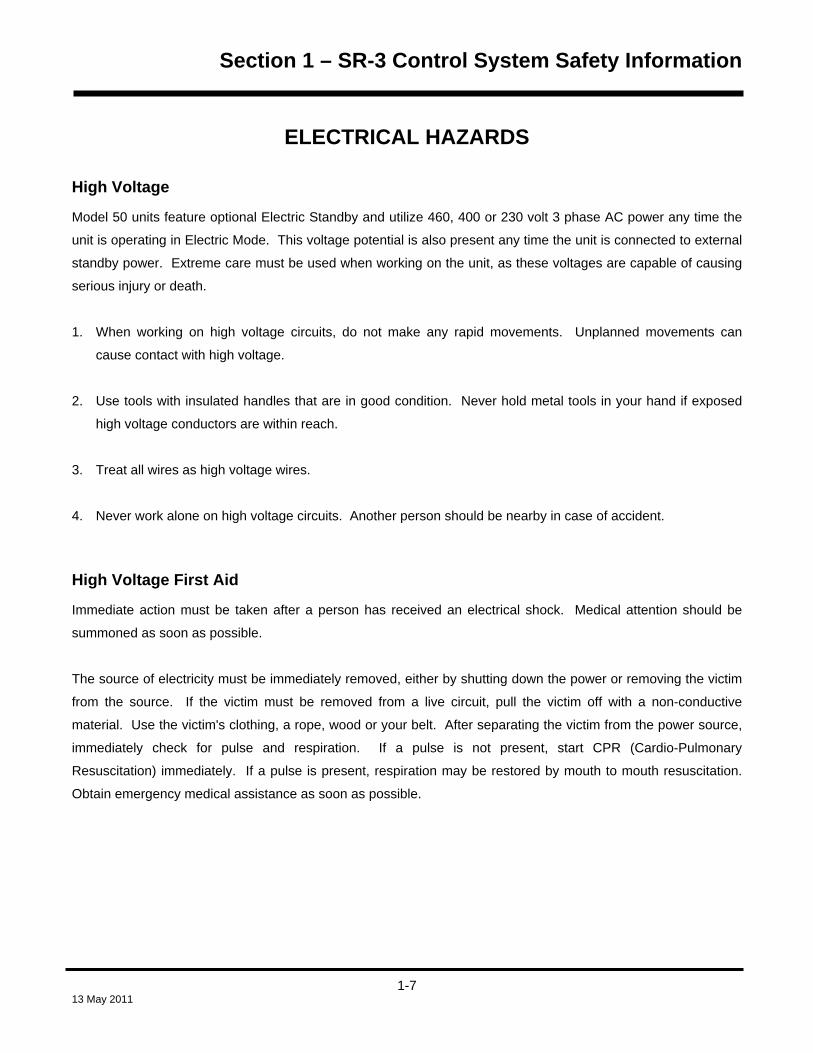
HMI Control Panel Operation The HMI contains a microprocessor and dedicated software. The HMI is a message center and does not directly
control the unit operation. It communicates with the Base Controller via a controller area network (CAN)
connection. The HMI displays system operating data and sends operating requests to the controller.
The display screen is used by the Base Controller to provide visual prompts and information to the operator, such
as operating mode, setpoint temperatures, gauges, hourmeter readings and operating conditions of the diesel
engine or electric motor. The HMI also contains the Cargo Watch Data Logger. The HMI and Base Controller
communicate via a CAN (Controller Area Network) connection.
Information can be displayed in 24 possible languages. A single HMI Control Panel software revision can display
a maximum of 11 languages. For this reason, there are a total of 4 HMI software revisions. Other than
languages supported, these software revisions are identical. The table below shows the 4 HMI Software
Revisions and the languages supported by each.
HMI Control Panel
Software Revision
Languages Supported
65xx English, Spanish, French, German, Italian, Dutch, Portuguese, Greek, Turkish, Hebrew,
Arabic
66xx English, Russian, Polish, Hungarian, Romanian, Bulgarian, Czech, Danish, Swedish,
Norwegian, Finnish
67xx English, Japanese, Chinese
68xx Set up using Wintrac. Settings are: English only, English and Spanish only, English and
up to 5 additional languages from the 65xx and 66xx lists shown above.
All SR-3 applications require HMI Control Panel Software Revision 6560, 6660, 6760, 6860 or later.
If the HMI Control Panel is disconnected from the unit while the unit is running, the unit will shut down. When the
HMI Control Panel is reconnected the unit will not restart until the On key is pressed.
NOTE: If necessary, the HMI Control Panel can be bypassed using fuse F10 as shown on page 2-23.
2-12 13 May 2011

Section 2 – SR-3 Trailer Single Temp Hardware Description
HMI Control Panel Hardware Versions All SR-3 applications require SR-3 HMI Control Panels. The SR-3 HMI Control Panel contains a Supervisor
Microprocessor and Supervisor Software. The Supervisor Microprocessor is used to manage power-up and
power down applications and to keep the HMI Control Panel operating under low voltage conditions.
The SR-3 HMI Control Panel uses an off line to turn the unit off when equipped with external devices such as
Rear Remote Control Panels. The CargoWatch Data Logger logs unit on and unit off information as well as
which device initiated the action.
For complete details of HMI Control Panel hardware versions see Section 7 of this manual.
HMI Control Panel Software Revisions All SR-3 applications require HMI Control Panel Software Revision 6550 or later.
For complete details of HMI Control Panel software revisions see Section 7 of this manual.
2-13 13 May 2011

Section 2 – SR-3 Trailer Single Temp Hardware Description
Real Time Clock The real time clock is located in the HMI Control Panel. The time is supplied to the Base Controller each time the
unit is turned on.
Clock Power The HMI Control Panel features a capacitor to provide backup power to the real time clock. This capacitor is
capable of maintaining the clock for approximately two weeks with no power connected to the unit. The capacitor
is recharged any time the HMI Control Panel is installed in the unit and a properly functioning starting battery is
connected.
If the unit starting battery is disconnected for an extended period the clock setting should be checked when the
unit is returned to service. If the HMI Control Panel is changed the clock setting should also be verified.
CargoWatch Data Logger The HMI Control Panel contains the CargoWatch Data Logger. The CargoWatch Data Logger is a fully
independent temperature logger. Up to six temperature sensors and 3 digital inputs can be connected to the
CargoWatch Data Logger. The optional CargoWatch temperature sensors are separate sensors installed as
required by each user. The CargoWatch Data Logger records CargoWatch temperature sensors, unit setpoint,
unit operating condition, and shutdown alarms.
The Countdown and Conservative features allow the CargoWatch Data Logger to continue to log after the unit is
turned off. See CargoWatch Sensor Configuration in Section 3 for details of operation.
SB Units: CargoWatch Data Logger sensors are not included with the unit.
SLX Units: Two CargoWatch Data Logger sensors are included with the unit. One CargoWatch Sensor is
factory mounted in the return air inlet. The other sensor is shipped loose and is intended to be installed in the
discharge air outlet or discharge air chute.
Programmable Features The settings of all programmable features are held in non-volatile memory in the Base Controller. The settings
are supplied to the HMI Control Panel each time the unit is turned on. If the HMI Control Panel is changed, the
current programmable feature settings will be supplied to the HMI Control Panel when the unit is turned on.
2-14 13 May 2011

Section 2 – SR-3 Trailer Single Temp Hardware Description
Display Heater The HMI Control Panel is equipped with a display heater. This heater is necessary to make the display quickly
visible in cold ambient temperatures.
The HMI has its own internal temperature sensor for the display heater. The display heater is energized when
the unit is turned on and the temperature sensed by the internal sensor is below 29°F (-2°C). The display heater
turns off when the temperature sensed by the internal sensor rises above 37°F (+3°C). The display heater draws
from 1.4 to 1.7 amps when energized.
The colder the ambient temperature the longer it will take for the heater to make the display visible on a cold
startup. It may take 10-15 seconds for the display to appear with very cold ambient temperatures.
2-15 13 May 2011

Section 2 – SR-3 Trailer Single Temp Hardware Description
SR-3 HMI Control Panel Connector Maps (1E64645 Rev A) HMI Control Panel Connector – arranged by use
Pin # Wire # Description
22 CANH-RED1-01 HMI Control Panel CAN bus 10 CANL-BLK1-01 HMI Control Panel CAN bus 33 OFF SR-3 HMI Off Line 34 ON-RED2-01 HMI Control Panel On Line 06 8XP-BLK3-01 8F power 12 BLK2-02 2P power NOTE 2 35 CH-RED3-01 HMI Control Panel chassis ground 23 SHLD HMI Control Panel shield 21 RXD1-01 CargoWatch receive 32 TXD1-01 CargoWatch transmit 19 COM-01 CargoWatch/Printer Port Chassis Ground NOTE 1 09 DPDI-01 CargoWatch Data Pak Detect 20 RXD2-01 Printer port receive 31 TXD2-01 Printer port transmit 19 COM2 CargoWatch/Printer Port Chassis Ground NOTE 1 29 D14-01 Printer port print 12 (2P) BLK2-02 Printer port printer power NOTE 2 18 RXD3 Receive 3 30 TXD3 Transmit 3 7 DPD3 Data Pak Detect 3
04 S1P-01 CargoWatch sensor 1 positive 16 S1N-01 CargoWatch sensor 1 negative 27 S2P-01 CargoWatch sensor 2 positive 15 S2N-01 CargoWatch sensor 2 negative 03 S3P-01 CargoWatch sensor 3 positive 14 S3N-01 CargoWatch sensor 3 negative 26 S4P-01 CargoWatch sensor 4 positive 25 S4N-01 CargoWatch sensor 4 negative 02 S5P-01 CargoWatch sensor 5 positive 13 S5N-01 CargoWatch sensor 5 negative 01 S6P-01 CargoWatch sensor 6 positive 24 S6N-01 CargoWatch sensor 6 negative
NOTE 1 – COM1-01 ground and COM2-01 ground are connected by splice in the harness.
NOTE 2 – 2PA-01 power and 2-BLK2-01 power are connected by splice in the harness.
2-16 13 May 2011

Section 2 – SR-3 Trailer Single Temp Hardware Description
HMI Control Panel J1 Connector – shown from pin side
112
1323
2435
2-17 13 May 2011
Section 2 – SR-3 Trailer Single Temp Hardware Description
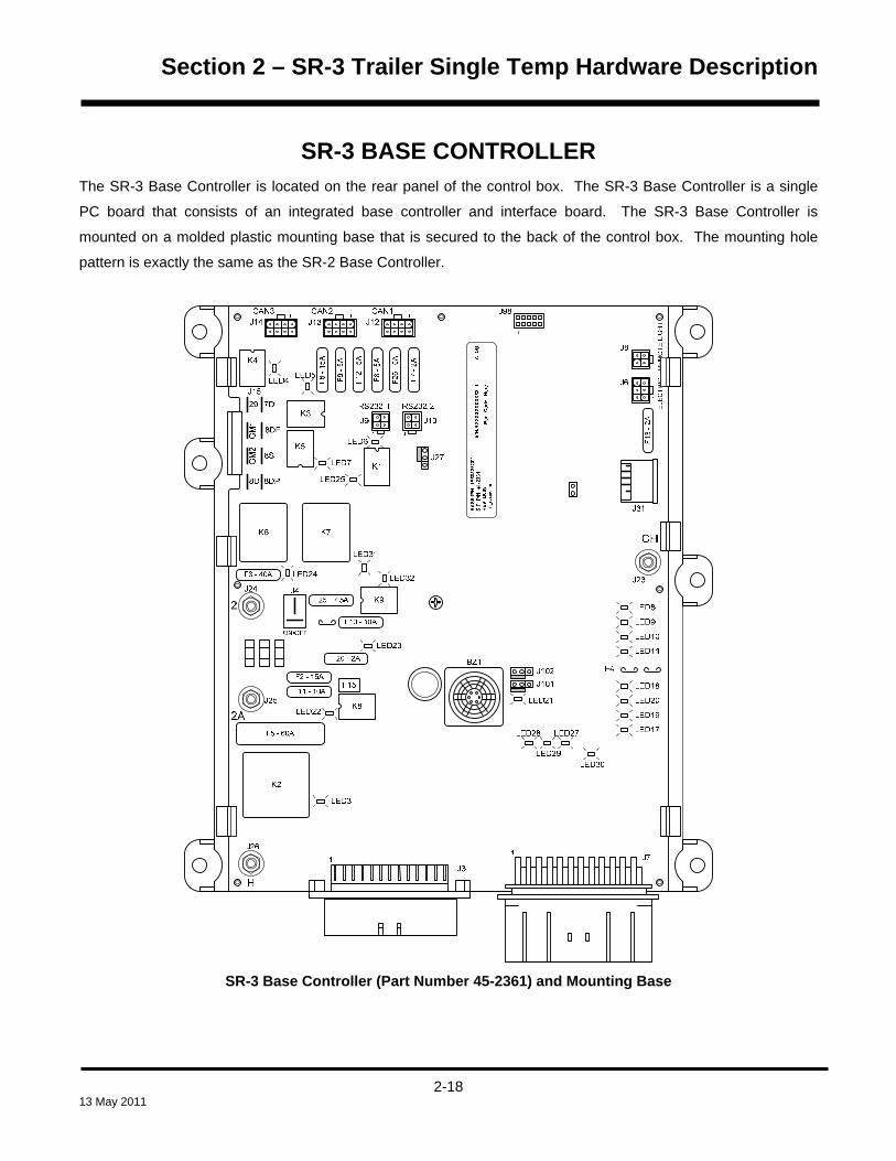
SR-3 BASE CONTROLLER The SR-3 Base Controller is located on the rear panel of the control box. The SR-3 Base Controller is a single
PC board that consists of an integrated base controller and interface board. The SR-3 Base Controller is
mounted on a molded plastic mounting base that is secured to the back of the control box. The mounting hole
pattern is exactly the same as the SR-2 Base Controller.
SR-3 Base Controller (Part Number 45-2361) and Mounting Base
2-18 13 May 2011

Section 2 – SR-3 Trailer Single Temp Hardware Description
Base Controller Hardware Versions As of this date there are two Base Controller hardware versions.
SR-3 Base Controller Part Number 45-2361 features a USB Port and uses Software Revision D005. This
Base Controller is used for SB Trailer and Rail units starting in February 2011.
SR-3 Base Controller Part Number 45-2362 does not have a USB Port and features Damper Gear Motor
Provisions and uses Software Revision D000. This Base Controller is used for European SLX units only
starting in September 2010.
For complete details of SR-3 Base Controller hardware versions and software requirements see Section 7 of this
manual.
Base Controller Software Revisions SR-3 Single Temperature Base Controllers require Base Controller Software Revision D0xx.
SR-3 SB Trailer and Rail units use Software Revision D005.
SR-3 European SLX Trailer units use Software Revision D000.
For complete details of Base Controller software revisions and hardware requirements see Section 7 of this
manual.
Real Time Clock The real time clock is located in the HMI Control Panel. The system time is supplied to the Base Controller each
time the unit is turned on. If the Base Controller is changed the clock setting will be automatically supplied to the
Base Controller when the unit is turned on. If the HMI Control Panel is changed the clock setting should be
verified.
2-19 13 May 2011

Section 2 – SR-3 Trailer Single Temp Hardware Description
ServiceWatch Data Logger The Base Controller contains the ServiceWatch Data Logger. The ServiceWatch Data Logger is a diagnostic
data logger. This data logger records unit temperature sensors, unit setpoint, unit operating conditions, alarms
and conditions that exist when an alarm is set.
Programmable Features The settings of all programmable features are held in non-volatile memory in the Base Controller. The settings
are supplied to the HMI Control Panel each time the unit is turned on. If the Base Controller is changed, all
programmable features must be reprogrammed. See Section 3 of this manual for programmable feature details.
Base Controller Operation The Base Controller is the heart of the SR-3 Control System. It consists of the Base Controller, Base Controller
software, memory, inputs and outputs. The Base Controller also provides the interface between the controller
inputs and outputs and the unit control components. The inputs are used to supply power and system information
to the Base Controller. The Base Controller and software examine the status of the inputs and turn the outputs to
the solenoids, valves and motor contactors on and off as required to control the operation of the unit. The Base
Controller also provides over-current and short circuit protection for the control circuits.
The only user serviceable components on the Base Controller are the fuses and the Cold Start jumper.
The Base Controller controls the operation of the unit using control relays or Smart FETs. The relays control
power to the high amperage loads such as the preheat relay, fuel solenoid pull-up coil and starter. The Smart
FETs control power to the lower amperage loads such as solenoids and valves. Each relay is individually fuse
protected. The Smart FETs are self-protecting. An LED next to each relay or Smart FET is illuminated when the
relay or FET is energized by the Base Controller. With relays the LED lights only when the relay coil is energized
and the relay contacts have transferred to the energized position.
2-20 13 May 2011

Section 2 – SR-3 Trailer Single Temp Hardware Description
Relay Functions
IMPORTANT: Do not attempt to remove the relays from the Base Controller, they are soldered in place.
Relay Function
K1 Run Relay
K2 Preheat Relay
K3 High Speed Relay
K4 Damper Relay
K5 Diesel/Electric Relay
K6 Fuel Solenoid Pull-In Relay
K7 Starter Solenoid Relay
K8 Fresh Air Exchange (Optional)
K9 On/Off Relay
2-21 13 May 2011

Section 2 – SR-3 Trailer Single Temp Hardware Description
Fuse Size & Function
Fuse Size Function
F2 15A Power to On/Off Switch
F3 40A Fuel Sol Pull-In/Starter Circuit
F4 None
or
2A
No fuse - all Bosch and TK
alternators (NOTE 1)
2A fuse - all Prestolite alternators
F5 60A Preheat Circuit (NOTE 2)
F6 15A Damper and High Speed Circuits
F7 2A 8XP Circuit – Controller On
Feedback to HMI
F8 5A 2A power to CAN Connector J12
F9 5A 2A power to CAN Connector J14
F10 10A 8X Power - install in right position
F11 10A Fresh Air Exchange (Optional)
F12 5A 2A power to CAN Connector J13
F13 2A 8FC Circuit (Remote Status
Light/Optional Power)
F15 P/S On/Off Relay (NOTE 3)
F20 2A Alternator Sense
F25 7.5A HPCO Switch Circuit
F26 5A Power to CAN Connector J98
NOTE 1: Fuse F4 fuse must be in place for Prestolite alternators to charge. Fuse F4 must be removed for
Bosch and Thermo King alternators. Service Parts Base Controllers are shipped without the F4 fuse.
NOTE 2: The F5 preheat fuse is a “slow blow” type fuse. It is designed for use with the Yanmar trailer engine air
pre-heater. Always replace the fuse with the TK specified fuse. Service Parts Base Controllers are shipped
without the F5 fuse.
NOTE 3: The device identified as F15 is a polyswitch. This polyswitch provides over-current protection for the
On/Off relay. The polyswitch will reset automatically and is not field repairable.
2-22 13 May 2011

Section 2 – SR-3 Trailer Single Temp Hardware Description
Fuse F10 There are three in-line fuse clips that allow for two configurations of the F10 fuse. The right position is the normal
position. This position has a white bar below it on the circuit board. When fuse F10 is installed in the right
position, control power is routed to the K9 On/Off Relay contacts. The On/Off keys on the HMI Control Panel
energize and de-energize the K9 On/Off Relay. When the K9 On/Off Relay is energized power is supplied
through the normally open K9 contacts to turn the unit on.
When fuse F10 is installed in the left position power bypasses the K9 On/Off relay contacts and the unit will start
and run without the HMI Control Panel connected. This fuse position is for emergency bypass operation only. Do
not operate the unit with the F10 fuse installed in the left position unless absolutely necessary.
IMPORTANT: If fuse F10 is installed in the left position the unit may start and run. If the HMI Control Panel is
connected and functional, the On and Off keys will still work. The Off key will turn the unit off if Fuse F10 is in the
left position, but the Base Controller will remain powered up.
IMPORTANT: If fuse F10 is installed in the left position and the unit is turned off using the Off key the unit will
shut down but the Base Controller will remain powered up. Leaving the unit turned off in this manner for an
extended period may result in a dead battery.
Fuse F15 The device identified as F15 is a poly switch. This over-current device resets automatically and is not
replaceable.
2-23 13 May 2011

Section 2 – SR-3 Trailer Single Temp Hardware Description
Smart FET Outputs A Smart FET is a self protecting output device used for the functions shown in the table below. If an over-current
condition occurs, the Smart FET will turn off until the over-current condition no longer exists. It will then resume
normal operation. A fuse is not required.
Not all Smart FETs shown below are used on single temperature trailer units.
Output Function
EVA, EVB, EVC, EVD ETV Outputs
PS Pilot Sol
HGS Hot Gas/Hot Gas Bypass Sol
LV1 Not Currently Used
EXC Alternator Excite
WV Not Currently Used
LQI Liquid Injection Valve
LLS Not Currently Used
GM1, GM2 Damper Gear Motor (NOTE 1)
CIS Condenser Inlet Solenoid
RTPS Receiver Tank Press Sol
PV Purge Valve
NOTE 1: Gear motor circuitry is not present on all Base Controllers.
2-24 13 May 2011

Section 2 – SR-3 Trailer Single Temp Hardware Description
LED Functions The LED is illuminated when the associated circuit output is energized. Not all output LEDs shown below are
used on single temperature trailer applications.
LED # Function LED3 K2 Preheat Circuit LED4 K4 Damper Circuit LED5 K3 High Speed Circuit LED6 K1 Run Relay Circuit LED7 K5 Diesel/Electric Relay LED 8 Pilot Solenoid or Condenser Inlet Solenoid Circuit LED 9 Receiver Tank Pressure Sol Circuit LED10 Hot Gas Bypass Valve Circuit LED11 Purge Valve Solenoid Circuit LED17 Not Currently Used LED18 Alternator Excite LED19 Liquid Injection Valve Circuit LED20 Not Currently Used LED21 Status – (NOTE 1) LED22 K8 Fresh Air Exchange (Optional) LED23 K9 On/Off Circuit LED24 K6 Fuel Solenoid Pull-In Circuit LED25 K7 Starter Solenoid Circuit LED27 ETV – D (NOTE 2) LED28 ETV – B (NOTE 2) LED29 ETV – A (NOTE 2) LED30 ETV – C (NOTE 2) LED31 Damper Gear Motor Close LED32 Damper Gear Motor Open
NOTE 1 The Status LED flashes once per second when the Base Controller is powered
and operating normally. The Status LED flashes several times per second during a flash
load. The Status LED is on without flashing during reboot and when the Base Controller
is under test. The Status LED flashes twice within 1 second followed by 1 second off if a
CAN communication error is present.
NOTE 2 ETV LED’s are illuminated when the respective ETV output is energized. Note
that on applications without ETV that the ETV LED’s may be illuminated even though
there is no ETV present.
2-25 13 May 2011
Section 2 – SR-3 Trailer Single Temp Hardware Description
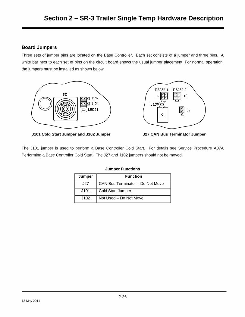
Board Jumpers Three sets of jumper pins are located on the Base Controller. Each set consists of a jumper and three pins. A
white bar next to each set of pins on the circuit board shows the usual jumper placement. For normal operation,
the jumpers must be installed as shown below.
J101 Cold Start Jumper and J102 Jumper J27 CAN Bus Terminator Jumper
The J101 jumper is used to perform a Base Controller Cold Start. For details see Service Procedure A07A
Performing a Base Controller Cold Start. The J27 and J102 jumpers should not be moved.
Jumper Functions
Jumper Function
J27 CAN Bus Terminator – Do Not Move
J101 Cold Start Jumper
J102 Not Used – Do Not Move
2-26 13 May 2011

Section 2 – SR-3 Trailer Single Temp Hardware Description
Connector Locations
ON/OFF
8DP
8S
8DF
7DJ15
GM
1G
M2
F3 - 40A
F25 - 7.5A
F7 -
2A
F8 -
5A
F9 -
5A
F12
-5A
F26
-5A
F6 -
15A
F5 - 60A
K2
1
J102J101
F4
LED8
LED9
LED10
LED11
LED18
LED20
LED19
LED17
K6 K7
K4
K5
CAN3 CAN2 CAN1
K9
K8
F13
-2A
F10 - 10A
F11 - 10A
F2 - 15A
F20 - 2A
J4
2A
2
H
CH
111
1
1
J31
LED21R
EM
OTE
LIG
HT
ELE
CTR
IC
K3
J7
BZ1
LED4LED5
29
LED25
LED7
LED24
LED31
LED32
LED23
J14 J13 J12
J31
J24
J25
J26
LED3
J8
J6
J23
1
J98
LED28 LED27
LED29LED30
LED22
8D
BA
SE P
/N: 1
E603
25G
01S.
P. P
/N: 4
1-23
61R
EV. D
005
TKS3
-A00
1-D
000
S/N
:AXX
XXXX
XXXX
3T1
A
DG
Bar
C
ode
Her
e
K1J27
1 1
RS232-1 RS232-2
J10J9
LED6
11
3
6
16
5
7
89 10
4
15
13
14
12
2 1 17
2-27 13 May 2011

Section 2 – SR-3 Trailer Single Temp Hardware Description
Connector Usage See the following pages for individual connector maps. Number Connector Circuit
1
J12 CAN connection.
2
J13 CAN Connection. 2P Power, Chassis Ground, and On Line are used for the optional Remote Control Panel, if installed. Can H and Can L are not currently used.
3
J14 CAN connection to HMI Control Panel
4
J15 Connections to unit engine and damper (and defrost gear motor – if so equipped)
5
J24 “2” circuit to fuse link
6
J4 Connections to Base Controller On/Off Switch
7
J25 “2A” circuit to alternator
8
J26 “H” circuit to air intake heater
9
J3 Connections to unit Sensor Harness
10
J7 Connections to unit Main Harness
11
J23 “CH” chassis ground to unit ground plate
12
J31 USB Connector to USB Connector on Front Panel
13
J6 Connections to optional Electric Standby
14
J8 Connections to optional Remote Status Light
15
J10 RS-232 Serial Port 2 connection to optional Remote Control Panel
16
J9 RS-232 Serial Port 1 connection to ServiceWatch connector
17
J98 CAN connector for future use
2-28 13 May 2011

Section 2 – SR-3 Trailer Single Temp Hardware Description
2-29 13 May 2011
SR-3 Base Controller Connector Maps (1E64645 Rev A) J3 - Base Controller Sensor – arranged by use – Single Temperature Applications
Pin # Wire # Description 1 RTP-01 Control return air temperature sensor positive (blue sensor wire)
2 RTN-01 Control return air temperature sensor negative (brown sensor wire)
21 RTRP-01 Display return air temperature sensor positive (blue sensor wire)
32 RTRN-01 Display return air temperature sensor negative (brown sensor wire)
24 DTP-01 Control discharge air temperature sensor positive (blue sensor wire)
13 DTN-01 Control discharge air temperature sensor negative (brown sensor wire)
22 DTRP-01 Display discharge air temperature sensor positive (blue sensor wire)
33 DTRN-01 Display discharge air temperature sensor negative (brown sensor wire)
25 CTP-01 Coil temperature sensor positive (blue sensor wire)
14 CTN-01 Coil temperature sensor negative (brown sensor wire)
3 ATP-01 Ambient temperature sensor positive (blue sensor wire)
4 ATN-01 Ambient temperature sensor negative (brown sensor wire)
26 WTP-01 Water temperature sensor positive (blue sensor wire)
15 WTN-01 Water temperature sensor negative (brown sensor wire)
27 ST1P-01 Spare 1 temperature sensor positive (blue sensor wire)
16 ST1N-01 Spare 1 temperature sensor negative (brown sensor wire)
9 DPI-01 Signal from discharge pressure transducer (white wire) (DPT)
10 SPI-01 Signal from suction pressure transducer (white wire) (DPT)
23 FLL-01 Optional fuel level sensor
35 FUELN-01 Optional fuel level sensor
12 2PL-01 Optional solid state fuel level sensor
J3 Sensor Harness Connector – shown from pin side
112
1323
2435

Section 2 – SR-3 Trailer Single Temp Hardware Description
J7 – 36 pin Base Controller to Main Harness Connector – Single Temperature Applications
Pin # Wire # Description 2 2-01 Power to the alternator sense circuit.
3 26-01 Power to energize pilot solenoid (PS)
5 HG-01 Power to energize hot gas solenoid (HG)
11 EVC-01 To electronic throttling valve (ETV)
12 EVD-01 To electronic throttling valve (ETV)
13 SPP-02 Power to suction pressure transducer (red wire) (SPT)
14 DPP-02 Power to discharge pressure transducer (red wire) (DPT)
15 CLP-01 Power to coolant level sensor (red wire) (CLS)
16 CLS-01 Signal from coolant level sensor (white wire) (CLS)
17 PHPCO-01 Power from high pressure cutout switch (HPCO)
18 HPCO-01 Power to high pressure cutout switch (HPCO)
20 DSP-01 Power to the optional door switch (red wire) (DS)
21 DS-01 Signal from the optional door switch (white wire) (DS)
22 FP-01 To fuel pressure switch (FPS)
23 EVB-01 To electronic throttling valve (ETV)
24 EVA-01 To electronic throttling valve (ETV)
25 SPN-02 Ground to suction pressure transducer (black wire) (SPT)
26 DPN-02 Ground to discharge pressure transducer (black wire) (DPT)
28 20B-01 To engine low oil pressure switch (LOPS)
29 OLS-01 To engine low oil level switch (OLS)
32 FLS-01 To optional fuel level switch (FLS)
33 EXC-01 Power to the alternator excite circuit
34 W-04 To the alternator “W” circuit
35 FS1-01 To flywheel sensor (FW)
36 FS2-01 To flywheel sensor (FW)
J7 Base Controller Harness Connector – shown from pin side
112
1324
2536
2-30 13 May 2011

Section 2 – SR-3 Trailer Single Temp Hardware Description
J6 - Electric Connector – arranged by pin number
Pin # Wire # Description 1 7E-01 To 7EA terminal on phase select module (PSM)
2 EOL-01 To normally closed contact pin 95 on overload relay (OLR)
3 8-01 To 8 terminal on phase select module (PSM)
4 CHHV To chassis ground
5 ER-01 To ER terminal on phase select module (PSM)
6 26E-01 Power to heater contactor (HC)
J8 - Remote Light Connector – arranged by pin number
Pin # Wire # Description 1 ALM-01 To white wire on remote light option
2 8FC-01 To red wire on remote light option
3 ALPC-01 To black wire on remote light option
4 8FC-01 Option Power
J9 – SERVICE WATCH Download Connector – arranged by pin number
Pin # Wire # Description 1 RXD-RED1-08 To J52 controller download connector pin A
2 TXD-BLK2-06 To J52 controller download connector pin B
3 COM-BLK1-09 To J52 controller download connector pin C
4 DPD-RED2-05 To J52 controller download connector pin E
Mini Mate-N-Lok Harness Connectors – shown from pin side of harness connector
2
3
1
4
4 Pin Connectors
1 2 3
4 5 6
6 Pin Connectors
1 2 3 4
5 6 7 8
8 Pin Connectors
2-31 13 May 2011

Section 2 – SR-3 Trailer Single Temp Hardware Description
J10 – Remote Controller Connector – arranged by pin number
Pin # Wire # Description 1 RXD-BLK To Remote Controller Panel Pin 7
2 TXD-RED To Remote Controller Panel Pin 8
3
4 REM-ON-BRN To Remote Controller Panel Pin 6
J12 – CAN 1 – arranged by pin number
Pin
Number
Wire
Number
Description
1 CANL-BLK1 To iBOX Option
2 CANH-RED1 To iBOX Option
3 DRAIN-WHT To iBOX Option
4 ON_OFF-RED2 To iBOX Option
5 2P-BLK2 To iBOX Option
6 8XP-BLK3 To iBOX Option
7 None Not Used
8 CH-RED3 Chassis ground to iBOX Option
Mini Mate-N-Lok Harness Connectors – shown from pin side of harness connector
2
3
1
4
4 Pin Connectors
1 2 3
4 5 6
6 Pin Connectors
1 2 3 4
5 6 7 8
8 Pin Connectors
2-32 13 May 2011

Section 2 – SR-3 Trailer Single Temp Hardware Description
J13 – CAN 2 – Remote Controller Connector – arranged by pin number
Pin
Number
Wire
Number
Description
1 CANL Not Used
2 CANH Not Used
3 SHLD Not Used
4 ON-ORN To Remote Controller Panel Pin 4
5 2-BLU To Remote Controller Panel Pin 1
6 8XP Not Used
7 None Not Used
8 DRAIN/CH/GRE To Remote Controller Panel Chassis Ground Pin 2
J14 – CAN 3 – HMI Connector – arranged by pin number
Pin
Number
Wire
Number
Description
1 CANL-BLK1-01 To HMI Control Panel Pin 10
2 CANH-RED1-01 To HMI Control Panel Pin 22
3 SHLD To HMI Control Panel Pin 23
4 ON-RED2-01 To HMI Control Panel Pin 34
5 2-BLK2-01 To HMI Control Panel Pin 12
6 8XP-BLK3-01 To HMI Control Panel Pin 6
7 OFF To HMI Control Panel Pin 33
8 CH-RED3-01 To HMI Control Panel Pin 35
Mini Mate-N-Lok Harness Connectors – shown from pin side of harness connector
2
3
1
4
4 Pin Connectors
1 2 3
4 5 6
6 Pin Connectors
1 2 3 4
5 6 7 8
8 Pin Connectors
2-33 13 May 2011

Section 2 – SR-3 Trailer Single Temp Hardware Description
2-34 13 May 2011
J4 - Power Switch Connector – arranged by pin number
Pin # Wire # Description 1 2AB-01 2AB Power
2 8-02 8 Power
J15 - Engine Connector – arranged by pin number
Pin # Wire # Description 1 8DP-01 Power to energize fuel solenoid pull-in coil (white wire) (FSP)
2 8S-01 Power to energize starter solenoid (SS)
3 8DF Power to 8DF circuit
4 7D-01 Power to energize high speed solenoid (HS)
5 8D-01 Power to energize fuel solenoid hold coil (red wire) (FSH)
6 GM2 Power to Defrost Gear Motor
7 GM1 Power to Defrost Gear Motor
8 29-01 Power to energize damper solenoid (DS)
Screw Terminal Power Connections
Terminal
Number
Wire
Number
Description
J24 (2) RED From fusible link (battery power)
J25 (2A) 2A From alternator
J26 (H) H To air intake heater or glow plugs
J23 (CH) CHP Chassis ground
J31 - USB Connector – arranged by pin number
Pin # Wire # Description 1 RED To Front Panel USB Connector
2 WHITE To Front Panel USB Connector
3 GREEN To Front Panel USB Connector
4
5
6 BLACK To Front Panel USB Connector

Section 2 – SR-3 Trailer Single Temp Hardware Description
COMPLETE SR-3 CONTROL SYSTEM
2-35 13 May 2011

Section 2 – SR-3 Trailer Single Temp Hardware Description
UNIT SENSORS The sensors monitor air temperatures at various points in the system, as well as the engine oil pressure, engine
oil level, engine coolant level, engine coolant temperature, engine speed, alternator frequency and fuel level.
Refrigerant pressures are also monitored on ETV units. Sensors are connected to the Base Controller via the J3
Sensor Connector.
AIR TEMPERATURE SENSORS
Graded and Un-graded Air Temperature Sensors The dual Return Air and Discharge Air sensors are graded sensors. Sensor grading allows maximum accuracy
without the need for ice water calibration. The sensor grade (from 1L through 9H) is stamped on the sensor and
must be entered into the Base Controller when a sensor is changed, in order to properly calibrate the sensor for
accurate temperature readings. If the grade is not changed from the factory setting of 5H, then Alarm Code 92
Sensor Grades Not Set will occur. Always update the sensor grade nameplate when graded sensors are
changed. The nameplate is mounted on the side of the control box.
Un-graded sensors are used to measure the evaporator coil temperature and ambient temperature, since these
temperatures are not as critical as the return and discharge air temperatures.
Do not replace a graded sensor with an un-graded sensor.
Dual Sensors Dual temperature sensors are provided for both return air temperature and discharge air temperature. The
sensors are located next to each other to insure common readings. One sensor is the control sensor and the
other sensor is the display sensor. The return and discharge control sensors are used for unit control. The return
and discharge display sensors are used by the HMI Control Panel to display the temperature.
2-36 13 May 2011

Section 2 – SR-3 Trailer Single Temp Hardware Description
Control and Display Return Air Sensors These sensors monitor the temperature of the air returning to the evaporator coil. The sensors are located in the
return air flow and are connected directly to the Base Controller connector J3. These sensors are graded
sensors and must be replaced with graded sensors. The Base Controller must be calibrated to the respective
grade of the installed sensor in order to operate properly. The Control Return Air Sensor is marked with one
yellow cable tie and is connected to the Base Controller via the RTP and RTN wires. The Display Return Air
Sensor is marked with two yellow cable ties and is connected to the Base Controller via the RTRP and RTRN
wires.
Return Air Sensor Clamp A brass clamp should be installed between the two return air sensors. This clamp increases the thermal coupling
between the sensors to provide more accurate temperature readings when the temperature is changing rapidly.
Rapid temperature changes may occur during pulldown or when the door has been opened. This clamp is not
required on the discharge air sensors.
Control and Display Discharge Air Sensors These sensors monitor the temperature of the air leaving the evaporator coil. The sensors are located in the
evaporator discharge air path and are connected directly to the Base Controller via connector J3. These sensors
are graded sensors and must be replaced with graded sensors. The Base Controller must be calibrated to the
respective grade of the installed sensor, in order to operate properly. The Control Discharge Air Sensor is
marked with one red cable tie and is connected to the Base Controller via the DTP and DTN wires. The Display
Discharge Air Sensor is marked with two red cable ties and is connected to the Base Controller via the DTRP and
DTRN wires.
2-37 13 May 2011

Section 2 – SR-3 Trailer Single Temp Hardware Description
Coil Temperature Sensor This sensor monitors the temperature of the evaporator coil. The sensor is located on the evaporator coil header
plate and is connected directly to the Base Controller via connector J3. This is an un-graded sensor. It is
connected to the Base Controller via the CTP and CTN wires.
Ambient Temperature Sensor This sensor monitors the ambient air temperature. The sensor is located in the main unit adjacent to the
condenser coil and is connected directly to the Base Controller via connector J3. This is an un-graded sensor. It
is connected to the Base Controller via the ATP and ATN wires.
Spare 1 Temperature Sensors This optional sensor monitors a temperature as selected by the customer. This optional sensor must be installed
as required by the customer. This is a graded sensor. It is connected to the Base Controller via the STIP and
STIN wires.
Alarm Code 92 Sensor Grades Not Set is not used with spare sensors. However, when used spare sensors
should be calibrated to achieve maximum accuracy.
2-38 13 May 2011

Section 2 – SR-3 Trailer Single Temp Hardware Description
CARGOWATCH SENSORS The CargoWatch Data Logger is part of the HMI Control Panel. The CargoWatch Data Logger conforms to
European standard EN12830. The Data Logger supports up to 6 temperature sensors and 4 digital inputs.
The sensors used for the CargoWatch Data Logger are RTD thermistor-type sensors that differ from the sensors
used for unit control. The CargoWatch sensors are connected directly to the HMI Control Panel.
CargoWatch sensors can be identified by:
• No shrink tubing over sensor barrel
• Shorter sensor barrel than unit sensors
• No sensor grades
• The sensor is not polarity sensitive
• Both wires are black
CargoWatch Sensor
No Shrink Tubing
IMPORTANT: The CargoWatch sensors ARE NOT interchangeable with the unit temperature sensors.
2-39 13 May 2011

Section 2 – SR-3 Trailer Single Temp Hardware Description
These thermistor sensors change resistance as the temperature changes. Resistance values can be measured
using a high quality ohmmeter and compared to a table to directly determine the temperature. Note that these
resistance values only apply to CargoWatch sensors.
CargoWatch Sensor Resistance vs Temperature
°F °C Ohms
-20°F -29°C 166,356
-10°F -23°C 115,757
0°F -18°C 86,501
10°F -12°C 61,737
20°F -7°C 47,070
30°F -1°C 34,374
32°F 0°C 32,650
40°F 4°C 26,688
50°F 10°C 19,904
60°F 16°C 15,002
70°F 21°C 11,944
80°F 27°C 9,166
90°F 32°C 7,402
100°F 38°C 5,775
For testing and replacement of the CargoWatch Sensors see Service Procedure D04A Checking CargoWatch
Sensors.
2-40 13 May 2011

Section 2 – SR-3 Trailer Single Temp Hardware Description
REFRIGERATION CONTROL COMPONENTS These components are used by the Base Controller to sense conditions or control operation of the refrigeration
system. The Base Controller determines the necessary requirements by considering the setpoint, the software,
the programmable feature and OptiSet® settings, and the information supplied by the sensors.
Discharge Pressure Transducer (DPT) This transducer supplies the compressor discharge pressure to the Base Controller. The sense wire is connected
to the Base Controller at J3 via the DPI wire. The DPP and DPN wires supply power to the sensor. This sensor
is installed on ETV-equipped units only.
Suction Pressure Transducer (SPT) This transducer supplies the compressor suction pressure to the Base Controller. The sense wire is connected to
the Base Controller at J3 via the SPI wire. The SPP and SPN wires supply power to the sensor. This sensor is
installed on ETV equipped units only.
High Pressure Cutout Switch (HPCO) The high pressure cutout switch is located on the discharge manifold of four cylinder compressors. The switch is
closed with normal pressures and opens with excessive pressures to shut the unit down and prevent damage.
Pilot Solenoid (PS) The Base Controller energizes (opens) the Pilot Solenoid to shift the 3 way valve to the heat position during heat
or defrost mode operation. The normally closed Pilot Solenoid is located near the 3 way valve. The pilot solenoid
is energized and LED 8 is lit when the Base Controller energizes the Pilot Solenoid Smart FET. This supplies
power via the 26 wire to the pilot solenoid. The circuit is protected by the Smart FET.
Electronic Throttling Valve (ETV) The Electronic Throttling Valve is capable of opening and closing incrementally and is installed between the
evaporator and the compressor.
The ETV is controlled directly by the Base Controller Smart FET outputs. As the temperature approaches
setpoint, the ETV begins to close, throttling the suction gas returning to the compressor and thus reducing cooling
capacity. As the box temperature approaches setpoint, the ETV becomes more nearly closed. This feature
provides very smooth and steady temperature control. The circuit is protected by the ETV Smart FETs.
2-41 13 May 2011

Section 2 – SR-3 Trailer Single Temp Hardware Description
Hot Gas Solenoid (HG) The normally closed hot gas bypass solenoid is opened during modulated cool when the temperature is very
close to setpoint. This diverts hot gas from the compressor discharge line, through the open hot gas solenoid to
the evaporator distributor, to further reduce cooling capacity. The valve also opens if the suction pressure is too
low. This valve is supplied on ETV equipped units only. The hot gas solenoid is energized and LED 10 is lit
when the Base Controller energizes the Hot Gas Solenoid Smart FET. This supplies power via the HG wire to the
hot gas solenoid. The circuit is protected by the Smart FET.
Damper Solenoid (DS) A damper solenoid is used to open and close the defrost damper doors. Damper solenoids are used on most US
domestic units. The Base Controller for units with damper solenoids is different than the one used with defrost
damper motors. See the information in Section 7 - Hardware Features and Interchange for Service Parts
numbers.
The damper solenoid is energized and LED 4 is lit when the Base Controller energizes the K4 Damper Relay.
The K4 Damper Relay normally open contacts supply power via the 29 wire to the damper solenoid. The circuit is
protected by the 15 amp fuse F6.
Damper Motor (DM) European SL units use hermetically sealed defrost damper gear motors to open and close the defrost damper
door. The Base Controller for units with damper solenoids is different than the one used with defrost damper
motors. See the information in Section 7 - Hardware Features and Interchange for Service Parts numbers.
2-42 13 May 2011

Section 2 – SR-3 Trailer Single Temp Hardware Description
Fresh Air Exchange Solenoid (FAE) Option An optional Fresh Air Exchange Feature is available. This allows fresh outside air to be drawn into the trailer and
the interior air to be exhausted. This feature is beneficial when hauling loads that release gas as they ripen, such
as potatoes.
The Fresh Air Exchange feature should be used exactly as specified by the customer and with fresh loads only.
Using the Fresh Air Exchange feature with frozen loads will result in poor refrigeration performance, excessive
defrost cycles and may set refrigeration capacity Alarm Codes.
A solenoid is used to open and close the Fresh Air Exchange Door. Note that the Fresh Air Exchange door will
only be open when the unit engine is running, as it is held in the open position by the Fresh Air Exchange
Solenoid. The door will close when the engine shuts down to preserve unit battery life. The setting of the Fresh
Air Exchange door will survive power off / power on cycles – if the door is set “Open” by the operator it will
continue to open any time the engine is running until it is set “Close” by the operator.
As of this date, Revision D006 Base Controller Software and Revision 6561 HMI Control Panel are required for
the Fresh Air Exchange feature and will be installed only in SR-3 SB units equipped with the Fresh Air Exchange
option. Revision D006 Base Controller Software is a direct descendent of Revision D007 Base Controller
Software and has all the same features as Revision D007 Software.
If installed and enabled, the Fresh Air Exchange is opened and closed from the Mode Menu. See Fresh Air
Exchange in Section 4 for details.
2-43 13 May 2011

Section 2 – SR-3 Trailer Single Temp Hardware Description
ENGINE CONTROL COMPONENTS These components are used by the Base Controller to sense conditions and control operation of the diesel
engine (or electric motor, if present).
Coolant Temperature Sensor This sensor monitors the temperature of the coolant in the diesel engine. It is located on the diesel engine
thermostat housing and is connected to the Base Controller via the J3 connector WTP and WTN wires.
Coolant Level Sensor (CLS) This sensor monitors the engine coolant level. It consists of a magnetic reed switch located on the radiator
expansion tank. The magnetic reed switch is a press-in miniature reed switch and a captive magnetic float inside
the radiator expansion tank. If the coolant level is low for a specified period of time a low coolant condition is
assumed to exist. The switch is connected to the Base Controller connector J7 via the CLS and CLP wire. The
switch is closed with adequate coolant level and open with low coolant level.
Oil Pressure Switch (LOPS) The normally closed low oil pressure switch monitors the oil pressure of the diesel engine. It is located on the
engine side of the unit frame. It is connected to the Base Controller via J7 connector 20B and CH wires. The
switch is open when the oil pressure is adequate.
Oil Level Switch (OLS) The normally open oil level switch monitors the oil level in the diesel engine. It is located above the oil pan on the
door side of the engine. It supplies information on the oil level to the Base Controller via the J7 connector OLS
wire. The switch is closed when the oil level is low.
Flywheel Sensor (FW) This sensor monitors the RPM of the diesel engine. The flywheel sensor is located on the door side of the engine
just under the starter. It supplies engine speed information to the Base Controller connector J7 via the FS1 and
FS2 wires.
2-44 13 May 2011

Section 2 – SR-3 Trailer Single Temp Hardware Description
Intake Air Heater The intake air heater is located at the inlet to the intake manifold of the diesel engine. The intake air heater is
energized and LED 3 is lit when the Base Controller energizes the K2 Preheat Relay. The K2 Preheat Relay
normally open contacts supply power via the H wire to the intake air heater to preheat the engine before starting.
The circuit is protected by the 60 amp fuse F5.
Starter Motor (SM) The starter motor is located on the door side of the engine. The starter motor is energized and LED 25 is lit when
the Base Controller energizes the K7 Starter Relay. The K7 Starter Relay normally open contacts supply power
via the 8S wire to the starter solenoid to crank the engine. The circuit is protected by the 40 amp fuse F3.
Fuel Solenoid (FSH, FSP) The fuel solenoid is located at the rear of the injector pump and is used to start and stop the flow of fuel to the
diesel engine during diesel mode operation. The fuel solenoid features two coils, a pull-in coil and a hold coil.
The pull-in coil transfers the fuel solenoid to the open position. The hold coil maintains the fuel solenoid in the
open position.
The hold coil is energized in Diesel Mode when the Base Controller energizes the K1 Run Relay. LED 6 is lit
when the Run Relay is energized and the contacts have transferred. The K1 Run Relay normally open contacts
supply power from the 8 wire thru the normally closed Diesel/Electric relay to the 8D wire to energize the fuel
solenoid hold coil. The circuit is protected by the 7.5 amp fuse F25.
The pull-in coil is momentarily energized and LED 24 is momentarily lit in Diesel Mode when the Base Controller
energizes the K6 Fuel Solenoid Pull-in Relay for 2 seconds. The K6 Fuel Solenoid Pull-in Relay normally open
contacts supply power via the 8DP wire to the fuel solenoid pull-in coil to positively open the fuel solenoid. The
circuit is protected by the 40 amp fuse F3.
High Speed Solenoid (HS) The high speed (throttle) solenoid is located behind the fuel injection pump. The high speed solenoid is
energized and LED 5 is lit when the Base Controller energizes the K3 High Speed Relay. The K3 High Speed
Relay contacts supply power to the 7D wire to the high speed solenoid to enable high speed operation. The
circuit is protected by the 15 amp fuse F6.
2-45 13 May 2011
Section 2 – SR-3 Trailer Single Temp Hardware Description
Alternator Frequency Alternator frequency is monitored by the microprocessor via the “W” wire. When a unit equipped with optional
Electric Standby is running in Diesel Mode, the ratio between the engine RPM and alternator frequency is
monitored. If these values are not in the proper ratio it is an indication that drive belt slippage is occurring. If this
occurs then Alarm Code 48 is set as a shutdown alarm.
2-46 13 May 2011

Section 2 – SR-3 Trailer Single Temp Hardware Description
COMMUNICATION PORTS The SR-3 features three communication ports. On SB units the CargoWatch and ServiceWatch ports are located
on the control panel and the Printer port is inside the control box. On SL and SLX units the CargoWatch port and
Printer ports are located on the control panel and the ServiceWatch port is located inside the control box. The port
inside the control box may be swapped with one of the ports on the control panel if required by the end user.
CargoWatch Port The CargoWatch port is used to download the CargoWatch Data Logger and to flash load software to the HMI
Control Panel. It is located on the Control Panel.
USB Port Thermo King SR-3 Trailer Units provide a USB (Universal Serial Bus) Port located on the unit control panel. If a
USB Flash Drive is connected to the Control Panel USB connector, this menu item allows the operator to select
the desired Flash Drive function.
IMPORTANT: The Flash Drive must be properly configured and the desired features must be enabled using
Wintrac 5.1 or later.
Using a properly configured and enabled flash drive, the following functions may be available:
Download the ServiceWatch Data Logger
Download the CargoWatch Data Logger
Flash load Base Controller Software
Flash load HMI Control Panel Software
Send OptiSet Plus Files
Retrieve OptiSet Plus Files
For Flash Drive details see USB Flash Drive in Section 4 of this manual.
2-47 13 May 2011

Section 2 – SR-3 Trailer Single Temp Hardware Description
ServiceWatch Port The ServiceWatch port is used to download the ServiceWatch data logger and to flash load software to the Base
Controller. On SB units the ServiceWatch port is located on the control panel. On SLX units the ServiceWatch
port is located inside the control box.
Printer Port This port is used to print trip records from the CargoWatch Data Logger. On SB units the Printer port is located
inside the control box. On SLX units the Printer port is located on the control panel below the CargoWatch
download port.
2-48 13 May 2011

Section 2 – SR-3 Trailer Single Temp Hardware Description
OPTIONAL ELECTRIC STANDBY (Model 50 units only) The Electric Standby option allows the unit to be operated on either the diesel engine or external electric power.
The units are supplied to operate on three phase power.
CAUTION High voltage AC power is present whenever the unit is operating in Electric mode and whenever the unit
is connected to external standby power. Voltages of this magnitude can be lethal. Exercise extreme
caution when working on the unit.
Model 50 Features The following features are standard equipment on units equipped with Electric Standby.
• Automatic Diesel/Electric Selection – The unit can be programmed to automatically switch to electric
operation when a power cord is connected and the standby power is switched “on”. The unit can also be
programmed to automatically switch back to diesel power if the standby power is switched off or fails. The
HMI Control Panel will prompt for electric or diesel switchover if the respective autoswitch feature is not
enabled.
Note: Auto-switch from electric to diesel is not recommended when the unit is running in electric mode
indoors or when below deck on a ferry.
Note: The unit will automatically switch to Cycle Sentry when the unit is manually switched or autoswitched
to electric mode.
• Automatic Overload Reset - The overload relay resets automatically after the motor cools. When the
overload trips, it interrupts power to the motor contactor coil.
• Electric Heat – Both hot gas and electric heat is utilized on model 50 units. The electric heaters are also
used during defrost.
2-49 13 May 2011

Section 2 – SR-3 Trailer Single Temp Hardware Description
• Automatic Phase Correction - The control system features two motor contactors. One of the connectors is
energized by the phase detection module to insure correct motor rotation, regardless of phase rotation on the
incoming power. The motor contactors are also mechanically interlocked.
• Low Voltage Detection – The phase detection modulation will not allow the unit to run if the supply voltage is
too low.
• Single Phase Protection – The phase detection modulation will not allow the unit to run if it detects a single
phase condition.
High Voltage Components The high voltage enclosure or tray contains the motor contactors, overload relay, heater contactor and phase
select module used to operate the drive motor on units equipped with Electric Standby. The contactors are
controlled by +12 volt dc control signals from the Base Controller. SB units have a separate control box located
on the compressor side of the unit for these high voltage components. SL units utilize a high voltage tray located
inside the unit control box.
Optional Remote Mount Power Receptacle An optional Remote Power Receptacle is available. This Remote Power Receptacle is located and installed as
specified by the customer. If an Optional Remote Power Receptacle is installed, a Standby Power Disconnect
Switch is required in the high voltage enclosure for safety reasons.
Standby Power Disconnect Switch A Standby Power Disconnect Switch is installed on all Electric Standby equipped units featuring the Remote
Mount Power Receptacle. The Standby Power Disconnect Switch is located in the high voltage enclosure.
2-50 13 May 2011

Section 2 – SR-3 Trailer Single Temp Hardware Description
Diesel/Electric Relay K5 The Diesel/Electric Relay K5 is present on all units. If the Electric Standby option is not present or if the unit is
running in Diesel Mode then control power is routed through the Diesel/Electric Relay normally closed contacts.
The Diesel/Electric Relay is energized and LED 7 is lit when the Base Controller requests Electric Mode
operation. The K5 Diesel/Electric Relay normally open contacts supply power to the 7E circuit to enable Electric
Mode operation.
Heater Contactor HC The heater contactor is used to supply standby power to the electric heaters during heat and defrost mode
electric operation. The heater contactor is energized and LED 5 is lit when the Base Controller energizes the K3
High Speed Relay during electric mode operation. The K3 High Speed Relay Smart FET supplies chassis ground
via the 26E wire to the heater contactor. The circuit is protected by the Smart FET.
Phase Detect Module The phase detect module is designed to monitor 3 phase voltages from 160 volts AC through 510 volts AC. The
phase detect module detects missing phases, automatically corrects phase rotation, and provides low voltage
protection. See Section 6 for operation and diagnostics.
THERMO KING9131C98G06
L1
L2
L30202
Brown
Blue
Black
Phase Detect Module
2-51 13 May 2011

Section 2 – SR-3 Trailer Single Temp Hardware Description
SB Unit Electric Standby Components These components are located in a separate control box on the compressor side of the unit.
2-52 13 May 2011

Section 2 – SR-3 Trailer Single Temp Hardware Description
SLX Unit Electric Standby Components These components are located near the top of the unit control box.
5L3
3L2
1L1
4T2
2T1
6T3
9897
9596
NO
NC
MCB MCA
OVL
HC
PSMTHERMO KING
9131C98G06L1
L2
L30202
L1L2L3
T1T2T3
L1L2L3
T1T2T3
1L1
3L2
5L3
13N
O
2T1
4T2
6T3
14N
C
2-53 13 May 2011

Section 2 – SR-3 Trailer Single Temp Hardware Description
2-54 13 May 2011

Section 3 – SR-3 Trailer Single Temp Software Description
TABLE OF CONTENTS SECTION 3
Software Operation ................................................................................................................................................. 9
Hardware and Software Compatibility ................................................................................................................ 10 SR-3 Base Controller ......................................................................................................................................... 10
HMI-3 Control Panel ........................................................................................................................................... 10
Menu Structure ...................................................................................................................................................... 11 Standard Display ................................................................................................................................................ 11
TemperatureWatch Display ................................................................................................................................ 11
Main Menu .......................................................................................................................................................... 11
Maintenance Menu ............................................................................................................................................. 11
Guarded Access Menu ....................................................................................................................................... 11
Menu Overview Flowchart .................................................................................................................................... 12
Operator Features ................................................................................................................................................. 13 Standard Display ................................................................................................................................................ 13
Setpoint Change ........................................................................................................................................... 13
Gauges .......................................................................................................................................................... 13
Sensors ......................................................................................................................................................... 13
Main Menu ..................................................................................................................................................... 13
TemperatureWatch® ........................................................................................................................................... 14
Main Menu Flowchart ............................................................................................................................................ 15
Main Menu Features .............................................................................................................................................. 16 Flash Drive ......................................................................................................................................................... 16
Language ............................................................................................................................................................ 16
Alarms ................................................................................................................................................................ 17
Data Logger ........................................................................................................................................................ 17
Hourmeters ......................................................................................................................................................... 17
Mode ................................................................................................................................................................... 18
Pretrip ................................................................................................................................................................. 18
Electric Standby (Model 50 units only) ............................................................................................................... 18
Diesel Mode (Model 50 units only) ..................................................................................................................... 18
Adjust Brightness ............................................................................................................................................... 19
Time .................................................................................................................................................................... 19
3-1
13 May 2011

Section 3 – SR-3 Trailer Single Temp Software Description
Maintenance Menu Flowchart .............................................................................................................................. 21
Maintenance Menu Features ................................................................................................................................ 23 Accessing the Maintenance Menu ..................................................................................................................... 23
Maintenance Menu Features ................................................................................................................................ 23 Hourmeters ......................................................................................................................................................... 23
Gauges ............................................................................................................................................................... 23
Sensors .............................................................................................................................................................. 24
Alarms ................................................................................................................................................................ 24
Service Test Mode ............................................................................................................................................. 24
Interface Board Test ........................................................................................................................................... 24
Display Self Test................................................................................................................................................. 25
Evacuation Test .................................................................................................................................................. 25
Software Revision .............................................................................................................................................. 25
Set Time and Date ............................................................................................................................................. 25
Guarded Access Menu Flowchart ........................................................................................................................ 27
Guarded Access Menu Features .......................................................................................................................... 29 Security Code Protection .................................................................................................................................... 29
Accessing the Guarded Access Menu ............................................................................................................... 29
Bypassing the Security Code ........................................................................................................................ 29
Leaving the Guarded Access Menu ................................................................................................................... 29
Programmable Features Menu ............................................................................................................................. 30 Temperature Units .............................................................................................................................................. 30
Pressure Units .................................................................................................................................................... 30
Restart Unit After Shutdown ............................................................................................................................... 31
Setpoint High Limit ............................................................................................................................................. 32
Setpoint Low Limit .............................................................................................................................................. 32
Fuel Saver II ....................................................................................................................................................... 33
High Speed Pulldown ......................................................................................................................................... 34
Fresh Frozen Range .......................................................................................................................................... 35
Door Open Forces .............................................................................................................................................. 36
Door Open Timeout ............................................................................................................................................ 37
Sleep Mode After Pretrip .................................................................................................................................... 37
Rail Option .......................................................................................................................................................... 38
Rail Alternate ...................................................................................................................................................... 38
Blocked Air Chute Detect ................................................................................................................................... 39
Temperature Differential ..................................................................................................................................... 39
3-2
13 May 2011

Section 3 – SR-3 Trailer Single Temp Software Description
Time to Alarm ..................................................................................................................................................... 40
Door Open Override ........................................................................................................................................... 40
Discharge Pressure Setpoint ............................................................................................................................. 40
Water Temperature Setpoint .............................................................................................................................. 41
Limited Alarm Resets ......................................................................................................................................... 41
Remote Device ................................................................................................................................................... 42
HMI Control Panel COM 1 Default Baud Rate ................................................................................................... 42
HMI Control Panel COM 2 Default Baud Rate ................................................................................................... 43
HMI Control Panel COM 3 Default Baud Rate ................................................................................................... 43
High Temperature Defrost .................................................................................................................................. 44
Local Authorization of OS+ Upload (Future Use)............................................................................................... 44
Local Authorization of Flash Load (Future Use) ................................................................................................ 44
Main Menu Configuration Menu ........................................................................................................................... 45 Add Keypad Lockout to Mode Menu .................................................................................................................. 45
Add Sleep to Mode Menu ................................................................................................................................... 45
Add Temperature Units to Mode Menu .............................................................................................................. 46
Alarm Display Menu .............................................................................................................................................. 47
Hourmeter Setup Menu ......................................................................................................................................... 48
Program Hourmeter Sub-menu ............................................................................................................................ 48 Total Run Time Reminder # 1 Hours ................................................................................................................. 49
Total Run Time Reminder # 2 Hours ................................................................................................................. 49
Controller Power On Hours ................................................................................................................................ 50
Pretrip Reminder Hours ...................................................................................................................................... 50
Engine Run Time Reminder # 1 Hours .............................................................................................................. 51
Engine Run Time Reminder # 2 Hours .............................................................................................................. 51
Electric Run Time Reminder # 1 Hours .............................................................................................................. 52
Electric Run Time Reminder # 2 Hours .............................................................................................................. 52
Viewable Hourmeter Setup Sub-menu ................................................................................................................ 53 Total Hours ......................................................................................................................................................... 53
Total Run Time Hours (If Model 50) ................................................................................................................... 54
Engine Hours ...................................................................................................................................................... 54
Electric Run Hours (If Model 50) ........................................................................................................................ 54
Total Run Time Reminder # 1 Hours ................................................................................................................. 55
Total Run Time Reminder # 2 Hours ................................................................................................................. 55
Controller Power On Hours ................................................................................................................................ 55
Pretrip Reminder Hours ...................................................................................................................................... 56
3-3
13 May 2011

Section 3 – SR-3 Trailer Single Temp Software Description
Engine Run Time Reminder # 1 Hours .............................................................................................................. 56
Engine Run Time Reminder # 2 Hours .............................................................................................................. 56
Electric Run Time Reminder # 1 Hours .............................................................................................................. 57
Electric Run Time Reminder # 2 Hours .............................................................................................................. 57
Programmable Service Due Date ...................................................................................................................... 58
Service Due Date ............................................................................................................................................... 58
Sensor Calibration Menu ...................................................................................................................................... 59 Sensor Cable Tie Identification .......................................................................................................................... 59
Control Return Air Sensor Grade ....................................................................................................................... 60
Control Discharge Air Sensor Grade .................................................................................................................. 61
Display Return Air Sensor Grade ....................................................................................................................... 62
Display Discharge Air Sensor Grade ................................................................................................................. 63
Spare 1 Sensor Grade ....................................................................................................................................... 64
Cycle Sentry Setup Menu...................................................................................................................................... 65 Cycle Sentry Amps Level ................................................................................................................................... 65
Battery Sentry Voltage Level .............................................................................................................................. 65
Defrost Setup Menu ............................................................................................................................................... 66 Defrost Interval In Range with Fresh Setpoint ................................................................................................... 66
Defrost Interval Not In Range with Fresh Setpoint ............................................................................................. 66
Defrost Interval In Range with Frozen Setpoint ................................................................................................. 67
Defrost Interval Not In Range with Frozen Setpoint ........................................................................................... 67
Maximum Defrost Duration ................................................................................................................................. 67
Language Setup Menu .......................................................................................................................................... 68 Software Revision Language Support Table ..................................................................................................... 68
Revision 65xx ................................................................................................................................................ 68
Revision 66xx ................................................................................................................................................ 68
Revision 67xx ................................................................................................................................................ 68
Revision 68xx ................................................................................................................................................ 68
Enable Language ............................................................................................................................................... 69
Access Code Setup Menu ..................................................................................................................................... 70 Enter Access Code ............................................................................................................................................. 70
OptiSet Plus Menu ................................................................................................................................................. 71
OptiSet Plus Features Available from the Guarded Access Menu ................................................................... 72 OptiSet Plus Reset ............................................................................................................................................. 72
Temperature Profile Selection ............................................................................................................................ 72
3-4
13 May 2011

Section 3 – SR-3 Trailer Single Temp Software Description
OptiSet Plus Continuous Mode Features ............................................................................................................ 73 Frozen Ranges and Fresh Ranges without ETV or with Modulation turned Off. ............................................... 73
Continuous High Speed Pulldown ...................................................................................................................... 73
Continuous Low Speed Switch Point ................................................................................................................. 74
Continuous Fuel Saver II .................................................................................................................................... 75
Continuous Low Speed Heat to Low Speed Cool Switch Point ......................................................................... 75
Continuous Low Speed Cool to Low Speed Cool FS II Switch Point ................................................................ 76
Door Switch Option ............................................................................................................................................ 76
Door Open Timer ................................................................................................................................................ 76
Continuous Minimum Discharge Air Mode ......................................................................................................... 77
Continuous Minimum Discharge Temperature .................................................................................................. 77
OptiSet Plus Continuous Modulation Mode Features ....................................................................................... 78 Controlling Sensor .............................................................................................................................................. 78
PMAX Modulation Pull Down Option .................................................................................................................. 79
Floor Limit ........................................................................................................................................................... 80
High Speed Modulation ...................................................................................................................................... 81
High Speed Modulation Ceiling .......................................................................................................................... 82
Low Ambient Temperature Override .................................................................................................................. 82
High Ambient Temperature Override ................................................................................................................. 83
Door Switch Option ............................................................................................................................................ 83
Door Open Timer ................................................................................................................................................ 83
OptiSet Plus Cycle Sentry Mode Features .......................................................................................................... 84 Cycle Sentry High Speed Pulldown ................................................................................................................... 84
Cycle Sentry Low Speed Switch Point ............................................................................................................... 85
Cycle Sentry Fuel Saver II .................................................................................................................................. 86
Cycle Sentry Null Restart Temperature ............................................................................................................. 87
Door Switch Option ............................................................................................................................................ 87
Door Open Timer ................................................................................................................................................ 87
OptiSet Plus Cycle Sentry Modulation Mode Features ...................................................................................... 88 MNTL Maximum Null Timer ................................................................................................................................ 88
MOTL Minimum Off Timer .................................................................................................................................. 89
Null Restart Temperature ................................................................................................................................... 89
Floor Limit ........................................................................................................................................................... 89
Door Switch Option ............................................................................................................................................ 90
Door Open Timer ................................................................................................................................................ 90
Minimum Run Time ............................................................................................................................................ 90
3-5
13 May 2011
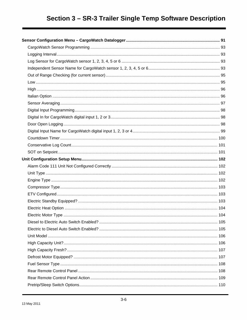
Section 3 – SR-3 Trailer Single Temp Software Description
Sensor Configuration Menu – CargoWatch Datalogger .................................................................................... 91 CargoWatch Sensor Programming .................................................................................................................... 93
Logging Interval .................................................................................................................................................. 93
Log Sensor for CargoWatch sensor 1, 2, 3, 4, 5 or 6 ........................................................................................ 93
Independent Sensor Name for CargoWatch sensor 1, 2, 3, 4, 5 or 6 ................................................................ 93
Out of Range Checking (for current sensor) ...................................................................................................... 95
Low ..................................................................................................................................................................... 95
High .................................................................................................................................................................... 96
Italian Option ...................................................................................................................................................... 96
Sensor Averaging ............................................................................................................................................... 97
Digital Input Programming .................................................................................................................................. 98
Digital In for CargoWatch digital input 1, 2 or 3.................................................................................................. 98
Door Open Logging ............................................................................................................................................ 98
Digital Input Name for CargoWatch digital input 1, 2, 3 or 4 .............................................................................. 99
Countdown Timer ............................................................................................................................................. 100
Conservative Log Count ................................................................................................................................... 101
SOT on Setpoint ............................................................................................................................................... 101
Unit Configuration Setup Menu.......................................................................................................................... 102 Alarm Code 111 Unit Not Configured Correctly ............................................................................................... 102
Unit Type .......................................................................................................................................................... 102
Engine Type ..................................................................................................................................................... 102
Compressor Type ............................................................................................................................................. 103
ETV Configured ................................................................................................................................................ 103
Electric Standby Equipped? ............................................................................................................................. 103
Electric Heat Option ......................................................................................................................................... 104
Electric Motor Type .......................................................................................................................................... 104
Diesel to Electric Auto Switch Enabled? .......................................................................................................... 105
Electric to Diesel Auto Switch Enabled? .......................................................................................................... 105
Unit Model ........................................................................................................................................................ 106
High Capacity Unit? .......................................................................................................................................... 106
High Capacity Fresh? ....................................................................................................................................... 107
Defrost Motor Equipped? ................................................................................................................................. 107
Fuel Sensor Type ............................................................................................................................................. 108
Rear Remote Control Panel ............................................................................................................................. 108
Rear Remote Control Panel Action .................................................................................................................. 109
Pretrip/Sleep Switch Options ............................................................................................................................ 110
3-6
13 May 2011

Section 3 – SR-3 Trailer Single Temp Software Description
3rd Party Device Control ................................................................................................................................... 110
Low Fuel Shutdown .......................................................................................................................................... 111
Fresh Air Exchange .......................................................................................................................................... 112
3-7
13 May 2011

Section 3 – SR-3 Trailer Single Temp Software Description
3-8
13 May 2011
Section 3 – SR-3 Trailer Single Temp Software Description
SOFTWARE OPERATION The software is a very complex set of instructions used by the Base Controller and HMI Control Panel to control
the refrigeration system and interface with the operator. The Base Controller and HMI Control Panel
microprocessors examine the conditions of all the inputs and compare them to the instructions contained in the
software. The outputs are then energized as specified by the software instructions.
There is no way to determine from the schematic or wiring diagrams what conditions will cause the unit to operate
in a particular mode. This decision is made by the software after examining all the input conditions and setpoint.
However, operating mode can generally be deduced from the existing conditions. As an example, if a 35°F (2°C)
setpoint is selected and the box temperature, as indicated by the return air sensor is 60°F (16°C), the unit should
operate in Cool mode when turned on.
The SR-3 system utilizes several different software sets.
Base Controller software family D0xx is used for single temperature applications.
HMI Control Panel software (6560, 6660, 6760, 6860 or later) is used for all SR-3 applications. Supervisor
software is part of the HMI Control Panel software and cannot be changed independently.
The software is flash loaded using a PC computer or a USB Flash Drive. See Service Procedures A46A and
A46B in Section 6 for details using a PC computer. See Section 4 for details using a USB Flash Drive.
To check the Base Controller, Supervisor or HMI Control Panel software revisions see Section 4 of this manual.
For software revision details see Section 7 of this manual.
3-9
13 May 2011

Section 3 – SR-3 Trailer Single Temp Software Description
HARDWARE AND SOFTWARE COMPATIBILITY
SR-3 Base Controller The SR-3 Base Controller is compatible with and may be used to replace the combined SR-2 Base Controller and
Interface Board assembly. The SR-3 Base Controller mounting base uses the same mounting hole pattern as did
the SR-2 Base Controller. The connectors on the SR-3 Base Controller are located in approximately the same
positions as they are on an SR-2 Interface Board. However, when replacing an SR-2 Base Controller/Interface
Board with an SR-3 Base Controller the wiring harness may need to be relocated slightly to reach the some of the
connectors.
It is critical that the correct software be used.
Single temperature applications with SR-3 Base Controllers must use Base Controller Software Revisions
D0xx.
See Section 7 of this manual for additional hardware and software details and requirements.
HMI-3 Control Panel The SR-3 Control System uses essentially the same HMI Control Panel as does the SR-2 Control System.
However, SR-3 HMI Control Panels feature 8 MB of memory and are marked Smart Reefer 3 on the lower front
panel as shown below.
The SR-2 HMI Control Panels feature 4 MB of memory. Other than memory, the SR-3 HMI Control Panel is
compatible with and may be used to replace the SR-2 HMI Control Panel.
SR-3 HMI Control Panels used on SR-3 applications without USB capability must use HMI Control Panel
Software Revision 6550 or later.
SR-3 HMI Control Panels used on SR-3 applications with USB capability must use HMI Control Panel
Software Revision 6560 or later.
See Section 7 for hardware and software details.
3-10
13 May 2011

Section 3 – SR-3 Trailer Single Temp Software Description
MENU STRUCTURE
The basic HMI Control Panel menu structure consists of the Standard Display, the TemperatureWatch® Display
and three menus. See the following material for a general description of each menu and feature. See Section 4
for complete operating instructions.
Standard Display The Standard Display shows the box temperature and setpoint. The box temperature is usually return air
temperature, but can be discharge air temperature if some features are enabled. The setpoint can be changed
from the Standard Display using the SETPOINT soft key. The readings of the unit gauges and temperature
sensors can be shown from the Standard Display using the GAUGES and SENSORS soft keys. The Main Menu
is accessed from the Standard Display using the MENU soft key.
TemperatureWatch Display The TemperatureWatch Display shows the return air temperature and setpoint using large numbers that allow
unit conditions to be checked from a distance. If there are no alarms other than Log Alarms present then the
TemperatureWatch Display will appear 2½ minutes after the last key is pressed. The Standard Display is
accessed by pressing any soft key.
Main Menu The Main Menu is made up of informational and operational items intended for the driver or unit operator. The
Main Menu is directly accessible from the Standard Display using the MENU soft key. This soft key is at the
bottom right of the display.
Maintenance Menu The Maintenance Menu is made up of informational, operational, control, and diagnostic items used to help the
service technician maintain and diagnose the unit. The Maintenance Menu is indirectly accessible from the Main
Menu.
Guarded Access Menu The Guarded Access Menu is made up of programmable settings that configure the unit, set sensor grades,
enable options, and allow the customer to tailor unit operation to his particular requirements. The CargoWatch
data logger is configured from this menu. The Guarded Access Menu is indirectly accessible from the
Maintenance Menu.
3-11
13 May 2011

Section 3 – SR-3 Trailer Single Temp Software Description
MENU OVERVIEW FLOWCHART D007 and 6560 SR-3 Trailer S/T Menu Overview
Sensor Soft Key
StandardDisplay
SetpointChange
GaugesMenu
SensorsMenu
Temp WatchDisplay
MainMenu
Flash Drive (If connected)Language (If enabled)
AlarmsDataloggerHourmeters
ModePretrip
Diesel Mode (If Model 50)Electric Standby (If Model 50)
Adjust BrightnessTime
Gauges Soft Key
Setpoint Soft Key
Menu Soft Key
Press Any Soft Key2.5 Minute
Time-out
MaintenanceMenu
HourmetersGaugesSensorsAlarms
Service TestInterface Board Test
Display Self TestEvacuation Test
Software RevisionSet Time and Date
Guarded Access Menu(Not Available if Running)
Security Code (If required)Programmable FeaturesMain Menu Configuration
AlarmsHourmeter Setup
Sensor CalibrationCycle Sentry Setup
Defrost SetupLanguage Setup
Access Code SetupOptiSet Plus
Sensor ConfigurationUnit Configuration
Controlled Access
Controlled Access
Not all menu featuresmay appear
Features shown are for units configured Trailer
Rev D007 and 6560 Trailer S/T 23 Apr 2011
3-12
13 May 2011

Section 3 – SR-3 Trailer Single Temp Software Description
OPERATOR FEATURES The Thermo King SR-3 control system features many special operator functions. These functions are available
from the Standard Display. A brief explanation of each menu is included here. For complete details see Section
4 of this manual.
Standard Display The Standard Display is the default display that appears if no other display function is selected. The Standard
Display shows the box temperature and setpoint. The box temperature is usually return air temperature, but can
be discharge air temperature if some features are enabled. The Standard Display soft keys provide direct
operator access to change the setpoint and to select the Gauges Menu, Sensors Menu or Main Menu. If a USB
Flash Drive is connected to the unit a USB Flash Drive Icon will appear in the display.
Setpoint Change The setpoint menu can be directly accessed from the Standard Display using the Setpoint soft key.
Gauges The unit Gauges Menu can be directly accessed using a soft key from the Standard Display. For a list of gauges
available see the Operator Menus Flowchart on the next page.
Sensors The unit Sensors Menu can be directly accessed using a soft key from the Standard Display. For a list of sensors
available see the Operator Menus Flowchart on the next page.
Main Menu The unit Main Menu can be directly accessed using a soft key from the Standard Display. For a list of Main Menu
functions see the Operator Menu Flowchart and the material on the following pages.
3-13
13 May 2011
Section 3 – SR-3 Trailer Single Temp Software Description
3-14
13 May 2011
TemperatureWatch® The TemperatureWatch Display shows the return air temperature and setpoint using large numbers that allow
unit conditions to be checked from a distance. If there are no alarms other than Log Alarms present then the
TemperatureWatch display appears 2½ minutes after the last key is pressed and will remain until any soft key is
pressed. To return to the Standard Display press any soft key.
The TemperatureWatch display will not appear if any Check, Prevent or Shutdown alarms are present or if the
CargoWatch -15°C Alarm is active. If the TemperatureWatch display is active and any of these alarm conditions
occur the display will return to the Standard Display. If a shutdown alarm is present the display will flash. This
provides a quick method to check for units that may have an alarm set.
If a USB Flash Drive is connected to the unit a USB Flash Drive Icon will appear in the display.

Section 3 – SR-3 Trailer Single Temp Software Description
MAIN MENU FLOWCHART
SetpointChange
GaugesMenu
SensorsMenu
TempWatchDisplay
MainMenu
Flash Drive (If connected)
Language (If enabled)
AlarmsDisplay all alarmsClear most alarms
Datalogger (CargoWatch)Start TripPrint / View
HourmetersTotal HoursTotal Run Time HoursEngine HoursElectric Run Hours (50 only)Total Run Reminder 1Total Run Reminder 2Controller Power OnPretrip ReminderEngine Reminder 1Engine Reminder 2Electric Reminder 1Electric Reminder 2
ModeTurn Cycle Sentry On or Off
(Off = Continuous)Degrees - Fahrenheit | CelsiusFresh Air Exchange - Open | CloseKeypad LockoutStart Sleep Mode
Program Wakeup TimeIf YES
Day to Wake UpHour to Wake UpMinutes to Wake Up
Pretrip
Electric Standby or Diesel Mode
Adjust BrightnessHigh – Medium – Low – Off
TimeTime/Date (Display Only)
Setpoint
Press Any Soft Key
2.5 Min
Soft Key
Gauges
Soft Key
Coolant TemperatureCoolant LevelOil PressureOil LevelAmpsBattery VoltageEngine RPMFuel Level SensorDischarge PressureSuction PressureETV PositionFresh Air ExchangeI/O (Inputs/Outputs)
High Speed RelayRun RelayRun Relay FeedbackAlternator Excite OutputDefrost DamperHeat OutputAlternator FrequencyFresh Air Exchange OutputDiesel/Electric Relay (50 only)Electric Ready Input (50 Only)Electric Overload (50 only)Hot Gas Bypass (ETV only)
Sensors
Soft Key
Control Return Air TempDisplay Return Air TempControl Discharge Air TempDisplay Discharge Air TempTemperature DifferentialEvaporator Coil TempAmbient Air TempSpare 1 TempLog Sensor 1Log Sensor 2Datalogger Sensor 3 TempDatalogger Sensor 4 Temp Datalogger Sensor 5 TempDatalogger Sensor 6 TempBoard Temperature Sensor
Menu
Soft Key
Time-out
Not all menu featuresmay appear
D007 and 6560 SR-3 Trailer S/T Operator & Main MenuFeatures shown are for units configured Trailer
Rev D007 and 6560 Trailer S/T 23 Apr 2011
3-15
13 May 2011

Section 3 – SR-3 Trailer Single Temp Software Description
MAIN MENU FEATURES
The Main menu allows the operator to check other unit conditions, change operating modes and perform other
operator functions. The Main menu is accessed from the Standard Display by means of the Menu soft key. The
sub-menus show below may be available. For additional details see Section 4 of this manual.
Flash Drive If a USB Flash Drive is connected to the Control Panel USB connector, this menu item allows the operator to
select the desired Flash Drive function.
IMPORTANT: The Flash Drive must be properly configured and the desired features must be enabled using
Wintrac 5.1 or later.
Using a properly configured and enabled flash drive, the following functions may be available:
Download the ServiceWatch Data Logger
Download the CargoWatch Data Logger
Flash load Base Controller Software
Flash load HMI Control Panel Software
Send OptiSet Plus Files
Retrieve OptiSet Plus Files
For Flash Drive details see USB Flash Drive in Section 4 of this manual.
Language If more than one language is enabled, this menu item allows the operator to select a language from a list of up to
11 languages at one time. All subsequent displays are shown in the selected language. Four different language
packages with a total of 24 languages are available. English is the default language and is provided in each of
the packages.
3-16
13 May 2011
Section 3 – SR-3 Trailer Single Temp Software Description
Alarms The Alarms display allows the operator to display any existing alarms. The operator can also clear most alarms
from this menu
A simplified list of Alarm Codes is presented in Section 4 of this manual. A list of Alarm Codes including
diagnostic procedures for each code is presented in Section 5 of this manual.
NOTE: Some alarms are clearable in Guarded Access only. Alarms with this feature will not
provide a soft key “Clear” function. See Section 4 for additional details
Data Logger This menu allows the operator to send a Start of Trip marker to the ServiceWatch and CargoWatch Data Loggers.
It can also be used to print the contents of the CargoWatch Data Logger.
The unit can also be programmed such that every time the setpoint is changed a Start of Trip Marker is sent to
the ServiceWatch and CargoWatch Data Loggers.
ServiceWatch and CargoWatch information can be downloaded and viewed by connecting a PC computer loaded
with WinTrac 5.1 or later software. For details see Service Procedure A50A ServiceWatch Data Logger in
Section 6 of this manual.
ServiceWatch and CargoWatch information can also be downloaded by connecting a properly configured and
enabled Universal Flash Drive to the USB Connector on the unit Control Panel. The Flash Drive is then
connected to a PC computer loaded with WinTrac 5.1 or later software to save and view the information. For
Flash Drive details see USB Flash Drive in Section 4 of this manual.
Hourmeters The Hourmeters menu allows the operator to view the unit hourmeters that have the view feature enabled in the
Guarded Access menu. If the view feature for a particular hourmeter is not enabled then that hourmeter cannot
be viewed from the Main Menu.
NOTE: All active hourmeters are available for viewing in the Maintenance Menu.
3-17
13 May 2011

Section 3 – SR-3 Trailer Single Temp Software Description
Mode The Mode menu allows the operator to change the unit operating modes if allowed. Not all modes may appear
depending on the settings selected from the Guarded Access menu.
Turn Off Cycle Sentry Mode/Turn On Cycle Sentry Mode (If Cycle Sentry Mode is turned Off then the unit
runs in Continuous Mode).
Select temperature displays in either degrees Fahrenheit or degrees Celsius (if enabled).
Open or close the optional Fresh Air Exchange vents (if feature is installed and enabled).
Allow Keypad Lockout to be selected (if enabled).
Start Sleep Mode (if enabled).
Pretrip A Pretrip Test is used to confirm unit operation. This menu allows a Pretrip Test to be initiated by the operator. If
the test is started with the engine or motor off a full test including the non-running amp checks and the running
performance tests are performed. If the test is started with the engine or motor running only the running tests are
performed. Test results are reported as PASS, CHECK or FAIL.
Electric Standby (Model 50 units only) If the Electric Standby option is present and the Diesel to Electric Auto-switch feature is set NO, this feature
allows the operator to manually select electric mode operation. This feature does not appear if the unit does not
have the optional Electric Standby or if the Diesel to Electric Auto-switch feature is set YES.
Diesel Mode (Model 50 units only) If a unit equipped with electric standby is running in electric mode and the Electric to Diesel Auto-switch feature is
set NO, this feature allows the operator to manually select diesel mode operation. This feature does not appear if
the unit does not have optional Electric Standby or if the Electric to Diesel Auto-switch feature is set YES.
Note: Auto-switch from electric to diesel is not recommended when the unit is running in electric mode
indoors or when below deck on a ferry.
3-18
13 May 2011

Section 3 – SR-3 Trailer Single Temp Software Description
Adjust Brightness This menu allows the operator to adjust the HMI Control Panel display backlight intensity as required by local
conditions. If desired, the backlight can also be turned off.
Time This menu allows the operator to view the unit time and date. The time and date cannot be changed from this
menu. The time and date is loaded from the HMI Control Panel to the Base Controller each time the unit is turned
on.
3-19
13 May 2011

Section 3 – SR-3 Trailer Single Temp Software Description
3-20
13 May 2011

Section 3 – SR-3 Trailer Single Temp Software Description
MAINTENANCE MENU FLOWCHART
Maintenance Menu1 of 3
Hourmeters - View and Reset TimeTotal HoursTotal Run Time HoursEngine HoursElectric Run HoursTotal Run Time Reminder #1 HoursTotal Run Time Reminder #2 HoursController Power On HoursPretrip Reminder HoursEngine Run Time Reminder #1 HoursEngine Run Time Reminder #2 HoursElectric Run Time Reminder #1 HoursElectric Run Time Reminder #2 Hours
GaugesCoolant TemperatureCoolant LevelOil PressureOil LevelAmpsBattery VoltageEngine RPMFuel Level SensorDischarge PressureSuction PressureETV PositionFresh Air ExchangeI/O (Input/Output State)
High Speed RelayRun RelayRun Relay FeedbackAlternator Excite OutputDefrost DamperHeat OutputAlternator FrequencyFresh Air Exchange OutputDiesel/Electric Relay (50 only)Electric Ready Input (50 Only)Electric Overload (50 only)Hot Gas Bypass (ETV only)
SensorsControl Return Air TemperatureDisplay Return Air TemperatureControl Discharge Air TemperatureDisplay Discharge Air TemperatureTemperature DifferentialEvaporator Coil TemperatureAmbient Air TemperatureSpare 1 TemperatureLog Sensor 1Log Sensor 2 Datalogger Sensor 3 TemperatureDatalogger Sensor 4 TemperatureDatalogger Sensor 5 TemperatureDatalogger Sensor 6 TemperatureBoard Temperature Sensor
AlarmsDisplay all alarmsClear most alarms
Service TestTest with Unit Running?
OffNullHigh Speed CoolLow Speed CoolLow Speed HeatHigh Speed HeatDefrostCool BypassMod Cool /HGBModulation CoolModulation Heat
Interface Board TestPreheat RelayBuzzerRun RelayAlternator Excite OutputHeat OutputDamper RelayIndicator LightAlarm LightDiesel/Electric RelayElectric HeatHigh Speed RelayHot Gas Bypass ValveFresh Air Exchange
Maintenance Menu2 of 3
Not all menu features may appear
Rev D007 and 6560 Trailer S/T 23 Apr 2011
D007 and 6560 SR-3 Trailer S/T Maintenance Menu (1 of 2)Features shown are for units configured Trailer
3-21
13 May 2011

Section 3 – SR-3 Trailer Single Temp Software Description
3-22
13 May 2011

Section 3 – SR-3 Trailer Single Temp Software Description
MAINTENANCE MENU FEATURES
The Thermo King SR-3 control system features many special technician functions. These functions are available
from the Maintenance Menu. A brief explanation of each menu is included here.
For complete details see Section 4 of this manual.
Accessing the Maintenance Menu The Maintenance Menu is accessible from the Main Menu. From the Standard Display press the MENU key.
The controller will display the Main Menu. From the first Main Menu display (either Alarms or Language) press
and hold both the EXIT key and the key with no label above it for 5 seconds. After 5 seconds the HMI will display
the Maintenance Menu.
MAINTENANCE MENU FEATURES A brief explanation of each menu is shown here. For complete operating details see Section 4.
Hourmeters This menu allows the technician to view all the active unit hourmeters, even if the Main Menu view has been
disabled. The Maintenance Menu Hourmeter Display also allows the technician to reset the time on hourmeters
with a programmed time limit.
Gauges The Gauges menu allows the technician to display operating information such as coolant level and temperature,
engine RPM, battery amps, battery volts, and suction and discharge pressure. The I/O selection under Gauges
indicates the named outputs as either On or Off. Some Gauges can also be viewed from the Service Test Mode
and Interface Board Test Mode displays.
NOTE: This menu contains the same information as the Standard Display Gauge Menu.
3-23
13 May 2011

Section 3 – SR-3 Trailer Single Temp Software Description
Sensors The Sensors menu allows the technician to display the reading of all unit temperature sensors as well as the
calculated temperature differential.
NOTE: This menu contains the same information as the Standard Display Sensors Menu.
Alarms The Alarms display allows the technician to display any existing alarms. The technician can also clear most
alarms from this menu
A simplified list of Alarm Codes is presented in Section 4 of this manual. A list of Alarm Codes including
diagnostic procedures for each code is presented in Section 5 of this manual.
NOTE: Some alarms are clearable in Guarded Access only. Alarms with this feature will not provide a
soft key “Clear” function. See Section 4 for additional details
Service Test Mode Since the complexity of the control software makes it impossible to predict exact operating conditions, a
troubleshooting feature called Service Test Mode has been incorporated. This feature allows the unit to be forced
to a known set of operating conditions in diesel or electric mode, regardless of setpoint or temperature sensor
inputs. Service personnel can use this mode to troubleshoot the system under defined operating conditions.
Service Test Mode can be used with the unit running or non-running. Any shutdown alarms that are present must
be cleared before Service Test Mode is available.
Interface Board Test Interface Board Test Mode allows individual relays or outputs to be energized. This permits service personnel to
troubleshoot individual circuits under known conditions. Interface Board Test Mode can only be used with the unit
in a non-running condition. If Interface Board Test Mode is entered with the diesel engine or electric motor
running the engine or motor will be shut down. Any shutdown alarms that are present must be cleared before
Interface Board Test Mode is available.
3-24
13 May 2011
Section 3 – SR-3 Trailer Single Temp Software Description
Display Self Test This menu allows the operator to perform a series of built in tests on the HMI Control Panel.
Evacuation Test Evacuation Test allows a full system evacuation to be performed. All normally closed valves are opened to allow
the entire system to be completely evacuated before charging with refrigerant. If present, the ETV will be fully
opened.
If the battery voltage falls below acceptable limits, the operator is prompted to connect a battery charger to
maintain sufficient battery voltage to hold all necessary valves open during the procedure. If the voltage from the
battery charger rises above acceptable limits, the controller will be turned off to prevent damage to the electronics
and/or system components.
Software Revision The Software Revision menu shows the software revision of the HMI Control Panel software, Base Controller
software and the Supervisor software.
Set Time and Date The Set Time and Date menu allows the system time and date to be checked and changed as required. The time
and date is loaded from the HMI Control Panel to the Base Controller each time the unit is turned on.
3-25
13 May 2011

Section 3 – SR-3 Trailer Single Temp Software Description
3-26
13 May 2011

Section 3 – SR-3 Trailer Single Temp Software Description
GUARDED ACCESS MENU FLOWCHART
Guarded Access Menu1 of 4
Security Code (if enabled)Enter Access Code
Programmable FeaturesTemperature Units (F)Pressure Units (PSIG)Restart Unit After Shutdown (Enabled)Setpoint High Limit (80°F)Setpoint Low Limit (-20°F)Fuel Saver II (Enabled)High Speed Pulldown (Enabled)Fresh Frozen Range (15°F)Door Open Forces (Log Only)
Door Open Timeout (HRS:MIN)Sleep Mode After Pretrip(Disabled)Rail Option (Disabled)
Rail Alternate (Disabled)Blocked Air Chute Detect (Disabled)
Temperature Differential (9.9)Time to Alarm (0:30)Door Open Override (Disabled)
Discharge Pressure Setpoint (415 PSI)Water Temperature Setpoint (210°F)Limited Alarm Restarts (Disabled)Remote Device (Disabled)COM 1 Default Baud Rate (1200COM 2 Default Baud Rate (9600)COM 3 Default Baud Rate (9600)High Temperature Defrost (Disabled)Local Authorization of OS+ Upload (Enabled)Local Authorization of Flash Load (Enabled)
Main Menu ConfigurationAdd Keypad Lockout to Mode Menu (Disabled)Add Sleep to Mode Menu (Disabled)Add Temperature Units to Mode Menu (Disabled)
AlarmsDisplay all alarmsClear most alarms
Hourmeter SetupProgram Hourmeter
Total Run Time Reminder #1 Hours (Off)Total Run Time Reminder #2 Hours (Off)Controller Power On Hours (Off)Pretrip Reminder Hours (Off)Engine Run Time Reminder #1 Hours (Off)Engine Run Time Reminder #2 Hours (Off)Electric Run Time Reminder #1 Hours (Off)Electric Run Time Reminder #2 Hours (Off)
Viewable Hourmeter SetupTotal Hours (Disabled)Total Run Time Hours (Enabled)Engine Hours (Enabled)Electric Run Hours (Enabled)Total Run Time Reminder #1 Hours (Disabled)Total Run Time Reminder #2 Hours (Disabled)Controller Power On Hours (Disabled)Pretrip Reminder Hours (Disabled)Engine Run Time Rem #1 Hours (Disabled)Engine Run Time Rem #2 Hours (Disabled)Electric Run Time Rem #1 Hours (Disabled)Electric Run Time Rem #2 Hours (Disabled)
Program Service Due DateEngine Run Time Service Due Date (Disabled)
Sensor CalibrationControl Return Air Sensor Grade (5H)Control Discharge Air Sensor Grade (5H)Display Return Air Sensor Grade (5H)Display Discharge AIr Sensor Grade (5H)Spare 1 Sensor Grade (5H)
Cycle Sentry SetupCycle Sentry Amps Level (5)Battery Sentry Voltage Level (12.2)
Defrost SetupDefrost Interval In Range w Fresh Setpoint (6)Defrost Interval Not In Range w Fresh Setpoint (4)Defrost Interval In Range w Frozen Setpoint (6)Defrost Interval Not In Range w Frozen Setpoint (4)Maximum Defrost Duration (45)
Guarded Access Menu2 of 4
Not all menu featuresmay appear
D007 and 6560 SR-3 Trailer S/T Guarded Access Menu (1 of 2)Features shown are for units configured Trailer
Rev D007 and 6560 Trailer S/T 23 Apr 2011
3-27
13 May 2011

Section 3 – SR-3 Trailer Single Temp Software Description
3-28
13 May 2011

Section 3 – SR-3 Trailer Single Temp Software Description
GUARDED ACCESS MENU FEATURES
The Guarded Access Menu allows unit operation to be configured to user requirements.
Security Code Protection A security code can be set to restrict access to the Guarded Access Menu. If a security code is set the technician
will be prompted to enter the correct code when accessing the Guarded Access Menu. The security code is
defaulted to No Code.
Accessing the Guarded Access Menu From the Standard Display press the MENU key. The controller will display the Main Menu. From the first Main
Menu display (either Language or Alarms) press and hold both the EXIT key and the key with no label above it for
5 seconds.
After 5 seconds the controller will display the Maintenance Menu. Press the NEXT key until the Set Time and
Date Menu appears. From the Set Time and Date Menu press and hold both the EXIT key and the key with no
label above it for 5 seconds.
The controller may display a Security Code challenge. If a Security Code has been set the operator is prompted
to enter the correct code using the “+” and “-“ keys. When the correct code is set press the YES key to enter the
Guarded Access Menu. If the correct Security Code is not entered access to the Guarded Access Menu will be
denied.
If no Security Code has been set the controller will enter the Guarded Access Menu directly.
Bypassing the Security Code If a Security Code is set and the Guarded Access Menu must be accessed, the Security Code can be bypassed
by entering “4444”.
Leaving the Guarded Access Menu When leaving the Guarded Access Menu the base controller will automatically turn the controller off and then
restart the controller in order to configure the changes that may have been made. This power cycle is termed a
controller “warm restart”.
3-29
13 May 2011

Section 3 – SR-3 Trailer Single Temp Software Description
PROGRAMMABLE FEATURES MENU
The Programmable Features Menu allows overall unit operation to be configured to specific end user
requirements. These features are set to factory defaults when shipped, but can easily be changed to suit the end
user’s needs. Programmable features are designed to allow the user to customize some unit operating
parameters without using OptiSet Plus
IMPORTANT
If a feature has been programmed in OptiSet Plus, the HMI will display “programmed in OptiSet Plus”, and
the feature cannot be updated from this menu.
Temperature Units Control Rev D000 and later
HMI Rev 6550 and later
Choices FAHRENHEIT or CELSIUS
Factory Set FAHRENHEIT
Exceptions The setting selected is used for all ranges.
Description The controller can be set to display temperatures in either degrees FAHRENHEIT or degrees
CELSIUS.
Pressure Units Control Rev D000 and later
HMI Rev 6550 and later
Choices PSIG, KPa or BARS
Factory Set PSI
Exceptions
Description The controller can be set to display system refrigerant pressures in PSIG, kPa or BARS.
3-30
13 May 2011

Section 3 – SR-3 Trailer Single Temp Software Description
Restart Unit After Shutdown Control Rev D000 and later
HMI Rev 6550 and later
Choices ENABLED, DISABLED, or CONTINUOUS
Factory Set ENABLED
Exceptions Use the CONTINUOUS option for rail applications only.
Description Standard restart alarms become permanent shutdown alarms after several attempts to start and
run. The CONTINUOUS feature is designed for rail applications where the unit runs unattended or is
inaccessible for service. It allows unlimited restart attempts to be made if the following restart alarms occur.
• Alarm Code 10 High Discharge Pressure
• Alarm Code 18 High Engine Coolant Temp
• Alarm Code 63 Engine Stopped
• Alarm Code 82 High Compressor Temp
If restarts are disabled, the unit will shut down on the first alarm event. The following differences exist between
a Standard Restart and a Continuous Restart alarm:
• Standard Restart alarms force a permanent shutdown if the alarm occurs a pre-determined number of
times (usually 3). Continuous Restart alarms allow an unlimited number of restarts for the four alarm
codes listed above.
• Standard Restart alarms typically use a 15 minute timer before a restart is allowed. Continuous Restart
alarms use a 1-hour timer before a restart is allowed.
• With Continuous Restart alarms ETV Head Pressure Setpoint is lowered based on the alarm type and
number of occurrences.
3-31
13 May 2011

Section 3 – SR-3 Trailer Single Temp Software Description
Setpoint High Limit Control Rev D000 and later
HMI Rev 6550 and later
Choices Maximum is 90°F (32°C)
Minimum is Setpoint Low Limit
Factory Set 80°F (27°C)
Exceptions If OptiSet Plus is active the HMI Control Panel will display [Programmed in OptiSet Plus] and
this feature cannot be changed from the Guarded Access Menu. The Setpoint High Limit setting selected is
used for all ranges.
Description Setpoint High Limit allows the upper setpoint limit to be set to a maximum of 90°F (32°C) in one
degree increments. The minimum setting is determined by the setting of Setpoint Low Limit. If the driver
attempts to select a setpoint higher than the Setpoint High Limit, the display will show Setpoint Limit, indicating
that the selected Setpoint High Limit has been reached. Setting Setpoint High Limit and Setpoint Low Limit to
the same temperature results in a single setpoint temperature available.
Setpoint Low Limit Control Rev D000 and later
HMI Rev 6550 and later
Choices Minimum is -30°F (-34°C)
Maximum is Setpoint High Limit
Factory Set -20°F (-29°C)
Exceptions If OptiSet Plus is active the HMI Control Panel will display [Programmed in OptiSet Plus] and
this feature cannot be changed from the Guarded Access Menu. The Setpoint Low Limit setting selected is
used for all ranges.
Description Setpoint Low Limit allows the lower setpoint limit to be set to a minimum of -30°F
(-34°C) in one degree increments. The maximum setting is determined by the setting of Setpoint High Limit. If
the driver attempts to select a setpoint lower than the Setpoint Low Limit, the display will show Setpoint Limit,
indicating that the selected Setpoint Low Limit has been reached. Setting Setpoint High Limit and Setpoint Low
Limit to the same temperature results in a single setpoint temperature available.
Setpoint temperatures lower than -25°F (-32°C) should only be used when absolutely required by the load.
3-32
13 May 2011

Section 3 – SR-3 Trailer Single Temp Software Description
Fuel Saver II Control Rev D000 and later
HMI Rev 6550 and later
Choices ENABLED or DISABLED
Factory Set ENABLED
Exceptions If OptiSet Plus is active the HMI Control Panel will display [Programmed in OptiSet Plus] and
this feature cannot be changed from the Guarded Access Menu.
Description If Fuel Saver II is ENABLED, and the box temperature changes a predetermined amount from
setpoint in Cycle Sentry mode operation, or if the box temperature indicates a need for high speed in Continuous
mode operation, the unit will first run in low speed. An 8-minute timer is started and the control sensor air
temperature is monitored. As long as the temperature falls (in cool mode operation) or rises (in heat mode
operation) a specified amount before the timer expires, the 8-minute timer is reset and low speed operation
continues. If the temperature has not changed the pre-determined amount when the timer times out, high speed
operation is resumed if allowed. This provides fuel savings by delaying high speed operation, yet assures that
the temperature continues to fall or rise as required to reach setpoint.
If the unit switches to high speed from FS-II, the unit will run in high speed until setpoint is reached. If FS-II is
DISABLED, high speed cool and high speed heat are allowed with no delay.
The FS-II feature does not apply to modulation operation.
3-33
13 May 2011

Section 3 – SR-3 Trailer Single Temp Software Description
High Speed Pulldown Control Rev D000 and later
HMI Rev 6550 and later
Choices ENABLED or DISABLED
Factory Set ENABLED
Exceptions If OptiSet Plus is active the HMI Control Panel will display [Programmed in OptiSet Plus] and
this feature cannot be changed from the Guarded Access Menu.
Description This feature allows High Speed Pull Down for the selected range to be ENABLED or
DISABLED. If High Speed Pull Down is ENABLED, the unit will run in high speed on initial start until setpoint is
reached in both cool and heat mode. If High Speed Pull Down is DISABLED, the unit will switch to low speed
cool when the return air temperature is below low speed switch point value plus setpoint.
NOTE: There is a two minute delay on initial startup before high speed operation is allowed.
If Fuel Saver II is ENABLED, there may be a delay before high speed operation is allowed.
This feature does not apply to modulation operation.
3-34
13 May 2011

Section 3 – SR-3 Trailer Single Temp Software Description
Fresh Frozen Range Control Rev D000 and later
HMI Rev 6550 and later
Choices 24°F (-4°C) or 15°F (-9°C)
Factory Set 15°F (-9°C)
Exceptions If OptiSet Plus is active the HMI Control Panel will display [Programmed in OptiSet Plus] and
this feature cannot be changed from the Guarded Access Menu. The setting selected is used for all ranges.
Description One set of general control specifications is used when operating in the Fresh range, and
another set of general operating specifications is used when operating in the Frozen range. This feature allows
the line between Fresh and Frozen ranges to be selected as either 15°F (-9°C) or 24°F (-4°C). All setpoints less
than or equal to this value will be treated as frozen ranges. All setpoints greater than this value will be treated
as Fresh ranges.
The Frozen setpoint range is from the limit of the Setpoint Limit Low setting to the Fresh Frozen range setting.
The Fresh setpoint range is from the limit of the Fresh Frozen range + 1 degree to the setpoint high limit setting.
When programming OptiSet Plus, no range may include both Frozen and Fresh range setpoints. This value is
the high value of the last frozen range programmed. The next range programmed will start at this value + 1-
degree depending on the selection made above. Changing this feature will reset all OptiSet Plus range values
to default.
3-35
13 May 2011

Section 3 – SR-3 Trailer Single Temp Software Description
Door Open Forces Control Rev D000 and later
HMI Rev 6550 and later
Choices LOG ONLY, UNIT NULL or UNIT NULL – NO ALARM
Factory Set LOG ONLY
Exceptions If OptiSet Plus is active the HMI Control Panel will display [Programmed in OptiSet Plus] and
this feature cannot be changed from the Guarded Access Menu. The optional door switch must be installed.
Description This feature allows the Door Open action to be set. If this feature is set LOG ONLY the door
opening will be logged after 4 seconds but the unit will continue to run. Door openings are logged in both the
CargoWatch and ServiceWatch data loggers. The door switch must be open or closed for 4 seconds before the
event is logged to prevent false readings.
If this feature is set UNIT NULL the base controller shuts the unit down and logs the door opening 4 seconds
after the door is opened. If the unit is in defrost when the door is opened, the defrost cycle will be completed
before the unit shuts down. If the Door Open Timeout feature has been set for a door open time, the unit will
restart and run if the time specified by Door Open Timeout is exceeded. The unit will continue to run even if the
door is still open. The event is logged in both the CargoWatch and ServiceWatch data loggers.
If this feature is set UNIT NULL – NO ALARM unit operation is the same as UNIT NULL above, but Alarm Code
108 Door Open Timeout is not set.
3-36
13 May 2011

Section 3 – SR-3 Trailer Single Temp Software Description
Door Open Timeout Control Rev D000 and later
HMI Rev 6550 and later
Choices 1:00 to 4:00 (Hours) in 10 Min Increments or OFF
Factory Set OFF
Exceptions If OptiSet Plus is active the HMI Control Panel will display [Programmed in OptiSet Plus] and
this feature cannot be changed from the Guarded Access Menu. The optional door switch must be installed.
Only appears if the DOOR OPEN FORCES feature is set to UNIT NULL or UNIT NULL – NO ALARM.
Description This feature allows the unit to restart if the door open time exceeds the set limit.
Door Open Timeout can be set to OFF or for a time limit from 1 to 4 hours, in 10-minute increments. If set to
OFF the unit will remain off until the door is closed. If the Door Open Timeout feature has been set for a door
open time, the unit will restart and run and Alarm Code 108 Door Open Timeout will be set as a Check Alarm if
the time specified by Door Open Timeout is exceeded. The unit will continue to run even if the door is still open.
The event is logged in both the CargoWatch and ServiceWatch data loggers.
Sleep Mode After Pretrip Control Rev D000 and later
HMI Rev 6550 and later
Choices ENABLED or DISABLED
Factory Set DISABLED
Exceptions
Description If the feature is set ENABLED, the unit will enter Sleep Mode after a Pretrip Test. If the feature
is set DISABLED, the unit will not enter Sleep Mode after a Pretrip Test.
3-37
13 May 2011
Section 3 – SR-3 Trailer Single Temp Software Description
Rail Option Control Rev D000 and later
HMI Rev 6550 and later
Choices ENABLED or DISABLED
Factory Set DISABLED
Exceptions The optional fuel level switch must be installed in order to use the Fuel Conserve Mode feature.
Description If the unit is a rail application, this feature is ENABLED. When the optional customer fuel level
switch closes (supplies chassis ground to the base controller fuel level input), the unit will enter a Fuel Conserve
Mode where the unit is forced to low speed operation only.
If the unit is not a rail application this feature should be DISABLED.
IMPORTANT: If RAIL OPTION is ENABLED, the fuel level switch will cause the unit to enter a full conserve
mode only. The Low Fuel Shutdown Feature is not available if RAIL OPTION is ENABLED.
Rail Alternate Control Rev D000 and later
HMI Rev 6550 and later
Choices ENABLED or DISABLED
Factory Set DISABLED
Exceptions Only available if RAIL OPTION is ENABLED.
Description This feature changes the alerts criteria, defrost allowed temperature and defrost termination
temperature. It should only be used when specified by the customer. If rail alternate is enabled a defrost cycle
is allowed with an evaporator coil temperature less than or equal to 55 °F (13°C) and terminates at 70°F (21°C).
3-38
13 May 2011

Section 3 – SR-3 Trailer Single Temp Software Description
Blocked Air Chute Detect Control Rev D000 and later
HMI Rev 6550 and later
Choices ENABLED or DISABLED
Factory Set DISABLED
Exceptions The optional Spare Sensor 1 must be installed.
Description The Air Chute Detect feature is designed to detect a blocked or improperly installed trailer air
chute. Spare sensor 1 is located at the rear of the trailer and directly in the air flow at the end of the chute. The
temperature detected by this sensor is compared to the temperature detected by the control discharge air
temperature sensor. This feature functions only during cool mode operation.
If this temperature differential exceeds a user defined number of degrees for a user defined period of time,
Alarm Code 46 CHECK AIR FLOW is generated as a check alarm. If the trailer is equipped with a door switch
and the feature is enabled, monitoring ceases when the door is opened and is resumed 45 minutes after the
door is closed. When the unit enters a defrost cycle, monitoring ceases and is resumed 45 minutes after the
defrost cycle terminates. Should the control discharge temperature sensor or Spare sensor 1 fail the Air Chute
Detect feature is disabled.
Temperature Differential Control Rev D000 and later
HMI Rev 6550 and later
Choices 1°F to 20°F in 0.1°F increments
1°C to 10°C in 0.1°C increments
Factory Set 9.9°F (5.5°C)
Exceptions Only available if BLOCKED AIR CHUTE DETECT is ENABLED.
Description This feature selects the temperature differential, from the front to the back of the trailer that must
be exceeded to cause an alarm to occur. The temperature differential is calculated using the control discharge
air sensor and spare sensor 1. This temperature differential must exist for the time specified by TIME TO
ALARM below in order to set Alarm Code 46 Check Air Flow.
3-39
13 May 2011

Section 3 – SR-3 Trailer Single Temp Software Description
Time to Alarm Control Rev D000 and later
HMI Rev 6550 and later
Choices 5 to 120 minutes in 1-minute
increments
Factory Set 30 minutes
Exceptions Only available if BLOCKED AIR CHUTE DETECT is ENABLED.
Description This feature selects the time interval that must be exceeded to cause Alarm Code 46 CHECK
AIR FLOW to occur. This condition must exist with a temperature differential, in excess of that specified by
TEMPERATURE DIFFERENTIAL above, in order to set Alarm Code 46 Check Air Flow.
Door Open Override Control Rev D000 and later
HMI Rev 6550 and later
Choices ENABLED or DISABLED
Factory Set ENABLED
Exceptions Only available if BLOCKED AIR CHUTE DETECT is ENABLED.
Description This feature determines if a door switch should interrupt the operation of the BLOCKED AIR
CHUTE DETECT feature. If set ENABLED, then monitoring ceases when the door is opened and is resumed 45
minutes after the door is closed. If set DISABLED, monitoring is not interrupted when a door opens.
Discharge Pressure Setpoint Control Rev D000 and later
HMI Rev 6550 and later
Choices 380 to 440 PSIG
Factory Set 415 PSIG
Exceptions Only on ETV equipped units.
Description This feature allows the head pressure setpoint to be adjusted. This pressure determines when
the base controller will enter a temporary operating mode to prevent unit shutdown. Do not change this setting
unless instructed to do so.
3-40
13 May 2011

Section 3 – SR-3 Trailer Single Temp Software Description
Water Temperature Setpoint Control Rev D000 and later
HMI Rev 6550 and later
Choices 180°F to 210°F (82°C to 99°C)
Factory Set 210°F (99°C)
Exceptions Only on ETV equipped units.
Description This feature allows the water temperature setpoint to be adjusted. This temperature
determines when the base controller will enter a temporary operating mode to prevent unit shutdown. Do not
change this setting unless instructed to do so.
Limited Alarm Resets Control Rev D000 and later
HMI Rev 6550 and later
Choices ENABLED or DISABLED
Factory Set DISABLED
Exceptions Does not appear unless rail is disabled and restarts are enabled.
Description This feature modifies the ability to repeatedly clear certain alarms from the Main menu or
Operators menu. If these alarms occur repeatedly, they may indicate a need for service to prevent unit or
product damage. These alarms are as follows:
• Alarm Code 23 Cooling Cycle Fault
• Alarm Code 24 Heating Cycle Fault
• Alarm Code 32 Refrigeration Capacity Low
• Alarm Code 82 High Comp Discharge Temp
Setting this feature to ENABLED will allow the above alarms to be cleared conventionally 2 times in a continuous
12 hour period. If any of these alarms are cleared more than 2 times in 12 hours, all subsequent occurrences
can only be cleared from the Guarded Access Menu. This helps ensure that the alarms receive the attention of
service personnel. The 12 hour timer is reset when any of the above alarms is cleared from the Guarded
Access Menu. The 12 hour timer is not reset with a unit or controller power-down.
Setting this feature DISABLED will allow the above alarms to be cleared conventionally an unlimited number of
times.
3-41
13 May 2011

Section 3 – SR-3 Trailer Single Temp Software Description
Remote Device Control Rev D000 and later
HMI Rev 6550 and later
Choices ENABLED or DISABLED
Factory Set DISABLED
Exceptions Requires optional device – see below.
Description
Setting this feature to ENABLED allows an external device, such as TracKing, to start and stop a properly
equipped unit. Setting this feature to DISABLED prevents this control.
IMPORTANT: The Remote Device feature should be set DISABLED before working on the unit if the unit is
equipped with a device that allows it to be started and stopped from a remote location.
HMI Control Panel COM 1 Default Baud Rate Control Rev D000 and later
HMI Rev 6550 and later
Choices 1200, 2400, 4800, 9600, 19200, 38400, 57600, and 115200 BPS
Factory Set 1200
Exceptions
Description This feature allows the default baud rate to be selected for the HMI Control Panel COM Port 1.
COM Port 1 is used by Wintrac. The setting of this feature should not be changed.
3-42
13 May 2011

Section 3 – SR-3 Trailer Single Temp Software Description
HMI Control Panel COM 2 Default Baud Rate Control Rev D000 and later
HMI Rev 6550 and later
Choices 1200, 2400, 4800, 9600, 19200, 38400, 57600, and 115200 BPS
Factory Set 9600
Exceptions
Description This feature allows the default baud rate to be selected for the HMI Control Panel COM Port 2.
COM Port 2 is used by the CargoWatch printer. If a customer has a mixed fleet with both SR-2/SR-3 and μP-IV
M/T controllers with DAS, the baud rate for COM 2 should be set to 2400. This will allow printing from both the
SR-2/SR-3 and μP-IV controllers without changing the printer baud rate. Note that the printer baud rate must be
set to match the baud rate setting of the Com 2 Port.
HMI Control Panel COM 3 Default Baud Rate Control Rev D000 and later
HMI Rev 6550 and later
Choices 1200, 2400, 4800, 9600, 19200, 38400, 57600, and 115200 BPS
Factory Set 9600
Exceptions
Description This feature allows the default baud rate to be selected for the HMI Control Panel COM port 3.
COM port 3 is currently used by R:COM or other telematics devices. The setting of this feature should not be
changed.
3-43
13 May 2011

Section 3 – SR-3 Trailer Single Temp Software Description
High Temperature Defrost Control Rev D000 and later
HMI Rev 6550 and later
Choices ENABLED or DISABLED
Factory Set DISABLED
Exceptions
Description This feature changes the defrost allowed temperature and defrost termination temperature. It
should only be used when specified by the customer. If High Temperature Defrost is enabled a defrost cycle is
allowed with an evaporator coil temperature less than or equal to 55 °F (13°C) and terminates at 70°F (21°C).
IMPORTANT: Unlike the Rail Alternate feature, the Low Fuel Shutdown feature is available when High
Temperature Defrost is set ENABLED and a float or solid state fuel level sensor is installed.
Local Authorization of OS+ Upload (Future Use) Control Rev D000 and later
HMI Rev 6550 and later
Choices ENABLED or DISABLED
Factory Set ENABLED
Exceptions This feature appears in the Guarded Access Menu but does not appear in OptiSet Plus 4.1.
Description Future Use –
Local Authorization of Flash Load (Future Use) Control Rev D000 and later
HMI Rev 6550 and later
Choices ENABLED or DISABLED
Factory Set ENABLED
Exceptions This feature appears in the Guarded Access Menu but does not appear in OptiSet Plus 4.1.
Description Future use –
3-44
13 May 2011
Section 3 – SR-3 Trailer Single Temp Software Description
MAIN MENU CONFIGURATION MENU
The Main Menu Configuration Menu determines if the Keypad Lockout and Sleep Mode menus are visible in the
Main Menu | Mode Menu. These features are set to factory defaults when shipped, but can easily be changed to
suit the end user’s needs.
Add Keypad Lockout to Mode Menu Control Rev D000 and later
HMI Rev 6550 and later
Choices Enabled or Disabled
Factory Set Disabled
Exceptions
Description When enabled, Keypad Lockout allows the operator to lock the keypad to prevent tampering.
Pressing any soft key for 5 seconds will unlock the keypad.
Setting this feature Enabled adds the Keypad Lockout feature to the Mode Menu.
Setting this feature Disabled turns the Keypad Lockout feature off and removes the feature from the Mode
Menu.
Add Sleep to Mode Menu Control Rev D000 and later
HMI Rev 6550 and later
Choices Enabled or Disabled
Factory Set Disabled
Exceptions
Description When enabled, Sleep Mode allows the operator to place the unit in Sleep Mode from the Mode
Menu.
Setting this feature Enabled adds the Sleep Mode feature to the Mode Menu.
Setting this feature Disabled removes the Sleep Mode feature from the Mode Menu.
3-45
13 May 2011

Section 3 – SR-3 Trailer Single Temp Software Description
Add Temperature Units to Mode Menu Control Rev D000 and later
HMI Rev 6550 and later
Choices Enabled or Disabled
Factory Set Disabled
Exceptions
Description When enabled, Select Temperature Units allows the operator to choose to display temperatures
in either degrees Fahrenheit or degrees Celsius.
Setting this feature Enabled adds the Select Temperature Units feature to the Mode Menu.
Setting this feature Disabled removes the Select Temperature Units feature from the Mode Menu.
3-46
13 May 2011

Section 3 – SR-3 Trailer Single Temp Software Description
ALARM DISPLAY MENU
The Alarm Menu allows the technician to display and clear any existing alarms except alarms that auto-clear only.
See Section 4 for operating details. If an alarm condition still exists when the alarm is cleared, the alarm will be
set again as soon as the alarm condition is detected.
A simplified list of Alarm Codes is presented in Section 4 of this manual.
A list of alarm codes including diagnostic procedures for each alarm code is presented in Section 5 of this
manual.
3-47
13 May 2011

Section 3 – SR-3 Trailer Single Temp Software Description
HOURMETER SETUP MENU
The Hourmeter Setup Menu allows the unit hourmeters to be configured to customer requirements. There are
two sub-menus under the Hourmeter Setup Menu as follows:
• Program Hourmeter
• Viewable Hourmeter Setup
• Program Service Due Date
PROGRAM HOURMETER SUB-MENU
The hourmeters listed below allow a time limit to be established for each programmable Hourmeter. These time
limits are defined by the customer and are typically used as maintenance reminders. When a hourmeter time is
exceeded, a stored alarm is set as a maintenance reminder. The hourmeter is cleared by means of a CLEAR soft
key when viewing the hourmeters from the Guarded Access Menu. The hour meter elapsed time should be reset
to 0. Hourmeters cannot be cleared from the Main Menu
With the exception of Controller Power On Hours and Pretrip Reminder Hours there are two hourmeters for each
feature to allow two different maintenance intervals to be set.
The Program Hourmeter Sub-menu is used to set and clear the adjustable time limits for each Hourmeter, as
required by a customer’s maintenance program. The default time limit for all hourmeters is 100 hours. The
hourmeters appear in the order shown here.
3-48
13 May 2011

Section 3 – SR-3 Trailer Single Temp Software Description
Total Run Time Reminder # 1 Hours Control Rev D000 and later
HMI Rev 6550 and later
Choices OFF, 1 to 99,999
Factory Set OFF
Exceptions If a time limit is set and exceeded then Alarm Code 132 will be set as a stored alarm.
Description Total Run Time Reminder #1 Hours is one of two hourmeters that track the total amount of time
the unit has run in both diesel and electric mode. If a time limit is set and exceeded then Alarm Code 132 will be
set as a stored alarm.
This feature sets the meter limits for this programmable hourmeter. The default setting is OFF. Time limits start
at 100 hours and can be decreased to 1 and then OFF or increased to a maximum of 99,999 hours.
Total Run Time Reminder # 2 Hours Control Rev D000 and later
HMI Rev 6550 and later
Choices OFF, 1 to 99,999
Factory Set OFF
Exceptions If a time limit is set and exceeded then Alarm Code 133 will be set as a stored alarm.
Description Total Run Time Reminder #2 Hours is one of two hourmeters that track the total amount of time
the unit has run in both diesel and electric mode. If a time limit is set and exceeded then Alarm Code 133 will be
set as a stored alarm.
This feature sets the meter limits for this programmable hourmeter. The default setting is OFF. Time limits start
at 100 hours and can be decreased to 1 and then OFF or increased to a maximum of 99,999 hours.
3-49
13 May 2011

Section 3 – SR-3 Trailer Single Temp Software Description
Controller Power On Hours Control Rev D000 and later
HMI Rev 6550 and later
Choices OFF, 1 to 99,999
Factory Set OFF
Exceptions If a time limit is set and exceeded then Alarm Code 134 will be set as a stored alarm.
Description Controller Power On Hours is the total amount of time the controller has been turned on. If a
time limit is set and exceeded then Alarm Code 134 will be set as a stored alarm.
This feature sets the meter limits for this programmable hourmeter. The default setting is OFF. Time limits start
at 100 hours and can be decreased to 1 and then OFF or increased to a maximum of 99,999 hours.
Pretrip Reminder Hours Control Rev D000 and later
HMI Rev 6550 and later
Choices OFF, 1 to 99,999
Factory Set OFF
Exceptions If a time limit is set and exceeded then Alarm Code 64 will be set as a stored alarm.
Description Controller Power On Hours is the total amount of time since the last Pretrip Test was performed.
If a time limit is set and exceeded then Alarm Code 64 will be set as a stored alarm.
This feature sets the meter limits for this programmable hourmeter. The default setting is OFF. Time limits start
at 100 hours and can be decreased to 1 and then OFF or increased to a maximum of 99,999 hours.
3-50
13 May 2011

Section 3 – SR-3 Trailer Single Temp Software Description
Engine Run Time Reminder # 1 Hours Control Rev D000 and later
HMI Rev 6550 and later
Choices OFF, 1 to 99,999
Factory Set OFF
Exceptions If a time limit is set and exceeded then Alarm Code 128 will be set as a stored alarm.
Description Engine Run Time Reminder #1 Hours is one of two hourmeters that track the total amount of
time the unit has run in diesel mode. If a time limit is set and exceeded then Alarm Code 128 will be set as a
stored alarm.
This feature sets the meter limits for this programmable hourmeter. The default setting is OFF. Time limits start
at 100 hours and can be decreased to 1 and then OFF or increased to a maximum of 99,999 hours.
Engine Run Time Reminder # 2 Hours Control Rev D000 and later
HMI Rev 6550 and later
Choices OFF, 1 to 99,999
Factory Set OFF
Exceptions If a time limit is set and exceeded then Alarm Code 129 will be set as a stored alarm.
Description Engine Run Time Reminder #2 Hours is one of two hourmeters that track the total amount of
time the unit has run in diesel mode. If a time limit is set and exceeded then Alarm Code 129 will be set as a
stored alarm.
This feature sets the meter limits for this programmable hourmeter. The default setting is OFF. Time limits start
at 100 hours and can be decreased to 1 and then OFF or increased to a maximum of 99,999 hours.
3-51
13 May 2011
Section 3 – SR-3 Trailer Single Temp Software Description
Electric Run Time Reminder # 1 Hours Control Rev D000 and later
HMI Rev 6550 and later
Choices OFF, 1 to 99,999
Factory Set OFF
Exceptions If a time limit is set and exceeded then Alarm Code 130 will be set as a stored alarm. Only
appears if the unit is configured as being equipped with optional electric standby.
Description Electric Run Time Reminder #1 Hours is one of two hourmeters that track the total amount of
time the unit has run in electric mode. If a time limit is set and exceeded then Alarm Code 130 will be set as a
stored alarm.
This feature sets the meter limits for this programmable hourmeter. The default setting is OFF. Time limits start
at 100 hours and can be decreased to 1 and then OFF or increased to a maximum of 99,999 hours.
Electric Run Time Reminder # 2 Hours Control Rev D000 and later
HMI Rev 6550 and later
Choices OFF, 1 to 99,999
Factory Set OFF
Exceptions If a time limit is set and exceeded then Alarm Code 131 will be set as a stored alarm. Only
appears if the unit is configured as being equipped with optional electric standby.
Description Electric Run Time Reminder #2 Hours is one of two hourmeters that track the total amount of
time the unit has run in electric mode. If a time limit is set and exceeded then Alarm Code 131 will be set as a
stored alarm.
This feature sets the meter limits for this programmable hourmeter. The default setting is OFF. Time limits start
at 100 hours and can be decreased to 1 and then OFF or increased to a maximum of 99,999 hours.
3-52
13 May 2011

Section 3 – SR-3 Trailer Single Temp Software Description
VIEWABLE HOURMETER SETUP SUB-MENU
The hourmeters can be programmed to be visible or hidden from the Main Menu. The hourmeters continue to
accumulate time even if the hourmeter view is hidden.
If an hourmeter view is set Enabled, then that hourmeter will appear in the Hourmeter menu in both the Main
Menu and Maintenance Menu. If the hourmeter view is set disabled, the hourmeter is only viewable from the
Maintenance Menu.
With Model 30 units the default setting for the Engine Hours hourmeter is Enabled. The default setting of all other
hourmeters is Disabled.
With Model 50 units the default setting for the Total Run Time Hours, Engine Hours and Electric Run Hours
hourmeters is Enabled. The default setting of all other hourmeters is Disabled.
The hourmeters appear in the order shown here.
Total Hours Control Rev D000 and later
HMI Rev 6550 and later
Choices Enabled or Disabled
Factory Set Disabled
Exceptions
Description The setting of this feature determines if the Total Hours hourmeter can be viewed from the Main
Menu. If the hourmeter is Enabled it can be viewed from the Main Menu. If it is Disabled it cannot be viewed
from the Main Menu but is visible from the Maintenance Menu.
3-53
13 May 2011

Section 3 – SR-3 Trailer Single Temp Software Description
Total Run Time Hours (If Model 50) Control Rev D000 and later
HMI Rev 6550 and later
Choices Enabled or Disabled
Factory Set Enabled if Model 50
Exceptions Only appears if the unit is configured as being equipped with optional electric standby.
Description The setting of this feature determines if the Total Run Time Hours hourmeter can be viewed
from the Main Menu. If the hourmeter is Enabled it can be viewed from the Main Menu. If it is Disabled it cannot
be viewed from the Main Menu but is visible from the Maintenance Menu.
Engine Hours Control Rev D000 and later
HMI Rev 6550 and later
Choices Enabled or Disabled
Factory Set Enabled
Exceptions
Description The setting of this feature determines if the Engine Hours hourmeter can be viewed from the
Main Menu. If the hourmeter is Enabled it can be viewed from the Main Menu. If it is Disabled it cannot be
viewed from the Main Menu but is visible from the Maintenance Menu.
Electric Run Hours (If Model 50) Control Rev D000 and later
HMI Rev 6550 and later
Choices Enabled or Disabled
Factory Set Enabled if Model 50
Exceptions Only appears if the unit is configured as being equipped with optional electric standby.
Description The setting of this feature determines if the Electric Run Hours hourmeter can be viewed from
the Main Menu. If the hourmeter is Enabled it can be viewed from the Main Menu. If it is Disabled it cannot be
viewed from the Main Menu but is visible from the Maintenance Menu.
3-54
13 May 2011

Section 3 – SR-3 Trailer Single Temp Software Description
Total Run Time Reminder # 1 Hours Control Rev D000 and later
HMI Rev 6550 and later
Choices Enabled or Disabled
Factory Set Disabled
Exceptions
Description The setting of this feature determines if the Total Run Time Reminder # 1 Hours hourmeter can
be viewed from the Main Menu. If the hourmeter is Enabled it can be viewed from the Main Menu. If it is
Disabled it cannot be viewed from the Main Menu but is visible from the Maintenance Menu.
Total Run Time Reminder # 2 Hours Control Rev D000 and later
HMI Rev 6550 and later
Choices Enabled or Disabled
Factory Set Disabled
Exceptions
Description The setting of this feature determines if the Total Run Time Reminder # 2 Hours hourmeter can
be viewed from the Main Menu. If the hourmeter is Enabled it can be viewed from the Main Menu. If it is
Disabled it cannot be viewed from the Main Menu but is visible from the Maintenance Menu.
Controller Power On Hours Control Rev D000 and later
HMI Rev 6550 and later
Choices Enabled or Disabled
Factory Set Disabled
Exceptions
Description The setting of this feature determines if the Controller Power On Hours hourmeter can be
viewed from the Main Menu. If the hourmeter is Enabled it can be viewed from the Main Menu. If it is Disabled
it cannot be viewed from the Main Menu but is visible from the Maintenance Menu.
3-55
13 May 2011

Section 3 – SR-3 Trailer Single Temp Software Description
Pretrip Reminder Hours Control Rev D000 and later
HMI Rev 6550 and later
Choices Enabled or Disabled
Factory Set Disabled
Exceptions
Description The setting of this feature determines if the Pretrip Reminder Hours hourmeter can be viewed
from the Main Menu. If the hourmeter is Enabled it can be viewed from the Main Menu. If it is Disabled it cannot
be viewed from the Main Menu but is visible from the Maintenance Menu.
Engine Run Time Reminder # 1 Hours Control Rev D000 and later
HMI Rev 6550 and later
Choices Disabled
Factory Set Disabled
Exceptions
Description The setting of this feature determines if the Engine Run Time Reminder # 1 Hours hourmeter
can be viewed from the Main Menu. If the hourmeter is Enabled it can be viewed from the Main Menu. If it is
Disabled it cannot be viewed from the Main Menu but is visible from the Maintenance Menu.
Engine Run Time Reminder # 2 Hours Control Rev D000 and later
HMI Rev 6550 and later
Choices Disabled
Factory Set Disabled
Exceptions
Description The setting of this feature determines if the Engine Run Time Reminder # 1 Hours hourmeter
can be viewed from the Main Menu. If the hourmeter is Enabled it can be viewed from the Main Menu. If it is
Disabled it cannot be viewed from the Main Menu but is visible from the Maintenance Menu.
3-56
13 May 2011

Section 3 – SR-3 Trailer Single Temp Software Description
Electric Run Time Reminder # 1 Hours Control Rev D000 and later
HMI Rev 6550 and later
Choices Disabled
Factory Set Disabled
Exceptions Only appears if the unit is configured as being equipped with optional electric standby.
Description The setting of this feature determines if the Electric Run Time Reminder # 1 Hours hourmeter
can be viewed from the Main Menu. If the hourmeter is Enabled it can be viewed from the Main Menu. If it is
Disabled it cannot be viewed from the Main Menu but is visible from the Maintenance Menu.
Electric Run Time Reminder # 2 Hours Control Rev D000 and later
HMI Rev 6550 and later
Choices Disabled
Factory Set Disabled
Exceptions Only appears if the unit is configured as being equipped with optional electric standby.
Description The setting of this feature determines if the Electric Run Time Reminder # 2 Hours hourmeter
can be viewed from the Main Menu. If the hourmeter is Enabled it can be viewed from the Main Menu. If it is
Disabled it cannot be viewed from the Main Menu but is visible from the Maintenance Menu.
3-57
13 May 2011

Section 3 – SR-3 Trailer Single Temp Software Description
Programmable Service Due Date
This feature allows a Service Due Date to be programmed. When the selected Service Due Date is reached,
Alarm Code 128 Service Due is set.
Service Due Date Control Rev D000 and later
HMI Rev 6550 and later
Choices Enabled or Disabled
Factory Set Disabled
Exceptions
Description If this feature is set Enabled, prompts appear to set a Service Due Date (Date / Month / Year).
When this date is reached, Alarm Code 128 Service Due is set as a stored alarm.
Alarm Code 128 Service Due can only be cleared from the Guarded Access Menu. When Alarm Code 128
Service Due is cleared, the Service Due Date feature is reset to Disabled. The feature can again be set Enabled
and a new Service Due Date selected.
3-58
13 May 2011

Section 3 – SR-3 Trailer Single Temp Software Description
SENSOR CALIBRATION MENU
The grade number for graded sensors must be set correctly for the unit to operate properly. Sensor grades are
defined such that a sensor grade 5H does not exist. The default setting for a new controller or after a cold start is
5H. This serves as a notice that the sensor grade is not set. The default grade of 5H is not a valid grade and will
not be printed on any sensor.
If a sensor grade for a return air or discharge air sensor is set to grade 5H, the Alarm Code for that sensor and
Alarm Code 92 Sensor Grade Not Set will be set.
Spare Sensor 1 is also a graded sensor but an alarm code is not set if this sensor grade is set to 5H.
NOTE: To insure proper operation the grades must be properly set to match the actual sensor grades. Failure to
do so may result in false alarm codes. Exercise care to properly identify the sensor grades. The best way to
positively identify the sensor grade is to physically check the sensor grade printed on each graded sensor. In
addition, colored cable ties are installed on the sensor harness near the sensor as shown in the Sensor Cable Tie
Identification Table.
IMPORTANT: Sensor grades cannot be set using OptiSet Plus.
The Sensor Calibration Menu allows the operator to select the correct grade for all graded sensors. Sensor
grades range from 1L through 9H. The sensors appear in the order shown here.
Sensor Cable Tie Identification Sensor and Alarm Code Wire # Cable Tie Color
Control Return Air Sensor
Alarm Code 03
RTP
RTN
1 Yellow
Control Discharge Air Sensor
Alarm Code 04
DTP
DTN
1 Red
Display Return Air Sensor
Alarm Code 203
RTRP
RTRN
2 Yellow
Display Discharge Air Sensor
Alarm Code 204
DTRP
DTRN
2 Red
3-59
13 May 2011

Section 3 – SR-3 Trailer Single Temp Software Description
Control Return Air Sensor Grade Control Rev D000 and later
HMI Rev 6550 and later
Choices 1L thru 9H
Factory Set 5H
Exceptions Unit Type = Trailer Single Temperature.
Description This feature is used to set the sensor grade for the Control Return Air Sensor.
The default setting for a new base controller or after a ServiceWatch base controller cold start is 5H. This
serves as a warning that the sensor grade is not set. The default grade of 5H is not a valid grade and will not be
printed on any sensor. If a sensor grade for a return air or discharge air sensor is set to grade 5H, the alarm
code for that sensor and Alarm Code 92 Sensor Grade Not Set will occur. Alarm Code 92 is not set if a Spare
Sensor is set to 5H.
To insure proper operation the grades must be properly set to match the actual sensor grades to prevent
nuisance alarm codes. Exercise care to properly identify the sensor grades. The best way to positively identify
the sensor grade is by physically checking the sensor grade printed on each graded sensor.
3-60
13 May 2011

Section 3 – SR-3 Trailer Single Temp Software Description
Control Discharge Air Sensor Grade Control Rev D000 and later
HMI Rev 6550 and later
Choices 1L thru 9H
Factory Set 5H
Exceptions Unit Type = Trailer Single Temperature.
Description This feature is used to set the sensor grade for the Control Discharge Air Sensor.
The default setting for a new base controller or after a ServiceWatch base controller cold start is 5H. This
serves as a warning that the sensor grade is not set. The default grade of 5H is not a valid grade and will not be
printed on any sensor. If a sensor grade for a return air or discharge air sensor is set to grade 5H, the alarm
code for that sensor and Alarm Code 92 Sensor Grade Not Set will occur. Alarm Code 92 is not set if a Spare
Sensor is set to 5H.
To insure proper operation the grades must be properly set to match the actual sensor grades to prevent
nuisance alarm codes. Exercise care to properly identify the sensor grades. The best way to positively identify
the sensor grade is by physically checking the sensor grade printed on each graded sensor.
3-61
13 May 2011
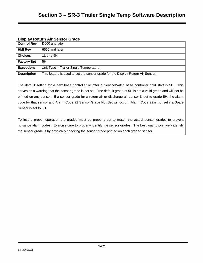
Section 3 – SR-3 Trailer Single Temp Software Description
Display Return Air Sensor Grade Control Rev D000 and later
HMI Rev 6550 and later
Choices 1L thru 9H
Factory Set 5H
Exceptions Unit Type = Trailer Single Temperature.
Description This feature is used to set the sensor grade for the Display Return Air Sensor.
The default setting for a new base controller or after a ServiceWatch base controller cold start is 5H. This
serves as a warning that the sensor grade is not set. The default grade of 5H is not a valid grade and will not be
printed on any sensor. If a sensor grade for a return air or discharge air sensor is set to grade 5H, the alarm
code for that sensor and Alarm Code 92 Sensor Grade Not Set will occur. Alarm Code 92 is not set if a Spare
Sensor is set to 5H.
To insure proper operation the grades must be properly set to match the actual sensor grades to prevent
nuisance alarm codes. Exercise care to properly identify the sensor grades. The best way to positively identify
the sensor grade is by physically checking the sensor grade printed on each graded sensor.
3-62
13 May 2011

Section 3 – SR-3 Trailer Single Temp Software Description
Display Discharge Air Sensor Grade Control Rev D000 and later
HMI Rev 6550 and later
Choices 1L thru 9H
Factory Set 5H
Exceptions Unit Type = Trailer Single Temperature.
Description This feature is used to set the sensor grade for the Display Discharge Air Sensor.
The default setting for a new base controller or after a ServiceWatch base controller cold start is 5H. This
serves as a warning that the sensor grade is not set. The default grade of 5H is not a valid grade and will not be
printed on any sensor. If a sensor grade for a return air or discharge air sensor is set to grade 5H, the alarm
code for that sensor and Alarm Code 92 Sensor Grade Not Set will occur. Alarm Code 92 is not set if a Spare
Sensor is set to 5H.
To insure proper operation the grades must be properly set to match the actual sensor grades to prevent
nuisance alarm codes. Exercise care to properly identify the sensor grades. The best way to positively identify
the sensor grade is by physically checking the sensor grade printed on each graded sensor.
3-63
13 May 2011

Section 3 – SR-3 Trailer Single Temp Software Description
Spare 1 Sensor Grade Control Rev D000 and later
HMI Rev 6550 and later
Choices 1L thru 9H
Factory Set 5H
Exceptions Unit Type = Trailer Single Temperature. If the optional Spare 1 Sensor is not present this
feature need not be set.
Description This feature is used to set the sensor grade for the Spare 1 Sensor.
The default setting for a new base controller or after a ServiceWatch base controller cold start is 5H. This
serves as a warning that the sensor grade is not set. The default grade of 5H is not a valid grade and will not be
printed on any sensor. If a sensor grade for a return air or discharge air sensor is set to grade 5H, the alarm
code for that sensor and Alarm Code 92 Sensor Grade Not Set will occur. Alarm Code 92 is not set if a Spare
Sensor is set to 5H.
To insure proper operation the grades must be properly set to match the actual sensor grades to prevent
nuisance alarm codes. Exercise care to properly identify the sensor grades. The best way to positively identify
the sensor grade is by physically checking the sensor grade printed on each graded sensor.
NOTE: Alarm Code 92 Sensor Grades Not Set is not active with spare sensors. However, if the sensor is in
used the sensor grade should be set to provide maximum sensor accuracy.
3-64
13 May 2011

Section 3 – SR-3 Trailer Single Temp Software Description
CYCLE SENTRY SETUP MENU
The Cycle Sentry Menu allows the unit defaults for Cycle Sentry Null and Sleep Null unit shut down on battery
charge current and unit restart on battery voltage to be modified as desired by the customer.
Cycle Sentry Amps Level Control Rev D000 and later
HMI Rev 6550 and later
Choices 2A to 8A in 1A increments
Factory Set 5A
Exceptions
Description When operating in Cycle Sentry or Sleep mode the unit will automatically run to charge the
battery, until the charging current falls below this set limit. This occurs even if cooling, heating or defrosting is
not required.
Battery Sentry Voltage Level Control Rev D000 and later
HMI Rev 6550 and later
Choices 11.8V to 12.6V in 0.1V increments
Factory Set 12.2V
Exceptions
Description When operating in Cycle Sentry or Sleep mode the controller will monitor battery voltage and
restart the unit to charge the battery, if the battery voltage falls below this set limit. This occurs even if cooling,
heating or defrosting is not required.
3-65
13 May 2011
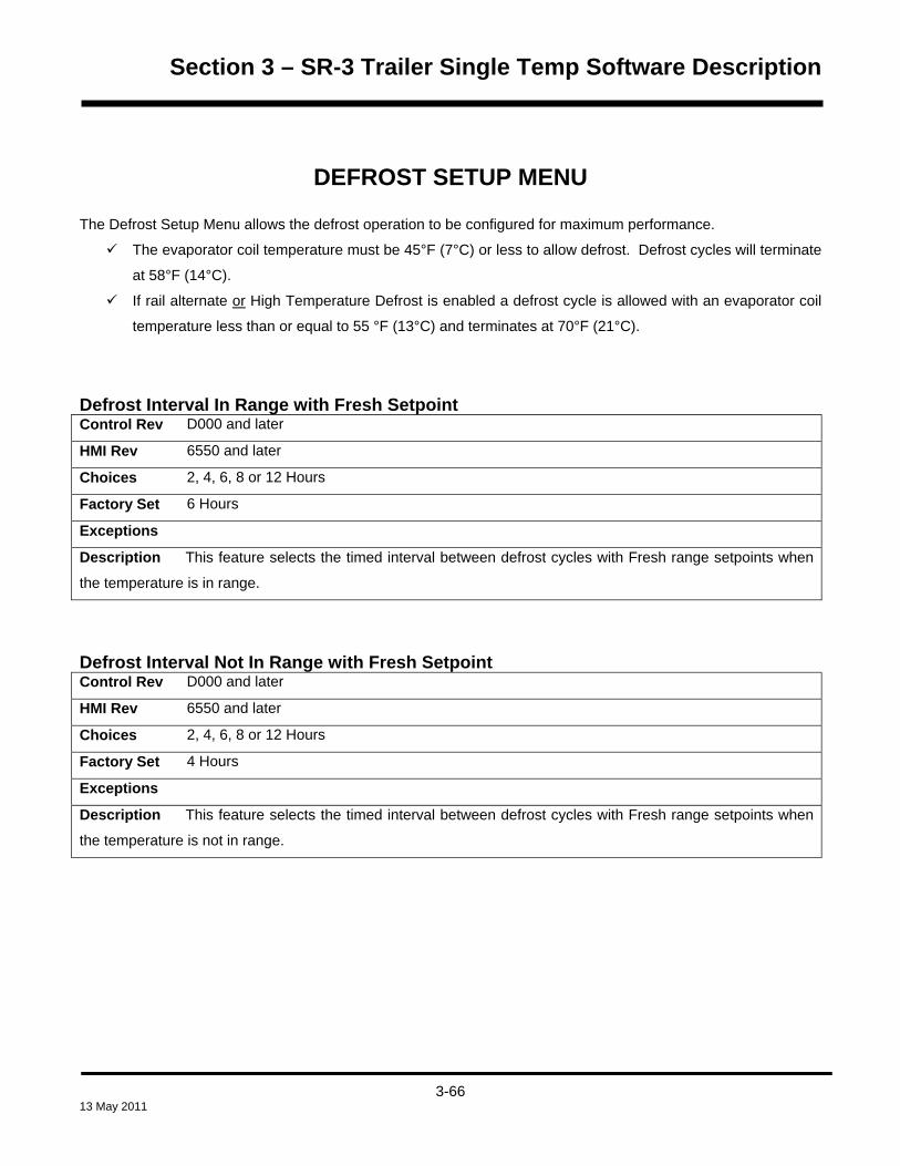
Section 3 – SR-3 Trailer Single Temp Software Description
DEFROST SETUP MENU
The Defrost Setup Menu allows the defrost operation to be configured for maximum performance.
The evaporator coil temperature must be 45°F (7°C) or less to allow defrost. Defrost cycles will terminate
at 58°F (14°C).
If rail alternate or High Temperature Defrost is enabled a defrost cycle is allowed with an evaporator coil
temperature less than or equal to 55 °F (13°C) and terminates at 70°F (21°C).
Defrost Interval In Range with Fresh Setpoint Control Rev D000 and later
HMI Rev 6550 and later
Choices 2, 4, 6, 8 or 12 Hours
Factory Set 6 Hours
Exceptions
Description This feature selects the timed interval between defrost cycles with Fresh range setpoints when
the temperature is in range.
Defrost Interval Not In Range with Fresh Setpoint Control Rev D000 and later
HMI Rev 6550 and later
Choices 2, 4, 6, 8 or 12 Hours
Factory Set 4 Hours
Exceptions
Description This feature selects the timed interval between defrost cycles with Fresh range setpoints when
the temperature is not in range.
3-66
13 May 2011

Section 3 – SR-3 Trailer Single Temp Software Description
Defrost Interval In Range with Frozen Setpoint Control Rev D000 and later
HMI Rev 6550 and later
Choices 2, 4, 6, 8 or 12 Hours
Factory Set 6 Hours
Exceptions
Description This feature selects the timed interval between defrost cycles with Frozen range setpoints when
the temperature is in range.
Defrost Interval Not In Range with Frozen Setpoint Control Rev D000 and later
HMI Rev 6550 and later
Choices 2, 4, 6, 8 or 12 Hours
Factory Set 6 Hours
Exceptions
Description This feature selects the timed interval between defrost cycles with Frozen range setpoints
when the temperature is not in range.
Maximum Defrost Duration Control Rev D000 and later
HMI Rev 6550 and later
Choices 30 or 45 Minutes
Factory Set 45 Minutes
Exceptions
Description This feature selects the maximum time the unit can remain in a defrost cycle. A defrost cycle
normally terminates when the evaporator coil temperature reaches 58°F (14°C). If Rail Alternate is enabled a
defrost cycle terminates at 70°F (21°C). If the evaporator temperature does not reach this temperature, the
defrost cycle will terminate after the elapsed time selected here.
3-67
13 May 2011

Section 3 – SR-3 Trailer Single Temp Software Description
LANGUAGE SETUP MENU
This menu allows the display language or languages to be enabled as required. When a language is selected all
subsequent displays are in that language.
The languages available are dependent on the software revision in the HMI Control Panel. Only one of the four
software revisions can be installed, and only the languages in that revision are available. Other than language
support, there is no difference between the software revisions. English is included in all HMI software versions.
HMI Control Panel software revisions support the languages shown in the table below.
Software Revision Language Support Table Revision 65xx Revision 66xx Revision 67xx Revision 68xx
English English English WinTrac Setup
Spanish Danish Japanese English
French Russian Chinese English and
German Norwegian Spanish
Italian Swedish English and
Dutch Finnish up to 5
Portuguese Polish additional
Greek Hungarian languages
Turkish Romanian from
Hebrew Bulgarian 65xx and
Arabic Czech 66xx
Revision 68xx HMI Control Panel Revision 68xx allows a combination of up to 5 languages from the 21 languages available in
Revision 65xx and Revision 66xx to be selected. This allows several languages from Revision 65xx and Revision
66xx to be loaded. HMI Control Panel Revision 68xx requires WinTrac 5.1 or later.
3-68
13 May 2011

Section 3 – SR-3 Trailer Single Temp Software Description
When flash loading HMI Control Panel Revision 68xx software, one of three language options is selected as
shown below.
• English only
• English and Spanish only
• Select up to five languages from the provided list
See Service Procedure A46B Flash Loading HMI Control Panel Software in Section 6 of this manual for details.
There is an Enable Language screen for each language included in the installed HMI software version. English is
included in all language sets and is factory set as Enabled. Only enabled languages will appear in the Main Menu
Language selections. All languages other than English are factory set as Disabled. If only one language is
enabled the Language selection screen does not appear in the Main Menu.
Enable Language Control Rev D000 and later
HMI Rev 6550 and later
Choices See Language Support Table
Factory Set English only
Exceptions
Description This feature allows any or all of the included languages to be enabled. Only enabled
languages will appear in the Operators Language Menu. All languages other than English are factory set as
Disabled. If only one language is enabled then the Language Menu screen will not appear in the Main Menu.
3-69
13 May 2011

Section 3 – SR-3 Trailer Single Temp Software Description
ACCESS CODE SETUP MENU
This menu allows an Access code to be required for entry to the Guarded Access Menu. If a code is selected, an
access code challenge will appear when entering the Guarded Access menu. If the correct code is not entered
access is denied.
A technician can bypass an unknown Access Code by entering “4444” and pressing the Enter key.
Enter Access Code The + and – keys are used to enter the desired Access Code. When the desired Access Code is displayed, the
Enter Key is pressed to load the code. The code should be recorded for future use.
If OptiSet Plus is active this feature is set using OptiSet Plus 4.1 or later.
3-70
13 May 2011

Section 3 – SR-3 Trailer Single Temp Software Description
OPTISET PLUS MENU
The OptiSet Plus™ Temperature Management System allows up to 64 different Named and/or Numeric
temperature profiles to be defined and tailored for maximum operating efficiency as determined by customer load
requirements. The term “OptiSet Plus” refers to both the programmable temperature profiles and the unit
operating features that can be tailored using OptiSet Plus.
Due to the large number of features available in OptiSet Plus, the OptiSet Plus features can no longer be viewed
or changed from the Guarded Access Menu. The only OptiSet Plus features available from the Guarded Access
Menu are OptiSet Plus Reset and Temperature Profile Selection.
OptiSet Plus Reset is used to reset all OptiSet Plus features to the factory default settings.
Temperature Profile Selection is used to determine what temperature profiles are available for use by the
driver.
For details of OptiSet Plus Reset and Temperature Profile Selection see the next page.
IMPORTANT: All other OptiSet Plus Features are set using OptiSet Plus. They cannot be viewed or changed
from the Guarded Access Menu. OptiSet Plus 4.1 or later is required for use with the SR-3 Control System and is
used to tailor unit performance to customer requirements.
For additional details see the following material. Information on installing and using OptiSet Plus 4.1 can be
found in the OptiSet Plus 3.0 User Guide (TK 54686-8-MS). Additional information can also be found in the
extensive Help Menu in OptiSet Plus 4.1.
3-71
13 May 2011

Section 3 – SR-3 Trailer Single Temp Software Description
OPTISET PLUS FEATURES AVAILABLE FROM THE GUARDED ACCESS MENU
These two features are available from the Guarded Access OptiSet Plus Menu.
OptiSet Plus Reset Control Rev D000 and later
HMI Rev 6550 and later
Exceptions Only available if OptiSet Plus features have been previously set using OptiSet Plus 4.1.
Description If any OptiSet Plus features have been previously set using OptiSet Plus 4.1, an OptiSet Reset
is provided at the beginning of the OptiSet Plus menu to return all settings to the default values. If this OptiSet
Reset feature is used, all OptiSet Plus settings are returned to factory defaults.
Temperature Profile Selection Control Rev D000 and later
HMI Rev 6550 and later
Choices NUMERIC SETPOINT ONLY
NAMED PRODUCT ONLY
NAMED PROD & NUMERIC SP
Factory Set Numeric Setpoint Only
Exceptions
Description This feature determines what profiles are available to the driver.
If NUMERIC SETPOINT ONLY is selected, only numeric setpoints are available to the driver, such as 35°F or -
10°F.
If NAMED PRODUCT ONLY is selected, only the named products enabled during OptiSet Plus setup are
available to the driver, such as Potatoes or Squash.
If NAMED PROD & NUMERIC SP is selected, both named products and numeric setpoints are available to the
driver.
3-72
13 May 2011

Section 3 – SR-3 Trailer Single Temp Software Description
OPTISET PLUS CONTINUOUS MODE FEATURES Frozen Ranges and Fresh Ranges without ETV or with Modulation turned Off.
The software features shown below are used to custom tailor temperature profiles using OptiSet Plus software.
These software features are accessible only in OptiSet Plus software. They are not available in the Guarded
Access Menu. They are shown here for convenience only. When shipped from the factory the features will be
set as shown by Factory Set.
Continuous High Speed Pulldown Control Rev D000 and later
HMI Rev 6550 and later
Choices Off or On
Factory Set On
Exceptions Not active if modulation is enabled
Description This feature allows High Speed Pull Down for the selected range to be turned On or Off. If High
Speed Pull Down is turned On, the unit will run in high speed on initial start until setpoint is reached in both cool
and heat mode. If High Speed Pull Down is turned Off, the unit will switch to low speed cool when the return air
temperature is below the programmed low speed switch point value plus setpoint.
There is a two-minute delay on initial startup before high speed operation is allowed.
If Fuel Saver II is turned On, there may be a delay before high speed operation is allowed.
This feature does not apply to modulation operation.
3-73
13 May 2011

Section 3 – SR-3 Trailer Single Temp Software Description
Continuous Low Speed Switch Point Control Rev D000 and later
HMI Rev 6550 and later
Choices 3.4°F (1.9°C) to 10.1°F (5.6°C)
Factory Set 3.4°F (1.9°C)
Exceptions Not active if modulation is enabled. Only appears if High Speed Pulldown = Off.
Description Low Speed Switch Point is the point at which the unit will switch from high speed operation to
low speed operation on temperature pull down. This is true on initial startup as well as a startup from Cycle
Sentry Null. This feature is not available if High Speed Pull Down = On.
If High Speed Cool to Low Speed Cool Switch Point is set above 3.4°F (1.9°C), the Null Restart Above Setpoint
feature will be changed automatically. It must be at least 1.5°F (0.8°C) above the setting of High Speed Cool to
Low Speed Cool Switch Point.
This feature is not used during modulation operation.
3-74
13 May 2011

Section 3 – SR-3 Trailer Single Temp Software Description
Continuous Fuel Saver II Control Rev D000 and later
HMI Rev 6550 and later
Choices Off or On
Factory Set On
Exceptions Not active if modulation is enabled
Description This feature allows Fuel Saver II for the selected range to be turned On or Off.
If Fuel Saver II is On, and the box temperature changes a predetermined amount from setpoint in Cycle Sentry
mode operation, or temperature indicates a need for high speed in Continuous mode operation, the unit will first
run in low speed. An 8-minute timer is started and the control sensor air temperature is monitored. As long as
the temperature falls (in cool mode operation) or rises (in heat mode operation) a specified amount before the
timer expires, the 8-minute timer is reset and low speed operation continues. If the temperature has not
changed the pre-determined amount when the timer times out, high speed operation resumes, if allowed. This
provides fuel savings by delaying high speed operation.
If the unit switches to high speed from FS-II the unit will run in high speed until setpoint is reached.
If Fuel Saver II is turned Off there is still a two-minute delay on initial startup before high speed operation is
allowed. If OFF high speed cool and high speed heat is allowed with no delay.
Continuous Low Speed Heat to Low Speed Cool Switch Point Control Rev D000 and later
HMI Rev 6550 and later
Choices 0.5°F (0.3°C) to 2.0°F (1.1°C)
Factory Set 1.7°F (0.9°C)
Exceptions This feature may not be available with all profiles.
Description This feature controls the switch point at which the unit shifts from Low Speed Heat to Low
Speed Cool.
3-75
13 May 2011

Section 3 – SR-3 Trailer Single Temp Software Description
Continuous Low Speed Cool to Low Speed Cool FS II Switch Point Control Rev D000 and later
HMI Rev 6550 and later
Choices 3.5°F (1.9°C) to 10.0°F (5.6°C)
Factory Set 5.0°F (2.8°C)
Exceptions Not active if modulation is enabled. This feature may not be available with all profiles.
Description The Low Speed Cool to Low Speed Cool FS II Switch Point is the Low Speed Cool to High
Speed Cool Switch Point + 1.5°F.
If enabled, then the Low Speed Cool FS II to High Speed Cool Switch Point will always be the Low Speed Cool
to Low Speed Cool FS II Switch Point + 3.5°F.
Door Switch Option Description This feature is the same as Door Open Forces shown under Programmable Features. See full
description on page 3-35.
Door Open Timer Description This feature is the same as Door Open Timeout shown under Programmable Features. See full
description on page 3-36.
3-76
13 May 2011

Section 3 – SR-3 Trailer Single Temp Software Description
Continuous Minimum Discharge Air Mode Control Rev D000 and later
HMI Rev 6550 and later
Choices Off or On
Factory Set Off
Exceptions Only appears if Cycle Sentry Door Open Forces = Off.
Description If set On, this feature limits the temperature of the discharge air to prevent top freeze on units
without an Electronic Throttling Valve (ETV). This feature can impact the unit’s ability to reach setpoint.
If set Off, then standard return air control is used.
Continuous Minimum Discharge Temperature Control Rev D000 and later
HMI Rev 6550 and later
Choices 27.0°F (-3.0°C to 37°F (3.0°C)
Factory Set 32.0°F (0.0°C)
Exceptions Only appears if Continuous Minimum Discharge Air Mode feature is set = Off.
Description This feature determines the minimum discharge air temperature that will be allowed if the
Minimum Discharge Air Mode feature (above) is set On.
3-77
13 May 2011

Section 3 – SR-3 Trailer Single Temp Software Description
OPTISET PLUS CONTINUOUS MODULATION MODE FEATURES
The software features shown below are used to custom tailor temperature profiles using OptiSet Plus software.
These software features are accessible only in OptiSet Plus software. They are not available in the Guarded
Access Menu. They are shown here for convenience only. When shipped from the factory the features will be
set as shown by Factory Set.
Controlling Sensor Control Rev D000 and later
HMI Rev 6550 and later
Choices Return or Discharge
Factory Set Return
Exceptions
Description Modulation provides very smooth and steady temperature control. Modulation is only
operational in Continuous Mode.
This feature determines the controlling sensor used during modulation operation, either the Return Air
Temperature Sensor or Discharge Air Temperature Sensor.
During Return Air Modulation, the discharge air temperature is limited to the programmed floor limit. The floor
limit is equal to setpoint minus the setting of the FreshSet Floor Limit feature. This provides additional protection
from freezing for sensitive loads.
During Discharge Air Modulation, the discharge air temperature is controlled to the setpoint.
3-78
13 May 2011

Section 3 – SR-3 Trailer Single Temp Software Description
PMAX Modulation Pull Down Option Control Rev D000 and later
HMI Rev 6550 and later
Choices On or Off
Factory Set On
Exceptions Only appears if Controlling Sensor = Return.
Description This feature determines the modulation pull down control algorithm used. This feature is only
available with return air temperature control. The floor limit algorithm is always used with discharge air control.
If PMAX is set On, modulation pull down control is governed by the 300°F*Minute (160°C*Minute) algorithm.
During pull down, the unit is in full cool and the discharge air temperature is allowed to drop below the
programmed floor limit for a defined period of time. This option provides the fastest pull down while minimizing
the potential for product top freezing.
MAX pull down example: If the discharge air is 15°F (8°C) below setpoint the unit will operate in full cool for 20
minutes before entering modulation cool.
e.g. 15°F x 20 minutes = 300°F*Minutes (8°C x 20 minutes = 160°C*Minutes)
If PMAX is set Off, modulation pull down control is governed by the Floor Limit pull down algorithm. During Floor
Limit pull down the unit will operate in high speed but will control the discharge air temperature to the
programmed Floor Limit. After the pull down conditions are satisfied the unit will switch to low speed
modulation. This option provides a fast pull down while eliminating the potential for product top freezing with
fragile commodities.
3-79
13 May 2011

Section 3 – SR-3 Trailer Single Temp Software Description
Floor Limit Control Rev D000 and later
HMI Rev 6550 and later
Choices 1.0°F (0.5°C) to 6.0°F (3.5°C)
Factory Set 4.0°F (2.8°C)
Exceptions Only appears if Controlling Sensor = Return.
Description This feature allows the minimum discharge air temperature during return air modulation to be
programmed. The discharge air temperature is limited to the programmed limit to provide additional protection
from freezing for sensitive loads.
For example, with a 35°F (1.7°C) setpoint and a 2.5°F (1.4°C) Floor Limit, the discharge air temperature is
limited to 32.5°F (0.3°C).
The minimum discharge air temperature is controlled to 29°F (-1.5°C) regardless of the programmed floor limit
with setpoints of 30°F (-1.1°C) and higher.
3-80
13 May 2011

Section 3 – SR-3 Trailer Single Temp Software Description
High Speed Modulation Control Rev D000 and later
HMI Rev 6550 and later
Choices Off or On
Factory Set On
Exceptions Only appears if Modulation Control = On.
Description This feature turns High Speed Modulation on or off. High Speed Modulation provides precise
modulation control with increased air-flow and capacity under high cooling load conditions. Air flow is increased
by operating the unit in high speed. The increased air flow reduces the rise in the return air temperature above
setpoint under high cooling load conditions. The discharge air temperature is controlled to the programmed floor
limit during high speed operation.
If this feature is On the unit will automatically enter high speed operation under high load conditions. The unit
will automatically switch back to low speed operation when conditions allow. High speed operation only occurs
when necessary to minimize fuel consumption and high speed operating hours.
3-81
13 May 2011

Section 3 – SR-3 Trailer Single Temp Software Description
High Speed Modulation Ceiling Control Rev D000 and later
HMI Rev 6550 and later
Choices 1.0°F (1.0°C) to 10.1°F (5.5°C)
Factory Set 2.0°F (1.1°C)
Exceptions Only appears if High Speed Modulation = On.
Description This switch point determines the number of degrees above setpoint the temperature must rise
before high speed modulation is allowed. A lower setting will result in tighter control to setpoint but increases
high speed operation time. A higher setting will result in looser temperature control but reduces high speed
operation time for additional fuel savings.
When the temperature rises to the Modulation Ceiling + 2°F (-17°C) the unit will run in high speed modulation
until the temperature falls back to the Modulation Ceiling.
For example, if the setpoint is 35°F (1.7°) and the High Speed Modulation Ceiling is 3°F (1.7°C), the Modulation
Ceiling is 38°F (3.4°C). If the temperature reaches 40°F (4.4°C) as determined by a Modulation Ceiling of 38°F
(3.4°C) + 2°F (1.0°C), the unit will switch to high speed modulation. The unit will run in high speed modulation
until the Modulation Ceiling of 38°F (3.4°C) is reached. The unit will then switch back to low speed modulation.
Low Ambient Temperature Override Control Rev D000 and later
HMI Rev 6550 and later
Choices OFF, 5°F to 35°F in 5°F Increments (-15°C to 1.7°C in 3°C Increments)
Factory Set OFF
Exceptions This is a trailer only feature.
Description If a temperature is selected and the ambient temperature is below the selected value, the unit
will run in high speed modulation for 100 minutes. This ensures adequate air flow throughout the trailer to
prevent hot or cold spots and provide more even temperature control. As a result, longer periods of high speed
operation may be observed. This is normal operation when the feature is enabled.
If the feature is set OFF there is no change in unit operation.
3-82
13 May 2011

Section 3 – SR-3 Trailer Single Temp Software Description
High Ambient Temperature Override Control Rev D000 and later
HMI Rev 6550 and later
Choices OFF, 85°F to 115°F in 5°F Increments (29°C to 46°C in 3°C Increments)
Factory Set OFF
Exceptions This is a trailer only feature.
Description If a temperature is selected and the ambient temperature is above the selected value, the unit
will run in high speed modulation for 100 minutes. This ensures adequate air flow throughout the trailer to
prevent hot or cold spots and provide more even temperature control. As a result, longer periods of high speed
operation may be observed. This is normal operation when the feature is enabled.
If the feature is set OFF there is no change in unit operation.
Door Switch Option Description This feature is the same as Door Open Forces shown under Programmable Features. See full
description on page 3-35.
Door Open Timer Description This feature is the same as Door Open Timeout shown under Programmable Features. See full
description on page 3-36.
3-83
13 May 2011

Section 3 – SR-3 Trailer Single Temp Software Description
OPTISET PLUS CYCLE SENTRY MODE FEATURES
The software features shown below are used to custom tailor temperature profiles using OptiSet Plus software.
These software features are accessible only in OptiSet Plus software. They are not available in the Guarded
Access Menu. They are shown here for convenience only. When shipped from the factory the features will be
set as shown by Factory Set.
Cycle Sentry High Speed Pulldown Control Rev D000 and later
HMI Rev 6550 and later
Choices Off or On
Factory Set On
Exceptions
Description This feature allows High Speed Pull Down for the selected range to be turned On or Off. If High
Speed Pull Down is turned On, the unit will run in high speed on initial start until setpoint is reached in both cool
and heat mode. If High Speed Pull Down is turned Off, the unit will switch to low speed cool when the return air
temperature is below the programmed low speed switch point value, plus setpoint.
There is a two minute delay on initial startup before high speed operation is allowed.
If Fuel Saver II is turned On, there may be a delay before high speed operation is allowed.
This feature does not apply to modulation operation.
3-84
13 May 2011

Section 3 – SR-3 Trailer Single Temp Software Description
Cycle Sentry Low Speed Switch Point Control Rev D000 and later
HMI Rev 6550 and later
Choices 3.4°F to 10.1°F
Factory Set 3.4°F
Exceptions Only appears if High Speed Pulldown = Off.
Description Low Speed Switch Point is the point at which the unit will switch from high speed operation to
low speed operation on temperature pull down. This is true on initial startup as well as a startup from Cycle
Sentry Null. This feature is not available if High Speed Pull Down = On.
If High Speed Cool to Low Speed Cool Switch Point is set above 3.4°F, the Null Restart Above Setpoint feature
will be changed automatically. It must be at least 1.5°F above the setting of High Speed Cool to Low Speed Cool
Switch Point.
3-85
13 May 2011
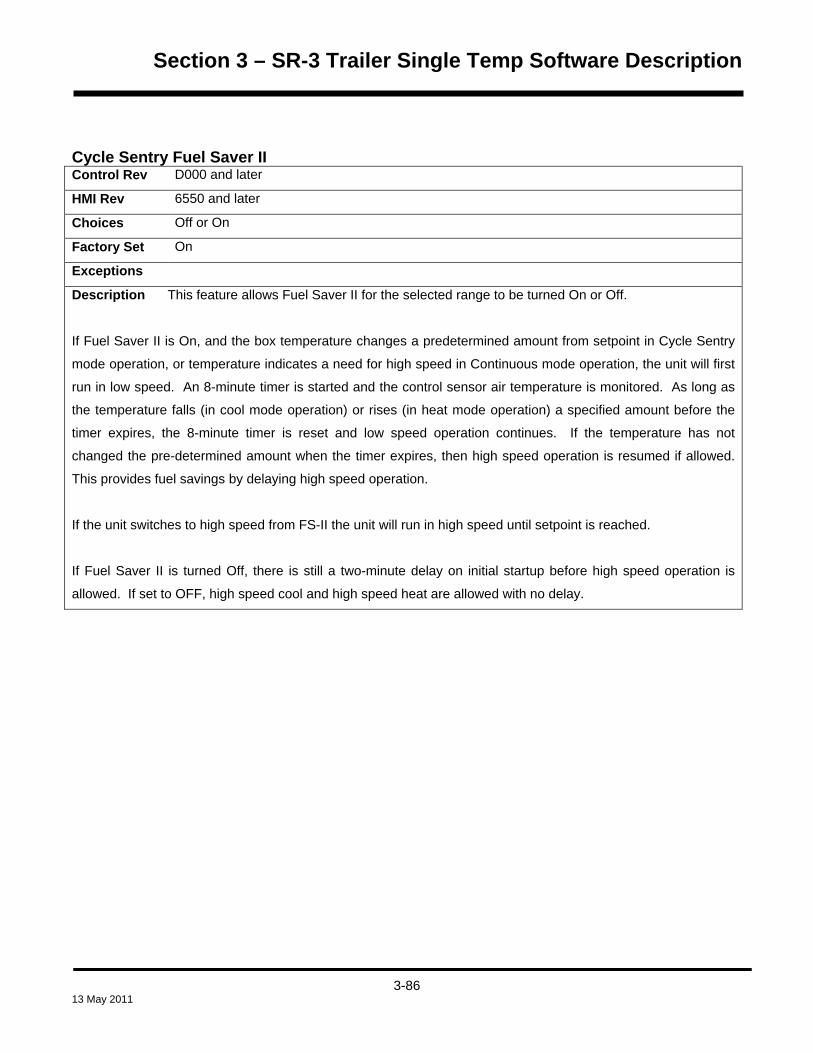
Section 3 – SR-3 Trailer Single Temp Software Description
Cycle Sentry Fuel Saver II Control Rev D000 and later
HMI Rev 6550 and later
Choices Off or On
Factory Set On
Exceptions
Description This feature allows Fuel Saver II for the selected range to be turned On or Off.
If Fuel Saver II is On, and the box temperature changes a predetermined amount from setpoint in Cycle Sentry
mode operation, or temperature indicates a need for high speed in Continuous mode operation, the unit will first
run in low speed. An 8-minute timer is started and the control sensor air temperature is monitored. As long as
the temperature falls (in cool mode operation) or rises (in heat mode operation) a specified amount before the
timer expires, the 8-minute timer is reset and low speed operation continues. If the temperature has not
changed the pre-determined amount when the timer expires, then high speed operation is resumed if allowed.
This provides fuel savings by delaying high speed operation.
If the unit switches to high speed from FS-II the unit will run in high speed until setpoint is reached.
If Fuel Saver II is turned Off, there is still a two-minute delay on initial startup before high speed operation is
allowed. If set to OFF, high speed cool and high speed heat are allowed with no delay.
3-86
13 May 2011

Section 3 – SR-3 Trailer Single Temp Software Description
Cycle Sentry Null Restart Temperature Control Rev D000 and later
HMI Rev 6550 and later
Choices 5.0°F to 15.0°F
Factory Set 5.0°F
Exceptions
Description This feature determines the number of degrees above setpoint that the temperature can rise
before the unit restarts in Cycle Sentry Mode. The range of values available is determined by the setting of High
Speed Pull Down. If Low Speed Switch Point is set above 3.5°F (1.9°C), the Null Restart Temperature feature
will be changed automatically. It must be at least 1.5°F (0.8°C) above the setting of High Speed Cool to Low
Speed Cool Switch Point.
With frozen range setpoints, the maximum restart limit can be no greater than 29°F (-1.6°C). This prevents melt
damage with frozen cargo.
The Null Restart Temperature below setpoint is a fixed value and cannot be changed.
Door Switch Option Description This feature is the same as Door Open Forces shown under Programmable Features. See full
description on page 3-35.
Door Open Timer Description This feature is the same as Door Open Timeout shown under Programmable Features. See full
description on page 3-36.
3-87
13 May 2011

Section 3 – SR-3 Trailer Single Temp Software Description
OPTISET PLUS CYCLE SENTRY MODULATION MODE FEATURES
The software features shown below are used to custom tailor temperature profiles using OptiSet Plus software.
These software features are accessible only in OptiSet Plus software. They are not available in the Guarded
Access Menu. They are shown here for convenience only.
IMPORTANT: Cycle Sentry Modulation is used at the customer’s discretion and is set up using a
customer designed named or numeric Temperature Profile in OptiSet Plus.
Cycle Sentry Modulation offers a compromise between fuel savings and temperature control when used with
fresh commodities with specific characteristics.
Some fresh commodities with the following characteristics may be candidates for Cycle Sentry Modulation.
Fresh commodities with low heat of respiration
Fresh commodities that do not ripen after harvest
Fresh commodities that do not require continuous airflow
If Cycle Sentry Modulation is enabled the following features can be tailored to the particular commodity:
MNTL Maximum Null Timer Control Rev D000 and later
HMI Rev 6550 and later
Choices Off, 20 Minutes, 40 Minutes, 60 Minutes, 80 Minutes
Factory Set None
Exceptions This feature is only available as a custom Temperature Profile created using OptiSet Plus.
Description This feature allows Maximum Null Time Limit [MNTL] for the selected range to be set for 20, 40,
60 or 80 minutes or turned off. If Maximum Null Time Limit is turned off normal Cycle Sentry operation will
occur. If a Maximum Null Time Limit is set (20, 40, 60 or 80 minutes) the unit will restart after the set time period
to provide air circulation even if cooling or heating is not required.
3-88
13 May 2011

Section 3 – SR-3 Trailer Single Temp Software Description
MOTL Minimum Off Timer Control Rev D000 and later
HMI Rev 6550 and later
Choices Off, 15 Minutes, 30 Minutes, 45 minutes
Factory Set None
Exceptions This feature is only available as a custom Temperature Profile created using OptiSet Plus.
Description This screen allows Minimum Off Time Limit [MOTL] for the selected range to be set for 15, 30 or
45 minutes or turned off. If Minimum Off Time Limit is turned off normal Cycle Sentry operation will occur. If a
Minimum Off Time Limit is set (15, 30 or 45 minutes) the unit will remain off for the set time period even if
cooling or heating is required. The time limit will be ignored if temperature varies an excessive amount above or
below setpoint.
Null Restart Temperature Control Rev D000 and later
HMI Rev 6550 and later
Choices 3.0°F to 15.0°F by 0.1°F Increments
Factory Set None
Exceptions This feature is only available as a custom Temperature Profile created using OptiSet Plus.
Description This feature determines the number of degrees above setpoint that the temperature can rise
before the unit restarts in Cycle Sentry Mode.
Floor Limit Control Rev D000 and later
HMI Rev 6550 and later
Choices 5.9°F to 15.0°F by 0.1°F Increments
Factory Set None
Exceptions This feature is only available as a custom Temperature Profile created using OptiSet Plus.
Description This feature allows the minimum discharge air temperature during modulation to be
programmed. The discharge air temperature will not fall below the programmed limit to provide additional
protection from freezing for chill sensitive loads.
3-89
13 May 2011

Section 3 – SR-3 Trailer Single Temp Software Description
Door Switch Option Description This feature is the same as Door Open Forces shown under Programmable Features. See full
description on page 3-35.
Door Open Timer Description This feature is the same as Door Open Timeout shown under Programmable Features. See full
description on page 3-36.
Minimum Run Time Control Rev D000 and later
HMI Rev 6550 and later
Choices 5 to 60 Minutes in 5 minute Increments
Factory Set None
Exceptions This feature is only available as a custom Temperature Profile created using OptiSet Plus.
Description This feature determines the minimum amount of time the unit will run after a Cycle Sentry
Modulation restart. It is used to provide adequate air circulation in the trailer.
3-90
13 May 2011

Section 3 – SR-3 Trailer Single Temp Software Description
SENSOR CONFIGURATION MENU – CARGOWATCH DATALOGGER
The CargoWatch Datalogger is internal to the HMI Control Panel. This datalogger conforms to European standard
EN12830. The data logger supports up to 6 temperature sensors and 3 digital inputs. These sensors are
optional sensors and are not the same as the temperature sensors used to control the unit. The CargoWatch
Data Logger features the ability to customize logging parameters and enable product temperature checking.
Note that the CargoWatch Data Logger does not record unit sensors. Unit sensors and other unit operating data
are recorded by the ServiceWatch Data Logger. The CargoWatch logger records the unit setpoint, operating
mode, and shutdown alarms.
When shipped from the factory, CargoWatch sensors 1 and 2 are turned on to be logged and CargoWatch
sensors 3 through 6 are turned off. Also, digital input 1 is turned on to be logged and digital inputs 2 through 4
are turned off. Sensors and digital inputs can be turned on, off and configured using the CargoWatch menu in
Guarded Access or with Wintrac.
3-91
13 May 2011
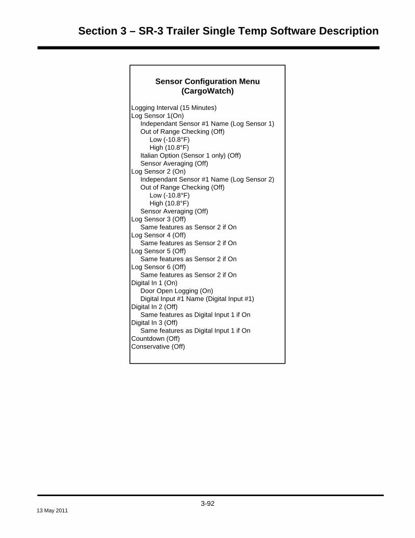
Section 3 – SR-3 Trailer Single Temp Software Description
Sensor Configuration Menu(CargoWatch)
Logging Interval (15 Minutes)Log Sensor 1(On) Independant Sensor #1 Name (Log Sensor 1) Out of Range Checking (Off) Low (-10.8°F) High (10.8°F) Italian Option (Sensor 1 only) (Off) Sensor Averaging (Off)Log Sensor 2 (On) Independant Sensor #1 Name (Log Sensor 2) Out of Range Checking (Off) Low (-10.8°F) High (10.8°F) Sensor Averaging (Off)Log Sensor 3 (Off) Same features as Sensor 2 if OnLog Sensor 4 (Off) Same features as Sensor 2 if OnLog Sensor 5 (Off) Same features as Sensor 2 if OnLog Sensor 6 (Off) Same features as Sensor 2 if OnDigital In 1 (On) Door Open Logging (On) Digital Input #1 Name (Digital Input #1)Digital In 2 (Off) Same features as Digital Input 1 if OnDigital In 3 (Off) Same features as Digital Input 1 if OnCountdown (Off)Conservative (Off)
3-92
13 May 2011

Section 3 – SR-3 Trailer Single Temp Software Description
CargoWatch Sensor Programming
Logging Interval Micro Rev D000 and later
HMI Rev 6550 and later
Choices 1 minute, 2 minutes and 5 to 60 minutes in 5-minute intervals
Factory Set 15 Minutes
Exceptions Wintrac is capable of setting additional intervals as short as 1 minute.
Description This feature allows the desired logging interval to be set for all sensors and digital inputs that
are turned On.
Log Sensor for CargoWatch sensor 1, 2, 3, 4, 5 or 6 Micro Rev D000 and later
HMI Rev 6550 and later
Choices ON or OFF
Factory Set Sensors 1-2 ON, sensors 3-6 OFF
Exceptions
Description This feature allows the desired sensors to be turned On to be logged. If the sensor is turned on
then additional features may be selected for that sensor.
Independent Sensor Name for CargoWatch sensor 1, 2, 3, 4, 5 or 6 Micro Rev D000 and later
HMI Rev 6550 and later
Choices See table below
Factory Set Log Sensor 1 through 6
Exceptions
Description This feature allows the desired sensor name to be specified. These names appear only on
handheld printer reports. This aids in reading and understanding data logger printer reports.
~ choices shown on next page ~
3-93
13 May 2011

Section 3 – SR-3 Trailer Single Temp Software Description
Choices • Log Sensor 1, 2, 3, 4, 5 or 6 • Spare Ambient • Ambient • Spare Dry • Spare Chilled • Spare Frozen • Spare Fresh • Dry • Chilled • Fresh • Spare Left Side • Spare Right Side • Spare Side • Spare Rear • Spare Front • Left Side • Right Side • Side • Rear • Front • Other Spare • Other • Spare • Spare USDA 1, 2 or 3 • USDA 1, 2 or 3 • Other Spare Discharge Air • Spare Discharge Air Zone 1, 2 or 3 • Spare Discharge Air • Other Spare Return Air • Spare Return Air Zone 1, 2 or 3 • Spare Return Air • Other Discharge Air • Discharge Air Zone 1, 2 or 3 • Discharge Air • Other Return Air • Return Air Zone 1, 2 or 3 • Return Air • Frozen • Independent Sensor 1, 2, 3, 4, 5 or 6
3-94
13 May 2011

Section 3 – SR-3 Trailer Single Temp Software Description
Out of Range Checking (for current sensor) Micro Rev D000 and later
HMI Rev 6550 and later
Choices ON or OFF
Factory Set ON
Exceptions
Description This feature allows the Out of Range Checking feature to be turned on or off. If Out of Range
Checking is turned on, an alarm will be set if the temperature, as sensed by the specified sensor, is above or
below setpoint by more than the number of degrees determined by the setting of LOW and HIGH programmable
features. The out of range condition must exist for 1 hour before the alarm is set. A visual notification will be
provided to the driver on the standard display, as shown below.
MENU35 °F
35OUT OF RANGE LIMIT
SET SENSORSGAUGESPOINT
.8
Low Micro Rev D000 and later
HMI Rev 6550 and later
Choices From -1.0° to –20.0° in 0.1-degree increments, in either Fahrenheit or Celsius.
Factory Set –10.8°F (-6.0°C)
Exceptions
Description This feature allows the low limit for Out of Range Checking to be set.
3-95
13 May 2011

Section 3 – SR-3 Trailer Single Temp Software Description
High Micro Rev D000 and later
HMI Rev 6550 and later
Choices From 1.0° to 20.0° in 0.1-degree increments, in either Fahrenheit or Celsius.
Factory Set 10.8°F (6.0°C)
Exceptions
Description This feature allows the high limit for Out of Range Checking to be set.
Italian Option Micro Rev D000 and later
HMI Rev 6550 and later
Choices ON or OFF
Factory Set OFF
Exceptions This feature is available with Sensor 1 only.
Description If this feature is turned ON, the driver is presented a visual “Out of Range Limit” notification and
flashes the backlight if the box temperature rises above -15°C. The visual notification appears on the Standard
Display as shown below.
MENU35 °F
35OUT OF RANGE LIMIT
SET SENSORSGAUGESPOINT
.8
3-96
13 May 2011

Section 3 – SR-3 Trailer Single Temp Software Description
Sensor Averaging Micro Rev D000 and later
HMI Rev 6550 and later
Choices ON or OFF
Factory Set OFF
Exceptions
Description If this feature is turned OFF, the temperature logged will be the actual instantaneous sensor
reading at the time of log. If this feature is turned ON, the sensor is read once each minute. The sensor
readings are averaged dependant on the setting of the Logging Interval feature selected above.
For example, if the Logging Interval is 15 minutes the previous 15 sensor readings are averaged and logged
instead of the actual instantaneous value. If the Logging Interval is set for 10 minutes, the previous 10 sensor
readings are averaged and logged.
3-97
13 May 2011

Section 3 – SR-3 Trailer Single Temp Software Description
Digital Input Programming The digital inputs are used to log the door switch status.
Digital In for CargoWatch digital input 1, 2 or 3 Micro Rev D000 and later
HMI Rev 6550 and later
Choices Digital Input 1, 2, 3 or 4
Factory Set
Exceptions
Description This feature allows the digital input to be programmed to be selected.
Door Open Logging Micro Rev D000 and later
HMI Rev 6550 and later
Choices ON or OFF
Factory Set Input 1 ON, inputs 2-4 OFF
Exceptions
Description This feature allows the desired digital inputs to be logged or ignored.
3-98
13 May 2011

Section 3 – SR-3 Trailer Single Temp Software Description
Digital Input Name for CargoWatch digital input 1, 2, 3 or 4 Micro Rev D000 and later
HMI Rev 6550 and later
Choices See table below
Factory Set Digital Input 1 through 4
Exceptions
Description This feature allows the desired input name to be specified. This aids in reading and
understanding data logger downloads.
Choices
• Digital Input 1, 2, 3 or 4
• Door
• Other Door
• Main Door
• Back Door
• Front Door
• Side Door
• Left Door
• Right Door
• Other Back Door
• Other Front Door
• Other Side Door
• Other Left Door
• Other Right Door
• Fresh Door
• Other Fresh Door
• Frozen Door
• Other Frozen Door
• Chilled Door
• Other Chilled Door
• Dry Door
• Other Dry Door
3-99
13 May 2011
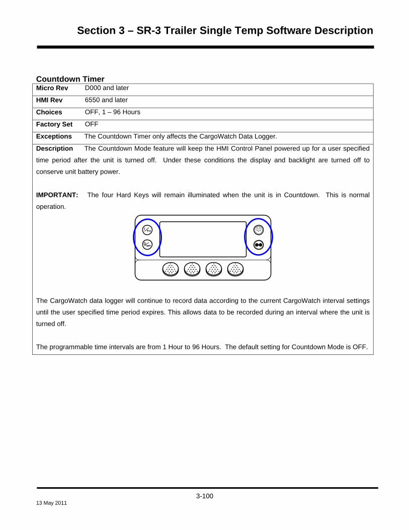
Section 3 – SR-3 Trailer Single Temp Software Description
Countdown Timer Micro Rev D000 and later
HMI Rev 6550 and later
Choices OFF, 1 – 96 Hours
Factory Set OFF
Exceptions The Countdown Timer only affects the CargoWatch Data Logger.
Description The Countdown Mode feature will keep the HMI Control Panel powered up for a user specified
time period after the unit is turned off. Under these conditions the display and backlight are turned off to
conserve unit battery power.
IMPORTANT: The four Hard Keys will remain illuminated when the unit is in Countdown. This is normal
operation.
The CargoWatch data logger will continue to record data according to the current CargoWatch interval settings
until the user specified time period expires. This allows data to be recorded during an interval where the unit is
turned off.
The programmable time intervals are from 1 Hour to 96 Hours. The default setting for Countdown Mode is OFF.
3-100
13 May 2011

Section 3 – SR-3 Trailer Single Temp Software Description
Conservative Log Count Micro Rev D000 and later
HMI Rev 6550 and later
Choices OFF, 1 – 400 Logs
Factory Set OFF
Exceptions The Countdown Timer only affects the CargoWatch Data Logger.
Description The Conservative Mode can be utilized by the user after the Countdown Mode interval above
has expired. When the Countdown Mode has expired, Conservative Mode (if programmed) allows the HMI
Control Panel to be temporarily powered up according to the current CargoWatch interval settings to log an
additional number of CargoWatch data logs. The HMI Control Panel will be powered up for approximately 30
seconds to perform each data log, and will then turn off.
The possible number of additional Conservative Mode CargoWatch data logs is from 1 Log to 400 Logs. The
default setting for Conservative Mode is OFF.
SOT on Setpoint Micro Rev D000 and later
HMI Rev 6550 and later
Choices Disabled, Enabled
Factory Set Disabled
Exceptions
Description If this feature is set ENABLED, a Start of Trip is sent to the ServiceWatch and CargoWatch Data
Loggers after any setpoint change. If this feature is set DISABLED, a Start of Trip is not sent.
3-101
13 May 2011

Section 3 – SR-3 Trailer Single Temp Software Description
UNIT CONFIGURATION SETUP MENU
The Unit Setup Menu is used to specify the actual unit configuration. These features are set at the factory as
required for each unit. The factory settings shown below are for a replacement base controller.
Alarm Code 111 Unit Not Configured Correctly If the base controller detects a mismatch between unit connections and configuration selections, Alarm Code 111
Unit Not Configured Correctly will be set.
Unit Type Control Rev D000 and later
HMI Rev 6550 and later
Choices TRUCK or TRAILER
Factory Set To match unit as built. A Base Controller Cold Start will default this feature to Trailer.
Exceptions If this feature is changed, it is necessary to exit the Guarded Access Menu after making the
change. This will reset the unit to the new setting. Failure to do so will result in the wrong selections to be
present in other Guarded Access Menu settings. For example, if the feature was set TRAILER and changed to
TRUCK, the reset changes the trailer default settings to truck default settings.
Description This feature allows the unit type to be selected.
Engine Type Control Rev D000 and later
HMI Rev 6550 and later
Choices Yanmar 2.1
Factory Set Yanmar 2.1
Exceptions
Description This feature allows the engine type to be selected.
3-102
13 May 2011

Section 3 – SR-3 Trailer Single Temp Software Description
Compressor Type Control Rev D000 and later
HMI Rev 6550 and later
Choices Recip or Screw
Factory Set Reciprocating
Exceptions
Description This feature allows the compressor type to be selected. The screw option is for a future
implementation and should not be selected.
ETV Configured Control Rev D000 and later
HMI Rev 6550 and later
Choices YES or NO
Factory Set To match unit as built. A base controller cold start will default this feature to YES.
Exceptions
Description This feature allows the unit to be configured with an Electronic Throttling Valve (ETV). Units
with an Electronic Throttling Valve should be set YES. All other units should be set NO.
Electric Standby Equipped? Control Rev D000 and later
HMI Rev 6550 and later
Choices YES or NO
Factory Set To match unit as built. A base controller cold start will default this feature to YES.
Exceptions This setting will automatically be forced from “NO” to “YES” if the unit detects that electric supply
power is connected to the unit.
Description This feature specifies if the unit is equipped with optional electric standby. If the unit is equipped
with electric standby, this feature should be set YES. If the unit is not equipped with electric standby, this
feature should be set NO.
3-103
13 May 2011

Section 3 – SR-3 Trailer Single Temp Software Description
Electric Heat Option Control Rev D000 and later
HMI Rev 6550 and later
Choices YES or NO
Factory Set To match unit as built. A base controller cold start will default this feature to YES.
Exceptions
Description This feature specifies if the unit is equipped with the electric heat option. If the unit is equipped
with electric heat, this feature should be set YES. If the unit is not equipped with electric heat, this feature
should be set NO.
On multi-temp applications electric heat is applicable to Zone 1 host evaporators only.
Electric Motor Type Control Rev D000 and later
HMI Rev 6550 and later
Choices 14 HP or optional 24 HP
Factory Set As built
Exceptions
Description This feature specifies which motor is used on units equipped with the Electric Standby option. A
14 HP motor is standard on units equipped with the Electric Standby option. The 24 HP motor is an available
option.
3-104
13 May 2011

Section 3 – SR-3 Trailer Single Temp Software Description
Diesel to Electric Auto Switch Enabled? Control Rev D000 and later
HMI Rev 6550 and later
Choices YES or NO
Factory Set NO
Exceptions
Description This feature allows the Auto Switch from Diesel to Electric to be enabled or disabled. If this
feature is set YES, the unit will switch automatically to electric mode when standby power is connected. If the
feature is set NO, the operator must manually switch the unit to electric mode using the HMI Control Panel mode
menu.
Electric to Diesel Auto Switch Enabled? Control Rev D000 and later
HMI Rev 6550 and later
Choices YES or NO
Factory Set NO
Exceptions
Description This feature allows the Auto Switch from Electric to Diesel to be enabled or disabled. If this
feature is set YES, the unit will switch automatically to diesel mode when standby power is disconnected or fails.
If the feature is set NO, the operator must manually switch the unit to diesel mode using the HMI Control Panel
mode menu.
NOTE: Auto-switch from electric to diesel is not recommended when the unit is running in electric mode indoors
or when below deck on a ferry.
3-105
13 May 2011
Section 3 – SR-3 Trailer Single Temp Software Description
Unit Model Control Rev D000 and later
HMI Rev 6550 and later
Choices SB, Super II, SL-400, SLX-100, SLX-200, SLX-300, SLX-400, SLX-LDB.
Factory Set To match unit as built. A base controller cold start will default this feature to SB.
Exceptions
Description Set for the appropriate unit.
High Capacity Unit? Control Rev D000 and later
HMI Rev 6550 and later
Choices YES or NO
Factory Set To match unit as built. A base controller cold start will default this feature to NO.
Exceptions
Description If the unit was built as a high capacity unit with an engine designed for 2600 RPM high speed
operation this setting should be set to YES. If the unit was not built as a high capacity unit then high speed is
2200 RPM and this setting must be set to NO.
IMPORTANT: Improper setting of this feature will cause Alarm Code 33 Check Engine RPM to be set
during a Pretrip Test.
3-106
13 May 2011

Section 3 – SR-3 Trailer Single Temp Software Description
High Capacity Fresh? Control Rev D000 and later
HMI Rev 6550 and later
Choices YES or NO
Factory Set NO
Exceptions Available only if the high capacity option is selected.
Description If the unit was built as a high capacity unit, the unit may be changed from the factory setting of
NO (1450 RPM) to YES (1720 RPM). This feature should be set to YES if the customer wants to allow the
engine to run at 1720 RPM in low speed. This provides additional airflow when necessary. If this feature is set
NO the engine will run at 1450 RPM in low speed.
Defrost Motor Equipped? Control Rev D000 and later
HMI Rev 6550 and later
Choices YES or NO
Factory Set To match unit as built. A base controller cold start will default this feature to NO.
Exceptions
Description This feature specifies if the unit is equipped with a defrost solenoid or defrost motor. If the unit
is equipped with a defrost motor this feature should be set YES. If the unit is not equipped with a defrost motor
this feature should be set NO. If OptiSet Plus is active this feature is set using OptiSet Plus 4.1 or later.
NOTE: All SL and SLX units are equipped with defrost motors and this feature must be set YES.
NOTE: A different SR-3 Base Controller is required for units equipped with a damper gear motor. The damper
gear motor SR-3 Base Controller has added electronic circuitry to drive the gear motor. See Section 7 for more
details and parts numbers.
3-107
13 May 2011

Section 3 – SR-3 Trailer Single Temp Software Description
Fuel Sensor Type Control Rev D000 and later
HMI Rev 6550 and later
Choices NONE, SOLID STATE, FLOAT or SWITCH
Factory Set NONE
Exceptions
Description This feature is used to select the type of fuel level sensor installed. If no fuel level sensor is
installed, this feature should be set to NONE.
Rear Remote Control Panel Control Rev D000 and later
HMI Rev 6550 and later
Choices NONE, COM 2
Factory Set NONE
Exceptions
Description This feature specifies if the unit is equipped with the optional flush mount Rear Remote Control
Panel. If the unit is equipped with the flush mount Rear Remote Control Panel this feature should be set to
COM 2 and the flush mount Rear Remote Control Panel should be connected to the COM2 port on the interface
board. If the unit is not equipped with a flush mount Rear Remote Control Panel, this feature should be set
NONE.
See Section 4 of this manual for more information on using the Rear Remote Control Panel.
3-108
13 May 2011

Section 3 – SR-3 Trailer Single Temp Software Description
Rear Remote Control Panel Action Control Rev D000 and later
HMI Rev 6550 and later
Choices STAND BY, RUN
Factory Set STAND BY
Exceptions Only appears if Rear Remote Control Panel is set for COM 2
Description If the Action is set to STAND BY, the unit will power up when the Rear Remote Control Panel
ON key is pressed. The setpoints can be changed from the Rear Remote Control Panel but the unit will not start
and run. The unit must be started from the HMI Control Panel on the unit. Pressing the Rear Remote Control
Panel OFF key will power down the control system. All Rear Remote Control Panel functions are present except
the engine will not start and a Manual Defrost Cycle or Pretrip Test cannot be initiated.
If the Action is set to RUN the unit will automatically start and run when the Rear Remote Control Panel ON key
is pressed. Pressing the Rear Remote Control Panel OFF key will power down the control system. All Rear
Remote Control Panel functions are present.
See Section 4 of this manual for more information on using the Rear Remote Control Panel.
3-109
13 May 2011

Section 3 – SR-3 Trailer Single Temp Software Description
Pretrip/Sleep Switch Options Control Rev D000 and later
HMI Rev 6550 and later
Choices DISABLE, PRETRIP, SLEEP
Factory Set DISABLE
Exceptions
Description This feature is used to allow an optional Sleep or Pretrip switch to be connected to the
controller. A momentary contact switch is connected from chassis ground to the Controller Sensor Connecter J7
pin 30. This feature determines the action resulting when this input is temporarily connected to chassis ground.
DISABLE results in no action. If a switch is not connected this feature should be set to Disable.
PRETRIP will start a Pretrip Test in the same manner as starting the test from the Main/Mode menu.
SLEEP will place the unit in Sleep Mode in the same manner as entering Sleep Mode from the Main/Pretrip
menu.
3rd Party Device Control Control Rev D000 and later
HMI Rev 6550 and later
Choices NONE, COM 1, COM 2
Factory Set NONE
Exceptions
Description This feature selects the communications port on the SR-3 Base Controller/Interface Board that
will be used by a third party control device such as satellite communications. If the unit is not equipped with a
third party device, this feature should be set NONE.
3-110
13 May 2011

Section 3 – SR-3 Trailer Single Temp Software Description
Low Fuel Shutdown Control Rev D000 and later
HMI Rev 6550 and later
Choices ENABLED, DISABLED
Factory Set DISABLED
Exceptions A float or solid state fuel level sensor must be installed and enabled from the Guarded Access /
Unit Configuration / Fuel Sensor Type menu. This feature is not available if the Rail Option feature is enabled.
Description Low Fuel Shutdown allows the low fuel shutdown feature to be enabled or disabled.
If Low Fuel Shutdown is set ENABLED then Alarm Code 44 Out of Fuel will be set as a shutdown alarm if the
fuel level falls below 5% of tank capacity. When the fuel tank is filled to more than 15% of tank capacity then
Alarm Code 44 Out of Fuel is automatically cleared.
IMPORTANT: If an Alarm Code 44 Out of Fuel Shutdown Alarm is manually cleared it is reset as a Check
Alarm. The unit can now be restarted but will continue to run until the fuel supply is exhausted.
If Low Fuel Shutdown is set DISABLED then no Out of Fuel alarm will be set and the unit will run until the fuel
supply is exhausted.
3-111
13 May 2011

Section 3 – SR-3 Trailer Single Temp Software Description
3-112
13 May 2011
Fresh Air Exchange Control Rev D006 Only – see Exceptions below
HMI Rev 6561 Only – see Exceptions below
Choices ENABLED, DISABLED
Factory Set DISABLED
Exceptions Guarded Access > Unit Configuration > Unit Type must be set for Trailer. The Fresh Air
Exchange Feature must be installed on the unit.
Software Revisions: As of this date, Revision D006 Base Controller Software and Revision 6561 HMI Control
Panel are required for the Fresh Air Exchange feature and will be installed only in SR-3 SB units equipped with
the Fresh Air Exchange option. Revision D006 Base Controller Software is a direct descendent of Revision
D007 Base Controller Software and has all the same features as Revision D007 Software.
Description The Fresh Air Exchange option allows fresh outside air to be drawn into the trailer and the
interior air to be exhausted by opening the Fresh Air Exchange doors. This feature is beneficial when hauling
loads that release gas as they ripen, such as potatoes. The Fresh Air Exchange feature should be used exactly
as specified by the customer.
The Fresh Air Exchange feature is only available with setpoints above 32°F (0°C). The feature is disabled with
setpoints of 32°F (0°C) and below.
A solenoid is used to open and close the Fresh Air Exchange Door. Note that the Fresh Air Exchange door will
only be open when the unit engine is running, as it is held in the open position by the Fresh Air Exchange
Solenoid. The door will close when the engine shuts down to preserve unit battery life. The setting of the Fresh
Air Exchange door will survive power off / power on cycles – if the door is set to “Open” by the operator it will
continue to open any time the engine is running until it is set to “Close” by the operator.
If Fresh Air Exchange is set ENABLED then the Fresh Air Exchange Open | Close feature will be shown in the
Mode Menu. If Fresh Air Exchange is set DISABLED then the Fresh Air Exchange Open | Close feature will not
appear in the Mode Menu.


Section 4 – SR-3 Trailer Single Temp Operation
TABLE OF CONTENTS SECTION 4
HMI Control Panel Features .................................................................................................................................... 5 Display ............................................................................................................................................................... 6
Keys ................................................................................................................................................................... 7
Hard Keys ..................................................................................................................................................... 7
Soft Keys ...................................................................................................................................................... 8
Display Heater ................................................................................................................................................... 9
Turning the Unit On and Off ................................................................................................................................. 10
The Standard Display ............................................................................................................................................ 16
The Temperature Watch Display .......................................................................................................................... 17
Changing the Setpoint .......................................................................................................................................... 18 Changing the Setpoint – Numerical Setpoint................................................................................................... 20
Changing the Setpoint – Numerical Setpoint................................................................................................... 21
Changing the Setpoint – Numerical Setpoint................................................................................................... 22
Changing the Setpoint – Named Product ........................................................................................................ 23
Changing the Setpoint – Named Product ........................................................................................................ 24
Changing the Setpoint – Named Product ........................................................................................................ 25
Changing the Setpoint – Both Numerical Setpoint and Named Product Available ......................................... 26
Starting the Diesel Engine .................................................................................................................................... 27
Starting the Electric Motor .................................................................................................................................... 28
Switching from Diesel to Electric ........................................................................................................................ 29
Switching from Electric to Diesel ........................................................................................................................ 30
Initiating a Manual Defrost Cycle ......................................................................................................................... 31
Selecting Cycle Sentry or Continuous Mode ...................................................................................................... 33
Using the Gauges Key .......................................................................................................................................... 36 Gauges Available ............................................................................................................................................. 37
Using the Sensors Key ......................................................................................................................................... 38 Sensors Available ............................................................................................................................................ 39
Main Menu Overview ............................................................................................................................................. 40
Using the Main Menu ............................................................................................................................................. 41
Main Menu Features .............................................................................................................................................. 42 USB Flash Drive .............................................................................................................................................. 46
Configuring a USB Flash Drive using WinTrac 5.1 or later ........................................................................ 46
Configured USB Flash Drive Contents ....................................................................................................... 49
4-1 13 May 2011
Section 4 – SR-3 Trailer Single Temp Operation
Considerations when using a WinTrac Configured USB Flash Drive ........................................................ 50
Inserting a USB Flash Drive in the USB Port on the Unit Control Panel .................................................... 52
Accessing the Flash Drive Menu from the SR-3 Main Menu ..................................................................... 53
Downloading the ServiceWatch or CargoWatch Data Loggers ................................................................. 55
Managing ServiceWatch and CargoWatch Files using a USB Flash Drive and WinTrac ......................... 57
Flash Load Files ......................................................................................................................................... 61
Flashload Files on the Internet ................................................................................................................... 61
Managing Flash Load Files using a USB Flash Drive and WinTrac .......................................................... 62
Flash Loading the SR-3 Base Controller or HMI Control Panel ................................................................. 64
OptiSet Plus Data File Formats when using a USB Flash Drive ................................................................ 67
Managing OptiSet Plus Files to be sent to the SR-3 Unit using a USB Flash Drive and WinTrac ............ 68
Sending OptiSet Plus Files to the SR-3 Unit using a USB Flash Drive and WinTrac ................................ 70
Managing OptiSet Plus Files retrieved from the SR-3 Unit using a USB Flash Drive and WinTrac .......... 72
Retrieving OptiSet Plus Files from the SR-3 Unit using a USB Flash Drive and WinTrac ......................... 76
Removing a USB Flash Drive from the Unit USB Port ............................................................................... 79
WinTrac Error Messages when using a USB Flash Drive ......................................................................... 80
Languages ....................................................................................................................................................... 81
Alarms .............................................................................................................................................................. 84
Pretrip Alarm Codes ................................................................................................................................... 84
Alarm Codes When Switching Between Diesel and Electric ...................................................................... 85
Clearing Alarm Codes ................................................................................................................................ 85
SR-3 Alarm Codes ........................................................................................................................................... 87
Displaying and Clearing Alarm Codes ........................................................................................................ 96
Important Alarm Notes ................................................................................................................................ 98
Data Logger (CargoWatch) ............................................................................................................................. 99
Hourmeters .................................................................................................................................................... 103
Hourmeter Names and Definitions ........................................................................................................... 104
Mode .............................................................................................................................................................. 105
Turn Cycle Sentry On or Off ..................................................................................................................... 106
Select Temperature Units ......................................................................................................................... 107
Fresh Air Exchange Open or Closed ........................................................................................................ 108
Keypad Lockout ........................................................................................................................................ 109
Start Sleep Mode ...................................................................................................................................... 110
Pretrip ............................................................................................................................................................ 111
Pretrip Test Conditions ............................................................................................................................. 111
Conditions where Pretrip Tests are not allowed ....................................................................................... 111
4-2 13 May 2011

Section 4 – SR-3 Trailer Single Temp Operation
Pretrip Test Sequence .............................................................................................................................. 111
Pretrip Test Considerations ...................................................................................................................... 112
Performing a Pretrip Test ......................................................................................................................... 112
Diesel/Electric Menu ...................................................................................................................................... 115
Switching from Diesel to Electric .............................................................................................................. 115
Switching from Electric to Diesel .............................................................................................................. 117
Adjust Brightness ........................................................................................................................................... 118
Time ............................................................................................................................................................... 120
Optional Rear Remote Control Panel ................................................................................................................ 121 Rear Remote Control Panel Functionality ..................................................................................................... 122
Rear Remote Control Action set to Run ................................................................................................... 122
Rear Remote Control Action set to Stand By ........................................................................................... 123
Keypad ........................................................................................................................................................... 124
Display ........................................................................................................................................................... 125
Reading a Typical Remote Standard Display ................................................................................................ 126
Remote Control Panel Lockout ...................................................................................................................... 126
Turning the Unit On or Off (Configured for STAND BY operation) ................................................................ 127
Turning the Unit On and Off (Configured for RUN operation) ....................................................................... 127
Changing the Setpoint ................................................................................................................................... 128
Selecting Cycle Sentry or Continuous Mode ................................................................................................. 129
Displaying the Discharge Air Temperature .................................................................................................... 130
Viewing and Clearing Alarm Codes ............................................................................................................... 131
Starting a Manual Defrost Cycle .................................................................................................................... 132
Sending a Start of Trip Marker....................................................................................................................... 133
Running a Pretrip Test ................................................................................................................................... 134
Maintenance Menu Overview ............................................................................................................................. 137
Using the Maintenance Menu ............................................................................................................................. 139
Maintenance Menu Choices ............................................................................................................................... 141 Hourmeters .................................................................................................................................................... 141
Hourmeter Definitions ............................................................................................................................... 142
Gauges .......................................................................................................................................................... 143
Gauge List ................................................................................................................................................ 144
Sensors .......................................................................................................................................................... 145
Sensor List ................................................................................................................................................ 146
Alarms ............................................................................................................................................................ 147
Log Alarms ................................................................................................................................................ 147
4-3 13 May 2011

Section 4 – SR-3 Trailer Single Temp Operation
Check Alarms ........................................................................................................................................... 148
Prevent Alarms ......................................................................................................................................... 148
Shutdown Alarms ..................................................................................................................................... 149
Displaying Alarms ..................................................................................................................................... 150
Clearing Alarms ........................................................................................................................................ 151
Alarm Notes .............................................................................................................................................. 152
Service Test Mode ......................................................................................................................................... 153
Service Test Modes .................................................................................................................................. 154
Devices Energized – Reciprocating Compressor – Diesel Mode ............................................................ 154
Devices Energized – Reciprocating Compressor – Electric Mode .......................................................... 155
Interface Board Test ...................................................................................................................................... 156
Interface Board Test Modes and Current Draw ....................................................................................... 157
Display Self Test ............................................................................................................................................ 158
Evacuation Test ............................................................................................................................................. 159
Software Revision .......................................................................................................................................... 161
Set Time and Date ......................................................................................................................................... 162
Guarded Access Menu Overview ....................................................................................................................... 163
Using the Guarded Access Menu ...................................................................................................................... 165
Guarded Access Menu Choices ......................................................................................................................... 168 Programmable Features (some features are not available if OptiSet Plus is in use) .................................... 168
Main Menu Configuration ............................................................................................................................... 169
Alarms ............................................................................................................................................................ 169
Hourmeter Setup ........................................................................................................................................... 169
Sensor Calibration ......................................................................................................................................... 170
Cycle Sentry Setup ........................................................................................................................................ 170
Defrost Setup ................................................................................................................................................. 170
Language Setup ............................................................................................................................................ 171
Access Code Setup ....................................................................................................................................... 171
OptiSet Plus ................................................................................................................................................... 171
Sensor Configuration (Cargo Watch) ............................................................................................................ 172
Unit Configuration .......................................................................................................................................... 174
4-4 13 May 2011

Section 4 – SR-3 Trailer Single Temp Operation
HMI CONTROL PANEL FEATURES
The HMI (Human/Machine Interface) Control Panel is connected to the Base Controller and is used to operate the
unit and display unit information. The HMI Control Panel communicates with the Base Controller via a controller
area network (CAN) bus. The HMI Control Panel also contains the ‘Cargo Watch®’ data logger. The HMI Control
Panel is located on the control box door.
SR-3 SB Unit Control Panel
The HMI Control Panel consists of a display and 8 touch-sensitive keys.
The display is capable of showing both text and graphics.
The keys on the left and right sides of the display are dedicated or single function keys.
The four keys under the display are termed “soft” keys. The functions of these keys change depending on the
operation being performed. If a soft key is active the current key function is shown in the display directly above
the key.
4-5 13 May 2011

Section 4 – SR-3 Trailer Single Temp Operation
Display
The display is used to present information to the operator. This information includes setpoint and temperature,
unit operating information, gauge readings, temperatures and other information as selected by the operator.
The Standard Display of box temperature and setpoint is shown here. The unit is running in Cycle Sentry Mode
as shown by the Cycle Sentry Icon in the upper right corner of the display. If the Cycle Sentry icon is not present,
the unit is running in Continuous Mode. The unit has a setpoint of 35°F, and an actual box temperature of 35.8°F.
The down-pointing arrow shows the unit is cooling.
The USB Icon in the upper left corner of the display indicates that a USB Flash Drive is inserted in the USB Port
on the Unit Control Panel.
The four keys under the display are termed “soft” keys. The functions of these keys change depending on the
operation being performed. The function of each soft key is shown in the display directly above the key. In the
example shown above, pressing the left soft key accesses the SETPOINT and pressing the right soft key
accesses the MAIN MENU. The other two soft keys access the GAUGES and SENSORS menus as shown in the
display.
4-6 13 May 2011

Section 4 – SR-3 Trailer Single Temp Operation
Keys
Hard Keys The keys on either side of the display are dedicated or “hard” keys. Their function always remains the same.
ON
This key is used to turn the unit on. First the display will briefly show the Thermo King Logo and
then the statement “Configuring System – Please Wait”. When the power-up sequence is
complete the display shows the Standard Display of box temperature and setpoint. For more
information see “Turning the Unit On and Off” later in this section.
OFF
This key is used to turn the unit off. First the display will briefly show “System is Powering Down
– Please Wait. Press On to Resume” and then “Off” will appear momentarily. When the power-
down sequence is complete the display will be blank. For more information see “Turning the
Unit On and Off” later in this section.
This key is used to initiate a manual defrost cycle. For more information see “Initiating a Manual
Defrost Cycle” later in this section.
This key is used to select Cycle Sentry Mode or Continuous Mode operation if allowed by
OptiSet Plus. For more information see “Selecting Cycle Sentry or Continuous Mode” later in
this section.
4-7 13 May 2011

Section 4 – SR-3 Trailer Single Temp Operation
Soft Keys
MENU
°F
SET SENSORSGAUGESPOINT
.8
SmartReefer3
OFF
ON
The four “soft” keys under the display are multi-purpose keys. Their function changes
depending on the operation being performed. If a soft key is active the key function is shown in
the display directly above the key. The keys are numbered from left to right, with Key 1 on the
far left and Key 4 on the far right.
Typical soft key functions:
MENU
NEXT BACK
YES NO
+ -
SELECT EXIT
CLEAR HELP
HOUR METERS SENSORS
GAUGES
4-8 13 May 2011

Section 4 – SR-3 Trailer Single Temp Operation
Display Heater The HMI Control Panel is equipped with a display heater. This heater is needed to make the display visible in
cold ambient temperatures.
The HMI has its own internal temperature sensor for the display heater. The heater is energized when the unit is
turned on and the ambient temperature is below 29.4°F (-2°C). The heater turns off when the temperature
sensed by the internal sensor rises above 37.4°F (+3°C). The heater draws from 1.4 to 1.7 amps when
energized.
The colder the ambient temperature the longer it will take for the heater to make the display visible on a cold
startup. It may take 10-15 seconds for the display to appear with very cold temperatures.
4-9 13 May 2011

Section 4 – SR-3 Trailer Single Temp Operation
TURNING THE UNIT ON AND OFF
The unit is turned on by pressing the ON Key and off by pressing the OFF Key. When the On Key is pressed the
display briefly shows the THERMO KING Logo as the display initializes.
IMPORTANT: The ON Key must be held down until the Thermo King Logo appears. If the ON Key is not held
down long enough (approximately ½ second), the display may flicker but the unit will not start up. If this occurs,
hold the ON Key down until the Thermo King logo appears.
NOTE: With extremely cold ambient temperatures it may take up to 15 seconds for the display to appear on
initial startup.
OFF
ON
Then the startup screen shown below appears while communications are established and the unit prepares for
operation.
OFF
ON CONFIGURING SYSTEM
PLEASE WAIT
4-10 13 May 2011

Section 4 – SR-3 Trailer Single Temp Operation
Turning the Unit On and Off - (continued)
THIS PAGE ONLY APPLIES IF MORE THAN ONE LANGUAGE IS ENABLED
If more than one language has been enabled from the Guarded Access Language Menu, a prompt will appear to
allow the desired language to be chosen as shown below. Only languages specifically enabled from the Guarded
Access Menu are available. If a different language is desired, press the NO Key as shown below.
IMPORTANT: The engine start is not delayed by the language prompt shown below. The prompt will appear for
10 seconds and then the engine will start. After the engine is started the display will return to the prompt shown
below.
The Language menu will appear as shown below. Press the + or – Keys to select the desired language. When
the desired language is shown press the YES Key to confirm the choice.
OFF
ONNEW LANGUAGE WILL BE
DEUTSCH
- YES NO+USE +/- TO CHANGE OK?
4-11 13 May 2011

Section 4 – SR-3 Trailer Single Temp Operation
Turning the Unit On and Off - (continued)
THIS PAGE ONLY APPLIES IF MORE THAN ONE LANGUAGE IS ENABLED
The display will briefly show PROGRAMMING LANGUAGE – PLEASE WAIT in the new language as shown
below.
The new language is confirmed, and then the Standard Display will appear in the new language as shown below.
The unit is ready to run. Continue on the next page.
4-12 13 May 2011

Section 4 – SR-3 Trailer Single Temp Operation
Turning the Unit On and Off - (continued)
THIS PAGE ONLY APPLIES IF A USB FLASH DRIVE IS INSERTED IN THE USB PORT WHEN THE UNIT IS
TURNED ON
If a USB Flash Drive is inserted in the USB Port on the Control Panel when the unit is turned on, the display will
briefly show FLASH DRIVE.
Then FLASH DRIVE DETECTED and the Flash Drive Menu will appear on the display as shown below. If
desired, downloads, flash loads and OptiSet Plus send and retrieve functions can be performed. For complete
details regarding using the USB Flash Drive see Using the USB Flash Drive later in this section.
IMPORTANT: The engine start is not delayed by the Flash Drive Menu shown above. The engine start prompt
will appear and the engine will start. After the engine is started the display will return to the Flash Drive Menu.
The Flash Drive Menu will time out about 30 seconds after the engine starts. When the Flash Drive Menu times
out, the Standard Display will appear. To go to the Standard Display immediately press the EXIT Key.
4-13 13 May 2011

Section 4 – SR-3 Trailer Single Temp Operation
Turning the Unit On and Off - (continued)
THIS PAGE ONLY APPLIES IF A USB FLASH DRIVE IS INSERTED IN THE USB PORT WHEN THE UNIT IS
TURNED ON
NOTE: If a USB Flash Drive is connected to the USB Port on the Control Panel, the USB Icon will appear in the
upper left corner of the display as shown below.
4-14 13 May 2011

Section 4 – SR-3 Trailer Single Temp Operation
Turning the Unit On and Off - (continued)
When the unit is ready to run the Standard Display appears.
Pressing the OFF Key stops unit operation. The unit shuts down immediately and the display briefly shows the
power down message.
OFF
ON SYSTEM IS POWERING DOWN
PRESS ON TO RESUME
The display briefly shows OFF and then goes blank. To start the unit again, press the ON Key.
OFF
ON
OFF
4-15 13 May 2011

Section 4 – SR-3 Trailer Single Temp Operation
THE STANDARD DISPLAY The Standard Display is the default display that appears if no other display function is selected. The Standard
Display shows the box temperature and setpoint. The box temperature is that measured by the controlling
sensor, usually the return air sensor. The box temperature here is 35.8°F with a 35°F setpoint.
The Cycle Sentry icon in the upper right corner of the display shows that the unit is operating in Cycle Sentry
mode. If the Cycle Sentry icon is not present, the unit is running in Continuous Mode.
The down-pointing arrow indicates that the unit is cooling.
The USB Icon in the upper left corner of the display indicates that a USB Flash Drive is inserted in the USB Port
on the Unit Control Panel.
Pressing the left soft key allows the user to change the SETPOINT, and pressing the right soft key accesses the
MAIN MENU. The other two soft keys access the GAUGES menu and the SENSORS menu.
4-16 13 May 2011

Section 4 – SR-3 Trailer Single Temp Operation
THE TEMPERATURE WATCH DISPLAY The TemperatureWatch Display appears 2 ½ minutes after the Standard Display appears so long as there is no
key activity and no check, prevent or shutdown alarms are present. The TemperatureWatch Display will remain
on until any key is pressed or a check, prevent or shutdown alarm occurs.
The TemperatureWatch Display shows the box temperature and setpoint. The large numbers allow unit
conditions to be checked from a distance. The box temperature is that measured by the controlling sensor,
usually the return air sensor. The box temperature here is 35.8°F with a 35°F setpoint. The Cycle Sentry icon in
the upper right corner of the display shows that the unit is operating in Cycle Sentry mode. If the Cycle Sentry
icon is not present, the unit is running in Continuous Mode. The down-pointing arrow indicates that the unit is
cooling. Pressing any soft key returns the display to the Standard Display. The USB Icon next to the Cycle
Sentry Icon in the upper right corner of the display indicates that a USB Flash Drive is inserted in the USB Port on
the Unit Control Panel.
If an alarm condition (other than a log alarm) is present, the TemperatureWatch Display will not appear. If an
alarm condition occurs while the TemperatureWatch Display is present the display will return to the Standard
Display to indicate that an alarm condition has occurred.
If the Defrost Key or Cycle Sentry Key is pressed, the display will return to the TemperatureWatch Display
immediately after the defrost cycle is initiated or the operating mode is changed.
4-17 13 May 2011

Section 4 – SR-3 Trailer Single Temp Operation
CHANGING THE SETPOINT
IMPORTANT: If OptiSet Plus is in use there are several possible options when changing the setpoint.
• Numerical Setpoints If OptiSet Plus is not in use or if only Numerical Setpoints are enabled, then the
Standard Display left soft key will be labeled SETPOINT as shown below.
OFF
ON
MENU
°F
SET SENSORSGAUGESPOINT
.8
• Named Products OptiSet Plus allows the use of Named Products such as GRAPEFRUIT or BANANAS
in place of a numerical setpoint. If only named products are enabled, then the Standard Display left soft
key will be labeled PRODUCT as shown below.
If Named Products are in use, a single setpoint temperature may be allowed for the specific
named product.
If Named Products are in use, a numerical setpoint range may be allowed for the specific named
product.
4-18 13 May 2011

Section 4 – SR-3 Trailer Single Temp Operation
Changing the Setpoint – (continued)
• Both Numerical Setpoints and Named Products OptiSet Plus can allow the use of both Numerical
Setpoints and Named Products. If both numerical setpoints and named products are enabled, then the
Standard Display left soft key will be labeled PRODUCT/SETPOINT as shown below.
4-19 13 May 2011

Section 4 – SR-3 Trailer Single Temp Operation
Changing the Setpoint – (continued)
Changing the Setpoint – Numerical Setpoint If the Temperature Watch display is shown, press any soft key to return to the Standard Display. From the
Standard Display, press the SETPOINT Key.
The setpoint display appears as shown below.
OFF
ON
- EXIT
CURRENT SETPOINT
35 F
++/- TO CHANGE
The “-“ and “+” Keys are used to increase or decrease the setpoint until the desired setpoint is shown. Here the
setpoint has been changed to 40°F using the “+” Key.
OFF
ON
- NO
NEW SETPOINT WILL BE
40 F
++/- TO CHANGE OK?YES
4-20 13 May 2011

Section 4 – SR-3 Trailer Single Temp Operation
Changing the Setpoint – (continued)
Changing the Setpoint – Numerical Setpoint The YES and NO Keys confirm the setpoint change. When the desired setpoint has been selected using the “+”
and/or “-“ Keys, press the YES Key to confirm and load the new setpoint. If the setpoint is changed using the “+”
or “-“ Keys, the change must be confirmed or rejected by pressing the YES or NO Key within 10 seconds of
changing the setpoint. A warning beep will sound for 5 seconds as a reminder.
Failure to confirm the new setpoint by pressing Yes or No within 10 seconds of changing the setpoint will result in
no setpoint change. In addition, Alarm Code 127 Setpoint Not Entered is set, to indicate that the setpoint change
was not completed.
OFF
ON
- NO
NEW SETPOINT WILL BE
40 F
++/- TO CHANGE OK?YES
After the YES Key has been pressed, the display briefly shows PROGRAMMING NEW SETPOINT – PLEASE
WAIT. The display then confirms the new setpoint for several seconds.
OFF
ON
NEW SETPOINT IS
40 F
If the NO Key is pressed the display will briefly show SETPOINT NOT CHANGED and return to the Standard
Display. The Standard Display will show the old setpoint.
4-21 13 May 2011

Section 4 – SR-3 Trailer Single Temp Operation
Changing the Setpoint – (continued)
Changing the Setpoint – Numerical Setpoint The display then returns to the Standard Display showing the new setpoint. Notice that the arrow now points up,
to indicate that the unit is heating.
IMPORTANT: If the setpoint is changed using the “+” or “-“ Keys, the change must be confirmed or
rejected by pressing the YES or NO Key within 10 seconds of changing the setpoint.
• If the YES Key is pressed, the setpoint change made with the “+” or “-“ Key is accepted, the setpoint
changes, and the display returns to the Standard Display.
• If the NO Key is pressed the setpoint change made with the “+” or “-“ Key is not accepted, the setpoint is
not changed, and the display returns to the Standard Display.
• If the YES or NO Key is not pressed within 10 seconds of making a change with the “+” or “-“ Key, the
setpoint is not changed and the display returns to the Standard Display. The display briefly shows
[SETPOINT NOT CHANGED] and Alarm Code 127 Setpoint Not Entered is set, to indicate that the
setpoint change was started but not completed.
4-22 13 May 2011

Section 4 – SR-3 Trailer Single Temp Operation
Changing the Setpoint – (continued)
Changing the Setpoint – Named Product If the Temperature Watch display is shown, press any soft key to return to the Standard Display. From the
Standard Display, press the PRODUCT Key. Note that PRODUCT is displayed in place of SETPOINT as shown
below.
The display briefly shows PRODUCT and then the setpoint display appears as shown below.
The “-“ and “+” Keys are used to change the Named Product until the desired product is shown. Here the product
has been changed to Potato, Late Crop.
OFF
ON
- NO
NEW PRODUCT WILL BE
++/- TO CHANGE OK?YES
POTATO, LATE CROP
4-23 13 May 2011

Section 4 – SR-3 Trailer Single Temp Operation
Changing the Setpoint – (continued)
Changing the Setpoint – Named Product The YES and NO Keys confirm the product change. When the desired product has been selected using the “+”
and/or “-“ Keys, press the YES Key to confirm and load the new product. If the product is changed using the “+”
or “-“ Keys, the change must be confirmed or rejected by pressing the YES or NO Key within 10 seconds of
changing the product. A warning beep will sound for 5 seconds as a reminder.
Failure to confirm the new product by pressing Yes or No within 10 seconds of changing the product will result in
no product change. In addition, Alarm Code 127 Setpoint Not Entered is set, to indicate that the product change
was not completed.
OFF
ON
- NO
NEW PRODUCT WILL BE
++/- TO CHANGE OK?YES
POTATO, LATE CROP
After the YES Key has been pressed, the display briefly shows PROGRAMMING NAMED PRODUCT – PLEASE
WAIT. The display then confirms the new setpoint for several seconds.
If the NO Key is pressed the display will briefly show SETPOINT NOT CHANGED and return to the Standard
Display. The Standard Display will show the old setpoint.
4-24 13 May 2011

Section 4 – SR-3 Trailer Single Temp Operation
Changing the Setpoint – (continued)
Changing the Setpoint – Named Product The display then returns to the Standard Display showing the new named product. Notice that the arrow points
down, to indicate that the unit is cooling.
IMPORTANT: If the named product is changed using the “+” or “-“ Keys, the change must be confirmed
or rejected by pressing the YES or NO Key within 10 seconds of changing the named product.
* If the YES Key is pressed, the product change made with the “+” or “-“ Key is accepted, the product
changes, and the display returns to the Standard Display.
* If the NO Key is pressed the product change made with the “+” or “-“ Key is not accepted, the product is
not changed, and the display returns to the Standard Display.
* If the YES or NO Key is not pressed within 10 seconds of making a change with the “+” or “-“ Key, the
product is not changed and the display returns to the Standard Display. The display briefly shows
[SETPOINT NOT CHANGED] and Alarm Code 127 Setpoint Not Entered is set, to indicate that the
setpoint change was started but not completed.
4-25 13 May 2011

Section 4 – SR-3 Trailer Single Temp Operation
Changing the Setpoint – (continued)
Changing the Setpoint – Both Numerical Setpoint and Named Product Available If the Temperature Watch display is shown, press any soft key to return to the Standard Display. From the
Standard Display, press the SETPOINT Key. Note that both PRODUCT and SETPOINT are displayed as shown
below.
OFF
ON
MENU
°F
PRODUCT/ SENSORSGAUGESSETPOINT
.8
The NAMED PRODUCT / NUMERIC SETPOINT appears briefly as shown below.
Press the NAMED Soft Key to proceed with Named Product change as shown previously.
Press the NUMERIC Soft Key to proceed with Numeric Setpoint change as shown previously.
Press the EXIT Soft Key to return to the Standard Display.
4-26 13 May 2011

Section 4 – SR-3 Trailer Single Temp Operation
STARTING THE DIESEL ENGINE
Diesel engine preheats and starts are automatic in both Continuous Mode and Cycle Sentry Mode. The engine
will preheat and start as required when the unit is turned on. The engine preheat and start will be delayed in
Cycle Sentry mode if there is no current need for the engine to run. If any keys are being pressed on the HMI
Control Panel the engine will not preheat and start until 10 seconds after the last key is pressed.
NOTE: If the unit is equipped with optional Electric Standby there may be some additional prompts
before the engine will start. See STARTING THE ELECTRIC MOTOR on the following pages for details.
CAUTION: The engine may start automatically any time the unit is turned on.
WARNING: Never use starting fluid.
When the engine is preparing to start the HMI Control Panel will display the engine start screen, as shown below.
The preheat buzzer sounds during the engine preheat and crank sequence.
OFF
ONDIESEL ENGINE STARTING
After the engine is started the display returns to the Standard Display of temperature and setpoint.
4-27 13 May 2011

Section 4 – SR-3 Trailer Single Temp Operation
STARTING THE ELECTRIC MOTOR
Units equipped with the Electric Standby option only
Electric motor starting is automatic in both Continuous Mode and Cycle Sentry Mode. The motor will start as
required when the unit is turned on. If any keys are being pressed on the HMI Control Panel prior to the motor
start, the motor start will be delayed until 10 seconds after the last key is pressed.
CAUTION: The motor may start automatically any time the unit is turned on.
When the motor is preparing to start the HMI Control Panel will display the motor start screen, as shown below.
The preheat buzzer sounds for 20 seconds before the electric motor starts.
OFF
ON ELECTRIC MOTOR STARTING
4-28 13 May 2011

Section 4 – SR-3 Trailer Single Temp Operation
SWITCHING FROM DIESEL TO ELECTRIC
Units equipped with the Electric Standby option only If the Diesel to Electric Autoswitch Enabled feature in Guarded Access is set YES then the unit will automatically
switch to Electric Mode operation when standby power is connected and available.
If the Diesel to Electric Autoswitch Enabled feature in Guarded Access is set NO then the prompt screen shown
below will appear when standby power is connected and available.
If NO is selected, then the unit will continue to operate in Diesel Mode. If YES is selected then the display will
briefly show the screen below.
Electric Mode operation will briefly be confirmed. If unit operation is required the electric motor will start as shown
above in STARTING THE ELECTRIC MOTOR.
If the Diesel to Electric Autoswitch Enabled feature in Guarded Access is set NO then the unit can also be
switched from Diesel mode to Electric mode operation using the Electric Standby Selection from the Main Menu
as shown later in this section.
4-29 13 May 2011

Section 4 – SR-3 Trailer Single Temp Operation
SWITCHING FROM ELECTRIC TO DIESEL
Units equipped with the Electric Standby option only If the Electric to Diesel Autoswitch Enabled feature in Guarded Access is set YES then the unit will automatically
switch to Diesel Mode operation when standby power is turned off or is no longer available.
If the Electric to Diesel Autoswitch Enabled feature in Guarded Access is set NO and standby power is
disconnected or fails, the unit will not automatically switch to Diesel mode. This is primarily designed to prevent
unauthorized diesel engine starts when the truck is indoors or on a ferry where engine operation is strictly
prohibited. If the Electric to Diesel Autoswitch Enabled feature in Guarded Access is set NO then the prompt
screen shown below will appear when standby power is turned off or is no longer available.
If YES is selected then the display will briefly show the screen below.
Diesel Mode operation will briefly be confirmed. If unit operation is required the diesel engine will start as shown
previously in STARTING THE DIESEL ENGINE.
If the Electric to Diesel Autoswitch Enabled feature in Guarded Access is set NO then the unit can also be
switched from Diesel mode to Electric mode operation using the Diesel Selection from the Main Menu as shown
later in this section.
4-30 13 May 2011

Section 4 – SR-3 Trailer Single Temp Operation
INITIATING A MANUAL DEFROST CYCLE
Defrost cycles are usually initiated automatically based on time or demand. Manual defrost is also available
Manual defrost is available if the unit is running and the evaporator coil temperature is less than or equal to 45°F
(7°C).
NOTE: If Rail Alternate is set YES defrost is allowed with an evaporator coil temperature less than or
equal to 55°F (13°C).
Other features such as door switch settings may not allow manual defrost under some conditions. To initiate a
manual defrost cycle, press the Defrost Key as shown below.
The display briefly shows [DEFROST], [PROGRAMMING DEFROST - PLEASE WAIT] and then [DEFROST
STARTED].
OFF
ON DEFROST STARTED
4-31 13 May 2011

Section 4 – SR-3 Trailer Single Temp Operation
Initiating a Manual Defrost Cycle - continued
The display then shows the Defrost display. The bar indicator shows approximately how much time remains to
complete the defrost cycle. The bar indicator below shows that the defrost cycle is about 25% complete.
Terminating a Defrost Cycle
The defrost cycle terminates automatically when the coil temperature is greater than or equal to 58°F (14°C) or
the defrost timer expires. Defrost can also be terminated by turning the unit off and back on.
NOTE: If Rail Alternate is set YES the defrost cycle terminates at 70°F (21°C) or if the defrost timer
expires.
4-32 13 May 2011

Section 4 – SR-3 Trailer Single Temp Operation
SELECTING CYCLE SENTRY OR CONTINUOUS MODE
When Cycle Sentry mode is selected the unit will start and stop automatically to maintain setpoint, keep the
engine warm and the battery charged. When Continuous Mode is selected, the unit starts automatically and runs
continuously to maintain setpoint and provide constant airflow.
IMPORTANT: Cycle Sentry or Continuous may not be selectable if OptiSet Plus is in use.
If the unit is operating in Cycle Sentry Mode, the Cycle Sentry Icon will be present in the upper right corner of the
display as shown below. If the Cycle Sentry Icon is not present the unit is operating in Continuous Mode.
If allowed by OptiSet Plus, Cycle Sentry Mode or Continuous Mode is selected by pressing the Cycle
Sentry/Continuous Key as shown below.
NOTE: Cycle Sentry Mode or Continuous Mode can also be selected using the Mode Submenu from the
Main Menu.
4-33 13 May 2011

Section 4 – SR-3 Trailer Single Temp Operation
Selecting Cycle Sentry or Continuous Mode - (continued)
If the unit is in Cycle Sentry mode, pressing the Cycle Sentry/Continuous Key changes the mode from Cycle
Sentry to Continuous. The display confirms the change, as shown below.
OFF
ON PROGRAMMING CONT MODE
PLEASE WAIT
The new mode is confirmed for 3 seconds.
OFF
ON NEW SYSTEM MODE IS
CONTINUOUS
The display then returns to the Standard Display. In the example shown below the absence of the Cycle Sentry
Icon indicates that the unit is running in Continuous mode.
4-34 13 May 2011

Section 4 – SR-3 Trailer Single Temp Operation
Selecting Cycle Sentry or Continuous Mode - (continued)
Pressing the Cycle Sentry/Continuous Key again allows the operator to change back to Cycle Sentry mode
operation.
IMPORTANT: If the unit is in Cycle Sentry null and the mode is switched to Continuous Mode, the unit will start
automatically.
IMPORTANT: Cycle Sentry or Continuous may not be selectable if OptiSet Plus is in use.
4-35 13 May 2011

Section 4 – SR-3 Trailer Single Temp Operation
USING THE GAUGES KEY
The GAUGES Key allows the operator to view the unit gauges. To access the GAUGES press the GAUGES
Key.
The first gauge display will appear. Press the NEXT and BACK Keys to scroll thru the gauges. Pressing the
LOCK Key will lock the gauges on the display.
OFF
ON
COOLANT TEMPERATURE
183 °FNEXTEXIT LOCK
The gauges available are shown on the next page. Not all gauges may appear depending on unit configuration
and software revision.
To return to the Standard Display press the EXIT Key.
4-36 13 May 2011

Section 4 – SR-3 Trailer Single Temp Operation
Gauges Available
Coolant Temperature – Displays the temperature of the engine coolant.
Coolant Level – Displays the coolant level in the overflow tank.
Oil Pressure – Displays the engine oil pressure as OK or LOW.
Oil Level – Displays the engine oil level as OK or LOW.
Amps – Displays the current flow in amps flowing to or from the unit battery
Battery Voltage – Displays the voltage of the unit battery.
Engine RPM – Displays the engine speed in RPMs.
Fuel Level Sensor – Displays the fuel level if a fuel level sensor is installed.
Discharge Pressure – Displays the unit discharge pressure. (ETV units only)
Suction Pressure – Displays the unit suction pressure. (ETV units only)
ETV Position – Displays the current position of the ETV valve. (ETV units only)
Fresh Air Exchange – Displays the current position of the optional Fresh Air Exchange Door
I/O (Input/Output State) – Displays the current state of the input/output devices listed below.
• High Speed Relay/Electric Heat
• Run Relay
• Run Relay Feedback
• Alternator Excite Output
• Defrost Damper
• Heat Output
• Alternator Frequency
• Optional Fresh Air Exchange Output
• Diesel/Electric Relay (Model 50 units only)
• Electric Ready Input (Model 50 units only)
• Electric overload (Model 50 units only)
• Hot Gas Bypass (ETV units only)
4-37 13 May 2011

Section 4 – SR-3 Trailer Single Temp Operation
USING THE SENSORS KEY
The SENSORS Key allows the operator to view the temperatures read by the unit temperature sensors. To
access the SENSORS press the SENSORS Key.
The first sensor display will appear. Press the NEXT and BACK Keys to scroll thru the sensors. Pressing the
LOCK Key will lock the current sensor on the display.
OFF
ON
CONTROL RETURN AIR TEMPERATURE
35. °FNEXTEXIT LOCK
7
The sensors available are shown on the next page.
To return to the Standard Display press the EXIT Key.
4-38 13 May 2011

Section 4 – SR-3 Trailer Single Temp Operation
Sensors Available
Control Return Air Temperature – Displays the temperature of the control return air sensor.
Display Return Air Temperature – Displays the temperature of the display return air sensor.
Control Discharge Air Temperature – Displays the temperature of the control discharge air sensor.
Display Discharge Air Temperature – Displays the temperature of the display discharge air sensor.
Temperature Differential – Displays the calculated difference between the control return air sensor and the
control discharge air sensor.
Evaporator Coil Temperature – Displays the temperature of the evaporator coil sensor.
Ambient Air Temperature – Displays the temperature of the ambient air sensor.
Spare 1 Temperature – Displays the temperature of the spare 1 temperature sensor.
Log Sensor 1 – Displays the temperature of the CargoWatch Data Logger temperature sensor 1.
Log Sensor 2 – Displays the temperature of the CargoWatch Data Logger temperature sensor 2.
Datalogger Sensor 3 Temperature – Displays the temperature of the CargoWatch Data Logger temperature
sensor 3.
Datalogger Sensor 4 Temperature – Displays the temperature of the CargoWatch Data Logger temperature
sensor 4.
Datalogger Sensor 5 Temperature – Displays the temperature of the CargoWatch Data Logger temperature
sensor 5.
Datalogger Sensor 6 Temperature – Displays the temperature of the CargoWatch Data Logger temperature
sensor 6.
Board Temperature Sensor – Displays the internal temperature of the HMI Control Panel pc board.
4-39 13 May 2011

Section 4 – SR-3 Trailer Single Temp Operation
MAIN MENU OVERVIEW
SetpointChange
GaugesMenu
SensorsMenu
TempWatchDisplay
MainMenu
Flash Drive (If connected)
Language (If enabled)
AlarmsDisplay all alarmsClear most alarms
Datalogger (CargoWatch)Start TripPrint / View
HourmetersTotal HoursTotal Run Time HoursEngine HoursElectric Run Hours (50 only)Total Run Reminder 1Total Run Reminder 2Controller Power OnPretrip ReminderEngine Reminder 1Engine Reminder 2Electric Reminder 1Electric Reminder 2
ModeTurn Cycle Sentry On or Off
(Off = Continuous)Degrees - Fahrenheit | CelsiusFresh Air Exchange - Open | CloseKeypad LockoutStart Sleep Mode
Program Wakeup TimeIf YES
Day to Wake UpHour to Wake UpMinutes to Wake Up
Pretrip
Electric Standby or Diesel Mode
Adjust BrightnessHigh – Medium – Low – Off
TimeTime/Date (Display Only)
Setpoint
Press Any Soft Key
2.5 Min
Soft Key
Gauges
Soft Key
Coolant TemperatureCoolant LevelOil PressureOil LevelAmpsBattery VoltageEngine RPMFuel Level SensorDischarge PressureSuction PressureETV PositionFresh Air ExchangeI/O (Inputs/Outputs)
High Speed RelayRun RelayRun Relay FeedbackAlternator Excite OutputDefrost DamperHeat OutputAlternator FrequencyFresh Air Exchange OutputDiesel/Electric Relay (50 only)Electric Ready Input (50 Only)Electric Overload (50 only)Hot Gas Bypass (ETV only)
Sensors
Soft Key
Control Return Air TempDisplay Return Air TempControl Discharge Air TempDisplay Discharge Air TempTemperature DifferentialEvaporator Coil TempAmbient Air TempSpare 1 TempLog Sensor 1Log Sensor 2Datalogger Sensor 3 TempDatalogger Sensor 4 Temp Datalogger Sensor 5 TempDatalogger Sensor 6 TempBoard Temperature Sensor
Menu
Soft Key
Time-out
Not all menu featuresmay appear
D006/D007 and 6560/6561 SR-3 Trailer S/T Operator & Main MenuFeatures shown are for units configured Trailer
Rev D006/D007 and 6560/6561 Trailer S/T 03 Apr 2011
4-40 13 May 2011
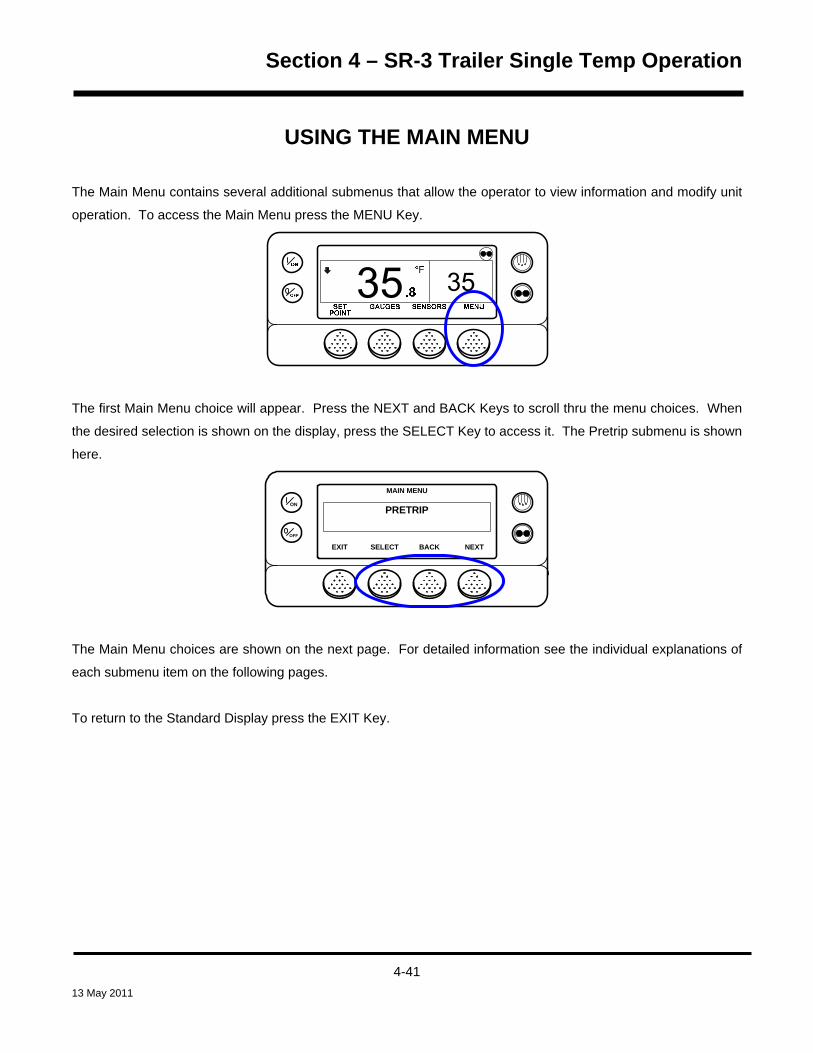
Section 4 – SR-3 Trailer Single Temp Operation
USING THE MAIN MENU
The Main Menu contains several additional submenus that allow the operator to view information and modify unit
operation. To access the Main Menu press the MENU Key.
The first Main Menu choice will appear. Press the NEXT and BACK Keys to scroll thru the menu choices. When
the desired selection is shown on the display, press the SELECT Key to access it. The Pretrip submenu is shown
here.
OFF
ON
MAIN MENU
PRETRIP
NEXTEXIT BACKSELECT
The Main Menu choices are shown on the next page. For detailed information see the individual explanations of
each submenu item on the following pages.
To return to the Standard Display press the EXIT Key.
4-41 13 May 2011

Section 4 – SR-3 Trailer Single Temp Operation
MAIN MENU FEATURES
USB FLASH DRIVE – If a USB Flash Drive is inserted into the USB Port on the unit Control Panel, this will be the
first Main Menu item to appear. If a WinTrac configured USB Flash Drive is connected to the USB connector, this
feature allows the operator to select the desired Flash Drive function. If enabled when the Flash Drive was
configured, the following functions may be available:
DOWNLOAD
Download the ServiceWatch Data Logger
Download the CargoWatch Data Logger
FLASHLOAD
Flash load Base Controller Software
Flash load HMI Control Panel Software
OPTISET PLUS
SEND
Send OptiSet Plus files
RETRIEVE
Retrieve OptiSet Plus files
If a USB Flash Drive is not connected to the unit, this feature will not appear in the Main Menu.
LANGUAGE – If a USB Flash Drive is not connected to the USB port and more than one language is enabled,
this will be the first menu item to appear. If only one language is enabled, this menu will not appear. The
Language Menu allows the operator to select a language from a list of up to 11 languages at one time. All
subsequent displays are shown in the selected language. Four different language packages with a total of 24
languages are available. English is the default language and is provided in each of the packages. See the
Guarded Access Language Setup Menu in Section 3 of this manual for details.
If Languages are not enabled from the Guarded Access Menu, this feature will not appear in the Main Menu.
4-42 13 May 2011
Section 4 – SR-3 Trailer Single Temp Operation
ALARMS – Allows the operator to view any active alarms, and allows most alarms to be cleared. If only one
language is enabled this will be the first menu item to appear.
DATA LOGGER – Allows the operator to set a Start of Trip marker to the CargoWatch and ServiceWatch data
loggers and print the contents of the CargoWatch data logger.
HOURMETERS – Allows the operator to view the unit hourmeters that have the view feature enabled in the
Guarded Access menu. If the view feature for a particular hourmeter is not enabled then that hourmeter will
continue to accumulate time but cannot be viewed from the Main Menu. However, all hourmeters can be viewed
from the Maintenance Menu, even if they are not enabled.
Possible Hourmeters
• Total Hours
• Total Run Time Hours
• Engine Hours
• Electric Run Hours
• Total Run Time Reminder # 1 Hours
• Total Run Time Reminder # 2 Hours
• Controller Power On Hours
• Pretrip Reminder Hours
• Engine Run Time Reminder # 1 Hours
• Engine Run Time Reminder # 2 Hours
• Electric Run Time Reminder # 1 Hours
• Electric Run Time Reminder # 2 Hours
4-43 13 May 2011

Section 4 – SR-3 Trailer Single Temp Operation
MODE – Allows the operator to change the unit operating modes if allowed. Not all modes may appear
depending on the settings selected from the Guarded Access menu and the HMI Control Panel software version.
• Turns Off Cycle Sentry Mode/Turns On Cycle Sentry Mode (If Cycle Sentry is Off unit
runs in Continuous). Note that selecting Cycle Sentry Mode or Continuous Mode can
also be accomplished using the Cycle Sentry Key to the right of the display.
• Allows temperature to be displayed in either Fahrenheit or Celsius degrees (if enabled
from the Guarded Access > Main Menu Configuration Menu).
• Allows the optional Fresh Air Exchange door to be opened or closed.
• Allows Keypad Lockout to be selected (if enabled from the Guarded Access > Main Menu
Configuration Menu).
• Start Sleep Mode (if enabled from the Guarded Access > Main Menu Configuration
Menu).
PRETRIP – Allows the operator to start a Pretrip Test. If an alarm is active, the Pretrip Test is not allowed and
the operator is prompted to clear the alarm(s).
ELECTRIC STANDBY – If the Electric Standby option is present and the Diesel to Electric Auto-switch feature is
set NO, this feature allows the operator to manually select electric mode operation. This feature does not appear
if the unit does not feature optional Electric Standby or if the Diesel to Electric Auto-switch feature is set YES.
4-44 13 May 2011

Section 4 – SR-3 Trailer Single Temp Operation
DIESEL MODE – If a unit equipped with electric standby is running in electric mode and the Electric to Diesel
Auto-switch feature is set NO, this feature allows the operator to manually select diesel mode operation. This
feature does not appear if the unit does not feature optional Electric Standby or if the Electric to Diesel Auto-
switch feature is set YES.
ADJUST BRIGHTNESS – Allows the operator to adjust the HMI Control Panel display backlight intensity as
required by local conditions.
TIME – Allows the operator to view the unit time and date. The time and date cannot be changed from this menu.
4-45 13 May 2011

Section 4 – SR-3 Trailer Single Temp Operation
USB Flash Drive When a properly configured USB flash drive is connected to the SR-3 front panel USB connector, the flash drive
user interface is shown on the HMI Control Panel. The USB flash drive provides SR-3 CargoWatch and
ServiceWatch Data Logger downloads, flash loading SR-3 HMI Control Panel and Base Controller software as
well as sending and retrieving OptiSet Plus files. A USB flash drive must be configured using WinTrac 5.1 or later
before the flash drive can be used with SR-3 trailer units equipped with a USB Communications Port.
Using a properly configured and enabled flash drive, the following functions may be available:
Download the ServiceWatch Data Logger
Download the CargoWatch Data Logger
Flash load Base Controller Software
Flash load HMI Control Panel Software
Send OptiSet Plus Files
Retrieve OptiSet Plus Files
Configuring a USB Flash Drive using WinTrac 5.1 or later A USB flash drive must be configured using WinTrac 5.1 or later before the flash drive can be used with SR-3
trailer units equipped with a USB Communications Port. When the USB Flash Drive is configured, only empty file
folders are created on the flash drive. The files required for flash loads and/or OptiSet Plus must then be placed
in the appropriate flash drive folders.
Insert the USB Flash Drive into a USB Port on the computer. If a USB Flash Drive is not connected to the
computer, the Configure and Manage USB Flash Drive selection in the WinTrac Tools Menu will not be available.
IMPORTANT: Only one USB memory device can be connected to the computer. If more than one device is
connected an error message will result.
4-46 13 May 2011

Section 4 – SR-3 Trailer Single Temp Operation
Open WinTrac 5.1 and enable the Tools Menu by simultaneously pressing CTRL-SHIFT-T. From the Tools Menu
select Configure and Manage USB Flash Drive / Configure USB Flash Drive as shown below.
A confirmation screen will appear. Choose Yes to proceed.
4-47 13 May 2011

Section 4 – SR-3 Trailer Single Temp Operation
Complete the Customer Information as shown below. The field for Company name and Author Name can each
be a maximum of 120 characters. Choose OK to continue.
Next, select the desired functions to be enabled on the flash drive. In the example shown below, downloading the
ServiceWatch and CargoWatch Data Loggers, flash loading the SR-3 Single Temperature Base Controller and
SR-3 HMI Control Panel and sending and retrieving OptiSet Plus files have all been selected. Choose OK to
continue.
IMPORTANT: If a feature is not enabled when the flash drive is configured, then that feature will not be available
when the flash drive is connected to the SR-3 unit using the USB Connector.
4-48 13 May 2011
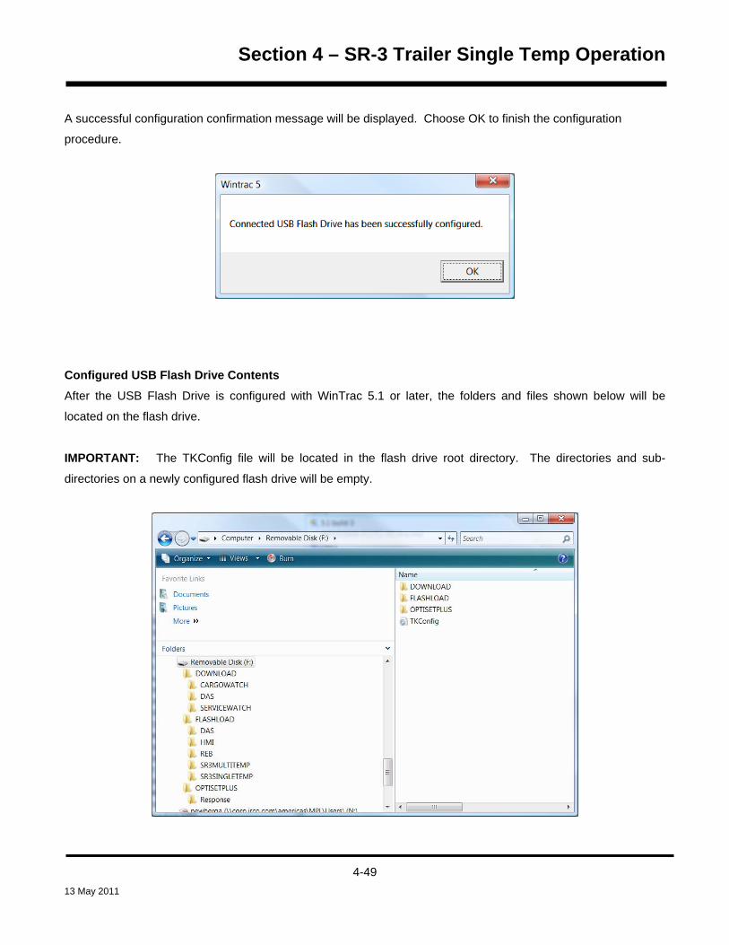
Section 4 – SR-3 Trailer Single Temp Operation
A successful configuration confirmation message will be displayed. Choose OK to finish the configuration
procedure.
Configured USB Flash Drive Contents After the USB Flash Drive is configured with WinTrac 5.1 or later, the folders and files shown below will be
located on the flash drive.
IMPORTANT: The TKConfig file will be located in the flash drive root directory. The directories and sub-
directories on a newly configured flash drive will be empty.
4-49 13 May 2011

Section 4 – SR-3 Trailer Single Temp Operation
DOWNLOAD Folder The DOWNLOAD Folder on the Flash Drive contains folders to hold the
downloaded CargoWatch and ServiceWatch data files. The DAS Folder is not currently used.
FLASHLOAD Folder The FLASHLOAD Folder on the Flash Drive contains folders to hold the software
upload files for the HMI Control Panel and SR-3 Single Temp Base Controller. The other folders are not
currently used.
OPTISETPLUS Folder The OPTISET PLUS FOLDER on the Flash Drive holds OptiSet Plus
configuration files to be sent to the Base Controller and OptiSet Plus configuration files that have been
retrieved from the Base Controller.
TKConfig FILE This configuration file is necessary to allow the USB Flash Drive to work with the SR-3
Control System.
Considerations when using a WinTrac Configured USB Flash Drive
ServiceWatch and CargoWatch Files If the ServiceWatch and/or CargoWatch Data Loggers are downloaded
using the USB Flash Drive, the downloaded files will be placed in the appropriate Download Sub-directory on the
Wintrac configured USB Flash Drive.
These files can be moved from the USB Flash Drive sub-directories to the desired location on the PC computer
using either Wintrac or Windows Explorer.
Flash Load Files Flash Load files for use with the USB Flash Drive must be *.FLA files. When SR-3 Base
Controller and HMI Control Panel flash load files are retrieved from the Thermo King iService web site, the flash
load files are downloaded as a *.ZIP file. When flash load files for SR-3 applications are unzipped, there will now
be three flash load files instead of the usual two. The traditional *.mXX and *.cXX files will be present as well as
the *.FLA file.
These files can be moved from the USB Flash Drive sub-directories to the desired location on the PC computer
using either Wintrac or Windows Explorer.
4-50 13 May 2011

Section 4 – SR-3 Trailer Single Temp Operation
OptiSet Plus Files If OptiSet Plus is being used with a USB Flash Drive, the file formats of the OptiSet Plus
data files must be considered.
IMPORTANT: The WinTrac 5.1 Upload > Manage OptiSet Plus Files feature must be used to move OptiSet Plus
files to or from the flash drive or the file conversion process will not take place. Do not move OptiSet Plus files to
or from the flash drive using Windows Explorer. Only ServiceWatch and CargoWatch Data Logger data files and
flash load *.FLA files can be moved using Windows Explorer.
OptiSet Plus only uses data files that are in the *.XML format.
When sending and retrieving OptiSet Plus data using the USB Flash Drive, the data is transferred between the flash drive and the SR-3 unit using *.OSP files. OptiSet Plus is unable to directly use these *.OSP files. These *.OSP files must be converted to *.XML files before they can be used by OptiSet Plus.
This file conversion is done automatically when the files are moved to or from the flash drive using the WinTrac 5.1 Upload > Manage OptiSet Plus Files feature as shown below.
4-51 13 May 2011

Section 4 – SR-3 Trailer Single Temp Operation
Inserting a USB Flash Drive in the USB Port on the Unit Control Panel If a properly configured USB Flash Drive is inserted into the USB Port on the unit Control Panel, the Flash Drive
Menu will automatically be shown on the HMI Control Panel. The HMI Control Panel will briefly show FLASH
DRIVE and FLASH DRIVE DETECTED. Then the Flash Drive Menu will appear as shown below.
The Flash Drive Menu will time out after about 20 seconds. When the Flash Drive Menu times out, the Standard
Display will re-appear. To go to the Standard Display immediately press the EXIT Key.
If the Flash Drive has not been properly configured it will not work when connected to the USB Port on the unit
Control Panel and an error message will appear on the unit HMI Control Panel as shown below.
NOTE: On occasion some Flash Drives that have been configured using WinTrac may still show this message.
If so, a different Flash Drive should be used.
4-52 13 May 2011

Section 4 – SR-3 Trailer Single Temp Operation
Accessing the Flash Drive Menu from the SR-3 Main Menu If the USB Icon is present in the upper left corner of the display a USB flash Drive is connected to the unit USB
Port on the Control Panel. To access the Flash Drive Menu when a USB Flash Drive is connected to the USB
Port, press the MENU Key. NOTE: If a USB Flash Drive is not connected to the unit, the Flash Drive Menu
feature will not appear in the Main Menu.
NOTE: The USB Icon will appear in the display when a USB Flash Drive is connected; even if the USB Flash
Drive has not been configured using WinTrac.
4-53 13 May 2011

Section 4 – SR-3 Trailer Single Temp Operation
The Main Menu Flash Drive selection will appear. Press the SELECT Key to choose the Flash Drive feature.
The Flash Drive Menu will appear.
To down load the ServiceWatch or CargoWatch Data Loggers, press the DOWN LOAD Key.
To flash load software to the Base Controller or HMI Control Panel, press the FLASH LOAD Key.
To send or retrieve OptiSet Plus files, press the OPTISET PLUS Key.
IMPORTANT: If a feature was not enabled when the Flash Drive was configured, the soft key for that feature will
not be present.
To exit to the Main Menu press the EXIT Key.
4-54 13 May 2011

Section 4 – SR-3 Trailer Single Temp Operation
Downloading the ServiceWatch or CargoWatch Data Loggers To download the ServiceWatch or CargoWatch Data Loggers press the DOWNLOAD Key from the Flash Drive
Menu as shown below.
The Down Load Menu will appear as shown below. To start the ServiceWatch Data Logger download, press the
SELECT Key.
To choose the CargoWatch Data Logger for download, press the NEXT Key to display CARGOWATCH, and then
press the SELECT Key to start the CargoWatch download.
4-55 13 May 2011

Section 4 – SR-3 Trailer Single Temp Operation
The download screen will appear. A progress bar indicates the download progress. The CargoWatch download
screen is shown here.
When the download is complete, the results are reported and the downloaded file is saved to the
DOWNLOAD/CARGOWATCH folder on the USB Flash Drive. To return to the Down Load Menu press the EXIT
Key.
OFF
ON CARGO WATCH DOWNLOADING
EXIT
SUCCESSFUL
If the download fails, the screen shown below will appear.
NOTE: The unit being downloaded must have a Trailer ID set by Wintrac. If a Trailer ID has not been assigned
to the unit this error will occur.
4-56 13 May 2011

Section 4 – SR-3 Trailer Single Temp Operation
Managing ServiceWatch and CargoWatch Files using a USB Flash Drive and WinTrac Open WinTrac 5.1 or later and activate the Tools Menu by simultaneously pressing the Ctrl – Shift – T keys.
From the WinTrac Tools Menu, select Configure and Manage USB Flash Drive > Upload / Manage Downloaded
Files. The screen below will appear.
Click Open and choose the desired file to be retrieved from the USB Flash drive as shown below.
4-57 13 May 2011

Section 4 – SR-3 Trailer Single Temp Operation
Double click the desired file to open it. The file selection screen shown below will reappear.
Click Browse and browse to the location where you wish to save the downloaded file. Left click OK to continue.
The screen shown below will appear. Confirm that the file name and location are correct and press OK to
continue.
4-58 13 May 2011

Section 4 – SR-3 Trailer Single Temp Operation
The selected file will be retrieved from the flash drive and placed in the specified location. A confirmation
message will appear as shown below. If you wish to delete the file from the USB Flash Drive left click Yes, if not,
left click No.
A final confirmation will appear. Left click OK to finish.
The selected file has been placed in the selected location as shown on the next page.
4-59 13 May 2011

Section 4 – SR-3 Trailer Single Temp Operation
NOTE: The downloaded files can also be moved to the PC Computer using Windows Explorer.
4-60 13 May 2011

Section 4 – SR-3 Trailer Single Temp Operation
Flash Load Files If flash loads are to be performed using the USB Flash Drive, the required software flash load files must be copied
to the appropriate Flashload directories located on the flash drive.
Flash load files for SR-3 applications will be supplied in two versions.
1. Flashload files will be supplied with the traditional filename extensions .mXX and .cXX in the same manner as in the past. These files are for use when flash loading a unit in the traditional manner using WinTrac on a PC computer connected to the unit with a data cable.
2. Flashload files will also be supplied with the filename extension .FLA. This file is for use when flash loading a unit using a WinTrac 5.1 configured USB Flash Drive.
The Flashload Directory on the configured USB Flash Drive contains sub-directories for HMI and SR3SINGLE
TEMP flash load *.FLA files. The *.FLA file must be placed in the correct directory on the flash drive using either
the WinTrac 5.1 Upload > Manage Flashload Files feature or Windows Explorer.
Flashload Files on the Internet When SR-3 Base Controller and HMI Control Panel flash load files are retrieved from the Thermo King iService
web site, the flash load files are downloaded as a *.ZIP file. When flash load files for SR-3 applications are
unzipped, there will now be three flash load files instead of the usual two.
The traditional *.mXX and *.cXX files will be unzipped. These two files are for use when flash loading an SR-3 unit in the traditional manner using a Data Cable to connected the PC Computer with WinTrac to the SR-3 Unit.
NOTE: Both the *.mXX and *.cXX files must be present in order to perform a flash load using a Data
Cable, even though only one of them is shown by WinTrac.
A *.FLA file will also be unzipped. This file is for use when flash loading a unit using a WinTrac 5.1 configured USB Flash Drive.
4-61 13 May 2011

Section 4 – SR-3 Trailer Single Temp Operation
Managing Flash Load Files using a USB Flash Drive and WinTrac To prepare a *.FLA for flash loading, place the flash load *.FLA file for the desired device (HMI Control Panel or
Single Temperature Base Controller) on the PC computer hard drive. Open WinTrac 5.1 or later and activate the
Tools Menu by simultaneously pressing the Ctrl – Shift _T keys. From the WinTrac Tools Menu, select Configure
and Manage USB Flash Drive > Upload / Manage Flashload Files. The screen below will appear.
Select the appropriate device using the drop-down menu and left click OK. Browse to the location and select the
desired *.FLA file as shown below. Left click Open to continue.
4-62 13 May 2011
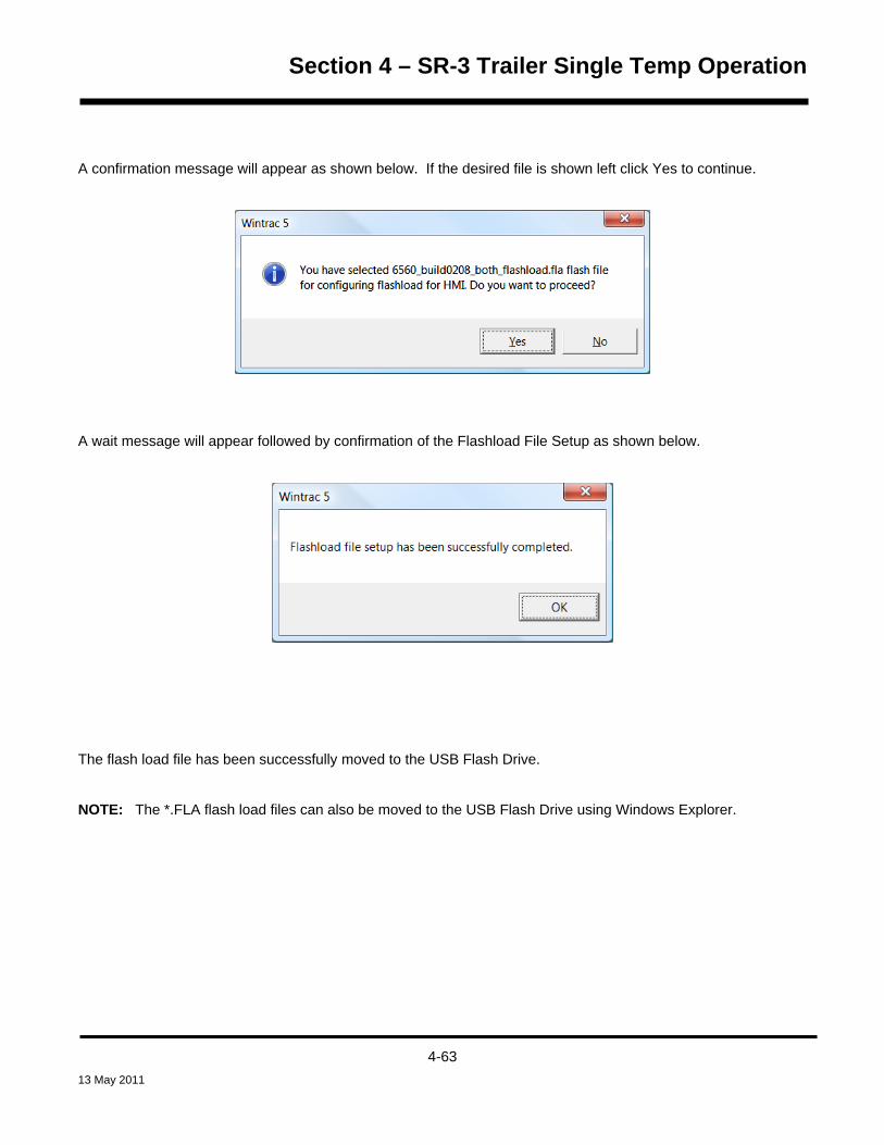
Section 4 – SR-3 Trailer Single Temp Operation
A confirmation message will appear as shown below. If the desired file is shown left click Yes to continue.
A wait message will appear followed by confirmation of the Flashload File Setup as shown below.
The flash load file has been successfully moved to the USB Flash Drive.
NOTE: The *.FLA flash load files can also be moved to the USB Flash Drive using Windows Explorer.
4-63 13 May 2011
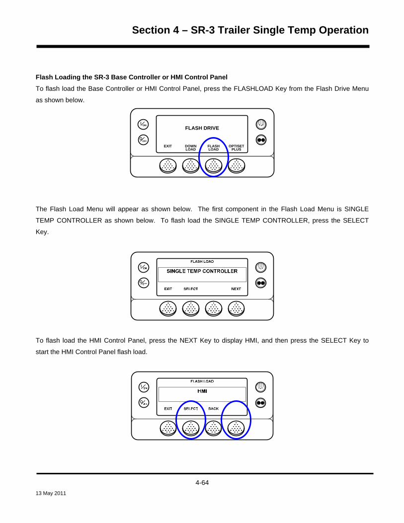
Section 4 – SR-3 Trailer Single Temp Operation
Flash Loading the SR-3 Base Controller or HMI Control Panel To flash load the Base Controller or HMI Control Panel, press the FLASHLOAD Key from the Flash Drive Menu
as shown below.
OFF
ONFLASH DRIVE
LOAD LOAD PLUSEXIT DOWN FLASH OPTISET
The Flash Load Menu will appear as shown below. The first component in the Flash Load Menu is SINGLE
TEMP CONTROLLER as shown below. To flash load the SINGLE TEMP CONTROLLER, press the SELECT
Key.
To flash load the HMI Control Panel, press the NEXT Key to display HMI, and then press the SELECT Key to
start the HMI Control Panel flash load.
4-64 13 May 2011

Section 4 – SR-3 Trailer Single Temp Operation
The HMI Flash Load Menu will appear. If there is more than one HMI flash load file on the Flash Drive, the NEXT
Key will be present as shown below. If only one HMI flash load file is present on the Flash Drive, the NEXT Key
will not appear. Pressing the NEXT Key will display the next flash load file.
Pressing the NEXT Key will display the next flash load file. Pressing the SELECT Key will flash load the file
shown on the display to the HMI Control Panel.
A confirmation screen will appear. If the update shown is correct, press the YES Key.
4-65 13 May 2011

Section 4 – SR-3 Trailer Single Temp Operation
FLASHLOADING IN PROGRESS will be shown on the display while the flash load process initializes. This may
take several minutes.
Then the Flash Load Display will appear. Progress is indicated by means of the black boxes in the bottom two
rows of the display.
When the flash load is complete the TK Logo will appear briefly in the display. Then the CONFIGURING
SYSTEM PLEASE WAIT message is shown as the system restarts. When the unit is ready to run, the Flash
Drive Menu appears on the display.
4-66 13 May 2011

Section 4 – SR-3 Trailer Single Temp Operation
OptiSet Plus Data File Formats when using a USB Flash Drive If OptiSet Plus is being used with a USB Flash Drive, the file formats of the OptiSet Plus data files must be
considered.
IMPORTANT: The WinTrac 5.1 Upload > Manage OptiSet Plus Files feature must be used to move OptiSet Plus
files to or from the flash drive or the file conversion process will not take place. Do not move OptiSet Plus files to
or from the flash drive using Windows Explorer. Only ServiceWatch and CargoWatch Data Logger data files and
flash load *.FLA files can be moved using Windows Explorer.
OptiSet Plus only uses data files that are in the *.XML format.
When sending and retrieving OptiSet Plus data using the USB Flash Drive, the data is transferred between the flash drive and the SR-3 unit using *.OSP files. OptiSet Plus is unable to directly use these *.OSP files. These *.OSP files must be converted to *.XML files before they can be used by OptiSet Plus.
This file conversion is done automatically when the files are moved to or from the flash drive using the WinTrac 5.1 Upload > Manage OptiSet Plus Files feature as shown below.
4-67 13 May 2011

Section 4 – SR-3 Trailer Single Temp Operation
Managing OptiSet Plus Files to be sent to the SR-3 Unit using a USB Flash Drive and WinTrac
PC ComputerEquipped With WinTrac 5.1 or
Later
WinTrac 5.1 automatically converts the OptiSet Plus file
USB Flash Drive
Configured by WinTrac
SR-3Unitfrom a *.XML file to a
*.OSP file when moving the file to the USB Flash
Drive
The OptiSet Plus *.OSP file is moved
from the USB Flash Drive to the SR-3 Unit
To Convert an OptiSet Plus *.XML File to a *.OSP File and Send it to the USB Flash Drive, open WinTrac 5.1 or
later and activate the Tools Menu by simultaneously pressing the Ctrl – Shift _T keys. From the WinTrac Tools
Menu select Configure and Manage USB Flash Drive > Upload / Manage OptiSet Plus Files > OptiSet Plus Send.
The file selection screen shown below will appear. When the desired file is selected, click Open to continue.
4-68 13 May 2011
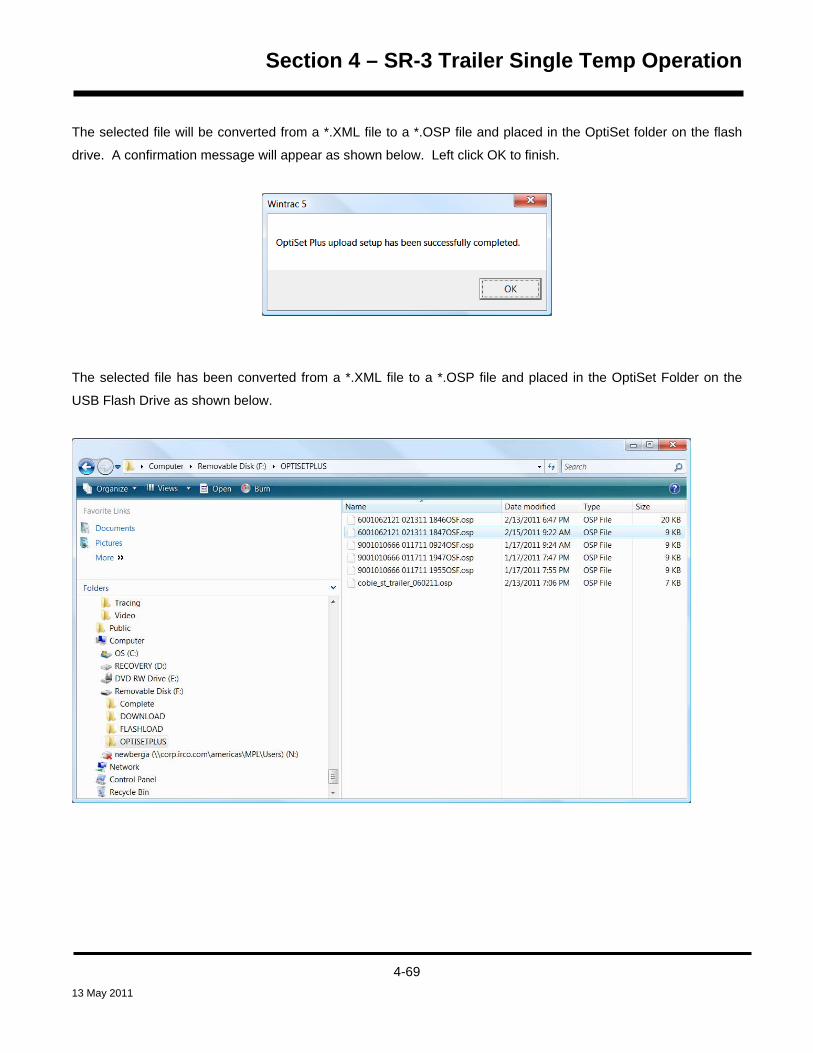
Section 4 – SR-3 Trailer Single Temp Operation
The selected file will be converted from a *.XML file to a *.OSP file and placed in the OptiSet folder on the flash
drive. A confirmation message will appear as shown below. Left click OK to finish.
The selected file has been converted from a *.XML file to a *.OSP file and placed in the OptiSet Folder on the
USB Flash Drive as shown below.
4-69 13 May 2011

Section 4 – SR-3 Trailer Single Temp Operation
Sending OptiSet Plus Files to the SR-3 Unit using a USB Flash Drive and WinTrac The Flash Drive allows OptiSet Plus configurations to be sent to the Base Controller. It also allows OptiSet Plus
information to be retrieved as needed. To Send an OptiSet Plus Configuration File to the Base Controller, press
the OPTISET PLUS Key.
The SEND Menu is the first menu to appear as shown below. Press the SELECT Key to choose the SEND
option.
Press the SELECT Key to choose the SEND option. The files available for uploading are shown, one at a time. If
only one file is available, the NEXT Key and BACK Key will not be present. If more than one file is available, they
can be chosen using the NEXT Key and BACK Key. When the desired file is shown, press the SELECT Key to
choose it.
4-70 13 May 2011
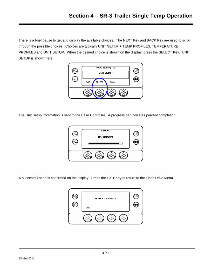
Section 4 – SR-3 Trailer Single Temp Operation
There is a brief pause to get and display the available choices. The NEXT Key and BACK Key are used to scroll
through the possible choices. Choices are typically UNIT SETUP + TEMP PROFILES, TEMPERATURE
PROFILES and UNIT SETUP. When the desired choice is shown on the display, press the SELECT Key. UNIT
SETUP is shown here.
The Unit Setup information is sent to the Base Controller. A progress bar indicates percent completion.
A successful send is confirmed on the display. Press the EXIT Key to return to the Flash Drive Menu.
4-71 13 May 2011

Section 4 – SR-3 Trailer Single Temp Operation
Managing OptiSet Plus Files retrieved from the SR-3 Unit using a USB Flash Drive and WinTrac
PC ComputerEquipped With WinTrac 5.1 or
Later
WinTrac 5.1 automatically converts the OptiSet Plus file
USB Flash Drive
Configured by WinTrac
SR-3Unit from a *.OSP file
to a *.XML file when moving the file to the PC
Computer
The OptiSet Plus *.OSP file is moved
from the SR-3 Unitto the USB Flash Drive
To Retrieve an OptiSet Plus *.OSP File from the USB Flash Drive and Convert to a *.XML File, open WinTrac 5.1
or later and activate the Tools Menu by simultaneously pressing the Ctrl – Shift _T keys. From the WinTrac Tools
Menu select Configure and Manage USB Flash Drive > Upload / Manage OptiSet Plus Files > OptiSet Plus
Retrieve. The file selection screen shown below will appear.
4-72 13 May 2011

Section 4 – SR-3 Trailer Single Temp Operation
Click Open and choose the desired file to be retrieved from the USB Flash drive as shown below.
Double click the desired file to open it. The file selection screen shown below will reappear.
4-73 13 May 2011
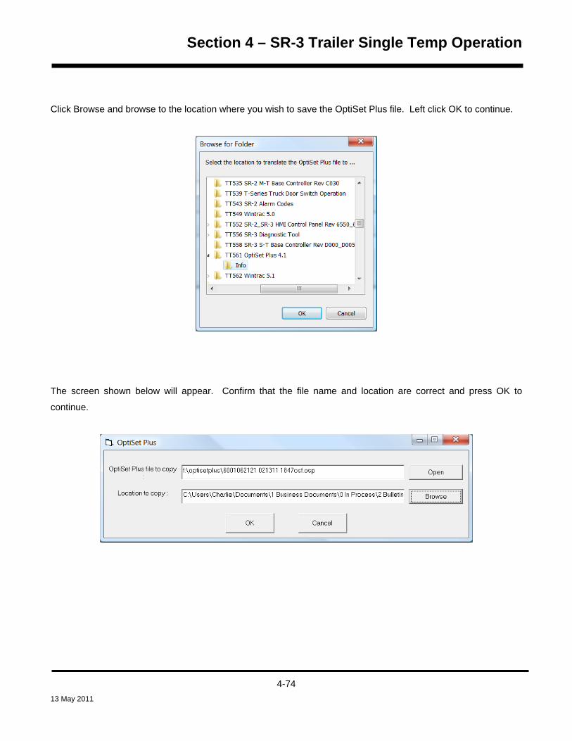
Section 4 – SR-3 Trailer Single Temp Operation
Click Browse and browse to the location where you wish to save the OptiSet Plus file. Left click OK to continue.
The screen shown below will appear. Confirm that the file name and location are correct and press OK to
continue.
4-74 13 May 2011

Section 4 – SR-3 Trailer Single Temp Operation
The selected file will be retrieved from the flash drive, converted to a *.XML file and placed in the specified
location. A confirmation message will appear as shown below. If you wish to delete the file from the USB Flash
Drive left click Yes, if not, left click No.
The selected file has been converted from a *.OSP file to a *.XML file and placed in the selected location as
shown below.
4-75 13 May 2011

Section 4 – SR-3 Trailer Single Temp Operation
Retrieving OptiSet Plus Files from the SR-3 Unit using a USB Flash Drive and WinTrac OptiSet Plus Configuration files can be retrieved for modification or for use with other units. To retrieve an
OptiSet Plus Configuration File from the Base Controller, press the OPTISET PLUS Key.
The SEND Menu is the first menu to appear as shown below. Press the NEXT Key to display RETRIEVE and
press the SELECT Key to choose the RETRIEVE option.
The files available for retrieval are shown, one at a time. The NEXT Key and BACK Key are used to select the
desired file. The first choice is ALL as shown below. NOTE: The BACK Key will appear after the NEXT Key is
pressed.
4-76 13 May 2011

Section 4 – SR-3 Trailer Single Temp Operation
The following choices are available:
ALL – Includes all of the files shown below.
CARGO SETUP + TEMP
UNIT SETUP + TEMP PROFILES
UNIT + CARGO WATCH SETUP
TEMPERATURE PROFILES
CARGO WATCH SETUP
UNIT SETUP
When the desired file is shown, press the SELECT Key to choose it.
The desired file is retrieved and saved to the flash Drive. A progress bar indicates percent completion.
4-77 13 May 2011
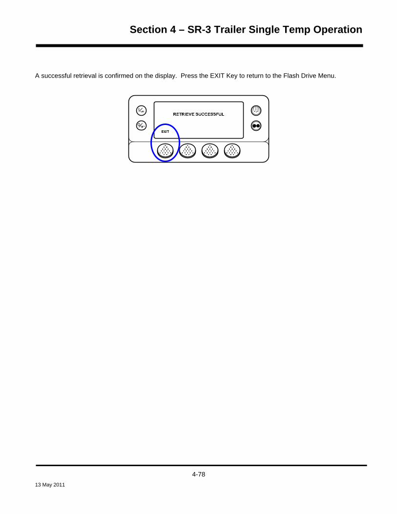
Section 4 – SR-3 Trailer Single Temp Operation
A successful retrieval is confirmed on the display. Press the EXIT Key to return to the Flash Drive Menu.
4-78 13 May 2011

Section 4 – SR-3 Trailer Single Temp Operation
Removing a USB Flash Drive from the Unit USB Port BE sure all USB Flash Drive operations have completed before removing the Flash Drive from the USB Port on
the unit. To remove the USB Flash Drive, simply unplug it from the USB Port. The display shown below will
appear briefly, followed by the Standard Display. The USB Icon will no longer be present.
IMPORTANT: Never remove the USB Flash Drive from the USB Port when it is actively doing a read or write
operation.
4-79 13 May 2011

Section 4 – SR-3 Trailer Single Temp Operation
WinTrac Error Messages when using a USB Flash Drive If either of the error messages shown below appears, the connected flash drive may not be able to be configured.
If the error message continues to appear, a different flash drive may need to be used.
NOTE: Some larger flash drives are formatted by the manufacturer as two separate drives. For example, when
the flash drive is connected to a PC computer it may appear as two drives – (F:) and (G:).
If the HMI Control Panel displays a message similar to the one shown below the WinTrac configuration has failed,
even if the configuration process using WinTrac was reported to be successful. If the error message continues to
appear, a different flash drive may need to be used.
4-80 13 May 2011

Section 4 – SR-3 Trailer Single Temp Operation
Languages If the Language Feature has been enabled from the Guarded Access Language Menu, an alternate language or
languages can be selected from the Language Menu. After a new language is chosen all displays will appear in
that language. If the Language Feature has not been enabled this menu does not appear. The default language
is English. Only languages specifically enabled from the Guarded Access Language Menu are available.
IMPORTANT: Exercise care when changing languages, as once changed all HMI Control Panel displays will be
in the new language. If the user is not familiar with the new language, problems may be experienced returning to
the default language.
The languages available are dependent on the HMI Control Panel software revision.
• Software Revision 65xx supports English, Spanish, French, German, Italian, Dutch, Portuguese, Greek,
Turkish, Hebrew and Arabic.
• Software Revision 66xx supports English, Danish, Russian, Norwegian, Swedish, Finnish, Polish,
Hungarian, Romanian, Bulgarian and Czech.
• Software Revision 67xx supports English, Japanese and Chinese.
• Software Revision 68xx supports English, English and Spanish or allows any 5 languages from Software
Revision 65xx and Software Revision 66xx to be selected. Note that Japanese and Chinese are not
available for use with this feature.
Other than the languages supported, software revisions 65xx, 66xx, 67xx and 68xx are identical.
To select an alternate language, press the MENU Key.
4-81 13 May 2011

Section 4 – SR-3 Trailer Single Temp Operation
If more than one language is enabled, the Language Menu is the first Main Menu item to appear as shown below.
Press the SELECT Key to choose the Language menu.
MAIN MENU
LANGUAGE
NEXTEXIT SELECT
OFF
ON
The Language menu will appear as shown below. Press the + or – Keys to select the desired language. Only
languages enabled from the Guarded Access Menu are available. When the desired language is shown press
the YES Key to confirm the choice.
OFF
ONNEW LANGUAGE WILL BE
DEUTSCH
- YES NO+USE +/- TO CHANGE OK?
The display will briefly show PROGRAMMING LANGUAGE – PLEASE WAIT in the new language. The display
will then return to the Language Menu, but will show the new language. German is shown below.
OFF
ONHAUPTMENU
SPRACHE
BEENDEN WEITERAUSWHAL
Repeat the process to select a different language. To select a different Main Menu item press the NEXT Key. To
return to the Standard Display press the EXIT Key.
4-82 13 May 2011

Section 4 – SR-3 Trailer Single Temp Operation
IMPORTANT: If necessary, English and all other languages in the software version may be accessed
from the Standard Display.
Should it be necessary at any time to change to English or any other language in the installed software, return to
the Standard Display and then press and hold the first and last soft keys for 5 seconds as shown below. The
Standard Display here is shown in Deutsch (German).
After 5 seconds the Language Menu will appear in the current language as shown below. Press the + or – Keys
to select the desired language. When the desired language is shown press the YES Key to confirm the choice.
Note that all languages in the installed software can be selected using this method.
4-83 13 May 2011

Section 4 – SR-3 Trailer Single Temp Operation
Alarms If an alarm condition occurs the alarm icon will appear as shown below.
OFF
ON
MENUSET SENSORSGAUGESPOINT
If a Shutdown Alarm occurs it will be indicated by all of the following:
• The Alarm Icon will appear.
• The display and backlight will flash on and off.
• The display will switch from normal video to reverse video and back to normal video. (Light areas
become dark and dark areas become light.)
Pretrip Alarm Codes If an alarm occurs during a Pretrip Test the alarm code will be displayed as Pretrip Alarm XX, where XX is the
alarm code.
4-84 13 May 2011

Section 4 – SR-3 Trailer Single Temp Operation
Alarm Codes When Switching Between Diesel and Electric If a shutdown alarm occurs that affects only diesel mode operation and the unit is switched to electric, the diesel
mode shutdown alarm becomes an electric mode log alarm. This allows the unit to run in electric mode without
clearing the shutdown alarm that is preventing diesel mode operation. If the unit is switched back to diesel mode,
the alarm again become a diesel mode shutdown alarm and prevents unit operation.
In the same manner, if a shutdown alarm occurs that affects only electric mode operation and the unit is switched
to diesel, the electric mode shutdown alarm becomes a diesel mode log alarm to allow diesel mode operation. If
the unit is switched back to electric mode, the alarm reverts to an electric mode shutdown alarm and prevents unit
operation. If the unit is configured for electric to diesel autoswitch, it automatically starts and runs in diesel mode
if an electric shutdown occurs.
Clearing Alarm Codes Most alarm codes can be cleared conventionally from the Alarm Menu using the CLEAR Key.
The following control and display sensor alarm codes can only be cleared from the Maintenance Menu or
Guarded Access Menu:
• Alarm Code 03 Check Control Return Air Sensor
• Alarm Code 04 Check Control Discharge Air Sensor
• Alarm Code 203 Check Display Return Air Sensor
• Alarm Code 204 Check Display Discharge Air Sensor
The following alarm codes clear automatically:
• Alarm Code 64 Pretrip Reminder – Clears when a Pretrip Test is performed.
• Alarm Code 84 Restart Null – Clears when the unit is no longer in a restart null due to a Prevent Alarm.
• Alarm Code 85 Forced Unit Operation – Clears when the unit is no longer running in a forced mode due
to a Prevent Alarm.
• Alarm Code 91 Check Electric Ready Input – Clears automatically when the unit starts running.
• Alarm Code 92 Sensor Grades Not Set – Clears when the sensor grade is changed from 5H.
4-85 13 May 2011

Section 4 – SR-3 Trailer Single Temp Operation
If the Limited Alarm Restarts feature is enabled the following additional alarm codes may only be cleared from the
Guarded Access Menu. If this is the case, the CLEAR soft key will not appear if the alarms are displayed from
the Main Menu or the Maintenance Menu. See the Limited Alarm Restarts feature in Section 3 for details.
• Alarm Code 10 High Discharge Pressure
• Alarm Code 23 Cooling Cycle Fault
• Alarm Code 24 Heating Cycle Fault
• Alarm Code 32 Refrigeration Capacity Low
4-86 13 May 2011

Section 4 – SR-3 Trailer Single Temp Operation
SR-3 Alarm Codes NOTE: Not all alarm codes are used with all applications
Code Description Operator Help
00 No Alarms Exist
02 Check Evaporator Coil Sensor Manually monitor load temperature. Report alarm at end of the
day.
03 Check (Control) Return Air Sensor Manually monitor load temperature. Report alarm at end of the
day.
04 Check (Control) Discharge Air
Sensor
Manually monitor load temperature. Report alarm at end of the
day.
05 Check Ambient Air Sensor Report alarm at end of the day.
06 Check Coolant Temp Sensor Report alarm at end of the day.
07 Check Engine RPM Sensor Report alarm at end of the day.
09 High Evaporator Temperature Manually monitor load temperature. Report alarm at end of the
day.
10 High Discharge Pressure If unit is shut down repair immediately. Otherwise, report alarm
at end of the day.
11 Unit Controlling on Alternate Sensor Manually monitor load temperature. Report alarm at end of the
day.
12 Sensor or Digital Input Shutdown The indicated zone is not longer able to operate and has been
shut down. Repair immediately.
13 Sensor Check Manually monitor load temperature. Report alarm at end of the
day.
15 Check Glow Plugs or Intake Air
Heater
If unit is shut down repair immediately. Otherwise, report alarm
at end of the day.
17 Engine Failed to Crank If unit is shut down repair immediately. Otherwise, report alarm
at end of the day.
4-87 13 May 2011
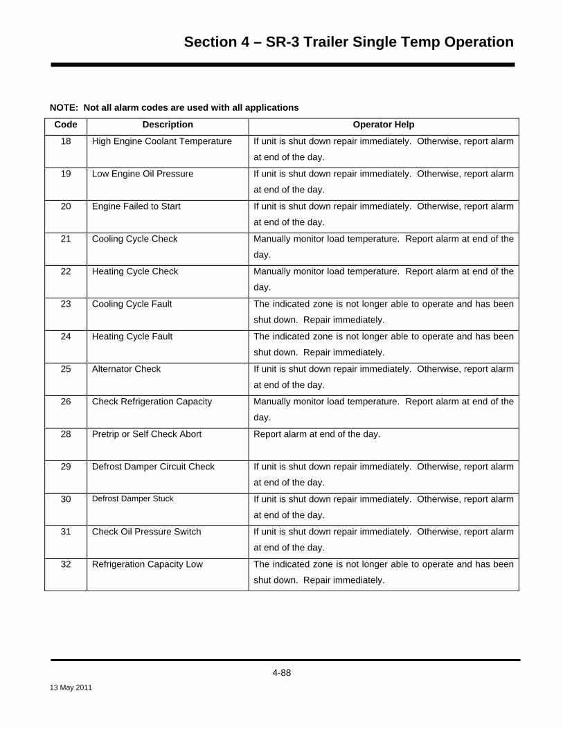
Section 4 – SR-3 Trailer Single Temp Operation
NOTE: Not all alarm codes are used with all applications
Code Description Operator Help
18 High Engine Coolant Temperature If unit is shut down repair immediately. Otherwise, report alarm
at end of the day.
19 Low Engine Oil Pressure If unit is shut down repair immediately. Otherwise, report alarm
at end of the day.
20 Engine Failed to Start If unit is shut down repair immediately. Otherwise, report alarm
at end of the day.
21 Cooling Cycle Check Manually monitor load temperature. Report alarm at end of the
day.
22 Heating Cycle Check Manually monitor load temperature. Report alarm at end of the
day.
23 Cooling Cycle Fault The indicated zone is not longer able to operate and has been
shut down. Repair immediately.
24 Heating Cycle Fault The indicated zone is not longer able to operate and has been
shut down. Repair immediately.
25 Alternator Check
If unit is shut down repair immediately. Otherwise, report alarm
at end of the day.
26 Check Refrigeration Capacity Manually monitor load temperature. Report alarm at end of the
day.
28 Pretrip or Self Check Abort Report alarm at end of the day.
29 Defrost Damper Circuit Check
If unit is shut down repair immediately. Otherwise, report alarm
at end of the day.
30
Defrost Damper Stuck If unit is shut down repair immediately. Otherwise, report alarm
at end of the day.
31 Check Oil Pressure Switch If unit is shut down repair immediately. Otherwise, report alarm
at end of the day.
32 Refrigeration Capacity Low The indicated zone is not longer able to operate and has been
shut down. Repair immediately.
4-88 13 May 2011

Section 4 – SR-3 Trailer Single Temp Operation
NOTE: Not all alarm codes are used with all applications
Code Description Operator Help
33 Check Engine RPM Report alarm at end of the day.
35 Check Run Relay Circuit If unit is shut down repair immediately. Otherwise, report alarm
at end of the day.
36 Electric Motor Failed to Run If unit is shut down repair immediately. Otherwise, report alarm
at end of the day.
37 Check Engine Coolant Level Report alarm at end of the day.
38 Electric Phase Reversed If unit is shut down repair immediately. Otherwise, report alarm
at end of the day.
40 Check High Speed Circuit If unit is shut down repair immediately. Otherwise, report alarm
at end of the day.
41 Check Engine Coolant Temperature If unit is shut down repair immediately. Otherwise, report alarm
at end of the day.
42 Unit Forced to Low Speed Report alarm at end of the day.
43 Unit Forced to Low Speed
Modulation
Report alarm at end of the day.
44 Check Fuel System
If unit is shut down repair immediately. Otherwise, report alarm
at end of the day.
45 Hot Gas or Hot Gas Bypass Circuit If unit is shut down repair immediately. Otherwise, report alarm
at end of the day.
46 Check Air Flow If unit is shut down repair immediately. Otherwise, report alarm
at end of the day.
48 Check Belts or Clutch If unit is shut down repair immediately. Otherwise, report alarm
at end of the day.
50 Reset Clock Report alarm at end of the day.
4-89 13 May 2011

Section 4 – SR-3 Trailer Single Temp Operation
NOTE: Not all alarm codes are used with all applications
Code Description Operator Help
52 Check Heat Circuit If unit is shut down repair immediately. Otherwise, report alarm
at end of the day.
54 Test Mode Timeout Service Test or Interface Board Test timed out after 15 minutes.
Report alarm at end of the day.
61 Low Battery Voltage If unit is shut down repair immediately. Otherwise, report alarm
at end of the day.
62 Ammeter Out of Calibration If unit is shut down repair immediately. Otherwise, report alarm
at end of the day.
63 Engine Stopped If unit is shut down repair immediately. Otherwise, report alarm
at end of the day.
64 Pretrip Reminder Report alarm at end of the day.
65 Abnormal Temperature Differential If unit is shut down repair immediately. Otherwise, report alarm
at end of the day.
66 Low Engine Oil Level Check engine oil level. If unit is shut down repair immediately.
Otherwise, report alarm at end of the day.
67 Check Liquid Line Solenoid Circuit If unit is shut down repair immediately. Otherwise, report alarm
at end of the day.
68 Internal Controller Fault Code Report alarm at end of the day.
70 Hourmeter Failure Report alarm at end of the day.
74 Controller Reset to Defaults Report alarm at end of the day.
77 Controller EPROM Checksum
Failure
If unit is shut down repair immediately. Otherwise, report alarm
at end of the day.
79 Internal Data Logger Overflow Report alarm at end of the day.
4-90 13 May 2011

Section 4 – SR-3 Trailer Single Temp Operation
NOTE: Not all alarm codes are used with all applications
Code Description Operator Help
80 Check Compressor Temp Sensor Report alarm at end of the day.
81 High Compressor Temp If unit is shut down repair immediately. Otherwise, report alarm
at end of the day.
82 High Compressor Temp Shutdown If unit is shut down repair immediately. Otherwise, report alarm
at end of the day.
83 Low Engine Coolant Temperature If unit is shut down repair immediately. Otherwise, report alarm
at end of the day.
84 Restart Null Report alarm at end of the day.
85 Forced Unit Operation Report alarm at end of the day.
86 Check Discharge Pressure Sensor Report alarm at end of the day.
87 Check Suction Pressure Sensor Report alarm at end of the day.
89 Check Electronic Throttling Valve
Circuit
If unit is shut down repair immediately. Otherwise, report alarm
at end of the day.
90 Electric Overload If unit is shut down repair immediately. Otherwise, report alarm
at end of the day.
91 Check Electric Ready Input If unit is shut down repair immediately. Otherwise, report alarm
at end of the day.
92 Sensor Grades Not Set Report alarm at end of the day.
93 Low Compressor Suction Pressure If unit is shut down repair immediately. Otherwise, report alarm
at end of the day.
94 Check Loader #1 Circuit
If unit is shut down repair immediately. Otherwise, report alarm
at end of the day.
4-91 13 May 2011

Section 4 – SR-3 Trailer Single Temp Operation
NOTE: Not all alarm codes are used with all applications
Code Description Operator Help
95 Check Loader #2 Circuit
If unit is shut down repair immediately. Otherwise, report alarm
at end of the day.
96 Low Fuel Level Check engine fuel level. If unit is shut down repair immediately.
Otherwise, report alarm at end of the day.
98 Check Fuel Level Sensor
Report alarm at end of the day.
99 High Compressor Pressure Ratio
If unit is shut down repair immediately. Otherwise, report alarm
at end of the day.
105 Check Receiver Tank Pressure
Solenoid Circuit
If unit is shut down repair immediately. Otherwise, report alarm
at end of the day.
106 Check Purge Valve Circuit If unit is shut down repair immediately. Otherwise, report alarm
at end of the day.
107 Check Condenser Inlet Solenoid
Circuit
If unit is shut down repair immediately. Otherwise, report alarm
at end of the day.
108 Door Open Timeout Close Doors. Report alarm at end of the day.
110 Check Suction Line Solenoid Circuit If unit is shut down repair immediately. Otherwise, report alarm
at end of the day.
111 Unit Not Configured Correctly Report alarm at end of the day.
112 Check Remote Fans If unit is shut down repair immediately. Otherwise, report alarm
at end of the day.
113 Check Electric Heat Circuit If unit is shut down repair immediately. Otherwise, report alarm
at end of the day.
114 Multiple Alarms – Can Not Run If unit is shut down repair immediately. Otherwise, report alarm
at end of the day.
115 Check High Pressure Cut Out Switch If unit is shut down repair immediately. Otherwise, report alarm
at end of the day.
4-92 13 May 2011

Section 4 – SR-3 Trailer Single Temp Operation
NOTE: Not all alarm codes are used with all applications
116 Check High Pressure Cut In Switch
Report alarm at end of the day.
117 Auto Switch from Diesel to Electric Report alarm at end of the day.
118 Auto Switch from Electric to Diesel Report alarm at end of the day.
120 Check Alternator Excite Circuit
If unit is shut down repair immediately. Otherwise, report alarm
at end of the day.
121 Check Liquid Injection Circuit If unit is shut down repair immediately. Otherwise, report alarm
at end of the day.
122 Check Diesel/Electric Circuit If unit is shut down repair immediately. Otherwise, report alarm
at end of the day.
127 Setpoint Not Entered Be sure the setpoint is set to the required temperature.
128 Engine Run Time Maintenance
Reminder #1
Report alarm at end of the day.
129 Engine Run Time Maintenance
Reminder #2
Report alarm at end of the day.
130 Electric Run Time Maintenance
Reminder #1
Report alarm at end of the day.
131 Electric Run Time Maintenance
Reminder #2
Report alarm at end of the day.
132 Total Unit Run Time Maintenance
Reminder #1
Report alarm at end of the day.
133 Total Unit Run Time Maintenance
Reminder #2
Report alarm at end of the day.
134 Controller Power On Hours Report alarm at end of the day.
4-93 13 May 2011
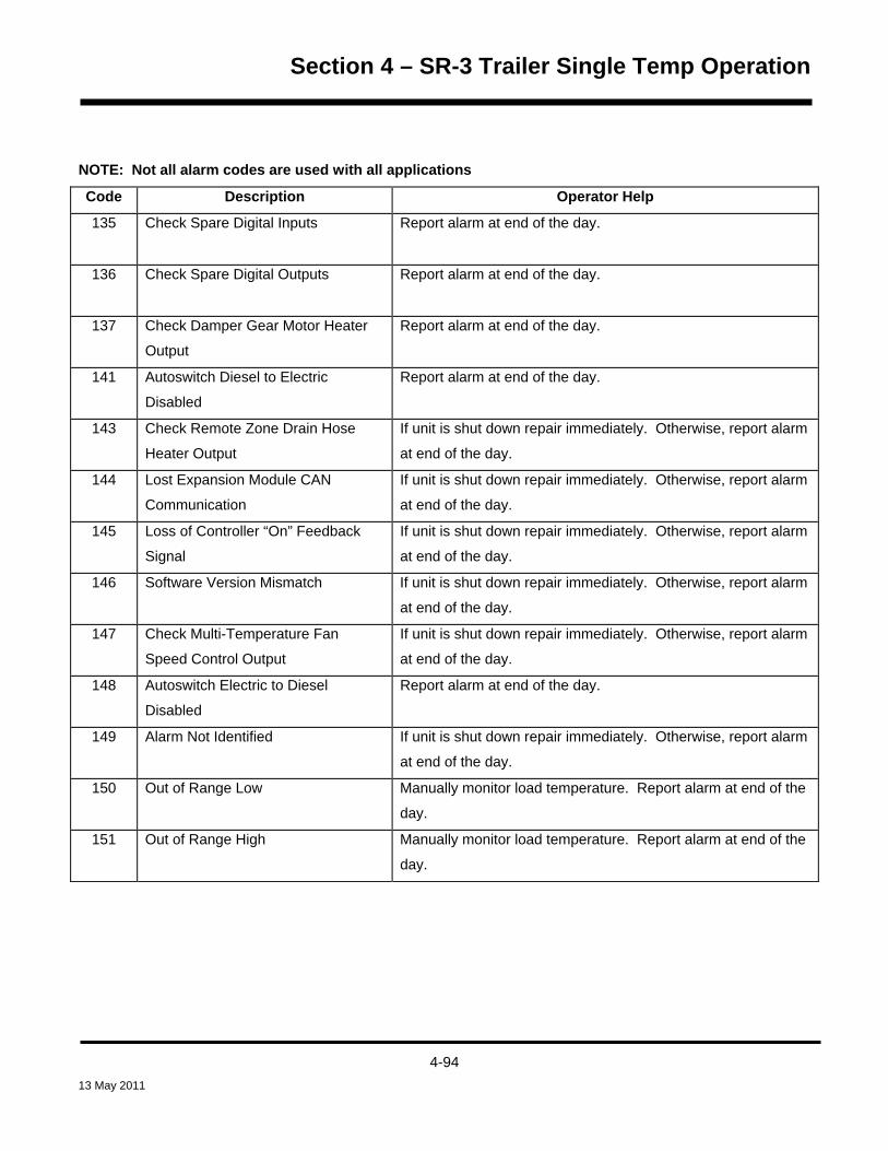
Section 4 – SR-3 Trailer Single Temp Operation
NOTE: Not all alarm codes are used with all applications
Code Description Operator Help
135
Check Spare Digital Inputs
Report alarm at end of the day.
136 Check Spare Digital Outputs
Report alarm at end of the day.
137 Check Damper Gear Motor Heater
Output
Report alarm at end of the day.
141 Autoswitch Diesel to Electric
Disabled
Report alarm at end of the day.
143 Check Remote Zone Drain Hose
Heater Output
If unit is shut down repair immediately. Otherwise, report alarm
at end of the day.
144 Lost Expansion Module CAN
Communication
If unit is shut down repair immediately. Otherwise, report alarm
at end of the day.
145 Loss of Controller “On” Feedback
Signal
If unit is shut down repair immediately. Otherwise, report alarm
at end of the day.
146 Software Version Mismatch If unit is shut down repair immediately. Otherwise, report alarm
at end of the day.
147 Check Multi-Temperature Fan
Speed Control Output
If unit is shut down repair immediately. Otherwise, report alarm
at end of the day.
148 Autoswitch Electric to Diesel
Disabled
Report alarm at end of the day.
149
Alarm Not Identified If unit is shut down repair immediately. Otherwise, report alarm
at end of the day.
150
Out of Range Low Manually monitor load temperature. Report alarm at end of the
day.
151
Out of Range High Manually monitor load temperature. Report alarm at end of the
day.
4-94 13 May 2011

Section 4 – SR-3 Trailer Single Temp Operation
NOTE: Not all alarm codes are used with all applications
Code Description Operator Help
153 Expansion Module Flash Load
Failure
If unit is shut down repair immediately. Otherwise, report alarm
at end of the day.
154 Low Suction Pressure Switch Failure If unit is shut down repair immediately. Otherwise, report alarm
at end of the day.
156 Check Suction/Liquid Heat
Exchanger Bypass Valve Circuit
If unit is shut down repair immediately. Otherwise, report alarm
at end of the day.
157 OptiSet File Mismatch Report alarm at end of the day.
158 Software Failed to Load Report alarm at end of the day.
203 Check Display Return Air Sensor Manually monitor load temperature. Report alarm at end of the
day.
204 Check Display Discharge Air Sensor Manually monitor load temperature. Report alarm at end of the
day.
252 Check Fresh Air Exchange Circuit Manually monitor load temperature. Report alarm at end of the
day.
4-95 13 May 2011

Section 4 – SR-3 Trailer Single Temp Operation
Displaying and Clearing Alarm Codes Alarms are displayed and cleared using the Alarm Menu. From the Standard Display, press the MENU Key.
The Language Menu or Alarm Menu will appear. If the Language Menu appears press the NEXT Key to show the
Alarm Menu. When the Alarm Menu is shown press the SELECT Key.
OFF
ON
MAIN MENU
ALARMS
NEXTEXIT SELECT
The Alarm Display will appear. If no alarms are present NO ALARMS will be shown.
4-96 13 May 2011

Section 4 – SR-3 Trailer Single Temp Operation
If alarms are present, the quantity of alarms (if more than one) and the most recent alarm code number will be
shown. In the example below, there are two alarms present. The most recent is Alarm Code 6. It indicates a
problem with the coolant temperature sensor.
OFF
ON
ALARM 6
2 OF 2 ALARMSCOOLANT TEMP SENSOR
NEXTEXIT HELPCLEAR
After the alarm situation is resolved press the CLEAR Key to clear the alarm. For additional information regarding
the alarm shown on the display, press the HELP Key. To display the next alarm, press the NEXT Key.
If a serious condition occurs, the unit will be shut down to prevent damage to the unit or the load. If this occurs,
the display will show that the unit is shut down and display the alarm code that caused the shutdown. In the
example below, the unit is shut down due to low oil level. For additional information regarding the alarm shown
on the display, press the HELP Key.
OFF
ON
ALARM 66
1 OF 1 ALARMSLOW ENGINE OIL LEVEL
NEXTEXIT HELPCLEAR
4-97 13 May 2011

Section 4 – SR-3 Trailer Single Temp Operation
A help message will appear. For the alarm shown above, the message “CHECK OIL LEVEL. IF UNIT IS SHUT
DOWN, REPAIR IMMEDIATELY. OTHERWISE, REPORT ALARM AT END OF THE DAY” will be shown on the
display. Check the oil level and add oil as required, clear the alarm and restart the engine.
To select a different Main Menu item press the NEXT Key. To return to the Standard Display press the EXIT Key.
Important Alarm Notes
• If an alarm will not clear, it may still exist. If the alarm is not corrected, it will not clear or may be
immediately set again.
• If an alarm cannot be cleared from the Main menu, the Clear Key will not appear. These alarms must be
cleared from the Maintenance or Guarded Access Menus.
• All alarms must be viewed before any of the alarms can be cleared.
4-98 13 May 2011

Section 4 – SR-3 Trailer Single Temp Operation
Data Logger (CargoWatch)
The CargoWatch Data Logger is physically located in the HMI Control Panel. It can support up to 6 optional
temperature sensors.
When shipped from the factory, CargoWatch sensors 1 and 2 are turned on to be logged and CargoWatch
sensors 3 through 6 are turned off. Also, digital input 1 is turned on to be logged and digital inputs 2 through 4
are turned off. Sensors and digital inputs can be turned on, off and configured using the CargoWatch menu in
Guarded Access or with Wintrac. The CargoWatch Data Logger can also be configured using the USB Flash
Drive OptiSet Plus Feature.
A Start of Trip can be sent to the unit ServiceWatch and CargoWatch Data Loggers. In addition, the CargoWatch
Data Logger contents can be printed with a hand-held printer.
The ServiceWatch and CargoWatch Data Logger are accessed using the Data Logger Menu. From the Standard
Display, press the MENU Key.
The Language Menu or Alarm Menu will appear. Press the NEXT Key as required to display the Data Logger
Menu. When the Data Logger Menu is shown press the SELECT Key.
OFF
ON
MAIN MENU
DATALOGGER
NEXTEXIT BACKSELECT
4-99 13 May 2011

Section 4 – SR-3 Trailer Single Temp Operation
The first feature that appears is the Start of Trip. To send a Start of Trip press the SELECT Key to select the
feature, and then press it again to send the Start of Trip. The display will briefly show START OF TRIP
COMPLETE to confirm that a Start of Trip marker was set in the data logger.
OFF
ON
START OF TRIP
START OF TRIP
NEXTEXIT SELECT
NOTE: The start of trip marker is sent to both the CargoWatch and ServiceWatch data loggers.
Press the NEXT Key to select the PRINT / VIEW feature. The PRINT / VIEW screen will appear.
OFF
ON
DATALOGGER
PRINT / VIEW
NEXTEXIT BACKSELECT
Press the SELECT Key. The first PRINT / VIEW screen allows the operator to print a Delivery Ticket. Pressing
the SELECT Key will print a delivery ticket. The Delivery Ticket is a short ticket that shows delivery specific
details including the current temperature.
OFF
ON
PRINT DATA
DELIVERY TICKET
NEXTEXIT SELECT
A sample Delivery Ticket is shown on the next page.
4-100 13 May 2011

Section 4 – SR-3 Trailer Single Temp Operation
UNIT SERIAL NUMBER:CONTROLLER SERIAL NUMBER:
CONTROLLER VERSION NUMBER:TRAILER ID:
CONTROLLER TYPE:
TEMPERATURE UNITS:DATALOGGER VERSION NUMBER:
START:FINISH:SENSORS:SETPOINT:
xxxxxxxxxxA00021506190T3
xxxxxxxxxxB007SR26512
FAHRENHEIT05/30/08 08:29:0805/30/08 09:18:33
232.0
Sensor Min Ave Max Last#1: 35 35 35 35
SENSOR #1: LOG SENSOR 1SENSOR #2: LOG SENSOR 2
#2: - - - - - - - - - - - -
CargoWatch Delivery Ticket
Pressing the NEXT Key allows the operator to print a Trip Ticket using a hand held printer. Pressing the SELECT
Key will print a Trip Ticket. The Trip Ticket is a long ticket that shows details for the current trip including a
temperature history. The Trip Ticket is also called a Journey Ticket.
OFF
ONPRINT DATA
TRIP TICKET
NEXTEXIT BACKSELECT
A sample delivery ticket is shown on the next page.
4-101 13 May 2011

Section 4 – SR-3 Trailer Single Temp Operation
UNIT SERIAL NUMBER:CONTROLLER SERIAL NUMBER:
CONTROLLER VERSION NUMBER:TRAILER ID:
CONTROLLER TYPE:
TEMPERATURE UNITS:DATALOGGER VERSION NUMBER:
START:FINISH:SENSORS:SETPOINT:
xxxxxxxxxxA00021506190T3
xxxxxxxxxxB007SR26512
FAHRENHEIT05/30/08 09:50:0805/30/08 13:07:33
132.0
SENSOR #1: LOG SENSOR 1SENSOR #2: LOG SENSOR 2
30 - MAY - 20081305 35.01250 35.21235 35.11220 35.21205 35.1
1150 35.01135 35.0
30 - MAY - 2008
1120 35.01105 34.91050 35.01035 35.01020 35.01005 35.10950 35.1
CargoWatch Delivery Ticket
Pressing the EXIT Key returns the display to the Main Menu.
For additional information concerning the CargoWatch Data Logger see Service Procedure A49A in Section 6 of
this manual.
4-102 13 May 2011

Section 4 – SR-3 Trailer Single Temp Operation
Hourmeters
Hourmeters are displayed using the Hourmeter Display. From the Standard Display, press the MENU Key.
The Language Menu or Alarm Menu will appear. Press the NEXT Key as required to show the Hourmeter Menu.
When the Hourmeter Menu is shown press the SELECT Key. The Hourmeter Display will appear.
OFF
ON
MAIN MENU
HOURMETERS
NEXTEXIT BACKSELECT
Press the NEXT or PREVIOUS Key to scroll through the hourmeters.
OFF
ON
TOTAL RUN TIME HOURS
78NEXTEXIT BACK
Hourmeter names and definitions are shown in the table on the next page in the order they appear. Only
hourmeters enabled in the Guarded Access Menu will be shown. To return to the Standard Display, press the
EXIT Key.
4-103 13 May 2011

Section 4 – SR-3 Trailer Single Temp Operation
Hourmeter Names and Definitions Only configured hourmeters that have been enabled in the Viewable Hourmeter Setup Menu will be shown
Hourmeter Name Definition
Total Hours
Total number of hours the unit has been turned on (protection hours).
Total Run Time Hours
Total number of hours the unit has run in both diesel and electric mode.
Engine Hours
Total number of hours the unit has run in diesel mode.
Electric Run Hours
Total number of hours the unit has run in electric mode.
Total Run Reminder 1
User Programmable – The number of hours before a Total Unit Run Time
Maintenance Reminder 1 occurs.
Total Run Reminder 2
User Programmable – The number of hours before a Total Unit Run Time
Maintenance Reminder 2 occurs.
Controller Power On
Total hours the controller and HMI Control Panel have been turned on.
Pretrip Reminder
User Programmable – number of hours before a Pretrip Reminder occurs.
Engine Reminder 1
User Programmable – The number of hours before an Engine Run Time
Maintenance Reminder 1 occurs.
Engine Reminder 2
User Programmable – The number of hours before an Engine Run Time
Maintenance Reminder 2 occurs.
Electric Reminder 1
User Programmable – The number of hours before an Electric Run Time
Maintenance Reminder 1 occurs.
Electric Reminder 2
User Programmable – The number of hours before an Electric Run Time
Maintenance Reminder 2 occurs.
Important: If a programmable hourmeter is not enabled or the view for that hourmeter is not turned on it will not
appear in the display sequence.
4-104 13 May 2011

Section 4 – SR-3 Trailer Single Temp Operation
Mode
Mode changes are made using the Mode Menu. From the Standard Display, press the MENU Key.
The Language Menu or Alarm Menu will appear. Press the NEXT Key as required to show the Mode Menu.
When the Mode Menu is shown press the SELECT Key.
OFF
ON
MAIN MENU
MODE
NEXTEXIT BACKSELECT
The first enabled mode change screen will appear. To choose that function, press the SELECT Key. To Scroll
thru the enabled features in the Mode Menu press the NEXT Key.
OFF
ON
CHANGE MODE
TURN OFF CYCLE SENTRY
NEXTEXIT SELECT
Possible Mode selections are shown on the following pages. Not all modes may be available, depending on
OptiSet Plus usage and the settings of other programmable features.
To return to the Standard Display press the EXIT Key.
4-105 13 May 2011

Section 4 – SR-3 Trailer Single Temp Operation
Various operating modes can be selected using the Mode menu. Not all modes may be available, depending on
OptiSet Plus usage and settings of other programmable features. The following modes may be available.
Turn Cycle Sentry On or Off Cycle Sentry Mode can be turned On or Off if Cycle Sentry Mode is allowed by OptiSet Plus. If Cycle Sentry is
turned off the unit runs in Continuous mode, unless Continuous Mode is not allowed by OptiSet Plus. Either
Cycle Sentry or Continuous operation can be disabled via OptiSet Plus. If the unit is running in Cycle Sentry
Mode, press the SELECT Key to turn off Cycle Sentry Mode as shown below.
OFF
ON
CHANGE MODE
TURN OFF CYCLE SENTRY
NEXTEXIT SELECT
Confirmation screens will appear briefly, and the unit will switch to Continuous Mode operation. To turn Cycle
Sentry back on press the SELECT Key again.
OFF
ON
CHANGE MODE
TURN ON CYCLE SENTRY
NEXTEXIT SELECT
NOTE: Cycle Sentry Mode can also be turned on and off using the Cycle Sentry Key on the HMI Control Panel.
4-106 13 May 2011

Section 4 – SR-3 Trailer Single Temp Operation
Select Temperature Units If this feature enabled in Guarded Access > Main Menu Configuration, the operator can select temperature units
to be displayed as either degrees Fahrenheit or degrees Celsius. To change the temperature units from
Fahrenheit to Celsius, press the SELECT Key as shown below.
Press the “+” and “-“ Keys to select the desired temperature units and press the YES Key to confirm.
Confirmation screens will appear briefly, and the unit will display temperature units in Celsius. To return the
display to Fahrenheit press the SELECT Key again.
4-107 13 May 2011

Section 4 – SR-3 Trailer Single Temp Operation
Fresh Air Exchange Open or Closed If installed and enabled, the Fresh Air Exchange option allows fresh outside air to be drawn into the trailer and the
interior air to be exhausted by opening the Fresh Air Exchange door. This feature is beneficial when hauling
loads that release gas as they ripen, such as potatoes. The Fresh Air Exchange feature is only available with
setpoints above 32°F (0°C). The feature is disabled with setpoints of 32°F (0°C) and below.
The Fresh Air Exchange feature should be used exactly as specified by the customer. To open the Fresh Air
Exchange door press the SELECT Key as shown below.
Confirmation screens will appear briefly, and the Fresh Air Exchange door will open. To close the Fresh Air
Exchange door press the SELECT Key again.
OFF
ON
CHANGE MODE
CLOSE FRESH AIR EXCH
NEXTEXIT SELECT BACK
IMPORTANT: The Fresh Air Exchange door will only be open when the unit engine is running. The door will
close when the engine shuts down to preserve unit battery life. The setting of the Fresh Air Exchange door will
survive power off/power on cycles – if the door is set to “Open” by the operator it will continue to open any time
the engine is running until it is set to “Close” by the operator.
4-108 13 May 2011

Section 4 – SR-3 Trailer Single Temp Operation
Keypad Lockout If enabled in Guarded Access > Main Menu Configuration, the keypad can be locked to prevent unauthorized use.
If the keypad is locked, only the On Key and Off Key function. The keypad will remain locked even if the unit is
turned off and back on. If Keypad Lockout is active, press and hold any soft key for 5 seconds to deactivate the
feature.
4-109 13 May 2011

Section 4 – SR-3 Trailer Single Temp Operation
Start Sleep Mode If this feature enabled in Guarded Access > Main Menu Configuration, the operator can select and set Sleep
Mode from the Mode Menu. Sleep Mode is used to keep the engine warm and the battery charged when the unit
is not in use. When the unit is Sleep Mode the display will show “SLEEP” and the current time.
The following features are available in Sleep Mode.
• Program Wakeup Time This feature allows a wakeup time to be specified. When the selected time is
reached the unit will start and resume normal operation.
If a Wakeup Time is selected the following features are available:
• Day to Wake Up This feature allows the day the unit is to wake up to be specified.
• Hour to Wake Up This feature allows the hour the unit is to wake up to be specified.
• Minute to Wake Up This feature allows the minute the unit is to wake up to be specified.
• Run Pretrip on Wakeup This feature allows a Pretrip Test to be automatically run when the unit wakes
up.
4-110 13 May 2011

Section 4 – SR-3 Trailer Single Temp Operation
Pretrip A Pretrip Test verifies unit operation. This display allows a Pretrip Test to be selected and initiated by the
operator. If the Pretrip Test is entered with the unit shut down a Full Pretrip Test with device amp checks will be
performed. If the Pretrip Test is entered with the unit running in either diesel or electric mode a Running Pretrip
Test is performed. Test results are reported as PASS, CHECK or FAIL when the Pretrip Test is completed.
Pretrip Test Conditions * Current unit settings are saved and restored at the end of the Pretrip Test or if the unit is turned off and
back on.
* Pretrip Test can be run in either Diesel or Electric Mode.
* The unit will auto switch from Diesel Mode to Electric Mode or from Electric Mode to Diesel Mode during
a Pretrip Test if these features are enabled and the auto switch conditions occur.
Conditions where Pretrip Tests are not allowed * If any shutdown alarms are present. Pretrip tests are allowed with some Check and Log alarms.
* If the unit is in Sleep Mode.
* If the unit is in Service Test Mode, Interface Board Test Mode or Evacuation Mode.
Pretrip Test Sequence Pretrip tests proceed in the order shown below. A Full Pretrip Test includes all tests. A Running Pretrip Test is
started with the engine or motor running and does not include the Amp Checks or Engine Start Check.
* Amp Checks – Each electrical control component is energized and the current drawn is confirmed as
within specification.
* Engine Start – The Engine will start automatically.
* Defrost – If the coil temperature is below 45°F (7°C), a defrost cycle is initiated.
* RPM Check – The engine RPM in high and low speed is checked during the Cool Check.
* Cool Check – The ability of the unit to cool in low speed is checked.
* Heat Check - The ability of the unit to heat in low speed is checked.
* Report Test Results – The test results are reported as PASS, CHECK or FAIL when the Pretrip Test is
completed. If test results are CHECK or FAIL alarm codes will exist to direct the technician to the source
of the problem.
4-111 13 May 2011

Section 4 – SR-3 Trailer Single Temp Operation
Pretrip Test Considerations When performing a Pretrip Test, the following issues should be considered.
• If running a Pretrip Test on a trailer loaded with dry cargo, insure that proper airflow can occur around the
load. If the load restricts airflow, false test results may occur. Also, SR-2 units have high refrigeration
capacity which results in rapid temperature changes. Sensitive dry cargo may be damaged as a result.
• If running a Pretrip Test on a trailer that has just been washed down, the extremely high humidity inside
the trailer may result in false test results.
• If running a Pretrip Test on a trailer loaded with sensitive cargo, monitor the load temperature during the
test as normal temperature control is suspended during pre-trip operation.
• Always perform Pretrip Tests with the trailer cargo doors closed to prevent false test failures.
Performing a Pretrip Test If a Pretrip Test is initiated with the engine shut down a Full Pretrip Test will be performed. If a Pretrip Test is
initiated with the engine or motor running a Running Pretrip Test is performed.
• Before initiating a Pretrip Test, clear all alarm codes.
• To stop a Pretrip Test at any time turn the unit off.
Pretrip Tests are initiated using the Pretrip Menu. From the Standard Display, press the MENU Key.
The Language Menu or Alarm Menu will appear. Press the NEXT Key as required to show the Pretrip Menu.
When the Pretrip Menu is shown press the SELECT Key to start a Pretrip Test.
OFF
ON
MAIN MENU
PRETRIP
NEXTEXIT BACKSELECT
4-112 13 May 2011
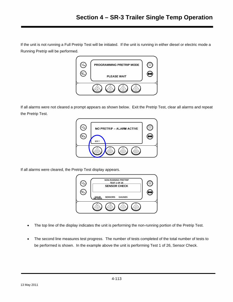
Section 4 – SR-3 Trailer Single Temp Operation
If the unit is not running a Full Pretrip Test will be initiated. If the unit is running in either diesel or electric mode a
Running Pretrip will be performed.
OFF
ON PROGRAMMING PRETRIP MODE
PLEASE WAIT
If all alarms were not cleared a prompt appears as shown below. Exit the Pretrip Test, clear all alarms and repeat
the Pretrip Test.
If all alarms were cleared, the Pretrip Test display appears.
OFF
ON
HOURMETERS
TEST 1 OF 26SENSOR CHECK
SENSORS GAUGES
NON-RUNNING PRETRIP
• The top line of the display indicates the unit is performing the non-running portion of the Pretrip Test.
• The second line measures test progress. The number of tests completed of the total number of tests to
be performed is shown. In the example above the unit is performing Test 1 of 26, Sensor Check.
4-113 13 May 2011

Section 4 – SR-3 Trailer Single Temp Operation
• The soft keys may be used during the Pretrip Test to select the Hourmeter, Gauge or Sensor menus.
• To stop a Pretrip Test at any time turn the unit off. This will generate Alarm Code 28 Pretrip Abort. Other
alarm codes may also be generated. This is normal when the Pretrip Test is halted before completion.
When the non-running tests are complete the unit will start automatically and continue with the Running Pretrip
Test. In the example shown below the unit is in the Running Pretrip and is performing Test 21 of 26, Cool Test.
OFF
ON
HOURMETERS
TEST 21 OF 26COOL TEST
SENSORS GAUGES
RUNNING PRETRIP
When all tests are complete, the results are reported as PASS, CHECK or FAIL. If the results are CHECK or
FAIL, the accompanying alarm codes will direct the technician to the cause of the problem.
OFF
ON
EXIT
PRETRIPPASS
If the Pretrip Test results are CHECK or FAIL the problem should be diagnosed and corrected before the unit is
released for service.
4-114 13 May 2011

Section 4 – SR-3 Trailer Single Temp Operation
Diesel/Electric Menu
The Diesel/Electric Standby selection from the Main Menu allows the operator to manually select diesel or electric
mode operation. The unit can also be programmed to automatically select electric mode operation when standby
power is available and to automatically select diesel mode operation if standby power fails or is removed. If the
unit is programmed to switch automatically from diesel to electric and electric to diesel these screens do not
appear.
Switching from Diesel to Electric If the unit is running in Diesel Mode and the Diesel to Electric Autoswitch Enabled feature in Guarded Access is
set YES then the unit will automatically switch to Electric Mode operation when standby power is connected and
available. The screens shown below will not appear.
If the unit is running in Diesel Mode and the Diesel to Electric Autoswitch Enabled feature in Guarded Access is
set NO, the unit can be switched to Electric Mode using the Electric Standby selection from the Main Menu. From
the Standard Display, press the MENU Key.
The Language Menu or Alarm Menu will appear. Press the NEXT Key as required to show the Electric Standby
selection. When the Electric Standby selection is shown press the SELECT Key.
OFF
ON
MAIN MENU
ELECTRIC STANDBY
NEXTEXIT BACKSELECT
4-115 13 May 2011

Section 4 – SR-3 Trailer Single Temp Operation
If the unit has standby power available and is turned on, the electric standby run screen will appear. The new
mode is then confirmed for 10 seconds. The unit will start and run in Electric Mode. If electric standby power is
not available the display will prompt for a return to Diesel Mode as shown below.
If the electric standby power source fails or is disconnected and manual switching to Diesel Mode is selected, the
unit will prompt for a switch to Diesel Mode. Selecting YES will switch unit operation back to Diesel Mode.
Pressing the NO Key will allow the unit to remain in Electric Mode even though standby power is not available.
The unit will not run and Alarm Code 91 Check Electric Ready Input will be set as a prevent alarm.
OFF
ON
ELECTRIC STANDBY UNDETECTED
DO YOU WISH TO SWITCH TO DIESEL?
NOYES
4-116 13 May 2011

Section 4 – SR-3 Trailer Single Temp Operation
Switching from Electric to Diesel If the unit is running in Electric Mode and the Electric to Diesel Autoswitch Enabled feature in Guarded Access is
set YES then the unit will automatically switch to Diesel Mode operation when standby power is no longer
available. The screens shown below will not appear.
If the Diesel to Electric Autoswitch Enabled feature in Guarded Access is set NO and standby power is
disconnected or fails, the unit will not automatically switch to Diesel mode. This is primarily designed to prevent
unauthorized diesel engine starts when the truck is indoors or on a ferry where engine operation is strictly
prohibited.
If the unit is running in Electric Mode and the Electric to Diesel Autoswitch Enabled feature in Guarded Access is
set NO, the unit can be switched to Diesel Mode using the Diesel selection from the Main Menu. From the
Standard Display, press the MENU Key.
The Language Menu or Alarm Menu will appear. Press the NEXT Key as required to show the Diesel Mode
selection. When the Diesel Mode selection is shown press the SELECT Key.
OFF
ON
MAIN MENU
DIESEL MODE
NEXTEXIT BACKSELECT
The new mode is confirmed for 10 seconds and the unit will return to Diesel Mode operation.
4-117 13 May 2011

Section 4 – SR-3 Trailer Single Temp Operation
Adjust Brightness
The brightness of the HMI Control Panel display can be adjusted to allow for changing ambient light conditions.
The choices available to the operator are HIGH, MEDIUM, LOW and OFF. OFF actually results in a very dim
screen suitable for low light conditions.
Display brightness is adjusted using the Adjust Brightness Menu. From the Standard Display, press the MENU
Key.
The Language Menu or Alarm Menu will appear. Press the NEXT Key as required to show the Adjust Brightness
Menu. When the Adjust Brightness Menu is shown press the SELECT Key.
OFF
ON
EXIT NEXT
MAIN MENU
ADJUST BRIGHTNESS
SELECT BACK
4-118 13 May 2011

Section 4 – SR-3 Trailer Single Temp Operation
The Display Brightness menu will appear as shown below. Press the + or – Keys to select the desired display
brightness. When the desired brightness is shown press the YES Key to confirm the choice.
OFF
ON
- YES NO
DISPLAY BRIGHTNESS WILL BE
MEDIUM
+USE +/- TO CHANGE OK?
The display will briefly show ADJUSTING BRIGHTNESS – PLEASE WAIT
OFF
ON ADJUSTING BRIGHTNESS
PLEASE WAIT
4-119 13 May 2011

Section 4 – SR-3 Trailer Single Temp Operation
Time
The Time and Date held by the Base Controller can be checked. Time and Date cannot be changed from the
Main Menu.
The time and date is accessed using the Main Menu. From the Standard Display, press the MENU Key.
The Language Menu or Alarm Menu will appear. Press the NEXT Key as required to show the Time. When Time
is shown press the SELECT Key. The current time and date will appear.
OFF
ON
TIME MENU
07:53 WEDNESDAY 10 DEC 2003
EXIT
4-120 13 May 2011

Section 4 – SR-3 Trailer Single Temp Operation
OPTIONAL REAR REMOTE CONTROL PANEL
The optional Rear Remote Control Panel is connected to the control system and is used to operate the unit from a
remote location, typically at the rear of the trailer. In the illustration below all display segments are turned on.
ZONE1234
OFFON
P
THERMO KING
IMPORTANT: There are several versions of the Rear Remote Control Panel available. They can be identified
by the color of the wide border around the actual control panel. SR-3 Single Temperature Rear Remote Control
Panels have a black border. SR-3 SPECTRUM Multi-Temperature Rear Remote Control Panels have a blue
border. They are two separate control panels and are not interchangeable.
4-121 13 May 2011
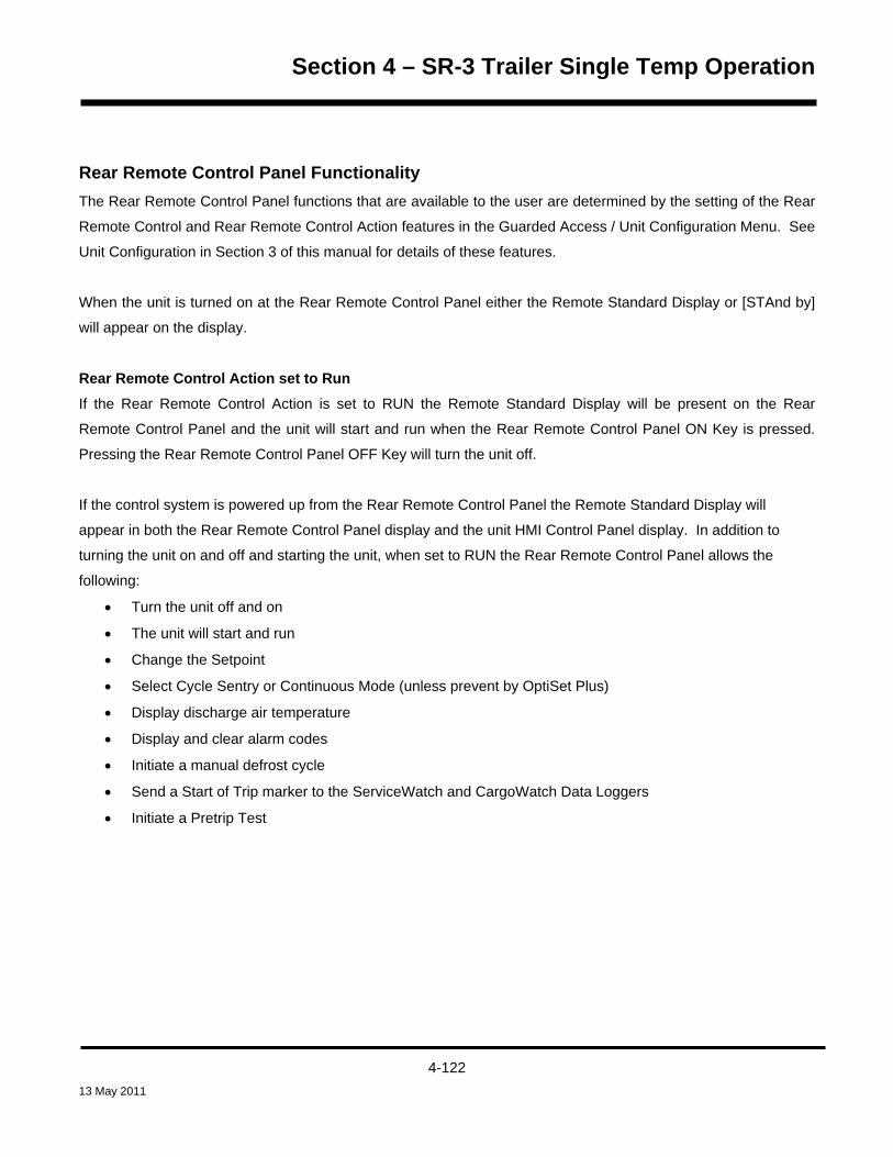
Section 4 – SR-3 Trailer Single Temp Operation
Rear Remote Control Panel Functionality The Rear Remote Control Panel functions that are available to the user are determined by the setting of the Rear
Remote Control and Rear Remote Control Action features in the Guarded Access / Unit Configuration Menu. See
Unit Configuration in Section 3 of this manual for details of these features.
When the unit is turned on at the Rear Remote Control Panel either the Remote Standard Display or [STAnd by]
will appear on the display.
Rear Remote Control Action set to Run If the Rear Remote Control Action is set to RUN the Remote Standard Display will be present on the Rear
Remote Control Panel and the unit will start and run when the Rear Remote Control Panel ON Key is pressed.
Pressing the Rear Remote Control Panel OFF Key will turn the unit off.
If the control system is powered up from the Rear Remote Control Panel the Remote Standard Display will
appear in both the Rear Remote Control Panel display and the unit HMI Control Panel display. In addition to
turning the unit on and off and starting the unit, when set to RUN the Rear Remote Control Panel allows the
following:
• Turn the unit off and on
• The unit will start and run
• Change the Setpoint
• Select Cycle Sentry or Continuous Mode (unless prevent by OptiSet Plus)
• Display discharge air temperature
• Display and clear alarm codes
• Initiate a manual defrost cycle
• Send a Start of Trip marker to the ServiceWatch and CargoWatch Data Loggers
• Initiate a Pretrip Test
4-122 13 May 2011

Section 4 – SR-3 Trailer Single Temp Operation
Rear Remote Control Action set to Stand By If the Rear Remote Control Action is set to STAND BY, pressing the Rear Remote Control Panel ON Key will
power up the control system, but the unit will not start and run. Pressing the Rear Remote Control Panel OFF
Key will turn the unit off. The HMI Control Panel on the unit must be used to start and stop unit operation.
In addition to turning the unit on and off, when set to STAND BY the Rear Remote Control Panel allows the
following:
• Turn the unit on and off
• The unit will not start and run
• Change the Setpoint
• Select Cycle Sentry or Continuous Mode (unless prevent by OptiSet Plus)
• Display discharge air temperature
• Display and clear alarm codes
• Send a Start of Trip marker to the ServiceWatch and CargoWatch Data Loggers
However, when in STAND BY, the engine will not start and a Defrost Cycle or Pretrip Test cannot be initiated.
If the control system is powered up from the remote control panel a stand by message will appear in both the
remote control panel display and the unit HMI Control Panel display as shown below.
Rear Remote Control Panel
REAR REMOTE CONTROL
STAND BY
Unit HMI Control Panel
When the StAnd bY display is shown, press the Select Key to show the Remote Standard Display. When the
remote standard Display is shown, the setpoint and operating mode can be changed, the discharge air
temperature can be displayed and alarms can be viewed and cleared. In addition, a Start of Trip can be sent to
the data loggers.
After the last key is pressed, the display will return to the StAnd bY display shown above in about 10 seconds.
4-123 13 May 2011

Section 4 – SR-3 Trailer Single Temp Operation
THERMO KING
ZONE1234
ON OFF
P
Keypad The nine touch sensitive keys are used to turn the unit on and off. They also allow the setpoint to be changed,
Cycle Sentry or Continuous Mode to be selected, Alarm Codes and other operating data to be displayed and
Pretrip Tests and Defrost Cycles to be performed. A Start of Trip marker can also be sent to the data loggers.
ON
ON KEY Turns the unit on as determined by the setting of Rear Remote Control
Action.
OFF
OFF KEY Turns the unit off.
UP ARROW KEY Increases setpoint or changes other setting.
DOWN ARROW KEY Decreases setpoint or changes other setting.
SELECT KEY Allows Cycle Sentry to be turned on and off, displays the discharge air
temperature and alarms.
ENTER KEY Executes a prompt or loads a new setpoint or other setting.
PRETRIP KEY Initiates a Pretrip Test
TK LOGO KEY Sends a Start of Trip marker to the data logger.
DEFROST KEY Initiates a defrost cycle if conditions allow.
4-124 13 May 2011

Section 4 – SR-3 Trailer Single Temp Operation
THERMO KING
ZONE1234
ON OFF
P
Display The display normally shows the Standard Display of return air temperature and setpoint. The icons on either side
of the display indicate operating modes and alarms. The display shown here has all possible segments lighted.
The display icons are defined below.
Cool Icon This icon appears when the unit is cooling.
Heat Icon This icon appears when the unit is heating.
Modulation Icon This icon appears when the unit is in modulation.
Defrost Icon This icon appears when the unit is defrosting.
Cycle Sentry Icon This icon appears when the unit is operating in Cycle Sentry mode.
Alarm Icon This icon appears when an alarm condition has been detected.
Electric Standby Icon This icon appears when the unit is operating in the optional electric standby
mode.
Setpoint Icon This icon appears when the setpoint is being shown in the display.
Not Used This icon appears during a remote control panel test but is not currently
used.
4-125 13 May 2011

Section 4 – SR-3 Trailer Single Temp Operation
Reading a Typical Remote Standard Display The Remote Standard Display shows the temperature and setpoint. The icons at the sides of the display indicate
operating conditions.
The Remote Standard Display above shows the following information:
• The temperature (typically return air temperature) is 35.8°F.
• The setpoint is 35°F.
• The unit is cooling as shown by the icon at the upper left side of the display.
• The unit is operating in Cycle Sentry mode as shown by the icon at the upper right side of the display.
Remote Control Panel Lockout The remote control panel may be locked out during some control system functions such as Service Test Mode,
Interface Board Test Mode and while setting programmable features. If this is the case the display shown below
will appear. The display will return to the Remote Standard Display when allowed by the control system.
ON OFF
4-126 13 May 2011

Section 4 – SR-3 Trailer Single Temp Operation
Turning the Unit On or Off (Configured for STAND BY operation) The control system is turned on by pressing the ON Key and off by pressing the OFF Key. When the On Key is
pressed the remote display briefly shows all segments and then STAnd by as shown below. A stand by message
will also appear on the unit HMI Control Panel display. The setpoint can be changed but the unit will not start and
run. Only the Select Key, Enter Key and Up and Down Arrow Keys are functional. The unit can be started and
run by pressing the unit HMI Control Panel ON Key. IMPORTANT: To change the setpoint, press the Select Key
to show the Remote Standard Display. The setpoint can now be changed as shown on the next page.
Turning the Unit On and Off (Configured for RUN operation) The unit is turned on by pressing the ON Key and off by pressing the OFF Key. When the On Key is pressed the
remote display briefly shows all segments and then COn FIg as the control system initializes. Then the Remote
Standard Display will appear as shown below. The unit will start and run if necessary.
4-127 13 May 2011

Section 4 – SR-3 Trailer Single Temp Operation
Changing the Setpoint The setpoint can be changed when the Remote Standard Display is shown.
1. When the Remote Standard Display is shown, press the Up or Down Arrow Keys to select the desired
setpoint.
2. When the desired setpoint is shown on the display, immediately press the Enter Key to load the new
setpoint. The display will briefly show [Lod] and then the new setpoint will reappear in the display.
IMPORTANT: The Enter Key must be pressed or the setpoint will not be changed. The display will return to the
Standard Display and the setpoint will return to the old setpoint in about 10 seconds if the Enter Key is not
pressed. Alarm Code 127 Setpoint Not Entered is set, to indicate that the setpoint change was started but not
completed.
IMPORTANT: Confirm that the correct setpoint is set.
4-128 13 May 2011
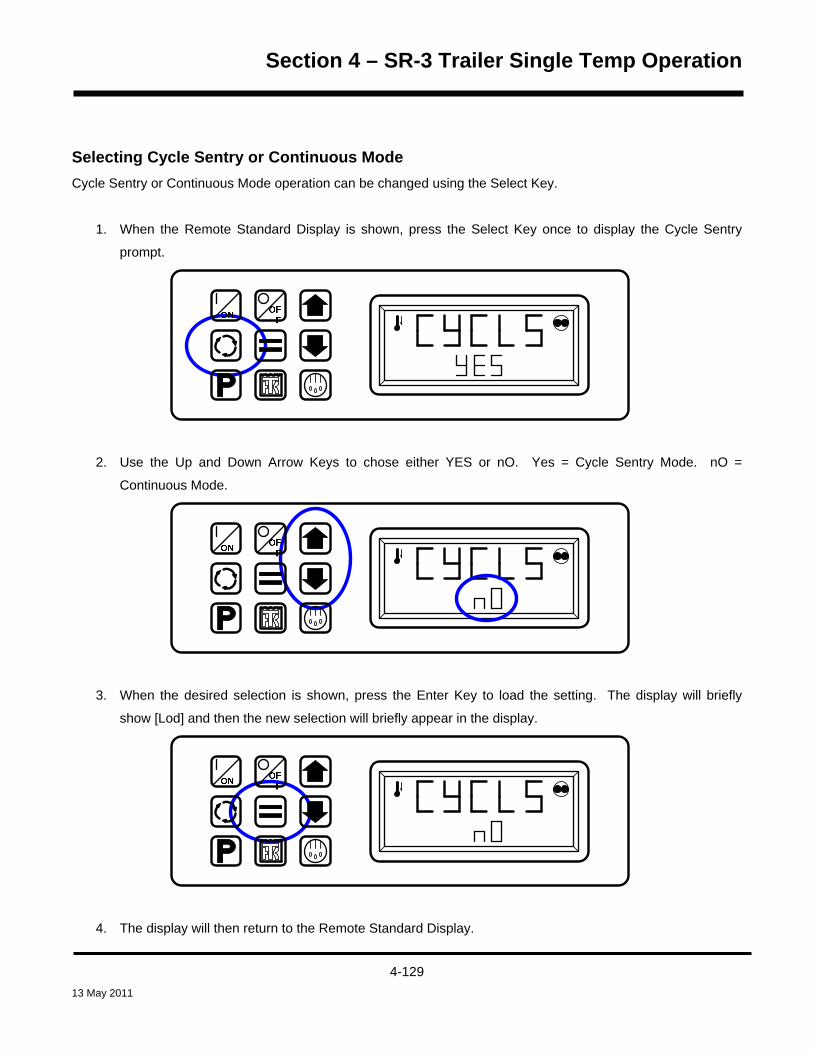
Section 4 – SR-3 Trailer Single Temp Operation
Selecting Cycle Sentry or Continuous Mode Cycle Sentry or Continuous Mode operation can be changed using the Select Key.
1. When the Remote Standard Display is shown, press the Select Key once to display the Cycle Sentry
prompt.
2. Use the Up and Down Arrow Keys to chose either YES or nO. Yes = Cycle Sentry Mode. nO =
Continuous Mode.
3. When the desired selection is shown, press the Enter Key to load the setting. The display will briefly
show [Lod] and then the new selection will briefly appear in the display.
4. The display will then return to the Remote Standard Display.
4-129 13 May 2011

Section 4 – SR-3 Trailer Single Temp Operation
Displaying the Discharge Air Temperature The discharge air temperature can be shown using the Select Key.
1. When the Remote Standard Display is shown, press the Select Key twice. The discharge air temperature
will be shown in the display for about 10 seconds.
2. The display will then return to the Remote Standard Display.
4-130 13 May 2011
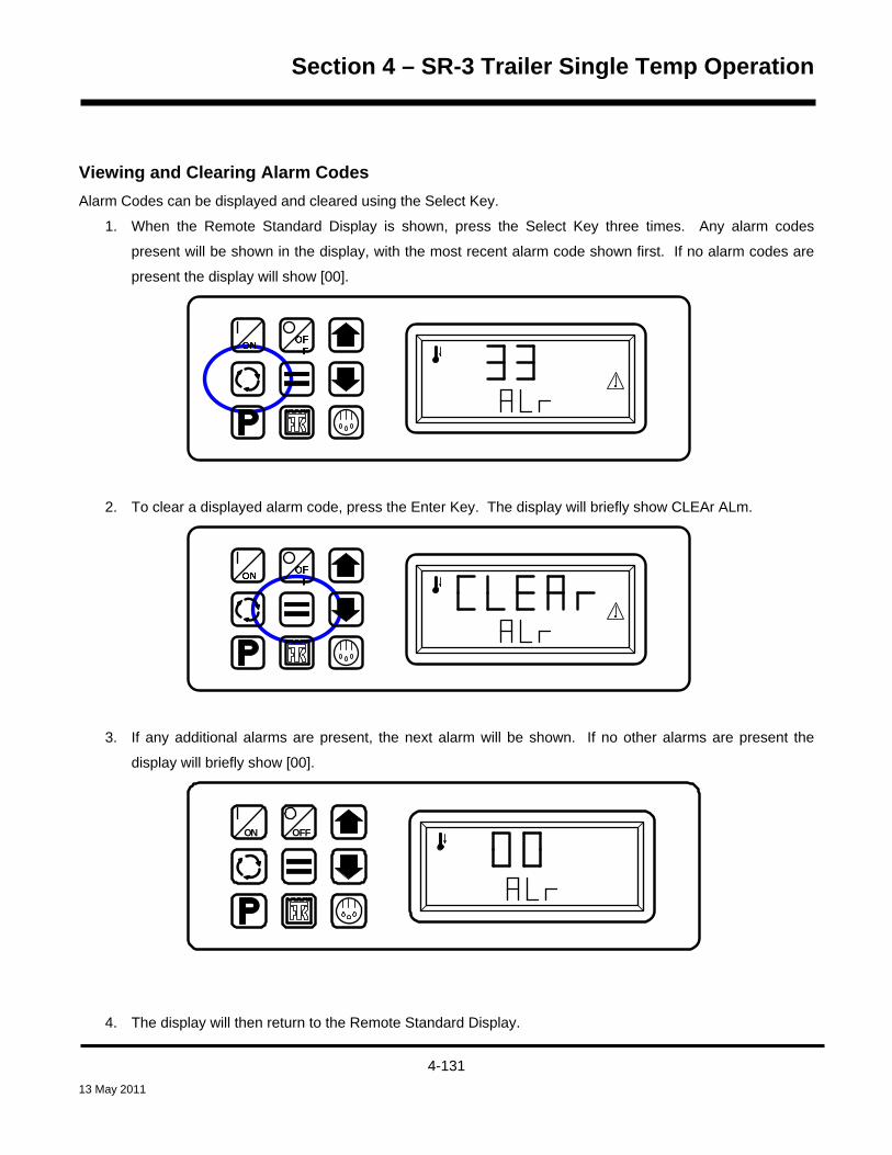
Section 4 – SR-3 Trailer Single Temp Operation
Viewing and Clearing Alarm Codes Alarm Codes can be displayed and cleared using the Select Key.
1. When the Remote Standard Display is shown, press the Select Key three times. Any alarm codes
present will be shown in the display, with the most recent alarm code shown first. If no alarm codes are
present the display will show [00].
2. To clear a displayed alarm code, press the Enter Key. The display will briefly show CLEAr ALm.
3. If any additional alarms are present, the next alarm will be shown. If no other alarms are present the
display will briefly show [00].
ON OFF
4. The display will then return to the Remote Standard Display.
4-131 13 May 2011

Section 4 – SR-3 Trailer Single Temp Operation
Starting a Manual Defrost Cycle If conditions allow, a manual defrost cycle can be initiated using the Defrost Key.
1. Press the Defrost Key. The defrost prompt [EnTEr dEF] will appear in the display.
2. When the defrost prompt is shown, press the Enter Key to start a manual defrost. The display will briefly
show LOAd dEF and then a defrost cycle will begin if conditions allow.
3. The display will return to the Remote Standard Display. The Defrost Icon will be shown in the display.
4. The defrost cycle will terminate automatically.
4-132 13 May 2011

Section 4 – SR-3 Trailer Single Temp Operation
Sending a Start of Trip Marker A Start of Trip marker can be sent to the data loggers using the Thermo King Logo Key.
1. Press the Thermo King Logo Key. The Start of Trip [EnTEr SOt] prompt will appear in the display.
2. When the Start of Trip prompt is shown, press the Enter Key to send a Start of Trip marker to the
CargoWatch and ServiceWatch data loggers. The display will briefly show LOAd SOt.
3. The display will return to the Remote Standard Display.
4-133 13 May 2011

Section 4 – SR-3 Trailer Single Temp Operation
Running a Pretrip Test A Pretrip Test can be started using the Pretrip Key. If the unit is not running when the Pretrip Test is started a
Full Pretrip Test will be performed. If the unit is running when the Pretrip Test is started a Running Pretrip Test
will be performed.
1. Clear any alarm codes as shown previously.
2. Press the Pretrip Key. The Pretrip [EntEr PrE] prompt will appear in the display.
3. When the Pretrip prompt is shown, press the Enter Key to start a Pretrip Test. The display will briefly
show LOAd PrE. If the unit is not running a Full Pretrip Test will be performed. If the unit is running a
Running Pretrip Test will be performed.
4-134 13 May 2011
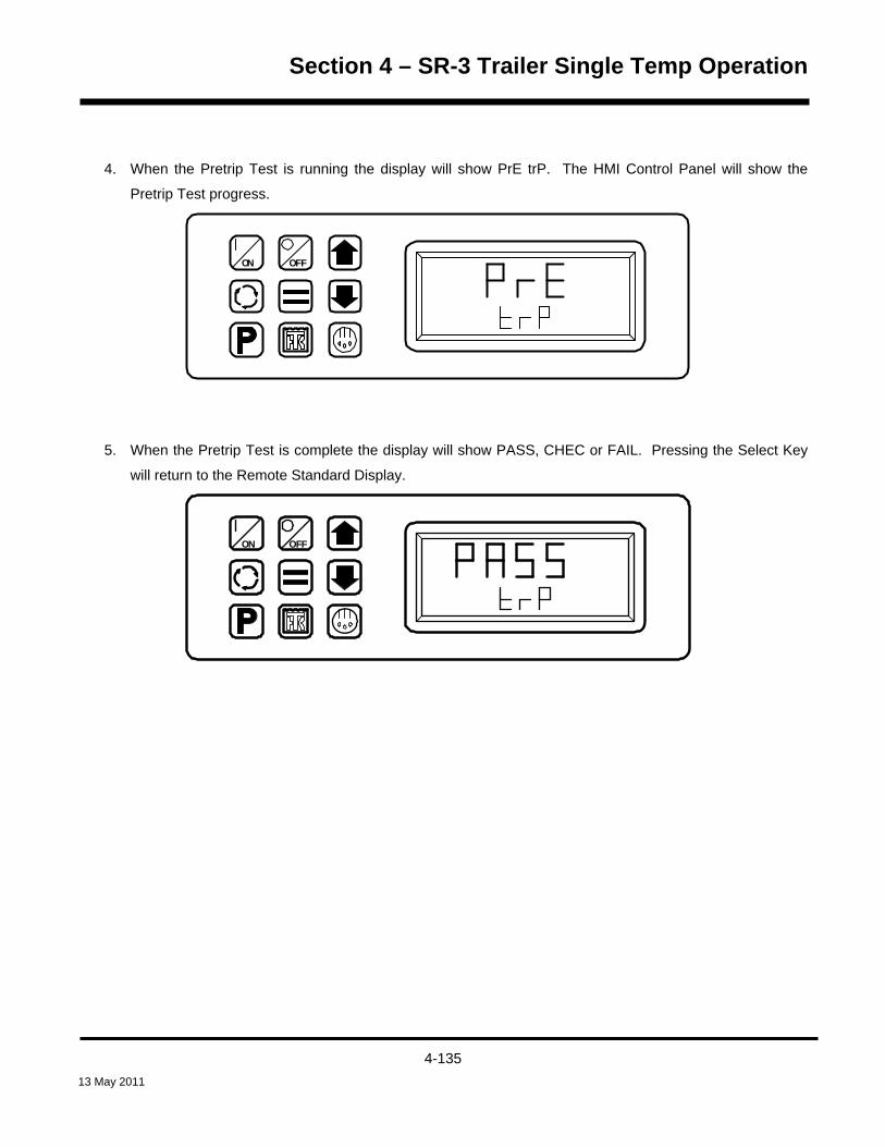
Section 4 – SR-3 Trailer Single Temp Operation
4. When the Pretrip Test is running the display will show PrE trP. The HMI Control Panel will show the
Pretrip Test progress.
ON OFF
5. When the Pretrip Test is complete the display will show PASS, CHEC or FAIL. Pressing the Select Key
will return to the Remote Standard Display.
ON OFF
4-135 13 May 2011

Section 4 – SR-3 Trailer Single Temp Operation
4-136 13 May 2011

Section 4 – SR-3 Trailer Single Temp Operation
MAINTENANCE MENU OVERVIEW
Maintenance Menu1 of 3
Hourmeters - View and Reset TimeTotal HoursTotal Run Time HoursEngine HoursElectric Run HoursTotal Run Time Reminder #1 HoursTotal Run Time Reminder #2 HoursController Power On HoursPretrip Reminder HoursEngine Run Time Reminder #1 HoursEngine Run Time Reminder #2 HoursElectric Run Time Reminder #1 HoursElectric Run Time Reminder #2 Hours
GaugesCoolant TemperatureCoolant LevelOil PressureOil LevelAmpsBattery VoltageEngine RPMFuel Level SensorDischarge PressureSuction PressureETV PositionFresh Air ExchangeI/O (Input/Output State)
High Speed RelayRun RelayRun Relay FeedbackAlternator Excite OutputDefrost DamperHeat OutputAlternator FrequencyFresh Air Exchange OutputDiesel/Electric Relay (50 only)Electric Ready Input (50 Only)Electric Overload (50 only)Hot Gas Bypass (ETV only)
SensorsControl Return Air TemperatureDisplay Return Air TemperatureControl Discharge Air TemperatureDisplay Discharge Air TemperatureTemperature DifferentialEvaporator Coil TemperatureAmbient Air TemperatureSpare 1 TemperatureLog Sensor 1Log Sensor 2 Datalogger Sensor 3 TemperatureDatalogger Sensor 4 TemperatureDatalogger Sensor 5 TemperatureDatalogger Sensor 6 TemperatureBoard Temperature Sensor
AlarmsDisplay all alarmsClear most alarms
Service TestTest with Unit Running?
OffNullHigh Speed CoolLow Speed CoolLow Speed HeatHigh Speed HeatDefrostCool BypassMod Cool /HGBModulation CoolModulation Heat
Interface Board TestPreheat RelayBuzzerRun RelayAlternator Excite OutputHeat OutputDamper RelayIndicator LightAlarm LightDiesel/Electric RelayElectric HeatHigh Speed RelayHot Gas Bypass ValveFresh Air Exchange
Maintenance Menu2 of 3
Not all menu features may appear
Rev D006/D007 and 6560/6561 Trailer S/T 03 Apr 2011
D006/D007 and 6560/6561 SR-3 Trailer S/T Maintenance Menu (1 of 2)Features shown are for units configured Trailer
4-137 13 May 2011

Section 4 – SR-3 Trailer Single Temp Operation
Maintenance Menu Overview - Continued
4-138 13 May 2011

Section 4 – SR-3 Trailer Single Temp Operation
USING THE MAINTENANCE MENU The Maintenance Menu contains features that allow the technician to view additional information, perform unit
diagnostics using Service Test Mode and Interface Board Test Mode and evacuate and charge the unit with
refrigerant using Evacuation Mode. Software revisions can be checked and the time and date can be set.
To access the Maintenance Menu press the MENU Key.
The Maintenance Menu is accessed from the first Main Menu screen that appears; either the Language Display
or the Alarms Display. The Alarms Display is shown here. Press and hold both the unlabelled soft key and the
Exit Key for 5 seconds.
OFF
ONMAIN MENU
ALARMS
NEXTEXIT SELECT
4-139 13 May 2011

Section 4 – SR-3 Trailer Single Temp Operation
The first Maintenance Menu feature will appear. Press the NEXT and BACK Keys to scroll thru the Maintenance
Menu choices. When the desired choice is shown on the display, press the SELECT Key to access it.
OFF
ON
MAINTENANCE MENU
HOURMETERS
NEXTEXIT SELECT
The Maintenance Menu choices are shown on the next page. For detailed information see the individual
explanations of each item later in this section of the manual.
To return to the Standard Display press the EXIT Key.
The HMI Control Panel will also return to the Standard Display 30 seconds after the last key is pressed.
4-140 13 May 2011

Section 4 – SR-3 Trailer Single Temp Operation
MAINTENANCE MENU CHOICES
Hourmeters The Hourmeters Menu allows the technician to view all the active unit hourmeters, even if the Main Menu view
has been turned off. The Maintenance Menu Hourmeter Display also allows the technician to reset the time on
hourmeters with a programmed time limit. Hourmeters can also be viewed from the Main Menu if enabled in
Guarded Access.
Choose Hourmeters by pressing the SELECT Key when HOURMETERS is shown in the Maintenance Menu.
The hourmeter screen appears as shown below.
OFF
ON
TOTAL RUN TIME HOURS
87
NEXTEXIT BACK
The NEXT and BACK Keys are used to scroll through the hourmeters.
The EXIT Key returns to the Maintenance Menu
See the definition of hourmeters on the next page.
4-141 13 May 2011

Section 4 – SR-3 Trailer Single Temp Operation
Hourmeter Definitions
Hourmeter Name Definition
Total Hours
Total number of hours the unit has been turned on (protection hours).
Total Run Time Hours
Total number of hours the unit has run in both diesel and electric mode.
Engine Hours
Total number of hours the unit has run in diesel mode.
Electric Run Hours
Total number of hours the unit has run in electric mode.
Total Run Reminder 1 Hours
User Programmable – The number of hours before a Total Unit Run Time
Maintenance Reminder 1 occurs.
Total Run Reminder 2 Hours
User Programmable – The number of hours before a Total Unit Run Time
Maintenance Reminder 2 occurs.
Controller Power On Hours
Total hours the controller and HMI Control Panel have been turned on.
Pretrip Reminder Hours
User Programmable – number of hours before a Pretrip Reminder occurs.
Engine Reminder 1 Hours
User Programmable – The number of hours before an Engine Run Time
Maintenance Reminder 1 occurs.
Engine Reminder 2 Hours
User Programmable – The number of hours before an Engine Run Time
Maintenance Reminder 2 occurs.
Electric Reminder 1 Hours
User Programmable – The number of hours before an Electric Run Time
Maintenance Reminder 1 occurs.
Electric Reminder 2 Hours
User Programmable – The number of hours before an Electric Run Time
Maintenance Reminder 2 occurs.
4-142 13 May 2011

Section 4 – SR-3 Trailer Single Temp Operation
Gauges The Gauge Menu allows the technician to view the unit gauges. The Gauge Menu can also be accessed from the
Standard Display.
Choose Gauges by pressing the SELECT Key when GAUGES is shown in the Maintenance Menu. The Gauges
screen appears as shown below.
OFF
ON
BATTERY VOLTAGE
13.2
NEXTEXIT BACKLOCK
v
The NEXT and BACK Keys are used to scroll through the gauges.
The LOCK Key allows a gauge display to be “locked” on the display for 15 minutes at the operator’s discretion.
The EXIT Key returns to the Maintenance Menu
Not all gauges are available on all units. Only gauges used by the specific unit configuration will appear.
See the list of gauges on the next page.
The I/O submenu shows the state of each named device – either On or Off, or Low or OK.
4-143 13 May 2011

Section 4 – SR-3 Trailer Single Temp Operation
Gauge List
NOTE: Not all gauges may appear
• Coolant Temperature
• Coolant Level
• Oil Pressure
• Oil Level
• Amps
• Battery Voltage
• Engine RPM
• Fuel Level
• Discharge Pressure
• Suction Pressure
• ETV Position
• Fresh Air Exchange Door Position
• I/O (Input/Output State)
High Speed Relay
Run Relay
Run Relay Feedback
Defrost Damper
Heat Output
Alternator Frequency
Fresh Air Exchange Output
Diesel/Electric Relay (50 only)
Electric Ready Input (50 only)
Electric Overload (50 only)
Hot Gas Bypass (ETV only)
4-144 13 May 2011

Section 4 – SR-3 Trailer Single Temp Operation
Sensors The Sensors Menu allows the technician to view the unit temperature sensors. The Sensors Menu can also be
accessed from the Standard Display.
Choose sensors by pressing the SELECT Key when SENSORS is shown in the Maintenance Menu. The
SENSORS screen appears as shown below.
OFF
ON
DISPLAY RETURN AIR TEMPERATURE
44.8
NEXTEXIT BACKLOCK
°F
The NEXT and BACK Keys are used to scroll through the sensors.
The LOCK Key allows a sensor display to be “locked” on the display to prevent the display from timing out.
The EXIT Key returns to the Maintenance Menu
See the list of sensors on the next page.
4-145 13 May 2011

Section 4 – SR-3 Trailer Single Temp Operation
Sensor List
• Control Return Air Temperature
• Display Return Air Temperature
• Control Discharge Air Temperature
• Display Discharge Air Temperature
• Temperature Differential
• Evaporator Coil Temperature
• Ambient Air Temperature
• Spare 1 Temperature
• Log Sensor 1
• Log Sensor 2
• Datalogger Sensor 3 Temperature
• Datalogger Sensor 4 Temperature
• Datalogger Sensor 5 Temperature
• Datalogger Sensor 6 Temperature
• Board Temperature Sensor (HMI Control Panel internal circuit board)
4-146 13 May 2011

Section 4 – SR-3 Trailer Single Temp Operation
Alarms The Alarms Menu allows the technician to view all alarms and clear most alarms. The Alarms Menu is also
available from the Main Menu.
Alarms may be one of four types as shown below.
Log Alarms Log Alarms are indicated for 60 seconds each time the unit is turned on. This level of alarm serves as a notice to
take corrective action before a problem becomes severe. Maintenance items such as maintenance hourmeter
time-outs are log alarms. The TemperatureWatch screen is not disabled if only log alarm(s) are active.
When the unit is turned on the display will show the Thermo King Logo and then the “Configuring System”
message. If log alarm(s) are present the Log Alarm notice will appear on the display for 60 seconds as shown
below. The remote indicator alarm light (if installed) will also be on during this period. The Standard Display will
appear and the remote indicator alarm light will go off after 60 seconds.
NOTE: The Alarm Icon does not appear on startup with log alarms present.
OFF
ON LOG ALARMS ACTIVE
GO TO MENU TO VIEW
EXIT
NOTE: If required, an engine start may occur while the display above is shown. This is normal operation.
4-147 13 May 2011
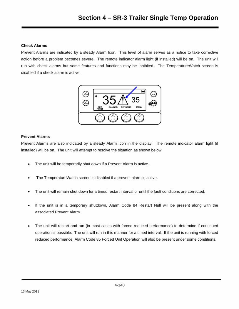
Section 4 – SR-3 Trailer Single Temp Operation
Check Alarms Prevent Alarms are indicated by a steady Alarm Icon. This level of alarm serves as a notice to take corrective
action before a problem becomes severe. The remote indicator alarm light (if installed) will be on. The unit will
run with check alarms but some features and functions may be inhibited. The TemperatureWatch screen is
disabled if a check alarm is active.
OFF
ON
MENUSET SENSORSGAUGESPOINT
Prevent Alarms Prevent Alarms are also indicated by a steady Alarm Icon in the display. The remote indicator alarm light (if
installed) will be on. The unit will attempt to resolve the situation as shown below.
• The unit will be temporarily shut down if a Prevent Alarm is active.
• The TemperatureWatch screen is disabled if a prevent alarm is active.
• The unit will remain shut down for a timed restart interval or until the fault conditions are corrected.
• If the unit is in a temporary shutdown, Alarm Code 84 Restart Null will be present along with the
associated Prevent Alarm.
• The unit will restart and run (in most cases with forced reduced performance) to determine if continued
operation is possible. The unit will run in this manner for a timed interval. If the unit is running with forced
reduced performance, Alarm Code 85 Forced Unit Operation will also be present under some conditions.
4-148 13 May 2011

Section 4 – SR-3 Trailer Single Temp Operation
• If the alarm does not reoccur during the timed running interval with reduced performance, the unit will
return to full performance to determine if continued operation is possible. The unit will run in this manner
for a timed interval. If the unit is successfully able to return to full performance for the timed interval
without the alarm re-occurring, the alarm is auto cleared and the unit will run normally.
• All Prevent Alarm events and conditions are logged by the ServiceWatch Data Logger.
• In general, if the alarm condition re-occurs a defined number of times, the alarm is set as a shutdown
alarm and no further restarts are possible.
NOTE: If the Restart After Shutdown feature in the Guarded Access Menu is set for CONTINUOUS, then
an unlimited number of restart attempts are allowed.
Shutdown Alarms Shutdown Alarms are indicated by the following:
• The Alarm Icon will appear.
• The display and backlight will flash on and off.
• The display will switch from normal video to reverse video and back to normal video. (Light areas
become dark and dark areas become light.)
Shutdown alarms will force the unit into shutdown. The unit will remain in shutdown until the shutdown alarm is
manually cleared. Exceptions are some engine and electric shutdown alarms that become log alarms when
switched to the alternate operating mode (diesel to electric or electric to diesel). The TemperatureWatch screen
is disabled if a unit level shutdown alarm is active.
4-149 13 May 2011
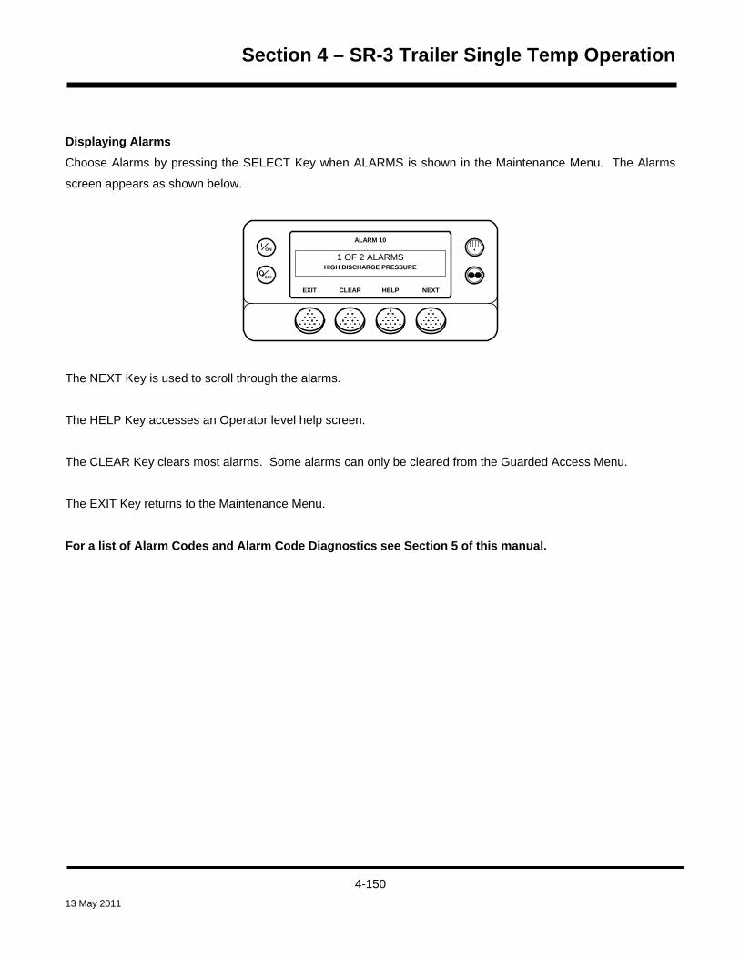
Section 4 – SR-3 Trailer Single Temp Operation
Displaying Alarms Choose Alarms by pressing the SELECT Key when ALARMS is shown in the Maintenance Menu. The Alarms
screen appears as shown below.
OFF
ON
ALARM 10
1 OF 2 ALARMS
NEXTEXIT HELPCLEAR
HIGH DISCHARGE PRESSURE
The NEXT Key is used to scroll through the alarms.
The HELP Key accesses an Operator level help screen.
The CLEAR Key clears most alarms. Some alarms can only be cleared from the Guarded Access Menu.
The EXIT Key returns to the Maintenance Menu.
For a list of Alarm Codes and Alarm Code Diagnostics see Section 5 of this manual.
4-150 13 May 2011

Section 4 – SR-3 Trailer Single Temp Operation
Clearing Alarms Most alarm codes can be cleared conventionally from the Alarm Menu using the CLEAR Key.
The following control and display sensor alarm codes can only be cleared from the Maintenance Menu or
Guarded Access Menu:
• Alarm Code 03 Check Control Return Air Sensor
• Alarm Code 04 Check Control Discharge Air Sensor
• Alarm Code 74 Controller Reset to Defaults (Guarded Access Only)
• Alarm Code 203 Check Display Return Air Sensor
• Alarm Code 204 Check Display Discharge Air Sensor
The following alarm codes clear automatically.
• Alarm Code 64 Pretrip Reminder – Clears when a Pretrip Test is performed.
• Alarm Code 84 Restart Null – Clears when the unit is no longer in a restart null due to a Prevent Alarm.
• Alarm Code 85 Forced Unit Operation – Clears when the unit is no longer running in a forced mode due
to a Prevent Alarm.
• Alarm Code 91 Check Electric Ready Input – Clears automatically when the unit starts running.
• Alarm Code 92 Sensor Grades Not Set – Clears when all required sensor grades are changed from 5H.
If the Limited Alarm Restarts feature is enabled the following additional alarm codes may only be cleared from the
Guarded Access Menu. If this is the case, the CLEAR Key will not appear if the alarms are displayed from the
Main Menu or the Maintenance Menu. See the Limited Alarm Restarts feature in Section 3 for details.
• Alarm Code 10 High Discharge Pressure
• Alarm Code 23 Cooling Cycle Fault
• Alarm Code 24 Heating Cycle Fault
• Alarm Code 32 Refrigeration Capacity Low
4-151 13 May 2011

Section 4 – SR-3 Trailer Single Temp Operation
Alarm Notes
• IMPORTANT: If an alarm will not clear, it may still exist. If the alarm is not corrected, it will not clear or
may be immediately set again.
• IMPORTANT: If an alarm cannot be cleared from the Main menu, the Clear Key will not appear. These
alarms must be cleared from the Maintenance or Guarded Access Menus.
• IMPORTANT: All alarms must be viewed before any of the alarms can be cleared.
• IMPORTANT: Shutdown alarms should receive immediate attention if the truck or trailer is loaded.
4-152 13 May 2011
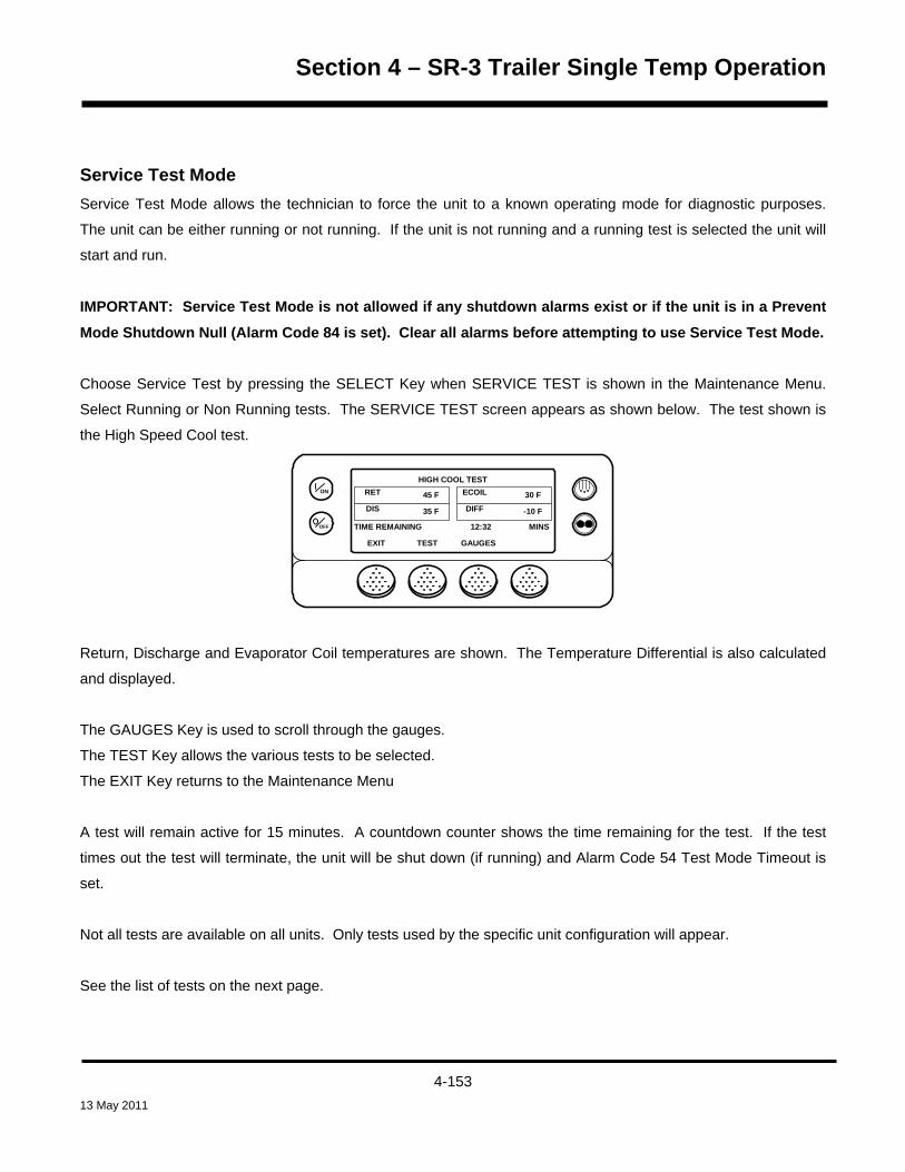
Section 4 – SR-3 Trailer Single Temp Operation
Service Test Mode Service Test Mode allows the technician to force the unit to a known operating mode for diagnostic purposes.
The unit can be either running or not running. If the unit is not running and a running test is selected the unit will
start and run.
IMPORTANT: Service Test Mode is not allowed if any shutdown alarms exist or if the unit is in a Prevent
Mode Shutdown Null (Alarm Code 84 is set). Clear all alarms before attempting to use Service Test Mode.
Choose Service Test by pressing the SELECT Key when SERVICE TEST is shown in the Maintenance Menu.
Select Running or Non Running tests. The SERVICE TEST screen appears as shown below. The test shown is
the High Speed Cool test.
OFF
ON
HIGH COOL TEST
EXIT GAUGESTEST
TIME REMAINING 12:32 MINS
RET ECOIL
DIS DIFF45 F
35 F
30 F
-10 F
Return, Discharge and Evaporator Coil temperatures are shown. The Temperature Differential is also calculated
and displayed.
The GAUGES Key is used to scroll through the gauges.
The TEST Key allows the various tests to be selected.
The EXIT Key returns to the Maintenance Menu
A test will remain active for 15 minutes. A countdown counter shows the time remaining for the test. If the test
times out the test will terminate, the unit will be shut down (if running) and Alarm Code 54 Test Mode Timeout is
set.
Not all tests are available on all units. Only tests used by the specific unit configuration will appear.
See the list of tests on the next page.
4-153 13 May 2011
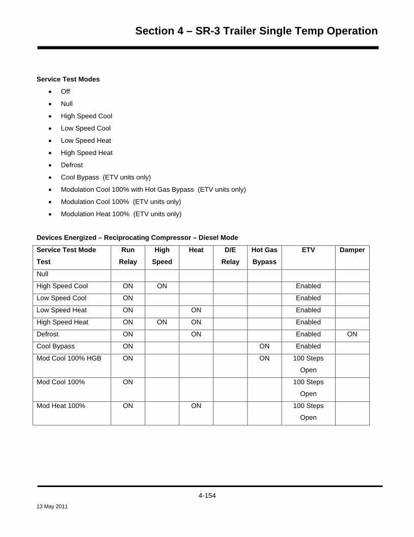
Section 4 – SR-3 Trailer Single Temp Operation
Service Test Modes
• Off
• Null
• High Speed Cool
• Low Speed Cool
• Low Speed Heat
• High Speed Heat
• Defrost
• Cool Bypass (ETV units only)
• Modulation Cool 100% with Hot Gas Bypass (ETV units only)
• Modulation Cool 100% (ETV units only)
• Modulation Heat 100% (ETV units only)
Devices Energized – Reciprocating Compressor – Diesel Mode
Service Test Mode
Test
Run
Relay
High
Speed
Heat D/E
Relay
Hot Gas
Bypass
ETV Damper
Null
High Speed Cool ON ON Enabled
Low Speed Cool ON Enabled
Low Speed Heat ON ON Enabled
High Speed Heat ON ON ON Enabled
Defrost ON ON Enabled ON
Cool Bypass ON ON Enabled
Mod Cool 100% HGB ON ON 100 Steps
Open
Mod Cool 100% ON 100 Steps
Open
Mod Heat 100% ON ON 100 Steps
Open
4-154 13 May 2011

Section 4 – SR-3 Trailer Single Temp Operation
Devices Energized – Reciprocating Compressor – Electric Mode
Service Test Mode
Test
Run
Relay
High
Speed/
Electric
Heat
Heat D/E
Relay
Hot Gas
Bypass
ETV Damper
Null
Cool ON ON Enabled
Hot Gas Heat ON ON ON Enabled
Hot Gas & Elec Heat ON ON ON ON Enabled
Defrost ON ON ON ON Enabled ON
Cool Bypass ON ON ON Enabled
Mod Cool 100% HGB ON ON ON 100 Steps
Open
Mod Cool 100% ON ON 100 Steps
Open
Mod Heat 100% ON ON ON 100 Steps
Open
4-155 13 May 2011

Section 4 – SR-3 Trailer Single Temp Operation
Interface Board Test Interface Board Test Mode allows the technician to energize and de-energize individual control devices for
diagnostic purposes. The unit cannot be running to use this test. If the test is entered with the unit running, the
unit will shut down.
IMPORTANT: Interface Board Test Mode is not allowed if any shutdown alarms exist or if the unit is in a
Prevent Mode Shutdown Null (Alarm Code 84 is set). Clear all alarms before using Interface Board Test
Mode.
Choose Interface Board Test by pressing the SELECT Key when INTERFACE BOARD TEST is shown in the
Maintenance Menu. The Interface Board Test screen appears as shown below. The test shown is the Heat
Output test.
OFF
ON
HEAT OUTPUT
EXIT LOCK ONTEMP ON
HEAD-P AMPS
SCT-P VOLTS169
169
0.3
13.4
NEXT
Discharge Pressure, Suction Pressure, Amps and Volts are shown.
The TEMP ON Key is used to momentarily energize the device.
The LOCK ON Key energizes the device for 15 minutes. A countdown counter shows the time remaining for the
test. If the test times out Alarm Code 54 Test Mode Timeout is set. Not all devices can be locked on.
The UNLOCK Key unlocks the display and returns to the Interface Board Test.
The EXIT Key returns to the Maintenance Menu.
Not all tests are available on all units. Only tests used by the specific unit will appear.
See the list of tests on the next page.
4-156 13 May 2011

Section 4 – SR-3 Trailer Single Temp Operation
Interface Board Test Modes and Current Draw
NOTE: Device current will vary dependant on battery voltage and battery condition.
Interface Board Test
Approximate Device
Current Draw
Comments
Preheat Relay 70 Amps Temporary On only
Buzzer Negligible Temporary On only
Run Relay 2.0 Amps
Alternator Excite Output 0.5 – 2.0 Amps
Heat Output 0.4 Amps
Damper Relay 6.0 Amps
Indicator Light 0.1 Amps
Alarm Light 0.1 Amps
Diesel/Electric Relay 1.1 Amps Not available if ER is high
Electric Heat 1.5 Amps
High Speed Relay 4.6 Amps
Hot Gas Bypass 1.5 Amps ETV units only.
Fresh Air Exchange 6.0 Amps
4-157 13 May 2011

Section 4 – SR-3 Trailer Single Temp Operation
Display Self Test The Display Self Test allows the technician to perform a number of self tests on the unit HMI Control Panel. The
tests available are shown below.
Choose Display Self Test by pressing the SELECT Key when DISPLAY SELF TEST is shown in the Maintenance
Menu. The Display Self Test screen appears. Select a test from the list below
• LCD Test – This test allows the technician to select a normal or inverted display. If inverted is chosen the
display is reversed – segments that were turned on are now turned off and segments that were turned off
are now turned on. The technician visually verifies that all display segments are functioning properly.
• Keypad Test – This test prompts the technician to press the four soft keys, the Defrost Key and the Cycle
Sentry Key. Each time the requested key is pressed the next prompt is displayed, allowing the technician
to verify proper operation of these keys.
• Backlight Test – This test allows the technician to turn the backlight on and off to confirm operation.
• Brightness Test – This test allows the technician to select Low, Medium or High backlight intensity.
• Buzzer Test – This test allows the technician to turn the HMI buzzer on and off to verify operation.
• Heater Output – This test allows the technician to turn the HMI display heater on and off.
• Serial E2 – This test allows the technician to perform an internal HMI memory test. The test takes less
than 1 second and the results are reported as PASS or FAIL.
• Data Log Flash – This test allows the technician to perform an internal HMI CargoWatch data logger
memory test. The test takes less than 1 second and the results are reported as PASS or FAIL.
• RTC Update – This test allows the technician to perform an internal HMI real time clock test. The test
takes less than 3 seconds and the results are reported as PASS or FAIL.
4-158 13 May 2011

Section 4 – SR-3 Trailer Single Temp Operation
Evacuation Test This menu allows the technician to open all normally closed refrigeration system valves to evacuate and charge
the unit with refrigerant. If the battery voltage falls below 13.0 VDC the technician is prompted to connect a
battery charger to maintain sufficient voltage to hold all valves open.
IMPORTANT: Evacuation mode has no time-out. The unit will remain in Evacuation Mode indefinitely
unless the battery voltage becomes excessive.
All selectable unit features will be disabled when in evacuation mode. Auto switch from diesel to electric or from
electric to diesel is allowed, but unit will not start.
Evacuation mode is not allowed if:
• Any shutdown alarms are present.
• The unit is in restart null.
• The unit is in a start sequence.
When in evacuation mode:
• If the unit is running it will shut down automatically when entering Evacuation Mode.
• Alarm Code 86 Check Discharge Pressure Sensor is disabled.
• Alarm Code 87 Check Suction Pressure Sensor is disabled.
• Door switch operation is disabled.
Choose Evacuation Test by pressing the SELECT Key when EVACUATION TEST is shown by the Maintenance
Menu. The Evacuation Test display shown below will appear and remain on the display so long as the battery
voltage does not fall below 13.0 VDC. All normally closed refrigerant valves are energized to the open position to
allow system evacuation to effectively remove air and moisture from the refrigeration system.
OFF
ON
EVAC MODE BATTERY VOLTS
13.1EXIT
V
4-159 13 May 2011

Section 4 – SR-3 Trailer Single Temp Operation
If the battery voltage falls below 13.0 VDC the technician is prompted to install a battery charger to guarantee
sufficient voltage to keep all valves open during the evacuation process.
OFF
ON
CONNECT BATTERY CHARGER
12.9EXIT
V
If the voltage from the battery charger rises above 16 Vdc, the controller will be turned off to prevent damage to
the electronics and/or system components.
To exit Evacuation Mode press the EXIT Key or turn the unit off.
4-160 13 May 2011

Section 4 – SR-3 Trailer Single Temp Operation
Software Revision This menu allows the technician to view the software revision for the HMI Control Panel and the Base Controller.
Choose Software Revision by pressing the SELECT Key when SOFTWARE REVISION is shown by the
Maintenance Menu. The Software Revision display appears as shown below.
The NEXT and BACK Keys allow the technician to scroll through the software revisions. Software revisions
appear in the order shown below:
• Display Software Revision
• Controller Software Revision
• Supervisor Software Revision (Determined by HMI Control Panel software revision)
To flash load new HMI Control Panel software see Service Procedure A46B Flash Loading HMI Control Panel
Software in Section 6 of this manual.
To flash load new Base Controller software see Service Procedure A46A Flash Loading HMI Control Panel
Software in Section 6 of this manual.
4-161 13 May 2011

Section 4 – SR-3 Trailer Single Temp Operation
Set Time and Date This menu allows the technician to view and change the HMI Control Panel clock/calendar.
Choose Set Time and Date by pressing the SELECT Key when SET TIME AND DATE is shown by the
Maintenance Menu. The Set Time and Date display appears as shown below.
OFF
ON
- NO
ENTER HOUR
16:00++/- TO CHANGE OK?
YES
The – and + Keys are used to change the hour as required. Pressing YES changes the hour to the selected time
and then shows the next Time/Date screen. The screens appear in the order shown below.
• Hour
• Minute
• Date (Day)
• Month
• Year
4-162 13 May 2011
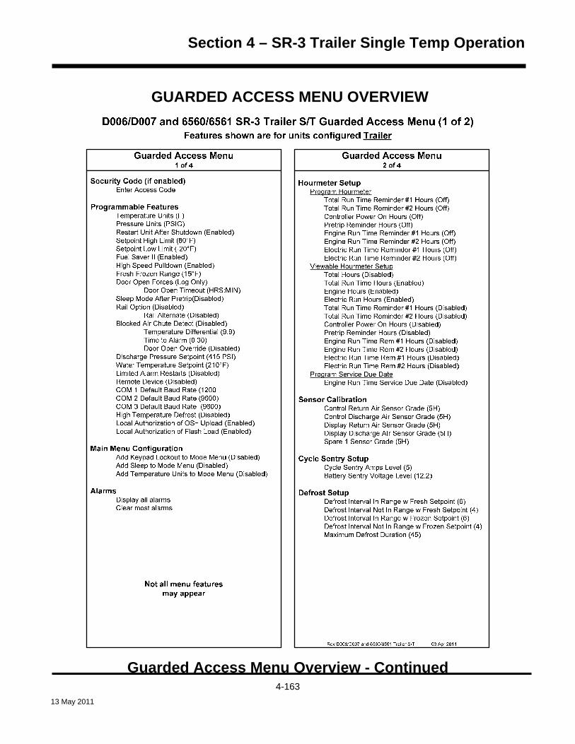
Section 4 – SR-3 Trailer Single Temp Operation
GUARDED ACCESS MENU OVERVIEW
Guarded Access Menu Overview - Continued
4-163 13 May 2011

Section 4 – SR-3 Trailer Single Temp Operation
Language SetupHMI Rev 65xx HMI Rev 66xx HMI Rev 67xxEnglish English EnglishSpanish Danish JapaneseFrench Russian ChineseGerman NorwegianItalian SwedishDutch Finnish HMI Rev 68xxPortuguese Polish Mix and MatchGreek Hungarian LanguagesTurkish RomanianHebrew BulgarianArabic Czech
Access Code SetupEnter Access Code
OptiSet PlusOptiSet Plus ResetTemperature Profile Selection ( Numeric Setpoint)
Sensor Configuration (CargoWatch)(See Cargo Watch description in Diagnostic Manual)
Logging Interval (15 Minutes)Log Sensor 1(On)
Independant Sensor #1 Name (Log Sensor 1)Out of Range Checking (Off)
Low (-10.8°F)High (10.8°F)
Italian Option - Available with Sensor 1 only (Off)Sensor Averaging (Off)
Log Sensor 2 (On)Independent Sensor #1 Name (Log Sensor 2)Out of Range Checking (Off)
Low (-10.8°F)High (10.8°F)
Sensor Averaging (Off)Log Sensor 3 (Off) Same features as Sensor 2 if OnLog Sensor 4 (Off) Same features as Sensor 2 if OnLog Sensor 5 (Off) Same features as Sensor 2 if OnLog Sensor 6 (Off) Same features as Sensor 2 if OnDigital In 1 (On)
Door Open Logging (On)Digital Input #1 Name (Digital Input #1)
Digital In 2 (Off) Same as Digital Input 1 if OnDigital In 3 (Off) Same as Digital Input 1 if OnCountdown Timer (Off)Conservative Log Count (Off)SOT on Setpoint (Disabled)
Guarded Access Menu3 of 4
Unit ConfigurationUnit Type (Truck - Trailer)Engine Type (Yanmar 2.1)Compressor Type (Recip, Screw)ETV Configured (Yes)Electric Standby Equipped? (Yes)Electric Heat Option (Yes)Electric Motor Type (14 HP Type, 24 HP Type)Diesel to Electric Autoswitch Enabled? (No)Electric to Diesel Autoswitch Enabled? (No)Unit Model (SB, Super-II, SL-400, SLX-100,
SLX-200, SLX-300, SLX-400, SLX-LDB)High Capacity Unit? (No)
High Capacity Fresh? (No)Defrost Motor Equipped? (No)Fuel Sensor Type (None)Rear Remote Control (None)
Rear Remote Control Action (Stand By)Pretrip/Sleep Switch Options (Disabled)3rd Party Device Control (None, COM 1, COM 2)Low Fuel Shutdown (Disabled)Fresh Air Exchange (Disabled)
Guarded Access Menu4 of 4
Not all menu featuresmay appear
D006/D007 and 6560/6561 SR-3 Trailer S/T Guarded Access Menu (2 of 2)Features shown are for units configured Trailer
Rev D006/D007 and 6560/6561 Trailer S/T 03 Apr 2011
4-164 13 May 2011

Section 4 – SR-3 Trailer Single Temp Operation
USING THE GUARDED ACCESS MENU The Guarded Access Menu contains menus that allow the technician to check and change the unit’s
programmable features. These features are detailed in Section 3 of this manual. Service Procedure A02A
explains how to display and record the Guarded Access programmable feature settings. Service Procedure
A04A explains how to set the Guarded Access programmable features.
The Guarded Access programmable features can also be changed using an OptiSet Plus Unit Setup file. Once
created, the Unit Setup file can be transferred to a USB Flash Drive to send the file to the unit. For more
information see the following resources:
OptiSet Plus 3.0 User Guide (TK 54686-8-MS) .
USB Flash Drive under Main Menu Features in this section of the manual.
Extensive help information is also available from the OptiSet Plus 4.1 Help Menu.
NOTE: A warm restart is performed when the Guarded Access menu is exited. The unit is reconfigured
so that any changes that were made from the Guarded Access menu take effect.
HINT: The Guarded Access Menu is entered from the last feature of the Maintenance Menu. The unit must not
be running in order to enter the Guarded Access Menu. If the unit is running, entering Interface Board Test Mode
from the Maintenance menu will shut the unit down. Press the EXIT Key to return to the Maintenance Menu and
continue scrolling to the end of the Maintenance Menu to enter the Guarded Access Menu.
To access the Guarded Access menu from the Standard Display press the MENU Key.
4-165 13 May 2011

Section 4 – SR-3 Trailer Single Temp Operation
The Maintenance Menu is accessed from the first Main Menu screen that appears; the Flash Drive Display,
Language Display or the Alarms Display. The Alarms Display is shown here. Press and hold both the unlabelled
soft key and the Exit Key for 5 seconds.
OFF
ONMAIN MENU
ALARMS
NEXTEXIT SELECT
The first Maintenance Menu feature will appear. Press the NEXT Key to scroll to Set Time and Date selection at
the end of the Maintenance Menu choices. Press and hold both the unlabelled soft key and the Exit Key for 5
seconds.
NOTE – Guarded Access cannot be entered if the unit is running. If the unit is running, when scrolling
thru the Maintenance Menu enter Interface Board Test Mode to shut the unit down. Press the EXIT Key to
return to the Maintenance Menu and continue scrolling to the end of the Maintenance Menu.
OFF
ON
MAINTENANCE MENU
SET TIME AND DATE
EXIT BACKSELECT
IMPORTANT: If a Security Code has been set the correct code must be entered here to gain access to the
Guarded Access Menu. If an Access Code is requested and the code is not known, enter 4444.
4-166 13 May 2011

Section 4 – SR-3 Trailer Single Temp Operation
If an Access Code is not enabled or when the correct security code is entered (4444 always works), the first
Guarded Access Menu feature will appear. Press the NEXT and BACK Keys to scroll thru the Guarded Access
Menu choices. When the desired choice is shown on the display, press the SELECT Key to access it.
OFF
ON
GUARDED ACCESS MENU
PROGRAMMABLE FEATURES
NEXTEXIT BACKSELECT
The Guarded Access Menu choices are shown on the next pages. For detailed information see the individual
explanations of each item in Section 3 of this manual.
Service Procedure A02A explains how to read and record the programmable feature settings using the HMI
Control Panel. Service Procedure A04A explains how to set the programmable features using the HMI Control
Panel.
To return to the Standard Display press the EXIT Key.
NOTE: A warm restart is performed when the Guarded Access menu is exited. The unit is reconfigured
so that any changes that were made from the Guarded Access menu take effect.
IMPORTANT: If Unit Type in the Guarded Access / Unit Configuration Menu is changed from trailer to truck or
truck to trailer, it is necessary to exit the Guarded Access Menu after making the change. This will reset the
software to the new setting. Failure to do so will cause the wrong selections to be present in other Guarded
Access Menu settings. For example, if the feature was set TRAILER and changed to TRUCK, the reset changes
the trailer settings to truck settings. Failure to do so would result in trailer feature settings being shown, even
though the Unit Type had been changed to truck.
After the unit is reset, the Guarded Access Menu should be re-entered to complete other required feature
changes.
The Unit Type default setting is (Trailer).
4-167 13 May 2011

Section 4 – SR-3 Trailer Single Temp Operation
GUARDED ACCESS MENU CHOICES See Section 3 of this manual for a complete description of Guarded Access Menu features.
Programmable Features (some features are not available if OptiSet Plus is in use) • Temperature Units (F)
• Pressure Units (PSIG)
• Restart Unit After Shutdown (Enabled)
• Setpoint High Limit (80°F) or (27°C)
• Setpoint Low Limit (-20°F) or (-29°C)
• Fuel Saver II (Enabled)
• High Speed Pulldown (Enabled)
• Fresh Frozen Range (15°F) or (-9°C)
• Door Open Forces (Log Only)
Door Open Timeout (HRS:MIN)
• Sleep Mode After Pretrip (Disabled)
• Rail Option (Disabled)
Rail Alternate (Disabled)
• Blocked Air Chute Detect (Disabled)
Temperature Differential (9.9)
Time to Alarm (0:30)
Door Open Override (Disabled)
• Discharge Pressure Setpoint (415 PSI)
• Water Temperature Setpoint (210°F) or (99°C)
• Limited Alarm Restarts (Disabled)
• Remote Device (Disabled)
• COM 1 Default Baud Rate (1200)
• COM 2 Default Baud Rate (9600)
• COM 3 Default Baud Rate (9600)
• Local Authorization of OS+ Upload (Enabled) – Future Use
• Local Authorization of Flash Load (Enabled) – Future Use
4-168 13 May 2011

Section 4 – SR-3 Trailer Single Temp Operation
Main Menu Configuration • Add Keypad Lockout to Mode Menu (Disabled)
• Add Sleep to Mode Menu (Disabled)
• Add Temperature Units to Mode Menu (Disabled)
Alarms • Display all alarms
• Clear most alarms.
Hourmeter Setup Program Hourmeter
• Total Run Time Reminder #1 Hours (Off)
• Total Run Time Reminder #2 Hours (Off)
• Controller Power On Hours (Off)
• Pretrip Reminder Hours (Off)
• Engine Run Time Reminder #1 Hours (Off)
• Engine Run Time Reminder #2 Hours (Off)
• Electric Run Time Reminder #1 Hours (Off)
• Electric Run Time Reminder #2 Hours (Off)
Viewable Hourmeter Setup
• Total Hours (Disabled)
• Total Run Time Hours (Enabled)
• Engine Hours (Enabled)
• Electric Run Hours (Enabled)
• Total Run Time Reminder #1 (Disabled)
• Total Run Time Reminder #2 (Disabled)
• Controller Power On Hours (Disabled)
• Pretrip Reminder Hours (Disabled)
• Engine Run Time Reminder #1 (Disabled)
• Engine Run Time Reminder #2 (Disabled)
• Electric Run Time Reminder #1 (Disabled)
• Electric Run Time Reminder #2 (Disabled)
4-169 13 May 2011

Section 4 – SR-3 Trailer Single Temp Operation
Program Service Due Date
• Engine Run Time Service Due Date (Disabled)
Sensor Calibration • Control Return Air Sensor Grade (5H)
• Control Discharge Air Sensor Grade (5H)
• Display Return Air Sensor Grade (5H)
• Display Discharge Air Sensor Grade (5H)
• Spare 1 Sensor Grade (5H)
Cycle Sentry Setup • Cycle Sentry Amps Level (5)
• Battery Sentry Voltage Level (12.2)
Defrost Setup • Defrost Interval In Range with Fresh Setpoint (6)
• Defrost Interval Not In Range with Fresh Setpoint (4)
• Defrost Interval In Range with Frozen Setpoint (6)
• Defrost Interval Not In Range with Frozen Setpoint (4)
• Maximum Defrost Duration (45)
4-170 13 May 2011

Section 4 – SR-3 Trailer Single Temp Operation
Language Setup HMI Rev 65xx HMI Rev 66xx HMI Rev 67xx English English English
Spanish Danish Japanese
French Russian Chinese
German Norwegian
Italian Swedish HMI Rev 68xx
Dutch Finnish Mix and Match Portuguese Polish Languages
Greek Hungarian
Turkish Romanian
Hebrew Bulgarian
Arabic Czech
Access Code Setup • If a security code is desired for entry to the Guarded Access menu, it is set up here.
OptiSet Plus • OptiSet Plus Reset
• Temperature Profile Selection (Numeric Setpoint)
4-171 13 May 2011

Section 4 – SR-3 Trailer Single Temp Operation
Sensor Configuration (Cargo Watch) See Service Procedure A49A in Section 6 of this manual for details
• Logging Interval (15 Minutes)
• Log Sensor 1 (On)
Independent Sensor #1 Name (Log Sensor 1)
Out of Range Checking (Off)
Low (-10.8°F) or (-24°C)
High (10.8°) or (-12°C)
Italian Option – Available with Sensor 1 Only (Off)
Sensor Averaging (Off)
• Log Sensor 2 (On)
Independent Sensor #1 Name (Log Sensor 1)
Out of Range Checking (Off)
Low (-10.8°F) or (-24°C)
High (10.8°) or (-12°C)
Sensor Averaging (Off)
• Log Sensor 3 (Off)
Same features as Sensor 2 if On
• Log Sensor 4 (Off)
Same features as Sensor 2 if On
• Log Sensor 5 (Off)
Same features as Sensor 2 if On
• Log Sensor 6 (Off)
Same features as Sensor 2 if On
~ Continued Next Page ~
4-172 13 May 2011

Section 4 – SR-3 Trailer Single Temp Operation
• Digital In 1 (On)
Door Open Logging (On)
Digital Input # 1 Name (Digital Input #1)
• Digital In 2 (Off)
Door Open Logging (On)
Same features as Digital Input 1 if On
• Digital In 3 (Off)
Door Open Logging (On)
Same features as Digital Input 1 if On
• Countdown Timer (Off)
• Conservative Log Count (Off)
• SOT on Setpoint
4-173 13 May 2011

Section 4 – SR-3 Trailer Single Temp Operation
4-174 13 May 2011
Unit Configuration • Unit Type (Trailer) SEE NOTE 1 BELOW
• Engine Type (Yanmar 2.1)
• Compressor Type (Recip)
• ETV Configured (Yes)
• Electric Standby Equipped (Yes)
Electric Heat Option (Yes)
Electric Motor Type (14 HP Type)
Diesel to Electric Autoswitch Enabled (No)
Electric to Diesel Autoswitch Enabled (No)
• Unit Model (SB, Super-II, SL-400, SLX-100, SLX-200, SLX-300, SLX-400, SLX-LDB)
• High Capacity Unit (No)
High Capacity Fresh (No)
• Defrost Motor Equipped (No)
• Fuel Sensor Type (None)
• Rear Remote Control (None)
Rear Remote Control Action (Stand By)
• Pretrip/Sleep Switch Options (None)
• 3rd Party Device Control (None)
• Low Fuel Shutdown (Disabled)
• Fresh Air Exchange (Disabled)
NOTE 1 – IMPORTANT If Unit Type is changed, it is necessary to exit the Guarded Access Menu after making
the change. This will reset the software to the new setting. Failure to do so will cause the wrong selections to be
present in other Guarded Access Menu settings. For example, if the feature was set TRAILER and changed to
TRUCK, the reset changes the trailer settings to truck settings. Failure to do so would result in trailer feature
settings being shown, even though the Unit Type had been changed to truck.
After the unit is reset, the Guarded Access Menu should be re-entered to complete other required feature
changes.
The Unit Type default setting is (Trailer).


Section 5 – SR-3 Diagnostics
TABLE OF CONTENTS – SECTION 5 SR-3 Diagnostics ..................................................................................................................................................... 5 SR-3 Control System Notes .................................................................................................................................... 6 Electrostatic Discharge ........................................................................................................................................... 6 Physical protection .................................................................................................................................................. 6 Corrective Actions As A Result Of Alarm Codes ................................................................................................. 7 Alarm Types ............................................................................................................................................................. 7
Log Alarms ........................................................................................................................................................... 7
Check Alarms ....................................................................................................................................................... 7
Prevent Alarms ..................................................................................................................................................... 8
Shutdown Alarms ................................................................................................................................................. 8
Special Alarm Code Considerations ...................................................................................................................... 9 Pretrip Alarm Codes ............................................................................................................................................. 9
Alarm Codes When Switching Between Diesel and Electric ................................................................................ 9
Clearing Alarm Codes ........................................................................................................................................... 10 00 No Alarms Exist ................................................................................................................................................ 11 02 Check Evaporator Coil Sensor ........................................................................................................................ 11 03 Check (Control) Return Air Sensor ................................................................................................................. 13 04 Check (Control) Discharge Air Sensor ........................................................................................................... 16 05 Check Ambient Temperature Sensor ............................................................................................................. 19 06 Check Coolant Temperature Sensor .............................................................................................................. 21 07 Check Engine RPM Sensor .............................................................................................................................. 23 09 High Evaporator Temperature ......................................................................................................................... 25 10 High Discharge Pressure ................................................................................................................................. 26 11 Unit Controlling on Alternate Sensor ............................................................................................................. 28 12 Sensor Shutdown ............................................................................................................................................. 29 13 Sensor Check .................................................................................................................................................... 30 15 Check Intake Air Heater ................................................................................................................................... 32 17 Engine Failed to Crank ..................................................................................................................................... 34 18 High Engine Coolant Temperature ................................................................................................................. 35 19 Low Engine Oil Pressure ................................................................................................................................. 36 20 Engine Failed to Start ....................................................................................................................................... 38 21 Cooling Cycle Check ........................................................................................................................................ 40 22 Heating Cycle Check ........................................................................................................................................ 41 23 Cooling Cycle Fault .......................................................................................................................................... 42
5-1 13 May 2011

Section 5 – SR-3 Diagnostics
24 Heating Cycle Fault .......................................................................................................................................... 43 25 Alternator Check ............................................................................................................................................... 45 26 Check Refrigeration Capacity ......................................................................................................................... 47 28 Pretrip Abort ...................................................................................................................................................... 48 29 Check Defrost Damper Circuit ........................................................................................................................ 49 30 Defrost Damper Stuck ...................................................................................................................................... 51 31 Check Oil Pressure Switch .............................................................................................................................. 52 32 Refrigeration Capacity Low ............................................................................................................................. 53 33 Check Engine RPM ........................................................................................................................................... 54 35 Check Run Relay Circuit .................................................................................................................................. 55 36 Electric Motor Failed to Run ............................................................................................................................ 57 37 Check Engine Coolant Level ........................................................................................................................... 58 38 Electric Phase Reversed .................................................................................................................................. 60 39 Check Water Valve Circuit ............................................................................................................................... 61 40 Check High Speed Circuit ................................................................................................................................ 62 41 Check Engine Coolant Temperature............................................................................................................... 64 42 Unit Forced to Low Speed ............................................................................................................................... 65 43 Unit Forced to Low Speed Modulation ........................................................................................................... 66 44 Check Fuel System ........................................................................................................................................... 67 45 Check Hot Gas or Hot Gas Bypass Circuit .................................................................................................... 68 46 Check Air Flow .................................................................................................................................................. 70 48 Check Belts or Clutch ...................................................................................................................................... 71 50 Reset Clock ....................................................................................................................................................... 72 52 Check Heat Circuit ............................................................................................................................................ 73 54 Test Mode Timeout ........................................................................................................................................... 75 61 Low Battery Voltage ......................................................................................................................................... 76 62 Ammeter Out of Calibration ............................................................................................................................. 78 63 Engine Stopped ................................................................................................................................................ 79 64 Pretrip Reminder............................................................................................................................................... 81 65 Abnormal Temperature Differential ................................................................................................................ 82 66 Low Engine Oil Level ....................................................................................................................................... 83 67 Check Liquid Line Solenoid Circuit ................................................................................................................ 84 68 Internal Controller Fault Code ......................................................................................................................... 85 70 Hourmeter Failure ............................................................................................................................................. 85 74 Controller Reset to Defaults ............................................................................................................................ 86 77 Controller EPROM Checksum Failure ............................................................................................................ 86
5-2 13 May 2011

Section 5 – SR-3 Diagnostics
79 Internal Data Logger Overflow ........................................................................................................................ 87 80 Check Compressor Temp Sensor ................................................................................................................... 87 81 High Compressor Temp ................................................................................................................................... 87 82 High Compressor Temp Shutdown ................................................................................................................ 88 83 Low Engine Coolant Temperature .................................................................................................................. 88 84 Restart Null ........................................................................................................................................................ 89 85 Forced Unit Operation ...................................................................................................................................... 91 86 Check Discharge Pressure Sensor ................................................................................................................. 92 87 Check Suction Pressure Sensor ..................................................................................................................... 94 89 Check Electronic Throttling Valve Circuit ...................................................................................................... 96 90 Electric Overload .............................................................................................................................................. 98 91 Check Electric Ready Input ............................................................................................................................. 99 92 Sensor Grades Not Set .................................................................................................................................. 100 93 Low Compressor Suction Pressure ............................................................................................................. 101 94 Check Loader #1 Circuit ................................................................................................................................ 102 95 Check Loader #2 Circuit ................................................................................................................................ 103 96 Low Fuel Level ................................................................................................................................................ 104 98 Check Fuel Level Sensor ............................................................................................................................... 105 99 High Compressor Pressure Ratio ................................................................................................................. 105 108 Door Open Timeout ...................................................................................................................................... 106 111 Unit Not Configured Correctly ..................................................................................................................... 107 113 Check Electric Heat Circuit .......................................................................................................................... 108 114 Multiple ALarms – Can Not Run .................................................................................................................. 109 115 Check High Pressure Cut Out Switch ........................................................................................................ 109 116 Check High Pressure Cut In Switch ........................................................................................................... 109 117 Auto Switch From Diesel to Electric ........................................................................................................... 110 118 Auto Switch From Electric to Diesel ........................................................................................................... 111 120 Check Alternator Excite Circuit ................................................................................................................... 112 121 Check PWM/Liquid Injection Circuit ........................................................................................................... 114 122 Check Diesel/Electric Circuit ....................................................................................................................... 115 127 Setpoint Not Entered .................................................................................................................................... 117 128 Engine Run Time Maintenance Reminder #1 ............................................................................................. 118 129 Engine Run Time Maintenance Reminder #2 ............................................................................................. 118 130 Electric Run Time Maintenance Reminder #1 ............................................................................................ 118 131 Electric Run Time Maintenance Reminder #2 ............................................................................................ 118 132 Total Unit Run Time Maintenance Reminder #1 ........................................................................................ 118
5-3 13 May 2011

Section 5 – SR-3 Diagnostics
133 Total Unit Run time maintenance Reminder #2 ......................................................................................... 118 134 Controller Power On Hours ......................................................................................................................... 118 135 Check Spare Digital Inputs .......................................................................................................................... 119 136 Check Spare Digital Outputs ....................................................................................................................... 119 137 Check Damper Motor Heater Output .......................................................................................................... 120 141 Auto-switch Diesel to Electric Disabled ..................................................................................................... 121 145 Loss of Controller “ON” Feedback Signal ................................................................................................. 122 146 Software Version Mismatch ......................................................................................................................... 123 148 Auto-switch Electric to Diesel Disabled ..................................................................................................... 123 149 Alarm Not Identified ..................................................................................................................................... 124 150 Out of Range Low ......................................................................................................................................... 125 151 Out of Range High ........................................................................................................................................ 126 157 OptiSet File Mismatch .................................................................................................................................. 127 157 - a Numbers in Lieu of Named Products .................................................................................................. 129 158 Software Failed to Load ............................................................................................................................... 130 203 Check Display Return Air Sensor ............................................................................................................... 131 204 Check Display Discharge Air Sensor ......................................................................................................... 134 252 Check Fresh Air Exchange Circuit.............................................................................................................. 137
5-4 13 May 2011
Section 5 – SR-3 Diagnostics
SR-3 DIAGNOSTICS Section 5 is devoted to diagnostic routines designed to help the technician quickly identify the cause of a problem
and repair it using the correct tools, information and procedures. It is important that the required procedures be
followed exactly. Failure to do so may result in an incomplete repair.
The following hints will prove helpful.
• Download the ServiceWatch data logger using Wintrac. Review the data using Technician Level to determine
the conditions at the time the alarm was set. Conditions relevant to the alarm are recorded when the alarm is
set and cleared. This data can be very helpful in determining the cause of the alarm.
• Every effort should be made to perform a Pretrip Test on a suspect unit. In almost all cases, the Pretrip Test
will result in one or more alarm codes that will lead you directly to the problem.
• Operators should record all alarm codes in sequence for reference. Alarm codes are displayed in order of
occurrence, with the most recent alarm code displayed last.
• Clear all alarm codes before starting a Pretrip Test.
• Use Interface Board Test and Service Test Mode as appropriate to verify unit operation
• Be certain all connectors on the Base Controller/Interface Board and HMI Control Panel are properly seated.
• Be certain all outboard harness connectors are properly seated.
• Make sure all programmable features are set to the customer’s specifications before releasing the unit for service.
5-5 13 May 2011

Section 5 – SR-3 Diagnostics
SR-3 CONTROL SYSTEM NOTES The following procedures must be followed when working on units equipped with SR-3 Base Controller/Interface Boards.
• Never use testers consisting of a battery and a light bulb to test circuits on any microprocessor-based device.
• Any time a Return Air or Discharge Air sensor is changed, it must be calibrated using the Sensor Calibration feature in the Guarded Access Menu.
• Any time the Base Controller/Interface Board is replaced, these Service Procedures must be used:
A02A - Recording Existing Base Controller/Interface Board Setup A03A - Base Controller/Interface Board Removal and Replacement A04A - Base Controller/Interface Board Setup
• Any time welding is necessary, Service Procedure A26A must be followed.
ELECTROSTATIC DISCHARGE
The following electrostatic precautions must be taken.
• Keep all SR-3 Base Controller/Interface Boards and HMI Control Panels in anti-static bags at all times.
PHYSICAL PROTECTION • Protect any defective SR-3 Base Controller/Interface Board and HMI control panels from physical damage by
placing them in the shipping carton supplied with the replacement. They will be returned for failure analysis
and possible re-manufacture.
5-6 13 May 2011

Section 5 – SR-3 Diagnostics
CORRECTIVE ACTIONS AS A RESULT OF ALARM CODES Every effort should be made to perform a Pretrip Test on a unit suspected of having a defect. In almost all cases, the Pretrip Test will result in one or more alarm codes that will lead you directly to the problem.
ALARM TYPES Alarms may be one of four types as shown below.
Log Alarms Log Alarms are indicated for 60 seconds each time the unit is turned on. This level of alarm serves as a notice to
take corrective action before a problem becomes severe. Maintenance items such as maintenance hourmeter
time-outs are log alarms. The Temperature Watch screen is not disabled if only log alarm(s) are active.
When the unit is turned on the display will show the Thermo King Logo and then the “Configuring System”
message. If log alarm(s) are present the Log Alarm notice will appear on the display for 60 seconds. The remote
indicator alarm light (if installed) will also be on during this period. The Standard Display will appear and the
remote indicator alarm light will go off after 60 seconds.
NOTE: The Alarm Icon does not appear on startup with log alarms present. Check Alarms Check Alarms are indicated by a steady alarm indication at the top of the display and the message “Service
Required within 24 Hours”. The Alarm Icon will appear. This level of alarm serves as a notice to take corrective
action before a problem becomes severe. The unit will run with check alarms but some features and functions
may be inhibited. The TemperatureWatch screen is disabled if a check alarm is active.
5-7 13 May 2011

Section 5 – SR-3 Diagnostics
Prevent Alarms Prevent Alarms are indicated by a steady alarm indication at the top of the display and the message “Service
Required within 24 Hours”. The Alarm Icon will appear. The unit will be temporarily shut down if a prevent alarm
is active. The unit will remain shut down for a timed restart interval or until the fault conditions are corrected and
then restart. If the unit is in a temporary shutdown, Alarm Code 84 Restart Null will be present along with the
associated Prevent Alarm. In most cases the unit will restart with reduced performance to determine if continued
operation is possible. If the alarm does not reoccur with reduced performance then the unit will then return to full
performance. If the unit is operating with reduced performance Alarm Code 85 Forced Unit Operation will also be
present under some conditions. In general, if the alarm condition reoccurs a defined number of times then the
alarm is set as a shutdown alarm and no further restarts are possible. The Temperature Watch screen is disabled
if a prevent alarm is active.
NOTE: If the Restart After Shutdown feature in the Guarded Access Menu is set for CONTINUOUS, then an unlimited number of restart attempts are allowed.
Shutdown Alarms Depending on software revisions, Shutdown Alarms may be indicated by the following:
• The Alarm Icon will appear.
• The display and backlight will flash on and off.
• The display will switch from normal video to reverse video and back to normal video. (Light areas
become dark and dark areas become light.)
Shutdown alarms will force the unit into shutdown. The unit will remain in shutdown until the shutdown alarm is
manually cleared. Exceptions are some engine and electric shutdown alarms that become log alarms when
switched to the alternate operating mode (diesel to electric or electric to diesel). The TemperatureWatch screen
is disabled if a unit level shutdown alarm is active.
5-8 13 May 2011

Section 5 – SR-3 Diagnostics
SPECIAL ALARM CODE CONSIDERATIONS
Pretrip Alarm Codes If an alarm occurs during a Pretrip Test the alarm code will be displayed as Pretrip Alarm XX, where XX is the
alarm code.
Alarm Codes When Switching Between Diesel and Electric If a shutdown alarm occurs that affects only diesel mode operation and the unit is switched to electric, the diesel
mode shutdown alarm becomes an electric mode log alarm. This allows the unit to run in electric mode without
clearing the shutdown alarm that is preventing diesel mode operation. If the unit is switched back to diesel mode,
the alarm again become a diesel mode shutdown alarm and prevents unit operation.
In the same manner, if a shutdown alarm occurs that affects only electric mode operation and the unit is switched
to diesel, the electric mode shutdown alarm becomes a diesel mode log alarm to allow diesel mode operation. If
the unit is switched back to electric mode, the alarm reverts to an electric mode shutdown alarm and prevents unit
operation.
5-9 13 May 2011
Section 5 – SR-3 Diagnostics
CLEARING ALARM CODES Most alarm codes can be cleared conventionally from the Alarm Menu using the CLEAR soft key.
The following alarm codes can only be cleared from the Guarded Access Menu. The CLEAR soft key will not
appear if the alarms are displayed from the Main Menu or the Maintenance Menu.
• Alarm Code 03 Check (Control) Return Air Sensor for all zones.
• Alarm Code 04 Check (Control) Discharge Air Sensor for all zones.
• Alarm Code 203 Check (Display) Return Air Sensor for all zones.
• Alarm Code 204 Check (Display) Discharge Air Sensor for all zones.
• Alarm Code 74 Controller Reset to Defaults
The following alarm codes clear automatically.
• Alarm Code 64 Pretrip Reminder – Clears when a Pretrip Test is performed.
• Alarm Code 84 Restart Null – Clears when the unit is no longer in a restart null due to a Prevent Alarm.
• Alarm Code 85 Forced Unit Operation – Clears when the unit is no longer running in a forced mode due
to a Prevent Alarm.
• Alarm Code 91 Check Electric Ready Input – Clears automatically when the unit starts running or the unit
is switched to diesel mode.
• Alarm Code 92 Sensor Grades Not Set – Clears when all installed graded sensor grades are changed
from 5H.
If the Limited Alarm Restarts feature is enabled the following additional alarm codes may only be cleared from the
Guarded Access Menu. If this is the case, the CLEAR soft key will not appear if the alarms are displayed from the
Main Menu or the Maintenance Menu. See the Limited Alarm Restarts feature in Section 3 for details.
• Alarm Code 10 High Discharge Pressure
• Alarm Code 23 Cooling Cycle Fault
• Alarm Code 24 Heating Cycle Fault
• Alarm Code 32 Refrigeration Capacity Low
5-10 13 May 2011

Section 5 – SR-3 Diagnostics
ALARM CODE DIAGNOSTICS
00 NO ALARMS EXIST Page 1 of 1
02 CHECK EVAPORATOR COIL SENSOR Page 1 of 2
Alarm Type Check Alarm (Shutdown Alarm during a Pretrip Test).
Associated Alarm Codes
Alarm Code 13 Sensor Calibration Check
Component Description and Location This sensor is an un-graded sensor and does not require calibration. The sensor is located on the evaporator coil header plate.
Circuit Description The evaporator coil temperature sensor circuit is a two wire circuit. The CTP-01 (+) wire connects the Base Controller/Interface Board 35 pin sensor connector J3 Pin 25 to the blue sensor wire. The CTN-01 (-) wire connects the Base Controller/Interface Board 35 pin sensor connector J3 Pin 14 to the brown sensor wire. The sensor wires are routed in the Sensor Harness. The sensor is hard-wired to the sensor harness.
Considerations 1. Sensors should be positioned to minimize the potential for moisture entry where the wires enter the
sensor shell. Mount sensors with the barrel up and the wires down wherever possible.
2. See Alarm Code 13 for an explanation of “Soft Failures” and “Hard Failures”.
How Alarm is Set 1. If the sensor reading is over 200°F (93°C) for 10 seconds then Alarm Code 02 is set as a check alarm.
The sensor reading will display dashes [ - - - ] and may return to normal. This condition is termed a “hard” sensor failure.
2. If the sensor reading is under -50°F (-46°C) for 10 seconds then Alarm Code 02 is set as a check alarm.
The sensor reading will display dashes [ - - - ] and may return to normal. The -50°F (-46°C) check is ignored when the zone is in a Low Evaporator Coil Temperature Demand Defrost. This condition is termed a “hard” sensor failure.
3. If the differential between the coil and other sensors is too large when Alarm Code 02 is cleared then
Alarm Code 02 and Alarm Code 13 Sensor Calibration Check are set as check alarms. This condition is termed a “soft” sensor failure.
4. If the sensor reading is erratic over time but does not go above 200°F (93°C) or below -50°F (-46°C) then
Alarm Code 02 and Alarm Code 13 Sensor Calibration Check are set as check alarms. This condition is termed a “soft” sensor failure.
5-11 13 May 2011

Section 5 – SR-3 Diagnostics
02 CHECK EVAPORATOR COIL SENSOR Page 2 of 2
How Alarm is Cleared This alarm can be cleared manually. When the alarm is cleared the return air sensors, discharge air sensors and evaporator coil sensor must all read within 30°F (17°C) of each other. If they do not, it is assumed that the sensor reading is not accurate. The alarm code is not cleared and Alarm Code 13 Sensor Calibration Check will also be set. Also, if the sensor is over or under range when the alarm clear is attempted, the alarm will not be cleared.
Diagnostic Procedure Download the ServiceWatch data logger using Wintrac. Review the data using Technician Level to determine the conditions at the time the alarm was set. Conditions relevant to the alarm are recorded when the alarm is set and cleared. This data can be very helpful in determining the cause of the alarm. Alarm Code 02 (Sensor was out of range)
1. Display the sensor reading using the Sensor Menu. If the display shows [----], the sensor is defective and should be replaced. If the condition still exists, check the sensor circuit for an open wire or short to ground. See Service Procedure D01A. Check the Base Controller/Interface Board using Service Procedure A01A.
2. If the display is normal proceed as shown below.
Alarm Code 02 and Alarm Code 13 (Sensor was reading erratically)
1. Review the ServiceWatch data logger and check the sensor reading at the time the alarm was set. Also review the history to see if previous alarm codes exist that would indicate an intermittent problem. If the sensor appears to have read incorrectly, it should be replaced.
2. If the problem reoccurs, check the sensor connector as shown in Service Procedure D01A.
3. Check the sensor circuit as shown by Service Procedure D01A.
If all or many of the Sensor Codes (02, 03, 04, 05, 06, 11, 12 and 13) are set
1. Be sure the 35 pin Base Controller/Interface Board sensor connector J3 is securely attached.
2. Check the Base Controller/Interface Board as shown by Service Procedure A01A.
5-12 13 May 2011

Section 5 – SR-3 Diagnostics
03 CHECK (CONTROL) RETURN AIR SENSOR Page 1 of 3
Alarm Type Check Alarm (Shutdown Alarm during a Pretrip Test).
Associated Alarm Codes
Alarm Code 11 Unit Controlling on Alternate Sensor Alarm Code 13 Sensor Check Alarm Code 92 Sensor Grades Not Set Alarm Code 203 Check Display Return Air Sensor
Component Description and Location This sensor is one of a pair of return air sensors. Both return air sensors must agree within specified limits. The sensor associated with Alarm Code 03 Check (Control) Return Air Sensor is used for unit control. The sensor is located next to the display return air sensor in the return air stream. The harness wires to this sensor are marked with one yellow cable tie near the sensor connection. It is a graded sensor. A brass clamp should be installed between the two return air sensors. This clamp increases the thermal coupling between the sensors to provide more accurate temperature readings when the temperature is changing rapidly. Rapid temperature changes may occur during pulldown or when the door has been opened. This clamp is not required on the discharge air sensors.
Circuit Description The control return air temperature sensor circuit is a two wire circuit. The RTP-01 (+) wire connects the Base Controller/Interface Board 35 pin sensor connector J3 pin 1 to the blue sensor wire. The RTN-01 (-) wire connects the Base Controller/Interface Board 35 pin sensor connector J3 pin 2 to the brown sensor wire. The sensor wires are routed in the Sensor Harness. The harness wires to this sensor are marked with one yellow cable tie near the sensor connection. The sensor is hard wired to the sensor harness.
Considerations 1. If the unit is controlling on return air temperature and a problem occurs with either return air sensor, the
unit will switch to Discharge Air Control and Alarm Code 11 Unit Controlling on Alternate Sensor will be set. The appropriate sensor alarm codes will also be set.
2. Sensor codes must be cleared from the Guarded Access Menu before Alarm Code 11 Unit Controlling on
Alternate Sensor can be cleared.
3. Sensor grades must be correctly set to the actual grade of the sensor installed. Failure to do so may result in nuisance sensor alarm codes.
4. Sensors should be positioned to minimize the potential for moisture entry where the wires enter the
sensor shell. Mount sensors with the barrel up and the wires down wherever possible.
5. See Alarm Code 13 for an explanation of “Soft Failures” and “Hard Failures”.
5-13 13 May 2011

Section 5 – SR-3 Diagnostics
03 CHECK (CONTROL) RETURN AIR SENSOR Page 2 of 3
How Alarm is Set 1. If the sensor reading is over 200°F (93°C) for 10 seconds then Alarm Code 03 is set as a check alarm.
The sensor reading will display dashes [ - - - ] and may return to normal. This condition is termed a “hard” sensor failure.
2. If the sensor reading is under -50°F (-46°C) for 10 seconds then Alarm Code 03 is set as a check alarm.
The sensor reading will display dashes [ - - - ] may return to normal. This condition is termed a “hard” sensor failure.
3. If the differential between the return air temperature and other temperature sensors is too large when
Alarm Code 03 is cleared then Alarm Code 03 and Alarm Code 13 Sensor Calibration Check are set as check alarms. This condition is termed a “soft” sensor failure.
4. If the sensor reading is erratic over time but does not go above 200°F (93°C) or below -50°F (-46°C) then
Alarm Code 03 and Alarm Code 13 Sensor Calibration Check are set as check alarms. This condition is termed a “soft” sensor failure.
5. If the sensor grade for this sensor is set to 5H then Alarm Code 03 and Alarm Code 92 Sensor Grades
Not Set are set as check alarms.
6. The temperatures of the control return air sensor and display return air sensor twins are not within a specified range. If the faulty sensor can be determined, only the alarm code for that sensor and Alarm Code 13 Sensor Check will be set. Alarm Codes 03 Check (Control) Return Air Sensor, 203 Check Display Return Air Sensor, and 13 Sensor Check are set if the faulty sensor cannot be determined.
How Alarm is Cleared This alarm can only be cleared manually from the Guarded Access menu. When the alarm is cleared the return air sensors, discharge air sensors and evaporator coil sensor must all read within 30°F (17°C) of each other. If they do not, it is assumed that the sensor reading is not accurate. The alarm code is not cleared and Alarm Code 13 Sensor Calibration Check will also be set. Also, if the sensor is over or under range when the alarm clear is attempted, the alarm will not be cleared. If the alarm is set by Condition #5 above, Alarm Code 92 will clear automatically if the sensor grade is changed from 5H. If the sensor grade remains 5H, Alarm Code 92 can not be cleared.
Programmable Features This is a graded sensor. The sensor grade must be correctly set in the Guarded Access Menu.
5-14 13 May 2011

Section 5 – SR-3 Diagnostics
03 CHECK (CONTROL) RETURN AIR SENSOR Page 3 of 3
Diagnostic Procedure Download the ServiceWatch data logger using Wintrac. Review the data using Technician Level to determine the conditions at the time the alarm was set. Conditions relevant to the alarm are recorded when the alarm is set and cleared. This data can be very helpful in determining the cause of the alarm. Alarm Code 03 (Sensor was out of range)
1. Display the sensor reading using the Sensor Menu. If the display shows [----], the sensor is defective and should be replaced. If the condition still exists, check the sensor circuit for an open wire or short to ground. See Service Procedure D01A. Check the Base Controller/Interface Board using Service Procedure A01A.
2. If the display is normal proceed as shown below.
Alarm Code 03 and Alarm Code 13 (Sensor drifted or was reading erratically) 1. Review the ServiceWatch data logger and check the senor reading at the time the alarm was set. Also,
review the history to see if previous alarm codes exist that would indicate an intermittent problem. If the sensor appears to have read incorrectly, it should be replaced.
2. Be sure the sensor grades are set to the actual sensor grade. 3. Check for an airflow obstruction and correct sensor mounting. 4. If the problem reoccurs, check the sensor connector as shown in Service Procedure D01A. 5. Check the sensor circuit, as shown by Service Procedure D01A.
Alarm Code 03 and Alarm Code 92 (Sensor grade set to 5H)
1. Verify and set the sensor grade. Alarm Code 03 and/or Alarm Code 203 are set with Alarm Code 13 (Dual sensors don’t agree)
1. Review the ServiceWatch data logger and check the senor readings at the time the alarm was set. Also, review the history to see if previous alarm codes exist that would indicate the problem sensor. If a sensor appears to have read incorrectly, it should be replaced.
2. Check for an airflow obstruction and correct sensor mounting. Be sure the brass clamp is installed on the
two return air sensors.
3. Be sure the sensor grades are set to the actual sensor grade, and are not transposed.
4. If the offending sensor cannot be determined, either ice bath both return air sensors simultaneously to determine which sensor is inaccurate or replace both sensors.
If all or many of the Sensor Codes (02, 03, 04, 05, 06, 11, 12, 203 and 204) are set
1. Be sure the 35 pin Base Controller/Interface Board sensor connector J3 is connected securely.
2. Check the Base Controller/Interface Board as shown by Service Procedure A01A.
5-15 13 May 2011
Section 5 – SR-3 Diagnostics
04 CHECK (CONTROL) DISCHARGE AIR SENSOR Page 1 of 3
Alarm Type Check Alarm (Shutdown Alarm during a Pretrip Test).
Associated Alarm Codes
Alarm Code 11 Unit Controlling on Alternate Sensor Alarm Code 13 Sensor Check Alarm Code 92 Sensor Grades Not Set Alarm Code 204 Check Display Return Air Sensor
Component Description and Location This sensor is one of a pair of dual discharge air sensors. Both discharge air sensors must agree within specified limits. The sensor associated with Alarm Code 04 Check (Control) Discharge Air Sensor is used for unit control. The sensor is located next to the display discharge air sensor in the discharge air stream. The harness wires to this sensor are marked with one red cable tie near the sensor connection. It is a graded sensor.
Circuit Description The discharge air temperature sensor circuit is a two wire circuit. The DTP-01 (+) wire connects the Base Controller/Interface Board 35 pin sensor connector J3 pin 24 to the blue sensor wire. The DTN-01 (-) wire connects the Base Controller/Interface Board 35 pin sensor connector J3 pin 13 to the brown sensor wire. The sensor wires are routed in the Sensor Harness. The harness wires to this sensor are marked with one red cable tie near the sensor connection. The sensor is hard wired to the sensor harness.
Considerations 1. If the unit is controlling on discharge air temperature, and a problem occurs with either discharge air
sensor, the unit will switch to Return Air Control and Alarm Code 11 Unit Controlling on Alternate Sensor will be set. The appropriate sensor alarm codes will also be set.
2. Sensor codes must be cleared from the Guarded Access Menu before Alarm Code 11 Unit Controlling on
Alternate Sensor can be cleared.
3. Sensor grades must be correctly set to the actual grade of the sensor installed. Failure to do so may result in nuisance sensor alarm codes.
4. Sensors should be positioned to minimize the potential for moisture entry where the wires enter the
sensor shell. Mount sensors with the barrel up and the wires down wherever possible.
5. See Alarm Code 13 for an explanation of “Soft Failures” and “Hard Failures”.
5-16 13 May 2011

Section 5 – SR-3 Diagnostics
04 CHECK (CONTROL) DISCHARGE AIR SENSOR Page 2 of 3
How Alarm is Set 1. If the sensor reading is over 200°F (93°C) for 10 seconds then Alarm Code 04 is set as a check alarm.
The sensor reading will display dashes [ - - - ] and may return to normal. This condition is termed a “hard” sensor failure.
2. If the sensor reading is under -50°F (-46°C) for 10 seconds then Alarm Code 04 is set as a check alarm.
The sensor reading will display dashes [ - - - ] may return to normal. This condition is termed a “hard” sensor failure.
3. If the differential between the discharge and other sensors is too large when Alarm Code 04 is cleared then Alarm Code 04 and Alarm Code 13 Sensor Calibration Check are set as check alarms. This condition is termed a “soft” sensor failure.
4. If the sensor reading is erratic over time but does not go above 200°F (93°C) or below -50°F (-46°C) then Alarm Code 04 and Alarm Code 13 Sensor Calibration Check are set as check alarms. This condition is termed a “soft” sensor failure.
5. If the sensor grade for this sensor is set to 5H then both Alarm Code 04 and Alarm Code 92 Sensor Grades Not Set are set as check alarms.
6. The temperatures of the control discharge air sensor and display discharge air sensor twins are not within
a specified range. If the faulty sensor can be determined, only the alarm code for that sensor and Alarm Code 13 Sensor Check will be set. Alarm Codes 04 Check (Control) Discharge Air Sensor, 204 Check Display Discharge Air Sensor, and 13 Sensor Check are set if the faulty sensor cannot be determined.
How Alarm is Cleared This alarm can only be cleared manually from the Guarded Access menu. When the alarm is cleared the return air sensors, discharge air sensors and evaporator coil sensor must all read within 30°F (17°C) of each other. If they do not, it is assumed that the sensor reading is not accurate. The alarm code is not cleared and Alarm Code 13 Sensor Calibration Check will also be set. Also, if the sensor is over or under range when the alarm clear is attempted, the alarm will not be cleared. If the alarm is set by Condition #5 above, Alarm Code 92 will clear automatically if the sensor grade is changed from 5H. If the sensor grade remains 5H, Alarm Code 92 can not be cleared.
Programmable Settings This is a graded sensor. The sensor grade must be correctly set in the Guarded Access Menu.
5-17 13 May 2011

Section 5 – SR-3 Diagnostics
04 CHECK (CONTROL) DISCHARGE AIR SENSOR Page 3 of 3
Diagnostic Procedure Download the ServiceWatch data logger using Wintrac. Review the data using Technician Level to determine the conditions at the time the alarm was set. Conditions relevant to the alarm are recorded when the alarm is set and cleared. This data can be very helpful in determining the cause of the alarm. Alarm Code 04 (Sensor was out of range)
1. Display the sensor reading using the Sensor Menu. If the display shows [----], the sensor is defective and should be replaced. If the condition still exists, check the sensor circuit for an open wire or short to ground. See Service Procedure D01A. Check the Base Controller/Interface Board using Service Procedure A01A.
2. If the display is normal proceed as shown below.
Alarm Code 04 and Alarm Code 13 (Sensor drifted or was reading erratically) 1. Review the ServiceWatch data logger and check the sensor reading at the time the alarm was set. Also,
review the history to see if previous alarm codes exist that would indicate an intermittent problem. If the sensor appears to have read incorrectly, it should be replaced.
2. Be sure the sensor grades are set to the actual sensor grade. 3. Check for an airflow obstruction and correct sensor mounting. 4. If the problem reoccurs, check the sensor connector as shown in Service Procedure D01A. 5. Check the sensor circuit, as shown by Service Procedure D01A.
Alarm Code 04 and Alarm Code 92 (Sensor grade set to 5H)
1. Verify and set the sensor grade. Alarm Code 04 and/or Alarm Code 204 are set with Alarm Code 13 (Dual sensors don’t agree)
1. Review the ServiceWatch data logger and check the senor readings at the time the alarm was set. Also, review the history to see if previous alarm codes exist that would indicate the problem sensor. If a sensor appears to have read incorrectly, it should be replaced.
2. Check for an airflow obstruction and correct sensor mounting.
3. Be sure the sensor grades are set to the actual sensor grade, and are not transposed.
4. If the offending sensor cannot be determined, either ice bath both return air sensors simultaneously to
determine which sensor is inaccurate or replace both sensors. If all or many of the Sensor Codes (02, 03, 04, 05, 06, 11, 12, 203 and 204) are set
1. Be sure the 35 pin Base Controller/Interface Board sensor connector J3 is connected securely.
2. Check the Base Controller/Interface Board as shown by Service Procedure A01A.
5-18 13 May 2011

Section 5 – SR-3 Diagnostics
05 CHECK AMBIENT TEMPERATURE SENSOR Page 1 of 2
Alarm Type Check Alarm (Shutdown Alarm during a Pretrip Test).
Associated Alarm Codes
Alarm Code 13 Sensor Check
Component Description and Location This sensor is an un-graded sensor and does not require calibration. The sensor is located in the condenser air stream behind the condenser grill.
Circuit Description The ambient temperature sensor circuit is a two wire circuit. The ATP-01 (+) wire connects the Base Controller/Interface Board 35 pin sensor connector J3 pin 3 to the blue sensor wire. The ATN-01 (-) wire connects the Base Controller/Interface Board 35 pin sensor connector J3 pin 4 to the brown sensor wire. The sensor wires are routed in the Sensor Harness. The sensor is connected to the sensor harness with a Deutsch connector.
Considerations 1. Sensors should be positioned to minimize the potential for moisture entry where the wires enter the
sensor shell. Mount sensors with the barrel up and the wires down wherever possible.
2. See Alarm Code 13 for an explanation of “Soft Failures” and “Hard Failures”.
How Alarm is Set 1. If the sensor reading is over 200°F (93°C) for 10 seconds then set alarm code 05 as a check alarm. The
sensor reading will display dashes [ - - - ] and may return to normal. This condition is termed a “hard” sensor failure.
2. If the sensor reading is under -50°F (-46°C) for 10 seconds then set alarm code 05 as a check alarm.
The sensor reading will display dashes [ - - - ] may return to normal. This condition is termed a “hard” sensor failure.
3. If the sensor reading is erratic over time but does not go above 200°F (93°C) or below -50°F (-46°C) then
Alarm Code 05 and Alarm Code 13 Sensor Calibration Check are set as check alarms. This condition is termed a “soft” sensor failure.
How Alarm is Cleared This alarm is cleared manually. If the sensor is over or under range when the alarm clear is attempted, the alarm will not be cleared.
5-19 13 May 2011

Section 5 – SR-3 Diagnostics
05 CHECK AMBIENT TEMPERATURE SENSOR Page 2 of 2
Diagnostic Procedure Download the ServiceWatch data logger using Wintrac. Review the data using Technician Level to determine the conditions at the time the alarm was set. Conditions relevant to the alarm are recorded when the alarm is set and cleared. This data can be very helpful in determining the cause of the alarm. Alarm Code 05 (Sensor was out of range) Only
1. Display the sensor reading using the Sensor Menu. If the display shows [- - - - ], the sensor is defective and should be replaced. If the condition still exists, check the sensor circuit for an open wire or short to ground. See Service Procedure D01A. Check the Base Controller/Interface Board using Service Procedure A01A.
2. If the display is normal proceed as shown below.
Alarm Code 05 and Alarm Code 13 (Sensor drifted or was reading erratically) 1. Review the ServiceWatch data logger and check the sensor reading at the time the alarm was set. Also,
review the history to see if previous alarm codes exist that would indicate an intermittent problem. If the sensor appears to have read incorrectly, it should be replaced.
2. Check for an airflow obstruction and correct sensor mounting. 3. If the problem reoccurs, check the sensor connector as shown in Service Procedure D01A. 4. Check the sensor circuit, as shown by Service Procedure D01A.
If all or many of the Sensor Codes (02, 03, 04, 05, 06, 11, 12, 203 and 204) are set
1. Be sure the 35 pin Base Controller/Interface Board sensor connector J3 is connected securely.
2. Check the Base Controller/Interface Board as shown by Service Procedure A01A.
5-20 13 May 2011

Section 5 – SR-3 Diagnostics
06 CHECK COOLANT TEMPERATURE SENSOR Page 1 of 2
Alarm Type Log, Check or Shutdown Alarm (Shutdown Alarm during a Pretrip Test or if Alarm Code 37 Check Engine Coolant Level is set) (Becomes a Log Alarm in the unit is switched to electric operation.)
Associated Alarm Codes
Component Description and Location This sensor is an un-graded sensor and does not require calibration. The sensor is located in the engine thermostat housing.
Circuit Description The coolant temperature sensor circuit is a two wire circuit. The WTP-01 (+) wire connects the Base Controller/Interface Board 35 pin sensor connector J3 pin 26 to the blue sensor wire. The WTN-01 (-) wire connects the Base Controller/Interface Board 35 pin sensor connector J3 pin 15 to the brown sensor wire. The sensor wires are routed in the Sensor Harness. The sensor is connected to the sensor harness with a Deutsch connector.
Considerations 1. Connectors should be positioned to minimize the potential for moisture entry where the wires enter the
connector shell.
How Alarm is Set 1. If the sensor reading is over 250°F (121°C) for 10 seconds then alarm code 06 is set as a check alarm.
The sensor reading will display dashes [ - - - ] and may return to normal.
2. If the sensor reading is under -50°F (-46°C) for 10 seconds then alarm code 06 is set as a check alarm. The sensor reading will display dashes [ - - - ] may return to normal.
How Alarm is Cleared This alarm is cleared manually. If the sensor is over or under range when the alarm clear is attempted, the alarm will not be cleared.
5-21 13 May 2011

Section 5 – SR-3 Diagnostics
06 CHECK COOLANT TEMPERATURE SENSOR Page 2 of 2
Diagnostic Procedure Download the ServiceWatch data logger using Wintrac. Review the data using Technician Level to determine the conditions at the time the alarm was set. Conditions relevant to the alarm are recorded when the alarm is set and cleared. This data can be very helpful in determining the cause of the alarm. Alarm Code 06 (Sensor was out of range) Only
1. Display the sensor reading using the Sensor Menu. If the display shows [- - - - ], the sensor is defective and should be replaced. If the condition still exists, check the sensor circuit for an open wire or short to ground. See Service Procedure D01A. Check the Base Controller/Interface Board using Service Procedure A01A.
If all or many of the Sensor Codes (02, 03, 04, 05, 06, 11, 12, 203 and 204) are set
1. Be sure the 35 pin Base Controller/Interface Board sensor connector J3 is connected securely.
2. Check the Base Controller/Interface Board as shown by Service Procedure A01A.
5-22 13 May 2011

Section 5 – SR-3 Diagnostics
07 CHECK ENGINE RPM SENSOR Page 1 of 2
Alarm Type Check Alarm
Associated Alarm Codes
Component Description and Location The flywheel sensor is a proximity sensor that generates a pulse as each flywheel tooth passes the sensor. The Base Controller/Interface Board counts these pulses and performs the arithmetic necessary to convert the pulses into engine rpm. It is located on the flywheel housing above the starter.
Circuit Description The flywheel sensor circuit is a two wire circuit and is not polarity sensitive. The FS1-01 wire connects the Base Controller/Interface Board 36 pin connector J7 pin 35 to one side of the flywheel sensor. The FS2-01 wire connects the Base Controller/Interface Board 36 pin connector J7 pin 36 to the other side of the flywheel sensor. The sensor wires are routed in the Main Harness.
How Alarm is Set 1. If the alternator frequency is greater than 100 Hz and oil pressure input is high but the RPM sensor
indicates less than 800 RPM then Alarm Code 07 is set as a check alarm.
2. If the alternator frequency is greater than 100 Hz and oil pressure input is high but the RPM sensor indicates less than 300 RPM for 4 seconds then Alarm Code 07 is set as a check alarm.
3. If the RPM is less than 40 during an engine start attempt then Alarm Code 07 is set as a check alarm.
How Alarm is Cleared This alarm is cleared manually.
5-23 13 May 2011

Section 5 – SR-3 Diagnostics
07 CHECK ENGINE RPM SENSOR Page 2 of 2
Diagnostic Procedure Download the ServiceWatch data logger using Wintrac. Review the data using Technician Level to determine the conditions at the time the alarm was set. Conditions relevant to the alarm are recorded when the alarm is set and cleared. This data can be very helpful in determining the cause of the alarm.
1. Disconnect the sensor wires at the flywheel sensor. Check the ac voltage at the sensor with the engine running. If a small ac voltage (greater than 1.0 VAC) is not present check the sensor adjustment. Turn the unit off, loosen the lock nut and turn the sensor in until it contacts the flywheel. Back the sensor out ½ turn and tighten the lock nut. Start the unit and recheck the sensor voltage. If more than 1.0 VAC is still not present the sensor is defective and must be replaced.
2. If ac voltage is present, disconnect the flywheel harness at the Base Controller/Interface Board and
disconnect the flywheel sensor. Using a Fluke meter set for ohms, check for shorts to chassis ground on the FS1-01 and FS2-01 wires. If a short exists, examine the wiring harness for chaffed areas and repair, as required.
3. If no shorts to chassis ground exist, connect the FS1-01 wire to the FS2-01 wire at the sensor. Check
continuity from FS1-01 to FS2-01 at the 36 pin Base Controller/Interface Board connector. The circuit should measure less than 1 ohm. If the circuit is open, check the harness using the wiring diagram for the unit.
4. Disconnect the FS1-01 and FS2-01 connections and check the flywheel sensor continuity. The
resistance between the flywheel sensor terminals should be approximately 250 to 300 ohms. Also check from each flywheel sensor terminal to ground. If either terminal is shorted to ground the flywheel sensor is defective.
5-24 13 May 2011

Section 5 – SR-3 Diagnostics
09 HIGH EVAPORATOR TEMPERATURE Page 1 of 1
Alarm Type Prevent or Shutdown Alarm
Associated Alarm Codes
Alarm Code 84 Restart Null
Component Description and Location See Alarm Code 02 Evaporator Coil Sensor.
How Alarm is Set If the unit is running and the evaporator coil temperature was greater than or equal to 155°F (68°C) or the discharge air temperature was greater than or equal to 135°F (57°C).
How Alarm is Cleared This alarm is cleared manually.
Diagnostic Procedure Download the ServiceWatch data logger using Wintrac. Review the data using Technician Level to determine the conditions at the time the alarm was set. Conditions relevant to the alarm are recorded when the alarm is set and cleared. This data can be very helpful in determining the cause of the alarm.
1. Check refrigeration system operation, especially in heat and defrost. a. This alarm may be set if the 3 way valve is stuck in the heat position. b. This alarm may be set if the defrost damper is stuck in the closed position.
2. Check the evaporator fan for proper operation.
3. If both the coil temperature sensor and the discharge temperature sensor are failed, then the defrost
cycle is terminated on time. If this occurs, the unit may remain in defrost long enough to cause excessive evaporator coil temperature.
4. Check evaporator coil sensor operation, as shown in Alarm Code 02 Check Evaporator Coil Sensor. If
the evaporator coil sensor reads high due to a defective sensor then Alarm Code 09 High Evaporator Temperature may be set as a result.
5-25 13 May 2011

Section 5 – SR-3 Diagnostics
10 HIGH DISCHARGE PRESSURE Page 1 of 2
Alarm Type Prevent or Shutdown Alarm
Associated Alarm Codes
Alarm Code 84 Restart Null
Component Description and Location The high pressure cutout switch (HPCO) is located on the compressor discharge manifold.
Circuit Description The high pressure cutout circuit is a two wire circuit. The PHPC-01 wire connects the Base Controller/Interface Board 36 pin connector J7 pin 17 to one side of the high pressure cutout switch. The HPCO-01 wire connects the Base Controller/Interface Board 36 pin connector J7 pin 18 to the other side of the high pressure cutout switch. The switch is not polarity sensitive. The switch wires are routed in the Main Harness. The HPCO switch is connected to the Main Harness with a Deutsch connector.
How Alarm is Set 1. If the HPCO switch opens then alarm code 10 is set as a prevent alarm. Two restart attempts will be
made to allow continued operation at temporarily reduced performance. If, at the end of the two attempts full performance is not possible, the alarm is set as a Shutdown alarm. The temporary shutdown period is 15 minutes Code 84 restart null is set along with the code 10 alarm to indicate the unit is in a temporary shutdown mode. If continuous restarts are enabled, a shutdown alarm is not set after 2 attempts. The temporary shutdown period is 60 minutes if continuous restarts are enabled. Code 84 restart null is set along with the code 10 alarm to indicate the unit is in a temporary shutdown mode. If restarts are disabled, the alarm will be set as a shutdown on the first occurrence.
2. If the discharge pressure transducer exceeds a pre-set value and the discharge pressure transducer is
not failed then alarm code 10 is set as a prevent alarm. Two restart attempts will be made to allow continued operation at temporarily reduced performance. If, at the end of the two attempts full performance is not possible, the alarm is set as a Shutdown alarm. The temporary shutdown period is 15 minutes Code 84 restart null is set along with the code 10 alarm to indicate the unit is in a temporary shutdown mode. If continuous restarts are enabled, a shutdown alarm is not set after 2 attempts. The temporary shutdown period is 60 minutes if continuous restarts are enabled. Code 84 restart null is set along with the code 10 alarm to indicate the unit is in a temporary shutdown mode. If restarts are disabled, the alarm will be set as a shutdown on the first occurrence.
5-26 13 May 2011

Section 5 – SR-3 Diagnostics
10 HIGH DISCHARGE PRESSURE Page 2 of 2
How Alarm is Cleared 1. The alarm can be cleared manually if the condition no longer exists.
2. The alarm will clear automatically at the conclusion of a successful prevent routine.
Considerations If the HPCO switch is open it will always shut the unit down. The switch contacts break power to the Run Relay and the Fuel Solenoid.
Diagnostic Procedure Download the ServiceWatch data logger using Wintrac. Review the data using Technician Level to determine the conditions at the time the alarm was set. Conditions relevant to the alarm are recorded when the alarm is set and cleared. This data can be very helpful in determining the cause of the alarm.
1. Check the refrigeration system for high discharge pressure and correct as required.
2. Check the High Pressure Cutout Switch for proper operation (closed under normal conditions). Check the switch for excessive resistance. The nominal switch resistance is less than 1 ohm.
3. Check the High Pressure Cutout Switch circuit, as shown by Service Procedure D01A.
4. Check the Base Controller/Interface Board High Pressure Cutout fuse F25.
5. Check the discharge pressure transducer for correct and accurate readings.
6. Check the refrigeration system valves for correct operation. A fault that prevents refrigerant flow from the system high side to the system low side may create high discharge pressure.
7. Review the ServiceWatch download in technician level view. The associated alarm data will show the status of the HPCO switch and the discharge pressure at the time the alarm was set. If this data indicates that the HPCO switch opened but the discharge pressure remained within acceptable limits, the actual problem is a defective HPCO switch, not high discharge pressure.
5-27 13 May 2011

Section 5 – SR-3 Diagnostics
11 UNIT CONTROLLING ON ALTERNATE SENSOR Page 1 of 1
Alarm Type Check Alarm
Associated Alarm Codes
Alarm Code 03 Check (Control) Return Air Sensor Alarm Code 203 Check Display Return Air Sensor Alarm Code 04 Check (Control) Discharge Air Sensor Alarm Code 204 Check Display Discharge Air Sensor
Component Description and Location See Alarm Codes indicated above.
Circuit Description See Alarm Codes indicated above.
How Alarm is Set The primary control sensor (either return or discharge depending on unit settings) has failed and the unit is controlling on the alternate sensor. If the unit is operating with return air sensor control, and either of the dual return air sensors fails, the unit will control using the discharge air sensor. If the unit is operating with discharge air sensor control, and either of the discharge air sensors fails, the unit will control using the return air sensor.
How Alarm is Cleared This alarm is cleared manually. The associated sensor alarm code must be cleared before Alarm Code 11 can be cleared. If Alarm Code 12 Sensor Shutdown is set then Alarm Code 11 will be auto cleared.
Diagnostic Procedure Download the ServiceWatch data logger using Wintrac. Review the data using Technician Level to determine the conditions at the time the alarm was set. Conditions relevant to the alarm are recorded when the alarm is set and cleared. This data can be very helpful in determining the cause of the alarm.
1. Determine which sensor Alarm Codes (03, 203 04 or 204) is present. Proceed as shown for that Alarm Code.
5-28 13 May 2011

Section 5 – SR-3 Diagnostics
12 SENSOR SHUTDOWN Page 1 of 1
Alarm Type Check or Shutdown Alarm
Associated Alarm Codes
Alarm Code 03 Check (Control) Return Air Sensor Alarm Code 203 Check Display Return Air Sensor Alarm Code 04 Check (Control) Discharge Air Sensor Alarm Code 204 Check Display Discharge Air Sensor
Component Description and Location See Alarm Codes indicated above.
Circuit Description See Alarm Codes indicated above.
How Alarm is Set Fresh Setpoints Both return and discharge sensors have failed or have been disabled by the dual sensor alarm control. With a fresh range setpoint the alarm is set as a shutdown alarm. Frozen Setpoints Both return and discharge sensors have failed or have been disabled by the dual sensor alarm control. With a frozen range setpoint the alarm is set as a check alarm. The unit will be forced into continuous low speed cool.
How Alarm is Cleared This alarm is cleared automatically when the associated sensor Alarm Codes 03 and 04 are cleared.
Diagnostic Procedure Download the ServiceWatch data logger using Wintrac. Review the data using Technician Level to determine the conditions at the time the alarm was set. Conditions relevant to the alarm are recorded when the alarm is set and cleared. This data can be very helpful in determining the cause of the alarm.
1. Determine which sensor Alarm Codes (03, 203, 04 or 204) are present. Proceed as shown for that alarm code.
5-29 13 May 2011

Section 5 – SR-3 Diagnostics
13 SENSOR CHECK Page 1 of 2
Alarm Type Check Alarm
Associated Alarm Codes
Alarm Code 02 Check Evaporator Coil Sensor Alarm Code 03 Check (Control) Return Air Sensor Alarm Code 203 Check Display Return Air Sensor Alarm Code 04 Check (Control) Discharge Air Sensor Alarm Code 204 Check Display Discharge Air Sensor Alarm Code 05 Check Ambient Temperature Sensor
Component Description and Location See Alarm Codes indicated above.
Circuit Description See Alarm Codes indicated above.
How Alarm is Set 1. Evaporator Coil Sensor Check If the evaporator coil, return and discharge sensors do not read within a
specified number of degrees of each other 20 minutes after a defrost cycle terminates then Alarm Code 13 Sensor Check is set as a check alarm. Alarm Code 02 Check Evaporator Coil Sensor will also be set.
2. The alarm is set if, immediately after clearing Alarm Codes 02, 03, 203, 04 or 204, all return, discharge
and coil sensors do not read within a specified number of degrees of each other.
3. Return, Discharge and Evaporator Coil Sensor Check If the return, discharge or evaporator coil sensors are reading erratically over a specified time then Alarm Code 13 will be set as a check alarm along with the alarm code for the erratic sensor (Alarm Code 03, 203 or Alarm Code 04, 204).
How Alarm is Cleared This alarm is cleared manually. The associated sensor code must be cleared from the Guarded Access menu.
5-30 13 May 2011

Section 5 – SR-3 Diagnostics
13 SENSOR CHECK Page 2 of 2
Diagnostic Procedure Download the ServiceWatch data logger using Wintrac. Review the data using Technician Level to determine the conditions at the time the alarm was set. Conditions relevant to the alarm are recorded when the alarm is set and cleared. This data can be very helpful in determining the cause of the alarm. Determine which sensor Alarm Codes (02, 03, 203, 04, 204 or 05) are present along with Alarm Code 13. Proceed as shown for that Alarm Code. Sensor alarms are classified as either “Soft Failures” or “Hard Failures”. A “Soft Failure” is defined as erratic operation or sensor drift that exceeds acceptable tolerances. If this occurs, the alarm code for the suspect sensor will be set along with Alarm Code 13. This indicates a potential problem that may not be immediately apparent, and also shows that a hard failure as defined below did not occur. Alarm Code 13 is always set if a soft failure occurs.
Note: Alarm Code 13 can be cleared by the driver, while sensor Alarm Codes 03, 04, 203 and 204 can only be cleared from the Guarded Access Menu. If the unit has only Alarm Code 03, 04, 203 or 204 set when inspected, that alarm code may have been originally set with Alarm Code 13. Checking the ServiceWatch data logger download will indicate the conditions that existed when the failure occurred.
A “Hard Failure” is defined by an out of range sensor reading, typically caused by an open or shorted sensor, connector, or harness conductor. The sensor display will show dashes if a hard failure occurs. If this occurs, only the alarm code for that sensor will be set (such as Alarm Code 03 if the control return air sensor failed). Alarm Code 13 will not be set if a hard failure occurs.
Note: The controller may not be currently showing dashes for the sensor reading, but the alarm will be present when the unit is inspected. If a sensor alarm code is set, a failure did occur at some point. Checking the ServiceWatch data logger download will indicate when the hard failure occurred.
5-31 13 May 2011

Section 5 – SR-3 Diagnostics
15 CHECK INTAKE AIR HEATER Page 1 of 2
Alarm Type Log, Check or Shutdown Alarm
Associated Alarm Codes
Alarm Code 62 Ammeter Out of Calibration
Component Description and Location The intake air heater is located at the engine intake manifold.
Circuit Description Power to the intake air heater is supplied by the H circuit. The associated Base Controller/Interface Board fuse is fuse F5. Intake air heater current is monitored by the Base Controller/Interface Board shunt.
How Alarm is Set 1. If the current draw is out of specification during an engine start then Alarm Code 15 is set as a log alarm if
the current is below the minimum and the battery voltage is within specifications. The alarm is set as a check alarm if the current exceeds the maximum specification. Minimum preheat current for the Yanmar engine is 63 amps. Maximum preheat current for the Yanmar engine is 80 amps.
2. If the current draw is out of specification during a Pretrip Test then Alarm Code 15 is set as a shutdown
alarm. Minimum preheat current on the Yanmar engine is 63 amps. Maximum preheat current on Yanmar engine is 80 amps.
3. If during a Pretrip Test the current does not return to less than 0.5 amps when de-energized then Alarm
Code 15 is set as a shutdown alarm.
How Alarm is Cleared The alarm is cleared manually.
5-32 13 May 2011

Section 5 – SR-3 Diagnostics
15 CHECK INTAKE AIR HEATER Page 2 of 2
Diagnostic Procedure Download the ServiceWatch data logger using Wintrac. Review the data using Technician Level to determine the conditions at the time the alarm was set. Conditions relevant to the alarm are recorded when the alarm is set and cleared. This data can be very helpful in determining the cause of the alarm.
1. Check the operation of the preheat circuit using Interface Board Test Mode. LED 3 should light. Current draw should be approximately 70 amps.
2. If the current draw is zero, check for an open heater, blown fuse F5 or defective K2 Preheat Relay.
3. If the current draw is low check for low battery voltage or high circuit resistance.
4. If the current draw is in excess of 80 amps, check for a shorted intake air heater.
5. Check for battery voltage at the intake air heater when the preheat circuit is energized. The voltage
should be above 11.2 volts. If the voltage is low, check the entire preheat circuit for excessive resistance due to burned preheat relay contacts or loose or corroded connections. Be sure all connections are secure.
6. Verify the current values above with an external ammeter. If the values do not match, the shunt may be
defective. Check the Base Controller/Interface Board as shown by Service Procedure A01A.
5-33 13 May 2011

Section 5 – SR-3 Diagnostics
17 ENGINE FAILED TO CRANK Page 1 of 1
Alarm Type Log, Check, Prevent or Shutdown Alarm in Diesel Mode Log Alarm in Electric Mode
Associated Alarm Codes
Alarm Code 84 Restart Null
How Alarm is Set 1. If the engine fails to reach 40 RPM or rises above and then falls below 40 RPM during the engine crank
sequence, then this alarm is set as a prevent alarm. Two attempts are made to crank, and then Alarm Code 17 Engine Failed to Crank is set as a shutdown alarm.
An Alarm Code 17 that follows an Alarm Code 20/84 Failed to Start will be set as a shutdown alarm. If Alarm Code 17 follows an Alarm Code 63 Engine Stopped alarm that has been cleared, only one crank attempt will be made.
How Alarm is Cleared The alarm is cleared manually.
Diagnostic Procedure Download the ServiceWatch data logger using Wintrac. Review the data using Technician Level to determine the conditions at the time the alarm was set. Conditions relevant to the alarm are recorded when the alarm is set and cleared. This data can be very helpful in determining the cause of the alarm.
1. Check the battery, battery cables and starter.
2. Be sure the Base Controller/Interface Board fuse F3 is not blown.
3. Check the operation of the starter circuit by forcing an engine start in Continuous mode. LED 25 should light indicating the starter motor is energized and the engine should start.
4. Check the 8S circuit for a pushed pin, loose pin crimp or broken wire.
5. Check the High Current Harness 8S wire with an ohmmeter for continuity, per Service Procedure H04A.
6. Check for a seized compressor or engine.
7. If a Model 50 Electric Standby unit, check for a failed clutch or seized electric motor.
5-34 13 May 2011

Section 5 – SR-3 Diagnostics
18 HIGH ENGINE COOLANT TEMPERATURE Page 1 of 1
Alarm Type Prevent or Shutdown Alarm in Diesel Mode Log Alarm in Electric Mode
Associated Alarm Codes
Alarm Code 84 Restart Null
How Alarm is Set 1. If the coolant temperature is high as determined by the coolant temperature sensor, and the coolant level
sensor is not indicating low coolant level then alarm code 18 is set as a prevent alarm. Two attempts will be made to allow continued operation at temporarily reduced performance. If, at the end of the two attempts full performance is not possible, the alarm is set as a Shutdown alarm. The temporary shutdown period is 15 minutes Code 84 restart null is set along with the code 18 alarm to indicate the unit is in a temporary shutdown mode. If continuous restarts are enabled, a shutdown alarm is not set after 2 attempts. .The temporary shutdown period is 60 minutes if continuous restarts are enabled. Code 84 restart null is set along with the code 18 alarm to indicate the unit is in a temporary shutdown mode. If restarts are disabled, the alarm will be set as a shutdown on the first occurrence.
2. If the coolant temperature is high as determined by the coolant temperature sensor and the coolant level sensor is indicating low coolant level then alarm Code 18 is set as a shutdown alarm.
How Alarm is Cleared 1. The alarm can be cleared manually if the condition no longer exists.
2. The alarm will clear automatically at the conclusion of a successful prevent routine.
Considerations This alarm becomes a log alarm if the unit is switched to electric mode. Alarm Code 18 alarm conditions will be monitored while the unit is operating in electric mode, and will auto-clear when the engine coolant temperature is reduced to a safe value.
Diagnostic Procedure 1. Check the engine water temperature using the Gauge Menu. If the temperature is above 220°F (104°C),
check the engine cooling system to determine the cause of overheating. 2. Check the engine coolant level. Bleed air from the cooling system if necessary. CAUTION: Do not
open the cap on the expansion tank when the coolant is hot! 3. Check the water pump drive belt. 4. Check the radiator for airflow and coolant flow restrictions. 5. Check the Water Temperature Sensor, as shown in Alarm Code 06 above.
5-35 13 May 2011
Section 5 – SR-3 Diagnostics
19 LOW ENGINE OIL PRESSURE Page 1 of 2
Alarm Type Shutdown Alarm in Diesel Mode Log Alarm in Electric Mode
Associated Alarm Codes
Alarm Code 31 Check Oil Pressure Switch Alarm Code 66 Low Engine Oil Level
Component Description and Location The oil pressure switch is located at the side of the oil filter housing.
Circuit Description The low oil pressure switch circuit is a single wire circuit. The 20B wire connects the Base Controller/Interface Board 36 pin connector J7 pin 28 to the low oil pressure switch. The switch is not polarity sensitive and is closed on low oil pressure. This applies chassis ground to the Base Controller/Interface Board. The switch wire is routed in the Main Harness.
How Alarm is Set 1. If running in diesel mode and the oil pressure is low for 30 seconds then alarm code 19 is set as a
shutdown alarm. If the low oil level switch is indicating low oil level when this occurs then alarm Code 66 Low Engine Oil Level will also be set as a shutdown alarm.
How Alarm is Cleared This alarm is cleared manually.
Considerations This alarm becomes a log alarm if the unit is switched to electric mode. It will again become a shutdown alarm if the unit is switched to diesel mode.
5-36 13 May 2011

Section 5 – SR-3 Diagnostics
19 LOW ENGINE OIL PRESSURE Page 2 of 2
Diagnostic Procedure Download the ServiceWatch data logger using Wintrac. Review the data using Technician Level to determine the conditions at the time the alarm was set. Conditions relevant to the alarm are recorded when the alarm is set and cleared. This data can be very helpful in determining the cause of the alarm.
1. Check for Alarm Code 31 as a related alarm.
2. Check engine oil level.
3. Display the oil pressure when the unit is running, using the Gauge menu. The oil pressure should be [OK]. If not, the switch may be stuck closed or the switch circuit may be shorted.
4. Verify the oil pressure switch is open with good oil pressure and closed with low oil pressure. The oil
pressure switch should be closed when the engine is not running and open when the engine is running. Confirm using an ohmmeter.
5. Check the voltage of the 20B-01 wire at the 36 pin Base Controller/Interface Board connector J7 pin 28.
Battery volts should be present when the engine is running.
6. Check the 20B wire in the Main Harness with an ohmmeter for continuity per Service Procedure H04A
7. Connect an external oil pressure gauge and confirm that adequate oil pressure (20 psig or above) is present when the unit is running.
5-37 13 May 2011

Section 5 – SR-3 Diagnostics
20 ENGINE FAILED TO START Page 1 of 2
Alarm Type Log, Check, Prevent or Shutdown Alarm in Diesel Mode Log Alarm in Electric Mode
Associated Alarm Codes
Alarm Code 84 Restart Null Alarm Code 15 Check Air Intake Heater
How Alarm is Set 1. If the engine failed to start after the starter motor was allowed to crank for the maximum allowed time then
Alarm Code 20 is set as a prevent alarm. Two start attempts are normally made. If the engine coolant sensor temperature is greater than 10°F, (-12°C), the crank timer on the first start attempt is 15 seconds. The crank timer on the second start is 15 seconds. If the engine coolant temperature is less than 10°F (-12°C), the crank timer on the first start attempt is 6 seconds. The crank timer on the second start is 30 seconds.
Notes: If Alarm Code 20 follows an Alarm Code 17/84 Failed to Crank then Alarm Code 20 will be set as a shutdown alarm. If Alarm Code 20 follows an Alarm Code 63 alarm clear, only one crank attempt will be made.
How Alarm is Cleared The alarm is cleared manually.
Considerations This alarm becomes a log alarm if the unit is switched to Electric mode.
5-38 13 May 2011

Section 5 – SR-3 Diagnostics
20 ENGINE FAILED TO START Page 2 of 2
Diagnostic Procedure Download the ServiceWatch data logger using Wintrac. Review the data using Technician Level to determine the conditions at the time the alarm was set. Conditions relevant to the alarm are recorded when the alarm is set and cleared. This data can be very helpful in determining the cause of the alarm. 1. Check the unit fuel level. 2. Check fuel solenoid, fuel pump, and fuel system electrically, mechanically and for fuel flow restrictions or
blockages. 3. Check for cause of slow start or no start of the engine. 4. In cold ambient temperatures check for fuel gelling. 5. Check for restricted air cleaner or air intake system. 6. Verify the intake air heater is operating properly, using Interface Board Test Mode. 7. If a Model 50 electric standby unit, check for a failed clutch or seized electric motor.
5-39 13 May 2011
Section 5 – SR-3 Diagnostics
21 COOLING CYCLE CHECK Page 1 of 1
Alarm Type Prevent Alarm
Associated Alarm Codes
Alarm Code 23 Cooling Cycle Fault Alarm Code 84 Restart Null Alarm Code 85 Forced Unit Operation
How Alarm is Set 1. If the unit or zone is exhibiting a heating temperature differential (ΔT) while operating in cool mode then
Alarm Code 21 is set as a prevent alarm.
How Alarm is Cleared This alarm is cleared automatically or manually.
Considerations 1. This is a Prevent alarm. A second occurrence of this alarm will be set as Alarm Code 23 Cooling Cycle
Fault shutdown alarm.
2. If restarts are disabled, Alarm Code 23 will be set as a shutdown alarm on the first occurrence of the alarm.
Diagnostic Procedure Download the ServiceWatch data logger using Wintrac. Review the data using Technician Level to determine the conditions at the time the alarm was set. Conditions relevant to the alarm are recorded when the alarm is set and cleared. This data can be very helpful in determining the cause of the alarm.
1. Check temperature differential by displaying the temperature differential, or by checking the difference between the return and discharge air temperature sensors.
2. Check refrigerant level.
3. Attach gauges and evaluate unit refrigeration system performance.
4. Verify that sensor grades are set correctly.
5. Check for proper air flow. Short cycling, caused by a blocked air flow path, may generate this code.
6. Check the three-way valve. A defective valve that does not return to the cooling position may cause this
alarm.
7. Check the pilot solenoid valve. A defective valve that is stuck open will prevent the three-way valve from shifting to the cooling position.
5-40 13 May 2011

Section 5 – SR-3 Diagnostics
22 HEATING CYCLE CHECK Page 1 of 1
Alarm Type Prevent Alarm
Associated Alarm Codes
Alarm Code 24 Heating Cycle Fault Alarm Code 84 Restart Null Alarm Code 85 Forced Unit Operation
How Alarm is Set 1. If the unit or zone is exhibiting a cooling temperature differential (ΔT) while operating in heat mode then
Alarm Code 22 is set as a prevent alarm.
How Alarm is Cleared This alarm is cleared automatically or manually.
Considerations 1. This is a Prevent alarm. A second occurrence of this alarm will be set as Alarm Code 24 Heating Cycle
Fault shutdown alarm if the zone is operating in the Fresh setpoint range.
2. The alarm is set as a check level alarm if the unit is operating in the frozen setpoint range. Heat operation is locked out if an Alarm Code 24 is set in a unit that is operating in the frozen setpoint range.
3. If restarts are disabled, Alarm Code 24 will be set as a shutdown alarm on the first occurrence of the
alarm.
Diagnostic Procedure Download the ServiceWatch data logger using Wintrac. Review the data using Technician Level to determine the conditions at the time the alarm was set. Conditions relevant to the alarm are recorded when the alarm is set and cleared. This data can be very helpful in determining the cause of the alarm.
1. Check temperature differential by displaying the temperature differential, or by checking the difference between the return and discharge air temperature sensors.
2. Check refrigerant level.
3. Attach gauges and evaluate unit refrigeration system performance.
4. Verify that sensor grades are set correctly.
5. Check for proper air flow. Short cycling, caused by a blocked air flow path, may generate this code.
6. Check the three-way valve. A defective valve that does not return to the heating position may cause this
alarm.
7. Check the pilot solenoid valve. A defective valve will prevent the three-way valve from shifting to the heating position.
5-41 13 May 2011

Section 5 – SR-3 Diagnostics
23 COOLING CYCLE FAULT Page 1 of 1
Alarm Type Shutdown Alarm
Associated Alarm Codes
Alarm Code 21 Cooling Cycle Check
How Alarm is Set 1. If the unit or zone was operating with a heating temperature differential (ΔT) while operating in cool mode
and Alarm Code 21 Cooling Cycle Check has previously been set then Alarm Code 23 is set as a shutdown alarm. If the unit is in a Pretrip Test or Restarts are set DISABLED then Alarm Code 23 can be set without Alarm Code 21 Cooling Cycle Check having occurred.
How Alarm is Cleared This alarm is cleared manually. If the Limited Alarm Resets feature is active then Alarm Code 23 will be promoted to Guarded Access clear. If restarts are disabled Alarm Code 24 will be set as a shutdown alarm on the first occurrence of the alarm.
Considerations 1. This is a Shutdown alarm. It is typically preceded by Alarm Code 21 Cooling Cycle Check alarm.
2. If restarts are disabled, Alarm Code 23 will be set as a shutdown alarm on the first occurrence of the
alarm.
Diagnostic Procedure Download the ServiceWatch data logger using Wintrac. Review the data using Technician Level to determine the conditions at the time the alarm was set. Conditions relevant to the alarm are recorded when the alarm is set and cleared. This data can be very helpful in determining the cause of the alarm.
1. Check temperature differential by displaying the temperature differential, or by checking the difference between the return and discharge air temperature sensors.
2. Check refrigerant level.
3. Attach gauges and evaluate unit refrigeration system performance.
4. Verify that sensor grades are set correctly.
5. Check for proper air flow. Short cycling, caused by a blocked air flow path, may generate this code.
6. Check the three-way valve. A defective valve that does not return to the cooling position may cause this
alarm.
7. Check the pilot solenoid valve. A defective valve that is stuck open will prevent the three-way valve from shifting to the cooling position.
5-42 13 May 2011

Section 5 – SR-3 Diagnostics
24 HEATING CYCLE FAULT Page 1 of 2
Alarm Type Shutdown Alarm
Associated Alarm Codes
Alarm Code 22 Heating Cycle Check
How Alarm is Set 1. If the unit or zone was operating with a cooling temperature differential (ΔT) while operating in heat mode
and Alarm Code 22 Heating Cycle Check has previously been set then Alarm Code 24 is set as a shutdown alarm. If the unit is in a Pretrip Test or Restarts are set DISABLED then Alarm Code 24 can be set without Alarm Code 22 Heating Cycle Check having occurred.
How Alarm is Cleared This alarm is cleared manually. If the Limited Alarm Resets feature is active Alarm Code 24 will be promoted to Guarded Access clear. If restarts are disabled Alarm Code 24 will be set as a shutdown alarm on the first occurrence of the alarm.
Considerations 1. This is a Shutdown alarm. It is typically preceded by Alarm Code 22 Heating Cycle Check alarm.
2. If restarts are disabled Alarm Code 24 will be set as a shutdown alarm on the first occurrence of the
alarm.
3. This alarm cannot be set in a unit operating in the frozen setpoint range. See the Alarm Code 22 description.
5-43 13 May 2011

Section 5 – SR-3 Diagnostics
24 HEATING CYCLE FAULT Page 2 of 2
Diagnostic Procedure Download the ServiceWatch data logger using Wintrac. Review the data using Technician Level to determine the conditions at the time the alarm was set. Conditions relevant to the alarm are recorded when the alarm is set and cleared. This data can be very helpful in determining the cause of the alarm.
1. Check temperature differential by displaying the temperature differential, or by checking the difference between the zone return and discharge air temperature sensors.
2. Check refrigerant level.
3. Attach gauges and evaluate unit refrigeration system performance.
4. Verify that sensor grades are set correctly.
5. Check for proper air flow. Short cycling, caused by a blocked air flow path, may generate this code.
6. Check the three-way valve. A defective valve that does not return to the heating position may cause this
alarm.
7. Check the pilot solenoid valve. A defective valve that is stuck open will prevent the three-way valve from shifting to the cooling position.
5-44 13 May 2011

Section 5 – SR-3 Diagnostics
25 ALTERNATOR CHECK Page 1 of 2
Alarm Type Log, Check or Shutdown Alarm
Associated Alarm Codes
None
How Alarm is Set 1. If the engine is running, oil pressure is good, charge amps are less than -1.0 amps, and battery volts are
less than 13.2 volts for 3 minutes, the alarm is set as a Check alarm in normal operation and during a Pretrip Test and as a Shutdown alarm in Sleep mode.
2. If the engine is running, oil pressure is good and battery volts are greater than 16.0 volts for 3 minutes,
the alarm is set as a Shutdown alarm.
3. If the unit is running in electric, the alternator frequency is >100HZ, charge amps are less than -1.0 amps, and battery volts are less than 13.2 volts for 3 minutes, the alarm is set as a Check alarm in normal operation and during a Pretrip Test, and as a Shutdown alarm in Sleep mode.
How Alarm is Cleared This alarm is cleared manually.
Considerations The alternator excite voltage is controlled by the Alternator Excite Output. The Alternator Excite Output will supply alternator excite voltage as soon as the engine starts.
5-45 13 May 2011

Section 5 – SR-3 Diagnostics
25 ALTERNATOR CHECK Page 2 of 2
Diagnostic Procedure Download the ServiceWatch data logger using Wintrac. Review the data using Technician Level to determine the conditions at the time the alarm was set. Conditions relevant to the alarm are recorded when the alarm is set and cleared. This data can be very helpful in determining the cause of the alarm.
1. Check and adjust the alternator drive belt.
2. Start the engine or electric motor and check the battery voltage and amperage, using the Gauge Display in the Maintenance Menu. The voltage should be greater than 13.2 volts but less than 16 volts. Current flow should be greater than –1.0 amps. Test and repair charging system as required.
3. Check the alternator connections.
4. Check the excitation voltage at the alternator. Excitation voltage should be equal to the battery voltage.
5. Check the operation of the Alternator Excite Output using Interface Board Test Mode. Be sure the
Alternator Excite LED 18 lights. The Alternator Excite Output will supply alternator excite voltage as soon as the engine starts.
6. Check the sense voltage at the alternator. Sense voltage should be equal to the battery voltage
7. Check Fuse F20 on the Base Controller/Interface Board.
8. If the unit is equipped with a Prestolite alternator, verify that fuse F4 is in place on the Base
Controller/Interface Board and is not open. Units equipped with a Bosch or a Thermo King alternator should not have fuse F4 installed on the Base Controller/Interface Board.
5-46 13 May 2011

Section 5 – SR-3 Diagnostics
26 CHECK REFRIGERATION CAPACITY Page 1 of 1
Alarm Type Check Alarm
Associated Alarm Codes
Alarm Code 85 Forced Unit Operation
How Alarm is Set 1. If the unit or zone heating or cooling capacity is reduced far enough below normal levels to indicate a
refrigeration problem then Alarm Code 26 is set as a check alarm. The capacity loss is not significant enough to force the unit into shutdown mode.
How Alarm is Cleared This alarm is cleared manually or automatically.
Considerations If the unit is running in reduced capacity mode because of a Prevent alarm and Alarm Code 26 is set, Alarm Code 85 Forced Unit Operation alarm is also set. Alarm Code 85 indicates the unit was forced into a reduced capacity mode.
Diagnostic Procedure Download the ServiceWatch data logger using Wintrac. Review the data using Technician Level to determine the conditions at the time the alarm was set. Conditions relevant to the alarm are recorded when the alarm is set and cleared. This data can be very helpful in determining the cause of the alarm.
1. Check temperature differential by displaying the temperature differential, or by checking the difference between the control return and control discharge sensors.
2. Check refrigerant level.
3. Attach gauges and evaluate unit refrigeration system performance.
4. Verify that sensor grades are set correctly.
5. Check for proper air flow. Short cycling, caused by a blocked air flow path, may generate this code.
6. Check evaporator superheat.
5-47 13 May 2011

Section 5 – SR-3 Diagnostics
28 PRETRIP ABORT Page 1 of 1
Alarm Type Shutdown Alarm
Associated Alarm Codes
The associated Pretrip alarm
How Alarm is Set 1. If a shutdown alarm occurs during a Pretrip test then Alarm Code 28 is set and the unit is shut down. The
alarm condition that caused the shutdown is also set. Alarm Code 28 is also set if the unit is turned off while a Pretrip Test is in progress, or if the Pretrip Test is terminated by a communications command.
How Alarm is Cleared This alarm is cleared manually.
Diagnostic Procedure Download the ServiceWatch data logger using Wintrac. Review the data using Technician Level to determine the conditions at the time the alarm was set. Conditions relevant to the alarm are recorded when the alarm is set and cleared. This data can be very helpful in determining the cause of the alarm.
1. This is a normal alarm any time the Pretrip Test is terminated before the completion of all tests.
2. Proceed with the corrective actions for any alarm codes that occurred.
3. After repairs, repeat the Pretrip Test. See Section 4 for details.
4. If only Alarm Code 28 is set, the unit may have been turned off during a Pretrip Test, or the test may have been interrupted by a communications request. Clear the alarm and repeat the Pretrip Test.
5-48 13 May 2011

Section 5 – SR-3 Diagnostics
29 CHECK DEFROST DAMPER CIRCUIT Page 1 of 2
Alarm Type Check or Shutdown Alarm
Associated Alarm Codes
Alarm Code 137 Check Damper Motor Heater Output
Component Description and Location The defrost damper is located in the discharge air stream at the top of the unit. It is closed during defrost to prevent warm air from being circulated over the load. The damper solenoid is mounted just outside the discharge plenum and is connected to the damper door by means of mechanical linkage.
Circuit Description The Damper Solenoid circuit is a two wire circuit. The Damper Solenoid is energized by Relay K4 and Fuse F6 on the Base Controller/Interface Board. The 29 wire applies 12 VDC to one side of the Damper Solenoid to energize the solenoid. The CHD wire connects the other side of the solenoid to chassis ground at the ground plate near the unit battery. The solenoid is not polarity sensitive, but the suppression diode must be installed with the bar end of the diode toward the 29 wire. The wires are routed in the Main Harness.
How Alarm is Set 1. If during a Pretrip Test the zone is configured with a damper solenoid and current is not between 2 to 10
amps when the solenoid is energized then Alarm Code 29 is set as a check alarm.
2. If during a Pretrip Test the zone is configured with a damper solenoid and current does not return to less than or equal to 0.5 amps when de-energized then Alarm Code 29 is set as a shutdown alarm.
3. If during a Pretrip Test the unit is equipped with a damper gear motor and the motor travel timer exceeds
its limit and the motor stall current has not been exceeded then Alarm Code 29 is set as a check alarm.
How Alarm is Cleared This alarm is cleared manually.
Considerations 1. Power for this circuit requires the run relay to be energized.
5-49 13 May 2011
Section 5 – SR-3 Diagnostics
29 CHECK DEFROST DAMPER CIRCUIT Page 2 of 2
Diagnostic Procedure Download the ServiceWatch data logger using Wintrac. Review the data using Technician Level to determine the conditions at the time the alarm was set. Conditions relevant to the alarm are recorded when the alarm is set and cleared. This data can be very helpful in determining the cause of the alarm.
1. Check the operation of the damper door circuit using Interface Board Test Mode. Be sure the damper relay LED 4 lights (for Zone 1). Fan output 1 is used for the Zone 2 damper on DE units. (Damper Solenoid Only)
2. Use the HMI Control Panel amps gauge to check the current drawn by the damper solenoid while
operating the damper door with Interface Board Test Mode. The current draw should be approximately 6 amps. (Damper Solenoid Only)
3. Energize the damper solenoid using Interface Board Test Mode and check for battery voltage on the 29
circuit. If voltage is present and no current was measured in the step above replace the damper solenoid. (Damper Solenoid Only)
4. If the unit is not configured correctly Alarm Code 137 Check Damper Motor Heater Output may occur
instead of Alarm Code 29.
5-50 13 May 2011

Section 5 – SR-3 Diagnostics
30 DEFROST DAMPER STUCK Page 1 of 1
Alarm Type Check Alarm
Associated Alarm Codes
Alarm Code 137 Check Damper Motor Heater Output
Component Description and Location The defrost damper door is located in the discharge air stream at the top of the unit. It is closed during defrost to prevent warm air from being circulated over the load. The Damper Gear Motor is mounted just outside the discharge plenum and is connected to the damper door by means of mechanical linkage.
Circuit Description The damper motor circuit is a two wire circuit. The GM- (black) wire is connected to one side of the damper gear motor and the GM+ (red) wire is connected to the other side of the gear motor. The motor wires are routed in the Main Harness. The Damper Heater wires 8F-01 and CH-19 are also routed in the Main Harness.
How Alarm is Set 1. This alarm is set as a Check alarm if the damper gear motor draws excessive current for a specified time.
This indicates that the damper is frozen or stalled.
How Alarm is Cleared This alarm is cleared manually. NOTE: When the alarm is cleared the damper motor will be indexed to verify correct operation. The damper door will first be positioned fully open and then fully closed. If the operating mode requires the damper door be closed, it will remain closed. If the operating mode requires the damper door be open, it will be repositioned open.
Considerations 1. The damper gear motor requires an Base Controller/Interface Board equipped with damper motor
provisions. 2. Power for the damper heater requires the run relay to be energized.
Diagnostic Procedure 1. Check the operation of the damper door gear motor circuit, using Interface Board Test Mode. Be sure
LED31 Damper Door Open and LED32 Damper Door Close light as appropriate.
2. The initial (breakaway) current draw occurs over a very short period of time and cannot be accurately measured. Once the motor is running the current draw should not exceed 0.8 amps.
3. Check for ice buildup between the damper blade and damper housing. Breaking the ice may cause
excessive current draw. 4. Check the door and linkage for binding, ice or other restrictions to proper door operation.
5-51 13 May 2011

Section 5 – SR-3 Diagnostics
31 CHECK OIL PRESSURE SWITCH Page 1 of 2
Alarm Type Log or Shutdown Alarm in Diesel Mode Log Alarm in Electric Mode
Associated Alarm Codes
Alarm Code 19 Low Engine Oil Pressure Alarm Code 66 Low Engine Oil Level
Component Description and Location The oil pressure switch is located at the side of the oil filter housing.
Circuit Description The low oil pressure switch circuit is a single wire circuit. The 20B wire connects the Base Controller/Interface Board 36 pin connector J7 pin 28 to the low oil pressure switch. The switch is not polarity sensitive and is closed on low oil pressure. This applies chassis ground to the Base Controller/Interface Board. The switch wire is routed in the Main Harness.
How Alarm is Set 1. If unit is in diesel mode but not running, the oil level is good, and the oil pressure switch is not indicating
low oil pressure, Alarm Code 31 Check Oil Pressure Switch is set as a Log alarm.
2. If unit is in diesel mode but not running, the oil level is not good, and the oil pressure switch is not indicating low oil pressure, Alarm Code 31 Check Oil Pressure Switch is set as a Shutdown alarm.
3. If unit is running in electric mode and the oil pressure switch is not indicating low oil pressure, Alarm Code
31 Check Oil Pressure Switch is set as a Log alarm.
How Alarm is Cleared This alarm is cleared manually.
Considerations If this alarm is set as a Shutdown alarm in diesel mode operation, it becomes a log alarm if unit is switched to electric mode operation. If the alarm exists in electric mode and the unit is switched to diesel, either condition #1 or #2 in the “How Alarm is Set” section above apply.
Diagnostic Procedure 1. Display the oil pressure when the unit is not running, using the Gauge menu. The oil pressure should
show [LOW]. If not, the switch may be stuck open or the switch circuit may be open.
2. Check the 20B-01 wires in the Interface Harness with an ohmmeter for continuity, per Service Procedure H04A
5-52 13 May 2011

Section 5 – SR-3 Diagnostics
32 REFRIGERATION CAPACITY LOW Page 1 of 2
Alarm Type Shutdown Alarm
Associated Alarm Codes
Alarm Code 26 Check Refrigeration Capacity
How Alarm is Set 1. If the unit heating or cooling capacity has degraded to the point where it has insufficient capacity to
operate then Alarm Code 32 is set as a shutdown alarm. The unit's cooling or heating performance is considerably impaired. Corrective actions such as defrost have failed to improve performance.
How Alarm is Cleared This alarm is cleared manually.
Considerations Alarm Code 32 Refrigeration Capacity Low requires that Alarm Code 26 Check Refrigeration Capacity has been set first.
Diagnostic Procedure Download the ServiceWatch data logger using Wintrac. Review the data using Technician Level to determine the conditions at the time the alarm was set. Conditions relevant to the alarm are recorded when the alarm is set and cleared. This data can be very helpful in determining the cause of the alarm.
1. Check temperature differential by displaying the temperature differential, or by checking the difference between the return and discharge air temperature sensors.
2. Check refrigerant level.
3. Attach gauges and evaluate unit refrigeration system performance.
4. Verify that sensor grades are set correctly.
5. Check for proper air flow. Short cycling caused by a blocked air flow path may generate this code.
6. Check the compressor and refrigeration system.
5-53 13 May 2011
Section 5 – SR-3 Diagnostics
33 CHECK ENGINE RPM Page 1 of 1
Alarm Type Check Alarm (Pretrip Only)
Associated Alarm Codes
Alarm 07 Check Engine RPM Sensor
How Alarm is Set 1. If during a Pretrip Test the engine high speed RPM is not within the correct range for the unit
configuration then Alarm Code 33 is set as a check alarm.
2. If during a Pretrip Test the engine low speed RPM is not within the correct range for the unit configuration then Alarm Code 33 is set as a check alarm.
NOTE: For engine RPM speeds see the Maintenance Manual for the unit.
How Alarm is Cleared This alarm is cleared manually.
Considerations Only checked during a Pretrip Test.
Diagnostic Procedure Download the ServiceWatch data logger using Wintrac. Review the data using Technician Level to determine the conditions at the time the alarm was set. Conditions relevant to the alarm are recorded when the alarm is set and cleared. This data can be very helpful in determining the cause of the alarm. 1. Check and adjust high speed, as shown in the Maintenance Manual for the unit. 2. Check and adjust low speed, as shown in the Maintenance Manual for the unit. 3. Check for a binding solenoid or disconnected linkage. 4. Verify the selected High and Low speeds match the programmed unit configuration. 5. Check the High Capacity settings in the Guarded Access – Unit Configuration menu. Improper high capacity
settings can cause this alarm. NOTE: Use Service Test Mode to run the unit in high speed cool and low speed cool. See Section 4 for details.
5-54 13 May 2011

Section 5 – SR-3 Diagnostics
35 CHECK RUN RELAY CIRCUIT Page 1 of 2
Alarm Type Shutdown Alarm
Associated Alarm Codes
Circuit Description The K1 Run Relay, LED 6, and associated fuse are located on the Base Controller/Interface Board. The 7K circuit is internal within the SR-3 Base Controller/Interface Board. Power to the Run Relay circuit is supplied by fuse F25. Consult the schematic diagram for the unit for complete circuit details. When the Run Relay is energized, 8 circuit power is supplied to the 7K circuit. This alarm code indicates that 7K circuit digital input is not present when the Run Relay output is energized or that 7K power is present when the Run Relay is de-energized.
How Alarm is Set 1. If the Run Relay is energized and the 7K input is low at the Base Controller/Interface Board then Alarm
Code 35 is set as a Shutdown Alarm.
2. If the Run Relay is not energized and the 7K input is high at the Base Controller/Interface Board for 4 seconds then Alarm Code 35 is set as a Shutdown Alarm.
3. If current draw is not between 0.4 to 5 amps when the Run Relay is energized during a Pretrip Test Amps
Check then Alarm Code 35 is set as a shutdown alarm.
4. If current draw is not less than 0.5 amps when the Run Relay is de-energized during a Pretrip Test Amps Check then Alarm Code 35 is set as a shutdown alarm.
How Alarm is Cleared This alarm is cleared manually.
5-55 13 May 2011

Section 5 – SR-3 Diagnostics
35 CHECK RUN RELAY CIRCUIT Page 2 of 2
Diagnostic Procedure Download the ServiceWatch data logger using Wintrac. Review the data using Technician Level to determine the conditions at the time the alarm was set. Conditions relevant to the alarm are recorded when the alarm is set and cleared. This data can be very helpful in determining the cause of the alarm.
1. Check the Run Relay circuit fuse on the Base Controller/Interface Board. Power to the Run Relay circuit is supplied by the 7.5 amp fuse F25. Consult the schematic diagram for the unit for complete circuit details.
2. Check to be sure the K1 Run Relay LED 6 is energized.
3. Check the operation of the K1 Run Relay circuit using Interface Board Test Mode.
4. Check to be sure the High Pressure Cutout Switch is closed (HPCO and PHPCO circuits).
5. Check the voltage of the HPCO wire at the HPCO switch. Battery volts should be present when the unit
is turned on.
6. Review the ServiceWatch download in technician level view. The associated alarm data will show the status of the 7K circuit when the alarm was set.
5-56 13 May 2011

Section 5 – SR-3 Diagnostics
36 ELECTRIC MOTOR FAILED TO RUN Page 1 of 1
Alarm Type Log, Check, Prevent, or Shutdown Alarm in Electric Mode Log Alarm in Diesel Mode
Associated Alarm Codes
Alarm Code 84 Restart Null Alarm Code 122 Check Diesel/Electric Circuit
How Alarm is Set 1. If the alternator frequency is less than 100 Hz for 10 seconds when the electric motor should be running
then Alarm Code 36 is set as a prevent alarm.
How Alarm is Cleared This alarm is cleared manually.
Considerations This alarm becomes a log alarm if the unit is switched to diesel.
Diagnostic Procedure CAUTION: Electric Standby Units utilize 460, 400 or 230 volt, 3 phase AC power. Extreme care must be used when working on the unit, as these voltages are capable of causing serious injury or death. Download the ServiceWatch data logger using Wintrac. Review the data using Technician Level to determine the conditions at the time the alarm was set. Conditions relevant to the alarm are recorded when the alarm is set and cleared. This data can be very helpful in determining the cause of the alarm.
1. Check the motor, motor contactor, overload relay and other associated electric standby motor circuitry. The internal pull coil/hold coil circuits in the contactor may be defective, requiring replacement of contactor.
2. Check the voltages at the phase detect module. Battery voltage should be present on the ER wire and the 8 wire.
3. Check the standby power voltage at the phase detect module. Standby power should be available at L1, L2 and L3.
4. Check the voltage at the motor contactor coils. Battery voltage should be present on either the 7EC or 7EB wire when the motor should be running.
5. Check for reason that the motor fails to turn the alternator, such as slipping belts, clutch, etc. 6. Check the alternator as shown under Alarm Code 25.
7. Download and inspect the ServiceWatch data logger to determine the operating conditions present when
the alarm code was set. Use the running Service Test Mode Feature to duplicate the operating conditions. The alternator frequency and engine RPM are logged in ServiceWatch and this information is viewable in technician mode. This information can be used to confirm the RPM sensor reading and alternator frequency when the alarm was set.
5-57 13 May 2011

Section 5 – SR-3 Diagnostics
37 CHECK ENGINE COOLANT LEVEL Page 1 of 2
Alarm Type Log, Check or Shutdown Alarm in Diesel Mode Log or Check Alarm in Electric Mode
Associated Alarm Codes
Alarm Code 06 Check Coolant Temp Sensor
Circuit Description Optical Sensor The 3-wire optical sensor is supplied with + 5 VDC and common from the Base Controller/Interface Board. The sensor is located in the coolant tank. The coolant level must be at or above the sensor location. If the sensor is not submerged in coolant, this alarm will be generated after the condition exists for 3 minutes. This alarm will self-clear automatically if the coolant level rises above the sensor location. The wiring is located in the Main Harness via the CLS-01, CLN-01, CLP-01 circuits. Magnetic Switch The two wire magnetic switch is actuated by a float inside the coolant expansion tank. The switch is closed if the coolant level is adequate. The two wire switch supplies + 5 VDC from the CLP wire to the CLS wire when the coolant level is adequate. The circuit is opened if coolant level falls below an adequate level. This alarm will self-clear automatically if the coolant level rises above the sensor location. The wiring is located in the Main Harness via the CLS and CLP circuits.
How Alarm is Set 1. If the engine coolant level input indicates low coolant level for 3 minutes and the unit is in electric mode
then Alarm Code 37 will be set as a log alarm. If the engine coolant level input indicates low coolant level for 3 minutes and the unit is in diesel mode then Alarm Code 37 will be set as a check alarm. If the unit is switched to electric mode this alarm remains a check alarm.
2. If Alarm Code 06 Check Coolant Temp Sensor is set and the engine coolant level input indicates low
coolant level for 3 minutes and the unit is in electric mode then Alarm Code 37 will be set as a check alarm. If Alarm Code 06 Check Coolant Temp Sensor is set and the engine coolant level input indicates low coolant level for 3 minutes and the unit is in diesel mode then Alarm Code 37 will be set as a shutdown alarm.
How Alarm is Cleared The alarm self-clears if coolant level input indicates good coolant level for 30 seconds. It can also be manually cleared.
Considerations The Discharge Pressure Transducer, Suction Pressure Transducer and Coolant Level switch each have a separate 5 Vdc power supply. A short circuit condition in one transducer or switch circuit should not affect the other circuits.
5-58 13 May 2011

Section 5 – SR-3 Diagnostics
37 CHECK ENGINE COOLANT LEVEL Page 2 of 2
Diagnostic Procedure CAUTION: Exercise extreme care when checking hot coolant.
1. Check the engine coolant level and mixture. Be sure coolant is above sensor when the coolant is cold.
2. Check the sensor connector for a pushed pin or missing orange pin lock, loose pin crimp or broken wire.
3. Check that +5 VDC is present between the (CLP-01) wire from the Base Controller/Interface Board and chassis ground.
4. If an optical sensor, check continuity to ground of the (CLN-01) wire.
5. Check the voltage between the (CLS-01) wire and chassis ground. Voltage should be +5 Vdc when the
sensor or switch is submerged in coolant and less than +0.5 Vdc when the sensor or switch is not submerged.
See Thermo King Service Bulletin T&T 379 for additional information on testing the coolant level switch.
5-59 13 May 2011

Section 5 – SR-3 Diagnostics
38 ELECTRIC PHASE REVERSED Page 1 of 2
Alarm Type Shutdown Alarm in Electric Mode Log Alarm in Diesel Mode
Associated Alarm Codes
Alarm Code 90 Electric Overload
How Alarm is Set Two phases are reversed on 3 phase standby power between the motor contactor and the motor or the motor is incorrectly wired. This will cause the compressor and condenser fan to rotate in the wrong direction. This is checked by monitoring the evaporator temperature differential.
1. If the unit is running in electric mode and the temperature differential between return air temperature and discharge air temperature is greater than 50°F (10°C) and is still greater than 45°F (7°C) after 5 minutes then Alarm Code 38 is set as a shutdown alarm. The large temperature differential indicates the motor is rotating in the wrong direction.
How Alarm is Cleared This alarm is cleared manually.
Diagnostic Procedure CAUTION: Electric Standby Units utilize 460, 400 or 230 volt, 3 phase AC power. Extreme care must be used when working on the unit, as these voltages are capable of causing serious injury or death. Download the ServiceWatch data logger using Wintrac. Review the data using Technician Level to determine the conditions at the time the alarm was set. Conditions relevant to the alarm are recorded when the alarm is set and cleared. This data can be very helpful in determining the cause of the alarm.
1. Check motor wiring to be sure phase rotation is correct.
2. Confirm that the 7EC-01 wire is connected to the MCB motor contactor and the 7EB-01 wire is connected to the MCA motor contactor.
3. Check the voltages at the phase detect module. Battery voltage should be present on the 7EA wire and
the 8 wire.
4. Check the standby power voltage at the phase detect module. Standby power should be available at L1, L2 and L3.
5. Confirm that the phase wiring between contactor MCA and MCB is correct.
5-60 13 May 2011

Section 5 – SR-3 Diagnostics
39 CHECK WATER VALVE CIRCUIT Page 1 of 1
Alarm Type Check Alarm (Pre-trip only)
Associated Alarm Codes
Alarm Code 28 Pretrip Abort Alarm Code 111 Unit Not Configured Correctly
How Alarm is Set The water valve is not currently used. However, the associated output is checked during the Non-running Pretrip Test to be certain nothing has been mistakenly connected to it. The output is energized and then de-energized to insure that no device is connected to the circuit and that the Base Controller/Interface Board is operating properly.
1. If current flow is detected during the output energized phase of the Non-running Pretrip Test then Alarm Code 39 will be set as a check alarm and Alarm Code 111 Unit Not Configured Correctly will be set as a log alarm. The Non-running Pretrip Test will be allowed to complete.
2. If current flow is detected during the output de-energized phase of the Non-running Pretrip Test then
Alarm Code 39 will be set as a check alarm, Alarm Code 111 Unit Not Configured Correctly will be set as a log alarm and Alarm Code 28 Pretrip Abort will be set as a shutdown alarm. The Pretrip Test will be aborted.
How Alarm is Cleared This alarm is cleared manually.
Diagnostic Procedure Download the ServiceWatch data logger using Wintrac. Review the data using Technician Level to determine the conditions at the time the alarm was set. Conditions relevant to the alarm are recorded when the alarm is set and cleared. This data can be very helpful in determining the cause of the alarm.
1. Check unit configuration to confirm proper setting.
2. Check the Base Controller/Interface Board wiring to insure that there is no connection to connector J7, pin 9.
3. Check the Base Controller/Interface Board as shown by Service Procedure A01A.
5-61 13 May 2011

Section 5 – SR-3 Diagnostics
40 CHECK HIGH SPEED CIRCUIT Page 1 of 2
Alarm Type Check or Shutdown Alarm (Pretrip Only)
Associated Alarm Codes
None
Component Description and Location The high speed solenoid is located at the rear of the injector pump.
Circuit Description The High Speed Solenoid circuit is a two wire circuit. The High Speed Solenoid is energized by Relay K3 and Fuse F6 on the Base Controller/Interface Board. The 7D wire applies 12 VDC to one side of the High Speed Solenoid to energize the solenoid. The CHHS wire connects the other side of the solenoid to chassis ground at the ground plate near the unit battery. The solenoid is not polarity sensitive, but the suppression diode must be installed with the bar end of the diode toward the 7D wire. The wires are routed in the Main Harness.
How Alarm is Set 1. If during a Pretrip Test the current is not between 2 to 8 amps when the solenoid is energized then Alarm
Code 40 is set as a check alarm.
2. If during a Pretrip Test the current does not return to less than 0.5 amps when de-energized then Alarm Code 40 is set as a shutdown alarm. If current flow is detected during the output de-energized phase of the Non-running Pretrip Test then Alarm Code 40 is set as a check alarm and Alarm Code 28 Pretrip Abort will be set as a shutdown alarm. The Pretrip Test will be aborted.
How Alarm is Cleared This alarm is cleared manually.
5-62 13 May 2011

Section 5 – SR-3 Diagnostics
40 CHECK HIGH SPEED CIRCUIT Page 2 of 2
Diagnostic Procedure Download the ServiceWatch data logger using Wintrac. Review the data using Technician Level to determine the conditions at the time the alarm was set. Conditions relevant to the alarm are recorded when the alarm is set and cleared. This data can be very helpful in determining the cause of the alarm.
1. Check the operation of the high speed circuit, using Interface Board Test Mode. Be sure the High Speed Relay LED 5 lights. If LED 5 does not light the Base Controller/Interface Board may be defective. Check the Base Controller/Interface Board as shown by Service Procedure A01A.
2. Use the HMI control panel amps gauge to check the current drawn by the high speed solenoid, while
operating the high speed solenoid with Interface Board Test Mode. The current draw should be approximately 4.6 amps. If the current is greater than 8 amps check the circuit for a shorted conductor or speed solenoid. If the current draw is zero check Base Controller/Interface Board fuse F6. See the unit wiring diagrams for wire numbers, locations and additional details.
3. Energize the high speed solenoid using Interface Board Test Mode, and check for battery voltage on the
7D-01 circuit. If voltage is present at the solenoid terminals and no current was measured in the step above replace the high speed solenoid. If voltage is not present at the solenoid terminals check the high speed circuit conductors for continuity. See the unit wiring diagrams for wire numbers, locations and additional details.
5-63 13 May 2011

Section 5 – SR-3 Diagnostics
41 CHECK ENGINE COOLANT TEMPERATURE Page 1 of 1
Alarm Type Check Alarm
Associated Alarm Codes
Alarm Code 42 Unit Forced to Low Speed Alarm Code 43 Unit Forced to Low Speed Modulation.
How Alarm is Set Alarm Code 41 indicates the engine coolant temperature is above expected operating limits, but is not high enough to force a shutdown condition.
1. If the engine coolant temperature rises above 210°F and remains above 205°F for 60 seconds then Alarm Code 41 is set as a check alarm.
How Alarm is Cleared This alarm is cleared manually.
Diagnostic Procedure Download the ServiceWatch data logger using Wintrac. Review the data using Technician Level to determine the conditions at the time the alarm was set. Conditions relevant to the alarm are recorded when the alarm is set and cleared. This data can be very helpful in determining the cause of the alarm.
1. Check the engine coolant temperature by pressing the Gauge key
2. Check the engine coolant level.
3. Check the water pump drive belt.
4. Check the radiator for airflow or coolant flow blockage.
5. Download and inspect the ServiceWatch data logger information to determine the operating conditions that were present when the alarm code was set. Use running Service Test Mode to duplicate the operating conditions.
5-64 13 May 2011
Section 5 – SR-3 Diagnostics
42 UNIT FORCED TO LOW SPEED Page 1 of 1
Alarm Type Log Alarm
Associated Alarm Codes
Alarm Code 10 High Discharge Pressure or Temperature Alarm Code 18 High Engine Coolant Temperature Alarm Code 41 Check Engine Coolant Temperature Alarm Code 43 Unit Forced to Low Speed Modulation.
How Alarm is Set 1. If the unit has been forced to low speed operation as a result of high engine coolant temperature or high
discharge pressure then Alarm Code 42 will be set as a log alarm. Alarm Code 10, Alarm Code 18 or Alarm Code 41 will also be set.
How Alarm is Cleared Alarm will self-clear if unit returns to normal operation.
Diagnostic Procedure Download the ServiceWatch data logger using Wintrac. Review the data using Technician Level to determine the conditions at the time the alarm was set. Conditions relevant to the alarm are recorded when the alarm is set and cleared. This data can be very helpful in determining the cause of the alarm.
1. Troubleshoot as shown for the associated alarm code.
2. Download and inspect the ServiceWatch data logger information to determine the operating conditions that were present when the alarm code was set. Use running Service Test Mode to duplicate the operating conditions.
5-65 13 May 2011

Section 5 – SR-3 Diagnostics
43 UNIT FORCED TO LOW SPEED MODULATION Page 1 of 1
Alarm Type Log Alarm
Associated Alarm Codes
Alarm Code 10 High Discharge Pressure or Temperature Alarm Code 18 High Engine Coolant Temperature Alarm Code 41 Check Engine Coolant Temperature Alarm Code 42 Unit Forced to Low Speed
How Alarm is Set 1. Unit has been forced to low speed, but the engine coolant temperature is still above acceptable limits.
The ETV will be closed to reduce the engine load.
How Alarm is Cleared Alarm will self-clear if unit returns to normal operation. Considerations Applies to ETV units only.
Diagnostic Procedure Download the ServiceWatch data logger using Wintrac. Review the data using Technician Level to determine the conditions at the time the alarm was set. Conditions relevant to the alarm are recorded when the alarm is set and cleared. This data can be very helpful in determining the cause of the alarm.
3. Troubleshoot as shown for the associated alarm code.
4. Download and inspect the ServiceWatch data logger information to determine the operating conditions that were present when the alarm code was set. Use running Service Test Mode to duplicate the operating conditions.
5-66 13 May 2011

Section 5 – SR-3 Diagnostics
44 CHECK FUEL SYSTEM Page 1 of 1
Alarm Type Shutdown Alarm
Associated Alarm Codes
Alarm Code 96 Low Fuel Level Alarm Code 98 Check Fuel Level Sensor
Component Description and Location Either float style or solid state style fuel level sensor must be installed and selected from Guarded Access > Unit Configuration > Fuel Sensor Type. Low Fuel Shutdown must be enabled from Guarded Access > Unit Configuration > Low Fuel Shutdown.
How Alarm is Set 1. If a fuel level sensor is enabled and fuel level falls to less than 7% of tank capacity for 5 minutes then
Alarm Code 44 Check Fuel System is set as a Shutdown alarm.
How Alarm is Cleared If this alarm is set as a Shutdown Alarm, manually clearing the alarm will demote it to a Check Alarm. This alarm is cleared automatically when the fuel level is increased to more than 15% of tank capacity. This alarm is cleared automatically if Alarm Code 98 Check Fuel Level Sensor is set. This alarm is cleared automatically if the unit is switched to Electric Mode operation.
Considerations Alarm Code 44 Check Fuel System is not available if Guarded Access > Programmable Features > Rail Option is set ENABLED.
Diagnostic Procedure Download the ServiceWatch data logger using Wintrac. Review the data using Technician Level to determine the conditions at the time the alarm was set. Conditions relevant to the alarm are recorded when the alarm is set and cleared. This data can be very helpful in determining the cause of the alarm. 1. Add fuel as necessary.
5-67 13 May 2011
Section 5 – SR-3 Diagnostics
45 CHECK HOT GAS OR HOT GAS BYPASS CIRCUIT Page 1 of 2
Alarm Type Check or Shutdown Alarm
Associated Alarm Codes
None
Component Description and Location The hot gas/hot gas bypass solenoid is located in the condenser section next to the receiver tank. It is a normally closed valve. This valve is only used on ETV units.
Circuit Description The hot gas/hot gas bypass solenoid circuit is a two wire circuit. The HG-01 wire connects the Base Controller/Interface Board Connector J7 Pin 5 to one side of the hot gas/hot gas bypass solenoid. The CHHG wire connects the other side of the solenoid to chassis ground at the ground plate near the unit battery. The solenoid is not polarity sensitive. The switch wires are routed in the Main Harness. A Smart FET on the Base Controller/Interface Board supplies power to the HG-01 circuit.
Considerations 1. During a non-running Pretrip the current draw is determined by the Base Controller shunt reading.
2. During normal operation the current draw is determined by the Smart FET feedback to the Base
Controller.
3. If an alarm code is set during normal operation then the ServiceWatch Data Logger will list the Alarm Code, FLTCT (Fault Current), Battery Volts, and the Shunt Current. The FLTCT will be the high or low current draw as determined by the Smart FET feedback that caused the Alarm Code to set.
How Alarm is Set 1. If during normal operation the current is greater than 3 amps or less than 0.5 amps at specified intervals
after the solenoid is energized then Alarm Code 45 Check Hot Gas Circuit is set as a check alarm and the output is turned off. If the output circuit is shorted it will be turned off immediately to protect the circuit and the alarm code will be set. Hot gas valve operation is not allowed until Alarm Code 45 Check Hot Gas Circuit is cleared. The unit will continue to run but with reduced performance until the condition is corrected and the alarm is cleared. If this condition occurs when the unit is in Evacuation Mode then Alarm Code 45 Check Hot Gas Circuit will be set as a shutdown alarm.
2. If during normal operation the current does not return to less than 0.5 amps at a specified interval after
the solenoid is de-energized then Alarm Code 45 Check Hot Gas Circuit is set as a check alarm. Hot gas valve operation is not allowed until Alarm Code 45 Check Hot Gas Circuit is cleared. The unit will continue to run but with reduced performance until the condition is corrected and the alarm is cleared.
3. If during a Pretrip Test the current is not between 0.5 to 3 amps when the solenoid is energized then
Alarm Code 45 Check Hot Gas Circuit is set as a check alarm.
4. If during a Pretrip Test the current does not return to less than 0.5 amps when de-energized then Alarm Code 45 Check Hot Gas Circuit is set as a shutdown alarm.
5-68 13 May 2011

Section 5 – SR-3 Diagnostics
45 CHECK HOT GAS OR HOT GAS BYPASS CIRCUIT Page 2 of 2
How Alarm is Cleared This alarm is cleared manually.
Diagnostic Procedure Download the ServiceWatch Data Logger using WinTrac. Review the data using Technician User Level to determine the conditions at the time the alarm was set. Conditions relevant to the alarm are recorded when the alarm is set and cleared. This data can be very helpful in determining the cause of the alarm.
1. If FLTCT is greater than 3.0 amps the circuit has excessive current flow. Check for a shorted circuit or solenoid coil.
2. If FLTCT is less than 0.5 amps the circuit has low current flow. Check for high resistance or an open in
the circuit or solenoid coil. Indicator LED Diagnosis
1. Clear the alarm to reset the Smart FET. Check the operation of the Hot Gas Solenoid circuit using Interface Board Test Mode. Be sure the Interface Board Hot Gas Solenoid circuit LED lights. For Interface Board LED identification see the LED decal on the control box door. If the Interface Board Hot Gas Solenoid circuit LED lights go to Step 2. If the Interface Board Hot Gas Solenoid circuit LED does not light go to Step 3.
2. If the Interface Board Hot Gas Solenoid circuit LED lights and Alarm Code 45 Check Hot Gas Circuit is
set, the circuit has high resistance or is open. Use the HMI Control Panel amps gauge to check the current drawn by the Hot Gas Solenoid, while operating the solenoid with Interface Board Test Mode. The current draw should be approximately 1.1 amps. If the current is not within limits then check for high resistance or open in the circuit or solenoid coil as shown in Step 3. Verify that all circuit connectors are secure.
3. If the Interface Board Hot Gas Solenoid circuit LED does not light and Alarm Code 45 Check Hot Gas
Circuit is set, check for a shorted circuit or solenoid coil. Disconnect the 36 pin Connector J7 and check the Hot Gas Solenoid circuit at Pin 5 with an accurate ohmmeter for a short circuit, open circuit or loose connection. The solenoid coil resistance should be approximately 8.3 ohms.
4. If no problems are found in Steps 1-3 and the output LED does not turn on then check the Base
Controller/Interface Board Assembly as shown in Service Procedure A01A.
5-69 13 May 2011

Section 5 – SR-3 Diagnostics
46 CHECK AIR FLOW Page 1 of 1
Alarm Type Check Alarm
Associated Alarm Codes
Component Description and Location The Blocked Air Chute Detect uses the Spare 1 sensor mounted in the discharge air chute.
How Alarm is Set 1. Alarm is set if the difference between the control discharge air temperature and a chute mounted sensor
(Spare 1) exceeds the programmed limits. See Blocked Air Chute Detect feature in Section 3 for details.
How Alarm is Cleared This alarm is cleared manually.
Programmable Features See Blocked Air Chute Detect in Section 3 for details and setup.
Diagnostic Procedure Download the ServiceWatch data logger using Wintrac. Review the data using Technician Level to determine the conditions at the time the alarm was set. Conditions relevant to the alarm are recorded when the alarm is set and cleared. This data can be very helpful in determining the cause of the alarm.
1. Check the discharge air chute for restricted air flow.
2. Check the spare sensor to be sure that it is positioned in the chute air flow at the rear of the trailer and is not obstructed.
3. Check operation of the spare sensor.
5-70 13 May 2011

Section 5 – SR-3 Diagnostics
48 CHECK BELTS OR CLUTCH Page 1 of 1
Alarm Type Shutdown Alarm
Associated Alarm Codes
How Alarm is Set 1. The ratio between the engine RPM and alternator frequency is monitored. If these values are not in the
proper ratio it is an indication that drive belt slippage is occurring. If this occurs then Alarm Code 48 is set as a shutdown alarm.
How Alarm is Cleared This alarm is cleared manually.
Considerations Applies to units equipped with electric standby only.
Diagnostic Procedure Download the ServiceWatch data logger using Wintrac. Review the data using Technician Level to determine the conditions at the time the alarm was set. Conditions relevant to the alarm are recorded when the alarm is set and cleared. This data can be very helpful in determining the cause of the alarm.
1. Check clutch and belts for condition, operation and slippage.
2. Check for a stuck compressor.
3. Check alternator operation.
4. Check "W" circuit including resistor for continuity. Monitor with Wintrac or a frequency meter.
5. Check unit configuration if this alarm occurs on a Model 30 (diesel only) unit.
6. Verify the unit model is correctly configured. This alarm is dependant on the alternator drive pulley sizes used in the unit. The pulley sizes can vary between unit models.
7. Verify that the correct pulley is installed on the alternator. This code can occur if the alternator is replaced
with an alternator with the wrong size pulley installed.
8. Download and inspect the ServiceWatch data logger to determine the operating conditions present when the alarm code was set. Use the running Service Test Mode Feature to duplicate the operating conditions. The alternator frequency and engine RPM are logged in ServiceWatch and this information is viewable in technician mode. This information can be used to confirm the RPM sensor reading and alternator frequency when the alarm was set.
5-71 13 May 2011

Section 5 – SR-3 Diagnostics
50 RESET CLOCK Page 1 of 1
Alarm Type Log Alarm
How Alarm is Set 1. This alarm indicates that power to the HMI control panel has been interrupted for an extended period and
the hold capacitor for the clock/calendar has discharged. As a result, the clock/calendar is no longer accurate. Turning the unit on will recharge the hold capacitor in the HMI control panel.
How Alarm is Cleared This alarm is cleared manually.
Diagnostic Procedure 1. Turn the unit on to recharge the hold capacitor in the HMI control panel.
2. Reset the clock to the customer’s time zone.
5-72 13 May 2011

Section 5 – SR-3 Diagnostics
52 CHECK HEAT CIRCUIT Page 1 of 2
Alarm Type Check or Shutdown Alarm
Associated Alarm Codes
None
Component Description and Location The pilot solenoid is located in the condenser section adjacent to the receiver tank.
Circuit Description The pilot solenoid circuit is a two wire circuit. The 26-01 wire connects the Base Controller/Interface Board connector J7 pin 3 to one side of the pilot solenoid. The CHPS wire connects the other side of the solenoid to chassis ground at the ground plate near the unit battery. The solenoid is not polarity sensitive. The switch wires are routed in the Main Harness. A Smart FET on the Base Controller/Interface Board supplies power to the 26-01 circuit.
Considerations 1. During a non-running Pretrip the current draw is determined by the Base Controller shunt reading.
2. During normal operation the current draw is determined by the Smart FET feedback to the Base
Controller.
3. If an alarm code is set during normal operation then the ServiceWatch Data Logger will list the Alarm Code, FLTCT (Fault Current), Battery Volts, and the Shunt Current. The FLTCT will be the high or low current draw as determined by the Smart FET feedback that caused the Alarm Code to set.
How Alarm is Set 1. If during normal operation the current is greater than 3 amps or less than 0.5 amps at specified intervals
after the solenoid is energized then Alarm Code 52 Check Heat Circuit is set as a check alarm and the output is turned off. If the output circuit is shorted it will be turned off immediately to protect the circuit and the alarm code will be set. Hot gas valve operation is not allowed until Alarm Code 52 Check Heat Circuit is cleared. The unit will continue to run but with reduced performance until the condition is corrected and the alarm is cleared. If this condition occurs when the unit is in Evacuation Mode then Alarm Code 52 Check Heat Circuit will be set as a shutdown alarm.
2. If during normal operation the current does not return to less than 0.5 amps at a specified interval after
the solenoid is de-energized then Alarm Code 52 Check Heat Circuit is set as a check alarm. Hot gas valve operation is not allowed until Alarm Code 52 Check Heat Circuit is cleared. The unit will continue to run but with reduced performance until the condition is corrected and the alarm is cleared.
3. If during a Pretrip Test the current is not between 0.5 to 3 amps when the solenoid is energized then
Alarm Code 52 Check Heat Circuit is set as a check alarm.
4. If during a Pretrip Test the current does not return to less than 0.5 amps when de-energized then Alarm Code 52 Check Heat Circuit is set as a shutdown alarm.
5-73 13 May 2011

Section 5 – SR-3 Diagnostics
52 CHECK HEAT CIRCUIT Page 2 of 2
How Alarm is Cleared This alarm is cleared manually.
Diagnostic Procedure Download the ServiceWatch Data Logger using WinTrac. Review the data using Technician User Level to determine the conditions at the time the alarm was set. Conditions relevant to the alarm are recorded when the alarm is set and cleared. This data can be very helpful in determining the cause of the alarm.
1. If FLTCT is greater than 3.0 amps the circuit has excessive current flow. Check for a shorted circuit or solenoid coil.
2. If FLTCT is less than 0.5 amps the circuit has low current flow. Check for high resistance or an open in
the circuit or solenoid coil. Indicator LED Diagnosis
1. Clear the alarm to reset the Smart FET. Check the operation of the Pilot Solenoid circuit using Interface Board Test Mode. Be sure the Interface Board Pilot Solenoid circuit LED lights. For Interface Board LED identification see the LED decal on the control box door. If the Interface Board Pilot Solenoid circuit LED lights go to Step 2. If the Interface Board Pilot Solenoid circuit LED does not light go to Step 3.
2. If the Interface Board Pilot Solenoid circuit LED lights and Alarm Code 52 Check Heat Circuit is set, the
circuit has high resistance or is open. Use the HMI Control Panel amps gauge to check the current drawn by the Pilot Solenoid, while operating the solenoid with Interface Board Test Mode. The current draw should be approximately 1.1 amps. If the current is not within limits then check for high resistance or open in the circuit or solenoid coil as shown in Step 3. Verify that all circuit connectors are secure.
3. If the Interface Board Pilot Solenoid circuit LED does not light and Alarm Code 52 Check Heat Circuit is
set, check for a shorted circuit or solenoid coil. Disconnect the 36 pin Connector J7 and check the Pilot Solenoid circuit at Pin 3 with an accurate ohmmeter for a short circuit, open circuit or loose connection. The solenoid coil resistance should be approximately 9.6 ohms.
4. If no problems are found in Steps 1-3 and the output LED does not turn on then check the Base
Controller/Interface Board Assembly as shown in Service Procedure A01A.
5-74 13 May 2011

Section 5 – SR-3 Diagnostics
54 TEST MODE TIMEOUT Page 1 of 1
Alarm Type Shutdown Alarm
Associated Alarm Codes
None
Considerations The HMI will display the remaining test time. The timer can be reset by pressing the HMI test “Select” key while the respective Service Test Mode or Interface Board Test Mode test is active.
How Alarm is Set 1. If the unit has been in the same Service Test Mode function for 15 minutes then Alarm Code 54 is set as
a shutdown alarm.
2. If the unit has been in the same Interface Board Test Mode function for 15 minutes then Alarm Code 54 is set as a shutdown alarm.
How Alarm is Cleared This alarm is manually cleared.
Diagnostic Procedure 1. If the unit is in Service Test Mode or Interface Board Test Mode and the function is not changed for 15
minutes then Alarm Code 54 is set as a shutdown alarm. Clear the alarm and re-enter the test mode as necessary to complete the diagnosis or repair.
5-75 13 May 2011

Section 5 – SR-3 Diagnostics
61 LOW BATTERY VOLTAGE Page 1 of 2
Alarm Type Log Alarm or Shutdown Alarm
Associated Alarm Codes
How Alarm is Set 1. If the unit is not preheating or starting, and battery voltage is less than 11.2 volts for 3 minutes, Alarm
Code 61 is set as a Shutdown alarm.
2. If during the preheat cycle prior to an engine start the battery voltage is below 10 volts during an engine start, Alarm Code 61 is set as a Log alarm. NOTE: The preheat output will have been de-energized prior to the alarm being set.
3. If during a Pretrip Test the preheat amps check is not within limits, and battery voltage is less than 11.3
volts, Alarm Code 61 is set as a Shutdown alarm.
4. If during a Pretrip Test all outputs are de-energized, and battery voltage is not within limits, Alarm Code 61 is set as a Shutdown alarm.
5. If the unit is in Evacuation mode, and battery voltage is greater than 16.0 volts for 3 minutes, Alarm Code
61 is set as a Shutdown alarm
6. If three power-up and start attempts are made without a successful start, Alarm Code 61 is set as a Shutdown Alarm. This indicates that the battery voltage dropped low enough during the start sequence that the Base Controller/Interface Board powered down. This can also occur if the unit is turned on and off 3 times without allowing the unit to start.
How Alarm is Cleared This alarm is cleared manually.
Considerations No other alarm codes are set after this alarm code is set as a shutdown alarm and is not cleared. This alarm code can be set by either low voltage or excessive voltage conditions.
5-76 13 May 2011

Section 5 – SR-3 Diagnostics
61 LOW BATTERY VOLTAGE Page 2 of 2
Diagnostic Procedure Download the ServiceWatch data logger using Wintrac. Review the data using Technician Level to determine the conditions at the time the alarm was set. Conditions relevant to the alarm are recorded when the alarm is set and cleared. This data can be very helpful in determining the cause of the alarm.
1. Check for discharged battery and charge as required. 2. Check the battery terminals for tightness and corrosion.
3. Check the unit ground plate connections for tightness and corrosion. 4. With the engine running, check the battery voltage and charge rate using the Gauge Menu.
5. Check the operation of the alternator. Be sure the belt is properly adjusted.
6. Load test the battery, replace if necessary.
7. Inspect the ServiceWatch downloads to check for 3 start attempts and the reason for the start attempts.
8. Download and inspect the ServiceWatch data logger to determine the operating conditions present when
the alarm code was set. The battery voltage, charge current, and alternator frequency are logged in ServiceWatch and this information is viewable in technician mode. This information can be used to determine which condition caused the alarm to be set.
5-77 13 May 2011

Section 5 – SR-3 Diagnostics
62 AMMETER OUT OF CALIBRATION Page 1 of 1
Alarm Type Shutdown Alarm (Pretrip Only)
Associated Alarm Codes
Considerations The current shunt on SR-3 Base Controller/Interface Boards is a surface mount device and is conformal coated for protection. Field resistance measurement of this circuit cannot be made.
How Alarm is Set 1. Shunt calibration check in Pretrip Test shows shunt circuit is out of calibration with all outputs de-
energized.
How Alarm is Cleared This alarm is cleared manually.
Diagnostic Procedure Download the ServiceWatch data logger using Wintrac. Review the data using Technician Level to determine the conditions at the time the alarm was set. Conditions relevant to the alarm are recorded when the alarm is set and cleared. This data can be very helpful in determining the cause of the alarm.
1. Check the ServiceWatch download for abnormal ammeter readings or all dashes [ - - - - ].
2. Check the Base Controller/Interface Board assembly, using Service Procedure A01A.
3. Check the current draw with the unit off and compare it to the reading of a clamp-on ammeter.
5-78 13 May 2011

Section 5 – SR-3 Diagnostics
63 ENGINE STOPPED Page 1 of 2
Alarm Type Prevent or Shutdown Alarm in Diesel Mode Log Alarm in Electric Mode
Associated Alarm Codes
Alarm Code 84 Restart Null
Considerations Becomes a log alarm if unit is switched to electric mode. If the Restart Unit After Shutdown feature is set for Continuous, then the shutdown alarm condition is disabled and the interval between restart attempts is increased from 15 minutes to 1 hour. Note: This feature is recommended only for rail application where the equipment is operated unattended for long periods of time. See the Restart Unit After Shutdown feature in Section 3 for additional information.
How Alarm is Set 1. If the unit was running and still should be but has stopped then Alarm Code 63 is set as a prevent alarm.
This is determined based on multiple factors, and can be caused by an intermittent condition. Three restart attempts will be made to allow continued operation at temporarily reduced performance. The time interval between restart attempts is 15 minutes. If at the end of the three attempts full performance is not possible, the alarm is set as a Shutdown alarm. If the Restart Unit After Shutdown feature is set for Continuous, then the shutdown alarm condition is disabled. If the Restart Unit After Shutdown feature is set for Disabled, then the alarm will be set as a shutdown alarm on the first occurrence.
2. If Alarm Code 17 Engine Failed to Crank, or Alarm code 20 Engine Failed to Start alarm occurs after
Alarm Code 63 is cleared then Alarm Code 63 will be set as a Shutdown alarm.
How Alarm is Cleared This alarm is cleared manually or automatically.
5-79 13 May 2011

Section 5 – SR-3 Diagnostics
63 ENGINE STOPPED Page 2 of 2
Diagnostic Procedure Download the ServiceWatch data logger using Wintrac. Review the data using Technician Level to determine the conditions at the time the alarm was set. Conditions relevant to the alarm are recorded when the alarm is set and cleared. This data can be very helpful in determining the cause of the alarm.
1. Download the ServiceWatch data logger and check the conditions when the alarm code was set.
2. Check for other alarm codes and proceed as indicated for each code.
3. Perform a Pretrip Test to determine cause for shutdown.
4. Verify the fuel level and check the fuel pump for proper operation.
5. Check the air cleaner and intake hose for obstructions.
6. Check the unit fuses.
7. Check the RPM sensor for proper operation.
8. Check Run Relay and fuel solenoid components and circuits.
9. Check for low battery voltage.
10. Be sure all ground connections on the master ground plate are secure.
11. Check for a seized compressor or engine. 12. Download and inspect the ServiceWatch data logger information to determine the operating conditions
that were present when the alarm code was set. Use the running service test mode feature to duplicate the operating conditions as required. Unit operating data is logged in ServiceWatch and the data is viewable in technician mode.
5-80 13 May 2011

Section 5 – SR-3 Diagnostics
64 PRETRIP REMINDER Page 1 of 1
Alarm Type Log Alarm
Associated Alarm Codes
Considerations The alarm is cleared when Pretrip Test is entered. If the Pretrip Test is not successful, the alarm will not be reset. If the Pretrip Test is not successful then diagnose and correct the fault.
How Alarm is Set 1. If a programmable hour meter is set as a Pretrip Reminder and the hourmeter time expires then Alarm
Code 64 is set as a log alarm.
How Alarm is Cleared The alarm self-clears when a Pretrip Test is entered.
Programmable Features This feature must be programmed. See Section 3 Hourmeters for details.
Diagnostic Procedure 1. Perform a Pretrip Test to confirm unit operation.
2. Reset the Pretrip Reminder hourmeter after a Pretrip Test is entered.
5-81 13 May 2011

Section 5 – SR-3 Diagnostics
65 ABNORMAL TEMPERATURE DIFFERENTIAL Page 1 of 1
Alarm Type Check Alarm
Associated Alarm Codes
Alarm Code 13 Sensor Check
Considerations This alarm only applies to Multi-Temperature Trailer Units and Single Temperature Truck Units.
How Alarm is Set Alarm Code 65 Abnormal Temperature Differential is set if there is an abnormally large cooling or heating temperature differential and the offending sensor cannot be determined. Alarm Code 13 Sensor Check will also be set.
How Alarm is Cleared This alarm is cleared manually.
Diagnostic Procedure Download the ServiceWatch data logger using Wintrac. Review the data using Technician Level to determine the conditions at the time the alarm was set. Conditions relevant to the alarm are recorded when the alarm is set and cleared. This data can be very helpful in determining the cause of the alarm. Determine which sensor Alarm Codes (02, 03, 203, 04, 204 or 05) are present along with Alarm Code 13. Proceed as shown for that Alarm Code. Sensor alarms are classified as either “Soft Failures” or “Hard Failures”. A “Soft Failure” is defined as erratic operation or sensor drift that exceeds acceptable tolerances. If this occurs, the alarm code for the suspect sensor will be set along with Alarm Code 13. This indicates a potential problem that may not be immediately apparent, and also shows that a hard failure as defined below did not occur. Alarm Code 13 is always set if a soft failure occurs.
Note: Alarm Code 13 can be cleared by the driver, while sensor Alarm Codes 03, 04, 203 and 204 can only be cleared from the Guarded Access Menu. If the unit has only Alarm Code 03, 04, 203 or 204 set when inspected, that alarm code may have been originally set with Alarm Code 13. Checking the ServiceWatch data logger download will indicate the conditions that existed when the failure occurred.
A “Hard Failure” is defined by an out of range sensor reading, typically caused by an open or shorted sensor, connector, or harness conductor. The sensor display will show dashes if a hard failure occurs. If this occurs, only the alarm code for that sensor will be set (such as Alarm Code 03 if the control return air sensor failed). Alarm Code 13 will not be set if a hard failure occurs.
Note: The controller may not be currently showing dashes for the sensor reading, but the alarm will be present when the unit is inspected. If a sensor alarm code is set, a failure did occur at some point. Checking the ServiceWatch data logger download will indicate when the hard failure occurred.
5-82 13 May 2011

Section 5 – SR-3 Diagnostics
66 LOW ENGINE OIL LEVEL Page 1 of 1
Alarm Type Shutdown Alarm in Diesel Mode Log Alarm in Electric Mode
Associated Alarm Codes
Considerations A shutdown level Alarm Code 66 becomes a log alarm if the unit is switched from diesel mode to electric mode. A log level Alarm Code 66 becomes a shutdown alarm if the unit is switched from electric to diesel mode.
Component Description and Location The switch is located on the top of the engine oil pan. The switch is open with full oil level and closed with low oil level.
Circuit Description The wiring is located in the Main Harness via the OLS and CHOL circuits.
How Alarm is Set 1. If the engine oil level switch indicates low engine oil for 3 minutes then Alarm Code 66 is set as a
Shutdown alarm.
2. If Alarm Code 66 is manually cleared and the engine oil level is still low then Alarm Code 66 is reset as a Shutdown Alarm.
How Alarm is Cleared This alarm is cleared manually.
Diagnostic Procedure 1. Check and adjust the engine oil level.
2. Check the switch with an ohmmeter. It should be open when the oil level is satisfactory.
3. Check the harness wires OLS-01 and CHOL with an ohmmeter for continuity, per Service Procedure
H04A.
5-83 13 May 2011

Section 5 – SR-3 Diagnostics
67 CHECK LIQUID LINE SOLENOID CIRCUIT Page 1 of 1
Alarm Type Check Alarm (Pre-trip only)
Associated Alarm Codes
Alarm Code 28 Pretrip Abort Alarm Code 111 Unit Not Configured Correctly
How Alarm is Set The liquid line solenoid is not used on single temperature applications. However, the associated output is checked during the Non-running Pretrip Test to be certain nothing has been mistakenly connected to it. The output is energized and then de-energized to insure that no device is connected to the circuit and that the Base Controller/Interface Board is operating properly.
1. If current flow is detected during the output energized phase of the Non-running Pretrip Test then Alarm Code 67 will be set as a check alarm and Alarm Code 111 Unit Not Configured Correctly will be set as a log alarm. The Non-running Pretrip Test will be allowed to complete.
2. If current flow is detected during the output de-energized phase of the Non-running Pretrip Test then
Alarm Code 67 will be set as a check alarm, Alarm Code 111 Unit Not Configured Correctly will be set as a log alarm and Alarm Code 28 Pretrip Abort will be set as a shutdown alarm. The Pretrip Test will be aborted.
How Alarm is Cleared This alarm is cleared manually.
Diagnostic Procedure Download the ServiceWatch data logger using Wintrac. Review the data using Technician Level to determine the conditions at the time the alarm was set. Conditions relevant to the alarm are recorded when the alarm is set and cleared. This data can be very helpful in determining the cause of the alarm.
1. Check unit configuration to confirm proper setting.
2. Check the Base Controller/Interface Board wiring to insure that there is no connection to connector J7, pin 4.
3. Check the Base Controller/Interface Board as shown by Service Procedure A01A.
5-84 13 May 2011
Section 5 – SR-3 Diagnostics
68 INTERNAL CONTROLLER FAULT CODE Page 1 of 1
Alarm Type Log, Check or Shutdown Alarm
How Alarm is Set 1. If a shutdown level internal fault occurs in the Base Controller/Interface Board then Alarm Code 68 is set
as a shutdown alarm.
2. If a check level internal fault occurs in the Base Controller/Interface Board then Alarm Code 68 is set as a check alarm.
3. If a log level internal fault occurs in the Base Controller/Interface Board the Alarm Code 68 is set as a log
alarm.
Diagnostic Procedure 1. Replace the Base Controller/Interface Board.
2. Return failed Base Controller/Interface Board for failure analysis
70 HOURMETER FAILURE Page 1 of 1
Alarm Type Log Alarm
Associated Alarm Codes
How Alarm is Set 1. If one or more hourmeters exceeds 499,999 hours the Alarm Code 70 is set as a log alarm.
How Alarm is Cleared This alarm is cleared manually.
Diagnostic Procedure 1. If the hourmeter readings are normal, perform a Cold Start per Service Procedure A07A.
2. If the code can now be cleared, proceed with Base Controller/Interface Board setup, using Service
Procedure A04A. IMPORTANT: Any time a Cold Start is performed the Base Controller/Interface Board must be set up using Service Procedure A04A. Failure to do so may result in the unit not operating to customer specifications.
5-85 13 May 2011

Section 5 – SR-3 Diagnostics
74 CONTROLLER RESET TO DEFAULTS Page 1 of 1
Alarm Type Check Alarm
How Alarm is Set 1. If all the Base Controller/Interface Board programmable features have been reset to factory defaults the
Alarm Code 74 is set as a check alarm. Alarm Code 74 is typically set by a cold start.
How Alarm is Cleared This alarm can only be cleared from the Guarded Access menu.
Diagnostic Procedure 1. Be sure the Base Controller/Interface Board cold start jumper J101 is in the correct (up) position. It
should match the white mark on the Base Controller/Interface Board, at the side of the jumper. If the jumper is in the wrong position a cold start will occur every time the unit is turned on.
2. Complete the Base Controller/Interface Board setup, using Service Procedure A04A.
3. Alarm code 74 will be cleared during the Base Controller/Interface Board setup.
IMPORTANT: Any time Alarm Code 74 occurs the Base Controller/Interface Board must be set up using Service
Procedure A04A. Failure to do so may result in the unit not operating to customer specifications.
77 CONTROLLER EPROM CHECKSUM FAILURE Page 1 of 1
Alarm Type Shutdown Alarm
How Alarm is Set 1. If a shutdown level internal memory fault has occurred in the Base Controller/Interface Board or data
logger then Alarm Code 77 is set as a shutdown alarm.
Diagnostic Procedure 1. Replace the Base Controller/Interface Board.
2. Return failed Base Controller/Interface Board for failure analysis
5-86 13 May 2011

Section 5 – SR-3 Diagnostics
79 INTERNAL DATA LOGGER OVERFLOW Page 1 of 1
Alarm Type Log Alarm
How Alarm is Set If too many data logger events occurred at once or if too many data logger events occurred during a download then Alarm Code 79 is set as a log alarm.
How Alarm is Cleared This alarm is cleared manually.
Diagnostic Procedure No corrective action is possible. This serves only as an indication that an event occurred that was not recorded by the data logger.
80 CHECK COMPRESSOR TEMP SENSOR Page 1 of 1
Alarm Type Check Alarm
Considerations Not implemented - future use.
81 HIGH COMPRESSOR TEMP Page 1 of 1
Alarm Type Log Alarm
Considerations Not implemented - future use.
5-87 13 May 2011

Section 5 – SR-3 Diagnostics
82 HIGH COMPRESSOR TEMP SHUTDOWN Page 1 of 1
Alarm Type Prevent Alarm
Considerations Not implemented - future use.
83 LOW ENGINE COOLANT TEMPERATURE Page 1 of 1
Alarm Type Log Alarm
Considerations Not implemented - future use.
5-88 13 May 2011

Section 5 – SR-3 Diagnostics
84 RESTART NULL Page 1 of 2
Alarm Type Prevent Alarm
Associated Alarm Codes
Alarm Codes 10, 17, 18. 20, 21, 22, 36, 42, 63, 90, 91 and 93
Considerations • This alarm is a secondary alarm that is set along with the associated primary alarm.
• The alarm indicates that the unit is in a temporary (“prevent” or “restart null”) shutdown. The alarm clears
automatically if the condition does not re-occur.
• Many of these actions include a “waiting period” (to allow the engine to cool down, a high pressure condition to subside or the like). The alarm code that caused the condition and Alarm Code 84 might be present to indicate that the Base Controller/Interface Board is taking a corrective action and that a restart will be attempted when conditions permit.
• If the corrective action is successful, the original alarm code and Alarm Code 84 are cleared
automatically. If the original alarm condition continues to occur, and the corrective actions taken by the Base Controller/Interface Board are not successful, the original alarm code remains. Alarm Code 84 is automatically cleared and the unit shuts down.
• This alarm occurs if unit operation is not allowed as a result of the associated prevent alarm. For
example, if a high discharge pressure condition shuts the unit down, a waiting period occurs to allow system pressures to equalize. A restart occurs when conditions permit.
• If restarts are disabled Alarm Code 84 is also disabled.
• Most prevent alarms become shutdown alarm if three occurrences of the alarm occur within a set time
period.
• Alarm Codes 10, 18 and 63 are not promoted to shutdown level if the Continuous Restarts feature is enabled.
• Alarm Codes 32 and 63 are promoted to guarded access clearable shutdown alarms if the Limited
Restarts Feature is enabled and the shutdown alarm occurs 3 times with a 12 hour time period.
• Some prevent alarms will result in modified unit operation after the alarm is self cleared. For example, Alarm Code 10 High Discharge Pressure will result in Alarm Code 42 Unit Forced to Low Speed being set and the unit being forced to low speed for a 1 hour period.
• If the unit is turned off while Alarm Code 84 is present the primary alarm becomes a shutdown alarm
when the unit is turned back on.
5-89 13 May 2011

Section 5 – SR-3 Diagnostics
84 RESTART NULL Page 2 of 2
How Alarm is Set 1. This alarm is set with the associated alarm that caused the condition.
How Alarm is Cleared This alarm clears automatically if the condition is resolved.
Diagnostic Procedure Check for associated alarms and repair as required.
5-90 13 May 2011
Section 5 – SR-3 Diagnostics
85 FORCED UNIT OPERATION Page 1 of 1
Alarm Type Check Alarm
Associated Alarm Codes
Alarm Code 26 Check Refrigeration Capacity
How Alarm is Set 1. This alarm is set only if an alert low refrigeration capacity alarm occurs while the unit is operating in the
reduced capacity state.
How Alarm is Cleared This alarm clears automatically if the condition is resolved.
Considerations 1. This alarm is a secondary alarm that is set along with the associated primary alarm.
2. This alarm indicates that the unit was forced to a different operating mode than would normally be
implemented under the existing conditions. This can occur as result of low coolant temperature or high compressor temperature. It indicates that normal unit operation has been over-ridden, (i.e., the discharge pressure setpoint has been reduced). The alarm is only set if a low cooling capacity condition occurs while the unit is in reduced capacity mode.
Diagnostic Procedure Check for associated alarms and repair as required.
5-91 13 May 2011

Section 5 – SR-3 Diagnostics
86 CHECK DISCHARGE PRESSURE SENSOR Page 1 of 1
Alarm Type Check Alarm
Associated Alarm Codes
Circuit Description The 3-wire discharge pressure sensor is supplied with +5 VDC and ground from the Base Controller/Interface Board. The wiring is located in the Sensor Harness via the DPP, DPN and DPI circuits.
Considerations The Discharge Pressure Transducer, Suction Pressure Transducer and Coolant Level switch each have a separate 5 Vdc power supply. A short circuit condition in one transducer or switch circuit should not affect the other circuits. The maximum discharge pressure that can be displayed is 500 psig. If the sensed pressure is greater than 500 psig, the HMI Control Panel will display [ - - - - ] instead of the discharge pressure. The minimum discharge pressure that can be sensed is –10 psig. The control system cannot determine if the minimum sensed pressure is the result of an electrical short or very low system pressure. The Discharge Pressure Transducer will have a “500” on the body of the part. The Suction Pressure Transducer will have a “200” on the body of the part. They are not interchangeable.
How Alarm is Set 1. If the unit is not running and the discharge pressure transducer reading is greater than 500 psig for 10
seconds then Alarm Code 86 is set as a check alarm. If the unit is in a Pretrip Test this alarm is set as a shutdown alarm.
2. If the unit is running, the ambient temperature is greater than 10°F (-12°C) and the discharge pressure
transducer reading is less than +15 psig for 10 seconds then Alarm Code 86 is set as a check alarm. If the unit is in a Pretrip Test this alarm is set as a shutdown alarm.
3. If Alarm Code 10 is cleared and the discharge pressure transducer reading is greater than or equal to 425
psig but less than 500 psig then Alarm Code 86 is set as a check alarm.
How Alarm is Cleared This alarm is cleared manually. Clearing the code will cause the unit to shut down and restart to check the transducer for proper operation by performing a ETV check.
5-92 13 May 2011

Section 5 – SR-3 Diagnostics
86 CHECK DISCHARGE PRESSURE SENSOR Page 2 of 2
Diagnostic Procedure Download the ServiceWatch data logger using Wintrac. Review the data using Technician Level to determine the conditions at the time the alarm was set. Conditions relevant to the alarm are recorded when the alarm is set and cleared. This data can be very helpful in determining the cause of the alarm.
1. Check the discharge pressure display using the Gauge Menu.
2. If the discharge pressure is not displayed by the Base Controller/Interface Board, unplug the transducer and check for +5 VDC between DPP and DPN. If +5 VDC is not present check the Base Controller/Interface Board using Service Procedure A01A.
3. Check the harness wires DPP, DPN and DPI for continuity using an ohmmeter. 4. Connect refrigeration gauges to verify that the sensor is displaying the correct pressure. Replace the
sensor if required.
5-93 13 May 2011

Section 5 – SR-3 Diagnostics
87 CHECK SUCTION PRESSURE SENSOR Page 1 of 2
Alarm Type Check Alarm
Associated Alarm Codes
Circuit Description The 3-wire suction pressure sensor is supplied with +5 VDC and ground from the Base Controller/Interface Board. The sensor is located in the suction line and downstream of the ETV if present. The wiring is located in the Sensor Harness via the SPP, SPN and SPI circuits.
Considerations The Discharge Pressure Transducer, Suction Pressure Transducer and Coolant Level switch each have a separate 5 Vdc power supply. A short circuit condition in one transducer or switch circuit should not affect the other circuits. The maximum suction pressure that can be displayed is 200 psig. If the sensed pressure is greater than 200 psig, the HMI Control Panel will display [ - - - - ] instead of the suction pressure. When the unit is off and the refrigerant pressures have equalized, the system pressure can exceed 200 psig when ambient temperatures are above 90°F (35°C). If this occurs the HMI Control Panel will display [ - - - - ]. This is normal operation and no cause for concern. The minimum suction pressure that be sensed is -12 psig. If the sensor opens the display will read -10 PSIG. An alarm may not be generated immediately but the unit will be forced to low speed due to low suction pressure. The Suction Pressure Transducer will have a “200” on the body of the part. The Discharge Pressure Transducer will have a “500” on the body of the part. They are not interchangeable.
How Alarm is Set 1. If the unit is running and the suction pressure sensor reading is greater than 200 PSIG for 10 seconds
then Alarm Code 87 is set as a check alarm. If the unit is in a Pretrip Test this alarm is set as a shutdown alarm. If the suction pressure is greater than 200 PSIG the sensor display will be dashes [ - - - - ].
2. If the unit is running and the suction pressure sensor reading is less than -9 PSIG for 10 seconds then Alarm Code 87 is set as a check alarm. If the unit is in a Pretrip Test this alarm is set as a shutdown alarm.
3. If suction pressure does not change ±3 PSIG during the ETV test then Alarm Code 87 is set as a check
alarm. If the unit is in a Pretrip Test this alarm is set as a shutdown alarm.
5-94 13 May 2011

Section 5 – SR-3 Diagnostics
87 CHECK SUCTION PRESSURE SENSOR Page 2 of 2
How Alarm is Cleared This alarm is cleared manually. Clearing the code will cause the unit to shut down and restart to check the transducer for proper operation by performing an ETV check.
Diagnostic Procedure Download the ServiceWatch data logger using Wintrac. Review the data using Technician Level to determine the conditions at the time the alarm was set. Conditions relevant to the alarm are recorded when the alarm is set and cleared. This data can be very helpful in determining the cause of the alarm.
1. Check the suction pressure display using the Gauge Menu. If the suction pressure is -10 psig then turn the unit off and allow the system refrigerant pressures to equalize. If the displayed suction pressure remains at –10 psig then the suction pressure transducer is defective and must be replaced.
2. Check the suction pressure display using the Gauge Menu. If the sensor reads [ - - - - ] psig then turn the unit off and allow the system pressures to equalize.
• If the actual suction pressure is less than 180 psig, but the displayed suction pressure remains at
[ - - - - ] then the transducer is defective and must be replaced.
• If the suction pressure is greater than 180 psig, the suction pressure transducer may be operating normally. Place the unit in full cool and allow the return air temperature to drop below 50°F (10°C). If the suction pressure display remains at [ - - - - ] then the transducer, controller power supply, or conductors are faulty.
3. If the suction pressure is not displayed by the Base Controller/Interface Board, unplug the transducer and
check for +5 Vdc between SPP-01 and SPN-01. If 5 volts is not present check the Base Controller/Interface Board, using Service Procedure A01A.
4. Connect refrigeration gauges to verify that the sensor is not displaying the correct pressure. Replace the sensor.
5. Check the harness wires SPP-01, SPN-01 and SP-01 for continuity using an ohmmeter.
5-95 13 May 2011

Section 5 – SR-3 Diagnostics
89 CHECK ELECTRONIC THROTTLING VALVE CIRCUIT Page 1 of 2
Alarm Type Check or Shutdown Alarm
Component Description and Location The Electronic Throttling Valve (ETV) is located in the suction line and is accessible from the rear of the unit. IMPORTANT: There are two different valves currently in use. They are connected in a similar manner, but the valve wire color codes are different for each valve. Consult the unit schematic diagram for connection details.
Circuit Description The ETV circuit consists of 4 wires from the ETV driver located on the Base Controller/Interface Board to the ETV. The harness wires to the valve are labeled EVA-01, EVB-01, EVC-01 and EVD-01. These wires are located in the Main Harness. IMPORTANT: There are two different valves currently in use. They are connected in a similar manner, but the valve wire color codes are different for each valve. Consult the unit schematic diagram for connection details.
How Alarm is Set The electrical test is performed before every engine or motor start. The running test is only performed when the unit restarts after a shutdown or prevent alarm or if the Base Controller/Interface Board senses a problem with either or both of the refrigerant pressure transducers. The running test is also performed when an engine start occurs during a Pre-trip Test. When Alarm Code 89 Check ETV Circuit is cleared the unit will shut down (if running) and perform a full ETV test to confirm proper ETV operation. The alarm can be set during the non-running or running phases of the unit engine start routine.
1. During the non-running phase the ETV driver outputs are checked for error conditions (ETV electrical test).
2. During the first phase of the running test, the ETV is nearly closed. The ETV closing is confirmed by a drop in suction pressure.
3. During the second phase of the running test, the ETV is opened. The ETV opening is confirmed by a rise
in suction pressure.
How Alarm is Cleared This alarm is cleared manually. The unit will shut down (if running) and perform a full ETV test to confirm proper ETV operation.
5-96 13 May 2011

Section 5 – SR-3 Diagnostics
89 CHECK ELECTRONIC THROTTLING VALVE CIRCUIT Page 2 of 2
Diagnostic Procedure 1. Check the suction and discharge pressures with unit not running, to determine if refrigerant charge
appears adequate. 2. Check the electrical operation of electronic throttling valve circuit, using Service Procedure G03A.
3. If the electronic throttling valve appears to function electrically, check the refrigeration system for low
refrigerant, a frozen expansion valve, or a severe restriction in the suction side of the system.
5-97 13 May 2011
Section 5 – SR-3 Diagnostics
90 ELECTRIC OVERLOAD Page 1 of 2
Alarm Type Check or Prevent Alarm in Electric Mode Log Alarm in Diesel Mode
Associated Alarm Codes
Alarm Code 84 Restart Null
How Alarm is Set Alarm conditions are only active when 3∅ power is connected (ER input is high).
1. This alarm will be set during electric mode operation if the Base Controller/Interface Board determines that the electric motor overload relay (EOL) has tripped.
2. If during a Pretrip Test the unit is not configured electric standby and the EOL input is low then Alarm Code 90 Electric Overload is set as a check alarm and Alarm Code 111 Unit Not Configured Correctly is set as a log alarm.
How Alarm is Cleared This alarm is cleared manually.
Considerations This alarm becomes a Log alarm if the unit is switched from electric mode to diesel mode.
Diagnostic Procedure CAUTION: Electric Standby Units utilize 460, 400 or 230 volt, 3 phase AC power. Extreme care must be used when working on the unit, as these voltages are capable of causing serious injury or death.
1. Check the electric motor for current draw. Refer to the motor nameplate for the Full Load Amperage rating (FLA) of the motor.
2. Check the setting of the motor overload relay. It should be 10% greater than full load rating of the motor.
3. Check the EOL-01 circuit for continuity from J6 pin 2 on the Base Controller/Interface Board to the overload relay.
4. Check for continuity between the overload relay terminals 95 and 96. The contacts should be normally closed.
5. Check the CHHV circuit for continuity to chassis ground.
5-98 13 May 2011

Section 5 – SR-3 Diagnostics
91 CHECK ELECTRIC READY INPUT Page 1 of 1
Alarm Type Prevent Alarm in Electric Mode Log Alarm in Diesel Mode
Associated Alarm Codes
Alarm Code 84 Restart Null
How Alarm is Set This alarm will only be set if the unit is configured for manual switchover from electric to diesel.
1. If electric mode operation is selected and the Base Controller/Interface Board determines that 3∅ standby power is not connected (ER input is low) then set Alarm code 91 as a prevent alarm.
How Alarm is Cleared This alarm is cleared automatically when one of the two actions occur:
• The unit is auto switched or manually switched to diesel mode operation. • 3∅ standby power is restored to the unit.
Considerations This alarm becomes a Log alarm if the unit is switched from electric mode to diesel mode.
Diagnostic Procedure CAUTION: Electric Standby Units utilize 460, 400 or 230 volt, 3 phase AC power. Extreme care must be used when working on the unit, as these voltages are capable of causing serious injury or death.
1. Check the ER-01 Circuit from the phase detect module for 12 volts to chassis ground when standby power is connected to the unit.
2. Check the 8 circuit at the phase detect module for 12 volts.
3. Check to be sure standby power of the correct voltage is present at L1, L2 and L3 on the phase detect module.
4. Check the ER-01 Circuit for continuity from J6 pin 5 on the Base Controller/Interface Board to the phase detect module.
5. If steps 1-5 above are correct, check the control system, using Service Procedure A01A.
6. If steps 1, 2, 4 or 5 above do not correct the fault, replace the phase detect module.
5-99 13 May 2011

Section 5 – SR-3 Diagnostics
92 SENSOR GRADES NOT SET Page 1 of 1
Alarm Type Check Alarm
Associated Alarm Codes
Alarm Codes 03, 04, 203, and 204 sensor alarm codes for graded sensors Alarm Code 12 Sensor Shutdown
How Alarm is Set 1. If any graded return or discharge sensor is in valid range and the sensor grade is set to grade 5H
(default) when the unit power switch is turned on then Alarm Code 92 is set as a log alarm. The offending sensor alarm code (03, 04, 203 or 204) is also set.
How Alarm is Cleared Clears automatically when the sensor grade is set to other than 5H. The offending sensor alarm code (03, 04, 203 or 204) must be manually cleared in Guarded Access after the sensor grades have been set.
Considerations The sensor grade must be set using the Sensor Calibration feature in the Guarded Access Menu. If the sensor grade is not properly set the sensor reading will not be accurate. Grade 5H is set as the default grade on factory Base Controller/Interface Board and is used as an indication that the sensor grade has not been set. Alarm Code 92 Sensor Grades Not Set is not set for spare sensors. However, if used, spare sensors should be calibrated to achieve maximum accuracy.
Diagnostic Procedure 1. Verify actual sensor grades for all graded sensors.
2. Using this information, calibrate the sensors using the Sensor Calibration feature in the Guarded Access
Menu. See Service Procedure A15A in Section 6 of this manual for details.
5-100 13 May 2011

Section 5 – SR-3 Diagnostics
93 LOW COMPRESSOR SUCTION PRESSURE Page 1 of 1
Alarm Type Prevent or Shutdown Alarm
Considerations Not implemented - future use.
5-101 13 May 2011

Section 5 – SR-3 Diagnostics
94 CHECK LOADER #1 CIRCUIT Page 1 of 1
Alarm Type Check Alarm (Pre-trip only)
Associated Alarm Codes
Alarm Code 28 Pretrip Abort Alarm Code 111 Unit Not Configured Correctly
How Alarm is Set The Loader #1 circuit is not currently used. However, the associated output is checked during the Non-running Pretrip Test to be certain nothing has been mistakenly connected to it. The output is energized and then de-energized to insure that no device is connected to the circuit and that the Base Controller/Interface Board is operating properly.
1. If current flow is detected during the output energized phase of the Non-running Pretrip Test then Alarm Code 94 will be set as a check alarm and Alarm Code 111 Unit Not Configured Correctly will be set as a log alarm. The Non-running Pretrip Test will be allowed to complete.
2. If current flow is detected during the output de-energized phase of the Non-running Pretrip Test then
Alarm Code 94 will be set as a check alarm, Alarm Code 111 Unit Not Configured Correctly will be set as a log alarm and Alarm Code 28 Pretrip Abort will be set as a shutdown alarm. The Pretrip Test will be aborted.
How Alarm is Cleared This alarm is cleared manually.
Diagnostic Procedure Download the ServiceWatch data logger using Wintrac. Review the data using Technician Level to determine the conditions at the time the alarm was set. Conditions relevant to the alarm are recorded when the alarm is set and cleared. This data can be very helpful in determining the cause of the alarm.
1. Check unit configuration to confirm proper setting.
2. Check the Base Controller/Interface Board wiring to insure that there is no connection to connector J7, pin 7.
3. Check the Base Controller/Interface Board as shown by Service Procedure A01A.
5-102 13 May 2011

Section 5 – SR-3 Diagnostics
95 CHECK LOADER #2 CIRCUIT Page 1 of 1
Alarm Type Check Alarm (Pre-trip only)
Associated Alarm Codes
Alarm Code 28 Pretrip Abort Alarm Code 111 Unit Not Configured Correctly
How Alarm is Set The Loader #2 circuit is not currently used. However, the associated output is checked during the Non-running Pretrip Test to be certain nothing has been mistakenly connected to it. The output is energized and then de-energized to insure that no device is connected to the circuit and that the Base Controller/Interface Board is operating properly.
1. If current flow is detected during the output energized phase of the Non-running Pretrip Test then Alarm Code 95 will be set as a check alarm and Alarm Code 111 Unit Not Configured Correctly will be set as a log alarm. The Non-running Pretrip Test will be allowed to complete.
2. If current flow is detected during the output de-energized phase of the Non-running Pretrip Test then
Alarm Code 95 will be set as a check alarm, Alarm Code 111 Unit Not Configured Correctly will be set as a log alarm and Alarm Code 28 Pretrip Abort will be set as a shutdown alarm. The Pretrip Test will be aborted.
How Alarm is Cleared This alarm is cleared manually.
Diagnostic Procedure Download the ServiceWatch data logger using Wintrac. Review the data using Technician Level to determine the conditions at the time the alarm was set. Conditions relevant to the alarm are recorded when the alarm is set and cleared. This data can be very helpful in determining the cause of the alarm.
1. Check unit configuration to confirm proper setting.
2. Check the Base Controller/Interface Board wiring to insure that there is no connection to connector J7, pin 7.
3. Check the Base Controller/Interface Board as shown by Service Procedure A01A.
5-103 13 May 2011

Section 5 – SR-3 Diagnostics
96 LOW FUEL LEVEL Page 1 of 1
Alarm Type Check Alarm
Associated Alarm Codes
Alarm Code 98 Check Fuel Level Sensor
Considerations This alarm is enabled only if the unit is configured with a fuel level sensor.
How Alarm is Set 1. If the fuel level indicated by the fuel level sensor falls to 15% of tank capacity then Alarm Code 96 is set
as a check alarm.
How Alarm is Cleared This alarm is cleared automatically when the fuel level exceeds 25% of tank capacity. The alarm will not clear manually until the fuel level is greater than 20%.
Diagnostic Procedure 1. Check fuel tank level and fill as required.
5-104 13 May 2011

Section 5 – SR-3 Diagnostics
98 CHECK FUEL LEVEL SENSOR Page 1 of 1
Alarm Type Check Alarm
Associated Alarm Codes
Alarm Code 96 Low Fuel Level
Considerations This alarm is enabled only if the unit is configured with a fuel level sensor.
How Alarm is Set 1. Alarm is set when the fuel level sensor is determined to be out of range.
How Alarm is Cleared This alarm is cleared manually.
Diagnostic Procedure 1. Check fuel level sensor harness to be sure it is connected and secure.
2. Check fuel level sensor harness for continuity.
3. Replace fuel level sensor.
99 HIGH COMPRESSOR PRESSURE RATIO Page 1 of 1
Alarm Type Prevent Alarm
Considerations Not implemented - future use.
5-105 13 May 2011

Section 5 – SR-3 Diagnostics
108 DOOR OPEN TIMEOUT Page 1 of 1
Alarm Type Check Alarm
Associated Alarm Codes
Considerations Changes in the door switch state are not recognized for 4 seconds. This is to prevent rapid unit operation changes if the door is ajar or the door switch is defective. The unit will be restarted after the off timer expires.
How Alarm is Set The following conditions must be met:
• The optional door switch must be installed. • The unit must programmed to force the unit off on door opening. • A maximum door open time must be programmed.
1. When door open timer expires, the unit will restart if allowed and resume operation even if the door is still
open. Alarm Code 108 is set as a check alarm.
How Alarm is Cleared This alarm is cleared manually.
Diagnostic Procedure Download the ServiceWatch data logger using Wintrac. Review the data using Technician Level to determine the conditions at the time the alarm was set. Conditions relevant to the alarm are recorded when the alarm is set and cleared. This data can be very helpful in determining the cause of the alarm.
1. Download the ServiceWatch data logger and inspect the information to determine if the door switch is defective or if the door was left open for an extended period of time during loading or unloading of the trailer.
2. Check the operation of the door switches.
5-106 13 May 2011

Section 5 – SR-3 Diagnostics
111 UNIT NOT CONFIGURED CORRECTLY Page 1 of 1
Alarm Type Log Alarm
Associated Alarm Codes
Alarm Code 02 Check Evaporator Coil Sensor Alarm Code 03 Check (Control) Return Air Sensor Alarm Code 04 Check (Control) Discharge Air Sensor Alarm Code 29 Check Defrost Damper Circuit Alarm Code 30 Defrost Damper Stuck Alarm Code 45 Check Hot Gas or Hot Gas Bypass Circuit Alarm Code 67 Check Liquid Line Solenoid Circuit Alarm Code 90 Electric Overload Alarm Code 94 Check Loader #1 Circuit Alarm Code 95 Check Loader #2 Circuit Alarm Code 110 Check Suction Line Solenoid Circuit Alarm Code 113 Check Electric Heat Circuit Alarm Code 121 Check PWM Liquid Injection Circuit Alarm Code 122 Check Diesel/Electric Circuit Alarm Code 137 Check Damper Gear Motor Heater Alarm Code 143 Check Drain Hose Heater Output
How Alarm is Set 1. If a mismatch exists between the unit hardware configuration and the unit hardware as detected by the
Base Controller/Interface Board then Alarm Code 111 is set as a log alarm.
How Alarm is Cleared This alarm is cleared manually.
Diagnostic Procedure 1. Verify actual unit configuration.
2. Set the unit configuration using the Unit Configuration sub-menu of the Programming Menu, as shown in
Service Procedure A04A.
5-107 13 May 2011

Section 5 – SR-3 Diagnostics
113 CHECK ELECTRIC HEAT CIRCUIT Page 1 of 1
Alarm Type Check or Shutdown Alarm (Pretrip test only)
Associated Alarm Codes
Alarm Code 28 Pretrip Abort.
How Alarm is Set This alarm is set if the measured shunt current is incorrect during a non-running pre-trip test. Current is measured with the output on and off.
1. The alarm is set as a Check alarm if the current is not within specifications when the solenoid is energized.
2. The alarm is set as a Shutdown alarm if the current does not return to 0 when the device is de-energized.
3. The alarm is set as a Shutdown alarm if the unit is not configured as a Model 50 unit and the current flow
is within specifications when the solenoid is energized.
How Alarm is Cleared This alarm is cleared manually.
Diagnostic Procedure Download the ServiceWatch data logger using Wintrac. Review the data using Technician Level to determine the conditions at the time the alarm was set. Conditions relevant to the alarm are recorded when the alarm is set and cleared. This data can be very helpful in determining the cause of the alarm.
1. Check for battery voltage at the 7E wire on the heater contactor.
2. Check the heater contactor coil for continuity.
3. Verify actual unit configuration.
5-108 13 May 2011

Section 5 – SR-3 Diagnostics
114 MULTIPLE ALARMS – CAN NOT RUN Page 1 of 1
Alarm Type Shutdown Alarm
Associated Alarm Codes
Associated alarm indicating the cause of shutdown.
How Alarm is Set 1. If both pressure transducers are failed and Alarm Code 03/203 Check Return Air Sensor or Alarm Code
04/204 Check Discharge Air Sensor is set then Alarm Code 114 is set as a shutdown alarm.
How Alarm is Cleared This alarm is cleared manually.
Diagnostic Procedure Download the ServiceWatch data logger using Wintrac. Review the data using Technician Level to determine the conditions at the time the alarm was set. Conditions relevant to the alarm are recorded when the alarm is set and cleared. This data can be very helpful in determining the cause of the alarm.
1. Proceed as indicated for associated alarm codes.
115 CHECK HIGH PRESSURE CUT OUT SWITCH Page 1 of 1
Alarm Type Check Alarm
Considerations Not implemented - future use.
116 CHECK HIGH PRESSURE CUT IN SWITCH Page 1 of 1
Alarm Type Log Alarm
Considerations Not implemented - future use.
5-109 13 May 2011

Section 5 – SR-3 Diagnostics
117 AUTO SWITCH FROM DIESEL TO ELECTRIC Page 1 of 1
Alarm Type Log or Shutdown Alarm
Associated Alarm Codes
Alarm Code 118 Auto Switch from electric to diesel
How Alarm is Set 1. If the unit is switched from diesel operation to electric operation during a Pretrip Test then set Alarm code
117 as a log alarm. The Pretrip Test will be restarted from the beginning in Electric Mode.
2. If the unit is switched from diesel operation to electric operation during a non-running Service Test Mode operation then set Alarm code 117 as a shutdown alarm.
3. If the unit is switched from diesel operation to electric operation during normal operation this alarm is set
as a log alarm for information only.
How Alarm is Cleared This alarm is cleared manually.
Diagnostic Procedure Information only. No action is required.
5-110 13 May 2011

Section 5 – SR-3 Diagnostics
118 AUTO SWITCH FROM ELECTRIC TO DIESEL Page 1 of 1
Alarm Type Log or Shutdown Alarm
Associated Alarm Codes
Alarm Code 117 Auto Switch from diesel to electric
How Alarm is Set 1. If the unit is switched from electric operation to diesel operation during a Pretrip Test then set Alarm code
118 as a log alarm. The Pretrip Test will be restarted from the beginning in Diesel Mode.
2. If the unit is switched from electric operation to diesel operation during a non-running Service Test Mode operation then set Alarm code 118 as a shutdown alarm.
3. If the unit is switched from electric operation to diesel operation during normal operation this alarm is set
as a log alarm for information only.
How Alarm is Cleared This alarm is cleared manually.
Diagnostic Procedure Information only. No action is required.
5-111 13 May 2011
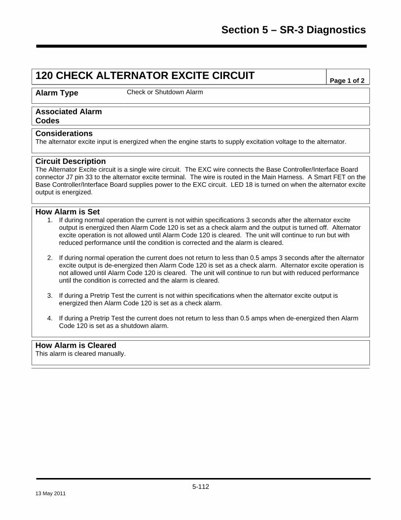
Section 5 – SR-3 Diagnostics
120 CHECK ALTERNATOR EXCITE CIRCUIT Page 1 of 2
Alarm Type Check or Shutdown Alarm
Associated Alarm Codes
Considerations The alternator excite input is energized when the engine starts to supply excitation voltage to the alternator.
Circuit Description The Alternator Excite circuit is a single wire circuit. The EXC wire connects the Base Controller/Interface Board connector J7 pin 33 to the alternator excite terminal. The wire is routed in the Main Harness. A Smart FET on the Base Controller/Interface Board supplies power to the EXC circuit. LED 18 is turned on when the alternator excite output is energized.
How Alarm is Set 1. If during normal operation the current is not within specifications 3 seconds after the alternator excite
output is energized then Alarm Code 120 is set as a check alarm and the output is turned off. Alternator excite operation is not allowed until Alarm Code 120 is cleared. The unit will continue to run but with reduced performance until the condition is corrected and the alarm is cleared.
2. If during normal operation the current does not return to less than 0.5 amps 3 seconds after the alternator
excite output is de-energized then Alarm Code 120 is set as a check alarm. Alternator excite operation is not allowed until Alarm Code 120 is cleared. The unit will continue to run but with reduced performance until the condition is corrected and the alarm is cleared.
3. If during a Pretrip Test the current is not within specifications when the alternator excite output is
energized then Alarm Code 120 is set as a check alarm.
4. If during a Pretrip Test the current does not return to less than 0.5 amps when de-energized then Alarm Code 120 is set as a shutdown alarm.
How Alarm is Cleared This alarm is cleared manually.
5-112 13 May 2011

Section 5 – SR-3 Diagnostics
120 CHECK ALTERNATOR EXCITE CIRCUIT Page 2 of 2
Diagnostic Procedure Download the ServiceWatch data logger using Wintrac. Review the data using Technician Level to determine the conditions at the time the alarm was set. Conditions relevant to the alarm are recorded when the alarm is set and cleared. This data can be very helpful in determining the cause of the alarm.
1. Check the operation of the alternator excite circuit using Interface Board Test Mode. Be sure the alternator excite circuit LED lights. If the alternator excite circuit LED 18 lights then go to Step 2. If the alternator excite circuit LED 18 does not light then go to Step 3.
2. If the alternator excite circuit LED 18 does light then check for 12 Vdc at the alternator excite terminal. If
12 Vdc is not present check for a short circuit, open circuit or loose connection.
3. If the alternator excite circuit LED 18 does not light then check the circuit with an accurate ohmmeter for a short circuit, open circuit or loose connection.
4. Disconnect the EXC wire at the alternator and check for 12 Vdc when the engine is running. If 12 VDC is
not present check the EXC circuit for continuity.
5. Check the Base Controller/Interface Board as shown by Service Procedure A01A.
5-113 13 May 2011

Section 5 – SR-3 Diagnostics
121 CHECK PWM/LIQUID INJECTION CIRCUIT Page 1 of 1
Alarm Type Log or Shutdown Alarm (Pretrip only)
Associated Alarm Codes
Alarm Code 111 Unit Not Configured Correctly
How Alarm is Set The PWM/Liquid Injection Circuit is not currently used. However, the associated output is checked during the Non-running Pretrip Test to be certain nothing has been mistakenly connected to it. The output is energized and then de-energized to insure that no device is connected to the circuit and that the Base Controller/Interface Board is operating properly.
1. If the unit is not configured as a screw compressor or scroll compressor and current flow is detected when the output is energized then Alarm Code 121 is set as a log alarm and Alarm Code 111 Unit Not Configured Correctly is also set as a log alarm.
How Alarm is Cleared This alarm is cleared manually.
Diagnostic Procedure 1. Check unit configuration to confirm proper setting.
2. Check the Base Controller/Interface Board wiring to insure that there is no connection to connector J7,
pin 10.
3. Check the Base Controller/Interface Board as shown by Service Procedure A01A.
5-114 13 May 2011
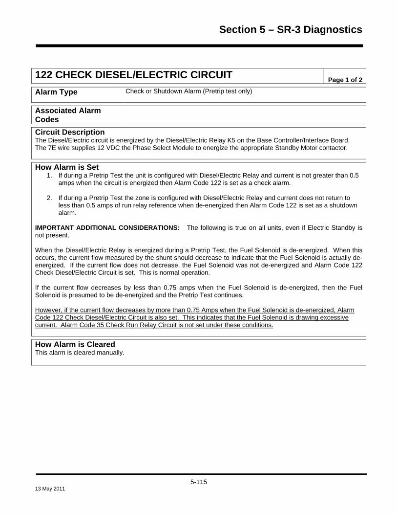
Section 5 – SR-3 Diagnostics
122 CHECK DIESEL/ELECTRIC CIRCUIT Page 1 of 2
Alarm Type Check or Shutdown Alarm (Pretrip test only)
Associated Alarm Codes
Circuit Description The Diesel/Electric circuit is energized by the Diesel/Electric Relay K5 on the Base Controller/Interface Board. The 7E wire supplies 12 VDC the Phase Select Module to energize the appropriate Standby Motor contactor.
How Alarm is Set 1. If during a Pretrip Test the unit is configured with Diesel/Electric Relay and current is not greater than 0.5
amps when the circuit is energized then Alarm Code 122 is set as a check alarm.
2. If during a Pretrip Test the zone is configured with Diesel/Electric Relay and current does not return to less than 0.5 amps of run relay reference when de-energized then Alarm Code 122 is set as a shutdown alarm.
IMPORTANT ADDITIONAL CONSIDERATIONS: The following is true on all units, even if Electric Standby is not present. When the Diesel/Electric Relay is energized during a Pretrip Test, the Fuel Solenoid is de-energized. When this occurs, the current flow measured by the shunt should decrease to indicate that the Fuel Solenoid is actually de-energized. If the current flow does not decrease, the Fuel Solenoid was not de-energized and Alarm Code 122 Check Diesel/Electric Circuit is set. This is normal operation. If the current flow decreases by less than 0.75 amps when the Fuel Solenoid is de-energized, then the Fuel Solenoid is presumed to be de-energized and the Pretrip Test continues. However, if the current flow decreases by more than 0.75 Amps when the Fuel Solenoid is de-energized, Alarm Code 122 Check Diesel/Electric Circuit is also set. This indicates that the Fuel Solenoid is drawing excessive current. Alarm Code 35 Check Run Relay Circuit is not set under these conditions.
How Alarm is Cleared This alarm is cleared manually.
5-115 13 May 2011

Section 5 – SR-3 Diagnostics
122 CHECK DIESEL/ELECTRIC CIRCUIT Page 2 of 2
Diagnostic Procedure Download the ServiceWatch data logger using Wintrac. Review the data using Technician Level to determine the conditions at the time the alarm was set. Conditions relevant to the alarm are recorded when the alarm is set and cleared. This data can be very helpful in determining the cause of the alarm.
1. Check the operation of the Diesel/Electric relay using Interface Board Test Mode in the Maintenance Menu. Be sure the Diesel/Electric LED 7 lights.
2. Use the HMI control panel amps gauge to check the current drawn by the Diesel/Electric relay while operating the Diesel/Electric relay with Interface Board Test Mode. The current draw should be between 0.1 to 2 amps.
3. If Alarm Code 122 Check Diesel/Electric Circuit is set, check the current draw of the Fuel Solenoid using
Interface Board Test Mode. If the current draw for the Fuel Solenoid decreases by more than 0.75 amps during the Diesel/Electric Relay Test, the Fuel Solenoid should be replaced.
Note: A replacement fuel solenoid can be plugged in but not physically installed and a Pretrip Test run to confirm the original fuel solenoid is the source of the problem. IMPORTANT: Do not replace the Base Controller or Interface Board without first confirming that Alarm Code 122 Check Diesel/Electric Circuit was not set by the Fuel Solenoid drawing current in excess of 0.75 amps.
5-116 13 May 2011

Section 5 – SR-3 Diagnostics
127 SETPOINT NOT ENTERED Page 1 of 1
Alarm Type Check Alarm
Associated Alarm Codes
How Alarm is Set 1. If the setpoint was changed but the change was not confirmed by pressing the YES key then Alarm Code
127 Setpoint Not Entered is set as a check alarm. The setpoint has not been changed and has returned to the original setting.
How Alarm is Cleared This alarm is cleared manually. Diagnostic Procedure Information only. Be sure setpoint is adjusted properly.
5-117 13 May 2011

Section 5 – SR-3 Diagnostics
128 ENGINE RUN TIME MAINTENANCE REMINDER #1 Page 1 of 1
129 ENGINE RUN TIME MAINTENANCE REMINDER #2 Page 1 of 1
130 ELECTRIC RUN TIME MAINTENANCE REMINDER #1 Page 1 of 1
131 ELECTRIC RUN TIME MAINTENANCE REMINDER #2 Page 1 of 1
132 TOTAL UNIT RUN TIME MAINTENANCE REMINDER #1
Page 1 of 1
133 TOTAL UNIT RUN TIME MAINTENANCE REMINDER #2
Page 1 of 1
134 CONTROLLER POWER ON HOURS Page 1 of 1
Alarm Type Log Alarm
Associated Alarm Codes
Considerations The programmable hourmeter alarms can be cleared from the Guarded Access Menu only.
How Alarm is Set 1. If one of the hourmeters above has exceeded the programmed time limit then the appropriate alarm code
is set as a log alarm.
How Alarm is Cleared This alarm is cleared from the Guarded Access Menu only.
Diagnostic Procedure 1. Perform required maintenance, as dictated by owner requirements.
2. Reset the hourmeter limit after completion using the Hourmeter menu. See Section 4 for details.
5-118 13 May 2011

Section 5 – SR-3 Diagnostics
135 CHECK SPARE DIGITAL INPUTS Page 1 of 1
Alarm Type Check Alarm (Pretrip Only)
Associated Alarm Codes
How Alarm is Set The Pretrip test indicates that a connection has been made to a spare digital input and should not have been.
How Alarm is Cleared This alarm is cleared manually.
Diagnostic Procedure Correct the wiring error.
136 CHECK SPARE DIGITAL OUTPUTS Page 1 of 1
Alarm Type Check Alarm (Pretrip Only)
Associated Alarm Codes
How Alarm is Set The Pretrip test indicates that a connection has been made to a spare digital output and should not have been.
How Alarm is Cleared This alarm is cleared manually.
Diagnostic Procedure Correct the wiring error.
5-119 13 May 2011
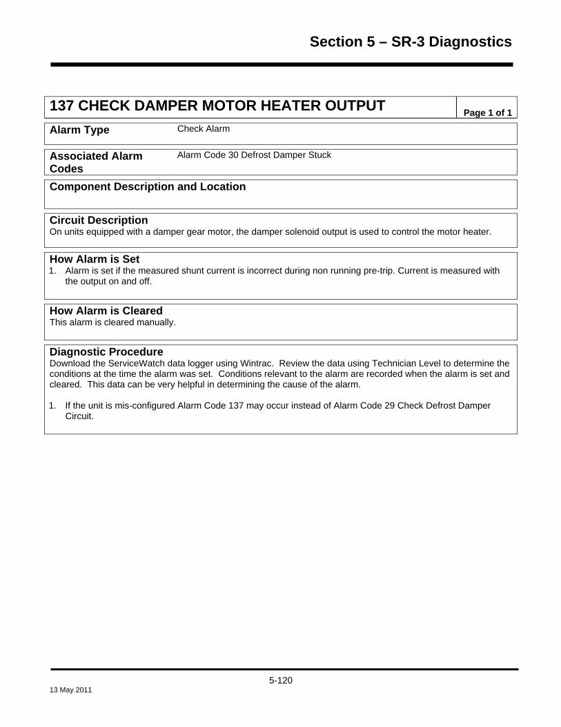
Section 5 – SR-3 Diagnostics
137 CHECK DAMPER MOTOR HEATER OUTPUT Page 1 of 1
Alarm Type Check Alarm
Associated Alarm Codes
Alarm Code 30 Defrost Damper Stuck
Component Description and Location
Circuit Description On units equipped with a damper gear motor, the damper solenoid output is used to control the motor heater.
How Alarm is Set 1. Alarm is set if the measured shunt current is incorrect during non running pre-trip. Current is measured with
the output on and off.
How Alarm is Cleared This alarm is cleared manually.
Diagnostic Procedure Download the ServiceWatch data logger using Wintrac. Review the data using Technician Level to determine the conditions at the time the alarm was set. Conditions relevant to the alarm are recorded when the alarm is set and cleared. This data can be very helpful in determining the cause of the alarm. 1. If the unit is mis-configured Alarm Code 137 may occur instead of Alarm Code 29 Check Defrost Damper
Circuit.
5-120 13 May 2011

Section 5 – SR-3 Diagnostics
141 AUTO-SWITCH DIESEL TO ELECTRIC DISABLED Page 1 of 1
Alarm Type Check Alarm
Considerations When this alarm is set the unit will remain in Diesel Mode operation even when connected to a fully functional electric standby power system.
How Alarm is Set 1. If the Autoswitch Diesel to Electric feature is set yes and the unit switches to Electric Mode operation and
an Electric Mode shutdown alarm is already set, then Alarm Code 141 Auto-switch Diesel to Electric is set as a check alarm.
How Alarm is Cleared This alarm is cleared manually.
Diagnostic Procedure 1. Check for associated alarms and repair as required.
5-121 13 May 2011

Section 5 – SR-3 Diagnostics
145 LOSS OF CONTROLLER “ON” FEEDBACK SIGNAL Page 1 of 1
Alarm Type Log Alarm
Circuit Description The Base Controller/Interface Board “On” feedback signal is supplied by 8X power flowing through fuse F7 (2A) to pin 6 on the CAN connectors J12, J13 and J14. The power on pin 6 of CAN connector J14 flows to the HMI Control Panel pin 6. The presence of power at pin 6 of the HMI Control Panel indicates that power is present on the 8X circuits. Active CAN communications indicate the K9 On/Off Relay is energized and the Base Controller/Interface Board is running. If CAN communications are active but power is not present at pin 6 of the HMI Control Panel then there is a problem with the 8XP or 8X circuit(s).
How Alarm is Set 1. If communications have been established between the Base Controller/Interface Board and a CAN
connected device such as the HMI Control Panel or an iBox and the device feedback input is low for 3 seconds then set Alarm Code 145 Loss of Controller “ON” Feedback Signal as a log alarm.
How Alarm is Cleared This alarm is cleared manually.
Diagnostic Procedure 1. Verify that fuse F7 is not blown. If fuse F7 is blown, check the 8XP circuit for shorts. This circuit supplies
power to pin 6 of all of the CAN communication ports (J12, J13 and J14) on the Base Controller/Interface Board. If necessary, check for shorts at any devices connected to any of the CAN ports.
2. Check for power at pin 6 of the HMI Control Panel. If power is not present, check for an open in the 8XP
circuit from fuse F7 to pin 6 of the CAN communication ports.
5-122 13 May 2011
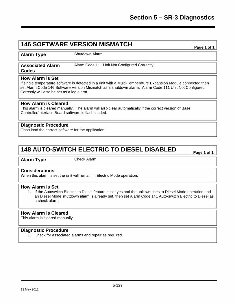
Section 5 – SR-3 Diagnostics
146 SOFTWARE VERSION MISMATCH Page 1 of 1
Alarm Type Shutdown Alarm
Associated Alarm Codes
Alarm Code 111 Unit Not Configured Correctly
How Alarm is Set If single temperature software is detected in a unit with a Multi-Temperature Expansion Module connected then set Alarm Code 146 Software Version Mismatch as a shutdown alarm. Alarm Code 111 Unit Not Configured Correctly will also be set as a log alarm.
How Alarm is Cleared This alarm is cleared manually. The alarm will also clear automatically if the correct version of Base Controller/Interface Board software is flash loaded.
Diagnostic Procedure Flash load the correct software for the application.
148 AUTO-SWITCH ELECTRIC TO DIESEL DISABLED Page 1 of 1
Alarm Type Check Alarm
Considerations When this alarm is set the unit will remain in Electric Mode operation.
How Alarm is Set 1. If the Autoswitch Electric to Diesel feature is set yes and the unit switches to Diesel Mode operation and
an Diesel Mode shutdown alarm is already set, then set Alarm Code 141 Auto-switch Electric to Diesel as a check alarm.
How Alarm is Cleared This alarm is cleared manually.
Diagnostic Procedure 1. Check for associated alarms and repair as required.
5-123 13 May 2011

Section 5 – SR-3 Diagnostics
149 ALARM NOT IDENTIFIED Page 1 of 1
Alarm Type Check
Considerations IMPORTANT: This alarm, if present does not affect unit operation. It is an information only alarm. If set, this alarm code may not appear in either the CargoWatch or ServiceWatch Data Loggers.
How Alarm is Set If an alarm in the alarm queue cannot be identified then Alarm Code 149 Alarm Not Identified is set as a Check alarm.
How Alarm is Cleared This alarm is cleared manually. This alarm may not be able to be cleared from the Main or Guarded Access Menu. If Alarm Code 149 cannot be cleared a Cold Start may be required to allow the alarm to be cleared.
Diagnostic Procedure Download the ServiceWatch data logger using Wintrac. Review the data using Technician Level to determine the conditions at the time the alarm was set. Conditions relevant to the alarm are recorded when the alarm is set and cleared. This data can be very helpful in determining the cause of the alarm.
1. Check and correct other existing alarms.
2. If Alarm Code 149 Alarm Not Identified is set, perform a Base Controller Cold Start as shown by Service Procedure A07A. Be sure to record programmable settings before performing the Cold Start and re-program all settings after the Cold Start is completed. Clear all alarm codes.
3. If Alarm Code 149 Alarm Not Identified is still set, it may not be possible to clear it. Should this be the case, consult the Minneapolis Service Department for instructions on how to proceed.
5-124 13 May 2011

Section 5 – SR-3 Diagnostics
150 OUT OF RANGE LOW Page 1 of 1
Alarm Type Log Alarm
Considerations The CargoWatch temperatures and times that will cause an alarm to be set are user programmable. These CargoWatch Data Logger features are configured as required for the particular customer applications. See the Sensor Configuration Menu – CargoWatch Data Logger in Section 3 of this manual for details. This alarm is only logged in the CargoWatch Data Logger. Be sure the CargoWatch Data Logger is downloaded before installing HMI Control Panel software, as the HMI Control Panel Cold Start will erase any existing data in the CargoWatch Logger.
How Alarm is Set 1. If the temperature falls below the user programmed temperature for the user programmed time interval
then Alarm Code 150 Out of Range Low is set as a log alarm.
2. If a CargoWatch sensor is open or shorted then Alarm Code 150 Out of Range Low is set as a log alarm.
3. If Out of Range Checking is turned On and no CargoWatch sensors are connected then Alarm Code 150 Out of Range Low is set as a log alarm.
How Alarm is Cleared This alarm is cleared manually.
Diagnostic Procedure Download the CargoWatch data logger using Wintrac. Review the data to determine the conditions at the time the alarm was set. Additional data may be accessed by reviewing the ServiceWatch data logger download. This data can be very helpful in determining the cause of the alarm.
1. Determine the cause of low CargoWatch sensor temperature and correct as necessary.
2. If no CargoWatch sensors are connected and the Out of Range feature is turned On, perform an HMI Control Panel Cold Start using Wintrac. The Cold Start will set the Out of Range Checking to Off. Be sure the CargoWatch Data Logger is downloaded before installing HMI Control Panel software, as the HMI Control Panel Cold Start will erase any existing data in the CargoWatch Data Logger.
IMPORTANT: Do not attempt a cold start using the Base Controller/Interface Board jumpers or with the download cable connected to the ServiceWatch port as this will restart the SR-3 Base Controller/Interface Board, not the HMI Control Panel.
5-125 13 May 2011

Section 5 – SR-3 Diagnostics
151 OUT OF RANGE HIGH Page 1 of 1
Alarm Type Log Alarm
Considerations The CargoWatch temperatures and times that will cause an alarm to be set are user programmable. These CargoWatch Data Logger features are configured as required for the particular customer applications. See the Sensor Configuration Menu – CargoWatch Data Logger in Section 3 of this manual for details. This alarm is only logged in the CargoWatch Data Logger. Be sure the CargoWatch Data Logger is downloaded before installing HMI Control Panel software, as the HMI Control Panel Cold Start will erase any existing data in the CargoWatch Logger.
How Alarm is Set 1. If the temperature falls above the user programmed temperature for the user programmed time interval
then Alarm Code 150 Out of Range High is set as a log alarm.
2. If a CargoWatch sensor is open or shorted then Alarm Code 150 Out of Range High is set as a log alarm.
3. If Out of Range Checking is turned On and no CargoWatch sensors are connected then Alarm Code 150 Out of Range High is set as a log alarm.
How Alarm is Cleared This alarm is cleared manually.
Diagnostic Procedure Download the CargoWatch data logger using Wintrac. Review the data to determine the conditions at the time the alarm was set. Additional data may be accessed by reviewing the ServiceWatch data logger download. This data can be very helpful in determining the cause of the alarm.
1. Determine the cause of low CargoWatch sensor temperature and correct as necessary.
2. If no CargoWatch sensors are connected and the Out of Range feature is turned On, perform an HMI Control Panel Cold Start using Wintrac. The Cold Start will set the Out of Range Checking to Off. Be sure the CargoWatch Data Logger is downloaded before installing HMI Control Panel software, as the HMI Control Panel Cold Start will erase any existing data in the CargoWatch Data Logger.
IMPORTANT: Do not attempt a cold start using the Base Controller/Interface Board jumpers or with the download cable connected to the ServiceWatch port as this will restart the SR-3 Base Controller/Interface Board, not the HMI Control Panel.
5-126 13 May 2011

Section 5 – SR-3 Diagnostics
157 OPTISET FILE MISMATCH Page 1 of 2
Alarm Type Check Alarm
Associated Alarm Codes
Considerations
How Alarm is Set Alarm Code 157 OptiSet Plus Profile Mismatch indicates that a problem exists with the OptiSet Plus Temperature Profiles. Alarm Code 157 will be set as a check alarm on power-up if the OptiSet configuration in the Base Controller does not match the configuration held in the HMI Control Panel. This alarm condition usually occurs if the Base Controller is Cold Started or replaced. If OptiSet Plus with Named Products is in use and the Base Controller is Cold Started or replaced with a new Base Controller, the Named Temperature Profiles are deleted by the Cold Start or do not exist in the replacement Base Controller but still exist in the HMI Control Panel. The following conditions will be present:
1. Alarm Code 157 OptiSet Plus Profile Mismatch will be set.
2. Alarm Code 157 may be able to be cleared manually but will re-occur when the unit is powered off and
back on.
3. The OptiSet Plus Reset selection in Guarded Access Menu may not be available. An OptiSet Plus Reset can still be performed using Wintrac.
If the number of profiles held in the SR-3 Base Controller/Interface Board memory does not match the number of profiles expected by WinTrac, then Alarm Code 157 OptiSet File Mismatch is set as a Check Alarm. If the OptiSet Configuration held in the SR-3 Base Controller/Interface Board does not match the OptiSet Configuration held in the HMI Control Panel when the unit is powered up, then Alarm Code 157 OptiSet File Mismatch is set as a Check Alarm.
How Alarm is Cleared This alarm is cleared manually.
5-127 13 May 2011

Section 5 – SR-3 Diagnostics
157 OPTISET FILE MISMATCH Page 2 of 2
Diagnostic Procedure 1. OptiSet Plus File is Available: If the correct OptiSet Plus File is available, sending the OptiSet Plus
File to the ServiceWatch Data Logger will transfer the correct Temperature Profiles to both the Base Controller and the HMI Control Panel. The OptiSet Plus Temperature Profiles in the Base Controller and HMI Control Panel now match. Alarm Code 157 can be cleared manually.
2. OptiSet Plus File is Not Available: Sending an OptiSet Plus Reset using Wintrac will reset both the Base Controller and the HMI Control Panel to OptiSet defaults. All OptiSet Plus Temperature Profiles will be cleared from both the Base Controller and HMI Control Panel – OptiSet Plus will be set to factory defaults with Numeric Settings only. Important: The OptiSet Plus Reset selection in Guarded Access Menu may not be available. An OptiSet Plus Reset can still be performed using Wintrac. Important: The Wintrac OptiSet Plus Reset will occur deceivingly fast and is not reported as successful by Wintrac. However, the OptiSet Plus Reset will be performed. There are no OptiSet Plus Temperature Profiles in either the Base Controller or HMI Control Panel. Alarm Code 157 can be cleared manually.
3. Alternative Action if OptiSet Plus File is Not Available: Perform an HMI Control Panel Cold Start as
shown by Service Procedure A07B. The HMI Control Panel will be reset to defaults and all OptiSet Plus Temperature Profiles will be cleared from the HMI. OptiSet Plus will be set to factory defaults with Numeric Settings only. Important: The CargoWatch Data Logger will also be cleared. Be sure to download the CargoWatch Data Logger before performing a Cold Start. There are no OptiSet Plus Temperature Profiles in the Base Controller or HMI Control Panel. Alarm Code 157 can be cleared manually.
4. Allow Alarm Code 157 to remain set: Alarm Code 157 OptiSet Plus Profile Mismatch can be left set
temporarily, but then only Numeric Setpoints will be available.
5-128 13 May 2011

Section 5 – SR-3 Diagnostics
157 - A NUMBERS IN LIEU OF NAMED PRODUCTS Page 1 of 1
Alarm Type NONE - No alarm code is set
Condition A Long String of Numbers is Present In Lieu of Named Products but Alarm Code 157 Is Not Present.
What Causes Condition If OptiSet Plus with Named Products is in use and the HMI Control Panel is Cold Started or replaced with a new HMI Control Panel, the Named Temperature Profiles are deleted by the Cold Start or do not exist in the replacement HMI Control Panel but still exist in the Base Controller. The following conditions will exist:
1. A long string of numbers will be shown in place of Named Product names.
2. The OptiSet Plus Reset can be performed using either the Guarded Access Menu or Wintrac.
Corrective Action
1. OptiSet Plus File is Available: If the correct OptiSet Plus File is available, sending the OptiSet Plus File to the ServiceWatch Data Logger will transfer the correct Temperature Profiles to both the Base Controller and the HMI Control Panel. The OptiSet Plus Temperature Profiles in the Base Controller and HMI Control Panel now match. The Named Profiles will now be present in lieu of the long strings of numbers.
2. OptiSet Plus File is Not Available: Sending an OptiSet Plus Reset using the Guarded Access Menu or Wintrac will reset both the Base Controller and the HMI Control Panel to OptiSet defaults. All OptiSet Plus Temperature Profiles will be cleared from both the Base Controller and HMI Control Panel – OptiSet Plus will be set to factory defaults with Numeric Settings only. Important: The Wintrac OptiSet Plus Reset will occur deceivingly fast and is not reported as successful by Wintrac. However, the OptiSet Plus Reset will be performed. There are no OptiSet Plus Temperature Profiles in either the Base Controller or HMI Control Panel.
3. Alternative Action if OptiSet Plus File is Not Available: Perform a Base Controller Cold Start as shown by Service Procedure A07A. The Base Controller will be reset to defaults. Be sure to record programmable settings before performing the Cold Start and re-program all settings after the Cold Start is completed. Clear all alarm codes. All OptiSet Plus Temperature Profiles will be cleared – OptiSet Plus will be set to factory defaults with Numeric Settings only. Important: All Guarded Access Programmable Feature settings will be cleared and set to factory defaults. Be sure to record all Guarded Access settings before performing the Cold Start. All Guarded Access Settings must be set to the recorded values or customer specifications before releasing the unit for service.
There are no OptiSet Plus Temperature Profiles in either the Base Controller or HMI Control Panel.
5-129 13 May 2011

Section 5 – SR-3 Diagnostics
158 SOFTWARE FAILED TO LOAD Page 1 of 1
Alarm Type Check Alarm
Associated Alarm Codes
Considerations Base Controller Software flash loads via WinTrac, USB Flash Drive or other methods are all performed and checked in the same manner.
How Alarm is Set When new software is being flash loaded to a Base Controller, the current revision software is held intact until the new revision software is installed and verified. If the flash load is unsuccessful, the Base Controller will continue to operate with the current revision software and Alarm Code 158 Software Failed to Load will be set as a check alarm.
How Alarm is Cleared This alarm is cleared automatically when the new software is successfully flash loaded. The alarm can be cleared manually, but will return when the unit power is switched off and back on.
Diagnostic Procedure Retry the flash load procedure.
5-130 13 May 2011

Section 5 – SR-3 Diagnostics
203 CHECK DISPLAY RETURN AIR SENSOR Page 1 of 3
Alarm Type Check Alarm (Shutdown Alarm during a Pretrip Test).
Associated Alarm Codes
Alarm Code 11 Unit Controlling on Alternate Sensor Alarm Code 13 Sensor Check Alarm Code 92 Sensor Grades Not Set Alarm Code 03 Check (Control) Return Air Sensor
Component Description and Location This sensor is one of a pair of return air sensors. Both return air sensors must agree within specified limits. The sensor associated with Alarm Code 203 Check Display Return Air Sensor is used to display the temperature. The sensor is located next to the control return air sensor in the return air stream. The harness wires to this sensor are marked with two yellow cables tie near the sensor connection. It is a graded sensor. A brass clamp should be installed between the two return air sensors. This clamp increases the thermal coupling between the sensors to provide more accurate temperature readings when the temperature is changing rapidly. Rapid temperature changes may occur during pulldown or when the door has been opened. This clamp is not required on the discharge air sensors.
Circuit Description The display return air temperature sensor circuit is a two wire circuit. The RTRP-01 (+) wire connects the Base Controller/Interface Board 35 pin sensor connector J3 pin 21 to the blue sensor wire. The RTRN-01 (-) wire connects the Base Controller/Interface Board 35 pin sensor connector J3 pin 32 to the brown sensor wire. The sensor wires are routed in the Sensor Harness. The harness wires to this sensor are marked with two yellow cables tie near the sensor connection. The sensor is hard wired to the sensor harness.
Considerations 1. If the unit is controlling on return air temperature and a problem occurs with either return air sensor, the
unit will switch to Discharge Air Control and Alarm Code 11 Unit Controlling on Alternate Sensor will be set. The appropriate sensor alarm codes will also be set.
2. Sensor codes must be cleared from the Guarded Access Menu before Alarm Code 11 Unit Controlling on
Alternate Sensor can be cleared.
3. Sensor grades must be correctly set to the actual grade of the sensor installed. Failure to do so may result in nuisance sensor alarm codes.
4. Sensors should be positioned to minimize the potential for moisture entry where the wires enter the
sensor shell. Mount sensors with the barrel up and the wires down wherever possible.
5. See Alarm Code 13 for an explanation of “Soft Failures” and “Hard Failures”.
5-131 13 May 2011

Section 5 – SR-3 Diagnostics
203 CHECK DISPLAY RETURN AIR SENSOR Page 2 of 3
How Alarm is Set 1. If the sensor reading is over 200°F (93°C) for 10 seconds then Alarm Code 203 is set as a check alarm.
The sensor reading will display dashes [ - - - ] and may return to normal. This condition is termed a “hard” sensor failure.
2. If the sensor reading is under -50°F (-46°C) for 10 seconds then Alarm Code 203 is set as a check alarm.
The sensor reading will display dashes [ - - - ] may return to normal. This condition is termed a “hard” sensor failure.
3. If the differential between the return air temperature and other temperature sensors is too large when
Alarm Code 03 is cleared then Alarm Code 203 and Alarm Code 13 Sensor Calibration Check are set as check alarms. This condition is termed a “soft” sensor failure.
4. If the sensor reading is erratic over time but does not go above 200°F (93°C) or below -50°F (-46°C) then
Alarm Code 203 and Alarm Code 13 Sensor Calibration Check are set as check alarms. This condition is termed a “soft” sensor failure.
5. If the sensor grade for this sensor is set to 5H then Alarm Code 203 and Alarm Code 92 Sensor Grades
Not Set are set as check alarms.
6. The temperatures of the control return air sensor and display return air sensor twins are not within a specified range. If the faulty sensor can be determined, only the alarm code for that sensor and Alarm Code 13 Sensor Check will be set. Alarm Codes 03 Check (Control) Return Air Sensor, 203 Check Display Return Air Sensor, and 13 Sensor Check are set if the faulty sensor cannot be determined.
How Alarm is Cleared This alarm can only be cleared manually from the Guarded Access menu. When the alarm is cleared the return air sensors, discharge air sensors and evaporator coil sensor must all read within 30°F (17°C) of each other. If they do not, it is assumed that the sensor reading is not accurate. The alarm code is not cleared and Alarm Code 13 Sensor Calibration Check will also be set. Also, if the sensor is over or under range when the alarm clear is attempted, the alarm will not be cleared. If the alarm is set by Condition #5 above, Alarm Code 92 will clear automatically if the sensor grade is changed from 5H. If the sensor grade remains 5H, Alarm Code 92 can not be cleared.
Programmable Features This is a graded sensor. The sensor grade must be correctly set in the Guarded Access Menu.
5-132 13 May 2011

Section 5 – SR-3 Diagnostics
203 CHECK DISPLAY RETURN AIR SENSOR Page 3 of 3
Diagnostic Procedure Download the ServiceWatch data logger using Wintrac. Review the data using Technician Level to determine the conditions at the time the alarm was set. Conditions relevant to the alarm are recorded when the alarm is set and cleared. This data can be very helpful in determining the cause of the alarm. Alarm Code 203 (Sensor was out of range)
1. Display the sensor reading using the Sensor Menu. If the display shows [----], the sensor is defective and should be replaced. If the condition still exists, check the sensor circuit for an open wire or short to ground. See Service Procedure D01A. Check the Base Controller/Interface Board using Service Procedure A01A.
2. If the display is normal proceed as shown below.
Alarm Code 203 and Alarm Code 13 (Sensor drifted or was reading erratically) 1. Review the ServiceWatch data logger and check the senor reading at the time the alarm was set. Also,
review the history to see if previous alarm codes exist that would indicate an intermittent problem. If the sensor appears to have read incorrectly, it should be replaced.
2. Be sure the sensor grades are set to the actual sensor grade. 3. Check for an airflow obstruction and correct sensor mounting. 4. If the problem reoccurs, check the sensor connector as shown in Service Procedure D01A. 5. Check the sensor circuit, as shown by Service Procedure D01A.
Alarm Code 203 and Alarm Code 92 (Sensor grade set to 5H)
1. Verify and set the sensor grade. Alarm Code 03 and/or Alarm Code 203 are set with Alarm Code 13 (Dual sensors don’t agree)
1. Review the ServiceWatch data logger and check the sensor readings at the time the alarm was set. Also, review the history to see if previous alarm codes exist that would indicate the problem sensor. If a sensor appears to have read incorrectly, it should be replaced.
2. Check for an airflow obstruction and correct sensor mounting. Be sure the brass clamp is installed on the
two return air sensors.
3. Be sure the sensor grades are set to the actual sensor grade, and are not transposed.
4. If the offending sensor cannot be determined, either ice bath both return air sensors simultaneously to determine which sensor is inaccurate or replace both sensors.
If all or many of the Sensor Alarm Codes (02, 03, 04, 05, 06, 11, 12, 203 and 204) are set
1. Be sure the 35 pin Base Controller/Interface Board sensor connector J3 is connected securely.
2. Check the Base Controller/Interface Board as shown by Service Procedure A01A.
5-133 13 May 2011

Section 5 – SR-3 Diagnostics
204 CHECK DISPLAY DISCHARGE AIR SENSOR Page 1 of 3
Alarm Type Check Alarm (Shutdown Alarm during a Pretrip Test).
Associated Alarm Codes
Alarm Code 11 Unit Controlling on Alternate Sensor Alarm Code 13 Sensor Check Alarm Code 92 Sensor Grades Not Set Alarm Code 04 Check (Control) Return Air Sensor
Component Description and Location This sensor is one of a pair of dual discharge air sensors. Both discharge air sensors must agree within specified limits. The sensor associated with Alarm Code 204 Check Display Discharge Air Sensor is used to display the temperature. The sensor is located next to the display discharge air sensor in the discharge air stream. The harness wires to this sensor are marked with two red cable ties near the sensor connection. It is a graded sensor.
Circuit Description The discharge air temperature sensor circuit is a two wire circuit. The DTRP-01 (+) wire connects the Base Controller/Interface Board 35 pin sensor connector J3 pin 21 to the blue sensor wire. The DTRN-01 (-) wire connects the Base Controller/Interface Board 35 pin sensor connector J3 pin 33 to the brown sensor wire. The sensor wires are routed in the Sensor Harness. The harness wires to this sensor are marked with two red cables tie near the sensor connection. The sensor is hard wired to the sensor harness.
Considerations 1. If the unit is controlling on discharge air temperature, and a problem occurs with either discharge air
sensor, the unit will switch to Return Air Control and Alarm Code 11 Unit Controlling on Alternate Sensor will be set. The appropriate sensor alarm codes will also be set.
2. Sensor codes must be cleared from the Guarded Access Menu before Alarm Code 11 Unit Controlling on
Alternate Sensor can be cleared.
3. Sensor grades must be correctly set to the actual grade of the sensor installed. Failure to do so may result in nuisance sensor alarm codes.
4. Sensors should be positioned to minimize the potential for moisture entry where the wires enter the
sensor shell. Mount sensors with the barrel up and the wires down wherever possible.
5. See Alarm Code 13 for an explanation of “Soft Failures” and “Hard Failures”.
5-134 13 May 2011

Section 5 – SR-3 Diagnostics
204 CHECK DISPLAY DISCHARGE AIR SENSOR Page 2 of 3
How Alarm is Set 1. If the sensor reading is over 200°F (93°C) for 10 seconds then Alarm Code 204 is set as a check alarm.
The sensor reading will display dashes [ - - - ] and may return to normal. This condition is termed a “hard” sensor failure.
2. If the sensor reading is under -50°F (-46°C) for 10 seconds then Alarm Code 204 is set as a check alarm.
The sensor reading will display dashes [ - - - ] may return to normal. This condition is termed a “hard” sensor failure.
3. If the differential between the discharge and other sensors is too large when Alarm Code 04 is cleared then Alarm Code 204 and Alarm Code 13 Sensor Calibration Check are set as check alarms. This condition is termed a “soft” sensor failure.
4. If the sensor reading is erratic over time but does not go above 200°F (93°C) or below -50°F (-46°C) then Alarm Code 204 and Alarm Code 13 Sensor Calibration Check are set as check alarms. This condition is termed a “soft” sensor failure.
5. If the sensor grade for this sensor is set to 5H then both Alarm Code 204 and Alarm Code 92 Sensor Grades Not Set are set as check alarms.
6. The temperatures of the control discharge air sensor and display discharge air sensor twins are not within
a specified range. If the faulty sensor can be determined, only the alarm code for that sensor and Alarm Code 13 Sensor Check will be set. Alarm Codes 04 Check (Control) Discharge Air Sensor, 204 Check Display Discharge Air Sensor, and 13 Sensor Check are set if the faulty sensor cannot be determined.
How Alarm is Cleared This alarm can only be cleared manually from the Guarded Access menu. When the alarm is cleared the return air sensors, discharge air sensors and evaporator coil sensor must all read within 30°F (17°C) of each other. If they do not, it is assumed that the sensor reading is not accurate. The alarm code is not cleared and Alarm Code 13 Sensor Calibration Check will also be set. Also, if the sensor is over or under range when the alarm clear is attempted, the alarm will not be cleared. If the alarm is set by Condition #5 above, Alarm Code 92 will clear automatically if the sensor grade is changed from 5H. If the sensor grade remains 5H, Alarm Code 92 can not be cleared.
Programmable Settings This is a graded sensor. The sensor grade must be correctly set in the Guarded Access Menu.
5-135 13 May 2011

Section 5 – SR-3 Diagnostics
204 CHECK DISPLAY DISCHARGE AIR SENSOR Page 3 of 3
Diagnostic Procedure Download the ServiceWatch data logger using Wintrac. Review the data using Technician Level to determine the conditions at the time the alarm was set. Conditions relevant to the alarm are recorded when the alarm is set and cleared. This data can be very helpful in determining the cause of the alarm. Alarm Code 204 (Sensor was out of range)
1. Display the sensor reading using the Sensor Menu. If the display shows [----], the sensor is defective and should be replaced. If the condition still exists, check the sensor circuit for an open wire or short to ground. See Service Procedure D01A. Check the Base Controller/Interface Board using Service Procedure A01A.
2. If the display is normal proceed as shown below.
Alarm Code 204 and Alarm Code 13 (Sensor drifted or was reading erratically) 1. Review the ServiceWatch data logger and check the sensor reading at the time the alarm was set. Also,
review the history to see if previous alarm codes exist that would indicate an intermittent problem. If the sensor appears to have read incorrectly, it should be replaced.
2. Be sure the sensor grades are set to the actual sensor grade. 3. Check for an airflow obstruction and correct sensor mounting. 4. If the problem reoccurs, check the sensor connector as shown in Service Procedure D01A. 5. Check the sensor circuit, as shown by Service Procedure D01A.
Alarm Code 204 and Alarm Code 92 (Sensor grade set to 5H)
1. Verify and set the sensor grade. Alarm Code 04 and/or Alarm Code 204 are set with Alarm Code 13 (Dual sensors don’t agree)
1. Review the ServiceWatch data logger and check the sensor readings at the time the alarm was set. Also, review the history to see if previous alarm codes exist that would indicate the problem sensor. If a sensor appears to have read incorrectly, it should be replaced.
2. Check for an airflow obstruction and correct sensor mounting.
3. Be sure the sensor grades are set to the actual sensor grade, and are not transposed.
4. If the offending sensor cannot be determined, either ice bath both return air sensors simultaneously to
determine which sensor is inaccurate or replace both sensors. If all or many of the Sensor Alarm Codes (02, 03, 04, 05, 06, 11, 12, 203 and 204) are set
1. Be sure the 35 pin Base Controller/Interface Board sensor connector J3 is connected securely.
2. Check the Base Controller/Interface Board as shown by Service Procedure A01A.
5-136 13 May 2011

Section 5 – SR-3 Diagnostics
252 CHECK FRESH AIR EXCHANGE CIRCUIT Page 1 of 2
Alarm Type Check or Shutdown Alarm
Associated Alarm Codes
Component Description and Location Fresh Air Exchange allows fresh outside air to be drawn into the trailer and the interior air to be exhausted. This feature is beneficial when hauling loads that release gas as they ripen, such as potatoes. The Fresh Air Exchange feature should be used exactly as specified by the customer. IMPORTANT: The Fresh Air Exchange feature is only available with setpoints above 32°F (0°C). The feature is disabled with setpoints of 32°F (0°C) and below. A Damper Solenoid and mechanical linkage is used to open and close the Fresh Air Exchange door.
Circuit Description NOTE: In normal operation the Auto Fresh Air Solenoid is only energized when the unit engine is running. The Fresh Air Exchange circuit is a two wire circuit. The Fresh Air Exchange Solenoid is energized by Relay K8 and Fuse F11 on the Base Controller/Interface Board. The AFA wire applies 12 VDC to one side of the Fresh Air Exchange Solenoid to energize the solenoid. The CHAFA wire connects the other side of the solenoid to chassis ground at the ground plate near the unit battery. The solenoid is not polarity sensitive, but the suppression diode must be installed with the bar end of the diode toward the AFA wire. The wires are routed in the Main Harness. The Fresh Air Reed Switch is closed when the fresh air door is closed and open when the fresh air door is open. Wire numbers AFASW and CHSW supply door position information to the microprocessor digital input at J7 Pin 19.
How Alarm is Set 1. When the Fresh Air Exchange Solenoid is energized, the fresh air door will open and the Auto Fresh Air
Reed Switch will also be open. If a mismatch exists between the Fresh Air Exchange and the Auto Fresh Air Reed Switch, up to three additional attempts to open the door will be made by de-energizing and energizing the Fresh Air Exchange Solenoid at 1 second intervals. If the door still fails to open as indicated by the Auto Fresh Air Reed Switch, Alarm Code 252 is set as a Check Alarm. The Fresh Air Exchange Solenoid will remain energized to open the door if conditions change – for example, should some ice melt that was restricting door movement.
2. If during a Pretrip Test the unit is configured with Fresh Air Exchange and current is not between 2 to 10
amps when the Fresh Air Exchange Solenoid is energized then Alarm Code 252 is set as a check alarm.
3. If during a Pretrip Test the unit is configured with Fresh Air Exchange and current does not return to less than or equal to 0.5 amps when de-energized then Alarm Code 252 is set as a shutdown alarm.
How Alarm is Cleared This alarm is cleared manually.
5-137 13 May 2011

Section 5 – SR-3 Diagnostics
5-138 13 May 2011
252 CHECK FRESH AIR EXCHANGE CIRCUIT Page 2 of 2
Considerations In normal operation the Auto Fresh Air Solenoid is only energized when the unit engine is running.
Diagnostic Procedure Download the ServiceWatch data logger using Wintrac. Review the data using Technician Level to determine the conditions at the time the alarm was set. Conditions relevant to the alarm are recorded when the alarm is set and cleared. This data can be very helpful in determining the cause of the alarm.
1. Check the operation of the Fresh Air Exchange circuit using Interface Board Test Mode. Be sure the Fresh Air Exchange LED 22 lights.
2. Use the HMI Control Panel amps gauge to check the current drawn by the Fresh Air Exchange Solenoid
while operating the Fresh Air Exchange Door with Interface Board Test Mode. The current draw should be approximately 6 amps.
3. Energize the Fresh Air Exchange Solenoid using Interface Board Test Mode and check for battery voltage
on the AFA circuit. If voltage is present and no current was measured in the step above replace the Fresh Air Exchange Solenoid.
4. Verify that the Auto Fresh Air Reed Switch is closed when the fresh air door is closed and open when the
fresh air door is open. Battery voltage should be present at J7 Pin 19 when the switch is open (door is open). 0 volts should be present at J7 Pin 19 when the switch is closed (door is closed).
5. Inspect the Fresh Air Exchange mechanical components for binding or ice buildup.


Section 6 – SR-3 Service Procedure Index
Section 6 Table of Contents A01A Base Controller/Interface Board Functional Test A01B HMI Control Panel Functional Test A01C HMI Control Panel Self Test A02A Recording Existing Programmable Feature Settings A03A Replacement of the Base Controller or Interface Board A03B Replacement of the HMI Control Panel A04A Programmable Feature Setup A05A Clock/Calendar Setup (See Section 4) A06A Checking Software Revision (See Section 4) A07A Performing a Base Controller Cold Start A07B Performing an HMI Control Panel Cold Start A15A Unit Temperature Sensor Grade Calibration A17A Full Pretrip Test (See Section 4) A26A Welding on Units Equipped with Microprocessors A28A Setting Unit Running Time Hourmeters A34A Operating Service Test Mode (See Section 4) A44A Operating Interface Board Test Mode (See Section 4) A46A Flash Loading Base Controller Software A46B Flash Loading HMI Control Panel Software A47B Setting up OptiSet Features using Wintrac A48A Phase Detect Module Operation and Diagnostics A49A CargoWatch Data Logger A50A ServiceWatch Data Logger
~ Continued next page ~
13 May 2011

Section 6 – SR-3 Service Procedure Index
13 May 2011
Section 6 Table of Contents - continued D01A Unit Temperature Sensor Test D03A Pressure Sensor Test D04A CargoWatch Temperature Sensor Test F01A Checking and Replacing the Oil Level Switch F05A Checking the Oil Pressure Switch F07B Magnetic Coolant Level Switch Test F08A Coolant Temperature Sensor Test F09A RPM Sensor Test and Adjustment G03A Electronic Throttling Valve (ETV) Test H04A Wiring Harness Continuity Test

Section 6 – SR-3 and SR-3 M/T Service Procedure A01A
SR-3 Base Controller/Interface Board Functional Test
Where Used
All SR-3 Single Temperature and SR-3 Spectrum Multi-Temperature units
Purpose
To confirm proper operation of the Base Controller/Interface Board
Materials Required
NEW DIAGNOSTIC TOOL An SR-2/SR-3 Diagnostic Tool with Diagnostic Tool Software 4.1 or greater is
required to test the SR-3 Base Controller/Interface Board. The SR-3 Base Controller/Interface Board is currently
used on SR-3 Single Temperature Trailer applications. This Diagnostic Tool will also work on all previous SR-2
Truck and Trailer Base Controller/Interface Boards and Trailer HMI Control Panels. It also tests the Truck
Premium HMI Control Panel.
The new Diagnostic Tool is available as a complete tool and also as an update kit for the SR-2 Blue Diagnostic
Tool. See Section 7 for parts numbers.
Features: The SR-2/SR-3 Diagnostic Tool includes the following new features.
Tests the SR-3 Base Controller/Interface Board
Tests the SR-3 USB Communications Port
Tests the SR-2 and SR-3 Base Controller and HMI Control Panel CAN Ports using a USB to CAN Adaptor
Page 1 P41xA01A 13 May 2011
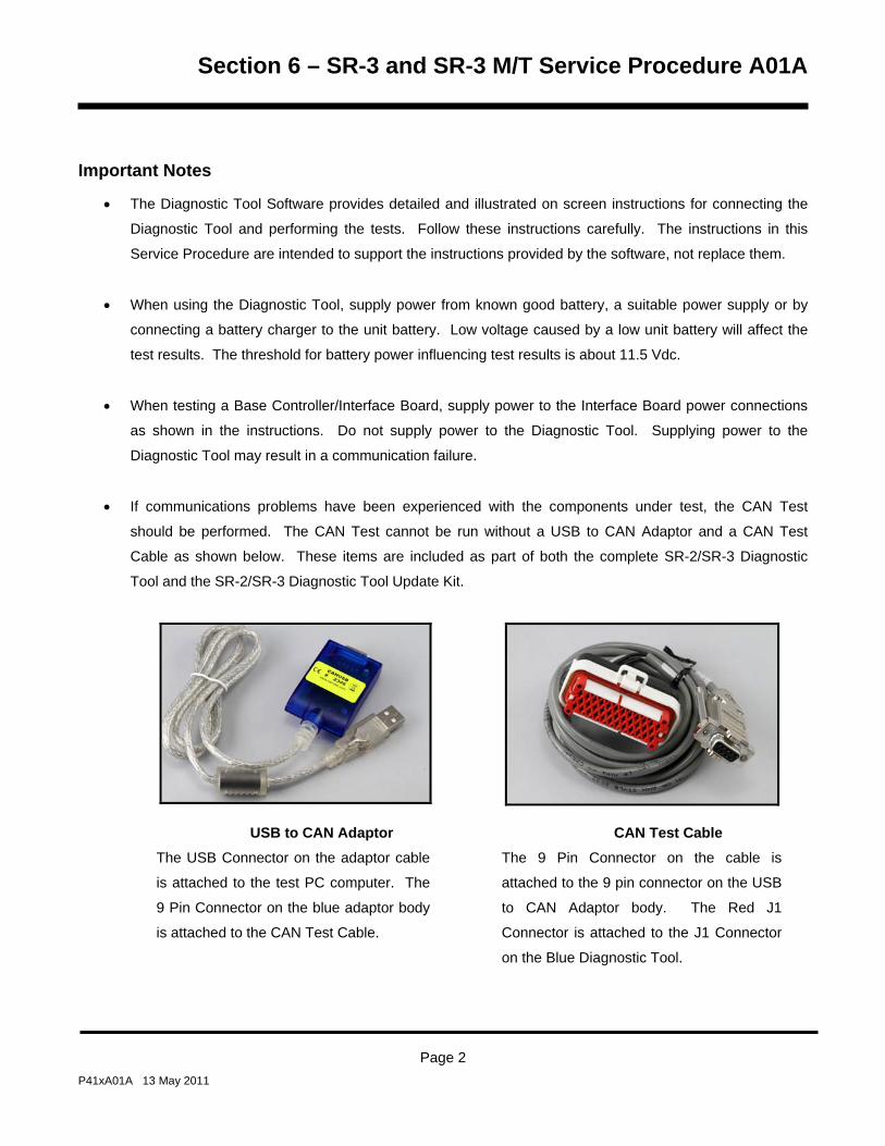
Section 6 – SR-3 and SR-3 M/T Service Procedure A01A
Important Notes
• The Diagnostic Tool Software provides detailed and illustrated on screen instructions for connecting the
Diagnostic Tool and performing the tests. Follow these instructions carefully. The instructions in this
Service Procedure are intended to support the instructions provided by the software, not replace them.
• When using the Diagnostic Tool, supply power from known good battery, a suitable power supply or by
connecting a battery charger to the unit battery. Low voltage caused by a low unit battery will affect the
test results. The threshold for battery power influencing test results is about 11.5 Vdc.
• When testing a Base Controller/Interface Board, supply power to the Interface Board power connections
as shown in the instructions. Do not supply power to the Diagnostic Tool. Supplying power to the
Diagnostic Tool may result in a communication failure.
• If communications problems have been experienced with the components under test, the CAN Test
should be performed. The CAN Test cannot be run without a USB to CAN Adaptor and a CAN Test
Cable as shown below. These items are included as part of both the complete SR-2/SR-3 Diagnostic
Tool and the SR-2/SR-3 Diagnostic Tool Update Kit.
USB to CAN Adaptor The USB Connector on the adaptor cable
is attached to the test PC computer. The
9 Pin Connector on the blue adaptor body
is attached to the CAN Test Cable.
CAN Test Cable The 9 Pin Connector on the cable is
attached to the 9 pin connector on the USB
to CAN Adaptor body. The Red J1
Connector is attached to the J1 Connector
on the Blue Diagnostic Tool.
Page 2 P41xA01A 13 May 2011

Section 6 – SR-3 and SR-3 M/T Service Procedure A01A
• Be certain to make secure connections both when attaching the tester and when reconnecting the unit
wiring harnesses.
• If a component fails the test, be sure all wiring is connected correctly.
• Be sure to complete the SR-3 Control System Warranty Report (TK 54903-9-FO) if the repair is covered
under warranty. This Warranty Report, as well as a printed copy of the Diagnostic Tool Test Report is
necessary to process a warranty claim. In addition, appropriate ServiceWatch and Cargo Watch data
logger downloads that relate to the issue can be extremely helpful for failure analysis studies.
• The Status Light conditions may be helpful when testing SR-3 Base Controller/Interface Boards. The
Status LED conditions are also required to complete the SR-3 Control System Warranty Report.
Status LED 21 condition Meaning
Flashing once per second Indicates normal Base Controller/Interface Board operation.
Flashing several times
per second
Indicates the Base Controller/Interface Board is in flash load mode. Flash
loading the controller usually resolves this situation. If this condition
cannot be resolved the Base Controller/Interface Board may need to be
replaced. Consult the Minneapolis Service Department if condition can not
be corrected.
Always off Indicates the Base Controller/Interface Board is not operating. This may
occur for reasons other than a defective Base Controller/Interface Board.
Verify power is available, all connections are secure and harnesses are in
good condition. Be sure the unit battery is not dead. Check the unit fuses.
Always on Indicates the Base Controller/Interface Board is rebooting or is under test
by the SR-3 Diagnostic Tool. If this condition cannot be resolved the Base
Controller/Interface Board must be replaced.
Page 3 P41xA01A 13 May 2011

Section 6 – SR-3 and SR-3 M/T Service Procedure A01A
Important PC Notes
The following notes apply to the pc computer used in conjunction with the Thermo King SR-3 Diagnostic Tool.
• The SR-3 Diagnostic Tool may not function properly on pc computers running Windows ME.
• The pc computer must be set for English. Select Control Panel – Regional and Language Options. Then
use the Regional Dropdown menu to select English.
• The pc computer must be set to use the decimal point (.) for the decimal symbol, not the comma (,). If a
comma is used it will be ignored – 12,3 will be read as 123. Select Control Panel – Regional and
Language Options – Customize – Decimal Symbol – select (.) instead of (,).
Page 4 P41xA01A 13 May 2011

Section 6 – SR-3 and SR-3 M/T Service Procedure A01A
Diagnostic Procedure
Step Action Result Comments
Base Controller/Interface Board Assembly Test
1 Turn the Microprocessor On/Off
switch off.
Failure to do so may damage the
unit components.
2 Start the TK Diagnostic Tool
software on the computer.
The TK Diagnostic Tool Software
provides illustrated step by step
connection and test instructions.
3 Diagnostic Tool software version
4.1 will prompt the technician to
use the correct Diagnostic Tool
as shown below.
If the prompt below does not
appear you are using software
prior to Revision 4.1. This
software will not test SR-3 Base
Controller/Interface Board
assemblies.
Page 5 P41xA01A 13 May 2011

Section 6 – SR-3 and SR-3 M/T Service Procedure A01A
Step Action Result Comments
4 From the Diagnostic Tool
software menu select “SR-3
Series - English”.
5 Left click RUN SELECTED
TEST.
6 Confirm the test selection by left
clicking RUN TEST WITH
SERVICE REPORT.
7 Follow the prompts to connect
the Diagnostic Tool to the unit
Base Controller/Interface Board
assembly and perform the test.
8 When the test is complete the
results will be reported on the pc.
Page 6 P41xA01A 13 May 2011

Section 6 – SR-3 and SR-3 M/T Service Procedure A01A
Step Action Result Comments
9 If the assembly failed the test,
check the test results for possible
causes and correct as directed.
The test results will indicate if a
problem exists with the Base
Controller/Interface Board.
10 Retest the assembly if necessary
to confirm the test results.
If component fails the test, be
sure the wiring is connected
correctly.
11 Record the data as requested by
the test report.
Be sure to complete the SR-3
Control System Warranty Report
(TK 54903-9-FO) if the repair is
covered under warranty. The
form is included with the
replacement component.
12 Print the test report for future
use.
A copy of the Diagnostic Tool
Test Report is also necessary to
process a warranty claim.
13 Disconnect the Diagnostic Tool
and reconnect the unit harnesses
and wires.
Be sure all connectors are
secure and harnesses are
properly routed and held in place
with tie bands.
14 After repairs are completed
perform a Full Pretrip Test to
confirm unit operation.
Page 7 P41xA01A 13 May 2011

Section 6 – SR-3 and SR-3 M/T Service Procedure A01A
Page 8 P41xA01A 13 May 2011

Section 6 – SR-3 and SR-3 M/T Service Procedure A01B
SR-3 HMI Control Panel Functional Test
Where Used
All SR-3 Single Temperature and SR-3 Spectrum Multi-Temperature units
Purpose
To confirm proper operation of the SR-3 Trailer HMI Control Panel
Materials Required
NEW DIAGNOSTIC TOOL An SR-2/SR-3 Diagnostic Tool with Diagnostic Tool Software 4.1 or greater is
required to test the SR-3 Base Controller/Interface Board. The SR-3 Base Controller/Interface Board is currently
used on SR-3 Single Temperature Trailer applications. This Diagnostic Tool will also work on all previous SR-2
Truck and Trailer Base Controller/Interface Boards and Trailer HMI Control Panels. It also tests the Truck
Premium HMI Control Panel.
The new Diagnostic Tool is available as a complete tool and also as an update kit for the SR-2 Blue Diagnostic
Tool. See Section 7 for parts numbers.
Features: The SR-2/SR-3 Diagnostic Tool includes the following new features.
Tests the SR-3 Base Controller/Interface Board
Tests the SR-3 USB Communications Port
Tests the SR-2 and SR-3 Base Controller and HMI Control Panel CAN Ports using a USB to CAN Adaptor
Page 1 P41xA01B 13 May 2011

Section 6 – SR-3 and SR-3 M/T Service Procedure A01B
Important Notes
• The Diagnostic Tool Software provides detailed and illustrated on screen instructions for connecting the
Diagnostic Tool and performing the tests. Follow these instructions carefully. The instructions in this
Service Procedure are intended to support the instructions provided by the software, not replace them.
• When using the Diagnostic Tool, supply power from known good battery, a suitable power supply or by
connecting a battery charger to the unit battery. Low voltage caused by a low unit battery will affect the
test results. The threshold for battery power influencing test results is about 11.5 Vdc.
• When testing an HMI Control Panel, supply power to the Diagnostic Tool. When testing a HMI Control
Panel, supply power to the Diagnostic Tool power connections as shown in the instructions.
• If communications problems have been experienced with the components under test, the CAN Test
should be performed. The CAN Test cannot be run without a USB to CAN Adaptor and a CAN Test
Cable as shown below. These items are included as part of both the complete SR-2/SR-3 Diagnostic
Tool and the SR-2/SR-3 Diagnostic Tool Update Kit.
USB to CAN Adaptor The USB Connector on the adaptor cable
is attached to the test PC computer. The
9 Pin Connector on the blue adaptor body
is attached to the CAN Test Cable.
CAN Test Cable The 9 Pin Connector on the cable is
attached to the 9 pin connector on the USB
to CAN Adaptor body. The Red J1
Connector is attached to the J1 Connector
on the Blue Diagnostic Tool.
Page 2 P41xA01B 13 May 2011

Section 6 – SR-3 and SR-3 M/T Service Procedure A01B
• Be certain to make secure connections both when attaching the tester and when reconnecting the unit
wiring harness.
• If a component fails the test, be sure all wiring is connected correctly.
• Be sure to complete the SR-3 Control System Warranty Report (TK 53079-9-FO) if the repair is covered
under warranty. This Warranty Report, as well as a printed copy of the Diagnostic Tool Test Report is
necessary to process a warranty claim. In addition, appropriate ServiceWatch and Cargo Watch data
logger downloads that relate to the issue can be extremely helpful for failure analysis studies.
Important PC Notes
The following notes apply to the pc computer used in conjunction with the Thermo King SR-3 Diagnostic Tool.
• The SR-3 Diagnostic Tool may not function properly on pc computers running Windows ME.
• The pc computer must be set for English. Select Control Panel – Regional and Language Options. Then
use the Regional Dropdown menu to select English.
• The pc computer must be set to use the decimal point (.) for the decimal symbol, not the comma (,). If a
comma is used it will be ignored – 12,3 will be read as 123. Select Control Panel – Regional and
Language Options – Customize – Decimal Symbol – select (.) instead of (,).
Page 3 P41xA01B 13 May 2011

Section 6 – SR-3 and SR-3 M/T Service Procedure A01B
Diagnostic Procedure
Step Action Result Comments
HMI Control Panel Test
1 Turn the Microprocessor On/Off
switch off.
Failure to do so may damage the
unit components.
2 Start the TK Diagnostic Tool
Software on the computer.
The TK Diagnostic Tool Software
provides illustrated step by step
connection and test instructions.
3 Diagnostic Tool Software
Revision 4.1 will prompt the
technician to use the correct
Diagnostic Tool as shown below.
If the prompt below does not
appear you are using software
prior to Revision 4.1. This
software will not test SR-3 Base
Controller/Interface Board
assemblies.
Page 4 P41xA01B 13 May 2011

Section 6 – SR-3 and SR-3 M/T Service Procedure A01B
Step Action Result Comments
4 From the Diagnostic Tool
software menu select “HMI Test -
English”.
5 Left click RUN SELECTED
TEST.
6 Confirm the test selection by left
clicking RUN TEST WITH
SERVICE REPORT.
7 Follow the prompts to connect
the Diagnostic Tool to the HMI
Control Panel and perform the
test.
8 When the test is complete the
results will be reported on the pc.
Page 5 P41xA01B 13 May 2011
Section 6 – SR-3 and SR-3 M/T Service Procedure A01B
Page 6 P41xA01B 13 May 2011
Step Action Result Comments
9 If the HMI Control Panel failed
the test, check the test results for
possible causes and correct as
directed.
The test results will indicate if a
problem exists with the HMI
Control Panel.
10 Retest the HMI Control Panel if
necessary to confirm the test
results.
If component fails the test, be
sure the wiring is connected
correctly.
11 Record the data as requested by
the test report.
Be sure to complete the SR-3
Control System Warranty Report
(TK 54903-9-FO) if the repair is
covered under warranty. The
form is included with the
replacement component.
12 Print the test report for future
use.
A copy of the Diagnostic Tool
Test Report is also necessary to
process a warranty claim.
13 Disconnect the Diagnostic Tool
and reconnect the unit harnesses
and wires.
Be sure all connectors are
secure and harnesses are
properly routed and held in place
with tie bands.
14 After repairs are completed
perform a Full Pretrip Test to
confirm unit operation.

Section 6 – SR-3 and SR-3 M/T Service Procedure A01C
SR-3 HMI Control Panel Self Test
Where Used
All SR-3 Single Temperature and SR-3 Spectrum Multi-Temperature units
Purpose
To confirm proper operation of the SR-3 Trailer HMI Control Panel using the built in Display Self Test
Materials Required
• None
Operation
The following procedure allows the technician to determine if the SR-3 Trailer HMI Control Panel is operating
properly using the built in HMI Self Tests.
Important Notes
• Replace only one component at a time to be certain the problem component is correctly identified.
Page 1 P41xA01C 13 May 2011

Section 6 – SR-3 and SR-3 M/T Service Procedure A01C
Diagnostic Procedure
Step Action Result Comments
HMI Control Panel Self Test
1 To access the Maintenance
Menu press the MENU key.
2 The Maintenance Menu is
accessed from the first Main
Menu screen that appears; either
the Language Display or the
Alarms Display. Press and hold
both the unlabelled soft key and
the Exit Key for 5 seconds.
3 The first Maintenance Menu
feature will appear. Press the
NEXT and BACK Keys to scroll
thru the Maintenance Menu
choices. When DISPLAY SELF
TEST is shown on the display,
press the SELECT Key to access
it.
5 The DISPLAY SELF TEST menu
appears. The available tests are
shown in the table on page 4.
6 Press the NEXT and BACK Keys
to scroll thru the Display Self Test
Menu choices.
Page 2 P41xA01C 13 May 2011

Section 6 – SR-3 and SR-3 M/T Service Procedure A01C
Step Action Result Comments
7 When DISPLAY SELF TEST is
shown on the display, press the
SELECT Key to access it.
8 When the individual test is
complete another test can be
selected.
9 When testing is finished press
EXIT to return to the
Maintenance Menu.
Page 3 P41xA01C 13 May 2011
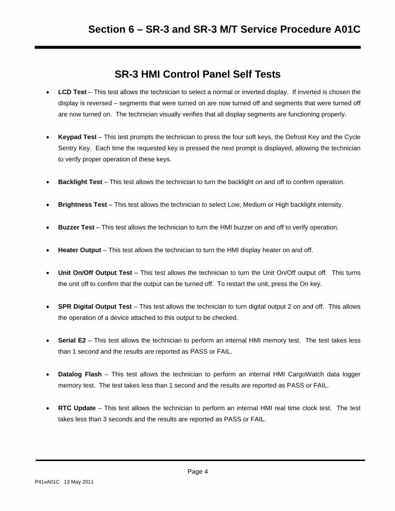
Section 6 – SR-3 and SR-3 M/T Service Procedure A01C
Page 4 P41xA01C 13 May 2011
SR-3 HMI Control Panel Self Tests • LCD Test – This test allows the technician to select a normal or inverted display. If inverted is chosen the
display is reversed – segments that were turned on are now turned off and segments that were turned off
are now turned on. The technician visually verifies that all display segments are functioning properly.
• Keypad Test – This test prompts the technician to press the four soft keys, the Defrost Key and the Cycle
Sentry Key. Each time the requested key is pressed the next prompt is displayed, allowing the technician
to verify proper operation of these keys.
• Backlight Test – This test allows the technician to turn the backlight on and off to confirm operation.
• Brightness Test – This test allows the technician to select Low, Medium or High backlight intensity.
• Buzzer Test – This test allows the technician to turn the HMI buzzer on and off to verify operation.
• Heater Output – This test allows the technician to turn the HMI display heater on and off.
• Unit On/Off Output Test – This test allows the technician to turn the Unit On/Off output off. This turns
the unit off to confirm that the output can be turned off. To restart the unit, press the On key.
• SPR Digital Output Test – This test allows the technician to turn digital output 2 on and off. This allows
the operation of a device attached to this output to be checked.
• Serial E2 – This test allows the technician to perform an internal HMI memory test. The test takes less
than 1 second and the results are reported as PASS or FAIL.
• Datalog Flash – This test allows the technician to perform an internal HMI CargoWatch data logger
memory test. The test takes less than 1 second and the results are reported as PASS or FAIL.
• RTC Update – This test allows the technician to perform an internal HMI real time clock test. The test
takes less than 3 seconds and the results are reported as PASS or FAIL.

Section 6 – SR-3 and SR-3 M/T Service Procedure A02A
Recording Existing Programmable Feature Settings
Where Used
All SR-3 Single Temperature and SR-3 SPECTRUM Multi-Temperature units
Purpose
To retrieve and record the sensor grades and programmable feature settings of an SR-3 Base Controller/Interface
Board
Materials Required
• A copy of the Setup Sheet at the back of this Service Procedure.
Operation
• The settings of the graded sensors and all programmable features must be retrieved before replacing a
Base Controller/Interface Board or performing a Base Controller/Interface Board Cold Start. These
settings will then be duplicated in the replacement Base Controller/Interface Board or after the Cold Start.
• See Section 3 of this manual for flowcharts and a complete description of programmable features.
• The default settings are shown on the Setup Sheet at the back of this Service Procedure.
• If a sensor grade is not shown on the setup sheet physically check the sensor to determine the grade. It
is very important that sensor grades be set properly.
Page 1 P41xA02A 13 May 2011

Section 6 – SR-3 and SR-3 M/T Service Procedure A02A
Procedure
Step Action Result Comments
1 Turn the unit on.
2 Press the MENU key. The Operator Menu appears.
Do not let the unit start. The
Guarded Access Menu can not
be entered in the unit is running.
3 Press and hold both the EXIT
and unlabelled key for 5
seconds.
The Maintenance Menu appears.
4 Press the NEXT key as required
to display the Software Revision
Menu. Then press the SELECT
key to enter the Software
Revision menu.
5 Use the NEXT and/or BACK
keys to scroll through the HMI
Control Panel and Base
Controller/Interface Board
software revisions.
Record the software revisions on
the Setup Sheet.
6 When the software revisions
have been recorded press the
EXIT key to return to the
Maintenance Menu.
Page 2 P41xA02A 13 May 2011

Section 6 – SR-3 and SR-3 M/T Service Procedure A02A
Step Action Result Comments
7 Press the NEXT key as required
to display the Set Time and Date
Menu. Then press the SELECT
key to enter the Set Time and
Date Menu.
The real time clock is located in
the HMI Control Panel. The time
is supplied to the Base
Controller/Interface Board each
time the unit is turned on. If the
Base Controller/Interface Board
is changed the clock setting will
be supplied to the Base
Controller/Interface Board when
the unit is turned on. If the HMI
Control Panel is changed the
time and date must be checked
and set if necessary.
8 Check the Time to determine the
time zone used by the customer.
Record the time zone on the
Setup Sheet.
Compare local time to unit time
to determine time zone.
9 When the time zone has been
recorded press the EXIT key to
return to the Maintenance Menu.
10 Be sure the unit is not running.
The unit will not enter the
Guarded Access Menu if it is
running.
If the unit is running, scroll back
and enter Interface Board Test
Mode. This will cause the unit to
shut down. Press the Exit key to
return to the Maintenance Menu.
Scroll back to the Set Time and
Date Menu and proceed with the
next step.
Page 3 P41xA02A 13 May 2011

Section 6 – SR-3 and SR-3 M/T Service Procedure A02A
Step Action Result Comments
11 Press and hold both the EXIT
and unlabelled key for 5
seconds.
The Guarded Access Menu
appears.
If a Security Code is requested
then enter the Security Code or
[4444] to enter the Guarded
Access Menu.
12 The Programmable Features
Menu will appear. Press the
SELECT key to enter the
Programmable Features Menu.
13 Use the NEXT and/or BACK
keys to scroll through all settings
in the Programmable Features
Menu.
Record all Programmable
Features settings on the Setup
Sheet.
14 When all Programmable
Features settings have been
recorded press the EXIT key to
return to the Guarded Access
Menu.
15 Use the NEXT and/or BACK
keys to scroll to the next
Guarded Access Menu.
Use the Setup Sheet as a guide.
16 Use the SELECT key to enter
the next Guarded Access Menu.
Use the Setup Sheet as a guide.
Page 4 P41xA02A 13 May 2011

Section 6 – SR-3 and SR-3 M/T Service Procedure A02A
Step Action Result Comments
17 Use the NEXT and/or BACK
keys to scroll through all settings
in the Menu.
Record all Programmable
Features settings on the Setup
Sheet.
18 Use the EXIT key to return to the
Guarded Access Menu.
19 Continue to use Steps 15 – 18
as required to complete the
Setup Sheet.
The OptiSet Plus features will be
retrieved at the end of this
procedure using a separate
OptiSet Plus Procedure. See
Service Procedure P41SA47B
Setting Up OptiSet Plus Features
using WinTrac.
20 When all settings have been
recorded press the EXIT key to
return to the Guarded Access
Menu.
21 Press the EXIT key again to
return to the Standard Display.
22 Download the ServiceWatch and
CargoWatch data loggers.
This information may be needed
for diagnostics.
23 Download the OptiSet Plus
settings using Service Procedure
P41SA47B Setting Up OptiSet
Plus Features using WinTrac.
Page 5 P41xA02A 13 May 2011

Section 6 – SR-3 and SR-3 M/T Service Procedure A02A
Page 6 P41xA02A 13 May 2011
Section 6 – SR-3 and SR-3 M/T Service Procedure A02A
Single Temperature Setup Sheet - D0xx Software
SOFTWARE REVISION
Function Default Setting Recorded Setting
HMI Control Panel Software Revision 65xx, 66xx, 67xx,
68xx
Base Controller/Interface Board Software Revision D0xx
SET DATE AND TIME
Compare local time to unit time to determine time zone. The real time clock is located in the HMI Control Panel.
The time is supplied to the Base Controller/Interface Board each time the unit is turned on. If the Base
Controller/Interface Board is changed the clock setting will be supplied to the Base Controller/Interface Board
when the unit is turned on. If the HMI Control Panel is changed the time and date must be checked and set if
necessary.
Function Default Setting Recorded Setting
Time Zone As specified by
customer
SECURITY CODE
Function Default Setting Recorded Setting
Security Code as specified by customer None
If an unknown security code is set then use Security Code 4444 to gain access.
IMPORTANT: Not all features shown on the Setup Sheet may appear. This is dependant on hardware type, software revision and unit settings.
Page 7 P41xA02A 13 May 2011

Section 6 – SR-3 and SR-3 M/T Service Procedure A02A
PROGRAMMABLE FEATURES
Function Default Setting Recorded Setting
Temperature Units FAHRENHEIT
Pressure Units PSI
Restart Unit After Shutdown ENABLED
Setpoint High Limit 80°F
Setpoint Low Limit -20°F
Fuel Saver II ENABLED
High Speed Pull Down ENABLED
Fresh Frozen Range 24°F
Door Open Forces LOG ONLY
Door Open Timeout (HRS:MIN) OFF
Sleep Mode After Pretrip DISABLED
Rail Option DISABLED
Rail Alternate (If Rail Option = ENABLED) DISABLED
Blocked Air Chute Detect DISABLED
Temperature Differential (If Blocked Air Chute = ENABLED) 9.9
Time to Alarm (If Blocked Air Chute = ENABLED) 0:30
Door Open Override (If Blocked Air Chute = ENABLED) DISABLED
Discharge Pressure Setpoint 415 PSIG
Water Temperature Setpoint 210°F
Limited Alarm Restarts DISABLED
Remote Device DISABLED
COM 1 Default Baud Rate 1200
COM 2 Default Baud Rate 9600
COM 3 Default Baud Rate 9600
High Temperature Defrost Disabled
Local Authorization of OS+ Upload (Not Currently Used)
Local Authorization of Flash Load (Not Currently Used)
Page 8 P41xA02A 13 May 2011

Section 6 – SR-3 and SR-3 M/T Service Procedure A02A
MAIN MENU CONFIGURATION
Function Default Setting Recorded Setting
Add Keypad Lockout to Mode Menu DISABLED
Add Sleep to Mode Menu DISABLED
Add Temperature Units to Mode Menu DISABLED
HOURMETER SETUP– PROGRAM HOURMETER
Function Default Setting Recorded Setting
Total Run Time Reminder # 1 Hours OFF
Total Run Time Reminder # 2 Hours OFF
Controller Power On Hours OFF
Pretrip Reminder Hours OFF
Engine Run Time Reminder # 1 OFF
Engine Run Time Reminder # 2 OFF
Electric Run Time Reminder # 1 OFF
Electric Run Time Reminder # 2 100 HOURS
HOURMETER SETUP– VIEWABLE HOURMETER SETUP
Function Default Setting Recorded Setting
Total Hours DISABLED
Total Run Time Hours ENABLED
Engine Hours ENABLED
Electric Hours ENABLED
Total Run Time Reminder # 1 Hours DISABLED
Total Run Time Reminder # 2 Hours DISABLED
Controller Power On Hours DISABLED
Pretrip Reminder Hours DISABLED
Engine Run Time Reminder # 1 Hours DISABLED
Engine Run Time Reminder # 2 Hours DISABLED
Electric Run Time Reminder # 1 Hours DISABLED
Electric Run Time Reminder # 2 Hours DISABLED
Page 9 P41xA02A 13 May 2011

Section 6 – SR-3 and SR-3 M/T Service Procedure A02A
HOURMETER SETUP– PROGRAM SERVICE DUE DATE
Function Default Setting Recorded Setting
Engine Run Time Service Due Date DISABLED
SENSOR CALIBRATION
Function Default Setting Recorded Setting
Control Return Air Sensor Grade 5H
Control Discharge Air Sensor Grade 5H
Display Return Air Sensor Grade 5H
Display Discharge Air Sensor Grade 5H
Spare 1 Sensor Grade 5H
CYCLE SENTRY SETUP
Function Default Setting Recorded Setting
Cycle Sentry Amperes Level 5 AMPS
Battery Sentry Voltage Level 12.2 VOLTS
DEFROST SETUP
Function Default Setting Recorded Setting
Defrost Interval In Range with Fresh Setpoint 6 HOURS
Defrost Interval Not In Range with Fresh Setpoint 4 HOURS
Defrost Interval In Range with Frozen Setpoint 6 HOURS
Defrost Interval Not In Range with Frozen Setpoint 4 HOURS
Maximum Defrost Duration 45 MINUTES
Page 10 P41xA02A 13 May 2011

Section 6 – SR-3 and SR-3 M/T Service Procedure A02A
LANGUAGE SETUP (First language = 65xx, second language 66xx)
Function Default Setting Recorded Setting
Version 65xx 66xx 67xx
Default Language ENGLISH
Enable Language English English English DISABLED
Enable Language Spanish Danish Japanese DISABLED
Enable Language French Russian DISABLED
Enable Language German Norwegian DISABLED
Enable Language Italian Swedish DISABLED
Enable Language Dutch Finnish DISABLED
Enable Language Portuguese Polish DISABLED
Enable Language Greek Hungarian DISABLED
Enable Language Turkish Romanian DISABLED
Enable Language Hebrew Bulgarian DISABLED
Enable Language Arabic Czech DISABLED
ACCESS CODE SETUP
Function Default Setting Recorded Setting
Enter Access Code NO CODE
OPTISET PLUS
OptiSet Plus features are retrieved using OptiSet Plus 4.1 or later.
Page 11 P41xA02A 13 May 2011

Section 6 – SR-3 and SR-3 M/T Service Procedure A02A
SENSOR CONFIGURATION (CargoWatch)
Log Interval is set for all sensors.
Function Default Setting Recorded Setting
Logging Interval 15 minutes
Up to 6 sensors may be configured
Function Default 1 2 3 4 5 6
Sensor Logging 1-2 On, 3-6 Off
Sensor Name Log Sensor X
Out of Range Checking OFF
Low Limit -10.8°
High Limit 10.8°
Italian Logging OFF
Sensor Averaging OFF
Up to 4 digital inputs may be configured.
Function Default 1 2 3 4
Door Open Logging 1On, 2-4 Off
Digital Input #X Name Digital Input #X
These features allow extended data logging when the unit is turned off.
Function Default Setting Recorded Setting
Countdown OFF
Conservative OFF
If set Enabled, this feature sends a Start of Trip marker to the CargoWatch and ServiceWatch Data Loggers any
time the setpoint is changed.
Function Default Setting Recorded Setting
SOT on Setpoint DISABLED
Page 12 P41xA02A 13 May 2011

Section 6 – SR-3 and SR-3 M/T Service Procedure A02A
UNIT CONFIGURATION
Function Default Setting Recorded Setting
Unit Type Trailer
Engine Type YANMAR 2.1
Compressor Type RECIP
ETV Configured YES
Electric Standby Equipped (Model 50) YES
Electric Heat Option (Model 50) YES
Electric Motor Type (14 HP Type, 24 HP Type) (Model 50) NO
Diesel to Electric Auto Switch Enabled (Model 50) NO
Electric to Diesel Auto Switch Enabled (Model 50) NO
Unit Model As built
High Capacity Unit NO
High Capacity Fresh (If High Capacity = YES) NO
Defrost Motor Equipped NO
Fuel Sensor Type NONE
Rear Remote Control NONE
Rear Remote Control Action (If Rear Remote installed) Stand By
Pretrip/Sleep Switch Options DISABLED
3rd Party Device Control NONE
Low Fuel Shutdown DISABLED
Fresh Air Exchange DISABLED
Page 13 P41xA02A 13 May 2011

Section 6 – SR-3 and SR-3 M/T Service Procedure A02A
Page 14 P41xA02A 13 May 2011

Section 6 – SR-3 and SR-3 M/T Service Procedure A03A
Replacement of the SR-3 Base Controller/Interface Board
Where Used
All SR-3 Single Temperature and SR-2 Spectrum Multi-Temperature units
Purpose
To replace the Base Controller/Interface Board
Materials Required
• Cable ties
Operation
The Base Controller/Interface Board is removed from the control box as an assembly.
Important Notes
• It is very important that the correct Base Controller/Interface Board be used for replacement. There are
currently two hardware versions of the Base Controller/Interface Board. Consult the material in Section 7
of this manual to determine the required Base Controller/Interface Board for the application.
• It is very important that the correct Base Controller software be used. Base Controllers are supplied from
Service Parts with the most recent software at the time of manufacture. The anti-static shipping bags are
also marked with pertinent information. Consult the material in Section 7 of this manual to determine the
required Base Controller software for the application. Check the available software on SharePoint
InfoCentral for the current released software version.
• Some Interface Board applications require the 60 amp fuse be removed from the old Base
Controller/Interface Board and installed in the replacement Base Controller/Interface Board.
• Be sure the harnesses are reconnected properly and do not place excessive strain on the connectors.
Secure the harnesses with cable ties as required.
Page 1 P41xA03A 13 May 2010

Section 6 – SR-3 and SR-3 M/T Service Procedure A03A
Diagnostic Procedure
Step Action Result Comments
1 Log the existing Base
Controller/Interface Board
settings using Service Procedure
A02A.
This information will be used
to set up the replacement
Base Controller.
2 Turn the unit off.
3 Disconnect standby power, if
connected.
4 Disconnect the unit battery.
Some circuits are directly
connected to the unit battery.
5 Disconnect all harness
connectors from the Base
Controller/Interface Board
assembly.
6 Remove the screws securing the
Base Controller/Interface Board
to the control box and remove
the Base Controller/Interface
Board assembly from the control
box.
7 Install the new Base
Controller/Interface Board
assembly in the control box.
Page 2 P41xA03A 13 May 2010

Section 6 – SR-3 and SR-3 M/T Service Procedure A03A
Step Action Result Comments
8 Reconnect all harness
connectors to the Base
Controller and Interface Board.
Apply Super Lube as needed.
Be sure all connectors are
securely mated and secure
the harnesses with cable ties
as required.
9 Reconnect the unit battery.
10 Reconnect the standby power if
needed.
11 Turn the unit on.
The real time clock settings
will be loaded from the HMI
Control Panel when the unit is
turned on.
12 Clear any alarm codes as shown
in Section 4.
13 Set up all programmable
features using Service
Procedure A04A.
14 Run a Pretrip Test as shown in
Section 4 to verify proper unit
operation.
Page 3 P41xA03A 13 May 2010

Section 6 – SR-3 and SR-3 M/T Service Procedure A03A
Page 4 P41xA03A 13 May 2010
Section 6 – SR-3 and SR-3 M/T Service Procedure A03B
Replacement of the Trailer HMI Control Panel
Where Used
All SR-3 Trailer Single Temperature and SR-3 Trailer Spectrum Multi-Temperature units
Purpose
To replace the Trailer HMI Control Panel
Materials Required
• Cable ties
Operation
The Trailer HMI Control Panel is removed from the control box door as an assembly.
Important Notes
• It is very important that the correct HMI Control Panel software be used. HMI Control Panels are supplied
from Service Parts with the most recent software at the time of manufacture. The anti-static shipping
bags are also marked with pertinent information. Consult the material in Section 7 of this manual to
determine the required HMI Control Panel software for the application. Check the available software on
SharePoint InfoCentral for the current released software version.
• Be sure the harnesses are reconnected properly and do not place excessive strain on the connectors.
Secure the harnesses with cable ties as required.
Page 1
P41xA03B 13 May 2011

Section 6 – SR-3 and SR-3 M/T Service Procedure A03B
Diagnostic Procedure
Step Action Result Comments
1 Turn the unit off.
2 Disconnect standby power, if
connected.
3 Disconnect the unit battery.
4 Disconnect the harness
connector from the HMI Control
Panel.
5 Remove the four screws
securing the HMI Control Panel
to the control box and remove
the HMI Control Panel from the
control box.
6 Install the new HMI Control
Panel in the control box.
7 Re-connect the harness
connector to the HMI Control
Panel. Apply Super Lube as
required
Be sure all connectors are
securely mated and secure
the harnesses with cable ties
as required.
Page 2
P41xA03B 13 May 2011

Section 6 – SR-3 and SR-3 M/T Service Procedure A03B
Step Action Result Comments
8 Reconnect the unit battery.
9 Reconnect the standby power if
needed.
10 Turn the unit on.
The programmable feature
settings will be loaded from
the Base Controller when the
unit is turned on.
11 Clear any alarm codes as shown
in Section 4.
12 Check the setting of the real time
clock as shown in Section 4 and
correct if necessary.
The clock may be set from
the Maintenance Menu or
with Wintrac when connected
to the CargoWatch Data
Logger port.
13 Run a Full Pretrip Test as shown
in Section 4 to verify proper unit
operation.
Page 3
P41xA03B 13 May 2011

Section 6 – SR-3 and SR-3 M/T Service Procedure A03B
Page 4
P41xA03B 13 May 2011

Section 6 – SR-3 and SR-3 M/T Service Procedure A04A
Programmable Feature Setup
Where Used
All SR-3 and SR-3 SPECTRUM Multi-Temp units
Purpose
To set the sensor grades and programmable features of an SR-3 Base Controller/Interface Board/Interface Board
to customer specifications
Materials Required
• A completed copy of the Setup Sheet at the back of Service Procedure A02A Recording Existing
Programmable Feature Settings.
Operation
• The settings of the graded sensors and all programmable features must be programmed after replacing a
Base Controller/Interface Board or performing a Base Controller/Interface Board Cold Start.
• See Section 3 of this manual for flowcharts and a complete description of programmable features.
• The default settings are shown on the appropriate Setup Sheet at the back of Service Procedure A02A
Recording Existing Base Controller/ Interface Board Settings.
• If a sensor grade is not shown on the setup sheet visually check the sensor to determine the grade. It is
very important that sensor grades be set properly.
Page 1 P41xA04A 13 May 2011
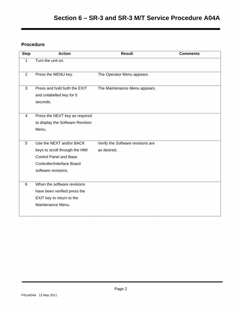
Section 6 – SR-3 and SR-3 M/T Service Procedure A04A
Procedure
Step Action Result Comments
1 Turn the unit on.
2 Press the MENU key. The Operator Menu appears.
3 Press and hold both the EXIT
and unlabelled key for 5
seconds.
The Maintenance Menu appears.
4 Press the NEXT key as required
to display the Software Revision
Menu.
5 Use the NEXT and/or BACK
keys to scroll through the HMI
Control Panel and Base
Controller/Interface Board
software revisions.
Verify the Software revisions are
as desired.
6 When the software revisions
have been verified press the
EXIT key to return to the
Maintenance Menu.
Page 2 P41xA04A 13 May 2011

Section 6 – SR-3 and SR-3 M/T Service Procedure A04A
Step Action Result Comments
8 Press the NEXT key as required
to display the Set Time and Date
Menu. Then press the SELECT
key to enter the Set Time and
Date Menu.
The real time clock is located in
the HMI Control Panel. The time
is supplied to the Base
Controller/Interface Board each
time the unit is turned on. If the
Base Controller/Interface Board
is changed the clock setting will
be supplied to the Base
Controller/Interface Board when
the unit is turned on. If the HMI
Control Panel is changed the
time and date must be checked
and set if necessary.
9 Verify that the Time is set to the
time zone used by the customer
as shown on the setup sheet.
10 When the time zone has been
verified press the EXIT key to
return to the Maintenance Menu.
11 Be sure the unit is not running.
The unit will not enter the
Guarded Access Menu if it is
running.
If the unit is running, scroll back
and enter Interface Board Test
Mode. This will cause the unit to
shut down. Press the Exit key to
return to the Maintenance Menu.
Scroll back to the Set Time and
Date Menu and proceed with the
next step.
Page 3 P41xA04A 13 May 2011

Section 6 – SR-3 and SR-3 M/T Service Procedure A04A
Step Action Result Comments
12 Press and hold both the EXIT
and unlabelled key for 5
seconds.
The Guarded Access Menu
appears.
If a Security Code is requested
then enter the Security Code or
[4444] to enter the Guarded
Access Menu.
13 The Programmable Features
Menu will appear. Press the
SELECT key to enter the
Programmable Features Menu.
14 Use the NEXT and/or BACK
keys to scroll through all the
features in the Programmable
Features Menu.
Set all Programmable Features
settings to those shown on the
Setup Sheet.
15 When all Programmable
Features have been set press
the EXIT key to return to the
Guarded Access Menu.
16 Use the NEXT and/or BACK
keys to scroll to the next
Guarded Access Menu.
Use the Setup Sheet as a guide.
17 Use the SELECT key to enter
the next Guarded Access Menu.
Use the Setup Sheet as a guide.
18 Use the NEXT and/or BACK
keys to scroll through all settings
in the Menu.
Set all menu settings to those
shown on the Setup Sheet.
Page 4 P41xA04A 13 May 2011

Section 6 – SR-3 and SR-3 M/T Service Procedure A04A
Step Action Result Comments
19 Use the EXIT key to return to the
Guarded Access Menu.
20 Continue to use Steps 16 – 19
as required to complete the
Setup Sheet.
The OptiSet features are set up
using OptiSet Plus 4.1 or later.
See Service Procedure
P41SA47B Setting Up OptiSet
Features using Wintrac.
21 When all settings have been
recorded press the EXIT key to
return to the Guarded Access
Menu.
22 Press the EXIT key again to
return to the Standard Display.
23 Set up the OptiSet features using
Service Procedure P41SA47B
Setting Up OptiSet Features
using Wintrac.
24 Run a Pretrip Test as shown in
Section 4 to verify proper unit
operation.
Page 5 P41xA04A 13 May 2011
Section 6 – SR-3 and SR-3 M/T Service Procedure A04A
Page 6 P41xA04A 13 May 2011

Section 6 – SR-3 and SR-3 M/T Service Procedure A07A
Performing a Base Controller/Interface Board Cold Restart
Where Used
All SR-3 Single Temperature and SR-3 Spectrum Multi-Temperature units
Purpose
To perform a Cold Restart on the Base Controller/Interface Board
Materials Required
• WinTrac 5.1 loaded on a PC Computer
Operation
This procedure will perform a Cold Restart on the Base Controller/Interface Board.
• The Unit Serial Number and Truck/trailer ID Number will both be reset to 0000000000.
• All programmable features except the hourmeters are reset to factory default settings.
• All sensor grades are reset to factory default settings (5H).
• The ServiceWatch Data Logger will be cleared.
IMPORTANT: The Unit Serial Number, Truck/trailer ID Number and all programmable features such as sensor
calibration, defrost settings and other feature settings will be reset to the standard (default) settings. They must
be set up using Service Procedure A04A after performing a Cold Restart or the unit may not operate to the
customer’s requirements.
IMPORTANT: The ServiceWatch Data Logger data will be cleared when a Cold Restart is performed. Be sure to
download and save the ServiceWatch Data Logger before performing a Cold Restart.
IMPORTANT: Be sure to connect the download cable to the ServiceWatch port. If the cable is connected to the CargoWatch port the HMI Control Panel will be restarted.
Page 1 P41xA07A 13 May 2011
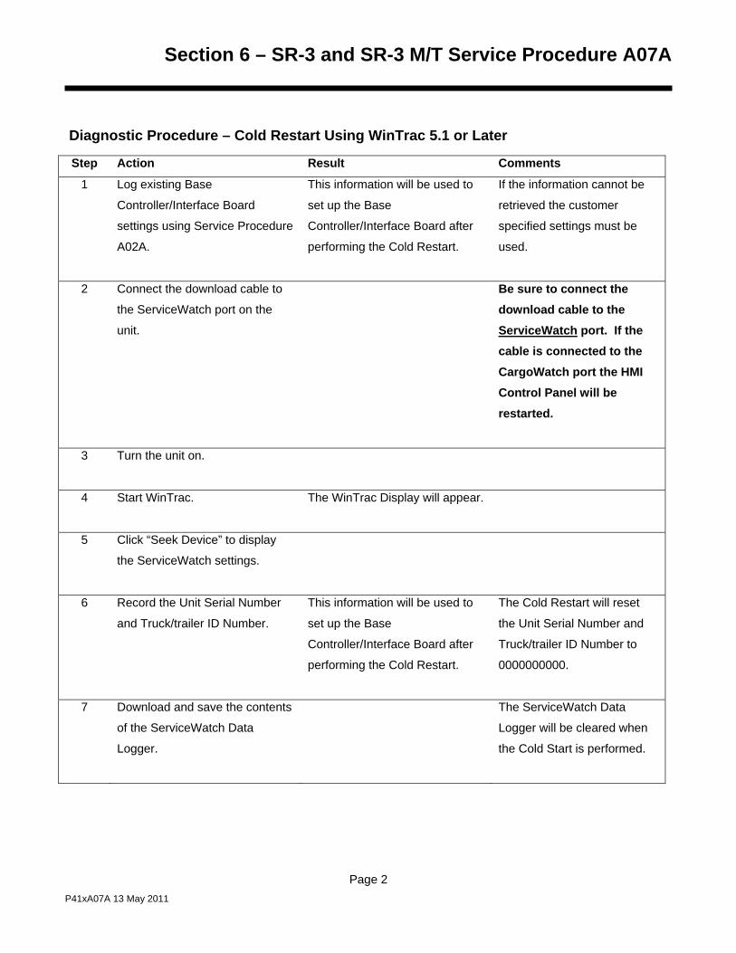
Section 6 – SR-3 and SR-3 M/T Service Procedure A07A
Diagnostic Procedure – Cold Restart Using WinTrac 5.1 or Later
Step Action Result Comments
1 Log existing Base
Controller/Interface Board
settings using Service Procedure
A02A.
This information will be used to
set up the Base
Controller/Interface Board after
performing the Cold Restart.
If the information cannot be
retrieved the customer
specified settings must be
used.
2 Connect the download cable to
the ServiceWatch port on the
unit.
Be sure to connect the download cable to the ServiceWatch port. If the cable is connected to the CargoWatch port the HMI Control Panel will be restarted.
3 Turn the unit on.
4 Start WinTrac.
The WinTrac Display will appear.
5 Click “Seek Device” to display
the ServiceWatch settings.
6 Record the Unit Serial Number
and Truck/trailer ID Number.
This information will be used to
set up the Base
Controller/Interface Board after
performing the Cold Restart.
The Cold Restart will reset
the Unit Serial Number and
Truck/trailer ID Number to
0000000000.
7 Download and save the contents
of the ServiceWatch Data
Logger.
The ServiceWatch Data
Logger will be cleared when
the Cold Start is performed.
Page 2 P41xA07A 13 May 2011

Section 6 – SR-3 and SR-3 M/T Service Procedure A07A
Step Action Result Comments
8 From the WinTrac display press
CTRL-SHIFT-T to enable the
WinTrac Tool Menu
The Tool Menu appears in the
WinTrac menu bar.
9 Select Tools – Restart Device –
Cold Restart. A display similar to
the one shown below will appear.
10 Select Yes to continue. The
display will briefly indicate that
the ServiceWatch settings are
being downloaded. Then a Cold
Restart confirmation similar to
the one shown below will appear.
Page 3 P41xA07A 13 May 2011

Section 6 – SR-3 and SR-3 M/T Service Procedure A07A
Step Action Result Comments
11 Select Yes to continue. A
display similar to the one shown
below will appear.
12 When the Cold Restart has
completed a display similar to
the one below will appear.
Page 4 P41xA07A 13 May 2011

Section 6 – SR-3 and SR-3 M/T Service Procedure A07A
Step Action Result Comments
13 When the Cold Restart is
complete the following Alarm
Codes will be present:
Alarm Code 03
Alarm Code 04
Alarm Code 13
Alarm Code 74
Alarm Code 92
Alarm Code 203
Alarm Code 204
Alarm Code 74 indicates the
Cold Restart was successful.
The other alarm codes exist
because the sensor grades have
been set to 5H. Alarm Code 92
will clear automatically when the
sensor grades are properly set.
The sensor codes will not
clear until the sensor grades
have been properly set. The
sensor codes and code 74
may be cleared in the Alarms
Menu.
14 Click “Seek Device” to display
the ServiceWatch settings.
15 Enter the Unit Serial Number and
Truck/trailer ID Number that was
recorded in Step 6.
16 Click “Update Unit” to load the
Unit Serial Number and
Truck/trailer ID Number.
17 Set up all programmable
features using Service
Procedure A04A.
Page 5 P41xA07A 13 May 2011

Section 6 – SR-3 and SR-3 M/T Service Procedure A07A
Page 6 P41xA07A 13 May 2011
Step Action Result Comments
18 Disconnect the download cable.
19 Clear any alarm codes.
20 Run a Pretrip Test as shown in
Section 4 to verify proper unit
operation.

Section 6 – SR-3 and SR-3 M/T Service Procedure A07B
Performing an HMI Control Panel Cold Restart
Where Used
All SR-3 Single Temperature and SR-3 Spectrum Multi-Temperature units
Purpose
To perform a Cold Restart on the HMI Control Panel
Materials Required
• WinTrac 5.1 loaded on a PC Computer
Operation
This procedure will perform a Cold Restart on the HMI Control Panel.
• The CargoWatch Data Logger will be cleared.
IMPORTANT: The CargoWatch Data Logger data will be cleared when a Cold Restart is performed. Be sure to
download and save the CargoWatch Data Logger before performing a Cold Restart.
IMPORTANT: Be sure to connect the download cable to the CargoWatch port. If the cable is connected to the ServiceWatch port the Base Controller/Interface Board will be restarted.
Page 1 P41xA07B 13 May 2011

Section 6 – SR-3 and SR-3 M/T Service Procedure A07B
Diagnostic Procedure – Cold Start Using WinTrac 5.1 or Later
Step Action Result Comments
1 Connect the download cable to
the ServiceWatch port on the
unit.
Be sure to connect the download cable to the CargoWatch port. If the cable is connected to the ServiceWatch port the Base Controller/Interface Board will be restarted.
2 Turn the unit on.
3 Start WinTrac.
The WinTrac Display will appear.
4 Download and save the contents
of the CargoWatch Data Logger.
The CargoWatch Data
Logger will be cleared when
the Cold Start is performed.
5 From the WinTrac display press
CTRL-SHIFT-T to enable the
WinTrac Tool Menu.
The Tool Menu appears in the
WinTrac menu bar.
6 Select Tools – Restart Device –
Cold Restart. A display similar to
the one shown below will appear.
Page 2 P41xA07B 13 May 2011

Section 6 – SR-3 and SR-3 M/T Service Procedure A07B
Step Action Result Comments
7 Select Yes to continue. The
display will briefly indicate that
the CargoWatch settings are
being downloaded. Then a Cold
Restart confirmation similar to
the one shown below will appear.
8 Select Yes to continue. A
display similar to the one shown
below will appear.
Page 3 P41xA07B 13 May 2011

Section 6 – SR-3 and SR-3 M/T Service Procedure A07B
Page 4 P41xA07B 13 May 2011
Step Action Result Comments
9 When the Cold Restart has
completed a display similar to
the one below will appear.
10 Disconnect the download cable.
11 Run a Pretrip Test as shown in
Section 4 to verify proper unit
operation.

Section 6 – SR-3 and SR-3 M/T Service Procedure A15A
Unit Temperature Sensor Grade Calibration
Where Used
All SR-3 Single Temperature and SR-3 Spectrum Multi-Temperature units
Purpose
To calibrate the sensor grades of graded sensors
Materials Required
• None
Operation
The following sensors are graded sensors and must be properly calibrated.
• Single Temperature Units The control and display return air temperature sensors and the control and
display discharge air temperature sensors are graded sensors. The Spare 1 temperature sensor is also a
graded sensor.
• Multi-Temperature Units The return air temperature sensors and discharge air temperature sensors for
all zones are graded sensors. The three spare temperature sensors are also graded sensors.
Any time these sensors are replaced or a Cold Start is performed the sensor grade must be correctly entered to
insure optimum performance of the unit. The sensor grade is stamped on the barrel of each sensor. Failure to
properly calibrate sensors may result in nuisance alarm codes.
Important Notes
• Always record the marked sensor grades of any replacement return, discharge or spare temperature
sensors. The grade is required to complete the sensor calibration procedure.
• If any return air temperature or discharge air temperature sensor grade is set to 5H then Alarm Code 92
Sensor Grades Not Set will be set. Calibrating the sensor grades automatically clears alarm Code 92.
Note that Alarm Code 92 does not apply to spare sensors. However, when used, spare sensors should
still be calibrated to achieve maximum accuracy.
Page 1 P41xA15A 13 May 2011

Section 6 – SR-3 and SR-3 M/T Service Procedure A15A
Diagnostic Procedure
Step Action Result Comments
1 Verify and record the sensor
grades of all return air, discharge
air and spare sensors (if used)
by physically checking the
sensor.
Note that Alarm Code 92
does not apply to spare
sensors. However, when
used, spare sensors should
still be calibrated to achieve
maximum accuracy.
2 Turn the unit on.
3 Press the MENU key. The Main Menu appears.
4 Press and hold both the EXIT
and unlabelled key for 5
seconds.
The Maintenance Menu appears.
5 Press the NEXT key as required
to display the Set Time and Date
Menu.
The Set Time and Date Menu
appears.
6 Press and hold both the EXIT
and unlabelled key for 5
seconds.
The Guarded Access Menu
appears.
7 Press the NEXT key as required
to display the Sensor Calibration
Menu.
The Sensor Calibration Menu
appears.
Page 2 P41xA15A 13 May 2011

Section 6 – SR-3 and SR-3 M/T Service Procedure A15A
Step Action Result Comments
8 When the Sensor Calibration
Menu is shown press the
SELECT key to access the
Sensor Calibration Menu.
The first graded sensor and the
current grade appear.
9 If necessary, use the NEXT
and/or BACK keys to select the
sensor to be calibrated.
These keys scroll thru all graded
sensors installed on the unit.
Be sure the correct sensor is
selected.
10 When the sensor to be calibrated
is shown on the display, press
the SELECT key.
The Sensor Change menu for
the selected sensor will appear.
11 Use the “+” and “-“ keys to
change the sensor grade to
match the grade stamped on the
sensor.
12 When the correct grade is shown
press the YES key to confirm the
choice.
13 If necessary, repeat steps 9 – 12
to change any other sensor
grades that are not correct.
14 Press Exit to leave the Sensor
Calibration Menu.
Page 3 P41xA15A 13 May 2011

Section 6 – SR-3 and SR-3 M/T Service Procedure A15A
Page 4 P41xA15A 13 May 2011
Step Action Result Comments
15 If graded sensor alarms exist
(Alarm Codes 03 and/or 04), use
the BACK key to return to the
Alarms Menu in Guarded
Access.
The Alarms Menu will appear.
16 Press the SELECT key to enter
the Alarms Menu.
17 Press the CLEAR key to clear
the sensor alarms.
18 When finished, press the EXIT
key several times or turn the unit
off to exit the Sensor Calibration
Menu.

Section 6 – SR-3 and SR-3 M/T Service Procedure A26A
Welding on Units Equipped with SR-3 Base Controllers
Where Used
All SR-3 Single Temperature and SR-3 Spectrum Multi-Temperature units
Purpose
To prevent damage to the Base Controller/Interface Board during welding operations
Materials Required
• None
Operation
Electric welding generates high amperage currents that can damage electrical and electronic components. In
order to minimize the possibility of damage the following procedures should be followed.
Page 1 P41xA26A 13 May 2011

Section 6 – SR-3 and SR-3 M/T Service Procedure A26A
Page 2 P41xA26A 13 May 2011
Before Welding
Step Action Result Comments
1. Turn the unit off.
2. Disconnect standby power, if
connected.
3. Remove the both battery cables.
4. Connect the welder ground cable
as close as possible to the area
where the welding is to be
performed. Move the welder
ground cable as required.
After Welding
Step Action Result Comments
1. Reconnect the battery cable.
2. Reconnect the standby power if
needed.
3. Perform a Pretrip Test as shown
in Section 4 to confirm operation.

Section 6 – SR-3 and SR-3 M/T Service Procedure A28A
Setting Unit Running Time Hourmeters
Where Used
All SR-3 Single Temperature and SR-3 Spectrum Multi-Temperature units
Purpose
This procedure should be followed to set the fixed running time hourmeters Total Hours, Total Run Time Hours,
Engine Hours, Electric Run Time Hours and Zone Run Hours after replacing a Base Controller with a new
replacement Base Controller. If all hourmeters have less than 100 hours accumulated, time can be added to
them as shown in this procedure. If hourmeter time exceeds 100 hours, the hourmeter time can no longer be
changed.
Materials Required
• None
IMPORTANT: Time can only be added if all hourmeters have less than 100 hours accumulated. If hourmeter
time exceeds 100 hours, the hourmeter time can no longer be changed.
IMPORTANT: If time in excess of 100 hours has been entered the hourmeters can no longer be changed.
Exercise care when changing these hourmeter settings. Be sure the correct number of hours are selected for
each hourmeter.
IMPORTANT: Do not allow the 3 minute Guarded Access keypad timeout to occur during this procedure. If the
keypad times out before all desired changes are made and a hourmeter exceeds 100 hours, the hourmeters can
no longer be changed.
IMPORTANT: Do not exit hourmeter setup until all hourmeters have been set as required. Once the hourmeter
setup has been exited this menu is locked out and the hourmeters can no longer be changed.
Page 1 P41xA28A 13 May 2011

Section 6 – SR-3 and SR-3 M/T Service Procedure A28A
Procedure
Step Action Result Comments
1 Determine the number of hours
to be set on each hourmeter. If
the unit is a Model 50 unit, be
sure the total of Engine Hours
and Electric Run Time Hours is
equal to the number of hours to
be set as Total Run Time Hours.
2 Turn the unit on.
3 Press the MENU key. The Main Menu appears.
Press the MENU key.
4 Press and hold both the EXIT
and unlabelled key for 5
seconds.
The Maintenance Menu appears.
5 Press the NEXT key as required
to display the Set Time and Date
Menu.
6 Press and hold both the EXIT
and unlabelled key for 5
seconds. If a Security Code is
requested enter the Security
Code or [4444] to enter the
Guarded Access Menu.
The Guarded Access Menu
appears.
Page 2 P41xA28A 13 May 2011

Section 6 – SR-3 and SR-3 M/T Service Procedure A28A
Step Action Result Comments
7 Press the NEXT key to display
the Hourmeter Setup Menu.
The Hourmeter Setup Menu
appears.
8 Press the SELECT key to
choose the Hourmeter Setup
Menu.
9 Press the SELECT key again to
choose the Program Hourmeter
Menu.
10 Press the NEXT key to scroll to
the last item in the Program
Hourmeter Menu. The NEXT
key will disappear.
11 Press and hold both the EXIT
and unlabelled key for 5
seconds.
This will add the non-
programmable hourmeters to the
menu only if the number of hours
in these hourmeters are less
than 100 hours.
IMPORTANT: Do not exit the
hourmeter setup or allow the
Guarded Access keypad
timeout to occur during this
procedure. If the keypad
times out and an hourmeter
exceeds 100 hours, the
hourmeters will be locked and
can no longer be changed.
Page 3 P41xA28A 13 May 2011

Section 6 – SR-3 and SR-3 M/T Service Procedure A28A
Page 4 P41xA28A 13 May 2011
Step Action Result Comments
12 Use the NEXT and/or BACK
keys to show the desired
hourmeter. When the desired
hourmeter is shown press the
SELECT key to chose it.
13 Change the value of the
hourmeter by pressing the + or -
keys.
14 When the correct number of
hours is shown press the YES
key to accept the change.
IMPORTANT: If time in
excess of 100 hours has
been entered the hourmeters
can no longer be changed.
Exercise care when changing
hourmeter settings.
15 Repeat Steps 12-14 as
necessary to change the
remaining hourmeters.
16 When all hourmeters are set
press the EXIT key to return to
the Program Hourmeter menu.
IMPORTANT: If time in
excess of 100 hours has
been entered the hourmeters
can no longer be changed.
Be sure all settings are
correct before leaving this
menu.
Section 6 – SR-2 and SR-2 M/T Service Procedure A46A
Flash Loading SR-3 Base Controller/Interface Board Software
Where Used
All SR-3 Single Temperature and SR-3 Spectrum Multi-Temperature units
Purpose
To update software for the Thermo King SR-3 Base Controller/Interface Board using a computer and WinTrac 5.1
or later software
Flash Loading using USB Flash Drive SR-3 equipped units can also flash load HMI Control Panel and SR-3 Base Controller software using a WinTrac
configured USB Flash Drive. See USB Flash Drive in Section 4 of this manual for details.
Materials Required
The following materials are required to perform a flash load.
• Thermo King WinTrac 5.1 or later software loaded on a PC computer.
• Interconnect Cable, Thermo King Service Part Number TK 44-9417 (20 foot, 6 meter) or TK 44-9418 (50 foot,
15 meter).
• Adapter Cable, Thermo King Service Part Number TK 204-918, 15 Pin “D” connector to 5 pin Deutsch.
• The correct Base Controller Flash Load file.
Page 1 P41xA46A 13 May 2011

Section 6 – SR-2 and SR-2 M/T Service Procedure A46A
Obtaining Flash Load Files on the Internet When SR-3 Base Controller and/or HMI Control Panel flash load files are downloaded from the Thermo King
iService web site, the flash load files are downloaded as a *.ZIP file. When flash load files for SR-3 applications
are unzipped, there will now be three flash load files instead of the usual two.
The traditional *.mXX and *.cXX files will be unzipped. These two files are for use when flash loading an
SR-3 unit in the traditional manner by using a Data Cable to connect the SR-3 Unit to a PC Computer
equipped with WinTrac.
NOTE: Both the *.mXX and *.cXX files must be present in order to perform a flash load using a Data
Cable, even though only one of them is shown by WinTrac.
A *.FLA file will also be unzipped. This file is for use when flash loading a unit using a WinTrac 5.1
configured USB Flash Drive.
The Flashload Directory on the configured USB Flash Drive contains sub-directories for HMI and
SR3SINGLE TEMP flash load *.FLA files. The *.FLA file must be placed in the correct directory on the
flash drive using either the WinTrac 5.1 Upload > Manage Flashload Files feature or Windows Explorer.
The latest SR-3 Revision D0xx Trailer Base Controller/Interface Board software is available on the Thermo King
TSA Info Central web site. Go to:
http://www.thermoking.com/tk/index.asp
Choose TSA Info Central and select Home > Software and Downloads > Microprocessors > Trailer
Microprocessor Updates.
The file name for the *.ZIP file containing both the traditional .mXX and .cXX files and the *.FLA file is
Micro Code D0xx Update for the SR-3 Single Temp Base Controller.zip. Double click this file to install the
software.
Page 2 P41xA46A 13 May 2011

Section 6 – SR-2 and SR-2 M/T Service Procedure A46A
Connecting the Cables
The same cables used for downloading are required to perform a flash load. Typically two cables are used to
connect the computer to the base controller as shown below.
Data Cable The data cable has a 9 pin “D” connector installed on one end to attach to the computer and a 15
pin “D” connector on the other end. The cable is available as either a 20 foot or 50 foot cable.
Adapter Cable An adapter cable is required to complete the connection to the base controller or data logger.
This cable has a 15 pin “D” connector on one end and a 5 pin Deutsch connector on the other end. The 15 pin
“D” connector is attached to the 15 pin “D” connector on the data cable and the 5 pin Deutsch connector is
attached to the Service Watch connector above the HMI Control Panel. Do not attach the cable to the Cargo
Watch connector.
Flash Load Details
Flashload status is reported on the PC, not on the HMI Control Panel. The HMI Control Panel will display the
message COMMUNICATION FAILURE – LOST CONTROLLER CONNECT. This is normal.
The unit must remain on and connections must not be disturbed during the flash load process.
If communications are lost, Wintrac will not be able to find the device.
If the Status LED is flashing rapidly (several times per second), the base controller is stuck in a flash load.
If the Status LED is flashing once per second the base controller is operating normally.
Page 3 P41xA46A 13 May 2011

Section 6 – SR-2 and SR-2 M/T Service Procedure A46A
Flash Load Procedure
The following procedure should be followed to flash load software using a connection to the ServiceWatch
connector.
Step Action Result Comments
NOTE: SR-3 Base Controllers
retain all the programmed
features when being flash
loaded. It is not necessary to
reprogram the SR-3 Base
Controller/Interface Board after a
flash load.
NOTE: Download and save the
ServiceWatch Data Logger
before flash loading the Base
Controller/Interface Board.
1 Obtain and prepare the flash
load files as described above.
2 Connect the data cables from the
PC to the Service Watch
connector as described above.
Be sure the cable is connected to the Service Watch connector.
3 Connect a power source to the
PC computer.
Do not rely on a laptop battery as low power may cause communications to be lost and the flash load to fail.
4 Start WinTrac 5.1 or later as
shown in the Wintrac manual.
Page 4 P41xA46A 13 May 2011

Section 6 – SR-2 and SR-2 M/T Service Procedure A46A
Step Action Result Comments
5 Turn the unit on. The unit can be
running. It will shut down
automatically during the flash
load process.
The unit must remain on and connections must not be disturbed during the flash load process.
6 Allow the unit to fully power up and the Standard Display to appear before starting a flash load. Failure to do so may result
in unreliable results.
7 If the Wintrac menu bar does not
show TOOLS, press and hold the
computers “Ctrl” and “Shift” keys
and then press the “T” key.
The TOOLS menu will appear
in the Wintrac menu bar.
8 Left click “Tools”. The TOOLS menu will appear.
9 From the Tools menu left click
“Flash Load”.
A download data warning menu
appears as shown below.
Be sure to download the
ServiceWatch data logger if
necessary.
Page 5 P41xA46A 13 May 2011

Section 6 – SR-2 and SR-2 M/T Service Procedure A46A
Step Action Result Comments
10 Left click “Yes” to continue. A directory containing the flash
load files appears.
11 Double click the flash load
directory and locate the correct
flash load file.
12 Double click the flash load file. Several status screens are
shown briefly and then a
confirmation message will
appear.
13 If the information shown is correct
left click “Yes” to continue. The
flash load will proceed
automatically.
If the unit is running it will shut
down. The HMI Control Panel
will display “Communication
Failure – Lost Controller
Connect”. This is normal. The
flash load will take several
minutes.
14 The unit must remain on and connections must not be disturbed during the flash load process.
Several status screens are
shown as the flash load
proceeds.
Page 6 P41xA46A 13 May 2011

Section 6 – SR-2 and SR-2 M/T Service Procedure A46A
Step Action Result Comments
15 When the flash load is complete a
message appears confirming a
successful flash load as shown
below.
16 Left click “OK” to complete the
flash load. The unit will
automatically restart and run.
SR-3 Base Controllers retain
all the programmed features
when being flash loaded. It is
not necessary to reprogram
the SR-3 Base
Controller/Interface Board
after a flash load.
17 Clear any alarm codes.
18 Run a Full Pretrip Test as shown
in Section 4.
This confirms proper unit
operation.
Page 7 P41xA46A 13 May 2011

Section 6 – SR-2 and SR-2 M/T Service Procedure A46A
Flash Load Failure During a Flash Load
When a flash load is initiated, Wintrac will perform a Full flash load. The full set of Wintrac commands is sent to
the Base Controller/Interface Board, such as seek device and read device properties. If the flash load procedure
does not complete successfully, the following message will appear.
Left click “Yes” to retry the flash load process.
The Retry flash load differs from the Full flash load as follows: Since the Base Controller/Interface Board is
already in flash load mode it does not respond to the full set of Datapac commands. Therefore, during a flash load
Retry, Wintrac skips most of the initial communications with the device and goes directly to the actual flash load
routine.
Wintrac simply sends the flash load write commands. If these fail then Wintrac will generate an error. If the flash
load write succeeds then Wintrac will finish the flash load in the same way as a normal flash load.
Page 8 P41xA46A 13 May 2011
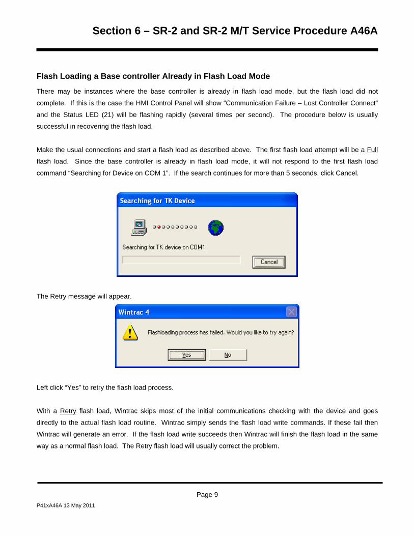
Section 6 – SR-2 and SR-2 M/T Service Procedure A46A
Flash Loading a Base controller Already in Flash Load Mode
There may be instances where the base controller is already in flash load mode, but the flash load did not
complete. If this is the case the HMI Control Panel will show “Communication Failure – Lost Controller Connect”
and the Status LED (21) will be flashing rapidly (several times per second). The procedure below is usually
successful in recovering the flash load.
Make the usual connections and start a flash load as described above. The first flash load attempt will be a Full
flash load. Since the base controller is already in flash load mode, it will not respond to the first flash load
command “Searching for Device on COM 1”. If the search continues for more than 5 seconds, click Cancel.
The Retry message will appear.
Left click “Yes” to retry the flash load process.
With a Retry flash load, Wintrac skips most of the initial communications checking with the device and goes
directly to the actual flash load routine. Wintrac simply sends the flash load write commands. If these fail then
Wintrac will generate an error. If the flash load write succeeds then Wintrac will finish the flash load in the same
way as a normal flash load. The Retry flash load will usually correct the problem.
Page 9 P41xA46A 13 May 2011

Section 6 – SR-2 and SR-2 M/T Service Procedure A46A
Page 10 P41xA46A 13 May 2011
Section 6 – SR-3 and SR-3 M/T Service Procedure A46B
Flash Loading SR-3 HMI Control Panel Software
Where Used
All SR-3 Single Temperature and SR-3 Spectrum Multi-Temperature units
Purpose
To change or update software for the Thermo King SR-3 HMI Control Panel using a computer and WinTrac 5.1 or
later software. IMPORTANT: This flash load takes at least 10 minutes. Plan accordingly.
Flash Loading using USB Flash Drive
SR-3 equipped units can also flash load HMI Control Panel and SR-3 Base Controller/Interface Board software
using a WinTrac configured USB Flash Drive. See USB Flash Drive in Section 4 of this manual for details.
Materials Required
The following materials are required to perform a flash load.
• Thermo King WinTrac 5.1 or later software loaded on a PC computer.
• Interconnect Cable, Thermo King Service Part Number TK 44-9417 (20 foot, 6 meter) or TK 44-9418 (50 foot,
15 meter).
• Adapter Cable, Thermo King Service Part Number TK 204-918, 15 Pin “D” connector to 5 pin Deutsch.
• The correct HMI Control Panel Flash Load file.
IMPORTANT – CargoWatch Data Logger on SR-3 Trailer Units: Due to CargoWatch Data Logger changes, a
HMI Control Panel Cold Start must be performed using WinTrac on both HMI-1 and HMI-2 Control Panels after
new HMI Control Panel software is flash loaded. The cold start also sets the Out of Range Checking to OFF.
Failure to perform a cold start may result in an inoperative or unresponsive CargoWatch data logger. This may
not be apparent until the data logger is downloaded.
Be sure the CargoWatch Data Logger is downloaded before installing new HMI Control Panel software, as the
HMI Control Panel Cold Start will erase any existing data in the CargoWatch Logger.
Page 1 P41xA46B 13 May 2011

Section 6 – SR-3 and SR-3 M/T Service Procedure A46B
1. Download the CargoWatch Data Logger before flash loading new HMI Control Panel Software
2. After flash loading the new HMI Control Panel software, send a Cold Start to the HMI Control Panel using
WinTrac 5.1 or later. Do not attempt a cold start using the interface board jumpers or with the download
cable connected to the ServiceWatch port as this will restart the SR-3 Base Controller/Interface Board,
not the HMI Control Panel.
3. Verify the data cable is connected to the CargoWatch port.
4. From the WinTrac 5.1 or later Tools menu select “Restart” and “Cold Start”.
Page 2 P41xA46B 13 May 2011

Section 6 – SR-3 and SR-3 M/T Service Procedure A46B
Obtaining Flash Load Files on the Internet
When SR-3 Base Controller and/or HMI Control Panel flash load files are downloaded from the Thermo King
iService web site, the flash load files are downloaded as a *.ZIP file. When flash load files for SR-3 applications
are unzipped, there will now be three flash load files instead of the usual two.
The traditional *.mXX and *.cXX files will be unzipped. These two files are for use when flash loading an
SR-3 unit in the traditional manner by using a Data Cable to connect the SR-3 Unit to a PC Computer
equipped with WinTrac.
NOTE: Both the *.mXX and *.cXX files must be present in order to perform a flash load using a Data
Cable, even though only one of them is shown by WinTrac.
A *.FLA file will also be unzipped. This file is for use when flash loading a unit using a WinTrac 5.1
configured USB Flash Drive.
The Flashload Directory on the configured USB Flash Drive contains sub-directories for HMI and
SR3SINGLE TEMP flash load *.FLA files. The *.FLA file must be placed in the correct directory on the
flash drive using either the WinTrac 5.1 Upload > Manage Flashload Files feature or Windows Explorer.
The latest SR-3 Revision 65xx Trailer Base Controller/Interface Board software is available on the Thermo King
TSA Info Central web site. Go to:
http://www.thermoking.com/tk/index.asp
Choose TSA Info Central and select Home > Software and Downloads > Microprocessors > Trailer
Microprocessor Updates.
The file name for the *.ZIP file containing both the traditional .mXX and .cXX files and the *.FLA file is
Micro Code 65xx Update for the SR-3 HMI Control Panel.zip. Double click this file to install the software.
Page 3 P41xA46B 13 May 2011
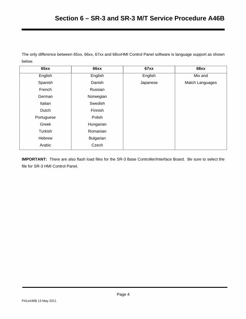
Section 6 – SR-3 and SR-3 M/T Service Procedure A46B
The only difference between 65xx, 66xx, 67xx and 68xxHMI Control Panel software is language support as shown
below.
65xx 66xx 67xx 68xx
English English English Mix and
Spanish Danish Japanese Match Languages
French Russian
German Norwegian
Italian Swedish
Dutch Finnish
Portuguese Polish
Greek Hungarian
Turkish Romanian
Hebrew Bulgarian
Arabic Czech
IMPORTANT: There are also flash load files for the SR-3 Base Controller/Interface Board. Be sure to select the
file for SR-3 HMI Control Panel.
Page 4 P41xA46B 13 May 2011

Section 6 – SR-3 and SR-3 M/T Service Procedure A46B
Connecting the Cables
The same cables used for downloading are required to perform a flash load. Typically two cables are used to
connect the computer to the base controller as shown below.
Data Cable The data cable has a 9 pin “D” connector installed on one end to attach to the computer and a 15 pin
“D” connector on the other end. The cable is available as either a 20 foot or 50 foot cable.
Adapter Cable An adapter cable is required to complete the connection to the base controller or data logger.
This cable has a 15 pin “D” connector on one end and a 5 pin Deutsch connector on the other end. The 15 pin
“D” connector is attached to the 15 pin “D” connector on the data cable and the 5 pin Deutsch connector is
attached to the CargoWatch connector above the HMI Control Panel. Do not attach the cable to the
ServiceWatch connector.
Flash Load Recovery
The unit must remain on and connections must not be disturbed during the flash load process.
If the HMI is turned off during a flash load it will lock up. Power will need to be completely removed from the HMI
before the flash load can be completed. This can be accomplished by removing the connector at the back of the
HMI or by disconnecting the unit battery).
If the power was turned off during flash load, the next flash load attempt will generate an error, but a following
attempt will flash successfully. The failure on the first attempt is 'as designed'. On the second attempt, some of
the error checking between the HMI and WinTrac is bypassed.
Page 5 P41xA46B 13 May 2011

Section 6 – SR-3 and SR-3 M/T Service Procedure A46B
Flash Load Procedure
The following procedure should be followed to flash load software using a connection to the CargoWatch
connector.
Step Action Result Comments
IMPORTANT: Download and
save the CargoWatch Data
Logger before flash loading the
HMI Control Panel.
Due to CargoWatch Data
Logger changes, a HMI
Control Panel Cold Start must
be performed using WinTrac
on both HMI-1 and HMI-2
Control Panels after new HMI
Control Panel software is
flash loaded. The cold start
also sets the Out of Range
Checking to OFF. Failure to
perform a cold start may
result in an inoperative or
unresponsive CargoWatch
data logger. This may not be
apparent until the data logger
is downloaded.
1 Obtain and prepare the flash
load files as described above.
2 Connect the data cables from the
PC to the CargoWatch connector
as described above.
Be sure the cable is connected to the CargoWatch connector.
Page 6 P41xA46B 13 May 2011

Section 6 – SR-3 and SR-3 M/T Service Procedure A46B
Step Action Result Comments
3 Connect a power source to the
PC computer.
Do not rely on a laptop battery as low power may cause communications to be lost and the flash load to fail. See Flash Load
Recovery on the previous
page.
4 Start WinTrac 5.1 or later as
shown in the WinTrac manual.
5 Turn the unit on. Download and
save the CargoWatch Data
Logger using WinTrac before
flash loading the HMI Control
Panel.
6 The unit can be running. It will
shut down automatically during
the flash load process.
The unit must remain on and connections must not be disturbed during the flash load process.
7 Allow the unit to fully power up and the Standard Display to appear before starting a flash load. Failure to do so may result
in unreliable results.
Page 7 P41xA46B 13 May 2011
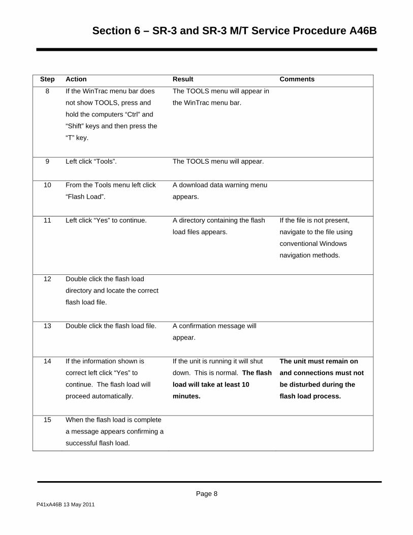
Section 6 – SR-3 and SR-3 M/T Service Procedure A46B
Step Action Result Comments
8 If the WinTrac menu bar does
not show TOOLS, press and
hold the computers “Ctrl” and
“Shift” keys and then press the
“T” key.
The TOOLS menu will appear in
the WinTrac menu bar.
9 Left click “Tools”. The TOOLS menu will appear.
10 From the Tools menu left click
“Flash Load”.
A download data warning menu
appears.
11 Left click “Yes” to continue. A directory containing the flash
load files appears.
If the file is not present,
navigate to the file using
conventional Windows
navigation methods.
12 Double click the flash load
directory and locate the correct
flash load file.
13 Double click the flash load file. A confirmation message will
appear.
14 If the information shown is
correct left click “Yes” to
continue. The flash load will
proceed automatically.
If the unit is running it will shut
down. This is normal. The flash load will take at least 10 minutes.
The unit must remain on and connections must not be disturbed during the flash load process.
15 When the flash load is complete
a message appears confirming a
successful flash load.
Page 8 P41xA46B 13 May 2011

Section 6 – SR-3 and SR-3 M/T Service Procedure A46B
Step Action Result Comments
16 Left click “OK” to complete the
flash load. The unit will
automatically restart and run.
17 Send a Cold Start to the HMI
Control Panel using WinTrac 5.1
or later. From the WinTrac
Tools menu select “Restart” and
“Cold Start”. For additional Cold
Start information see Service
Procedure A07B Performing an
HMI Control Panel Cold Start.
Do not attempt a cold start using
the interface board jumpers or
with the download cable
connected to the ServiceWatch
port as this will restart the SR-3
Base Controller/Interface Board,
not the HMI Control Panel.
Be sure the CargoWatch
Data Logger is downloaded
before sending a Cold Start to
the HMI Control Panel, as the
Cold Start will erase any
existing data in the
CargoWatch Data Logger.
18 Clear any alarm codes.
19 Run a Pretrip Test as shown in
Section 4.
This confirms proper unit
operation.
Page 9 P41xA46B 13 May 2011

Section 6 – SR-3 and SR-3 M/T Service Procedure A46B
Page 10 P41xA46B 13 May 2011

Section 6 – SR-3 Service Procedure A47B
Retrieving and Sending OptiSet Plus Configurations
Where Used
All SR-3 units
Purpose
To retrieve and send OptiSet Plus configurations to and from the Thermo King SR-3 Base Controller using a PC
computer, OptiSet Plus Plus 4.1 or later and WinTrac 5.1 or later.
Materials Required
The following materials are required to retrieve and send OptiSet Plus configurations.
• Thermo King WinTrac 5.1 or later software loaded on a PC computer.
• Thermo King OptiSet Plus 4.1 or later software loaded on a PC computer. Thermo King OptiSet Plus
software is available from SharePoint InfoCentral under Software Updates.
• Interconnect Cable, Thermo King Service Part Number TK 44-9417 (20 foot, 6 meter) or TK 44-9418 (50 foot,
15 meter).
• Adapter Cable, Thermo King Service Part Number TK 204-918, 15 Pin “D” connector to 5 pin Deutsch.
Description
This Service Procedure allows OptiSet Plus settings to be saved and restored using WinTrac. This eliminates the
need to manually retrieve and reprogram the settings using the Guarded Access Menu.
• WinTrac retrieves the existing OptiSet Plus settings from a unit and saves them as a *.opt file.
• OptiSet Plus Setup Guide is used to convert the *.opt file to the *.csv file necessary to send the OptiSet
Plus settings back to a unit.
• WinTrac is then used to send the OptiSet Plus settings back to the unit.
Page 1 P41xA47B 13 May 2011
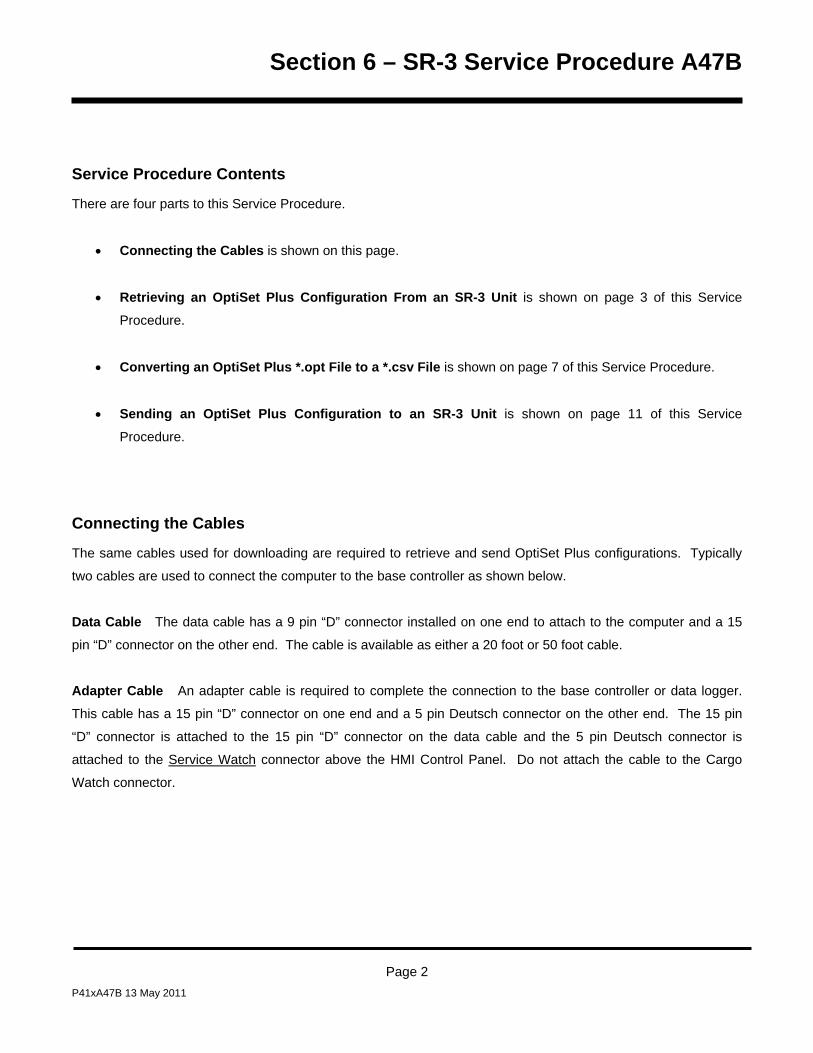
Section 6 – SR-3 Service Procedure A47B
Service Procedure Contents
There are four parts to this Service Procedure.
• Connecting the Cables is shown on this page.
• Retrieving an OptiSet Plus Configuration From an SR-3 Unit is shown on page 3 of this Service
Procedure.
• Converting an OptiSet Plus *.opt File to a *.csv File is shown on page 7 of this Service Procedure.
• Sending an OptiSet Plus Configuration to an SR-3 Unit is shown on page 11 of this Service
Procedure.
Connecting the Cables
The same cables used for downloading are required to retrieve and send OptiSet Plus configurations. Typically
two cables are used to connect the computer to the base controller as shown below.
Data Cable The data cable has a 9 pin “D” connector installed on one end to attach to the computer and a 15
pin “D” connector on the other end. The cable is available as either a 20 foot or 50 foot cable.
Adapter Cable An adapter cable is required to complete the connection to the base controller or data logger.
This cable has a 15 pin “D” connector on one end and a 5 pin Deutsch connector on the other end. The 15 pin
“D” connector is attached to the 15 pin “D” connector on the data cable and the 5 pin Deutsch connector is
attached to the Service Watch connector above the HMI Control Panel. Do not attach the cable to the Cargo
Watch connector.
Page 2 P41xA47B 13 May 2011

Section 6 – SR-3 Service Procedure A47B
Retrieving an OptiSet Plus Configuration From an SR-3 Unit
The following procedure should be followed to retrieve an OptiSet Plus configuration from an SR-3 unit using
WinTrac 5.1 or later and a connection to the ServiceWatch connector. The retrieved OptiSet Plus configuration
file will be saved as a *.opt file.
Step Action Result Comments
1 Connect the data cables from the
PC to the Service Watch
connector as described on page
2.
Be sure the cable is connected to the Service Watch connector.
2 Turn the unit on. The unit can be
running.
The unit must remain on and connections must not be disturbed during the OptiSet Plus Configuration download process.
3 Start WinTrac 5.1 or later as
shown in the WinTrac manual.
4 If the WinTrac menu bar does not
show TOOLS, press and hold the
computers “Ctrl” and “Shift” keys
and then press the “T” key.
The TOOLS menu will appear
in the WinTrac menu bar.
5 Left click “Tools”. The TOOLS menu will appear.
6 From the Tools menu left click
“Retrieve OptiSet Plus
Configuration” as shown below.
Page 3 P41xA47B 13 May 2011

Section 6 – SR-3 Service Procedure A47B
Step Action Result Comments
7 A Downloading ServiceWatch
Settings display similar to the one
shown below will appear briefly.
Page 4 P41xA47B 13 May 2011

Section 6 – SR-3 Service Procedure A47B
Step Action Result Comments
8 Then the Retrieving OptiSet Plus
Data displays similar to those
shown below will appear briefly.
Step Action Result Comments
9 The Save OptiSet Plus
Configuration File display will
appear as shown on the next
page. Choose a file name and
location. Left click “Save” to save
the file.
The file name selected in the
display shown on the next page is
“Trailer1”.
Be sure to note the file name
and location. This file name
and location will be necessary
to review the retrieved
downloaded OptiSet Plus
configuration or to convert the
file and send the OptiSet Plus
configuration back to a unit.
The default file location is
C:\OptiSet Plus\Data.
Page 5 P41xA47B 13 May 2011

Section 6 – SR-3 Service Procedure A47B
Step Action Result Comments
10 The display shown below will
appear indicating the OptiSet
Plus configuration has been
retrieved and saved. Left click
“OK” to return to the WinTrac
Main Menu.
The OptiSet Plus
configuration has been
retrieved and saved to the
computer.
Page 6 P41xA47B 13 May 2011

Section 6 – SR-3 Service Procedure A47B
Converting an OptiSet Plus .opt File to a .csv File
The OptiSet Plus configuration file retrieved by WinTrac will be saved as a *.opt file. However, a file formatted as
a *.csv file is required to upload the OptiSet Plus configuration to a unit.
Thermo King OptiSet Plus Setup Guide 4.1 or later software loaded on a PC computer is used to convert a *.opt
file to a *.csv file. Thermo King OptiSet Plus Setup Guide software is available from SharePoint InfoCentral under
Software Updates.
Step Action Result Comments
1 Start OptiSet Plus 4.1 or later.
2 From the OptiSet Plus Setup
Guide Main Menu left click “File _
Open” as shown on the next
page.
Page 7 P41xA47B 13 May 2011

Section 6 – SR-3 Service Procedure A47B
Step Action Result Comments
3 Select the desired file and left
click “OK”. File “Trailer1.opt” has
been selected as shown below.
The file will be opened.
Page 8 P41xA47B 13 May 2011

Section 6 – SR-3 Service Procedure A47B
Step Action Result Comments
4 The display will return to the
OptiSet Plus Setup Guide Main
Menu. Left click “File _ Export for
Upload” as shown below.
If necessary, the file can be
opened to review or change
OptiSet Plus settings. The
*.opt file must still be
converted to a *.csv file.
5 Select the desired file and left
click “OK”. File “Trailer1.opt” has
been selected as shown on the
next page.
The *.opt file is converted to a
*.csv file.
Page 9 P41xA47B 13 May 2011

Section 6 – SR-3 Service Procedure A47B
Step Action Result Comments
6 The display shown below will
appear indicating the file
conversion is complete. Left click
“OK” to return to the OptiSet Plus
Setup Guide Main Menu.
7 The file conversion is complete.
Exit OptiSet Plus Setup Guide.
Page 10 P41xA47B 13 May 2011
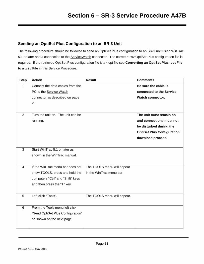
Section 6 – SR-3 Service Procedure A47B
Sending an OptiSet Plus Configuration to an SR-3 Unit
The following procedure should be followed to send an OptiSet Plus configuration to an SR-3 unit using WinTrac
5.1 or later and a connection to the ServiceWatch connector. The correct *.csv OptiSet Plus configuration file is
required. If the retrieved OptiSet Plus configuration file is a *.opt file see Converting an OptiSet Plus .opt File to a .csv File in this Service Procedure.
Step Action Result Comments
1 Connect the data cables from the
PC to the Service Watch
connector as described on page
2.
Be sure the cable is connected to the Service Watch connector.
2 Turn the unit on. The unit can be
running.
The unit must remain on and connections must not be disturbed during the OptiSet Plus Configuration download process.
3 Start WinTrac 5.1 or later as
shown in the WinTrac manual.
4 If the WinTrac menu bar does not
show TOOLS, press and hold the
computers “Ctrl” and “Shift” keys
and then press the “T” key.
The TOOLS menu will appear
in the WinTrac menu bar.
5 Left click “Tools”. The TOOLS menu will appear.
6 From the Tools menu left click
“Send OptiSet Plus Configuration”
as shown on the next page.
Page 11 P41xA47B 13 May 2011

Section 6 – SR-3 Service Procedure A47B
Step Action Result Comments
7 The Open OptiSet Plus
Configuration File display will
appear. Choose the desired file
name and location. Left click
“Open” to open the file.
The file name selected in the
display shown on the next page is
“Trailer1”.
The default file location is
C:\OptiSet Plus\Data.
Page 12 P41xA47B 13 May 2011

Section 6 – SR-3 Service Procedure A47B
Step Action Result Comments
8 A Downloading ServiceWatch
Settings display similar to the one
shown below will appear briefly.
Page 13 P41xA47B 13 May 2011

Section 6 – SR-3 Service Procedure A47B
Step Action Result Comments
9 A confirmation display message
similar to the one shown below
will appear. Left click “Yes” to
continue.
10 A confirmation display message
similar to the one shown below
will appear.
Page 14 P41xA47B 13 May 2011
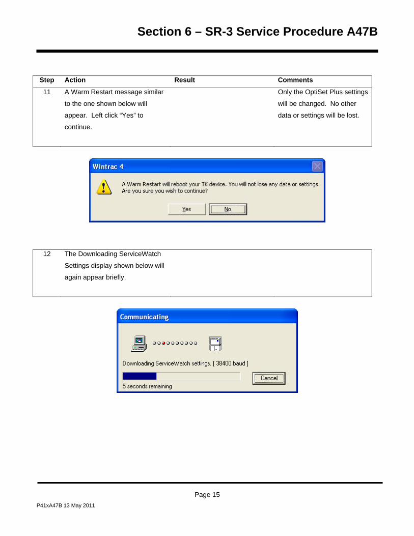
Section 6 – SR-3 Service Procedure A47B
Step Action Result Comments
11 A Warm Restart message similar
to the one shown below will
appear. Left click “Yes” to
continue.
Only the OptiSet Plus settings
will be changed. No other
data or settings will be lost.
12 The Downloading ServiceWatch
Settings display shown below will
again appear briefly.
Page 15 P41xA47B 13 May 2011

Section 6 – SR-3 Service Procedure A47B
Step Action Result Comments
13 A confirmation display message
similar to the one shown below
will appear. Left click “Yes” to
continue.
14 A confirmation display message
similar to the one shown below
will appear.
Page 16 P41xA47B 13 May 2011

Section 6 – SR-3 Service Procedure A47B
Step Action Result Comments
15 A display similar to the one shown
below will appear indicating the
unit has been restarted. Left click
“OK” to continue.
16 A display similar to the one shown
below will appear indicating the
OptiSet Plus Download is
complete. Left click “OK” to
return to the WinTrac Main Menu.
Page 17 P41xA47B 13 May 2011

Section 6 – SR-3 Service Procedure A47B
Page 18 P41xA47B 13 May 2011

Section 6 – SR-3 and SR-3 M/T Service Procedure A48A
Phase Detect Module Operation and Diagnostics
Where Used
All SR-3 Single Temperature and SR-3 Spectrum Multi-Temperature units equipped with electric standby
Purpose
To understand phase detect module operation and diagnostic procedures
Description
The phase detect module is designed to monitor 3 phase voltages from 160 volts AC thru 510 volts AC.
THERMO KING9131C98G06
L1
L2
L30202
Brown
Blue
Black
CAUTION: Units featuring optional Electric Standby utilize 460, 400 or 230 volt 3 phase AC electrical power any time the unit is operating in Electric Mode. This voltage potential is also present any time the unit is connected to a source of external standby power. Extreme care must be used when working on the unit, as these voltages are capable of causing serious injury or death.
Page 1 P41xA48A 13 May 2011

Section 6 – SR-3 and SR-3 M/T Service Procedure A48A
Operation
The brown, blue and black wires are used to sample the power at L1, L2 and L3 respectively. Operating power
from 12 to 24 VDC is supplied to the module via the 8 wire and CH wire.
When the voltage sensed rises above 180 volts AC and all three phases are present the module ER wire will
output 12-24 VDC after the conditions exist for 2 to 4 seconds. This signal informs the base controller that electric
standby operation is possible. If the voltage drops below 160 volts AC or a phase is lost, the output is turned off
after the condition exists for 8 to 10 seconds. The module continues to monitor the power and will again output
12-24 VDC within 2 to 4 seconds after the voltage rises above 180 volts AC and all three phases are present.
If phase rotation is L1, L2, L3 the 7EB wire will supply 12 to 24 VDC to energize the appropriate phase rotation
contactor. If phase rotation is L1, L3, L2 the 7EC wire will supply a chassis ground to energize the appropriate
phase rotation contactor. The 7EB and 7EC wires are interlocked to prevent both phase contactors from being
energized at once.
Connections
Connections to the module are shown in the tables below.
Power Connections
Input Description
8F Supplies nominal 12-24 volt DC power to the phase detect module.
CH Chassis ground
Inputs
Input Description
L1 This brown wire supplies standby power L1 to the phase detect module.
L2 This blue wire supplies standby power L2 to the phase detect module.
L3 This black wire supplies standby power L3 to the phase detect module.
Page 2 P41xA48A 13 May 2011

Section 6 – SR-3 and SR-3 M/T Service Procedure A48A
Outputs
Output Description
7EH With 12-24 VDC is supplied, then outputs 7EB and 7EC will be at 12-24 VDC.
7EB If phase rotation is L1, L2, L3 then this wire will provide 12-24 VDC to energize the appropriate phase
rotation contactor. The 7EC wire is interlocked to prevent both phase contactors from being
energized at once.
7EC If phase rotation is L1, L3, L2 then this wire will provide 12-24 VDC to energize the appropriate phase
rotation contactor. The 7EB wire is interlocked to prevent both phase contactors from being
energized at once.
ER This wire will output 12-24 VDC 2 to 4 seconds after the voltage rises above 180 volts AC and all
three phases are present. If the voltage drops below 160 volts AC or a phase is lost and the
condition remains for 8 to 10 seconds, the output is turned off. The module continues to monitor and
will again output 12-24 VDC 2 to 4 seconds after the power returns to normal (voltage rises above
180 volts AC and all three phases are present).
Connector Pinout
Pin Wire Description
1 8F Power to Module
2 CH Chassis ground
3 ER Power OK
4 7EH Switches the 7EC and 7EB from grounding to power logic
5 7EB Phase A-B-C
6 7EC Phase A-C-B
7 Unused
8 Unused
9 Unused
Page 3 P41xA48A 13 May 2011

Section 6 – SR-3 and SR-3 M/T Service Procedure A48A
Removal and Replacement
CAUTION: Units featuring optional Electric Standby utilize 460, 400 or 230 volt 3 phase AC electrical power any time the unit is operating in Electric Mode. This voltage potential is also present any time the unit is connected to a source of external standby power. Extreme care must be used when working on the unit, as these voltages are capable of causing serious injury or death.
1. Turn the unit off.
2. Disconnect the unit battery.
3. Disconnect the standby power.
4. Disconnect the three wires from the phase detect module at the motor contactor.
5. Unplug the phase detect module harness.
6. Remove the old phase detect module.
7. Install the new phase detect module.
8. Connect the new phase detect module wires to the upper contactor as follows:
9. Connect the brown wire to L1 on the contactor.
10. Connect the blue wire to L2 on the contactor.
11. Connect the black wire to L3 on the contactor.
12. Use crimp-on terminals as required.
13. Connect the plug on the short harness from the phase detect module.
14. Install the high voltage cover.
15. Secure wires and wire harnesses as required using cable ties.
16. Connect the unit battery.
17. Connect standby power.
18. Perform a Pretrip Test to verify proper operation.
Page 4 P41xA48A 13 May 2011

Section 6 – SR-3 and SR-3 M/T Service Procedure A48A
Diagnostics
CAUTION: Units featuring optional Electric Standby utilize 460, 400 or 230 volt 3 phase AC electrical power any time the unit is operating in Electric Mode. This voltage potential is also present any time the unit is connected to a source of external standby power. Extreme care must be used when working on the unit, as these voltages are capable of causing serious injury or death.
Step Action Result Comments
1. Plug the standby power cord into
a known good standby power
supply and turn the unit on.
2. Using a Fluke Meter, measure
the standby voltage between
phases L1 - L2, L2 - L3 and L3 -
L1 at the input to the terminals
where the Brown, Blue and Black
wires are connected.
The standby voltage between
phases should be between 200 -
500 VAC. If not, repair as
necessary to supply the needed
voltage to the unit.
3. Check the 8F and CH circuits to
the phase detect module. 12-24
VDC must be present from 8F to
CH.
If this power is not present, check
the 8 circuit from the On/Off
switch.
4. If correct power is present in the
test above then the ER circuit on
the interface board should have
12-24 VDC present.
If power is not present replace
the phase detect module.
Removal and replacement of the
phase detect module is detailed
on a previous page.
Page 5 P41xA48A 13 May 2011

Section 6 – SR-3 and SR-3 M/T Service Procedure A48A
Page 6 P41xA48A 13 May 2011
Step Action Result Comments
5. If LED 6 on the interface board is
on then the 7EH circuit should
have 12-24 VDC present.
If power is not present check the
Diesel/Electric Relay circuit on
the interface board.
6. If the unit is calling for operation
(LED 6 is on) one of the phase
select contactors should be
energized.
If neither contactor is energized
check for 12-24 VDC. If voltage is
not present replace the phase
detect module.
Removal and replacement of the
phase detect module is detailed
on a previous page.

Section 6 – SR-3 and SR-3 M/T Service Procedure A49A
CargoWatch Data Logger
Where Used
All SR-3 Single Temperature and SR-3 Spectrum Multi-Temperature units equipped with optional CargoWatch
sensors
Purpose
To understand, use and diagnose the CargoWatch Data Logger
Description
The CargoWatch Data Logger is contained within the HMI Control Panel. This data logger conforms to European
standard EN12830. The data logger supports up to 6 optional temperature sensors and 4 digital inputs. These
optional sensors are not the same as the temperature sensors used to control the unit. Note that the CargoWatch
data logger does not record unit sensors. Unit sensors and other unit operating data are recorded by the
ServiceWatch data logger.
The CargoWatch data logger logs the following items:
• Up to 6 optional temperature sensors
• Up to 4 digital inputs (optional door switches)
• Setpoint
• Operating Modes – Timed and Event
• Defrost Entry and Exit
• Shutdown Alarms
• Real Time Clock Updates
Page 1 P41xA49A 13 May 2011

Section 6 – SR-3 and SR-3 M/T Service Procedure A49A
CargoWatch Temperature Sensors
The sensors used for the CargoWatch data logger are RTD thermistor type sensors. These sensors are different
and cannot be used to replace the unit temperature sensors. The Service Part number for the optional
CargoWatch sensors is 41-5436. CargoWatch sensors can be identified by:
• No shrink tubing over sensor barrel
• Shorter sensor barrel than unit sensors
• No sensor grades
Thermistor CargoWatch Sensor
These thermistor sensors change resistance as the temperature changes. Resistance values are as shown in the
table. They can be measured directly using a high quality ohmmeter. Note that this applies only to CargoWatch
sensors.
CargoWatch Sensor Resistance vs Temperature
°F °C Ohms
-20°F -29°C 166,356
-10°F -23°C 115,757
0°F -18°C 86,501
10°F -12°C 61,737
20°F -7°C 47,070
30°F -1°C 34,374
32°F 0°C 32,650
40°F 4°C 26,688
50°F 10°C 19,904
60°F 16°C 15,002
70°F 21°C 11,944
80°F 27°C 9,166
90°F 32°C 7,402
100°F 38°C 5,775
Page 2 P41xA49A 13 May 2011

Section 6 – SR-3 and SR-3 M/T Service Procedure A49A
CargoWatch Time and Date
The time and date used by the CargoWatch data logger is held in the HMI Control Panel. To set or change the
date and time use the Set Time and Date feature at the end of the Maintenance Menu. The time and date can
also be set or changed by using WinTrac 5.1 or later.
The HMI Control Panel will update the SR-3 Controller and the ServiceWatch data logger with the correct time
and date each time the unit is turned on.
Downloads
To download the datalogger connect the download cable to the CargoWatch port on the unit. Downloads are
obtained using WinTrac 5.1 or later.
Downloads can also be obtained by means of a Wintrac configured USB Flash Drive. See Section 4 of this
manual for details.
Printing Reports
Trip Reports and Delivery Reports can be directly printed. The printer must be connected to the printer port
connector located inside the unit control box. This port may be routed to the outside of the unit as required by the
individual user.
Page 3 P41xA49A 13 May 2011

Section 6 – SR-3 and SR-3 M/T Service Procedure A49A
Programmable Features
The CargoWatch data logger programmable features are set from the Sensor Configuration Sub-menu in the
Guarded Access menu. The sensor features allow the logging interval to be set and the sensors and digital
inputs to be enabled, named, and tailored to customer requirements. The flowchart on the next page illustrates
the features and menu flow. See Section 3 of this manual for complete information on CargoWatch
programmable features.
Programmable features may also be set up using WinTrac 5.1 or later.
Factory defaults have the Setpoint and CargoWatch Sensors 1 and 2 turned On. CargoWatch Sensors 3 through
6 and Digital Inputs 1 through 4 are turned Off.
Page 4 P41xA49A 13 May 2011

Section 6 – SR-3 and SR-3 M/T Service Procedure A49A
Dig
ital I
n 1
Sens
orC
onfig
Sens
orC
onfig
Sens
orC
onfig
SN/
BN/
BN/
BN/
BN/
BSe
nsor
Con
figSe
nsor
Con
figLo
ggin
gIn
terv
alN
Sens
orC
onfig
N/B
Dig
ital I
n 2
N/B
Dig
ital I
n 3
N/B
Dig
ital I
n 4
N/B
B
(15
Min
)Fr
om S
enso
rC
onfig
sele
ctio
nin
Gua
rded
Acc
ess
Men
u
(+6.
0°)
(Off)
(Off)
(Sen
sors
1 &
2 O
n,Se
nsor
s 3-
6 O
ff)
(Log
Sen
sor X
)
(On)
(-6.0
°)
(+6.
0°)
(Off)
(Off)
(Sen
sors
1 &
2 O
n,Se
nsor
s 3-
6 O
ff)
(Log
Sen
sor X
)
(On)
(-6.0
°)
Sens
orLo
ggin
g
Ind
Sens
or#1
: Nam
e
Out
-of-R
ange
Che
ckin
g
Low
Hig
h
Italia
n O
ptio
n
Sens
orA
vera
ging
S N/B
N/B
N/B
N/B
N/B B
Sens
orLo
ggin
g
Ind
Sens
or#2
: Nam
e
Out
-of-R
ange
Che
ckin
g
Low
Hig
h
Italia
n O
ptio
n
Sens
orA
vera
ging
S N/B
N/B
N/B
N/B
N/B B
Sens
orLo
ggin
g
Ind
Sens
or#3
: Nam
e
Out
-of-R
ange
Che
ckin
g
Low
Hig
h
Italia
n O
ptio
n
Sens
orA
vera
ging
S N/B
N/B
N/B
N/B
N/B B
Sens
orLo
ggin
g
Ind
Sens
or#6
: Nam
e
Out
-of-R
ange
Che
ckin
g
Low
Hig
h
Italia
n O
ptio
n
Sens
orA
vera
ging
S N/B
N/B
N/B
N/B
N/B B
Sens
orLo
ggin
g
Ind
Sens
or#5
: Nam
e
Out
-of-R
ange
Che
ckin
g
Low
Hig
h
Italia
n O
ptio
n
Sens
orA
vera
ging
S N/B
N/B
N/B
N/B
N/B B
Sens
orLo
ggin
g
Ind
Sens
or#4
: Nam
e
Out
-of-R
ange
Che
ckin
g
Low
Hig
h
Italia
n O
ptio
n
Sens
orA
vera
ging
S N/B
N/B
N/B
N/B
N/B B
Doo
r Ope
nLo
ggin
g
Dig
ital I
nput
#1S B(D
igita
l Inpu
t#X
Nam
e)
(Dig
ital 1
On,
Dig
ital 2
-4 O
ff)D
oor O
pen
Logg
ing
Dig
ital I
nput
#2S B
Doo
r Ope
nLo
ggin
g
Dig
ital I
nput
#3S B
Doo
r Ope
nLo
ggin
g
Dig
ital I
nput
#4S B
SR2
MEN
U O
VER
VIEW
- G
UA
RD
ED A
CC
ESS
- SEN
SOR
CO
NFI
G M
ENU
Def
ault
valu
es a
re s
how
n in
par
enth
esis
( )
(Dig
ital 1
On,
Dig
ital 2
-4 O
ff)
(Dig
ital In
put
#X N
ame)
(Log
Sen
sor 1
)(L
og S
enso
r 2)
(Log
Sen
sor 3
)(L
og S
enso
r 4)
(Log
Sen
sor 5
)(L
og S
enso
r 6)
Page 5 P41xA49A 13 May 2011

Section 6 – SR-3 and SR-3 M/T Service Procedure A49A
Page 6 P41xA49A 13 May 2011

Section 6 – SR-3 and SR-3 M/T Service Procedure A50A
ServiceWatch Data Logger
Where Used
All SR-3 Single Temperature and SR-3 Spectrum Multi-Temperature units
Purpose
To understand and use the ServiceWatch Data Logger
Description
The ServiceWatch Data Logger is contained within the SR-3 base controller.
ServiceWatch logs the following items:
• Thermo King Unit Serial Number
• Trailer Number
• SR-3 Serial Number
• SR-3 Software Revision
• Temperature Sensors
• Operating Modes
• Alarms Set and Cleared
• Defrost Entry and Exit
• Door Openings
• Real Time Clock Updates
ServiceWatch Time and Date
The time and date used by ServiceWatch are loaded from the HMI Control Panel each time the unit is turned on.
To set or change the date and time use the Set Time and Date feature at the end of the Maintenance Menu.
To change the time and date with WinTrac the download cable must be connected to the CargoWarch port to
change the time and date in the HMI Control Panel. The HMI Control Panel will then update the base controller
and the ServiceWatch Data Logger when the unit is turned off and back on. Time and date can not be changed
by connecting directly to the ServiceWatch Data Logger with WinTrac.
Page 1 P41xA50A 13 May 2011

Section 6 – SR-3 and SR-3 M/T Service Procedure A50A
Downloads
Downloads are obtained using WinTrac 5.1 or later as shown here.
Downloads can also be obtained by means of a Wintrac configured USB Flash Drive. See Section 4 of this
manual for details.
Step Action Result Comments
1 Turn the unit on.
2 Connect the download cable to
the ServiceWatch port on the
unit.
3 Start WinTrac 5.1 or later
The WinTrac Display will appear.
4 Left click the Truck Icon in the of
the WinTrac menu bar.
WinTrac will connect to the SR-3
and display the Unit Serial
Number, Trailer Number, SR-3
Serial Number and SR-3
Software Revision.
5 Left click Download Data button
.
The current data will be
downloaded and saved.
6 Left click the Close button.
The Download Display is closed.
Page 2 P41xA50A 13 May 2011

Section 6 – SR-3 and SR-3 M/T Service Procedure A50A
To View the Customer Level Data
7 Left click the File Icon in the
upper left corner of the WinTrac
menu bar.
The Open WinTrac File Menu
appears.
8 Select the desired trailer number
and data file and left click OK.
The file is opened. Customer
Level data is shown according to
the list below.
Customer Level Data
Graphical Tabular
• Setpoint
• Return Control
• Discharge Control
• Ambient
• Coil
• Operating Mode
Page 3 P41xA50A 13 May 2011

Section 6 – SR-3 and SR-3 M/T Service Procedure A50A
To View the Technician Level Data
7 From the WinTrac display press
CTRL-SHIFT-T to enable the
WinTrac Tool Menu
The Tool Menu appears in the
WinTrac menu bar.
8 Left click the Tool Menu and
select Enable Technician User
Level.
The Technician Level is enabled
and if a file is currently open the
message shown below will
appear.
9 Left click OK.
10 Left click the File Icon in the
upper left corner of the WinTrac
menu bar.
The Open WinTrac File Menu
appears.
11 Select the desired trailer number
and data file and left click OK.
The file is opened. Technician
Level data is shown according to
the list on the next page.
Page 4 P41xA50A 13 May 2011

Section 6 – SR-3 and SR-3 M/T Service Procedure A50A
Technician Level Data
Graphical Tabular
• Setpoint
• Return Control
• Return Display
• Discharge Control
• Discharge Display
• Ambient
• Coil
• Spare 1
• Operating Mode
• Suction Pressure
• Discharge Pressure
• ETV Position
• Engine RPM
• Engine Temp
• ETV State
• Battery Volts
• Shunt Current
• Alternator Frequency
Page 5 P41xA50A 13 May 2011

Section 6 – SR-3 and SR-3 M/T Service Procedure A50A
Page 6 P41xA50A 13 May 2011

Section 6 – SR-3 Service Procedure D01A
Unit Temperature Sensor Test
Where Used
All SR-3 Single Temperature Units
Purpose
To confirm the proper operation of the unit temperature sensors
Materials Required
• Fluke Digital Multimeter.
Operation
Both graded and ungraded sensors are used on SR-3 applications. Graded sensors are used to sense return air
and discharge air temperature. The spare sensor (if used) is also a graded sensor. Ungraded sensors are used
to sense coil and ambient air temperature. Both graded and ungraded sensors are checked in the same manner.
Dual Sensors
Dual temperature sensors are provided for both return air temperature and discharge air temperature. The
sensors are physically located next to each other to insure common readings. The control sensor is used for unit
control and the display sensor is used by the HMI Control Panel to display the return and discharge temperatures.
Control and Display Return Air Sensors
These sensors monitor the temperature of the air returning to the evaporator coil. The sensors are located in the
return air flow and are connected directly to the Base Controller/Interface Board connector J3. These sensors are
graded sensors and must be replaced with graded sensors. The Base Controller/Interface Board must be
calibrated to the actual grade of the installed sensor in order to operate properly. The Control Return Air Sensor
is marked with one yellow cable tie and is connected to the Base Controller/Interface Board via the RTP and RTN
wires. The Display Return Air Sensor is marked with two yellow cable ties and is connected to the Base
Controller/Interface Board via the RTRP and RTRN wires. When replacing a sensor, be certain the sensors are
connected properly.
Page 1 P41RD01A 13 May 2011

Section 6 – SR-3 Service Procedure D01A
Control and Display Discharge Air Sensors
These sensors monitor the temperature of the air leaving the evaporator coil. The sensors are located in the
evaporator discharge air path and are connected directly to the Base Controller/Interface Board via connector J3.
These sensors are graded sensors and must be replaced with graded sensors. The Base Controller/Interface
Board must be calibrated to the actual grade of the installed sensor, in order to operate properly. The Control
Discharge Air Sensor is marked with one red cable tie and is connected to the Base Controller/Interface Board via
the DTP and DTN wires. The Display Discharge Air Sensor is marked with two red cable ties and is connected to
the Base Controller/Interface Board via the DTRP and DTRN wires. When replacing a sensor, be certain the
sensors are connected properly.
Hard and Soft Failures
Sensor alarms can occur in the following ways.
A “Hard Failure” is defined by an out of range sensor reading, typically caused by an open or shorted sensor.
The sensor display will show dashes if a hard failure occurs. If this occurs, only the alarm code for that sensor will
be set. Alarm code 13 will not be present. The HMI Control Panel may not be showing dashes for the sensor
reading, but the alarm will be active when the unit is inspected. If a sensor alarm code is set, a failure did occur at
some point. Checking a ServiceWatch data logger download at Technician Level may indicate when the hard
failure occurred.
A “Soft Failure” is defined by erratic operation or sensor drift that exceeds acceptable tolerances, (sensor is out
of calibration). If this occurs, the alarm code for the suspect sensor or sensors will be set along with Alarm Code
13. This indicates a potential problem that may not be immediately apparent, and that a hard failure as defined
above did not occur. Checking a ServiceWatch data logger download at Technician Level may indicate when
the soft failure occurred.
Page 2 P41RD01A 13 May 2011
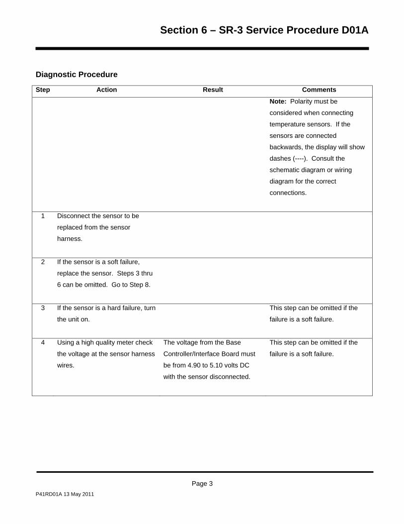
Section 6 – SR-3 Service Procedure D01A
Diagnostic Procedure
Step Action Result Comments
Note: Polarity must be
considered when connecting
temperature sensors. If the
sensors are connected
backwards, the display will show
dashes (----). Consult the
schematic diagram or wiring
diagram for the correct
connections.
1 Disconnect the sensor to be
replaced from the sensor
harness.
2 If the sensor is a soft failure,
replace the sensor. Steps 3 thru
6 can be omitted. Go to Step 8.
3 If the sensor is a hard failure, turn
the unit on.
This step can be omitted if the
failure is a soft failure.
4 Using a high quality meter check
the voltage at the sensor harness
wires.
The voltage from the Base
Controller/Interface Board must
be from 4.90 to 5.10 volts DC
with the sensor disconnected.
This step can be omitted if the
failure is a soft failure.
Page 3 P41RD01A 13 May 2011

Section 6 – SR-3 Service Procedure D01A
Page 4 P41RD01A 13 May 2011
Step Action Result Comments
5 If the voltage measured in the
previous step is correct, go to
Step 8.
This step can be omitted if the
failure is a soft failure.
6 If the voltage measured in Step 4
above is incorrect, unplug the
sensor connector at the Base
Controller/Interface Board and
check the harness for shorts and
open wires.
Test and repair the harness as
required. See Service Procedure
H04A for additional information.
This step can be omitted if the
failure is a soft failure.
7 If the harness passes inspection,
check the Base
Controller/Interface Board as
shown in Service Procedure
A01A.
If the Base Controller/Interface
Board fails the test it must be
replaced.
This step can be omitted if the
failure is a soft failure.
8 If the failure is a soft failure or the
voltage at the harness connector
is correct replace the sensor.

Section 6 – SR-3 and SR-3 M/T Service Procedure D03A
Pressure Transducer Test
Where Used
All SR-3 Single Temperature and SR-3 Spectrum Multi-Temperature units
Purpose
To confirm the proper operation of the suction or discharge pressure transducers
Materials Required
• Fluke Digital Multi-meter.
Additional Information SR-3 Base Controller/Interface Boards have a separate 5 Vdc power supply for the Discharge Pressure
Transducer, Suction Pressure Transducer and Coolant Level switch. A short circuit condition in one transducer or
switch circuit should not affect the other devices.
Discharge Pressure Transducers The maximum discharge pressure that can be displayed is 500 psig. If the sensed pressure is greater than 500
psig, the HMI Control Panel will display [ - - - - ] instead of the discharge pressure.
The minimum discharge pressure that can be sensed is -10 psig. The control system cannot determine if the
minimum sensed pressure is the result of an electrical short or very low system pressure.
Page 1 P41xD03A 13 May 2011

Section 6 – SR-3 and SR-3 M/T Service Procedure D03A
Suction Pressure Transducers The maximum suction pressure that can be displayed is 200 psig. If the sensed pressure is greater than 200
psig, the HMI Control Panel will display [ - - - - ] instead of the suction pressure. When the unit is off and the
refrigerant pressures have equalized, the system pressure can exceed 200 psig when ambient temperatures are
above 90°F (35°C). If this occurs the HMI Control Panel will display [ - - - - ]. This is normal operation and no
cause for concern.
The minimum suction pressure that can be sensed is -12 psig.
If the suction pressure transducer opens the display will read -10 PSIG. An alarm may not be generated
immediately but the unit will be forced to low speed due to low suction pressure.
Pressure Transducer Identification The Discharge Pressure Transducer will have “500” on the body of the part. The Suction Pressure Transducer
will have “200” on the body of the part. The transducers are not interchangeable.
Page 2 P41xD03A 13 May 2011
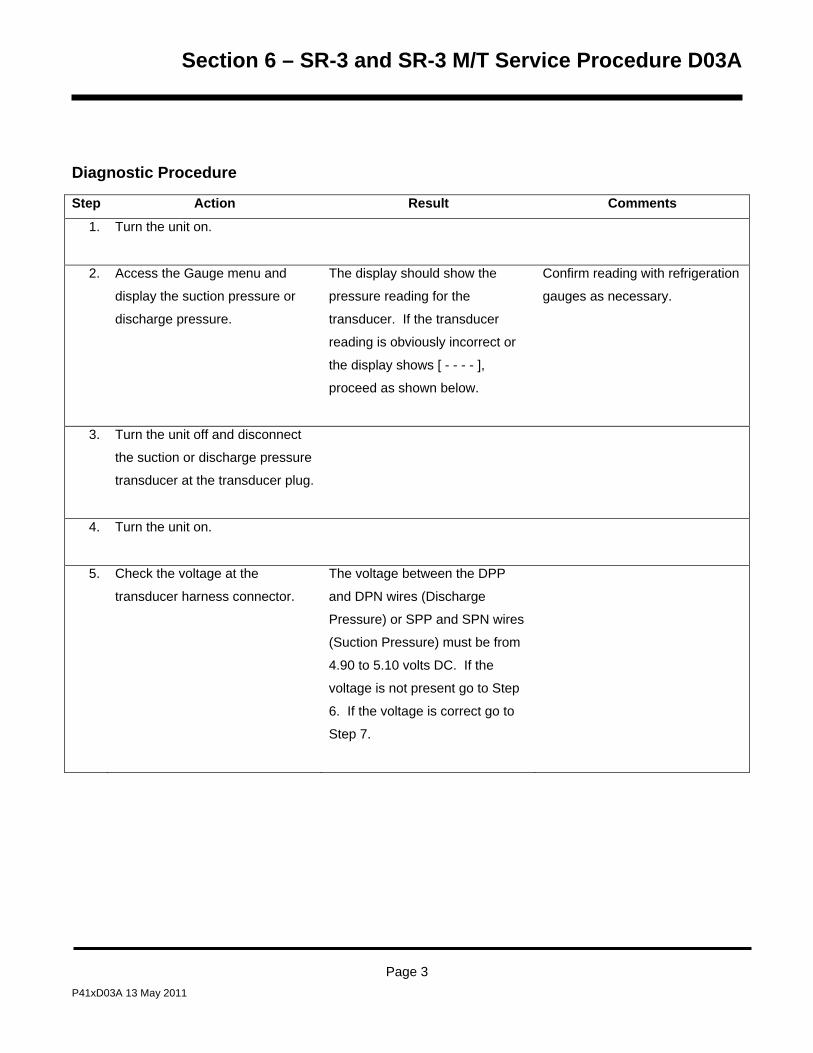
Section 6 – SR-3 and SR-3 M/T Service Procedure D03A
Diagnostic Procedure
Step Action Result Comments
1. Turn the unit on.
2. Access the Gauge menu and
display the suction pressure or
discharge pressure.
The display should show the
pressure reading for the
transducer. If the transducer
reading is obviously incorrect or
the display shows [ - - - - ],
proceed as shown below.
Confirm reading with refrigeration
gauges as necessary.
3. Turn the unit off and disconnect
the suction or discharge pressure
transducer at the transducer plug.
4. Turn the unit on.
5. Check the voltage at the
transducer harness connector.
The voltage between the DPP
and DPN wires (Discharge
Pressure) or SPP and SPN wires
(Suction Pressure) must be from
4.90 to 5.10 volts DC. If the
voltage is not present go to Step
6. If the voltage is correct go to
Step 7.
Page 3 P41xD03A 13 May 2011

Section 6 – SR-3 and SR-3 M/T Service Procedure D03A
Page 4 P41xD03A 13 May 2011
Step Action Result Comments
6. If the voltage is not present,
check the harness continuity of
the DPP-DPN or SPP-SPN wires.
If the continuity checks good and
voltage is still not present, check
the Base Controller/Interface
Board using Service Procedure
A01A. Replace the Base
Controller/Interface Board if
necessary.
7. IF the voltage is correct, check
the harness continuity of the DPI
or SPI wires.
If the voltage at Step 5 is present
and the DPI or SPI wire has
continuity, replace the transducer
in question.
8. Transducer circuit operation can
be verified by installing a known
good transducer in the center
port of a gauge manifold.
Connect the transducer to the
unit wiring harness and check the
gauge reading.
If the transducer in the gauge
manifold reads properly the unit
transducer is bad.
Apply discharge or suction
pressure to the test transducer
via the gauge manifold center
port.

Section 6 – SR-3 Service Procedure D04A
CargoWatch Temperature Sensor Test
Where Used
All SR-3 Single Temperature and SR-3 Spectrum Multi-Temperature units
Purpose
To confirm the proper operation of the CargoWatch temperature sensors
Materials Required
• Fluke Digital Multimeter.
CargoWatch Temperature Sensors
The optional sensors used for the CargoWatch data logger are RTD thermistor type sensors. These sensors are
different and cannot be used to replace the unit temperature sensors. The Service Part number for the optional
CargoWatch sensors is 41-5436. CargoWatch sensors can be identified by:
• No shrink tubing over sensor barrel
• Shorter sensor barrel than unit sensors
• No sensor grades
• The sensor is not polarity sensitive
• Both wires are black
Thermistor CargoWatch Sensor
Page 1 P41xD04A 13 May 2011

Section 6 – SR-3 Service Procedure D04A
CargoWatch Temperature Sensor Resistor Values vs Temperature
CargoWatch thermistor type sensors change resistance as the temperature changes. Resistance values are as
shown in the table below. They can be measured directly using a high quality ohmmeter. Note that this applies
only to CargoWatch Data Logger sensors.
CargoWatch Sensor Resistance vs Temperature
°F °C Ohms
-20°F -29°C 166,356
-10°F -23°C 115,757
0°F -18°C 86,501
10°F -12°C 61,737
20°F -7°C 47,070
30°F -1°C 34,374
32°F 0°C 32,650
40°F 4°C 26,688
50°F 10°C 19,904
60°F 16°C 15,002
70°F 21°C 11,944
80°F 27°C 9,166
90°F 32°C 7,402
100°F 38°C 5,775
Page 2 P41xD04A 13 May 2011

Section 6 – SR-3 Service Procedure D04A
Diagnostic Procedure
Step Action Result Comments
1 Disconnect the sensor to be
tested from the sensor harness.
This can be done at the 12 pin
Deutsch connector in the
evaporator compartment.
2 Using a high quality meter, check
the sensor resistance. This can
be done at the 12 pin Deutsch
connector in the evaporator
compartment.
The sensor resistance is
dependant on the sensor
temperature as shown by the
table on the previous page. The
measured sensor resistance
should approximate the value
shown for the current sensor
temperature.
If the sensor resistance does not
match the table the sensor must
be replaced.
3 If the resistance measured in the
previous step is correct, go to
Step 4. If the resistance
measured is not correct replace
the sensor.
4 Using a high quality meter check
the voltage at the sensor harness
wires. This can be done at the
12 pin Deutsch connector in the
evaporator compartment.
The voltage from the HMI Control
Panel should be 2.5 Vdc with the
sensor disconnected.
Page 3 P41xD04A 13 May 2011

Section 6 – SR-3 Service Procedure D04A
Page 4 P41xD04A 13 May 2011
Step Action Result Comments
5 If the voltage measured in the
previous step is correct, go to
Step 7. If the voltage measured
is not correct go to Step 6.
6 If the voltage measured in Step 4
above is incorrect, unplug the 35
pin connector at the HMI Control
Panel and check the harness for
shorts and open wires.
Test and repair the harness as
required. See Service Procedure
H04A for additional information.
7 If the harness passes inspection,
check the HMI Control Panel as
shown in Service Procedure
A01B.
If the HMI Control Panel fails the
test it must be replaced.

Section 6 – SR-3 and SR-3 M/T Service Procedure F01A
Checking and Replacing the Oil Level Switch
Where Used
All SR-3 Single Temperature and SR-3 Spectrum Multi-Temperature units
Purpose
To test the oil level switch for proper operation
Materials Required
• Fluke Digital Multimeter.
Operation
The switch is open with the float up (indicating full oil level). The switch is closed with the float down (indicating
low oil level).
Diagnostic Procedure
Step Action Result Comments
1. Turn the unit off.
2. Disconnect the Deutsch
connector at the switch.
The oil level switch is located on
the top of the oil pan.
3. Use an ohmmeter to check
switch continuity.
With the oil above the "add"
mark, the switch should be open.
If the engine is 6 or more quarts
low the switch should be closed.
This check can be performed
while changing oil.
4. Reconnect the Deutsch
connector.
Page 1 P41xF01A 13 May 2011

Section 6 – SR-3 and SR-3 M/T Service Procedure F01A
Page 2 P41xF01A 13 May 2011
Replacing the Switch – Screw In Applications
Step Action Result Comments
1. Turn the unit off.
2. Disconnect the Deutsch connector at the
switch.
The oil level switch is located on the top of
the oil pan.
3. Unscrew and remove the old switch.
4. Apply Teflon tape to the threads on the new
switch.
5. Screw the new switch into the hole in the oil
pan. Tighten until snug. Do not over-tighten.
6. Reconnect the Deutsch switch connector.

Section 6 – SR-3 and SR-3 M/T Service Procedure F05A
Checking the Oil Pressure Switch
Where Used
All SR-3 Single Temperature and SR-3 Spectrum Multi-Temperature units
Purpose
To test the oil pressure switch for proper operation
Materials Required
• Fluke Digital Multi-meter.
Diagnostic Procedure
Step Action Result Comments
1. Connect a multi-meter set for DC
Volts between the 20B wire at the
oil pressure shutdown switch and
chassis ground.
2. Turn the unit on and observe the
meter reading.
The voltage with the unit on and
the engine not running should be
0. If there is voltage present the
switch is defective.
3. Start the engine and observe the
meter reading.
Battery voltage should be present
when the engine is running. If
the voltage is low or is 0, proceed
to Step 4.
Page 1 P41xF05A 13 May 2011

Section 6 – SR-3 and SR-3 M/T Service Procedure F05A
Page 2 P41xF05A 13 May 2011
Step Action Result Comments
4. With the unit running, disconnect
the 20B wire from the switch.
Measure the voltage from the
20B wire to chassis ground.
If the battery voltage is present
on the wire, the switch is
defective and should be replaced.
If the voltage on the 20B wire is
low or 0, there is a problem in the
20B circuit.
Check the 20B circuit as required
to determine the cause.

Section 6 – SR-3 and SR-3 M/T Service Procedure F07B
Magnetic Coolant Level Sensor Test
Where Used
All SR-3 Single Temperature and SR-3 Spectrum Multi-Temperature units
Purpose
To confirm proper operation of the magnetic coolant level sensor
Materials Required
• Fluke Digital Multimeter.
Operation
A magnetic reed switch is used to determine the coolant level. This two wire switch is supplied with +5 VDC from
the Base Controller/Interface Board on the CLP wire (J7 Pin 15). The switch outputs +5 VDC on the CLS wire (J7
Pin 16) when coolant level is above the sensor and less than 0 VDC when the coolant level is below the sensor.
The switch is housed in an isolated chamber within the coolant tank. A magnetic float is located in the engine
coolant adjacent to the switch chamber. The switch will open or close as the magnetic float falls or rises with the
coolant level. The switch can be changed without removing coolant from the radiator. Exercise care when
removing and installing the reed switch as the switch is enclosed in a glass shell.
Diagnostic Procedure Step Action Result Comments
1 Disconnect the switch and check
the voltage between the CLP wire
at the sensor harness connector
and chassis ground for + 5 VDC.
+ 5 VDC should be present
between the CLP wire and
chassis ground. If not, check the
harness and connectors as
required to determine the cause.
Page 1 P41xF07B 13 May 2011

Section 6 – SR-3 and SR-3 M/T Service Procedure F07B
Page 2 P41xF07B 13 May 2011
Step Action Result Comments
2 If + 5 VDC is present at the
sensor, check the voltage on the
CLS wire at the sensor harness
connector.
Less than 0.5 VDC should be
present when the coolant level is
below the switch and +5 VDC
should be present when the
coolant level is above the switch.
If these voltages are not present
the sensor must be replaced.
3 The switch is housed in an
isolated chamber within the
coolant tank. The switch can be
changed without removing
coolant from the radiator.
Exercise care when removing
and installing the reed switch as
the switch is enclosed in a glass
shell. Carefully pry the switch
from the chamber in the coolant
tank. To install the switch
carefully press it into the chamber
by hand.

Section 6 – SR-3 and SR-3 M/T Service Procedure F08A
Coolant Temperature Sensor Test
Where Used
All SR-3 Single Temperature and SR-3 Spectrum Multi-Temperature units
Purpose
To test the coolant temperature sensor for proper operation
Materials Required
• Fluke Digital Multi-meter.
Engine Temperature Sensor
Page 1 P41xF08A 13 May 2011

Section 6 – SR-3 and SR-3 M/T Service Procedure F08A
Diagnostic Procedure
Step Action Result Comments
1. Note: Polarity must be
considered when connecting
temperature sensors. If the
sensors are connected
backwards, the display will show
dashes [ - - - - ]. Consult the
schematic diagram or wiring
diagram for the correct
connections.
2. Turn the unit off.
3. Disconnect the sensor at the plug
next to the sensor.
4. Turn the unit on.
The Standard Display will appear.
5. Access the Gauge menu and
display Coolant Temperature.
The display for the Engine
Coolant Temperature sensor
should show dashes [ - - - - ].
If all the temperature sensors
show dashes [ - - - - ] without
being disconnected, the Base
Controller/Interface Board is
defective.
6. Using a high quality meter check
the voltage at the sensor plug on
the harness.
The voltage must be from 4.90 to
5.10 volts DC.
7. If the voltage at the harness
connector is correct, replace the
sensor.
Page 2 P41xF08A 13 May 2011

Section 6 – SR-3 and SR-3 M/T Service Procedure F08A
Step Action Result Comments
8. If the voltage measured in Step 6
above is incorrect, check the
Base Controller/Interface Board
as shown in Service Procedure
A01A.
If the Base Controller/Interface
Board fails the test it must be
replaced.
9. If the Base Controller/Interface
Board passes the test, the
problem is in the wiring harness.
Test and repair the harness as
required.
Page 3 P41xF08A 13 May 2011

Section 6 – SR-3 and SR-3 M/T Service Procedure F08A
Page 4 P41xF08A 13 May 2011

Section 6 – SR-3 and SR-3 M/T Service Procedure F09A
RPM Sensor Test and Adjustment
Where Used
All SR-3 Single Temperature and SR-3 Spectrum Multi-Temperature units
Purpose
To test and adjust the RPM sensor
Materials Required
• Fluke Digital Multimeter.
Operation
The RPM sensor rarely fails but may require adjustment for proper operation.
Diagnostic Procedure
Step Action Result Comments
1. Turn the unit off.
2. Remove the FS1 and FS2 wires
from the sensor.
3. Check the sensor resistance
using a high quality multi-meter.
The sensor resistance should be
250 to 300 ohms with the wires
removed. If not, the sensor
should be replaced.
4. Loosen the lock nut, turn the
sensor in until it contacts the ring
gear on the flywheel, then back it
out ½ turn and tighten the lock
nut.
Page 1 P41xF09A 13 May 2011

Section 6 – SR-3 and SR-3 M/T Service Procedure F09A
Page 2 P41xF09A 13 May 2011
Step Action Result Comments
5. Start the unit.
6. Using Service Test Mode, place
the unit in high speed cool [HSC].
For information on Service Test
Mode see Section 4.
7. Check the voltage across the
sensor terminals with the FS1
and FS2 wires removed.
The voltage in high speed should
read from 1.0 to 5.0 volts ac.
Set the meter to read AC volts.
8. If the required voltage is not
present, replace the RPM sensor.
If the required voltage is present,
check the harness wires and
repair as required.
9. Reattach the FS1 and FS2 wires
to the sensor.
Polarity is not important.
10. Access the Gauge menu and
display Engine RPM.
The display should show the
engine RPM.
11. If the RPM reading does not
appear in the display, check the
base controller as shown in
Service Procedure A01A.
If the base controller fails the test
it must be replaced.

Section 6 – SR-3 Service Procedure G03A
Electronic Throttling Valve (ETV) Test
Where Used
All SR-3 units equipped with an Electronic Throttling Valve (ETV)
Purpose
To confirm proper operation of the Electronic Throttling Valve
• Test ETV to confirm operation.
• If the ETV must be changed consult the Maintenance Manual for the specific unit.
Materials Required
• Fluke Digital Multimeter.
Operation
This procedure should be used to check the operation of the electronic throttling valve if Alarm Code 89 Check
Electronic Throttling Valve Circuit occurs. Alarm Code 89 indicates that refrigeration system pressures did not
respond as expected. This may be caused by a malfunction in the electronic throttling valve circuits or a
refrigeration system problem such as low refrigerant level, frozen expansion valve or a severe suction side
restriction.
The Electronic Throttling Valve has two internal coils. The Base Controller/Interface Board operates the valve is
by energizing the coils with a variable frequency ac signal. The sequence in which the Base Controller/Interface
Board energizes the coils determines the direction of travel and the frequency of the signal determines the speed
of valve motion. Wires EVA and EVB energize one coil and wires EVC and EVD energize the other coil. The
ETV circuits are protected by Smart FETs. Valve position may be monitored by using the Gauge key. 0 indicates
the valve is fully closed and 800 indicates the valve is fully opened.
IMPORTANT: The LED’s on SR-3 Base Controller/Interface Boards can be used to verify controller output to the
ETV.
Page 1 P41xG03A 13 May 2011

Section 6 – SR-3 Service Procedure G03A
Electronic Throttling Valve Types and Wire Color Codes
Electronic Throttling Valve
• The current electronic throttling valves do not have a removable connector on the valve. There is a
sheathed cable consisting of colored wires that run from the connector on the valve to the Deutsch
harness connector on this pigtail as shown above. The color code and connections for this valve are
shown in the table below.
Harness Wire Wire Colors
EVA Red
EVB Green
EVC White
EVD Black
SR-3 Base Controller/Interface Boards feature yellow and green ETV LED’s located at the lower right edge of the
board. These LED’s flash when a signal is being sent to the ETV. These LED’s flash rapidly for a brief period of
time on initial startup. They flash at a slower rate when the valve is opening or closing normally. If LED’s are
flashing a signal is being sent to the ETV.
Page 2 P41xG03A 13 May 2011

Section 6 – SR-3 Service Procedure G03A
Diagnostic Procedure
Step Action Result Comments
1 Be certain that all connectors are
secure.
2 Disconnect the Base
Controller/Interface Board
connector J7 and measure the
resistance from the EVA wire to
the EVB wire at the connector.
J7 Pin 24 – EVA wire
J7 Pin 23 – EVB wire
The resistance should be from
20 to 35 ohms. If the resistance
is incorrect check the EVA and
EVB wires and connectors
leading to the electronic throttling
valve. Also check the EVA and
EVB wires for shorts to ground.
Be sure the valve connector is
properly attached to the valve.
Identify the associated pins
on the ETV and check for
continuity at the valve. If the
resistance from the EVA and
EVB pins directly on the valve
is not from 20 to 35 ohms the
valve is defective. Neither pin
should show a short to
ground.
3 Measure the resistance from the
EVC wire to the EVD wire at the
connector.
J7 Pin 11 – EVC wire
J7 Pin 12 – EVD wire
The resistance should be from
20 to 35 ohms. If the resistance
is incorrect check the EVC and
EVD wires and connectors
leading to the electronic throttling
valve. Also check the EVC and
EVD wires for shorts to ground.
Be sure the valve connector is
properly attached to the valve.
Identify the associated pins
on the ETV and check for
continuity at the valve. If the
resistance from the EVC and
EVD pins directly on the valve
is not from 20 to 35 ohms the
valve is defective. Neither pin
should show a short to
ground.
4 Reconnect J7 to the Base
Controller/Interface Board.
Page 3 P41xG03A 13 May 2011

Section 6 – SR-3 Service Procedure G03A
Step Action Result Comments
5 Temporarily connect a known
good test ETV at the ETV
connector.
IMPORTANT: Be sure to use
the entire valve, not just a
replacement stepper motor and
piston assembly. If only a
stepper motor and piston
assembly is used, the piston may
become completely unscrewed
from the stepper motor shaft.
The original valve can be left
in place on the unit.
IMPORTANT: If the piston
becomes completely
unscrewed from the stepper
motor shaft then further
disassembly is required to
reinstall the piston on the
stepper motor shaft.
6 Position an assistant in the trailer
to report valve operation.
7 From the Maintenance Menu,
enter Evacuation Test.
The test ETV should open when
Evacuation Test is entered.
8 Exit Evacuation Test. The test ETV should close when
Evacuation Test is exited.
9 If the test ETV opens and closes
as described in Step 7 & 8,
replace the unit ETV stepper
motor/piston assembly.
If the entire ETV must be
changed consult the
Maintenance Manual for the
specific unit.
Page 4 P41xG03A 13 May 2011

Section 6 – SR-3 Service Procedure G03A
Step Action Result Comments
10 If the test ETV does not open
and close as described in Steps
7 and 8, test the Base
Controller/Interface Board as
shown in Service Procedure
A01A.
11 If the Base Controller/Interface
Board Test fails, replace the
Base Controller/Interface Board.
12 When repairs are complete
perform a Full Pretrip Test as
shown in Section 4 to confirm
proper operation.
Page 5 P41xG03A 13 May 2011

Section 6 – SR-3 Service Procedure G03A
Page 6 P41xG03A 13 May 2011

Section 6 – SR-3 and SR-3 M/T Service Procedure H04A
Wiring Harness Continuity Test
Where Used
All SR-3 Single Temperature and SR-3 Spectrum Multi-Temperature units
Purpose
To illustrate the correct procedures for checking harness continuity on equipment utilizing solid state devices
Materials Required
• Fluke Digital Multimeter
• Jumper wires as required
Important Notes
• Do not use battery and light test tools to check continuity.
• Do not check to see if a circuit is energized by tapping a circuit wire to ground and watching for a spark.
Diagnostic Procedure
Step Action Result Comments
1. Do not use battery and light test
tools to check continuity.
Using such devices may present
excessive voltage or current to
solid state devices. In many
cases the device will be damaged
or destroyed.
Page 1 P41xH04A 13 May 2011
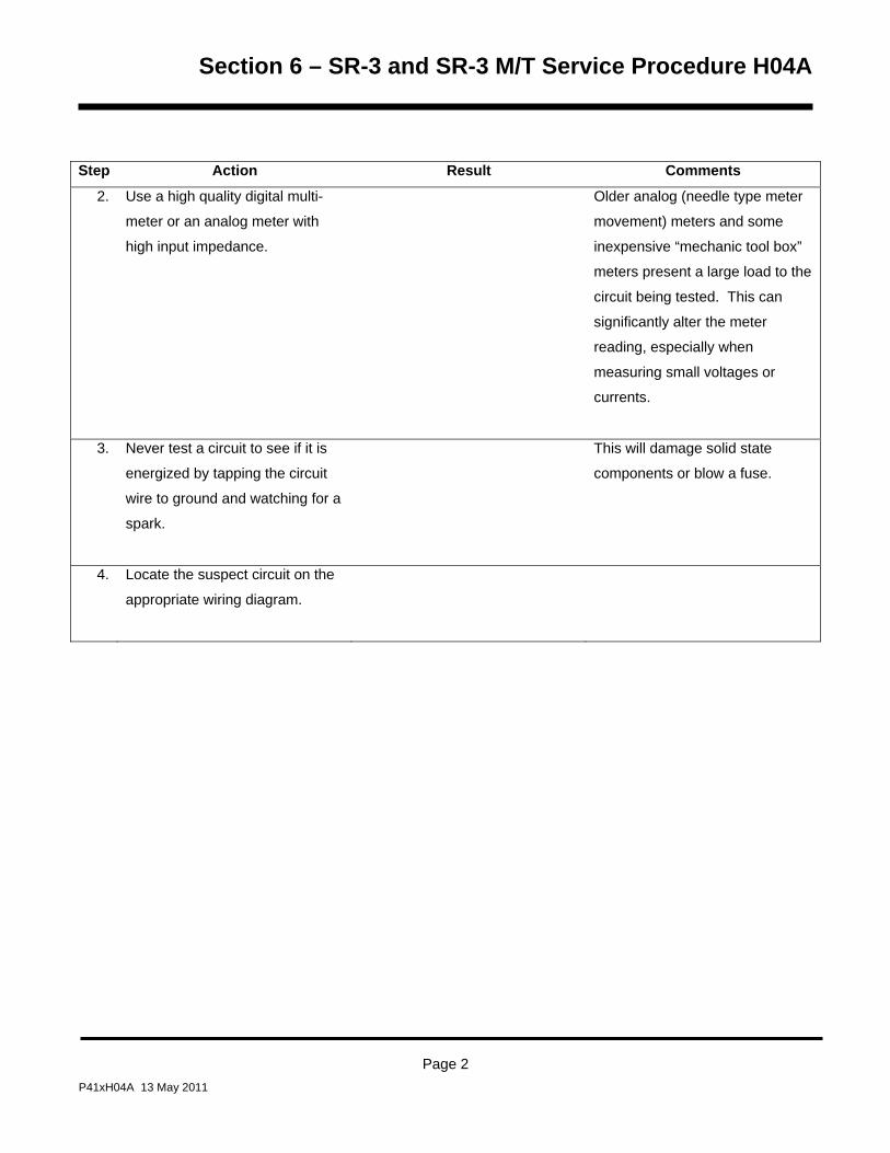
Section 6 – SR-3 and SR-3 M/T Service Procedure H04A
Step Action Result Comments
2. Use a high quality digital multi-
meter or an analog meter with
high input impedance.
Older analog (needle type meter
movement) meters and some
inexpensive “mechanic tool box”
meters present a large load to the
circuit being tested. This can
significantly alter the meter
reading, especially when
measuring small voltages or
currents.
3. Never test a circuit to see if it is
energized by tapping the circuit
wire to ground and watching for a
spark.
This will damage solid state
components or blow a fuse.
4. Locate the suspect circuit on the
appropriate wiring diagram.
Page 2 P41xH04A 13 May 2011

Section 6 – SR-3 and SR-3 M/T Service Procedure H04A
Step Action Result Comments
5. Isolate both ends of the circuit
using the following methods as
required.
• Disconnect the appropriate
connector at the Base
Controller/Interface Board.
• Disconnect the device
connector at the device.
• Remove the wire from the
device terminal.
Harness connections are
identified in the Service
Procedures appropriate to the
device in question. They may
also be determined by consulting
the wiring diagrams.
CAUTION: Failure to isolate both ends may cause
misleading results.
6. Using jumpers as required,
connect each end of the circuit to
a high quality multimeter.
The meter must show a very low
resistance (less than 1.0 ohm),
indicating circuit continuity. If not,
the circuit is open or has
excessive resistance.
Troubleshoot the circuit to
determine the cause using the
wiring diagrams.
Be certain the ohmmeter battery
is good and the meter zeros with
the leads held together to prevent
misleading results.
Page 3 P41xH04A 13 May 2011
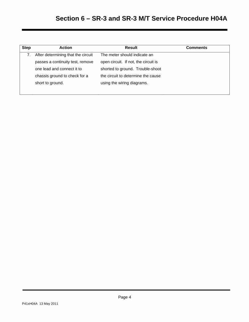
Section 6 – SR-3 and SR-3 M/T Service Procedure H04A
Page 4 P41xH04A 13 May 2011
Step Action Result Comments
7. After determining that the circuit
passes a continuity test, remove
one lead and connect it to
chassis ground to check for a
short to ground.
The meter should indicate an
open circuit. If not, the circuit is
shorted to ground. Trouble-shoot
the circuit to determine the cause
using the wiring diagrams.

Section 7 – SR-3 Service Information Index
Table of Contents Section 7 I01A SR-3 Hardware Features I02A SR-3 Software Features I10A SR-3 Power On/Off Control I12A SR-3 HMI Control Panel Message and Their Causes
13 May 2011

Section 7 – SR-3 Service Information Index
13 May 2011

Section 7 – SR-3 Trailer S/T Hardware Features I01A
SR-3 Hardware Features Table of Contents
SR-3 Base Controller/Interface Boards ................................................................................................................. 3
SR-3 Base Controller/Interface Board Hardware Versions ................................................................................... 3
Service Parts Numbers for SR-3 Base Controller/Interface Boards ...................................................................... 3
SR-3 Base Controller/Interface Board Identification .............................................................................................. 3
SR-3 Base Controller/Interface Board Software Requirements ............................................................................ 4
SR-3 Base Controller/Interface Board Compatibility.............................................................................................. 4
SR-3 HMI Control Panels ........................................................................................................................................ 5 SR-3 HMI Control Panel Hardware Versions ......................................................................................................... 5
Service Part Number 45-2372 SR-3 Base Controller/Interface Board ............................................................... 5 SR-3 HMI Control Panel Identification ................................................................................................................... 5
SR-3 HMI Control Panel Label Location ................................................................................................................ 6
SR-3 HMI Control Panel Software Requirements .................................................................................................. 6
SR-3 HMI Control Panel Compatibility ................................................................................................................... 6
Service Parts Numbers for SR-3 HMI Control Panels ........................................................................................... 6
SR-2/SR-3 Diagnostic Tool ..................................................................................................................................... 7 Base Controller/Interface Board and HMI Control Panel Diagnostic Tool ............................................................. 7
Service Parts Number for the Complete SR-2/SR-3 Diagnostic Tool .................................................................... 8
Service Parts Number for the SR-2/SR-3 Diagnostic Tool Upgrade Kit ................................................................ 9
Page 1 13 May 2011

Section 7 – SR-3 Trailer S/T Hardware Features I01A
Page 2 13 May 2011

Section 7 – SR-3 Trailer S/T Hardware Features I01A
SR-3 BASE CONTROLLER/INTERFACE BOARDS SR-3 Base Controller/Interface Board Hardware Versions There are currently two versions of the SR-3 (3T1) Base Controller/Interface Board/Interface Board as shown in
the Table below.
Service Parts Numbers for SR-3 Base Controller/Interface Boards Dates Base Controller/Interface Board
Description Type
Designator Service Part #
Production SLX S/T
Units from
September 2010
To Present
Supports Damper Gear Motor
Does not support USB Port
N/A 45-2362
Production SB S/T
Units from February
2011
To Present
Does not support Damper Gear Motor
Supports USB Port
N/A 45-2361
SR-3 Base Controller/Interface Board Identification The SR-3 Base Controller/Interface Board is identified by Service Part Number as shown above. The serial
number of SR-3 Base Controller/Interface Boards ends in 3T1 as shown below.
Page 3 13 May 2011
Section 7 – SR-3 Trailer S/T Hardware Features I01A
SR-3 Base Controller/Interface Board Software Requirements Single temperature applications with SR-3 Base Controller/Interface Boards must use SR-3 Base
Controller/Interface Board Software Revisions D0xx.
SR-3 Base Controller/Interface Board Compatibility The SR-3 Base Controller/Interface Board is 100% compatible with and may be used to replace the combined
SR-2 Base Controller/Interface Board and Interface Board assembly. The SR-3 Base Controller/Interface Board
mounting base uses the same mounting hole pattern as did the SR-2 Base Controller/Interface Board. The
connectors on the SR-3 Base Controller/Interface Board are located in approximately the same positions as they
are on an SR-2 Interface Board. However, when replacing an SR-2 Base Controller/Interface Board/Interface
Board with an SR-3 Base Controller/Interface Board the wiring harness may need to be relocated slightly to reach
the some of the connectors.
It is critical that the correct software be used.
• Single temperature applications with SR-2 Base Controller/Interface Boards must use Base
Controller/Interface Board Software Revisions B0xx.
• Single temperature applications with SR-3 Base Controller/Interface Boards must use Base
Controller/Interface Board Software Revisions D0xx.
• Multi-temperature applications with SR-3 Base Controller/Interface Boards have not yet been
implemented.
Page 4 13 May 2011

Section 7 – SR-3 Trailer S/T Hardware Features I01A
SR-3 HMI CONTROL PANELS SR-3 HMI Control Panel Hardware Versions The SR-3 Control System uses essentially the same HMI Control Panel as does the SR-2 Control System.
However, SR-3 HMI Control Panels feature 8 MB of memory and are marked Smart Reefer 3 on the lower front
panel as shown below.
Service Part Number 45-2372 SR-3 Base Controller/Interface Board
• Production release for NAD SB units starting February 2011.
SR-3 HMI Control Panel Identification The SR-3 HMI Control Panel is identified by Service Part Number as shown on the label. It can be physically
identified by the Smart Reefer 3 Decal on the front panel as shown below.
SmartReefer3
OFF
ON
MENU35 °F
35SET SENSORSGAUGES
POINT
.8
Page 5 13 May 2011

Section 7 – SR-3 Trailer S/T Hardware Features I01A
SR-3 HMI Control Panel Label Location The HMI Control Panel label showing the Service Part number is located on the back of the assembly. The serial
number of SR-3 HMI Control Panel ends in 0T3 as shown below.
BASE P/N: 1E65319G01S.P. P/N: 45-2372REV. 6560S/N: HXXXXXXXXXX0T3Bar Code HereATP-MUC 1060 TSX13651536070
SR-3 Designator
SR-3 HMI Control Panel Software Requirements • SR-3 HMI Control Panels used on SR-3 applications without USB capability and use HMI Control Panel
Software Revision 6550 or later.
• SR-3 HMI Control Panels used on SR-3 applications with USB capability and use HMI Control Panel
Software Revision 6560 or later.
SR-3 HMI Control Panel Compatibility The SR-3 Control System uses essentially the same HMI Control Panel as does the SR-2 Control System.
However, SR-3 HMI Control Panels feature 8 MB of memory and are marked Smart Reefer 3 on the lower front
panel as shown below. The SR-2 HMI Control Panels feature 4 MB of memory. Other than memory, the SR-3
HMI Control Panel is compatible with and may be used to replace the SR-2 HMI Control Panel.
Service Parts Numbers for SR-3 HMI Control Panels
HMI Control Panel
HMI Control Panel Description
Type Designator
Service Part #
SR-3 Current SR-3 HMI Control Panel. Front panel art reads
“SR-3”.
HMI-3 45-2372
Page 6 13 May 2011

Section 7 – SR-3 Trailer S/T Hardware Features I01A
SR-2/SR-3 DIAGNOSTIC TOOL Base Controller/Interface Board and HMI Control Panel Diagnostic Tool An SR-2/SR-3 Diagnostic Tool with Diagnostic Tool Software 4.1 or greater is required to test the SR-3 Base
Controller/Interface Board. The SR-3 Base Controller/Interface Board is currently used on SR-3 Single
Temperature Trailer applications. This Diagnostic Tool will also work on all previous SR-2 Truck and Trailer Base
Controller/Interface Boards and Trailer HMI Control Panels. It also tests the Truck Premium HMI Control Panel.
The new Diagnostic Tool is available as a complete tool and also as an update kit for the SR-2 Blue Diagnostic
Tool.
Features: The SR-2/SR-3 Diagnostic Tool includes the following new features.
Tests the SR-3 Base Controller/Interface Board
Tests the SR-3 USB Communications Port
Tests the SR-2 and SR-3 Base Controller and HMI Control Panel CAN Ports using a USB to CAN Adaptor
Page 7 13 May 2011

Section 7 – SR-3 Trailer S/T Hardware Features I01A
Service Parts Number for the Complete SR-2/SR-3 Diagnostic Tool The complete SR-2/SR-3 Diagnostic Tool is available as Service Part Number 204-1930. It includes the
following:
The Blue Diagnostic Tool. This component is the same as the Blue Diagnostic Tool supplied with earlier versions of the Diagnostic Tool.
All cables supplied with previous Blue Diagnostic Tool.
A USB Cable to connect the USB Port on the SR-3 Base Controller to a USB Flash Drive.
A USB to CAN Adaptor. This adaptor is required to perform the CAN Test that is part of the new Diagnostic Tool.
A CAN Test Cable to connect the USB to CAN Adaptor to the Diagnostic Tool J1 Connector.
A Premium Truck HMI Cable to connect the Premium Truck HMI Control Panel to the Diagnostic Tool J2 Connector.
SR-2/SR-3 Diagnostic Tool Software Revision 4.1.
Instructions and Storage Box.
Page 8 13 May 2011

Section 7 – SR-3 Trailer S/T Hardware Features I01A
Service Parts Number for the SR-2/SR-3 Diagnostic Tool Upgrade Kit The SR-2/SR-3 Diagnostic Tool Upgrade Kit is available as Service Part Number 204-1931. It utilizes the current
Blue SR-2 Diagnostic Tool hardware (Part Number 204-1196) and cables with no changes and includes the
following:
A USB Cable to connect the USB Port on the SR-3 Base Controller to a USB Flash Drive.
A USB to CAN Adaptor. This adaptor is required to perform the CAN Test that is part of the new Diagnostic Tool.
A CAN Test Cable to connect the USB to CAN Adaptor to the Diagnostic Tool J1 Connector.
A Premium Truck HMI Cable to connect the Premium Truck HMI Control Panel to the Diagnostic Tool J2 Connector.
SR-2/SR-3 Diagnostic Tool Software Revision 4.1.
Instructions.
Page 9 13 May 2011

Section 7 – SR-3 Trailer S/T Hardware Features I01A
Page 10 13 May 2011

Section 7 – SR-3 Trailer S/T Software Features I02A
SR-3 SOFTWARE FEATURES Table of Contents
SR-3 Base Controller/Interface Board/Interface Board Software ....................................................................... 3
SR-3 Trailer Single Temperature Base Controller/Interface Board Software Revisions ....................................... 3
Base Controller/Interface Board Software Revision D000 ..................................................................................... 3
Base Controller/Interface Board Software Revision D005 ..................................................................................... 4
Base Controller/Interface Board Software Revision D006 ..................................................................................... 4
Base Controller/Interface Board Software Revision D007 ..................................................................................... 4
Availability of SR-3 Base Controller/Interface Board Single Temp Software ........................................................ 5
Flash Loading using PC Computer ........................................................................................................................ 6
Flash Loading using USB Flash Drive ................................................................................................................... 6
SR-3 HMI Control Panel Software .......................................................................................................................... 7
SR-2 and SR-3 HMI Control Panel Revisions ....................................................................................................... 7
Compatibility ........................................................................................................................................................... 8
HMI Control Panel Software Revision 6550-6650-6750-6850 for SR-3 Applications ............................................ 8
HMI Control Panel Software Revision 6560-6660-6760-6860 for SR-3 Applications ............................................ 8
HMI Control Panel Software Revision 6561-6661-6761-6861 for SR-3 Applications ............................................ 8
Availability of Current SR-2 and SR-3 HMI Control Panel Software ...................................................................... 9
Flash Loading using PC Computer ...................................................................................................................... 10
Flash Loading using USB Flash Drive ................................................................................................................. 10
SR-2/SR-3 Diagnostic Tool Software ................................................................................................................... 11
Base Controller/Interface Board and HMI Control Panel Tester .......................................................................... 11
Features: .............................................................................................................................................................. 11
Service Parts Number for the Complete SR-2/SR-3 Diagnostic Tool .................................................................. 11
Service Parts Number for the SR-2/SR-3 Diagnostic Tool Upgrade Kit .............................................................. 11
Diagnostic Tool Software ..................................................................................................................................... 11
Page 1 13 May 2011

Section 7 – SR-3 Trailer S/T Software Features I02A
SR-3 OptiSet Requirements .................................................................................................................................. 13 Features: .............................................................................................................................................................. 13
Compatibility: ........................................................................................................................................................ 13
Sending and Retrieving OptiSet Plus Files using a Data Cable and PC Computer with WinTrac ...................... 13
Using OptiSet Plus with a WinTrac Plus configured USB Flash Drive ................................................................ 14
OptiSet Plus Data Files when using a USB Flash Drive ...................................................................................... 14
Availability: ........................................................................................................................................................... 15
SR-3 WinTrac Requirements ................................................................................................................................ 17
Features ............................................................................................................................................................... 17
Compatibility: ........................................................................................................................................................ 17
Availability: ........................................................................................................................................................... 18
WinTrac on the Internet .................................................................................................................................... 18 WinTrac on CD ................................................................................................................................................. 18
Page 2 13 May 2011
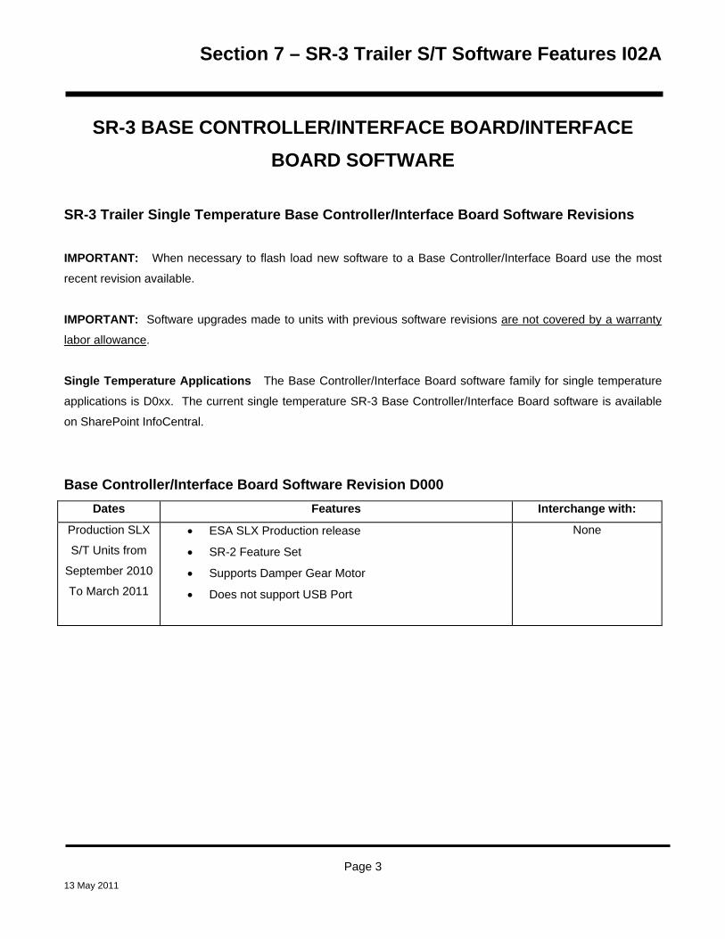
Section 7 – SR-3 Trailer S/T Software Features I02A
SR-3 BASE CONTROLLER/INTERFACE BOARD/INTERFACE BOARD SOFTWARE
SR-3 Trailer Single Temperature Base Controller/Interface Board Software Revisions IMPORTANT: When necessary to flash load new software to a Base Controller/Interface Board use the most
recent revision available.
IMPORTANT: Software upgrades made to units with previous software revisions are not covered by a warranty
labor allowance.
Single Temperature Applications The Base Controller/Interface Board software family for single temperature
applications is D0xx. The current single temperature SR-3 Base Controller/Interface Board software is available
on SharePoint InfoCentral.
Base Controller/Interface Board Software Revision D000 Dates Features Interchange with:
Production SLX
S/T Units from
September 2010
To March 2011
• ESA SLX Production release
• SR-2 Feature Set
• Supports Damper Gear Motor
• Does not support USB Port
None
Page 3 13 May 2011

Section 7 – SR-3 Trailer S/T Software Features I02A
Base Controller/Interface Board Software Revision D005 Dates Features Interchange with:
Production SB
S/T Units from
February 2011
To March 2011
• NAD Production release
• SR-2 Feature Set
• Does not support Damper Gear Motor
• Supports USB Port
None
Base Controller/Interface Board Software Revision D006 Dates Features Interchange with:
Units with Fresh
Air Exchange
only starting
June 2011
• All D005 and D007 Features
• Supports Fresh Air Exchange Feature
Use only for units
equipped with the Fresh
Air Exchange Feature
Base Controller/Interface Board Software Revision D007 Dates Features Interchange with:
Production SB
and SLX S/T
Units from
March 2011
To Current
• All D000 and D005 Features
• Corrected nuisance refrigeration Alarm Code 21 Cooling
Cycle Check and Alarm Code 26 Check Refrigeration
Capacity on SR-3 units equipped with ETV
Replaced D005 by
Campaign CB528 in all
NAD SB Units
Page 4 13 May 2011

Section 7 – SR-3 Trailer S/T Software Features I02A
Availability of SR-3 Base Controller/Interface Board Single Temp Software The most current version of SR-3 Single Temperature Base Controller/Interface Board software is available on
the internet.
When SR-3 Base Controller and/or HMI Control Panel flash load files are downloaded from the Thermo King
iService web site, the flash load files are downloaded as a *.ZIP file. When flash load files for SR-3 applications
are unzipped, there will now be three flash load files instead of the usual two.
The traditional *.mXX and *.cXX files will be unzipped. These two files are for use when flash loading an
SR-3 Unit in the traditional manner using a Data Cable to connect the SR-3 Unit to the PC Computer
equipped with WinTrac.
NOTE: Both the *.mXX and *.cXX files must be present in order to perform a flash load using a Data
Cable, even though only one of them is shown by WinTrac.
A *.FLA file will also be unzipped. This file is for use when flash loading a unit using a WinTrac 5.1
configured USB Flash Drive.
The Flashload Directory on the configured USB Flash Drive contains sub-directories for HMI and
SR3SINGLE TEMP flash load *.FLA files. The *.FLA file must be placed in the correct directory on the
flash drive using either the WinTrac 5.1 Upload > Manage Flashload Files feature or Windows Explorer.
Page 5 13 May 2011

Section 7 – SR-3 Trailer S/T Software Features I02A
Revision D007 Trailer Single Temperature SR-3 Base Controller Software is available on the Thermo King TSA
Info Central web site. Go to:
http://www.thermoking.com/tk/index.asp
Choose TSA Info Central and select Home > Software and Downloads > Microprocessors > Trailer
Microprocessor Updates.
The file name for the *.ZIP file containing both the traditional .mXX and .cXX files and the *.FLA file is
Micro Code D007 Update for the SR-3 Single Temp Base Controller.zip. Double click this file to install the
software.
Flash Loading using PC Computer For additional information on flash loading Base Controller software using a PC computer, WinTrac 5.1 and a data
cable, see Service Procedure A46A Flash Loading Base Controller Software in Section 6 of the SR-3 Trailer
Single Temperature Diagnostic Manual (TK 54842).
Flash Loading using USB Flash Drive SR-3 equipped units can also flash load HMI Control Panel and SR-3 Base Controller software using a WinTrac
configured USB Flash Drive. See USB Flash Drive in Section 4 of the SR-3 Trailer Single Temperature
Diagnostic Manual (TK 54842) for details.
Page 6 13 May 2011

Section 7 – SR-3 Trailer Power Circuit Features I10A
SR-3 POWER ON/OFF CONTROL Table of Contents
SR-3 Power On/Off Control ..................................................................................................................................... 3 Schematic Diagram Text Color Definitions ........................................................................................................... 3 SR-3 HMI Control Panel - Unit Not Turned On ...................................................................................................... 4 SR-3 HMI Control Panel - Turning the Unit On ..................................................................................................... 6 SR-3 HMI Control Panel – Turning the Unit On with a Remote Control Panel .................................................. 8 SR-3 HMI Control Panel – Turning the Unit Off with a Remote Control Panel ................................................ 10
Page 1 13 May 2011

Section 7 – SR-3 Trailer Power Circuit Features I10A
Page 2 13 May 2011

Section 7 – SR-3 Trailer Power Circuit Features I10A
SR-3 POWER ON/OFF CONTROL
SR-3 HMI Control Panels with software revision 6550 or later control power on and power off operations by the
use of a Supervisor Microprocessor located within the SR-3 HMI Control Panel.
• Power on requests are controlled by turning on the SR-3 HMI Control Panel. This in turn supplies a path
to chassis ground to energize the On/Off Relay K9. The unit will turn on.
• Power off requests are controlled by removing the path to chassis ground to de-energize Relay K9.
• The CargoWatch Data Logger will document power on and what device turned power on (SR-3 HMI
Control Panel, SCOM or an external device such as iBox).
• The CargoWatch Data Logger will document power off and what device turned power off (SR-3 HMI
Control Panel, SCOM or an external device such as iBox).
SCHEMATIC DIAGRAM TEXT COLOR DEFINITIONS
The text colors shown below are used on the schematic diagrams in this section:
• CH chassis ground circuits are shown in green on the diagrams.
• Power circuits are shown in red on the diagrams.
• Other text colors are defined in the descriptions.
• The Microprocessor On/Off Switch is turned on (closed).
Page 3 13 May 2011
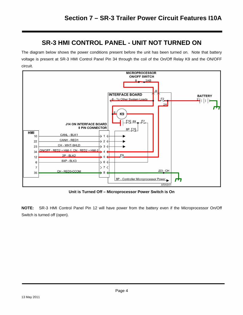
Section 7 – SR-3 Trailer Power Circuit Features I10A
SR-3 HMI CONTROL PANEL - UNIT NOT TURNED ON The diagram below shows the power conditions present before the unit has been turned on. Note that battery
voltage is present at SR-3 HMI Control Panel Pin 34 through the coil of the On/Off Relay K9 and the ON/OFF
circuit.
Unit is Turned Off – Microprocessor Power Switch is On
NOTE: SR-3 HMI Control Panel Pin 12 will have power from the battery even if the Microprocessor On/Off
Switch is turned off (open).
Page 4 13 May 2011

Section 7 – SR-3 Trailer Power Circuit Features I10A
Page 5 13 May 2011

Section 7 – SR-3 Trailer Power Circuit Features I10A
SR-3 HMI CONTROL PANEL - TURNING THE UNIT ON The diagram on the facing page shows the power conditions when the unit has been turned on by pressing the
On Key of an SR-3 HMI Control Panel.
1. Pressing the On Key of the SR-3 HMI Control Panel turns the SR-3 HMI microprocessor on. The SR-3 HMI Control Panel microprocessor then supplies chassis ground to the ON/OFF circuit at HMI Control Panel Pin 34 by connecting it internally to HMI Control Panel Pin 35.
2. This energizes the On/Off Relay K9, which closes the normally open K9 contacts to supply power to the 8X, 8P, and 8XP - BLK3 circuits. The K9 LED 23 will light to indicate the On/Off Relay K9 is energized. The 8P circuit signals the Base Controller/Interface Board to turn on. The Base Controller/Interface Board Heart Beat LED 21 will begin to flash, indicating that the Base Controller/Interface Board is powered up. The 8XP – BLK3 wire supplies feedback to pin 6 of the HMI Control Panel that the SR-3 Base Controller is powered up.
3. The unit will start and run as determined by the SR-3 Base Controller/Interface Board programmable feature settings.
NOTE: Battery power is present at SR-3 HMI Control Panel Pin 12 even if the Microprocessor On/Off Switch is
turned off (open).
NOTE: The SR-3 HMI Control Panel communicates with the SR-3 Base Controller through the CAN (Controller
Area Network) bus connections CANL - BLK1 and CANH - RED1. CAN is a standard serial communications
protocol that allows communication between two or more devices. The circuit that connects devices is called the
CAN Bus.
NOTE: The SR-3 HMI Control Panel monitors power on the 8X circuit through the 8XP – BLK3 circuit.
Page 6 13 May 2011

Section 7 – SR-3 Trailer Power Circuit Features I10A
Turning Unit On with SR-3 HMI Control Panel
Page 7 13 May 2011

Section 7 – SR-3 Trailer Power Circuit Features I10A
SR-3 HMI CONTROL PANEL – TURNING THE UNIT ON WITH A REMOTE CONTROL PANEL
The diagram on the facing page shows the power conditions present when the unit has been turned on by
pressing the On Key of a Remote Control Panel on a unit equipped with an SR-3 HMI Control Panel.
1. Pressing the On Key of the Remote Control Panel initiates turning the unit on by supplying chassis ground to the ON (ORN) circuit at the Remote Control Panel Pin 4 for 5 seconds. This turns the HMI Control Panel on and energizes the On/Off Relay K9. During this 5 second interval the communications in steps 2 through 7 occur. After 5 seconds the Remote Control Panel removes the ground from the ON (ORN) circuit but the On/Off Relay K9 is now provided a ground by the HMI Control Panel (see step 7) and will remain on.
2. The SR-3 HMI Control Panel powers up and displays the “REMOTE START-PLEASE WAIT” screen.
3. The SR-3 HMI Control Panel then sends a query via the CAN Bus to the SR-3 Base Controller asking if the Remote Control Panel is attempting to turn the unit on.
4. The SR-3 Base Controller then sends a query via the RS-232 serial port (RXD and TXD circuits) to the Remote Control Panel asking if the Remote Control Panel is attempting to turn the unit on.
5. The Remote Control Panel will then reply via the RS-232 serial port (RXD and TXD circuits) to the SR-3 Base Controller that it is attempting to turn the unit on.
6. The SR-3 Base Controller then replies to the HMI Control Panel via the CAN Bus that the Remote Control Panel is attempting to turn the unit on.
7. The SR-3 HMI Control Panel microprocessor then supplies chassis ground to the ON/OFF circuit at HMI Control Panel Pin 34 by connecting it internally to HMI Control Panel Pin 35.
8. This energizes the On/Off Relay K9, which closes the normally open K9 contacts to supply power to the 8X, 8P, and 8XP - BLK3 circuits. The K9 LED 23 will light to indicate the On/Off Relay K9 is energized. The 8P circuit signals the Base Controller/Interface Board to turn on. The Base Controller/Interface Board Heart Beat LED 21 will begin to flash, indicating that the Base Controller/Interface Board is powered up. The 8XP – BLK3 wire supplies feedback to pin 6 of the HMI Control Panel that the SR-3 Base Controller is powered up.
9. The unit will start and run as determined by the SR-3 Base Controller and the Remote Control Panel programmable feature settings.
Page 8 13 May 2011

Section 7 – SR-3 Trailer Power Circuit Features I10A
Turning Unit On with SR-3 HMI Control Panel and Remote Control Panel
This simplified diagram does not show the remote controller harness connector located in the evaporator.
Page 9 13 May 2011

Section 7 – SR-3 Trailer Power Circuit Features I10A
SR-3 HMI CONTROL PANEL – TURNING THE UNIT OFF WITH A REMOTE CONTROL PANEL
The diagram on the facing page shows the power conditions present when the unit has been turned off by
pressing the Off Key of a Remote Control Panel on a unit equipped with an SR-3 HMI Control Panel.
1. Pressing the Off Key of the Remote Control Panel momentarily supplies a chassis ground to the OFF circuit at the Remote Control Panel Pin 5 as shown by the green dashed lines. This causes the SR-3 HMI Control Panel to begin to power down.
2. The SR-3 HMI Control Panel then powers down. This turns the unit off by removing the ground from the ON/OFF circuit at HMI Control Panel pin 34 to de-energize the On/Off Relay K9 relay as shown by bold blue dashed lines.
3. When the On/Off Relay is de-energized power is removed from the 8X, 8P, and 8XP – BLK3 circuits as shown in thin black on the diagram. When power is removed from the 8P circuit this signals the Base Controller/Interface Board to turn off. The Base Controller/Interface Board Heart Beat LED 21 will stop flashing, indicating that the Base Controller/Interface Board is powered down.
NOTE: If the OFF (YEL) circuit from the Remote Controller to the SR-3 HMI Control Panel is not connected, the
SR-3 HMI Control Panel will power down by sending messages via the communications ports.
NOTE: On SR-3 applications the Off Line is connected to CAN Connectors J12, J13 and J14 at Pin 7. The OFF
Line is also connected to CAN Connector J98 Pin 10.
Page 10 13 May 2011

Section 7 – SR-3 Trailer Power Circuit Features I10A
Page 11 13 May 2011

Section 7 – SR-3 Trailer Power Circuit Features I10A
Page 12 13 May 2011


Section 7 – SR-3 Trailer S/T Software Features I02A
SR-3 HMI CONTROL PANEL SOFTWARE SR-2 and SR-3 HMI Control Panel Revisions HMI Control Panel Software Revisions 65xx, 66xx, 67xx and 68xx functions with both single temperature and
multi-temperature SR-2 and SR-3 applications.
The four revisions of HMI Control Panel software (65xx, 66xx, 67xx and 68xx) are identical other than the
languages supported. All four support English. The languages supported by each revision are shown below.
65xx Software 66xx Software 67xx Software 68xx Software
English
Spanish
French
German
Italian
Dutch
Portuguese
Greek
Turkish
Hebrew
Arabic
English
Russian
Polish
Hungarian
Romanian
Bulgarian
Czech
Danish
Swedish
Norwegian
Finnish
English
Japanese
Chinese
68xx allows three
configurations of
languages.
• English only
• English and
Spanish only
• English and up to
five languages
from the 65xx and
66xx lists
IMPORTANT: When necessary to flash load new software to an HMI Control Panel use the most recent revision
available.
IMPORTANT: Software upgrades made to units with previous software revisions are not covered by a warranty
labor allowance.
Page 7 13 May 2011

Section 7 – SR-3 Trailer S/T Software Features I02A
Compatibility HMI Control Panels used on SR-3 applications must use HMI Control Panel Software Revision 6550 or later.
HMI Control Panel Software Revision 6550-6650-6750-6850 for SR-3 Applications Dates Features Interchange with:
Production SLX
Units starting
September 2010
To Current
Production release.
None
HMI Control Panel Software Revision 6560-6660-6760-6860 for SR-3 Applications Dates Features Interchange with:
Production SB
Units starting
March 2011
to Current
Production release.
Supports USB Communications Port
None
HMI Control Panel Software Revision 6561-6661-6761-6861 for SR-3 Applications Dates Features Interchange with:
Units with Fresh
Air Exchange
only starting
June 2011
Supports Fresh Air Exchange feature.
Use only for units
equipped with the Fresh
Air Exchange Feature
Page 8 13 May 2011

Section 7 – SR-3 Trailer S/T Software Features I02A
Availability of Current SR-2 and SR-3 HMI Control Panel Software The most current version of SR-2 and SR-3 HMI Control Panel software is available on the internet.
When SR-3 Base Controller and/or HMI Control Panel flash load files are downloaded from the Thermo King
iService web site, the flash load files are downloaded as a *.ZIP file. When flash load files for SR-3 applications
are unzipped, there will now be three flash load files instead of the usual two.
The traditional *.mXX and *.cXX files will be unzipped. These two files are for use when flash loading an
SR-3 unit in the traditional manner by using a Data Cable to connect the SR-3 Unit to a PC Computer
equipped with WinTrac.
NOTE: Both the *.mXX and *.cXX files must be present in order to perform a flash load using a Data
Cable, even though only one of them is shown by WinTrac.
A *.FLA file will also be unzipped. This file is for use when flash loading a unit using a WinTrac 5.1
configured USB Flash Drive.
The Flashload Directory on the configured USB Flash Drive contains sub-directories for HMI and
SR3SINGLE TEMP flash load *.FLA files. The *.FLA file must be placed in the correct directory on the
flash drive using either the WinTrac 5.1 Upload > Manage Flashload Files feature or Windows Explorer.
Page 9 13 May 2011

Section 7 – SR-3 Trailer S/T Software Features I02A
SR-2 and SR-3 Revision 6560 Trailer HMI Control Panel Software is available on the Thermo King TSA Info
Central web site. Go to:
http://www.thermoking.com/tk/index.asp
Choose TSA Info Central and select Home > Software and Downloads > Microprocessors > Trailer
Microprocessor Updates.
The file name for the *.ZIP file containing both the traditional .mXX and .cXX files and the *.FLA file is
Micro Code 6560 Update for the SR-3 HMI Control Panel.zip. Double click this file to install the software.
Flash Loading using PC Computer For additional information on flash loading HMI Control Panel software using a PC computer, WinTrac 5.1 and a
data cable, see Service Procedure A46B Flash Loading HMI Control Panel Software in the appropriate SR-2 or
SR-3 Diagnostic Manual.
SR-2 Trailer Single Temperature Diagnostic Manual (TK 51727)
SR-3 Trailer Single Temperature Diagnostic Manual (TK 54842)
Flash Loading using USB Flash Drive SR-3 equipped units can also flash load HMI Control Panel and SR-3 Base Controller software using a WinTrac
configured USB Flash Drive. See USB Flash Drive in Section 4 of the SR-3 Trailer Single Temperature
Diagnostic Manual (TK 54842) for details.
Page 10 13 May 2011

Section 7 – SR-3 Trailer S/T Software Features I02A
SR-2/SR-3 DIAGNOSTIC TOOL SOFTWARE
Base Controller/Interface Board and HMI Control Panel Tester An SR-2/SR-3 Diagnostic Tool with Diagnostic Tool Software 4.1 or greater is required to test the SR-3 Base
Controller/Interface Board. The SR-3 Base Controller/Interface Board is currently used on SR-3 Single
Temperature Trailer applications. This Diagnostic Tool will also work on all previous SR-2 Truck and Trailer Base
Controller/Interface Boards and Trailer HMI Control Panels. It also tests the Truck Premium HMI Control Panel.
The new Diagnostic Tool is available as a complete tool and also as an update kit for the SR-2 Blue Diagnostic
Tool.
Features: The SR-2/SR-3 Diagnostic Tool includes the following new features.
Tests the SR-3 Base Controller/Interface Board
Tests the SR-3 USB Communications Port
Tests the SR-2 and SR-3 Base Controller and HMI Control Panel CAN Ports using a USB to CAN
Adaptor
Service Parts Number for the Complete SR-2/SR-3 Diagnostic Tool The Diagnostic Tester for SR-3 applications is Service Part # 204-1930.
Service Parts Number for the SR-2/SR-3 Diagnostic Tool Upgrade Kit The Service Part Number for the Upgrade Kit is 204-1931.
Diagnostic Tool Software SR-2 Diagnostic Tool Revision 4.1 software is available on the Thermo King TSA Info Central web site. Go to:
http://www.thermoking.com/tk/index.asp
Choose TSA Info Central and select Home > Software and Downloads > SR-2 and SR-3 Diagnostic Tool.
The file name is SR-2 SR-3 Diagnostic Tool Software Version 4.1 for the Blue Tester.zip. It will take a
few moments to load. Save and unzip the file to the desired directory on your computer. It will take a few
moments to unzip and there will be several files as a result. If necessary, double click Setup.exe to install
the software.
Page 11 13 May 2011

Section 7 – SR-3 Trailer S/T Software Features I02A
Page 12 13 May 2011

Section 7 – SR-3 Trailer S/T Software Features I02A
SR-3 OPTISET REQUIREMENTS
If OptiSet Plus is being used with an SR-3 unit, then OptiSet Plus 4.1 Software and WinTrac 5.1 Software is
required. Original OptiSet or OptiSet Plus 1.0, 2.0 or 3.0 software and WinTrac 4.9 or earlier software cannot be
used for OptiSet Plus applications on SR-3 trailer units.
OptiSet Plus 4.1 is fully backwards compatible with all previous Thermo King applications requiring OptiSet Plus
software.
Features: OptiSet Plus 4.1 supports SR-3 Single Temperature Trailer Units.
OptiSet Plus 4.1 allows Revision D005 Base Controller software and HMI Control Panel 6560 software to
be selected when setting up OptiSet Plus files.
Other OptiSet Plus 4.1 features are similar to OptiSet Plus 3.0.
Compatibility: If OptiSet Plus is being used, OptiSet Plus 4.1 Software is required for use with SR-3 Trailer Units.
OptiSet Plus 4.1 Software is fully compatible with all previous OptiSet Plus applications.
WinTrac 5.1 software is required.
Sending and Retrieving OptiSet Plus Files using a Data Cable and PC Computer with WinTrac
OptiSet Plus *.XML files can be sent directly to and from the unit in the traditional manner using a Data Cable and
a PC Computer. No file conversion is required.
Page 13 13 May 2011

Section 7 – SR-3 Trailer S/T Software Features I02A
Using OptiSet Plus with a WinTrac configured USB Flash Drive
Thermo King SR-3 Trailer Units provide a USB (Universal Serial Bus) Port located on the unit control panel. A
USB Flash Drive can be connected to the USB port. The Flash Drive used must first be configured using WinTrac
5.1 or later. When the Flash Drive has been properly configured and enabled, the following functions can be
performed.
Send and Retrieve OptiSet Plus files
OptiSet Plus Data Files when using a USB Flash Drive
If OptiSet Plus is being used with a USB Flash Drive, the file formats of the OptiSet Plus data files must be
considered.
IMPORTANT: The WinTrac 5.1 Upload > Manage OptiSet Plus Files feature must be used to move OptiSet Plus
files to or from the flash drive or the file conversion process will not take place. Do not move OptiSet Plus files to
or from the flash drive using Windows Explorer. Only ServiceWatch and CargoWatch Data Logger data files and
flash load *.FLA files can be moved using Windows Explorer.
OptiSet Plus only uses data files that are in the *.XML format.
When sending and retrieving OptiSet Plus data using the USB Flash Drive, the data is transferred
between the flash drive and the SR-3 unit using *.OSP files. OptiSet Plus is unable to directly use these
*.OSP files. These *.OSP files must be converted to *.XML files before they can be used by OptiSet Plus.
This file conversion is done automatically when the files are moved to or from the flash drive using the
WinTrac 5.1 Upload > Manage OptiSet Plus Files feature as shown below and on the next page.
Page 14 13 May 2011

Section 7 – SR-3 Trailer S/T Software Features I02A
Sending OptiSet Plus Files to the SR-3 Unit using a USB Flash Drive and WinTrac
PC ComputerEquipped With WinTrac 5.1 or
Later
WinTrac 5.1 automatically converts
the OptiSet Plus file USB
Flash DriveConfigured by
WinTrac
SR-3Unitfrom a *.XML file to a
*.OSP file when moving the file to the USB Flash
Drive
The OptiSet Plus *.OSP file is moved
from the USB Flash Drive to the SR-3 Unit
For additional details see USB Flash Drive in Section 4 of the SR-3 Single Temperature Trailer Diagnostic Manual
(TK54842) and Service Bulletin TT562 WinTrac 5.0 and 5.1 Software.
Availability: OptiSet Plus on the Internet OptiSet Plus 4.1 software is available on the Thermo King TSA Info Central web
site. Go to:
http://www.thermoking.com/tk/index.asp
Choose TSA Info Central and select Home > Software and Downloads > OptiSet Plus > OptiSet Plus 4.1. The file
name is OptiSetPlus-4.1.zip. It will take a few moments to load. Save and unzip the file to the desired directory
on your computer. It will take a few moments to unzip and there will be several files as a result. If necessary,
double click Setup.exe to install the software.
For additional information on installing and using OptiSet Plus 4.1 Software see the extensive help information
available from the OptiSet Plus 4.1 Help Menu.
Page 15 13 May 2011

Section 7 – SR-3 Trailer S/T Software Features I02A
Page 16 13 May 2011

Section 7 – SR-3 Trailer S/T Software Features I02A
SR-3 WINTRAC REQUIREMENTS
WinTrac 5.1 or later is required for use with SR-3 applications.
Features • WinTrac 5.1 software supports Thermo King SR-3 single temperature trailer applications.
• The WinTrac 5.1 User Manual was updated and improved.
• WinTrac 5.1 provides improved flash load recovery compared to earlier WinTrac versions.
• WinTrac 5.1 supports the configuration of a USB flash drive for use with SR-3 units. When a properly
configured USB flash drive is connected to the SR-3 front panel USB connector, the flash drive user
interface is shown on the HMI Control Panel. The USB flash drive provides SR-3 CargoWatch and
ServiceWatch Data Logger downloads, flash loading SR-3 HMI Control Panel and Base Controller
software as well as sending and retrieving OptiSet Plus files. See additional information on page 3 of this
bulletin.
Compatibility: WinTrac 5.1 software is fully backwards compatible with all previous Thermo King applications requiring WinTrac
software.
WinTrac 5.1 Software is required for compatibility with North American SR-3 single temperature trailer units with
USB Communications Port and with HMI Control Panel software 6560 and Base Controller software D005.
Page 17 13 May 2011

Section 7 – SR-3 Trailer S/T Software Features I02A
Page 18 13 May 2011
Availability: WinTrac on the Internet WinTrac 5.1 Upgrade software is available on the Thermo King TSA Info Central web
site. NOTE: An existing version of WinTrac must be present on the computer in order to install WinTrac 5.1
Upgrade software. Go to:
http://www.thermoking.com/tk/index.asp
Choose TSA Info Central and select Home > Software AND Downloads > WinTrac. The file name is WinTrac 5.1
Upgrade.zip. It will take a few moments to load. Save and unzip the file to the desired directory on your
computer. It will take a few moments to unzip and there will be several files as a result. If necessary, double click
Setup.exe to install the software.
WinTrac on CD Both the full version and upgrade version of WinTrac 5.1 are available on CD from Service
Parts under the numbers shown below.
Version Where Used Interchange With Service Parts #
WinTrac 5.1 Full Version
Publications # 54696-8-CD
All WinTrac Applications Replaces all previous 204-1934
WinTrac 5.1 Upgrade Version
Publications # 54697-8-CD
See NOTE 1.
All WinTrac Applications Replaces all previous 204-1935
NOTE 1 - An existing version of WinTrac must be present on the computer in order to install WinTrac 5.1
Upgrade software.
For additional information on installing and using WinTrac Revision 5.1 Software see the WinTrac 5.0 User’s
Guide (TK 54890-8-MS). The WinTrac 5.0 User’s Guide is also available from the WinTrac 5.1 Help Menu.
Section 7 – SR-3 Trailer HMI Control Panel Messages I12A
SR-3 HMI CONTROL PANEL MESSAGES AND THEIR CAUSES The following error messages will appear on the SR-3 HMI Control Panel display if the stated conditions occur.
[ SYSTEM IS POWERING DOWN ]
If the HMI Control Panel ON key is pressed and the TK Logo display is shown and then [SYSTEM IS POWERING
DOWN] appears, the OFF Line between a remote control device and the HMI Control Panel is likely shorted to
ground. The HMI Control Panel will not remain powered up if the OFF Line is shorted to ground. On SR-3
applications the Off Line is connected to CAN Connectors J12, J13 and J14 at Pin 7. The OFF Line is also
connected to CAN Connector J98 Pin 10.
NOTE: In some cases, if the OFF Line circuit is shorted to ground the HMI Control Panel may not power up at all.
[ COMMUNICATIONS FAILURE -- LOST CONTROLLER CONNECT ]
This message indicates that the HMI Control Panel has not received any messages from the SR-3 Base
Controller for 20 seconds. The HMI Control Panel will stay powered up and try to re-establish communications
with the SR-3 Base Controller via the CAN Bus. This message can result from one of the following conditions.
• This message may appear if there are open or shorted circuits on the CANL or CANH wires between the
HMI Control Panel and the SR-3 Base Controller CAN Bus circuits.
• This message may appear if the CAN communications fail between the HMI Control Panel and SR-3
Base Controller or if CAN communications are not operational.
• This message may appear if the HMI Control Panel or SR-3 Base Controller is defective.
Page 1 13 May 2011

Section 7 – SR-3 Trailer HMI Control Panel Messages I12A
[ LOST CONTROLLER POWER ]
This message indicates that the HMI Control Panel has detected a loss of power on the 8XP circuit and that the
SR-3 Base Controller did not respond to messages from the HMI Control Panel for at least 3 seconds. If this
occurs the HMI Control Panel will display LOST CONTROLLER POWER -- POWERING DOWN and shut down.
This message can result from one of the following conditions.
• This message may appear if there are open circuits or bad connections on the 8XP and CAN Bus circuits
between the HMI Control Panel and the SR-3 Base Controller
• This message may appear if Fuse F10 is blown or if the K9 On/Off Relay on the Base Controller is
defective.
• This message may appear if the SR-3 Base Controller is defective.
[ CHECK 8X WIRING ]
If this message appears it indicates that the HMI Control Panel has detected a loss of power on the 8XP circuit
but that CAN communications between the HMI Control Panel and the SR-3 Base Controller still exist. This
message can result if 8XP power is lost as a result of one of the following conditions.
• Loss of 8XP power could be caused by an open 8XP circuit or a bad connection between the HMI Control
Panel and the SR-3 Base Controller.
• Loss of 8XP power will occur if Fuse F7 on the SR-3 Base Controller is blown.
Page 2 13 May 2011

Section 7 – SR-3 Trailer HMI Control Panel Messages I12A
HMI Power Up and Power Down Documentation
SR-3 HMI Control Panels have a Supervisor microprocessor that documents the reason a unit is powered up or
powered down. The power up and power down information is logged into the CargoWatch Data Logger contained
in the HMI Control Panel. This data can be very helpful in determining the causes of power up and power down
issues. One exception to the logging of these items is if a power supply or ground problem turns the HMI off
instantly. If this should happen the HMI is immediately Off and will not make the normal logs that it does in a
controlled power down sequence.
The table’s below list the Power Up and Power Down reasons along with a brief description.
Power Up Reasons
Number Description Comments 1 On Key Pressing the HMI Control Panel On Key is the reason for an On Key power up.
2 On Line Providing a ground to the On Line is the reason for an On Line power up. The On Line
power up is normally initiated by a Remote Controller On key being pressed or a 3rd
party Telematic device providing a ground via the iBox. Grounding of the On Line will
cause the K9 On/Off Relay coil to energize and initiate a power up of the SR-3 Base
Controller and the HMI Control Panel.
3 DPD Connecting a download cable to the CargoWatch Download Port is the reason for a
DPD power up. Connecting the download cable will ground the DPD wire causing the
HMI to power up. This will allow the user to perform a download without the unit
running.
4 Cold Crank A Cold Crank power up may occur during a low voltage situation during an attempted
engine start.
5 Reset A Reset power up may occur if the CAN communication to the HMI Control Panel has
been interrupted and then reestablished. Essentially the HMI Control Panel reboots
and comes back on line. This can be observed in downloads where the SR-3 Unit and
HMI Control Panel are both operating and a Power Up Reset will be observed without a
prior Power Down being present.
Page 3 13 May 2011

Section 7 – SR-3 Trailer HMI Control Panel Messages I12A
Power Up Reasons - continued
Number Description Comments 6 Unknown Unknown
7 Conservative
Mode Power
Up
A Conservative Mode power up will be present if the Conservative Mode has been
programmed in the HMI Control Panel. This power up happens at user defined time
intervals to document temperature readings on the CargoWatch Sensors when the unit
is turned Off.
Page 4 13 May 2011
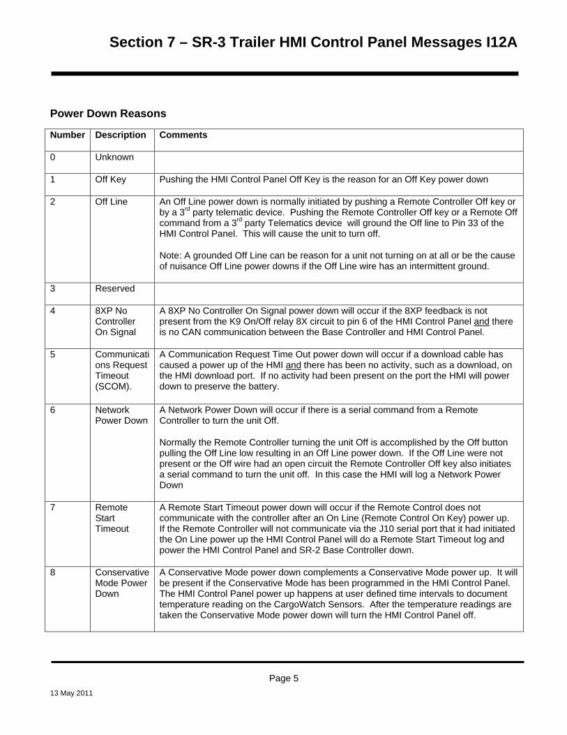
Section 7 – SR-3 Trailer HMI Control Panel Messages I12A
Power Down Reasons
Number Description Comments
0 Unknown
1 Off Key Pushing the HMI Control Panel Off Key is the reason for an Off Key power down
2 Off Line An Off Line power down is normally initiated by pushing a Remote Controller Off key or by a 3rd party telematic device. Pushing the Remote Controller Off key or a Remote Off command from a 3rd party Telematics device will ground the Off line to Pin 33 of the HMI Control Panel. This will cause the unit to turn off.
Note: A grounded Off Line can be reason for a unit not turning on at all or be the cause of nuisance Off Line power downs if the Off Line wire has an intermittent ground.
3 Reserved
4 8XP No Controller On Signal
A 8XP No Controller On Signal power down will occur if the 8XP feedback is not present from the K9 On/Off relay 8X circuit to pin 6 of the HMI Control Panel and there is no CAN communication between the Base Controller and HMI Control Panel.
5 Communications Request Timeout (SCOM).
A Communication Request Time Out power down will occur if a download cable has caused a power up of the HMI and there has been no activity, such as a download, on the HMI download port. If no activity had been present on the port the HMI will power down to preserve the battery.
6 Network Power Down
A Network Power Down will occur if there is a serial command from a Remote Controller to turn the unit Off.
Normally the Remote Controller turning the unit Off is accomplished by the Off button pulling the Off Line low resulting in an Off Line power down. If the Off Line were not present or the Off wire had an open circuit the Remote Controller Off key also initiates a serial command to turn the unit off. In this case the HMI will log a Network Power Down
7 Remote Start Timeout
A Remote Start Timeout power down will occur if the Remote Control does not communicate with the controller after an On Line (Remote Control On Key) power up. If the Remote Controller will not communicate via the J10 serial port that it had initiated the On Line power up the HMI Control Panel will do a Remote Start Timeout log and power the HMI Control Panel and SR-2 Base Controller down.
8 Conservative Mode Power Down
A Conservative Mode power down complements a Conservative Mode power up. It will be present if the Conservative Mode has been programmed in the HMI Control Panel. The HMI Control Panel power up happens at user defined time intervals to document temperature reading on the CargoWatch Sensors. After the temperature readings are taken the Conservative Mode power down will turn the HMI Control Panel off.
Page 5 13 May 2011

Section 7 – SR-3 Trailer HMI Control Panel Messages I12A
Page 6 13 May 2011


Section 8 – SR-3 Trailer Single Temp Diagrams
SR-3 Schematic Diagrams and Wiring Diagrams
1E64645 Rev C – SB 130 / 230 / 330 Single Temp 30 / 50 Yanmar T2 Schematic Diagram
1E64644 Rev C – SB 130 / 230 / 330 Single Temp 30 / 50 Yanmar T2 Wiring Diagram
13 May 2011

Section 8 – SR-3 Trailer Single Temp Diagrams
13 May 2011