Sr. - pcmcindia.gov.
79
-
Upload
khangminh22 -
Category
Documents
-
view
0 -
download
0
Transcript of Sr. - pcmcindia.gov.


1 | P a g e
Telecom Department: Quotation Notice for Surveillance system for budgetary estimation
Sr. No. Item Name Unit Qty. Unit Price
without GST
1 Supply, Installation Testing & Commissioning of Fixed Box Camera along with associated accessories & systems including all cables, wires with 1 year of on-site warranty Image Sensor - 1/2.8” progressive CMOS Sensor or better, shutter speed up to 1/15000 sec. or better WDR - 120 dB WDR or better. Resolution -1920 x 1080p, 2MP, triple stream support. Lens - Compatible to image sensor, Full HD (1080P), P IRIS. Minimum illumination-Colour: 0.1 lux or better, B/W: 0.05 lux or better (at 30 IRE). Video Compression-H.264, H.265 with smart codec Frame Rate-30 FPS @ all resolutions. Local Storage – Compatible with 2 TB memory slot, Minimum 1 TB Memory card should be provided. In the event of failure of connectivity to the central server, the camera shall record video locally on the SD card automatically. After the connectivity is restored these recordings shall be automatically merged with the server recording such that no manual intervention is required to transfer the SD card-based recordings to server. Ethernet -10/100 Base-T ports Protocols-IPv4, IPv6, TCP/IP, HTTPS, FTP, SMTP, SNMP, RTP, RTSP, DDNS, DHCP, DNS, NTP, UDP, 802.11x HTTP, TCP, UDP, RTCP, DHCP, UPnP, QoS. ONVIF Profile- Support Profile S, ONVIF Profile G, ONVIF Profile T. Power Supply-PoE(802.3af) , 12/24VDC ±10%, 10W MAX. Operating Temperature -0° C to 50° C or better. Operating Humidity-20% to 95% for cameras. Enclosure / Casing-IP66 for weather resistant and IK10 as Vandal Proof with Cast iron or aluminium alloy casing. Certifications-UL, EN, CE, FCC, NDAA OEM Self declaration and BIS . Support-The camera should not be end of life / end of service for minimum 5 years, and OEM should certify that they will give spare support. Streaming-The camera shall be able to setup and stream out minimum three (3) stream profiles. Each stream profile shall have its own compression, resolution, frame rate and quality independently. All the 3 streams with 30 FPS should be individually configurable and compatible with H.264 with smart codec / H.265. White Balance: -Auto / Manual Back Light Compensation-Auto Security-HTTPS authentication, Password Protection Security-Vandal and impact resistant housing, IK 10, IP66, NEMA 4x. Mounting Accessories -All mounts & brackets for installing the equipment shall be from the same OEM of Camera. Edge Analytics -Camera tempering and Motion detection Other The proposed OEM for camera should provide MAC ids of the quoted products; the MAC address of the proposed equipment must be registered in the name of the OEM only. Note: - OEM of Cameras from America, Europe, Japan to quote
Nos. 1
2 Supply, Installation, Testing & Commissioning of PTZ Camera along with associated accessories & systems including all cables, wires with one year of on-site warranty Image Sensor- with WDR-1/2.8” or better with up to 120 WDR, progressive CMOS Sensor or better, shutter speed upto 1/15000 sec. Resolution-1920X1080 At least 2 Megapixel or better. Frame Rate-30 FPS @ all resolution. Lens specs - 30X, Focal length range lower 8mm better & upper limit 120 mm or better. Minimum illumination-Colour: 0.5 lux, B/W: 0.1 lux (at 30 IRE AGC “on”) or better. Pre-set Positions-256 or better, Pre-set tour PTZ Pan: 360° endless/continuous, 0.2 to 300°/s (auto), 0.2 to 100°/s (Manual) Tilt: 90°, 0.2 to 100°/s (Auto), 0.2 to 40°/s (Manual)30x optical zoom and Minimum 10x digital zoom 64 pre-set positions Auto-Tracking. Streaming-3 fully configurable streams or better. Outdoor Protection-IP66 for weather resistant and IK10 as Vandal Proof. Protocol-IPv4, IPv6, TCP/IP, HTTPS, FTP, SMTP, SNMP, RTP, RTSP, DDNS, DHCP, DNS, NTP, UDP, 802.11x HTTP, TCP, UDP, RTCP, DHCP, UPnP, QoS. Video Compression -H.264, H.265 smart codec. Image Enhancement-
Nos. 1

2 | P a g e
Sr. No. Item Name Unit Qty. Unit Price
without GST
2D/3D DNR, Smart Defogger, Image Stabilization (EIS), ROI, Anti-Flicker, De-blur mode. Certificate-FCC, CE, UL, EN, NDAA OEM Self declaration and BIS. ONVIF Profile- Support Profile S, ONVIF Profile G, ONVIF Profile T. Power Supply -PoE (802.3at) , 12/ 24VDC / 3A±10%, 40W MAX. Ethernet-Connectors: 10Base-T/100Base-TX. Wide Dynamic Range-WDR 120dB or better. Operating Condition-Temperature: 0℃~50℃ / Humidity: 0~95% or less (Non-condensing) Support The camera should not be end of life / end of service for minimum 5 years, and OEM should certify that they will give spare support. Local Storage - Compatible with 2 TB memory slot, Minimum 1 TB Memory card should be provided. In the event of failure of connectivity to the central server, the camera shall record video locally on the SD card automatically. After the connectivity is restored these recordings shall be automatically merged with the server recording such that no manual intervention is required to transfer the SD card-based recordings to server. Security-Password Protection, IP Address filtering, User Access Log, HTTPS encryption. S/N Ratio ≥ 50dB. Mounting Accessories- All mounts & brackets for installing the equipment shall be from the same OEM of Camera. IR Illuminator-Build-in IR Illuminator with minimum 150 mtr. Or better with adjustable angle to cover the complete field of view at specified locations Enclosure / Casing IP66 for weather resistant and IK10 as Vandal Proof with Cast iron or aluminium alloy casing. Edge Analytics- Camera tempering, Motion detection and PTZ Auto Tracking, Auto adjustment + Remote Control of Image settings Colour, brightness, sharpness, contrast, white balance, exposure control, backlight compensation, Gain Control, Wide Dynamic Range. Other -The proposed OEM for camera should provide MAC ids of the quoted products; the MAC address of the proposed equipment must be registered in the name of the OEM only Note: - OEM of Cameras from America, Europe, Japan to quote
3 Supply, Installation, Testing & Commissioning of Indoor Dome Camera along with all accessories with 1 year of on-site warranty. General Requirements-The camera should be manufacturer's official product line designed for commercial / industrial 24x7x365 use. The camera and camera firmware should be designed and developed by same OEM. Image Sensor - with WDR ½.8 “or better Progressive CMOS Sensor or better shutter speed upto 1/30000 sec. Wide Dynamic Range-Minimum 120 dB or better. Lens Specs-Compatible to image sensor, Full HD (1080P), P IRIS, Corrected IR with IR cut filter Focal Length: 3x varifocal lens (Lower limit as 4 mm or better , and Upper limit as 8mm or greater. Resolution-1920 x 1080 or better Minimum illumination-Colour: 0.1 lux or better, B/W: 0.05 lux or better (at 30 IRE) Video Encoder -H.264, H.265with smart codec Frame Rate-min. 30 FPS or higher Local Storage - Compatible with 2 TB memory slot, Minimum 1 TB Memory card should be provided. In the event of failure of connectivity to the central server, the camera shall record video locally on the SD card automatically. After the connectivity is restored these recordings shall be automatically merged with the server recording such that no manual intervention is required to transfer the SD card-based recordings to server. Ethernet -10/100 Base-T ports Protocols-IPv4, IPv6, TCP/IP, HTTPS, FTP, SMTP, SNMP, RTP, RTSP, DDNS, DHCP, DNS, NTP, UDP, 802.11x HTTP, TCP, UDP, RTCP, DHCP, UPnP, QoS, ONVIF Compatible ONVIF Profile -Support Profile S, Profile G, Profile T Power Supply-POE IEE 802.3af compliant Operating Temperature-0° C to 50° C or better Operating Humidity-20% to 95% for cameras Enclosure / Casing-IP66 for weather resistant and IK10 as Vandal Proof with Cast iron or aluminium alloy casing Certifications-CE, LVD, FCC Class A, UL, BIS, ONVIF, NDAA OEM self-declaration. Streaming-The camera shall be able to setup and stream out minimum three (3) stream profiles. Each stream profile shall have its own compression, resolution,
Nos 1

3 | P a g e
Sr. No. Item Name Unit Qty. Unit Price
without GST
frame rate and quality independently. All the 3 streams with 30 FPS should be individually configurable and compatible with H.264, H.264 with smart codec . White Balance Auto / Manual Back Light Compensation-Auto Security-HTTPS authentication, Password Protection Security-Detection of camera tampering and Detection of Motion should be possible using either camera or VMS Mounting Accessories: - All mounts & brackets for installing the equipment shall be from the same OEM of Camera. Wall mount / pole mount IR Illuminator: -Integrated illumination with minimum 30 mtr. Range/ Camera support low color lux level 0.01 Edge Analytics: -Camera Tampering and motion detection Other: The proposed OEM for camera should provide MAC ids of the quoted products; the MAC address of the proposed equipment must be registered in the name of the OEM only Body Material: Non-Corrosive metal Note: - OEM of Cameras from America, Europe, Japan to quote
4 Supply, Installation, Testing & Commissioning of Fixed box Evidence Camera (RLVD & SPEED DETECTION ) along with associated accessories & systems including all cables/wires with 1 year of on-site warranty. General Requirements-The camera should be manufacturer's official product line designed for commercial / industrial 24x7x365 use. The camera and camera firmware should be designed and developed by same OEM Image Sensor- 1/2.8” or better progressive CMOS sensor or better, shutter speed upto 1/15000 sec. WDR -120db. Resolution-Active Pixels 1920 x 1080 (2 MP) Minimum illumination-Colour: 0.1 lux or better, B/W: 0.05 lux or better (at 30 IRE) Video Compression-H.264, H.265 smart codec Frame Rate-Minimum 60 FPS or higher for all resolutions Local Storage- Compatible with 2 TB memory slot, Minimum 1 TB Memory card Ethernet-10/100 Base-T ports Protocols-Minimum of the following protocols to be supported RTSP, RTP/TCP, RTP/UDP, HTTP, HTTPS, DHCP, 802.11x Industry Standards-ONVIF Compliant Power Supply-POE IEE 802.3af compliant Operating Temperature-0° C to 50° C or better Operating Humidity-20% to 90% for cameras Enclosure / Casing-IP 66 with Cast iron or aluminium alloy casing Certifications- UL, EN, CE, FCC, NDAA OEM Self declaration and BIS. Streaming-The camera shall be able to setup and stream out minimum three (3) stream profiles. Each stream profile shall have its own compression, resolution, frame rate and quality independently. All the 3 streams with 60 FPS should be individually configurable and compatible with H.264, h.265 with smart codec White Balance -Auto / Manual Back Light-Compensation Auto Security-Security Password protection Security-Vandal and impact resistant housing, IK 10, IP66, NEMA-4x Mounting -All mounts & brackets for installing the equipment shall be from the same OEM of Camera Edge Analytics-Camera tampering Note: - OEM of Cameras from America, Europe, Japan to quote
Nos. 1
5 Supply, Installation, Testing & Commissioning of ANPR cameras for RLVD system along with associated accessories & systems including all cables/wires (with 1 year of on-site warranty) General Requirements-The camera should be manufacturer's official product line designed for commercial / industrial 24x7x365 use. The camera and camera firmware should be designed and developed by same OEM Image Sensor with WDR-1/2.8 or better with 120 dB WDR, progressive CMOS Sensor or better Resolution-Active Pixels 1920 x 1080 (2 MP) Minimum illumination-Colour: 0.1 lux or better, B/W: 0.05 lux with IR ON Video Compression-H.264, H.265 with smart codec Frame Rate-Minimum 60 FPS or higher for all resolutions
Nos. 1

4 | P a g e
Sr. No. Item Name Unit Qty. Unit Price
without GST
Local Storage- Compatible with 2 TB memory slot, Minimum 1 TB Memory card Ethernet -10/100/ Base-T ports Protocols-Minimum of the following protocols to be supported RTSP, RTP/TCP, RTP/UDP, HTTP, HTTPS, DHCP, 802.11x Industry Standards-ONVIF Compliant Power Supply-POE IEE 802.3af compliant, 12/24VDC Operating Temperature-0° C to 50° C or better Operating Humidity-20% to 90% for cameras Enclosure / Casing-IP 66 with Cast iron or aluminium alloy casing Certifications- UL, EN, CE, FCC, NDAA OEM Self declaration and BIS Streaming- The camera shall be able to setup and stream out minimum three (3) stream profiles. Each stream profile shall have its own compression, resolution, frame rate and quality independently. All the 3 streams should be individually configurable and compatible with H.264 with smart codec / H.265 with smart codec White Balance -Auto / Manual Back Light Compensation-Auto Security-Security Password protection Security-Vandal and impact resistant housing, IK 10, IP66 , NEMA 4x Mounting -All mounts & brackets for installing the equipment shall be from the same OEM of Camera Note: - OEM of Cameras from America, Europe, Japan to quote
6 Supply, Installation, testing and commissioning of lens of lower limit 4mm or better & higher limit 8mm & better varifocal IR corrected 3 Megapixel Lens, P Iris CS Mount, including 1 year of onsite warranty. Lens- P iris function. Operation Control – Focus Manual, Zoom Manual Operating Temperature 0℃ to +50℃
Nos. 1
7 Supply, Installation, testing and commissioning of lens of lower limit 8mm or better & upper limit of 50mm or better varifocal IR corrected 3 Megapixel Lens, P Iris CS Mount with 1 year of on-site warranty. Operation Control – Focus Manual, Zoom Manual Operating Temperature 0℃ ‐ to +50℃
Nos. 1
8 Supply, Installation, Testing & Commissioning of External IR illuminator along with associated accessories & systems including all cables, wires with 1 year of on-site warranty Range Distance -Minimum 25 Mtrs. adjustable IR in sync with lens. Adaptive illumination-10 to 80 degrees; High sensitivity at Zero lux. Power Input- 100-240V AC, or 12/24 V AC/DC Casing- IP66 rated / NEMA-4x, vandal resistance Operating Condition- 0° to 50°C or better Certification-CE, FCC, EN, UL, RoHS Lighting-High Definition LED's Required Accessories- Power Supply, Mounting Clamps, U-bracket Mounting-Pole and wall mount
Nos. 1
9 Supply, Installation, Testing & Commissioning of External IR illuminator along with associated accessories & systems including all cables, wires with 1 year of on-site warranty Range Distance -Minimum 80 Mtrs. adjustable IR in sync with lens. Adaptive illumination-10 to 80 degrees; High sensitivity at Zero lux. Power Input- 100-240V AC, or 12/24 V AC/DC Casing- IP66 rated / NEMA-4x, vandal resistance Operating Condition- 0° to 50°C or better Certification-CE, FCC, EN, UL, RoHS Lighting-High Definition LED's Required Accessories- Power Supply, Mounting Clamps, U-bracket Mounting-Pole and wall mount
Nos. 1
10 Supply, Installation Testing & commissioning of Local Processing unit (LPU) suitable for Speed detection and number plate recognition cameras along with all the power cables, SMPS, Power Adapter, Handing arrangement in Junction Box along with all the accessories with 1 year of on-site warranty Building-Enclosure with fan less design IP Rating-IP66 compliant LAN port-3 x 10/100 Ethernet or more Internal Storage-The system should have capacity to locally store min than 500,000 vehicle number plate data
Nos. 1

5 | P a g e
Sr. No. Item Name Unit Qty. Unit Price
without GST
Operating System-Linux /Windows RAM – 6GB or better Internal Storage- 320GB or better Certifications-The System should be certified by government body (from country of origin/ministry of traffic) and authenticated by Indian authority. Speed measurement Accuracy for Spot and Average speed measurement-Upto100 km/hr (3 % variation) and100 to180 km/hr (3% variation only).
11 Supply Installation Testing & Commissioning of RADAR for speed detection system with 1 year of on-site warranty Objects Tracking- Up to 126 Objects Lane Coverage-Up to 4 lanes Detection Range-Up to 250 m Range Accuracy -<±2.5% or ±0.25m (whichever is bigger) Speed Detection Range-Up to 250 kmph Speed Detection Accuracy-<±1% Sensor Frequency-76 - 81 GHz EIRP-Up to 20 dBm Measurement-Cartesian (x, y, z) coordinates, Azimuth, Elevation, Speed Communication Interfaces-Ethernet, USB, RS 485 Refresh time-75 MS Power Supply-12V DC Power Consumption-20W Operating Temperature -40 to 85 ◦C Environment Protection-IP67 Note: - OEM of Cameras from America, Europe, Japan to quote
Nos. 1
12 Supply, Installation, testing and Commissioning of Pole mounted Variable Message Display (VMD) 600mm(W) x 600(H) x 90mm (D) with 1 year of on-site warranty with pole/wall mounted bracket and other accessories. Source of light-Super Bright LED Colour-Multi Colour Display – Full Matrix Viewing distance-100 meters Typical Viewing angle-Better than 130° (Hor/Ver) Typical Display capability-Display Speed Symbols (Number) – Full Matrix MECHANICAL Housing Material-Powder Coated Anti Corrosive GPSP Alloy Sheet Housing Size-640mm (W) x 640mm(H) x 90mm (D) Approx. Front plate Coat-Low reflection black matt finish Finish and Paint-Powder Coated – Black Colour Weight 30 kgs approx. Maintenance provision From Rear Side with Back Door Entry. Protection-Front Face IP 65. ELECTRICAL Input voltage-180 ‐ 250V AC, 50 Hz Single Phase. 230V AC Typical COMMUNICATION Communication Port-Ethernet ENVIRONMENT Operating Temperature-0º C to 50º C Humidity-Operating ambient humidity: 10 to 95% Rh Mounting – Pole and wall mounted
Nos. 1
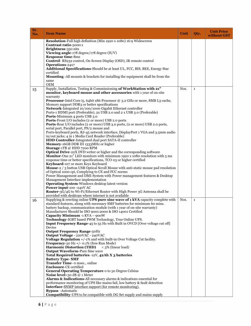
13 Local Viewing Centre Infra at Indoor - LED Screen (55”) along with associated accessories & systems including all cables, wires with 1 year of on-site warranty Technology-HD LED Display, Direct LED Backlight Screen Size- 55’’ diagonal or better for viewing centres Resolution-Full high definition (Min 1920 x 1080) 16:9 Widescreen Contrast ratio-5000:1 Brightness-350 nits Viewing angle-178 degree/178 degree (H/V) Response time-8ms Contr0l- RS232 control, On Screen Display (OSD), IR remote control Operations-24x7 Additional Specifications-Should be at least UL, FCC, BIS, BEE, Energy Star certified Mounting -All mounts & brackets for installing the equipment shall be from the same OEM
Nos. 1
14 Local Viewing Centre Infra at Indoor - LED Screen (65”) along with associated accessories & systems including all cables, wires with 1 year of on-site warranty Technology-HD LED Display, Direct LED Backlight Screen Size- 65’’ diagonal or better for viewing centres
Nos. 1
6 | P a g e
Sr. No. Item Name Unit Qty. Unit Price
without GST
Resolution-Full high definition (Min 1920 x 1080) 16:9 Widescreen Contrast ratio-5000:1 Brightness-350 nits Viewing angle-178 degree/178 degree (H/V) Response time-8ms Contr0l- RS232 control, On Screen Display (OSD), IR remote control Operations-24x7 Additional Specifications-Should be at least UL, FCC, BIS, BEE, Energy Star certified Mounting -All mounts & brackets for installing the equipment shall be from the same OEM
15 Supply, Installation, Testing & Commissioning of WorkStation with 21" monitor, keyboard mouse and other accessories with 1 year of on-site warranty Processor-Intel Core i5, 64bit x86 Processor @ 3.2 GHz or more, 8MB L3 cache, Memory support DDR3 or better specifications Network-Integrated 10/100/1000 Gigabit Ethernet controller Ports-1 HDMI port (Preferable), 2x USB 2.0 and 2 x USB 3.0 (Preferable) Ports-Minimum 4 ports USB 3.0 Ports-Front I/O includes (2 or more) USB 2.0 ports Ports-Rear I/O includes (2 or more) USB 3.0 ports, (2 or more) USB 2.0 ports, serial port, Parallel port, PS/2 mouse and Ports-keyboard ports, RJ-45 network interface, DisplayPort 1 VGA and 3.5mm audio in/out jacks; 4 in 1 Media Card Reader (Preferable) HDD Controller-Integrated dual port SATA-II controller Memory-16GB DDR III 1333MHz or higher Storage-1TB @ HDD 7200 RPM Optical Drive-22X DVD writer or higher and the corresponding software Monitor-One 21” LED monitors with minimum 1920 x 1080 resolution with 5 ms response time or better specifications, TCO 03 or higher certified Keyboard-107 or more Keys Keyboard Mouse-2 / 3 button USB Optical Scroll Mouse with anti-static mouse pad resolution of Optical 1000 cpi, Complying to CE and FCC norms Power Management and DMI-System with Power management features & Desktop Management Interface implementation Operating System-Windows desktop latest version Power input-100 -240V AC Router-3G/4G to Wi-Fi/Ethernet Router with High Power 3G Antenna shall be provided with desktops where internet is not available
Nos. 1
16 Supplying & erecting online UPS pure sine wave of 1 kVA capacity complete with standard features, along with necessary SMF batteries for minimum 60 mins. battery backup, communication module (with 1 year of on-site warranty) Manufacturer Should be ISO 9001:2000 & ISO 14001 Certified Capacity Minimum -1 KVA – 900W Technology-IGBT based PWM Technology, True Online UPS. Input Frequency Range-45 to 55 Hz with Built in OVCD [Over voltage cut off] Device Output Frequency Range-50Hz Output Voltage - 220VAC - 240VAC Voltage Regulation +/-1% and with built-in Over Voltage Cut facility. Frequency-50 Hz +/- 0.1% (free Run Mode) Harmonic Distortion (THD) < 3% (linear load) Output Waveform-Pure Sine wave Total Required batteries -12V, 42Ah X 3 batteries Battery Type- SMF Transfer Time- 0 msec., online Enclosure-CE certified General Operating Temperature 0 to 50 Degree Celsius Noise level<50 dB @ 1 Meter Alarms & Indications-All necessary alarms & indications essential for performance monitoring of UPS like mains fail, low battery & fault detection Interface-SNMP interface support (for remote monitoring). Bypass -Automatic Compatibility-UPS to be compatible with DG Set supply and mains supply
Nos. 1
7 | P a g e
Sr. No. Item Name Unit Qty. Unit Price
without GST
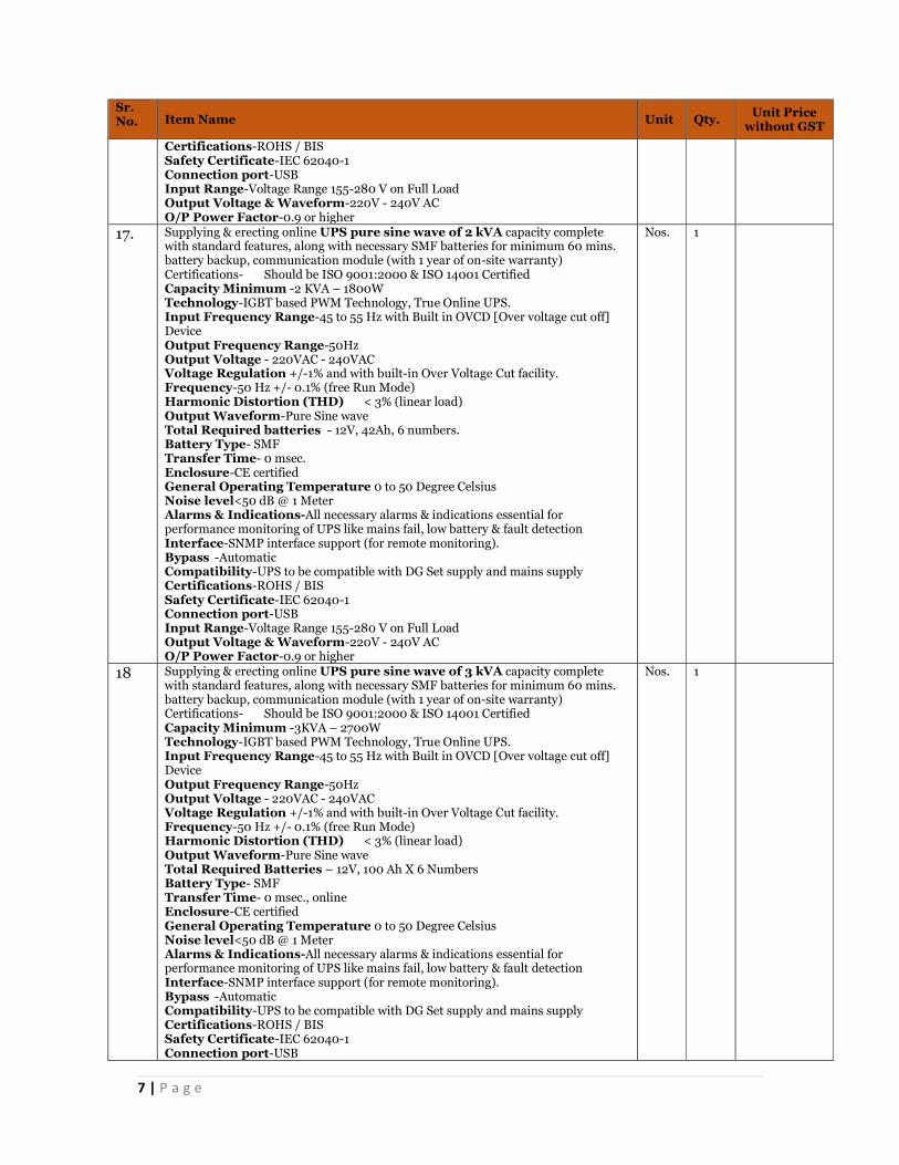
Certifications-ROHS / BIS Safety Certificate-IEC 62040-1 Connection port-USB Input Range-Voltage Range 155-280 V on Full Load Output Voltage & Waveform-220V - 240V AC O/P Power Factor-0.9 or higher
17. Supplying & erecting online UPS pure sine wave of 2 kVA capacity complete with standard features, along with necessary SMF batteries for minimum 60 mins. battery backup, communication module (with 1 year of on-site warranty) Certifications- Should be ISO 9001:2000 & ISO 14001 Certified Capacity Minimum -2 KVA – 1800W Technology-IGBT based PWM Technology, True Online UPS. Input Frequency Range-45 to 55 Hz with Built in OVCD [Over voltage cut off] Device Output Frequency Range-50Hz Output Voltage - 220VAC - 240VAC Voltage Regulation +/-1% and with built-in Over Voltage Cut facility. Frequency-50 Hz +/- 0.1% (free Run Mode) Harmonic Distortion (THD) < 3% (linear load) Output Waveform-Pure Sine wave Total Required batteries - 12V, 42Ah, 6 numbers. Battery Type- SMF Transfer Time- 0 msec. Enclosure-CE certified General Operating Temperature 0 to 50 Degree Celsius Noise level<50 dB @ 1 Meter Alarms & Indications-All necessary alarms & indications essential for performance monitoring of UPS like mains fail, low battery & fault detection Interface-SNMP interface support (for remote monitoring). Bypass -Automatic Compatibility-UPS to be compatible with DG Set supply and mains supply Certifications-ROHS / BIS Safety Certificate-IEC 62040-1 Connection port-USB Input Range-Voltage Range 155-280 V on Full Load Output Voltage & Waveform-220V - 240V AC O/P Power Factor-0.9 or higher
Nos. 1
18 Supplying & erecting online UPS pure sine wave of 3 kVA capacity complete with standard features, along with necessary SMF batteries for minimum 60 mins. battery backup, communication module (with 1 year of on-site warranty) Certifications- Should be ISO 9001:2000 & ISO 14001 Certified Capacity Minimum -3KVA – 2700W Technology-IGBT based PWM Technology, True Online UPS. Input Frequency Range-45 to 55 Hz with Built in OVCD [Over voltage cut off] Device Output Frequency Range-50Hz Output Voltage - 220VAC - 240VAC Voltage Regulation +/-1% and with built-in Over Voltage Cut facility. Frequency-50 Hz +/- 0.1% (free Run Mode) Harmonic Distortion (THD) < 3% (linear load) Output Waveform-Pure Sine wave Total Required Batteries – 12V, 100 Ah X 6 Numbers Battery Type- SMF Transfer Time- 0 msec., online Enclosure-CE certified General Operating Temperature 0 to 50 Degree Celsius Noise level<50 dB @ 1 Meter Alarms & Indications-All necessary alarms & indications essential for performance monitoring of UPS like mains fail, low battery & fault detection Interface-SNMP interface support (for remote monitoring). Bypass -Automatic Compatibility-UPS to be compatible with DG Set supply and mains supply Certifications-ROHS / BIS Safety Certificate-IEC 62040-1 Connection port-USB
Nos. 1

8 | P a g e
Sr. No. Item Name Unit Qty. Unit Price
without GST
Input Range-Voltage Range 155-280 V on Full Load Output Voltage & Waveform-220V - 240V AC O/P Power Factor-0.9 or higher
19 Supplying & erecting online UPS pure sine wave of 6 kVA capacity complete with standard features, along with necessary SMF batteries, communication module with 1 year of on-site warranty Certifications- Should be ISO 9001:2000 & ISO 14001 Certified Capacity Minimum -6KVA – 6000W Technology-IGBT based PWM Technology, True Online UPS. Input Frequency Range-45 to 55 Hz with Built in OVCD [Over voltage cut off] Device Output Frequency Range-50Hz Output Voltage - 220VAC - 240VAC Voltage Regulation +/-1% and with built-in Over Voltage Cut facility. Frequency-50 Hz +/- 0.1% (free Run Mode) Harmonic Distortion (THD) < 3% (linear load) Output Waveform-Pure Sine wave Total Required Batteries -12 V, 65Ah, 16 Batteries Battery Type- SMF Transfer Time- 0 msec. Enclosure-CE certified General Operating Temperature 0 to 50 Degree Celsius Noise level<50 dB @ 1 Meter Alarms & Indications-All necessary alarms & indications essential for performance monitoring of UPS like mains fail, low battery & fault detection Interface-SNMP interface support (for remote monitoring). Bypass -Automatic Compatibility-UPS to be compatible with DG Set supply and mains supply Certifications-ROHS / BIS Safety Certificate-IEC 62040-1 Connection port-USB Input Range-Voltage Range 155-280 V on Full Load Output Voltage & Waveform-220V - 240V AC O/P Power Factor-0.9 or higher
Nos. 1
20 Supplying & erecting online UPS pure sine wave of 10 kVA capacity complete with standard features, along with necessary SMF batteries for minimum 60 mins. battery backup, communication module (with 1 year of on-site warranty) Certifications- Should be ISO 9001:2000 & ISO 14001 Certified Manufacturer-Should be ISO 9001:2000 & ISO 14001 Certified Capacity Minimum -10 KVA/10KW Technology IGBT based PWM Technology, True Online UPS. Input wiring L+N+G 1 phase L1+L2+L3+N+G 3 phase Rated input voltage 1 phase 220/230/240V 3 phase 380/400/415V Rated input frequency 50Hz- 60Hz Input frequency range 40Hz- 70Hz Input power factor(PF) >0.995 both 1 phase and 3 phase Output Phase Connection Input-output 3-1, 3-3, 1-1 Rated output voltage 1 phase 220/230/240V Frequency 50 Hz +/- 0.1% (free Run Mode) Harmonic Distortion (THDi) ≤ 3% (linear load) Load Crest Factor 3:1 Output Waveform Pure Sine wave Max. Power Factor 1 Min. required batteries12v. 84 Ah, 16 numbers Battery Type SMF Transfer Time 0 msec. Enclosure CE certified Interface-SNMP interface support (for remote monitoring). Environment Operating Temperature °C ~ 50 °C(0~40 no derating,40°C~ 50°C derating to 50%) Noise level ≤55dB @ 1 Meter
Nos. 1

9 | P a g e
Sr. No. Item Name Unit Qty. Unit Price
without GST
Alarms & Indications All necessary alarms & indications essential for performance monitoring of UPS like mains fail, low battery & fault detection Bypass Automatic Installation Type Rack/ Tower Compatibility UPS to be compatible with DG Set supply and mains supply Certifications ROHS / BIS
21 Supplying & erecting online UPS pure sine wave of 20 kVA capacity complete with standard features, along with necessary SMF batteries for minimum 60 mins. battery backup, communication module (with 1 year of on-site warranty) Certifications- Should be ISO 9001:2000 & ISO 14001 Certified Manufacturer Should be ISO 9001:2000 & ISO 14001 Certified Capacity Minimum 20 KVA/ KW Technology IGBT based PWM Technology, True Online UPS. Input wiring L+N+G 1 phase L1+L2+L3+N+G 3 phase Rated input voltage 3 phase Rated input frequency 50Hz- 60Hz Input frequency range 40Hz- 70Hz Input power factor(PF) >0.995 both 1 phase and 3 phase Output Phase Connection Input-output 3-1, 3-3, 1-1 Rated output voltage 1 phase 220/230/240V Frequency 50 Hz +/- 0.1% (free Run Mode) Harmonic Distortion (THDi) ≤ 3% (linear load) Load Crest Factor 3:1 Output Waveform Pure Sine wave Max. Power Factor 1 Min. required batteries 12V, 100 Ah, 24 numbers Battery Type SMF Transfer Time 0 msec. Enclosure CE certified Interface-SNMP interface support (for remote monitoring). Environment Operating Temperature 0°C ~ 50 °C(0~40 no derating,40°C~ 50°C derating to 50%) Noise level ≤55dB @ 1 Meter Alarms & Indications All necessary alarms & indications essential for performance monitoring of UPS like mains fail, low battery & fault detection Bypass Automatic Installation Type Rack/ Tower Compatibility UPS to be compatible with DG Set supply and mains supply Certifications ROHS / BIS Safety Certificate IEC 62040-1
Nos. 1
22 Supply, Installation Testing & Commissioning of Vertical GI Cantilever square type 100mm x 100 mm x 3mm suitable for departmentally supplied 6 Mtr octagonal pole including clamping for pole. Including vibration pad, nut bolts, CCTV camera & IR mounting facility with all concealed cabling facility. Cantilever Length: 1 meter Fabrication: Hot Dip Galvanized after Fabrication with Silver coating of 86 micron as per IS:2629; Fabrication in accordance with IS-2713
Nos. 1
23 Supply, Installation Testing & Commissioning of Vertical GI Cantilever square type 100mm x 100 mm x 3mm suitable for departmentally supplied 6 Mtr octagonal pole including clamping for pole. Including vibration pad, nut bolts, CCTV camera & IR mounting facility with all concealed cabling facility. Cantilever Length: 1.5 meter Fabrication: Hot Dip Galvanized after Fabrication with Silver coating of 86 micron as per IS:2629; Fabrication in accordance with IS-2713
Nos. 1
24 Supply, Installation Testing & Commissioning of Vertical GI Cantilever square type 100mm x 100 mm x 3mm suitable for departmentally supplied 6 Mtr octagonal pole including clamping for pole. Including vibration pad, nut bolts, CCTV camera & IR mounting facility with all concealed cabling facility. Cantilever Length: 2 meter Fabrication: Hot Dip Galvanized after Fabrication with Silver coating of 86 micron as per IS:2629; Fabrication in accordance with IS-2713
Nos. 1

10 | P a g e
Sr. No. Item Name Unit Qty. Unit Price
without GST
25 Supply, Installation Testing & Commissioning of Vertical GI Cantilever square type 100mm x 100 mm x 4mm suitable for departmentally supplied 6 Mtr octagonal pole including clamping for pole. Including vibration pad, nut bolts, CCTV camera & IR mounting facility with all concealed cabling facility. Cantilever Length: 3 meter Fabrication: Hot Dip Galvanized after Fabrication with Silver coating of 86 micron as per IS:2629; Fabrication in accordance with IS-2713
Nos. 1
26 Supplying, Installation and erecting of ISI mark Gantry. with pole cap .with 1 year of on-site warranty Gantry Hight-6 meter above road surface Gantry Length – Covering 2 lanes Gantry Thickness- 4mm or better General Requirement-The support structure shall be of MS IS: 2062 Gantry type General Requirement-The structure should be supported on the round (shoulder/foot-path) on both the sides of the road through appropriate concrete Foundation. General Requirement-The minimum vertical clearance between the finished road surface and the bottom of the support structure/bottom (whichever is lower) shall be 5.5 m as per applicable guidelines General Requirement-The support structure shall provide adequate support to the Installed element from all four sides as well as top and bottom Load Requirement-The structure for gantry mounting should withstand wind-speeds upto150km/hr and support the weight. This should be certified by a structure engineer Painting-The structure shall be painted with one coat of primer and two coats of PU paint. Grey/silver paint or as described by PCMC authority General Requirement-The RCC foundation with M20 Grade or higher Ready-mix RCC and required IRON bar structure to take load of Structure weight approved by Structure Engineer General Requirement-Lighting arrestors with proper grounding and earthing
Nos. 1
27 Supplying, Installation and erecting of ISI mark Gantry. with pole cap .with 1 year of on-site warranty Gantry Hight-6 meter above road surface Gantry Length – Covering 3 lanes Gantry Thickness- 4mm or better General Requirement-The support structure shall be of MS IS: 2062 Gantry type General Requirement-The structure should be supported on the round (shoulder/foot-path) on both the sides of the road through appropriate concrete Foundation. General Requirement-The minimum vertical clearance between the finished road surface and the bottom of the support structure/bottom (whichever is lower) shall be 5.5 m as per applicable guidelines General Requirement-The support structure shall provide adequate support to the Installed element from all four sides as well as top and bottom Load Requirement-The structure for gantry mounting should withstand wind-speeds upto150km/hr and support the weight. This should be certified by a structure engineer Painting-The structure shall be painted with one coat of primer and two coats of PU paint. Grey/silver paint or as described by PCMC authority General Requirement-The RCC foundation with M20 Grade or higher Ready-mix RCC and required IRON bar structure to take load of Structure weight approved by Structure Engineer General Requirement-Lighting arrestors with proper grounding and earthing
Nos. 1
28 Supplying, Installation and erecting of ISI mark Gantry. with pole cap .with 1 year of on-site warranty Gantry Hight-6 meter above road surface Gantry Length – Covering 4 lanes Gantry Thickness- 4mm or better General Requirement-The support structure shall be of MS IS: 2062 Gantry type General Requirement-The structure should be supported on the round (shoulder/foot-path) on both the sides of the road through appropriate concrete Foundation.
Nos. 1

11 | P a g e
Sr. No. Item Name Unit Qty. Unit Price
without GST
General Requirement-The minimum vertical clearance between the finished road surface and the bottom of the support structure/bottom (whichever is lower) shall be 5.5 m as per applicable guidelines General Requirement-The support structure shall provide adequate support to the Installed element from all four sides as well as top and bottom Load Requirement-The structure for gantry mounting should withstand wind-speeds upto150km/hr and support the weight. This should be certified by a structure engineer Painting-The structure shall be painted with one coat of primer and two coats of PU paint. Grey/silver paint or as described by PCMC authority General Requirement-The RCC foundation with M20 Grade or higher Ready-mix RCC and required IRON bar structure to take load of Structure weight approved by Structure Engineer General Requirement-Lighting arrestors with proper grounding and earthing
29 Supply, Installation Testing & Commissioning of the Outdoor Utility Cabinet (Junction Box 1200mm(H) x 650mm(W) x 750mm(D)) with 1 year of on-site warranty constructed with a front sheet steel door and cabinet thickness 1.6 mm with 3-point lock and pad lock arrangement to ensure the security of the cabinet. Side and Wall Panels shall be double wall constructed, with fixing bolts internal to the cabinet. The Cabinet should have the required frames to mount the components like network device, power, UPS, LIU, battery, etc. Junction Box should be Made for 24x7x365 Outdoor Applications; The Utility Cabinet shall be IP 55 or better rated with built-in redundant fan and filter assembly inherent in the design. Junction Box design should ensure to keep the Operating temperature range of 10° C to 50° C for all the equipment housed within and provide protection from dust, low pressure water jets from any direction, ingress protection. with 1 year of on-site warranty Built-The Outdoor Utility Cabinet will be constructed with a front sheet steel door with 3-point lock and pad lock arrangement to ensure the security of the cabinet. Side and Wall Panels shall be double wall constructed, with fixing bolts internal to the cabinet. The Cabinet should have the required frames to mount the components like network device, power, UPS, LIU, battery, etc. Utility & IP rating-Should be Made for 24/7/365 Outdoor Applications; The Utility Cabinet shall be IP 55 or better rated with built-in redundant fan and filter assembly inherent in the design. Junction Box design should ensure to keep the Operating temperature range of 10° C to 50° C for all the equipment housed within and provide protection from dust, low pressure water jets from any direction, ingress protection. the cabinet shall be suitable for the mounting of the associated network devices, power, UPS and battery components securely and safely within the cabinet. Power Slot-Minimum 3 x PDU’s has to be provided to support the site equipment. PDU type should be as per actual requirement as per Indian standards. Cable Management-Proper cable management should be provided .Cable Routing: Power connection cable shall be provided from the nearest access point provided by Power utility company to the Outdoor Utility Cabinet through Power meter enclosure. Built-Junction box to be mounted on a raised height concrete Plinth, 1.5 ft high or as per site requirements. Junction box would be divided into multiple compartments having separate doors and keys for power meters, switch, UPS/batteries etc.,3 phase Power input with Electricity meter, Fuse and MCCB would be in separate compartment having independent door and keys as per electricity board, rules. Surge protector to be installed before connectivity to UPS. Traffic controller unit to be placed in a separate section with its own door and keys. Colour and powder coating thickness-Color - RAL7035, Powder coating thickness between 70 to 120 micron Finish - Textured .Junction box’s design shall be aesthetically appealing with branding and appropriately sized to accommodate the followings: o UPS (as per site requirement to manage power backup of 1 hrs for all the plugged
devices at site including, camera, other sensors/devices) o LIU (as per requirement) o Access Switch (at least 2) o Power Meter (as per requirement) o Batteries (to provide 1 hrs back to devices) o PA System Amplifier o LPU for ANPR & RLVD
Nos. 1

12 | P a g e
Sr. No. Item Name Unit Qty. Unit Price
without GST
o Requisite space for other accessories & systems along with provisioning of future scalability
The size of the Junction Box is allowed to vary as per the site requirement; bidder to provision the same considering each site requirement. Branding at Outside wall of JB (all sides)- Colour should be all weather proof and city branding should be of premium quality, clean finish (paint/embossed/paper etc.) with at least durability for 10 years in all weather conditions.
30 Supply, Installation Testing & Commissioning of the Outdoor Utility Cabinet (Junction Box- 1200mm(H)x850mm(W)x800mm(D)) (with 1 year of on-site warranty) constructed with a front sheet steel door and cabinet thickness 1.6 mm with 3-point lock and pad lock arrangement to ensure the security of the cabinet. Side and Wall Panels shall be double wall constructed, with fixing bolts internal to the cabinet. The Cabinet should have the required frames to mount the components like network device, power, UPS, LIU, battery, etc. Junction Box should be Made for 24x7x365 Outdoor Applications; The Utility Cabinet shall be IP 55 or better rated with built-in redundant fan and filter assembly inherent in the design. Junction Box design should ensure to keep the Operating temperature range of 10° C to 50° C for all the equipment housed within and provide protection from dust, low pressure water jets from any direction, ingress protection. (with 1 year of on-site warranty) Built-The Outdoor Utility Cabinet will be constructed with a front sheet steel door with 3-point lock and pad lock arrangement to ensure the security of the cabinet. Side and Wall Panels shall be double wall constructed, with fixing bolts internal to the cabinet. The Cabinet should have the required frames to mount the components like network device, power, UPS, LIU, battery, etc. Utility & IP rating-Should be Made for 24/7/365 Outdoor Applications; The Utility Cabinet shall be IP 55 or better rated with built-in redundant fan and filter assembly inherent in the design. Junction Box design should ensure to keep the Operating temperature range of 10° C to 50° C for all the equipment housed within and provide protection from dust, low pressure water jets from any direction, ingress protection. Size- 1100mm(H)x750mm(W)x650mm(D), the cabinet shall be suitable for the mounting of the associated network devices, power, UPS and battery components securely and safely within the cabinet. Power Slot-Minimum 3 x PDU’s has to be provided to support the site equipment. PDU type should be as per actual requirement as per Indian standards. Cable Management-Proper cable management should be provided. Cable Routing: Power connection cable shall be provided from the nearest access point provided by Power utility company to the Outdoor Utility Cabinet through Power meter enclosure. Built-Junction box to be mounted on a raised height concrete Plinth, 1.5 ft high or as per site requirements. Junction box would be divided into multiple compartments having separate doors and keys for power meters, switch, UPS/batteries etc.,3 phase Power input with Electricity meter, Fuse and MCCB would be in separate compartment having independent door and keys as per electricity board, rules. Surge protector to be installed before connectivity to UPS. Traffic controller unit to be placed in a separate section with its own door and keys. Colour and powder coating thickness-Color - RAL7035, Powder coating thickness between 70 to 120 micron Finish. Junction box’s design shall be aesthetically appealing with branding and appropriately sized to accommodate the followings: o UPS (as per site requirement to manage power backup of 1 hrs for all the plugged
devices at site including, camera, other sensors/devices) o LIU (as per requirement) o Access Switch (at least 2) o Power Meter (as per requirement) o Batteries (to provide 1 hrs back to devices) o PA System Amplifier o LPU for ANPR & RLVD o Requisite space for other accessories & systems along with provisioning of future
scalability The size of the Junction Box is allowed to vary as per the site requirement; bidder to provision the same considering each site requirement. Branding at Outside wall of JB (all sides)- Colour should be all weather proof and city branding should be of premium quality, clean finish (paint/embossed/paper etc.) with at least durability for 10 years in all weather conditions.
Nos. 1

13 | P a g e
Sr. No. Item Name Unit Qty. Unit Price
without GST
31 Supply, Installation Testing & Commissioning of the Outdoor Utility Cabinet (Junction Box- 1550mm(H)x900mm(W)x800mm(D)) (with 1 year of on-site warranty) constructed with a front sheet steel door and cabinet thickness 1.6 mm with 3-point lock and pad lock arrangement to ensure the security of the cabinet. Side and Wall Panels shall be double wall constructed, with fixing bolts internal to the cabinet. The Cabinet should have the required frames to mount the components like network device, power, UPS, LIU, battery, etc. Junction Box should be Made for 24x7x365 Outdoor Applications; The Utility Cabinet shall be IP 55 or better rated with built-in redundant fan and filter assembly inherent in the design. Junction Box design should ensure to keep the Operating temperature range of 10° C to 50° C for all the equipment housed within and provide protection from dust, low pressure water jets from any direction, ingress protection. (with 1 year of on-site warranty) Built-The Outdoor Utility Cabinet will be constructed with a front sheet steel door with 3-point lock and pad lock arrangement to ensure the security of the cabinet. Side and Wall Panels shall be double wall constructed, with fixing bolts internal to the cabinet. The Cabinet should have the required frames to mount the components like network device, power, UPS, LIU, battery, etc. Utility & IP rating-Should be Made for 24/7/365 Outdoor Applications; The Utility Cabinet shall be IP 55 or better rated with built-in redundant fan and filter assembly inherent in the design. Junction Box design should ensure to keep the Operating temperature range of 10° C to 50° C for all the equipment housed within and provide protection from dust, low pressure water jets from any direction, ingress protection. Colour and powder coating thickness-Color - RAL7035, Powder coating thickness between 70 to 120 micron Finish , the cabinet shall be suitable for the mounting of the associated network devices, power, UPS and battery components securely and safely within the cabinet. Power Slot-Minimum 3 x PDU’s has to be provided to support the site equipment. PDU type should be as per actual requirement as per Indian standards. Cable Management-Proper cable management should be provided. Cable Routing: Power connection cable shall be provided from the nearest access point provided by Power utility company to the Outdoor Utility Cabinet through Power meter enclosure. Built-Junction box to be mounted on a raised height concrete Plinth, 1.5 ft high or as per site requirements. Junction box would be divided into multiple compartments having separate doors and keys for power meters, switch, UPS/batteries etc.,3 phase Power input with Electricity meter, Fuse and MCCB would be in separate compartment having independent door and keys as per electricity board, rules. Surge protector to be installed before connectivity to UPS. Traffic controller unit to be placed in a separate section with its own door and keys Design & Size Junction box’s design shall be aesthetically appealing with branding and appropriately sized to accommodate the followings: o UPS (as per site requirement to manage power backup of 1 hrs for all the plugged
devices at site including, camera, other sensors/devices) o LIU (as per requirement) o Access Switch (at least 2) o Power Meter (as per requirement) o Batteries (to provide 1 hrs back to devices) o PA System Amplifier o LPU for ANPR & RLVD o Requisite space for other accessories & systems along with provisioning of future
scalability The size of the Junction Box is allowed to vary as per the site requirement; bidder to provision the same considering each site requirement. Branding at Outside wall of JB (all sides)- Colour should be all weather proof and city branding should be of premium quality, clean finish (paint/embossed/paper etc.) with at least durability for 10 years in all weather conditions.
Nos. 1
32 Supply, Installation Testing & Commissioning of the SMPS/Inverter Smart Power System: Suitable for 1 KW backup in outdoor IP55 rated cabinet with one year of onsite warranty System Capacity-3.4 KW (Redundancy N+1),Input Voltage Range-90 - 300 V Frequency-47-53 Hz, Protection-Inbuilt Short Circuit, Over/ Under Voltage, Surge Protection-Class C type (IEC 61643-1 , UL 94-0), Power Factor / THD: > 0.98 at 50% load or more / < 5% AC Output
Nos. 1

14 | P a g e
Sr. No. Item Name Unit Qty. Unit Price
without GST
Maximum Capacity-300 VA, Nominal System output Voltage-220V AC/ Sine Wave, Frequency-50Hz +- 5%, Input Voltage Range-42V DC ~ 58V DC Overload Protection-Yes, THD-<5% Protection-Short Circuit, Over Temperature, Crest Factor-3, Efficiency-89% @ full load, Output Ports- 2 nos (3 amps) DC ports Output Voltage type-48V DC, 24 V DC, 12VDC, Architecture-Modular, Protection-Short Circuit, Over Load, Load Sharing-Yes, Output Ports -Individual Ports with suitable rating Rectifier Efficiency-93% Output Ports-"IPDU- remote ON/OFF with integration to the central software 1- POE Switch x 1 (16 Amp) 2. 2x 6 amps General: Controls and Monitoring High End Embedded Controller with LCD display, Measurement-DC Energy monitoring with Class 1 accuracy. User interface-LEDs for local visual alarming (Major, Minor, Power ON) Ethernet for remote or local monitoring and control via Web browser. SNMP V2 & V.3.0 protocol with TRAP, SET and GET on Ethernet. Email of TRAP alarms" Operating temperature: 0 to +65 ºC Battery Technology and Management-Support both VRLA/SMF and Lithium Iron Phosphate. Monitoring battery alarms and parameters with led indications. Battery Backup-2 Hrs Standards Safety-EN / IEC 60950 UL 60950 EMI-EN 55022, class A Environment-RoHS compliant
33 Supply, Installation Testing & Commissioning of the SMPS/Inverter Smart Power System: Suitable for 2KW backup in outdoor IP55 rated cabinet with one year of onsite warranty Electrical Specifications Input System Capacity-5.2 KW (Redundancy N+1) Input Voltage Range-90 - 300 V Frequency (default: sync range)-47-53 Hz Protection-Inbuilt Short Circuit, Over/ Under Voltage Surge Protection-Class C type (IEC 61643-1 , UL 94-0) Power Factor / THD:> 0.98 at 50% load or more / < 5% DC Output Output Voltage type-48V DC, 24 V DC, 12VDC, Architecture-Modular, Protection-Short Circuit, Over Load, Load Sharing-Yes, Output Ports-Individual Ports with suitable rating, Rectifier Efficiency-93% Output Ports "IPDU- remote ON/OFF with integration to the central software 1- POE Switch: x 1 (16 Amp) 2- ANPR LPU : x 1 (6 Amp) 3- Face Detection LPU x 1 (6 Amp) 4- IR Illuminator: x 6 (6 Amp)" Maximum Capacity:300 VA, Nominal System output Voltage:220V AC/ Sine Wave Frequency: 50Hz +- 5%, Input Voltage Range:-42V DC ~ 58V DC Overload Protection: Yes, THD-<5%, Protection: Short Circuit, Over, Temperature, Crest Factor: 3, Efficiency: 89% @ full load Output Ports- x 1 (3 Amp) Miscellaneous x 1 (3 Amp)" General: Controls and Monitoring High End Embedded Controller with LCD display Measurement: DC Energy monitoring with Class 1 accuracy. User interface: LEDs for local visual alarming (Major, Minor, Power ON) Ethernet for remote or local monitoring and control via Web browser. SNMP V2 & V.3.0 protocol with TRAP, SET and GET on Ethernet. Email of TRAP alarms" Operating temperature:0 to +65 ºC Battery Technology and Management: Support both VRLA/SMF and Lithium Iron Phosphate. Monitoring battery alarms and parameters with led indications. Battery Backup: 2 Hrs Standards
Nos. 1

15 | P a g e
Sr. No. Item Name Unit Qty. Unit Price
without GST
Safety-EN / IEC 60950 UL 60950 EMI-EN 55022, class A Environment-RoHS compliant
34 Supply, Installation, Testing & Commissioning of Signages “You are under CCTV surveillance” across various location of PCMC as per IRC guideline. Design of signage’s should conform with IRC standards IRC 67‐2010 and Motor Vehicles act in accordance with the recommendations by traffic police dept of Pune. The size and shape of letters and their interspacing and numerals used on informatorily signs or definition plates shall be as detailed in IRC:30-1968 "Standard Letters and Numerals of Heights for use on Road/highway Signs Letter size should be chosen with due regard to the speed, classification and location
of the road, so that the sign is of adequate size for legibility but without being too large or obtrusive. The size of the letter, in terms of x-height, to be chosen as per the design speed are given in IRC guidelines Plates and Supports: Plates and support for the signboard shall confirm to the IS:226 and IS:2062 or any other stated IS standard. Mounting: Wall and pole mounting bracket with other accessories required for installation shall be provided by the bidder.
Nos 1
35 Supply, Installation, Testing & Commissioning of Signages “Speed Limit” across various location of PCMC as per IRC guideline. Design of signage’s should conform with IRC standards IRC 67‐2010 and Motor Vehicles act in accordance with the recommendations by traffic police dept of Pune. The size and shape of letters and their interspacing and numerals used on informatorily signs or definition plates shall be as detailed in IRC:30-1968 "Standard Letters and Numerals of Heights for use on Road/highway Signs Letter size should be chosen with due regard to the speed, classification and location of the road, so that the sign is of adequate size for legibility but without being too large or obtrusive. The size of the letter, in terms of x-height, to be chosen as per the design speed are given in IRC guidelines
Plates and Supports: Plates and support for the signboard shall confirm to the IS:226 and IS:2062 or any other stated IS standard. Mounting: Wall and pole mounting bracket with other accessories required for installation shall be provided by the bidder.
Nos 1

16 | P a g e
Sr. No. Item Name Unit Qty. Unit Price
without GST
36 Supply, Installation, testing & Commissioning of IP based PA 7 W Amplifier with 1 year of on-site warranty PAS system-Should have the capability to control individual PAS i.e. to make an announcement at select location (1:1) one to all and one to many simultaneously. The PAS should also support both, Live and Recorded inputs. Connectivity- Native IP connectivity, no convertors to be used Format-The system shall have the capability of playing live and pre-recorded (i.e. MP3, WAV etc.) messages Access Control-Access control mechanism would be also required to establish so that the usage is regulated. Integration-With Command and Control Center Construction-Cast Iron Foundation and M.S. Pole, Sturdy Body for equipment Power-Automatic on/off operation Casing-IP-55 rated for housing Operating conditions - 0° to 55°C Amplifier- Integrated 7W amplifier with 4 speakers as per site requirement, POE or 12V power, 10/100Base-TX Ethernet, The slot for Micro SD card, 1x digital input and output, Remote configuration & administration Frequency Response of Amplifier-50Hz to 15000 Hz for Amplifier Frequency Response of Speaker-280 -10,000Hz or better Protocols-IPv6, IPv4, TCP, UDP, HTTP (RFC 2617, RFC 3310),DHCP, SDP (RFC 2327),SIP (RFC 3261), SNMPv2, STUN, TFTP, URI (RFC 2396), DTMF Decoding (RFC 2876, RFC 2833),SIP User Agent (UDP RFC 3261), SIP Refer Method (RFC 3515) Input output-1 Inputs and 1 Output ONVIF-ONVIF Profile S for unidirectional audio Main power supply-100 – 240 VAC Backup power supply: 24 VDC Transmission bandwidth-16000 KHz for master control desk Approvals- EN, FCC, VCCI, UL, NEMA 250 Type 4X Firmware- Upgrade should be free required
Nos. 1
37 Supply, Installation, testing & Commissioning of IP based PA 14W Amplifier with 1 year of on-site warranty PAS system-Should have the capability to control individual PAS i.e. to make an announcement at select location (1:1) one to all and one to many simultaneously. The PAS should also support both, Live and Recorded inputs. Connectivity- Native IP connectivity, no convertors to be used Format-The system shall have the capability of playing live and pre-recorded (i.e. MP3, WAV etc.) messages Access Control-Access control mechanism would be also required to establish so that the usage is regulated. Integration-With Command and Control Center Construction-Cast Iron Foundation and M.S. Pole, Sturdy Body for equipment Power-Automatic on/off operation Casing-IP-55 rated for housing Operating conditions - 0° to 55°C Amplifier- Integrated 14W amplifier with 4 speakers as per site requirement, POE or 12V power, 10/100Base-TX Ethernet, The slot for Micro SD card, 1x digital input and output, Remote configuration & administration Frequency Response of Amplifier-50Hz to 15000 Hz for Amplifier Frequency Response of Speaker-280 -10,000Hz or better Protocols-IPv6, IPv4, TCP, UDP, HTTP (RFC 2617, RFC 3310),DHCP, SDP (RFC 2327),SIP (RFC 3261), SNMPv2, STUN, TFTP, URI (RFC 2396), DTMF Decoding (RFC 2876, RFC 2833),SIP User Agent (UDP RFC 3261), SIP Refer Method (RFC 3515) Input output-1 Inputs and 1 Output ONVIF-ONVIF Profile S for unidirectional audio Main power supply-100 – 240 VAC Backup power supply: 24 VDC Transmission bandwidth-16000 KHz for master control desk Approvals- EN, FCC, VCCI, UL, NEMA 250 Type 4X Firmware- Upgrade should be free required
No. 1
38 Supply, Installation Testing & Commissioning of layer 3 switch(Access) , 20 POE+ Nos- 10/100/1000base-T ports + 4 combo 10/100/1000Base-T/SFP ports + 4 Nos of 1/10GE SFP+ ports with 2 x 1G single mode SFP module (10 Km). (with 1 year of on-site warranty) Architecture - Shall be 19" Rack Mountable, 20 X RJ-45 autosensing 10/100/1000
Nos. 1

17 | P a g e
Sr. No. Item Name Unit Qty. Unit Price
without GST
PoE+ ports (30W power output per port) and 4 X 1000BASE-T or 1000Mbps SFP Ports or 10G SFP+ ports. All proposed Access Switches should to be supplied with dual power supply for redundancy from day one and each 12-port PoE+ switch must deliver 360 Watts power budget using single power supply only & each 20-port PoE+ switch must deliver 600 Watts power budget using single power supply only. For both the switch variants (12-port & 20-port), the second power supply should be used solely for redundancy purpose only so that even in the event of failure of either of the power supply, the switch should continue to deliver the power budget spelt above. Bidder should provide the power budget calculations for each proposed switch as part of its technical proposal. The switch should have the capability to upgrade to 2 X 10G SFP+ uplinks on fibre backbone in future without changing the switch or its components. All transceiver modules should be from the same Switching OEM. 1 RJ-45 serial console port.1 RJ-45 out-of-band management port/Remote management using web browser.1GB SDRAM and 512 MB flash and 2 MB Packet buffer size. Shall have switching capacity/bandwidth of 128 Gbps. Shall have up to 90 Mpps switching throughput or more. The Switch should support 16000 MAC address. Features-The switch should support HTTP redirect function The Switch should automatically configure switch for different settings such as VLAN, CoS, PoE max power, and PoE priority when a wireless access point is detected. Quality of Service (QoS)The switch should support Traffic prioritization which allows real-time traffic classification Layer 4 prioritization enables prioritization based on TCP/ UDP port numbers The switch should support Class of Service (CoS) to set the IEEE 802.1p priority tag based on IP address, IP Type of Service (ToS), Layer 3 protocol, TCP/UDP port number, source port, and DiffServ. The switch should support Rate limiting The switch should support large buffers & provide congestion management. Connectivity-The switch should support Auto-MDIX The switch should support IEEE 802.3at Power over Ethernet (PoE+).IPv6 feature-The switch should support IPV6 host enables switches to be managed in an IPV6 network.The switch should support Dual stack (IPV4 and IPV6) transitions from IPV4 to IPV6, supporting connectivity for both protocols. The switch should support MLD snooping forwards IPV6 multicast traffic to the appropriate interface.The switch should support IPV6 ACL/QoS supports ACL and QoS for IPV6 network traffic.The switch should support IPV6 routing supports static protocols.The switch should support DHCPv6 protection, dynamic IPv6 lockdown, and DHCP Guard/DHCP snooping/IGMP snooping/ND snooping. Performance-The switch should support selectable queue configurations or priority queueing to allow for increased performance by selecting the number of queues and associated memory buffering that best meet the requirements of the network applications. Resiliency and high availability-The switch should support IEEE 802.3ad Link Aggregation Protocol (LACP) The switch should support IEEE 802.1s Multiple Spanning Tree The switch should provide easy-to-configure link redundancy of active and standby links. Convergence -The switch should support IP multicast snooping (data-driven IGMP) / IGMP snooping (data-driven IGMP).The switch should support LLDP-MED (Media Endpoint Discovery).The switch should support IP multicast routing including PIM sparse and dense modes to route IP multicast traffic.The switch should support Auto-VLAN or industry equivalent for configuration of voice.The switch should support Local MAC Authentication to assign attributes such as VLAN and QoS using locally configured profile that can be a list of MAC prefixes. Management-The switch should support IEEE 802.1AB Link Layer Discovery Protocol (LLDP).The switch should support Multiple configuration files to store easily to the flash image.The switch should support Dual flash images to provide independent primary and secondary operating system files for backup while upgrading.The switch should support Zero-Touch Provisioning (ZTP).The switch should support Unidirectional Link Detection (UDLD). Layer 2 Feature-The switch should support IEEE 802.1ad QinQ.The switch should support VLAN and tagging and support the IEEE 802.1Q (4094 VLAN IDs) and 2K VLANs (for 20-port PoE+ switch variant) simultaneously and 1K VLANs (for 12-port PoE+ switch variant) simultaneously.The switch should support Jumbo packet .The switch should support MAC-based VLAN.The switch should support Rapid Per-VLAN spanning tree plus (RPVST+) or Rapid Convergence Spanning Tree Protocol or equivalent The switch should support GVRP / MVRP or equivalent industry standard protocols. Layer 3 feature-The switch should support DHCP server The switch should support Static IP routing with ECMP capability The switch

18 | P a g e
Sr. No. Item Name Unit Qty. Unit Price
without GST
should support RIP & OSPF for IPv4 & IPv6. Security -The switch should support Web-based authentication provides a browser-based environment. The switch should support MAC-based authentication. The switch should support Multiple IEEE 802.1X users per port to provide authentication of multiple IEEE 802.1X users per port and also to prevent a user from “piggybacking” on another user's IEEE 802.1X authentication. The switch should support Concurrent IEEE 802.1X, Web, and MAC authentication schemes per port. The switch should support Access control lists (ACLs) provide IP Layer 3 filtering based on source/destination IP address/subnet and source/destination TCP/UDP port number. The switch should support Source-port filtering to allow only specified ports to communicate with each other. The switch should support RADIUS/TACACS+ .The switch should support Secure shell encrypts all transmitted data for secure remote CLI access over IP networks. The switch should support Secure Sockets Layer (SSL) encrypts all HTTP traffic, allowing secure access to the browser-based management GUI in the switch. The switch should support Port security allows access only to specified MAC addresses, which can be learned or specified by the administrator. The switch should support MAC address lockout to prevent particular configured MAC addresses from connecting to the network. The switch should support Secure FTP .Switch management logon security helps secure switch CLI logon by optionally requiring either RADIUS or TACACS+ authentication. The switch should support STP BPDU port protection to block Bridge Protocol Data Units (BPDUs) on ports that do not require BPDUs and also prevent forged BPDU attacks The switch should support DHCP protection to block DHCP packets from unauthorized DHCP servers and prevent denial-of-service attacks. The switch should support Dynamic ARP protection to block ARP broadcasts from unauthorized hosts and prevent eavesdropping or theft of network data. The switch should support STP root guard to protect the root bridge from malicious attacks or configuration mistakes. The switch should support Identity-driven ACL enables implementation of a highly granular and flexible access security policy and VLAN assignment specific to each authenticated network user The switch should support Per-port broadcast throttling The switch should support Private VLAN .Operating temperature of 0°C to 55°C .Safety and Emission standards including EN 60950; IEC 60950; VCCI Class A; FCC Class A. Software Defined Networking (SDN) - Capability The Switch should have OpenFlow 1.3 / REST APIs or equivalent protocol capability to enable software-defined networking / software-defined access from Day one. Necessary licenses should be included with the switches from day one. Immunity Standards-Switch should comply to following certifications: Electrostatic Discharge: IEC/EN 61000-4-2.Radiation: IEC/EN 61000-4-3.Electrical Fast Transient / Burst Immunity: IEC/EN 61000-4-4.Surge Immunity: IEC/EN 61000-4-5.Power Frequency Magnetic Field: IEC/EN 61000-4-8.Voltage dips and variations Immunity: IEC/EN 61000-4- 11.
39 Supply, Installation, testing & Commissioning of Aggregation Switch along with cables and accessories including SFP module. (with 1 year of on-site warranty) Architecture- The switch should have at least 48 fixed 1G/10G SFP/SFP+ ports & 6 x 40G/100G QSFP+/QSFP28 ports. All transceiver modules should be from the same Switching OEM The switch Shall support 1000 Base-SX, LX, LH, 1000BASE-T The switch Shall Support 10Gbase-SR, LR, ER The switch shall have 2Tbps switching capacity The switch shall have switching throughput upto 1600 million pps The switch should have 32K ARP entries The switch should support 80K IPv4 routes, 20K IPv6 routes, 2K multicast routes The switch should have Modular operating system with OVSDB to support a database-centric operating system The switch should have non-blocking architecture The switch should have independent monitoring and restart of individual software modules, and enhanced software process serviceability functions The switch should have individual software modules to be upgraded for higher availability The switch should have framework for monitoring, troubleshooting and capacity planning The switch should support Jumbo frames size of 9K bytes The switch should support internal loopback testing for maintenance purposes and an increase in availability
Nos. 1

19 | P a g e
Sr. No. Item Name Unit Qty. Unit Price
without GST
The switch should have redundant fans and power supplies The switch should have hot-swappable line cards, transceivers, power supply, fan etc. The switch should protect against unknown broadcast, unknown multicast or unicast storms The switch should support internal Redundant power supplies Resiliency and high availability- The switch should support MLAG or equivalent The switch should support VRRP The switch should support Unidirectional Link Detection (UDLD) The switch should support IEEE 802.3ad LACP with support up to 128 trunks and eight links per trunk The switch should support Generic Routing Encapsulation (GRE) The switch should support Ethernet Ring Protection Switching (ERPS) / Ring Resiliency Protection Protocol (RRPP) for sub-milisecond recovery in Ethernet-based ring topology for city-wide deployment Management- The switch should have built-in troubleshooting feature The switch should have the capability to enable or disable interfaces depending on security preferences The switch should support Industry-standard CLI The switch should restrict access to critical configuration commands and support multiple privilege levels with password protection The switch shall provide ACL based SNMP access and support local and remote syslog capabilities allow logging of all access The switch should Provide SNMP read and trap support of industry standard Management Information Base (MIB), and private extensions The switch should support sFlow (RFC 3176) The switch should support Remote monitoring (RMON) The switch should support TFTP, and SFTP support The switch should support Debugging The switch should support ping and traceroute for both IPv4 and IPv6 The switch should support Network Time Protocol (NTP) The switch should support IEEE 802.1AB Link Layer Discovery Protocol (LLDP) The switch should support Dual flash images The switch should support Multiple configuration files Layer 2 feature- The switch should support up to 4,096 port-based or IEEE 802.1Q-based VLANs and supports MAC-based VLANs and IP subnet-based VLANs The switch should support Bridge Protocol Data Unit (BPDU) tunnelling The switch should support Port mirroring The switch should support IEEE 802.1D STP, IEEE 802.1w Rapid Spanning Tree Protocol (RSTP) for faster convergence, and IEEE 802.1s Multiple Spanning Tree Protocol (MSTP) The switch should support Rapid Per-VLAN spanning tree plus (RPVST+) or Rapid Convergence Spanning Tree Protocol or equivalent The switch should support Internet Group Management Protocol IGMP v1, v2, and v3 The switch should support congestion actions and support strict priority (SP) queuing and weighted fair queuing OR both weighted random early detection & weighted round robin. Layer 3 feature- The switch should support Address Resolution Protocol (ARP) and supports static ARPs, gratuitous ARP to allows detection of duplicate IP addresses and proxy ARP The switch should support UDP helper / DHCP helper The switch should support Dynamic Host Configuration Protocol (DHCP) and support DHCP Relay The switch should support Domain Name System (DNS) The switch should support Multicast VLAN or equivalent industry standard protocol. The switch should support Protocol Independent Multicast (PIM) and supports Sparse Mode (SM) The switch should support Static, Open shortest path first (OSPF), Border Gateway Protocol IPv4 routing The switch should support directed broadcasts control and support of ICMP
20 | P a g e
Sr. No. Item Name Unit Qty. Unit Price
without GST
The switch should support Static IPv6 routing, OSPFv3 and BGP-4 The switch should support Dual IP stack The switch should support Equal-Cost Multipath (ECMP) Security- The switch should support ACLs for both IPv4 and IPv6 based on a Layer 2 header or a Layer 3 protocol header The switch should support Remote Authentication Dial-In User Service (RADIUS) The switch should support Terminal Access Controller Access-Control System (TACACS+) The switch should support Secure shell (SSHv2) Environmental Features- Shall provide support WEEE regulations / ROHS regulations Operating temperature of 0°C to 40°C Safety and Emission standards including UL 60950-1; IEC 60950-1; VCCI Class A; EN 55022 Class A Software Defined Networking (SDN) Capability- The Switch should have OpenFlow 1.3 / REST APIs or equivalent protocol capability to enable software-defined networking from Day one City-wide Network & Datacentre deployment Architecture Functional requirement of the Project is that the proposed Network Active devices at Core Layer and Aggregation Layer MUST be capable of delivering Ring Topology at the city-wide Network level and the same Network Infrastructure should support and deliver Spine-Leaf Architecture at Core Layer and Server Farm Layer respectively within the datacentre
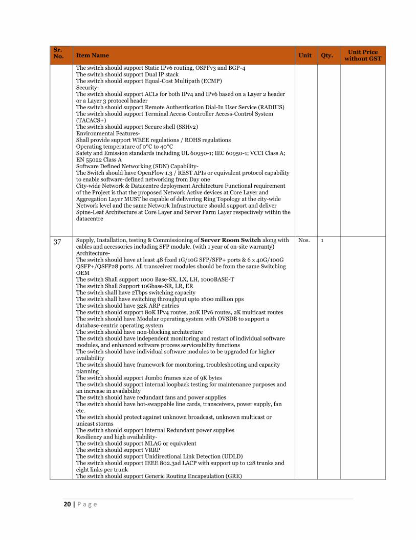
37 Supply, Installation, testing & Commissioning of Server Room Switch along with cables and accessories including SFP module. (with 1 year of on-site warranty) Architecture- The switch should have at least 48 fixed 1G/10G SFP/SFP+ ports & 6 x 40G/100G QSFP+/QSFP28 ports. All transceiver modules should be from the same Switching OEM The switch Shall support 1000 Base-SX, LX, LH, 1000BASE-T The switch Shall Support 10Gbase-SR, LR, ER The switch shall have 2Tbps switching capacity The switch shall have switching throughput upto 1600 million pps The switch should have 32K ARP entries The switch should support 80K IPv4 routes, 20K IPv6 routes, 2K multicast routes The switch should have Modular operating system with OVSDB to support a database-centric operating system The switch should have non-blocking architecture The switch should have independent monitoring and restart of individual software modules, and enhanced software process serviceability functions The switch should have individual software modules to be upgraded for higher availability The switch should have framework for monitoring, troubleshooting and capacity planning The switch should support Jumbo frames size of 9K bytes The switch should support internal loopback testing for maintenance purposes and an increase in availability The switch should have redundant fans and power supplies The switch should have hot-swappable line cards, transceivers, power supply, fan etc. The switch should protect against unknown broadcast, unknown multicast or unicast storms The switch should support internal Redundant power supplies Resiliency and high availability- The switch should support MLAG or equivalent The switch should support VRRP The switch should support Unidirectional Link Detection (UDLD) The switch should support IEEE 802.3ad LACP with support up to 128 trunks and eight links per trunk The switch should support Generic Routing Encapsulation (GRE)
Nos. 1

21 | P a g e
Sr. No. Item Name Unit Qty. Unit Price
without GST
The switch should support Ethernet Ring Protection Switching (ERPS) / Ring Resiliency Protection Protocol (RRPP) for sub-milisecond recovery in Ethernet-based ring topology for city-wide deployment Management- The switch should have built-in troubleshooting feature The switch should have the capability to enable or disable interfaces depending on security preferences The switch should support Industry-standard CLI The switch should restrict access to critical configuration commands and support multiple privilege levels with password protection The switch shall provide ACL based SNMP access and support local and remote syslog capabilities allow logging of all access The switch should Provide SNMP read and trap support of industry standard Management Information Base (MIB), and private extensions The switch should support sFlow (RFC 3176) The switch should support Remote monitoring (RMON) The switch should support TFTP, and SFTP support The switch should support Debugging The switch should support ping and traceroute for both IPv4 and IPv6 The switch should support Network Time Protocol (NTP) The switch should support IEEE 802.1AB Link Layer Discovery Protocol (LLDP) The switch should support Dual flash images The switch should support Multiple configuration files Layer 2 feature- The switch should support up to 4,096 port-based or IEEE 802.1Q-based VLANs and supports MAC-based VLANs and IP subnet-based VLANs The switch should support Bridge Protocol Data Unit (BPDU) tunnelling The switch should support Port mirroring The switch should support IEEE 802.1D STP, IEEE 802.1w Rapid Spanning Tree Protocol (RSTP) for faster convergence, and IEEE 802.1s Multiple Spanning Tree Protocol (MSTP) The switch should support Rapid Per-VLAN spanning tree plus (RPVST+) or Rapid Convergence Spanning Tree Protocol or equivalent The switch should support Internet Group Management Protocol IGMP v1, v2, and v3 The switch should support congestion actions and support strict priority (SP) queuing and weighted fair queuing OR both weighted random early detection & weighted round robin. Layer 3 feature- The switch should support Address Resolution Protocol (ARP) and supports static ARPs, gratuitous ARP to allows detection of duplicate IP addresses and proxy ARP The switch should support UDP helper / DHCP helper The switch should support Dynamic Host Configuration Protocol (DHCP) and support DHCP Relay The switch should support Domain Name System (DNS) The switch should support Multicast VLAN or equivalent industry standard protocol. The switch should support Protocol Independent Multicast (PIM) and supports Sparse Mode (SM) The switch should support Static, Open shortest path first (OSPF), Border Gateway Protocol IPv4 routing The switch should support directed broadcasts control and support of ICMP The switch should support Static IPv6 routing, OSPFv3 and BGP-4 The switch should support Dual IP stack The switch should support Equal-Cost Multipath (ECMP) Security- The switch should support ACLs for both IPv4 and IPv6 based on a Layer 2 header or a Layer 3 protocol header The switch should support Remote Authentication Dial-In User Service (RADIUS) The switch should support Terminal Access Controller Access-Control System (TACACS+) The switch should support Secure shell (SSHv2) Environmental Features- Shall provide support WEEE regulations / ROHS regulations Operating temperature of 0°C to 40°C
22 | P a g e
Sr. No. Item Name Unit Qty. Unit Price
without GST
Safety and Emission standards including UL 60950-1; IEC 60950-1; VCCI Class A; EN 55022 Class A Software Defined Networking (SDN) Capability- The Switch should have OpenFlow 1.3 / REST APIs or equivalent protocol capability to enable software-defined networking from Day one City-wide Network & Datacentre deployment ArchitectureFunctional requirement of the Project is that the proposed Network Active devices at Core Layer and Aggregation Layer MUST be capable of delivering Ring Topology at the city-wide Network level and the same Network Infrastructure should support and deliver Spine-Leaf Architecture at Core Layer and Server Farm Layer respectively within the datacentre
40 Supply, Installation Testing & Commissioning of rack mount 48 Ports, coupler & Pigtail loaded (LIU) interconnect unit with adapter panel as per specification complete. (with 1 year of on-site warranty) LIU/FDMS (CCC) Type – I FDMS Outer Dimensions -Height 2200mm, Width 900mm, Depth 600mm, +/- 5% 48F S & P Module 19inch Rack Mountable, 2U high, with 4 nos. of 2x6FRibbon Splicing & Patching Trays, each preloaded with 2Nos. 6F SC-PC type Ribbon Fanout & 12 Nos. of SCPC Adaptors. The quantity of these shelves to be decided by the bidder. Type of ribbon: 6F as per Bellcore document GR-19 Issue-4 2013 96F S & P Module -19inch Rack Mountable, 4U high, with 8 nos. of 2x6FRibbon Splicing & Patching Trays, each preloaded with 2Nos. 6F SC-PC type Ribbon Fanout & 12 Nos. of SCPC Adaptors. The quantity of these shelves to be decided by the bidder. Type of ribbon: 6F as per Bellcore document GR-19 Issue-4 2013 FDMS Exchange Type - I capacity Should have provision to load up to 9 nos of 96F S & P Module Splicing Module (1 No.) - 19 inch Rack Mountable, 3U high (splice tray shall be 16 nos with each tray having a capacity of 2 x 6F Ribbon) Type of Adaptor, (CACT Approved) - SC-PC as per TEC GR TX/OFJ-01/05 NOV 2009 Patch cords Supplied SC-PC Patch Cord (3 Meter length) 8 Nos. OFC Entry Ports (Top) 4 Nos. for Ribbon OFC Diameter 15-24mm, 6 Nos. for 24F OFC Diameter 10-14mm Patch Cord Ports (Top) 12 Nos. for 24 x 3mm SC-PC Patch Cords. LIU/FDMS Outdoor: TEC GR Reference - TEC/GR/TX/FDM-003/01 MAR 2012. Additional specification of FDMS Outdoor. Wherever Specifications under this section shall contradict with TEC GR, then specifications under this section shall prevail OFC Entry Ports -O4 Nos. Round Port, suitable for Ribbon O F Cable of Diameter 1422mm; 1 No. Oval Port (100mm x 40mm) suitable for Ribbon O F Cable of Diameter 14-24mm Splicing Tray Capacity -14 Nos. Splice Trays of 4 x 6F Ribbon each = 336 Fibres Type of Ribbon 6F as per Bellcore document GR-20 Issue 4, 2013 Cable Entry Port Sealing-Supplied with 4 Sets suitable for Ribbon O F Cable of Diameter 14-22mm and 1 Set suitable for Ribbon O F Cable of Diameter 14-24mm Splice Protection Sleeves -As per GR TEC/GR/TX/PTS-02/03. JAN-2011 - 56 nos. + 25 extra Test Procedure As per TEC GR referred. LIU/FDMS Type – I at site TEC GR Reference - GR/FDM-01/02 APR 2007. Design and additional specification of FDMS Type-I (at Exchange) at site. Wherever Specifications under this section shall contradict with TEC GR, then specifications under this section shall prevail. This will be mounted in the rack at sites. 48F S & P Module- 19-inch Rack Mountable, 2U high, with 4 nos. of 2x6FRibbon Splicing & Patching Trays, each preloaded with 2Nos. 6F SC-PC type Ribbon Fanout & 12 Nos. of SCPC Adaptors. The quantity of these shelves to be decided by the bidder. 96F S & P Module- 19 inch Rack Mountable, 4U high, with 8 nos. of 2x6FRibbon Splicing & Patching Trays, each preloaded with 2Nos. 6F SC-PC type Ribbon Fanout & 12 Nos. of SCPC Adaptors. The quantity of these shelves to be decided by the bidder.Type of Ribbon 6F as per Bellcore document GR-20 Issue-4 2013 Type of Adaptor, (CACT Approved) SC-PC as per TEC GR TX/OFJ-01/05 NOV 2009 Patch cords Supplied SC-PC Patch Cord (3 Meter length) 8 Nos OFC Entry Ports (Top) 4 Nos. for Ribbon OFC Diameter 15-24mm, 6 Nos. for 24F OFC Diameter 10-14mm Patch Cord Ports (Top) 12 Nos. for 24 x 3mm SC-PC Patch Cords.
Nos. 1
39 Supplying and fixing rack mount 96 Ports, coupler and pigtails loaded (LIU) interconnect unit with adapter panel as per specification complete. (with 1 year of on-site warranty) LIU/FDMS (CCC) Type – I
Nos. 1
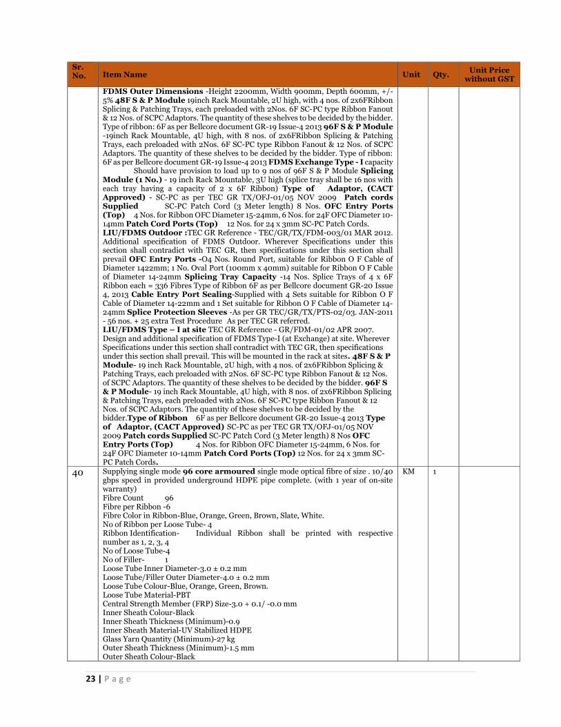
23 | P a g e
Sr. No. Item Name Unit Qty. Unit Price
without GST
FDMS Outer Dimensions -Height 2200mm, Width 900mm, Depth 600mm, +/- 5% 48F S & P Module 19inch Rack Mountable, 2U high, with 4 nos. of 2x6FRibbon Splicing & Patching Trays, each preloaded with 2Nos. 6F SC-PC type Ribbon Fanout & 12 Nos. of SCPC Adaptors. The quantity of these shelves to be decided by the bidder. Type of ribbon: 6F as per Bellcore document GR-19 Issue-4 2013 96F S & P Module -19inch Rack Mountable, 4U high, with 8 nos. of 2x6FRibbon Splicing & Patching Trays, each preloaded with 2Nos. 6F SC-PC type Ribbon Fanout & 12 Nos. of SCPC Adaptors. The quantity of these shelves to be decided by the bidder. Type of ribbon: 6F as per Bellcore document GR-19 Issue-4 2013 FDMS Exchange Type - I capacity Should have provision to load up to 9 nos of 96F S & P Module Splicing Module (1 No.) - 19 inch Rack Mountable, 3U high (splice tray shall be 16 nos with each tray having a capacity of 2 x 6F Ribbon) Type of Adaptor, (CACT Approved) - SC-PC as per TEC GR TX/OFJ-01/05 NOV 2009 Patch cords Supplied SC-PC Patch Cord (3 Meter length) 8 Nos. OFC Entry Ports (Top) 4 Nos. for Ribbon OFC Diameter 15-24mm, 6 Nos. for 24F OFC Diameter 10-14mm Patch Cord Ports (Top) 12 Nos. for 24 x 3mm SC-PC Patch Cords. LIU/FDMS Outdoor :TEC GR Reference - TEC/GR/TX/FDM-003/01 MAR 2012. Additional specification of FDMS Outdoor. Wherever Specifications under this section shall contradict with TEC GR, then specifications under this section shall prevail OFC Entry Ports -O4 Nos. Round Port, suitable for Ribbon O F Cable of Diameter 1422mm; 1 No. Oval Port (100mm x 40mm) suitable for Ribbon O F Cable of Diameter 14-24mm Splicing Tray Capacity -14 Nos. Splice Trays of 4 x 6F Ribbon each = 336 Fibres Type of Ribbon 6F as per Bellcore document GR-20 Issue 4, 2013 Cable Entry Port Sealing-Supplied with 4 Sets suitable for Ribbon O F Cable of Diameter 14-22mm and 1 Set suitable for Ribbon O F Cable of Diameter 14-24mm Splice Protection Sleeves -As per GR TEC/GR/TX/PTS-02/03. JAN-2011 - 56 nos. + 25 extra Test Procedure As per TEC GR referred. LIU/FDMS Type – I at site TEC GR Reference - GR/FDM-01/02 APR 2007. Design and additional specification of FDMS Type-I (at Exchange) at site. Wherever Specifications under this section shall contradict with TEC GR, then specifications under this section shall prevail. This will be mounted in the rack at sites. 48F S & P Module- 19 inch Rack Mountable, 2U high, with 4 nos. of 2x6FRibbon Splicing & Patching Trays, each preloaded with 2Nos. 6F SC-PC type Ribbon Fanout & 12 Nos. of SCPC Adaptors. The quantity of these shelves to be decided by the bidder. 96F S & P Module- 19 inch Rack Mountable, 4U high, with 8 nos. of 2x6FRibbon Splicing & Patching Trays, each preloaded with 2Nos. 6F SC-PC type Ribbon Fanout & 12 Nos. of SCPC Adaptors. The quantity of these shelves to be decided by the bidder.Type of Ribbon 6F as per Bellcore document GR-20 Issue-4 2013 Type of Adaptor, (CACT Approved) SC-PC as per TEC GR TX/OFJ-01/05 NOV 2009 Patch cords Supplied SC-PC Patch Cord (3 Meter length) 8 Nos OFC Entry Ports (Top) 4 Nos. for Ribbon OFC Diameter 15-24mm, 6 Nos. for 24F OFC Diameter 10-14mm Patch Cord Ports (Top) 12 Nos. for 24 x 3mm SC-PC Patch Cords.
40 Supplying single mode 96 core armoured single mode optical fibre of size . 10/40 gbps speed in provided underground HDPE pipe complete. (with 1 year of on-site warranty) Fibre Count 96 Fibre per Ribbon -6 Fibre Color in Ribbon-Blue, Orange, Green, Brown, Slate, White. No of Ribbon per Loose Tube- 4 Ribbon Identification- Individual Ribbon shall be printed with respective number as 1, 2, 3, 4 No of Loose Tube-4 No of Filler- 1 Loose Tube Inner Diameter-3.0 ± 0.2 mm Loose Tube/Filler Outer Diameter-4.0 ± 0.2 mm Loose Tube Colour-Blue, Orange, Green, Brown. Loose Tube Material-PBT Central Strength Member (FRP) Size-3.0 + 0.1/ -0.0 mm Inner Sheath Colour-Black Inner Sheath Thickness (Minimum)-0.9 Inner Sheath Material-UV Stabilized HDPE Glass Yarn Quantity (Minimum)-27 kg Outer Sheath Thickness (Minimum)-1.5 mm Outer Sheath Colour-Black
KM 1

24 | P a g e
Sr. No. Item Name Unit Qty. Unit Price
without GST
Outer Sheath Material-UV Stabilized HDPE Cable diameter 17.8 ± 1.0 mm Cable Weight-230 ± 8% kg/gm Maximum Tensile Strength- 3000N @ 0.25% Fibre Strain Minimum Bend Radius- 20 D, D is diameter of the cable Crush Resistance-2000N/10x10mm Kink-10 D, D is diameter of the cable Temperature Performance: -20ºC to +70ºC Fiber Type- ITU-T G.652D Maximum Cabled attenuation at 1310 nm: ≤ 0.36 Maximum Cabled attenuation at 1550 nm: ≤ 0.23 Maximum Cabled attenuation at 1625 nm: ≤ 0.26
41 Supplying single mode - 48 core armoured single mode optical fibre of size . 10/40 gbps speed in provided underground HDPE pipe complete. (with 1 year of on-site warranty) Fiber Count- 48 Fiber per Ribbon-6 Fiber Color in Ribbon-Blue, Orange, Green, Brown, Slate, White. No of Ribbon per Loose Tube-2 Ribbon Identification- Individual Ribbon shall be printed with respective number as 1, 2. No of Loose Tube-4 No of Filler-1 Loose Tube Inner Diameter (Minimum): 2.8 ± 0.2 mm Loose Tube/Filler Outer Diameter: 3.4 ± 0.2 mm Loose Tube Colour- Blue, Orange, Green, Brown. Loose Tube Material-PBT Central Strength Member (FRP) Size:2.5 + 0.1 / -0.0 Inner Sheath Colour: Black Inner Sheath Thickness(Minimum)-0.9 mm Inner Sheath Material-UV Stabilized HDPE Glass Yarn Quantity (Minimum)-27 kg Outer Sheath Thickness (Minimum)-1.5 mm Outer Sheath Colour-Black Outer Sheath Material-UV Stabilized HDPE Cable diameter-16.0 ± 1.0 mm Cable Weight-185 ± 8% kg Maximum Tensile Strength-3000N @ 0.25% Fibre Strain Minimum Bend Radius- 20 D, D is diameter of the cable Crush Resistance-2000N/10x10mm Kink-10 D, D is diameter of the cable Temperature Performance: -20ºC to +70ºC Fiber Type: ITU-T G.652D Maximum Cabled attenuation at 1310 nm: ≤ 0.36 Maximum Cabled attenuation at 1550 nm: ≤ 0.23 Maximum Cabled attenuation at 1625 nm: ≤ 0.26
KM 1
42 Supply Installation Testing and Commissioning of Blade Chassis along with cables and accessories Blade Chassis- Solution to house the Required number of blade servers in smallest number of enclosures Should support full height and half height blades in the same enclosure, occupying a max of 10U rack height Should support full height/width and half height/width blades in the same enclosure Should support 3 interconnect bays to configure N+N redundancy Should support redundant image storage device with failover and high-availability (for deploying O.S, hypervisors & Applications) Enclosure should support latest Intel Skylake processors based Blades Should support Auto-Discovery of resources in every Chassis Blade Chassis / Blade solution should provide display port and USB port to connect Laptop/Monitor locally Should support linking multiple enclosures together to provide single management pane/console to reduce complexity and provide single console of management for connected enclosures Interconnects Support-
Nos. 1
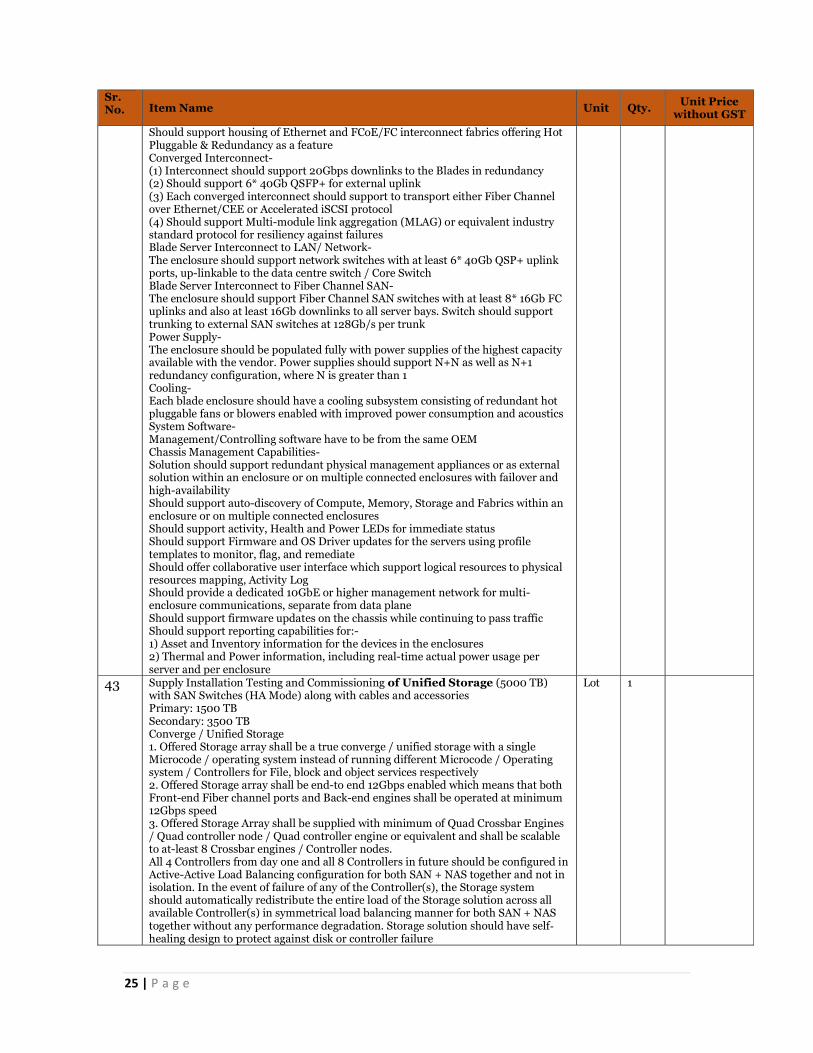
25 | P a g e
Sr. No. Item Name Unit Qty. Unit Price
without GST
Should support housing of Ethernet and FCoE/FC interconnect fabrics offering Hot Pluggable & Redundancy as a feature Converged Interconnect- (1) Interconnect should support 20Gbps downlinks to the Blades in redundancy (2) Should support 6* 40Gb QSFP+ for external uplink (3) Each converged interconnect should support to transport either Fiber Channel over Ethernet/CEE or Accelerated iSCSI protocol (4) Should support Multi-module link aggregation (MLAG) or equivalent industry standard protocol for resiliency against failures Blade Server Interconnect to LAN/ Network- The enclosure should support network switches with at least 6* 40Gb QSP+ uplink ports, up-linkable to the data centre switch / Core Switch Blade Server Interconnect to Fiber Channel SAN- The enclosure should support Fiber Channel SAN switches with at least 8* 16Gb FC uplinks and also at least 16Gb downlinks to all server bays. Switch should support trunking to external SAN switches at 128Gb/s per trunk Power Supply- The enclosure should be populated fully with power supplies of the highest capacity available with the vendor. Power supplies should support N+N as well as N+1 redundancy configuration, where N is greater than 1 Cooling- Each blade enclosure should have a cooling subsystem consisting of redundant hot pluggable fans or blowers enabled with improved power consumption and acoustics System Software- Management/Controlling software have to be from the same OEM Chassis Management Capabilities- Solution should support redundant physical management appliances or as external solution within an enclosure or on multiple connected enclosures with failover and high-availability Should support auto-discovery of Compute, Memory, Storage and Fabrics within an enclosure or on multiple connected enclosures Should support activity, Health and Power LEDs for immediate status Should support Firmware and OS Driver updates for the servers using profile templates to monitor, flag, and remediate Should offer collaborative user interface which support logical resources to physical resources mapping, Activity Log Should provide a dedicated 10GbE or higher management network for multi-enclosure communications, separate from data plane Should support firmware updates on the chassis while continuing to pass traffic Should support reporting capabilities for:- 1) Asset and Inventory information for the devices in the enclosures 2) Thermal and Power information, including real-time actual power usage per server and per enclosure
43 Supply Installation Testing and Commissioning of Unified Storage (5000 TB) with SAN Switches (HA Mode) along with cables and accessories Primary: 1500 TB Secondary: 3500 TB Converge / Unified Storage 1. Offered Storage array shall be a true converge / unified storage with a single Microcode / operating system instead of running different Microcode / Operating system / Controllers for File, block and object services respectively 2. Offered Storage array shall be end-to end 12Gbps enabled which means that both Front-end Fiber channel ports and Back-end engines shall be operated at minimum 12Gbps speed 3. Offered Storage Array shall be supplied with minimum of Quad Crossbar Engines / Quad controller node / Quad controller engine or equivalent and shall be scalable to at-least 8 Crossbar engines / Controller nodes. All 4 Controllers from day one and all 8 Controllers in future should be configured in Active-Active Load Balancing configuration for both SAN + NAS together and not in isolation. In the event of failure of any of the Controller(s), the Storage system should automatically redistribute the entire load of the Storage solution across all available Controller(s) in symmetrical load balancing manner for both SAN + NAS together without any performance degradation. Storage solution should have self‐healing design to protect against disk or controller failure
Lot 1

26 | P a g e
Sr. No. Item Name Unit Qty. Unit Price
without GST
4. Only Modular or Monolithic architecture shall be offered. In case of Modular architecture, only tightly coupled clustered storage implying integrated physical backplane or switching fabric or internal bus (into which different storage controllers are connected) would be considered Operating System & Clustering Support The storage array should support industry-leading Operating System platforms including: Windows Server 2012 / 2016, VMware, IBM-AIX & HPE-UX etc. Data Availability The Storage system should guarantee and deliver (6-Nines) 99.9999% Data Availability Capacity & Scalability 1. The Storage Array shall be offered with 5000 TB usable capacity (with inbuilt/external single namespace for NAS) in RAID 6 using 7.2K RPM SAS/NL-SAS drives or better for Video Data and 500 TB usable capacity in RAID 6 using 10K RPM SAS drives or better for Application Data. All offered Drives should be FIPS encrypted HDDs only with Level-2 encryption 2. Offered Array shall be scalable to more than 9PB of raw capacity using the same combination of drives used from day one Cache 1. Offered Storage Array shall be given with at-least 1.5TB DRAM cache in a Single Array for both Data and control operations and shall be scalable to 3TB DRAM Cache or more. Vendors to submit detailed configuration and bill of material depicting Controllers/Nodes, Controller Cache, Flash Cache calculations, Hard Drives calculations etc. along with the bid 2. Cache shall be used only for Data and Control information. OS overhead shall not be done inside cache. In case the vendor doesn't support the functionality of no OS overhead inside the Controller Cache, then additional 1TB DRAM Cache across Controllers should be provided from day one 3. Offered Storage shall also be offered with additional 20TB usable Flash cache using SSD / Flash drives in Raid 1+0 and shall be scalable to more than 40TB Flash cache 4. If Flash cache is not supported inside the storage array then vendor shall supply the storage array with at-least 8TB of DRAM cache from day one Processing Power 1. Offered Storage architecture shall be based on purpose-built technology such as ASIC / XOR etc. wherein there shall be no load on the storage CPU during RAID Parity calculations. Vendors shall provide the documentary proof for same along with the bid 2. In case vendor doesn’t have above functionality of no load on Storage CPU during RAID parity calculations then additional 1TB DRAM Cache shall be supplied for read and write operations to balance out the performance Architecture & Processing Power Offered Storage array shall be true active-active so that a single logical unit can be shared across all offered controllers in symmetrical fashion, while supporting all the major functionalities like Thin Provisioning, Data Tiering etc. No Single point of Failure Offered Storage Array shall be configurable in a No Single Point of failure including Array Controller card, Cache memory, FAN, Power supply etc. Disk Drive Support 1. The storage array should support dual-ported 300GB / 600GB / 1200GB / 1800GB or higher hot-pluggable Enterprise SAS, 400GB or higher SSD and SAS - NL of 2TB / 4TB / 6TB / 8TB or higher drives 2. Offered Storage array shall be truly optimized for flash operations and shall support Solid State disks / Flash disks Raid Support & Virtualization 1. Offered Storage Subsystem shall support RAID 1 (mirroring), RAID 5 (single parity) and RAID 6 (dual parity) 2. Offered storage array shall have native virtualization support so that RAID 1 (mirroring), RAID 5 (single parity) and RAID 6 (dual parity) can be carved out from a logical space instead of dedicating separate physical disks for each application 3. Every supplied disk shall be able to participate into multiple and different RAID sets simultaneously 4. In case vendor does not have this functionality of every HDDs participating into multiple & different RAID sets simultaneously, then 25% additional raw capacity shall be provided for each type of disk to balance out the capacity utilization. Vendors to submit Disk & Capacity Sizing Calculation and Effective Storage Capacity available calculations at the time of bid Data Protection In case of Power failure, Storage array shall have de-stage feature to avoid any data loss
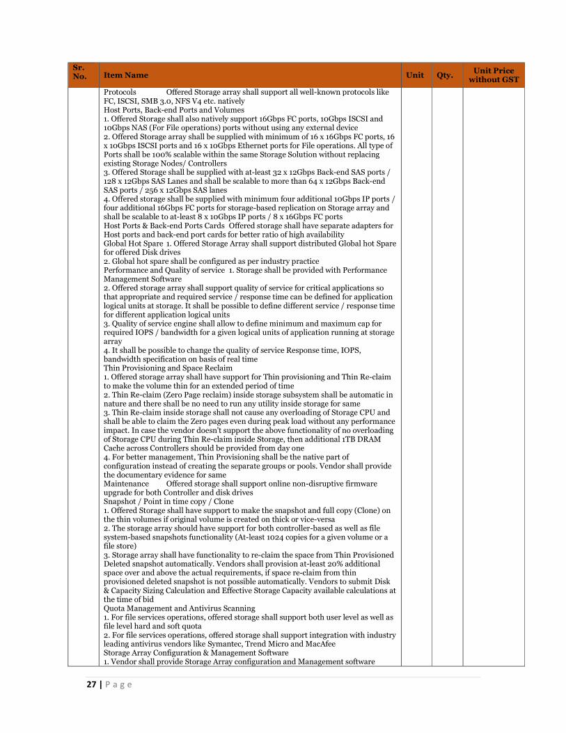
27 | P a g e
Sr. No. Item Name Unit Qty. Unit Price
without GST
Protocols Offered Storage array shall support all well-known protocols like FC, ISCSI, SMB 3.0, NFS V4 etc. natively Host Ports, Back-end Ports and Volumes 1. Offered Storage shall also natively support 16Gbps FC ports, 10Gbps ISCSI and 10Gbps NAS (For File operations) ports without using any external device 2. Offered Storage array shall be supplied with minimum of 16 x 16Gbps FC ports, 16 x 10Gbps ISCSI ports and 16 x 10Gbps Ethernet ports for File operations. All type of Ports shall be 100% scalable within the same Storage Solution without replacing existing Storage Nodes/ Controllers 3. Offered Storage shall be supplied with at-least 32 x 12Gbps Back-end SAS ports / 128 x 12Gbps SAS Lanes and shall be scalable to more than 64 x 12Gbps Back-end SAS ports / 256 x 12Gbps SAS lanes 4. Offered storage shall be supplied with minimum four additional 10Gbps IP ports / four additional 16Gbps FC ports for storage-based replication on Storage array and shall be scalable to at-least 8 x 10Gbps IP ports / 8 x 16Gbps FC ports Host Ports & Back-end Ports Cards Offered storage shall have separate adapters for Host ports and back-end port cards for better ratio of high availability Global Hot Spare 1. Offered Storage Array shall support distributed Global hot Spare for offered Disk drives 2. Global hot spare shall be configured as per industry practice Performance and Quality of service 1. Storage shall be provided with Performance Management Software 2. Offered storage array shall support quality of service for critical applications so that appropriate and required service / response time can be defined for application logical units at storage. It shall be possible to define different service / response time for different application logical units 3. Quality of service engine shall allow to define minimum and maximum cap for required IOPS / bandwidth for a given logical units of application running at storage array 4. It shall be possible to change the quality of service Response time, IOPS, bandwidth specification on basis of real time Thin Provisioning and Space Reclaim 1. Offered storage array shall have support for Thin provisioning and Thin Re-claim to make the volume thin for an extended period of time 2. Thin Re-claim (Zero Page reclaim) inside storage subsystem shall be automatic in nature and there shall be no need to run any utility inside storage for same 3. Thin Re-claim inside storage shall not cause any overloading of Storage CPU and shall be able to claim the Zero pages even during peak load without any performance impact. In case the vendor doesn't support the above functionality of no overloading of Storage CPU during Thin Re-claim inside Storage, then additional 1TB DRAM Cache across Controllers should be provided from day one 4. For better management, Thin Provisioning shall be the native part of configuration instead of creating the separate groups or pools. Vendor shall provide the documentary evidence for same Maintenance Offered storage shall support online non-disruptive firmware upgrade for both Controller and disk drives Snapshot / Point in time copy / Clone 1. Offered Storage shall have support to make the snapshot and full copy (Clone) on the thin volumes if original volume is created on thick or vice-versa 2. The storage array should have support for both controller-based as well as file system-based snapshots functionality (At-least 1024 copies for a given volume or a file store) 3. Storage array shall have functionality to re-claim the space from Thin Provisioned Deleted snapshot automatically. Vendors shall provision at-least 20% additional space over and above the actual requirements, if space re-claim from thin provisioned deleted snapshot is not possible automatically. Vendors to submit Disk & Capacity Sizing Calculation and Effective Storage Capacity available calculations at the time of bid Quota Management and Antivirus Scanning 1. For file services operations, offered storage shall support both user level as well as file level hard and soft quota 2. For file services operations, offered storage shall support integration with industry leading antivirus vendors like Symantec, Trend Micro and MacAfee Storage Array Configuration & Management Software 1. Vendor shall provide Storage Array configuration and Management software
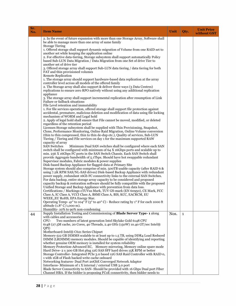
28 | P a g e
Sr. No. Item Name Unit Qty. Unit Price
without GST
2. In the event of future expansion with more than one Storage Array, Software shall be able to manage more than one array of same family Storage Tiering 1. Offered storage shall support dynamic migration of Volume from one RAID set to another set while keeping the application online 2. For effective data-tiering, Storage subsystem shall support automatically Policy based Sub-LUN Data Migration / Data Migration from one Set of drive Tier to another set of drive tier 3. Offered storage array shall support Sub-LUN data tiering / data tiering for both FAT and thin provisioned volumes Remote Replication 1. The storage array should support hardware-based data replication at the array controller level across all models of the offered family 2. The Storage array shall also support & deliver three ways (3 Data Centres) replications to ensure zero RPO natively without using any additional replication appliance 3. The storage array shall support incremental replication after resumption of Link Failure or failback situations File Level retention and immutability 1. For file services operation, offered storage shall support file protection against accidental, premature, malicious deletion and modification of data using file locking mechanism of WORM and Legal hold 2. Apply of legal hold shall ensure that File cannot be moved, modified, or deleted regardless of the retention period Licenses Storage subsystem shall be supplied with Thin Provisioning, Snapshot, Clone, Performance Monitoring, Online Raid Migration, Online Volume conversion (thin to thin compressed, thin to thin de-dup etc.), Quality of services, Sub-LUN Tiering / Tiering and File services on day 1 for the maximum supported RAW capacity of array SAN Switches Minimum Dual SAN switches shall be configured where each SAN switch shall be configured with minimum of 64 X 16Gbps ports and scalable up to min. 256 X 16Gbps FC ports in the SAN Switch Chassis. Each SAN Switch shall provide Aggregate bandwidth of 5.1Tbps. Should have hot swappable redundant Supervisor modules, Fabric modules & power supplies Disk-based Backup Appliance for flagged-data at Primary Site Storage system should also comprise of min. 500TB usable capacity (after RAID 6 & using 7.2K RPM SAS/NL-SAS drives) Disk-based Backup Appliance with redundant power supply, redundant 16Gb FC connectivity links to the external SAN Switches. For data backup, entire storage array capacity to be considered and proposed capacity backup & restoration software should be fully compatible with the proposed Unified Storage and Backup Appliance with prevention from data loss. Certifications / Markings-cTUVus Mark, TUV GS-mark (EN 60950), CE Mark, FCC Class A, IC Class A, VCCI Class A, BSMI Class A, BIS, KCC, EACRCM, EU WEEE,,EU RoHS, EPA Energy Star. Operating Temp- 41° to 104° F (5° to 40° C) - Reduce rating by 1° F for each 1000 ft altitude (1.8° C/1,000 m). Humidity- 10% to 90% non-condensing
44 Supply Installation Testing and Commissioning of Blade Server Type- 1 along with cables and accessories CPU- Two numbers of latest generation Intel Skylake Gold 6148 CPU 6148 (27.5M cache, 20 Cores, 40 Threads, 2.40 GHz (150W) 10.40 GT/sec Intel® QPI) Motherboard-Intel® C621 Series Chipset Memory-512 GB DIMMS scalable to at least up to 1.5 TB, using DDR4 Load Reduced DIMM (LRDIMM) memory modules. Should be capable of identifying and reporting whether genuine OEM memory is installed for system reliability Memory Protection-Advanced EC, Memory mirroring, Memory online spare mode Hard Drive- 2 x 300 GB Hot plug 12G SAS SFF hard drives 15K RPM or better Storage Controller- Integrated PCIe 3.0 based 12G SAS Raid Controller with RAID 0, 1 with 1GB of Flash backed write cache onboard Networking features- Dual Port 20GbE Converged Network Adaptor Interfaces- Minimum of 1 X internal / external USB 3.0 port Blade Server Connectivity to SAN- Should be provided with 16 Gbps Dual port Fiber Channel HBA. If the bidder is proposing FCoE connectivity, then bidder needs to
Nos. 1

29 | P a g e
Sr. No. Item Name Unit Qty. Unit Price
without GST
provide 2 X 20G FCoE HBA/ports in place of Dual-port 16Gbps FC HBA over and above Dual port 20GbE Converged Network Adaptor Bus Slots- Minimum of 2 Nos. or more of x16 PCIe 3.0 based mezzanine slots supporting Ethernet & FC adapters/Converged Ethernet adapters Graphics- Integrated G200eh Video Controller OS Support- Microsoft Windows Server latest version Red Hat Enterprise Linux (RHEL) latest version SUSE Linux Enterprise Server (SLES) latest version Vmware latest version Antivirus- To be provided along with 3rd party Anti-Malware, HIPS, Integrity monitoring, Log Inspection providing complete protection for Physical Servers and Virtual Machines. Certifications / Markings-cTUVus Mark, TUV GS-mark (EN 60950), CE Mark, FCC Class A, IC Class A, VCCI Class A, BSMI Class A, BIS, KCC, EACRCM, EU WEEE,,EU RoHS, EPA Energy Star. Operating Temperature : 10°C to 35°C (50°F to 95°F) Humidity: 10% to 90% @ 28C (82.4F)
45 Supply Installation Testing and Commissioning of Blade Server Type- 2 along with cables and accessories Category- Minimum Requirement Specifications CPU- Four numbers of latest generation Intel Skylake Platinum 8180M CPU 8180M (38.5M cache, 28 Cores, 56 Threads, 2.50 GHz (205W) 10.40 GT/sec Intel® QPI) Motherboard- Intel® C621 Series Chipset Memory- 1.5TB DIMMS scalable to at least up to 4.5 TB, using 128GB DDR4 Load Reduced DIMM (LRDIMM) memory modules. Should be capable of identifying and reporting whether genuine OEM memory is installed for system reliability Memory Protection- Advanced ECC, Memory mirroring, Memory online spare mode Hard Drive- 4 x 3.2TB Hot plug Mixed Use SFF SSD drives or better Storage Controller- Integrated PCIe 3.0 based 12G SAS Raid Controller with RAID 0, 1 with 1GB of Flash backed write cache onboard Networking features- 2 x Dual Port 20GbE Converged Network Adaptor Interfaces- Minimum of 1 X internal / external USB 3.0 port Blade Server Connectivity to SAN- Should be provided with 2 x 16 Gbps Dual port Fiber Channel HBA. If the bidder is proposing FCoE connectivity, then bidder needs to provide 4 X 20G FCoE HBA/ports in place of 2 x Dual-port 16Gbps FC HBA over and above 2 x Dual port 20GbE Converged Network Adaptor Bus Slots- Minimum of 2 Nos. or more of x16 PCIe 3.0 based mezzanine slots supporting Ethernet & FC adapters/Converged Ethernet adapters Graphics- Integrated G200eh Video Controller OS Support- Microsoft Windows Server latest version Red Hat Enterprise Linux (RHEL) latest version SUSE Linux Enterprise Server (SLES) latest version Vmware latest version Antivirus- To be provided along with 3rd party Anti-Malware, HIPS, Integrity monitoring, Log Inspection providing complete protection for Physical Servers and Virtual Machines Certifications / Markings-cTUVus Mark, TUV GS-mark (EN 60950), CE Mark, FCC Class A, IC Class A, VCCI Class A, BSMI Class A, BIS, KCC, EACRCM, EU WEEE,,EU RoHS, EPA Energy Star. Operating Temperature : 10°C to 35°C (50°F to 95°F) Humidity: 10% to 90% @ 28C (82.4F)
Nos. 1
46 Supply Installation Testing and Commissioning of Blade Server Type- 3 along with cables and accessories CPU-Two numbers of latest generation Intel Skylake Platinum 8168 CPU 8168 (33M cache, 24 Cores, 48 Threads, 2.70 GHz (205W) 10.40 GT/sec Intel® QPI) Motherboard- Intel® C621 Series Chipset Memory- 512 GB DIMMS scalable to at least up to 1.5 TB, using DDR4 Load Reduced DIMM (LRDIMM) memory modules. Should be capable of identifying and reporting whether genuine OEM memory is installed for system reliability Memory Protection- Advanced ECC, Memory mirroring, Memory online spare mode Hard Drive- 2 x 900 GB Hot plug 12G SAS SFF hard drives 15K RPM or better Storage Controller- Integrated PCIe 3.0 based 12G SAS Raid Controller with RAID 0, 1 with 1GB of Flash backed write cache onboard
Nos. 1
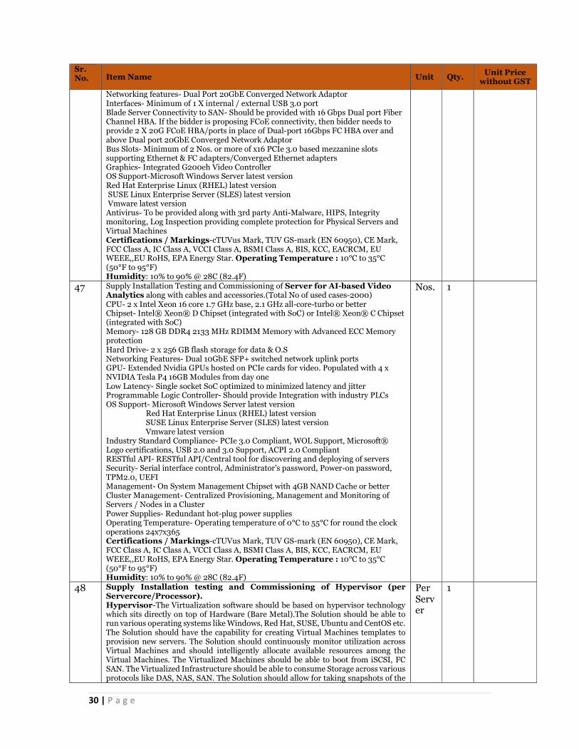
30 | P a g e
Sr. No. Item Name Unit Qty. Unit Price
without GST
Networking features- Dual Port 20GbE Converged Network Adaptor Interfaces- Minimum of 1 X internal / external USB 3.0 port Blade Server Connectivity to SAN- Should be provided with 16 Gbps Dual port Fiber Channel HBA. If the bidder is proposing FCoE connectivity, then bidder needs to provide 2 X 20G FCoE HBA/ports in place of Dual-port 16Gbps FC HBA over and above Dual port 20GbE Converged Network Adaptor Bus Slots- Minimum of 2 Nos. or more of x16 PCIe 3.0 based mezzanine slots supporting Ethernet & FC adapters/Converged Ethernet adapters Graphics- Integrated G200eh Video Controller OS Support-Microsoft Windows Server latest version Red Hat Enterprise Linux (RHEL) latest version SUSE Linux Enterprise Server (SLES) latest version Vmware latest version Antivirus- To be provided along with 3rd party Anti-Malware, HIPS, Integrity monitoring, Log Inspection providing complete protection for Physical Servers and Virtual Machines Certifications / Markings-cTUVus Mark, TUV GS-mark (EN 60950), CE Mark, FCC Class A, IC Class A, VCCI Class A, BSMI Class A, BIS, KCC, EACRCM, EU WEEE,,EU RoHS, EPA Energy Star. Operating Temperature : 10°C to 35°C (50°F to 95°F) Humidity: 10% to 90% @ 28C (82.4F)
47 Supply Installation Testing and Commissioning of Server for AI-based Video Analytics along with cables and accessories.(Total No of used cases-2000) CPU- 2 x Intel Xeon 16 core 1.7 GHz base, 2.1 GHz all-core-turbo or better Chipset- Intel® Xeon® D Chipset (integrated with SoC) or Intel® Xeon® C Chipset (integrated with SoC) Memory- 128 GB DDR4 2133 MHz RDIMM Memory with Advanced ECC Memory protection Hard Drive- 2 x 256 GB flash storage for data & O.S Networking Features- Dual 10GbE SFP+ switched network uplink ports GPU- Extended Nvidia GPUs hosted on PCIe cards for video. Populated with 4 x NVIDIA Tesla P4 16GB Modules from day one Low Latency- Single socket SoC optimized to minimized latency and jitter Programmable Logic Controller- Should provide Integration with industry PLCs OS Support- Microsoft Windows Server latest version Red Hat Enterprise Linux (RHEL) latest version SUSE Linux Enterprise Server (SLES) latest version Vmware latest version Industry Standard Compliance- PCIe 3.0 Compliant, WOL Support, Microsoft® Logo certifications, USB 2.0 and 3.0 Support, ACPI 2.0 Compliant RESTful API- RESTful API/Central tool for discovering and deploying of servers Security- Serial interface control, Administrator's password, Power-on password, TPM2.0, UEFI Management- On System Management Chipset with 4GB NAND Cache or better Cluster Management- Centralized Provisioning, Management and Monitoring of Servers / Nodes in a Cluster Power Supplies- Redundant hot-plug power supplies Operating Temperature- Operating temperature of 0°C to 55°C for round the clock operations 24x7x365 Certifications / Markings-cTUVus Mark, TUV GS-mark (EN 60950), CE Mark, FCC Class A, IC Class A, VCCI Class A, BSMI Class A, BIS, KCC, EACRCM, EU WEEE,,EU RoHS, EPA Energy Star. Operating Temperature : 10°C to 35°C (50°F to 95°F) Humidity: 10% to 90% @ 28C (82.4F)
Nos. 1
48 Supply Installation testing and Commissioning of Hypervisor (per Servercore/Processor). Hypervisor-The Virtualization software should be based on hypervisor technology which sits directly on top of Hardware (Bare Metal).The Solution should be able to run various operating systems like Windows, Red Hat, SUSE, Ubuntu and CentOS etc. The Solution should have the capability for creating Virtual Machines templates to provision new servers. The Solution should continuously monitor utilization across Virtual Machines and should intelligently allocate available resources among the Virtual Machines. The Virtualized Machines should be able to boot from iSCSI, FC SAN. The Virtualized Infrastructure should be able to consume Storage across various protocols like DAS, NAS, SAN. The Solution should allow for taking snapshots of the
Per Server
1

31 | P a g e
Sr. No. Item Name Unit Qty. Unit Price
without GST
Virtual Machines to be able to roll back to an older state, if required. The Solution should be able to dynamically allocate and balance computing capacity across collections of hardware resources of one physical box aggregated into one unified resource pool.The Solution should cater for the fact that if one server fails all the resources running on that server shall be able to migrate to another set of virtual servers as available. The Solution should provide support for cluster services between Virtual Machines. Virtualization software should provide secure boot for protection for both the hypervisor and guest operating system by ensuring images have not been tampered with and preventing loading of unauthorized components. The Solution should provide a virtualization layer that resides between the bare metal server hardware and guest OS for greater reliability and security. The Hypervisor should support the memory page sharing. The Solution should deliver above listed Hypervisor capabilities using standard server infrastructure supporting Intel/AMD OEMs. The Solution should provide unstructured data analytics, machine learning and predictive analytics. The Solution should constantly monitor and report underlying server health and should migrate the VMs from servers before occurrence of an issue to other healthy hosts/servers. The Solution should constantly monitor and report underlying server health and should migrate the VMs from servers before occurrence of an issue to other healthy hosts/servers. Compute-The Software should have the capability to create Virtual Machines with required number of vCPUs. The Software should have the capability to provide uninterrupted application availability upto failure of 4 vCPUs without any data loss or downtime Storage The Solution should also integrate with FC, FCoE and iSCSI SAN and infrastructure from leading Vendors so as to leverage high performance shared storage to centralize Virtual Machine file storage for greater manageability, flexibility and availability. The Software should improve Storage Quality of Service by mitigating Storage I/O contention between VMs in the environment and should be able to ensure & provide pre-defined I/O share levels to enhance Storage performance on FC & iSCSI Storage. Network-The Solution should allow configuring each Virtual Machine with one or more virtual NICs. Each of those network interfaces can have its own IP address and even its own MAC address. The Solution should support configurations of 802.1 q VLANs which are compatible with standard VLAN implementations from other vendors. The solution should take advantage of NIC Teaming Capabilities. Virtualization Manager-Virtualization administrator portal provides a graphical management system for administrators to manage virtual machines, templates, desktops, storage, clusters, and datacentres. Should provide Tree-view for hierarchical management of the Enterprise Virtualization environment. Should have enhanced query engine for searching for Enterprise Virtualization objects. Management Features-Single-view for centralized control of Host and VM system monitoring and management. No single point of failure for high availability: Enterprise Virtualization Manager can be configured for high availability. Maintenance Mode: Hosts undergoing maintenance automatically have their Guest VMs migrated to other available hosts. High availability for enterprise management module: Automatic fail over to standby management server in the event of failure to primary. Thin provisioning: Virtual disks do not take up all of their allowed space upon creation. Templates: Virtual machines can be deployed from master installations. Import/Export of VMs in the standard OVF format. Self-service user portal: Provides administrative access to users for creating/running VMs and managing environment. Add CPU, Memory & devices to virtual machines on the fly when needed, without disruption or downtime of working VMs for both windows and Linux based VMs. System scheduler: Cluster policies to automatically distribute workload evenly across cluster host servers. API: Programmatic access to all management commands. Availability-Zero downtime, Zero data loss and continuous availability for the applications running in virtual machines in the event of physical host failure, without the cost and complexity of traditional hardware or software clustering solutions.Live Virtual Machine migration between different generations of CPUs in the same cluster with and without the need for shared storage option and long distances from one site to another (up to 150 milliseconds round trip time) with no disruption to users or loss of services, eliminating the need to schedule application downtime or business downtime. Network and Security Virtualization Hypervisor-Solution should provide agentless deployment of Antivirus, HIPS so that there is no requirement of installing agent inside every Virtual Machine, thereby reducing the need for scanning and signature patching on every VM. The security policies should follow the Virtual Machines as they move within and across the virtual

32 | P a g e
Sr. No. Item Name Unit Qty. Unit Price
without GST
infrastructure so that there is no need of creation of security policies again for the applications once they move inside the datacenter. Solution should enable creation of security groups and security policies/ rules based on constructs like machine name, OS type, IP address, Logical Switches, Security Tags etc. Solution should be integrated with proposed virtualization solution so that it should allow for automated and on-demand creation of security policies which is scalable in nature. Solution should enable integration of third-party network and security solutions through open architecture and standard APIs. The bidder shall provide a list of ecosystem vendors that integrate with the framework. Solution should have Built-in Security for Inter-VM data consistency. The Solution should be capable of routing the data packets from one VM to other VM scattered across the Compute stack without resending (to & fro) the requests to Application Load Balancer, Firewall, IPS/IDS etc. for each connected event. The Solution should have the capability to identify and quarantine a single VM in the event of VM's security had been compromised without impacting any other VM's running on the same physical server.
49 Supply Installation Testing and Commissioning of Antivirus Solution (Perpetual License) per server Shall be able to scan through several types of compression Formats. Must update itself over internet for virus definitions, program updates etc. (periodically as well as in push-updates in case of outbreaks) Shall be able to scan only those file types which are potential virus carriers (based on true file type) Shall be able to scan for HTML, VBScript Viruses, malicious applets and ActiveX controls Shall provide Real-time product Performance Monitor and 6Built-in Debug and Diagnostic tools, and context- sensitive Shall provide for virus notification options for Virus Outbreak Alert and other configurable Conditional Notification. Should be capable of providing multiple layers of defence Shall have facility to clean, delete and quarantine the virus affected files. Should support scanning for ZIP, RAR compressed files, and TAR archive files Should support online update, whereby most product updates and patches can be performed without bringing messaging server off-line. Should use multiple scan engines during the scanning process Should support in-memory scanning to minimize Disk IO. Should support Multi-threaded scanning Should support scanning of nested compressed files Should support heuristic scanning to allow rule-based detection of unknown viruses Updates to the scan engines should be automated and should not require manual intervention All binaries from the vendor that are downloaded and distributed must be signed and the signature verified during runtime for enhanced security Should support various types of reporting Formats such as CSV, HTML and text files
Per server
1
50 Supply Installation Testing and Commissioning of Enterprise Management System (Perpetual License) for 100 IOT/IP devices (like Camera, Edge devices, LPU etc) General Attributes Bidder is expected to provide EMS encompassing but not limited to the following functions: Configuration Management Fault Management Incident, Problem and Change Management Asset Management Remote Control SLA Management & Monitoring Performance Management Event Management Server, Storage and other Infrastructure Management Monitor network components of the LAN & WAN Network Link Monitoring Any other modules as required by SI to meet the requirements of the RFP
Per lot
1

33 | P a g e
Sr. No. Item Name Unit Qty. Unit Price
without GST
Note: It is mandatory that all the modules for the proposed EMS Solution shall provide out-of-the-box and seamless integration capabilities. Bidder shall provide the specifications and numbers for all necessary Hardware, OS & DB (if any) which is required for an EMS to operate effectively and provide the same at no extra cost General Attributes-The EMS system shall provide for the regular monitoring, management and reporting of the ICT infrastructure of the project assets installed in the respective operations centre as well as field locations. It shall be noted that the activities performed by the Bidder shall be under the supervision of PCMC. The EMS system shall have the following features including but not limited to and as well act as authoritative source for the same: General Attributes Following functionalities are essential and required from such EMS tools: Availability Monitoring, Management and Reporting Performance Monitoring, Management and Reporting Helpdesk Monitoring, Management and Reporting Traffic Analysis Asset Management Incident Management and RCA reporting Change and Configuration management Discovery, Configuration and Faults The proposed system shall support multiple types of discovery like IP range discovery – including built-in support for IPv6, Seed router based discovery and discovery whenever new devices are added with capability to exclude specific devices Monitoring and Management Discovery, Configuration and Faults The proposed system shall support exclusion of specific IP addresses or IP address ranges Monitoring and Management Discovery, Configuration and Faults The system shall provide discovery & inventory of physical network devices like Layer-2 & Layer-3 switches, Routers and other IP devices and shall provide mapping of LAN & WAN connectivity Monitoring and Management Discovery, Configuration and Faults The discovery shall be able to identify and model of the ICT asset Monitoring and Management Discovery, Configuration and Faults The proposed system shall provide a detailed asset report, organized by Bidder’s name and device, listing all ports for all devices. The proposed system shall provide sufficient reports that identify unused ports in the managed network infrastructure that can be reclaimed and reallocated Monitoring and Management Discovery, Configuration and Faults The proposed system shall determine device availability and shall exclude outages from the availability calculation with an option to indicate the reason Monitoring and Management Discovery, Configuration and Faults The proposed system shall provide out of the box root cause analysis Monitoring and Management Discovery, Configuration and Faults The proposed system shall include the ability to monitor and visualize a virtualized system infrastructure by discovering and monitoring virtual machines and providing ability to depict the logical relationships between virtual servers and virtual machines Monitoring and Management Discovery, Configuration and Faults The proposed solution shall detect virtual server and virtual machine configuration changes and automatically update topology and shall raise alarm when VM migrations happen between hosts Monitoring and Management Discovery, Configuration and Faults The proposed solution shall have the ability to collect data from the virtual systems without solely relying on SNMP Monitoring and Management Discovery, Configuration and Faults The proposed solution shall support an architecture that can be extended to support multiple virtualization platforms and technologies Monitoring and Management
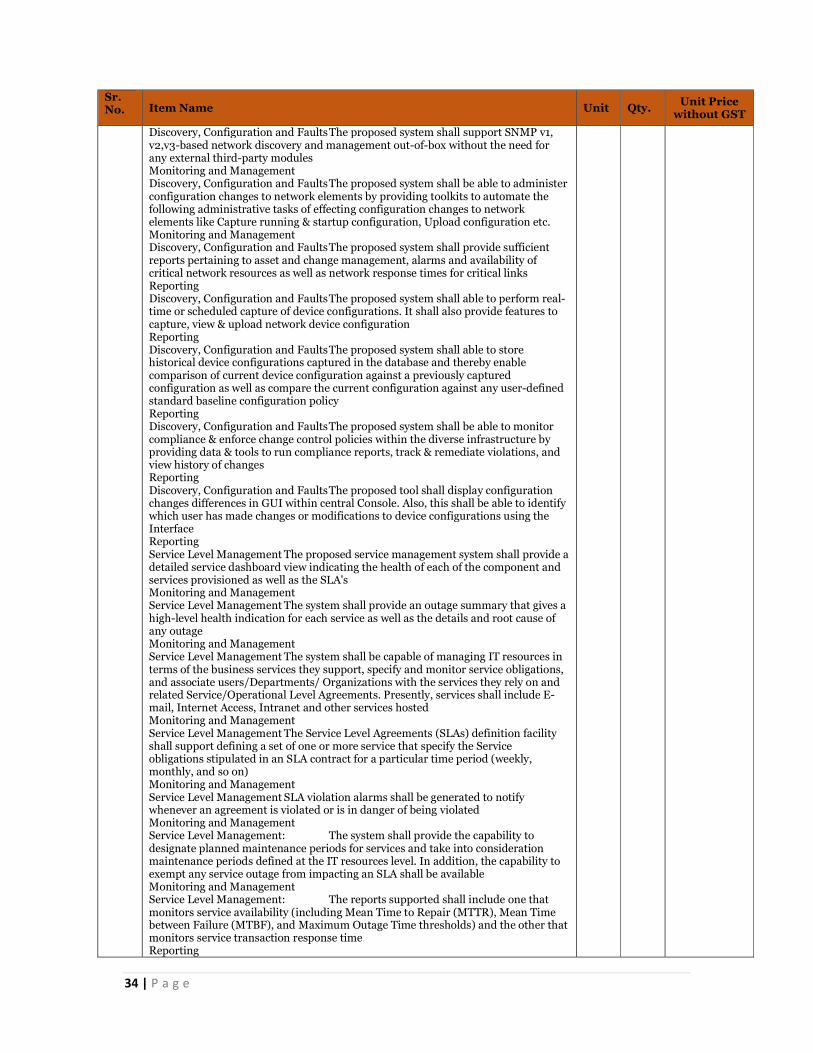
34 | P a g e
Sr. No. Item Name Unit Qty. Unit Price
without GST
Discovery, Configuration and Faults The proposed system shall support SNMP v1, v2,v3-based network discovery and management out-of-box without the need for any external third-party modules Monitoring and Management Discovery, Configuration and Faults The proposed system shall be able to administer configuration changes to network elements by providing toolkits to automate the following administrative tasks of effecting configuration changes to network elements like Capture running & startup configuration, Upload configuration etc. Monitoring and Management Discovery, Configuration and Faults The proposed system shall provide sufficient reports pertaining to asset and change management, alarms and availability of critical network resources as well as network response times for critical links Reporting Discovery, Configuration and Faults The proposed system shall able to perform real-time or scheduled capture of device configurations. It shall also provide features to capture, view & upload network device configuration Reporting Discovery, Configuration and Faults The proposed system shall able to store historical device configurations captured in the database and thereby enable comparison of current device configuration against a previously captured configuration as well as compare the current configuration against any user-defined standard baseline configuration policy Reporting Discovery, Configuration and Faults The proposed system shall be able to monitor compliance & enforce change control policies within the diverse infrastructure by providing data & tools to run compliance reports, track & remediate violations, and view history of changes Reporting Discovery, Configuration and Faults The proposed tool shall display configuration changes differences in GUI within central Console. Also, this shall be able to identify which user has made changes or modifications to device configurations using the Interface Reporting Service Level Management The proposed service management system shall provide a detailed service dashboard view indicating the health of each of the component and services provisioned as well as the SLA's Monitoring and Management Service Level Management The system shall provide an outage summary that gives a high-level health indication for each service as well as the details and root cause of any outage Monitoring and Management Service Level Management The system shall be capable of managing IT resources in terms of the business services they support, specify and monitor service obligations, and associate users/Departments/ Organizations with the services they rely on and related Service/Operational Level Agreements. Presently, services shall include E-mail, Internet Access, Intranet and other services hosted Monitoring and Management Service Level Management The Service Level Agreements (SLAs) definition facility shall support defining a set of one or more service that specify the Service obligations stipulated in an SLA contract for a particular time period (weekly, monthly, and so on) Monitoring and Management Service Level Management SLA violation alarms shall be generated to notify whenever an agreement is violated or is in danger of being violated Monitoring and Management Service Level Management: The system shall provide the capability to designate planned maintenance periods for services and take into consideration maintenance periods defined at the IT resources level. In addition, the capability to exempt any service outage from impacting an SLA shall be available Monitoring and Management Service Level Management: The reports supported shall include one that monitors service availability (including Mean Time to Repair (MTTR), Mean Time between Failure (MTBF), and Maximum Outage Time thresholds) and the other that monitors service transaction response time Reporting

35 | P a g e
Sr. No. Item Name Unit Qty. Unit Price
without GST
Service Level Management: The system shall provide a historical reporting facility that shall allow for the generation of on-demand and scheduled reports of Service related metrics with capabilities for customization of the report presentation Reporting Service Level Management: The system shall provide for defining service policies like Service Condition High\Low Sensitivity, Port Status High\Low Sensitivity shall be provided out of the box Reporting Service Level Management The system shall display option on Services, Customer, SLA’s, SLA templates Reporting Performance - Monitoring, Management and Reporting The proposed performance management system shall integrate network, server and database performance information and alarms in a single console and provide a unified reporting interface for network components Network Performance Monitoring, Management and Reporting: The System shall have all the capabilities of a Network Management System which shall provide Real time network monitoring and Measurement offend-to-end Network performance & availability to define service levels and further improve upon them Monitoring and Management Network Performance Monitoring, Management and Reporting: The tool shall provide a live exceptions list displaying the various health and threshold exceptions that are occurring in the managed infrastructure Monitoring and Management Network Performance Monitoring, Management and Reporting: The tool shall have the capability to configure different polling speeds for different devices in the managed infrastructure with capability to poll critical devices Monitoring and Management Network Performance Monitoring, Management and Reporting: The proposed system shall use intelligent alarm algorithms to learn the behavior of the network infrastructure components over a period of time Monitoring and Management Network Performance Monitoring, Management and Reporting: The Network Performance Management console shall provide a consistent report generation interface from a single central console Reporting Network Performance Monitoring, Management and Reporting: This central console shall also provide all required network performance reports (including latency, threshold violations, packet errors, availability, bandwidth utilization etc.) for the network infrastructure. The proposed system shall identify over-and under-utilized links and assist in maximizing the utilization of current resources Reporting Network Performance Monitoring, Management and Reporting: The proposed system shall enable complete customization flexibility of performance reports for network devices and monitored servers Reporting Network Performance Monitoring, Management and Reporting: The proposed system shall provide an integrated performance view for all the managed systems and networks along with the various threshold violations alarms in them Reporting Network Performance Monitoring, Management and Reporting: The proposed system shall provide the following reports as part of the base performance monitoring product out-of-the-box to help network operators quickly identify device problems quickly. The following charts like mentioned below shall be available for routers: Backplane Utilization, Buffer Create Failures, Buffer Hits, Buffer Misses, Buffer Utilization, Bus Drops, CPU Utilization, Fan Status, Free Memory, Memory Utilization, Packets by Protocol, and Packets out Reporting Network Performance Monitoring, Management and Reporting: The proposed system shall be able to auto-calculate resource utilization baselines for the entire managed systems and networks and allow user to set corresponding upper and lower threshold limits Reporting Application Performance Monitoring, Management and Reporting: The proposed solution shall proactively monitor all user transactions for any web-application

36 | P a g e
Sr. No. Item Name Unit Qty. Unit Price
without GST
hosted; detect failed transactions; gather evidence necessary for triage and diagnosis of problems that affect user experiences and prevent completion of critical business processes Monitoring and Management Application Performance Monitoring, Management and Reporting: The proposed solution shall determine if the cause of performance issues is inside the application, in connected back-end systems or at the network layer Monitoring and Management Application Performance Monitoring, Management and Reporting: The proposed solution shall correlate performance data from HTTP Servers (external requests) with internal application performance data Monitoring and Management Application Performance Monitoring, Management and Reporting: The proposed solution shall see response times based on different call parameters. For example, the proposed solution shall be able to provide CPU utilization metrics Monitoring and Management Application Performance Monitoring, Management and Reporting: The proposed Solution shall be able to correlate Application changes (code and configuration files) with change in Application performance Monitoring and Management Application Performance Monitoring, Management and Reporting: The proposed solution shall allow data to be seen only by those with a need to know and limit access by user roles Monitoring and Management Application Performance Monitoring, Management and Reporting: The proposed solution shall measure the end users' experiences based on transactions Monitoring and Management Application Performance Monitoring, Management and Reporting: The proposed solution shall give visibility into user experience without the need to install agents on user desktops Monitoring and Management Application Performance Monitoring, Management and Reporting: The solution shall be deployable as an appliance-based/software based system acting as a passive listener on the network thus inducing zero overhead on the network and application layer Monitoring and Management Application Performance Monitoring, Management and Reporting: The proposed solution shall be able to provide the ability to detect and alert which exact end users experience HTTP error codes such as 404 errors or errors coming from the web application Monitoring and Management Application Performance Monitoring, Management and Reporting: The proposed system shall be able to detect user impacting defects and anomalies and reports them in real-time for Slow Response Time, Fast Response time, Low Throughput, Partial Response, Missing component within transaction Reporting Application Performance Monitoring, Management and Reporting: The proposed system shall be able to instantly identify whether performance problems like slow response times are within or outside the Data centre without having to rely on network monitoring tools Reporting Application Performance Monitoring, Management and Reporting: The proposed system shall be able to provide trend analysis reports and compare the user experience over time by identifying transactions whose performance or count has deteriorated over time Reporting Systems and Database Performance Monitoring, Management and Reporting: The proposed system shall address management challenges by providing centralized management across physical and virtual systems across the layer including network, servers, DB and applications Monitoring and Management Systems and Database Performance Monitoring, Management and Reporting: The proposed system shall be able to monitor various operating system parameters such as processors, memory, files, processes, file systems, etc. where applicable, using agents on the servers to be monitored

37 | P a g e
Sr. No. Item Name Unit Qty. Unit Price
without GST
Monitoring and Management Systems and Database Performance Monitoring, Management and Reporting: It shall be possible to configure the operating system monitoring agents to monitor based on user-defined thresholds for warning/critical states and escalate events to event console of enterprise management system Monitoring and Management Systems and Database Performance Monitoring, Management and Reporting: It shall also be able to monitor various operating system parameters depending on the operating system being monitored yet offer a similar interface for viewing the agents and setting thresholds Monitoring and Management Systems and Database Performance Monitoring, Management and Reporting:The proposed solution shall support monitoring Processors, File Systems, Log Files, System Processes, and Memory etc. Monitoring and Management Systems and Database Performance Monitoring, Management and Reporting: The proposed tool shall provide Process and NT Service Monitoring wherein if critical application processes or services fail, administrators are immediately alerted and processes and services are automatically restarted while generating an incident report for the same subject to investigation Monitoring and Management Systems and Database Performance Monitoring, Management and Reporting: The proposed tool shall be able to provide Log File Monitoring which enables administrator to watch system logs and text log files by specifying messages to watch for. When matching messages gets logged, the proposed tool shall notify administrators and enable to take action like sending an email Monitoring and Management Systems and Database Performance Monitoring, Management and Reporting: The proposed database performance management system shall integrate network, server & database performance management systems and provide the unified view of the performance state in a single console Monitoring and Management Systems and Database Performance Monitoring, Management and Reporting: It shall be able to automate monitoring, data collection and analysis of performance Monitoring and Management Systems and Database Performance Monitoring, Management and Reporting: It shall also provide the ability to set thresholds and send notifications when an event occurs, enabling database administrators (DBAs) to quickly trace and resolve performance-related bottlenecks Monitoring and Management Systems and Database Performance Monitoring, Management and Reporting: The proposed system shall provide Performance Management and Reporting — Provides real-time and historical performance of physical and virtual environments enabling customers gain valuable insights of a given virtual container of the relative performance of a given Virtual Machine compared to other Virtual Machines, and of the relative performance of groups of Virtual Machines Reporting Systems and Database Performance Monitoring, Management and Reporting: Role based Access — Enables role-based management by defining access privileges according to the role of the user Reporting Systems and Database Performance Monitoring, Management and Reporting: The proposed Virtual Performance Management system shall integrate latest virtualization technologies Reporting Helpdesk - Monitoring, Management and Reporting The proposed helpdesk system shall provide flexibility of logging, viewing, updating and closing incident manually via web interface Helpdesk - Monitoring, Management and Reporting The proposed helpdesk system shall support ITIL processes like request management, problem management, configuration management and change order management with out-of-the-box templates for various ITIL service support processes Helpdesk - Monitoring, Management and Reporting Each incident shall be able to associate multiple activity logs entries via manual update or automatic update from other enterprise management tools

38 | P a g e
Sr. No. Item Name Unit Qty. Unit Price
without GST
Helpdesk - Monitoring, Management and Reporting The proposed helpdesk system shall be able to provide flexibility of incident assignment based on the workload, category, location etc. Helpdesk - Monitoring, Management and Reporting Each escalation policy shall allow easy definition on multiple escalation levels and notification to different personnel via window GUI/console with no or minimum programming Helpdesk - Monitoring, Management and Reporting The proposed helpdesk system shall provide grouping access on different security knowledge articles for different group of users Helpdesk - Monitoring, Management and Reporting The proposed helpdesk system shall have an updateable knowledge base for tech al analysis and further help end-users to search solutions for previously solved issues Helpdesk - Monitoring, Management and Reporting The proposed helpdesk system shall support tracking of SLA (service level agreements) for call requests within the help desk through service types Helpdesk - Monitoring, Management and Reporting The proposed helpdesk system shall be capable of assigning call requests to technical staff manually as well as automatically based on predefined rules, and shall support notification and escalation over email, web etc. Helpdesk - Monitoring, Management and Reporting The proposed helpdesk system shall integrate tightly with the Knowledge tools and CMDB and shall be accessible from the same login window Helpdesk - Monitoring, Management and Reporting It shall support remote management for end-user & allow analysts to do the desktop sharing for any system located anywhere, just connected to internet Helpdesk - Monitoring, Management and Reporting Remote desktop sharing in the system shall be agent less & all activity shall be automatically logged into the service desk ticket Helpdesk - Monitoring, Management and Reporting It shall allow IT team to create solution & make them available on the end – user login window for the most common requests Traffic analysis The proposed system shall enable the Data centre to centrally manage user access privileges and allow deploying baseline security polices so that the right people have access to the right information. It shall proactively secure access to data and applications located on Linux, UNIX and Windows system servers The traffic analysis system shall be from same OEM providing Network Fault & Performance Management System The tool shall support Flow monitoring and traffic analysis for NetFlow, J-Flow, sFlow, Netstream, IPFIX technologies The solution shall provide a central web based integration point for NetFlow based reporting and able to report from a single console across 100,000 interfaces The solution shall be of the type passive monitoring without a need to install any probe or collector for data collection The solution shall provide the following NetFlow based metrics: Rate, Utilization, Byte Count, IP hosts with automatic DNS resolution, IP conversation pairs with automatic DNS resolution, Router/interface with automatic SNMP name resolution, IPv6 addresses The proposed solution shall keep historical rate and protocol data for a minimum of 12 months (most recent) in its current long term operating database. All data in that database shall have a maximum 60 minutes window granularity without roll up. A user shall be able to select any 60 minutes window over the last 12 months and display unique utilization and protocol data for every monitored interface The proposed solution shall keep historical rate and protocol data for a minimum of 30 days (most recent) in its short term operating database. All data in that database shall have a maximum 1-minute window granularity. User shall be able to select any 1-minute window over the last 30 days and display unique utilization and protocol data for every monitored interface All custom reports from the long-term database shall support the ability to be run manually or scheduled to run automatically at user selectable intervals All reports shall be generated and displayed directly by the system from a common interface The system shall allow Excel to download data to generate reports
39 | P a g e
Sr. No. Item Name Unit Qty. Unit Price
without GST
The system shall be able to restrict views and access for defined users to specific routers, interfaces, and reports The user shall be able to generate reports from the long-term database based on specific thresholds defined by the user where the threshold can be compared to rate, utilization or volume of every monitored interface as a filter for inclusion in the report The system shall analyze all NetFlow traffic and alert via SNMP trap and syslog of any suspicious activity on the network The system shall provide the ability to group interfaces into functional groups based on any user criteria. The grouping function shall allow users to create group names and add interfaces into that grouping for reporting purposes. Once created, these groups shall be available for selection within custom reports as a mechanism to include multiple interfaces without individual selection for inclusion The monthly view shall provide a graphical representation of the level of utilization for each fifteen-minute interval of each day of the month The user shall be able to easily change the data type of the main interface view to a tabular format showing the increase or decrease of traffic generated by that protocol as a percentage using discrete least-squares approximation to find a best fit line of growth Asset Management through EMS Ability to provide inventory of hardware and software applications on end-user desktops, including information on processor, memory, OS etc. through agents installed on them Asset Management through EMS Ability to have reporting capabilities; provide predefined reports and ability to create customized reports on data in the inventory database. Report results could be displayed as lists or graphs Asset Management through EMS Ability to provide the facility to collect complete details including custom information from desktops Asset Management through EMS Facility for the administrator to register a new application to the detectable application list using certain identification criteria. Shall enable the new application to be detected automatically next time the inventory is scanned Asset Management through EMS Facility for User self-registration Asset Management through EMS Ability to support configuration management functionality using which standardization of configuration can be achieved of all the desktops Asset Management through EMS Software metering shall be supported to audit and control software usage. Shall support offline and online metering Asset Management through EMS Ability to support dynamic grouping of enabling assets to be grouped dynamically based on some pre-defined criteria e.g. a group shall be able to display how many and which computers has a specific application installed. As and when a new computer gets the new application installed it shall dynamically add to the group Asset Management through EMS Ability to use the query tool to identify specific instances of concern like policy violation (presence of prohibited programs / games and old versions, etc.), inventory changes (memory change, etc.) and accordingly it could perform several actions as reply. These actions could be (a) sending a mail, (b) writing to files, sound an alarm (c) message to scroll on monitor screen if the administrator, etc. Asset Management through EMS Facility to track changes by maintaining history of an asset Asset Management through EMS Ability to have web based console Incident Management and Root Cause Analysis Reporting Incident management shall be governed by the change management and configuration management policy of PCMC. The policy shall be shared with the Bidder Incident Management and Root Cause Analysis Reporting Incidents shall be categorized and prioritized. While prioritizing incidents the impact and urgency of the incident shall be taken into consideration Incident Management and Root Cause Analysis Reporting It shall be ensured that the incident database is integrated with Known Error Database (KeDB), Configuration Management Database (CMDB). These details shall be accessible to relevant personnel as and when needed Incident Management and Root Cause Analysis Reporting Testing shall be performed to ensure that recovery action is complete and that the service has been fully restored

40 | P a g e
Sr. No. Item Name Unit Qty. Unit Price
without GST
Incident Management and Root Cause Analysis Reporting The Bidder shall keep the end users informed of the progress of their reported incident Incident Management and Root Cause Analysis Reporting When the incident has been resolved, it shall be ensured that the service desk records of the resolution steps are updated, and confirm that the action taken has been agreed to by the end user. Also, unresolved incidents (known errors and workarounds) shall be recorded and reported to provide information for effective problem management Incident Management and Root Cause Analysis Reporting Information security incidents and weaknesses associated with information systems shall be communicated in a manner allowing timely corrective action to be taken Incident Management and Root Cause Analysis Reporting The Bidder shall conduct regular reviews on performance of incident management activities against documented Key Performance Indicators (KPI's) Incident Management and Root Cause Analysis Reporting The incident management activities shall be carried out by the Bidder in such a way that an incident is resolved within the agreed time schedule. Root Cause Analysis (RCA) shall be conducted by the Bidder Incident Management and Root Cause Analysis Reporting Controls related to incident management need to be implemented and each implemented control shall have a documentary evidence to substantiate and demonstrate effective implementation Change and Configuration Management Change and configuration management shall be governed by the change management and configuration management policy Change and Configuration Management Change management provides information on changes, and enables better control of changes to reduce errors and disruption in services Change and Configuration Management All changes shall be initiated using change management process; and a Request For Change (RFC) shall be created. All requests for change shall be evaluated to determine the impact on business processes and IT services, and to assess whether change shall adversely affect the operational environment and introduce unacceptable risk Change and Configuration Management The Bidder shall ensure that all changes are logged, prioritized, categorized, assessed, authorized, planned and scheduled to track and report all changes Change and Configuration Management Ensure review of changes for effectiveness and take actions agreed with interested parties. Requests for change shall be analyzed at planned intervals to detect trends. The results and conclusions drawn from the analysis shall be recorded and reviewed to identify opportunities for improvement Change and Configuration Management Controls related to change management need to be implemented and each implemented control shall have a documentary evidence to substantiate and demonstrate effective implementation Change and Configuration Management The roles and responsibilities of the management shall include review and approval of the implementation of change management policies, processes and procedures Change and Configuration Management A configuration management database shall be established which stores unique information about each type Configuration Item CI or group of CI Change and Configuration Management The Configuration Management Database (CMDB) shall be managed such that it ensures its reliability and accuracy including control of update access Change and Configuration Management The degree of control shall maintain the integrity of services and service components taking into consideration the service requirements and the risks associated with the CI Change and Configuration Management Corrective actions shall be taken for any deficiencies identified in the audit and shall be reported to the management and process owners Change and Configuration Management Information from the CMDB shall be provided to the change management process and the changes to the CI shall be traceable and auditable Change and Configuration Management A configuration baseline of the attached CI shall be taken before deployment of a release into the live environment. It shall be stored in the safe environment with appropriate access control

41 | P a g e
Sr. No. Item Name Unit Qty. Unit Price
without GST
Change and Configuration Management Master copies of CI shall be recorded in the CMDB and shall be stored in secure physical or electronic libraries which shall be referenced in the configuration records. This shall be applicable to documentations, license information, software and hardware configuration images EMS Ability to Integrate with Other Services The proposed EMS solution shall comply with key integration points out of the box as listed below but not limited to: EMS Ability to Integrate with Other Services The proposed network management system shall integrate with the helpdesk system by updating the Asset with CI information to support viewing history or open issues in helpdesk on the particular managed asset and associate an SLA to the ticket in the helpdesk EMS Ability to Integrate with Other Services The proposed network management system shall attach an asset identifier when submitting a helpdesk ticket. In case the asset is not found in the helpdesk database, it shall be automatically created prior to submitting the ticket. NMS console shall show associated helpdesk ticket number for the alarms that generated those tickets EMS Ability to Integrate with Other Services SLA’s violation on monitored end user response time shall open a helpdesk incident out of the box EMS Ability to Integrate with Other Services Proposed Application Performance Solution shall integrate with Network Fault Monitoring Solution to forward Application Performance Threshold violation alarms in proposed Network Fault Manager Console EMS Ability to Integrate with Other Services The proposed Fault Management Solution shall support integration with proposed help desk or trouble ticketing system such that integration shall Associates alarms with Service Desk tickets in the following ways: Manually creates tickets when requested by Fault Management GUI operators Automatically creates tickets based on alarm type Provides a link to directly launch a Service Desk view of a particular ticket created by alarm from within the Network Operation console Maintains the consistency of the following information that is shared between alarm and its associated Service Desk ticket including status of alarms and associated tickets and current assignee assigned to tickets Helpdesk ticket number created for associated alarm shall be visible inside Network Operation Console. It shall be integrated in a way that Helpdesk incident can be launched once clicked on ticket number for associated alarm from within Network Operation Console The proposed virtual performance management system shall integrate with proposed Network Management and Performance Management system out of the box The proposed NMS shall provide unified workflow between the fault and performance management systems including bi-directional and context-sensitive navigation, such as: Navigate from the Topology View to At-a-Glance or Trend Reports for any asset Navigate from the Alarm View to At-a-Glance, Trend or Alarm Detail Reports Proposed Performance Management system shall feed in discovery from Devices already discovered in Network Management Module without starting discovery process again all together in Performance Management Engine this shall reduce effort of having to perform discovery on both Fault and Performance Management Engines Discovery can be synchronized EMS Ability to Integrate with Other Services Keeping in view the intricacies involved in the installation, configuration and day to day use of various components of Enterprise Management System covered under this document, the proposed EMS solution shall involve tools to ensure smooth/seamless integration and out of the box workability of the offered solution ICT Assets Hardening All the ICT assets shall be hardened as per the Hardening guidelines and industry leading practices. Remove all unauthorized software, utilities, and services. All required logs shall be configured and monitored
51 Supply Installation Testing and Commissioning of Server Operating System (Perpetual License) per server
Per server
1
52 Supply Installation testing and commissioning of AAA licenses MSI to quote licenses in lot of 500. With one year of on-site warranty The Solution should support AAA, NAC, BYOD and/or Guest Access
Per Lot
1
42 | P a g e
Sr. No. Item Name Unit Qty. Unit Price
without GST
The solution should support 25,000 endpoints for AAA and 25,000 device profiling from day 1. The solution should be scalable and stable solution to support 20,00,000 endpoints for AAA in future using additional appliances. Solution must be Agnostic to existing wired, wireless and VPN network in place today. Servers Shall protected by CLI providing configuration for base appliance settings must provide disk or file encryption Servers Ability to mix and match virtual and hardware appliances in one deployment and must be deployable in out-of-band model and support for clustering with 1:1 Active-Active redundancy model. Cluster must be Upgradeable from the GUI. A single pane, which upgrades all the nodes in a cluster. The solution should have policy Manager and license features into a single appliance or cluster Servers Flexibility to operate all features/functions on any appliance in the cluster Functionality Web-based, interface that includes several productivity tools such as a configuration wizard and preconfigured policy templates Functionality Support any type of networking equipment (Wired, Wireless, VPN) and a variety of authentication methods (802.1X, MAC Auth, Web Auth) Functionality AAA server must support both functionality RADIUS server for client device authentication and TACACS / TACACS+ for network device authentication and logging from day 1. Overlay component can be added to achieve both functionality Functionality Ability to take advantage of a phased implementation approach by starting with one element of access management (role based) and later incorporating added security measures (endpoint health) Functionality The system should provide standard based external facing APIs to extend support and integration with external applications like Ticketing systems, Firewall, IDS/IPS solutions Functionality The solution Must be an easy-to-deploy hardware platform that utilizes identity based policies to secure network access and includes an integrated set of capabilities bundled under one policy platform: • Built-in guest management and device/user on boarding • Web-based management interface with Dashboard • Reporting and analysis with custom data filters • Data repository for user, device, transaction information • Rich policies using identity, device, health, or conditional elements Management The solution should support flexible licensing model based on required functionality (i.e. Profile, On board, Posture and/or Guest Access) whenever required Licensing The solution should support Correlation of user, device, and authentication information for easier troubleshooting, tracking Functionality The solution should must allow for the complete separation of Authentication and Authorization sources. For example, authentication against Active Directory but authorize against Local database Functionality The solution should support authentication or authorization support for LDAP, AD Functionality The solution should have policy creation tools like: • Pre-configured templates • Wizard based interface • LDAP browser for quick look-up of AD attributes • Policy simulation engine for testing policy integrity Policy The solution should support incorporation of several contextual elements including identity, endpoint health, device, authentication method & types, and conditions such as location, time, day, etc. Policy The solution should support Location Based Access, Time Based Access and able to join multiple Active Directory domains to facilitate 802.1x PEAP authentication Functionality The solution should support complex PKI deployment where TLS authentication requires validating client certificate from multiple CA trust chain. Must also support AAA server certificate being signed by external CA whilst validating internal PKI signed client certificates Functionality Failure of master node should not impact the ability for backup appliances to continue servicing authentication traffic and support several deployment modes including centralized, distributed, or mixed

43 | P a g e
Sr. No. Item Name Unit Qty. Unit Price
without GST
Reliability / Performance The Policy Management solution should integrate with developed security and operations features like firewalls, MDM/EMM, and SIEM with REST based APIs , Syslog messaging, and deliver end-to-end policy enforcement and visibility from day 1 Reliability / Performance The solution should have Integrated / External Certificate Authority (CA) provides a complete and secure BYOD solution from day one Reliability / Performance The solution should support for Single Sign On (SAML 2.0) and Oauth for social logins with Facebook, Twitter, Google etc. from day one Reliability / Performance The solution should support captive portal customization, and even offers professional, in-house creation from day one Reliability / Performance The solution should support a wide array of REST/SOAP/XML APIs and protocols that customers can use to integrate their own CRMs, helpdesks, SIEM vendors, admission systems and more from day one Reliability / Performance The solution should support multivendor solution for network access, supporting RADIUS vendor dictionaries for ultimate end-user flexibility from day one Reliability / Performance The solution should supports Profiling and MDM integration, in the base appliance, to gather endpoint attributes for policy enforcement from day one Reliability / Performance The solution should support SQL as authentication source from day one and should support HTTP enforcement (JSON, XML, HTTP payload) from day one Reliability / Performance The solution should support sponsor base On boarding Reliability / Performance The solution should have Enhanced capabilities for endpoint compliance and control Reliability / Performance The solution should maintain a list of active visitor sessions and Guest solution should support a number of options for MAC Authentication and the ability to authenticate devices Reliability / Performance Guest solution has ability to make changes to a visitor account’s session while it is in progress User Access Parameters The solution should integrate with SMS and Email gateway to provide OTP authentication to guest user User Access Parameters The solution should be able to identify the existing user for repeat connection, and provide a hassle-free authentication User Access Parameters The Solution should support AAA, NAC, BYOD and/or Guest Access User Access Parameters The solution should support 25,000 endpoints for AAA and 25,000 device profiling from day 1
53 SITC for Cloud Orchestration Software (SDN) for network Switches 1 No with 1 year of on-site warranty support Implementing Agency shall also provide comprehensive onsite OEM warranty for all the supplied products/services at all the designated project locations for the entire project period. Implementing agency shall be responsible to provide a cloud-based “Network Device Monitoring & Management System” for centralized remote monitoring and management of networking devices like switches, LPU, CCTV camera etc. envisoned to be deployed at the selected locations on the intended network nodes/PoPs. The Device Monitoring & Management System shall further provide below mentioned functionalities: Simplify the deployment, management and optimization of WLAN, LAN, VPN and SD-WAN Seamlessly integrate (bi-directional integration) with existing PCSCL’s AAA and Wireless Network Management system to effectively rollout existing NMS & AAA policies on the network nodes/Pops devices Able to provide direct access to manage network and security infrastructure and configuration, add or remove devices and licenses, and integrate with existing IT systems from a single pane of glass. Should provide Zero-Touch provisioning for installation, configuration, patch management etc. Should be capable of providing contact tracing and location tracing features for future deployments.
Per switch
1
44 | P a g e
Sr. No. Item Name Unit Qty. Unit Price
without GST
Should be capable of providing holistic network health overview on a dashboard. Parameters like device usage, utilization, RF noise, link status, tunnel status should be available as required. Should provide comprehensive reports that cover device connectivity, network health and user account activity. It should also be able to generate scheduled and on-demand reports that highlight network and application health, throughput and usage data, device and client inventory and activity auditing. Should provide Network topology, should support Template creation, Audit configuration, Network device firmware upgrade seamlessly from central login dashboard. Should offer a simple and secure way to manage switches Must be capable of providing cloud-based and on-premise management without ripping and replacing switching infrastructure. Should provide list view of all the switch clients connected to the network. Must be able to deliver following functionalities like: Unified Infrastructure Management Zero-Touch Provisioning Streamlined Network Operations Reporting and In-Depth Troubleshooting SD-WAN Orchestration and Management Threat Defense with IPS/IDS New features and continuously available updates Lifecycle management of all managed devices Cloud and on-premises as-a-service options Predictive search and AI-based troubleshooting assistance
54 Supply Installation testing and commissioning of Media Converters card with 1 year of on-site warranty support
Nos 1
55 Supply Installation testing and commissioning of 40G line card with 1 year of on-site warranty support
Nos. 1
56 Supply Installation testing and commissioning of 10G line card with 1 year of on-site warranty support
Nos. 1
57 Supply Installation testing and commissioning of 40G SFP module (Multi-mode-) with 1 year of on-site warranty support
Nos. 1
58 Supply Installation testing and commissioning of 40G SFP module (single- Mode=10km) with 1 year of on-site warranty support
Nos. 1
59 Supply Installation testing and commissioning of 40G SFP module (single- Mode>10km) with 1 year of on-site warranty support
Nos. 1
60 Supply Installation testing and commissioning of 10G SFP module (Multi- Mode) with 1 year of on-site warranty support
Nos. 1
61 Supply Installation testing and commissioning of 10G SFP module (Single- Mode=10 km) with 1 year of on-site warranty support
Nos. 1
62 Supply Installation testing and commissioning of 10G SFP module (Single- Mode>10 km) with 1 year of on-site warranty support
Nos. 1
63 Supply Installation testing and commissioning of 1G SFP module (Multi- Mode) with 1 year of on-site warranty support
Nos. 1
64 Supply Installation testing and commissioning of 1G SFP module (single- Mode=10 km) with 1 year of on-site warranty support
Nos. 1
65 Supply Installation testing and commissioning of 1G SFP module (single- Mode>10 km) with 1 year of on-site warranty support with 1 year of on-site warranty support
Nos. 1
67 Supply Installation Testing and Commissioning of DHCP Server Licenses (Perpetual License). with 1 year of on-site warranty support Provide secure, flexible, audited, dual-stack (IPv4 & IPv6) infrastructure services (DNS, DHCP, IP address management, device administration, etc.) for network-connected devices. Provide capability for delegated network configuration activities and workflows with flexible role-based access control, approvals and auditing. Provided DNS functionality must stop malicious activities before they can reach to critical business applications.
Per server
1

45 | P a g e
Sr. No. Item Name Unit Qty. Unit Price
without GST
Provide intuitive tools and wizards that ease configuration, deployment and administration of DNS, DHCP and IP address management services. Provide error checking utilities that ensure DNS and DHCP configurations are free of syntax and logical errors. Support creation of static DNS reverse zones on dynamic DHCP scopes to minimize zone updates from masters to slaves. Must support bulk moves and addition of IP address assignments from one subnet to another. Support copy of records between or within subnets and subdomains. Support secure DNS standard and provide intuitive administrative interface to maintain its setup. DHCP service must securely connect and on-board devices.
68 Supply Installation Testing and Commissioning of DNS Server Licenses (Perpetual License) with 1 year of on-site warranty support Provide secure, flexible, audited, dual-stack (IPv4 & IPv6) infrastructure services (DNS, DHCP, IP address management, device administration, etc.) for network-connected devices. Provide capability for delegated network configuration activities and workflows with flexible role-based access control, approvals and auditing. Provided DNS functionality must stop malicious activities before they can reach to critical business applications. Provide intuitive tools and wizards that ease configuration, deployment and administration of DNS, DHCP and IP address management services. Provide error checking utilities that ensure DNS and DHCP configurations are free of syntax and logical errors. Support creation of static DNS reverse zones on dynamic DHCP scopes to minimize zone updates from masters to slaves. Must support bulk moves and addition of IP address assignments from one subnet to another. Support copy of records between or within subnets and subdomains. Support secure DNS standard and provide intuitive administrative interface to maintain its setup. DHCP service must securely connect and on-board devices.
Per server
1
69 Supply Instantiation Testing and Commissioning of ICCC application with 1lac I/O points per Lot
Each 1
70 Supply Instantiation Testing and Commissioning of Integrated Smart Operation Centre Software Functional Requirements for Integrated Smart Operation Centre Software The OT/RT DMP Platform shall enable: Maintaining a system of records for all Operational data, Out of box interfaces/connectors for collecting data from different systems., Situational awareness for all smart city assets, Monitoring operational performances, Improvement of operation and process efficiency, Condition monitoring of assets, Organizational KPI tracking, Compliance, regulatory and senior management reporting, Interface with ISOC platform, The OT/RT DMP Platform shall bring in best in class software technology along with the following: Available as off-the-shelf software, Simple to deploy in a solution that is tailored to the specific requirements of Utility Name, Customizable using a library of standard development tools, Scalable, robust, and reliable , Easy to configure and use, Can meet the needs of critical operations SCOPE for OT Data Management Platform : The scope of work shall include overall project management along with planning, engineering, design, supply, installation, configuration, implementation, testing and hand over of complete OT data management platform software at PCMC Smart City. The scope of services shall include: Preparation of detailed implementation plan covering the complete lifecycle of the project., Complete project management activities as per standard norms & practices, Deployment of required resources for execution of the project, design the required infrastructure to meet solution and performance requirements. Preparation of Bill of Material (BoM) for hardware, networking equipment, application software and additional system software required for successful implementation and running the solution requirement. Installation and configuration of all required software components including interface, data server, analytics, visualization and other associated applications as per OEMs recommendations and best practices, establishing communication between OT systems by following OEM recommendations and proper cyber security
Lot 1

46 | P a g e
Sr. No. Item Name Unit Qty. Unit Price
without GST
measures, Integration with operational data sources such as DCS, BMS, SCADA, EMS ABT, ERP system using out-of-the box interfaces etc, Tag standardization and mapping base on the requirement, Configuration of asset hierarchies, asset modelling and asset templates based on the functional requirements., Configuration of all analysis based on the functional requirement. Ad-hoc analysis and display to be part of solution, Configuration of alert triggers and notification to user based on functional requirement, Configuration of web based real time dashboards as per PCMC SMART CITY requirement. Ad-hoc display for developing dashboards without any coding requirement, Configuration of standard reports as per PCMC SMART CITY requirement, Preparation of User Acceptance Test (UAT) document, Conducting integrated testing and User Acceptance Test (UAT) ,Sign Off and handing over of the solution, Conduct functional, technical and end user training as per training plan. Implementation of Cyber Security measures as per PCMC SMART CITY cyber security policy Support during warranty as mentioned in the Support and Warranty section. Solution and planning for future requirements through detailed as-is, to-be study and gap analysis. Design of improved, streamlined, standardized, more efficient to-be processes through business process re-engineering based on industry best practices. FUNCTIONAL REQUIREMENT OT Data Management Platform The DMP platform shall collect large volumes of high-speed data (sub-second data) in real time, allowing it to service the full data collection needs of Utility Name. The scaling or expansion of the system shall not negatively impact speed or data volume collection capabilities or data retrieval for online 10 years data. Based on current requirement, the system shall have a perpetual license model for tags with the capability of seamless expansion by 50% without the requirement of any additional changes to the architecture or hardware. The licencing model shall be flexible to migrate to cloud along with subscription based licencing model if required in future. The system shall support a high availability architecture at interface level to ensure that there is no data loss. The system shall enable real time and historical data monitoring, visualization and analysis. The system shall also have the capability to handle future time stamped data such as forecasted or predicted data. The system shall collect data at sub-second speeds, organize data by assets and events, and deliver data to users and systems across the enterprise. The system shall be designed to be highly scalable, reliable, flexible and secure to support a wide variety of uses cases and architecture. The system shall not be a point solution or specialized application. The system shall be a configurable data infrastructure that will be the foundation for digital transformation and operational & business support for PCMC. Using the system capabilities, it shall be possible for PCMC team to develop a wide variety of operational and business use cases using drag & drop GUI based functionalities without the need for programming or custom development (Ad-hoc analysis/display should be possible) The system shall function as an innovation platform where similar new use cases can be easily configured in the system by users. There shall be no limitation in the number of uses cases that are possible to be configured in the system. Interfacing with operational data sources. The OT DMP Platform shall have all these standard Listed interfaces/connector which shall integrate and consolidate data from a variety of data sources including individual unit DCS, SCADA systems, metering/ABT systems, automation systems, controllers, BMS and devices including meters with support to standard industry protocols: OPC-DA,OPC-HDA, OPC- A&E, OPC-UA. MODBUS TCP/IP, IEC 61850, IEC 104, DNP3, RDBMS, BACNet, MQTT The details of the system of the to be integrated shall be finalized during detailed engineering. All the above protocols shall be supported out of the box without requiring any external third-party converters or additional development for protocol conversion. It shall be ready to use plug and play type installations requiring only basic settings with protocol related configurations. The data shall be acquired at the same frequency as the source data is updating.

47 | P a g e
Sr. No. Item Name Unit Qty. Unit Price
without GST
It shall be possible to configure the update frequency for individual tags either on exception or periodic basis. Facility shall be available to set the exception parameter and time interval for update of data. The system shall have capability to integrate and store data from sources such as Vibration monitoring system and Wide Area Monitoring Systems (WAMS) that provide high speed sub-second data. The Interface application shall support centralized as well as distributed architecture where all interfaces can be installed in the same machine or distributed across the plant on separate machines based on the location of the data source in the plant. The interface application shall support redundancy and failover mechanism. It shall also be capable of handling redundant data sources, no restrictions of licensing for the number of instances of the interface applications that can be deployed for the project. Quality It shall be possible to distinguish true flatlines in data from disruptions in data collection i.e. the system shall be able to differentiate between stale data and other data status being written by the respective protocol, Data buffering shall be available to cater to conditions of connectivity loss/failure between the interface application and data archive server or unavailability of data archive server due to reasons like upgradation, maintenance, shutdown etc. There shall be no data loss under such scenario and buffering shall be available for a minimum period of 30 days. The buffer shall be automatically pushed into the database once the data archive server is available, Storage and retrieval of operations data, The OT/RT DMP platform shall have a built-in time series data archive for storage of process, operational and computed data. data archive server shall be sized to store minimum 25,000 tags, support storage of different data types viz. Boolean, Byte, DateTime, Single (Float32), Double (Float64), Int16, Int32, Int64, String and Blob, support storing of millisecond time stamp data, the system shall support storage of data with future timestamp (predicted, forecasted data), possible to set exception reporting/ dead band at individual tag level for the incoming data to filter and ensure only meaningful data is stored in the system, the system shall also support the swinging door compression method which enables storage of only the relevant data that will enable to accurately reproduce the original signal thereby optimizing the storage and other resources requirement.The implementation of exception and compression mechanisms should no way affect the performance of the overall storage and retrieval process. The system shall be able to manage out of order data i.e. if the incoming data is not coming in sequence, the data shall be automatically inserted and arranged in the right sequence based on time index. Managing dataThe data shall be available online for retrieval for minimum 10 years. It shall be possible to further expand the online storage by expanding only the hardware resources. All data shall be backed up periodically during off-peak hours. There shall be incremental, verified backup done each day. It shall be possible to backup all data locally as well as remote external storage drives. The backup shall facilitate recovery after system failure, unintended configuration changes (such as an accidental point deletion) and database corruption.A graphical user interface tool shall be available to perform administration tasks including configuring security settings, managing archives, building and configuring points, and viewing message logs. A powerful command-line utility shall also be available for carrying out administration tasks.An excel add-in shall be available to create, delete, and edit objects, such as points, asset templates, and asset attributes in bulk. Asset Framework: A system shall allow users to model physical or logical objects along with the data associated with them. The tool shall identify the components/elements that make up a process, specify relationships between objects, and organize them based on the use case requirement. A meta data warehouse shall be used to define all assets, physical or logical. The tool shall provide a managed environment for Building contextual models Accessing and integrating data from different sources, Performing analyses, Generation of logical events. Generation of notifications The system shall make use of data abstraction model based on templates containing necessary attributes, data references and properties. The system shall a allow unification of data from disparate source systems. In addition to time series data coming from the data archival system, the system shall support bringing in the data from external relational database in the form of table lookup. In addition, it shall be possible to manually enter these data into the system. The system shall facilitate creation of relationships between these assets and create multiple representations of same assets based on hierarchy, role or function.

48 | P a g e
Sr. No. Item Name Unit Qty. Unit Price
without GST
It shall be possible to create multiple templates for different type of assets which allow users to create commonalities between different objects. It shall also be possible to create derived templates that make use of the parent template. Creation and managing of the templates shall be user configurable and should not involve any programming or coding. Whenever the templates are updated or modified, it shall immediately reflect in all instances created from that template. There shall be no limit on the number of hierarchies, templates, assets or analysis that can be created within the system. The system shall support a rich set of units of measure libraries using which it shall be possible to easily convert between units without the need to uses additional formulas/calculations for conversion. i.e. if the source data is defined and being recorded in a certain unit (eg. kW) and the template or asset value field is defined using a different unit (eg. MW), the system shall be capable of automatically handling such conversions. The system shall have a powerful real-time streaming calculation engine that shall enable users to configure, schedule and run calculations using a wide variety of functions and performance equations. Using the calculation engine, it shall be possible to generate Key Performance indicators and matrices using historical, real time and future data. It shall be possible to calculate equipment availability, equipment and process performance calculations, rate of change calculations, logical expressions, arithmetic, trigonometric and logarithm calculations, steam tables and enthalpy calculations, linear regression, standard deviations and other first principle-based analysis and calculations. It shall be possible to create rollup analysis, statistical quality control analysis and also create analysis and calculations based on future data. The system shall be able to run the analysis over an earlier time period to backfill data for the data points mapped to its outputs and stored in the history/archive of the output tag. In case the values for the inputs of a calculation have changed it shall be possible to recalculate update the calculation results accordingly. The system shall be capable of defining rules for automatically detecting and logging repeatable events that have a start and end time such as process events, downtime, shifts, startups, batch processes etc. The captured events shall automatically create references to process data along with its context so that users can analyse, compare and report similar events. The system shall have notification functionality where real time alerts of events can be sent to people or systems. It shall be possible to acknowledge the notifications. Facility shall be available to resend open notifications periodically or even escalate the notification to a different user in case the notification is not acknowledged, or appropriate action is taken by the user. Notification to users shall be in the for of emails and SMS. Notification to other system shall be in the form of webservices (SOAP and REST). Using this it shall be possible to trigger automatic workorders or workflows in the external system. Data Visualization and Reporting The system shall support an easy-to-use self-service and scalable visualization tool that will enable all users to gain insights into critical operation and processes in real-time. The tool shall be intuitive, web-based and shall enables users to retrieve, monitor, and analyse data to provide a deep level of operational intelligence. It shall have ready to use symbol sets to visualize data in the form of trends, tables, values, gauges, and XY plots. It shall also support a rich set of graphical symbol library. The visualization and reporting tools shall tightly integrate with the rich contextualized, asset-based data models leveraging common asset lexicons, calculations and alerting. Navigation tree to visualize the data hierarchy shall be provided The displays or dashboards created shall support symbol collection and context switching eg. A group of symbols or display created for one asset shall be automatically applicable for assets of similar templates without having to recreate the displays. The system shall enable choosing one or more data symbols and instantly view their related assets without having to search for each asset separately. In addition, it shall

49 | P a g e
Sr. No. Item Name Unit Qty. Unit Price
without GST
be possible to define selection criteria so that only the assets fulfilling the criteria shall be dynamically displayed eg. If the criteria are defined to display only pumps having efficiency below 75%, then the displays shall dynamically update and display the data symbol for only those pumps whose efficiency is below 75% at the selected point of time or time range. It shall support configuration of multi-state symbols to create visual alarms for critical process states. Using multi-states, it shall be possible to dynamically hide symbol visibility and change text and symbol colour on display based on real time data update. Facility shall be available to create ad-hoc displays, analysis and calculations for deep dive analysis directly via the web browser. The ad-hoc displays shall enable creation of summary traces with customizable intervals. Eg. for a given data stream, the system shall be capable of displaying summary traces such as maximum, minimum, average etc. These summary traces shall be dynamically calculated based on the time duration and time interval selected by the user. Feature to categorize, visualize, analyse and compare events shall be available. It shall be possible to overlay similar events and their parameters for comparative analysis. Users shall also be able to acknowledge, annotate, add reason codes and attach files and images to events. It shall be possible to view parent child events in the form of Gantt chart. It shall enable sharing of displays with other members of a group or anyone with access to system. The tool shall support touch mode for touch enabled devices such as mobiles, tablets, 2in1 hybrid laptops etc. Touch-sensitive device gestures shall support functions such as drag & drop, pan, zoom, select etc using the touch functionalities of the device. The system shall have provision to write custom symbols and tool panes, including unique or industry-specific ways of visualizing data. An excel add-in tool shall be made available to retrieve, monitoring, analysing, and reporting data directly into excel worksheet. It shall be possible to retrieve raw, calculated and contextual information directly into excel. This shall be used for creating user customizable, free form reports leveraging the combined power of the tool and excel. The tool shall be used in such a way that a templated created in excel shall automatically update based on the time range and asset selected. Integration with enterprise system The system shall provide integration capabilities with multiple enterprise systems and applications. It shall provide a wide variety of tools for to integrate and exchange data with third party systems. The system shall support following technologies for sharing all data and related asset information: SQL-based data access (OLEDB Provider, OLEDB Enterprise, JDBC Driver) OPC specifications (OPC DA/HDA Server),Webservices/RESTful APIs Scalability and Architecture: Products that can be used on-premises or in the cloud, Commercial off-the-shelf products, Options for installing and using its products in production, development, and test environments. Connect multiple production sites including sites in remote locations. Bring data to a central server that is accessible from multiple locations, Support at unlimited users Store metadata that describes millions of assets and the associated real-time data streams for those assets Scale horizontally so Utility Name can increase the number of installations and users. Scale vertically so Utility Name can add new tools and functionality to the system. Support an architecture that includes failover, redundancy, backup, and data recovery options. Run on standard operating systems and use off-the-shelf hardware. Layered Approach-The system should follow a layered approach and should broadly consist of following software components. Vendor should demonstrate the key functionality of each of the following component during bid evaluation stage: Data AcquisitionOffer a variety of interfaces that can connect to a wide range of distributed control systems, SCADA, PLCs, RTUs and other data sources, including process control systems manufactured by major vendors such as General Electric, Schneider Electric, Invensys, Foxboro, Wonderware, Emerson, Siemens, Honeywell, Rockwell, Yokogawa, and ABB, among others

50 | P a g e
Sr. No. Item Name Unit Qty. Unit Price
without GST
Support and provide interfaces for standard protocols including OPC DA, OPC HDA, OPC Alarms and Events, OPC UA, BACnet, Modbus, OLE DB, SNMP, DNP3, IEEE C37.118, IEC 60870-5-104, IEC-61850, ASCII, XML, and ODBC. MQTT Have a roadmap for acquiring data from new systems, protocols and standards. Provide an open development messaging framework for developing connectors for sensors and devices that are associated with The Industrial Internet of Things Collect data from sites that have different control systems Collect data from legacy control systems Centralize data into one system that can be accessed by users at multiple locations Buffer data when that data cannot be sent to the server or historian immediately Support bi-directional data collection and delivery Integrate and send data to systems on the control LAN and on the business network Automatically configure and populate both an asset hierarchy and a tag database Automatically synchronize changes made to tags in the control system Trigger a data back-up process that can collect data and send the data to the server when the primary data acquisition process is disconnected Enable users to collect data manually from non-instrumented sources using personal devices and handheld terminals Offer flexible deployment and streamlined configuration No LIMITATION on NUMBER OR TYPE of standard interfaces for current or future requirements for the tag entitlement Data Storage:Support future data such as predicted or forecasted data which has a future.2 collect and store data from up to 10,000,000 data streams, tags, or points Sustain inbound data rates of 10,000 to 400,000 events per second to disk Capture events at a sub-second rate Store data efficiently and make it available online for years Provide options for handling time for operations located in different time zones Accommodate daylight savings time Store data with historical, current, and future time stamps Capture and store data based on time, assets, and events Sustain outbound data rates of 500,000 to 2,000,000 events per second Automatically handle conversions between engineering units Handle custom units of measure Integration and Data Access-Create calculations, visualize data, and create reports using data that is organized by location, equipment type, process, and other common categories Organize and retrieve data about events that have a specific start and end time ,Integrate data with third-party applications using OPC DA, OPC HDA, XML, Web Services, Excel, and other applications, Import and export data in a range of file formats, including CSV, XML, and JSON View data as a relational database using SQL queries through standards-based connectivity such as provided by ODBC, OLEDB, and JDBC interfaces Use data with standard reporting tools such Excel and Microsoft SQL Server Reporting Services (SSRS) Calculation and Analytics Download data easily for offline analysis Write simple and complex calculations, including roll-up aggregations and summaries, without needing programming skills Create calculations that can be applied across multiple assets and easily replicated using templates Specify when calculations are triggered, using time-based or event-based scheduling Use analytics to detect and mark the start and end of important events Perform calculations in real time on millions of data streams associated with assets Preview real-time calculations using historical data to assess the accuracy of these calculations Backfill the results of calculations to represent new or adjusted calculation routines Do recalculations over specified time ranges to represent new or adjusted data or calculation routines Create SQC calculations to generate numeric results or to mark the start and end time of events Use a built-in library of standard engineering calculations Create and manage a large number of calculations Deploy the vendor’s software with third-party business intelligence and machine learning software

51 | P a g e
Sr. No. Item Name Unit Qty. Unit Price
without GST
Visualization and Reporting: Visualize data with graphs, trends, symbols, dials, gauges, and other graphics Access data from any web browser Access data on mobile devices Use raw and filtered data, calculations, and events, in reports and displays Use Excel functionalities on available data on real time View historical and real-time data in the same displays See key process measurements in one display Create displays that show general and detailed views of data View, organize, analyze and share detailed data about assets using templates to easily replicate data organization to similar assets Access data, displays, and reports on desktops, tablets, and mobile devices Get an overview of all available data to which they have access rights Distribute reports by email, via a web portal, and to mobile devices Use data with Microsoft Office applications, including Excel, PowerPivot, and SharePoint Create displays using a built-in library of symbols and graphics Create dashboards, displays, calculations, and reports without needing coding or programming assistance Define the content of notifications and distribute notifications by email and web services Specify who can receive notifications Specify the conditions for escalating, and acknowledging notifications Design a custom web portal to display data from the vendor’s system and other sources Customize software using JavaScript, HTML, CSS, and AngularJS Security Integrate with Microsoft Active Directory, Centralize the management of user entitlements, multi-factor authentication systems, passwords, and group security policy objects, Use Windows Integrated Security and Active Directory to support single sign-on and to enforce group policies Provide mechanisms, such as data buffering, failover and high availability, for upgrading the system with minimum disruption and zero data loss Reduce the number of users who have access from outside a security perimeter Support the use of data diodes Support mobility using federated identity providers Support a reduced footprint on servers, such as Windows Server Core, to minimize the effort required to update security settings Administrators should be able to perform the following tasks: * Limit access to control system devices and automation protocols * Configure access for groups and individuals down to the tag level * Apply security definitions down to the level of individual tags * Deploy read-only access for web displays and application servers System Administration Manage the data archives, configure security settings, create new tags, access message logs, and monitor the performance of multiple installations of the vendor’s data system from one central location Manage metadata, including asset data, which is used to properly describe a piece of logical or physical data Manage calculations and analyses that write results back to the data archive or similar data storage mechanism Monitor diagnostics and logs, including alarms, alerts, and notifications Easily manage user permissions Analyze system use and configurations changes by maintaining an audit trail Monitor the health and performance of servers, workstations, firewalls, control system applications, and network equipment
71 Supply Installation Testing and Commissioning of Server Room Switch (Make-HPE, Model-HPE Flex Fabric 5845 switch series) along with cables and accessories including SFP module with 1 year of on-site warranty
Nos. 1
72 Supply Installation Testing and Commissioning of Blade Chassis (Make-HPE, Model- HPE synergy 12000 Frame) along with cables and accessories. with 1 year of on-site warranty
Nos. 1
73 Supply Installation Testing and Commissioning of Unified Storage (5000 TB) with SAN Switches (HA Mode) along with cables and accessories Storage capacity 200Tb SSD + 5PB NL-SAS usable RAID 6 Make-HPE
Set 1

52 | P a g e
Sr. No. Item Name Unit Qty. Unit Price
without GST
Model-HPE 3PAR Store Serv20000 Storage with SAN swicthes and HPE storeonce s250(At primary Site). with 1 year of on-site warranty
74 Supply Installation Testing and Commissioning of Unified Storage with SAN Switches (HA Mode) along with cables and accessories Addl. Storage capacity 1PB SSD + 5PB NL-SAS usable RAID 6
Set 1
75 Supply Installation Testing and Commissioning of Blade Server Type- 1 along with cables and accessories. with 1 year of on-site warranty Make-HPE Model-HPE Synergy 480 Gen 10 Compute module
Nos. 1
76 Supply Installation Testing and Commissioning of Blade Server Type- 2 along with cables and accessories. with 1 year of on-site warranty Make-HPE Model-HPE Synergy 660 Gen 10 Compute module
Nos. 1
77 Supply Installation Testing and Commissioning of Blade Server Type- 3 along with cables and accessories. with 1 year of on-site warranty Make-HPE Model-HPE Synergy 480 Gen 10 Compute module
Nos. 1
78 Supply Installation Testing and Commissioning of Server for AI-based Video Analytics along with cables and accessories. with 1 year of on-site warranty (Total No of used cases-2000) Make-HPE Model-HPE Edgeline EL4000 system.
No 1
79 Supply Installation testing and Commissioning of Extension of existing ICCC with min 25k I/O points. with 1 year of on-site warranty Make-Schneider Social Media Analytics-Aptive Model-Schneider Social Media Analytics-Aptive Globe
Lumpsum 1
80 Supply Installation testing and Commissioning of Hypervisor (per Server core/Processor). with 1 year of on-site warranty Make- Vmware Model- Vmware NXTT
Lumpsum 1
81 Supply Installation Testing and Commissioning of Antivirus Solution (Perpetual License) per server. with 1 year of on-site warranty Make- Trend Micro Model- Trend Micro AV
Per Server
1
82 Supply Installation Testing and Commissioning of Enterprise Management System (Perpetual License) for 100 IOT/IP devices (like Camera, Edge devices, LPU etc) with 1 year of on-site warranty Make- Micr0focus Model- Microfocus IT OM
Lot 1
83 Supply Installation Testing and Commissioning of Database Server Licenses (Perpetual License) with 1 year of on-site warranty Make- Microsoft
Lot 1
84 Supply Installation Testing and Commissioning of DHCP Server Licenses (Perpetual License) with 1 year of on-site warranty Make- Microsoft
Lot 1
85 Supply Installation Testing and Commissioning of DNS Server Licenses (Perpetual License) with 1 year of on-site warranty Make – Microsoft
Lot 1
86 Supply Installation testing & commissioning of Rodent Repellent System (20Ft *20 Ft *12Ft). with 1 year of on-site warranty The entry of Rodents and other unwanted pests shall be controlled using non-chemical, non-toxic devices. Ultrasonic pest repellents shall be provided in the false flooring and ceiling to repel the pests without killing them. However periodic pest control using Chemical spray can be done once in 3 months as a contingency measure to effectively fight the pest menace. Configuration: Master console with necessary transducer Operating Frequency: Above 20 KHz (Variable) Sound Output: 50 dB to 110 dB (at 1 meter) Power output:800 mW per transducer Power consumption: 15 W approximately Power Supply:230 V AC 50 Hz Mounting: Wall / Table Mounting
Set 1

53 | P a g e
Sr. No. Item Name Unit Qty. Unit Price
without GST
87 Supply Installation testing & commissioning of Water Leakage Detection System (20Ft *20 Ft *12Ft) with 1 year of on-site warranty WATER LEAK DETECTION SENSOR: Water Leak Detection sensors should be able to mount in DIN rails, inside AHU’s, power distribution units or other equipment where localized leak detection is required. The detectors should be resistant to oxidation and erosion. The detector should have relay output for connection to the controller. LED alarm indication should also be provided. The detectors should operate in AC or DC supply. TAPE SENSORS: Tape sensors are used to detect water leaks usually under floors. Tape sensors for use with water leak detectors should be covered with plastic netting to prevent short circuits when used in metal trays or conduits, and enables the tape to be folded at right angles to allow easy routing. HOOTER / SOUNDER: The hooter / sounder should give audible alarm when any sensor operates. It should be complete with electronic oscillations, magnetic coil (sound coil) and accessories ready for mounting (fixing). The sound output from the Hooter should not be less than 85 decibels at the source point.
Set 1
88 Supply Installation testing & commissioning of PAC system complete in all respect(20Ft *20 Ft *12Ft) with 1 year of on-site warranty Set 1
89 Supply Installation testing & commissioning of Gas Suppression System system complete in all respect(20Ft *20 Ft *12Ft) with 1 year of on-site warranty as per NFPA 2001 guidelines or the latest guidelines
Set 1
90 Site Preparation Cost which includes Raised Floor, False ceiling, access control (biometric), necessary illumination (20ft *20 ft *12ft) etc. with 1 year of on-site warranty
Set 1
91 48 Core Fibre Optic Cable blowing in duct including all other requisite service items like splicing, termination, Route Marker for OFC, Splicing Charges, Duct Integration Testing, like FOSC, jointer etc. with 1 year of on-site warranty
KM 1
92 96 Core Fibre Optic Cable blowing in duct including all other requisite service items like splicing, termination, Route Marker for OFC, Splicing Charges, Duct Integration Testing, like FOSC, jointer etc. with 1 year of on-site warranty
KM 1
93 Supply Installation testing and commissioning of 96 core fibre splice Dome closure Nos 1
94 Supply Installation testing and commissioning of 96 core fibre splice Dome closure
Nos 1
95 Supply Installation testing and commissioning of AI-based Video Analytics system for Surveillance (Perpetual License) (as per functional requirement). with 1 year of on-site warranty Bidder to quote licenses per use case basis Total number of uses cases shall be 2000 General Requirements: The System shall be a real-time video analytics engine that utilizes advanced image processing algorithms to turn video into actionable intelligence. The system shall provide configurable detection zones and lines to detect events of interest, Detection zones define an area of interest and Detection lines define a perimeter instead of a region. The system shall facilitate creating multiple zones and lines in a single scene to trigger various alerts The system shall allow the configuration of applicable rules and manage them. The system shall also enable editing the Zones and lines to the desired shape or size. The triggers generated by the applied rules shall provide visual indicators to identify the event. Such as a yellow coloured target changing the colour to red on event The system shall enable masking of areas which interfere detection zones in other areas of the scene The system shall enable detecting rules in the defined areas (zones/ lines) The system shall provide a functionality for configuring timelines for various events such as abandoned object, camera tampering etc. The system shall be able to filter large amounts of video and do a video summarization for the operator The system shall allow classification of different objects like animals, vehicles, people etc., The System shall have Automated PTZ camera control for zooming in on interesting events like motion Detection etc. as picked up by Camera without the need for human intervention. VCA shall provide secured feeds with encryption, watermarking for data authenticity
Per use case
1

54 | P a g e
Sr. No. Item Name Unit Qty. Unit Price
without GST
VCA shall be able to trigger alerts for the vehicle direction, vehicle speed, vehicle parked in defined zones etc., The system shall have a reporting generation functionality to provide inputs on various instances of events triggered in the system VAS should allow to add, edit, delete or disable and enable Policies. Features:The city-wide surveillance system needs to have the capability to deploy intelligent video analytics software on any of selected cameras. This software should have the capability to provide various alarms & triggers. The solution should offer following triggers from Day1. Security Features:AI-based video analytics: 1. Unattended object 2. Tripwire / Intrusion Above use case to be provided with machine learning and deep learning features. Crowd Management AI-based video analytics: 1. People & Head Counting 2. People Tracking / Attribute-based search (shirt, pant colour, texture, skin colour, bag, shoe, hat, coat etc. attributes) 3. Face Capture & Facial Recognition System 4. Facial Attendance Management System Above use case to be provided with machine learning and deep learning features. Traffic Management 1. Red Light Violation Detection (RLVD) with Automated Number Plate Recognition (ANPR) – Traditional AI-based video analytics: 2. Zebra Crossing Violation / Stop Line Violation with ANPR 3. Speed detection with ANPR 4. Wrong direction vehicle movement with ANPR 5. Mobile phone detection while driving on 2-wheeler Above use case to be provided with machine learning and deep learning features. Motion Detection component that automatically detects moving objects in the field of view of a camera, and is capable of filtering out movement in configurable directions and movement due to camera motion (e.g. from wind) System shall have a sophisticated rule-based engine with powerful analytics capabilities that provides automatic event notification, Log Management System should have a proper MIS system for recording of various video analytics as per need. There should be provisions for acknowledging the events with remarks in the system itself & print out of a period specific list can be taken for recording purpose. Artificial Intelligence: System should support advanced Video Analytics with supportive Artificial Intelligence System. This can implement through either edge / hybrid / DC based advanced analytical solution. It should support commonly used Deep Learning based AI frameworks like TensorFlow / CNTK / any other equivalent frameworks No dependencies- The system should be completely handling the dependencies implicitly such as hardware, software, environment, libraries, versioning etc. Scalability- The algorithms or the platform should scale automatically and dynamically depending on the demand and load. The system should include components that are self-optimizing for resources and cost depending on the load. Should support software libraries for continuous learning and improvement for betterment of Intelligent video analytics software installed in edge/field devices using Deep Learning based AI methodologies Artificial Intelligence with Continuous Learning & Improvement system: Should deliver processing units’ performance of 1 petaFLOPS on FP16 or better, Should have software tools for achieving the following tasks- Resource allocation, queueing of jobs, performance monitoring and creating software containers Should have minimum 512GB system memory per system or better Should have dual 10GbE and 4 IB EDR per system or better Should have minimum power consumption requirements Should have dual 20-core Intel Xeon E5-2698 or better per system Should support parallel computing architecture Should support software libraries for continuous learning and improvement for betterment of Intelligent video analytics software installed in edge/field devices using Deep Learning based AI methodologies
55 | P a g e
Sr. No. Item Name Unit Qty. Unit Price
without GST
The system should be able to use algorithms and unsupervised deep learning methods to provide alerts and useful actionable insights from live streaming video feed data. System shall have capability to automatically analyse hours of video data for defining own rule. The system should be capable of fully self-learning with no initial programming input by the end user. The solution should learn what is normal behavior for people, vehicles, machines, and the environment based on its own observation of patterns of various characteristics such as size, speed, reflectivity, color, grouping, vertical or horizontal orientation and so forth. The System should normalize the visual data, meaning that it classifies and tags the objects and patterns it observes, building up continuously refined definitions of what is normal or average behavior for the various observed objects. After several weeks of learning in this fashion it can recognize when things break the pattern. When it observes any such anomaly, it should generate an alert to the authorized user.
96 Supply Installation testing and commissioning of expansion of existing Traffic Violation Detection System-Speed detection (Perpetual License) with 1 year of on-site warranty . (192 Cameras/lane) Make-Videonetics Model-FaceVACS-VideoScan, Videonetics Intelligent Video analytics Bidder to quote licenses per lane or per camera basis Total number of cameras/lanes shall be 192
Per/ Came
ra
1
97 Supply Installation testing and commissioning of Traffic Violation Detection System (TVDS) - Red Light Violation Detection (RLVD) system (Perpetual License)( (with 1 year of on-site warranty) Bidder to quote licenses per lane or per camera basis Total number of cameras/lanes shall be 384 The TVDS sub-system shall be able to detect traffic violations. And the violation data captured by the system should be temper proof to stand in court of law. TVDS will be operational and detect violations on 24X7 basis The TVDS sub-system shall have an ANPR based on non-intrusive type of enforcement for detecting various traffic violations. The TVDS shall automatically detect the license plate in the captured video feed in real-time. The system should work seamlessly with the ANPR sub-system to perform OCR (Optical Character Recognition) of the license plate characters (English alpha-numeric characters in standard fonts) and convert into machine readable format for further processing. The system shall be capable of storing JPEG image of the violating vehicle along with its license plate and enter the license plate number into the database along with date, time-stamp and site location details. The TVDS system should instantaneously (within 4 seconds) receive the processed ANPR of the violating vehicle from the ANPR sub-system. The system should store a continuous unaltered video clip of the vehicle approaching and leaving the violation location in the database. Secured connectivity for real-time data transfer between the TVDS sensors (camera) locations in the field with the central control room shall be provided along with complete hardware and networking required for the solution. The TVDS sub-system should work in both day and night conditions with the defined minimum accuracy levels. The TVDS sub-system should work with minimum intervention and maximum accuracy levels in all weather conditions The system should at least have 95% of accuracy level for standard number plate irrespective of weather condition, Lux level and vehicle category. The system should be able to provide Unique Case number for each of the Violation Detected. The system should be capable of providing a search and filter option to find specific cases at any point of time Type of Violations – The following type of traffic violations should be automatically detected using the appropriate non-intrusive technology in each case as applicable. All the traffic violations should be seamlessly integrated with the ANPR sub-system and maintain the status of each violation till closure in the database. • Red Light Violation/Stop Line Violation with ANPR • Speed detection with ANPR • Wrong Direction Vehicle Movement with ANPR
Per/ Camera
1

56 | P a g e
Sr. No. Item Name Unit Qty. Unit Price
without GST
Red Light Violation Detection (RLVD) – The non-intrusive RLVD sub- system should be capable of capturing multiple Infraction Vehicle Data (IVD) simultaneously on each arm of the junction at any point of time. Stop Line Violation at Junctions – The non-intrusive system should be capable of detecting the violations and capturing multiple IVD simultaneously on each arm of the junction at any point of time. Speed Violation- The system shall be able to integrate and display information such as vehicle no. and speed of vehicle on locally installed LED. LED which would be installed between 50 to 100 meters away from speed detection point. Wrong Direction Vehicle Movement – The non-intrusive system should be installed at critical junctions to capture the wrong direction vehicle movement. The system should identify and capture multiple IVD. The E-Challan standard procedure should be triggered. The TVDS should also seamlessly integrate with e-challan sub-system which is capable of providing a legally binding court evidence following a proven and a robust procedure. The system shall show the status (connected/disconnected, faulty/working) of all logical devices (ANPR Camera, Overview/Evidence camera, other units etc.) connected to a particular node when clicking on a node from the monitoring dashboard GUI. In case of any fault in the devices connected to a node, or connectivity failure with a node, a pop-up message shall appear on the monitoring dashboard workstation. The operator has to acknowledge the pop-up message & report the type of fault to the maintenance team & shall record the details to the assigned team/individual into the system The access to monitoring dashboard shall be specific to the privilege of the user which can be defined in the system & shall be specific to a group/part of node locations. ANPR System is the core to identify the infracting vehicle from the traffic violation perspective. The ANPR System identifies the number plates of these vehicles which is then passed on to various other sub-systems for further processing. The following are the Functional Requirements related to the ANPR System. The ANPR System shall be core to identifying the exact violating vehicle which is detected using the TVDS sub-system. The ANPR system shall capture vehicle license plate from front or from rear depending on the proposed solution and ensuring the performance Parameters are met. The ANPR sub-system is also used for identifying hot-listed vehicles for ensuring law & order in the city of PCMC by the police department. The system should have option to input certain license plates according to the hot listed categories like “Wanted”, “Suspicious”, “Stolen”, etc. by authorized personnel. The TVDS along with the ANPR system when seamlessly integrated with the e-challan system shall generate challans (tickets) to various traffic violators. The ANPR sub-system shall be used for satisfying various add-on use- cases such as stolen vehicle identification. ANPR system should be able to capture number plat of the vehicles passing through its field of view irrespective of violation committed. ANPR system at junctions should capture and read each and every vehicle number plate that passes through its field of view in multiple lanes and stores the number in the database. The ANPR system at City entry/exit points should continuously capture all number plates in its field of view which is to be stored at a local base station and simultaneously upload the data to the central data base. The ANPR system should be able to detect and recognize the English alpha numeric License plates in all standard fonts and formats of all vehicle classes irrespective of the type and size of the vehicle. Apart from standard number plates, the system should be able to recognize hand painted straight font alpha numeric number plates in standard formats found on Indian license plates The system processing should be in real time i.e. the recognition of license plate number should happen instantaneously (within three seconds of capture) Speed Violations - The nonintrusive system shall be capable of measuring speed of vehicles and capture over speed vehicles. The Speed measurement should support multiple methods for calculation of speed – either Average or Instantaneous Speed Measurement methods. The certification should be approved by authorized NABL
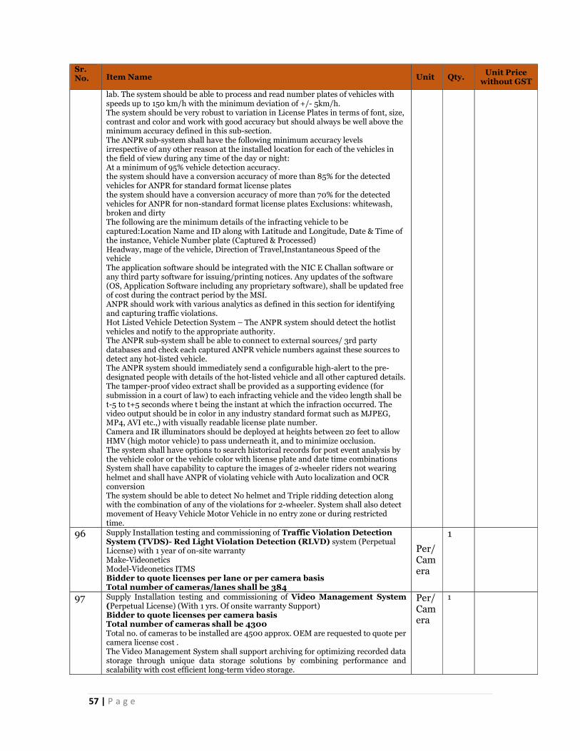
57 | P a g e
Sr. No. Item Name Unit Qty. Unit Price
without GST
lab. The system should be able to process and read number plates of vehicles with speeds up to 150 km/h with the minimum deviation of +/- 5km/h. The system should be very robust to variation in License Plates in terms of font, size, contrast and color and work with good accuracy but should always be well above the minimum accuracy defined in this sub-section. The ANPR sub-system shall have the following minimum accuracy levels irrespective of any other reason at the installed location for each of the vehicles in the field of view during any time of the day or night: At a minimum of 95% vehicle detection accuracy. the system should have a conversion accuracy of more than 85% for the detected vehicles for ANPR for standard format license plates the system should have a conversion accuracy of more than 70% for the detected vehicles for ANPR for non-standard format license plates Exclusions: whitewash, broken and dirty The following are the minimum details of the infracting vehicle to be captured:Location Name and ID along with Latitude and Longitude, Date & Time of the instance, Vehicle Number plate (Captured & Processed) Headway, mage of the vehicle, Direction of Travel,Instantaneous Speed of the vehicle The application software should be integrated with the NIC E Challan software or any third party software for issuing/printing notices. Any updates of the software (OS, Application Software including any proprietary software), shall be updated free of cost during the contract period by the MSI. ANPR should work with various analytics as defined in this section for identifying and capturing traffic violations. Hot Listed Vehicle Detection System – The ANPR system should detect the hotlist vehicles and notify to the appropriate authority. The ANPR sub-system shall be able to connect to external sources/ 3rd party databases and check each captured ANPR vehicle numbers against these sources to detect any hot-listed vehicle. The ANPR system should immediately send a configurable high-alert to the pre-designated people with details of the hot-listed vehicle and all other captured details. The tamper-proof video extract shall be provided as a supporting evidence (for submission in a court of law) to each infracting vehicle and the video length shall be t-5 to t+5 seconds where t being the instant at which the infraction occurred. The video output should be in color in any industry standard format such as MJPEG, MP4, AVI etc.,) with visually readable license plate number. Camera and IR illuminators should be deployed at heights between 20 feet to allow HMV (high motor vehicle) to pass underneath it, and to minimize occlusion. The system shall have options to search historical records for post event analysis by the vehicle color or the vehicle color with license plate and date time combinations System shall have capability to capture the images of 2-wheeler riders not wearing helmet and shall have ANPR of violating vehicle with Auto localization and OCR conversion The system should be able to detect No helmet and Triple ridding detection along with the combination of any of the violations for 2-wheeler. System shall also detect movement of Heavy Vehicle Motor Vehicle in no entry zone or during restricted time.
96 Supply Installation testing and commissioning of Traffic Violation Detection System (TVDS)- Red Light Violation Detection (RLVD) system (Perpetual License) with 1 year of on-site warranty Make-Videonetics Model-Videonetics ITMS Bidder to quote licenses per lane or per camera basis Total number of cameras/lanes shall be 384
Per/Camera
1
97 Supply Installation testing and commissioning of Video Management System (Perpetual License) (With 1 yrs. Of onsite warranty Support) Bidder to quote licenses per camera basis Total number of cameras shall be 4300 Total no. of cameras to be installed are 4500 approx. OEM are requested to quote per camera license cost . The Video Management System shall support archiving for optimizing recorded data storage through unique data storage solutions by combining performance and scalability with cost efficient long-term video storage.
Per/Camera
1

58 | P a g e
Sr. No. Item Name Unit Qty. Unit Price
without GST
The Video Management system shall have minimum 20 nos. of remote viewing station licenses. The Video Management System shall incorporate intuitive map functions allowing for multi layered map environment. The map functionality shall allow for the interactive control of the complete surveillance system, at-a-glance overview of system integrity, and seamless drag-and-drop integration with video wall module option. The System should support Maps integration with below features; i. Adding Image Layers to the location map ii. Define the location map for each location iii. Add cameras to the map images iv. Add image layers to the map v. Add a Maps Server vi. System should support raster format images of jpeg/jpg and png file and Vector (shape files) The Video Management System shall incorporate fully integrated matrix functionality for distributed viewing of any camera in the system from any computer with the client viewer. VMS shall be ONVIF Profile G, S, and T complied VMS shall be scalable to support minimum 5000 or more cameras, which can be added into the system by only addition of software licenses and servers It shall be possible to integrate VMS into the Command & Control system. In that respect bidders shall provide their SDK/API (or any other integration means) libraries and documentation to ensure a seamless integration with any other system. VMS shall be open to any standard storage technologies integration. VMS shall already support Storage system from multiple vendors. VMS shall provide the ability to save any event that was tagged as an alarm (video motion detection, video loss or input) received, to be saved in a manner wherein it cannot be overwritten. VMS shall have ready plug-ins and compatibility with industry-leading video wall OEMs VMS shall offer the possibility to integrate external Video Analytics systems. It shall be possible to access VMS without installing dedicated client software (e.g. through the use of common web browser such as Internet Explorer…) VMS shall be designed to offer a full IP based distributed architecture VMS shall have the capability to handle software clients (operators) connected in different locations on the same network. Simultaneous quantity of operators per location shall not be limited VMS shall store the system’s configuration in a relational database, either on the management server computer or on the network. VMS shall authenticate user access, user rights and privileges of all operators through Active Directory Access rights and privileges shall consist in but not limited to Visibility of devices, live view, playback, AVI/ ASF/ MP4 export, JPEG export, database export, sequences, smart search, input status, output control. PTZ control, PTZ priority, PTZ pre-set control Smart/Remote Client, live playback/setup, status API, service, registration API and privileges for the map feature The VMS shall be used for centralized management of all field devices, servers and client users. The VMS shall support a flexible rule-based system driven by schedules and events The VMS shall be supported for fully distributed solution for monitoring and control function, designed for limitless multi-site and multiple server installations requiring 24/7 surveillance with support for devices from different vendors. The VMS shall be supported for fully distributed solution for monitoring and control function, designed for limitless multi-site and multiple server installations requiring 24/7 surveillance with support for devices from different vendors. The VMS shall be capable of being deployed in a virtualized environment without loss of any functionality. The VMS server shall be deployed in a clustered server environment for high availability and failover. The VMS shall have an administrator interface to set system parameters, manage codecs, manage permissions, and manage storage. The VMS day to day control of cameras and monitoring on client workstations shall be controlled through the administrator interface

59 | P a g e
Sr. No. Item Name Unit Qty. Unit Price
without GST
Distributed Architecture-Registration of the system shall allow for on line activation and off-line activation of licenses Distributed Architecture-The system shall support automatic failover for Recording Servers. This functionality shall be accomplished by one Failover Server as a standby unit for max. 5 servers that shall take over in the event that one of a group of designated Recording Servers fails. Recordings shall be synchronized back to the original Recording Server once it is back online VMS shall operate in multicast, unicast and bandwidth throttling protocol to minimize the network bandwidth VMS shall support video streams up to at least 60fps Monitoring module shall allow for continuous monitoring of the operational status and event-triggered alarms from servers, cameras and other devices. The Monitoring module shall provide a real-time overview of alarm status or technical problems while allowing for immediate visual verification and troubleshooting. Module shall include flexible access rights and allow each user to be assigned several roles where each shall define access rights to cameras. Viewing live video from cameras on the surveillance system with Playback recordings from cameras on the surveillance system, with a selection of advanced navigation tools, including an intuitive timeline browser. VMS shall support access and view of cameras on a smartphone or a tablet (a mobile device). The system shall allow views to be created which are only accessible to the user, or to groups of users based on different layouts optimized for 4:3 and 16:9 display ratios. It should be able to create and switch between an unlimited number of views and able to display video from at least 64 cameras from multiple servers at a time. Bidder shall be required to provide a standardized Mobile Application to integrate smart phones and tablets for 2-way communication with the Surveillance System in a secure manner. It will be responsibility of MSI to configure such tablets / Smartphone, for the Surveillance System being implemented a part of this project and ensure that all the necessary access is given to these mobile users. Functionalities to be provided through mobile application: Viewing of any video steam from Central VMS, uploading of video / pictures to central VMS, Location based GIS Map access, tagging of mobile device/location information for all relevant functionalities It shall be possible to schedule recording and archiving by a recurrence pattern (daily, weekly, specific time and dates) and by specific time ranges (all day, time range, daytime, night time…) It shall be possible to schedule recording on per camera basis (Continuous, manual or motion based) The System should support LDAP (Lightweight Directory Access Protocol) server It shall be possible to protect specific video streams against any deletion and for any period of time The system log shall be searchable by Level, Source and Event Type. Multicasting: The Alert Log records alerts triggered by rules (searchable by Alert type, Source and Event type) Monitoring Module:The system shall have smart recording wherein no recording or recording at lower frame rate is done when there is no movement. The VMS shall be able to record higher-quality video and shall reduce fps when not in use during VAS night time. Monitoring Module:System should support recording management to view the recordings available on a camera’s local storage device (such as an SD card), and copy them to the server. The VMS shall support retrieving data from edge storage. Thus when a lost or broken connection is restored, it shall be possible to retrieve the video from SD card and store it on central storage. Monitoring Module:System should support thumbnail search, Thumbnail Search to quickly locate specific scenes or events in recorded video without fast-forwarding or rewinding. Thumbnail Search should display a range of video as thumbnail images, should allow to identify a portion of the recording to review. Monitoring Module:System should support Clip Management—Use Clip Management to view, download and delete clips that are stored on the server. Videos in the system shall be deleted / overwritten only by the pre-programmed logic of FIFO or based on expiry (retention period).

60 | P a g e
Sr. No. Item Name Unit Qty. Unit Price
without GST
All the streams shall be available in real-time (expecting the network latency) and at full resolution. Resolution and other related parameters shall be configurable by the administrator if required The VMS shall support tamper detection for all cameras to warn of accidental or deliberate acts that disable the surveillance capability. For alarm interfacing requirements, the designated primary camera shall be automatically displayed as a main GUI CCTV screen. The VMS shall also, on alarm, present associated pre/post event video allowing the Operator to assess the alarm cause. Other associated cameras, when called up, shall be displayed as split-screen images on the other monitor of the operator workstation. The system shall support a mode of operation whereby a map of all or part of the map (at operator request) is displayed on a separate or same screen and that status information can be provided via an icon, and access to any cameras shall be accessible by means of an icon on that screen. The system shall also provide the ability to log all operational functions for future investigations and reports. The system shall be fully configurable allowing a selection of parameters that can be optionally logged. Both pre-defined and custom reports shall be available for generation from all system logs and then optionally exported to standard Windows format programs VMS Storage: Security Platform shall have strong security mechanism such as the use of advance encryption, digital certificates and claims-based authentication to ensure that only authorised personnel have access to critical information, prevent man-in-the-middle attacks, and that the data is kept private. VMS Storage: It shall be possible to schedule recording on per camera basis (Continuous, manual or motion based) VMS Storage: The VMS shall be enabled for any standard storage technologies and video wall system integration. The solution design for the VMS shall provide flexible video signal compression, display, storage and retrieval. VMS Storage: VMS shall allow the control of the amount of used disk space. Management: No. of operators shall not be software licenses dependant. The VMS shall support bookmarking the videos. Thus, allowing the users to mark incidents on live and/or playback video streams. The VMS shall allow the administrator to distribute camera load across multiple recorders and be able shift the cameras from one recorder. Enhanced Monitoring Features 1. Video Stitching with Object Tracking-It indicates to find a defined person / object. VMS should be capable of opening the cameras in one Video matrix, which will help to trace the person from one camera to another camera and same can be tracked on a map. 2. Video Digging-It can search and track the person / object from the stored video in minutes by defining the time and sets of cameras. Heath Monitoring-VMS shall be able to generate up-time for its associates’ device.
98 Supply Installation testing and commissioning of Video Management System (Perpetual License) (With 5 yrs. Of OEM comprehensive warranty Support) (4300 Camereas) Make- Videonatics Model-Videonatics IVMS Bidder to quote licenses per camera basis Total number of cameras shall be 4300
Per/Camera
1
99 Supply Installation testing and commissioning of PA Software License (Perpetual License) (With 1 yrs. Of On-site comprehensive warranty Support): The PAS can be used by Police and other stakeholders of the project to disseminate information to road users/public. a. The objective of the voice based sub-system is to disseminate the information to
the citizens particularly during emergencies for the messages to reach quickly. b. The system should have the capability of designing the messages based on the
situation or context for broadcasting across PAS. c. The software and solution of PAS shall comply with all functional and business
requirement as specified in this RFP, elsewhere. d. The PA system shall provide provision for emergency announcements to be
made on per-location, selection of locations, or a system wide basis. e. The PA system shall have provision for announcements to be made from two
central locations.
Per/Speaker
1

61 | P a g e
Sr. No. Item Name Unit Qty. Unit Price
without GST
f. The Integrated Traffic Management system shall provide for the ability to produce and play-out either pre-recorded messages or make live announcements through PA software.
g. The system should have ability to configure the messages with the static or dynamic text from various applications/systems to form a complete message as and when required.
h. The system should recognize, and broadcast messages based on some of the analytics such as sound alerts, system alerts, incident alerts and various other alerts.
i. The system should be able to integrate other network’s PA systems or third-party application systems where the alerts are generated to broadcast messages.
j. The system should be able to generate various statistics, reports & MIS from time to time
k. The system shall be designed and installed so that it automatically minimizes community sound pollution
l. The requirements of local noise level standards & by-laws shall be respected by this system.
m. The system should have the ability to schedule category wise system messages or overall messages in advance for a period of time to selective or all PAS locations.
n. The PAS message quality shall be such that it is clearly audible from its location to a distance of up to 100 mtr. without any distortion and loss in quality of the sound during the prevailing situation in street.
o. Ability to categorize the messages as per the business need and able to configure as per category.
p. The PAS should provide the status indicators on the system and as well at various command centre
q. The PA system shall have an operations monitoring dashboard, located at the control centre
r. On this dashboard there shall be a schematic layout of the PA system showing all the connected nodes on the GUI.
s. The various nodes when connected & disconnected shall be represented in different color schema on the GUI of the Control Centre operator.
t. If any particular node is disconnected from the control room, the same shall raise an alarm to operator GUI & appropriate action shall be taken to rectify the same.
u. The monitoring dashboard shall allow the operator to click on any node & view the details of “operator” logged in, time duration since logged in, summary of operations If operator or any other user form disable/enable/operate any active device remotely, the same shall be captured in ICCC, activity report with all details including but not limited to date, time, device, action performed etc.
v. The monitoring dashboard shall show the status (connected/disconnected, faulty/working) of all logical devices (PA system) connected to a particular node when clicking on a node from the monitoring dashboard GUI.
w. In case of any fault in the devices connected to a node, or connectivity failure with a node, a pop-up message shall appear on the monitoring dashboard workstation. The operator has to acknowledge the pop-up message & report the type of fault to the maintenance team & shall record the details to the assigned team/individual into the system.
x. Fault assignment to the maintenance team shall be managed and controlled by the system software only. Once a fault is assigned by the COC operator or authorized user to the maintenance team, the same shall be displayed in the maintenance module and once fault is closed/resolved by the maintenance team it shall be updated automatically (in case of active devices) or else updated manually in the software application/maintenance module.
The access to monitoring dashboard shall be specific to the privilege of the user which can be defined in the system & shall be specific to a group/part of node locations.
100 Supply Installation testing and commissioning of PA Software License (Perpetual License) (with 1 year of on-site warranty) Make- Commend Model-AF2501, CD800PI, TR20,VirteupoSIS
Per/Speaker
1
101 Supply Installation testing and commissioning of Traffic Violation Detection System(TVDS) - ANPR & Speed system (Perpetual License) with 1 year of on-site warranty Bidder to quote licenses per camera or per lane basis
Per/ Camera
1

62 | P a g e
Sr. No. Item Name Unit Qty. Unit Price
without GST
Total number of cameras shall be 4500 cameras
The TVDS sub-system shall be able to detect traffic violations. And the violation data
captured by the system should be temper proof to stand in court of law.
TVDS will be operational and detect violations on 24X7 basis The TVDS sub-system shall have an ANPR based on non-intrusive type of enforcement for detecting various traffic violations. The TVDS shall automatically detect the license plate in the captured video feed in real-time. The system should work seamlessly with the ANPR sub-system to perform OCR (Optical Character Recognition) of the license plate characters (English alpha-numeric characters in standard fonts) and convert into machine readable format for further processing. The system shall be capable of storing JPEG image of the violating vehicle along with its license plate and enter the license plate number into the database along with date, time-stamp and site location details. The TVDS system should instantaneously (within 4 seconds) receive the processed ANPR of the violating vehicle from the ANPR sub-system. The system should store a continuous unaltered video clip of the vehicle approaching and leaving the violation location in the database. Secured connectivity for real-time data transfer between the TVDS sensors (camera) locations in the field with the central control room shall be provided along with complete hardware and networking required for the solution. The TVDS sub-system should work in both day and night conditions with the defined minimum accuracy levels. The TVDS sub-system should work with minimum intervention and maximum accuracy levels in all weather conditions The system should at least have 95% of accuracy level for standard number plate irrespective of weather condition, Lux level and vehicle category. The system should be able to provide Unique Case number for each of the Violation Detected. The system should be capable of providing a search and filter option to find specific cases at any point of time Type of Violations – The following type of traffic violations should be automatically detected using the appropriate non-intrusive technology in each case as applicable. All the traffic violations should be seamlessly integrated with the ANPR sub-system and maintain the status of each violation till closure in the database. • Red Light Violation/Stop Line Violation with ANPR • Speed detection with ANPR • Wrong Direction Vehicle Movement with ANPR Red Light Violation Detection (RLVD) – The non-intrusive RLVD sub- system should be capable of capturing multiple Infraction Vehicle Data (IVD) simultaneously on each arm of the junction at any point of time. Stop Line Violation at Junctions – The non-intrusive system should be capable of detecting the violations and capturing multiple IVD simultaneously on each arm of the junction at any point of time. Speed Violation- The system shall be able to integrate and display information such as vehicle no. and speed of vehicle on locally installed LED. LED which would be installed between 50 to 100 meters away from speed detection point. Wrong Direction Vehicle Movement – The non-intrusive system should be installed at critical junctions to capture the wrong direction vehicle movement. The system should identify and capture multiple IVD. The E-Challan standard procedure should be triggered. The TVDS should also seamlessly integrate with e-challan sub-system which is capable of providing a legally binding court evidence following a proven and a robust procedure. The system shall show the status (connected/disconnected, faulty/working) of all logical devices (ANPR Camera, Overview/Evidence camera, other units etc.) connected to a particular node when clicking on a node from the monitoring dashboard GUI. In case of any fault in the devices connected to a node, or connectivity failure with a node, a pop-up message shall appear on the monitoring dashboard workstation. The operator has to acknowledge the pop-up message & report the type of fault to the

63 | P a g e
Sr. No. Item Name Unit Qty. Unit Price
without GST
maintenance team & shall record the details to the assigned team/individual into the system The access to monitoring dashboard shall be specific to the privilege of the user which can be defined in the system & shall be specific to a group/part of node locations. ANPR System is the core to identify the infracting vehicle from the traffic violation perspective. The ANPR System identifies the number plates of these vehicles which is then passed on to various other sub-systems for further processing. The following are the Functional Requirements related to the ANPR System. The ANPR System shall be core to identifying the exact violating vehicle which is detected using the TVDS sub-system. The ANPR system shall capture vehicle license plate from front or from rear depending on the proposed solution and ensuring the performance Parameters are met. The ANPR sub-system is also used for identifying hot-listed vehicles for ensuring law & order in the city of PCMC by the police department. The system should have option to input certain license plates according to the hot listed categories like “Wanted”, “Suspicious”, “Stolen”, etc. by authorized personnel. The TVDS along with the ANPR system when seamlessly integrated with the e-challan system shall generate challans (tickets) to various traffic violators. The ANPR sub-system shall be used for satisfying various add-on use- cases such as stolen vehicle identification. ANPR system should be able to capture number plat of the vehicles passing through its field of view irrespective of violation committed. ANPR system at junctions should capture and read each and every vehicle number plate that passes through its field of view in multiple lanes and stores the number in the database. The ANPR system at City entry/exit points should continuously capture all number plates in its field of view which is to be stored at a local base station and simultaneously upload the data to the central data base. The ANPR system should be able to detect and recognize the English alpha numeric License plates in all standard fonts and formats of all vehicle classes irrespective of the type and size of the vehicle. Apart from standard number plates, the system should be able to recognize hand painted straight font alpha numeric number plates in standard formats found on Indian license plates The system processing should be in real time i.e. the recognition of license plate number should happen instantaneously (within three seconds of capture) Speed Violations - The nonintrusive system shall be capable of measuring speed of vehicles and capture over speed vehicles. The Speed measurement should support multiple methods for calculation of speed – either Average or Instantaneous Speed Measurement methods. The certification should be approved by authorized NABL lab. The system should be able to process and read number plates of vehicles with speeds up to 150 km/h with the minimum deviation of +/- 5km/h. The system should be very robust to variation in License Plates in terms of font, size, contrast and color and work with good accuracy but should always be well above the minimum accuracy defined in this sub-section. The ANPR sub-system shall have the following minimum accuracy levels irrespective of any other reason at the installed location for each of the vehicles in the field of view during any time of the day or night: At a minimum of 95% vehicle detection accuracy. the system should have a conversion accuracy of more than 85% for the detected vehicles for ANPR for standard format license plates the system should have a conversion accuracy of more than 70% for the detected vehicles for ANPR for non-standard format license plates Exclusions: whitewash, broken and dirty The following are the minimum details of the infracting vehicle to be captured:Location Name and ID along with Latitude and Longitude, Date & Time of the instance, Vehicle Number plate (Captured & Processed) Headway, mage of the vehicle, Direction of Travel,Instantaneous Speed of the vehicle The application software should be integrated with the NIC E Challan software or any third party software for issuing/printing notices. Any updates of the software (OS, Application Software including any proprietary software), shall be updated free of cost during the contract period by the MSI.

64 | P a g e
Sr. No. Item Name Unit Qty. Unit Price
without GST
ANPR should work with various analytics as defined in this section for identifying and capturing traffic violations. Hot Listed Vehicle Detection System – The ANPR system should detect the hotlist vehicles and notify to the appropriate authority. The ANPR sub-system shall be able to connect to external sources/ 3rd party databases and check each captured ANPR vehicle numbers against these sources to detect any hot-listed vehicle. The ANPR system should immediately send a configurable high-alert to the pre-designated people with details of the hot-listed vehicle and all other captured details. The tamper-proof video extract shall be provided as a supporting evidence (for submission in a court of law) to each infracting vehicle and the video length shall be t-5 to t+5 seconds where t being the instant at which the infraction occurred. The video output should be in color in any industry standard format such as MJPEG, MP4, AVI etc.,) with visually readable license plate number. Camera and IR illuminators should be deployed at heights between 20 feet to allow HMV (high motor vehicle) to pass underneath it, and to minimize occlusion. The system shall have options to search historical records for post event analysis by the vehicle color or the vehicle color with license plate and date time combinations System shall have capability to capture the images of 2-wheeler riders not wearing helmet and shall have ANPR of violating vehicle with Auto localization and OCR conversion The system should be able to detect No helmet and Triple ridding detection along with the combination of any of the violations for 2-wheeler. System shall also detect movement of Heavy Vehicle Motor Vehicle in no entry zone or during restricted time.
102 Supply Installation testing and commissioning of ANPR licenses for Speed Detection and RLVD system (with 1 year of on-site warranty) Make-Videonetics Model- Videonetics PRO-IVMS-CCL Bidder to quote licenses per camera or per lane basis Total number of cameras shall be 4500 cameras
per/Camera
1
103 Fibre Optic Cable blowing in duct including all other requisite service items like splicing, termination, Route Marker for OFC, Splicing Charges, Duct Integration Testing, like FOSC, jointer etc. Duct(4 ducts together) laying via HDD/Open trenching/Micro Trenching or equivalents including all requisite accessories (DW/GI Pipe, Coupler, jointer, manholes, chambers, concrete etc.) and services & including restoration & reinstatement etc. The selected System Integrator shall be responsible for Procurement, Supply, Installation, Testing and Commissioning of OFC based City Network Backbone (Passive Infra only) along with 5 years of Operations & Maintenance Support, from the date of Go Live. Detailed City / Route Survey Fiber backbone infrastructure is an important component of the entire smart city initiative that shall enable the delivery of all the key and important services to be made available to its citizens with seamless access. Network backbone infrastructure shall comprise of laying of ducts & blowing of fiber, setting of various point of presence (PoP) that shall be established across city locations, PCMC zones & ward offices and at other government institutions. Preliminary detailed survey shall be carried out by System Integrator for finalizing the route of Optical Fiber Cable basis indicative Network Architecture, refer Fig 2. At the end of the survey, SI shall estimate the network route length to be executed via Horizontal Directional Drilling (HDD), to the best possible extent, and Open Trench Technique. Following activities shall constitute this survey, but not limited to:
Selecting the optimal route in general Deciding the number of drop and insert locations Deciding the size and assessing the length of cable required Capturing the coordinates of the drop and insert locations. Working out the requirement of circuits that are to be provided in the
cable Working out the requirements of heavy tools and plants depending
upon nature of the territory, availability of roads alongside etc.

65 | P a g e
Sr. No. Item Name Unit Qty. Unit Price
without GST
Assessing the special problems of the section such as type of soil, long cuttings, new embankments, water logged areas, types of major bridges, major yards, culverts etc.
Collecting details of the existing facilities like telecommunication, utilities, water etc. and the additional requirements
Assessing the number of road crossings and other protective works required to be done
Capturing the areas where UG Fiber laying may not be feasible. Capturing the availability and coordinated of poles wherever UF Fiber
laying may not be feasible. During the site survey exercise, details should be captured while
keeping below points into consideration: o Avoiding laying of cable too close to a newly built road o Avoiding the toe of the embankment adjacent to the
cultivated fields o Avoiding burrow pits and areas prone to water logging o Avoiding heavily fertilized soils containing acids, electrolytes
and decomposable organic materials promoting bacterial activity
o Avoiding proximity to chemical, paper and such other industries which discharge chemically active affluent
o Avoiding large rock cuttings, routes of existing cables and areas difficult to approach
o Avoid built up areas including those areas where building, etc. are likely to come up in future
o Determining composition of the soil which may result in corrosion, etc. on the cable for which special protection for the cable shall be required
o Working out requirement of transport vehicles like jeeps, lorries, motor trolleys, etc. for execution of the work
o Avoiding side of the alignment which is likely to be affected due to addition/alteration of earth work/supply structures
o Avoiding underground structures, signalling cables, power cables, pipelines, other utilities etc.
o Avoiding laying of cable on the side of the drains in built up areas which are generally difficult to lay
o Taking the cable route preferably through the bed of small culverts where water does not accumulate instead of taking it over the culverts
o Avoiding termites/rodents infected areas
1.2 Network Design Preparation
The System Integrator shall be responsible for the preparation of City Network Backbone layout/ architecture, basis on the below mentioned indicative three tiered architecture which is based on the Ring Topology to ensure redundancy at each node level, and get the same approved by the purchaser. The SI is also required to propose the Network Architecture as part of its technical bid. The envisaged layers of the City Network Backbone are: a. Core Layer: The Core layer forms the backbone; comprising of network Point of Presence (PoP) at all the PCMC Zone Offices, City Operation Centre, Command Control Centre and PCMC Head Office. This layer shall enable all systems planned to be hosted at City Operations Centre & Command Control Centre to be accessed over the backbone. Core layer shall form the point of aggregation for all the traffic coming from the respective Aggregation Layer and beyond. b. Aggregation Layer: The aggregation layer is envisaged to have network PoPs at PCMC Ward Offices/PCMC Institutions. The traffic coming from respective service/filed locations shall get aggregated at the Aggregation Layer PoP. The aggregation layer shall further connect to the Core layer for forwarding the traffic

66 | P a g e
Sr. No. Item Name Unit Qty. Unit Price
without GST
to the Core layer. All the Aggregation layer PoPs in the respective zone shall form individual rings to establish redundancy. There can be multiple rings within the respective zone; e.g. if there are 10 wards in a given zone, then two rings comprising of 5 wards each can be created. These two rings shall ultimately connect to the respective zone (PoP). c. Services / Access Layer: The Service/ Access layer shall be formed at various locations within the wards of PCMC. The service layer shall enable the smart city solutions such as City Surveillance, ITMS, Street lighting, Smart parking, etc. to connect to the network backbone. The aggregation switch of the respective smart city solution shall connect on the Service / Access layer devices to connect to the network backbone. Various locations for deployment of above layers are: 1.3 Procure, Supply and Installation of City Network along with requisite
accessories
Procure & Supply all the passive components and accessories required for laying of ducts and blowing of fiber including but not limited to duct pipes, jointers, couplers, fiber cable, splicer, jointer etc.
All fittings, accessories and associated works for proper and safe installation of fiber assets to be taken into consideration by the SI.
SI shall be responsible for laying of 4 ducts, on the approved network route and design, using Horizontal Directional Drilling (HDD), wherever possible, and Open Trenching (OT) Technique, where HDD is not possible, after obtaining approvals from PCSCL and shall blow Optical Fiber in only one of the four ducts as per below:
o 96 core (or more) at the Core & Aggregation layer o 48 core (or more) at Service/Access layer
SI shall be responsible for operation & maintenance of the following: o 1 (one) duct along with blown fibre during the contract period o 3 empty/dark ducts for a period of one year (on quarterly
basis) SI is required to accordingly submit its Project Operation & Services cost in the financial bid. HDPE Ducts and Optical Fiber shall be laid primarily along the roads and
footpaths and close coordination will have to be done with concerned department for getting permission and deciding execution methodology
Laying, jointing, live line installation, testing and commissioning of all optical fiber and its accessories
The estimated fiber optic cable length requirements are indicated in the Bill of Material (BoM) and reflected in the Price Schedule.
For the purpose of payment of civil works related to laying of Duct/OFC, the length of the trench shall be used and not the length of the OFC laid or the ducts laid.
The Optical fibre cable shall be manufactured so as to protect the cable from rodent and termite.
For each trenching, SI shall take clearance from the Ward Junior Engineer (JE) (or any other
appointed authority) for the depth achieved to lay the HDPE pipes and Fiber. SI to take the picture of the depth measurement and share it with PCSCL
for records. 1.4 Pre-Requisite for Laying of City Network The SI shall prepare the list of equipment, number of field employees to be
deployed, no. of HDD machine to be deployed etc. in order to ensure adherence with the project timelines. The same shall be apprised to the purchaser and concerned authority.
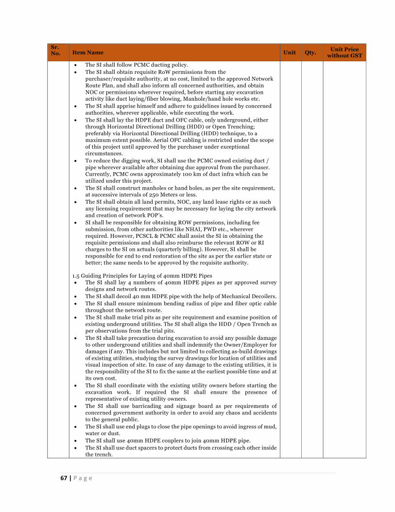
67 | P a g e
Sr. No. Item Name Unit Qty. Unit Price
without GST
The SI shall follow PCMC ducting policy. The SI shall obtain requisite RoW permissions from the
purchaser/requisite authority, at no cost, limited to the approved Network Route Plan, and shall also inform all concerned authorities, and obtain NOC or permissions wherever required, before starting any excavation activity like duct laying/fiber blowing, Manhole/hand hole works etc.
The SI shall apprise himself and adhere to guidelines issued by concerned authorities, wherever applicable, while executing the work.
The SI shall lay the HDPE duct and OFC cable, only underground, either through Horizontal Directional Drilling (HDD) or Open Trenching; preferably via Horizontal Directional Drilling (HDD) technique, to a maximum extent possible. Aerial OFC cabling is restricted under the scope of this project until approved by the purchaser under exceptional circumstances.
To reduce the digging work, SI shall use the PCMC owned existing duct / pipe wherever available after obtaining due approval from the purchaser. Currently, PCMC owns approximately 100 km of duct infra which can be utilized under this project.
The SI shall construct manholes or hand holes, as per the site requirement, at successive intervals of 250 Meters or less.
The SI shall obtain all land permits, NOC, any land lease rights or as such any licensing requirement that may be necessary for laying the city network and creation of network POP’s.
SI shall be responsible for obtaining ROW permissions, including fee submission, from other authorities like NHAI, PWD etc., wherever required. However, PCSCL & PCMC shall assist the SI in obtaining the requisite permissions and shall also reimburse the relevant ROW or RI charges to the SI on actuals (quarterly billing). However, SI shall be responsible for end to end restoration of the site as per the earlier state or better; the same needs to be approved by the requisite authority.
1.5 Guiding Principles for Laying of 40mm HDPE Pipes The SI shall lay 4 numbers of 40mm HDPE pipes as per approved survey
designs and network routes. The SI shall decoil 40 mm HDPE pipe with the help of Mechanical Decoilers. The SI shall ensure minimum bending radius of pipe and fiber optic cable
throughout the network route. The SI shall make trial pits as per site requirement and examine position of
existing underground utilities. The SI shall align the HDD / Open Trench as per observations from the trial pits.
The SI shall take precaution during excavation to avoid any possible damage to other underground utilities and shall indemnify the Owner/Employer for damages if any. This includes but not limited to collecting as-build drawings of existing utilities, studying the survey drawings for location of utilities and visual inspection of site. In case of any damage to the existing utilities, it is the responsibility of the SI to fix the same at the earliest possible time and at its own cost.
The SI shall coordinate with the existing utility owners before starting the excavation work. If required the SI shall ensure the presence of representative of existing utility owners.
The SI shall use barricading and signage board as per requirements of concerned government authority in order to avoid any chaos and accidents to the general public.
The SI shall use end plugs to close the pipe openings to avoid ingress of mud, water or dust.
The SI shall use 40mm HDPE couplers to join 40mm HDPE pipe. The SI shall use duct spacers to protect ducts from crossing each other inside
the trench.
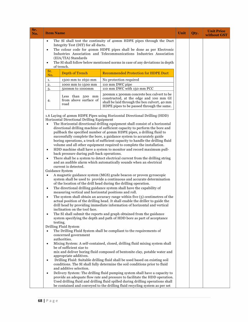
68 | P a g e
Sr. No. Item Name Unit Qty. Unit Price
without GST
The SI shall test the continuity of 40mm HDPE pipes through the Duct Integrity Test (DIT) for all ducts.
The colour code for 40mm HDPE pipes shall be done as per Electronic Industries Association and Telecommunications Industries Association (EIA/TIA) Standards
The SI shall follow below mentioned norms in case of any deviations in depth of trench.
Sr. No. Depth of Trench Recommended Protection for HDPE Duct
1. 1500 mm to 1650 mm No protection required 2. 1000 mm to 1500 mm 110 mm DWC pipe 3. 500mm to 1000mm 110 mm DWC with 150 mm PCC
4. Less than 500 mm from above surface of road
300mm x 300mm concrete box culvert to be constructed, at the edge and 100 mm GI shall be laid through the box culvert, 40 mm HDPE pipes to be passed through the same.
1.6 Laying of 40mm HDPE Pipes using Horizontal Directional Drilling (HDD) Horizontal Directional Drilling Equipment The Horizontal directional drilling equipment shall consist of a horizontal
directional drilling machine of sufficient capacity to perform the bore and pullback the specified number of 40mm HDPE pipes, a drilling fluid to successfully complete the bore, a guidance system to accurately guide boring operations, a truck of sufficient capacity to handle the drilling fluid volume and all other equipment required to complete the installation.
HDD machine shall have a system to monitor and record maximum pull-back pressure during pull-back operations.
There shall be a system to detect electrical current from the drilling string and an audible alarm which automatically sounds when an electrical current is detected.
Guidance System A magnetic guidance system (MGS) grade beacon or proven gyroscopic
system shall be used to provide a continuous and accurate determination of the location of the drill head during the drilling operation.
The directional drilling guidance system shall have the capability of measuring vertical and horizontal positions and roll.
The system shall obtain an accuracy range within five (5) centimetres of the actual position of the drilling head. It shall enable the driller to guide the drill head by providing immediate information of horizontal and vertical inclination on the tool face.
The SI shall submit the reports and graph obtained from the guidance system specifying the depth and path of HDD bore as part of acceptance testing.
Drilling Fluid System The Drilling Fluid System shall be compliant to the requirements of
concerned government authorities.
Mixing System: A self-contained, closed, drilling fluid mixing system shall be of sufficient size to mix and deliver boring fluid composed of bentonite clay, potable water and appropriate additives.
Drilling Fluid: Suitable drilling fluid shall be used based on existing soil conditions. The SI shall fully determine the soil conditions prior to fluid and additive selection.
Delivery System: The drilling fluid pumping system shall have a capacity to provide an adequate flow rate and pressure to facilitate the HDD operation. Used drilling fluid and drilling fluid spilled during drilling operations shall be contained and conveyed to the drilling fluid recycling system as per set
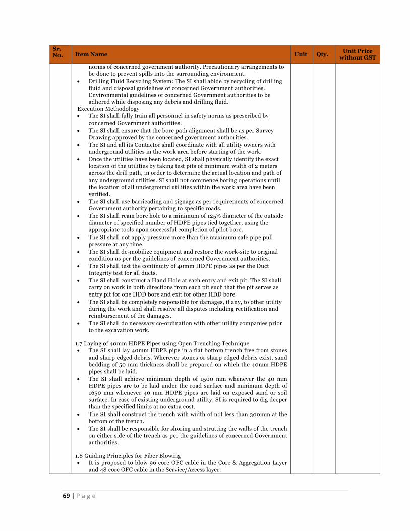
69 | P a g e
Sr. No. Item Name Unit Qty. Unit Price
without GST
norms of concerned government authority. Precautionary arrangements to be done to prevent spills into the surrounding environment.
Drilling Fluid Recycling System: The SI shall abide by recycling of drilling fluid and disposal guidelines of concerned Government authorities. Environmental guidelines of concerned Government authorities to be adhered while disposing any debris and drilling fluid.
Execution Methodology The SI shall fully train all personnel in safety norms as prescribed by
concerned Government authorities. The SI shall ensure that the bore path alignment shall be as per Survey
Drawing approved by the concerned government authorities. The SI and all its Contactor shall coordinate with all utility owners with
underground utilities in the work area before starting of the work. Once the utilities have been located, SI shall physically identify the exact
location of the utilities by taking test pits of minimum width of 2 meters across the drill path, in order to determine the actual location and path of any underground utilities. SI shall not commence boring operations until the location of all underground utilities within the work area have been verified.
The SI shall use barricading and signage as per requirements of concerned Government authority pertaining to specific roads.
The SI shall ream bore hole to a minimum of 125% diameter of the outside diameter of specified number of HDPE pipes tied together, using the appropriate tools upon successful completion of pilot bore.
The SI shall not apply pressure more than the maximum safe pipe pull pressure at any time.
The SI shall de-mobilize equipment and restore the work-site to original condition as per the guidelines of concerned Government authorities.
The SI shall test the continuity of 40mm HDPE pipes as per the Duct Integrity test for all ducts.
The SI shall construct a Hand Hole at each entry and exit pit. The SI shall carry on work in both directions from each pit such that the pit serves as entry pit for one HDD bore and exit for other HDD bore.
The SI shall be completely responsible for damages, if any, to other utility during the work and shall resolve all disputes including rectification and reimbursement of the damages.
The SI shall do necessary co-ordination with other utility companies prior to the excavation work.
1.7 Laying of 40mm HDPE Pipes using Open Trenching Technique The SI shall lay 40mm HDPE pipe in a flat bottom trench free from stones
and sharp edged debris. Wherever stones or sharp edged debris exist, sand bedding of 50 mm thickness shall be prepared on which the 40mm HDPE pipes shall be laid.
The SI shall achieve minimum depth of 1500 mm whenever the 40 mm HDPE pipes are to be laid under the road surface and minimum depth of 1650 mm whenever 40 mm HDPE pipes are laid on exposed sand or soil surface. In case of existing underground utility, SI is required to dig deeper than the specified limits at no extra cost.
The SI shall construct the trench with width of not less than 300mm at the bottom of the trench.
The SI shall be responsible for shoring and strutting the walls of the trench on either side of the trench as per the guidelines of concerned Government authorities.
1.8 Guiding Principles for Fiber Blowing It is proposed to blow 96 core OFC cable in the Core & Aggregation Layer
and 48 core OFC cable in the Service/Access layer.

70 | P a g e
Sr. No. Item Name Unit Qty. Unit Price
without GST
The SI shall place route marker as per given alignment & maintaining offset distance from road centre , co-locating with each manhole and at every location where the route changes direction as per norms set by concerned government authorities.
The SI shall use barricading and signage board as per requirements of concerned government authority in order to avoid any chaos and accidents to the general public.
The SI shall install the OFC inside the 40mm HDPE pipe as per design consideration. The OFC shall be installed by compressed air blowing technique.
The SI shall handle the Optical Fiber Cable Drums as per instructions given by the manufacturer.
The SI shall use Duct rodder for pulling OFC from one Man/Hand Hole to another Man/Hand hole for short spans up to 250 Metres.
The SI shall ensure manufacturer's guidelines for minimum bend radius and tension are followed while installing the OFC.
The SI shall keep minimum 18-20m loop in each Man/Hand hole, properly coiled and tied with cable ties. Aluminium cable tags with punching to be used for tagging.
The SI shall seal both the ends of 40 mm HDPE pipe with cable sealing plugs / simplex plugs after installing OFC.
The SI shall pull through 5mm thick Nylon rope in spare 40 mm HDPE pipes and tied properly at both the ends for future cable pulling. The 40 mm HDPE pipe then shall be secured using End plug.
1.9 Guiding Principles for Hand holes Hand holes shall be made of medium duty HDPE with Polymer concrete
Lid. Boxes, rings and lids should sustain a minimum vertical test load of 33,500
lb (AASHTO HS 20 loading) as a stand-alone unit, over a 10-inch x 20-inch square steel plate centred on the cover and body in accordance with ASTM C 857-95 design load A-16.
The boxes, rings and lids shall meet the physical and chemical
Requirement’s listed below : Holes for keeping service loops of duct shall be of suitable height as per the
Project Requirements. Furnish lids that have a non-skid surface for pedestrian traffic with
minimum coefficient of friction of 0.50 in accordance with ASTM C1028 without the use of coatings.
All lids shall be manufactured with the markings “PCMC/PCSCL” in the logo area of the lid, in 25 mm recessed letters.
Lid access points shall have recessed reinforced steel pull slots to allow for the removal of the cover with a hook or lever. Replace the lid if damage occurs to the pulling point.
Bolts used on hand holes and lids shall be stainless steel, recessed hex head bolts with washer.
The top of hand hole shall be flushed with the ground level. All PLB HDPE duct entries, cable entries and holes shall be properly sealed.

71 | P a g e
Sr. No. Item Name Unit Qty. Unit Price
without GST
Seal duct ends inside all hand holes with at least 50mm thick duct caulking after fiber is installed. Seal vacant duct with a manufacturer end plug and attach detectable pull tape.
Hand holes shall have capabilities to absorb water as per ASTM 570 standards. They shall be provided with sump holes or open bottom for water drainage.
The hand holes shall be installed with a minimum of 101mm layer of small rock in the bottom to prevent mud and wildlife (rodents) from intruding the hand holes. The gravel shall help facilitate drainage.
No hand holes shall be installed under direct traffic load and shall be only suitable for installation at boulevards or areas where there is pedestrian movement.
The HDPE manholes shall have following markings provided on each unit: • Code of product • Name of Manufacturer • Date of manufacturing • Named as ‘PCSCL OFC HANDHOLE
1.10 Guiding Principles for Manhole Manhole shall be pre-cast RCC rectangular type with minimum wall
thickness of 150mm and shall include 8mm diameter or more steel reinforcement.
The base of manhole shall be minimum 150mm thick PCC (Plain Cement Concrete) and minimum internal clearance shall be at least 1mx1mx1m.
Holes for keeping service loops of duct shall be at minimum 300mm height from internal base.
All PLB HDPE duct entries, cable entries and holes shall be properly sealed. The size of the holes shall not be larger than 6mm from conduit outer
diameter (sleeve). Seal conduit ends inside all manholes with at least 50mm thick duct caulking after fiber is installed. Seal vacant conduit with a manufacturer end plug and attach detectable pull tape.
The manhole cover shall be heavy duty water tight FRC type. However, for easy handling purpose, he cover shall be constructed with suitable arrangement for lifting.
The top of manhole should be flushed with the ground level. The manhole shall have suitable access from cable trench and sufficient holes
in all walls for PLB HDPE duct entries and exits. Requisite brackets along with cable hangers for placing cable and splice box
inside the manhole shall be provisioned and made of junk free material. The Manholes shall meet the physical and chemical Requirements listed
below:
Manholes shall be equipped with a covered sump hole for drainage and shall be reasonably waterproof. Manholes shall have reasonable level of gravel bed extending 203mm to 305mm beyond the outer edges of the manhole.
Manholes shall have capabilities to absorb water as per ASTM standards as per current version.
All manholes shall have grounding halo installed that wraps the manhole and is connected to the ground rod. The halo shall be tin coated, copper ribbon that shall be anchored to concrete approximately 457 to 610mm apart. The

72 | P a g e
Sr. No. Item Name Unit Qty. Unit Price
without GST
halo shall be bonded to ground rod with non-insulated 6 AWG solid copper conductor.
SI Shall seal both ends of the PLB HDPE pipe in manhole by hard rubber bush of suitable size to avoid entry of rodents into the PLB HDPE Ducts, putting split PLB HDPE Ducts and split RCC pipes with proper fixtures over cable in the manhole to protect the bare cable.
The manholes shall be placed on 152mm of compacted rock or sand to ensure uniform distribution of soil pressure on floor.
No manhole shall be installed under direct traffic load and shall be only suitable for installation at boulevards or areas where there is pedestrian movement.
The SI shall provide Man Holes at a distance of 200 meters. The SI shall provide additional Hand Holes at Major Road crossings, Bridges
and other location. The SI shall provide Hand Holes of size 1M (L) X 1M (W) X 1.2M (D) with
single lid. The installation of Hand Hole shall be done in such a manner that top surface of the Hand Hole lid shall flush with existing Road/Earth Surface.
Required excavation and backfilling for the construction of the Hand Hole shall be carried out adhering to all the requirements of concerned Government authority.
1.11 Splicing of OFC and Installation of Fiber Splice Joint closure The SI shall ensure that the splice loss per joint shall be less than
0.05dB/splicing joint. The SI shall ensure that during splicing fiber cores of 0.6 metre to 0.8 metre
shall be stored in cable tray. The SI shall seal and install the Fiber Splice Joint closure assembly as per
instructions of manufacturer. The SI shall carry one hour of leakage/ water penetration test on Fiber Splice
Joint closures after installation. The SI shall attach Cable tags to all OFC which are entering the Fiber Splice
Joint Closure and OFC readings shall be recorded for updating in the As-build and GIS drawings.
The SI shall provide an As-build diagram for splicing of OFC. The diagram shall indicate the cores from all OFC with their colour coding and numbering.
The SI shall use Mid-Span Access Buffer Tube Slitter during mid-span splicing (for last mile location connectivity) to ensure that buffer jackets of fiber tubes are cut longitudinally to access all fibers inside tube and then only required fiber cores will be cut for splicing with fiber cores of last mile cable.
During maintenance of the network, SI shall ensure that all fiber cores are spliced at the cut location (and not only live fiber cores) during rectification process. PCMC / any third party as appointed may audit the health / continuity of all fiber cores at any time and SI shall have to facilitate this exercise by performing LSPM and OTDR testing in presence of the team.
1.1 1.12 Earthing System
All electrical components are to be earthed by connecting two earth tapes from the frame of the component ring and will be connected via several earth electrodes. The cable arm will be earthed through the cable glands. The entire applicable IT infrastructure shall have adequate earthing. Further, earthing should be done as per Local state national standard in relevance with IS standard. Earthing should be done for the entire power system and provisioning
should be there to earth UPS systems, Power distribution units, AC units, etc. so as to avoid a ground differential. PCSCL shall provide the necessary space required to prepare the earthing pits.
All metallic objects on the premises that are likely to be energized by electric currents should be effectively grounded.
73 | P a g e
Sr. No. Item Name Unit Qty. Unit Price
without GST
There should be enough space between data and power cabling and there should not be any cross wiring of the two, in order to avoid any interference, or corruption of data
The earth connections shall be properly made. Provide separate earthing pits for active equipment & UPS as per the
standards.
1.13 Guiding Principles for Laying of DWC Pipes The SI shall use 110 mm DWC pipe to facilitate adequate protection to 40
mm HDPE pipe and OFC within low depth areas (as specified in Table 1 above) as well as at rail, road, bridge and culvert crossings.
The SI shall insert maximum 2 numbers of 40 mm HDPE pipe in one 110mm DWC pipe.
The SI shall use 110 mm DWC coupler to joint 110 mm DWC pipe. The SI shall lay 110 mm DWC pipe on levelled bed of trench. The SI shall ensure that the trench bed is free from sharp edge, debris, and
stones. .
1.14 Guiding Principles for Laying of 100mm GI Pipes The SI shall lay 100 mm GI pipe wherever road and culvert crossings are
encountered on the route as well as in low depth areas as specified in Table 1 above.
The SI shall insert 2 Nos. of 40 mm HDPE pipes through one 100 mm GI pipe.
The SI shall clamp 100mm GI Pipe with suitable clamps where ever culvert crossing is to be done and excavation is not possible. The 40mm HDPE Pipes shall be laid through 100mm GI Pipe.
The SI shall build a box culvert to protect 100mm GI Pipe in case of lower depth as specified in the above table.
The SI shall extend the100 mm GI pipe by at least 1 meter on each side of crossing subject to availability of space.
The SI shall join 100 mm GI pipes using 100 mm GI Coupler. Wherever required, to protect the GI pipe from theft, suitable concreting
shall be done to cover the GI pipe. 1.15 Protection for OFC The Optical Fiber Network shall be built by considering following protection methods to protect the OFC from accidental damage. Concreting: Concreting shall be used to provide additional protection on
bridges, culverts and also on stretches wherever depth of excavation is less than 0.2Mtr.
RCC Half round: Where-ever cables are laid in cities where human habitation exists or where construction activity can happen in near future, Full Round or Half Round, 100mm, NP2 Grade shall be put after 100 mm padding with excavated material over duct, wherever the depth is less than 0.5Mtr but more than 0.4Mtr.
RCC Full round: Where-ever cables are laid in cities where human habitation exists or where construction activity can happen in near future, Full Round or Half Round, 100mm, NP2 Grade shall be put after 100 mm padding with excavated material over duct, wherever the depth is less than 0.4Mtr but more than 0.2Mtr.
1.16 Backfilling and Reinstatement of Excavated Area The SI shall backfill and reinstate the area to its original condition as per
the guidelines issued by the concerned government authorities pertaining to specific road after completion of work.
The SI shall dispose the surplus earth material to a suitable location as indicated by concerned Government authorities.

74 | P a g e
Sr. No. Item Name Unit Qty. Unit Price
without GST
The SI shall be responsible for obtaining the sign off on the reinstated area from the concerned authority; the reinstatement shall be performed to the level of quality to be accepted by the concerned authority.
Testing & Commissioning The SI shall be responsible for undertaking the following activities:
Optical Fiber Cable Testing Methodology The procedure shall comply with the ISO/IEC 14763-3 standard and to the
vendor testing procedure. The ISO/IEC 14763 standard specifies the implementation and operation of
customer premises cabling. The part 3 of this ISO document (14763-3) details test procedures for optical
fiber cabling designed in accordance with ISO/IEC 11801:2002 and installed according to the recommendations of ISO/IEC 14763-2 (Planning and installation of customer premises cabling).
Fiber-optic Tests applied to links and exclude equipment and work area cord. OF Attenuation testing is used to verify the initial performance of the
installed link. 100 % of the installed OF links have to be tested and must pass the
acceptance criteria. The attenuation of the link is measured using the insertion loss method. This
method uses an optical source and an optical power meter to compare the difference between two optical power levels.
When testing Single Mode optical Fiber links with a Light Source and a Power Meter, this measurement kit has to be capable of operating at 1550 nm and 1310 nm for Single Mode.
The test scenario with a Light Source and a Power Meter shall be of the following for each link: Bidirectional testing @ 1550 nm and @ 1310 nm for single mode fibers and calculating average of both readings.
The use of certification tool is recommended. Those tools are capable of producing a report logging the time of the test the link identification under test, the link length, the attenuation at the window tested and the acceptable link attenuation. The report shall also identify in which direction the testing was implemented.
When testing with basic optical source and power meter, the operator will fill up a report logging the time of the test, the link identification under test, the link length and attenuation at the window tested in presence of the deputed staff/any person by PCMC/PCSCL.
The report shall also identify in which direction the testing was implemented.
Acceptable link attenuation to be calculated. The measured attenuation of the links shall have a lower value than the
acceptable link attenuation calculated. The Test should be carried out by certified Engineer and once the report is
submitted to the manufacturer he will issue the Performance Certification which will mention minimum performance of 20 years or higher.
The SI shall also provide bidirectional OTDR report for all fiber cores. HDPE Ducts Testing Methodology Factory Testing Requirement’s for HDPE Ducts: Factory acceptance tests shall be conducted on randomly selected final
assemblies of all equipment to be supplied. Visual inspection shall be carried out on 100% basis for all the equipment/items offered. Factory acceptance testing shall be carried out on PLB HDPE and accessories.
From each batch PLB-HDPE duct presented by the SI for Factory acceptance testing, PCSCL shall select random sample (s).
The following tests shall be carried out during Factory Acceptance Testing (FAT):

75 | P a g e
Sr. No. Item Name Unit Qty. Unit Price
without GST
• Visual Inspection • Dimension Check • Hydraulic Characteristics • Reversion Test • Tensile Strength and Elongation Test • Environmental Stress Crack Test • Impact Strength Test • Crush Resistance • Mandrel Test • Ovality Test • Coil Set Test • Internal Co-efficient of Friction • Ash content • Colour fading • Optical Fiber Cable Blowing Test • Air Pressure test on plastic coupler • Ageing test on accessories • Dimensional test shall be carried out on 10% sample of the
respective lot. • In case any of the selected samples fail, the failed sampled is
rejected and additional 20% samples shall be selected randomly and tested. In case any sample from the additional 20% also fails the entire batch may be rejected.
Pipe Integrity Test The SI shall perform the Duct Integrity test for all 40 mm HDPE pipes with
blow compressed air at 5 Kg/Sq.cm for removing sand, mud and other foreign particles creeped during laying of pipes.
The SI shall carry out Duct integrity test with the help of medium density of sponge at pressure of 5 Kg/Sq.cm.
The SI shall perform the Duct Integrity testing from Hand hole to Hand hole. However wherever the site conditions permit SI shall perform the Duct integrity test for several Hand holes together by coupling the 40 mm HDPE pipes within the Hand Holes.
The SI shall carry out the Duct Integrity test before pulling/blowing of OFC. The SI shall seal the spare 40 mm HDPE pipes with End plugs immediately
after acceptance of Duct integrity test Duct Cleaning (Sponge Test): Compressed air should be blown through the duct in order to remove any
dirt and water that has accumulated inside the duct with the help of suitable capacity Air Compressor.
A short blast of air about 2-3 bar shall be blown through the duct for about 2 minutes.
Sponge will be blown through the duct and should emerge from the other end to thoroughly clean the duct from inside.
Crush and Deformity Test: This test is to be done to check the integrity of the duct. During installation, while backfilling process there is a possibility of
flattening, twisting or kinking of the duct. This is also possible if the duct has not been uncoiled properly and is laid
improperly. Place the wooden shuttle in the duct. Shuttle should be 80% of inner
diameter of the duct and 150 mm in length. Connect the Compressor pipe fitting to the duct. Place the flexible wire grip to the downstream end of the duct. Connect the air hose supply to the compressor and the equipment.

76 | P a g e
Sr. No. Item Name Unit Qty. Unit Price
without GST
Open the discharge valve of the compressor and blow the shuttle through the duct.
Note: The shuttle will pass through at a very high speed and must be trapped in flexible wire grip to avoid accident and injury. Mandrel/Shuttle Test: A mandrel/shuttle of at least 90% of the inside diameter size shall be
passed through the duct to test the clear pathway of the duct. Pressure Testing: This test is carried out to detect leakage in duct, if any. Seal one end of the
duct with End Coupler and then through End Coupler with valve, feed the compressed air into the duct.
Raise the pressure up to 5 Bar and then observe. After observing for 30 mins, pressure drop of up to a max. 0.5 Bar is permissible.
The detection device for detecting the presence of the buried HDPE Duct with co-extruded copper wire/tracer wire, shall have following features:
One set of Transmitter and Receiver along with suitable batteries in a portable box.
Capability to detect HDPE duct with co-extruded copper wire/tracer wire up to a depth of 3 meters.
Capability to emit peak audible signal when the HDPE duct with co-extruded copper wire/tracer wire is exactly below the receiver.
Capability to distinguish presence of passive metallic objects as well as current carrying metallic conductors other than the duct itself.
Capability to indicate the depth of the duct at which it has been buried. Capability to change the Frequency of detection current to avoid possibility
of mixing up with detection of another HDPE Duct with co -extruded copper wire/tracer wire in the vicinity, if any.
It should have a backlit LCD display for visibility in low light conditions. It should have rugged one piece case design and sealed keypad for
withstanding tough weather conditions and for superior moisture resistance.
Impact Strength on individual duct: There shall be no crack/split when 9.1kg load (Tup B) dropped from 1.5
meters height after conditioning at 0 degree Cent. for one Hour. Environmental Stress Crack resistance characteristics for duct: No cracking when tested with 10% LGEPAL solution, CO 0630 solution at
500C for 96 Hours. The Tensile strength of yield shall be at least 20N/ mm2 as per ASTM F
2160, and ASTM D 638 Type IV. Hydraulic Characteristics - No Swelling leakage or bursting observed
after 48 hours at an induced stress of 3.8 Mpa @ 800C as per IS 4984. Elongation at Break for both 40 mm and 20 mm duct shall be at least
500% as per ASTM F 2160, and ASTM D 638 Type IV standard.
The product shall meet or exceed the following American Society for Testing and Materials (ASTM) Standards: ASTM C 857-95: Standard Practice for Minimum Structural Design
Loading for Underground Precast, Concrete Utility Structures; ASTM C 109: Standard Test Method for Compressive Strength of
Hydraulic Cement Mortars; ASTM C 580: Standard Test Method for Flexural Strength and Modulus
of Elasticity of Chemical-Resistant Mortars, Grouts, Monolithic Surfacing’s, and Polymer Concrete;

77 | P a g e
Sr. No. Item Name Unit Qty. Unit Price
without GST
ASTM C 496: Standard Test Method for Splitting Tensile Strength of Cylindrical Concrete Specimens;
ASTM C 543: Standard Specification for Pressure Vessel Plates, Alloy Steel, Quenched and Tempered Nickel-Chromium-Molybdenum.
ASTM C 1028: Standard Test Method for Determining the Static Coefficient of Friction;
ASTM C 570: Standard Specification for Oil- and Resin-Base Caulking Compound
104 Integration of Surveillance System (VMS & VA) with Existing ICCC Lumpsum 1
105 Integration of RLVD with Existing ICCC Lumpsum 1
106 Integration of SVDS with Existing ICCC Lumpsum 1
107 Integration of PA System with Existing ICCC Lumpsum 1
108 Comprehensive annual maintenance of complete City Surveillance system and Traffic violation and detection system(RLVD, SVDS, PA) of total estimated cost, including all breakdowns and preventive maintenance work of Surveillance system, RLVD system, SVDS, PA system i.e Camera, Server and Storage, Monitor, Manageable switches, inverter, UPS, OFC, Cat6 &Fiber optic cables & others supply cable and all items consider in the estimate . The contractor should check , inspect the system monthly & submit reports including periodical maintenance, attending emergency breakdown and resolving all repairs within 24 hrs, including extracting video files/footage whenever required by PCMC , Police Dept including replacement of all spares parts with authentic OEM spares.The contractor has to safe guard all above system, equipment accessories etc from lightening, electrical spikes, short circuit, damages etc complete for one year. The contractor shall provide comprehensive and on-site warranty for 1 years from the date of completion for the infrastructure deployed on the project. The contractor need to have OEM support for these components (Hardware & Software Application) and documentation in this regard need to be submitted to PCMC on annual basis. The contractor shall do all the updates/ up gradation of the software applications, firmware and security patches
Year (Per centage of CAPEX)
1
TOTAL COST (in INR Cr.)
No: - Telecom/03/KV/225/2021 Date:15/09/2021 Sd/-
Thomas N0ronha) Executive Engineer (Telecom) Pimpri Chinchwad Municipal Corp.
Pimpri-18