AcTIve LINe ArrAy SpeAker SySTeMS Sr-D8-M, Sr-D8-S
40
INSTALLATION MANUAL ACTIVE LINE ARRAY SPEAKER SYSTEMS SR-D8-M, SR-D8-S Optional products WALL MOUNTING ADAPTER SR-D8CS WALL MOUNTING ADAPTER SR-D8CL EXTENSION PLATE SR-D8EP WALL MOUNTING BRACKET SR-D8WB HOISTING BRACKET SR-D8HB FIXING BAR SR-D8FB Thank you for purchasing TOA’s Active Line Array Speaker System. Please carefully follow the instructions in this manual to ensure long, trouble-free use of your equipment.
-
Upload
khangminh22 -
Category
Documents
-
view
5 -
download
0
Transcript of AcTIve LINe ArrAy SpeAker SySTeMS Sr-D8-M, Sr-D8-S

INSTALLATION MANUAL
AcTIve LINe ArrAy SpeAker SySTeMSSr-D8-M, Sr-D8-S
Optional products
WALL MOUNTINg ADApTer Sr-D8cSWALL MOUNTINg ADApTer Sr-D8cLexTeNSION pLATe Sr-D8epWALL MOUNTINg brAckeT Sr-D8WbHOISTINg brAckeT Sr-D8HbFIxINg bAr Sr-D8Fb
Thank you for purchasing TOA’s Active Line Array Speaker System. Please carefully follow the instructions in this manual to ensure long, trouble-free use of your equipment.

2
TAbLe OF cONTeNTS
1. IMpOrTANT SAFeTy INSTrUcTIONS ........................................... 3
2. SAFeTy precAUTIONS ............................................................................. 5
3. geNerAL DeScrIpTION ........................................................................ 10
4. FeATUreS .......................................................................................................... 10
5. INSTALLATION precAUTIONS ........................................................... 11
6. HANDLINg precAUTIONS .................................................................... 11
7. NOMeNcLATUre AND FUNcTIONS ............................................... 12
8. brAckeTS ......................................................................................................... 15
9. cOMMUNIcATIONS beTWeeN pc AND SpeAkerS ......... 16
10. cONNecTIONS ............................................................................................. 1710.1. Connection Example 1 (CobraNet Connection) ................................................ 1710.2. Connection Example 2 (CobraNet Connection, 4-Unit Configuration) ............. 1810.3. Connection Example 3 (Analog Line Connection) ............................................ 1910.4. Connection Example 4 (Maximum System) ...................................................... 2010.5. Removable Terminal Plug Connection .............................................................. 2210.6. Fixing Power Supply Cord ................................................................................. 2310.7. System Expansion Using CobraNet Connection ............................................... 24
11. INSTALLATION .............................................................................................. 2811.1. Installing a Single SR-D8-M Unit ....................................................................... 2811.2. Installing SR-D8-M and SR-D8-S(s) in multi-unit configuration ........................ 3011.3. Angle Adjustment .............................................................................................. 35
12. DIMeNSIONAL DIAgrAMS .................................................................. 3712.1. SR-D8-M, SR-D8-S Active Line Array Speaker Systems ................................. 3712.2. Brackets ............................................................................................................ 37
13. SpecIFIcATIONS ........................................................................................ 3913.1. SR-D8-M, SR-D8-S Active Line Array Speaker Systems ................................. 3913.2. Brackets ............................................................................................................ 40

3
1. IMpOrTANT SAFeTy INSTrUcTIONS • Readtheseinstructions.
• Keep these instructions.
• Heed all warnings.
• Follow all instructions.
• Do not use this apparatus near water.
• Clean only with dry cloth.
• Do not block any ventilation openings. Install in accordance with the manufacturer's instructions.
• Do not install near any heat sources such as radiators, heat registers, stoves, or other apparatus (including amplifiers) that produce heat.
• Do not defeat the safety purpose of the polarized or grounding-type plug. A polarized plug has two blades with one wider than the other. A grounding type plug has two blades and a third grounding prong. The wide blade or the third prong are provided for your safety. If the provided plug does not fit into your outlet, consult an electrician for replacement of the obsolete outlet.
• Protect the power cord from being walked on or pinched particularly at plugs, convenience receptacles, and the point where they exit from the apparatus.
• Only use attachments/accessories specified by the manufacturer.
• Unplug this apparatus during lightning storms or when unused for long periods of time.
• Refer all servicing to qualified service personnel. Servicing is required when the apparatus has been damaged in any way, such as power-supply cord or plug is damaged, liquid has been spilled or objects have fallen into the apparatus, the apparatus has been exposed to rain or moisture, does not operate normally, or has been dropped.

4
INSTrUcTIONS eSSeNTIeLLeS pOUr LA SÉcUrITÉ
• Lirecesinstructions.• Conservercesinstructionspourréférenceultérieure.• Respectertouslesavertissements.• Suivretouteslesinstructions.• Nepasutilisercetappareilàproximitéd'eau.• Nettoyeruniquementàl'aided'unchiffonsec.• Nepasobstruerlesorificesdeventilation.Installerconformémentauxinstructionsdufabricant.• Nepasinstalleràproximitédesourcesdechaleurtellesquedesradiateurs,desregistresthermiques,deschaudièresoud'autresappareils(notammentdesamplificateurs)produisantdelachaleur.
• Nepascontournerlafonctiondesécuritédelafichepolariséeoudemiseàlaterre.Unefichepolariséeestéquipéededeuxbroches,dontl'uneestpluslargequel'autre.Unefichedemiseàlaterreestéquipéededeuxbrochesetd'unetroisièmepourlamiseàlaterre.Cettedernière,lapluslarge,estprévueàdesfinsdesécurité.Silafichefournienepeutêtreinséréedanslapriseélectriquesouhaitée,consulterunélectricienpour faire remplacer cette dernière.
• Protégerlecordond'alimentationpouréviterqu'ilnesoitpiétinéoupincé,notammentauniveaudesfiches,des prises de courant ou de son point de sortie de l'appareil.
• Utiliseruniquementlesaccessoiresspécifiésparlefabricant.• Débranchercetappareilpendantlesoragesainsiquelorsqu'ilresteinutilisépendantunepériodeprolongée.• Lamaintenancedel'appareildoitêtreconfiéeàuntechnicienaprès-ventequalifié.Unemaintenances'avèrenécessairesi l'appareilestendommagé(auniveauducordond'alimentationoudelafiche),aétémouilléparunliquide,unobjetesttombéàl'intérieur,s'ilaétéexposéàlapluieoul'humidité,s'ilnefonctionnepasnormalementous'ilesttombé.

5
When Installing the Unit• This apparatusmust be securely attached to the
wall per installation instructions. Tipping , shaking, or rocking the machine may cause injury/death.
• Donotexpose theunit to rainor anenvironmentwhere it may be splashed by water or other liquids, asdoingsomayresultinfireorelectricshock.
• Use the unit only with the voltage specified onthe unit. Using a voltage higher than that which is specifiedmayresultinfireorelectricshock.
• Do not cut, kink, otherwise damage nor modifythe power supply cord. In addition, avoid using the power cord in close proximity to heaters, and never place heavy objects -- including the unit itself -- on the power cord, as doing somay result in fire orelectric shock.
• Theapparatusshallbeconnectedtoamainssocketoutlet with a protective earthing connection.
• The socket-outlet shall be installed near theequipment and the plug (disconnecting device) shall be easily accessible.
• Referallhoistingworktothedealerfromwhomthespeaker was purchased. Hoisting work requires extensive technical knowledge and experience. The speaker may fall off if incorrectly installed, resulting in possible personal injury.
• HoistingworkPrecautions Be sure to follow the instructions below. Otherwise,
the hoisting wires or belts may be off or snap and the speaker may fall off, causing personal injury.· Use the SR-D8HB Hoisting Bracket for hoisting
the speaker.· Checktoconfirmthatthehoistingwiresandbelts
are strong enough to withstand the speaker load.· The hoisting wires and belts must be securely
connected to the speaker.· All parts and components (such as enclosures,
metal pieces, and bolts) must be free from any deformation, crack, and corrosion.
• Installtheunitonlyinalocationthatcanstructurallysupport the weight of the unit and the mounting bracket. Doing otherwise may result in the unit falling down and causing personal injury and/or property damage.
• Donotusethisspeakerinaflyinginstallation. Never use the eyebolt mounted on top of the
speaker stack (multi-unit line array) for the purpose of permanent installation. Be sure to use the eyebolt only for hoisting work.
Failure to observe the instructions may result in the unit falling down, and causing personal injury.
• Installtheunitonthewalltiltingwithin30°. Doing otherwise may result in the unit falling down,
and causing personal injury.
• Neveradjust thespeakerangle to the leftor rightwhen the unit is installed facing up or down. Doing so may cause the unit to move unexpectedly or fall down, resulting in personal injury.
• Since the unit is designed for indoor use, do notinstall it outdoors. If installed outdoors, the aging of parts causes the unit to fall off, resulting in personal injury. Also, when it gets wet with rain, there is a danger of electric shock.
• Owingtotheunit’ssizeandweight,besurethatatleast two persons are available to install the unit. Failure to do so could result in personal injury.
• Donotuseothermethodsthanspecifiedtoinstall
30° 30°
2. SAFeTy precAUTIONS• Before installationoruse,besure tocarefully readall the instructions in thissection forcorrectandsafe
operation.• Besuretofollowalltheprecautionaryinstructionsinthissection,whichcontainimportantwarningsand/or
cautions regarding safety.• Afterreading,keepthismanualhandyforfuturereference.
Safety Symbol and Message conventions Safety symbols and messages described below are used in this manual to prevent bodily injury and property damage which could result from mishandling. Before operating your product, read this manual first andunderstand the safety symbols and messages so you are thoroughly aware of the potential safety hazards.
Indicates a potentially hazardous situation which, if mishandled, could result in death or serious personal injury.
Indicates a potentially hazardous situation which, if mishandled, could result in moderate or minor personal injury, and/or property damage.
WArNINgcAUTION
WArNINg

6
the unit. Extreme force is applied to the unit and the unit could fall off, possibly resulting in personal injuries.
• Attachthesafetywire,strongenoughtowithstandheavy load, to the unit. If not attached, the unit could fall off, resulting in personal injury.
• Use nuts and bolts that are appropriate for thewall’s structure and composition. Failure to do so may cause the speaker to fall, resulting in material damage and possible personal injury.
• Tighten each nut and bolt securely. Ensure thatthe mounting bracket has no loose joints after installation to prevent accidents that could result in personal injury.
• Usethespecifiedmountingbracketincombination.Doing otherwise may cause the unit or component to fall off, resulting in personal injury.
• Do not mount the unit in locations exposed toconstant vibration. The mounting bracket can be damaged by excessive vibration, potentially causing the unit to fall, which could result in personal injury.
When the Unit is in Use • Donotuseanti-rustlubricant.Ifitcontactsresinor
rubber parts, they could deteriorate and cause the unit to fall, possibly resulting in personal injury.
• Should the following irregularity be found duringuse, immediately unplug the power supply cord and contact your nearest TOA dealer. Make no further attempt to operate the unit in this condition as this maycausefireorelectricshock.· If you detect smoke or a strange smell coming
from the unit.· If water or any metallic object gets into the unit · If the unit falls, or the unit case breaks · If the power supply cord is damaged (exposure of
the core, disconnection, etc.)· If it is malfunctioning (no tone sounds.)
• Topreventafireorelectricshock,neveropennorremove the unit case as there are high voltage components inside the unit. Refer all servicing to qualifiedservicepersonnel.
• Do not place cups, bowls, or other containers ofliquid or metallic objects on top of the unit. If they accidentallyspillintotheunit,thismaycauseafireor electric shock.
• Donotinsertnordropmetallicobjectsorflammablematerials into the ventilation slots in the unit’s rear and bottom, as this may result in fire or electricshock.
• Donottouchthepowersupplyplugduringthunderand lightning, as this may result in electric shock.
When Installing the Unit• Never plug in nor remove the power supply plug
with wet hands, as doing so may cause electric shock.
• Whenunpluggingthepowersupplycord,besuretograsp the power supply plug; never pull on the cord itself. Operating the unit with a damaged power supplycordmaycauseafireorelectricshock.
• Whenmovingtheunit,besuretoremoveitspowersupply cord from the wall outlet. Moving the unit with the power cord connected to the outlet may causedamagetothepowercord,resultinginfireorelectric shock.
• Donotblocktheventilationslots in theunit’srearand bottom. Doing so may cause heat to build up inside theunitand result infire.Also,periodicallyclean the ventilation slots of dust.
• Avoidinstallingtheunitinhumidordustylocations,in locations exposed to the direct sunlight, near the heaters, or in locations generating sooty smoke or steamas doing otherwisemay result in fire orelectric shock.
• When unpacking or moving the unit, be sure tohandle it with two or more persons. Falling or dropping the unit may cause personal injury and/or property damage.
• Avoid touching the unit’s sharp metal edge toprevent injury.
• To avoid electric shocks, be sure to unplug thepower supply cord when making cable connections.
When the Unit is in Use • Donotplaceheavyobjectsontheunitasthismay
cause it to fall or break which may result in personal injury and/or property damage. In addition, the object itself may fall off and cause injury and/or damage.
• Donotoperate theunit foranextendedperiodoftime with the sound distorting. Doing so may cause theconnectedspeakerstoheat,resultinginafire.
• ContactyourTOAdealerastothecleaning.Ifdustisallowed to accumulate in the unit over a long period oftime,afireordamagetotheunitmayresult.
• If dust accumulates on the power supply plug orin the wall AC outlet, a fire may result. Clean itperiodically. In addition, insert the plug in the wall outlet securely.
• UnplugthepowersupplyplugfromtheACoutletforsafety purposes when cleaning or leaving the unit unused for 10 days or more. Doing otherwise may causeafireorelectricshock.
• Donotstandorsiton,norhangdownfromtheunitas this may cause it to fall down or drop, resulting in personal injury and/or property damage.
• Havetheunitcheckedperiodicallybytheshopfromwhere it was purchased. Failure to do so may result in corrosion or damage to the unit or its mounting bracket that could cause the unit to fall, possibly causing personal injury.
cAUTION

7
cONSeILS De SÉcUrITÉ• Avant l’installation ou l’utilisation, lire attentivement l’ensemble des instructions de cette section pour un
fonctionnement correct et sûr.• Veilleràrespecterlesprécautionsrecommandéesdanscettesection,laquellecontientdesmisesengardeet/ouprécautionsimportantesenmatièredesécurité.
• Aprèslecture,conservercemanuelàportéedemainpourconsultationultérieure.
Symboles de sécurité et conventionsLessymbolesetmessagesdesécuritédécritsci-dessoussontutilisésdanscettenoticepourprévenir toutdommagecorporeloumatérielpouvantrésulterd’unemauvaiseutilisation.Lireattentivementcettenoticepourcomprendreparfaitementlessymbolesetmessagesdesécuritéafindeprévenirtoutrisqueéventuel.
Indique une situation risquant d’entraîner des blessures graves, voire la mort, en cas de mauvaise manipulation.
Indique une situation risquant d’entraîner des blessures moyennementgravesoumineures,et/oudesdommagesmatériels.
AverTISSeMeNTATTeNTION
Lors de l’installation de l’appareil
• Cetappareildoitêtrefixéaumurconformémentauxinstructions d’installation. Ne pas incliner, secouer ou basculer la machine - Risque de blessure, voire de mort.
• Nepasexposerl’appareilàlapluieetleprotégerdetoutcontactavecdel’eauoud’autresliquidesafind’éviterunincendieouuneélectrocution.
• Utilisez l’appareil uniquement avec la tensionspécifiéesurlechargeur.L’utilisationd’unetensionsupérieure à celle spécifiée peut être à l’origined’unincendieoud’uneélectrocution.
• Nepascouper,entortiller,modifierouendommagerlecordond’alimentation.Enoutre,éviterd’utiliserlecordond’alimentationàproximitéd’unradiateuretne jamais placer d’objets lourds (y compris l’appareil lui-même) sur le cordon d’alimentation, car ceciprésenteunrisqued’incendieoud’électrocution.
• L’appareildoitêtrebranchéàuneprised’alimentationavecmiseàlaterredeprotection.
• La prise doit être installée à proximité del’équipementetlafiche(dispositifdedéconnexion)doitêtrefacilementaccessible.
• Les travaux de levage doivent être confiées aurevendeur auprès duquel le haut-parleur a étéacheté. Les travaux de levage nécessitent desconnaissances techniques et une expérienceapprofondie.S’iln’estpasinstallécorrectement,lehaut-parleur risque de tomber et de provoquer une blessure corporelle.
• Précautionsrelativesaulevage Respecter scrupuleusement les instructions ci-
dessous. Sinon, les câbles ou courroies de levage risquentdesedétacheroudecraqueret lehaut-parleur peut tomber en engendrant des blessures. · Utiliser la patte de levage SR-D8HB pour soulever
le haut-parleur. · Vérifierquelescâblesetcourroiesdelevagesontsuffisammentrésistantspoursupporterlachargedu haut-parleur.
· Les câbles et courroies de levage doivent êtrebienattachésauhaut-parleur.
· L’ensemble des pièces et composants (bâtis, piècesmétalliquesetboulons)doitêtreexemptdedéformation,defissureetdecorrosion.
• Installer l’unité dans un endroit structurellementcapable de soutenir le poids de l’appareil et de la patte de montage.
L’appareil pourrait tomber et provoquer des blessures corporelles et/ou des dommages matériels.
• Nepasutilisercehaut-parleuràbordd’unavionouautre engin volant.
Ne jamais utiliser le boulon à œil monté sur lacrémaillère du haut-parleur (enceintes multiples)pouruneinstallationpermanente.Leboulonàœildoit uniquement être utilisé pour les travaux delevage.
Le non-respect de ces instructions peut entraîner la chute de l’appareil et provoquer des blessures.
• Installer l’appareil au mur, avec une inclinaisoninférieure à 30. L’appareil pourrait tomber etprovoquer des blessures corporelles.
AverTISSeMeNT
30° 30°

8
• Ne jamais ajuster l’angle du haut-parleur vers ladroite ou la gauche lorsque l’appareil est tournéface vers le haut ou le bas.
L’appareil risque alors de bouger ou de tomber de manièreimprévueetd’engendreruneblessure.
• Cet appareil est conçu pour une installation enintérieur. Il ne doit pas être installé à l’extérieur.S’ilestinstalléàl’extérieur, lespiècesrisquentderouilleretdecéder.Lachutedel’appareilpeutalorsengendredesblessures.Lapluieprésenteenoutreundangerd’électrocution.
• Enraisondelatailleetdupoidsdel’appareil,soninstallationnécessiteaumoinsdeuxpersonnes.
Une seule personne risquerait de se blesser.
• Pour l’installation de l’appareil, ne pas utiliserd’autres méthodes que celles spécifiées. Cesdernières impliquent une force extrême qui peutentraînerunechutedel’appareiletrésulterendesblessures corporelles.
• Fixer le câble de sécurité de manière à ce qu’ilsupporte l’application d’une charge lourde. S’il n’est pas fixé, l’appareil peut tomber et engendrer uneblessure corporelle.
• Utiliser des boulons et des écrous adaptés àla structure et à la composition dumur. Le haut-parleur risque sinon de tomber et de provoquer des dégradationsmatérielles/blessurescorporelles.
• Bien serrer chaque écrou et boulon. Aprèsl’installation, vérifier que les joints de la pattede montage ne sont pas desserrés pour éviterles accidents pouvant résulter en une blessurecorporelle.
• Utiliserconjointementlapattedemontagespécifiée.L’appareil risque sinon de bouger ou de tomber de manièreimprévueetd’engendreruneblessure.
• Ne pas monter l’appareil dans des endroitsexposés à des vibrations constantes. La pattede montage peut être endommagée par desvibrations excessives. L’appareil peut alors tomber et provoquer des blessures corporelles.
Lors de l’installation de l’appareil
• Nepasutiliserdelubrifiantanti-rouille.Sidespiècesen résine ou en caoutchouc entrent en contactavecleproduit,ellesrisqueraientdesedégraderetprovoquer la chute de l’appareil, pouvant engendrer des blessures.
• Sivousconstatezlesanomaliessuivantespendantl’utilisation, débranchez immédiatement le cordond’alimentation et contactez votre revendeur TOA le plus proche. Ne pas essayer pas d’utiliser l’appareil dans ces conditions sous peine de provoquer un incendieouuneélectrocution.· Détection de fumée ou d’une odeur inhabituelleémanantdel’appareil.
· Pénétration d’eau ou d’un objetmétallique dansl’appareil
· Chute ou endommagement de l’appareil · Dégradation du cordon d’alimentation (âme ducâbledénudée,déconnexionetc.).
· Dysfonctionnement(absencedetonalité).
• Pourempêcherun incendieouuneélectrocution,ne jamais ouvrir ni ne retirer le boîtier de l’appareil, enraisondelaprésencedepiècesàhautetension.
Lamaintenancedel’appareildoitêtreconfiéeàuntechnicienaprès-ventequalifié.
• Nepasplacerdetasses,bolsouautresrécipientsremplis de liquides ou d’objets métalliques au-dessusdel’appareil.S’ilsserépandentparaccidentsur l’appareil, ils peuvent provoquer un incendie ou uneélectrocution.
• Ne pas insérer ni jeter d’objets métalliques oude matériaux inflammables dans les évents deventilation à l’arrière et au fond de l’appareil,sous peine de provoquer un incendie ou une électrocution.
• Ne pas toucher la fiche du cordon d’alimentationpendantunorage.Risqued’électrocution.
Lors de l’installation de l’appareil
• Ne jamais brancher, ni débrancher la fiche ducordon d’alimentation avec les mains mouillées.Risqued’électrocution.
• Pour débrancher le cordon d’alimentation, veilleràletenirparsafiche;nejamaistirerdirectementle cordon. Utiliser l’appareil avec un cordon d’alimentation endommagé peut présenter unrisqued’incendieoud’électrocution.
• Lorsdudéplacementde l’appareil,veillerà retirerla fiche du cordon d’alimentation de l’adaptateursecteur de la prise murale. Si le chargeur est déplacéaveclecordond’alimentationbranchédanslaprise,cedernierrisqued’êtreendommagé,cequiprésenteunrisqued’incendieoud’électrocution.
ATTeNTION

9
• Nepasobstruerlesfentesdeventilationsurlefondet l’arrière de l’appareil sous peine de provoquer une accumulation de chaleur à l’intérieur del’appareil,pouvantaboutiràun incendie.Nettoyerrégulièrementlesencochesdeventilation.
• Éviterd’installer l’appareildansunendroithumideou poussiéreux, en plein soleil, à proximité d’unradiateur,oudansunendroitdégageantdelafuméenoire ou de la vapeur sous peine de provoquer un incendieouuneélectrocution.
• Au moins deux personnes sont nécessaires audéballageetautransportdel’appareil.Unechutedel’appareil peut engendrer une blessure corporelle et/ouunedégradationmatérielle.
• Éviterdetoucherlerebordmétalliquetranchantdel’appareilpourévitertouteblessure.
• Afind’éviterleschocsélectriques,assurez-vousdebiendébrancherlecordond’alimentationlorsdelaconnexion des câbles.
pendant l’utilisation de l’appareil
• Ne pas placer d’objets lourds sur l’appareil souspeine de le faire tomber ou de le rompre, ce qui présenteunrisquedeblessurescorporelleset/oude dommages matériels. Par ailleurs, l’objet lui-mêmepeuttomberetprovoquerdesblessureset/oudégâts.
• Ne pas utiliser l’appareil pendant une périodeprolongéesilesonestdistordu.
Leshaut-parleursbranchésrisquentdesurchaufferet de provoquer un incendie.
• Pournettoyer l’appareil,contactervotrerevendeurTOA. L’accumulation de poussière pendant une période prolongée peut entraîner un incendie ouunedégradationdel’appareil.
• L’accumulationdepoussièresurlaficheducordond’alimentationoudanslaprisesecteurprésenteunrisqued’incendie.Lesnettoyerrégulièrement.
Parailleurs,insérercomplètementlafichedanslaprise murale.
• Débranchez la fiche d’alimentation de la prisesecteur pour des raisons de sécurité lors dunettoyage ou si vous laissez l’appareil inutilisépendant10joursouplus.S’iln’estpasdébranché,l’appareil risque d’entraîner un incendie ou un choc électrique.
• Ne pas placer d’objets lourds sur l’appareil souspeinedelefairetomber,cequiprésenteunrisquede blessures corporelles et/ou de dommages matériels.
• Fairerégulièrementvérifierl’appareilparlaboutiqueauprèsde laquellevous l’avezacheté.Sinon,unecorrosion ou dégradation de l’appareil ou de sapatte de montage peuvent provoquer sa chute et unepossibilitédeblessurecorporelle.

10
3. geNerAL DeScrIpTIONThe TOA SR-D8-M and SR-D8-S are all-in-one Active Line Array Speaker Systems, each featuring a CobraNet digitalaudioinput(SR-D8-Monly),digitalsignalprocessor,digitalpoweramplifier,andspeakersconfiguredina line array. Precise control of the speaker’s vertical directivity and acoustic beamwidth makes it possible to create fully optimized sound spaces in a wide range of locations. All function settings can be controlled from a remote PC using the supplied SR-D8 PC Software. Equipped with a primary audio input, the SR-D8-M transmits the audio signal to the secondary SR-D8-S via the SR-D8-M’s dedicated local link. The local link allows up to 3 SR-D8-S speaker units to be connected in series to one SR-D8-M, permitting a line array of up to 4 connected speakers (hereinafter, a line array speaker system consisting ofoneormorespeakersisreferredtoas“stack”)tobeconfigured.Inacompletesystem,upto4stackscanbecontrolled, making it possible to build systems consisting of up to 16 speakers.
4. FeATUreS• Variable beam line array speaker unit equippedwith eight 10 cm low-frequencywoofers, 24 small high-frequencytweetersandan8-channel30W(4Ωoutput)digitalpoweramplifier.
• Closeverticalarrangementofthesoundsourcespeakerunitscreatesacontinuouslylinearsoundsourceforauniformsoundfieldwithlessdistanceattenuation.
• Abuilt-insignalprocessorcontrolsthenumberofbeams(amaximumof2beamsperstack),beamangle(vertical directional angle) and beamwidth.
• Sincetheverticalcoverageareacanbesetandthesounddirectedonlytorequiredareas,soundradiationtounnecessaryareasisminimizedtosignificantlyreducereverberationandreflection.
• Optimalsoundfieldscanbecreatedeveninlocationsthatrestrictoptimalspeakermountingangle,positionand height.
• Withtwobeamsofoutput,awidecoverageareacanbesettoextendacrosslongdistances.Configuringamulti-unit array makes more precise settings possible.
• Asoundleveldistributionsimulationfunctionallowscoverageareastobesetwhilevisuallymonitoringthem.
• LANconnectionpermitsPCcontrolsusingthesuppliedSR-D8PCSoftware.
• TheSR-D8system’smaximumconfigurationis4stacks(1stack=1SR-D8-Munit+3SR-D8-Sunits),andup to 16 speakers can be controlled in synchronization.
• CobraNetensureshigh-qualitysoundtransmission.
Note: CobraNet is a trademark of Cirrus Logic Inc. .

11
5. INSTALLATION precAUTIONSTo avoid equipment failures, do not install the speaker in locations exposed to high temperatures or high humidity, such as indoor swimming pools.
prÉcAUTIONS D’INSTALLATIONPourévitertoutepanne,nepasinstallerlehaut-parleurdansdesendroitsexposésàdestempératuresouunehumiditéélevées,commeunepiscine.
6. HANDLINg precAUTIONS• Thesuppliedpowersupplycordisdesignedforexclusiveusewiththisunit.Neveruseitwithotherequipment.
• Installtheunitinlocationswherethetemperatureisbetween0and+40°C(32and104°F)andthemoistureis less than 90% (no dew condensation must be formed).
• Theunitsareprecisionaudiocomponents.Topreventfailure,avoidlocationswheretheunitmaybeexposedto strong shocks or vibrations.
• Toclean,besuretofirstremovethepowercordfromtheunit,thenwipewithadrycloth.Whentheunitgetsvery dirty, use a cloth damped in a neutral cleanser. Never use benzene, thinner, alcohol, or chemically-treated cleaning cloth because such volatile liquids could deform or discolor the unit.
prÉcAUTIONS De MANIpULATION• Le cordon d’alimentation fourni est exclusivement destiné à une utilisation avec cet appareil. Ne jamaisl’utiliseravecunautreéquipement.
• Installerl’appareildansdesendroitsoùlatempératureambianteestcompriseentre0et+40°C(32et104°F)etl’humiditéestinférieureà90%(vérifierl’absencedecondensation).
• Lesenceintessontdescomposantsaudiodeprécision.Pourévitertoutepanne,nepasinstallerl’appareildansunendroitexposéàdeschocsouvibrationsimportants.
• Pourlenettoyage,commencerpardébrancherlecordond’alimentationetterminerenessuyantàl’aided’unchiffondoux.Sil’appareilesttrèssale,utiliserunchiffonimbibédenettoyantneutre.Nejamaisutiliserdebenzène,diluantouchiffondenettoyagetraitéchimiquement,cardetelsliquidesvolatilespeuvententraînerladéformationouladécolorationdel’appareil.

12
7. NOMeNcLATUre AND FUNcTIONS• SR-D8-M
[Rear] [Rear Terminals]
[Bottom Terminals]
[Front]
[Front] [Rear] [Rear Terminals]
[Bottom Terminals]
15
15
1
1
2 3
4 5
2 3
5
6 7
7
8
9
10
11
10
11
12
13
14
• SR-D8-S
13
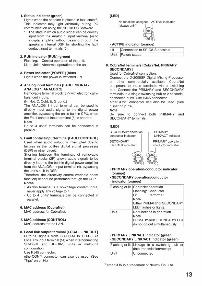
1. Status indicator (green)Lights when the speaker is placed in fault state*1. This indicator may light arbitrarily during PC communication using the SR-D8 PC Software.*1 The state in which audio signal can be directly
input from the Analog 1 input terminal (4) to adigitalamplifierwithoutpassingthroughthespeaker’s internal DSP by shorting the fault contact input terminals (5).
2. rUN indicator [rUN] (green)Flashing: Correct operation of the unit.Lit or Unlit: Abnormal operation of the unit.
3. power indicator [pOWer] (blue)Lights when the power is switched ON.
4. Analog input terminals [FAULT SIgNAL/ANALOg 1, ANALOg 2]Removable terminal block (3P) with electronically-balanced inputs. (H: Hot, C: Cold, E: Ground.)The ANALOG 1 input terminal can be used to directly input audio signal to the digital power amplifier,bypassingtheunit’sbuilt-inCPU,whenthe Fault contact input terminal (5) is shorted.NoteUp to 4 units’ terminals can be connected in parallel.
5. Fault contact input terminal [FAULT cONTrOL]Used when audio output is interrupted due to failures in the built-in digital signal processor (DSP) or other circuit.Shorting between the terminals of removable terminal blocks (2P) allows audio signals to be directlyinputtothebuilt-indigitalpoweramplifierfrom the ANALOG 1 input terminal (4), bypassing the unit’s built-in DSP.Therefore, the directivity control (variable beam function) cannot be performed through the DSP.Notes• As this terminal is a no-voltage contact input,
never apply any voltage to it. • Up to 4 units’ terminals can be connected in
parallel.
6. MAc address (cobraNet)MAC address for CobraNet.
7. MAc address (cONTrOL)MAC address for the LAN.
8. Local link output terminal [LOcAL LINk OUT]Outputs signals from SR-D8-M to SR-D8-S’s Local link input terminal (14) when interconnecting SR-D8-M and SR-D8-S units in multi-unit configuration.Use RJ45 connector. etherCON*2 connector can also be used. (See "Tips" on p. 14.)
[LeD]ACTIVE indicatorNo functions assigned
(always unlit)
• ACTIVE indicator (orange)Lit Connection to SR-D8-S possible.Unlit Failure status
9. cobraNet terminals [cobraNet, prIMAry, SecONDAry]Used for CobraNet connection. Connect the D-2008SP Digital Mixing Processor or other commercially available CobraNet equipment to these terminals via a switching hub. Connect the PRIMARY and SECONDARY terminals to a single switching hub or 2 cascade-connected hubs. Use RJ45 connector. etherCON*2 connector can also be used. (See "Tips" on p. 14.)NoteBe sure to connect both PRIMARY and SECONDARY terminals.
[LeD]
PRIMARY operation/conductor indicator
SECONDARYLINK/ACT indicator
PRIMARYLINK/ACT indicator
SECONDARY operation/conductor Indicator
• PRIMARY operation/conductor indicator (orange) • SECONDARY operation/conductor indicator (orange)
Flashing or lit CobraNet operationFlashing: ConductorLit: PerformerNoteEither PRIMARY or SECONDARY LEDflashesorlights.
Unlit No functions in operationNotePRIMARY and SECONDARY LEDs do not go out simultaneously.
• PRIMARY LINK/ACT indicator (green) • SECONDARY LINK/ACT indicator (green)
Flashing or lit Linkage to a switching hub or data transmission/receipt
Unlit Unconnected
*2 etherCON is a trademark of Neutrik Co., Ltd.

14
10. LAN connection terminal [LAN]For PC communication using the SR-D8 PC Software.Connects to a 100BASE-TX-compatible network. Connect this terminal to a PC via a switching hub.Use RJ45 connector. etherCON* connector can also be used. (See Tip below.)NoteDo not connect the LAN terminal directly to the PC.
[LeD]LINK indicator FULL indicator
• FULL indicator (orange)Lit Communicating with a switching hubUnlit Undetected
• LINK indicator (green)Lit Linkage to a switching hubUnlit Undetected
11. Ac inletInsert supplied power cord (2 m or 6.56 ft) into this socket.
12. Analog input terminal [FAULT SIgNAL]Removable terminal block (3P) with electronically-balanced input.(H: Hot, C: Cold, E: Ground)This terminal is used for direct audio signal input to the digital power amplifier, bypassing theunit’s built-in CPU, when the Fault Contact input terminal (5) is shorted.NoteUp to 4 units’ terminals can be connected in parallel.
13. Local link through terminal [LOcAL LINk THrOUgH]
Outputs signals from SR-D8-M to SR-D8-S’s Local link input terminal (14) when interconnecting SR-D8-M and SR-D8-S units in 3-unit or 4-unit configuration.Use RJ45 connector. etherCON* connector can also be used. (See Tip below.)
[LeD]ACTIVE indicatorNo functions assigned
(always unlit)
• ACTIVE indicator (orange)Lit Connection to SR-D8-S possible.Unlit Failure status
14. Local link input terminal [LOcAL LINk IN] Accepts signals from SR-D8-M’s Local link output terminal (8) or SR-D8-S’s Local link through terminal (13) when interconnecting SR-D8-M and SR-D8-Sunitsinmulti-unitconfiguration.Use RJ45 connector. etherCON* connector can also be used. (See Tip below.)
[LeD]LINK indicatorNo functions assigned
(always unlit)
• LINK indicator (orange)Lit Connection to SR-D8-M complete.Unlit Undetected
15. cord clampFixes the power cord.
Tips• UseSTPCategory5StandardstraightthroughcablewithRJ45connectors.• ForetherCON*connectors,useNeutrikNE8MCorNE8MC-B.
* etherCON is a trademark of Neutrik Co., Ltd.

15
8. brAckeTS• SR-D8CS Wall Mounting Adapter
• SR-D8WB Wall Mounting Bracket
• SR-D8CL Wall Mounting Adapter
Hex bolt M8×25 (with spring and plain washers) ... 4
Hex bolt M8×25 (with spring and plain washers) ... 4
Hex nut M8 (with flange) ... 1Hex bolt M8×25 (with spring and plain washers, for spare) ... 2Hex bolt M6×20 (with spring and plain washers, paint) ... 8
Hex bolt M6×20 (with spring and plain washers, paint) ... 16
Hex bolt M6×20 (with spring and plain washers, paint) ... 8Hex bolt M10×30 (with spring and plain washers, paint) ... 4
Wall bracket Speaker bracket
SR-D8HB Hoisting Bracket
• SR-D8FB Fixing Bar
Hoisting bracket Eyebolt
• SR-D8EP Extension PlateL bracket R bracket
[Number of linked speakers and required joint brackets]Model No. Single Unit 2-UnitConfiguration 3-UnitConfiguration 4-UnitConfiguration
Speaker SR-D8-M 1 1 1 1SR-D8-S 0 1 2 3
Bracket SR-D8EP 0 1 2 3SR-D8WB 2 2 3 4SR-D8FB* 2 2 3 4SR-D8CS 1 0 0 0SR-D8CL 0 1 2 3SR-D8HB 0 1 1 1
*Useonlywhensettingleftorrightanglestoover45°.

16
9. cOMMUNIcATIONS beTWeeN pc AND SpeAkerSConnect the PC to the SR-D8-M’s/SR-D8-S’s LAN connection terminal via a switching hub.Useastraightthroughcable(STPCategory5orhighercablefittedwithRJ45connectors)forconnection.Up to 4 stacks (up to 16 speakers) can be controlled by a single PC.
Note: Do not connect the LAN terminal directly to the PC.
PC with the SR-D8 PC Software installed
Switching hub
Category 5 or higher straight throughcable for LAN (with RJ45 connectors)
SR-D8-MBottom terminals
SR-D8-SBottom terminals
SR-D8-SBottom terminals
SR-D8-SBottom terminals

17
10. cONNecTIONS10.1. connection example 1 (cobraNet connection)
MIC/LINE INPUT M
ODULE [–50 / –36 / –10 / +4 dB]
model D
-2000AD1
:E:H:C
4
3
2
1
MIC/LINE INPUT M
ODULE [–50 / –36 / –10 / +4 dB]
model D
-2000AD1
:E:H:C
4
3
2
1
1R
2R
1L
2L
3L3R
4L4R
model D
-936RSTER
EO SELEC
T INPU
T MO
DU
LE [ –10 dB]
4
3
2
1
LINE OUTPUT MODULE [–10/+4 dB]
model D-2000DA1
123
: E: H: C
MicrophoneBGM player (Cassette deck, CD player, MD player, etc.)
PC
Digital mixerD-2008SP
D-2000AD1D-936R
D-2000DA1
Switching hub
CobraNet
CobraNet
SR-D8-M
Switch
Rear terminals
Bottom terminals

18
10.2. connection example 2 (cobraNet connection, 4-Unit configuration)
MIC/LINE INPUT M
ODULE [–50 / –36 / –10 / +4 dB]
model D
-2000AD1
:E:H:C
4
3
2
1
MIC/LINE INPUT M
ODULE [–50 / –36 / –10 / +4 dB]
model D
-2000AD1
:E:H:C
4
3
2
1
1R
2R
1L
2L
3L3R
4L4R
model D
-936RSTER
EO SELEC
T INPU
T MO
DU
LE [ –10 dB]
4
3
2
1
LINE OUTPUT MODULE [–10/+4 dB]
model D-2000DA1
123
: E: H: C
MicrophoneBGM player (Cassette deck, CD player, MD player, etc.)
PC
Digital mixerD-2008SP
D-2000AD1D-936R
D-2000DA1
Rear terminals
Switch
SR-D8-M
SR-D8-S
Bottom terminals
Rear terminals
Bottom terminals
SR-D8-S
Rear terminals
Bottom terminals
SR-D8-S
Rear terminals
Bottom terminals
Switching hub(for CobraNet)
CobraNet
CobraNetSwitching hub(for LAN)
All local link cables connected between speakers should be under 1.5 m (4.92 ft) long.

19
10.3. connection example 3 (Analog Line connection)
MIC/LINE INPUT M
ODULE [–50 / –36 / –10 / +4 dB]
model D
-2000AD1
:E:H:C
4
3
2
1
MIC/LINE INPUT M
ODULE [–50 / –36 / –10 / +4 dB]
model D
-2000AD1
:E:H:C
4
3
2
1
1R
2R
1L
2L
3L3R
4L4R
model D
-936RSTER
EO SELEC
T INPU
T MO
DU
LE [ –10 dB]
4
3
2
1
LINE OUTPUT MODULE [–10/+4 dB]
model D-2000DA1
123
: E: H: C
MicrophoneBGM player (Cassette deck, CD player, MD player, etc.)
PC
Digital mixerD-2008SP
D-2000AD1D-936R
D-2000DA1
Switching hub
Analog line
SR-D8-M
Switch
Rear terminals
Bottom terminals

20
10.4. connection example 4 (Maximum System)
MIC/LINE INPUT M
ODULE [–50 / –36 / –10 / +4 dB]
model D
-2000AD1
:E:H:C
4
3
2
1
MIC/LINE INPUT M
ODULE [–50 / –36 / –10 / +4 dB]
model D
-2000AD1
:E:H:C
4
3
2
1
1R
2R
1L
2L
3L3R
4L4R
model D
-936RSTER
EO SELEC
T INPU
T MO
DU
LE [ –10 dB]
4
3
2
1
LINE OUTPUT MODULE [–10/+4 dB]
model D-2000DA1
123
: E: H: C
MicrophoneBGM player (Cassette deck, CD player, MD player, etc.)
PC
Digital mixerD-2008SP
D-2000AD1D-936R
D-2000DA1
Switching hub(for CobraNet)
Switching hub (1)(for LAN)
Switching hub (2)(for LAN)
To switching hub (2)
Rear terminals
SwitchSR-D8-M
SR-D8-S
Bottom terminals
Rear terminals
Bottom terminals
SR-D8-S
Rear terminals
Bottom terminals
SR-D8-S
SR-D8-M
SR-D8-S
SR-D8-S
SR-D8-S
Rear terminals
Bottom terminals
Stack A
To switching hub (1)
B-1
B-2
B-3
B-3
B-3
B-3
SR-D8-M
SR-D8-S
SR-D8-S
SR-D8-S
C-1
C-2
C-3
C-3
C-3
C-3
SR-D8-M
SR-D8-S
SR-D8-S
SR-D8-S
D-1
D-2
D-3
D-3
D-3
D-3
To B-3 To C-3
To D-3
Stack B Stack C Stack D
To D-1
To B-1
To C-1
To D-2To C-2To B-2
All local link cables connected between speakers should be under 1.5 m (4.92 ft) long.

21
MIC/LINE INPUT M
ODULE [–50 / –36 / –10 / +4 dB]
model D
-2000AD1
:E:H:C
4
3
2
1
MIC/LINE INPUT M
ODULE [–50 / –36 / –10 / +4 dB]
model D
-2000AD1
:E:H:C
4
3
2
1
1R
2R
1L
2L
3L3R
4L4R
model D
-936RSTER
EO SELEC
T INPU
T MO
DU
LE [ –10 dB]
4
3
2
1
LINE OUTPUT MODULE [–10/+4 dB]
model D-2000DA1
123
: E: H: C
MicrophoneBGM player (Cassette deck, CD player, MD player, etc.)
PC
Digital mixerD-2008SP
D-2000AD1D-936R
D-2000DA1
Switching hub(for CobraNet)
Switching hub (1)(for LAN)
Switching hub (2)(for LAN)
To switching hub (2)
Rear terminals
SwitchSR-D8-M
SR-D8-S
Bottom terminals
Rear terminals
Bottom terminals
SR-D8-S
Rear terminals
Bottom terminals
SR-D8-S
SR-D8-M
SR-D8-S
SR-D8-S
SR-D8-S
Rear terminals
Bottom terminals
Stack A
To switching hub (1)
B-1
B-2
B-3
B-3
B-3
B-3
SR-D8-M
SR-D8-S
SR-D8-S
SR-D8-S
C-1
C-2
C-3
C-3
C-3
C-3
SR-D8-M
SR-D8-S
SR-D8-S
SR-D8-S
D-1
D-2
D-3
D-3
D-3
D-3
To B-3 To C-3
To D-3
Stack B Stack C Stack D
To D-1
To B-1
To C-1
To D-2To C-2To B-2
All local link cables connected between speakers should be under 1.5 m (4.92 ft) long.

22
10.5. removable Terminal plug connection
Notes• Avoidsolderingstrandedorshieldedcable,ascontactresistancemayincreasewhenthecableistightened
and the solder is crushed, possibly resulting in an excessive rise in joint temperatures.• Whenconnecting2cablesorashieldedcabletoasingleterminal,useaferruleterminalwithaninsulation
sleeve to crimp the cables because such cable conductors could become loose. Use the No. 4 ferrule terminal when connecting 2 cables to a single terminal.
• Recommendedferruleterminalsforallremovableterminalplugs (made by Phoenix Contact)
Unit: mm (in)Model Number a b l1 l2AI 0,34-8 TQ 2 (0.08) 0.8 (0.03) 12.5 (0.49) 8 (0.31)AI0,5-8WH 2.5 (0.1) 1.1 (0.04) 14 (0.55) 8 (0.31)Al 1,5-8 BK 3.4 (0.13) 1.8 (0.07) 14 (0.55) 8 (0.31)
Model Number a1 a2 b l1 l2AI-TWIN2x0,5-8BK 6.6 (0.26) 3.6 (0.14) 2.3 (0.09) 16 (0.63) 8 (0.31)
Crimping tool: CRIMPFOX UD6-4 (made by Phoenix Contact) Note: The No. 3 ferrule terminal cannot be used for the Fault contact
input terminal (5) on p. 13.• Cablesvs.recommendedterminals AWG22cable:No.1ferruleterminal AWG20cable:No.2ferruleterminal AWG16cable:No.3ferruleterminal 2 x 0.5 mm2(AWG20)cable:No.4ferruleterminal
• Cablesheathtotrim
Insulation sleeveContact section
Insulation sleeveContact section
a
l2
a1
a2
l1
l2
l1
bb
Solid cable and stranded cable Shielded cable7 mm*(0.28'') (0.28'')
(0.79'')
7 mm*
20 mm
Expose 8 mm (0.31'') or more when using the above ferrule terminal, and cut off an extra conductor protruding from the sleeve.
*
[Connecting a single wire to one terminal]
[Connecting two wires to one terminal]
• Connectionstoferruleterminals
• Wiringprocedures
Step 1. Connect the wire to the supplied removable terminal plug.
1-1. Loosen the terminal screws to insert the wire.
1-2. Tighten the terminal screws.Ensure that the wire does not break free when pulled. If the wire does pull free, repeat the connection procedure from the start.
Step 2. Insert the wired terminal plug into the corresponding terminal block in the unit’s rear panel.
Step 3 Tightenthefixingscrews.
Note Do not reverse Steps 1 and 2 above. Force is applied to the connected receptacle pins while tightening the terminal screw and they may be damaged, resulting in bad connector contact.
Terminal screwFixing screw
Removable terminal plug(accessory)
Tightens
Tightens
Slotted screwdriver*
Recommended slotted screwdriver type: Screwdriver with blade that is 2.5 mm (0.1'') in width
Loosens
Bit shape
1
13
*
2.5 mm (0.1'')

23
10.6. Fixing power Supply cord
To prevent the power supply cord from being accidentallypulledout,fixitusingthesuppliedcord clamp as shown at right.
SR-D8-M rear SR-D8-S rear
Power cord (supplied with the SR-D8-S)
Cord clamp
Power cord (supplied with the SR-D8-M)
Cord clamp

24
10.7. System expansion Using cobraNet connection
10.7.1. cobraNet connection outline
The system can be expanded by connecting the SR-D8-M’s CobraNet terminals to the D-2008SP with the D-2000CB CobraNet Interface Module. Connect the SR-D8-M to the D-2008SP via a switching hub. Connect each of CobraNet Primary and Secondary ports of the SR-D8-M to the same switching hub or different switching hubs connected in cascade.
SR-D8-M
Rear terminals
CobraNet terminal(PRIMARY)
CobraNet terminal(SECONDARY)
Bottom terminals
Notes• MaketheCobraNetterminalscompletelyindependentfromotherLAN.• ThedistancebetweeneachoftheSR-D8-Mandtheswitchinghubislessthan100m(110yd).• BesuretomakeconnectionsofbothterminalsPRIMARYandSECONDARY.• AudiosignalsmaybeinterruptedtemporarilyatthetimeofswitchingbetweenPRIMARYandSECONDARY
ports.• When connecting CobraNet terminal PRIMARY or SECONDARY to multiple switching hubs, be sure to
connect the hubs in cascade. • Upto7switchinghubscanbeconnectedincascade.ThenumberofswitchinghubsbetweentheSR-D8-M
and all CobraNet devices connected to the SR-D8-M should be 7 or less. (Refer to connection examples 1 and 2 on the next page.)
• Whenusingmultipleswitchinghubs,makingstarconnectionatthehubdirectlyconnectedtotheSR-D8-Masshown in Connection example 2 is highly recommended to reduce the number of cascade-connected hubs.

25
[connection example 1: redundant configuration of switching hubs]
CobraNet PRIMARY CobraNet SECONDARY
CobraNet PRIMARY(Operating)
CobraNetSECONDARY
CobraNetPRIMARY
CobraNetSECONDARY(Operating)
SR-D8-M
CobraNet unit B
CobraNet unit A
SW-HUB SW-HUB
SW-HUB SW-HUB
SW-HUB SW-HUB 6
5
43
2
1
As shown in the example above, when the CobraNet unit A is operating via the CobraNet PRIMARY and the CobraNet unit B is operating via the CobraNet SECONDARY, 6 switching hubs are used for communications betweenbothunits.Therefore,inaredundantconfigurationofswitchinghubs*,thenumberofhubscascade-connected from the SR-D8-M should be 3 or less.
* A method of connecting a single unit’s CobraNet PRIMARY and SECONDARY terminals to each different switching hub to prevent the system from going down when a cable is broken or power fails.
[connection example 2: Non-redundant configuration of switching hubs]
SR-D8-M
CobraNet unit C
CobraNet unit B
CobraNet unit A
SW-HUB
SW-HUBSW-HUB SW-HUB SW-HUB
SW-HUBSW-HUB SW-HUB SW-HUB
SW-HUB SW-HUB SW-HUB
SW-HUB
1
2
3
4
5
6
7
8
CobraNet PRIMARY, SECONDARY
Star connections
As 7 switching hubs are on the communication path from the CobraNet unit A to the CobraNet unit B, there is no problem for the system. However, as the number of hubs from the CobraNet unit A to the CobraNet unit C is 8, there may be a system failure.

26
10.7.2. redundant configuration of switching hubs
Shownbelowistheconnectionexampleofthe4stackconfiguration,inwhicheachSR-D8-Misconnectedtoswitching hubs.In the connection example below, the CobraNet PRIMARY and SECONDARY terminals of each unit are individually connected to different switching hubs. Even if any one of the switching hubs fails or Main line breaks, the system is kept operating using another Main line, thus preventing system down.
Notes• Cycletheentiresystem’spowerafterconnectioncompletion.• Performspanningtreesettingwithinswitchinghubs.Forthesettings,refertotheinstructionmanualofthe
switching hub. • Audio signals may be interrupted temporarily at the time when the network configuration automatically
changes due to failure of any switching hub or disconnection of the main line.• ContactyourTOAdealerformoreinformationonswitchinghubs.
SR-D8-Mbottom terminals
SR-D8-Mbottom terminals
SR-D8-Mbottom terminals
SR-D8-Mbottom terminals
PRIMARY
SECONDARY
Switching hub(SECONDARY)
Switching hub(PRIMARY)
To other switching hub
To other switching hub
Other CobraNet unit
Main line
Main line
Category 5 or higher standard straight through cable for LAN (with RJ45 connectors)

27
10.7.3. Non-redundant configuration of switching hubs
Shownbelowistheconnectionexampleofthe4stackconfiguration,inwhicheachSR-D8-Misconnectedtothe same switching hub.In the connection example below, both CobraNet PRIMARY and SECONDARY terminals of each unit are connected to the same switching hub.
Notes• Cycletheentiresystem’spowerafterconnectioncompletion.• ContactyourTOAdealerformoreinformationonswitchinghubs.
SR-D8-Mbottom terminals
SR-D8-Mbottom terminals
SR-D8-Mbottom terminals
SR-D8-Mbottom terminals
PRIMARY
SECONDARY
Switching hub
Other CobraNet unit
Category 5 or higher standard straight through cable for LAN (with RJ45 connectors)

28
11. INSTALLATION11.1. Installing a Single Sr-D8-M Unit
• Attachthesafetywire,strongenoughtowithstandheavyload,totheunit.• Theapparatusshallbeconnectedtoamainssocketoutletwithaprotectiveearthingconnection.• The socket-outlet shall be installed near the equipment and the plug (disconnecting device) shall be
easily accessible.• Donotusethisspeakerinaflyinginstallation.• Only install speaker units in locations that can structurally support theweight of the speaker and its
mounting brackets (Total weight: 31 kg or 68.34 lb).• Nutsandboltsusedforwallmountingarenotsuppliedwiththeunit. Use hardware appropriate to the wall’s structure and composition.• Neverinstalltheunitonthewalltiltingover30°.• Neveradjustthespeakerangletotheleftorrightwhentheunitisinstalledfacingupordown.
WArNINg
11.1.1. required mounting bracketsMounting Bracket Number Remark
SR-D8WBWallMountingBracket 2 Arrange 9 sets of M10 anchor bolts and M10 nuts separately.SR-D8CSWallMountingAdapter 1SR-D8FB Fixing Bar 2 Usewhensettingleftorrightanglestoover45°.
11.1.2. Wall mounting
Step 1. Install anchor stud bolts in the wall (see thefigureatright).
Step 2. Assemble the bracket sets to be mounted to the wall.
Step 3. Mount the assembled bracket sets to the wall.
32 (1.2
6)12
5(4
.92)
(4.9
2)24
6 (9
.69)
155
(6.1
)12
5
625
(24.
61)
56 (2.2)
120.4(4.74)
9-12×28(9-0.47×1.1)
NoteGray area indicates speaker mounting position.
Unit: mm (in)
[Anchor Stud Bolt Mounting Dimensions]Bracket Mounting Anchor Stud Bolts (M10)
[Single nut] [Double nut]18 – 30 25 – 30
(0.71 – 1.18) (0.98 – 1.18)
Wall Wall
Unit: mm (in)
To determine stud bolt projection from the wall surface, refer to the dimensions indicated below:
WallWall bracket of the SR-D8WB
Wall bracket of the SR-D8WB
SR-D8CS
Hex bolt M8×25 (with spring and plain washers, supplied with the SR-D8CS)
Hex bolt M8×25 (with spring and plain washers, supplied with the SR-D8CS)
322
Nut for M10(Prepare separately.)
Anchor Stud Bolt M10 (Prepare separately.)

29
Step 4. Remove screws from speaker sides.
Step 5. Securely tighten 6 angle adjustment bolts (4 on the upper side and 2 on the lower side) of each speaker bracket, then attach each bracket to the speaker.
Step 6. Loosely tighten bolts in the mounting holes located on both sides of the lower part of each speaker bracket.
Step 7. Hang the loosely tightened bolts on the wall bracket.
Step 8. Install bolts in left- and right-side mounting holes located in the upper part of the speaker bracket.
Step 9. Securely tighten all bolts.
[completed Mounting]
NoteLeftandrightanglescanbeadjustedwithinarangeof0°–90°.If no angle adjustments are required, this completes the installation. Whenperforming angle adjustments, please refer to “Angle Adjustment” on p. 35.
Unit: mm (in)
Remove screws.
The removed screws are not used. Note
SR-D8-M
5
5
6
6
7
78
4
Wall
Hex bolt M6×20 (with spring and plain washers)*
Hex bolt M10×30 (with spring and plain washers)*
Loosely tighten bolts.
Securely tighten.
Securely tighten.
Hang on wall bracket.
[Enlarged figure of Part A]
Speaker bracket of the SR-D8WB
Speaker bracket of the SR-D8WB
Wall bracket of the SR-D8WB
Wall bracket ofthe SR-D8WB
* Supplied with the SR-D8WB
Hex bolt M10×30 (with spring and plain washers)*
A
A
[completed Dimensional Diagram]
373 (14.69)
48 (1
.89)
576.
5 (2
2.7)
319
(12.
56)
118 (4.65)
Unit: mm (in)

30
11.2. Installing Sr-D8-M and Sr-D8-S(s) in multi-unit configuration
Up to 3 SR-D8-S speaker units can be connected in series to one SR-D8-M.
• Attachthesafetywire,strongenoughtowithstandheavyload,totheunit.• Theapparatusshallbeconnectedtoamainssocketoutletwithaprotectiveearthingconnection.• The socket-outlet shall be installed near the equipment and the plug (disconnecting device) shall be
easily accessible.• Donotusethisspeakerinaflyinginstallation.• Only install speaker units in locations that can structurally support theweight of the speaker and itsmountingbrackets(Totalweight...2-UnitConfiguration:57kgor125.66lb,3-UnitConfiguration:88kgor194lb,4-UnitConfiguration:118kgor260.14lb).
• Nutsandboltsusedforwallmountingarenotsuppliedwiththeunit. Use hardware appropriate to the wall’s structure and composition. • Neverinstalltheunitonthewalltiltingover30°.• Neveradjustthespeakerangletotheleftorrightwhentheunitisinstalledfacingupordown.
WArNINg
11.2.1. required mounting brackets
[2-Unit configuration]Mounting Bracket Number Remark
SR-D8EP Extension Plate 1SR-D8WBWallMountingBracket 2 Arrange 9 sets of M10 anchor bolts and M10 nuts separately.SR-D8CLWallMountingAdapter 1SR-D8HB Hoisting Bracket 1SR-D8FB Fixing Bar 2 Usewhensettingleftorrightanglestoover45°.
[3-Unit configuration]Mounting Bracket Number Remark
SR-D8EP Extension Plate 2SR-D8WBWallMountingBracket 3 Arrange 14 sets of M10 anchor bolts and M10 nuts separately.SR-D8CLWallMountingAdapter 2SR-D8HB Hoisting Bracket 1SR-D8FB Fixing Bar 3 Usewhensettingleftorrightanglestoover45°.
[4-Unit configuration]Mounting Bracket Number Remark
SR-D8EP Extension Plate 3SR-D8WBWallMountingBracket 4 Arrange 19 sets of M10 anchor bolts and M10 nuts separately.SR-D8CLWallMountingAdapter 3SR-D8HB Hoisting Bracket 1SR-D8FB Fixing Bar 4 Usewhensettingleftorrightanglestoover45°.

31
11.2.2. Wall mounting
Belowistheprocedureforinstallationin2-unitconfiguration.
Step 1. Installanchorstudboltsinthewall(seethefigureinthelowerright).Note:Formountingdimensionsin3-unitand4-unitconfigurations,seep.34.
Step 2. Assemble the bracket sets to be mounted to the wall.
Step 3. Mount the assembled bracket sets to the wall.
NoteGray area indicates speaker mounting position.
Wall bracket of the SR-D8WB
Wall bracket of the SR-D8WB
SR-D8CL
Hex bolt M8×25 (with spring and plain washers,supplied with the SR-D8CL)
2
Hex bolt M8×25 (with spring and plain washers, supplied with the SR-D8CL)
2
3212
541
8 (1
6.46
)35
3 (1
3.9)
125
1150
.2 (4
5.28
)
120.4
56 (2.2)
9-12×28
3
Wall
Unit: mm (in)
[Anchor Stud Bolt Mounting Dimensions (2-Unit Configuration)]
(1.2
6)(4
.92)
(4.9
2)
(4.74)(9-0.47×1.1)
Nut for M10(Prepare separately.)
Anchor Stud Bolt M10 (Prepare separately.)
Bracket Mounting Anchor Stud Bolts (M10)
[Single nut] [Double nut]18 – 30 25 – 30
(0.71 – 1.18) (0.98 – 1.18)
Wall Wall
Unit: mm (in)
To determine stud bolt projection from the wall surface, refer to the dimensions indicated below:

32
Step 4. Remove screws from speaker sides.
Step 5. Attach each speaker bracket to the speaker. Bracket Mounting position Remark
Hoisting Bracket On top of the speaker stack Mount an eyebolt.Use only for hoisting the speaker stack at speaker installation.
Speaker Bracket Center of each speaker Securely tighten 6 angle adjustment bolts (4 on the upper side and 2 on the lower side) of each speaker bracket, then attach each bracket to the speaker.
Extension Plate Joint part of speakers
Step 6. Loosely tighten bolts in the mounting holes located on both sides of the lower part of each speaker bracket.
SR-D8-S
5
6
4
Hex bolt M6×20 (with spring and plain washers)*1
Hex bolt M10×30 (with spring and plain washers)*3
Speaker bracket of the SR-D8WB
Hoisting bracket of theSR-D8HB
Eyebolt of the SR-D8HB
*1 Supplied with the SR-D8RB*2 Supplied with the SR-D8EP*3 Supplied with the SR-D8WB
A
A
5 64
Hex bolt M6×20 (with spring and plain washers)*2
Hex bolt M6×20 (with spring and plain washers)*3
Hex bolt M10×30 (with spring and plain washers)*3
R bracket of the SR-D8EP
L bracket of the SR-D8EP
SR-D8-M
5
5Loosely tighten bolts.
Speaker bracket of the SR-D8WB
Remove screws.
Securely tighten.
Securely tighten.
NoteOnly 8 screws out of all removed in this step are used in Step 10.No other screws are used.

33
Step 7. Hang the loosely tightened bolts on the wall bracket.
Step 8. Install bolts in left- and right-side mounting holes located in the upper part of the speaker bracket.
Step 9. Securely tighten all bolts.
Step 10. Remove the hoisting bracket, then replace the 8 screws removed in Step 4.TipThe performance of the speaker is maintained even if the bracket is mounted as it is.
NoteLeft and right angles can be adjusted within a range of0°–90°.If no angle adjustments are required, this completes theinstallation.Whenperformingangleadjustments,please refer to “Angle Adjustment” on p. 35.
7
78
[Enlarged figure of previous page Part A]
*3 Supplied with the SR-D8WB
Hex bolt M10×30 (with spring and plain washers)*3
Hang on wall bracket.
Speaker bracket of the SR-D8WB
Wall bracket of the SR-D8WB
Note: For Completed Mountings and Completed Mounting Dimensional Diagramsin3-unitand4-unitconfigurations,seep.34.
[completed Mounting (2-Unit configuration)]
373 (14.69)118 (4.65)
322.
5 (1
2.7)
*431
9 (1
2.56
)*411
50.2
(45.
28)
These dimensions are the same as those in 3-unit and 4-unit configurations.
*4
80 (3
.15)
*4
[completed Dimensional Diagram (2-Unit configuration) with Hoisting bracket Mounted]
Unit: mm (in)

34
Wallmountingmethodsfor3-unitand4-unitconfigurationsarethesameasthemountingmethodfor2-unitconfiguration.Mount the speakers referring to the diagrams as shown below.
3-Unit configuration 4-Unit configuration
SR-D8HBSR-D8WBSR-D8CLSR-D8EP
NoteGray area indicates speaker mounting position.
NoteGray area indicates speaker mounting position.
125
2942
.6 (1
15.8
5)
418
(16.
46)
353
(13.
9)
125
56 (2.2) 56 (2.2)
2046
.4 (8
0.57
)
125
353
(13.
9)12
541
8 (1
6.46
)
418
(16.
46)
353
(13.
9)35
3 (1
3.9)
418
(16.
46)
353
(13.
9)41
8 (1
6.46
)
3212
5(1
.26)
(4.9
2)
(1.2
6)(4
.92)
(4.9
2)(4
.92)
(4.9
2)
(4.9
2)(4
.92)
120.4(4.74)
14-12×28(14-0.47×1.1)
(19-0.47×1.1)
3212
512
5
120.419-12×28
319
(12.
56)
322.
5(1
2.7)
80(3
.15)
322.
5(1
2.7)
373 (14.69) 373 (14.69)118
(4.65)118
(4.65)
319
(12.
56)
80(3
.15)
1
2
3
4
2
2
4
1
2
3
3 3
4
2
2
4
3
2
4
1234
[Completed Mounting][Completed Mounting]
[Completed Dimensional Diagram with Hoisting Bracket Mounted]
[Completed Dimensional Diagram with Hoisting Bracket Mounted][Anchor Stud Bolt
Mounting Dimensions][Anchor Stud Bolt Mounting Dimensions]
Unit: mm (in)
35
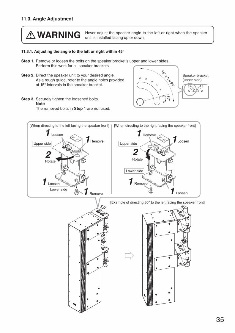
11.3. Angle Adjustment
11.3.1. Adjusting the angle to the left or right within 45°
Step 1. Remove or loosen the bolts on the speaker bracket’s upper and lower sides. Perform this work for all speaker brackets.
Step 2. Direct the speaker unit to your desired angle.As a rough guide, refer to the angle holes provided at15°intervalsinthespeakerbracket.
Step 3. Securely tighten the loosened bolts.NoteThe removed bolts in Step 1 are not used.
15º
15º x 6 = 90º
Speaker bracket(upper side)
[When directing to the right facing the speaker front]
LoosenRemove
Upper side
Lower side
Remove
1
1
1
Rotate
Loosen
2
1[Example of directing 30° to the left facing the speaker front]
[When directing to the left facing the speaker front]
Remove
Rotate
Loosen
Upper side
Lower sideLoosen
Remove
1
2
11
1
Never adjust the speaker angle to the left or right when the speaker unit is installed facing up or down.WArNINg

36
11.3.2. Adjusting the angle to the left or right over 45°
15º
15º x 6 = 90º
Speaker bracket(upper side)
Step 1. Remove or loosen the bolts on the speaker bracket’s upper and lower sides. Perform this work for all speaker brackets.
Step 2. Directthespeakerunittoanangleof45°.As a rough guide, refer to the angle holes provided at 15° intervals in the speakerbracket.
Step 3. Loosely secure the SR-D8FB Fixing Bar to the speaker bracket’s upper side. Perform this work for all speaker brackets.Use 2 of the removed bolts in Step 1 and a nut supplied with the SR-D8FB.
Step 4. Direct the speaker unit to your desired angle.
Step 5. Securely tighten all loosened bolts and nuts.NoteThe removed bolts except those used in Step 3 are not used.
[Example of directing 90° to the left facing the speaker front]
SR-D8FB
Rotate43
[When directing to the right facing the speaker front]
Loosen
Remove
Upper sideUpper side
Lower side
Remove
1
1
1Rotate
Hex nut M8 (with flange,supplied with the SR-D8FB)
Loosen
2
1
[When directing to the left facing the speaker front]
Remove
Rotate
Loosen
Upper side
Lower sideLoosen
Remove
1
2
11
1※
※
※ Hex bolt M8 x 25 (with spring and plain washers) supplied with the SR-D8FB may be used.

37
12. DIMeNSIONAL DIAgrAMS12.1. Sr-D8-M, Sr-D8-S Active Line Array Speaker Systems
Unit: mm (in)
12.2. brackets
12.2.1. Sr-D8cL Wall Mounting Adapter
Unit: mm (in)
12.2.2. Sr-D8cS Wall Mounting Adapter
Unit: mm (in)
50 (1.97)
642.
2 (2
5.28
)
33 (1.3)
[Top]
[Side][Front][Rear]
(SR-D8-M)[Rear]
(SR-D8-S)
160 (6.3) 255 (10.04)
895.
2 (3
5.24
)
50(1.97)
116.
633
(4.5
9)(1
.3)

38
12.2.3. Sr-D8ep extension plateUnit: mm (in)
12.2.4. Sr-D8Wb Wall bracketUnit: mm (in)
12.2.5. Sr-D8Hb Hoisting bracketUnit: mm (in)
12.2.6. Sr-D8Fb Fixing barUnit: mm (in)
[L bracket] [r bracket]
[Wall bracket] [Speaker bracket]
[Hoisting bracket]
[eyebolt]
15.2 (0.6) 194.2 (7.65)
275
(10.
83)
15.2 (0.6) 194.2 (7.65)
275
(10.
83)
254
(10)
120.4(4.74)
52(2.05)
167.4 (6.59)15
0.7
(5.9
3)
295 (11.61)
171
(6.7
3)
170 (6.69)168 (6.61)
73(2
.87)
25(0.98)
50(1.97)
30 (1.18)
135.
5 (5
.33)
28 (1.1) 3.2 (0.13)
6.4 (0.25)

39
13. SpecIFIcATIONS13.1. Sr-D8-M, Sr-D8-S Active Line Array Speaker Systems
Version CE CUPower source 220–240VAC,50/60Hz 120VAC,60HzPower Consumption 315W(ratedoutput),
72W(basedonENstandards)320W(ratedoutput),72W(basedonUL/CSAstandards)
Frequency Response 130Hz–20kHzSignal to Noise Ratio 100dBormore(A-weighted),DSP+DigitalpoweramplifierAmplificationSystem Class D, 8 channelsSpeaker Component Low frequency: 10 cm (4") cone-type x 8
High frequency: 2.5 cm (1") balanced dome-type x 24Output 30W,1channel(1%THD+N)Maximum SPL 93 dB SPL (A-weighted, pink noise, 30 m or 32.81 yd)VerticalVariableAngle –45to+45º(AdjustablebyusingthesuppliedSR-D8PCSoftware)Horizontal Directional Angle
90º
Line Input(Only SR-D8-M)
2channels,+4dB*,10kΩ,electronically-balanced, removable terminal block (3 pins)
Sampling Frequency 48 kHzNetwork I/F
Audio CobraNet: 100BASE-TX, PRIMARY/SECONDARY 2 system, RJ45 receptacle (etherCON: NEUTRICK)Connection cable: Shielded twisted pair (STP) CAT 5 or higher LAN cable TobeconnectedviathespecifiedswitchinghubMax. extend distance: 100 m (109.36 yd) (connected via a switching hub)Note: This network should be completely independent of other LAN.
Control LAN: TCP/IP, 100BASE-TX 1 system, RJ45 receptacle (etherCON: NEUTRICK)Connection cable: Shielded twisted pair (STP) CAT 5 or higher LAN cable TobeconnectedviathespecifiedswitchinghubMax. extend distance: 100 m (109.36 yd) (connected via a switching hub)
Communication Between Main and Sub Speakers
LOCAL LINK: TOA original digital audio transmission, RJ45 receptacle (etherCON: NEUTRICK) Connection cable: Shielded twisted pair (STP) CAT 5 or higher LAN cable
Operating Temperature 0to+40ºC(32to104ºF)Operating Humidity 90 %RH or less (no condensation)Finish Enclosure: MDF, white, pant
Front grille: Punched steel plate, white, acrylic paintDimensions 160 (w) x 895 (h) x 255 (d) mm (6.3" x 35.24" x 10.04")Weight 21 kg (46.3 lb)
*0dB=0.775V
Note: Thedesignandspecificationsaresubjecttochangewithoutnoticeforimprovement.
• Accessories[Sr-D8-M]Power cord (2 m or 6.56 ft) ....................................... 1Removable terminal plug (3 pins) ............................. 2Removable terminal plug (2 pins) ............................. 1CD-ROM (containing SR-D8 PC Software) .............. 1
[Sr-D8-S]Power cord (2 m or 6.56 ft) ....................................... 1Removable terminal plug (3 pins) ............................. 1Removable terminal plug (2 pins) ............................. 1

Traceability Information for europeManufacturer:
TOA Corporation7-2-1, Minatojima-Nakamachi, Chuo-ku, Kobe, Hyogo, Japan
Authorized representative:TOA Electronics Europe GmbHSuederstrasse 282, 20537 Hamburg,Germany
URL: http://www.toa.jp/133-01-00019-00
Fcc reQUIreMeNTS
Note: This equipment has been tested and found to comply with the limits for a Class A digital device, pursuant to part 15 of the FCC Rules. These limits are designed to provide reasonable protection against harmful interference when the equipment is operated in a commercial environment. This equipment generates, uses, and can radiate radio frequency energy and, if not installed and used in accordance with the instruction manual, may cause harmful interference to radio communications. Operation of this equipment in a residential area is likely to cause harmful interference in which case the user will be required to correct the interference at his own expense.
This Class A digital apparatus complies with Canadian ICES-003.CetappareilnumériquedelaclasseAestconformeàlanormeNMB-003duCanada.
WarningThis is a class A product. In a domestic environment this product may cause radio interference in which case the user may be required to take adequate measures.
13.2. brackets
Model No. SR-D8CS SR-D8CL SR-D8EP SR-D8WB SR-D8HB SR-D8FBFinish Steel plate, white, paintDimensions See p. 37. See p. 38.Weight(includingaccessories)
240 g(0.53 lb)
760 g(1.68 lb)
2.9 kg(6.39 lb)
4.7 kg(10.36 lb)
2.4 kg(5.29 lb)
120 g(0.26 lb)
Note: Thedesignandspecificationsaresubjecttochangewithoutnoticeforimprovement.
• AccessoriesSee p. 15.