Speaker Prototyping Design - Digital Commons @ East ...
19
East Tennessee State University East Tennessee State University Digital Commons @ East Tennessee State University Digital Commons @ East Tennessee State University Undergraduate Honors Theses Student Works 12-2020 Speaker Prototyping Design Speaker Prototyping Design Andrew Lathe Follow this and additional works at: https://dc.etsu.edu/honors Part of the Electrical and Electronics Commons, and the Technology and Innovation Commons Recommended Citation Recommended Citation Lathe, Andrew, "Speaker Prototyping Design" (2020). Undergraduate Honors Theses. Paper 584. https://dc.etsu.edu/honors/584 This Honors Thesis - Open Access is brought to you for free and open access by the Student Works at Digital Commons @ East Tennessee State University. It has been accepted for inclusion in Undergraduate Honors Theses by an authorized administrator of Digital Commons @ East Tennessee State University. For more information, please contact [email protected].
-
Upload
khangminh22 -
Category
Documents
-
view
1 -
download
0
Transcript of Speaker Prototyping Design - Digital Commons @ East ...

East Tennessee State University East Tennessee State University
Digital Commons @ East Tennessee State University Digital Commons @ East Tennessee State University
Undergraduate Honors Theses Student Works
12-2020
Speaker Prototyping Design Speaker Prototyping Design
Andrew Lathe
Follow this and additional works at: https://dc.etsu.edu/honors
Part of the Electrical and Electronics Commons, and the Technology and Innovation Commons
Recommended Citation Recommended Citation Lathe, Andrew, "Speaker Prototyping Design" (2020). Undergraduate Honors Theses. Paper 584. https://dc.etsu.edu/honors/584
This Honors Thesis - Open Access is brought to you for free and open access by the Student Works at Digital Commons @ East Tennessee State University. It has been accepted for inclusion in Undergraduate Honors Theses by an authorized administrator of Digital Commons @ East Tennessee State University. For more information, please contact [email protected].

East Tennessee State University
Speaker Protoyping Design Engineering Technology Honors-in-Discipline Thesis Andrew Lathe
Andrew Lathe, Author
Mr. Richard Cox, Mentor
Dr. Paul Sims, Reader

2
Speaker Prototyping Design
Andrew Lathe
East Tennessee State University Electronics Engineering Technology Program
Abstract
Audio design is a pertinent industry in today’s world, with an extremely large market including leaders such as Bose, Harman International, and Sennheiser. This project is designed to explore the processes that are necessary to create a new type of product in this market. The end goal is to have a functioning, high–quality set of speakers to prove various concepts of design and prototyping.
The steps involved in this project go through the entire design process from initial choice of product to a finished prototype. Processes include the selection of outsourced components such as drivers and necessary connectors. The design stage will include any design processes necessary to create the enclosure or any electronics. Production will be controlled by shipping dates and any potential issues that lie within the methods chosen for production. The final product will be tested for response. The prototyping process is usually fulfilled by various departments with extreme expertise in the respective field.
Index Terms
Driver – Term for individual component speaker Tweeter – High frequency range driver Woofer – Medium to low range driver PLA – Polylactic Acid, most common material for 3D printing FDM – Fused Deposition Modelling Enclosure – Box designed to house component speakers Fidelity – The accuracy with which a source sound is replicated MDF – Medium density fiberboard
Introduction
This project delves into the entire design and manufacturing process involved with new product introduction in the audio industry. It is an overview from an initial idea all the way through the production stage. Prototyping in this fashion allows for a product to be tested and efficiently set up to go into full production.
Audio engineering is an extremely complex field with many facets that include design of speakers or acoustics of a room. My personal experience working with audio equipment is mostly in speaker design and live sound systems. Having built a custom speaker system previously, the goal of this project was to experiment with more complex design aspects by creating custom crossovers as well as a non-traditional enclosure. An interest in 3D printing also lead me to an attempt to mix this method of manufacturing into the design. There is some evidence of others experimenting with printed enclosures, though no heavy research has been conducted into the viability of the process. The main advantage that printing offers is the ease of creating more complex or customized enclosure designs. Enclosures such as horn-style or transmission lines require large amounts of woodworking if using a traditional enclosure material such as MDF. The increasing popularity of 3D printing could lead to many new breakthroughs in terms of audio enclosure design.
On the electronics side of the project, the experimentation is with crossover frequencies. There are many pre-built crossovers that can be purchased for ease of creating a two-way speaker system. I wanted to test custom crossovers to have a visualization of how the crossover frequency affects the overall response of the speakers. The amplifier and all other electronic components will still be pre-built designs to ensure that any response variations are due to the crossovers. The circuit boards to be

2
used for the crossovers were designed from scratch to allow for a custom layout of components.
The final product will be used as a home speaker system. The design process will push for the highest quality possible, striving for a studio monitor style speaker system that could be used in such an environment.
Background and Literature Review
There is much theory required to create a prototype speaker such as this design. A basic understanding of audio enclosure engineering is necessary to create a balanced enclosure to accentuate the response capabilities of the drivers. On the electronics side, the level of engineering for all components is rather extensive. This project specifically designs crossovers while using pre-designed components for all other aspects of the electronics systems. These pre-designed components have been thoroughly tested and redesigned to create the cleanest possible signals for audio applications.
Audio Enclosure Design Audio enclosure designs can generally be broken into two common types: sealed and ported. A sealed enclosure is an enclosed box that isolates the audio waves produced by the rear side of the driver cone from those of the front. This can be termed as an infinite baffle. A ported enclosure, also known as a bass reflex enclosure, introduces a constrained air funnel for the rear-side waves to exit the enclosure through. This affects the phase of these waves and is typically used to boost low-end frequencies by creating constructive interference. These two basic enclosure styles can be heavily expanded upon with various designs. The design style used for this prototype is known as a transmission line. This style of enclosure is an extension of the previously mentioned ported enclosure. It expands upon the boosting of low-end frequencies and filtering out higher frequencies through physical means. King [1] mentions that the transmission line was an unproven experimental design that had no truly proven effects on audio performance. His article introduces the theory behind creating a method to achieve consistent repeatable results from a transmission line design. This project did not require such a deep dive into the algorithms for creating such results but was more
interested in the generic testing results presented by King [2]. Fig. 1 is a table showing the driver resonant frequency, the calculated tube quarter wavelength frequencies, and the measured system peaks [2] base upon a test conducted using two different Focal 8V 4412 drivers.
Figure 1 – Transmission Line Responses
King mentions that these responses exhibit a similar quality to that of a ported enclosure design. The transmission line is a refined version of a generic ported enclosure. This response lends itself to this design project because the goal of the woofer is to produce mostly lower-end frequencies. The final design for this project is a combination of a bass reflex cavity that the woofer sits in with a quarter-wavelength transmission line as the part. This transmission wave guide was designed to match the resonant frequency of the woofer drivers chosen for this project. The tweeters did not require any special consideration during design as they are a self-contained enclosure.
The electronics theory behind even a simple speaker project can be quite complicated. Audio amplifiers are often engineered to create a high-fidelity signal reproduction. Noise reduction is necessary to keep any form of distortion out of audio signals, especially desired in applications such as studio recording. For this reason, designing the amplifier, power board, and Bluetooth receiver board was considered, but was rejected in favor of pre-designed components to prevent large amounts of noise being introduced into the system. These pre-designed components have been tuned to reduce noise as much as possible. Crossovers can be created as either active or passive systems. Active systems require external power to be applied but are able to adapt to the frequencies in a system, allowing for a much more stable and high-quality filtering systems. Passive crossover systems use simple filtering circuits utilizing capacitors and inductors to create a set filtering frequency without requiring external power. Resistors can be included in these passive

2
circuits to adjust the impedance and relative levels of the drivers. The passive crossovers chosen for this project were based on second order Linkwitz-Riley filter responses with no additional impedance adjustments.
Choosing a filter response for crossovers is heavily determined by the required characteristics of the filtered signal. Common filter responses of Butterworth, Chebyshev, and Bessel were avoided for this project after exploration into a Linkwitz-Riley response style. This filter response was specifically designed to work in audio applications, aligning the filtered signals to prevent phase issue between different component speakers. Bohn [3] explains that the ideal audio response is created by adjusting the time alignment of the filtered signals, eliminating any type of phase shift between the signals to each driver. Most filter responses only exhibit true issues with audio alignment in a vertical plane, as exhibited in fig. 2.
Figure 2 – Filter Response Vertical Lobe Error
This figure demonstrates the difference between a common Butterworth all-pass filter and an equivalent Linkwitz-Riley filter at the same crossover frequencies and drop-off rates. Correcting this vertical alignment creates a much more balanced listening experience from the speakers. This error correction relies on the non-coincident drivers to be aligned via point of sound propagation [3]. The cancellation axes being centered with the on axis allow for less dead-zone responses within a room due to the shift. Since the enclosure design of these speakers was rather simple, using electronics to manipulate the time alignment of the speakers was necessary to prevent any lobe error. The characteristics of this style crossover are also ideal
for a high-quality application. These characteristics include flat amplitude response throughout the
passband with a steep 24 dB/octave roll off rate after the crossover point, an acoustic sum of unity between the two driver responses at crossover, zero phase difference between the drivers at crossover, and low pass and high pass outputs are entirely in phase [3]. The second order style filter, though not at refined as higher orders, was used in this prototype to avoid overly complex filtering and keep material costs lower.
This electronic system is designed to provide a high-fidelity audio experience without requiring programming of active crossovers or additional power circuitry. More extensive filtering systems could be explored to further enhance the quality of the system.
Methods and Materials
The methods followed for this project can be observed in most industries for any form of product prototyping. A tentative schedule was created as a guideline to keep the project from stalling. Updates were provided to the project supervisor, in this case Richard Cox, on overall progress and any issues encountered along the way. The design, production, and final assembly will be detailed below.
Component Selection The component selection process can be quite arbitrary in method. This project is designed to be a mid-sized set of home speakers that receive signal through Bluetooth. The first step in selecting components was the tweeter and woofer. These two components are the basis for all other component selection. It is best to pick a power amplifier that has some headroom to power both speakers with ease. The popularity of Bluetooth has led to the technology being rather easy to obtain in a predesigned package, sometimes included within an amplifier package. The crossovers, which in the case of this project were designed based upon the Thiele-Small parameters of the chosen drivers [Appendix B), provide options to the overall sound of the speakers. Three crossover frequencies of 3kHz, 4kHz, and 5kHz were chosen as potential crossovers for this project. These were
2
chosen by comparing the two frequency response graphs of each speaker. Other components that had to be selected included a power supply, a buck converter to power both the amplifier and the separate Bluetooth receiver board, any required hardware, and speaker wire.
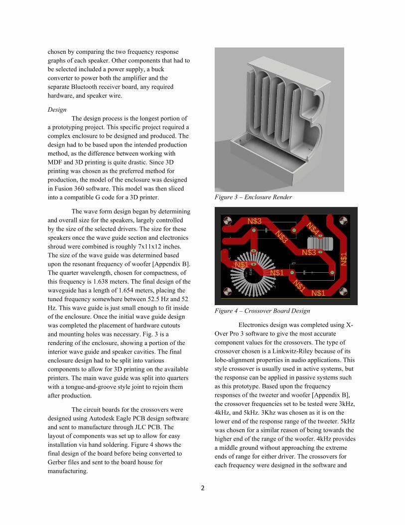
Design The design process is the longest portion of a prototyping project. This specific project required a complex enclosure to be designed and produced. The design had to be based upon the intended production method, as the difference between working with MDF and 3D printing is quite drastic. Since 3D printing was chosen as the preferred method for production, the model of the enclosure was designed in Fusion 360 software. This model was then sliced into a compatible G code for a 3D printer.
The wave form design began by determining and overall size for the speakers, largely controlled by the size of the selected drivers. The size for these speakers once the wave guide section and electronics shroud were combined is roughly 7x11x12 inches. The size of the wave guide was determined based upon the resonant frequency of woofer [Appendix B]. The quarter wavelength, chosen for compactness, of this frequency is 1.638 meters. The final design of the waveguide has a length of 1.654 meters, placing the tuned frequency somewhere between 52.5 Hz and 52 Hz. This wave guide is just small enough to fit inside of the enclosure. Once the initial wave guide design was completed the placement of hardware cutouts and mounting holes was necessary. Fig. 3 is a rendering of the enclosure, showing a portion of the interior wave guide and speaker cavities. The final enclosure design had to be split into various components to allow for 3D printing on the available printers. The main wave guide was split into quarters with a tongue-and-groove style joint to rejoin them after production.
The circuit boards for the crossovers were designed using Autodesk Eagle PCB design software and sent to manufacture through JLC PCB. The layout of components was set up to allow for easy installation via hand soldering. Figure 4 shows the final design of the board before being converted to Gerber files and sent to the board house for manufacturing.
Figure 3 – Enclosure Render
Figure 4 – Crossover Board Design
Electronics design was completed using X-Over Pro 3 software to give the most accurate component values for the crossovers. The type of crossover chosen is a Linkwitz-Riley because of its lobe-alignment properties in audio applications. This style crossover is usually used in active systems, but the response can be applied in passive systems such as this prototype. Based upon the frequency responses of the tweeter and woofer [Appendix B], the crossover frequencies set to be tested were 3kHz, 4kHz, and 5kHz. 3Khz was chosen as it is on the lower end of the response range of the tweeter. 5kHz was chosen for a similar reason of being towards the higher end of the range of the woofer. 4kHz provides a middle ground without approaching the extreme ends of range for either driver. The crossovers for each frequency were designed in the software and

2
component values were picked as closely as possible to the given values for inductors and capacitors. Once these components were chosen, the circuit board design process began. The board was designed around the size of the components, using a simple design to split the input through the low-pass and high-pass filters to output to the woofer and tweeter respectively.
Production The production stage involved ordering components and printing out the enclosure design. Timeline variances became a common issue during this stage between stocking issues with component warehouses as well as some minor printing issues.
The printing process for objects as large as the enclosure can be extremely time consuming. The overall time for the project to print each individual component was roughly 320 hours in total. The efficiency of this project was aided by using two printers available through East Tennessee State University. The largest components took up to 40 hours to complete printing. All components were printed with a 12% infill to assist in saving material while maintaining a rigid structure. The infill creates a hollow space in the walls of the enclosure that can also be useful in absorbing potential vibrations. At low levels of infill, the distance between the interior supports can vary greatly. A difference of 1% could add 8+ millimeters between supports. For the basic line infill used for this project 12% provided a pattern of roughly 4-millimeter squares which saved a great deal of material while maintaining an extremely rigid structure. 3D printing was chosen as an experimental enclosure to gauge the viability of PLA plastic to be used in audio applications. The common material used is some form of dense wood, typically MDF. Modern day audio systems sometimes use plastics for a custom shape or for complicated interior designs, meaning that it is a viable material to create speaker enclosure. In terms of ease of manufacture, a style of production such as injection-molding could be much more efficient in creating high volumes of product. For a prototyping project such as this, 3D printing is extremely useful due to the ease of adjusting design without incurring massive costs for something such as a mold.
The assembly stage of production included assembling the enclosure components and installing all drivers and electronics. Enclosure components were sealed together using a commercial two-part epoxy, JB Weld. This epoxy was chosen simply because of availability, ease of use, and the resulting bond strength. Sealing the wave guide portion of the enclosure was accomplished by painting the epoxy into the tongue and groove connections of each quarter of and clamping them together, creating an airtight seal around the entire enclosure. The design of the joints left a 0.5 mm gap to allow for the epoxy to flow between the pieces and create a stronger seal. Before completely joining the halves of the wave guide, the speaker cable to go from the crossover to the drivers was fed through the holes. These were sealed with a small amount of epoxy to ensure an airtight seal around the wires.
Electronic components were installed onto the custom crossover boards, starting with one board for each of the 3kHz, 4kHz, and 5kHz crossovers to be tested. The testing process takes place at this point, determining which of the crossovers fits best with this specific prototype design. Once determined, all electronics can then be installed. The right-side speaker houses all power, input, and volume control boards for this product. The 36-volt power supply is wired directly into the audio amplifier and sent into a buck converter board to step down to 12 volts to send into the Bluetooth receiver board. The output of the Bluetooth receiver is fed into the input of the amplifier, which is then wired into the crossovers for each speaker. The wiring between the two speakers is accomplished using an RCA style connector into each speaker. The speaker wire that was fed into the wave guides previously is directly connected to the crossovers. This completes the electronic systems in these speakers.
Testing The testing stage of this project mostly included testing frequency response of the drivers to determine overall response compared to what was expected based upon design. This stage experienced extreme delays because of stocking issues as well as software issues. Stock of the tweeter that the prototype was designed to use was challenging to find and took nearly an extra month to acquire. The

2
mentioned software issues had to deal with outdated version of the intended software to be used.
The testing process involved a frequency sweep of 20 Hz to 20 kHz to measure the response over this range. This sweep is performed using TrueRTA software to generate the sweep as well as analyze the frequency response. A specially designed microphone is input into an amplifier interface that connects to the computer, providing the ability to analyze the sweep. The speakers were powered using an external amplifier that was simply hooked into the speaker output of the computer. The three tests involved one of the woofers in air with no form of an enclosure, a test of just the woofer installed into the wave guide enclosure to observe the effect of the enclosure on the frequency response, and a full system test with the crossover installed to test overall range of woofer and tweeter. The overall test was done three times, one for each of the various crossover frequencies chosen to be tested. The crossover that produces the smoothest sounding response and the flattest graph will be used in this project.
Data and Results
The project completion has been delayed due to an inability to obtain the second tweeter needed to finish the set of speakers. This supply issue has not prevented testing to determine the best crossover frequency and the effectiveness of 3D-printed enclosures.
In terms of success of the 3D printed enclosure, production was a complete success. The pieces fit together well and were able to be completely sealed using the JB Weld epoxy. Speaker wire fit snugly through the cutouts and the speaker drivers fit into their respective cutouts with minimal effort. All threaded holes for hardware printed decently considering the size of threads versus the detail capability of the printer. The overall feel of the enclosure pieces was solid though they have been printed with a lower infill. This hollowness did raise some concerns regarding the audio performance of the enclosure. However, once assembled, the hollowness was not as evident, and the performance is rather impressive. The effectiveness of the wave guide enclosure was measured by performing an
audio sweep on the woofer in open air and installed in the enclosure using TrueRTA software. The resulting response graphs are shown in appendix C. There is an obvious boost in frequencies at the low end of the graph, meaning that the wave guide is performing as expected. The efficiency of the design cannot be measured with the available resources, as it would be necessary to generate an expected response based upon material, environment, and other variables. Small modifications to the electronics shroud on the bottom need to be made to allow room for the crossover boards height-wise. This is a simple modification and reprint that does not require much material. Overall, the enclosure design is a success, with few minor revisions necessary. Future revisions of the design could apply further audio engineering to tune the performance of the wave guide as well as explore various aesthetic options besides a simple box design.
The testing of crossovers was completed with the same sweep function of the TrueRTA software, providing an overall response of the tweeter and woofer combined. These responses are also displayed in appendix C. This overall response is as expected when combining the tweeter and woofer, creating a much flatter overall response for the speaker. The main difference seen when crossovers are applied is a slight dip in response around the crossover frequency. Between the 3kHz, 4kHz, and 5kHz crossovers the response of the 3kHz provides the flattest response. The crossover dip of is much more evident at the two higher frequencies. Behavior around the crossover frequency tends to be a spike rather than a dip when the two drivers are time-aligned, as both speakers output the same frequencies. This odd behavior in testing could be caused by some physical misalignment, causing a phase difference that could cause destructive interference around the crossover frequency. This falls back to the same process of further audio engineering of the enclosure design to ensure that the drivers are physically aligned. Any phase differences after physical alignment would need to be addressed through additional circuitry if necessary. TrueRTA unfortunately does not offer a way to monitor and record these differences in phase.

2
As a prototype this project exceeded expectations. The quality and clarity of the sound is exceptional, with an overall flat response as would be expected out of something such as studio monitors. This quality could further be enhanced by introducing an equalizer unit to manipulate the audio signal. Further revisions to the enclosure design as well as
electronic circuits could be conducted if the final application required an extremely high level of fidelity. For most generic listening applications, they will perform above average in terms of volume, quality, and clarity. Though not yet fully completed, this project has certainly been a success.

2
References
[1] Martin J. King, Transmission Line Theory, Section 1 – Introduction, 07/05/02, Quarter Wavelength Loudspeaker
Design. [Online]. Available: http://www.quarter-wave.com/TLs/Introduction.pdf
[2] Martin J. King, Transmission Line Theory, Section 2 – Construction and Measurement of a Simple Test Transmission Line, 07/05/02, Quarter Wavelength Loudspeaker Design. [Online]. Available:
http://www.quarter-wave.com/TLs/Test_Line_Results.pdf
[3] Dennis Bohn, Rane Corporation, “Linkwitz-Riley Crosssovers: A Primer, RaneNote 160, 2005. [Online]. Available: http://citeseerx.ist.psu.edu/viewdoc/download;jsessionid=734F8B9FB1A7E000877D05205E33D219?doi=10.1.1.353.9944&rep=rep1&type=pdf

2
Appendix A
Bill of Materials
Description Quantity Part Number Price Supplier
Black PLA 1.75mm 1kg Roll 4 3D PLA-1KG1.75-BLK $22.99 Amazon
JB Weld Original Steel Reinforced Epoxy 4 8265S $4.84 Amazon
Bluetooth Audio Receiver Board V4. 320-351 1 AA-AB41136 $25.98 Parts Express
2x200W Class D Audio Amplifier Board 1 AA-AB32281 $54.98 Parts Express
1-1/8" Silk Dome Shielded Tweeter 2 DC28FS-8 $22.48 Parts Express
5" Designer Series Woofer 2 DS135-8 $24.98 Parts Express
Electric Digital Volume Control Kit 1 AA-AA11117 $7.49 Parts Express
"D" Flange Panel Mount RCA Jack B 2 ACJB-BLK $4.85 Parts Express
36 VDC 5A Grounded Switching Power Supply Adapter 1 120-063 $39.95
Parts Express
7A DC 60V Adjustable Step Down Regulator NC Power S 1 320-615 $15.98
Parts Express
Locking RCA Plug Solder Type 2 Pair 1 091-1270 $15.48 Parts Express
14 AWG OFC Speaker Wire 50 ft. 1 SKRL-14-50 $16.98 Parts Express
2.5mm Metal Panel Mount DC Jack 1 090-5018 $1.46 Parts Express
Curved Rocker Switch I/O DPDT Bl 1 EHRRSLB $6.53 Parts Express
#8 x 1/2" Phillips Truss Head Screws 100 Pcs. 1 081-480 $2.65 Parts Express
0.35mH 20 AWG Air Core Inductor 2 255-030 $4.79 Parts Express
0.44mH 18 AWG Air Core Inductor 2 255-226 $7.59 Parts Express
0.56mH 18 AWG Air Core Inductor 2 255-232 $8.19 Parts Express
0.37mH 18 AWG Air Core Inductor 2 255-222 $7.29 Parts Express
0.47mH 18 AWG Air Core Inductor 2 255-228 $7.89 Parts Express
0.60mH 18 AWG Air Core Inductor 2 255-234 $8.49 Parts Express
0.22uF 400V Crosscap Capacitor 4 027-902 $1.49 Parts Express

2
0.33uF 400V Crosscap Capacitor 2 027-904 $1.86 Parts Express
0.47uF 400V Crosscap Capacitor 2 027-906 $1.86 Parts Express
2.7uF 400V Crosscap Capacitor 4 027-918 $3.25 Parts Express
3.3uF 400V Z-Standard Capacitor 4 027-270 $3.93 Parts Express
4.0uF 250V Polypropylene C 2 027-421 $1.98 Parts Express
4.7uF 400V Crosscap Capacitor 2 027-924 $5.12 Parts Express
PC Board M3 Standoff Kit with 8 pcs 16mm Stud / 8 p 2 320-3290 $4.79
Parts Express
Crossover Boards x10 1 Y1-2941026A $10.40 JLC PCB

2
Appendix B

2

2
Appendix C
Woofer Response in Open Air
Woofer Response in Wave Guide Enclosure

2
3kHz Crossover Frequency Response
4kHz Crossover Frequency Response

2
5kHz Crossover Frequency Response
2
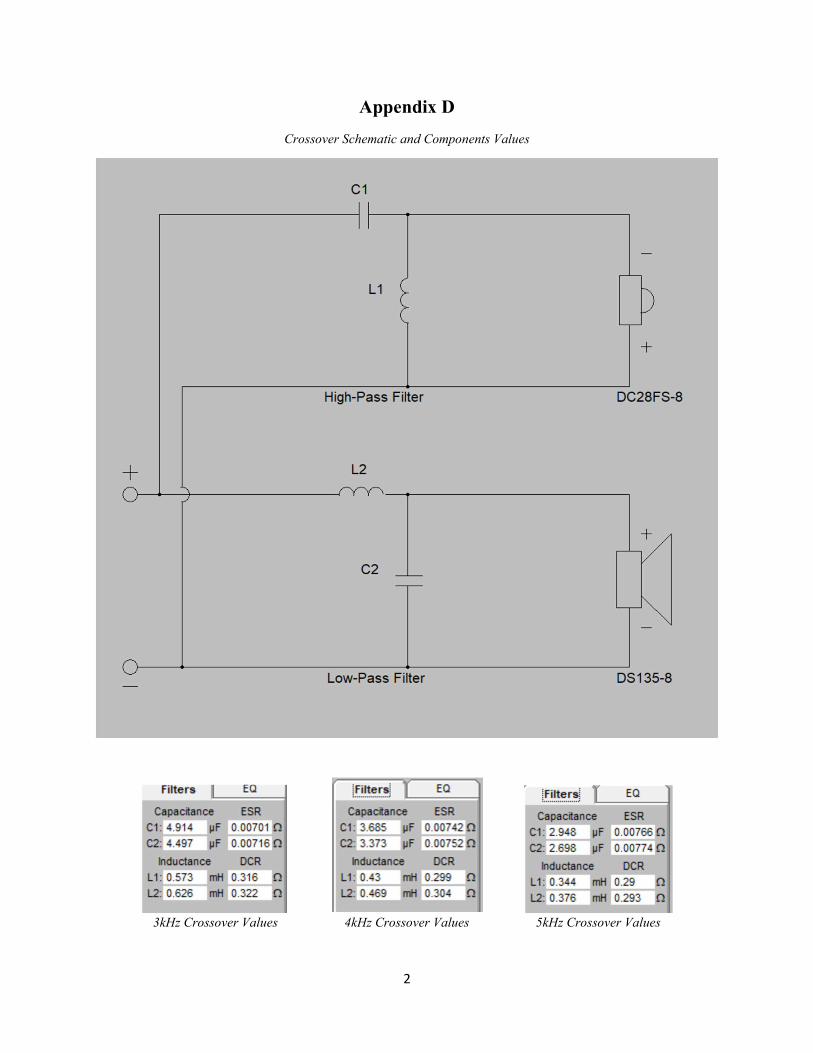
Appendix D
Crossover Schematic and Components Values
3kHz Crossover Values 4kHz Crossover Values 5kHz Crossover Values

2
Appendix E
Basic Schematic
Speaker Speaker
Amplifier Bluetooth Receiver
Voltage Converter
Crossover Crossover
36 Volt
12 Volt
Input
Left Right