Informally Prototyping Multimodal, Multidevice User Interfaces
194
Informally Prototyping Multimodal, Multidevice User Interfaces By Anoop Kumar Sinha B.S. (Stanford University) 1996 M.S. (University of California, Berkeley) 1997 A dissertation submitted in partial satisfaction of the requirements for the degree of Doctor of Philosophy in Engineering-Electrical Engineering and Computer Sciences in the GRADUATE DIVISION of the UNIVERSITY OF CALIFORNIA, BERKELEY Committee in charge: Professor James A. Landay, Chair Professor John C. Canny Professor Robert E. Cole Fall 2003
-
Upload
khangminh22 -
Category
Documents
-
view
0 -
download
0
Transcript of Informally Prototyping Multimodal, Multidevice User Interfaces

Informally Prototyping Multimodal, Multidevice User Interfaces
By
Anoop Kumar Sinha
B.S. (Stanford University) 1996 M.S. (University of California, Berkeley) 1997
A dissertation submitted in partial satisfaction of the
requirements for the degree of
Doctor of Philosophy
in
Engineering-Electrical Engineering and Computer Sciences
in the
GRADUATE DIVISION
of the
UNIVERSITY OF CALIFORNIA, BERKELEY
Committee in charge: Professor James A. Landay, Chair
Professor John C. Canny Professor Robert E. Cole
Fall 2003

The dissertation of Anoop Kumar Sinha is approved:
Chair Date
Date
Date
University of California, Berkeley
Fall 2003

Informally Prototyping Multimodal, Multidevice User Interfaces
© 2003
by
Anoop Kumar Sinha

1
Abstract
Informally Prototyping Multimodal, Multidevice User Interfaces
by
Anoop Kumar Sinha
Doctor of Philosophy in Engineering-Electrical Engineering and Computer Sciences
University of California, Berkeley
Professor James A. Landay, Chair
Increasingly, it is important to look at the end-user’s tool of the future as not
a solitary PC, but as a diverse set of devices, ranging from laptops to PDA’s to tablet
computers. Some of these devices do not have keyboard and mouse, and thus
multimodal interaction techniques, such as pen input and speech input, will be
required to interface with them. Interaction designers are beginning to be faced with
the challenge of creating interfaces that target this style of interface. Our study into
their interface design practice uncovered the lack of processes and tools to help
them.
This dissertation covers the motivation, design, and development of
CrossWeaver, a tool for helping these designers prototype multimodal, multidevice
user interfaces. This tool embodies the informal prototyping paradigm, leaving
design representations in an informal, sketched form and creating a working
2
prototype from these sketches. Informal prototypes created with CrossWeaver can
run across multiple standalone devices simultaneously, processing multimodal input
from each one. CrossWeaver captures all of the user interaction when running a test
of a prototype. This input log can quickly be viewed for the details of the users’
multimodal interaction, and it can be replayed across all participating devices, giving
the designer information to help him or her iterate the interface design.
Our evaluation of CrossWeaver with professional designers has shown that
we have created an effective tool for early creative design of multimodal,
multidevice user interfaces. CrossWeaver dovetails with existing design processes
and can assist in a number of current design challenges.

i
Dedicated to:
Aparna

ii
Table of Contents
Table of Contents ____________________________________________________ ii
List of Figures_______________________________________________________ v
List of Tables ______________________________________________________ xii
Acknowledgments _________________________________________________ xiii
1 Introduction ____________________________________________________ 1
1.1 Research Goals ______________________________________________ 2
1.2 Drawbacks of Current Methods _________________________________ 3
1.3 Advantages of the Proposed Method _____________________________ 4
1.4 Programming by Illustration____________________________________ 5
1.5 Thesis Statement_____________________________________________ 5
1.6 Design Range _______________________________________________ 6
1.7 Contributions ______________________________________________ 11
1.8 Dissertation Outline _________________________________________ 12
2 Related Work __________________________________________________ 14
2.1 Commercial Prototyping Tools ________________________________ 14
2.2 Informal User Interfaces______________________________________ 17
2.3 Multimodal User Interfaces ___________________________________ 21
2.4 Programming by Demonstration _______________________________ 24
3 Field Studies ___________________________________________________ 27
3.1 Interaction Designers ________________________________________ 27
3.2 Game Designers ____________________________________________ 30
3.3 Movie Designers____________________________________________ 32
3.4 Implications from Field Studies ________________________________ 34
4 Multimodal Theater _____________________________________________ 36
4.1 Multimodal Photo Album_____________________________________ 37
4.2 Multimodal In-Car Navigation System __________________________ 40
4.3 Design Implications for Multimodal Design Tools _________________ 42

iii
5 Design Evolution of CrossWeaver __________________________________ 44
6 First Interactive Prototype of CrossWeaver ___________________________ 56
6.1 Defining Interaction in CrossWeaver____________________________ 58
6.2 Matching the Designers’ Mental Models _________________________ 67
6.3 Informal Evaluation of the First Interactive Prototype_______________ 69
6.4 Design Implications _________________________________________ 72
7 CrossWeaver’s Final Implementation _______________________________ 74
7.1 CrossWeaver Final Implementation Definitions ___________________ 75
7.2 Design Mode ______________________________________________ 76
7.3 Test Mode_________________________________________________ 86
7.4 Analysis Mode _____________________________________________ 89
7.5 Final Prototype Summary_____________________________________ 92
8 Evaluation_____________________________________________________ 94
8.1 Recruitment _______________________________________________ 94
8.2 Experimental Set-Up ________________________________________ 96
8.3 Pre-Test Questionnaire _______________________________________ 96
8.4 Training __________________________________________________ 97
8.5 Protocol___________________________________________________ 97
8.6 Tasks_____________________________________________________ 98
8.7 Post-Test Questionnaire ______________________________________ 99
8.8 Designers’ Profiles __________________________________________ 99
8.9 Designers’ Case Studies _____________________________________ 103
8.10 Designers’ Post-Test Survey Results ___________________________ 115
8.11 Designers’ Post-Test Questionnaire Results _____________________ 119
8.12 Design Issues _____________________________________________ 122
8.13 Evaluation Summary _______________________________________ 124
9 Implementation and Limitations___________________________________ 126
9.1 Implementation Details _____________________________________ 126
9.2 Limitations _______________________________________________ 130

iv
10 Future Work and Conclusions __________________________________ 133
10.1 Future Work ______________________________________________ 133
10.2 Contributions _____________________________________________ 135
10.3 Conclusions ______________________________________________ 137
Appendix A. Evaluation Materials ____________________________________ 139
A.1 Demo Script_________________________________________________ 139
A.2 Participant Background Questionnaire ____________________________ 143
A.3 User Interface Designer Pre-Test Questionnaire _____________________ 144
A.4 User Interface Designer Post-Test Survey__________________________ 145
A.5 User Interface Designer Post-Test Questionnaire ____________________ 147
A.6 Consent Form _______________________________________________ 148
A.7 Participant’s Designs Built Using CrossWeaver During User Testing ____ 149
References _______________________________________________________ 167
v
List of Figures
Figure 1-1. Four motivating applications from the academic literature. ...................10
Figure 3-1. Storyboard showing a multimodal map navigation system for an in-car
dash.....................................................................................................................28
Figure 3-2. Artifacts produced by game designers include bubble diagrams and
characteristic storyboards. ..................................................................................30
Figure 3-3. Movie designers have a formal storyboarding process encompassing
annotations for camera, character, and director instructions. .............................33
Figure 4-1. Multimodal Photo Album Room simulation. .........................................38
Figure 4-2. User testing a Multimodal in-car navigation system (left) with a Wizard
of Oz using the Speech Command Center (right). .............................................40
Figure 5-1. Design evolution of CrossWeaver. .........................................................44
Figure 5-2. Early design sketch for CrossWeaver’s interface for creating
representations of multimodal input. ..................................................................45
Figure 5-3. Early design sketch for CrossWeaver’s interface showing a potential
way of representing “Operations”. .....................................................................46
Figure 5-4. Early design sketch for CrossWeaver’s interface showing the
representation of a “Selection Region” in which a command will be active. ....47
Figure 5-5. The first interactive prototype of CrossWeaver.....................................48
Figure 5-6. The design mode in the Collaborative CrossWeaver Prototype. ............50

vi
Figure 5-7. The test mode browsers in the Collaborative CrossWeaver Prototype. .51
Figure 5-8. A design sketch of CrossWeaver before the final implementation. .......52
Figure 5-9. The Design Mode of CrossWeaver in the final implementation. ...........53
Figure 5-10. The Test Mode of CrossWeaver in the final implementation...............54
Figure 5-11. The Analysis Mode of CrossWeaver in the final implementation. ......55
Figure 6-1. The first prototype of CrossWeaver shows two scenes in a multimodal
application and a transition, representing various input modes, between them.
Transitions are allowed to occur in this design when the user types ‘n’, writes
‘n’, or says ‘next’................................................................................................56
Figure 6-2. A participant executes the application in Figure 6-1 in the multimodal
browser. The browser shows the starting scene (a); the participant then draws
the gesture “n” on the scene (b); the browser then transitions to the next pane in
the multimodal storyboard shown in (c).............................................................57
Figure 6-3. The first CrossWeaver prototype shows thumbnails representing
reusable operations (top), scenes that have imported images (left and right), a
scene that targets screen and audio output (left) and a scene that targets PDA
output (right).......................................................................................................59
Figure 6-4. The available output devices for scenes: screen output (default), audio,
PDA, and printer (future work). These icons are dragged onto scenes to specify
cross device output. ............................................................................................60

vii
Figure 6-5. The available input modes for transitions in the first CrossWeaver
prototype: mouse gesture, keyboard, pen gesture, speech input, and phone
keypad input. These are dragged onto transition areas to specify multimodal
interaction. ..........................................................................................................61
Figure 6-6. (a) The transition specifies a keyboard press ‘n’ to move to the next
scene or a gesture ‘n’ via pen input or a speech command ‘next’. (b) With the
two bottom elements grouped together, the transition represents either a
keyboard press ‘n’ by itself or the pen gesture ‘n’ and the speech command
‘next’ together synergistically. ...........................................................................62
Figure 6-7. The designer designates a storyboard sequence as a specific operation by
stamping it with the appropriate operation primitive icon. There are six basic
primitives that can be used, from top to bottom: defining adding an object,
defining deletion, defining a specific color change, defining a view change
(zoom in, zoom out, rotate, or translation), defining an animation path, or
defining a two point selection (as in a calculate distance command).................63
Figure 6-8. The designer designates a pushpin as a reusable component by creating a
storyboard scene and dragging the “+/add object” icon on to it. A pushpin can
then be added in any scene by selecting a location and using any of the input
modes specified (e.g., pressing ‘p’ on keyboard or saying ‘pin’ or drawing the
‘p’ gesture)..........................................................................................................64

viii
Figure 6-9. The designer designates coloring blue as a reusable operation by
creating a storyboard scene and dragging the “define color” icon onto it. A
selected object in a scene can be colored blue in any scene by any of the input
modes specified (e.g., clicking on the object and pressing ‘b’ on the keyboard or
saying ‘make blue’). ...........................................................................................65
Figure 6-10. The designer defines zooming in and out as separate operations by
drawing examples of growing and shrinking with any example shape and
stamping the view operation icon onto them. These operations are triggered in
the browser by the input operations in the transition between them (e.g.,
pressing ‘z’ on the keyboard, gesturing ‘z’ with the pen, or saying ‘zoom in’
and pressing ‘o’ on the keyboard, gesturing ‘o’, or saying ‘zoom out’). ...........66
Figure 6-11. The user can click anywhere and say “add pin” to add the reusable
pushpin component, as defined in Figure 6-8, at the clicked point. ...................67
Figure 6-12. The user triggers the make blue color operation, as defined in Figure
6-9, by selecting any object and saying “make blue”.........................................68
Figure 7-1. The CrossWeaver design mode’s left pane contains the storyboard,
which is made up of scenes and input transitions. The right pane contains the
drawing area for the currently selected scene.....................................................75
Figure 7-2. A scene in the storyboard contains (a) a thumbnail of the drawing, (b)
device targets and text to speech audio output, (c) input transitions showing the
natural inputs necessary to move from scene to scene, including mouse click,

ix
keyboard gesture, pen gesture, and speech input, and (d) a number identifying
the scene and a title.............................................................................................78
Figure 7-3. Here we specify an input region, a dashed green area in the pane (the
circles), in which linked gesture commands must happen to follow the
transitions. ..........................................................................................................80
Figure 7-4. CrossWeaver’s comic strip view shows the storyboard in rows. Arrows
can be drawn (as shown) or can be turned off....................................................81
Figure 7-5. Grouping two scenes and creating an “Operation.” Based on the
difference between the scenes, this operation is inferred as the addition of a
building to a scene, triggered by any of the three input modes in the transition
joining the two scenes. .......................................................................................83
Figure 7-6. A global transition points back to the scene from which it started. The
third input panel specifies that a keyboard press of ‘h’ or a gesture of ‘h’ or a
spoken ‘home’ on any scene will take the system back to this starting scene of
the storyboard. ....................................................................................................85
Figure 7-7. A bitmap image of a map has been inserted into the scene. A typed text
label has also been added. These images co-exist with strokes, providing
combined formal and informal elements in the scene. Images can be imported
from the designer’s past work or an image repository. ......................................87
Figure 7-8. Clicking on the “Run Test…” button in design mode brings up the Test
Mode Browser, which accepts mouse, keyboard, and pen input. (Top) In the

x
first sequence, the end user gestures ‘s’ on the scene and the scene moves to the
appropriate scene in the storyboard. (Bottom) In the second sequence, the user
accesses the ‘add building’ operation, adding buildings to the scene. This is
occurring in the standalone browser running on device PDA #0, as identified by
the ID in the title bar of the window. Pen recognition and speech recognition
results come into the browser from separate participating agents......................88
Figure 7-9. CrossWeaver’s Analysis Mode shows a running timeline of all of the
scenes that were shown across all of the devices. It also displays the interaction
that triggered changes in the state machine. The red outline represents the
current state in the replay routine. Pressing the play button steps through the
timeline step-by-step replaying the scenes and inputs across devices. The
timestamp shows the clock time of the machine running when the input was
made. ..................................................................................................................91
Figure 8-1. Diagram of the Experimental Setup. ......................................................97
Figure 8-2. Participant #4’s storyboard for Task #1................................................105
Figure 8-3. Participant #4’s storyboard for Task #2................................................106
Figure 8-4. Participant #1’s storyboard for Task #1................................................109
Figure 8-5. Participant #1’s storyboard for Task #2................................................111
Figure 8-6. Participant #9’s storyboard for Task #1................................................112
Figure 8-7. Participant #9’s storyboard for Task #2................................................115
Figure 8-8. Rating of CrossWeaver’s functional capability. ...................................117

xi
Figure 8-9. Rating of CrossWeaver’s ease of use. ..................................................118
Figure 8-10. Rating of CrossWeaver’s understandability. ......................................119
Figure 9-1. CrossWeaver Architecture....................................................................126
Figure A-1. Participant #1, Task #1 ........................................................................149
Figure A-2. Participant #1, Task #2 ........................................................................150
Figure A-3. Participant #2, Task #1 ........................................................................151
Figure A-4. Participant #2, Task #2 ........................................................................152
Figure A-5. Participant #3, Task #1 ........................................................................153
Figure A-6. Participant #3, Task #2 ........................................................................154
Figure A-7. Participant #4, Task #1 ........................................................................155
Figure A-8. Participant #4, Task #2 ........................................................................156
Figure A-9. Participant #5, Task #1 ........................................................................157
Figure A-10. Participant #5, Task #2. .....................................................................158
Figure A-11. Participant #6, Task #1 ......................................................................159
Figure A-12. Participant #6, Task #2 ......................................................................160
Figure A-13. Participant #7, Task #1 ......................................................................161
Figure A-14. Participant #7, Task #2 ......................................................................162
Figure A-15. Participant #8, Task #1 ......................................................................163
Figure A-16. Participant #8, Task #2 ......................................................................164
Figure A-17. Participant #9, Task #1 ......................................................................165
Figure A-18. Participant #9, Task #2 ......................................................................166

xii
List of Tables
Table 1-1. What is Multimodal, Multidevice? ............................................................7
Table 1-2. Motivating applications for multimodal, multidevice interface design. ....9
Table 4-1. Multimodal Theater Simulations .............................................................36
Table 8-1. Participant designers’ backgrounds in the final CrossWeaver user tests
..........................................................................................................................102
Table 8-2. Results of the Post Test Survey given to the participants. .....................116
Table 8-3. Selected participant’s general comments from the post-test questionnaire.
..........................................................................................................................122

xiii
Acknowledgments
Primary thanks go to Prof. James Landay, the head advisor for this thesis and
the biggest proponent of Informal Prototyping as a paradigm in User Interface
Design. Prof. Landay’s insights and constructive comments have improved this
work in many ways.
The other two readers of this dissertation, Prof. John Canny and Prof. Bob
Cole (Haas) have been inspirational teachers and advisors throughout my years in the
Ph.D. program in graduate school. Prof. Jen Mankoff and Prof. Ken Goldberg,
members of my thesis proposal committee, have provided creative and patient
feedback on this work.
Great thanks go to the entire Group for User Interface Research (GUIR) at
UC Berkeley, who have been like brothers and sisters in my years in graduate
school. Jimmy, Jason, and Scott have been there from the very beginning for
collaboration, discussion, debate, and friendship. Jimmy has been an especially
valuable collaborator, including writing some lines of early CrossWeaver code, and
had many great insights along the way in this thesis. Xiaodong, Hesham, Yang,
Richard, Sarah, Mark, Wai-ling, Katie, and Francis have been collaborators,
officemates, and friends that I appreciate greatly. Corey, Amit, Gloria, Alan, and
others have been great undergraduate collaborators during the course of this

xiv
research. Prof. Marti Hearst, Prof. Anind Dey, and Dr. Rashmi Sinha have always
given extremely valuable feedback and instruction during talks about this work.
The Diva Group in the EECS Department was instrumental in the final
implementation of CrossWeaver. Michael, Heloise, John, and Steve all deserve
special thanks. Michael in particular has been a constant collaborator and colleague
from the beginning of graduate school, and I am fortunate to have benefited from
that excellent interaction while I was completing this Ph.D.
I spent one summer at SRI with a pioneering group that did work in
interactive multimodal applications. Luc Julia and Christine Halverson were
instrumental in supporting this research.
Special thanks to all of the participants in the design interviews and
evaluation. This group was extremely interesting and valuable to work with during
the course of this Ph.D.
The last but not least groups to thank are my family and friends who traveled
with me through this journey. Mom, Dad, Gita, and Anoop P. are always my
supporters and my fans, and have believed in me more than I have believed in myself
at times. I unfortunately cannot name all friends, but Steve, Sam, Emilie, Ameet,
Lela, Hemanth, and Amir have given support and seen me grow through many years.
My wife Aparna is a wonderful life partner who I cherish greatly.

Chapter 1
1
1 Introduction
Increasingly, it is important to look at the end-user’s tool of the future as not a
solitary PC, but as a diverse set of smart, cooperating devices, ranging from laptops
to PDA’s to cell phones to web tablets. Some of these devices do not have keyboard
and mouse, and thus techniques such as pen input or speech input, are required to
interface with them. Applications that utilize pen and speech and other natural input
modes are called multimodal applications (Oviatt, Cohen et al. 2000). At present,
various networking infrastructures such as BlueTooth (Bluetooth 2003) and IEEE
802.11 (IEEE 2003) are being built to enable users to collaborate with each other or
run applications that span more than one device per end-user. Applications that span
across devices are what we term multidevice applications. Together, applications
that use natural input modes and span across devices are what we term multimodal,
multidevice applications.
Many interaction designers are already faced with the challenge of
developing interfaces for multimodal, multidevice applications (Sinha and Landay
2002). The enormous increase in the number of mobile devices in use, such as
cellular phones, palm-sized devices, and in-car navigation systems, has precipitated
this (InStat 2003). Many mobile devices lack screen real estate and lack keyboards,
and thus push these designers towards pen interfaces and speech interfaces. At

Chapter 1
2
present, there are few techniques and tools to help these designers prototype
multimodal, multidevice interfaces (Sinha and Landay 2002).
This dissertation covers the motivation, design, development, and evaluation
of CrossWeaver, a tool that will allow designers to informally prototype multidevice,
multimodal interfaces. CrossWeaver embodies the informal prototyping paradigm
(Landay and Myers 2001), leaving design representations in an informal, sketched
form and creating a working prototype from these sketches. CrossWeaver allows the
designer to quickly specify device-appropriate user interfaces that use pen, speech,
mouse, or keyboard. It supports immediate testing of those interfaces with end-
users, using the desired interaction modes on the proper devices. It also allows the
designers to collect and analyze that interaction to inform their iterative designs.
1.1 Research Goals
The primary goal of this research is to show that informal prototyping
principles can be used to enable designers to creatively design multimodal,
multidevice interfaces. To date, informal prototyping tools have been created for
graphical user interfaces in SILK (Landay and Myers 1995; Landay 1996), web
interfaces in DENIM (Lin, Newman et al. 2000), speech user interfaces in SUEDE
(Klemmer, Sinha et al. 2001; Sinha, Klemmer et al. 2002); and multimedia interfaces
in DEMAIS (Bailey, Konstan et al. 2001; Bailey 2002). Multimodal and multidevice
interfaces is a new domain for informal prototyping and one for which few formal

Chapter 1
3
tools even exist. This dissertation covers the development of an informal tool for
multimodal, multidevice prototyping.
1.2 Drawbacks of Current Methods
Multimodal, multidevice systems are difficult to prototype. This difficulty is
due to the complexity of the hardware and software used for multimodal design
experimentation combined with the lack of established techniques. A typical
multimodal interface today is built with a complex programming application
programming interface (API) that involves asynchronous processing of recognition
results, as in the Tablet PC (Microsoft 2003d), or with a distributed agent-based
architecture with messages that are defined to enable and process communication, as
in the Adaptive Agent Architecture (Cohen, Johnston et al. 1997) and Open Agent
Architecture (Moran, Cheyer et al. 1998). In both cases, multimodal interface
development involves brittle recognizers that are difficult to integrate into an
application. These recognizers require formal specification of input grammars and
lengthy logic to process and interpret results.
At present there are few tools for non-programmers to utilize recognizers and
build multimodal systems, making it difficult for non-programmer designers to
explore and envision different designs. We address this problem by building a
multimodal, multidevice user interface prototyping tool based on sketching of
interface storyboards.

Chapter 1
4
1.3 Advantages of the Proposed Method
Sketching storyboards as a computer input technique builds upon designers’
experience with sketching on paper in the early stages of interface design (Landay
1996). By relying on sketching as the input technique, CrossWeaver allows non-
programmer designers to use our system.
We enable our designers to utilize multimodal recognition and multidevice
output by abstracting the underlying software, recognition systems, and hardware
required. CrossWeaver is based on the Open Agent Architecture, one of the agent
architectures that is commonly used for implementing multimodal interfaces (Moran,
Cheyer et al. 1998), but we hide this from the designers that use the system. We also
offer abstractions for speech and pen recognition systems and shield the designer
from the details of the recognizers. The recognizers in the system can easily be
substituted with Wizards of Oz (Kelley 1984), people who perform the recognition
and input it via a separate computer interface.
Dividing the early informal prototyping process into three phases – design,
test, and analysis – has proved successful in past informal prototyping tools
(Klemmer, Sinha et al. 2001). We have adopted this three phase process in
CrossWeaver. Putting all three phases into the same tool simplifies the early stage
design process and enhances the designer’s ability to iterate his or her designs.

Chapter 1
5
1.4 Programming by Illustration
Defining a working prototype via a set of example sketches is a process that
we term Programming by Illustration, in which there is enough information in the
sketches, the sequencing, and the designer’s annotations to create a working
prototype (Sinha and Landay 2001). Programming by Illustration is specifically
useful in the case of user interface design in which sketching is already a key part of
the design process. Similar to many Programming by Demonstration (PBD)
techniques (Cypher 1993), Programming by Illustration relies on a specific set of
examples to represent an application. In contrast to many PBD techniques,
Programming by Illustration is an informal visual specification. It more closely
matches the informal visual language style used by user interface designers (Wagner
1990; Landay and Myers 2001). Sketched storyboarding in Programming by
Illustration takes the place of more formal template matching used in most
Programming by Demonstration techniques. In sketched storyboarding, the full
interface is specified in the scenes and transitions that are drawn in the design.
1.5 Thesis Statement
CrossWeaver, an informal prototyping tool, allows interface designers to
build multimodal, multidevice user interface prototypes, test those prototypes with

Chapter 1
6
end-users, and collect valuable feedback informing iterative multimodal, multidevice
design.
1.6 Design Range
Our working definition of multimodal, multidevice applications that is
presented below introduces applications for which it is useful. We motivate our
work from past research efforts in multimodal and multidevice interfaces.
1.6.1 What is Multimodal, Multidevice?
Multimodal systems have been viewed as an attractive area for human-
computer interaction research since Bolt’s seminal “Put That There” (Bolt 1980) for
positioning objects on a large screen using speech and pointing. The promise of
multimodal interaction has been and continues to be more natural and efficient
human-computer interaction (Cohen, Johnston et al. 1998). The multimodal design
space is growing in popularity due to the increasing accuracy of perceptual input
systems (e.g., speech recognition, handwriting recognition, vision recognition, etc.)
and the increasing ubiquity of heterogeneous computing devices (e.g., cellular
telephones, handheld devices, laptops, and whiteboard computers).
In the HCI academic community, multidevice has typically referred to the use
of a variety of devices for computing tasks (Rekimoto 1997). In industry, the term
multimodality has instead started to include the use of multiple devices for

Chapter 1
7
computing tasks, and interfaces that scale or morph across these different devices
(W3C 2000). In this dissertation, multidevice is introduced as the term referring to
applications that might span multiple devices simultaneously, such as in a
collaborative application or in an application that has multiple devices for a single
user. Multimodal is a term used specifically to refer to natural input modes. In
contrast, multimedia refers to systems that incorporate multiple output modes (e.g.,
visual and audio). Although multimodal and multidevice are terms still open to
formal definition, we embrace both multiple input modalities and multidevice
interaction and propose the following working definitions:
Table 1-1. What is Multimodal, Multidevice?
Multimodal Communication with computing systems using perceptual input modalities such as speech, pen, gesture, vision, brain wave recognition, etc., either fused multiple modes at once or un-fused and possibly used in place of one another Human-computer interaction generated from our “normal” sensory interaction with the world, not based on restrictive keyboard and mouse input.
Multidevice Applications that span heterogeneous devices cooperatively. Can be with multiple users as in a collaborative application or with one user using multiple devices simultaneously.
Multimedia Communication from the computing system using perceptual output modes, such as visuals and audio.

Chapter 1
8
Multidevice is a broad category, ranging from handhelds to tablets to laptops
to whiteboard computers. In this dissertation, we restrict our attention to popular
existing devices, including handhelds, laptops, tablet computers, desktops, and
whiteboard computers.
The broadness of the definition of multimodal interaction necessitates picking
specific modalities to consider at the outset. Commercial systems currently support
speech recognition (IBM 2003; Nuance 2003) and handwriting/pen gesture
recognition (Paragraph 1999; Microsoft 2003d). These two input modes are
tractable while still being potentially rich. Thus, in this dissertation we focus on
speech and pen as input modalities. Multimedia has been explored in detail over the
last 20 years in both research (Bailey 2002; SIGMM 2003) and commercial systems
(Adobe 2003a; Macromedia 2003a). It is not a research focus of this dissertation.
1.6.2 Where is Multimodal, Multidevice useful?
Table 1-2 lists some of the motivating applications in the multimodal,
multidevice interface design space. When implemented with input mechanisms that
are different from traditional keyboard and mouse, these applications often benefit
from improved efficiency of use, immersion, realism, and natural communication
with the end-user.

Chapter 1
9
Various multimodal and multidevice prototypes have already been built in
academic research and have demonstrated the benefits shown in Table 1-2. Four of
these motivating applications are shown in Figure 1-1. The Infowiz kiosk (Cheyer,
Julia et al. 1998) involves speech control of a kiosk touch screen. This provides two
methods of navigation input in one interface. The CARS navigation system (Julia
and Cheyer 1999) combines augmented reality glasses, pointing, and speech
commands to allow a user to identify buildings and landmarks while driving.
Quickset (Cohen, Johnston et al. 1997) is a map navigation system that uses speech
and pointing for military planning. The eClassroom (Abowd, Atkeson et al. 1996;
Abowd 1999) at Georgia Tech links whiteboard computers, desktop computers, and
laptops in the classroom into a classroom instruction system. This is an example of a
multimodal and multidevice application. Each of these applications required a
Table 1-2. Motivating applications for multimodal, multidevice interface design.
CommunicationGesture, Avatars, Voice, VideoComputer Mediated Collaboration, Meetings, Classrooms
Practicing on Realistic Situations,Military Preparation
Hand/feet Coordination, Display Panel
Flight Simulation
Controlling Characters, Immersion
Hand/feet CoordinationGames and Virtual Reality
Fluidity, SpeedPointing, Drawing, and SpeechMap and Drawing Applications
Human ConcernNovel inputExisting Examples

Chapter 1
10
significant investment of time and equipment to implement. Even the earliest
prototypes of these interfaces were only demonstrable after significant development
by expert programmers.
1.6.3 What can CrossWeaver prototype?
CrossWeaver has been designed to prototype a wide variety of applications
similar to the motivating applications shown above. As introduced in Chapter 5, it
accomplishes this by providing the user with a generic storyboarding model, suitable
for creating scenes of an application in many different domains.
Certain applications require more functionality than a storyboard-based model
can provide, such as map navigation or drawing tools, query-response systems, and
CARS navigation assistant from SRI by Julia, et. al. 1999
InfoWiz kiosk from SRI by
Cheyer, et. al. 1999
QuickSetfrom OHSIby Cohen,et. al. 1999
eClassroomfrom GeorgiaTech by Abowd, et. al. 1999
CARS navigation assistant from SRI by Julia, et. al. 1999
InfoWiz kiosk from SRI by
Cheyer, et. al. 1999
QuickSetfrom OHSIby Cohen,et. al. 1999
eClassroomfrom GeorgiaTech by Abowd, et. al. 1999
Figure 1-1. Four motivating applications from the academic literature.

Chapter 1
11
interactive multi-person whiteboards. CrossWeaver has within it basic facilities for
prototyping features of map and drawing tools, such as zooming, panning, and
adding objects. CrossWeaver does not have within it general functionality for other
domains. Extensions can be made to CrossWeaver for other domains as will be
discussed in the future work section.
1.7 Contributions
CrossWeaver extends Informal Prototyping to the multimodal, multidevice
domain, giving non-programmer designers one of the first tools that they can use to
explore this design space. Specific contributions include:
Concepts and Techniques:
Extending Wizard of Oz simulation to multimodal, multidevice interface
design.
Extending the methodology of informal prototyping with electronic sketching
to the multimodal, multidevice interface domain.
Introducing a compact way of representing multimodal input and output.
Creating a storyboarding scheme that represents a testable prototype of a
multimodal, multidevice application.
Enabling the testing of an informal prototype that spans multiple devices and
uses multiple input recognizers simultaneously.

Chapter 1
12
Capturing the execution of a multimodal, multidevice prototype across
multiple devices with multiple input recognizers.
Artifacts:
The first tool that can be used for the earliest phases of multimodal,
multidevice user interface design experimentation.
Implementation of the three phases (design, test, and analysis) of the early-
stage, iterative design process for multimodal, multidevice interface
designers.
Experimental Results:
A survey of professional interface designers with an interest in multimodal,
multidevice interface design showing that they presently use ad hoc
techniques to approach the multimodal, multidevice design space.
An evaluation that shows that such designers believe that CrossWeaver will
enable them to better explore the new design space of multimodal,
multidevice interface design and will help them with their designs.
1.8 Dissertation Outline
The rest of this dissertation covers the design, development, and evaluation of
CrossWeaver. The dissertation begins with a review of the related work in the
different research areas that impact this work. It continues with a description of the
background field studies of designers interested in multimodal, multidevice design.

Chapter 1
13
The next chapter describes techniques and guidelines that we developed and
experimented with to assist designers in multimodal, multidevice design using
traditional paper prototyping. From the lessons learned in the field studies and in the
paper prototyping techniques, we discuss the design evolution of CrossWeaver,
including the key problems that we faced in the design process. We describe in
detail the first interactive prototype that we built of CrossWeaver, including an
informal evaluation of that system. We then describe the final implementation of
CrossWeaver. We next cover an evaluation of the final CrossWeaver tool with nine
professional interaction designers, and report on their experiences using
CrossWeaver in the user test. We conclude with a discussion of the future work for
this research and a review of the contributions of this research.

Chapter 2
14
2 Related Work
Bill Buxton’s refrain in his invited plenary at the Computer Human
Interaction Conference in 1997 was “Don’t take the GUI as given” (Buxton 1997).
Many researchers including our research group have heeded this call. CrossWeaver
adds to existing research in informal user interfaces (Landay and Myers 2001),
multimodal user interfaces (Oviatt, Cohen et al. 2000), and Programming by
Demonstration (Cypher 1993). It combines lessons and approaches from these
different areas towards a new approach for building user interface prototypes that go
beyond GUI interfaces.
2.1 Commercial Prototyping Tools
The professional designers that we worked with in the development of
CrossWeaver (see Chapter 3) were all familiar with the technique of paper
prototyping (Wagner 1990; Rettig 1994) in which drawings on paper represent
scenes of an interface. The designer or one or two assistants can play the role of
computer with those drawings and show them in the proper sequence in front of an
end-user who is testing the simulated interface. Sketched drawings can evolve into
formal storyboards, which are like formal comic strip sequences showing the
temporal sequence of a set of user actions in an interface (McCloud 1993; Modugno
1995).

Chapter 2
15
Even though all of the designers were comfortable with sketching on paper,
some preferred to use electronic tools to assist in storage, versioning, and
collaboration (Sinha and Landay 2002). All of the designers used some professional
drawing or prototyping tool, usually soon after drawing a few rough sketches on
paper. Some of these prototyping tools have become very sophisticated and have
underlying programming environments to allow interface simulation and movement.
Others are used simply as drawing tools, without any capability of creating or
simulating active applications.
The most popular tool used by the designers that we worked with was
Microsoft PowerPoint (Microsoft 2003b). PowerPoint was used by designers for
organizing prototype screenshots, creating wireframe storyboard scenes, organizing
design requirements, keeping design notes, and making presentations to
management. It is an extremely versatile tool for the designers and can fit in many
steps in the design process.
The next most popular tools were Adobe Photoshop (Adobe 2003c) and
Adobe Illustrator (Adobe 2003b), both used by designers as drawing tools.
Photoshop is particularly adept at taking existing images or screenshots and splitting,
merging, or making modifications to them. Illustrator is used by designers for
drawings of screens, wireframes, or creating scenes of a storyboard. Both of these
tools create artifacts that are commonly printed or exported to other programs, such
as Microsoft PowerPoint, before being shown.

Chapter 2
16
Macromedia Director (Macromedia 2003b) was used by many of our
designers to create interactive prototypes. Director enables sophisticated multimedia
output using the metaphors of actors, scenes, and storyboards. The actors are given
behaviors in Director with built-in templates or via a programming language, Lingo.
Director is a fairly advanced tool and is not as well suited for early stage prototyping
as pen and paper, as it requires considerable expertise in computer use and
programming, which many designers do not have (Landay 1996).
These tools and other tools like them (e.g., Macromedia Freehand for
storyboarding and drawing (Macromedia 2003d), Microsoft Visio for workflow
diagrams (Microsoft 2003e), Macromedia Fireworks for graphics manipulation
(Macromedia 2003c), PaintShopPro for drawing (Software 2003), Solidworks 3D
CAD Software for mechanical design (Solidworks 2003) are popular with the
interface designers that we worked with, but none have yet approached the problem
of multimodal input using speech or pen recognition systems. The designers that we
talked to utilized different attributes of these tools into their own process to build
prototypes and explore the design space. Our approach is positioned between pen
and paper and more sophisticated computer tools, enabling designers to carry out
informal prototyping for multimodal, multidevice interfaces in a quick, self-
contained fashion.

Chapter 2
17
2.2 Informal User Interfaces
The Informal User Interface approach has been shown to successfully support
user interface designers’ early stage work practice (Landay and Myers 1995; Lin,
Newman et al. 2000; Klemmer, Sinha et al. 2001; Landay and Myers 2001;
Newman, Lin et al. 2003). In the informal user interface approach, designers work
from the natural forms of input: sketches, audio, other sensory input and only
transform into more formal representations gradually, if at all. Specifically,
CrossWeaver starts with designer-sketched screen shots, usually sketched with a
tablet on the computer.
Electronic sketching traces its roots to Sutherland’s original Sketchpad
(Sutherland 1963) which pioneered the use of a stylus (in Sketchpad’s case an
electronic light-pen) to draw on one of the first graphical displays. Stylus-based
graphical drawing and the potential benefits of pen-based computer interfaces have
been studied in various research efforts since then (Negroponte and Taggart 1971;
Negroponte 1973; Wolf, Rhyne et al. 1989; Brocklehurst 1991) and also in some
pioneering commercial efforts (Wang 1988; GO 1992; Microsoft 1992; Apple 1993).
(A comprehensive survey of the history of pen interfaces in research can be found in
(Landay 1996; Long 2001) and in commercial projects in (Bricklin 2003).)
More recently, electronic sketching has been applied to the exploratory
design process for designers in various domains. For example, Gross’s Electronic

Chapter 2
18
Cocktail Napkin supports freeform electronic sketching for architectural design
(Gross 1994; Gross and Do 1996). Alvarado’s ASSIST allows mechanical designers
to sketch diagrams which are then interpreted as working mechanical systems (Davis
2002). Hammond’s Tahuti (Hammond and Davis 2002) and Damm’s Knight tool
(Damm, Hansen et al. 2000) have incorporated electronic sketching in the design
process for software UML diagrams. Li’s SketchPoint enables quick electronic
sketching of informal presentations (Li, Landay et al. 2003). Kramer’s Translucent
Patches supports conceptual design involving freeform sketches organized as layers
(Kramer 1994). Through tests and field studies, these projects and an expanding list
of others have shown the potential benefits of electronic sketching in the design
process. One claim becoming more evident from these projects is that tools that
support informal design, those leaving designs in sketched, unrecognized, and un-
beautified form, might elicit greater comments than more finished prototypes (Wong
1992; Hong, Li et al. 2001). Leaving designs in unrecognized form is the approach
that CrossWeaver takes.
SILK (Landay and Myers 1995; Landay 1996) is a tool that was created for
sketching graphical interfaces. SILK introduced the idea of sketching user interfaces
and leaving them in unrecognized form when testing. SILK also introduced a
storyboarding paradigm for this type of design (Landay and Myers 1996).
CrossWeaver has extended SILK’s storyboard to multimodal commands and

Chapter 2
19
introduced the new concept of multidevice prototyping as an extension to the work
that SILK pioneered.
DENIM (Lin, Newman et al. 2000; Lin, Thomsen et al. 2002; Newman, Lin
et al. 2003) is an informal prototyping tool for web design. DENIM has sketched
pages and transitions as its basic elements. DENIM uses an infinite sheet layout,
arrows, and semantic zooming for web page layout and linking. In DENIM,
transitions are based on mouse events of different types (e.g., left or right click).
DENIM runs its designed web pages as a single state machine in its integrated
browser or in a standard standalone web browser. CrossWeaver has also adopted
sketched scenes and transitions. CrossWeaver uses a linear storyboard instead of an
infinite sheet to match the multimodal designers’ preference for thinking in terms of
short linear examples. CrossWeaver adds gesture transitions and speech transitions
to promote multimodal experimentation.
The design, test, analysis paradigm for informal prototyping was introduced
in SUEDE (Klemmer, Sinha et al. 2001; Sinha, Klemmer et al. 2002), an informal
prototyping tool for Wizard of Oz design of speech interfaces. SUEDE’s design
mode creates a flowchart of the speech interface in which transitions are speech
commands. The test mode of SUEDE maintains one active state, the currently
spoken prompt. SUEDE analysis mode captures the full execution of a user test. A
CrossWeaver design is also a flowchart. In CrossWeaver, transitions can be mouse
clicks, keyboard input, pen gestures, or speech input. In CrossWeaver test mode,

Chapter 2
20
however, the storyboard maintains a separate state per device and executes logic in
the storyboard across multiple devices. CrossWeaver’s analysis mode also captures
a full user test across those devices.
CrossWeaver’s analysis mode is influenced by the Designer’s Outpost history
mechanism (Klemmer, Thomsen et al. 2002), which captures the history of the
creation of an information architecture by web designers. CrossWeaver’s focus is on
capturing the log of the test of an interactive multimodal, multidevice application,
versus a history of commands in a design tool.
DEMAIS (Bailey, Konstan et al. 2001; Bailey 2002) is an informal tool for
multimedia authoring. It includes the concept of joined formal and informal
representations, in which audio and video clips co-exist with sketched
representations, and claims the informal representations have specific benefits
(Bailey and Konstan 2003). It also includes the concept of rich transitions between
scenes in its storyboard based on mouse events. As a multimedia tool, DEMAIS is
focused on the design of rich, diverse output. CrossWeaver’s focus is on natural
input for an interactive application. The two tools are quite complementary.
Among informal user interface techniques, Wizard of Oz (Kelley 1984) is
used for simulation when recognizers are not available or not convenient to use
(Gould and Lewis 1985). In a Wizard of Oz study, a human simulates the
recognition system, as a substitute for a real speech recognizer. Wizard of Oz has a
long history in the prototyping of speech applications (Dahlbäck, Jönsson et al.

Chapter 2
21
1993). Yankelovich made use of Wizard of Oz simulations in the design of the
Office Monitor application (Yankelovich and McLain 1996) and recommends them
generally in her work on Designing SpeechActs (Yankelovich, Levow et al. 1995;
Yankelovich and Lai 1998). Wizard of Oz simulation has also been used in
multimodal interface design and execution, which we cover in more detail in Section
2.3. CrossWeaver specifically supports Wizard of Oz techniques on the computer,
enabling the Wizard to participate as a speech or pen recognizer.
2.3 Multimodal User Interfaces
Past multimodal research, starting with Bolt’s Put that There pointing and
speaking application (Bolt 1980), has laid a fair amount of groundwork that we build
upon. Advances in recognition technologies (Paragraph 1999; IBM 2003; Nuance
2003) and also in hardware devices (Microsoft 2003d) are making multimodal
research more accessible and fruitful (Oviatt and Cohen 2003). Recent studies on
QuickSet in the map domain (Cohen, Johnston et al. 1997) and MultiPoint in the
presentation domain (Sinha, Shilman et al. 2001) have shown that end-users tend to
be very interested and attracted to multimodal user interfaces when asked about their
preference of multimodal versus graphical user interface interaction. (A
comprehensive review of multimodal interface history can be found in (Oviatt
2003).)

Chapter 2
22
Nigay and Coutaz outlined a design space for multimodal user interfaces
(Nigay and Coutaz 1993) that pointed out the possible use of concurrent and fused
user input modalities, where input recognition could be used one after another or
simultaneously. This design space focused on the possible technical combinations of
multimodal input modalities and how they might be used in an application.
CrossWeaver supports exploration of applications that lend themselves to
multimodal interaction, though not all of Nigay’s design space is fully supported.
Instead, CrossWeaver can support prototyping of any application that can fit into its
storyboarding model (see Section 7.2).
Dahlback gave guidelines for Wizard of Oz simulation (Dahlbäck, Jönsson et
al. 1993), with a focus on speech user interfaces. Wizard of Oz has also been viewed
as a successful technique for multimodal simulation in many experiments. Mignot
studied the potential future form of multimodal commands using Wizard of Oz
techniques (Mignot, Valot et al. 1993). Salber and Coutaz developed the NEIMO
platform (Salber and Coutaz 1993) for multimodal user interface simulation together
with tools that enable multimodal interaction and logging of user interactions. Nigay
and Coutaz formalized a computer architecture for multimodal interface
implementation (Nigay and Coutaz 1995). Cohen (Cohen, Johnston et al. 1997) and
Cheyer and Julia (Cheyer, Julia et al. 1998) have built systems with similar
capabilities for multimodal interface implementation either with computer-based
recognizers or with Wizard of Oz simulation. In those systems, the Wizard

Chapter 2
23
participates as a recognizer or as a remote controller of the application. However, all
of these Wizard of Oz systems require the application to pre-exist, pre-programmed
in the specific application environment. CrossWeaver enables Wizards of Oz to
participate as recognizers in the execution of an interface specified only by a
storyboard. Application programming that integrates real recognizers is not
required.
The seminal platform for interactive multimodal application design is the
QuickSet system (Cohen, Johnston et al. 1997) for implementing multimodal
applications built using the Adaptive Agent Architecture (AAA) (OGI 2003).
QuickSet is a programming platform that has been used to create multimodal
applications for map and military planning and mobile domains (Cohen, Johnston et
al. 1998; McGee and Cohen 2001; McGee, Cohen et al. 2002). It includes all of the
capabilities for creating multimodal, multidevice applications, and the applications
created with QuickSet could be considered target applications that could be designed
in CrossWeaver. Prototyping by non-programmers has not been the target of
QuickSet.
STAMP (Clow and Oviatt 1998), a multimodal logging tool accompanying
QuickSet, has been used to capture detailed information about multimodal user input.
These input logs can be analyzed to understand multimodal ordering, preferences,
and statistics. The CrossWeaver analysis display is designed only to give the
information that is of relevance to designers at the very first stage of multimodal,

Chapter 2
24
multidevice design, specifically the attempted commands and subsequent scenes
displayed. Hence CrossWeaver shows much less information than the STAMP tool,
but it shows the information that we found most interesting to non-programmer
designers.
An additional set of multimodal applications (Moran, Cheyer et al. 1998;
Ionescu and Julia 2000) have been built using the Open Agent Architecture (OAA)
from SRI (SRI 2003), which is the predecessor to QuickSet. Because of our need for
only basic multimodal features and based on our research collaboration with SRI,
CrossWeaver is built on top of OAA, using its distributed recognition agent
capabilities and its ability to manage the standalone CrossWeaver browsers.
Multimodal application design with OAA also has not previously been available to
non-programmer designers.
2.4 Programming by Demonstration
Specifying an application from example sketches, described later in this
dissertation, takes its inspiration from Programming by Demonstration techniques
(Halbert 1984; Cypher 1993; Smith, Cyper et al. 2000), those that build applications
from a set of examples. CrossWeaver takes the approach of using example scenes
and storyboards to create a testable application, but since it focuses only on informal
prototyping, CrossWeaver does not incorporate learning algorithms or underlying
Chapter 2
25
model-based architectures that are common in Programming by Demonstration
systems.
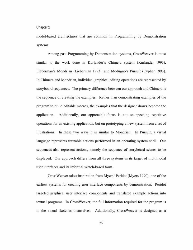
Among past Programming by Demonstration systems, CrossWeaver is most
similar to the work done in Kurlander’s Chimera system (Kurlander 1993),
Lieberman’s Mondrian (Lieberman 1993), and Modugno’s Pursuit (Cypher 1993).
In Chimera and Mondrian, individual graphical editing operations are represented by
storyboard sequences. The primary difference between our approach and Chimera is
the sequence of creating the examples. Rather than demonstrating examples of the
program to build editable macros, the examples that the designer draws become the
application. Additionally, our approach’s focus is not on speeding repetitive
operations for an existing application, but on prototyping a new system from a set of
illustrations. In these two ways it is similar to Mondrian. In Pursuit, a visual
language represents trainable actions performed in an operating system shell. Our
sequences also represent actions, namely the sequence of storyboard scenes to be
displayed. Our approach differs from all three systems in its target of multimodal
user interfaces and its informal sketch-based form.
CrossWeaver takes inspiration from Myers’ Peridot (Myers 1990), one of the
earliest systems for creating user interface components by demonstration. Peridot
targeted graphical user interface components and translated example actions into
textual programs. In CrossWeaver, the full information required for the program is
in the visual sketches themselves. Additionally, CrossWeaver is designed as a

Chapter 2
26
multimodal application prototyping tool. Many of Peridot’s goals, such as creating a
visual programming system that enables users to easily create a working application,
are the same as the goals for CrossWeaver.

Chapter 3
27
3 Field Studies
We interviewed 12 professional designers with an interest in multimodal user
interfaces in a field study similar to other studies done for other informal prototyping
tools (Landay 1996; Bailey 2002; Newman, Lin et al. 2003). Each of the
interviewed designers uses sketching during the first stage of his or her design
process to conceptualize user interface ideas. Most use some type of informal
storyboarding to string together the sketches into more complex behaviors.
Three of these designers were professional interaction designers targeting
applications for PDA’s, phones, or in-car navigation systems. Four of the designers
were game designers, a category of designers that has used alternative input devices
such as joysticks since the early pong games. Five of the designers were animators
and movie designers, who specify multimodal interaction through their storyboards,
even though they are not necessarily designing an interactive application. We review
the techniques and artifacts from each category of designers below.
3.1 Interaction Designers
The three professional interaction designers that we talked to all had
backgrounds in graphical user interface design. They were assigned by their
companies to work on projects for non-personal-computer devices in the last two or
three years. They considered these new projects for PDA’s and speech interfaces

Chapter 3
28
more challenging than the graphical user interface projects, and they changed some
of their design processes to address these new concerns.
The three designers all used some form of “Sketch-and-Show,” a term one of
them invented. They would sketch scenes of the proposed application and the
transitions among scenes and show them to other designers and others in the office.
On these sketches, they would add arrows and other informal annotations to show
different interaction techniques, such as pen gestures or speech commands.
One designer, who worked on a speech-based car navigation system, showed
us sketches with speech balloons systematically added to visual scenes to represent
combined visual and speech input and output (see Figure 3-1). These side-by-side
You are at Soda Hall, Berkeley
Computer, where am
I?
Turn leftTake me to Cory
Hall
Cory Hall on right
Speech input Speech outputVisual output
You are at Soda Hall, Berkeley
Computer, where am
I?
Turn leftTake me to Cory
Hall
Cory Hall on right
Speech input Speech outputVisual output
You are at Soda Hall, Berkeley
Computer, where am
I?
Turn leftTake me to Cory
Hall
Cory Hall on right
Speech input Speech outputVisual output
Figure 3-1. Storyboard showing a multimodal map navigation system for an in-car dash.

Chapter 3
29
visualizations addressed the challenge of combined audio and visual output
modalities.
For each of the designers, the sketched designs were difficult to evaluate.
The designer of the speech-based car navigation system had to wait until the system
was nearly complete before being able to see and hear what she had designed.
Building adequate prototypes to get comments from others was a common
challenge in the design process among the designers that we talked to. Typically, the
prototyping process for these interaction designers quickly jumps from sketches to
coded prototypes after a few iterations with paper designs.
One of the PDA designers that we talked to mentioned a prototyping process
that involved building screen representations in a tool such as Adobe Photoshop and
then stringing together those representations with hotspots in a tool such as Adobe
Acrobat or in HTML. These representations were adequate for walk-throughs, but
not for running prototypes, as they did not simulate pen-based interaction.
The car navigation system designer was unable to find any tool adequate for
simulating the in-car navigation system. The hardware system was being designed in
parallel to the interaction design and was unavailable for prototyping. The
multimodal interaction design for this system needed to be very good before
implementation, because it would be nearly impossible to make changes once the
hardware was fully developed.

Chapter 3
30
The interaction designers were particularly challenged when new hardware
devices were targeted. Not only does the interaction for these hardware devices need
to be worked out well in advance of the hardware being built, but the hardware
devices typically have many implementation challenges, making prototyping on
actual hardware extremely difficult.
3.2 Game Designers
The game designers that we talked to were primarily designing applications
for role-playing or action games in which there is a character traveling around an
animated world with a set of tasks, usually involving shooting. They were primarily
targeting the most popular video game consoles and were expecting input that used
joysticks, buttons, or special input devices based on the specific game system.
Soda Hall
Faculty Row
Undergrad Labs
Dungeon
Bubble diagrams show the outline of the different levels
Grad Offices
Sunny BeachStudent:programsneeds caffeine
Tools:backpack
Student:programsneeds caffeine
Tools:backpack
Figure 3-2. Artifacts produced by game designers include bubble diagrams and characteristic storyboards.

Chapter 3
31
The game designers that we interviewed emphasized that the plot of the game
being designed was much more important than any of the interaction design.
Typically, the script for the game is written; among our interviewees, scripts ranged
from a few dozen pages to 150 pages. The scripts for the game were thought of as
movie scripts, with the exception that they were translated into an interactive
application with characters and a set.
The storyboards sketched in game design generally outline the behaviors and
features of a particular character. The “characteristic storyboard” sketches out
different views of a character or a vehicle or a weapon, and lists the item’s behaviors
together with the view (see Figure 3-2). Additionally, most role-playing games
involve some sort of map, representing the levels or the virtual geography that the
end-user needs to negotiate. Some of the designers that we talked to drew sketches
representing physical maps; others represented virtual geography with bubble
diagrams (see Figure 3-2).
For the game designers, the input modes were determined by the target game
console, typically some sort of joystick or control pad. Consequently, the designers
were trying to fit their designs into available input capabilities. The designers
considered these non-keyboard and mouse capabilities more immersive than desktop
interaction for their games.
The game designers that we talked to were also experts in image editing tools
such as Adobe Photoshop. This allowed them to create screenshots and image
Chapter 3
32
representations close to the actual look of the final application. However, they were
unable to use these graphic representations for simulation in any of the available
tools. They had to rely on techniques similar to what they used when working with
the sketches to imagine the interaction.
Game designers typically work with expert programmers who pick up the
implementation when the story for the game is finalized. The game programmers
utilize a game engine that assists with graphics rendering, texture mapping, and
interaction with the input devices. These sophisticated game engines speed the
development process and allow refinement of the game as it is being created.
Typically the design evolves during implementation, with new levels being created
by the game designers in parallel to the programmers implementing the graphics.
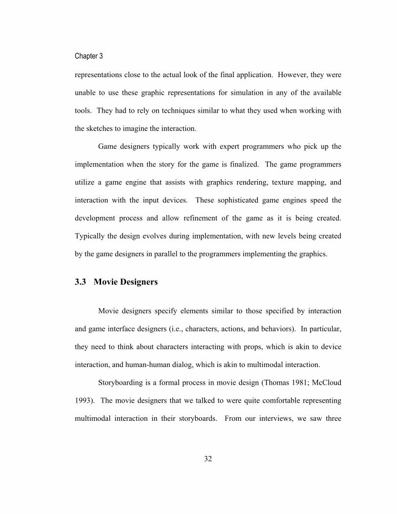
3.3 Movie Designers
Movie designers specify elements similar to those specified by interaction
and game interface designers (i.e., characters, actions, and behaviors). In particular,
they need to think about characters interacting with props, which is akin to device
interaction, and human-human dialog, which is akin to multimodal interaction.
Storyboarding is a formal process in movie design (Thomas 1981; McCloud
1993). The movie designers that we talked to were quite comfortable representing
multimodal interaction in their storyboards. From our interviews, we saw three

Chapter 3
33
different styles of annotations: annotations for camera instruction, annotations for
character instructions, and annotations for director instructions (see Figure 3-3).
Typically there is a storyboard for every scene in the movie, because the
storyboard is used to guide the filming. Some designers mentioned that while the
script was the central artifact determining the movie plot and story, the movie
storyboards were the central artifact guiding the filming of the movie.
Movie storyboards have a remarkable ability to convey visual, verbal, and
non-visual information to guide filming. A large part of this effect is accomplished
with captions or annotations, which tie the storyboards back to the script, specify the
expression of the actors, and describe the movement of the actors within the scene.
CameraDirections
e.g., cut
zoom in
Description of scene, actions (e.g., our hero enters the saloon)
“Dialogue” (if present)
3 5
dissolve dissolve
1
All the players around the table“Hit me”
Pan across the players faces
2
4
Sound of cards shuffling“I raise you $1”
Don’t show any faces
Pictures of cards tossed on the table“I fold”
Figure 3-3. Movie designers have a formal storyboarding process encompassing annotations for camera, character, and director instructions.

Chapter 3
34
Most of the movie designers that we talked to learned how to storyboard from
classes in film school or from other formal instruction. The look of the storyboards
that we saw was similar among the different movie designers that we interviewed.
Typically the storyboard is the artifact necessary to move to pre-production
and then filming. A good storyboard documents each shot in a movie with
significant detail. Much like in storyboarding for interaction design, changes to the
storyboard are best made at the drawing stage, rather than when the filming has
already begun.
3.4 Implications from Field Studies
From the field studies we learned that informal storyboarding was common
among multimodal designers. We also learned that the designers were comfortable
with special symbols representing different modalities; this was a fairly natural
concept for them akin to speech bubbles in comic strips (McCloud 1993). We also
learned that designers used annotations in all of their storyboards, representing
sequences, behaviors, and actions.
The most important visual elements of multimodal storyboarding were
arrows and text. Arrows were used to represent sequences, types of transitions,
movement, and actions. Since they were used in so many ways, the context in which
they were used was critical to understanding their meaning. Text is used for

Chapter 3
35
descriptions, dialog, commands, scenes, and other explanations necessary in the
storyboard. Generally the position of the text is enough to convey the context.
Each of the designers we talked to felt that the early stage processes for
multimodal user interface designs were more challenging than the corresponding
processes for two-dimensional graphical user interface design. In graphical user
interface design, paper prototyping is a well known technique (Rettig 1994). There
are no well-known similar techniques in the multimodal application domain. In
Chapter 4, we explore one such technique that we have developed for multimodal,
multidevice interface design.

Chapter 4
36
4 Multimodal Theater
To address some of the designers’ prototyping challenges (see Chapter 3) and
to explore techniques that might be adapted to interactive tools, we have made
efforts to extend some of the techniques of paper prototyping that are familiar to
interaction designers (Rettig 1994) to multimodal simulation using paper, other
physical materials, and Wizard of Oz participation (Chandler, Lo et al. 2002).
We call these experiments “Multimodal Theater” since they involve a
participant or participants, a set of actions specified in a script, a variety of props,
and a cast of Wizards of Oz in the actual simulation. In Multimodal Theater, the
script defines the behavior of the application. The props are paper sketches of screen
shots or other physical representation of devices. The Wizards of Oz simulate the
application based on the details in the script while the participant runs the
application. The applications that we prototyped and simulated include:
Table 4-1. Multimodal Theater Simulations
1) A voice-activated digital desk application for organizing photos (see Figure 4-1)
2) A mobile assistant to be used in an automobile (see Figure 4-2) 3) A collaborative document editing application 4) A technology-enhanced classroom with a digital whiteboard and a Personal
Digital Assistant (PDA) for the professor, as well as collaborative PDAs for the students
5) A handwriting recognition application 6) A dictation application 7) An application for creating animations 8) A voice-activated MP3 player

Chapter 4
37
Through these simulations we can quickly explore a variety of multimodal
interface commands. We can stick specifically to the application script or we can
allow the Wizards to improvise. With this flexibility, we have been able to capture
users’ preferred commands, the commands that should be added to the design, and
some of the required error handling behavior of the application. These simulations
also inform our design of computer support for interactive simulation of multimodal
applications, since we can see where paper techniques fail to be adequate for
multimodal simulation.
4.1 Multimodal Photo Album
For example, in the multimodal photo album application (see Figure 4-1), our
scripted design included the use of a simulated whiteboard computer, a simulated
table computer, and multimodal and unimodal commands for moving and arranging
photos. We tested this application with three participants recruited from the
computer science department. In our test, we gave the participants a brief
introduction to the simulation and the Wizard of Oz methodology that we would be
using. We provided the participant with a written set of instructions, which detailed
the task and available commands in the interface. The task was very basic for this
application: create a photo album of your vacation using the available photos.

Chapter 4
38
We had designed the application to behave like a photo album organizer with
multimodal commands. For example, a participant could point to a space on the
table computer and say “make a page.” This would create a photo album page.
They could then go to the whiteboard computer and point to photos and say “move
this to the album” to add photos to the album page on the table computer. Since we
were using Wizard of Oz simulation, the wizards had wide flexibility in the
commands that they would accept. For instance, “make a page” could be triggered
Figure 4-1. Multimodal Photo Album Room simulation.

Chapter 4
39
by “create a page,” “new page,” or any other phrase with similar meaning. Moving
the photo from whiteboard to table could be performed with a point-and-speak
command, like “move this photo,” or it could be performed with a gesture of
dragging the photo to a special area on the whiteboard computer.
In our tests, each participant was able to successfully complete the task.
Since the task was open-ended by its nature, the participants took different amounts
of time and used different commands to create pages and arrange the photos. A
given individual tended to choose a specific style, either unimodal or multimodal, for
most of the commands that they used. One of the participants tended to not use any
speech commands, and would only point and drag. Another participant most
commonly used point-and-speak whenever it was possible. The last participant had
elements of both styles.
We assigned two Wizards and one observer to simulate this application. One
Wizard was responsible for the table computer and one Wizard was responsible for
the whiteboard computer. When the participant would come to that computer, the
Wizard in front of it would respond to the participant’s commands based on the
script. Occasionally this involved the Wizard informing the user that a certain
speech command or other command was not possible. This was done in a consistent
manner based on the specification for feedback errors in the script. We developed
enough expertise in multimodal simulation involving speech and pointing commands
to recognize multimodal commands and react to them appropriately as a pair of
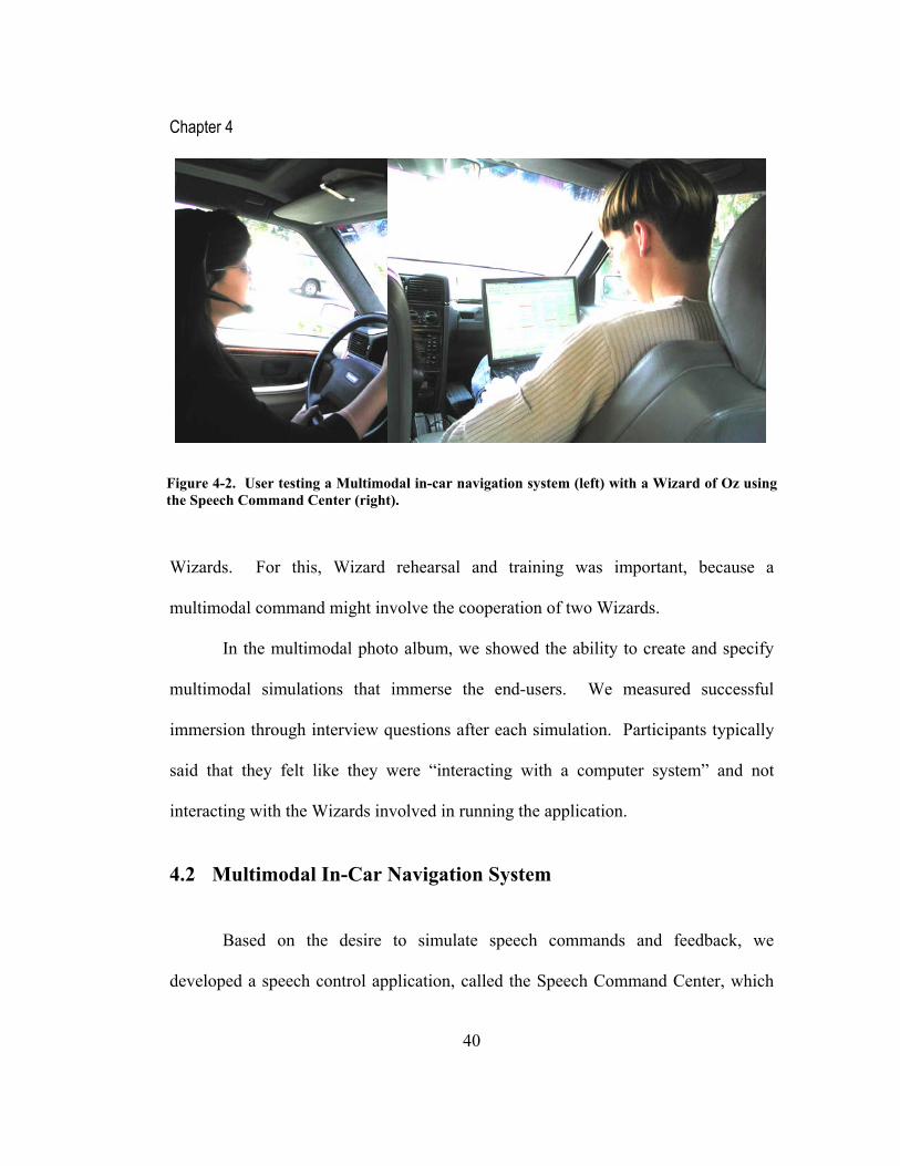
Chapter 4
40
Wizards. For this, Wizard rehearsal and training was important, because a
multimodal command might involve the cooperation of two Wizards.
In the multimodal photo album, we showed the ability to create and specify
multimodal simulations that immerse the end-users. We measured successful
immersion through interview questions after each simulation. Participants typically
said that they felt like they were “interacting with a computer system” and not
interacting with the Wizards involved in running the application.
4.2 Multimodal In-Car Navigation System
Based on the desire to simulate speech commands and feedback, we
developed a speech control application, called the Speech Command Center, which
Figure 4-2. User testing a Multimodal in-car navigation system (left) with a Wizard of Oz using the Speech Command Center (right).

Chapter 4
41
we provided to one of the Wizards in a scenario simulating speech-based in-car
navigation (see Figure 4-2). In the in-car navigation system, the participant sits in
the driver seat with a headset. The Wizard sits in the right seat with a computer that
has the Speech Command Center on it. As the participant makes requests via speech
commands the Wizard responds using the Speech Command Center. This Speech
Command Center is a Microsoft Excel spreadsheet that the designer pre-creates. The
spreadsheet contains links that trigger playing the various speech commands. It also
has the facility to record what the participant is saying and possibly use it in follow-
up commands. Running on a laptop, the Speech Command Center is a portable
Wizard of Oz tool that allows the Wizard to do a fairly sophisticated speech-based
simulation.
We tested the in-car navigation system with two participants. We had the
participants drive around the local area and use the system as they would normally
use their car stereo, if it had speech capabilities, listening to news reports or getting
other pieces of information. Both participants had no trouble using the system. The
Wizard needed to respond quickly to the participants’ command to make the
simulation seem realistic. This was done successfully for both participants, who felt
they were immersed in the application, rather than talking to the Wizard. Since the
voice commands were pre-recorded and played on the computer, the participants felt
like they were using a computer rather than talking to an individual.

Chapter 4
42
4.3 Design Implications for Multimodal Design Tools
Based on informal observation, we have noticed that the Wizards’ actions
become more predictable with a formal script, and end users sense that predictability.
In general, we have found that the most successful simulations are ones in which the
application is fully scripted rather than improvised. For a design tool, this means
that the designer can fully script the interface, rather than leaving many details
unfinished.
We have found that we can build a prototype for a given application in a few
hours, and refine that prototype quickly. Happily, a large fraction of the time is
spent actually thinking about and refining the design of the application rather than
working with physical materials to put together the simulation. A design tool should
not take significantly more time, otherwise the incentive to use the design tool
decreases in comparison to the paper-based simulation.
The Wizards had a complicated task in Multimodal Theater. They had
commands to memorize, devices to manage, and props to utilize. In a design tool,
the ability to use a computer to handle the response of commands alleviates the time
required to train the Wizards. A tool can perform a similar simulation more
consistently without the participation of the Wizards.
However, using Wizards was valuable for collecting a broad set of
commands that participants wanted to use in the simulation. The designer would not

Chapter 4
43
get that same breadth of commands in a design tool that relied on computer-based
recognition. Thus, Multimodal Theater could be used to get early ideas about
possible multimodal commands and behaviors, even if a recognition-based design
tool exists.

Chapter 5
44
5 Design Evolution of CrossWeaver
The study of multimodal interface designers (see Chapter 3) and experiments
with Multimodal Theater (see Chapter 4) has given us insight into the design process
for multimodal applications. This design process is similar in its steps to the design
process for graphical user interfaces (Landay 1996) or web interfaces (Newman, Lin
et al. 2003), involving sketching and storyboarding at the early stages. The visual
form of the multimodal designers’ storyboards is unique in its use of symbols and
annotations to represent different input modalities. We used this insight into the
Input modes
Output modes
Modifiers
Text:
Ctrl+P
“add pushpin”
“add pushpin here”
Tools
Pushpin
Definition of adding a pushpin
Zoom in
In put modes
Outpu t modes
Mo di fie rs
Text
:
Ctrl
+Z
“zoom
i
n”
“zoom
in
to
here”
ToolsZoom
De fining zoo min in
File Edit View
Connect
Points
This is the way from Point 1 to Point 2
Connect
Points
This is the wa y fr om Po int 1 to Po int 2
Connect
Points
This is the wa y fr om Po int 1 to Po int 2
Selec t
Point 2
Out put De vices
Ti tle
Selec t
Point 2
Out put De vices
Ti tle
Back ground
Of
Map
Outpu t Devices
T itle
Back ground
Of
Map
Outpu t Devices
T itle
Select
Point 1
Outp ut Device s
Ti tle
Background Of Map Select Point 1 Select Point 2 Connect Points
Connect Points
Paper Prototype Design Sketches Early Prototype
CrossWeaver Prototype Collaborative CrossWeaver Prototype Design Sketches
CrossWeaver
Figure 5-1. Design evolution of CrossWeaver.

Chapter 5
45
sketching representation of multimodal storyboards and used it in our design of
CrossWeaver.
The stages in the design evolution of CrossWeaver are shown in Figure 5-1.
Each of the stages grappled with the issue of representation of input modalities and
output modalities. Each stage also tried to further develop the storyboarding
paradigm in CrossWeaver. The key challenge with the storyboard visual form
involves incorporating the input and output representations in a space-efficient way.
A multimodal storyboard that has many scenes and input transitions can get cluttered
Input modes
Output modes
Modifiers
Text:
Ctrl+P
“add pushpin”
“add pushpin here”
Tools
Pushpin
Definition of adding a pushpin
Zoom in
In put m od es
Ou tp ut modes
Modi fier s
Text:
Ctrl
+Z
“z
oom
i
n”
“zoom
in
t
o
her
e”
To olsZoom
Defi nin g z oomi n in
Figure 5-2. Early design sketch for CrossWeaver’s interface for creating representations of multimodal input.

Chapter 5
46
given the variety of input and output modes that need to be labeled.
The paper prototype and early design sketches introduced an iconic
representation for input and output modalities (see Figure 5-2). The figure shows
icons that represent mouse, keyboard, pen gesture, speech, and other inputs on the
left side of the screen. The column to the right of that shows output modalities, such
as output to a screen, audio speaker or printer. Both screen and audio output were
Input modes
Output modes
Modifiers
Text:
“Calculate distance” 30 miles
“30 miles”
Defining Calculate Distance
“Calculate distance”
30 miles
“30 miles”Tools
Blah blah
Find Distance
Blah blah
Zoom in
Input modes
Out put mod es
Modif ier s
Text
:
Ctrl+Z
“z
oom
i
n”
“
zoom
in
t
o
her
e”
ToolsZoom
Defin ing zoomin in
Add push pin
Input modes
Output modes
Modifiers
Text:
Ctrl+P
“add
pushpin”
“add
pushpin
h
ToolsPushpin
Definition of adding a pushpin
Select pushpin
Input modes
Output modes
Modifiers
Text:
Ctrl+S
“select
pushpin”
“select
this
pushpin”
ToolsPushpin
Definition of selecting a pushpin
Select pushpin
Input modes
Output modes
Modifiers
Text:
Ctrl+S
“select
pushpin”
“select
this
pushpin”
ToolsPushpin
Definition of selecting a pushpin
Select pushpin
Input modes
Output modes
Modifiers
Text:
Ctrl+S
“select
pushpin”
“select
this
ToolsPushpin
Definition of selecting a pushpin
Figure 5-3. Early design sketch for CrossWeaver’s interface showing a potential way of representing “Operations”.

Chapter 5
47
retained through all of the design iterations of CrossWeaver. The screen concept
expanded to multidevice output in later designs.
The storyboard in Figure 5-2 shows a scene-by-scene storyboard layout that
uses annotated arrows with input modalities to connect the scenes. This layout
assumes an “infinite sheet” metaphor so that storyboard panes can exist anywhere in
the screen area and can be linked to any other screen.
To enable more sophisticated functionality in a limited space, the design
sketches also incorporate the concept of grouping scenes in the storyboard together
Input modes
Output modes
Modifiers
Text:
Zoom in
In put modes
Output modes
Mod if ier s
Text:
Ctrl
+Z
“z
oom
in”
“
zoom
in
to
here”
ToolsZoom
Defini ng zo omin in
Add push pin
Input modes
Output modes
Modifiers
Text:
Ctrl+P
“add
pushpin”
“add
pushpin
h
ToolsPushpin
Definitio n of a dding a pushpin
Select pushpin
Input modes
Output modes
Modifiers
Text:
Ctrl+S
“select
pushpin”
“select
this
p
ToolsPushpin
Definition of selecting a p ushpin
Calculate distance
I np ut
m od e s
O ut p ut
mo de s
Mod if i er s
Text:
“C alc ul ate
dist a nce” 30 miles
“30 mi les”
De fi ning Cal culate Distance
“Calcu l at e dist an ce”
30 miles
“30 mi les”To olsBlah bl ahFind Di stanceBlah bl ah
Zoo m in
Input modesOutput modesModifiersText:Ctrl+Z“zoomin”“zoomintohere”ToolsZoomDefining zoomin in Ad d push pin
I npu t mod esO utput modesM odi fier s
Text:
Ctrl+
P
“add
pushp
in”
“
add
pu
shpin
here”
T ool sPu shp in
De fini tio n o f a ddi ng a pus hp in
Select p ushp in
In put mode s
Ou tp ut mode sMo dif ier s
Text:
Ctrl+S
“sel
ect
pus
hpin”
“s
elect
this
p
ushpin
”
Too lsPus hpi n
De finitio n o f s electin g a p ush pi n
Sel ect pushp in
I npu t
mod es
O utp ut
m od esM od ifie rs
Tex
t:
Ctr
l+S
“s
elect
pushpi
n”
“selec
t
this
pushp
in”
ToolsPushp in
D efin iti on of sel ect ing a pus hpin
Se le ct pu shpi n
Inp ut mo de s
Ou tpu t mo de sMo difi ers
Text:
Ctrl+
S
“se
lect
p
ushpin
”
“
select
this
pushpi
n”
T oo lsPu sh pin
Def ini tion of se lec tin g a pu sh pin
SELECTION SCOPINGAFTER SELECTION TOOLPLACED ON CANVAS AREA
Figure 5-4. Early design sketch for CrossWeaver’s interface showing the representation of a “Selection Region” in which a command will be active.

Chapter 5
48
into operations, shown as a thumbnail at the bottom of Figure 5-2 for the operation
“zoom in” and shown in detail in Figure 5-3 for the operation “calculate distance.”
Reusable operations allow the incorporation of higher-level concepts into the
application, such as zooming, panning, or adding objects. The operations concept
was a primary thrust of the first interactive prototype, which is described in Chapter
6.
In Figure 5-4, dashed lines represent areas in which a gesture command will
be active, which we call selection regions. In a map, a selection region could be the
Figure 5-5. The first interactive prototype of CrossWeaver.
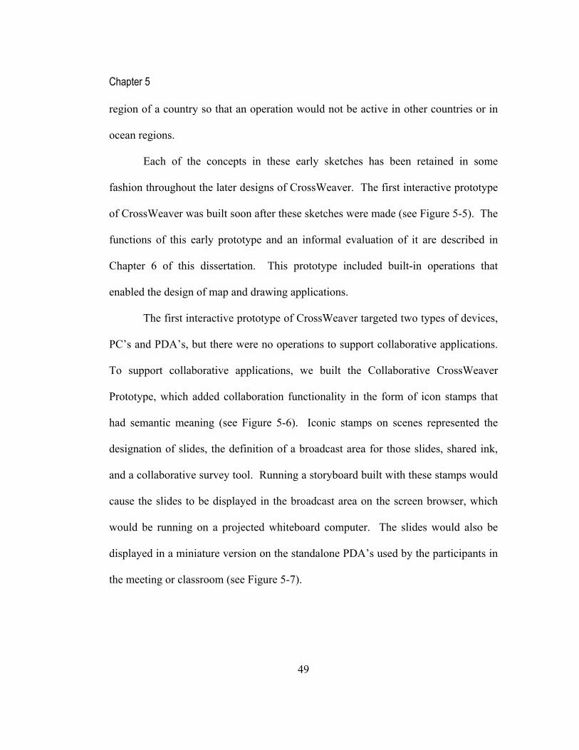
Chapter 5
49
region of a country so that an operation would not be active in other countries or in
ocean regions.
Each of the concepts in these early sketches has been retained in some
fashion throughout the later designs of CrossWeaver. The first interactive prototype
of CrossWeaver was built soon after these sketches were made (see Figure 5-5). The
functions of this early prototype and an informal evaluation of it are described in
Chapter 6 of this dissertation. This prototype included built-in operations that
enabled the design of map and drawing applications.
The first interactive prototype of CrossWeaver targeted two types of devices,
PC’s and PDA’s, but there were no operations to support collaborative applications.
To support collaborative applications, we built the Collaborative CrossWeaver
Prototype, which added collaboration functionality in the form of icon stamps that
had semantic meaning (see Figure 5-6). Iconic stamps on scenes represented the
designation of slides, the definition of a broadcast area for those slides, shared ink,
and a collaborative survey tool. Running a storyboard built with these stamps would
cause the slides to be displayed in the broadcast area on the screen browser, which
would be running on a projected whiteboard computer. The slides would also be
displayed in a miniature version on the standalone PDA’s used by the participants in
the meeting or classroom (see Figure 5-7).

Chapter 5
50
The design in Figure 5-6 includes a set of slides (Global Slides) and a
multimodal command (Global Transition) representing the way for a user to move
from slide to slide. The Screen Layout is a scene that is divided into three different
areas: a broadcast area, a shared ink area, and a survey. These areas are labeled by
placing the corresponding stamp in the desired area. Upon running the application,
the screen layout appears on the Screen Browser, shown in Figure 5-7. The slides
show up as miniatures on the PDA Browsers that are participating in the test, also
shown in Figure 5-7. Each PDA Browser has a shared ink area, which accepts ink
strokes. The screen browser has a shared ink area, which displays the aggregate ink
from all of the participating devices. Each PDA browser also has a survey area
slide broadcast sharedink
survey
Globalslides
Globaltransition
Screenlayout
slide broadcast sharedink
survey
Globalslides
Globaltransition
Screenlayout
Figure 5-6. The design mode in the Collaborative CrossWeaver Prototype.

Chapter 5
51
which accepts numbers as inputs. The screen has an area displaying a dynamic bar
graph of the aggregate responses that were entered in the PDA survey area.
Even though the functions that we built into this interactive prototype are
appropriate for a variety of collaborative applications, a test of this system showed
that it was very complex to run. We tested this system informally during a
presentation in a course focused on Computer Supported Cooperative Work (CSCW)
(Landay 2001). The design of the interface was very similar to the one shown in
Figure 5-6. The slides were originally created in Microsoft PowerPoint and then
imported into Collaborative CrossWeaver, which was a multi-step process since
Collaborative CrossWeaver could only import images. The multimodal transition
was not particularly useful in this scenario, since we had ready access to the
keyboard and needed to use the mouse for pen gesture input. We did use the voice
commands to transition among slides, but voice commands were unreliable due to
Screen BrowserPDA Browser(per device)Screen BrowserPDA Browser(per device)
Figure 5-7. The test mode browsers in the Collaborative CrossWeaver Prototype.

Chapter 5
52
ambient noise and the correspondingly poor performance of the speech recognizer.
The PDA Browsers were not particularly attractive to the participants in the test.
They commented that the miniature version of the slide was not necessary since it
was displayed in full form in the Screen Browser. Furthermore, the shared ink area
and survey area quickly lost their novelty among the participants.
The Collaborative CrossWeaver prototype indicated that our design and
implementation were not adequate and also that adding too much domain
functionality into this prototyping tool might be counter-productive. Collaborative
File Edit View
Connect
Points
This is the way from Point 1 to Point 2
Connect
Points
This is the way from Point 1 to Point 2
Connect
Points
This is the way from Point 1 to Point 2
Select
Point 2
Output Devices
Title
Select
Point 2
Output Devices
Title
Background
O f
Map
Output Devices
Title
Background
O f
Map
Output Devices
Title
Select
Point 1
Output Devices
Ti tle
Background Of Map Select Point 1 Select Point 2 Connect Points
Connect Points
Figure 5-8. A design sketch of CrossWeaver before the final implementation.

Chapter 5
53
CrossWeaver increased the complexity beyond what would be comfortable for a
non-programmer designer, the target user of this tool.
After implementing Collaborative CrossWeaver, we drew a new set of design
sketches for the final implementation of the tool (see Figure 5-8 for one of those
sketches). Based on feedback from the initial implementation, we made the
storyboard scheme linear and changed the representation of the input and output
modes. In these sketches, operations are represented as a short sequence in the
storyboard instead of a thumbnail. The final implementation of CrossWeaver, which
we more fully describe in Chapter 7, does not include built-in collaborative
Figure 5-9. The Design Mode of CrossWeaver in the final implementation.
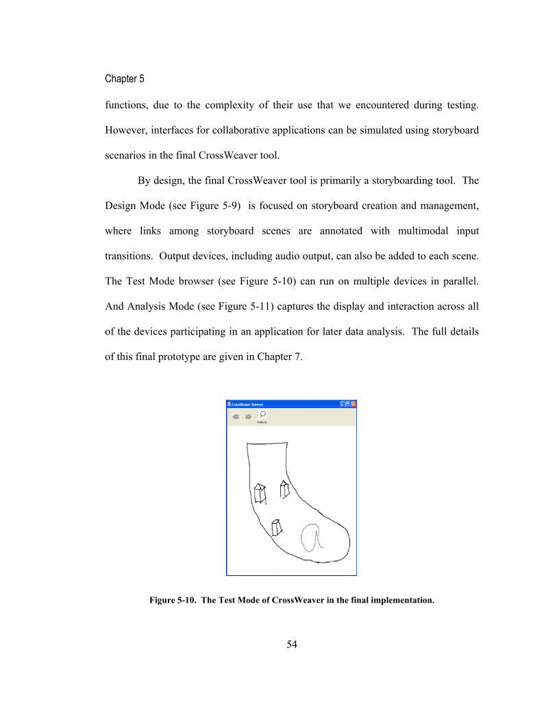
Chapter 5
54
functions, due to the complexity of their use that we encountered during testing.
However, interfaces for collaborative applications can be simulated using storyboard
scenarios in the final CrossWeaver tool.
By design, the final CrossWeaver tool is primarily a storyboarding tool. The
Design Mode (see Figure 5-9) is focused on storyboard creation and management,
where links among storyboard scenes are annotated with multimodal input
transitions. Output devices, including audio output, can also be added to each scene.
The Test Mode browser (see Figure 5-10) can run on multiple devices in parallel.
And Analysis Mode (see Figure 5-11) captures the display and interaction across all
of the devices participating in an application for later data analysis. The full details
of this final prototype are given in Chapter 7.
Figure 5-10. The Test Mode of CrossWeaver in the final implementation.

Chapter 5
55
The design evolution of CrossWeaver eventually converged on a prototype
that solves the issues of input and output modality representation, keeps the
storyboard model understandable and simple, and gives the designer flexibility in the
types of interfaces that can be created.
Figure 5-11. The Analysis Mode of CrossWeaver in the final implementation.
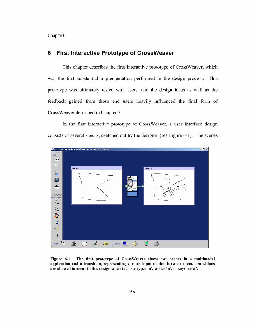
Chapter 6
56
6 First Interactive Prototype of CrossWeaver
This chapter describes the first interactive prototype of CrossWeaver, which
was the first substantial implementation performed in the design process. This
prototype was ultimately tested with users, and the design ideas as well as the
feedback gained from those end users heavily influenced the final form of
CrossWeaver described in Chapter 7.
In the first interactive prototype of CrossWeaver, a user interface design
consists of several scenes, sketched out by the designer (see Figure 6-1). The scenes
Figure 6-1. The first prototype of CrossWeaver shows two scenes in a multimodal application and a transition, representing various input modes, between them. Transitions are allowed to occur in this design when the user types ‘n’, writes ‘n’, or says ‘next’.

Chapter 6
57
show the important visual changes in the user interface that occur in response to end-
user input. The scenes can also incorporate other output modalities, such as speech.
Transitions between scenes, caused by end-user input, are represented by arrows
joining icons representing the input modes that the scene handles.
Sequences of scenes and transitions form a multimodal storyboard, which can
be tested with an associated, standalone multimodal browser (see Figure 6-2). The
multimodal browser displays scenes as output using visual displays and audio output.
It is connected to user interface agents using the Open Agent Architecture (Moran,
Cheyer et al. 1998), which enables the browser to respond to pen gestures, speech
commands, keyboard input, or any other input mechanism for which there is an
associated input agent. The multimodal browser runs on multiple platforms,
including Windows CE handhelds (e.g., the Compaq iPaq Pocket PC) and
whiteboard computers (e.g., the SmartBoard).
(a) (b) (c)
Figure 6-2. A participant executes the application in Figure 6-1 in the multimodal browser. The browser shows the starting scene (a); the participant then draws the gesture “n” on the scene (b); the browser then transitions to the next pane in the multimodal storyboard shown in (c).
Chapter 6
58
With this architecture, we can also optionally substitute humans as Wizard of
Oz recognition agents (Kelley 1984). For instance, we have consoles for the Wizard
to simulate speech and pen recognition from any networked computer. Wizard of Oz
would be an appropriate testing method if a computer recognizer is not convenient to
use, such as in the first attempt at testing, or if a computer recognizer is not available.
A Wizard serves only as a recognizer, and does not participate in deciding the flow
of the scenes executed when browsing.
6.1 Defining Interaction in CrossWeaver
The interaction in CrossWeaver is meant to encourage experimentation with
different user interface ideas. In CrossWeaver, designers can quickly change the
gestures, keystrokes, or speech commands used in their application design using a
visual interface; they do not have to modify formal grammars or code to experiment
with different interaction ideas.
Unlike many traditional visual programming approaches, most of which
require formal specification or complex state transition diagrams (Burnett and
McIntyre 1995), CrossWeaver enables the designer to use a more intuitive visual
form based on drawing example sketches, a paradigm we call defining operations.
This is especially helpful when the designer defines reusable operations, described
later in this chapter.

Chapter 6
59
6.1.1 Defining Scenes
Scenes are sketched using a mouse or a pen tablet. In this early stage of
prototyping, pen tablet-based sketches encourage fluid interaction and keep the
representations in an informal form (Gross and Do 1996; Landay and Myers 2001).
The informal form of the design ensures that designers and end-users focus on the
interaction and not on the fit-and-finish (Wong 1992).
CrossWeaver also allows import of multiple types of media into each scene.
For instance, images can be imported into a scene using the camera icon from the
Figure 6-3. The first CrossWeaver prototype shows thumbnails representing reusable operations (top), scenes that have imported images (left and right), a scene that targets screen and audio output (left) and a scene that targets PDA output (right).

Chapter 6
60
tool panel (see Figure 6-3 top left). Sequences of images can be imported using the
movie icon to create a rough flip-book style movie, keeping with the informal, fluid
nature of the tool. Both of these import tools can directly utilize physical capture
devices, such as digital cameras and scanners. In the two scenes shown in Figure
6-3, we have imported images of a map.
In CrossWeaver, scenes can specifically target different output devices types,
which are shown in Figure 6-4. In Figure 6-3, we have attached audio output, the
phrase “Welcome to Minnesota,” to the first scene. When the audio icon is stamped
on the scene, a text box appears below the scene representing text to be played via a
text-to-speech agent simultaneously with the visual output. The second screen
targets a PDA represented by the PDA icon at the bottom of the screen. That scene
will be visually displayed in the PDA version of the multimodal browser. This list of
output modes is also extensible; it could be expanded to printer, pager, or phone
screen output.
Figure 6-4. The available output devices for scenes: screen output (default), audio, PDA, and printer (future work). These icons are dragged onto scenes to specify cross device output.

Chapter 6
61
6.1.2 Defining Transitions
The various input modes available in this first prototype are shown in the
extensible input tool panel at the bottom of the CrossWeaver design screen (see
Figure 6-5). If new input modes become available, they can be added to this area.
For instance, one could imagine adding camera/vision input.
When used to define interaction, each input mode has an associated modifier,
representing the value needed for that particular input mode to cause a scene
transition. The example in Figure 6-6(a) shows how we have stamped three possible
input modes, each with different modifiers, to define the possible input transitions.
The multimodal browser responds to input of these various types and matches them
with the multimodal storyboard to determine what scene to present next.
By specifying transitions in this way, it is possible to accept input modes that
are independent or fused (Nigay and Coutaz 1993). If the inputs are fused (see
Figure 6-6b), CrossWeaver uses a simple slotting system to wait for recognized
inputs and joins them if the designated inputs arrive within a certain pre-specified
Figure 6-5. The available input modes for transitions in the first CrossWeaver prototype: mouse gesture, keyboard, pen gesture, speech input, and phone keypad input. These are dragged onto transition areas to specify multimodal interaction.

Chapter 6
62
time period; for testing purposes we used two seconds. In the future, we may allow
the designer to set the time interval and other parameters related to fusion, though at
this early stage in the design, designers might not be interested in setting these
parameters. Ultimately, taking advantage of fused input modes enhances recognition
performance using mutual disambiguation (Oviatt 1999).
6.1.3 Defining Operations
Specifying scene-to-scene transitions for each and every interaction would
quickly lead to visual spaghetti. This is a common problem with visual languages
(Chang, Ichikawa et al. 1986; Chang 1987). Not only is complete transition
(a) (b)(a) (b)
Figure 6-6. (a) The transition specifies a keyboard press ‘n’ to move to the next scene or a gesture ‘n’ via pen input or a speech command ‘next’. (b) With the two bottom elements grouped together, the transition represents either a keyboard press ‘n’ by itself or the pen gesture ‘n’ and the speech command ‘next’ together synergistically.

Chapter 6
63
specification not practical, but as previously described, transitions do not allow
various commands to happen at any time, in an unspecified order.
To address the scalability problem and to enable parallel commands,
CrossWeaver supports designer-defined operations, essentially storyboards with
specific meaning that can execute at any time, built from a set of existing operation
primitives (see Figure 6-7). For example, CrossWeaver allows the designer to create
a reusable pushpin that can be added anywhere in the scene (see Figure 6-8). A full
CrossWeaver design contains a set of operations as thumbnailed storyboard
Figure 6-7. The designer designates a storyboard sequence as a specific operation by stamping it with the appropriate operation primitive icon. There are six basic primitives that can be used, from top to bottom: defining adding an object, defining deletion, defining a specific color change, defining a view change (zoom in, zoom out, rotate, or translation), defining an animation path, or defining a two point selection (as in a calculate distance command).
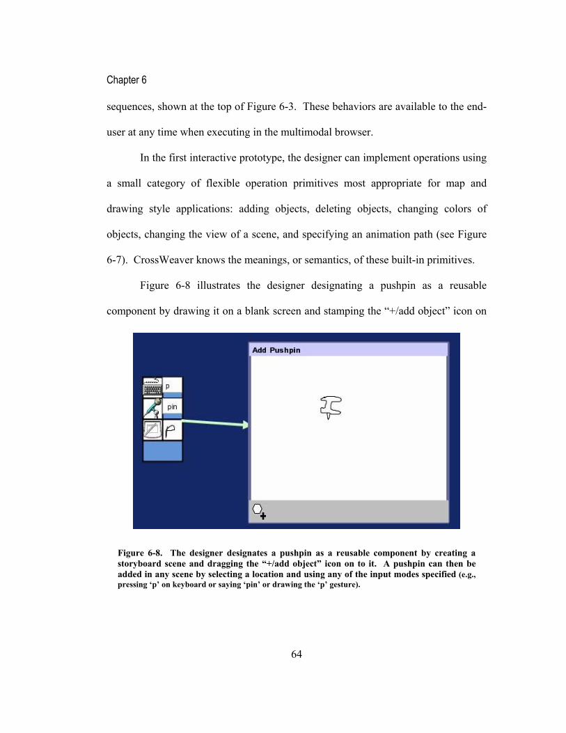
Chapter 6
64
sequences, shown at the top of Figure 6-3. These behaviors are available to the end-
user at any time when executing in the multimodal browser.
In the first interactive prototype, the designer can implement operations using
a small category of flexible operation primitives most appropriate for map and
drawing style applications: adding objects, deleting objects, changing colors of
objects, changing the view of a scene, and specifying an animation path (see Figure
6-7). CrossWeaver knows the meanings, or semantics, of these built-in primitives.
Figure 6-8 illustrates the designer designating a pushpin as a reusable
component by drawing it on a blank screen and stamping the “+/add object” icon on
Figure 6-8. The designer designates a pushpin as a reusable component by creating a storyboard scene and dragging the “+/add object” icon on to it. A pushpin can then be added in any scene by selecting a location and using any of the input modes specified (e.g., pressing ‘p’ on keyboard or saying ‘pin’ or drawing the ‘p’ gesture).

Chapter 6
65
the scene. The key press ‘p’ or speech command ‘pin,’ or proper pen gesture will
trigger the addition of a pushpin in the current multimodal browser screen at the
currently selected point (see Figure 6-11).
In Figure 6-9, we have used a specific example of coloring a shape to define
the color blue operation, triggered by clicking on the ‘b’ key or by speaking ‘make
blue’. By attaching the “define color” primitive to the scene we know that this
particular sequence represents the globally available blue coloring operation in the
designer’s application. Figure 6-12 shows the blue coloring operation in action.
Figure 6-9. The designer designates coloring blue as a reusable operation by creating a storyboard scene and dragging the “define color” icon onto it. A selected object in a scene can be colored blue in any scene by any of the input modes specified (e.g., clicking on the object and pressing ‘b’ on the keyboard or saying ‘make blue’).

Chapter 6
66
In Figure 6-10, we have defined two additional operations. The top operation,
composed of before and after scenes and a transition between them, gives the
example of zooming in on an object. The bottom operation gives the corresponding
example for zooming out. After the “view change” operation icon is stamped on the
scenes, the system infers with a simple algorithm that these sequences become zoom
in and zoom out operations in the multimodal browser, triggered by the designated
input modes. The rectangles used in these scenes are strictly examples; they could be
any example shapes that the designer draws. The semantic meaning, zooming of the
scene, is carried out by the system during browsing. Additional view changes that
Figure 6-10. The designer defines zooming in and out as separate operations by drawing examples of growing and shrinking with any example shape and stamping the view operation icon onto them. These operations are triggered in the browser by the input operations in the transition between them (e.g., pressing ‘z’ on the keyboard, gesturing ‘z’ with the pen, or saying ‘zoom in’ and pressing ‘o’ on the keyboard, gesturing ‘o’, or saying ‘zoom out’).

Chapter 6
67
can be defined by illustrative examples are scene translation and rotation.
Allowing the designer to define addition and deletion of objects, coloring,
view changes and other operations enables him or her to prototype and test a
multimodal application with map or drawing functionality using CrossWeaver. We
believe other application domains can be similarly divided into primitive operations.
We saw evidence of this in our field studies in which the designers would show us
short sequences of sketches which represented the basic operations in the interface
that they were designing.
6.2 Matching the Designers’ Mental Models
CrossWeaver’s style of sketching maps well to the mental models of the user
interface designers that we interviewed (see Chapter 3). They often add annotations
to their sketches to give a semantic meaning to the sketch. For instance, game
designers draw a character, meaning for the character to be a reusable object. They
Figure 6-11. The user can click anywhere and say “add pin” to add the reusable pushpin component, as defined in Figure 6-8, at the clicked point.

Chapter 6
68
might even draw three or four different styles of that character and experiment with
using each of them in a background scene. In CrossWeaver, the equivalent
annotation for designating a drawing as a reusable component is using the “+/add
object” operator.
Designers also make sketches to represent example operations in the
applications that they are designing. In envisioning complex ideas, we have found
that some designers sketch a sequence representing an operation and then say the
sequence applies to many scenes. For instance, for defining “calculate distance,” a
designer would draw the selection of two locations, show their connection, and
display the distance between them. Then the designer would point out that the
operation applies to any two locations. This was the motivation for CrossWeaver’s
operators.
Figure 6-12. The user triggers the make blue color operation, as defined in Figure 6-9, by selecting any object and saying “make blue”.

Chapter 6
69
6.3 Informal Evaluation of the First Interactive Prototype
To gauge the understandability of operations and the usability of the first
interactive prototype, we evaluated CrossWeaver in an informal test with 10 people,
five advanced HCI computer science graduate students with significant programming
ability and five advanced university students without significant programming
ability.
Each participant was placed in front of a desktop computer (1 GHz Pentium
4, 512 MB RAM) with a Wacom pen tablet, a mouse, and a regular keyboard to use
for the CrossWeaver input. We gave each of the participants a brief verbal tutorial in
CrossWeaver’s operation and showed them screen shots of different steps in building
a map-based multimodal application, much like the screen shots in this dissertation.
We then asked them to build their own multimodal map editing application in 30
minutes and were available for questions as they were using the system. The
screenshots that we showed to them specified a generic map and the adding pushpins
operation. We asked the participants to pick their own domain, such as trip planning,
finding directions, or browsing a map. For the purposes of this test, we simulated
computer speech recognition using a Wizard of Oz application.
All of the participants, with programming experience or not, said that they
understood the CrossWeaver paradigm of stamping sketches to turn them into
operations within five minutes of starting to use the tool. Each participant was able

Chapter 6
70
to successfully create three or more reusable operations and test them out in the
multimodal browser. These operations included defining “add mountain,” “color
yellow,” “delete,” “rotate 45 degrees,” and “zoom in.”
Different participants supported different styles of multimodal interaction in
their application. One participant exclusively defined speech commands saying that
if speech was available, she did not see why anyone would want to use the keyboard.
In contrast, another participant defined interaction using only using keyboard
commands. One participant was immediately attracted to speech output phrases for
some of the scenes that he created. He also attached the PDA stamp to some of the
output scenes, but in this test, we did not specifically test the PDA platform.
When asked, the five participants without significant programming
experience all commented that they did not feel that using CrossWeaver was
anything like their concept of programming; they did not need to learn complex
syntax or decipher cryptic text. Some mentioned that using CrossWeaver felt like
drawing, others mentioned that it felt like storyboarding, others said that it was like
making a comic strip.
The participants with programming experience, in contrast, mentioned that
defining operations reminded them somewhat of programming. Two of these
participants felt a bit frustrated about not being able to build certain functions, such
as filtering, that they wanted to include in their designs. One participant asked if
operations were extensible. Another asked about scoping the various defined

Chapter 6
71
operations to specific scenes. These concerns appeared to come out of experienced
programmers’ mental models. One programmer, however, specifically mentioned
that, versus programming, the visual ideas in the CrossWeaver interface were very
easy to grasp.
When asked to rate the understandability of the Programming by Illustration
paradigm on a 0 (not understandable) to 10 (simplest possible) scale, the participants
without programming experience rated the paradigm easier to understand
(Mean=8.4, Variance=1.3) than those with programming experience (Mean=6.8,
Variance=2.2). This difference is statistically significant t(8)=1.91, p<0.046,
suggesting that those without programming experience will likely react more
favorably to CrossWeaver than experienced programmers who might choose to
implement these interfaces with formal programming tools. This is a positive result,
since CrossWeaver is targeted at non-programmer designers.
There was no statistically significant difference in between programmers’ and
non-programmers’ ratings of the overall usability of CrossWeaver. Four participants
mentioned that some of their interaction problems were due to inexperience with the
Wacom tablet. For some participants, there were interruptions caused by a problem
in the agent infrastructure. Many participants said that with greater time and use of
CrossWeaver, they would be able to create a more sophisticated application.
The participants mentioned that the tutorial was essential for their
understanding of the operations in CrossWeaver. That they were able to learn from a

Chapter 6
72
single example, however, shows that the operations concept is straightforward. In
Chapter 8, we describe an evaluation of the final implementation of CrossWeaver
with professional designers.
6.4 Design Implications
From the user test of the first interactive prototype, we learned that a stylus-
only interface did not work particularly well. Many of the critical incidents were
related to poor resolution of the stylus on the screen and the difficulty in selecting
menu items. One of the users even asked for the mouse to avoid using the stylus. In
the final CrossWeaver implementation, we chose to target a system that could use
mouse or stylus equally well and one that also used the keyboard.
Many users also commented that they thought the interface had unwieldy
management of scenes and arrows. They found zooming unnecessary and difficult.
This led us to re-think the scheme for the CrossWeaver storyboard. In the final
version, we chose to make the storyboard linear, to emphasize scene-by-scene
drawing, and to make CrossWeaver more focused on storyboarding.
Users also wanted a more functional “copy and paste” in the final version.
They also wanted to use the import of outside drawings. We added these features
and others as general usability enhancements in the final CrossWeaver design.
This interactive prototype is not suited to widget or web-based user
interfaces. Since our focus is multimodal interface design and other tools are better

Chapter 6
73
suited for informal prototyping of GUI (Landay and Myers 1995) and web interfaces
(Lin, Newman et al. 2000), we chose not to include any concept of widget in the
final implementation. The concept of hotspots did seem like a useful addition, so
that CrossWeaver could simulate the addition of multimodal functionality to specific
regions, and we chose to add that in the final interface.
Multimodal user interfaces might in the future be most beneficial for use on
small devices, which is why the initial prototype of CrossWeaver included multi-
device support. However, the initial support of two types of devices was lacking in
that it did not allow the designer to differentiate among specific devices. In the final
implementation, we have enhanced multiple device support to target specific
devices.
The first implementation of CrossWeaver was suited for basic map and
drawing-style applications, those that start with a background canvas scene and then
add, delete, move, and color objects, and change views. This style of application has
been explored in the multimodal user interface community since Bolt’s Put That
There (Bolt 1980). Though it does not support the full capabilities of many of these
pioneering and existing multimodal map and drawing-based systems (Oviatt 1996;
Moran, Cheyer et al. 1998), this first prototype was novel in its ability to allow the
designer to quickly change the multimodal input interaction used to control the
designed application. This domain proved interesting and rich, and the final
implementation of CrossWeaver retains its focus on that domain.

Chapter 7
74
7 CrossWeaver’s Final Implementation
Our original study of multimodal, multidevice user interface design practice
uncovered the lack of processes and tools for experimenting with multimodal,
multidevice interfaces (Sinha and Landay 2002). We also learned how traditional
multimodal platforms have required significant programming expertise to deal with
natural input recognition (Oviatt, Cohen et al. 2000). Our design goal since the start
of our research has been to remove programming as a requirement for multimodal
interface design through the use of visual prototyping of simple multimodal
interfaces (Sinha and Landay 2001).
This final version of CrossWeaver builds on our past experiments with
multimodal storyboarding, introducing a linear, example-based storyboard style that
also enables prototyping of multidevice interfaces. Designers can now create
multimodal and multidevice interfaces, which can use unimodal natural input or
multimodal input and can span multiple devices simultaneously. This allows
interaction designers to conceptualize user interface scenarios that they were
previously unable to create on the computer.
Our final version of the tool also formalizes the informal prototyping process,
supporting distinct design, test, and analysis phases, as in SUEDE (Klemmer, Sinha
et al. 2001; Sinha, Klemmer et al. 2002). What follows in this chapter is a
description of the designer’s process using our tool in each of those phases. In

Chapter 7
75
Chapter 8, we describe a user study of this version of the tool with professional
interaction designers.
7.1 CrossWeaver Final Implementation Definitions
In the design phase (Section 7.2), the designer creates the storyboard, the
artifact that describes the prototype, which includes sketches and input
specifications. In the test phase (Section 7.3), the designer can execute the
Figure 7-1. The CrossWeaver design mode’s left pane contains the storyboard, which is made up of scenes and input transitions. The right pane contains the drawing area for the currently selected scene.

Chapter 7
76
prototype. Execution involves running the prototype with end-users, collecting both
quantitative and qualitative data about how the interface performed. The analysis
phase (Section 7.4) occurs after a test. The analysis data contains a log of all of the
user interaction – the scenes that were displayed across all participating devices and
the user input that was received. To aid analysis, CrossWeaver allows the designer
to review the user test data and replay a user test later, across all of the participating
devices.
CrossWeaver uses sketches that are displayed in an unrecognized and un-
beautified form. Rough sketches have been suggested as a better way to illicit
feedback about interaction in the early stages of design rather than obtaining
comments about fit-and-finish (Wagner 1990; Wong 1992; Landay and Myers 1995).
Comments about interaction and high level structure are what designers seek in the
first stages of design.
7.2 Design Mode
The CrossWeaver design mode is shown in Figure 7-1. The design being
created is the Bay Area Map, an example inspired by the various multimodal map
applications that have been developed over time (Oviatt 1996). This version shows a
simple hand-drawn map representing the San Francisco Bay Area. Different
multimodal transitions allow users to navigate to different locations on the map. The
scenes that show the resulting directions can be displayed on different devices.

Chapter 7
77
Definitions
A storyboard is a collection of scenes and transitions. A scene is a pane in
the storyboard. An input transition, or simply, transition, is the input mode and
parameter value that triggers switching from one scene to another. An output target
or output device is the label of the device onto which the scene will be shown,
typically labeled by an identification number. In the main design screen, the
storyboard is linear, though it also supports branching. Transitions connect the first
scene to scenes much lower in the storyboard in Figure 7-1. The linear form
encourages the designer to think in terms of short, step-by-step examples, which we
have found in our studies to be quite common in the design process (see Chapter 3),
while branching gives the flexibility to connect different scenarios.
Drawing Area
The right pane in Design Mode is the drawing area (see Figure 7-1). In
“Draw” mode, the designer can use a pen-based input device or a mouse to add
strokes in the drawing area. The toolbar palette has buttons that can change the
stroke color, fill color, and line width, represented in the fourth, fifth, and sixth
buttons, respectively. In “Gesture” mode, strokes can be selected, moved, and
erased. Circling a stroke selects it and scribbling on top of a stroke deletes it.
The left pane contains the storyboard. The currently highlighted scene is also
shown in the drawing area. The yellow transitions to the right of each scene show

Chapter 7
78
the possible inputs that go from scene to scene when testing the prototype (see
Figure 7-2c).
Input Transitions
Each transition can specify four different input modes. The top input mode is
mouse click. Below that is keyboard press. The next after that is pen gesture. And
the bottom input mode is speech input. Beneath each icon is an input area to specify
the recognition parameter. For instance, the first transition in Figure 7-2c specifies
‘n’ as a keyboard input as well as a pen gesture input. (For the purposes of our
examples, we are using a letter recognizer and all gesture recognition parameters are
letters.)
d
a
b c
d
a
b c
Figure 7-2. A scene in the storyboard contains (a) a thumbnail of the drawing, (b) device targets and text to speech audio output, (c) input transitions showing the natural inputs necessary to move from scene to scene, including mouse click, keyboard gesture, pen gesture, and speech input, and (d) a number identifying the scene and a title.

Chapter 7
79
By default, the set of inputs specified in a vertical transition represents a
logical “or”. If one of the vertical transitions matches, then the arrow connected at
the bottom of the transition will be followed. In Figure 7-2, this means a pen gesture
‘n’ or a keyboard press ‘n’ will lead to a transition from the scene labeled 2. Also, a
multimodal command of pen gesture ‘w’ and spoken input ‘west’ will lead to a
transition from scene labeled 2. The arrow and number at the top of the transition
specify the next scene to show if the input is matched. For example, in Figure 7-2,
each transition will go to scene 3.
The second vertical transition is a multimodal command, specified by ‘mm’
for multimodal in the mouse input area. It specifies that the gesture ‘w’ and the
spoken command ‘west’ must both occur within two seconds of each other for the
transition to proceed. None of the designers we interviewed mentioned a need to
experiment with strategies for processing fused natural input commands. Thus, we
have only incorporated a simple strategy for multimodal input fusion in the tool. A
future version of the tool could easily add strategies for specifying fused input
(Oviatt 1999).
Input Regions
If a designer wants to specify that an input command can only occur in a
certain region of a scene, he switches to the Region tool shown in the toolbar of
Figure 7-1. With the region tool, he can draw on areas of the scene. As shown in
Figure 7-3, the region tool specifies input regions, dashed green areas in the pane, in

Chapter 7
80
which linked gesture commands must happen to trigger the transitions. This is
analogous to the concept of a web hotspot -- a multimodal command must happen in
a specific region for it to be interpreted.
Processing Recognition
We use an agent-based architecture for processing recognition input (Moran,
Cheyer et al. 1998). In our examples, pen gesture recognition is done by a
commercial letter recognizer (Paragraph 1999) or optionally by Wizard of Oz. A
different recognizer could be used to return named gestures such as ‘up’, ‘down’,
‘copy’, or ‘paste.’
In our example, the speech command ‘down’ might be an individual speech
command or it might be a keyword returned by a keyword spotting speech
recognition agent. We presently use a speech recognition agent written using
Microsoft’s Speech Recognition Engine (Microsoft 2003c).
Figure 7-3. Here we specify an input region, a dashed green area in the pane (the circles), in which linked gesture commands must happen to follow the transitions.

Chapter 7
81
Output Devices
The output devices for each scene are specified in the bottom panel
underneath the thumbnail (see Figure 7-2b). The number next to the screen icon
represents the PC screen identifiers that would show this scene (i.e., PC Device #0).
The PDA icon is next to the PDA identifiers (i.e., PDA #0, PDA #1). A “-1” for
device number means no devices of that type are targetted The sound icon is next to
the text-to-speech audio that is played when this scene is shown.
Each of the devices specified needs to be running a standalone version of the
test browser, which is further described with Test Mode in Section 7.3. The audio is
Figure 7-4. CrossWeaver’s comic strip view shows the storyboard in rows. Arrows can be drawn (as shown) or can be turned off.

Chapter 7
82
played when the scene is shown via a text-to-speech agent. In Figure 7-2, this
specific scene is broadcast to all three devices at the same time. With changes in the
device identifiers, it is also possible to specify output to only a single device.
Arrows and Comic Strip View
The green arrows in the storyboard show connections between scenes and
transitions. In Figure 7-1, we see that the different scenes are laid out linearly, one
on top of another in the storyboard view. Branching is fully supported by arrows
that connect to non-adjacent scenes as in Figure 7-1. An alternative view of the
storyboard, called the “Comic Strip View,” can be brought up in another window
(see Figure 7-4). This is similar to the storyboard representation in SILK (Landay
1996).
Operations
A designer can group together two scenes and create an Operation (see
Figure 7-5). An operation is like a production rule for CrossWeaver. In the example
shown in Figure 7-5, the tool determines the difference between the two scenes; here
the difference is the addition of an object, a building. During test mode, the
transitions in the operation can be used to add the object to an arbitrary scene.
During test mode, the operation applies globally.
CrossWeaver interprets operations by looking at the difference between the
two scenes and assigning a meaning to that difference. In this version, CrossWeaver
understands adding an object, change of color, zooming in and out, moving objects,

Chapter 7
83
and deleting an object. These are the set of operations that are most useful in a map
or drawing application. The specific parameters for each operation, e.g., location to
move to, are inferred from the drawn scenes.
The first scene must be copied-and-pasted to the second scene and then
modified for CrossWeaver to make the correct inference about the difference
between the two scenes. Each stroke in the scene has an associated identifier.
CrossWeaver looks at the changes to the strokes in its inference algorithm. If the
Figure 7-5. Grouping two scenes and creating an “Operation.” Based on the difference between the scenes, this operation is inferred as the addition of a building to a scene, triggered by any of the three input modes in the transition joining the two scenes.

Chapter 7
84
second scene has more strokes than the first scene, CrossWeaver treats this as an
addition, and uses the difference of strokes between the scenes as the added object.
If CrossWeaver sees a color difference of one of the strokes, then it interprets the
difference as coloring. If CrossWeaver calculates that the bounding box of the
strokes in the first scene has grown or shrunk, while the number of strokes has
remained the same, then CrossWeaver interprets this as a zoom operation. Likewise,
if the bounding box has stayed within 5% of the original size and has just shifted,
then CrossWeaver interprets the operation as a move of an object. If CrossWeaver
counts that the second scene has fewer strokes than the first, then CrossWeaver
interprets this as a deletion.
This method of specifying operations focuses the designer on experimenting
with different input commands that trigger the interaction. Any input transition in an
operation will be valid for triggering the operation. The designer can modify the
input transitions to quickly try different input modes that trigger an operation.
Operations were easily understood by the designers we spoke with and were
called potentially useful. But in the first few trials, the designers were more
concerned with using different storyboard scenes individually rather than
parameterized operations (see Chapter 8). Thus, for designers, operations will be a
more advanced feature that is learned over time.
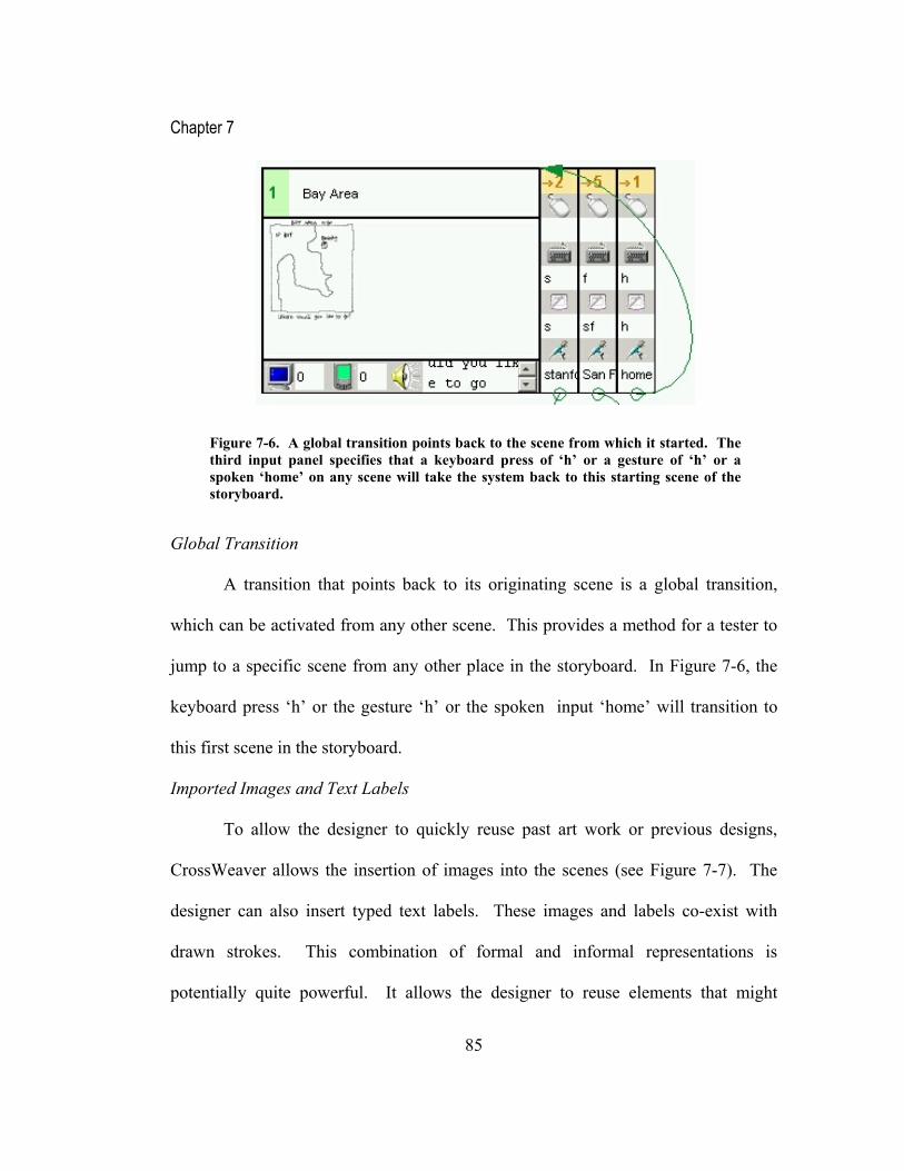
Chapter 7
85
Global Transition
A transition that points back to its originating scene is a global transition,
which can be activated from any other scene. This provides a method for a tester to
jump to a specific scene from any other place in the storyboard. In Figure 7-6, the
keyboard press ‘h’ or the gesture ‘h’ or the spoken input ‘home’ will transition to
this first scene in the storyboard.
Imported Images and Text Labels
To allow the designer to quickly reuse past art work or previous designs,
CrossWeaver allows the insertion of images into the scenes (see Figure 7-7). The
designer can also insert typed text labels. These images and labels co-exist with
drawn strokes. This combination of formal and informal representations is
potentially quite powerful. It allows the designer to reuse elements that might
Figure 7-6. A global transition points back to the scene from which it started. The third input panel specifies that a keyboard press of ‘h’ or a gesture of ‘h’ or a spoken ‘home’ on any scene will take the system back to this starting scene of the storyboard.

Chapter 7
86
already have been created in another tool, such as a background design or a template.
The designer can also quickly change the elements that are more in flux using drawn
strokes. Imported text labels can also be used for labeling images, as shown in the
example in Figure 7-7.
7.3 Test Mode
Once the storyboard is complete, the designer can execute the application by
clicking on the “Run Test…” button. A built in multimodal browser will be started,
corresponding to PC device #0.
Architecture of Test Execution
The browser accepts mouse button presses, keyboard presses, pen gestures,
and speech input from a tester. Gesture recognition and speech recognition are
performed in separate recognition agents participating with the test browser in the
execution of the application.
In the storyboard, each scene specifies target output devices. A standalone
version of the multimodal browser, written in Java, can be started separately on the
devices that are participating in the test (see the bottom of Figure 7-8). This
standalone version works just like the built-in browser, displaying scenes and
accepting mouse, keyboard, pen and speech input. The standalone browsers and the
recognition engines are all joined together as agents using the Open Agent
Architecture (SRI 2003).

Chapter 7
87
The state management of the test is controlled by CrossWeaver in Test Mode
running on the main PC. CrossWeaver tracks the current scene being displayed on
each device and also translates an input action into the next scenes to be shown. Any
input is tagged by a specific device ID. Communication among test browser is done
via messages passed by the Open Agent Architecture (Moran, Cheyer et al. 1998)
that include the specific device ID. Thus, CrossWeaver is managing a state machine
based on the storyboard with multiple active states. Each active state corresponds to
a device participating in the test.
Figure 7-7. A bitmap image of a map has been inserted into the scene. A typed text label has also been added. These images co-exist with strokes, providing combined formal and informal elements in the scene. Images can be imported from the designer’s past work or an image repository.

Chapter 7
88
Two or more standalone device browsers can share the same device ID. This
provides a shared scene configuration, where the device screens are kept in sync. A
shared screen configuration would be used for a broadcast presentation tool, for
example. Race conditions on input would be handled by the Open Agent
Architecture (Moran, Cheyer et al. 1998), and would generally resolve with the first
input received determining the next state.
Figure 7-8. Clicking on the “Run Test…” button in design mode brings up the Test Mode Browser, which accepts mouse, keyboard, and pen input. (Top) In the first sequence, the end user gestures ‘s’ on the scene and the scene moves to the appropriate scene in the storyboard. (Bottom) In the second sequence, the user accesses the ‘add building’ operation, adding buildings to the scene. This is occurring in the standalone browser running on device PDA #0, as identified by the ID in the title bar of the window. Pen recognition and speech recognition results come into the browser from separate participating agents.
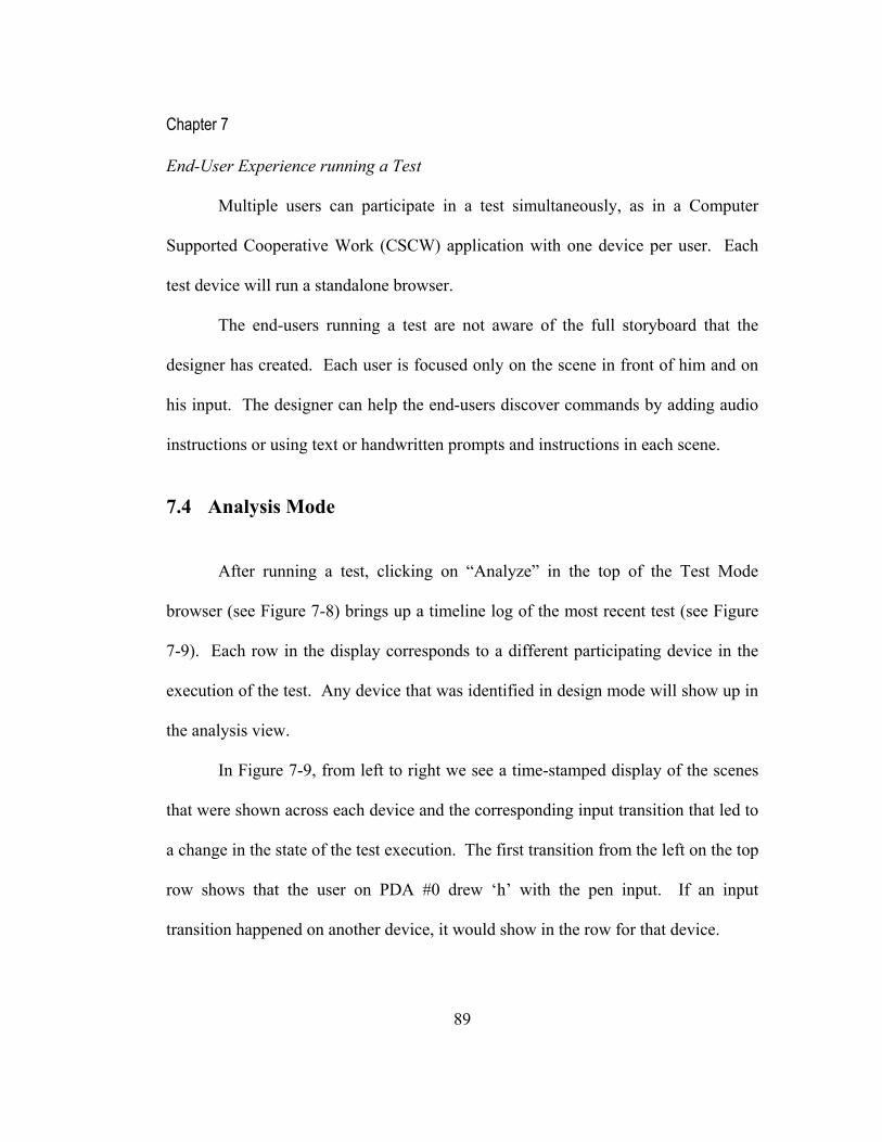
Chapter 7
89
End-User Experience running a Test
Multiple users can participate in a test simultaneously, as in a Computer
Supported Cooperative Work (CSCW) application with one device per user. Each
test device will run a standalone browser.
The end-users running a test are not aware of the full storyboard that the
designer has created. Each user is focused only on the scene in front of him and on
his input. The designer can help the end-users discover commands by adding audio
instructions or using text or handwritten prompts and instructions in each scene.
7.4 Analysis Mode
After running a test, clicking on “Analyze” in the top of the Test Mode
browser (see Figure 7-8) brings up a timeline log of the most recent test (see Figure
7-9). Each row in the display corresponds to a different participating device in the
execution of the test. Any device that was identified in design mode will show up in
the analysis view.
In Figure 7-9, from left to right we see a time-stamped display of the scenes
that were shown across each device and the corresponding input transition that led to
a change in the state of the test execution. The first transition from the left on the top
row shows that the user on PDA #0 drew ‘h’ with the pen input. If an input
transition happened on another device, it would show in the row for that device.

Chapter 7
90
Some rows have a scene following a blank area, such as the third row
corresponding to PDA #1. Blank grid spaces mean that no changes were made on
that specific device during a transition on another device.
This view allows the designer to examine the inputs attempted by the end
participants even if they were not successful in triggering a transition, such as the
second input transition in row one in Figure 7-9. All input attempts are captured in
this log. The designer can use the analysis display to see if the user switched input
modes or strategies to attempt to trigger the next scene. These repair actions are
especially important in multimodal applications.
Viewing Multimodal Input
Analysis mode will also show the building of a fused multimodal input. If an
input can possibly match a multimodal command, the system waits for other inputs
within a specified time period. If those other inputs happen, they are added to the
display as a multimodal input transition, with multiple input mode slots filled in.
The end transition looks like the multimodal transition as specified in Figure 7-2.
Replay
From within the Analysis Mode display, a designer can replay the entire log
of execution across all of the devices by pressing the play button in the toolbar. This
replay allows the designer to see the user test again, in action, across all of the
devices. Replay is valuable for finding critical incidents or more subtle design flaws
long after the user test is finished.

Chapter 7
91
Returning Full Circle to the Design
The analysis view purposely looks similar to the original design view: it is
linear for each device and has the same scenes and transition layout.
Analysis files can be saved individually and loaded into separate windows,
allowing the designer to compare two or more different participants side-by-side. By
Figure 7-9. CrossWeaver’s Analysis Mode shows a running timeline of all of the scenes that were shown across all of the devices. It also displays the interaction that triggered changes in the state machine. The red outline represents the current state in the replay routine. Pressing the play button steps through the timeline step-by-step replaying the scenes and inputs across devices. The timestamp shows the clock time of the machine running when the input was made.

Chapter 7
92
having the analysis data collected in the design tool itself, designers can quickly
review a number of user tests and refine the design.
An analysis view does not have to correspond to the current scenes in the
storyboard. For example, analysis views of different user tests can be displayed even
after the storyboard itself has changed. (There is presently no facility in
CrossWeaver to assist with labeling different versions of the storyboard.) Keeping
all design, test, and analysis data together in the same tool facilitates rapid iterative
design.
7.5 Final Prototype Summary
CrossWeaver gives a non-programmer designer the ability to conceptualize,
design, test, and analyze a multimodal, multidevice informal prototype. They can
also quickly create a user interface that spans multiple devices simultaneously, and
test that interface with end-users. Interaction designers tasked with creating an
application in this new domain can quickly create a prototype that incorporates pen
gestures, speech input, and multimodal commands.
The design, test, and analysis methodology in CrossWeaver dovetails with
the existing design process and provides the capabilities for rapid multimodal design
in one tool. CrossWeaver’s analysis mode helps capture the spirit of each end-user
test, helping designers decide on the multimodal vocabulary that they will use in
their final application. Rapid design experimentation with CrossWeaver will help

Chapter 7
93
improve a design and help extend the proliferation of multimodal, multidevice
interfaces.

Chapter 8
94
8 Evaluation
We evaluated the final version of CrossWeaver with nine professional
interaction designers working in a range of companies, from design consultancies to
software companies, in the San Francisco Bay Area. Testing with professional
interaction designers brought us full circle from the original field studies for
CrossWeaver as described in Chapter 3. We wanted to test how well we met the
interests of this audience in the final version of the tool.
8.1 Recruitment
These interaction designers were recruited via e-mail lists maintained by the
Group for User Interface Research at UC Berkeley (GUIR 2003). Four of the nine
designers had previously participated in an interview or user test for a different
GUIR project. Two of the participants had participated in the formative interviews
for CrossWeaver. Testing with them brought CrossWeaver full circle and helped test
how well the ideas in CrossWeaver matched their responses in the formative
interviews.
The interaction designers were verbally surveyed about their past experience
with multimodal and multidevice user interfaces, such as speech interface design
experience or design for handheld devices. To participate in the tests, it was not
explicitly required that they had created interfaces in these domains before. Two

Chapter 8
95
designers did have significant experience building multimodal applications. Five of
the interface designers had some experience creating applications for small devices.
The two remaining designers were primarily designers for web and graphical user
interfaces and did not have experience with multimodal or multidevice UIs. None of
the designers worked primarily in speech interfaces. A more detailed profile of the
designers is given in Section 8.8.
The designers were from the following companies:
• BravoBrava!, an educational and game software start-up that is based
in Union City, California and is building applications that use pen and
speech input with rich multimedia output
• IDEO, a product, industrial, and interaction design firm based in Palo
Alto, California
• Roxio, a multimedia hardware and software company based in San
Jose, California
• Adobe, a multimedia software tools company based in San Jose,
California
• PeopleSoft, an enterprise software company based in Pleasanton,
California
• Google, a search engine company based in Mountain View, California
Two designers were tested at BravoBrava!, IDEO, and Google, while one designer
was tested at each of the other three companies.

Chapter 8
96
8.2 Experimental Set-Up
Each user tested the CrossWeaver system on a Toshiba Portege 3500 Tablet
PC (Toshiba 2003), with 256MB RAM and a 1.0GHz Mobile Pentium III, in laptop
configuration (see Figure 8-1). The Tablet PC was connected via a null Ethernet
cable to a Fujitsu laptop (Fujitsu 2003), which served as a second device in the test
mode. In addition to having a built-in stylus for the screen, the Tablet PC also had a
mouse attached to it, and the designer was allowed to use either the mouse or the
stylus. The Tablet PC and the laptop were placed on a table in a conference room,
with the Tablet PC in front of the designer and the laptop to the side of it. The
observer (myself) sat in a seat next to the designer. The observer recorded a log of
the user test using handwritten notes. The observer also periodically saved the
current state of the participant’s design onto the disk.
Tests for the designers at BravoBrava!, IDEO, and Google were performed at
the offices of those companies. Tests for Roxio and Peoplesoft were performed in
the homes of the designers. Tests for Adobe were performed in a conference room
in the Computer Science division’s building at UC Berkeley.
8.3 Pre-Test Questionnaire
Each designer was asked to fill out a paper survey about their background as
a designer and they were interviewed about their current and past design work and

Chapter 8
97
their role on their current team (see Appendix A.2 and A.3). They were asked in the
survey about what prototyping and drawing tools they had used in their past work
and about any likes and dislikes that they had for those tools.
8.4 Training
Each designer was given the same 10 minute demonstration of
CrossWeaver’s features as a training tutorial. This tutorial stepped through the
basics of defining input and output modes in the CrossWeaver system and showed all
three modes of the tool: Design, Test, and Analysis. The demonstration was done
with tutorial examples, and not any specific scenario (See Appendix A.1).
8.5 Protocol
Since this is the first time the tool was introduced to each user, we chose to
PC #0PDA #0
Participant Observer
PC #0PDA #0
Participant Observer
Figure 8-1. Diagram of the Experimental Setup.

Chapter 8
98
use a modified think aloud protocol for this user study, where the user was also
permitted to ask questions about the system if they did not remember how to perform
a certain task or wanted assistance. Since the number of requests for help varied
from participant to participant, time on the task and time on the help was not
captured. Critical incidents and usage log were captured. Assistance was provided
as requested, and was done to explain the use of different features or to remind the
user about the tutorial from the training demonstration if they got stuck.
The three metrics that we focused on in this user study were:
understandability, usability, and capability. We measured this through a
combination of observations about what problems the participant had in
accomplishing the tasks and also in a post-test questionnaire given to the
participants.
8.6 Tasks
Each designer was asked to perform two tasks (see Appendix A.1). The first
task involved creating a multimodal web site, where pages could be accessed via pen
gestures or speech commands in addition to mouse clicks. This task tested the ability
of the designers to use and understand the multimodal input capabilities of
CrossWeaver, by having them create a storyboard that accesses the underlying
recognizers. The designers were allowed to pick what inputs and outputs they used
for the scenario that they implemented. For seven of the designers, this was the first

Chapter 8
99
time that they had ever themselves created an application that used a speech
recognizer.
The second task was to create a remote control, as in a multimedia
entertainment center, where the Tablet PC controlled what was displayed on the
laptop. This task focused on the multidevice output capabilities of CrossWeaver,
and emphasized the fact that scenarios could be used to create applications that span
devices simultaneously. The designers were asked to use the Tablet PC as the
remote control and the laptop as an output device, simulating a TV or radio.
8.7 Post-Test Questionnaire
Each participant was asked to fill out a paper survey (see Appendix A.4) and
written questionnaire (see Appendix A.5) giving their ratings of different aspects of
using the system. The survey and questionnaire measured their subjective reactions
to the system. They were also briefly interviewed to elicit their comments about the
system and their suggestions for feedback.
8.8 Designers’ Profiles
The profiles of the designers that participated in the evaluation are shown in
Table 8-2. Demographically, all but one of the designers that we interviewed were
male, simply based on the designers who responded to our initial inquiry. The
designers had between 3 and 15 years professional design experience with an

Chapter 8
100
average of about 6 years. This was an experienced group of interface designers with
a broad range of completed design projects. All had an interest in multimodal
interface design.
Three of the designers considered themselves as having significant
programming experience and said that they did programming in their daily jobs.
Four of the others said they had minimal programming experience, and mainly
counted their use of HTML as programming experience. The two others considered
themselves non-programmers, and did not claim knowledge of any particular
programming environment.
Only two of the participants had significant exposure to speech and pen
interfaces. These two were directly involved in multimodal application design and
implementation in their jobs. Most of the other designers had some experience using
speech interfaces in telephone directory assistance domains and using pen interfaces
on Palm PDA’s or tablet computers.
The most popular programming language was HTML followed by Visual
Basic. Two of the designers were focused on web design and delivered HTML as
part of their design output. The other designers either used HTML intermittently for
prototyping or for organizing prototypes. Visual Basic was the next most popular
tool. Only two of the designers used Visual Basic frequently. The other designers
had used Visual Basic in the past but not on a daily basis. One of the designers was

Chapter 8
101
an expert in using Director, including the use of the Director programming facilities
through the Lingo programming language (Macromedia 2003b).
The most popular tools used for drawing were Microsoft PowerPoint, Adobe
Photoshop, and Adobe Illustrator. The only designers who did not use Photoshop or
Illustrator were the two programmers. The tool of preference varied significantly
from designer to designer. One designer said that he uses Macromedia Fireworks for
almost all design tasks that he is doing, even though it is targeted to web image
creation. He finds a way to fit Fireworks into his other design problems. This was a
common observation from the users who had specific preferences among drawing
tools. They would typically stick with one tool, learn it well, and fit it into their
design process, even if it was not the most appropriate tool for some of their design
tasks.

Chapter 8
102
Table 8-1. Participant designers’ backgrounds in the final CrossWeaver user tests
CrossWeaver Background Survey Results Designer ID#
1 2 3 4 5 6 7 8 9
Average
Gender M M M M M M M F MAge (years) 30 28 28 33 40 26 27 25 28 29
College Major Fine ArtsMechanical Engineering
Computer Science
Computer Engineering Humanities
Information Systems
Cognitive Science
Information Systems
Computer Graphics
How long have you been a designer? 5 3 4 11 15 3 5 4 5 6
How long have you been using computers? (years) 10 22 8 13 20 20 12 15 20 16
How long have you been programming computers? (Years. Criteria varied. Some were HTML only.) 6 (HTML)
22 (Basic, C, CAD) 8 (C, Java) 7 (C, Java) 20 (Lingo) 1 (HTML) 5 (HTML) 8 (HTML) 20 (C, Java) 10
Have you used speech interfaces? When?
Phone directory
Directory assistance
Yes. Last 3 years
All sorts. 3 years
Airline reservations
Insurance application
Airline directory No
Experiments on Mac
Have you used pen interfaces? When? Palm PDA Palm PDA
Yes. Last 3 years
All sorts. 3 years
Old CAD systems Tablet PC Palm PDA
Yes, drawing program
Yes, experimental
Have you used a multimodal interface? When? No No
Yes. Last 3 years
All sorts. 3 years. No No No No No
Mark all of the following tools that you have used:
Total
HTML x x x x x x x 7Visual Basic x x x x x 5Director x x 2Hypercard x 1TclTk x 1Other: PDF Seq Visual C# Visual C++
FoamcoreAfter Effects
Mark all of the drawing/painting tools that you have used:PowerPoint x x x x x x x x x 9Photoshop x x x x x x x x 8Illustrator x x x x x x x 7Freehand x x x x 4Visio x x x x 4MacDraw x x x 3MacPaint x x x 3Corel Draw x x 2Paintbrush x x 2Other (Fireworks) x x 2Other (Solidworks) x x 2Other (CAD) x x 2Canvas 0Color It! 0Cricket Draw 0SuperPaint 0Xfig 0
Other Cinema 4DPaint Shop
Pro

Chapter 8
103
8.9 Designers’ Case Studies
Below we profile the experience of three of the participants in our evaluation.
These three case studies represent the range of designers that participated in the tests
and the experiences that they had. We describe how these participants reacted to
CrossWeaver and what they accomplished in the evaluation.
8.9.1 Analysis of Participant #4 Usage Log
The first participant described here (Participant #4) is tasked in his day to day
job with designing multimodal user interfaces. One of his projects includes the
multimodal home in which he is designing a multimodal user interface to control the
TV, stereo and other appliances. Another project involves creating an educational
training tool for students learning a second language. He is experienced with pen
interfaces, speech interfaces, and multimodal interfaces, and is both a designer of the
system and an implementer.
In his company, he works on his designs in small teams of two or three. The
team works together on all stages of the project, from the first stage whiteboarding of
the design to the actual coding. In his case, the design process has essentially only
those two steps. The design ideas, specification, and capabilities are brainstormed on
a whiteboard. The details from the whiteboard turn into the specification, which is

Chapter 8
104
often written up as a document. The document is used to build the application in the
programming environment.
One part of this designer’s overall philosophy is “Two is better than one,”
meaning two alternative unimodal commands are better than one. He said fused
commands are used on a case-by-case basis. There are often alternative unimodal
commands for the same operation.
The programming is done with tools such as Microsoft’s Visual C# or Visual
Basic, which can access libraries that utilize speech, pen, and multimodal
recognition. The first coding is done in this environment, and typically the same
code base is iterated on and added to as design refinements are made. Milestone
versions of the application are installed in the final environment and tested with
users; this last step is a laborious process and is done only occasionally.
Task #1
Participant #4 began the multimodal web page task by taking some time to
think about what to draw. He began scene #1 by sketching text in the web page
using the tablet stylus, creating a navigation menu that highlighted that this is the top
level page in his hierarchy (see Figure 8-2). In his case, up to this point he had been
spending more time (~3 minutes) thinking about what he would draw than actually
drawing it (~1 minute).
After creating scene #2, (see the left storyboard area of Figure 8-2), he first
added a speech command, “log-in,” to connect the first two scenes. He asked about

Chapter 8
105
branching to the other three scenes from the top level navigation scene, and upon
being reminded of the way to do this, he immediately creates the tree structure
navigation for his speech controlled web browser. By the end of his storyboard, the
“log-in” speech command points transitions from scene #5 to scene #4 (see Figure
8-2).
In his first test, he assumes that the first page in the storyboard is the starting
scene. In CrossWeaver’s case, the currently selected scene is the start of the tests,
Figure 8-2. Participant #4’s storyboard for Task #1.

Chapter 8
106
which allows the designer to start from any scene in the storyboard. He quickly
selects the home page scene that he has drawn and then runs his first test successfully
in the test browser.
Participant #4 is experienced in multimodal interface design and begins to
briefly experiment with fused input, combining speech commands and gesture input.
Figure 8-3. Participant #4’s storyboard for Task #2.

Chapter 8
107
For example, he added the pen gesture “l” to his speech command “log-in.” After
modifying his hierarchy and running tests with fused input successfully (3 minutes),
he is done with the first task and asks to move to the second.
Task #2
To avoid needing to redraw, Participant #4 starts with the storyboard that he
has created in the last task. He states that his objective is to modify the storyboard so
that the target scenes are displayed on the second device.
At this point, he spends some time building his own conceptual model of
what he is going to do (~4 minutes). He asks for a reminder about specifying
devices, and after being given it, he changes the specific output device of scene #1,
#3, and #4 to only PC #0, the Tablet PC, and changes scene #2 to PDA #1, the laptop
(see Figure 8-3). He also modifies other scenes. While doing this, he wanted to add
hotspot regions to the navigation page, and in doing so he did some trial and error
with defining regions (see Figure 8-3). After understanding the different ways to
define regions, he ran a test successfully.
This designer has designed multidevice scenarios before in his work for a
home entertainment control system. At this point, he requested speech control to be
available across all devices instead of just Device #0, which is an enhancement that
has been added to CrossWeaver since this test.
Participant #4 said that he saw the potential use of CrossWeaver anywhere
speech and pen are used in his designs. He thought it had the potential to very

Chapter 8
108
quickly show the preliminary form of the interface that he is designing. He saw
immediate application to the project he is doing designing a digital home. He also
saw the limits of the tool for helping him with an ESL (English as a Second
Language) project that relies heavily on dictation recognition, because there is no
facility in CrossWeaver to process input streams from a dictation recognizer.
8.9.2 Analysis of Participant #1 Usage Log
Participant #1 is a professional interaction and product designer who came
from a fine arts background and has no formal education in design. He describes his
job as building prototypes and feels very facile with the tools that he uses to build
those prototypes. He most frequently creates HTML pages for prototyping and has
experience with HTML coding, but uses no other programming languages. Among
prototyping, drawing and painting tools, he has used Director, Adobe Photoshop,
Adobe Illustrator and video simulations. He makes paper sketches often and
sometimes converts those sketches to representations in CAD tools if it is required in
his client work. He does make paper storyboards for illustrations and for illustrating
behaviors.

Chapter 8
109
Task #1
Participant #1 began the first task (see Figure 8-4) by experimenting with the
stylus on the tablet computer. He had used a stylus before on PDAs and an attached
tablet to make drawings on his computer, but had not used a tablet computer before.
His initial scenes in the drawings were almost exclusively words; he wrote
instructions for a user explaining the interaction that would trigger behaviors in the
Figure 8-4. Participant #1’s storyboard for Task #1.

Chapter 8
110
execution mode. He drew and erased a few different scenes. His storyboard only
shows the two remaining scenes at the end of his test (see Figure 8-4).
As a professional designer, he was very quick to make requests about
additional features in CrossWeaver’s Design interface, including handles and visual
enhancements that would help access the underlying behaviors and storyboard state.
The visual enhancements that he requested were inspired by the handles that he had
seen in his professional tools, such as Photoshop and Director.
He quickly understood the way to build a branch structure in the storyboard.
During his trial he made the request for a logical “NOT,” a transition that would
happen if the recognition in a test did not match a transition.
Task #2
In his second task (see Figure 8-5), Participant #1 began by spending a few
minutes puzzling over the concept of a multidevice application. He had never
designed such an application and questioned the usefulness of multidevice as a style.
He also wanted to minimize the device specification area, since he thought he would
be using this tool primarily to target a single device scenario.
Nevertheless, he quickly drew an abstract scenario of a house with some lines
underneath it. He had those lines act as hyperlinks on the primary device, the Tablet
PC, to create the picture of a house on the laptop. He created the scenario and
quickly tested it.

Chapter 8
111
At the end of the second task, this designer got excited about the possibility
of using CrossWeaver in some of his product design scenarios. He sketched a
storyboard quickly on paper with the picture of a toaster and toast in it, and described
how he often uses two dimensional mock-ups to represent three dimensional
products. The two dimensional mock-ups that he creates in HTML often have
hotspot areas on top of active elements in the 3D object, such as the lever of the
Figure 8-5. Participant #1’s storyboard for Task #2.

Chapter 8
112
toaster. He said he would like to use CrossWeaver for the toaster scenario and some
other product design scenarios that he was working on.
8.9.3 Analysis of Participant #9 Usage Log
Participant #9 was both a designer and a programmer, who primarily was
Figure 8-6. Participant #9’s storyboard for Task #1.

Chapter 8
113
working on web page design. His training was in Computer Graphics, and most of
his design training was self taught. He had a background in a number of computer
languages and drawing tools and considered himself an expert and daily user of
Macromedia Homesite, a web page creation tool. He frequently created paper mock-
ups of the web page designs that he was working on, and mentioned that one of his
specific problems with paper was losing it and keeping track of versions.
Task #1
Participant #9 started using the tablet stylus and created a page with two links
(see Figure 8-6). Before creating the links, the participant asked for a reminder
about defining hotspot areas. The links he created were done on regions of the page
that were otherwise blank; in other words, he did not create the link text before
creating the link. He just created a blank link region. This participant found that he
had to write slower than he expected on the tablet, based on the tablet hardware
speed.
He created the other pages as boxes with a small amount of text in them,
hooked up the links and then tested his small design. He then proceeded to
experiment with different color strokes and image and text label import. In total he
spent seventeen minutes completing the task and experimenting with the other
functions.
Chapter 8
114
After the test, he said he was impressed with the speech and gesture input
functionality, but he wanted the system to export to HTML. All of the mock-ups he
does at present are shown in HTML.
Task #2
Participant #9 created a new site for the remote control scenario (see Figure
8-7). He created a storyboard that showed a stoplight-like controller for the Tablet
PC changing the text that is shown on the remote device, the laptop. At this point,
the participant was more comfortable with the basic way of using this tool, and he
started making some requests about features he would like to see. He suggested
some sort of different visual to show the global transitions. He suggested a few
changes to the visuals such as collapsing the arrows of adjacent transitions. He also
asked for full screen edit mode, which is available in the tool, and suggested that
could be the default view and that the storyboard view could be separate from it.
His main concern at the end of the test was on the scalability of the
storyboard model and visuals as shown. He said that he liked the potential of the
tool to help him with scene management and organizing the mock-ups of his web
pages. For his web work, he wanted a tool that would more fully support a sitemap
view, export to HTML, and focus on web site design as the target domain.

Chapter 8
115
8.10 Designers’ Post-Test Survey Results
Each interface designer was given a survey (see Appendix A.4) and a
questionnaire (described in Section 8.11) at the end of the user test. The survey
results are shown below:
Figure 8-7. Participant #9’s storyboard for Task #2.

Chapter 8
116
Table 8-2. Results of the Post Test Survey given to the participants.
CrossWeaver Post Survey Results Participant #
Ranking Questions: 1 2 3 4 5 6 7 8 9
Average
Std Dev
1) How functional did you find this prototype? (1=not functional, 10=functional) 8 7 7 8 7 8 8 9 9 7.9 0.82) Did you find yourself making a lot of errors with this tool? (1=no, 10=yes) 2 5 3 3 4 8 7 2 6 4.4 2.23) Did you find it easy to correct the errors that you made? (1=no, 10=yes) 6 10 7 9 2 8 7 9 8 7.3 2.34) Did you find yourself making a lot of steps to accomplish each task? (1=no, 10=yes) 2 3 3 2 3 6 7 2 4 3.6 1.85) Ease of use of the prototype as given. (1=hard, 10=easy) 7 7 8 10 4 5 7 9 8 7.2 1.96) Quickness with which you could accomplish the tasks you had to complete. (1=very poor, 10=excellent) 8 9 7 9 7 5 7 9 7 7.6 1.37) How natural (understandable) were the commands that you used? (1=very poor, 10=excellent) 7 9 8 8 9 7 6 9 7 7.8 1.1Recognition performance:8) What are your comments about the performance of the speech recognizer? (1=very poor, 10=excellent) n/a n/a 3 9 4 3 10 9 9 6.7 3.09) What are your comments about the performance of the handwriting recognizer? (1=very poor, 10=excellent) 6 10 4 8 6 8 5 10 8 7.2 2.1
The survey was designed to elicit metrics of functional capability (Question
#1), ease of use (Question #5), and understandability (Question #7) from each of the
designers. The information on other freeform survey questions collected data about
the quality of the prototype and in what areas the participants had specific problems.
The responses to these questions are discussed in Section 8.12.

Chapter 8
117
Functional capability (see Figure 8-8) was rated an average 7.9 out of 10 (SD
0.8), which showed that the designers believed that they were able to create
applications that utilize multimodal and multidevice interaction using this tool.
Ease of use (see Figure 8-9) was rated average 7.2 out of 10 (SD 1.9).
Participants #5 and #6 had several critical incidents related to erasing and selection
during their user test, which may have contributed to them rating the tool lower.
This is also reflected in their responses to question #2, in which they said they found
themselves making a lot of errors with this tool. These two participants use a single
tool in their daily design work, and they both asked a few times during the test for
Functional Capability
0
1
2
3
4
5
6
7
8
9
10
Figure 8-8. Rating of CrossWeaver’s functional capability.

Chapter 8
118
features in CrossWeaver that had their origin in their tool of preference.
Understandability (see Figure 8-10) was rated 7.8 out of 10 (SD 1.1). (The
question asked in the survey was, “How natural were the commands that you used?”
This was clarified to each participant verbally as “How understandable were
CrossWeaver’s commands?”) After the initial training and experimentation, many of
the designers said that they felt prepared to try out the tool on their day-to-day design
tasks. Further details about understandability were elicited in the freeform survey
questions discussed later in Section 8.11.
Given that these results were measured in a subjective survey, the positive
results that the participants gave need to be taken with a bit of skepticism. With
survey measurement, negative numbers would more likely be more accurate
Ease of Use
0
1
2
3
4
5
6
7
8
9
10
Figure 8-9. Rating of CrossWeaver’s ease of use.

Chapter 8
119
indicators of problem areas than positive numbers are indicators of the complete lack
of problems.
8.11 Designers’ Post-Test Questionnaire Results
Each interface designer was also given a post-test, freeform questionnaire in
written form at the end of his or her test (see Appendix A.5). When asked about
whether they would use CrossWeaver to design interfaces, seven of the nine
participants wrote “Yes” outright. Two of the participants wrote “Yes” with the
caveat that they would use it if they were tasked with designing interfaces that use
Understandability
0
1
2
3
4
5
6
7
8
9
10
Figure 8-10. Rating of CrossWeaver’s understandability.
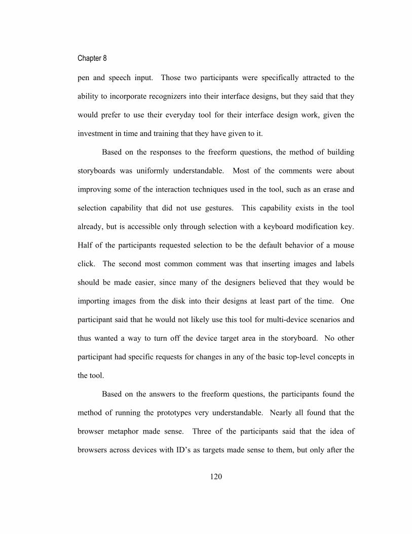
Chapter 8
120
pen and speech input. Those two participants were specifically attracted to the
ability to incorporate recognizers into their interface designs, but they said that they
would prefer to use their everyday tool for their interface design work, given the
investment in time and training that they have given to it.
Based on the responses to the freeform questions, the method of building
storyboards was uniformly understandable. Most of the comments were about
improving some of the interaction techniques used in the tool, such as an erase and
selection capability that did not use gestures. This capability exists in the tool
already, but is accessible only through selection with a keyboard modification key.
Half of the participants requested selection to be the default behavior of a mouse
click. The second most common comment was that inserting images and labels
should be made easier, since many of the designers believed that they would be
importing images from the disk into their designs at least part of the time. One
participant said that he would not likely use this tool for multi-device scenarios and
thus wanted a way to turn off the device target area in the storyboard. No other
participant had specific requests for changes in any of the basic top-level concepts in
the tool.
Based on the answers to the freeform questions, the participants found the
method of running the prototypes very understandable. Nearly all found that the
browser metaphor made sense. Three of the participants said that the idea of
browsers across devices with ID’s as targets made sense to them, but only after the

Chapter 8
121
tutorial demonstration. In their normal course of work, they are used to only
working with screens on a single device.
Using operations was not specifically part of any of the tasks, though it was
demonstrated in the tutorial. We prompted four of the participants who had
experimented with operations to answer the freeform question about the method of
creating “Operations.” These participants said that they were not immediately sure if
it was a useful technique in this tool. They primarily envisioned this tool as useful
for managing their storyboards, and did not see themselves creating reusable objects
or other drawing behaviors in their designs. One participant did write that he thought
primitive operations would be useful. He gave the example of operations that trigger
the same behaviors for different entertainment appliances, such as an on-off button,
volume control, and channel changing. He wanted to see the functions of a universal
remote control as primitive operations. Based on what he wrote, his request would
likely be fulfilled by allowing subcomponent scenes to exist in the CrossWeaver
tool, where the same sequence in the storyboard can be reused in other storyboard
sequences to trigger behaviors in other scenes.
Some of the general comments added to the end of the questionnaire are
shown in Table 8-3. These comments illustrate a positive response to the tool from
the participants. In the oral request for additional comments, all of the participants
asked about the availability of the tool for further experimentation.

Chapter 8
122
Table 8-3. Selected participant’s general comments from the post-test questionnaire.
Cool! Has GREAT potential as a tool for real world use!
Not too many bugs!
Looks good - I'd like to try out on real stuff
Fun
Very cool
Impressive work!
8.12 Design Issues
Questions #2, #3, #4, and #6 in the Post Test Survey (see Table 8-2) were
meant to specifically generate comments about the quality of the CrossWeaver
implementation and find areas that the participants had specific problems with during
the tests. Based on the results of those questions, we could see that two participants
(#6 and #9), who had significant interaction design errors as they were working with
the tool, gave rankings of 8 out of 10 and 6 out of 10 to question #2 (where 10 means
many errors and 1 means few). They specifically had problems with selecting and
erasing strokes. Both of those functions were accessed in the tool by switching to
the “Gesture” mode in the tool and performing a selection gesture or an erase
gesture. These two participants had to retry the gestures multiple times before
getting them to work.

Chapter 8
123
These participants also said that the errors were easy to correct, based on
their rankings 8 out of 10 and 8 out of 10 for question #3, about how easy the errors
were to correct. Other participants picked up the specific gestures fairly quickly
after the tutorial and explanation, but nearly all asked for clarification. Based on this
feedback, the method for erase and select has been changed in a later version of
CrossWeaver. Instead of using gestures, CrossWeaver uses click-select as the
default and accepts the delete key for erasing the selected object.
All of the designers thought that the user test capture in Analysis Mode was a
valuable feature in CrossWeaver and noted that it was not presently incorporated in
any of the tools that they use. Some designers wanted to see the user test capture
extended to capture think-aloud audio comments of the users during the test. This
could be added in a future version.
CrossWeaver’s Design Mode layout was inspired by Microsoft PowerPoint
(Microsoft 2003b). PowerPoint was listed as the most common drawing tool used by
the designers that we talked to. Even so, six of the designers mentioned that they
wanted to see CrossWeaver behave like their favorite tool (e.g., Director, Fireworks,
Homesite, Photoshop, or Illustrator). Two designers who saw themselves as tied to a
single tool (Director or Fireworks) gave rankings of 4 out of 10 and 5 out of 10 for
“Ease of use” for CrossWeaver (see Table 8-2). Choosing PowerPoint as the design
model was intended to make CrossWeaver more inviting for the participants in the

Chapter 8
124
test. Adding in features that are common to the other tools mentioned will increase
CrossWeaver’s appeal to certain designers.
Questions #4 and #6 related to how quickly the designers could accomplish their
design tasks in CrossWeaver. In general the designers found that CrossWeaver was
quick to use.
Questions #8 and #9 asked about the performance of the recognizers in the tests.
The designers’ ratings of performance varied depending on the performance during
their specific test. The recognizer performance did not interfere with CrossWeaver’s
use in any case.
8.13 Evaluation Summary
Our evaluation of CrossWeaver tested the initial reaction of nine professional
designers to the capabilities of CrossWeaver. These professional designers, who
work or will work on multimodal and multidevice interfaces, represented the target
users we envisioned when initially planning CrossWeaver. We designed two
evaluation tasks to cover both multimodal and multidevice interfaces. We utilized a
modified talk-aloud protocol since this was the first time these designers were using
this tool.
Based on the survey and questionnaire responses after the tests, it appears
that the two participants who were presently involved in the design of multimodal
interfaces were most excited and enthusiastic about CrossWeaver. Their typical
Chapter 8
125
process takes them from whiteboard directly into programming to allow them to
utilize recognizers and multimodal behaviors in their interface designs.
CrossWeaver enables them to use recognition in the early stages of their designs and
lets them try out scenarios with participants long before they finish programming.
The two participants who were primarily web designers found CrossWeaver
useful, but specifically asked for features that would be useful for them in their work,
such as support for HTML output. These are features that are part of the DENIM
tool (Lin, Newman et al. 2000; Newman, Lin et al. 2003), which was geared
specifically towards web site designers. These two designers were familiar with
DENIM and thought it was more appropriate for their day-to-day work than
CrossWeaver.
All of the participants said that they thought this tool opened up a new design
space versus the design space that they think about in tools that they presently use.
This appears to be based on having speech and pen recognition and multidevice
features integrated into the tool, which are unavailable in the other tools. Three of
the designers said the tool was appealing because they could envision using it to
design accessible interfaces for disabled persons.

Chapter 9
126
9 Implementation and Limitations
In the following chapter, we cover the implementation details and limitations of the
final implementation of CrossWeaver.
9.1 Implementation Details
CrossWeaver is built as a Java application using JDK1.4.1. The core
sketching capabilities in CrossWeaver and the scene models are extended from Diva
(Reekie, Shilman et al. 1998), an infrastructure for building sketch-based
applications. The standalone browser is built in Java as well, using only capabilities
compatible with Java on mobile devices.
The first interactive prototype of CrossWeaver (see Chapter 6) used the
This work
Open Agent Architecture [SRI]
CrossWeaver Design Mode
Informal Prototype
ApplicationLayer
DesignLayer
InfrastructureLayer
Recognition Agents
Speech Agent
Pen Agent
Output Agents
Visual Agent
Audio Agent
Built-in Browser Standalone Browser
WOz
Diva [Shilman]
CrossWeaver Analysis Mode
CrossWeaver Test Mode
MSFT
Paragraph/Diva
MSFT
This work
Open Agent Architecture [SRI]
CrossWeaver Design Mode
Informal Prototype
ApplicationLayer
DesignLayer
InfrastructureLayer
Recognition Agents
Speech Agent
Pen Agent
Output Agents
Visual Agent
Audio Agent
Built-in Browser Standalone Browser
WOz
Diva [Shilman]
CrossWeaver Analysis Mode
CrossWeaver Test Mode
MSFT
Paragraph/Diva
MSFTOpen Agent Architecture [SRI]
CrossWeaver Design Mode
Informal Prototype
ApplicationLayer
DesignLayer
InfrastructureLayer
Recognition Agents
Speech Agent
Pen Agent
Output Agents
Visual Agent
Audio Agent
Built-in Browser Standalone Browser
WOz
Diva [Shilman]
CrossWeaver Analysis Mode
CrossWeaver Test Mode
MSFT
Paragraph/Diva
MSFT
Figure 9-1. CrossWeaver Architecture

Chapter 9
127
SATIN infrastructure for building sketch-based applications (Hong and Landay
2000). SATIN provides basic stroke management capabilities and the ability to
zoom in and out when viewing the storyboard. Since we changed from an infinite-
sheet layout in the preliminary version of CrossWeaver to a linear storyboard layout
in the final version, we had no need for zooming. Thus, Diva was a more suitable
choice than SATIN for the underlying infrastructure in the final implementation.
CrossWeaver’s multimodal and multidevice capabilities are integrated
through SRI’s Open Agent Architecture (OAA) (SRI 2003) and off the shelf agents
for handwriting recognition and speech recognition are used to communicate with
the CrossWeaver system.
The architecture for CrossWeaver’s final implementation is shown in Figure
9-1. CrossWeaver’s application layer is the control center for the Open Agent
Architecture. During testing, CrossWeaver’s application layer communicates with
the Recognition Input Agents and Output Agents via OAA. The Recognition Agents
take natural input, either audio input from a microphone or a pen gesture represented
as a OAA string message from the browser, and return a recognition result. The
recognition agents and the output agents can run on any machine. Each output agent
is labeled by a device identifier which facilitates the management of multiple devices
by OAA.
The CrossWeaver application itself is composed of three parts, Design Mode,
Test Mode, and Analysis Mode as described in Chapter 7. The prototype built in

Chapter 9
128
Design Mode in CrossWeaver runs in the built-in browser in Test Mode and also
runs in the standalone browsers that have been activated. The standalone browsers
are implemented using the Output Agents. The application layer communicates with
the output and input agents.
CrossWeaver can be used to build a prototype that runs cooperatively across
desktop and handheld systems. Such an application responds appropriately to pen
gestures or key presses from the handheld device. Currently, speech input can be run
in an agent that specifies the device identifier. Hence, speech recognition can be
running on a full powered PC and still have effect on the low powered handheld
device.
Speech recognition agents have been written using Microsoft’s Speech SDK
5.0 (Microsoft 2003c), IBM ViaVoice (IBM 2003), and Nuance’s Voice Recognition
system (Nuance 2003). Text-to-speech agents have been written using Microsoft’s
Text to Speech Engine (Microsoft 2003c) and IBM’s Text to Speech Engine (IBM
2003). An agent wrapped around Paragraph’s handwriting recognition system
(Paragraph 1999) performs pen recognition. We have also wrapped a basic gesture
recognizer that comes in the Diva system as a pen recognition agent (Reekie,
Shilman et al. 1998).
We have created tools so that any of these recognition agents can be
simulated by a Wizard participating on a separate networked terminal. These tools
are standalone graphical applications that allow a Wizard to type in recognition

Chapter 9
129
results and send them as OAA messages to the running CrossWeaver application.
This architecture allows the recognition systems that are used to be easily extensible.
A user need only wrap up their recognizer with the Open Agent Architecture to have
it participate in the CrossWeaver prototype’s execution.
The standalone browsers can be written for different platforms using a similar
method. We have written standalone browsers using Java JDK 1.4 (Sun 2002) and
Java JDK 1.1.7 (Sun 1999). These can run on standard PC’s or Macintosh’s. The
JDK 1.1.7 version is specifically targeted to the Microsoft Pocket PC (Microsoft
2003a) and compatible handheld devices. The JDK 1.1.7 browser for the Microsoft
Pocket PC uses a proxy agent. The proxy agent is an OAA agent that runs on a PC
in the environment and receives messages targeted to the Pocket PC from
CrossWeaver. The proxy agent forwards the messages to the Pocket PC browser via
a lightweight socket mechanism. This lightweight communication allows the Pocket
PC browser to run more efficiently than it would if we tried to run the standalone
OAA browser agent directly.
By its nature, the CrossWeaver Design Mode enforces a specific usage
paradigm. To extend it involves source code modifications. The area where this is
easiest is in adding the interpretation of new operations. In other areas, such as
adding different input modalities to the visual interface or adding different categories
of target devices, possible changes are significantly more limited. We do not expect
non-programmer designers to modify the basic interaction of the tool and expect

Chapter 9
130
them to instead spend time concentrating on their designs. Modifications to the basic
design of CrossWeaver will have to be done as extensions and upgrades.
9.2 Limitations
Based on the implementation details, CrossWeaver also requires multiple steps
for installation and distribution. Most of the installation steps are related to the use
of the Open Agent Architecture and the set-up of OAA and the recognition agents.
To use CrossWeaver with recognition agents requires individual set-up of each
recognizer. For example, the installation of Microsoft’s Speech Recognizer and Text
to Speech engine each requires a separate download. The agents that access each of
these also require separate installation. Without the Open Agent Architecture
installed, CrossWeaver does allow testing of an interface with solely mouse and
keyboard input.
Based on the user test results and the details of the implementation, it has
become clear that CrossWeaver will require brief training or a demonstration video
for every participant who is going to use it. This is not an unexpected requirement,
since the original design target for CrossWeaver did not include learning without
training and the concepts represented in the tool are complex. Nearly all of the
designers volunteered that they felt comfortable with the tool at the end of their first
session using it. They felt they could now go ahead and try to use it for their design
tasks. Some of the advanced features in CrossWeaver, however, such as definable

Chapter 9
131
operations are not fully self-disclosing. The CrossWeaver tutorial video at
http://guir.berkeley.edu/crossweaver/ (CrossWeaver 2003) includes a walk-through
of all of the features for this reason.
Two participants in the user test were particularly concerned about scalability
of the storyboard and arrows after their user test. They foresaw how their designs
might get cluttered with excess arrows. CrossWeaver has the ability to turn off
display arrows as an alternative view of the storyboard, but their comments highlight
the fact that CrossWeaver’s storyboard has a bias towards being linear. The linear
bias originates from CrossWeaver’s focus on helping illustrate scenarios. Each short
linear sequence is a scenario. Different scenarios can be connected in the tool via
transitions that jump from one scenario to another scenario in a different part of the
storyboard. Multiple scenarios in the storyboard can ultimately add up to a full
application interface. However, a full application interface might have scalability
problems in CrossWeaver’s Design Mode if it is not divided into scenarios.
The concept of Operations was added into CrossWeaver to allow it to more
closely simulate a full application. Right now, only a few drawing domain
operations are in CrossWeaver, but they can be used to simulate the behaviors that
are in many map and drawing applications. CrossWeaver is not suited for
applications in other domains, unless those applications can be simulated using
storyboards alone.

Chapter 9
132
As one specific example, CrossWeaver’s Operations would have to be
extended to simulate data-driven applications. There is no facility in CrossWeaver to
look-up or utilize data. CrossWeaver cannot simulate interfaces that rely on
animation, since CrossWeaver’s scenes are static and do not show moving objects.
CrossWeaver would also have to be extended to cover graphical user interfaces,
since there is no concept of widget in CrossWeaver. SILK (Landay 1996; Landay
and Myers 2001) is a more appropriate tool for GUI’s. Likewise, DENIM (Lin,
Newman et al. 2000; Newman, Lin et al. 2003) is a more appropriate tool for web
design since it has a site-map view as its storyboard, and DEMAIS (Bailey, Konstan
et al. 2001; Bailey 2002) is a more appropriate tool for multimedia interfaces, since it
has incorporated multimedia import and synchronization.
The designers who experimented with Operations thought initially that some
of the behaviors that Operations enabled could be simulated using storyboards. To
them, the operations concept was “interesting” and “potentially useful” but was not
something that was immediately necessary for any of the designs that they wanted to
test. Greater use of CrossWeaver might change their opinion and might change their
requests for specific operations to assist them in their design tasks.

Chapter 10
133
10 Future Work and Conclusions
The following chapter covers potential future work for CrossWeaver, a review of the
contributions of this dissertation, and a statement of conclusions.
10.1 Future Work
Various refinements can be made to CrossWeaver, including inclusion of
additional recognition engines, drawing capabilities, and visual refinements that
would make it more appealing to designers. For example, an aggregate view could
be added to the Analysis Mode to help manage large numbers of user tests. Two
other valuable specific directions for CrossWeaver to take are enhanced multimodal
command design and enhanced sketch interpretation capabilities.
For multimodal command design, CrossWeaver presently only includes
simple algorithms for multimodal fusion. CrossWeaver could incorporate a visual
interface for adding multimodal parameters and disambiguating inputs (Oviatt 1999).
To assist with the design of multimodal fusion algorithms, CrossWeaver’s analysis
mode could also capture and display timing data on received inputs.
For sketch interpretation, CrossWeaver’s concept of an Operation can be
enhanced to include more capabilities in other domains based on sketch
interpretation. The existing mechanism is extensible, and applications in different

Chapter 10
134
domains might have different requirements for baseline Operations. For example,
shared ink might be an Operation in the classroom presentation domain.
Other application types that might be supported in CrossWeaver include
context-aware applications and collaborative applications. CrossWeaver currently
does not have internal support for these styles of applications.
For context-aware applications, one possibility is to enable multiple device
representations for a particular scene (e.g., visual large screen, visual small screen,
speech only) and use visual conditionals to determine which scene to display. This
resembles the component approach in DENIM (Lin, Thomsen et al. 2002; Newman,
Lin et al. 2003). We can choose the right scene to display based on the available
device, the user identity, location, or other pieces of actual or simulated context
information. Context conditionals might be visually represented similar to input
modes: a context type and an attached modifier parameter could determine when to
respond to the context information.
For collaborative applications, one idea is to add the ability, via additional
icons representing operations, to illustrate and execute collaboration functionality,
such as sharing strokes, sending drawn items among different devices, and archiving
items (as was illustrated in an earlier CrossWeaver prototype described in Chapter
5). Collaborative operations will increase the sophistication of the categories of
multimodal applications that CrossWeaver can support.

Chapter 10
135
In general storyboard management, CrossWeaver can be extended to utilize
not just a Wizard of Oz for recognition, but also a Wizard of Oz for determining
which storyboard scene is shown next. This would more closely resemble what is
presently performed in paper prototyping (Rettig 1994), where the Wizard actually
changes the scenes that the participant sees based on the input. CrossWeaver’s
Wizard would click on the appropriate next scene to display. This would eliminate
the need for the transitions to be fully specified before execution. CrossWeaver
would still be able to capture the user inputs and the time log of the interaction.
With this log information, the transitions might be inferred from a set of tests.
10.2 Contributions
CrossWeaver has extended the methodology of informal prototyping to the
multimodal, multidevice interface domain. CrossWeaver has retained the techniques
of electronic sketching, executing in sketched form, and incorporating design, test,
and analysis in one tool (Landay 1996; Lin, Newman et al. 2000; Klemmer, Sinha et
al. 2001; Newman, Lin et al. 2003). It has also introduced a compact way of
representing multimodal input and output and a storyboard scheme that represents a
testable prototype of a multimodal, multidevice application.
These techniques have been formalized in this dissertation under the term,
Programming by Illustration. Programming by Illustration is a powerful technique
that also builds upon and complements the pioneering work in programming by

Chapter 10
136
demonstration and other styles of end-user programming. Using this technique,
CrossWeaver enables a designer to build a functional multimodal interface prototype
where the interface is itself specified from the designer’s sketches. This work
includes the necessary tools to execute that interface across multiple devices that
may use multiple input recognizers simultaneously.
CrossWeaver integrates a wide set of different input and output modes into a
single prototyping environment and provides a flexible abstraction on top of an
underlying multimodal application infrastructure. By supporting sketching and
Wizard of Oz-based recognition techniques, CrossWeaver can be used to rapidly
create rough prototypes in the early stages of design. Additionally, support for
image import and working computer-based recognizers, allow CrossWeaver to ease
the path from these early designs to more finished prototypes.
CrossWeaver introduces the capture of a multimodal, multidevice prototype
execution across multiple devices with multiple input recognizers. This technique is
intended to assist designers in analyzing a user test of their interface prototypes and
helping them iterate on those designs.
CrossWeaver is the first tool enabling non-programmer UI designers to
prototype multimodal, multidevice applications. Previously multimodal, multidevice
interface designs were inaccessible to this category of designers, since complex
recognition systems, programming tools, and computing environments were
Chapter 10
137
required. Designing an interface with CrossWeaver is accessible to this previously
unsupported group.
10.3 Conclusions
This dissertation states that: CrossWeaver, an informal prototyping tool,
allows interface designers to build multimodal, multidevice user interface prototypes,
test those prototypes with end-users, and collect valuable feedback informing
iterative multimodal, multidevice design.
Based on the state of current research (see Chapter 2) and our background
interviews (see Chapter 3), we have learned multimodal, multidevice interface
design is still a new interface design domain with few established techniques or
tools. As shown in this dissertation, we have created a prototyping technique (see
Chapter 4) and iteratively created a tool, CrossWeaver (see Chapter 5, 6, 7), that
helps designers address the challenge of designing multimodal, multidevice
interfaces. Based on the interest of designers that participated in the final evaluation
(see Chapter 8), we have shown that we have created a tool that is of interest to
professional designers, our target audience.
From the investigations performed in this work, we have learned that
multimodal, multidevice interface design is an area of increasing interest and
importance to designers, even if their current area of activity is in a different domain.
For multimodal, multidevice interfaces to become more popular, tools that non-

Chapter 10
138
programmers can use are needed. Furthermore, as multimodal applications are not
yet easy to envision, tools for informal prototyping and experimentation are clearly
needed. CrossWeaver has taken the initial step, enabling user interface designers to
experiment with multimodal, multidevice interface design.
139
Appendix A. Evaluation Materials
A.1 Demo Script
Greetings. My name is Anoop Sinha and I am a graduate student in the Group
for User Interface Research at UC Berkeley. I am testing CrossWeaver, a system for
designing multimodal, multidevice user interfaces. Multimodal interfaces are those
that might use mouse, keyboard, pen, or speech commands as input to control the
interaction. Multidevice interfaces might target handheld devices, laptop computer
screens, or PC computer screens, potentially simultaneously, such as in a meeting
room application.
Thank you for agreeing to perform this user test. Now I would like to ask you
some questions about your experience as an interaction design and ask you to fill out
this background questionnaire.
CrossWeaver is a storyboarding tool for informally prototyping multimodal,
multidevice user interfaces.
This is it’s Design Mode layout, similar to PowerPoint, with thumbnails of
storyboard scenes here on the left and the drawing area on the right. In the drawing
area you can add stroke by drawing with the Tablet PC pen or the mouse while Draw
Mode is selected. To erase strokes, you switch to Selection Mode and draw a
scribble gesture on the stroke to erase it. You can also select strokes and erase them

140
by pressing the Delete key. In Region Mode, you define input regions which behave
like hot spots in the system.
To the right of the thumbnail, you see the input transitions. These signify how
the system will transition from one storyboard scene to another. There are four
different input modes, mouse, keyboard, pen gesture, and speech input. You fill in
the parameter underneath each input mode to signify the expected input. Input
transitions lined up next to each other each can happen as alternatives; they are
executed logically as Or’s. Parameters in the same input transition are expected to
happen fused together, meaning happening within two seconds of each other; they
are executed logically as And.
Underneath each thumbnail is the place to specify outputs. From left to right,
you have the PC screens that will show this screen, the PDA screens that will show
this screen, and the text-to-speech audio output that will be played simultaneously
with showing this screen. You can specify multiple devices by putting a comma
between the different devices.
CrossWeaver’s second Mode is the Test Mode, which executes the storyboard as
a working informal prototype. The default browser that starts in the CrossWeaver
view corresponds to PC #0. Standalone versions of the browser can be started
individually on different machines. The system will process mouse, keyboard, pen
gesture, and speech input from each machine simultaneously and execute the
storyboard as it has been specified.
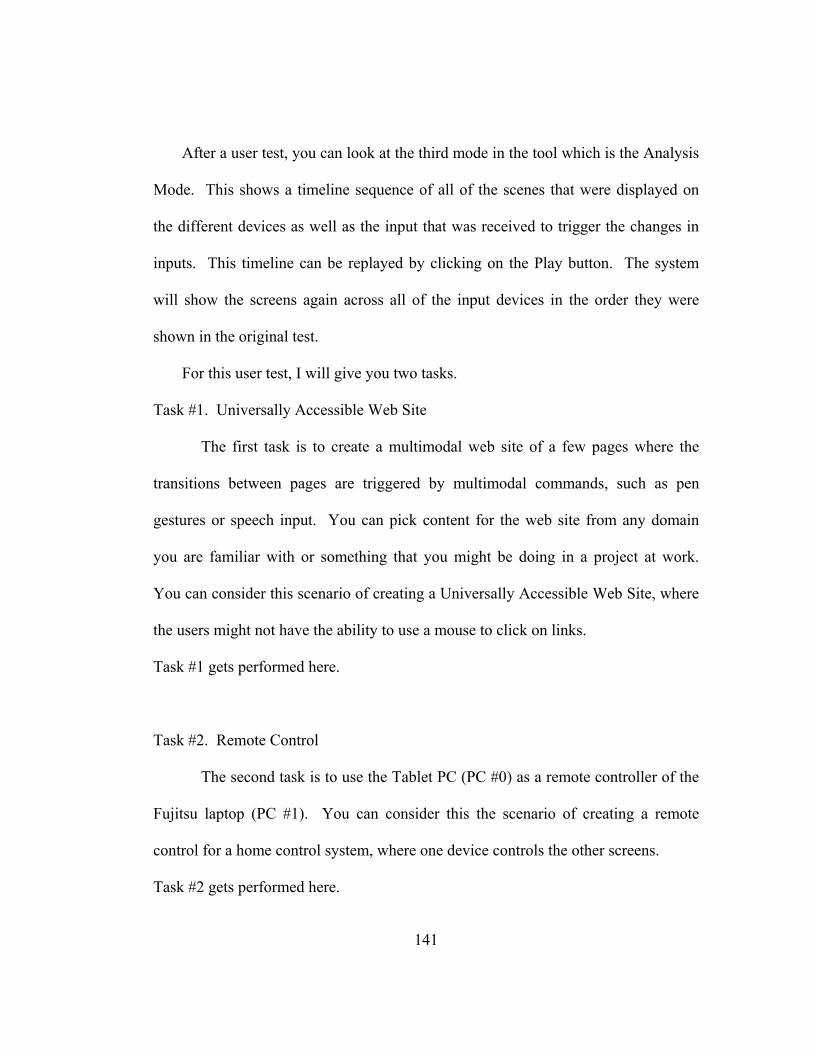
141
After a user test, you can look at the third mode in the tool which is the Analysis
Mode. This shows a timeline sequence of all of the scenes that were displayed on
the different devices as well as the input that was received to trigger the changes in
inputs. This timeline can be replayed by clicking on the Play button. The system
will show the screens again across all of the input devices in the order they were
shown in the original test.
For this user test, I will give you two tasks.
Task #1. Universally Accessible Web Site
The first task is to create a multimodal web site of a few pages where the
transitions between pages are triggered by multimodal commands, such as pen
gestures or speech input. You can pick content for the web site from any domain
you are familiar with or something that you might be doing in a project at work.
You can consider this scenario of creating a Universally Accessible Web Site, where
the users might not have the ability to use a mouse to click on links.
Task #1 gets performed here.
Task #2. Remote Control
The second task is to use the Tablet PC (PC #0) as a remote controller of the
Fujitsu laptop (PC #1). You can consider this the scenario of creating a remote
control for a home control system, where one device controls the other screens.
Task #2 gets performed here.

142
Thank you for performing these two tasks. Now I would like to ask you some
questions about your experience with CrossWeaver and ask you to fill out this post
questionnaire.

143
A.2 Participant Background Questionnaire
ID _____ Gender: Female Male Age: _____ Status: Undergraduate: ______ year Graduate: ______ year Major: _____________________ How long have you been using computers? ______________ How long have you been programming computers? In what capacity?______________ Have you used speech interfaces? When? ______________ Have you used pen interfaces? When? ______________ Have you used a multimodal interface? When? ______________ Place a check mark next to all of the following tools with which you have used:
Director Visual Basic HyperCard HTML Tcl/Tk Other: _________________________
None of the above Place a check mark next to all of the drawing/painting tools which you have used:
Canvas MacPaint Color It! Paintbrush Corel Draw Photoshop Cricket Draw PowerPoint Freehand SuperPaint Illustrator Visio MacDraw Xfig Other: _________________________ None of the above

144
A.3 User Interface Designer Pre-Test Questionnaire
ID _____ General
Describe what you do. Are you primarily devoted to designing? How long have you been a designer? What is your background in terms of education and experience?
Projects How long does the design process typically take? How many people are typically involved? Describe how the design process works. Does it differ much from project to project?
Phases What are the distinct phases to the project? Do you, personally, concentrate or specialize in a particular phase? How do you communicate or preserve design ideas from one phase to another?
Tools What tools, software or otherwise, do you use during the design process? What do you like/dislike about the tools you use?
Sketching/Storyboarding Do you draw sketches or make storyboards on paper during the design process? How do you use the sketches? Do you convert the sketches to another medium at some point? Do you use an electronic tablet?

145
A.4 User Interface Designer Post-Test Survey
ID _____ Ranking Questions: How functional did you find this prototype? Not at all Neutral Extremely 1 2 3 4 5 6 7 8 9 10 Did you find yourself making a lot of errors with this tool? Not at all Neutral Extremely 1 2 3 4 5 6 7 8 9 10 Did you find it easy to correct the errors that you made? Not at all Neutral Extremely 1 2 3 4 5 6 7 8 9 10 Did you find yourself making a lot of steps to accomplish each task? Not at all Neutral Extremely 1 2 3 4 5 6 7 8 9 10 Ease of use of the prototype as given: Not at all Neutral Extremely 1 2 3 4 5 6 7 8 9 10 Quickness with which you could accomplish the tasks you had to complete: Not at all Neutral Extremely 1 2 3 4 5 6 7 8 9 10

146
How natural were the commands that you used? Not at all Neutral Extremely 1 2 3 4 5 6 7 8 9 10 Recognition performance: What are your comments about the performance of the speech recognizer? Worst Neutral Best 1 2 3 4 5 6 7 8 9 10 What are your comments about the performance of the handwriting recognizer? Worst Neutral Best 1 2 3 4 5 6 7 8 9 10

147
A.5 User Interface Designer Post-Test Questionnaire
Freeform Questions:
1. Would you use CrossWeaver to design user interfaces? Why or why not?
2. Does the method of building the storyboards make sense to you? ________ If so, what did you like about it? If not, how was it confusing, and how can it be improved?
3. Does the method of running the prototypes make sense to you? ________
If so, what did you like about it?
If not, how was it confusing, and how can it be improved? 4. Do you believe the primitive operation metaphor is useful for designing user
interfaces? Why or why not?
5. If you have any other comments about CrossWeaver, please write them below.

148
A.6 Consent Form
COLLEGE OF ENGINEERING DEPARTMENT OF ELECTRICAL ENGINEERING AND COMPUTER SCIENCES BERKELEY, CALIFORNIA 94720-1776 527 SODA HALL Consent form for participation in research relating to Multimodal, Multidevice Prototyping Using Programming by Illustration. This research is being conducted by Mr. Anoop Sinha for Professor James Landay in the Department of Computer Science at the University of California, Berkeley. The aim of the research is to investigate sketching prototyping tools for designing multimodal, multidevice user interfaces. The main goal is to test the usability of a tool that we have designed and built. The information in this study will be collected by questionnaires and by software recording the interactions of participants with the tool. Additionally, in some situations interviews, observations, and video recording will be used as well. Participants will be notified of all information collection methods used during the time they are involved with the study. Participation in this experiment is voluntary. Participants may withdraw themselves and their data at any time without fear of consequences. Any concerns about the experiment may be discussed with the researcher, Mr. Anoop Sinha, or with Professor James Landay. Participant confidentiality will be provided by storing data so that it will only be identifiable by participant number. The video recordings of the session will not be released without the consent of the participant. No identifying information about the participants will be available to anyone except the researchers and their supervisors. There are no foreseeable risks to you from participating in this research. There is no direct benefit to you. However we hope that the research will benefit society by improving the techniques used to build user interfaces. There will be no costs to you, other than your time and any personal transportation costs. Participation involves filling out a pre-questionnaire, performing some tasks on the internet (such as finding a news story or retrieving maps and driving directions), and filling out a post-questionnaire. As a participant, you will receive $15 compensation. I hereby acknowledge that I have been given an opportunity to ask questions about the nature of the experiment and my participation in it. I give my consent to have data collected on my behavior and opinions in relation to this experiment. I understand I may withdraw my permission and data at any time. I am 18 years or older. If I have any questions, I can contact the primary researcher, Mr. Anoop Sinha, via email at [email protected] or phone at (510) 642-3437. Signed ______________________________________________ Name (please print) _______________________________________________ Date ____________________________________________ If you have any questions about your rights or treatment as a participant in this research project, please contact the Committee for Protection of Human Subjects at (510) 642-7461

149
A.7 Participant’s Designs Built Using CrossWeaver During User
Testing
Figure A-1. Participant #1, Task #1

150
Figure A-2. Participant #1, Task #2

151
Figure A-3. Participant #2, Task #1

152
Figure A-4. Participant #2, Task #2
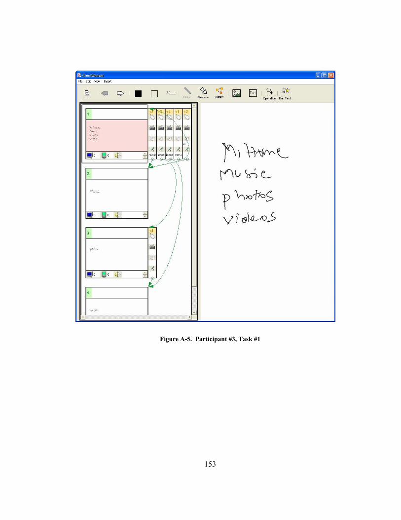
153
Figure A-5. Participant #3, Task #1

154
Figure A-6. Participant #3, Task #2

155
Figure A-7. Participant #4, Task #1
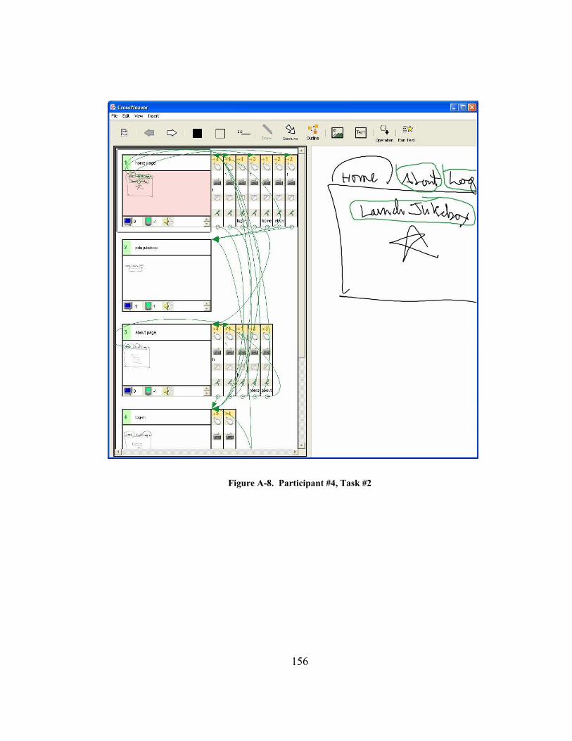
156
Figure A-8. Participant #4, Task #2

157
Figure A-9. Participant #5, Task #1

158
Figure A-10. Participant #5, Task #2.

159
Figure A-11. Participant #6, Task #1

160
Figure A-12. Participant #6, Task #2

161
Figure A-13. Participant #7, Task #1
162
Figure A-14. Participant #7, Task #2

163
Figure A-15. Participant #8, Task #1

164
Figure A-16. Participant #8, Task #2

165
Figure A-17. Participant #9, Task #1
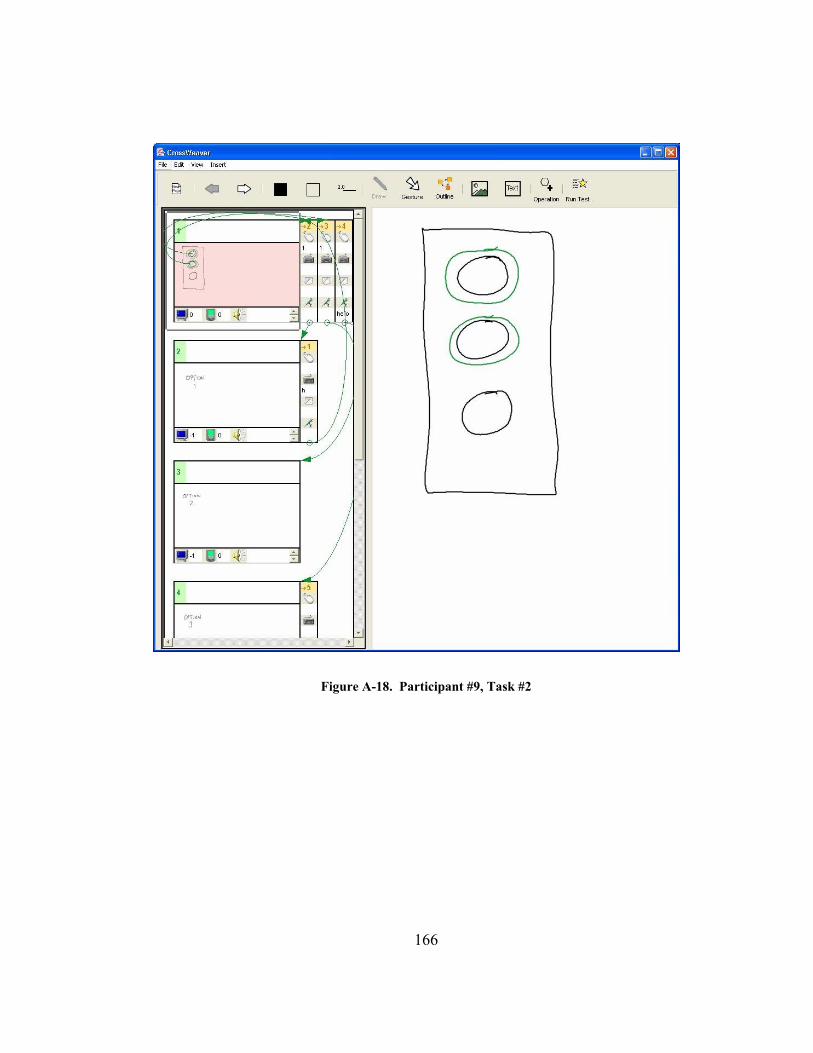
166
Figure A-18. Participant #9, Task #2

167
References
Abowd, G. D. (1999). "Classroom 2000: An Experiment with the Instrumentation of a Living Educational Environment." IBM Systems Journal, Special issue on Pervasive Computing 38(4): 508-530.
Abowd, G. D., C. G. Atkeson, et al. (1996). Teaching and Learning as Multimedia Authoring: The Classroom 2000 Project. Multimedia '96: 187-198.
Adobe (2003a). Adobe Corporation http://www.adobe.com/.
Adobe (2003b). Adobe Illustrator http://www.adobe.com/products/illustrator/main.html.
Adobe (2003c). Adobe Photoshop http://www.adobe.com/products/photoshop/main.html.
Apple (1993). Apple Corporation Newton Personal Digital Assistant.
Bailey, B. P. (2002). A Behavior-Sketching Tool for Early Multimedia Design, Ph.D. Thesis. Minneapolis, MN, Computer Science Department, University of Minnesota: 235.
Bailey, B. P. and J. A. Konstan (2003). Are Informal Tools Better? Comparing DEMAIS, Pencil and Paper, and Authorware for Early Multimedia Design. Proceedings of the ACM Conference on Human Factors in Computing Systems. Ft. Lauderdale, FL: 313-320.
Bailey, B. P., J. A. Konstan, et al. (2001). DEMAIS: Designing Multimedia Applications with Interactive Storyboards. Proceedings of the 9th ACM International Conference on Multimedia. Ottawa, Ontario, Canada: 241-250.
Bluetooth (2003). https://www.bluetooth.org/.
Bolt, R. A. (1980). "Put-that-There: Voice and Gesture at the Graphics Interface." Computer Graphics 14(3): 262-270.
Bricklin, D. (2003). About Tablet Computing Old and New http://www.bricklin.com/tabletcomputing.htm.
Brocklehurst, E. R. (1991). "The NPL Electronic Paper Project." International Journal of Man-Machine Studies 34(1): 69-95.

168
Burnett, M. and D. McIntyre (1995). "Visual Programming." Computer 28(3): 14-16.
Buxton, W. (1997). Out From Behind the Glass and the Outside-In Squeeze. ACM CHI '97 Conference on Human Factors in Computing Systems.
Chandler, C., G. Lo, et al. (2002). "Multimodal Theater: Extending Paper Prototyping to Multimodal Applications." Extended Abstracts of Conference on Human Factors in Computing Systems: CHI 2002 2: 874-875.
Chang, S.-K. (1987). "Visual Languages: A Tutorial and Survey." IEEE Software 4(1): 29-39.
Chang, S.-K., T. Ichikawa, et al., Eds. (1986). Visual Languages. New York, Plenum Press.
Cheyer, A., L. Julia, et al. (1998). A Unified Framework for Constructing Multimodal Experiments and Applications. Proceedings of Cooperative Multimodal Communication '98. Tilburg (The Netherlands): 63-69.
Clow, J. and S. L. Oviatt (1998). STAMP: an automated tool for analysis of multimodal system performance. Proceedings of the International Conference on Spoken Language Processing. Sydney, Australia: 277--280.
Cohen, P. R., M. Johnston, et al. (1997). QuickSet: Multimodal Interaction for Distributed Applications. Proceedings of ACM Multimedia 97. Seattle, WA, USA, ACM, New York, NY, USA: 31-40.
Cohen, P. R., M. Johnston, et al. (1998). The Efficiency of Multimodal Interaction: A Case Study. International Conference on Spoken Language Processing, ICSLP'98. Australia. 2: 249-252.
CrossWeaver (2003). http://guir.berkeley.edu/crossweaver/.
Cypher, A., Ed. (1993). Watch What I Do: Programming by Demonstration. Cambridge, MA, MIT Press.
Dahlbäck, N., A. Jönsson, et al. (1993). Wizard of Oz Studies - Why and How. Intelligent User Interfaces '93: 193-200.
Damm, C. H., K. M. Hansen, et al. (2000). Tool Support for Cooperative Design: Gesture Based Modeling on an Electronic Whiteboard. Proceedings of CHI 2000, ACM Conference on Human Factors in Computing Systems. The Hague, The Netherlands: 518 - 525.
169
Davis, R. (2002). Sketch Understanding in Design: Overview of Work at the MIT AI Lab. 2002 AAAI Spring Symposium. Stanford, CA: 24-31.
Fujitsu (2003). Fujitsu Laptop, http://www.computers.us.fujitsu.com/index.shtml.
GO (1992). Go Corporation PenPoint Operating System. Reading, MA, Addison-Wesley.
Gould, J. D. and C. Lewis (1985). "Designing for Usability: Key Principles and What Designers Think." Communcations of the ACM 28(3): 300-311.
Gross, M. D. (1994). Recognizing and Interpreting Diagrams in Design. The ACM Conference on Advanced Visual Interfaces '94. Bari, Italy: 89-94.
Gross, M. D. and E. Y.-L. Do (1996). Ambiguous Intentions: A Paper-like Interface for Creative Design. ACM Symposium on User Interface Software and Technology. Seattle, WA: 183-192.
GUIR (2003). Group for User Interface Research, http://guir.berkeley.edu.
Halbert, D. C. (1984). Programming by Example, Ph.D. Thesis. Berkeley, CA, Computer Science Division, EECS Department, University of California.
Hammond, T. and R. Davis (2002). Tahuti: A Geometrical Sketch Recognition System for UML Class Diagrams. 2002 AAAI Spring Symposium on Sketch Understanding. Stanford, CA: 59-68.
Hong, J. I. and J. A. Landay (2000). "SATIN: A Toolkit for Informal Ink-based Applications." UIST 2000, ACM Symposium on User Interface and Software Technology, CHI Letters 2(2): 63-72.
Hong, J. I., F. C. Li, et al. (2001). End-User Perceptions of Formal and Informal Representations of Web Sites. Proceedings of Extended Abstracts of Human Factors in Computing Systems: CHI 2001. Seattle, WA: 385-386.
IBM (2003). ViaVoice http://www.ibm.com/software/voice/viavoice/.
IEEE (2003). http://grouper.ieee.org/groups/802/11/.
InStat (2003). Event Horizon: Two Billion Mobile Subscribers by 2007: 2003 Subscriber Forecast. http://www.instat.com/abstract.asp?id=98&SKU=IN0301117GW.

170
Ionescu, A. and L. Julia (2000). EMCE: A Multimodal Environment Augmenting Conferencing Experiences. FAUIC'2000. Canberra (Australia).
Julia, L. and A. Cheyer (1999). Multimedia Augmented Tutoring Environment for Travel CARS. http://www.ai.sri.com/oaa/chic/projects/docs/TravelMATE.pdf.
Kelley, J. F. (1984). "An Iterative Design Methodology for User-Friendly Natural Language Office Information Applications." ACM Transactions on Office Information Systems 2(1): 26-41.
Klemmer, S. R., A. K. Sinha, et al. (2001). "SUEDE: A Wizard of Oz Prototyping Tool for Speech User Interfaces." CHI Letters, The 13th Annual ACM Symposium on User Interface Software and Technology: UIST 2000 2(2): 1-10.
Klemmer, S. R., M. Thomsen, et al. (2002). "Where Do Web Sites Come From? Capturing and Interacting with Design History." CHI Letters, Human Factors in Computing Systems: CHI2002 4(1): 1-10.
Kramer, A. (1994). Translucent Patches – Dissolving Windows. ACM Symposium on User Interface Software and Technology. Marina del Rey, CA: 121-130.
Kurlander, D. (1993). Graphical Editing by Example, Ph.D. Thesis. New York, Computer Science Department, Columbia University.
Landay, J. (2001). Computer Supported Cooperative Work (CS294-2). http://guir.berkeley.edu/courses/cscw/fall2001/.
Landay, J. A. (1996). Interactive Sketching for the Early Stages of User Interface Design, Ph.D. Thesis. Pittsburgh, PA, Computer Science Department, Carnegie Mellon University: 242.
Landay, J. A. and B. A. Myers (1995). Interactive Sketching for the Early Stages of User Interface Design. Human Factors in Computing Systems: CHI ’95. Denver, CO: 43-50.
Landay, J. A. and B. A. Myers (1996). Sketching Storyboards to Illustrate Interface Behavior. Human Factors in Computing Systems: CHI '96 Conference Companion, Vancouver, Canada.
Landay, J. A. and B. A. Myers (2001). "Sketching Interfaces: Toward More Human Interface Design." IEEE Computer 34(3): 56-64.

171
Li, Y., J. A. Landay, et al. (2003). Sketching Informal Presentations. Fifth ACM International Conference on Multimodal Interfaces: ICMI-PUI 2003. Vancouver, B.C., Canada: 234 - 241.
Lieberman, H., MIT Press, 1993. (1993). Mondrian: A Teachable Graphical Editor. Watch What I Do:Programming by Demonstration. A. Cypher, MIT Press.
Lin, J., M. W. Newman, et al. (2000). "DENIM: Finding a Tighter Fit Between Tools and Practice for Web Site Design." CHI 2000, Human Factors in Computing Systems, CHI Letters 2(1): 510-517.
Lin, J., M. Thomsen, et al. (2002). "A Visual Language for Sketching Large and Complex Interactive Designs." CHI Letters: Human Factors in Computing Systems, CHI 2002 4(1): 307-314.
Long, A. C. (2001). Quill: A Gesture Design Tool for Pen-based User Interfaces, Ph.D. Thesis. Berkeley, CA, Computer Science Department, University of California, Berkeley: 307.
Macromedia (2003a). http://www.macromedia.com/.
Macromedia (2003b). Macromedia Director http://www.macromedia.com/software/director/.
Macromedia (2003c). Macromedia Fireworks http://www.macromedia.com/software/fireworks/.
Macromedia (2003d). Macromedia FreeHand http://www.macromedia.com/software/freehand/.
McCloud, S. (1993). Understanding Comics. New York, NY, Harper Colins.
McGee, D. R. and P. R. Cohen (2001). Creating Tangible Interfaces by Augmenting Physical Objects with Multimodal Language. Proceedings of the 6th International Conference on Intelligent User Interfaces. Santa Fe, New Mexico: 113-119.
McGee, D. R., P. R. Cohen, et al. (2002). "Comparing paper and tangible multimodal tools." CHI Letters: Human Factors in Computing Systems: CHI 2002 1(1): 407-414.
Microsoft (1992). Microsoft Windows for Pen Computing.

172
Microsoft (2003a). Microsoft Pocket PC, http://www.pocketpc.com/.
Microsoft (2003b). Microsoft PowerPoint http://www.microsoft.com/office/powerpoint/default.asp.
Microsoft (2003c). Microsoft Speech SDK http://www.microsoft.com/speech/.
Microsoft (2003d). Microsoft Tablet PC SDK http://www.tabletpcdeveloper.com/.
Microsoft (2003e). Microsoft Visio http://www.microsoft.com/office/visio/.
Mignot, C., C. Valot, et al. (1993). An Experimental Study of Future 'Natural' Multimodal Human-Computer Interaction. Proceedings of ACM INTERCHI'93 Conference on Human Factors in Computing Systems -- Adjunct Proceedings: 67-68.
Modugno, F. (1995). Extending End-User Programming in a Visual Shell with Programming by Demonstration and Graphical Language Techniques. March. Pittsburgh, PA, Computer Science Department, Carnegie Mellon University: 308.
Moran, L. B., A. J. Cheyer, et al. (1998). "Multimodal User Interfaces in the Open Agent Architecture." Knowledge-Based Systems 10(5): 295-304.
Myers, B. A. (1990). "Creating user interfaces using programming by example, visual programming, and constraints." ACM Transactions on Programming Languages and Systems 12(2): 143-177.
Negroponte, N. (1973). Recent Advances in Sketch Recognition. 1973 National Computer Conference and Exposition. New York, AFIPS Press. 42: 663-675.
Negroponte, N. and J. Taggart (1971). HUNCH – An Experiment in Sketch Recognition. Computer Graphics. W. Giloi, Berlif.
Newman, M. W., J. Lin, et al. (2003). "DENIM: An Informal Web Site Design Tool Inspired by Observations of Practice." Human-Computer Interaction 18(3): 259-324.
Nigay, L. and J. Coutaz (1993). A Design Space for Multimodal Systems: Concurrent Processing and Data Fusion. Proceedings of ACM INTERCHI'93 Conference on Human Factors in Computing Systems: 172-178.

173
Nigay, L. and J. Coutaz (1995). A Generic Platform for Addressing the Multimodal Challenge. Proceedings of ACM CHI'95 Conference on Human Factors in Computing Systems. 1: 98-105.
Nuance (2003). Nuance Speech Recognizer http://www.nuance.com/.
OGI (2003). Oregon Graduate Institute, Adaptive Agent Architecture, http://chef.cse.ogi.edu/AAA/.
Oviatt, S. and P. Cohen (2003). "Multimodal Interfaces That Process What Comes Naturally." Communications of the ACM 43(9): 45-51.
Oviatt, S., P. Cohen, et al. (2000). "Designing the User Interface for Multimodal Speech and Pen-Based Gesture Applications: State-of-the-Art Systems and Future Research Directions." Human-Computer Interaction 15(4): 263-322.
Oviatt, S. L. (1996). Multimodal Interfaces for Dynamic Interactive Maps. Proceedings of Conference on Human Factors in Computing Systems: CHI '96: 95-102.
Oviatt, S. L. (1999). Mutual Disambiguation of Recognition Errors in a Multimodal Architecture. Proceedings of CHI 1999: 576-583.
Oviatt, S. L. (2003). Multimodal interfaces. The Human-Computer Interaction Handbook: Fundamentals, Evolving Technologies and Emerging Applications. J. Jacko and A. Sears. Mahwah, NJ, Lawrence Erlbaum Associates: 286-304.
Paragraph (1999). Calligrapher Handwriting Recognizer http://www.phatware.com/calligrapher/index.html.
Reekie, J., M. Shilman, et al. (1998). Diva, a Software Infrastructure for Visualizing and Interacting with Dynamic Information Spaces. http://www.gigascale.org/diva/.
Rekimoto, J. (1997). Pick-and-Drop: A Direct Manipulation Technique for Multiple Computer Environments. Proceedings of UIST'97: 31-39.
Rettig, M. (1994). "Prototyping for Tiny Fingers." Communications of the ACM 37(4): 21-27.

174
Salber, D. and J. Coutaz (1993). A Wizard of Oz Platform for the Study of Multimodal Systems. Proceedings of ACM INTERCHI'93 Conference on Human Factors in Computing Systems -- Adjunct Proceedings: 95-96.
SIGMM (2003). ACM Multimedia SIG http://www.acm.org/sigmm/.
Sinha, A., M. Shilman, et al. (2001). MultiPoint: A Case Study of Multimodal Interaction for Building Presentations. Proceedings of CHI2001: Extended Abstracts: 431-432.
Sinha, A. K., S. R. Klemmer, et al. (2002). "Embarking on Spoken Language NL Interface Design." International Journal of Speech Technology: Special Issue on Natural Language Interfaces 5(2): 159-169.
Sinha, A. K. and J. A. Landay (2001). Visually Prototyping Perceptual User Interfaces Through Multimodal Storyboarding. IEEE Workshop on Perceptive User Interfaces: PUI 2001. Orlando, FL: 101-104.
Sinha, A. K. and J. A. Landay (2002). Embarking on Multimodal Interface Design. International Conference on Multimodal Interfaces. Pittsburgh, PA: 355-360.
Smith, D. C., A. Cyper, et al. (2000). "Programming by Example: Novice Programming Comes of Age." Communications of the ACM 43(3): 75-81.
Software, J. (2003). PaintShopPro http://www.jasc.com/products/paintshoppro/.
Solidworks (2003). Solidworks 3D CAD Software http://www.solidworks.com/.
SRI (2003). Open Agent Architecture http://www.openagent.com/.
Sun (1999). Java JDK 1.1.7, http://java.sun.com/products/jdk/1.1/.
Sun (2002). Java JDK 1.4, http://java.sun.com/j2se/1.4/.
Sutherland, I. E. (1963). SketchPad: A Man-Machine Graphical Communication System. AFIPS Spring Joint Computer Conference. 23: 329-346.
Thomas, F. (1981). Disney Animation: The Illusion of Life / Frank Thomas and Ollie Johnston. New York, Abbeville Press.
Toshiba (2003). Toshiba Portege 3500 Tablet PC, http://www.tabletpc.toshiba.com/.

175
W3C (2000). Multimodal Requirements for Voice Markup Languages http://www.w3.org/TR/multimodal-reqs.
Wagner, A. (1990). Prototyping: A Day in the Life of an Interface Designer. The Art of Human-Computer Interface Design. B. Laurel. Reading, MA, Addison-Wesley: 79-84.
Wang (1988). Wang Corporation Freestyle tablet computer.
Wolf, C. G., J. R. Rhyne, et al. (1989). The Paper-Like Interface. Proceedings of the Third International Conference on Human-Computer Interaction: 494-501.
Wong, Y. Y. (1992). Rough and Ready Prototypes: Lessons From Graphic Design. Human Factors in Computing Systems. Monterey, CA: 83-84.
Yankelovich, N. and J. Lai (1998). Designing Speech User Interfaces. Proceedings of ACM CHI 98 Conference on Human Factors in Computing Systems (Summary). 2: 131-132.
Yankelovich, N., G.-A. Levow, et al. (1995). Designing SpeechActs: Issues in Speech User Interfaces. Proceedings of ACM CHI'95 Conference on Human Factors in Computing Systems. 1: 369-376.
Yankelovich, N. and C. D. McLain (1996). Office Monitor. Proceedings of ACM CHI 96 Conference on Human Factors in Computing Systems. 2: 173-174.