Configuring Interfaces - Cisco
40
CHAPTER Send documentation comments to [email protected] 12-1 Cisco MDS 9000 Family CLI Configuration Guide OL-16184-01, Cisco MDS SAN-OS Release 3.x 12 Configuring Interfaces A switch's main function is to relay frames from one data link to another. To do that, the characteristics of the interfaces through which the frames are received and sent must be defined. The configured interfaces can be Fibre Channel interfaces, Gigabit Ethernet interfaces, the management interface (mgmt0), or VSAN interfaces. This chapter describes the basic interface configuration to get your switch up and running. It includes the following sections: • Fibre Channel Interfaces, page 12-1 • TL Ports for Private Loops, page 12-28 • Buffer Credits, page 12-32 • Management Interfaces, page 12-37 • VSAN Interfaces, page 12-39 • Default Settings, page 12-40 See Chapter 5, “Initial Configuration,” and Chapter 43, “Configuring IP Services,” for more information on configuring mgmt0 interfaces. See Chapter 45, “Configuring IPv4 for Gigabit Ethernet Interfaces” and Chapter 46, “Configuring IPv6 for Gigabit Ethernet Interfaces”for more information on configuring Gigabit Ethernet interfaces. Tip Before you begin configuring the switch, ensure that the modules in the chassis are functioning as designed. To verify the status of a module at any time, issue the show module command in EXEC mode (see the “Verifying the Module Status” section on page 5-15). Fibre Channel Interfaces This section describes Fibre Channel interface characteristics, including (but not limited to) modes, frame encapsulation, states, SFPs, and speeds. This section includes the following topics: • 32-Port Switching Module Configuration Guidelines, page 12-2 • About Interface Modes, page 12-3 • N Port Identifier Virtualization, page 12-7 • About Interface States, page 12-7
-
Upload
khangminh22 -
Category
Documents
-
view
8 -
download
0
Transcript of Configuring Interfaces - Cisco

Send documenta t ion comments to mdsfeedback -doc@c i sco .com
OL-16184-01, Cisco MDS SAN-OS Release 3.x
C H A P T E R 12
Configuring InterfacesA switch's main function is to relay frames from one data link to another. To do that, the characteristics of the interfaces through which the frames are received and sent must be defined. The configured interfaces can be Fibre Channel interfaces, Gigabit Ethernet interfaces, the management interface (mgmt0), or VSAN interfaces.
This chapter describes the basic interface configuration to get your switch up and running. It includes the following sections:
• Fibre Channel Interfaces, page 12-1
• TL Ports for Private Loops, page 12-28
• Buffer Credits, page 12-32
• Management Interfaces, page 12-37
• VSAN Interfaces, page 12-39
• Default Settings, page 12-40
See Chapter 5, “Initial Configuration,” and Chapter 43, “Configuring IP Services,” for more information on configuring mgmt0 interfaces.
See Chapter 45, “Configuring IPv4 for Gigabit Ethernet Interfaces” and Chapter 46, “Configuring IPv6 for Gigabit Ethernet Interfaces”for more information on configuring Gigabit Ethernet interfaces.
Tip Before you begin configuring the switch, ensure that the modules in the chassis are functioning as designed. To verify the status of a module at any time, issue the show module command in EXEC mode (see the “Verifying the Module Status” section on page 5-15).
Fibre Channel InterfacesThis section describes Fibre Channel interface characteristics, including (but not limited to) modes, frame encapsulation, states, SFPs, and speeds.
This section includes the following topics:
• 32-Port Switching Module Configuration Guidelines, page 12-2
• About Interface Modes, page 12-3
• N Port Identifier Virtualization, page 12-7
• About Interface States, page 12-7
12-1Cisco MDS 9000 Family CLI Configuration Guide

Send documenta t ion comments to mdsfeedback -doc@c i sco .com
Chapter 12 Configuring InterfacesFibre Channel Interfaces
• Configuring Fibre Channel Interfaces, page 12-11
• Graceful Shutdown, page 12-12
• Configuring Interface Modes, page 12-13
• Configuring Port Speeds, page 12-14
• Enabling N Port Identifier Virtualization, page 12-15
• About Interface Descriptions, page 12-15
• Configuring the Interface Description, page 12-15
• About Frame Encapsulation, page 12-16
• About Receive Data Field Size, page 12-16
• Configuring Receive Data Field Size, page 12-16
• Identifying the Beacon LEDs, page 12-16
• About Beacon Mode, page 12-17
• About Bit Error Thresholds, page 12-18
• Switch Port Attribute Default Values, page 12-19
• About SFP Transmitter Types, page 12-19
• Displaying Interface Information, page 12-20
32-Port Switching Module Configuration GuidelinesThe 32-port switching module guidelines apply to the following hardware:
• The 32-port, 2-Gbps or 1-Gbps switching module
• The Cisco MDS 9140 Switch
When configuring these host-optimized ports, the following port mode guidelines apply:
• You can configure only the first port in each 4-port group (for example, the first port in ports 1-4, the fifth port in ports 5-8 and so on) as an E port. If the first port in the group is configured as an E port, the other three ports in each group (ports 2-4, 6-8 and so on) are not usable and remain shutdown.
• If you execute the write erase command on a 32-port switching module, and then copy a saved configuration to the switch from a text file that contains the no system default switchport shutdown command, you need to copy the text file to the switch again for the E ports to come up without manual configuration.
• If any of the other three ports are enabled, you cannot configure the first port as an E port. The other three ports continue to remain enabled.
• The auto mode is not allowed in a 32-port switching module or the host-optimized ports in the Cisco 9100 Series (16 host-optimized ports in the Cisco MDS 9120 switch and 32 host-optimized ports in the Cisco MDS 9140 switch).
• The default port mode is Fx (Fx negotiates to F or FL) for 32-port switching modules and the host-optimized ports in the Cisco 9100 Series (16 host-optimized ports in the Cisco MDS 9120 switch and 32 host-optimized ports in the Cisco MDS 9140 switch).
• The 32-port switching module does not support FICON.
12-2Cisco MDS 9000 Family CLI Configuration Guide
OL-16184-01, Cisco MDS SAN-OS Release 3.x

Send documenta t ion comments to mdsfeedback -doc@c i sco .com
Chapter 12 Configuring InterfacesFibre Channel Interfaces
Note We recommend that you configure your E ports on a 16-port switching module. If you must configure an E port on a 32-port host optimized switching module, the other three ports in that 4-port group cannot be used.
Note In the Cisco MDS 9100 Series, the left most groups of ports outlined in white (4 ports in the 9120 switch and 8 ports in the 9140 switch) are full line rate like the 16-port switching module. The other ports (16 ports in the 9120 switch and 32 ports in the 9140 switch) are host-optimized like the 32-port switching module. Each group of 4 host-optimized ports have the same rules as for the 32-port switching module.
About Interface Modes Each physical Fibre Channel interface in a switch may operate in one of several port modes: E port, F port, FL port, TL port, TE port, SD port, ST port, and B port (see Figure 12-1). Besides these modes, each interface may be configured in auto or Fx port modes. These two modes determine the port type during interface initialization.
Figure 12-1 Cisco MDS 9000 Family Switch Port Modes
Note Interfaces are created in VSAN 1 by default. See Chapter 20, “Configuring and Managing VSANs.”
Each interface has an associated administrative configuration and an operational status:
• The administrative configuration does not change unless you modify it. This configuration has various attributes that you can configure in administrative mode.
• The operational status represents the current status of a specified attribute like the interface speed. This status cannot be changed and is read-only. Some values may not be valid when the interface is down (for example, the operational speed).
N port
F port
Publicloop
loop
E port E port FL port
NL port NL port
NL port NL port p
FL port
ISL link
7952
8
Public
12-3Cisco MDS 9000 Family CLI Configuration Guide
OL-16184-01, Cisco MDS SAN-OS Release 3.x

Send documenta t ion comments to mdsfeedback -doc@c i sco .com
Chapter 12 Configuring InterfacesFibre Channel Interfaces
Note When a module is removed and replaced with the same type of module, the configuration is retained. If a different type of module is inserted, then the original configuration is no longer retained.
A brief description of each interface mode follows.
E Port
In expansion port (E port) mode, an interface functions as a fabric expansion port. This port may be connected to another E port to create an Inter-Switch Link (ISL) between two switches. E ports carry frames between switches for configuration and fabric management. They serve as a conduit between switches for frames destined to remote N ports and NL ports. E ports support class 2, class 3, and class F service.
An E port connected to another switch may also be configured to form a PortChannel (see Chapter 17, “Configuring PortChannels”).
Note We recommend that you configure E ports on 16-port modules. If you must configure an E port on a 32-port oversubscribed module, then you can only use the first port in a group of four ports (for example, ports 1 through 4, 5 through 8, and so forth). The other three ports cannot be used.
F Port
In fabric port (F port) mode, an interface functions as a fabric port. This port may be connected to a peripheral device (host or disk) operating as an N port. An F port can be attached to only one N port. F ports support class 2 and class 3 service.
FL Port
In fabric loop port (FL port) mode, an interface functions as a fabric loop port. This port may be connected to one or more NL ports (including FL ports in other switches) to form a public arbitrated loop. If more than one FL port is detected on the arbitrated loop during initialization, only one FL port becomes operational and the other FL ports enter nonparticipating mode. FL ports support class 2 and class 3 service.
Note FL port mode is not supported on 4-port 10-Gbps switching module interfaces.
NP Ports
An NP port is a port on a device that is in NPV mode and connected to the core switch via a F port. NP ports behave like N ports except that in addition to providing N port behavior, they also function as proxies for multiple, physical N ports.
For more details about NP ports and NPV, see Chapter 13, “Configuring N Port Virtualization.”
12-4Cisco MDS 9000 Family CLI Configuration Guide
OL-16184-01, Cisco MDS SAN-OS Release 3.x

Send documenta t ion comments to mdsfeedback -doc@c i sco .com
Chapter 12 Configuring InterfacesFibre Channel Interfaces
TL Port
In translative loop port (TL port) mode, an interface functions as a translative loop port. It may be connected to one or more private loop devices (NL ports). TL ports are specific to Cisco MDS 9000 Family switches and have similar properties as FL ports. TL ports enable communication between a private loop device and one of the following devices:
• A device attached to any switch on the fabric
• A device on a public loop anywhere in the fabric
• A device on a different private loop anywhere in the fabric
• A device on the same private loop
TL ports support class 2 and class 3 services.
Private loop devices refer to legacy devices that reside on arbitrated loops. These devices are not aware of a switch fabric because they only communicate with devices on the same physical loop (see the “About TL Port ALPA Caches” section on page 12-30).
Tip We recommend configuring devices attached to TL ports in zones that have up to 64 zone members.
Note TL port mode is not supported on Generation 2 switching module interfaces.
TE Port
In trunking E port (TE port) mode, an interface functions as a trunking expansion port. It may be connected to another TE port to create an extended ISL (EISL) between two switches. TE ports are specific to Cisco MDS 9000 Family switches. They expand the functionality of E ports to support the following:
• VSAN trunking
• Transport quality of service (QoS) parameters
• Fibre Channel trace (fctrace) feature
In TE port mode, all frames are transmitted in EISL frame format, which contains VSAN information. Interconnected switches use the VSAN ID to multiplex traffic from one or more VSANs across the same physical link. This feature is referred to as trunking in the Cisco MDS 9000 Family (see Chapter 16, “Configuring Trunking”). TE ports support class 2, class 3, and class F service.
SD Port
In SPAN destination port (SD port) mode, an interface functions as a switched port analyzer (SPAN). The SPAN feature is specific to switches in the Cisco MDS 9000 Family. It monitors network traffic that passes though a Fibre Channel interface. This monitoring is done using a standard Fibre Channel analyzer (or a similar switch probe) that is attached to an SD port. SD ports do not receive frames, they merely transmit a copy of the source traffic. The SPAN feature is nonintrusive and does not affect switching of network traffic for any SPAN source ports (see Chapter 54, “Monitoring Network Traffic Using SPAN”).
12-5Cisco MDS 9000 Family CLI Configuration Guide
OL-16184-01, Cisco MDS SAN-OS Release 3.x

Send documenta t ion comments to mdsfeedback -doc@c i sco .com
Chapter 12 Configuring InterfacesFibre Channel Interfaces
ST Port
In the SPAN tunnel port (ST port) mode, an interface functions as an entry point port in the source switch for the RSPAN Fibre Channel tunnel. The ST port mode and the remote SPAN (RSPAN) feature are specific to switches in the Cisco MDS 9000 Family. When configured in ST port mode, the interface cannot be attached to any device, and thus cannot be used for normal Fibre Channel traffic (see the “Configuring SPAN” section on page 54-7).
Note ST port mode is not supported on the Cisco MDS 9124 Fabric Switch, the Cisco Fabric Switch for HP c-Class BladeSystem, and the Cisco Fabric Switch for IBM BladeCenter.
Fx Port
Interfaces configured as Fx ports can operate in either F port or FL port mode. The Fx port mode is determined during interface initialization depending on the attached N port or NL port. This administrative configuration disallows interfaces to operate in any other mode—for example, preventing an interface to connect to another switch.
B Port
While E ports typically interconnect Fibre Channel switches, some SAN extender devices, such as the Cisco PA-FC-1G Fibre Channel port adapter, implement a bridge port (B port) model to connect geographically dispersed fabrics. This model uses B ports as described in the T11 Standard FC-BB-2.
Figure 12-1 on page 12-3 depicts a typical SAN extension over an IP network.
If an FCIP peer is a SAN extender device that only supports Fibre Channel B ports, you need to enable the B port mode for the FCIP link. When a B port is enabled, the E port functionality is also enabled and they coexist. If the B port is disabled, the E port functionality remains enabled (see Chapter 44, “Configuring IP Storage”).
Auto Mode
Interfaces configured in auto mode can operate in one of the following modes: F port, FL port, E port, or TE port. The port mode is determined during interface initialization. For example, if the interface is connected to a node (host or disk), it operates in F port or FL port mode depending on the N port or NL port mode. If the interface is attached to a third-party switch, it operates in E port mode. If the interface is attached to another switch in the Cisco MDS 9000 Family, it may become operational in TE port mode (see Chapter 16, “Configuring Trunking”).
TL ports and SD ports are not determined during initialization and are administratively configured.
Note Fibre Channel interfaces on Storage Services Modules (SSMs) cannot be configured in auto mode.
12-6Cisco MDS 9000 Family CLI Configuration Guide
OL-16184-01, Cisco MDS SAN-OS Release 3.x

Send documenta t ion comments to mdsfeedback -doc@c i sco .com
Chapter 12 Configuring InterfacesFibre Channel Interfaces
N Port Identifier VirtualizationN port identifier virtualization (NPIV) provides a means to assign multiple FC IDs to a single N port. This feature allows multiple applications on the N port to use different identifiers and allows access control, zoning, and port security to be implemented at the application level. Figure 12-2 shows an example application using NPIV.
Figure 12-2 NPIV Example
You must globally enable NPIV for all VSANs on the MDS switch to allow the NPIV-enabled applications to use multiple N port identifiers.
Note All of the N port identifiers are allocated in the same VSAN.
About Interface StatesThe interface state depends on the administrative configuration of the interface and the dynamic state of the physical link.
Administrative States
The administrative state refers to the administrative configuration of the interface as described in Table 12-1.
Operational States
The operational state indicates the current operational state of the interface as described in Table 12-2.
Web
Node N portcontroller
LUN 1N_Port_ID 1
LUN 2N_Port_ID 2
LUN 3N_Port_ID 3
Applicationserver
MDS switch
F port
1540
19
Table 12-1 Administrative States
Administrative State Description
Up Interface is enabled.
Down Interface is disabled. If you administratively disable an interface by shutting down that interface, the physical link layer state change is ignored.
12-7Cisco MDS 9000 Family CLI Configuration Guide
OL-16184-01, Cisco MDS SAN-OS Release 3.x
Send documenta t ion comments to mdsfeedback -doc@c i sco .com
Chapter 12 Configuring InterfacesFibre Channel Interfaces
Reason Codes
Reason codes are dependent on the operational state of the interface as described in Table 12-3.
Note Only some of the reason codes are listed in Table 12-4.
If the administrative state is up and the operational state is down, the reason code differs based on the nonoperational reason code as described in Table 12-4.
Table 12-2 Operational States
Operational State Description
Up Interface is transmitting or receiving traffic as desired. To be in this state, an interface must be administratively up, the interface link layer state must be up, and the interface initialization must be completed.
Down Interface cannot transmit or receive (data) traffic.
Trunking Interface is operational in TE mode.
Table 12-3 Reason Codes for Interface States
Administrative Configuration
Operational Status Reason Code
Up Up None.
Down Down Administratively down—If you administratively configure an interface as down, you disable the interface. No traffic is received or transmitted.
Up Down See Table 12-4.
12-8Cisco MDS 9000 Family CLI Configuration Guide
OL-16184-01, Cisco MDS SAN-OS Release 3.x

Send documenta t ion comments to mdsfeedback -doc@c i sco .com
Chapter 12 Configuring InterfacesFibre Channel Interfaces
Table 12-4 Reason Codes for Nonoperational States
Reason Code (long version) DescriptionApplicable Modes
Link failure or not connected The physical layer link is not operational. All
SFP not present The small form-factor pluggable (SFP) hardware is not plugged in.
Initializing The physical layer link is operational and the protocol initialization is in progress.
Reconfigure fabric in progress The fabric is currently being reconfigured.
Offline The Cisco SAN-OS software waits for the specified R_A_TOV time before retrying initialization.
Inactive The interface VSAN is deleted or is in a suspended state.
To make the interface operational, assign that port to a configured and active VSAN.
Hardware failure A hardware failure is detected.
Error disabled Error conditions require administrative attention. Interfaces may be error-disabled for various reasons. For example:
• Configuration failure.
• Incompatible buffer-to-buffer credit configuration.
To make the interface operational, you must first fix the error conditions causing this state; and next, administratively shut down or enable the interface.
FC redirect failure A port is isolated because a Fibre Channel redirect is unable to program routes.
No port activation license available
A port is not active because it does not have a port license.
SDM failure A port is isolated because SDM is unable to program routes.
12-9Cisco MDS 9000 Family CLI Configuration Guide
OL-16184-01, Cisco MDS SAN-OS Release 3.x

Send documenta t ion comments to mdsfeedback -doc@c i sco .com
Chapter 12 Configuring InterfacesFibre Channel Interfaces
Isolation due to ELP failure The port negotiation failed. Only E ports and TE ports Isolation due to ESC failure The port negotiation failed.
Isolation due to domain overlap
The Fibre Channel domains (fcdomain) overlap.
Isolation due to domain ID assignment failure
The assigned domain ID is not valid.
Isolation due to the other side of the link E port isolated
The E port at the other end of the link is isolated.
Isolation due to invalid fabric reconfiguration
The port is isolated due to fabric reconfiguration.
Isolation due to domain manager disabled
The fcdomain feature is disabled.
Isolation due to zone merge failure
The zone merge operation failed.
Isolation due to VSAN mismatch
The VSANs at both ends of an ISL are different.
Nonparticipating FL ports cannot participate in loop operations. It may happen if more than one FL port exists in the same loop, in which case all but one FL port in that loop automatically enters nonparticipating mode.
Only FL ports and TL ports
PortChannel administratively down
The interfaces belonging to the PortChannel are down. Only PortChannel interfacesSuspended due to incompatible
speedThe interfaces belonging to the PortChannel have incompatible speeds.
Suspended due to incompatible mode
The interfaces belonging to the PortChannel have incompatible modes.
Suspended due to incompatible remote switch WWN
An improper connection is detected. All interfaces in a PortChannel must be connected to the same pair of switches.
Table 12-4 Reason Codes for Nonoperational States (continued)
Reason Code (long version) DescriptionApplicable Modes
12-10Cisco MDS 9000 Family CLI Configuration Guide
OL-16184-01, Cisco MDS SAN-OS Release 3.x

Send documenta t ion comments to mdsfeedback -doc@c i sco .com
Chapter 12 Configuring InterfacesFibre Channel Interfaces
Configuring Fibre Channel InterfacesTo configure a Fibre Channel interface, follow these steps:
To configure a range of interfaces, follow these steps:
For the Cisco Fabric Switch for HP c-Class BladeSystem and the Cisco Fabric Switch for IBM BladeCenter, you can configure a range of interfaces among internal ports or external ports, but you cannot mix both interface types within the same range. For example, “bay 1-10, bay 12” or “ext 0, ext 15-18” are valid ranges, but “bay 1-5, ext 15-17” is not.
Command Purpose
Step 1 switch# config t Enters configuration mode.
Step 2 switch(config)# interface fc1/1switch(config-if)#
Selects a Fibre Channel interface and enters interface configuration submode.
Note When a Fibre Channel interface is configured, it is automatically assigned a unique world wide name (WWN). If the interface’s operational state is up, it is also assigned a Fibre Channel ID (FC ID).
Command Purpose
Step 1 switch# config t Enters configuration mode.
Step 2 switch(config)# interface fc1/1 - 4 , fc2/1 - 3switch(config-if)#
Selects the range of Fibre Channel interfaces and enters interface configuration submode3.
Note In this command, provide a space before and after the comma.
12-11Cisco MDS 9000 Family CLI Configuration Guide
OL-16184-01, Cisco MDS SAN-OS Release 3.x

Send documenta t ion comments to mdsfeedback -doc@c i sco .com
Chapter 12 Configuring InterfacesFibre Channel Interfaces
Graceful ShutdownInterfaces on a port are shutdown by default (unless you modified the initial configuration).
The Cisco SAN-OS software implicitly performs a graceful shutdown in response to either of the following actions for interfaces operating in the E port mode:
• If you shut down an interface.
• If a Cisco SAN-OS software application executes a port shutdown as part of its function.
A graceful shutdown ensures that no frames are lost when the interface is shutting down. When a shutdown is triggered either by you or the Cisco SAN-OS software, the switches connected to the shutdown link coordinate with each other to ensure that all frames in the ports are safely sent through the link before shutting down. This enhancement reduces the chance of frame loss.
A graceful shutdown is not possible in the following situations:
• If you physically remove the port from the switch.
• If in-order-delivery (IOD) is enabled (see “In-Order Delivery” section on page 25-13).
• If the Min_LS_interval interval is higher than 10 seconds (see“Displaying Global FSPF Information” section on page 25-20).
Note This feature is only triggered if both switches at either end of this E port interface are MDS switches and are running Cisco SAN-OS Release 2.0(1b) or later.
Setting the Interface Administrative StateTo gracefully shut down an interface, follow these steps:
To enable traffic flow, follow these steps:
Command Purpose
Step 1 switch# config t Enters configuration mode.
Step 2 switch(config)# interface fc1/1 Selects a Fibre Channel interface and enters interface configuration submode.
Step 3 switch(config-if)# shutdown Gracefully shuts down the interface and administratively disables traffic flow (default).
Command Purpose
Step 1 switch# config t Enters configuration mode.
Step 2 switch(config)# interface fc1/1 Selects a Fibre Channel interface and enters interface configuration submode.
Step 3 switch(config-if)# no shutdown Enables traffic flow to administratively allow traffic when the no prefix is used (provided the operational state is up).
12-12Cisco MDS 9000 Family CLI Configuration Guide
OL-16184-01, Cisco MDS SAN-OS Release 3.x

Send documenta t ion comments to mdsfeedback -doc@c i sco .com
Chapter 12 Configuring InterfacesFibre Channel Interfaces
Configuring Interface ModesTo configure the interface mode, follow these steps:
Configuring System Default Port Mode F
The system default switchport mode F command sets the administrative mode of all Fibre Channel ports to mode F, while avoiding traffic disruption caused by the formation of unwanted inter-switch links (ISLs). This command is part of the setup utility that runs during bootup after a write erase or reload. It can also be executed from the command line in configuration mode. This command changes the configuration of the following ports to administrative mode F:
• All ports that are down and that are not out-of-servicel.
• All F ports that are up, whose operational mode is F, and whose administrative mode is not F.
This command does not affect the configuration of the following ports:
• All user-configured ports, even if they are down.
• All non-F ports that are up; however, if non-F ports are down, this command changes the administrative mode of those ports.
Example 12-1 shows the command in the setup utility, and Example 12-2 shows the command from the command line.
Example 12-1 Setup Utility
Configure default switchport mode F (yes/no) [n]: y
Example 12-2 Command Line
switch(config)# system default switchport mode F
Command Purpose
Step 1 switch# config t Enters configuration mode.
Step 2 switch(config)# interface fc1/1switch(config-if)#
Selects a Fibre Channel interface and enters interface configuration submode.
Step 3 switch(config-if)# switchport mode Fswitch(config-if)#
Configures the administrative mode of the port. You can set the operational state to auto, E, F, FL, Fx, TL, or SD port mode.
Note Fx ports refers to an F port or an FL port (host connection only), but not E ports.
switch(config-if)# switchport mode autoswitch(config-if)#
Configures the interface mode to auto-negotiate an E, F, FL, or TE port mode (not TL or SD port modes) of operation.
Note TL ports and SD ports cannot be configured automatically. They must be administratively configured.
Note You cannot configure Fibre Channel interfaces on SSMs in auto mode.
12-13Cisco MDS 9000 Family CLI Configuration Guide
OL-16184-01, Cisco MDS SAN-OS Release 3.x

Send documenta t ion comments to mdsfeedback -doc@c i sco .com
Chapter 12 Configuring InterfacesFibre Channel Interfaces
Note To ensure that ports that are part of ISLs do not get changed to port mode F, configure the ports in port mode E, rather than in Auto mode.
Note When the command is executed from the command line, switch operation remains graceful. No ports are flapped.
To sets the administrative mode of Fibre Channel ports to mode F in the CLI, follow these steps:
Note For detailed information about the switch setup utility see Chapter 5, “Initial Configuration.”
Configuring Port SpeedsBy default, the portspeed for an interface is automatically calculated by the switch.
Caution Changing the port speed is a disruptive operation.
To configure the port speed of the interface, follow these steps:
For internal ports on the Cisco Fabric Switch for HP c_Class BladeSystem and Cisco Fabric Switch for IBM BladeCenter a port speed of 1 Gbps is not supported. Auto-negotiation is supported between 2 Gbps and 4 Gbps only. Also, if the BladeCenter is a “T” chassis, then port speeds are fixed at 2 Gbps and auto-negotiation is not enabled.
Command Purpose
Step 1 switch# config t Enters configuration mode.
Step 2 switch(config)# system default switchport mode F
Sets the administrative mode of Fibre Channel ports to mode F (if applicable).
switch(config)# no system default switchport mode F
Sets the administrative mode of Fibre Channel ports to the default (unless user configured).
Command Purpose
Step 1 switch# config t Enters configuration mode.
Step 2 switch(config)# interface fc 1/1 Selects the mgmt0 interface and enters interface configuration mode.
Step 3 switch(config-if)# switchport speed 1000 Configures the port speed of the interface to 1000 Mbps.
The number indicates the speed in megabits per second (Mbps). You can set the speed to 1000 (for 1-Gbps interfaces), 2000 (for 2-Gbps interfaces), 4000 (for 4-Gbps interfaces), or auto (default).
switch(config-if)# no switchport speed Reverts the factory default (auto) administrative speed of the interface.
12-14Cisco MDS 9000 Family CLI Configuration Guide
OL-16184-01, Cisco MDS SAN-OS Release 3.x

Send documenta t ion comments to mdsfeedback -doc@c i sco .com
Chapter 12 Configuring InterfacesFibre Channel Interfaces
Autosensing
Autosensing speed is enabled on all 4-Gbps switching module interfaces by default. This configuration enables the interfaces to operate at speeds of 1 Gbps, 2 Gbps, or 4 Gbps on the 4-Gbps switching modules. When autosensing is enabled for an interface operating in dedicated rate mode, 4-Gbps of bandwidth is reserved, even if the port negotiates at an operating speed of 1-Gbps or 2-Gbps.
To avoid wasting unused bandwidth on 48-port and 24-port 4-Gbps Fibre Channel switching modules, you can specify that only 2 Gbps of required bandwidth be reserved, not the default of 4 Gbps. This feature shares the unused bandwidth within the port group provided that it does not exceed the rate limit configuration for the port. You can also use this feature for shared rate ports that are configured for autosensing.
Tip When migrating a host that supports up to 2-Gbps traffic (that is, not 4-Gbps with autosensing capabilities) to the 4-Gbps switching modules, use autosensing with a maximum bandwidth of 2-Gbps.
Enabling N Port Identifier VirtualizationYou must globally enable NPIV for all VSANs on the MDS switch to allow the NPIV-enabled applications to use multiple N port identifiers.
Note All of the N port identifiers are allocated in the same VSAN.
To enable or disable NPIV on the switch, follow these steps:
About Interface DescriptionsInterface descriptions should help you identify the traffic or use for that interface. The interface description can be any alphanumeric string.
Configuring the Interface DescriptionTo configure a description for an interface, follow these steps:
Command Purpose
Step 1 switch# config t Enters configuration mode.
Step 2 switch(config)# npiv enable Enables NPIV for all VSANs on the switch.
Step 3 switch(config)# no npiv enable Disables (default) NPIV on the switch.
Command Purpose
Step 1 switch# config t Enters configuration mode.
Step 2 switch(config)# interface fc1/1switch(config-if)#
Selects a Fibre Channel interface and enters interface configuration submode.
12-15Cisco MDS 9000 Family CLI Configuration Guide
OL-16184-01, Cisco MDS SAN-OS Release 3.x

Send documenta t ion comments to mdsfeedback -doc@c i sco .com
Chapter 12 Configuring InterfacesFibre Channel Interfaces
About Frame EncapsulationThe switchport encap eisl command only applies to SD port interfaces. This command determines the frame format for all frames transmitted by the interface in SD port mode. If the encap is set to EISL, all outgoing frames are transmitted in the EISL frame format, irrespective of the SPAN source(s).
The switchport encap eisl command is disabled by default. If you enable encapsulation, all outgoing frames are encapsulated, and you will see a new line (Encapsulation is eisl) in the show interface SD_port_interface command output (see the “Encapsulating Frames” section on page 54-12).
About Receive Data Field SizeYou can also configure the receive data field size for Fibre Channel interfaces. If the default data field size is 2112 bytes, the frame length will be 2148 bytes.
Configuring Receive Data Field SizeYou can also configure the receive data field size for Fibre Channel interfaces. If the default data field size is 2112 bytes, the frame length will be 2148 bytes.
To configure the receive data field size, follow these steps:
Identifying the Beacon LEDsFigure 12-3 displays the status, link, and speed LEDs in a 16-port switching module.
Step 3 switch(config-if)# switchport description cisco-HBA2 Configures the description of the interface. The string can be up to 80 characters long.
switch(config-if)# no switchport description Clears the description of the interface.
Command Purpose
Command Purpose
Step 1 switch# config t Enters configuration mode.
Step 2 switch(config)# interface fc1/1switch(config-if)#
Selects a Fibre Channel interface and enters interface configuration submode.
Step 3 switch(config-if)# switchport fcrxbufsize 2000 Reduces the data field size for the selected interface to 2000 bytes. The default is 2112 bytes and the range is from 256 to 2112 bytes.
12-16Cisco MDS 9000 Family CLI Configuration Guide
OL-16184-01, Cisco MDS SAN-OS Release 3.x

Send documenta t ion comments to mdsfeedback -doc@c i sco .com
Chapter 12 Configuring InterfacesFibre Channel Interfaces
Figure 12-3 Cisco MDS 9000 Family Switch Interface Modes
About Speed LEDs
Each port has one link LED on the left and one speed LED on the right.
The speed LED displays the speed of the port interface:
• Off—The interface attached to that port is functioning at 1000 Mbps.
• On (solid green)—The interface attached to that port is functioning at 2000 Mbps (for 2 Gbps interfaces).
The speed LED also displays if the beacon mode is enabled or disabled:
• Off or solid green—Beacon mode is disabled.
• Flashing green—The beacon mode is enabled. The LED flashes at one-second intervals.
About Beacon ModeBy default, the beacon mode is disabled on all switches. The beacon mode is indicated by a flashing green light that helps you identify the physical location of the specified interface.
Configuring the beacon mode has no effect on the operation of the interface.
Configuring Beacon ModeTo enable beacon mode for a specified interface or range of interfaces, follow these steps:
1 Status LED1
1. See the “Identifying Module LEDs” section on page 11-9.
3 Link LEDs1 and speed LEDs2
2. See the “About Speed LEDs” section on page 12-17.
2 1/2-Gbps Fibre Channel port group3
3. See the “32-Port Switching Module Configuration Guidelines” section on page 12-2.
4 Asset tag4
4. Refer to the Cisco MDS 9000 Family hardware installation guide for your platform.
7768
6
2
1 43
Command Purpose
Step 1 switch# config tswitch(config)#
Enters configuration mode.
Step 2 switch(config)# interface fc1/1switch(config-if)#
Selects a Fibre Channel interface and enters interface configuration submode.
12-17Cisco MDS 9000 Family CLI Configuration Guide
OL-16184-01, Cisco MDS SAN-OS Release 3.x

Send documenta t ion comments to mdsfeedback -doc@c i sco .com
Chapter 12 Configuring InterfacesFibre Channel Interfaces
Note The flashing green light turns on automatically when an external loopback is detected that causes the interfaces to be isolated. The flashing green light overrides the beacon mode configuration. The state of the LED is restored to reflect the beacon mode configuration after the external loopback is removed.
About Bit Error ThresholdsThe bit error rate threshold is used by the switch to detect an increased error rate before performance degradation seriously affects traffic.
The bit errors can occur for the following reasons:
• Faulty or bad cable.
• Faulty or bad GBIC or SFP.
• GBIC or SFP is specified to operate at 1 Gbps but is used at 2 Gbps
• GBIC or SFP is specified to operate at 2 Gbps but is used at 4 Gbps
• Short haul cable is used for long haul or long haul cable is used for short haul.
• Momentary sync loss
• Loose cable connection at one or both ends.
• Improper GBIC or SFP connection at one or both ends
A bit error rate threshold is detected when 15 error bursts occur in a 5-minute period. By default, the switch disables the interface when the threshold is reached. You can issue shutdown/no shutdown command sequence to reenable the interface.
You can configure the switch to not disable an interface when the threshold is crossed. By default, the threshold disables the interface.
To disable the bit error threshold for an interface, follow these steps:
Note Regardless of the setting of the switchport ignore bit-errors command, the switch generates a syslog message when bit error threshold events are detected.
Step 3 switch(config-if)# switchport beacon Enables the beacon mode for the interface.
switch(config-if)# no switchport beacon Disables the beacon mode for the interface.
Command Purpose
Command Purpose
Step 1 switch# config t Enters configuration mode.
Step 2 switch(config)# interface fc1/1switch(config-if)#
Selects a Fibre Channel interface and enters interface configuration submode.
Step 3 switch(config-if)# switchport ignore bit-errors
Prevents the detection of bit error threshold events from disabling the interface.
switch(config-if)# no switchport ignore bit-errors
Prevents the detection of bit error threshold events from enabling the interface.
12-18Cisco MDS 9000 Family CLI Configuration Guide
OL-16184-01, Cisco MDS SAN-OS Release 3.x

Send documenta t ion comments to mdsfeedback -doc@c i sco .com
Chapter 12 Configuring InterfacesFibre Channel Interfaces
Switch Port Attribute Default Values You can configure attribute default values for various switch port attributes. These attributes will be applied globally to all future switch port configurations, even if you do not individually specify them at that time.
To configure switch port attributes, follow these steps:
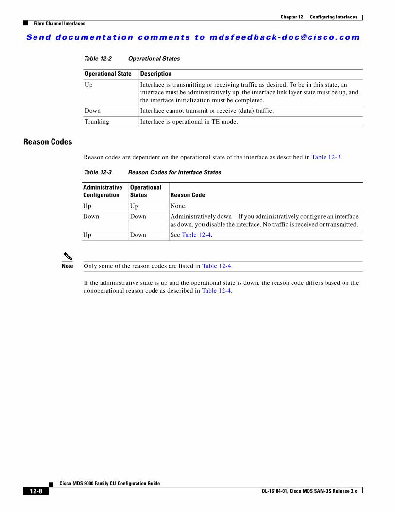
About SFP Transmitter TypesThe small form-factor pluggable (SFP) hardware transmitters are identified by their acronyms when displayed in the show interface brief command. If the related SFP has a Cisco-assigned extended ID, then the show interface and show interface brief commands display the ID instead of the transmitter type. The show interface transceiver command and the show interface fcslot/port transceiver command display both values for Cisco supported SFPs. Table 12-5 defines the acronyms used in the command output (see the “Displaying Interface Information” section on page 12-20).
Command Purpose
Step 1 switch# config t Enters configuration mode.
Step 2 switch(config)# no system default switchport shutdownswitch(config)#
Configures the default setting for administrative state of an interface as Up. (The factory default setting is Down).
Tip This command is applicable only to interfaces for which no user configuration exists for the administrative state.
switch(config)# system default switchport shutdownswitch(config)#
Configures the default setting for administrative state of an interface as Down. This is the factory default setting.
Tip This command is applicable only to interfaces for which no user configuration exists for the administrative state.
switch(config)# system default switchport trunk mode autoswitch(config)#
Configures the default setting for administrative trunk mode state of an interface as Auto.
Note The default setting is trunk mode on.
Table 12-5 SFP Transmitter Acronym Definitions
Definition Acronym
Standard transmitters defined in the GBIC specifications
short wave laser swl
long wave laser lwl
long wave laser cost reduced lwcr
electrical elec
Extended transmitters assigned to Cisco-supported SFPs
CWDM-1470 c1470
CWDM-1490 c1490
CWDM-1510 c1510
12-19Cisco MDS 9000 Family CLI Configuration Guide
OL-16184-01, Cisco MDS SAN-OS Release 3.x
Send documenta t ion comments to mdsfeedback -doc@c i sco .com
Chapter 12 Configuring InterfacesFibre Channel Interfaces
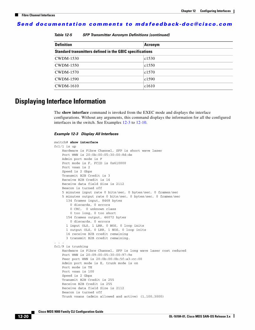
Displaying Interface InformationThe show interface command is invoked from the EXEC mode and displays the interface configurations. Without any arguments, this command displays the information for all the configured interfaces in the switch. See Examples 12-3 to 12-10.
Example 12-3 Display All Interfaces
switch# show interface fc1/1 is up Hardware is Fibre Channel, SFP is short wave laser Port WWN is 20:0b:00:05:30:00:8d:de Admin port mode is F Port mode is F, FCID is 0x610000 Port vsan is 2 Speed is 2 Gbps Transmit B2B Credit is 3 Receive B2B Credit is 16 Receive data field Size is 2112 Beacon is turned off 5 minutes input rate 0 bits/sec, 0 bytes/sec, 0 frames/sec 5 minutes output rate 0 bits/sec, 0 bytes/sec, 0 frames/sec 134 frames input, 8468 bytes 0 discards, 0 errors 0 CRC, 0 unknown class 0 too long, 0 too short 154 frames output, 46072 bytes 0 discards, 0 errors 1 input OLS, 1 LRR, 0 NOS, 0 loop inits 1 output OLS, 0 LRR, 1 NOS, 0 loop inits 16 receive B2B credit remaining 3 transmit B2B credit remaining.. . .fc1/9 is trunking Hardware is Fibre Channel, SFP is long wave laser cost reduced Port WWN is 20:09:00:05:30:00:97:9e Peer port WWN is 20:0b:00:0b:5f:a3:cc:00 Admin port mode is E, trunk mode is on Port mode is TE Port vsan is 100 Speed is 2 Gbps Transmit B2B Credit is 255 Receive B2B Credit is 255 Receive data field Size is 2112 Beacon is turned off Trunk vsans (admin allowed and active) (1,100,3000)
CWDM-1530 c1530
CWDM-1550 c1550
CWDM-1570 c1570
CWDM-1590 c1590
CWDM-1610 c1610
Table 12-5 SFP Transmitter Acronym Definitions (continued)
Definition Acronym
Standard transmitters defined in the GBIC specifications
12-20Cisco MDS 9000 Family CLI Configuration Guide
OL-16184-01, Cisco MDS SAN-OS Release 3.x

Send documenta t ion comments to mdsfeedback -doc@c i sco .com
Chapter 12 Configuring InterfacesFibre Channel Interfaces
Trunk vsans (up) (1,100,3000) Trunk vsans (isolated) () Trunk vsans (initializing) () 5 minutes input rate 280 bits/sec, 35 bytes/sec, 0 frames/sec 5 minutes output rate 176 bits/sec, 22 bytes/sec, 0 frames/sec 4609939 frames input, 8149405708 bytes 0 discards, 0 errors 0 CRC, 0 unknown class 0 too long, 0 too short 4638491 frames output, 7264731728 bytes 0 discards, 0 errors 3 input OLS, 9 LRR, 1 NOS, 0 loop inits 9 output OLS, 7 LRR, 1 NOS, 0 loop inits 16 receive B2B credit remaining 3 transmit B2B credit remaining.. . .fc1/13 is up Hardware is Fibre Channel, SFP is short wave laser Port WWN is 20:0d:00:05:30:00:97:9e Admin port mode is auto, trunk mode is on Port mode is F, FCID is 0x650100 Port vsan is 100 Speed is 2 Gbps Transmit B2B Credit is 3 Receive B2B Credit is 16 Receive data field Size is 2112 Beacon is turned off 5 minutes input rate 0 bits/sec, 0 bytes/sec, 0 frames/sec 5 minutes output rate 0 bits/sec, 0 bytes/sec, 0 frames/sec 8696 frames input, 3227212 bytes 0 discards, 0 errors 0 CRC, 0 unknown class 0 too long, 0 too short 16799 frames output, 6782444 bytes 0 discards, 0 errors 0 input OLS, 0 LRR, 0 NOS, 0 loop inits 1 output OLS, 1 LRR, 0 NOS, 1 loop inits 16 receive B2B credit remaining 3 transmit B2B credit remaining.. . .sup-fc0 is up Hardware is Fibre Channel Speed is 1 Gbps 139597 packets input, 13852970 bytes 0 multicast frames, 0 compressed 0 input errors, 0 frame, 0 overrun 0 fifo 139516 packets output, 16759004 bytes, 0 underruns 0 output errors, 0 collisions, 0 fifo 0 carrier errors
You can also specify arguments (a range of interfaces or multiple, specified interfaces) to display interface information. You can specify a range of interfaces by issuing a command with the following example format:
interface fc1/1 - 5 , fc2/5 - 7
Note The spaces are required before and after the dash ( - ) and before and after the comma ( , ).
Example 12-4 Display Multiple, Specified Interfaces
switch# show interface fc3/13 , fc3/16fc3/13 is up
12-21Cisco MDS 9000 Family CLI Configuration Guide
OL-16184-01, Cisco MDS SAN-OS Release 3.x

Send documenta t ion comments to mdsfeedback -doc@c i sco .com
Chapter 12 Configuring InterfacesFibre Channel Interfaces
Hardware is Fibre Channel, SFP is short wave laser Port WWN is 20:8d:00:05:30:00:97:9e Admin port mode is FX Port mode is F, FCID is 0x7b0300 Port vsan is 1 Speed is 2 Gbps Transmit B2B Credit is 3 Receive B2B Credit is 12 Receive data field Size is 2112 Beacon is turned off 5 minutes input rate 0 bits/sec, 0 bytes/sec, 0 frames/sec 5 minutes output rate 0 bits/sec, 0 bytes/sec, 0 frames/sec 1856 frames input, 116632 bytes 0 discards, 0 errors 0 CRC, 0 unknown class 0 too long, 0 too short 1886 frames output, 887712 bytes 0 discards, 0 errors 0 input OLS, 0 LRR, 0 NOS, 1 loop inits 1 output OLS, 1 LRR, 0 NOS, 1 loop inits 16 receive B2B credit remaining 3 transmit B2B credit remaining.
fc3/16 is up Hardware is Fibre Channel, SFP is short wave laser Port WWN is 20:90:00:05:30:00:97:9e Admin port mode is FX Port mode is F, FCID is 0x7d0100 Port vsan is 3000 Speed is 2 Gbps Transmit B2B Credit is 3 Receive B2B Credit is 12 Receive data field Size is 2112 Beacon is turned off 5 minutes input rate 504 bits/sec, 63 bytes/sec, 0 frames/sec 5 minutes output rate 520 bits/sec, 65 bytes/sec, 0 frames/sec 47050 frames input, 10311824 bytes 0 discards, 0 errors 0 CRC, 0 unknown class 0 too long, 0 too short 62659 frames output, 10676988 bytes 0 discards, 0 errors 0 input OLS, 0 LRR, 0 NOS, 0 loop inits 1 output OLS, 1 LRR, 0 NOS, 1 loop inits 16 receive B2B credit remaining 3 transmit B2B credit remaining.
Example 12-5 Display a Specific Interface
switch# show interface fc2/2fc2/2 is trunking Port description is Trunk to Core-4 Hardware is Fibre Channel, SFP is short wave laser Port WWN is 20:42:00:05:30:00:97:9e Peer port WWN is 20:cc:00:05:30:00:50:9e Admin port mode is E, trunk mode is on Port mode is TE Port vsan is 1 Speed is 2 Gbps Transmit B2B Credit is 255 Receive B2B Credit is 255 Receive data field Size is 2112 Beacon is turned off
12-22Cisco MDS 9000 Family CLI Configuration Guide
OL-16184-01, Cisco MDS SAN-OS Release 3.x

Send documenta t ion comments to mdsfeedback -doc@c i sco .com
Chapter 12 Configuring InterfacesFibre Channel Interfaces
Belongs to port-channel 2 Trunk vsans (admin allowed and active) (1,100,3000) Trunk vsans (up) (1) Trunk vsans (isolated) (100,3000) Trunk vsans (initializing) () 5 minutes input rate 0 bits/sec, 0 bytes/sec, 0 frames/sec 5 minutes output rate 32 bits/sec, 4 bytes/sec, 0 frames/sec 2214834 frames input, 98673588 bytes 0 discards, 0 errors 0 CRC, 0 unknown class 0 too long, 0 too short 2262415 frames output, 343158368 bytes 0 discards, 0 errors 1 input OLS, 1 LRR, 1 NOS, 0 loop inits 2 output OLS, 1 LRR, 0 NOS, 0 loop inits 16 receive B2B credit remaining 3 transmit B2B credit remaining.
Example 12-6 Displays Port Description
switch# show interface description-------------------------------------------------------------------------------Interface Description-------------------------------------------------------------------------------fc3/1 test intestfc3/2 --fc3/3 --fc3/4 TE portfc3/5 --fc3/6 --fc3/10 Next hop switch 5fc3/11 --fc3/12 --fc3/16 ---------------------------------------------------------------------------------Interface Description-------------------------------------------------------------------------------port-channel 1 --port-channel 5 --port-channel 6 --
Example 12-7 Display Interface Information in a Brief Format
switch# show interface brief
-------------------------------------------------------------------------------Interface Vsan Admin Admin Status SFP Oper Oper Port Mode Trunk Mode Speed Channel Mode (Gbps)-------------------------------------------------------------------------------fc1/1 1 E on trunking swl TE 2 1fc1/2 1 E on trunking swl TE 2 1fc1/3 1 auto on SFPAbsent -- -- --fc1/4 1 auto on SFPAbsent -- -- --fc1/5 3000 auto on up swl F 2 --...fc2/2 1 E on trunking swl TE 2 2fc2/3 1 auto on down c1610 -- --fc2/4 1 auto on down c1590 -- --fc2/5 3000 auto on notConnected lwcr -- --fc2/6 1 auto on SFPAbsent -- -- --...
12-23Cisco MDS 9000 Family CLI Configuration Guide
OL-16184-01, Cisco MDS SAN-OS Release 3.x

Send documenta t ion comments to mdsfeedback -doc@c i sco .com
Chapter 12 Configuring InterfacesFibre Channel Interfaces
fc3/16 3000 FX -- up swl F 2 --fc3/17 1 FX -- SFPAbsent -- -- --...-------------------------------------------------------------------------------Interface Status IP Address Speed MTU-------------------------------------------------------------------------------GigabitEthernet4/1 SFPAbsent -- auto 1500...GigabitEthernet4/6 down 10.1.1.2/8 auto 3000GigabitEthernet4/7 down 10.1.1.27/24 auto 1500GigabitEthernet4/8 down -- auto 1500
-------------------------------------------------------------------------------Interface Status Oper Mode Oper Speed (Gbps)-------------------------------------------------------------------------------iscsi4/1 down --...-------------------------------------------------------------------------------Interface Status Speed (Gbps)-------------------------------------------------------------------------------sup-fc0 up 1
-------------------------------------------------------------------------------Interface Status IP Address Speed MTU-------------------------------------------------------------------------------mgmt0 up 172.19.48.96/25 100 Mbps 1500
-------------------------------------------------------------------------------Interface Vsan Admin Status Oper Oper Trunk Mode Speed Mode (Gbps)-------------------------------------------------------------------------------port-channel 1 1 on trunking TE 4port-channel 2 1 on trunking TE 4
-------------------------------------------------------------------------------Interface Vsan Admin Admin Status Oper Profile Port-channel Mode Trunk Mode Mode-------------------------------------------------------------------------------fcip10 1 auto on notConnected -- 10 --
Example 12-8 Display Interface Counters
switch# show interface countersfc3/1 5 minutes input rate 24 bits/sec, 3 bytes/sec, 0 frames/sec 5 minutes output rate 16 bits/sec, 2 bytes/sec, 0 frames/sec 3502 frames input, 268400 bytes 0 discards, 0 CRC, 0 unknown class 0 too long, 0 too short 3505 frames output, 198888 bytes 0 discards 1 input OLS, 1 LRR, 1 NOS, 0 loop inits 2 output OLS, 1 LRR, 1 NOS, 0 loop inits 1 link failures, 1 sync losses, 1 signal losses...fc9/8 5 minutes input rate 0 bits/sec, 0 bytes/sec, 0 frames/sec
12-24Cisco MDS 9000 Family CLI Configuration Guide
OL-16184-01, Cisco MDS SAN-OS Release 3.x

Send documenta t ion comments to mdsfeedback -doc@c i sco .com
Chapter 12 Configuring InterfacesFibre Channel Interfaces
5 minutes output rate 0 bits/sec, 0 bytes/sec, 0 frames/sec 0 frames input, 0 bytes 0 class-2 frames, 0 bytes 0 class-3 frames, 0 bytes 0 class-f frames, 0 bytes 0 discards, 0 CRC, 0 unknown class 0 too long, 0 too short 0 frames output, 0 bytes 0 class-2 frames, 0 bytes 0 class-3 frames, 0 bytes 0 class-f frames, 0 bytes 0 discards 0 input OLS, 0 LRR, 0 NOS, 0 loop inits 0 output OLS, 0 LRR, 0 NOS, 0 loop inits 0 link failures, 0 sync losses, 0 signal losses 16 receive B2B credit remaining 3 transmit B2B credit remaining.. . .sup-fc0 114000 packets input, 11585632 bytes 0 multicast frames, 0 compressed 0 input errors, 0 frame, 0 overrun 0 fifo 113997 packets output, 10969672 bytes, 0 underruns 0 output errors, 0 collisions, 0 fifo 0 carrier errors
mgmt0 31557 packets input, 2230860 bytes 0 multicast frames, 0 compressed 0 input errors, 0 frame, 0 overrun 0 fifo 26618 packets output, 16824342 bytes, 0 underruns 0 output errors, 0 collisions, 7 fifo 0 carrier errors
vsan1 0 packets input, 0 bytes, 0 errors, 0 multicast 0 packets output, 0 bytes, 0 errors, 0 dropped...port-channel 1 5 minutes input rate 0 bits/sec, 0 bytes/sec, 0 frames/sec 5 minutes output rate 0 bits/sec, 0 bytes/sec, 0 frames/sec 0 frames input, 0 bytes 0 class-2 frames, 0 bytes 0 class-3 frames, 0 bytes 0 class-f frames, 0 bytes 0 discards, 0 CRC, 0 unknown class 0 too long, 0 too short 0 frames output, 0 bytes 0 class-2 frames, 0 bytes 0 class-3 frames, 0 bytes 0 class-f frames, 0 bytes 0 discards 0 input OLS, 0 LRR, 0 NOS, 0 loop inits 0 output OLS, 0 LRR, 0 NOS, 0 loop inits 0 link failures, 0 sync losses, 0 signal losses
Note Interfaces 9/8 and 9/9 are not trunking ports and display class 2, 3, and F information as well.
12-25Cisco MDS 9000 Family CLI Configuration Guide
OL-16184-01, Cisco MDS SAN-OS Release 3.x
Send documenta t ion comments to mdsfeedback -doc@c i sco .com
Chapter 12 Configuring InterfacesFibre Channel Interfaces
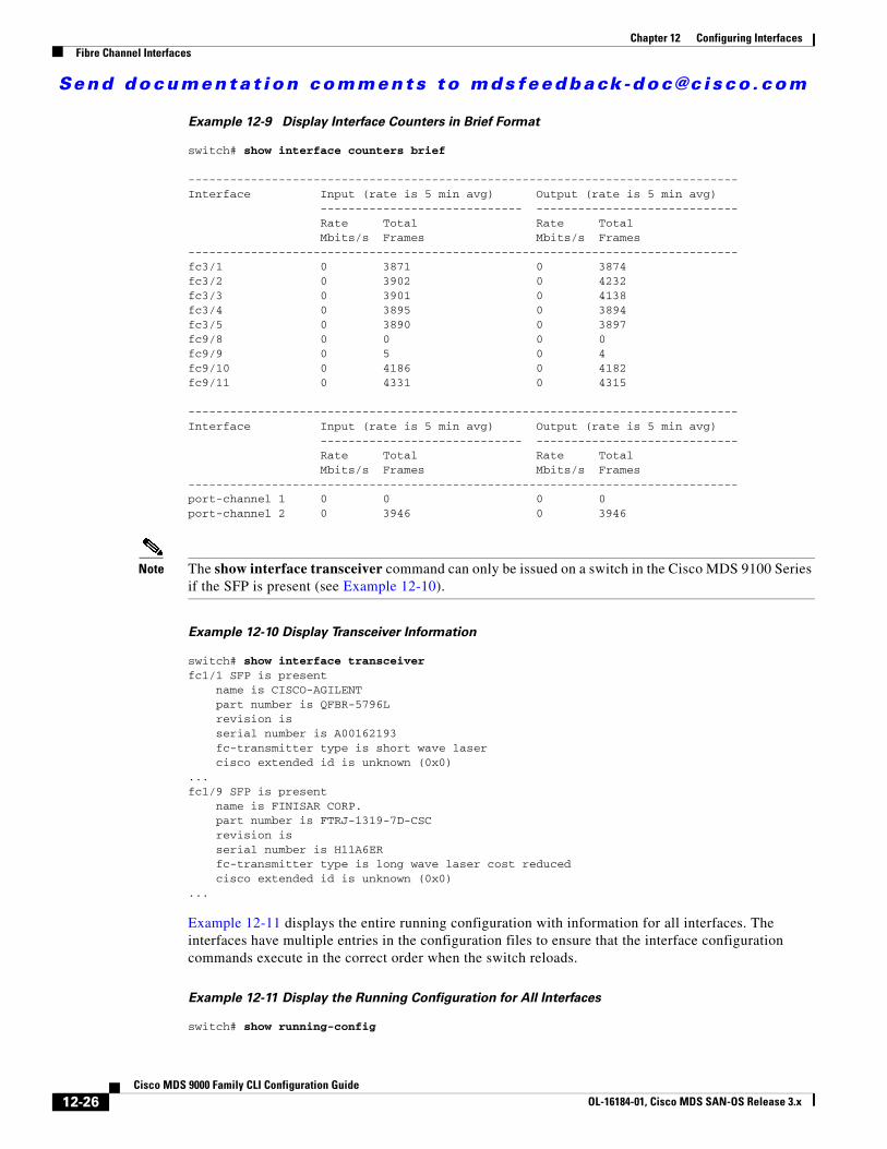
Example 12-9 Display Interface Counters in Brief Format
switch# show interface counters brief
-------------------------------------------------------------------------------Interface Input (rate is 5 min avg) Output (rate is 5 min avg) ----------------------------- ----------------------------- Rate Total Rate Total Mbits/s Frames Mbits/s Frames-------------------------------------------------------------------------------fc3/1 0 3871 0 3874fc3/2 0 3902 0 4232fc3/3 0 3901 0 4138fc3/4 0 3895 0 3894fc3/5 0 3890 0 3897fc9/8 0 0 0 0fc9/9 0 5 0 4fc9/10 0 4186 0 4182fc9/11 0 4331 0 4315
-------------------------------------------------------------------------------Interface Input (rate is 5 min avg) Output (rate is 5 min avg) ----------------------------- ----------------------------- Rate Total Rate Total Mbits/s Frames Mbits/s Frames-------------------------------------------------------------------------------port-channel 1 0 0 0 0port-channel 2 0 3946 0 3946
Note The show interface transceiver command can only be issued on a switch in the Cisco MDS 9100 Series if the SFP is present (see Example 12-10).
Example 12-10 Display Transceiver Information
switch# show interface transceiver fc1/1 SFP is present name is CISCO-AGILENT part number is QFBR-5796L revision is serial number is A00162193 fc-transmitter type is short wave laser cisco extended id is unknown (0x0)...fc1/9 SFP is present name is FINISAR CORP. part number is FTRJ-1319-7D-CSC revision is serial number is H11A6ER fc-transmitter type is long wave laser cost reduced cisco extended id is unknown (0x0)...
Example 12-11 displays the entire running configuration with information for all interfaces. The interfaces have multiple entries in the configuration files to ensure that the interface configuration commands execute in the correct order when the switch reloads.
Example 12-11 Display the Running Configuration for All Interfaces
switch# show running-config
12-26Cisco MDS 9000 Family CLI Configuration Guide
OL-16184-01, Cisco MDS SAN-OS Release 3.x

Send documenta t ion comments to mdsfeedback -doc@c i sco .com
Chapter 12 Configuring InterfacesFibre Channel Interfaces
...interface fc9/1 switchport speed 2000...interface fc9/1 switchport mode E ...interface fc9/1 channel-group 11 force no shutdown
Example 12-12 displays the running configuration information for a specified interface. The interface configuration commands are grouped together
Example 12-12 Display the Running Configuration for a Specified Interface
switch# show running-config interface fc1/1interface fc9/1 switchport speed 2000 switchport mode E channel-group 11 force no shutdown
Example 12-13 displays the running configuration after the system default switchport mode F command is executed. Example 12-14 displays the running configuration after two interfaces are individually configured for mode FL.
Example 12-13 Display the Running Configuration After the System Default Switchport Mode F
Command is Executed
switch# show running-configversion 3.1(3)system default switchport mode Finterface fc4/1interface fc4/2interface fc4/3interface fc4/4interface fc4/5interface fc4/6interface fc4/7interface fc4/8interface fc4/9interface fc4/10
Example 12-14 Display the Running Configuration After Two Interfaces Are Individually Configured for
Mode FL
switch# show running-configversion 3.1(3)system default switchport mode Finterface fc4/1 switchport mode FLinterface fc4/2interface fc4/3 switchport mode FLinterface fc4/4interface fc4/5interface fc4/6interface fc4/7interface fc4/8
12-27Cisco MDS 9000 Family CLI Configuration Guide
OL-16184-01, Cisco MDS SAN-OS Release 3.x

Send documenta t ion comments to mdsfeedback -doc@c i sco .com
Chapter 12 Configuring InterfacesTL Ports for Private Loops
interface fc4/9interface fc4/1
Example 12-15 displays interface information in a brief format after the system default switchport mode F command is executed. Example 12-16 displays interface information in a brief format after two interfaces are individually configured for mode FL.
Example 12-15 Display Interface Information in a Brief Format After the System Default Switchport
Mode F Command is Executed
switch# sh int brief-------------------------------------------------------------------------------Interface Vsan Admin Admin Status SFP Oper Oper Port Mode Trunk Mode Speed Channel Mode (Gbps)-------------------------------------------------------------------------------fc4/1 1 F -- notConnected swl -- --fc4/2 1 F -- notConnected swl -- --fc4/3 1 F -- notConnected swl -- --fc4/4 1 F -- notConnected swl -- --fc4/5 1 F -- sfpAbsent -- -- --fc4/6 1 F -- sfpAbsent -- -- --fc4/7 1 F -- sfpAbsent -- -- --fc4/8 1 F -- sfpAbsent -- -- --fc4/9 1 F -- sfpAbsent -- -- --
Example 12-16 Display Interface Information in a Brief Format After Two Interfaces Are Individually
Configured for Mode FL
switch# show interface brief
-------------------------------------------------------------------------------Interface Vsan Admin Admin Status SFP Oper Oper Port Mode Trunk Mode Speed Channel Mode (Gbps)-------------------------------------------------------------------------------fc4/1 1 FL -- notConnected swl -- --fc4/2 1 F -- notConnected swl -- --fc4/3 1 FL -- notConnected swl -- --fc4/4 1 F -- notConnected swl -- --fc4/5 1 F -- sfpAbsent -- -- --fc4/6 1 F -- sfpAbsent -- -- --fc4/7 1 F -- sfpAbsent -- -- --fc4/8 1 F -- sfpAbsent -- -- --fc4/9 1 F -- sfpAbsent -- -- --fc4/10 1 F -- sfpAbsent -- -- --
TL Ports for Private LoopsPrivate loops require setting the interface mode to TL. This section describes TL ports and includes the following sections:
• About TL Ports, page 12-29
• About TL Port ALPA Caches, page 12-30
• Displaying TL Port Information, page 12-30
• Manually Inserting Entries into ALPA Cache, page 12-32
12-28Cisco MDS 9000 Family CLI Configuration Guide
OL-16184-01, Cisco MDS SAN-OS Release 3.x

Send documenta t ion comments to mdsfeedback -doc@c i sco .com
Chapter 12 Configuring InterfacesTL Ports for Private Loops
• Displaying the ALPA Cache Contents, page 12-32
• Clearing the ALPA Cache, page 12-32
About TL PortsTL port mode is not supported on the following:
• Generation 2 switching module interfaces
• Cisco MDS 9124 Fabric Switch
• Cisco Fabric Switch for HP c-Class BladeSystem
• Cisco Fabric Switch for IBM BladeCenter
Private loop devices refer to legacy devices that reside on arbitrated loops. These devices are not aware of a switch fabric because they only communicate with devices on the same physical loop.
The legacy devices are used in Fibre Channel networks and devices outside the loop may need to communicate with them.The communication functionality is provided through TL ports. See the “About Interface Modes” section on page 12-3.
Follow these guidelines when configuring private loops:
• A maximum of 64 fabric devices can be proxied to a private loop.
• Fabric devices must be in the same zone as private loop devices to be proxied to the private loop.
• Each private device on a TL port may be included in a different zone.
• All devices on the loop are treated as private loops. You cannot mix private and public devices on the loop if the configured port mode is TL.
• The only FC4-type supported by TL ports is SCSI (FCP).
• Communication between a private initiator to a private target on the same private loop does not invoke TL port services.
Table 12-6 lists the TL port translations supported in Cisco MDS 9000 Family switches. Figure 12-4 shows examples of TL port translation support.
Table 12-6 Supported TL Port Translations
Translation from Translation to Example
Private initiator Private target From I1 to T1 or vice versa
Private initiator Public target — N port From I1 to T2 or vice versa
Private initiator Public target — NL port From I4 to T3 or vice versa
Public initiator — N port Private target From I2 to T1 or vice versa
Public initiator — NL port Private target From I3 to T1 or vice versa
12-29Cisco MDS 9000 Family CLI Configuration Guide
OL-16184-01, Cisco MDS SAN-OS Release 3.x

Send documenta t ion comments to mdsfeedback -doc@c i sco .com
Chapter 12 Configuring InterfacesTL Ports for Private Loops
Figure 12-4 TL Port Translation Support Examples
About TL Port ALPA CachesAlthough TL ports cannot be automatically configured, you can manually configure entries in arbitrated loop physical address (ALPA) caches. Generally, ALPA cache entries are automatically populated when an ALPA is assigned to a device. Each device is identified by its port world wide name (pWWN). When a device is allocated an ALPA, an entry for that device is automatically created in the ALPA cache.
A cache contains entries for recently allocated ALPA values. These caches are maintained on various TL ports. If a device already has an ALPA, the Cisco SAN-OS software attempts to allocate the same ALPA to the device each time. The ALPA cache is maintained in persistent storage and saves information across switch reboots. The maximum cache size is 1000 entries. If the cache is full, and a new ALPA is allocated, the Cisco SAN-OS software discards an inactive cache entry (if available) to make space for the new entry. See the “TL Port” section on page 12-5 for more information on TL ports.
Displaying TL Port InformationPrivate loop devices refer to legacy devices that reside on arbitrated loops. These devices are not aware of a switch fabric because they only communicate with devices on the same physical loop.
The legacy devices are used in Fibre Channel networks and devices outside the loop may need to communicate with them.The communication functionality is provided through TL ports.
Use the switchport mode command to configure a TL port (see the “Configuring Interface Modes” section on page 12-13).
NL port
NL port
NL port
NL port
NL port
N port
N port
F port
F portTL port
TL port
FL port
Privateloop
Privateloop
Publicloop
Privateinitiator (I4)
Privateinitiator (I1)
Publicinitiator (I2)
Publicinitiator (I3)
Publictarget (T2)
Privatetarget (T1)
Publictarget (3)
9169
9
12-30Cisco MDS 9000 Family CLI Configuration Guide
OL-16184-01, Cisco MDS SAN-OS Release 3.x

Send documenta t ion comments to mdsfeedback -doc@c i sco .com
Chapter 12 Configuring InterfacesTL Ports for Private Loops
The show tlport command displays the TL port interface configurations. This command provides a list of all TL ports configured in a switch and shows the associated VSAN, the FC ID for the port (only domain and area are valid), and the current operational state of the TL port (up or initializing). See Example 12-17 through Example 12-20.
Example 12-17 Displays the TL Ports in All VSANs
switch# show tlport list ------------------------------- Interface Vsan FC-ID State ------------------------- ------ fc1/16 1 0x420000 Init fc2/26 1 0x150000 Up
TL ports allow a private device (devices that physically reside on the loop) to see a fabric device and vice-versa by proxying fabric devices on the loop. Fabric devices are proxied by allocating each fabric device an ALPA on this loop.
In addition to these proxied devices, other virtual devices (local or remote domain controller addresses) are also allocated ALPAs on the loop. A switch reserves the ALPA for its own communication with private devices, and the switch acts as a SCSI initiator.
The first column in the output of the show tlport interface command is the ALPA identity of the device on the loop. The columns that follow include the port WWNs, the node WWNs for each device, the device as a SCSI initiator or target, and the real FC ID of the device.
Example 12-18 Displays the Detailed Information for a Specific TL Port
switch# show tlport interface fc1/16 all fc1/16 is up, vsan 1, FCID 0x420000 -------------------------------------------------------------------------------- alpa pWWN nWWN SCSI Type Device FC-ID -------------------------------------------------------------------------------- 0x01 20:10:00:05:30:00:4a:de 20:00:00:05:30:00:4a:de Initiator Proxied 0xfffc42 0x73 22:00:00:20:37:39:ae:54 20:00:00:20:37:39:ae:54 Target Private 0x420073 0xef 20:10:00:05:30:00:4a:de 20:00:00:05:30:00:4a:de Initiator Switch 0x0000ef
Example 12-19 Displays TL Port Information for Private Devices
switch# show tlport interface fc 1/16 private fc1/16 is up, vsan 1, FCID 0x420000 ------------------------------------------------------------------------ alpa pWWN nWWN SCSI Type FC-ID ------------------------------------------------------------------------ 0x73 22:00:00:20:37:39:ae:54 20:00:00:20:37:39:ae:54 Target 0x420073 0x74 22:00:00:20:37:38:d3:de 20:00:00:20:37:38:d3:de Target 0x420074
Example 12-20 Displays TL Port Information for Proxied Devices
switch# show tlport interface fc 1/16 proxied fc1/16 is up, vsan 1, FCID 0x420000 ------------------------------------------------------------------------ alpa pWWN nWWN SCSI Type FC-ID ------------------------------------------------------------------------ 0x01 20:10:00:05:30:00:4a:de 20:00:00:05:30:00:4a:de Initiator 0xfffc42 0x02 21:00:00:e0:8b:01:95:e7 20:00:00:e0:8b:01:95:e7 Initiator 0x420100
12-31Cisco MDS 9000 Family CLI Configuration Guide
OL-16184-01, Cisco MDS SAN-OS Release 3.x

Send documenta t ion comments to mdsfeedback -doc@c i sco .com
Chapter 12 Configuring InterfacesBuffer Credits
Manually Inserting Entries into ALPA CacheTo manually insert entries into the ALPA cache, follow these steps:
Displaying the ALPA Cache ContentsThe show tlport alpa-cache command displays the contents of the ALPA cache.
switch# show tlport alpa-cache---------------------------------------------------------alpa pWWN Interface---------------------------------------------------------0x02 22:00:00:20:37:46:09:bd fc1/20x04 23:00:00:20:37:46:09:bd fc1/2
The first entry indicates that if a device with a pWWN of 22:00:00:20:37:46:09:bd is exported on TL port fc1/2, then the pWWN is allocated an alpa 0x02 (if available).
Clearing the ALPA Cache The clear tlport alpa-cache command clears the entire content of the ALPA cache.
Buffer CreditsFibre Channel interfaces use buffer credits to ensure all packets are delivered to their destination. This section describes the different buffer credits available on the Cisco MDS Family switches and includes the following topics:
• About Buffer-to-Buffer Credits, page 12-32
• Configuring Buffer-to-Buffer Credits, page 12-33
• About Performance Buffers, page 12-34
• Configuring Performance Buffers, page 12-34
• About Extended BB_credits, page 12-34
• Configuring Extended BB_credits, page 12-36
• Displaying BB_Credit Information, page 12-37
About Buffer-to-Buffer CreditsBuffer-to-buffer credits (BB_credits) are a flow control mechanism to ensure that FC switches do not run out of buffers, because switches must not drop frames. BB_credits are negotiated on a per-hop basis.
Command Purpose
Step 1 switch# config t Enters configuration mode.
Step 2 switch(config)# tlport alpa-cache interface fc1/2 pwwn 22:00:00:20:37:46:09:bd alpa 0x02
Configures manual entries into the ALPA cache.
Step 3 switch(config)# tlport alpa-cache interface fc1/3 pwwn 22:00:00:20:37:46:09:bd
Removes this entry from the ALPA cache.
12-32Cisco MDS 9000 Family CLI Configuration Guide
OL-16184-01, Cisco MDS SAN-OS Release 3.x

Send documenta t ion comments to mdsfeedback -doc@c i sco .com
Chapter 12 Configuring InterfacesBuffer Credits
The receive BB_credit (fcrxbbcredit) value may be configured for each FC interface. In most cases, you do not need to modify the default configuration.
Note The receive BB_credit values depend on the module type and the port mode, as follows:
• For 16-port switching modules and full rate ports, the default value is 16 for Fx mode and 255 for E or TE modes. The maximum value is 255 in all modes. This value can be changed as required.
• For 32-port switching modules and host-optimized ports, the default value is 12 for Fx, E, and TE modes. These values cannot be changed.
• For Generation 2 switching modules, see the “Buffer Pools” section on page 14-8.
Note In the Cisco MDS 9100 Series, the left most groups of ports outlined in white (4 ports in the 9120 switch and 8 ports in the 9140 switch) are full line rate like the 16-port switching module. The other ports (16 ports in the 9120 switch and 32 ports in the 9140 switch) are host-optimized like the 32-port switching module. Each group of 4 host-optimized ports have the same rules as for the 32-port switching module.
Configuring Buffer-to-Buffer CreditsTo configure BB_credits for a Fibre Channel interface, follow these steps:
Command Purpose
Step 1 switch# config tswitch(config)#
Enters configuration mode.
Step 2 switch(config)# interface fc1/1switch(config-if)#
Selects a Fibre Channel interface and enters interface configuration submode.
Step 3 switch(config-if)# switchport fcrxbbcredit default
Applies the default operational value to the selected interface. The operational value depends on the port mode. The default values are assigned based on the port capabilities.
switch(config-if)# switchport fcrxbbcredit 5 Assigns a BB_credit of 5 to the selected interface. The range to assign BB_credits is between 1 and 255.
switch(config-if)# switchport fcrxbbcredit 5 mode E
Assigns this value if the port is operating in E or TE mode. The range to assign BB_credits is between 1 and 255.
switch(config-if)# switchport fcrxbbcredit 5 mode Fx
Assigns this value if the port is operating in F or FL mode. The range to assign BB_credits is between 1 and 255.
Step 4 switch(config-if# do show int fc1/1 fc1/1 is up ... 16 receive B2B credit remaining 3 transmit B2B credit remaining
Displays the receive and transmit BB_credit along with other pertinent interface information for this interface.
Note The BB_credit values are correct at the time the registers are read. They are useful to verify situations when the data traffic is slow.
12-33Cisco MDS 9000 Family CLI Configuration Guide
OL-16184-01, Cisco MDS SAN-OS Release 3.x

Send documenta t ion comments to mdsfeedback -doc@c i sco .com
Chapter 12 Configuring InterfacesBuffer Credits
About Performance Buffers
Note Performance buffers are not supported on the Cisco MDS 9124 Fabric Switch, the Cisco Fabric Switch for HP c-Class BladeSystem, and the Cisco Fabric Switch for IBM BladeCeter.
Regardless of the configured receive BB_credit value, additional buffers, called performance buffers, improve switch port performance. Instead of relying on the built-in switch algorithm, you can manually configure the performance buffer value for specific applications (for example, forwarding frames over FCIP interfaces).
For each physical Fibre Channel interface in any switch in the Cisco MDS 9000 Family, you can specify the amount of performance buffers allocated in addition to the configured receive BB_credit value.
The default performance buffer value is 0. If you use the default option, the built-in algorithm is used. If you do not specify this command, the default option is automatically used.
Configuring Performance BuffersTo configure performance buffers for a Fibre Channel interface, follow these steps:
Note Use the show interface bbcredit command to display performance buffer values and other BB_credit information.
About Extended BB_creditsYou can use the extended BB_credits flow control mechanism in addition to BB_credits for long haul links.
This section includes the following topics:
• Extended BB_credits on Generation 1 Switching Modules, page 12-35
• Extended BB_credits on Generation 2 Switching Modules, page 12-36
Command Purpose
Step 1 switch# config t Enters configuration mode.
Step 2 switch(config)# interface fc1/1switch(config-if)#
Selects a Fibre Channel interface and enters interface configuration submode.
Step 3 switch(config-if)# switchport fcrxbbcredit performance-buffers 45
Assigns a performance buffer of 45 to the selected interface. The value ranges from 1 to 145.
switch(config-if)# switchport fcrxbbcredit performance-buffers default
Reverts to the factory default of using the built-in algorithm.
12-34Cisco MDS 9000 Family CLI Configuration Guide
OL-16184-01, Cisco MDS SAN-OS Release 3.x

Send documenta t ion comments to mdsfeedback -doc@c i sco .com
Chapter 12 Configuring InterfacesBuffer Credits
Extended BB_credits on Generation 1 Switching Modules
The BB_credits feature allows you to configure up to 255 receive buffers on Generation 1 switching modules. To facilitate BB_credits for long haul links, you can configure up to 3,500 receive BB_credits on a Fibre Channel port on a Generation 1 switching module.
To use this feature on Generation 1 switching modules, you must meet the following requirements:
• Obtain the ENTERPRISE_PKG license (see Chapter 3, “Obtaining and Installing Licenses”).
• Configure this feature in any port of the full-rate 4-port group in either the Cisco MDS 9216i Switch or in the MPS-14/2 module (see Figure 12-5).
Figure 12-5 Port Group Support for the Extended BB_Credits Feature
The port groups that support extended credit configurations are as follows.
– Any one port in ports 1 to 4 (identified as Group 1 in Figure 12-1).
– Any one port in ports 5 to 8 (identified as Group 2 in Figure 12-1).
– Any one port in ports 9 to 12 (identified as Group 3 in Figure 12-1).
Note The last two Fibre Channel ports (port 13 and port 14) and the two Gigabit Ethernet ports do not support the extended BB_credits feature (see Figure 12-1).
• Explicitly enable this feature in the required Cisco MDS switch.
• Disable the remaining three ports in the 4-port group if you need to assign more than 2,400 BB_credits to the first port in the port group.
– If you assign less than 2,400 extended BB_credits to any one port in a port group, the remaining three ports in that port group can retain up to 255 BB_credits based on the port mode.
Note The receive BB_credit value for the remaining three ports depends on the port mode. The default value is 16 for the Fx mode and 255 for E or TE modes. The maximum value is 255 in all modes. This value can be changed as required without exceeding the maximum value of 255 BB_credits.
– If you assign more than 2,400 (up to a maximum of 3,500) extended BB_credits to the port in a port group, you must disable the other three ports.
• Be aware that changing the BB_credit value results in the port being disabled and then reenabled.
• Disable (explicitly) this feature if you need to nondisruptively downgrade to Cisco SAN-OS Release 1.3 or earlier. When you disable this feature, the existing extended BB_credit configuration is completely erased.
—SPEED LINK—
LINK-
—SPEEDLINK—
STATUS
1 5 6 7 8 9
LINK— —SPEED
10 11 12 13 142 3 4
1 2
LINK-
GIGABIT E THERNET
1204
79Group 1 Group 2 Group 3Extended credits
not supported
12-35Cisco MDS 9000 Family CLI Configuration Guide
OL-16184-01, Cisco MDS SAN-OS Release 3.x

Send documenta t ion comments to mdsfeedback -doc@c i sco .com
Chapter 12 Configuring InterfacesBuffer Credits
Note The extended BB_credit configuration takes precedence over the receive BB_credit and performance buffer configurations.
Extended BB_credits on Generation 2 Switching Modules
To use this feature on Generation 2 switching modules, you must meet the following requirements:
• Obtain the Enterprise package (ENTERPRISE_PKG) license (see Chapter 3, “Obtaining and Installing Licenses”).
• Configure this feature in any port on a Generation 2 switch module. See the Extended BB_Credits, page 14-15 for more information on extended BB_credits on Generation 2 switching modules.
Note Extended BB_credits are not supported on the Cisco MDS 9124 Fabric Switch.
Configuring Extended BB_creditsTo configure extended BB_credits for a MDS-14/2 interface, for a Generation 2 switching module interface (not including the Cisco MDS 9124 Fabric Switch), or for an interface in a Cisco MDS 9216i switch, follow these steps:
Command Purpose
Step 1 switch# config tswitch(config)#
Enters configuration mode.
Step 2 switch(config)# fcrxbbcredit extended enable Enables the extended BB_credits feature.
switch(config)# no fcrxbbcredit extended enable
Disables (default) the extended BB_credits feature.
Step 3 switch(config)# interface fc1/1switch(config-if)#
Selects a Fibre Channel interface and enters interface configuration submode.
Step 4 switch(config-if)# switchport fcrxbbcredit extended 1500
Applies the extended BB_credit value of 1,500 credits to the selected interface. The valid range is from 256 to 3,500 credits.
switch(config-if)# no switchport fcrxbbcredit extended 1500
Clears the configured extended BB_credit configuration for this port.
Step 5 switch# do show interface fc3/2 fc3/2 is trunkingHardware is Fibre Channel, SFP is short wave laser w/o OFC (SN) Port WWN is 20:82:00:05:30:00:2a:1e Peer port WWN is 20:42:00:0b:46:79:f1:80 Admin port mode is auto, trunk mode is on Port mode is TE Port vsan is 1 Speed is 2 Gbps Transmit B2B Credit is 255 Receive B2B Credit is 1500 Receive data field Size is 2112
...
Displays the receive and transmit BB_credit values along with other pertinent interface information for this interface if the interface is in the up state.
Note The receive BB_credit value reflects the extended BB_credit configuration, if applicable.
12-36Cisco MDS 9000 Family CLI Configuration Guide
OL-16184-01, Cisco MDS SAN-OS Release 3.x

Send documenta t ion comments to mdsfeedback -doc@c i sco .com
Chapter 12 Configuring InterfacesManagement Interfaces
Displaying BB_Credit InformationTo display the BB_credit information, use the show interface bbcredit command (see Example 12-21 and Example 12-22).
Example 12-21 Displays BB_credit Information
switch# show interface bbcredit fc2/1 is down (SFP not present)...fc2/17 is trunking Transmit B2B Credit is 255 Receive B2B Credit is 12 Receive B2B Credit performance buffers is 375 12 receive B2B credit remaining 255 transmit B2B credit remainingfc2/18 is down (SFP not present)fc2/19 is down (SFP not present)fc2/20 is down (SFP not present)fc2/21 is down (Link failure or not-connected)...fc2/31 is up Transmit B2B Credit is 0 Receive B2B Credit is 12 Receive B2B Credit performance buffers is 48 12 receive B2B credit remaining 0 transmit B2B credit remainingfc2/32 is down (Link failure or not-connected)
Example 12-22 Displays BB_credit Information for a Specified Fibre Channel Interface
switch# show interface fc2/31 bbcreditfc2/31 is up Transmit B2B Credit is 0 Receive B2B Credit is 12 Receive B2B Credit performance buffers is 48 12 receive B2B credit remaining 0 transmit B2B credit remaining
Management InterfacesYou can remotely configure the switch through the management interface (mgmt0). To configure a connection on the mgmt0 interface, you must configure either the IP version 4 (IPv4) parameters (IP address, subnet mask, and default gateway) or the IP version 6 (IPv6) parameters so that the switch is reachable.
This section describes the management interfaces and includes the following topics:
• About Management Interfaces, page 12-38
• Configuring Management Interfaces, page 12-38
• Displaying Management Interface Configuration, page 12-39
12-37Cisco MDS 9000 Family CLI Configuration Guide
OL-16184-01, Cisco MDS SAN-OS Release 3.x
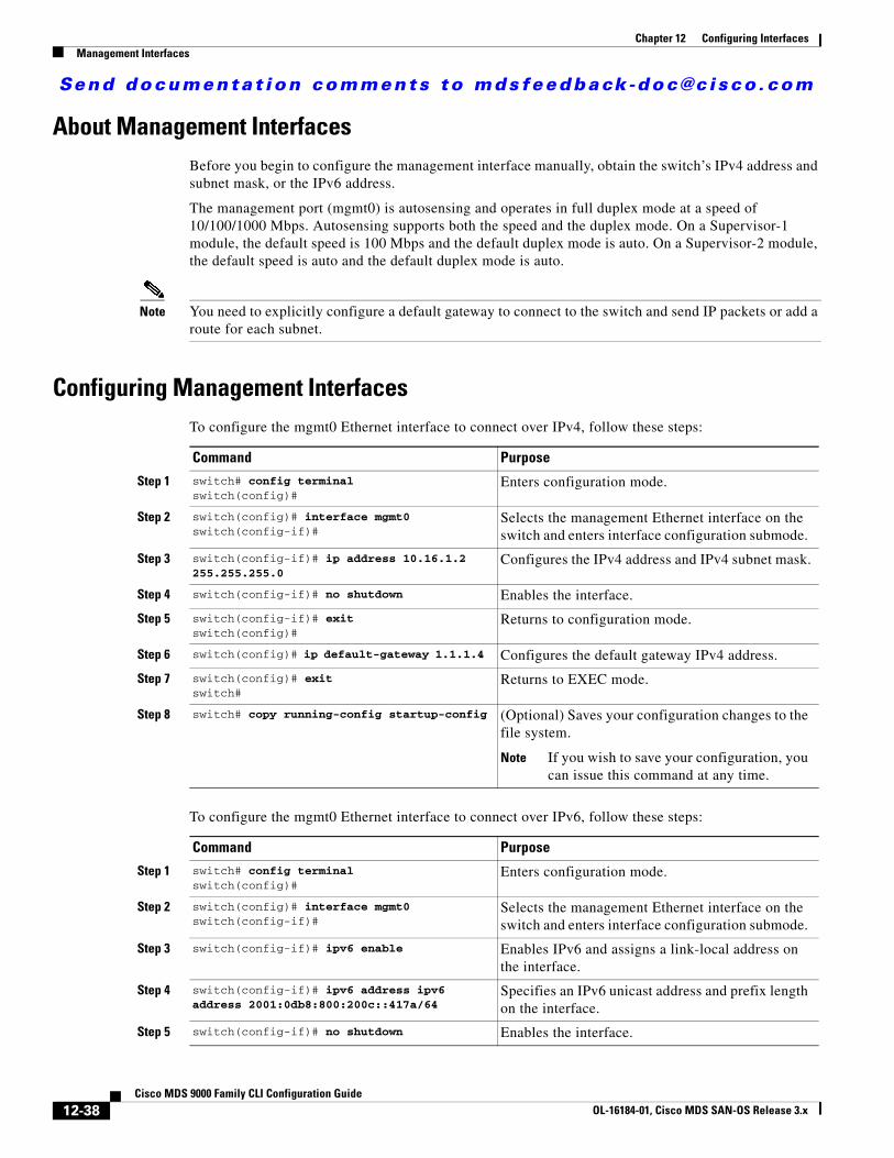
Send documenta t ion comments to mdsfeedback -doc@c i sco .com
Chapter 12 Configuring InterfacesManagement Interfaces
About Management InterfacesBefore you begin to configure the management interface manually, obtain the switch’s IPv4 address and subnet mask, or the IPv6 address.
The management port (mgmt0) is autosensing and operates in full duplex mode at a speed of 10/100/1000 Mbps. Autosensing supports both the speed and the duplex mode. On a Supervisor-1 module, the default speed is 100 Mbps and the default duplex mode is auto. On a Supervisor-2 module, the default speed is auto and the default duplex mode is auto.
Note You need to explicitly configure a default gateway to connect to the switch and send IP packets or add a route for each subnet.
Configuring Management InterfacesTo configure the mgmt0 Ethernet interface to connect over IPv4, follow these steps:
To configure the mgmt0 Ethernet interface to connect over IPv6, follow these steps:
Command Purpose
Step 1 switch# config terminalswitch(config)#
Enters configuration mode.
Step 2 switch(config)# interface mgmt0switch(config-if)#
Selects the management Ethernet interface on the switch and enters interface configuration submode.
Step 3 switch(config-if)# ip address 10.16.1.2 255.255.255.0
Configures the IPv4 address and IPv4 subnet mask.
Step 4 switch(config-if)# no shutdown Enables the interface.
Step 5 switch(config-if)# exitswitch(config)#
Returns to configuration mode.
Step 6 switch(config)# ip default-gateway 1.1.1.4 Configures the default gateway IPv4 address.
Step 7 switch(config)# exitswitch#
Returns to EXEC mode.
Step 8 switch# copy running-config startup-config (Optional) Saves your configuration changes to the file system.
Note If you wish to save your configuration, you can issue this command at any time.
Command Purpose
Step 1 switch# config terminalswitch(config)#
Enters configuration mode.
Step 2 switch(config)# interface mgmt0switch(config-if)#
Selects the management Ethernet interface on the switch and enters interface configuration submode.
Step 3 switch(config-if)# ipv6 enable Enables IPv6 and assigns a link-local address on the interface.
Step 4 switch(config-if)# ipv6 address ipv6 address 2001:0db8:800:200c::417a/64
Specifies an IPv6 unicast address and prefix length on the interface.
Step 5 switch(config-if)# no shutdown Enables the interface.
12-38Cisco MDS 9000 Family CLI Configuration Guide
OL-16184-01, Cisco MDS SAN-OS Release 3.x

Send documenta t ion comments to mdsfeedback -doc@c i sco .com
Chapter 12 Configuring InterfacesVSAN Interfaces
Displaying Management Interface ConfigurationTo display the management interface configuration, use the show interface mgmt 0 command.
switch# show interface mgmt 0mgmt0 is up Hardware is FastEthernet Address is 000c.30d9.fdbc Internet address is 10.16.1.2/24 MTU 1500 bytes, BW 100 Mbps full Duplex 26388 packets input, 6101647 bytes 0 multicast frames, 0 compressed 0 input errors, 0 frame, 0 overrun 0 fifo 10247 packets output, 2389196 bytes, 0 underruns 0 output errors, 0 collisions, 0 fifo 0 carrier errors
VSAN InterfacesVSANs apply to Fibre Channel fabrics and enable you to configure multiple isolated SAN topologies within the same physical infrastructure. You can create an IP interface on top of a VSAN and then use this interface to send frames to this VSAN. To use this feature, you must configure the IP address for this VSAN. VSAN interfaces cannot be created for nonexisting VSANs.
This section describes VSAN interfaces and includes the following topics:
• About VSAN Interfaces, page 12-39
• Creating VSAN Interfaces, page 12-40
• Displaying VSAN Interface Information, page 12-40
About VSAN InterfacesFollow these guidelines when creating or deleting VSAN interfaces:
• Create a VSAN before creating the interface for that VSAN. If a VSAN does not exist, the interface cannot be created.
• Create the interface VSAN—it is not created automatically.
• If you delete the VSAN, the attached interface is automatically deleted.
• Configure each interface only in one VSAN.
Step 6 switch(config-if)# endswitch#
Returns to EXEC mode.
Step 7 switch# copy running-config startup-config (Optional) Saves your configuration changes to the file system.
Note If you wish to save your configuration, you can issue this command at any time.
Command Purpose
12-39Cisco MDS 9000 Family CLI Configuration Guide
OL-16184-01, Cisco MDS SAN-OS Release 3.x

Send documenta t ion comments to mdsfeedback -doc@c i sco .com
Chapter 12 Configuring InterfacesDefault Settings
Tip After configuring the VSAN interface, you can configure an IP address or Virtual Router Redundancy Protocol (VRRP) feature (see Chapter 43, “Configuring IP Services”).
Creating VSAN Interfaces To create a VSAN interface, follow these steps:
Displaying VSAN Interface InformationTo display VSAN interface information, use the show interface vsan command.
switch# show interface vsan 2vsan2 is up, line protocol is up WWPN is 10:00:00:05:30:00:59:1f, FCID is 0xb90100 Internet address is 10.1.1.1/24 MTU 1500 bytes, BW 1000000 Kbit 0 packets input, 0 bytes, 0 errors, 0 multicast 0 packets output, 0 bytes, 0 errors, 0 dropped
Default SettingsTable 12-7 lists the default settings for interface parameters.
Command Purpose
Step 1 switch# config t Enters configuration mode.
Step 2 switch(config)# interface vsan 2switch(config-if)#
Configures a VSAN with the ID 2.
Step 3 switch(config-if)# no shutdown Enables the VSAN interface.
Table 12-7 Default Interface Parameters
Parameters Default
Interface mode Auto
Interface speed Auto
Administrative state Shutdown (unless changed during initial setup)
Trunk mode On (unless changed during initial setup)
Trunk-allowed VSANs 1 to 4093
Interface VSAN Default VSAN (1)
Beacon mode Off (disabled)
EISL encapsulation Disabled
Data field size 2112 bytes
12-40Cisco MDS 9000 Family CLI Configuration Guide
OL-16184-01, Cisco MDS SAN-OS Release 3.x