Cisco MDS 9000 Series NX-OS Interfaces Configuration Guide
308
Cisco MDS 9000 Series NX-OS Interfaces Configuration Guide Americas Headquarters Cisco Systems, Inc. 170 West Tasman Drive San Jose, CA 95134-1706 USA http://www.cisco.com Tel: 408 526-4000 800 553-NETS (6387) Fax: 408 527-0883
-
Upload
khangminh22 -
Category
Documents
-
view
0 -
download
0
Transcript of Cisco MDS 9000 Series NX-OS Interfaces Configuration Guide

Cisco MDS 9000 Series NX-OS Interfaces Configuration GuideAmericas HeadquartersCisco Systems, Inc.170 West Tasman DriveSan Jose, CA 95134-1706USAhttp://www.cisco.comTel: 408 526-4000
800 553-NETS (6387)Fax: 408 527-0883

© 2019 Cisco Systems, Inc. All rights reserved.

C O N T E N T S
Preface xvP R E F A C E
Preface xv
Audience xv
Document Conventions xv
Related Documentation xvi
Communications, Services, and Additional Information xvi
New and Changed Information 1C H A P T E R 1
Interface Overview 3C H A P T E R 2
Finding Feature Information 4
Trunks and PortChannels 5
Fibre Channel Port Rate Limiting 6
Maximum NPIV Limit 7
Extended Credits 8
N Port Virtualization 9
FlexAttach 10
Configuring Interfaces 11C H A P T E R 3
Finding Feature Information 12
Information About Interfaces 13
Interface Description 13
Interface Modes 13
E Port 14
F Port 14
FL Port 14
Cisco MDS 9000 Series NX-OS Interfaces Configuration Guideiii

NP Ports 14
TE Port 14
TF Port 15
TNP Port 15
SD Port 15
ST Port 15
Fx Port 16
B Port 16
Auto Mode 16
Interface States 16
Administrative States 16
Operational States 17
Reason Codes 17
Graceful Shutdown 19
10-Gbps Fiber Channel Mode 20
Benefits of 10-Gbps Fiber Channel Mode 20
Supported Modules and Switches 20
Port Administrative Speeds 22
Autosensing 22
Frame Encapsulation 23
Bit Error Rate Thresholds 23
Disabling the Bit Error Rate Threshold 23
SFP Transmitter Types 24
Portguard 25
Port Level Portguard 25
Port Monitor Portguard 26
Port Monitor 27
Warning Threshold 31
Port Monitor Check Interval 33
Port Group Monitor 33
Local Switching 34
Interface Types 35
Management Interfaces 35
VSAN Interfaces 35
Cisco MDS 9000 Series NX-OS Interfaces Configuration Guideiv
Contents

Prerequisites for Interfaces 36
Guidelines and Limitations 37
Guidelines for Configuring Port Monitor Check Interval 37
Guidelines for Local Switching 39
Guidelines for 10-Gbps Fibre Channel Mode 39
Guidelines for VSAN Interface Configuration 39
Default Settings 41
Configuring Interfaces 42
Configuring a Fibre Channel Interface 42
Configuring a Range of Fibre Channel Interfaces 42
Setting the Interface Administrative State 42
Shutting Down an Interface 43
Enabling Traffic Flow 43
Configuring an Interface Mode 43
Configuring the MAX NPIV Limit 44
Configuring the System Default F Port Mode 44
Configuring ISL Between Two Switches 45
Configuring the 10-G bps Fiber Channel Mode via the CLI 46
Configuring the 10-Gbps Fibre Channel Mode via the Device Manager 47
Configuring the Port Administrative Speeds 47
Configuring Port Speed Group 48
Enabling 10-Gbps Speed Mode 48
Configuring the Interface Description 49
Specifying a Port Owner 49
Configuring Beacon Mode 50
Configuring a Switch Port Attribute Default Value 51
Configuring the Port-Level Portguard 51
Configuring a Port Monitor 53
Enabling a Port Monitor 53
Configuring the Check Interval 54
Configuring a Port Monitor Policy 54
Activating a Port Monitor Policy 55
Configuring Port Monitor Portguard 56
Configuring Port Group Monitor 57
Cisco MDS 9000 Series NX-OS Interfaces Configuration Guidev
Contents

Enabling a Port Group Monitor 57
Configuring a Port Group Monitor Policy 57
Reverting to the Default Policy for a Specific Counter 58
Turning Off Specific Counter Monitoring 58
Activating a Port Group Monitor Policy 59
Configuring Management Interfaces 59
Configuring the Management Interface Over IPv4 59
Configuring the Management Interface Over IPv6 60
Creating VSAN Interfaces 60
Verifying Interfaces Configuration 62
Displaying Interface Information 62
Displaying the Port-Level Portguard 71
Displaying Port Monitor Status and Policies 71
Displaying Port Group Monitor Status and Policies 77
Displaying the Management Interface Configuration 78
Displaying VSAN Interface Information 78
Transmit-Wait History Graph 80
Configuring Fibre Channel Interfaces 83C H A P T E R 4
Finding Feature Information 84
Information About Fibre Channel Interfaces 85
Generations of Modules and Switches 85
Port Groups 87
Port Rate Modes 89
Dedicated Rate Mode 90
Shared Rate Mode 91
Dedicated Rate Mode Configurations for the 8-Gbps Modules 92
Port Speed 93
Forward Error Correction 93
Dynamic Bandwidth Management 94
Out-of-Service Interfaces 94
Oversubscription Ratio Restrictions 95
Bandwidth Fairness 101
Upgrade or Downgrade Scenario 102
Cisco MDS 9000 Series NX-OS Interfaces Configuration Guidevi
Contents

Guidelines and Limitations 103
Combining Generation 1, Generation 2, Generation 3, and Generation 4 Modules 103
Local Switching Limitations 103
Port Index Limitations 103
PortChannel Limitations 106
Default Settings 111
Configuring Fibre Channel Interfaces 113
Task Flow for Migrating Interfaces from Shared Mode to Dedicated Mode 113
Task Flow for Migrating Interfaces from Dedicated Mode to Shared Mode 114
Task Flow for Configuring 4-Port 10-Gbps Module Interfaces 114
Configuring Port Speed 115
Configuring FEC 116
Configuring Rate Mode 118
Displaying the Rate Mode Configuration for Interfaces 118
Configuring Local Switching 123
Disabling Restrictions on Oversubscription Ratios 124
Examples 124
Enabling Restrictions on Oversubscription Ratios 127
Enabling Bandwidth Fairness 128
Disabling Bandwidth Fairness 128
Taking Interfaces out of Service 129
Releasing Shared Resources in a Port Group 130
Disabling ACL Adjacency Sharing for System Image Downgrade 131
Verifying Fibre Channel Interfaces Configuration 132
Displaying Interface Capabilities 132
Displaying SFP Diagnostic Information 133
Configuration Examples for Fibre Channel Interfaces 134
Configuration Example for FEC Module Interfaces 134
Configuration Example for 48-Port 8-Gbps Module Interfaces 134
Configuration Example for 24-Port 8-Gbps Module Interfaces 136
Configuration Example for 4/44-Port 8-Gbps Module Interfaces 137
Configuration Example for 48-Port 4-Gbps Module Interfaces 138
Configuration Example for 24-Port 4-Gbps Module Interfaces 140
Cisco MDS 9000 Series NX-OS Interfaces Configuration Guidevii
Contents

Configuring Interface Buffers 141C H A P T E R 5
Finding Feature Information 142
Information About Interface Buffers 143
Buffer-to-Buffer Credits 143
Performance Buffers 143
Buffer Pools 144
Buffer-to-Buffer Credit Buffers for Switching Modules 146
Configuring Buffer Credits on a 4-Gbps, 8-Gbps, or Advanced 8-Gbps Module 146
48-Port 16-Gbps Fibre Channel Module Buffer-to-Buffer Credit Buffers 147
48-Port 8-Gbps Advanced Fibre Channel Module Buffer-to-Buffer Credit Buffers 148
48-Port 8-Gbps Fibre Channel Module Buffer-to-Buffer Credit Buffers 149
24-Port 8-Gbps Fibre Channel Module Buffer-to-Buffer Credit Buffers 150
4/44-Port 8-Gbps Host-Optimized Fibre Channel Module Buffer-to-Buffer Credit Buffers 151
48-Port 4-Gbps Fibre Channel Module Buffer-to-Buffer Credit Buffers 152
24-Port 4-Gbps Fibre Channel Module Buffer-to-Buffer Credit Buffers 155
18-Port Fibre Channel/4-Port Gigabit Ethernet Multiservice Module Buffer-to-Buffer CreditBuffers 156
12-Port 4-Gbps Switching Module Buffer-to-Buffer Credit Buffers 157
4-Port 10-Gbps Switching Module Buffer-to-Buffer Credit Buffers 158
Buffer-to-Buffer Credit Buffers for Fabric Switches 159
Cisco MDS 9396S Fabric Switch Buffer-to-Buffer Credit Buffers 159
Cisco MDS 9250i and Cisco MDS 9148S Fabric Switch Buffer-to-Buffer Credit Buffers 160
Cisco MDS 9148 Fabric Switch Buffer-to-Buffer Credit Buffers 161
Cisco MDS 9134 Fabric Switch Buffer-to-Buffer Credit Buffers 161
Cisco MDS 9124 Fabric Switch Buffer-to-Buffer Credit Buffers 162
Cisco MDS 9222i Multiservice Modular Switch Buffer-to-Buffer Credit Buffers 163
Extended Buffer-to-Buffer Credits 163
Extended Buffer-to-Buffer Credits on Generation 1 Switching Modules 164
Extended Buffer-to-Buffer Credits on 4-Gbps and 8-Gbps Switching Modules 165
Buffer-to-Buffer Credit Recovery 165
Receive Data Field Size 167
Configuring Interface Buffers 168
Configuring Buffer-to-Buffer Credits 168
Cisco MDS 9000 Series NX-OS Interfaces Configuration Guideviii
Contents

Configuring Performance Buffers 168
Configuring Extended Buffer-to-Buffer Credits 169
Configuring Buffer-to-Buffer Credit Recovery 169
Configuring Receive Data Field Size 170
Configuration Examples for Interface Buffers 171
Verifying Interface Buffer Configuration 173
Troubleshooting Interface Buffer Credits 175
Congestion Avoidance 177C H A P T E R 6
Finding Feature Information 178
Feature History for Congestion Avoidance 179
Information About Congestion Avoidance 180
Configuring Congestion Avoidance 181
Configuring the Congestion Drop Timeout Value for FCoE 181
Configuring Pause Drop Timeout for FCoE 182
Configuring the Congestion Drop Timeout Value for Fibre Channel 183
Configuring the No-Credit Frame Timeout Value for Fibre Channel 183
Configuring the Slow-Port Monitor Timeout Value for Fibre Channel 184
Displaying Credit Loss Recovery Actions 185
Configuring the Transmit Average Credit-Not-Available Duration Threshold and Action in PortMonitor 186
Configuration Examples for Congestion Avoidance 188
Verifying Configuration Examples for Slow Drain Device Detection and Congestion Avoidance 190
Displaying the Congestion Frame Timeout Value for FCoE 190
Displaying the Pause Frame Timeout Value for FCoE 190
Displaying the Congestion Drop Timeout Value for Fibre Channel 190
Displaying the No-Credit Frame Timeout Value for Fibre Channel 190
Verifying Congestion Detection and Avoidance 191
Configuring Trunking 197C H A P T E R 7
Finding Feature Information 198
Information About Trunking 199
Trunking E Ports 199
Trunking F Ports 199
Cisco MDS 9000 Series NX-OS Interfaces Configuration Guideix
Contents

Key Concepts 200
Trunking Protocols 201
Trunk Modes 202
Trunk-Allowed VSAN Lists and VF_IDs 202
Guidelines and Limitations 205
General Guidelines and Limitations 205
Upgrade and Downgrade Limitations 205
Difference Between TE Ports and TF-TNP Ports 206
Trunking Misconfiguration Examples 207
Default Settings 209
Configuring Trunking 210
Enabling the Cisco Trunking and Channeling Protocols 210
Enabling the F Port Trunking and Channeling Protocol 210
Configuring Trunk Mode 210
Configuring an Allowed-Active List of VSANs 211
Verifying Trunking Configuration 212
Configuration Example for F Port Trunking 214
Configuring PortChannels 217C H A P T E R 8
Finding Feature Information 218
Information About PortChannels 219
PortChannels Overview 219
E PortChannels 219
F and TF PortChannels 220
PortChanneling and Trunking 220
Load Balancing 221
PortChannel Modes 223
PortChannel Deletion 224
Interfaces in a PortChannel 224
Interface Addition to a PortChannel 225
Forcing an Interface Addition 226
Interface Deletion from a PortChannel 226
PortChannel Protocols 226
Channel Group Creation 227
Cisco MDS 9000 Series NX-OS Interfaces Configuration Guidex
Contents

Autocreation 228
Manually Configured Channel Groups 229
Prerequisites for PortChannels 230
Default Settings 231
Guidelines and Limitations 232
General Guidelines and Limitations 232
Generation 1 PortChannel Limitations 232
F and TF PortChannel Limitations 232
Valid and Invalid PortChannel Examples 233
Configuring PortChannels 235
Configuring PortChannels Using the Wizard Creating a PortChannel 235
Configuring the PortChannel Mode 235
Deleting PortChannels 235
Adding an Interface to a PortChannel 236
Adding a Range of Ports to a PortChannel 236
Forcing an Interface Addition 237
Deleting an Interface From a PortChannel 237
Enabling and Configuring Autocreation 237
Converting to Manually Configured Channel Groups 238
Verifying PortChannel Configuration 239
Configuration Examples for F and TF PortChannels 244
Configuration Examples for F and TF PortChannels (Dedicated Mode) 246
Configuring N Port Virtualization 249C H A P T E R 9
Finding Feature Information 250
Information About N Port Virtualization 251
NPV Overview 251
N Port Identifier Virtualization 251
N Port Virtualization 252
NPV Mode 253
NP Ports 255
NP Links 255
Internal FLOGI Parameters 255
Default Port Numbers 257
Cisco MDS 9000 Series NX-OS Interfaces Configuration Guidexi
Contents

NPV CFS Distribution over IP 257
NPV Traffic Management 257
Auto 257
Traffic Map 257
Disruptive 257
Multiple VSAN Support 258
Guidelines and Limitations 259
NPV Guidelines and Requirements 259
NPV Traffic Management Guidelines 259
DPVM Configuration Guidelines 260
NPV and Port Security Configuration Guidelines 260
Connecting an NPIV-Enabled Cisco MDS Fabric Switch 260
Configuring N Port Virtualization 262
Enabling N Port Identifier Virtualization 262
Configuring NPV 262
Configuring NPV Traffic Management 264
Configuring List of External Interfaces per Server Interface 264
Enabling the Global Policy for Disruptive Load Balancing 264
Verifying NPV Configuration 266
Verifying NPV 266
Verifying NPV Traffic Management 268
Configuring FlexAttach Virtual pWWN 269C H A P T E R 1 0
Finding Feature Information 270
Information About FlexAttach Virtual pWWN 271
FlexAttach Virtual pWWN 271
Difference Between San Device Virtualization and FlexAttach Port Virtualization 271
FlexAttach Virtual pWWN CFS Distribution 272
Security Settings for FlexAttach Virtual pWWN 272
Guidelines and Limitations 273
Configuring FlexAttach Virtual pWWN 274
Automatically Assigning FlexAttach Virtual pWWN 274
Manually Assigning FlexAttach Virtual pWWN 274
Mapping pWWN to Virtual pWWN 275
Cisco MDS 9000 Series NX-OS Interfaces Configuration Guidexii
Contents

Verifying FlexAttach Virtual pWWN Configuration 277
Verifying the End Device 277
Monitoring FlexAttach Virtual pWWN 278
Configuring Port Tracking 279C H A P T E R 1 1
Finding Feature Information 280
Information About Port Tracking 281
Guidelines and Limitations 282
Default Settings 283
Configuring Port Tracking 284
Enabling Port Tracking 284
Information About Configuring Linked Ports 284
Binding a Tracked Port Operationally 284
Information About Tracking Multiple Ports 285
Tracking Multiple Ports 285
Information About Monitoring Ports in a VSAN 286
Monitoring Ports in a VSAN 286
Information AboutForceful Shutdown 287
Forcefully Shutting Down a Tracked Port 287
Verifying Port Tracking Configuration 288
Cisco MDS 9000 Series NX-OS Interfaces Configuration Guidexiii
Contents

Cisco MDS 9000 Series NX-OS Interfaces Configuration Guidexiv
Contents

Preface
• Preface, on page xv• Audience, on page xv• Document Conventions, on page xv• Related Documentation, on page xvi• Communications, Services, and Additional Information, on page xvi
PrefaceThis preface describes the audience, organization of, and conventions used in the Cisco MDS 9000 SeriesConfiguration Guides. It also provides information on how to obtain related documentation, and contains thefollowing chapters:
AudienceTo use this installation guide, you need to be familiar with electronic circuitry and wiring practices, andpreferably be an electronic or electromechanical technician.
Document ConventionsThis document uses the following conventions:
Means reader take note. Notes contain helpful suggestions or references to material not covered in the manual.Note
Means reader be careful. In this situation, you might do something that could result in equipment damage orloss of data.
Caution
Warnings use the following conventions:
Cisco MDS 9000 Series NX-OS Interfaces Configuration Guidexv

This warning symbol means danger. You are in a situation that could cause bodily injury. Before you workon any equipment, be aware of the hazards involved with electrical circuitry and be familiar with standardpractices for preventing accidents. Use the statement number provided at the end of each warning to locateits translation in the translated safety warnings that accompanied this device. Statement 1071.
Warning
Related DocumentationThe documentation set for the Cisco MDS 9000 Series Switches includes the following documents.
Release Notes
http://www.cisco.com/c/en/us/support/storage-networking/mds-9000-nx-os-san-os-software/products-release-notes-list.html
Regulatory Compliance and Safety Information
http://www.cisco.com/c/en/us/td/docs/switches/datacenter/mds9000/hw/regulatory/compliance/RCSI.html
Compatibility Information
http://www.cisco.com/c/en/us/support/storage-networking/mds-9000-nx-os-san-os-software/products-device-support-tables-list.html
Installation and Upgrade
http://www.cisco.com/c/en/us/support/storage-networking/mds-9000-nx-os-san-os-software/products-installation-guides-list.html
Configuration
http://www.cisco.com/c/en/us/support/storage-networking/mds-9000-nx-os-san-os-software/products-installation-and-configuration-guides-list.html
CLI
http://www.cisco.com/c/en/us/support/storage-networking/mds-9000-nx-os-san-os-software/products-command-reference-list.html
Troubleshooting and Reference
http://www.cisco.com/c/en/us/support/storage-networking/mds-9000-nx-os-san-os-software/tsd-products-support-troubleshoot-and-alerts.html
To find a document online, use the Cisco MDS NX-OS Documentation Locator at:
http://www.cisco.com/c/en/us/td/docs/storage/san_switches/mds9000/roadmaps/doclocater.html
Communications, Services, and Additional Information• To receive timely, relevant information from Cisco, sign up at Cisco Profile Manager.
• To get the business impact you’re looking for with the technologies that matter, visit Cisco Services.
• To submit a service request, visit Cisco Support.
Cisco MDS 9000 Series NX-OS Interfaces Configuration Guidexvi
PrefaceRelated Documentation

• To discover and browse secure, validated enterprise-class apps, products, solutions and services, visitCisco Marketplace.
• To obtain general networking, training, and certification titles, visit Cisco Press.
• To find warranty information for a specific product or product family, access Cisco Warranty Finder.
Cisco Bug Search Tool
Cisco Bug Search Tool (BST) is a web-based tool that acts as a gateway to the Cisco bug tracking systemthat maintains a comprehensive list of defects and vulnerabilities in Cisco products and software. BST providesyou with detailed defect information about your products and software.
Cisco MDS 9000 Series NX-OS Interfaces Configuration Guidexvii
PrefacePreface

Cisco MDS 9000 Series NX-OS Interfaces Configuration Guidexviii
PrefacePreface

New and Changed Information
There are no new features in the Cisco MDS 9000 Series NX-OS Interfaces Configuration Guide for CiscoMDS NX-OS Release 7.3(0)D1(1).
Cisco MDS 9000 Series NX-OS Interfaces Configuration Guide1

Cisco MDS 9000 Series NX-OS Interfaces Configuration Guide2
New and Changed Information

Interface Overview
This chapter provides an overview of the interfaces and its features.
• Finding Feature Information, on page 4• Trunks and PortChannels, on page 5• Fibre Channel Port Rate Limiting, on page 6• Maximum NPIV Limit, on page 7• Extended Credits, on page 8• N Port Virtualization, on page 9• FlexAttach, on page 10
Cisco MDS 9000 Series NX-OS Interfaces Configuration Guide3

Finding Feature InformationYour software release might not support all the features documented in this module. For the latest caveatsand feature information, see the Bug Search Tool at https://tools.cisco.com/bugsearch/ and the release notesfor your software release. To find information about the features documented in this module, and to see a listof the releases in which each feature is supported, see the New and Changed chapter or the Feature Historytable below.
Cisco MDS 9000 Series NX-OS Interfaces Configuration Guide4
Interface OverviewFinding Feature Information

Trunks and PortChannelsTrunking, also known as VSAN trunking, is a feature specific to switches in the Cisco MDS 9000 Series.Trunking enables interconnect ports to transmit and receive frames in more than one VSAN, over the samephysical link. Trunking is supported on E ports and F ports.
PortChannels aggregate multiple physical ISLs into one logical link with higher bandwidth and port resiliencyfor both Fibre Channel and FICON traffic. With this feature, up to 16 expansion ports (E-ports) or trunkingE-ports (TE-ports) can be bundled into a PortChannel. ISL ports can reside on any switching module, andthey do not need a designated master port. If a port or a switching module fails, the PortChannel continues tofunction properly without requiring fabric reconfiguration.
Cisco NX-OS software uses a protocol to exchange PortChannel configuration information between adjacentswitches to simplify PortChannel management, including misconfiguration detection and autocreation ofPortChannels among compatible ISLs. In the autoconfigure mode, ISLs with compatible parametersautomatically form channel groups; no manual intervention is required.
PortChannels load balance Fibre Channel traffic using a hash of source FC-ID and destination FC-ID, andoptionally the exchange ID. Load balancing using PortChannels is performed over both Fibre Channel andFCIP links. Cisco NX-OS software also can be configured to load balance across multiple same-cost FSPFroutes.
Cisco MDS 9000 Series NX-OS Interfaces Configuration Guide5
Interface OverviewTrunks and PortChannels

Fibre Channel Port Rate LimitingThe Fibre Channel port rate-limiting feature for the CiscoMDS 9100 Series controls the amount of bandwidthavailable to individual Fibre Channel ports within groups of four host-optimized ports. Limiting bandwidthon one or more Fibre Channel ports allows the other ports in the group to receive a greater share of the availablebandwidth under high-utilization conditions. Port rate limiting is also beneficial for throttling WAN traffic atthe source to help eliminate excessive buffering in Fibre Channel and IP data network devices.
Cisco MDS 9000 Series NX-OS Interfaces Configuration Guide6
Interface OverviewFibre Channel Port Rate Limiting

Maximum NPIV LimitThe maximum number of NPIV logins is not configurable at the port level on edge switches operating in NPVmode. Starting with Cisco MDS 9000 Release 6.2(7), the maximum NPIV limit feature is supported on coreNPIV switches, which include Cisco MDS 9513, MDS 9710, and MDS 9250i switches. The maximumNPIVlimit per-port feature allows you to configure a per-port limit. If a maximum limit is configured, wheneveran FDISC is received, it checks if the maximum NPIV limit is exceeded, then it will reject the FLOGI. If themaximum NPIV limit is not exceeded, if the limit is exceeded, then it will process the FLOGI. Thetrunk-max-npiv-limit command is used for F ports in trunking mode with multiple VSANs. If a port’soperational mode goes into trunking mode, this parameter is used.
Cisco MDS 9000 Series NX-OS Interfaces Configuration Guide7
Interface OverviewMaximum NPIV Limit

Extended CreditsFull line-rate Fibre Channel ports provide at least 255 standard buffer credits . Adding credits lengthensdistances for the Fibre Channel SAN extension. Using extended credits, up to 4095 buffer credits from a poolof more than 6000 buffer credits for a module can be allocated to ports as needed to greatly extend the distancefor Fibre Channel SANs.
This feature is supported on all Cisco MDS Director Class Fabric Switches and it is not supported on anyCisco MDS Fabric switches.
Note
Cisco MDS 9000 Series NX-OS Interfaces Configuration Guide8
Interface OverviewExtended Credits

N Port VirtualizationCisco NX-OS software supports industry-standard N port identifier virtualization (NPIV), which allowsmultiple N port fabric logins concurrently on a single physical Fibre Channel link. HBAs that support NPIVcan help improve SAN security by enabling zoning and port security to be configured independently for eachvirtual machine (OS partition) on a host. In addition to being useful for server connections, NPIV is beneficialfor connectivity between core and edge SAN switches.
N port virtualizer (NPV) is a complementary feature that reduces the number of Fibre Channel domain IDsin core-edge SANs. Cisco MDS 9000 Series Multilayer switches operating in the NPV mode do not join afabric; they only pass traffic between core switch links and end devices, which eliminates the domain IDs forthese switches. NPIV is used by edge switches in the NPV mode to log in to multiple end devices that sharea link to the core switch. This feature is available only for Cisco MDS Blade Switch Series, the Cisco MDS9124 Multilayer Fabric Switch, Cisco MDS 9134 Multilayer Fabric Switch, Cisco MDS 9148 MultilayerFabric Switch, CiscoMDS 9148SMultilayer Fabric Switch, and CiscoMDS 9396SMultilayer Fabric Switch.
Cisco MDS 9000 Series NX-OS Interfaces Configuration Guide9
Interface OverviewN Port Virtualization

FlexAttachOne of the main problems in a SAN environment is the time and effort required to install and replace servers.The process involves both SAN and server administrators, and the interaction and coordination between themcan make the process time consuming. To alleviate the need for interaction between SAN and serveradministrators, the SAN configuration should not be changed when a new server is installed or an existingserver is replaced. FlexAttach addresses these problems by reducing configuration changes and the time andcoordination required by SAN and server administrators when installing and replacing servers. This featureis available only for Cisco MDS 9000 Blade Switch Series, the Cisco MDS 9124, Cisco MDS 9134, CiscoMDS 9148 Multilayer Fabric Switch, Cisco MDS 9148S Multilayer Fabric Switch, and Cisco MDS 9396Sswitches when NPV mode is enabled.
Cisco MDS 9000 Series NX-OS Interfaces Configuration Guide10
Interface OverviewFlexAttach

Configuring Interfaces
This chapter provides information about interfaces and how to configure interfaces.
• Finding Feature Information, on page 12• Information About Interfaces, on page 13• Prerequisites for Interfaces, on page 36• Guidelines and Limitations, on page 37• Default Settings, on page 41• Configuring Interfaces, on page 42• Verifying Interfaces Configuration, on page 62• Transmit-Wait History Graph, on page 80
Cisco MDS 9000 Series NX-OS Interfaces Configuration Guide11

Finding Feature InformationYour software release might not support all the features documented in this module. For the latest caveatsand feature information, see the Bug Search Tool at https://tools.cisco.com/bugsearch/ and the release notesfor your software release. To find information about the features documented in this module, and to see a listof the releases in which each feature is supported, see the New and Changed chapter or the Feature Historytable below.
Cisco MDS 9000 Series NX-OS Interfaces Configuration Guide12
Configuring InterfacesFinding Feature Information

Information About InterfacesThe main function of a switch is to relay frames from one data link to another. To relay the frames, thecharacteristics of the interfaces through which the frames are received and sent must be defined. The configuredinterfaces can be Fibre Channel interfaces, Gigabit Ethernet interfaces, the management interface (mgmt0),or VSAN interfaces.
Interface DescriptionFor Fibre Channel interfaces, you can configure the description parameter to provide a recognizable name foran interface. Using a unique name for each interface allows you to quickly identify an interface when you arelooking at a listing of multiple interfaces. You can also use the description to identify the traffic or the usefor a specific interface.
Interface ModesEach physical Fibre Channel interface in a switch may operate in one of several port modes: E port, F port,FL port, TL port, TE port, SD port, ST port, and B port (see Figure 1: Cisco MDS 9000 Series Switch PortModes, on page 13). Besides these modes, each interface may be configured in auto or Fx port modes. Thesetwo modes determine the port type during interface initialization.Figure 1: Cisco MDS 9000 Series Switch Port Modes
Interfaces are created in VSAN 1 by default. For more information about VSAN, see the Cisco MDS 9000Series NX-OS Fabric Configuration Guide.
Note
Each interface has an associated administrative configuration and an operational status:
• The administrative configuration does not change unless you modify it. This configuration has variousattributes that you can configure in administrative mode.
Cisco MDS 9000 Series NX-OS Interfaces Configuration Guide13
Configuring InterfacesInformation About Interfaces

• The operational status represents the current status of a specified attribute, such as the interface speed.This status cannot be changed and is read-only. Some values, for example, operational speed, may notbe valid when the interface is down.
When a module is removed and replaced with the same type of module, the original configuration is retained.If a different type of module is inserted, the original configuration is no longer retained.
Note
E PortIn expansion port (E port) mode, an interface functions as a fabric expansion port. This port can be connectedto another E port to create an Inter-Switch Link (ISL) between two switches. E ports carry frames betweenswitches for configuration and fabric management. They serve as a conduit between switches for framesdestined for remote N ports and NL ports. E ports support Class 2, Class 3, and Class F services.
An E port connected to another switch can also be configured to form a port channel. For more details aboutconfiguring a port channel, see Configuring PortChannels, on page 217.
F PortIn fabric port (F port) mode, an interface functions as a fabric port. This port can be connected to a peripheraldevice (host or disk) operating as an N port. An F port can be attached to only one N port. F ports supportClass 2 and Class 3 services.
FL PortIn fabric loop port (FL port) mode, an interface functions as a fabric loop port. This port can be connected toone or more NL ports (including FL ports in other switches) to form a public, arbitrated loop. If more thanone FL port is detected on the arbitrated loop during initialization, only one FL port becomes operational andthe other FL ports enter nonparticipating mode. FL ports support Class 2 and Class 3 services.
FL port mode is not supported on 4-port 10-Gbps switching module interfaces.Note
NP PortsAn NP port is a port on a device that is in NPV mode and connected to the core switch via an F port. NP portsfunction like N ports, except that in addition to providing N port operations, they also function as proxies formultiple physical N ports.
For more details about NP ports and NPV, see Configuring N Port Virtualization, on page 249 .
TE PortIn trunking E port (TE port) mode, an interface functions as a trunking expansion port. It can be connectedto another TE port to create an extended ISL (EISL) between two switches. TE ports are specific to CiscoMDS 9000 Series Multilayer Switches. These switches expand the functionality of E ports to support thefollowing:
• VSAN trunking
Cisco MDS 9000 Series NX-OS Interfaces Configuration Guide14
Configuring InterfacesE Port

• Transport quality of service (QoS) parameters
• Fibre Channel trace (fctrace) feature
In TE port mode, all the frames are transmitted in EISL frame format, which contains VSAN information.Interconnected switches use the VSAN ID to multiplex traffic from one or more VSANs across the samephysical link. This feature is referred to as trunking in the Cisco MDS 9000 Series Multilayer Switches. Formore details about trunking, see Configuring Trunking, on page 197. TE ports support Class 2, Class 3, andClass F services.
TF PortIn trunking F port (TF port) mode, an interface functions as a trunking expansion port. It can be connected toanother trunked N port (TN port) or trunked NP port (TNP port) to create a link between a core switch andan NPV switch or an host bus adapter (HBA) in order to carry tagged frames. TF ports are specific to CiscoMDS 9000 Series Multilayer Switches. They expand the functionality of F ports to support VSAN trunking.
In TF port mode, all the frames are transmitted in EISL frame format, which contains VSAN information.Interconnected switches use the VSAN ID to multiplex traffic from one or more VSANs across the samephysical link. This feature is referred to as trunking in the Cisco MDS 9000 Series Multilayer Switches. Formore details about trunking, see Configuring Trunking, on page 197. TF ports support Class 2, Class 3, andClass F services.
TNP PortIn trunking NP port (TNP port) mode, an interface functions as a trunking expansion port. It can be connectedto a trunked F port (TF port) to create a link to a core NPIV switch from an NPV switch in order to carrytagged frames.
SD PortIn SPAN destination port (SD port) mode, an interface functions as a switched port analyzer (SPAN). TheSPAN feature is specific to switches in the Cisco MDS 9000 Series. It monitors network traffic that passesthough a Fibre Channel interface. This is done using a standard Fibre Channel analyzer (or a similar switchprobe) that is attached to an SD port. SD ports do not receive frames; they only transmit a copy of the sourcetraffic. The SPAN feature is non-intrusive and does not affect switching of network traffic in SPAN sourceports. Formore details about SPAN, see the CiscoMDS 9000 Series NX-OS SystemManagement ConfigurationGuide.
ST PortIn the SPAN tunnel port (ST port) mode, an interface functions as an entry point port in the source switch forthe RSPAN Fibre Channel tunnel. The ST port mode and the remote SPAN (RSPAN) feature are specific toswitches in the Cisco MDS 9000 Series Multilayer Switches. When configured in ST port mode, the interfacecannot be attached to any device, and thus cannot be used for normal Fibre Channel traffic. For more detailsabout SPAN, see the Cisco MDS 9000 Series NX-OS System Management Configuration Guide.
ST port mode is not supported on the CiscoMDS 9124 Fabric Switch, the Cisco Fabric Switch for HP c-ClassBladeSystem, and the Cisco Fabric Switch for IBM BladeCenter.
Note
Cisco MDS 9000 Series NX-OS Interfaces Configuration Guide15
Configuring InterfacesTF Port

Fx PortInterfaces configured as Fx ports can operate in either F port mode or FL port mode. The Fx port mode isdetermined during interface initialization depending on the attached N port or NL port. This administrativeconfiguration disallows interfaces to operate in any other mode, for example, preventing an interface to connectto another switch.
B PortWhile E ports typically interconnect Fibre Channel switches, some SAN extender devices, such as the CiscoPA-FC-1G Fibre Channel port adapter, implement a bridge port (B port) model to connect geographicallydispersed fabrics. This model uses B ports as described in the T11 Standard FC-BB-2.
If an FCIP peer is a SAN extender device that supports only Fibre Channel B ports, you should enable the Bport mode for the FCIP link. When a B port mode is enabled, the E port functionality is also enabled and theycoexist. Even if the B port mode is disabled, the E port functionality remains enabled. For more details aboutSPAN, see the Cisco MDS 9000 Series NX-OS IP Services Configuration Guide.
Auto ModeInterfaces configured in auto mode can operate in F port, FL port, E port, TE port, or TF port mode. The portmode is determined during interface initialization. For example, if the interface is connected to a node (hostor disk), it operates in F port mode or FL port mode depending on the N port mode or NL port mode. If theinterface is attached to a third-party switch, it operates in E port mode. If the interface is attached to anotherswitch in the Cisco MDS 9000 Series Multilayer Switches, it may become operational in TE port mode. Formore details about trunking, see Configuring Trunking, on page 197.
TL ports and SD ports are not determined during initialization and are administratively configured.
Fibre Channel interfaces on Storage Services Modules (SSMs) cannot be configured in auto mode.Note
Interface StatesAn interface state depends on the administrative configuration of the interface and the dynamic state of thephysical link.
Administrative StatesThe administrative state refers to the administrative configuration of the interface, as described in Table 1:Administrative States , on page 16.
Table 1: Administrative States
DescriptionAdministrative State
Interface is enabled.Up
Interface is disabled. If you administratively disable an interface by shutting downthat interface, the physical link layer state change is ignored.
Down
Cisco MDS 9000 Series NX-OS Interfaces Configuration Guide16
Configuring InterfacesFx Port

Operational StatesOperational state indicates the current operational state of an interface, as described in Table 2: OperationalStates , on page 17.
Table 2: Operational States
DescriptionOperational State
Interface is transmitting or receiving traffic, as required. To be in this state, an interfacemust be administratively up, the interface link layer state must be up, and the interfaceinitialization must be completed.
Up
Interface cannot transmit or receive (data) traffic.Down
Interface is operational in TE mode or TF mode.Trunking
Reason CodesReason codes are dependent on the operational state of an interface, as described in Table 3: Reason Codesfor Interface States , on page 17.
Table 3: Reason Codes for Interface States
Reason CodeOperational StatusAdministrativeConfiguration
None.UpUp
Administratively down—If you administratively configure aninterface as down, you disable the interface. No traffic isreceived or transmitted.
DownDown
See Table 4: Reason Codes for Nonoperational States , on page18. Note that only some of the reason codes are listed in Table4: Reason Codes for Nonoperational States , on page 18.
DownUp
Only some of the reason are listed in the table.Note
If the administrative state is up and the operational state is down, the reason code differs based on thenonoperational reason code, as described in Table 4: Reason Codes for Nonoperational States , on page 18.
Cisco MDS 9000 Series NX-OS Interfaces Configuration Guide17
Configuring InterfacesOperational States

Table 4: Reason Codes for Nonoperational States
ApplicableModes
DescriptionReason Code (Long Version)
AllThe physical layer link is not operational.Link failure or not connected
The small form-factor pluggable (SFP) hardware is notplugged in.
SFP not present
The physical layer link is operational and the protocolinitialization is in progress.
Initializing
The fabric is currently being reconfigured.Reconfigure fabric in progress
The Cisco NX-OS software waits for the specifiedR_A_TOV time before retrying initialization.
Offline
The interface VSAN is deleted or is in a suspended state.
To make the interface operational, assign that port to aconfigured and active VSAN.
Inactive
A hardware failure is detected.Hardware failure
Error conditions require administrative attention. Interfacesmay be error-disabled for various reasons:
• Configuration failure
• Incompatible buffer-to-buffer credit configuration
To make the interface operational, you must first fix theerror conditions causing this state, and administrativelyshut down or enable the interface.
Error disabled
A port is isolated because a Fibre Channel redirect isunable to program routes.
Fibre Channel redirect failure
A port is not active because it does not have a port license.No port activation license available
A port is isolated because SDM is unable to programroutes.
SDM failure
Cisco MDS 9000 Series NX-OS Interfaces Configuration Guide18
Configuring InterfacesReason Codes

ApplicableModes
DescriptionReason Code (Long Version)
Only Eports andTE ports
The port negotiation failed.Isolation due to ELP failure
The port negotiation failed.Isolation due to ESC failure
The Fibre Channel domains (fcdomain) overlap.Isolation due to domain overlap
The assigned domain ID is not valid.Isolation due to domain IDassignment failure
The E port at the other end of the link is isolated.Isolation due to the other side of thelink E port isolated
The port is isolated due to fabric reconfiguration.Isolation due to invalid fabricreconfiguration
The fcdomain feature is disabled.Isolation due to domain managerdisabled
The zone merge operation failed.Isolation due to zone merge failure
The VSANs at both ends of an ISL are different.Isolation due to VSAN mismatch
Only FLports andTL ports
FL ports cannot participate in loop operations. This mightoccur if more than one FL port exists in the same loop, inwhich case, all but one FL port in that loop automaticallyenters nonparticipating mode.
Nonparticipating
Only portchannelinterfaces
The interfaces belonging to a port channel are down.Port Channel administratively down
The interfaces belonging to a port channel haveincompatible speeds.
Suspended due to incompatible speed
The interfaces belonging to a port channel haveincompatible modes.
Suspended due to incompatible mode
An improper connection is detected. All interfaces in aport channel must be connected to the same pair ofswitches.
Suspended due to incompatibleremote switch WWN
Graceful ShutdownInterfaces on a port are shut down by default (unless you modified the initial configuration).
The Cisco NX-OS software implicitly performs a graceful shutdown in response to either of the followingactions for interfaces operating in the E port mode:
• If you shut down an interface.
• If a Cisco NX-OS software application executes a port shutdown as part of its function.
Cisco MDS 9000 Series NX-OS Interfaces Configuration Guide19
Configuring InterfacesGraceful Shutdown

A graceful shutdown ensures that no frames are lost when the interface is shutting down. When a shutdownis triggered either by you or the Cisco NX-OS software, the switches connected to the shutdown link coordinatewith each other to ensure that all the frames in the ports are safely sent through the link before shutting down.This enhancement reduces the chance of frame loss.
A graceful shutdown is not possible in the following situations:
• If you physically remove the port from the switch.
• If In-Order Delivery (IOD) is enabled. For more details about IOD, see Cisco MDS 9000 Series NX-OSFabric Configuration Guide.
• If the Min_LS_interval interval is higher than 10 seconds. For information about Fabric Shortest PathFirst (FSPF) global configuration, see Cisco MDS 9000 Series NX-OS Fabric Configuration Guide
.
This feature is triggered only if both the switches at either end of the E port interface are Cisco MDS switchesand are running Cisco SAN-OS Release 2.0(1b) or later, or Cisco MDS NX-OS Release 4.1(1a) or later.
Note
10-Gbps Fiber Channel ModeSome Cisco MDS Fibre Channel 8-Gbps and 16-Gbps modules and the Cisco MDS 9396S 16-Gbps FabricSwitch have the capability to run at 10-Gbps speed, and in two modes:
• 1/2/4/8-Gbps (for 8-Gbps modules) or 2/4/8/16-Gbps (for 16-Gbps modules and 9396S 16-Gbps FabricSwitch).
• 10-Gbps
Benefits of 10-Gbps Fiber Channel ModeA 10-Gbps Fibre Channel uses a more efficient encoding and a faster clock rate than an 8-Gbps Fibre Channel.Therefore, it has an approximately 50 percent throughput advantage over an 8-Gbps Fibre Channel.Consequently, less links are needed to achieve a given bandwidth.
Supported Modules and SwitchesThe following modules and switches support 10-Gbps mode:
• 32-port Cisco MDS 1/2/4/8/10-Gbps Advanced Fibre Channel Module (DS-X9232-256K9)
• 48-port Cisco MDS 1/2/4/8/10-Gbps Advanced Fibre Channel Module (DS-X9248-256K9)
• 48-port Cisco MDS 2/4/8/10/16-Gbps Advanced Fibre Channel Module (DS-X9448-768K9)
• 96-port Cisco MDS 9396S 2/4/8/10/16-Gbps Fabric Switch (DS-C9396S-96EK9)
By default, all of the above are in their native Fibre Channel speed (1/2/4/8 Gbps or 2/4/8/16 Gbps) mode.Note
Cisco MDS 9000 Series NX-OS Interfaces Configuration Guide20
Configuring Interfaces10-Gbps Fiber Channel Mode

The following tables contain information about each module and the port ranges that need to be configuredin 10-Gbps speed:
Table 5: 32-Port Cisco MDS 1/2/4/8/10-Gbps Advanced Fibre Channel Module (DS-X9232-256K9)
Offline Port10G PortASIC PortRange
1,72-6,81-8
9,1510-14,169-16
17,2318-22,2417-24
25,3126-30,3225-32
Table 6: 48-Port Cisco MDS 1/2/4/8/10-Gbps Advanced Fibre Channel Module (DS-X9248-256K9)
Offline Port10G PortASIC PortRange
1-3,9,11-124-8,101-12
13-15,21,23-2416-20,2213-24
25-27,33,35-3628-32,3425-36
37-39,45,47-48
40-44,4637-48
Table 7: 48-Port Cisco MDS 2/4/8/10/16-Gbps Advanced Fibre Channel Module (DS-X9448-768K9)
OfflinePorts
ASIC PortRange
None1-8
None9-16
None17-24
None25-32
None33-40
None41-48
Table 8: 96-Port Cisco MDS 9396S 2/4/8/10/16-Gbps Fabric Switch (DS-C9396S-96EK9)
OfflinePort
ASIC PortRange
None1-8
Cisco MDS 9000 Series NX-OS Interfaces Configuration Guide21
Configuring InterfacesSupported Modules and Switches

OfflinePort
ASIC PortRange
None9-16
None17-24
None25-32
None33-40
None41-48
None49-56
None57-64
None65-72
None73-80
None81-88
None89-96
Port Administrative SpeedsBy default, the port administrative speed for an interface is automatically calculated by the switch.
For internal ports on the Cisco Fabric Switch for HP c_Class BladeSystem and Cisco Fabric Switch for IBMBladeCenter, a port speed of 1 Gbps is not supported. Auto negotiation is supported between 2 Gbps and 4Gbps only. Also, if the BladeCenter is a T chassis, then port speeds are fixed at 2 Gbps, and auto negotiationis not enabled.
AutosensingAuto sensing speed is enabled on all 4-Gbps and 8-Gbps switching module interfaces by default. Thisconfiguration enables the interfaces to operate at speeds of 1 Gbps, 2 Gbps, or 4 Gbps on 4-Gbps switchingmodules, and 8 Gbps on 8-Gbps switching modules. When auto sensing is enabled for an interface operatingin dedicated rate mode, 4 Gbps of bandwidth is reserved even if the port negotiates at an operating speed of1 Gbps or 2 Gbps.
To avoid wasting unused bandwidth on 48-port and 24-port 4-Gbps and 8-Gbps Fibre Channel switchingmodules, you can specify that only 2 Gbps of required bandwidth be reserved, not the default of 4 Gbps or 8Gbps. This feature shares the unused bandwidth within the port group, provided the bandwidth does not exceedthe rate limit configuration for the port. You can also use this feature for shared rate ports that are configuredfor auto sensing.
When migrating a host that supports up to 2-Gbps traffic (that is, not 4 Gbps with auto-sensing capabilities)to the 4-Gbps switching modules, use auto sensing with a maximum bandwidth of 2 Gbps. When migratinga host that supports up to 4-Gbps traffic (that is, not 8 Gbps with auto-sensing capabilities) to the 8-Gbpsswitching modules, use auto sensing with a maximum bandwidth of 4 Gbps.
Tip
Cisco MDS 9000 Series NX-OS Interfaces Configuration Guide22
Configuring InterfacesPort Administrative Speeds

Frame EncapsulationThe switchport encap eisl command applies only to SD port interfaces. This command determines the frameformat for all the frames transmitted by the interface in SD port mode. If the encapsulation is set to EISL, alloutgoing frames are transmitted in the EISL frame format, regardless of the SPAN sources. For informationabout encapsulation, see the Cisco MDS 9000 Series NX-OS System Management Configuration Guide.
The switchport encap eisl command is disabled by default. If you enable encapsulation, all outgoing framesare encapsulated, and you will see a new line (Encapsulation is eisl) in the show interface SD_port_interfacecommand output. For information about encapsulation, see the Cisco MDS 9000 Series NX-OS SystemManagement Configuration Guide.
Bit Error Rate ThresholdsThe bit error rate (BER) threshold is used by a switch to detect an increased error rate before performancedegradation seriously affects traffic.
Bit errors occur because of the following reasons:
• Faulty or bad cable
• Faulty or bad Gigabit Interface Converter (GBIC) or Small Form-Factor Pluggable (SFP)
• GBIC or SFP is specified to operate at 1 Gbps, but is used at 2 Gbps
• GBIC or SFP is specified to operate at 2 Gbps, but is used at 4 Gbps
• Short-haul cable is used for long haul or long-haul cable is used for short haul
• Momentary synchronization loss
• Loose cable connection at one end or both ends
• Improper GBIC or SFP connection at one end or both ends
ABER threshold is detected when 15 error bursts occur in an interval of minimum 45 seconds and amaximumof 5-minute period with a sampling interval of 3 seconds. By default, the switch disables the interface whenthe threshold is reached. Use the shutdown and no shutdown command sequence to re-enable the interface.
You can configure the switch to not disable an interface when the threshold is crossed. By default, the thresholddisables the interface.
Disabling the Bit Error Rate ThresholdBy default, the threshold disables the interface. However, you can configure the switch to not disable aninterface when the threshold is crossed.
To disable the BER threshold for an interface, perform these steps:
Step 1 Enter configuration mode:
switch# configure terminal
Step 2 Select a Fibre Channel interface and enter interface configuration submode:
switch(config)# interface fc1/1
Cisco MDS 9000 Series NX-OS Interfaces Configuration Guide23
Configuring InterfacesFrame Encapsulation

Step 3 Prevent the detection of BER events from disabling the interface:
switch(config-if)# switchport ignore bit-errors
(Optional) Prevent the detection of BER events from enabling the interface:
switch(config-if)# no switchport ignore bit-errors
Regardless of the setting of the switchport ignore bit-errors command, a switch generates a syslog messagewhen the BER threshold is exceeded.
Tip
SFP Transmitter TypesThe SFP hardware transmitters are identified by their acronyms when displayed using the show interfacebrief command. If the related SFP has a Cisco-assigned extended ID, the show interface and show interfacebrief commands display the ID instead of the transmitter type. The show interface transceiver and showinterface fc slot/port transceiver commands display both values (ID and transmitter type) for Cisco-supportedSFPs. Table 9: SFP Transmitter AcronymDefinitions , on page 24 defines the acronyms used in the commandoutput. For information about how to display interface information, see the Displaying Interface Information,on page 62.
Table 9: SFP Transmitter Acronym Definitions
AcronymDefinition
Standard transmitters defined in the GBIC specifications
swlShort wave laser
lwlLong wave laser
lwcrLong wave laser cost reduced
elecElectrical
Extended transmitters assigned to Cisco-supported SFPs
c1470CWDM-1470
c1490CWDM-1490
c1510CWDM-1510
c1530CWDM-1530
c1550CWDM-1550
c1570CWDM-1570
c1590CWDM-1590
c1610CWDM-1610
Cisco MDS 9000 Series NX-OS Interfaces Configuration Guide24
Configuring InterfacesSFP Transmitter Types

PortguardThe Portguard feature is intended for use in environments where systems do not adapt quickly to a port goingdown and up (single or multiple times). For example, if a large fabric takes 5 seconds to stabilize after a portgoes down, but the port actually goes up and down once per second, a severe failure might occur in the fabric,including devices becoming permanently unsynchronized.
The Portguard feature provides the SAN administrator with the ability to prevent this issue from occurring.A port can be configured to stay down after a specified number of failures in a specified time period. Thisallows the SAN administrator to automate fabric stabilization, thereby avoiding problems caused by theup-down cycle.
Using the Portguard feature, the SAN administrator can restrict the number of error events and bring amalfunctioning port to down state dynamically once the error events exceed the event threshold. A port canbe configured such that it shuts down when specific failures occur.
There are two types of portguard, Port Level type and Port Monitor type. While the former is a basic typewhere event thresholds are configurable on a per port basis, the latter allows the configuration of policies thatare applied to all the ports of the same type, for example, all E ports or all F ports.
We recommend against the simultaneous use of both types of portguard for a given port.Note
Port Level PortguardThe following is the list of events that can be used to trigger port-level portguard actions:
• TrustSec violation—Link fails because of excessive TrsustSec violation events.
• Bit errors—Link fails because of excessive bit error events.
• Signal loss—Link fails because of excessive signal loss events.
• Signal synchronization loss—Link fails because of excessive signal synchronization events.
• Link reset—Link fails because of excessive link reset events.
• Link down—Link fails because of excessive link down events.
• Credit loss (Loop F ports only)—Link fails because of excessive credit loss events.
A link failure occurs when it receives two bad frames in an interval of 10 seconds and the respective interfacewill be error disabled. A general link failure caused by link down is the superset of all other causes. The sumof the number of all other causes equals the number of link down failures. This means that a port is broughtto down state when it reaches the maximum number of allowed link failures or the maximum number ofspecified causes.
Port level portguard can be used to shut down misbehaving ports based on certain link event types. Eventthresholds are configurable for each event type per port which makes them customizable between host, array,and tape F ports, or between intra- and inter-data center E ports, for example.
The events listed above might get triggered by certain events on a port, such as:
• Receipt of Not Operational Signal (NOS)
• Too many hardware interrupts
Cisco MDS 9000 Series NX-OS Interfaces Configuration Guide25
Configuring InterfacesPortguard

• The cable is disconnected
• The detection of hardware faults
• The connected device is rebooted (F ports only)
• The connected modules are rebooted (E ports only)
Port Monitor PortguardThe Port Monitor Portguard feature allows a port to be automatically error disabled or flapped when a givenevent threshold is reached.
The Port Monitor portguard is not available for absolute counters.Note
The following is the list of events that can be used to trigger the Port Monitor portguard actions:
• err-pkt-from-port
• err-pkt-from-xbar
• err-pkt-to-xbar
• credit-loss-reco
• link-loss
• signal-loss
• sync-loss
• rx-datarate
• invalid-crc
• invalid-words
• link-loss
• tx-credit-not-available
• tx-datarate
• tx-discards
• tx-slowport-oper-delay
• tx-slowport-count
• txwait
• tx-discards
Cisco MDS 9000 Series NX-OS Interfaces Configuration Guide26
Configuring InterfacesPort Monitor Portguard

Port MonitorThe Port Monitor feature can be used to monitor the performance and status of ports and generate alerts whenproblems occur. You can configure thresholds for various counters and enable event triggers when the valuescross the threshold.
For rising and falling thresholds, a syslog is generated only when the error count crosses these thresholdvalues.
Table 10: Default Port Monitor Policy with Threshold Values, on page 27 displays the default port monitorpolicy with threshold values. The unit for threshold values (rising and falling) differs across different counters.
NP ports are not monitored in port monitor.Note
Table 10: Default Port Monitor Policy with Threshold Values
PortMonitorPortguard
WarningThreshold
EventFallingThreshold
EventRisingThreshold
Interval(Seconds)
ThresholdType
Counter
Notenabled
Notenabled
414560Deltalink-loss
Notenabled
Notenabled
414560Deltasync-loss
Notenabled
Notenabled
414560Deltasignal-loss
Notenabled
Notenabled
404560Deltastate-change
Notenabled
Notenabled
404560Deltainvalid-words
Notenabled
Notenabled
414560Deltainvalid-crc
Notenabled
Notenabled
410420060Deltatx-discards
Notenabled
Notenabled
414560Deltalr-rx
Notenabled
Notenabled
414560Deltalr-tx
Notenabled
Notenabled
410420060Deltatimeout-discards
Notenabled
Notenabled
404160Deltacredit-loss-reco
Cisco MDS 9000 Series NX-OS Interfaces Configuration Guide27
Configuring InterfacesPort Monitor

Notenabled
Notenabled
40%410%1
1Deltatx-credit-not-available
Notenabled
Notenabled
420%480%60Deltarx-datarate
Notenabled
Notenabled
420%480%60Deltatx-datarate
Notenabled
Notenabled
404560Deltatx-slowport-count2
Notenabled
Notenabled
40 ms450 ms
80 ms(Advanced8-Gbpsmodules)
60Absolutetx-slowport-oper-delay3
Notenabled
Notenabled
40%440%60Deltatxwait4
————————err-pkt-from-port_ASICError Pktfrom Port
————————err-pkt-to-xbar_ASICError Pktto xbar
————————err-pkt-from-xbar_ASICError Pktfrom xbar
1 tx-credit-not-available and TXWait are configured as a percentage of the polling interval. So, if 10%is configured with a 1 second polling interval, the tx-credit-not-available will alert when the port doesnot have tx credits available for 100 ms.
2 For all platforms, if the default value for tx-slowport-count is modified, ISSD will be restricted. Toproceed with ISSD, use the no form of the counter tx-slowport-count command to roll back to thedefault value.
3 For all platforms, if the default value for tx-slowport-oper-delay is modified, ISSD to a versionlower than Cisco MDS NX-OS Release 6.2(13) will be restricted. To proceed with ISSD, use theno form of the counter tx-slowport-oper-delay command to roll back to the default value.
•
• This counter was introduced in Cisco NX-OS Release 6.2(13).
4 For all platforms, if the default value for txwait is modified, ISSD to a version lower than CiscoMDS NX-OS Release 6.2(13) will be restricted. To proceed with ISSD, use the no form of thecounter txwait command to roll back to the default value.
•
• This counter was introduced in Cisco NX-OS Release 6.2(13).
Cisco MDS 9000 Series NX-OS Interfaces Configuration Guide28
Configuring InterfacesPort Monitor

Table 11: Recommended Units for Port Monitor Policy
WarningThreshold
EventFallingThreshold
EventRisingThreshold
Interval(Seconds)
ThresholdType
Counter
NumberEventID
NumberEventID
NumberSecondsDeltalink-loss
NumberEventID
NumberEventID
NumberSecondsDeltasync-loss
NumberEventID
NumberEventID
NumberSecondsDeltasignal-loss
NumberEventID
NumberEventID
NumberSecondsDeltastate-change
NumberEventID
NumberEventID
NumberSecondsDeltainvalid-words
NumberEventID
NumberEventID
NumberSecondsDeltainvalid-crc
NumberEventID
NumberEventID
NumberSecondsDeltatx-discards
NumberEventID
NumberEventID
NumberSecondsDeltalr-rx
NumberEventID
NumberEventID
NumberSecondsDeltalr-tx
NumberEventID
NumberEventID
NumberSecondsDeltatimeout-discards
NumberEventID
NumberEventID
NumberSecondsDeltacredit-loss-reco
PercentageEventID
PercentageEventID
PercentageSecondsDeltatx-credit-not-available
PercentageEventID
PercentageEventID
PercentageSecondsDeltarx-datarate
PercentageEventID
PercentageEventID
PercentageSecondsDeltatx-datarate
NumberEventID
NumberEventID
NumberSecondsDeltatx-slowport-count
MillisecondsEventID
MillisecondsEventID
MillisecondsSecondsAbsolutetx-slowport-oper-delay
PercentageEventID
PercentageEventID
PercentageSecondsDeltatxwait
Cisco MDS 9000 Series NX-OS Interfaces Configuration Guide29
Configuring InterfacesPort Monitor

• The err-pkt-from-port_ASIC Error Pkt from Port, err-pkt-to-xbar_ ASIC Error Pkt to xbar, anderr-pkt-from-xbar_ASIC Error Pkt from xbar counters were introduced in Cisco NX-OS Release 5.2(2a)and are not supported on one rack unit and two rack unit switches.
• We recommend that you use the delta threshold type for all the counters except the tx-slowport-oper-delaycounter which uses absolute threshold type.
• The rx-datarate and tx-datarate are calculated using the inoctets and outoctets on an interface.
• The unit for threshold values (rising and falling) differs across different counters.
• tx-slowport-count is applicable only for 8-Gbps modules (DS-X9224-96K9, DS-X9248-96K9, andDS-X9248-48K9) in the Cisco MDS 9500 Series switches. In the default configuration, the port monitorsends an alert when a slow-port condition is detected 5 times in 1 second for the configured slow-portmonitor timeout. (See the system timeout slowport-monitor command in the Cisco MDS 9000 SeriesCommand Reference.)
• tx-slowport-oper-delay is applicable only for advanced 8 and 16-Gbps modules. There are two defaultsbased on the module type:
• For advanced 8-Gbps modules, the default rising threshold is 80 ms in a 1-second polling interval.
• For 16-Gbps modules, the default rising threshold is 50 ms in a 1-second polling interval.
• You must configure slow-port monitoring using the system timeout slowport-monitor command inorder to get alerts for tx-slowport-count and tx-slowport-oper-delay for a particular port type. (See thesystem timeout slowport-monitor command in the Cisco MDS 9000 Series Command Reference.)
• Portguard action for tx-slowport-oper-delay (for Absolute type counter) is not supported.
• txwait is applicable only for advanced 8 and 16-Gbps modules. In the default configuration, the portmonitor sends an alert if the transmit credit is not available for 400 ms (40%) in 1 second.
txwait sends alerts when there are multiple slow-port events that have not hit the slow-port monitorthreshold, but have together hit the txwait threshold configured. For example, if there are 40 discrete10-ms intervals of 0 TX credits in 1 second, tx-slowport-oper-delay does not find these credits; txwaitfinds the credits and sends an alert.
• The state-change counter records the port down-to-port up action as one state change that is similar toflap. This is the reason the state-change counter does not have the portguard action set as flap.
• When the portguard action is set as flap, you will get alerts only through syslog.
• Only the credit-loss-reco, tx-credit-not-available, tx-slowport-oper-delay, and txwait counters use thecong-isolate keywords to detect slow flow on a device. For more information, see Configuring a PortMonitor Policy, on page 54.
Note
The following counters were added from Cisco MDS NX-OS Release 5.2(2a) that are not included in thedefault policy:
Cisco MDS 9000 Series NX-OS Interfaces Configuration Guide30
Configuring InterfacesPort Monitor

• Crossbar (Xbar) counters are supported only on the Cisco MDS 9700 48-Port 16-Gbps Fibre ChannelSwitching Module (DS-X9448-768K9) and Cisco MDS 9000 24/10-Port SAN Extension Module(DS-X9334-K9).
• Crossbar counters do not work as expected when check interval is configured.
• Crossbar counters work only when the poll-interval is set to 300 seconds.
Note
• err-pkt-from-port_ASIC Error Pkt from port
• err-pkt-to-xbar_ ASIC Error Pkt to xbar—This counter provides information about the number of errorpackets that were sent from the crossbar on a module to the crossbar on a supervisor.
• err-pkt-from-xbar_ ASIC Error Pkt from xbar—This counter provides information about the number oferror packets that were sent to the crossbar on a module from the crossbar on a supervisor.
Table 12: Slowdrain Port-Monitor Policy Threshold Value, on page 31 displays the threshold value of theslow-drain port-monitor policy:
Table 12: Slowdrain Port-Monitor Policy Threshold Value
Port MonitorPortguard
EventFallingThreshold
EventRisingThreshold
Interval(Seconds)
ThresholdType
Counter
Not enabled40411DeltaCredit Loss Reco
Not enabled404101DeltaTX Credit NotAvailable
If no other port monitor policy is explicitly activated, the slowdrain policy is activated. The default policyshows only the default counter monitor values.
Note
Warning ThresholdFrom Cisco MDS NX-OS Release 6.2(15), the warning threshold functionality is available for each counterin a Port Monitor policy.
Port Monitor warning thresholds can be used to generate syslog messages before rising and falling thresholdsare reached. A single threshold is configurable per Port Monitor counter. A syslog is generated whenever thecounter crosses the configured warning threshold in either the rising or falling direction. This allows the userto track counters that are not severe enough to hit the rising threshold, but where nonzero events are of interest.
The warning threshold must be equal or less than the rising threshold and equal or greater than the fallingthreshold.
The warning threshold is optional; warning syslogs are only generated when it is specified in a counterconfiguration.
Cisco MDS 9000 Series NX-OS Interfaces Configuration Guide31
Configuring InterfacesWarning Threshold

Use Case—Warning Threshold
Let us consider two scenarios with the following configurations:
• Rising threshold is 30
• Warning threshold is 10
• Falling threshold is 0
This example displays the syslog generated when the error count is less than the rising threshold value, buthas reached the warning threshold value:
Syslog Generated When the Error Count is Less Than the Rising Threshold Value
%PMON-SLOT2-4-WARNING_THRESHOLD_REACHED_UPWARD: Invalid Words has reached warning thresholdin the upward direction (port fc2/18 [0x1091000], value = 10).
%PMON-SLOT2-5-WARNING_THRESHOLD_REACHED_DOWNWARD: Invalid Words has reached warning thresholdin the downward direction (port fc2/18 [0x1091000], value = 5).
In the first polling interval, the errors triggered for the counter (Invalid Words) are 10, and havereached the warning threshold value. A syslog is generated, indicating that the error count is increasing(moving in the upward direction).
In the next polling interval, the error count decreases (moves in the downward direction), and a syslogis generated, indicating that the error count has decreased (moving in the downward direction).
This example displays the syslog that is generated when the error count crosses the rising threshold value:
Syslog Generated When the Error Count Crosses the Rising Threshold Value
%PMON-SLOT2-4-WARNING_THRESHOLD_REACHED_UPWARD: Invalid Words has reached warning thresholdin the upward direction (port fc2/18 [0x1091000], value = 30).
%PMON-SLOT2-3-RISING_THRESHOLD_REACHED: Invalid Words has reached the rising threshold(port=fc2/18 [0x1091000], value=30).
%SNMPD-3-ERROR: PMON: Rising Alarm Req for Invalid Words counter for port fc2/18(1091000),value is 30 [event id 1 threshold 30 sample 2 object 4 fcIfInvalidTxWords]
%PMON-SLOT2-5-WARNING_THRESHOLD_REACHED_DOWNWARD: Invalid Words has reached warning thresholdin the downward direction (port fc2/18 [0x1091000], value = 3).
%PMON-SLOT2-5-FALLING_THRESHOLD_REACHED: Invalid Words has reached the falling threshold(port=fc2/18 [0x1091000], value=0).
%SNMPD-3-ERROR: PMON: Falling Alarm Req for Invalid Words counter for port fc2/18(1091000),value is 0 [event id 2 threshold 0 sample 2 object 4 fcIfInvalidTxWords]
This example displays the syslog generated when the error count is more than the warning threshold valueand less than the rising threshold value:
Cisco MDS 9000 Series NX-OS Interfaces Configuration Guide32
Configuring InterfacesUse Case—Warning Threshold

Syslog Generated When the Error Count is More than the Warning Threshold Value and Less thanthe Rising Threshold Value
%PMON-SLOT2-4-WARNING_THRESHOLD_REACHED_UPWARD: Invalid Words has reached warning thresholdin the upward direction (port fc2/18 [0x1091000], value = 15).
%PMON-SLOT2-5-WARNING_THRESHOLD_REACHED_DOWNWARD: Invalid Words has reached warning thresholdin the downward direction (port fc2/18 [0x1091000], value = 3).
The errors generated for the counter (Invalid Words) are 30 when the counter has crossed both the warningand rising threshold values. A syslog is generated when no further errors are triggered.
As there are no further errors in this poll interval, the consecutive polling interval will have no errors, and theerror count decreases (moves in downward direction) and reaches the falling threshold value, which is zero.A syslog is generated for the falling threshold.
Port Monitor Check IntervalFrom Cisco MDS NX-OS Release 6.2(15), a new functionality called check interval is introduced to checkerrors at a shorter time interval than the poll interval.
Check interval polls for values more frequently within a poll interval so that the errors are detected muchearlier and appropriate action can be taken.
With the existing poll interval, it is not possible to detect errors at an early stage. Users have to wait till thecompletion of the poll interval to detect the errors.
By default, the check interval functionality is not enabled.
• The port monitor check interval feature is supported only on the Cisco MDS 9710 Multilayer Director,Cisco MDS 9718 Multilayer Directors, and Cisco MDS 9706 Multilayer Directors.
• Check interval is supported on both counters, absolute and delta.
• We recommend that you configure the poll interval as a multiple of the check interval.
• Check interval is supported on the CiscoMDS 9700 SeriesMultilayer Directors fromCiscoMDSNX-OSRelease 6.2(15) onwards, and on the Cisco MDS 9250i Multiservice Fabric Switch from Cisco MDSNX-OS Release 6.2(17) onwards.
• When a port comes up, the check interval will not provide an alert regarding invalid words for the portuntil the poll interval expires. We recommend that you bring up a set of ports at a given time in themodule instead of all the ports.
Note
Port Group Monitor
Port Group Monitor functionality only applies to modules that support oversubscription.Note
Cisco MDS 9000 Series NX-OS Interfaces Configuration Guide33
Configuring InterfacesPort Monitor Check Interval

The ports on a line card are divided into fixed groups called port groups that share a link of fixed bandwidthto the backplane. Since the total port bandwidth can exceed the backplane link bandwidth, frames will bequeued, introducing traffic delays. The Port Group Monitor functionality can be used to monitor thisoversubscription in both the transmit and receive directions to allow ports to be rebalanced between portgroups before the delays become unacceptable.
When the Port Group Monitor feature is enabled and when a policy consisting of polling interval in secondsand the rising and falling thresholds in percentage are specified, the port group monitor generates a syslog ifport group traffic goes above the specified percentage of the maximum supported bandwidth for that portgroup (for receive and for transmit). Another syslog is generated if the value falls below the specified threshold.
Table shows the threshold values for the default Port Group Monitor policy:
Table 13: Default Port Group Monitor Policy Threshold Values
% Falling Threshold% RisingThreshold
Interval(Seconds)
ThresholdType
Counter
208060DeltaRXDatarate
208060DeltaTXDatarate
When a port group monitor is enabled in a 1-rack box, and if any of the thresholds is met for the receiveperformance and transmit performance counters, the port group monitor is not supported.
Note
Local SwitchingLocal switching allows traffic to be switched directly with a local crossbar when the traffic is directed fromone port to another on the same line card. By using local switching, an extra switching step is avoided, whichin turn decreases the latency.
When using local switching, note the following guidelines:
• All ports need to be in shared mode, which is the default state. To change a port mode to shared, use theswitchport ratemode shared command.
• E ports are not allowed in the module because they must be in dedicated mode.
Local switching is not supported on the Cisco MDS 9700 Series switches.Note
Cisco MDS 9000 Series NX-OS Interfaces Configuration Guide34
Configuring InterfacesLocal Switching

Interface Types
Management InterfacesYou can remotely configure a switch through the management interface (mgmt0). To configure a connectionon the mgmt0 interface, configure either the IPv4 parameters (IP address, subnet mask, and default gateway),or the IPv6 parameters (IP address, subnet mask, and default gateway) so that the switch is reachable.
Before you configure the management interface manually, obtain the switch’s IPv4 address, subnet mask,and default gateway, or the IPv6 address, depending on which IP version you are configuring.
The management port (mgmt0) auto senses and operates in full-duplex mode at a speed of 10, 100, or 1000Mbps. Auto sensing supports both the speedmode and the duplex mode. On a Supervisor-1 module, the defaultspeed is 100 Mbps and the default duplex mode is auto. On a Supervisor-2 module, the default speed and thedefault duplex mode are set to auto.
Explicitly configure a default gateway to connect to the switch and send IP packets or add a route for eachsubnet.
Note
VSAN InterfacesVSANs are applicable to Fibre Channel fabrics and enable you to configure multiple isolated SAN topologieswithin the same physical infrastructure. You can create an IP interface on top of a VSAN, and then use thisinterface to send frames to the corresponding VSAN. To use this feature, configure the IP address for thisVSAN.
VSAN interfaces cannot be created for non existing VSANs.Note
Cisco MDS 9000 Series NX-OS Interfaces Configuration Guide35
Configuring InterfacesInterface Types

Prerequisites for InterfacesBefore you begin configuring the interfaces, ensure that the modules in the chassis are functioning as designed.To verify the status of a module at any time, enter the showmodule command in EXECmode. For informationabout verifying the module status, refer to the Cisco MDS 9000 Series NX-OS Fundamentals ConfigurationGuide.
Cisco MDS 9000 Series NX-OS Interfaces Configuration Guide36
Configuring InterfacesPrerequisites for Interfaces

Guidelines and LimitationsFrom Cisco MDS NX-OS Release 7.3(x) or earlier, ports were classified as port type access ports, trunks, orall in the port monitor. Access ports were mode (T)F ports and trunks were mode (T)E ports (ISLs). Sinceports connecting to Cisco NPV switches are mode (T)F, they were included under the port type access ports.These Cisco NPV ports behave like ISLs, but they are a multi-user connection to a switch and not an enddevice. Because of this, it is not preferred to take portguard actions on the access ports for port-monitorcounters pertaining to slow-drain conditions.
From Cisco MDS NX-OS Release 8.1(1), the port monitor has implemented a different classificationmechanism. Instead of port type access ports, trunks, or all, a logical type core, edge, or all value can beconfigured. Core ports are mode T(E) ports and ports connecting core switches to Cisco NPV switches. Edgeports are mode F ports connecting to end devices. With this new classification, portguard actions can safelybe configured especially pertaining to slow drain type conditions such that when the problem is detected andthe action is taken, it is only on the ports connected to end devices. It is still valid to configure portguardactions for logical type core ports, but this should only be done for counters pertaining to physical errors onthe port (such as link loss, invalid words, invalid CRC, and so on).
The MDS NX-OS will automatically classify all F port-channels and trunking F ports as logical-type core. Itwill classify all non-trunking F ports, including those to both Cisco and non-CiscoNPV switches, as logical-typeedge.
If a Cisco NPV switch or non-Cisco NPV switch cannot take portguard types of actions then classifying theports connected to it as logical-type edge is appropriate.
The logical type of a port is displayed using the show interface and show interface brief commands.
When you use the logical-type command to define a port type, the command overrides the default port type.Note
In the port monitor, you can configure the policies per port type (core and edge) so that portguard action canbe taken on the ports when certain criteria are met. Generally, edge policies are configured to take portguardaction on ports and the core policies will not be configured with portguard action. If the link between a coreswitch and a Cisco NPV switch is treated as an edge port, portguard action is taken on such ports which willresult in the loss of connectivity to all the devices connected to the Cisco NPV switch.
For any Cisco NPV switch that supports its own Port Monitor policies, it is best to implement these portguardactions on the Cisco NPV switch itself. Hence, we recommend that all non-trunking F ports connected toCisco NPV switches be manually configured to a logical type of core, using the switchport logical-type corecommand. This will ensure that port monitor core policy is applied to the port connected to a Cisco NPVswitch. We also recommend that Port Monitor be implemented on the Cisco NPV switch, if supported.
For more information, see Interface Modes, on page 13.
Guidelines for Configuring Port Monitor Check Interval• Check interval should be configured before activating any port monitor policies.
Cisco MDS 9000 Series NX-OS Interfaces Configuration Guide37
Configuring InterfacesGuidelines and Limitations

The value of the check interval is common across counters and policies.Note
• Check interval should be less than the poll interval.
• Check interval is applicable to all the active port monitor policies configured.
• Users should deactivate all the active port monitor policies before enabling, modifying, or disabling thecheck interval functionality.
• Check interval cannot be enabled when an active policy is configured.
• Software downgrade to a version that does not support the check interval functionality is restricted whenthe check interval functionality is enabled.
• We recommend that you do not have a portguard action set to the state-change counter when an interfacestate is changed from down state to up state.
• Port logical type core should be configured for the ports that connect a core switch to a Cisco NPV switchfrom port monitor and system timeout perspective. If not, port monitor and system timeout considers theoperational port mode for such ports. For example, F ports are considered under edge policy in the portmonitor.
• We recommend that you do not use the default policy when the check interval is configured.
Check Interval
Let us consider a scenario where the poll interval, rising threshold and check interval are configuredwith the following values:
• Poll interval is 100 seconds
• Rising threshold is 30
• Check interval is 20 seconds
The check interval starts its interval, C1, along with the poll interval at P1. If an error occurs betweenthe check intervals C2 and C3, the check intervals C2 and C3 are higher than the configured risingthreshold value of 30, an alert (syslog or trap or both) is generated at C3, alerting the user that anerror has occurred at that particular port.
Cisco MDS 9000 Series NX-OS Interfaces Configuration Guide38
Configuring InterfacesGuidelines for Configuring Port Monitor Check Interval

You can configure longer poll intervals to capture events across poll intervals. For example, configurea poll interval of 24 hours with a check interval of 30 seconds, with the rising threshold value beingchecked cumulatively every 30 seconds.
Note
Guidelines for Local Switching• All the ports should be in shared mode, which is usually the default state. To place a port in shared mode,enter the switchport rate-mode shared command.
• E ports are not allowed in the module because they must be in dedicated mode.
Local switching is not supported on the Cisco MDS 9700 Series switches.Note
Guidelines for 10-Gbps Fibre Channel Mode• For Cisco MDS 9513, the ports in the module can be configured to 10-Gbps speed only when theDS-13SLT-FAB3 (fabric 3) module bandwidth is 256 Gbps. Any other combination of fabric modulesor Cisco MDS 9506 or Cisco MDS 9509 will not let the ports come up in 10 Gbps.
• When the 8-Gbps modules are in 10-Gbps mode, the ports in the module that are not 10-Gbps capableare disabled and will be in the out of service state. For DS-X9232-256K9, the ASIC range is eight ports,of which two ports will be out of service. For DS-X9248-256K9, the ASIC range is 12 ports, of whichsix ports will be out of service. For the 16-Gbps modules and fabric switch, all the ports have 10-G speedmode.
• The ports function only in full rate mode. They cannot be moved to shared rate mode.
• The ports cannot be configured in any other speed other than the speed values provided in the k command.
• Ports that are 10-Gbps capable and are disabled or are out of service cannot be put back in service usingthe no out-of-service command. To put these ports back in service, all the ports in the ASIC range needto be reconfigured with the no 10g-speed-mode command.
• Local switching must be disabled. Otherwise, ports cannot be configured in dedicated mode.
Thus, for interconnecting 16-Gbps Fibre Channel modules, 16 Gbps is the preferred speed. However, forinterconnecting 8-Gbpsmodules, or for interconnecting 16-Gbpsmodules and 8-Gbpsmodules, we recommend10 Gbps as the preferred speed.
Guidelines for VSAN Interface Configuration• Create a VSAN before creating the interface for that VSAN. If a VSAN does not exist, the interfacecannot be created.
• Create the interface VSAN; it is not created automatically.
Cisco MDS 9000 Series NX-OS Interfaces Configuration Guide39
Configuring InterfacesGuidelines for Local Switching

• If you delete the VSAN, the attached interface is automatically deleted.
• Configure each interface only in one VSAN.
After configuring the VSAN interface, you can configure an IP address or Virtual Router Redundancy Protocol(VRRP) feature. See the Cisco MDS 9000 Series NX-OS IP Services Configuration Guide.
Tip
Cisco MDS 9000 Series NX-OS Interfaces Configuration Guide40
Configuring InterfacesGuidelines for VSAN Interface Configuration

Default SettingsTable 14: Default Interface Parameters , on page 41 lists the default settings for interface parameters.
Table 14: Default Interface Parameters
DefaultParameters
AutoInterface mode
AutoInterface speed
Shutdown (unless changed during initial setup)Administrative state
On (unless changed during initial setup) on non-NPV and NPIV coreswitches. Off on NPV switches.
Trunk mode
1 to 4093Trunk-allowed VSANs or VF-IDs
Default VSAN (1)Interface VSAN
Off (disabled)Beacon mode
DisabledEISL encapsulation
2112 bytesData field size
Cisco MDS 9000 Series NX-OS Interfaces Configuration Guide41
Configuring InterfacesDefault Settings

Configuring InterfacesFor more information on configuring mgmt0 interfaces, refer to the Cisco MDS 9000 Series NX-OSFundamentals Configuration Guide and Cisco MDS 9000 Series NX-OS IP Services Configuration Guide.
For more information on configuring Gigabit Ethernet interfaces, see the Cisco MDS 9000 Series NX-OS IPServices Configuration Guide.
Configuring a Fibre Channel InterfaceTo configure a Fibre Channel interface, perform these steps:
Step 1 Enter configuration mode:
switch# configure terminal
Step 2 Select a Fibre Channel interface and enter interface configuration submode:
switch(config)# interface fc 1/1
When a Fibre Channel interface is configured, it is automatically assigned a unique world wide name (WWN). If theinterface’s operational state is up, it is also assigned a Fibre Channel ID (FC ID).
Configuring a Range of Fibre Channel InterfacesTo configure a range of interfaces, perform these steps:
Step 1 Enter configuration mode:
switch# configure terminal
Step 2 Select the range of Fibre Channel interfaces and enter interface configuration submode3:
switch(config)# interface fc1/1 - 4 , fc2/1 - 3
When using this command, provide a space before and after the comma.Note
For the Cisco Fabric Switch for HP c-Class BladeSystem and the Cisco Fabric Switch for IBM BladeCenter, you canconfigure a range of interfaces in internal ports or external ports, but you cannot mix both interface types within the samerange. For example, bay 1-10 , bay 12 or ext 0 , ext 15-18 are valid ranges, but bay 1-5 , ext 15-17 is not.
Setting the Interface Administrative StateTo set the interface administrative state, you must first gracefully shut down the interface and enable trafficflow.
Cisco MDS 9000 Series NX-OS Interfaces Configuration Guide42
Configuring InterfacesConfiguring Interfaces

Shutting Down an InterfaceTo gracefully shut down an interface, perform these steps:
Step 1 Enter configuration mode:
switch# configure terminal
Step 2 Select a Fibre Channel interface and enter interface configuration submode:
switch(config)# interface fc1/1
Step 3 Gracefully shut down the interface and administratively disable the traffic flow; this is the default state
switch(config-if)# shutdown
Enabling Traffic FlowTo enable traffic flow, perform these steps:
Step 1 Enter configuration mode:
switch# configure terminal
Step 2 Select a Fibre Channel interface and enter interface configuration submode:
switch(config)# interface fc1/1
Step 3 Enable traffic flow to administratively allow traffic when the no prefix is used (provided the operational state is up):
switch(config-if)# no shutdown
Configuring an Interface ModeTo configure the interface mode, perform these steps:
Step 1 Enter configuration mode:
switch# configure terminal
Step 2 Select a Fibre Channel interface and enter interface configuration submode:
switch(config)# interface fc1/1
Step 3 Configure the administrative mode of the port. You can set the operational state to auto, E, F, FL, Fx, TL, NP, or SD portmode:
switch(config-if)# switchport mode F
Fx ports refer to an F port or an FL port (host connection only), but not E ports.Note
Cisco MDS 9000 Series NX-OS Interfaces Configuration Guide43
Configuring InterfacesShutting Down an Interface

Step 4 Configure interface mode to auto negotiate an E, F, FL, or TE port mode (not TL or SD port modes) of operation:
switch(config-if)# switchport mode auto
• TL ports and SD ports cannot be configured automatically. They must be administratively configured.
• You cannot configure Fibre Channel interfaces on Storage Services Modules (SSM) in auto mode.
Note
Configuring the MAX NPIV Limit
Both themax-npiv-limit and trunk-max-npiv-limit can be configured on a port or port channel. If the portor port channel becomes a trunking port, trunk-max-npiv-limit is used for limit checks.
Note
To configure the maximum NPIV limit, perform these steps:
Step 1 Enter configuration mode:
switch# configure terminal
Step 2 Select a Fibre Channel interface and enter interface configuration submode:
switch(config)# interface fc 3/29
Step 3 Configure switch port mode F on the Fibre Channel interface:
switch(config-if)# switchport mode F
Step 4 Specify the maximum login value for this port:
switch(config-if)# switchport max-npiv-limit 100
The valid range is from 1 to 256.
Configuring the System Default F Port ModeThe system default switchport mode F command sets the administrative mode of all Fibre Channel ports tomode F, while avoiding traffic disruption caused by the formation of unwanted ISLs. This command is partof the setup utility that runs during bootup after a write erase or reload command is issued. It can also beexecuted from the command line in configuration mode. This command changes the configuration of thefollowing ports to administrative mode F:
• All ports that are down and that are not out of service.
• All F ports that are up, whose operational mode is F, and whose administrative mode is not F.
The system default switchport mode F command does not affect the configuration of the following ports:
• All user-configured ports, even if they are down.
Cisco MDS 9000 Series NX-OS Interfaces Configuration Guide44
Configuring InterfacesConfiguring the MAX NPIV Limit

• All non-F ports that are up. However, if non-F ports are down, this command changes the administrativemode of those ports.
• To ensure that ports that are a part of ISLs do not get changed to port mode F, configure the ports in portmode E, rather than in auto mode.
• When the command is executed from the command line, the switch operation remains graceful. No portsare flapped.
Note
To set the administrative mode of Fibre Channel ports to mode F in the CLI, perform these steps:
Step 1 Enter configuration mode:
switch# configure terminal
Step 2 Sets administrative mode of Fibre Channel ports to mode F (if applicable):
switch(config)# system default switchport mode F
(Optional) Set the administrative mode of Fibre Channel ports to the default (unless user configured), use the followingcommand:
switch(config)# no system default switchport mode F
For detailed information about the switch setup utility, see the Cisco MDS 9000 Series NX-OS FundamentalsConfiguration Guide.
Note
Setup Utility
Setup Utility , on page 45 shows the command in the setup utility and the command from thecommand line.
Configure default switchport mode F (yes/no) [n]: y
switch(config)# system default switchport mode F
Configuring ISL Between Two Switches
Ensure that the Fibre Channel cable is connected between the ports and perform a no-shut operation on eachport.
Note
E-port mode is used when a port functions as one end of an ISL setting. When you set the port mode to E,you restrict the port coming up as an E port (trunking or nontrunking, depending on the trunking port mode).
To configure the port mode to E:
Cisco MDS 9000 Series NX-OS Interfaces Configuration Guide45
Configuring InterfacesConfiguring ISL Between Two Switches
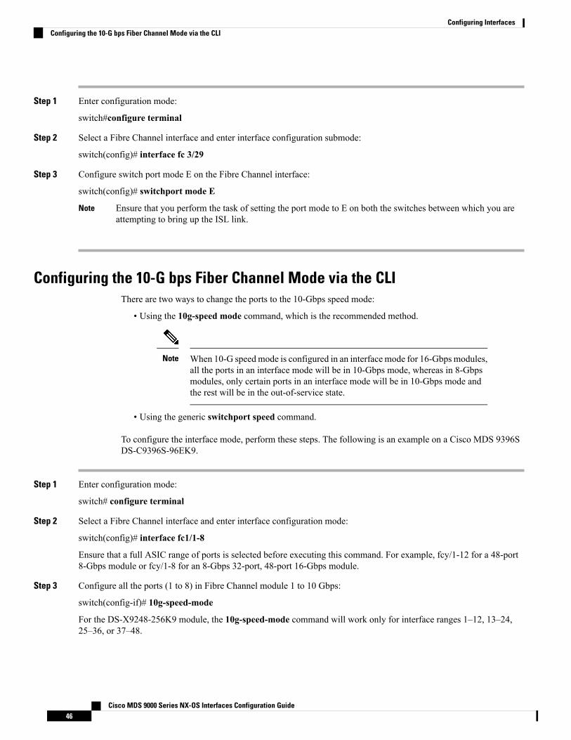
Step 1 Enter configuration mode:
switch#configure terminal
Step 2 Select a Fibre Channel interface and enter interface configuration submode:
switch(config)# interface fc 3/29
Step 3 Configure switch port mode E on the Fibre Channel interface:
switch(config)# switchport mode E
Ensure that you perform the task of setting the port mode to E on both the switches between which you areattempting to bring up the ISL link.
Note
Configuring the 10-G bps Fiber Channel Mode via the CLIThere are two ways to change the ports to the 10-Gbps speed mode:
• Using the 10g-speed mode command, which is the recommended method.
When 10-G speedmode is configured in an interface mode for 16-Gbps modules,all the ports in an interface mode will be in 10-Gbps mode, whereas in 8-Gbpsmodules, only certain ports in an interface mode will be in 10-Gbps mode andthe rest will be in the out-of-service state.
Note
• Using the generic switchport speed command.
To configure the interface mode, perform these steps. The following is an example on a Cisco MDS 9396SDS-C9396S-96EK9.
Step 1 Enter configuration mode:
switch# configure terminal
Step 2 Select a Fibre Channel interface and enter interface configuration mode:
switch(config)# interface fc1/1-8
Ensure that a full ASIC range of ports is selected before executing this command. For example, fcy/1-12 for a 48-port8-Gbps module or fcy/1-8 for an 8-Gbps 32-port, 48-port 16-Gbps module.
Step 3 Configure all the ports (1 to 8) in Fibre Channel module 1 to 10 Gbps:
switch(config-if)# 10g-speed-mode
For the DS-X9248-256K9 module, the 10g-speed-mode command will work only for interface ranges 1–12, 13–24,25–36, or 37–48.
Cisco MDS 9000 Series NX-OS Interfaces Configuration Guide46
Configuring InterfacesConfiguring the 10-G bps Fiber Channel Mode via the CLI

For the DS-X9232-256K9 module, the 10g-speed-mode command will work only for interface ranges 1–8, 9–16, 17–24,or 25–32.
For the DS-X9448-768K9 module, the 10g-speed-mode command will work only for interface ranges 1–8, 9–16, 17–24,25–32, 33–40, or 41–48.
For the DS-C9396S-96EK9module, the 10g-speed-mode command will work only for interface ranges 1-8, 9-16, 17-24,25-32, 33-40, 41-48, 49-56, 57-64, 65-72, 73-80, 81-88, or 89-96.
Step 4 (Optional) Revert the settings and put all the ports (1 to 8) in the out-of-service state and move them to the in-servicestate:
switch(config-if)# no 10g-speed-mode
Configuring the 10-Gbps Fibre Channel Mode via the Device ManagerPerform these steps to convert a defined range of interfaces to 10-Gmode for a module with 2/4/8/10/16-GbpsAdvanced Fibre Channel module (DS-X9448-768K9):
Step 1 Launch the Device Manager for the device supporting 10-G speed.Step 2 Right-click the module and select Configure bandwidth Reservation.Step 3 Select one or more ASIC port ranges and clickApply. By default, all the ports are 2/4/8 or 2/4/8/16-Gbps speed capable.
Configuring the Port Administrative Speeds
Changing the port administrative speed is a disruptive operation.Note
To configure the port speed of the interface, perform these steps:
Step 1 Enter configuration mode:
switch# configure terminal
Step 2 Select the Fibre Channel interface and enter interface configuration mode:
switch(config)# interface fc 1/1
Step 3 Configure the port speed of the interface to 1000 Mbps:
switch(config-if)# switchport speed 1000
All the 10-Gbps capable interfaces, except the interface that is being configured, must be in the out-of-service state. Atleast one other 10-Gbps capable interface must be in the in-service state.
(Optional) Revert to the factory default (auto) administrative speed of the interface:
Cisco MDS 9000 Series NX-OS Interfaces Configuration Guide47
Configuring InterfacesConfiguring the 10-Gbps Fibre Channel Mode via the Device Manager

switch(config-if)# no switchport speed
Configuring Port Speed GroupTo configure the port speed group of the interface, perform these steps:
Step 1 Enter configuration mode:
switch# configure terminal
Step 2 Select the Fibre Channel interface and enter interface configuration mode:
switch(config)# interface fc 1/1
Step 3 Configure the port speed group to 10 Gbps:
switch(config-if)# speed group 10g
The preferred way of changing the speed group is the 10g-speed-mode command.
(Optional) Unset the port speed group and revert to the factory default (auto) administrative speed group of the interface:
switch(config-if)# no speed group 10g
Enabling 10-Gbps Speed ModeCisco MDS 9000 Series Advanced 8-Gbps modules support 10-Gbps ports. However, a group of ports mustbe configured to 10-Gbps mode in order to use the port speed group feature. Individual ports cannot beconfigured to 10-Gbps mode.
• For the 48-Port Advanced 8-Gbps module, the group size is 12 ports (1-12, 13-24, and so on). When thegroup is configured to 10-Gbps mode, the ports 1-3, 9, and 11-12 in that group are unavailable for useand displays them as outOfServc or Out of Service in the output.
• For the 32-Port Advanced 8-Gbps module, the group size is 8 ports (1-8, 9-16, and so on). When thegroup is configured to 10-Gbps mode, the ports 1 and 7 in the group are unavailable for use and displaysthem as outOfServc or Out of Service in the output.
• For the 48-Port 16-Gbps module, in the Cisco MDS 9700 switch and the Cisco MDS 9396S switch thegroup size is 8 ports. When the group is configured to 10-Gbps mode, all the 8 ports are available foruse.
To enable the 10-Gbps speed mode on a group of ports, perform these steps:
Step 1 Enter configuration mode:
switch# configure terminal
Step 2 Select the Fibre Channel interface and enter interface configuration mode:
Cisco MDS 9000 Series NX-OS Interfaces Configuration Guide48
Configuring InterfacesConfiguring Port Speed Group

switch(config)# interface fc1/1-12
Step 3 Change the speed group to 10-Gbps:
switch(config-if)# 10g-speed-mode
(Optional) Revert to default speed group setting:
switch(config-if)# no 10g-speed-mode
What to do next
In Cisco NX-OS Release 5.2(8c), the default speed group for the supported switching modules are 1-, 2-, 4-,and 8-Gbps.
Note
Configuring the Interface DescriptionThe interface description can be any alphanumeric string that is up to 80 characters long.
To configure a description for an interface, perform these steps:
Step 1 Enter configuration mode:
switch# configure terminal
Step 2 Select a Fibre Channel interface and enter interface configuration submode:
switch(config)# interface fc1/1
Step 3 Configure the description of the interface:
switch(config-if)# switchport description cisco-HBA2
The string can be up to 80 characters long.
(Optional) Clear the description of the interface:
switch(config-if)# no switchport description
Specifying a Port OwnerUsing the Port Owner feature, you can specify the owner of a port and the purpose for which a port is usedso that the other administrators are informed.
The Portguard and Port Owner features are available for all ports regardless of the operational mode.Note
Cisco MDS 9000 Series NX-OS Interfaces Configuration Guide49
Configuring InterfacesConfiguring the Interface Description

To specify or remove a port owner, perform these steps:
Step 1 Enter configuration mode:
switch# configure terminal
Step 2 Select the port interface:
switch(config)# interface fc1/1
Step 3 Specify the owner of the switch port:
switch(config)# switchport owner description
The description can include the name of the owner and the purpose for which the port is used, and can be up to 80characters long.
(Optional) Remove the port owner description:
switch(config)# no switchport owner
(Optional) Display the owner description specified for a port, use one of the following commands:
• switch# show running interface fc module-number/interface-number
• switch# show port internal info interface fc module-number/interface-number
Configuring Beacon ModeBy default, the beacon mode is disabled on all switches. The beacon mode is indicated by a flashing greenlight that helps you identify the physical location of the specified interface. Note that configuring the beaconmode has no effect on the operation of the interface.
To configure a beacon mode for a specified interface or range of interfaces, perform these steps:
Step 1 Enter configuration mode:
switch# configure terminal
Step 2 Select a Fibre Channel interface and enter interface configuration submode:
switch(config)# interface fc1/1
Step 3 Enable the beacon mode for the interface:
switch(config-if)# switchport beacon
(Optional) Disable the beacon mode for the interface:
switch(config-if)# no switchport beacon
Cisco MDS 9000 Series NX-OS Interfaces Configuration Guide50
Configuring InterfacesConfiguring Beacon Mode

The flashing green light turns on automatically when an external loopback that causes the interfaces to beisolated is detected. The flashing green light overrides the beacon mode configuration. The state of the LED isrestored to reflect the beacon mode configuration after the external loopback is removed.
Tip
Configuring a Switch Port Attribute Default ValueYou can configure default values for various switch port attributes. These attributes will be applied globallyto all future switch port configurations, even if you do not individually specify them at that time.
To configure a default value for a switch port attribute, perform these steps:
Step 1 Enter configuration mode:
switch# configure terminal
Step 2 Configure the default setting for the administrative state of an interface as up (the factory default setting is down):
switch(config)# no system default switchport shutdown
This command is applicable only to interfaces for which no user configuration exists for the administrativestate.
Note
(Optional) Configure the default setting for the administrative state of an interface as down:
switch(config)# system default switchport shutdown
This command is applicable only to interfaces for which no user configuration exists for the administrativestate.
Note
(Optional) Configure the default setting for the administrative trunk mode state of an interface as Auto:
switch(config)# system default switchport trunk mode auto
The default setting is On.Note
Configuring the Port-Level PortguardAll portguard causes are monitored over a common time interval with the same start and stop times. The linkdown counter is not a specific event, but the aggregation of all other cause counters in the same time interval.
To configure a port-level portguard for a interface, perform these steps:
Step 1 Enter configuration mode:
switch# configure terminal
Step 2 Select the interface:
switch(config)# interface fc1/1
Cisco MDS 9000 Series NX-OS Interfaces Configuration Guide51
Configuring InterfacesConfiguring a Switch Port Attribute Default Value

Step 3 Enable portguard error disabling of the interface if the link goes down once:
switch(config-if)# errdisable detect cause link-down
(Optional) Enable portguard error disabling of the interface if the link flaps a certain number of times within the specifiedtime, in seconds:
switch(config-if)# errdisable detect cause link-down [num-times number duration seconds ]
(Optional) Remove the portguard configuration for the interface:
switch(config-if)# no errdisable detect cause link-down
The link resumes flapping and sending error reports normally.
Step 4 Enable portguard error disabling of the interface if the specified error occurs once:
switch(config-if)# errdisable detect cause {trustsec-violation | bit-errors | credit-loss | link-reset | signal-loss |sync-loss}
(Optional) Enable portguard error disabling of the interface if the specified error occurs a certain number times withinthe specified time, in seconds:
switch(config-if)# errdisable detect cause {trustsec-violation | bit-errors | credit-loss | link-reset | signal-loss |sync-loss} [num-times number duration seconds ]
(Optional) Remove the portguard configuration for the interface:
switch(config-if)# no errdisable detect cause {trustsec-violation | bit-errors | credit-loss | link-reset | signal-loss |sync-loss}
The link resumes flapping and sending error reports normally.
The portguard credit loss event is triggered only on loop interfaces; it is not triggered on point-to-point interfaces.Note
This example shows how to configure portguard to set an interface to Error Disabled state if the link flaps five timeswithin 120 seconds due to multiple causes. The portguard controls the interface in the following manner:
• The interface will be error disabled due to link down if there are link failures due to bit errors 2 times and link failuresdue to credit loss 3 times in 120 seconds.
• The interface will be error disabled due to bit errors if there are link failures due to bit errors 5 times in 120 seconds.
• The interface will be error disabled due to credit loss if there are link failures due to credit loss 5 times in 120 seconds.
Example
This example shows how to configure portguard to bring a port to down state if the link flaps 5 timeswithin 120 seconds based on multiple causes:
switch# configure terminal
switch (config)# interface fc1/1
switch (config-if)# errdisable detect cause link-down num-times 5 duration 120
switch (config-if)# errdisable detect cause bit-errors num-times 5 duration 120
Cisco MDS 9000 Series NX-OS Interfaces Configuration Guide52
Configuring InterfacesConfiguring the Port-Level Portguard

switch (config-if)# errdisable detect cause credit-loss num-times 5 duration 120
The above example sets the configuration to the following status:
• The port will be error disabled due to bit errors if the port suffers link failure due to bit errors5 times in 120 seconds.
• The port will be error-disabled due to credit loss if the port suffers link failure due to credit loss5 times in 120 seconds.
• The port will be error-disabled due to link down if the port suffers link failure due to bit errors2 times and link-failure due to credit loss 3 times in 120 seconds.
This example shows the internal information about a port in down state because of TrustSec violation:
switch# show interface fc8/3
fc8/3 is down (Error disabled - port down due to trustsec violation)Hardware is Fibre Channel, SFP is short wave laser w/o OFC (SN)Port WWN is 21:c3:00:0d:ec:10:57:80Admin port mode is E, trunk mode is onsnmp link state traps are enabledPort vsan is 1Receive data field Size is 2112Beacon is turned off5 minutes input rate 0 bits/sec, 0 bytes/sec, 0 frames/sec5 minutes output rate 0 bits/sec, 0 bytes/sec, 0 frames/sec11274 frames input, 1050732 bytes0 discards, 0 errors0 CRC, 0 unknown class0 too long, 0 too short
11242 frames output, 971900 bytes0 discards, 0 errors
11 input OLS, 34 LRR, 10 NOS, 0 loop inits72 output OLS, 37 LRR, 2 NOS, 0 loop inits
Interface last changed at Sun Nov 27 07:34:05 1988
• Link down is the superset of all other causes. A port is brought to down state if the total numberof other causes equals to the number of allowed link-down failures.
• Even if the link does not flap due to failure of the link, and portguard is not enabled, the portgoes into a down state if too many invalid FLOGI requests are received from the same host.Use the shut and the no shut commands consecutively to bring up the link.
Tip
Configuring a Port MonitorConfiguring a portguard action is optional for each counter in a port monitor policy, and is disabled by default.
Enabling a Port MonitorTo enable or disable a port monitor, perform these steps:
Cisco MDS 9000 Series NX-OS Interfaces Configuration Guide53
Configuring InterfacesConfiguring a Port Monitor

Step 1 Enter configuration mode:
switch# configure terminal
Step 2 Enable port monitoring:
switch(config)# port-monitor enable
(Optional) Disable port monitoring:
switch(config)# no port-monitor enable
Configuring the Check IntervalTo configure the check interval, perform these steps:
Step 1 Enter the configuration mode:
switch# configure terminal
Step 2 Configure the check interval time to 30 seconds
switch# port-monitor check-interval 30
To disable check interval use the following command:
switch# no port-monitor check-interval
Configuring a Port Monitor PolicyTo configure a port monitor policy, perform these steps:
Step 1 Enter configuration mode:
switch# configure terminal
Step 2 Specify the policy name and enter port monitoring policy configuration mode:
switch(config)# port-monitor name policyname
(Optional) Remove the policy name:
switch(config)# no port-monitor name policyname
Step 3 Apply policy type:
switch(config-port-monitor)# port-type {access-port | trunks | all}
Step 4 Specify the counter parameters:
switch(config-port-monitor)# counter {credit-loss-reco | err-pkt-from-port | err-pkt-from-xbar | err-pkt-to-xbar |invalid-crc | invalid-words | link-loss | lr-rx | lr-tx | rx-datarate | signal-loss | state-change | sync-loss | timeout-discards
Cisco MDS 9000 Series NX-OS Interfaces Configuration Guide54
Configuring InterfacesConfiguring the Check Interval

| tx-credit-not-available | tx-datarate | tx-discards | tx-slowport-count | tx-slowport-oper-delay | txwait} poll-intervalseconds {absolute | delta} rising-threshold count1 event RMON-ID warning-threshold count2 falling-thresholdcount3 event RMON-ID portguard {errordisable | flap}
• We recommend that you use the delta threshold type for all the counters except the tx-slowport-oper-delaycounter which uses absolute threshold type.
• The rx-datarate and tx-datarate are calculated using the inoctets and outoctets on an interface.
• You must activate the err-pkt-from-port, err-pkt-from-xbar, and err-pkt-to-xbar counters using themonitor counter name command, before specifying the counter parameters.
• Counters err-pkt-from-xbar, err-pkt-from-port, and err-pkt-to-xbar support delta threshold type only.
• Counter tx-slowport-oper-delay supports absolute threshold type only.
• Counter tx-slowport-oper-delay does not support portguard action.
• Counter tx-slowport-count is supported only onDS-X9224-96K9, DS-X9248-96K9, andDS-X9248-48K9modules.
Note
(Optional) Revert to the default values for a counter:
switch(config-port-monitor)# no counter {credit-loss-reco | err-pkt-from-port | err-pkt-from-xbar | err-pkt-to-xbar| invalid-crc | invalid-words | link-loss | lr-rx | lr-tx | rx-datarate | signal-loss | state-change | sync-loss |timeout-discards | tx-credit-not-available | tx-datarate | tx-discards | tx-slowport-count | tx-slowport-oper-delay |txwait} poll-interval seconds {absolute | delta} rising-threshold count1 event RMON-ID warning-threshold count2falling-threshold count3 event RMON-ID portguard {errordisable | flap}
(Optional) Monitor a counter:
switch(config-port-monitor)#monitor counter {credit-loss-reco | err-pkt-from-port | err-pkt-from-xbar |err-pkt-to-xbar | invalid-crc | invalid-words | link-loss | lr-rx | lr-tx | rx-datarate | signal-loss | state-change | sync-loss| timeout-discards | tx-credit-not-available | tx-datarate | tx-discards | tx-slowport-count | tx-slowport-oper-delay| txwait}
A port monitor currently recognizes two kinds of ports:
• Port type access ports are normally F ports with a single end device logged in. However, a port monitor considersTF ports and F ports with multiple logins to be port type access as well.
• Port type trunk ports are E ports (ISLs) regardless of whether they are actually carrying multiple VSANs (TE,trunking) or not. Some of the access port counter thresholds and portguard actions might not be appropriate on theTF ports in the port-monitor configurations. Specifically, port guard disable or flap actions can affect multiple enddevices on the F ports with multiple logins. Therefore, performing disable or flap actions should be avoided on anN-Port Identifier Virtualization (NPIV) system.
Activating a Port Monitor PolicyTo activate a port monitor policy, perform these steps:
Step 1 Enter configuration mode:
Cisco MDS 9000 Series NX-OS Interfaces Configuration Guide55
Configuring InterfacesActivating a Port Monitor Policy

switch# configure terminal
Step 2 Activate the specified port monitor policy:
switch(config)# port-monitor activate policyname
(Optional) Activate the default port monitor policy:
switch(config)# port-monitor activate
(Optional) Deactivate the specified port monitoring policy:
switch(config)# no port-monitor activate policyname
Configuring Port Monitor PortguardTo configure a port monitor portguard action, perform these steps:
Step 1 Enter configuration mode:
switch# configure terminal
Step 2 Specify the policy name and enter port monitoring policy configuration mode:
switch(config)# port-monitor name policyname
(Optional) Remove the policy:
switch(config)# no port-monitor name policyname
Step 3 Specify a counter, its parameters, and a portguard action for a counter:
switch(config-port-monitor)# counter {credit-loss-reco | err-pkt-from-port | err-pkt-from-xbar | err-pkt-to-xbar |invalid-crc | invalid-words | link-loss | lr-rx | lr-tx | rx-datarate | signal-loss | state-change | sync-loss | timeout-discards| tx-credit-not-available | tx-datarate | tx-discards | tx-slowport-count | tx-slowport-oper-delay | txwait} poll-intervalseconds {absolute | delta} rising-threshold count1 event RMON-ID warning-threshold count2 falling-thresholdcount3 event RMON-ID portguard {errordisable | flap}
Cisco MDS 9000 Series NX-OS Interfaces Configuration Guide56
Configuring InterfacesConfiguring Port Monitor Portguard

• We recommend that you use the delta threshold type for all the counters except the tx-slowport-oper-delaycounter which uses absolute threshold type.
• The rx-datarate and tx-datarate are calculated using the inoctets and outoctets on an interface.
• You must activate the err-pkt-from-port, err-pkt-from-xbar, and err-pkt-to-xbar counters using themonitor counter name command, before specifying the counter parameters.
• Counters err-pkt-from-xbar, err-pkt-from-port, and err-pkt-to-xbar support delta threshold type only.
• Counter tx-slowport-oper-delay supports absolute threshold type only.
• Counter tx-slowport-oper-delay does not support portguard action.
• Counter tx-slowport-count is supported only onDS-X9224-96K9, DS-X9248-96K9, andDS-X9248-48K9modules.
Note
Configuring Port Group Monitor
Enabling a Port Group MonitorTo enable a port group monitor, perform these steps:
Step 1 Enter configuration mode:
switch# configure terminal
Step 2 Enable port monitoring:
switch(config)# port-group-monitor enable
(Optional) Disable port monitoring:
switch(config)# no port-group-monitor enable
Configuring a Port Group Monitor PolicyTo configure a port group monitor policy, perform these steps:
Step 1 Enter configuration mode:
switch# configure terminal
Step 2 Specify the policy name and enter port group monitoring policy configuration mode:
switch(config)# port-group-monitor name policyname
(Optional) Remove the policy:
switch(config)# no port-group-monitor name policyname
Cisco MDS 9000 Series NX-OS Interfaces Configuration Guide57
Configuring InterfacesConfiguring Port Group Monitor

Step 3 Specify the delta receive or transmit counter poll interval (in seconds) and thresholds (in percentage):
switch(config-port-group-monitor)# counter {rx-datarate | tx-datarate} poll-interval seconds delta rising-thresholdpercentage1 falling-threshold percentage2
(Optional) Revert to the default policy:
switch(config-port-group-monitor)# no counter tx-datarate
For more information on reverting to the default policy, see Reverting to the Default Policy for a Specific Counter andPort Group Monitor.
Step 4 Turn on datarate monitoring:
switch(config-port-group-monitor)#monitor counter {rx-datarate | tx-datarate}
(Optional) Turn off datarate monitoring:
switch(config-port-group-monitor)# no monitor counter {rx-datarate | tx-datarate}
For more information on turning off transmit datarate monitoring, see Turning Off Specific Counter Monitoring.
On 8-Gbps and higher speed modules, port errors are monitored using the invalid-crc and invalid-wordscounters. The err-pkt-from-port counter is supported only on 4-Gbps modules.
Note
Reverting to the Default Policy for a Specific CounterThe following examples display the default values for counters:
switch(config)# port-group-monitor name PGMON_policyswitch(config-port-group-monitor)# counter tx-datarate poll-interval 200 deltarising-threshold 75 falling-threshold 0switch(config)# show port-group-monitor PGMON_policyPolicy Name : PGMON_policyAdmin status : Not ActiveOper status : Not ActivePort type : All Port Groups------------------------------------------------------------------------------------------Counter Threshold Interval %ge Rising Threshold %ge Falling Threshold------- --------- -------- -------------------- ---------------------RX Datarate Delta 200 75 0TX Datarate Delta 60 80 20
switch(config-port-group-monitor)# no counter tx-datarateswitch(config)# show port-group-monitor PGMON_policyPolicy Name : PGMON_policyAdmin status : Not ActiveOper status : Not ActivePort type : All Port Groups------------------------------------------------------------------------------------------Counter Threshold Interval %ge Rising Threshold %ge Falling Threshold------- --------- -------- -------------------- ----------------------RX Datarate Delta 60 80 10TX Datarate Delta 60 80 10------------------------------------------------------------------------------------------
Turning Off Specific Counter MonitoringThe following examples display turning off counter monitoring:
Cisco MDS 9000 Series NX-OS Interfaces Configuration Guide58
Configuring InterfacesReverting to the Default Policy for a Specific Counter

switch(config)# port-group-monitor name PGMON_policyswitch(config-port-group-monitor)# no monitor counter rx-datarateswitch(config)# show port-group-monitor PGMON_policyPolicy Name : PGMON_policyAdmin status : Not ActiveOper status : Not ActivePort type : All Port Groups------------------------------------------------------------------------------------------Counter Threshold Interval %ge Rising Threshold %ge Falling Threshold------- --------- -------- -------------------- ----------------------TX Datarate Delta 60 100 80------------------------------------------------------------------------------------------
Activating a Port Group Monitor PolicyTo activate a port group monitor policy, perform these steps:
Step 1 Enter configuration mode:
switch# configure terminal
Step 2 Activate the specified port group monitor policy:
switch(config)# port-group-monitor activate policyname
(Optional) Activate the default port group monitor policy:
switch(config)# port-group-monitor activate
(Optional) Deactivate the specified port group monitor policy:
switch(config)# no port-group-monitor activate policyname
Configuring Management Interfaces
Configuring the Management Interface Over IPv4To configure the mgmt0 Ethernet interface to connect over IPv4, perform these steps:
Step 1 Enter configuration mode:
switch# configure terminal
Step 2 Select the management Ethernet interface on the switch and enter interface configuration submode:
switch(config)# interface mgmt0
Step 3 Configure the IPv4 address and IPv4 subnet mask:
switch(config-if)# ip address 10.16.1.2 255.255.255.0
Step 4 Enable the interface:
switch(config-if)# no shutdown
Cisco MDS 9000 Series NX-OS Interfaces Configuration Guide59
Configuring InterfacesActivating a Port Group Monitor Policy

Step 5 Return to configuration mode:
switch(config-if)# exit
Step 6 Configure the default gateway IPv4 address:
switch(config)# ip default-gateway 1.1.1.4
Step 7 Return to user EXEC mode:
switch(config)# exit
(Optional) Save your configuration changes to the file system:
switch# copy running-config startup-config
Configuring the Management Interface Over IPv6To configure the mgmt0 Ethernet interface to connect over IPv6, perform these steps:
Step 1 Enter configuration mode:
switch# configure terminal
Step 2 Select the management Ethernet interface on the switch and enter interface configuration submode:
switch(config)# interface mgmt0
Step 3 Enable IPv6 and assign a link-local address on the interface:
switch(config-if)# ipv6 enable
Step 4 Specify an IPv6 unicast address and prefix length on the interface:
switch(config-if)# ipv6 address 2001:0db8:800:200c::417a/64
Step 5 Enable the interface:
switch(config-if)# no shutdown
Step 6 Return to user EXEC mode:
switch(config)# exit
(Optional) Save your configuration changes to the file system:
switch# copy running-config startup-config
Creating VSAN InterfacesTo create a VSAN interface, perform these steps:
Step 1 Enter configuration mode:
Cisco MDS 9000 Series NX-OS Interfaces Configuration Guide60
Configuring InterfacesConfiguring the Management Interface Over IPv6

switch# configure terminal
Step 2 Configure a VSAN with the ID 2:
switch(config)# interface vsan 2
Step 3 Enable the VSAN interface:
switch(config-if)# no shutdown
Cisco MDS 9000 Series NX-OS Interfaces Configuration Guide61
Configuring InterfacesCreating VSAN Interfaces

Verifying Interfaces Configuration
Displaying Interface InformationRun the show interface command from user EXECmode. This command displays the interface configurations.Without any arguments, this command displays the information for all the configured interfaces in the switch.
The following example displays the status of interfaces:
Displays All Interfaces
switch# show interface
fc1/1 is upHardware is Fibre Channel, SFP is short wave laserPort WWN is 20:0b:00:05:30:00:8d:deAdmin port mode is FPort mode is F, FCID is 0x610000Port vsan is 2Speed is 2 GbpsTransmit B2B Credit is 3Receive B2B Credit is 16Receive data field Size is 2112Beacon is turned off5 minutes input rate 0 bits/sec, 0 bytes/sec, 0 frames/sec5 minutes output rate 0 bits/sec, 0 bytes/sec, 0 frames/sec134 frames input, 8468 bytes0 discards, 0 errors0 CRC, 0 unknown class0 too long, 0 too short
154 frames output, 46072 bytes0 discards, 0 errors
1 input OLS, 1 LRR, 0 NOS, 0 loop inits1 output OLS, 0 LRR, 1 NOS, 0 loop inits16 receive B2B credit remaining3 transmit B2B credit remaining.
.
.
.fc1/9 is trunking
Hardware is Fibre Channel, SFP is long wave laser cost reducedPort WWN is 20:09:00:05:30:00:97:9ePeer port WWN is 20:0b:00:0b:5f:a3:cc:00Admin port mode is E, trunk mode is onPort mode is TEPort vsan is 100Speed is 2 GbpsTransmit B2B Credit is 255Receive B2B Credit is 255Receive data field Size is 2112Beacon is turned offTrunk vsans (admin allowed and active) (1,100,3000)Trunk vsans (up) (1,100,3000)Trunk vsans (isolated) ()Trunk vsans (initializing) ()5 minutes input rate 280 bits/sec, 35 bytes/sec, 0 frames/sec5 minutes output rate 176 bits/sec, 22 bytes/sec, 0 frames/sec
Cisco MDS 9000 Series NX-OS Interfaces Configuration Guide62
Configuring InterfacesVerifying Interfaces Configuration

4609939 frames input, 8149405708 bytes0 discards, 0 errors0 CRC, 0 unknown class0 too long, 0 too short
4638491 frames output, 7264731728 bytes0 discards, 0 errors
3 input OLS, 9 LRR, 1 NOS, 0 loop inits9 output OLS, 7 LRR, 1 NOS, 0 loop inits16 receive B2B credit remaining3 transmit B2B credit remaining.
.
.
.fc1/13 is up
Hardware is Fibre Channel, SFP is short wave laserPort WWN is 20:0d:00:05:30:00:97:9eAdmin port mode is auto, trunk mode is onPort mode is F, FCID is 0x650100Port vsan is 100Speed is 2 GbpsTransmit B2B Credit is 3Receive B2B Credit is 16Receive data field Size is 2112Beacon is turned off5 minutes input rate 0 bits/sec, 0 bytes/sec, 0 frames/sec5 minutes output rate 0 bits/sec, 0 bytes/sec, 0 frames/sec8696 frames input, 3227212 bytes0 discards, 0 errors0 CRC, 0 unknown class0 too long, 0 too short
16799 frames output, 6782444 bytes0 discards, 0 errors
0 input OLS, 0 LRR, 0 NOS, 0 loop inits1 output OLS, 1 LRR, 0 NOS, 1 loop inits16 receive B2B credit remaining3 transmit B2B credit remaining.
.
.
.sup-fc0 is up
Hardware is Fibre ChannelSpeed is 1 Gbps139597 packets input, 13852970 bytes0 multicast frames, 0 compressed0 input errors, 0 frame, 0 overrun 0 fifo
139516 packets output, 16759004 bytes, 0 underruns0 output errors, 0 collisions, 0 fifo0 carrier errors
You can also specify arguments (a range of interfaces or multiple specified interfaces) to displayinterface information. You can specify a range of interfaces by issuing a command in the followingformat:
interface fc1/1 - 5 , fc2/5 - 7
The spaces are required before and after the dash ( - ) and before and after the comma ( , ).Note
The following example displays the status of a range of interfaces:
Cisco MDS 9000 Series NX-OS Interfaces Configuration Guide63
Configuring InterfacesDisplaying Interface Information

Displays Multiple, Specified Interfaces
switch# show interface fc3/13 , fc3/16fc3/13 is up
Hardware is Fibre Channel, SFP is short wave laserPort WWN is 20:8d:00:05:30:00:97:9eAdmin port mode is FXPort mode is F, FCID is 0x7b0300Port vsan is 1Speed is 2 GbpsTransmit B2B Credit is 3Receive B2B Credit is 12Receive data field Size is 2112Beacon is turned off5 minutes input rate 0 bits/sec, 0 bytes/sec, 0 frames/sec5 minutes output rate 0 bits/sec, 0 bytes/sec, 0 frames/sec1856 frames input, 116632 bytes0 discards, 0 errors0 CRC, 0 unknown class0 too long, 0 too short
1886 frames output, 887712 bytes0 discards, 0 errors
0 input OLS, 0 LRR, 0 NOS, 1 loop inits1 output OLS, 1 LRR, 0 NOS, 1 loop inits16 receive B2B credit remaining3 transmit B2B credit remaining.
fc3/16 is upHardware is Fibre Channel, SFP is short wave laserPort WWN is 20:90:00:05:30:00:97:9eAdmin port mode is FXPort mode is F, FCID is 0x7d0100Port vsan is 3000Speed is 2 GbpsTransmit B2B Credit is 3Receive B2B Credit is 12Receive data field Size is 2112Beacon is turned off5 minutes input rate 504 bits/sec, 63 bytes/sec, 0 frames/sec5 minutes output rate 520 bits/sec, 65 bytes/sec, 0 frames/sec47050 frames input, 10311824 bytes0 discards, 0 errors0 CRC, 0 unknown class0 too long, 0 too short
62659 frames output, 10676988 bytes0 discards, 0 errors
0 input OLS, 0 LRR, 0 NOS, 0 loop inits1 output OLS, 1 LRR, 0 NOS, 1 loop inits16 receive B2B credit remaining3 transmit B2B credit remaining.
The following example displays the status of a specified interface:
Displays a Specific Interface
switch# show interface fc2/2fc2/2 is trunking
Port description is Trunk to Core-4Hardware is Fibre Channel, SFP is short wave laserPort WWN is 20:42:00:05:30:00:97:9ePeer port WWN is 20:cc:00:05:30:00:50:9e
Cisco MDS 9000 Series NX-OS Interfaces Configuration Guide64
Configuring InterfacesDisplaying Interface Information

Admin port mode is E, trunk mode is onPort mode is TEPort vsan is 1Speed is 2 GbpsTransmit B2B Credit is 255Receive B2B Credit is 255Receive data field Size is 2112Beacon is turned offBelongs to port-channel 2Trunk vsans (admin allowed and active) (1,100,3000)Trunk vsans (up) (1)Trunk vsans (isolated) (100,3000)Trunk vsans (initializing) ()5 minutes input rate 0 bits/sec, 0 bytes/sec, 0 frames/sec5 minutes output rate 32 bits/sec, 4 bytes/sec, 0 frames/sec2214834 frames input, 98673588 bytes0 discards, 0 errors0 CRC, 0 unknown class0 too long, 0 too short
2262415 frames output, 343158368 bytes0 discards, 0 errors
1 input OLS, 1 LRR, 1 NOS, 0 loop inits2 output OLS, 1 LRR, 0 NOS, 0 loop inits16 receive B2B credit remaining3 transmit B2B credit remaining.
The following example displays the description of interfaces:
Displays Port Description
switch# show interface description-------------------------------------------------------------------------------Interface Description-------------------------------------------------------------------------------fc3/1 test intestfc3/2 --fc3/3 --fc3/4 TE portfc3/5 --fc3/6 --fc3/10 Next hop switch 5fc3/11 --fc3/12 --fc3/16 ---------------------------------------------------------------------------------Interface Description-------------------------------------------------------------------------------port-channel 1 --port-channel 5 --port-channel 6 --
The following example displays a summary of information:
Displays Interface Information in a Brief Format
switch# show interface brief-------------------------------------------------------------------------------Interface Vsan Admin Admin Status SFP Oper Oper Port
Cisco MDS 9000 Series NX-OS Interfaces Configuration Guide65
Configuring InterfacesDisplaying Interface Information

Mode Trunk Mode Speed ChannelMode (Gbps)
-------------------------------------------------------------------------------fc1/1 1 E on trunking swl TE 2 1fc1/2 1 E on trunking swl TE 2 1fc1/3 1 auto on SFPAbsent -- -- --fc1/4 1 auto on SFPAbsent -- -- --fc1/5 3000 auto on up swl F 2 --...fc2/2 1 E on trunking swl TE 2 2fc2/3 1 auto on down c1610 -- --fc2/4 1 auto on down c1590 -- --fc2/5 3000 auto on notConnected lwcr -- --fc2/6 1 auto on SFPAbsent -- -- --...fc3/16 3000 FX -- up swl F 2 --fc3/17 1 FX -- SFPAbsent -- -- --...-------------------------------------------------------------------------------Interface Status IP Address Speed MTU-------------------------------------------------------------------------------GigabitEthernet4/1 SFPAbsent -- auto 1500...GigabitEthernet4/6 down 10.1.1.2/8 auto 3000GigabitEthernet4/7 down 10.1.1.27/24 auto 1500GigabitEthernet4/8 down -- auto 1500-------------------------------------------------------------------------------Interface Status Oper Mode Oper Speed
(Gbps)-------------------------------------------------------------------------------iscsi4/1 down --...-------------------------------------------------------------------------------Interface Status Speed
(Gbps)-------------------------------------------------------------------------------sup-fc0 up 1-------------------------------------------------------------------------------Interface Status IP Address Speed MTU-------------------------------------------------------------------------------mgmt0 up 172.19.48.96/25 100 Mbps 1500-------------------------------------------------------------------------------Interface Vsan Admin Status Oper Oper
Trunk Mode SpeedMode (Gbps)
-------------------------------------------------------------------------------port-channel 1 1 on trunking TE 4port-channel 2 1 on trunking TE 4-------------------------------------------------------------------------------Interface Vsan Admin Admin Status Oper Profile Port-channel
Mode Trunk ModeMode
-------------------------------------------------------------------------------fcip10 1 auto on notConnected -- 10 --
The following example displays a summary of information:
Displays Interface Counters
switch# show interface counters
Cisco MDS 9000 Series NX-OS Interfaces Configuration Guide66
Configuring InterfacesDisplaying Interface Information

fc3/15 minutes input rate 24 bits/sec, 3 bytes/sec, 0 frames/sec5 minutes output rate 16 bits/sec, 2 bytes/sec, 0 frames/sec3502 frames input, 268400 bytes0 discards, 0 CRC, 0 unknown class0 too long, 0 too short
3505 frames output, 198888 bytes0 discards
1 input OLS, 1 LRR, 1 NOS, 0 loop inits2 output OLS, 1 LRR, 1 NOS, 0 loop inits1 link failures, 1 sync losses, 1 signal losses
.
.
.fc9/8
5 minutes input rate 0 bits/sec, 0 bytes/sec, 0 frames/sec5 minutes output rate 0 bits/sec, 0 bytes/sec, 0 frames/sec0 frames input, 0 bytes0 class-2 frames, 0 bytes0 class-3 frames, 0 bytes0 class-f frames, 0 bytes0 discards, 0 CRC, 0 unknown class0 too long, 0 too short
0 frames output, 0 bytes0 class-2 frames, 0 bytes0 class-3 frames, 0 bytes0 class-f frames, 0 bytes0 discards
0 input OLS, 0 LRR, 0 NOS, 0 loop inits0 output OLS, 0 LRR, 0 NOS, 0 loop inits0 link failures, 0 sync losses, 0 signal losses16 receive B2B credit remaining3 transmit B2B credit remaining.
. . .sup-fc0
114000 packets input, 11585632 bytes0 multicast frames, 0 compressed0 input errors, 0 frame, 0 overrun 0 fifo
113997 packets output, 10969672 bytes, 0 underruns0 output errors, 0 collisions, 0 fifo0 carrier errors
mgmt031557 packets input, 2230860 bytes0 multicast frames, 0 compressed0 input errors, 0 frame, 0 overrun 0 fifo
26618 packets output, 16824342 bytes, 0 underruns0 output errors, 0 collisions, 7 fifo0 carrier errors
vsan10 packets input, 0 bytes, 0 errors, 0 multicast0 packets output, 0 bytes, 0 errors, 0 dropped
.
.
.port-channel 1
5 minutes input rate 0 bits/sec, 0 bytes/sec, 0 frames/sec5 minutes output rate 0 bits/sec, 0 bytes/sec, 0 frames/sec0 frames input, 0 bytes0 class-2 frames, 0 bytes0 class-3 frames, 0 bytes0 class-f frames, 0 bytes0 discards, 0 CRC, 0 unknown class0 too long, 0 too short
0 frames output, 0 bytes
Cisco MDS 9000 Series NX-OS Interfaces Configuration Guide67
Configuring InterfacesDisplaying Interface Information

0 class-2 frames, 0 bytes0 class-3 frames, 0 bytes0 class-f frames, 0 bytes0 discards
0 input OLS, 0 LRR, 0 NOS, 0 loop inits0 output OLS, 0 LRR, 0 NOS, 0 loop inits0 link failures, 0 sync losses, 0 signal losses
Interfaces 9/8 and 9/9 are not trunking ports and display Class 2, 3, and F information as well.Note
The following example displays the brief counter information of interfaces:
Displays Interface Counters in Brief Format
switch# show interface counters brief-------------------------------------------------------------------------------Interface Input (rate is 5 min avg) Output (rate is 5 min avg)
----------------------------- -----------------------------Rate Total Rate TotalMbits/s Frames Mbits/s Frames
-------------------------------------------------------------------------------fc3/1 0 3871 0 3874fc3/2 0 3902 0 4232fc3/3 0 3901 0 4138fc3/4 0 3895 0 3894fc3/5 0 3890 0 3897fc9/8 0 0 0 0fc9/9 0 5 0 4fc9/10 0 4186 0 4182fc9/11 0 4331 0 4315-------------------------------------------------------------------------------Interface Input (rate is 5 min avg) Output (rate is 5 min avg)
----------------------------- -----------------------------Rate Total Rate TotalMbits/s Frames Mbits/s Frames
-------------------------------------------------------------------------------port-channel 1 0 0 0 0port-channel 2 0 3946 0 3946
You can run the show interface transceiver command only on a switch in the Cisco MDS 9100Series if the SFP is present, as show in the following example:
Displays Transceiver Information
switch# show interface transceiver
fc1/1 SFP is presentname is CISCO-AGILENTpart number is QFBR-5796Lrevision isserial number is A00162193fc-transmitter type is short wave lasercisco extended id is unknown (0x0)
...fc1/9 SFP is present
Cisco MDS 9000 Series NX-OS Interfaces Configuration Guide68
Configuring InterfacesDisplaying Interface Information

name is FINISAR CORP.part number is FTRJ-1319-7D-CSCrevision isserial number is H11A6ERfc-transmitter type is long wave laser cost reducedcisco extended id is unknown (0x0)
...
The following example displays the entire running configuration, with information about all theinterfaces. The interfaces have multiple entries in the configuration files to ensure that the interfaceconfiguration commands execute in the correct order when the switch reloads.
Displays the Running Configuration for All Interfaces
switch# show running-config...interface fc9/1switchport speed 2000
...interface fc9/1switchport mode E
...interface fc9/1channel-group 11 forceno shutdown
The following example displays the running configuration information for a specified interface. Theinterface configuration commands are grouped together:
Displays the Running Configuration for a Specified Interface
switch# show running-config interface fc1/1interface fc9/1switchport speed 2000switchport mode Echannel-group 11 forceno shutdown
Displays the Running Configuration after the System Default Switchport Mode F Command isExecuted, on page 69 displays the running configuration after the system default switchport modeF command is executed.
The following example displays the running configuration after the system default switchport modeF command is executed:
Displays the Running Configuration after the System Default Switchport Mode F Command is Executed
switch# show running-configversion 3.1(3)system default switchport mode Finterface fc4/1interface fc4/2interface fc4/3interface fc4/4interface fc4/5
Cisco MDS 9000 Series NX-OS Interfaces Configuration Guide69
Configuring InterfacesDisplaying Interface Information

interface fc4/6interface fc4/7interface fc4/8interface fc4/9interface fc4/10
The following example displays the running configuration after two interfaces are individuallyconfigured for FL mode:
Displays the Running Configuration after Two Interfaces are Individually Configured for Mode FL
switch# show running-configversion 3.1(3)system default switchport mode Finterface fc4/1switchport mode FL
interface fc4/2interface fc4/3switchport mode FL
interface fc4/4interface fc4/5interface fc4/6interface fc4/7interface fc4/8interface fc4/9interface fc4/1
The following example displays interface information in a brief format after the system defaultswitchport mode F command is executed:
Displays Interface Information in a Brief Format after the System Default Switchport Mode F Commandis Executed
switch# show interface brief-------------------------------------------------------------------------------Interface Vsan Admin Admin Status SFP Oper Oper Port
Mode Trunk Mode Speed ChannelMode (Gbps)
-------------------------------------------------------------------------------fc4/1 1 F -- notConnected swl -- --fc4/2 1 F -- notConnected swl -- --fc4/3 1 F -- notConnected swl -- --fc4/4 1 F -- notConnected swl -- --fc4/5 1 F -- sfpAbsent -- -- --fc4/6 1 F -- sfpAbsent -- -- --fc4/7 1 F -- sfpAbsent -- -- --fc4/8 1 F -- sfpAbsent -- -- --fc4/9 1 F -- sfpAbsent -- -- --
The following example displays interface information in a brief format after two interfaces areindividually configured for FL mode:
Cisco MDS 9000 Series NX-OS Interfaces Configuration Guide70
Configuring InterfacesDisplaying Interface Information

Displays Interface Information in a Brief Format after Two Interfaces Are Individually Configuredfor Mode FL
switch# show interface brief-------------------------------------------------------------------------------Interface Vsan Admin Admin Status SFP Oper Oper Port
Mode Trunk Mode Speed ChannelMode (Gbps)
-------------------------------------------------------------------------------fc4/1 1 FL -- notConnected swl -- --fc4/2 1 F -- notConnected swl -- --fc4/3 1 FL -- notConnected swl -- --fc4/4 1 F -- notConnected swl -- --fc4/5 1 F -- sfpAbsent -- -- --fc4/6 1 F -- sfpAbsent -- -- --fc4/7 1 F -- sfpAbsent -- -- --fc4/8 1 F -- sfpAbsent -- -- --fc4/9 1 F -- sfpAbsent -- -- --fc4/10 1 F -- sfpAbsent -- -- --
Displaying the Port-Level PortguardThe following command displays information about an interface that is set to error-disabled state by theportguard because of a TrustSec violation:
switch# show interface fc8/3
fc8/3 is down (Error disabled - port down due to trustsec violation) Hardware is FibreChannel, SFP is short wave laser w/o OFC (SN) Port WWN is 21:c3:00:0d:ec:10:57:80Admin port mode is E, trunk mode is on snmp link state traps are enabledPort vsan is 1Receive data field Size is 2112 Beacon is turned off5 minutes input rate 0 bits/sec, 0 bytes/sec, 0 frames/sec5 minutes output rate 0 bits/sec, 0 bytes/sec, 0 frames/sec11274 frames input, 1050732 bytes0 discards, 0 errors0 CRC, 0 unknown class0 too long, 0 too short11242 frames output, 971900 bytes0 discards, 0 errors11 input OLS, 34 LRR, 10 NOS, 0 loop inits72 output OLS, 37 LRR, 2 NOS, 0 loop initsInterface last changed at Sun Nov 27 07:34:05 1988
An interfacemay be error disabled for several reasons. To recover an error-disabled interface, use the shutdownand no shutdown commands in interface configuration mode to re-enable the link.
Displaying Port Monitor Status and PoliciesThe following commands display information about the Port Monitor feature:switch# show port-monitor------------------------------------------------------------------------------------------Port Monitor : enabled------------------------------------------------------------------------------------------Policy Name : Sample
Cisco MDS 9000 Series NX-OS Interfaces Configuration Guide71
Configuring InterfacesDisplaying the Port-Level Portguard

Admin status : Not ActiveOper status : Not ActivePort type : All Ports-----------------------------------------------------------------------------------------------------------------------------Counter Threshold Interval Rising Threshold event Falling Thresholdevent PMON Portguard-----------------------------------------------------------------------------------------------------------------------------Link Loss Delta 60 5 4 14 Not enabledSync Loss Delta 60 5 4 14 Not enabledSignal Loss Delta 60 5 4 14 Not enabledInvalid Words Delta 60 1 4 04 Not enabledInvalid CRC's Delta 60 5 4 14 Not enabledTX Discards Delta 60 200 4 104 Not enabledLR RX Delta 60 5 4 14 Not enabledLR TX Delta 60 5 4 14 Not enabledTimeoutDiscards Delta 60 200 4 104 Not enabledCredit LossReco Delta 1 1 4 04 Not enabledTX Credit NotAvailable Delta 1 10% 4 0%4 Not enabledRX Datarate Delta 60 80% 4 20%4 Not enabledTX Datarate Delta 60 80% 4 20%4 Not enabledTX-Slowport-Count Delta 1 5 4 04 Not enabledTX-Slowport-Oper-Delay Absolute 1 50ms 4 0ms4 Not enabledTXWait Delta 1 40% 4 0%4 Not enabled------------------------------------------------------------------------------------------------------------------------------Policy Name : defaultAdmin status : Not ActiveOper status : Not ActivePort type : All Ports----------------------------------------------------------------------------------------------------------------Counter Threshold Interval Rising Threshold event Falling Threshold event
PMON Portguard----------------------------------------------------------------------------------------------------------------Link Loss Delta 60 5 4 1 4
Not enabledSync Loss Delta 60 5 4 1 4
Not enabledSignal Loss Delta 60 5 4 1 4
Not enabledInvalid Words Delta 60 1 4 0 4
Not enabledInvalid CRC's Delta 60 5 4 1 4
Not enabledTX Discards Delta 60 200 4 10 4
Cisco MDS 9000 Series NX-OS Interfaces Configuration Guide72
Configuring InterfacesDisplaying Port Monitor Status and Policies

Not enabledLR RX Delta 60 5 4 1 4
Not enabledLR TX Delta 60 5 4 1 4
Not enabledTimeoutDiscards Delta 60 200 4 10 4
Not enabledCredit LossReco Delta 1 1 4 0 4
Not enabledTX Credit NotAvailable Delta 1 10% 4 0% 4
Not enabledRX Datarate Delta 60 80% 4 20% 4
Not enabledTX Datarate Delta 60 80% 4 20% 4
Not enabledTX-Slowport-Count Delta 1 5 4 0 4
Not enabledTX-Slowport-Oper-Delay Absolute 1 50ms 4 0ms 4
Not enabledTXWait Delta 1 40% 4 0% 4
Not enabled-----------------------------------------------------------------------------------------------------------------
switch# show port-monitor------------------------------------------------------------------------------------------Port Monitor : enabled------------------------------------------------------------------------------------------Policy Name : SampleAdmin status : Not ActiveOper status : Not ActivePort type : All Ports-----------------------------------------------------------------------------------------------------------------------------Counter Threshold Interval Rising Threshold event Falling Thresholdevent PMON Portguard-----------------------------------------------------------------------------------------------------------------------------Link Loss Delta 60 5 4 14 Not enabledSync Loss Delta 60 5 4 14 Not enabledSignal Loss Delta 60 5 4 14 Not enabledInvalid Words Delta 60 1 4 04 Not enabledInvalid CRC's Delta 60 5 4 14 Not enabledTX Discards Delta 60 200 4 104 Not enabledLR RX Delta 60 5 4 14 Not enabledLR TX Delta 60 5 4 14 Not enabledTimeoutDiscards Delta 60 200 4 104 Not enabledCredit LossReco Delta 1 1 4 04 Not enabledTX Credit NotAvailable Delta 1 10% 4 0%
Cisco MDS 9000 Series NX-OS Interfaces Configuration Guide73
Configuring InterfacesDisplaying Port Monitor Status and Policies

4 Not enabledRX Datarate Delta 60 80% 4 20%4 Not enabledTX Datarate Delta 60 80% 4 20%4 Not enabledTX-Slowport-Count Delta 1 5 4 04 Not enabledTX-Slowport-Oper-Delay Absolute 1 50ms 4 0ms4 Not enabledTXWait Delta 1 40% 4 0%4 Not enabled------------------------------------------------------------------------------------------------------------------------------Policy Name : defaultAdmin status : Not ActiveOper status : Not ActivePort type : All Ports----------------------------------------------------------------------------------------------------------------Counter Threshold Interval Rising Threshold event Falling Threshold event
PMON Portguard----------------------------------------------------------------------------------------------------------------Link Loss Delta 60 5 4 1 4
Not enabledSync Loss Delta 60 5 4 1 4
Not enabledSignal Loss Delta 60 5 4 1 4
Not enabledInvalid Words Delta 60 1 4 0 4
Not enabledInvalid CRC's Delta 60 5 4 1 4
Not enabledTX Discards Delta 60 200 4 10 4
Not enabledLR RX Delta 60 5 4 1 4
Not enabledLR TX Delta 60 5 4 1 4
Not enabledTimeoutDiscards Delta 60 200 4 10 4
Not enabledCredit LossReco Delta 1 1 4 0 4
Not enabledTX Credit NotAvailable Delta 1 10% 4 0% 4
Not enabledRX Datarate Delta 60 80% 4 20% 4
Not enabledTX Datarate Delta 60 80% 4 20% 4
Not enabledTX-Slowport-Count Delta 1 5 4 0 4
Not enabledTX-Slowport-Oper-Delay Absolute 1 50ms 4 0ms 4
Not enabledTXWait Delta 1 40% 4 0% 4
Not enabled-----------------------------------------------------------------------------------------------------------------
switch# show port-monitor activePolicy Name : sample
Cisco MDS 9000 Series NX-OS Interfaces Configuration Guide74
Configuring InterfacesDisplaying Port Monitor Status and Policies

Admin status : ActiveOper status : ActivePort type : All Access Ports-----------------------------------------------------------------------------------------------------------Counter Threshold Interval Rising Threshold event Falling Threshold eventportguard-----------------------------------------------------------------------------------------------------------Link Loss Delta 60 5 4 1 4
Not enabledSync Loss Delta 60 5 4 1 4
Not enabledSignal Loss Delta 60 5 4 1 4
Not enabledInvalid Words Delta 60 1 4 0 4
Not enabledInvalid CRC's Delta 60 5 4 1 4
Not enabledTX Discards Delta 60 200 4 10 4
Not enabledLR RX Delta 60 5 4 1 4
Not enabledLR TX Delta 60 5 4 1 4
Not enabledTimeoutDiscards Delta 60 200 4 10 4
Not enabledCredit LossReco Delta 1 1 4 0 4
Not enabledTX Credit NotAvailable Delta 1 10% 4 0% 4
Not enabledRX Datarate Delta 60 80% 4 20% 4
Not enabledTX Datarate Delta 60 80% 4 20% 4
Not enabledTX-Slowport-Count Delta 1 5 4 0 4
Not enabledTX-Slowport-Oper-Delay Absolute 1 50ms 4 0ms 4
Not enabledTXWait Delta 1 40% 4 0% 4
Not enabled--------------------------------------------------------------------------------------------------------------
switch# show port-monitor samplePolicy Name : sampleAdmin status : ActiveOper status : ActivePort type : All Access Ports----------------------------------------------------------------------------------------------------------Counter Threshold Interval Rising Threshold event Falling Threshold eventportgurard----------------------------------------------------------------------------------------------------------Link Loss Delta 60 5 4 1 4Not enabledSync Loss Delta 60 5 4 1 4Not enabledSignal Loss Delta 60 5 4 1 4Not enabledInvalid Words Delta 60 1 4 0 4
Cisco MDS 9000 Series NX-OS Interfaces Configuration Guide75
Configuring InterfacesDisplaying Port Monitor Status and Policies

Not enabledInvalid CRC's Delta 60 5 4 1 4Not enabledTX Discards Delta 60 200 4 10 4Not enabledLR RX Delta 60 5 4 1 4Not enabledLR TX Delta 60 5 4 1 4Not enabledTimeout Discards Delta 60 200 4 10 4Not enabledCredit Loss Reco Delta 1 1 4 0 4Not enabledTX Credit NotAvailable Delta 1 10% 4 0% 4Not enabledRX Datarate Delta 60 80% 4 20% 4Not enabledTX Datarate Delta 60 80% 4 20% 4Not enabledTX-Slowport-Count Delta 1 5 4 0 4Not enabledTX-Slowport-Oper-Delay Absolute 1 50ms 4 0ms 4Not enabledTXWait Delta 1 40% 4 0% 4Not enabled-----------------------------------------------------------------------------------------------------------
switch# show port-monitor defaultPolicy Name : defaultAdmin status : Not ActiveOper status : Not ActivePort type : All Ports----------------------------------------------------------------------------------------------------Counter Threshold Interval Rising event Falling event WarningPMON
Threshold Threshold ThresholdPortguard-----------------------------------------------------------------------------------------------------Link Loss Delta 60 5 4 1 4 Not enabledNot enabledSync Loss Delta 60 5 4 1 4 Not enabledNot enabledSignal Loss Delta 60 5 4 1 4 Not enabledNot enabledInvalid Words Delta 60 1 4 0 4 Not enabledNot enabledInvalid CRC's Delta 60 5 4 1 4 Not enabledNot enabledState Change Delta 60 5 4 0 4 Not enabledNot enabledTX Discards Delta 60 200 4 10 4 Not enabledNot enabledLR RX Delta 60 5 4 1 4 Not enabledNot enabledLR TX Delta 60 5 4 1 4 Not enabledNot enabledTimeout Discards Delta 60 200 4 10 4 Not enabledNot enabledCredit Loss Reco Delta 60 1 4 0 4 Not enabledNot enabledTX Credit Not Delta 60 10% 4 0% 4 Not enabled
Cisco MDS 9000 Series NX-OS Interfaces Configuration Guide76
Configuring InterfacesDisplaying Port Monitor Status and Policies

Not enabledAvailableRX Datarate Delta 60 80% 4 20% 4 Not enabledNot enabledTX Datarate Delta 60 80% 4 20% 4 Not enabledNot enabledTX-Slowport- Absolute 60 50ms 4 0ms 4 Not enabledNot enabledOper-DelayTXWait Delta 60 40% 4 0% 4 Not enabledNot enabled-------------------------------------------------------------------------------------------------------
switch# show port-monitor slowdrainPolicy Name : slowdrainAdmin status : Not ActiveOper status : Not ActivePort type : All Access Ports-------------------------------------------------------------------------------------------------------------------------------Counter Threshold Interval Rising Threshold event Falling Threshold
event PMON Portguard-------------------------------------------------------------------------------------------------------------------------------Credit Loss Reco Delta 1 1 4 0
4 Not enabledTX Credit NotAvailable Delta 1 10% 4 0%
4 Not enabled--------------------------------------------------------------------------------------------------------------------------------
Displaying Port Group Monitor Status and PoliciesThe following examples display information about the port group monitor:
switch# show port-group-monitor statusPort Group Monitor : EnabledActive Policies : pgm2Last 100 logs :switch#switch# show port-group-monitor------------------------------------------------------------------------------------------Port Group Monitor : enabled------------------------------------------------------------------------------------------Policy Name : pgm1Admin status : Not ActiveOper status : Not ActivePort type : All Port Groups------------------------------------------------------------------------------------------Counter Threshold Interval %ge Rising Threshold %ge Falling Threshold------- --------- -------- -------------------- ----------------------RX Datarate Delta 60 50 10TX Datarate Delta 60 50 10------------------------------------------------------------------------------------------Policy Name : pgm2Admin status : ActiveOper status : ActivePort type : All Port Groups------------------------------------------------------------------------------------------Counter Threshold Interval %ge Rising Threshold %ge Falling Threshold
Cisco MDS 9000 Series NX-OS Interfaces Configuration Guide77
Configuring InterfacesDisplaying Port Group Monitor Status and Policies

------- --------- -------- -------------------- ----------------------RX Datarate Delta 60 80 10TX Datarate Delta 60 80 10------------------------------------------------------------------------------------------Policy Name : defaultAdmin status : Not ActiveOper status : Not ActivePort type : All Port Groups------------------------------------------------------------------------------------------Counter Threshold Interval %ge Rising Threshold %ge Falling Threshold------- --------- -------- -------------------- ----------------------RX Datarate Delta 60 80 20TX Datarate Delta 60 80 20------------------------------------------------------------------------------------------switch# show port-group-monitor activePolicy Name : pgm2Admin status : ActiveOper status : ActivePort type : All Port Groups------------------------------------------------------------------------------------------Counter Threshold Interval %ge Rising Threshold %ge Falling Threshold------- --------- -------- -------------------- ----------------------RX Datarate Delta 60 80 10TX Datarate Delta 60 80 10------------------------------------------------------------------------------------------switch# show port-group-monitor PGMON_policyPPolicy Name : PGMON_policyAdmin status : Not ActiveOper status : Not ActivePort type : All Port Groups------------------------------------------------------------------------------------------Counter Threshold Interval %ge Rising Threshold %ge Falling Threshold------- --------- -------- -------------------- ----------------------RX Datarate Delta 26 450 250TX Datarate Delta 60 100 80------------------------------------------------------------------------------------------
Displaying the Management Interface ConfigurationThe following command displays the management interface configuration:
switch# show interface mgmt 0mgmt0 is up
Hardware is FastEthernetAddress is 000c.30d9.fdbcInternet address is 10.16.1.2/24MTU 1500 bytes, BW 100 Mbps full Duplex26388 packets input, 6101647 bytes0 multicast frames, 0 compressed0 input errors, 0 frame, 0 overrun 0 fifo
10247 packets output, 2389196 bytes, 0 underruns0 output errors, 0 collisions, 0 fifo0 carrier errors
Displaying VSAN Interface InformationTo following example displays the VSAN interface information:
switch# show interface vsan 2
Cisco MDS 9000 Series NX-OS Interfaces Configuration Guide78
Configuring InterfacesDisplaying the Management Interface Configuration

vsan2 is up, line protocol is upWWPN is 10:00:00:05:30:00:59:1f, FCID is 0xb90100Internet address is 10.1.1.1/24MTU 1500 bytes, BW 1000000 Kbit0 packets input, 0 bytes, 0 errors, 0 multicast0 packets output, 0 bytes, 0 errors, 0 dropped
Cisco MDS 9000 Series NX-OS Interfaces Configuration Guide79
Configuring InterfacesDisplaying VSAN Interface Information

Transmit-Wait History GraphThe transmit-wait history for the slow ports on advanced 8-Gbps and 16-Gbps modules and switches can bedisplayed in the form of a graph over a period of time. The total transmit-wait time for each time period isdisplayed as a column of #. The actual value appears above each column as a vertically printed number. Thefollowing graphs can be displayed:
• Seconds scale—The transmit-wait history for the port over the last 60 seconds. The Y-axis value is thetotal transmit-wait time for each second, in milliseconds.
• Minutes scale—The transmit-wait history for the port over the last 60 seconds. The Y-axis value is thetotal transmit-wait time for each minute, in seconds, to one decimal place.
• Hours scale—The transmit-wait history for the port over the last 60 seconds. The Y-axis value is thetotal transmit-wait time for each hour, in minutes.
To display the transmit-wait history for a given interval of time, use the following commands:
Display the transmit-wait history graph for the period when transmit credit is not available for a given intervalof time (seconds, minutes, or hours):
switch# show process creditmon txwait-history [module x [port y]]
Display the transmit-wait time in 2.5 microsecond units, as well as in seconds:
switch# show logging onboard txwait
The transmit-wait delta values are logged periodically (every 20 seconds) into the OBFL when transmit waitincreases by at least 100 ms in the 20-second interval.
Note
Display the total transmit-wait value for a particular interface in 2.5-microsecond units:
switch# show interface fcx/y counters
The following example displays the transmit-wait history graph, in seconds, for advanced 8-Gbps modulesand 16-Gbps modules:
switch(config)# show process creditmon txwait-history module 1 port 81
TxWait history for port fc1/81:==============================
455555555455554555554555599999999999999999999999999999999999900000000800009000008100011111231922322211321121112112113111433799991899990359909838608935137962088988254848894870461938
1000 #900 ###################################800 ###################################700 ###################################600 ###################################500 ############################################################400 ############################################################300 ############################################################200 ############################################################100 ############################################################
0....5....1....1....2....2....3....3....4....4....5....5....6
Cisco MDS 9000 Series NX-OS Interfaces Configuration Guide80
Configuring InterfacesTransmit-Wait History Graph

0 5 0 5 0 5 0 5 0 5 0
Tx Credit Not Available per second (last 60 seconds)# = TxWait (ms)
The following example displays the transmit-wait history graph, in minutes, for advanced 8-Gbps modulesand 16-Gbps modules:
555555555555555555555555555555555555555555555555555555555555055555555555555555555555555555555555555555555555555555555555............................................................035444445444445445454444444445635363534375434453343554545344
6054 ###########################################################48 ############################################################42 ############################################################36 ############################################################30 ############################################################24 ############################################################18 ############################################################12 ############################################################6 ############################################################0....5....1....1....2....2....3....3....4....4....5....5....6
0 5 0 5 0 5 0 5 0 5 0
Tx Credit Not Available per minute (last 60 minutes)# = TxWait (secs)
The following example displays the transmit wait history graph, in hours, for advanced 8-Gbps modules and16-Gbps modules:
3333333333333333333333333333333333333333333333333333333333333333333333333333333332
22222222222222222222222222222222222222229777788777777877877778777877677777777876790000000000000000000000000000000
36003240 #########################################2880 #########################################2520 #########################################2160 #########################################1800 #########################################1440 #########################################1080 #########################################720 #########################################360 #########################################
0....5....1....1....2....2....3....3....4....4....5....5....6....6....7.70 5 0 5 0 5 0 5 0 5 0 5 0 2
Tx Credit Not Available per hour (last 72 hours)# = TxWait (secs)
The following example displays the transmit-wait OBFL logging for advanced 8-Gbps modules and 16-Gbpsmodules:
switch# show logging onboard txwaitNotes:
- sampling period is 20 seconds- only txwait delta value >= 100 ms are logged
---------------------------------Module: 1 txwait count---------------------------------
Cisco MDS 9000 Series NX-OS Interfaces Configuration Guide81
Configuring InterfacesTransmit-Wait History Graph

-----------------------------------------------------------------------------| Interface | Delta TxWait Time | Congestion | Timestamp || | 2.5us ticks | seconds | | |-----------------------------------------------------------------------------| fc1/11 | 3435973 | 08 | 42% | Sun Sep 30 05:23:05 2001 || fc1/11 | 6871947 | 17 | 85% | Sun Sep 30 05:22:25 2001 |
Cisco MDS 9000 Series NX-OS Interfaces Configuration Guide82
Configuring InterfacesTransmit-Wait History Graph

Configuring Fibre Channel Interfaces
This chapter provides information about Fibre Channel interfaces, its features, and how to configure the FibreChannel interfaces.
• Finding Feature Information, on page 84• Information About Fibre Channel Interfaces, on page 85• Guidelines and Limitations, on page 103• Default Settings, on page 111• Configuring Fibre Channel Interfaces, on page 113• Verifying Fibre Channel Interfaces Configuration, on page 132• Configuration Examples for Fibre Channel Interfaces, on page 134
Cisco MDS 9000 Series NX-OS Interfaces Configuration Guide83

Finding Feature InformationYour software release might not support all the features documented in this module. For the latest caveatsand feature information, see the Bug Search Tool at https://tools.cisco.com/bugsearch/ and the release notesfor your software release. To find information about the features documented in this module, and to see a listof the releases in which each feature is supported, see the New and Changed chapter or the Feature Historytable below.
Cisco MDS 9000 Series NX-OS Interfaces Configuration Guide84
Configuring Fibre Channel InterfacesFinding Feature Information

Information About Fibre Channel Interfaces
Generations of Modules and SwitchesCisco MDS 9000 Series hardware modules and switches are categorized into generations based on the timeof introduction, capabilities, features, and compatibilities:
• Generation 1—Modules and switches with a maximum port speed of 2 Gbps.
• Generation 2—Modules and switches with a maximum port speed of 4 Gbps.
• Generation 3—Modules and switches with a maximum port speed of 8 Gbps.
• Generation 4—Modules with a maximum port speed of 8-Gbps or 10-Gbps.
The CiscoMDS 9500 Series switches, CiscoMDS 9222i, CiscoMDS 9216A, and CiscoMDS 9216i switchessupport the Generation 2 modules. Each module or switch can have one or more ports in port groups thatshare common resources such as bandwidth and buffer credits.
In addition to supporting Generation 2 modules, the Cisco MDS 9500 Series switches and the Cisco MDS9222i switch support the Generation 3 modules. Similar to Generation 2, each Generation 3 or Generation 4module can have one or more ports in port groups that share common resources such as bandwidth and buffercredits.
Generation 3 modules are supported on the CiscoMDS 9222i switch. Similar to Generation 2, each Generation3 or Generation 4 module can have one or more ports in port groups that share common resources such asbandwidth and buffer credits.
Generation 3 modules are supported on the Cisco MDS 9506 and 9509 switches with Supervisor-2 modules.The MDS 9513 Director supports 4/44-port Host-Optimized Fibre Channel switching module with eitherFabric 1 or Fabric 2 modules, but requires Fabric 2 module for support of the 48-port and the 24-port 8-GbpsFibre Channel switching modules.
The MDS 9222i switch supports the 4/44-port Host-Optimized Fibre Channel switching module.
The Cisco 9500 Series switches support the following Generation 4 modules: the 48-port 8-Gbps AdvancedFibre Channel switchingmodule (DS-X9248-256K9) and the 32-port 8-Gbps Advanced Fibre Channel module(DS-X9232-256K9).
Cisco MDS NX-OS Release 5.2(1) or higher is required to support the Generation 4 modules.
Table 15: Fibre Channel Modules and Fabric Switches , on page 85 identifies the Generation 2, Generation3, and Generation 4 modules, as well as the Fabric switches.
Table 15: Fibre Channel Modules and Fabric Switches
Product Name and DescriptionPart Number
Generation 4 Modules
48-port 8-Gbps Advanced Fibre Channel switchingmodule.
DS-X9248-256K9
32-port 8-Gbps Advanced Fibre Channel switchingmodule.
DS-X9232-256K9
Cisco MDS 9000 Series NX-OS Interfaces Configuration Guide85
Configuring Fibre Channel InterfacesInformation About Fibre Channel Interfaces
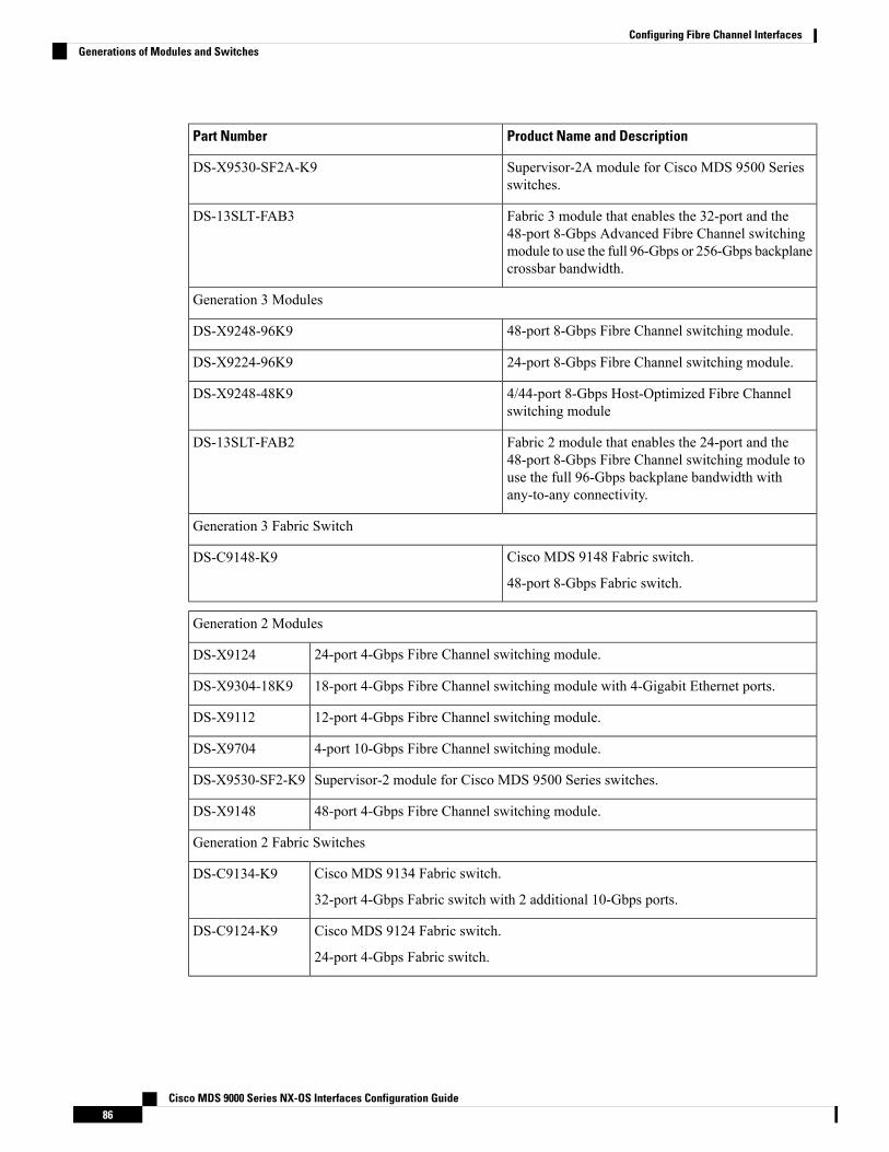
Product Name and DescriptionPart Number
Supervisor-2A module for Cisco MDS 9500 Seriesswitches.
DS-X9530-SF2A-K9
Fabric 3 module that enables the 32-port and the48-port 8-Gbps Advanced Fibre Channel switchingmodule to use the full 96-Gbps or 256-Gbps backplanecrossbar bandwidth.
DS-13SLT-FAB3
Generation 3 Modules
48-port 8-Gbps Fibre Channel switching module.DS-X9248-96K9
24-port 8-Gbps Fibre Channel switching module.DS-X9224-96K9
4/44-port 8-Gbps Host-Optimized Fibre Channelswitching module
DS-X9248-48K9
Fabric 2 module that enables the 24-port and the48-port 8-Gbps Fibre Channel switching module touse the full 96-Gbps backplane bandwidth withany-to-any connectivity.
DS-13SLT-FAB2
Generation 3 Fabric Switch
Cisco MDS 9148 Fabric switch.
48-port 8-Gbps Fabric switch.
DS-C9148-K9
Generation 2 Modules
24-port 4-Gbps Fibre Channel switching module.DS-X9124
18-port 4-Gbps Fibre Channel switching module with 4-Gigabit Ethernet ports.DS-X9304-18K9
12-port 4-Gbps Fibre Channel switching module.DS-X9112
4-port 10-Gbps Fibre Channel switching module.DS-X9704
Supervisor-2 module for Cisco MDS 9500 Series switches.DS-X9530-SF2-K9
48-port 4-Gbps Fibre Channel switching module.DS-X9148
Generation 2 Fabric Switches
Cisco MDS 9134 Fabric switch.
32-port 4-Gbps Fabric switch with 2 additional 10-Gbps ports.
DS-C9134-K9
Cisco MDS 9124 Fabric switch.
24-port 4-Gbps Fabric switch.
DS-C9124-K9
Cisco MDS 9000 Series NX-OS Interfaces Configuration Guide86
Configuring Fibre Channel InterfacesGenerations of Modules and Switches

Cisco MDS 9222i Multiservice Modular switch.
18-port 4-Gbps switch with 4-Gigabit Ethernet IP storage services ports, and a modularexpansion slot to host Cisco MDS 9000 Series switching and services modules.
DS-C9222i-K9
Generation 2 Fibre Channel switching modules are not supported on the Cisco MDS 9216 switch; however,they are supported by both the Supervisor-1 module and the Supervisor-2 module.
Note
For detailed information about the installation and specifications for these modules and switches, refer to thehardware installation guide for your switch.
Port GroupsEach module or switch can have one or more ports in port groups that share common resources such asbandwidth and buffer credits. Port groups are defined by the hardware consisting of sequential ports. Forexample, ports 1 through 6, ports 7 through 12, ports 13 through 18, ports 19 through 24, ports 25 through30, 31 through 36, and ports 37 through 42, 43 through 48 are the port groups on the 48-port 8-Gbps AdvancedFibre Channel switching modules.
Table 16: Bandwidth and Port Groups for the Fibre Channel Modules and Fabric Switches , on page 87 showsthe bandwidth and number of ports per port group for the Generation 2, Generation 3, and Generation 4 FibreChannel modules and Generation 2 and Generation 3 Fabric switches.
Table 16: Bandwidth and Port Groups for the Fibre Channel Modules and Fabric Switches
MaximumBandwidth Per Port(Gbps)
Bandwidth Per PortGroup (Gbps)
Number of Ports PerPort Group
Product Name/Description
Part Number
Generation 4 Modules
8 or 10Gbps—dependingon the configuration
32.45 or 12.86648-port 8-GbpsAdvanced FibreChannel switchingmodule.
DS-X9248-256K9
8 or 10Gbps—dependingon the configuration
32.4 or 12.8432-port 8-GbpsAdvanced FibreChannel switchingmodule.
DS-X9232-256K9
Generation 3 Modules
8 Gbps12.8648-port 8-GbpsFibre Channelswitching module
DS-X9248-96K9
8 Gbps12.8324-port 8-GbpsFibre Channelswitching module
DS-X9224-96K9
Cisco MDS 9000 Series NX-OS Interfaces Configuration Guide87
Configuring Fibre Channel InterfacesPort Groups

MaximumBandwidth Per Port(Gbps)
Bandwidth Per PortGroup (Gbps)
Number of Ports PerPort Group
Product Name/Description
Part Number
8/4 Gbps712.8124/44-port 8-GbpsHost-OptimizedFibre Channelswitching module
DS-X9248-48K9
Generation 3 Fabric Switches
8 Gbps32448-port 8-GbpsFabric switch
DS-C9148-K9
(Cisco MDS 9148Fabric switch)
5 This bandwidth is available with the Fabric 3 module (DS-13SLT-FAB3) in the MDS 9513 switch.6 This bandwidth is available with the Fabric 2 module (DS-13SLT-FAB2) in the MDS 9513 switch, andwith the Supervisor-2 (DS-X9530-SF2-K9) or Supervisor-2A module (DS-X9530-SF2AK9) in theMDS 9509 switch or MDS 9506 switch.
7 A maximum of four ports (one per port group) in a 4/44-port 8-Gbps switching module can operate at8-Gbps bandwidth in dedicated or shared mode. All the other ports can operate at a maximum of 4-Gbpsin shared mode or dedicated mode.
Generation 2 Modules
4 Gbps12.81248-port 4-Gbps Fibre Channel switchingmoduleDS-X9148
4 Gbps12.8624-port 4-Gbps Fibre Channel switchingmoduleDS-X9124
4 Gbps12.8618-port 4-Gbps Fibre Channel switchingmodulewith 4-Gigabit Ethernet ports
DS-X9304-18K9
(MSM-18/4 Multiservice module)
4 Gbps12.8312-port 4-Gbps Fibre Channel switchingmoduleDS-X9112
10Gbps1014-port 10-Gbps Fibre Channel switchingmoduleDS-X9704
Generation 2 Fabric Switches
4 Gbps16432-port 4-Gbps Fabric switchDS-C9134-K9
(Cisco MDS 9134 Fabric switch) 10Gbps1012-port 10-Gbps Fabric switch
4 Gbps16424-port 4-Gbps Fabric switchDS-C9124K9 (Cisco MDS 9124Fabric switch)
4 Gbps12.8618-port 4-Gbps, 4 Gigabit Ethernet ports and amodular expansion slot.
DS-C9222i-K9
(Cisco MDS 9222i MultiserviceModular switch)
Cisco MDS 9000 Series NX-OS Interfaces Configuration Guide88
Configuring Fibre Channel InterfacesPort Groups

Port Rate ModesIn Generation 2, Generation 3, and Generation 4 modules, you can configure the port rate modes. The portrate mode configuration is used to determine the bandwidth allocation for ports in a port group. Two port ratemodes are supported:
• Dedicated RateMode-A port is allocated required fabric bandwidth to sustain line traffic at the maximumoperating speed configured on the port. For more information, see the Dedicated Rate Mode, on page90 section.
• Shared RateMode-Multiple ports in a port group share data paths to the switch fabric and share bandwidth.For more information, see the Shared Rate Mode, on page 91 section.
In Generation 1 modules, you cannot configure the port rate modes. The mode is determined implicitly basedon the port mode and line card type.
Note
Port rate modes are not supported on the Cisco Fabric Switch for HP c-Class Blade System, and the CiscoFabric Switch for IBM Blade Center.
Note
Table 17: Port Rate Mode Support on Generation 2, Generation 3, and Generation 4 Modules and Switches, on page 89 shows the modules that support dedicated, shared, and the default rate modes.
Table 17: Port Rate Mode Support on Generation 2, Generation 3, and Generation 4 Modules and Switches
Generation 2 Modules
Auto, SharedYesYes48-port 4-Gbps Fibre Channel switchingmodule 8
DS-X9148
Auto, SharedYesYes24-port 4-Gbps Fibre Channel switchingmodule
DS-X9124
Auto, SharedYesYes18-port 4-Gbps Fibre Channel switchingmodule with 4-Gigabit Ethernet ports
DS-X9304-18K9
(MSM-18/4 Multiservicemodule)
Auto, DedicatedNoYes12-port 4-Gbps Fibre Channel switchingmodule
DS-X9112
Auto, DedicatedNoYes4-port 10-Gbps Fibre Channel switchingmodule
DS-X9704
Generation 2 Fabric Switches
Auto, SharedYesYes32-port 4-Gbps Fabric switchDS-C9134-K9
(Cisco MDS 9134 Fabricswitch)
Auto, DedicatedNoYes2-port 10-Gbps Fabric switch
Cisco MDS 9000 Series NX-OS Interfaces Configuration Guide89
Configuring Fibre Channel InterfacesPort Rate Modes

Auto, DedicatedNoYes24-port 4-Gbps Fabric switch 9DS-C9124-K9
(Cisco MDS 9124 Fabricswitch)
Auto, SharedYesYes18-port 4-Gbps Fibre Channel switch with4-Gigabit Ethernet IP storage services ports,and a modular expansion slot to host CiscoMDS 9000 Series switching and servicesmodules
DS-C9222i-K9
(Cisco MDS 9222iMultiservice Modular switch)
8 All ports in a 48-port 4-Gbps switching module can operate in dedicated rate mode with a 1-Gbpsoperating speed. However, if you configure one or more ports to operate in 2-Gbps or 4-Gbps dedicatedrate mode, some of the other ports in the port group would have to operate in shared mode.
9 All ports in a 24-port 4-Gbps switching module can operate in dedicated rate mode with a 2-Gbpsoperating speed. However, if you configure one or more ports to operate in 4-Gbps dedicated rate mode,some of the other ports in the port group would have to operate in shared mode.
Dedicated Rate ModeWhen port rate mode is configured as dedicated, a port is allocated required fabric bandwidth and relatedresources to sustain line rate traffic at the maximum operating speed configured for the port. In this mode,ports do not use local buffering and all receive buffers are allocated from a global buffer pool.
Table 18: Bandwidth Reserved for the Port Speeds on Generation 4 Switching Modules , on page 90 showsthe bandwidth provided by the various port speed configurations on the 8-Gbps Advanced Fibre Channelswitching modules.
Table 18: Bandwidth Reserved for the Port Speeds on Generation 4 Switching Modules
Reserved BandwidthConfigured Speed
8 GbpsAuto
8-Gbps
4 GbpsAuto with 4-Gbps maximum
4-Gbps
2 GbpsAuto with 2-Gbps maximum
2-Gbps
1 Gbps1-Gbps
Table 19: Bandwidth Reserved for the Port Speeds on Generation 3 Switching Modules , on page 91 showsthe bandwidth provided by the various port speed configurations on the 8-Gbps Fibre Channel switchingmodules.
Cisco MDS 9000 Series NX-OS Interfaces Configuration Guide90
Configuring Fibre Channel InterfacesDedicated Rate Mode

Table 19: Bandwidth Reserved for the Port Speeds on Generation 3 Switching Modules
Reserved BandwidthConfigured Speed
8 GbpsAuto
8-Gbps
4 GbpsAuto with 4-Gbps maximum
4-Gbps
2 GbpsAuto with 2-Gbps maximum
2-Gbps
1 Gbps1-Gbps
Table 20: Bandwidth Reserved for the Port Speeds on Generation 2 Switching Modules , on page 91 showsthe amount of bandwidth reserved for a configured port speed on 4-Gbps switching modules.
Table 20: Bandwidth Reserved for the Port Speeds on Generation 2 Switching Modules
Reserved BandwidthConfigured Speed
4 GbpsAuto
4-Gbps
2 GbpsAuto with 2-Gbps maximum
2-Gbps
1 Gbps1-Gbps
The 4-Port 10-Gbps Fibre Channel module ports in auto mode only support auto speed mode at 10 Gbps.Note
Shared Rate ModeWhen port rate mode is configured as shared, multiple ports within a port group share data paths to the switchfabric so that fabric bandwidth and related resources are shared. Often, the available bandwidth to the switchfabric may be less than the negotiated operating speed of a port. Ports in this mode use local buffering for theBB_credit buffers.
All ports in 8-Gbps Advanced Fibre Channel switching modules where bandwidth is shared support 1-Gbps,2-Gbps, 4-Gbps, or 8 Gbps traffic. However, it is possible to configure one or more ports in a port group tooperate in dedicated rate mode with 1-Gbps, 2-Gbps, 4-Gbps, or 8 Gbps operating speed.
All ports in 4-Gbps Fibre Channel switching modules where bandwidth is shared support 1-Gbps, 2-Gbps, or4-Gbps traffic. However, it is possible to configure one or more ports in a port group to operate in dedicatedrate mode with 1-Gbps, 2-Gbps, or 4-Gbps operating speed.
Cisco MDS 9000 Series NX-OS Interfaces Configuration Guide91
Configuring Fibre Channel InterfacesShared Rate Mode

All ports in the 32-Port or 48-Port 8-Gbps Advanced Fibre Channel modules where bandwidth is sharedsupport 1-Gbps, 2-Gbps, 4-Gbps, or 8-Gbps traffic in a maximum or 32 or 48 ports.
All ports in the 48-Port and 24-Port 8-Gbps Fibre Channel switching modules where bandwidth is sharedsupport 1-Gbps, 2-Gbps, 4-Gbps, or 8-Gbps traffic.
In the 4/44-Port 8-Gbps Host-Optimized Fibre Channel switching module, all the ports where bandwidth isshared support 1-Gbps, 2-Gbps, 4-Gbps in a maximum of 44 ports, or 8 Gbps in a maximum of 4 ports.
Dedicated Rate Mode Configurations for the 8-Gbps ModulesTable 21: Dedicated Rate Mode Bandwidth Reservation for Generation 4 Fibre Channel Modules , on page92 shows the maximum possible dedicated rate mode configuration scenarios for the Generation 4 FibreChannel modules.
Table 21: Dedicated Rate Mode Bandwidth Reservation for Generation 4 Fibre Channel Modules
Ports inShared Mode
Maximum Allowed PortsThat Can Come Up
Dedicated Bandwidth perPort
Product Name/Description
Part Number
All theremainingports are 8Gbps shared.
24 Ports10 Gbps48-port 8-GbpsAdvanced FibreChannelswitchingmodule
DS-X9248-256K9
32 Ports8 Gbps
48 Ports4 Gbps
48 Ports2 Gbps
48 Ports1 Gbps
All theremainingports are 8Gbps shared.
24 Ports10 Gbps32-port 8-GbpsAdvanced FibreChannelswitchingmodule
DS-X9232-256K9
32 Ports8 Gbps
32 Ports4 Gbps
32 Ports2 Gbps
32 Ports1 Gbps
Table 22: Dedicated Rate Mode Bandwidth Reservation for Generation 3 Fibre Channel Modules , on page92 shows the maximum possible dedicated rate mode configuration scenarios for the Generation 3 FibreChannel modules.
Table 22: Dedicated Rate Mode Bandwidth Reservation for Generation 3 Fibre Channel Modules
Ports in SharedMode
Maximum AllowedPorts That Can Come Up
Dedicated Bandwidthper Port
Product Name/Description
Part Number
All the remainingports are 8 Gbpsshared.
8 Ports8 Gbps24-port 8-GbpsFibre Channelswitching module
DS-X9224-96K9
24 Ports4 Gbps
Cisco MDS 9000 Series NX-OS Interfaces Configuration Guide92
Configuring Fibre Channel InterfacesDedicated Rate Mode Configurations for the 8-Gbps Modules

Ports in SharedMode
Maximum AllowedPorts That Can Come Up
Dedicated Bandwidthper Port
Product Name/Description
Part Number
All the remainingports are 8 Gbpsshared.
8 Ports8 Gbps48-port 8-GbpsFibre Channelswitching module
DS-X9248-96K9
24 Ports4 Gbps
48 Ports2 Gbps
All the remainingports are 4 Gbpsshared (8 Gbps ofbandwidth can beprovided only to oneport per port groupin dedicated orshared rate mode).
4 Ports8 Gbps4/44-port 8-GbpsHost-OptimizedFibre Channelswitching module
DS-X9248-48K9
12 Ports4 Gbps
24 Ports2 Gbps
48 Ports1 Gbps
Port SpeedThe port speed on an interface, combined with the rate mode, determines the amount of shared resourcesavailable to the ports in the port group on a 48-port, 24-port 4-Gbps, or any 8-Gbps Fibre Channel switchingmodule. With the dedicated rate mode, the port group resources are reserved even though the bandwidth isnot used. For example, on Generation 3 modules, if an interface is configured for autosensing (auto) anddedicated rate mode, then 8 Gbps of bandwidth is reserved even though the maximum operating speed is 2Gbps. For the same interface, if autosensing with a maximum speed of 2 Gbps (auto max 2000) is configured,then only 2 Gbps of bandwidth is reserved and the unused 2 Gbps is shared with the other interface in the portgroup.
• The Generation 2, 4-port 10-Gbps switching module supports 10-Gbps traffic only.
• On Generation 2, 4-Gbps modules, setting the port speed to auto enables autosensing, which negotiatesto a maximum speed of 4 Gbps.
• On Generation 3, 8-Gbps modules, setting the port speed to auto enables autosensing, which negotiatesto a maximum speed of 8 Gbps.
• On Generation 4, 8-Gbps modules, setting the port speed to auto enables autosensing, which negotiatesto a maximum speed of 8 Gbps.
Note
Forward Error CorrectionThe Transmitter Training Signal (TTS) is defined in FC-FS-4(Clause 5.5). It provides the capability for FCports to negotiate the following two capabilities:
1. Transmitter training, which enables a receiver to send feedback to a transmitter to assist the transmitterin adapting to the characteristics of the link that connects them.
2. FEC usage.
Cisco MDS 9000 Series NX-OS Interfaces Configuration Guide93
Configuring Fibre Channel InterfacesPort Speed

The TTS is not used by 4 and 8-gigabit FC ports. From 32-gigabit speed and higher, its use is mandatory. For16-gigabit FC ports, EA variants must transmit the TTS during the link speed negotiation, but the use of it bythe receiver is optional, and EL variants must not use TTS.
Forward Error Correction (FEC) is defined in IEEE 802.3TM clause 74 and is implemented in FC withoutmodification. FEC is not supported on 4, 8 and 16-gigabit EL ports. Its use is optional on 16-gigabit EA ports.The TTS is the mechanism that allows FEC negotiation on such ports.
For more information on configuring FEC and TTS, see the Configuring FEC, on page 116 section.
Dynamic Bandwidth ManagementOn port switching modules where bandwidth is shared, the bandwidth available to each port within a portgroup can be configured based on the port rate mode and speed configurations. Within a port group, someports can be configured in dedicated rate mode while others operate in shared mode.
Ports configured in dedicated rate mode are allocated the required bandwidth to sustain a line rate of trafficat the maximum configured operating speed, and ports configured in sharedmode share the available remainingbandwidth within the port group. Bandwidth allocation among the sharedmode ports is based on the operationalspeed of the ports.
For example, if four ports operating at speeds 1 Gbps, 1 Gbps, 2 Gbps, and 4 Gbps share bandwidth of 8 Gbps,the ratio of allocation would be 1:1:2:4.
Unutilized bandwidth from the dedicated ports is shared among only the shared ports in a port group as perthe ratio of the configured operating speed. A port cannot be brought up unless the reserved bandwidth isquarantined for the shared ports. For dedicated ports, configured bandwidth is taken into consideration whilecalculating available bandwidth for the port group. This behavior can be changed using bandwidth fairnessby using the rate-mode bandwidth-fairness module number command.
For example, consider a 48-port 8-Gbps module. This module has 6 ports per port group with 12.8 Gbpsbandwidth. Ports 3 to 6 are configured at 4 Gbps. If the first port is configured at 8 Gbps dedicated rate mode,and the second port is configured at 4-Gbps dedicated rate mode, then no other ports can be configured at 4Gbps or 8 Gbps because the left over bandwidth of 0.8 Gbps (12.8-(8+4)) cannot meet the required 0.96 Gbpsfor the remaining four ports. A minimum of 0.24 Gbps reserved bandwidth is required for the for the rest ofthe four ports. However, if the two ports (for example, 5 and 6) are taken out of service (which is not sameas shutdown), required reserved bandwidth for the two ports (3 and 4) is 0.48 and port 2 can be configuredat 4 Gbps in dedicated rate mode. This behavior can be overridden by the bandwidth fairness command inwhich case reserved bandwidth is not enforced. Once the port is up, ports 3 and 4 can share the unutilizedbandwidth from ports 1 and 2.
Out-of-Service InterfacesOn supported modules and fabric switches, you might need to allocate all the shared resources for one or moreinterfaces to another interface in the port group or module. You can take interfaces out of service to releaseshared resources that are needed for dedicated bandwidth. When an interface is taken out of service, all sharedresources are released and made available to the other interface in the port group or module. These sharedresources include bandwidth for the shared mode port, rate mode, BB_credits, and extended BB_credits. Allshared resource configurations are returned to their default values when the interface is brought back intoservice. Corresponding resources must be made available in order for the port to be successfully returned toservice.
Cisco MDS 9000 Series NX-OS Interfaces Configuration Guide94
Configuring Fibre Channel InterfacesDynamic Bandwidth Management

If you need to bring an interface back into service, you might disrupt traffic if you need to release sharedresources from other interfaces in the same port group.
Caution
Oversubscription Ratio RestrictionsThe 48-port and 24-port 4-Gbps, and all 8-Gbps Fibre Channel switching modules support oversubscriptionon switches with shared rate mode configurations. By default, all 48-port and 24-port 4-Gbps, and 8-GbpsFibre Channel switching modules have restrictions on oversubscription ratios enabled. As of Cisco SAN-OSRelease 3.1(1) and NX-OS Release 4.1(1), you can disable restrictions on oversubscription ratios.
Table 23: Bandwidth Allocation for Oversubscribed Interfaces , on page 95 describes the bandwidth allocationfor oversubscribed interfaces configured in shared mode on the 4-Gbps and 8-Gbps modules.
Table 23: Bandwidth Allocation for Oversubscribed Interfaces
Ratios disabledMaximumBandwidth (Gbps)
ReservedBandwidth (Gbps)
Configured SpeedSwitching Module
Ratios enabled
80.80.8Auto 8 Gbps24-Port 8-GbpsFibre ChannelModule 40.40.4Auto Max 4 Gbps
20.20.2Auto Max 2 Gbps
80.160.878 Gbps4/44-Port 8-GbpsHost-OptimizedFibre ChannelModule
40.080.436Auto Max 4 Gbps
20.040.218Auto Max 2 Gbps
10.020.1091 Gbps
40.090.8Auto 4 Gbps48-port 4-GbpsFibre Channelswitching module 20.0450.4Auto Max 2 Gbps
10.02250.21 Gbps
40.271Auto 4 Gbps24-port 4-GbpsFibre Channelswitching module 20.1350.5Auto Max 2 Gbps
10.0670.251 Gbps
All ports in the 48-port and 24-port 4-Gbps modules can be configured to operate at 4 Gbps in shared modeeven if other ports in the port group are configured in dedicated mode, regardless of available bandwidth.However, when oversubscription ratio restrictions are enabled, you may not have all shared 4-Gbps moduleports operating at 4 Gbps.
Cisco MDS 9000 Series NX-OS Interfaces Configuration Guide95
Configuring Fibre Channel InterfacesOversubscription Ratio Restrictions

All ports in the 48-port, 32-Port, and 24-port 8-Gbps modules can be configured to operate at 8 Gbps in sharedmode even if other ports in the port group are configured in dedicated mode, regardless of available bandwidth.However, when oversubscription ratio restrictions are enabled you may not have all shared 8-Gbps moduleports operating at 8 Gbps.
On the 48-port, 32-Port, and 24-port 8-Gbps modules, if you have configured one 8-Gbps dedicated port inone port group, no other ports in the same port group can be configured to operate at 8-Gbps dedicated mode.You can have any number of 8-Gbps shared and 4-Gbps dedicated or shared ports. On the 4/44-port 8-Gbpsmodule, only one port per port group can be configured in 8-Gbps dedicated or shared mode.
In the following example, each of the 4 ports already have 500 credits and you have 2150 remaining for theport group. So, in all 4150 credits:
switch(config-if)# show port-resources module 1Module 1Available dedicated buffers for global buffer #0 [port-group 1] are 2150Available dedicated buffers for global buffer #1 [port-group 2] are 2150Available dedicated buffers for global buffer #2 [port-group 3] are 2150Available dedicated buffers for global buffer #3 [port-group 4] are 2148Available dedicated buffers for global buffer #4 [port-group 5] are 2150Available dedicated buffers for global buffer #5 [port-group 6] are 2150Available dedicated buffers for global buffer #6 [port-group 7] are 2150Available dedicated buffers for global buffer #7 [port-group 8] are 650Available dedicated buffers for global buffer #8 [port-group 9] are 2150Available dedicated buffers for global buffer #9 [port-group 10] are 2150Available dedicated buffers for global buffer #10 [port-group 11] are 2150Available dedicated buffers for global buffer #11 [port-group 12] are 2150
Port-Group 1Total bandwidth is 64.0 GbpsAllocated dedicated bandwidth is 64.0 Gbps--------------------------------------------------------------------Interfaces in the Port-Group B2B Credit Bandwidth Rate Mode
Buffers (Gbps)--------------------------------------------------------------------fc1/1 500 16.0 dedicatedfc1/2 500 16.0 dedicatedfc1/3 500 16.0 dedicatedfc1/4 500 16.0 dedicated
Port-Group 6Total bandwidth is 64.0 GbpsAllocated dedicated bandwidth is 64.0 Gbps--------------------------------------------------------------------Interfaces in the Port-Group B2B Credit Bandwidth Rate Mode
Buffers (Gbps)--------------------------------------------------------------------fc4/21 4090 16.0 dedicatedfc4/22 10 16.0 dedicatedfc4/23 10 16.0 dedicatedfc4/24 10 16.0 dedicated
In the following example, a 24-port 4-Gbps module has oversubscription ratios enabled and three dedicatedports in one port group operating at 4-Gbps. No other ports in the same port group can be configured to operateat 4 Gbps.
switch# show port-resources module 8Module 8Available dedicated buffers are 5478
Cisco MDS 9000 Series NX-OS Interfaces Configuration Guide96
Configuring Fibre Channel InterfacesOversubscription Ratio Restrictions

Port-Group 1Total bandwidth is 12.8 GbpsTotal shared bandwidth is 0.8 GbpsAllocated dedicated bandwidth is 12.0 Gbps--------------------------------------------------------------------Interfaces in the Port-Group B2B Credit Bandwidth Rate Mode
Buffers (Gbps)--------------------------------------------------------------------fc8/1 16 4.0 dedicatedfc8/2 16 4.0 dedicatedfc8/3 16 4.0 dedicatedfc8/4 (out-of-service)fc8/5 (out-of-service)fc8/6 (out-of-service)
For dedicated ports, oversubscription ratio restrictions do not apply to the shared pool in port groups. So ifoversubscription ratio restrictions are disabled, and you have configured three 4-Gbps dedicated ports in oneport group, then you can configure all other ports in the same port group to operate at a shared rate of 4 Gbps.
In the following example, a 48-port module has a group of six ports, four dedicated ports are operating at 8Gbps, and the two shared ports are also operating at 8 Gbps:
switch# show port-resources module 5Module 5Available dedicated buffers for global buffer #0 [port-group 1] are 3970Available dedicated buffers for global buffer #1 [port-group 2] are 3970Available dedicated buffers for global buffer #2 [port-group 3] are 3970Available dedicated buffers for global buffer #3 [port-group 4] are 3970Available dedicated buffers for global buffer #4 [port-group 5] are 3058Available dedicated buffers for global buffer #5 [port-group 6] are 3058Available dedicated buffers for global buffer #6 [port-group 7] are 3970Available dedicated buffers for global buffer #7 [port-group 8] are 3970
Port-Group 1Total bandwidth is 32.4 GbpsTotal shared bandwidth is 32.4 GbpsAllocated dedicated bandwidth is 0.0 Gbps--------------------------------------------------------------------Interfaces in the Port-Group B2B Credit Bandwidth Rate Mode
Buffers (Gbps)--------------------------------------------------------------------fc5/1 32 8.0 sharedfc5/2 32 8.0 sharedfc5/3 32 8.0 sharedfc5/4 32 8.0 shared
Port-Group 2Total bandwidth is 32.4 GbpsTotal shared bandwidth is 32.4 GbpsAllocated dedicated bandwidth is 0.0 Gbps--------------------------------------------------------------------Interfaces in the Port-Group B2B Credit Bandwidth Rate Mode
Buffers (Gbps)--------------------------------------------------------------------fc5/5 32 8.0 sharedfc5/6 32 8.0 sharedfc5/7 32 8.0 sharedfc5/8 32 8.0 shared
Port-Group 3Total bandwidth is 32.4 GbpsTotal shared bandwidth is 32.4 Gbps
Cisco MDS 9000 Series NX-OS Interfaces Configuration Guide97
Configuring Fibre Channel InterfacesOversubscription Ratio Restrictions

Allocated dedicated bandwidth is 0.0 Gbps--------------------------------------------------------------------Interfaces in the Port-Group B2B Credit Bandwidth Rate Mode
Buffers (Gbps)--------------------------------------------------------------------fc5/9 32 8.0 sharedfc5/10 32 8.0 sharedfc5/11 32 8.0 sharedfc5/12 32 8.0 shared
Port-Group 4Total bandwidth is 32.4 GbpsTotal shared bandwidth is 32.4 GbpsAllocated dedicated bandwidth is 0.0 Gbps--------------------------------------------------------------------Interfaces in the Port-Group B2B Credit Bandwidth Rate Mode
Buffers (Gbps)--------------------------------------------------------------------fc5/13 32 8.0 sharedfc5/14 32 8.0 sharedfc5/15 32 8.0 sharedfc5/16 32 8.0 shared
Port-Group 5Total bandwidth is 32.4 GbpsTotal shared bandwidth is 16.4 GbpsAllocated dedicated bandwidth is 16.0 Gbps--------------------------------------------------------------------Interfaces in the Port-Group B2B Credit Bandwidth Rate Mode
Buffers (Gbps)--------------------------------------------------------------------fc5/17 32 8.0 sharedfc5/18 32 8.0 sharedfc5/19 500 8.0 dedicatedfc5/20 500 8.0 dedicated
Port-Group 6Total bandwidth is 32.4 GbpsTotal shared bandwidth is 16.4 GbpsAllocated dedicated bandwidth is 16.0 Gbps--------------------------------------------------------------------Interfaces in the Port-Group B2B Credit Bandwidth Rate Mode
Buffers (Gbps)--------------------------------------------------------------------fc5/21 500 8.0 dedicatedfc5/22 500 8.0 dedicatedfc5/23 32 8.0 sharedfc5/24 32 8.0 shared
Port-Group 7Total bandwidth is 32.4 GbpsTotal shared bandwidth is 32.4 GbpsAllocated dedicated bandwidth is 0.0 Gbps--------------------------------------------------------------------Interfaces in the Port-Group B2B Credit Bandwidth Rate Mode
Buffers (Gbps)--------------------------------------------------------------------fc5/25 32 8.0 sharedfc5/26 32 8.0 sharedfc5/27 32 8.0 sharedfc5/28 32 8.0 shared
Port-Group 8Total bandwidth is 32.4 Gbps
Cisco MDS 9000 Series NX-OS Interfaces Configuration Guide98
Configuring Fibre Channel InterfacesOversubscription Ratio Restrictions

Total shared bandwidth is 32.4 GbpsAllocated dedicated bandwidth is 0.0 Gbps--------------------------------------------------------------------Interfaces in the Port-Group B2B Credit Bandwidth Rate Mode
Buffers (Gbps)--------------------------------------------------------------------fc5/29 32 8.0 sharedfc5/30 32 8.0 sharedfc5/31 32 8.0 sharedfc5/32 32 8.0 shared
switch# show port-resources module 13Module 13Available dedicated buffers for global buffer #0 [port-group 1] are 3880Available dedicated buffers for global buffer #1 [port-group 2] are 3880Available dedicated buffers for global buffer #2 [port-group 3] are 3880Available dedicated buffers for global buffer #3 [port-group 4] are 3056Available dedicated buffers for global buffer #4 [port-group 5] are 3880Available dedicated buffers for global buffer #5 [port-group 6] are 3880Available dedicated buffers for global buffer #6 [port-group 7] are 3880Available dedicated buffers for global buffer #7 [port-group 8] are 3880
Port-Group 1Total bandwidth is 32.4 GbpsTotal shared bandwidth is 32.4 GbpsAllocated dedicated bandwidth is 0.0 Gbps--------------------------------------------------------------------Interfaces in the Port-Group B2B Credit Bandwidth Rate Mode
Buffers (Gbps)--------------------------------------------------------------------fc13/1 32 8.0 sharedfc13/2 32 8.0 sharedfc13/3 32 8.0 sharedfc13/4 32 8.0 sharedfc13/5 32 8.0 sharedfc13/6 32 8.0 shared
Port-Group 2Total bandwidth is 32.4 GbpsTotal shared bandwidth is 32.4 GbpsAllocated dedicated bandwidth is 0.0 Gbps--------------------------------------------------------------------Interfaces in the Port-Group B2B Credit Bandwidth Rate Mode
Buffers (Gbps)--------------------------------------------------------------------fc13/7 32 8.0 sharedfc13/8 32 8.0 sharedfc13/9 32 8.0 sharedfc13/10 32 8.0 sharedfc13/11 32 8.0 sharedfc13/12 32 8.0 shared
Port-Group 3Total bandwidth is 32.4 GbpsTotal shared bandwidth is 32.4 GbpsAllocated dedicated bandwidth is 0.0 Gbps--------------------------------------------------------------------Interfaces in the Port-Group B2B Credit Bandwidth Rate Mode
Buffers (Gbps)--------------------------------------------------------------------fc13/13 32 8.0 sharedfc13/14 32 8.0 sharedfc13/15 32 8.0 sharedfc13/16 32 8.0 shared
Cisco MDS 9000 Series NX-OS Interfaces Configuration Guide99
Configuring Fibre Channel InterfacesOversubscription Ratio Restrictions

fc13/17 32 8.0 sharedfc13/18 32 8.0 shared
Port-Group 4Total bandwidth is 32.4 GbpsTotal shared bandwidth is 0.4 GbpsAllocated dedicated bandwidth is 32.0 Gbps--------------------------------------------------------------------Interfaces in the Port-Group B2B Credit Bandwidth Rate Mode
Buffers (Gbps)--------------------------------------------------------------------fc13/19 250 8.0 dedicatedfc13/20 250 8.0 dedicatedfc13/21 250 8.0 dedicatedfc13/22 250 8.0 dedicatedfc13/23 32 8.0 sharedfc13/24 32 8.0 shared
Port-Group 5Total bandwidth is 32.4 GbpsTotal shared bandwidth is 32.4 GbpsAllocated dedicated bandwidth is 0.0 Gbps--------------------------------------------------------------------Interfaces in the Port-Group B2B Credit Bandwidth Rate Mode
Buffers (Gbps)--------------------------------------------------------------------fc13/25 32 8.0 sharedfc13/26 32 8.0 sharedfc13/27 32 8.0 sharedfc13/28 32 8.0 sharedfc13/29 32 8.0 sharedfc13/30 32 8.0 shared
Port-Group 6Total bandwidth is 32.4 GbpsTotal shared bandwidth is 32.4 GbpsAllocated dedicated bandwidth is 0.0 Gbps--------------------------------------------------------------------Interfaces in the Port-Group B2B Credit Bandwidth Rate Mode
Buffers (Gbps)--------------------------------------------------------------------fc13/31 32 8.0 sharedfc13/32 32 8.0 sharedfc13/33 32 8.0 sharedfc13/34 32 8.0 sharedfc13/35 32 8.0 sharedfc13/36 32 8.0 shared
Port-Group 7Total bandwidth is 32.4 GbpsTotal shared bandwidth is 32.4 GbpsAllocated dedicated bandwidth is 0.0 Gbps--------------------------------------------------------------------Interfaces in the Port-Group B2B Credit Bandwidth Rate Mode
Buffers (Gbps)--------------------------------------------------------------------fc13/37 32 8.0 sharedfc13/38 32 8.0 sharedfc13/39 32 8.0 sharedfc13/40 32 8.0 sharedfc13/41 32 8.0 sharedfc13/42 32 8.0 shared
Port-Group 8
Cisco MDS 9000 Series NX-OS Interfaces Configuration Guide100
Configuring Fibre Channel InterfacesOversubscription Ratio Restrictions

Total bandwidth is 32.4 GbpsTotal shared bandwidth is 32.4 GbpsAllocated dedicated bandwidth is 0.0 Gbps--------------------------------------------------------------------Interfaces in the Port-Group B2B Credit Bandwidth Rate Mode
Buffers (Gbps)--------------------------------------------------------------------fc13/43 32 8.0 sharedfc13/44 32 8.0 sharedfc13/45 32 8.0 sharedfc13/46 32 8.0 sharedfc13/47 32 8.0 sharedfc13/48 32 8.0 shared
...
When disabling restrictions on oversubscription ratios, all ports in shared mode on 48-port and 24-port 4-Gbpsor any 8-Gbps Fibre Channel switching modules must be shut down. When applying restrictions onoversubscription ratios, you must take shared ports out of service.
When restrictions on oversubscription ratios are disabled, the bandwidth allocation among the shared portsis proportionate to the configured speed. If the configured speed is auto on Generation 2 modules, thenbandwidth is allocated assuming a speed of 4 Gbps. For example, if you have three shared ports configuredat 1, 2, and 4 Gbps, then the allocated bandwidth ratio is 1:2:4.
As of Cisco SAN-OS Release 3.0 and NX-OS Release 4.1(1) or when restrictions on oversubscription ratiosare enabled, the port bandwidths are allocated in equal proportions, regardless of port speed, so, the bandwidthallocation for the same three ports mentioned in the example would be 1:1:1.
Note
Bandwidth FairnessThis feature improves fairness of bandwidth allocation among all ports and provides better throughput averageto individual data streams. Bandwidth fairness can be configured per module.
As of Cisco SAN-OS Release 3.1(2), all 48-port and 24-port 4-Gbps Fibre Channel switching modules, aswell as 18-port Fibre Channel/4-port Gigabit Ethernet Multiservice modules, have bandwidth fairness enabledby default. As of CiscoNX-OSRelease 4.1(1), all the 8-Gbps Fibre Channel switchingmodules have bandwidthfairness enabled by default.
When you disable or enable bandwidth fairness, the change does not take effect until you reload the module.Caution
Use the show module bandwidth-fairness command to check whether ports in a module are operating withbandwidth fairness enabled or disabled.
switch# show module 2 bandwidth-fairnessModule 2 bandwidth-fairness is enabled
This feature is supported only on the 48-port and 24-port 4-Gbps modules, the 8-Gbps modules, and the18/4-port Multiservice Module (MSM).
Note
Cisco MDS 9000 Series NX-OS Interfaces Configuration Guide101
Configuring Fibre Channel InterfacesBandwidth Fairness

Upgrade or Downgrade ScenarioWhen you are upgrading from a release earlier than Cisco SAN-OS Release 3.1(2), all modules operate withbandwidth fairness disabled until the next module reload. After the upgrade, any new module that is insertedhas bandwidth fairness enabled.
When you are downgrading to a release earlier than Cisco SAN-OS Release 3.1(2), all modules keep operatingin the same bandwidth fairness configuration prior to the downgrade. After the downgrade, any new modulethat is inserted has bandwidth fairness disabled.
After the downgrade, any insertion of a module or module reload will have bandwidth fairness disabled.Note
Cisco MDS 9000 Series NX-OS Interfaces Configuration Guide102
Configuring Fibre Channel InterfacesUpgrade or Downgrade Scenario

Guidelines and Limitations
CombiningGeneration1,Generation2,Generation3,andGeneration4ModulesCisco MDS NX-OS Release 5.2(x) and later supports combining Generation 1, Generation 2, Generation 3,and Generation 4 modules and switches with the following considerations:
• MDS NX-OS Release 4.1(1) and later features are not supported on the following Generation 1 switchesand modules:
• Supervisor 1 module
• 4-Port IP Storage Services module
• 8-Port IP Storage Services module
• MDS 9216 switch
• MDS 9216A switch
• MDS 9020 switch
• MDS 9120 switch
• MDS 9140 switch
• Supervisor-1 modules must be upgraded to Supervisor-2 modules on the MDS 9506 and MDS 9509Directors.
• IPS-4 and IPS-8 modules must be upgraded to the MSM-18/4 Multiservice modules.
• Fabric 1 modules must be upgraded to Fabric 2 modules on the MDS 9513 Director to use the 48-portor the 24-port 8-Gbps module.
• Fabric 2 modules must be upgraded to Fabric 3 modules on the MDS 9513 Director to get the maximumbackplane bandwidth of 256 Gbps.
• Cisco Fabric Manager Release 4.x supports MDS SAN-OS Release 3.x and NX-OS 4.x in mixed modethrough Interswitch Link (ISL) connectivity.
Local Switching Limitations• All ports in the module must be in shared mode. Use the switchport ratemode shared command toensure that all the ports in the module are in shared mode.
• No E ports are allowed in the module because E ports must be in dedicated mode.
Port Index LimitationsCisco MDS 9000 switches allocate index identifiers for the ports on the modules. These port indexes cannotbe configured. You can combine Generation 1, Generation 2, Generation 3, and Generation 4 switching
Cisco MDS 9000 Series NX-OS Interfaces Configuration Guide103
Configuring Fibre Channel InterfacesGuidelines and Limitations

modules, with either Supervisor-1 modules or Supervisor-2 modules. However, combining switching modulesand supervisor modules has the following port index limitations:
• Supervisor-1 modules only support a maximum of 252 port indexes, regardless of the type of switchingmodules.
• Supervisor-2 modules support a maximum of 1020 port indexes when all switchingmodules in the chassisare Generation 2 or Generation 3.
• Supervisor-2 modules only support a maximum of 252 port indexes when only Generation 1 switchingmodules, or a combination of Generation 1, Generation 2, Generation 3, or Generation 4 switchingmodules are installed in the chassis.
On a switch with the maximum limit of 252 as port index, any new module that exceeds the limit does notpower up when installed.
Note
You can use the show port index-allocation command to display the allocation of port indexes on the switch.
switch# show port index-allocationModule index distribution:------------------------------------------------------+Slot | Allowed | Allotted indices info |
| range | Total | Index values |-----------|---------|-------|-----------------------|1 | ----- | - | (None) |2 | ----- | - | (None) |3 | ----- | - | (None) |4 | ----- | - | (None) |5 | 0-1023| 32 | 0-31 |6 | ----- | - | (None) |9 | ----- | - | (None) |10 | ----- | - | (None) |11 | ----- | - | (None) |12 | ----- | - | (None) |13 | 0-1023| 48 | 32-79 |SUP | 253-255 | 3 | 253-255 |
Generation 1 switching modules have specific numbering requirements. If these requirements are not met,the module does not power up. The port index numbering requirements include the following:
• If port indexes in the range of 256 to 1020 are assigned to operational ports, Generation 1 switchingmodules do not power up.
• A block of contiguous port indexes is available. If this block of port indexes is not available, Generation1 modules do not power up. Table 24: Port Index Requirements for Generation 1 Modules , on page 105shows the port index requirements for the Generation 1 modules.
If the switch has Supervisor-1 modules, the block of 32 contiguous port indexes must begin on the slotboundary. The slot boundary for slot 1 is 0, for slot 2 is 32, and so on. For Supervisor-2 modules, the contiguousblock can start anywhere.
Note
Cisco MDS 9000 Series NX-OS Interfaces Configuration Guide104
Configuring Fibre Channel InterfacesPort Index Limitations

Table 24: Port Index Requirements for Generation 1 Modules
Number of Port Indexes RequiredGeneration 1 Module
Supervisor-2 ModuleSupervisor-1 Module
161616-port 2-Gbps Fibre Channelmodule
323232-port 2-Gbps Fibre Channelmodule
32328-port Gigabit Ethernet IP StorageServices module
16324-port Gigabit Ethernet IP StorageServices module
323232-port 2-Gbps Fibre ChannelStorage Services Module (SSM).
223214-port Fibre Channel/2-portGigabit Ethernet MultiprotocolServices (MPS-14/2) module
The allowed mix of Generation 1 and Generation 2 switching modules in a chassis is determined at run-time,either when booting up the switch or when installing the modules. In some cases, the sequence in whichswitching modules are inserted into the chassis determines if one or more modules is powered up.
When a module does not power up because of a resource limitation, you can display the reason by using theshow module command.
switch# show moduleMod Ports Module-Type Model Status--- ----- ----------------------------------- ------------------ ----------5 32 1/2/4/8/10 Gbps Advanced FC Module DS-X9232-256K9 ok7 0 Supervisor/Fabric-2 DS-X9530-SF2-K9 active *13 48 1/2/4/8/10 Gbps Advanced FC Module DS-X9248-256K9 okMod Sw Hw World-Wide-Name(s) (WWN)--- -------------- ------ --------------------------------------------------5 5.2(2) 0.207 21:01:00:0d:ec:b7:28:c0 to 21:20:00:0d:ec:b7:28:c07 5.2(2) 1.9 --13 5.2(2) 0.212 23:01:00:0d:ec:b7:28:c0 to 23:30:00:0d:ec:b7:28:c0Mod MAC-Address(es) Serial-Num--- -------------------------------------- ----------5 68-ef-bd-a8-45-cc to 68-ef-bd-a8-45-d0 JAF1450CHQT7 00-24-c4-60-00-f8 to 00-24-c4-60-00-fc JAE141502L213 68-ef-bd-a8-40-00 to 68-ef-bd-a8-40-04 JAF1450BMBPXbar Ports Module-Type Model Status--- ----- ----------------------------------- ------------------ ----------1 0 Fabric Module 3 DS-13SLT-FAB3 ok2 0 Fabric Module 3 DS-13SLT-FAB3 okXbar Sw Hw World-Wide-Name(s) (WWN)--- -------------- ------ --------------------------------------------------1 NA 0.4 --2 NA 0.4 --Xbar MAC-Address(es) Serial-Num--- -------------------------------------- ----------
Cisco MDS 9000 Series NX-OS Interfaces Configuration Guide105
Configuring Fibre Channel InterfacesPort Index Limitations

1 NA JAF1451AMHG2 NA JAF1451AMHN* this terminal session
The running configuration is updated when modules are installed. If you save the running configuration tothe startup configuration (using the copy running-config startup-config command), during reboot the switchpowers up the same set of modules as before the reboot regardless of the sequence in which the modulesinitialize. You can use the show port index-allocation startup command to display the index allocation theswitch uses at startup.
switch# show port index-allocation startupStartup module index distribution:------------------------------------------------------+Slot | Allowed | Alloted indices info |
| range | Total | Index values |-----|---------|-------|------------------------------|1 | ----- | 34 | 0-31,80-81 |2 | ----- | 32 | 32-63 |3 | ----- | 16 | 64-79 |(Slot 1 shares 80-81)4 | ----- | 48 | 96-127,224-239 |SUP | 253-255 | 3 | 253-255 |
The output of the show port index-allocation startup command does not display anything in the Allowedrange column because the command extracts the indices from the persistent storage service (PSS) and displayingan allowed range for startup indices is meaningless.
Note
If a module fails to power up, you can use the show module slot recovery-steps command to display thereason.
Whenever using mixed Generation 1 and Generation 2 modules, power up the Generation 1 modules first.During a reboot of the entire switch, the Generation 1 modules power up first (default behavior).
Tip
PortChannel LimitationsPortChannels have the following restrictions:
• The maximum number of PortChannels allowed is 256 if all switching modules are Generation 2 orGeneration 3, or both.
• The maximum number of PortChannels allowed is 128 whenever there is a Generation 1 switchingmodule in use with a Generation 2 or Generation 3 switching module.
• Ports need to be configured in dedicated rate mode on the Generation 2 and Generation 3 switchingmodule interfaces to be used in the PortChannel.
• Cisco MDS 9700 48-Port 32-Gbps Fibre Channel Switching Module (DS-X9648-1536K9) supports 32Gbps, 16 Gbps, 8 Gbps, and 4 Gbps speed. However, a single 32-Gbps SFP supports only 32 Gbps, 16Gbps, and 8 Gbps speed and a single 16-Gbps SFP supports only 16 Gbps, 8 Gbps, and 4 Gbps speed.You must not configure speed values other than the values recommended for these SFPs.
Cisco MDS 9000 Series NX-OS Interfaces Configuration Guide106
Configuring Fibre Channel InterfacesPortChannel Limitations

The number of PortChannels allowed does not depend on the type of supervisor module. However, Generation3 modules require the Supervisor 2 module on the MDS 9506 and 9509 switches.
Note
The Generation1, Generation 2, and Generation 3 modules have the following restrictions for PortChannelconfiguration:
• Generation 1 switching module interfaces do not support auto speed with a maximum of 2 Gbps.
• Generation 1 and Generation 2 module interfaces do not support auto speed with maximum of 4 Gbps.
• Generation 2 and Generation 3 switching module interfaces cannot be forcefully added to a PortChannelif sufficient resources are not available.
Before adding a Generation 2 or Generation 3 interface to a PortChannel, use the show port-resourcesmodulecommand to check for resource availability.
Note
When configuring PortChannels on switches with Generation 1, Generation 2, and Generation 3 switchingmodules, follow one of these procedures:
• Configure the PortChannel, and then configure the Generation 2 and Generation 3 interfaces to auto witha maximum of 2 Gbps.
• Configure the Generation 1 switching modules followed by the Generation 2 switching modules, andthen the Generation 3 switching modules, and then configure the PortChannel.
When configuring PortChannels on switches with only Generation 2 and Generation 3 switching modules,follow one of these procedures:
• Configure the PortChannel, and then configure the Generation 3 interfaces to auto with a maximum of4 Gbps.
• Configure the Generation 2 switching modules, followed by the Generation 3 switching modules, andthen configure the PortChannel.
Table 25: PortChannel Configuration and Addition Results , on page 108 describes the results of adding amember to a PortChannel for various configurations.
Cisco MDS 9000 Series NX-OS Interfaces Configuration Guide107
Configuring Fibre Channel InterfacesPortChannel Limitations

Table 25: PortChannel Configuration and Addition Results
ResultAddition TypeNew MemberType
Configured SpeedPortChannelMembers
New MemberPortChannel
PassForceGeneration 1 orGeneration 2 orGeneration 3 orGeneration 4
AnyAnyNo members
PassNormal or forceGeneration 1 orGeneration 2 orGeneration 3 orGeneration 4
AutoAuto
FailNormalGeneration 2 orGeneration 3 orGeneration 4
Auto max 2000Auto
Pass or fail10Force
Generation 3 orGeneration 4
Auto max 4000Auto
FailNormalGeneration 2 orGeneration 3 orGeneration 4
AutoAuto max 2000
PassForce
Generation 3 oror Generation 4
Auto max 4000Auto max 2000
Generation 2 orGeneration 3 oror Generation 4
AutoAuto max 4000
Generation 2 orGeneration 3 oror Generation 4
Auto max 2000Auto max 4000
FailNormalGeneration 2 orGeneration 3
AutoAutoGeneration 1interfaces
PassForce
PassNormal or forceGeneration 1AutoAuto max 2000
FailNormalGeneration 2 orGeneration 3
AutoAuto max 2000
Pass or fail11Force
Generation 1 orGeneration 2
AutoAuto max 4000
Generation 3AutoAuto max 4000
Cisco MDS 9000 Series NX-OS Interfaces Configuration Guide108
Configuring Fibre Channel InterfacesPortChannel Limitations

ResultAddition TypeNew MemberType
Configured SpeedPortChannelMembers
New MemberPortChannel
FailNormal or forceGeneration 1AutoAutoGeneration 2interfaces
PassNormal or forceGeneration 1AutoAuto max 2000
FailNormalGeneration 2 orGeneration 3
AutoAuto max 2000
PassForce
FailNormalGeneration 2 orGeneration 3
Auto max 2000Auto
PassForce
FailNormal or forceGeneration 1AutoAutoGeneration 3interfaces
PassNormal or forceGeneration 1AutoAuto max 2000
FailNormalGeneration 2AutoAuto max 2000
PassForce
FailNormalGeneration 2Auto max 2000Auto
PassForce
FailNormalGeneration 3AutoAuto max 2000
PassForce
FailNormalGeneration 3Auto max 2000Auto
PassForce
FailNormal or forceGeneration 1AutoAutoGeneration 4interfaces
PassNormal or forceGeneration 1AutoAuto max 2000
FailNormalGeneration 2AutoAuto max 2000
PassForce
FailNormalGeneration 2Auto max 2000Auto
PassForce
FailNormalGeneration 3 orGeneration 4
AutoAuto max 2000
PassForce
FailNormalGeneration 3 orGeneration 4
Auto max 2000Auto
PassForce
10 If resources are not available.
Cisco MDS 9000 Series NX-OS Interfaces Configuration Guide109
Configuring Fibre Channel InterfacesPortChannel Limitations

11 If resources are not available.
Use the show port-channel compatibility parameters command to obtain information about PortChanneladdition errors.
Cisco MDS 9000 Series NX-OS Interfaces Configuration Guide110
Configuring Fibre Channel InterfacesPortChannel Limitations

Default SettingsTable 26: Default Generation 2 Interface Parameters , on page 111 lists the default settings for Generation 2interface parameters.
Table 26: Default Generation 2 Interface Parameters
DefaultParameter
4-Port 10-GbpsSwitching Module
12-Port 4-GbpsSwitching Module
24-Port 4-GbpsSwitching Module
48-Port 4-GbpsSwitching Module
auto12autoautoautoSpeed mode
dedicateddedicatedsharedsharedRate mode
auto 14auto13FxFxPort mode
2502501616BB_credit buffers
145 5145 15––Performance buffers
12 The 4-port 10-Gbps switching module only supports 10-Gbps traffic.13 Auto port mode on the 12-port 4-Gbps switching module interfaces can operate in E port mode, TE port
mode, and Fx port mode.14 Auto port mode on the 4-port 10-Gbps switching module interfaces can operate in E port mode, TE port
mode, and F port mode.15 Performance buffers are shared among all ports on the module.
Table 27: Default Generation 3 Interface Parameters , on page 111 lists the default settings for Generation 3interface parameters.
Table 27: Default Generation 3 Interface Parameters
DefaultParameter
4/44-Port 8-GbpsHost-Optimized SwitchingModule
24-Port 8-Gbps SwitchingModule
48-Port 8-Gbps SwitchingModule
auto_max_4G 17auto16autoSpeed mode
sharedsharedsharedRate mode
FxFxFxPort mode
323232BB_credit buffers
16 Auto_max_4G speed mode on the 4/44-port 8-Gbps switching module negotiates to a maximum speedof 4 Gbps.
17 Auto_max_4G speed mode on the 4/44-port 8-Gbps switching module negotiates to a maximum speedof 4 Gbps.
Cisco MDS 9000 Series NX-OS Interfaces Configuration Guide111
Configuring Fibre Channel InterfacesDefault Settings

Table 28: Default Generation 4 Interface Parameters , on page 112 lists the default settings for Generation 4interface parameters.
Table 28: Default Generation 4 Interface Parameters
DefaultParameter
32-Port 8-Gbps Advanced FibreChannel Switching Module
48-Port 8-Gbps Advanced FibreChannel Switching Module
autoautoSpeed mode
sharedsharedRate mode
FxFxPort mode
3232BB_credit buffers
Cisco MDS 9000 Series NX-OS Interfaces Configuration Guide112
Configuring Fibre Channel InterfacesDefault Settings

Configuring Fibre Channel Interfaces
Task Flow for Migrating Interfaces from Shared Mode to Dedicated ModeThe 48-Port, 24-Port, and 4/44-Port 8-Gbps Fibre Channel switching modules support the following features:
• 1-Gbps, 2-Gbps, 4-Gbps, and 8-Gbps speed traffic
• Shared and dedicated rate mode
• ISL and Fx port modes
• Extended BB_credits
The 48-port and 24-port 4-Gbps Fibre Channel switching modules support the following features:
• 1-Gbps, 2-Gbps, and 4-Gbps speed traffic
• Shared and dedicated rate mode
• ISL (E or TE) and Fx (F or FL) port modes
• Extended BB_credits
If you change the port bandwidth reservation parameters on a 48-port or 24-port 4-Gbps module, the changeaffects only the changed port. No other ports in the port group are affected.
Note
To configure the Fibre Channel switching modules when starting with the default configuration or whenmigrating from shared rate mode to dedicated rate mode, perform these steps:
Step 1 Take unused interfaces out of service to release resources for other interfaces, if necessary.
See the Taking Interfaces out of Service, on page 129.
Step 2 Configure the traffic speed to use (1 Gbps, 2 Gbps, 4 Gbps, 8 Gbps, or autosensing with a maximum of 2 Gbps or 4Gbps).
See the Dynamic Bandwidth Management, on page 94.
Step 3 Configure the rate mode (dedicated or shared).
See the Configuring FEC, on page 116.
Step 4 Configure the port mode.
See the Configuring an Interface Mode , on page 43.
ISL ports cannot operate in shared rate mode.Note
Step 5 Configure the BB_credits and extended BB_credits, as necessary.
Cisco MDS 9000 Series NX-OS Interfaces Configuration Guide113
Configuring Fibre Channel InterfacesConfiguring Fibre Channel Interfaces

See the Configuring Buffer-to-Buffer Credits, on page 168 and Extended Buffer-to-Buffer Credits, on page 163 .
Task Flow for Migrating Interfaces from Dedicated Mode to Shared ModeTo configure the Fibre Channel switching modules migrating from dedicated rate mode to shared rate mode,perform these steps:
Step 1 Take unused interfaces out of service to release resources for other interfaces, if necessary.
See the Taking Interfaces out of Service, on page 129.
Step 2 Configure the BB_credits and extended BB_credits, as necessary.See the Configuring Buffer-to-Buffer Credits, on page 168 and Extended Buffer-to-Buffer Credits, on page 163
Step 3 Configure the port mode.
See the Configuring an Interface Mode , on page 43.
ISL ports cannot operate in shared rate mode.Note
Step 4 Configure the rate mode (dedicated or shared) to use.
See the Configuring FEC, on page 116.
Step 5 Configure the traffic speed (1 Gbps, 2 Gbps, 4 Gbps, or autosensing with a maximum of 2 Gbps or 4 Gbps) to use.
See the Dynamic Bandwidth Management, on page 94.
Task Flow for Configuring 4-Port 10-Gbps Module InterfacesThe 4-port 10-Gbps switching modules support the following features:
• Only 10-Gbps speed traffic
• Only dedicated rate mode
• ISL (E or TE) and F port modes
• Extended BB_credits
• Performance buffers
To configure 4-port 10-Gbps switching modules when starting with the default configuration, perform thesesteps:
Step 1 Configure the port mode.
See the Configuring an Interface Mode , on page 43.
Step 2 Configure the BB_credits, performance buffers, and extended BB_credits, as necessary.
Cisco MDS 9000 Series NX-OS Interfaces Configuration Guide114
Configuring Fibre Channel InterfacesTask Flow for Migrating Interfaces from Dedicated Mode to Shared Mode

See the Configuring Buffer-to-Buffer Credits, on page 168 and Extended Buffer-to-Buffer Credits, on page 163
Configuring Port Speed
Changing port speed and rate mode disrupts traffic on the port. Traffic on other ports in the port group is notaffected.
Note
To configure the port speed on an interface, perform these steps:
Step 1 switch# configure terminal
Enters configuration mode.
Step 2 switch(config)# interface fc 1/1
Selects the interface and enters interface configuration submode.
Step 3 switch(config-if)# switchport speed {1000 | 2000 | 4000 | 8000 | 10000 | 16000 | 32000}
Configures the port speed in megabits per second. The auto parameter enables autosensing on the interface.
Step 4 switch(config-if)# switchport speed auto
Configures autosensing for an interface.
The auto speed configurations are available only for the specific modules.Note
Step 5 switch(config-if)# no switchport speed
Reverts to the default speed for the interface (auto).
The default speed on 48-port and 24-port 4-Gbps modules is 4000. The default speed on 48-port and 24-port8-Gbps modules is 8000. The default speed on the 4/44-port 8-Gbps module is auto max 4000.
Note
Use the show interface command to verify the port speed configuration for an interface.
switch# show interface fc 9/1fc9/1 is up
Hardware is Fibre Channel, SFP is short wave laser w/o OFC (SN)Port WWN is 22:01:00:05:30:01:9f:02Admin port mode is Fsnmp traps are enabledPort mode is F, FCID is 0xeb0002Port vsan is 1Speed is 2 GbpsRate mode is sharedTransmit B2B Credit is 64Receive B2B Credit is 16Receive data field Size is 2112Beacon is turned off5 minutes input rate 0 bits/sec, 0 bytes/sec, 0 frames/sec5 minutes output rate 0 bits/sec, 0 bytes/sec, 0 frames/sec226 frames input, 18276 bytes
Cisco MDS 9000 Series NX-OS Interfaces Configuration Guide115
Configuring Fibre Channel InterfacesConfiguring Port Speed

0 discards, 0 errors0 CRC, 0 unknown class0 too long, 0 too short
326 frames output, 21364 bytes0 discards, 0 errors
0 input OLS, 0 LRR, 1 NOS, 0 loop inits3 output OLS, 2 LRR, 0 NOS, 0 loop inits16 receive B2B credit remaining64 transmit B2B credit remaining
Configuring FECFEC has the following restrictions:
• In Cisco NX-OS 6.2(7), Release 7.3(0)D1(1), and later releases, FEC is supported on the DS-X9334-K9,DS-X9648-1536K9, and DS-X9448-768K9 modules in the Cisco MDS 9700 Series switch. From CiscoMDSNX-OS Release 6.2(13), FEC is also supported on the CiscoMDS 9396SMultilayer Fabric Switch.FEC is not supported on the MDS 9500 series, MDS 9148, MDS 9148S, and MDS 9200 series switches.
• Modifying FEC configuration briefly disrupts traffic on the port.
• FEC can be configured only on fixed speed 16-Gbps Fibre Channel ports. FEC is not supported for portsconfigured with 2000/4000/8000/auto/auto-max maximum speed.
• 32-Gbps Fibre Channel ports come up automatically in FEC. You do not have to configure the portsusing the switchport fec and switchport fec tts commands, as they are meant only for 16-Gbps FibreChannel ports and have no effect on 32-Gbps Fibre Channel ports.
• From Cisco MDS NX-OS Release 6.2(11c), FEC with Transmitter Training Signal (TTS) is supportedon the Cisco MDS 9396S 16-Gbps Multilayer Fabric Switch and Cisco MDS 9700 48-Port 16-GbpsFibre Channel Switching Module (DS-X9448-768K9), except in Cisco MDS NX-OS Release 6.2(13).
• From Cisco MDS NX-OS Release 8.2(1), FEC with TTS feature is supported in Simple NetworkManagement Protocol (SNMP) and Device Manager (DM). This feature is not supported in Cisco MDSNX-OS Release 8.1(1) or earlier.
FEC is supported in DM.Note
• DM uses SNMP to get switch updates.
To configure FEC on an interface on the 48-port 16-Gbps Fibre Channel switching module, perform thesesteps:
Step 1 switch# configure terminal
Enters configuration mode.
Step 2 switch(config)# interface fc 1/1
Selects the interface and enters interface configuration submode.
Cisco MDS 9000 Series NX-OS Interfaces Configuration Guide116
Configuring Fibre Channel InterfacesConfiguring FEC

Step 3 switch(config-if)# switchport speed 16000
Sets the port speed to 16 Gbps.
Step 4 switch(config-if)# switchport fec
The switchport fec command works only in fixed 16-Gbps speed and a message stating the same appearswhen you execute this command.
Note
Enables FEC for the 16-Gbps interface.
• FEC is active if it is configured on both local and peer switches.
• FEC is not active if it is configured only on the local switch, but not on the peer switch.
Step 5 switch(config-if)# switchport fec tts
(Optional) Enables TTS, that allows negotiation of FEC. This command is only accepted on ports with fixed 16-Gbpsspeed and FEC enabled.
The switchport fec tts command can be used only after configuring FEC using the switchport fec command.Note
Use the show interface command to verify the port speed configuration for an interface on the 48-port, 16-Gbps FibreChannel switching module.
switch# show interface fc3/15fc3/15 is up
Hardware is Fibre Channel, SFP is short wave laser w/o OFC (SN)Port WWN is 20:8f:54:7f:ee:ea:3a:00Admin port mode is auto, trunk mode is offsnmp link state traps are enabledPort mode is F, FCID is 0xdf0000Port vsan is 100Speed is 2 GbpsRate mode is dedicatedTransmit B2B Credit is 128Receive B2B Credit is 32Receive data field Size is 2112Beacon is turned offadmin fec state is downoper fec state is down5 minutes input rate 0 bits/sec,0 bytes/sec, 0 frames/sec5 minutes output rate 0 bits/sec,0 bytes/sec, 0 frames/sec16072969258 frames input,34396153854332 bytes23 discards,45 errors22 invalid CRC/FCS,0 unknown class0 too long,0 too short
8040504998 frames output,17206679580576 bytes1344 discards,0 errors
0 input OLS,0 LRR,0 NOS,0 loop inits306 output OLS,304 LRR, 1 NOS, 4 loop inits32 receive B2B credit remaining128 transmit B2B credit remaining128 low priority transmit B2B credit remaining
Interface last changed at Wed Mar 12 21:23:36 2014Last clearing of "show interface" counters :never
Cisco MDS 9000 Series NX-OS Interfaces Configuration Guide117
Configuring Fibre Channel InterfacesConfiguring FEC

Configuring Rate Mode
Changing port speed and rate mode disrupts traffic on the port.Note
To configure the rate mode (dedicated or shared) on an interface on a Fibre Channel switchingmodule, performthese steps:
Step 1 switch# configure terminal
Enters configuration mode.
Step 2 switch(config)# interface fc 1/1
Selects the interface and enters interface configuration submode.
Step 3 switch(config-if)# switchport rate-mode dedicated
Reserves dedicated bandwidth for the interface.
If you cannot reserve dedicated bandwidth on an interface, you might have exceeded the port group maximumbandwidth. Use the show port-resources command to determine what resources are already allocated.
Note
Step 4 switch(config-if)# switchport rate-mode shared
Reserves shared (default) bandwidth for the interface.
Step 5 switch(config-if)# no switchport rate-mode
Reverts to the default state (shared).
Displaying the Rate Mode Configuration for InterfacesUse show port-resources module command to verify the rate mode configuration for interfaces on a FibreChannel switching module.
This example shows the port rate mode configuration for interfaces on a 4-Gbps module:
switch# show port-resources module 9Module 9Available dedicated buffers are 5400Port-Group 1Total bandwidth is 12.8 GbpsTotal shared bandwidth is 12.8 GbpsAllocated dedicated bandwidth is 0.0 Gbps--------------------------------------------------------------------Interfaces in the Port-Group B2B Credit Bandwidth Rate Mode
Buffers (Gbps)--------------------------------------------------------------------fc9/1 16 4.0 sharedfc9/2 16 4.0 sharedfc9/3 16 4.0 sharedfc9/4 16 4.0 shared
Cisco MDS 9000 Series NX-OS Interfaces Configuration Guide118
Configuring Fibre Channel InterfacesConfiguring Rate Mode

fc9/5 16 4.0 sharedfc9/6 16 4.0 sharedPort-Group 2Total bandwidth is 12.8 GbpsTotal shared bandwidth is 12.8 GbpsAllocated dedicated bandwidth is 0.0 Gbps--------------------------------------------------------------------Interfaces in the Port-Group B2B Credit Bandwidth Rate Mode
Buffers (Gbps)--------------------------------------------------------------------fc9/7 16 4.0 sharedfc9/8 16 4.0 sharedfc9/9 16 4.0 sharedfc9/10 16 4.0 sharedfc9/11 16 4.0 sharedfc9/12 16 4.0 sharedPort-Group 3Total bandwidth is 12.8 GbpsTotal shared bandwidth is 12.8 GbpsAllocated dedicated bandwidth is 0.0 Gbps--------------------------------------------------------------------Interfaces in the Port-Group B2B Credit Bandwidth Rate Mode
Buffers (Gbps)--------------------------------------------------------------------fc9/13 16 4.0 sharedfc9/14 16 4.0 sharedfc9/15 16 4.0 sharedfc9/16 16 4.0 sharedfc9/17 16 4.0 sharedfc9/18 16 4.0 sharedPort-Group 4Total bandwidth is 12.8 GbpsTotal shared bandwidth is 12.8 GbpsAllocated dedicated bandwidth is 0.0 Gbps--------------------------------------------------------------------Interfaces in the Port-Group B2B Credit Bandwidth Rate Mode
Buffers (Gbps)--------------------------------------------------------------------fc9/19 16 4.0 sharedfc9/20 16 4.0 sharedfc9/21 16 4.0 sharedfc9/22 16 4.0 sharedfc9/23 16 4.0 sharedfc9/24 16 4.0 shared
This example shows the port rate mode configuration for interfaces on a 48-port 8-Gbps module:
switch# show port-resource module 4Module 4Available dedicated buffers for global buffer #0 [port-groups 1-4] are 5016Available dedicated buffers for global buffer #1 [port-groups 5-8] are 5016Port-Group 1Total bandwidth is 12.8 GbpsTotal shared bandwidth is 12.8 GbpsAllocated dedicated bandwidth is 0.0 Gbps--------------------------------------------------------------------Interfaces in the Port-Group B2B Credit Bandwidth Rate Mode
Buffers (Gbps)--------------------------------------------------------------------fc4/1 32 8.0 sharedfc4/2 32 8.0 sharedfc4/3 32 8.0 sharedfc4/4 32 8.0 shared
Cisco MDS 9000 Series NX-OS Interfaces Configuration Guide119
Configuring Fibre Channel InterfacesDisplaying the Rate Mode Configuration for Interfaces
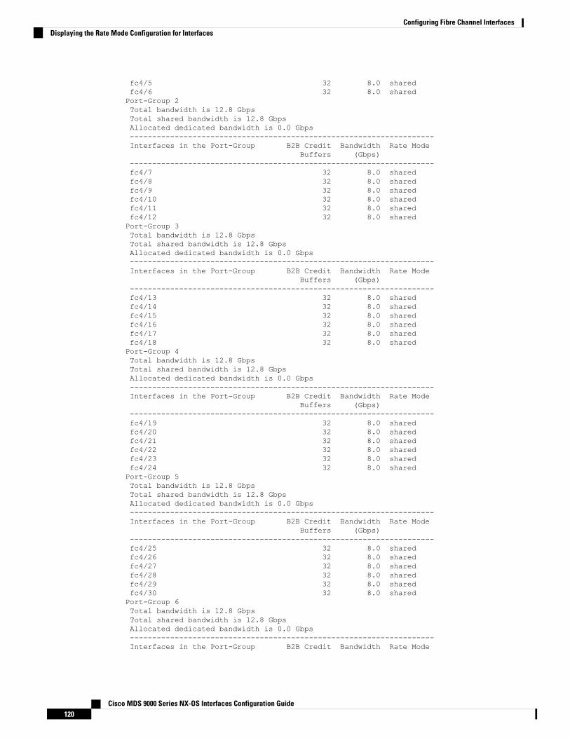
fc4/5 32 8.0 sharedfc4/6 32 8.0 sharedPort-Group 2Total bandwidth is 12.8 GbpsTotal shared bandwidth is 12.8 GbpsAllocated dedicated bandwidth is 0.0 Gbps--------------------------------------------------------------------Interfaces in the Port-Group B2B Credit Bandwidth Rate Mode
Buffers (Gbps)--------------------------------------------------------------------fc4/7 32 8.0 sharedfc4/8 32 8.0 sharedfc4/9 32 8.0 sharedfc4/10 32 8.0 sharedfc4/11 32 8.0 sharedfc4/12 32 8.0 sharedPort-Group 3Total bandwidth is 12.8 GbpsTotal shared bandwidth is 12.8 GbpsAllocated dedicated bandwidth is 0.0 Gbps--------------------------------------------------------------------Interfaces in the Port-Group B2B Credit Bandwidth Rate Mode
Buffers (Gbps)--------------------------------------------------------------------fc4/13 32 8.0 sharedfc4/14 32 8.0 sharedfc4/15 32 8.0 sharedfc4/16 32 8.0 sharedfc4/17 32 8.0 sharedfc4/18 32 8.0 sharedPort-Group 4Total bandwidth is 12.8 GbpsTotal shared bandwidth is 12.8 GbpsAllocated dedicated bandwidth is 0.0 Gbps--------------------------------------------------------------------Interfaces in the Port-Group B2B Credit Bandwidth Rate Mode
Buffers (Gbps)--------------------------------------------------------------------fc4/19 32 8.0 sharedfc4/20 32 8.0 sharedfc4/21 32 8.0 sharedfc4/22 32 8.0 sharedfc4/23 32 8.0 sharedfc4/24 32 8.0 sharedPort-Group 5Total bandwidth is 12.8 GbpsTotal shared bandwidth is 12.8 GbpsAllocated dedicated bandwidth is 0.0 Gbps--------------------------------------------------------------------Interfaces in the Port-Group B2B Credit Bandwidth Rate Mode
Buffers (Gbps)--------------------------------------------------------------------fc4/25 32 8.0 sharedfc4/26 32 8.0 sharedfc4/27 32 8.0 sharedfc4/28 32 8.0 sharedfc4/29 32 8.0 sharedfc4/30 32 8.0 sharedPort-Group 6Total bandwidth is 12.8 GbpsTotal shared bandwidth is 12.8 GbpsAllocated dedicated bandwidth is 0.0 Gbps--------------------------------------------------------------------Interfaces in the Port-Group B2B Credit Bandwidth Rate Mode
Cisco MDS 9000 Series NX-OS Interfaces Configuration Guide120
Configuring Fibre Channel InterfacesDisplaying the Rate Mode Configuration for Interfaces

Buffers (Gbps)--------------------------------------------------------------------fc4/31 32 8.0 sharedfc4/32 32 8.0 sharedfc4/33 32 8.0 sharedfc4/34 32 8.0 sharedfc4/35 32 8.0 sharedfc4/36 32 8.0 sharedPort-Group 7Total bandwidth is 12.8 GbpsTotal shared bandwidth is 12.8 GbpsAllocated dedicated bandwidth is 0.0 Gbps--------------------------------------------------------------------Interfaces in the Port-Group B2B Credit Bandwidth Rate Mode
Buffers (Gbps)--------------------------------------------------------------------fc4/37 32 8.0 sharedfc4/38 32 8.0 sharedfc4/39 32 8.0 sharedfc4/40 32 8.0 sharedfc4/41 32 8.0 sharedfc4/42 32 8.0 sharedPort-Group 8Total bandwidth is 12.8 GbpsTotal shared bandwidth is 12.8 GbpsAllocated dedicated bandwidth is 0.0 Gbps--------------------------------------------------------------------Interfaces in the Port-Group B2B Credit Bandwidth Rate Mode
Buffers (Gbps)--------------------------------------------------------------------fc4/43 32 8.0 sharedfc4/44 32 8.0 sharedfc4/45 32 8.0 sharedfc4/46 32 8.0 sharedfc4/47 32 8.0 sharedfc4/48 32 8.0 shared
This example shows the port rate mode configuration for interfaces on a 4/44-port 8-Gbps module:
switch# show port-resources module 7Module 7Available dedicated buffers are 3888Port-Group 1Total bandwidth is 12.8 GbpsTotal shared bandwidth is 12.8 GbpsAllocated dedicated bandwidth is 0.0 Gbps--------------------------------------------------------------------Interfaces in the Port-Group B2B Credit Bandwidth Rate Mode
Buffers (Gbps)--------------------------------------------------------------------fc7/1 32 4.0 sharedfc7/2 32 4.0 sharedfc7/3 32 4.0 sharedfc7/4 32 4.0 sharedfc7/5 32 4.0 sharedfc7/6 32 4.0 sharedfc7/7 32 4.0 sharedfc7/8 32 4.0 sharedfc7/9 32 4.0 sharedfc7/10 32 4.0 sharedfc7/11 32 4.0 sharedfc7/12 32 4.0 sharedPort-Group 2
Cisco MDS 9000 Series NX-OS Interfaces Configuration Guide121
Configuring Fibre Channel InterfacesDisplaying the Rate Mode Configuration for Interfaces

Total bandwidth is 12.8 GbpsTotal shared bandwidth is 12.8 GbpsAllocated dedicated bandwidth is 0.0 Gbps--------------------------------------------------------------------Interfaces in the Port-Group B2B Credit Bandwidth Rate Mode
Buffers (Gbps)--------------------------------------------------------------------fc7/13 32 4.0 sharedfc7/14 32 4.0 sharedfc7/15 32 4.0 sharedfc7/16 32 4.0 sharedfc7/17 32 4.0 sharedfc7/18 32 4.0 sharedfc7/19 32 4.0 sharedfc7/20 32 4.0 sharedfc7/21 32 4.0 sharedfc7/22 32 4.0 sharedfc7/23 32 4.0 sharedfc7/24 32 4.0 sharedPort-Group 3Total bandwidth is 12.8 GbpsTotal shared bandwidth is 12.8 GbpsAllocated dedicated bandwidth is 0.0 Gbps--------------------------------------------------------------------Interfaces in the Port-Group B2B Credit Bandwidth Rate Mode
Buffers (Gbps)--------------------------------------------------------------------fc7/25 32 4.0 sharedfc7/26 32 4.0 sharedfc7/27 32 4.0 sharedfc7/28 32 4.0 sharedfc7/29 32 4.0 sharedfc7/30 32 4.0 sharedfc7/31 32 4.0 sharedfc7/32 32 4.0 sharedfc7/33 32 4.0 sharedfc7/34 32 4.0 sharedfc7/35 32 4.0 sharedfc7/36 32 4.0 sharedPort-Group 4Total bandwidth is 12.8 GbpsTotal shared bandwidth is 12.8 GbpsAllocated dedicated bandwidth is 0.0 Gbps--------------------------------------------------------------------Interfaces in the Port-Group B2B Credit Bandwidth Rate Mode
Buffers (Gbps)--------------------------------------------------------------------fc7/37 32 4.0 sharedfc7/38 32 4.0 sharedfc7/39 32 4.0 sharedfc7/40 32 4.0 sharedfc7/41 32 4.0 sharedfc7/42 32 4.0 sharedfc7/43 32 4.0 sharedfc7/44 32 4.0 sharedfc7/45 32 4.0 sharedfc7/46 32 4.0 sharedfc7/47 32 4.0 sharedfc7/48 32 4.0 shared
Cisco MDS 9000 Series NX-OS Interfaces Configuration Guide122
Configuring Fibre Channel InterfacesDisplaying the Rate Mode Configuration for Interfaces
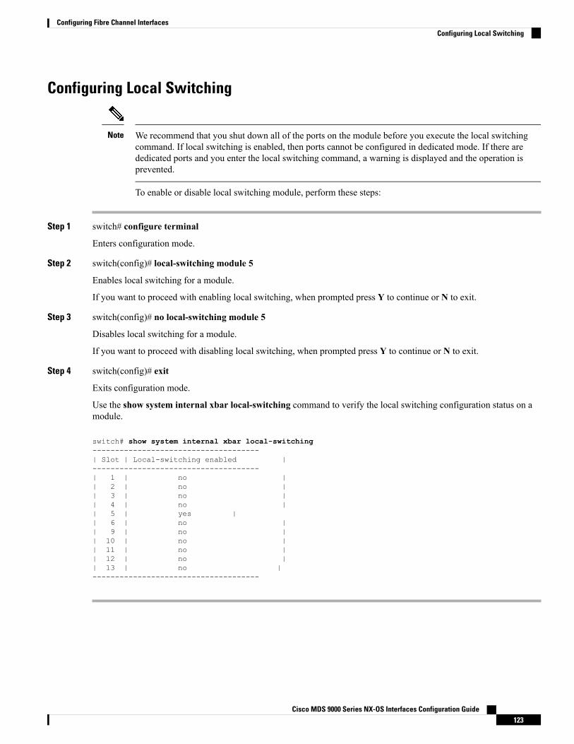
Configuring Local Switching
We recommend that you shut down all of the ports on the module before you execute the local switchingcommand. If local switching is enabled, then ports cannot be configured in dedicated mode. If there arededicated ports and you enter the local switching command, a warning is displayed and the operation isprevented.
Note
To enable or disable local switching module, perform these steps:
Step 1 switch# configure terminal
Enters configuration mode.
Step 2 switch(config)# local-switching module 5
Enables local switching for a module.
If you want to proceed with enabling local switching, when prompted press Y to continue or N to exit.
Step 3 switch(config)# no local-switching module 5
Disables local switching for a module.
If you want to proceed with disabling local switching, when prompted press Y to continue or N to exit.
Step 4 switch(config)# exit
Exits configuration mode.
Use the show system internal xbar local-switching command to verify the local switching configuration status on amodule.
switch# show system internal xbar local-switching-------------------------------------| Slot | Local-switching enabled |-------------------------------------| 1 | no || 2 | no || 3 | no || 4 | no || 5 | yes || 6 | no || 9 | no || 10 | no || 11 | no || 12 | no || 13 | no |-------------------------------------
Cisco MDS 9000 Series NX-OS Interfaces Configuration Guide123
Configuring Fibre Channel InterfacesConfiguring Local Switching

Disabling Restrictions on Oversubscription Ratios
Before disabling restrictions on oversubscription ratios, ensure that you have explicitly shut down sharedports.
Note
To disable restrictions on oversubscription ratios on a Fibre Channel switching module, perform these steps:
Step 1 switch# configure terminal
Enters configuration mode.
Step 2 switch(config)# no rate-mode oversubscription-limit module 1
Disables restrictions on oversubscription ratios for a module.
You must enter this command separately for each module for which you want to remove the restrictions.Note
Step 3 switch(config)# exit
Exits configuration mode.
Step 4 switch# copy running-config startup-config
Saves the new oversubscription ratio configuration to the startup configuration, and then the new configuration is enforcedupon subsequent reboots of the module.
Use the show running-config command to view oversubscription ratios for a module. If oversubscription ratios areenabled, then no restriction appears in the output.
switch# show running-configversion 3.1(1)...no rate-mode oversubscription-limit module 2interface fc2/1switchport speed 2000
interface fc2/1...
ExamplesTo disable restrictions on oversubscription ratios for ports on a 48-port Generation 2 switch that is configuredwith both shared and dedicated ports, perform these steps:
Step 1 To disable restrictions on oversubscription ratios, you must shut down any shared ports. Use the show port-resourcescommand to view the configuration on a module and to identify shared ports.
Example:
switch# show port-resources module 2Module 2Available dedicated buffers are 4656
Cisco MDS 9000 Series NX-OS Interfaces Configuration Guide124
Configuring Fibre Channel InterfacesDisabling Restrictions on Oversubscription Ratios

Port-Group 1Total bandwidth is 12.8 GbpsTotal shared bandwidth is 12.8 GbpsAllocated dedicated bandwidth is 0.0 Gbps--------------------------------------------------------------------Interfaces in the Port-Group B2B Credit Bandwidth Rate Mode
Buffers (Gbps)--------------------------------------------------------------------fc2/1 16 4.0 sharedfc2/2 16 4.0 sharedfc2/3 16 4.0 dedicatedfc2/4 16 4.0 sharedfc2/5 16 4.0 sharedfc2/6 16 4.0 dedicatedfc2/7 16 4.0 dedicatedfc2/8 16 4.0 sharedfc2/9 16 4.0 sharedfc2/10 16 4.0 sharedfc2/11 16 4.0 sharedfc2/12 16 4.0 shared...Port-Group 4Total bandwidth is 12.8 GbpsTotal shared bandwidth is 12.8 GbpsAllocated dedicated bandwidth is 0.0 Gbps--------------------------------------------------------------------Interfaces in the Port-Group B2B Credit Bandwidth Rate Mode
Buffers (Gbps)--------------------------------------------------------------------fc2/37 16 4.0 sharedfc2/38 16 4.0 sharedfc2/39 16 4.0 dedicatedfc2/40 16 4.0 dedicatedfc2/41 16 4.0 dedicatedfc2/42 16 4.0 sharedfc2/43 16 4.0 sharedfc2/44 16 4.0 sharedfc2/45 16 4.0 sharedfc2/46 16 4.0 sharedfc2/47 16 4.0 sharedfc2/48 16 4.0 shared
Step 2 Shut down all shared ports for which you want to remove restrictions on oversubscription ratios.
Example:
switch (config)# interface fc2/1-2, fc2/4-5, fc2/8-38, fc2/43-48switch (config-if)# shutdown
Step 3 Display the interface status to confirm the shutdown of all shared ports.
Example:
switch(config-if)# endswitch# show interface brief-------------------------------------------------------------------------------Interface Vsan Admin Admin Status SFP Oper Oper Port
Mode Trunk Mode Speed ChannelMode (Gbps)
-------------------------------------------------------------------------------fc2/1 1 FX -- down swl -- --
Cisco MDS 9000 Series NX-OS Interfaces Configuration Guide125
Configuring Fibre Channel InterfacesExamples

fc2/2 1 FX -- down swl -- --fc2/3 1 T -- up swl -- --fc2/4 1 FX -- down swl -- --fc2/5 1 FX -- down swl -- --fc2/6 1 TE -- up swl -- --fc2/7 1 TE -- up swl -- --fc2/8 1 FX -- down swl -- --...fc2/48 1 FX -- down sw1 -- --
Step 4 Disable restrictions on oversubscription ratios for the ports.
Example:
switch# config tEnter configuration commands, one per line. End with CNTL/Z.switch(config)# no rate-mode oversubscription-limit module 2
Step 5 Bring up the ports that you shut down in step 2, and display their status to confirm that they are no longer shut down.
Example:
switch(config)# interface fc2/1-2, fc2/4-5, fc2/8-38, fc2/43-48switch(config-if)# no shutdownswitch(config-if)# endswitch# show interface brief-------------------------------------------------------------------------------Interface Vsan Admin Admin Status SFP Oper Oper Port
Mode Trunk Mode Speed ChannelMode (Gbps)
-------------------------------------------------------------------------------fc2/1 1 FX -- up swl -- --fc2/2 1 FX -- up swl -- --fc2/3 1 T -- up swl -- --fc2/4 1 FX -- up swl -- --fc2/5 1 FX -- up swl -- --fc2/6 1 TE -- up swl -- --fc2/7 1 TE -- up swl -- --fc2/8 1 FX -- up swl -- --...fc2/48 1 FX -- up sw1 -- --
Step 6 Confirm that the ports are now operating with no restrictions on oversubscription ratios.
Example:
switch# show running-config | include oversubscription-limitno rate-mode oversubscription-limit module 2 <---indicates no restrictions on oversubscription ratios
Step 7 Save the new oversubscription ratio configuration to the startup configuration.
Example:
switch# copy running-config startup-config
Cisco MDS 9000 Series NX-OS Interfaces Configuration Guide126
Configuring Fibre Channel InterfacesExamples

Enabling Restrictions on Oversubscription Ratios
• You must enable restrictions on oversubscription ratios before you can downgrade modules to a previousrelease.
• Before enabling restrictions on oversubscription ratios, ensure that you have explicitly configured sharedports to out-of-service mode.
Note
To enable restrictions on oversubscription ratios on a Fibre Channel switching module, perform these steps:
Step 1 switch# configure terminal
Enters configuration mode.
Step 2 switch(config)# interface fc2/1-2, fc2/4-5, fc2/8-38, fc2/43-48
Specifies the port interfaces for which you want to enable restrictions on oversubscription ratios.
Step 3 switch(config-if)# shutdown
Shuts down shared ports.
Step 4 switch(config-if)# out-of-service
Takes shared ports out of service.
Step 5 switch# rate-mode oversubscription-limit module 1
Enables restrictions on oversubscription ratios for the module.
You must enter this command separately for each module for which you want to add the restriction.Note
Step 6 switch# configure terminal
Enters configuration mode.
Step 7 switch(config)# interface fc2/1-2, fc2/4-5, fc2/8-38, fc2/43-48
Specifies the port interfaces for which you want to enable restrictions on oversubscription ratios.
Step 8 switch(config)# no out-of-service
Returns all shared ports to service.
Step 9 switch(config-if)# no shutdown
Bring up shared ports.
Step 10 switch(config)# exit
Exits configuration mode.
Step 11 switch# copy running-config startup-config
Cisco MDS 9000 Series NX-OS Interfaces Configuration Guide127
Configuring Fibre Channel InterfacesEnabling Restrictions on Oversubscription Ratios

Saves the new oversubscription ratio configuration to the startup configuration, and then the new configuration isenforced upon subsequent reboots of the module.
Enabling Bandwidth FairnessTo enable bandwidth fairness on a switching module, perform these steps:
Step 1 switch# configure terminal
Enters configuration mode.
Step 2 switch(config)# rate-mode bandwidth-fairness module 1
Enables bandwidth fairness for a module.
You must enter this command separately for each module for which you want to enable bandwidth fairness.You must reload the module for the command to take effect.
Note
Step 3 switch(config)# exit
Exits configuration mode.
Disabling Bandwidth Fairness
If you disable bandwidth fairness, up to a 20 percent increase in internal bandwidth allocation is possible foreach port group; however, bandwidth fairness is not guaranteed when there is a mix of shared and full-rateports in the same port group.
Note
To disable bandwidth fairness on a switching module, perform these steps:
Step 1 switch# configure terminal
Enters configuration mode.
Step 2 switch(config)# no rate-mode bandwidth-fairness module 1
Disables bandwidth fairness for a module.
You must enter this command separately for each module for which you want to disable bandwidth fairness.You must reload the module for the command to take effect.
Note
Step 3 switch(config)# exit
Exits configuration mode.
Cisco MDS 9000 Series NX-OS Interfaces Configuration Guide128
Configuring Fibre Channel InterfacesEnabling Bandwidth Fairness

Taking Interfaces out of ServiceYou can take interfaces out of service on Generation 2 and Generation 3 switching modules.When an interfaceis out of service, all the shared resources for the interface are released as well as the configuration associatedwith those resources.
• The interface must be disabled using a shutdown command before it can be taken out of service.
• The interface cannot be a member of a PortChannel.
• Taking interfaces out of service releases all the shared resources to ensure that they are available to otherinterfaces. This causes the configuration in the shared resources to revert to default when the interfaceis brought back into service. Also, an interface cannot come back into service unless the default sharedresources for the port are available. The operation to free up shared resources from another port isdisruptive.
Note
To take an interface out of service, perform these steps:
Step 1 switch# configure terminal
Enters configuration mode.
Step 2 switch(config)# interface fc 1/1
Selects the interface and enters interface configuration submode.
Step 3 switch(config-if)# no channel-group
Removes the interface from a PortChannel.
Step 4 switch(config-if)# shutdown
Disables the interface.
Step 5 switch(config-if)# out-of-service
Takes the interface out of service.
Use the show port-resources module command to verify the out-of-service configuration for interfaces on a Generation2 and Generation 3 switching module.
This example shows a 24-port 4-Gbps module:
switch# show port-resources module 9Module 9Available dedicated buffers are 5429Port-Group 1Total bandwidth is 12.8 GbpsTotal shared bandwidth is 12.8 GbpsAllocated dedicated bandwidth is 0.0 Gbps--------------------------------------------------------------------Interfaces in the Port-Group B2B Credit Bandwidth Rate Mode
Buffers (Gbps)--------------------------------------------------------------------fc9/1 16 4.0 shared
Cisco MDS 9000 Series NX-OS Interfaces Configuration Guide129
Configuring Fibre Channel InterfacesTaking Interfaces out of Service

fc9/2 (out-of-service)fc9/3 16 4.0 sharedfc9/4 16 4.0 sharedfc9/5 16 4.0 sharedfc9/6 16 4.0 shared
...
Releasing Shared Resources in a Port GroupWhen you want to reconfigure the interfaces in a port group on a Generation 2 or Generation 3 module, youcan return the port group to the default configuration to avoid problems with allocating shared resources.
• The interface cannot be a member of a PortChannel.
• Releasing shared resources disrupts traffic on the port. Traffic on other ports in the port group is notaffected.
Note
To release the shared resources for a port group, perform these steps:
Step 1 switch# configure t
Enters configuration mode.
Step 2 switch(config)# interface fc 1/1
Selects the interface and enters interface configuration submode.
You can use an interface range to release the resources for all interfaces in a port group.Tip
Step 3 switch(config-if)# no channel-group
Removes the interface from a PortChannel.
Step 4 switch(config-if)# shutdown
Disables the interface.
Step 5 switch(config-if)# out-of-service
Takes the interface out of service.
Step 6 switch(config-if)# no out-of-service
Makes the interface available for service. Repeat Step 2 through Step 6 for all the interfaces in the port group.
Cisco MDS 9000 Series NX-OS Interfaces Configuration Guide130
Configuring Fibre Channel InterfacesReleasing Shared Resources in a Port Group

Disabling ACL Adjacency Sharing for System Image DowngradeFibre Channel ACL adjacency sharing is enabled by default on the switches with an active Generation 2switching module as of Cisco MDS SAN-OS Release 3.0(3), and with an active Generation 3 module as ofMDS NX-OS Release 4.1(1). Fibre Channel ACL adjacency sharing improves the performance for zoningand inter-VSAN routing (IVR) network address translation (NAT). To prevent disruptions when downgradingthe system image on your switch to a release prior to Cisco SAN-OS Release 3.0(3), enter the followingcommand in EXEC mode:
switch# system no acl-adjacency-sharing
To reenable Fibre Channel ACL adjacency sharing on your switch, enter the following command in EXECmode:
switch# system acl-adjacency-sharing
Cisco MDS 9000 Series NX-OS Interfaces Configuration Guide131
Configuring Fibre Channel InterfacesDisabling ACL Adjacency Sharing for System Image Downgrade

Verifying Fibre Channel Interfaces ConfigurationTo display Fibre Channel interface configuration information, perform one of the following tasks:
PurposeCommand
Displays the module.show module
Displays the slot for the module.show module slot recovery-steps
Displays the port resources for the slot.show port-resources module slot
Displays the slot or port information. FEC admin andoperational states are displayed.
show interface fc slot/port
Displays the interface.show interface brief
Displays the port in the index allocation.show port index-allocation
Displays the startup port in the index allocation.show port index-allocation startup
Displays the PortChannel compatibility parameters.show port-channel compatibility parameters
Displays the module slot bandwidth fairness information.show module slot bandwidth-fairness
For detailed information about the fields in the output from these commands, refer to the Cisco MDS 9000Series Command Reference.
Displaying Interface CapabilitiesBefore configuring a Generation 2 or Generation 3 interface, you can use the show interface capabilitiescommand to display detailed information about the capabilities of the interface.
This example shows the capabilities of a Generation 2 Fibre Channel interface:
switch# show interface fc 9/1 capabilitiesMin Speed is 1 GbpsMax Speed is 4 GbpsFC-PH Version (high, low) (0,6)Receive data field size (max/min) (2112/256) bytesTransmit data field size (max/min) (2112/128) bytesClasses of Service supported are Class 2, Class 3, Class FClass 2 sequential delivery supportedClass 3 sequential delivery supportedHold time (max/min) (100/1) micro secBB state change notification supportedMaximum BB state change notifications 14Rate Mode change supportedRate Mode Capabilities Shared DedicatedReceive BB Credit modification supported yes yesFX mode Receive BB Credit (min/max/default) (1/16/16) (1/250/16)ISL mode Receive BB Credit (min/max/default) -- (2/250/250)Performance buffer modification supported no noOut of Service capable yes
Cisco MDS 9000 Series NX-OS Interfaces Configuration Guide132
Configuring Fibre Channel InterfacesVerifying Fibre Channel Interfaces Configuration

Beacon mode configurable yes
This example shows the capabilities of an interface on the 48-port 8-Gbps Fibre Channel switching module:
switch# show interface fc 4/1 capabilitiesMin Speed is 1 GbpsMax Speed is 8 GbpsFC-PH Version (high, low) (0,6)Receive data field size (max/min) (2112/256) bytesTransmit data field size (max/min) (2112/128) bytesClasses of Service supported are Class 2, Class 3, Class FClass 2 sequential delivery supportedClass 3 sequential delivery supportedHold time (max/min) (100000/1) micro secBB state change notification supportedMaximum BB state change notifications 14Rate Mode change supportedRate Mode Capabilities Shared DedicatedReceive BB Credit modification supported yes yesFX mode Receive BB Credit (min/max/default) (1/32/32) (1/500/32)ISL mode Receive BB Credit (min/max/default) -- (2/500/250)Performance buffer modification supported no noOut of Service capable yesBeacon mode configurable yesExtended B2B credit capable yes
Displaying SFP Diagnostic InformationYou can use the show interface transceiver command to display small form-factor pluggable (SFP) diagnosticinformation.
switch# show interface transceiver...fc2/9 sfp is present
Name is CISCO-SwitchManufacturer's part number is XXXX-XXXX-XXXRevision is V01Serial number is XXXXXXCisco part number is XXXXXCisco pid is XXXXXXFC Transmitter type is short wave laser w/o OFC (SN)FC Transmitter supports short distance link lengthTransmission medium is multimode laser with 50 um aperture (M5)Supported speeds are - Min speed: 8000 Mb/s, Max speed: 32000 Mb/sNominal bit rate is 28000 Mb/sLink length supported for 50/125um OM3 fiber is 70 mCisco extended id is unknown (0x0)
No tx fault, rx loss, no sync exists, diagnostic monitoring type is 0x68SFP Diagnostics Information:
Temperature : 30.61 CVoltage : 3.35 VCurrent : 4.10 mAOptical Tx Power : -2.44 dBmOptical Rx Power : N/A dBm --Tx Fault count : 0
Note: ++ high-alarm; + high-warning; -- low-alarm; -low-warning...
Cisco MDS 9000 Series NX-OS Interfaces Configuration Guide133
Configuring Fibre Channel InterfacesDisplaying SFP Diagnostic Information

Configuration Examples for Fibre Channel Interfaces
Configuration Example for FEC Module InterfacesThese steps describe how to configure FEC module interfaces:
Step 1 Select the interfaces fc 4/1 through fc 4/2.
Example:
switch# configure terminalswitch(config)# interface fc 4/1 - 2
Step 2 Configure the FEC on the interfaces.
Example:
switch(config-if)# switchport speed 16000switch(config-if)# switchport fec
Step 3 Enable the interfaces and return to configuration mode.
Example:
switch(config-if)# no shutdownswitch(config-if)# exit
Step 4 Select the interfaces fc 4/3 through fc 4/4.
Example:
switch# configure terminalswitch(config)# interface fc 4/3 - 4
Step 5 Configure the port speed, rate mode, and port mode on the interfaces.
Example:
switch(config-if)# switchport speed 16000switch(config-if)# switchport fec
Configuration Example for 48-Port 8-Gbps Module InterfacesThese steps describe how to configure the 48-port 8-Gbps module interfaces:
Cisco MDS 9000 Series NX-OS Interfaces Configuration Guide134
Configuring Fibre Channel InterfacesConfiguration Examples for Fibre Channel Interfaces

Step 1 Select the interfaces fc 4/1 through fc 4/2.
Example:
switch# configure terminalswitch(config)# interface fc 4/1 - 2
Step 2 Configure the port speed, rate mode, and port mode on the interfaces.
Example:
switch(config-if)# switchport speed 8000switch(config-if)# switchport rate-mode sharedswitch(config-if)# switchport mode f
Step 3 Enable the interfaces and return to configuration mode.
Example:
switch(config-if)# no shutdownswitch(config-if)# exit
Step 4 Select the interfaces fc 4/3 through fc 4/4.
Example:
switch# configure terminalswitch(config)# interface fc 4/3 - 4
Step 5 Configure the port speed, rate mode, and port mode on the interfaces.
Example:
switch(config-if)# switchport speed auto max 4000switch(config-if)# switchport rate-mode dedicatedswitch(config-if)# switchport mode f
Step 6 Enable the interfaces and return to configuration mode.
Example:
switch(config-if)# no shutdownswitch(config-if)# exit
Step 7 Select the interfaces fc 4/5 through fc 4/6.
Example:
switch# configure terminalswitch(config)# interface fc 4/5 - 6
Cisco MDS 9000 Series NX-OS Interfaces Configuration Guide135
Configuring Fibre Channel InterfacesConfiguration Example for 48-Port 8-Gbps Module Interfaces

Step 8 Configure the port speed, rate mode, and port mode on the interfaces.
Example:
switch(config-if)# switchport speed auto max 4000switch(config-if)# switchport rate-mode sharedswitch(config-if)# switchport mode f
Step 9 Enable the interfaces and return to configuration mode.
Example:
switch(config-if)# no shutdownswitch(config-if)# exit
Configuration Example for 24-Port 8-Gbps Module InterfacesThese steps describe how to configure the 24-port 8-Gbps module interfaces:
Step 1 Select interfaces fc 3/1.
Example:
switch# configure terminalswitch(config)# interface fc 3/1
Step 2 Configure the port speed, rate mode, and port mode on the interfaces.
Example:
switch(config-if)# switchport speed 8000switch(config-if)# switchport rate-mode dedicatedswitch(config-if)# switchport mode f
Step 3 Enable the interfaces and return to configuration mode.
Example:
switch(config-if)# no shutdownswitch(config-if)# exit
Step 4 Select the interfaces fc 3/2 through fc 3/3.
Example:
switch# configure terminalswitch(config)# interface fc 3/2 - 3
Step 5 Configure the port speed, rate mode, and port mode on the interfaces.
Cisco MDS 9000 Series NX-OS Interfaces Configuration Guide136
Configuring Fibre Channel InterfacesConfiguration Example for 24-Port 8-Gbps Module Interfaces

Example:
switch(config-if)# switchport speed 8000switch(config-if)# switchport rate-mode sharedswitch(config-if)# switchport mode f
Step 6 Enable the interfaces and return to configuration mode.
Example:
switch(config-if)# no shutdownswitch(config-if)# exit
Configuration Example for 4/44-Port 8-Gbps Module InterfacesThese steps describe how to configure the 4/44-port 8-Gbps module interfaces:
Step 1 Select interfaces fc 4/11 through fc 4/12.
Example:
switch# config terminalswitch(config)# interface fc 4/11 - 12
Step 2 Disable the interfaces and take them out of service.
Example:
switch(config-if)# shutdownswitch(config-if)# out-of-service
Step 3 Return to configuration mode.
Example:
switch(config-if)# exit
Step 4 Select the interfaces fc 4/1.
Example:
switch# config tswitch(config)# interface fc 4/1
Step 5 Configure the port speed, rate mode, and port mode on the interfaces.
Example:
Cisco MDS 9000 Series NX-OS Interfaces Configuration Guide137
Configuring Fibre Channel InterfacesConfiguration Example for 4/44-Port 8-Gbps Module Interfaces

switch(config-if)# switchport speed 8000switch(config-if)# switchport rate-mode sharedswitch(config-if)# switchport mode f
Step 6 Enable the interfaces and return to configuration mode.
Example:
switch(config-if)# no shutdownswitch(config-if)# exit
Step 7 Select the interfaces fc 4/2 through fc 4/10.
Example:
switch# config tswitch(config)# interface fc 4/2 - 10
Step 8 Configure the port speed, rate mode, and port mode on the interfaces.
Example:
switch(config-if)# switchport speed auto max 4000switch(config-if)# switchport rate-mode sharedswitch(config-if)# switchport mode f
Step 9 Enable the interfaces and return to configuration mode.
Example:
switch(config-if)# no shutdownswitch(config-if)# exit
Configuration Example for 48-Port 4-Gbps Module InterfacesThese steps describe how to configure the example shown in :
Step 1 Select interfaces fc 4/11 through fc 4/12.
Example:
switch# configure terminalswitch(config)# interface fc 4/11 - 12
Step 2 Disable the interfaces and take them out of service.
Example:
Cisco MDS 9000 Series NX-OS Interfaces Configuration Guide138
Configuring Fibre Channel InterfacesConfiguration Example for 48-Port 4-Gbps Module Interfaces

switch(config-if)# shutdownswitch(config-if)# out-of-service
Step 3 Return to configuration mode.
Example:
switch(config-if)# exit
Step 4 Select the interfaces fc 4/1 through fc 4/6.
Example:
switch# configure terminalswitch(config)# interface fc 4/1 - 6
Step 5 Configure the port speed, rate mode, and port mode on the interfaces.
Example:
switch(config-if)# switchport speed auto max 2000switch(config-if)# switchport rate-mode dedicatedswitch(config-if)# switchport mode e
Step 6 Enable the interfaces and return to configuration mode.
Example:
switch(config-if)# no shutdownswitch(config-if)# exit
Step 7 Select the interfaces fc 4/7 through fc 4/10.
Example:
switch# configure terminalswitch(config)# interface fc 4/7 - 10
Step 8 Configure the port speed, rate mode, and port mode on the interfaces.
Example:
switch(config-if)# switchport speed 1000switch(config-if)# switchport rate-mode sharedswitch(config-if)# switchport mode f
Step 9 Enable the interfaces and return to configuration mode.
Example:
switch(config-if)# no shutdown
Cisco MDS 9000 Series NX-OS Interfaces Configuration Guide139
Configuring Fibre Channel InterfacesConfiguration Example for 48-Port 4-Gbps Module Interfaces

switch(config-if)# exit
Configuration Example for 24-Port 4-Gbps Module InterfacesThese steps describe how to configure the example shown in :
Step 1 Select interfaces fc 3/1 through fc 3/3.
Example:
switch# config tswitch(config)# interface fc 3/1 - 3
Step 2 Configure the port speed, rate mode, and port mode on the interfaces.
Example:
switch(config-if)# switchport speed 4000switch(config-if)# switchport rate-mode dedicatedswitch(config-if)# switchport mode e
Step 3 Enable the interfaces and return to configuration mode.
Example:
switch(config-if)# no shutdownswitch(config-if)# exitswitch#
Step 4 Select the interfaces fc 3/4 through fc 3/6.
Example:
switch# config terminalswitch(config)# interface fc 3/4 - 6
Step 5 Configure the port speed, rate mode, and port mode on the interfaces.
Example:
switch(config-if)# switchport speed 1000switch(config-if)# switchport rate-mode sharedswitch(config-if)# switchport mode f
Step 6 Enable the interfaces and return to configuration mode.
Example:
switch(config-if)# no shutdownswitch(config-if)# exitswitch#
Cisco MDS 9000 Series NX-OS Interfaces Configuration Guide140
Configuring Fibre Channel InterfacesConfiguration Example for 24-Port 4-Gbps Module Interfaces

Configuring Interface Buffers
This chapter provides information about interfaces buffers, its features, and how to configure the interfacebuffers.
• Finding Feature Information, on page 142• Information About Interface Buffers, on page 143• Configuring Interface Buffers, on page 168• Configuration Examples for Interface Buffers, on page 171• Verifying Interface Buffer Configuration, on page 173• Troubleshooting Interface Buffer Credits, on page 175
Cisco MDS 9000 Series NX-OS Interfaces Configuration Guide141

Finding Feature InformationYour software release might not support all the features documented in this module. For the latest caveatsand feature information, see the Bug Search Tool at https://tools.cisco.com/bugsearch/ and the release notesfor your software release. To find information about the features documented in this module, and to see a listof the releases in which each feature is supported, see the New and Changed chapter or the Feature Historytable below.
Cisco MDS 9000 Series NX-OS Interfaces Configuration Guide142
Configuring Interface BuffersFinding Feature Information

Information About Interface BuffersFibre Channel interfaces use buffer credits to ensure all packets are delivered to their destination.
Buffer-to-Buffer CreditsBuffer-to-buffer credits (BB_credits) are a flow-control mechanism to ensure that Fibre Channel switches donot run out of buffers, so that switches do not drop frames. Buffer-to-buffer credits are negotiated on a per-hopbasis.
The receive buffer-to-buffer credit (fcrxbbcredit) value may be configured for each Fibre Channel interface.In most cases, you do not need to modify the default configuration.
The receive buffer-to-buffer credit values depend on the module type and the port mode, as follows:
• For 16-port switching modules and full rate ports, the default value is 16 for Fx mode and 255 for E orTE modes. The maximum value is 255 in all modes. This value can be changed as required.
• For 32-port switching modules and host-optimized ports, the default value is 12 for Fx, E, and TEmodes.These values cannot be changed.
• For 4-Gbps, 8-Gbps, advanced 8-Gbps switching modules, see the “Buffer Pools” section.
Because Generation 1 modules do not support as many buffer-to-buffer credits as advanced 8-Gbps modulessupport, you cannot configure an ISL on E or TE ports between a Generation 1 module such as the 16-port1-, 2-Gbps Fibre Channel Switching Module (DS-X9016) and a advanced 8-Gbps module such as the 48 port8-Gbps Advanced Fibre Channel module (DS-X9248-256K9) or the 32-port 8-Gbps Advanced Fibre Channelmodule (DS-X9232-256k9).
Note
Performance BuffersRegardless of the configured receive buffer-to-buffer credit value, additional buffers, called performancebuffers, improve switch port performance. Instead of relying on the built-in switch algorithm, you canmanuallyconfigure the performance buffer value for specific applications (for example, forwarding frames over FCIPinterfaces).
Performance buffers are not supported on the CiscoMDS 9148 Fabric Switch, CiscoMDS 9124 Fabric Switch,the Cisco Fabric Switch for HP c-Class BladeSystem, and the Cisco Fabric Switch for IBM BladeCenter.
Note
For each physical Fibre Channel interface in any switch in the Cisco MDS 9000 Series, you can specify theamount of performance buffers allocated in addition to the configured receive buffer-to-buffer credit value.
The default performance buffer value is 0. If you use the default option, the built-in algorithm is used. If youdo not specify this command, the default option is automatically used.
Cisco MDS 9000 Series NX-OS Interfaces Configuration Guide143
Configuring Interface BuffersInformation About Interface Buffers

Buffer PoolsIn the architecture of 4-Gbps, 8-Gbps, and 16-Gbps modules, receive buffers shared by a set of ports are calledbuffer groups. The receive buffer groups are organized into global and local buffer pools.
The receive buffers allocated from the global buffer pool to be shared by a port group are called a globalreceive buffer pool. Global receive buffer pools include the following buffer groups:
• Reserved internal buffers
• Allocated buffer-to-buffer credit buffers for each Fibre Channel interface (user configured or assignedby default)
• Common unallocated buffer pool for buffer-to-buffer credits, if any, to be used for additionalbuffer-to-buffer credits as needed
• Performance buffers (only used on 12-port 4-Gbps and 4-port 10-Gbps switching modules)
The 48-port and 24-port 8-Gbps modules have dual global buffer pools. Each buffer pool in the 48-portmodules support 24 ports and in the 24-port modules each buffer pool supports 12 ports.
Note
Figure 2: Receive Buffers for Fibre Channel Ports in a Global Buffer Pool, on page 144 shows the allocationof BB_credit buffers on line cards (24-port and 48-port 4-Gbps line cards).Figure 2: Receive Buffers for Fibre Channel Ports in a Global Buffer Pool
Figure 3: BB_Credit Buffer Allocation in 48-Port 8-Gbps Switching Modules, on page 145 shows the defaultBB_credit buffer allocation model for 48-port 8-Gbps switching modules. The minimumBB_credits requiredto bring up a port is two buffers.
Cisco MDS 9000 Series NX-OS Interfaces Configuration Guide144
Configuring Interface BuffersBuffer Pools

Figure 3: BB_Credit Buffer Allocation in 48-Port 8-Gbps Switching Modules
Figure 4: BB_Credit Buffer Allocation in 24-Port 8-Gbps Switching Modules, on page 145 shows the defaultBB_credit buffer allocation model for 24-port 8-Gbps switching modules. The minimumBB_credits requiredto bring up a port is two buffers.Figure 4: BB_Credit Buffer Allocation in 24-Port 8-Gbps Switching Modules
Figure 5: BB_Credit Buffer Allocation in 4/44-Port 8-Gbps SwitchingModules, on page 146 shows the defaultBB_credit buffer allocation model for 4/44-port 8-Gbps host-optimized switching modules. The minimumBB_credits required to bring up a port is two buffers.
Cisco MDS 9000 Series NX-OS Interfaces Configuration Guide145
Configuring Interface BuffersBuffer Pools

Figure 5: BB_Credit Buffer Allocation in 4/44-Port 8-Gbps Switching Modules
Figure 6: BB_Credit Buffer Allocation in 24-Port 4-Gbps Switching Modules, on page 146 shows the defaultBB_credit buffer allocation model for 24-port 4-Gbps switching modules. The minimumBB_credits requiredto bring up a port is two buffers.Figure 6: BB_Credit Buffer Allocation in 24-Port 4-Gbps Switching Modules
The default BB_credit buffer allocation is the same for all port speeds.Note
Buffer-to-Buffer Credit Buffers for Switching ModulesThis section describes how buffer credits are allocated to Cisco MDS 9000 Series Multilayer switches.
Configuring Buffer Credits on a 4-Gbps, 8-Gbps, or Advanced 8-Gbps ModuleWhen you configure port mode to auto or E on a 4-Gbps module, one of the ports will not come up for thefollowing configuration:
• Port Mode: auto or E for all of the ports
• Rate Mode: dedicated
Cisco MDS 9000 Series NX-OS Interfaces Configuration Guide146
Configuring Interface BuffersBuffer-to-Buffer Credit Buffers for Switching Modules

• Buffer Credits: default value
When you configure port mode to auto or E on a 8-Gbps module, one or two of the ports will not come upfor the following configuration:
• Port Mode: auto or E for the first half of the ports, the second half of the ports or for all of the ports
• Rate Mode: dedicated
• Buffer Credits: default value
When you configure port mode to auto or E for all ports in the global buffer pool, you need to reconfigurebuffer credits on one or more of the ports. The total number of buffer credits configured for all the ports inthe global buffer pool should be reduced by 64.
48-Port 16-Gbps Fibre Channel Module Buffer-to-Buffer Credit BuffersTable 29: 48-Port 16-Gbps SwitchingModule Buffer-to-Buffer Credit Buffer Allocation, on page 147 lists thebuffer-to-buffer credit buffer allocation for the 48-port 16-Gbps Fibre Channel switching module(DS-X9448-768K9).
Table 29: 48-Port 16-Gbps Switching Module Buffer-to-Buffer Credit Buffer Allocation
Buffer-to-Buffer Credit Buffers Per PortBuffer-to-BufferCredit BufferAllocation Dedicated Rate Mode 8-Gbps to 16-Gbps Speed
Fx PortISL
32500Defaultbuffer-to-buffercredit buffers
500500Maximumbuffer-to-buffercredit buffers
Extended Buffer-to-Buffer Credit Buffers Per PortExtendedBuffer-to-BufferCredit BufferAllocation
Dedicated Rate Mode 8-Gbps to 16-Gbps Speed
Fx PortISL
21502150Maximum extendedbuffer-to-buffercredit buffers
The DS-X9448-768K9 module is a 16 Gbps line-rate module.Note
The following guidelines apply to buffer-to-buffer credit buffers on the 48-port 16-Gbps Fibre Channelswitching modules:
Cisco MDS 9000 Series NX-OS Interfaces Configuration Guide147
Configuring Interface Buffers48-Port 16-Gbps Fibre Channel Module Buffer-to-Buffer Credit Buffers

• Buffer-to-buffer credit buffers for ISL connections can be configured from a minimum of 2 buffers to amaximum of 500 buffers.
• Buffer-to-buffer credit buffers for Fx port mode connections can be configured from a minimum of 1buffers to a maximum of 500 buffers.
• If the user has installed an enterprise license, per port credits in a port group can be increased up to 2650using extended buffer to buffer credits.
• If the user has installed an enterprise license, per port credits in a port group can be increased up to 4144using extended buffer to buffer credits when ports are moved to out of service. However, the cli restrictsthe per port credits to be increased to only 4095.
In Cisco MDS 9700 Series Switches module, each port group comprises of 4 ports, and there are 12 portgroups per ASIC. Port group buffers can be allocated to any combination of ports in that port group usingextended buffer configuration. Refer to the show port-resourcemodulemodule_number command for detailsabout buffers supported by port-groups.
Note
48-Port 8-Gbps Advanced Fibre Channel Module Buffer-to-Buffer Credit BuffersTable 30: 48-Port 8-Gbps Advanced Switching Module Buffer-to-Buffer Credit Buffer Allocation, on page148 lists the buffer-to-buffer credit buffer allocation for the 48-port 8-Gbps Advanced Fibre Channel switchingmodule.
Table 30: 48-Port 8-Gbps Advanced Switching Module Buffer-to-Buffer Credit Buffer Allocation
Buffer-to-Buffer Credit Buffers Per PortBuffer-to-BufferCredit BufferAllocation Shared Rate Mode 8-Gbps
SpeedDedicated Rate Mode 8-Gbps Speed
Fx PortFx PortISL
3232250 for 48 port
500 for 32 port
Defaultbuffer-to-buffercredit buffers
32500500Maximumbuffer-to-buffercredit buffers
The following guidelines apply to buffer-to-buffer credit buffers on 32/48-port Advanced 8-Gbps FibreChannel switching modules:
• Buffer-to-buffer credit buffers for ISL connections can be configured from a minimum of 2 buffers to amaximum of 500 buffers for dedicated rate mode.
• Buffer-to-buffer credit buffers for Fx port mode connections can be configured. The minimum is 2 buffersand the maximum of 500 buffers for dedicated rate mode or 32 buffers for shared rate mode.
• Performance buffers are not supported on this module.
Cisco MDS 9000 Series NX-OS Interfaces Configuration Guide148
Configuring Interface Buffers48-Port 8-Gbps Advanced Fibre Channel Module Buffer-to-Buffer Credit Buffers

• The buffers should not be allocated automatically.
Each port group on the 32/48-port Advanced 8-Gbps Fibre Channel switching module consists of four/sixports. The ports in shared rate mode in a port group can have a maximum bandwidth oversubscription of 1.5:1considering that each port group has 32-Gbps bandwidth. In case of 32 Port version, each port group of 4ports has sufficient bandwidth (32 Gbps) to handle the line rate traffic without any oversubscription.
The following example configurations are supported by the 48-port Advanced 8-Gbps Fibre Channel switchingmodules:
• Six ports with shared rate mode and 8-Gbps speed (1.5:1 oversubscription) (default).
• Two port with dedicated rate mode and 8-Gbps speed plus four ports with shared rate mode and 8-Gbpsspeed (2:1 oversubscription).
• Two ports with dedicated rate mode and 8-Gbps speed plus four ports with shared rate mode and 8-Gbpsspeed (2:1 oversubscription).
• One port with dedicated rate mode and 8-Gbps speed plus three ports with dedicated rate mode and4-Gbps speed plus two ports with shared rate mode and 8-Gbps speed (1.33:1 oversubscription).
• Six ports with dedicated rate mode and 8-Gbps speed.
48-Port 8-Gbps Fibre Channel Module Buffer-to-Buffer Credit BuffersTable 31: 48-Port 8-Gbps Switching Module Buffer-to-Buffer Credit Buffer Allocation, on page 149 lists thebuffer-to-buffer credit buffer allocation for the 48-port 8-Gbps Fibre Channel switching module.
Table 31: 48-Port 8-Gbps Switching Module Buffer-to-Buffer Credit Buffer Allocation
Buffer-to-Buffer Credit Buffers Per PortBuffer-to-BufferCredit BufferAllocation Shared Rate Mode 8-Gbps
SpeedDedicated Rate Mode 8-Gbps Speed
Fx PortFx PortISL
3232250Defaultbuffer-to-buffercredit buffers
32500500Maximumbuffer-to-buffercredit buffers
Total Number of Buffer-to-Buffer Credit Buffers per Module
6000Ports 1through 24
6000Ports 25through 48
The following guidelines apply to buffer-to-buffer credit buffers on 48-port 8-Gbps Fibre Channel switchingmodules:
Cisco MDS 9000 Series NX-OS Interfaces Configuration Guide149
Configuring Interface Buffers48-Port 8-Gbps Fibre Channel Module Buffer-to-Buffer Credit Buffers

• Buffer-to-buffer credit buffers allocated for ports 1 through 24 and 25 through 48 can be a maximum of6000 each so that the load is distributed.
• Buffer-to-buffer credit buffers for ISL connections can be configured from a minimum of 2 buffers to amaximum of 500 buffers for dedicated rate mode.
• Buffer-to-buffer credit buffers for Fx port mode connections can be configured. The minimum is 2 buffersand the maximum of 500 buffers for dedicated rate mode or 32 buffers for shared rate mode.
• Performance buffers are not supported on this module.
• The buffers should not be allocated automatically.
Each port group on the 48-port 8-Gbps Fibre Channel switching module consists of six ports. The ports inshared rate mode in a port group can have a maximum bandwidth oversubscription of 10:1 considering thateach port group has 12.8-Gbps bandwidth.
The following example configurations are supported by the 48-port 8-Gbps Fibre Channel switchingmodules:
• Six ports with shared rate mode and 8-Gbps speed (4:1 oversubscription) (default)
• One port with dedicated rate mode and 8-Gbps speed plus five ports with shared rate mode and 8-Gbpsspeed (10:1 oversubscription)
• Two ports with dedicated rate mode and 4-Gbps speed plus four ports with shared rate mode and 4-Gbpsspeed (4:1 oversubscription)
• One port with dedicated rate mode and 4-Gbps speed plus three ports with dedicated rate mode and2-Gbps speed plus two ports with shared rate mode and 4-Gbps speed (4:1 oversubscription)
• Six ports with dedicated rate mode and 2-Gbps speed
24-Port 8-Gbps Fibre Channel Module Buffer-to-Buffer Credit BuffersTable 32: 24-Port 8-Gbps Switching Module Buffer-to-Buffer Credit Buffer Allocation, on page 150 lists thebuffer-to-buffer credit buffer allocation for the 24-port 8-Gbps Fibre Channel switching module.
Table 32: 24-Port 8-Gbps Switching Module Buffer-to-Buffer Credit Buffer Allocation
Buffer-to-Buffer Credit Buffers Per PortBuffer-to-BufferCredit BufferAllocation Shared Rate Mode 8-Gbps
SpeedDedicated Rate Mode 8-Gbps Speed
Fx PortFx PortISL
3232500Defaultbuffer-to-buffercredit buffers
325001950018Maximumbuffer-to-buffercredit buffers
Total Number of Buffer-to-Buffer Credit Buffers per Module
Cisco MDS 9000 Series NX-OS Interfaces Configuration Guide150
Configuring Interface Buffers24-Port 8-Gbps Fibre Channel Module Buffer-to-Buffer Credit Buffers

6000Ports 1through 12
6000Ports 13through 24
18 When connected to Generation 1 modules, reduce the maximum buffer-to-buffer credit allocation to250.
19 When connected to Generation 1 modules, reduce the maximum buffer-to-buffer credit allocation to250.
The following guidelines apply to buffer-to-buffer credit buffers on 24-port 8-Gbps Fibre Channel switchingmodules:
• Buffer-to-buffer credit buffers allocated for ports 1 through 12 and 13 through 24 can be a maximum of6000 each so that the load is distributed.
• Buffer-to-buffer credit buffers for ISL connections can be configured from a minimum of 2 buffers to amaximum of 500 buffers for dedicated rate mode.
• Buffer-to-buffer credit buffers for Fx port mode connections can be configured. The minimum is 2 buffersand the maximum of 500 buffers for dedicated rate mode or 32 buffers for shared rate mode.
• Performance buffers are not supported on this module.
Each port group on the 24-port 8-Gbps Fibre Channel switching module consists of three ports. The ports inshared rate mode in a port group can have a maximum bandwidth oversubscription of 10:1 considering thateach port group has 12.8-Gbps bandwidth.
The following example configurations are supported by the 24-port 8-Gbps Fibre Channel switchingmodules:
• Three ports with shared rate mode and 8-Gbps speed (2:1 oversubscription) (default)
• One port with dedicated rate mode and 8-Gbps speed plus two ports with shared rate mode and 8-Gbpsspeed (4:1 oversubscription)
• One port with dedicated rate mode and 8-Gbps speed plus one port with dedicated rate mode and 4-Gbpsspeed plus one port with shared rate mode and 8-Gbps speed (10:1 oversubscription)
• Two ports with dedicated rate mode and 4-Gbps speed plus one port with shared rate mode and 8-Gbpsspeed (2:1 oversubscription)
• Three ports with dedicated rate mode and 4-Gbps speed
4/44-Port 8-Gbps Host-Optimized Fibre Channel Module Buffer-to-Buffer Credit BuffersTable 33: 4/44-Port 8-Gbps Switching Module Buffer-to-Buffer Credit Buffer Allocation, on page 152 liststhe buffer-to-buffer credit buffer allocation for the 4/44-port 8-Gbps Fibre Channel switching module.
Cisco MDS 9000 Series NX-OS Interfaces Configuration Guide151
Configuring Interface Buffers4/44-Port 8-Gbps Host-Optimized Fibre Channel Module Buffer-to-Buffer Credit Buffers

Table 33: 4/44-Port 8-Gbps Switching Module Buffer-to-Buffer Credit Buffer Allocation
Buffer-to-Buffer Credit Buffers Per PortBuffer-to-BufferCredit BufferAllocation Shared Rate Mode 8-Gbps
SpeedDedicated Rate Mode 8-Gbps Speed
Fx PortFx PortISL
3232125Defaultbuffer-to-buffercredit buffers
32250250Maximumbuffer-to-buffercredit buffers
6000Total numberofbuffer-to-buffercredit buffersper module
The following guidelines apply to buffer-to-buffer credit buffers on 4/44-port 8-Gbps Fibre Channel switchingmodules:
• Buffer-to-buffer credit buffers for ISL connections can be configured from a minimum of 2 buffers to amaximum of 500 buffers for dedicated rate mode.
• Buffer-to-buffer credit buffers for Fx port mode connections can be configured. The minimum is 2 buffersand the maximum of 250 buffers for dedicated rate mode or 32 buffers for shared rate mode.
• Performance buffers are not supported on this module.
Each port group on the 24-port 8-Gbps Fibre Channel switching module consists of 12 ports. The ports inshared rate mode in a port group can have a maximum bandwidth oversubscription of 10:1 considering thateach port group has 12.8-Gbps bandwidth.
The following example configurations are supported by the 4/44-port 8-Gbps Fibre Channel switchingmodules:
• Twelve ports with shared rate mode and 4-Gbps speed (5:1 oversubscription) (default)
• One port with dedicated rate mode and 8-Gbps speed plus eleven ports with shared rate mode and 4-Gbpsspeed (10:1 oversubscription)
• One port with dedicated rate mode and 4-Gbps speed plus three ports with dedicated rate mode and3-Gbps speed plus eight ports with shared rate mode and 4-Gbps speed (2:1 oversubscription)
• Twelve ports with dedicated rate mode and 1-Gbps speed
48-Port 4-Gbps Fibre Channel Module Buffer-to-Buffer Credit BuffersTable 34: 48-Port 4-Gbps Switching Module Buffer-to-Buffer Credit Buffer Allocation, on page 153 lists thebuffer-to-buffer credit buffer allocation for 48-port 4-Gbps Fibre Channel switching modules.
Cisco MDS 9000 Series NX-OS Interfaces Configuration Guide152
Configuring Interface Buffers48-Port 4-Gbps Fibre Channel Module Buffer-to-Buffer Credit Buffers

Table 34: 48-Port 4-Gbps Switching Module Buffer-to-Buffer Credit Buffer Allocation
Buffer-to-Buffer Credit Buffers Per PortBuffer-to-BufferCredit BufferAllocation Shared Rate Mode 4-Gbps
SpeedDedicated Rate Mode 4-Gbps Speed
Fx PortFx PortISL20
1616125Defaultbuffer-to-buffercredit buffers
16250250Maximumbuffer-to-buffercredit buffers
6000Total numberofbuffer-to-buffercredit buffersper module
20 ISL = E port or TE port.
The following considerations apply to buffer-to-buffer credit buffers on 48-port 4-Gbps Fibre Channel switchingmodules:
• Buffer-to-buffer credit buffers for ISL connections can be configured from a minimum of 2 buffers to amaximum of 250 buffers for dedicated rate mode or 16 buffers for shared rate mode.
• Buffer-to-buffer credit buffers for Fx port mode connections can be configured. The minimum is 2 buffersand the maximum of 250 buffers for dedicated rate mode or 16 buffers for shared rate mode.
• Performance buffers are not supported on this module.
Each port group on the 48-port 4-Gbps Fibre Channel switching module consists of 12 ports. The ports inshared rate mode have bandwidth oversubscription of 2:1 by default. However, some configurations of theshared ports in a port group can have maximum bandwidth oversubscription of 4:1 (considering that eachport group has 12.8-Gbps bandwidth).
The following example configurations are supported by the 48-port 4-Gbps Fibre Channel switchingmodules:
• Twelve ports with shared rate mode and 4-Gbps speed (4:1 oversubscription) (default)
• One port with dedicated rate mode and 4-Gbps speed plus 11 ports with shared rate mode and 4-Gbpsspeed (5:1 oversubscription)
• One port with dedicated rate mode and 4-Gbps speed plus 11 ports with shared rate mode and 2-Gbpsspeed (2.5:1 oversubscription)
• Two ports with dedicated rate mode and 2-Gbps speed plus 10 ports with shared rate mode and 4-Gbpsspeed (5:1 oversubscription)
• Two ports with dedicated rate mode and 2-Gbps speed plus 10 ports with shared rate mode and 2-Gbpsspeed (2.5:1 oversubscription)
Cisco MDS 9000 Series NX-OS Interfaces Configuration Guide153
Configuring Interface Buffers48-Port 4-Gbps Fibre Channel Module Buffer-to-Buffer Credit Buffers

• Twelve ports with dedicated rate mode and 1-Gbps speed
• Three ports with dedicated rate mode and 4-Gbps speed plus four ports with shared rate mode and 1-Gbpsspeed plus five ports put out-of-service (see Figure 7: Example Speed and Rate Configuration on a 48-Port4-Gbps Switching Module, on page 154)Figure 7: Example Speed and Rate Configuration on a 48-Port 4-Gbps Switching Module
• Six ports with dedicated rate mode and 2-Gbps speed plus four ports with shared rate mode and 1-Gbpsspeed plus two ports put out-of-service (see Figure 8: Example Speed and Rate Configuration on a 48-Port4-Gbps Switching Module, on page 154)
For detailed configuration steps of this example, see “Configuration Example for48-Port 8-Gbps Module Interfaces” section.
Note
Figure 8: Example Speed and Rate Configuration on a 48-Port 4-Gbps Switching Module
Cisco MDS 9000 Series NX-OS Interfaces Configuration Guide154
Configuring Interface Buffers48-Port 4-Gbps Fibre Channel Module Buffer-to-Buffer Credit Buffers

24-Port 4-Gbps Fibre Channel Module Buffer-to-Buffer Credit BuffersTable 35: 24-Port 4-Gbps Switching Module Buffer-to-Buffer Credit Buffer Allocation, on page 155 lists thebuffer-to-buffer credit buffer allocation for 24-port 4-Gbps Fibre Channel switching modules.
Table 35: 24-Port 4-Gbps Switching Module Buffer-to-Buffer Credit Buffer Allocation
Buffer-to-Buffer Credit Buffers Per PortBuffer-to-BufferCredit BufferAllocation Shared Rate Mode 4-Gbps
SpeedDedicated Rate Mode 4-Gbps Speed
Fx PortFx PortISL21
1616250Defaultbuffer-to-buffercredit buffers
16250250Maximumbuffer-to-buffercredit buffers
6000Total numberofbuffer-to-buffercredits buffersper module
21 ISL = E port or TE port.
The following considerations apply to buffer-to-buffer credit buffers on 24-port 4-Gbps Fibre Channel switchingmodules:
• Buffer-to-buffer credit buffers for ISL connections can be configured from a minimum of 2 buffers to amaximum of 250 buffers for dedicated rate mode or 16 buffers for shared rate mode.
• Buffer-to-buffer credit buffers for Fx port mode connections can be configured. The minimum is 2 buffersand the maximum of 250 buffers for dedicated rate mode or 16 buffers for shared rate mode.
• Performance buffers are not supported on this module.
Each port group on the 24-port 4-Gbps Fibre Channel switching module consists of six ports. The ports inshared rate mode have a bandwidth oversubscription of 2:1 by default. However, some configurations of theshared ports in a port group can have a maximum bandwidth oversubscription of 4:1 (considering that eachport group has 12.8-Gbps bandwidth).
The following example configurations are supported by the 24-port 4-Gbps Fibre Channel switchingmodules:
• Six ports with shared rate mode and 4-Gbps speed (2:1 oversubscription) (default)
• Two ports with dedicated rate mode and 4-Gbps speed plus four ports with shared rate mode and 4-Gbpsspeed (with 4:1 oversubscription)
• One port with dedicated rate mode and 4-Gbps speed plus three ports with dedicated rate mode and2-Gbps speed plus two ports with shared rate mode and 4-Gbps speed (4:1 oversubscription)
• Six ports with dedicated rate mode and 2-Gbps speed
Cisco MDS 9000 Series NX-OS Interfaces Configuration Guide155
Configuring Interface Buffers24-Port 4-Gbps Fibre Channel Module Buffer-to-Buffer Credit Buffers

• Three ports with dedicated rate mode and 4-Gbps speed plus three ports with shared rate mode and1-Gbps speed (see Figure 9: Example Speed and Rate Configuration on a 24-Port 4-Gbps SwitchingModule, on page 156)Figure 9: Example Speed and Rate Configuration on a 24-Port 4-Gbps Switching Module
For detailed configuration steps of this example, see the “Configuration Examplefor 24-Port 8-Gbps Module Interfaces” section.
Note
Example Speed and Rate Configuration on a 24-Port 4-Gbps Switching Module
18-Port Fibre Channel/4-Port Gigabit Ethernet Multiservice Module Buffer-to-Buffer Credit BuffersTable 36: 18-Port 4-Gbps Multiservice Module Buffer-to-Buffer Credit Buffer Allocation, on page 156 liststhe buffer-to-buffer credit buffer allocation for 18-port 4-Gbps multiservice modules.
Table 36: 18-Port 4-Gbps Multiservice Module Buffer-to-Buffer Credit Buffer Allocation
Buffer-to-Buffer Credit Buffers Per PortBuffer-to-BufferCreditBufferAllocation
Shared Rate Mode 4-Gbps SpeedDedicated Rate Mode 4-Gbps Speed
Fx PortISL23Fx PortISL22
161616250Defaultbuffer-to-buffercreditbuffers
1616250250Maximumbuffer-to-buffercreditbuffers
4509Total number of buffer-to-buffercredit buffers per module
22 ISL = E port or TE port.23 ISL = E port or TE port.
The following considerations apply to buffer-to-buffer credit buffers on18-port 4-Gbps Fibre Channel switchingmodules:
• Buffer-to-buffer credit buffers for ISL connections can be configured from a minimum of 2 buffers to amaximum of 250 buffers for dedicated rate mode or 16 buffers for shared rate mode.
Cisco MDS 9000 Series NX-OS Interfaces Configuration Guide156
Configuring Interface Buffers18-Port Fibre Channel/4-Port Gigabit Ethernet Multiservice Module Buffer-to-Buffer Credit Buffers

• Buffer-to-buffer credit buffers for Fx port mode connections can be configured. The minimum is 2 buffersand the maximum of 250 buffers for dedicated rate mode or 16 buffers for shared rate mode.
• Performance buffers are not supported on this module.
12-Port 4-Gbps Switching Module Buffer-to-Buffer Credit BuffersTable 37: 12-Port 4-Gbps Switching Module Buffer-to-Buffer Credit Buffer Allocation, on page 157 lists thebuffer-to-buffer credit buffer allocation for 12-port 4-Gbps switching modules.
Table 37: 12-Port 4-Gbps Switching Module Buffer-to-Buffer Credit Buffer Allocation
Buffer-to-Buffer Credit Buffers Per PortBuffer-to-BufferCredit BufferAllocation Dedicated Rate Mode 4-Gbps Speed
Fx PortISL24
32500Defaultbuffer-to-buffercredit buffers
500500Maximumbuffer-to-buffercredit buffers
24 ISL = E port or TE port.
The following considerations apply to buffer-to-buffer credit buffers on 12-port 4-Gbps switching modules:
• Buffer-to-buffer credit buffers for ISL connections can be configured from a minimum of 2 buffers to amaximum of 250 buffers.
• Buffer-to-buffer credit buffers for Fx port mode connections can be configured from a minimum of 2buffers to a maximum of 250 buffers.
• By default, 512 performance buffers are preallocated and are shared by all the ports. These buffers areconfigurable and the buffers are assigned to the port based on the availability of the buffers in the sharedpool.
• There are 2488 extra buffers available as extended buffer-to-buffer credit buffers after allocating all thedefault buffer-to-buffer credit buffers for all the ports in ISL mode (5488 - (250 * 12)).
• Extended buffer-to-buffer credits are allocated across all ports on the switch. That is, they are not allocatedby port group.
• By default, the ports in the 12-port 4-Gbps switching modules come up in 4-Gbps dedicated rate modebut can be configured as 1-Gbps and 2-Gbps dedicated rate mode. Shared mode is not supported.
Note
Cisco MDS 9000 Series NX-OS Interfaces Configuration Guide157
Configuring Interface Buffers12-Port 4-Gbps Switching Module Buffer-to-Buffer Credit Buffers

4-Port 10-Gbps Switching Module Buffer-to-Buffer Credit BuffersTable 38: 4-Port 10-Gbps Switching Module Buffer-to-Buffer Credit Buffer Allocation, on page 158 lists thebuffer-to-buffer credit buffer allocation for 4-port 10-Gbps switching modules.
Table 38: 4-Port 10-Gbps Switching Module Buffer-to-Buffer Credit Buffer Allocation
Buffer-to-Buffer Credit Buffers Per PortBuffer-to-BufferCredit BufferAllocation Dedicated Rate Mode 10-Gbps Speed
Fx Port26ISL25
16250Defaultbuffer-to-buffercredit buffers
16750Maximumbuffer-to-buffercredit buffers
4095Maximumbuffer-to-buffercredit buffers on oneof the ports withEnterprise license
5488Total number ofbuffer-to-buffercredit buffers permodule
12145Default Performancebuffers
512 (shared)Total number ofperformance buffersper module
25 ISL = E port or TE port.26 Ports on the 4-port 10-Gbps cannot operate in FL port mode.
The ports in the 4-port 10-Gbps switching module only support 10-Gbps dedicated rate mode. FL port modeand shared rate mode are not supported.
Note
The following considerations apply to buffer-to-buffer credit buffers on 4-port 10-Gbps switching modules:
• Buffer-to-buffer credit buffers for ISL connections can be configured from a minimum of 2 buffers to amaximum of 750 buffers.
• Buffer-to-buffer credit buffers for Fx port mode connections can be configured from a minimum of 2buffers to a maximum of 750 buffers.
Cisco MDS 9000 Series NX-OS Interfaces Configuration Guide158
Configuring Interface Buffers4-Port 10-Gbps Switching Module Buffer-to-Buffer Credit Buffers

• By default, 512 performance buffers are preallocated and are shared by all the ports. These buffers areconfigurable and the buffers are assigned to the port based on the availability of the buffers in the sharedpool.
• There are 2488 extra buffers available as extended buffer-to-buffer credits after allocating all the defaultbuffer-to-buffer credit buffers for all the ports in ISL mode (5488 - (750 * 4)).
Extended buffer-to-buffer credits are allocated across all ports on the switch. That is, they are not allocatedby port group.
Note
Buffer-to-Buffer Credit Buffers for Fabric SwitchesThis section describes how buffer credits are allocated to Cisco MDS 9000 Fabric switches.
Cisco MDS 9396S Fabric Switch Buffer-to-Buffer Credit BuffersTable 39: 96-Port 16-Gbps Switch Buffer-to-Buffer Credit Buffer Allocation, on page 159 lists thebuffer-to-buffer credit buffer allocation for the 96-port 16-Gbps Fibre Channel switch.
Table 39: 96-Port 16-Gbps Switch Buffer-to-Buffer Credit Buffer Allocation
Buffer-to-Buffer Credit Buffers Per PortBuffer-to-BufferCredit BufferAllocation Dedicated Rate Mode 16-Gbps Speed
Fx PortISL
32500Defaultbuffer-to-buffercredit buffers
500500Maximumbuffer-to-buffercredit buffers
Cisco MDS 9396S is a 16 Gbps line-rate switch.Note
The following guidelines apply to buffer-to-buffer credit buffers on the 96-port 16-Gbps Fibre Channel switch:
• Buffer-to-buffer credit buffers for ISL connections can be configured from a minimum of 2 buffers to amaximum of 500 buffers.
• Buffer-to-buffer credit buffers for Fx port mode connections can be configured from a minimum of 2buffers to a maximum of 500 buffers.
• Per port credits can be increased up to 4095 using extended buffer to buffer credits if the user has installedan enterprise license.
Cisco MDS 9000 Series NX-OS Interfaces Configuration Guide159
Configuring Interface BuffersBuffer-to-Buffer Credit Buffers for Fabric Switches

In MDS 9396S Fabric switch, total buffer available are 99600 for 24 port groups. One port group comprisesof 4 ports, and there are 2 port groups per ASIC. Each port-group consists of total 4150 buffers. These bufferscan be allocated to any combination of port(s) using extended buffer configuration. Please refer showport-resource module module_number command for details about buffers supported by port-groups.
Note
Cisco MDS 9250i and Cisco MDS 9148S Fabric Switch Buffer-to-Buffer Credit BuffersTable 40: 40/48-Port 16-Gbps Switch Buffer-to-Buffer Credit Buffer Allocation, on page 160 lists thebuffer-to-buffer credit buffer allocation for 40/48-port 16-Gbps CiscoMDS 9250i and 9148S Fabric switches.
Table 40: 40/48-Port 16-Gbps Switch Buffer-to-Buffer Credit Buffer Allocation
Buffer-to-Buffer Credit Buffers Per PortBuffer-to-BufferCredit BufferAllocation Dedicated Rate Mode 16-Gbps Speed
Fx PortISL
6464Defaultbuffer-to-buffercredit buffers
253253Maximumbuffer-to-buffercredit buffers
Cisco MDS 9148S and Cisco MDS 9250i are 16 Gbps line-rate switches.Note
The following guidelines apply to buffer-to-buffer credit buffers on the 40/48-port 9250i/9148S Fabric switches:
• Buffer-to-buffer credit buffers can be configured from aminimum of 1 buffer to a maximum of 64 buffersper port when the ports are in F or FL mode.
• Buffer-to-buffer credit buffers can be configured from a minimum of 2 buffers to a maximum of 64buffers per port when the ports are in E or TE mode.
• Buffer-to-buffer credit buffers for F or FL port can be configured for a single port in a port group froma minimum of 1 buffer to a maximum of 253 buffers when all other ports in a port group are moved toout of service.
• Buffer-to-buffer credit buffers for E or TE port can be configured for a single port in a port group froma minimum of 2 buffer to a maximum of 253 buffers when all other ports in a port group are moved toout of service.
The ports that are moved to out-of-service need not be licensed.Note
Cisco MDS 9000 Series NX-OS Interfaces Configuration Guide160
Configuring Interface BuffersCisco MDS 9250i and Cisco MDS 9148S Fabric Switch Buffer-to-Buffer Credit Buffers

Cisco MDS 9148 Fabric Switch Buffer-to-Buffer Credit BuffersTable 41: 48-Port 8-Gbps Fabric Switch Buffer-to-Buffer Credit Buffer Allocation, on page 161 lists thebuffer-to-buffer credit buffer allocation for 48-port 8-Gbps Fabric switches.
Table 41: 48-Port 8-Gbps Fabric Switch Buffer-to-Buffer Credit Buffer Allocation
Buffer-to-Buffer Credit Buffers Per PortBuffer-to-Buffer CreditBuffers Per Port
Buffer-to-BufferCredit BufferAllocation Fx PortISL27
3232128Defaultbuffer-to-buffercredit buffers
125125128Maximumconfigurablebuffer-to-buffercredit bufferson 8-Gbpsmode
27 ISL = E port or TE port.
The following considerations apply to buffer-to-buffer credit buffers on 48-port 8-Gbps Fabric switches:
• Buffer-to-buffer credit buffers can be configured from aminimum of 1 buffer to a maximum of 32 buffersper port when the ports are in F or FL mode.
• Buffer-to-buffer credit buffers can be configured from a minimum of 2 buffers to a maximum of 32buffers per port when the ports are in E or TE mode.
• Buffer-to-buffer credit buffers for F or FL port can be configured for a single port in a port group froma minimum of 1 buffer to a maximum of 125 buffers when all other ports in a port group are moved toout of service.
• Buffer-to-buffer credit buffers for E or TE port can be configured for a single port in a port group froma minimum of 2 buffer to a maximum of 125 buffers when all other ports in a port group are moved toout of service.
The ports that are moved to out-of-service need not be licensed.Note
Cisco MDS 9134 Fabric Switch Buffer-to-Buffer Credit BuffersTable 42: MDS 9134 Fabric Switch Buffer-to-Buffer Credit Buffer Allocation, on page 161 lists thebuffer-to-buffer credit buffer allocation for MDS 9134 Fabric Switches.
Table 42: MDS 9134 Fabric Switch Buffer-to-Buffer Credit Buffer Allocation
Buffer-to-Buffer Credit Buffers Per PortBuffer-to-BufferCredit BuffersPer Port
Buffer-to-Buffer CreditBuffer Allocation
Fx PortISL28
Cisco MDS 9000 Series NX-OS Interfaces Configuration Guide161
Configuring Interface BuffersCisco MDS 9148 Fabric Switch Buffer-to-Buffer Credit Buffers

616164Maximumuser-configurablebuffer-to-buffer creditbuffers
12NAMinimum user-configurablebuffer-to-buffer creditbuffers
646464Default buffer-to-buffercredit buffers on 10-Gbpsmode
161664Default buffer-to-buffercredit buffers on 4-Gbpsmode
28 ISL = E port or TE port.
Cisco MDS 9134 is a 10/4 Gbps line-rate switch.Note
The following guidelines apply to buffer-to-buffer credit buffers on the Cisco MDS 9134 Fabric switch:
• Buffer-to-buffer credit buffers can be configured from aminimum of 1 buffer to a maximum of 61 buffersper port when the ports are in F or FL mode.
• Buffer-to-buffer credit buffers can be configured from a minimum of 2 buffers to a maximum of 61buffers per port when the ports are in E or TE mode.
• Buffer-to-buffer credit buffers for F or FL port can be configured for a single port in a port group froma minimum of 1 buffer to a maximum of 61 buffers when all other ports in a port group are moved toout of service.
• Buffer-to-buffer credit buffers for E or TE port can be configured for a single port in a port group froma minimum of 2 buffer to a maximum of 61 buffers when all other ports in a port group are moved toout of service.
The ports that are moved to out-of-service need not be licensed.Note
Cisco MDS 9124 Fabric Switch Buffer-to-Buffer Credit BuffersTable 43: MDS 9124 Fabric Switch Buffer-to-Buffer Credit Buffer Allocation Defaults, on page 162 lists thebuffer-to-buffer credit buffer allocation for MDS 9124 Fabric Switches.
Table 43: MDS 9124 Fabric Switch Buffer-to-Buffer Credit Buffer Allocation Defaults
Buffer-to-Buffer Credit Buffers Per PortBuffer-to-Buffer CreditBuffers Per Port
Buffer-to-BufferCredit BufferAllocation Fx PortISL29
Cisco MDS 9000 Series NX-OS Interfaces Configuration Guide162
Configuring Interface BuffersCisco MDS 9124 Fabric Switch Buffer-to-Buffer Credit Buffers

616164Maximumuser-configurablebuffer-to-buffercredit buffers
12NAMinimumuser-configurablebuffer-to-buffercredit buffers
161664Defaultbuffer-to-buffercredit buffers
29 ISL = E port or TE port.
Cisco MDS 9222i Multiservice Modular Switch Buffer-to-Buffer Credit BuffersTable 44: 18-Port 4-Gbps Fabric Switch Buffer-to-Buffer Credit Buffer Allocation Defaults, on page 163 liststhe buffer-to-buffer credit buffer allocation for 18-port 4-Gbps Multiservice Modular switches.
Table 44: 18-Port 4-Gbps Fabric Switch Buffer-to-Buffer Credit Buffer Allocation Defaults
Buffer-to-Buffer Credit Buffers Per PortBuffer-to-Buffer CreditBuffers Per Port
Buffer-to-BufferCredit BufferAllocation Fx PortISL30
162504509User-configurablebuffer-to-buffercredit buffers
30 ISL = E port or TE port.
Extended Buffer-to-Buffer CreditsTo facilitate buffer-to-buffer credits for long-haul links, the extended buffer-to-buffer credits feature allowsyou to configure the receive buffers above the maximum value on all 4-Gbps, 8-Gbps, advanced 8-Gbps,16-Gbps, and 32-Gbps switching modules.When necessary, you can reduce the buffers on one port and assignthem to another port, exceeding the default maximum. The minimum extended buffer-to-buffer credits perport is 256 and the maximum is 4095.
Extended buffer-to-buffer credits are not supported on the Cisco MDS 9148 Fabric Switch, Cisco MDS 9134Fabric Switch, Cisco MDS 9124 Fabric Switch, the Cisco Fabric Switch for HP c-Class BladeSystem, andthe Cisco Fabric Switch for IBM BladeCenter.
Note
In general, you can configure any port in a port group to dedicated rate mode. To do this, you must first releasethe buffers from the other ports before configuring larger extended buffer-to-buffer credits for a port.
Cisco MDS 9000 Series NX-OS Interfaces Configuration Guide163
Configuring Interface BuffersCisco MDS 9222i Multiservice Modular Switch Buffer-to-Buffer Credit Buffers

The ENTERPRISE_PKG license is required to use extended buffer-to-buffer credits on 4-Gbps, 8-Gbps,advanced 8-Gbps, 16-Gbps, and 32-Gbps switching modules. Also, extended buffer-to-buffer credits are notsupported by ports in shared rate mode.
All ports on the 4-Gbps, 8-Gbps, 16-Gbps, and 32-Gbps switching modules support extended buffer-to-buffercredits. There are no limitations for how many extended buffer-to-buffer credits you can assign to a port(except for the maximum and minimum limits). If necessary, you can take interfaces out of service to makemore extended buffer-to-buffer credits available to other ports.
Note
Extended Buffer-to-Buffer Credits on Generation 1 Switching ModulesThe buffer-to-buffer credits feature allows you to configure up to 255 receive buffers on Generation 1 switchingmodules. To facilitate buffer-to-buffer credits for long haul links, you can configure up to 3,500 receivebuffer-to-buffer credits on a Fibre Channel port on a Generation 1 switching module.
To use this feature on Generation 1 switching modules, you must meet the following requirements:
• Obtain the ENTERPRISE_PKG license. See the Cisco MDS 9000 Series Licensing Guide.
• Configure this feature in any port of the full-rate 4-port group in either the Cisco MDS 9216i Switch orin the MPS-14/2 module (see Figure 10: Port Group Support for the Extended BB_Credits Feature, onpage 164).Figure 10: Port Group Support for the Extended BB_Credits Feature
The port groups that support extended credit configurations are as follows:
• Any one port in ports 1 to 4 (identified as Group 1).
• Any one port in ports 5 to 8 (identified as Group 2).
• Any one port in ports 9 to 12 (identified as Group 3).
The last two Fibre Channel ports (port 13 and port 14) and the two GigabitEthernet ports do not support the extended buffer-to-buffer credits feature.
Note
• Any one port in ports 1 to 4 (identified as Group 1).Explicitly enable this feature in the required CiscoMDS switch.
• Disable the remaining three ports in the 4-port group if you need to assignmore than 2,400 buffer-to-buffercredits to the first port in the port group.
• If you assign less than 2,400 extended buffer-to-buffer credits to any one port in a port group, theremaining three ports in that port group can retain up to 255 buffer-to-buffer credits based on theport mode.
Cisco MDS 9000 Series NX-OS Interfaces Configuration Guide164
Configuring Interface BuffersExtended Buffer-to-Buffer Credits on Generation 1 Switching Modules

The receive buffer-to-buffer credit value for the remaining three ports dependson the port mode. The default value is 16 for the Fx mode and 255 for E or TEmodes. The maximum value is 255 in all modes. This value can be changed asrequired without exceeding the maximum value of 255 buffer-to-buffer credits.
Note
• If you assign more than 2,400 (up to a maximum of 3,500) extended buffer-to-buffer credits to theport in a port group, you must disable the other three ports.
• If you change the buffer-to-buffer credit value the port is disabled, and then reenabled.
Disable (explicitly) this feature if you need to nondisruptively downgrade to Cisco SAN-OS Release 1.3or earlier. When you disable this feature, the existing extended buffer-to-buffer credit configuration iscompletely erased.
The extended buffer-to-buffer credit configuration takes precedence over the receive buffer-to-buffer creditand performance buffer configurations.
Note
Extended Buffer-to-Buffer Credits on 4-Gbps and 8-Gbps Switching ModulesTo use this feature on 4-Gbps or, 8-Gbps switching modules, you must meet the following requirements:
• Display the interface configuration in the Information pane.
• Obtain the Enterprise package (ENTERPRISE_PKG) license (see the CiscoMDS 9000 Series LicensingGuide).
• Configure this feature in any port on a 4-Gbps switch module. See the “Extended Buffer-to-BufferCredits” section for more information on extended buffer-to-buffer credits on 2-Gbps switching modules.
Extended buffer-to-buffer credits are not supported on the Cisco MDS 9124 Fabric Switch, Cisco MDS 9134Fabric Switch, the Cisco Fabric Switch for HP c-Class BladeSystem, and the Cisco Fabric Switch for IBMBladeCenter.
Note
Buffer-to-Buffer Credit RecoveryAlthough Fibre Channel standards require low bit and frame error rates, there is a likelihood of errors occuring.When these errors affect certain Fibre Channel primitives, credit loss might occur. When credits are lost,performance degradation might occur. When all credits are lost, transmission of frames in that direction stops.The Fibre Channel standards introduces a feature for two attached ports to detect and correct such scenariosnondisruptively. This feature is called buffer-to-buffer credit recovery.
A credit can be lost in either of these scenarios:
Cisco MDS 9000 Series NX-OS Interfaces Configuration Guide165
Configuring Interface BuffersExtended Buffer-to-Buffer Credits on 4-Gbps and 8-Gbps Switching Modules

• An error corrupts the start-of-frame (SoF) delimiter of a frame. The receiving port fails to recognize theframe and subsequently does not send a corresponding receiver ready (R_RDY) primitive to the sender.The sending port does not replenish the credit to the receiving port.
• An error corrupts an R_RDY primitive. The receiving port fails to recognize the R_RDY and does notreplenish the corresponding credit to the sending port.
The Buffer-to-Buffer Credit Recovery feature can help recover from the two specified scenarios. It is a per-hopfeature and is negotiated between two directly attached peer ports when the link comes up, by exchangingparameters. Buffer-to-buffer credit recovery is enabledwhen a receiver acknowledges a nonzero buffer-to-bufferstate change number (BB_SC_N).
Buffer-to-buffer credit recovery functions as follows:
1. The local port and peer port agree to send checkpoint primitives to each other for frames and R_RDYs,starting from the time the link comes up.
2. If a port detects frame loss, it sends the corresponding number of R_RDYs to replenish the lost credits atthe peer port.
3. If a port detects R_RDY loss, the port internally replenishes the lost credits to the interface buffer pool.
Buffer-to-buffer credit recovery implementation is as follows:
1. Buffer-to-buffer state change SOF (BB_SCs) primitives are transmitted every 2BB_SC_N number of framessent. This enables an attached port to determine if any frames are lost. If frames loss is detected, thereceiver of the BB_SCs transmits the appropriate number of R_RDYs to compensate for the lost frames.
2. Buffer-to-buffer state change R_RDY (BB_SCr) primitives are transmitted every 2BB_SC_N number ofR_RDY primitives sent. This enables an attached port to determine if any R_RDY primitives are lost. IfR_RDY primitive loss is detected, the receiver of the BB_SCr increments the number of transmit creditsby the appropriate number to compensate for the lost R_RDYs.
The Buffer-to-Buffer Credit Recovery feature can be used on any nonarbitrated loop link. This feature is mostuseful on unreliable links, such as Metropolitan Area Networks (MANs) or WANs, but can also help onshorter, high-loss links, such as a link with a faulty fiber connection.
The Buffer-to-Buffer Credit Recovery feature is not compatible with the distance extension (DE) feature, alsoknown as buffer-to-buffer credit spoofing. If you use intermediate optical equipment, such as densewavelength-division multiplexing (DWDM) or Fibre Channel bridges that use DE on Inter-Switch Links(ISLs) between switches, then buffer-to-buffer credit recovery on both sides of an ISL must be disabled.
Note
For 4 and 8 Gbps modules, the BB_SC_N on ISLs (E or TE ports) is enabled by default. This can fail theISLs if used with optical equipment using distance extension (DE), also known as buffer-to-buffer creditspoofing.
On a 4-Gbps module, one port will not come up for the following configuration for all ports:
• Port Mode: auto or E for all the ports
• Rate Mode: dedicated
• Buffer Credits: default value
Cisco MDS 9000 Series NX-OS Interfaces Configuration Guide166
Configuring Interface BuffersBuffer-to-Buffer Credit Recovery

On an 8-Gbps module, one or two ports will not come up for the following configuration for the first half ofthe ports, the second half of the ports, or all ports:
• Port Mode: auto or E for the first half of the ports, the second half of the ports, or for all of the ports
• Rate Mode: dedicated
• Buffer Credits: default value
Receive Data Field SizeYou can configure the receive data field size for Fibre Channel interfaces. The default data field size is 2112bytes, which supports frame lengths up to 2148 byte, the maximum size of Fibre Channel frames.
Cisco MDS 9000 Series NX-OS Interfaces Configuration Guide167
Configuring Interface BuffersReceive Data Field Size

Configuring Interface Buffers
Configuring Buffer-to-Buffer Credits
When you configure port mode to auto or E, and rate mode to dedicated for all the ports in the global bufferpool, you must reconfigure buffer credits on one or more ports (other than the default mode).
Note
To configure a single pool of buffer-to-buffer credits for a Fibre Channel interface, perform these steps. Theinterface must be in R_RDY flow-control mode.
Before you begin
Enable the Receiver Ready (R_RDY) mode on ISLs before configuring the shared buffer-to-buffer creditpool. For more information, see Disabling Extended Receiver Ready.
Step 1 Enter configuration mode:
switch# configure terminal
Step 2 Select a Fibre Channel interface and enter interface configuration submode:
switch(config)# interface fc slot/port
Step 3 Set the buffer-to-buffer credits as a single pool on an interface:
switch(config-if)# switchport fcrxbbcredit creditsmode {E | Fx}
(Optional) Reset the buffer-to-buffer credits on the interface to the default value:
switch(config-if)# switchport fcrxbbcredit default
Configuring Performance BuffersTo configure performance buffers for a Fibre Channel interface, perform these steps:
Step 1 Enter configuration mode:
switch# configure terminal
Step 2 Select a Fibre Channel interface and enters interface configuration submode:
switch(config)# interface fcslot/port
Step 3 Set the number of performance buffers on an interface:
switch(config-if)# switchport fcrxbbcredit performance-buffers perf_bufs
Cisco MDS 9000 Series NX-OS Interfaces Configuration Guide168
Configuring Interface BuffersConfiguring Interface Buffers

(Optional) Reset the number of performance buffers on an interface to the default value:
switch(config-if)# switchport fcrxbbcredit performance-buffers default
Configuring Extended Buffer-to-Buffer Credits
You cannot configure regular buffer-to-buffer credits after configuring the extended buffer-to-buffer credits.Note
To configure a single pool of extended buffer-to-buffer credits for a Fibre Channel interface, perform thesesteps. The interface must be in R_RDY flow-control mode.
Before you begin
Enable the Receiver Ready (R_RDY) mode on ISLs before configuring the shared buffer-to-buffer creditpool. For more information, see Disabling Extended Receiver Ready.
Step 1 Enter configuration mode:
switch# configure terminal
Step 2 Enable the extended Buffer-to-Buffer Credits feature:
switch(config)# fcrxbbcredit extended enable
Step 3 Select a Fibre Channel interface and enter interface configuration submode:
switch(config)# interface fc slot/port
Step 4 Set the extended buffer-to-buffer credits as a single pool on an interface:
switch(config-if)# switchport fcrxbbcredit extended extend_bufsmode {E | Fx}
Step 5 (Optional) Reset the extended buffer-to-buffer credits on the interface to the default value:
switch(config-if)# switchport fcrxbbcredit extended default
Configuring Buffer-to-Buffer Credit RecoveryBuffer-to-buffer credit recovery is enabled by default on all Fibre Channel ports.
To disable the buffer-to-buffer credit recovery on a port, perform these steps:
Step 1 Enter configuration mode:
switch# configure terminal
Step 2 Select the interface and enter interface configuration submode:
Cisco MDS 9000 Series NX-OS Interfaces Configuration Guide169
Configuring Interface BuffersConfiguring Extended Buffer-to-Buffer Credits

switch(config)# interface fc slot/port
Step 3 Disable buffer-to-buffer credit recovery on the interface:
switch(config-if)# no switchport fcbbscn
Step 4 (Optional) To enable buffer-to-buffer credit recovery on an interface if it was disabled:
switch(config-if)# switchport fcbbscn
Configuring Receive Data Field SizeTo configure the receive data field size, perform these steps:
Step 1 Enter configuration mode:
switch# configure terminal
Step 2 Select a Fibre Channel interface and enter interface configuration submode:
switch(config)# interface fc slot/port
Step 3 Set the data field size for the selected interface:
switch(config-if)# switchport fcrxbufsize bytes
Step 4 (Optional) Reset the receive data field size on the interface to the default value:
switch(config-if)# no switchport fcrxbufsize
Cisco MDS 9000 Series NX-OS Interfaces Configuration Guide170
Configuring Interface BuffersConfiguring Receive Data Field Size

Configuration Examples for Interface BuffersThis example shows how to enable buffer-to-buffer credit recovery on an interface if it is disabled:
switch# configure terminalswitch(config)# interface fc 1/1switch(config-if)# switchport fcbbscn
This example shows how to configure default credits on an interface:
switch# configure terminalswitch(config)# interface fc 1/1switch(config-if)# switchport fcrxbbcredit default
This example shows how to configure 50 receive buffer credits on an interface:
switch# configure terminalswitch(config)# interface fc 1/1switch(config-if)# switchport fcrxbbcredit 50
This example shows how to configure 4095 extended buffer credits to an interface:
switch# configure terminalswitch(config)# fcrxbbcredit extended enableswitch(config)# interface fc 1/1switch(config-if)# switchport fcrxbbcredit extended 4095
This examples shows how to assign 45 performance buffers to a selected interface:
switch# configure terminalswitch(config)# interface fc 1/1switch(config-if)# switchport fcrxbbcredit performance-buffers 45
This example shows how to set the received frame data field size for an interface to 2000 bytes:
switch# configure terminalswitch(config)# interface fc 1/1switch(config-if)# switchport fcrxbufsize 2000
This example shows how to assign buffer-to-buffer credits per virtual link on an ISL:
switch# configure terminalswitch(config)# interface fc 1/1switch(config-if)# switchport vl-credit vl0 12 vl1 10 vl2 29 vl3 349
This example shows how to assign extended buffer-to-buffer credits per virtual link on an ISL:
switch# configure terminalswitch(config)# fcrxbbcredit extended enableswitch(config)# interface fc 1/1
Cisco MDS 9000 Series NX-OS Interfaces Configuration Guide171
Configuring Interface BuffersConfiguration Examples for Interface Buffers

switch(config-if)# switchport vl-credit extended vl0 20 vl1 25 vl2 40 vl3 349
Cisco MDS 9000 Series NX-OS Interfaces Configuration Guide172
Configuring Interface BuffersConfiguration Examples for Interface Buffers

Verifying Interface Buffer ConfigurationThis example shows which of the interfaces on a specified module are in R_RDY flow-control mode:
switch# show flow-control r_rdy module 3fc3/17fc3/18
This example shows how to verify the buffer-to-buffer credit information for all interfaces:
sswitch# show interface bbcreditfc2/1 is down (SFP not present)...fc2/17 is trunkingTransmit B2B Credit is 255Receive B2B Credit is 12Receive B2B Credit performance buffers is 37512 receive B2B credit remaining255 transmit B2B credit remainingfc2/21 is down (Link failure or not-connected)...fc2/31 is upTransmit B2B Credit is 0Receive B2B Credit is 12Receive B2B Credit performance buffers is 4812 receive B2B credit remaining0 transmit B2B credit remaining
This example shows how to verify buffer-to-buffer credit information for a specific Fibre Channel interface:
switch# show interface fc2/31 bbcreditfc2/31 is upTransmit B2B Credit is 0Receive B2B Credit is 12Receive B2B Credit performance buffers is 4812 receive B2B credit remaining0 transmit B2B credit remaining
This example shows how to verify the type of buffers and data field size a port supports:
switch# show interface fc1/1 capabilitiesfc1/1Min Speed is 2 GbpsMax Speed is 16 GbpsFC-PH Version (high, low) (0,6)Receive data field size (max/min) (2112/256) bytesTransmit data field size (max/min) (2112/128) bytesClasses of Service supported are Class 2, Class 3, Class FClass 2 sequential delivery supportedClass 3 sequential delivery supportedHold time (max/min) (100000/1) micro secBB state change notification supported
Cisco MDS 9000 Series NX-OS Interfaces Configuration Guide173
Configuring Interface BuffersVerifying Interface Buffer Configuration

Maximum BB state change notifications 14Rate Mode change not supported
Rate Mode Capabilities DedicatedReceive BB Credit modification supported yesFX mode Receive BB Credit (min/max/default) (1/500/32)ISL mode Receive BB Credit (min/max/default) (2/500/500)Performance buffer modification supported yesFX mode Performance buffers (min/max/default) (1/0/0)ISL mode Performance buffers (min/max/default) (1/0/0)
Out of Service capable yesBeacon mode configurable yesExtended B2B credit capable yesOn demand port activation license supported no
This example shows how to verify the operational receive data field size for a port:
switch# show interface fc 4/1fc4/1 is down (SFP not present)Hardware is Fibre ChannelPort WWN is 20:c1:8c:60:4f:c9:53:00Admin port mode is auto, trunk mode is onsnmp link state traps are enabledPort vsan is 1Receive data field Size is 2112Beacon is turned offLogical type is Unknown(0)5 minutes input rate 0 bits/sec,0 bytes/sec, 0 frames/sec5 minutes output rate 0 bits/sec,0 bytes/sec, 0 frames/sec4 frames input,304 bytes0 discards,0 errors0 invalid CRC/FCS,0 unknown class0 too long,0 too short4 frames output,304 bytes0 discards,0 errors0 input OLS,0 LRR,0 NOS,0 loop inits0 output OLS,0 LRR, 0 NOS, 0 loop initsLast clearing of "show interface" counters : never
Cisco MDS 9000 Series NX-OS Interfaces Configuration Guide174
Configuring Interface BuffersVerifying Interface Buffer Configuration

Troubleshooting Interface Buffer CreditsUse the show logging onboard interrupt-stats command to view the number of times a port sent extraR_RDYs or incremented transmit buffer to buffer credits to restore credit counts:
switch# show logging onboard interrupt-stats...-------------------------------------------------------------------------------INTERRUPT COUNTS INFORMATION FOR DEVICE: FCMAC-------------------------------------------------------------------------------Interface| | | Time StampRange | Interrupt Counter Name | Count |MM/DD/YY HH:MM:SS
| | |-------------------------------------------------------------------------------fc1/1 |IP_FCMAC_INTR_ERR_BB_SCR_INCREMENT |1 |01/01/17 20:00:00fc1/1 |IP_FCMAC_INTR_ERR_BB_SCS_RESEND |1 |01/01/17 10:00:00...
Cisco MDS 9000 Series NX-OS Interfaces Configuration Guide175
Configuring Interface BuffersTroubleshooting Interface Buffer Credits

Cisco MDS 9000 Series NX-OS Interfaces Configuration Guide176
Configuring Interface BuffersTroubleshooting Interface Buffer Credits

Congestion Avoidance
This chapter provides information about slow devices that cause congestion (slow-drain devices) in a networkand how to avoid slow-drain devices.
• Finding Feature Information, on page 178• Feature History for Congestion Avoidance, on page 179• Information About Congestion Avoidance, on page 180• Configuring Congestion Avoidance, on page 181• Configuration Examples for Congestion Avoidance, on page 188• Verifying Configuration Examples for SlowDrain Device Detection and Congestion Avoidance, on page190
Cisco MDS 9000 Series NX-OS Interfaces Configuration Guide177

Finding Feature InformationYour software release might not support all the features documented in this module. For the latest caveatsand feature information, see the Bug Search Tool at https://tools.cisco.com/bugsearch/ and the release notesfor your software release. To find information about the features documented in this module, and to see a listof the releases in which each feature is supported, see the New and Changed chapter or the Feature Historytable below.
Cisco MDS 9000 Series NX-OS Interfaces Configuration Guide178
Congestion AvoidanceFinding Feature Information

Feature History for Congestion AvoidanceThere are no new features for this chapter in the Cisco MDS 9000 Series NX-OS Interfaces ConfigurationGuide for Cisco MDS NX-OS Release 7.3(0)D1(1).
Cisco MDS 9000 Series NX-OS Interfaces Configuration Guide179
Congestion AvoidanceFeature History for Congestion Avoidance

Information About Congestion AvoidanceCongestion avoidance focuses on minimizing or completely avoiding the congestion that results from framesbeing queued to congested ports.
Cisco MDS switches have multiple features designed to void congestion in SAN:
• Congestion-drop timeout threshold (Fibre Channel and FCoE): The congestion-drop timeout thresholddetermines the amount of time a queued Fibre Channel or FCoE frame will stay in the switch awaitingtransmission. Once the threshold is reached the frame is discarded as a timeout drop. The lower the valuethe quicker these queued frames are dropped and the result buffer freed. This can relieve some backpressure in the switch, especially on ISLs. By default it is 500 ms but can be configured as low as 200ms in 1 ms increments. It is configured using the system timeout congestion-drop (Fibre Channel) andsystem timeout fcoe congestion-drop (FCoE) commands.
• No-credit-drop timeout threshold (Fibre Channel only): No-credit-drop timeout threshold is used to timewhen a Fibre Channel port is at zero Tx credits. Once a Fibre Channel port hits zero Tx credits the timeris started. If the configured threshold is reached then all frames queued to that port will be droppedregardless of their actual age in the switch. Furthermore, as long as the port remains at zero Tx credits,all newly arriving frames are immediately dropped. This can have a dramatic effect on reliving congestionespecially on upstream ISLs. This allows unrelated flows to move continuously. This is off by default.If configured, it should be set to a value that is lower than the configured (or defaulted) Fibre Channelcongestion-drop timeout. It is configured via the system timeout no-credit-drop command. The no-credittimeout functionality is only used for edge ports because these ports are directly connected to theslow-drain devices.
• Pause-drop timeout threshold (FCoE only): Pause-drop timeout threshold is used to time when a FCoEport is in a continuous state of Rx pause (unable to transmit). After an FCoE port receives a PFC pausewith a non-zero quanta, the timer is started. If the port continues to receive PFC pauses with a non-zeroquanta such that it remains in the Rx pause state continuously for the pause-drop threshold, then allframes queued to that port will be dropped regardless of their actual age in the switch. Furthermore, aslong as the port remains in a Rx pause state, all newly arriving frames are immediately dropped. Thiscan have a dramatic effect on relieving congestion especially on the upstream ISLs. This allows unrelatedflows to move continuously. This is on by default with a value of 500 ms. If configured, it should be setto a value that is lower than the configured (or defaulted) FCoE congestion-drop timeout. It is configuredvia the system timeout fcoe pause-drop commands (available from Cisco MDS NX-OS Release 8.2(1)onwards). The FCoE pause-drop timeout functionality is only used for edge ports, because these portsare directly connected to the slow-drain devices.
• Port monitor with portguard actions of flap and error disable: For more information, see the Port Monitor,on page 27 section.
The no-credit timeout functionality is only used for edge ports because these ports are directly connected tothe slow-drain devices. The no-credit timeout functionality is not supported on Generation 1 modules.
Note
Cisco MDS 9000 Series NX-OS Interfaces Configuration Guide180
Congestion AvoidanceInformation About Congestion Avoidance

Configuring Congestion AvoidanceSlow-drain devices are devices that do not accept frames at the configured rate. The presence of these slow-draindevices leads to traffic congestion in the Fibre Channel or Fibre Channel over Ethernet (FCoE) fabric. Thistraffic congestion can affect the unrelated flows in the fabric that use the same ISLs for its traffic as theslow-drain device. This is true even though the destination devices are not slow-drain devices.
From Cisco MDS NX-OS Release 4.2(1), slow-drain device detection and congestion avoidance is supportedon all Fibre Channel switching modules.
From Cisco MDS NX-OS Release 5.2(1), slow-drain device detection and congestion avoidance is supportedon all FCoE switch modules.
From Cisco MDS NX-OS Release 5.2(1), slow-drain detection and congestion avoidance functionality foredge ports was enhanced.
From Cisco MDS NX-OS Release 6.2(13), many new features were added to slow-drain device detection andcongestion avoidance.
From Cisco MDS NX-OS Release 8.1(1), slow-drain device detection and congestion isolation feature wasadded.
Multiple features are available on the Cisco MDS 9000 Series Multilayer Switches to detect slow drain andavoid the resulting effects.
Configuring the Congestion Drop Timeout Value for FCoEWhen an FCoE frame takes longer than the congestion drop timeout period to be transmitted by the egressport, the frame is dropped. This dropping of frames is useful in controlling the effect of slow egress ports thatare paused almost continuously (long enough to cause congestion), but not long enough to trigger the pausetimeout drop. Frames dropped due to the congestion drop threshold are counted as egress discards against theegress port. Egress discards release buffers in the upstream ingress ports of a switch, allowing the unrelatedflows to move continuously through the ports.
The congestion drop timeout value is 500 ms by default for all port types. We recommend that you retain thedefault timeout for core ports, and consider configuring a lower value for edge ports. The congestion droptimeout value should be equal to or greater than the pause drop timeout value for that port type.
To configure the congestion drop timeout value for FCoE, perform these steps:
Step 1 Enter configuration mode:
switch# configure terminal
Step 2 Depending on the Cisco MDS NX-OS release version you are using, use one of the following commands to configurethe system-wide FCoE congestion drop timeout, in milliseconds, for core or edge ports:
• Cisco MDS NX-OS Release 8.1(1) and earlier releases
switch(config)# system default interface congestion timeout millisecondsmode {core | edge}
The FCoE congestion drop timeout range is from 100 to 1000 ms.
To prevent premature packet drops, the minimum value recommended for FCoE congestion drop timeoutis 200 ms.
Note
Cisco MDS 9000 Series NX-OS Interfaces Configuration Guide181
Congestion AvoidanceConfiguring Congestion Avoidance

(Optional) Depending on the Cisco MDS NX-OS release version you are using, use one of the following commands torevert to the default FCoE congestion drop timeout value of 500 milliseconds:
• Cisco MDS NX-OS Release 8.1(1) and earlier releases
switch(config)# no system default interface congestion timeout millisecondsmode {core | edge}
Configuring Pause Drop Timeout for FCoEWhen an FCoE port is in a state of continuous pause during the FCoE pause drop timeout period, all the framesthat are queued to that port are dropped immediately. As long as the port continues to remain in the pausestate, the newly arriving frames destined for the port are dropped immediately. These drops are counted asegress discards on the egress port, and free up buffers in the upstream ingress ports of the switch, allowingunrelated flows to continue moving through them.
To reduce the effect of a slow-drain device on unrelated traffic flows, configure a lower-pause drop timeoutvalue than the congestion frame timeout value, for edge ports. This causes the frames that are destined for aslow port to be dropped immediately after the FCoE pause drop timeout period has occurred, rather thanwaiting for the congestion timeout period to drop them.
By default, the FCoE pause drop timeout is enabled on all ports and the value is set to 500 ms. We recommendthat you retain the default timeout core ports and consider configuring a lower value for edge ports.
To configure the FCoE pause drop timeout value, perform these steps:
Step 1 Enter configuration mode:
switch# configure terminal
Step 2 Depending on the CiscoMDSNX-OS release version that you are using, use one of the following commands to configurethe system-wide FCoE pause drop timeout value, in milliseconds, for edge or core ports:
• Cisco MDS NX-OS Release 8.1(1) and earlier releases
switch(config)# system default interface pause timeout millisecondsmode {core | edge}
The range is from 100 to 500 milliseconds.
(Optional) Depending on the Cisco MDS NX-OS release version that you are using, use one of the following commandsto enable the FCoE pause drop timeout to the default value of 500 milliseconds for edge or core ports:
• Cisco MDS NX-OS Release 8.1(1) and earlier releases
switch(config)# system default interface pause mode {core | edge}
(Optional) Depending on the Cisco MDS NX-OS release version that you are using, use one of the following commandsto disable the FCoE pause drop timeout for edge or core ports:
• Cisco MDS NX-OS Release 8.1(1) and earlier releases
switch(config)# no system default interface pause mode {core | edge}
Cisco MDS 9000 Series NX-OS Interfaces Configuration Guide182
Congestion AvoidanceConfiguring Pause Drop Timeout for FCoE

Configuring the Congestion Drop Timeout Value for Fibre ChannelWhen a Fibre Channel frame takes longer than the congestion timeout period to be transmitted by the egressport, the frame is dropped. This option of the frames being dropped is useful for controlling the effect of slowegress ports that lack transmit credits almost continuously; long enough to cause congestion, but not longenough to trigger the no-credit timeout drop. These drops are counted as egress discards on the egress port,and release buffers into the upstream ingress ports of the switch, allowing unrelated flows to continue movingthrough them.
By default, the congestion timeout value is 500 ms for all port types. We recommend that you retain the defaulttimeout for core ports and configure a lower value (not less than 200 ms) for edge ports. The congestiontimeout value should be equal to or greater than the no-credit frame timeout value for that port type.
To configure the congestion frame timeout value for the Fibre Channel, perform these steps:
Step 1 Enter configuration mode:
switch# configure terminal
Step 2 Configure the Fibre Channel congestion drop timeout value, in milliseconds, for the specified port type:
switch(config)# system timeout congestion-drop millisecondsmode {E | F}
The range is 100-500 ms in multiples of 10.
Step 3 (Optional) Revert to the default value for the congestion timeout for the specified port type:
switch(config)# system timeout congestion-drop default mode {E | F}
Configuring the No-Credit Frame Timeout Value for Fibre ChannelWhen a Fibre Channel egress port has no transmit credits continuously for the no-credit timeout period, allthe frames that are already queued to that port are dropped immediately. As long as the port remains in thiscondition, newly arriving frames destined for that port are dropped immediately. These drops are counted asegress discards on the egress port, and release buffers in the upstream ingress ports of the switch, allowingunrelated flows to continue moving through them.
No-credit dropping can be enabled or disabled. By default, frame dropping is disabled and the frame timeoutvalue is 500 ms for all port types. We recommend that you retain the default frame timeout for core ports andconfigure a lower value (300 ms) for edge ports. If the slow-drain events continue to affect unrelated trafficflows, the frame timeout value for the edge ports can be lowered to drop the previous slow-drain frames. Thisfrees the ingress buffers for frames of unrelated flows, thus reducing the latency of the frames through theswitch.
• The no-credit frame timeout value should always be less than the congestion frame timeout for the sameport type, and the edge port frame timeout values should always be lower than the core port frame timeoutvalues.
• The slow-port monitor delay value should always be less than the no-credit frame timeout value for thesame port type.
Note
Cisco MDS 9000 Series NX-OS Interfaces Configuration Guide183
Congestion AvoidanceConfiguring the Congestion Drop Timeout Value for Fibre Channel

For pre-16-Gbps-capable modules and systems, the no-credit timeout value can be 100 to 500 ms in multiplesof 100 ms. On these systems, the no-credit condition is checked only at 100-ms intervals. At this point, if theno-credit condition exists, dropping starts. Depending on the timing of the actual onset of the no-creditcondition, the task of checking port dropping can be delayed by up to 100 ms later than the configured value.
On 16-Gbps and later modules and systems, the no-credit timeout value can be 1 to 500 ms in multiples of 1ms. Dropping starts immediately after the no-credit condition comes into existence for the configured timeoutvalue.
To configure the no-credit timeout value, perform these steps:
Step 1 Enter configuration mode:
switch# configure terminal
Step 2 Specify the no-credit timeout value:
switch(config)# system timeout no-credit-drop millisecondsmode F
(Optional) Revert to the default no-credit timeout value (500 ms):
switch(config)# system timeout no-credit-drop default mode F
(Optional) Disable the no-credit drop timeout value:
switch(config)# no system timeout no-credit-drop mode F
Configuring the Slow-Port Monitor Timeout Value for Fibre ChannelThe slow-port monitor functionality is similar to the no-credit frame timeout and drop functionality, exceptthat it does not drop frames; it only logs qualifying events. When a Fibre Channel egress port has no transmitcredits continuously for the slow-port monitor timeout period, the event is logged. No frames are droppedunless the no-credit frame timeout period is reached and no-credit frame timeout drop is enabled. If theno-credit frame timeout drop is not enabled, no frames are dropped until the congestion frame timeout periodis reached.
Slow-port monitoring is implemented in the hardware, with the slow-port monitor functionality being slightlydifferent in each generation of hardware. The 8-Gbps modules report a single slow-port monitor event foreach 100-ms window in which the slow-port monitor threshold has crossed one or more times. They do nothave the ability to report the exact number of slow-port events. The advanced 8-Gbps and 16-Gbps modulesand switches are not restricted and can detect each instance of the slow-port monitor threshold being crossed.The slow-port monitor log is updated at 100-ms intervals. A log entry for a slow port on an 8-Gbps modulecan increment by a maximum of one. A log for a slow-port event on an advanced 8-Gbps or 16-Gbps moduleor system increments the exact number of times the threshold is reached.
Slow port monitor can also generate an alert and syslog message via port monitor.
To configure the slow-port monitor timeout value, perform these steps:
Step 1 Enter configuration mode:
switch# configure terminal
Cisco MDS 9000 Series NX-OS Interfaces Configuration Guide184
Congestion AvoidanceConfiguring the Slow-Port Monitor Timeout Value for Fibre Channel

Step 2 Specify the slow-port monitor timeout value:
switch(config)# system timeout slowport-monitor millisecondsmode {E | F}
Valid values for the slow-port monitor timeout are:
• 32-Gbps and 16-Gbps modules or switches—1 to 500 ms in 1-ms increments.
• 8-Gbps and advanced 8-Gbps modules—1 to 100 ms in 1-ms increments.
(Optional) Revert to the default slow-port monitor timeout value (50 ms) for the specified port type:
switch(config)# system timeout slowport-monitor default mode {E | F}
(Optional) Disable the slow-port monitor:
switch(config)# no system timeout slowport-monitor default mode {E | F}
Displaying Credit Loss Recovery ActionsWhen a port is at zero transmit credits for 1 full second (F ports) and 1.5 seconds (E ports), it is called a creditloss condition. Cisco MDS initiates credit loss recovery by transmitting a Link Credit Reset (LCR). If the enddevice responds with a Link Credit Reset Response (LCRR), the port is back at its fully agreed number ofB2B credits in both directions. If an LRR is not received, the port is shut down.
When the port detects the credit loss condition and recovers, some of the following actions might occur:
1. An SNMP trap with interface details can be sent, indicating the credit loss event.
2. The port can be error disabled.
3. The port can be flapped.
When the configured threshold is exceeded, one or more of these actions can be combined together. Theseactions can be turned on or off depending on the situation. The Port Monitor feature provides the CLI toconfigure the thresholds and action.
The 1 second (F ports) and 1.5 seconds (E ports) timers that are set for the switch to initiate CLR are fixedand cannot be changed.
To verify a port monitor policy to generate SNMP alerts and take other actions in the quantity and timing ofthese events, perform these steps:
Step 1 Display the last 10 credit loss events per interface per module:
switch# show process creditmon credit-loss-events [module x]
Step 2 Display a chronological log of credit loss events per module:
switch# show process creditmon credit-loss-event-history [module x]
When a port sees the credit loss condition and fails to recover, the port flaps. This function is already a part ofthe portguard, and you can configure the supported actions using the Portguard feature.
Note
Cisco MDS 9000 Series NX-OS Interfaces Configuration Guide185
Congestion AvoidanceDisplaying Credit Loss Recovery Actions

Configuring the Transmit Average Credit-Not-Available Duration Thresholdand Action in Port Monitor
Cisco MDS monitors its ports that are at zero transmit credits for 100 ms or more. This is called transmitaverage credit-not-available duration. The Port Monitor feature can monitor this using the TX Credit NotAvailable counter. When the transmit average credit-not-available duration exceeds the threshold set in theport monitor policy, an SNMP trap with interface details is sent, indicating the transmit average credit notavailable duration event along with a syslog message. Additionally, the following events may be configured:
• A warning message is displayed.
• The port can be error disabled.
• The port can be flapped.
The Port Monitor feature provides the CLI to configure the thresholds and actions. The threshold configurationis configured as a percentage of the interval. The thresholds can be 0 to 100 percent in multiples of 10, andthe interval can be 1 second to 1 hour. The default is 10 percent of a 1-second interval and generates a SNMPtrap and syslog message when the transmit-average-credit-not-available duration hits 100 ms.
The following edge port monitor policy is active by default. No port monitor policy is enabled for core portsby default.
switch# show port-monitor slowdrain
Policy Name : slowdrainAdmin status : Not ActiveOper status : Not ActivePort type : All Access Ports------------------------------------------------------------------------------------Counter Threshold Interval Rising event Falling event PMON Portguard
Threshold Threshold------------------------------------------------------------------------------------Credit Loss Reco Delta 1 1 4 0 4 Not enabledTX Credit NotAvailable Delta 1 10% 4 0% 4 Not enabled
The following example shows how to configure a new policy similar to the slowdrain policy with the tx-creditnot available threshold set to 200 ms:
The default slowdrain port monitor policy cannot be modified and a new policy needs to be configured.Note
switch# configureswitch(config)# port-monitor name slowdrain_tx200msswitch(config-port-monitor)# logical-type edgeswitch(config-port-monitor)# no monitor counter allswitch(config-port-monitor)# monitor counter credit-loss-recoswitch(config-port-monitor)# monitor counter tx-credit-not-availableswitch(config-port-monitor)# counter tx-credit-not-available poll-interval 1 deltarising-threshold 20 event 4 falling-threshold 0 event 4switch(config-port-monitor)# no port-monitor activate slowdrainswitch(config)# port-monitor activate slowdrain_tx200msswitch(config)# end
switch# show port-monitor active
Cisco MDS 9000 Series NX-OS Interfaces Configuration Guide186
Congestion AvoidanceConfiguring the Transmit Average Credit-Not-Available Duration Threshold and Action in Port Monitor

Policy Name : slowdrain_tx200msAdmin status : ActiveOper status : ActivePort type : All Edge Ports------------------------------------------------------------------------------------------------------------Counter Threshold Interval Rising event Falling event Warning PMON
Threshold Threshold Threshold Portguard------------------------------------------------------------------------------------------------------------Credit LossReco Delta 1 1 4 0 4 Not enabled Not enabledTX CreditNot Available Delta 1 20% 4 0% 4 Not enabled Not enabled
Cisco MDS 9000 Series NX-OS Interfaces Configuration Guide187
Congestion AvoidanceConfiguring the Transmit Average Credit-Not-Available Duration Threshold and Action in Port Monitor

Configuration Examples for Congestion Avoidance
• From Cisco MDS NX-OS Release 8.1(1), mode E is treated as logical-type core and mode F is treatedas logical-type edge.
• The port Logical type is displayed as the Port type.
Note
This example shows hot to check the currently active port-monitor policy:
switch# show port-monitor activePolicy Name : sampleAdmin status : ActiveOper status : ActivePort type : All Ports------------------------------------------------------------------------------------------Counter Threshold Interval Rising event Falling event Warning PMON
Threshold Threshold Threshold Portguard-------------------------------------------------------------------------------------------LinkLoss Delta 10 6 4 5 4 Not enabled FlapSyncLoss Delta 60 5 4 1 4 Not enabled Not enabledSignalLoss Delta 60 5 4 1 4 Not enabled Not enabledInvalidWords Delta 60 1 4 0 4 Not enabled Not enabledInvalidCRC's Delta 30 20 2 10 2 Not enabled Not enabledStateChange Delta 60 5 4 0 4 Not enabled Not enabledTXDiscards Delta 60 200 4 10 4 Not enabled Not enabledLR RX Delta 60 5 4 1 4 Not enabled Not enabledLR TX Delta 60 5 4 1 4 Not enabled Not enabledTimeoutDiscards Delta 60 200 4 10 4 Not enabled Not enabledCreditLoss Reco Delta 1 1 4 0 4 Not enabled Not enabledTX CreditNot Available Delta 3 40% 4 2% 4 Not enabled Not enabledRX Datarate Delta 60 80% 4 20% 4 Not enabled Not enabledTX Datarate Delta 60 80% 4 20% 4 Not enabled Not enabledASIC ErrorPkt to xbar Delta 300 5 4 0 4 Not enabled Not enabled-----------------------------------------------------------------------------------------------
This example shows how to configure the Fibre Channel congestion drop timeout value of 210 millisecondsfor mode E:
switch# configure terminalswitch(config)# system timeout congestion-drop 210 mode E
This example shows how to configure the Fibre Channel congestion drop timeout to the default value of 200milliseconds for mode E:
Cisco MDS 9000 Series NX-OS Interfaces Configuration Guide188
Congestion AvoidanceConfiguration Examples for Congestion Avoidance

switch# configure terminalswitch(config)# system timeout congestion-drop default mode E
This example shows how to configure the Fibre Channel no-credit drop timeout value of 100 millisecondsfor mode F:
switch# configure terminalswitch(config)# system timeout no-credit-drop 100 mode F
This example shows how to configure the Fibre Channel no-credit drop timeout to the default value of 500milliseconds for mode F:
switch# configure terminalswitch(config)# system timeout no-credit-drop default mode F
The no-credit drop timeout value is disabled by default.Note
This example shows how to disable the Fibre Channel no-credit drop timeout for mode F:
switch# configure terminalswitch(config)# no system timeout no-credit-drop default mode F
This example shows how to configure the Fibre Channel hardware slowport monitoring value of 10millisecondsfor mode F:
switch# configure terminalswitch(config)# system timeout slowport-monitor 10 mode F
This example shows how to configure the Fibre Channel hardware slowport monitoring to the default valueof 50 milliseconds for mode F:
switch# configure terminalswitch(config)# system timeout slowport-monitor default mode F
The slowport monitoring value is disabled by default.Note
This example shows how to disable the Fibre Channel hardware slowport monitoring for mode F:
switch# configure terminalswitch(config)# no system timeout slowport-monitor default mode F
Cisco MDS 9000 Series NX-OS Interfaces Configuration Guide189
Congestion AvoidanceConfiguration Examples for Congestion Avoidance

Verifying Configuration Examples for Slow Drain DeviceDetection and Congestion Avoidance
Displaying the Congestion Frame Timeout Value for FCoEThe following commands display the congestion frame timeout value for FCoE (pause counter log and pauseevent log, respectively, with timeout value):
(Optional) Display the pause counter log with time-stamp information:
switch# show logging onboard flow-control pause-count
(Optional) Display the pause event log with time-stamp information:
switch# show logging onboard flow-control pause-events
Displaying the Pause Frame Timeout Value for FCoEThe following commands display the pause frame timeout value for FCoE:
(Optional) Display the pause counter log with time-stamp information:
switch# show logging onboard flow-control pause-count
(Optional) Display the pause counters per module per interface with time-stamp information:
switch# show logging onboard flow-control pause-events
(Optional) Display the timeout drops per module per interface with time-stamp information:
switch# show logging onboard flow-control timeout-drops [module x] [last mmminutes] [last hh hours][last dd days]
Displaying the Congestion Drop Timeout Value for Fibre ChannelThe following command displays the timeout drops per module per interface with time-stamp information:
switch# show logging onboard flow-control timeout-drops [module x] [last mmminutes] [last hh hours][last dd days]
Displaying the No-Credit Frame Timeout Value for Fibre ChannelThe following command displays various error statistics per module per interface with time-stamp information:
switch# show logging onboard [module x] [starttime mm/dd/yy-hh:mm:ss] error-stats
The following counters indicate that the no-credit drop threshold has been reached:
• FCP_CNTR_FORCE_TIMEOUT_ON
• AK_FCP_CNTR_FORCE_TIMEOUT_ON
• FCP_SW_CNTR_FORCE_TIMEOUT_ON
Cisco MDS 9000 Series NX-OS Interfaces Configuration Guide190
Congestion AvoidanceVerifying Configuration Examples for Slow Drain Device Detection and Congestion Avoidance

The following counters indicate that a credit has been received on the interface, and the port no longer dropspackets because of the no-credit drop condition:
• FCP_CNTR_FORCE_TIMEOUT_OFF
• AK_FCP_CNTR_FORCE_TIMEOUT_OFF
• FCP_SW_CNTR_FORCE_TIMEOUT_OFF
Verifying Congestion Detection and AvoidanceThe following commands display slow-port monitor events:
These commands are applicable for both supervisor and module prompts.Note
Display slow-port monitor events per module:
switch# show process creditmon slowport-monitor-events [module x [port y]]
Display the slow-port monitor events on the Onboard Failure Logging (OBFL):
switch# show logging onboard slowport-monitor-events
The slow-port monitor events are logged periodically into the OBFL.Note
The following example displays the credit monitor or output of the creditmon slow-port monitor-eventscommand for the 16-Gbps and 32-Gbps modules and switches:
switch# show process creditmon slowport-monitor-events
Module: 06 Slowport Detected: YES=========================================================================Interface = fc6/3----------------------------------------------------------------| admin | slowport | oper | Timestamp || delay | detection | delay | || (ms) | count | (ms) | |----------------------------------------------------------------| 1 | 46195 | 1 | 1. 10/14/12 21:46:51.615 || 1 | 46193 | 50 | 2. 10/14/12 21:46:51.515 || 1 | 46191 | 50 | 3. 10/14/12 21:46:51.415 || 1 | 46189 | 50 | 4. 10/14/12 21:46:51.315 || 1 | 46187 | 50 | 5. 10/14/12 21:46:51.215 || 1 | 46185 | 50 | 6. 10/14/12 21:46:51.115 || 1 | 46183 | 50 | 7. 10/14/12 21:46:51.015 || 1 | 46181 | 50 | 8. 10/14/12 21:46:50.915 || 1 | 46179 | 50 | 9. 10/14/12 21:46:50.815 || 1 | 46178 | 50 |10. 10/14/12 21:46:50.715 |----------------------------------------------------------------
Cisco MDS 9000 Series NX-OS Interfaces Configuration Guide191
Congestion AvoidanceVerifying Congestion Detection and Avoidance

For 16-Gbps modules, 32-Gbps modules, and Cisco MDS 9700, 9148S, 9250i, and 9396S switches, ifno-credit-drop timeout is configured, the maximum value of tx-slowport-oper-delay as shown in slow-portmonitor events is limited by the no-credit-drop timeout. So, the maximum value for tx-slowport-oper-delaycan reach the level of the no-credit-drop timeout even if the actual slow-port delay from the device is higherbecause the frames are forcefully dropped by the hardware when tx-slowport-oper-delay reaches the levelof the no-credit-drop timeout.
Note
The following example displays the output of the creditmon slowport-monitor-events commandfor the Cisco MDS 9500 switches (8-Gbps modules):
switch# show process creditmon slowport-monitor-eventsModule: 04 Slowport Detected: YES
========================================================================Interface = fc4/13--------------------------------------------------------| admin | slowport | Timestamp || delay | detection | || (ms) | count | |--------------------------------------------------------| 1 | 194 | 1. 04/29/15 17:19:13.345 || 1 | 193 | 2. 04/29/15 17:19:13.245 || 1 | 192 | 3. 04/29/15 17:19:13.145 || 1 | 191 | 4. 04/29/15 17:19:13.045 || 1 | 190 | 5. 04/29/15 17:19:12.945 || 1 | 189 | 6. 04/29/15 17:19:12.845 || 1 | 188 | 7. 04/29/15 17:19:12.745 || 1 | 187 | 8. 04/29/15 17:19:12.645 || 1 | 186 | 9. 04/29/15 17:19:12.545 || 1 | 185 |10. 04/29/15 17:19:12.445 |--------------------------------------------------------========================================================================
The Cisco MDS 9500 Series 8-Gbps modules can only detect whether the slow-port monitor hasreached the threshold (admin delay) or not for every 100-ms polling interval. The modules cannotdetermine the actual length of time, whether it is higher than the threshold, or when the port is in thezero-transmit-credits-remaining condition. Additionally, themodules cannot determine if the slow-portmonitor has reached the threshold (admin delay) multiple times. The modules can record only oneevent per 100-ms polling interval.
Note
The following example displays output of the creditmon slow-port-monitor-events command forthe Cisco MDS 9500 switches (advanced 8-Gbps modules):
The Cisco MDS 9500 Series advanced 8-Gbps modules utilize the transmit wait functionality toimplement slow-port monitoring. Hence, tx-slowport-oper-delay is the total amount of time theport was in the zero-transmit-credits-remaining condition during the 100-ms polling interval. Nospecific duration of time is indicated.
Note
Cisco MDS 9000 Series NX-OS Interfaces Configuration Guide192
Congestion AvoidanceVerifying Congestion Detection and Avoidance

switch# show process creditmon slowport-monitor-events module 1Module: 01 Slowport Detected: YES
===================================================================Interface = fc1/5----------------------------------------------------------------| admin | slowport | txwait| Timestamp || delay | detection | oper | || (ms) | count | delay | || | | (ms) | |----------------------------------------------------------------| 10 | 888 | 93 | 1. 04/30/15 21:33:42.561 || 10 | 887 | 81 | 2. 04/30/15 21:33:42.461 || 10 | 886 | 76 | 3. 04/30/15 21:33:42.361 || 10 | 885 | 99 | 4. 04/30/15 21:33:42.261 || 10 | 884 | 99 | 5. 04/30/15 21:33:42.161 |--------------------------------------------------------========================================================================
For advanced 8-Gbps modules, the transmit-wait value does not increment after the no-credit-dropthreshold has been reached because the frames are forcefully dropped by the hardware, and no moreframes are queued for transmit. Consequently, when slow-port monitor is used in conjunction withno-credit-drop, the tx-slowport-oper-delay value, as shown in the output of the slow-port monitorevents command may be lower than expected.
Note
The following example displays the transmit-wait statistics for a particular interface for the CiscoMDS 9500 switches (advanced 8-Gbps modules and 16-Gbps modules):
switch# show interface fc1/1 countersorswitch# show interface fc1/1 counters details
switch(config)# show int fc1/81 countersfc1/81
5 minutes input rate 0 bits/sec, 0 bytes/sec, 0 frames/sec5 minutes output rate 280288 bits/sec, 35036 bytes/sec, 15 frames/sec5206879 frames input, 11142684612 bytes0 class-2 frames, 0 bytes5206879 class-3 frames, 11142684612 bytes0 class-f frames, 0 bytes171 discards, 175 errors, 0 CRC/FCS0 unknown class, 0 too long, 4 too short
2498081 frames output, 5345868788 bytes0 class-2 frames, 0 bytes2498081 class-3 frames, 5345868788 bytes0 class-f frames, 0 bytes7260927715 discards, 0 errors
7260927715 timeout discards, 0 credit loss2 input OLS, 272 LRR, 0 NOS, 0 loop inits3 output OLS, 3 LRR, 2 NOS, 0 loop inits2 link failures, 0 sync losses, 0 signal losses2498321 Transmit B2B credit transitions to zero275 Receive B2B credit transitions to zero54867361792 2.5us TxWait due to lack of transmit creditsPercentage Tx credits not available for last 1s/1m/1h/72h: 50%/50%/92%/52%32 receive B2B credit remaining0 transmit B2B credit remaining
Cisco MDS 9000 Series NX-OS Interfaces Configuration Guide193
Congestion AvoidanceVerifying Congestion Detection and Avoidance

0 low priority transmit B2B credit remainingLast clearing of "show interface" counters :never
=================================================================================switch(config)# show int fc1/81 counters detailsfc1/81
5206879 frames, 11142684612 bytes received0 class-2 frames, 0 bytes received0 class-2 discards0 F_BSY frames, 0 F_RJT frames
generated against class-2 frames0 port reject frames5206879 class-3 frames, 11142684612 bytes received0 class-f frames, 0 bytes received171 discards, 175 errors received7273423181 discards, 0 errors transmitted2499069 frames, 5347983108 bytes transmitted0 class-2 frames, 0 bytes transmitted2499069 class-3 frames, 5347983108 bytes transmitted171 class-3 frames discarded0 class-f frames, 0 bytes transmitted0 class-f frames discarded0 multicast packets received, 0 transmitted0 broadcast packets received, 0 transmitted5206879 unicast packets received, 2499069 transmitted7273423181 timeout discards, 0 credit loss2 link failures, 0 sync losses, 0 signal losses0 primitive sequence protocol errors31822 invalid transmission words0 invalid CRCs, 0 Delimiter Errors0 address identifier errors0 link reset received while link is active272 link reset transmitted while link is active2 Offline Sequence errors received3 Offline Sequence errors transmitted0 frames received that are shorter than
the minimum allowable frame lengthregardless of the CRC/FCS error
0 frames received that are longer thanthe maximum frame length and also have aCRC/FCS error
54879203328 2.5us TxWait due to lack of transmit credits0 frames received with length greater
than what was agreed to in FLOGI/PLOGI4 frames received with length less than
the minimum indicated by the frame header272 link reset responses received3 link reset responses transmitted0 non-operational sequences received2 non-operational sequences transmitted0 fragmented frames received171 frames received with EOF aborts0 unknown class frames received0 8b10b disparity errors0 frames discarded0 Exchange Link Parameters switch fabric
internal link service request failures2499309 Transmit B2B credit transitions to zero275 Receive B2B credit transitions to zero0 Enhanced Inter Switch Link (EISL) frames
discarded0 framing errors0 F8 type LIP sequence errors received0 F8 type LIP sequence errors issued
Cisco MDS 9000 Series NX-OS Interfaces Configuration Guide194
Congestion AvoidanceVerifying Congestion Detection and Avoidance

0 Non F8 type LIP sequence errors received0 Non F8 type LIP sequence errors issued0 fec corrected blocks0 fec uncorrected blocks
Percentage Tx credits not available for last 1s/1m/1h/72h: 50%/50%/92%/52%
Cisco MDS 9000 Series NX-OS Interfaces Configuration Guide195
Congestion AvoidanceVerifying Congestion Detection and Avoidance

Cisco MDS 9000 Series NX-OS Interfaces Configuration Guide196
Congestion AvoidanceVerifying Congestion Detection and Avoidance

Configuring Trunking
This chapter provides information about trunking and how to configure the trunking.
• Finding Feature Information, on page 198• Information About Trunking, on page 199• Guidelines and Limitations, on page 205• Default Settings, on page 209• Configuring Trunking, on page 210• Verifying Trunking Configuration, on page 212• Configuration Example for F Port Trunking, on page 214
Cisco MDS 9000 Series NX-OS Interfaces Configuration Guide197

Finding Feature InformationYour software release might not support all the features documented in this module. For the latest caveatsand feature information, see the Bug Search Tool at https://tools.cisco.com/bugsearch/ and the release notesfor your software release. To find information about the features documented in this module, and to see a listof the releases in which each feature is supported, see the New and Changed chapter or the Feature Historytable below.
Cisco MDS 9000 Series NX-OS Interfaces Configuration Guide198
Configuring TrunkingFinding Feature Information

Information About TrunkingTrunking, also known as VSAN trunking, is a feature specific to switches in the Cisco MDS 9000 SeriesMultilayer Switches. Trunking enables interconnect ports to transmit and receive frames in more than oneVSAN, over the same physical link. Trunking is supported on E ports and F ports (see Figure 11: TrunkingE Ports, on page 199 and Figure 12: Trunking F Ports, on page 200).
Trunking E PortsTrunking the E ports enables interconnect ports to transmit and receive frames in more than one VSAN, overthe same physical link, using enhanced ISL (EISL) frame format.Figure 11: Trunking E Ports
Trunking is not supported by internal ports on both the Cisco Fabric Switch for HP c_Class BladeSystem andthe Cisco Fabric Switch for IBM BladeCenter.
Note
Trunking F PortsTrunking F ports allows interconnected ports to transmit and receive tagged frames in more than one VSAN,over the same physical link.
Figure 12: Trunking F Ports, on page 200 represents the possible trunking scenarios in a SAN with MDS coreswitches, NPV switches, third-party core switches, and HBAs.
Cisco MDS 9000 Series NX-OS Interfaces Configuration Guide199
Configuring TrunkingInformation About Trunking

Figure 12: Trunking F Ports
Link DescriptionLink Number
F port trunk with N port.311a and 1b
F port trunk with NP port.2
F PortChannnel with NP port.3
Trunked F PortChannel with NP port.4
Trunking NP port with third-party core switch F port5
31 These features are not supported currently.
Key ConceptsThe trunking feature includes the following key concepts:
• TE port—If trunk mode is enabled in an E port and that port becomes operational as a trunking E port,it is referred to as a TE port.
• TF port—If trunk mode is enabled in an F port (see the link 2 in Figure 12: Trunking F Ports, on page200) and that port becomes operational as a trunking F port, it is referred to as a TF port.
• TN port—If trunk mode is enabled (not currently supported) in an N port (see the link 1b in Figure 12:Trunking F Ports, on page 200) and that port becomes operational as a trunking N port, it is referred toas a TN port.
• TNP port—If trunk mode is enabled in an NP port (see the link 2 in Figure 12: Trunking F Ports, on page200) and that port becomes operational as a trunking NP port, it is referred to as a TNP port.
• TF PortChannel—If trunk mode is enabled in an F PortChannel> (see the link 4 in Figure 12: TrunkingF Ports, on page 200) and that PortChannel becomes operational as a trunking F PortChannel, it is referredto as TF PortChannel. Cisco Port Trunking Protocol (PTP) is used to carry tagged frames.
• TF-TN port link—A single link can be established to connect an F port to an HBA to carry tagged frames(see the link 1a and 1b in Figure 12: Trunking F Ports, on page 200) using Exchange Virtual Fabrics
Cisco MDS 9000 Series NX-OS Interfaces Configuration Guide200
Configuring TrunkingKey Concepts

Protocol (EVFP). A server can reach multiple VSANs through a TF port without inter-VSAN routing(IVR).
• TF-TNP port link—A single link can be established to connect an TF port to an TNP port using the PTPprotocol to carry tagged frames (see the link 2 in Figure 12: Trunking F Ports, on page 200). PTP is usedbecause PTP also supports trunking PortChannels.
The TF-TNP port link between a third-party NPV core and a Cisco NPV switchis established using the EVFP protocol.
Note
• A Fibre Channel VSAN is called Virtual Fabric and uses a VF_ID in place of the VSAN ID. By default,the VF_ID is 1 for all ports. When an N port supports trunking, a pWWN is defined for each VSAN andcalled a logical pWWN. In the case of MDS core switches, the pWWNs for which the N port requestsadditional FC_IDs are called virtual pWWNs.
Trunking ProtocolsThe trunking protocol is important for trunking operations on the ports. The protocols enable the followingactivities:
• Dynamic negotiation of operational trunk mode.• Selection of a common set of trunk-allowed VSANs.• Detection of a VSAN mismatch across an ISL.
Table 45: Supported Trunking Protocols, on page 201 specifies the protocols used for trunking and channeling.
Table 45: Supported Trunking Protocols
DefaultTrunk Link
Cisco EPP (PTP)TE-TE port link
FC-LS Rev 1.62 EVFPTF-TN port link32
Cisco EPP (PTP)TF-TNP port link
Cisco EPP (PCP)E or F PortChannel
Cisco EPP (PTP and PCP)TF Port Channel
FC-LS Rev 1.62 EVFPThird-party TF-TNP port link 33
32 These features are not currently supported.33 These features are not currently supported.
By default, the trunking protocol is enabled on E ports and disabled on F ports. If the trunking protocol isdisabled on a switch, no port on that switch can apply new trunk configurations. Existing trunk configurationsare not affected. The TE port continues to function in trunk mode, but only supports traffic in VSANs that itnegotiated with previously (when the trunking protocol was enabled). Also, other switches that are directlyconnected to this switch are similarly affected on the connected interfaces. In some cases, you may need tomerge traffic from different port VSANs across a non-trunking ISL. If so, disable the trunking protocol.
Cisco MDS 9000 Series NX-OS Interfaces Configuration Guide201
Configuring TrunkingTrunking Protocols

We recommend that both ends of a trunking link belong to the same port VSAN. On certain switches or fabricswitches where the port VSANs are different, one end returns an error and the other end is not connected.
Note
Trunk ModesBy default, trunk mode is enabled on all Fibre Channel interfaces (Mode: E, F, FL, Fx, ST, and SD) onnon-NPV switches. On NPV switches, by default, trunk mode is disabled. You can configure trunk mode ason (enabled), off (disabled), or auto (automatic). The trunk mode configuration at the two ends of an ISL,between two switches, determine the trunking state of the link and the port modes at both ends (see Table 46:Trunk Mode Status Between Switches , on page 202).
Table 46: Trunk Mode Status Between Switches
Resulting State and Port ModeYour Trunk Mode Configuration
Port ModeTrunking StateSwitch 2Switch 1Port Type
TE portTrunking (EISL)Auto or onOnE ports
E portNo trunking (ISL)Auto, on, or offOff
E portNo trunking (ISL)AutoAuto
Link ModeTrunking StateNPV SwitchCore SwitchPort Type
TF-TNP linkTrunkingAuto or onOnF and NP ports
TF-TNP linkTrunkingOnAuto
F-NP linkNo trunkingAuto, on, or offOff
The preferred configuration on the Cisco MDS 9000 Series Multilayer Switches is one side of the trunk setto auto and the other side set to on.
Tip
When connected to a third-party switch, the trunk mode configuration on E ports has no effect. The ISL isalways in a trunking disabled state. In the case of F ports, if the third-party core switch ACC's physical FLOGIwith the EVFP bit is configured, then EVFP protocol enables trunking on the link.
Note
Trunk-Allowed VSAN Lists and VF_IDsEach Fibre Channel interface has an associated trunk-allowed VSAN list. In TE-port mode, frames aretransmitted and received in one or more VSANs specified in this list. By default, the VSAN range (1 through4093) is included in the trunk-allowed list.
Cisco MDS 9000 Series NX-OS Interfaces Configuration Guide202
Configuring TrunkingTrunk Modes

The common set of VSANs that are configured and active in the switch are included in the trunk-allowedVSAN list for an interface, and they are called allowed-active VSANs. The trunking protocol uses the list ofallowed-active VSANs at the two ends of an ISL to determine the list of operational VSANs in which trafficis allowed.
Switch 1 (see Figure 13: Default Allowed-Active VSAN Configuration, on page 204) has VSANs 1 through5, switch 2 has VSANs 1 through 3, and switch 3 has VSANs 1, 2, 4, and 5 with a default configuration oftrunk-allowed VSANs. All VSANs configured in all three switches are allowed-active. However, only thecommon set of allowed-active VSANs at the ends of the ISL become operational (see Figure 13: DefaultAllowed-Active VSAN Configuration, on page 204).
For all F, N, and NP ports, the default VF_ID is 1 when there is no VF_ID configured. The trunk-allowedVF_ID list on a port is same as the list of trunk-allowed VSANs. VF_ID 4094 is called the control VF_IDand it is used to define the list of trunk-allowed VF-IDs when trunking is enabled on the link.
If F port trunking and channeling is enabled, or if switchport trunk mode on is configured in NPV modefor any interface, or if NP PortChannel is configured, the VSAN and VF-ID ranges available for theconfiguration are as described in Table 47: VSAN and VF-ID Reservations, on page 203.
Table 47: VSAN and VF-ID Reservations
DescriptionVSAN or VF-ID
Cannot be used as virtual fabric identifier.000h
This VSAN range is available for user configuration.001h(1) to EFFh(3839)
Reserved VSANs and they are not available for user configuration.F00h(3840) to FEEh(4078)
EVFP isolated VSAN.FEFh(4079)
Used for vendor-specific VSANs.FF0h(4080) to FFEh(4094)
Cannot be used as virtual fabric identifier.FFFh
If the VF_ID of the F port and the N port do not match, then no tagged frames can be exchanged.Note
Cisco MDS 9000 Series NX-OS Interfaces Configuration Guide203
Configuring TrunkingTrunk-Allowed VSAN Lists and VF_IDs
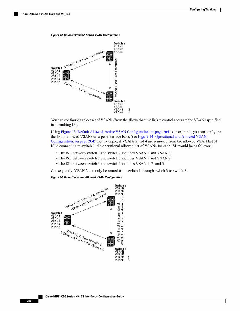
Figure 13: Default Allowed-Active VSAN Configuration
You can configure a select set of VSANs (from the allowed-active list) to control access to the VSANs specifiedin a trunking ISL.
Using Figure 13: Default Allowed-Active VSANConfiguration, on page 204 as an example, you can configurethe list of allowed VSANs on a per-interface basis (see Figure 14: Operational and Allowed VSANConfiguration, on page 204). For example, if VSANs 2 and 4 are removed from the allowed VSAN list ofISLs connecting to switch 1, the operational allowed list of VSANs for each ISL would be as follows:
• The ISL between switch 1 and switch 2 includes VSAN 1 and VSAN 3.• The ISL between switch 2 and switch 3 includes VSAN 1 and VSAN 2.• The ISL between switch 3 and switch 1 includes VSAN 1, 2, and 5.
Consequently, VSAN 2 can only be routed from switch 1 through switch 3 to switch 2.Figure 14: Operational and Allowed VSAN Configuration
Cisco MDS 9000 Series NX-OS Interfaces Configuration Guide204
Configuring TrunkingTrunk-Allowed VSAN Lists and VF_IDs

Guidelines and Limitations
General Guidelines and LimitationsThe trunking feature has the following general configuration guidelines and limitations:
• F ports support trunking in Fx mode.
• The trunk-allowed VSANs configured for TE, TF, and TNP links are used by the trunking protocol todetermine the allowed active VSANs in which frames can be received or transmitted.
• If a trunking enabled E port is connected to a third-party switch, the trunking protocol ensures seamlessoperation as an E port.
• Trunking F ports and trunking F PortChannels are not supported on the following hardware:
• 91x4 switches, if NPIV is enabled and used as the NPIV core switch.
• Generation 1 2-Gbps Fibre Channel switching modules.
• On core switches, the FC-SP authentication will be supported only for the physical FLOGI from thephysical pWWN.
• No FC-SP authentication is supported by the NPV switch on the server F ports.
• MDS does not enforce the uniqueness of logical pWWNs across VSANs.
• DPVM is not supported on trunked F port logins.
• The DPVM feature is limited to the control of the port VSAN, since the EVFP protocol does not allowchanging the VSAN on which a logical pWWN has done FLOGI.
• The port security configuration will be applied to both the first physical FLOGI and the per VSANFLOGIs.
• Trunking is not supported on F ports that have FlexAttach enabled.
• On MDS 91x4 core switches, hard zoning can be done only on F ports that are doing either NPIV ortrunking. However, in NPV mode, this restriction does not apply since zoning is enforced on the core Fport.
Fibre Channel Security Protocol (FC-SP) is not supported for 6.2(1) release on MDS 9710, but targeted fora future release.
Note
Upgrade and Downgrade LimitationsThe trunking and channeling feature includes the following upgrade and downgrade limitations:
• When F port trunking or channeling is configured on a link, the switch cannot be downgraded to CiscoMDS SAN-OS Release 3.x and NX-OS Release 4.1(1b), or earlier.
Cisco MDS 9000 Series NX-OS Interfaces Configuration Guide205
Configuring TrunkingGuidelines and Limitations

• If you are upgrading from a SAN-OS Release 3.x to NX-OS Release 5.0(1), and you have not createdVSAN 4079, the NX-OS software will automatically create VSAN 4079 and reserve it for EVFP use.
If VSAN 4079 is reserved for EVFP use, the switchport trunk allowed vsan command will filter out VSAN4079 from the allowed list, as shown in the following example:
switch(config-if)# switchport trunk allowed vsan 1-40801-4078,4080
• If you have created VSAN 4079, the upgrade to NX-OS Release 5.0(1) will have no affect on VSAN4079.
• If you downgrade after NX-OS Release 5.0(1), the VSAN will no longer be reserved for EVFP use.
Difference Between TE Ports and TF-TNP PortsIn case of TE ports, the VSAN will in be initializing state when VSAN is coming up on that interface andwhen peers are in negotiating phase. Once the handshake is done, VSAN will be moved to up state in thesuccessful case, and isolated state in the case of failure. Device Manager will show the port status as amberduring initializing state and it will be green once VSANs are up.
This example shows the trunk VSAN states of a TE port:
switch# show interface fc2/15fc2/15 is trunking
Hardware is Fibre Channel, SFP is short wave laser w/o OFC (SN)Port WWN is 20:4f:00:0d:ec:6d:2b:40Peer port WWN is 20:0a:00:0d:ec:3f:ab:80Admin port mode is auto, trunk mode is onsnmp link state traps are enabledPort mode is TEPort vsan is 1Speed is 2 GbpsRate mode is dedicatedTransmit B2B Credit is 16Receive B2B Credit is 250B2B State Change Number is 14Receive data field Size is 2112Beacon is turned offTrunk vsans (admin allowed and active) (1,100-101,1101,1163-1166,1216,2172,2182-2183)Trunk vsans (up) (1,1101,1163-1166,1216,2172,2182-2183)Trunk vsans (isolated) (100-101)Trunk vsans (initializing) ()
In case of TF ports, after the handshake, one of the allowed VSANs will be moved to the up state. All otherVSANs will be in initializing state even though the handshake with the peer is completed and successful.Each VSANwill be moved from initializing state to up state when a server or target logs in through the trunkedF or NP ports in the corresponding VSAN.
In case of TF or TNP ports, the Device Manager will show the port status as amber even after port is up andthere is no failure. It will be changed to green once all the VSAN has successful logins.
Note
Cisco MDS 9000 Series NX-OS Interfaces Configuration Guide206
Configuring TrunkingDifference Between TE Ports and TF-TNP Ports

This example shows a TF port information after the port is in the up state:
sw7# show interface fc1/13fc1/13 is trunking (Not all VSANs UP on the trunk)
Hardware is Fibre Channel, SFP is short wave laser w/o OFC (SN)Port WWN is 20:0d:00:0d:ec:6d:2b:40Admin port mode is FX, trunk mode is onsnmp link state traps are enabledPort mode is TFPort vsan is 1Speed is 4 GbpsRate mode is sharedTransmit B2B Credit is 16Receive B2B Credit is 32Receive data field Size is 2112Beacon is turned offTrunk vsans (admin allowed and active) (1,100-101,1101,1163-1166,1216,2172,2182-2183)Trunk vsans (up) (1)Trunk vsans (isolated) ()Trunk vsans (initializing) (1101,1163-1166,1216,2172,2182)
This example shows the TF port information when a server logs in on noninternal FLOGI VSAN. VSAN2183 is moved to the up state when the server logs in to VSAN 2183.
w7# show interface fc1/13fc1/13 is trunking (Not all VSANs UP on the trunk)
Hardware is Fibre Channel, SFP is short wave laser w/o OFC (SN)Port WWN is 20:0d:00:0d:ec:6d:2b:40Admin port mode is FX, trunk mode is onsnmp link state traps are enabledPort mode is TFPort vsan is 1Speed is 4 GbpsRate mode is sharedTransmit B2B Credit is 16Receive B2B Credit is 32Receive data field Size is 2112Beacon is turned offTrunk vsans (admin allowed and active) (1,100-101,1101,1163-1166,1216,2172,2
182-2183)Trunk vsans (up) (1,2183)Trunk vsans (isolated) ()Trunk vsans (initializing) (1101,1163-1166,1216,2172,2182)
Trunking Misconfiguration ExamplesIf you do not configure the VSANs correctly, issues with the connection may occur. For example, if youmerge the traffic in two VSANs, both VSANs will be mismatched. The trunking protocol validates the VSANinterfaces at both ends of a link to avoid merging VSANs (see Figure 15: VSAN Mismatch, on page 208).
Cisco MDS 9000 Series NX-OS Interfaces Configuration Guide207
Configuring TrunkingTrunking Misconfiguration Examples

Figure 15: VSAN Mismatch
The trunking protocol detects potential VSANmerging and isolates the ports involved (see Figure 15: VSANMismatch, on page 208).
The trunking protocol cannot detect merging of VSANs when a third-party switch is placed in between twoCisco MDS 9000 Series Multilayer Switches (see Figure 16: Third-Party Switch VSAN Mismatch, on page208).Figure 16: Third-Party Switch VSAN Mismatch
VSAN 2 and VSAN 3 are effectively merged with overlapping entries in the name server and the zoneapplications. Cisco DCNM-SAN helps detect such topologies.
Cisco MDS 9000 Series NX-OS Interfaces Configuration Guide208
Configuring TrunkingTrunking Misconfiguration Examples

Default SettingsTable 48: Default Trunk Configuration Parameters , on page 209 lists the default settings for trunking parameters.
Table 48: Default Trunk Configuration Parameters
DefaultParameters
ON on non-NPV and MDS core switches.
OFF on NPV switches.
Switch port trunk mode
1 to 4093 user-defined VSAN IDs.Allowed VSAN list
1 to 4093 user-defined VF-IDs.Allowed VF-ID list
Enabled.Trunking protocol on E ports
Disabled.Trunking protocol on F ports
Cisco MDS 9000 Series NX-OS Interfaces Configuration Guide209
Configuring TrunkingDefault Settings

Configuring Trunking
Enabling the Cisco Trunking and Channeling ProtocolsTo enable or disable the Cisco trunking and channeling protocol, perform these steps:
Before you begin
To avoid inconsistent configurations, disable all ports with a shutdown command before enabling or disablingthe trunking protocols.
Step 1 switch# configure terminal
Enters configuration mode.
Step 2 switch(config)# trunk protocol enable
Enables the Cisco PTP trunking protocol (default).
Step 3 switch(config)# no trunk protocol enable
Disables the Cisco PTP trunking protocol.
Enabling the F Port Trunking and Channeling ProtocolTo enable or disable the F port trunking and channeling protocol, perform these steps:
Before you begin
To avoid inconsistent configurations, shut all ports before enabling or disabling the trunking protocols.
Step 1 switch# configure terminal
Enters configuration mode.
Step 2 switch(config)# feature fport-channel-trunk
Enables the F port trunking and channeling protocol (default).
Step 3 switch(config)# no feature fport-channel-trunk
Disables the F port trunking and channeling protocol.
Configuring Trunk ModeTo configure trunk mode, perform these steps:
Cisco MDS 9000 Series NX-OS Interfaces Configuration Guide210
Configuring TrunkingConfiguring Trunking

Step 1 switch# configure terminal
Enters configuration mode.
Step 2 switch(config)# interface fc1/1
Configures the specified interface.
Step 3 switch(config-if)# switchport trunk mode on
Enables (default) the trunk mode for the specified interface.
switch(config-if)# switchport trunk mode off
(Optional) Disables the trunk mode for the specified interface.
switch(config-if)# switchport trunk mode auto
(Optional) Configures the trunk mode to auto mode, which provides automatic sensing for the interface.
Configuring an Allowed-Active List of VSANsTo configure an allowed-active list of VSANs for an interface, perform these steps:
Step 1 switch# configure terminal
Enters configuration mode.
Step 2 switch(config)# interface fc1/1
Configures the specified interface.
Step 3 switch(config-if)# switchport trunk allowed vsan 2-4
Changes the allowed list for the specified VSANs.
Step 4 switch(config-if)# switchport trunk allowed vsan add 5
Expands the specified VSAN (5) to the new allowed list.
switch(config-if)# no switchport trunk allowed vsan 2-4
(Optional) Deletes VSANs 2, 3, and 4.
switch(config-if)# no switchport trunk allowed vsan add 5
(Optional) Deletes the expanded allowed list.
Cisco MDS 9000 Series NX-OS Interfaces Configuration Guide211
Configuring TrunkingConfiguring an Allowed-Active List of VSANs

Verifying Trunking ConfigurationTo display trunking configuration information, perform one of the following tasks:
PurposeCommand
Displays the interface configuration information that includes trunking,trunk mode, allowed VSANs, and status.
show interface fc slot/port
Displays whether the trunk protocol is enabled.show trunk protocol
Displays whether the interface is trunking, and the allowed VSAN listfor each trunking interface.
show interface trunk vsan numbers
For detailed information about the fields in the output from these commands, refer to the Cisco MDS NX-OSCommand Reference.
The show interface command is invoked from the EXEC mode and displays trunking configurations for aTE port. Without any arguments, this command displays the information for all of the configured interfacesin the switch. See Examples Displays a Trunked Fibre Channel Interface, on page 212 to Displays Per VSANInformation on Trunk Ports, on page 213.
Displays a Trunked Fibre Channel Interface
switch# show interface fc1/13fc1/13 is trunking
Hardware is Fibre ChannelPort WWN is 20:0d:00:05:30:00:58:1ePeer port WWN is 20:0d:00:05:30:00:59:1eAdmin port mode is auto, trunk mode is onPort mode is TEPort vsan is 1Speed is 2 GbpsReceive B2B Credit is 255Beacon is turned offTrunk vsans (admin allowed and active) (1)Trunk vsans (up) (1)Trunk vsans (isolated) ()Trunk vsans (initializing) ()5 minutes input rate 0 bits/sec, 0 bytes/sec, 0 frames/sec5 minutes output rate 0 bits/sec, 0 bytes/sec, 0 frames/sec233996 frames input, 14154208 bytes, 0 discards0 CRC, 0 unknown class0 too long, 0 too short
236 frames output, 13818044 bytes, 0 discards11 input OLS, 12 LRR, 10 NOS, 28 loop inits34 output OLS, 19 LRR, 17 NOS, 12 loop inits
Displays the Trunking Protocol
switch# show trunk protocolTrunk protocol is enabled
Cisco MDS 9000 Series NX-OS Interfaces Configuration Guide212
Configuring TrunkingVerifying Trunking Configuration

Displays Per VSAN Information on Trunk Ports
switch# show interface trunk vsan 1-1000fc3/1 is not trunking...fc3/7 is trunkingVsan 1000 is down (Isolation due to vsan not configured on peer)...fc3/10 is trunking
Vsan 1 is up, FCID is 0x760001Vsan 2 is up, FCID is 0x6f0001
fc3/11 is trunkingBelongs to port-channel 6
Vsan 1 is up, FCID is 0xef0000Vsan 2 is up, FCID is 0xef0000
...port-channel 6 is trunkingVsan 1 is up, FCID is 0xef0000
Vsan 2 is up, FCID is 0xef0000
Cisco MDS 9000 Series NX-OS Interfaces Configuration Guide213
Configuring TrunkingVerifying Trunking Configuration

Configuration Example for F Port TrunkingThis example shows how to configure trunking and bring up the TF-TNP link between an F port in the NPIVcore switch and an NP port in the NPV switch:
Step 1 Enable the F port trunking and channeling protocol on the MDS core switch:
Example:
switch(config)# feature fport-channel-trunk
Step 2 Enable NPIV on the MDS core switch:
Example:
switch(config)# feature npiv
Step 3 Configure the port mode to auto, F, or Fx on the MDS core switch:
Example:
switch(config)# interface fc1/2switch(config-if)# switchport mode F
Step 4 Configure the trunk mode to ON on the MDS core switch:
Example:
switch(config-if)# switchport trunk mode on
Step 5 Configure the port mode to NP on the NPV switch:
Example:
switch(config)# interface fc1/2switch(config-if)# switchport mode NP
Step 6 Configure the trunk mode to ON on the NPV switch:
Example:
switch(config-if)# switchport trunk mode on
Step 7 Set the port administrative state on NPIV and NPV switches to ON:
Example:
switch(config)# interface fc1/2switch(config-if)# shut
Cisco MDS 9000 Series NX-OS Interfaces Configuration Guide214
Configuring TrunkingConfiguration Example for F Port Trunking

switch(config-if)# no shut
Step 8 Save the configuration.
Example:
switch(config)# copy running-config startup-config
Cisco MDS 9000 Series NX-OS Interfaces Configuration Guide215
Configuring TrunkingConfiguration Example for F Port Trunking

Cisco MDS 9000 Series NX-OS Interfaces Configuration Guide216
Configuring TrunkingConfiguration Example for F Port Trunking

Configuring PortChannels
This chapter provides information about PortChannels and how to configure the PortChannels.
• Finding Feature Information, on page 218• Information About PortChannels, on page 219• Prerequisites for PortChannels, on page 230• Default Settings, on page 231• Guidelines and Limitations, on page 232• Configuring PortChannels, on page 235• Verifying PortChannel Configuration, on page 239• Configuration Examples for F and TF PortChannels, on page 244• Configuration Examples for F and TF PortChannels (Dedicated Mode), on page 246
Cisco MDS 9000 Series NX-OS Interfaces Configuration Guide217

Finding Feature InformationYour software release might not support all the features documented in this module. For the latest caveatsand feature information, see the Bug Search Tool at https://tools.cisco.com/bugsearch/ and the release notesfor your software release. To find information about the features documented in this module, and to see a listof the releases in which each feature is supported, see the New and Changed chapter or the Feature Historytable below.
Cisco MDS 9000 Series NX-OS Interfaces Configuration Guide218
Configuring PortChannelsFinding Feature Information

Information About PortChannels
PortChannels OverviewPortChannels refer to the aggregation of multiple physical interfaces into one logical interface to providehigher aggregated bandwidth, load balancing, and link redundancy (see Figure 17: PortChannel Flexibility,on page 219). PortChannels can connect to interfaces across switching modules, so a failure of a switchingmodule cannot bring down the PortChannel link.Figure 17: PortChannel Flexibility
PortChannels on CiscoMDS 9000 SeriesMultilayer Switches allow flexibility in configuration. This illustratesthree possible PortChannel configurations:
• PortChannel A aggregates two links on two interfaces on the same switching module at each end of aconnection.
• PortChannel B also aggregates two links, but each link is connected to a different switching module. Ifthe switching module goes down, traffic is not affected.
• PortChannel C aggregates three links. Two links are on the same switching module at each end, whileone is connected to a different switching module on switch 2.
E PortChannelsAn E PortChannel refers to the aggregation of multiple E ports into one logical interface to provide higheraggregated bandwidth, load balancing, and link redundancy. PortChannels can connect to interfaces acrossswitching modules, so a failure of a switching module cannot bring down the PortChannel link.
A PortChannel has the following features and restrictions:
• Provides a point-to-point connection over ISL (E ports) or EISL (TE ports).Multiple links can be combinedinto a PortChannel.
• Increases the aggregate bandwidth on an ISL by distributing traffic among all functional links in thechannel.
• Load balances across multiple links and maintains optimum bandwidth utilization. Load balancing isbased on the source ID, destination ID, and exchange ID (OX ID).
Cisco MDS 9000 Series NX-OS Interfaces Configuration Guide219
Configuring PortChannelsInformation About PortChannels
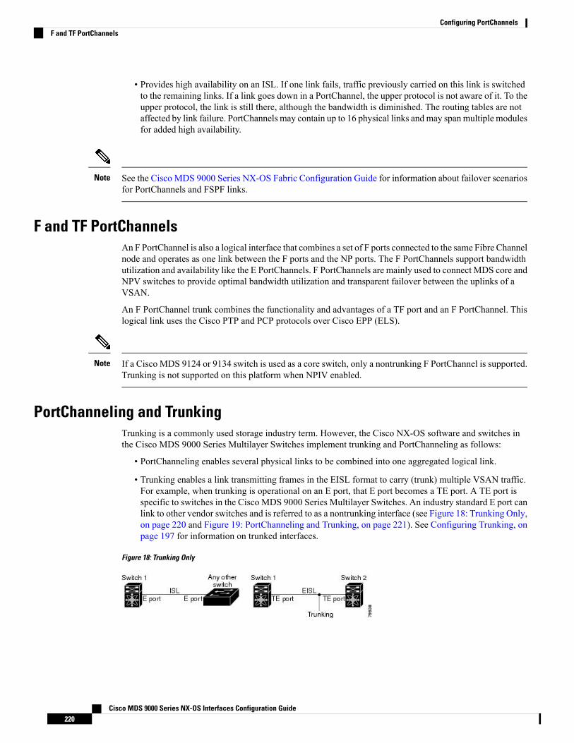
• Provides high availability on an ISL. If one link fails, traffic previously carried on this link is switchedto the remaining links. If a link goes down in a PortChannel, the upper protocol is not aware of it. To theupper protocol, the link is still there, although the bandwidth is diminished. The routing tables are notaffected by link failure. PortChannels may contain up to 16 physical links and may span multiple modulesfor added high availability.
See the Cisco MDS 9000 Series NX-OS Fabric Configuration Guide for information about failover scenariosfor PortChannels and FSPF links.
Note
F and TF PortChannelsAn F PortChannel is also a logical interface that combines a set of F ports connected to the same Fibre Channelnode and operates as one link between the F ports and the NP ports. The F PortChannels support bandwidthutilization and availability like the E PortChannels. F PortChannels are mainly used to connect MDS core andNPV switches to provide optimal bandwidth utilization and transparent failover between the uplinks of aVSAN.
An F PortChannel trunk combines the functionality and advantages of a TF port and an F PortChannel. Thislogical link uses the Cisco PTP and PCP protocols over Cisco EPP (ELS).
If a Cisco MDS 9124 or 9134 switch is used as a core switch, only a nontrunking F PortChannel is supported.Trunking is not supported on this platform when NPIV enabled.
Note
PortChanneling and TrunkingTrunking is a commonly used storage industry term. However, the Cisco NX-OS software and switches inthe Cisco MDS 9000 Series Multilayer Switches implement trunking and PortChanneling as follows:
• PortChanneling enables several physical links to be combined into one aggregated logical link.
• Trunking enables a link transmitting frames in the EISL format to carry (trunk) multiple VSAN traffic.For example, when trunking is operational on an E port, that E port becomes a TE port. A TE port isspecific to switches in the Cisco MDS 9000 Series Multilayer Switches. An industry standard E port canlink to other vendor switches and is referred to as a nontrunking interface (see Figure 18: Trunking Only,on page 220 and Figure 19: PortChanneling and Trunking, on page 221). See Configuring Trunking, onpage 197 for information on trunked interfaces.
Figure 18: Trunking Only
Cisco MDS 9000 Series NX-OS Interfaces Configuration Guide220
Configuring PortChannelsF and TF PortChannels

Figure 19: PortChanneling and Trunking
PortChanneling and trunking are used separately across an ISL.
• PortChanneling—Interfaces can be channeled between the following sets of ports:
• E ports and TE ports
• F ports and NP ports
• TF ports and TNP ports
• Trunking—Trunking permits carrying traffic on multiple VSANs between switches.
See the Cisco MDS 9000 Series NX-OS Fabric Configuration Guide.
• Both PortChanneling and trunking can be used between TE ports over EISLs.
Load BalancingTwo methods support the load-balancing functionality:
• Flow based—All frames between source and destination follow the same links for a given flow. That is,whichever link is selected for the first exchange of the flow is used for all subsequent exchanges.
• Exchange based—The first frame in an exchange picks a link and subsequent frames in the exchangefollow the same link. However, subsequent exchanges can use a different link. This provides moregranular load balancing while preserving the order of frames for each exchange.
Figure 20: SID1 and DID1-Based Load Balancing, on page 222 illustrates how source ID 1 (SID1) anddestination ID1 (DID1) based load balancing works. When the first frame in a flow is received on an interfacefor forwarding, link 1 is selected. Each subsequent frame in that flow is sent over the same link. No frame inSID1 and DID1 utilizes link 2.
Cisco MDS 9000 Series NX-OS Interfaces Configuration Guide221
Configuring PortChannelsLoad Balancing

Figure 20: SID1 and DID1-Based Load Balancing
Figure 21: SID1, DID1, and Exchange-Based Load Balancing, on page 223 illustrates how exchange-basedload balancing works. When the first frame in an exchange is received for forwarding on an interface, link 1is chosen by a hash algorithm. All remaining frames in that particular exchange are sent on the same link. Forexchange 1, no frame uses link 2. For the next exchange, link 2 is chosen by the hash algorithm. Now allframes in exchange 2 use link 2.
Cisco MDS 9000 Series NX-OS Interfaces Configuration Guide222
Configuring PortChannelsLoad Balancing

Figure 21: SID1, DID1, and Exchange-Based Load Balancing
For more information on configuring load balancing and in-order delivery features, see the Cisco MDS 9000Series NX-OS Fabric Configuration Guide.
PortChannel ModesYou can configure each PortChannel with a channel group mode parameter to determine the PortChannelprotocol behavior for all member ports in this channel group. The possible values for a channel group modeare as follows:
• ON (default)—The member ports only operate as part of a PortChannel or remain inactive. In this mode,the PortChannel protocol is not initiated. However, if a PortChannel protocol frame is received from apeer port, the software indicates its nonnegotiable status. This mode is backward compatible with theexisting implementation of PortChannels in releases prior to Release 2.0(1b), where the channel groupmode is implicitly assumed to be ON. In CiscoMDS SAN-OSReleases 1.3 and earlier, the only availablePortChannel mode was the ONmode. PortChannels configured in the ONmode require you to explicitlyenable and disable the PortChannel member ports at either end if you add or remove ports from thePortChannel configuration. You must physically verify that the local and remote ports are connected toeach other.
• ACTIVE—The member ports initiate PortChannel protocol negotiation with the peer port(s) regardlessof the channel group mode of the peer port. If the peer port, while configured in a channel group, doesnot support the PortChannel protocol, or responds with a nonnegotiable status, it will default to the ONmode behavior. The ACTIVE PortChannel mode allows automatic recovery without explicitly enablingand disabling the PortChannel member ports at either end.
Table 49: Channel Group Configuration Differences , on page 224 compares ON and ACTIVE modes.
Cisco MDS 9000 Series NX-OS Interfaces Configuration Guide223
Configuring PortChannelsPortChannel Modes

Table 49: Channel Group Configuration Differences
ACTIVE ModeON Mode
A PortChannel protocol negotiation is performed withthe peer ports.
No protocol is exchanged.
Moves interfaces to the isolated state if its operationalvalues are incompatible with the PortChannel.
Moves interfaces to the suspended state if itsoperational values are incompatible with thePortChannel.
When you add or modify a PortChannel interface, thePortChannel automatically recovers.
When you add or modify a PortChannel member portconfiguration, you must explicitly disable (shut) andenable (no shut) the PortChannel member ports ateither end.
There is synchronized startup of all ports in a channelacross peer switches.
Port initialization is not synchronized.
Consistently detect misconfigurations using aPortChannel protocol.
All misconfigurations are not detected as no protocolis exchanged.
Transitions misconfigured ports to the isolated state tocorrect the misconfiguration. Once you correct themisconfiguration, the protocol ensures automaticrecovery.
Transitions misconfigured ports to the suspendedstate. You must explicitly disable (shut) and enable(no shut) the member ports at either end.
You must explicitly configure this mode.This is the default mode.
PortChannel DeletionWhen you delete the PortChannel, the corresponding channel membership is also deleted. All interfaces inthe deleted PortChannel convert to individual physical links. After the PortChannel is removed, regardless ofthe mode used (ACTIVE and ON), the ports at either end are gracefully brought down, indicating that noframes are lost when the interface is going down (see the Graceful Shutdown, on page 19).
If you delete the PortChannel for one port, then the individual ports within the deleted PortChannel retain thecompatibility parameter settings (speed, mode, port VSAN, allowed VSAN, and port security). You canexplicitly change those settings as required.
• If you use the default ON mode to avoid inconsistent states across switches and to maintain consistencyacross switches, then the ports shut down. You must explicitly enable those ports again.
• If you use the ACTIVE mode, then the PortChannel ports automatically recover from the deletion.
Interfaces in a PortChannelYou can add or remove a physical interface (or a range of interfaces) to an existing PortChannel. The compatibleparameters on the configuration are mapped to the PortChannel. Adding an interface to a PortChannel increasesthe channel size and bandwidth of the PortChannel. Removing an interface from a PortChannel decreases thechannel size and bandwidth of the PortChannel.
Cisco MDS 9000 Series NX-OS Interfaces Configuration Guide224
Configuring PortChannelsPortChannel Deletion

For information about PortChannel support on Generation 2 switching modules, see the PortChannelLimitations, on page 106.
Note
Interface Addition to a PortChannelYou can add a physical interface (or a range of interfaces) to an existing PortChannel. The compatibleparameters on the configuration are mapped to the PortChannel. Adding an interface to a PortChannel increasesthe channel size and bandwidth of the PortChannel.
A port can be configured as a member of a static PortChannel only if the following configurations are thesame in the port and the PortChannel:
• Speed• Mode• Rate mode• Port VSAN• Trunking mode• Allowed VSAN list or VF-ID list
After the members are added, regardless of the mode (ACTIVE and ON) used, the ports at either end aregracefully brought down, indicating that no frames are lost when the interface is going down (see the Generation1 PortChannel Limitations, on page 232 and Graceful Shutdown, on page 19).
Compatibility Check
A compatibility check ensures that the same parameter settings are used in all physical ports in the channel.Otherwise, they cannot become part of a PortChannel. The compatibility check is performed before a port isadded to the PortChannel.
The check ensures that the following parameters and settings match at both ends of a PortChannel:
• Capability parameters (type of interface, Gigabit Ethernet at both ends, or Fibre Channel at both ends).• Administrative compatibility parameters (speed, mode, rate mode, port VSAN, allowed VSAN list, andport security).
Ports in shared rate mode cannot form a PortChannel or a trunking PortChannel.Note
• Operational parameters (remote switch WWN and trunking mode).
A port addition procedure fails if the capability and administrative parameters in the remote switch areincompatible with the capability and administrative parameters in the local switch. If the compatibility checkis successful, the interfaces are operational and the corresponding compatibility parameter settings apply tothese interfaces.
Suspended and Isolated States
If the operational parameters are incompatible, the compatibility check fails and the interface is placed in asuspended or isolated state based on the configured mode:
• An interface enters the suspended state if the interface is configured in the ON mode.
Cisco MDS 9000 Series NX-OS Interfaces Configuration Guide225
Configuring PortChannelsInterface Addition to a PortChannel

• An interface enters the isolated state if the interface is configured in the ACTIVE mode.
Forcing an Interface AdditionYou can force the port configuration to be overwritten by the PortChannel. In this case, the interface is addedto a PortChannel.
• If you use the default ON mode to avoid inconsistent states across switches and to maintain consistencyacross switches, then the ports shut down. You must explicitly enable those ports again.
• If you use the ACTIVE mode, then the PortChannel ports automatically recover from the addition.
When PortChannels are created from within an interface, the force option cannot be used.Note
After the members are forcefully added, regardless of the mode (ACTIVE and ON) used, the ports at eitherend are gracefully brought down, indicating that no frames are lost when the interface is going down (see theGraceful Shutdown, on page 19) sections.
Interface Deletion from a PortChannelWhen a physical interface is deleted from the PortChannel, the channel membership is automatically updated.If the deleted interface is the last operational interface, then the PortChannel status is changed to a down state.Deleting an interface from a PortChannel decreases the channel size and bandwidth of the PortChannel.
• If you use the default ON mode to avoid inconsistent states across switches and to maintain consistencyacross switches, then the ports shut down. You must explicitly enable those ports again.
• If you use the ACTIVE mode, then the PortChannel ports automatically recover from the deletion.
After the members are deleted, regardless of the mode (ACTIVE and ON) used, the ports at either end aregracefully brought down, indicating that no frames are lost when the interface is going down (see the Generation1 PortChannel Limitations, on page 232 and Graceful Shutdown, on page 19 sections).
PortChannel ProtocolsIn earlier Cisco SAN-OS releases, PortChannels required additional administrative tasks to supportsynchronization. The Cisco NX-OS software provides robust error detection and synchronization capabilities.You can manually configure channel groups or they can be automatically created. In both cases, the channelgroups have the same capability and configurational parameters. Any change in configuration applied to theassociated PortChannel interface is propagated to all members of the channel group.
A protocol to exchange PortChannel configurations is available in all Cisco MDS switches. This additionsimplifies PortChannel management with incompatible ISLs. An additional autocreation mode enables ISLswith compatible parameters to automatically form channel groups without manual intervention.
The PortChannel protocol is enabled by default.
The PortChannel protocol expands the PortChannel functional model in Cisco MDS switches. It uses theexchange peer parameters (EPP) services to communicate across peer ports in an ISL. Each switch uses theinformation received from the peer ports along with its local configuration and operational values to decideif it should be part of a PortChannel. The protocol ensures that a set of ports are eligible to be part of the samePortChannel. They are only eligible to be part of the same PortChannel if all the ports have a compatiblepartner.
Cisco MDS 9000 Series NX-OS Interfaces Configuration Guide226
Configuring PortChannelsForcing an Interface Addition

The PortChannel protocol uses two subprotocols:
• Bringup protocol—Automatically detects misconfigurations so you can correct them. This protocolsynchronizes the PortChannel at both ends so that all frames for a given flow (as identified by the sourceFC ID, destination FC ID and OX_ID) are carried over the same physical link in both directions. Thishelps make applications such as write acceleration, work for PortChannels over FCIP links.
• Autocreation protocol—Automatically aggregates compatible ports into a PortChannel.
Channel Group Creation
Channel groups are not supported on internal ports in the Cisco Fabric Switch for HP c-Class BladeSystemand the Cisco Fabric Switch for IBM BladeSystem.
Note
Assuming link A1-B1 comes up first (see Figure 22: Autocreating Channel Groups, on page 227), that link isoperational as an individual link.When the next link comes up, for example, A2-B2, the PortChannel protocolidentifies if this link is compatible with link A1-B1 and automatically creates channel groups 10 and 20 inthe respective switches. If link A3-B3 can join the channel groups (the PortChannels), the respective portshave compatible configurations. If link A4-B4 operates as an individual link, it is because of the incompatibleconfiguration of the two end ports with the other member ports in this channel group.Figure 22: Autocreating Channel Groups
The channel group numbers are selected dynamically, and as such, the administrative configuration of theports forming the channel group at either end are applicable to the newly created channel group. The channelgroup number being chosen dynamically may be different across reboots for the same set of PortChannelsbased on the order of ports that are initialized in the switch.
Table 50: Channel Group Configuration Differences , on page 227 identifies the differences betweenuser-configured and auto-configured channel groups.
Table 50: Channel Group Configuration Differences
Autocreated Channel GroupUser-Configured Channel Group
Created automatically when compatible links come upbetween two compatible switches, if channel groupautocreation is enabled in all ports at both ends.
Manually configured by the user.
None of these ports are members of a user-configuredchannel group.
Member ports cannot participate in autocreationof channel groups. The autocreation featurecannot be configured.
Cisco MDS 9000 Series NX-OS Interfaces Configuration Guide227
Configuring PortChannelsChannel Group Creation

Autocreated Channel GroupUser-Configured Channel Group
All ports included in the channel group participate in thePortChannel—no member port becomes isolated orsuspended; instead, the member port is removed from thechannel group when the link is found to be incompatible.
You can form the PortChannel with a subset ofthe ports in the channel group. Incompatible portsremain in a suspended or isolated state dependingon the ON or ACTIVE mode configuration.
Any administrative configurationmade to the PortChannelis applied to all ports in the channel group, but theconfigurations are saved for the member ports; noconfiguration is saved for the PortChannel interface. Youcan explicitly convert this channel group, if required.
Any administrative configuration made to thePortChannel is applied to all ports in the channelgroup, and you can save the configuration for thePortChannel interface.
You cannot remove a channel group, or add/remove anyof its members. The channel group is removed when nomember ports exist.
You can remove any channel group and addmembers to a channel group.
Autocreation is not supported as of MDS NX-OS Release 4.1(1b) and later.Note
AutocreationThe autocreation protocol has the following functionality:
• A port is not allowed to be configured as part of a PortChannel when the autocreation feature is enabled.These two configurations are mutually exclusive.
• Autocreation must be enabled in both the local and peer ports to negotiate a PortChannel.
• Aggregation occurs in one of two ways:
• A port is aggregated into a compatible autocreated PortChannel.
• A port is aggregated with another compatible port to form a new PortChannel.
• Newly created PortChannels are allocated from the maximum possible PortChannel (128 for Generation1 or a combination of Generation 1 and Generation 2 switches, or 256 for Generation 2 switches) in adecreasing order based on availability. If all 128 (or 256) numbers are used up, aggregation is not allowed.
• You cannot change the membership or delete an autocreated PortChannel.
• When you disable autocreation, all member ports are removed from the autocreated PortChannel.
• Once the last member is removed from an autocreated PortChannel, the channel is automatically deletedand the number is released for reuse.
• An autocreated PortChannel is not persistent through a reboot. An autocreated PortChannel can bemanually configured to appear the same as a persistent PortChannel. Once the PortChannel is madepersistent, the autocreation feature is disabled in all member ports.
• You can enable or disable the autocreation feature on a per-port basis or for all ports in the switch. Whenthis configuration is enabled, the channel group mode is assumed to be active. The default for this taskis disabled.
Cisco MDS 9000 Series NX-OS Interfaces Configuration Guide228
Configuring PortChannelsAutocreation

• If autocreation of channel groups is enabled for an interface, you must first disable autocreation beforedowngrading to earlier software versions or before configuring the interface in a manually configuredchannel group.
When enabling autocreation in any switch in the CiscoMDS 9000 SeriesMultilayer Switches, we recommendthat you retain at least one interconnected port between the switches without any autocreation configuration.If all ports between two switches are configured with the autocreation feature at the same time, you may facea possible traffic disruption between these two switches as the ports are automatically disabled and reenabledwhen ports are added to an autocreated PortChannel.
Tip
Manually Configured Channel GroupsA user-configured channel group cannot be converted to an autocreated channel group. However, you canconvert an autocreated channel group to a manual channel group. Once performed, this task is irreversible.The channel group number does not change, but the member ports operate according to the properties of themanually configured channel group, and the autocreation of channel group is implicitly disabled for all memberports.
If you enable persistence, be sure to enable it at both ends of the PortChannel.Tip
Cisco MDS 9000 Series NX-OS Interfaces Configuration Guide229
Configuring PortChannelsManually Configured Channel Groups

Prerequisites for PortChannelsBefore configuring a PortChannel, consider the following guidelines:
• Configure the PortChannel across switching modules to implement redundancy on switching modulereboots or upgrades.
• Ensure that one PortChannel is not connected to different sets of switches. PortChannels requirepoint-to-point connections between the same set of switches.
On switches with Generation 1 switching modules, or a combination of Generation 1 and Generation 2switching modules, you can configure a maximum of 128 PortChannels. On switches with only Generation2 switching modules, or Generation 2 and Generation 3 switching modules, you can configure a maximumof 256 PortChannels.
Note
If you misconfigure PortChannels, you may receive a misconfiguration message. If you receive this message,the PortChannel’s physical links are disabled because an error has been detected.
A PortChannel error is detected if the following requirements are not met:
• Each switch on either side of a PortChannel must be connected to the same number of interfaces.• Each interface must be connected to a corresponding interface on the other side (see Figure 24:Misconfigured Configurations, on page 234 for an example of an invalid configuration).
• Links in a PortChannel cannot be changed after the PortChannel is configured. If you change the linksafter the PortChannel is configured, be sure to reconnect the links to interfaces within the PortChanneland reenable the links.
If all three conditions are not met, the faulty link is disabled.
Enter the show interface command for that interface to verify that the PortChannel is functioning as required.
Cisco MDS 9000 Series NX-OS Interfaces Configuration Guide230
Configuring PortChannelsPrerequisites for PortChannels

Default SettingsTable 51: Default PortChannel Parameters , on page 231 lists the default settings for PortChannels.
Table 51: Default PortChannel Parameters
DefaultParameters
FSPF is enabled by default.PortChannels
Administratively up.Create PortChannel
ON mode on non-NPV and NPIV core switches.
ACTIVE mode on NPV switches.
Default PortChannel mode
Disabled.Autocreation
Cisco MDS 9000 Series NX-OS Interfaces Configuration Guide231
Configuring PortChannelsDefault Settings

Guidelines and Limitations
General Guidelines and LimitationsCisco MDS 9000 Series Multilayer switches support the following number of PortChannels per switch:
• Switches with only Generation 1 switching modules do not support F and TF PortChannels.
• Switches with Generation 1 switching modules, or a combination of Generation 1 and Generation 2switching modules, support a maximum of 128 PortChannels. Only Generation 2 ports can be includedin the PortChannels.
• Switches with only Generation 2 switching modules or Generation 2 and Generation 3 modules supporta maximum of 256 PortChannels with 16 interfaces per PortChannel.
• A PortChannel number refers to the unique identifier for each channel group. This number ranges fromof 1 to 256.
Generation 1 PortChannel LimitationsThis section includes the restrictions on creation and addition of PortChannel members to a PortChannel onGeneration 1 hardware:
• The 32-port 2-Gbps or 1-Gbps switching module.• The MDS 9140 and 9120 switches.
When configuring the host-optimized ports on Generation 1 hardware, the following PortChannel guidelinesapply:
• If you execute the write erase command on a 32-port switching module, and then copy a savedconfiguration to the switch from a text file that contains the no system default switchport shutdowncommand, you need to copy the text file to the switch again for the E ports to come up without manualconfiguration.
• Any (or all) full line rate port(s) in the Cisco MDS 9100 Series can be included in a PortChannel.• The host-optimized ports in the Cisco MDS 9100 Series are subject to the same PortChannel rules as32-port switching modules; only the first port of each group of 4 ports is included in a PortChannel.
• You can configure only the first port in each 4-port group as an E port (for example, the first portin ports 1–4, the fifth port in ports 5–8, and so on). If the first port in the group is configured as aPortChannel, the other three ports in each group (ports 2–4, 6–8, and so on) are not usable andremain in the shutdown state.
• If any of the other three ports are configured in a no shutdown state, you cannot configure the firstport to be a PortChannel. The other three ports continue to remain in a no shutdown state.
F and TF PortChannel LimitationsThe following guidelines and restrictions are applicable for F and TF PortChannels:
• The ports must be in F mode.• Automatic creation is not supported.
Cisco MDS 9000 Series NX-OS Interfaces Configuration Guide232
Configuring PortChannelsGuidelines and Limitations

• The PortChannel interface must be in ACTIVE mode when multiple FCIP interfaces are grouped withWA.
• ONmode is not supported. Only ACTIVE-ACTIVEmode is supported. By default, the mode is ACTIVEon the NPV switches.
• Devices logged in through F PortChannel on an MDS switch are not supported in IVR non-NATconfiguration. The devices are supported only in IVR NAT configuration.
• Port security rules are enforced only on physical pWWNs at the single link level.• FC-SP authenticates only the first physical FLOGI of every PortChannel member.• Since the FLOGI payload carries only the VF bits to trigger the use of a protocol after the FLOGIexchange, those bits will be overridden. In the case of the NPV switches, the core has a Cisco WWNand will try to initiate the PCP protocol.
• The name server registration of the N ports logging in through an F PortChannel will use the fWWN ofthe PortChannel interface.
• DPVM configuration is not supported.• The PortChannel port VSAN cannot be configured using DPVM.• The Dynamic Port VSAN Management (DPVM) database will be queried only for the first physicalFLOGI of each member, so that the port VSAN can be configured automatically.
• DPVM does not bind FC_IDs to VSANs, but pWWNs to VSANs. It will be queried only for the physicalFLOGI.
Valid and Invalid PortChannel ExamplesPortChannels are created with default values. You can change the default configuration just like any otherphysical interface.
Figure 23: Valid PortChannel Configurations, on page 233 provides examples of valid PortChannelconfigurations.Figure 23: Valid PortChannel Configurations
Figure 24:Misconfigured Configurations, on page 234 provides examples of invalid configurations. Assumingthat the links are brought up in the 1, 2, 3, 4 sequence, links 3 and 4 will be operationally down as the fabricis misconfigured.
Cisco MDS 9000 Series NX-OS Interfaces Configuration Guide233
Configuring PortChannelsValid and Invalid PortChannel Examples

Figure 24: Misconfigured Configurations
Cisco MDS 9000 Series NX-OS Interfaces Configuration Guide234
Configuring PortChannelsValid and Invalid PortChannel Examples

Configuring PortChannels
Configuring PortChannels Using the Wizard Creating a PortChannelTo create a PortChannel, perform these steps:
Step 1 switch# configure terminal
Enters configuration mode.
Step 2 switch(config)# interface port-channel 1
Configures the specified PortChannel (1) using the default ON mode.
Configuring the PortChannel ModeBy default, the CLI and the Device Manager create the PortChannel in ON mode in the NPIV core switchesand ACTIVE mode on the NPV switches. DCNM-SAN creates all PortChannels in ACTIVE mode. Werecommend that you create PortChannels in ACTIVE mode.
An F PortChannel is supported only on ACTIVE mode.Note
To configure ACTIVE mode, perform these steps:
Step 1 switch# configure terminal
Enters configuration mode.
Step 2 switch(config)# interface port-channel 1
Configures the specified PortChannel (1) using the default ON mode.
Step 3 switch(config-if)# channel mode active
Configures the ACTIVE mode.
switch(config-if)# no channel mode active
(Optional) Reverts to the default ON mode.
Deleting PortChannelsTo delete a PortChannel, perform these steps:
Cisco MDS 9000 Series NX-OS Interfaces Configuration Guide235
Configuring PortChannelsConfiguring PortChannels

Step 1 switch# configure terminal
Enters configuration mode.
Step 2 switch(config)# no interface port-channel 1
Deletes the specified PortChannel (1), its associated interfacemappings, and the hardware associations for this PortChannel.
Adding an Interface to a PortChannelTo add an interface to a PortChannel, perform these steps:
Step 1 switch# configure terminal
Enters configuration mode.
Step 2 switch(config)# interface fc1/15
Configures the specified port interface (fc1/15).
Step 3 switch(config-if)# channel-group 15
Adds physical Fibre Channel port 1/15 to channel group 15. If channel group 15 does not exist, it is created. The port isshut down.
Adding a Range of Ports to a PortChannelTo add a range of ports to a PortChannel, perform these steps:
Step 1 switch# configure terminal
Enters configuration mode.
Step 2 switch(config)# interface fc1/1 - 5
Configures the specified range of interfaces. In this example, interfaces from 1/1 to 1/5 are configured.
Step 3 switch(config-if)# channel-group 2
Adds physical interfaces 1/1, 1/2, 1/3, 1/4, and 1/5 to channel group 2. If channel group 2 does not exist, it is created.
If the compatibility check is successful, the interfaces are operational and the corresponding states apply to these interfaces.
Cisco MDS 9000 Series NX-OS Interfaces Configuration Guide236
Configuring PortChannelsAdding an Interface to a PortChannel

What to do next
By default, the CLI adds a interface normally to a PortChannel, while DCNM-SAN adds the interface byforce, unless specified explicitly.
Note
Forcing an Interface AdditionTo force the addition of a port to a PortChannel, perform these steps:
Step 1 switch# configure terminal
Enters configuration mode.
Step 2 switch(config)# interface fc1/1
Specifies the interface fc1/1.
Step 3 switch(config-if)# channel-group 1 force
Forces the addition of the physical port for interface fc1/1 to channel group 1. The port is shut down.
Deleting an Interface From a PortChannelTo delete a physical interface (or a range of physical interfaces) from a PortChannel, perform these steps:
Step 1 switch# configure terminal
Enters configuration mode.
Step 2 switch(config)# interface fc1/1
Enters the selected physical interface level.
Step 3 switch(config)# interface fc1/1 - 5
Enters the selected range of physical interfaces.
Step 4 switch(config-if)# no channel-group 2
Deletes the physical Fibre Channel interfaces in channel group 2.
Enabling and Configuring AutocreationTo configure automatic channel groups, perform these steps:
Cisco MDS 9000 Series NX-OS Interfaces Configuration Guide237
Configuring PortChannelsForcing an Interface Addition

Step 1 switch# configure terminal
Enters configuration mode.
Step 2 switch(config)# interface fc8/13
Enters the configuration mode for the selected interface(s).
Step 3 switch(config- if)# channel-group auto
Automatically creates the channel group for the selected interface(s).
switch(config- if)# no channel-group auto
(Optional) Disables the autocreation of channel groups for this interface, even if the system default configuration mayhave autocreation enabled.
Converting to Manually Configured Channel GroupsYou can convert autocreated channel group to a user-configured channel group using the port-channelchannel-group-number persistent EXEC command. If the PortChannel does not exist, this command is notexecuted.
Cisco MDS 9000 Series NX-OS Interfaces Configuration Guide238
Configuring PortChannelsConverting to Manually Configured Channel Groups

Verifying PortChannel ConfigurationTo display PortChannel configuration information, perform one of the following tasks:
PurposeCommand
Displays a summary of PortChannels within the switch. A one-linesummary of each PortChannel provides the administrative state,the operational state, the number of attached and active interfaces(up), and the first operational port (FOP), which is the primaryoperational interface selected in the PortChannel to carrycontrol-plane traffic (no load-balancing). The FOP is the first portthat comes up in a PortChannel and can change if the port goesdown. The FOP is also identified by an asterisk ( * ).
show port-channel summary
Displays the PortChannel configured in the default ON mode andACTIVE mode.
show port-channel database
Displays the consistency status without details.show port-channel consistency
Displays the consistency status with details.show port-channel consistency detail
Displays the PortChannel usage.show port-channel usage
Displays the PortChannel compatibility.show port-channelcompatibility-parameters
Displays autocreated PortChannels.show interface fc slot/port
Displays the specified PortChannel interface.show port-channel database interfaceport-channel number
For detailed information about the fields in the output from these commands, refer to the Cisco MDS 9000Series NX-OS Command Reference.
You can view specific information about existing PortChannels at any time from EXEC mode. The followingshow commands provide further details on existing PortChannels. You can force all screen output to go to aprinter or save it to a file. See Examples Displays the PortChannel Summary, on page 239 to Displays thePortChannel Summary, on page 239.
Displays the PortChannel Summary
switch# show port-channel summary------------------------------------------------------------------------------Interface Total Ports Oper Ports First Oper Port------------------------------------------------------------------------------port-channel 77 2 0 --port-channel 78 2 0 --port-channel 79 2 2 fcip200
Cisco MDS 9000 Series NX-OS Interfaces Configuration Guide239
Configuring PortChannelsVerifying PortChannel Configuration

Displays the PortChannel Configured in the Default ON Mode
switch# show port-channel database
port-channel 77Administrative channel mode is onOperational channel mode is onLast membership update succeeded2 ports in total, 0 ports upPorts: fcip1 [down]
fcip2 [down]port-channel 78
Administrative channel mode is onOperational channel mode is onLast membership update succeeded2 ports in total, 0 ports upPorts: fc2/1 [down]
fc2/5 [down]port-channel 79
Administrative channel mode is onOperational channel mode is onLast membership update succeededFirst operational port is fcip2002 ports in total, 2 ports upPorts: fcip101 [up]
fcip200 [up] *
Displays the PortChannel Configured in the ACTIVE Mode
switch# show port-channel database
port-channel 77Administrative channel mode is activeOperational channel mode is activeLast membership update succeeded2 ports in total, 0 ports upPorts: fcip1 [down]
fcip2 [down]port-channel 78
Administrative channel mode is activeOperational channel mode is activeLast membership update succeeded2 ports in total, 0 ports upPorts: fc2/1 [down]
fc2/5 [down]port-channel 79
Administrative channel mode is activeOperational channel mode is activeLast membership update succeededFirst operational port is fcip2002 ports in total, 2 ports upPorts: fcip101 [up]
fcip200 [up] *
The show port-channel consistency command has two options: without details and with details.
Cisco MDS 9000 Series NX-OS Interfaces Configuration Guide240
Configuring PortChannelsVerifying PortChannel Configuration

Displays the Consistency Status without Details
switch# show port-channel consistencyDatabase is consistent
Displays the Consistency Status with Details
switch# show port-channel consistency detailAuthoritative port-channel database:================================================totally 3 port-channelsport-channel 77:
2 ports, first operational port is nonefcip1 [down]fcip2 [down]
port-channel 78:2 ports, first operational port is nonefc2/1 [down]fc2/5 [down]
port-channel 79:2 ports, first operational port is fcip200fcip101 [up]fcip200 [up]
================================================database 1: from module 5================================================totally 3 port-channelsport-channel 77:
2 ports, first operational port is nonefcip1 [down]fcip2 [down]
port-channel 78:2 ports, first operational port is nonefc2/1 [down]fc2/5 [down]
port-channel 79:2 ports, first operational port is fcip200fcip101 [up]fcip200 [up]
================================================database 2: from module 4================================================totally 3 port-channelsport-channel 77:
2 ports, first operational port is nonefcip1 [down]fcip2 [down]
port-channel 78:2 ports, first operational port is nonefc2/1 [down]fc2/5 [down]
port-channel 79:2 ports, first operational port is fcip200fcip101 [up]fcip200 [up]
...
Cisco MDS 9000 Series NX-OS Interfaces Configuration Guide241
Configuring PortChannelsVerifying PortChannel Configuration

The show port-channel usage command displays details of the used and unused PortChannelnumbers.
Displays the PortChannel Usage
switch# show port-channel usageTotally 3 port-channel numbers used===================================Used : 77 - 79Unused: 1 - 76 , 80 - 256
Use the existing show commands to obtain further details on autocreated channel group attributes.Autocreated PortChannels are indicated explicitly to help differentiate them from the manuallycreated PortChannels.
Displays the PortChannel Compatibility
switch# show port-channel compatibility-parametersphysical port layer fibre channel or ethernet
port mode E/AUTO onlytrunk modespeedport VSANport allowed VSAN list
Displays Autocreated PortChannels
switch# show interface fc1/1fc1/1 is trunking
Hardware is Fibre Channel, FCOT is short wave laserPort WWN is 20:0a:00:0b:5f:3b:fe:80...Receive data field Size is 2112Beacon is turned offPort-channel auto creation is enabled
Belongs to port-channel 123...
Displays the Specified PortChannel Interface
switch# show port-channel database interface port-channel 128port-channel 128
Administrative channel mode is activeOperational channel mode is activeLast membership update succeededChannel is auto createdFirst operational port is fc1/11 ports in total, 1 ports upPorts: fc1/1 [up] *
Cisco MDS 9000 Series NX-OS Interfaces Configuration Guide242
Configuring PortChannelsVerifying PortChannel Configuration

Displays the PortChannel Summary
switch# show port-channel summary------------------------------------------------------------------------------Interface Total Ports Oper Ports First Oper Port------------------------------------------------------------------------------port-channel 1 1 0 --port-channel 2 1 1 fc8/13port-channel 3 0 0 --port-channel 4 0 0 --port-channel 5 1 1 fc8/3port-channel 6 0 0 --
Cisco MDS 9000 Series NX-OS Interfaces Configuration Guide243
Configuring PortChannelsVerifying PortChannel Configuration

Configuration Examples for F and TF PortChannelsThis example shows how to configure F PortChannel in shared mode and bring up the link (not supported onthe MDS 91x4 switches) between F ports on the NPIV core switches and NP ports on the NPV switches:
Step 1 Enable the F port trunking and channeling protocol on the MDS core switch.
Example:
switch(config)# feature fport-channel-trunk
Step 2 Enable NPIV on the MDS core switch:
Example:
switch(config)# feature npiv
Step 3 Create the PortChannel on the MDS core switch:
Example:
switch(config)# interface port-channel 1switch(config-if)# switchport mode Fswitch(config-if)# channel mode activeswitch(config-if)# switchport trunk mode offswitch(config-if)# switchport rate-mode sharedswitch(config-if)# exit
Step 4 Configure the PortChannel member interfaces on the core switch:
Example:
switch(config)# interface fc2/1-3switch(config-if)# shutswitch(config-if)# switchport mode Fswitch(config-if)# switchport trunk mode offswitch(config-if)# switchport speed 4000switch(config-if)# switchport rate-mode sharedswitch(config-if)# channel-group 1switch(config-if)# no shutswitch(config-if)# exit
Step 5 Create the PortChannel on the NPV switch:
Example:
switch(config)# interface port-channel 1switch(config-if)# switchport mode NPswitch(config-if)# switchport rate-mode sharedswitch(config-if)# exit
Cisco MDS 9000 Series NX-OS Interfaces Configuration Guide244
Configuring PortChannelsConfiguration Examples for F and TF PortChannels

Step 6 Configure the PortChannel member interfaces on the NPV switch:
Example:
switch(config)# interface fc2/1-3switch(config-if)# shutswitch(config-if)# switchport mode NPswitch(config-if)# switchport speed 4000switch(config-if)# switchport rate-mode sharedswitch(config-if)# switchport trunk mode offswitch(config-if)# channel-group 1switch(config-if)# no shutswitch(config-if)# exit
Step 7 Set the administrative state of all the PortChannel member interfaces in both NPIV core switch and the NPV switch toON:
Example:
switch(config)# interface fc1/1-3switch(config-if)# shutswitch(config-if)# >no shutswitch(config)# interface fc2/1-3switch(config-if)# shutswitch(config-if)# >no shut
Cisco MDS 9000 Series NX-OS Interfaces Configuration Guide245
Configuring PortChannelsConfiguration Examples for F and TF PortChannels

Configuration Examples for F and TF PortChannels (DedicatedMode)
The speed configuration must be the same for all member interfaces in a PortChannel. While configuring thechannel in dedicated mode, ensure that required bandwidth is available to the ports.
Note
This example shows how to configure channeling in dedicated mode and bring up the TF-TNP PortChannellink between TF ports in the NPIV core switch, and TNP ports in the NPV switch:
Step 1 Enable the F port trunking and channeling protocol on the MDS core switch:
Example:
switch(config)# feature fport-channel-trunk
Step 2 Enable NPIV on the MDS core switch:
Example:
switch(config)# feature npiv
Step 3 Create the PortChannel on the MDS core switch:
Example:
switch(config)# interface port-channel 2switch(config-if)# switchport mode Fswitch(config-if)# switchport rate-mode dedicatedswitch(config-if)# channel mode activeswitch(config-if)# exit
Step 4 Configure the PortChannel member interfaces on the MDS core switch in dedicated mode:
Example:
switch(config)# interface fc1/4-6switch(config-if)# shutswitch(config-if)# switchport mode Fswitch(config-if)# switchport speed 4000switch(config-if)# switchport rate-mode dedicatedswitch(config-if)# switchport trunk mode onswitch(config-if)# channel-group 2switch(config-if)# no shutswitch(config-if)# exit
Step 5 Create the PortChannel in dedicated mode on the NPV switch:
Example:
Cisco MDS 9000 Series NX-OS Interfaces Configuration Guide246
Configuring PortChannelsConfiguration Examples for F and TF PortChannels (Dedicated Mode)

switch(config)# interface port-channel 2switch(config-if)# switchport rate-mode dedicatedswitch(config-if)# switchport mode NPswitch(config-if)# no shutswitch(config-if)# exit
Step 6 Configure the PortChannel member interfaces on the NPV switch in dedicated mode:
Example:
switch(config)# interface fc3/1-3switch(config-if)# shutswitch(config-if)# switchport mode NPswitch(config-if)# switchport speed 4000switch(config-if)# switchport rate-mode dedicatedswitch(config-if)# switchport trunk mode onswitch(config-if)# channel-group 2switch(config-if)# no shutswitch(config-if)# exit
Step 7 Set the administrative state of all the PortChannel member interfaces in both NPIV core switch and the NPV switch toON:
Example:
switch(config)# interface fc1/4-6switch(config-if)# shutswitch(config-if)# no shutswitch(config)# interface fc3/1-3switch(config-if)# shutswitch(config-if)# no shut
Cisco MDS 9000 Series NX-OS Interfaces Configuration Guide247
Configuring PortChannelsConfiguration Examples for F and TF PortChannels (Dedicated Mode)

Cisco MDS 9000 Series NX-OS Interfaces Configuration Guide248
Configuring PortChannelsConfiguration Examples for F and TF PortChannels (Dedicated Mode)

Configuring N Port Virtualization
This chapter provides information about N port virtualization and how to configure N port virtualization.
• Finding Feature Information, on page 250• Information About N Port Virtualization, on page 251• Guidelines and Limitations, on page 259• Configuring N Port Virtualization, on page 262• Verifying NPV Configuration, on page 266
Cisco MDS 9000 Series NX-OS Interfaces Configuration Guide249

Finding Feature InformationYour software release might not support all the features documented in this module. For the latest caveatsand feature information, see the Bug Search Tool at https://tools.cisco.com/bugsearch/ and the release notesfor your software release. To find information about the features documented in this module, and to see a listof the releases in which each feature is supported, see the New and Changed chapter or the Feature Historytable below.
Cisco MDS 9000 Series NX-OS Interfaces Configuration Guide250
Configuring N Port VirtualizationFinding Feature Information

Information About N Port Virtualization
NPV OverviewN port virtualization (NPV) reduces the number of Fibre Channel domain IDs in SANs. Switches operatingin the NPV mode do not join a fabric. They pass traffic between NPV core switch links and end devices,which eliminates the domain IDs for these edge switches.
NPV is supported by the following Cisco MDS 9000 switches only:
• Cisco MDS 9148S 16G Multilayer Fabric Switch
• Cisco MDS 9250i Multiservice Fabric Switch
• Cisco MDS 9396S 16G Multilayer Fabric Switch
NPV is available on these switches only while in NPV mode; if in switch mode, NPV is not available.Note
N Port Identifier VirtualizationN port identifier virtualization (NPIV) provides a means to assign multiple FC IDs to a single N port. Thisfeature allows multiple applications on the N port to use different identifiers and allows access control, zoning,and port security to be implemented at the application level Figure 25: NPIV Example, on page 251 shows anexample application using NPIV.Figure 25: NPIV Example
You must globally enable NPIV for all VSANs on the MDS switch to allow the NPIV-enabled applicationsto use multiple N port identifiers.
Cisco MDS 9000 Series NX-OS Interfaces Configuration Guide251
Configuring N Port VirtualizationInformation About N Port Virtualization

All of the N port identifiers are allocated in the same VSAN.Note
N Port VirtualizationTypically, Fibre Channel networks are deployed using a core-edge model with a large number of fabricswitches connected to edge devices. Such a model is cost-effective because the per port cost for director classswitches is much higher than that of fabric switches. However, as the number of ports in the fabric increases,the number of switches deployed also increases, and you can end up with a significant increase in the numberof domain IDs. This challenge becomes even more difficult when additional blade chassis are deployed inFibre Channel networks.
NPV addresses the increase in the number of domain IDs needed to deploy a large number of the ports bymaking a fabric or blade switch appear as a host to the core Fibre Channel switch, and as a Fibre Channelswitch to the servers in the fabric or blade switch. NPV aggregates multiple locally connected N ports intoone or more external NP links, which shares the domain ID of the NPV core switch among multiple NPVswitches. NPV also allows multiple devices to attach to same port on the NPV core switch, which reducesthe need for more ports on the core
For more information on scalability limits, see the Cisco MDS NX-OS Configuration Limits guide.Figure 26: Cisco NPV Fabric Configuration
While NPV is similar to N port identifier virtualization (NPIV), it does not offer exactly the same functionality.NPIV provides a means to assign multiple FC IDs to a single N port, and allows multiple applications on theN port to use different identifiers. NPIV also allows access control, zoning, and port security to be implementedat the application level. NPV makes use of NPIV to get multiple FCIDs allocated from the core switch on theNP port.
For the CiscoMDS 9124, CiscoMDS 9134, and CiscoMDS 9148 legacy switches and the CiscoMDS 9148Sand Cisco MDS 9396S switches supporting NPV mode, the nested NPV switches are not supported in thetopology.
Note
Cisco MDS 9000 Series NX-OS Interfaces Configuration Guide252
Configuring N Port VirtualizationN Port Virtualization

Figure 27: Cisco NPV Configuration-Interface View, on page 253 shows a more granular view of an NPVconfiguration at the interface level.Figure 27: Cisco NPV Configuration-Interface View
NPV ModeA switch is in NPV mode after a user has enabled NPV and the switch has successfully rebooted. NPV modeapplies to an entire switch. All end devices connected to a switch that is in NPV mode must log in as an Nport to use this feature (loop-attached devices are not supported). All links from the edge switches (in NPVmode) to the NPV core switches are established as NP ports (not E ports), which are used for typical interswitchlinks. NPIV is used by the switches in NPV mode to log in to multiple end devices that share a link to theNPV core switch.
In-order data delivery is not required in NPV mode because the exchange between two end devices alwaystakes the same uplink to the core from the NPV device. For traffic beyond the NPV device, core switches willenforce in-order delivery if needed and/or configured.
Note
After entering NPV mode, only the following commands are available:
DescriptionCommand
Configure aaa functions.aaa
Configure banner message.banner
Configure boot variables.boot
Enter the callhome configuration mode.callhome
CFS configuration commands.cfs
Configure CLI commands.cli
Configure time-of-day clock.clock
Set crypto settings.crypto
Event Manager commands.event
Configure cisco fabric analyzer.fcanalyzer
Cisco MDS 9000 Series NX-OS Interfaces Configuration Guide253
Configuring N Port VirtualizationNPV Mode

DescriptionCommand
Command to enable/disable features.feature
Enable/Disable FIPS mode.fips
Configure Flex Attach.flex-attach
Hardware Internal Information.hardware
Enable/Disable OBFL information.hw-module
Configure interfaces.interface
Configure IP features.ip
Configure IPv6 features.ipv6
Modify license features.license
Configure a terminal line.line
Modify message logging facilities.logging
Configure for module.module
Negate a command or set its defaults.no
Config commands for FC N_port Virtualizer.npv
NTP Configuration.ntp
Password for the userpassword
Configure port group monitor.port-group-monitor
Configure port monitor.port-monitor
Configure power supply.power
Power off a module in the switch.poweroff
Configure RADIUS configuration.radius
Configure RADIUS related parameters.radius-server
Configure rate mode oversubscription limit.rate-mode
Remote Monitoring.rmon
Configure roles.role
Configure snmp.snmp
Configure snmp server.snmp-server
Enter SPAN configuration mode.span
Cisco MDS 9000 Series NX-OS Interfaces Configuration Guide254
Configuring N Port VirtualizationNPV Mode

DescriptionCommand
SSH to another system.ssh
Configure system's network name.switchname
System management commands.system
Configure terminal settings.terminal
Shows info about current object (mode's instance).this
Configure user information.username
Enter the vsan configuration mode.vsan
Set secondary base MAC addr and range for additional WWNs.wwn
NP PortsAn NP port (proxy N port) is a port on a device that is in NPV mode and connected to the NPV core switchusing an F port. NP ports behave like N ports except that in addition to providing N port behavior, they alsofunction as proxies for multiple, physical N ports.
NP LinksAn NP link is basically an NPIV uplink to a specific end device. NP links are established when the uplink tothe NPV core switch comes up; the links are terminated when the uplink goes down. Once the uplink isestablished, the NPV switch performs an internal FLOGI to the NPV core switch, and then (if the FLOGI issuccessful) registers itself with the NPV core switch’s name server. Subsequent FLOGIs from end devices inthis NP link are converted to FDISCs. For more details refer to the Internal FLOGI Parameters, on page 255section.
Server links are uniformly distributed across the NP links. All the end devices behind a server link will bemapped to only one NP link.
Internal FLOGI ParametersWhen an NP port comes up, the NPV device first logs itself in to the NPV core switch and sends a FLOGIrequest that includes the following parameters:
• The fWWN (fabric port WWN) of the NP port used as the pWWN in the internal login.• The VSAN-based sWWN (switchWWN) of the NPV device used as nWWN (nodeWWN) in the internalFLOGI.
After completing its FLOGI request, the NPV device registers itself with the fabric name server using thefollowing additional parameters:
• Switch name and interface name (for example, fc1/4) of the NP port is embedded in the symbolic portname in the name server registration of the NPV device itself.
• The IP address of the NPV device is registered as the IP address in the name server registration of theNPV device.
Cisco MDS 9000 Series NX-OS Interfaces Configuration Guide255
Configuring N Port VirtualizationNP Ports

The BB_SCN of internal FLOGIs on NP ports is always set to zero. The BB_SCN is supported at the F-portof the NPV device.
Note
Figure 28: Internal FLOGI Flows, on page 256 shows the internal FLOGI flows between an NPV core switchand an NPV device.Figure 28: Internal FLOGI Flows
Table 52: Internal FLOGI Parameters , on page 256 identifies the internal FLOGI parameters that appear in .
Table 52: Internal FLOGI Parameters
Derived FromParameter
The fWWN of the NP port.pWWN
The VSAN-based sWWN of the NPV device.nWWN
The fWWN of the F port on the NPV core switch.fWWN
The switch name and NP port interface string.
If there is no switch name available, then the output will display “switch.” For example,switch: fc1/5.
Note
symbolic port name
The IP address of the NPV device.IP address
The NPV switch name.symbolic node name
Although fWWN-based zoning is supported for NPV devices, it is not recommended because:
• Zoning is not enforced at the NPV device (rather, it is enforced on the NPV core switch).• Multiple devices behind an NPV device log in via the same F port on the core (they use same fWWNand cannot be separated into different zones).
• The same device might log in using different fWWNs on the core switch (depending on the NPV link ituses) and may need to be zoned using different fWWNs.
Cisco MDS 9000 Series NX-OS Interfaces Configuration Guide256
Configuring N Port VirtualizationInternal FLOGI Parameters

Default Port NumbersPort numbers on NPV-enabled switches will vary depending on the switch model. For details about portnumbers for NPV-eligible switches, see the Cisco NX-OS Series Licensing Guide.
NPV CFS Distribution over IPNPV devices use only IP as the transport medium. CFS uses multicast forwarding for CFS distribution. NPVdevices do not have ISL connectivity and FC domain. To use CFS over IP, multicast forwarding has to beenabled on the Ethernet IP switches all along the network that physically connects the NPV switch. You canalso manually configure the static IP peers for CFS distribution over IP on NPV-enabled switches. For moreinformation, see the Cisco MDS 9000 Series NX-OS System Management Configuration Guide.
NPV Traffic Management
AutoBefore Cisco MDS SAN-OS Release 3.3(1a), NPV supported automatic selection of external links. When aserver interface is brought up, an external interface with the minimum load is selected from the availablelinks. There is no manual selection on the server interfaces using the external links. Also, when a new externalinterface was brought up, the existing load was not distributed automatically to the newly available externalinterface. This newly brought up interface is used only by the server interfaces that come up after this interface.
Traffic MapAs in Cisco MDS SAN-OS Release 3.3(1a) and NX-OS Release 4.1(1a), NPV supports traffic managementby allowing you to select and configure the external interfaces that the server uses to connect to the coreswitches.
When the NPV traffic management is configured, the server uses only the configured external interfaces. Anyother available external interface will not be used.
Note
The NPV traffic management feature provides the following benefits:
• Facilitates traffic engineering by providing dedicated external interfaces for the servers connected toNPV.
• Uses the shortest path by selecting external interfaces per server interface.• Uses the persistent FC ID feature by providing the same traffic path after a link break, or reboot of theNPV or core switch.
• Balances the load by allowing the user to evenly distribute the load across external interfaces.
DisruptiveDisruptive load balance works independent of automatic selection of interfaces and a configured traffic mapof external interfaces. This feature forces reinitialization of the server interfaces to achieve load balance whenthis feature is enabled and whenever a new external interface comes up. To avoid flapping the server interfacestoo often, enable this feature once and then disable it whenever the needed load balance is achieved.
Cisco MDS 9000 Series NX-OS Interfaces Configuration Guide257
Configuring N Port VirtualizationDefault Port Numbers

If disruptive load balance is not enabled, you need to manually flap the server interface to move some of theload to a new external interface.
Multiple VSAN SupportBy grouping devices into different NPV sessions based on VSANs, it is possible to support multiple VSANson the NPV-enabled switch. The correct uplink must be selected based on the VSAN that the uplink is carrying.
Cisco MDS 9000 Series NX-OS Interfaces Configuration Guide258
Configuring N Port VirtualizationMultiple VSAN Support

Guidelines and Limitations
NPV Guidelines and RequirementsFollowing are recommended guidelines and requirements when deploying NPV:
• NPV core switches must support NPIV.
• You can have up to 105 NPV devices.
• Nondisruptive upgrades are supported. See the Cisco MDS 9000 Series NX-OS FundamentalsConfiguration Guide.
• Port tracking is supported. See the Cisco MDS 9000 Series NX-OS Security Configuration Guide.
• You can configure zoning for end devices that are connected to edge switches using all available membertypes on a core switch. However, the preferred way of zoning servers connected to any switch in NPVmode is via pWWN, device-alias, and fc alias. Multiple servers should be configured in the same zoneonly when using smart zoning. The smart zoning feature is available on all MDS switches. For moreinformation, see the Smart Zoning section in the Configuring and Managing Zones chapter of the CiscoMDS 9000 Series Fabric Configuration Guide.
• Port security is supported on the NPV core switch for devices logged in via NPV.
• NPV uses a load-balancing algorithm to automatically assign end devices in a VSAN to one of the NPVcore switch links (in the same VSAN) upon initial login. If there are multiple NPV core switch links inthe same VSAN, then you cannot assign a specific one to an end device.
• Both servers and targets can be connected to an NPV device.
• Remote SPAN is not supported.
• Local switching is not supported; all traffic is switched using the NPV core switch.
• NPV devices can connect to multiple NPV core switches. In other words, different NP ports can beconnected to different NPV core switches.
• NPV supports NPIV-capable servers. This capability is called nested NPIV.
• Connecting two Cisco NPV switches together is not supported.
• Only F, NP, and SD ports are supported in NPV mode.
• In the case of servers that are booted over the SAN with NPV, if an NPV link failover occurs, serverswill lose access to their boot LUN temporarily.
• NPV switches do not recognize the BB_SCN configuration on the xNP ports because of interoperabilityissues with the third-party core switches.
NPV Traffic Management GuidelinesWhen deploying NPV traffic management, follow these guidelines:
Cisco MDS 9000 Series NX-OS Interfaces Configuration Guide259
Configuring N Port VirtualizationGuidelines and Limitations

• Use NPV traffic management only when the automatic traffic engineering by the NPV device is notsufficient for the network requirements.
• Do not configure traffic maps for all the servers. For non-configured servers, NPV will use automatictraffic engineering.
• Configure the Persistent FC ID on the core switch. Traffic engineering directs the associated serverinterface to external interfaces that lead to the same core switch. The server will be assigned the sameFC ID for every log in. This guideline is not applicable if a 91x4 switch is used as the core switch.
• Server interfaces configured to a set of external interfaces cannot use any other available external interfaces,even if the configured interfaces are not available.
• Do not configure disruptive load balancing because this involves moving a device from one externalinterface to another interface. Moving the device between external interfaces requires NPV relogin tothe core switch through F port leading to traffic disruption.
• Link a set of servers to a core switch by configuring the server to a set of external interfaces that arelinked to the core switch.
DPVM Configuration GuidelinesWhen NPV is enabled, the following requirements must be met before you configure DPVM on the NPVcore switch:
• You must explicitly configure the WWN of the internal FLOGI in DPVM. If DPVM is configured onthe NPV core switch for an end device that is connected to the NPV device, then that end device mustbe configured to be in the same VSAN. Logins from a device connected to an NPV device will fail ifthe device is configured to be in a different VSAN. To avoid VSAN mismatches, ensure that the internalFLOGI VSAN matches the port VSAN of the NP port.
• The first login from an NP port determines the VSAN of that port. If DPVM is configured for this firstlogin, which is the internal login of the NPV device, then the NPV core switch’s VSAN F port is locatedin that VSAN. Otherwise, the port VSAN remains unchanged.
For details about DPVM configuration, see the Cisco MDS 9000 Series NX-OS Fabric Configuration Guide.
NPV and Port Security Configuration GuidelinesPort security is enabled on the NPV core switch on a per interface basis. To enable port security on the NPVcore switch for devices logging in via NPV, you must adhere to the following requirements:
• The internal FLOGI must be in the port security database so that, the port on the NPV core switch willallow communications and links.
• All of the end device pWWNs must also be in the port security database.
Once these requirements are met, you can enable port security as you would in any other context. For detailsabout enabling port security, see the Cisco MDS 9000 Series NX-OS Security Configuration Guide.
Connecting an NPIV-Enabled Cisco MDS Fabric SwitchThis topic provides information about connecting an NPIV-enabled Cisco MDS 9396S Multilayer FabricSwitch to an NPV switch running Cisco MDS NX-OS Release 6.2(13) and earlier.
Cisco MDS 9000 Series NX-OS Interfaces Configuration Guide260
Configuring N Port VirtualizationDPVM Configuration Guidelines

When trunking is enabled on the NPV ports of any MDS switch (released before the Cisco MDS 9396SMultilayer Fabric Switch) that runs on an Cisco MDS NX-OS Release 6.2(13) and earlier, and you connectan NPIV enabled Cisco MDS 9396S Multilayer Fabric Switch, use ports fc1/1 through fc1/63.
Trunking failure can occur in both non-portChannel (individual physical NP uplinks) and portChannel NPuplinks. To avoid trunking failure, ensure that you upgrade the NPV switch to Cisco MDS NX-OS Release6.2(13) or later.
Note
Cisco MDS 9000 Series NX-OS Interfaces Configuration Guide261
Configuring N Port VirtualizationConnecting an NPIV-Enabled Cisco MDS Fabric Switch

Configuring N Port Virtualization
Enabling N Port Identifier VirtualizationYou must globally enable NPIV for all VSANs on the MDS switch to allow the NPIV-enabled applicationsto use multiple N port identifiers.
All of the N port identifiers are allocated in the same VSAN.Note
To enable or disable NPIV on the switch, perform these steps:
Step 1 switch# configure terminal
Enters configuration mode.
Step 2 switch(config)# feature npiv
Enables NPIV for all VSANs on the switch.
switch(config)# no feature npiv
(Optional) Disables (default) NPIV on the switch.
Configuring NPVWhen you enable NPV, the system configuration is erased and the system reboots with the NPVmode enabled.
We recommend that you save the current configuration either on bootflash or a TFTP server before NPV (ifthe configuration is required for later use). Use the following commands to save either your non-NPV or NPVconfiguration:
switch# copy running bootflash:filename
The configuration can be reapplied later using the following command:
switch# copy bootflash:filename running-config
Note
NPV cannot be enabled or disabled from the ASCII configuration file. You can enable or disable only fromthe command line.
Note
To configure NPV using the CLI, perform the following steps:
Cisco MDS 9000 Series NX-OS Interfaces Configuration Guide262
Configuring N Port VirtualizationConfiguring N Port Virtualization

Step 1 switch# configure terminal
On the NPV core switch, enters configuration mode.
Step 2 switch(config)# feature npiv
Enables NPIV mode on the NPV core switch.
switch(config)# no feature npiv
(Optional) Disables NPIV mode on the NPV core switch.
Step 3 switch(config)# interface fc 2/1
Configures the NPIV core switch port as an F port.
Changes Admin status to bring up the interfaces.
Step 4 switch(config)# vsan database
Configures the port VSANs for the F port on the NPIV core switch.
Step 5 switch(config)# npv enable
Enables NPV mode on a NPV device (module, Cisco MDS 9124, Cisco MDS 9134, Cisco MDS 9148 Fabric Switch,Cisco MDS 9148S Multilayer Fabric Switch Cisco MDS 9250i Multilayer Fabric Switch, and Cisco MDS 9396SMultilayer Fabric Switch). The module or switch is rebooted, and when it comes back up, is in NPV mode.
A write-erase is performed during the reboot.Note
Step 6 switch(config)# interface fc 1/1
On the NPV device, selects the interfaces that will be connected to the aggregator switch and configure them as NPports.
Changes Admin status to bring up the interfaces.
Step 7 switch(config)# vsan database
Configures the port VSANs for the NP port on the NPV device.
Step 8 switch(config-if)# exit
Exits interface mode for the port.
Step 9 switch(config)# interface fc 1/2 - 6
Selects the remaining interfaces (2 through 6) on the NPV-enabled device and configures them as F ports.
Changes Admin status to bring up the interfaces.
Step 10 switch(config)# vsan database
Configures the port VSANs for the F ports on the NPV device.
Step 11 switch(config-npv)# no npv enable
Terminates session and disables NPV mode, which results in a reload of the NPV device.
Cisco MDS 9000 Series NX-OS Interfaces Configuration Guide263
Configuring N Port VirtualizationConfiguring NPV

Configuring NPV Traffic ManagementThe NPV traffic management feature is enabled after configuring NPV. Configuring NPV traffic managementinvolves configuring a list of external interfaces to the servers, and enabling or disabling disruptive loadbalancing.
Configuring List of External Interfaces per Server InterfaceA list of external interfaces are linked to the server interfaces when the server interface is down, or if thespecified external interface list includes the external interface already in use.
To configure the list of external interfaces per server interface, perform the following tasks:
Step 1 switch# configure terminal
Enters configuration mode on the NPV.
Step 2 switch(config)# npv traffic-map server-interface svr-if-range external-interface fc ext-fc-if-range
Allows you to configure a list of external FC interfaces per server interface by specifying the external interfaces in thesvr-if-range. The server to be linked is specified in the ext-fc-if-range.
Step 3 switch(config)# npv traffic-map server-interface svr-if-range external-interface port-channel ext-pc-if-range
Allows you to configure a list of external PortChannel interfaces per server interface by specifying the external interfacesin the svr-if-range. The server to be linked is specified in the ext-pc-if-range.
While mapping non-PortChannel interfaces and PortChannel interfaces to the server interfaces, include themseparately in two steps.
Note
Step 4 switch(config)# no npv traffic-map server-interface svr-if-range external-interface ext-if-range
Disables the NPV traffic management feature on the NPV.
Enabling the Global Policy for Disruptive Load BalancingDisruptive load balancing allows you to review the load on all the external interfaces and balance the loaddisruptively. Disruptive load balancing is done bymoving the servers using heavily loaded external interfaces,to the external interfaces running with fewer loads.
To enable or disable the global policy for disruptive load balancing, perform the following tasks:
Step 1 switch# configure terminal
Enters configuration mode on the NPV.
Step 2 switch(config)# npv auto-load-balance disruptive
Enables disruptive load balancing on the NPV core switch.
Step 3 switch (config)# no npv auto-load-balance disruptive
Cisco MDS 9000 Series NX-OS Interfaces Configuration Guide264
Configuring N Port VirtualizationConfiguring NPV Traffic Management

Disables disruptive load balancing on the NPV core switch.
Cisco MDS 9000 Series NX-OS Interfaces Configuration Guide265
Configuring N Port VirtualizationEnabling the Global Policy for Disruptive Load Balancing

Verifying NPV ConfigurationTo display NPV configuration information, perform one of the following tasks:
PurposeCommand
Displays all the NPV devices in all the VSANs that the aggregatorswitch belongs to.
show fcns database
Displays additional details such as IP addresses, switch names, interfacenames about the NPV devices.
show fcns database detail
Displays a list of the NPV devices that are logged in, along withVSANs, source information, pWWNs, and FCIDs.
show npv flogi-table
Displays the status of the different servers and external interfaces.show npv status
Displays the NPV traffic map.show npv traffic-map
Displays the NPV internal traffic details.show npv internal info traffic-map
For detailed information about the fields in the output from these commands, refer to the Cisco MDS 9000Series NX-OS Command Reference.
Verifying NPVTo view all the NPV devices in all the VSANs that the aggregator switch belongs to, enter the show fcnsdatabase command.
switch# show fcns database
VSAN 1:--------------------------------------------------------------------------FCID TYPE PWWN (VENDOR) FC4-TYPE:FEATURE--------------------------------------------------------------------------0x010000 N 20:01:00:0d:ec:2f:c1:40 (Cisco) npv0x010001 N 20:02:00:0d:ec:2f:c1:40 (Cisco) npv0x010200 N 21:00:00:e0:8b:83:01:a1 (Qlogic) scsi-fcp:init0x010300 N 21:01:00:e0:8b:32:1a:8b (Qlogic) scsi-fcp:initTotal number of entries = 4
For additional details (such as IP addresses, switch names, interface names) about the NPV devices you seein the show fcns database output, enter the show fcns database detail command.
switch# show fcns database detail
------------------------VSAN:1 FCID:0x010000------------------------port-wwn (vendor) :20:01:00:0d:ec:2f:c1:40 (Cisco)node-wwn :20:00:00:0d:ec:2f:c1:40class :2,3node-ip-addr :172.20.150.38ipa :ff ff ff ff ff ff ff ff
Cisco MDS 9000 Series NX-OS Interfaces Configuration Guide266
Configuring N Port VirtualizationVerifying NPV Configuration

fc4-types:fc4_features :npvsymbolic-port-name :para-3:fc1/1symbolic-node-name :para-3port-type :Nport-ip-addr :0.0.0.0fabric-port-wwn :20:01:00:0d:ec:04:99:40hard-addr :0x000000permanent-port-wwn (vendor) :20:01:00:0d:ec:2f:c1:40 (Cisco)connected interface :port-channel6switch name (IP address) :switch (192.0.2.1)------------------------VSAN:1 FCID:0x010001------------------------port-wwn (vendor) :20:02:00:0d:ec:2f:c1:40 (Cisco)node-wwn :20:00:00:0d:ec:2f:c1:40class :2,3node-ip-addr :172.20.150.38ipa :ff ff ff ff ff ff ff fffc4-types:fc4_features :npvsymbolic-port-name :para-3:fc1/2symbolic-node-name :para-3port-type :Nport-ip-addr :0.0.0.0fabric-port-wwn :20:02:00:0d:ec:04:99:40hard-addr :0x000000permanent-port-wwn (vendor) :20:02:00:0d:ec:2f:c1:40 (Cisco)connected interface :port-channel6switch name (IP address) :switch (192.0.2.1)
If you need to contact support, enter the show tech-support NPV command and save the output so that supportcan use it to troubleshoot, if necessary.
To display a list of the NPV devices that are logged in, along with VSANs, source information, pWWNs, andFCIDs, enter the show npv flogi-table command.
switch# show npv flogi-table
----------------------------------------------------------------------------------------
EXTERNALNODE NAMEPORT NAMEFCIDVSANSERVER
INTERFACEINTERFACE
----------------------------------------------------------------------------------------
fc1/920:00:00:00:c9:60:e4:9a10:00:00:00:c9:60:e4:9a0xee00081fc1/19
fc1/120:00:00:00:c9:60:e4:9a20:00:00:00:0a:00:00:010xee00091fc1/19
fc1/920:00:00:00:c9:60:e4:9a20:00:00:00:0a:00:00:020xee000a1fc1/19
fc1/120:00:00:00:c9:60:e4:9a33:33:33:33:33:33:33:330xee000b1fc1/19
Cisco MDS 9000 Series NX-OS Interfaces Configuration Guide267
Configuring N Port VirtualizationVerifying NPV

Total number of flogi = 4.
To display the status of the different servers and external interfaces, enter the show npv status command.
switch# show npv status
npiv is enabled
External Interfaces:====================Interface: fc1/1, VSAN: 2, FCID: 0x1c0000, State: UpInterface: fc1/2, VSAN: 3, FCID: 0x040000, State: Up
Number of External Interfaces: 2
Server Interfaces:==================Interface: fc1/7, VSAN: 2, NPIV: No, State: UpInterface: fc1/8, VSAN: 3, NPIV: No, State: Up
Number of Server Interfaces: 2
Verifying NPV Traffic ManagementTo display the NPV traffic map, enter the show npv traffic-map command.
switch# show npv traffic-map
NPV Traffic Map Information:-----------------------------Server-If External-If(s)-----------------------------fc1/1 fc1/5-----------------------------
To display the NPV internal traffic details, enter the show npv internal info traffic-map command.
switch# show npv internal info traffic-map
NPV Traffic Map Information:------------------------------------------------------------Server-If Last Change Time External-If(s)------------------------------------------------------------fc1/1 2015-01-15 03:24:16.247856 fc1/5------------------------------------------------------------
Cisco MDS 9000 Series NX-OS Interfaces Configuration Guide268
Configuring N Port VirtualizationVerifying NPV Traffic Management

Configuring FlexAttach Virtual pWWN
This chapter provides information about FlexAttach virtual pWWN and how to configure FlexAttach virtualpWWN.
• Finding Feature Information, on page 270• Information About FlexAttach Virtual pWWN, on page 271• Guidelines and Limitations, on page 273• Configuring FlexAttach Virtual pWWN, on page 274• Verifying FlexAttach Virtual pWWN Configuration, on page 277• Monitoring FlexAttach Virtual pWWN, on page 278
Cisco MDS 9000 Series NX-OS Interfaces Configuration Guide269

Finding Feature InformationYour software release might not support all the features documented in this module. For the latest caveatsand feature information, see the Bug Search Tool at https://tools.cisco.com/bugsearch/ and the release notesfor your software release. To find information about the features documented in this module, and to see a listof the releases in which each feature is supported, see the New and Changed chapter or the Feature Historytable below.
Cisco MDS 9000 Series NX-OS Interfaces Configuration Guide270
Configuring FlexAttach Virtual pWWNFinding Feature Information

Information About FlexAttach Virtual pWWN
FlexAttach Virtual pWWNFlexAttach virtual pWWN feature facilitates server and configuration management. In a SAN environment,the server installation or replacement, requires interaction and coordination among the SAN and serveradministrators. For coordination, it is important that the SAN configuration does not change when a newserver is installed, or when an existing server is replaced. FlexAttach virtual pWWNminimizes the interactionbetween the server administrator and the SAN administrator by abstracting the real pWWN using virtualpWWNs.
When FlexAttach virtual pWWN is enabled on an interface, a virtual pWWN is assigned to the server interface.The real pWWN is replaced by a virtual pWWN, which is used for a SAN configuration such as zoning.
Server administrators can benefit from FlexAttach in the following scenarios:
• Pre-configure—Pre-configure SAN for new servers that are not available physically yet. For example,they may be on order. FlexAttach can be enabled on the ports designated for the new servers and use thevirtual WWNs assigned for configuring SAN. The new servers are then plugged into the fabric withoutany change needed in the SAN.
• Replacement to the same port—A failed server can be replaced onto the same port without changing theSAN. The new server gets a same pWWN as the failed server because the virtual pWWN is assigned tothe port.
• Replacement to (spare)—A spare server, which is on the same NPV device or a different NPV device)can be brought online without changes to the SAN. This action is achieved by moving the virtual portWWN from the current server port to the spare port.
• ServerMobility—A server can be moved to another port on the sameNPV device or another NPV devicewithout changing the SAN. This is accomplished by moving the virtual pWWN to the new port. Nochange is needed if FlexAttach was configured using the physical port WWN of the server to the virtualport WWN mapping.
Difference Between San Device Virtualization and FlexAttach PortVirtualization
Table describes the difference between SAN device virtualization (SDV) and FlexAttach port virtualization.
Table 53: Difference Between SDV and FlexAttach Virtualization
FlexAttach VirtualizationSAN Device Virtualization (SDV)
Facilitates server management and has no restrictionon the end devices used.
Facilitates target and disk management, and onlyfacilitates disk and data migration.
WWN and Network Address Transport (NAT) isallocated to host bus adapter (HBA).
WWN NAT and Fibre Channel ID (FC-ID) areallocated on the virtual device, both primary andsecondary.
Cisco MDS 9000 Series NX-OS Interfaces Configuration Guide271
Configuring FlexAttach Virtual pWWNInformation About FlexAttach Virtual pWWN

FlexAttach VirtualizationSAN Device Virtualization (SDV)
No rewrite requirements.FC-ID rewrite on the switch indicates arewrite-capable switch on the path.
Configuration distribution is not required for any ofthe interface-based configurations.
Configuration is distributed. This allows programmingrewrites and connectivity anywhere.
Does not require device alias for virtual pWWN.Configuration is secured to device alias.
Allows automapping to the new HBA. Mappingprocess is manual for NPIV.
Does not allow automapping to the secondary device.
FlexAttach Virtual pWWN CFS DistributionThe FlexAttach virtual pWWN configuration is distributed for CFS through IPv4, and is enabled by default.The FlexAttach virtual pWWN distribution, by default, is on CFS region 201. The CFS region 201 links onlyto the NPV-enabled switches. Other CFS features such as syslog is on region 0. Region 0 will be linkedthrough IPv4 for all NPV switches on the same physical fabric. If CFS has an option to link through IPv4 orISL, then CFS will select the ISL path.
NPV switches do not have ISL (E or TE ports) and are linked through IPv4.Note
Security Settings for FlexAttach Virtual pWWNSecurity settings for the FlexAttach virtual pWWN feature are done by port security at the NPV core. NodeWWN of the end device is used to provide physical security.
For more details on enabling port security, refer to the CiscoMDS 9000 Series NX-OS Security ConfigurationGuide.
Cisco MDS 9000 Series NX-OS Interfaces Configuration Guide272
Configuring FlexAttach Virtual pWWNFlexAttach Virtual pWWN CFS Distribution

Guidelines and LimitationsFollowing are recommended guidelines and requirements when deploying FlexAttach virtual pWWN:
• FlexAttach configuration is supported only on NPV switches.• Cisco Fabric Services (CFS) IP version 4 (IPv4) distribution should be enabled.• Virtual WWNs should be unique across the fabric.
Cisco MDS 9000 Series NX-OS Interfaces Configuration Guide273
Configuring FlexAttach Virtual pWWNGuidelines and Limitations

Configuring FlexAttach Virtual pWWN
Automatically Assigning FlexAttach Virtual pWWNAutomatic assignment of virtual pWWN can be configured on an NPV switch globally, per VSAN, or perport. When assigned automatically, a virtual WWN is generated from the device local switch WWN.
To assign a virtual pWWN automatically, perform this task:
Before you begin
The port must be in a shut state when the virtual pWWN is enabled.
Step 1 Enter configuration mode:
Example:
switch# configure terminal
Step 2 Assign FlexAttach virtual pWWN automatically for the interfaces:
Example:
switch(config)# flex-attach virtual-pwwn auto [interface interface-list]
To assign FlexAttach virtual pWWN automatically for the VSANs:
switch# (config)# flex-attach virtual-pwwn auto [vsan vsan-range]
Step 3 Commit the configuration:
Example:
switch(config)# flex-attach commit
Manually Assigning FlexAttach Virtual pWWNRestrictions
The interface mentioned in the interface value must be in a shut state.
To assign virtual pWWN manually, perform this task:
Before you begin
• Some ports may be in automode, some in manual mode, and the virtual pWWNs need not be assigned.
Cisco MDS 9000 Series NX-OS Interfaces Configuration Guide274
Configuring FlexAttach Virtual pWWNConfiguring FlexAttach Virtual pWWN

• The port must be in a shut state when a virtual pWWN is assigned.
Step 1 Enter configuration mode:
Example:
switch# configure terminal
Step 2 Configure the FlexAttach virtual pWWN for the interface:
Example:
switch(config)# flex-attach virtual-pwwn vpwwn interface interface
(Optional) Configure the FlexAttach virtual pWWN for the interface in the VSAN:
switch(config)# flex-attach virtual-pwwn vpwwn interface interface [ vsan vsan]
Step 3 Commit the configuration:
switch(config)# flex-attach commit
Mapping pWWN to Virtual pWWNYou can configure virtual pWWNs through real pWWNs. This process is required for NPIV hosts containingmultiple pWWNs, of which only FLOGI is mapped to the virtual pWWN. Subsequent FDSIDs will havedifferent mappings.
Several checks are done by the NPV core to ensure the uniqueness of virtual pWWNs in the switch acrossthe NPV switches. When duplicate virtual pWWNs are configured, the subsequent logins are rejected by theNPV core switch.
Restrictions
• The specified virtual pWWN and the real pWWN must not be logged in.
• To map pWWN to virtual pWWN, perform this task:
Before you begin
The interface must be in a shut state and the specified virtual pWWN should not be logged in.
Step 1 Enter configuration mode:
Example:
Cisco MDS 9000 Series NX-OS Interfaces Configuration Guide275
Configuring FlexAttach Virtual pWWNMapping pWWN to Virtual pWWN

switch# configure terminal
Step 2 Map the pWWN to the virtual pWWN:
Example:
switch(config)# flex-attach virtual-pwwn vpwwn pwwn pwwn
Step 3 Commit the configuration:
switch(config)# flex-attach commit
Cisco MDS 9000 Series NX-OS Interfaces Configuration Guide276
Configuring FlexAttach Virtual pWWNMapping pWWN to Virtual pWWN

Verifying FlexAttach Virtual pWWN ConfigurationTo display FlexAttach configuration information, perform one of the following tasks:
PurposeCommand
Displays the type and value of virtual pWWNs.show flex-attach virtual-pwwn
Displays if the end device is logged with the correctvirtual WWNs.
show fcns database
For detailed information about the fields in the output from these commands, refer to the Cisco MDS 9000Series NX-OS Command Reference.
To view and confirm that the type and value of virtual pWWNs are correct, enter the show flex-attachvirtual-pwwn command.
Example: Displaying the Type and Value of Virtual pWWNs
switch# show flex-attach virtual-pwwnVIRTUAL PORT WWNS ASSIGNED TO INTERFACES----------------------------------------------------------------------VSAN INTERFACE VIRTUAL-PWWN AUTO LAST-CHANGE----------------------------------------------------------------------1 fc1/1 00:00:00:00:00:00:00:001 fc1/2 22:73:00:05:30:01:6e:1e TRUE Thu Jan 31 01:58:52 20081 fc1/3 22:5e:00:05:30:01:6e:1e TRUE Thu Jan 31 01:58:52 20081 fc1/4 22:5f:00:05:30:01:6e:1e TRUE Thu Jan 31 01:58:52 20081 fc1/5 22:74:00:05:30:01:6e:1e TRUE Thu Jan 31 01:26:24 20081 fc1/6 22:60:00:05:30:01:6e:1e TRUE Thu Jan 31 01:58:52 20081 fc1/7 22:61:00:05:30:01:6e:1e TRUE Thu Jan 31 01:58:52 20081 fc1/8 22:62:00:05:30:01:6e:1e TRUE Thu Jan 31 01:58:52 20081 fc1/9 22:63:00:05:30:01:6e:1e TRUE Thu Jan 31 01:58:52 20081 fc1/10 22:64:00:05:30:01:6e:1e TRUE Thu Jan 31 01:58:52 20081 fc1/11 22:65:00:05:30:01:6e:1e TRUE Thu Jan 31 01:58:52 20081 fc1/12 22:66:00:05:30:01:6e:1e TRUE Thu Jan 31 01:58:52 2008
Verifying the End DeviceTo verify that the end device is logged with the correct virtual WWNs, use the show fcns database commandon the NPV core.
Example: Verifying the End Device
switch# show fcns databaseVSAN 1:--------------------------------------------------------------------------FCID TYPE PWWN (VENDOR) FC4-TYPE:FEATURE--------------------------------------------------------------------------0x010000 N 20:01:00:0d:ec:2f:c1:40 (Cisco) npv0x010001 N 20:02:00:0d:ec:2f:c1:40 (Cisco) npv0x010200 N 21:00:00:e0:8b:83:01:a1 (Qlogic) scsi-fcp:init0x010300 N 21:01:00:e0:8b:32:1a:8b (Qlogic) scsi-fcp:initTotal number of entries = 4
Cisco MDS 9000 Series NX-OS Interfaces Configuration Guide277
Configuring FlexAttach Virtual pWWNVerifying FlexAttach Virtual pWWN Configuration

Monitoring FlexAttach Virtual pWWNTable lists the errors that might be displayed and provides the workarounds.
Table 54: FlexAttach Errors and Workarounds
WorkaroundDescriptionError
To move the port to the shut state, enable theFlexAttach configuration, and then move theport to no shut state.
FlexAttach configuration failsbecause the configuration isenabled for an active interfacewith the operation state as up.
fc1/1 : interface is not down
FlexAttach configuration will not bedistributed if cfs ipv4 distribute, or cfs ipv6distribute is disabled. Enable cfs ipv4distribute, or cfs ipv6 distribute.
The FlexAttach configurationon one peer NPV is notavailable to any other peerNPV.
FlexAttach configuration isnot distributed to the peers
CFS over IP uses IP multicast to discover theNPV peers in the network. IBMMMdoes notsupport multicast and cannot act as a peer withNPV. This prevents the FlexAttachconfiguration from getting distributed to otherpeer NPVs in the network.
CFS over IP is enabled, andthe Inagua in one blade centeris not the peer NPV for otherNPVs.
Even with CFS distributionenabled Inagua does notbecome a peer with otherNPVs
FlexAttach is supported on server interfacessuch as F ports, and not on external interfacessuch as NP ports.
This occurs when NP portuses physical pWWN insteadof virtual pWWN, that isconfigured throughFlexAttach.
NP port uses physical pWWNinstead of virtual pWWNconfigured throughFlexAttach
Use different values for pWWN and virtualpWWN, as similar values for pWWN andvirtual pWWn are not allowed.
This occurs when you try toconfigure FlexAttach with asimilar value for pWWN andvirtual pWWN.
real port WWN and virtualWWN cannot be same
Use an undefined virtual pWWN for a newinterface.
This occurs when you try toconfigure an already definedpWWN to a differentinterface.
Virtual port WWN alreadyexists
Cisco MDS 9000 Series NX-OS Interfaces Configuration Guide278
Configuring FlexAttach Virtual pWWNMonitoring FlexAttach Virtual pWWN

Configuring Port Tracking
This chapter provides information about port tracking and how to configure port tracking.
• Finding Feature Information, on page 280• Information About Port Tracking, on page 281• Guidelines and Limitations, on page 282• Default Settings, on page 283• Configuring Port Tracking, on page 284• Verifying Port Tracking Configuration, on page 288
Cisco MDS 9000 Series NX-OS Interfaces Configuration Guide279

Finding Feature InformationYour software release might not support all the features documented in this module. For the latest caveatsand feature information, see the Bug Search Tool at https://tools.cisco.com/bugsearch/ and the release notesfor your software release. To find information about the features documented in this module, and to see a listof the releases in which each feature is supported, see the New and Changed chapter or the Feature Historytable below.
Cisco MDS 9000 Series NX-OS Interfaces Configuration Guide280
Configuring Port TrackingFinding Feature Information

Information About Port TrackingGenerally, hosts can instantly recover from a link failure on a link that is immediately (direct link) connectedto a switch. However, recovering from an indirect link failure between switches in a WAN or MAN fabricwith a keep-alive mechanism is dependent on several factors such as the time out values (TOVs) and onregistered state change notification (RSCN) information.
In Figure 29: Traffic Recovery Using Port Tracking, on page 281, when the direct link 1 to the host fails,recovery can be immediate. However, when the ISL 2 fails between the two switches, recovery depends onTOVs, RSCNs, and other factors.Figure 29: Traffic Recovery Using Port Tracking
The port tracking feature monitors and detects failures that cause topology changes and brings down the linksconnecting the attached devices. When you enable this feature and explicitly configure the linked and trackedports, the Cisco NX-OS software monitors the tracked ports and alters the operational state of the linked portson detecting a link state change.
The following terms are used in this chapter:
• Tracked ports—A port whose operational state is continuously monitored. The operational state of thetracked port is used to alter the operational state of one or more ports. Fibre Channel, VSAN, PortChannel,FCIP, or a Gigabit Ethernet port can be tracked. Generally, ports in E and TE port modes can also be Fxports.
• Linked ports—A port whose operational state is altered based on the operational state of the trackedports. Only a Fibre Channel port can be linked.
Cisco MDS 9000 Series NX-OS Interfaces Configuration Guide281
Configuring Port TrackingInformation About Port Tracking

Guidelines and LimitationsBefore configuring port tracking, consider the following guidelines:
• Verify that the tracked ports and the linked ports are on the same Cisco MDS switch.• Do not track a linked port back to itself (for example, Port fc1/2 to Port fc2/5 and back to Port fc1/2) toavoid recursive dependency.
• Be aware that the linked port is automatically brought down when the tracked port goes down. Be awarethat the linked port is automatically brought down when the tracked port goes down.
Cisco MDS 9000 Series NX-OS Interfaces Configuration Guide282
Configuring Port TrackingGuidelines and Limitations

Default SettingsTable 55: Default Port Tracking Parameters , on page 283 lists the default settings for port tracking parameters.
Table 55: Default Port Tracking Parameters
DefaultParameters
Disabled.Port tracking
Enabled along with port tracking.Operational binding
Cisco MDS 9000 Series NX-OS Interfaces Configuration Guide283
Configuring Port TrackingDefault Settings

Configuring Port TrackingPort tracking has the following features:
• The application brings the linked port down when the tracked port goes down. When the tracked portrecovers from the failure and comes back up again, the tracked port is also brought up automatically(unless otherwise configured).
• You can forcefully continue to keep the linked port down, even though the tracked port comes back up.In this case, you must explicitly bring the port up when required.
Enabling Port TrackingThe port tracking feature is disabled by default in all switches in the Cisco MDS 9000 Series MultilayerSwitches. When you enable this feature, port tracking is globally enabled for the entire switch.
To configure port tracking, enable the port tracking feature and configure the linked port(s) for the trackedport.
To enable port tracking, perform these steps:
Step 1 switch# configure terminal
Enters configuration mode.
Step 2 switch(config)# feature port-track
Enables port tracking.
switch(config)# no feature port-track
(Optional) Removes the currently applied port tracking configuration and disables port tracking.
Information About Configuring Linked PortsYou can link ports using one of two methods:
• Operationally binding the linked port(s) to the tracked port (default).• Continuing to keep the linked port down forcefully—even if the tracked port has recovered from the linkfailure.
Binding a Tracked Port OperationallyWhen you configure the first tracked port, operational binding is automatically in effect. When you use thismethod, you have the option to monitor multiple ports or monitor ports in one VSAN.
To operationally bind a tracked port, perform these steps:
Cisco MDS 9000 Series NX-OS Interfaces Configuration Guide284
Configuring Port TrackingConfiguring Port Tracking

Step 1 switch# configure terminal
Enters configuration mode.
Step 2 switch(config)# interface fc8/6
Configures the specified interface and enters the interface configuration submode. You can now configure tracked ports.
This link symbolizes the direct link (1) in .Note
Step 3 switch(config-if)# port-track interface port-channel 1
Tracks interface fc8/6 with interface port-channel 1. When port-channel 1 goes down, interface fc8/6 is also broughtdown.
This link symbolizes the ISL (2) in .Note
switch(config-if)# no port-track interface port-channel 1
(Optional) Removes the port tracking configuration that is currently applied to interface fc8/6.
Information About Tracking Multiple PortsYou can control the operational state of the linked port based on the operational states of multiple trackedports. When more than one tracked port is associated with a linked port, the operational state of the linkedport will be set to down only if all the associated tracked ports are down. Even if one tracked port is up, thelinked port will stay up.
In Figure 30: Traffic Recovery Using Port Tracking, on page 285, only if both ISLs 2 and 3 fail, will the directlink 1 be brought down. Direct link 1 will not be brought down if either 2 or 3 are still functioning as desired.Figure 30: Traffic Recovery Using Port Tracking
Tracking Multiple PortsTo track multiple ports, perform these steps:
Step 1 switch# configure terminal
Enters configuration mode.
Cisco MDS 9000 Series NX-OS Interfaces Configuration Guide285
Configuring Port TrackingInformation About Tracking Multiple Ports

Step 2 switch(config)# interface fc8/6
Configures the specified interface and enters the interface configuration submode. You can now configure tracked ports.
This link symbolizes the direct link (1) in Figure 30: Traffic Recovery Using Port Tracking, on page 285.Note
Step 3 switch(config-if)# port-track interface port-channel 1
Tracks interface fc8/6 with interface port-channel 1. When port-channel 1 goes down, interface fc8/6 is also broughtdown.
This link symbolizes the ISL (2) in Figure 30: Traffic Recovery Using Port Tracking, on page 285.Note
Step 4 switch(config-if)# port-track interface fcip 5
Tracks interface fc8/6 with interface fcip 5. When FCIP 5 goes down, interface fc8/6 is also brought down.
This link symbolizes the ISL (3) in Figure 30: Traffic Recovery Using Port Tracking, on page 285.Note
Information About Monitoring Ports in a VSANYou can optionally configure one VSAN from the set of all operational VSANs on the tracked port with thelinked port by specifying the required VSAN. This level of flexibility provides higher granularity in trackedports. In some cases, when a tracked port is a TE port, the set of operational VSANs on the port can changedynamically without bringing down the operational state of the port. In such cases, the port VSAN of thelinked port can be monitored on the set of operational VSANs on the tracked port.
If you configure this feature, the linked port is up only when the VSAN is up on the tracked port.
The specified VSAN does not have to be the same as the port VSAN of the linked port.Tip
Monitoring Ports in a VSANTo monitor a tracked port in a specific VSAN, perform these steps:
Step 1 switch# configure terminal
Enters configuration mode.
Step 2 switch(config)# interface fc8/6
Configures the specified interface and enters the interface configuration submode. You can now configure tracked ports.
Step 3 switch(config-if)# port-track interface port-channel 1 vsan 2
Enables tracking of the PortChannel in VSAN 2.
switch(config-if)# no port-track interface port-channel 1 vsan 2
(Optional) Removes the VSAN association for the linked port. The PortChannel link remains in effect.
Cisco MDS 9000 Series NX-OS Interfaces Configuration Guide286
Configuring Port TrackingInformation About Monitoring Ports in a VSAN

Information AboutForceful ShutdownIf a tracked port flaps frequently, then tracking ports using the operational binding feature may cause frequenttopology change. In this case, you may choose to keep the port in the down state until you are able to resolvethe reason for these frequent flaps. Keeping the flapping port in the down state forces the traffic to flow throughthe redundant path until the primary tracked port problems are resolved. When the problems are resolved andthe tracked port is back up, you can explicitly enable the interface.
If you configure this feature, the linked port continues to remain in the shutdown state even after the trackedport comes back up. You must explicitly remove the forced shut state (by administratively bringing up thisinterface) of the linked port once the tracked port is up and stable.
Tip
Forcefully Shutting Down a Tracked PortTo forcefully shut down a tracked port, perform these steps:
Step 1 switch# configure terminal
Enters configuration mode.
Step 2 switch(config)# interface fc1/5
Configures the specified interface and enters the interface configuration submode. You can now configure tracked ports.
Step 3 switch(config-if)# port-track force-shut
Forcefully shuts down the tracked port.
switch(config-if)# no port-track force-shut
(Optional) Removes the port shutdown configuration for the tracked port.
Cisco MDS 9000 Series NX-OS Interfaces Configuration Guide287
Configuring Port TrackingInformation AboutForceful Shutdown

Verifying Port Tracking ConfigurationThe show commands display the current port tracking settings for the Cisco MDS switch (see ExamplesDisplays the Linked and Tracked Port Configuration, on page 288 to Displays a Forced ShutdownConfiguration, on page 289).
Displays the Linked and Tracked Port Configuration
switch# show interface...fc8/6 is down (All tracked ports down) <-------------------------------------Linked port
Hardware is Fibre Channel, FCOT is short wave laserPort WWN is 21:c6:00:05:30:00:37:1eAdmin port mode is auto, trunk mode is onPort vsan is 1Receive data field Size is 2112Beacon is turned offPort tracked with interface port-channel 1 vsan 2 (trunking) <-----Tracked port
Port tracked with interface fcip 5 <------------------------------------------Tracked port5 minutes input rate 0 bits/sec, 0 bytes/sec, 0 frames/sec5 minutes output rate 0 bits/sec, 0 bytes/sec, 0 frames/sec269946 frames input, 22335204 bytes0 discards, 0 errors0 CRC, 0 unknown class0 too long, 0 too short
205007 frames output, 10250904 bytes0 discards, 0 errors
0 input OLS, 0 LRR, 0 NOS, 0 loop inits2 output OLS, 2 LRR, 0 NOS, 1 loop inits0 receive B2B credit remaining0 transmit B2B credit remaining
...
Displays a Tracked Port Configuration for a Fibre Channel Interface
switch# show interface fc1/1fc1/1 is down (Administratively down)
Hardware is Fibre Channel, FCOT is short wave laser w/o OFC (SN)Port WWN is 20:01:00:05:30:00:0d:deAdmin port mode is FXPort vsan is 1Receive data field Size is 2112Beacon is turned offPort tracked with interface fc1/2 (down)
Port tracked with interface port-channel 1 vsan 2 (down)Port tracked with interface fcip1 (down)
5 minutes input rate 0 bits/sec, 0 bytes/sec, 0 frames/sec5 minutes output rate 0 bits/sec, 0 bytes/sec, 0 frames/sec1 frames input, 128 bytes0 discards, 0 errors0 CRC, 0 unknown class0 too long, 0 too short
1 frames output, 128 bytes0 discards, 0 errors
Cisco MDS 9000 Series NX-OS Interfaces Configuration Guide288
Configuring Port TrackingVerifying Port Tracking Configuration

0 input OLS, 0 LRR, 0 NOS, 0 loop inits0 output OLS, 0 LRR, 0 NOS, 0 loop inits0 receive B2B credit remaining0 transmit B2B credit remaining
Displays a Tracked Port Configuration for a PortChannel Interface
switch# show interface port-channel 1port-channel 1 is down (No operational members)
Hardware is Fibre ChannelPort WWN is 24:01:00:05:30:00:0d:deAdmin port mode is auto, trunk mode is onPort vsan is 2Linked to 1 port(s)Port linked to interface fc1/1
5 minutes input rate 0 bits/sec, 0 bytes/sec, 0 frames/sec5 minutes output rate 0 bits/sec, 0 bytes/sec, 0 frames/sec0 frames input, 0 bytes0 discards, 0 errors0 CRC, 0 unknown class0 too long, 0 too short
0 frames output, 0 bytes0 discards, 0 errors
0 input OLS, 0 LRR, 0 NOS, 0 loop inits0 output OLS, 0 LRR, 0 NOS, 0 loop inits
No members
Displays a Forced Shutdown Configuration
switch# show interface fc 1/5fc1/5 is up
Hardware is Fibre Channel, FCOT is short wave laserPort WWN is 20:05:00:05:30:00:47:9eAdmin port mode is FPort mode is F, FCID is 0x710005Port vsan is 1Speed is 1 GbpsTransmit B2B Credit is 64Receive B2B Credit is 16Receive data field Size is 2112Beacon is turned offPort track mode is force_shut <--this port remains shut even if the tracked port is
back up
Cisco MDS 9000 Series NX-OS Interfaces Configuration Guide289
Configuring Port TrackingVerifying Port Tracking Configuration

Cisco MDS 9000 Series NX-OS Interfaces Configuration Guide290
Configuring Port TrackingVerifying Port Tracking Configuration