MDS-D Series.pdf
566
-
Upload
khangminh22 -
Category
Documents
-
view
0 -
download
0
Transcript of MDS-D Series.pdf


MELDAS is a registered trademark of Mitsubishi Electric Corporation.
Other company and product names that appear in this manual are trademarks or registered
trademarks of their respective companies.


Introduction
Thank you for selecting the Mitsubishi numerical control unit. This instruction manual describes the
handling and caution points for using this AC servo/spindle.Incorrect handling may lead to unforeseen
accidents, so always read this instruction manual thoroughly to ensure correct usage.
Make sure that this instruction manual is delivered to the end user. Always store this manual in a safe
place.
In order to confirm if all function specifications described in this manual are applicable, refer to the
specifications for each CNC.
Notes on Reading This Manual
(1) Since the description of this specification manual deals with NC in general, for the specifications of
individual machine tools, refer to the manuals issued by the respective machine manufacturers.
The "restrictions" and "available functions" described in the manuals issued by the machine
manufacturers have precedence to those in this manual.
(2) This manual describes as many special operations as possible, but it should be kept in mind that
items not mentioned in this manual cannot be performed.


Precautions for safety
Please read this manual and auxiliary documents before starting installation, operation, maintenance or
inspection to ensure correct usage. Thoroughly understand the device, safety information and
precautions before starting operation.
The safety precautions in this instruction manual are ranked as "WARNING" and "CAUTION".
Note that some items described as " CAUTION" may lead to major results depending on the situation.
In any case, important information that must be observed is described.
When there is a potential risk of fatal or serious injuries if handling is mistaken.
When a dangerous situation, or fatal or serious injuries may occur if handling is mistaken.
When a dangerous situation may occur if handling is mistaken leading to medium or minor
injuries, or physical damage.
DANGER
WARNING
CAUTION

The signs indicating prohibited and mandatory matters are explained below.
The meaning of each pictorial sign is as follows.
After reading this specifications and instructions manual, store it where the user can access it easily for
reference.
The numeric control unit is configured of the control unit, operation board, servo drive unit, spindle drive
unit, power supply, servomotor and spindle motor, etc.
In this section "Precautions for safety", the following items are generically called the "motor".
• Servomotor
• Linear servomotor
• Spindle motor
In this section "Precautions for safety", the following items are generically called the "unit".
• Servo drive unit
• Spindle drive unit
• Power supply unit
• Scale interface unit
• Magnetic pole detection unit
Indicates a prohibited matter. For example, "Fire Prohibited" is indicated as .
Indicates a mandatory matter. For example, grounding is indicated as .
CAUTION
CAUTION rotated
object
CAUTION HOT
Danger Electric shock
risk
Danger explosive
Prohibited
Disassembly is
prohibited
KEEP FIRE AWAY
General instruction
Earth ground
Important matters that should be understood for operation of this machine are indicated as a POINT
in this manual. POINT

1. Electric shock prevention
Do not open the front cover while the power is ON or during operation. Failure to observe this could lead
to electric shocks.
Do not operate the unit with the front cover removed. The high voltage terminals and charged sections
will be exposed, and can cause electric shocks.
Do not remove the front cover and connector even when the power is OFF unless carrying out wiring
work or periodic inspections. The inside of the units is charged, and can cause electric shocks.
Since the high voltage is supplied to the main circuit connector while the power is ON or during
operation, do not touch the main circuit connector with an adjustment screwdriver or the pen tip. Failure
to observe this could lead to electric shocks.
Wait at least 15 minutes after turning the power OFF, confirm that the CHARGE lamp has gone out, and
check the voltage between P and N terminals with a tester, etc., before starting wiring, maintenance or
inspections. Failure to observe this could lead to electric shocks.
Ground the unit and motor following the standards set forth by each country.
Wiring, maintenance and inspection work must be done by a qualified technician.
Wire the servo drive unit and servomotor after installation. Failure to observe this could lead to electric
shocks.
Do not touch the switches with wet hands. Failure to observe this could lead to electric shocks.
Do not damage, apply forcible stress, place heavy items on the cables or get them caught. Failure to
observe this could lead to electric shocks.
After assembling the built-in IPM spindle motor, if the rotor is rotated by hand etc., voltage occurs
between the terminals of lead. Take care not to get electric shocks.
WARNING
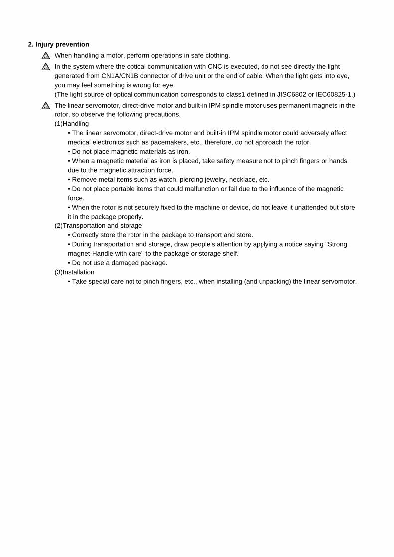
2. Injury prevention
When handling a motor, perform operations in safe clothing.
In the system where the optical communication with CNC is executed, do not see directly the light
generated from CN1A/CN1B connector of drive unit or the end of cable. When the light gets into eye,
you may feel something is wrong for eye.
(The light source of optical communication corresponds to class1 defined in JISC6802 or IEC60825-1.)
The linear servomotor, direct-drive motor and built-in IPM spindle motor uses permanent magnets in the
rotor, so observe the following precautions.
(1)Handling
• The linear servomotor, direct-drive motor and built-in IPM spindle motor could adversely affect
medical electronics such as pacemakers, etc., therefore, do not approach the rotor.
• Do not place magnetic materials as iron.
• When a magnetic material as iron is placed, take safety measure not to pinch fingers or hands
due to the magnetic attraction force.
• Remove metal items such as watch, piercing jewelry, necklace, etc.
• Do not place portable items that could malfunction or fail due to the influence of the magnetic
force.
• When the rotor is not securely fixed to the machine or device, do not leave it unattended but store
it in the package properly.
(2)Transportation and storage
• Correctly store the rotor in the package to transport and store.
• During transportation and storage, draw people's attention by applying a notice saying "Strong
magnet-Handle with care" to the package or storage shelf.
• Do not use a damaged package.
(3)Installation
• Take special care not to pinch fingers, etc., when installing (and unpacking) the linear servomotor.

1. Fire prevention
Install the units, motors and regenerative resistor on non-combustible material. Direct installation on
combustible material or near combustible materials could lead to fires.
Always install a circuit protector and contactor on the servo drive unit power input as explained in this
manual. Refer to this manual and select the correct circuit protector and contactor. An incorrect
selection could result in fire.
Shut off the power on the unit side if a fault occurs in the units. Fires could be caused if a large current
continues to flow.
When using a regenerative resistor, provide a sequence that shuts off the power with the regenerative
resistor's error signal. The regenerative resistor could abnormally overheat and cause a fire due to a
fault in the regenerative transistor, etc.
The battery unit could heat up, ignite or rupture if submerged in water, or if the poles are incorrectly
wired.
Cut off the main circuit power with the contactor when an alarm or emergency stop occurs.
2. Injury prevention
Do not apply a voltage other than that specified in this manual, on each terminal. Failure to observe this
item could lead to ruptures or damage, etc.
Do not mistake the terminal connections. Failure to observe this item could lead to ruptures or damage,
etc.
Do not mistake the polarity (+,- ). Failure to observe this item could lead to ruptures or damage, etc.
Do not touch the radiation fin on unit back face, regenerative resistor or motor, etc., or place parts
(cables, etc.) while the power is turned ON or immediately after turning the power OFF. These parts
may reach high temperatures, and can cause burns or part damage.
Structure the cooling fan on the unit back face, etc., etc so that it cannot be touched after installation.
Touching the cooling fan during operation could lead to injuries.
When handling a motor, perform operations in safe clothing.
CAUTION

3. Various precautions
Observe the following precautions. Incorrect handling of the unit could lead to faults, injuries and electric
shocks, etc.
(1) Transportation and installation
Correctly transport the product according to its weight.
Use the motor's hanging bolts only when transporting the motor. Do not transport the machine when the
motor is installed on the machine.
Do not stack the products above the tolerable number.
Follow this manual and install the unit or motor in a place where the weight can be borne.
Do not get on top of or place heavy objects on the unit.
Do not hold the cables, axis or detector when transporting the motor.
Do not hold the connected wires or cables when transporting the units.
Do not hold the front cover when transporting the unit. The unit could drop.
Always observe the installation directions of the units or motors.
Secure the specified distance between the units and control panel, or between the servo drive unit and
other devices.
Do not install or run a unit or motor that is damaged or missing parts.
Do not block the intake or exhaust ports of the motor provided with a cooling fan.
Do not let foreign objects enter the units or motors. In particular, if conductive objects such as screws or
metal chips, etc., or combustible materials such as oil enter, rupture or breakage could occur.
Provide adequate protection using a material such as connector for conduit to prevent screws, metallic
detritus, water and other conductive matter or oil and other combustible matter from entering the motor
through the power line lead-out port.
The units, motors and detectors are precision devices, so do not drop them or apply strong impacts to
them.
CAUTION

Store and use the units under the following environment conditions.
(Note 1) For details, confirm each unit or motor specifications in addition.
(Note 2) -15°C to 55°C for linear servomotor.
Securely fix the servomotor to the machine. Insufficient fixing could lead to the servomotor slipping off
during operation.
Always install the servomotor with reduction gear in the designated direction. Failure to do so could lead
to oil leaks.
Structure the rotary sections of the motor so that it can never be touched during operation. Install a
cover, etc., on the shaft.
When installing a coupling to a servomotor shaft end, do not apply an impact by hammering, etc. The
detector could be damaged.
Do not apply a load exceeding the tolerable load onto the servomotor shaft. The shaft could break.
Store the motor in the package box.
When inserting the shaft into the built-in IPM spindle motor, do not heat the rotor higher than 130°C. The
magnet could be demagnetized, and the specifications characteristics will not be ensured.
Always use a nonmagnetic tool (explosion-proof beryllium copper alloy safety tool: NGK Insulators, etc.)
when installing the linear servomotor.
Always provide a mechanical stopper on the end of the linear servomotor's travel path.
If the unit has been stored for a long time, always check the operation before starting actual operation.
Please contact the Service Center, Service Station, Sales Office or delayer.
(2) Wiring
Correctly and securely perform the wiring. Failure to do so could lead to abnormal operation of the
motor.
Do not install a condensing capacitor, surge absorber or radio noise filter on the output side of the drive
unit.
Correctly connect the output side of the drive unit (terminals U, V, W). Failure to do so could lead to
abnormal operation of the motor.
When using a power regenerative power supply unit, always install an AC reactor for each power supply
unit.
In the main circuit power supply side of the unit, always install an appropriate circuit protector or
contactor for each unit. Circuit protector or contactor cannot be shared by several units.
Environment Unit Motor
Ambient temperatureOperation: 0 to 55°C(with no freezing),Storage / Transportation: -15°C to 70°C
(with no freezing)
Operation: 0 to 40°C(with no freezing),Storage: -15°C to 70°C (Note2) (with no freezing)
Ambient humidity
Operation: 90%RH or less (with no dew condensation)
Storage / Transportation: 90%RH or less (with no dew condensation)
Operation: 80%RH or less (with no dew condensation),
Storage: 90%RH or less (with no dew condensation)
AtmosphereIndoors (no direct sunlight)
With no corrosive gas, inflammable gas, oil mist, dust or conductive fine particles
Altitude
Operation/Storage: 1000 meters or less above sea level,
Transportation: 13000 meters or less above sea level
Operation: 1000 meters or less above sea level,Storage: 10000 meters or less above sea level
Vibration/impact According to each unit or motor specification
CAUTION

Always connect the motor to the drive unit's output terminals (U, V, W).
Do not directly connect a commercial power supply to the servomotor. Failure to observe this could
result in a fault.
When using an inductive load such as a relay, always connect a diode as a noise measure parallel to
the load.
When using a capacitance load such as a lamp, always connect a protective resistor as a noise
measure serial to the load.
Do not reverse the direction of a diode which
connect to a DC relay for the control output
signals such as contractor and motor brake
output, etc. to suppress a surge. Connecting it
backwards could cause the drive unit to
malfunction so that signals are not output, and
emergency stop and other safety circuits are inoperable.
Do not connect/disconnect the cables connected between the units while the power is ON.
Securely tighten the cable connector fixing screw or fixing mechanism. An insecure fixing could cause
the cable to fall off while the power is ON.
When using a shielded cable instructed in the instruction manual, always ground the cable with a cable
clamp, etc.
Always separate the signals wires from the drive wire and power line.
Use wires and cables that have a wire diameter, heat resistance and flexibility that conforms to the
system.
(3) Trial operation and adjustment
Check and adjust each program and parameter before starting operation. Failure to do so could lead to
unforeseen operation of the machine.
Do not make remarkable adjustments and changes of parameter as the operation could become
unstable.
The usable motor and unit combination is predetermined. Always check the combinations and
parameters before starting trial operation.
The linear servomotor does not have a stopping device such as magnetic brakes. Install a stopping
device on the machine side.
CAUTION
RA
COM(24VDC)
COM(24VDC)
RA
Servodrive unit Servodrive unit
Control outputsignal
Control outputsignal

(4) Usage methods
In abnormal state, install an external emergency stop circuit so that the operation can be stopped and
power shut off immediately.
Turn the power OFF immediately if smoke, abnormal noise or odors are generated from the unit or
motor.
Do not disassemble or repair this product.
Never make modifications.
When an alarm occurs, the machine will start suddenly if an alarm reset (RST) is carried out while an
operation start signal (ST) is being input. Always confirm that the operation signal is OFF before
carrying out an alarm reset. Failure to do so could lead to accidents or injuries.
Reduce magnetic damage by installing a noise filter. The electronic devices used near the unit could be
affected by magnetic noise. Install a line noise filter, etc., if there is a risk of magnetic noise.
Use the unit, motor and regenerative resistor with the designated combination. Failure to do so could
lead to fires or trouble.
The brake (magnetic brake) of the servomotor are for holding, and must not be used for normal braking.
There may be cases when holding is not possible due to the magnetic brake's life, the machine
construction (when ball screw and servomotor are coupled via a timing belt, etc.) or the magnetic
brake's failure. Install a stop device to ensure safety on the machine side.
After changing the programs/parameters or after maintenance and inspection, always test the operation
before starting actual operation.
Do not enter the movable range of the machine during automatic operation. Never place body parts
near or touch the spindle during rotation.
Follow the power supply specification conditions given in each specification for the power (input voltage,
input frequency, tolerable sudden power failure time, etc.).
Set all bits to "0" if they are indicated as not used or empty in the explanation on the bits.
Do not use the dynamic brakes except during the emergency stop. Continued use of the dynamic
brakes could result in brake damage.
If a circuit protector for the main circuit power supply is shared by several units, the circuit protector may
not activate when a short-circuit fault occurs in a small capacity unit. This is dangerous, so never share
the circuit protector.
Mitsubishi spindle motor is dedicated to machine tools. Do not use for other purposes.
(5) Troubleshooting
If a hazardous situation is predicted during power failure or product trouble, use a servomotor with
magnetic brakes or install an external brake mechanism.
Use a double circuit configuration that allows the
operation circuit for the magnetic brakes to be operated
even by the external emergency stop signal.
Always turn the main circuit power of the motor OFF
when an alarm occurs.
If an alarm occurs, remove the cause, and secure the
safety before resetting the alarm.
CAUTION
MBREMG
Servomotor
Magneticbrake
Shut off with the servomotorbrake control output.
Shut off with NC brake control PLC output.
24VDC

(6) Maintenance, inspection and part replacement
Always backup the programs and parameters before starting maintenance or inspections.
The capacity of the electrolytic capacitor will drop over time due to self-discharging, etc. To prevent
secondary disasters due to failures, replacing this part every five years when used under a normal
environment is recommended. Contact the Service Center, Service Station, Sales Office or delayer for
repairs or part replacement.
Do not perform a megger test (insulation resistance measurement) during inspections.
If the battery low warning is issued, back up the machining programs, tool data and parameters with an
input/output unit, and then replace the battery.
Do not short circuit, charge, overheat, incinerate or disassemble the battery.
For after-purchase servicing of the built-in motor (including the detector), supplies of servicing parts and
repairs can only be offered.
For maintenance, part replacement, and services in case of failures in the built-in motor (including the
detector), take necessary actions at your end. For spindle drive unit, Mitsubishi can offer the after-
purchase servicing as with the general spindle drive unit.
When a failure has occurred in the built-in motor (including the detector), some period of time can be
required to supply the servicing parts or repair. Prepare the spare parts at your end whenever possible.
(7) Disposal
Take the batteries and backlights for LCD, etc., off from the controller, drive unit and motor, and dispose
of them as general industrial wastes.
Do not disassemble the unit or motor.
Dispose of the battery according to local laws.
Always return the secondary side (magnet side) of the linear servomotor to the Service Center or
Service Station.
When incinerating optical communication cable, hydrogen fluoride gas or hydrogen chloride gas which
is corrosive and harmful may be generated. For disposal of optical communication cable, request for
specialized industrial waste disposal services that has incineration facility for disposing hydrogen
fluoride gas or hydrogen chloride gas.
(8) Transportation
The unit and motor are precision parts and must be handled carefully.
According to a United Nations Advisory, the battery unit and battery must be transported according to
the rules set forth by the International Civil Aviation Organization (ICAO), International Air
Transportation Association (IATA), International Maritime Organization (IMO), and United States
Department of Transportation (DOT), etc.
(9) General precautions
The drawings given in this manual show the covers and safety partitions, etc., removed to provide a
clearer explanation. Always return the covers or partitions to their respective places before starting
operation, and always follow the instructions given in this manual.
CAUTION

Treatment of waste
The following two laws will apply when disposing of this product. Considerations must be made to each law.
The following laws are in effect in Japan. Thus, when using this product overseas, the local laws will have a
priority. If necessary, indicate or notify these laws to the final user of the product.
(1) Requirements for "Law for Promotion of Effective Utilization of Resources"
(a) Recycle as much of this product as possible when finished with use.
(b) When recycling, often parts are sorted into steel scraps and electric parts, etc., and sold to scrap
contractors. Mitsubishi recommends sorting the product and selling the members to appropriate
contractors.
(2) Requirements for "Law for Treatment of Waste and Cleaning"
(a) Mitsubishi recommends recycling and selling the product when no longer needed according to item
(1) above. The user should make an effort to reduce waste in this manner.
(b) When disposing a product that cannot be resold, it shall be treated as a waste product.
(c) The treatment of industrial waste must be commissioned to a licensed industrial waste treatment
contractor, and appropriate measures, including a manifest control, must be taken.
(d) Batteries correspond to "primary batteries", and must be disposed of according to local disposal
laws.

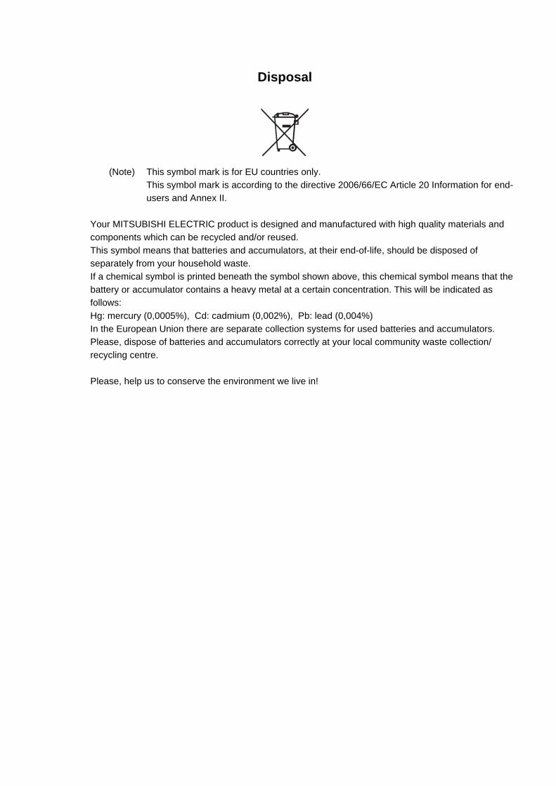
Disposal
(Note) This symbol mark is for EU countries only.
This symbol mark is according to the directive 2006/66/EC Article 20 Information for end-
users and Annex II.
Your MITSUBISHI ELECTRIC product is designed and manufactured with high quality materials and
components which can be recycled and/or reused.
This symbol means that batteries and accumulators, at their end-of-life, should be disposed of
separately from your household waste.
If a chemical symbol is printed beneath the symbol shown above, this chemical symbol means that the
battery or accumulator contains a heavy metal at a certain concentration. This will be indicated as
follows:
Hg: mercury (0,0005%), Cd: cadmium (0,002%), Pb: lead (0,004%)
In the European Union there are separate collection systems for used batteries and accumulators.
Please, dispose of batteries and accumulators correctly at your local community waste collection/
recycling centre.
Please, help us to conserve the environment we live in!


本製品の取扱いについて
( 日本語 /Japanese)
本製品は工業用 ( クラス A) 電磁環境適合機器です。販売者あるいは使用者はこの点に注意し、住商業環境以外で
の使用をお願いいたします。
Handling of our product
(English)
This is a class A product. In a domestic environment this product may cause radio interference in which case the
user may be required to take adequate measures.
본 제품의 취급에 대해서
( 한국어 /Korean)
이 기기는 업무용 (A 급 ) 전자파적합기기로서 판매자 또는 사용자는 이 점을 주의하시기 바라며 가정외의 지역에
서 사용하는 것을 목적으로 합니다 .


Contents
1 Installation..............................................................................................1 - 11-1 Installation of servomotor.................................................................................................................. 1 - 2
1-1-1 Environmental conditions ......................................................................................................... 1 - 21-1-2 Quakeproof level ...................................................................................................................... 1 - 31-1-3 Cautions for mounting load (prevention of impact on shaft) ..................................................... 1 - 41-1-4 Installation direction.................................................................................................................. 1 - 41-1-5 Shaft characteristics ................................................................................................................. 1 - 51-1-6 Machine accuracy..................................................................................................................... 1 - 61-1-7 Coupling with the load .............................................................................................................. 1 - 71-1-8 Oil/water standards................................................................................................................... 1 - 91-1-9 Installation of servomotor ....................................................................................................... 1 - 111-1-10 Cable stress.......................................................................................................................... 1 - 12
1-2 Installation of spindle motor ............................................................................................................ 1 - 131-2-1 Environmental conditions ....................................................................................................... 1 - 131-2-2 Cautions for mounting fittings................................................................................................. 1 - 131-2-3 Shaft characteristics ............................................................................................................... 1 - 141-2-4 Machine accuracy................................................................................................................... 1 - 151-2-5 Coupling with the fittings......................................................................................................... 1 - 151-2-6 Ambient environment.............................................................................................................. 1 - 151-2-7 Installation of spindle motor.................................................................................................... 1 - 151-2-8 Connection ............................................................................................................................. 1 - 161-2-9 Cable stress............................................................................................................................ 1 - 17
1-3 Installation of tool spindle motor ..................................................................................................... 1 - 181-3-1 Environmental conditions ....................................................................................................... 1 - 181-3-2 Shaft characteristics ............................................................................................................... 1 - 18
1-4 Installation of the drive unit ............................................................................................................. 1 - 191-4-1 Environmental conditions ....................................................................................................... 1 - 191-4-2 Installation direction and clearance ........................................................................................ 1 - 201-4-3 Prevention of entering of foreign matter ................................................................................. 1 - 221-4-4 Panel installation hole work drawings (Panel cut drawings)................................................... 1 - 231-4-5 Heating value.......................................................................................................................... 1 - 251-4-6 Heat radiation countermeasures ............................................................................................ 1 - 26
1-5 Installation of the spindle detector .................................................................................................. 1 - 291-5-1 Spindle side ABZ pulse output detector (OSE-1024 Series) .................................................. 1 - 291-5-2 Spindle side PLG serial output detector (TS5690, MU1606 Series) ...................................... 1 - 301-5-3 Installation accuracy diagnosis for PLG detector ................................................................... 1 - 32
1-6 Noise measures.............................................................................................................................. 1 - 34
2 Wiring and Connection..........................................................................2 - 12-1 Part system connection diagram ...................................................................................................... 2 - 32-2 Main circuit terminal block/control circuit connector ......................................................................... 2 - 4
2-2-1 Names and applications of main circuit terminal block signals and control circuit connectors. 2 - 42-2-2 Connector pin assignment........................................................................................................ 2 - 5
2-3 NC and drive unit connection.......................................................................................................... 2 - 142-4 Connecting with optical communication repeater unit .................................................................... 2 - 172-5 Motor and detector connection ....................................................................................................... 2 - 19
2-5-1 Connection of the servomotor ................................................................................................ 2 - 192-5-2 Connection of the full-closed loop system.............................................................................. 2 - 242-5-3 Connection of the speed command synchronization control system...................................... 2 - 262-5-4 Connection of the spindle motor............................................................................................. 2 - 282-5-5 Connection of tool spindle motor ............................................................................................ 2 - 30
2-6 Connection of power supply ........................................................................................................... 2 - 332-6-1 Power supply input connection............................................................................................... 2 - 342-6-2 Connecting the grounding cable............................................................................................. 2 - 37
2-7 Wiring of the motor brake .............................................................................................................. 2 - 38

2-7-1 Wiring of the motor magnetic brake........................................................................................ 2 - 382-7-2 Dynamic brake unit wiring ...................................................................................................... 2 - 41
2-8 Peripheral control wiring ................................................................................................................. 2 - 422-8-1 Input/output circuit wiring........................................................................................................ 2 - 422-8-2 Wiring of an external emergency stop .................................................................................... 2 - 432-8-3 Safety observation function .................................................................................................... 2 - 482-8-4 Specified speed output ........................................................................................................... 2 - 522-8-5 Spindle coil changeover ......................................................................................................... 2 - 542-8-6 Specifications of proximity switch ........................................................................................... 2 - 58
3 Setup....................................................................................................... 3 - 13-1 Initial setup........................................................................................................................................ 3 - 2
3-1-1 Setting the rotary switch ........................................................................................................... 3 - 23-1-2 Setting DIP switch .................................................................................................................... 3 - 33-1-3 Transition of LED display after power is turned ON ................................................................. 3 - 3
3-2 Setting the initial parameters for the servo drive unit........................................................................ 3 - 43-2-1 Setting of servo specification parameters................................................................................. 3 - 53-2-2 Setting of machine side detector .............................................................................................. 3 - 83-2-3 Setting of distance-coded reference scale ............................................................................ 3 - 113-2-4 Setting of speed command synchronous control.................................................................... 3 - 133-2-5 List of standard parameters for each servomotor................................................................... 3 - 143-2-6 Servo parameters .................................................................................................................. 3 - 34
3-3 Setting the initial parameters for the spindle drive unit ................................................................... 3 - 683-3-1 Setting of parameters related to the spindle........................................................................... 3 - 683-3-2 List of standard parameters for each spindle motor ............................................................... 3 - 753-3-3 Spindle specification parameters.......................................................................................... 3 - 1203-3-4 Spindle parameters .............................................................................................................. 3 - 141
4 Servo Adjustment.................................................................................. 4 - 14-1 D/A output specifications for servo drive unit.................................................................................... 4 - 2
4-1-1 D/A output specifications .......................................................................................................... 4 - 24-1-2 Output data settings ................................................................................................................. 4 - 34-1-3 Setting the output magnification ............................................................................................... 4 - 4
4-2 Servo adjustment procedure............................................................................................................. 4 - 54-3 Gain adjustment................................................................................................................................ 4 - 6
4-3-1 Current loop gain ...................................................................................................................... 4 - 64-3-2 Speed loop gain........................................................................................................................ 4 - 74-3-3 Position loop gain ................................................................................................................... 4 - 12
4-4 Characteristics improvement .......................................................................................................... 4 - 154-4-1 Optimal adjustment of cycle time............................................................................................ 4 - 154-4-2 Vibration suppression measures ............................................................................................ 4 - 184-4-3 Improving the cutting surface precision .................................................................................. 4 - 254-4-4 Improvement of characteristics during acceleration/deceleration........................................... 4 - 284-4-5 Improvement of protrusion at quadrant changeover............................................................... 4 - 324-4-6 Improvement of overshooting ................................................................................................. 4 - 374-4-7 Improvement of the interpolation control path ........................................................................ 4 - 40
4-5 Adjustment during full closed loop control ...................................................................................... 4 - 424-5-1 Outline .................................................................................................................................... 4 - 424-5-2 Speed loop delay compensation ............................................................................................ 4 - 434-5-3 Dual feedback control............................................................................................................. 4 - 44
4-6 Settings for emergency stop ........................................................................................................... 4 - 464-6-1 Deceleration control................................................................................................................ 4 - 464-6-2 Vertical axis drop prevention control ...................................................................................... 4 - 494-6-3 Vertical axis pull-up control..................................................................................................... 4 - 56
4-7 Protective functions......................................................................................................................... 4 - 584-7-1 Overload detection ................................................................................................................. 4 - 584-7-2 Excessive error detection ....................................................................................................... 4 - 594-7-3 Collision detection function..................................................................................................... 4 - 60

4-8 Servo control signal ........................................................................................................................ 4 - 644-8-1 Servo control input (NC to Servo)........................................................................................... 4 - 644-8-2 Servo control output (Servo to NC) ........................................................................................ 4 - 67
5 Spindle Adjustment ...............................................................................5 - 15-1 D/A output specifications for spindle drive unit ................................................................................. 5 - 2
5-1-1 D/A output specifications.......................................................................................................... 5 - 25-1-2 Setting the output data ............................................................................................................. 5 - 35-1-3 Setting the output magnification ............................................................................................... 5 - 6
5-2 Adjustment procedures for each control ........................................................................................... 5 - 75-2-1 Basic adjustments .................................................................................................................... 5 - 75-2-2 Gain adjustment ....................................................................................................................... 5 - 85-2-3 Adjusting the acceleration/deceleration operation.................................................................. 5 - 125-2-4 Orientation adjustment ........................................................................................................... 5 - 195-2-5 Synchronous tapping adjustment ........................................................................................... 5 - 235-2-6 High-speed synchronous tapping........................................................................................... 5 - 265-2-7 Spindle C axis adjustment (For lathe system) ........................................................................ 5 - 285-2-8 Spindle synchronization adjustment (For lathe system) ......................................................... 5 - 335-2-9 Deceleration coil changeover valid function by emergency stop............................................ 5 - 355-2-10 High-response acceleration/deceleration function................................................................ 5 - 365-2-11 Spindle cutting withstand level improvement........................................................................ 5 - 37
5-3 Settings for emergency stop ........................................................................................................... 5 - 385-3-1 Deceleration control................................................................................................................ 5 - 38
5-4 Spindle control signal...................................................................................................................... 5 - 395-4-1 Spindle control input (NC to Spindle) ..................................................................................... 5 - 395-4-2 Spindle control output (Spindle to NC) ................................................................................... 5 - 43
6 Troubleshooting.....................................................................................6 - 16-1 Points of caution and confirmation.................................................................................................... 6 - 2
6-1-1 LED display when alarm or warning occurs ............................................................................. 6 - 36-2 Protective functions list of units ........................................................................................................ 6 - 4
6-2-1 List of alarms ............................................................................................................................ 6 - 46-2-2 List of warnings......................................................................................................................... 6 - 9
6-3 Troubleshooting .............................................................................................................................. 6 - 116-3-1 Troubleshooting at power ON................................................................................................. 6 - 116-3-2 Troubleshooting for each alarm No. ....................................................................................... 6 - 126-3-3 Troubleshooting for each warning No..................................................................................... 6 - 396-3-4 Parameter numbers during initial parameter error.................................................................. 6 - 426-3-5 Troubleshooting the spindle system when there is no alarm or warning................................ 6 - 43
7 Maintenance ...........................................................................................7 - 17-1 Periodic inspections.......................................................................................................................... 7 - 2
7-1-1 Inspections ............................................................................................................................... 7 - 27-1-2 Cleaning of spindle motor......................................................................................................... 7 - 2
7-2 Service parts..................................................................................................................................... 7 - 77-3 Adding and replacing units and parts ............................................................................................... 7 - 8
7-3-1 Replacing the drive unit ............................................................................................................ 7 - 97-3-2 Replacing the unit fan............................................................................................................. 7 - 107-3-3 Replacing the battery.............................................................................................................. 7 - 127-3-4 Replacing the fuse.................................................................................................................. 7 - 14
Appendix 1 Cable and Connector Specifications ................ Appendix 1 - 1Appendix 1-1 Selection of cable ............................................................................................. Appendix 1 - 2
Appendix 1-1-1 Cable wire and assembly ......................................................................... Appendix 1 - 2Appendix 1-2 Cable connection diagram ................................................................................ Appendix 1 - 4
Appendix 1-2-1 Battery cable............................................................................................. Appendix 1 - 4
Appendix 1-2-2 Power supply communication cable and connector ................................. Appendix 1 - 5Appendix 1-2-3 Optical communication repeater unit cable .............................................. Appendix 1 - 6Appendix 1-2-4 Servo / tool spindle detector cable ........................................................... Appendix 1 - 7Appendix 1-2-5 Brake connector (Brake connector for motor brake control output)........ Appendix 1 - 13Appendix 1-2-6 Spindle detector cable ............................................................................ Appendix 1 - 14
Appendix 1-3 Main circuit cable connection diagram............................................................ Appendix 1 - 16Appendix 1-4 Connector outline dimension drawings........................................................... Appendix 1 - 17
Appendix 1-4-1 Connector for drive unit .......................................................................... Appendix 1 - 17Appendix 1-4-2 Connector for servo and tool spindle...................................................... Appendix 1 - 21Appendix 1-4-3 Connector for spindle ............................................................................. Appendix 1 - 25
Appendix 2 Cable and Connector Assembly ........................Appendix 2 - 1Appendix 2-1 CM10-SPxxS-x(D6) plug connector.................................................................. Appendix 2 - 2Appendix 2-2 CM10-APxxS-x(D6) angle plug connector ........................................................ Appendix 2 - 6Appendix 2-3 CM10-SP-CV reinforcing cover for straight plug............................................. Appendix 2 - 11Appendix 2-4 CM10-AP-D-CV reinforcing cover for angle plug ............................................ Appendix 2 - 11Appendix 2-5 1747464-1 plug connector .............................................................................. Appendix 2 - 12
Appendix 2-5-1 Applicable products ................................................................................ Appendix 2 - 12Appendix 2-5-2 Applicable cable ..................................................................................... Appendix 2 - 12Appendix 2-5-3 Related documents................................................................................. Appendix 2 - 12Appendix 2-5-4 Assembly procedure............................................................................... Appendix 2 - 12
Appendix 3 Precautions in Installing Spindle Motor............Appendix 3 - 1Appendix 3-1 Precautions in transporting motor ..................................................................... Appendix 3 - 2Appendix 3-2 Precautions in selecting motor fittings .............................................................. Appendix 3 - 3Appendix 3-3 Precautions in mounting fittings........................................................................ Appendix 3 - 3Appendix 3-4 Precautions in coupling shafts .......................................................................... Appendix 3 - 4Appendix 3-5 Precautions in installing motor in machine........................................................ Appendix 3 - 5Appendix 3-6 Other Precautions............................................................................................. Appendix 3 - 5Appendix 3-7 Example of unbalance correction...................................................................... Appendix 3 - 5Appendix 3-8 Precautions in balancing of motor with key....................................................... Appendix 3 - 6
Appendix 4 Compliance to EC Directives .............................Appendix 4 - 1Appendix 4-1 Compliance to EC Directives ............................................................................ Appendix 4 - 2
Appendix 4-1-1 European EC Directives ........................................................................... Appendix 4 - 2Appendix 4-1-2 Cautions for EC Directive compliance ...................................................... Appendix 4 - 2
Appendix 5 EMC Installation Guidelines...............................Appendix 5 - 1Appendix 5-1 Introduction ....................................................................................................... Appendix 5 - 2Appendix 5-2 EMC instructions............................................................................................... Appendix 5 - 2Appendix 5-3 EMC measures ................................................................................................. Appendix 5 - 3Appendix 5-4 Measures for panel structure ............................................................................ Appendix 5 - 3
Appendix 5-4-1 Measures for control panel unit ................................................................ Appendix 5 - 3Appendix 5-4-2 Measures for door ................................................................................... Appendix 5 - 4Appendix 5-4-3 Measures for operation board panel........................................................ Appendix 5 - 4Appendix 5-4-4 Shielding of the power supply input section ............................................. Appendix 5 - 4
Appendix 5-5 Measures for various cables ............................................................................. Appendix 5 - 5Appendix 5-5-1 Measures for wiring in panel..................................................................... Appendix 5 - 5Appendix 5-5-2 Measures for shield treatment .................................................................. Appendix 5 - 5Appendix 5-5-3 Servo/spindle motor power cable ............................................................. Appendix 5 - 6Appendix 5-5-4 Servo/spindle motor feedback cable ........................................................ Appendix 5 - 7
Appendix 5-6 EMC countermeasure parts .............................................................................. Appendix 5 - 7Appendix 5-6-1 Shield clamp fitting ................................................................................... Appendix 5 - 7Appendix 5-6-2 Ferrite core ............................................................................................... Appendix 5 - 8Appendix 5-6-3 Power line filter ......................................................................................... Appendix 5 - 8Appendix 5-6-4 Surge protector....................................................................................... Appendix 5 - 15

Appendix 6 EC Declaration of Conformity ........................... Appendix 6 - 1Appendix 6-1 Compliance to EC Directives ............................................................................ Appendix 6 - 2
Appendix 6-1-1 Low voltage equipment............................................................................. Appendix 6 - 2
Appendix 7 Higher Harmonic Suppression Measure Guidelines........................................................................ Appendix 7 - 1
Appendix 7-1 Higher harmonic suppression measure guidelines........................................... Appendix 7 - 2Appendix 7-1-1 Calculating the equivalent capacity of the higher harmonic generator ..... Appendix 7 - 3


Outline for MDS-D/DH Series Specifications Manual (IB-1500875-E)
1 Introduction1-1 Servo/spindle drive system configuration
1-1-1 System configuration1-2 Explanation of type
1-2-1 Servomotor type1-2-2 Servo drive unit type1-2-3 Spindle motor type1-2-4 Tool spindle motor type1-2-5 Spindle drive unit type1-2-6 Power supply unit type1-2-7 AC reactor type
2 Specifications2-1 Servomotor
2-1-1 Specifications list2-1-2 Torque characteristics
2-2 Spindle motor2-2-1 Specifications2-2-2 Output characteristics
2-3 Tool spindle motor2-3-1 Specifications2-3-2 Output characteristics
2-4 Drive unit2-4-1 Installation environment conditions2-4-2 Servo drive unit2-4-3 Spindle drive unit2-4-4 Power supply unit 2-4-5 Unit outline dimension drawing2-4-6 AC reactor2-4-7 Explanation of each part
3 Function SpecificationsFunction specifications list3-1 Base control functions
3-1-1 Full closed loop control3-1-2 Position command synchronous control3-1-3 Speed command synchronous control3-1-4 Distance-coded reference position control3-1-5 Spindle's continuous position loop control3-1-6 Coil changeover control3-1-7 Gear changeover control3-1-8 Orientation control3-1-9 Indexing control3-1-10 Synchronous tapping control3-1-11 Spindle synchronous control3-1-12 Spindle/C axis control3-1-13 Proximity switch orientation control3-1-14 Power regeneration control3-1-15 Resistor regeneration control
3-2 Servo/Spindle control functions3-2-1 Torque limit function3-2-2 Variable speed loop gain control3-2-3 Gain changeover for synchronous tapping
control
3-2-4 Speed loop PID changeover control3-2-5 Disturbance torque observer3-2-6 Smooth High Gain control (SHG control)3-2-7 High-speed synchronous tapping control
(OMR-DD control)3-2-8 Dual feedback control3-2-9 HAS control3-2-10 Control loop gain changeover3-2-11 Spindle output stabilizing control3-2-12 High-response spindle acceleration/
deceleration function3-3 Compensation control function
3-3-1 Jitter compensation3-3-2 Notch filter3-3-3 Adaptive tracking-type notch filter3-3-4 Overshooting compensation3-3-5 Machine end compensation control3-3-6 Lost motion compensation type 23-3-7 Lost motion compensation type 33-3-8 Lost motion compensation type 43-3-9 Spindle motor temperature compensation
function3-4 Protection function
3-4-1 Deceleration control at emergency stop3-4-2 Vertical axis drop prevention/pull-up control3-4-3 Earth fault detection3-4-4 Collision detection function3-4-5 Safety observation function3-4-6 Fan stop detection3-4-7 Open-phase detection3-4-8 Contactor weld detection
3-5 Sequence functions3-5-1 Contactor control function3-5-2 Motor brake control function3-5-3 External emergency stop function3-5-4 Specified speed output3-5-5 Quick READY ON sequence
3-6 Diagnosis function3-6-1 Monitor output function3-6-2 Machine resonance frequency display
function3-6-3 Machine inertia display function3-6-4 Motor temperature display function3-6-5 Load monitor output function3-6-6 Open loop control function3-6-7 Power supply voltage display function
4 Characteristics4-1 Servomotor
4-1-1 Environmental conditions 4-1-2 Quakeproof level4-1-3 Shaft characteristics4-1-4 Machine accuracy4-1-5 Oil / water standards4-1-6 Installation of servo motor4-1-7 Overload protection characteristics4-1-8 Magnetic brake4-1-9 Dynamic brake characteristics
4-2 Spindle motor

4-2-1 Environmental conditions 4-2-2 Shaft characteristics4-2-3 Machine accuracy4-2-4 Installation of spindle motor
4-3 Tool spindle motor4-3-1 Environmental conditions 4-3-2 Shaft characteristics4-3-3 Tool spindle temperature characteristics
4-4 Drive unit4-4-1 Environmental conditions 4-4-2 Heating value4-4-3 Drive unit arrangement
5 Dedicated Options5-1 Servo options
5-1-1 Dynamic brake unit (MDS-D-DBU)5-1-2 Battery option (ER6V-C119B, A6BAT,
MDS-A-BT, MDS-BTBOX-36)5-1-3 Ball screw side detector (OSA105ET2,
OSA166ET2N)5-1-4 Machine side detector
5-2 Spindle options5-2-1 Spindle side ABZ pulse output detector
(OSE-1024 Series)5-2-2 Spindle side PLG serial output detector
(TS5690, MU1606 Series)5-2-3 Spindle side accuracy serial output detector
(ERM280, MPCI Series)5-3 Detector interface unit
5-3-1 Serial output interface unit for ABZ analog detector MDS-B-HR
5-3-2 Serial signal division unit MDS-B-SD5-3-3 Pulse output interface unit for ABZ analog
detector IBV Series (Other manufacturer's product)
5-3-4 Serial output interface unit for ABZ analog detector EIB192M (Other manufacturer's product)
5-3-5 Serial output interface unit for ABZ analog detector EIB392M (Other manufacturer's product)
5-3-6 Serial output interface unit for ABZ analog detector ADB-20J Series (Other manufacturer's product)
5-4 Drive unit option5-4-1 Optical communication repeater unit
(FCU7-EX022)5-4-2 DC connection bar5-4-3 Side protection cover
5-5 Cables and connectors5-5-1 Cable connection diagram5-5-2 List of cables and connectors5-5-3 Optical communication cable specifications
6 Specifications of Peripheral Devices6-1 Selection of wire
6-1-1 Example of wires by unit6-2 Selection of circuit protector and contactor
6-2-1 Selection of circuit protector
6-2-2 Selection of contactor6-3 Selection of earth leakage breaker6-4 Branch-circuit protection (for control power
supply)6-4-1 Circuit protector6-4-2 Fuse protection
6-5 Noise filter6-6 Surge absorber6-7 Relay
7 Selection7-1 Selection of the servomotor
7-1-1 Outline7-1-2 Selection of servomotor capacity7-1-3 Motor shaft conversion load torque7-1-4 Expressions for load inertia calculation
7-2 Selection of the spindle motor7-3 Selection of the power supply unit
7-3-1 Calculation of spindle output7-3-2 Calculation of servo motor output7-3-3 Selection of the power supply unit7-3-4 Required capacity of power supply7-3-5 Example for power supply unit and power
supply facility capacity
Appendix 1 Cable and Connector Specifications
Appendix 1-1 Selection of cableAppendix 1-1-1 Cable wire and assembly
Appendix 1-2 Cable connection diagramAppendix 1-2-1 Battery cableAppendix 1-2-2 Power supply communication
cable and connectorAppendix 1-2-3 Optical communication repeater
unit cableAppendix 1-2-4 Servo / tool spindle detector cableAppendix 1-2-5 Brake connector (Brake
connector for motor brake control output)
Appendix 1-2-6 Spindle detector cableAppendix 1-3 Main circuit cable connection diagramAppendix 1-4 Connector outline dimension drawings
Appendix 1-4-1 Connector for drive unitAppendix 1-4-2 Connector for servo and tool
spindleAppendix 1-4-3 Connector for spindle
Appendix 2 Restrictions for Lithium Batteries
Appendix 2-1 Restriction for PackingAppendix 2-1-1 Target ProductsAppendix 2-1-2 Handling by UserAppendix 2-1-3 Reference
Appendix 2-2 Products information data sheet (ER battery)
Appendix 2-3 Issuing Domestic Law of the United States for Primary Lithium Battery Transportation

Appendix 2-3-1 Outline of RegulationAppendix 2-3-2 Target ProductsAppendix 2-3-3 Handling by UserAppendix 2-3-4 Reference
Appendix 2-4 Restriction related to EU Battery Directive
Appendix 2-4-1 Important NotesAppendix 2-4-2 Information for end-user
Appendix 3 Compliance to EC DirectivesAppendix 3-1 Compliance to EC Directives
Appendix 3-1-1 European EC DirectivesAppendix 3-1-2 Cautions for EC Directive
compliance
Appendix 4 EMC Installation GuidelinesAppendix 4-1 IntroductionAppendix 4-2 EMC instructionsAppendix 4-3 EMC measuresAppendix 4-4 Measures for panel structure
Appendix 4-4-1 Measures for control panel unitAppendix 4-4-2 Measures for door Appendix 4-4-3 Measures for operation board
panelAppendix 4-4-4 Shielding of the power supply
input sectionAppendix 4-5 Measures for various cables
Appendix 4-5-1 Measures for wiring in panelAppendix 4-5-2 Measures for shield treatmentAppendix 4-5-3 Servo/spindle motor power cableAppendix 4-5-4 Servo/spindle motor feedback
cableAppendix 4-6 EMC countermeasure parts
Appendix 4-6-1 Shield clamp fittingAppendix 4-6-2 Ferrite coreAppendix 4-6-3 Power line filterAppendix 4-6-4 Surge protector
Appendix 5 EC Declaration of ConformityAppendix 5-1 Compliance to EC Directives
Appendix 5-1-1 Low voltage equipment
Appendix 6 Instruction Manual for Compliance with UL/c-UL
StandardAppendix 6-1 Operation surrounding air ambient
temperatureAppendix 6-2 Notes for AC servo/spindle system
Appendix 6-2-1 General PrecautionAppendix 6-2-2 InstallationAppendix 6-2-3 Short-circuit ratings (SCCR)Appendix 6-2-4 Peripheral devicesAppendix 6-2-5 Field Wiring Reference Table for
Input and Output (Power Wiring)Appendix 6-2-6 Motor Over Load Protection Appendix 6-2-7 Flange of servo motorAppendix 6-2-8 Spindle Drive/Motor
CombinationsAppendix 6-2-9 Servo Drive/Motor Combinations
Appendix 6-3 AC Servo/Spindle System ConnectionAppendix 6-3-1 MDS-D/DH/DM-Vx/SP SeriesAppendix 6-3-2 MDS-D-SVJ3/SPJ3 Series
Appendix 7 Compliance with Restrictions in China
Appendix 7-1 Compliance with China CCC certification system
Appendix 7-1-1 Outline of China CCC certification system
Appendix 7-1-2 First catalogue of products subject to compulsory product certification
Appendix 7-1-3 Precautions for shipping productsAppendix 7-1-4 Application for exemptionAppendix 7-1-5 Mitsubishi NC product subject to/
not subject to CCC certificationAppendix 7-2 Response to the China environment
restrictionsAppendix 7-2-1 Outline of the law on the pollution
prevention and control for electronic information products
Appendix 7-2-2 Response to the drive product for Mitsubishi NC
Appendix 7-2-3 Indication based on “Pollution suppression marking request for electronic information product”
For outline dimension drawings, refer to "DRIVE SYSTEM DATA BOOK" (IB-1500273(ENG)).

Function specifications list
<Power Supply specification>
Item MDS-D-CV MDS-DH-CVMDS-DM-SPVbuilt-in con-
verter
MDS-D-SVJ3NA
MDS-D-SVJ3built-in con-
verter
MDS-D-SPJ3NA
MDS-D-SPJ3built-in con-
verter
Software version B0 B0 B0 A3 A3
1 Base controlfunctions
1-14 Power regeneration control - -
1-15 Resistor regeneration control - - -
4 Protection function
4-6 Fan stop detection
4-7 Open-phase detection - -
4-8 Contactor weld detection
5 Sequence function
5-1 Contactor control function
5-3 External emergency stop function
5-5 High-speed READY ON sequence -
6 Diagnosis function
6-7 Power supply voltage display function - - -

<Servo specification>
(Note 1) For the multiaxis drive unit, a control by each axis is not available.
It is required to turn the servo of all axes OFF in the drive unit in order to enable a motor brake output.
(Note 2) For the drive unit MDS-DM-SPV2/3, this function is not available.
ItemMDS-D-V1/V2
MDS-DH-V1/V2
MDS-DM-V3
MDS-DM-SPV2F/3FMDS-DM-SPV2/3
MDS-D-SVJ3NA
MDS-D-SVJ3
Software version B0 B0 B0 C0/C0 A1/B0
1 Base controlfunctions
1-1 Full closed loop control - (Note2)
1-2 Position command synchronous control
1-3 Speed command synchronous control - - -
1-4 Distance-coded reference position control - - -
2 Servo control function
2-1 Torque limit function (stopper function)
2-2 Variable speed loop gain control
2-3 Gain changeover for synchronous tapping control
2-4 Speed loop PID changeover control
2-5 Disturbance torque observer
2-6 Smooth High Gain control (SHG control)
2-7 High-speed synchronous tapping control (OMR-DD control)
(Only for 1-axis)
(Only for 1-axis)-
2-8 Dual feedback control - (Note2)
2-9 HAS control -
3 Compensa-tion controlfunction
3-1 Jitter compensation
3-2 Notch filter
Variable frequency: 4Fixed frequency: 1
Variable frequency: 4Fixed frequency: 1
Variable frequency: 4Fixed frequency: 1
Variable frequency: 4Fixed frequency: 1
Variable frequency: 4Fixed frequency: 1
3-3 Adaptive tracking-type notch filter - - -
3-4 Overshooting compensation
3-5 Machine end compensation control
3-6 Lost motion compensation type 2
3-7 Lost motion compensation type 3
3-8 Lost motion compensation type 4 - - -
4 Protection function
4-1 Deceleration control at emergency stop
4-2 Vertical axis drop prevention/pull-up con-trol
4-3 Earth fault detection
4-4 Collision detection function
4-5 Safety observation function
4-6 Fan stop detection
5 Sequence function
5-2 Motor brake control function (Note 1)
5-4 Specified speed output - - -
5-5 Quick READY ON sequence -
6 Diagnosis function
6-1 Monitor output function
6-2 Machine resonance frequency display func-tion
6-3 Machine inertia display function
6-4 Motor temperature display function(Only for linear or direct-drive motor)
- -

<Spindle specifications>
(Note) The motor output effective value cannot be displayed.
ItemMDS-D-
SPMDS-DH-
SPMDS-D-
SP2
MDS-DM-SPV2F/3FMDS-DM-SPV2/3
MDS-D-SPJ3NA
MDS-D-SPJ3
Software version B0 B0 B0 C0/C0 A1/B0
1 Base controlfunctions
1-5 Spindle's continuous position loop control
1-6 Coil changeover control - -
1-7 Gear changeover control
1-8 Orientation control
1-9 Indexing control
1-10 Synchronous tapping control
1-11 Spindle synchronous control
1-12 Spindle/C axis control
1-13 Proximity switch orientation control -
2 Spindle control functions
2-1 Torque limit function
2-2 Variable speed loop gain control
2-5 Disturbance torque observer -
2-6 Smooth High Gain control (SHG control)
2-7 High-speed synchronous tapping control (OMR-DD control)
-
2-8 Dual feedback control
2-10 Control loop gain changeover
2-11 Spindle output stabilizing control
2-12 High-response spindle acceleration/decel-eration function
3 Compensa-tion controlfunction
3-1 Jitter compensation
3-2 Notch filter
Variable frequency: 4Fixed frequency: 1
Variable frequency: 4Fixed frequency: 1
Variable frequency: 4Fixed frequency: 1
Variable frequency: 4Fixed frequency: 1
Variable frequency: 4Fixed frequency: 1
3-4 Overshooting compensation
3-6 Lost motion compensation type 2
3-9 Spindle motor temperature compensation function
-
4 Protection function
4-1 Deceleration control at emergency stop
4-3 Earth fault detection
4-5 Safety observation function
4-6 Fan stop detection
5 Sequence functions
5-4 Specified speed output -
5-5 Quick READY ON sequence -
6 Diagnosis functions
6-1 Monitor output function
6-2 Machine resonance frequency display func-tion
6-3 Machine inertia display function
6-4 Motor temperature display function
6-5 Load monitor output function (Note)
6-6 Open loop control function

1 - 1
付録 1 章
1 - 1
1Installation

1 - 2
1 InstallationMITSUBISHI CNC
1-1 Installation of servomotor
1-1-1 Environmental conditions
1. Do not hold the cables, axis or detector when transporting the motor. Failure to observe this could
lead to faults or injuries.
2. Securely fix the motor to the machine. Insufficient fixing could lead to the motor deviating during
operation. Failure to observe this could lead to injuries.
3. When coupling to a servomotor shaft end, do not apply an impact by hammering, etc. The detector
could be damaged.
4. Never touch the rotary sections of the motor during operations. Install a cover, etc., on the shaft.
5. Do not apply a load exceeding the tolerable load onto the servomotor shaft. The shaft could break.
Failure to observe this could lead to injuries.
6. Do not connect or disconnect any of the connectors while the power is ON.
Environment ConditionsAmbient temperature 0°C to +40°C (with no freezing)
Ambient humidity 80% RH or less (with no dew condensation)
Storage temperature -15°C to +70°C (with no freezing)
Storage humidity 90% RH or less (with no dew condensation)
AtmosphereIndoors (no direct sunlight)
No corrosive gas, inflammable gas, oil mist or dust
AltitudeOperation / storage: 1000m or less above sea level
Transportation: 10000m or less above sea level
CAUTION
1 - 3
MDS-D/DH Series Instruction Manual
1-1 Installation of servomotor
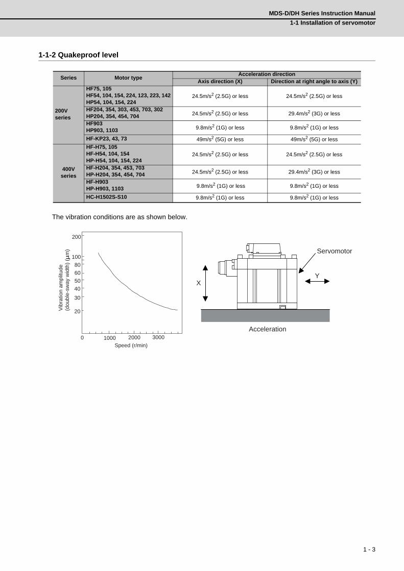
1-1-2 Quakeproof level
The vibration conditions are as shown below.
Series Motor typeAcceleration direction
Axis direction (X) Direction at right angle to axis (Y)
200Vseries
HF75, 105HF54, 104, 154, 224, 123, 223, 142HP54, 104, 154, 224
24.5m/s2 (2.5G) or less 24.5m/s2 (2.5G) or less
HF204, 354, 303, 453, 703, 302HP204, 354, 454, 704 24.5m/s2 (2.5G) or less 29.4m/s2 (3G) or less
HF903HP903, 1103 9.8m/s2 (1G) or less 9.8m/s2 (1G) or less
HF-KP23, 43, 73 49m/s2 (5G) or less 49m/s2 (5G) or less
400Vseries
HF-H75, 105HF-H54, 104, 154HP-H54, 104, 154, 224
24.5m/s2 (2.5G) or less 24.5m/s2 (2.5G) or less
HF-H204, 354, 453, 703HP-H204, 354, 454, 704 24.5m/s2 (2.5G) or less 29.4m/s2 (3G) or less
HF-H903HP-H903, 1103 9.8m/s2 (1G) or less 9.8m/s2 (1G) or less
HC-H1502S-S10 9.8m/s2 (1G) or less 9.8m/s2 (1G) or less
Speed (r/min)0 1000 2000 3000
Vibr
atio
n am
plitu
de
(dou
ble-
sway
wid
th) (
µm
)
20
3040506080
100
200
Servomotor
YX
Acceleration

1 - 4
1 InstallationMITSUBISHI CNC
1-1-3 Cautions for mounting load (prevention of impact on shaft)
[1] When using the servomotor with key way, use the screw hole at the end of the shaft to mount the pulley
onto the shaft. To install, first place the double-end stud into the shaft screw holes, contact the coupling
end surface against the washer, and press in as if tightening with a nut. When the shaft does not have a
key way, use a frictional coupling, etc.
[2] When removing the pulley, use a pulley remover, and make sure not to apply an impact on the shaft.
[3] Install a protective cover on the rotary sections such as the pulley installed on the shaft to ensure safety.
[4] The direction of the detector installed on the servomotor cannot be changed.
1-1-4 Installation direction
[1] There are no restrictions on the installation direction. Installation in any direction is possible, but as a
standard the motor is installed so that the motor power line and detector cable cannon plugs (lead-in
wires) face downward. Installation in the standard direction is effective against dripping. Measure to
prevent oil and water must be taken when not installing in the standard direction. When the motor is not
installed in the standard direction, refer to section "1-1-8 Oil/water standards" and take the appropriate
measures.
The brake plates may make a sliding sound when a servomotor with magnetic brake is installed with the
shaft facing upward, but this is not a fault.
Never hammer the end of the shaft during assembly.
Servomotor Double-end stud
Nut
Pulley Washer
CAUTION
Up
Down
Standard installation direction

1 - 5
MDS-D/DH Series Instruction Manual
1-1 Installation of servomotor
1-1-5 Shaft characteristics
There is a limit to the load that can be applied on the motor shaft. Make sure that the load applied on the
radial direction and thrust direction, when mounted on the machine, is below the tolerable values given
below. These loads may affect the motor output torque, so consider them when designing the machine.
(Note 1) The tolerable radial load and thrust load in the above table are values applied when each motor is
used independently.
(Note 2) The symbol L in the table refers to the value of L below.
L : Length from flange installation surface to center of load weight [mm]
Series Servomotor Tolerable radial load Tolerable thrust load
200Vseries
HF75T, 105T (Taper shaft) 245N (L=33) 147N
HF75S, 105S (Straight shaft) 245N (L=33) 147N
HF54T, 104T, 154T, 224T,123T, 223T, 142T (Taper shaft) 392N (L=58) 490N
HF54S, 104S, 154S, 224S,123S, 223S, 142S (Straight shaft) 980N (L=55) 490N
HF204S, 354S, 303S, 453S, 703S, 302S (Straight shaft) 2058N (L=79) 980N
HF903S (Straight shaft) 2450N (L=85) 980N
HP54T, 104T, 154T, 224T (Taper shaft) 392N (L=52.7) 490N
HP54S, 104S, 154S, 224S (Straight shaft) 980N (L=52.7) 490N
HP204S, 354S, 454S (Straight shaft) 1500N (L=52.7) 490N
HP704S (Straight shaft) 1300N (L=52.7) 590N
HP903S (Straight shaft) 2500N (L=52.7) 1100N
HP1103S (Straight shaft) 2700N (L=52.7) 1500N
HF-KP23, 43 (Straight shaft) 245N (L=30) 98N
HF-KP73 (Straight shaft) 392N (L=40) 147N
400Vseries
HF-H75T, 105T (Taper shaft) 245N (L=33) 147N
HF-H75S, 105S (Straight shaft) 245N (L=33) 147N
HF-H54T, 104T, 154T (Taper shaft) 392N (L=58) 490N
HF-H54S, 104S, 154S (Straight shaft) 980N (L=55) 490N
HF-H204S, 354S, 453S, 703S (Straight shaft) 2058N (L=79) 980N
HF-H903S (Straight shaft) 2450N (L=85) 980N
HP-H54T, 104T, 154T, 224T (Taper shaft) 392N (L=52.7) 490N
HP-H54S, 104S, 154S, 224S (Straight shaft) 980N (L=52.7) 490N
HP-H204S, 354S, 454S (Straight shaft) 1500N (L=52.7) 490N
HP-H704S (Straight shaft) 1300N (L=52.7) 590N
HP-H903S (Straight shaft) 2500N (L=52.7) 1100N
HP-H1103S (Straight shaft) 2700N (L=52.7) 1500N
HC-H1502S-S10 (Straight shaft) 3234N (L=140) 1470N
Radial load
Thrust load
L
1 - 6
1 InstallationMITSUBISHI CNC
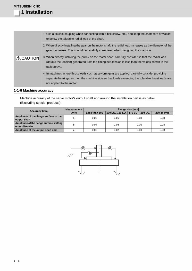
1-1-6 Machine accuracy
Machine accuracy of the servo motor's output shaft and around the installation part is as below.
(Excluding special products)
1. Use a flexible coupling when connecting with a ball screw, etc., and keep the shaft core deviation
to below the tolerable radial load of the shaft.
2. When directly installing the gear on the motor shaft, the radial load increases as the diameter of the
gear decreases. This should be carefully considered when designing the machine.
3. When directly installing the pulley on the motor shaft, carefully consider so that the radial load
(double the tension) generated from the timing belt tension is less than the values shown in the
table above.
4. In machines where thrust loads such as a worm gear are applied, carefully consider providing
separate bearings, etc., on the machine side so that loads exceeding the tolerable thrust loads are
not applied to the motor.
Accuracy (mm)Measurement
pointFlange size [mm]
Less than 100 100 SQ., 130 SQ. 176 SQ. - 250 SQ. 280 or overAmplitude of the flange surface to the output shaft
a 0.05 0.06 0.08 0.08
Amplitude of the flange surface's fitting outer diameter
b 0.04 0.04 0.06 0.08
Amplitude of the output shaft end c 0.02 0.02 0.03 0.03
CAUTION
a cb

1 - 7
MDS-D/DH Series Instruction Manual
1-1 Installation of servomotor
1-1-7 Coupling with the load
There are several ways to couple the motor shaft and machine, such as direct coupling with flexible coupling
or rigid coupling, gear connection, timing belt connection, etc.
Summarized comparison is as follows.
(1) Direct coupling - Flexible coupling
When coupling the load directly, a flexible coupling is recommended. The benefits of a flexible coupling
are as below.
(a) Shaft's angle deviation and core deviation can be absorbed to some extent, so adjustment in motor
installation is easier.
However, in the case of single, shaft core deviation cannot be allowed, so it is required to design
and adjust so that the shaft cores of the motor and ball screw align. Check the specification of the
coupling to use. If the shaft core deviation exceeds the coupling's tolerable level, the motor will
have a broken shaft, or the bearing will have a shorter life. Thus, in order to simplify the installation
adjustment, use a double flexible coupling.
(b) Less looseness produces less vibration and less noise at the coupling part.
On the other hand, if assembling is loose, lower rigidity may be caused. When using a coupling with
lower rigidity, the accuracy in centering the core doesn't have to be high, however, it is undesirable
for servo. In order to fully utilize the servo's efficiency to ensure the maximum durability of the
equipments, it is required to use a highly rigid coupling, and to fully align the shaft cores in the initial
installation. It is also required to select the optimum flexible coupling according to the working
conditions, and use it correctly according to the manufacturer's specification manual.
Example of direct coupling with load
NoiseNo
lubri-cation
Back-lash
RigidityReliability
in couplingLife
Torque increased at deceleration
Degree of free-dom in motor installation
Cautions in motor installation
Direct coupling with
flexible coupling
Looseness of bolt
Shaft core deviation(In the case of single)
Direct coupling with
rigid coupling
Looseness of bolt
Shaft core deviation Angle deviation
Gear Tooth chipping
Backlash too small Pitch diameter too small
Timing belt Belt is broken
Belt stretched too much Pitch diameter too small
If the cautions in motor installation in the above table are not observed, the motor will have a broken
shaft, or the bearing will have a shorter life. Carry out design and installation adjustment so that the
load on the motor shaft will be below the tolerable loads mentioned in "1-1-5 Shaft characteristics".
×
× ×
× ×
× × ×
CAUTION
Load shaftSpun ring Flexible coupling
Motor shaft Load shaft
Spun ringFlexible couplingMotor shaft
(a) Taper shaft (b) Straight shaft

1 - 8
1 InstallationMITSUBISHI CNC
(2) Direct coupling - Rigid coupling
A rigid coupling has benefits such as high rigidity, and relatively lower price. However, shaft core
deviation and angle deviation of the motor shaft and ball screw are not allowed, so full attention is
required in installing the rigid coupling. Shaft core deviation is desired to be 0.01mm or less. If enough
accuracy cannot be ensured, the motor will have a broken shaft, or the bearing will have a shorter life.
In addition, note that a rigid coupling is not acceptable for HF-KP Series servo motors.
Also note that the motor side ball screw bearing must be locked so that to avoid the thrust load on the
motor shaft due to expansion and contraction of the ball screw.
(3) Gear connection
Gear's accuracy and backlash amount
greatly affect on the machine's positioning
accuracy and noise during operation.
Thus, according to the machine's
specification, appropriately select the
accuracy and backlash amount.
In gear connection, it is required to take
measures against oil to enter the motor.
Load sideCoupling
Motor side
0.01mm or less
Load side
Motor sideExample of gear connection with load

1 - 9
MDS-D/DH Series Instruction Manual
1-1 Installation of servomotor
1-1-8 Oil/water standards
[1] The motor protective format uses the IP type, which complies with IEC Standard. However, these
Standards are short-term performance specifications. They do not guarantee continuous environmental
protection characteristics. Measures such as covers, etc., must be taken if there is any possibility that oil
or water will fall on the motor, and the motor will be constantly wet and permeated by water. Note that
the motor’s IP-type is not indicated as corrosion-resistant.
[2] When a gear box is installed on the servomotor, make sure that the oil level height from the center of the
shaft is higher than the values given below. Open a breathing hole on the gear box so that the inner
pressure does not rise.
Series Servomotor Oil level (mm)
200Vseries
HF75, 105 15
HF54, 104, 154, 224, 123, 223, 142 22.5
HP54, 104, 154, 224 20
HF204, 354, 303, 453, 302 30
HP204, 354, 454, 704 25
HF703 30
HF903 34
HP903, 1103 30
HF-KP23, 43 12.5
HF-KP73 15
400Vseries
HF-H75, 105 15
HF-H54, 104, 154 22.5
HP-H54, 104, 154, 224 20
HF-H204, 354, 453 30
HP-H204, 354, 454, 704 25
HF-H703 30
HF-H903 34
HP-H903, 1103 30
HC-H1502S-S10 45
Oil or water
Servomotor
GearServomotor
Oil seal
Oil level
Lip

1 - 10
1 InstallationMITSUBISHI CNC
[3] When installing the servomotor horizontally, set the power cable and detector cable to face downward.
When installing vertically or on an inclination, provide a cable trap.
[4] Do not use the unit with the cable submerged in oil or water.
(Refer to following drawing.)
[5] Make sure that oil and water do not flow along the cable into the motor or detector.
(Refer to right drawing.)
1. The servomotors, including those having IP65 specifications, do not have a completely waterproof
(oil-proof) structure. Do not allow oil or water to constantly contact the motor, enter the motor, or
accumulate on the motor. Oil can also enter the motor through cutting chip accumulation, so be
careful of this also.
2. When the motor is installed facing upwards, take measures on the machine side so that gear oil,
etc., does not flow onto the motor shaft.
Cable trap
CAUTION
Cover
Oil water
<Fault> Capillary tube phenomenon
Servomotor
<Fault> Respiration
Cover
Servomotor

1 - 11
MDS-D/DH Series Instruction Manual
1-1 Installation of servomotor
[6] When installing on the top of the shaft end, make sure that oil from the gear box, etc., does not enter the
servomotor. The servomotor does not have a waterproof structure.
1-1-9 Installation of servomotor
Mount the servo motor on a flange which has the following size or produces an equivalent or higher heat
dissipation effect:
Flange size(mm)
Servo MotorHF, HF-H, HP, HP-H, HF-KP
150x150x6 100W
250x250x6 200 to 400W
250x250x12 0.5 to 1.5kW
300x300x20 2.0 to 7.0kW
800x800x35 9.0 to 11.0kW
Servomotor
Gear
Lubricating oil

1 - 12
1 InstallationMITSUBISHI CNC
1-1-10 Cable stress
[1] Sufficiently consider the cable clamping method so that bending stress and the stress from the cable's
own weight is not applied on the cable connection part.
[2] In applications where the servomotor moves, make sure that excessive stress is not applied on the
cable.
If the detector cable and servomotor wiring are stored in a cable bear and the servomotor moves, make
sure that the cable bending part is within the range of the optional detector cable.
Fix the detector cable and power cable enclosed with the servomotor.
[3] Make sure that the cable sheathes will not be cut by sharp cutting chips, worn or stepped on by workers
or vehicles.
The bending life of the detector cable is as shown below. Regard this with a slight allowance. If the
servomotor/spindle motor is installed on a machine that moves, make the bending radius as large as
possible.
4 7 10 20 40 70 100 200
1× 10⁸
5× 10⁷
2× 10⁷
1× 10⁷
5× 10⁶
2× 10⁶
1× 10⁶
5× 10⁵
2× 10⁵
1× 10⁵
5× 10⁴
3× 10⁴
Detector cable bending life (Material of Mitsubishi optional detector cable: A14B2343)
(Note) The values in this graph are calculated values and are not guaranteed.
Bending radius (mm)
No.
of b
ends
(tim
es)
4 7 10 20 40 70 100 200 3 x 10⁴
5 x 10⁴
1 x 10⁵
2 x 10⁵
5 x 10⁵
1 x 10⁶
2 x 10⁶
5 x 10⁶
1 x 10⁷
2 x 10⁷
5 x 10⁷
1 x 10⁸

1 - 13
MDS-D/DH Series Instruction Manual
1-2 Installation of spindle motor
1-2 Installation of spindle motor
1-2-1 Environmental conditions
(Note) Refer to each spindle motor specifications for details on the spindle motor vibration class.
1-2-2 Cautions for mounting fittings
[1] When a spindle motor is driven at a high speed, slight unbalance generated on the rotor causes
increase of the whirling load on the rotor. Thus rotational vibration occurs, which may result in abnormal
sound, shorter bearing life and/or damages (fretting or flaking). Therefore, minimize the unbalance of
rotational objects including the gear, pulley, coupling, rotary joint for coolant, etc. that are attached on
the motor shaft.
[2] Key-less shaft is considered as standard in order to simplify balancing procedure of such as gear,
pulley, coupling and rotary joint for coolant. We recommend you to choose a gear, pulley and coupling
that have a fully symmetric shape, and arrange screw holes on their end faces at short and equal
intervals in the circumferential direction.
[3] Use a fastener such as a shaft lock element to fix those fittings to the motor shaft.
[4] When you attach fittings to the motor shaft, be careful not to apply excessive impact by striking with a
hammer, etc. This may cause a high incidence of the shaft distortion and bearing damage, resulting in
abnormal vibration, sound or shorter bearing life.
1. Do not hold the cables, axis or detector when transporting the motor. Failure to observe this could
lead to faults or injuries.
2. Securely fix the motor to the machine. Insufficient fixing could lead to the motor deviating during
operation. Failure to observe this could lead to injuries.
3. When coupling to a servomotor shaft end, do not apply an impact by hammering, etc. The detector
could be damaged.
4. Never touch the rotary sections of the motor during operations. Install a cover, etc., on the shaft.
5. Do not apply a load exceeding the tolerable load onto the servomotor shaft. The shaft could break.
Failure to observe this could lead to injuries.
6. Do not connect or disconnect any of the connectors while the power is ON.
7. When coupling the motor directly with the spindle, perform the adequate centering and parallel
correcting with the axis to be coupled. The vibration of the motor should be 4.9m/s2 (0.5G) or less.
8. Perform a running-in before operating the machine.
Environment ConditionsAmbient temperature 0°C to +40°C (with no freezing)
Ambient humidity 90%RH or less (with no dew condensation)
Storage temperature -20°C to +65°C (with no freezing)
Storage humidity 90%RH or less (with no dew condensation)
AtmosphereIndoors (Where unit is not subject to direct sunlight)
No corrosive gases, flammable gases, oil mist or dust
AltitudeOperation/storage: 1000m or less above sea levelTransportation: 10000m or less above sea level
Vibration X:29.4m/s2 (3G) Y:29.4m/s2 (3G)
CAUTION

1 - 14
1 InstallationMITSUBISHI CNC
1-2-3 Shaft characteristics
There is a limit to the load that can be applied on the motor shaft. Make sure that the load applied on the
radial direction, when mounted on the machine, is below the tolerable values given below. These loads also
affect the motor output torque, so consider them when designing the machine.
Series Spindle motor Tolerable radial load
200Vseries
SJ-VL2.2-02ZT, SJ-V3.7-02ZT 196N
SJ-VL11-10FZT 245N
SJ-VL0.75-01T, SJ-VL1.5-01T 490N
SJ-D3.7/100-01, SJ-DJ5.5/100-01,SJ-V2.2-01T, SJ-V3.7-01T, SJ-V5.5-01ZT, SJ-V7.5-01ZT, SJ-V7.5-03ZT,SJ-V11-06ZT, SJ-VL11-05FZT-S01, SJ-VL11-07ZT
980N
SJ-D5.5/100-01, SJ-DJ7.5/100-01, SJ-V11-08ZT 1470N
SJ-D7.5/100-01, SJ-D11/80-01, SJ-DJ11/100-01, SJ-DJ15/80-01SJ-V11-01T, SJ-V11-01ZT, J-V11-13ZT, SJ-V22-06ZT, SJ-V30-02ZT
1960N
SJ-V11-09T, SJ-V15-01ZT, SJ-V15-03ZT, SJ-V15-09ZT, SJ-V18.5-03T,SJ-V18.5-01ZT, SJ-V18.5-04ZT, SJ-V22-05T, SJ-V22-01ZT, SJ-V22-04ZT,SJ-V26-01ZT
2940N
SJ-V37-01T, SJ-V45-01T, SJ-V22-09T, SJ-VK22-19ZT 3920N
SJ-V55-01T 5880N
400Vseries
SJ-4-V3.7-05ZT 490N
SJ-4-V2.2-03T, SJ-4-V3.7-03T, SJ-4-V7.5-13ZT, SJ-4-V11-22ZT 980N
SJ-4-V5.5-07T, SJ-4-V11-23ZT 1470N
SJ-4-V7.5-12T, SJ-4-V11-18T, SJ-4-V22-18ZT, SJ-4-V30-15ZT 1960N
SJ-4-V11-21T, SJ-4-V15-18T, SJ-4-V15-20T, SJ-4-V18.5-14T, SJ-4-V18.5-17T,SJ-4-V22-15T, SJ-4-V22-16T, SJ-4-V26-08T
2940N
SJ-4-V37-04T, SJ-4-V45-02T 3920N
SJ-4-V55-03T 5880N
Consider on the machine side so that the thrust loads are not applied to the spindle motor.
Radial load
(Note) The load point is at the one-half of the shaft length.
CAUTION

1 - 15
MDS-D/DH Series Instruction Manual
1-2 Installation of spindle motor
1-2-4 Machine accuracy
Machine accuracy of the spindle motor's output shaft and around the installation part is as below.
(Excluding special products)
1-2-5 Coupling with the fittings
[1] If the selection or tension of belt is incorrect, an excessive force is applied to the shaft end and bearings,
which may result in shorter life or damages. We recommend you to adjust the dynamic balance (field
balance) before fastening a belt.
[2] When the load by the belt exceeds the tolerable radial load of the motor, reselect the motor or belt/
pulley.
[3] The position deviation in the axial direction between the motor pulley and spindle side pulley should be
as small as possible and perform parallel correcting carefully.
1-2-6 Ambient environment
If you continue to use the spindle motor with dirt such as oil mist and dust adhered, its cooling performance
degrades and the motor is unable to fully exercise its performance, which may cause the spindle motor
overheat alarm. In some cases this may result in damage to the bearing or cooling fan. Use a filter, etc. to
protect the motor from oil mist and dust.
1-2-7 Installation of spindle motor
Make sure that the spindle motor is installed so that the motor shaft points from downward to 90° as shown
below. When installing upward more than 90°, contact your Mitsubishi Electric dealer.
Accuracy [mm]Measurement
pointFlange size [mm]
Amplitude of the flange surface to the output shaft a 0.08
Amplitude of the flange surface's fitting outer diameter b 0.04
Amplitude of the output shaft end c 0.02
a cb

1 - 16
1 InstallationMITSUBISHI CNC
To yield good cooling performance, provide a space of at least 30mm between the cooling fan and wall. If
the motor is covered by a structure and the air is not exchanged, its cooling performance degrades and the
motor is unable to fully exercise its performance, which may cause the spindle motor overheat alarm. Do not
use the spindle motor in an enclosed space with little ventilation.
1-2-8 Connection
When connecting the power line to the terminal block, tighten the screws with proper torque as shown below.
1. Rubber packing for waterproof is attached on the inner surface of the top cover of terminal block.
After checking that the packing is installed, install the top cover.
2. When installing a motor on a flange, chamfer(C1) the part of flange that touches inside low part of
the motor.
1. When connecting the power line to the terminal block, tighten the screws with proper torque
described in this section.
2. Make sure to connect the terminal to the terminal block. If running the motor with the terminal
loosened, fires could be caused by motor overheat, and earth fault, short circuit and electric shocks
could be caused by disconnection of the terminal.
3.To keep the insulation distance, always cover crimp terminals with insulation tubes when
connecting crimp terminals at the end of the power line.
Screw size Proper torque [N•m]
M4 2.0
M5 2.5
M6 3.0
M8 10.0
CAUTION
wall
Cooling fan
30mm or more
CAUTION
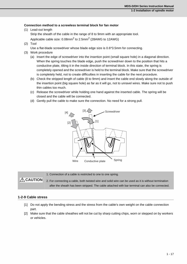
1 - 17
MDS-D/DH Series Instruction Manual
1-2 Installation of spindle motor
Connection method to a screwless terminal block for fan motor
(1) Lead-out length
Strip the sheath of the cable in the range of 8 to 9mm with an appropriate tool.
Applicable cable size: 0.08mm2 to 2.5mm2 (28AWG to 12AWG)
(2) Tool
Use a flat-blade screwdriver whose blade edge size is 0.6*3.5mm for connecting.
(3) Work procedure
(a) Insert the edge of screwdriver into the insertion point (small square hole) in a diagonal direction.
When the spring touches the blade edge, push the screwdriver down to the position that hits a
conductive plate, tilting it in the inside direction of terminal block. In this state, the spring is
completely opened and the screwdriver is held to the terminal block. Make sure that the screwdriver
is completely held, not to create difficulties in inserting the cable for the next procedure.
(b) Check the stripped length of cable (8 to 9mm) and insert the cable end slowly along the outside of
the insertion point (big square hole) as far as it will go, not to unravel wires. Make sure not to push
thin cables too much.
(c) Release the screwdriver while holding one hand against the inserted cable. The spring will be
closed and the cable will be connected.
(d) Gently pull the cable to make sure the connection. No need for a strong pull.
1-2-9 Cable stress
[1] Do not apply the bending stress and the stress from the cable's own weight on the cable connection
part.
[2] Make sure that the cable sheathes will not be cut by sharp cutting chips, worn or stepped on by workers
or vehicles.
1. Connection of a cable is restricted to one to one spring.
2. For connecting a cable, both twisted wire and solid wire can be used as it is without termination
after the sheath has been stripped. The cable attached with bar terminal can also be connected.
[1][2]
[4][3] Screwdriver
SpringConductive plateWire
CAUTION

1 - 18
1 InstallationMITSUBISHI CNC
1-3 Installation of tool spindle motor1-3-1 Environmental conditions
1-3-2 Shaft characteristics
There is a limit to the load that can be applied on the motor shaft. Make sure that the load applied on the
radial direction and thrust direction, when mounted on the machine, is below the tolerable values given
below. These loads may affect the motor output torque, so consider them when designing the machine.
(Note 1) The tolerable radial load and thrust load in the above table are values applied when each motor is
used independently.
(Note 2) The symbol L in the table refers to the value of L below.
L: Length from flange installation surface to center of load mass [mm]
Environment Conditions
Ambient temperature 0°C to +40°C (with no freezing)
Ambient humidity 80% RH or less (with no dew condensation)
Storage temperature -15°C to +70°C (with no freezing)
Storage humidity 90% RH or less (with no dew condensation)
AtmosphereIndoors (no direct sunlight)
No corrosive gas, inflammable gas, oil mist or dust
AltitudeOperation / storage: 1000m or less above sea level
Transportation: 10000m or less above sea level
Vibration X:19.6m/s2 (2G) Y:19.6m/s2(2G)
Tool spindle motor Tolerable radial load Tolerable thrust load
HF-KP46, 56 245N (L=30) 98N
HF-KP96 392N (L=40) 147N
HF-SP226, 406 980N (L=55) 490N
HF75S, 105S 245N (L=33) 147N
HF54S, 104S, 154S, 224S, 123S, 223S 980N (L=55) 490N
HF204S, 303S, 354S, 453S, 703S 2058N (L=79) 980N
HF903S 2450N (L=85) 980N
Radial load
Thrust load
L

1 - 19
MDS-D/DH Series Instruction Manual
1-4 Installation of the drive unit
1-4 Installation of the drive unit
1-4-1 Environmental conditions
(Note) When installing the machine at 1,000m or more above sea level, the heat dissipation
characteristics will drop as the altitude increases.
The upper limit of the ambient temperature drops 1°C with every 100m increase in altitude.
(The ambient temperature at an altitude of 2,000m is between 0 and +45°C.)
1. Install the unit on noncombustible material. Direct installation on combustible material or near
combustible materials may lead to fires.
2. Follow the instructions in this manual and install the unit while allowing for the unit mass.
3. Do not get on top of the units or motor, or place heavy objects on the unit.
Failure to observe this could lead to injuries.
4. Always use the unit within the designated environment conditions.
5. Do not let conductive objects such as screws or metal chips, etc., or combustible materials such as
oil enter the units.
6. Do not block the units intake and outtake ports. Doing so could lead to failure.
7. The units and servomotor are precision devices, so do not drop them or apply strong impacts to
them.
8. Do not install or run units or servomotor that is damaged or missing parts.
9. When storing for a long time, please contact your dealer.
10. Always observe the installation directions. Failure to observe this could lead to faults.
11. Secure the specified distance between the units and panel, or between the units and other
devices. Failure to observe this could lead to faults.
Environment ConditionsAmbient temperature 0°C to +55°C (with no freezing)
Ambient humidity 90%RH or less (with no dew condensation)
Storage temperature -15°C to +70°C (with no freezing)
Storage humidity 90%RH or less (with no dew condensation)
AtmosphereIndoors (no direct sunlight);
no corrosive gases, inflammable gases, oil mist, dust or conductive particles
AltitudeOperation/storage: 1000m or less above sea levelTransportation: 10000m or less above sea level
Vibration Operation/storage: 4.9m/s2 (0.5G) or less Transportation: 49m/s2 (5G) or less
CAUTION

1 - 20
1 InstallationMITSUBISHI CNC
1-4-2 Installation direction and clearance
Wire each unit in consideration of the maintainability and the heat dissipation, as well as secure sufficient
space for ventilation.
Installation clearance
Panel structure of the unit back face
The type ‘(a)’ that has substantial cooling effect is recommended.
1. The ambient temperature condition for the power supply unit or the drive units is 55°C or less.
2. Because heat can easily accumulate in the upper portion of the units, give sufficient consideration
to heat dissipation when designing the panel. If required, install a fan in the panel to agitate the
heat in the upper portion of the units.
60mm/67mm92mm
A
Exhaust
Inlet
Filter
100mm or more
1mm or more
60mm
260mm
100mm or more
10mm or
more
10mm or
more
80mm or more
100mm or more
100mm or more
60mm or
more
60mm or
more
60mm
Exhaust
75mm or more114mm or more
Radiation fin size Installation clearance A
CAUTION
Filter
(a) Back face inlet type
Cooling will be more high- efficiency by installing a partition plate inside to separate inlet and exhaust.
Fan inlet hole
(b) Side face inlet type
Filter
Install a partition plate inside to separate inlet and exhaust.
Fan inlet hole

1 - 21
MDS-D/DH Series Instruction Manual
1-4 Installation of the drive unit
Cooling fan position[Unit: mm]
1. Design the inlet so that it is the position of the cooling fan.
2. Make the inlet and exhaust size more than the area that is a total of the cooling fan area.
60mm width unit
40
40
170
105
60
60
105
170
92.5
92
.5
170
105
92.5
17
0 92
.5
105
90mm width unit
120mm width unit
150mm width unit
200
(124
*)
75 150
150mm width unit
(MDS-D-SP-320)
120
240mm width unit
190
101.5 240
69.25
90 x
2
300mm width unit
190
130 300
85
120
x 2
(*MDS-D-CV-450)
CAUTION
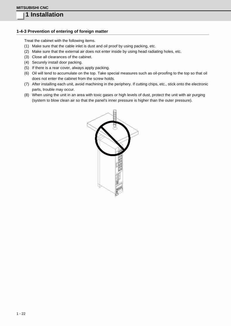
1 - 22
1 InstallationMITSUBISHI CNC
1-4-3 Prevention of entering of foreign matter
Treat the cabinet with the following items.
(1) Make sure that the cable inlet is dust and oil proof by using packing, etc.
(2) Make sure that the external air does not enter inside by using head radiating holes, etc.
(3) Close all clearances of the cabinet.
(4) Securely install door packing.
(5) If there is a rear cover, always apply packing.
(6) Oil will tend to accumulate on the top. Take special measures such as oil-proofing to the top so that oil
does not enter the cabinet from the screw holds.
(7) After installing each unit, avoid machining in the periphery. If cutting chips, etc., stick onto the electronic
parts, trouble may occur.
(8) When using the unit in an area with toxic gases or high levels of dust, protect the unit with air purging
(system to blow clean air so that the panel's inner pressure is higher than the outer pressure).

1 - 23
MDS-D/DH Series Instruction Manual
1-4 Installation of the drive unit
1-4-4 Panel installation hole work drawings (Panel cut drawings)
Prepare a square hole to match the unit width.[Unit: mm]
Attach packing around the square hole to provide a seal.
Unit width: 60mm
2-M5 screw hole
Unit width: 90mm
2-M5 screw hole
Unit width: 150mm
4-M5 screw hole
Unit width: 120mm
2-M5 screw hole
Square hole Square hole
Squarehole
Squarehole
POINT

1 - 24
1 InstallationMITSUBISHI CNC
[Unit: mm]
Attach packing around the square hole to provide a seal.
Unit width: 240mm 4-M5 screw hole
Unit width: 300mm 4-M5 screw hole
Square hole Square hole
POINT

1 - 25
MDS-D/DH Series Instruction Manual
1-4 Installation of the drive unit
1-4-5 Heating value
The values for the servo drive unit apply at 50% of the stall output. The values for the spindle drive unit apply
for the continuous rated output. The values for the power supply unit include the AC reactor's heating value.
< MDS-D Series >
< MDS-DH Series >
Servo drive unit Spindle drive unit Power supply unit
TypeMDS-D-
Heating value [W]
TypeMDS-D-
Heating value [W]
TypeMDS-D-
Heating value [W]
TypeMDS-D-
Heating value [W]
TypeMDS-D-
Heating value [W]
In-side
panel
Out-side
panel
In-side
panel
Out-side
panel
In-side
panel
Out-side
panel
In-side
panel
Out-side
panel
In-side
panel
Out-side
panel
V1-20 18 22 V2-2020 26 44 SP-20 24 31 SP2-2020 28 62 CV-37 20 34
V1-40 20 38 V2-4020 28 60 SP-40 29 65 SP2-4020 33 96 CV-75 24 55
V1-80 25 71 V2-4040 31 75 SP-80 37 121 SP2-4040S 38 130 CV-110 25 99
V1-160 36 148 V2-8040 35 109 SP-160 54 236 SP2-4040 38 130 CV-185 32 161
V1-160W 44 201 V2-8080 40 142 SP-200 78 404 SP2-8040 46 186 CV-300 45 272
V1-320 59 307 V2-16080 51 219 SP-240 100 520 SP2-16080S 70 358 CV-370 53 343
V1-320W 72 399 V2-160160 62 296 SP-320 118 688 SP2-8080 54 242 CV-450 104 392
V2-16160W 77 403 SP-400 148 897 SP2-16080 70 358 CV-550 164 431
SP-640 196 1231
Servo drive unit Spindle drive unit Power supply unit
TypeMDS-DH-
Heating value [W]Type
MDS-DH-
Heating value [W]Type
MDS-DH-
Heating value [W]Type
MDS-DH-
Heating value [W]
Inside panel
Outside panel
Inside panel
Outside panel
Inside panel
Outside panel
Inside panel
Outside panel
V1-10 19 27 V2-1010 28 54 SP-20 32 88 CV-37 20 34
V1-20 22 46 V2-2010 30 74 SP-40 42 158 CV-75 24 55
V1-40 27 87 V2-2020 33 93 SP-80 54 237 CV-110 25 99
V1-80 40 175 V2-4020 39 133 SP-100 73 369 CV-185 32 161
V1-80W 47 222 V2-4040 45 173 SP-160 110 639 CV-300 45 272
V1-160 62 328 V2-8040 57 262 SP-200 126 746 CV-370 53 343
V1-160W 81 461 V2-8080 70 350 SP-320 168 1034 CV-450 104 392
V1-200 105 630 V2-8080W 83 445 SP-480 232 1488 CV-550 164 431
CV-750 228 614
1. Design the panel's heating value taking the actual axis operation (load rate) into consideration.
2. The heating values in the above tables are calculated with the following load rates.
POINT50%
100%
100%
Unit Load rate
Servo drive unit
Spindle drive unit
Power supply unit

1 - 26
1 InstallationMITSUBISHI CNC
1-4-6 Heat radiation countermeasures
(1) Heat radiation countermeasures in the control panel
In order to secure reliability and life, design the temperature in the panel so that the ambient
temperature of each unit is 55°C or less.
If the heat accumulates at the top of the unit, etc., install a fan or heat exchanger so that the
temperature in the panel remains constant.
Please refer to following method for heat radiation countermeasures.
Examples of mounting heat exchanger and temperature measurement positions (reference)
<Point> [1] Refer to the section “1-3-4 Heating value” for the heat
generated by each unit. [2] Refer to the following calculation for calculation W1 of the
panel’s cooling capacity (thin steel plate). W1 = U x A x T
U: 6W/m2 x °C (with internal agitating fan) 4W/m2 x °C (without internal agitating fan)
A: Effective heat radiation area [m2] Heat dissipation area in panel
Sections contacting other objects are excluded. T: Internal temperature rise value (10°C)
[3] Points in manufacturing and evaluation Understanding the temperature rise in the panel, andinstall a fan or heat exchanger.
T (average value) 10°C Tmax (maximum value) 15°C
<Hypothetical conditions > [1] Average temperature in panel: T 55°C [2] Panel peripheral temperature: Ta 0 to 45°C [3] Internal temperature rise value: T=T-Tamax =10°C
Calculate total heat radiation of each unit in panel (W)
Manufacturing and evaluation
W W1
W>W1
T > 10
T 10
Completion
Evaluate temperature in panel
Comparison of W and W1
Calculate panel’s cooling capacity (W1)
Consider heat exchanger
Consider adding fan or heat exchanger
Temperature measurement positions
Hea
t ex
chan
ger Heat
exchanger
Unit
Relay, etc
Unit Flow of air
Flow of air Relay, etc

1 - 27
MDS-D/DH Series Instruction Manual
1-4 Installation of the drive unit
The following shows a calculation example for considering heat radiation countermeasures.
<Control panel outline dimension (assumption) >
When installing four units which have the heating value in the panel of 15W
Heat radiation area (A): When a bottom section contacts with a machine
(Note) Actually, sections contacting other objects are excluded.
Heating value in panel (W): when installing four units which are 15W
W = 15 x 4 = 60 (W)
<Considering necessity of agitating fan>
1 Temperature standard
(1) Standard of temperature in panel (around each unit) T 55°C
(2) External peripheral temperature Ta = 0 to 45°C
(3) Internal temperature rise value DT = T - Ta (MAX) = 10°C
2 Cooling capacity of control panel (W1)
W1 = U x A x DT DT = Internal temperature rise value (=10°C)
U = 6W/m2 • °C (with internal agitating fan)
4W/m2 • °C (without internal agitating fan)
A = Effective heat radiation area (m2)
(1) With internal agitating fan W1 = 6 x 1.26 x 10 = 75.6 (W) > 60 (W)
(2) Without internal agitating fan W1 = 4 x 1.26 x 10 = 50.4 (W) < 60 (W) -- Internal fan is required.
Measure an actual internal temperature, and install a fan or heat exchanger which agitates the heat at
the top of the unit if the temperature rise exceeds 10°C.
Top of panel inside Fan for agitating
600
300 600
A = 0.6 × 0.3 + 0.6 × 0.6 × 2 + 0.6 × 0.3 × 2 = 1.26 (m ) 2
(Top face) (Front/back face) (Side face)
≦
POINT

1 - 28
1 InstallationMITSUBISHI CNC
(2) Heat radiation countermeasures outside the control panel
Measure the temperature at 40mm form tops of all units, and design the temperature rise so that it is
20°C or less against the ambient temperature.
If the temperature rise at the temperature measurement position exceeds 20°C, consider adding a fan.
The temperature of some units may rise locally, because air accumulates at a particular point.
Therefore, take a temperature measurement in each unit.
If a temperature at even one point exceeds 20°C in the temperature measurements, take a heat
radiation countermeasure such as addicting fans.
40mm
Temperature measurement position
40mm
Side face Back face
POINT

1 - 29
MDS-D/DH Series Instruction Manual
1-5 Installation of the spindle detector
1-5 Installation of the spindle detector1-5-1 Spindle side ABZ pulse output detector (OSE-1024 Series)
To maintain the detector life and performance, a flexible coupling should be used to couple the spindle side
detector and C-axis detector with the spindle.
Detector and coupling installation accuracy
Recommended coupling
Recommendation 1 Recommendation 2Manufacturer Tokushu Seiko Eagle
Model Model M1 FCS38A
Resonance frequency 1374Hz 3515Hz
Position detection error 0.8×10⁻³ ° 1.2×10⁻³ °
Tolerable speed 20,000r/min 10,000r/min
Mis-alignmentCore deviation 0.7mm 0.16mm
Angle displacement 1.5° 1.5°
Outline dimensionsMax. length 74.5mm 33mm
Max. diameter φ57mm φ38mm
Confirm that the gear ratio (pulley ratio) of the spindle end to the detector is 1:1.
Refer to the coupling catalog, etc., for details on the coupling.
0.02
0.02
Detector
Opposite detector shaftside
Flexible coupling
CAUTION

1 - 30
1 InstallationMITSUBISHI CNC
1-5-2 Spindle side PLG serial output detector (TS5690, MU1606 Series)
(1) Part configuration
The detector is configured of a sensor and detection gear. The sensor and detection gear must be used
in the designated combination.
These are precision parts, and require care when handling. Do not apply an excessive force on the
sensor's detection surface, as this could result in faults. Do not pull and apply a load on the lead wires.
Make sure that foreign matters (iron chips, etc.) do not get on the sensor's detection surface or detection
gears. If any foreign matter should get on these parts, carefully remove while taking care not to damage
the parts. When handling the detection gears, take care not to damage or deform the teeth.
Spindle side PLG serial output detector TS5690 Series
(2) Installing the detection gears
[1] Install the detection gears so that the first gear's teeth side (Z phase) face the sensor's lead side.
[2] The detection gears and shaft or sleeve should be fixed with shrink fitting. Refer to the following
table for the shrink fitting values. The detection gears should be heated evenly between 120 and
150°C using an electric furnace, etc.
Guideline for detection gear shrink fitting values
[3] Keep the deflection of the outer diameter, when the detection gears are installed on the shaft, to
0.02mm or less.
[4] To remove a detection gear fixed with shrink fitting, use the screw holes opened in the axial
direction for pulling (two M5 screw holes or two M8 screw holes), or push the end with a jig. Carry
out this work carefully. Applying excessive force when pulling out the gears could cause the inner
diameter of the detection gears to deform.
[5] Before reusing detection gears which have been removed, always measure the inner diameter
dimensions, and carefully check that the inner diameter is not deformed, and that the sufficient
tightening amount can be secured. Do not reuse the detection gears if the inner diameter is
deformed, or if any abnormality such as damage to the teeth is found.
Inner diameter (mm)
Shrink fitting (mm)Inner diameter
(mm)Shrink fitting (mm)
φ40 0.020 to 0.040 φ140 0.050 to 0.085φ70 0.030 to 0.055 φ160 0.060 to 0.090φ80 0.030 to 0.055 φ215 0.080 to 0.110φ125 0.050 to 0.085
Detectiongears
Sensor section
Output connector
※Thermal sensor terminals
※Thermal sensor terminals are not used when the detector is installed on the spindle side.

1 - 31
MDS-D/DH Series Instruction Manual
1-5 Installation of the spindle detector
(3) Installing the sensor section
[1] Prepare the notched fitting section at the machine side's
installation position to be of the specified dimensions in
advance.
[2] With the sensor installation seat's R section butted against
the notched fitting section, fix the sensor installation seat with
a mounting screw (M5 x 0.8 screws). A locking agent should
be applied on the mounting screw before it is tightened.
[3] Fix the sensor with its R section butted against the notched
fitting section so that the position relation between the
detection gear and sensor is kept constant. This ensures
favorable accuracy of the sensor installation.
[4] Keep the deviation of the sensor center and outer diameter
center of the detection gear to ±0.25mm or less. If the center
deviation cannot be directly measured, set so that the
dimension from the sensor installing surface to the outer
diameter edge of the detection gears is 22.5±0.25mm. (Some
detection gears have thickness at the inner diameter section.)
[5] Make sure that force is not constantly applied on the sensor's lead wires.
Shape of notched fitting section
Installing dimension of the sensor section
To install the sensor section, the notched fitting section on the machine side must have the specified
dimensions.
The sensor's installation accuracy is assured by adjusting the outside dimensions of the notched
fitting section.
Sensor series typeScrew holes’ height from the
rotation center (mm)Notched fitting section's outer
diameter (mm)
TS5690N6400 51.4 φ72.0 +0.060-0.010
TS5690N1200 77.0 φ122.0 +0.025-0.025
TS5690N2500 128.2 φ223.6 +0.025-0.025
16.5mm
22.5mm ± 0.25mm
Sensor installation surface
Sensor installation seat
Lead wire
Installing the detector
R section
Z phase side
Def
lect
ion
of th
e ou
ter
diam
eter
0.0
2mm
or l
ess
To the end of the outer diameter
POINT
38mm
3.0mm
Butt the R section of the sensor installation seatagainst here
Butt the back side of the sensor installation seatagainst here
Notched section'souter diameter
Notched section'souter diameter
screw holes' height from the rotation center
2-M5×0.8 screw

1 - 32
1 InstallationMITSUBISHI CNC
1-5-3 Installation accuracy diagnosis for PLG detector
(1) Outline
PLG detects the speed and position by the rotation of the gear installed at the motor end or spindle end.
Adjustment-free PLG can be used without adjusting the waveform after installing the sensor section
(TS5690 Series) on the machined notched fitting section. With this function, whether the PLG
installation position is OK or not can be judged using the D/A output of the spindle drive unit while
rotating the spindle in an open loop. For an IPM spindle motor, the waveform should be measured while
rotating the spindle by hand because an open loop operation cannot be carried out.
Example: For full closed mode
(2) Setting the parameters
The parameters related to the installation accuracy diagnosis for PLG detector are shown below.
【#13018(PR)】 SP018 SPEC2 Spindle specification 2
bit 1 : oplp Open loop control
This allows the operation in which no detector feedback signals are used. It is used when adjusting the detector, etc. 0: Disable 1: Enable
【#13113】 SP113 OPLP Current command value for open loop
Set the current command value for when the open loop control is enabled. When "0" is set, the state will be the same as when "50" is set. When not using, set to "0". The open loop control is enabled when "SP018 /bit1" is set to "1".
---Setting range---0 to 999 (Short-time rated %)
Make sure that the motor can be rotated freely in the unloaded state without being locked.CAUTION
MDS-D/DH-SP
To CN3
To CN2
Spindlemotor
Spindle
MU1606 (Gear)
TS5690 (Sensor)
Spindlegear
Motor gear
MU1606 (Gear)
TS5690 (Sensor)
Open loop
(6) Judging the installation gap using the D/A output signal waveform.
(2) Open loop setting
(3) Power ON again
(4) Spindle rotation at the 100r/min command
(1) Power ON
(1) Power ON
(5) Spindle rotation

1 - 33
MDS-D/DH Series Instruction Manual
1-5 Installation of the spindle detector
(3) Details for PLG installation diagnosis
Installation error judgment of the adjustment-free PLG can be checked using the D/A output of the
spindle drive unit. The setting numbers of D/A output are shown below. For the output waveform, 2.5V
represents a normal state and +1V or -1V of the normal state represents an abnormal state.
*Set the D/A output numbers to the spindle parameters "#13125(SP125)" and "#13126(SP126)".
Because the D/A output of the drive unit is 2ch, perform the check for both at the motor end and spindle
end in full closed mode.
(4) Related alarms
There is no alarm related to the installation accuracy diagnosis for PLG detector.
D/A output No.
Details Description
120Motor end PLG installationGap diagnosis
The result of the quality judgement for the gap of the motor end PLG is output.When the gap is good, =2.5V is output. When the gap is excessive, =2.5+1V is output and when the gap is too small, =2.5-1V is output.
121Motor end PLG installationAll errors diagnosis
The result of the quality judgement for the installed position of the motor end PLG is output.When the sensor installation is good, =2.5V is output. When sensor instal-lation is incorrect (such as a center deviation between a sensor and gear, and Z-phase error), =2.5+1V is output.
122Spindle end PLG installationGap diagnosis
The result of the quality judgement for the gap of the spindle end PLG is output.The output procedure is the same as that of motor end PLG.
123Spindle end PLG installationAll errors diagnosis
The result of the quality judgement for the installed position of the spindle end PLG is output.The output procedure is the same as that of motor end PLG.
When the D/A output parameter "#13125(SP125)" is set to 120(=D/A output of ch1), and
"#13126(SP126)" is set to 121(=D/A output of ch2), the check is performed at the motor end detector.
When the D/A output of ch1 is 2.5V and ch2 is 3.5V(=2.5+1V), for example, the gap is normal,
however, the center deviation (offset) between a sensor and gear occurs, so check again after the
sensor installed position is finely adjusted. Adjust until the two D/A outputs finally become 2.5V during
spindle rotation.
When the sensor installed position is finely adjusted, adjust after the power of the drive unit is turned
OFF.
5.0V
2.5V
0.0V
5.0V
2.5V
0.0V
+1V - 1V
+1V
The gap is excessive
Waveform examplewhen the gap is not good
The gap is too small
Waveform examplewhen all results of the diagnosis are not good
Offset faultGap faultZ-phase errorThe gap is good when the
waveform is constantly at 2.5V during the rotation.
The installation is good when the waveform is constantly at 2.5V during the rotation.
POINT
CAUTION

1 - 34
1 InstallationMITSUBISHI CNC
1-6 Noise measures
Noise includes "propagation noise" generated from the power supply or relay, etc., and propagated along a
cable causing the power supply unit or drive unit to malfunction, and "radiated noise" propagated through air
from a peripheral device, etc., and causing the power supply unit or drive unit to malfunction.
Always implement these noise measures to prevent the peripheral devices and unit from malfunctioning. The
measures differ according to the noise propagation path, so refer to the following explanation and take
appropriate measures.
(1) General noise measures
(a) Avoid laying the drive unit's power line and signal wire in a parallel or bundled state. Always
separate these wires. Use a twisted pair shielded wire for the detector cable and signal wires such
as the communication cable connected with the NC unit, and accurately ground the devices.
(b) Use one-point grounding for the drive unit and motor.
(c) Accurately ground the AC reactor.
(2) Propagation noise measures
Take the following measures when noise generating devices are installed and the power supply unit or
drive unit could malfunction.
(a) Install a surge killer on devices (magnetic contacts, relays, etc.) which generate high levels of
noise.
(b) Install a power line filter in the stage before the power supply unit.
(c) Install a ferrite core on the signal wire.
(d) Ground the shield of the servo detector's cable with a cable clamp.
(e) Wire the spindle PLG detector cable away from other wires.
(3) Measures against radiated noise
The types of propagation paths of the noise and the noise measures for each propagation path are
shown below.
Noise generated from drive unit
Noise directly radiated from drive unit
Airborne propagation noise Path [1]
Noise radiated from power line
Magnetic induction noise
Path [2] Path [4] and [5]
Noise radiated from servomotor/spindle motor
Static induction noise
Path [3] Path [6]
Noise propagated over power line
Cable propagation noise
Path [7]
Noise lead in from grounding wire by leakage current
Path [8]

1 - 35
MDS-D/DH Series Instruction Manual
1-6 Noise measures
Generated noise of drive system
Noise propagation path Measures
[1] [2] [3]
When devices such as instrument, receiver or sensor, which handle minute signals and are easily affected by noise, or the signal wire of these devices, are stored in the same panel as the drive units and the wiring is close, the device could malfunction due to air-borne propagation of the noise. In this case, take the following measures.(a) Install devices easily affected as far away from the drive units as possible.(b) Lay devices easily affected as far away from the signal wire of the drive unit as pos-sible.(c) Avoid laying the signal wire and power line in a parallel or bundled state.(d) Insert a line noise filter on the input/output wire or a radio filter on the input to sup-press the noise radiated from the wires.(e) Use a shield wire for the signal wire and power line, or place in separate metal ducts.
[4] [5] [6]
If the signal wire is laid in parallel to the power line, or if it is bundled with the power line, the noise could be propagated to the signal wire and cause malfunction because of the magnetic induction noise or static induction noise. In this case, take the following mea-sures.(a) Install devices easily affected as far away from the drive unit as possible.(b) Lay devices easily affected as far away from the signal wire of the drive unit as pos-sible.(c) Avoid laying the signal wire and power line in a parallel or bundled state.(d) Use a shield wire for the signal wire and power line, or place in separate metal ducts.
[7]
If the power supply for the peripheral devices is connected to the power supply in the same system as the drive units, the noise generated from the power supply unit could back flow over the power line and cause the devices to malfunction. In this case, take the following measures.(a) Install a radio filter on the power supply unit's power line.(b) Install a power filter on the power supply unit's power line.
[8]If a closed loop is created by the peripheral device and drive unit's grounding wire, a leak-age current could flow and cause the device to malfunction.In this case, change the device grounding methods and the grounding place.
[1]
[2]
[3]
[4]
[5]
[6]
[7]
[8]
Drive unit
Sensor Servomotor Spindle motor M
Receiver Instru- ment
[2] [7]
Sensor power supply

1 - 36
1 InstallationMITSUBISHI CNC

2 - 1
付録 2 章
2 - 1
2Wiring and Connection

2 Wiring and ConnectionMITSUBISHI CNC
2 - 2
1. Wiring work must be done by a qualified technician.
2. Wait at least 15 minutes after turning the power OFF and check the voltage with a tester, etc.,
before starting wiring. Failure to observe this could lead to electric shocks.
3. Securely ground the drive units and servo/spindle motor.
4. Wire the drive units and servo/spindle motor after installation. Failure to observe this could lead to
electric shocks.
5. Do not damage, apply forcible stress, place heavy items on the cables or get them caught. Failure
to observe this could lead to electric shocks.
6. Always insulate the power terminal connection section. Failure to observe this could lead to electric
shocks.
1. Correctly and securely perform the wiring. Failure to do so could result in runaway of the servo/
spindle motor or injury.
2. Do not mistake the terminal connections.
3. Do not mistake the polarity ( + , - ). Failure to observe this item could lead to ruptures or damage,
etc.
4. Do not mistake the direction of the diodes for the surge absorption installed on the DC relay for the
motor brake and contactor (magnetic contactor) control. The signal might not be output when a
failure occurs.
5. Electronic devices used near the drive units may receive magnetic obstruction. Reduce the effect
of magnetic obstacles by installing a noise filter, etc.
6. Do not install a phase advancing capacitor, surge absorber or radio noise filter on the power line
(U, V, W) of the servo/spindle motor.
7. Do not modify this unit.
8. If the connectors are connected incorrectly, faults could occur. Make sure that the connecting
position and the connection are correct.
9. When grounding the motor, connect to the protective grounding terminal on the drive units, and
ground from the other protective grounding terminal.(Use one-point grounding)
Do not separately ground the connected motor and drive unit as noise could be generated.
DANGER
CAUTION
Servo drive unit Servo drive unit
Control outputsignal
Control outputsignal
RA
COM(24VDC)
COM(24VDC)
RA

MDS-D/DH Series Instruction Manual
2-1 Part system connection diagram
2 - 3
2-1 Part system connection diagram
(Note 1) The total length of the optical communication cable from the NC must be within 30m and the
minimum-bending radius within 80mm.
(Note 2) The connection method will differ according to the used motor.
(Note 3) Battery for the detector back up is built-in the drive unit. (An external battery is available as an
option.)
(Note 4) The main circuit ( ) and control circuit ( ) and ground ( ) are safely separated.
(Note 5) Connect the ground of the motor to the ground of the connected drive unit.
MC2
OPT1,2
T
S
R
CN1A
CN23A
CN4
CN9
L1
L2
L3
L11TE3
TE1
CN9
CN1B
L+
L-
U
V
W
CN2
TE1
PLG
CN4
TE3
TE2L+
L-
L11
L21
TE2
L21
CN3
CN1A
CN4
CN9
CN20
CN1B
MU
MV
MW
CN2L
CN2M
LU
LV
LW
TE1
TE3
TE2L+
L-
L11
L21
CN3L
CN3M
MC MC1CN23B
EMG1
EMG2
(PE)(PE)(PE)
(PE)Optical communication cable
24VDC
: Control circuit
SH21cable
ACreactor
Machine side detector
Machine side detector
External emergency stop input
Contactor
Ground
: Main circuit
Spindlemotor
Motor side detector
Motor side detector
Servomotor
Optical communication cable
Mitsubishi CNC Spindle drive unitPower supply unit
Ground Ground
Servo drive unit
Ground
Servomotor
Circuitprotector
Circuitprotector
: Ground

2 Wiring and ConnectionMITSUBISHI CNC
2 - 4
2-2 Main circuit terminal block/control circuit connector2-2-1 Names and applications of main circuit terminal block signals and control circuit
connectors
The following table shows the details for each terminal block signal.
Name Signal name Description
L1 . L2 . L3Main circuit power supply
Main circuit power supply input terminalFor MDS-D : Connect a 3-phase 200VAC (50Hz) or 200 to 230VAC (60Hz) power sup-ply.For MDS-DH : Connect a 3-phase 380V to 440VAC (50Hz) / 380V to 480VAC (60Hz) power supply.
L11 L21Control circuit power supply
Control circuit power supply input terminalFor MDS-D : Connect a single-phase 200VAC (50Hz) or 200 to 230VAC (60Hz) power supply.For MDS-DH : Connect a single-phase 380V to 440VAC (50Hz) / 380V to 480VAC (60Hz) power supply.
MC1 Contactor controlContactor control terminalThe MC1 terminal has the same phase as L21. Connect to a different phase than the phase connected to L21.
U . V . WMotor output(Single-axis unit)
Servo/spindle motor power output terminalThe servo/spindle motor power terminal (U, V, W) is connected.
LU . LV . LWMU . MV . MW
Motor output(Triple-axis unit)
Servo motor power output terminal (L-axis/M-axis)The servo/spindle motor power terminal (U, V, W) is connected.
Protective grounding (PE)
Grounding terminalThe servomotor/spindle motor grounding terminal is connected and grounded.
1. Always use one AC reactor per power supply unit. Failure to observe this lead to unit damage.
2. When sharing a circuit protector for several power supply units, of a short-circuit fault occurs in a
small capacity unit, the circuit protector could trip. This can be hazardous, so do not share the
circuit protector.
3. Be sure to use the circuit protector of proper capacity for each power supply unit.
CAUTION

MDS-D/DH Series Instruction Manual
2-2 Main circuit terminal block/control circuit connector
2 - 5
2-2-2 Connector pin assignment
(1) Main circuit terminal block and connector
Power supply unit
(Note) The illustrations of drive units are shown as an example.
Do not apply a voltage other than that specified in Instruction Manual on each terminal. Failure to
observe this item could lead to rupture or damage, etc.
UnitTerminal
MDS-D-CV-37 to 75MDS-D-CV-110 to 185MDS-DH-CV-37 to 185
Terminalposition
Terminal specification/
Pin assignment
[1] TE1
[2] TE2
[3] TE3
[4] - The PE screw size is the same as TE1.
CAUTION
[2]
[3]
[1]
[2]
[3]
[4]
[1]
Compatible unit
Screw size
Tightening torque
All of CV
(Note) This is a bottom view.
1.2NmM4 x 12
U V W
Compatible unit
Screw size
Tightening torque
All of CV
2.0NmM5 x 12
U V W
Compatible unit
Screw size
Tightening torque
All of CV
4.0NmM6 x 16
L+
L-
Compatible unit
Screw size
Tightening torque
All of CV
M4 x 121.2Nm
L11 L21

2 Wiring and ConnectionMITSUBISHI CNC
2 - 6
(Note) The illustrations of drive units are shown as an example.
UnitTerminal
MDS-D-CV-350 to 450MDS-DH-CV-300 to 450
MDS-D-CV-550MDS-DH-CV-550 to 750
Terminalposition
Terminal specification/
Pin assignment
[1] TE1
[2] TE2
[3] TE3
[4] Screw size: M8 x 14
Tightening torque: 6.0Nm
[2]
[3]
[4]
[1]
[2]
[3]
[4]
[2]
[1]
Compatible unit
Screw size
Tightening torque
All of CV
6.0NmM8 x 16
U V W
Compatible
unit
Screw size
Tightening torque
550 to 750
D-CV
DH-CV
550
--
11.0NmM10 x 20
U V W
M8 x 156.0Nm
Compatible
unit
Screw size
Tightening torque
300 to 750
D-CV
DH-CV - -300 to 450 550 Left side 550 Right side
4.0NmM6 x 16 M10 x 20
11.0Nm
L+
L- M6 x 164.0Nm
Compatible
unit
Screw size
Tightening torque
300 to 450
D-CV
DH-CV
550300 to 450
550 to 750
1.2NmM4 x 12 M4 x 8
1.2Nm
L11 L21
Compatible
unit
Screw size
Tightening torque
D-CV
DH-CV
550
550 to 750
--
11.0NmM10 x 20 M8 x 16
6.0Nm

MDS-D/DH Series Instruction Manual
2-2 Main circuit terminal block/control circuit connector
2 - 7
1-axis servo drive unit / 1-axis spindle drive unit
(Note) The illustrations of drive units are shown as an example.
UnitTerminal
MDS-D-V1-160 or lessMDS-D-SP-80 or less
MDS-DH-V1-80W or lessMDS-DH-SP-80 or less
MDS-D-V1-160W or moreMDS-D-SP-160 to 320
MDS-DH-V1-160 to 160WMDS-DH-SP-100 to 160
Terminalposition
Terminal specification/
Pin assignment
[1] TE1
[2] TE2
[3] TE3
[4] Screw size: M5 x 12
Tightening torque: 2.0NmThe PE screw size is the same as TE1.
[2]
[3]
[1] [4]
[2]
[3]
[1] [4]
U V W
(Note) This is a bottom view.
Compatible
unit
Screw size
Tightening torque
240 to 320
DH-V1-
DH-SP-
320W
--
D-V1-
D-SP-
160W to 320
160 to 200
160 to 160W
100 to 160
2.0NmM5 x 12 M8 x 12
6.0Nm
U V W
Compatible unit
Screw size
Tightening torque
All of V1/V2/SP
4.0NmM6 x 16
L+
L-
Compatible unit
Screw size
Tightening torque
All of V1/V2/SP
1.2NmM4 x 12 L11
L21

2 Wiring and ConnectionMITSUBISHI CNC
2 - 8
(Note) The illustrations of drive units are shown as an example.
UnitTerminal
MDS-D-SP-400 to 640MDS-DH-V1-200
MDS-DH-SP-200 to 480
Terminalposition
Terminal specification/
Pin assignment
[1] TE1
[2] TE2
[3] TE3
[4]
Always install a large capacity drive unit in the left side of power supply unit, and connect with DC
connection bar.
[1]
[3]
[2]
[4]
Screw size
Tightening torque
Compatible
unit--
400 to 640
DH-V1-
DH-SP-
D-SP-
200
200 to 480
-
(Note) Refer to "POINT" below.
U V W
6.0NmM8 x 15 M10 x 20
11.0Nm
Compatible
unit
Screw size
Tightening torque
400 to 640
DH-SP- -
D-SP-
DH-V1- 200
200 to 480
--
4.0NmM6 x 16 M10 x 20
11.0Nm
L+
L-
Compatible
unit
Screw size
Tightening torque
400 to 640
DH-SP-
D-SP-
DH-V1- 200
200 to 480
1.2NmM4 x 8
L11 L21
Screw size
Tightening torque
Compatible
unit--
400 to 640
DH-V1-
DH-SP-
D-SP-
200
200 to 480
-
6.0NmM8 x 16 M10 x 20
11.0Nm
POINT

MDS-D/DH Series Instruction Manual
2-2 Main circuit terminal block/control circuit connector
2 - 9
2-axis servo/spindle drive unit
(Note) The illustrations of drive units are shown as an example.
UnitTerminal
MDS-D-V2-160160 or lessMDS-D-SP2-8080 or less
MDS-DH-V2-8080Wor less
MDS-D-V2-160160WMDS-D-SP2-16080S,16080
Terminalposition
Terminal specification/
Pin assignment
[1] TE1
[2] TE2
[3] TE3
[4]
[2]
[3]
[1]
[4]
[2]
[3]
[1]
[4]
MU MV MW LU LV LW
(Note) This is a bottom view.
For M axisFor L axis
Compatible
unit
Screw size
Tightening torque
D-V1-
D-SP-
160160W
16080
2.0NmM5 x 12
MU MV MWLU LV LW
Compatible
unit
Screw size
Tightening torque
L+ L -
D-SP2-DH-V2-
2020 16080
D-V2-
1010 8080W
2020 160160W
4.0NmM6 x 16
Compatible
unit
Screw size
Tightening torque 1.2NmM4 x 12
D-SP2-DH-V2-
2020 16080
D-V2-
1010 8080W
2020 160160W
L11 L21
Screw size
Tightening torque
Compatible
unit2020 8040D-SP2-
DH-V2-
D-V2-
1010 8080
160160W2020 160160
1.2NmM4 x 12 M5 x 12
2.0Nm
8080W8080, 16080

2 Wiring and ConnectionMITSUBISHI CNC
2 - 10
(2) Control circuit connector
1-axis servo drive unit
(Note1) The illustrations of drive units are shown as an example.
(Note2) The [5] and [6] connector names differ for the MDS-D/DH-V1 unit. (CN2L, CN3L → CN2, CN3)
UnitTerminal
MDS-D-V1MDS-DH-V1-160W or less
MDS-DH-V1-200
Connectorposition
Connectorspecification
[1] CN1A[2] CN1B
Optical communication connector
[3] CN9[4] CN4
[5] CN2L[6] CN3L[7] CN2M[8] CN3M
[9] CN20
[4]
[9]
[1]
[3]
[5]
[2]
[6]
[3]
[1] [2]
[5] [6]
[4]
[9]
No.10
No.1No.11
No.20
Pin No.
No.1
No.2No.10
No.9
No.1No.2
Pin No.
No.3

MDS-D/DH Series Instruction Manual
2-2 Main circuit terminal block/control circuit connector
2 - 11
2-axis servo drive unit
(Note) The illustrations of drive units are shown as an example.
UnitTerminal
MDS-D/DH-V2
Connectorposition
Connectorspecification
[1] CN1A[2] CN1B
Optical communication connector
[3] CN9[4] CN4
[5] CN2L[6] CN3L[7] CN2M[8] CN3M
[9] CN20
[1]
[3]
[5]
[2]
[4]
[9] [6] [7]
[8]
No.10
No.1No.11
No.20
Pin No.
No.1
No.2No.10
No.9
No.1No.2
Pin No.
No.3

2 Wiring and ConnectionMITSUBISHI CNC
2 - 12
1-axis spindle drive unit
(Note) The illustrations of drive units are shown as an example.
UnitTerminal
MDS-D-SP-320 or lessMDS-DH-SP-160 or less
MDS-D-SP-400 or moreMDS-DH-SP-200 or more
Connectorposition
Connectorspecification
[1] CN1A[2] CN1B
Optical communication connector
[3] CN9[4] CN4
[5] CN2L[6] CN3L
[1]
[3]
[5]
[2]
[4]
[6]
[3]
[1] [2]
[5] [6]
[4]
No.10
No.1No.11
No.20
Pin No.
No.1
No.2No.10
No.9

MDS-D/DH Series Instruction Manual
2-2 Main circuit terminal block/control circuit connector
2 - 13
2-axis spindle drive unit
(Note) The illustrations of drive units are shown as an example.
UnitTerminal
MDS-D-SP2-8080 or less MDS-D-SP2-16080S,16080
Connectorposition
Connectorspecification
[1] CN1A[2] CN1B
Optical communication connector
[3] CN9[4] CN4
[5] CN2L[6] CN3L[7] CN2M[8] CN3M
[1]
[3]
[5]
[2]
[4]
[6] [7]
[8]
[1]
[3]
[5]
[2]
[4]
[6] [7]
[8]
No.10
No.1No.11
No.20
Pin No.
No.1
No.2No.10
No.9

2 Wiring and ConnectionMITSUBISHI CNC
2 - 14
2-3 NC and drive unit connection
Connect the optical communication cables from the NC to the each drive unit so that they run in a straight
line from the NC to the drive unit that is a final axis. And up to 16 axes can be connected per system.
Note that the number of connected axes is limited by the NC.
(1) When using one power supply unit
Connect the largest-capacity spindle drive unit to the final axis of the NC communication bus in order to
control the power supply unit. The spindle drive unit must be installed adjacent to the power supply unit.
In the system with servo only, a servo drive unit for controlling unbalance axis must be installed in the
same manner in the same way.
< Connection >
CN1A : CN1B connector on NC or previous stage's drive unit
CN1B : CN1A connector on next stage's drive unit
CN4 : Connector for communication between power supply unit (master side) and drive unit
Connection when using one power supply unit
1. Connect the NC and the drive units by the optical communication cables. The distance between
the NC and the final drive unit must be within 30m and the bending radius within 80mm.
2. For the main circuit wiring of the drive unit and power supply unit, the drive unit of 200V series is to
be wired with MDS-D-CV, and the drive unit of 400V series is to be wired with MDS-DH-CV.
Axis Nos. are determined by the rotary switch for setting the axis No. (Refer to section "3-1-1 Setting
the rotary switch".) The axis No. has no relation to the order for connecting to the NC.
CAUTION
POINT
CN4 CN4 Refer to the instruction manual of each NC for details.
The optical communication cables from the NC to the final drive unit must be within 30m.
Optical communication cable
Connected to the NC
MDS-D/DH-V21st/2nd axis
MDS-D/DH-V23rd axis
MDS-D/DH-SP6th axis
(Final axis)
MDS-D/DH-CVMDS-D-SP24th/5th axis

MDS-D/DH Series Instruction Manual
2-3 NC and drive unit connection
2 - 15
(2) When using two or more power supply units within a single NC communication bus system
Two or more power supply units may be required within a single NC communication bus system if the
spindle drive unit capacity is large. The drive unit receiving power (L+, L-) from each power supply unit
must always have NC communication cable connection at the NC side of each power supply unit. In the
NC communication bus connection example below, power supply [1] cannot supply power (L+, L-) to the
5th axis servo drive unit.
For basic connection information, refer to "(1) When using one power supply unit".
Connections when using two power supply units within a single NC communication bus system
1. The drive unit receiving power (L+, L-) from each power supply unit must always have NC
communication bus connection at the NC side of each power supply unit.
2. If two or more power supply units are connected in the drive system, confirm that the units are not
connected with each other through the L+ and L- lines before turning ON the power. Also make
sure that the total capacity of the drive units connected to the same power supply unit meets the
unit's selected capacity.
CN4 CN4 CN4 CN4
Connected to the NC
Power cannot be supplied
Optical communication cable
MDS-D/DH-SP8th axis
(CV control axis)
MDS-D/DH-CV[2]
MDS-D-SP26th/7th axis
MDS-D/DH-V21st/2nd axis
MDS-D/DH-V23rd/4th axis
(CV control axis)
MDS-D/DH-CV[1]
MDS-D/DH-V15th axis
CAUTION

2 Wiring and ConnectionMITSUBISHI CNC
2 - 16
(3) When using one power supply shared unit by two NC communication bus systems
In systems employing a number of small-capacity drive units, a single power supply unit can be shared
by two NC communication bus systems. In this case, a power supply control axis must be set for each
axis of each NC communication bus.
For basic connection information, refer to "(1) When using one power supply unit".
Connections when using one power supply shared by two NC communication bus systems
1. If the two NC communication bus systems include a spindle drive unit, connect the power supply
unit's CN4 connector to the CN4 connector of the largest- capacity spindle drive unit. If there is no
spindle drive unit, connect to the unbalance-axis servo drive unit.
2. One power supply unit cannot be shared by two NCs.
CN9
CN4
CN4 CN4
MDS-D/DH-SP 13th axis
(CV control axis)
MDS-D/DH-V1 7th axis
(CV control axis)
MDS-D/DH-CV (Shared)
MDS-D/DH-V2 1st/2nd axis
MDS- D/DH -V2 3rd/4th axis
MDS-D/DH-V2 5th/6th axis
MDS-D/DH-V2 8th/9th axis
MDS-D/DH-V1 10th axis
MDS-D-SP2 11th/12th axis
Connected to the NC (1st part system)
Optical communication cable
Connected to the NC (2nd part system)
Optical communication cable
CAUTION

MDS-D/DH Series Instruction Manual
2-4 Connecting with optical communication repeater unit
2 - 17
2-4 Connecting with optical communication repeater unit
(1) Connection example
For the 1st part system, connect the control unit to OPT1IN and the drive unit to OPT1OUT.
For the 2nd part system, connect the control unit to OPT2IN and the drive unit to OPT2OUT.
(Note) The figure below is an example of the two part system's optical communication.
L1: Distance between the drive unit and the control unit.
L2: Distance between the drive unit and the optical communication repeater unit. (The wire length of
G380 cable)
L3: Distance between the optical communication repeater unit and the control unit. (The wire length of
G380 cable)
<Related items>
Cable drawing "Cable: F070 Cable", "Cable: G380 Cable"
Connector pin assignment: "General Specifications: Optical Communication Repeater Unit" (DCIN
connector, OPT1IN connector, OPT1OUT connector, OPT2IN connector, OPT2OUT connector)
Optical Communication Repeater Unit cannot be used to connect between two Servo Drive Units.CAUTION
DCOUT FG
FG
OPT1INOPT1OUT
MDS-D/DH/DM
FCU7-EX022
DCINCF01
DCOUTDCIN
F070
OPT2INOPT2OUT
G380
ACIN
G380
DCOUT FGF070
ACIN
FG
OPT1
CF01
ON/OFF
OPT2
$1
$2
G380 G380
Drive Units
24VDC stabilizedpower supply
Electric cabinet
Control unit
Operation panel
L1 : Max. cable length > 30m
Relay box
L2 : Max. cable length < 30m L3 : Max. cable length < 30m
24VDC stabilizedpower supply
Optical communicationrepeater unit

2 Wiring and ConnectionMITSUBISHI CNC
2 - 18
(2) Power Supply Sequence
The diagram below shows the timing of power ON/OFF of the drive unit 200VAC (400VAC), the optical
communication repeater unit, and the control unit.
[Power ON]
Turn the power ON in the following order; drive unit -> optical communication repeater unit -> control
unit
If the control unit is powered ON before the optical communication repeater unit, the initial
communication with the drive unit may fail and cause an alarm.
[Power OFF]
Turn the power OFF in the following order; control unit -> optical communication repeater unit -> drive
unit.
Set aside more than 8ms the time difference between the power OFF of the control unit and the power
OFF of the optical communication repeater unit.
If the optical communication repeater unit is powered OFF before the drive unit, or the time lag is less
than 8ms, data acquisition from the drive unit may fail and cause an alarm.
t1: Time lag between the power-ON of the drive unit and the optical communication repeater unit
t2: Time lag between the power-ON of the optical communication repeater unit and the control unit
t3: Time lag between the power-OFF of the optical communication repeater unit and the control unit
200VAC(400VAC)
(Drive unit power)
24VDC(The optical communication repeat-
er unit power)
24VDC(The control unit power)
t1 0ms
t2 0mst3 8ms

MDS-D/DH Series Instruction Manual
2-5 Motor and detector connection
2 - 19
2-5 Motor and detector connection2-5-1 Connection of the servomotor
(1) Connecting the HF75(B) / HF105(B)/ HF54(B) / HF104(B) / HF154(B) / HF224(B) /
HF123(B) / HF223(B) / HF142(B)
HP54(B) / HP104(B) / HP154(B) / HP224(B)
HF-H75(B) / HF-H105(B) / HF-H54(B) / HF-H104(B) / HF-H154(B)
HP-H54(B) / HP-H104(B) / HP-H154(B) / HP-H224(B)
MDS-D/DH-V1
LG RQ*
SD*
2 4 6 8
10
P5(+5V) RQ
SD BT
1 3 5 7 9
A
BC
D
CE05-2A18-10PD
U V W
A B C D
CN2L
CM10-R2P
12 B1
B2 1 2
CM10-R10P
8
4 5 7 6
9 10
1 2 3
1 RQ 2 RQ* 3 4 BAT 5 LG(GND) 6 SD 7 SD* 8 P5(+5V) 9 10 SHD
U V W
NamePinNamePin
Ground
NamePin
NamePin
NamePin
Pin No.
Detector connector : CN2L
Power connector
Optional cable: CNV2E (Refer to Appendix 2 for details on the cable treatment.)
Max. 30m
Power wire and grounding wire (Refer to Specification manual for details on selecting the wire.)
No.9 No.1
No.10 No.2
Brake connector
These are 24VDC, and have no polarity.
(Refer to section"Wiring of the motor magnetic brake" for details.)
Motor magnetic brake wiring
Detector connector

2 Wiring and ConnectionMITSUBISHI CNC
2 - 20
(2) Connecting the HF204(B) / HF303(B) / HF354(B) / HF453(B) / HF302(B)
HP204(B) / HP354(B) / HP454(B)
HF-H204(B) / HF-H354(B) / HF-H453(B) / HF-H703(B)
HP-H204(B) / HP-H354(B) / HP-H454(B) / HP-H704(B)
MDS-D/DH-V1
LG
RQ*
SD*
2 4 6 8
10
P5(+5V)
RQ
SD BT
1 3 5 7 9
A
B C
D
CE05-2A22-22PD
U V W
A B C D
CM10-R2P
1 2
B1 B2
1 2
CM10-R10P
8
4 5 7 6
9 10
1 2 3
1 RQ 2 RQ* 3 4 BAT 5 LG(GND) 6 SD 7 SD* 8 P5(+5V) 9 10 SHD
U V W
CN2L
NamePinNamePin
Name
NamePin
Name
Ground
Pin
Pin No
Detector connector : CN2
Power connector
Optional cable: CNV2E (Refer to Appendix 2 for details on the cable treatment.)
Max. 30m
Power wire and grounding wire (Refer to Specification manual for details on selecting the wire.)
No.9 No.1
No.10 No.2
Brake connector
These are 24VDC, and have no polarity.
(Refer to section "Wiring of the motor magnetic brake" for details.)
Motor magnetic brake wiring
Detector connector
U V W

MDS-D/DH Series Instruction Manual
2-5 Motor and detector connection
2 - 21
(3) Connecting the HF703(B) / HF903(B)
HP704(B) / HP903(B) / HP1103(B)
HF-H903(B)
HP-H903(B) / HP-H1103(B)
Dynamic brake unit is required for HP1103 and HP-H1103. Refer to section "Dynamic brake unit
wiring" for details.
MDS-D/DH-V1
LG
RQ*
SD*
2 4 6 8
10
P5(+5V)
RQ
SD BT
1 3 5 7 9
A
B C
D
CE05-2A32-17PD
U V W
A B C D
CN2L
CM10-R2P
12
B1 B2
1 2
CM10-R10P
8
4 5 7 6
9 10
1 2 3
1 RQ2 RQ*34 BAT5 LG(GND)6 SD7 SD*8 P5(+5V)910 SHD
U V W
NamePinNamePin
Name
Ground
Pin
Max. 30m
NamePin
Pin Name
Pin No
Detector connector : CN2L
Power connector
Optional cable: CNV2E (Refer to Appendix 2 for details on the cable treatment.)
Power wire and grounding wire(Refer to Specification manual for details on selecting the wire.)
No.9 No.1
No.10 No.2
Brake connector
These are 24VDC, and have no polarity.
(Refer to section "Wiring of the motor
magnetic brake" for details.)
Motor brake magnetic wiring
Detector connector
CAUTION

2 Wiring and ConnectionMITSUBISHI CNC
2 - 22
(4) Connecting the HF-KP23 / HF-KP43 / HF-KP73
UVW
1 2 3 4
12
34
JN4AT04NJ1-R
MDS-D-V1
CN2L
U V W
B1 B2
1 2 2
1
JN4AT02PJ1-R
1
RQ
2
RQ*3
CNT
4
BT
5 LG(GND)6
SD7 SD*8 9 SHD
P5 (+5V)
123456789
LG RQ*
SD*
2 4 6 8 10
P5 (+5V)
RQ
SD BT
1 3 5 7 9
Power connector
Ground
Optional cable: CNV2E(Refer to Appendix 2 for details on thecable treatment.)
Max : 10mDetector connector
Detector connector : CN2L
NamePin NamePin
NamePin
NamePin
(Refer to section "Wiring of the motor
magnetic brake" for details.)
Motor magnetic brake wiring
Brake connector
These are 24VDC, and have no polarity.
NamePin
Pin No. No.9 No.1
No.10 No.2
Optional cable: MR-PWS1CBL

MDS-D/DH Series Instruction Manual
2-5 Motor and detector connection
2 - 23
(5) Connecting the HC-H1502
1. For a 3-phase cooling fan, when the phase sequence of the 3-phase power supply is connected
reversely, its cooling capacity degrades due to the reversed rotation direction. Make sure the air
blowoff direction.
When the fan rotates reversely, reconnect BU and BW reversely, and then check the blowoff
direction.
2. The user must connect the motor thermal(OHS1 OHS2 maximum switching voltage 30V DC) with
PLC and construct a sequence in which an alarm occurs in an OPEN state.
3. Dynamic brake unit is required for HC-H1502. Refer to section "Dynamic brake unit wiring" for
details.
MDS-DH-V1
CN2L
CM10-R10P
8
4 5 7 6
9 10
1 2 3
1 RQ 2 RQ* 3 4 BAT 5 LG(GND) 6 SD 7 SD* 8 P5(+5V) 9 10 SHD
U V W
U V W BU BW BV
LG RQ*
SD*
2 4 6 8 10
P5 (+5V)
RQ
SD BT
1 3 5 7 9
(U,V,W) M8 screw
(OHS1,OHS2) M4 screw
(BU,BV,BW) M4 screw
Max. 30m
Pin Name
Optional cable: CNV2E (Refer to Appendix 2 for details on the cable treatment.)
Power wire and grounding wire(Refer to Specification manual for details on selecting the wire.)
Detector connector
Motor power terminal block
Thermal sensor terminal block
Detector connector
Grounding terminal ( ) M6 screw
Cooling fan terminal block
3-phase 400Vpower supply
Detector connector : CN2L
NamePin NamePin
Pin No. No.9 No.1
No.10 No.2
Exhaust air
Cooling air inlet
CAUTION

2 Wiring and ConnectionMITSUBISHI CNC
2 - 24
2-5-2 Connection of the full-closed loop system
Refer to the section "2-4-1 Connecting the servomotor" for details on connecting each motor type and wiring
the power line or the motor magnetic brake.
(1) Connecting the ball screw side detector
Connect the ball screw side detector cable to CN3L(CN3M for M axis of dual-axis unit). Option battery is
required for the absolute position system.
(2) Connecting the linear scale (For Mitsubishi serial signal output)
Mitsubishi serial signal output (including when SIN wave signal output is converted to Mitsubishi serial
signal output with a scale manufacturer detector interface unit) can directly input to the drive unit.
CN3L
CN2L
MDS-D/DH-V1
13579
246810
P5(+5V)RQ
SDBT
LGRQ*
SD*
Pin No.
No. 9 No.1
No.10 No.2
Detector connector : CN3L
Name NamePinCNV2E cable
Max. 30mCNV2E cable
Max. 30m
Detector type settingSV025 = 62xx
Servomotor
Ball screw sidedetector
Pin
CN3L
CN2L
MDS-D/DH-V1
13579
P5(+5V)RQ
SD
LGRQ*
SD*
246810
Cable prepared by user
Max. 30mLinear scale
( Mitsubishi serial signal output )
(Note) The conversion unit of the scale manufacturer is included.
Detector type settingSV025=A2xx
CNV2E cable
Max. 30m
Servomotor
Pin No.
No. 9 No.1
No.10 No.2
Detector connector : CN3L
Name NamePin Pin

MDS-D/DH Series Instruction Manual
2-5 Motor and detector connection
2 - 25
(3) Connecting the linear scale (for rectangular wave signal output)
Rectangular wave signal output (including when SIN wave signal output is converted to the rectangular
wave signal output with a scale manufacturer detector interface unit) can directly input to the drive unit.
(4) Connecting the linear scale (for SIN wave signal output)
SIN wave signal output is converted to Mitsubishi serial signal output with the detector interface unit
(MDS-B-HR). The distance-coded reference scale interface is also available.
MDS-D/DH-V1
CN3L
CN2L13579
P5(+5V)A
ZB
246810
LGA*B*Z*
ABZSEL*
Cable prepared by user
Max. 30mLinear scale( Rectangular wave signal output )
Detector type settingSV025=82xx
CNV2E cable
Max. 30m
Pin No.No. 9 No.1
No.10 No.2
Detector connector : CN3L
Name NamePin Pin
Servomotor
13579
P5(+5V)RQ
SD
246810
LGRQ*
SD*
CON3
CON4
CON1
CON2
MDS-D/DH-V1
CN3L
CN2L
MDS-B-HR-11Detector interface unit
CNV2E-HPcable
Max. 30m
Cable prepared by user
Linear scale( SIN wave signal output )
Detector type settingSV025=A2xx
CNV2E cable
Max. 30m
Servomotor
Pin No.No. 9 No.1
No.10 No.2
Detector connector : CN3L
Name NamePin Pin

2 Wiring and ConnectionMITSUBISHI CNC
2 - 26
2-5-3 Connection of the speed command synchronization control system
Connecting the position command synchronous control system, connect each system as an independent
axis.
(1) Connecting SIN wave signal output linear scale (when using MDS-D/DH-V2)
For the FB signal of the linear scale, the SIN wave signal is converted to Mitsubishi serial signal with the
detector conversion unit (MDS-B-HR-11), and that signal is divided to each axis control inside the 2-axis
drive unit.
(2) Connecting SIN wave signal output linear scale (when using two units of MDS-D/DH-V1)
For the FB signal of the linear scale, the SIN wave signal is converted to Mitsubishi serial signal with the
detector conversion unit (MDS-B-HR-12), and that signal is divided to each drive unit.
MDS-D/DH-V2
CN2M
CN2L
CN3L
CON3
CON4
CON1
CON2
MDS-B-HR-11Detector conversion unit
Cable prepared by user
Linear scale( SIN wave signal output )
Detector type settingPrimary axis: SV025=A2xx
Secondary axis: SV025=D2xx
CNV2E cable
Max. 30m
CNV2E cable
Max. 30m
CNV2E-HPcable
Max. 30m
Primary axis
Secondary axis
CN2L
CN3L
CN2L
CN3L
CON3
CON4
CON1
CON2
MDS-D/DH-V1(Primary axis)
MDS-D/DH-V1(Secondary axis)
MDS-B-HR-12Detector interface unit
Cable prepared by user
Linear scale( SIN wave signal output )
Detector type settingSV025=A2xx
CNV2E cable
Max. 30m
CNV2E cable
Max. 30m
Primary axis
Secondary axis
CNV2E-HPcable
Max. 30m
Detector type settingSV025=D2xx

MDS-D/DH Series Instruction Manual
2-5 Motor and detector connection
2 - 27
(3) Connecting Mitsubishi serial signal output linear scale (when using MDS-D/DH-V2)
The FB signal of the linear scale is divided to each axis control inside the 2-axis drive unit. An external
option unit is not required.
(4) Connecting Mitsubishi serial signal output linear scale (when using two units of MDS-D/DH-V1)
The FB signal of the linear scale is divided to each drive unit with the signal division unit (MDS-B-SD).
MDS-D/DH-V2
CN2M
CN2L
CN3L
Cable prepared by user
Max. 30mLinear scale
( Mitsubishi serial signal output )
Detector type settingPrimary axis: SV025=A2xx
Secondary axis: SV025=D2xx
CNV2E cableMax. 30m
Primary axis
Secondary axis
CNV2E cable
Max. 30m
MDS-B-SDDetector
division unit
CN2L
CN3L
CN2L
CN3L
MDS-D/DH-V1(Primary axis)
MDS-D/DH-V1(Secondary axis)
Cable prepared by userLinear scale
( SIN wave signal output )
Detector type settingSV025=A2xx
CNV2E cable
Max. 30m
Primary axis
Secondary axis
CNV2E-Dcable
Max. 30m
Detector type settingSV025=D2xx

2 Wiring and ConnectionMITSUBISHI CNC
2 - 28
2-5-4 Connection of the spindle motor
Refer to each motor specifications for details on the motor side connection destination, specifications and
outline, and for the spindle PLG detector specifications.
(1) Connecting the motor built-in PLG
For a 3-phase cooling fan, when the phase sequence of the 3-phase power supply is connected
reversely, its cooling capacity degrades due to the reversed rotation direction. Make sure the air
blowoff direction.
When the fan rotates reversely, reconnect BU and BW reversely, and then check the blowoff
direction.
BW
BW
BV
BV
BU
BU
W V U
U V W
CN2L
MDS-D/DH-SP
BU BW BV
LG
RQ* MT2 SD*
2 4 6 8
10
P5(+5V)
RQ MT1 SD
1 3 5 7 9
U V W
NamePinNamePinMax. 30m
Spindle motor
Power cable
Option cable: CNP2E-1
Example for 3-phase cooling fan power supply
(Note) Either a single-phase or 3-phase power supply is used for the cooling fan. Refer to the Spindle Motor Specifications for details.
Pin No.
Detector connector : CN2L
No.9 No.1
No.10 No.2
(Note) MDS-D-SP-80 or more and MDS-DH-SP-100 or more are terminal connections.Single-phase
or3-phase
power supply
- -
Cooling fan terminal block (BU,BV,BW)
Grounding terminal
Motor power terminal block (U,V,W) Detector connector
CAUTION

MDS-D/DH Series Instruction Manual
2-5 Motor and detector connection
2 - 29
(2) Connecting the spindle side ABZ pulse output detector (OSE-1024-3-15-68, OSE-1024-3-15-68-8)
(Note) Confirm that the gear ratio (pulley ratio) of the spindle end to the detector is 1:1. Use a timing belt
for connecting.
(3) Connecting the spindle side PLG serial output detector (TS5690 Series)
LGA*B*Z*
ABZSEL*
24 6810
ABZ
13579
CN2L
CN3L
MDS-D/DH-SP
P5(+5V)
Spindle side detector
Spindle motor
Pin No. No.9 No.1
No.10 No.2
NamePinNamePinCNP2E-1 cable
max. 30m
CNP3EZ cable
max. 30m
Detector connector : CN3L
Spindle
LG RQ*
SD*
2 4 6 8 10
RQ
SD
1 3 5 7 9
CN2L
CN3L
MDS-D/DH-SP
P5(+5V)
Spindle motor
Pin No.No.9 o.1
No.10 No.2
NamePinNamePinCNP2E-1 cable
max. 30m
CNP2E-1 cable
max. 30m
Detector connector : CN3L
SpindleSpindle side accuracy detector
TS5690 series

2 Wiring and ConnectionMITSUBISHI CNC
2 - 30
2-5-5 Connection of tool spindle motor
(1) Connecting the HF-KP46 / HF-KP56 / HF-KP96
(2) Connecting the HF-SP226 / HF75 / HF105 / HF54 / HF104 / HF154 / HF224 / HF123 / HF223
UVW
1 2 3 4
1
RQ
2
RQ*3
CNT
4
BT
5 LG(GND)6
SD7 SD*8 9 SHD
P5 (+5V)
12
34
JN4AT04NJ1-R
U V W
CN2L
MDS-D-SP
CM10-R10P
8
4 5 7 6
9 10
1 2 3
+5V)
5
LGRQ*
SD*
2468
10
P5(RQ
SDBT
13
79
Power connector
Power wire and grounding wire(Refer to Specification manual for detailson selecting the wire.)
Ground
Optional cable: CNV2E(Refer to Appendix 2 for details on thecable treatment.)
Max : 10m
Detector connector
NamePin
NamePin
NamePinNamePin
Pin No. Detector connector : CN2L
No.9 No.1
No.10 No.2
1
RQ
2
RQ*3
CNT
4
BT
5 LG(GND)6
SD7 SD*8 9 SHD
P5 (+5V)
LG RQ*
SD*
2 4 6 8
10
P5(+5V) RQ
SD BT
1 3 5 7 9
U V W
CN2L
MDS-D-SP
CM10-R10P
8
4 5 7 6
9 10
1 2 3
A
BC
DU V W
A B C D
CE05-2A18-10PD
Power wire and grounding wire(Refer to Specification manual for detailson selecting the wire.)
Optional cable: CNV2E(Refer to Appendix 2 for details on thecable treatment.)
Max : 30m
Detector connector
NamePin
NamePinNamePin
Pin No.
Detector connector : CN2L
No.9 No.1
No.10 No.2
Ground
NamePin
Power connector

MDS-D/DH Series Instruction Manual
2-5 Motor and detector connection
2 - 31
(3) Connecting the HF-SP406
(4) Connecting the HF204 / HF303
A
B C
D
CE05-2A18-10PD
U VW
A B C D
CM10-R10P
8
4 5 7 6
9 10
1 2 3
1 RQ2 RQ*3 CNT 4 BAT5 LG(GND)6 SD7 SD*8 910 SHD
P5 (+5V)
LG RQ*
SD*
2 4 6 8
10
P5(+5V) RQ
SD BT
1 3 5 7 9
U V W
CN2L
MDS-D-SP
Power connector
Ground
Optional cable: CNV2E(Refer to Appendix 2 for details on thecable treatment.)
Max : 30m
Detector connector
NamePin
NamePin
Power wire and grounding wire(Refer to Specification manual for detailson selecting the wire.)
NamePinNamePin
Pin No.
Detector connector : CN2L
No.9 No.1
No.10 No.2
A
B C
D
CE05-2A22-22PD
U VW
A B C D
CM10-R10P
8
4 5 7 6
9 10
1 2 3
1 RQ 2 RQ* 3 CNT 4 BAT 5 LG(GND) 6 SD 7 SD* 8 910 SHD
P5 (+5V)
LG
RQ*
SD*
2 4 6 8
10
P5(+5V)
RQ
SD BT
1 3 5 7 9
U V W
MDS-D-SP
Power connector
Ground
Optional cable: CNV2E(Refer to Appendix 2 for details on thecable treatment.)
Max : 30m
Detector connector
NamePin
NamePin
NamePinNamePin
Pin No
Detector connector : CN2
Power wire and grounding wire (Refer to Specification manual for details on selecting the wire.)
No.9 No.1
No.10 No.2
Pin No
Detector connector : CN2L
Name LG
RQ*
SD*
Pin 2 4 6 8
10
Name P5(+5V)
RQ
SD BT
Pin 1 3 5 7 9
Power wire and grounding wire (Refer to Specification manual for details on selecting the wire.)
U V W

2 Wiring and ConnectionMITSUBISHI CNC
2 - 32
(5) Connecting the HF354 / HF453
(6) Connecting the HF703 / HF903
A
B C
D
CE05-2A22-22PD
U VW
A B C D
CM10-R10P
8
4 5 7 6
9 10
1 2 3
1 RQ2 RQ*3 CNT 4 BAT5 LG(GND)6 SD7 SD*8 910 SHD
P5 (+5V)
MDS-D-SP
LG
RQ*
SD*
2 4 6 8
10
P5(+5V)
RQ
SD BT
1 3 5 7 9
CN2L
U V W
Power connector
Ground
Optional cable: CNV2E(Refer to Appendix 2 for details on thecable treatment.)
Max : 30m
Detector connector
NamePin
NamePin
NamePinNamePin
Pin No
Detector connector : CN2L
Power wire and grounding wire (Refer to Specification manual for details on selecting the wire.)
No.9 No.1
No.10 No.2
A
B C
D
CE05-2A32-17PD
U VW
A B C D
CM10-R10P
8
4 5 7 6
9 10
1 2 3
1 RQ2 RQ*3 CNT 4 BAT5 LG(GND)6 SD7 SD*8 910 SHD
P5 (+5V)
MDS-D-SP
LG
RQ*
SD*
2 4 6 8
10
P5(+5V)
RQ
SD BT
1 3 5 7 9
CN2L
U V W
Power connector
Ground
Optional cable: CNV2E(Refer to Appendix 2 for details on thecable treatment.)
Max : 30m
Detector connector
NamePin
NamePin
NamePinNamePin
Pin No
Detector connector : CN2L
Power wire and grounding wire (Refer to Specification manual for details on selecting the wire.)
No.9 No.1
No.10 No.2

MDS-D/DH Series Instruction Manual
2-6 Connection of power supply
2 - 33
2-6 Connection of power supply
1. Make sure that the power supply voltage is within the specified range of each unit. Failure to
observe this could lead to damage or faults.
2. For safety purposes, always install a circuit protector, and make sure that the circuit is cut off when
an error occurs or during inspections.
3. The wire size will differ according to each drive unit capacity.
4. For safety purposes, always install a magnetic contactor (contactor) on the main circuit power
supply input. Large rush currents will flow when the power is turned ON.
5. A semiconductor element is used in the power supply unit's magnetic contact drive circuit, and a
surge absorber is installed to protect the element. Therefore, a leakage current of approx. 15mA is
passed. Confirm that the exciting coil in the magnetic contact will not function at 15mA or less.
CAUTION

2 Wiring and ConnectionMITSUBISHI CNC
2 - 34
2-6-1 Power supply input connection
(1) When using one power supply unit
Install the unit so that the total wiring length of DC power supply terminals TE2 (L+, L-) is 50cm or less.
Large-capacity spindle drive units, in particular, should be installed adjacent to the power supply unit
which they control.
1. The power supply unit is a power supply regenerative type converter; an AC reactor is surely
installed in the power supply line.
2. When connecting to the TE3 terminal, connect to the power supply side (primary side) of the AC
reactor.
3. Connect the power supply unit's CN4 connector with the spindle drive unit of the maximum
capacity. If there is no spindle drive unit, connect to the servo drive unit which is the unbalance
axis.
4. When installing the units dispersed install the spindle drive unit adjacent to the power supply unit,
and connections for other drive units should be such that the total TE2 wiring length is 50cm or
less.
MC2
T
S
R
CN4
L1
L2
L3
L11 TE3
TE1
L+
L-
MDS-D/DH-SP/SP2 MDS-D/DH-CV
TE3
TE2 L+
L-
L11
L21
TE2
L21
MDS-D/DH-V1/V2
TE3
TE2 L+
L-
L11
L21
MC
CN4
MC1 CN23B
CN1A
CN1B
To NC CN1A
AC reactor Contactor Circuit
protector
Ground
: Main circuit
: Control circuit Ground Ground Ground
Circuitprotector
: Ground
CAUTION

MDS-D/DH Series Instruction Manual
2-6 Connection of power supply
2 - 35
(2) When using two or more power supply units within a single NC communication bus system
Install a circuit protector and a contactor for each of the power supply units.
1. An AC reactor and circuit protector are required for each power supply unit.
2. Install the spindle drive unit of large capacity adjacent to the power supply unit, and connections for
other drive units should be such that the total TE2 wiring length is 50cm or less.
3. Make sure that the total capacity of the drive units connected to the same power supply unit meets
the unit's selected capacity and connect the CN4 of the drive unit, which is used as a final axis
(when a spindle drive unit is included, spindle drive unit), with that of the power supply unit.
4.Confirm that the power supply units are not connected with each other through the TE2(L+,L-)
wiring before turning the power ON.
MC2
T
S
R
CN1A
CN4
L1
L2
L3
L11 TE3
TE1
CN1B
L+
L-
MDS-D/DH-SP/SP2 MDS-D/DH-CV
CN4
TE3
TE2 L+
L-
L11
L21
TE2
L21
CN1A
CN1B
MDS-D/DH-V1/V2
TE3
TE2 L+
L-
L11
L21
To NC
MC
MC2
CN1A
CN4
L1
L2
L3
L11 TE3
TE1
L+
L-
MDS-D/DH-SP/SP2 MDS-D/DH-CV
CN4
TE3
TE2 L+
L-
L11
L21
TE2
L21
CN1A
MDS-D/DH-V1/V2
TE3
TE2 L+
L-
L11
L21
MC
MC1 CN23B
MC1 CN23B
CN1B
Contactor Circuit protector
Ground
AC reactor
Ground Ground Ground
Contactor Circuit protector
Ground
: Main circuit
: Control circuit
AC reactor
Ground Ground Ground
Circuitprotector
Circuitprotector
: Ground
CAUTION

2 Wiring and ConnectionMITSUBISHI CNC
2 - 36
(3) When using one power supply shared by two NC communication bus systems
The axis connected to the power supply unit's CN4 connector becomes the power supply unit
control axis.
1. If the two NC communication bus systems include a spindle drive unit, connect the power supply
unit's CN4 connector to the CN4 connector of the largest-capacity spindle drive unit. If there is no
spindle drive unit, connect to the unbalance-axis servo drive unit.
2. Install the spindle drive unit adjacent to the power supply unit, and connections for other drive units
should be such that the total TE2 wiring length is 50cm or less.
MC2
T
S
R
CN4
L1
L2
L3
L11 TE3
TE1
CN9
L+
L-
MDS-D/DH-SP/SP2 MDS-D/DH-CV
CN4
TE3
TE2 L+
L-
L11
L21
TE2
L21
MDS-D/DH-V1/V2
TE3
TE2 L+
L-
L11
L21
MC
CN4
MDS-D/DH-V1/V2
TE3
TE2 L+
L-
L11
L21
MDS-D/DH-V1/V2
TE3
TE2 L+
L-
L11
L21
MC1 CN23B
CN1A
CN1B
CN1A
CN1B
CN1A
CN1A
Contactor Circuit protector
Ground
AC reactor
Ground Ground Ground
Ground Ground
NC 1 part system
NC 2 part system
Circuitprotector
: Main circuit
: Control circuit
: Ground
CAUTION

MDS-D/DH Series Instruction Manual
2-6 Connection of power supply
2 - 37
2-6-2 Connecting the grounding cable
(1) Connecting the protective grounding (PE) and frame ground (FG)
Each unit has a terminal or mounting hole to connect PE ( ) or FG.
Please connect an earth wire to the main ground of a cabinet or a machine frame at one point.
Ground each device according to the grounding conditions set forth by each country. (Typically, a Y-
connection neutral point ground is used in Europe.)
PE: Grounding to provide protection from electric shock, etc.
FG: Grounding to stabilize the operation of the devices, etc. (Suppress noise)
(2) Grounding cable size
Earth wire size should follow the following table.
Do not connect the grounding cable from each unit
directly to the grounding plate. Noise from other units
could result in malfunctions.
Type Grounding cable size (Required grounding)MDS-D/DH-CV Unit Larger than thickness of wire connected to TE1 (L1/L2/L3). (PE)
MDS-D/DH-V1/V2/SP/SP2 UnitLarger than thickness of wire connected to TE1 (U/V/W). (PE)(For two axes, the thickness of wire which the total current can be applied to.)
D/DH-AL (AC Reactor) 5.5 mm2(AWG10) or more (FG)
MDS-D/DH-V1/V2/SP/SP2 MDS-D/DH-CV
D/DH-AL
Spindle motor
Servo motor
Grounding plate
POINT Grounding plate
Unit

2 Wiring and ConnectionMITSUBISHI CNC
2 - 38
2-7 Wiring of the motor brake 2-7-1 Wiring of the motor magnetic brake
The magnetic brake of servomotors with a magnetic brake is controlled by the motor brake control connector
(CN20) on the servo drive unit. The servo drive unit releases the brake when the motor is ON.
(Servo ON means when torque is generated in the motor.)
(1) Motor brake control connector output circuit
As shown in the illustration below, an external power supply circuit is controlled by the CN20 connector
output. Dynamic brake unit is controlled simultaneously for large-capacity drive unit (MDS-D-V1-320W
or larger and MDS-DH-V1-160W or larger). Refer to "2-6-2 Dynamic brake unit wiring" for details.
(2) Motor brake release sequence
The motor brake control connector (CN20: MBR) releases the magnetic brake in the sequences in the
following drawing when canceling the emergency stop. The brake is released after the start of the power
ON to the servomotor.
If the power of the power supply unit has been charged by the servo parameter setting, the time to the
Ready completion can be reduced.
1. Always install a surge absorber near the motor's brake terminal to eliminate noise and protect the
contacts.
2. The brakes cannot be released just by connecting the CN20 and motor brake terminal. 24VDC
must be supplied.
3. When using 2-axis drive unit (MDS-D/DH-V2), apply parallel circuit for the output circuit of CN20.
4. For the 24V power supply used in the motor brake circuit, use the one separated from the 24 power
supply for the control circuit.
To ensure safety in an emergency, make sure that the magnetic brakes are applied in sequence with
the emergency stop switch.
CN20
3 MBR 2 DBR 1 P24
MDS-D/DH-V1/V2
stop switch
24VDC
Always install a surge absorber.
Brakeabsorber
(Unit internal relay specification: 5A 30Vdc/8A 250Vac)
Emergency
Surge
CAUTION
POINT

MDS-D/DH Series Instruction Manual
2-7 Wiring of the motor brake
2 - 39
【#2217(PR)】 SV017 SPEC1 Servo specification 1
bit 2 : seqh Ready on sequence
0: Normal 1: High-speed
【#13017(PR)】 SP017 SPEC1 Spindle specification 1
bit 2 : seqh READY ON sequence
0: Normal 1: High-speed
[1] When SV017 is set to bit2 = 0:
[2] When SV017 is set to bit2 = 1:
Using the high-speed ready ON sequence, set the parameter for all the axes including the spindle.
Especially when it is not set for the power supply control axis, power supply will not work at high-
speed sequence.
When SV017/bit2=1, SP017/bit2=1 is set, for the model using an external dynamic brake,
the Ready completion will be delayed by 10ms to ensure the external contactor operation time.
150010005000
ONOFFONOFF
Emergency stop (EMG)
Dynamic brake
Motor brake control output (CN20)
Servo ready signal (RDY)
Servo ready completion signal (SA)
Motor brake control sequences when an emergency stop is canceled 1
Ready completion
Command input enable
Time (ms)
ONCancel
CancelON
CancelON
150010005000
ONOFFONOFF
ONCancel
CancelON
CancelON
Command input enable
Ready completion
Emergency stop (EMG)
Dynamic brake
Motor brake control output (CN20)
Servo ready signal (RDY)
Servo ready completion signal (SA)
Motor brake control sequences when an emergency stop is canceled 2
Time (ms)
Note) The time when the power of the power supply unit is charged, the Ready completion (Servo ready signal) and the Command input enable (Servo ready completion signal) are delayed.
POINT
CAUTION

2 Wiring and ConnectionMITSUBISHI CNC
2 - 40
(3) Control during the servo OFF command
When a servo OFF command is input by an NC sequence input, the motor brake turns ON
simultaneously when the motor ON is shut off. Note that the vertical axis drop prevention control is not
validated, so a drop due to the brake operation lag occurs. When the servo OFF is canceled, a drop due
to an uncontrolled state does not occur.
< Caution in use of MDS-D/DH-V2 >
It is required to input a servo OFF command to both axes in order to turn the brake ON with a motor
brake control output (CN20) of 2-axis servo drive unit. Input the servo OFF command to an axis cannot
turn the brake ON. Therefore, when performing a control to fix the position with the motor brake by the
servo OFF command during the motor stop for PLC axis, use 1-axis drive unit.
During emergency stop, the servo OFF is applied to all axes at same time, so a brake control is not
affected even if 2-axis unit is used.
(4) Operation sequences when an emergency stop occurs
The motor brake control output operation when an emergency stop occurs differs according to the motor
deceleration stop method. Refer to section "4-6 Setting for emergency stop" for details on the operation
sequences for each stop method.
1. The vertical axis drop prevention control only is performed during an emergency stop (including
alarms and power failures). It is not performed when a servo OFF command is input.
2. A servo OFF command is required at both axes in order to perform a motor brake control output
(MBR) at 2-axis drive unit.
Servo OFF command
Dynamic brake
Motor brake control output (CN20)
Motor ON (GATE)
Motor brake control sequences when a servo OFF command is output
SERVO ONSERVO OFF
OFFON
ONOFF
OFFON
200ms
CAUTION
MDS-D/DH-V2
Servo ONcommand
NC axisAxis drop
The brake does not work.
Danger !
Servo OFF command
Motor brake controlPLC axis

MDS-D/DH Series Instruction Manual
2-7 Wiring of the motor brake
2 - 41
2-7-2 Dynamic brake unit wiring
The servo drive units of MDS-D-V1-320W or larger and MDS-DH-V1-160W or larger do not have built-in
dynamic brakes. Always install a dynamic brake unit.
The servo drive units of MDS-D-V1-320 or smaller or MDS-DH-V1-160 or smaller have built-in dynamic
brakes.
Correct wire the dynamic brake unit to the servo drive unit.
Do not use for applications other than emergencies (normal braking, etc.). The internal resistor could
heat up, and lead to fires or faults.
When you use a servomotor with a brake, please wire (between 1pin and 3pin) of CN20 connector.
V
W
U
14
13
b
a
C SK
R (0.5 )
VW
21
3
U
U V W a b
23
NCab1314
56
21
34
DC24V GND
CNU20S(AWG14)(CN20)
23
M
(MDS-D-DBU)
DBRP24
MBR
1
1
Brake connector
Externalpower supply
Twist wire
Control terminal block (M3)
Dynamic brake unit
Power terminalblock (M3)
Internal circuit diagram
Servomotor
Pin Name
Terminal Name
Terminal NameTe
rmin
al b
lock
To a motor brake
CAUTION
POINT

2 Wiring and ConnectionMITSUBISHI CNC
2 - 42
2-8 Peripheral control wiring2-8-1 Input/output circuit wiring
The input/output circuit to control the external signal such as external emergency stop input and relay
changeover signal output is wired.
The input/output circuit for each unit is as follows.
(Note) Do not connect "(1)" or "(2)".
If a ground of the external 24V power is same as the 24V power in the drive unit, a fault or
abnormal operation could occur.
For a switch or relay to be wired, use a switch or relay that satisfies the input/output (voltage, current)
conditions.
Connector Input condition Connector Output condition
CN9Switch ON
18VDC to 25.2VDC4.3mA or more
CN9Output voltage 24VDC ±5%
Switch OFF4VDC or less2mA or less
Tolerable output current to
50mA or less
CN23ASwitch ON
18VDC to 25.2VDC9mA or more
Switch OFF4VDC or less2mA or less
Interface name Selection example
For digital input signal (CN23,CN9)Use a minute signal switch which is stably contacted and operated even with low voltage or current<Example> OMRON: G2A, G6B type, MY type, LY type
For digital output signal (CN9)Use a compact relay operated with rating of 24VDC, 50mA or less.<Example> OMROM: G6B type, MY type
DICOM
DI1 13
20
3
1
2k
24V 24V
24V
(1)
(1)
8
18
16
10
MPO1
MPO2
MPO3
24G
D01
D02
D03
4.1k
(2)
CN9 connector CN9 connector
Servo/spindledrive unit
CN23A connector
Switch
Power supply unit
Input circuit Output circuit
Servo/spindledrive unit
Relay, etc.
The part indicated by the " " must be prepared by the user.
Switch
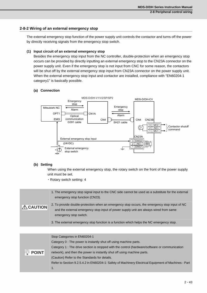
MDS-D/DH Series Instruction Manual
2-8 Peripheral control wiring
2 - 43
2-8-2 Wiring of an external emergency stop
The external emergency stop function of the power supply unit controls the contactor and turns off the power
by directly receiving signals from the emergency stop switch.
(1) Input circuit of an external emergency stop
Besides the emergency stop input from the NC controller, double-protection when an emergency stop
occurs can be provided by directly inputting an external emergency stop to the CN23A connector on the
power supply unit. Even if the emergency stop is not input from CNC for some reason, the contactors
will be shut off by the external emergency stop input from CN23A connector on the power supply unit.
When the external emergency stop input and contactor are installed, compliance with "EN60204-1
category1" is basically possible.
(a) Connection
(b) Setting
When using the external emergency stop, the rotary switch on the front of the power supply
unit must be set.
・Rotary switch setting: 4
1. The emergency stop signal input to the CNC side cannot be used as a substitute for the external
emergency stop function (CN23).
2. To provide double-protection when an emergency stop occurs, the emergency stop input of NC
and the external emergency stop input of power supply unit are always wired from same
emergency stop switch.
3. The external emergency stop function is a function which helps the NC emergency stop.
Stop Categories in EN60204-1
Category 0 : The power is instantly shut off using machine parts.
Category 1 : The drive section is stopped with the control (hardware/software or communication
network), and then the power is instantly shut off using machine parts.
(Caution) Refer to the Standards for details.
Refer to Section 9.2.5.4.2 in EN60204-1: Safety of Machinery Electrical Equipment of Machines - Part
1.
CN1A
CN4
MDS-D/DH-CV
CN4
3 EMG2 2 (NC) 1 EMG1
CN23B
CN23A
OPT1
3 MC2 2 (NC) 1 MC1
EMG
MDS-D/DH-V1/V2/SP/SP2
SH21 cable
(24VDC)
External emergency stop switch
External emergency stop input
Mitsubishi NC
G391 cable
Alarm
Emergency stop
Optical communication
Emergency stop
Alarm
Contactor shutoff command
CAUTION
POINT

2 Wiring and ConnectionMITSUBISHI CNC
2 - 44
(2) Operation sequences of external emergency stop function
[1] Operation sequences of normal emergency stop
If the normal NC emergency stop and the external emergency stop are simultaneously input, the
operation sequence will be the same as in the case of using only the NC emergency stop.
Immediately after the emergency stop is input, deceleration control is carried out in spindle control,
and dynamic brake stop in servo control in a standard case, or deceleration control when the
parameter is set. The ready signal is turned OFF after the NC confirms all axes stop, and the
contactor control axis turns the contactor OFF.
Even when the NC emergency stop signal and the external emergency stop signal are not
simultaneously input, the operation sequence will be the same as that of the normal emergency
stop provided that both signals are input before all axes stop.
ONOFF
0
ONOFF
dx Cx→dx E7
NCEmergency stop input (EMG)
External emergency stop input (EMGX)
Motor break control output (MBR)(Servo only)
Motor speed
Contactor control output (MC)
Drive unit status display
Operation sequences of normal emergency stop
ONCancel
ONCancel
CancelON
Ready signal (RDY)(Contactor control command)
NC confirms all axes stop
Deceleration control, or dynamic brake stop

MDS-D/DH Series Instruction Manual
2-8 Peripheral control wiring
2 - 45
[2] When only the external emergency stop is input
If only the external emergency stop is input, all the drive units that share one NC communication
enter an emergency stop state and deceleration control (servo/spindle) or dynamic brake stop
(servo) is executed. At this time, the axis to which the external emergency stop is input enters "in
external emergency stop" (EA display). The contactor is turned OFF in accordance with the gate off
delay time (SV055/SP055), as the NC emergency stop is not input and the ready signal is not
turned OFF.
[3] When only the NC emergency stop is input
Motors of all axes enter deceleration stop in the same sequence as normal operation (when both
NC and external emergency stop signals are input) and the contactor is shut off. In case that all
axes stop is not confirmed and the ready signal is not turned OFF, the contactor is shut off in
accordance with the max. gate off delay time (SV055/SP055) which is set to the contactor control
axis.
ONOFF
0
dx Cx→dx EA E7
ONOFF
Deceleration control, or dynamic brake stop
NCEmergency stop input (EMG)
External emergency stop input (EMGX)
Motor break control output (MBR) (Servo only)
Motor speed
Contactor control output (MC)
Servo drive unit status display
When only the external emergency stop is input
Gate off delay timeSV055/SP055
ONCancel
ONCancel
CancelON
Ready signal (RDY)(Contactor control command)
ONOFF
0
ONOFF
dx Cx→dx E7
NCEmergency stop input (EMG)
External emergency stop input (EMGX)
Motor break control output (MBR)(Servo only)
Motor speed
Contactor control output (MC)
Drive unit status display
When only the emergency stop of NC is input
ONCancel
ONCancel
CancelON
Ready signal (RDY)(Contactor control command)
NC confirms all axes stop
Deceleration control, or dynamic brake stop
The contactor is shut off after RDY signal turns OFF, or after set time of SV055 or SP055.

2 Wiring and ConnectionMITSUBISHI CNC
2 - 46
(3) Example of emergency stop circuit
[1] Outline of function
The power supply unit's external emergency stop can be validated by wiring to the CN23 connector,
and setting the parameters and rotary switch. If the emergency stop cannot be processed and the
external contractor cannot be shut off (due to a fault) by the CNC unit, the external contactor can be
shut off by the power supply unit instead of the CNC. At this time, both servomotor and spindle
motor will stop with the deceleration control.
EN60204-1 Category 1 can be basically complied with by installing the external emergency stop
switch and contactor.
The emergency stop is a signal used to stop the machine in an emergency. This is connected to the
CNC unit. Wire to the power supply unit when necessary.
The servo/spindle unit will be decelerated and controlled by the software according to the
deceleration stop command issued from the CNC unit.
1. The power supply unit external emergency stop function is a function that assists the NC
emergency stop.
2. The emergency stop signal input to the CNC side cannot be used as a substitute for the external
emergency stop function (CN23).
3. It will take 30 seconds for the external contactor to function after the emergency stop is input to
CN23. (This time is fixed.)
CAUTION

MDS-D/DH Series Instruction Manual
2-8 Peripheral control wiring
2 - 47
[2] Example of emergency stop circuit
The diagram on the right shows an example of the emergency stop circuit (EN60204-1 Category 0)
in which an off delay timer (TM1) is installed as a power shutoff method independent from the NC
emergency stop input. The required safety category may be high depending on the machine and
the Safety Standards may not be met. Thus, always pay special attention when selecting the parts
and designing the circuit.
Provide a mechanism that shuts off the power even if the CNC system fails.
Stop Categories in EN60204-1
Category 0: The power is instantly shut off using machine parts.
Category 1: The drive section is stopped with the control (hardware/software
or communication network), and then the power is instantly shut off using machine parts.
(Caution) Refer to the Standards for details.
Refer to Section 9.2.5.4.2 in EN60204-1: Safety of Machinery
Electrical Equipment of Machines - Part 1.
Hardware Emergency
Software Emergency
NC Unit
Servo/Spindle
Drive Unit
Power Supply
Unit
ExternalEmergency
Switch
MotorBrake
AC
Reactor
External
Contactor
TM1
GND
R RA1 R
GND
EMG
CPU&
ASIC
SV1/2
CN1A/BCN23
GND
CPU&
ASIC
CPU&
ASIC
MBR*
CN4 CN4
L11
L21
L11
L21
MC1
CN20MBR*
P
N
L1
L2
L3
MC MC-OFF*
RA
Setting the off delay timer (TM1) timeSet the TM1 operation time so that it functions after it has been confirmed that all axes have stopped.If the set time is too short, a power supply alarm occurs, and the spindle motor will coast to a stop.
tm All axes stop time
POINT

2 Wiring and ConnectionMITSUBISHI CNC
2 - 48
2-8-3 Safety observation function
By using the safety observation function, the safety door, etc. can be opened during operation without
shutting the power. This function contributes to reducing preparation time and improving operation. The
safety is observed in the control section (NC) and drive section (servo drive unit and spindle drive unit). If
safety conditions are not satisfied in either system, emergency stop operation is applied and the power is
shut to secure the safety.
(1) Connection
The following three wirings are required for the safety observation.
[1] The state signal for the safety door of the machine is wired to both the NC unit side (DI) and drive
unit side (CN9 connector MPI1). The double-protection for the wiring must be provided by wiring
the signal to each of the NC side and drive unit side as the following figure.
[2] Add the wiring to control the contactor in the NC unit side in order to shut the power when an error
occurs.
[3] In addition to the emergency stop wiring for the NC unit, add the external emergency stop wiring for
the CN23A connector of the power supply unit.
L+ L-
MPI1
CN23B CN23A
[1]
[2]
[3]
(MDS-D/DH-CV)(MDS-D/DH-SP)(MDS-D/DH-V2)(MDS-D/DH-V1)
Servomotor Spindle motor
Machine safety door
Open/close switch (
Door status signal
sensor
NC unit
Emergency stop switch
3-phase AC power supply
Circuit protector (Note)
Prepared by user
AC reactor
Contactor (Note)
Prepared by user
Breaker or
fuse (Note)
Prepared by user To 2th and 3th axis
servo
CN9 connector
)

MDS-D/DH Series Instruction Manual
2-8 Peripheral control wiring
2 - 49
(2) Parameter setting for servo drive unit
Starts the safe observation function.
【#2313】 SV113 SSF8 Servo function 8
bit F : ssc Safety observation function
0: Stop 1: Start
The digital signal input selection is set to "1" for the drive unit connected with the door state signal. The
digital signal input selection is set to "0" for the other drive unit not connected with the signal.
【#2282】 SV082 SSF5 Servo function 5
bit F-C: dis Digital signal input selection
0: No signal 1: Safety observation function door state signal 2: Battery box voltage drop warning (It is not available for MDS-D-SVJ3 Series.) 3 to F: Setting prohibited
1. The safety observation function is NC option. Make sure the compatibility with this function.
2. Make sure to input one of the door status signal for each control system to CN9 connector of servo
or spindle drive unit. In the control system, it is conveyed to the axis which is not directly connected
via the NC.
3. Using the safety observation function, it is required to set parameter in addition to the wiring
mentioned above. To prevent a certain axis from being involved in the safety observation function,
set SV113/bitF or SP229/bitF to 0.
4. For details on this function, refer to the manual of NC system.
CAUTION

2 Wiring and ConnectionMITSUBISHI CNC
2 - 50
Sets the safety speed of the machine and motor for which the safety observation is executed.
【#2233】 SV033 SSF2 Servo function 2
bit D : rps Speed setting increment
Change the setting units of the specified speed signal output speed (SV073) and safety observation safety speed (SV238). 0: mm/min 1: 100mm/min
【#2438】 SV238 SSCFEED Safety observation Safety speed
Set the machine's safety speed for the safety observation function. Set this parameter within the following setting ranges. For linear axis: 2000mm/min or less For rotary axis: 18000°/min (50r/min) or lessWhen not using, set to "0".
---Setting range---0 to 18000 (mm/min) or (°/min)
However, when SV033/bitD=1, the setting range is from -32768 to 32767 (100 mm/min) or (100°/min).
【#2439】 SV239 SSCRPM Safety observation Safety motor speed
Set the motor's safety speed for the safety observation function. Set a value to hold the following relationship. SV239=(SV238/SV018) x (SV002/SV001) Only when the product is 0, set to "1". When not using, set to "0".
---Setting range---0 to 32767 (r/min)
(Note) The value of the safety observation safety speed and safety observation safety motor speed
must satisfy the following relation.
If this relation is not satisfied, the parameter error (37or E4) will occur.(Error parameter No. is
239.)
Checking this relation is executed when the drive unit is turned ON and parameter is changed
and speed observation mode (states when a speed observation command is turned ON) is
entered.
Note that "1 (r/min)" is applied when the calculation result is "0 (r/min)"
SV238 :SSCFEED SV002 :PC2
SV018 :PIT X
SV001 :PC1 = SV239 :SSCRPM

MDS-D/DH Series Instruction Manual
2-8 Peripheral control wiring
2 - 51
(3) Parameter setting for spindle drive unit
Starts the safe observation function.
【#13229】 SP229 SFNC9 Spindle function 9
bit F : ssc Safety observation function
0: Disable 1: Enable
bit D : rps Safety observation speed setting unit
0: Normal 1: 100°/min
The digital signal input selection is set to "1" for the drive unit connected with the door state signal. The
digital signal input selection is set to "0" for the other drive unit not connected with the signal.
【#13227】 SP227 SFNC7 Spindle function 7
bit F-C : dis Digital signal input selection
0: No signal 1: Safety observation function door state signal 4: Proximity switch signal detection Other settings: setting prohibited
Sets the safety speed of the machine and motor for which the safety observation is executed.
【#13238】 SP238 SSCFEED Safety observation Safety speed
Set the safety speed at the spindle end for the safety observation function. When not using, set to "0".
---Setting range---0 to 18000 (゜/min)
However, when SP229/bitD is set to "1", the setting range is from -32768 to 32767 (100゜/min).
【#13239】 SP239 SSCRPM Safety observation Safety motor speed
Set the motor's safety speed for the safety observation function. When not using, set to "0".
---Setting range---0 to 32767 (r/min)
(Note) The value of the safety observation safety speed and safety observation safety motor speed
must satisfy the following relation.
If this relation is not satisfied, the parameter error (37or E4) will occur. (Error parameter No. is
239.)
Checking this relation is executed when the drive unit is turned ON and parameter is changed
and speed observation mode (states when a speed observation command is turned ON) is
entered.
Note that "1 (r/min)" is applied when the calculation result is "0 (r/min)"
SP238 :SSCFEED
360 X
= SP239 :SSCRPM
SP057 :GRA1
SP061 :GRB1

2 Wiring and ConnectionMITSUBISHI CNC
2 - 52
2-8-4 Specified speed output
Specified speed output function turns the output signal ON when the machine-end speed is below the speed
specified with the parameter. This function enables the protection door, etc., to be locked to secure the
machine operator when the machine-end speed has exceeded the specified speed. This function can also
be used for judging whether the current machine-end speed reaches the specified speed.
The specified speed output signal is output to the digital signal output 2 (MPO2). Refer to the next page for
details, because the configuration of the parameters differs from the servo to spindle. For the 2-axis drive
unit, it is required to set the parameter to the both axes. The signal output turns ON when the both axes
satisfy the conditions (theoretical product output).
Specified speed signal output sequence
0 [mm/min] 0 [mm/min]
OFF ON ON
OFF ON ON
0 [mm/min]
0 [mm/min] 0 [mm/min]
0 [mm/min]
Speed command
Specified speed [mm/min]
Output signal
Machine end speed
For 1-axis drive unit(MDS-D/DH-V1, MDS-D/DH-SP)
As for 2- axis drive unit, the output signal turns OFF when either axis exceeds the specified speed, and it turns ON when both axes are within the specified speed.
For 2-axis drive unit(MDS-D/DH-V2, MDS-D-SP2)
Output signal
Specified speed [mm/min]
Specified speed [mm/min]
L-axis
M-axis

MDS-D/DH Series Instruction Manual
2-8 Peripheral control wiring
2 - 53
< Servo drive unit >
【#2233】 SV033 SSF2 Servo function 2
bit D : rps Safety observation Safety speed setting increment
Change the setting units of the specified speed signal output speed (SV073) and safety observation safety speed (SV238). 0: mm/min 1: 100mm/min
【#2273(PR)】 SV073 FEEDout Specified speed outup speed
Set the specified speed. Also set SV082/bit9,8 to output digital signal.
---Setting range---0 to 32767 (r/min)
However, when SV033/bitD=1, the setting range is from 0 to 32767(100mm/min).
【#2282】 SV082 SSF5 Servo function 5
bit 9-8 : dos2 Digital signal output 2 selection
00: Disable 01: Specified speed output
< Spindle drive unit >
【#13018(PR)】 SP018 SPEC2 Spindle specification 2
bit 8 : spsu Command speed limit value
0: 33,750 r/min 1: 135,000 r/min
【#13030】 SP030 SDT2 2nd speed detection setting value
Set the specified speed of the specified speed output. When carrying out digital output of the specified speed output, set SP229/bitC to "1".
---Setting range---0 to 32767 (r/min)
【#13229】 SP229 SFNC9 Spindle function 9
bit C : sdt2 Specified speed output digital signal 2 output
0: Normal 1: Enable

2 Wiring and ConnectionMITSUBISHI CNC
2 - 54
2-8-5 Spindle coil changeover
There are spindle motors capable of coil changeover control, which enables favorable characteristics to be
attained from low speeds to high speeds by changing two types of coils.
(1) Coil changeover control
The speed at which to change the coils is detected by the spindle drive according to the value set with
spindle parameter SP028. This is conveyed to the NC with a speed detection (SD) signal. The NC
judges the other conditions (coil fixed, etc.), and issue a coil changeover command to the spindle drive
with the L coil selection command (LCS).
To prevent the contactor from varying, the hysteresis set with SP029 is applied on the speed when
changing from the low-speed coil to the high-speed coil and the high-speed coil to the low-speed coil.
Spindle motor coil changeover control
【#13028】 SP028 SDTS Speed detection set value
Set the motor speed for detecting the speed. If the motor speed drops below the set speed, the speed detection signal turns ON. The standard setting is 10% of the maximum motor speed.
---Setting range---10 to 32767 (r/min)
【#13029】 SP029 SDTR Speed detection reset width
Set the hysteresis width in which the speed detection changes from ON to OFF. If the setting value is small, the speed detection will chatter easily. The standard setting is "30".
---Setting range---10 to 1000 (r/min)
Spindle motor speed (r/min)
Speed detection (SD1)L coil selection command (LCS)Changing coil (MKC)
Contactor changeover speed coilLow-
Time
High-speed coil Low-speed coil
[SP→NC] [NC SP] [SP NC]
0
2000
6000
4000
(SP028+SP029)
SP028
→
→

MDS-D/DH Series Instruction Manual
2-8 Peripheral control wiring
2 - 55
(2) Protective functions
[1] Gate shutoff after a winding changeover
When the L-coil selection command (LCS) is used to perform low-speed winding -> high-speed
winding switching, or vice-versa, the gate is shut off during contactor operation time in order to
protect the spindle drive unit's main circuit. The gate shutoff time is determined by the "Coil
changeover gate cutoff timer" (SP114) setting. The standard time setting should be used, as a
shorter time can cause contactor burn damage.
(Refer to 5-3-2 (5) "Spindle control output 5" Coil changing (bit 6) for details.)
【#13114】 SP114 MKT Coil changeover gate cutoff timer
Set the time required to cut off the gate when turning OFF/ON the coil switch contactor. The value should be longer than the coil switch contactor's OFF/ON time. The standard setting is "150".
---Setting range---0 to 3500 (ms)
[2] Current limit after coil changeover
Following a coil changeover, the current is limited (SP116) for the period specified by the current
limit timer (SP115) in order to stabilize control. Because position loop control (synchronous tap, C-
axis control, etc.) that occurs immediately after a coil changeover will result in unstable control, be
sure that position commands specified by the sequence is input after the current limit is cancelled.
【#13115】 SP115 MKT2 Coil changeover current limit timer
Set the time required to limit the current immediately after the coil switch contactor ON/OFF is completed and the gate is turned ON. The standard setting is "250".
---Setting range---0 to 3500 (ms)
【#13116】 SP116 MKIL Coil changeover current limit value
Set the time required to limit the current immediately after the coil switch contactor ON/OFF is completed and the gate is turned ON. The standard setting is "120".
---Setting range---0 to 999 (Short-time rated %)

2 Wiring and ConnectionMITSUBISHI CNC
2 - 56
(3) Wiring
The illustration below shows the 2 types of changeover that occur after a coil changeover, (a) (star) –
D (delta) changeover, and (b) (star) – (star) changeover. As shown in (c), one of the contactors
(MC1 or MC2) is turned ON and the other is turned OFF at all of the coil changeover control circuits.
(a) (star) - D (delta) changeover circuit
Coil changeover circuit
<Wiring of motor coil>
-connection (MC1:ON MC2:OFF) Δconnection (MC1:OFF MC2:ON)
Wire it according to each 6 terminal’s sign of spindle motor for the coil changeover.
U V W
Y Z
U V W
MC2
MC1
X
Spindle motor
MC1: Contactor to connect low-speed coil ( -connection) MC2: Contactor to connect high-speed coil (∆-connection)
Spindledrive unit
Motor terminal
Y ZX
U
V W
W
UV
Spindledrive unit
:The terminal which is assembled at the contactor ON
XY
ZU
VW
W
UV
Spindledrive unit
:The terminal which is assembled at the contactor ON
POINT

MDS-D/DH Series Instruction Manual
2-8 Peripheral control wiring
2 - 57
(b) (star) - (star) changeover circuit
Coil changeover circuit
<Wiring of motor coil>
(c) Coil changeover control circuit (common)
Coil changeover relay control circuit
-connection (MC1:ON MC2:OFF) -connection (MC1:ON MC2:OFF)
Wire it according to each 6 terminal’s sign of spindle motor for the coil changeover.
U1 V1 W1
U2 V2 W2
U V W
MC1
MC2
Spindle motor
Spindledrive unit
MC1: Contactor to connect low-speed coil (1st -connection) MC2: Contactor to connect high-speed coil (2nd -connection)
Motor terminal
U2
U1
V1 W1
V2 W2
W
UV
Spindledrive unit
:The terminal which is assembled at the contactor ON
U2
U1
V1 W1
V2 W2
W
UV
:The terminal which is assembled at the contactor ON
Spindledrive unit
POINT
RA
MDS-D/DH-SP
CN9-8
CN9-10 MC1 SK
MC2
RA
S
T MC2 SK
MC1
RA

2 Wiring and ConnectionMITSUBISHI CNC
2 - 58
2-8-6 Specifications of proximity switch
Use a proximity switch which satisfies the following specifications.
(1) Electrical specifications
(2) Connection with drive unit
The connection with a drive unit is shown below.
(a) Supply the 24VDC power externally.
(b) Install a proximity switch at the spot that rotates in the ratio of 1:1 to the spindle.
(c) Set the spindle parameter to the pulley ratio for belt drive or to the gear ratio for gear drive.
Item SpecificationOutput method DC double wire system /three wire systemPower supply voltage 24V DCResponse frequency 400Hz or moreLoad current 14mA or moreResidual voltage 4V or lessLeakage current 1mA or less
MDS-D/DH-SP
Spindle
Proximity switch
To CN9(DI1)
Externalpowersupply 24VDC
V-belt
Spindlemotor

MDS-D/DH Series Instruction Manual
2-8 Peripheral control wiring
2 - 59
20 DICOM13 DI1
MDS-D/DH-SP
4.1k
CN9
DICOM
MDS-D/DH-SP
4.1k
CN9
DICOM
MDS-D/DH-SP
4.1k
CN9
24G
2013 DI1
2013 DI1
24VDC Current direction
Proximity switchShield
Caseground
Detection circuit
24VDC Current direction
Proximity switchShield
Caseground
Detection circuit
Select the polarity of DICOM
< Connection details: For proximity switch of two wire system >
< Connection details: For proximity switch of three wire system >
24VDC
Current direction
Proximity switchShield
Caseground
Detection circuit
< Connection details: For proximity switch of two wire system >
< Connection details: For proximity switch of three wire system >
(a) When DICOM is connected to 24V
(b) When DICOM is connected to 24G
Not usable.

2 Wiring and ConnectionMITSUBISHI CNC
2 - 60
(3) Detection signal polarity
The table below is the polarities of the detections signals. According to the polarity, select the enable
edge of the signals with the spindle parameter (SP225/bit5).
(4) Parameter setting
When using the proximity switch, set the following parameters to the spindle to be used.
【#3106】 zrn_typ Zero point return specifications
Select the zero point return specification.
bit F : Spindle zero point detection with contactless switch
0: Normal 1: Enable spindle zero point detection using proximity switch
bit E : Control mode selection in orientation
Select non-interpolation mode when vibration occurs since the gain is high during the orientation.0: Interpolation mode (Use the interpolation mode gain "SP002".)1: Non-interpolation mode (Use the non-interpolation mode gain "SP001")
bit D-B :
Not used. Set to "0".
bit A-9 : Spindle/C axis zero point return direction
bitA,9=00: Short-cut01: Forward run10: Reverse run
bit 8 : Designate zero point return
0: Automatically return to zero point simultaneously with C-axis changeover1: Separate operations are required for zero point return
bit 7 : Synchronous tapping command polarity
0: Forward direction1: Reverse direction (The standard setting when spindle and motor are directly coupled)
bit 6-5 : Synchronous tapping zero point return direction
bit 6,5=00: Short-cut01: Forward run10: Reverse run
Sensor operationEnable
detectionDrive unit input signal polarity
(CN9 DI1)
Enable edge selection
(SP225/bit5)Normal open
(NO)Rising part
Falling edge(0)Normal close
(NC)Falling part
Normal open(NO)
Rising part
Rising edge(1)Normal close
(NC)Falling part
Detection of enable
Detection of enable

MDS-D/DH Series Instruction Manual
2-8 Peripheral control wiring
2 - 61
bit 4 : Designate zero point return/deceleration stop in synchronous tapping
0: Automatically return to zero point before synchronous tapping is started (tapping phase alignment)
1: Not return to zero point and immediately synchronous tapping is started
bit 3 :
Not used. Set to "0".
bit 2-1 : Orientation direction
bit 2,1=00: Short-cut01: Forward run10: Reverse run
bit 0 : Z phase detection direction
0: Forward direction 1: Reverse direction
【#3108】 ori_sft Position shift amount for orientation
The orientation stop position can be moved with this parameter setting although normally the position is Z -phase position. During multi-point orientation control, the stop position is determined by the total value of this parameter and the position data for multi-point orientation of PLC input.
---Setting range----35999 to 35999 (0.01°)
【#3109】 zdetspd Z phase detection speed
For the first S command after power is turned ON, the spindle rotates at the speed of setting value for this parameter.When "#3106/bitF = 1" (Spindle zero point proximity switch detection enabled), also proximity switch is detected.
(Note) When spindle zero point return proximity switch detection is enabled, the rotation direction of the orientation/zero point return (synchronous tapping, spindle/C axis, etc.) will follow Z phase detection direction. And the speed will follow Z phase detection speed (In order to prevent the influences of the delayed detection of the signal pulse edges).
【#3111】 tap_sft Synchronous tapping zero point return shift amount
Set the zero point return shift amount during synchronous tapping control. Zero point angle shifts from Z phase according to the setting angle.
---Setting range---0 to 35999 (0.01°)
【#3113】 cax_sft Spindle C axis zero point return shift amount
Set the spindle C axis zero point return shift amount. Zero point angle shifts from Z phase according to the setting angle.
---Setting range---0 to 359999 (0.001°)
【#13225】 SP225 SFNC5 Spindle function 5
bit 5 : ddir Proximity switch signal enable edge
0: Falling edge 1: Rising edge
【#13227】 SP227 SFNC7 Spindle function 7
bit F-C : dis Digital signal input selection
0: No signal 1: Safety observation function door state signal 4: Proximity switch signal detection Other settings: setting prohibited

2 - 62
2 Wiring and ConnectionMITSUBISHI CNC
<Related control signals>
Control input 5 bitD. Zero point re-detection request (ORC)
When ORC is changed from 0 to 1, the Z phase passed will be 0(control output2/bit0).
Control output 5 bitD. Zero point re-detection complete (ORF)
If the zero point re-detection is completed after the zero point re-detection request (control input5/bitD)
is set to1, ORF=1 is set. If the zero point re-detection request is set to 0, ORF=0 is set.

3 - 1
付録 3 章
3 - 1
3Setup
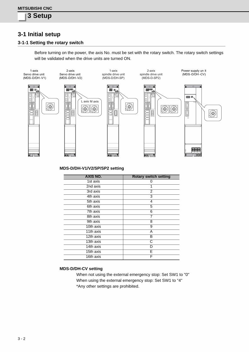
3 - 2
3 SetupMITSUBISHI CNC
3-1 Initial setup3-1-1 Setting the rotary switch
Before turning on the power, the axis No. must be set with the rotary switch. The rotary switch settings
will be validated when the drive units are turned ON.
MDS-D/DH-V1/V2/SP/SP2 setting
MDS-D/DH-CV setting
When not using the external emergency stop: Set SW1 to "0"
When using the external emergency stop: Set SW1 to "4"
*Any other settings are prohibited.
AXIS NO. Rotary switch setting1st axis 02nd axis 13rd axis 24th axis 35th axis 46th axis 57th axis 68th axis 79th axis 8
10th axis 911th axis A12th axis B13th axis C14th axis D15th axis E16th axis F
L axis M axis
1-axis Servo drive unit (MDS-D/DH -V1)
2-axis Servo drive unit (MDS-D/DH -V2)
Power supply un it (MDS-D/DH -CV)
1-axis spindle drive unit(MDS-D/DH-SP)
2-axisspindle drive unit
(MDS-D-SP2)

3 - 3
MDS-D/DH Series Instruction Manual
3-1 Initial setup
3-1-2 Setting DIP switch
Setting the DIP switches is necessary prior to turning ON the power. Setting of the DIP switches at the time
of turning ON the power is validated. The DIP switches shall be as the standard setting (all the switches
OFF).
3-1-3 Transition of LED display after power is turned ON
When CNC, each drive unit and the power supply unit power have been turned ON, each unit will
automatically execute self-diagnosis and initial settings for operation, etc. The LEDs on the front of the units
will change as shown below according to the progression of these processes.
If an alarm occurs, the alarm No. will appear on the LEDs. Refer to section "LED display when alarm or
warning occurs" for details on the alarm displays.
Always input emergency stop when starting the servo system.
The switches are OFF when facing bottom as illustrated.
M axis Setting unused axis
L axis Setting unused axis
Unused axis can be set by turning the switches ON. When there is unused axis for the 2-axis drive unit, set unused axis.
Executing initial communication with NC
Drive unit initialization complete Waiting for NC power start up
Emergency stop state The LED will alternate between
F# E7 not lit.(# is the set axis No.)
Repeats lighting and going out. (1st axis in the display example)
NC power ONWaiting for NC power start up
NC power OFF
NC power ON
LED display
Servo ON state Servo OFF sate
Drive units
Emergency stop state
NC power ON
LED display
In servo ON (Charge completed)
Power supply unit
In initializing
Initializing completed Contactor OFF
Ready OFF state
In ready ON (In Charging)
Contactor ON
CAUTION

3 - 4
3 SetupMITSUBISHI CNC
3-2 Setting the initial parameters for the servo drive unitThe servo parameters must be set before the servo system can be started up. The servo parameters are
input from the NC. The input method differs according to the NC being used, so refer to each NC Instruction
Manual.
When setting the initial setting parameters, perform the following settings in each system.
<For semi closed loop control (single-axis control)>
(1) Set the standard parameters in the section "3-2-5 List of standard parameters for each
servomotor".
(2) "3-2-1 Setting of servo specification parameters"
<For full closed loop control (single-axis control)>
(1) Set the standard parameters in the section "3-2-5 List of standard parameters for each
servomotor".
(2) "3-2-1 Setting of servo specification parameters"
(3) "3-2-2 Setting of machine side detector"
<For full closed loop control with a distance-coded reference scale (single-axis control)>
(1) Set the standard parameters in the section "3-2-5 List of standard parameters for each
servomotor".
(2) "3-2-1 Setting of servo specification parameters"
(3) "3-2-2 Setting of machine side detector"
(4) "3-2-3 Setting of distance-coded reference scale"
<For speed command synchronous control>
(1) Set the standard parameters in the section "3-2-5 List of standard parameters for each
servomotor".
(2) "3-2-1 Setting of servo specification parameters"
(3) "3-2-2 Setting of machine side detector"
(4) "3-2-4 Setting of speed command synchronous control"
(Note) For the position command synchronous control, perform the items of single-axis control for
each axis.
Setting the initial parameters above enables the test operation for the servo axis (Ex. manual pulse feed,
low-speed JOG feed). When machine resonance occurs, check the machine resonance frequency at AFLT
frequency on the drive monitor screen and set to the following servo parameters (When the AFLT frequency
displays "0", resonance is not occurring).
【#2238】 SV038 FHz1 Notch filter frequency 1
Set the vibration frequency to suppress when machine vibration occurs. (Normally, do not set 80 or less.)
---Setting range---0 to 2250 (Hz)

3 - 5
MDS-D/DH Series Instruction Manual
3-2 Setting the initial parameters for the servo drive unit
3-2-1 Setting of servo specification parameters
(1) Basic specification parameters
When performing absolute position control, set the axis specification parameter #2049. When the
setting value of #2049 is "1 to 4", "SV017/bit7" is automatically set to the absolute position control.
It is not possible to set SV017/bit7 directly.
【#2049(PR)】 type Absolute position detection method
Select the absolute position zero point alignment method.0: Not absolute position detection 1: Stopper method (push against mechanical stopper) 2: Marked point alignment method I (The grid point is the reference position.) 3: Dog-type (align with dog and near point detection switch) 4: Marked point alignment method II
(The position with which the mark was aligned is the reference position.)9: Simple absolute position (Not absolute position detection, but the position when the power is
turned off is registered.)
【#2217(PR)】 SV017 SPEC1 Servo specification 1
bit 7 : abs Position control
These parameters are set automatically by the NC system.
0: Incremental 1: Absolute position control
For C70 NC, set the following parameters. Ignore the unnecessary alarm history which occurs when the
NC power is turned off.
【#2314】 SV114 SSF9 Servo function 9
bit 8 : nohis History of communication error alarm between NC and DRV (34, 36, 38, 39)
Set "1" for C70. 0: Enable 1: Disable

3 - 6
3 SetupMITSUBISHI CNC
(2) Electronic gear related parameters
Servo control is performed by changing NC command unit to servo control unit with the following
parameters (electric gear). Even if each parameter is within the setting range, overflow of the electric
gear coefficient may be occur. When the overflow of the electric gear occurs, initial parameter error
(servo alarm 37) will occur.
【#2201(PR)】 SV001 PC1 Motor side gear ratio
【#2202(PR)】 SV002 PC2 Machine side gear ratio
Set the gear ratio in the machine side when there is the gear between the servomotor's shaft and machine (ball screw, etc.). For the rotary axis, set the total deceleration (acceleration) ratio. Even if the gear ratio is within the setting range, the electronic gears may overflow and an initial parameter error (servo alarm 37) may occur.
【#2218(PR)】 SV018 PIT Ball screw pitch/Magnetic pole pitch
Set the ball screw pitch. For the rotary axis, set to "360".
【#2219(PR)】 SV019 RNG1 Sub side detector resolution
Set the same value as SV020.For the full-closed loop control, refer to "3-2-2 Setting of machine side detector".
【#2220(PR)】 SV020 RNG2 Main side detector resolution
Set the number of pulses per revolution of the motor side detector. OSA18 (-A48) (260,000 p/rev) ----------- SV020 = 260 OSA105 (-A51) (1,000,000 p/rev) ------- SV020 = 1000 OSA166 (-A74(N)) (16,000,000 p/rev) ----- SV020 = 16000

3 - 7
MDS-D/DH Series Instruction Manual
3-2 Setting the initial parameters for the servo drive unit
(3) Setting of power supply type
Set the drive unit connected to the power supply unit with the CN4 connector. This does not need to be
set if the power supply for the axis is not connected with the CN4 connector. (Set "0000".)
If the power supply unit is connected with the spindle drive unit, the parameters do not need to be set on
the servo side. When connected to a 2-axis servo drive unit (MDS-D/DH-V2), set the power supply type
for one of the two target axes.
【#2236(PR)】 SV036 PTYP Power supply type
When the emergency stop input signal of the power supply unit is "disabled" Power supply unit is not connected : 0000h MDS-D-CV-37 / MDS-DH-CV-37 : 0004h MDS-D-CV-75 / MDS-DH-CV-75 : 0008h MDS-D-CV-110 / MDS-DH-CV-110 : 0011h MDS-D-CV-185 / MDS-DH-CV-185 : 0019h MDS-D-CV-300 / MDS-DH-CV-300 : 0030h MDS-D-CV-370 / MDS-DH-CV-370 : 0037h MDS-D-CV-450 / MDS-DH-CV-450 : 0045h MDS-D-CV-550 / MDS-DH-CV-550 : 0055h MDS-DH-CV-750 : 0075h When the emergency stop input signal of the power supply unit is "enabled"(Note) Set the power supply rotary switch to "4". Power supply unit is not connected : 0000h MDS-D-CV-37 / MDS-DH-CV-37 : 0044h MDS-D-CV-75 / MDS-DH-CV-75 : 0048h MDS-D-CV-110 / MDS-DH-CV-110 : 0051h MDS-D-CV-185 / MDS-DH-CV-185 : 0059h MDS-D-CV-300 / MDS-DH-CV-300 : 0070h MDS-D-CV-370 / MDS-DH-CV-370 : 0077h MDS-D-CV-450 / MDS-DH-CV-450 : 0085h MDS-D-CV-550 / MDS-DH-CV-550 : 0095h MDS-DH-CV-750 : 00B5h

3 - 8
3 SetupMITSUBISHI CNC
3-2-2 Setting of machine side detector
(1) Setting of the machine side detector specification
【#2225(PR)】 SV025 MTYP Motor/Detector type
Set the position detector type, according to the machine side detector specifications.
bit F-C: pen Position detector
OSA105ET2, OSA166ET2(N) : pen=6Serial signal output rotary scale : pen=6Rectangular wave signal output scale : pen=8Serial signal output linear scale : pen=A
【#2219(PR)】 SV019 RNG1 Sub side detector resolution
For a ball screw end detectorOSA105ET2: RNG1=1000OSA166ET2(N): RNG1=16000
For a linear scaleSet the number of pulses per ball screw lead in one "kp" increments.For a rotary scaleSet the number of pulses per revolution in one "kp" increments.
Note that the value must be input in increments of 10K pulses (the 1st digit of the setting value is "0").If any restriction is imposed due to the above condition, also set SV117 in one pulse increments.
【#2317(PR)】 SV117 RNG1ex Expansion sub side detector resolution
To set the resolution of the machine side detector in one pulse increments, set the number of pulses of the detector by 4-byte data in total to SV117 (high-order 16bit) and SV019 (low-order 16bit).
SV117= Quotient of the number of pulses divided by 65536 (If the quotient is 0, set SV117 to -1).SV019= Remainder of the number of pulses divided by 65536
(SV019 can be set in one pulse increments).
If the NC is C70 and SV019 is greater than 32767, enter the (negative) value obtained by subtracting 65536 from the above remainder in SV019.

3 - 9
MDS-D/DH Series Instruction Manual
3-2 Setting the initial parameters for the servo drive unit
(2) Setting table for each detector
Rectangular wave signal output detector
(Note) When the quotient is "0", "SV117 = -1" is applied.
Mitsubishi serial signal output detector (Incremental)
(Note 1) When the quotient is "0", "SV117 = -1" is applied.
(Note 2) The communication specification of EIB192M/392M is "MITSU02-4".
Mitsubishi serial signal output detector (Absolute position)
(Note) When the quotient is "0", "SV117 = -1" is applied.
Manufacturer Detector type Interface unit typeControl
resolutionSV025 SV019 SV117
MAGNESCALESR74SR84
Not required
1.0μm 82 SV018 x 1000/1 -10.5μm 82 SV018 x 1000/0.5 -10.1μm 82 SV018/0.1 0
0.05μm 82 SV018/0.05 0
HEIDENHAINLS187LS487
IBV 101 (10 divisions) 0.5μm 82 SV018 x 1000/0.5 -1IBV 102 (100 divisions) 0.05μm 82 SV018/0.05 0
IBV 660B (400 divi-sions)
0.0125μm 82 SV018/0.0125 0
Other manufacturers
Rectangular wave output scale
Not requiredSignal frequency
μm/482
(SV018 x 1000/(signal cycleμm/4)) /65536 =remainder quotient
Manufacturer Detector type Interface unit typeControl
resolutionSV025 SV019 SV117
MAGNESCALESR75SR85
Not required0.1μm A2 SV018/0.1 0
0.05μm A2 SV018/0.05 00.01μm A2 SV018/0.01 0
HEIDENHAIN
LS187LS487
EIB192M A4 20μm(20/16384) μm A2
(SV018 x 819200)/65536 =EIB392M A4 20μm remainder quotient
ERM280 1200EIB192M C4 1200
19,660,800p/rev 62 0 300EIB392M C4 1200
ERM280 2048EIB192M C6 2048
33,554,432p/rev 62 0 512EIB392M C6 2048
LS187CLS487C
MDS-B-HRSignal cycle μm/
512A2
(SV018 x 512000/signal cycle μm)/65536 =remainder quotient
Other manufacturers
SIN wave outputlinear scale
MDS-B-HRSignal cycle μm/
512A2
(SV018 x 512000/signal cycle μm) /655356 = remainder quotient
SIN wave outputrotary scale
MDS-B-HRSignal frequency
x 512p/rev62
(Signal frequency x 512)/65536 =remainder quotient
Manufacturer Detector type Interface unit typeControl
resolutionSV025 SV019 SV117
MITSUBISHI ELEC-TRIC
OSA105ET2OSA166ET2(N)
Not required1,000,000p/rev 62 1000 0
16,000,000p/rev 62 16000 0
MAGNESCALE
SR77SR87
Not required0.1μm A2 SV018/0.1 0
0.05μm A2 SV018/0.05 00.01μm A2 SV018/0.01 0
RU77 Not required8,000,000p/rev 62 8000 0
32,000,000p/rev 62 32000 0
HEIDENHAIN
LC193MLC493M
Not required0.05μm A2 SV018/0.05 00.01μm A2 SV018/0.01 0
RCN223M Not required 8,000,000p/rev 62 8000 0RCN227M Not required 134,217,728p/rev 62 0 2048RCN727MRCN827M
Not required 134,217,728p/rev 62 0 2048
Mitutoyo
AT343 Not required 0.05μm A2 SV018/0.05 0AT543 Not required 0.05μm A2 SV018/0.05 0
AT545 Not required (20/4096) μm A2(SV018×204800)/65536 =
remainder quotientMHI MACHINE TOOLENGINEERING CO., LTD
MPRZ Series ADB-20J71 8,000,000p/rev 62 8000 0MPS Series ADB-20J60 0.05μm A2 SV018/0.05 0
MPI SeriesADB-20J60 7,200,000p/rev A2 7200 0ADB-20J60 14,400,000p/rev A2 14400 0
FAGOR
SAM Series Not required 0.05μm A2 SV018/0.05 0SVAM Series Not required 0.05μm A2 SV018/0.05 0GAM Series Not required 0.05μm A2 SV018/0.05 0LAM Series Not required 0.1μm A2 SV018/0.1 0

3 - 10
3 SetupMITSUBISHI CNC
For MPI scale, set the following parameters depends on the number of poles.
【#2217(PR)】 SV017 SPEC1 Servo specification 1
bit 8 : mp MPI scale pole number setting
0: 360 poles 1: 720 poles
(3) Setting of the installation polarity of the machine side detector
Since the installation polarity may not be judged from the detector appearance, confirm the installation
polarity of the machine side detector with moving the axis by hand after the installation.
If "Motor end FB" or "Machine end FB" on the NC drive monitor screen changes to the opposite polarity
when the axis is moved, set"SV017/bit4" to "Reverse polarity".
【#2217(PR)】 SV017 SPEC1 Servo specification 1
bit 4 : sdir Sub side detector feedback
0: Forward polarity 1: Reverse polarity
(4) Setting of the machine side detector alarm detection
When using a rectangular wave linear scale, set the following parameters.
【#2235】 SV035 SSF4 Servo function 4
bit 7 : ckab No signal detection 2
Set this to use rectangular wave output linear scale. This enables the detection of No signal 2 (alarm 21). 0: Disable 1: Enable
【#2398】 SV198 NSE No signal 2 special detection width
Set the special detection width for the no signal 2 (alarm 21). When "0" is set, the detection will be performed with a 15μm width.
---Setting range---0 to 32767 (μm)
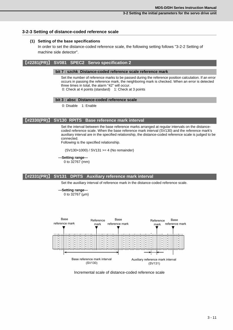
3 - 11
MDS-D/DH Series Instruction Manual
3-2 Setting the initial parameters for the servo drive unit
3-2-3 Setting of distance-coded reference scale
(1) Setting of the base specifications
In order to set the distance-coded reference scale, the following setting follows "3-2-2 Setting of
machine side detector".
【#2281(PR)】 SV081 SPEC2 Servo specification 2
bit 7 : szchk Distance-coded reference scale reference mark
Set the number of reference marks to be passed during the reference position calculation. If an error occurs in passing the reference mark, the neighboring mark is checked. When an error is detected three times in total, the alarm "42" will occur. 0: Check at 4 points (standard) 1: Check at 3 points
bit 3 : absc Distance-coded reference scale
0: Disable 1: Enable
【#2330(PR)】 SV130 RPITS Base reference mark interval
Set the interval between the base reference marks arranged at regular intervals on the distance-coded reference scale. When the base reference mark interval (SV130) and the reference mark's auxiliary interval are in the specified relationship, the distance-coded reference scale is judged to be connected. Following is the specified relationship. (SV130×1000) / SV131 >= 4 (No remainder)
---Setting range---0 to 32767 (mm)
【#2331(PR)】 SV131 DPITS Auxiliary reference mark interval
Set the auxiliary interval of reference mark in the distance-coded reference scale.
---Setting range---0 to 32767 (μm)
Incremental scale of distance-coded reference scale
Base reference mark interval(SV130)
Auxiliary reference mark interval (SV131)
Reference mark
Base reference mark
Basereference mark
Reference mark
Basereference mark

3 - 12
3 SetupMITSUBISHI CNC
(2) Setting of the distance-coded reference check function
If The reference marks are checked at four points by the basic point computer processing, the basic
point can be recreated almost certainly. If you would like to strengthen the check further, set the
distance-coded reference check function, which executes the relation check with a coordinate of the
motor side detector during the basic point calculation after the power-on.
When an error occurs, "Alarm 42" is detected. The battery option is required to use this function since
the motor side detector is under the absolute position control.
<Initial setup of the distance-coded reference check>
Performed this initial setup at the start of the system setup, linear scale exchange, or motor exchange.
(1) Complete the setup of the distance-coded reference scale.
( Complete the base specification setting, and enable the basic point establishment.)
(2) Turn the power ON again after setting "SV137 = -1".
( Under a state of the distance-coded reference check initial setup warning "A3".)
(3) Perform the reference point return.
(4) Conform that the warning "A3" turns OFF.
(5) Set the value of "Rn", "Pn" and "MPOS" to "SV134", "SV135" and "SV136" on the drive monitor.
(6) When SV137=32767, the distance-coded reference check function is disabled.
【#2334】 SV134 RRn0 Distance-coded reference check / revolution counter
【#2335】 SV135 RPn0H Distance-coded reference check /position within one rotation High
【#2336】 SV136 RPn0L Distance-coded reference check / position within one rotation Low
Set this parameter to operate distance-coded reference check when using distance-coded reference scale. During the distance-coded reference check initial setup (SV137:RAER=-1), set the following items on the NC drive monitor screen after the distance-coded reference check initial setup warning A3 turns OFF. SV134=Rn, SV135=Pn, SV136=MPOS
【#2337】 SV137 RAER Distance-coded reference check allowable width
For the distance-coded reference check function when using distance-coded reference scale, set the allowable gap from the reference point position data calculated by the main side detector. When the gap exceeds the allowable range, reference point created by distance-code is judged as wrong and detects alarm 42. The standard setting value is "basic reference mark interval (SV130) / 4". SV137=0 setting carries out the same operation as the standard setting value. SV137=-1 setting enables the distance-coded reference initial set up mode and displays setting values of SV134 to SV136 on NC drive monitor. To enable the distance-coded reference check function, SV081/bit3=1setting and a battery option are needed.
---Setting range----1 to 32767 (mm)

3 - 13
MDS-D/DH Series Instruction Manual
3-2 Setting the initial parameters for the servo drive unit
3-2-4 Setting of speed command synchronous control
This section explains about the setting of the speed command synchronous control of the full closed loop
control. The servo parameter setting during the position command synchronous control is same as single
axis.
【#2225(PR)】 SV025 MTYP Motor/Detector type
Set the position detector type for the secondary axis to "D". The same value is set for 2-axis drive unit and two 1-axis drive units.
bit F-C : pen Position detector
Speed command synchronization control primary axis : pen=ASpeed command synchronization control secondary axis : pen=D
1. When performing the command synchronous control with 2-axis drive unit (MDS-D/DH-V2), make
sure to set L-axis as primary axis.
2. The rectangular waveform output scale is not available for the speed command synchronous
control.
3. The distance-coded reference scale is not available for the speed command synchronous control.
CAUTION

3 - 14
3 SetupMITSUBISHI CNC
3-2-5 List of standard parameters for each servomotor
(1) 200V Standard motor HF Series
MotorParameter
200V Standard motor HF SeriesHF75 HF105 HF54 HF104 HF154 HF224 HF204 HF354
No. Abbrev. Details MDS-D-V1- 20 20 40 40 80 80 80 160SV001 PC1 Motor side gear ratio - - - - - - - -SV002 PC2 Machine side gear ratio - - - - - - - -SV003 PGN1 Position loop gain 1 33 33 33 33 33 33 33 33SV004 PGN2 Position loop gain 2 0 0 0 0 0 0 0 0SV005 VGN1 Speed loop gain 1 100 100 100 100 100 80 100 100SV006 VGN2 Speed loop gain 2 0 0 0 0 0 0 0 0SV007 VIL Speed loop delay compensation 0 0 0 0 0 0 0 0SV008 VIA Speed loop lead compensation 1364 1364 1364 1364 1364 1364 1364 1364SV009 IQA Current loop q axis lead compensation 20480 10240 20480 10240 10240 8192 8192 8192SV010 IDA Current loop d axis lead compensation 20480 10240 20480 10240 10240 8192 8192 8192SV011 IQG Current loop q axis gain 768 512 3072 1280 1536 1280 2048 2048SV012 IDG Current loop d axis gain 768 512 3072 1280 1536 1280 2048 2048SV013 ILMT Current limit value 800 800 800 800 800 800 800 800SV014 ILMTsp Current limit value in special control 800 800 800 800 800 800 800 800SV015 FFC Acceleration rate feed forward gain 0 0 0 0 0 0 0 0SV016 LMC1 Lost motion compensation 1 0 0 0 0 0 0 0 0SV017 SPEC1 Servo specification 1 1000 1000 1000 1000 1000 1000 1000 1000SV018 PIT Ball screw pitch/Magnetic pole pitch - - - - - - - -SV019 RNG1 Sub side detector resolution - - - - - - - -SV020 RNG2 Main side detector resolution - - - - - - - -SV021 OLT Overload detection time constant 60 60 60 60 60 60 60 60SV022 OLL Overload detection level 150 150 150 150 150 150 150 150SV023 OD1 Excessive error detection width during servo ON 6 6 6 6 6 6 6 6SV024 INP In-position detection width 50 50 50 50 50 50 50 50SV025 MTYP Motor/Detector type 2201 2202 2203 2204 2205 2206 2207 2208SV026 OD2 Excessive error detection width during servo OFF 6 6 6 6 6 6 6 6SV027 SSF1 Servo function 1 4000 4000 4000 4000 4000 4000 4000 4000SV028 0 0 0 0 0 0 0 0SV029 VCS Speed at the change of speed loop gain 0 0 0 0 0 0 0 0SV030 IVC Voltage non-sensitive band compensation 0 0 0 0 0 0 0 0SV031 OVS1 Overshooting compensation 1 0 0 0 0 0 0 0 0SV032 TOF Torque offset 0 0 0 0 0 0 0 0SV033 SSF2 Servo function 2 0000 0000 0000 0000 0000 0000 0000 0000SV034 SSF3 Servo function 3 0000 0000 0000 0000 0000 0000 0000 0000SV035 SSF4 Servo function 4 0000 0000 0000 0000 0000 0000 0000 0000SV036 PTYP Power supply type/ Regenerative resistor type 0000 0000 0000 0000 0000 0000 0000 0000SV037 JL Load inertia scale 0 0 0 0 0 0 0 0SV038 FHz1 Notch filter frequency 1 0 0 0 0 0 0 0 0SV039 LMCD Lost motion compensation timing 0 0 0 0 0 0 0 0SV040 LMCT Lost motion compensation non-sensitive band 0 0 0 0 0 0 0 0SV041 LMC2 Lost motion compensation 2 0 0 0 0 0 0 0 0SV042 OVS2 Overshooting compensation 2 0 0 0 0 0 0 0 0SV043 OBS1 Disturbance observer filter frequency 0 0 0 0 0 0 0 0SV044 OBS2 Disturbance observer gain 0 0 0 0 0 0 0 0SV045 TRUB Friction torque 0 0 0 0 0 0 0 0SV046 FHz2 Notch filter frequency 2 0 0 0 0 0 0 0 0SV047 EC Inductive voltage compensation gain 100 100 100 100 100 100 100 100SV048 EMGrt Vertical axis drop prevention time 0 0 0 0 0 0 0 0SV049 PGN1sp Position loop gain 1 in spindle synchronous control 15 15 15 15 15 15 15 15SV050 PGN2sp Position loop gain 2 in spindle synchronous control 0 0 0 0 0 0 0 0SV051 DFBT Dual feedback control time constant 0 0 0 0 0 0 0 0SV052 DFBN Dual feedback control non-sensitive band 0 0 0 0 0 0 0 0SV053 OD3 Excessive error detection width in special control 0 0 0 0 0 0 0 0SV054 ORE Overrun detection width in closed loop control 0 0 0 0 0 0 0 0SV055 EMGx Max. gate off delay time after emergency stop 0 0 0 0 0 0 0 0SV056 EMGt Deceleration time constant at emergency stop 0 0 0 0 0 0 0 0SV057 SHGC SHG control gain 0 0 0 0 0 0 0 0SV058 SHGCsp SHG control gain in spindle synchronous control 0 0 0 0 0 0 0 0SV059 TCNV Collision detection torque estimated gain 0 0 0 0 0 0 0 0SV060 TLMT Collision detection level 0 0 0 0 0 0 0 0SV061 DA1NO D/A output ch1 data No. for initial DC excitation level 0 0 0 0 0 0 0 0SV062 DA2NO D/A output ch2 data No. for final DC excitation level 0 0 0 0 0 0 0 0
SV063 DA1MPYD/A output ch1 output scale for initial DC excitation time
0 0 0 0 0 0 0 0
SV064 DA2MPY D/A output ch2 output scale 0 0 0 0 0 0 0 0SV065 TLC Machine end compensation gain 0 0 0 0 0 0 0 0

3 - 15
MDS-D/DH Series Instruction Manual
3-2 Setting the initial parameters for the servo drive unit
(Note) When driving HF354 with MDS-D-V2-160160W, set the same parameters.
MotorParameter
200V Standard motor HF SeriesHF75 HF105 HF54 HF104 HF154 HF224 HF204 HF354
No. Abbrev. Details MDS-D-V1- 20 20 40 40 80 80 80 160(System parameter area)
SV073 FEEDout Specified speed output speed 0 0 0 0 0 0 0 0(System parameter area)
SV081 SPEC2 Servo specification 2 0200 0200 0200 0200 0200 0200 0200 0200SV082 SSF5 Servo function 5 0000 0000 0000 0000 0000 0000 0000 0000SV083 SSF6 Servo function 6 0000 0000 0000 0000 0000 0000 0000 0000SV084 SSF7 Servo function 7 0000 0000 0000 0000 0000 0000 0000 0000SV085 LMCk Lost motion compensation 3 spring constant 0 0 0 0 0 0 0 0SV086 LMCc Lost motion compensation 3 viscous coefficient 0 0 0 0 0 0 0 0SV087 FHz4 Notch filter frequency 4 0 0 0 0 0 0 0 0SV088 FHz5 Notch filter frequency 5 0 0 0 0 0 0 0 0SV089 0 0 0 0 0 0 0 0SV090 0 0 0 0 0 0 0 0SV091 LMC4G Lost motion compensation 4 gain 0 0 0 0 0 0 0 0SV092 0 0 0 0 0 0 0 0SV093 0 0 0 0 0 0 0 0SV094 MPV Magnetic pole position error detection speed 10 10 10 10 10 10 10 10SV095 ZUPD Vertical axis pull up distance 0 0 0 0 0 0 0 0SV096 0 0 0 0 0 0 0 0SV097 0 0 0 0 0 0 0 0SV098 0 0 0 0 0 0 0 0SV099 0 0 0 0 0 0 0 0SV100 0 0 0 0 0 0 0 0SV101
:SV256
0 0 0 0 0 0 0 0

3 - 16
3 SetupMITSUBISHI CNC
MotorParameter
200V Standard motor HF SeriesHF123 HF223 HF303 HF453 HF703 HF903 HF142 HF302
No. Abbrev. Details MDS-D-V1- 20 40 80 160 160W 320 20 40SV001 PC1 Motor side gear ratio - - - - - - - -SV002 PC2 Machine side gear ratio - - - - - - - -SV003 PGN1 Position loop gain 1 33 33 33 33 33 33 33 33SV004 PGN2 Position loop gain 2 0 0 0 0 0 0 0 0SV005 VGN1 Speed loop gain 1 100 100 100 100 100 100 100 100SV006 VGN2 Speed loop gain 2 0 0 0 0 0 0 0 0SV007 VIL Speed loop delay compensation 0 0 0 0 0 0 0 0SV008 VIA Speed loop lead compensation 1364 1364 1364 1364 1364 1364 1364 1364SV009 IQA Current loop q axis lead compensation 10240 8192 10240 6144 6144 4096 15360 8192SV010 IDA Current loop d axis lead compensation 10240 8192 10240 6144 6144 4096 15360 8192SV011 IQG Current loop q axis gain 1536 1280 2048 2048 2048 1536 2048 2048SV012 IDG Current loop d axis gain 1536 1280 2048 2048 2048 1536 2048 2048SV013 ILMT Current limit value 800 800 800 800 800 800 800 800SV014 ILMTsp Current limit value in special control 800 800 800 800 800 800 800 800SV015 FFC Acceleration rate feed forward gain 0 0 0 0 0 0 0 0SV016 LMC1 Lost motion compensation 1 0 0 0 0 0 0 0 0SV017 SPEC1 Servo specification 1 1000 1000 1000 1000 1000 1000 1000 1000SV018 PIT Ball screw pitch/Magnetic pole pitch - - - - - - - -SV019 RNG1 Sub side detector resolution - - - - - - - -SV020 RNG2 Main side detector resolution - - - - - - - -SV021 OLT Overload detection time constant 60 60 60 60 60 60 60 60SV022 OLL Overload detection level 150 150 150 150 150 150 150 150SV023 OD1 Excessive error detection width during servo ON 6 6 6 6 6 6 6 6SV024 INP In-position detection width 50 50 50 50 50 50 50 50SV025 MTYP Motor/Detector type 2224 2226 2228 2209 220A 220B 2225 2227SV026 OD2 Excessive error detection width during servo OFF 6 6 6 6 6 6 6 6SV027 SSF1 Servo function 1 4000 4000 4000 4000 4000 4000 4000 4000SV028 0 0 0 0 0 0 0 0SV029 VCS Speed at the change of speed loop gain 0 0 0 0 0 0 0 0SV030 IVC Voltage non-sensitive band compensation 0 0 0 0 0 0 0 0SV031 OVS1 Overshooting compensation 1 0 0 0 0 0 0 0 0SV032 TOF Torque offset 0 0 0 0 0 0 0 0SV033 SSF2 Servo function 2 0000 0000 0000 0000 0000 0000 0000 0000SV034 SSF3 Servo function 3 0000 0000 0000 0000 0000 0000 0000 0000SV035 SSF4 Servo function 4 0000 0000 0000 0000 0000 0000 0000 0000SV036 PTYP Power supply type/ Regenerative resistor type 0000 0000 0000 0000 0000 0000 0000 0000SV037 JL Load inertia scale 0 0 0 0 0 0 0 0SV038 FHz1 Notch filter frequency 1 0 0 0 0 0 0 0 0SV039 LMCD Lost motion compensation timing 0 0 0 0 0 0 0 0SV040 LMCT Lost motion compensation non-sensitive band 0 0 0 0 0 0 0 0SV041 LMC2 Lost motion compensation 2 0 0 0 0 0 0 0 0SV042 OVS2 Overshooting compensation 2 0 0 0 0 0 0 0 0SV043 OBS1 Disturbance observer filter frequency 0 0 0 0 0 0 0 0SV044 OBS2 Disturbance observer gain 0 0 0 0 0 0 0 0SV045 TRUB Friction torque 0 0 0 0 0 0 0 0SV046 FHz2 Notch filter frequency 2 0 0 0 0 0 0 0 0SV047 EC Inductive voltage compensation gain 100 100 100 100 100 100 100 100SV048 EMGrt Vertical axis drop prevention time 0 0 0 0 0 0 0 0SV049 PGN1sp Position loop gain 1 in spindle synchronous control 15 15 15 15 15 15 15 15SV050 PGN2sp Position loop gain 2 in spindle synchronous control 0 0 0 0 0 0 0 0SV051 DFBT Dual feedback control time constant 0 0 0 0 0 0 0 0SV052 DFBN Dual feedback control non-sensitive band 0 0 0 0 0 0 0 0SV053 OD3 Excessive error detection width in special control 0 0 0 0 0 0 0 0SV054 ORE Overrun detection width in closed loop control 0 0 0 0 0 0 0 0SV055 EMGx Max. gate off delay time after emergency stop 0 0 0 0 0 0 0 0SV056 EMGt Deceleration time constant at emergency stop 0 0 0 0 0 0 0 0SV057 SHGC SHG control gain 0 0 0 0 0 0 0 0SV058 SHGCsp SHG control gain in spindle synchronous control 0 0 0 0 0 0 0 0SV059 TCNV Collision detection torque estimated gain 0 0 0 0 0 0 0 0SV060 TLMT Collision detection level 0 0 0 0 0 0 0 0SV061 DA1NO D/A output ch1 data No. for initial DC excitation level 0 0 0 0 0 0 0 0SV062 DA2NO D/A output ch2 data No. for final DC excitation level 0 0 0 0 0 0 0 0
SV063 DA1MPYD/A output ch1 output scale for initial DC excitation time
0 0 0 0 0 0 0 0
SV064 DA2MPY D/A output ch2 output scale 0 0 0 0 0 0 0 0SV065 TLC Machine end compensation gain 0 0 0 0 0 0 0 0

3 - 17
MDS-D/DH Series Instruction Manual
3-2 Setting the initial parameters for the servo drive unit
(Note) When driving HF453 with MDS-D-V2-160160W, set the same parameters.
MotorParameter
200V Standard motor HF SeriesHF123 HF223 HF303 HF453 HF703 HF903 HF142 HF302
No. Abbrev. Details MDS-D-V1- 20 40 80 160 160W 320 20 40(System parameter area)
SV073 FEEDout Specified speed output speed 0 0 0 0 0 0 0 0(System parameter area)
SV081 SPEC2 Servo specification 2 0200 0200 0200 0200 0200 0200 0200 0200SV082 SSF5 Servo function 5 0000 0000 0000 0000 0000 0000 0000 0000SV083 SSF6 Servo function 6 0000 0000 0000 0000 0000 0000 0000 0000SV084 SSF7 Servo function 7 0000 0000 0000 0000 0000 0000 0000 0000SV085 LMCk Lost motion compensation 3 spring constant 0 0 0 0 0 0 0 0SV086 LMCc Lost motion compensation 3 viscous coefficient 0 0 0 0 0 0 0 0SV087 FHz4 Notch filter frequency 4 0 0 0 0 0 0 0 0SV088 FHz5 Notch filter frequency 5 0 0 0 0 0 0 0 0SV089 0 0 0 0 0 0 0 0SV090 0 0 0 0 0 0 0 0SV091 LMC4G Lost motion compensation 4 gain 0 0 0 0 0 0 0 0SV092 0 0 0 0 0 0 0 0SV093 0 0 0 0 0 0 0 0SV094 MPV Magnetic pole position error detection speed 10 10 10 10 10 10 10 10SV095 ZUPD Vertical axis pull up distance 0 0 0 0 0 0 0 0SV096 0 0 0 0 0 0 0 0SV097 0 0 0 0 0 0 0 0SV098 0 0 0 0 0 0 0 0SV099 0 0 0 0 0 0 0 0SV100 0 0 0 0 0 0 0 0SV101
:SV256
0 0 0 0 0 0 0 0

3 - 18
3 SetupMITSUBISHI CNC
(2) 200V Standard motor HP Series
MotorParameter
200V Standard motor HP SeriesHP54 HP104 HP154 HP224 HP204
No. Abbrev. Details MDS-D-V1- 40 40 80 80 80SV001 PC1 Motor side gear ratio - - - - -SV002 PC2 Machine side gear ratio - - - - -SV003 PGN1 Position loop gain 1 33 33 33 33 33SV004 PGN2 Position loop gain 2 0 0 0 0 0SV005 VGN1 Speed loop gain 1 100 100 100 60 100SV006 VGN2 Speed loop gain 2 0 0 0 0 0SV007 VIL Speed loop delay compensation 0 0 0 0 0SV008 VIA Speed loop lead compensation 1364 1364 1364 1364 1364SV009 IQA Current loop q axis lead compensation 8192 4096 6144 3072 3072SV010 IDA Current loop d axis lead compensation 8192 4096 6144 3072 3072SV011 IQG Current loop q axis gain 1280 768 1536 1024 1024SV012 IDG Current loop d axis gain 1280 768 1536 1024 1024SV013 ILMT Current limit value 800 800 800 800 800SV014 ILMTsp Current limit value in special control 800 800 800 800 800SV015 FFC Acceleration rate feed forward gain 0 0 0 0 0SV016 LMC1 Lost motion compensation 1 0 0 0 0 0SV017 SPEC1 Servo specification 1 1000 1000 1000 1000 1000SV018 PIT Ball screw pitch/Magnetic pole pitch - - - - -SV019 RNG1 Sub side detector resolution - - - - -SV020 RNG2 Main side detector resolution - - - - -SV021 OLT Overload detection time constant 60 60 60 60 60SV022 OLL Overload detection level 150 150 150 150 150SV023 OD1 Excessive error detection width during servo ON 6 6 6 6 6SV024 INP In-position detection width 50 50 50 50 50SV025 MTYP Motor/Detector type 2211 2212 2213 221B 2214SV026 OD2 Excessive error detection width during servo OFF 6 6 6 6 6SV027 SSF1 Servo function 1 4000 4000 4000 4000 4000SV028 0 0 0 0 0SV029 VCS Speed at the change of speed loop gain 0 0 0 0 0SV030 IVC Voltage non-sensitive band compensation 0 0 0 0 0SV031 OVS1 Overshooting compensation 1 0 0 0 0 0SV032 TOF Torque offset 0 0 0 0 0SV033 SSF2 Servo function 2 0000 0000 0000 0000 0000SV034 SSF3 Servo function 3 0000 0000 0000 0000 0000SV035 SSF4 Servo function 4 0000 0000 0000 0000 0000SV036 PTYP Power supply type/ Regenerative resistor type 0000 0000 0000 0000 0000SV037 JL Load inertia scale 0 0 0 0 0SV038 FHz1 Notch filter frequency 1 0 0 0 0 0SV039 LMCD Lost motion compensation timing 0 0 0 0 0SV040 LMCT Lost motion compensation non-sensitive band 0 0 0 0 0SV041 LMC2 Lost motion compensation 2 0 0 0 0 0SV042 OVS2 Overshooting compensation 2 0 0 0 0 0SV043 OBS1 Disturbance observer filter frequency 0 0 0 0 0SV044 OBS2 Disturbance observer gain 0 0 0 0 0SV045 TRUB Friction torque 0 0 0 0 0SV046 FHz2 Notch filter frequency 2 0 0 0 0 0SV047 EC Inductive voltage compensation gain 100 100 100 100 100SV048 EMGrt Vertical axis drop prevention time 0 0 0 0 0SV049 PGN1sp Position loop gain 1 in spindle synchronous control 15 15 15 15 15SV050 PGN2sp Position loop gain 2 in spindle synchronous control 0 0 0 0 0SV051 DFBT Dual feedback control time constant 0 0 0 0 0SV052 DFBN Dual feedback control non-sensitive band 0 0 0 0 0SV053 OD3 Excessive error detection width in special control 0 0 0 0 0SV054 ORE Overrun detection width in closed loop control 0 0 0 0 0SV055 EMGx Max. gate off delay time after emergency stop 0 0 0 0 0SV056 EMGt Deceleration time constant at emergency stop 0 0 0 0 0SV057 SHGC SHG control gain 0 0 0 0 0SV058 SHGCsp SHG control gain in spindle synchronous control 0 0 0 0 0SV059 TCNV Collision detection torque estimated gain 0 0 0 0 0SV060 TLMT Collision detection level 0 0 0 0 0SV061 DA1NO D/A output ch1 data No. for initial DC excitation level 0 0 0 0 0SV062 DA2NO D/A output ch2 data No. for final DC excitation level 0 0 0 0 0
SV063 DA1MPYD/A output ch1 output scale for initial DC excitation time
0 0 0 0 0
SV064 DA2MPY D/A output ch2 output scale 0 0 0 0 0SV065 TLC Machine end compensation gain 0 0 0 0 0

3 - 19
MDS-D/DH Series Instruction Manual
3-2 Setting the initial parameters for the servo drive unit
MotorParameter
200V Standard motor HP SeriesHP54 HP104 HP154 HP224 HP204
No. Abbrev. Details MDS-D-V1- 40 40 80 80 80(System parameter area)
SV073 FEEDout Specified speed output speed 0 0 0 0 0(System parameter area)
SV081 SPEC2 Servo specification 2 0200 0200 0200 0200 0200SV082 SSF5 Servo function 5 0000 0000 0000 0000 0000SV083 SSF6 Servo function 6 0000 0000 0000 0000 0000SV084 SSF7 Servo function 7 0000 0000 0000 0000 0000SV085 LMCk Lost motion compensation 3 spring constant 0 0 0 0 0SV086 LMCc Lost motion compensation 3 viscous coefficient 0 0 0 0 0SV087 FHz4 Notch filter frequency 4 0 0 0 0 0SV088 FHz5 Notch filter frequency 5 0 0 0 0 0SV089 0 0 0 0 0SV090 0 0 0 0 0SV091 LMC4G Lost motion compensation 4 gain 0 0 0 0 0SV092 0 0 0 0 0SV093 0 0 0 0 0SV094 MPV Magnetic pole position error detection speed 10 10 10 10 10SV095 ZUPD Vertical axis pull up distance 0 0 0 0 0SV096 0 0 0 0 0SV097 0 0 0 0 0SV098 0 0 0 0 0SV099 0 0 0 0 0SV100 0 0 0 0 0SV101
:SV256
0 0 0 0 0

3 - 20
3 SetupMITSUBISHI CNC
MotorParameter
200V Standard motor HP SeriesHP354 HP454 HP704 HP903 HP1103
No. Abbrev. Details MDS-D-V1- 160 160 160W 320 320WSV001 PC1 Motor side gear ratio - - - - -SV002 PC2 Machine side gear ratio - - - - -SV003 PGN1 Position loop gain 1 33 33 33 33 33SV004 PGN2 Position loop gain 2 0 0 0 0 0SV005 VGN1 Speed loop gain 1 100 100 100 100 100SV006 VGN2 Speed loop gain 2 0 0 0 0 0SV007 VIL Speed loop delay compensation 0 0 0 0 0SV008 VIA Speed loop lead compensation 1364 1364 1364 1364 1364SV009 IQA Current loop q axis lead compensation 4096 3072 3072 2048 2048SV010 IDA Current loop d axis lead compensation 4096 3072 3072 2048 2048SV011 IQG Current loop q axis gain 1280 1024 1024 1280 1280SV012 IDG Current loop d axis gain 1280 1024 1024 1280 1280SV013 ILMT Current limit value 800 800 800 800 800SV014 ILMTsp Current limit value in special control 800 800 800 800 800SV015 FFC Acceleration rate feed forward gain 0 0 0 0 0SV016 LMC1 Lost motion compensation 1 0 0 0 0 0SV017 SPEC1 Servo specification 1 1000 1000 1000 1000 1000SV018 PIT Ball screw pitch/Magnetic pole pitch - - - - -SV019 RNG1 Sub side detector resolution - - - - -SV020 RNG2 Main side detector resolution - - - - -SV021 OLT Overload detection time constant 60 60 60 60 60SV022 OLL Overload detection level 150 150 150 150 150SV023 OD1 Excessive error detection width during servo ON 6 6 6 6 6SV024 INP In-position detection width 50 50 50 50 50SV025 MTYP Motor/Detector type 2215 2216 2217 2218 2219SV026 OD2 Excessive error detection width during servo OFF 6 6 6 6 6SV027 SSF1 Servo function 1 4000 4000 4000 4000 4000SV028 0 0 0 0 0SV029 VCS Speed at the change of speed loop gain 0 0 0 0 0SV030 IVC Voltage non-sensitive band compensation 0 0 0 0 0SV031 OVS1 Overshooting compensation 1 0 0 0 0 0SV032 TOF Torque offset 0 0 0 0 0SV033 SSF2 Servo function 2 0000 0000 0000 0000 0000SV034 SSF3 Servo function 3 0000 0000 0000 0000 0000SV035 SSF4 Servo function 4 0000 0000 0000 0000 0000SV036 PTYP Power supply type/ Regenerative resistor type 0000 0000 0000 0000 0000SV037 JL Load inertia scale 0 0 0 0 0SV038 FHz1 Notch filter frequency 1 0 0 0 0 0SV039 LMCD Lost motion compensation timing 0 0 0 0 0SV040 LMCT Lost motion compensation non-sensitive band 0 0 0 0 0SV041 LMC2 Lost motion compensation 2 0 0 0 0 0SV042 OVS2 Overshooting compensation 2 0 0 0 0 0SV043 OBS1 Disturbance observer filter frequency 0 0 0 0 0SV044 OBS2 Disturbance observer gain 0 0 0 0 0SV045 TRUB Friction torque 0 0 0 0 0SV046 FHz2 Notch filter frequency 2 0 0 0 0 0SV047 EC Inductive voltage compensation gain 100 100 100 100 100SV048 EMGrt Vertical axis drop prevention time 0 0 0 0 0SV049 PGN1sp Position loop gain 1 in spindle synchronous control 15 15 15 15 15SV050 PGN2sp Position loop gain 2 in spindle synchronous control 0 0 0 0 0SV051 DFBT Dual feedback control time constant 0 0 0 0 0SV052 DFBN Dual feedback control non-sensitive band 0 0 0 0 0SV053 OD3 Excessive error detection width in special control 0 0 0 0 0SV054 ORE Overrun detection width in closed loop control 0 0 0 0 0SV055 EMGx Max. gate off delay time after emergency stop 0 0 0 0 0SV056 EMGt Deceleration time constant at emergency stop 0 0 0 0 0SV057 SHGC SHG control gain 0 0 0 0 0SV058 SHGCsp SHG control gain in spindle synchronous control 0 0 0 0 0SV059 TCNV Collision detection torque estimated gain 0 0 0 0 0SV060 TLMT Collision detection level 0 0 0 0 0SV061 DA1NO D/A output ch1 data No. for initial DC excitation level 0 0 0 0 0SV062 DA2NO D/A output ch2 data No. for final DC excitation level 0 0 0 0 0
SV063 DA1MPYD/A output ch1 output scale for initial DC excitation time
0 0 0 0 0
SV064 DA2MPY D/A output ch2 output scale 0 0 0 0 0SV065 TLC Machine end compensation gain 0 0 0 0 0

3 - 21
MDS-D/DH Series Instruction Manual
3-2 Setting the initial parameters for the servo drive unit
(Note) When driving HP354 or HP454 with MDS-D-V2-160160W, set the same parameters.
MotorParameter
200V Standard motor HP SeriesHP354 HP454 HP704 HP903 HP1103
No. Abbrev. Details MDS-D-V1- 160 160 160W 320 320W(System parameter area)
SV073 FEEDout Specified speed output speed 0 0 0 0 0(System parameter area)
SV081 SPEC2 Servo specification 2 0200 0200 0200 0200 0200SV082 SSF5 Servo function 5 0000 0000 0000 0000 0000SV083 SSF6 Servo function 6 0000 0000 0000 0000 0000SV084 SSF7 Servo function 7 0000 0000 0000 0000 0000SV085 LMCk Lost motion compensation 3 spring constant 0 0 0 0 0SV086 LMCc Lost motion compensation 3 viscous coefficient 0 0 0 0 0SV087 FHz4 Notch filter frequency 4 0 0 0 0 0SV088 FHz5 Notch filter frequency 5 0 0 0 0 0SV089 0 0 0 0 0SV090 0 0 0 0 0SV091 LMC4G Lost motion compensation 4 gain 0 0 0 0 0SV092 0 0 0 0 0SV093 0 0 0 0 0SV094 MPV Magnetic pole position error detection speed 10 10 10 10 10SV095 ZUPD Vertical axis pull up distance 0 0 0 0 0SV096 0 0 0 0 0SV097 0 0 0 0 0SV098 0 0 0 0 0SV099 0 0 0 0 0SV100 0 0 0 0 0SV101
:SV256
0 0 0 0 0

3 - 22
3 SetupMITSUBISHI CNC
(3) 200V Standard motor HF-KP Series
MotorParameter
200V Standard motor HF-KP SeriesHF-KP23JW04-S6 HF-KP43JW04-S6 HF-KP73JW04-S6
No. Abbrev. Details MDS-D-V1- 20 20 20SV001 PC1 Motor side gear ratio - - -SV002 PC2 Machine side gear ratio - - -SV003 PGN1 Position loop gain 1 33 33 33SV004 PGN2 Position loop gain 2 0 0 0SV005 VGN1 Speed loop gain 1 5 10 30SV006 VGN2 Speed loop gain 2 0 0 0SV007 VIL Speed loop delay compensation 0 0 0SV008 VIA Speed loop lead compensation 1364 1364 1364SV009 IQA Current loop q axis lead compensation 20480 15360 4096SV010 IDA Current loop d axis lead compensation 20480 15360 4096SV011 IQG Current loop q axis gain 2048 1024 768SV012 IDG Current loop d axis gain 2048 1024 768SV013 ILMT Current limit value 300 300 300SV014 ILMTsp Current limit value in special control 300 300 300SV015 FFC Acceleration rate feed forward gain 0 0 0SV016 LMC1 Lost motion compensation 1 0 0 0SV017 SPEC1 Servo specification 1 1000 1000 1000SV018 PIT Ball screw pitch/Magnetic pole pitch - - -SV019 RNG1 Sub side detector resolution 260 260 260SV020 RNG2 Main side detector resolution 260 260 260SV021 OLT Overload detection time constant 60 60 60SV022 OLL Overload detection level 150 150 150SV023 OD1 Excessive error detection width during servo ON 6 6 6SV024 INP In-position detection width 50 50 50SV025 MTYP Motor/Detector type 22EA 22EB 22ECSV026 OD2 Excessive error detection width during servo OFF 6 6 6SV027 SSF1 Servo function 1 4000 4000 4000SV028 0 0 0SV029 VCS Speed at the change of speed loop gain 0 0 0SV030 IVC Voltage non-sensitive band compensation 0 0 0SV031 OVS1 Overshooting compensation 1 0 0 0SV032 TOF Torque offset 0 0 0SV033 SSF2 Servo function 2 0000 0000 0000SV034 SSF3 Servo function 3 0000 0000 0000SV035 SSF4 Servo function 4 0000 0000 0000SV036 PTYP Power supply type/ Regenerative resistor type 0000 0000 0000SV037 JL Load inertia scale 0 0 0SV038 FHz1 Notch filter frequency 1 0 0 0SV039 LMCD Lost motion compensation timing 0 0 0SV040 LMCT Lost motion compensation non-sensitive band 0 0 0SV041 LMC2 Lost motion compensation 2 0 0 0SV042 OVS2 Overshooting compensation 2 0 0 0SV043 OBS1 Disturbance observer filter frequency 0 0 0SV044 OBS2 Disturbance observer gain 0 0 0SV045 TRUB Friction torque 0 0 0SV046 FHz2 Notch filter frequency 2 0 0 0SV047 EC Inductive voltage compensation gain 100 100 100SV048 EMGrt Vertical axis drop prevention time 0 0 0SV049 PGN1sp Position loop gain 1 in spindle synchronous control 15 15 15SV050 PGN2sp Position loop gain 2 in spindle synchronous control 0 0 0SV051 DFBT Dual feedback control time constant 0 0 0SV052 DFBN Dual feedback control non-sensitive band 0 0 0SV053 OD3 Excessive error detection width in special control 0 0 0SV054 ORE Overrun detection width in closed loop control 0 0 0SV055 EMGx Max. gate off delay time after emergency stop 0 0 0SV056 EMGt Deceleration time constant at emergency stop 0 0 0SV057 SHGC SHG control gain 0 0 0SV058 SHGCsp SHG control gain in spindle synchronous control 0 0 0SV059 TCNV Collision detection torque estimated gain 0 0 0SV060 TLMT Collision detection level 0 0 0SV061 DA1NO D/A output ch1 data No. for initial DC excitation level 0 0 0SV062 DA2NO D/A output ch2 data No. for final DC excitation level 0 0 0
SV063 DA1MPYD/A output ch1 output scale for initial DC excitation time
0 0 0
SV064 DA2MPY D/A output ch2 output scale 0 0 0SV065 TLC Machine end compensation gain 0 0 0

3 - 23
MDS-D/DH Series Instruction Manual
3-2 Setting the initial parameters for the servo drive unit
MotorParameter
200V Standard motor HF-KP SeriesHF-KP23JW04-S6 HF-KP43JW04-S6 HF-KP73JW04-S6
No. Abbrev. Details MDS-D-V1- 20 20 20(System parameter area)
SV073 FEEDout Specified speed output speed 0 0 0(System parameter area)
SV081 SPEC2 Servo specification 2 0200 0200 0200SV082 SSF5 Servo function 5 0000 0000 0000SV083 SSF6 Servo function 6 0000 0000 0000SV084 SSF7 Servo function 7 0000 0000 0000SV085 LMCk Lost motion compensation 3 spring constant 0 0 0SV086 LMCc Lost motion compensation 3 viscous coefficient 0 0 0SV087 FHz4 Notch filter frequency 4 0 0 0SV088 FHz5 Notch filter frequency 5 0 0 0SV089 0 0 0SV090 0 0 0SV091 LMC4G Lost motion compensation 4 gain 0 0 0SV092 0 0 0SV093 0 0 0SV094 MPV Magnetic pole position error detection speed 10 10 10SV095 ZUPD Vertical axis pull up distance 0 0 0SV096 0 0 0SV097 0 0 0SV098 0 0 0SV099 0 0 0SV100 0 0 0SV101
:SV256
0 0 0

3 - 24
3 SetupMITSUBISHI CNC
(4) 400V Standard motor HF-H Series
MotorParameter
400V Standard motor HF-H SeriesHF-H75 HF-H105 HF-H54 HF-H104 HF-H154
No. Abbrev. Details MDS-DH-V1- 10 10 20 20 40SV001 PC1 Motor side gear ratio - - - - -SV002 PC2 Machine side gear ratio - - - - -SV003 PGN1 Position loop gain 1 33 33 33 33 33SV004 PGN2 Position loop gain 2 0 0 0 0 0SV005 VGN1 Speed loop gain 1 100 100 100 100 100SV006 VGN2 Speed loop gain 2 0 0 0 0 0SV007 VIL Speed loop delay compensation 0 0 0 0 0SV008 VIA Speed loop lead compensation 1364 1364 1364 1364 1364SV009 IQA Current loop q axis lead compensation 20480 10240 20480 10240 15360SV010 IDA Current loop d axis lead compensation 20480 10240 20480 10240 15360SV011 IQG Current loop q axis gain 768 512 3072 1280 2048SV012 IDG Current loop d axis gain 768 512 3072 1280 2048SV013 ILMT Current limit value 800 800 800 800 800SV014 ILMTsp Current limit value in special control 800 800 800 800 800SV015 FFC Acceleration rate feed forward gain 0 0 0 0 0SV016 LMC1 Lost motion compensation 1 0 0 0 0 0SV017 SPEC1 Servo specification 1 3000 3000 3000 3000 3000SV018 PIT Ball screw pitch/Magnetic pole pitch - - - - -SV019 RNG1 Sub side detector resolution - - - - -SV020 RNG2 Main side detector resolution - - - - -SV021 OLT Overload detection time constant 60 60 60 60 60SV022 OLL Overload detection level 150 150 150 150 150SV023 OD1 Excessive error detection width during servo ON 6 6 6 6 6SV024 INP In-position detection width 50 50 50 50 50SV025 MTYP Motor/Detector type 2201 2202 2203 2204 2205SV026 OD2 Excessive error detection width during servo OFF 6 6 6 6 6SV027 SSF1 Servo function 1 4000 4000 4000 4000 4000SV028 0 0 0 0 0SV029 VCS Speed at the change of speed loop gain 0 0 0 0 0SV030 IVC Voltage non-sensitive band compensation 0 0 0 0 0SV031 OVS1 Overshooting compensation 1 0 0 0 0 0SV032 TOF Torque offset 0 0 0 0 0SV033 SSF2 Servo function 2 0000 0000 0000 0000 0000SV034 SSF3 Servo function 3 0000 0000 0000 0000 0000SV035 SSF4 Servo function 4 0000 0000 0000 0000 0000SV036 PTYP Power supply type/ Regenerative resistor type 0000 0000 0000 0000 0000SV037 JL Load inertia scale 0 0 0 0 0SV038 FHz1 Notch filter frequency 1 0 0 0 0 0SV039 LMCD Lost motion compensation timing 0 0 0 0 0SV040 LMCT Lost motion compensation non-sensitive band 0 0 0 0 0SV041 LMC2 Lost motion compensation 2 0 0 0 0 0SV042 OVS2 Overshooting compensation 2 0 0 0 0 0SV043 OBS1 Disturbance observer filter frequency 0 0 0 0 0SV044 OBS2 Disturbance observer gain 0 0 0 0 0SV045 TRUB Friction torque 0 0 0 0 0SV046 FHz2 Notch filter frequency 2 0 0 0 0 0SV047 EC Inductive voltage compensation gain 100 100 100 100 100SV048 EMGrt Vertical axis drop prevention time 0 0 0 0 0SV049 PGN1sp Position loop gain 1 in spindle synchronous control 15 15 15 15 15SV050 PGN2sp Position loop gain 2 in spindle synchronous control 0 0 0 0 0SV051 DFBT Dual feedback control time constant 0 0 0 0 0SV052 DFBN Dual feedback control non-sensitive band 0 0 0 0 0SV053 OD3 Excessive error detection width in special control 0 0 0 0 0SV054 ORE Overrun detection width in closed loop control 0 0 0 0 0SV055 EMGx Max. gate off delay time after emergency stop 0 0 0 0 0SV056 EMGt Deceleration time constant at emergency stop 0 0 0 0 0SV057 SHGC SHG control gain 0 0 0 0 0SV058 SHGCsp SHG control gain in spindle synchronous control 0 0 0 0 0SV059 TCNV Collision detection torque estimated gain 0 0 0 0 0SV060 TLMT Collision detection level 0 0 0 0 0SV061 DA1NO D/A output ch1 data No. for initial DC excitation level 0 0 0 0 0SV062 DA2NO D/A output ch2 data No. for final DC excitation level 0 0 0 0 0
SV063 DA1MPYD/A output ch1 output scale for initial DC excitation time
0 0 0 0 0
SV064 DA2MPY D/A output ch2 output scale 0 0 0 0 0SV065 TLC Machine end compensation gain 0 0 0 0 0

3 - 25
MDS-D/DH Series Instruction Manual
3-2 Setting the initial parameters for the servo drive unit
MotorParameter
400V Standard motor HF-H SeriesHF-H75 HF-H105 HF-H54 HF-H104 HF-H154
No. Abbrev. Details MDS-DH-V1- 10 10 20 20 40(System parameter area)
SV073 FEEDout Specified speed output speed 0 0 0 0 0(System parameter area)
SV081 SPEC2 Servo specification 2 0200 0200 0200 0200 0200SV082 SSF5 Servo function 5 0000 0000 0000 0000 0000SV083 SSF6 Servo function 6 0000 0000 0000 0000 0000SV084 SSF7 Servo function 7 0000 0000 0000 0000 0000SV085 LMCk Lost motion compensation 3 spring constant 0 0 0 0 0SV086 LMCc Lost motion compensation 3 viscous coefficient 0 0 0 0 0SV087 FHz4 Notch filter frequency 4 0 0 0 0 0SV088 FHz5 Notch filter frequency 5 0 0 0 0 0SV089 0 0 0 0 0SV090 0 0 0 0 0SV091 LMC4G Lost motion compensation 4 gain 0 0 0 0 0SV092 0 0 0 0 0SV093 0 0 0 0 0SV094 MPV Magnetic pole position error detection speed 10 10 10 10 10SV095 ZUPD Vertical axis pull up distance 0 0 0 0 0SV096 0 0 0 0 0SV097 0 0 0 0 0SV098 0 0 0 0 0SV099 0 0 0 0 0SV100 0 0 0 0 0SV101
:SV256
0 0 0 0 0

3 - 26
3 SetupMITSUBISHI CNC
MotorParameter
400V Standard motor HF-H SeriesHF-H204 HF-H354 HF-H453 HF-H703 HF-H903
No. Abbrev. Details MDS-DH-V1- 40 80 80 80W 160SV001 PC1 Motor side gear ratio - - - - -SV002 PC2 Machine side gear ratio - - - - -SV003 PGN1 Position loop gain 1 33 33 33 33 33SV004 PGN2 Position loop gain 2 0 0 0 0 0SV005 VGN1 Speed loop gain 1 100 100 100 100 100SV006 VGN2 Speed loop gain 2 0 0 0 0 0SV007 VIL Speed loop delay compensation 0 0 0 0 0SV008 VIA Speed loop lead compensation 1364 1364 1364 1364 1364SV009 IQA Current loop q axis lead compensation 8192 8192 6144 6144 6144SV010 IDA Current loop d axis lead compensation 8192 8192 6144 6144 6144SV011 IQG Current loop q axis gain 2048 2048 2048 2048 2048SV012 IDG Current loop d axis gain 2048 2048 2048 2048 2048SV013 ILMT Current limit value 800 800 800 800 800SV014 ILMTsp Current limit value in special control 800 800 800 800 800SV015 FFC Acceleration rate feed forward gain 0 0 0 0 0SV016 LMC1 Lost motion compensation 1 0 0 0 0 0SV017 SPEC1 Servo specification 1 3000 3000 3000 3000 3000SV018 PIT Ball screw pitch/Magnetic pole pitch - - - - -SV019 RNG1 Sub side detector resolution - - - - -SV020 RNG2 Main side detector resolution - - - - -SV021 OLT Overload detection time constant 60 60 60 60 60SV022 OLL Overload detection level 150 150 150 150 150SV023 OD1 Excessive error detection width during servo ON 6 6 6 6 6SV024 INP In-position detection width 50 50 50 50 50SV025 MTYP Motor/Detector type 2207 2208 2209 220A 220BSV026 OD2 Excessive error detection width during servo OFF 6 6 6 6 6SV027 SSF1 Servo function 1 4000 4000 4000 4000 4000SV028 0 0 0 0 0SV029 VCS Speed at the change of speed loop gain 0 0 0 0 0SV030 IVC Voltage non-sensitive band compensation 0 0 0 0 0SV031 OVS1 Overshooting compensation 1 0 0 0 0 0SV032 TOF Torque offset 0 0 0 0 0SV033 SSF2 Servo function 2 0000 0000 0000 0000 0000SV034 SSF3 Servo function 3 0000 0000 0000 0000 0000SV035 SSF4 Servo function 4 0000 0000 0000 0000 0000SV036 PTYP Power supply type/ Regenerative resistor type 0000 0000 0000 0000 0000SV037 JL Load inertia scale 0 0 0 0 0SV038 FHz1 Notch filter frequency 1 0 0 0 0 0SV039 LMCD Lost motion compensation timing 0 0 0 0 0SV040 LMCT Lost motion compensation non-sensitive band 0 0 0 0 0SV041 LMC2 Lost motion compensation 2 0 0 0 0 0SV042 OVS2 Overshooting compensation 2 0 0 0 0 0SV043 OBS1 Disturbance observer filter frequency 0 0 0 0 0SV044 OBS2 Disturbance observer gain 0 0 0 0 0SV045 TRUB Friction torque 0 0 0 0 0SV046 FHz2 Notch filter frequency 2 0 0 0 0 0SV047 EC Inductive voltage compensation gain 100 100 100 100 100SV048 EMGrt Vertical axis drop prevention time 0 0 0 0 0SV049 PGN1sp Position loop gain 1 in spindle synchronous control 15 15 15 15 15SV050 PGN2sp Position loop gain 2 in spindle synchronous control 0 0 0 0 0SV051 DFBT Dual feedback control time constant 0 0 0 0 0SV052 DFBN Dual feedback control non-sensitive band 0 0 0 0 0SV053 OD3 Excessive error detection width in special control 0 0 0 0 0SV054 ORE Overrun detection width in closed loop control 0 0 0 0 0SV055 EMGx Max. gate off delay time after emergency stop 0 0 0 0 0SV056 EMGt Deceleration time constant at emergency stop 0 0 0 0 0SV057 SHGC SHG control gain 0 0 0 0 0SV058 SHGCsp SHG control gain in spindle synchronous control 0 0 0 0 0SV059 TCNV Collision detection torque estimated gain 0 0 0 0 0SV060 TLMT Collision detection level 0 0 0 0 0SV061 DA1NO D/A output ch1 data No. for initial DC excitation level 0 0 0 0 0SV062 DA2NO D/A output ch2 data No. for final DC excitation level 0 0 0 0 0
SV063 DA1MPYD/A output ch1 output scale for initial DC excitation time
0 0 0 0 0
SV064 DA2MPY D/A output ch2 output scale 0 0 0 0 0SV065 TLC Machine end compensation gain 0 0 0 0 0

3 - 27
MDS-D/DH Series Instruction Manual
3-2 Setting the initial parameters for the servo drive unit
(Note) When driving HF-H354 or HF-H453 with MDS-DH-V2-8080W, set the same parameters.
MotorParameter
400V Standard motor HF-H SeriesHF-H204 HF-H354 HF-H453 HF-H703 HF-H903
No. Abbrev. Details MDS-DH-V1- 40 80 80 80W 160(System parameter area)
SV073 FEEDout Specified speed output speed 0 0 0 0 0(System parameter area)
SV081 SPEC2 Servo specification 2 0200 0200 0200 0200 0200SV082 SSF5 Servo function 5 0000 0000 0000 0000 0000SV083 SSF6 Servo function 6 0000 0000 0000 0000 0000SV084 SSF7 Servo function 7 0000 0000 0000 0000 0000SV085 LMCk Lost motion compensation 3 spring constant 0 0 0 0 0SV086 LMCc Lost motion compensation 3 viscous coefficient 0 0 0 0 0SV087 FHz4 Notch filter frequency 4 0 0 0 0 0SV088 FHz5 Notch filter frequency 5 0 0 0 0 0SV089 0 0 0 0 0SV090 0 0 0 0 0SV091 LMC4G Lost motion compensation 4 gain 0 0 0 0 0SV092 0 0 0 0 0SV093 0 0 0 0 0SV094 MPV Magnetic pole position error detection speed 10 10 10 10 10SV095 ZUPD Vertical axis pull up distance 0 0 0 0 0SV096 0 0 0 0 0SV097 0 0 0 0 0SV098 0 0 0 0 0SV099 0 0 0 0 0SV100 0 0 0 0 0SV101
:SV256
0 0 0 0 0

3 - 28
3 SetupMITSUBISHI CNC
(5) 400V Standard motor HP-H Series
MotorParameter
400V Standard motor HP-H SeriesHP-H54 HP-H104 HP-H154 HP-H224 HP-H204
No. Abbrev. Details MDS-DH-V1- 20 20 40 40 40SV001 PC1 Motor side gear ratio - - - - -SV002 PC2 Machine side gear ratio - - - - -SV003 PGN1 Position loop gain 1 33 33 33 33 33SV004 PGN2 Position loop gain 2 0 0 0 0 0SV005 VGN1 Speed loop gain 1 100 100 100 60 100SV006 VGN2 Speed loop gain 2 0 0 0 0 0SV007 VIL Speed loop delay compensation 0 0 0 0 0SV008 VIA Speed loop lead compensation 1364 1364 1364 1364 1364SV009 IQA Current loop q axis lead compensation 8192 4096 6144 3072 3072SV010 IDA Current loop d axis lead compensation 8192 4096 6144 3072 3072SV011 IQG Current loop q axis gain 1280 768 1536 1024 1024SV012 IDG Current loop d axis gain 1280 768 1536 1024 1024SV013 ILMT Current limit value 800 800 800 800 800SV014 ILMTsp Current limit value in special control 800 800 800 800 800SV015 FFC Acceleration rate feed forward gain 0 0 0 0 0SV016 LMC1 Lost motion compensation 1 0 0 0 0 0SV017 SPEC1 Servo specification 1 3000 3000 3000 3000 3000SV018 PIT Ball screw pitch/Magnetic pole pitch - - - - -SV019 RNG1 Sub side detector resolution - - - - -SV020 RNG2 Main side detector resolution - - - - -SV021 OLT Overload detection time constant 60 60 60 60 60SV022 OLL Overload detection level 150 150 150 150 150SV023 OD1 Excessive error detection width during servo ON 6 6 6 6 6SV024 INP In-position detection width 50 50 50 50 50SV025 MTYP Motor/Detector type 2211 2212 2213 221B 2214SV026 OD2 Excessive error detection width during servo OFF 6 6 6 6 6SV027 SSF1 Servo function 1 4000 4000 4000 4000 4000SV028 0 0 0 0 0SV029 VCS Speed at the change of speed loop gain 0 0 0 0 0SV030 IVC Voltage non-sensitive band compensation 0 0 0 0 0SV031 OVS1 Overshooting compensation 1 0 0 0 0 0SV032 TOF Torque offset 0 0 0 0 0SV033 SSF2 Servo function 2 0000 0000 0000 0000 0000SV034 SSF3 Servo function 3 0000 0000 0000 0000 0000SV035 SSF4 Servo function 4 0000 0000 0000 0000 0000SV036 PTYP Power supply type/ Regenerative resistor type 0000 0000 0000 0000 0000SV037 JL Load inertia scale 0 0 0 0 0SV038 FHz1 Notch filter frequency 1 0 0 0 0 0SV039 LMCD Lost motion compensation timing 0 0 0 0 0SV040 LMCT Lost motion compensation non-sensitive band 0 0 0 0 0SV041 LMC2 Lost motion compensation 2 0 0 0 0 0SV042 OVS2 Overshooting compensation 2 0 0 0 0 0SV043 OBS1 Disturbance observer filter frequency 0 0 0 0 0SV044 OBS2 Disturbance observer gain 0 0 0 0 0SV045 TRUB Friction torque 0 0 0 0 0SV046 FHz2 Notch filter frequency 2 0 0 0 0 0SV047 EC Inductive voltage compensation gain 100 100 100 100 100SV048 EMGrt Vertical axis drop prevention time 0 0 0 0 0SV049 PGN1sp Position loop gain 1 in spindle synchronous control 15 15 15 15 15SV050 PGN2sp Position loop gain 2 in spindle synchronous control 0 0 0 0 0SV051 DFBT Dual feedback control time constant 0 0 0 0 0SV052 DFBN Dual feedback control non-sensitive band 0 0 0 0 0SV053 OD3 Excessive error detection width in special control 0 0 0 0 0SV054 ORE Overrun detection width in closed loop control 0 0 0 0 0SV055 EMGx Max. gate off delay time after emergency stop 0 0 0 0 0SV056 EMGt Deceleration time constant at emergency stop 0 0 0 0 0SV057 SHGC SHG control gain 0 0 0 0 0SV058 SHGCsp SHG control gain in spindle synchronous control 0 0 0 0 0SV059 TCNV Collision detection torque estimated gain 0 0 0 0 0SV060 TLMT Collision detection level 0 0 0 0 0SV061 DA1NO D/A output ch1 data No. for initial DC excitation level 0 0 0 0 0SV062 DA2NO D/A output ch2 data No. for final DC excitation level 0 0 0 0 0
SV063 DA1MPYD/A output ch1 output scale for initial DC excitation time
0 0 0 0 0
SV064 DA2MPY D/A output ch2 output scale 0 0 0 0 0SV065 TLC Machine end compensation gain 0 0 0 0 0

3 - 29
MDS-D/DH Series Instruction Manual
3-2 Setting the initial parameters for the servo drive unit
MotorParameter
400V Standard motor HP-H SeriesHP-H54 HP-H104 HP-H154 HP-H224 HP-H204
No. Abbrev. Details MDS-DH-V1- 20 20 40 40 40(System parameter area)
SV073 FEEDout Specified speed output speed 0 0 0 0 0(System parameter area)
SV081 SPEC2 Servo specification 2 0200 0200 0200 0200 0200SV082 SSF5 Servo function 5 0000 0000 0000 0000 0000SV083 SSF6 Servo function 6 0000 0000 0000 0000 0000SV084 SSF7 Servo function 7 0000 0000 0000 0000 0000SV085 LMCk Lost motion compensation 3 spring constant 0 0 0 0 0SV086 LMCc Lost motion compensation 3 viscous coefficient 0 0 0 0 0SV087 FHz4 Notch filter frequency 4 0 0 0 0 0SV088 FHz5 Notch filter frequency 5 0 0 0 0 0SV089 0 0 0 0 0SV090 0 0 0 0 0SV091 LMC4G Lost motion compensation 4 gain 0 0 0 0 0SV092 0 0 0 0 0SV093 0 0 0 0 0SV094 MPV Magnetic pole position error detection speed 10 10 10 10 10SV095 ZUPD Vertical axis pull up distance 0 0 0 0 0SV096 0 0 0 0 0SV097 0 0 0 0 0SV098 0 0 0 0 0SV099 0 0 0 0 0SV100 0 0 0 0 0SV101
:SV256
0 0 0 0 0

3 - 30
3 SetupMITSUBISHI CNC
MotorParameter
400V Standard motor HP-H SeriesHP-H354 HP-H454 HP-H704 HP-H903 HP-H1103
No. Abbrev. Details MDS-DH-V1- 80 80 80W 160 160WSV001 PC1 Motor side gear ratio - - - - -SV002 PC2 Machine side gear ratio - - - - -SV003 PGN1 Position loop gain 1 33 33 33 33 33SV004 PGN2 Position loop gain 2 0 0 0 0 0SV005 VGN1 Speed loop gain 1 100 100 100 100 100SV006 VGN2 Speed loop gain 2 0 0 0 0 0SV007 VIL Speed loop delay compensation 0 0 0 0 0SV008 VIA Speed loop lead compensation 1364 1364 1364 1364 1364SV009 IQA Current loop q axis lead compensation 4096 3072 3072 2048 2048SV010 IDA Current loop d axis lead compensation 4096 3072 3072 2048 2048SV011 IQG Current loop q axis gain 1280 1024 1024 1280 1280SV012 IDG Current loop d axis gain 1280 1024 1024 1280 1280SV013 ILMT Current limit value 800 800 800 800 800SV014 ILMTsp Current limit value in special control 800 800 800 800 800SV015 FFC Acceleration rate feed forward gain 0 0 0 0 0SV016 LMC1 Lost motion compensation 1 0 0 0 0 0SV017 SPEC1 Servo specification 1 3000 3000 3000 3000 3000SV018 PIT Ball screw pitch/Magnetic pole pitch - - - - -SV019 RNG1 Sub side detector resolution - - - - -SV020 RNG2 Main side detector resolution - - - - -SV021 OLT Overload detection time constant 60 60 60 60 60SV022 OLL Overload detection level 150 150 150 150 150SV023 OD1 Excessive error detection width during servo ON 6 6 6 6 6SV024 INP In-position detection width 50 50 50 50 50SV025 MTYP Motor/Detector type 2215 2216 2217 2218 2219SV026 OD2 Excessive error detection width during servo OFF 6 6 6 6 6SV027 SSF1 Servo function 1 4000 4000 4000 4000 4000SV028 0 0 0 0 0SV029 VCS Speed at the change of speed loop gain 0 0 0 0 0SV030 IVC Voltage non-sensitive band compensation 0 0 0 0 0SV031 OVS1 Overshooting compensation 1 0 0 0 0 0SV032 TOF Torque offset 0 0 0 0 0SV033 SSF2 Servo function 2 0000 0000 0000 0000 0000SV034 SSF3 Servo function 3 0000 0000 0000 0000 0000SV035 SSF4 Servo function 4 0000 0000 0000 0000 0000SV036 PTYP Power supply type/ Regenerative resistor type 0000 0000 0000 0000 0000SV037 JL Load inertia scale 0 0 0 0 0SV038 FHz1 Notch filter frequency 1 0 0 0 0 0SV039 LMCD Lost motion compensation timing 0 0 0 0 0SV040 LMCT Lost motion compensation non-sensitive band 0 0 0 0 0SV041 LMC2 Lost motion compensation 2 0 0 0 0 0SV042 OVS2 Overshooting compensation 2 0 0 0 0 0SV043 OBS1 Disturbance observer filter frequency 0 0 0 0 0SV044 OBS2 Disturbance observer gain 0 0 0 0 0SV045 TRUB Friction torque 0 0 0 0 0SV046 FHz2 Notch filter frequency 2 0 0 0 0 0SV047 EC Inductive voltage compensation gain 100 100 100 100 100SV048 EMGrt Vertical axis drop prevention time 0 0 0 0 0SV049 PGN1sp Position loop gain 1 in spindle synchronous control 15 15 15 15 15SV050 PGN2sp Position loop gain 2 in spindle synchronous control 0 0 0 0 0SV051 DFBT Dual feedback control time constant 0 0 0 0 0SV052 DFBN Dual feedback control non-sensitive band 0 0 0 0 0SV053 OD3 Excessive error detection width in special control 0 0 0 0 0SV054 ORE Overrun detection width in closed loop control 0 0 0 0 0SV055 EMGx Max. gate off delay time after emergency stop 0 0 0 0 0SV056 EMGt Deceleration time constant at emergency stop 0 0 0 0 0SV057 SHGC SHG control gain 0 0 0 0 0SV058 SHGCsp SHG control gain in spindle synchronous control 0 0 0 0 0SV059 TCNV Collision detection torque estimated gain 0 0 0 0 0SV060 TLMT Collision detection level 0 0 0 0 0SV061 DA1NO D/A output ch1 data No. for initial DC excitation level 0 0 0 0 0SV062 DA2NO D/A output ch2 data No. for final DC excitation level 0 0 0 0 0
SV063 DA1MPYD/A output ch1 output scale for initial DC excitation time
0 0 0 0 0
SV064 DA2MPY D/A output ch2 output scale 0 0 0 0 0SV065 TLC Machine end compensation gain 0 0 0 0 0

3 - 31
MDS-D/DH Series Instruction Manual
3-2 Setting the initial parameters for the servo drive unit
(Note) When driving HP-H354 or HP-H454 with MDS-DH-V2-8080W, set the same parameters.
MotorParameter
400V Standard motor HP-H SeriesHP-H354 HP-H454 HP-H704 HP-H903 HP-H1103
No. Abbrev. Details MDS-DH-V1- 80 80 80W 160 160W(System parameter area)
SV073 FEEDout Specified speed output speed 0 0 0 0 0(System parameter area)
SV081 SPEC2 Servo specification 2 0200 0200 0200 0200 0200SV082 SSF5 Servo function 5 0000 0000 0000 0000 0000SV083 SSF6 Servo function 6 0000 0000 0000 0000 0000SV084 SSF7 Servo function 7 0000 0000 0000 0000 0000SV085 LMCk Lost motion compensation 3 spring constant 0 0 0 0 0SV086 LMCc Lost motion compensation 3 viscous coefficient 0 0 0 0 0SV087 FHz4 Notch filter frequency 4 0 0 0 0 0SV088 FHz5 Notch filter frequency 5 0 0 0 0 0SV089 0 0 0 0 0SV090 0 0 0 0 0SV091 LMC4G Lost motion compensation 4 gain 0 0 0 0 0SV092 0 0 0 0 0SV093 0 0 0 0 0SV094 MPV Magnetic pole position error detection speed 10 10 10 10 10SV095 ZUPD Vertical axis pull up distance 0 0 0 0 0SV096 0 0 0 0 0SV097 0 0 0 0 0SV098 0 0 0 0 0SV099 0 0 0 0 0SV100 0 0 0 0 0SV101
:SV256
0 0 0 0 0

3 - 32
3 SetupMITSUBISHI CNC
(6) 400V Standard motor HC-H Series
MotorParameter
400V Standard motor HC-H SeriesHC-H1502
No. Abbrev. Details MDS-DH-V1- 200SV001 PC1 Motor side gear ratio -SV002 PC2 Machine side gear ratio -SV003 PGN1 Position loop gain 1 33SV004 PGN2 Position loop gain 2 0SV005 VGN1 Speed loop gain 1 100SV006 VGN2 Speed loop gain 2 0SV007 VIL Speed loop delay compensation 0SV008 VIA Speed loop lead compensation 1364SV009 IQA Current loop q axis lead compensation 1536SV010 IDA Current loop d axis lead compensation 1536SV011 IQG Current loop q axis gain 512SV012 IDG Current loop d axis gain 512SV013 ILMT Current limit value 800SV014 ILMTsp Current limit value in special control 800SV015 FFC Acceleration rate feed forward gain 0SV016 LMC1 Lost motion compensation 1 0SV017 SPEC1 Servo specification 1 F000SV018 PIT Ball screw pitch/Magnetic pole pitch -SV019 RNG1 Sub side detector resolution -SV020 RNG2 Main side detector resolution -SV021 OLT Overload detection time constant 60SV022 OLL Overload detection level 150SV023 OD1 Excessive error detection width during servo ON 6SV024 INP In-position detection width 50SV025 MTYP Motor/Detector type 22B9SV026 OD2 Excessive error detection width during servo OFF 6SV027 SSF1 Servo function 1 4000SV028 0SV029 VCS Speed at the change of speed loop gain 0SV030 IVC Voltage non-sensitive band compensation 0SV031 OVS1 Overshooting compensation 1 0SV032 TOF Torque offset 0SV033 SSF2 Servo function 2 0000SV034 SSF3 Servo function 3 0000SV035 SSF4 Servo function 4 0000SV036 PTYP Power supply type/ Regenerative resistor type 0000SV037 JL Load inertia scale 0SV038 FHz1 Notch filter frequency 1 0SV039 LMCD Lost motion compensation timing 0SV040 LMCT Lost motion compensation non-sensitive band 0SV041 LMC2 Lost motion compensation 2 0SV042 OVS2 Overshooting compensation 2 0SV043 OBS1 Disturbance observer filter frequency 0SV044 OBS2 Disturbance observer gain 0SV045 TRUB Friction torque 0SV046 FHz2 Notch filter frequency 2 0SV047 EC Inductive voltage compensation gain 100SV048 EMGrt Vertical axis drop prevention time 0SV049 PGN1sp Position loop gain 1 in spindle synchronous control 15SV050 PGN2sp Position loop gain 2 in spindle synchronous control 0SV051 DFBT Dual feedback control time constant 0SV052 DFBN Dual feedback control non-sensitive band 0SV053 OD3 Excessive error detection width in special control 0SV054 ORE Overrun detection width in closed loop control 0SV055 EMGx Max. gate off delay time after emergency stop 0SV056 EMGt Deceleration time constant at emergency stop 0SV057 SHGC SHG control gain 0SV058 SHGCsp SHG control gain in spindle synchronous control 0SV059 TCNV Collision detection torque estimated gain 0SV060 TLMT Collision detection level 0SV061 DA1NO D/A output ch1 data No. for initial DC excitation level 0SV062 DA2NO D/A output ch2 data No. for final DC excitation level 0
SV063 DA1MPYD/A output ch1 output scale for initial DC excitation time
0
SV064 DA2MPY D/A output ch2 output scale 0SV065 TLC Machine end compensation gain 0
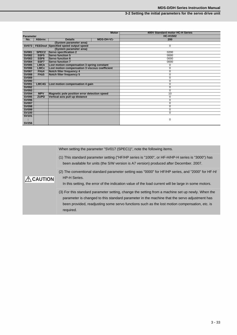
3 - 33
MDS-D/DH Series Instruction Manual
3-2 Setting the initial parameters for the servo drive unit
MotorParameter
400V Standard motor HC-H SeriesHC-H1502
No. Abbrev. Details MDS-DH-V1- 200(System parameter area)
SV073 FEEDout Specified speed output speed 0(System parameter area)
SV081 SPEC2 Servo specification 2 0200SV082 SSF5 Servo function 5 0000SV083 SSF6 Servo function 6 0000SV084 SSF7 Servo function 7 0000SV085 LMCk Lost motion compensation 3 spring constant 0SV086 LMCc Lost motion compensation 3 viscous coefficient 0SV087 FHz4 Notch filter frequency 4 0SV088 FHz5 Notch filter frequency 5 0SV089 0SV090 0SV091 LMC4G Lost motion compensation 4 gain 0SV092 0SV093 0SV094 MPV Magnetic pole position error detection speed 10SV095 ZUPD Vertical axis pull up distance 0SV096 0SV097 0SV098 0SV099 0SV100 0SV101
:SV256
0
When setting the parameter "SV017 (SPEC1)", note the following items.
(1) This standard parameter setting ("HF/HP series is "1000", or HF-H/HP-H series is "3000") has
been available for units (the S/W version is A7 version) produced after December. 2007.
(2) The conventional standard parameter setting was "0000" for HF/HP series, and "2000" for HF-H/
HP-H Series.
In this setting, the error of the indication value of the load current will be large in some motors.
(3) For this standard parameter setting, change the setting from a machine set up newly. When the
parameter is changed to this standard parameter in the machine that the servo adjustment has
been provided, readjusting some servo functions such as the lost motion compensation, etc. is
required.
CAUTION

3 - 34
3 SetupMITSUBISHI CNC
3-2-6 Servo parameters
The parameters with "(PR)" requires the CNC to be turned OFF after the settings. Turn the power OFF and
ON to enable the parameter settings.
【#2201(PR)】 SV001 PC1 Motor side gear ratio
Set the gear ratio in the motor side when there is the gear between the servomotor's shaft and machine (ball screw, etc.). For the rotary axis, set the total deceleration (acceleration) ratio. Even if the gear ratio is within the setting range, the electronic gears may overflow and an initial parameter error (servo alarm 37) may occur. For linear servo systemSet to "1".
---Setting range---1 to 32767
【#2202(PR)】 SV002 PC2 Machine side gear ratio
Set the gear ratio in the machine side when there is the gear between the servomotor's shaft and machine (ball screw, etc.). For the rotary axis, set the total deceleration (acceleration) ratio. Even if the gear ratio is within the setting range, the electronic gears may overflow and an initial parameter error (servo alarm 37) may occur. For linear servo systemSet to "1".
---Setting range---1 to 32767
【#2203】 SV003 PGN1 Position loop gain 1
Set the position loop gain. The standard setting is "33". The higher the setting value is, the more accurately the command can be followed, and the shorter the settling time in positioning gets, however, note that a bigger shock will be applied to the machine during acceleration/deceleration. When using the SHG control, also set SV004 (PGN2) and SV057 (SHGC).
---Setting range---1 to 200 (rad/s)
【#2204】 SV004 PGN2 Position loop gain 2
When performing the SHG control, set the value of "SV003 x 8/3" to "SV004". When not using the SHG control, set to "0". Related parameters: SV003, SV057
---Setting range---0 to 999 (rad/s)
【#2205】 SV005 VGN1 Speed loop gain 1
Set the speed loop gain. The higher the setting value is, the more accurate the control will be, however, vibration tends to occur. If vibration occurs, adjust by lowering by 20 to 30%. The value should be determined to the 70 to 80% of the value at which the vibration stops. The value differs depending on servo motors. Aim at the standard value determined by the servo motor type and load inertia ratio to adjust.
---Setting range---1 to 30000

3 - 35
MDS-D/DH Series Instruction Manual
3-2 Setting the initial parameters for the servo drive unit
【#2206】 SV006 VGN2 Speed loop gain 2
Set the speed loop gain at the motor limitation speed VLMT (maximum rotation speed x 1.15) with "VCS(SV029: Speed at the change of speed loop gain)". Use this to suppress noise at high speed rotation during rapid traverse, etc. Then, the speed loop gain decreases at faster speed than the setting value of VCS. When not using, set to "0".
---Setting range----1000 to 30000
【#2207】 SV007 VIL Speed loop delay compensation
Set this when the limit cycle occurs in the full-closed loop, or overshooting occurs in positioning. The speed loop delay compensation method can be selected with SV027/bit1,0. Normally, use "Changeover type 2". Changeover type 2 controls the occurrence of overshooting by lowering the speed loop lead compensation after the position droop gets 0. When setting this parameter, make sure to set the torque offset (SV032).
---Setting range---0 to 32767
【#2208】 SV008 VIA Speed loop lead compensation
Set the gain of the speed loop integral control. Standard setting: 1364 Standard setting in the SHG control: 1900Adjust the value by increasing/decreasing this by about 100 at a time. Raise this value to improve contour tracking accuracy in high-speed cutting. Lower this value when the position droop does not stabilize (when the vibration of 10 to 20Hz occurs).
---Setting range---1 to 9999
【#2209】 SV009 IQA Current loop q axis lead compensation
Set the fixed value of each motor. Set the standard value for each motor described in the standard parameter list.
---Setting range---1 to 20480
【#2210】 SV010 IDA Current loop d axis lead compensation
Set the fixed value of each motor. Set the standard value for each motor described in the standard parameter list.
---Setting range---1 to 20480
【#2211】 SV011 IQG Current loop q axis gain
Set the fixed value of each motor. Set the standard value for each motor described in the standard parameter list.
---Setting range---1 to 8192
VGN1
VGN2
VCS VLMT
Gain
Speed
(Overspeed detection speed)

3 - 36
3 SetupMITSUBISHI CNC
【#2212】 SV012 IDG Current loop d axis gain
Set the fixed value of each motor. Set the standard value for each motor described in the standard parameter list.
---Setting range---1 to 8192
【#2213】 SV013 ILMT Current limit value
Set the current (torque) limit value in a normal operation. This is a limit value in forward run and reverse run (for linear motors:forward and reverse direction). When the standard setting value is "800", the maximum torque is determined by the specification of the motor. Set this parameter as a proportion (%) to the stall current.
---Setting range---0 - 999 (Stall current %)
【#2214】 SV014 ILMTsp Current limit value in special control
Set the current (torque) limit value in a special operation (absolute position initial setting, stopper control and etc.). This is a limit value in forward and reverse directions. Set to "800" when not using. Set this parameter as a proportion (%) to the stall current.
---Setting range---0 - 999 (Stall current %)
However, when SV084/bitB=1, the setting range is from 0 to 32767 (Stall current 0.01%).
【#2215】 SV015 FFC Acceleration rate feed forward gain
When a relative error in synchronous control is too large, set this parameter to the axis that is delaying. The standard setting is "0". The standard setting in the SHG control is "100". To adjust a relative error in acceleration/deceleration, increase the value by 50 - 100 at a time.
---Setting range---0 to 999 (%)
【#2216】 SV016 LMC1 Lost motion compensation 1
Set this parameter when the protrusion (that occurs due to the non-sensitive band by friction, torsion, backlash, etc.) at quadrant change is too large. This sets the compensation torque at quadrant change (when an axis feed direction is reversed) by the proportion (%) to the stall torque. Whether to enable the lost motion compensation and the method can be set with other parameters. Type 2: When SV027/bit9, 8=10 (Compatible with obsolete type) Set the type 2 method compensation torque. The standard setting is double the friction torque. Related parameters: SV027/bit9,8, SV033/bitF, SV039, SV040, SV041, SV082/bit2 Type 3: When SV082/bit1=1 Set the compensation torque equivalent of dynamic friction amount of the type 3 method compensation amount. The standard setting is double the dynamic friction torque. Related parameters: SV041, SV082/bit2,1, SV085, SV086 To vary compensation amount according to the direction. When SV041 (LMC2) is "0", compensate with the value of SV016 (LMC1) in both +/-directions. If you wish to change the compensation amount depending on the command direction, set this and SV041 (LMC2). (SV016: + direction, SV041: - direction. However, the directions may be opposite depending on other settings.) When "-1" is set, the compensation will not be performed in the direction of the command.
---Setting range----1 to 200 (Stall current %)
Note that when SV082/bit2 is "1", the setting range is between -1 and 20000 (Stall current 0.01%).

3 - 37
MDS-D/DH Series Instruction Manual
3-2 Setting the initial parameters for the servo drive unit
【#2217(PR)】 SV017 SPEC1 Servo specification 1
Select the servo specifications. A function is allocated to each bit. Set this in hexadecimal format.
bit F-C : spm Motor series selection
0: 200V HF, HP motor 1 1: 200V HF, HP motor 2 (Standard) 2: 400V HF-H, HP-H motor 1 3: 400V HF-H, HP-H motor 2 (Standard) 6: 200V LM-F linear motor 7: 200V direct-drive motor 8: 400V LM-F linear motor 9: 400V direct-drive motor
bit B :
Not used. Set to "0".
bit A : drvup Combined drive unit:
- For MDS-DM Series 0: Normal setting (Combined drive unit: normal) 1: Combined drive unit: one upgradeIn the following combination of the drive unit and servomotors, set to "bitA=1". MDS-DM-V3-404040 --------- HF75, HF105, HF123, HF142MDS-DM-SPV2/SPV3 --------- HF54, HF104, HF223, HF302
bit 9 :
Not used. Set to "0".
bit 8 : mp MPI scale pole number setting
0: 360 poles 1: 720 poles
bit 7 : abs Position control
These parameters are set automatically by the NC system. 0: Incremental 1: Absolute position control
bit 6-5 :
Not used. Set to "0".
bit 4 : sdir Sub side detector feedback
Set the machine side detector's installation polarity. 0: Forward polarity 1: Reverse polarity
bit 3 : vfb Speed feedback filter
0: Stop 1: Start (2250Hz)
bit 2 : seqh Ready on sequence
0: Normal 1: High-speed
bit 1 : dfbx Dual feedback control
Control the position FB signal in full closed control by the combination of a motor side detector and machine side detector. 0: Stop 1: Start Related parameters: SV051, SV052
abs
spm
mdirdfbx
vfbsdir
mp
3 - 38
3 SetupMITSUBISHI CNC
bit 0 : mdir Machine side detector feedback (for Linear/direct-drive motor)
Set the detector installation polarity in the linear servo and direct-drive motor control. 0: Forward polarity 1: Reverse polarity
【#2218(PR)】 SV018 PIT Ball screw pitch/Magnetic pole pitch
For servo motor: Set the ball screw pitch. For the rotary axis, set to "360". For direct-drive motor Set to "360". - For linear motor Set the ball screw pitch. (For LM-F series, set to "48")
---Setting range---For general motor: 1 to 32767 (mm/rev)
- For linear motor 1 to 32767 (mm)
【#2219(PR)】 SV019 RNG1 Sub side detector resolution
For semi-closed loop control Set the same value as SV020. For full-closed loop control Set the number of pulses per ball screw pitch. For direct-drive motor Set the same value as SV020. For 1000 pulse unit resolution detector, set the number of pulses in SV019 in increments of 1000 pulse (kp). In this case, make sure to set "0" to SV117. For high-accuracy binary resolution detector, set the number of pulses to four bite data of SV117 (high-order) and SV019 (low-order) in pulse (p) unit. SV117 = number of pulses / 65536 (when =0, set "-1" to SV117) SV019 = the remainder of number of "pulses / 65536" When the NC is C70 and "SV019 > 32767", set "the reminder of above - 65536 (negative number)" to "SV019".
---Setting range---When SV117 = 0, the setting range is from 0 to 32767 (kp)
When SV117≠0 M700V, M70V, M70: 0 to 65536 (p) C70: -32768 to 32767 (p)

3 - 39
MDS-D/DH Series Instruction Manual
3-2 Setting the initial parameters for the servo drive unit
【#2220(PR)】 SV020 RNG2 Main side detector resolution
Set the number of pulses per revolution of the motor side detector. OSA18 (-A48) (260,000 p/rev) ----------- SV020 = 260 OSA105 (-A51) (1,000,000 p/rev) ------- SV020 = 1000 OSA166 (-A74(N)) (16,000,000 p/rev) ----- SV020 = 16000 For linear motor Set the number of pulses of the detector per magnetic pole pitch with SV118. For direct-drive motor Set the number of pulses per revolution of the motor side detector. For 1000 pulse unit resolution detector, set the number of pulses to SV020 in increments of 1000 pulse(kp). In this case, make sure to set SV118 to "0". For high-accuracy binary resolution detector, set the number of pulses to four bite data of SV118 (high-order) and SV020 (low-order) in pulse(p) unit. SV118 = number of pulses / 65536 (when =0, set "-1" to SV118) SV019 = the remainder of "number of pulses / 65536" When the NC is C70 and "SV020 > 32767", set "the reminder of above - 65536 (negative number)" to "SV020".
---Setting range---When SV118 = 0, the setting range is from 0 to 32767 (kp)
When SV118≠0 For M700V,M70V,M70: 0 to 65536 (p) For C70: -32768 to 32767 (p)
【#2221】 SV021 OLT Overload detection time constant
Normally, set to "60". (For machine tool builder adjustment.) Related parameters: SV022
---Setting range---1 to 999 (s)
【#2222】 SV022 OLL Overload detection level
Set the "Overload 1" (Alarm 50) current detection level as percentage to the stall current. Normally set this parameter to "150". (For machine tool builder adjustment.) Related parameters: SV021
---Setting range---110 to 500 (Stall current %)
【#2223】 SV023 OD1 Excessive error detection width during servo ON
Set the excessive error detection width in servo ON. When set to "0", the excessive error alarm detection will be ignored, so do not set to "0".<Standard setting value> OD1=OD2= (Rapid traverse rate [mm/min]) / (60×PGN1) / 2 [mm] Related parameters: SV026
---Setting range---0 to 32767 (mm)
However, when SV084/bitC=1, the setting range is from 0 to 32767 (μm). (Only for MDS-D/DH and MDS-DM)
【#2224】 SV024 INP In-position detection width
Set the in-position detection width. Set the positioning accuracy required for the machine. The lower the setting is, the higher the positioning accuracy will be. However the cycle time (settling time) becomes longer. The standard setting value is "50".
---Setting range---0 to 32767 (μm)

3 - 40
3 SetupMITSUBISHI CNC
【#2225(PR)】 SV025 MTYP Motor/Detector type
Set the position detector type, speed detector type and motor type. The setting value is a four-digit hex (HEX).
bit F-C : pen(HEX-4) Position detector
Semi-closed loop control by general motor pen=2 Full-closed loop control by general motor - Ball screw end detector (OSA105ET2, OSA166ET2(N)) pen=6 - For serial signal output rotary scale (including MDS-B-HR) pen=6 - For rectangular wave signal output scale pen=8 - For serial signal output linear scale (including MDS-B-HR and MPI scale) pen=A - For speed command synchronization control Primary axis pen=A Secondary axis pen=D For linear motor pen=A For direct-drive motor pen=2
bit B-8 : ent(HEX-3) Speed detector
For general motor ent=2For linear motor ent=AFor direct-drive motor ent=2
mtypentpen
1234HEX-

3 - 41
MDS-D/DH Series Instruction Manual
3-2 Setting the initial parameters for the servo drive unit
bit 7-0 : mtyp(HEX-2,1) Motor type
Set the motor type. Set this with SV017/bitF-C. For SV017/bitF-C = 1 (200V standard motor series) HF75 : 01h HP54 : 11h HF-KP13 : E9h (Note 3) HF105 : 02h HP104 : 12h HF-KP23 : EAh HF54 : 03h HP154 : 13h HF-KP43 : EBh HF104 : 04h HP224 : 1Bh HF-KP73 : ECh HF154 : 05h, 0Fh (Note 1) HP204 : 14h HF224 : 06h HP354 : 15h HF204 : 07h HP454 : 16h HF354 : 08h HP704 : 17h HF123 : 24h HP903 : 18h HF223 : 26h, 2Dh (Note 2) HP1103 : 19h HF303 : 28h HF453 : 09h HF703 : 0Ah HF903 : 0Bh HF142 : 25h HF302 : 27h, 2Eh (Note 2) (Note 1) When MDS-DM-V3 is connected (Note 2) When MDS-DM-V3 M/S axis is connected (Note 3) MDS-D-SVJ3 only For SV017/bitF-C = 3 (400V standard motor series) HF-H75 : 01h, HP-H54 : 11h HF-H105 : 02h, HP-H104 : 12h HF-H54 : 03h, HP-H154 : 13h HF-H104 : 04h, HP-H204 : 14h HF-H154 : 05h, HP-H354 : 15h HP-H454 : 16h HF-H204 : 07h, HP-H704 : 17h HF-H354 : 08h, HP-H903 : 18h HF-H453 : 09h, HP-H1103: 19h HF-H703 : 0Ah HF-H903 : 0Bh, HP-H224 : 1Bh HC-H1502: B9h For linear motor and direct-drive motor, follow the settings stated in respective materials.
【#2226】 SV026 OD2 Excessive error detection width during servo OFF
Set the excessive error detection width during servo OFF. When set to "0", the excessive error alarm detection will be ignored, so do not set to "0". <Standard setting value> OD1=OD2= (Rapid traverse rate [mm/min]) / (60×PGN1) / 2 [mm] Related parameters: SV023
---Setting range---0 to 32767 (mm)
However, when SV084/bitC=1, the setting range is from 0 to 32767 (μm). (Only for MDS-D/DH and MDS-DM)

3 - 42
3 SetupMITSUBISHI CNC
【#2227】 SV027 SSF1 Servo function 1
Select the servo functions. A function is assigned to each bit. Set this in hexadecimal format.
bit F :
Not used. Set to "0".
bit E : zrn2
Set to "1". (Fixed)
bit D :
Not used. Set to "0".
bit C :
Not used. Set to "0".
bit B-A : ovs Overshooting compensation
Set this if overshooting occurs during positioning. bitB,A= 00: Compensation stop 01: Setting prohibited 10: Setting prohibited 11: Type 3Set the compensation amount in SV031(OVS1) and SV042(OVS2). Related parameters: SV031, SV042, SV034/bitF-C
bit 9-8 : lmc Lost motion compensation type
Set this parameter when the protrusion at quadrant change is too large.Type 2 has an obsolete type compatible control. bit9,8= 00: Compensation stop 01: Setting prohibited 10: Type 2 11: Setting prohibitedSet the compensation amount in SV016(LMC1) and SV041(LMC2).(Note) When "SV082/bit1=1", the lost motion compensation type 3 will be selected regardless of this setting.
bit 7 :
Not used. Set to "0".
bit 6 :
Not used. Set to "0".
bit 5-4 : vfct Jitter compensation pulse number
Suppress vibration by machine backlash when axis stops. bit5,4= 00: Disable 01: 1 pulse 10: 2 pulse 11: 3 pulses

3 - 43
MDS-D/DH Series Instruction Manual
3-2 Setting the initial parameters for the servo drive unit
bit 3 :
Not used. Set to "0".
bit 2 :
Not used. Set to "0".
bit 1-0 : vcnt Speed loop delay compensation changeover type selection
Normally, use "Changeover type 2". bit1,0= 00: Disable 01: Changeover type 1 10: Changeover type 2 11: Setting prohibited Related parameters: SV007
【#2228(PR)】 SV028 MSFT Magnetic pole shift amount (for linear/direct-drive motor)
Set this parameter to adjust the motor magnetic pole position and detector's installation phase when using linear motors or direct-drive motors. During the DC excitation of the initial setup (SV034/bit4=1), set the same value displayed in "AFLT gain" on the NC monitor screen. Related parameters: SV034/bit4, SV061, SV062, SV063 For general motor: Not used. Set to "0".
---Setting range----18000 to 18000 (Mechanical angle 0.01°)
【#2229】 SV029 VCS Speed at the change of speed loop gain
Noise at high speed rotation including rapid traverse can be reduced by lowering the speed loop gain at high speeds.Set the speed at which the speed loop gain changes. Use this with SV006 (VGN2). When not using, set to "0".
---Setting range---0 to 9999 (r/min)
【#2230】 SV030 IVC Voltage non-sensitive band compensation
When 100% is set, the voltage reduction amount equivalent to the logical non-energization in the PWM control will be compensated. When "0" is set, 100% compensation will be performed. Adjust in increments of 10% from the default value of 100%.If increased too much, vibration or vibration noise may be generated.
---Setting range---0 to 255 (%)

3 - 44
3 SetupMITSUBISHI CNC
【#2231】 SV031 OVS1 Overshooting compensation 1
This compensates the motor torque when overshooting occurs during positioning. This is valid only when the overshooting compensation (SV027/bitB,A) is selected. Type 3 SV027(SSF1)/bitB,A=11 Set the compensation amount based on the motor stall current. Observing positioning droop waveform, increase in increments of 1% and find the value where overshooting does not occur. To vary compensation amount depending on the direction. When SV042 (OVS2) is "0", change the SV031 (OVS1) value in both of the +/- directions to compensate. To vary the compensation amount depending on the command direction, set this and SV042 (OVS2). (SV031: + direction, SV042: - direction. However, the directions may be opposite depending on other settings.) When "-1" is set, the compensation will not be performed in the direction of the command. Related parameters: SV027/bitB,A, SV034/bitF-C, SV042, SV082/bit2
---Setting range----1 to 100 (Stall current %)
Note that the range will be "-1 - 10000" (Stall current 0.01%) when SV082/bit2 is "1".
【#2232】 SV032 TOF Torque offset
Set the unbalance torque on vertical axis and inclined axis. When the vertical axis pull up function is enabled, the pull up compensation direction is determined by this parameter's sign. When set to "0", the vertical axis pull up will not be executed. This can be used for speed loop delay compensation and collision detection function. To use load inertia estimation function (drive monitor display), set this parameter, friction torque (SV045) and load inertia display enabling flag(SV035/bitF). Related parameters: SV007, SV033/bitE, SV059
---Setting range----100 to 100 (Stall current %)

3 - 45
MDS-D/DH Series Instruction Manual
3-2 Setting the initial parameters for the servo drive unit
【#2233】 SV033 SSF2 Servo function 2
Select the servo functions. A function is assigned to each bit. Set this in hexadecimal format.
bit F : lmc2a Lost motion compensation 2 timing
0: Normal 1: Change
bit E : zup Vertical axis pull up function
0: Stop 1: Enable Related parameters: SV032, SV095
bit D : rps Speed setting increment
Change the setting units of the specified speed signal output speed (SV073) and safety observation safety speed (SV238). 0: mm/min 1: 100mm/min Related parameters: SV073, SV238
bit C-8 :
Not used. Set to "0".
bit 7-5 : nfd2 Depth of Notch filter 2
Set the depth of Notch filter 2 (SV046). bit7,6,5= 000: -∞ 001: -18.1[dB] 010: -12.0[dB] 011: -8.5[dB] 100: -6.0[dB] 101: -4.1[dB] 110: -2.5[dB] 111: -1.2[dB]
bit 4 : fhz3 Notch filter 3
0: Stop 1: Start (1,125Hz)
bit 3-1 : nfd1 Depth of Notch filter 1
Set the depth of Notch filter 1 (SV038). bit3,2,1= 000: -∞ 001: -18.1[dB] 010: -12.0[dB] 011: -8.5[dB] 100: -6.0[dB] 101: -4.1[dB] 110: -2.5[dB] 111: -1.2[dB]
bit 0 :
Not used. Set to "0".
zup
nfd1nf3nfd2rps
lmc2a

3 - 46
3 SetupMITSUBISHI CNC
【#2234】 SV034 SSF3 Servo function 3
Select the servo functions. A function is assigned to each bit. Set this in hexadecimal format.
bit F-C: ovsn Overshooting compensation type 3 Non-sensitive band
Set the non-sensitive band of the model position droop overshooting amount in increments of 2μm. In the feed forward control, set the non-sensitive band of the model position droop and ignore the overshooting of the model. 0 : 0 μm, 1: 2 μm, 2: 4μm,---, E : 28 μm, F: 30μm
bit B-8 : linN The number of parallel connections when using linear motors (for linear)
Set to"2" to perform 1 amplifier 2 motor control by linear servo.
bit 7-5 :
Not used. Set to "0".
bit 4 : dcd (linear/direct-drive motor)
0: Normal setting 1: DC excitation mode Related parameters: SV061, SV062, SV063
bit 3 :
Not used. Set to "0".
bit 2 : mohn Thermistor temperature detection (linear/direct-drive motor)
0: Normal setting 1: Disable
bit 1 : has HAS control
This stabilizes the speed overshooting by torque saturation phenomenon. 0: Normal setting 1: Enable Related parameters: SV084/bitF
bit 0 :
Not used. Set to "0".
has2
ovsn
mohndcdlinN

3 - 47
MDS-D/DH Series Instruction Manual
3-2 Setting the initial parameters for the servo drive unit
【#2235】 SV035 SSF4 Servo function 4
Select the servo functions. A function is assigned to each bit. Set this in hexadecimal format.
bit F : clt Inertia ratio display
0: Setting for normal use 1: Display the total inertia ratio estimated at acceleration/deceleration at the inertia ratio on the servo monitor screen To display it on the screen, set an imbalance torque and friction torque to both SV032 and SV045 and repeat acceleration/deceleration operations for several times.
bit E-C: clG1 G1 Collision detection level
Set the collision detection level in the collision detection method 1 during cutting feed (G1) in multiples of that of rapid traverse (G0). When set to "0", detection of collision detection method 1 during cutting feed will be ignored. G1 Collision detection level = G0 collision detection level (SV060) × clG1
bit B : cl2n Collision detection method 2
0: Enable 1: Disable
bit A :
Not used. Set to "0".
bit 9-8 : cltq Retract torque in collision detection
Set the retract torque in collision detection using the ratio of motor's maximum torque. bit9,8= 00: 100% 01: 90% 10: 80%(Standard) 11: 70%
bit 7 : ckab No signal detection 2
Set this to use rectangular wave output linear scale. This enables the detection of No signal 2 (alarm 21). 0: Disable 1: Enable
bit 6-0 :
Not used. Set to "0".
cltqckab
cl2nclG1clt

3 - 48
3 SetupMITSUBISHI CNC
【#2236(PR)】 SV036 PTYP Power supply type/ Regenerative resistor type
MDS-D/DH Series: Power supply type
When connecting a power supply unit, set a code for each power supply unit.
bit F-C : amp
Not used. Set to "0".
bit B-8 : rtyp
Not used. Set to "0".
bit 7-0 : ptyp External emergency stop setting
When the emergency stop input signal of the power supply unit is "disabled" Power supply unit is not connected : 00 MDS-D-CV-37 / MDS-DH-CV-37 : 04 MDS-D-CV-75 / MDS-DH-CV-75 : 08 MDS-D-CV-110 / MDS-DH-CV-110 : 11 MDS-D-CV-185 / MDS-DH-CV-185 : 19 MDS-D-CV-300 / MDS-DH-CV-300 : 30 MDS-D-CV-370 / MDS-DH-CV-370 : 37 MDS-D-CV-450 / MDS-DH-CV-450 : 45 MDS-D-CV-550 / MDS-DH-CV-550 : 55 MDS-DH-CV-750 : 75 When the emergency stop input signal of the power supply unit is "enabled"(Note) Set the power supply rotary switch to "4". Power supply unit is not connected : 00MDS-D-CV-37 / MDS-DH-CV-37 : 44 MDS-D-CV-75 / MDS-DH-CV-75 : 48 MDS-D-CV-110 / MDS-DH-CV-110 : 51 MDS-D-CV-185 / MDS-DH-CV-185 : 59 MDS-D-CV-300 / MDS-DH-CV-300 : 70 MDS-D-CV-370 / MDS-DH-CV-370 : 77 MDS-D-CV-450 / MDS-DH-CV-450 : 85 MDS-D-CV-550 / MDS-DH-CV-550 : 95 MDS-DH-CV-750 : B5
MDS-DM-SPV Series
Not used. Set to "0000". External emergency stop power supply type is set by spindle parameter (SP032).
ptyprtypamp

3 - 49
MDS-D/DH Series Instruction Manual
3-2 Setting the initial parameters for the servo drive unit
MDS-D-SVJ3 Series: Regenerative resistor type
Set the regenerative resistor type.
bit F-8 : amp(bit F-C) / rtyp(bit B-8)
Resistor built-in drive unit : 10Setting prohibited : 11MR-RB032 : 12MR-RB12 or GZG200W39OHMK : 13MR-RB32 or GZG200W120OHMK 3 units connected in parallel : 14MR-RB30 or GZG200W39OHMK 3 units connected in parallel : 15MR-RB50 or GZG300W39OHMK 3 units connected in parallel : 16MR-RB31 or GZG200W20OHMK 3 units connected in parallel : 17MR-RB51 or GZG300W20OHMK 3 units connected in parallel : 18Setting prohibited : 19-1F Setting prohibited : 20-23FCUA-RB22 : 24FCUA-RB37 : 25FCUA-RB55 : 26Setting prohibited : 27-28R-UNIT2 : 29Setting prohibited : 2A-2CFCUA-RB75/2 2 units connected in parallel : 2DFCUA-RB55 2 units connected in parallel : 2ESetting prohibited : 2F
bit 7-4 : emgx External emergency stop function
Set the external emergency stop function. (Do not set a value other than specified.) 0: Disable 4: Enable
bit 3-0 :
Not used. Set to "0".
【#2237】 SV037 JL Load inertia scale
Set the motor axis conversion total load inertia including motor itself in proportion to the motor inertia. SV037(JL)=(Jm+Jl)/Jm×100 Jm: Motor inertia Jl: Motor axis conversion load inertia For linear motor, set the gross mass of the moving sections in kg unit. <<Drive monitor load inertia ratio display>>Set SV035/bitF=1 and imbalance torque and friction torque to both SV032 and SV045, and then repeat acceleration/deceleration for several times.
---Setting range---For general motor: 0 to 5000 (%)
For linear motor 0 to 5000 (kg)
emgxrtypamp
00 0 0

3 - 50
3 SetupMITSUBISHI CNC
【#2238】 SV038 FHz1 Notch filter frequency 1
Set the vibration frequency to suppress when machine vibration occurs. (Normally, do not set 80 or less.)Set to "0" when not using. Related parameters: SV033/bit3-1, SV115
---Setting range---0 to 2250 (Hz)
【#2239】 SV039 LMCD Lost motion compensation timing
Set this when the timing of lost motion compensation type 2 does not match. Adjust increments of 10 at a time.
---Setting range---0 to 2000 (ms)
【#2240】 SV040 LMCT Lost motion compensation non-sensitive band
Set the non-sensitive band of the lost motion compensation in the feed forward control. When "0" is set, 2μm is the actual value to be set. Adjust increments of 1μm.
---Setting range---0 to 255 (μm)
【#2241】 SV041 LMC2 Lost motion compensation 2
Set this with SV016 (LMC1) only when you wish to vary the lost motion compensation amount depending on the command directions. Normally, set to "0".
---Setting range----1 to 200 (Stall current %)
Note that when SV082/bit2 is "1", the setting range is between -1 and 20000 (Stall current 0.01%).
【#2242】 SV042 OVS2 Overshooting compensation 2
Set this with SV031 (OVS1) only when you wish to vary the overshooting compensation amount depending on the command directions. Normally, set to "0".
---Setting range----1 to 100 (Stall current %)
Note that when SV082/bit2 is "1", the setting range is between -1 and 10000 (Stall current 0.01%).
【#2243】 SV043 OBS1 Disturbance observer filter frequency
Set the disturbance observer filter band. Normally, set to "100". Setting values of 49 or less is equal to "0" setting. To use the disturbance observer, also set SV037 (JL) and SV044 (OBS2). When disturbance observer related parameters are changed, lost motion compensation needs to be readjusted. Set to "0" when not using.
---Setting range---0 to 1000 (rad/s)

3 - 51
MDS-D/DH Series Instruction Manual
3-2 Setting the initial parameters for the servo drive unit
【#2244】 SV044 OBS2 Disturbance observer gain
Set the disturbance observer gain. The standard setting is "100 to 300". To use the disturbance observer, also set SV037 (JL) and SV043 (OBS1). When disturbance observer related parameters are changed, lost motion compensation needs to be readjusted. Set to "0" when not using.
---Setting range---0 to 500 (%)
【#2245】 SV045 TRUB Friction torque
Set the frictional torque when using the collision detection function. To use load inertia estimation function (drive monitor display), set this parameter, imbalance torque (SV032) and load inertia display enabling flag (SV035/bitF).
---Setting range---0 to 255 (Stall current %)
【#2246】 SV046 FHz2 Notch filter frequency 2
Set the vibration frequency to suppress when machine vibration occurs. (Normally, do not set 80 or less.)Set to "0" when not using. Related parameters: SV033/bit7-5, SV115
---Setting range---0 to 2250 (Hz)
【#2247】 SV047 EC Inductive voltage compensation gain
Set the inductive voltage compensation gain. Standard setting value is "100". If the current FB peak exceeds the current command peak, lower the gain.
---Setting range---0 to 200 (%)
【#2248】 SV048 EMGrt Vertical axis drop prevention time
Input the time required to prevent the vertical axis from dropping by delaying READY OFF until the brake works at an emergency stop. Increase in increments of 100ms at a time, find and set the value where the axis does not drop. When using a motor with a break of HF(-H) Series or HP(-H) Series, set to "200ms" as a standard. When the pull up function is enabled (SV033/bitE=1), the pull up is established during the drop prevention time. Related parameters: SV033/bitE, SV055, SV056
---Setting range---0 to 20000 (ms)
【#2249】 SV049 PGN1sp Position loop gain 1 in spindle synchronous control
Set the position loop gain during spindle synchronization control (synchronous tapping and synchronization control with spindle C-axis). Set the same value as that of the position loop gain for spindle synchronous tapping control. When performing the SHG control, set this parameter with SV050 (PGN2sp) and SV058 (SHGCsp). When changing the value, change the value of "#2017 tap_g Axis servo gain".
---Setting range---1 to 200 (rad/s)
3 - 52
3 SetupMITSUBISHI CNC
【#2250】 SV050 PGN2sp Position loop gain 2 in spindle synchronous control
When using SHG control during spindle synchronous control (synchronous tapping and synchronization control with spindle C-axis), set this parameter with SV049 (PGN1sp) and SV058 (SHGCsp). Make sure to set the value 8/3 times that of SV049. When not using the SHG control, set to "0".
---Setting range---0 to 999 (rad/s)
【#2251】 SV051 DFBT Dual feedback control time constant
Set the control time constant in dual feed back. When "0" is set, it operates at 1ms. The higher the time constant is, the closer it gets to the semi-closed control, so the limit of the position loop gain will be raised. For linear servo/direct-drive motor system Not used. Set to "0". Related parameters: SV017/bit1, SV052
---Setting range---0 to 9999 (ms)
【#2252】 SV052 DFBN Dual feedback control non-sensitive band
Set the non-sensitive band in the dual feedback control. Normally, set to "0". For linear servo/direct-drive motor system Not used. Set to "0". Related parameters: SV017/bit1, SV052
---Setting range---0 to 9999 (μm)
【#2253】 SV053 OD3 Excessive error detection width in special control
Set the excessive error detection width when servo ON in a special control (initial absolute position setting, stopper control and etc.). When "0" is set, excessive error detection will not be performed when servo ON during a special control.
---Setting range---0 to 32767 (mm)
However, when SV084/bitC=1, the setting range is from 0 to 32767 (μm). (Only for MDS-D/DH and MDS-DM)
【#2254】 SV054 ORE Overrun detection width in closed loop control
Set the overrun detection width in the full-closed loop control. When the gap between the motor side detector and the linear scale (machine side detector) exceeds the value set by this parameter, it will be judged as overrun and "Alarm 43" will be detected. When "-1" is set, the alarm detection will not be performed. When "0" is set, overrun will be detected with a 2mm width. For linear servo/direct-drive motor system Not used. Set to "0".
---Setting range---MDS-D/DH, MDS-DM:-1 to 32767 (mm)
However, when SV084/bitD=1, the setting range is from -1 to 32767 (μm). MDS-D-SVJ3:-1 to 127 (mm)

3 - 53
MDS-D/DH Series Instruction Manual
3-2 Setting the initial parameters for the servo drive unit
【#2255】 SV055 EMGx Max. gate off delay time after emergency stop
Set the time required between an emergency stop and forced READY OFF. Set the maximum value "+ 100ms" of the SV056 setting value of the servo drive unit electrified by the same power supply unit. When executing the vertical axis drop prevention, the gate off will be delayed for the length of time set at SV048 even when SV055's is smaller than that of SV048. Related parameters: SV048, SV056
---Setting range---0 to 20000 (ms)
【#2256】 SV056 EMGt Deceleration time constant at emergency stop
Set the time constant used for the deceleration control at emergency stop. Set the time required to stop from rapid traverse rate (rapid). The standard setting value is EMGt<=G0tL*0.9.However, note that the standard setting value differs from the above-mentioned value when the setting value of "#2003:smgst Acceleration and deceleration modes bit 3-0:Rapid traverse acceleration/deceleration type" is 8 or F. Refer to Instruction Manual of the drive unit (section "Deceleration control") for details.When the axis is used in the synchronous control, set the same value with minus sign to both axes. If one of the axes switches to dynamic brake by an alarm during deceleration control, another axis will also switch. Related parameters: SV048, SV055
---Setting range----20000 to 20000 (ms)
【#2257】 SV057 SHGC SHG control gain
When performing the SHG control, set to SV003(PGN1)*6. When not using the SHG control, set to "0". Related parameters: SV003, SV004
---Setting range---0 to 1200 (rad/s)
【#2258】 SV058 SHGCsp SHG control gain in spindle synchronous control
When using SHG control during spindle synchronization control (synchronous tapping and synchronous control with spindle C-axis), set this parameter with SV049 (PGN1sp) and SV050 (PGN2sp). Make sure to set the value 6 times that of SV049. When not using the SHG control, set to "0".
---Setting range---0 to 1200 (rad/s)
【#2259】 SV059 TCNV Collision detection torque estimated gain
Set the torque estimated gain when using the collision detection function.The standard setting value is the same as the load inertia ratio (SV037 setting value) including motor inertia. Set to "0" when not using the collision detection function. Related parameters: SV032, SV035/bitF-8, SV037, SV045, SV060 <<Drive monitor load inertia ratio display>>Set SV035/bitF=1 and imbalance torque and friction torque to both SV032 and SV045, and then repeat acceleration/deceleration for several times.
---Setting range---For general motor: 0 to 5000 (%)
For linear motor: 0 to 5000 (kg)

3 - 54
3 SetupMITSUBISHI CNC
【#2260】 SV060 TLMT Collision detection level
When using the collision detection function, set the collision detection level at the G0 feeding. When "0" is set, none of the collision detection function will work. Related parameters: SV032, SV035/bitF-8, SV037, SV045, SV059
---Setting range---0 to 999 (Stall current %)
【#2261】 SV061 DA1NO D/A output ch1 data No. / Initial DC excitation level
Input the data number you wish to output to the D/A output channel 1. When using the 2-axis drive unit, set "-1" to the axis that the data will not be output. When the DC excitation is running (SV034/bit4=1): Use this when the DC excitation is running (SV034/bit4=1) to adjust the initial magnetic pole position (when measuring the magnetic pole shift amount) for linear motor and direct-drive motor. Set the initial excitation level in DC excitation control. Set 5% as standard. Related parameters: SV062, SV063
---Setting range----1 to 127
When the DC excitation is running (SV034/bit4=1): 0 to 100 (Stall current %)
【#2262】 SV062 DA2NO D/A output ch2 data No. / Final DC excitation level
Input the data number you wish to output to the D/A output channel 2. When using the 2-axis drive unit, set "-1" to the axis that the data will not be output. When the DC excitation is running (SV034/bit4=1): Use this when the DC excitation is running (SV034/bit4=1) to adjust the initial magnetic pole position (when measuring the magnetic pole shift amount) for linear motor and direct-drive motor. Set the final excitation level in DC excitation control. Set 5% as standard. When the magnetic pole shift amount measurement value is unsteady, adjust the value in increments of 5%. Related parameters: SV061, SV063
---Setting range----1 to 127
When the DC excitation is running (SV034/bit4=1): 0 to 100 (Stall current %)
【#2263】 SV063 DA1MPY D/A output ch1 output scale / Initial DC excitation time
Set output scale of the D/A output channel 1 in increment of 1/100. When "0" is set, the magnification is the same as when "100" is set. When the DC excitation is running (SV034/bit4=1): Use this when the DC excitation is running (SV034/bit4=1) to adjust the initial magnetic pole position (when measuring the magnetic pole shift amount) for linear motor and direct-drive motor. Set the initial excitation time in DC excitation control. Set 500ms as standard. When the magnetic pole shift amount measurement value is unsteady, adjust the value in increments of 500ms. Related parameters: SV061, SV062
---Setting range----32768 to 32767 (1/100-fold)
When the DC excitation is running (SV034/bit4=1): 0 to 10000 (ms)
【#2264】 SV064 DA2MPY D/A output ch2 output scale
Set output scale of the D/A output channel 2 in increment of 1/100. When "0" is set, the magnification is the same as when "100" is set.
---Setting range----32768 to 32767 (1/100-fold)

3 - 55
MDS-D/DH Series Instruction Manual
3-2 Setting the initial parameters for the servo drive unit
【#2265】 SV065 TLC Machine end compensation gain
The shape of the machine end is compensated by compensating the spring effect from the machine end to the motor end. Set the machine end compensation gain. Measure the error amount by roundness measurement and estimate the setting value by the following formula. Compensation amount (μm) = Command speed F(mm/min)2 * SV065 / (Radius R(mm) * SV003 * 16,200,000) Set to "0" when not using.
---Setting range----30000 to 30000 (Acceleration ratio 0.1%)
【#2266-2272】 SV066 - SV072
This parameter is set automatically by the NC system.
【#2273(PR)】 SV073 FEEDout Specified speed output speed
Set the specified speed. Also set SV082/bit9,8 to output digital signal.
---Setting range---0 to 32767 (r/min)
However, when SV033/bitD=1, the setting range is from 0 to 32767 (100mm/min).
【#2274-2280】 SV074 - SV080
This parameter is set automatically by the NC system.
【#2281(PR)】 SV081 SPEC2 Servo specification 2
Select the servo functions. A function is assigned to each bit. Set this in hexadecimal format.
bit F-A :
Not used. Set to "0".
bit 9 : npg Earth fault detection
0: Disable 1: Enable (standard) Set "0" and it is constantly "Enable" for MDS-D-SVJ3 Series.
bit 8 :
Not used. Set to "0".
bit 7 : szchk Distance-coded reference scale reference mark
0: Check at 4 points (standard) 1: Check at 3 points
bit 6-4 :
Not used. Set to "0".
bit 3 : absc Distance-coded reference scale
0: Disable 1: Enable
bit 2-0 :
Not used. Set to "0".
abscszchknpg

3 - 56
3 SetupMITSUBISHI CNC
【#2282】 SV082 SSF5 Servo function 5
Select the servo functions. A function is assigned to each bit. Set this in hexadecimal format.
bit F-C : dis Digital signal input selection
0: No signal 1: Safety observation function door state signal 2: Battery box voltage drop warning (It is not available for MDS-D-SVJ3 Series.) 3 to F: Setting prohibited
bit B-A : dos3 Digital signal output 3 selection
bitB,A= 00: Disable 01: Setting prohibited 10: Contactor control signal output (For MDS-D-SVJ3) 11: Setting prohibited
bit 9-8 : dos2 Digital signal output 2 selection
bit9,8= 00: Disable 01: Specified speed output 10: Setting prohibited 11: Setting prohibited
bit 7-3 :
Not used. Set to "0".
bit 2 : ccu Lost motion overshoot compensation compensation amount setting increment
0: Stall current % 1: Stall current 0.01%
bit 1 : lmc3 Lost motion compensation type 3
Set this when protrusion at a quadrant change is too big. 0: Stop 1: Start Related parameters: SV016, SV041, SV085, SV086
bit 0 :
Not used. Set to "0".
lmc3ccudos2
disdos3
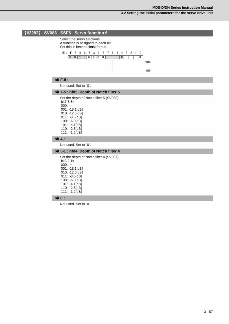
3 - 57
MDS-D/DH Series Instruction Manual
3-2 Setting the initial parameters for the servo drive unit
【#2283】 SV083 SSF6 Servo function 6
Select the servo functions. A function is assigned to each bit. Set this in hexadecimal format.
bit F-8 :
Not used. Set to "0".
bit 7-5 : nfd5 Depth of Notch filter 5
Set the depth of Notch filter 5 (SV088). bit7,6,5= 000: -∞ 001: -18.1[dB] 010: -12.0[dB] 011: -8.5[dB] 100: -6.0[dB] 101: -4.1[dB] 110: -2.5[dB] 111: -1.2[dB]
bit 4 :
Not used. Set to "0".
bit 3-1 : nfd4 Depth of Notch filter 4
Set the depth of Notch filter 4 (SV087). bit3,2,1= 000: -∞ 001: -18.1[dB] 010: -12.0[dB] 011: -8.5[dB] 100: -6.0[dB] 101: -4.1[dB] 110: -2.5[dB] 111: -1.2[dB]
bit 0 :
Not used. Set to "0".
nfd4
nfd5

3 - 58
3 SetupMITSUBISHI CNC
【#2284】 SV084 SSF7 Servo function 7
Select the servo functions. A function is assigned to each bit. Set this in hexadecimal format.
bit F : h2c HAS control cancel amount
0: 1/4 (standard) 1: 1/2 Related parameters: SV034/bit1
bit E :
Not used. Set to "0".
bit D : oru Overrun detection width unit (for MDS-D/DH and MDS-DM)
0: mm (normal setting) 1: μm It is not available for MDS-D-SVJ3 Series.
bit C : odu Excessive error detection width unit (for MDS-D/DH and MDS-DM)
0: mm (normal setting) 1: μm It is not available for MDS-D-SVJ3 Series.
bit B : ilm2u Current limit value (SV014) in special control setting unit
0: Stall current % (normal setting) 1: Stall current 0.01%
bit A-1 :
Not used. Set to "0".
bit 0 : irms Motor current display
0: Motor q axis current display (normal) 1: Motor effective current display
【#2285】 SV085 LMCk Lost motion compensation 3 spring constant
Set the machine system's spring constant when selecting lost motion compensation type 3. When not using, set to "0". Related parameters: SV016, SV041, SV082/bit2,1, SV086
---Setting range---0 to 32767 (0.01%/μm)
【#2286】 SV086 LMCc Lost motion compensation 3 viscous coefficient
Set the machine system's viscous coefficient when selecting lost motion compensation type 3. When not using, set to "0". Related parameters: SV016, SV041, SV082/bit2,1, SV086
---Setting range---0 to 32767 (0.01%•s/mm)
irms
h2c
ilm2uoduoru

3 - 59
MDS-D/DH Series Instruction Manual
3-2 Setting the initial parameters for the servo drive unit
【#2287】 SV087 FHz4 Notch filter frequency 4
Set the vibration frequency to suppress when machine vibration occurs. (Normally, do not set 80 or less.)Set to "0" when not using. Related parameters: SV083/bit3-1, SV115
---Setting range---0 to 2250 (Hz)
【#2288】 SV088 FHz5 Notch filter frequency 5
Set the vibration frequency to suppress when machine vibration occurs. (Normally, do not set 80 or less.)Set to "0" when not using. Related parameters: SV083/bit7-5, SV115
---Setting range---0 to 2250 (Hz)
【#2289】 SV089
Not used. Set to "0".
【#2290】 SV090
Not used. Set to "0".
【#2291】 SV091 LMC4G Lost motion compensation 4 gain
Use this with LMC compensation type 3. As the delay in path tracking is monitored and compensated, the delay in path tracking will be minimized even if machine friction amount changes by aging. Use the lost motion compensation amount (SV016) * 5 (10% of the dynamic friction torque) as the target. The higher the setting value is, the more accurate the quadrant change be; however, the more likely vibrations occur.
---Setting range---0 to 20000 (Stall current 0.01%)
【#2292】 SV092
Not used. Set to "0".
【#2293】 SV093
Not used. Set to "0".

3 - 60
3 SetupMITSUBISHI CNC
【#2294】 SV094 MPV Magnetic pole position error detection speed
The magnetic pole position detection function monitors the command speed and motor speed at the position command stop and detects the magnetic pole position error alarm (3E) if any. Set the error detection level for the command speed and motor speed at the position command stop. Be aware when setting the parameter as the setting units for general motors and linear motors are different. <<For general motor>> When the command speed error detection level is set to "0", the magnetic pole position error (3E) is detected at 10r/min. Set "10" as standard. This detects the magnetic pole position error (3E) when the motor rotation speed is 100r/min and more. <<For linear motor>> When the command motor speed level is set to "0", the magnetic pole position error (3E) is detected at 1mm/s. Set "10" as standard. This detects the magnetic pole position error (3E) when the motor speed is 10mm/s and more.
---Setting range---0 to 31999
<<For general motor>> Ten-thousands digit, Thousands digit ----------- Command speed error detection level (10r/min)Hundreds digit, Tens digit, Ones digit ----------- Motor speed error detection level (10r/min) <<For linear motor>> Ten-thousands digit, Thousands digit ----------- Command speed error detection speed level (10r/min)Hundreds digit, Tens digit, Ones digit ----------- Motor speed error detection level (10r/min)
【#2295】 SV095 ZUPD Vertical axis pull up distance
Set this parameter to adjust the pull up distance when the vertical axis pull up function is enabled. When the pull up function is enabled and this parameter is set to "0", for a rotary motor, 8/1000 of a rotation at the motor end is internally set as the pull up distance, and for a linear motor, 80[μm] is set. Related parameters: SV032 : The pull up direction is determined. When "0" is set, pull up control is not executed. SV033/bitE : Start-up of the pull up function SV048 : Set the drop prevention time. When "0" is set, pull up control is not executed.
---Setting range---0 to 2000 (μm)
【#2296】 SV096
Not used. Set to "0".
【#2297】 SV097
Not used. Set to "0".
【#2298】 SV098
Not used. Set to "0".
【#2299】 SV099
Not used. Set to "0".
【#2300】 SV100
Not used. Set to "0".
【#2301-2312】 SV101 - SV112
Not used. Set to "0".

3 - 61
MDS-D/DH Series Instruction Manual
3-2 Setting the initial parameters for the servo drive unit
【#2313】 SV113 SSF8 Servo function 8
Select the servo functions. A function is assigned to each bit. Set this in hexadecimal format.
bit F : ssc Safety observation function
0: Stop 1: Start
bit E-0 :
Not used. Set to "0".
【#2314】 SV114 SSF9 Servo function 9
Select the servo functions. A function is assigned to each bit. Set this in hexadecimal format.
bit F-9 :
Not used. Set to "0".
bit 8 : nohis History of communication error alarm between NC and DRV (34, 36, 38, 39)
Set "1" for C70. 0: Enable 1: Disable
bit 7 : cse Command speed monitoring function
0: Normal setting 1: Enable
bit 6-0 :
Not used. Set to "0".
ssc
csenohis

3 - 62
3 SetupMITSUBISHI CNC
【#2315】 SV115 SSF10 Servo function 10
Select the servo functions. A function is assigned to each bit. Set this in hexadecimal format.
bit F : are Notch filter5 all frequencies adapted
When enabled, Notch filter5 all frequencies adaptive range is not limited regardless of SV115/bit4,5 setting. 0: Disable 1: Enable
bit E-C: dsl Notch filter frequency display
Switch the "AFLT frequency" display on drive monitor screen to check every notch filter frequency. When the selected notch filter is not used, "0" is displayed. bitE,D,C= 000 : Estimated resonance frequency (Normal display) 001 : Notch filter 1 frequency 010 : Notch filter 2 frequency 011 : Notch filter 3 frequency (always displays 1125Hz) 100 : Notch filter 4 frequency 101 : Notch filter 5 frequency Other settings: setting prohibited
bit B : ade5 Notch filter 5 / Adaptive follow-up function
0: Disable 1: Enable
bit A : ade4 Notch filter 4 / Adaptive follow-up function
0: Disable 1: Enable
bit 9 : ade2 Notch filter 2 / Adaptive follow-up function
0: Disable 1: Enable
bit 8 : ade1 Notch filter 1 / Adaptive follow-up function
0: Disable 1: Enable
bit 7-6 : dsn Estimated resonance frequency display holding time
Set the estimated resonance frequency display holding time to the "AFLT frequency" display on drive monitor screen. bit7,6= 00: 4 [s] 01: 8 [s] 10: 12 [s] 11: 16 [s]
esndfhzdsnade1ade2ade4ade5dslare
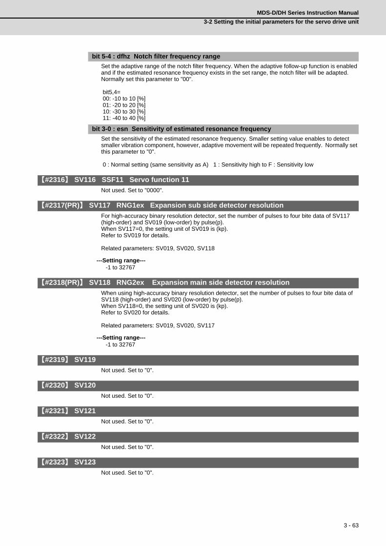
3 - 63
MDS-D/DH Series Instruction Manual
3-2 Setting the initial parameters for the servo drive unit
bit 5-4 : dfhz Notch filter frequency range
Set the adaptive range of the notch filter frequency. When the adaptive follow-up function is enabled and if the estimated resonance frequency exists in the set range, the notch filter will be adapted. Normally set this parameter to "00". bit5,4= 00: -10 to 10 [%] 01: -20 to 20 [%] 10: -30 to 30 [%] 11: -40 to 40 [%]
bit 3-0 : esn Sensitivity of estimated resonance frequency
Set the sensitivity of the estimated resonance frequency. Smaller setting value enables to detect smaller vibration component, however, adaptive movement will be repeated frequently. Normally set this parameter to "0". 0 : Normal setting (same sensitivity as A) 1 : Sensitivity high to F : Sensitivity low
【#2316】 SV116 SSF11 Servo function 11
Not used. Set to "0000".
【#2317(PR)】 SV117 RNG1ex Expansion sub side detector resolution
For high-accuracy binary resolution detector, set the number of pulses to four bite data of SV117 (high-order) and SV019 (low-order) by pulse(p). When SV117=0, the setting unit of SV019 is (kp). Refer to SV019 for details. Related parameters: SV019, SV020, SV118
---Setting range----1 to 32767
【#2318(PR)】 SV118 RNG2ex Expansion main side detector resolution
When using high-accuracy binary resolution detector, set the number of pulses to four bite data of SV118 (high-order) and SV020 (low-order) by pulse(p). When SV118=0, the setting unit of SV020 is (kp). Refer to SV020 for details. Related parameters: SV019, SV020, SV117
---Setting range----1 to 32767
【#2319】 SV119
Not used. Set to "0".
【#2320】 SV120
Not used. Set to "0".
【#2321】 SV121
Not used. Set to "0".
【#2322】 SV122
Not used. Set to "0".
【#2323】 SV123
Not used. Set to "0".

3 - 64
3 SetupMITSUBISHI CNC
【#2324】 SV124
Not used. Set to "0".
【#2325】 SV125
Not used. Set to "0".
【#2326】 SV126
Not used. Set to "0".
【#2327】 SV127
Not used. Set to "0".
【#2328】 SV128
Not used. Set to "0".
【#2329】 SV129 Kwf Synchronous control feed forward filter frequency
Set the acceleration rate feed forward filter frequency in high-speed synchronous tapping control. The standard setting is "600". Related parameters: SV244
---Setting range---0 to 32767 (rad/s)
【#2330(PR)】 SV130 RPITS Base reference mark interval
Set the base reference mark intervals of distance-coded reference scale. When the distance-coded reference scale is not used, set to "0". The interval of basic reference mark (SV130) and auxiliary interval (SV131) must be in the specified relationship. Other settings cause the initial parameter error (alarm 37). Following is the specified relationship. The quotient of (SV130×1000) / SV131 must be 4 or more and leaves no remainder. Related parameters: SV081/bit7,3, SV131, SV134 to SV137
---Setting range---0 to 32767 (mm)
【#2331(PR)】 SV131 DPITS Auxiliary reference mark interval
Set the auxiliary interval of reference mark in the distance-coded reference scale. When the distance-coded reference scale is not used, set to "0". The interval of basic reference mark (SV130) and auxiliary interval (SV131) must be in the specified relationship. Other settings cause the initial parameter error (alarm 37). Following is the specified relationship. The quotient of (SV130×1000) / SV131 must be 4 or more and leaves no remainder. Related parameters: SV081/bit7,3, SV130, SV134 to SV137
---Setting range---0 to 32767 (μm)
【#2332】 SV132
Not used. Set to "0".
【#2333】 SV133
Not used. Set to "0".

3 - 65
MDS-D/DH Series Instruction Manual
3-2 Setting the initial parameters for the servo drive unit
【#2334】 SV134 RRn0 Distance-coded reference check / revolution counter
Set this parameter to operate distance-coded reference check when using distance-coded reference scale. During the distance-coded reference check initial setup (SV137:RAER=-1), set the following items on the NC drive monitor screen after the distance-coded reference check initial setup warning A3 turns OFF. SV134=Rn, SV135=Pn, SV136=MPOS When reference point is set, the warning A3 turns OFF. To enable the distance-coded reference check function, SV081/bit3=1setting and a battery option are needed. Related parameters: SV081/bit3,7, SV130, SV131, SV134 to SV137
---Setting range----32768 to 32767
【#2335】 SV135 RPn0H Distance-coded reference check /position within one rotation High
Set this parameter to operate distance-coded reference check when using distance-coded reference scale. During the distance-coded reference check initial setup (SV137:RAER=-1), set the following items on the NC drive monitor screen after the distance-coded reference check initial setup warning A3 turns OFF. SV134=Rn, SV135=Pn, SV136=MPOS When reference point is set, the warning A3 turns OFF. To enable the distance-coded reference check function, SV081/bit3=1setting and a battery option are needed. Related parameters: SV081/bit3,7, SV130, SV131, SV134 to SV137
---Setting range----32768 to 32767
【#2336】 SV136 RPn0L Distance-coded reference check / position within one rotation Low
Set this parameter to operate distance-coded reference check when using distance-coded reference scale. During the distance-coded reference check initial setup (SV137:RAER=-1), set the following items on the NC drive monitor screen after the distance-coded reference check initial setup warning A3 turns OFF. SV134=Rn, SV135=Pn, SV136=MPOS When reference point is set, the warning A3 turns OFF. To enable the distance-coded reference check function, SV081/bit3=1setting and a battery option are needed. Related parameters: SV081/bit3,7, SV130, SV131, SV134 to SV137
---Setting range----32768 to 32767

3 - 66
3 SetupMITSUBISHI CNC
【#2337】 SV137 RAER Distance-coded reference check allowable width
For the distance-coded reference check function when using distance-coded reference scale, set the allowable gap from the reference point position data calculated by the main side detector. When the gap exceeds the allowable range, reference point created by distance-code is judged as wrong and detects alarm 42. The standard setting value is "basic reference mark interval (SV130) / 4". SV137=0 setting carries out the same operation as the standard setting value. SV137=-1 setting enables the distance-coded reference initial set up mode and displays setting values of SV134 to SV136 on NC drive monitor. To enable the distance-coded reference check function, SV081/bit3=1setting and a battery option are needed. When SV137=32767, the distance-coded reference check function is disabled. Related parameters: SV081/bit3,7, SV130, SV131, SV134 to SV136
---Setting range----1 to 32767 (mm)
【#2338-2397】 SV138 - SV197
Not used. Set to "0".
【#2398】 SV198 NSE No signal 2 special detection width
Set the special detection width for the no signal 2 (alarm 21). This detects no signal 2 (alarm 21) when machine side feedback is not invoked even if the motor side detector feedback exceeds this setting in the rectangular wave signal output linear scale. When "0" is set, the detection will be performed with a 15μm width. For MDS-D-SVJ3, this parameter setting is invalid and the detection width is fixed to 15μm.
---Setting range---0 to 32767 (μm)
【#2399-2437】 SV199 - SV237
Not used. Set to "0".
【#2438】 SV238 SSCFEED Safety observation Safety speed
Set the machine's safety speed for the safety observation function. Set this parameter within the following setting ranges. For linear axis: 2000mm/min or less For rotary axis: 18000°/min (50r/min) or lessWhen not using, set to "0". Related parameters: SV033/bitD, SV113/bitF, SV239
---Setting range---0 to 18000 (mm/min) or (°/min)
However, when SV033/bitD=1, the setting range is from -32768 to 32767 (100 mm/min) or (100°/min).
【#2439】 SV239 SSCRPM Safety observation Safety motor speed
Set the motor's safety speed for the safety observation function. Set a value to hold the following relationship. SV239=(SV238/SV018) x (SV002/SV001) Only when the product is 0, set to "1". When not using, set to "0". Related parameters: SV033/bitD, SV113/bitF, SV239
---Setting range---0 to 32767 (r/min)

3 - 67
MDS-D/DH Series Instruction Manual
3-2 Setting the initial parameters for the servo drive unit
【#2440-2443】 SV240 - SV243
Not used. Set to "0".
【#2444(PR)】 SV244 DUNIT Communication interpolation unit for communication among drive units
Set the communication interpolation unit among drive units in high-speed synchronous tapping control. When set to "0", it will be regarded as 20 (0.05μm) is set. Related parameters: SV129
---Setting range---0 to 2000 (1/μm)
【#2445-2456】 SV245 - SV256
Not used. Set to "0".
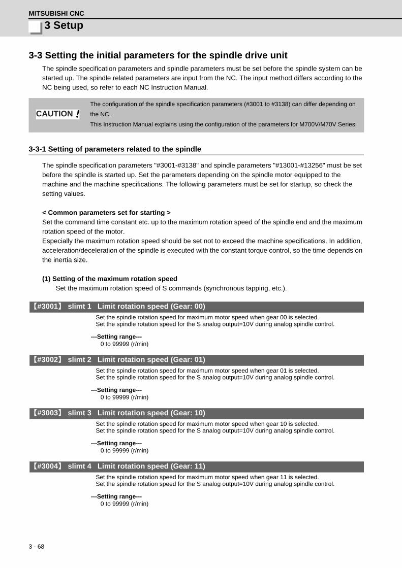
3 - 68
3 SetupMITSUBISHI CNC
3-3 Setting the initial parameters for the spindle drive unitThe spindle specification parameters and spindle parameters must be set before the spindle system can be
started up. The spindle related parameters are input from the NC. The input method differs according to the
NC being used, so refer to each NC Instruction Manual.
3-3-1 Setting of parameters related to the spindle
The spindle specification parameters "#3001-#3138" and spindle parameters "#13001-#13256" must be set
before the spindle is started up. Set the parameters depending on the spindle motor equipped to the
machine and the machine specifications. The following parameters must be set for startup, so check the
setting values.
< Common parameters set for starting >
Set the command time constant etc. up to the maximum rotation speed of the spindle end and the maximum
rotation speed of the motor.
Especially the maximum rotation speed should be set not to exceed the machine specifications. In addition,
acceleration/deceleration of the spindle is executed with the constant torque control, so the time depends on
the inertia size.
(1) Setting of the maximum rotation speed
Set the maximum rotation speed of S commands (synchronous tapping, etc.).
【#3001】 slimt 1 Limit rotation speed (Gear: 00)
Set the spindle rotation speed for maximum motor speed when gear 00 is selected.Set the spindle rotation speed for the S analog output=10V during analog spindle control.
---Setting range---0 to 99999 (r/min)
【#3002】 slimt 2 Limit rotation speed (Gear: 01)
Set the spindle rotation speed for maximum motor speed when gear 01 is selected.Set the spindle rotation speed for the S analog output=10V during analog spindle control.
---Setting range---0 to 99999 (r/min)
【#3003】 slimt 3 Limit rotation speed (Gear: 10)
Set the spindle rotation speed for maximum motor speed when gear 10 is selected.Set the spindle rotation speed for the S analog output=10V during analog spindle control.
---Setting range---0 to 99999 (r/min)
【#3004】 slimt 4 Limit rotation speed (Gear: 11)
Set the spindle rotation speed for maximum motor speed when gear 11 is selected.Set the spindle rotation speed for the S analog output=10V during analog spindle control.
---Setting range---0 to 99999 (r/min)
The configuration of the spindle specification parameters (#3001 to #3138) can differ depending on
the NC.
This Instruction Manual explains using the configuration of the parameters for M700V/M70V Series.
CAUTION

3 - 69
MDS-D/DH Series Instruction Manual
3-3 Setting the initial parameters for the spindle drive unit
【#3005】 smax 1 Maximum rotation speed (Gear: 00)
Set the maximum spindle rotation speed which is actually commanded when gear 00 is selected.Set this as smax1(#3005)<= slimit1(#3001).By comparing the S command value and the values of gear 1 - 4, a spindle gear shift command will be output automatically.
---Setting range---0 to 99999 (r/min)
【#3006】 smax 2 Maximum rotation speed (Gear: 01)
Set the maximum spindle rotation speed which is actually commanded when gear 01 is selected.Set this as smax2(#3006)<= slimit2(#3002).By comparing the S command value and the values of gear 1 - 4, a spindle gear shift command will be output automatically.
---Setting range---0 to 99999 (r/min)
【#3007】 smax 3 Maximum rotation speed (Gear: 10)
Set the maximum spindle rotation speed which is actually commanded when gear 10 is selected.Set this as smax3(#3007)<= slimit3(#3003).By comparing the S command value and the values of gear 1 - 4, a spindle gear shift command will be output automatically.
---Setting range---0 to 99999 (r/min)
【#3008】 smax 4 Maximum rotation speed (Gear: 11)
Set the maximum spindle rotation speed which is actually commanded when gear 11 is selected.Set this as smax4(#3008)<= slimit4(#3004).By comparing the S command value and the values of gear 1 - 4, a spindle gear shift command will be output automatically.
---Setting range---0 to 99999 (r/min)
(2) Time constant settings during acceleration/deceleration
Set the time constant from the stopped state to reach S commands of smax.
【#3101】 sp_t 1 Acceleration/deceleration time constant with S command (Gear: 00)
Set the acceleration/deceleration time constant with S command (speed operation mode) when gear 00 is selected. Set the linear acceleration/deceleration time up to maximum speed (smax1). Set the short time constant that the motor torque at acceleration is always saturated, however, when an abnormal noise or V-belt slip occurs, increase the time constant.
---Setting range---0 to 30000 (ms)
【#3102】 sp_t 2 Acceleration/deceleration time constant with S command (Gear: 01)
Set the acceleration/deceleration time constant with S command (speed operation mode) when gear 01 is selected. Set the linear acceleration/deceleration time up to maximum speed (smax2). Set the short time constant that the motor torque at acceleration is always saturated, however, when an abnormal noise or V-belt slip occurs, increase the time constant.
---Setting range---0 to 30000 (ms)
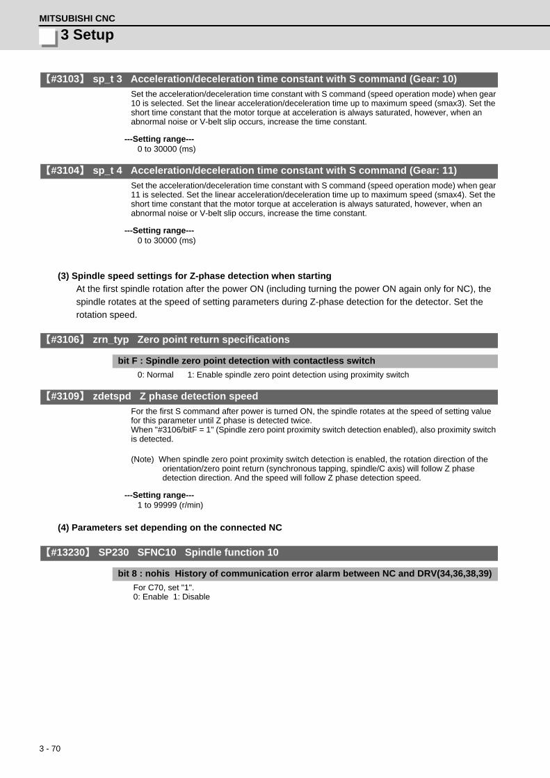
3 - 70
3 SetupMITSUBISHI CNC
【#3103】 sp_t 3 Acceleration/deceleration time constant with S command (Gear: 10)
Set the acceleration/deceleration time constant with S command (speed operation mode) when gear 10 is selected. Set the linear acceleration/deceleration time up to maximum speed (smax3). Set the short time constant that the motor torque at acceleration is always saturated, however, when an abnormal noise or V-belt slip occurs, increase the time constant.
---Setting range---0 to 30000 (ms)
【#3104】 sp_t 4 Acceleration/deceleration time constant with S command (Gear: 11)
Set the acceleration/deceleration time constant with S command (speed operation mode) when gear 11 is selected. Set the linear acceleration/deceleration time up to maximum speed (smax4). Set the short time constant that the motor torque at acceleration is always saturated, however, when an abnormal noise or V-belt slip occurs, increase the time constant.
---Setting range---0 to 30000 (ms)
(3) Spindle speed settings for Z-phase detection when starting
At the first spindle rotation after the power ON (including turning the power ON again only for NC), the
spindle rotates at the speed of setting parameters during Z-phase detection for the detector. Set the
rotation speed.
【#3106】 zrn_typ Zero point return specifications
bit F : Spindle zero point detection with contactless switch
0: Normal 1: Enable spindle zero point detection using proximity switch
【#3109】 zdetspd Z phase detection speed
For the first S command after power is turned ON, the spindle rotates at the speed of setting value for this parameter until Z phase is detected twice.When "#3106/bitF = 1" (Spindle zero point proximity switch detection enabled), also proximity switch is detected.
(Note) When spindle zero point proximity switch detection is enabled, the rotation direction of the orientation/zero point return (synchronous tapping, spindle/C axis) will follow Z phase detection direction. And the speed will follow Z phase detection speed.
---Setting range---1 to 99999 (r/min)
(4) Parameters set depending on the connected NC
【#13230】 SP230 SFNC10 Spindle function 10
bit 8 : nohis History of communication error alarm between NC and DRV(34,36,38,39)
For C70, set "1". 0: Enable 1: Disable

3 - 71
MDS-D/DH Series Instruction Manual
3-3 Setting the initial parameters for the spindle drive unit
< Initial parameters set depending on the machine specifications >
Set the following parameters depending on the spindle drive method (direct, gear drive, etc.) or inertia size of
rotary sections for machine specifications.
(1) Adjustment parameters in orientation mode
When the inertia ratio is large for the spindle motor such as large lathes, set the following parameters so
that abnormal noise or machine sway does not occur during orientation control.
【#3106】 zrn_typ Zero point return specifications
bit E : Control mode selection in orientation
Select non-interpolation mode when vibration occurs since the gain is high during the orientation.0: Interpolation mode (Use the interpolation mode gain "SP002".)1: Non-interpolation mode (Use the non-interpolation mode gain "SP001")
(2) Setting of the gear ratio
Set the following parameters depending on the spindle drive method (direct, gear drive, belt drive) for
the machine.
【#13057(PR)】 SP057 GRA1 Spindle side gear ratio 1
Set the number of gear teeth on the spindle side when "the gear selection command (control input 4/bit6, 5) "is set to "00".
---Setting range---1 to 32767
【#13058(PR)】 SP058 GRA2 Spindle side gear ratio 2
Set the number of gear teeth on the spindle side when "the gear selection command (control input 4/bit6, 5) " is set to "01".
---Setting range---1 to 32767
【#13059(PR)】 SP059 GRA3 Spindle side gear ratio 3
Set the number of gear teeth on the spindle side when "the gear selection command (control input 4/bit6, 5) " is set to "10".
---Setting range---1 to 32767
【#13060(PR)】 SP060 GRA4 Spindle side gear ratio 4
Set the number of gear teeth on the spindle side when "the gear selection command (control input 4/bit6, 5) " is set to "11".
---Setting range---1 to 32767
【#13061(PR)】 SP061 GRB1 Motor side gear ratio 1
Set the number of gear teeth on the spindle side when "the gear selection command (control input 4/bit6, 5) " is set to "00".
---Setting range---1 to 32767
【#13062(PR)】 SP062 GRB2 Motor side gear ratio 2
Set the number of gear teeth on the spindle side when "the gear selection command (control input 4/bit6, 5) " is set to "01".
---Setting range---1 to 32767

3 - 72
3 SetupMITSUBISHI CNC
【#13063(PR)】 SP063 GRB3 Motor side gear ratio 3
Set the number of gear teeth on the spindle side when "the gear selection command (control input 4/bit6, 5)" is set to "10".
---Setting range---1 to 32767
【#13064(PR)】 SP064 GRB4 Motor side gear ratio 4
Set the number of gear teeth on the spindle side when "the gear selection command (control input 4/bit6, 5)" is set to "11".
---Setting range---1 to 32767
< Setting parameters for the detector with semi/full-closed loop control >
Set parameters depending on the detector configured in the machine. For semi-closed loop, set the same
value to the main side and the sub side. For full-closed loop, set the detector of the main side and the sub
side.
【#13019(PR)】 SP019 RNG1 Sub side detector resolution
[For semi-closed loop] Set the same value as SP020 (RNG2). (Refer to the explanation of SP020.) [For full-closed loop] Set the number of pulses per revolution of the machine side detector. When using ABZ pulse output detector (OSE-1024-3-15-68), set this combined with SP097(RNG1ex). SP019 = 4096 SP097 = -1
---Setting range---When SP097=0, the setting range is from 0 to 32767 (kp/rev)
When SP097≠0M700V, M70V: 0 to 65536 (p)C70: -32768 to 32767 (p)

3 - 73
MDS-D/DH Series Instruction Manual
3-3 Setting the initial parameters for the spindle drive unit
【#13020(PR)】 SP020 RNG2 Main side detector resolution
Set the number of pulses per revolution of the motor side detector. When using the detector interface unit MDS-B-HR, use this with SP098 (RNG2ex). Detector TS5691(128 teeth): SP020 = 2000 TS5691(180 teeth): SP020 = 2880 TS5691(256 teeth): SP020 = 4000 TS5691(384 teeth): SP020 = 6000 TS5691(512 teeth): SP020 = 8000 TS5690( 64 teeth): SP020 = 2000 TS5690( 90 teeth): SP020 = 2880 TS5690(128 teeth): SP020 = 4000 TS5690(192 teeth): SP020 = 6000 TS5690(256 teeth): SP020 = 8000 TS5690(384 teeth): SP020 =12000 ERM280(1200 teeth): SP020 = 4800 ERM280(2048 teeth): SP020 = 8000 MPCI : SP020 = 7200 MBE205: SP020 = 2000 Tool spindle motor OSA18(-A48): SP020 = 260
---Setting range---When SV118=0, the setting range is from 0 to 32767 (kp)
When SV118≠0For M700V,M70V,M70: 0 to 65536 (p)For C70: -32768 to 32767 (p
【#13097】 SP097 RNG1ex Extension sub side detector resolution
When setting the machine side detector resolution in pulse (p) unit, set the number of pulses to four bite data of SP097 (high-order) and SP019 (low-order) in pulse (p) unit. When SP097=0, the setting unit of SP019 is (kp).Refer to SP019 for details.
---Setting range----1 to 32767
【#13098】 SP098 RNG2ex Extension main side detector resolution
When setting the motor side detector resolution in pulse (p) unit, set the number of pulses to four bite data of SP098 (high-order) and SP020 (low-order) in pulse (p) unit. When SP098=0, the setting unit of SP020 is (kp).Refer to SP020 for details.
---Setting range----1 to 32767
【#13031(PR)】 SP031 MTYP Motor type
Set the control system of the spindle drive unit.2200: Semi closed loop control4200: Full closed loop control by using spindle side ABZ pulse output detector6200: Full closed loop control by using spindle side serial output detector
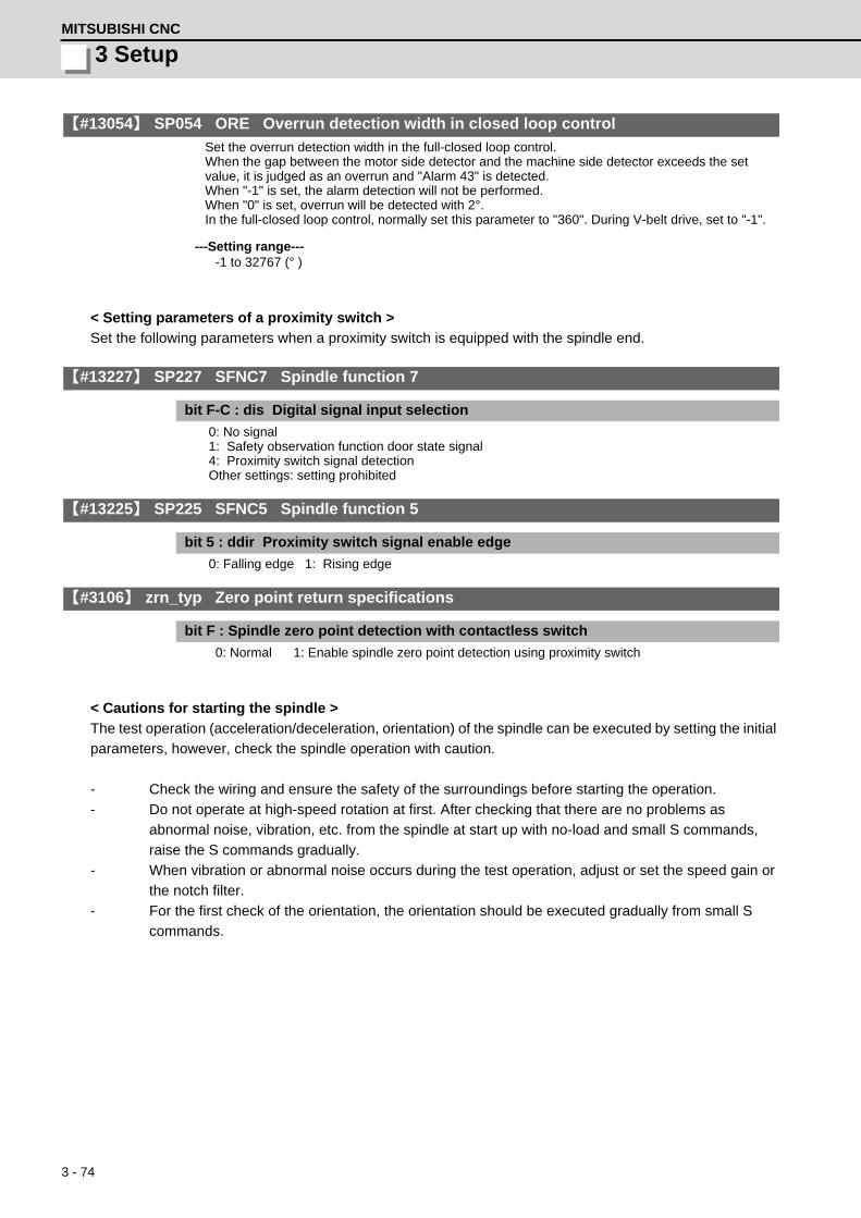
3 - 74
3 SetupMITSUBISHI CNC
【#13054】 SP054 ORE Overrun detection width in closed loop control
Set the overrun detection width in the full-closed loop control. When the gap between the motor side detector and the machine side detector exceeds the set value, it is judged as an overrun and "Alarm 43" is detected. When "-1" is set, the alarm detection will not be performed. When "0" is set, overrun will be detected with 2°. In the full-closed loop control, normally set this parameter to "360". During V-belt drive, set to "-1".
---Setting range----1 to 32767 (° )
< Setting parameters of a proximity switch >
Set the following parameters when a proximity switch is equipped with the spindle end.
【#13227】 SP227 SFNC7 Spindle function 7
bit F-C : dis Digital signal input selection
0: No signal 1: Safety observation function door state signal 4: Proximity switch signal detection Other settings: setting prohibited
【#13225】 SP225 SFNC5 Spindle function 5
bit 5 : ddir Proximity switch signal enable edge
0: Falling edge 1: Rising edge
【#3106】 zrn_typ Zero point return specifications
bit F : Spindle zero point detection with contactless switch
0: Normal 1: Enable spindle zero point detection using proximity switch
< Cautions for starting the spindle >
The test operation (acceleration/deceleration, orientation) of the spindle can be executed by setting the initial
parameters, however, check the spindle operation with caution.
- Check the wiring and ensure the safety of the surroundings before starting the operation.
- Do not operate at high-speed rotation at first. After checking that there are no problems as
abnormal noise, vibration, etc. from the spindle at start up with no-load and small S commands,
raise the S commands gradually.
- When vibration or abnormal noise occurs during the test operation, adjust or set the speed gain or
the notch filter.
- For the first check of the orientation, the orientation should be executed gradually from small S
commands.

3 - 75
MDS-D/DH Series Instruction Manual
3-3 Setting the initial parameters for the spindle drive unit
3-3-2 List of standard parameters for each spindle motor
(1) 200V Standard motor SJ-D Series (Standard)
MotorParameter
200V Standard motor SJ-D Series (Standard)SJ-D3.7/100-01 SJ-D5.5/100-01 SJ-D7.5/100-01 SJ-D11/80-01
No. Abbrev. Details MDS-D-SP- 80 80 160 160SP001 PGV Position loop gain non-interpolation mode 15 15 15 15SP002 PGN Position loop gain interpolation mode 33 33 33 33SP003 PGS Position loop gain spindle synchronization 15 15 15 15SP004 0 0 0 0SP005 VGN1 Speed loop gain 1 150 150 150 150SP006 VIA1 Speed loop lead compensation 1 1900 1900 1900 1900SP007 VIL1 Speed loop delay compensation 1 0 0 0 0SP008 VGN2 Speed loop gain 2 150 150 150 150SP009 VIA2 Speed loop lead compensation 2 1900 1900 1900 1900SP010 VIL2 Speed loop delay compensation 2 0 0 0 0SP011 0 0 0 0SP012 0 0 0 0SP013 0 0 0 0SP014 PY1 Minimum excitation rate 1 50 50 50 50SP015 PY2 Minimum excitation rate 2 100 100 100 100SP016 DDT Phase alignment deceleration rate 20 20 20 20SP017 SPEC1 Spindle specification 1 000C 000C 000C 000CSP018 SPEC2 Spindle specification 2 0000 0000 0000 0000SP019 RNG1 Sub side detector resolution 2000 2000 2000 2000SP020 RNG2 Main side detector resolution 2000 2000 2000 2000SP021 OLT Overload detection time constant 60 60 60 60SP022 OLL Overload detection level 120 120 120 120
SP023 OD1Excessive error detection width (interpolation mode - spindle synchroniza-tion)
120 120 120 120
SP024 INP In-position width 875 875 875 875SP025 INP2 2nd in-position width 875 875 875 875SP026 TSP Maximum motor speed 10000 10000 10000 8000SP027 ZSP Motor zero speed 25 25 25 25SP028 SDTS Speed detection set value 1000 1000 1000 800SP029 SDTR Speed detection reset width 30 30 30 30SP030 SDT2 2nd speed detection setting value 0 0 0 0SP031 MTYP Motor type 2200 2200 2200 2200
SP032 PTYPPower supply type/ Regenerative resistor type
0000 0000 0000 0000
SP033 SFNC1 Spindle function 1 0000 0000 0000 0000SP034 SFNC2 Spindle function 2 0000 0000 0000 0000SP035 SFNC3 Spindle function 3 1600 1600 1600 1600SP036 SFNC4 Spindle function 4 0000 0000 0000 0000SP037 JL Load inertia scale 100 100 100 100SP038 FHz1 Notch filter frequency 1 0 0 0 0SP039 LMCD Lost motion compensation timing 0 0 0 0
SP040 LMCTLost motion compensation non-sensitive band
0 0 0 0
SP041 LMC2 Lost motion compensation 2 0 0 0 0SP042 OVS2 Overshooting compensation 2 0 0 0 0SP043 OVS1 Overshooting compensation 1 0 0 0 0SP044 OBS2 Disturbance observer gain 0 0 0 0SP045 OBS1 Disturbance observer filter frequency 0 0 0 0SP046 FHz2 Notch filter frequency 2 0 0 0 0SP047 EC Inductive voltage compensation gain 100 100 100 100SP048 LMC1 Lost motion compensation 1 0 0 0 0SP049 FFC Acceleration rate feed forward gain 0 0 0 0SP050 TOF Torque offset 0 0 0 0SP051 DFBT Dual feed back control time constant 0 0 0 0SP052 DFBN Dual feedback control non-sensitive band 0 0 0 0
SP053 ODSExcessive error detection width (non-interpolation mode)
2000 2000 2000 1600
SP054 OREOverrun detection width in closed loop con-trol
0 0 0 0
SP055 EMGx Max. gate off delay time after emergency stop 20000 20000 20000 20000
SP056 EMGtDeceleration time constant at emergency stop
300 300 300 300
SP057 GRA1 Spindle side gear ratio 1 1 1 1 1SP058 GRA2 Spindle side gear ratio 2 1 1 1 1SP059 GRA3 Spindle side gear ratio 3 1 1 1 1SP060 GRA4 Spindle side gear ratio 4 1 1 1 1SP061 GRB1 Motor side gear ratio 1 1 1 1 1SP062 GRB2 Motor side gear ratio 2 1 1 1 1SP063 GRB3 Motor side gear ratio 3 1 1 1 1SP064 GRB4 Motor side gear ratio 4 1 1 1 1SP065 TLM1 Torque limit 1 10 10 10 10

3 - 76
3 SetupMITSUBISHI CNC
SP066 TLM2 Torque limit 2 10 10 10 10SP067 TLM3 Torque limit 3 10 10 10 10SP068 TLM4 Torque limit 4 10 10 10 10SP069 PCMP Phase alignment completion width 875 875 875 875SP070 KDDT Phase alignment deceleration rate scale 0 0 0 0
SP071 DIQMVariable current limit during deceleration, lower limit value
60 60 50 45
SP072 DIQNVariable current limit during deceleration, break point speed
6000 6000 5000 3700
SP073 VGVN Variable speed gain target value 0 0 0 0SP074 VGVS Variable speed gain change start speed 0 0 0 0
SP075 DWSHSlip compensation scale during regeneration high-speed coil
0 0 0 0
SP076 DWSLSlip compensation scale during regeneration low-speed coil
0 0 0 0
SP077 IQA Q axis current lead compensation 4096 4096 4096 4096SP078 IDA D axis current lead compensation 4096 4096 4096 4096SP079 IQG Q axis current gain 1024 1024 1024 1024SP080 IDG D axis current gain 1024 1024 1024 1024
SP081 IQALQ axis current lead compensation low-speed coil
0 0 0 0
SP082 IDALD axis current lead compensation low-speed coil
0 0 0 0
SP083 IQGL Q axis current gain low-speed coil 0 0 0 0SP084 IDGL D axis current gain low-speed coil 0 0 0 0SP085 0 0 0 0SP086 0 0 0 0SP087 FHz4 Notch filter frequency 4 0 0 0 0SP088 FHz5 Notch filter frequency 5 0 0 0 0SP089 TMKQ Spindle output stabilizing gain Q axis 100 100 100 100SP090 TMKD Spindle output stabilizing gain D axis 0 0 0 0SP091 0 0 0 0
: : : : :SP093 0 0 0 0SP094 MPV Magnetic pole error detection speed 0 0 0 0
SP095 VIAXLead compensation scale during high-re-sponse acceleration/deceleration
0 0 0 0
SP096 SDW Speed slowdown allowable width 0 0 0 0SP097 RNG1ex Extension sub side detector resolution 0 0 0 0SP098 RNG2ex Extension main side detector resolution 0 0 0 0SP099 0 0 0 0
: : : : :SP112 0 0 0 0SP113 OPLP Current command value for open loop 0 0 0 0SP114 MKT Coil changeover gate cutoff timer 150 150 150 150SP115 MKT2 Coil changeover current limit timer 250 250 250 250SP116 MKIL Coil changeover current limit value 120 120 120 120SP117 SETM Excessive speed deviation timer 12 12 12 12SP118 MSFT Magnetic pole shift amount 0 0 0 0SP119 0 0 0 0SP120 0 0 0 0SP121 MP Kpp Magnetic pole detection position loop gain 0 0 0 0SP122 MP Kvp Magnetic pole detection speed loop gain 0 0 0 0
SP123 MP KviMagnetic pole detection speed loop lead compensation
0 0 0 0
SP124 ILMTsp Magnetic pole detection current limit value 0 0 0 0SP125 DA1NO D/A output ch1 data No. 0 0 0 0SP126 DA2NO D/A output ch2 data No. 0 0 0 0SP127 DA1MPY D/A output ch1 output scale 0 0 0 0SP128 DA2MPY D/A output ch2 output scale 0 0 0 0SP129 PM Motor unique constants (H) 2 2 2 2SP130 JM Motor unique constants (H) 8 13 22 29SP131 ATYP Motor unique constants (H) 80 80 160 160SP132 0 0 0 0SP133 NR Motor unique constants (H) 10000 10000 10000 8000SP134 NB Motor unique constants (H) 1800 1800 1500 1500SP135 NF Motor unique constants (H) 1800 1800 1800 1800SP136 KT Motor unique constants (H) 1155 1234 1262 1338SP137 KF1 Motor unique constants (H) 59 67 73 68SP138 KF2 Motor unique constants (H) 3222 3330 3252 3208SP139 KF3 Motor unique constants (H) 2478 2345 2427 2468SP140 KF4 Motor unique constants (H) 1938 1961 1947 1942SP141 KF5 Motor unique constants (H) 86 98 145 145SP142 KF6 Motor unique constants (H) 0 0 0 0SP143 0 0 0 0SP144 TMIL Motor unique constants (H) 0 0 0 0SP145 TMBR Motor unique constants (H) 388 335 369 339
MotorParameter
200V Standard motor SJ-D Series (Standard)SJ-D3.7/100-01 SJ-D5.5/100-01 SJ-D7.5/100-01 SJ-D11/80-01
No. Abbrev. Details MDS-D-SP- 80 80 160 160

3 - 77
MDS-D/DH Series Instruction Manual
3-3 Setting the initial parameters for the spindle drive unit
SP146 TMBD Motor unique constants (H) 423 428 434 432SP147 KE Motor unique constants (H) 71 66 74 75SP148 LA Motor unique constants (H) 1869 1186 969 811SP149 IQSM Motor unique constants (H) 2039 2837 3785 5233SP150 IDSM Motor unique constants (H) 784 1228 1742 2214SP151 R1 Motor unique constants (H) 343 167 105 81SP152 TMLR Motor unique constants (H) 110 110 90 90SP153 TMLD Motor unique constants (H) 120 120 120 120SP154 TMLS Motor unique constants (H) 150 150 150 150SP155 KI1 Motor unique constants (H) 1095 1083 1051 1051SP156 PCNT Motor unique constants (H) 0 0 0 0SP157 0 0 0 0SP158 DNB Motor unique constants (H) 1500 1500 0 0SP159 SNB Motor unique constants (H) 1500 1500 0 0SP160 BSD Motor unique constants (H) 0 0 0 0SP161 0 0 0 0
: : : : :SP164 0 0 0 0SP165 NRL Motor unique constants (L) 0 0 0 0SP166 NBL Motor unique constants (L) 0 0 0 0SP167 NFL Motor unique constants (L) 0 0 0 0SP168 KT Motor unique constants (L) 0 0 0 0SP169 KF1L Motor unique constants (L) 0 0 0 0SP170 KF2L Motor unique constants (L) 0 0 0 0SP171 KF3L Motor unique constants (L) 0 0 0 0SP172 KF4L Motor unique constants (L) 0 0 0 0SP173 KF5L Motor unique constants (L) 0 0 0 0SP174 KF6L Motor unique constants (L) 0 0 0 0SP175 0 0 0 0SP176 TMILL Motor unique constants (L) 0 0 0 0SP177 TMBRL Motor unique constants (L) 0 0 0 0SP178 TMBDL Motor unique constants (L) 0 0 0 0SP179 KEL Motor unique constants (L) 0 0 0 0SP180 LAL Motor unique constants (L) 0 0 0 0SP181 IQSML Motor unique constants (L) 0 0 0 0SP182 IDSML Motor unique constants (L) 0 0 0 0SP183 R1L Motor unique constants (L) 0 0 0 0SP184 0 0 0 0SP185 TMLRL Motor unique constants (L) 0 0 0 0SP186 TMLSL Motor unique constants (L) 0 0 0 0SP187 KI1L Motor unique constants (L) 0 0 0 0SP188 PCNTL Motor unique constants (L) 0 0 0 0SP189 0 0 0 0SP190 DNBL Motor unique constants (L) 0 0 0 0SP191 SNBL Motor unique constants (L) 0 0 0 0SP192 BSDL Motor unique constants (L) 0 0 0 0SP193 0 0 0 0
: : : : :SP224 0 0 0 0SP225 SFNC5 Spindle function 5 0000 0000 0000 0000SP226 SFNC6 Spindle function 6 1000 1000 1000 1000SP227 SFNC7 Spindle function 7 0000 0000 0000 0000SP228 SFNC8 Spindle function 8 0000 0000 0000 0000SP229 SFNC9 Spindle function 9 0000 0000 0000 0000SP230 SFNC10 Spindle function 10 0000 0000 0000 0000SP231 0000 0000 0000 0000SP232 0000 0000 0000 0000SP233 IVC Voltage non-sensitive band compensation 0 0 0 0SP234 0 0 0 0SP235 R2H Temperature compensation gain 0 0 0 0SP236 WIH Temperature compensation time constant 0 0 0 0SP237 TCF Torque command filter 500 500 500 500SP238 SSCFEED Safety observation Safety speed 0 0 0 0SP239 SSCRPM Safety observation Safety motor speed 0 0 0 0SP240 0 0 0 0
:SP256
MotorParameter
200V Standard motor SJ-D Series (Standard)SJ-D3.7/100-01 SJ-D5.5/100-01 SJ-D7.5/100-01 SJ-D11/80-01
No. Abbrev. Details MDS-D-SP- 80 80 160 160

3 - 78
3 SetupMITSUBISHI CNC
(2) 200V Standard motor SJ-DJ Series (Compact & Lightweight output)
MotorParameter
200V SJ-DJ Series (Compact & Lightweight output)SJ-DJ5.5/100-01 SJ-DJ7.5/100-01 SJ-DJ11/100-01 SJ-DJ15/80-01
No. Abbrev. Details MDS-D-SP- 80 160 160 200SP001 PGV Position loop gain non-interpolation mode 15 15 15 15SP002 PGN Position loop gain interpolation mode 33 33 33 33SP003 PGS Position loop gain spindle synchronization 15 15 15 15SP004 0 0 0 0SP005 VGN1 Speed loop gain 1 150 150 150 150SP006 VIA1 Speed loop lead compensation 1 1900 1900 1900 1900SP007 VIL1 Speed loop delay compensation 1 0 0 0 0SP008 VGN2 Speed loop gain 2 150 150 150 150SP009 VIA2 Speed loop lead compensation 2 1900 1900 1900 1900SP010 VIL2 Speed loop delay compensation 2 0 0 0 0SP011 0 0 0 0SP012 0 0 0 0SP013 0 0 0 0SP014 PY1 Minimum excitation rate 1 50 50 50 50SP015 PY2 Minimum excitation rate 2 100 100 100 100SP016 DDT Phase alignment deceleration rate 20 20 20 20SP017 SPEC1 Spindle specification 1 000C 000C 000C 000CSP018 SPEC2 Spindle specification 2 0000 0000 0000 0000SP019 RNG1 Sub side detector resolution 2000 2000 2000 2000SP020 RNG2 Main side detector resolution 2000 2000 2000 2000SP021 OLT Overload detection time constant 60 60 60 60SP022 OLL Overload detection level 120 120 120 120
SP023 OD1Excessive error detection width (interpolation mode - spindle synchroniza-tion)
120 120 120 120
SP024 INP In-position width 875 875 875 875SP025 INP2 2nd in-position width 875 875 875 875SP026 TSP Maximum motor speed 10000 10000 10000 8000SP027 ZSP Motor zero speed 25 25 25 25SP028 SDTS Speed detection set value 1000 1000 1000 800SP029 SDTR Speed detection reset width 30 30 30 30SP030 SDT2 2nd speed detection setting value 0 0 0 0SP031 MTYP Motor type 2200 2200 2200 2200
SP032 PTYPPower supply type/ Regenerative resistor type
0000 0000 0000 0000
SP033 SFNC1 Spindle function 1 0000 0000 0000 0000SP034 SFNC2 Spindle function 2 0000 0000 0000 0000SP035 SFNC3 Spindle function 3 1600 1600 1600 1600SP036 SFNC4 Spindle function 4 0000 0000 0000 0000SP037 JL Load inertia scale 100 100 100 100SP038 FHz1 Notch filter frequency 1 0 0 0 0SP039 LMCD Lost motion compensation timing 0 0 0 0
SP040 LMCTLost motion compensation non-sensitive band
0 0 0 0
SP041 LMC2 Lost motion compensation 2 0 0 0 0SP042 OVS2 Overshooting compensation 2 0 0 0 0SP043 OVS1 Overshooting compensation 1 0 0 0 0SP044 OBS2 Disturbance observer gain 0 0 0 0SP045 OBS1 Disturbance observer filter frequency 0 0 0 0SP046 FHz2 Notch filter frequency 2 0 0 0 0SP047 EC Inductive voltage compensation gain 100 100 100 100SP048 LMC1 Lost motion compensation 1 0 0 0 0SP049 FFC Acceleration rate feed forward gain 0 0 0 0SP050 TOF Torque offset 0 0 0 0SP051 DFBT Dual feed back control time constant 0 0 0 0SP052 DFBN Dual feedback control non-sensitive band 0 0 0 0
SP053 ODSExcessive error detection width (non-interpolation mode)
2000 2000 2000 1600
SP054 OREOverrun detection width in closed loop con-trol
0 0 0 0
SP055 EMGx Max. gate off delay time after emergency stop 20000 20000 20000 20000
SP056 EMGtDeceleration time constant at emergency stop
300 300 300 300
SP057 GRA1 Spindle side gear ratio 1 1 1 1 1SP058 GRA2 Spindle side gear ratio 2 1 1 1 1SP059 GRA3 Spindle side gear ratio 3 1 1 1 1SP060 GRA4 Spindle side gear ratio 4 1 1 1 1SP061 GRB1 Motor side gear ratio 1 1 1 1 1SP062 GRB2 Motor side gear ratio 2 1 1 1 1SP063 GRB3 Motor side gear ratio 3 1 1 1 1SP064 GRB4 Motor side gear ratio 4 1 1 1 1SP065 TLM1 Torque limit 1 10 10 10 10SP066 TLM2 Torque limit 2 10 10 10 10SP067 TLM3 Torque limit 3 10 10 10 10SP068 TLM4 Torque limit 4 10 10 10 10

3 - 79
MDS-D/DH Series Instruction Manual
3-3 Setting the initial parameters for the spindle drive unit
SP069 PCMP Phase alignment completion width 875 875 875 875SP070 KDDT Phase alignment deceleration rate scale 0 0 0 0
SP071 DIQMVariable current limit during deceleration, lower limit value
45 45 45 40
SP072 DIQNVariable current limit during deceleration, break point speed
4500 4500 4500 3300
SP073 VGVN Variable speed gain target value 0 0 0 0SP074 VGVS Variable speed gain change start speed 0 0 0 0
SP075 DWSHSlip compensation scale during regeneration high-speed coil
0 0 0 0
SP076 DWSLSlip compensation scale during regeneration low-speed coil
0 0 0 0
SP077 IQA Q axis current lead compensation 4096 4096 4096 4096SP078 IDA D axis current lead compensation 4096 4096 4096 4096SP079 IQG Q axis current gain 1024 1024 1024 1024SP080 IDG D axis current gain 1024 1024 1024 1024
SP081 IQALQ axis current lead compensation low-speed coil
0 0 0 0
SP082 IDALD axis current lead compensation low-speed coil
0 0 0 0
SP083 IQGL Q axis current gain low-speed coil 0 0 0 0SP084 IDGL D axis current gain low-speed coil 0 0 0 0SP085 0 0 0 0SP086 0 0 0 0SP087 FHz4 Notch filter frequency 4 0 0 0 0SP088 FHz5 Notch filter frequency 5 0 0 0 0SP089 TMKQ Spindle output stabilizing gain Q axis 100 100 100 100SP090 TMKD Spindle output stabilizing gain D axis 0 0 0 0SP091 0 0 0 0
: : : : :SP093 0 0 0 0SP094 MPV Magnetic pole error detection speed 0 0 0 0
SP095 VIAXLead compensation scale during high-re-sponse acceleration/deceleration
0 0 0 0
SP096 SDW Speed slowdown allowable width 0 0 0 0SP097 RNG1ex Extension sub side detector resolution 0 0 0 0SP098 RNG2ex Extension main side detector resolution 0 0 0 0SP099 0 0 0 0
: : : : :SP112 0 0 0 0SP113 OPLP Current command value for open loop 0 0 0 0SP114 MKT Coil changeover gate cutoff timer 150 150 150 150SP115 MKT2 Coil changeover current limit timer 250 250 250 250SP116 MKIL Coil changeover current limit value 120 120 120 120SP117 SETM Excessive speed deviation timer 12 12 12 12SP118 MSFT Magnetic pole shift amount 0 0 0 0SP119 0 0 0 0SP120 0 0 0 0SP121 MP Kpp Magnetic pole detection position loop gain 0 0 0 0SP122 MP Kvp Magnetic pole detection speed loop gain 0 0 0 0
SP123 MP KviMagnetic pole detection speed loop lead compensation
0 0 0 0
SP124 ILMTsp Magnetic pole detection current limit value 0 0 0 0SP125 DA1NO D/A output ch1 data No. 0 0 0 0SP126 DA2NO D/A output ch2 data No. 0 0 0 0SP127 DA1MPY D/A output ch1 output scale 0 0 0 0SP128 DA2MPY D/A output ch2 output scale 0 0 0 0SP129 PM Motor unique constants (H) 2 2 2 2SP130 JM Motor unique constants (H) 8 13 24 31SP131 ATYP Motor unique constants (H) 80 160 160 200SP132 0 0 0 0SP133 NR Motor unique constants (H) 10000 10000 10000 8000SP134 NB Motor unique constants (H) 1800 1800 1800 1500SP135 NF Motor unique constants (H) 1800 1800 1800 1800SP136 KT Motor unique constants (H) 1123 1352 1377 1355SP137 KF1 Motor unique constants (H) 67 73 68 73SP138 KF2 Motor unique constants (H) 2880 3023 2963 2952SP139 KF3 Motor unique constants (H) 2939 2652 2796 2785SP140 KF4 Motor unique constants (H) 1884 1922 1900 1904SP141 KF5 Motor unique constants (H) 72 88 127 130SP142 KF6 Motor unique constants (H) 0 0 0 0SP143 0 0 0 0SP144 TMIL Motor unique constants (H) 0 0 0 0SP145 TMBR Motor unique constants (H) 460 424 466 404SP146 TMBD Motor unique constants (H) 423 429 434 432SP147 KE Motor unique constants (H) 82 73 83 82SP148 LA Motor unique constants (H) 1405 1165 940 701
MotorParameter
200V SJ-DJ Series (Compact & Lightweight output)SJ-DJ5.5/100-01 SJ-DJ7.5/100-01 SJ-DJ11/100-01 SJ-DJ15/80-01
No. Abbrev. Details MDS-D-SP- 80 160 160 200

3 - 80
3 SetupMITSUBISHI CNC
SP149 IQSM Motor unique constants (H) 3118 3532 5085 7045SP150 IDSM Motor unique constants (H) 1189 1525 2197 2867SP151 R1 Motor unique constants (H) 259 167 105 68SP152 TMLR Motor unique constants (H) 90 90 90 90SP153 TMLD Motor unique constants (H) 120 120 120 120SP154 TMLS Motor unique constants (H) 150 150 150 150SP155 KI1 Motor unique constants (H) 1100 1065 1075 1041SP156 PCNT Motor unique constants (H) 0 0 0 0SP157 0 0 0 0SP158 DNB Motor unique constants (H) 1500 1500 1500 0SP159 SNB Motor unique constants (H) 1500 1500 1500 0SP160 BSD Motor unique constants (H) 0 0 0 0SP161 0 0 0 0
: : : : :SP164 0 0 0 0SP165 NRL Motor unique constants (L) 0 0 0 0SP166 NBL Motor unique constants (L) 0 0 0 0SP167 NFL Motor unique constants (L) 0 0 0 0SP168 KT Motor unique constants (L) 0 0 0 0SP169 KF1L Motor unique constants (L) 0 0 0 0SP170 KF2L Motor unique constants (L) 0 0 0 0SP171 KF3L Motor unique constants (L) 0 0 0 0SP172 KF4L Motor unique constants (L) 0 0 0 0SP173 KF5L Motor unique constants (L) 0 0 0 0SP174 KF6L Motor unique constants (L) 0 0 0 0SP175 0 0 0 0SP176 TMILL Motor unique constants (L) 0 0 0 0SP177 TMBRL Motor unique constants (L) 0 0 0 0SP178 TMBDL Motor unique constants (L) 0 0 0 0SP179 KEL Motor unique constants (L) 0 0 0 0SP180 LAL Motor unique constants (L) 0 0 0 0SP181 IQSML Motor unique constants (L) 0 0 0 0SP182 IDSML Motor unique constants (L) 0 0 0 0SP183 R1L Motor unique constants (L) 0 0 0 0SP184 0 0 0 0SP185 TMLRL Motor unique constants (L) 0 0 0 0SP186 TMLSL Motor unique constants (L) 0 0 0 0SP187 KI1L Motor unique constants (L) 0 0 0 0SP188 PCNTL Motor unique constants (L) 0 0 0 0SP189 0 0 0 0SP190 DNBL Motor unique constants (L) 0 0 0 0SP191 SNBL Motor unique constants (L) 0 0 0 0SP192 BSDL Motor unique constants (L) 0 0 0 0SP193 0 0 0 0
: : : : :SP224 0 0 0 0SP225 SFNC5 Spindle function 5 0000 0000 0000 0000SP226 SFNC6 Spindle function 6 1000 1000 1000 1000SP227 SFNC7 Spindle function 7 0000 0000 0000 0000SP228 SFNC8 Spindle function 8 0000 0000 0000 0000SP229 SFNC9 Spindle function 9 0000 0000 0000 0000SP230 SFNC10 Spindle function 10 0000 0000 0000 0000SP231 0000 0000 0000 0000SP232 0000 0000 0000 0000SP233 IVC Voltage non-sensitive band compensation 0 0 0 0SP234 0 0 0 0SP235 R2H Temperature compensation gain 0 0 0 0SP236 WIH Temperature compensation time constant 0 0 0 0SP237 TCF Torque command filter 500 500 500 500
SP238SSC-FEED
Safety observation Safety speed 0 0 0 0
SP239 SSCRPM Safety observation Safety motor speed 0 0 0 0SP240 0 0 0 0
:SP256
MotorParameter
200V SJ-DJ Series (Compact & Lightweight output)SJ-DJ5.5/100-01 SJ-DJ7.5/100-01 SJ-DJ11/100-01 SJ-DJ15/80-01
No. Abbrev. Details MDS-D-SP- 80 160 160 200

3 - 81
MDS-D/DH Series Instruction Manual
3-3 Setting the initial parameters for the spindle drive unit
(3) 200V Standard motor SJ-V Series (Standard)
MotorParameter
200V Standard motor SJ-V Series (Standard)SJ-VL0.75-
01TSJ-VL1.5-
01TSJ-V2.2-
01TSJ-V3.7-
01TSJ-V5.5-
01ZT SJ-V7.5-
01ZTSJ-V7.5-
03ZTSJ-V11-
01ZTSJ-V11-
13ZTNo. Abbrev. Details MDS-D-SP- 20 20 40 80 80 160 160 160 200
SP001 PGV Position loop gain non-interpolation mode 15 15 15 15 15 15 15 15 15SP002 PGN Position loop gain interpolation mode 33 33 33 33 33 33 33 33 33SP003 PGS Position loop gain spindle synchronization 15 15 15 15 15 15 15 15 15SP004 0 0 0 0 0 0 0 0 0SP005 VGN1 Speed loop gain 1 150 150 150 150 150 150 150 150 150SP006 VIA1 Speed loop lead compensation 1 1900 1900 1900 1900 1900 1900 1900 1900 1900SP007 VIL1 Speed loop delay compensation 1 0 0 0 0 0 0 0 0 0SP008 VGN2 Speed loop gain 2 150 150 150 150 150 150 150 150 150SP009 VIA2 Speed loop lead compensation 2 1900 1900 1900 1900 1900 1900 1900 1900 1900SP010 VIL2 Speed loop delay compensation 2 0 0 0 0 0 0 0 0 0SP011 0 0 0 0 0 0 0 0 0SP012 0 0 0 0 0 0 0 0 0SP013 0 0 0 0 0 0 0 0 0SP014 PY1 Minimum excitation rate 1 50 50 50 50 50 50 50 50 50SP015 PY2 Minimum excitation rate 2 100 100 100 100 100 100 100 100 100SP016 DDT Phase alignment deceleration rate 20 20 20 20 20 20 20 20 20SP017 SPEC1 Spindle specification 1 000C 000C 000C 000C 000C 000C 000C 000C 000CSP018 SPEC2 Spindle specification 2 0000 0000 0000 0000 0000 0000 0000 0000 0000SP019 RNG1 Sub side detector resolution 2000 2000 4000 4000 4000 4000 4000 4000 4000SP020 RNG2 Main side detector resolution 2000 2000 4000 4000 4000 4000 4000 4000 4000SP021 OLT Overload detection time constant 60 60 60 60 60 60 60 60 60SP022 OLL Overload detection level 120 120 120 120 120 120 120 120 120
SP023 OD1Excessive error detection width (interpola-tion mode - spindle synchronization)
120 120 120 120 120 120 120 120 120
SP024 INP In-position width 875 875 875 875 875 875 875 875 875SP025 INP2 2nd in-position width 875 875 875 875 875 875 875 875 875SP026 TSP Maximum motor speed 10000 10000 10000 10000 12000 12000 12000 8000 10000SP027 ZSP Motor zero speed 25 25 25 25 25 25 25 25 25SP028 SDTS Speed detection set value 1000 1000 1000 1000 1200 1200 1200 800 1000SP029 SDTR Speed detection reset width 30 30 30 30 30 30 30 30 30SP030 SDT2 2nd speed detection setting value 0 0 0 0 0 0 0 0 0SP031 MTYP Motor type 2200 2200 2200 2200 2200 2200 2200 2200 2200
SP032 PTYPPower supply type/ Regenerative resistor type
0000 0000 0000 0000 0000 0000 0000 0000 0000
SP033 SFNC1 Spindle function 1 0000 0000 0000 0000 0000 0000 0000 0000 0000SP034 SFNC2 Spindle function 2 0000 0000 0000 0000 0000 0000 0000 0000 0000SP035 SFNC3 Spindle function 3 1600 1600 1600 1600 1600 1600 1600 1600 1600SP036 SFNC4 Spindle function 4 0000 0000 0000 0000 0000 0000 0000 0000 0000SP037 JL Load inertia scale 100 100 100 100 100 100 100 100 100SP038 FHz1 Notch filter frequency 1 0 0 0 0 0 0 0 0 0SP039 LMCD Lost motion compensation timing 0 0 0 0 0 0 0 0 0
SP040 LMCTLost motion compensation non-sensitive band
0 0 0 0 0 0 0 0 0
SP041 LMC2 Lost motion compensation 2 0 0 0 0 0 0 0 0 0SP042 OVS2 Overshooting compensation 2 0 0 0 0 0 0 0 0 0SP043 OVS1 Overshooting compensation 1 0 0 0 0 0 0 0 0 0SP044 OBS2 Disturbance observer gain 0 0 0 0 0 0 0 0 0SP045 OBS1 Disturbance observer filter frequency 0 0 0 0 0 0 0 0 0SP046 FHz2 Notch filter frequency 2 0 0 0 0 0 0 0 0 0SP047 EC Inductive voltage compensation gain 100 100 100 100 100 100 100 100 100SP048 LMC1 Lost motion compensation 1 0 0 0 0 0 0 0 0 0SP049 FFC Acceleration rate feed forward gain 0 0 0 0 0 0 0 0 0SP050 TOF Torque offset 0 0 0 0 0 0 0 0 0SP051 DFBT Dual feed back control time constant 0 0 0 0 0 0 0 0 0SP052 DFBN Dual feedback control non-sensitive band 0 0 0 0 0 0 0 0 0
SP053 ODSExcessive error detection width (non-inter-polation mode)
2000 2000 2000 2000 2400 2400 2400 1600 2000
SP054 OREOverrun detection width in closed loop con-trol
0 0 0 0 0 0 0 0 0
SP055 EMGxMax. gate off delay time after emergency stop
20000 20000 20000 20000 20000 20000 20000 20000 20000
SP056 EMGtDeceleration time constant at emergency stop
300 300 300 300 300 300 300 300 300
SP057 GRA1 Spindle side gear ratio 1 1 1 1 1 1 1 1 1 1SP058 GRA2 Spindle side gear ratio 2 1 1 1 1 1 1 1 1 1SP059 GRA3 Spindle side gear ratio 3 1 1 1 1 1 1 1 1 1SP060 GRA4 Spindle side gear ratio 4 1 1 1 1 1 1 1 1 1SP061 GRB1 Motor side gear ratio 1 1 1 1 1 1 1 1 1 1SP062 GRB2 Motor side gear ratio 2 1 1 1 1 1 1 1 1 1SP063 GRB3 Motor side gear ratio 3 1 1 1 1 1 1 1 1 1SP064 GRB4 Motor side gear ratio 4 1 1 1 1 1 1 1 1 1SP065 TLM1 Torque limit 1 10 10 10 10 10 10 10 10 10SP066 TLM2 Torque limit 2 10 10 10 10 10 10 10 10 10SP067 TLM3 Torque limit 3 10 10 10 10 10 10 10 10 10

3 - 82
3 SetupMITSUBISHI CNC
SP068 TLM4 Torque limit 4 10 10 10 10 10 10 10 10 10SP069 PCMP Phase alignment completion width 875 875 875 875 875 875 875 875 875SP070 KDDT Phase alignment deceleration rate scale 0 0 0 0 0 0 0 0 0
SP071 DIQMVariable current limit during deceleration, lower limit value
50 50 50 50 40 40 55 45 50
SP072 DIQNVariable current limit during deceleration, break point speed
5000 5000 5000 5000 5000 5000 7100 3700 5000
SP073 VGVN Variable speed gain target value 0 0 0 0 0 0 0 0 0SP074 VGVS Variable speed gain change start speed 0 0 0 0 0 0 0 0 0
SP075 DWSHSlip compensation scale duringregeneration high-speed coil
0 0 0 0 0 0 0 0 0
SP076 DWSLSlip compensation scale duringregeneration low-speed coil
0 0 0 0 0 0 0 0 0
SP077 IQA Q axis current lead compensation 4096 4096 4096 4096 4096 4096 4096 4096 4096SP078 IDA D axis current lead compensation 4096 4096 4096 4096 4096 4096 4096 4096 4096SP079 IQG Q axis current gain 1024 1024 1024 1024 1024 1024 1024 1024 1024SP080 IDG D axis current gain 1024 1024 1024 1024 1024 1024 1024 1024 1024
SP081 IQALQ axis current lead compensation low-speed coil
0 0 0 0 0 0 0 0 0
SP082 IDALD axis current lead compensation low-speed coil
0 0 0 0 0 0 0 0 0
SP083 IQGL Q axis current gain low-speed coil 0 0 0 0 0 0 0 0 0SP084 IDGL D axis current gain low-speed coil 0 0 0 0 0 0 0 0 0SP085 0 0 0 0 0 0 0 0 0SP086 0 0 0 0 0 0 0 0 0SP087 FHz4 Notch filter frequency 4 0 0 0 0 0 0 0 0 0SP088 FHz5 Notch filter frequency 5 0 0 0 0 0 0 0 0 0SP089 TMKQ Spindle output stabilizing gain Q axis 0 0 0 0 0 0 0 0 0SP090 TMKD Spindle output stabilizing gain D axis 0 0 0 0 0 0 0 0 0SP091 0 0 0 0 0 0 0 0 0
: : : : : : : : : :SP093 0 0 0 0 0 0 0 0 0SP094 MPV Magnetic pole error detection speed 0 0 0 0 0 0 0 0 0
SP095 VIAXLead compensation scale during high-re-sponse acceleration/deceleration
0 0 0 0 0 0 0 0 0
SP096 SDW Speed slowdown allowable width 0 0 0 0 0 0 0 0 0SP097 RNG1ex Extension sub side detector resolution 0 0 0 0 0 0 0 0 0SP098 RNG2ex Extension main side detector resolution 0 0 0 0 0 0 0 0 0SP099 0 0 0 0 0 0 0 0 0
: : : : : : : : : :SP112 0 0 0 0 0 0 0 0SP113 OPLP Current command value for open loop 0 0 0 0 0 0 0 0 0SP114 MKT Coil changeover gate cutoff timer 150 150 150 150 150 150 150 150 150SP115 MKT2 Coil changeover current limit timer 250 250 250 250 250 250 250 250 250SP116 MKIL Coil changeover current limit value 120 120 120 120 120 120 120 120 120SP117 SETM Excessive speed deviation timer 12 12 12 12 12 12 12 12 12SP118 MSFT Magnetic pole shift amount 0 0 0 0 0 0 0 0 0SP119 0 0 0 0 0 0 0 0 0SP120 0 0 0 0 0 0 0 0 0SP121 MP Kpp Magnetic pole detection position loop gain 0 0 0 0 0 0 0 0 0SP122 MP Kvp Magnetic pole detection speed loop gain 0 0 0 0 0 0 0 0 0
SP123 MP KviMagnetic pole detection speed loop lead compensation
0 0 0 0 0 0 0 0 0
SP124 ILMTsp Magnetic pole detection current limit value 0 0 0 0 0 0 0 0 0SP125 DA1NO D/A output ch1 data No. 0 0 0 0 0 0 0 0 0SP126 DA2NO D/A output ch2 data No. 0 0 0 0 0 0 0 0 0SP127 DA1MPY D/A output ch1 output scale 0 0 0 0 0 0 0 0 0SP128 DA2MPY D/A output ch2 output scale 0 0 0 0 0 0 0 0 0SP129 PM Motor unique constants (H) 1 1 2 2 2 2 2 2 2SP130 JM Motor unique constants (H) 1 2 7 9 14 24 25 30 30SP131 ATYP Motor unique constants (H) 20 20 40 80 80 160 160 160 200SP132 0 0 0 0 0 0 0 0 0SP133 NR Motor unique constants (H) 10000 10000 10000 10000 12000 12000 12000 8000 12000SP134 NB Motor unique constants (H) 1500 1500 1500 1500 1500 1500 1500 1500 1500SP135 NF Motor unique constants (H) 1800 1800 1800 1800 1800 1800 2100 1800 1800SP136 KT Motor unique constants (H) 987 950 1176 1121 1305 1218 963 1326 1194SP137 KF1 Motor unique constants (H) 53 50 68 59 67 73 73 68 68SP138 KF2 Motor unique constants (H) 3065 3084 3035 2902 3174 3070 3058 2854 3019SP139 KF3 Motor unique constants (H) 2642 2570 2662 2591 2519 2693 2683 2744 2744SP140 KF4 Motor unique constants (H) 1919 1932 1918 1946 1934 1907 1911 1922 1903SP141 KF5 Motor unique constants (H) 83 106 113 128 137 169 170 170 170SP142 KF6 Motor unique constants (H) 0 0 0 0 0 0 0 0 0SP143 0 0 0 0 0 0 0 0 0SP144 TMIL Motor unique constants (H) 0 0 0 0 0 0 0 0 0SP145 TMBR Motor unique constants (H) 174 157 325 327 430 460 362 366 459SP146 TMBD Motor unique constants (H) 212 196 415 422 433 440 440 437 441
MotorParameter
200V Standard motor SJ-V Series (Standard)SJ-VL0.75-
01TSJ-VL1.5-
01TSJ-V2.2-
01TSJ-V3.7-
01TSJ-V5.5-
01ZT SJ-V7.5-
01ZTSJ-V7.5-
03ZTSJ-V11-
01ZTSJ-V11-
13ZTNo. Abbrev. Details MDS-D-SP- 20 20 40 80 80 160 160 160 200

3 - 83
MDS-D/DH Series Instruction Manual
3-3 Setting the initial parameters for the spindle drive unit
SP147 KE Motor unique constants (H) 42 36 67 61 60 63 63 64 63SP148 LA Motor unique constants (H) 7132 3163 2735 1805 1294 970 607 861 696SP149 IQSM Motor unique constants (H) 484 1005 1191 2102 2683 3921 4958 5280 5865SP150 IDSM Motor unique constants (H) 172 375 517 671 1081 1408 1773 1498 1935SP151 R1 Motor unique constants (H) 3103 1020 650 344 187 79 50 64 51SP152 TMLR Motor unique constants (H) 90 90 90 90 90 90 90 90 90SP153 TMLD Motor unique constants (H) 120 120 120 120 120 120 120 120 120SP154 TMLS Motor unique constants (H) 150 150 150 150 150 150 150 150 150SP155 KI1 Motor unique constants (H) 1511 1549 1092 1047 1051 1049 1048 1334 1046SP156 PCNT Motor unique constants (H) 0 0 0 0 0 0 0 0 0SP157 0 0 0 0 0 0 0 0 0SP158 DNB Motor unique constants (H) 0 0 0 0 0 0 0 0 0SP159 SNB Motor unique constants (H) 0 0 0 0 0 0 0 0 0SP160 BSD Motor unique constants (H) 0 0 0 0 0 0 0 0 0SP161 0 0 0 0 0 0 0 0 0
: : : : : : : : : :SP164 0 0 0 0 0 0 0 0 0SP165 NRL Motor unique constants (L) 0 0 0 0 0 0 0 0 0SP166 NBL Motor unique constants (L) 0 0 0 0 0 0 0 0 0SP167 NFL Motor unique constants (L) 0 0 0 0 0 0 0 0 0SP168 KT Motor unique constants (L) 0 0 0 0 0 0 0 0 0SP169 KF1L Motor unique constants (L) 0 0 0 0 0 0 0 0 0SP170 KF2L Motor unique constants (L) 0 0 0 0 0 0 0 0 0SP171 KF3L Motor unique constants (L) 0 0 0 0 0 0 0 0 0SP172 KF4L Motor unique constants (L) 0 0 0 0 0 0 0 0 0SP173 KF5L Motor unique constants (L) 0 0 0 0 0 0 0 0 0SP174 KF6L Motor unique constants (L) 0 0 0 0 0 0 0 0 0SP175 0 0 0 0 0 0 0 0 0SP176 TMILL Motor unique constants (L) 0 0 0 0 0 0 0 0 0SP177 TMBRL Motor unique constants (L) 0 0 0 0 0 0 0 0 0SP178 TMBDL Motor unique constants (L) 0 0 0 0 0 0 0 0 0SP179 KEL Motor unique constants (L) 0 0 0 0 0 0 0 0 0SP180 LAL Motor unique constants (L) 0 0 0 0 0 0 0 0 0SP181 IQSML Motor unique constants (L) 0 0 0 0 0 0 0 0 0SP182 IDSML Motor unique constants (L) 0 0 0 0 0 0 0 0 0SP183 R1L Motor unique constants (L) 0 0 0 0 0 0 0 0 0SP184 0 0 0 0 0 0 0 0 0SP185 TMLRL Motor unique constants (L) 0 0 0 0 0 0 0 0 0SP186 TMLSL Motor unique constants (L) 0 0 0 0 0 0 0 0 0SP187 KI1L Motor unique constants (L) 0 0 0 0 0 0 0 0 0SP188 PCNTL Motor unique constants (L) 0 0 0 0 0 0 0 0 0SP189 0 0 0 0 0 0 0 0 0SP190 DNBL Motor unique constants (L) 0 0 0 0 0 0 0 0 0SP191 SNBL Motor unique constants (L) 0 0 0 0 0 0 0 0 0SP192 BSDL Motor unique constants (L) 0 0 0 0 0 0 0 0 0SP193 0 0 0 0 0 0 0 0 0
: : : : : : : : : :SP224 0 0 0 0 0 0 0 0 0SP225 SFNC5 Spindle function 5 0000 0000 0000 0000 0000 0000 0000 0000 0000SP226 SFNC6 Spindle function 6 0000 0000 0000 0000 0000 0000 0000 0000 0000SP227 SFNC7 Spindle function 7 0000 0000 0000 0000 0000 0000 0000 0000 0000SP228 SFNC8 Spindle function 8 0000 0000 0000 0000 0000 0000 0000 0000 0000SP229 SFNC9 Spindle function 9 0000 0000 0000 0000 0000 0000 0000 0000 0000SP230 SFNC10 Spindle function 10 0000 0000 0000 0000 0000 0000 0000 0000 0000SP231 0000 0000 0000 0000 0000 0000 0000 0000 0000SP232 0000 0000 0000 0000 0000 0000 0000 0000 0000SP233 IVC Voltage non-sensitive band compensation 0 0 0 0 0 0 0 0 0SP234 0 0 0 0 0 0 0 0 0SP235 R2H Temperature compensation gain 0 0 0 0 0 0 0 0 0
SP236 WIHTemperature compensation timeconstant
0 0 0 0 0 0 0 0 0
SP237 TCF Torque command filter 500 500 500 500 500 500 500 500 500
SP238SSC-FEED
Safety observation Safety speed 0 0 0 0 0 0 0 0 0
SP239 SSCRPM Safety observation Safety motor speed 0 0 0 0 0 0 0 0 0SP240 0 0 0 0 0 0 0 0 0
:SP256
MotorParameter
200V Standard motor SJ-V Series (Standard)SJ-VL0.75-
01TSJ-VL1.5-
01TSJ-V2.2-
01TSJ-V3.7-
01TSJ-V5.5-
01ZT SJ-V7.5-
01ZTSJ-V7.5-
03ZTSJ-V11-
01ZTSJ-V11-
13ZTNo. Abbrev. Details MDS-D-SP- 20 20 40 80 80 160 160 160 200

3 - 84
3 SetupMITSUBISHI CNC
MotorParameter
200V Standard motor SJ-V Series (Standard)SJ-V15-
01ZTSJ-V15-
09ZTSJ-V18.5-
01ZTSJ-V18.5-
04ZTSJ-V22-
01ZT SJ-V22-
04ZTSJ-V26-
01ZTSJ-V37-
01ZTSJ-V45-
01ZTNo. Abbrev. Details MDS-D-SP- 200 200 200 240 240 320 320 400 640
SP001 PGV Position loop gain non-interpolation mode 15 15 15 15 15 15 15 15 15SP002 PGN Position loop gain interpolation mode 33 33 33 33 33 33 33 33 33
SP003 PGSPosition loop gain spindlesynchronization
15 15 15 15 15 15 15 15 15
SP004 0 0 0 0 0 0 0 0 0SP005 VGN1 Speed loop gain 1 150 150 150 150 150 150 150 150 150SP006 VIA1 Speed loop lead compensation 1 1900 1900 1900 1900 1900 1900 1900 1900 1900SP007 VIL1 Speed loop delay compensation 1 0 0 0 0 0 0 0 0 0SP008 VGN2 Speed loop gain 2 150 150 150 150 150 150 150 150 150SP009 VIA2 Speed loop lead compensation 2 1900 1900 1900 1900 1900 1900 1900 1900 1900SP010 VIL2 Speed loop delay compensation 2 0 0 0 0 0 0 0 0 0SP011 0 0 0 0 0 0 0 0 0SP012 0 0 0 0 0 0 0 0 0SP013 0 0 0 0 0 0 0 0 0SP014 PY1 Minimum excitation rate 1 50 50 50 50 50 50 50 50 50SP015 PY2 Minimum excitation rate 2 100 100 100 100 100 100 100 100 100SP016 DDT Phase alignment deceleration rate 20 20 20 20 20 20 20 20 20SP017 SPEC1 Spindle specification 1 000C 000C 000C 000C 000C 000C 000C 000C 000CSP018 SPEC2 Spindle specification 2 0000 0000 0000 0000 0000 0000 0000 0000 0000SP019 RNG1 Sub side detector resolution 4000 4000 4000 4000 4000 4000 4000 4000 4000SP020 RNG2 Main side detector resolution 4000 4000 4000 4000 4000 4000 4000 4000 4000SP021 OLT Overload detection time constant 60 60 60 60 60 60 60 60 60SP022 OLL Overload detection level 120 120 120 120 120 120 120 120 120
SP023 OD1Excessive error detection width (interpolation mode - spindle synchroniza-tion)
120 120 120 120 120 120 120 120 120
SP024 INP In-position width 875 875 875 875 875 875 875 875 875SP025 INP2 2nd in-position width 875 875 875 875 875 875 875 875 875SP026 TSP Maximum motor speed 8000 8000 8000 8000 8000 8000 8000 6000 6000SP027 ZSP Motor zero speed 25 25 25 25 25 25 25 25 25SP028 SDTS Speed detection set value 800 800 800 800 800 800 800 600 600SP029 SDTR Speed detection reset width 30 30 30 30 30 30 30 30 30SP030 SDT2 2nd speed detection setting value 0 0 0 0 0 0 0 0 0SP031 MTYP Motor type 2200 2200 2200 2200 2200 2200 2200 2200 2200
SP032 PTYPPower supply type/ Regenerativeresistor type
0000 0000 0000 0000 0000 0000 0000 0000 0000
SP033 SFNC1 Spindle function 1 0000 0000 0000 0000 0000 0000 0000 0000 0000SP034 SFNC2 Spindle function 2 0000 0000 0000 0000 0000 0000 0000 0000 0000SP035 SFNC3 Spindle function 3 1600 1600 1600 1600 1600 1600 1600 1600 1600SP036 SFNC4 Spindle function 4 0000 0000 0000 0000 0000 0000 0000 0000 0000SP037 JL Load inertia scale 100 100 100 100 100 100 100 100 100SP038 FHz1 Notch filter frequency 1 0 0 0 0 0 0 0 0 0SP039 LMCD Lost motion compensation timing 0 0 0 0 0 0 0 0 0
SP040 LMCTLost motion compensation non-sensitive band
0 0 0 0 0 0 0 0 0
SP041 LMC2 Lost motion compensation 2 0 0 0 0 0 0 0 0 0SP042 OVS2 Overshooting compensation 2 0 0 0 0 0 0 0 0 0SP043 OVS1 Overshooting compensation 1 0 0 0 0 0 0 0 0 0SP044 OBS2 Disturbance observer gain 0 0 0 0 0 0 0 0 0SP045 OBS1 Disturbance observer filter frequency 0 0 0 0 0 0 0 0 0SP046 FHz2 Notch filter frequency 2 0 0 0 0 0 0 0 0 0SP047 EC Inductive voltage compensation gain 100 100 100 100 100 100 100 100 100SP048 LMC1 Lost motion compensation 1 0 0 0 0 0 0 0 0 0SP049 FFC Acceleration rate feed forward gain 0 0 0 0 0 0 0 0 0SP050 TOF Torque offset 0 0 0 0 0 0 0 0 0SP051 DFBT Dual feed back control time constant 0 0 0 0 0 0 0 0 0SP052 DFBN Dual feedback control non-sensitive band 0 0 0 0 0 0 0 0 0
SP053 ODSExcessive error detection width (non-interpolation mode)
1600 1600 1600 1600 1600 1600 1600 1200 1200
SP054 OREOverrun detection width in closed loop con-trol
0 0 0 0 0 0 0 0 0
SP055 EMGxMax. gate off delay time after emergency stop
20000 20000 20000 20000 20000 20000 20000 20000 20000
SP056 EMGtDeceleration time constant at emergency stop
300 300 300 300 300 300 300 300 300
SP057 GRA1 Spindle side gear ratio 1 1 1 1 1 1 1 1 1 1SP058 GRA2 Spindle side gear ratio 2 1 1 1 1 1 1 1 1 1SP059 GRA3 Spindle side gear ratio 3 1 1 1 1 1 1 1 1 1SP060 GRA4 Spindle side gear ratio 4 1 1 1 1 1 1 1 1 1SP061 GRB1 Motor side gear ratio 1 1 1 1 1 1 1 1 1 1SP062 GRB2 Motor side gear ratio 2 1 1 1 1 1 1 1 1 1SP063 GRB3 Motor side gear ratio 3 1 1 1 1 1 1 1 1 1SP064 GRB4 Motor side gear ratio 4 1 1 1 1 1 1 1 1 1SP065 TLM1 Torque limit 1 10 10 10 10 10 10 10 10 10SP066 TLM2 Torque limit 2 10 10 10 10 10 10 10 10 10

3 - 85
MDS-D/DH Series Instruction Manual
3-3 Setting the initial parameters for the spindle drive unit
SP067 TLM3 Torque limit 3 10 10 10 10 10 10 10 10 10SP068 TLM4 Torque limit 4 10 10 10 10 10 10 10 10 10SP069 PCMP Phase alignment completion width 875 875 875 875 875 875 875 875 875SP070 KDDT Phase alignment deceleration rate scale 0 0 0 0 0 0 0 0 0
SP071 DIQMVariable current limit during deceleration, lower limit value
45 60 45 60 45 60 80 45 80
SP072 DIQNVariable current limit during deceleration, break point speed
3700 5000 3700 5000 3700 5000 5000 2800 3700
SP073 VGVN Variable speed gain target value 0 0 0 0 0 0 0 0 0SP074 VGVS Variable speed gain change start speed 0 0 0 0 0 0 0 0 0
SP075 DWSHSlip compensation scale during regenera-tion high-speed coil
0 0 0 0 0 0 0 0 0
SP076 DWSLSlip compensation scale during regenera-tion low-speed coil
0 0 0 0 0 0 0 0 0
SP077 IQA Q axis current lead compensation 4096 4096 4096 4096 4096 4096 4096 4096 4096SP078 IDA D axis current lead compensation 4096 4096 4096 4096 4096 4096 4096 4096 4096SP079 IQG Q axis current gain 1024 1024 1024 1024 1024 1024 1024 1024 1024SP080 IDG D axis current gain 1024 1024 1024 1024 1024 1024 1024 1024 1024
SP081 IQALQ axis current lead compensation low-speed coil
0 0 0 0 0 0 0 0 0
SP082 IDALD axis current lead compensation low-speed coil
0 0 0 0 0 0 0 0 0
SP083 IQGL Q axis current gain low-speed coil 0 0 0 0 0 0 0 0 0SP084 IDGL D axis current gain low-speed coil 0 0 0 0 0 0 0 0 0SP085 0 0 0 0 0 0 0 0 0SP086 0 0 0 0 0 0 0 0 0SP087 FHz4 Notch filter frequency 4 0 0 0 0 0 0 0 0 0SP088 FHz5 Notch filter frequency 5 0 0 0 0 0 0 0 0 0SP089 TMKQ Spindle output stabilizing gain Q axis 0 0 0 0 0 0 0 0 0SP090 TMKD Spindle output stabilizing gain D axis 0 0 0 0 0 0 0 0 0SP091 0 0 0 0 0 0 0 0 0
: : : : : : : : : :SP093 0 0 0 0 0 0 0 0 0SP094 MPV Magnetic pole error detection speed 0 0 0 0 0 0 0 0 0
SP095 VIAXLead compensation scale during high-re-sponse acceleration/deceleration
0 0 0 0 0 0 0 0 0
SP096 SDW Speed slowdown allowable width 0 0 0 0 0 0 0 0 0SP097 RNG1ex Extension sub side detector resolution 0 0 0 0 0 0 0 0 0SP098 RNG2ex Extension main side detector resolution 0 0 0 0 0 0 0 0 0SP099 0 0 0 0 0 0 0 0 0
: : : : : : : : : :SP112 0 0 0 0 0 0 0 0SP113 OPLP Current command value for open loop 0 0 0 0 0 0 0 0 0SP114 MKT Coil changeover gate cutoff timer 150 150 150 150 150 150 150 150 150SP115 MKT2 Coil changeover current limit timer 250 250 250 250 250 250 250 250 250SP116 MKIL Coil changeover current limit value 120 120 120 120 120 120 120 120 120SP117 SETM Excessive speed deviation timer 12 12 12 12 12 12 12 12 12SP118 MSFT Magnetic pole shift amount 0 0 0 0 0 0 0 0 0SP119 0 0 0 0 0 0 0 0 0SP120 0 0 0 0 0 0 0 0 0SP121 MP Kpp Magnetic pole detection position loop gain 0 0 0 0 0 0 0 0 0SP122 MP Kvp Magnetic pole detection speed loop gain 0 0 0 0 0 0 0 0 0
SP123 MP KviMagnetic pole detection speed loop lead compensation
0 0 0 0 0 0 0 0 0
SP124 ILMTsp Magnetic pole detection current limit value 0 0 0 0 0 0 0 0 0SP125 DA1NO D/A output ch1 data No. 0 0 0 0 0 0 0 0 0SP126 DA2NO D/A output ch2 data No. 0 0 0 0 0 0 0 0 0SP127 DA1MPY D/A output ch1 output scale 0 0 0 0 0 0 0 0 0SP128 DA2MPY D/A output ch2 output scale 0 0 0 0 0 0 0 0 0SP129 PM Motor unique constants (H) 2 2 2 2 2 2 2 2 2SP130 JM Motor unique constants (H) 58 58 58 58 80 80 93 340 340SP131 ATYP Motor unique constants (H) 200 200 200 240 240 320 320 400 640SP132 0 0 0 0 0 0 0 0 0SP133 NR Motor unique constants (H) 8000 8000 8000 8000 8000 6000 8000 6000 6000SP134 NB Motor unique constants (H) 1500 1500 1500 1500 1500 1500 1500 1500 1500SP135 NF Motor unique constants (H) 1800 1800 1800 1800 1800 1800 1800 1380 1800SP136 KT Motor unique constants (H) 1517 1330 1514 1312 1511 1365 1298 2018 1612SP137 KF1 Motor unique constants (H) 73 73 81 81 84 84 85 81 82SP138 KF2 Motor unique constants (H) 3005 3017 2847 2847 2920 2887 2920 2951 3283SP139 KF3 Motor unique constants (H) 2591 2601 2847 2847 2755 2724 2755 2683 2345SP140 KF4 Motor unique constants (H) 1937 1933 1905 1905 1913 1923 1913 1924 1966SP141 KF5 Motor unique constants (H) 203 203 186 186 199 201 201 276 314SP142 KF6 Motor unique constants (H) 0 0 0 0 0 0 0 0 0SP143 0 0 0 0 0 0 0 0 0SP144 TMIL Motor unique constants (H) 0 0 0 0 0 0 0 0 0SP145 TMBR Motor unique constants (H) 307 265 333 284 244 192 240 242 225
MotorParameter
200V Standard motor SJ-V Series (Standard)SJ-V15-
01ZTSJ-V15-
09ZTSJ-V18.5-
01ZTSJ-V18.5-
04ZTSJ-V22-
01ZT SJ-V22-
04ZTSJ-V26-
01ZTSJ-V37-
01ZTSJ-V45-
01ZTNo. Abbrev. Details MDS-D-SP- 200 200 200 240 240 320 320 400 640

3 - 86
3 SetupMITSUBISHI CNC
SP146 TMBD Motor unique constants (H) 424 360 434 389 331 255 325 328 304SP147 KE Motor unique constants (H) 60 60 65 65 62 61 61 74 66SP148 LA Motor unique constants (H) 618 473 538 404 392 325 243 274 219SP149 IQSM Motor unique constants (H) 6296 7177 7779 8979 9270 10259 12753 15226 17774SP150 IDSM Motor unique constants (H) 2614 3006 3267 3768 4215 4567 5816 9830 8621SP151 R1 Motor unique constants (H) 52 39 46 34 29 24 17 14 11SP152 TMLR Motor unique constants (H) 90 90 90 90 90 90 90 90 90SP153 TMLD Motor unique constants (H) 120 120 120 120 120 120 120 120 120SP154 TMLS Motor unique constants (H) 150 150 150 150 150 150 150 150 150SP155 KI1 Motor unique constants (H) 1036 1036 1039 1039 1036 1036 1036 1031 1025SP156 PCNT Motor unique constants (H) 0 0 0 0 0 0 0 0 0SP157 0 0 0 0 0 0 0 0 0SP158 DNB Motor unique constants (H) 0 0 0 0 0 0 0 0 0SP159 SNB Motor unique constants (H) 0 0 0 0 0 0 0 0 0SP160 BSD Motor unique constants (H) 0 0 0 0 0 0 0 0 0SP161 0 0 0 0 0 0 0 0 0
: : : : : : : : : :SP164 0 0 0 0 0 0 0 0 0SP165 NRL Motor unique constants (L) 0 0 0 0 0 0 0 0 0SP166 NBL Motor unique constants (L) 0 0 0 0 0 0 0 0 0SP167 NFL Motor unique constants (L) 0 0 0 0 0 0 0 0 0SP168 KT Motor unique constants (L) 0 0 0 0 0 0 0 0 0SP169 KF1L Motor unique constants (L) 0 0 0 0 0 0 0 0 0SP170 KF2L Motor unique constants (L) 0 0 0 0 0 0 0 0 0SP171 KF3L Motor unique constants (L) 0 0 0 0 0 0 0 0 0SP172 KF4L Motor unique constants (L) 0 0 0 0 0 0 0 0 0SP173 KF5L Motor unique constants (L) 0 0 0 0 0 0 0 0 0SP174 KF6L Motor unique constants (L) 0 0 0 0 0 0 0 0 0SP175 0 0 0 0 0 0 0 0 0SP176 TMILL Motor unique constants (L) 0 0 0 0 0 0 0 0 0SP177 TMBRL Motor unique constants (L) 0 0 0 0 0 0 0 0 0SP178 TMBDL Motor unique constants (L) 0 0 0 0 0 0 0 0 0SP179 KEL Motor unique constants (L) 0 0 0 0 0 0 0 0 0SP180 LAL Motor unique constants (L) 0 0 0 0 0 0 0 0 0SP181 IQSML Motor unique constants (L) 0 0 0 0 0 0 0 0 0SP182 IDSML Motor unique constants (L) 0 0 0 0 0 0 0 0 0SP183 R1L Motor unique constants (L) 0 0 0 0 0 0 0 0 0SP184 0 0 0 0 0 0 0 0 0SP185 TMLRL Motor unique constants (L) 0 0 0 0 0 0 0 0 0SP186 TMLSL Motor unique constants (L) 0 0 0 0 0 0 0 0 0SP187 KI1L Motor unique constants (L) 0 0 0 0 0 0 0 0 0SP188 PCNTL Motor unique constants (L) 0 0 0 0 0 0 0 0 0SP189 0 0 0 0 0 0 0 0 0SP190 DNBL Motor unique constants (L) 0 0 0 0 0 0 0 0 0SP191 SNBL Motor unique constants (L) 0 0 0 0 0 0 0 0 0SP192 BSDL Motor unique constants (L) 0 0 0 0 0 0 0 0 0SP193 0 0 0 0 0 0 0 0 0
: : : : : : : : : :SP224 0 0 0 0 0 0 0 0 0SP225 SFNC5 Spindle function 5 0000 0000 0000 0000 0000 0000 0000 0000 0000SP226 SFNC6 Spindle function 6 0000 0000 0000 0000 0000 0000 0000 0000 0000SP227 SFNC7 Spindle function 7 0000 0000 0000 0000 0000 0000 0000 0000 0000SP228 SFNC8 Spindle function 8 0000 0000 0000 0000 0000 0000 0000 0000 0000SP229 SFNC9 Spindle function 9 0000 0000 0000 0000 0000 0000 0000 0000 0000SP230 SFNC10 Spindle function 10 0000 0000 0000 0000 0000 0000 0000 0000 0000SP231 0000 0000 0000 0000 0000 0000 0000 0000 0000SP232 0000 0000 0000 0000 0000 0000 0000 0000 0000SP233 IVC Voltage non-sensitive band compensation 0 0 0 0 0 0 0 0 0SP234 0 0 0 0 0 0 0 0 0SP235 R2H Temperature compensation gain 0 0 0 0 0 0 0 0 0SP236 WIH Temperature compensation time constant 0 0 0 0 0 0 0 0 0SP237 TCF Torque command filter 500 500 500 500 500 500 500 500 500SP238 SSCFEED Safety observation Safety speed 0 0 0 0 0 0 0 0 0SP239 SSCRPM Safety observation Safety motor speed 0 0 0 0 0 0 0 0 0SP240 0 0 0 0 0 0 0 0 0
:SP256
MotorParameter
200V Standard motor SJ-V Series (Standard)SJ-V15-
01ZTSJ-V15-
09ZTSJ-V18.5-
01ZTSJ-V18.5-
04ZTSJ-V22-
01ZT SJ-V22-
04ZTSJ-V26-
01ZTSJ-V37-
01ZTSJ-V45-
01ZTNo. Abbrev. Details MDS-D-SP- 200 200 200 240 240 320 320 400 640

3 - 87
MDS-D/DH Series Instruction Manual
3-3 Setting the initial parameters for the spindle drive unit
(4) 200V Standard motor SJ-V Series (High-speed)
MotorParameter
200V Standard motor SJ-V Series (High-speed)SJ-VL2.2-
02ZTSJ-V3.7-
02ZTSJ-V11-
06ZTSJ-V11-
08ZTSJ-V22-
06ZTSJ-V18.5-
04ZTSJ-V30-
02ZTNo. Abbrev. Details MDS-D-SP- 40 80 200 200 240 240 320
SP001 PGV Position loop gain non-interpolation mode 15 15 15 15 15 15 15SP002 PGN Position loop gain interpolation mode 33 33 33 33 33 33 33SP003 PGS Position loop gain spindle synchronization 15 15 15 15 15 15 15SP004 0 0 0 0 0 0 0SP005 VGN1 Speed loop gain 1 150 150 150 150 150 150 150SP006 VIA1 Speed loop lead compensation 1 1900 1900 1900 1900 1900 1900 1900SP007 VIL1 Speed loop delay compensation 1 0 0 0 0 0 0 0SP008 VGN2 Speed loop gain 2 150 150 150 150 150 150 150SP009 VIA2 Speed loop lead compensation 2 1900 1900 1900 1900 1900 1900 1900SP010 VIL2 Speed loop delay compensation 2 0 0 0 0 0 0 0SP011 0 0 0 0 0 0 0SP012 0 0 0 0 0 0 0SP013 0 0 0 0 0 0 0SP014 PY1 Minimum excitation rate 1 50 50 50 50 50 50 50SP015 PY2 Minimum excitation rate 2 100 100 100 100 100 100 100SP016 DDT Phase alignment deceleration rate 20 20 20 20 20 20 20SP017 SPEC1 Spindle specification 1 000C 000C 000C 000C 000C 000C 000CSP018 SPEC2 Spindle specification 2 0000 0000 0000 0000 0000 0000 0000SP019 RNG1 Sub side detector resolution 2000 4000 4000 4000 4000 4000 4000SP020 RNG2 Main side detector resolution 2000 4000 4000 4000 4000 4000 4000SP021 OLT Overload detection time constant 60 60 60 60 60 60 60SP022 OLL Overload detection level 120 120 120 120 120 120 120
SP023 OD1Excessive error detection width (interpolation mode - spindle synchronization)
120 120 120 120 120 120 120
SP024 INP In-position width 875 875 875 875 875 875 875SP025 INP2 2nd in-position width 875 875 875 875 875 875 875SP026 TSP Maximum motor speed 15000 15000 12000 12000 10000 8000 8000SP027 ZSP Motor zero speed 25 25 25 50 25 25 25SP028 SDTS Speed detection set value 1500 1500 1200 1200 1000 800 800SP029 SDTR Speed detection reset width 30 30 30 30 30 30 30SP030 SDT2 2nd speed detection setting value 0 0 0 0 0 0 0SP031 MTYP Motor type 2200 2200 2200 2200 2200 2200 2200SP032 PTYP Power supply type/ Regenerative resistor type 0000 0000 0000 0000 0000 0000 0000SP033 SFNC1 Spindle function 1 0000 0000 0000 0000 0000 0000 0000SP034 SFNC2 Spindle function 2 0000 0000 0000 0000 0000 0000 0000SP035 SFNC3 Spindle function 3 1600 1600 1600 1600 1600 1600 1600SP036 SFNC4 Spindle function 4 0000 0000 0000 0000 0000 0000 0000SP037 JL Load inertia scale 100 100 100 100 100 100 100SP038 FHz1 Notch filter frequency 1 0 0 0 0 0 0 0SP039 LMCD Lost motion compensation timing 0 0 0 0 0 0 0SP040 LMCT Lost motion compensation non-sensitive band 0 0 0 0 0 0 0SP041 LMC2 Lost motion compensation 2 0 0 0 0 0 0 0SP042 OVS2 Overshooting compensation 2 0 0 0 0 0 0 0SP043 OVS1 Overshooting compensation 1 0 0 0 0 0 0 0SP044 OBS2 Disturbance observer gain 0 0 0 0 0 0 0SP045 OBS1 Disturbance observer filter frequency 0 0 0 0 0 0 0SP046 FHz2 Notch filter frequency 2 0 0 0 0 0 0 0SP047 EC Inductive voltage compensation gain 100 100 100 100 100 100 100SP048 LMC1 Lost motion compensation 1 0 0 0 0 0 0 0SP049 FFC Acceleration rate feed forward gain 0 0 0 0 0 0 0SP050 TOF Torque offset 0 0 0 0 0 0 0SP051 DFBT Dual feed back control time constant 0 0 0 0 0 0 0SP052 DFBN Dual feedback control non-sensitive band 0 0 0 0 0 0 0
SP053 ODSExcessive error detection width (non-interpolation mode)
3000 3000 2400 2400 2000 1600 1600
SP054 ORE Overrun detection width in closed loop control 0 0 0 0 0 0 0SP055 EMGx Max. gate off delay time after emergency stop 20000 20000 20000 20000 20000 20000 20000SP056 EMGt Deceleration time constant at emergency stop 300 300 300 300 300 300 300SP057 GRA1 Spindle side gear ratio 1 1 1 1 1 1 1 1SP058 GRA2 Spindle side gear ratio 2 1 1 1 1 1 1 1SP059 GRA3 Spindle side gear ratio 3 1 1 1 1 1 1 1SP060 GRA4 Spindle side gear ratio 4 1 1 1 1 1 1 1SP061 GRB1 Motor side gear ratio 1 1 1 1 1 1 1 1SP062 GRB2 Motor side gear ratio 2 1 1 1 1 1 1 1SP063 GRB3 Motor side gear ratio 3 1 1 1 1 1 1 1SP064 GRB4 Motor side gear ratio 4 1 1 1 1 1 1 1SP065 TLM1 Torque limit 1 10 10 10 10 10 10 10SP066 TLM2 Torque limit 2 10 10 10 10 10 10 10SP067 TLM3 Torque limit 3 10 10 10 10 10 10 10SP068 TLM4 Torque limit 4 10 10 10 10 10 10 10SP069 PCMP Phase alignment completion width 875 875 875 875 875 875 875SP070 KDDT Phase alignment deceleration rate scale 0 0 0 0 0 0 0
SP071 DIQMVariable current limit during deceleration, low-er limit value
100 65 65 100 65 60 60

3 - 88
3 SetupMITSUBISHI CNC
SP072 DIQNVariable current limit during deceleration, break point speed
3000 10000 8300 3000 5500 5000 5000
SP073 VGVN Variable speed gain target value 0 0 0 0 0 0 0SP074 VGVS Variable speed gain change start speed 0 0 0 0 0 0 0
SP075 DWSHSlip compensation scale during regeneration high-speed coil
0 0 0 0 0 0 0
SP076 DWSLSlip compensation scale during regeneration low-speed coil
0 0 0 0 0 0 0
SP077 IQA Q axis current lead compensation 4096 4096 4096 4096 4096 4096 4096SP078 IDA D axis current lead compensation 4096 4096 4096 4096 4096 4096 4096SP079 IQG Q axis current gain 1024 1024 1024 1024 1024 1024 1024SP080 IDG D axis current gain 1024 1024 1024 1024 1024 1024 1024
SP081 IQALQ axis current lead compensation low-speed coil
0 0 0 0 0 0 0
SP082 IDALD axis current lead compensation low-speed coil
0 0 0 0 0 0 0
SP083 IQGL Q axis current gain low-speed coil 0 0 0 0 0 0 0SP084 IDGL D axis current gain low-speed coil 0 0 0 0 0 0 0SP085 0 0 0 0 0 0 0SP086 0 0 0 0 0 0 0SP087 FHz4 Notch filter frequency 4 0 0 0 0 0 0 0SP088 FHz5 Notch filter frequency 5 0 0 0 0 0 0 0SP089 TMKQ Spindle output stabilizing gain Q axis 0 0 0 0 0 0 0SP090 TMKD Spindle output stabilizing gain D axis 0 0 0 0 0 0 0SP091 0 0 0 0 0 0 0
: : : : : : : :SP093 0 0 0 0 0 0 0SP094 MPV Magnetic pole error detection speed 0 0 0 0 0 0 0
SP095 VIAXLead compensation scale during high-re-sponse acceleration/deceleration
0 0 0 0 0 0 0
SP096 SDW Speed slowdown allowable width 0 0 0 0 0 0 0SP097 RNG1ex Extension sub side detector resolution 0 0 0 0 0 0 0SP098 RNG2ex Extension main side detector resolution 0 0 0 0 0 0 0SP099 0 0 0 0 0 0 0
: : : : : : : :SP112 0 0 0 0 0 0 0SP113 OPLP Current command value for open loop 0 0 0 0 0 0 0SP114 MKT Coil changeover gate cutoff timer 150 150 150 150 150 150 150SP115 MKT2 Coil changeover current limit timer 250 250 250 25 250 250 250SP116 MKIL Coil changeover current limit value 120 120 120 120 120 120 120SP117 SETM Excessive speed deviation timer 12 12 12 12 12 12 12SP118 MSFT Magnetic pole shift amount 0 0 0 0 0 0 0SP119 0 0 0 0 0 0 0SP120 0 0 0 0 0 0 0SP121 MP Kpp Magnetic pole detection position loop gain 0 0 0 0 0 0 0SP122 MP Kvp Magnetic pole detection speed loop gain 0 0 0 0 0 0 0
SP123 MP KviMagnetic pole detection speed loop lead com-pensation
0 0 0 0 0 0 0
SP124 ILMTsp Magnetic pole detection current limit value 0 0 0 0 0 0 0SP125 DA1NO D/A output ch1 data No. 0 0 0 0 0 0 0SP126 DA2NO D/A output ch2 data No. 0 0 0 0 0 0 0SP127 DA1MPY D/A output ch1 output scale 0 0 0 0 0 0 0SP128 DA2MPY D/A output ch2 output scale 0 0 0 0 0 0 0SP129 PM Motor unique constants (H) 1 2 2 2 2 2 2SP130 JM Motor unique constants (H) 2 7 25 30 58 58 80SP131 ATYP Motor unique constants (H) 40 80 200 200 240 240 320SP132 0 0 0 0 0 0 0SP133 NR Motor unique constants (H) 15000 15000 12000 12000 10000 8000 8000SP134 NB Motor unique constants (H) 3000 3000 2200 1500 2200 1500 1750SP135 NF Motor unique constants (H) 3600 3600 2640 2100 2640 1800 2100SP136 KT Motor unique constants (H) 647 616 783 1053 1001 1312 1225SP137 KF1 Motor unique constants (H) 68 59 68 68 84 81 87SP138 KF2 Motor unique constants (H) 3123 3485 3200 3028 3146 2847 2931SP139 KF3 Motor unique constants (H) 2560 2263 2540 2703 2458 2847 2714SP140 KF4 Motor unique constants (H) 1930 1969 1925 1911 1951 1905 1920SP141 KF5 Motor unique constants (H) 105 133 179 172 214 186 201SP142 KF6 Motor unique constants (H) 0 0 0 0 0 0 0SP143 0 0 0 0 0 0 0SP144 TMIL Motor unique constants (H) 0 0 0 0 0 0 0SP145 TMBR Motor unique constants (H) 139 284 313 459 216 284 237SP146 TMBD Motor unique constants (H) 176 388 437 441 290 389 321SP147 KE Motor unique constants (H) 36 59 60 63 57 65 61SP148 LA Motor unique constants (H) 1758 1010 434 553 294 404 265SP149 IQSM Motor unique constants (H) 1082 1911 6101 6652 9538 8979 13365SP150 IDSM Motor unique constants (H) 460 636 1911 2124 3451 3768 5036SP151 R1 Motor unique constants (H) 585 224 35 40 24 34 20
MotorParameter
200V Standard motor SJ-V Series (High-speed)SJ-VL2.2-
02ZTSJ-V3.7-
02ZTSJ-V11-
06ZTSJ-V11-
08ZTSJ-V22-
06ZTSJ-V18.5-
04ZTSJ-V30-
02ZTNo. Abbrev. Details MDS-D-SP- 40 80 200 200 240 240 320

3 - 89
MDS-D/DH Series Instruction Manual
3-3 Setting the initial parameters for the spindle drive unit
SP152 TMLR Motor unique constants (H) 90 90 90 90 90 90 90SP153 TMLD Motor unique constants (H) 120 120 120 120 120 120 120SP154 TMLS Motor unique constants (H) 150 150 150 150 150 150 150SP155 KI1 Motor unique constants (H) 1080 1157 1050 1044 1087 1039 1033SP156 PCNT Motor unique constants (H) 0 0 0 0 0 0 0SP157 0 0 0 0 0 0 0SP158 DNB Motor unique constants (H) 0 0 1500 0 0 0 1500SP159 SNB Motor unique constants (H) 0 0 1500 0 0 0 1500SP160 BSD Motor unique constants (H) 0 0 0 0 0 0 2045SP161 0 0 0 0 0 0 0
: : : : : : : :SP164 0 0 0 0 0 0 0SP165 NRL Motor unique constants (L) 0 0 0 0 0 0 0SP166 NBL Motor unique constants (L) 0 0 0 0 0 0 0SP167 NFL Motor unique constants (L) 0 0 0 0 0 0 0SP168 KT Motor unique constants (L) 0 0 0 0 0 0 0SP169 KF1L Motor unique constants (L) 0 0 0 0 0 0 0SP170 KF2L Motor unique constants (L) 0 0 0 0 0 0 0SP171 KF3L Motor unique constants (L) 0 0 0 0 0 0 0SP172 KF4L Motor unique constants (L) 0 0 0 0 0 0 0SP173 KF5L Motor unique constants (L) 0 0 0 0 0 0 0SP174 KF6L Motor unique constants (L) 0 0 0 0 0 0 0SP175 0 0 0 0 0 0 0SP176 TMILL Motor unique constants (L) 0 0 0 0 0 0 0SP177 TMBRL Motor unique constants (L) 0 0 0 0 0 0 0SP178 TMBDL Motor unique constants (L) 0 0 0 0 0 0 0SP179 KEL Motor unique constants (L) 0 0 0 0 0 0 0SP180 LAL Motor unique constants (L) 0 0 0 0 0 0 0SP181 IQSML Motor unique constants (L) 0 0 0 0 0 0 0SP182 IDSML Motor unique constants (L) 0 0 0 0 0 0 0SP183 R1L Motor unique constants (L) 0 0 0 0 0 0 0SP184 0 0 0 0 0 0 0SP185 TMLRL Motor unique constants (L) 0 0 0 0 0 0 0SP186 TMLSL Motor unique constants (L) 0 0 0 0 0 0 0SP187 KI1L Motor unique constants (L) 0 0 0 0 0 0 0SP188 PCNTL Motor unique constants (L) 0 0 0 0 0 0 0SP189 0 0 0 0 0 0 0SP190 DNBL Motor unique constants (L) 0 0 0 0 0 0 0SP191 SNBL Motor unique constants (L) 0 0 0 0 0 0 0SP192 BSDL Motor unique constants (L) 0 0 0 0 0 0 0SP193 0 0 0 0 0 0 0
: : : : : : : :SP224 0 0 0 0 0 0 0SP225 SFNC5 Spindle function 5 0000 0000 0000 0000 0000 0000 0000SP226 SFNC6 Spindle function 6 0000 0000 0000 0000 0000 0000 0000SP227 SFNC7 Spindle function 7 0000 0000 0000 0000 0000 0000 0000SP228 SFNC8 Spindle function 8 0000 0000 0000 0000 0000 0000 0000SP229 SFNC9 Spindle function 9 0000 0000 0000 0000 0000 0000 0000SP230 SFNC10 Spindle function 10 0000 0000 0000 0000 0000 0000 0000SP231 0000 0000 0000 0000 0000 0000 0000SP232 0000 0000 0000 0000 0000 0000 0000SP233 IVC Voltage non-sensitive band compensation 0 0 0 0 0 0 0SP234 0 0 0 0 0 0 0SP235 R2H Temperature compensation gain 0 0 0 0 0 0 0SP236 WIH Temperature compensation time constant 0 0 0 0 0 0 0SP237 TCF Torque command filter 500 500 500 500 500 500 500SP238 SSCFEED Safety observation Safety speed 0 0 0 0 0 0 0SP239 SSCRPM Safety observation Safety motor speed 0 0 0 0 0 0 0SP240 0 0 0 0 0 0 0
:SP256
MotorParameter
200V Standard motor SJ-V Series (High-speed)SJ-VL2.2-
02ZTSJ-V3.7-
02ZTSJ-V11-
06ZTSJ-V11-
08ZTSJ-V22-
06ZTSJ-V18.5-
04ZTSJ-V30-
02ZTNo. Abbrev. Details MDS-D-SP- 40 80 200 200 240 240 320

3 - 90
3 SetupMITSUBISHI CNC
(5) 200V Standard motor SJ-V Series (Wide range constant output)
MotorParameter
200V Standard motor SJ-V Series (Wide range constant output)SJ-V11-
01TSJ-V11-
09TSJ-V15-
03TSJ-V18.5-
03TSJ-V22-
05TSJ-V22-
09TSJ-VK22-
19ZTNo. Abbrev. Details MDS-D-SP- 160 160 200 240 320 320 320
SP001 PGV Position loop gain non-interpolation mode 15 15 15 15 15 15 15SP002 PGN Position loop gain interpolation mode 33 33 33 33 33 33 33SP003 PGS Position loop gain spindle synchronization 15 15 15 15 15 15 15SP004 0 0 0 0 0 0 0SP005 VGN1 Speed loop gain 1 150 150 150 150 150 150 150SP006 VIA1 Speed loop lead compensation 1 1900 1900 1900 1900 1900 1900 1900SP007 VIL1 Speed loop delay compensation 1 0 0 0 0 0 0 0SP008 VGN2 Speed loop gain 2 150 150 150 150 150 150 150SP009 VIA2 Speed loop lead compensation 2 1900 1900 1900 1900 1900 1900 1900SP010 VIL2 Speed loop delay compensation 2 0 0 0 0 0 0 0SP011 0 0 0 0 0 0 0SP012 0 0 0 0 0 0 0SP013 0 0 0 0 0 0 0SP014 PY1 Minimum excitation rate 1 50 50 50 50 50 50 50SP015 PY2 Minimum excitation rate 2 100 100 100 100 100 100 100SP016 DDT Phase alignment deceleration rate 20 20 20 20 20 20 20SP017 SPEC1 Spindle specification 1 000C 000C 000C 000C 000C 000C 000CSP018 SPEC2 Spindle specification 2 0000 0000 0000 0000 0000 0000 0020SP019 RNG1 Sub side detector resolution 4000 4000 4000 4000 4000 4000 4000SP020 RNG2 Main side detector resolution 4000 4000 4000 4000 4000 4000 4000SP021 OLT Overload detection time constant 60 60 60 60 60 60 60SP022 OLL Overload detection level 120 120 120 120 120 120 120
SP023 OD1Excessive error detection width (interpolation mode - spindle synchroniza-tion)
120 120 120 120 120 120 120
SP024 INP In-position width 875 875 875 875 875 875 875SP025 INP2 2nd in-position width 875 875 875 875 875 875 875SP026 TSP Maximum motor speed 6000 6000 6000 8000 6000 4500 6000SP027 ZSP Motor zero speed 25 50 25 50 25 25 25SP028 SDTS Speed detection set value 600 600 600 800 600 450 484SP029 SDTR Speed detection reset width 30 30 30 30 30 30 30SP030 SDT2 2nd speed detection setting value 0 0 0 0 0 0 0SP031 MTYP Motor type 2200 2200 2200 2200 2200 2200 2200
SP032 PTYPPower supply type/ Regenerative resistor type
0000 0000 0000 0000 0000 0000 0000
SP033 SFNC1 Spindle function 1 0000 0000 0000 0000 0000 0000 0000SP034 SFNC2 Spindle function 2 0000 0000 0000 0000 0000 0000 0000SP035 SFNC3 Spindle function 3 1600 1600 1600 1600 1600 1600 1600SP036 SFNC4 Spindle function 4 0000 0000 0000 0000 0000 0000 0000SP037 JL Load inertia scale 100 100 100 100 100 100 100SP038 FHz1 Notch filter frequency 1 0 0 0 0 0 0 0SP039 LMCD Lost motion compensation timing 0 0 0 0 0 0 0
SP040 LMCTLost motion compensation non-sensitive band
0 0 0 0 0 0 0
SP041 LMC2 Lost motion compensation 2 0 0 0 0 0 0 0SP042 OVS2 Overshooting compensation 2 0 0 0 0 0 0 0SP043 OVS1 Overshooting compensation 1 0 0 0 0 0 0 0SP044 OBS2 Disturbance observer gain 0 0 0 0 0 0 0SP045 OBS1 Disturbance observer filter frequency 0 0 0 0 0 0 0SP046 FHz2 Notch filter frequency 2 0 0 0 0 0 0 0SP047 EC Inductive voltage compensation gain 100 100 100 100 100 100 100SP048 LMC1 Lost motion compensation 1 0 0 0 0 0 0 0SP049 FFC Acceleration rate feed forward gain 0 0 0 0 0 0 0SP050 TOF Torque offset 0 0 0 0 0 0 0SP051 DFBT Dual feed back control time constant 0 0 0 0 0 0 0SP052 DFBN Dual feedback control non-sensitive band 0 0 0 0 0 0 0
SP053 ODSExcessive error detection width (non-interpolation mode)
1200 1200 1200 1600 1200 900 1200
SP054 OREOverrun detection width in closed loop con-trol
0 0 0 0 0 0 0
SP055 EMGxMax. gate off delay time after emergency stop
20000 20000 20000 20000 20000 20000 20000
SP056 EMGtDeceleration time constant at emergency stop
300 300 300 300 300 300 300
SP057 GRA1 Spindle side gear ratio 1 1 1 1 1 1 1 1SP058 GRA2 Spindle side gear ratio 2 1 1 1 1 1 1 1SP059 GRA3 Spindle side gear ratio 3 1 1 1 1 1 1 1SP060 GRA4 Spindle side gear ratio 4 1 1 1 1 1 1 1SP061 GRB1 Motor side gear ratio 1 1 1 1 1 1 1 1SP062 GRB2 Motor side gear ratio 2 1 1 1 1 1 1 1SP063 GRB3 Motor side gear ratio 3 1 1 1 1 1 1 1SP064 GRB4 Motor side gear ratio 4 1 1 1 1 1 1 1SP065 TLM1 Torque limit 1 10 10 10 10 10 10 10SP066 TLM2 Torque limit 2 10 10 10 10 10 10 10

3 - 91
MDS-D/DH Series Instruction Manual
3-3 Setting the initial parameters for the spindle drive unit
SP067 TLM3 Torque limit 3 10 10 10 10 10 10 10SP068 TLM4 Torque limit 4 10 10 10 10 10 10 10SP069 PCMP Phase alignment completion width 875 875 875 875 875 875 875SP070 KDDT Phase alignment deceleration rate scale 0 0 0 0 0 0 0
SP071 DIQMVariable current limit during deceleration, lower limit value
60 100 50 35 60 65 45
SP072 DIQNVariable current limit during deceleration, break point speed
3700 3000 3100 3100 3700 2900 2800
SP073 VGVN Variable speed gain target value 0 0 0 0 0 0 0SP074 VGVS Variable speed gain change start speed 0 0 0 0 0 0 0
SP075 DWSHSlip compensation scale during regenera-tion high-speed coil
0 0 0 0 0 0 0
SP076 DWSLSlip compensation scale during regenera-tion low-speed coil
0 0 0 0 0 0 0
SP077 IQA Q axis current lead compensation 4096 4096 4096 4096 4096 4096 4096SP078 IDA D axis current lead compensation 4096 4096 4096 4096 4096 4096 4096SP079 IQG Q axis current gain 1024 1024 1024 1024 1024 1024 1024SP080 IDG D axis current gain 1024 1024 1024 1024 1024 1024 1024
SP081 IQALQ axis current lead compensation low-speed coil
0 0 0 0 0 0 4096
SP082 IDALD axis current lead compensation low-speed coil
0 0 0 0 0 0 4096
SP083 IQGL Q axis current gain low-speed coil 0 0 0 0 0 0 1024SP084 IDGL D axis current gain low-speed coil 0 0 0 0 0 0 1024SP085 0 0 0 0 0 0 0SP086 0 0 0 0 0 0 0SP087 FHz4 Notch filter frequency 4 0 0 0 0 0 0 0SP088 FHz5 Notch filter frequency 5 0 0 0 0 0 0 0SP089 TMKQ Spindle output stabilizing gain Q axis 0 0 0 0 0 0 0SP090 TMKD Spindle output stabilizing gain D axis 0 0 0 0 0 0 0SP091 0 0 0 0 0 0 0
: : : : : : : :SP093 0 0 0 0 0 0 0SP094 MPV Magnetic pole error detection speed 0 0 0 0 0 0 0
SP095 VIAXLead compensation scale during high-re-sponse acceleration/deceleration
0 0 0 0 0 0 0
SP096 SDW Speed slowdown allowable width 0 0 0 0 0 0 0SP097 RNG1ex Extension sub side detector resolution 0 0 0 0 0 0 0SP098 RNG2ex Extension main side detector resolution 0 0 0 0 0 0 0SP099 0 0 0 0 0 0 0
: : : : : : : :SP112 0 0 0 0 0 0 0SP113 OPLP Current command value for open loop 0 0 0 0 0 0 0SP114 MKT Coil changeover gate cutoff timer 150 150 150 150 150 150 150SP115 MKT2 Coil changeover current limit timer 250 25 250 250 250 250 250SP116 MKIL Coil changeover current limit value 120 120 120 120 120 120 120SP117 SETM Excessive speed deviation timer 12 12 12 12 12 12 12SP118 MSFT Magnetic pole shift amount 0 0 0 0 0 0 0SP119 0 0 0 0 0 0 0SP120 0 0 0 0 0 0 0SP121 MP Kpp Magnetic pole detection position loop gain 0 0 0 0 0 0 0SP122 MP Kvp Magnetic pole detection speed loop gain 0 0 0 0 0 0 0
SP123 MP KviMagnetic pole detection speed loop lead compensation
0 0 0 0 0 0 0
SP124 ILMTsp Magnetic pole detection current limit value 0 0 0 0 0 0 0SP125 DA1NO D/A output ch1 data No. 0 0 0 0 0 0 0SP126 DA2NO D/A output ch2 data No. 0 0 0 0 0 0 0SP127 DA1MPY D/A output ch1 output scale 0 0 0 0 0 0 0SP128 DA2MPY D/A output ch2 output scale 0 0 0 0 0 0 0SP129 PM Motor unique constants (H) 2 2 2 2 2 2 2SP130 JM Motor unique constants (H) 30 58 58 80 80 308 340SP131 ATYP Motor unique constants (H) 160 160 200 240 320 320 320SP132 0 0 0 0 0 0 0SP133 NR Motor unique constants (H) 6000 8000 8000 8000 6000 4500 6000SP134 NB Motor unique constants (H) 1500 1100 1250 1250 1100 600 575SP135 NF Motor unique constants (H) 1800 1320 1500 1500 1320 720 690SP136 KT Motor unique constants (H) 1326 1893 1689 1791 1697 2897 3110SP137 KF1 Motor unique constants (H) 68 68 73 81 84 84 84SP138 KF2 Motor unique constants (H) 2854 3045 2886 2875 2772 2864 2970SP139 KF3 Motor unique constants (H) 2744 2580 2775 2765 2888 3113 2652SP140 KF4 Motor unique constants (H) 1922 1935 1913 1916 1906 1854 1928SP141 KF5 Motor unique constants (H) 170 204 191 198 190 399 279SP142 KF6 Motor unique constants (H) 0 0 0 0 0 0 0SP143 0 0 0 0 0 0 0SP144 TMIL Motor unique constants (H) 0 0 0 0 0 0 0SP145 TMBR Motor unique constants (H) 266 396 322 346 310 419 463
MotorParameter
200V Standard motor SJ-V Series (Wide range constant output)SJ-V11-
01TSJ-V11-
09TSJ-V15-
03TSJ-V18.5-
03TSJ-V22-
05TSJ-V22-
09TSJ-VK22-
19ZTNo. Abbrev. Details MDS-D-SP- 160 160 200 240 320 320 320

3 - 92
3 SetupMITSUBISHI CNC
SP146 TMBD Motor unique constants (H) 362 435 435 436 428 436 437SP147 KE Motor unique constants (H) 64 60 64 62 64 61 73SP148 LA Motor unique constants (H) 861 966 692 549 465 751 665SP149 IQSM Motor unique constants (H) 5280 5044 6785 7892 11251 12087 11748SP150 IDSM Motor unique constants (H) 1498 2083 2762 3595 4187 4156 6173SP151 R1 Motor unique constants (H) 64 82 58 41 35 33 35SP152 TMLR Motor unique constants (H) 90 90 90 90 90 90 90SP153 TMLD Motor unique constants (H) 120 120 120 120 120 120 120SP154 TMLS Motor unique constants (H) 150 150 150 150 150 150 150SP155 KI1 Motor unique constants (H) 1334 1048 1037 1037 1114 1038 1024SP156 PCNT Motor unique constants (H) 0 0 0 0 0 0 0SP157 0 0 0 0 0 0 0SP158 DNB Motor unique constants (H) 750 750 750 750 750 500 0SP159 SNB Motor unique constants (H) 750 750 750 750 750 500 0SP160 BSD Motor unique constants (H) 0 0 0 0 0 0 0SP161 0 0 0 0 0 0 0
: : : : : : : :SP164 0 0 0 0 0 0 0SP165 NRL Motor unique constants (L) 0 0 0 0 0 0 6000SP166 NBL Motor unique constants (L) 0 0 0 0 0 0 330SP167 NFL Motor unique constants (L) 0 0 0 0 0 0 396SP168 KT Motor unique constants (L) 0 0 0 0 0 0 5798SP169 KF1L Motor unique constants (L) 0 0 0 0 0 0 81SP170 KF2L Motor unique constants (L) 0 0 0 0 0 0 2756SP171 KF3L Motor unique constants (L) 0 0 0 0 0 0 3062SP172 KF4L Motor unique constants (L) 0 0 0 0 0 0 1879SP173 KF5L Motor unique constants (L) 0 0 0 0 0 0 243SP174 KF6L Motor unique constants (L) 0 0 0 0 0 0 0SP175 0 0 0 0 0 0 0SP176 TMILL Motor unique constants (L) 0 0 0 0 0 0 0SP177 TMBRL Motor unique constants (L) 0 0 0 0 0 0 463SP178 TMBDL Motor unique constants (L) 0 0 0 0 0 0 437SP179 KEL Motor unique constants (L) 0 0 0 0 0 0 83SP180 LAL Motor unique constants (L) 0 0 0 0 0 0 1965SP181 IQSML Motor unique constants (L) 0 0 0 0 0 0 9234SP182 IDSML Motor unique constants (L) 0 0 0 0 0 0 4453SP183 R1L Motor unique constants (L) 0 0 0 0 0 0 104SP184 0 0 0 0 0 0 90SP185 TMLRL Motor unique constants (L) 0 0 0 0 0 0 120SP186 TMLSL Motor unique constants (L) 0 0 0 0 0 0 150SP187 KI1L Motor unique constants (L) 0 0 0 0 0 0 1078SP188 PCNTL Motor unique constants (L) 0 0 0 0 0 0 0SP189 0 0 0 0 0 0 0SP190 DNBL Motor unique constants (L) 0 0 0 0 0 0 0SP191 SNBL Motor unique constants (L) 0 0 0 0 0 0 0SP192 BSDL Motor unique constants (L) 0 0 0 0 0 0 0SP193 0 0 0 0 0 0
: : : : : : :SP224 0 0 0 0 0 0SP225 SFNC5 Spindle function 5 0000 0000 0000 0000 0000 0000 0000SP226 SFNC6 Spindle function 6 0000 0000 0000 0000 0000 0000 0000SP227 SFNC7 Spindle function 7 0000 0000 0000 0000 0000 0000 0000SP228 SFNC8 Spindle function 8 0000 0000 0000 0000 0000 0000 0000SP229 SFNC9 Spindle function 9 0000 0000 0000 0000 0000 0000 0000SP230 SFNC10 Spindle function 10 0000 0000 0000 0000 0000 0000 0000SP231 0000 0000 0000 0000 0000 0000 0000SP232 0000 0000 0000 0000 0000 0000 0000SP233 IVC Voltage non-sensitive band compensation 0 0 0 0 0 0 0SP234 0 0 0 0 0 0 0SP235 R2H Temperature compensation gain 0 0 0 0 0 0 0SP236 WIH Temperature compensation time constant 0 0 0 0 0 0 0SP237 TCF Torque command filter 500 500 500 500 500 500 500SP238 SSCFEED Safety observation Safety speed 0 0 0 0 0 0 0SP239 SSCRPM Safety observation Safety motor speed 0 0 0 0 0 0 0SP240 0 0 0 0 0 0 0
:SP256
MotorParameter
200V Standard motor SJ-V Series (Wide range constant output)SJ-V11-
01TSJ-V11-
09TSJ-V15-
03TSJ-V18.5-
03TSJ-V22-
05TSJ-V22-
09TSJ-VK22-
19ZTNo. Abbrev. Details MDS-D-SP- 160 160 200 240 320 320 320

3 - 93
MDS-D/DH Series Instruction Manual
3-3 Setting the initial parameters for the spindle drive unit
(6) 200V Standard motor SJ-VL Series (Low-inertia)
MotorParameter
200V Standard motor SJ-VL Series (Low-inertia)
SJ-VL11-05FZT-S01
SJ-VL11-10FZT(Short-time
rated 3.7kW)
SJ-VL11-10FZT(Short-time
rated 5.5kW)
SJ-VL11-07ZT(Short-time
rated 7.5kW)
SJ-VL11-07ZT(Short-time
rated 11kW)No. Abbrev. Details MDS-D-SP- 160 160 160 160 160
SP001 PGV Position loop gain non-interpolation mode 15 15 15 15 15SP002 PGN Position loop gain interpolation mode 33 33 33 33 33SP003 PGS Position loop gain spindle synchronization 15 15 15 15 15SP004 0 0 0 0 0SP005 VGN1 Speed loop gain 1 150 150 150 150 150SP006 VIA1 Speed loop lead compensation 1 1900 1900 1900 1900 1900SP007 VIL1 Speed loop delay compensation 1 0 0 0 0 0SP008 VGN2 Speed loop gain 2 150 150 150 150 150SP009 VIA2 Speed loop lead compensation 2 1900 1900 1900 1900 1900SP010 VIL2 Speed loop delay compensation 2 0 0 0 0 0SP011 0 0 0 0 0SP012 0 0 0 0 0SP013 0 0 0 0 0SP014 PY1 Minimum excitation rate 1 50 50 50 50 50SP015 PY2 Minimum excitation rate 2 100 100 100 100 100SP016 DDT Phase alignment deceleration rate 20 20 20 20 20SP017 SPEC1 Spindle specification 1 000C 000C 000C 000C 000CSP018 SPEC2 Spindle specification 2 0000 0000 0000 0000 0000SP019 RNG1 Sub side detector resolution 2000 2000 2000 4000 4000SP020 RNG2 Main side detector resolution 2000 2000 2000 4000 4000SP021 OLT Overload detection time constant 60 60 60 60 60SP022 OLL Overload detection level 120 120 120 120 120
SP023 OD1Excessive error detection width (interpolation mode - spindle synchroniza-tion)
120 120 120 120 120
SP024 INP In-position width 875 875 875 875 875SP025 INP2 2nd in-position width 875 875 875 875 875SP026 TSP Maximum motor speed 20000 15000 15000 12000 12000SP027 ZSP Motor zero speed 25 25 25 25 25SP028 SDTS Speed detection set value 2000 1500 1500 1200 1200SP029 SDTR Speed detection reset width 30 30 30 30 30SP030 SDT2 2nd speed detection setting value 0 0 0 0 0SP031 MTYP Motor type 2200 2200 2200 2200 2200
SP032 PTYPPower supply type/ Regenerative resistor type
0000 0000 0000 0000 0000
SP033 SFNC1 Spindle function 1 0000 0000 0000 0000 0000SP034 SFNC2 Spindle function 2 0000 0000 0000 0000 0000SP035 SFNC3 Spindle function 3 1600 1600 1600 1600 1600SP036 SFNC4 Spindle function 4 0000 0000 0000 0000 0000SP037 JL Load inertia scale 100 100 100 100 100SP038 FHz1 Notch filter frequency 1 0 0 0 0 0SP039 LMCD Lost motion compensation timing 0 0 0 0 0
SP040 LMCTLost motion compensation non-sensitive band
0 0 0 0 0
SP041 LMC2 Lost motion compensation 2 0 0 0 0 0SP042 OVS2 Overshooting compensation 2 0 0 0 0 0SP043 OVS1 Overshooting compensation 1 0 0 0 0 0SP044 OBS2 Disturbance observer gain 0 0 0 0 0SP045 OBS1 Disturbance observer filter frequency 0 0 0 0 0SP046 FHz2 Notch filter frequency 2 0 0 0 0 0SP047 EC Inductive voltage compensation gain 100 100 100 100 100SP048 LMC1 Lost motion compensation 1 0 0 0 0 0SP049 FFC Acceleration rate feed forward gain 0 0 0 0 0SP050 TOF Torque offset 0 0 0 0 0SP051 DFBT Dual feed back control time constant 0 0 0 0 0SP052 DFBN Dual feedback control non-sensitive band 0 0 0 0 0
SP053 ODSExcessive error detection width (non-interpolation mode)
4000 3000 3000 2400 2400
SP054 OREOverrun detection width in closed loop con-trol
0 0 0 0 0
SP055 EMGx Max. gate off delay time after emergency stop 20000 20000 20000 20000 20000
SP056 EMGtDeceleration time constant at emergency stop
300 300 300 300 300
SP057 GRA1 Spindle side gear ratio 1 1 1 1 1 1SP058 GRA2 Spindle side gear ratio 2 1 1 1 1 1SP059 GRA3 Spindle side gear ratio 3 1 1 1 1 1SP060 GRA4 Spindle side gear ratio 4 1 1 1 1 1SP061 GRB1 Motor side gear ratio 1 1 1 1 1 1SP062 GRB2 Motor side gear ratio 2 1 1 1 1 1SP063 GRB3 Motor side gear ratio 3 1 1 1 1 1SP064 GRB4 Motor side gear ratio 4 1 1 1 1 1SP065 TLM1 Torque limit 1 10 10 10 10 10SP066 TLM2 Torque limit 2 10 10 10 10 10

3 - 94
3 SetupMITSUBISHI CNC
SP067 TLM3 Torque limit 3 10 10 10 10 10SP068 TLM4 Torque limit 4 10 10 10 10 10SP069 PCMP Phase alignment completion width 875 875 875 875 875SP070 KDDT Phase alignment deceleration rate scale 0 0 0 0 0
SP071 DIQMVariable current limit during deceleration, lower limit value
75 80 80 65 65
SP072 DIQNVariable current limit during deceleration, break point speed
15000 12500 12500 6600 6600
SP073 VGVN Variable speed gain target value 0 0 0 0 0SP074 VGVS Variable speed gain change start speed 0 0 0 0 0
SP075 DWSHSlip compensation scale during regeneration high-speed coil
0 0 0 0 0
SP076 DWSLSlip compensation scale during regeneration low-speed coil
0 0 0 0 0
SP077 IQA Q axis current lead compensation 4096 4096 4096 4096 4096SP078 IDA D axis current lead compensation 4096 4096 4096 4096 4096SP079 IQG Q axis current gain 1024 1024 1024 1024 1024SP080 IDG D axis current gain 1024 1024 1024 1024 1024
SP081 IQALQ axis current lead compensation low-speed coil
0 0 0 0 0
SP082 IDALD axis current lead compensation low-speed coil
0 0 0 0 0
SP083 IQGL Q axis current gain low-speed coil 0 0 0 0 0SP084 IDGL D axis current gain low-speed coil 0 0 0 0 0SP085 0 0 0 0 0SP086 0 0 0 0 0SP087 FHz4 Notch filter frequency 4 0 0 0 0 0SP088 FHz5 Notch filter frequency 5 0 0 0 0 0SP089 TMKQ Spindle output stabilizing gain Q axis 0 0 0 0 0SP090 TMKD Spindle output stabilizing gain D axis 0 0 0 0 0SP091 0 0 0 0 0
: : : : : :SP093 0 0 0 0 0SP094 MPV Magnetic pole error detection speed 0 0 0 0 0
SP095 VIAXLead compensation scale during high-re-sponse acceleration/deceleration
0 0 0 0 0
SP096 SDW Speed slowdown allowable width 0 0 0 0 0SP097 RNG1ex Extension sub side detector resolution 0 0 0 0 0SP098 RNG2ex Extension main side detector resolution 0 0 0 0 0SP099 0 0 0 0 0
: : : : : :SP112 0 0 0 0 0SP113 OPLP Current command value for open loop 0 0 0 0 0SP114 MKT Coil changeover gate cutoff timer 150 150 150 150 150SP115 MKT2 Coil changeover current limit timer 250 250 250 250 250SP116 MKIL Coil changeover current limit value 120 120 120 120 120SP117 SETM Excessive speed deviation timer 12 12 12 12 12SP118 MSFT Magnetic pole shift amount 0 0 0 0 0SP119 0 0 0 0 0SP120 0 0 0 0 0SP121 MP Kpp Magnetic pole detection position loop gain 0 0 0 0 0SP122 MP Kvp Magnetic pole detection speed loop gain 0 0 0 0 0
SP123 MP KviMagnetic pole detection speed loop lead compensation
0 0 0 0 0
SP124 ILMTsp Magnetic pole detection current limit value 0 0 0 0 0SP125 DA1NO D/A output ch1 data No. 0 0 0 0 0SP126 DA2NO D/A output ch2 data No. 0 0 0 0 0SP127 DA1MPY D/A output ch1 output scale 0 0 0 0 0SP128 DA2MPY D/A output ch2 output scale 0 0 0 0 0SP129 PM Motor unique constants (H) 1 1 1 1 1SP130 JM Motor unique constants (H) 2 5 5 18 18SP131 ATYP Motor unique constants (H) 160 160 160 160 160SP132 0 0 0 0 0SP133 NR Motor unique constants (H) 20000 15000 15000 12000 12000SP134 NB Motor unique constants (H) 6000 5000 5000 2200 2200SP135 NF Motor unique constants (H) 7200 6000 6000 2640 2640SP136 KT Motor unique constants (H) 341 451 451 1019 1019SP137 KF1 Motor unique constants (H) 68 68 68 68 68SP138 KF2 Motor unique constants (H) 2897 2961 2961 2888 2888SP139 KF3 Motor unique constants (H) 3082 2847 2847 3072 3072SP140 KF4 Motor unique constants (H) 1855 1890 1890 1858 1858SP141 KF5 Motor unique constants (H) 87 192 192 300 300SP142 KF6 Motor unique constants (H) 0 0 0 0 0SP143 0 0 0 0 0SP144 TMIL Motor unique constants (H) 0 0 0 0 0
MotorParameter
200V Standard motor SJ-VL Series (Low-inertia)
SJ-VL11-05FZT-S01
SJ-VL11-10FZT(Short-time
rated 3.7kW)
SJ-VL11-10FZT(Short-time
rated 5.5kW)
SJ-VL11-07ZT(Short-time
rated 7.5kW)
SJ-VL11-07ZT(Short-time
rated 11kW)No. Abbrev. Details MDS-D-SP- 160 160 160 160 160

3 - 95
MDS-D/DH Series Instruction Manual
3-3 Setting the initial parameters for the spindle drive unit
SP145 TMBR Motor unique constants (H) 172 144 144 149 149SP146 TMBD Motor unique constants (H) 224 189 189 197 197SP147 KE Motor unique constants (H) 42 38 38 29 29SP148 LA Motor unique constants (H) 400 431 431 641 641SP149 IQSM Motor unique constants (H) 5131 4659 4659 4686 4686SP150 IDSM Motor unique constants (H) 1260 1375 1375 1593 1593SP151 R1 Motor unique constants (H) 130 64 64 80 80SP152 TMLR Motor unique constants (H) 90 90 90 90 90SP153 TMLD Motor unique constants (H) 120 120 120 120 120SP154 TMLS Motor unique constants (H) 150 150 150 150 150SP155 KI1 Motor unique constants (H) 1068 1052 1052 1042 1042SP156 PCNT Motor unique constants (H) 0 0 0 0 0SP157 0 0 0 0 0SP158 DNB Motor unique constants (H) 0 0 0 0 0SP159 SNB Motor unique constants (H) 5000 1700 2500 1500 0SP160 BSD Motor unique constants (H) 0 0 0 0 0SP161 0 0 0 0 0
: : : : : :SP164 0 0 0 0 0SP165 NRL Motor unique constants (L) 0 0 0 0 0SP166 NBL Motor unique constants (L) 0 0 0 0 0SP167 NFL Motor unique constants (L) 0 0 0 0 0SP168 KT Motor unique constants (L) 0 0 0 0 0SP169 KF1L Motor unique constants (L) 0 0 0 0 0SP170 KF2L Motor unique constants (L) 0 0 0 0 0SP171 KF3L Motor unique constants (L) 0 0 0 0 0SP172 KF4L Motor unique constants (L) 0 0 0 0 0SP173 KF5L Motor unique constants (L) 0 0 0 0 0SP174 KF6L Motor unique constants (L) 0 0 0 0 0SP175 0 0 0 0 0SP176 TMILL Motor unique constants (L) 0 0 0 0 0SP177 TMBRL Motor unique constants (L) 0 0 0 0 0SP178 TMBDL Motor unique constants (L) 0 0 0 0 0SP179 KEL Motor unique constants (L) 0 0 0 0 0SP180 LAL Motor unique constants (L) 0 0 0 0 0SP181 IQSML Motor unique constants (L) 0 0 0 0 0SP182 IDSML Motor unique constants (L) 0 0 0 0 0SP183 R1L Motor unique constants (L) 0 0 0 0 0SP184 0 0 0 0 0SP185 TMLRL Motor unique constants (L) 0 0 0 0 0SP186 TMLSL Motor unique constants (L) 0 0 0 0 0SP187 KI1L Motor unique constants (L) 0 0 0 0 0SP188 PCNTL Motor unique constants (L) 0 0 0 0 0SP189 0 0 0 0 0SP190 DNBL Motor unique constants (L) 0 0 0 0 0SP191 SNBL Motor unique constants (L) 0 0 0 0 0SP192 BSDL Motor unique constants (L) 0 0 0 0 0SP193 0 0 0 0 0
: : : : : :SP224 0 0 0 0 0SP225 SFNC5 Spindle function 5 0000 0000 0000 0000 0000SP226 SFNC6 Spindle function 6 0000 0000 0000 0000 0000SP227 SFNC7 Spindle function 7 0000 0000 0000 0000 0000SP228 SFNC8 Spindle function 8 0000 0000 0000 0000 0000SP229 SFNC9 Spindle function 9 0000 0000 0000 0000 0000SP230 SFNC10 Spindle function 10 0000 0000 0000 0000 0000SP231 0000 0000 0000 0000 0000SP232 0000 0000 0000 0000 0000SP233 IVC Voltage non-sensitive band compensation 0 0 0 0 0SP234 0 0 0 0 0SP235 R2H Temperature compensation gain 0 0 0 0 0SP236 WIH Temperature compensation time constant 0 0 0 0 0SP237 TCF Torque command filter 500 500 500 500 500SP238 SSCFEED Safety observation Safety speed 0 0 0 0 0SP239 SSCRPM Safety observation Safety motor speed 0 0 0 0 0SP240 0 0 0 0 0
:SP256
MotorParameter
200V Standard motor SJ-VL Series (Low-inertia)
SJ-VL11-05FZT-S01
SJ-VL11-10FZT(Short-time
rated 3.7kW)
SJ-VL11-10FZT(Short-time
rated 5.5kW)
SJ-VL11-07ZT(Short-time
rated 7.5kW)
SJ-VL11-07ZT(Short-time
rated 11kW)No. Abbrev. Details MDS-D-SP- 160 160 160 160 160
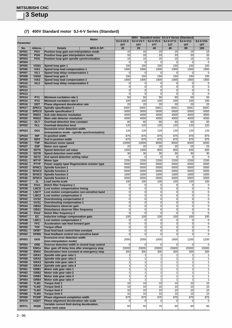
3 - 96
3 SetupMITSUBISHI CNC
(7) 400V Standard motor SJ-4-V Series (Standard)
MotorParameter
400V Standard motor SJ-4-V Series (Standard)SJ-4-V2.2-
03TSJ-4-V3.7-
03TSJ-4-V5.5-
07TSJ-4-V7.5-
12TSJ-4-V11-
18TSJ-4-V15-
18TNo. Abbrev. Details MDS-D-SP- 20 20 40 40 80 100
SP001 PGV Position loop gain non-interpolation mode 15 15 15 15 15 15SP002 PGN Position loop gain interpolation mode 33 33 33 33 33 33SP003 PGS Position loop gain spindle synchronization 15 15 15 15 15 15SP004 0 0 0 0 0 0SP005 VGN1 Speed loop gain 1 150 150 150 150 150 150SP006 VIA1 Speed loop lead compensation 1 1900 1900 1900 1900 1900 1900SP007 VIL1 Speed loop delay compensation 1 0 0 0 0 0 0SP008 VGN2 Speed loop gain 2 150 150 150 150 150 150SP009 VIA2 Speed loop lead compensation 2 1900 1900 1900 1900 1900 1900SP010 VIL2 Speed loop delay compensation 2 0 0 0 0 0 0SP011 0 0 0 0 0 0SP012 0 0 0 0 0 0SP013 0 0 0 0 0 0SP014 PY1 Minimum excitation rate 1 50 50 50 50 50 50SP015 PY2 Minimum excitation rate 2 100 100 100 100 100 100SP016 DDT Phase alignment deceleration rate 20 20 20 20 20 20SP017 SPEC1 Spindle specification 1 200C 200C 200C 200C 200C 200CSP018 SPEC2 Spindle specification 2 0000 0000 0000 0000 0000 0000SP019 RNG1 Sub side detector resolution 4000 4000 4000 4000 4000 4000SP020 RNG2 Main side detector resolution 4000 4000 4000 4000 4000 4000SP021 OLT Overload detection time constant 60 60 60 60 60 60SP022 OLL Overload detection level 120 120 120 120 120 120
SP023 OD1Excessive error detection width (interpolation mode - spindle synchronization)
120 120 120 120 120 120
SP024 INP In-position width 875 875 875 875 875 875SP025 INP2 2nd in-position width 875 875 875 875 875 875SP026 TSP Maximum motor speed 10000 10000 8000 8000 6000 6000SP027 ZSP Motor zero speed 25 25 25 25 25 25SP028 SDTS Speed detection set value 1000 1000 800 800 600 600SP029 SDTR Speed detection reset width 30 30 30 30 30 30SP030 SDT2 2nd speed detection setting value 0 0 0 0 0 0SP031 MTYP Motor type 2200 2200 2200 2200 2200 2200SP032 PTYP Power supply type/ Regenerative resistor type 0000 0000 0000 0000 0000 0000SP033 SFNC1 Spindle function 1 0000 0000 0000 0000 0000 0000SP034 SFNC2 Spindle function 2 0000 0000 0000 0000 0000 0000SP035 SFNC3 Spindle function 3 1600 1600 1600 1600 1600 1600SP036 SFNC4 Spindle function 4 0000 0000 0000 0000 0000 0000SP037 JL Load inertia scale 100 100 100 100 100 100SP038 FHz1 Notch filter frequency 1 0 0 0 0 0 0SP039 LMCD Lost motion compensation timing 0 0 0 0 0 0SP040 LMCT Lost motion compensation non-sensitive band 0 0 0 0 0 0SP041 LMC2 Lost motion compensation 2 0 0 0 0 0 0SP042 OVS2 Overshooting compensation 2 0 0 0 0 0 0SP043 OVS1 Overshooting compensation 1 0 0 0 0 0 0SP044 OBS2 Disturbance observer gain 0 0 0 0 0 0SP045 OBS1 Disturbance observer filter frequency 0 0 0 0 0 0SP046 FHz2 Notch filter frequency 2 0 0 0 0 0 0SP047 EC Inductive voltage compensation gain 100 100 100 100 100 100SP048 LMC1 Lost motion compensation 1 0 0 0 0 0 0SP049 FFC Acceleration rate feed forward gain 0 0 0 0 0 0SP050 TOF Torque offset 0 0 0 0 0 0SP051 DFBT Dual feed back control time constant 0 0 0 0 0 0SP052 DFBN Dual feedback control non-sensitive band 0 0 0 0 0 0
SP053 ODSExcessive error detection width (non-interpolation mode)
2000 2000 1600 1600 1200 1200
SP054 ORE Overrun detection width in closed loop control 0 0 0 0 0 0SP055 EMGx Max. gate off delay time after emergency stop 20000 20000 20000 20000 20000 20000SP056 EMGt Deceleration time constant at emergency stop 300 300 300 300 300 300SP057 GRA1 Spindle side gear ratio 1 1 1 1 1 1 1SP058 GRA2 Spindle side gear ratio 2 1 1 1 1 1 1SP059 GRA3 Spindle side gear ratio 3 1 1 1 1 1 1SP060 GRA4 Spindle side gear ratio 4 1 1 1 1 1 1SP061 GRB1 Motor side gear ratio 1 1 1 1 1 1 1SP062 GRB2 Motor side gear ratio 2 1 1 1 1 1 1SP063 GRB3 Motor side gear ratio 3 1 1 1 1 1 1SP064 GRB4 Motor side gear ratio 4 1 1 1 1 1 1SP065 TLM1 Torque limit 1 10 10 10 10 10 10SP066 TLM2 Torque limit 2 10 10 10 10 10 10SP067 TLM3 Torque limit 3 10 10 10 10 10 10SP068 TLM4 Torque limit 4 10 10 10 10 10 10SP069 PCMP Phase alignment completion width 875 875 875 875 875 875SP070 KDDT Phase alignment deceleration rate scale 0 0 0 0 0 0
SP071 DIQMVariable current limit during deceleration, lower limit value
50 50 75 60 60 60

3 - 97
MDS-D/DH Series Instruction Manual
3-3 Setting the initial parameters for the spindle drive unit
SP072 DIQNVariable current limit during deceleration, break point speed
5000 5000 6000 5000 3700 3700
SP073 VGVN Variable speed gain target value 0 0 0 0 0 0SP074 VGVS Variable speed gain change start speed 0 0 0 0 0 0
SP075 DWSHSlip compensation scale during regeneration high-speed coil
0 0 0 0 0 0
SP076 DWSLSlip compensation scale during regeneration low-speed coil
0 0 0 0 0 0
SP077 IQA Q axis current lead compensation 4096 4096 4096 4096 4096 4096SP078 IDA D axis current lead compensation 4096 4096 4096 4096 4096 4096SP079 IQG Q axis current gain 1024 1024 1024 1024 1024 1024SP080 IDG D axis current gain 1024 1024 1024 1024 1024 1024SP081 IQAL Q axis current lead compensation low-speed coil 0 0 0 0 0 0SP082 IDAL D axis current lead compensation low-speed coil 0 0 0 0 0 0SP083 IQGL Q axis current gain low-speed coil 0 0 0 0 0 0SP084 IDGL D axis current gain low-speed coil 0 0 0 0 0 0SP085 0 0 0 0 0 0SP086 0 0 0 0 0 0SP087 FHz4 Notch filter frequency 4 0 0 0 0 0 0SP088 FHz5 Notch filter frequency 5 0 0 0 0 0 0SP089 TMKQ Spindle output stabilizing gain Q axis 0 0 0 0 0 0SP090 TMKD Spindle output stabilizing gain D axis 0 0 0 0 0 0SP091 0 0 0 0 0 0
: : : : : : :SP093 0 0 0 0 0 0SP094 MPV Magnetic pole error detection speed 0 0 0 0 0 0
SP095 VIAXLead compensation scale during high-response accel-eration/deceleration
0 0 0 0 0 0
SP096 SDW Speed slowdown allowable width 0 0 0 0 0 0SP097 RNG1ex Extension sub side detector resolution 0 0 0 0 0 0SP098 RNG2ex Extension main side detector resolution 0 0 0 0 0 0SP099 0 0 0 0 0 0
: : : : : : :SP112 0 0 0 0 0 0SP113 OPLP Current command value for open loop 0 0 0 0 0 0SP114 MKT Coil changeover gate cutoff timer 150 150 150 150 150 150SP115 MKT2 Coil changeover current limit timer 250 250 250 250 250 250SP116 MKIL Coil changeover current limit value 120 120 120 120 120 120SP117 SETM Excessive speed deviation timer 12 12 12 12 12 12SP118 MSFT Magnetic pole shift amount 0 0 0 0 0 0SP119 0 0 0 0 0 0SP120 0 0 0 0 0 0SP121 MP Kpp Magnetic pole detection position loop gain 0 0 0 0 0 0SP122 MP Kvp Magnetic pole detection speed loop gain 0 0 0 0 0 0
SP123 MP KviMagnetic pole detection speed loop lead compensa-tion
0 0 0 0 0 0
SP124 ILMTsp Magnetic pole detection current limit value 0 0 0 0 0 0SP125 DA1NO D/A output ch1 data No. 0 0 0 0 0 0SP126 DA2NO D/A output ch2 data No. 0 0 0 0 0 0SP127 DA1MPY D/A output ch1 output scale 0 0 0 0 0 0SP128 DA2MPY D/A output ch2 output scale 0 0 0 0 0 0SP129 PM Motor unique constants (H) 2 2 2 2 2 2SP130 JM Motor unique constants (H) 7 9 15 25 30 58SP131 ATYP Motor unique constants (H) 20 20 40 40 80 100SP132 0 0 0 0 0 0SP133 NR Motor unique constants (H) 10000 10000 8000 8000 8000 8000SP134 NB Motor unique constants (H) 1500 1500 1800 1500 1500 1500SP135 NF Motor unique constants (H) 1800 1800 1800 1800 1800 1800SP136 KT Motor unique constants (H) 2354 2281 2596 2443 2645 2998SP137 KF1 Motor unique constants (H) 68 59 67 73 68 73SP138 KF2 Motor unique constants (H) 3053 3105 3198 3028 3062 3364SP139 KF3 Motor unique constants (H) 2632 2632 2499 2703 2734 2273SP140 KF4 Motor unique constants (H) 1923 1916 1936 1911 1899 1979SP141 KF5 Motor unique constants (H) 114 122 137 168 171 143SP142 KF6 Motor unique constants (H) 0 0 0 0 0 0SP143 0 0 0 0 0 0SP144 TMIL Motor unique constants (H) 0 0 0 0 0 0SP145 TMBR Motor unique constants (H) 333 325 155 298 312 306SP146 TMBD Motor unique constants (H) 417 421 202 410 432 421SP147 KE Motor unique constants (H) 67 65 60 63 63 74SP148 LA Motor unique constants (H) 11173 7300 5175 3873 3443 2433SP149 IQSM Motor unique constants (H) 595 1033 1349 1955 2648 3185SP150 IDSM Motor unique constants (H) 251 360 535 711 863 1650SP151 R1 Motor unique constants (H) 2559 1454 735 333 267 234SP152 TMLR Motor unique constants (H) 90 90 90 90 90 90SP153 TMLD Motor unique constants (H) 120 120 120 120 120 120
MotorParameter
400V Standard motor SJ-4-V Series (Standard)SJ-4-V2.2-
03TSJ-4-V3.7-
03TSJ-4-V5.5-
07TSJ-4-V7.5-
12TSJ-4-V11-
18TSJ-4-V15-
18TNo. Abbrev. Details MDS-D-SP- 20 20 40 40 80 100

3 - 98
3 SetupMITSUBISHI CNC
SP154 TMLS Motor unique constants (H) 150 150 150 150 150 150SP155 KI1 Motor unique constants (H) 1097 1061 1111 1048 1045 1026SP156 PCNT Motor unique constants (H) 0 0 0 0 0 0SP157 0 0 0 0 0 0SP158 DNB Motor unique constants (H) 0 0 1500 0 0 0SP159 SNB Motor unique constants (H) 0 0 1500 0 0 0SP160 BSD Motor unique constants (H) 0 0 0 0 0 0SP161 0 0 0 0 0 0
: : : : : : :SP164 0 0 0 0 0 0SP165 NRL Motor unique constants (L) 0 0 0 0 0 0SP166 NBL Motor unique constants (L) 0 0 0 0 0 0SP167 NFL Motor unique constants (L) 0 0 0 0 0 0SP168 KT Motor unique constants (L) 0 0 0 0 0 0SP169 KF1L Motor unique constants (L) 0 0 0 0 0 0SP170 KF2L Motor unique constants (L) 0 0 0 0 0 0SP171 KF3L Motor unique constants (L) 0 0 0 0 0 0SP172 KF4L Motor unique constants (L) 0 0 0 0 0 0SP173 KF5L Motor unique constants (L) 0 0 0 0 0 0SP174 KF6L Motor unique constants (L) 0 0 0 0 0 0SP175 0 0 0 0 0 0SP176 TMILL Motor unique constants (L) 0 0 0 0 0 0SP177 TMBRL Motor unique constants (L) 0 0 0 0 0 0SP178 TMBDL Motor unique constants (L) 0 0 0 0 0 0SP179 KEL Motor unique constants (L) 0 0 0 0 0 0SP180 LAL Motor unique constants (L) 0 0 0 0 0 0SP181 IQSML Motor unique constants (L) 0 0 0 0 0 0SP182 IDSML Motor unique constants (L) 0 0 0 0 0 0SP183 R1L Motor unique constants (L) 0 0 0 0 0 0SP184 0 0 0 0 0 0SP185 TMLRL Motor unique constants (L) 0 0 0 0 0 0SP186 TMLSL Motor unique constants (L) 0 0 0 0 0 0SP187 KI1L Motor unique constants (L) 0 0 0 0 0 0SP188 PCNTL Motor unique constants (L) 0 0 0 0 0 0SP189 0 0 0 0 0 0SP190 DNBL Motor unique constants (L) 0 0 0 0 0 0SP191 SNBL Motor unique constants (L) 0 0 0 0 0 0SP192 BSDL Motor unique constants (L) 0 0 0 0 0 0SP193 0 0 0 0 0 0
: : : : : : :SP224 0 0 0 0 0 0SP225 SFNC5 Spindle function 5 0000 0000 0000 0000 0000 0000SP226 SFNC6 Spindle function 6 0000 0000 0000 0000 0000 0000SP227 SFNC7 Spindle function 7 0000 0000 0000 0000 0000 0000SP228 SFNC8 Spindle function 8 0000 0000 0000 0000 0000 0000SP229 SFNC9 Spindle function 9 0000 0000 0000 0000 0000 0000SP230 SFNC10 Spindle function 10 0000 0000 0000 0000 0000 0000SP231 0000 0000 0000 0000 0000 0000SP232 0000 0000 0000 0000 0000 0000SP233 IVC Voltage non-sensitive band compensation 0 0 0 0 0 0SP234 0 0 0 0 0 0SP235 R2H Temperature compensation gain 0 0 0 0 0 0SP236 WIH Temperature compensation time constant 0 0 0 0 0 0SP237 TCF Torque command filter 500 500 500 500 500 500SP238 SSCFEED Safety observation Safety speed 0 0 0 0 0 0SP239 SSCRPM Safety observation Safety motor speed 0 0 0 0 0 0SP240 0 0 0 0 0 0
:SP256
MotorParameter
400V Standard motor SJ-4-V Series (Standard)SJ-4-V2.2-
03TSJ-4-V3.7-
03TSJ-4-V5.5-
07TSJ-4-V7.5-
12TSJ-4-V11-
18TSJ-4-V15-
18TNo. Abbrev. Details MDS-D-SP- 20 20 40 40 80 100

3 - 99
MDS-D/DH Series Instruction Manual
3-3 Setting the initial parameters for the spindle drive unit
MotorParameter
400V Standard motor SJ-4-V Series (Standard)SJ-4-V18.5-
14TSJ-4-V22-15T SJ-4-V26-08T SJ-4-V45-02T SJ-4-V55-03T
No. Abbrev. Details MDS-D-SP- 100 160 160 320 320SP001 PGV Position loop gain non-interpolation mode 15 15 15 15 15SP002 PGN Position loop gain interpolation mode 33 33 33 33 33SP003 PGS Position loop gain spindle synchronization 15 15 15 15 15SP004 0 0 0 0 0SP005 VGN1 Speed loop gain 1 150 150 150 150 150SP006 VIA1 Speed loop lead compensation 1 1900 1900 1900 1900 1900SP007 VIL1 Speed loop delay compensation 1 0 0 0 0 0SP008 VGN2 Speed loop gain 2 150 150 150 150 150SP009 VIA2 Speed loop lead compensation 2 1900 1900 1900 1900 1900SP010 VIL2 Speed loop delay compensation 2 0 0 0 0 0SP011 0 0 0 0 0SP012 0 0 0 0 0SP013 0 0 0 0 0SP014 PY1 Minimum excitation rate 1 50 50 50 50 50SP015 PY2 Minimum excitation rate 2 100 100 100 100 100SP016 DDT Phase alignment deceleration rate 20 20 20 20 20SP017 SPEC1 Spindle specification 1 200C 200C 200C 200C 200CSP018 SPEC2 Spindle specification 2 0000 0000 0000 0000 0000SP019 RNG1 Sub side detector resolution 4000 4000 4000 4000 4000SP020 RNG2 Main side detector resolution 4000 4000 4000 4000 4000SP021 OLT Overload detection time constant 60 60 60 60 60SP022 OLL Overload detection level 120 120 120 120 120
SP023 OD1Excessive error detection width (interpolation mode - spindle synchronization)
120 120 120 120 120
SP024 INP In-position width 875 875 875 875 875SP025 INP2 2nd in-position width 875 875 875 875 875SP026 TSP Maximum motor speed 6000 6000 6000 3450 3450SP027 ZSP Motor zero speed 25 25 25 25 25SP028 SDTS Speed detection set value 600 600 600 345 345SP029 SDTR Speed detection reset width 30 30 30 30 30SP030 SDT2 2nd speed detection setting value 0 0 0 0 0SP031 MTYP Motor type 2200 2200 2200 2200 2200SP032 PTYP Power supply type/ Regenerative resistor type 0000 0000 0000 0000 0000SP033 SFNC1 Spindle function 1 0000 0000 0000 0000 0000SP034 SFNC2 Spindle function 2 0000 0000 0000 0000 0000SP035 SFNC3 Spindle function 3 1600 1600 1600 1600 1600SP036 SFNC4 Spindle function 4 0000 0000 0000 0000 0000SP037 JL Load inertia scale 100 100 100 100 100SP038 FHz1 Notch filter frequency 1 0 0 0 0 0SP039 LMCD Lost motion compensation timing 0 0 0 0 0SP040 LMCT Lost motion compensation non-sensitive band 0 0 0 0 0SP041 LMC2 Lost motion compensation 2 0 0 0 0 0SP042 OVS2 Overshooting compensation 2 0 0 0 0 0SP043 OVS1 Overshooting compensation 1 0 0 0 0 0SP044 OBS2 Disturbance observer gain 0 0 0 0 0SP045 OBS1 Disturbance observer filter frequency 0 0 0 0 0SP046 FHz2 Notch filter frequency 2 0 0 0 0 0SP047 EC Inductive voltage compensation gain 100 100 100 100 100SP048 LMC1 Lost motion compensation 1 0 0 0 0 0SP049 FFC Acceleration rate feed forward gain 0 0 0 0 0SP050 TOF Torque offset 0 0 0 0 0SP051 DFBT Dual feed back control time constant 0 0 0 0 0SP052 DFBN Dual feedback control non-sensitive band 0 0 0 0 0
SP053 ODSExcessive error detection width (non-interpolation mode)
1200 1200 1200 690 690
SP054 ORE Overrun detection width in closed loop control 0 0 0 0 0SP055 EMGx Max. gate off delay time after emergency stop 20000 20000 20000 20000 20000SP056 EMGt Deceleration time constant at emergency stop 300 300 300 300 300SP057 GRA1 Spindle side gear ratio 1 1 1 1 1 1SP058 GRA2 Spindle side gear ratio 2 1 1 1 1 1SP059 GRA3 Spindle side gear ratio 3 1 1 1 1 1SP060 GRA4 Spindle side gear ratio 4 1 1 1 1 1SP061 GRB1 Motor side gear ratio 1 1 1 1 1 1SP062 GRB2 Motor side gear ratio 2 1 1 1 1 1SP063 GRB3 Motor side gear ratio 3 1 1 1 1 1SP064 GRB4 Motor side gear ratio 4 1 1 1 1 1SP065 TLM1 Torque limit 1 10 10 10 10 10SP066 TLM2 Torque limit 2 10 10 10 10 10SP067 TLM3 Torque limit 3 10 10 10 10 10SP068 TLM4 Torque limit 4 10 10 10 10 10SP069 PCMP Phase alignment completion width 875 875 875 875 875SP070 KDDT Phase alignment deceleration rate scale 0 0 0 0 0
SP071 DIQMVariable current limit during deceleration, lower limit value
60 60 80 80 80
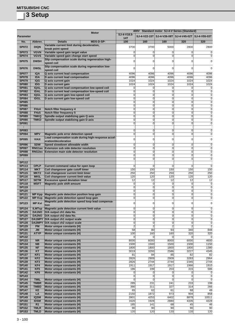
3 - 100
3 SetupMITSUBISHI CNC
SP072 DIQNVariable current limit during deceleration, break point speed
3700 3700 5000 2800 2800
SP073 VGVN Variable speed gain target value 0 0 0 0 0SP074 VGVS Variable speed gain change start speed 0 0 0 0 0
SP075 DWSHSlip compensation scale during regeneration high-speed coil
0 0 0 0 0
SP076 DWSLSlip compensation scale during regeneration low-speed coil
0 0 0 0 0
SP077 IQA Q axis current lead compensation 4096 4096 4096 4096 4096SP078 IDA D axis current lead compensation 4096 4096 4096 4096 4096SP079 IQG Q axis current gain 1024 1024 1024 1024 1024SP080 IDG D axis current gain 1024 1024 1024 1024 1024SP081 IQAL Q axis current lead compensation low-speed coil 0 0 0 0 0SP082 IDAL D axis current lead compensation low-speed coil 0 0 0 0 0SP083 IQGL Q axis current gain low-speed coil 0 0 0 0 0SP084 IDGL D axis current gain low-speed coil 0 0 0 0 0SP085 0 0 0 0 0SP086 0 0 0 0 0SP087 FHz4 Notch filter frequency 4 0 0 0 0 0SP088 FHz5 Notch filter frequency 5 0 0 0 0 0SP089 TMKQ Spindle output stabilizing gain Q axis 0 0 0 0 0SP090 TMKD Spindle output stabilizing gain D axis 0 0 0 0 0SP091 0 0 0 0 0
: : : : : :SP093 0 0 0 0 0SP094 MPV Magnetic pole error detection speed 0 0 0 0 0
SP095 VIAXLead compensation scale during high-response accel-eration/deceleration
0 0 0 0 0
SP096 SDW Speed slowdown allowable width 0 0 0 0 0SP097 RNG1ex Extension sub side detector resolution 0 0 0 0 0SP098 RNG2ex Extension main side detector resolution 0 0 0 0 0SP099 0 0 0 0 0
: 0 0 0 0 0SP112 : : : : :SP113 OPLP Current command value for open loop 0 0 0 0 0SP114 MKT Coil changeover gate cutoff timer 150 150 150 150 150SP115 MKT2 Coil changeover current limit timer 250 250 250 250 250SP116 MKIL Coil changeover current limit value 120 120 120 120 120SP117 SETM Excessive speed deviation timer 12 12 12 12 12SP118 MSFT Magnetic pole shift amount 0 0 0 0 0SP119 0 0 0 0 0SP120 0 0 0 0 0SP121 MP Kpp Magnetic pole detection position loop gain 0 0 0 0 0SP122 MP Kvp Magnetic pole detection speed loop gain 0 0 0 0 0
SP123 MP KviMagnetic pole detection speed loop lead compensa-tion
0 0 0 0 0
SP124 ILMTsp Magnetic pole detection current limit value 0 0 0 0 0SP125 DA1NO D/A output ch1 data No. 0 0 0 0 0SP126 DA2NO D/A output ch2 data No. 0 0 0 0 0SP127 DA1MPY D/A output ch1 output scale 0 0 0 0 0SP128 DA2MPY D/A output ch2 output scale 0 0 0 0 0SP129 PM Motor unique constants (H) 2 2 2 2 2SP130 JM Motor unique constants (H) 58 80 93 340 848SP131 ATYP Motor unique constants (H) 100 160 160 320 320SP132 0 0 0 0 0SP133 NR Motor unique constants (H) 8000 6000 8000 6000 4600SP134 NB Motor unique constants (H) 1500 1500 1500 1500 1150SP135 NF Motor unique constants (H) 1800 1800 1800 1800 1380SP136 KT Motor unique constants (H) 3019 3293 2586 3227 4345SP137 KF1 Motor unique constants (H) 81 84 85 82 82SP138 KF2 Motor unique constants (H) 2826 2909 2909 3283 2964SP139 KF3 Motor unique constants (H) 2826 2744 2744 2345 2744SP140 KF4 Motor unique constants (H) 1911 1917 1917 1966 1910SP141 KF5 Motor unique constants (H) 186 199 203 315 586SP142 KF6 Motor unique constants (H) 0 0 0 0 0SP143 0 0 0 0 0SP144 TMIL Motor unique constants (H) 0 0 0 0 0SP145 TMBR Motor unique constants (H) 285 231 241 233 199SP146 TMBD Motor unique constants (H) 390 311 327 314 266SP147 KE Motor unique constants (H) 65 62 61 68 49SP148 LA Motor unique constants (H) 2150 1872 973 904 858SP149 IQSM Motor unique constants (H) 3901 4253 6402 8878 10511SP150 IDSM Motor unique constants (H) 1620 1928 2880 4335 4328SP151 R1 Motor unique constants (H) 185 141 68 45 46SP152 TMLR Motor unique constants (H) 90 90 90 90 90SP153 TMLD Motor unique constants (H) 120 120 120 120 120
MotorParameter
400V Standard motor SJ-4-V Series (Standard)SJ-4-V18.5-
14TSJ-4-V22-15T SJ-4-V26-08T SJ-4-V45-02T SJ-4-V55-03T
No. Abbrev. Details MDS-D-SP- 100 160 160 320 320

3 - 101
MDS-D/DH Series Instruction Manual
3-3 Setting the initial parameters for the spindle drive unit
SP154 TMLS Motor unique constants (H) 150 150 150 150 150SP155 KI1 Motor unique constants (H) 1039 1036 1056 1024 1031SP156 PCNT Motor unique constants (H) 0 0 0 0 0SP157 0 0 0 0 0SP158 DNB Motor unique constants (H) 0 0 0 0 0SP159 SNB Motor unique constants (H) 0 0 0 0 0SP160 BSD Motor unique constants (H) 0 0 0 0 0SP161 0 0 0 0 0
: : : : : :SP164 0 0 0 0 0SP165 NRL Motor unique constants (L) 0 0 0 0 0SP166 NBL Motor unique constants (L) 0 0 0 0 0SP167 NFL Motor unique constants (L) 0 0 0 0 0SP168 KT Motor unique constants (L) 0 0 0 0 0SP169 KF1L Motor unique constants (L) 0 0 0 0 0SP170 KF2L Motor unique constants (L) 0 0 0 0 0SP171 KF3L Motor unique constants (L) 0 0 0 0 0SP172 KF4L Motor unique constants (L) 0 0 0 0 0SP173 KF5L Motor unique constants (L) 0 0 0 0 0SP174 KF6L Motor unique constants (L) 0 0 0 0 0SP175 0 0 0 0 0SP176 TMILL Motor unique constants (L) 0 0 0 0 0SP177 TMBRL Motor unique constants (L) 0 0 0 0 0SP178 TMBDL Motor unique constants (L) 0 0 0 0 0SP179 KEL Motor unique constants (L) 0 0 0 0 0SP180 LAL Motor unique constants (L) 0 0 0 0 0SP181 IQSML Motor unique constants (L) 0 0 0 0 0SP182 IDSML Motor unique constants (L) 0 0 0 0 0SP183 R1L Motor unique constants (L) 0 0 0 0 0SP184 0 0 0 0 0SP185 TMLRL Motor unique constants (L) 0 0 0 0 0SP186 TMLSL Motor unique constants (L) 0 0 0 0 0SP187 KI1L Motor unique constants (L) 0 0 0 0 0SP188 PCNTL Motor unique constants (L) 0 0 0 0 0SP189 0 0 0 0 0SP190 DNBL Motor unique constants (L) 0 0 0 0 0SP191 SNBL Motor unique constants (L) 0 0 0 0 0SP192 BSDL Motor unique constants (L) 0 0 0 0 0SP193 0 0 0 0 0
: : : : : :SP224 0 0 0 0 0SP225 SFNC5 Spindle function 5 0000 0000 0000 0000 0000SP226 SFNC6 Spindle function 6 0000 0000 0000 0000 0000SP227 SFNC7 Spindle function 7 0000 0000 0000 0000 0000SP228 SFNC8 Spindle function 8 0000 0000 0000 0000 0000SP229 SFNC9 Spindle function 9 0000 0000 0000 0000 0000SP230 SFNC10 Spindle function 10 0000 0000 0000 0000 0000SP231 0000 0000 0000 0000 0000SP232 0000 0000 0000 0000 0000SP233 IVC Voltage non-sensitive band compensation 0 0 0 0 0SP234 0 0 0 0 0SP235 R2H Temperature compensation gain 0 0 0 0 0SP236 WIH Temperature compensation time constant 0 0 0 0 0SP237 TCF Torque command filter 500 500 500 500 500SP238 SSCFEED Safety observation Safety speed 0 0 0 0 0SP239 SSCRPM Safety observation Safety motor speed 0 0 0 0 0SP240 0 0 0 0 0
:SP256
MotorParameter
400V Standard motor SJ-4-V Series (Standard)SJ-4-V18.5-
14TSJ-4-V22-15T SJ-4-V26-08T SJ-4-V45-02T SJ-4-V55-03T
No. Abbrev. Details MDS-D-SP- 100 160 160 320 320

3 - 102
3 SetupMITSUBISHI CNC
(8) 400V Standard motor SJ-4-V Series (High-speed)
MotorParameter
400V Standard motor SJ-4-V Series (High-speed)
400V Standard motor SJ-4-VS Series (Hollow shaft)
SJ-4-V7.5-13ZT SJ-4-VS7.5-13TNo. Abbrev. Details MDS-D-SP- 80 80
SP001 PGV Position loop gain non-interpolation mode 15 15SP002 PGN Position loop gain interpolation mode 33 33SP003 PGS Position loop gain spindle synchronization 15 15SP004 0 0SP005 VGN1 Speed loop gain 1 150 150SP006 VIA1 Speed loop lead compensation 1 1900 1900SP007 VIL1 Speed loop delay compensation 1 0 0SP008 VGN2 Speed loop gain 2 150 150SP009 VIA2 Speed loop lead compensation 2 1900 1900SP010 VIL2 Speed loop delay compensation 2 0 0SP011 0 0SP012 0 0SP013 0 0SP014 PY1 Minimum excitation rate 1 50 50SP015 PY2 Minimum excitation rate 2 100 100SP016 DDT Phase alignment deceleration rate 20 20SP017 SPEC1 Spindle specification 1 200C 200CSP018 SPEC2 Spindle specification 2 0000 0000SP019 RNG1 Sub side detector resolution 4000 4000SP020 RNG2 Main side detector resolution 4000 4000SP021 OLT Overload detection time constant 60 60SP022 OLL Overload detection level 120 120
SP023 OD1Excessive error detection width (interpolation mode - spindle synchroniza-tion)
120 120
SP024 INP In-position width 875 875SP025 INP2 2nd in-position width 875 875SP026 TSP Maximum motor speed 12000 12000SP027 ZSP Motor zero speed 25 25SP028 SDTS Speed detection set value 1200 1200SP029 SDTR Speed detection reset width 30 30SP030 SDT2 2nd speed detection setting value 0 0SP031 MTYP Motor type 2200 2200
SP032 PTYPPower supply type/ Regenerative resistor type
0000 0000
SP033 SFNC1 Spindle function 1 0000 0000SP034 SFNC2 Spindle function 2 0000 0000SP035 SFNC3 Spindle function 3 1600 1600SP036 SFNC4 Spindle function 4 0000 0000SP037 JL Load inertia scale 100 100SP038 FHz1 Notch filter frequency 1 0 0SP039 LMCD Lost motion compensation timing 0 0
SP040 LMCTLost motion compensation non-sensitive band
0 0
SP041 LMC2 Lost motion compensation 2 0 0SP042 OVS2 Overshooting compensation 2 0 0SP043 OVS1 Overshooting compensation 1 0 0SP044 OBS2 Disturbance observer gain 0 0SP045 OBS1 Disturbance observer filter frequency 0 0SP046 FHz2 Notch filter frequency 2 0 0SP047 EC Inductive voltage compensation gain 100 100SP048 LMC1 Lost motion compensation 1 0 0SP049 FFC Acceleration rate feed forward gain 0 0SP050 TOF Torque offset 0 0SP051 DFBT Dual feed back control time constant 0 0SP052 DFBN Dual feedback control non-sensitive band 0 0
SP053 ODSExcessive error detection width (non-interpolation mode)
2400 2400
SP054 OREOverrun detection width in closed loop con-trol
0 0
SP055 EMGx Max. gate off delay time after emergency stop 20000 20000
SP056 EMGtDeceleration time constant at emergency stop
300 300
SP057 GRA1 Spindle side gear ratio 1 1 1SP058 GRA2 Spindle side gear ratio 2 1 1SP059 GRA3 Spindle side gear ratio 3 1 1SP060 GRA4 Spindle side gear ratio 4 1 1SP061 GRB1 Motor side gear ratio 1 1 1SP062 GRB2 Motor side gear ratio 2 1 1SP063 GRB3 Motor side gear ratio 3 1 1SP064 GRB4 Motor side gear ratio 4 1 1SP065 TLM1 Torque limit 1 10 10SP066 TLM2 Torque limit 2 10 10SP067 TLM3 Torque limit 3 10 10

3 - 103
MDS-D/DH Series Instruction Manual
3-3 Setting the initial parameters for the spindle drive unit
SP068 TLM4 Torque limit 4 10 10SP069 PCMP Phase alignment completion width 875 875SP070 KDDT Phase alignment deceleration rate scale 0 0
SP071 DIQMVariable current limit during deceleration, lower limit value
60 60
SP072 DIQNVariable current limit during deceleration, break point speed
7600 7600
SP073 VGVN Variable speed gain target value 0 0SP074 VGVS Variable speed gain change start speed 0 0
SP075 DWSHSlip compensation scale during regeneration high-speed coil
0 0
SP076 DWSLSlip compensation scale during regeneration low-speed coil
0 0
SP077 IQA Q axis current lead compensation 4096 4096SP078 IDA D axis current lead compensation 4096 4096SP079 IQG Q axis current gain 1024 1024SP080 IDG D axis current gain 1024 1024
SP081 IQALQ axis current lead compensation low-speed coil
0 0
SP082 IDALD axis current lead compensation low-speed coil
0 0
SP083 IQGL Q axis current gain low-speed coil 0 0SP084 IDGL D axis current gain low-speed coil 0 0SP085 0 0SP086 0 0SP087 FHz4 Notch filter frequency 4 0 0SP088 FHz5 Notch filter frequency 5 0 0SP089 TMKQ Spindle output stabilizing gain Q axis 0 0SP090 TMKD Spindle output stabilizing gain D axis 0 0SP091 0 0
: : :SP093 0 0SP094 MPV Magnetic pole error detection speed 0 0
SP095 VIAXLead compensation scale during high-re-sponse acceleration/deceleration
0 0
SP096 SDW Speed slowdown allowable width 0 0SP097 RNG1ex Extension sub side detector resolution 0 0SP098 RNG2ex Extension main side detector resolution 0 0SP099 0 0
: : :SP112 0 0SP113 OPLP Current command value for open loop 0 0SP114 MKT Coil changeover gate cutoff timer 150 150SP115 MKT2 Coil changeover current limit timer 250 250SP116 MKIL Coil changeover current limit value 120 120SP117 SETM Excessive speed deviation timer 12 12SP118 MSFT Magnetic pole shift amount 0 0SP119 0 0SP120 0 0SP121 MP Kpp Magnetic pole detection position loop gain 0 0SP122 MP Kvp Magnetic pole detection speed loop gain 0 0
SP123 MP KviMagnetic pole detection speed loop lead compensation
0 0
SP124 ILMTsp Magnetic pole detection current limit value 0 0SP125 DA1NO D/A output ch1 data No. 0 0SP126 DA2NO D/A output ch2 data No. 0 0SP127 DA1MPY D/A output ch1 output scale 0 0SP128 DA2MPY D/A output ch2 output scale 0 0SP129 PM Motor unique constants (H) 2 2SP130 JM Motor unique constants (H) 25 25SP131 ATYP Motor unique constants (H) 80 80SP132 0 0SP133 NR Motor unique constants (H) 12000 12000SP134 NB Motor unique constants (H) 1500 1500SP135 NF Motor unique constants (H) 1950 1950SP136 KT Motor unique constants (H) 1926 1926SP137 KF1 Motor unique constants (H) 73 73SP138 KF2 Motor unique constants (H) 3058 3058SP139 KF3 Motor unique constants (H) 2683 2683SP140 KF4 Motor unique constants (H) 1911 1911SP141 KF5 Motor unique constants (H) 170 170SP142 KF6 Motor unique constants (H) 0 0SP143 0 0SP144 TMIL Motor unique constants (H) 0 0SP145 TMBR Motor unique constants (H) 363 363SP146 TMBD Motor unique constants (H) 440 440
MotorParameter
400V Standard motor SJ-4-V Series (High-speed)
400V Standard motor SJ-4-VS Series (Hollow shaft)
SJ-4-V7.5-13ZT SJ-4-VS7.5-13TNo. Abbrev. Details MDS-D-SP- 80 80

3 - 104
3 SetupMITSUBISHI CNC
SP147 KE Motor unique constants (H) 63 63SP148 LA Motor unique constants (H) 2433 2433SP149 IQSM Motor unique constants (H) 2479 2479SP150 IDSM Motor unique constants (H) 886 886SP151 R1 Motor unique constants (H) 204 204SP152 TMLR Motor unique constants (H) 90 90SP153 TMLD Motor unique constants (H) 120 120SP154 TMLS Motor unique constants (H) 150 150SP155 KI1 Motor unique constants (H) 1100 1100SP156 PCNT Motor unique constants (H) 0 0SP157 0 0SP158 DNB Motor unique constants (H) 0 0SP159 SNB Motor unique constants (H) 0 0SP160 BSD Motor unique constants (H) 0 0SP161 0 0
: : :SP164 0 0SP165 NRL Motor unique constants (L) 0 0SP166 NBL Motor unique constants (L) 0 0SP167 NFL Motor unique constants (L) 0 0SP168 KT Motor unique constants (L) 0 0SP169 KF1L Motor unique constants (L) 0 0SP170 KF2L Motor unique constants (L) 0 0SP171 KF3L Motor unique constants (L) 0 0SP172 KF4L Motor unique constants (L) 0 0SP173 KF5L Motor unique constants (L) 0 0SP174 KF6L Motor unique constants (L) 0 0SP175 0 0SP176 TMILL Motor unique constants (L) 0 0SP177 TMBRL Motor unique constants (L) 0 0SP178 TMBDL Motor unique constants (L) 0 0SP179 KEL Motor unique constants (L) 0 0SP180 LAL Motor unique constants (L) 0 0SP181 IQSML Motor unique constants (L) 0 0SP182 IDSML Motor unique constants (L) 0 0SP183 R1L Motor unique constants (L) 0 0SP184 0 0SP185 TMLRL Motor unique constants (L) 0 0SP186 TMLSL Motor unique constants (L) 0 0SP187 KI1L Motor unique constants (L) 0 0SP188 PCNTL Motor unique constants (L) 0 0SP189 0 0SP190 DNBL Motor unique constants (L) 0 0SP191 SNBL Motor unique constants (L) 0 0SP192 BSDL Motor unique constants (L) 0 0SP193 0 0
: 0 :SP224 0 0SP225 SFNC5 Spindle function 5 0000 0000SP226 SFNC6 Spindle function 6 0000 0000SP227 SFNC7 Spindle function 7 0000 0000SP228 SFNC8 Spindle function 8 0000 0000SP229 SFNC9 Spindle function 9 0000 0000SP230 SFNC10 Spindle function 10 0000 0000SP231 0000 0000SP232 0000 0000SP233 IVC Voltage non-sensitive band compensation 0 0SP234 0 0SP235 R2H Temperature compensation gain 0 0SP236 WIH Temperature compensation time constant 0 0SP237 TCF Torque command filter 500 500SP238 SSCFEED Safety observation Safety speed 0 0SP239 SSCRPM Safety observation Safety motor speed 0 0SP240 0 0
:SP256
MotorParameter
400V Standard motor SJ-4-V Series (High-speed)
400V Standard motor SJ-4-VS Series (Hollow shaft)
SJ-4-V7.5-13ZT SJ-4-VS7.5-13TNo. Abbrev. Details MDS-D-SP- 80 80

3 - 105
MDS-D/DH Series Instruction Manual
3-3 Setting the initial parameters for the spindle drive unit
(9) 400V Standard motor SJ-4-V Series (Wide range constant output)
MotorParameter
400V Standard motor SJ-4-V Series (Wide range constant output)SJ-4-V11-18T SJ-4-V15-20T SJ-4-V18.5-17T SJ-4-V22-16T
No. Abbrev. Details MDS-D-SP- 80 100 160 160SP001 PGV Position loop gain non-interpolation mode 15 15 15 15SP002 PGN Position loop gain interpolation mode 33 33 33 33SP003 PGS Position loop gain spindle synchronization 15 15 15 15SP004 0 0 0 0SP005 VGN1 Speed loop gain 1 150 150 150 150SP006 VIA1 Speed loop lead compensation 1 1900 1900 1900 1900SP007 VIL1 Speed loop delay compensation 1 0 0 0 0SP008 VGN2 Speed loop gain 2 150 150 150 150SP009 VIA2 Speed loop lead compensation 2 1900 1900 1900 1900SP010 VIL2 Speed loop delay compensation 2 0 0 0 0SP011 0 0 0 0SP012 0 0 0 0SP013 0 0 0 0SP014 PY1 Minimum excitation rate 1 50 50 50 50SP015 PY2 Minimum excitation rate 2 100 100 100 100SP016 DDT Phase alignment deceleration rate 20 20 20 20SP017 SPEC1 Spindle specification 1 200C 200C 200C 200CSP018 SPEC2 Spindle specification 2 0000 0000 0000 0000SP019 RNG1 Sub side detector resolution 4000 4000 4000 4000SP020 RNG2 Main side detector resolution 4000 4000 4000 4000SP021 OLT Overload detection time constant 60 60 60 60SP022 OLL Overload detection level 120 120 120 120
SP023 OD1Excessive error detection width (interpolation mode - spindle synchroniza-tion)
120 120 120 120
SP024 INP In-position width 875 875 875 875SP025 INP2 2nd in-position width 875 875 875 875SP026 TSP Maximum motor speed 6000 6000 6000 6000SP027 ZSP Motor zero speed 25 25 25 25SP028 SDTS Speed detection set value 600 600 600 600SP029 SDTR Speed detection reset width 30 30 30 30SP030 SDT2 2nd speed detection setting value 0 0 0 0SP031 MTYP Motor type 2200 2200 2200 2200
SP032 PTYPPower supply type/ Regenerative resistor type
0000 0000 0000 0000
SP033 SFNC1 Spindle function 1 0000 0000 0000 0000SP034 SFNC2 Spindle function 2 0000 0000 0000 0000SP035 SFNC3 Spindle function 3 1600 1600 1600 1600SP036 SFNC4 Spindle function 4 0000 0000 0000 0000SP037 JL Load inertia scale 100 100 100 100SP038 FHz1 Notch filter frequency 1 0 0 0 0SP039 LMCD Lost motion compensation timing 0 0 0 0
SP040 LMCTLost motion compensation non-sensitive band
0 0 0 0
SP041 LMC2 Lost motion compensation 2 0 0 0 0SP042 OVS2 Overshooting compensation 2 0 0 0 0SP043 OVS1 Overshooting compensation 1 0 0 0 0SP044 OBS2 Disturbance observer gain 0 0 0 0SP045 OBS1 Disturbance observer filter frequency 0 0 0 0SP046 FHz2 Notch filter frequency 2 0 0 0 0SP047 EC Inductive voltage compensation gain 100 100 100 100SP048 LMC1 Lost motion compensation 1 0 0 0 0SP049 FFC Acceleration rate feed forward gain 0 0 0 0SP050 TOF Torque offset 0 0 0 0SP051 DFBT Dual feed back control time constant 0 0 0 0SP052 DFBN Dual feedback control non-sensitive band 0 0 0 0
SP053 ODSExcessive error detection width (non-interpolation mode)
1200 1200 1200 1200
SP054 OREOverrun detection width in closed loop con-trol
0 0 0 0
SP055 EMGxMax. gate off delay time after emergency stop
20000 20000 20000 20000
SP056 EMGtDeceleration time constant at emergency stop
300 300 300 300
SP057 GRA1 Spindle side gear ratio 1 1 1 1 1SP058 GRA2 Spindle side gear ratio 2 1 1 1 1SP059 GRA3 Spindle side gear ratio 3 1 1 1 1SP060 GRA4 Spindle side gear ratio 4 1 1 1 1SP061 GRB1 Motor side gear ratio 1 1 1 1 1SP062 GRB2 Motor side gear ratio 2 1 1 1 1SP063 GRB3 Motor side gear ratio 3 1 1 1 1SP064 GRB4 Motor side gear ratio 4 1 1 1 1SP065 TLM1 Torque limit 1 10 10 10 10SP066 TLM2 Torque limit 2 10 10 10 10SP067 TLM3 Torque limit 3 10 10 10 10

3 - 106
3 SetupMITSUBISHI CNC
SP068 TLM4 Torque limit 4 10 10 10 10SP069 PCMP Phase alignment completion width 875 875 875 875SP070 KDDT Phase alignment deceleration rate scale 0 0 0 0
SP071 DIQMVariable current limit during deceleration, lower limit value
60 60 60 75
SP072 DIQNVariable current limit during deceleration, break point speed
3700 3700 3700 4500
SP073 VGVN Variable speed gain target value 0 0 0 0SP074 VGVS Variable speed gain change start speed 0 0 0 0
SP075 DWSHSlip compensation scale during regeneration high-speed coil
0 0 0 0
SP076 DWSLSlip compensation scale during regeneration low-speed coil
0 0 0 0
SP077 IQA Q axis current lead compensation 4096 4096 4096 4096SP078 IDA D axis current lead compensation 4096 4096 4096 4096SP079 IQG Q axis current gain 1024 1024 1024 1024SP080 IDG D axis current gain 1024 1024 1024 1024
SP081 IQALQ axis current lead compensation low-speed coil
0 0 0 0
SP082 IDALD axis current lead compensation low-speed coil
0 0 0 0
SP083 IQGL Q axis current gain low-speed coil 0 0 0 0SP084 IDGL D axis current gain low-speed coil 0 0 0 0SP085 0 0 0 0SP086 0 0 0 0SP087 FHz4 Notch filter frequency 4 0 0 0 0SP088 FHz5 Notch filter frequency 5 0 0 0 0SP089 TMKQ Spindle output stabilizing gain Q axis 0 0 0 0SP090 TMKD Spindle output stabilizing gain D axis 0 0 0 0SP091 0 0 0 0
: : : : :SP093 0 0 0 0SP094 MPV Magnetic pole error detection speed 0 0 0 0
SP095 VIAXLead compensation scale during high-re-sponse acceleration/deceleration
0 0 0 0
SP096 SDW Speed slowdown allowable width 0 0 0 0SP097 RNG1ex Extension sub side detector resolution 0 0 0 0SP098 RNG2ex Extension main side detector resolution 0 0 0 0SP099 0 0 0 0
: : : : :SP112 0 0 0 0SP113 OPLP Current command value for open loop 0 0 0 0SP114 MKT Coil changeover gate cutoff timer 150 150 150 150SP115 MKT2 Coil changeover current limit timer 250 250 250 250SP116 MKIL Coil changeover current limit value 120 120 120 120SP117 SETM Excessive speed deviation timer 12 12 12 12SP118 MSFT Magnetic pole shift amount 0 0 0 0SP119 0 0 0 0SP120 0 0 0 0SP121 MP Kpp Magnetic pole detection position loop gain 0 0 0 0SP122 MP Kvp Magnetic pole detection speed loop gain 0 0 0 0
SP123 MP KviMagnetic pole detection speed loop lead compensation
0 0 0 0
SP124 ILMTsp Magnetic pole detection current limit value 0 0 0 0SP125 DA1NO D/A output ch1 data No. 0 0 0 0SP126 DA2NO D/A output ch2 data No. 0 0 0 0SP127 DA1MPY D/A output ch1 output scale 0 0 0 0SP128 DA2MPY D/A output ch2 output scale 0 0 0 0SP129 PM Motor unique constants (H) 2 2 2 2SP130 JM Motor unique constants (H) 30 58 80 80SP131 ATYP Motor unique constants (H) 80 100 160 160SP132 0 0 0 0SP133 NR Motor unique constants (H) 8000 8000 8000 8000SP134 NB Motor unique constants (H) 1500 1250 1250 1100SP135 NF Motor unique constants (H) 1800 1250 1250 1100SP136 KT Motor unique constants (H) 2645 3365 3548 3394SP137 KF1 Motor unique constants (H) 68 73 59 68SP138 KF2 Motor unique constants (H) 3062 2865 2942 2830SP139 KF3 Motor unique constants (H) 2734 2755 2724 2888SP140 KF4 Motor unique constants (H) 1899 1919 1917 1899SP141 KF5 Motor unique constants (H) 171 191 201 190SP142 KF6 Motor unique constants (H) 0 0 0 0SP143 0 0 0 0SP144 TMIL Motor unique constants (H) 0 0 0 0SP145 TMBR Motor unique constants (H) 312 382 350 433SP146 TMBD Motor unique constants (H) 432 435 437 436SP147 KE Motor unique constants (H) 63 63 61 64
MotorParameter
400V Standard motor SJ-4-V Series (Wide range constant output)SJ-4-V11-18T SJ-4-V15-20T SJ-4-V18.5-17T SJ-4-V22-16T
No. Abbrev. Details MDS-D-SP- 80 100 160 160
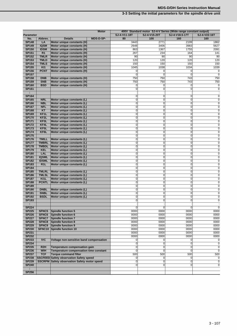
3 - 107
MDS-D/DH Series Instruction Manual
3-3 Setting the initial parameters for the spindle drive unit
SP148 LA Motor unique constants (H) 3443 2771 2199 1862SP149 IQSM Motor unique constants (H) 2648 3406 3983 5627SP150 IDSM Motor unique constants (H) 863 1367 1755 2091SP151 R1 Motor unique constants (H) 267 234 164 141SP152 TMLR Motor unique constants (H) 90 90 90 90SP153 TMLD Motor unique constants (H) 120 120 120 120SP154 TMLS Motor unique constants (H) 150 150 150 150SP155 KI1 Motor unique constants (H) 1045 1038 1034 1039SP156 PCNT Motor unique constants (H) 0 0 0 0SP157 0 0 0 0SP158 DNB Motor unique constants (H) 750 750 743 750SP159 SNB Motor unique constants (H) 750 750 743 750SP160 BSD Motor unique constants (H) 0 0 0 0SP161 0 0 0 0
: : : : :SP164 0 0 0 0SP165 NRL Motor unique constants (L) 0 0 0 0SP166 NBL Motor unique constants (L) 0 0 0 0SP167 NFL Motor unique constants (L) 0 0 0 0SP168 KT Motor unique constants (L) 0 0 0 0SP169 KF1L Motor unique constants (L) 0 0 0 0SP170 KF2L Motor unique constants (L) 0 0 0 0SP171 KF3L Motor unique constants (L) 0 0 0 0SP172 KF4L Motor unique constants (L) 0 0 0 0SP173 KF5L Motor unique constants (L) 0 0 0 0SP174 KF6L Motor unique constants (L) 0 0 0 0SP175 0 0 0 0SP176 TMILL Motor unique constants (L) 0 0 0 0SP177 TMBRL Motor unique constants (L) 0 0 0 0SP178 TMBDL Motor unique constants (L) 0 0 0 0SP179 KEL Motor unique constants (L) 0 0 0 0SP180 LAL Motor unique constants (L) 0 0 0 0SP181 IQSML Motor unique constants (L) 0 0 0 0SP182 IDSML Motor unique constants (L) 0 0 0 0SP183 R1L Motor unique constants (L) 0 0 0 0SP184 0 0 0 0SP185 TMLRL Motor unique constants (L) 0 0 0 0SP186 TMLSL Motor unique constants (L) 0 0 0 0SP187 KI1L Motor unique constants (L) 0 0 0 0SP188 PCNTL Motor unique constants (L) 0 0 0 0SP189 0 0 0 0SP190 DNBL Motor unique constants (L) 0 0 0 0SP191 SNBL Motor unique constants (L) 0 0 0 0SP192 BSDL Motor unique constants (L) 0 0 0 0SP193 0 0 0 0
: : : : :SP224 0 0 0 0SP225 SFNC5 Spindle function 5 0000 0000 0000 0000SP226 SFNC6 Spindle function 6 0000 0000 0000 0000SP227 SFNC7 Spindle function 7 0000 0000 0000 0000SP228 SFNC8 Spindle function 8 0000 0000 0000 0000SP229 SFNC9 Spindle function 9 0000 0000 0000 0000SP230 SFNC10 Spindle function 10 0000 0000 0000 0000SP231 0000 0000 0000 0000SP232 0000 0000 0000 0000SP233 IVC Voltage non-sensitive band compensation 0 0 0 0SP234 0 0 0 0SP235 R2H Temperature compensation gain 0 0 0 0SP236 WIH Temperature compensation time constant 0 0 0 0SP237 TCF Torque command filter 500 500 500 500SP238 SSCFEED Safety observation Safety speed 0 0 0 0SP239 SSCRPM Safety observation Safety motor speed 0 0 0 0SP240 0 0 0 0
:SP256
MotorParameter
400V Standard motor SJ-4-V Series (Wide range constant output)SJ-4-V11-18T SJ-4-V15-20T SJ-4-V18.5-17T SJ-4-V22-16T
No. Abbrev. Details MDS-D-SP- 80 100 160 160

3 - 108
3 SetupMITSUBISHI CNC
(10) Tool spindle motor HF-KP Series
MotorParameter
Tool spindle motor HF-KP SeriesHF-KP46 HF-KP56 HF-KP96
No. Abbrev. Details MDS-D-SP- 20 20 20SP001 PGV Position loop gain non-interpolation mode 15 15 15SP002 PGN Position loop gain interpolation mode 33 33 33SP003 PGS Position loop gain spindle synchronization 15 15 15SP004 0 0 0SP005 VGN1 Speed loop gain 1 10 10 20SP006 VIA1 Speed loop lead compensation 1 40 70 270SP007 VIL1 Speed loop delay compensation 1 0 0 0SP008 VGN2 Speed loop gain 2 10 10 20SP009 VIA2 Speed loop lead compensation 2 40 70 270SP010 VIL2 Speed loop delay compensation 2 0 0 0SP011 0 0 0SP012 0 0 0SP013 0 0 0SP014 PY1 Minimum excitation rate 1 0 0 0SP015 PY2 Minimum excitation rate 2 0 0 0SP016 DDT Phase alignment deceleration rate 20 20 20SP017 SPEC1 Spindle specification 1 400C 400C 400CSP018 SPEC2 Spindle specification 2 0000 0000 0000SP019 RNG1 Sub side detector resolution 260 260 260SP020 RNG2 Main side detector resolution 260 260 260SP021 OLT Overload detection time constant 40 40 40SP022 OLL Overload detection level 100 100 100
SP023 OD1Excessive error detection width (interpolation mode - spindle synchroniza-tion)
120 120 120
SP024 INP In-position width 875 875 875SP025 INP2 2nd in-position width 875 875 875SP026 TSP Maximum motor speed 6000 6000 6000SP027 ZSP Motor zero speed 25 25 25SP028 SDTS Speed detection set value 600 600 600SP029 SDTR Speed detection reset width 30 30 30SP030 SDT2 2nd speed detection setting value 0 0 0SP031 MTYP Motor type 2200 2200 2200
SP032 PTYPPower supply type/ Regenerative resistor type
0000 0000 0000
SP033 SFNC1 Spindle function 1 0000 0000 0000SP034 SFNC2 Spindle function 2 0100 0100 0100SP035 SFNC3 Spindle function 3 1600 1600 1600SP036 SFNC4 Spindle function 4 0000 0000 0000SP037 JL Load inertia scale 100 100 100SP038 FHz1 Notch filter frequency 1 0 0 0SP039 LMCD Lost motion compensation timing 0 0 0
SP040 LMCTLost motion compensation non-sensitive band
0 0 0
SP041 LMC2 Lost motion compensation 2 0 0 0SP042 OVS2 Overshooting compensation 2 0 0 0SP043 OVS1 Overshooting compensation 1 0 0 0SP044 OBS2 Disturbance observer gain 0 0 0SP045 OBS1 Disturbance observer filter frequency 0 0 0SP046 FHz2 Notch filter frequency 2 0 0 0SP047 EC Inductive voltage compensation gain 100 100 100SP048 LMC1 Lost motion compensation 1 0 0 0SP049 FFC Acceleration rate feed forward gain 0 0 0SP050 TOF Torque offset 0 0 0SP051 DFBT Dual feed back control time constant 0 0 0SP052 DFBN Dual feedback control non-sensitive band 0 0 0
SP053 ODSExcessive error detection width (non-interpolation mode)
1200 1200 1200
SP054 OREOverrun detection width in closed loop con-trol
0 0 0
SP055 EMGx Max. gate off delay time after emergency stop 20000 20000 20000
SP056 EMGtDeceleration time constant at emergency stop
300 300 300
SP057 GRA1 Spindle side gear ratio 1 1 1 1SP058 GRA2 Spindle side gear ratio 2 1 1 1SP059 GRA3 Spindle side gear ratio 3 1 1 1SP060 GRA4 Spindle side gear ratio 4 1 1 1SP061 GRB1 Motor side gear ratio 1 1 1 1SP062 GRB2 Motor side gear ratio 2 1 1 1SP063 GRB3 Motor side gear ratio 3 1 1 1SP064 GRB4 Motor side gear ratio 4 1 1 1SP065 TLM1 Torque limit 1 10 10 10SP066 TLM2 Torque limit 2 10 10 10SP067 TLM3 Torque limit 3 10 10 10SP068 TLM4 Torque limit 4 10 10 10

3 - 109
MDS-D/DH Series Instruction Manual
3-3 Setting the initial parameters for the spindle drive unit
SP069 PCMP Phase alignment completion width 875 875 875SP070 KDDT Phase alignment deceleration rate scale 0 0 0
SP071 DIQMVariable current limit during deceleration, lower limit value
100 100 100
SP072 DIQNVariable current limit during deceleration, break point speed
3000 3000 3000
SP073 VGVN Variable speed gain target value 0 0 0SP074 VGVS Variable speed gain change start speed 0 0 0
SP075 DWSHSlip compensation scale during regeneration high-speed coil
0 0 0
SP076 DWSLSlip compensation scale during regeneration low-speed coil
0 0 0
SP077 IQA Q axis current lead compensation 1000 1950 600SP078 IDA D axis current lead compensation 1000 1950 600SP079 IQG Q axis current gain 800 1024 900SP080 IDG D axis current gain 800 1024 900
SP081 IQALQ axis current lead compensation low-speed coil
0 0 0
SP082 IDALD axis current lead compensation low-speed coil
0 0 0
SP083 IQGL Q axis current gain low-speed coil 0 0 0SP084 IDGL D axis current gain low-speed coil 0 0 0SP085 0 0 0SP086 0 0 0SP087 FHz4 Notch filter frequency 4 0 0 0SP088 FHz5 Notch filter frequency 5 0 0 0SP089 TMKQ Spindle output stabilizing gain Q axis 100 100 100SP090 TMKD Spindle output stabilizing gain D axis 100 100 100SP091 0 0 0
: : : :SP093 0 0 0SP094 MPV Magnetic pole error detection speed 0 0 0
SP095 VIAXLead compensation scale during high-re-sponse acceleration/deceleration
0 0 0
SP096 SDW Speed slowdown allowable width 0 0 0SP097 RNG1ex Extension sub side detector resolution 0 0 0SP098 RNG2ex Extension main side detector resolution 0 0 0SP099 0 0 0
: : : :SP112 0 0 0SP113 OPLP Current command value for open loop 0 0 0SP114 MKT Coil changeover gate cutoff timer 0 0 0SP115 MKT2 Coil changeover current limit timer 0 0 0SP116 MKIL Coil changeover current limit value 0 0 0SP117 SETM Excessive speed deviation timer 12 12 12SP118 MSFT Magnetic pole shift amount 0 0 0SP119 0 0 0SP120 0 0 0SP121 MP Kpp Magnetic pole detection position loop gain 0 0 0SP122 MP Kvp Magnetic pole detection speed loop gain 0 0 0
SP123 MP KviMagnetic pole detection speed loop lead compensation
0 0 0
SP124 ILMTsp Magnetic pole detection current limit value 0 0 0SP125 DA1NO D/A output ch1 data No. 0 0 0SP126 DA2NO D/A output ch2 data No. 0 0 0SP127 DA1MPY D/A output ch1 output scale 0 0 0SP128 DA2MPY D/A output ch2 output scale 0 0 0SP129 PM Motor unique constants (H) 3 3 3SP130 JM Motor unique constants (H) 1 1 1SP131 ATYP Motor unique constants (H) 20 20 20SP132 0 0 0SP133 NR Motor unique constants (H) 8000 8000 8000SP134 NB Motor unique constants (H) 6000 6000 6000SP135 NF Motor unique constants (H) 0 0 0SP136 KT Motor unique constants (H) 424 442 398SP137 KF1 Motor unique constants (H) 4096 4096 4096SP138 KF2 Motor unique constants (H) 1024 1024 1024SP139 KF3 Motor unique constants (H) 25 66 74SP140 KF4 Motor unique constants (H) 1024 1024 1024SP141 KF5 Motor unique constants (H) 5345 2022 1806SP142 KF6 Motor unique constants (H) 0 0 0SP143 0 0 0SP144 TMIL Motor unique constants (H) 714 1609 2105SP145 TMBR Motor unique constants (H) 828 600 899SP146 TMBD Motor unique constants (H) 800 822 868SP147 KE Motor unique constants (H) 1000 1000 1000SP148 LA Motor unique constants (H) 11366 4299 3841
MotorParameter
Tool spindle motor HF-KP SeriesHF-KP46 HF-KP56 HF-KP96
No. Abbrev. Details MDS-D-SP- 20 20 20

3 - 110
3 SetupMITSUBISHI CNC
SP149 IQSM Motor unique constants (H) 150 180 360SP150 IDSM Motor unique constants (H) 0 0 0SP151 R1 Motor unique constants (H) 5062 1484 548SP152 TMLR Motor unique constants (H) 330 565 388SP153 TMLD Motor unique constants (H) 330 565 388SP154 TMLS Motor unique constants (H) 367 628 431SP155 KI1 Motor unique constants (H) 1000 1000 1000SP156 PCNT Motor unique constants (H) 100 100 100SP157 0 0 0SP158 DNB Motor unique constants (H) 0 0 0SP159 SNB Motor unique constants (H) 0 0 0SP160 BSD Motor unique constants (H) 0 0 0SP161 0 0 0
: : : :SP164 0 0 0SP165 NRL Motor unique constants (L) 0 0 0SP166 NBL Motor unique constants (L) 0 0 0SP167 NFL Motor unique constants (L) 0 0 0SP168 KT Motor unique constants (L) 0 0 0SP169 KF1L Motor unique constants (L) 0 0 0SP170 KF2L Motor unique constants (L) 0 0 0SP171 KF3L Motor unique constants (L) 0 0 0SP172 KF4L Motor unique constants (L) 0 0 0SP173 KF5L Motor unique constants (L) 0 0 0SP174 KF6L Motor unique constants (L) 0 0 0SP175 0 0 0SP176 TMILL Motor unique constants (L) 0 0 0SP177 TMBRL Motor unique constants (L) 0 0 0SP178 TMBDL Motor unique constants (L) 0 0 0SP179 KEL Motor unique constants (L) 0 0 0SP180 LAL Motor unique constants (L) 0 0 0SP181 IQSML Motor unique constants (L) 0 0 0SP182 IDSML Motor unique constants (L) 0 0 0SP183 R1L Motor unique constants (L) 0 0 0SP184 0 0 0SP185 TMLRL Motor unique constants (L) 0 0 0SP186 TMLSL Motor unique constants (L) 0 0 0SP187 KI1L Motor unique constants (L) 0 0 0SP188 PCNTL Motor unique constants (L) 0 0 0SP189 0 0 0SP190 DNBL Motor unique constants (L) 0 0 0SP191 SNBL Motor unique constants (L) 0 0 0SP192 BSDL Motor unique constants (L) 0 0 0SP193 0 0 0
: : : :SP224 0 0 0SP225 SFNC5 Spindle function 5 0004 0004 0004SP226 SFNC6 Spindle function 6 0000 0000 0000SP227 SFNC7 Spindle function 7 0000 0000 0000SP228 SFNC8 Spindle function 8 0000 0000 0000SP229 SFNC9 Spindle function 9 0000 0000 0000SP230 SFNC10 Spindle function 10 0000 0000 0000SP231 0000 0000 0000SP232 0000 0000 0000SP233 IVC Voltage non-sensitive band compensation 0 0 0SP234 0 0 0SP235 R2H Temperature compensation gain 0 0 0SP236 WIH Temperature compensation time constant 0 0 0SP237 TCF Torque command filter 500 500 500SP238 SSCFEED Safety observation Safety speed 0 0 0SP239 SSCRPM Safety observation Safety motor speed 0 0 0SP240 0 0 0
:SP256
MotorParameter
Tool spindle motor HF-KP SeriesHF-KP46 HF-KP56 HF-KP96
No. Abbrev. Details MDS-D-SP- 20 20 20

3 - 111
MDS-D/DH Series Instruction Manual
3-3 Setting the initial parameters for the spindle drive unit
(11) Tool spindle motor HF-SP Series
MotorParameter
Tool spindle motor HF-SP SeriesHF-SP226 HF-SP406
No. Abbrev. Details MDS-D-SP- 80 160SP001 PGV Position loop gain non-interpolation mode 15 15SP002 PGN Position loop gain interpolation mode 33 33SP003 PGS Position loop gain spindle synchronization 15 15SP004 0 0SP005 VGN1 Speed loop gain 1 150 150SP006 VIA1 Speed loop lead compensation 1 1900 1900SP007 VIL1 Speed loop delay compensation 1 0 0SP008 VGN2 Speed loop gain 2 150 150SP009 VIA2 Speed loop lead compensation 2 1900 1900SP010 VIL2 Speed loop delay compensation 2 0 0SP011 0 0SP012 0 0SP013 0 0SP014 PY1 Minimum excitation rate 1 0 0SP015 PY2 Minimum excitation rate 2 0 0SP016 DDT Phase alignment deceleration rate 20 20SP017 SPEC1 Spindle specification 1 400C 400CSP018 SPEC2 Spindle specification 2 0000 0000SP019 RNG1 Sub side detector resolution 260 260SP020 RNG2 Main side detector resolution 260 260SP021 OLT Overload detection time constant 300 300SP022 OLL Overload detection level 100 100
SP023 OD1Excessive error detection width (interpolation mode - spindle synchroniza-tion)
120 120
SP024 INP In-position width 875 875SP025 INP2 2nd in-position width 875 875SP026 TSP Maximum motor speed 6000 6000SP027 ZSP Motor zero speed 25 25SP028 SDTS Speed detection set value 600 600SP029 SDTR Speed detection reset width 30 30SP030 SDT2 2nd speed detection setting value 0 0SP031 MTYP Motor type 2200 2200
SP032 PTYPPower supply type/ Regenerative resistor type
0000 0000
SP033 SFNC1 Spindle function 1 0000 0000SP034 SFNC2 Spindle function 2 0100 0100SP035 SFNC3 Spindle function 3 1600 1600SP036 SFNC4 Spindle function 4 0000 0000SP037 JL Load inertia scale 100 100SP038 FHz1 Notch filter frequency 1 0 0SP039 LMCD Lost motion compensation timing 0 0
SP040 LMCTLost motion compensation non-sensitive band
0 0
SP041 LMC2 Lost motion compensation 2 0 0SP042 OVS2 Overshooting compensation 2 0 0SP043 OVS1 Overshooting compensation 1 0 0SP044 OBS2 Disturbance observer gain 0 0SP045 OBS1 Disturbance observer filter frequency 0 0SP046 FHz2 Notch filter frequency 2 0 0SP047 EC Inductive voltage compensation gain 100 100SP048 LMC1 Lost motion compensation 1 0 0SP049 FFC Acceleration rate feed forward gain 0 0SP050 TOF Torque offset 0 0SP051 DFBT Dual feed back control time constant 0 0SP052 DFBN Dual feedback control non-sensitive band 0 0
SP053 ODSExcessive error detection width (non-interpolation mode)
1200 1200
SP054 OREOverrun detection width in closed loop con-trol
0 0
SP055 EMGx Max. gate off delay time after emergency stop 20000 20000
SP056 EMGtDeceleration time constant at emergency stop
300 300
SP057 GRA1 Spindle side gear ratio 1 1 1SP058 GRA2 Spindle side gear ratio 2 1 1SP059 GRA3 Spindle side gear ratio 3 1 1SP060 GRA4 Spindle side gear ratio 4 1 1SP061 GRB1 Motor side gear ratio 1 1 1SP062 GRB2 Motor side gear ratio 2 1 1SP063 GRB3 Motor side gear ratio 3 1 1SP064 GRB4 Motor side gear ratio 4 1 1SP065 TLM1 Torque limit 1 10 10SP066 TLM2 Torque limit 2 10 10SP067 TLM3 Torque limit 3 10 10SP068 TLM4 Torque limit 4 10 10

3 - 112
3 SetupMITSUBISHI CNC
SP069 PCMP Phase alignment completion width 875 875SP070 KDDT Phase alignment deceleration rate scale 0 0
SP071 DIQMVariable current limit during deceleration, lower limit value
100 100
SP072 DIQNVariable current limit during deceleration, break point speed
3000 3000
SP073 VGVN Variable speed gain target value 0 0SP074 VGVS Variable speed gain change start speed 0 0
SP075 DWSHSlip compensation scale during regeneration high-speed coil
0 0
SP076 DWSLSlip compensation scale during regeneration low-speed coil
0 0
SP077 IQA Q axis current lead compensation 640 730SP078 IDA D axis current lead compensation 640 730SP079 IQG Q axis current gain 900 1020SP080 IDG D axis current gain 900 1020
SP081 IQALQ axis current lead compensation low-speed coil
0 0
SP082 IDALD axis current lead compensation low-speed coil
0 0
SP083 IQGL Q axis current gain low-speed coil 0 0SP084 IDGL D axis current gain low-speed coil 0 0SP085 0 0SP086 0 0SP087 FHz4 Notch filter frequency 4 0 0SP088 FHz5 Notch filter frequency 5 0 0SP089 TMKQ Spindle output stabilizing gain Q axis 100 100SP090 TMKD Spindle output stabilizing gain D axis 100 100SP091 0 0
: : :SP093 0 0SP094 MPV Magnetic pole error detection speed 0 0
SP095 VIAXLead compensation scale during high-re-sponse acceleration/deceleration
0 0
SP096 SDW Speed slowdown allowable width 0 0SP097 RNG1ex Extension sub side detector resolution 0 0SP098 RNG2ex Extension main side detector resolution 0 0SP099 0 0
: : :SP112 0 0SP113 OPLP Current command value for open loop 0 0SP114 MKT Coil changeover gate cutoff timer 0 0SP115 MKT2 Coil changeover current limit timer 0 0SP116 MKIL Coil changeover current limit value 0 0SP117 SETM Excessive speed deviation timer 12 12SP118 MSFT Magnetic pole shift amount 0 0SP119 0 0SP120 0 0SP121 MP Kpp Magnetic pole detection position loop gain 0 0SP122 MP Kvp Magnetic pole detection speed loop gain 0 0
SP123 MP KviMagnetic pole detection speed loop lead compensation
0 0
SP124 ILMTsp Magnetic pole detection current limit value 0 0SP125 DA1NO D/A output ch1 data No. 0 0SP126 DA2NO D/A output ch2 data No. 0 0SP127 DA1MPY D/A output ch1 output scale 0 0SP128 DA2MPY D/A output ch2 output scale 0 0SP129 PM Motor unique constants (H) 4 4SP130 JM Motor unique constants (H) 1 2SP131 ATYP Motor unique constants (H) 80 160SP132 0 0SP133 NR Motor unique constants (H) 6000 6000SP134 NB Motor unique constants (H) 6000 6000SP135 NF Motor unique constants (H) 0 0SP136 KT Motor unique constants (H) 427 442SP137 KF1 Motor unique constants (H) 4096 4096SP138 KF2 Motor unique constants (H) 1024 1024SP139 KF3 Motor unique constants (H) 104 231SP140 KF4 Motor unique constants (H) 1024 1024SP141 KF5 Motor unique constants (H) 1464 646SP142 KF6 Motor unique constants (H) 0 0SP143 0 0SP144 TMIL Motor unique constants (H) 3352 7526SP145 TMBR Motor unique constants (H) 899 899SP146 TMBD Motor unique constants (H) 875 878SP147 KE Motor unique constants (H) 1000 1000SP148 LA Motor unique constants (H) 2335 1030
MotorParameter
Tool spindle motor HF-SP SeriesHF-SP226 HF-SP406
No. Abbrev. Details MDS-D-SP- 80 160

3 - 113
MDS-D/DH Series Instruction Manual
3-3 Setting the initial parameters for the spindle drive unit
SP149 IQSM Motor unique constants (H) 820 1440SP150 IDSM Motor unique constants (H) 0 0SP151 R1 Motor unique constants (H) 259 99SP152 TMLR Motor unique constants (H) 483 594SP153 TMLD Motor unique constants (H) 483 594SP154 TMLS Motor unique constants (H) 537 660SP155 KI1 Motor unique constants (H) 1000 1000SP156 PCNT Motor unique constants (H) 100 100SP157 0 0SP158 DNB Motor unique constants (H) 0 0SP159 SNB Motor unique constants (H) 0 0SP160 BSD Motor unique constants (H) 0 0SP161 0 0
: : :SP164 0 0SP165 NRL Motor unique constants (L) 0 0SP166 NBL Motor unique constants (L) 0 0SP167 NFL Motor unique constants (L) 0 0SP168 KT Motor unique constants (L) 0 0SP169 KF1L Motor unique constants (L) 0 0SP170 KF2L Motor unique constants (L) 0 0SP171 KF3L Motor unique constants (L) 0 0SP172 KF4L Motor unique constants (L) 0 0SP173 KF5L Motor unique constants (L) 0 0SP174 KF6L Motor unique constants (L) 0 0SP175 0 0SP176 TMILL Motor unique constants (L) 0 0SP177 TMBRL Motor unique constants (L) 0 0SP178 TMBDL Motor unique constants (L) 0 0SP179 KEL Motor unique constants (L) 0 0SP180 LAL Motor unique constants (L) 0 0SP181 IQSML Motor unique constants (L) 0 0SP182 IDSML Motor unique constants (L) 0 0SP183 R1L Motor unique constants (L) 0 0SP184 0 0SP185 TMLRL Motor unique constants (L) 0 0SP186 TMLSL Motor unique constants (L) 0 0SP187 KI1L Motor unique constants (L) 0 0SP188 PCNTL Motor unique constants (L) 0 0SP189 0 0SP190 DNBL Motor unique constants (L) 0 0SP191 SNBL Motor unique constants (L) 0 0SP192 BSDL Motor unique constants (L) 0 0SP193 0 0
: : :SP224 0 0SP225 SFNC5 Spindle function 5 0004 0004SP226 SFNC6 Spindle function 6 0000 0000SP227 SFNC7 Spindle function 7 0000 0000SP228 SFNC8 Spindle function 8 0000 0000SP229 SFNC9 Spindle function 9 0000 0000SP230 SFNC10 Spindle function 10 0000 0000SP231 0000 0000SP232 0000 0000SP233 IVC Voltage non-sensitive band compensation 0 0SP234 0 0SP235 R2H Temperature compensation gain 0 0SP236 WIH Temperature compensation time constant 0 0SP237 TCF Torque command filter 500 500SP238 SSCFEED Safety observation Safety speed 0 0SP239 SSCRPM Safety observation Safety motor speed 0 0SP240 0 0
:SP256
MotorParameter
Tool spindle motor HF-SP SeriesHF-SP226 HF-SP406
No. Abbrev. Details MDS-D-SP- 80 160

3 - 114
3 SetupMITSUBISHI CNC
(12) Tool spindle motor HF Series-
MotorParameter
Tool spindle motor HF SeriesHF75 HF105 HF54 HF104 HF154 HF224 HF204 HF354
No. Abbrev. Details MDS-D-SP- 20 20 40 40 80 80 80 160SP001 PGV Position loop gain non-interpolation mode 15 15 15 15 15 15 15 15SP002 PGN Position loop gain interpolation mode 33 33 33 33 33 33 33 33SP003 PGS Position loop gain spindle synchronization 15 15 15 15 15 15 15 15SP004 0 0 0 0 0 0 0 0SP005 VGN1 Speed loop gain 1 150 150 150 150 150 150 150 150SP006 VIA1 Speed loop lead compensation 1 1900 1900 1900 1900 1900 1900 1900 1900SP007 VIL1 Speed loop delay compensation 1 0 0 0 0 0 0 0 0SP008 VGN2 Speed loop gain 2 150 150 150 150 150 150 150 150SP009 VIA2 Speed loop lead compensation 2 1900 1900 1900 1900 1900 1900 1900 1900SP010 VIL2 Speed loop delay compensation 2 0 0 0 0 0 0 0 0SP011 0 0 0 0 0 0 0 0SP012 0 0 0 0 0 0 0 0SP013 0 0 0 0 0 0 0 0SP014 PY1 Minimum excitation rate 1 0 0 0 0 0 0 0 0SP015 PY2 Minimum excitation rate 2 0 0 0 0 0 0 0 0SP016 DDT Phase alignment deceleration rate 20 20 20 20 20 20 20 20SP017 SPEC1 Spindle specification 1 400C 400C 400C 400C 400C 400C 400C 400CSP018 SPEC2 Spindle specification 2 0000 0000 0000 0000 0000 0000 0000 0000SP019 RNG1 Sub side detector resolution 260 260 260 260 260 260 260 260SP020 RNG2 Main side detector resolution 260 260 260 260 260 260 260 260SP021 OLT Overload detection time constant 300 300 300 300 300 300 300 300SP022 OLL Overload detection level 100 100 100 100 100 100 100 100
SP023 OD1Excessive error detection width (interpolation mode - spindle synchroniza-tion)
120 120 120 120 120 120 120 120
SP024 INP In-position width 875 875 875 875 875 875 875 875SP025 INP2 2nd in-position width 875 875 875 875 875 875 875 875SP026 TSP Maximum motor speed 4000 4000 3000 3000 3000 3000 3000 3000SP027 ZSP Motor zero speed 25 25 25 25 25 25 25 25SP028 SDTS Speed detection set value 400 400 300 300 300 300 300 300SP029 SDTR Speed detection reset width 30 30 30 30 30 30 30 30SP030 SDT2 2nd speed detection setting value 0 0 0 0 0 0 0 0SP031 MTYP Motor type 2200 2200 2200 2200 2200 2200 2200 2200
SP032 PTYPPower supply type/ Regenerative resistor type
0000 0000 0000 0000 0000 0000 0000 0000
SP033 SFNC1 Spindle function 1 0000 0000 0000 0000 0000 0000 0000 0000SP034 SFNC2 Spindle function 2 0100 0100 0100 0100 0100 0100 0100 0100SP035 SFNC3 Spindle function 3 1600 1600 1600 1600 1600 1600 1600 1600SP036 SFNC4 Spindle function 4 0000 0000 0000 0000 0000 0000 0000 0000SP037 JL Load inertia scale 100 100 100 100 100 100 100 100SP038 FHz1 Notch filter frequency 1 0 0 0 0 0 0 0 0SP039 LMCD Lost motion compensation timing 0 0 0 0 0 0 0 0
SP040 LMCTLost motion compensation non-sensitive band
0 0 0 0 0 0 0 0
SP041 LMC2 Lost motion compensation 2 0 0 0 0 0 0 0 0SP042 OVS2 Overshooting compensation 2 0 0 0 0 0 0 0 0SP043 OVS1 Overshooting compensation 1 0 0 0 0 0 0 0 0SP044 OBS2 Disturbance observer gain 0 0 0 0 0 0 0 0SP045 OBS1 Disturbance observer filter frequency 0 0 0 0 0 0 0 0SP046 FHz2 Notch filter frequency 2 0 0 0 0 0 0 0 0SP047 EC Inductive voltage compensation gain 100 100 100 100 100 100 100 100SP048 LMC1 Lost motion compensation 1 0 0 0 0 0 0 0 0SP049 FFC Acceleration rate feed forward gain 0 0 0 0 0 0 0 0SP050 TOF Torque offset 0 0 0 0 0 0 0 0SP051 DFBT Dual feed back control time constant 0 0 0 0 0 0 0 0SP052 DFBN Dual feedback control non-sensitive band 0 0 0 0 0 0 0 0
SP053 ODSExcessive error detection width (non-interpolation mode)
800 800 600 600 600 600 600 600
SP054 OREOverrun detection width in closed loop con-trol
0 0 0 0 0 0 0 0
SP055 EMGx Max. gate off delay time after emergency stop 20000 20000 20000 20000 20000 20000 20000 20000
SP056 EMGtDeceleration time constant at emergency stop
300 300 300 300 300 300 300 300
SP057 GRA1 Spindle side gear ratio 1 1 1 1 1 1 1 1 1SP058 GRA2 Spindle side gear ratio 2 1 1 1 1 1 1 1 1SP059 GRA3 Spindle side gear ratio 3 1 1 1 1 1 1 1 1SP060 GRA4 Spindle side gear ratio 4 1 1 1 1 1 1 1 1SP061 GRB1 Motor side gear ratio 1 1 1 1 1 1 1 1 1SP062 GRB2 Motor side gear ratio 2 1 1 1 1 1 1 1 1SP063 GRB3 Motor side gear ratio 3 1 1 1 1 1 1 1 1SP064 GRB4 Motor side gear ratio 4 1 1 1 1 1 1 1 1SP065 TLM1 Torque limit 1 10 10 10 10 10 10 10 10SP066 TLM2 Torque limit 2 10 10 10 10 10 10 10 10SP067 TLM3 Torque limit 3 10 10 10 10 10 10 10 10SP068 TLM4 Torque limit 4 10 10 10 10 10 10 10 10

3 - 115
MDS-D/DH Series Instruction Manual
3-3 Setting the initial parameters for the spindle drive unit
SP069 PCMP Phase alignment completion width 875 875 875 875 875 875 875 875SP070 KDDT Phase alignment deceleration rate scale 0 0 0 0 0 0 0 0
SP071 DIQMVariable current limit during deceleration, lower limit value
60 60 60 60 60 60 60 60
SP072 DIQNVariable current limit during deceleration, break point speed
1800 1800 1800 1800 1800 1800 1800 1800
SP073 VGVN Variable speed gain target value 0 0 0 0 0 0 0 0SP074 VGVS Variable speed gain change start speed 0 0 0 0 0 0 0 0
SP075 DWSHSlip compensation scale during regeneration high-speed coil
0 0 0 0 0 0 0 0
SP076 DWSLSlip compensation scale during regeneration low-speed coil
0 0 0 0 0 0 0 0
SP077 IQA Q axis current lead compensation 1700 2100 700 820 630 2700 410 370SP078 IDA D axis current lead compensation 1700 2100 700 820 630 2700 410 370SP079 IQG Q axis current gain 510 850 850 820 760 3400 830 740SP080 IDG D axis current gain 510 850 850 820 760 3400 830 740
SP081 IQALQ axis current lead compensation low-speed coil
0 0 0 0 0 0 0 0
SP082 IDALD axis current lead compensation low-speed coil
0 0 0 0 0 0 0 0
SP083 IQGL Q axis current gain low-speed coil 0 0 0 0 0 0 0 0SP084 IDGL D axis current gain low-speed coil 0 0 0 0 0 0 0 0SP085 0 0 0 0 0 0 0 0SP086 0 0 0 0 0 0 0 0SP087 FHz4 Notch filter frequency 4 0 0 0 0 0 0 0 0SP088 FHz5 Notch filter frequency 5 0 0 0 0 0 0 0 0SP089 TMKQ Spindle output stabilizing gain Q axis 100 100 100 100 100 100 100 100SP090 TMKD Spindle output stabilizing gain D axis 100 100 100 100 100 100 100 100SP091 0 0 0 0 0 0 0 0
: : : : : : : : :SP093 0 0 0 0 0 0 0 0SP094 MPV Magnetic pole error detection speed 0 0 0 0 0 0 0 0
SP095 VIAXLead compensation scale during high-re-sponse acceleration/deceleration
0 0 0 0 0 0 0 0
SP096 SDW Speed slowdown allowable width 0 0 0 0 0 0 0 0SP097 RNG1ex Extension sub side detector resolution 0 0 0 0 0 0 0 0SP098 RNG2ex Extension main side detector resolution 0 0 0 0 0 0 0 0SP099 0 0 0 0 0 0 0 0
: : : : : : : : :SP112 0 0 0 0 0 0 0 0SP113 OPLP Current command value for open loop 0 0 0 0 0 0 0 0SP114 MKT Coil changeover gate cutoff timer 0 0 0 0 0 0 0 0SP115 MKT2 Coil changeover current limit timer 0 0 0 0 0 0 0 0SP116 MKIL Coil changeover current limit value 0 0 0 0 0 0 0 0SP117 SETM Excessive speed deviation timer 12 12 12 12 12 12 12 12SP118 MSFT Magnetic pole shift amount 0 0 0 0 0 0 0 0SP119 0 0 0 0 0 0 0 0SP120 0 0 0 0 0 0 0 0SP121 MP Kpp Magnetic pole detection position loop gain 0 0 0 0 0 0 0 0SP122 MP Kvp Magnetic pole detection speed loop gain 0 0 0 0 0 0 0 0
SP123 MP KviMagnetic pole detection speed loop lead compensation
0 0 0 0 0 0 0 0
SP124 ILMTsp Magnetic pole detection current limit value 0 0 0 0 0 0 0 0SP125 DA1NO D/A output ch1 data No. 0 0 0 0 0 0 0 0SP126 DA2NO D/A output ch2 data No. 0 0 0 0 0 0 0 0SP127 DA1MPY D/A output ch1 output scale 0 0 0 0 0 0 0 0SP128 DA2MPY D/A output ch2 output scale 0 0 0 0 0 0 0 0SP129 PM Motor unique constants (H) 4 4 4 4 4 4 4 4SP130 JM Motor unique constants (H) 1 1 1 1 2 2 4 8SP131 ATYP Motor unique constants (H) 20 20 40 40 80 80 80 160SP132 0 0 0 0 0 0 0 0SP133 NR Motor unique constants (H) 5000 5000 4000 4000 4000 4000 4000 4000SP134 NB Motor unique constants (H) 4000 4000 3000 3000 3000 3000 3000 3000SP135 NF Motor unique constants (H) 0 0 0 0 0 0 0 0SP136 KT Motor unique constants (H) 626 652 904 1284 818 824 1022 804SP137 KF1 Motor unique constants (H) 4096 4096 4096 4096 4096 4096 4096 4096SP138 KF2 Motor unique constants (H) 1024 1024 1024 1024 1024 1024 1024 1024SP139 KF3 Motor unique constants (H) 46 124 43 105 163 221 148 294SP140 KF4 Motor unique constants (H) 1024 1024 1024 1024 1024 1024 1024 1024SP141 KF5 Motor unique constants (H) 4139 1674 5311 2301 1480 1035 1819 1022SP142 KF6 Motor unique constants (H) 0 0 0 0 0 0 0 0SP143 0 0 0 0 0 0 0 0SP144 TMIL Motor unique constants (H) 1404 2481 1053 2384 3812 5445 3315 6812SP145 TMBR Motor unique constants (H) 899 331 899 899 899 899 899 899SP146 TMBD Motor unique constants (H) 810 485 832 842 851 855 871 875SP147 KE Motor unique constants (H) 1000 1000 1000 1000 1000 1000 1000 1000SP148 LA Motor unique constants (H) 6600 2670 8470 3670 2360 1650 2900 1630
MotorParameter
Tool spindle motor HF SeriesHF75 HF105 HF54 HF104 HF154 HF224 HF204 HF354
No. Abbrev. Details MDS-D-SP- 20 20 40 40 80 80 80 160

3 - 116
3 SetupMITSUBISHI CNC
SP149 IQSM Motor unique constants (H) 286 366 176 248 584 850 623 1386SP150 IDSM Motor unique constants (H) 0 0 0 0 0 0 0 0SP151 R1 Motor unique constants (H) 2180 1200 1690 630 340 220 250 120SP152 TMLR Motor unique constants (H) 392 339 764 934 712 536 731 668SP153 TMLD Motor unique constants (H) 392 339 764 934 712 536 731 668SP154 TMLS Motor unique constants (H) 490 423 955 1169 890 671 915 837SP155 KI1 Motor unique constants (H) 1000 1000 1000 1000 1000 1000 1000 1000SP156 PCNT Motor unique constants (H) 100 100 100 100 100 100 100 100SP157 0 0 0 0 0 0 0 0SP158 DNB Motor unique constants (H) 0 0 0 0 0 0 0 0SP159 SNB Motor unique constants (H) 0 0 0 0 0 0 0 0SP160 BSD Motor unique constants (H) 0 0 0 0 0 0 0 0SP161 0 0 0 0 0 0 0 0
: : : : : : : : :SP164 0 0 0 0 0 0 0 0SP165 NRL Motor unique constants (L) 0 0 0 0 0 0 0 0SP166 NBL Motor unique constants (L) 0 0 0 0 0 0 0 0SP167 NFL Motor unique constants (L) 0 0 0 0 0 0 0 0SP168 KT Motor unique constants (L) 0 0 0 0 0 0 0 0SP169 KF1L Motor unique constants (L) 0 0 0 0 0 0 0 0SP170 KF2L Motor unique constants (L) 0 0 0 0 0 0 0 0SP171 KF3L Motor unique constants (L) 0 0 0 0 0 0 0 0SP172 KF4L Motor unique constants (L) 0 0 0 0 0 0 0 0SP173 KF5L Motor unique constants (L) 0 0 0 0 0 0 0 0SP174 KF6L Motor unique constants (L) 0 0 0 0 0 0 0 0SP175 0 0 0 0 0 0 0 0SP176 TMILL Motor unique constants (L) 0 0 0 0 0 0 0 0SP177 TMBRL Motor unique constants (L) 0 0 0 0 0 0 0 0SP178 TMBDL Motor unique constants (L) 0 0 0 0 0 0 0 0SP179 KEL Motor unique constants (L) 0 0 0 0 0 0 0 0SP180 LAL Motor unique constants (L) 0 0 0 0 0 0 0 0SP181 IQSML Motor unique constants (L) 0 0 0 0 0 0 0 0SP182 IDSML Motor unique constants (L) 0 0 0 0 0 0 0 0SP183 R1L Motor unique constants (L) 0 0 0 0 0 0 0 0SP184 0 0 0 0 0 0 0 0SP185 TMLRL Motor unique constants (L) 0 0 0 0 0 0 0 0SP186 TMLSL Motor unique constants (L) 0 0 0 0 0 0 0 0SP187 KI1L Motor unique constants (L) 0 0 0 0 0 0 0 0SP188 PCNTL Motor unique constants (L) 0 0 0 0 0 0 0 0SP189 0 0 0 0 0 0 0 0SP190 DNBL Motor unique constants (L) 0 0 0 0 0 0 0 0SP191 SNBL Motor unique constants (L) 0 0 0 0 0 0 0 0SP192 BSDL Motor unique constants (L) 0 0 0 0 0 0 0 0SP193 0 0 0 0 0 0 0 0
: : : : : : : : :SP224 0 0 0 0 0 0 0 0SP225 SFNC5 Spindle function 5 0004 0004 0004 0004 0004 0004 0004 0004SP226 SFNC6 Spindle function 6 0000 0000 0000 0000 0000 0000 0000 0000SP227 SFNC7 Spindle function 7 0000 0000 0000 0000 0000 0000 0000 0000SP228 SFNC8 Spindle function 8 0000 0000 0000 0000 0000 0000 0000 0000SP229 SFNC9 Spindle function 9 0000 0000 0000 0000 0000 0000 0000 0000SP230 SFNC10 Spindle function 10 0000 0000 0000 0000 0000 0000 0000 0000SP231 0000 0000 0000 0000 0000 0000 0000 0000SP232 0000 0000 0000 0000 0000 0000 0000 0000SP233 IVC Voltage non-sensitive band compensation 0 0 0 0 0 0 0 0SP234 0 0 0 0 0 0 0 0SP235 R2H Temperature compensation gain 0 0 0 0 0 0 0 0SP236 WIH Temperature compensation time constant 0 0 0 0 0 0 0 0SP237 TCF Torque command filter 500 500 500 500 500 500 500 500SP238 SSCFEED Safety observation Safety speed 0 0 0 0 0 0 0 0SP239 SSCRPM Safety observation Safety motor speed 0 0 0 0 0 0 0 0SP240 0 0 0 0 0 0 0 0
:SP256
MotorParameter
Tool spindle motor HF SeriesHF75 HF105 HF54 HF104 HF154 HF224 HF204 HF354
No. Abbrev. Details MDS-D-SP- 20 20 40 40 80 80 80 160

3 - 117
MDS-D/DH Series Instruction Manual
3-3 Setting the initial parameters for the spindle drive unit
MotorParameter
Tool spindle motor HF SeriesHF123 HF223 HF303 HF453 HF703 HF903
No. Abbrev. Details MDS-D-SP- 20 40 80 160 160 320SP001 PGV Position loop gain non-interpolation mode 15 15 15 15 15 15SP002 PGN Position loop gain interpolation mode 33 33 33 33 33 33SP003 PGS Position loop gain spindle synchronization 15 15 15 15 15 15SP004 0 0 0 0 0 0SP005 VGN1 Speed loop gain 1 150 150 150 150 150 150SP006 VIA1 Speed loop lead compensation 1 1900 1900 1900 1900 1900 1900SP007 VIL1 Speed loop delay compensation 1 0 0 0 0 0 0SP008 VGN2 Speed loop gain 2 150 150 150 150 150 150SP009 VIA2 Speed loop lead compensation 2 1900 1900 1900 1900 1900 1900SP010 VIL2 Speed loop delay compensation 2 0 0 0 0 0 0SP011 0 0 0 0 0 0SP012 0 0 0 0 0 0SP013 0 0 0 0 0 0SP014 PY1 Minimum excitation rate 1 0 0 0 0 0 0SP015 PY2 Minimum excitation rate 2 0 0 0 0 0 0SP016 DDT Phase alignment deceleration rate 20 20 20 20 20 20SP017 SPEC1 Spindle specification 1 400C 400C 400C 400C 400C 400CSP018 SPEC2 Spindle specification 2 0000 0000 0000 0000 0000 0000SP019 RNG1 Sub side detector resolution 260 260 260 260 260 260SP020 RNG2 Main side detector resolution 260 260 260 260 260 260SP021 OLT Overload detection time constant 300 300 300 300 300 300SP022 OLL Overload detection level 100 100 100 100 100 100
SP023 OD1Excessive error detection width (interpolation mode - spindle synchroniza-tion)
120 120 120 120 120 120
SP024 INP In-position width 875 875 875 875 875 875SP025 INP2 2nd in-position width 875 875 875 875 875 875SP026 TSP Maximum motor speed 2000 2000 2000 3000 3000 3000SP027 ZSP Motor zero speed 25 25 25 25 25 25SP028 SDTS Speed detection set value 200 200 200 300 300 300SP029 SDTR Speed detection reset width 30 30 30 30 30 30SP030 SDT2 2nd speed detection setting value 0 0 0 0 0 0SP031 MTYP Motor type 2200 2200 2200 2200 2200 2200
SP032 PTYPPower supply type/ Regenerative resistor type
0000 0000 0000 0000 0000 0000
SP033 SFNC1 Spindle function 1 0000 0000 0000 0000 0000 0000SP034 SFNC2 Spindle function 2 0000 0000 0000 0000 0000 0000SP035 SFNC3 Spindle function 3 1600 1600 1600 1600 1600 1600SP036 SFNC4 Spindle function 4 0000 0000 0000 0000 0000 0000SP037 JL Load inertia scale 100 100 100 100 100 100SP038 FHz1 Notch filter frequency 1 0 0 0 0 0 0SP039 LMCD Lost motion compensation timing 0 0 0 0 0 0
SP040 LMCTLost motion compensation non-sensitive band
0 0 0 0 0 0
SP041 LMC2 Lost motion compensation 2 0 0 0 0 0 0SP042 OVS2 Overshooting compensation 2 0 0 0 0 0 0SP043 OVS1 Overshooting compensation 1 0 0 0 0 0 0SP044 OBS2 Disturbance observer gain 0 0 0 0 0 0SP045 OBS1 Disturbance observer filter frequency 0 0 0 0 0 0SP046 FHz2 Notch filter frequency 2 0 0 0 0 0 0SP047 EC Inductive voltage compensation gain 100 100 100 100 100 100SP048 LMC1 Lost motion compensation 1 0 0 0 0 0 0SP049 FFC Acceleration rate feed forward gain 0 0 0 0 0 0SP050 TOF Torque offset 0 0 0 0 0 0SP051 DFBT Dual feed back control time constant 0 0 0 0 0 0SP052 DFBN Dual feedback control non-sensitive band 0 0 0 0 0 0
SP053 ODSExcessive error detection width (non-interpolation mode)
400 400 400 600 600 600
SP054 OREOverrun detection width in closed loop con-trol
0 0 0 0 0 0
SP055 EMGxMax. gate off delay time after emergency stop
20000 20000 20000 20000 20000 20000
SP056 EMGtDeceleration time constant at emergency stop
300 300 300 300 300 300
SP057 GRA1 Spindle side gear ratio 1 1 1 1 1 1 1SP058 GRA2 Spindle side gear ratio 2 1 1 1 1 1 1SP059 GRA3 Spindle side gear ratio 3 1 1 1 1 1 1SP060 GRA4 Spindle side gear ratio 4 1 1 1 1 1 1SP061 GRB1 Motor side gear ratio 1 1 1 1 1 1 1SP062 GRB2 Motor side gear ratio 2 1 1 1 1 1 1SP063 GRB3 Motor side gear ratio 3 1 1 1 1 1 1SP064 GRB4 Motor side gear ratio 4 1 1 1 1 1 1SP065 TLM1 Torque limit 1 10 10 10 10 10 10SP066 TLM2 Torque limit 2 10 10 10 10 10 10SP067 TLM3 Torque limit 3 10 10 10 10 10 10SP068 TLM4 Torque limit 4 10 10 10 10 10 10

3 - 118
3 SetupMITSUBISHI CNC
SP069 PCMP Phase alignment completion width 875 875 875 875 875 875SP070 KDDT Phase alignment deceleration rate scale 0 0 0 0 0 0
SP071 DIQMVariable current limit during deceleration, lower limit value
60 60 60 60 60 60
SP072 DIQNVariable current limit during deceleration, break point speed
1800 1800 1800 1800 1800 1800
SP073 VGVN Variable speed gain target value 0 0 0 0 0 0SP074 VGVS Variable speed gain change start speed 0 0 0 0 0 0
SP075 DWSHSlip compensation scale during regeneration high-speed coil
0 0 0 0 0 0
SP076 DWSLSlip compensation scale during regeneration low-speed coil
0 0 0 0 0 0
SP077 IQA Q axis current lead compensation 900 1400 1900 350 350 210SP078 IDA D axis current lead compensation 900 1400 1900 350 350 210SP079 IQG Q axis current gain 1070 1750 3050 930 930 640SP080 IDG D axis current gain 1070 1750 3050 930 930 640
SP081 IQALQ axis current lead compensation low-speed coil
0 0 0 0 0 0
SP082 IDALD axis current lead compensation low-speed coil
0 0 0 0 0 0
SP083 IQGL Q axis current gain low-speed coil 0 0 0 0 0 0SP084 IDGL D axis current gain low-speed coil 0 0 0 0 0 0SP085 0 0 0 0 0 0SP086 0 0 0 0 0 0SP087 FHz4 Notch filter frequency 4 0 0 0 0 0 0SP088 FHz5 Notch filter frequency 5 0 0 0 0 0 0SP089 TMKQ Spindle output stabilizing gain Q axis 100 100 100 100 100 100SP090 TMKD Spindle output stabilizing gain D axis 100 100 100 100 100 100SP091 0 0 0 0 0 0
: : : : : : :SP093 0 0 0 0 0 0SP094 MPV Magnetic pole error detection speed 0 0 0 0 0 0
SP095 VIAXLead compensation scale during high-re-sponse acceleration/deceleration
0 0 0 0 0 0
SP096 SDW Speed slowdown allowable width 0 0 0 0 0 0SP097 RNG1ex Extension sub side detector resolution 0 0 0 0 0 0SP098 RNG2ex Extension main side detector resolution 0 0 0 0 0 0SP099 0 0 0 0 0 0
: : : : : : :SP112 0 0 0 0 0 0SP113 OPLP Current command value for open loop 0 0 0 0 0 0SP114 MKT Coil changeover gate cutoff timer 0 0 0 0 0 0SP115 MKT2 Coil changeover current limit timer 0 0 0 0 0 0SP116 MKIL Coil changeover current limit value 0 0 0 0 0 0SP117 SETM Excessive speed deviation timer 12 12 12 12 12 12SP118 MSFT Magnetic pole shift amount 0 0 0 0 0 0SP119 0 0 0 0 0 0SP120 0 0 0 0 0 0SP121 MP Kpp Magnetic pole detection position loop gain 0 0 0 0 0 0SP122 MP Kvp Magnetic pole detection speed loop gain 0 0 0 0 0 0
SP123 MP KviMagnetic pole detection speed loop lead compensation
0 0 0 0 0 0
SP124 ILMTsp Magnetic pole detection current limit value 0 0 0 0 0 0SP125 DA1NO D/A output ch1 data No. 0 0 0 0 0 0SP126 DA2NO D/A output ch2 data No. 0 0 0 0 0 0SP127 DA1MPY D/A output ch1 output scale 0 0 0 0 0 0SP128 DA2MPY D/A output ch2 output scale 0 0 0 0 0 0SP129 PM Motor unique constants (H) 4 4 4 4 4 4SP130 JM Motor unique constants (H) 1 2 8 11 15 20SP131 ATYP Motor unique constants (H) 20 40 80 160 160 320SP132 0 0 0 0 0 0SP133 NR Motor unique constants (H) 3000 3000 3000 3000 3000 3000SP134 NB Motor unique constants (H) 2000 2000 2000 3000 3000 3000SP135 NF Motor unique constants (H) 0 0 0 0 0 0SP136 KT Motor unique constants (H) 1102 1167 1339 1071 1346 1050SP137 KF1 Motor unique constants (H) 4096 4096 4096 4096 4096 4096SP138 KF2 Motor unique constants (H) 1024 1024 1024 1024 1024 1024SP139 KF3 Motor unique constants (H) 79 158 203 404 472 735SP140 KF4 Motor unique constants (H) 1024 1024 1024 1024 1024 1024SP141 KF5 Motor unique constants (H) 3951 2007 1850 815 809 414SP142 KF6 Motor unique constants (H) 0 0 0 0 0 0SP143 0 0 0 0 0 0SP144 TMIL Motor unique constants (H) 1936 3872 5082 8821 11483 17896SP145 TMBR Motor unique constants (H) 530 498 899 899 899 899SP146 TMBD Motor unique constants (H) 750 619 872 874 872 874SP147 KE Motor unique constants (H) 1000 1000 1000 1000 1000 1000SP148 LA Motor unique constants (H) 6300 3200 2950 1300 1290 660
MotorParameter
Tool spindle motor HF SeriesHF123 HF223 HF303 HF453 HF703 HF903
No. Abbrev. Details MDS-D-SP- 20 40 80 160 160 320
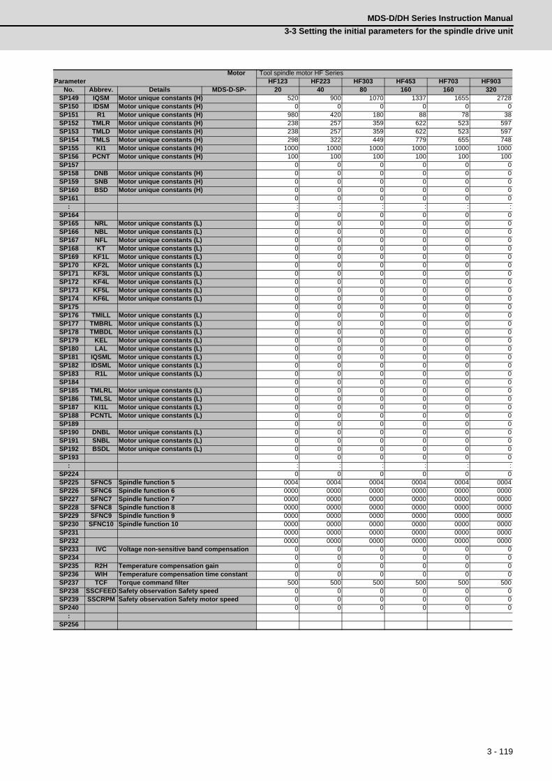
3 - 119
MDS-D/DH Series Instruction Manual
3-3 Setting the initial parameters for the spindle drive unit
SP149 IQSM Motor unique constants (H) 520 900 1070 1337 1655 2728SP150 IDSM Motor unique constants (H) 0 0 0 0 0 0SP151 R1 Motor unique constants (H) 980 420 180 88 78 38SP152 TMLR Motor unique constants (H) 238 257 359 622 523 597SP153 TMLD Motor unique constants (H) 238 257 359 622 523 597SP154 TMLS Motor unique constants (H) 298 322 449 779 655 748SP155 KI1 Motor unique constants (H) 1000 1000 1000 1000 1000 1000SP156 PCNT Motor unique constants (H) 100 100 100 100 100 100SP157 0 0 0 0 0 0SP158 DNB Motor unique constants (H) 0 0 0 0 0 0SP159 SNB Motor unique constants (H) 0 0 0 0 0 0SP160 BSD Motor unique constants (H) 0 0 0 0 0 0SP161 0 0 0 0 0 0
: : : : : : :SP164 0 0 0 0 0 0SP165 NRL Motor unique constants (L) 0 0 0 0 0 0SP166 NBL Motor unique constants (L) 0 0 0 0 0 0SP167 NFL Motor unique constants (L) 0 0 0 0 0 0SP168 KT Motor unique constants (L) 0 0 0 0 0 0SP169 KF1L Motor unique constants (L) 0 0 0 0 0 0SP170 KF2L Motor unique constants (L) 0 0 0 0 0 0SP171 KF3L Motor unique constants (L) 0 0 0 0 0 0SP172 KF4L Motor unique constants (L) 0 0 0 0 0 0SP173 KF5L Motor unique constants (L) 0 0 0 0 0 0SP174 KF6L Motor unique constants (L) 0 0 0 0 0 0SP175 0 0 0 0 0 0SP176 TMILL Motor unique constants (L) 0 0 0 0 0 0SP177 TMBRL Motor unique constants (L) 0 0 0 0 0 0SP178 TMBDL Motor unique constants (L) 0 0 0 0 0 0SP179 KEL Motor unique constants (L) 0 0 0 0 0 0SP180 LAL Motor unique constants (L) 0 0 0 0 0 0SP181 IQSML Motor unique constants (L) 0 0 0 0 0 0SP182 IDSML Motor unique constants (L) 0 0 0 0 0 0SP183 R1L Motor unique constants (L) 0 0 0 0 0 0SP184 0 0 0 0 0 0SP185 TMLRL Motor unique constants (L) 0 0 0 0 0 0SP186 TMLSL Motor unique constants (L) 0 0 0 0 0 0SP187 KI1L Motor unique constants (L) 0 0 0 0 0 0SP188 PCNTL Motor unique constants (L) 0 0 0 0 0 0SP189 0 0 0 0 0 0SP190 DNBL Motor unique constants (L) 0 0 0 0 0 0SP191 SNBL Motor unique constants (L) 0 0 0 0 0 0SP192 BSDL Motor unique constants (L) 0 0 0 0 0 0SP193 0 0 0 0 0 0
: : : : : : :SP224 0 0 0 0 0 0SP225 SFNC5 Spindle function 5 0004 0004 0004 0004 0004 0004SP226 SFNC6 Spindle function 6 0000 0000 0000 0000 0000 0000SP227 SFNC7 Spindle function 7 0000 0000 0000 0000 0000 0000SP228 SFNC8 Spindle function 8 0000 0000 0000 0000 0000 0000SP229 SFNC9 Spindle function 9 0000 0000 0000 0000 0000 0000SP230 SFNC10 Spindle function 10 0000 0000 0000 0000 0000 0000SP231 0000 0000 0000 0000 0000 0000SP232 0000 0000 0000 0000 0000 0000SP233 IVC Voltage non-sensitive band compensation 0 0 0 0 0 0SP234 0 0 0 0 0 0SP235 R2H Temperature compensation gain 0 0 0 0 0 0SP236 WIH Temperature compensation time constant 0 0 0 0 0 0SP237 TCF Torque command filter 500 500 500 500 500 500SP238 SSCFEED Safety observation Safety speed 0 0 0 0 0 0SP239 SSCRPM Safety observation Safety motor speed 0 0 0 0 0 0SP240 0 0 0 0 0 0
:SP256
MotorParameter
Tool spindle motor HF SeriesHF123 HF223 HF303 HF453 HF703 HF903
No. Abbrev. Details MDS-D-SP- 20 40 80 160 160 320

3 - 120
3 SetupMITSUBISHI CNC
3-3-3 Spindle specification parameters
The parameters with "(PR)" requires the CNC to be turned OFF after the settings. Turn the power OFF and
ON to enable the parameter settings.
【#3001】 slimt 1 Limit rotation speed (Gear: 00)
Set the spindle rotation speed for maximum motor speed when gear 00 is selected.Set the spindle rotation speed for the S analog output=10V during analog spindle control.
---Setting range---0 to 99999 (r/min)
【#3002】 slimt 2 Limit rotation speed (Gear: 01)
Set the spindle rotation speed for maximum motor speed when gear 01 is selected.Set the spindle rotation speed for the S analog output=10V during analog spindle control.
---Setting range---0 to 99999 (r/min)
【#3003】 slimt 3 Limit rotation speed (Gear: 10)
Set the spindle rotation speed for maximum motor speed when gear 10 is selected.Set the spindle rotation speed for the S analog output=10V during analog spindle control.
---Setting range---0 to 99999 (r/min)
【#3004】 slimt 4 Limit rotation speed (Gear: 11)
Set the spindle rotation speed for maximum motor speed when gear 11 is selected.Set the spindle rotation speed for the S analog output=10V during analog spindle control.
---Setting range---0 to 99999 (r/min)
【#3005】 smax 1 Maximum rotation speed (Gear: 00)
Set the maximum spindle rotation speed which is actually commanded when gear 00 is selected.Set this as smax1(#3005)<= slimit1(#3001).By comparing the S command value and the values of gear 1 - 4, a spindle gear shift command will be output automatically.
---Setting range---0 to 99999 (r/min)
The configuration of the spindle specification parameters (#3001 to #3138) can differ depending on
the NC.
This Instruction Manual explains using the configuration of the parameters for M700V/M70V Series.
CAUTION

3 - 121
MDS-D/DH Series Instruction Manual
3-3 Setting the initial parameters for the spindle drive unit
【#3006】 smax 2 Maximum rotation speed (Gear: 01)
Set the maximum spindle rotation speed which is actually commanded when gear 01 is selected.Set this as smax2(#3006)<= slimit2(#3002).By comparing the S command value and the values of gear 1 - 4, a spindle gear shift command will be output automatically.
---Setting range---0 to 99999 (r/min)
【#3007】 smax 3 Maximum rotation speed (Gear: 10)
Set the maximum spindle rotation speed which is actually commanded when gear 10 is selected.Set this as smax3(#3007)<= slimit3(#3003).By comparing the S command value and the values of gear 1 - 4, a spindle gear shift command will be output automatically.
---Setting range---0 to 99999 (r/min)
【#3008】 smax 4 Maximum rotation speed (Gear: 11)
Set the maximum spindle rotation speed which is actually commanded when gear 11 is selected.Set this as smax4(#3008)<= slimit4(#3004).By comparing the S command value and the values of gear 1 - 4, a spindle gear shift command will be output automatically.
---Setting range---0 to 99999 (r/min)
【#3009】 ssift 1 Shift rotation speed (Gear: 00)
Set the spindle speed for gear shifting with gear 00.(Note) Setting too large value may cause a gear nick when changing gears.
---Setting range---0 to 32767 (r/min)
【#3010】 ssift 2 Shift rotation speed (Gear: 01)
Set the spindle speed for gear shifting with gear 01.(Note) Setting too large value may cause a gear nick when changing gears.
---Setting range---0 to 32767 (r/min)
【#3011】 ssift 3 Shift rotation speed (Gear: 10)
Set the spindle speed for gear shifting with gear 10.(Note) Setting too large value may cause a gear nick when changing gears.
---Setting range---0 to 32767 (r/min)
【#3012】 ssift 4 Shift rotation speed (Gear: 11)
Set the spindle speed for gear shifting with gear 11.(Note) Setting too large value may cause a gear nick when changing gears.
---Setting range---0 to 32767 (r/min)

3 - 122
3 SetupMITSUBISHI CNC
【#3013】 stap 1 Synchronous tapping 1st step rotation speed (Gear: 00)
Set the speed which switches from 1st step to 2nd step in synchronous tapping multi-step acceleration/deceleration control when gear 00 is selected.The inclination of linear acceleration/deceleration control for 1st step is determined by the ratio of stap1(#3013) to stapt1(#3017).When the inclination is not set after 2nd step or it is higher than that of 1st step, the acceleration/deceleration control is executed with the same inclination as the 1st step for the rotation speed of stap1 or higher.
---Setting range---0 to 99999 (r/min)
【#3014】 stap 2 Synchronous tapping 1st step rotation speed (Gear: 01)
Set the speed which switches from 1st step to 2nd step in synchronous tapping multi-step acceleration/deceleration control when gear 01 is selected.The inclination of linear acceleration/deceleration control for 1st step is determined by the ratio of stap2(#3014) to stapt2(#3018).When the inclination is not set after 2nd step or it is higher than that of 1st step, the acceleration/deceleration control is executed with the same inclination as the 1st step for the rotation speed of stap2 or higher.
---Setting range---0 to 99999 (r/min)
【#3015】 stap 3 Synchronous tapping 1st step rotation speed (Gear: 10)
Set the speed which switches from 1st step to 2nd step in synchronous tapping multi-step acceleration/deceleration control when gear 10 is selected.The inclination of linear acceleration/deceleration control for 1st step is determined by the ratio of stap3(#3015) to stapt3(#3019).When the inclination is not set after 2nd step or it is higher than that of 1st step, the acceleration/deceleration control is executed with the same inclination as the 1st step for the rotation speed of stap3 or higher.
---Setting range---0 to 99999 (r/min)
【#3016】 stap 4 Synchronous tapping 1st step rotation speed (Gear: 11)
Set the speed which switches from 1st step to 2nd step in synchronous tapping multi-step acceleration/deceleration control when gear 11 is selected.The inclination of linear acceleration/deceleration control for 1st step is determined by the ratio of stap4(#3016) to stapt4(#3020).When the inclination is not set after 2nd step or it is higher than that of 1st step, the acceleration/deceleration control is executed with the same inclination as the 1st step for the rotation speed of stap4 or higher.
---Setting range---0 to 99999 (r/min)
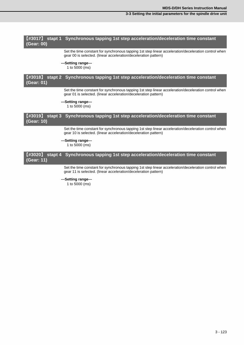
3 - 123
MDS-D/DH Series Instruction Manual
3-3 Setting the initial parameters for the spindle drive unit
【#3017】 stapt 1 Synchronous tapping 1st step acceleration/deceleration time constant (Gear: 00)
Set the time constant for synchronous tapping 1st step linear acceleration/deceleration control when gear 00 is selected. (linear acceleration/deceleration pattern)
---Setting range---1 to 5000 (ms)
【#3018】 stapt 2 Synchronous tapping 1st step acceleration/deceleration time constant (Gear: 01)
Set the time constant for synchronous tapping 1st step linear acceleration/deceleration control when gear 01 is selected. (linear acceleration/deceleration pattern)
---Setting range---1 to 5000 (ms)
【#3019】 stapt 3 Synchronous tapping 1st step acceleration/deceleration time constant (Gear: 10)
Set the time constant for synchronous tapping 1st step linear acceleration/deceleration control when gear 10 is selected. (linear acceleration/deceleration pattern)
---Setting range---1 to 5000 (ms)
【#3020】 stapt 4 Synchronous tapping 1st step acceleration/deceleration time constant (Gear: 11)
Set the time constant for synchronous tapping 1st step linear acceleration/deceleration control when gear 11 is selected. (linear acceleration/deceleration pattern)
---Setting range---1 to 5000 (ms)

3 - 124
3 SetupMITSUBISHI CNC
<Relation of spindle limit rotation speed and spindle maximum rotation speed>
The spindle rotation speed which can be attained at the spindle motor's maximum rotation speed is set
for the limit rotation speed (slimt). This value is obtained by multiplying the gear ratio on the spindle
motor maximum rotation speed (SP026). Set the maximum rotation speed (smax) when the rotation
speed is to be limited according to the machine specifications, such as the spindle gear specifications.
Up to four value can be set for gear changeover.
<Synchronous tapping multi-step acceleration/deceleration control parameter>
The acceleration/deceleration control can be set up to three steps in synchronous tapping control to
carry out an optimal acceleration/deceleration control in accordance with the spindle motor
characteristics whose output torque steps down when exceeding the base rotation speed.
Set the inclination for 2nd step or subsequent steps when the maximum rotation speed exceeds the
base rotation speed during synchronous tapping control.
When the inclination is not set after 2nd step or it is higher than that of 1st step, the acceleration/
deceleration control is executed with the same inclination as the 1st step for all the rotation speed.
SP026
0smax slimt1 smax2 smax(n) slimt2 slimt(n) 1
Spin
dle
mot
or ro
tatio
n sp
eed
(r/m
in)
Spindle rotation speed (r/min)
2000
4000
6000
8000
taps21=3000
stap1=1500
0
0 1000
2000
0
3000
4000
stapt1=300
tapt21=900
tapt31=5000
1000 smax1=10000
Spi
ndle
rota
tion
spee
d [r/
min
]
Time [ms]

3 - 125
MDS-D/DH Series Instruction Manual
3-3 Setting the initial parameters for the spindle drive unit
<Spindle synchronization multi-step acceleration/deceleration control parameter>
The acceleration/deceleration control can be set up to eight steps in spindle synchronization control to
carry out an optimal acceleration/deceleration control in accordance with the spindle motor
characteristics whose output torque steps down when exceeding the base rotation speed and further
attenuate in output stepdown zone.
For 2nd step or subsequent steps, the specification allows to set the time constant magnification and
changeover rotation speed based on the acceleration/deceleration setting of the 1st step.
Set the value of limit rotation speed or higher as the changeover rotation speed for the step not to be
shifted when not carrying out a step shift.
2000
4000
6000
8000
sptc7=9200
sptc6=8200
sptc5=7200
sptc4=6000
sptc3=4800
sptc2=3000
sptc1=1000
0
spt=400
smax1=10000
1200(=spt * spdiv1 = 400 * 3)
2000(=spt * spdiv2 = 400 * 5)
2800(=spt * spdiv3 = 400 * 7)
4000(=spt * spdiv4 = 400 * 10)
5600(=spt * spdiv5 = 400 * 14)
8000(=spt * spdiv6 = 400 * 20)
11200(=spt * spdiv7 = 400 * 28)
1000
0 2000
3000
4000
1000
Time [ms]
Spi
ndle
rota
tion
spee
d [r/
min
]

3 - 126
3 SetupMITSUBISHI CNC
【#3021】
Not used. Set to "0".
【#3022】 sgear Encoder gear ratio
Set the gear ratio of the spindle to the detector when inputting ABZ pulse output detector feedback to NC during analog spindle control.
0: Detector : Spindle = 1:11: Detector : Spindle = 1:22: Detector : Spindle = 1:43: Detector : Spindle = 1:8
---Setting range---0 to 3
【#3023】 smini Minimum rotation speed
Set the minimum spindle speed.If an S command below this setting is issued, the spindle will rotate at the minimum speed set by this parameter.
---Setting range---0 to 32767 (r/min)
【#3024(PR)】 sout Spindle connection
Select the connection method with a spindle drive unit.0: No unit to connect1: Optical digital communication (Mitsubishi spindle drive unit)2 - 5: S-analog (Analog spindle drive unit)
---Setting range---0 to 5
【#3025(PR)】 enc-on Spindle encoder
Set the connection specifications of a spindle's detector.0: Without detector feedback when using analog spindle and connecting to NC1: With detector feedback when using analog spindle and connecting to NC2: Mitsubishi spindle drive unit
---Setting range---0 to 2
【#3026】 cs_ori Selection of winding in orientation mode
Select the coil control in orientation mode for the spindle motor which performs coil changeover.0: Perform coil changeover based on the command from NC. (depending on the setting of
parameter #1239/bit0)1: Use the coil L
【#3027】 cs_syn Selection of winding in spindle synchronization control mode
Select the coil control in spindle synchronization control mode for the spindle motor which performs coil changeover.
0: Perform coil changeover based on the command from NC. (depending on the setting of parameter #1239/bit0)
1: Use the coil H
【#3028】 sprcmm Tap cycle M command selection
Set the M codes for the spindle forward run/reverse run commands during tapping cycle.High-order 3 digits: Set the M code for spindle forward run command.Low-order 3 digits: Set the M code for spindle reverse run command.
When "0" is set, it is handled assuming that "3004" is set (the M code for spindle forward run command is "3" and the M code for spindle reverse run command is "4").
---Setting range---0 to 999999

3 - 127
MDS-D/DH Series Instruction Manual
3-3 Setting the initial parameters for the spindle drive unit
【#3029】 tapsel Asynchronous tap gear selection
Select the speed which is compared with S command at gear selection when using asynchronous tapping control with the spindle which performs gear changeover.
0: Synchronous tapping 1st step rotation speed (stap)--- Multi-step acceleration/deceleration is not used.
1: Maximum speed (smax)--- Multi-step acceleration/deceleration is used.This parameter is enabled only when "#1272 ext08/bit1 is 1".
【#3030】
Not used. Set to "0".
【#3031(PR)】 smcp_no Drive unit I/F channel No. (spindle)
Set the interface channel No. of CNC control unit to which the spindle is connected and the axis No. within each channel.Set this parameter in 4-digit (hexadecimal) format.
HEX-4 : Drive unit interface channel No.HEX-3 : Not used. Set to "0".HEX-2, 1 : Axis No.
For an analog spindle, set to "0000".
---Setting range---0000, 1001 to 1010, 2001 to 2010
- For MDS-DM-SPV2/SPV3 SeriesThese drive units have no rotary switches for axis No. selection.The spindle axis No. is fixed to 1st axis, so set “01” as the number of axes. (last 2 digits).
【#3032】
Not used. Set to "0".
【#3035(PR)】 spunit Output unit
Select the data unit for communication with the spindle drive unit.This selection is applied to the data communicated between the NC and spindle drive unit as well as the spindle movement data. Although the standard setting is B (0.001deg), set the same value as "#1004 ctrl_unit" when using Spindle/C axis control.
B: 0.001deg (1μm)C: 0.0001deg (0.1μm)D: 0.00001deg (10nm)E: 0.000001deg (1nm)
1 2 3
1234HEX-0
Number of axesInterface channel No.
Channel No.=1
Channel No.=2
Channel No.=m
Axis No.= 1 2 n
Axis No.=Rotary switch settings
CNCcontrol
unit
Spindledriveunit

3 - 128
3 SetupMITSUBISHI CNC
【#3037】 taps21 Synchronous tapping 2nd step rotation speed (Gear: 00)
Set the speed which switches from 2nd step to 3rd step in synchronous tapping multi-step acceleration/deceleration control when gear 00 is selected.The inclination of linear acceleration/deceleration control for 2nd step is determined by the ratio of taps21(#3037) to tapt21(#3041).When the inclination is not set for 3rd step or it is higher than that of 2nd step, the acceleration/deceleration control is executed with the same inclination as the 2nd step for the rotation speed of taps21 or higher.
---Setting range---0 to 99999 (r/min)
【#3038】 taps22 Synchronous tapping 2nd step rotation speed (Gear: 01)
Set the speed which switches from 2nd step to 3rd step in synchronous tapping multi-step acceleration/deceleration control when gear 01 is selected.The inclination of linear acceleration/deceleration control for 2nd step is determined by the ratio of taps22(#3038) to tapt22(#3042).When the inclination is not set for 3rd step or it is higher than that of 2nd step, the acceleration/deceleration control is executed with the same inclination as the 2nd step for the rotation speed of taps22 or higher.
---Setting range---0 to 99999 (r/min)
【#3039】 taps23 Synchronous tapping 2nd step rotation speed (Gear: 10)
Set the speed which switches from 2nd step to 3rd step in synchronous tapping multi-step acceleration/deceleration control when gear 10 is selected.The inclination of linear acceleration/deceleration control for 2nd step is determined by the ratio of taps23(#3039) to tapt23(#3043).When the inclination is not set for 3rd step or it is higher than that of 2nd step, the acceleration/deceleration control is executed with the same inclination as the 2nd step for the rotation speed of taps23 or higher.
---Setting range---0 to 99999 (r/min)
【#3040】 taps24 Synchronous tapping 2nd step rotation speed (Gear: 11)
Set the speed which switches from 2nd step to 3rd step in synchronous tapping multi-step acceleration/deceleration control when gear 11 is selected.The inclination of linear acceleration/deceleration control for 2nd step is determined by the ratio of taps24(#3040) to tapt24(#3044).When the inclination is not set for 3rd step or it is higher than that of 2nd step, the acceleration/deceleration control is executed with the same inclination as the 2nd step for the rotation speed of taps24 or higher.
---Setting range---0 to 99999 (r/min)
【#3041】 tapt21 Synchronous tapping 2nd step acceleration/deceleration time constant (Gear: 00)
Set the time constant for synchronous tapping 2nd step linear acceleration/deceleration control when gear 00 is selected.
---Setting range---1 to 5000 (ms)
【#3042】 tapt22 Synchronous tapping 2nd step acceleration/deceleration time constant 2 (Gear: 01)
Set the time constant for synchronous tapping 2nd step linear acceleration/deceleration control when gear 01 is selected.
---Setting range---1 to 5000 (ms)
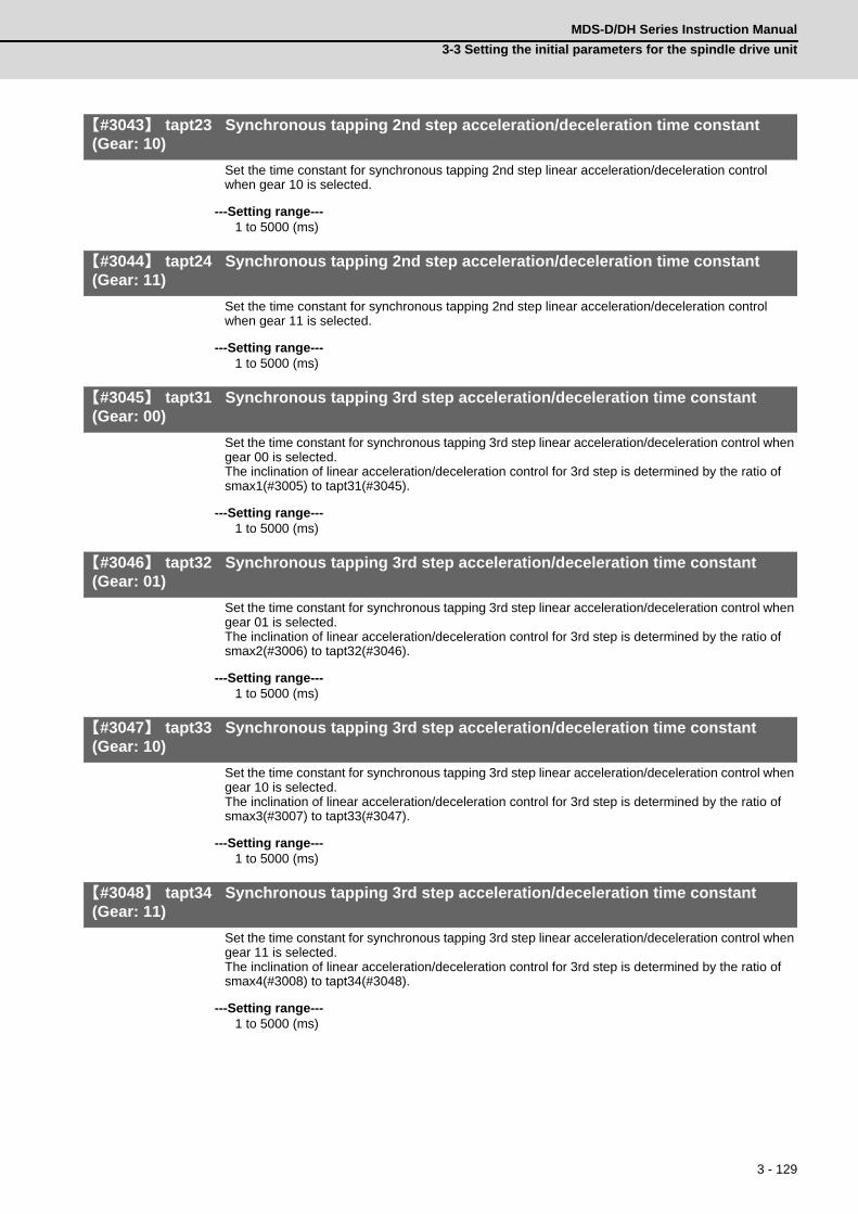
3 - 129
MDS-D/DH Series Instruction Manual
3-3 Setting the initial parameters for the spindle drive unit
【#3043】 tapt23 Synchronous tapping 2nd step acceleration/deceleration time constant (Gear: 10)
Set the time constant for synchronous tapping 2nd step linear acceleration/deceleration control when gear 10 is selected.
---Setting range---1 to 5000 (ms)
【#3044】 tapt24 Synchronous tapping 2nd step acceleration/deceleration time constant (Gear: 11)
Set the time constant for synchronous tapping 2nd step linear acceleration/deceleration control when gear 11 is selected.
---Setting range---1 to 5000 (ms)
【#3045】 tapt31 Synchronous tapping 3rd step acceleration/deceleration time constant (Gear: 00)
Set the time constant for synchronous tapping 3rd step linear acceleration/deceleration control when gear 00 is selected.The inclination of linear acceleration/deceleration control for 3rd step is determined by the ratio of smax1(#3005) to tapt31(#3045).
---Setting range---1 to 5000 (ms)
【#3046】 tapt32 Synchronous tapping 3rd step acceleration/deceleration time constant (Gear: 01)
Set the time constant for synchronous tapping 3rd step linear acceleration/deceleration control when gear 01 is selected.The inclination of linear acceleration/deceleration control for 3rd step is determined by the ratio of smax2(#3006) to tapt32(#3046).
---Setting range---1 to 5000 (ms)
【#3047】 tapt33 Synchronous tapping 3rd step acceleration/deceleration time constant (Gear: 10)
Set the time constant for synchronous tapping 3rd step linear acceleration/deceleration control when gear 10 is selected.The inclination of linear acceleration/deceleration control for 3rd step is determined by the ratio of smax3(#3007) to tapt33(#3047).
---Setting range---1 to 5000 (ms)
【#3048】 tapt34 Synchronous tapping 3rd step acceleration/deceleration time constant (Gear: 11)
Set the time constant for synchronous tapping 3rd step linear acceleration/deceleration control when gear 11 is selected.The inclination of linear acceleration/deceleration control for 3rd step is determined by the ratio of smax4(#3008) to tapt34(#3048).
---Setting range---1 to 5000 (ms)

3 - 130
3 SetupMITSUBISHI CNC
【#3049】 spt Spindle synchronization acceleration/deceleration time constant
Set the acceleration/deceleration time constant under spindle synchronization control.The inclination of acceleration/deceleration control is determined by the ratio to limit rotation speed (slimit). Set the same value for the reference axis and synchronous axis.The time constant for 2nd step or subsequent steps is the magnification setting on the basis of this setting value.
---Setting range---0 to 9999 (ms)
【#3050】 sprlv Spindle synchronization rotation speed attainment level
Set the level of speed difference between the basic and synchronous spindles during spindle synchronization control. Setting of the synchronous spindle side is enabled. When the difference becomes below the setting level, the spindle speed synchronization complete signal will turn ON.
---Setting range---0 to 4095 (pulse) (1 pulse = 0.088°)
【#3051】 spplv Spindle phase synchronization attainment level
Set the level of phase difference between the basic and synchronous spindles during spindle synchronization. Setting of the synchronous spindle side is validated. When the difference becomes below the setting level, the spindle phase synchronization complete signal will go ON.
---Setting range---0 to 4095 (pulse) (1 pulse = 0.088°)
【#3052】 spplr Spindle motor spindle relative polarity
Set the spindle motor and spindle's relative polarity.0: Positive polarity (Spindle CW rotation at motor CW rotation)1: Negative polarity (Spindle CCW rotation at motor CW rotation)
---Setting range---0000/0001 (HEX)
【#3053】 sppst Spindle encoder Z -phase position
Set the deviation amount from the spindle's basic point to the spindle detector's Z phase.Obtain the deviation amount, considering a clockwise direction as positive when viewed from the spindle's front side.
---Setting range---0 to 359999 (1/1000°)
【#3054】 sptc1 Spindle synchronization multi-step acceleration/deceleration changeover speed 1
Set the speed which switches from 1st step to 2nd step in spindle synchronization multi-step acceleration/deceleration control. Set the same value for the reference axis and synchronous axis.Set the value of limit rotation speed (slimit) or higher not to carry out a step shift.
---Setting range---0 to 99999 (r/min)
【#3055】 sptc2 Spindle synchronization multi-step acceleration/deceleration changeover speed 2
Set the speed which switches from 2nd step to 3rd step in spindle synchronization multi-step acceleration/deceleration control. Set the same value for the reference axis and synchronous axis.Set the value of limit rotation speed (slimit) or higher not to carry out a step shift.
---Setting range---0 to 99999 (r/min)
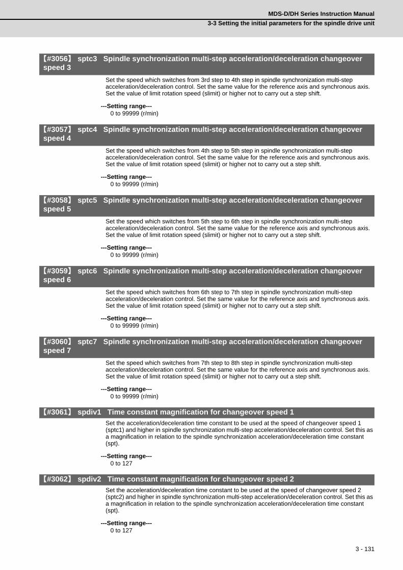
3 - 131
MDS-D/DH Series Instruction Manual
3-3 Setting the initial parameters for the spindle drive unit
【#3056】 sptc3 Spindle synchronization multi-step acceleration/deceleration changeover speed 3
Set the speed which switches from 3rd step to 4th step in spindle synchronization multi-step acceleration/deceleration control. Set the same value for the reference axis and synchronous axis.Set the value of limit rotation speed (slimit) or higher not to carry out a step shift.
---Setting range---0 to 99999 (r/min)
【#3057】 sptc4 Spindle synchronization multi-step acceleration/deceleration changeover speed 4
Set the speed which switches from 4th step to 5th step in spindle synchronization multi-step acceleration/deceleration control. Set the same value for the reference axis and synchronous axis.Set the value of limit rotation speed (slimit) or higher not to carry out a step shift.
---Setting range---0 to 99999 (r/min)
【#3058】 sptc5 Spindle synchronization multi-step acceleration/deceleration changeover speed 5
Set the speed which switches from 5th step to 6th step in spindle synchronization multi-step acceleration/deceleration control. Set the same value for the reference axis and synchronous axis.Set the value of limit rotation speed (slimit) or higher not to carry out a step shift.
---Setting range---0 to 99999 (r/min)
【#3059】 sptc6 Spindle synchronization multi-step acceleration/deceleration changeover speed 6
Set the speed which switches from 6th step to 7th step in spindle synchronization multi-step acceleration/deceleration control. Set the same value for the reference axis and synchronous axis.Set the value of limit rotation speed (slimit) or higher not to carry out a step shift.
---Setting range---0 to 99999 (r/min)
【#3060】 sptc7 Spindle synchronization multi-step acceleration/deceleration changeover speed 7
Set the speed which switches from 7th step to 8th step in spindle synchronization multi-step acceleration/deceleration control. Set the same value for the reference axis and synchronous axis.Set the value of limit rotation speed (slimit) or higher not to carry out a step shift.
---Setting range---0 to 99999 (r/min)
【#3061】 spdiv1 Time constant magnification for changeover speed 1
Set the acceleration/deceleration time constant to be used at the speed of changeover speed 1 (sptc1) and higher in spindle synchronization multi-step acceleration/deceleration control. Set this as a magnification in relation to the spindle synchronization acceleration/deceleration time constant (spt).
---Setting range---0 to 127
【#3062】 spdiv2 Time constant magnification for changeover speed 2
Set the acceleration/deceleration time constant to be used at the speed of changeover speed 2 (sptc2) and higher in spindle synchronization multi-step acceleration/deceleration control. Set this as a magnification in relation to the spindle synchronization acceleration/deceleration time constant (spt).
---Setting range---0 to 127

3 - 132
3 SetupMITSUBISHI CNC
【#3063】 spdiv3 Time constant magnification for changeover speed 3
Set the acceleration/deceleration time constant to be used at the speed of changeover speed 3 (sptc3) and higher in spindle synchronization multi-step acceleration/deceleration control. Set this as a magnification in relation to the spindle synchronization acceleration/deceleration time constant (spt).
---Setting range---0 to 127
【#3064】 spdiv4 Time constant magnification for changeover speed 4
Set the acceleration/deceleration time constant to be used at the speed of changeover speed 4 (sptc4) and higher in spindle synchronization multi-step acceleration/deceleration control. Set this as a magnification in relation to the spindle synchronization acceleration/deceleration time constant (spt).
---Setting range---0 to 127
【#3065】 spdiv5 Time constant magnification for changeover speed 5
Set the acceleration/deceleration time constant to be used at the speed of changeover speed 5 (sptc5) and higher in spindle synchronization multi-step acceleration/deceleration control. Set this as a magnification in relation to the spindle synchronization acceleration/deceleration time constant (spt).
---Setting range---0 to 127
【#3066】 spdiv6 Time constant magnification for changeover speed 6
Set the acceleration/deceleration time constant to be used at the speed of changeover speed 6 (sptc6) and higher in spindle synchronization multi-step acceleration/deceleration control. Set this as a magnification in relation to the spindle synchronization acceleration/deceleration time constant (spt).
---Setting range---0 to 127
【#3067】 spdiv7 Time constant magnification for changeover speed 7
Set the acceleration/deceleration time constant to be used at the speed of changeover speed 7 (sptc7) and higher in spindle synchronization multi-step acceleration/deceleration control. Set this as a magnification in relation to the spindle synchronization acceleration/deceleration time constant (spt).
---Setting range---0 to 127
【#3068】 symtm1 Phase synchronization start confirmation time
Set the time to confirm that synchronization is attained before spindle phase synchronization control is started.When "0" is set, the time will be 500ms. When "100" or less is set, the time will be 100ms.
---Setting range---0 to 9999 (ms)
【#3069】 symtm2 Phase synchronization end confirmation time
Set a period of waiting time for spindle phase synchronization control's completion as a time in which the speed stays within the attainment range.When "0" is set, the time will be 500ms. When "100" or less is set, the time will be 100ms.
---Setting range---0 to 9999 (ms)

3 - 133
MDS-D/DH Series Instruction Manual
3-3 Setting the initial parameters for the spindle drive unit
【#3070】 syprt Phase synchronization alignment speed
Set the amount of speed fluctuation of synchronous spindle during spindle phase synchronization control. Set this as a proportion to commanded speed.When "0" is set, the amount will be 5%.
---Setting range---0 to 100 (%)
【#3071(PR)】 SscDrSelSp Speed monitor Door selection
Select which door group of the speed monitoring a spindle belongs to.0000: Belong to the door 1 group.0001: Belong to the door 1 group.0002: Belong to the door 2 group.0003: Belong to the door 1 and 2 groups.
(Note) Speed monitoring function is validated when "SP229/bitF=1".
---Setting range---0000 to 0003 (HEX)
【#3072(PR)】 Ssc Svof Filter Sp Speed monitor Error detection time during servo OFF
Set the error detection time for when an error of command speed monitoring or feedback speed monitoring is detected during servo OFF.The alarm will occur if actual speed exceeds safe speed or safe rotation speed for a period of time longer than this setting.When "0" is set, the detection time will be 200 (ms).(Note) Speed monitoring function is validated when "SP229/bitF=1".
---Setting range---0 to 9999 (ms)
【#3101】 sp_t 1 Acceleration/deceleration time constant with S command (Gear: 00)
Set the acceleration/deceleration time constant with S command (speed operation mode) when gear 00 is selected. Set the linear acceleration/deceleration time up to maximum speed (smax1). Set the short time constant that the motor torque at acceleration is always saturated, however, when an abnormal noise or V-belt slip occurs, increase the time constant.
---Setting range---0 to 30000 (ms)
【#3102】 sp_t 2 Acceleration/deceleration time constant with S command (Gear: 01)
Set the acceleration/deceleration time constant with S command (speed operation mode) when gear 01 is selected. Set the linear acceleration/deceleration time up to maximum speed (smax2). Set the short time constant that the motor torque at acceleration is always saturated, however, when an abnormal noise or V-belt slip occurs, increase the time constant.
---Setting range---0 to 30000 (ms)
【#3103】 sp_t 3 Acceleration/deceleration time constant with S command (Gear: 10)
Set the acceleration/deceleration time constant with S command (speed operation mode) when gear 10 is selected. Set the linear acceleration/deceleration time up to maximum speed (smax3). Set the short time constant that the motor torque at acceleration is always saturated, however, when an abnormal noise or V-belt slip occurs, increase the time constant.
---Setting range---0 to 30000 (ms)
【#3104】 sp_t 4 Acceleration/deceleration time constant with S command (Gear: 11)
Set the acceleration/deceleration time constant with S command (speed operation mode) when gear 11 is selected. Set the linear acceleration/deceleration time up to maximum speed (smax4). Set the short time constant that the motor torque at acceleration is always saturated, however, when an abnormal noise or V-belt slip occurs, increase the time constant.
---Setting range---0 to 30000 (ms)

3 - 134
3 SetupMITSUBISHI CNC
【#3105】 sut Speed reach range
Set the speed deviation rate with respect to the commanded speed, at which the speed reach signal will be output.It will be 15% when set to "0".If the speed deviation is smaller than 45r/min, it will be set as 45r/min.
---Setting range---0 to 100 (%)

3 - 135
MDS-D/DH Series Instruction Manual
3-3 Setting the initial parameters for the spindle drive unit
【#3106】 zrn_typ Zero point return specifications
Select the zero point return specification.Functions are allocated to each bit.Set this in hexadecimal format.
bit F : Spindle zero point detection with contactless switch
0: Normal 1: Enable spindle zero point detection using proximity switch
bit E : Control mode selection in orientation
Select non-interpolation mode when vibration occurs since the gain is high during the orientation.0: Interpolation mode (Use the interpolation mode gain "SP002".)1: Non-interpolation mode (Use the non-interpolation mode gain "SP001")
bit D-B :
Not used. Set to "0".
bit A-9 : Spindle/C axis zero point return direction
bitA,9=00: Short-cut01: Forward run10: Reverse run
bit 8 : Designate zero point return
0: Automatically return to zero point simultaneously with C-axis changeover1: Separate operations are required for zero point return
bit 7 : Synchronous tapping command polarity
0: Forward direction1: Reverse direction (The standard setting when spindle and motor are directly coupled)
bit 6-5 : Synchronous tapping zero point return direction
bit 6,5=00: Short-cut01: Forward run10: Reverse run
bit 4 : Designate zero point return
0: Automatically return to zero point before synchronous tapping is started (tapping phase alignment)
1: Not return to zero point and immediately synchronous tapping is started
bit 3 :
Not used. Set to "0".
bit 2-1 : Orientation direction
bit 2,1=00: Short-cut01: Forward run10: Reverse run
bit 0 : Z phase detection direction
0: Forward direction 1: Reverse direction
Interpolation mode selection in orientation
Z phase detection directionOrientation directionSynchronous tapping zero point return/Deceleration stop designationSynchronous tapping zero point return directionSynchronous tapping command polaritySpindle/C axis zero point return/Deceleration stop designationSpindle/C axis zero point return direction
Spindle zero point proximity switch detection

3 - 136
3 SetupMITSUBISHI CNC
【#3107】 ori_spd Orientation command speed
Set the spindle speed during orientation command.When the spindle is not running or running to the different direction with the orientation, the orientation is carried out with this speed after a stop. When the spindle is running to the same direction with the orientation, this parameter does not have a meaning because it decelerates directly and the orientation is carried out.
---Setting range---1 to 99999 (r/min)
【#3108】 ori_sft Position shift amount for orientation
The orientation stop position can be moved by this parameter setting although normally the position is Z -phase position. During multi-point orientation control, the stop position is determined by the total value of this parameter and the position data for multi-point orientation of PLC input.
---Setting range----35999 to 35999 (0.01°)
【#3109】 zdetspd Z phase detection speed
For the first S command after power is turned ON, the spindle rotates at the speed of setting value for this parameter until Z phase is detected twice.When "#3106/bitF = 1" (Spindle zero point proximity switch detection enabled), also proximity switch is detected.
(Note) When spindle zero point proximity switch detection is enabled, the rotation direction of the orientation/zero point return (synchronous tapping, spindle/C axis) will follow Z phase detection direction. And the speed will follow Z phase detection speed.
---Setting range---1 to 99999 (r/min)
【#3110】 tap_spd Synchronous tapping zero point return speed
Set the zero point return speed during synchronous tapping control.
---Setting range---1 to 99999 (r/min)
【#3111】 tap_sft Synchronous tapping zero point return shift amount
Set the zero point return shift amount during synchronous tapping control. Zero point angle shifts from Z phase according to the setting angle.
---Setting range---0 to 35999 (0.01°)
【#3112】 cax_spd Spindle C axis zero point return speed
Set the zero point return speed during spindle C axis control.
---Setting range---1 to 99999 (r/min)
【#3113】 cax_sft Spindle C axis zero point return shift amount
Set the spindle C axis zero point return shift amount. Zero point angle shifts from Z phase according to the setting angle.
---Setting range---0 to 359999 (0.001°)

3 - 137
MDS-D/DH Series Instruction Manual
3-3 Setting the initial parameters for the spindle drive unit
【#3114】 cax_para_chg Spindle/C axis parameter switch
Parameter switches when switching the detector system between normal spindle control and C axis control, such as using spindle side detector only for C axis control in spindle drive system. It is validated with replacing a certain servo parameter of the corresponding servo axis to a spindle parameter.
0: Not switch1: Switch
---Setting range---0/1 (Standard: 0)
【#3115】 sp2_t1 Time constant in orientation/interpolation mode automatic reference position return (Gear: 00)
Set the linear acceleration/deceleration time constant for zero point return control (#3106/bit4,8) which is automatically started at the time of switching orientation control, C axis control and synchronous tapping control when gear 00 is selected. The inclination is determined by the ratio to limit rotation speed (slimit1). Set the sufficiently large value compared to the acceleration/deceleration time constant with S command (sp_t1) so that the output torque is not saturated. When executing C axis zero point return manually, it depends on the axis specification parameter.
---Setting range---0 to 30000 (ms)
【#3116】 sp2_t2 Time constant in orientation/interpolation mode automatic reference position return (Gear: 01)
Set the linear acceleration/deceleration time constant for zero point return control (#3106/bit4,8) which is automatically started at the time of switching orientation control, C axis control and synchronous tapping control when gear 01 is selected. The inclination is determined by the ratio to limit rotation speed (slimit2). Set the sufficiently large value compared to the acceleration/deceleration time constant with S command (sp_t2) so that the output torque is not saturated. When executing C axis zero point return manually, it depends on the axis specification parameter.
---Setting range---0 to 30000 (ms)
【#3117】 sp2_t3 Time constant in orientation/interpolation mode automatic reference position return (Gear: 10)
Set the linear acceleration/deceleration time constant for zero point return control (#3106/bit4,8) which is automatically started at the time of switching orientation control, C axis control and synchronous tapping control when gear 10 is selected. The inclination is determined by the ratio to limit rotation speed (slimit3). Set the sufficiently large value compared to the acceleration/deceleration time constant with S command (sp_t3) so that the output torque is not saturated. When executing C axis zero point return manually, it depends on the axis specification parameter.
---Setting range---0 to 30000 (ms)
【#3118】 sp2_t4 Time constant in orientation/interpolation mode automatic reference position return (Gear: 11)
Set the linear acceleration/deceleration time constant for zero point return control (#3106/bit4,8) which is automatically started at the time of switching orientation control, C axis control and synchronous tapping control when gear 11 is selected. The inclination is determined by the ratio to limit rotation speed (slimit4). Set the sufficiently large value compared to the acceleration/deceleration time constant with S command (sp_t4) so that the output torque is not saturated. When executing C axis zero point return manually, it depends on the axis specification parameter.
---Setting range---0 to 30000 (ms)
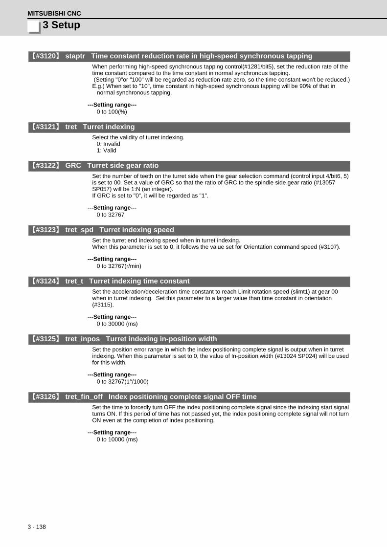
3 - 138
3 SetupMITSUBISHI CNC
【#3120】 staptr Time constant reduction rate in high-speed synchronous tapping
When performing high-speed synchronous tapping control(#1281/bit5), set the reduction rate of the time constant compared to the time constant in normal synchronous tapping. (Setting "0"or "100" will be regarded as reduction rate zero, so the time constant won't be reduced.)E.g.) When set to "10", time constant in high-speed synchronous tapping will be 90% of that in
normal synchronous tapping.
---Setting range---0 to 100(%)
【#3121】 tret Turret indexing
Select the validity of turret indexing.0: Invalid1: Valid
【#3122】 GRC Turret side gear ratio
Set the number of teeth on the turret side when the gear selection command (control input 4/bit6, 5) is set to 00. Set a value of GRC so that the ratio of GRC to the spindle side gear ratio (#13057 SP057) will be 1:N (an integer).If GRC is set to "0", it will be regarded as "1".
---Setting range---0 to 32767
【#3123】 tret_spd Turret indexing speed
Set the turret end indexing speed when in turret indexing.When this parameter is set to 0, it follows the value set for Orientation command speed (#3107).
---Setting range---0 to 32767(r/min)
【#3124】 tret_t Turret indexing time constant
Set the acceleration/deceleration time constant to reach Limit rotation speed (slimt1) at gear 00 when in turret indexing. Set this parameter to a larger value than time constant in orientation (#3115).
---Setting range---0 to 30000 (ms)
【#3125】 tret_inpos Turret indexing in-position width
Set the position error range in which the index positioning complete signal is output when in turret indexing. When this parameter is set to 0, the value of In-position width (#13024 SP024) will be used for this width.
---Setting range---0 to 32767(1°/1000)
【#3126】 tret_fin_off Index positioning complete signal OFF time
Set the time to forcedly turn OFF the index positioning complete signal since the indexing start signal turns ON. If this period of time has not passed yet, the index positioning complete signal will not turn ON even at the completion of index positioning.
---Setting range---0 to 10000 (ms)

3 - 139
MDS-D/DH Series Instruction Manual
3-3 Setting the initial parameters for the spindle drive unit
【#3127】 SPECSP Spindle specification
bit0: Select the gear changeover method.
0: Gear change type 1 (Gear is changed when the spindle stop signal is ON and when a gear recommended by NC and the one selected are different)
1: Gear change type 2 (Gear is changed when the spindle stop signal and spindle gear shift signal is ON)
---Setting range---0x0000 to 0xffff (hexadecimal)
【#3128】 ori_spec Orientation control specification
bit0: Orientation imposition advance output
Reduce the orientation time by detecting an in-position faster.The in-position detection width is changed from SP024(#13024) to ori_inp2.
0: Invalid 1: Valid
---Setting range---0x0000 to 0xffff (hexadecimal)
【#3129】 cax_spec Spindle/C axis control specification
Not used. Set to "0000".
【#3130】 syn_spec Spindle synchronization control specification
bit0: Tool spindle synchronization II (hobbing) automatic compensation selection
1: Compensate hobbing axis delay (advance) with workpiece axis.0: No compensation.
【#3131】 tap_spec Synchronous tapping control specification
Not used. Set to "0000".
【#3132】 ori_inp2 2nd in-position width for orientation
Set the in-position width when imposition advance output control (#3128/bit0) is valid. Reduce the orientation time by setting a bigger value than the value of conventional SP024 and detecting an in-position faster.Conventional SP024 is used for 2nd in-position signal detection width.
---Setting range---0 to 32767 (1deg/1000)
【#3133】 spherr Hobbing axis delay (advance) allowable angle
Set the allowable angle between the commanded position and actual position of hobbing axis when it is in tool spindle synchronization II (hobbing) mode (X18AE ON), and also when hobbing axis and workpiece axis are synchronizing (X18A9 ON).
---Setting range---0 to 32767 (1deg/1000)
【#3134】 sphtc Primary delay time constant for hobbing axis automatic compensation
Set the primary delay time constant of hobbing axis automatic compensation primary delay filter control in tool spindle synchronization II (hobbing).When set to 0, primary delay filter control is invalid.
---Setting range---0 to 32767 (ms)

3 - 140
3 SetupMITSUBISHI CNC
【#3135】 sfwd_g Feed forward gain for hobbing axis
Set the feed forward gain for the hobbing axis in tool spindle synchronization II (hobbing) mode.
---Setting range---0 to 200 (%)
【#3137】 stap_ax_off High-speed synchronous tapping unsupported axis
Set the high-speed synchronous tapping control unsupported axis as a bit. Each bit (bit0 -) corresponds to the order of the axis name parameter (#1013) setting.
bit 0-F : High-speed synchronous tapping unsupported setting
0: High-speed synchronous tapping supported axis1: High-speed synchronous tapping unsupported axis
【#3138】 motor_type Spindle motor type
Set the spindle motor type. The set type will be displayed on the drivemonitor screen, and it will be also output to the system configuration data.
---Setting range---Character string within 26 characters including A-Z, a-z, 0-9, "." (decimal point), "-" (hyphen), "/"
(slash)(Cleared by inputting "0".)
【#3140(PR)】 S_DINSp Speed observation input door No.
Set the door signal input in the drive unit. Use this parameter only when the axis with a door signal belongs to several door groups.The correspondence between the door signals and bits are as follows. bit0 : Door1 signal bit1 : Door2 signalIf the axis does not receive any door signal, set to "0".An error (Y20 0027) will occur in the following cases.- Several bits are enabled.- Any bit other than those set in "#3071 S_DSlSp" is enabled.
---Setting range---0000 to 0002 (HEX)
3 - 141
MDS-D/DH Series Instruction Manual
3-3 Setting the initial parameters for the spindle drive unit
3-3-4 Spindle parameters
These parameters are sent to the spindle drive unit when the NC power is turned ON. The standard
parameters are designated with the "Spindle parameter setting list" enclosed when the spindle motor is
delivered. There may be cases when the machine specifications are unclear, so the parameters determined
by the machine specifications should be confirmed by the user.
The parameters with "(PR)" requires the CNC to be turned OFF after the settings. Turn the power OFF and
ON to enable the parameter settings.
【#13001】 SP001 PGV Position loop gain non-interpolation mode
Set the position loop gain for "Non-interpolation" control mode.When the setting value increases, the command tracking ability will enhance and the positioning settling time can be shorter. However, the impact on the machine during acceleration/deceleration will increase.Use the selection command, the control mode "bit 2, 1, 0 = 000" in control input 4.(Note) The control mode is commanded by NC.
---Setting range---1 to 200 (1/s)
【#13002】 SP002 PGN Position loop gain interpolation mode
Set the position loop gain for "interpolation" control mode.When the setting value increases, the command tracking ability will enhance and the positioning settling time can be shorter. However, the impact on the machine during acceleration/deceleration will increase. Use the selection command, the control mode "bit 2, 1, 0 = 010 or 100" in control input 4.(Note) The control mode is commanded by NC. When carrying out the SHG control, set SP035/bitC to "1".
---Setting range---1 to 200 (1/s)
【#13003】 SP003 PGS Position loop gain spindle synchronization
Set the position loop gain for "spindle synchronization" control mode.When the setting value increases, the command tracking ability will enhance and the positioning settling time can be shorter. However, the impact on the machine during acceleration/deceleration will increase. Use the selection command, the control mode "bit 2, 1, 0 = 001" in control input 4.(Note) The control mode is commanded by NC. When carrying out the SHG control, set SP036/bit4 to "1".
---Setting range---1 to 200 (1/s)
【#13004】 SP004
Not used. Set to "0".
【#13005】 SP005 VGN1 Speed loop gain 1
Set the speed loop gain. Set this according to the load inertia size. The higher setting value will increase the accuracy of control, however, vibration tends to occur. If vibration occurs, adjust by lowering by 20 to 30%. The final value should be 70 to 80% of the value at which the vibration stops.
---Setting range---1 to 9999

3 - 142
3 SetupMITSUBISHI CNC
【#13006】 SP006 VIA1 Speed loop lead compensation 1
Set the speed loop integral control gain. The standard setting is "1900". Adjust the value by increasing/decreasing the value by about 100. Raise this value to improve the contour tracking accuracy in high-speed cutting. Lower this value when the position droop does not stabilize (when the vibration of 10 to 20Hz occurs).
---Setting range---1 to 9999
【#13007】 SP007 VIL1 Speed loop delay compensation 1
Set this parameter when the limit cycle occurs in the full-closed loop or overshooting occurs in positioning. For MDS-D/DH-SP, the control method can be selected by SP033/bit1,0. Normally, use "Changeover type 2". When setting this parameter, make sure to set the torque offset "SP050(TOF)". When not using, set to "0".
---Setting range---0 to 32767
【#13008】 SP008 VGN2 Speed loop gain 2
Normally SP005(VGN1) is used. By setting "SP035/bit1, SP035/bit9 or SP036/bit1=1", gain 2 can be used according to the application. Gain 2 can also be used by setting "Speed gain set 2 changeover request (control input 5/ bitC) = 1". Refer to SP005(VGN1) for adjustment procedures.
---Setting range---1 to 9999
【#13009】 SP009 VIA2 Speed loop lead compensation 2
Normally SP006(VIA1) is used. By setting "SP035/bit1, SP035/bit9 or SP036/bit1=1", gain 2 can be used according to the application. Gain 2 can also be used by setting "Speed gain set 2 changeover request (control input 5/ bitC) = 1". Refer to SP006(VIA1) for adjustment procedures.
---Setting range---1 to 9999
【#13010】 SP010 VIL2 Speed loop delay compensation 2
Normally SP007(VIL1) is used. By setting "SP035/bit1, SP035/bit9 or SP036/bit1=1", gain 2 can be used according to the application. Gain 2 can also be used by setting "Speed gain set 2 changeover request (control input 5/ bitC) = 1". Refer to SP007(VIL1) for adjustment procedures.
---Setting range---0 to 32767
【#13011】 SP011
Not used. Set to "0".
【#13012】 SP012
Not used. Set to "0".

3 - 143
MDS-D/DH Series Instruction Manual
3-3 Setting the initial parameters for the spindle drive unit
【#13013】 SP013
Not used. Set to "0".
【#13014】 SP014 PY1 Minimum excitation rate 1
Set the minimum value for the variable excitation rate. The standard setting is "50". Set to "0" when using an IPM spindle motor. If noise including gear noise is loud, select a small value. However, a larger setting value is more effective for impact response. (Note) When setting a value at "50 or more", check if there is no problem with gear noise, motor excitation noise, vibration during low-speed rotation or vibration when the servo is locked during orientation stop, etc. When setting a value at "less than 50", check if there is no problem with the impact load response or rigidity during servo lock.
---Setting range---0 to 100 (%)
【#13015】 SP015 PY2 Minimum excitation rate 2
Normally, SP014(PY1) is used. By setting "SP035/bit2, SP035/bitA or SP036/bit2=1", the excitation rate 2 can be used according to the application. The excitation rate 2 can also be used by setting "the minimum excitation rate 2 changeover request (control input 5/ bitB) = 1". Refer to SP014(PY1) for adjustment procedures. Set to "0" when using an IPM spindle motor.
---Setting range---0 to 100 (%)
【#13016】 SP016 DDT Phase alignment deceleration rate
Set the single-rotation position alignment deceleration rate for orientation stopping, phase alignment while rotating and switching from non-interpolation mode to spindle synchronization mode while rotating. When the load inertia is larger, the setting value should be smaller. When the setting value is larger, the orientation in-position and single-rotation position alignment complete faster, but the impact applied on the machine will increase. To change the deceleration rate only during rotation command (command F ⊿ T ≠ 0), set this parameter together with SP070 (KDDT).
---Setting range---1 to 32767 (0.1(r/min)/ms)

3 - 144
3 SetupMITSUBISHI CNC
【#13017(PR)】 SP017 SPEC1 Spindle specification 1
Select the spindle specification. A function is allocated to each bit. Set this in hexadecimal format.
bit F-C : msr Motor series selection
0: 200V specification IM spindle motor 1: 200V specification IPM spindle motor 2: 400V specification IM spindle motor 3: 400V specification IPM spindle motor 4: 200V specification Tool spindle motor Only "0" or "4" setting is available for MDS-D-SPJ3 Series. For MDS-DM-SPV2/SPV3, set to "0".
bit B-5 :
Not used. Set to "0".
bit 4 : fdir Position feedback
Set the machine side detector's installation polarity. 0: Forward polarity 1: Reverse polarity
bit 3 : vfb Speed feedback filter
0: Disable 1: Enable (2250Hz)
bit 2 : seqh READY ON sequence
0: Normal 1: High-speed
bit 1 : dfbx Dual feedback control
Control the position FB signal in full closed control by the combination of a motor side detector and machine side detector. 0: Stop 1: Start Related parameters: SP051, SP052
bit 0 : fdir2 Speed feedback polarity
Set the motor side detector's installation polarity by a built-in motor. 0: Forward polarity 1: Reverse polarity
msrfdirvfbseqh
fdir2dfbx

3 - 145
MDS-D/DH Series Instruction Manual
3-3 Setting the initial parameters for the spindle drive unit
【#13018(PR)】 SP018 SPEC2 Spindle specification 2
Select the spindle specification. A function is allocated to each bit. Set this in hexadecimal format.
bit F-A :
Not used. Set to "0".
bit 9 : mpg Earth fault detection
0: Disable 1: Enable (standard) Set "0" and it is constantly "Enable" for MDS-D-SPJ3 Series.
bit 8 : spsu Command speed limit value
0: 33,750 r/min 1: 135,000 r/min
bit 7-6 :
Not used. Set to "0".
bit 5 : mkch Coil switch function
0: Disable 1: Enable
bit 4-2 :
Not used. Set to "0".
bit 1 : oplp Open loop control
This allows the operation in which no detector feedback signals are used. It is used when adjusting the detector, etc. 0: Disable 1: Enable
bit 0 :
Not used. Set to "0".
【#13019(PR)】 SP019 RNG1 Sub side detector resolution
[For semi-closed loop] Set the same value as SP020 (RNG2). (Refer to the explanation of SP020.) [For full-closed loop] Set the number of pulses per revolution of the machine side detector. When using ABZ pulse output detector (OSE-1024-3-15-68), set this combined with SP097(RNG1ex). SP019 = 4096 SP097 = -1
---Setting range---When SP097=0, the setting range is from 0 to 32767 (kp/rev)
When SP097≠0M700V, M70V: 0 to 65536 (p)C70: -32768 to 32767 (p)
mpg
oplpmkchspsu

3 - 146
3 SetupMITSUBISHI CNC
【#13020(PR)】 SP020 RNG2 Main side detector resolution
Set the number of pulses per revolution of the motor side detector. When using the detector interface unit MDS-B-HR, use this with SP098(RNG2ex). Detector TS5691(128 teeth): SP020 = 2000 TS5691(180 teeth): SP020 = 2880 TS5691(256 teeth): SP020 = 4000 TS5691(384 teeth): SP020 = 6000 TS5691(512 teeth): SP020 = 8000 TS5690( 64 teeth): SP020 = 2000 TS5690( 90 teeth): SP020 = 2880 TS5690(128 teeth): SP020 = 4000 TS5690(192 teeth): SP020 = 6000 TS5690(256 teeth): SP020 = 8000 TS5690(384 teeth): SP020 =12000 ERM280(1200 teeth): SP020 = 4800 ERM280(2048 teeth): SP020 = 8000 MPCI : SP020 = 7200 MBE205: SP020 = 2000 Tool spindle motor OSA18(-A48): SP020 = 260
---Setting range---When SV118=0, the setting range is from 0 to 32767 (kp)
When SV118≠0For M700V,M70V,M70: 0 to 65536 (p)For C70: -32768 to 32767 (p
【#13021(PR)】 SP021 OLT Overload detection time constant
Set the detection time constant of Overload 1 (Alarm 50). (For machine tool builder adjustment)Normally, set to "60". Set to "300" when using an IPM spindle motor.
---Setting range---1 to 15300 (s)
【#13022】 SP022 OLL Overload detection level
Set the current detection level of "Overload 1" (Alarm 50) as a percentage against the motor short-time rated output current. (For machine tool builder adjustment)Normally, set to "120". Set to "100" when using an IPM spindle motor.
---Setting range---1 to 200 (Short-time rated %)
【#13023】 SP023 OD1 Excessive error detection width (interpolation mode - spindle synchronization)
Set the excessive error detection width for the interpolation mode and spindle synchronization. The standard setting is "120". When set to "0", the excessive error detection will be ignored, so do not set to "0".
---Setting range---1 to 32767 (°)

3 - 147
MDS-D/DH Series Instruction Manual
3-3 Setting the initial parameters for the spindle drive unit
【#13024】 SP024 INP In-position width
Set the in-position detection width. Set the positioning accuracy required to the machine. Lower setting value increases the positioning accuracy, but makes the cycle time (settling time) longer. The standard setting is "875".
---Setting range---0 to 32767 (1°/1000)
【#13025】 SP025 INP2 2nd in-position width
Use this when detecting an in-position different from normal in-position width such as advancing the in-position signal. The adjustment procedure is the same as SP024 (INP). The standard setting is "875".
---Setting range---0 to 32767 (1°/1000)
【#13026(PR)】 SP026 TSP Maximum motor speed
Set the maximum motor speed. If the motor speed exceeds the set maximum speed, an overspeed alarm will occur.
---Setting range---1 to 32767 (r/min)
【#13027】 SP027 ZSP Motor zero speed
Set the motor speed for detecting zero speed. If the motor speed drops below the set speed, the zero speed signal turns ON. The standard setting is "50".
---Setting range---1 to 1000 (r/min)
【#13028】 SP028 SDTS Speed detection set value
Set the motor speed for detecting the speed. If the motor speed drops below the set speed, the speed detection signal turns ON. The standard setting is 10% of the maximum motor speed.
---Setting range---10 to 32767 (r/min)
【#13029】 SP029 SDTR Speed detection reset width
Set the hysteresis width in which the speed detection changes from ON to OFF. If the setting value is small, the speed detection will chatter easily. The standard setting is "30".
---Setting range---10 to 1000 (r/min)
【#13030】 SP030 SDT2 2nd speed detection setting value
Set the specified speed of the specified speed output. When carrying out digital output of the specified speed output, set SP229/bitC to "1".
---Setting range---0 to 32767 (r/min)
【#13031(PR)】 SP031 MTYP Motor type
Set the control system of the spindle drive unit.2200: Semi closed loop control4200: Full closed loop control by using spindle side ABZ pulse output detector6200: Full closed loop control by using spindle side serial output detector

3 - 148
3 SetupMITSUBISHI CNC
【#13032(PR)】 SP032 PTYP Power supply type/ Regenerative resistor type
MDS-D/DH Series: Power supply type
When connecting a power supply unit, set a code for each power supply unit.
bit F-C : amp
Not used. Set to "0".
bit B-8 : rtyp
Not used. Set to "0".
bit 7-0 : ptyp External emergency stop setting
When the emergency stop input signal of the power supply unit is "disabled" Power supply unit is not connected : 00MDS-D-CV-37 / MDS-DH-CV-37 : 04 MDS-D-CV-75 / MDS-DH-CV-75 : 08 MDS-D-CV-110 / MDS-DH-CV-110 : 11 MDS-D-CV-185 / MDS-DH-CV-185 : 19 MDS-D-CV-300 / MDS-DH-CV-300 : 30 MDS-D-CV-370 / MDS-DH-CV-370 : 37 MDS-D-CV-450 / MDS-DH-CV-450 : 45 MDS-D-CV-550 / MDS-DH-CV-550 : 55 MDS-DH-CV-750 : 75 When the emergency stop input signal of the power supply unit is "enabled"(Note) Set the power supply rotary switch to "4". Power supply unit is not connected : 00 MDS-D-CV-37 / MDS-DH-CV-37 : 44 MDS-D-CV-75 / MDS-DH-CV-75 : 48 MDS-D-CV-110 / MDS-DH-CV-110 : 51 MDS-D-CV-185 / MDS-DH-CV-185 : 59 MDS-D-CV-300 / MDS-DH-CV-300 : 70 MDS-D-CV-370 / MDS-DH-CV-370 : 77 MDS-D-CV-450 / MDS-DH-CV-450 : 85 MDS-D-CV-550 / MDS-DH-CV-550 : 95 MDS-DH-CV-750 : B5
MDS-DM-SPV Series: Power supply type
Set as follows for the spindle drive section of the MDS-DM-SPV.
bit F-C : amp
Not used. Set to "0".
bit B-8 : rtyp
Not used. Set to "0".
bit 7-0 : ptyp External emergency stop setting
Normal : 19External emergency stop function 59
ptyprtypamp
ptyprtypamp

3 - 149
MDS-D/DH Series Instruction Manual
3-3 Setting the initial parameters for the spindle drive unit
MDS-D-SPJ3 Series: Regenerative resistor type
Set the regenerative resistor type.
bit F-8 : amp(bit F-C) / rtyp(bit B-8)
Setting prohibited : 10-12MR-RB12 or GZG200W39OHMK : 13MR-RB32 or GZG200W120OHMK 3 units connected in parallel : 14MR-RB30 or GZG200W39OHMK 3 units connected in parallel : 15MR-RB50 or GZG300W39OHMK 3 units connected in parallel : 16Setting prohibited : 17-1FSetting prohibited : 20-23FCUA-RB22 : 24FCUA-RB37 : 25FCUA-RB55 : 26FCUA-RB75/2 1 unit : 27R-UNIT1 : 28R-UNIT2 : 29R-UNIT3 : 2AR-UNIT4 : 2BR-UNIT5 : 2CFCUA-RB75/2 2 units connected in parallel: 2DFCUA-RB55/2 2 units connected in parallel: 2ESetting prohibited : 2F
bit 7-4 : emgx External emergency stop function
Set the external emergency stop function. (Do not set a value other than specified.) 0: Disable 4: Enable
bit 3-0 :
Not used. Set to "0".
emgxrtypamp
00 0 0

3 - 150
3 SetupMITSUBISHI CNC
【#13033】 SP033 SFNC1 Spindle function 1
Select the spindle specification. A function is allocated to each bit. Set this in hexadecimal format.
bit F-C :
Not used. Set to "0".
bit B-A : ovs Overshoot compensation
Set this parameter when overshooting occurs during positioning. bitB,A= 00: Compensation stop 01: Setting prohibited 10: Setting prohibited 11: Compensation type 3 Set the compensation amount in SP043(OVS1) and SP042(OVS2).
bit 9-8 : lmc Lost motion compensation type2
Set this parameter when the protrusion at quadrant change is too large. bit9,8= 00: Compensation stop 01: Setting prohibited 10: Compensation type 2 11: Setting prohibited
bit 7 : lmc2a Lost motion compensation 2 timing
0: Normal 1: Change
bit 6 :
Not used. Set to "0".
bit 5-4 : vfct Jitter compensation pulse number
Suppress vibration by machine backlash when axis stops. bit5,4= 00: Disable 01: 1 pulse 10: 2 pulse 11: 3 pulses
bit 3-0 :
Not used. Set to "0".
vfct

3 - 151
MDS-D/DH Series Instruction Manual
3-3 Setting the initial parameters for the spindle drive unit
【#13034】 SP034 SFNC2 Spindle function 2
Select the spindle function. A function is allocated to each bit. Set this in hexadecimal format.
bit F-D : nfd5 Depth of Notch filter 5
Set the depth of Notch filter 5 (SP088). bit F,E,D= 000: -∞ 001: -18.1[dB] 010: -12.0[dB] 011: -8.5[dB] 100: -6.0[dB] 101: -4.1[dB] 110: -2.5[dB] 111: -1.2[dB]
bit C :
Not used. Set to "0".
bit B-9 : nfd4 Depth of Notch filter 4
Set the depth of Notch filter 4 (SP087). bit B,A,9= 000: -∞ 001: -18.1[dB] 010: -12.0[dB] 011: -8.5[dB] 100: -6.0[dB] 101: -4.1[dB] 110: -2.5[dB] 111: -1.2[dB]
bit 8 : pwm Current control
0: Standard current control 1: High frequency current control
bit 7-5 : nfd2 Depth of Notch filter 2
Set the depth of Notch filter 2 (SP046). bit7,6,5= 000: -∞ 001: -18.1[dB] 010: -12.0[dB] 011: -8.5[dB] 100: -6.0[dB] 101: -4.1[dB] 110: -2.5[dB] 111: -1.2[dB]
bit 4 : fhz3 Notch filter 3
0: Stop 1: Start (1125Hz)
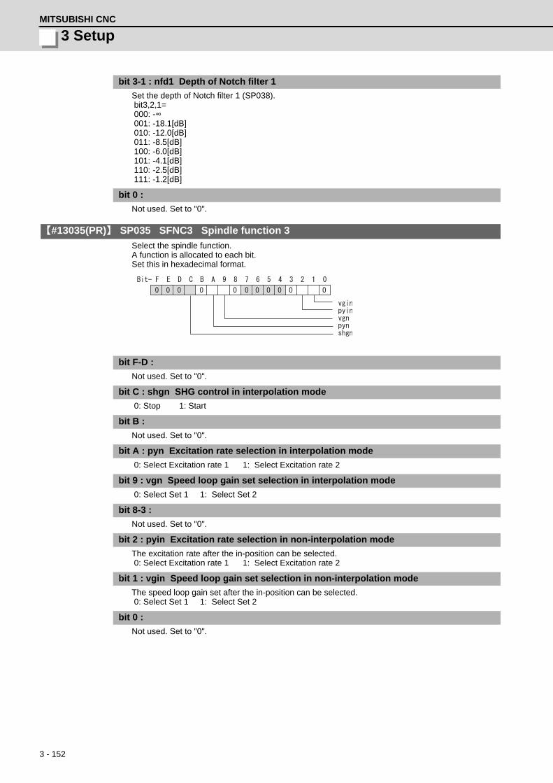
3 - 152
3 SetupMITSUBISHI CNC
bit 3-1 : nfd1 Depth of Notch filter 1
Set the depth of Notch filter 1 (SP038). bit3,2,1= 000: -∞ 001: -18.1[dB] 010: -12.0[dB] 011: -8.5[dB] 100: -6.0[dB] 101: -4.1[dB] 110: -2.5[dB] 111: -1.2[dB]
bit 0 :
Not used. Set to "0".
【#13035(PR)】 SP035 SFNC3 Spindle function 3
Select the spindle function. A function is allocated to each bit. Set this in hexadecimal format.
bit F-D :
Not used. Set to "0".
bit C : shgn SHG control in interpolation mode
0: Stop 1: Start
bit B :
Not used. Set to "0".
bit A : pyn Excitation rate selection in interpolation mode
0: Select Excitation rate 1 1: Select Excitation rate 2
bit 9 : vgn Speed loop gain set selection in interpolation mode
0: Select Set 1 1: Select Set 2
bit 8-3 :
Not used. Set to "0".
bit 2 : pyin Excitation rate selection in non-interpolation mode
The excitation rate after the in-position can be selected. 0: Select Excitation rate 1 1: Select Excitation rate 2
bit 1 : vgin Speed loop gain set selection in non-interpolation mode
The speed loop gain set after the in-position can be selected. 0: Select Set 1 1: Select Set 2
bit 0 :
Not used. Set to "0".

3 - 153
MDS-D/DH Series Instruction Manual
3-3 Setting the initial parameters for the spindle drive unit
【#13036(PR)】 SP036 SFNC4 Spindle function 4
Select the spindle function. A function is allocated to each bit. Set this in hexadecimal format.
bit F-8 :
Not used. Set to "0".
bit 7 : mksl Coil selection in spindle synchronization mode
0: Select the coil commanded during synchronization 1: Select high-speed coil
bit 6-5 :
Not used. Set to "0".
bit 4 : shgs SHG control in spindle synchronization mode
0: Stop 1: Start
bit 3 :
Not used. Set to "0".
bit 2 : pys Excitation rate selection in spindle synchronization mode
0: Select Excitation rate 1 1: Select Excitation rate 2
bit 1 : vgs Speed loop gain set selection in spindle synchronization mode
0: Select Set 1 (SP005,SP006,SP007) 1: Select Set 2 (SP008,SP009,SP010)
bit 0 :
Not used. Set to "0".
【#13037】 SP037 JL Load inertia scale
Set the motor axis conversion total load inertia including motor itself in proportion to the motor inertia. SV037(JL)=(Jm+Jl)/Jm×100 Jm: Motor inertia Jl: Motor axis conversion load inertia
---Setting range---0 to 5000 (%)
【#13038】 SP038 FHz1 Notch filter frequency 1
Set the vibration frequency to suppress when machine vibration occurs. (Enabled at 50 or more.)When not using, set to "0". Related parameters: SP034/bit3-1
---Setting range---0 to 2250 (Hz)
【#13039】 SP039 LMCD Lost motion compensation timing
Set this parameter when the lost motion compensation type2 timing does not match. Adjust by increasing the value by 10 at a time.
---Setting range---0 to 2000 (ms)

3 - 154
3 SetupMITSUBISHI CNC
【#13040】 SP040 LMCT Lost motion compensation non-sensitive band
Set the non-sensitive band of the lost motion compensation in the feed forward control. When "0" is set, 2°/1000 is set. Adjust by increasing the value by 1°/1000 at a time.
---Setting range----32768 to 32767 (1°/1000)
【#13041】 SP041 LMC2 Lost motion compensation 2
Set this parameter with SP048(LMC1) only to vary the lost motion compensation amount depending on the command directions. Normally, set to "0".
---Setting range----1 to 200 (Short-time rated %)
Note that when SP227/bit2 is "1", the range will be -1 to 20000 (Short-time rated 0.01%).
【#13042】 SP042 OVS2 Overshooting compensation 2
Set this parameter with SP043(OVS1) only to vary the lost motion compensation amount depending on the command directions. Normally, set to "0".
---Setting range----1 to 100 (Short-time rated %)
Note that when SP227/bit2 is "1", the range will be -1 to 10000 (Short-time rated 0.01%).
【#13043】 SP043 OVS1 Overshooting compensation 1
Set this parameter when overshooting occurs during positioning. This compensates the motor torque during positioning. This is valid only when the overshooting compensation SP033 (SFNC1/ovs) is selected. [Type 3 "When SP033/ bitB,A=11"] Use this when performing overshoot compensation in the feed forward control during arc cutting mode. Set the compensation amount based on the motor short-time rated current. Increase the value in increments of 1% to find the value where overshooting ceases. [To vary compensation amount depending on the direction]When SV042 (OVS2) is "0", change the SP043 (OVS1) value in both +/- directions to compensate. To change the compensation amount depending on the command direction, set this with SP042 (OVS2). (SP043: + direction, SP042: - direction, However, the directions may be opposite depending on other settings. )When "-1" is set, the compensation will not be performed in the command direction.
---Setting range----1 to 100 (Short-time rated %)
Note that when SP227/bit2 is "1", the range will be -1 to 10000 (Short-time rated 0.01%).
【#13044】 SP044 OBS2 Disturbance observer gain
Set the disturbance observer gain. The standard setting is "100".To use the disturbance observer, also set SP037(JL), SP045(OBS1) and SP226/ bitE. When not using, set to "0".
---Setting range---0 to 500 (%)
【#13045】 SP045 OBS1 Disturbance observer filter frequency
Set the disturbance observer filter band. Normally, set to "100". To use the disturbance observer, also set SP037(JL), SP044(OBS2) and SP226/ bitE. When not using, set to "0".
---Setting range---0 to 1000 (rad/s)

3 - 155
MDS-D/DH Series Instruction Manual
3-3 Setting the initial parameters for the spindle drive unit
【#13046】 SP046 FHz2 Notch filter frequency 2
Set the vibration frequency to suppress when machine vibration occurs. (Enabled at 50 or more.)When not using, set to "0". Related parameters: SP034/bit7-5
---Setting range---0 to 2250 (Hz)
【#13047】 SP047 EC Inductive voltage compensation gain
Set the inductive voltage compensation gain. Normally, set to "100". Lower the gain when the current FB peak exceeds the current command peak.
---Setting range---0 to 200 (%)
【#13048】 SP048 LMC1 Lost motion compensation 1
Set this parameter when the protrusion (that occurs due to the non-sensitive band by friction, torsion, backlash, etc.) at quadrant change is too large. This sets the compensation torque at quadrant change (when an axis feed direction is reversed) by Short-time rated %.Whether to enable the lost motion compensation and the method can be set with other parameters. [Type 2 "When SP033/bit9,8=10"] Set the compensation amount based on the motor short-time rated current. The standard setting is double of the friction torque. The compensation amount will be 0 when "0" is set. Related parameters: SP033/bit9-8, SP039, SP040, SP041, SP227/bit2 [To vary compensation amount depending on the direction]When SP041 (LMC2) is "0", change SP048 (LMC1) value in both of +/- directions to compensate. To vary the compensation amount depending on the command direction, set this with SP041 (LMC2). (SP048: + direction, SP041: - direction, However, the directions may be opposite depending on other settings. )When "-1" is set, the compensation will not be performed in the command direction.
---Setting range----1 to 200 (Short-time rated %)
Note that when SP227/bit2 is "1", the range will be -1 to 20000 (Short-time rated 0.01%).
【#13049】 SP049 FFC Acceleration rate feed forward gain
When a relative error in the synchronous control is too large, set this parameter to the axis that is delaying. The standard setting is "0". The standard setting in the SHG control is "100". Adjust relative errors in acceleration/deceleration by increasing the value by 50 to 100.
---Setting range---0 to 999 (%)
【#13050】 SP050 TOF Torque offset
Set the imbalance torque.
---Setting range----100 to 100 (Short-time rated %)

3 - 156
3 SetupMITSUBISHI CNC
【#13051】 SP051 DFBT Dual feed back control time constant
Set the control time constant in dual feed back. When the function is valid, the standard setting is "100". When "0" is set, the value is 1 ms. When the time constant is increased, the operation will get closer to the semi-closed control and the limit of the position loop gain will be raised. However, this cannot be used when the spindle slip occurs in machine configuration such as V-belt drive. Related parameters: SP017/bit1, SP052
---Setting range---0 to 9999 (ms)
【#13052】 SP052 DFBN Dual feedback control non-sensitive band
Set the non-sensitive band in the dual feedback control. Normally set to "0". Related parameters: SP017/bit1, SP051
---Setting range---0 to 9999 (1/1000")
【#13053】 SP053 ODS Excessive error detection width (non-interpolation mode)
Set the excessive error detection width in non-interpolation mode. Standard setting value: ODS = Maximum motor speed [r/min] × 6/PGV/2 When set to "0", the excessive error detection will not be performed.
---Setting range---0 to 32767 (°)
【#13054】 SP054 ORE Overrun detection width in closed loop control
Set the overrun detection width in the full-closed loop control. When the gap between the motor side detector and the machine side detector exceeds the set value, it is judged as an overrun and "Alarm 43" is detected. When "-1" is set, the alarm detection will not be performed. When "0" is set, overrun will be detected with 2°. In the full-closed loop control, normally set this parameter to "360". During V-belt drive, set to "-1".
---Setting range----1 to 32767 (°)
【#13055】 SP055 EMGx Max. gate off delay time after emergency stop
Set the time required to forcibly execute READY OFF after the emergency stop is input. Normally set to "20000". When "0" is set, READY OFF is forcibly executed with "7000ms". When the set time is shorter than the time to decelerate and stop, the spindle will stop with the dynamic brake after the set time is out. Related parameters: SP056
---Setting range---0 to 29900 (ms)
【#13056】 SP056 EMGt Deceleration time constant at emergency stop
Set the time constant used for the deceleration control at emergency stop. Set the time required to stop from the maximum motor speed (TSP). When "0" is set, the deceleration control is executed with "7000ms". Related parameters: SP055
---Setting range---0 to 29900 (ms)

3 - 157
MDS-D/DH Series Instruction Manual
3-3 Setting the initial parameters for the spindle drive unit
【#13057(PR)】 SP057 GRA1 Spindle side gear ratio 1
Set the number of gear teeth on the spindle side when "the gear selection command (control input 4/bit6, 5) "is set to "00".
---Setting range---1 to 32767
【#13058(PR)】 SP058 GRA2 Spindle side gear ratio 2
Set the number of gear teeth on the spindle side when "the gear selection command (control input 4/bit6, 5) " is set to "01".
---Setting range---1 to 32767
【#13059(PR)】 SP059 GRA3 Spindle side gear ratio 3
Set the number of gear teeth on the spindle side when "the gear selection command (control input 4/bit6, 5) " is set to "10".
---Setting range---1 to 32767
【#13060(PR)】 SP060 GRA4 Spindle side gear ratio 4
Set the number of gear teeth on the spindle side when "the gear selection command (control input 4/bit6, 5) " is set to "11".
---Setting range---1 to 32767
【#13061(PR)】 SP061 GRB1 Motor side gear ratio 1
Set the number of gear teeth on the motor side when "the gear selection command (control input 4/bit6, 5) " is set to "00".
---Setting range---1 to 32767
【#13062(PR)】 SP062 GRB2 Motor side gear ratio 2
Set the number of gear teeth on the motor side when "the gear selection command (control input 4/bit6, 5) " is set to "01".
---Setting range---1 to 32767
【#13063(PR)】 SP063 GRB3 Motor side gear ratio 3
Set the number of gear teeth on the motor side when "the gear selection command (control input 4/bit6, 5)" is set to "10".
---Setting range---1 to 32767
【#13064(PR)】 SP064 GRB4 Motor side gear ratio 4
Set the number of gear teeth on the motor side when "the gear selection command (control input 4/bit6, 5)" is set to "11".
---Setting range---1 to 32767
【#13065】 SP065 TLM1 Torque limit 1
Set the torque limit value when "the torque limit (control input 1/bitA, 9, 8) " is set to "001".
---Setting range---0 to 999 (Short-time rated %)

3 - 158
3 SetupMITSUBISHI CNC
【#13066】 SP066 TLM2 Torque limit 2
Set the torque limit value when "the torque limit (control input 1/bitA, 9, 8)" is set to "010".
---Setting range---0 to 999 (Short-time rated %)
【#13067】 SP067 TLM3 Torque limit 3
Set the torque limit value when "the torque limit (control input 1/bitA, 9, 8) " is set to "011".
---Setting range---0 to 999 (Short-time rated %)
【#13068】 SP068 TLM4 Torque limit 4
Set the torque limit value when "the torque limit (control input 1/bitA, 9, 8) " is set to "100".
---Setting range---0 to 999 (Short-time rated %)
【#13069】 SP069 PCMP Phase alignment completion width
Set the single-rotation position alignment completion width for phase alignment and changing from non-interpolation to spindle synchronization mode during rotation. Set the rotation error that is required to the machine. When the setting value decreases, the rotation error will decrease, but the cycle time (settling time) will get longer. The standard setting is "875".
---Setting range---0 to 32767 (1°/1000)
【#13070】 SP070 KDDT Phase alignment deceleration rate scale
Set the scale for SP016 (DDT) to change the deceleration rate only during rotation command (command F ⊿ T ≠ 0). When the setting value increases, the single-rotation position alignment will be completed faster, but the impact to the machine will also increase. When not using, set to "0".
---Setting range---0 to 255 (1/16-fold)
【#13071】 SP071 DIQM Variable current limit during deceleration, lower limit value
Set this parameter to adjust the deceleration time by changing the current limit value during deceleration depending on the motor speed. As shown below, set the lower limit rate of the current limit in SP071 (DIQM), and use with SP072 (DIQN). When DIQM is set to 100%, the standard current limit value in deceleration (TMLR) is applied.
---Setting range---0 to 999 (%)
DIQN0
DIQM
100%(TMLR)
Motor speed

3 - 159
MDS-D/DH Series Instruction Manual
3-3 Setting the initial parameters for the spindle drive unit
【#13072】 SP072 DIQN Variable current limit during deceleration, break point speed
Set this parameter to adjust the deceleration time by changing the current limit value during deceleration depending on the motor speed. As shown below, set the lower limit rate of the current limit in SP071 (DIQM), and use with SP072 (DIQN). When DIQM is set to 100%, the standard current limit value in deceleration (TMLR) is applied.
---Setting range---1 to 32767 (r/min)
【#13073】 SP073 VGVN Variable speed gain target value
If noise is bothersome during high speed rotation, it may be reduced by lowering the speed loop gain at high speed. Set this value to ensure the adequate response by suppressing noise and vibration at low speeds and increasing the speed loop gain at high speeds for a high-speed spindle of machining center, etc.As shown below, set the speed loop gain rate for the overspeed detection speed in SP073 (VGVN), and use with SP074 (VGVS). When not using, set to "0". The overspeed detection speed (VLMT) is 115% of the maximum motor speed (TSP). This function can be used when either Speed loop gain set 1 or Speed loop gain set 2 is selected.
---Setting range---0 to 999 (%)
DIQN0
DIQM
100%(TMLR)
Motor speed
VGVN(SP073)
<100
VGVS(SP074)
VLMT(SP026 1.15)
100
VGVN(SP073)
>100
VGVS(SP074)
VLMT(SP026 1.15)
100
Scale[%]
Motor speed[r/min]
Scale[%]
Motor speed[r/min]
When lowering the speed loop gain at high speed When increasing the speed loop gain at high speed

3 - 160
3 SetupMITSUBISHI CNC
【#13074】 SP074 VGVS Variable speed gain change start speed
If noise is bothersome during high speed rotation, it may be reduced by lowering the speed loop gain at high speed. Set this value to ensure the adequate response by suppressing noise and vibration at low speeds and increasing the speed loop gain at high speeds for a high-speed spindle of machining center, etc.As shown below, set the speed loop gain rate for the overspeed detection speed in SP073 (VGVN), and use with SP074 (VGVS). When not using, set to "0". The overspeed detection speed (VLMT) is 115% of the maximum motor speed (TSP). This function can be used when either Speed loop gain set 1 or Speed loop gain set 2 is selected.
---Setting range---0 to 32767 (r/min)
【#13075】 SP075 DWSH Slip compensation scale during regeneration high-speed coil
Set the slip frequency scale during deceleration. Normally, set to "0". (For machine tool builder adjustment)
---Setting range---0 to 255 (1/16-fold)
【#13076】 SP076 DWSL Slip compensation scale during regeneration low-speed coil
Set the slip frequency scale at deceleration when using the low-speed coil. Normally, set to "0". (For machine tool builder adjustment)
---Setting range---0 to 255 (1/16-fold)
【#13077】 SP077 IQA Q axis current lead compensation
Set the current loop gain. To use the coil switch function, set the current loop gain for when the high-speed coil is selected. The setting value is determined by the motor's electrical characteristics so that the value is fixed to each motor used. Set the value given in the spindle parameter list. (For machine tool builder adjustment)
---Setting range---1 to 20480
【#13078】 SP078 IDA D axis current lead compensation
Set the current loop gain. To use the coil switch function, set the current loop gain for when the high-speed coil is selected. The setting value is determined by the motor's electrical characteristics so that the value is fixed to each motor used. Set the value given in the spindle parameter list. (For machine tool builder adjustment)
---Setting range---1 to 20480
VGVN(SP073)
<100
VGVS(SP074)
VLMT(SP026 1.15)
100
VGVN(SP073)
>100
VGVS(SP074)
VLMT(SP026 1.15)
100
Scale[%]
Motor speed[r/min]
Scale[%]
Motor speed[r/min]
When lowering the speed loop gain at high speed When increasing the speed loop gain at high speed

3 - 161
MDS-D/DH Series Instruction Manual
3-3 Setting the initial parameters for the spindle drive unit
【#13079】 SP079 IQG Q axis current gain
Set the current loop gain. To use the coil switch function, set the current loop gain for when the high-speed coil is selected. The setting value is determined by the motor's electrical characteristics so that the value is fixed to each motor used. Set the value given in the spindle parameter list. (For machine tool builder adjustment)
---Setting range---1 to 8192
【#13080】 SP080 IDG D axis current gain
Set the current loop gain. To use the coil switch function, set the current loop gain for when the high-speed coil is selected. The setting value is determined by the motor's electrical characteristics so that the value is fixed to each motor used. Set the value given in the spindle parameter list. (For machine tool builder adjustment)
---Setting range---1 to 8192
【#13081】 SP081 IQAL Q axis current lead compensation low-speed coil
When using coil switch function, set the current loop gain for when the low-speed coil is selected. The setting value is determined by the motor's electrical characteristics so that the value is fixed to each motor used. Set the value given in the spindle parameter list. (For machine tool builder adjustment)
---Setting range---1 to 20480
【#13082】 SP082 IDAL D axis current lead compensation low-speed coil
When using coil switch function, set the current loop gain for when the low-speed coil is selected. The setting value is determined by the motor's electrical characteristics so that the value is fixed to each motor used. Set the value given in the spindle parameter list. (For machine tool builder adjustment)
---Setting range---1 to 20480
【#13083】 SP083 IQGL Q axis current gain low-speed coil
When using coil switch function, set the current loop gain for when the low-speed coil is selected. The setting value is determined by the motor's electrical characteristics so that the value is fixed to each motor used. Set the value given in the spindle parameter list. (For machine tool builder adjustment)
---Setting range---1 to 8192
【#13084】 SP084 IDGL D axis current gain low-speed coil
When using coil switch function, set the current loop gain for when the low-speed coil is selected. The setting value is determined by the motor's electrical characteristics so that the value is fixed to each motor used. Set the value given in the spindle parameter list. (For machine tool builder adjustment)
---Setting range---1 to 8192
【#13085】 SP085
Not used. Set to "0".
【#13086】 SP086
Not used. Set to "0".

3 - 162
3 SetupMITSUBISHI CNC
【#13087】 SP087 FHz4 Notch filter frequency 4
Set the vibration frequency to suppress when machine vibration occurs. (Enabled at 50 or more.)When not using, set to "0". Related parameters: SP034/bitB-9
---Setting range---0 to 2250 (Hz)
【#13088】 SP088 FHz5 Notch filter frequency 5
Set the vibration frequency to suppress when machine vibration occurs. (Enabled at 50 or more.)When not using, set to "0". Related parameters: SP034/bitF-D
---Setting range---0 to 2250 (Hz)
【#13089】 SP089 TMKQ Spindle output stabilizing gain Q axis
Set the magnification of the torque current stabilizing gain. (For machine tool builder adjustment)When set to "0", the torque current stabilization is disabled.When not using, set to "0".
---Setting range---0 to 32767
【#13090】 SP090 TMKD Spindle output stabilizing gain D axis
Set the magnification of the excitation current stabilizing gain. (For machine tool builder adjustment)When set to "0", the excitation current stabilization is disabled. When not using, set to "0".
---Setting range---0 to 32767
【#13091】 SP091
Not used. Set to "0".
【#13092】 SP092
Not used. Set to "0".
【#13093】 SP093
Not used. Set to "0".
【#13094】 SP094 MPV Magnetic pole error detection speed
In the magnetic pole position detection function, the command motor speed and motor speed during the position command stop are monitored. Set the command motor speed level and motor speed level during the position command stop in "r/min" unit. When the command motor speed level is set to "0", the magnetic pole position error is detected at 10r/min. Set to "10" as a standard setting when the magnetic pole position error detection function is enabled. This detects the magnetic pole position error when the motor speed is "100r/min". Ten-thousands digit, Thousands digit ------------ Command motor speed level (10r/min) Hundreds digit, Tens digit, Ones digit ----------- Motor speed level (10r/min)
---Setting range---0 to 31999

3 - 163
MDS-D/DH Series Instruction Manual
3-3 Setting the initial parameters for the spindle drive unit
【#13095】 SP095 VIAX Lead compensation scale during high-response acceleration/deceleration
Set the magnification against delay/lead compensation (SP006) of the high-response acceleration/deceleration (valid when SP226/ bitD is set to "1"). Normally, set to "0". Set this parameter to suppress overshooting when the speed is reached.
---Setting range---0 to 10000 (0.01%)
【#13096】 SP096 SDW Speed slowdown allowable width
When the spindle slows down due to multiple cutting, set the processable speed as percentage against the NC command speed. When "0" is set, the magnification is the same as when "85" is set. When set to "-1", the allowable width will be disabled.
---Setting range----1,0 to 100(%)
【#13097】 SP097 RNG1ex Extension sub side detector resolution
When setting the machine side detector resolution in pulse (p) unit, set the number of pulses to four bite data of SP097 (high-order) and SP019 (low-order) in pulse (p) unit. When SP097=0, the setting unit of SP019 is (kp).Refer to SP019 for details. Related parameters: SP019, SP020, SP098
---Setting range----1 to 32767
【#13098】 SP098 RNG2ex Extension main side detector resolution
When setting the motor side detector resolution in pulse (p) unit, set the number of pulses to four bite data of SP098 (high-order) and SP020 (low-order) in pulse (p) unit. When SP098=0, the setting unit of SP020 is (kp).Refer to SP020 for details. Related parameters: SP019, SP020, SP097
---Setting range----1 to 32767
【#13099】 SP099
Not used. Set to "0".
【#13100】 SP100
Not used. Set to "0".
【#13101-13112】 SP101 - SP112
Not used. Set to "0".
【#13113】 SP113 OPLP Current command value for open loop
Set the current command value for when the open loop control is enabled. When "0" is set, the state will be the same as when "50" is set. When not using, set to "0". The open loop control is enabled when "SP018/bit1" is set to "1".
---Setting range---0 to 999 (Short-time rated %)
3 - 164
3 SetupMITSUBISHI CNC
【#13114】 SP114 MKT Coil changeover gate cutoff timer
Set the time required to cut off the gate when turning OFF/ON the coil switch contactor. The value should be longer than the coil switch contactor's OFF/ON time. The standard setting is "150".
---Setting range---0 to 3500 (ms)
【#13115】 SP115 MKT2 Coil changeover current limit timer
Set the time required to limit the current immediately after the coil switch contactor ON/OFF is completed and the gate is turned ON. The standard setting is "250".
---Setting range---0 to 3500 (ms)
【#13116】 SP116 MKIL Coil changeover current limit value
Set the time required to limit the current immediately after the coil switch contactor ON/OFF is completed and the gate is turned ON. The standard setting is "120".
---Setting range---0 to 999 (Short-time rated %)
【#13117】 SP117 SETM Excessive speed deviation timer
Set the time to detect the speed excessive error alarm. Set the time required to the machine. The standard setting is "12".
---Setting range---0 to 60 (s)
【#13118(PR)】 SP118 MSFT Magnetic pole shift amount
Set the magnetic pole shift amount of IPM spindle motor. During DC excitation of the initial setup: Set the same value displayed in the "AFLT gain" on the NC monitor screen in SP225/bit4=1. When not using, set to "0".
---Setting range----18000 to 18000 (electrical angle 0.01°)
【#13119】 SP119
Not used. Set to "0".
【#13120】 SP120
Not used. Set to "0".
【#13121】 SP121 MP Kpp Magnetic pole detection position loop gain
Set the position loop gain in the magnetic polar detection loop. This is used in the initial magnetic polar detection when the IPM spindle motor is turned ON. Set to "0" when using an IM spindle motor.
---Setting range---0 to 32767

3 - 165
MDS-D/DH Series Instruction Manual
3-3 Setting the initial parameters for the spindle drive unit
【#13122】 SP122 MP Kvp Magnetic pole detection speed loop gain
Set the speed loop gain in the magnetic polar detection loop. This is used in the initial magnetic polar detection when the IPM spindle motor is turned ON. Set to "0" when using an IM spindle motor.
---Setting range---0 to 32767
【#13123】 SP123 MP Kvi Magnetic pole detection speed loop lead compensation
Set the speed loop lead compensation in the magnetic polar detection loop. This is used in the initial magnetic polar detection when the IPM spindle motor is turned ON. Set to "0" when using an IM spindle motor.
---Setting range---0 to 32767
【#13124】 SP124 ILMTsp Magnetic pole detection current limit value
Set the current limit value for the magnetic polar detection loop. This is used in the initial magnetic polar detection when the IPM spindle motor is turned ON. Set to "0" when using an IM spindle motor.
---Setting range---0 to 999 (Short-time rated %)
【#13125】 SP125 DA1NO D/A output ch1 data No. / Initial DC excitation level
Input the desired data number to D/A output channel.When using the 2-axis drive unit, set "-1" to the axis that the data will not be output. [When driving an IPM spindle motor (MDS-D/DH Series)] Use in the DC excitation function. DC excitation: Set the initial excitation level when SP225/bit4=1. When "0" is set, the state will be the same as when "20" is set.
---Setting range----32768 to 32767
【#13126】 SP126 DA2NO D/A output ch2 data No. / Final DC excitation level
Input the desired data number to D/A output channel.When using the 2-axis drive unit, set "-1" to the axis that the data will not be output. [When driving an IPM spindle motor (MDS-D/DH Series)] Use in the DC excitation function. DC excitation: Set the final excitation level when SP225/bit4=1. When "0" is set, the state will be the same as when "50" is set.
---Setting range----32768 to 32767
【#13127】 SP127 DA1MPY D/A output ch1 output scale / Initial DC excitation time
Set the output scale in increments of 1/100. When "0" is set, the scale is the same as when "100" is set. [When driving an IPM spindle motor (MDS-D/DH Series)] Use in the DC excitation function. DC excitation: Set the initial excitation time when SP225/bit4=1. When "0" is set, the state will be the same as when "10000" is set.
---Setting range----32768 to 32767 (1/100-fold)

3 - 166
3 SetupMITSUBISHI CNC
【#13128】 SP128 DA2MPY D/A output ch2 output scale
Set the output scale in increments of 1/100. When "0" is set, the scale is the same as when "100" is set.
---Setting range----32768 to 32767 (1/100-fold)
【#13129(PR)-13141(PR)】 SP129 - SP141
Set the unique constants for the spindle motor. (High-speed coil) The setting value is determined by the motor's mechanical and electrical characteristics and specifications, so normally set the value given in the spindle parameter list.
【#13142(PR)】 SP142
Set the unique constants for the spindle motor. (High-speed coil) The setting value is determined by the motor's mechanical and electrical characteristics and specifications, so normally set the value given in the spindle parameter list.For IPM spindle motorThis parameter is used in initial magnetic pole detection of IPM spindle motor.(1) Pulse application time: Set it in [μs] unit.(0 < application time < 350)(2) Pulse application coil: To select a low-speed coil, add 1000 to the pulse application time.(3) Polarity of estimated magnetic pole: When it is set to the reverse polarity, add "-" to the total of (1) and (2).E.g.: When performing 333μs pulse-applied magnetic pole estimation in a low-speed coil and selecting the reverse polarity for the estimated polarity SP142 = -(333+1000) = -1333
【#13143(PR)-13160(PR)】 SP143 - SP160
Set the unique constants for the spindle motor. (High-speed coil) The setting value is determined by the motor's mechanical and electrical characteristics and specifications, so normally set the value given in the spindle parameter list.
【#13161(PR)-13192(PR)】 SP161 - SP192
Set the unique constants for the spindle motor. (Low-speed coil) The setting value is determined by the motor's mechanical and electrical characteristics and specifications, so normally set the value given in the spindle parameter list.
【#13193】 SP193 LMR Change magnification for load meter standard output (High-speed coil)
Set the standard output to be displayed as 100% in load meter using the short-time rated output ratio. To display the continuous rated output as 100%, set as follows. Continuous rated output/Short-time rated output × 100When "0" is set, normal display will be applied. It is not available for MDS-D-SPJ3 Series.
---Setting range---0 to 100 (%)
【#13194】 SP194 LMN Base speed for load meter standard output (High-speed coil)
Set the base speed of the standard output to be displayed as 100% in load meter. When "0" is set, the base speed of the short-time rated output will be applied. It is not available for MDS-D-SPJ3 Series.
---Setting range---0 to 32767 (r/min)
3 - 167
MDS-D/DH Series Instruction Manual
3-3 Setting the initial parameters for the spindle drive unit
【#13195】 SP195 LMRL Change magnification for load meter standard output (Low-speed coil)
Set the standard output to be displayed as 100% in load meter using the short-time rated output ratio. To display the continuous rated output as 100%, set as follows. Continuous rated output/Short-time rated output × 100When "0" is set, normal display will be applied. It is not available for MDS-D-SPJ3 Series.
---Setting range---0 to 100 (%)
【#13196】 SP196 LMNL Base speed for load meter standard output (Low-speed coil)
Set the base speed of the standard output to be displayed as 100% in load meter. When "0" is set, the base speed of the short-time rated output will be applied. It is not available for MDS-D-SPJ3 Series.
---Setting range---0 to 32767 (r/min)
【#13197-13224】 SP197 - SP224
Not used. Set to "0".

3 - 168
3 SetupMITSUBISHI CNC
【#13225】 SP225 SFNC5 Spindle function 5
Select the spindle functions. Functions are allocated to each bit. Set this in hexadecimal format.
bit F-C : ovsn Overshooting compensation type 3 non-sensitive band
Set the non-sensitive band of the overshooting compensation type 3 in increments of 2°/1000. In the feed forward control, set the non-sensitive band for the model position droop and ignore the model overshooting. Set to "2°/1000" as a standard.
bit B-9 :
Not used. Set to "0".
bit 8 : mken Coil switch allowance in deceleration control
This enables a coil changeover while decelerating after an emergency stop for a spindle motor with coil changeover specification. A coil changeover may enable an excessive load inertia to stop within the maximum delay time. 0: Normal (Disable) 1: Enable
bit 7-6 : thno
Select the thermistor characteristics.When SP225/bit3=0 (N type) is selected bit7,6= 00: For Mitsubishi spindle motor 01: Setting prohibited 10: Setting prohibited 11: Setting prohibitedWhen SP225/bit3=1 (P type) is selected 00: KTY84-130 (Manufactured by Philips) 01: Setting prohibited 10: Setting prohibited 11: Setting prohibited
bit 5 : ddir Proximity switch signal enable edge
0: Falling edge 1: Rising edge
bit 4 : dcd DC excitation mode
0: Normal 1: Start
bit 3 : thtyp
Select the thermistor type.0: Type N thermistor (Mitsubishi standard) 1: Type P thermistor
bit 2 : mohn Thermistor temperature detection
0: Normal 1: Disable (Except for TS5690/5691)
bit 1-0 :
Not used. Set to "0".
ddir
ovsn
dcd
mohn
mken
thtyp
thno

3 - 169
MDS-D/DH Series Instruction Manual
3-3 Setting the initial parameters for the spindle drive unit
【#13226】 SP226 SFNC6 Spindle function 6
Select the spindle functions. Functions are allocated to each bit. Set this in hexadecimal format.
bit F : clt Spindle monitor load inertia ratio
0: Normal 1: Display
bit E : obs Disturbance observer
0: Normal 1: Enable
bit D : vup High response acceleration / deceleration
This suppresses a temporal delay which occurs when the target speed is attained from acceleration and when the spindle stops from deceleration. 0: Normal acceleration/deceleration 1: High response acceleration/deceleration Enable
bit C : tqof Spindle output stabilization during acceleration
0: Normal 1: Disable
bit B-9 :
Not used. Set to "0".
bit 8 : r2c Temperature compensation adjustment indicator
0: Normal 1: Display
bit 7-6 :
Not used. Set to "0".
bit 5 : pon IPM spindle pulse application magnetic pole estimation
0: Normal 1: Enable
bit 4-0 :
Not used. Set to "0".
r2ctqof
pon
vup
cltobs

3 - 170
3 SetupMITSUBISHI CNC
【#13227】 SP227 SFNC7 Spindle function 7
Select the spindle functions. Functions are allocated to each bit. Set this in hexadecimal format.
bit F-C : dis Digital signal input selection
0: No signal 1: Safety observation function door state signal 4: Proximity switch signal detection Other settings: setting prohibited
bit B-A : dos3 Digital signal output 3 selection (MDS-D-SPJ3)
bitB,A= 00: Disable 01: Setting prohibited 10: Contactor control signal output 11: Setting prohibited
bit 9-3 :
Not used. Set to "0".
bit 2 : ccu Lost motion/overshoot compensation compensation amount setting unit
0: Short-time rated % 1: Short-time rated 0.01%
bit 1-0 :
Not used. Set to "0".
【#13228】 SP228 SFNC8 Spindle function 8
Not used. Set to "0000".
【#13229】 SP229 SFNC9 Spindle function 9
Select the spindle functions. Functions are allocated to each bit. Set this in hexadecimal format.
bit F : ssc Safety observation function
0: Disable 1: Enable
bit E :
Not used. Set to "0".
bit D : rps Safety observation speed setting unit
0: Normal 1: 100°/min
bit C : sdt2 Specified speed output digital signal 2 output
0: Normal 1: Enable
bit B-0 :
Not used. Set to "0".
ccu
disdos3
sdt2rpsssc

3 - 171
MDS-D/DH Series Instruction Manual
3-3 Setting the initial parameters for the spindle drive unit
【#13230】 SP230 SFNC10 Spindle function 10
Select the spindle functions. Functions are allocated to each bit. Set this in hexadecimal format.
bit F-9 :
Not used. Set to "0".
bit 8 : nohis History of communication error alarm between NC and DRV(34,36,38,39)
For C70, set "1". 0: Enable 1: Disable
bit 7 : cse Spindle C axis command speed monitoring function
0: Normal setting (function disabled) 1: Function enabled It is not available for MDS-D-SPJ3 Series.
bit 6-0 :
Not used. Set to "0".
【#13231】 SP231
Not used. Set to "0000".
【#13232】 SP232
Not used. Set to "0000".
【#13233】 SP233 IVC Voltage non-sensitive band compensation
When 100% is set, the voltage equivalent to the logical non-energized time will be compensated.When "0" is set, 100% compensation will be performed. Adjust in increments of 10% from the default value 100%. If the value is too large, vibration or vibration noise may be generated.
---Setting range---0 to 255 (%)
【#13234】 SP234
Not used. Set to "0".
【#13235(PR)】 SP235 R2H Temperature compensation gain
Set the magnification in converting the thermistor temperature to the control compensation amount. When "0" is set, the temperature compensation function is disabled. When not using, or when using an IPM spindle motor, set to "0".
---Setting range---0 to 400 (%)
【#13236(PR)】 SP236 WIH Temperature compensation time constant
Set the delay time constant from the thermistor temperature to the control compensation amount. When "0" is set, the delay time constant is disabled. When not using, or when using an IPM spindle motor, set to "0".
---Setting range---0 to 150 (min)
csenohis

3 - 172
3 SetupMITSUBISHI CNC
【#13237(PR)】 SP237 TCF Torque command filter
Set the filter for the torque command. When not using, set to "0". The standard value is "500" when using the motor side detector TS5690 or TS5691.
---Setting range---0 to 4500 (Hz)
【#13238】 SP238 SSCFEED Safety observation Safety speed
Set the safety speed at the spindle end for the safety observation function. When not using, set to "0".
---Setting range---0 to 18000 (°/min)
However, when SP229/bitD is set to "1", the setting range is from -32768 to 32767 (100°/min).
【#13239】 SP239 SSCRPM Safety observation Safety motor speed
Set the motor's safety speed for the safety observation function. When not using, set to "0".
---Setting range---0 to 32767 (r/min)
【#13240(PR)】 SP240
Not used. Set to "0".
【#13241(PR)-13256(PR)】 SP241 - SP256
This is automatically set by the NC system.

4 - 1
付録 4 章
4 - 1
4Servo Adjustment

4 - 2
4 Servo AdjustmentMITSUBISHI CNC
4-1 D/A output specifications for servo drive unitDrive unit has a function to D/A output the various control data.
The servo adjustment data required for setting the servo parameters to match the machine can be D/A
output. Measure using a high-speed waveform recorder, oscilloscope, etc.
4-1-1 D/A output specifications
When the output data is 0, the offset voltage is 2.5V. If there is an offset voltage, adjust the zero level
position in the measuring instrument side.
Item Explanation
No. of channels 2ch
Output cycle 0.8ms (min. value)
Output precision 12bit
Output voltage range 0V to 2.5V (zero) to +5V
Output magnification setting -32768 to 32767 (1/100-fold)
Output pin (CN9, CN9B connector) MO1 = Pin 9, MO2 = Pin 19, LG = Pin 1,11
OthersThe D/A output for the 2-axis unit is also 2ch. When using the 2-axis unit,
always set -1 for the output data (SV061, 62) of the axis that is not to be measured.
MDS-D/DH-V2
CN9 connectorPin Pin NameName
LGLG
M01 M02
9
2
5
1
6
4 3
10
7 8
19
12
15
11
16
14 13
20
17 18
+2.5 [V]
0 [V]
Speed FB
Current FB
+2.5 [V]
0 [V]+5 [V]
+5 [V]
Example of D/A output waveform

4 - 3
MDS-D/DH Series Instruction Manual
4-1 D/A output specifications for servo drive unit
4-1-2 Output data settings
<Standard output>
【#2261】 SV061 DA1NO D/A output ch1 data No.
Input the data number you wish to output to the D/A output channel 1. When using the 2-axis drive unit, set "-1" to the axis that the data will not be output.
---Setting range----1 to 127
【#2262】 SV062 DA2NO D/A output ch2 data No.
Input the data number you wish to output to the D/A output channel 2. When using the 2-axis drive unit, set "-1" to the axis that the data will not be output.
---Setting range----1 to 127
(Note) The estimated load inertia ratio (unit: 100%/V) is applied for the rotary motor.
No. Output dataStandard output unit Output cycle
Linear axis Rotary axis
-1 D/A output not selectedFor 2nd axis or 3rd axis drive unit.Set the parameters to the other axes in the drive unit that is not D/A output.
0 Commanded rotation speed 1000(r/min)/V 0.8ms
1 Motor rotation speed 1000(r/min)/V 0.8ms
2 Torque command Motor stall rated ratio 100%/V 0.8ms
3 Torque feedback Motor stall rated ratio 100%/V 0.8ms
6 Effective current command 100%/V 0.8ms
7 Effective current feedback 100%/V 0.8ms
8 Machine vibration frequency 500Hz/V 0.8ms
9 HAS control droop cancel amount 1mm/V 1°/V 0.8ms
30 Collision detection estimated torque 100%/V 0.8ms
31Collision detection disturbance estimated
torque100%/V 0.8ms
32Estimated load inertia ratio
or moving sections gross weight100%/V or 100kg/V (Note) 0.8ms
35Disturbance observer estimated disturbance
torque100%/V 0.8ms
50 Position droop 1μm/V 1/1000°/V 0.8ms
51 Position command 1μm/V 1/1000°/V 0.8ms
52 Position feedback 1μm/V 1/1000°/V 0.8ms
53 Position FΔT 1μm/s/V 1/1000°/s/V 0.8ms
54Deviation from ideal position
(considering servo tracking delay)1μm/V 1/1000°/V 0.8ms
60 Position droop 1mm/V 1°/V 0.8ms
61 Position command 1mm/V 1°/V 0.8ms
62 Position feedback 1mm/V 1°/V 0.8ms
63 Position FΔT 1mm/s/V 1°/s/V 0.8ms
64Deviation from ideal position
(considering servo tracking delay)1mm/V 1°/V 0.8ms
70 Position droop 1m/V 1000°/V 0.8ms
71 Position command 1m/V 1000°/V 0.8ms
72 Position feedback 1m/V 1000°/V 0.8ms
73 Position FΔT 1m/s/V 1000°/s/V 0.8ms
74Deviation from ideal position
(considering servo tracking delay)1m/V 1000°/V 0.8ms
126 Saw tooth wave 0V to 5V 0.8ms
127 2.5V test data 2.5V 0.8ms
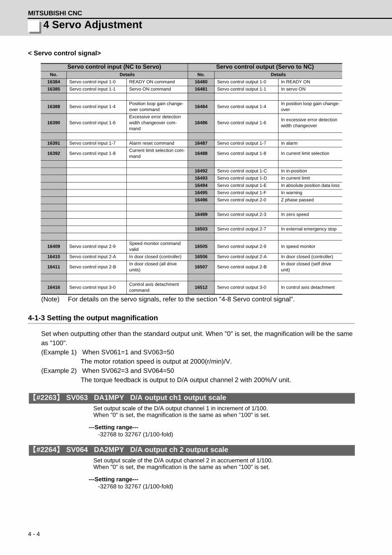
4 - 4
4 Servo AdjustmentMITSUBISHI CNC
< Servo control signal>
(Note) For details on the servo signals, refer to the section "4-8 Servo control signal".
4-1-3 Setting the output magnification
Set when outputting other than the standard output unit. When "0" is set, the magnification will be the same
as "100".
(Example 1) When SV061=1 and SV063=50
The motor rotation speed is output at 2000(r/min)/V.
(Example 2) When SV062=3 and SV064=50
The torque feedback is output to D/A output channel 2 with 200%/V unit.
【#2263】 SV063 DA1MPY D/A output ch1 output scale
Set output scale of the D/A output channel 1 in increment of 1/100. When "0" is set, the magnification is the same as when "100" is set.
---Setting range----32768 to 32767 (1/100-fold)
【#2264】 SV064 DA2MPY D/A output ch 2 output scale
Set output scale of the D/A output channel 2 in accruement of 1/100. When "0" is set, the magnification is the same as when "100" is set.
---Setting range----32768 to 32767 (1/100-fold)
Servo control input (NC to Servo) Servo control output (Servo to NC)No. Details No. Details
16384 Servo control input 1-0 READY ON command 16480 Servo control output 1-0 In READY ON
16385 Servo control input 1-1 Servo ON command 16481 Servo control output 1-1 In servo ON
16388 Servo control input 1-4Position loop gain change-over command
16484 Servo control output 1-4In position loop gain change-over
16390 Servo control input 1-6Excessive error detection width changeover com-mand
16486 Servo control output 1-6In excessive error detection width changeover
16391 Servo control input 1-7 Alarm reset command 16487 Servo control output 1-7 In alarm
16392 Servo control input 1-8Current limit selection com-mand
16488 Servo control output 1-8 In current limit selection
16492 Servo control output 1-C In in-position
16493 Servo control output 1-D In current limit
16494 Servo control output 1-E In absolute position data loss
16495 Servo control output 1-F In warning
16496 Servo control output 2-0 Z phase passed
16499 Servo control output 2-3 In zero speed
16503 Servo control output 2-7 In external emergency stop
16409 Servo control input 2-9Speed monitor command valid
16505 Servo control output 2-9 In speed monitor
16410 Servo control input 2-A In door closed (controller) 16506 Servo control output 2-A In door closed (controller)
16411 Servo control input 2-BIn door closed (all drive units)
16507 Servo control output 2-BIn door closed (self drive unit)
16416 Servo control input 3-0Control axis detachment command
16512 Servo control output 3-0 In control axis detachment

4 - 5
MDS-D/DH Series Instruction Manual
4-2 Servo adjustment procedure
4-2 Servo adjustment procedure
Perform adjusting the servo in the factory configuration of the machine. When the servo is adjusted
without having an enough running-in or a cover, friction torque, machine resonance frequency or
resonance gain may be different, resulting in an incorrect adjustment.
NO
YES
Mainly measure the position droop waveform.
Measure the electrical end position FB (detector position FB) waveform.
Setup has completed.
Set speed loop gain
Set position loop gain
Measures against the vibration · Notch filter · Jitter compensation · Variable speed loop gain
Vibration occurs?
Adjusting servo
Set the functions of overload detection, deceleration control at emergency stop, vertical axis drop upr evention, etc .
Improve protrusion at quadrant Perform lost motion compensation
Set protective function
Adjusting servo completed Accuracy adjustment of the electrical end position FB has completed.
Perform the adjustment so that vibration or overshooting does not occur.
Look for the maximum value not causesmachine resonance. The final settingvalue should be 70 to 80% of themaximum value at which the machinedoes not resonate.
CAUTION

4 - 6
4 Servo AdjustmentMITSUBISHI CNC
4-3 Gain adjustment4-3-1 Current loop gain
【#2209】 SV009 IQA Current loop q axis lead compensation
Set the fixed value of each motor. Set the standard value for each motor described in the standard parameter list.
---Setting range---1 to 20480
【#2210】 SV010 IDA Current loop d axis lead compensation
Set the fixed value of each motor. Set the standard value for each motor described in the standard parameter list.
---Setting range---1 to 20480
【#2211】 SV011 IQG Current loop q axis gain
Set the fixed value of each motor. Set the standard value for each motor described in the standard parameter list.
---Setting range---1 to 8192
【#2212】 SV012 IDG Current loop d axis gain
Set the fixed value of each motor. Set the standard value for each motor described in the standard parameter list.
---Setting range---1 to 8192

4 - 7
MDS-D/DH Series Instruction Manual
4-3 Gain adjustment
4-3-2 Speed loop gain
(1) Setting the speed loop gain
The speed loop gain 1 (SV005: VGN1) is an important parameter for determining the responsiveness of
the servo control. During servo adjustment, the highest extent that this value can be set to becomes
important. The setting value has a large influence on the machine cutting precision and cycle time.
[1] Refer to the following standard VGN1 graphs and set the standard VGN1 according to the size of
the entire load inertia (motor and machine load inertia).
[2] If the standard VGN1 setting value is exceeded, the current command fluctuation will increase even
if the speed feedback fluctuates by one pulse. This can cause the machine to vibrate easily, so set
a lower value to increase the machine stability.
<When machine resonance does not occur at the standard VGN1>
Set the standard VGN1. Use the standard value if no problem (such as machine resonance)
occurs. If sufficient cutting precision cannot be obtained at the standard VGN1, VGN1 can be
raised above the standard value as long as a 70 percent margin in respect to the machine
resonance occurrence limit is maintained. The cutting accuracy can also be improved by adjusting
with the disturbance observer.
<When machine resonance occurs at the standard VGN1>
Machine resonance is occurring if the shaft makes abnormal sounds when operating or stopping,
and a fine vibration can be felt when the machine is touched while stopped. Machine resonance
occurs because the servo control responsiveness includes the machine resonance points. (Speed
control resonance points occur, for example, at parts close to the motor such as ball screws.)
Machine resonance can be suppressed by lowering VGN1 and the servo control responsiveness,
but the cutting precision and cycle time are sacrificed. Thus, set a vibration suppression filter and
suppress the machine resonance (Refer to section "4-4-2 Vibration suppression measures"), and
set a value as close as possible to the standard VGN1. If the machine resonance cannot be
sufficiently eliminated even by using a vibration suppression filter, then lower the VGN1.
【#2205】 SV005 VGN1 Speed loop gain 1
Set the speed loop gain. The higher the setting value is, the more accurate the control will be, however, vibration tends to occur. If vibration occurs, adjust by lowering by 20 to 30%. The value should be determined to the 70 to 80% of the value at which the vibration stops. The value differs depending on servo motors. Aim at the standard value determined by the servo motor type and load inertia ratio to adjust.
---Setting range---1 to 30000
Suppressing the resonance with the vibration suppression function and increasing the VGN1 setting
is effective for adjusting the servo later. POINT

4 - 8
4 Servo AdjustmentMITSUBISHI CNC
Load inertia ratio display
Perform the measurement in the section "4-4-5 (1) Measuring unbalance torque and frictional torque",
and set a torque offset (SV032) and frictional torque (SV045).
When an acceleration/deceleration operation is executed with the setting of SV035/bitF=1, an estimated
load inertia ratio will be displayed in "load inertia ratio " on the drive monitor screen.
Standard VGN1 graph (servo motor HF, HF-H, HF-KP Series)
100
200
0
500
400
300
100 200 400 600 300 500
600
100
200
0
500
400
300
100 200 400 600 300 500
600
100
200
0
500
400
300
100 200 400 600 300 500
600
100
200
0
500
400
300
100 200 400 600 300 500
600
10
20
0
50
40
30
100 200 400 600 300 500
60
HF- KP23
HF-KP43
20
40
0
100
80
60
100 200 400 600 300 500
120
[ HF204, HF354, HF123, HF142, HF223 ][ HF-H204, HF-H354 ]
[ HF453, HF703, HF302, HF303, HF903 ][ HF-H453, HF-H703, HF-H903 ]
[ HF105, HF104, HF154, HF224 ][ HF-H105, HF-H104, HF-H154 ]
[ HF75, HF54 ][ HF-H75, HF-H54 ]
[ HF-KP73 ][ HF-KP23, HF-KP43 ]
Isolated motor Isolated motor
Load inertia magnification (%)
Standard VGN1
Isolated motor
Load inertia magnification (%)
Standard VGN1
Isolated motor
Load inertia magnification (%)
Isolated motor
Isolated motor
Load inertia magnification (%)
Load inertia magnification (%) Load inertia magnification (%)
OSA166(-A74(N)) VGN limit = 500OSA105(-A51) VGN limit = 350OSA18(-A48) VGN limit = 300
OSA166(-A74(N)) VGN limit = 500OSA105(-A51) VGN limit = 350OSA18(-A48) VGN limit = 300

4 - 9
MDS-D/DH Series Instruction Manual
4-3 Gain adjustment
Standard VGN1 graph (servo motor HP, HP-H Series)
Standard VGN1 graph (servo motor HC-H Series)
100
200
0
500
400
300
100 200 400 600 300 500
600
[ HP54, HP154, HP224 ] [ HP- H54, HP- H154, HP- H224 ]
100
200
0
500
400
300
100 200 400 600 300 500
600
[ HP104 ] [ HP- H104 ]
100
200
0
500
400
300
100 200 400 600 300 500
600
[ HP204, HP354, HP454 ] [ HP- H204, HP- H354, HP-H454 ]
100
200
0
500
400
300
100 200 400 600 300 500
600
[ HP704, HP903, HP1103 ] [ HP- H704, HP- H903, HP-H1103 ]
Load inertia magnification (%)
Standard VGN1
Isolated motor
Load inertia magnification (%)
Standard VGN1
Isolated motor
Load inertia magnification (%)
Isolated motor
Isolated motor
Load inertia magnification (%)
OSA166(-A74(N)) VGN limit = 500OSA105(-A51) VGN limit = 350OSA18(-A48) VGN limit = 300
OSA166(-A74(N)) VGN limit = 500OSA105(-A51) VGN limit = 350OSA18(-A48) VGN limit = 300
100
200
0
500
400
300
100 200 400 600 300 500
600
[ HC-H1502 ]
Isolated motor
Load inertia magnification (%)
OSA166(-A74(N)) VGN limit = 500OSA105(-A51) VGN limit = 350OSA18(-A48) VGN limit = 300
Standard VGN1
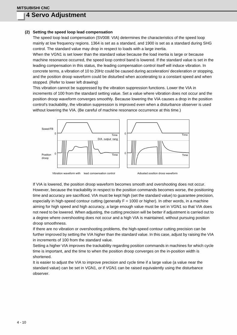
4 - 10
4 Servo AdjustmentMITSUBISHI CNC
(2) Setting the speed loop lead compensation
The speed loop lead compensation (SV008: VIA) determines the characteristics of the speed loop
mainly at low frequency regions. 1364 is set as a standard, and 1900 is set as a standard during SHG
control. The standard value may drop in respect to loads with a large inertia.
When the VGN1 is set lower than the standard value because the load inertia is large or because
machine resonance occurred, the speed loop control band is lowered. If the standard value is set in the
leading compensation in this status, the leading compensation control itself will induce vibration. In
concrete terms, a vibration of 10 to 20Hz could be caused during acceleration/ deceleration or stopping,
and the position droop waveform could be disturbed when accelerating to a constant speed and when
stopped. (Refer to lower left drawing)
This vibration cannot be suppressed by the vibration suppression functions. Lower the VIA in
increments of 100 from the standard setting value. Set a value where vibration does not occur and the
position droop waveform converges smoothly. Because lowering the VIA causes a drop in the position
control's trackability, the vibration suppression is improved even when a disturbance observer is used
without lowering the VIA. (Be careful of machine resonance occurrence at this time.)
If VIA is lowered, the position droop waveform becomes smooth and overshooting does not occur.
However, because the trackability in respect to the position commands becomes worse, the positioning
time and accuracy are sacrificed. VIA must be kept high (set the standard value) to guarantee precision,
especially in high-speed contour cutting (generally F = 1000 or higher). In other words, in a machine
aiming for high speed and high accuracy, a large enough value must be set in VGN1 so that VIA does
not need to be lowered. When adjusting, the cutting precision will be better if adjustment is carried out to
a degree where overshooting does not occur and a high VIA is maintained, without pursuing position
droop smoothness.
If there are no vibration or overshooting problems, the high-speed contour cutting precision can be
further improved by setting the VIA higher than the standard value. In this case, adjust by raising the VIA
in increments of 100 from the standard value.
Setting a higher VIA improves the trackability regarding position commands in machines for which cycle
time is important, and the time to when the position droop converges on the in-position width is
shortened.
It is easier to adjust the VIA to improve precision and cycle time if a large value (a value near the
standard value) can be set in VGN1, or if VGN1 can be raised equivalently using the disturbance
observer.
0
0 0
0
Vibration waveform with lead compensation control Adjusted position droop waveform
Speed FB
Position droop
TimeD/A output rang
Time
Time
Time

4 - 11
MDS-D/DH Series Instruction Manual
4-3 Gain adjustment
【#2208】 SV008 VIA Speed loop lead compensation
Set the gain of the speed loop integral control. Standard setting: 1364 Standard setting in the SHG control: 1900Adjust the value by increasing/decreasing this by about 100 at a time. Raise this value to improve contour tracking accuracy in high-speed cutting. Lower this value when the position droop does not stabilize (when the vibration of 10 to 20Hz occurs).
---Setting range---1 to 9999
Position droop vibration of 10Hz or less is not leading compensation control vibration. The position
loop gain must be adjusted. POINT

4 - 12
4 Servo AdjustmentMITSUBISHI CNC
4-3-3 Position loop gain
(1) Setting the position loop gain
The position loop gain 1 (SV003: PGN1) is a parameter that determines the trackability to the command
position. 33 is set as a standard. Set the same position loop gain value between interpolation axes.
When PGN1 is raised, the trackability will be raised and the settling time will be shortened, but a speed
loop that has a responsiveness that can track the position loop gain with increased response will be
required. If the speed loop responsiveness is insufficient, several Hz of vibration or overshooting will
occur during acceleration/deceleration. Vibration or overshooting will also occur when VGN1 is smaller
than the standard value during VIA adjustment, but the vibration in the position loop occurs generally
10Hz or less. (The VIA vibration occurs from 10 to 20Hz.) When the position control includes machine
resonance points (Position control machine resonance points occur at the tool end parts, etc.) because
of insufficient machine rigidity, the machine will vibrate during positioning, etc. In either case, lower
PGN1 and adjust so that vibration does not occur.
If the machine also vibrates due to machine backlash when the motor stops, the vibration can be
suppressed by lowering the PGN1 and smoothly stopping.
If SHG control is used, an equivalently high position loop gain can be maintained while suppressing
these vibrations. Adjust SHG control by raising the gain gradually after setting PGN1 as 1/2 a value of
PGN1 at which a vibration does not occur under the normal control. If the PGN1 setting value is more
than 1/2 of the normal control PGN1 when SHG control is used, there is an improvement effect in
position control. (Note that for the settling time the improvement effect is at 1/ or more.)
【#2203】 SV003 PGN1 Position loop gain 1
Set the position loop gain. The standard setting is "33". The higher the setting value is, the more accurately the command can be followed, and the shorter the settling time in positioning gets, however, note that a bigger shock will be applied to the machine during acceleration/deceleration. When using the SHG control, also set SV004 (PGN2) and SV057 (SHGC).
---Setting range---1 to 200 (rad/s)
【#2204】 SV004 PGN2 Position loop gain 2
When performing the SHG control, set the value of "SV003 x 8/3" to "SV004". When not using the SHG control, set to "0".
---Setting range---0 to 999 (rad/s)
【#2257】 SV057 SHGC SHG control gain
When performing the SHG control, set to SV003(PGN1)*6. When not using the SHG control, set to "0".
---Setting range---0 to 1200 (rad/s)
Always set the same value for the position loop gain between the interpolation axes.
√2
CAUTION

4 - 13
MDS-D/DH Series Instruction Manual
4-3 Gain adjustment
(2) Setting the position loop gain for spindle synchronous control
During spindle synchronous control (synchronous tapping control, etc.), there are three sets of position
loop gain parameters besides the normal control.
【#2249】 SV049 PGN1sp Position loop gain 1 in spindle synchronous control
Set the position loop gain during spindle synchronization control (synchronous tapping and synchronization control with spindle C-axis). Set the same value as that of the position loop gain for spindle synchronous tapping control. When performing the SHG control, set this parameter with SV050 (PGN2sp) and SV058 (SHGCsp).
---Setting range---1 to 200 (rad/s)
【#2250】 SV050 PGN2sp Position loop gain 2 in spindle synchronous control
When using SHG control during spindle synchronous control (synchronous tapping and synchronization control with spindle C-axis), set this parameter with SV049 (PGN1sp) and SV058 (SHGCsp). Make sure to set the value 8/3 times that of SV049. When not using the SHG control, set to "0".
---Setting range---0 to 999 (rad/s)
【#2258】 SV058 SHGCsp SHG control gain in spindle synchronous control
When using SHG control during spindle synchronization control (synchronous tapping and synchronous control with spindle C-axis), set this parameter with SV049 (PGN1sp) and SV050 (PGN2sp). Make sure to set the value 6 times that of SV049.When not using the SHG control, set to "0".
---Setting range---0 to 1200 (rad/s)
(3) SHG control
If the position loop gain is increased or feed forward control (NC function) is used to shorten the settling
time or increase the precision, the machine system may vibrate easily.
SHG control changes the position loop to a high-gain by stably compensating the servo system position
loop through a delay. This allows the settling time to be reduced and a high precision to be achieved.
(SHG: Smooth High-Gain)
(Feature 1) When the SHG control is set, even if PGN1 is set to the same value as the conventional
gain, the position loop gain will be doubled.
(Feature 2) The SHG control response is smoother than conventional position control during
acceleration/deceleration, so the gain can be increased further with SHG control compared to
the conventional position control.
(Feature 3)With SHG control, a high gain is achieved so a high precision can be obtained during contour
control.
The following drawing shows an example of the improvement in roundness characteristics with
SHG control.
Always set the same value for the position loop gain between the spindle and servo synchronous
axes.CAUTION

4 - 14
4 Servo AdjustmentMITSUBISHI CNC
Shape error characteristics
During SHG control, PGN1, PGN2 and SHGC are set with the following ratio.
PGN1 : PGN2 : SHGC = 1 : 8/3 : 6
During SHG control even if the PGN1 setting value is the same, the actual position loop gain will be
higher, so the speed loop must have a sufficient response. If the speed loop response is low, vibration
or overshooting could occur during acceleration/deceleration in the same manner as conventional
control. If the speed loop gain has been lowered because machine resonance occurs, lower the position
loop gain and adjust.
【#2208】 SV008 VIA Speed loop lead compensation
Set the gain of the speed loop integral control. Standard setting: 1364 Standard setting in the SHG control: 1900Adjust the value by increasing/decreasing this by about 100 at a time. Raise this value to improve contour tracking accuracy in high-speed cutting. Lower this value when the position droop does not stabilize (when the vibration of 10 to 20Hz occurs).
---Setting range---1 to 9999
【#2215】 SV015 FFC Acceleration rate feed forward gain
When a relative error in synchronous control is too large, set this parameter to the axis that is delaying. The standard setting is "0". The standard setting in the SHG control is "100". To adjust a relative error in acceleration/deceleration, increase the value by 50 - 100 at a time.
---Setting range---0 to 999 (%)
No. Abbrev. Parameter nameSetting
ratioSetting example Explanation
Setting range
SV003(SV049)
PGN1(PGN1sp)
Position loop gain 1 1 21 27 33 39 48
Always set with a combination of these three parameters.
1 to 200(rad/s)
SV004(SV050)
PGN2(PGN2sp)
Position loop gain 2 8/3 56 72 88 104 1280 to 999(rad/s)
SV057(SV058)
SHGC(SHGCsp)
SHG control gain 6 126 162 198 234 2880 to 1200
(rad/s)
(F=3000mm/min , ERROR=5.0μm/div) -50.0 50.00.0
0.0
-50.0
50.0 [1] : Commanded path
[2] : SHG control (PGN1=47)
[3] : Conventional control (PGN1=33)
Conventional control
SHG control
Control method Roundness error ( m)
2.5
22.5
<Effect>

4 - 15
MDS-D/DH Series Instruction Manual
4-4 Characteristics improvement
4-4 Characteristics improvement4-4-1 Optimal adjustment of cycle time
The following items must be adjusted to adjust the cycle time. Refer to the Instruction Manuals provided with
each CNC for the acceleration/deceleration pattern.
[1] Rapid traverse rate (rapid) : This will affect the maximum speed during positioning.
[2] Clamp speed (clamp) : This will affect the maximum speed during cutting.
[3] Acceleration/deceleration time constant (G0t*, G1t*) : Set the time to reach the feedrate.
[4] In-position width (SV024) : This will affect each block's movement command end time.
[5] Position loop gain (SV003) : This will affect each block's movement command settling time.
(1) Adjusting the rapid traverse
To adjust the rapid traverse, the CNC axis specification parameter rapid traverse rate (rapid) and
acceleration/deceleration time constant (G0t*) are adjusted. The rapid traverse rate is set so that the
motor speed matches the machine specifications in the range below the maximum speed in the motor
specifications. For the acceleration/deceleration time constants, carry out rapid traverse reciprocation
operation, and set so that the maximum current command value at acceleration/
deceleration is within the range shown below. The output torque is limited at areas near the maximum
speed, so monitor the current FB waveform during acceleration/deceleration and adjust so that the
torque is within the specified range.
If the drive unit's input voltage is less than the rated voltage, the torque will easily become insufficient,
and excessive errors will occur easily during acceleration/deceleration.
Maximum tolerable current command value when adjusting the rapid traverse acceleration/deceleration time constant
MDS-D Series (200V) MDS-DH Series (400V)
Motormodel
Max. tolerable current command
value
Motormodel
Max. tolerable current command
value
Motormodel
Max. tolerable current command
value
Motormodel
Max. tolerable current command
valueHF75 Within 350% HP54 Within 370% HF-H75 Within 350% HP-H54 Within 370%
HF105 Within 270% HP104 Within 300% HF-H105 Within 270% HP-H104 Within 300%HF54 Within 420% HP154 Within 440% HF-H54 Within 420% HP-H154 Within 440%
HF104 Within 350% HP224 Within 330% HF-H104 Within 350% HP-H224 Within 330%HF154 Within 380% HP204 Within 300% HF-H154 Within 380% HP-H204 Within 300%HF224 Within 310% HP354 Within 300% HF-H204 Within 310% HP-H354 Within 300%HF204 Within 310% HP454 Within 290% HF-H354 Within 330% HP-H454 Within 290%HF354 Within 420% HP704 Within 220% HF-H453 Within 250% HP-H704 Within 220%HF123 Within 190% HP903 Within 250% HF-H703 Within 240% HP-H903 Within 250%HF223 Within 230% HP1103 Within 210% HF-H903 Within 290% HP-H1103 Within 210%HF303 Within 240%HF453 Within 250% HF-KP23 Within 250% HC-H1502 Within 170%HF703 Within 240% HF-KP43 Within 250%HF903 Within 290% HF-KP73 Within 240%HF142 Within 190%HF302 Within 210%

4 - 16
4 Servo AdjustmentMITSUBISHI CNC
(2) Adjusting the cutting feed
To adjust the cutting rate, the NC axis specification parameter clamp speed (clamp) and acceleration/
deceleration time constant (G1t*) are adjusted. The in-position width at this time must be set to the
same value as actual cutting.
• Determining the clamp rate and adjusting the acceleration/deceleration time constant
(Features)The maximum cutting rate (clamp speed) can be determined freely.
(Adjustment)Carry out cutting feed reciprocation operation with dwell at the maximum cutting rate and
adjust the acceleration/deceleration time constant so that the maximum current command
value during acceleration/deceleration is within the range shown below.
• Setting the step acceleration/deceleration and adjusting the clamp speed
(Features)The acceleration/deceleration time constant is determined with the position loop in the servo,
so the acceleration/deceleration FΔT can be reduced.
(Adjustment)Set 1 (step) for the acceleration/deceleration time constant and carry out cutting feed
reciprocation operation with dwell. Adjust the cutting feed rate so that the maximum current
command value during acceleration/deceleration is within the range shown below, and then
set the value in the clamp speed.
Maximum tolerable current command value when adjusting the cutting feed acceleration/deceleration time constant
MDS-D Series (200V) MDS-DH Series (400V)
Motormodel
Max. tolerable current command
value
Motormodel
Max. tolerable current command
value
Motormodel
Max. tolerable current command
value
Motormodel
Max. tolerable current command
valueHF75 Within 245% HP54 Within 259% HF-H75 Within 245% HP-H54 Within 259%
HF105 Within 189% HP104 Within 210% HF-H105 Within 189% HP-H104 Within 210%HF54 Within 294% HP154 Within 308% HF-H54 Within 294% HP-H154 Within 308%
HF104 Within 245% HP224 Within 231% HF-H104 Within 245% HP-H224 Within 231%HF154 Within 266% HP204 Within 210% HF-H154 Within 266% HP-H204 Within 210%HF224 Within 217% HP354 Within 210% HF-H204 Within 217% HP-H354 Within 210%HF204 Within 217% HP454 Within 203% HF-H354 Within 231% HP-H454 Within 203%HF354 Within 294% HP704 Within 154% HF-H453 Within 175% HP-H704 Within 154%HF123 Within 133% HP903 Within 175% HF-H703 Within 168% HP-H903 Within 175%HF223 Within 161% HP1103 Within 147% HF-H903 Within 203% HP-H1103 Within 147%HF303 Within 168%HF453 Within 175% HF-KP23 Within 175% HC-H1502 Within 119%HF703 Within 168% HF-KP43 Within 175%HF903 Within 203% HF-KP73 Within 168%HF142 Within 133%HF302 Within 147%

4 - 17
MDS-D/DH Series Instruction Manual
4-4 Characteristics improvement
(3) Adjusting the in-position width
Because there is a response delay in the servomotor drive due to position loop control, a "settling time"
is also required for the motor to actually stop after the command speed from the CNC reaches 0.
The movement command in the next block is generally started after it is confirmed that the machine has
entered the "in-position width" range set for the machine.
Set the precision required for the machine as the in-position width. If a high precision is set needlessly,
the cycle time will increase due to a delay in the settling time.
The in-position width is validated with the servo parameter settings, but there may be cases when it is
validated with the NC parameters. Refer to each NC Instruction Manual.
【#2224】 SV024 INP In-position detection width
Set the in-position detection width. Set the positioning accuracy required for the machine. The lower the setting is, the higher the positioning accuracy will be. However the cycle time (settling time) becomes longer. The standard setting value is "50".
---Setting range---0 to 32767 (μm)
(4) Adjusting the settling time
The settling time is the time required for the
position droop to enter the in-position width
after the feed command (FΔT) from the CNC
reaches 0.
The settling time can be shortened by raising
the position loop gain or using SHG control.
However, a sufficient response (sufficiently
large VGN1 setting) for the speed loop is
required to carry out stable control.
The settling time during normal control when
the CNC is set to linear acceleration/
deceleration can be calculated using the
following equation. During SHG control,
estimate the settling time by multiplying PGN1
by .
The in-position width setting and confirmation availability depend on the CNC parameters. POINT
0
0
F T
Position droop
F
Time
Setting time
In -position
In -position width
G0tL
√2
ln INP
F × 106
60 × G0tL × PGN12PGN1×G0tL103
1- exp103
PGN1Settling time ( ms) =
PGN1 : Position loop gain1 (SV003) (rad/s)F : Rapid traverse rate (mm/min)G0tL : Rapid traverse linear acceleration/ deceleration time constant (ms)INP : In-position width (SV024) ( m)

4 - 18
4 Servo AdjustmentMITSUBISHI CNC
4-4-2 Vibration suppression measures
If vibration (machine resonance) occurs, it can be suppressed by lowering the speed loop gain 1 (VGN1).
However, cutting precision and cycle time will be sacrificed. (Refer to "4-3-2 Speed loop gain".) Thus, try to
maintain the VGN1 as high as possible, and suppress the vibration using the vibration suppression
functions.
If the VGN1 is lowered and adjusted because vibration cannot be sufficiently suppressed with the vibration
suppression functions, adjust the entire gain (including the position loop gain) again.
(Examples of vibration occurrence)
• A fine vibration is felt when the machine is touched, or a groaning sound is heard.
• Vibration or noise occurs during rapid traverse.
If machine resonance occurs, the resonance frequency can be confirmed at AFLT frequency on NC drive
monitor screen. Based on this frequency, the notch filter frequency can be set. When "0" is displayed,
resonance is not occurring.
Suppress the vibration using the vibration suppression functions, and maintain the speed loop gain
(SV005) as high as possible. POINT

4 - 19
MDS-D/DH Series Instruction Manual
4-4 Characteristics improvement
<Notch filter>
This servo drive unit mounts 5 notch filters. Measure the resonance frequency with AFLT frequency
display on NC drive monitor screen and the current feedback analog output function, and set that
frequency in parameter.
However, if the notch filter is set to a particularly low frequency, another resonance frequency that did
not vibrate initially may occur. If the notch filter's depth compensation (SV033, nfd1, nfd2) is adjusted so
that the filter does not operate unless necessary, the servo control will be stabilized.
Notch filter 3 is a filter with frequency fixed to 1125Hz, and has no depth compensation.
<Setting method>
[1] Set the resonance frequency in the notch filter frequency (1, 2, 4, 5).
[2] If the machine starts to vibrate at another frequency, raise (make shallower) the notch filter
depth compensation value, and adjust to the optimum value at which the resonance can be
eliminated.
[3] When the vibration cannot be completely eliminated, use also another notch filter for this
frequency.
【#2233】 SV033 SSF2 Servo function 2
bit 7-5 : nfd2 Depth of Notch filter 2
Set the depth of Notch filter 2 (SV046). bit7,6,5= 000: -∞ 001: -18.1[dB] 010: -12.0[dB] 011: -8.5[dB] 100: -6.0[dB] 101: -4.1[dB] 110: -2.5[dB] 111: -1.2[dB]
bit 4 : fhz3 Notch filter 3
0: Stop 1: Start (1,125Hz)
bit 3-1 : nfd1 Depth of Notch filter 1
Set the depth of Notch filter 1 (SV038). bit3,2,1= 000: -∞ 001: -18.1[dB] 010: -12.0[dB] 011: -8.5[dB] 100: -6.0[dB] 101: -4.1[dB] 110: -2.5[dB] 111: -1.2[dB]
【#2238】 SV038 FHz1 Notch filter frequency 1
Set the vibration frequency to suppress when machine vibration occurs. (Normally, do not set 80 or less.)Set to "0" when not using.
---Setting range---0 to 2250 (Hz)
【#2246】 SV046 FHz2 Notch filter frequency 2
Set the vibration frequency to suppress when machine vibration occurs. (Normally, do not set 80 or less.)Set to "0" when not using.
---Setting range---0 to 2250 (Hz)

4 - 20
4 Servo AdjustmentMITSUBISHI CNC
【#2283】 SV083 SSF6 Servo function 6
bit 7-5 : nfd5 Depth of Notch filter 5
Set the depth of Notch filter 5 (SV088). bit7,6,5= 000: -∞ 001: -18.1[dB] 010: -12.0[dB] 011: -8.5[dB] 100: -6.0[dB] 101: -4.1[dB] 110: -2.5[dB] 111: -1.2[dB]
bit 3-1 : nfd4 Depth of Notch filter 4
Set the depth of Notch filter 4 (SV087). bit3,2,1= 000: -∞ 001: -18.1[dB] 010: -12.0[dB] 011: -8.5[dB] 100: -6.0[dB] 101: -4.1[dB] 110: -2.5[dB] 111: -1.2[dB]
【#2287】 SV087 FHz4 Notch filter frequency 4
Set the vibration frequency to suppress when machine vibration occurs. (Normally, do not set 80 or less.)Set to "0" when not using.
---Setting range---0 to 2250 (Hz)
【#2288】 SV088 FHz5 Notch filter frequency 5
Set the vibration frequency to suppress when machine vibration occurs. (Normally, do not set 80 or less.)Set to "0" when not using.
---Setting range---0 to 2250 (Hz)

4 - 21
MDS-D/DH Series Instruction Manual
4-4 Characteristics improvement
<Notch filter frequency adaptive tracking function>
Machine system resonance can vary depending on secular changes or installation conditions of
machine, resonance frequency may deviate from the notch filter frequency set at the initial adjustment.
The adaptive tracking function estimates minor changes in resonance frequency from current command
oscillating component, automatically adjusting notch filter effective frequency. The resonance frequency
is estimated while G0 is moving and effective frequency is modified while the axis is stopped.
The adaptive tracking function can be applied to notch filter 1, 2, 4, 5 (SV038, SV046, SV087, SV088).
When resonance frequency is detected within the adaptive ranges which centers in the frequency set by
parameter, resonance frequency from which notch filter effective frequency with the closest setting
value is detected, suppressing machine resonance.
<Other specifications>
(a) Machine resonance is detected at frequency ranges of 150Hz to 90Hz.
(b) The depth of notch filter is not automatically adjusted. Only the effective frequency will change
while the filter depth remains fixed.
(c) When the notch filter 5 is adaptive to all frequency and also, others are not available, the effective
frequency of notch filter 5 is changed.
(d) When parameter setting value is changed; if the effective frequency remains within the adaptive
ranges, it will keep operating with the original frequency; if it doesn't, changed parameter value will
be applied.
Notch filter application ranges when the adaptive tracking function is available
Notch filterEstimated adaptive
frequency rangeAvail. Adaptive
operationAdaptive range
Notch filter 1 150 to 900 [Hz] SV115/bit8 Setting value(SV038)±Adaptive range (SV115/bit4,5) [Hz]
Notch filter 2 150 to 900 [Hz] SV115/bit9 Setting value (SV046)±Adaptive range (SV115/bit4,5) [Hz]
Notch filter 3 Not included Not included Not included
Notch filter 4 150 to 900 [Hz] SV115/bitA Setting value (SV087)±Adaptive range (SV115/bit4,5) [Hz]
Notch filter 5 150 to 900 [Hz] SV115/bitBSetting value (SV088)±Adaptive range (SV115/bit4,5) [Hz]
(Note) When adaptive to all frequency (SV115/bitF) 150 to 900 [Hz]
If adaptive ranges are set too wide, frequency may fluctuate so greatly that the control can become
unstable.
When the notch filter 5 is set adaptive to all frequency, the depth of the filter shall be set shallowly to
enable stable operation with low frequency.
CAUTION

4 - 22
4 Servo AdjustmentMITSUBISHI CNC
【#2315】 SV115 SSF10 Servo function 10
bit F : are Notch filter5 all frequencies adopted
When enabled, Notch filter5 all frequencies adoptive range is not limited regardless of SV115/bit4,5 setting. 0: Disable 1: Enable
bit E-C: dsl Notch filter frequency display
Switch the "AFLT frequency" display on drive monitor screen to check every notch filter frequency. When the selected notch filter is not used, "0" is displayed. bitE,D,C= 000 : Estimated resonance frequency (Normal display) 001 : Notch filter 1 frequency 010 : Notch filter 2 frequency 011 : Notch filter 3 frequency (always displays 1125Hz) 100 : Notch filter 4 frequency 101 : Notch filter 5 frequency Other settings: setting prohibited
bit B : ade5 Notch filter 5 / Adoptive follow-up function
0: Disable 1: Enable
bit A : ade4 Notch filter 4 / Adoptive follow-up function
0: Disable 1: Enable
bit 9 : ade2 Notch filter 2 / Adoptive follow-up function
0: Disable 1: Enable
bit 8 : ade1 Notch filter 1 / Adoptive follow-up function
0: Disable 1: Enable
bit 7-6 : dsn Estimated resonance frequency display holding time
Set the estimated resonance frequency display holding time to the "AFLT frequency" display on drive monitor screen. bit7,6= 00: 4 [s] 01: 8 [s] 10: 12 [s] 11: 16 [s]
bit 5-4 : dfhz Notch filter frequency range
Set the adaptive range of the notch filter frequency. When the adaptive follow-up function is enabled and if the estimated resonance frequency exists in the set range, the notch filter will be adapted. Normally set this parameter to "00". bit5,4= 00: -10 to 10 [%] 01: -20 to 20 [%] 10: -30 to 30 [%] 11: -40 to 40 [%]
bit 3-0 : esn Sensitivity of estimated resonance frequency
Set the sensitivity of the estimated resonance frequency. Smaller setting value enables to detect smaller vibration component, however, adoptive movement will be repeated frequently. Normally set this parameter to "0". 0 : Normal setting (same sensitivity as A) 1 : Sensitivity high to F : Sensitivity low

4 - 23
MDS-D/DH Series Instruction Manual
4-4 Characteristics improvement
<Jitter compensation (Vibration control when motor is stopped.)>
The load inertia becomes much smaller than usual if the motor position enters the machine backlash
when the motor is stopped. Because this means that an extremely large VGN1 is set for the load inertia,
vibration may occur.
Jitter compensation can suppress the vibration that occurs at the motor stop by ignoring the backlash
amount of speed feedback pulses when the speed feedback polarity changes.
Increase the number of ignored pulses by one pulse at a time, and set a value at which the vibration can
be suppressed. (Because the position feedback is controlled normally, there is no worry of positional
deviation.)
When jitter compensation is set to an axis that is not vibrating is set, vibration could be induced, so take
care.
【#2227】 SV027 SSF1 Servo function 1
bit 5-4 : vfct Jitter compensation pulse number
Suppress vibration by machine backlash when axis stops. bit5,4= 00: Disable 01: 1 pulse 10: 2 pulse 11: 3 pulses
Jitter compensation vibration suppression is only effective when the motor is stopped. POINT

4 - 24
4 Servo AdjustmentMITSUBISHI CNC
<Variable speed loop gain control>
If vibration occurs when the motor is rotating at a high speed, such during rapid traverse, or if disturbing
noise occurs, the state can be improved by lowering the speed loop gain during high-speed rotation.
The low-speed region speed loop gain used for cutting feed (G1 feed), etc., is maintained at a high level,
so the vibration can be improved without dropping the machining accuracy.
【#2205】 SV005 VGN1 Speed loop gain 1
Set the speed loop gain. The higher the setting value is, the more accurate the control will be, however, vibration tends to occur. If vibration occurs, adjust by lowering by 20 to 30%. The value should be determined to the 70 to 80% of the value at which the vibration stops. The value differs depending on servo motors. Aim at the standard value determined by the servo motor type and load inertia ratio to adjust.
---Setting range---1 to 30000
【#2206】 SV006 VGN2 Speed loop gain 2
Set the speed loop gain at the motor limitation speed VLMT (maximum rotation speed x 1.15) with "VCS(SV029: Speed at the change of speed loop gain)". Use this to suppress noise at high speed rotation during rapid traverse, etc. Then, the speed loop gain decreases at faster speed than the setting value of VCS. When not using, set to "0".
---Setting range----1000 to 30000
【#2229】 SV029 VCS Speed at the change of speed loop gain
Noise at high speed rotation including rapid traverse can be reduced by lowering the speed loop gain at high speeds.Set the speed at which the speed loop gain changes. Use this with SV006 (VGN2). When not using, set to "0".
---Setting range---0 to 9999 (r/min)
VGN1
VGN2
VCS VLMT
Gain
Speed
(Overspeed detection speed)

4 - 25
MDS-D/DH Series Instruction Manual
4-4 Characteristics improvement
4-4-3 Improving the cutting surface precision
If the cutting surface precision or roundness is poor, these can be improved by increasing the speed loop
gain (VGN1, VIA) or by using the disturbance observer function.
<Examples of faults>
• The surface precision in the 45° direction of a taper or arc is poor.
• The load fluctuation during cutting is large, causing vibration or surface precision defects to occur.
(1) Adjusting the speed loop gain (VGN1)
If the speed loop gain is increased, the cutting surface precision will be improved but the machine will
resonate easily.
The final VGN1 setting should be approx. 70 to 80% of the maximum value where resonance does not
occur. (Refer to "4-3-2 (1) Setting the speed loop gain")
(2) Adjusting the speed loop leading compensation (VIA)
The VIA has a large influence on the position trackability, particularly during high-speed cutting
(generally F1000 or more). Raising the setting value improves the position trackability, and the contour
precision during high-speed cutting can be improved. For high-speed high-precision cutting machines,
adjust so that a value equal to or higher than the standard value can be set.
When VIA is set lower than the standard value and set to a value differing between interpolation axes,
the roundness may worsen (the circle may distort). This is due to differences occurring in the position
trackability between interpolation axes. The distortion can be improved by matching the VIA with the
smaller of the values. Note that because the position trackability is not improved, the surface precision
will not be improved.
(Refer to "4-3-2 (2) Setting the speed loop leading compensation")
Adjust by raising the speed loop gain equivalently to improve cutting surface precision, even if the
measures differ. In this case, it is important how much the machine resonance can be controlled, so
adjust making sufficient use of vibration suppression functions.
X
Y
POINT

4 - 26
4 Servo AdjustmentMITSUBISHI CNC
【#2205】 SV005 VGN1 Speed loop gain 1
Set the speed loop gain. The higher the setting value is, the more accurate the control will be, however, vibration tends to occur. If vibration occurs, adjust by lowering by 20 to 30%. The value should be determined to the 70 to 80% of the value at which the vibration stops. The value differs depending on servo motors. Aim at the standard value determined by the servo motor type and load inertia ratio to adjust.
---Setting range---1 to 30000
【#2208】 SV008 VIA Speed loop lead compensation
Set the gain of the speed loop integral control. Standard setting: 1364 Standard setting in the SHG control: 1900Adjust the value by increasing/decreasing this by about 100 at a time. Raise this value to improve contour tracking accuracy in high-speed cutting. Lower this value when the position droop does not stabilize (when the vibration of 10 to 20Hz occurs).
---Setting range---1 to 9999
(3) Voltage non-sensitive zone (Td) compensation
With the PWM control of the inverter circuit, a dead time (non-energized time) is set to prevent short-
circuits caused by simultaneous energizing of the P side and N side transistors having the same phase.
The dead time has a non-sensitive zone for particularly low voltage commands. Thus, when feeding
with a low speed and a low torque, the control may be unstable.
When an unbalanced axis is lowering, the frictional torque and unbalance torque, and the frictional
torque and deceleration torque before the quadrant changes during circle cutting, are balanced. The
motor output torque will be approximately zero, and the control accuracy may drop. In this case, the
control accuracy can be improved by using the voltage non-sensitive band compensation. Note that this
may cause vibration to be increased while the motor is running.
【#2230】 SV030 IVC Voltage non-sensitive band compensation
When 100% is set, the voltage reduction amount equivalent to the logical non-energization in the PWM control will be compensated. When "0" is set, 100% compensation will be performed. Adjust in increments of 10% from the default value of 100%.If increased too much, vibration or vibration noise may be generated.
---Setting range---0 to 255 (%)
Frictional torque
Lowering
Balanced
Unbalance torque
For unbalance torqueFor circle cutting
Cutting direction
Deceleration torque = frictional torque
Motor torque 0

4 - 27
MDS-D/DH Series Instruction Manual
4-4 Characteristics improvement
(4) Disturbance observer
The disturbance observer can reduce the effect caused by disturbance, frictional resistance or torsion
vibration during cutting by estimating the disturbance torque and compensating it. It also is effective in
suppressing the vibration caused by speed leading compensation control.
<Setting method>
[1] Adjust VGN1 to the value where vibration does not occur, and then lower it 10 to 20%.
[2] Set the load inertia scale (SV037: JL) with a percentage in respect to the motor inertia of the
total load inertia.
[3] Set the observer filter band (observer pole) in the disturbance observer filter frequency
(SV043: OBS1), and suppress the high frequency disturbance estimate to suppress the
vibration. Set "100" as a standard.
[4] Set the observer gain in disturbance observer gain (SV044: OBS2). The disturbance observer
will function here for the first time. Set 100 first, and if vibration does not occur, increase the
setting by 50 at a time to increase the observer effect.
【#2237】 SV037 JL Load inertia scale
Set the motor axis conversion total load inertia including motor itself in proportion to the motor inertia. SV037(JL)=(Jm+Jl)/Jm×100 Jm: Motor inertia Jl: Motor axis conversion load inertia For linear motor, set the gross mass of the moving sections in kg unit. <<Drive monitor load inertia ratio display>>Set SV035/bitF=1 and imbalance torque and friction torque to both SV032 and SV045, and then repeat acceleration/deceleration for several times.
---Setting range---For general motor: 0 to 5000 (%)
For linear motor 0 to 5000 (kg)
【#2243】 SV043 OBS1 Disturbance observer filter frequency
Set the disturbance observer filter band. Normally, set to "100". Setting values of 49 or less is equal to "0" setting. To use the disturbance observer, also set SV037 (JL) and SV044 (OBS2). When disturbance observer related parameters are changed, lost motion compensation needs to be readjusted. Set to "0" when not using.
---Setting range---0 to 1000 (rad/s)
【#2244】 SV044 OBS2 Disturbance observer gain
Set the disturbance observer gain. The standard setting is "100 to 300". To use the disturbance observer, also set SV037 (JL) and SV043 (OBS1). When disturbance observer related parameters are changed, lost motion compensation needs to be readjusted. Set to "0" when not using.
---Setting range---0 to 500 (%)
The lost motion compensation must be readjusted when the disturbance observer is started. POINT

4 - 28
4 Servo AdjustmentMITSUBISHI CNC
4-4-4 Improvement of characteristics during acceleration/deceleration
<SHG control>
Because SHG control has a smoother response during acceleration/deceleration than conventional
position controls, the acceleration/deceleration torque (current FB) has more ideal output characteristics
(A constant torque is output during acceleration/deceleration.) The peak torque is kept low by the same
acceleration/deceleration time constant, enabling the time constant to be shortened.
Refer to item "(3) SHG control" in section "4-2-3 Position loop gain" for details on setting SHG control.
No. Abbrev. Parameter name Setting ratio Setting example Explanation Setting rangeSV003
(SV049)PGN1
(PGN1sp)Position loop gain 1 1 21 27 33 39 48
Always set with a combination of these three parameters.
1 to 200(rad/s)
SV004 (SV050)
PGN2 (PGN2sp)
Position loop gain 2 8/3 56 72 88 104 1280 to 999(rad/s)
SV057 (SV058)
SHGC (SHGCsp)
SHG control gain 6 126 162 198 234 2880 to 1200
(rad/s)
0
0
3000
200
-200
-3000
Acceleration/deceleration characteristics during conventional control
Speed command (r/min)
Current FB (stall current %)
Time
Time
0
0
3000
200
-200
-3000
Acceleration/deceler ation characteristics during SHG control
Speed command (r/min)
Current FB (stall current %)
Time
Time

4 - 29
MDS-D/DH Series Instruction Manual
4-4 Characteristics improvement
<Acceleration feed forward>
Vibration may occur at 10 to 20 Hz during acceleration/deceleration when a short time constant of 30
ms or less is applied, and a position loop gain (PGN1) higher than the general standard value or SHG
control is used. This is because the torque is insufficient when starting or when starting deceleration,
and can be resolved by setting the acceleration rate feed forward gain (SV015: FFC). This is also
effective in reducing the peak current (torque).
While measuring the current command waveform, increase FFC by 50 to 100 at a time and set the value
where vibration does not occur.
Acceleration rate feed forward gain means that the speed loop gain during acceleration/deceleration is
raised equivalently. Thus, the torque (current command) required during acceleration/deceleration
starts sooner. The synchronization precision will improve if the FFC of the delayed side axis is raised
between axes for which high-precision synchronous control (such as synchronous tapping control and
superimposition control).
【#2215】 SV015 FFC Acceleration rate feed forward gain
When a relative error in synchronous control is too large, set this parameter to the axis that is delaying. The standard setting is "0". The standard setting in the SHG control is "100". To adjust a relative error in acceleration/deceleration, increase the value by 50 - 100 at a time.
---Setting range---0 to 999 (%)
Overshooting occurs easily when a value above the standard value is set during SHG control.
Current command (%)
200
100
0
100806040200Time (ms)
200
100
0
100806040200Time (ms)
No FFC setting With FFC setting
POINT

4 - 30
4 Servo AdjustmentMITSUBISHI CNC
<Inductive voltage compensation>
The current loop response is improved by compensating the back electromotive force element induced
by the motor rotation. This improved the current command efficiency, and allows the acceleration/
deceleration time constant to the shortened.
<Adjustment method>
While accelerating/decelerating at rapid traverse, adjust the inductive voltage compensation gain
(SV047: EC) so that the current FB peak (MAX current 3) is a few % smaller than the current
command peak (MAX current 2).
【#2247】 SV047 EC Inductive voltage compensation gain
Set the inductive voltage compensation gain. Standard setting value is "100". If the current FB peak exceeds the current command peak, lower the gain.
---Setting range---0 to 200 (%)
If the current FB peak (MAX current 3) becomes larger than the current command peak (MAX current
2) (over compensation), an overcurrent (alarm 3A) will occur easily. Note that over compensation will
occur easily if the load inertia is large.
0
0
3000
200
-200
-3000
Speed command(r/min)
Current command (Rated current %)
No inductive voltage compensation
With inductive voltage compensation
Time
Time
Inductive voltage compensation
POINT

4 - 31
MDS-D/DH Series Instruction Manual
4-4 Characteristics improvement
<HAS control>
If an output torque during acceleration/deceleration is close to the servo motor's maximum torque, the
motor cannot accelerate with a commanded time constant when the torque is saturated due to input
voltage fluctuation, etc. Generally, if an acceleration command is switched to a constant speed
command, speed FB overshoots to compensate a delay of position droop, making the machine
operation unstable.
When the HAS control is enabled, a delay of position droop will be compensated by controlling the
amount of speed FB overshoot within 1% or less than maximum speed of the motor.
The controllable amount of position droop delay with HAS control HAS can be set at 1/4 or 1/2 of the
excessive error detection width.
【#2234】 SV034 SSF3 Servo function 3
bit 1 : has HAS control
This stabilizes the speed overshooting by torque saturation phenomenon. 0: Normal setting 1: Enable
【#2284】 SV084 SSF7 Servo function 7
bit F : h2c HAS control cancel amount
0: 1/4 (standard) 1: 1/2
1. During G1 drive, if HAS control is started, the compensation amount can not be compensated.
Therefore, adjust the feed speed cramp value or acceleration/deceleration time constant so that
the current limit does not occur.
2. HAS control can not be used for axes in synchronous control since machine torsion may be occur.
3. Even if HAS control is enabled, adjust the acceleration/deceleration time constant so that the
current limit does not occur.
4. If setting half of error excessive detector width to the droop compensation amount, error excessive
alarm in acceleration may occur more easily than if 1/4.
0[r/min] 0[r/min]0[r/min]0[r/min]
HAS control will catch up the delay of position.
Speed feedback
1% or less than maximum speed
Speed commandOvershoot will occur to catch up the delay of position.
Speed command
Speed feedback
During current limitDuring current limit
HAS control is disabled. HAS control is enabled.
POINT

4 - 32
4 Servo AdjustmentMITSUBISHI CNC
4-4-5 Improvement of protrusion at quadrant changeover
The response delay (caused by dead band from friction, torsion, expansion/contraction, backlash, etc.)
caused when the machine advance direction reverses is compensated with the lost motion compensation
(LMC compensation) function.
With this, the protrusions that occur at the quadrant changeover in the DBB measurement method, or the
streaks that occur when the quadrant changes during circular cutting can be improved.
DBB: Double Ball Bar
[1] LMC compensation type 2
This is an obsolete compensation method. When performing new adjustment, use LMC compensation
type 3.
[2] LMC compensation type 3
In addition to frictional torque influence, this type compensates torsion and expansion/contraction
influences in the machine system in which compensation amount is changed by travel speed. A
mechanical system viscosity coefficient setting further enhances the compensation accuracy even if the
travel speed is changed. Adjustment requires a machine roundness measurement.
[3] LMC compensation type 4
This is used in combination with LMC compensation type 3. Compensation is performed by monitoring
path tracking delay. Therefore, even if the machine friction amount has changed due to aged
deterioration, the path tracking delay is controlled so that it will be minimum.
1. LMC compensation performs adjustment while measuring the electrical end roundness waveform
(detector position FB). Disable the NC side machine error compensation (pitch error
compensation, relative position compensation, backlash compensation).
2. After the compensation adjustment is completed, adjust the machine error compensation while
measuring the machine error compensation with DBB measurement method, etc.
Compensation
Cutting direction
Circle cutting path after compensationCircle cutting path before compensation
POINT

4 - 33
MDS-D/DH Series Instruction Manual
4-4 Characteristics improvement
(1) Measuring unbalance torque and frictional torque
Machine unbalance torque and frictional torque measurements are required before the LMC
compensation can be set. However, the horizontal axis unbalance torque is necessarily "0".
Carry out the reciprocating operation (approx. F1000) with the measured axis, and the load current %
value during constant-speed feed is measured at the NC servo monitor screen. The unbalance torque
and frictional torque at that time are expressed by the following formulas.
The measurement values are not used for LMC compensation type 3. However, since they are used for
other controls, set them to the following parameters.
【#2232】 SV032 TOF Torque offset
Set the unbalance torque on vertical axis and inclined axis. When the vertical axis pull up function is enabled, the pull up compensation direction is determined by this parameter's sign. When set to "0", the vertical axis pull up will not be executed. This can be used for speed loop delay compensation and collision detection function. To use load inertia estimation function (drive monitor display), set this parameter, friction torque (SV045) and load inertia display enabling flag(SV035/bitF). Related parameters: SV007, SV033/bitE, SV059
---Setting range----100 to 100 (Stall current %)
【#2245】 SV045 TRUB Friction torque
Set the frictional torque when using the collision detection function. To use load inertia estimation function (drive monitor display), set this parameter, imbalance torque (SV032) and load inertia display enabling flag (SV035/bitF).
---Setting range---0 to 255 (Stall current %)
Unbalance torque (%) =(+ feed load current %) + (- feed load current %)
2
Frictional torque (%) =| (+ feed load current %) - (- feed load current %) |
2
Assume that the load current % was -55% in the + direction and -25% in the - direction
when JOG feed was carried out at approx. F1000. The unbalance torque and frictional
torque are as shown below.
Unbalance torque (%) = (-55) + (-25) 2
= -40%
(Example)
Friction torque (%) = (-55) - (-25) 2
= 15%

4 - 34
4 Servo AdjustmentMITSUBISHI CNC
(2) Setting and adjusting LMC compensation type 3
LCM compensation type 3 can be used to accommodate quadrant projection changes that accompany
feed rate and circular radius changes which could not be accommodated by LCM compensation type 2.
In this case, on a machine model where the travel direction is reversed, the effect caused by torsion or
expansion and contraction on the machine system are also considered in addition to the friction, with
compensation occurring in accordance with the changes in the cutting conditions.
Adjust Compensation parameter (SV016, SV041), a basis of compensation, while measuring roundness
at low speed. Then adjust viscous coefficient (SV086) while measuring roundness at high speed.
LMC compensation type 3 parameter adjustments should be made while measuring an electrical end
position FB waveform by the NC sampling function.
<Adjustment method>
[1] Turn the NC side machine error compensation (pitch error compensation, relative position
compensation or backlash compensation) OFF.
[2] Set servo function selection 5 SV082/ bit=1. (The LMC compensation type 3 will start).
[3] Set a value double the friction torque to the lost motion compensation 1 (SV016). The SV016
setting value will be used for compensation in the positive and negative directions when the lost
motion compensation 2 (SV041) is 0.
[4] Set the initial value, SV016 x 200 to the lost motion compensation viscous coefficient (SV086).
[5] Perform a roundness measurement at such speed as radius R=100mm and feedrate F=1000mm/
min and adjust SV016 value.
[6] Set SV041, when changing the compensation amount in the direction for compensation. The
setting of the compensation direction is shown below with the setting of CW/CCW in the NC
parameter. If compensating only one direction, set –1 to the side not to be compensated.
[7] Perform a roundness measurement at such speed as radius, R=100mm and feedrate, F=5000mm/
min. (Select a condition to be used for the actual cutting according to the machine's specification.)
Adjust viscous coefficient (SV086) by increasing and reducing it approx. ±500 gradually to have
minimum quadrant protrusion.
[8] After adjusting SV086, verify its accuracy by performing roundness measurement at low speed
again.
[9] At this time, if requiring to improve the accuracy further, adjust the spring constant (SV085) in
increments of about 50 while performing the machine roundness measurement at low speed.
Compensation point CW CCW
A X axis: SV041 X axis: SV016
B Y axis: SV016 Y axis: SV041
C X axis: SV016 X axis: SV041
D Y axis: SV041 Y axis: SV016
+Y
-Y
+X-X
A The X axis command directionchanges from + to -.
D The Y axis command direction changes from + to - .
B The Y axis command directionchanges from - to +.
C The X axis command directionchanges from - to +.

4 - 35
MDS-D/DH Series Instruction Manual
4-4 Characteristics improvement
【#2216】 SV016 LMC1 Lost motion compensation 1
Set this parameter when the protrusion (that occurs due to the non-sensitive band by friction, torsion, backlash, etc.) at quadrant change is too large. This sets the compensation torque at quadrant change (when an axis feed direction is reversed) by the proportion (%) to the stall torque. Whether to enable the lost motion compensation and the method can be set with other parameters. Type 2: When SV027/bit9, 8 =10 (Compatible with obsolete type) Set the type 2 method compensation torque. The standard setting is double the friction torque. Type 3: When SV082/bit1= 1 Set the compensation torque equivalent of dynamic friction amount of the type 3 method compensation amount. The standard setting is double the dynamic friction torque. To vary compensation amount according to the direction. When SV041 (LMC2) is "0", compensate with the value of SV016 (LMC1) in both +/-directions. If you wish to change the compensation amount depending on the command direction, set this and SV041 (LMC2). (SV016: + direction, SV041: - direction. However, the directions may be opposite depending on other settings.) When "-1" is set, the compensation will not be performed in the direction of the command.
---Setting range----1 to 200 (Stall current %)
Note that when SV082/bit2 is "1", the setting range is between -1 and 20000 (Stall current 0.01%).
【#2241】 SV041 LMC2 Lost motion compensation 2
Set this with SV016 (LMC1) only when you wish to vary the lost motion compensation amount depending on the command directions. Normally, set to "0".
---Setting range----1 to 200 (Stall current %)
Note that when SV082/bit2 is "1", the setting range is between -1 and 20000 (Stall current 0.01%).
【#2282】 SV082 SSF5 Servo function 5
bit 2 : ccu Lost motion overshoot compensation compensation amount setting increment
0: Stall current % 1: Stall current 0.01%
bit 1 : lmc3 Lost motion compensation type 3
Set this when protrusion at a quadrant change is too big. 0: Stop 1: Start
【#2285】 SV085 LMCk Lost motion compensation 3 spring constant
Set the machine system's spring constant when selecting lost motion compensation type 3. When not using, set to "0".
---Setting range---0 to 32767 (0.01%/μm)
1. As the acceleration of circular feed increases, the quadrant protrusion tends to get larger.
Therefore, the quadrant protrusion gets larger as the circular feedrate increases for the same
radius and as radius gets smaller for the same feedrate.
2. Torque offset (SV032) does not work for LMC compensation type 3.
3. Always set 0 to the lost motion compensation timing (SV039:LMCD).
POINT

4 - 36
4 Servo AdjustmentMITSUBISHI CNC
【#2286】 SV086 LMCc Lost motion compensation 3 viscous coefficient
Set the machine system's viscous coefficient when selecting lost motion compensation type 3. When not using, set to "0".
---Setting range---0 to 32767 (0.01%•s/mm)
(3) Setting and adjusting LMC compensation type 4
LMC compensation type 4 is enabled by being used with LMC compensation type 3. Make sure to
adjust the LMC compensation type 3 before setting the LMC compensation type 4.
<Adjustment method>
[1] Set about 5-fold SV016 setting value in SV091. (Set about 10% of machine friction.)
[2] Increase SV0091 in increments of about 20%, and confirm the limit value where vibration does not
occur. Note that the limit value is about 500.
[3] Set 50% of the limit value.
【#2291】 SV091 LMC4G Lost motion compensation 4 gain
Use this with LMC compensation type 3. As the delay in path tracking is monitored and compensated, the delay in path tracking will be minimized even if machine friction amount changes by aging. Use the lost motion compensation amount (SV016) * 5 (10% of the dynamic friction torque) as the target. The higher the setting value is, the more accurate the quadrant change be; however, the more likely vibrations occur.
---Setting range---0 to 20000 (Stall current 0.01%)
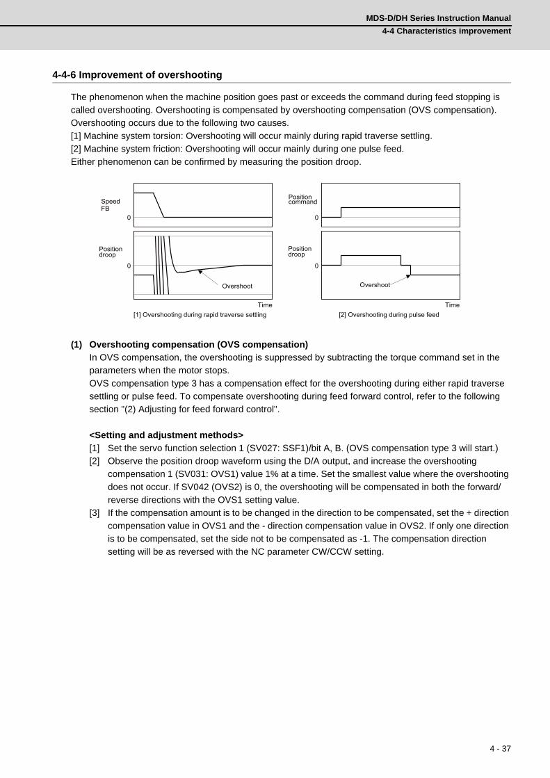
4 - 37
MDS-D/DH Series Instruction Manual
4-4 Characteristics improvement
4-4-6 Improvement of overshooting
The phenomenon when the machine position goes past or exceeds the command during feed stopping is
called overshooting. Overshooting is compensated by overshooting compensation (OVS compensation).
Overshooting occurs due to the following two causes.
[1] Machine system torsion: Overshooting will occur mainly during rapid traverse settling.
[2] Machine system friction: Overshooting will occur mainly during one pulse feed.
Either phenomenon can be confirmed by measuring the position droop.
(1) Overshooting compensation (OVS compensation)
In OVS compensation, the overshooting is suppressed by subtracting the torque command set in the
parameters when the motor stops.
OVS compensation type 3 has a compensation effect for the overshooting during either rapid traverse
settling or pulse feed. To compensate overshooting during feed forward control, refer to the following
section "(2) Adjusting for feed forward control".
<Setting and adjustment methods>
[1] Set the servo function selection 1 (SV027: SSF1)/bit A, B. (OVS compensation type 3 will start.)
[2] Observe the position droop waveform using the D/A output, and increase the overshooting
compensation 1 (SV031: OVS1) value 1% at a time. Set the smallest value where the overshooting
does not occur. If SV042 (OVS2) is 0, the overshooting will be compensated in both the forward/
reverse directions with the OVS1 setting value.
[3] If the compensation amount is to be changed in the direction to be compensated, set the + direction
compensation value in OVS1 and the - direction compensation value in OVS2. If only one direction
is to be compensated, set the side not to be compensated as -1. The compensation direction
setting will be as reversed with the NC parameter CW/CCW setting.
0
0
0
0
Position command
Position droop
Time
Overshoot
Speed FB
Position droop
Time
Overshoot
[1] Overshooting during rapid traverse settling [2] Overshooting during pulse feed
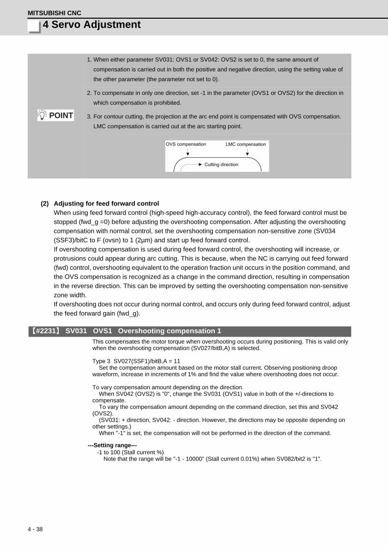
4 - 38
4 Servo AdjustmentMITSUBISHI CNC
(2) Adjusting for feed forward control
When using feed forward control (high-speed high-accuracy control), the feed forward control must be
stopped (fwd_g =0) before adjusting the overshooting compensation. After adjusting the overshooting
compensation with normal control, set the overshooting compensation non-sensitive zone (SV034
(SSF3)/bitC to F (ovsn) to 1 (2µm) and start up feed forward control.
If overshooting compensation is used during feed forward control, the overshooting will increase, or
protrusions could appear during arc cutting. This is because, when the NC is carrying out feed forward
(fwd) control, overshooting equivalent to the operation fraction unit occurs in the position command, and
the OVS compensation is recognized as a change in the command direction, resulting in compensation
in the reverse direction. This can be improved by setting the overshooting compensation non-sensitive
zone width.
If overshooting does not occur during normal control, and occurs only during feed forward control, adjust
the feed forward gain (fwd_g).
【#2231】 SV031 OVS1 Overshooting compensation 1
This compensates the motor torque when overshooting occurs during positioning. This is valid only when the overshooting compensation (SV027/bitB,A) is selected. Type 3 SV027(SSF1)/bitB,A = 11 Set the compensation amount based on the motor stall current. Observing positioning droop waveform, increase in increments of 1% and find the value where overshooting does not occur. To vary compensation amount depending on the direction. When SV042 (OVS2) is "0", change the SV031 (OVS1) value in both of the +/-directions to compensate. To vary the compensation amount depending on the command direction, set this and SV042 (OVS2). (SV031: + direction, SV042: - direction. However, the directions may be opposite depending on other settings.) When "-1" is set, the compensation will not be performed in the direction of the command.
---Setting range----1 to 100 (Stall current %)
Note that the range will be "-1 - 10000" (Stall current 0.01%) when SV082/bit2 is "1".
1. When either parameter SV031: OVS1 or SV042: OVS2 is set to 0, the same amount of
compensation is carried out in both the positive and negative direction, using the setting value of
the other parameter (the parameter not set to 0).
2. To compensate in only one direction, set -1 in the parameter (OVS1 or OVS2) for the direction in
which compensation is prohibited.
3. For contour cutting, the projection at the arc end point is compensated with OVS compensation.
LMC compensation is carried out at the arc starting point.
POINT
Cutting direction
LMC compensation OVS compensation
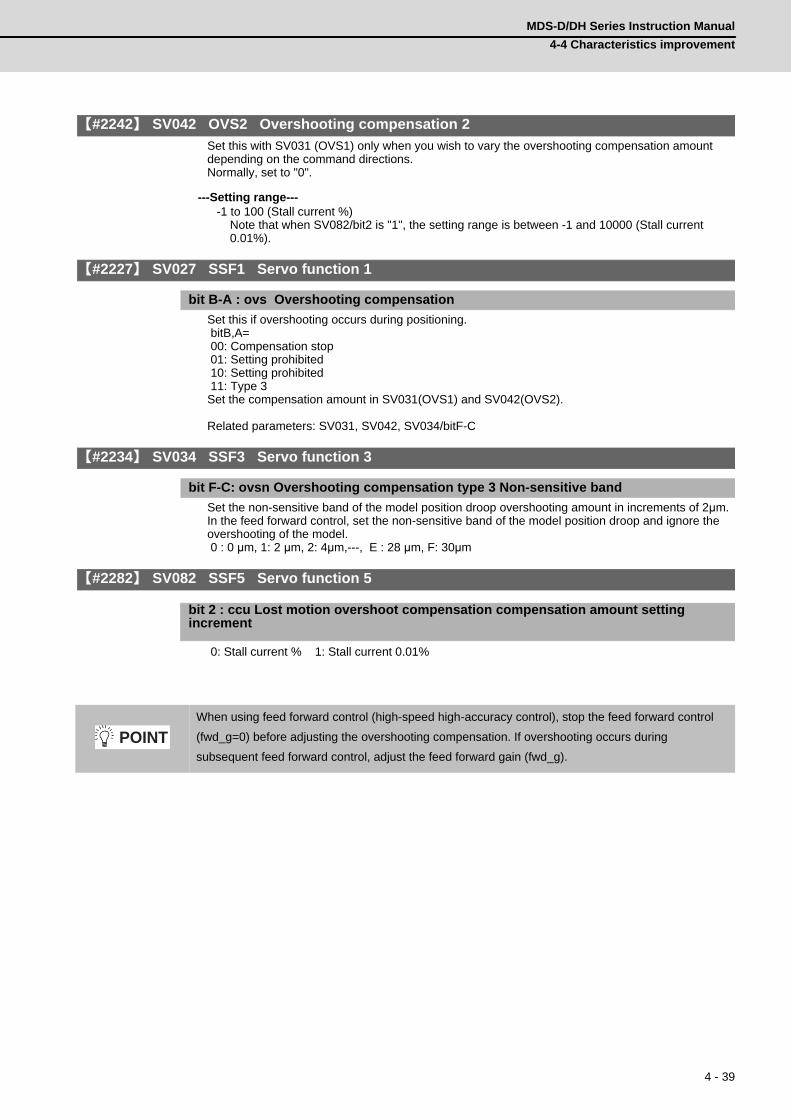
4 - 39
MDS-D/DH Series Instruction Manual
4-4 Characteristics improvement
【#2242】 SV042 OVS2 Overshooting compensation 2
Set this with SV031 (OVS1) only when you wish to vary the overshooting compensation amount depending on the command directions. Normally, set to "0".
---Setting range----1 to 100 (Stall current %)
Note that when SV082/bit2 is "1", the setting range is between -1 and 10000 (Stall current 0.01%).
【#2227】 SV027 SSF1 Servo function 1
bit B-A : ovs Overshooting compensation
Set this if overshooting occurs during positioning. bitB,A= 00: Compensation stop 01: Setting prohibited 10: Setting prohibited 11: Type 3Set the compensation amount in SV031(OVS1) and SV042(OVS2). Related parameters: SV031, SV042, SV034/bitF-C
【#2234】 SV034 SSF3 Servo function 3
bit F-C: ovsn Overshooting compensation type 3 Non-sensitive band
Set the non-sensitive band of the model position droop overshooting amount in increments of 2μm. In the feed forward control, set the non-sensitive band of the model position droop and ignore the overshooting of the model. 0 : 0 μm, 1: 2 μm, 2: 4μm,---, E : 28 μm, F: 30μm
【#2282】 SV082 SSF5 Servo function 5
bit 2 : ccu Lost motion overshoot compensation compensation amount setting increment
0: Stall current % 1: Stall current 0.01%
When using feed forward control (high-speed high-accuracy control), stop the feed forward control
(fwd_g=0) before adjusting the overshooting compensation. If overshooting occurs during
subsequent feed forward control, adjust the feed forward gain (fwd_g).
POINT

4 - 40
4 Servo AdjustmentMITSUBISHI CNC
4-4-7 Improvement of the interpolation control path
(1) Machine end compensation control
The machine end compensation control compensates the shape of the tool end during high-speed and
high-speed acceleration/deceleration. The spring effect from the machine (spindle) end to the motor
(scale) end is compensated. If the machine has a large spring effect, the shape may be fine during low-
speed operation. However, at high speeds (specially when using a small radius), the section from the
machine (spindle) end to the outer sides of the motor (scale) end could swell, and cause the shape to
become elliptical during measurement of the roundness. The machine end compensation control
compensates the motor end position according to the acceleration size, so the tool end position is
always controlled to the commanded position.
1. Always evaluate the roundness accuracy at the machine side.
2. Adjust the parameter after adjusting the electrical end roundness accuracy.
With machine end compensation control
During high acceleration, the end section swells outward due to the spring effect.
The inner side is driven by the amount that the end section swells due to the spring effect.
Machine roundness (machining surface)Elliptical shape fault
Machine roundness (machining surface)Elliptical shape is improved
Low speed: Example:
R25mm F1000mm/min
High speed (high acceleration): Example:
R25mm F10000mm /min
Both low speed and high speed are on the same path.Command path
(ideal path)
Machine path (machining surface)
Machine path (machining surface)
Command path (ideal path)
Without machine end compensation control
POINT

4 - 41
MDS-D/DH Series Instruction Manual
4-4 Characteristics improvement
<Adjustment methods>
[1] Confirm that the motor side circle accuracy measured with the NC sampling function is appropriate.
[2] In this state, measure the machine side low-speed and high-speed circle path without machine end
compensation control. The difference of the high-speed circle path and low-speed circle path is the
amount that path has swelled due to the spring effect of the machine system. Calculate the SV065
setting value with the following expression using this amount as the compensation amount.
[3] Input the value calculated in step [2] into SV065. Measure the high-speed circle path. If the shape is
still elliptical, adjust by increasing/decreasing the SV065 value in 1/10 units.
[4] Confirm that there is no problem with the low-speed circle path.
Example of low-speed and high-speed roundness measurement for adjusting machine compensation
【#2265】 SV065 TLC Machine end compensation gain
The shape of the machine end is compensated by compensating the spring effect from the machine end to the motor end. Set the machine end compensation gain. Measure the error amount by roundness measurement and estimate the setting value by the following formula. Compensation amount (μm) = Command speed F (mm/min)2 * SV065 / (Radius R (mm) * SV003 * 16,200,000) Set to "0" when not using.
---Setting range----30000 to 30000 (Acceleration ratio 0.1%)
When using grid encoder When using DBB measurement AccelerationLow speed (reference circle)
R=25 [mm], F=500 [mm/min] R=100 [mm], F=1000 [mm/min] 0.00028G
High-speed (when adjusting compen-sation amount)
R=25 [mm], F=10000 [mm/min] R=100 [mm], F=20000 [mm/min] 0.11G
1. To confirm the machine's spring element, adjust the electrical end roundness, and then machine
roundness while changing the cutting speed. Confirm that the error increases with the speed.
2. The electrical roundness will have an error on the inner side when machine end compensation
control is used.
If an excessive value is set in the machine end compensation gain (SV065), the machine could
vibrate when stopping, resulting in a dangerous state.
SV065 = Compensation amount [μm] x radius R [mm] x SV003 x 16,200,000 (command speed F [mm/min]) 2
POINT
CAUTION

4 - 42
4 Servo AdjustmentMITSUBISHI CNC
4-5 Adjustment during full closed loop control4-5-1 Outline
(1) Full closed loop control
The servo control is all closed loop control using the detector's feedback. "Full closed loop control" is the
system that directly detects the machine position using a linear scale, whereas the general "semi-closed
loop" is the one that detects the motor position.
In a machine that drives a table with a ball screw, the following factors exist between the motor and
table end:
[1] Coupling or ball screw table bracket's backlash
[2] Ball screw pitch error
These can adversely affect the accuracy. If the table position is directly detected with a linear scale,
high-accuracy position control which is not affected by backlash or pitch error is possible. However, with
the full closed loop system, the machine system is also directly included in the position loop control.
Thus, if the machine's rigidity is not high, the gain cannot be increased, and the required high accuracy
cannot be attained.
The procedures for adjusting the servo with the full closed loop system are the same as the semi-closed
loop system. Vibration or overshooting will occur easily, so the position loop gain is generally lower than
the semi-closed loop.
(2) Overrun detection
With the full closed system, the position feedback (FB) detected with the linear scale is used for the
position control. However, the motor position FB is detected at the same time, and the error of both FB
is observed. If this FB error exceeds the servo parameter SV054 setting value, alarm 43 will be detected
and the system will stop to prevent overrunning due to a scale FB error from occurring.
【#2254】 SV054 ORE Overrun detection width in closed loop control
Set the overrun detection width in the full-closed loop control. When the gap between the motor side detector and the linear scale (machine side detector) exceeds the value set by this parameter, it will be judged as overrun and "Alarm 43" will be detected. When "-1" is set, the alarm detection will not be performed. When "0" is set, overrun will be detected with a 2mm width. For linear servo/direct-drive motor system Not used. Set to "0".
---Setting range----1 to 32767 (mm)
However, when SV084/bitD=1, the setting range is from -1 to 32767 (μm).
Position command
PGN +
-
FB error
Position droop Servo- motor
ENC Linear scale
Table Speed command
Position FB
Position FB
+-
Overrun detection control

4 - 43
MDS-D/DH Series Instruction Manual
4-5 Adjustment during full closed loop control
4-5-2 Speed loop delay compensation
Generally, the machine position follows the operation later than the motor position. With full closed loop
position loop control, the machine position is used for position feedback, so the motor position could
advance too far and cause the machine position to overshoot easily. Speed loop delay compensation
suppresses overshooting by weakening the speed loop PI control (weakening lead compensation =
delaying). If the compensation is too large and PI control is weakened too far, the positioning time could
increase, or the position droop will remain when the motor is stopped.
<Adjustment method>
[1] Set the servo function selection 1 (SV027: SSF1)/bit1, bit0 to 10. (Select delay compensation
changeover type 2)
[2] Set the axis unbalance torque to the torque offset (SV032: TOF). (Refer to "4-4-5 (1) Measuring
unbalance torque and frictional torque" for details on measuring the unbalance torque.)
[3] Observe the position droop waveform, and confirm the overshooting. Increase SV007 (VIL) in
increments of 5, and adjust so that the overshooting is improved. If set too high, the position droop
will remain when the axis is stopped.
【#2207】 SV007 VIL Speed loop delay compensation
Set this when the limit cycle occurs in the full-closed loop, or overshooting occurs in positioning. The speed loop delay compensation method can be selected with SV027/bit1,0. Normally, use "Changeover type 2". Changeover type 2 controls the occurrence of overshooting by lowering the speed loop lead compensation after the position droop gets 0. When setting this parameter, make sure to set the torque offset (SV032).
---Setting range---0 to 32767
【#2232】 SV032 TOF Torque offset
Set the unbalance torque on vertical axis and inclined axis. When the vertical axis pull up function is enabled, the pull up compensation direction is determined by this parameter's sign. When set to "0", the vertical axis pull up will not be executed. This can be used for speed loop delay compensation and collision detection function. To use load inertia estimation function (drive monitor display), set this parameter, friction torque (SV045) and load inertia display enabling flag(SV035/bitF).
---Setting range----100 to 100 (Stall current %)
【#2227】 SV027 SSF1 Servo function 1
bit 1-0 : vcnt Speed loop delay compensation changeover type selection
Normally, use "Changeover type 2". bit1,0= 00: Disable 01: Changeover type 1 10: Changeover type 2 11: Setting prohibited
The position droop will remain if SV007 is set too high.CAUTION

4 - 44
4 Servo AdjustmentMITSUBISHI CNC
4-5-3 Dual feedback control
If the motor and machine coupling or machine system's rigidity is low (ex. large machine, etc.) when using a
closed loop system, the response during acceleration/deceleration will vibrate and cause overshooting. This
can cause the position loop gain from increasing. The dual feedback function is effective in this case.
To validate the dual feedback function, use position feedback with a motor side detector in ranges with high
acceleration to enable stable control. In ranges with low acceleration, use position feedback with the
machine side detector (scale). This will make it possible to increase the position loop gain.
The state will approach the semi-closed loop system as the primary delay filter's time constant increases, so
the position loop gain limit will increase. Note that the limit of the position loop gain increased with the dual
feedback function is the same as the position loop gain limit for a semi-closed system that does not use a
machine side detector (scale, etc.). In addition, the positioning time will increase as the primary delay filter
time constant increases.
1. Dual feedback control is a function that compensates symptoms resulting from insufficient machine
rigidity. If there are items that can be improved on the machine (improvement of scale installation
position, etc.) improve those first.
2. The position loop gain limit will not increase compared to the semi-closed loop system even when
using dual feedback control.
ENC
SV051
+
++
-
--
Position control
Primary delay filter
High frequency FB element
Position command
Position droop Servo motor
Linear scale
Table Speed command
Position FB
Position FB
Dual feedback control
Lowfrequency FBelement
POINT

4 - 45
MDS-D/DH Series Instruction Manual
4-5 Adjustment during full closed loop control
<Adjustment method>
[1] Set the servo specifications (SV017: SPEC)/bit1 to 1, and turn the NC power ON again.
[2] Measure the position droop overshooting while increasing the dual feedback control time constant
(SV051: DFBT) in increments of 5ms. Adjust to the time constant where overshooting does not
occur.
[3] For the final setting value, set a value 1.5 to 2-fold the value adjusted in 3.
【#2217(PR)】 SV017 SPEC1 Servo specification 1
bit 1 : dfbx Dual feedback control
Control the position FB signal in full closed control by the combination of a motor side detector and machine side detector. 0: Stop 1: Start
【#2251】 SV051 DFBT Dual feedback control time constant
Set the control time constant in dual feed back. When "0" is set, it operates at 1ms. The higher the time constant is, the closer it gets to the semi-closed control, so the limit of the position loop gain will be raised. For linear servo/direct-drive motor system Not used. Set to "0".
---Setting range---0 to 9999 (ms)
【#2252】 SV052 DFBN Dual feedback control non-sensitive band
Set the non-sensitive band in the dual feedback control. Normally, set to "0". For linear servo/direct-drive motor system Not used. Set to "0".
---Setting range---0 to 9999 (μm)
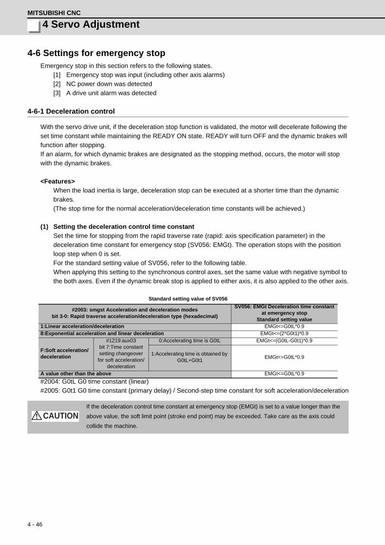
4 - 46
4 Servo AdjustmentMITSUBISHI CNC
4-6 Settings for emergency stopEmergency stop in this section refers to the following states.
[1] Emergency stop was input (including other axis alarms)
[2] NC power down was detected
[3] A drive unit alarm was detected
4-6-1 Deceleration control
With the servo drive unit, if the deceleration stop function is validated, the motor will decelerate following the
set time constant while maintaining the READY ON state. READY will turn OFF and the dynamic brakes will
function after stopping.
If an alarm, for which dynamic brakes are designated as the stopping method, occurs, the motor will stop
with the dynamic brakes.
<Features>
When the load inertia is large, deceleration stop can be executed at a shorter time than the dynamic
brakes.
(The stop time for the normal acceleration/deceleration time constants will be achieved.)
(1) Setting the deceleration control time constant
Set the time for stopping from the rapid traverse rate (rapid: axis specification parameter) in the
deceleration time constant for emergency stop (SV056: EMGt). The operation stops with the position
loop step when 0 is set.
For the standard setting value of SV056, refer to the following table.
When applying this setting to the synchronous control axes, set the same value with negative symbol to
the both axes. Even if the dynamic break stop is applied to either axis, it is also applied to the other axis.
Standard setting value of SV056
#2004: G0tL G0 time constant (linear)
#2005: G0t1 G0 time constant (primary delay) / Second-step time constant for soft acceleration/deceleration
#2003: smgst Acceleration and deceleration modesbit 3-0: Rapid traverse acceleration/deceleration type (hexadecimal)
SV056: EMGt Deceleration time constant at emergency stop
Standard setting value1:Linear acceleration/deceleration EMGt<=G0tL*0.98:Exponential acceleration and linear deceleration EMGt<=(2*G0t1)*0.9
F:Soft acceleration/deceleration
#1219:aux03bit 7:Time constant setting changeover
for soft acceleration/deceleration
0:Accelerating time is G0tL EMGt<=(G0tL-G0t1)*0.9
1:Accelerating time is obtained by G0tL+G0t1
EMGt<=G0tL*0.9
A value other than the above EMGt<=G0tL*0.9
If the deceleration control time constant at emergency stop (EMGt) is set to a value longer than the
above value, the soft limit point (stroke end point) may be exceeded. Take care as the axis could
collide the machine.
CAUTION

4 - 47
MDS-D/DH Series Instruction Manual
4-6 Settings for emergency stop
<Operation>
When an emergency stop occurs, the motor will decelerate at the same inclination from each speed.
【#2255】 SV055 EMGx Max. gate off delay time after emergency stop
Set the time required between an emergency stop and forced READY OFF. Set the maximum value "+ 100ms" of the SV056 setting value of the servo drive unit electrified by the same power supply unit. When executing the vertical axis drop prevention, the gate off will be delayed for the length of time set at SV048 even when SV055's is smaller than that of SV048.
---Setting range---0 to 20000 (ms)
【#2256】 SV056 EMGt Deceleration time constant at emergency stop
Set the time constant used for the deceleration control at emergency stop. Set the time required to stop from rapid traverse rate (rapid). The standard setting value is EMGt<=G0tL*0.9.However, note that the standard setting value differs from the above-mentioned value when the setting value of "#2003:smgst Acceleration and deceleration modes bit 3-0:Rapid traverse acceleration/deceleration type" is 8 or F. Refer to Instruction Manual of the drive unit (section "Deceleration control") for details.When the axis is used in the synchronous control, set the same value with minus sign to both axis. If one of the axis switches to dynamic brake by an alarm during deceleration control, another axis will also switch.
---Setting range----20000 to 20000 (ms)
RAPID
SV056
OFFON
ON OFF
ON OFF
SV055
ON OFF
Forced READY OFF range
Constant inclination decelerationMotor speed
Time
Motor brake control output (CN20)
Servo READY (READY)
In -position (INP)
READY OFF after in - position
Emergency stop (EMG)
Deceleration control sequence

4 - 48
4 Servo AdjustmentMITSUBISHI CNC
(2) Deceleration control stop distance
The stopping distance Lemg when the motor is stopped with deceleration control during an emergency
stop can be approximated with the following expression. Note that the value will be higher than this if the
current is limited during deceleration.
F :Feedrate during emergency stop (mm/min)
rapid :Rapid traverse rate (mm/min)
PGN1 :Position loop gain 1 (SV003) (rad/s)
EMGt :Deceleration time constant for emergency stop (SV056) (ms)
1. Deceleration control will not take place when a servo alarm, for which the stopping method is
dynamic, occurs. The motor will stop with dynamic braking regardless of the parameter setting.
2. If the power fails and the deceleration time constant is set to a relatively long time, the braking
method may change from deceleration control to dynamic braking due to a drop in the bus voltage
in the drive unit.
If the deceleration control time constant (EMGt) is set to a value longer than the acceleration/
deceleration time constant, the soft limit point (stroke end point) may be exceeded.
Take care as the axis could collide the machine.
Lemg = F PGN1 x 60 + 1
2 x F
60 x F x EMGt
rapid x 1000 (mm)
POINT
CAUTION
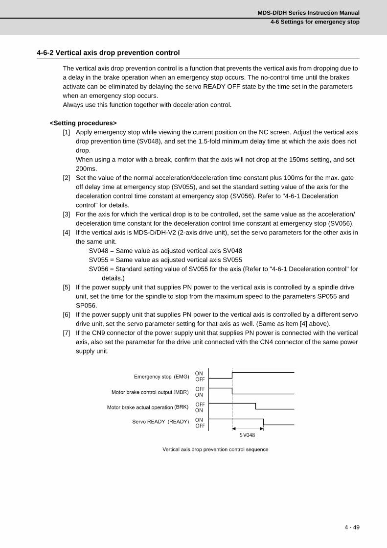
4 - 49
MDS-D/DH Series Instruction Manual
4-6 Settings for emergency stop
4-6-2 Vertical axis drop prevention control
The vertical axis drop prevention control is a function that prevents the vertical axis from dropping due to
a delay in the brake operation when an emergency stop occurs. The no-control time until the brakes
activate can be eliminated by delaying the servo READY OFF state by the time set in the parameters
when an emergency stop occurs.
Always use this function together with deceleration control.
<Setting procedures>
[1] Apply emergency stop while viewing the current position on the NC screen. Adjust the vertical axis
drop prevention time (SV048), and set the 1.5-fold minimum delay time at which the axis does not
drop.
When using a motor with a break, confirm that the axis will not drop at the 150ms setting, and set
200ms.
[2] Set the value of the normal acceleration/deceleration time constant plus 100ms for the max. gate
off delay time at emergency stop (SV055), and set the standard setting value of the axis for the
deceleration control time constant at emergency stop (SV056). Refer to "4-6-1 Deceleration
control" for details.
[3] For the axis for which the vertical drop is to be controlled, set the same value as the acceleration/
deceleration time constant for the deceleration control time constant at emergency stop (SV056).
[4] If the vertical axis is MDS-D/DH-V2 (2-axis drive unit), set the servo parameters for the other axis in
the same unit.
SV048 = Same value as adjusted vertical axis SV048
SV055 = Same value as adjusted vertical axis SV055
SV056 = Standard setting value of SV055 for the axis (Refer to "4-6-1 Deceleration control" for
details.)
[5] If the power supply unit that supplies PN power to the vertical axis is controlled by a spindle drive
unit, set the time for the spindle to stop from the maximum speed to the parameters SP055 and
SP056.
[6] If the power supply unit that supplies PN power to the vertical axis is controlled by a different servo
drive unit, set the servo parameter setting for that axis as well. (Same as item [4] above).
[7] If the CN9 connector of the power supply unit that supplies PN power is connected with the vertical
axis, also set the parameter for the drive unit connected with the CN4 connector of the same power
supply unit.
OFFON
ON OFF
ON OFF
SV048
OFFON
Vertical axis drop prevention control sequence
Servo READY (READY)
Emergency stop (EMG)
Motor brake actual operation (BRK)
Motor brake control output(MBR)

4 - 50
4 Servo AdjustmentMITSUBISHI CNC
【#2248】 SV048 EMGrt Vertical axis drop prevention time
Input the time required to prevent the vertical axis from dropping by delaying READY OFF until the brake works at an emergency stop. Increase in increments of 100ms at a time, find and set the value where the axis does not drop. When using a motor with a break, set to "200ms" as a standard. When the pull up function is enabled (SV033/bitE=1), the pull up is established during the drop prevention time.
---Setting range---0 to 20000 (ms)
【#2255】 SV055 EMGx Max. gate off delay time after emergency stop
Set the time required between an emergency stop and forced READY OFF. Set the maximum value "+ 100ms" of the SV056 setting value of the servo drive unit electrified by the same power supply unit. When executing the vertical axis drop prevention, the gate off will be delayed for the length of time set at SV048 even when SV055's is smaller than that of SV048.
---Setting range---0 to 20000 (ms)
【#2256】 SV056 EMGt Deceleration time constant at emergency stop
Set the time constant used for the deceleration control at emergency stop. Set the time required to stop from rapid traverse rate (rapid). The standard setting value is EMGt<=G0tL*0.9. However, note that the standard setting value differs from the above-mentioned value when the setting value of "#2003:smgst Acceleration and deceleration modes bit 3-0:Rapid traverse acceleration/deceleration type" is 8 or F. Refer to Instruction Manual of the drive unit (section "Deceleration control") for details.When the axis is used in the synchronous control, set the same value with minus sign to both axis. If one of the axis switches to dynamic brake by an alarm during deceleration control, another axis will also switch.
---Setting range----20000 to 20000 (ms)
1. Always set deceleration control when using the vertical axis drop prevention control setting.
2. Configure so that the power supply unit is controlled directly by the servo drive unit which controls
the spindle drive unit or the vertical axis drop prevention control.
3. In the 2nd part system of the power supply, if the axis for vertical axis drop prevention is connected
with the CN9 connector of the power supply unit, provide the vertical axis drop prevention control
setting also for the drive unit connected with CN4 connector of the same power supply unit.
4. If an alarm, for which dynamic brake stopping is designated, occurs with the axis for which vertical
axis drop prevention control is active, the function will not activate. To prevent axis dropping under
all conditions, provide measures on the machine side by installing a balance unit, etc.
5. In consideration of the relay delay time for the break control, set the vertical axis drop prevention
time.
CAUTION

4 - 51
MDS-D/DH Series Instruction Manual
4-6 Settings for emergency stop
1. SV048 and SV055 are set for each axis, but when using MDS-D/DH-V2 (2-axis drive unit), the two
axes are simultaneously controlled with the larger setting value for the two axes.
2. If an alarm, for which dynamic brake stopping is designated, occurs with the axis for which vertical
axis drop prevention control is active, the function will not activate.
3. A drop amount of several µm to several 10µm may be generated due to brake play.
1. Do not set the vertical axis drop prevention time longer than required. The servo control and brakes
could collide, resulting in an overload alarm or drive unit damage. There is no problem if the
overlapping time is within 100ms.
2. Vertical axis drop prevention control (including deceleration control) longer than 100ms will not be
guaranteed during a power failure. The operation will change to dynamic brakes.
3. If only SV048 and SV055 are set, and SV056 is set to 0, the deceleration stop will be a stepped
stop and could result in collision with the machine.
POINT
CAUTION

4 - 52
4 Servo AdjustmentMITSUBISHI CNC
<Outline of system configurations and corresponding parameter settings>
[1] Spindle drive unit controls power supply unit. Vertical axis is a 1-axis unit (vertical axis: Z
axis).
(Note) For the standard setting value of SV056, refer to "4-6-1 Deceleration control".
[2] Spindle drive unit controls power supply unit. Vertical axis is a 2-axis unit (vertical axis: Z
axis).
(Note) For the standard setting value of SV056, refer to "4-6-1 Deceleration control".
AxisParameter
X axis Y axis Z axis (Vertical axis) SpindleMDS-D/DH-V2 MDS-D/DH-V1 MDS-D/DH-SP
SV048 0 0200ms as a standard(Set by adjustment) Set as follows.
SP055=20000SP056=300
SV055 X, Y, Z axis Maximum value of SV056 setting value +100ms
SV056 Standard setting value for each axis (Note)
AxisParameter
X axis Y axis Z axis (Vertical axis) SpindleMDS-D/DH-V1 MDS-D/DH-V2 MDS-D/DH-SP
SV048 0Same value as Z axis ->
200ms as a standard(Set by adjustment) Set as follows.
SP055=20000SP056=300
SV055 X, Y, Z axis Maximum value of SV056 setting value +100ms
SV056 Standard setting value for each axis (Note)
MDS-D/DH-V2 MDS-D/DH-V1 MDS-D/DH-SP MDS-D/DH-CV
NC
*Z axis Spindle Power supplyX axis, Y axis
NC
MDS-D/DH-V1 MDS-D/DH-V2 MDS-D/DH-SP MDS-D/DH-CVY axis, *Z axis Spindle Power supplyX axis

4 - 53
MDS-D/DH Series Instruction Manual
4-6 Settings for emergency stop
[3] Servo drive unit controls power supply unit. Vertical axis is a 1-axis unit (vertical axis: Z
axis).
(Note) For the standard setting value of SV056, refer to "4-6-1 Deceleration control".
[4] Servo drive unit controls power supply unit. Vertical axis is a 2-axis unit (vertical axis: Z
axis).
(Note) For the standard setting value of SV056, refer to "4-6-1 Deceleration control".
AxisParameter
X axis Y axis Z axis (Vertical axis) SpindleMDS-D/DH-V2 MDS-D/DH-V1 MDS-D/DH-SP
SV048 0 0200ms as a standard(Set by adjustment) Set as follows.
SP055=20000SP056=300
SV055 X, Y, Z axis Maximum value of SV056 setting value +100ms
SV056 Standard setting value for each axis (Note)
AxisParameter
X axis Y axis Z axis (Vertical axis) SpindleMDS-D/DH-V1 MDS-D/DH-V2 MDS-D/DH-SP
SV048 0Same value as Z axis ->
200ms as a standard(Set by adjustment) Set as follows.
SP055=20000SP056=300
SV055 X, Y, Z axis Maximum value of SV056 setting value +100ms
SV056 Standard setting value for each axis (Note)
MDS-D/DH-V2 MDS-D/DH-V1 MDS-D/DH-SPMDS-D/DH-CV
NC
MDS-D/DH-CV*Z axis SpindlePower supplyX axis, Y axis Power supply
MDS-D/DH-V2MDS-D/DH-V1 MDS-D/DH-SPMDS-D/DH-CV
NC
MDS-D/DH-CVSpindlePower supplyY axis, *Z axis Power supplyX axis
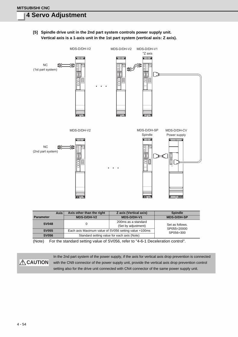
4 - 54
4 Servo AdjustmentMITSUBISHI CNC
[5] Spindle drive unit in the 2nd part system controls power supply unit.
Vertical axis is a 1-axis unit in the 1st part system (vertical axis: Z axis).
(Note) For the standard setting value of SV056, refer to "4-6-1 Deceleration control".
AxisParameter
Axis other than the right Z axis (Vertical axis) SpindleMDS-D/DH-V2 MDS-D/DH-V1 MDS-D/DH-SP
SV048 0200ms as a standard(Set by adjustment) Set as follows.
SP055=20000SP056=300
SV055 Each axis Maximum value of SV056 setting value +100ms
SV056 Standard setting value for each axis (Note)
In the 2nd part system of the power supply, if the axis for vertical axis drop prevention is connected
with the CN9 connector of the power supply unit, provide the vertical axis drop prevention control
setting also for the drive unit connected with CN4 connector of the same power supply unit.
MDS-D/DH-V2
MDS-D/DH-V2 MDS-D/DH-SP MDS-D/DH-CV
NC
NC
MDS-D/DH-V1MDS-D/DH-V2
Spindle Power supply
(1st part system)
(2nd part system)
*Z axis
CAUTION

4 - 55
MDS-D/DH Series Instruction Manual
4-6 Settings for emergency stop
[6] Spindle drive unit in the 2nd part system controls power supply unit.
Vertical axis is a 2-axis unit in the 1st part system (vertical axis: Z axis).
(Note) For the standard setting value of SV056, refer to "4-6-1 Deceleration control".
AxisParameter
Axis other than the right
Y axis Z axis (Vertical axis) Spindle
MDS-D/DH-V1,V2 MDS-D/DH-V2 MDS-D/DH-SP
SV048 0Same value as Z axis ->
200ms as a standard(Set by adjustment) Set as follows.
SP055=20000SP056=300
SV055 Each axis Maximum value of SV056 setting value +100ms
SV056 Standard setting value for each axis (Note)
In the 2nd part system of the power supply, if the axis for vertical axis drop prevention is connected
with the CN9 connector of the power supply unit, provide the vertical axis drop prevention control
setting also for the drive unit connected with CN4 connector of the same power supply unit.
MDS-D/DH-V2
MDS-D/DH-V2 MDS-D/DH-SP MDS-D/DH-CV
NC
NC
MDS-D/DH-V1 MDS-D/DH-V2
Spindle Power supply
(1st part system)
(2nd part system)
Y axis, *Z axis
CAUTION

4 - 56
4 Servo AdjustmentMITSUBISHI CNC
4-6-3 Vertical axis pull-up control
Even when the vertical axis drop prevention control is applied, the axis will drop several μm due to the
mechanical play of the motor brakes. Work could be damaged especially when the power fails during
machining. For the vertical machining center, etc., vertical axis pull-up control protect works from
collision by slightly pulling the vertical axis when an emergency stop (including the power failure)
occurs.
If the pull-up control itself has possibility to cause interference during synchronous tapping machining or
soft limit's stop, vertical axis pull-up control suppression command (servo control input 4/bit2) is input
from NC and stops the pull-up control.
< Adjustment procedure >
[1] Set "4-6-2 Vertical axis drop prevention control".
[2] Set servo function selection 2 SV033/bitE = 1 (Vertical axis drop prevention control will start).
[3] Set the torque offset SV032. The pull-up directions is distinguished by this setting value's sign.
Refer to "4-4-5 (1) Measuring unbalance torque and frictional torque measurement" for details on
the setting.
[4] Input emergency stop when axes stop and confirm the subject axis to be retracted upward.
[5] If the pull-up range is insufficient, adjust vertical axis pull-up distance SV095.
1. This function is valid for Z axis in the vertical machining center. Basically it cannot be used with the
horizontal machining center's Y axis or the lathe's X axis as collisions could occur. Check the
machine's working conditions carefully before using this function.
2. When the power fails, charging energy remaining in the power supply unit executes the pull-up
control. Thus, pull-up range depends on charging situation of the power supply or the timing when
the magnetic brake is applied.
OFF
ON
ON
OFF
AC source input
Drop according to the brake playafter the READY OFF
Vertical axis pull-up control operation sequences when the power fails
80μm(For PIT=10, PC1=1, PC2=1 or SV095=0)
Power down detection output from converter
Axis position which Vertical axis pull-up function is set in.
Emergency stop
Motor brake control output
Power fialer occurs.
Detection period of phase interruption or instantaneous power interrupt
Axis rise
CAUTION

4 - 57
MDS-D/DH Series Instruction Manual
4-6 Settings for emergency stop
【#2232】 SV032 TOF Torque offset
Set the unbalance torque on vertical axis and inclined axis. When the vertical axis pull up function is enabled, the pull up compensation direction is determined by this parameter's sign. When set to "0", the vertical axis pull up will not be executed. This can be used for speed loop delay compensation and collision detection function. To use load inertia estimation function (drive monitor display), set this parameter, friction torque (SV045) and load inertia display enabling flag(SV035/bitF).
---Setting range----100 to 100 (Stall current %)
【#2233】 SV033 SSF2 Servo function 2
bit E : zup Vertical axis pull up function
0: Stop 1: Enable
【#2248】 SV048 EMGrt Vertical axis drop prevention time
Input the time required to prevent the vertical axis from dropping by delaying READY OFF until the brake works at an emergency stop. Increase in increments of 100ms at a time, find and set the value where the axis does not drop. When using a motor with a break, set to "200ms" as a standard. When the pull up function is enabled (SV033/bitE=1), the pull up is established during the drop prevention time.
---Setting range---0 to 20000 (ms)
【#2295】 SV095 ZUPD Vertical axis pull up distance
Set this parameter to adjust the pull up distance when the vertical axis pull up function is enabled. When the pull up function is enabled and this parameter is set to "0", for a rotary motor, 8/1000 of a rotation at the motor end is internally set as the pull up distance, and for a linear motor, 80[μm] is set.
---Setting range---0 to 2000 (μm)

4 - 58
4 Servo AdjustmentMITSUBISHI CNC
4-7 Protective functions4-7-1 Overload detection
The servo drive unit is equipped with an electronic thermal that protects the servomotor and servo drive unit
from overload conditions. The overload 1 alarm (alarm 50) is detected if an overload condition occurs, and
the overload 2 alarm (alarm 51) is detected if 95% or more of the maximum current is commanded
continuously for 1 second or longer due to a machine collision, etc. The parameters shown below are for
machine tool builder adjustment purposes only, and should be kept at their standard settings (SV021=60,
SV022=150).
【#2221】 SV021 OLT Overload detection time constant
Normally, set to "60". (For machine tool builder adjustment.)
---Setting range---1 to 999 (s)
【#2222】 SV022 OLL Overload detection level
Set the "Overload 1" (Alarm 50) current detection level as percentage to the stall current. Normally set this parameter to "150". (For machine tool builder adjustment.)
---Setting range---110 to 500 (Stall current %)
For details concerning the overload protection characteristics, refer to the MDS-D/DH Series Specifications
Manual (IB-1500875).

4 - 59
MDS-D/DH Series Instruction Manual
4-7 Protective functions
4-7-2 Excessive error detection
An excessive error (alarms 52, 53, 54) is detected when the difference between the servo's commanded
position and the FB position exceeds the value set by parameter. Separate excessive error detection width
can be set for servo ON (SV023) and servo OFF (SV026) statuses. When a wider excessive error detection
width than that used for standard control is required in stopper control, etc., the detection width setting can
be changed to the SV053 setting value by NC command.
Follow-up control (NC commanded position tracks servo FB position) is used during emergency stop and
during a servo OFF command, and so there is no excessive error detection at those times, although the
follow-up control during a servo OFF status can be disabled by an NC system parameter setting.
【#2223】 SV023 OD1 Excessive error detection width during servo ON
Set the excessive error detection width in servo ON. <Standard setting value> OD1=OD2= (Rapid traverse rate [mm/min]) / (60×PGN1) / 2 [mm] When set to "0", the excessive error alarm detection will be ignored, so do not set to "0".
---Setting range---0 to 32767 (mm)
However, when SV084/bitC=1, the setting range is from 0 to 32767 (μm).
【#2226】 SV026 OD2 Excessive error detection width during servo OFF
Set the excessive error detection width during servo OFF. <Standard setting value> OD1=OD2= (Rapid traverse rate [mm/min]) / (60×PGN1) / 2 [mm]When set to "0", the excessive error alarm detention will be ignored, so do not set to "0".
---Setting range---0 to 32767 (mm)
However, when SV084/bitC=1, the setting range is from 0 to 32767 (μm).
【#2253】 SV053 OD3 Excessive error detection width in special control
Set the excessive error detection width when servo ON in a special control (initial absolute position setting, stopper control and etc.). When "0" is set, excessive error detection will not be performed when servo ON during a special control.
---Setting range---0 to 32767 (mm)
However, when SV084/bitC=1, the setting range is from 0 to 32767 (μm).

4 - 60
4 Servo AdjustmentMITSUBISHI CNC
4-7-3 Collision detection function
Collision detection function quickly detects a collision of the motor shaft, and decelerates and stops the
motor. This suppresses the generation of an excessive torque in the machine tool, and helps to prevent an
abnormal state from occurring. Impact at a collision will not be prevented by using this collision detection
function, so this function does not necessarily guarantee that the machine tool will not be damaged or that
the machine accuracy will be maintained after a collision. The same caution as during regular operation is
required to prevent the machine from colliding.
(1) Collision detection method 1
The required torque for the command is estimated from the position command issued from the NC, and
the disturbance torque is obtained from the difference with the actual torque. When this disturbance
torque exceeds the collision detection level set with the parameters, the motor will decelerate to a stop
with a torque 80% (standard) value of the motor's maximum torque. After decelerating to a stop, alarm
58 or 59 will occur, and the system will stop.
The collision detection level for rapid traverse (G0) is set with SV060: TLMT. The collision detection
level for cutting feed (G1) is set to 0 to 7-fold (SV35.clG1) based on the collision detection level for rapid
traverse. When clG1 is set to 0, collision detection method 1 will not function during cutting feed. If
SV060 is set to 0, all collision detection (including methods 1 and 2) will not function.
Collision detection level setting parameter Detected alarm
During rapid traverse (During G0 feed) SV060 Alarm 58
During cutting feed (During G1 feed) SV060 × c1G1 (SV035) Alarm 59
The collision detection function does not guarantee safety or machine accuracy when a collision
occurs. Thus, the same caution as during regular operation is required to prevent the machine from
colliding.
Collision detection function outline
(a) A collision of machine is detected. (b) A retracting torque is generated. The collision of machine is reduced.
Speed command (r/min) 0
Estimated torque (stall%)
0
3000
200
100
-200
-100
-3000
Unbalance torque (SV032)
G0 collision detection level (SV060)
Collision detection method 1, detection range(alarm 58/59)
Frictional torque(SV045)
G1 feed (cutting feed)G0 feed (rapid traverse)
G1 collision detection level (SV060×clG1)
Alarm detection range for collision detection method 1
CAUTION

4 - 61
MDS-D/DH Series Instruction Manual
4-7 Protective functions
(2) Collision detection method 2
When the current command reaches the motor's maximum current, the motor will decelerate and stop at
a torque 80% (standard value) of the motor's maximum torque. After decelerating to a stop, alarm 5A
will occur, and the system will stop. If the acceleration/deceleration time constant is short and incorrect
detections easily occur during normal operation, lengthen the acceleration/ deceleration time constant
and adjust so that the current is not saturated (does not reach the maximum current) during
acceleration.
If the acceleration/deceleration time constant cannot be lengthened, set parameter SV035/bitB
(SSF4.c12n) to 1 to ignore collision detection method 2.
(3) Retracting torque
In each collision detection method, impact after a collision is reduced by generating the retracting torque
after the collision is detected.
The retracting torque is a torque 70% to 100% which is set with SV035: SSF4/cltq (bit8, bit9) based on
the current of the motor maximum ability.
1. Always validate SHG control when using the collision detection function, or when carrying out
SV059 setting value operation.
2. Provide an allowance in the detection level setting to prevent incorrect detections.
3. All collision detection functions will be disabled when SV60 is set to 0.
4. Collision detection method 2 will function if a value other than 0 is set in SV060. Note that the
detection can be ignored by setting the parameter (SV035/bitB).
5. The torque estimated gain (SV059) must be readjusted when there are changes in the detector
replacement following maintenance, etc., in the detector resolution, or in the position control
system such as detector loop gain (PGN), etc. (closed loop control and semi-closed loop has been
changed).
6. The retracting torque generated when a collision is detected outputs the motor maximum torque. If
the torque limitation is required in order to protect the machine, set "SV035 : SSF4/cltq (bit8, bit9)".
POINT

4 - 62
4 Servo AdjustmentMITSUBISHI CNC
<Setting and adjustment methods>
[1] Confirm that SHG control is active. Collision detection function is valid only during SHG control.
[2] Set the axis unbalanced torque to the torque offset (SV032: TOF). (Refer to "4-4-5 (1) Measuring
unbalance torque and frictional torque" for details on measuring the unbalance torque.)
[3] Measure the frictional torque and set in the frictional torque (SV045: TRUB). Carry out reciprocation
operation (approx. F1000) with the axis to be adjusted, and measure the load current % when the
axis is fed at the constant speed on the NC SERVO MONITOR screen. This frictional torque is
expressed with the following expression.
[4] Set SV035: SSF4.clt (bitF) to 1 for the axis being adjusted, and move in both directions with JOG,
etc., at the rapid traverse rate. When the load inertia ratio display on the NC SERVO MONITOR
screen has stabilized, set that value for the torque estimated gain (SV059: TCNV). Return SV035:
SSF4.clt (bitF) to 0.
[5] If the acceleration/deceleration time is short, and the current is limited, set SV035: SSF4.c12n
(bitB) to 1 to invalidate collision detection method 2.
[6] Adjust the collision detection level (SV060: TLMT). First set 100. If operation at the rapid traverse
rate results in an alarm, increase the setting value by approx. 20. If an alarm does not occur, lower
the setting value by approx. 10. The estimated disturbance torque value on the servo monitor
screen will indicate the estimated disturbance torque peak value for the latest two seconds. This
value can be used as reference. Set the final setting value to a value approx. 1.5-fold the limit value
at which an alarm does not occur.
[7] Divide the maximum cutting load with the value set for the collision detection level (SV060: TLMT).
(Round up the decimal) Set this value in SV035: SSF4.clG1 (bitC-E).
(Example) For maximum cutting load: 200%, SV060: TLMT setting value: 80%
200/80=2.5 -> The detection level is 3 (-fold), so set SV035:SSF4 to "3xxx".
[8] Set the retracting torque when the a collision is detected to SV035: SSF4.cltq (bit8,9).
(Example) To set the retracting torque to 70% of the motor maximum torque:
Set SV035:SSF4 to "x3xx".
【#2232】 SV032 TOF Torque offset
Set the unbalance torque on vertical axis and inclined axis. When the vertical axis pull up function is enabled, the pull up compensation direction is determined by this parameter's sign. When set to "0", the vertical axis pull up will not be executed. This can be used for speed loop delay compensation and collision detection function. To use load inertia estimation function (drive monitor display), set this parameter, friction torque (SV045) and load inertia display enabling flag(SV035/bitF).
---Setting range----100 to 100 (Stall current %)
2=
(+ feed load current %) - (- feed load current %)Frictional torque (%)

4 - 63
MDS-D/DH Series Instruction Manual
4-7 Protective functions
【#2235】 SV035 SSF4 Servo function 4
bit F : clt Inertia ratio display
0: Setting for normal use 1: Display the total inertia ratio estimated at acceleration/deceleration at the inertia ratio on the servo monitor screen To display it on the screen, set an imbalance torque and friction torque to both SV032 and SV045 and repeat acceleration/deceleration operations for several times.
bit E-C: clG1 G1 Collision detection level
Set the collision detection level in the collision detection method 1 during cutting feed (G1) in multiples of that of rapid traverse (G0). When set to "0", detection of collision detection method 1 during cutting feed will be ignored. G1 Collision detection level = G0 collision detection level (SV060) × clG1
bit B : cl2n Collision detection method 2
0: Enable 1: Disable
bit 9-8 : cltq Retract torque in collision detection
Set the retract torque in collision detection using the ratio of motor's maximum torque. bit9,8= 00: 100% 01: 90% 10: 80%(Standard) 11: 70%
【#2245】 SV045 TRUB Friction torque
Set the frictional torque when using the collision detection function. To use load inertia estimation function (drive monitor display), set this parameter, imbalance torque (SV032) and load inertia display enabling flag (SV035/bitF).
---Setting range---0 to 255 (Stall current %)
【#2259】 SV059 TCNV Collision detection torque estimated gain
Set the torque estimated gain when using the collision detection function.The standard setting value is the same as the load inertia ratio (SV037 setting value) including motor inertia. Set to "0" when not using the collision detection function. <<Drive monitor load inertia ratio display>>Set SV035/bitF=1 and imbalance torque and friction torque to both SV032 and SV045, and then repeat acceleration/deceleration for several times.
---Setting range---For general motor: 0 to 5000 (%)
For linear motor: 0 to 5000 (kg)
【#2260】 SV060 TLMT Collision detection level
When using the collision detection function, set the collision detection level at the G0 feeding. When "0" is set, none of the collision detection function will work.
---Setting range---0 to 999 (Stall current %)

4 - 64
4 Servo AdjustmentMITSUBISHI CNC
4-8 Servo control signalThe sequence input/output signals exchanged between the NC and servo drive unit are explained in this
section. The status of each signal is displayed on the NC SERVO MONITOR screen.
4-8-1 Servo control input (NC to Servo)
(1) Servo control input 1
bit0. READY ON command (RDY)
Status turns to ready ON at RDY=1.
bit1. Servo ON command (SRV)
[1] Drive unit turns ON at SRV=1 (servo ON status).
[2] Drive unit turns OFF at SRV=0 (servo OFF status).
bit4. Position loop gain changeover command (KPM)
[1] The position loop gain (SV049/SV050/SV058) for spindle synchronous (synchronous
tapping, synchronous control with spindle C-axis, etc.) is selected at KPM=1.
[2] The normal position loop gain (SV003/SV004/SV057) is selected at KPM=0.
bit6. Excessive error detection width changeover command (EOM)
[1] The excessive error width (SV053) for the special control (initial absolute position setting,
stopper control, etc.) is selected at EOM =1.
[2] The normal excessive error width (SV023) is selected at EOM =0.
bit7. Alarm reset command (ALMR)
NR alarm is reset at ALMR=1.
bit8. Current limit selection command (IL1)
[1] The current (torque) limit (SV014) for the special control (initial absolute position setting,
stopper control, etc.) is selected at IL1 =1.
[2] The normal current (torque) limit (SV013) is selected at IL1 =0.
(Note) The bits other than those above are used for maintenance.
F E D C B A 9 8 7 6 5 4 3 2 1 0
bit0123456789ABCDEF
RDYSRV
--
KPM
-EOM
IL1
-------
RDYSRVKPMEOMALMRIL1
ALMR
Details
Name Details
Servo control input 1
READY ON commandServo ON command
(For maintenance)Position loop gain changeover command
Excessive error detection width changeover commandAlarm reset commandCurrent limit selection command
(For maintenance)
(For maintenance)
(For maintenance)
(For maintenance)(For maintenance)
(For maintenance)(For maintenance)
(For maintenance)(For maintenance)

4 - 65
MDS-D/DH Series Instruction Manual
4-8 Servo control signal
(2) Servo control input 2
bit9. Speed monitor command valid (SSW)
When speed monitor command is valid, SSW=1 (valid) is set.
bitA. In door closed (controller) (NCDC)
When "In door closed" signal for controller is valid, NCDC =1 (valid) is set.
bitB. In door closed (all drive units) (SRVDC)
When the theoretical sum of "In door closed" signals for all drive units is valid, SRVDC =1
(valid) is set.
(Note) The bits other than those above are used for maintenance.
(3) Servo control input 3
bit0. Control axis detachment command (AXF)
The control axis is detached at AXF=1.
(Note) The bits other than those above are used for maintenance.
Name Details
Servo control input 2
F E D C B A 9 8 7 6 5 4 3 2 1 0 SRVDC NCDC SSW
bit Details
0 - (For maintenance) 1 - (For maintenance) 2 - (For maintenance) 3 - (For maintenance) 4 - (For maintenance) 5 - (For maintenance) 6 - (For maintenance) 7 - (For maintenance) 8 - (For maintenance) 9 SSW Speed monitor command valid A NCDC In door closed (controller) B SRVDC In door closed (all drive units) C - (For maintenance) D - (For maintenance) E - (For maintenance) F - (For maintenance)
Name Details
Servo control input 3
F E D C B A 9 8 7 6 5 4 3 2 1 0 AXF
bit Details
0 AXF Control axis detachment command 1 - (For maintenance) 2 - (For maintenance) 3 - (For maintenance) 4 - (For maintenance) 5 - (For maintenance) 6 - (For maintenance) 7 - (For maintenance) 8 - (For maintenance) 9 - (For maintenance) A - (For maintenance) B - (For maintenance) C - (For maintenance) D - (For maintenance) E - (For maintenance) F - (For maintenance)

4 - 66
4 Servo AdjustmentMITSUBISHI CNC
(4) Servo control input 4
This is used for maintenance.
(5) Servo control input 5
This is used for maintenance.
(6) Servo control input 6
This is used for maintenance.

4 - 67
MDS-D/DH Series Instruction Manual
4-8 Servo control signal
4-8-2 Servo control output (Servo to NC)
(1) Servo control output 1
bit0. In ready ON (RDY)
It indicates that the status is in ready ON at RDN=1.
bit1. In servo ON (SRV)
It indicates that the drive unit turns ON (servo ON) at SRV=1.
bit4. In position loop gain changeover (KPM)
[1] The position loop gain (SV049/SV050/SV058) for spindle synchronous (synchronous
tapping, synchronous control with spindle C-axis, etc.) is being selected at KPM=1.
[2] The normal position loop gain (SV003/SV004/SV057) is being selected at KPM=0.
bit6. In excessive error detection width changeover (EOM)
[1] The excessive error width (SV053) for the special control (initial absolute position setting,
stopper control, etc.) is being selected at EOM =1.
[2] The normal excessive error width (SV023) is being selected at EOM =0.
bit7. In alarm (ALMR)
It indicates that drive unit is in some alarm state at ALM=1.
bit8. In current limit selection (IL1)
[1] The current (torque) limit (SV014) for the special control (initial absolute position setting,
stopper control, etc.) is being selected at IL1 =1.
[2] The normal current (torque) limit (SV013) is being selected at IL1 =0.
bitC. In in-position (INP)
The status changes to INP=1 when position droop exists within the in-position area set by
parameter SP024 (INP) regardless of serve ON or OFF.
bitD. In current limit (LMT)
It indicates that the drive unit is in current limit at LMT=1.
F E D C B A 9 8 7 6 5 4 3 2 1 0
bit0123456789ABCDEF
RDYSRV
--
KPM-
EOM
IL1---
RDYSRVKPMEOMALMRIL1INPLMTAERWRN
INPLMTAERWRN
ALMR
Details
Name Details
Servo control output 1
In READY ONIn servo ON
(For maintenance)In position loop gain changeover
In excessive error detection width changeoverIn alarmIn current limit selection
(For maintenance)
(For maintenance)
(For maintenance)
(For maintenance)(For maintenance)
In in-positionIn current limit
In warningIn absolute position data loss
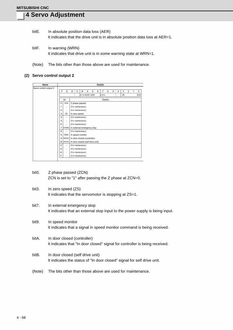
4 - 68
4 Servo AdjustmentMITSUBISHI CNC
bitE. In absolute position data loss (AER)
It indicates that the drive unit is in absolute position data loss at AER=1.
bitF. In warning (WRN)
It indicates that drive unit is in some warning state at WRN=1.
(Note) The bits other than those above are used for maintenance.
(2) Servo control output 2
bit0. Z phase passed (ZCN)
ZCN is set to "1" after passing the Z phase at ZCN=0.
bit3. In zero speed (ZS)
It indicates that the servomotor is stopping at ZS=1.
bit7. In external emergency stop
It indicates that an external stop input to the power supply is being input.
bit9. In speed monitor
It indicates that a signal in speed monitor command is being received.
bitA. In door closed (controller)
It indicates that "In door closed" signal for controller is being received.
bitB. In door closed (self drive unit)
It indicates the status of "In door closed" signal for self drive unit.
(Note) The bits other than those above are used for maintenance.
Name Details
Servo control output 2
F E D C B A 9 8 7 6 5 4 3 2 1 0 SRVDC NCDC SSW EXEMG ZS ZCN
bit Details
0 ZCN Z phase passed 1 - (For maintenance) 2 - (For maintenance) 3 ZS In zero speed 4 - (For maintenance) 5 - (For maintenance) 6 - (For maintenance) 7 EXEMG In external emergency stop 8 - (For maintenance) 9 SSW In speed monitor A NCDC In door closed (controller) B SRVDC In door closed (self drive unit) C - (For maintenance) D - (For maintenance) E - (For maintenance) F - (For maintenance)

4 - 69
MDS-D/DH Series Instruction Manual
4-8 Servo control signal
(3) Servo control output 3
bit0. In control axis detachment (AXF)
The control axis is being detached at AXF=1.
(Note) The bits other than those above are used for maintenance.
(4) Servo control output 4
This is used for maintenance.
(5) Servo control output 5
This is used for maintenance.
(6) Servo control output 6
This is used for maintenance.
Name Details
Servo control output 3
F E D C B A 9 8 7 6 5 4 3 2 1 0 AXF
bit Details
0 AXF In control axis detachment 1 - (For maintenance) 2 - (For maintenance) 3 - (For maintenance) 4 - (For maintenance) 5 - (For maintenance) 6 - (For maintenance) 7 - (For maintenance) 8 - (For maintenance) 9 - (For maintenance) A - (For maintenance) B - (For maintenance) C - (For maintenance) D - (For maintenance) E - (For maintenance) F - (For maintenance)

4 - 70
4 Servo AdjustmentMITSUBISHI CNC

5 - 1
付録 5 章
5 - 1
5Spindle Adjustment

5 - 2
5 Spindle AdjustmentMITSUBISHI CNC
5-1 D/A output specifications for spindle drive unitThe drive unit has a function to D/A output each control data. The spindle adjustment data required to set the
spindle parameters matching the machine can be D/A output. The data can be measured with a high-speed
waveform recorder or oscilloscope, etc.
5-1-1 D/A output specifications
When the output data is 0, the offset voltage is 2.5V. If there is an offset voltage, adjust the zero level
position in the measuring instrument side.
Item Explanation
No. of channels 2ch
Output cycle 0.8ms (min. value)
Output precision 12bit
Output voltage range 0V to 2.5V (zero) to +5V
Output magnification setting -32768 to 32767 (1/100-fold)
Output pin (CN9 connector) MO1 = Pin 9, MO2 = Pin 19, LG = Pin 1,11
MO19
NameLG
2
5
1Pin
6
43
10
78
CN9 connector
MO219
NameLG
12
15
11Pin
16
1413
20
1718
MDS-D/DH-SP
+2.5 [V]
0 [V]
Speed FB
Current FB
+2.5 [V]
0 [V]+5 [V]
+5 [V]Scroll
Memory
Example of D/A output waveform

5 - 3
MDS-D/DH Series Instruction Manual
5-1 D/A output specifications for spindle drive unit
5-1-2 Setting the output data
<Standard output>
【#13125】 SP125 DA1NO D/A output ch1 data No.
Input the desired data number to D/A output channel.When using the 2-axis drive unit, set "-1" to the axis that the data will not be output.
---Setting range----32768 to 32767
【#13126】 SP126 DA2NO D/A output ch2 data No.
Input the desired data number to D/A output channel.When using the 2-axis drive unit, set "-1" to the axis that the data will not be output.
---Setting range----32768 to 32767
(Note) Load meter displays "100%(=2.5V)" when the control power turns ON and the NC is starting.
After the NC has been run, it displays "0%(=0V%)".
No. Output data Output unit for standard setting Output cycle
-1 D/A output stop -
0 Commanded motor rotation speed 1000(r/min)/V 0.8ms(min)
1 Motor rotation speed 1000(r/min)/V 0.8ms(min)
2 Torque current command Short time rated ratio 100%/V 0.8ms(min)
3 Torque current feedback Short time rated ratio 100%/V 0.8ms(min)
35Disturbance observer estimated dis-turbance torque
Short time rated torque current value ratio 100%/V
0.8ms(min)
50 Position droop 1/1000°/V 0.8ms(min)
51 Position command 1/1000°/V 0.8ms(min)
52 Position feedback 1/1000°/V 0.8ms(min)
53 Position FΔT 1/1000°/s/V 0.8ms(min)
54Deviation from ideal position(considering spindle tracking delay)
1/1000°/V 0.8ms(min)
60 Position droop 1°/V 0.8ms(min)
61 Position command 1°/V 0.8ms(min)
62 Position feedback 1°/V 0.8ms(min)
63 Position FΔT 1°/s/V 0.8ms(min)
64Deviation from ideal position(considering spindle tracking delay)
1°/V 0.8ms(min)
70 Position droop 1000°/V 0.8ms(min)
71 Position command 1000°/V 0.8ms(min)
72 Position feedback 1000°/V 0.8ms(min)
73 Position FΔT 1000°/s/V 0.8ms(min)
74Deviation from ideal position(considering spindle tracking delay)
1000°/V 0.8ms(min)
110 3.0V output load meter (Note) 40%/V, 120%/3V 0.8ms(min)
126 Saw tooth wave 0V to 5V 0.8ms(min)
127 2.5V test data output 2.5V 0.8ms(min)

5 - 4
5 Spindle AdjustmentMITSUBISHI CNC
<Special output>
The result of PLG(TS5690) installation accuracy diagnosis is output to D/A output. D/A output
magnification:SP127(DA1MPY) and SP128(DA2MPY) is 0.
PLG installation diagnosis function can be enabled during the rotation, when open loop control is
enabled:SP018(SPEC2)/bit1=1.
D/A output No.
Details Description
120Motor end PLG installationGap diagnosis
Motor end PLG installation gap is diagnosed.When the gap is good, 2.5V is output.When the gap is excessive, 2.5V+1V is output.When the gap is too small, 2.5V-1V is output.
121Motor end PLG installationAll errors diagnosis
Motor end PLG installation error (including the gap) is diagnosed.When the installation is good, 2.5V is output.When the installation is incorrect, 2.5V+1V is output.
122Spindle end PLG installationGap diagnosis
Spindle end PLG installation gap is diagnosed.Diagnostic procedure is the same as that of motor end PLG.
123Spindle end PLG installationAll errors diagnosis
Spindle end PLG installation error (including the gap) is diagnosed.Diagnostic procedure is the same as that of motor end PLG.

5 - 5
MDS-D/DH Series Instruction Manual
5-1 D/A output specifications for spindle drive unit
< Spindle control signal>
(Note 1) Control signal is bit output. Setting the No. of the table above to the data output(SP125, SP126),
and when the scale (SP127, SP128) is set to "0", the output is "0V" for bit 0, and "2.5V" for bit 1.
(Note 2) Refer to "5-3 Spindle control signal" for details on the spindle control signal.
Spindle control input (NC to Spindle) Spindle control output (Spindle to NC)No. Details No. Details
16384 Spindle control input 1-0 READY ON command 16480 Spindle control output 1-0 In ready ON
16385 Spindle control input 1-1 Servo ON command 16481 Spindle control output 1-1 In servo ON
16391 Spindle control input 1-7 Alarm reset command 16487 Spindle control output 1-7 In alarm
16392 Spindle control input 1-8Torque limit 1 selection com-mand
16488 Spindle control output 1-8 In torque limit 1 selection
16393 Spindle control input 1-9Torque limit 2 selection com-mand
16489 Spindle control output 1-9 In torque limit 2 selection
16394 Spindle control input 1-ATorque limit 3 selection com-mand
16490 Spindle control output 1-A In torque limit 3 selection
16492 Spindle control output 1-C In in-position
16495 Spindle control output 1-F In warning
16496 Spindle control output 2-0 Z phase passed
16499 Spindle control output 2-3 In zero speed
16503 Spindle control output 2-7 In external emergency stop
16409 Spindle control input 2-9Speed monitor command val-id
16505 Spindle control output 2-9 In speed monitor
16410 Spindle control input 2-A In door closed (controller) 16506 Spindle control output 2-A In door closed (controller)
16411 Spindle control input 2-B In door closed (all drive units) 16507 Spindle control output 2-B In door closed (self drive unit)
16432 Spindle control input 4-0Spindle control mode selec-tion command 1
16528 Spindle control output 4-0In spindle control mode se-lection 1
16433 Spindle control input 4-1Spindle control mode selec-tion command 2
16529 Spindle control output 4-1In spindle control mode se-lection 2
16434 Spindle control input 4-2Spindle control mode selec-tion command 3
16530 Spindle control output 4-2In spindle control mode se-lection 3
16436 Spindle control input 4-4 Gear changeover command 16532 Spindle control output 4-4In gear changeover com-mand
16437 Spindle control input 4-5 Gear selection command 1 16533 Spindle control output 4-5 In gear selection 1
16438 Spindle control input 4-6 Gear selection command 2 16534 Spindle control output 4-6 In gear selection 2
16445 Spindle control input 4-D L coil selection command 16541 Spindle control output 4-D In L coil selection
16545 Spindle control output 5-1 Speed detection
16550 Spindle control output 5-6 In coil changeover
16458 Spindle control input 5-APhase synchronization sup-pression command
16554 Spindle control output 5-AIn phase synchronization suppression
16459 Spindle control input 5-BMinimum excitation rate 2 changeover request
16555 Spindle control output 5-BIn minimum excitation rate 2 selection
16460 Spindle control input 5-CSpeed gain set 2 changeover request
16556 Spindle control output 5-C In speed gain set 2 selection
16461 Spindle control input 5-DZero point re-detection re-quest
16557 Spindle control output 5-DZero point re-detection com-plete
16462 Spindle control input 5-E Spindle holding force up 16558 Spindle control output 5-ESpindle holding force up completed
16559 Spindle control output 5-F In 2nd in-position
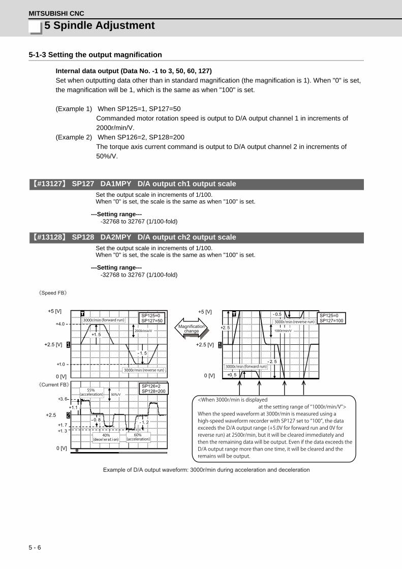
5 - 6
5 Spindle AdjustmentMITSUBISHI CNC
5-1-3 Setting the output magnification
Internal data output (Data No. -1 to 3, 50, 60, 127)
Set when outputting data other than in standard magnification (the magnification is 1). When "0" is set,
the magnification will be 1, which is the same as when "100" is set.
(Example 1) When SP125=1, SP127=50
Commanded motor rotation speed is output to D/A output channel 1 in increments of
2000r/min/V.
(Example 2) When SP126=2, SP128=200
The torque axis current command is output to D/A output channel 2 in increments of
50%/V.
【#13127】 SP127 DA1MPY D/A output ch1 output scale
Set the output scale in increments of 1/100. When "0" is set, the scale is the same as when "100" is set.
---Setting range----32768 to 32767 (1/100-fold)
【#13128】 SP128 DA2MPY D/A output ch2 output scale
Set the output scale in increments of 1/100. When "0" is set, the scale is the same as when "100" is set.
---Setting range----32768 to 32767 (1/100-fold)
+2.5
+2.5 [V]
+5 [V]
0 [V]
+4.0
+1.0
+1. 5
- 1. 5
2000r/min/V
50%/V
SP125=0 SP127=50
SP126=2 SP128=200
+3. 6
+1. 7 +1. 3
- 1. 2
0 [V]
+1.1
- 0. 8
SP125=0 SP127=100
+2. 5
+0. 5
- 2. 5
- 0.5
1000r/min/V
+2.5 [V]
0 [V]
+5 [V]
(acceleration)55%
3000r/min (reverse run)
Example of D/A output waveform: 3000r/min during acceleration and deceleration
《Speed FB》
《Current FB》
<When 3000r/min is displayed at the setting range of “1000r/min/V”>When the speed waveform at 3000r/min is measured using a high-speed waveform recorder with SP127 set to “100”, the data exceeds the D/A output range (+5.0V for forward run and 0V for reverse run) at 2500r/min, but it will be cleared immediately and then the remaining data will be output. Even if the data exceeds the D/A output range more than one time, it will be cleared and the remains will be output.
Magnification change
3000r/min (forward run) 3000r/min (reverse run)
3000r/min (forward run)
( )40%
(acceleration)60%
5 - 7
MDS-D/DH Series Instruction Manual
5-2 Adjustment procedures for each control
5-2 Adjustment procedures for each control
5-2-1 Basic adjustments
(1) Items to check during trial operation
[1] When the power is ON for the first time, check the wiring. When the machine is operated for the first
time, check the set parameters again.
[2] Confirm that the values of the NC side parameters "slimt1 to 4", "smax1 to 4", and "smini" comply
with the machine specification.
[3] When the machine running-in has not been completed, gradually raise the rotation speed (in
increments of 1000r/min) for the spindle. Raise the speed at the timing when the load meter value
is stabilized during rotation.
If the load meter value is higher than the normal value, stop the operation and check the spindle
section of the machine.
[4] Confirm that the command (S command) speed and actual speed match during running-in. When
gear ratio is set, the spindle end speed and motor speed differ.
[5] Confirm that there is no abnormal noise, odor or motor overheat during running-in.
(2) Adjusting the spindle rotation speed
When the spindle motor and the spindle end are coupled using a gear or pulley, the rotation speeds of
the spindle motor and the spindle end may not match. Adjust the command and the rotation speed of
spindle end with the following method.
Apply the following adjustment methods [1] to [3] individually to each of the gears 00 to 11. Confirm that
the machine's gear changes correctly before the adjustment.
[1] Set the spindle specification parameters, "slimt1 to 4".
Calculation expression:
slimt1 to 4 = SP026 × (deceleration rate of the gears 00 to 11 between the motor and spindle end)
[2] Set the S command to half of the maximum spindle rotation speed and confirm the rotation speed
of the spindle end. Adjust slimt1 to 4 until the rotation speed matches.
[3] Set the S command to the maximum spindle end rotation speed and confirm that the S command
speed and the spindle end speed match.
1. Do not adjust when possible risks associated with adjustment procedures are not thoroughly taken
into consideration.
2. Be careful when touching rotating section, or your hand may be caught in or cut.
3. Changing of parameters has to be done carefully.
CAUTION

5 - 8
5 Spindle AdjustmentMITSUBISHI CNC
5-2-2 Gain adjustment
(1) Checking the current loop gain
Check to see if the settings of following parameters, SP077 to SP084, are the standard setting.
Basically, parameters for current loop gain do not need to be changed.
【#13077】 SP077 IQA Q axis current lead compensation
Set the current loop gain. To use the coil switch function, set the current loop gain for when the high-speed coil is selected. The setting value is determined by the motor's electrical characteristics so that the value is fixed to each motor used. Set the value given in the spindle parameter list. (For machine tool builder adjustment)
---Setting range---1 to 20480
【#13078】 SP078 IDA D axis current lead compensation
Set the current loop gain. To use the coil switch function, set the current loop gain for when the high-speed coil is selected. The setting value is determined by the motor's electrical characteristics so that the value is fixed to each motor used. Set the value given in the spindle parameter list. (For machine tool builder adjustment)
---Setting range---1 to 20480
【#13079】 SP079 IQG Q axis current gain
Set the current loop gain. To use the coil switch function, set the current loop gain for when the high-speed coil is selected. The setting value is determined by the motor's electrical characteristics so that the value is fixed to each motor used. Set the value given in the spindle parameter list. (For machine tool builder adjustment)
---Setting range---1 to 8192
【#13080】 SP080 IDG D axis current gain
Set the current loop gain. To use the coil switch function, set the current loop gain for when the high-speed coil is selected. The setting value is determined by the motor's electrical characteristics so that the value is fixed to each motor used. Set the value given in the spindle parameter list. (For machine tool builder adjustment)
---Setting range---1 to 8192
【#13081】 SP081 IQAL Q axis current lead compensation low-speed coil
When using coil switch function, set the current loop gain for when the low-speed coil is selected. The setting value is determined by the motor's electrical characteristics so that the value is fixed to each motor used. Set the value given in the spindle parameter list. (For machine tool builder adjustment)
---Setting range---1 to 20480

5 - 9
MDS-D/DH Series Instruction Manual
5-2 Adjustment procedures for each control
【#13082】 SP082 IDAL D axis current lead compensation low-speed coil
When using coil switch function, set the current loop gain for when the low-speed coil is selected. The setting value is determined by the motor's electrical characteristics so that the value is fixed to each motor used. Set the value given in the spindle parameter list. (For machine tool builder adjustment)
---Setting range---1 to 20480
【#13083】 SP083 IQGL Q axis current gain low-speed coil
When using coil switch function, set the current loop gain for when the low-speed coil is selected. The setting value is determined by the motor's electrical characteristics so that the value is fixed to each motor used. Set the value given in the spindle parameter list. (For machine tool builder adjustment)
---Setting range---1 to 8192
【#13084】 SP084 IDGL D axis current gain low-speed coil
When using coil switch function, set the current loop gain for when the low-speed coil is selected. The setting value is determined by the motor's electrical characteristics so that the value is fixed to each motor used. Set the value given in the spindle parameter list. (For machine tool builder adjustment)
---Setting range---1 to 8192
(Note) Low-speed coil setting SP081, SP082, SP083 and SP084 are set to "0" when coil changeover
specification is not available.
(2) Adjusting the gain parameter
Adjust the gain parameters as usual or by application in accordance with the chart below.
(Note 1) The speed loop gain can switch from Set 1 to Set 2 with the bit selection for SP035.
(Note 2) Position and speed loop gain is switched depend on the control item, so set the parameter
correctly.
(Note 3) When "#3106 bitE" is set to "1".
(Note 4) When "#3106 bitE" is set to "0".
Control itemGain
Regular adjustment By-application adjustment (compensation)Acceleration/deceleration or
orientation (Note 3)Synchronous
tapping Spindle C axis
adjustmentOrientation
(Note 4)Spindle
synchronization
Position loop gain SP001 SP002 SP003
Speed loop gain
SP005, SP006, SP007→Set 1
SP008, SP009, SP010→Set 2
SP005, SP006, SP007→Set 1
[1]Valid for SP035 bit9=0[2]Switch the speed loop gain in the orientation stop to Set 2
with SP035 bit1=1
Valid for SP035 bit9=1 Valid for SP035 bit9=0

5 - 10
5 Spindle AdjustmentMITSUBISHI CNC
(3) Adjusting the speed loop parameter
Stops at servo ON status
Increase the value up to where resonance occurs. Set SP005 (standard setting 150)
Command M19 (orientation stop)
Adjust speed loop gain
Set SP001=15
Resonance occurs?
Increase SP005 by +20
Emergency stop
Command M19 (orientation stop)
Increase SP005 by -20
Subtract 20 from SP005
Acceleration/deceleration operation
Resonance (abnormal noise) or abnormal
operation occurs?
Command M19 (orientation stop)
Set D/A output as shown on the right.
Waveform for Ref.
0.045°or less
q axis current command
Position droop
Adjustment completed
Multiply SP005 by 0.9 Subtract 3 from SP005
Is droop oscillation 0.045°p-p or less?
Note that the maximum setting value is as follows:SP005(max)150 x inertia ratio(Inertia ratio:total inertia/motor inertia)
(Example) When inertia rate is double and the determined gain is 350, the setting value for SP005 is 315, which is 90% of the determined gain, however,the setting value for SP005 should be 300, because the maximum setting value is 150x2(inertia rate)=300.
Output waveform:Position droop
Output waveform:q axis current command
Executes acceleration/deceleration operation in phase up to maximum rotation speed from 0.
(Note)hen the maximum speed is 10000r/min, executes in approx. 1000r/min increments, divided by 10.
SP125:60
SP126:2
SP127:4000(0.025°/V)
SP128:1000(10%/V)
Ch1
Ch2
Yes
NO
YES
NO
0
0
NO
YES

5 - 11
MDS-D/DH Series Instruction Manual
5-2 Adjustment procedures for each control
【#13005】 SP005 VGN1 Speed loop gain 1
Set the speed loop gain. Set this according to the load inertia size. The higher setting value will increase the accuracy of control, however, vibration tends to occur. If vibration occurs, adjust by lowering by 20 to 30%. The final value should be 70 to 80% of the value at which the vibration stops.
---Setting range---1 to 9999
(4) Adjusting the position loop gain (SP001: PGV non-interpolation mode position loop gain)
After setting the speed gain, in order to perform acceleration/deceleration operation, set the position
loop gain (SP001) by increasing its setting value from 15. When overshooting occurs at the time of
acceleration/deceleration completion, or when oscillation of the q axis current command gets bigger
during a set rotation, the position loop gain is in limit state. Note that standard position loop gain below is
set for the setting gain.
Method for checking the limitation of position loop gain
(Example)As the closest value should be selected from the standard setting range shown below, set 47
to SP001 when the limit gain is 55.
【#13001】 SP001 PGV Position loop gain non-interpolation mode
Set the position loop gain for "Non-interpolation" control mode.When the setting value increases, the command tracking ability will enhance and the positioning settling time can be shorter. However, the impact on the machine during acceleration/deceleration will increase.Use the selection command, the control mode "bit 2, 1, 0 = 000" in control input 4.(Note) The control mode is commanded by NC.
---Setting range---1 to 200 (1/s)
Change "Excessive error detection width" (SP053) when "Position loop gain" (SP001) is changed.
Standard position loop gain 15 18 21 23 26 33 38 47 60 70
CAUTION
0
Speed waveform (Set Ch1: SP125=1)
The gain when overshooting occurs is the limit.
0
q axis current comnd waveform (Set Ch2: SP126=2)
When oscillation gets bigger is the limit.

5 - 12
5 Spindle AdjustmentMITSUBISHI CNC
5-2-3 Adjusting the acceleration/deceleration operation
(1) Calculating the theoretical acceleration/deceleration time
The spindle motor output characteristics (shown on the right)
have three ranges, which are constant torque, constant output,
and deceleration ranges. Each range has different calculation
method. The acceleration/deceleration time is calculated using
the calculation expression which corresponds to each range of
the rotation speed for calculation. Note that the load torque
(friction torque) is not considered in the calculation expression, so
the result may slightly differ from the actual acceleration/
deceleration time.
(a) Maximum motor output during acceleration/deceleration: Po
During acceleration/deceleration, the output is 1.2-fold the short-time rating.
The output Po during acceleration/deceleration follows the expression below.
Po = (Short-time rated output) x 1.2 [W]
Substitute this value into Po of the expression.
(b) Total load inertia: Jall
Total load inertia means the total inertia of the spindle motor and of the components which are
rotated the motor (shaft, etc.).
Jall = (Motor inertia) + (Spindle conversion inertia) [kg•m2]
The values obtained in (a) and (b) are substituted into the following calculation expressions.
To calculate the acceleration/deceleration time of the rotation speed N (r/min), use the expression
(c), (d) or (e) which is selected depending on the range that corresponds to the speed N.
(c) Acceleration/deceleration time for constant torque range: t1···0 to N [r/min] (0 N N1)
(For N>N1, apply N=N1 and also calculate t2 or t3.)
(d) Acceleration/deceleration time for constant output range: t2···N1 to N [r/min] (N1<N N2)
(For N>N2, apply N=N2 and also calculate t3.)
(e) Acceleration/deceleration time in deceleration output range: t3···N2 to N [r/min] (N2<N N3)
Based on the above expressions, the acceleration/deceleration time: t from 0 to N3 [r/min] is:
t = t1 + t2 + t3 [s] (Caution 2)
Out
put
[W]
Output characteristics for acceleration/deceleration
0 N1 N2 0
N3
Po
Rotation speed [r/min ]
Short -time rating ×1.2
Constant output range
Constant torque range
Decelerationrange
≦ ≦
1.097 x 10⁻² x Jall x N1 x N t1 = Po [s] (Caution 1)
≦
1.097 x 10⁻² x Jall x (N2 - N12) t2 = 2 x Po [s] (Caution 1)
≦
1.097 x 10⁻² x Jall x (N3 - N23) t3 = 3 x Po x N2 [s] (Caution 1)

5 - 13
MDS-D/DH Series Instruction Manual
5-2 Adjustment procedures for each control
[Calculation example]
Calculate the acceleration/deceleration time from 0 to
10000[r/min] for an spindle motor having the output
characteristics shown on the right when the motor inertia is
0.0148 [kg•m2], and when the motor shaft conversion load
inertia is 0.05 [kg•m2].
Po = (Short-time rated output) x 1.2 = 5500 x 1.2 = 6600 [W]
Jall = (Motor inertia) + (load inertia)
= 0.0148 + 0.05 =0.0648 [kg•m2]
Thus,
t = t1 + t2 + t3 = 0.242 + 1.818 + 4.691 = 6.751 [s]
1. Note that the inertia (J) is a quarter of "GD2".
Ex.) When "GD2" is 0.2 [kg•m2], the inertia is "0.2 / 4 = 0.05 [kg•m2]".
2. If the AC input power voltage to the power supply is low, or if the input power impedance is high,
the acceleration/deceleration time may be long. (Especially, the acceleration/deceleration time of
the deceleration output range may be long.)
3. For the actual measurement in comparison with the theoretical value, perform under the same
condition as the calculated load inertia of Jall. The acceleration/deceleration time differs according
to the inertia. When performing the measurement with a workpiece or tool installed to the spindle,
confirm that the acceleration/deceleration time has been calculated when the total inertia is
included in the installed workpiece and tool.
CAUTION
0 1500 60000
2.0
6.0
8.0
4.0O
utpu
t [k
W]
10000
15-minute rating
3.7
5.54.1
Continuousrating
Rotation speed [ r/min ] Spindle motor characteristics
2.8
1.097 x 10⁻² x Jall x N12 1.097 x 10-2 x 0.0648 x 15002 t1 = Po = 6600 = 0.242 [s]
1.097 x 10⁻² x Jall x (N22 - N12) 1.097 x 10-2 x 0.0648 x (60002 - 15002) t2 = 2 Po = 2 6600 = 1.818 [s]
1.097 x 10⁻² x Jall x (N33 - N23) 1.097 x 10-2 x 0.0648 x (100003 - 60003) t3 = 3 x Po x N2 = 3 x 6600 x 6000 = 4.691 [s]

5 - 14
5 Spindle AdjustmentMITSUBISHI CNC
(2) Measuring the acceleration/deceleration waveforms
Outputs the motor rotation speed by using the spindle drive unit's D/A output function and check if
theoretical acceleration/deceleration time is within ±15%. Refer to "5-1 D/A output specifications for
spindle drive unit" for details on D/A output functions.
Phase current FB output can be measured by the waveform for either U or V phase FB.
The motor phase current cannot be measured on D/A output. Thus, measure the current in the motor
wire, using a measuring device, current clamp meter.
When acceleration/deceleration time does not match the theoretical value (an error rate 15% or more),
check the following items.
[1] There may be an error in calculating load inertia for the motor axis conversion used when
calculating the theoretical acceleration/deceleration time. Check the load inertia again.
[2] When acceleration time is long and deceleration time is short, friction torque is thought to be large.
Check load meter value at the maximum speed (spindle monitor screen). If the load is 10% or
more, friction torque is thought to be relatively large. Mechanical friction, such as bearing friction or
timing belt friction, is assumed to be large. Measure the acceleration/deceleration time again
following trial run.
[3] Even if the problems above are not found, when acceleration/deceleration time does not match,
there may be a possibility of using spindle motor and spindle drive unit that are not specified, or
using wrong parameters. Check the spindle motor type and spindle drive unit type again, as well as
the spindle parameter settings.
There are cases where acceleration/deceleration waveforms change depending on the spindle
temperature. Check the waveforms when the spindle temperature is high (after continuous operation)
and when it is low.
When performing measurement with a workpiece or tool installed, be careful during the operation at
the maximum rotation speed, which may be dangerous because of the increase of inertia.
Motor rotation speed
Acceleration/deceleration waveforms of spindle motor
0
0U(V) phase current FB
Acceleration time: ta Deceleration time: td
POINT
CAUTION

5 - 15
MDS-D/DH Series Instruction Manual
5-2 Adjustment procedures for each control
(3) Adjustment when the load inertia is large
When the load inertia is large and acceleration time is 10s or more, excessive speed deviation alarm
(ALM23) may occur because the time in which deviation between speed command and speed FB,
which is the actual spindle motor rotation speed, exists is prolonged. In this case, increase the time
constant (3101 to 3104) during spindle rotation by S command. When the acceleration time is 10s or
less, use the standard value 300 (300ms).
Alarm can be avoided by adjusting excessive speed deviation timer (SP117). However, in this case,
alarm detection will be delayed during constant speed operation.
In order to improve current ripple waveforms during acceleration/deceleration, adjust by using speed
command dual cushion explained later.
【#13117】 SP117 SETM Excessive speed deviation timer
Set the time to detect the speed excessive error alarm. Set the time required to the machine. The standard setting is "12".
---Setting range---0 to 60 (s)
【#3101】 sp_t 1 Acceleration/deceleration time constant with S command (Gear: 00)
Set the acceleration/deceleration time constant with S command (speed operation mode) when gear 00 is selected. Set the linear acceleration/deceleration time up to maximum speed (smax1). Set the short time constant that the motor torque at acceleration is always saturated, however, when an abnormal noise or V-belt slip occurs, increase the acceleration/deceleration time constant.
---Setting range---0 to 30000 (ms)
【#3102】 sp_t 2 Acceleration/deceleration time constant with S command (Gear: 01)
Set the acceleration/deceleration time constant with S command (speed operation mode) when gear 01 is selected. Set the linear acceleration/deceleration time up to maximum speed (smax2).
---Setting range---0 to 30000 (ms)
【#3103】 sp_t 3 Acceleration/deceleration time constant with S command (Gear: 10)
Set the acceleration/deceleration time constant with S command (speed operation mode) when gear 10 is selected. Set the linear acceleration/deceleration time up to maximum speed (smax3).
---Setting range---0 to 30000 (ms)
【#3104】 sp_t 4 Acceleration/deceleration time constant with S command (Gear: 11)
Set the acceleration/deceleration time constant with S command (speed operation mode) when gear 11 is selected. Set the linear acceleration/deceleration time up to maximum speed (smax4).
---Setting range---0 to 30000 (ms)

5 - 16
5 Spindle AdjustmentMITSUBISHI CNC
(4) Acceleration/deceleration adjustment
Checks acceleration waveform and adjusts deceleration time.
(a) Checking acceleration waveform
Set the measuring device so that U phase current can bemeasured by a clamp meter.
Perform acceleration/deceleration operation from the maximum rotation speed in 1000 rotations increments.
0
Speed waveform (Ch1: SP125=0)
0
Phase current waveform (clamp meter)
Acceleration time
Motor rotation speed
Ch1
Output waveform: Motor rotation speed
SP125:1 SP127: Set so that the
maximum rotation speed is displayed.
Acceleration waveform check completed
Acceleration/deceleration operation
Check acceleration waveform
Set D/A output as shown on the right

5 - 17
MDS-D/DH Series Instruction Manual
5-2 Adjustment procedures for each control
(b) Adjusting deceleration time
Adjusts deceleration time in the same manner as acceleration time by using SP071 (variable
current limit during deceleration, lower limit value) and SP072 (variable current limit during
deceleration, break point speed).
Adjust deceleration time
Deceleration time adjustment completed
Set SP071 and SP072 When SP071=100 is set, current limit during deceleration is constant regardless of the speed. When setting SP071 to 100 or less and SP072 to maximum rotation speed or less, deceleration time will be longer as current limit during deceleration may be variable depending on the speed. * Although a value more than 100 can be set to SP071,
basically, 100 or less should be set.
0
Speed waveform (Ch1: SP125=0) Motor rotation speed
0
Phase current waveform (clamp meter)
Adjust SP071 and SP072 so that deceleration time is within ± 10% of acceleration time.
Set the measuring device so that U phase current can be measured by a clamp meter.
Acceleration/deceleration operation
Set D/A output as shown on the right
Execute M5 stop operation from the maximum rotation speed.
Ch1
Output waveform: Motor rotation speed
SP125:1 SP127: Set so that the
maximum rotation speed is displayed.
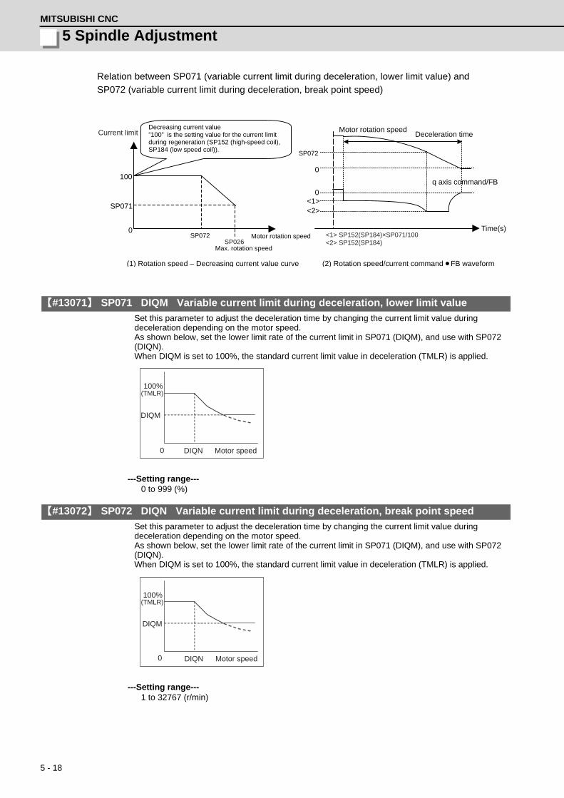
5 - 18
5 Spindle AdjustmentMITSUBISHI CNC
Relation between SP071 (variable current limit during deceleration, lower limit value) and
SP072 (variable current limit during deceleration, break point speed)
【#13071】 SP071 DIQM Variable current limit during deceleration, lower limit value
Set this parameter to adjust the deceleration time by changing the current limit value during deceleration depending on the motor speed. As shown below, set the lower limit rate of the current limit in SP071 (DIQM), and use with SP072 (DIQN). When DIQM is set to 100%, the standard current limit value in deceleration (TMLR) is applied.
---Setting range---0 to 999 (%)
【#13072】 SP072 DIQN Variable current limit during deceleration, break point speed
Set this parameter to adjust the deceleration time by changing the current limit value during deceleration depending on the motor speed. As shown below, set the lower limit rate of the current limit in SP071 (DIQM), and use with SP072 (DIQN). When DIQM is set to 100%, the standard current limit value in deceleration (TMLR) is applied.
---Setting range---1 to 32767 (r/min)
100
SP072
SP071
0
0
<1> <2>
SP072
SP026
<1> SP152(SP184)×SP071/100 <2> SP152(SP184)
0
Current limit
Motor rotation speed
Max. rotation speed
Decreasing current value ”100” is the setting value for the current limit during regeneration (SP152 (high-speed coil), SP184 (low speed coil)).
(1) Rotation speed – Decreasing current value curve
Time(s)
Motor rotation speed Deceleration time
q axis command/FB
(2) Rotation speed/current command FB waveform
DIQN0
DIQM
100%(TMLR)
Motor speed
DIQN0
DIQM
100%(TMLR)
Motor speed

5 - 19
MDS-D/DH Series Instruction Manual
5-2 Adjustment procedures for each control
5-2-4 Orientation adjustment
Adjusts orientation time by adjusting SP016.
(1)Orientation characteristics
When decelerating to stop is executed with orientation, the remaining distance to the orientation stop
position is compensated within one rotation. Thus, as shown in Case 1 below, when the remaining
distance in deceleration is about "0", orientation time would be the shortest (time required to decelerate
and stop + 0s), and as shown in Case 2 below, when the remaining distance in deceleration is about as
much as one rotation amount, orientation time would be the longest.
【#13016】 SP016 DDT Phase alignment deceleration rate
Set the single-rotation position alignment deceleration rate for orientation stopping, phase alignment while rotating and switching from non-interpolation mode to spindle synchronization mode while rotating. When the load inertia is larger, the setting value should be smaller. When the setting value is larger, the orientation in-position and single-rotation position alignment complete faster, but the impact applied on the machine will increase. To change the deceleration rate only during rotation command (command F Δ T ≠ 0), set this parameter together with SP070 (KDDT).
---Setting range---1 to 32767 (0.1(r/min)/ms)
【#13035(PR)】 SP035 SFNC3 Spindle function 3
bit 2 : pyin Excitation rate selection in non-interpolation mode
The excitation rate after the in-position can be selected. 0: Select Excitation rate 1 1: Select Excitation rate 2
bit 1 : vgin Speed loop gain set selection in non-interpolation mode
The speed loop gain set after the in-position can be selected. 0: Select Set 1 1: Select Set 2
0
0
Time(s) 0
0
Time(s)
Case1: Remaining distance at deceleration 0 rotation Case2: Remaining distance at deceleration 1 rotation
q axis current command (SP126: 1 SP128: 100)
Motor rotation speed
Current edge [1] Current limit range at deceleration (SP152 or SP184)
Motor rotation speed
Current edge [2]
q axis current commandq axis current command

5 - 20
5 Spindle AdjustmentMITSUBISHI CNC
(2) Confirmation in orientation stop at deceleration ≒ 0 rotation according to spindle specification
If orientation stop is performed with the load inertia increased due to an excessive workpiece or tool
installed to the spindle, the spindle may start vibrating by trying to reverse after overshooting the stop
position and stop after converging the vibrations (refer to the waveform below).
In this case, the orientation completion time is extended by the time to converge the spindle vibrations.
Thus, the adjustment to suppress the reversing and vibrations at stop is required.
<Adjustment method>
(1) Set SP016: Lower the setting value by 5. By lowering, the inclination of the speed becomes
gradual. Set the optimum value while observing the speed waveform so that the speed will not
vibrate.
(2) Lower the position loop gain.
By lowering the position loop gain, a sway that exceeds the stop position is suppressed.
(3) Adjust the speed gain (SP005, SP006).
The converging time becomes shorter if the rigidity during orientation stop is higher. However this
affects the speed stability during constant feed, thus it is required to confirm the speed waveform at
the constant speed and the machining surface during cutting.
Vibration
Motor rotation speed
In-position signal

5 - 21
MDS-D/DH Series Instruction Manual
5-2 Adjustment procedures for each control
(1) Orientation time adjustment method
(a) Orientation adjustment from maximum rotation speed
Check the orientation operation with the maximum inertia by installing a workpiece or tool to the
spindle head. However, if it is dangerous to check the operation at the maximum speed, slow down to
the safe speed to check.
YES
NO
Adjust orientation time
Rotate spindle at the maximum rotation speed
Increase SP016 by +5
Current edge < Current control value ?
YES
NO
NO
YES
Increase SP016 by +5
Command M19 (orientation stop)
Ch1
Ouput waveform: Motor rotation speed
SP125:1 SP127: Set so that the maximum rotation speed is displayed.
Ch2
Ouput waveform: q axis current command
SP126:2 SP128:100(100%/V)
Set D/A output as shown on the right
Ch1
Ouput waveform: Motor rotation speed
SP125:1 SP127: Set so that the maximum rotation speed is displayed.
Ch2
Ouput waveform:
SP128:100(100%/V)
Set D/A output as shown on the right
Rotate spindle at the maximum rotation speed
Command M19 (orientation stop)
Multiply SP016 setting value by 1/2
(Orientation stop time) - (deceleration time) < 0.4s
Set to SP016 as recovery time constant.
Orientation time adjustment completed
0
0
Current edge [1]
Current limit range at deceleration (SP152 or SP184)
Time(s)
Motor rotation speed
Current edge [2]
SP152
-(SP152)
Compen. amount One rotation? (Current edge?)
orientation stop waveform example(≒1 rotation)
0
Motor rotation speed
4.00s(deceleration time = 3.70s)
In-position signal
Stop within In-position
Orientation time = 4.00s- 3.70s = 0.30s<0.4s OK
In-position signal
SP126:16492
orientation stop waveform example(≒1 rotation)
q axis currentcommand
POINT

5 - 22
5 Spindle AdjustmentMITSUBISHI CNC
(b) Orientation adjustment from stop mode
YES
NO
0
0
0
0
SP125:1
SP126:2
Ch1
Ch2 SP128:100(100%/V)
Ch1
Ch2
SP125:1
SP126:16492
SP127:200(500r/min/V)
SP128:100
Orientation time adjustment completed
Command M19 (orientation stop)
Stop with 180° deviated (Refer to the right )
Current edge < Current control value?
Check the orientation stop time
Set D/A output as shown on the right
Ch1: Motor rotation speed
Ch2: q axis current command
Ch1: Motor rotation speed
Ch2: In-position signal
standard value 0.4s or less
Adjust orientation time
Increase SP016 by +5
Set D/A output as shown on the right
Command M19 (orientation stop)
Cancel emergency stop
Emergency stop
Orientation position Orientation position
180° rotation Spindle Spindle
Screen operation [1] Press the NC function key DIAGN . [2] Press the NC menu key I/F diagn . [3] Press the NC menu key 1-shot output . [4] Input “R7009/4650” with the NC key. [5] Command M19 (orientation stop).
<-Stop at the side opposite to the orientation stop position (with 180° deviated).
[6] Press the NC menu key 1-shot output . [7] Input “R7009/0”with the NC key.
Stop with approx.180° deviated
Output waveform:Motor rotationspeed
Output waveform:q axis currentcommandv
SP127:Set so that the maximumrotation speed is displayed.
Output waveform:Motor rotation speed
Output waveform:In-position signal
Current limit at regeneration(SP152 or SP184)
Current limit at acceleration(SP153 or SP185)

5 - 23
MDS-D/DH Series Instruction Manual
5-2 Adjustment procedures for each control
5-2-5 Synchronous tapping adjustment
(1) Gain setting and time constant determination
[1] For speed loop gain during synchronous tapping, speed loop gain set 2, which consists of SP008
(speed loop gain 2), SP009 (speed loop lead compensation 2), and SP010 (speed loop delay
compensation 2), is used. Thus, SP035 has to be set as follows. For position loop gain, set
standard 33 to SP002 (position loop gain interpolation mode).
<List of parameters used for adjustment>
<Related servo parameters>
Set the spindle and interpolation axis by tapping.
[2] Create a NC program so that the synchronous tapping operation program has 3000r/min of spindle
rotation speed, 1mm (equivalent of M6 screw) of screw pitch size, and depths at which the following
two different operation patterns are generated.
(Note that the operation conditions, such as spindle rotation speed and screw pitch, may be
specified by the machine manufacturer.)
Parameter Setting value
SP002 33
SP008 Value in SP005 set at "5-3-2" (Initial setting value: 150)
SP009 1900
SP010 0
SP035 0200: Speed loop gain set 2 selection (Validate bit9)
Parameter Setting value
SV049 Set the same value as spindle parameter "SP002"
SV050 Set it when using SHG control (when not using, set to "0" )
SV058 Set it when using SHG control (when not using, set to "0" )
Operation pattern 1
Adjust depth so that motor rotation speed waveform shapes trapezoids
Operation pattern 2
Adjust depth so that motor rotation speed waveform shapes mountain-valley
Constant speed area
Spindle rotation speed (r/min)
Spin
dle
rota
tion
spee
d (r
/min
)
Time (sec)
No constant speed area
Spindle rotation speed (r/min)
Spin
dle
rota
tion
spee
d (r
/min
)
Time (sec)
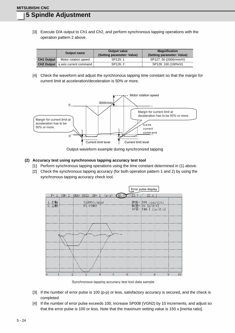
5 - 24
5 Spindle AdjustmentMITSUBISHI CNC
[3] Execute D/A output to Ch1 and Ch2, and perform synchronous tapping operations with the
operation pattern 2 above.
[4] Check the waveform and adjust the synchronous tapping time constant so that the margin for
current limit at acceleration/deceleration is 50% or more.
Output waveform example during synchronized tapping
(2) Accuracy test using synchronous tapping accuracy test tool
[1] Perform synchronous tapping operations using the time constant determined in (1) above.
[2] Check the synchronous tapping accuracy (for both operation pattern 1 and 2) by using the
synchronous tapping accuracy check tool.
[3] If the number of error pulse is 100 (p-p) or less, satisfactory accuracy is secured, and the check is
completed.
[4] If the number of error pulse exceeds 100, increase SP008 (VGN2) by 10 increments, and adjust so
that the error pulse is 100 or less. Note that the maximum setting value is 150 x [inertia ratio].
Output nameOutput value
(Setting parameter: Value)Magnification
(Setting parameter: Value)
CH1 Output Motor rotation speed SP125: 1 SP127: 50 (2000r/min/V)
CH2 Output q axis current command SP126: 2 SP128: 100 (100%/V)
0
0
Motor rotation speed
q a xis current comm and
3000r/min
Current limit level Current limit level
Margin for current limit atacceleration has to be 50% or more.
Margin for current limit atdeceleration has to be 50% or more.
Error pulse display
Synchronous tapping accuracy test tool data sample

5 - 25
MDS-D/DH Series Instruction Manual
5-2 Adjustment procedures for each control
【#13002】 SP002 PGN Position loop gain interpolation mode
Set the position loop gain for "interpolation" control mode.When the setting value increases, the command tracking ability will enhance and the positioning settling time can be shorter. However, the impact on the machine during acceleration/deceleration will increase. Use the selection command, the control mode "bit 2, 1, 0 = 010 or 100" in control input 4.(Note) The control mode is commanded by NC. When carrying out the SHG control, set SP035/bitC to "1".
---Setting range---1 to 200 (1/s)
【#13008】 SP008 VGN2 Speed loop gain 2
Normally SP005(VGN1) is used. By setting "SP035/bit9=1", gain 2 can be used according to the application. Gain 2 can also be used by setting "Speed gain set 2 changeover request (control input 5/ bitC) = 1". Refer to SP005(VGN1) for adjustment procedures.
---Setting range---1 to 9999
【#13009】 SP009 VIA2 Speed loop lead compensation 2
Normally SP006(VIA1) is used. By setting "SP035/bit9=1", gain 2 can be used according to the application. Gain 2 can also be used by setting "Speed gain set 2 changeover request (control input 5/ bitC) = 1". Refer to SP006(VIA1) for adjustment procedures.
---Setting range---1 to 9999
【#13010】 SP010 VIL2 Speed loop delay compensation 2
Normally SP007(VIL1) is used. By setting "SP035/bit9=1", gain 2 can be used according to the application. Gain 2 can also be used by setting "Speed gain set 2 changeover request (control input 5/ bitC) = 1". Refer to SP007(VIL1) for adjustment procedures.
---Setting range---0 to 32767
【#13035(PR)】 SP035 SFNC3 Spindle function 3
bit C : shgn SHG control in interpolation mode
0: Stop 1: Start
bit A : pyn Excitation rate selection in interpolation mode
0: Select Excitation rate 1 1: Select Excitation rate 2
bit 9 : vgn Speed loop gain set selection in interpolation mode
0: Select Set 1 1: Select Set 2

5 - 26
5 Spindle AdjustmentMITSUBISHI CNC
5-2-6 High-speed synchronous tapping
This function enables the reduction of synchronization errors by allowing data communication between drive
units.
<Adjustment method>
(1) Adjust the normal synchronous tapping.
(2) Set the total inertia rate with respect to the motor inertia to the servo parameter "SV037". If this value
has already been set for adjustment of the other functions, use the same value.
(3) Set 600 to the servo parameter "SV129".
(4) Set the basic specification parameter "#1281/ bit5 =1(high-speed synchronous tapping valid)".
(5) Adjust the spindle parameter "#3120" while confirming that the current margin and the number of error
pulses are within the tolerable range in the high-speed synchronous tapping operation.
High-speed synchronous tapping time constant
= Normal synchronous tapping time constant×100 - (Setting value of #3120) /100
<Cautions for setting the OMR-DD (high-speed tapping control)>
When using the OMR-DD with the MDS-DM Series, numbers of servo axes that can be set is only one
axis.
The synchronization of two servo/spindle axes or more are not available.
(Example: Compound axis or inclined tapping, etc. is disable.)
If the OMR-DD is set for two servo axes or more, "Alarm 37 (initial parameter error)" will occur.
[Setting example] When enabling the OMR-DD only for Z-axis
X-axis : 1st axis Y-axis : 2nd axis Z-axis : 3rd axis
[1] NC parameter : Set to "3137 (stap_ax_off) High-speed synchronous tapping disabled axis:
0003 (HEX setting 4 digits)".
bit0=1 : X-axis disabled
bit1=1 : Y-axis disabled,
bit2=0 : Z-axis is enabled, and X-axis and Y-axis are disabled.
The axis order set with the NC parameter "1013 (axname)" is applied.
[2] NC parameter : Set to "1281 (ext17) : 00100000 ( 8bits of bin setting)", and enable the OMR-
DD.
NC parameter : When all values of "3137" are "0", all servo axes are regarded as enabled, so
"Alarm 37 (initial parameter error)" will occur.
Cycle time Cycle time
Synchronous error
Spindle position
Spindle speedSpindle speed
Spindle position
Synchronous error
Normal synchronous tapping High-speed synchronous tapping
Reduction

5 - 27
MDS-D/DH Series Instruction Manual
5-2 Adjustment procedures for each control
【#2237】 SV037 JL Load inertia scale
Set the motor axis conversion total load inertia including motor itself in proportion to the motor inertia. SV037(JL)=(Jm+Jl)/Jm×100 Jm: Motor inertia Jl: Motor axis conversion load inertia For linear motor, set the gross mass of the moving sections in kg unit. <<Drive monitor load inertia ratio display>>Set SV035/bitF=1 and imbalance torque and friction torque to both SV032 and SV045, and then repeat acceleration/deceleration for several times.
---Setting range---For general motor: 0 to 5000 (%)
For linear motor 0 to 5000 (kg)
【#2329】 SV129 Kwf Synchronous control feed forward filter frequency
Set the acceleration rate feed forward filter frequency in high-speed synchronous tapping control. The standard setting is "600". Related parameters: SV244
---Setting range---0 to 32767 (rad/s)
【#1281(PR)】 ext17
bit5: High-speed synchronous tapping valid
Select whether to enable the high-speed synchronous tapping. 0: Disable1: Enable
【#3120】 staptr Time constant reduction rate in high-speed synchronous tapping
When performing high-speed synchronous tapping control (#1281/bit5), set the reduction rate of the time constant compared to the time constant in normal synchronous tapping. (Setting "0"or "100" will be regarded as reduction rate zero, so the time constant won't be reduced.)E.g.) When set to "10", time constant in high-speed synchronous tapping will be 90% of that in
normal synchronous tapping.
---Setting range---0 to 100(%)

5 - 28
5 Spindle AdjustmentMITSUBISHI CNC
5-2-7 Spindle C axis adjustment (For lathe system)
(1) Setting the gain
For spindle C axis speed loop gain, SP008 (speed loop gain 2), speed loop gain set 2, which consists of
SP009 (speed loop lead compensation 2), and SP010 (speed loop delay compensation 2), is used.
Thus, SP035 has to be set as follows. For position loop gain, set standard 33 to SP002 (position loop
gain, interpolation mode).
<Related servo parameters>
Set the spindle and interpolation axis.
(2) Gain adjustment and accuracy test during C axis operation
[1] Set the D/A output as follows during stopped in C axis mode (servo ON status) or when executing
cutting feed with G01 F20. Then check the droop fluctuation is within 10°/1000.
Offset is 2.5V.
* Waveform during stopped in C axis (Reference)
* Waveform when executing cutting feed with G01 F20 (Reference)
[2] When satisfactory accuracy is not secured, increase SP008 (VGN2) by 10 increments and adjust
so that the accuracy level meets the standard. Note that the maximum setting value is 150 x [inertia
ratio].
Parameter Setting valueSP002 33SP008 SP005 setting value set in "5-2-1" (Initial setting value: 150)SP009 1900SP010 0SP035 0200: Speed loop gain set 2 selection (validate bit9)
Parameter Setting value
SV003 Set the same value as spindle parameter "SP002"
SV004 Set it when using SHG control (when not using, set to "0" )
SV057 Set it when using SHG control (when not using, set to "0" )
Output name Setting value (Setting parameter: Value) Magnification (Setting parameter: Value)
CH1 output Position droop SP125 : 60 SP127 = 10000 (0.01°/V)
CH2 output Current command SP126 : 2 SP128 = 1000 (10%/V)
Ch1: Position droop
Ch2: q axis current command
0
0 0.010° or less
Ch1: Position droop
Ch2: q axis current command
0
0 0.010° or less

5 - 29
MDS-D/DH Series Instruction Manual
5-2 Adjustment procedures for each control
(3) Setting the notch filter
During spindle C axis operation, there are times where motor is rotated while brake is applied, resulting
in resonance occurred. In this case, measure resonance frequency from q axis current command
waveform and set the value to SP038 (notch filter 1). Also, depending on the set frequency, filter depth
must be set to SP034. When notch filter is set, perform acceleration/deceleration operation at the
maximum speed and confirm that no abnormal oscillation or noise is found.
Notch filter's set frequency and standard depth setting
Setting example: When there are 16 wavelengths within 0.02 sec.
Set 800 to SP038 and XXX0 to SP034. Measure position droop and current command at this time, and
adjust notch filter's frequency and depth so that the position droop is within standard range.
SP034Notch filter 1 Depth setting
bit3=0 bit2=0 bit1=0Setting value: XXX0
bit3=0 bit2=1 bit1=0Setting value: XXX4
bit3=1 bit2=0 bit1=0Setting value: XXX8
SP038Notch filter 1 Setting frequency
2000(Hz) to 400(Hz) 399(Hz) to 200(Hz) 190(Hz) or lower
1. When incorrect frequency is set, suddenly resonance can occur and big abnormal noise can be
generated. Input the appropriate value.
2. Do not set the value to low-frequency (50Hz).
Ch1: Position droop
Ch2: q axis current command
0
0
16 wavelengths within 0.02sec = 800Hz
POINT

5 - 30
5 Spindle AdjustmentMITSUBISHI CNC
【#13002】 SP002 PGN Position loop gain interpolation mode
Set the position loop gain for "interpolation" control mode.When the setting value increases, the command tracking ability will enhance and the positioning settling time can be shorter. However, the impact on the machine during acceleration/deceleration will increase. Use the selection command, the control mode "bit 2, 1, 0 = 010 or 100" in control input 4.(Note) The control mode is commanded by NC. When carrying out the SHG control, set SP035/bitC to "1".
---Setting range---1 to 200 (1/s)
【#13008】 SP008 VGN2 Speed loop gain 2
Normally SP005(VGN1) is used. By setting "SP035/bit9=1", gain 2 can be used according to the application. Gain 2 can also be used by setting "Speed gain set 2 changeover request (control input 5/ bitC) = 1". Refer to SP005(VGN1) for adjustment procedures.
---Setting range---1 to 9999
【#13009】 SP009 VIA2 Speed loop lead compensation 2
Normally SP006(VIA1) is used. By setting "SP035/bit9=1", gain 2 can be used according to the application. Gain 2 can also be used by setting "Speed gain set 2 changeover request (control input 5/ bitC) = 1". Refer to SP006(VIA1) for adjustment procedures.
---Setting range---1 to 9999
【#13010】 SP010 VIL2 Speed loop delay compensation 2
Normally SP007(VIL1) is used. By setting "SP035/bit9=1", gain 2 can be used according to the application. Gain 2 can also be used by setting "Speed gain set 2 changeover request (control input 5/ bitC) = 1". Refer to SP007(VIL1) for adjustment procedures.
---Setting range---0 to 32767

5 - 31
MDS-D/DH Series Instruction Manual
5-2 Adjustment procedures for each control
【#13034】 SP034 SFNC2 Spindle function 2
bit F-D : nfd5 Depth of Notch filter 5
Set the depth of Notch filter 5 (SP088). bit F,E,D= 000: -∞ 001: -18.1[dB] 010: -12.0[dB] 011: -8.5[dB] 100: -6.0[dB] 101: -4.1[dB] 110: -2.5[dB] 111: -1.2[dB]
bit B-9 : nfd4 Depth of Notch filter 4
Set the depth of Notch filter 4 (SP087). bit B,A,9= 000: -∞ 001: -18.1[dB] 010: -12.0[dB] 011: -8.5[dB] 100: -6.0[dB] 101: -4.1[dB] 110: -2.5[dB] 111: -1.2[dB]
bit 7-5 : nfd2 Depth of Notch filter 2
Set the depth of Notch filter 2 (SP046). bit7,6,5= 000: -∞ 001: -18.1[dB] 010: -12.0[dB] 011: -8.5[dB] 100: -6.0[dB] 101: -4.1[dB] 110: -2.5[dB] 111: -1.2[dB]
bit 4 : fhz3 Notch filter 3
0: Stop 1: Start (1125Hz)
bit 3-1 : nfd1 Depth of Notch filter 1
Set the depth of Notch filter 1 (SP038). bit3,2,1= 000: -∞ 001: -18.1[dB] 010: -12.0[dB] 011: -8.5[dB] 100: -6.0[dB] 101: -4.1[dB] 110: -2.5[dB] 111: -1.2[dB]
【#13035(PR)】 SP035 SFNC3 Spindle function 3
bit C : shgn SHG control in interpolation mode
0: Stop 1: Start
bit A : pyn Excitation rate selection in interpolation mode
0: Select Excitation rate 1 1: Select Excitation rate 2
bit 9 : vgn Speed loop gain set selection in interpolation mode
0: Select Set 1 1: Select Set 2

5 - 32
5 Spindle AdjustmentMITSUBISHI CNC
【#13038】 SP038 FHz1 Notch filter frequency 1
Set the vibration frequency to suppress when machine vibration occurs. (Enabled at 50 or more.)When not using, set to "0".
---Setting range---0 to 2250 (Hz)
【#13046】 SP046 FHz2 Notch filter frequency 2
Set the vibration frequency to suppress when machine vibration occurs. (Enabled at 50 or more.)When not using, set to "0".
---Setting range---0 to 2250 (Hz)
【#13087】 SP087 FHz4 Notch filter frequency 4
Set the vibration frequency to suppress when machine vibration occurs. (Enabled at 50 or more.)When not using, set to "0".
---Setting range---0 to 2250 (Hz)
【#13088】 SP088 FHz5 Notch filter frequency 5
Set the vibration frequency to suppress when machine vibration occurs. (Enabled at 50 or more.)When not using, set to "0".
---Setting range---0 to 2250 (Hz)
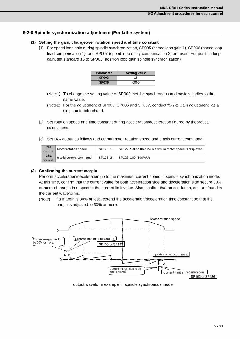
5 - 33
MDS-D/DH Series Instruction Manual
5-2 Adjustment procedures for each control
5-2-8 Spindle synchronization adjustment (For lathe system)
(1) Setting the gain, changeover rotation speed and time constant
[1] For speed loop gain during spindle synchronization, SP005 (speed loop gain 1), SP006 (speed loop
lead compensation 1), and SP007 (speed loop delay compensation 2) are used. For position loop
gain, set standard 15 to SP003 (position loop gain spindle synchronization).
(Note1) To change the setting value of SP003, set the synchronous and basic spindles to the
same value.
(Note2) For the adjustment of SP005, SP006 and SP007, conduct "5-2-2 Gain adjustment" as a
single unit beforehand.
[2] Set rotation speed and time constant during acceleration/deceleration figured by theoretical
calculations.
[3] Set D/A output as follows and output motor rotation speed and q axis current command.
(2) Confirming the current margin
Perform acceleration/deceleration up to the maximum current speed in spindle synchronization mode.
At this time, confirm that the current value for both acceleration side and deceleration side secure 30%
or more of margin in respect to the current limit value. Also, confirm that no oscillation, etc. are found in
the current waveforms.
(Note) If a margin is 30% or less, extend the acceleration/deceleration time constant so that the
margin is adjusted to 30% or more.
output waveform example in spindle synchronous mode
Parameter Setting value
SP003 15
SP036 0000
Ch1 output
Motor rotation speed SP125: 1 SP127: Set so that the maximum motor speed is displayed
Ch2 output
q axis current command SP126: 2 SP128: 100 (100%/V)
0
0
Motor rotation speed
Current limit at regeneration
Current limit at accelarationCurrent margin has to be 30% or more.
Current margin has to be 30% or more.
q axis current command
SP153 or SP185
SP152 or SP186

5 - 34
5 Spindle AdjustmentMITSUBISHI CNC
【#13003】 SP003 PGS Position loop gain spindle synchronization
Set the position loop gain for "spindle synchronization" control mode.When the setting value increases, the command tracking ability will enhance and the positioning settling time can be shorter. However, the impact on the machine during acceleration/deceleration will increase. Use the selection command, the control mode "bit 2, 1, 0 = 001" in control input 4.(Note) The control mode is commanded by NC. When carrying out the SHG control, set SP036/bit4 to "1".
---Setting range---1 to 200 (1/s)
【#13036(PR)】 SP036 SFNC4 Spindle function 4
bit 4 : shgs SHG control in spindle synchronization mode
0: Stop 1: Start
bit 2 : pys Excitation rate selection in spindle synchronization mode
0: Select Excitation rate 1 1: Select Excitation rate 2
bit 1 : vgs Speed loop gain set selection in spindle synchronization mode
0: Select Set 1 (SP005,SP006,SP007) 1: Select Set 2 (SP008,SP009,SP010)

5 - 35
MDS-D/DH Series Instruction Manual
5-2 Adjustment procedures for each control
5-2-9 Deceleration coil changeover valid function by emergency stop
If a large workpiece is mounted on a large workpiece chuck in lathe, the acceleration/deceleration time
increases because of the increase of the total inertia. When the deceleration stop time at emergency stop
exceeds the upper limit value (29900ms) of the gate shutoff delay time (SP055), the spindle motor will coast.
This function enables the coil changeover motor to change to low-speed coil during emergency stop and if
the deceleration time is reduced to complete within the gate shutoff time, the spindle enters an emergency
stop state.
【#13225】 SP225 SFNC5 Spindle function 5
bit 8 : mken Coil switch allowance in deceleration control
This enables a coil changeover while decelerating after an emergency stop for a spindle motor with coil changeover specification. A coil changeover may enable an excessive load inertia to stop within the maximum delay time. 0: Normal (Disable) 1: Enable
【#13055】 SP055 EMGx Max. gate off delay time after emergency stop
Set the time required to forcibly execute READY OFF after the emergency stop is input. Normally set to "20000". When "0" is set, READY OFF is forcibly executed with "7000ms". When the set time is shorter than the time to decelerate and stop, the spindle will stop with the dynamic brake after the set time is out.
---Setting range---0 to 29900 (ms)
【#13056】 SP056 EMGt Deceleration time constant at emergency stop
Set the time constant used for the deceleration control at emergency stop. Set the time required to stop from the maximum motor speed (TSP). When "0" is set, the deceleration control is executed with "7000ms".
---Setting range---0 to 29900 (ms)
bit8=0 bit8=1
Coast
Max. delay time only Max. delay time+Coil changeover enabled
Low-speed coil
Emergency stop High-speedcoil
Enable Disable
After the elapse of maximum delay time, the motor cannot stop but caost
Because of the changeover to high-speed coil,deceleration finishes in time and the motor stops
Stop
Max. delay time(29900ms)Max. delay time(29900ms)
Emergency stopHigh-speedcoil Low-speed coilLow-speed coil
commandLow-speed coilcommand
Deceleration
Deceleration
Deceleratie usinglow-speed coil

5 - 36
5 Spindle AdjustmentMITSUBISHI CNC
5-2-10 High-response acceleration/deceleration function
Under continuous position control method makes position droop is set with primary delay depending on the
position control gain during the acceleration/deceleration by S command. If the position gain is set lower, the
zero speed detection which indicates the spindle stop is more conspicuously delayed.
This function enables the position droop’s primary delay to be shorter and the zero speed detection to be
faster.
【#13095】 SP095 VIAX Lead compensation scale during high-response acceleration/deceleration
Set the magnification against delay/lead compensation (SP006) of the high-response acceleration/deceleration (valid when SP226/ bitD is set to "1"). Normally, set to "0". Set this parameter to suppress overshooting when the speed is reached.
---Setting range---0 to 10000 (0.01%)
【#13226】 SP226 SFNC6 Spindle function 6
bit D : vup High response acceleration / deceleration
This suppresses a temporal delay which occurs when the target speed is attained from acceleration and when the spindle stops from deceleration. 0: Normal acceleration/deceleration 1: High response acceleration/deceleration Enable
This function is invalid during orientation and interpolation control (spindle synchronous/C axis/
synchronous tapping control) even when it is set.
0
0
FB
Current command
Motor speed
Time
Time
Conventional High-response
S command
Comparison of spindle
acceleration/deceleration by S command
Delay time ≒2/posotion control gain[s]
POINT

5 - 37
MDS-D/DH Series Instruction Manual
5-2 Adjustment procedures for each control
5-2-11 Spindle cutting withstand level improvement
Conventionally, the spindle rotation speed was slowed down due to heavy cutting that exceeds the spindle
output characteristics, and this caused the alarm (Excessive error 52, Overload command 51) to stop the
machining.
This function enables setting of the dropping speed allowable value by parameter. As long as the speed is
the set value or higher, machining can be executed within the output characteristics without being stopped
by the alarm.
Even when the parameter setting value is the normal value of 0, the standard value of 85 is applied. This can
improve the efficiency of heavy cutting (feed per revolution).
If excessive speed dropping occurs and the speed exceeds the allowable range, the excessive speed
deviation alarm 23 is output to reduce the damage to the machine.
【#13096】 SP096 SDW Speed slowdown allowable width
When the spindle slows down due to multiple cutting, set the processable speed as percentage against the NC command speed. If the speed reduces below the tolerable range, the alarm 23 (Excessive speed error) will occur.E.g.] When set to 90 [%] If S1000 is commanded, the speed reduced by 900r/min (=1000r/min × 90%) is the allowable lower limit. Thus if the spindle speed reduces to 100r/min or below, the alarm will occur.When "0" is set, the magnification is the same as when "85" is set. When set to "-1", the allowable width will be disabled.
---Setting range----1,0 to 100(%)
0
0
0
(1) (2) (3)
(3)
(2)
(1)Cutting torque
Feed axis speed
Spindle speed
Torque characteristics
Torque for the command speed>Maximum torpue
(1) Heavy cutting start(2) Machining at a lowered speed(3) Normal cutting
Time
Time
Command×SP096(%)
Feed axis speed
Actual speed Command speed
Speed
Cutting which exceeds the maximum spindle output
Command speedActual speed
Max. torque
Torque
Controls so that the cutting torque is maintained and the finished surface has even cut marks.
When the spindle speed is lowered by machining which exceeds the maximum torque, the feed axis
speed is also lowered.
Workpiece
Cutter
Set the feed amountaccording to the spindle rotation
Spindle
Allows the speed lowering and continues the machining
Alarm23 area

5 - 38
5 Spindle AdjustmentMITSUBISHI CNC
5-3 Settings for emergency stopEmergency stop in this section refers to the following states.
[1] Emergency stop was input (including other axis alarms)
[2] NC power down was detected
[3] A drive unit alarm was detected
5-3-1 Deceleration control
With the spindle drive unit, the motor will decelerate following the time constant set at emergency stop.
When the NC confirms the zero speed of all axes, the spindle drive unit turns the contactor of the power
supply unit OFF.
(1) Setting the deceleration control time constant
Set the time for stopping from the maximum motor speed (TSP) in the deceleration time constant for
emergency stop (SV056: EMGt). When "0" is set, the deceleration stop is executed with "7000ms".
<Operation>
When an emergency stop occurs, the motor will decelerate at the same inclination from each speed.
(Note) If the setting value of SP056 is longer than the value of SP055, the motor will coast.
【#13055】 SP055 EMGx Max. gate off delay time after emergency stop
Set the time required to forcibly execute READY OFF after the emergency stop is input. Normally set to "20000". When "0" is set, READY OFF is forcibly executed with "7000ms". When the set time is shorter than the time to decelerate and stop, the spindle will stop with the dynamic brake after the set time is out.
---Setting range---0 to 29900 (ms)
【#13056】 SP056 EMGt Deceleration time constant at emergency stop
Set the time constant used for the deceleration control at emergency stop. Set the time required to stop from the maximum motor speed (TSP). When "0" is set, the deceleration control is executed with "7000ms".
---Setting range---0 to 29900 (ms)
ON OFF
ON OFF
ON OFF
TSP
SP056
SP055
(EMG)
(ZSP)
(READY)
Forced READY OFF range
Constant inclination decelerationMotor speed
Time
Deceleration control sequence
Emergency stop
Servo READY
Zero speed

5 - 39
MDS-D/DH Series Instruction Manual
5-4 Spindle control signal
5-4 Spindle control signalThe sequence input/output signals exchanged between the NC and spindle drive unit are explained in this
section. The status of each signal is displayed on the NC SPINDLE MONITOR screen.
5-4-1 Spindle control input (NC to Spindle)
(1) Spindle control input 1
bit0. READY ON command (RDY)
Status turns to ready ON at RDY=1.
bit1. Servo ON command (SRV)
[1] Drive unit turns ON at SRV=1 (gate ON status), and rotation control starts.
Plus or minus of the rotation direction is determined depending on +/- of the NC command
FΔT.
[2] Servo immediately turns OFF (SON=0) at SRV=0 during rotation control. Drive unit also turns
OFF (gate OFF status) at this time.
bit7. Alarm reset command (ALMR)
NR alarm is reset at ALMR=1.
bit8. Torque limit 1 selection command (TL1)
bit9. Torque limit 2 selection command (TL2)
bitA. Torque limit 3 selection command (TL3)
The following 4 types of torque limit are available depending on TL1, TL2 and TL3 bit combinations.
(Note) The ratio to motor short time rated torque (load meter 100%) is indicated in %.
(Note) The bits other than those above are used for maintenance.
TL3 TL2 TL1 Torque limit value0 0 1 Torque limit value (%) set with parameter SP0650 1 0 Torque limit value (%) set with parameter SP0660 1 1 Torque limit value (%) set with parameter SP0671 0 0 Torque limit value (%) set with parameter SP068
Name Details
Spindle control input 1
F E D C B A 9 8 7 6 5 4 3 2 1 0 TL3 TL2 TL1 ALMR SRV RDY
bit Details
0 RDY READY ON command 1 SRV Servo ON command 2 - (For maintenance) 3 - (For maintenance) 4 - (For maintenance) 5 - (For maintenance) 6 - (For maintenance) 7 ALMR Alarm reset command 8 TL1 Torque limit 1 selection command 9 TL2 Torque limit 2 selection command A TL3 Torque limit 3 selection command B - (For maintenance) C - (For maintenance) D - (For maintenance) E - (For maintenance) F - (For maintenance)
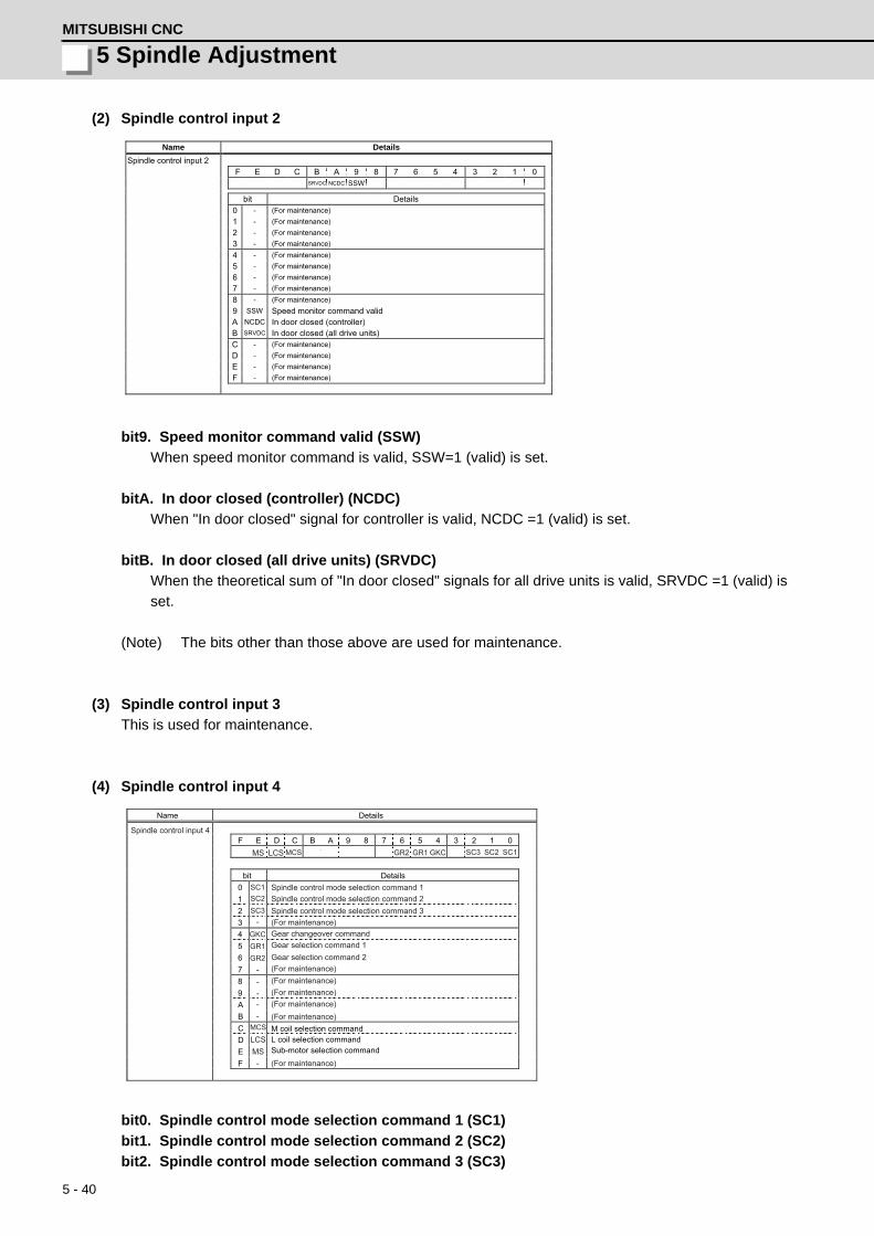
5 - 40
5 Spindle AdjustmentMITSUBISHI CNC
(2) Spindle control input 2
bit9. Speed monitor command valid (SSW)
When speed monitor command is valid, SSW=1 (valid) is set.
bitA. In door closed (controller) (NCDC)
When "In door closed" signal for controller is valid, NCDC =1 (valid) is set.
bitB. In door closed (all drive units) (SRVDC)
When the theoretical sum of "In door closed" signals for all drive units is valid, SRVDC =1 (valid) is
set.
(Note) The bits other than those above are used for maintenance.
(3) Spindle control input 3
This is used for maintenance.
(4) Spindle control input 4
bit0. Spindle control mode selection command 1 (SC1)
bit1. Spindle control mode selection command 2 (SC2)
bit2. Spindle control mode selection command 3 (SC3)
Name Details
Spindle control input 2
F E D C B A 9 8 7 6 5 4 3 2 1 0 SRVDC NCDC SSW
bit Details
0 - (For maintenance) 1 - (For maintenance) 2 - (For maintenance) 3 - (For maintenance) 4 - (For maintenance) 5 - (For maintenance) 6 - (For maintenance) 7 - (For maintenance) 8 - (For maintenance) 9 SSW Speed monitor command valid A NCDC In door closed (controller) B SRVDC In door closed (all drive units) C - (For maintenance) D - (For maintenance) E - (For maintenance) F - (For maintenance)
F E D C B A 9 8 7 6 5 4 3 2 1 0
bit0123456789ABCDEF
-
-
-
-
-
SC2GKCGR2
-
-
GR1 SC3 SC1
SC2
GKC
GR2GR1
SC3
SC1
MCS
LCSMS
MCSLCSMS
Details
Name Details
Spindle control input 4
Spindle control mode selection command 1
(For maintenance)
Gear selection command 1
(For maintenance)
(For maintenance)
Gear changeover command
Spindle control mode selection command 2Spindle control mode selection command 3
Gear selection command 2(For maintenance)(For maintenance)(For maintenance)(For maintenance)
M coil selection commandL coil selection commandSub-motor selection command

5 - 41
MDS-D/DH Series Instruction Manual
5-4 Spindle control signal
[1] Drive unit operation mode can be selected with the bit correspondences below.
[2] Mode changeover is valid during in-position (INP=1) or other than during droop cancel / phase
compensation (DCSL=PCMP=0).
(Note) When selecting bits other than above, control mode error (4E) occurs.
[3] Continuity cannot be guaranteed for the value of position FB in non-interpolation mode.
(Position may be skipped for multiple rotations due to droop cancel or phase compensation.)
bit4. In gear changeover command (GKC)
By inputting GKC=1, the gear ratio is changed to the gear ratio specified with the gear selection
command (GR1, GR2). This command is invalid during the interpolation mode.
bit5. Gear selection command 1 (GR1)
bit6. Gear selection command 2 (GR2)
[1] The following 4 types of gear ratio are available depending on GR1 and GR2 2-bit input
combinations.
[2] Gear specifications in semi-closed position control do not secure a position within one rotation
of the spindle.
bitC. M coil selection command (MCS) (IPM spindle motor only)
[1] M coil is selected at MCS=1 when 3-step coil changeover is valid.
[2] Signal change is invalid during interpolation mode, but coil changeover is valid if control mode
changeover is applied together.
bitD. L coil selection command (LCS)
[1] L coil is selected at LCS=1 when coil changeover is valid.
[2] Signal change is invalid during interpolation mode, but coil changeover is valid if control mode
changeover is applied together.
bitE. Sub-motor selection command (MS)
When 1 drive unit 2 motor function is valid, a main motor is selected at MS=0 and a sub-motor is
selected at MS=1. An input cannot be changed during motor changeover.
(Note) The bits other than those above are used for maintenance.
SC3 SC2 SC1Operation mode
Conventional method New method0 0 0 Speed/orientation control Non interpolation control0 0 1 Spindle synchronization Spindle synchronization0 1 0 C-axis control
Interpolation control1 0 0 Synchronous tapping control
GR2 GR1 Parameters requiring gear ratio setting
0 0 SP057 (GRA1), SP061 (GRB1)
0 1 SP058 (GRA2), SP062 (GRB2)
1 0 SP059 (GRA3), SP063 (GRB3)
1 1 SP060 (GRA4), SP064 (GRB4)

5 - 42
5 Spindle AdjustmentMITSUBISHI CNC
(5) Spindle control input 5
bitB. Minimum excitation rate 2 changeover request (PY2)
[1] When PY2=1 is set, the minimum excitation rate 2 (SP015) is selected.
[2] When PY2=0 is set, the minimum excitation rate 1(SP014) is selected.
bitC. Speed gain set 2 changeover request (VG2)
[1] When VG2=1 is set, the gain parameter (SP008/SP009/SP010) used in the speed loop is
selected.
[2] When VG2=0 is set, the gain parameter (SP005/SP006/SP007) used in the speed loop is
selected.
[3] The speed gain set changeover is valid during the in-position.
bitD. Zero point re-detection request (ORC)
When ORC is changed from 0 to 1, the Z phase passed will be 0 (control output2/bit0).
bitE. Spindle holding force up (TLUP)
Spindle holding force up (disturbance observer) starts at TLUP=1 and that state is retained during
TLUP=1.
(Note) The bits other than those above are used for maintenance.
(6) Spindle control input 6
This is used for maintenance.
F E D C B A 9 8 7 6 5 4 3 2 1 0
bit0123456789ABCDEF
-
-
-
-
VG2ORC
-
ORC
TLUP
TLUP
VG2
PY2
PY2
-
--
---
-
Details
Name Details
Spindle control input 5
(For maintenance)
(For maintenance)(For maintenance)
Zero point re-detection request
(For maintenance)Spindle holding force up
(For maintenance)(For maintenance)(For maintenance)
(For maintenance)
(For maintenance)
(For maintenance)(For maintenance)
Minimum excitation rate 2 changeover requestSpeed gain set 2 changeover request
(For maintenance)
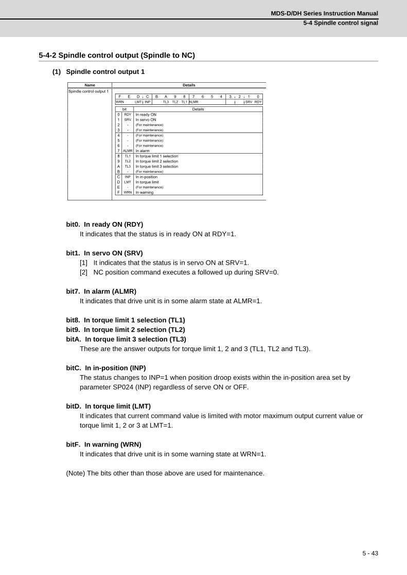
5 - 43
MDS-D/DH Series Instruction Manual
5-4 Spindle control signal
5-4-2 Spindle control output (Spindle to NC)
(1) Spindle control output 1
bit0. In ready ON (RDY)
It indicates that the status is in ready ON at RDY=1.
bit1. In servo ON (SRV)
[1] It indicates that the status is in servo ON at SRV=1.
[2] NC position command executes a followed up during SRV=0.
bit7. In alarm (ALMR)
It indicates that drive unit is in some alarm state at ALMR=1.
bit8. In torque limit 1 selection (TL1)
bit9. In torque limit 2 selection (TL2)
bitA. In torque limit 3 selection (TL3)
These are the answer outputs for torque limit 1, 2 and 3 (TL1, TL2 and TL3).
bitC. In in-position (INP)
The status changes to INP=1 when position droop exists within the in-position area set by
parameter SP024 (INP) regardless of serve ON or OFF.
bitD. In torque limit (LMT)
It indicates that current command value is limited with motor maximum output current value or
torque limit 1, 2 or 3 at LMT=1.
bitF. In warning (WRN)
It indicates that drive unit is in some warning state at WRN=1.
(Note) The bits other than those above are used for maintenance.
Name Details
Spindle control output 1
F E D C B A 9 8 7 6 5 4 3 2 1 0 WRN LMT INP TL3 TL2 TL1 ALMR SRV RDY
bit Details
0 RDY In ready ON 1 SRV In servo ON 2 - (For maintenance) 3 - (For maintenance) 4 - (For maintenance) 5 - (For maintenance) 6 - (For maintenance) 7 ALMR In alarm 8 TL1 In torque limit 1 selection 9 TL2 In torque limit 2 selection A TL3 In torque limit 3 selection B - (For maintenance) C INP In in-position D LMT In torque limit E - (For maintenance) F WRN In warning

5 - 44
5 Spindle AdjustmentMITSUBISHI CNC
(2) Spindle control output 2
bit0. Z phase passed (ZCN)
[1] When Z phase is passed, ZCN=0 is turned to ZCN=1.
[2] Grid amount (within one rotation) is transmitted when ZCN =0 is changed to ZCN =1.
bit3. In zero speed (ZS)
[1] Approximately 200ms after the motor speed reaches parameter SP027 (ZSP) + 15r/min, ZS=0
is set.
[2] When the motor speed becomes slower than the speed set by parameter SP027 (ZSP), ZS=1
is set. ZS signal is detected by the motor speed absolute value regardless of the rotation
direction.
bit7. In external emergency stop
It indicates that an external stop input to the power supply is being input.
bit9. In speed monitor
It indicates that a signal in speed monitor command is being received.
bitA. In door closed (controller)
It indicates that "In door closed" signal for controller is being received.
bitB. In door closed (self drive unit)
It indicates the status of "In door closed" signal for self drive unit.
(Note) The bits other than those above are used for maintenance.
(3) Spindle control output 3
This is used for maintenance.
Name Details
Spindle control output 2
F E D C B A 9 8 7 6 5 4 3 2 1 0 SRVDC NCDC SSW EXEMG ZS ZCN
bit Details
0 ZCN Z phase passed 1 - (For maintenance) 2 - (For maintenance) 3 ZS In zero speed 4 - (For maintenance) 5 - (For maintenance) 6 - (For maintenance) 7 EXEMG In external emergency stop 8 - (For maintenance) 9 SSW In speed monitor A NCDC In door closed (controller) B SRVDC In door closed (self drive unit) C - (For maintenance) D - (For maintenance) E - (For maintenance) F - (For maintenance)
Motor speed
Motor zero speed: SP027(Standard 50r/min Sub-standard 25r/min)
Output signal Zero speed detection OFF Zero speed detection ON
+ 15r/min
200ms

5 - 45
MDS-D/DH Series Instruction Manual
5-4 Spindle control signal
(4) Spindle control output 4
bit0. In spindle control mode selection 1 (SC1)
bit1. In spindle control mode selection 2 (SC2)
bit2. In spindle control mode selection 3 (SC3)
These are the answer outputs for control mode selection command 1, 2, 3 (SC1, SC2, SC3).
bit4. In gear changeover command (GKC)
[1] This is an answerer output for the gear changeover command.
[2] The position feedback is generated from the speed detector at GKC=1.
bit5. In gear selection 1 (GR1)
bit6. In gear selection 2 (GR2)
These are the answer outputs for gear selection command 1 and 2 (GR1 and GR2).
bitD. In L coil selection (LCS)
It indicates that L coil is being selected at LCSA=1.
(Note) The bits other than those above are used for maintenance.
F E D C B A 9 8 7 6 5 4 3 2 1 0
bit0123456789ABCDEF
-
-
-
-
-
SC2GKCGR2
-
-
GR1 SC3 SC1
SC2
GKC
GR2GR1
SC3
SC1
LCS
LCS
-
-
Details
Name Details
Spindle control output 4
In spindle control mode selection 1
(For maintenance)
In gear selection 1
(For maintenance)
(For maintenance)
In gear changeover command
In spindle control mode selection 2In spindle control mode selection 3
In gear selection 2(For maintenance)(For maintenance)(For maintenance)(For maintenance)
In L coil selection(For maintenance)
(For maintenance)

5 - 46
5 Spindle AdjustmentMITSUBISHI CNC
(5) Spindle control output 5
bit0. Current detection (CD)
It indicates that current command value is over 110% of the motor short time rating at CD=1.
bit1. Speed detection (MD)
[1] When motor speed exceeds the speed set by parameter SP028 (SDTS) + SP029 (SDTR),
SD=0 is set.
[2] When motor speed becomes slower than the speed set by parameter SP028 (SDTS), SD=1 is
set. SD signal is detected by the motor speed absolute value regardless of rotation direction.
bit6. In coil changeover (MKC)
MKC=1 is set for the amount of time set by parameter SP114 (MKT) during coil changeover
operation.
bit7. Magnetic pole position not set (MPN)
It indicates that the magnetic pole position of the motor is not established at MPN=1.
bit9. 2nd speed detection (SD2) (IPM spindle motor)
[1] The status changes to SD2=0 when motor speed exceeds the speed set by parameter SP030
(SDT2) + SP029 (SDTR).
[2] The status changes to SD2=1 when motor speed becomes slower than the speed set by
parameter SP030 (SDT2).
[3] It is used as M coil changeover speed. (IPM spindle motor only)
F E D C B A 9 8 7 6 5 4 3 2 1 0
bit0123456789ABCDEF
-
-
VG2ORF
ORF
PY2
PY2
--
-
INP2
INP2
MD
MD
-
CD
MKC
SD2
CDSD2 MKC
-
MPN
VG2
MPN
Details
Name Details
Spindle control output 5
(For maintenance)
Speed detection(For maintenance)
Zero point re-detection request
In 2nd in-position
Magnetic pole position not set
(For maintenance)(For maintenance)
In minimum excitation rate 2 selection(For maintenance)
Current detection
In coil changeover
2nd speed detection
(For maintenance)
(For maintenance)
In speed gain set 2 selection
SD signal
Motor speed
Speed detection
OFF
Speed detection
ON
Speed detection set value: SP028
Speed detection reset width : SP029

5 - 47
MDS-D/DH Series Instruction Manual
5-4 Spindle control signal
bitB. In minimum excitation rate 2 selection (PY2)
[1] When PY2=1 is set, the minimum excitation rate 2 (SP015) is being selected.
[2] When PY2=0 is set, the minimum excitation rate 1(SP014) is being selected.
bitC. In speed gain set 2 selection (VG2)
[1] When VG2=1 is set, the gain parameter (SP008/SP009/SP010) used in the speed loop isbeing
selected.
[2] When VG2=0 is set, the gain parameter (SP005/SP006/SP007) used in the speed loop isbeing
selected.
bitD. Zero point re-detection complete
If the zero point re-detection is completed after the zero point re-detection request (control input5/
bitD) is set to1, ORF=1 is set. If the zero point re-detection request is set to 0, ORF=0 is set.
bitF. In 2nd in-position (INP2)
The status changes to INP2=1 when position droop exists within the in-position area set by
parameter SP025 (INP2) regardless of serve ON or OFF.
(Note) The bits other than those above are used for maintenance.
(6) Spindle control output 6
This is used for maintenance.

5 - 48
5 Spindle AdjustmentMITSUBISHI CNC

6 - 1
付録 6 章
6 - 1
6Troubleshooting

6 - 2
6 TroubleshootingMITSUBISHI CNC
6-1 Points of caution and confirmationIf an error occurs in the drive unit, the warning or alarm will occur. When a warning or alarm occurs, check
the state while observing the following points, and inspect or remedy the unit according to the details given in
this section.
<Points of confirmation>
[1] What is the alarm code display?
[2] Can the error or trouble be repeated? (Check alarm history)
[3] Is the motor and servo drive unit temperature and ambient temperature normal?
[4] Are the servo drive unit, control unit and motor grounded?
[5] Was the unit accelerating, decelerating or running at a set speed? What was the speed?
[6] Is there any difference during forward and backward run?
[7] Was there a momentary power failure?
[8] Did the trouble occur during a specific operation or command?
[9] At what frequency does the trouble occur?
[10] Is a load applied or removed?
[11] Has the drive unit been replaced, parts replaced or emergency measures taken?
[12] How many years has the unit been operating?
[13] Is the power supply voltage normal? Does the state change greatly according to the time band?
1. This power supply unit uses a large capacity electrolytic capacitor. When the CHARGE lamp on the
front of the power supply unit is lit, voltage is still present at the PN terminal (TE2). Do not touch the
terminal block in this state.
2. Before replacing the unit, etc., always confirm that there is no voltage at the PN terminal (TE2) with
a tester or wait at least 15 minutes after turning the main power OFF.
3. The conductivity in the unit cannot be checked.
4. Never carry out a megger test on the drive unit or power supply unit as the unit could be damaged.
CAUTION
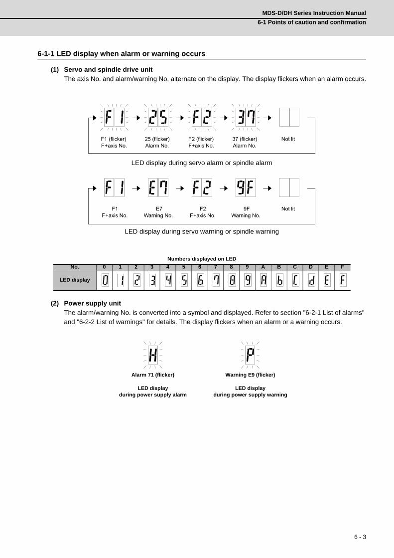
6 - 3
MDS-D/DH Series Instruction Manual
6-1 Points of caution and confirmation
6-1-1 LED display when alarm or warning occurs
(1) Servo and spindle drive unit
The axis No. and alarm/warning No. alternate on the display. The display flickers when an alarm occurs.
LED display during servo alarm or spindle alarm
LED display during servo warning or spindle warning
Numbers displayed on LED
(2) Power supply unit
The alarm/warning No. is converted into a symbol and displayed. Refer to section "6-2-1 List of alarms"
and "6-2-2 List of warnings" for details. The display flickers when an alarm or a warning occurs.
No. 0 1 2 3 4 5 6 7 8 9 A B C D E F
LED display
Alarm 71 (flicker) Warning E9 (flicker)
LED displayduring power supply alarm
LED displayduring power supply warning
F1 (flicker) F+axis No.
25 (flicker) Alarm No.
Not lit F2 (flicker) F+axis No.
37 (flicker) Alarm No.
F1 F+axis No.
E7 Warning No.
Not lit F2 F+axis No.
9F Warning No.

6 - 4
6 TroubleshootingMITSUBISHI CNC
6-2 Protective functions list of units6-2-1 List of alarms
When an alarm occurs, the servo drive unit will make the motor stop by the deceleration control or dynamic
brake. The spindle drive unit will coast to a stop or will decelerate to a stop. At the same time, the alarm No.
will appear on the NC monitor screen and with the LEDs on the front of the drive unit. Check the alarm No.,
and remove the cause of the alarm by following this list.
(1) Drive unit alarm
(Note1) Definitions of terms in the table are as follows.Main side detector: Detector connected to CN2 Sub side detector: Detector connected to CN3
(Note2) Resetting methodsNR: Reset with the NC RESET button. This alarm can also be reset with the PR and AR resetting conditions.PR: Reset by turning the NC power ON again. This alarm can also be reset with the AR resetting conditions. When the control axis is removed, this alarm can be reset with the NC RESET button. (Excluding alarms 32 and 37.)AR: Reset by turning the servo drive unit power ON again.
No. Name DetailsReset
methodServo
stop methodSpindle
stop method
10 Insufficient voltage A drop of bus voltage was detected in main circuit. PR Dynamic stop Coast to a stop
11 Axis selection error The axis selection rotary switch has been incorrectly set. AR Initial error Initial error
12 Memory error 1 A hardware error was detected during the power ON self-check. AR Initial error Initial error
13 Software processing error 1 An error was detected for the software execution state. PR Dynamic stop Coast to a stop
16Initial magnetic pole position de-tection error
In the built-in motor which uses the absolute position detector, the servo ON has been set before the magnetic pole shift amount is set.The magnetic pole position, detected in the initial magnetic pole position detection control, is not correctly set.
PR Dynamic stop Coast to a stop
17 A/D converter error A current feedback error was detected. PR Dynamic stop Coast to a stop
18Main side detector: Initial communication error
An error was detected in the initial communication with the motor side detector.
PR Initial error Initial error
19Detector communication error in synchronous control
An error of the shared detector on the machine side was detected on the secondary axis of the speed command synchronization control.
PR Dynamic stop -
1ASub side detector:Initial communication error
An error was detected in the initial communication with the ma-chine side detector.
PR Initial error Initial error
1B Sub side detector: Error 1An error was detected by the detector connected to the machine side. The error details are different according to the detector type. Refer to "Detec-tor alarm" for details.
Dynamic stop Coast to a stop1C Sub side detector: Error 2
1D Sub side detector: Error 3
1E Sub side detector: Error 4
1FSub side detector: Communication error
An error was detected in the communication with the machine side detector.
PR Dynamic stop Coast to a stop
21 Sub side detector no signal 2In the machine side detector, ABZ-phase feedback cannot be re-turned even when the motor moves.
PR Dynamic stop Coast to a stop
22 Detector data errorAn error was detected in the feedback data from the position de-tector.
AR Dynamic stop -
23 Excessive speed errorThe state that there is a difference between the actual speed and command speed continued for longer than the excessive speed deviation timer setting.
NR - Coast to a stop
24 Grounding The motor power cable is in contact with FG (Frame Ground). PR Dynamic stop Coast to a stop
25 Absolute position data lost The absolute position data was lost in the detector. AR Initial error -
26 Unused axis errorIn the multiaxis drive unit, there is an axis set to free, and the other axis detected a power module error.
PR Dynamic stop Coast to a stop
27 Sub side detector: Error 5An error was detected by the detector connected to the machine side.The error details are different according to the detector type. Refer to "Detec-tor alarm" for details.
Dynamic stop Coast to a stop28 Sub side detector: Error 6
29 Sub side detector: Error 7
2A Sub side detector: Error 8
2B Main side detector: Error 1An error was detected by the detector connected to the motor side. The error details are different according to the detector type. Refer to "Detec-tor alarm" for details.
Dynamic stop Coast to a stop2C Main side detector: Error 2
2D Main side detector: Error 3
2E Main side detector: Error 4
2FMain side detector: Communication error
An error was detected in the communication with the motor side detector.
PR Dynamic stop Coast to a stop
30 Over regenerationOver-regeneration level exceeded 100%. The regenerative resis-tor is overloaded.
PR Dynamic stop Coast to a stop
31 Overspeed The motor speed exceeded the allowable speed. PRDeceleration stop
enabledDeceleration stop
enabled

6 - 5
MDS-D/DH Series Instruction Manual
6-2 Protective functions list of units
(Note1) Definitions of terms in the table are as follows.Main side detector: Detector connected to CN2 Sub side detector: Detector connected to CN3
(Note2) Resetting methodsNR: Reset with the NC RESET button. This alarm can also be reset with the PR and AR resetting conditions.PR: Reset by turning the NC power ON again. This alarm can also be reset with the AR resetting conditions. When the control axis is removed, this alarm can be reset with the NC RESET button. (Excluding alarms 32 and 37.)AR: Reset by turning the servo drive unit power ON again.
No. Name DetailsReset
methodServo
stop methodSpindle
stop method
32Power module error (overcurrent)
The power module detected the overcurrent. PR Dynamic stop Coast to a stop
33 Overvoltage The bus voltage in main circuit exceeded the allowable value. PR Dynamic stop Coast to a stop
34 NC communication: CRC error The data received from the NC was outside the setting range. PRDeceleration stop
enabledDeceleration stop
enabled
35 NC command errorThe travel command data received from the NC was exces-sive.
PRDeceleration stop
enabledDeceleration stop
enabled
36NC communication: Communi-cation error
The communication with the NC was interrupted. PRDeceleration stop
enabledDeceleration stop
enabled
37 Initial parameter error
An incorrect set value was detected among the parameters send from the NC at the power ON.In the safety observation function, an error was detected in the relation between the safety speed and safety rotation number in the speed observation mode.
PR Initial error Initial error
38NC communication: Protocol er-ror 1
An error was detected in the communication frames received from the NC.Or, removing an axis or changing an axis was performed in the synchronous control.
PRDeceleration stop
enabledDeceleration stop
enabled
39NC communication: Protocol er-ror 2
An error was detected in the axis data received from the NC.Or, in changing an axis, the parameter setting of the synchro-nous control was applied when the axis was installed.
PRDeceleration stop
enabledDeceleration stop
enabled
3A Overcurrent Excessive motor drive current was detected. PR Dynamic stop Coast to a stop
3B Power module error (overheat) The power module detected an overheat. PR Dynamic stop Coast to a stop
3C Regeneration circuit errorAn error was detected in the regenerative transistor or in the regenerative resistor.
PR Dynamic stop -
3DPower supply voltage error at acceleration/deceleration
A motor control error during acceleration/deceleration, due to a power voltage failure, was detected.
PR Dynamic stop -
3EMagnetic pole position detection error
The magnetic pole position, detected in the magnetic pole po-sition detection control, is not correctly detected.
AR Dynamic stop Coast to a stop
41 Feedback error 3Either a missed feedback pulse in the motor side detector or an error in the Z-phase was detected in the full closed loop sys-tem.
PR Dynamic stop Coast to a stop
42 Feedback error 1
Either a missed feedback pulse in the position detection or an error in the Z-phase was detected. Or the distance-coded ref-erence check error exceeded the allowable value when the distance-coded reference scale was used.
PR Dynamic stop Coast to a stop
43 Feedback error 2An excessive difference in feedback was detected between the machine side detector and the motor side detector.
PR Dynamic stop Coast to a stop
45 Fan stopAn overheat of the power module was detected during the cooling fan stopping.
PR Dynamic stop Coast to a stop
46 Motor overheat / Thermal error
Either the motor or the motor side detector detected an over-heat.Or, the thermistor signal receiving circuit of the linear motor or direct-drive motor was disconnected.Or, the thermistor signal receiving circuit was short-circuited.
NRDeceleration stop
enabledDeceleration stop
enabled
48 Main side detector: Error 5An error was detected by the detector connected to the main side. The error details are different according to the connected detector. Refer to "Detector alarm".
Dynamic stop Coast to a stop49 Main side detector: Error 6
4A Main side detector: Error 7
4B Main side detector: Error 8
4CCurrent error at initial magnetic pole estimate
Current detection failed at the initial magnetic pole estimation. NR Dynamic stop Coast to a stop
4E NC command mode error An error was detected in the control mode send from the NC. NRDeceleration stop
enabledDeceleration stop
enabled
4F Instantaneous power interruptThe control power supply has been shut down for 50ms or more.
NRDeceleration stop
enabledDeceleration stop
enabled
50 Overload 1Overload detection level became 100% or more. The motor or the drive unit is overloaded.
NRDeceleration stop
enabledDeceleration stop
enabled
51 Overload 2
In a servo system, current command of 95% or more of the unit’s max. current was given continuously for 1 second or lon-ger. In a spindle system, current command of 95% or more of the motor’s max. current was given continuously for 1 second or longer.
NRDeceleration stop
enabledDeceleration stop
enabled
52 Excessive error 1 A position tracking error during servo ON was excessive. NRDeceleration stop
enabledDeceleration stop
enabled
53 Excessive error 2 A position tracking error during servo OFF was excessive. NR Dynamic stop -

6 - 6
6 TroubleshootingMITSUBISHI CNC
(Note1) Definitions of terms in the table are as follows.Main side detector: Detector connected to CN2 Sub side detector: Detector connected to CN3
(Note2) Resetting methodsNR: Reset with the NC RESET button. This alarm can also be reset with the PR and AR resetting conditions.PR: Reset by turning the NC power ON again. This alarm can also be reset with the AR resetting conditions. When the control axis is removed, this alarm can be reset with the NC RESET button. (Excluding alarms 32 and 37.)AR: Reset by turning the servo drive unit power ON again.
No. Name DetailsReset
methodServo
stop methodSpindle
stop method
54 Excessive error 3There was no motor current feedback when the alarm "Exces-sive error 1" was detected.
NR Dynamic stop Coast to a stop
56 Commanded speed errorIn the C-axis control mode, excessive speed error was detect-ed.
NR -Deceleration stop
enabled
58 Collision detection 1: G0A disturbance torque exceeded the allowable value in rapid traverse modal (G0).
NRMaximum capacity deceleration stop
-
59 Collision detection 1: G1A disturbance torque exceeded the allowable value in the cut-ting feed modal (G1).
NRMaximum capacity deceleration stop
-
5A Collision detection 2A current command with the maximum drive unit current value was detected.
NRMaximum capacity deceleration stop
-
5BSafety observation: Command-ed speed monitoring error
A commanded speed exceeding the safe speed was detected in the safety observation mode.
PRDeceleration stop
enabledDeceleration stop
enabled
5DSafety observation: Door state error
The door state signal input in the NC does not coincide with the door state signal input in the drive unit in the safety observation mode. Otherwise, door open state was detected in normal mode.
PRDeceleration stop
enabledDeceleration stop
enabled
5ESafety observation: Speed feed-back monitoring error
A motor speed exceeding the safe speed was detected in the safety observation mode.
PRDeceleration stop
enabledDeceleration stop
enabled
5F External contactor error A contact of the external contactor is welding. NRDeceleration stop
enabledDeceleration stop
enabled
60 to 77
Power supply alarmThe power supply unit detected an error. The error details are different according to the connected power supply unit. Refer to "Power supply alarm" for details.
Dynamic stop Coast to a stop
80 Main side detector cable errorThe cable type of the motor side detector cable is for rectangu-lar wave signal.
AR Initial error -
81 Sub side detector cable errorThe cable type of the machine side detector cable does not co-incide with the detector type which is set by the parameter.
AR Initial error -
87 Drivers communication error The communication frame between drive units was aborted. PR Dynamic stop Coast to a stop
88 Watchdog The drive unit does not operate correctly. AR Dynamic stop Coast to a stop
8ADrivers communication data er-ror 1
The communication data 1 between drivers exceeded the tol-erable value in the communication between drive units.
PR Dynamic stop Coast to a stop
8BDrivers communication data er-ror 2
The communication data 2 between drivers exceeded the tol-erable value in the communication between drive units.
PR Dynamic stop Coast to a stop

6 - 7
MDS-D/DH Series Instruction Manual
6-2 Protective functions list of units
Detector alarm (Servo drive unit)
(Note) A driver processes all reset types of alarms as "PR". However, "AR" will be applied according to the detector.
Detector alarm (Spindle drive unit)
(Note) A driver processes all reset types of alarms as "PR". However, "AR" will be applied according to the detector.
Alarm number when the detector is connected to CN2 side
2B 2C 2D 2E 48 49 4A 4B
Alarm number when the detector is connected to CN3 side
1B 1C 1D 1E 27 28 29 2A
OSA105, OSA105ET2
OSA166, OSA166ET2(N) MITSUBISHI
Memory alarm
LED alarm Data alarm - - - - -
OSA18 CPU alarm - Data alarm - - - - -
MDS-B-HRMemory
error- Data error -
Scale not connected
- - -
AT343AT543AT545
MitsutoyoInitialization
errorEEPROM
error
Photoelec-tric type,
static capac-ity type data
mismatch
ROM/RAMerror
CPU errorPhotoelec-
tric type overspeed
Static capacity
type error
Photoelec-tric type
error
LC193M, LC493M
RCN223M, RCN227MRCN727M, RCN827MEIB Series
HEIDENHAINInitialization
errorEEPROM
error
Relative/ absolute
position data mismatch
ROM/RAMerror
CPU error OverspeedAbsolute
position data error
Relative position data
error
MPRZ Series MHIInstallation accuracy
fault-
Detection position
deviance
Scale breaking
Absolute value detec-
tion fault - Gain fault Phase fault
SR75, SR85SR77, SR87
RU77
MAGNE-SCALE
Laser diode error
System memory er-
ror
Encoder mismatch
error- - Over speed
Absolute position
data error
Relative position data
error
SAM/SVAM/GAM/LAM
SeriesFAGOR - -
Absolute value detec-
tion errorH/W error CPU error - - -
Alarm number when the detector is connected toCN2 side
2B 2C 2D 2E 48 49 4A 4B
Alarm number when the detector is connected to CN3 side
1B 1C 1D 1E 27 28 29 2A
TS5690TS5691
MITSUBISHI
Memory error
Waveform error
- - - Overspeed -Relative
position data error
MDS-B-HRInitialization
error- Data error -
Connection error
- - -
OSA18 CPU error - Data error - - - - -
EIB SeriesHEIDEN-
HAINInitialization
errorEEPROM
error- - CPU error Overspeed -
Relative position data
error
MPCI scale MHIInstallation accuracy
fault-
Detection position deviance
Scale breaking
- - Gain fault Phase fault

6 - 8
6 TroubleshootingMITSUBISHI CNC
(2) Power supply alarm
(Note 1) If a power supply alarm (60 to 77) occurs, all servos will stop with the dynamic brakes, and all spindles will coast to a stop.(Note 2) "b", "C" and "d" displayed on the power supply unit's LED as a solid light (not flickering) do not indicate an alarm.
No.LED
displayName Details
Resetmethod
61 Power supply: Power module overcurrent Overcurrent protection function in the power module has started its operation. PR
62 Power supply: Frequency error The input power supply frequency increased above the specification range. PR
66 Process error An error occurred in the process cycle. PR
67 Power supply: Phase interruption An open-phase condition was detected in input power supply circuit. PR
68 Power supply: Watchdog The system does not operate correctly. AR
69 Power supply: Grounding The motor power cable is in contact with FG (Frame Ground). PR
6A Power supply: External contactor welding A contact of the external contactor is welding. PR
6B Power supply: Rush circuit error An error was detected in the rush circuit. PR
6C Power supply: Main circuit error An error was detected in charging operation of the main circuit capacitor. PR
6D Parameter setting error An error was detected in the parameter sent from the drive unit. PR
6E
Memory error An error was detected in the internal memory.
ARA/D error An error was detected in the A/D converter.
Unit ID error An error was detected in the unit identification.
6F Power supply errorNo power supply is connected to the drive unit, or a communication error was detected.
AR
70 Power supply: External emergency stop errorA mismatch of the external emergency stop input and NC emergency stop in-put continued for 30 seconds.
PR
71 Power supply: Instantaneous power interruption The power was momentarily interrupted. NR
72 Power supply: Fan stopA cooling fan built in the power supply unit stopped, and overheat occurred in the power module.
PR
73 Power supply: Over regeneration
Over-regeneration detection level became over 100%. The regenerative re-sistor is overloaded. This alarm cannot be reset for 15 min from the occur-rence to protect the regeneration resistor. Leave the drive system energized for more than 15 min, then turn the power ON to reset the alarm.
NR
75 Power supply: Overvoltage
L+ and L- bus voltage in main circuit exceeded the allowable value. As the voltage between L+ and L- is high immediately after this alarm, another alarm may occur if this alarm is reset in a short time. Wait more than 5 min before resetting so that the voltage drops.
NR
76Power supply: External emergency stop setting error
The rotary switch setting of external emergency stop is not correct, or a wrong external emergency stop signal is input.
AR
77 Power supply: Power module overheat Thermal protection function in the power module has started its operation. PR

6 - 9
MDS-D/DH Series Instruction Manual
6-2 Protective functions list of units
6-2-2 List of warnings
When a warning occurs, a warning No. will appear on the NC monitor screen and with the LEDs on the front
of the drive unit. Check the warning No., and remove the cause of the warning by following this list.
(1) Drive unit warning
(Note1) Definitions of terms in the table are as follows.Main side detector: Detector connected to CN2 Sub side detector: Detector connected to CN3
(Note 2) Resetting methods* : Automatically reset once the cause of the warning is removed.NR: Reset with the NC RESET button. This warning can also be reset with the PR and AR resetting conditions.PR: Reset by turning the NC power ON again. This warning can also be reset with the AR resetting conditions. When the control axis is removed, this warning can be reset with the NC RESET button. (Excluding warning 93.)AR: Reset by turning the servo drive unit power ON again.
(Note 3) Servo and spindle motor do not stop when the warning occurs.(Note 4) When an emergency stop is input, servo and spindle motor decelerate to a stop.
(When SV048, SV055 or SV056 is set for servo and when SP055 or SP056 is set for spindle.)
No. Name DetailsReset
methodStop method
96 Scale feedback errorAn excessive difference in feedback amount was detected between the main side detector and the MPI scale in MPI scale absolute position de-tection system.
* -
97 Scale offset errorAn error was detected in the offset data that is read at the NC power-ON in MPI scale absolute position detection system.
PR -
9BIncremental detector/magnetic pole shift warning
The difference between the magnetic pole position after the phase Z has been passed (magnetic pole shift amount:SV028) and the initially detected position is excessive in the built-in motor's incremental control system.The magnetic pole is controlled by the initial detection value.
* -
9EAbsolute position detector: Revolution counter error
An error was detected in the revolution counter data of the absolute po-sition detector. The accuracy of absolute position is not guaranteed.
* -
9F Battery voltage dropThe battery voltage to be supplied to the absolute position detector is dropping.
* -
A3Distance-coded reference check / initial setup warning
This warning is detected until the axis reaches the reference position during the initial setup of the distance-coded reference check function. This warning turns OFF after the axis has reached the position, thus set the value displayed on the drive monitor to the parameter.
* -
A6 Fan stop warning A cooling fan in the drive unit stopped. * -
E0 Overregeneration warning Over-regeneration detection level exceeded 80%. * -
E1 Overload warning A level of 80% of the Overload 1 alarm state was detected. * -
E4 Parameter warningAn incorrect set value was detected among the parameters send from the NC in the normal operation.
* -
E6 Control axis detachment warning A control axis is being detached. (State display) * -
E7 NC emergency stop In NC emergency stop. (State display) *Deceleration stop
enabled
E8 to EF
Power supply warningThe power supply unit detected a warning. The error details are differ-ent according to the connected power supply unit. Refer to "Power supply warning".
*
-*EA:
Deceleration stop enabled

6 - 10
6 TroubleshootingMITSUBISHI CNC
(2) Power supply warning
(Note 1) Resetting methods* : Automatically reset once the cause of the warning is removed.NR: Reset with the NC RESET button. This warning can also be reset with the PR and AR resetting conditions.PR: Reset by turning the NC power ON again. This warning can also be reset with the AR resetting conditions. When the control axis is removed, this warning can be reset with the NC RESET button. (Excluding warning 93.)AR: Reset by turning the servo drive unit power ON again.
(Note 2) Servo and spindle motor do not stop when the warning occurs.
No.LED
displayName Details
Resetmethod
E9 Instantaneous power interruption warning The power was momentarily interrupted. NR
EA In external emergency stop state External emergency stop signal was input. *
EB Power supply: Over regeneration warning Over-regeneration detection level exceeded 80%. *
EE Power supply: Fan stop warning A cooling fan built in the power supply unit stopped. *

6 - 11
MDS-D/DH Series Instruction Manual
6-3 Troubleshooting
6-3 TroubleshootingFollow this section to troubleshoot the alarms that occur during start up or while the machine is operating. If
the state is not improved with the following investigations, the drive unit may be faulty. Exchange the unit
with another unit of the same capacity, and check whether the state is improved.
6-3-1 Troubleshooting at power ON
If the NC system does not start up correctly and a system error occurs when the NC power is turned ON, the
drive unit may not have been started up properly. Check the LED display on the drive unit, and take
measures according to this section.
The drive unit has started up normally if the following type of emergency stop (E7) is displayed on the display
unit's LED display.
LED display
Symptom Cause of occurrence Investigation method Remedy
AAInitial communication with the CNC was not completed cor-rectly.
The drive unit axis No. setting is incorrect.
Is there any other drive unit that has the same axis No. set?
Set correctly.
The CNC setting is incorrect. Is the No. of CNC controlled axes correct? Set correctly.
Communication with CNC is incor-rect.
Is the connector (CN1A, CN1B) connected? Connect correctly.
Is the cable broken? Replace the cable.
AbInitial communication with the CNC was not carried out.
The axis is not used, the setting is for use inhibiting.
Is the DIP switch set correctly? Set correctly.
Communication with CNC is incor-rect.
Is the connector (CN1A, CN1B) connected? Connect correctly.
Is the cable broken? Replace the cable.
12An error was detected in the unit's memory and IC during the self-diagnosis at power ON.
The CPU peripheral circuit is ab-normal.
Check the repeatability. Replace the unit.
Check whether there is any abnormality with the unit's surrounding environment, etc.
Improve the sur-rounding environ-ment.
F1 F+axis No.
E7 Emergency stop
Not lit F2 F+axis No.
E7 Emergency stop
Normal drive unit LED display at NC power ON (for 1st axis)

6 - 12
6 TroubleshootingMITSUBISHI CNC
6-3-2 Troubleshooting for each alarm No.
Alarm No.10
Insufficient voltage
Insufficient bus voltage was detected in main circuit.
Investigation details Investigation results Remedies SV SP
1 Check the timing when the alarm occurs.The moment of READY ON Check the investigation item No. 2.
During operation Increase the power supply capacity (KVA).
2Did the external contactor turn ON at the READY ON?
The external contactor did not turn ON. Check the investigation item No. 3.
The external contactor turned ON,but the alarm occurred immediately.
Check the investigation item No. 4.
3Check the wiring of contactor excitation cir-cuit.
The wiring is correct. Replace the contactor.
The wiring is not correct. Rewire.
4Check the input voltage of the drive unit by a tester. (Voltage between L1 and L2, L2 and L3, L1 and L3)
The input voltage is normal. Replace the drive unit.
The input voltage is abnormal.The measured voltage fluctuates.
Increase the power supply capacity (KVA).Replace the power supply.
Alarm No.11
Axis selection error
The axis selection rotary switch is incorrectly set.
Investigation details Investigation results Remedies SV SP
1Check the setting of the axis selection switch (rotary switch) on the top of the unit.
The same axis No. is set for the L and M ax-es.
Correctly set the axis No.0 = No. 1 axis, 1 = No. 2 axis, ...
The value is duplicated with other axis.Correctly set the axis No.0 = No. 1 axis, 1 = No. 2 axis, ...
The axis No. is correctly set. Replace the drive unit.
Alarm No.12
Memory error 1
Hardware error (a CPU or an internal memory error was detected during the power ON self-check.
Investigation details Investigation results Remedies SV SP
1 Check the repeatability.The error is always repeated. Replace the drive unit.
The state returns to normal once, but occurs sometimes thereafter.
Check the investigation item No. 2.
2
Check if there is any abnormality in the unit's ambient environment.(Ex. Ambient temperature, noise, ground-ing)
Take remedies according to the causes of the abnormality in the ambient environment.
Alarm No.13
Software processing error 1
An error was detected in the software execution state.Software processing has not finished within the specified time.
Investigation details Investigation results Remedies SV SP
1 Check the repeatability.The error is always repeated. Replace the drive unit.
The state returns to normal once, but occurs sometimes thereafter.
Check the investigation item No. 2.
2
Check if there is any abnormality in the unit's ambient environment.(Ex. Ambient temperature, noise, ground-ing)
Take remedies according to the causes of the abnormality in the ambient environment.[1] Machine grounding check
Alarm No.16
Initial magnetic pole position detection error
In linear motor or IPM spindle motor using absolute position detector, the servo ON has been set before the magnetic pole shift amount(servo:SV028,spindle:SP118) is set. In the initial magnetic pole position detection control, the pole position was not correctly set.
Investigation details Investigation results Remedies SV SP
1Check the parameters, SV028 (for the ser-vo) and SP118(for the spindle).
The parameters have not been set. Set the magnetic shift pole amount(SP118).
The parameters have been set, but the alarm occurs.
Carry out the magnetic pole estimation again, as the setting value is wrong.
The setting parameter value is the same even when initial magnetic pole function was executed again.
Check the investigation item No. 2.
2 Check the repeatability.The error is always repeated. Replace the drive unit.
The state returns to normal once, but occurs sometimes thereafter.
Check the investigation item No. 3.
3
Check if there is any abnormality in the unit's ambient environment.(Ex. Ambient temperature, noise, ground-ing)
Take remedies according to the causes of the abnormality in the ambient environment.[1] Machine grounding check[2] Shield connection of the cable

6 - 13
MDS-D/DH Series Instruction Manual
6-3 Troubleshooting
Alarm No.17
A/D converter error
An error was detected in the current FB.
Investigation details Investigation results Remedies SV SP
1 Check the repeatability.The error is always repeated. Replace the drive unit.
The state returns to normal, but occurs thereafter.
Check the investigation item No. 2.
2
Check if there is any abnormality in the unit's ambient environment.(Ex. Ambient temperature, noise, ground-ing)
Take remedies according to the causes of the abnormality in the ambient environment.
Alarm No.18
Main side detector: Initial communication error
An error was detected in the initial communication with the motor side detector.
Investigation details Investigation results Remedies SV SP
1
Check the servo parameter (SV025.ent) setting value.Check the spindle parameter(SP020) set-ting value.
The value is not set correctly.Correctly set SV025 for the servo, and SP020 for the spindle.
The value is set correctly. Check the investigation item No. 3.
2Check the detector.Check if a pulse detector is used for serial detector specifications.
The pulse detector is used. Replace the detector to the serial.
The serial detector is used. Check the investigation item No. 3.
3Jiggle the detector connectors (drive unit side and detector side) and check if they are disconnected.
The connector is disconnected (or loose). Correctly install.
The connector is not disconnected. Check the investigation item No. 4.
4Turn the power OFF, and check the detector cable connection with a tester.
The connection is faulty. Replace the detector cable.
The connection is normal. Check the investigation item No. 5.
5Replace with another unit, and check whether the fault is on the unit side or detec-tor side.
The alarm is on the drive unit side. Replace the drive unit.
The alarm is on the detector side. Check the investigation item No. 6.
6
Check if there is any abnormality in the de-tector's ambient environment.(Ex. Ambient temperature, noise, ground-ing)
Take remedies according to the causes of the abnormality in the ambient environment.[1] Machine grounding check[2] Shield connection of the cable
Alarm No.19
Detector communication error in synchronous control:
An error was detected in the machine side detector of the secondary axis at the speed command synchronization control.
Investigation details Investigation results Remedies SV SP
1Check the servo parameter value of sec-ondary axis (SV025.pen:position detector).
The value is not set correctly. Correctly set.
The value is set correctly. Check the investigation item No. 2.
2Check if there are no problems in the con-nection between the detector (linear scale) and MDS-B-HR.
The screw connected to MDS-B-HR is wind-ed down.
Tighten up the screw.
No problems found in the connector con-nection.
Check the investigation item No. 3.
3Jiggle the detector connectors (drive unit side and detector side) and check if they are disconnected.
The connector is disconnected (or loose). Correctly install.
The connector is not disconnected. Check the investigation item No. 3.
4Turn the power OFF, and check the detector cable connection with a tester.
The connection is faulty. Replace the detector cable.
The connection is normal. Check the investigation item No. 4.
5Replace with another unit, and check whether the fault is on the unit side or detec-tor side.
The alarm is on the drive unit side. Replace the drive unit.
The alarm is on the detector side. Check the investigation item No. 5.
6
Check if there is any abnormality in the de-tector's ambient environment.(Ex. Ambient temperature, noise, ground-ing)
Take remedies according to the causes of the abnormality in the ambient environment.[1] Machine grounding check[2] Shield connection of the cable

6 - 14
6 TroubleshootingMITSUBISHI CNC
Alarm No.1A
Sub side detector: Initial communication errorInitial communication with the machine side detector failed.
Investigation details Investigation results Remedies SV SP
1
Check the servo parameter (SV025.pen:po-sition detector) setting value.Check the spindle parameter(SP019) set-ting value.Are the serial communication type detector parameters set for the pulse type detector?
The value is not set correctly. Correctly set SV025.
The value is set correctly. Check the investigation item No. 2.
2Check the detector.Check if the pulse detector is used for the detector specified to be serial.
The pulse detector is used. Replace the detector.
The serial detector is used. Check the investigation item No. 3.
3Jiggle the detector connectors (drive unit side and detector side) and check if they are disconnected.
The connector is disconnected (or loose). Correctly install.
The connector is not disconnected. Check the investigation item No. 4.
4Turn the power OFF, and check the detector cable connection with a tester.
The connection is faulty. Replace the detector cable.
The connection is normal. Check the investigation item No. 5.
5Replace with another unit, and check whether the fault is on the unit side or detec-tor side.
The alarm is on the drive unit side. Replace the drive unit.
The alarm is on the detector side. Check the investigation item No. 6.
6
Check if there is any abnormality in the de-tector's ambient environment.(Ex. Ambient temperature, noise, ground-ing)
Take remedies according to the causes of the abnormality in the ambient environment.
Alarm No.1B
Sub side detector: Error 1
The machine side detector (CN3 side) detected an error. As details differ for each detector, refer to "Detector alarm" in 6-2-1.
Investigation details Investigation results Remedies SV SP
1Check whether the servo axis has moved and the spindle has rotated when an alarm occurred.
The axis has operated. Check the investigation item No. 3.
The axis has not operated. Check the investigation item No. 2.
2Check whether the operation at low speed is normal.
The operation is normal. Check the investigation item No. 3.
The operation is not normal.Check the cautions at power ON.[1] Wiring check[2] Parameter check
3Jiggle the detector connectors (drive unit side and detector side) and check if they are disconnected.
The connector is disconnected (or loose). Correctly install.
The connector is not disconnected. Check the investigation item No. 4.
4Turn the power OFF, and check the detector cable connection with a tester.
The connection is faulty. Replace the detector cable.
The connection is normal. Check the investigation item No. 5.
5Replace with another unit, and check whether the fault is on the unit side or detec-tor side.
The alarm is on the drive unit side. Replace the drive unit.
The alarm is on the detector side. Check the investigation item No. 6.
6
Check if there is any abnormality in the de-tector's ambient environment.(Ex. Ambient temperature, noise, ground-ing)
Take remedies according to the causes of the abnormality in the ambient environment.
Alarm No.1C
Sub side detector: Error 2
The machine side detector (CN3 side) detected an error. As details differ for each detector, refer to "Detector alarm" in 6-2-1.
Investigation details Investigation results Remedies SV SP
1 Check the alarm No. "1B" items.
Alarm No.1D
Sub side detector: Error 3
The machine side detector (CN3 side) detected an error. As details differ for each detector, refer to "Detector alarm" in 6-2-1.
Investigation details Investigation results Remedies SV SP
1 Check the alarm No. "1B" items.

6 - 15
MDS-D/DH Series Instruction Manual
6-3 Troubleshooting
Alarm No.1E
Sub side detector: Error 4
The machine side detector (CN3 side) detected an error. As details differ for each detector, refer to "Detector alarm" in 6-2-1.
Investigation details Investigation results Remedies SV SP
1 Check the alarm No. "1B" items.
Alarm No.1F
Sub side detector: Communication error
An error was detected in communication data with the linear scale or the ball screw side detector. Or the communication was interrupted.
Investigation details Investigation results Remedies SV SP
1Jiggle the detector connectors (drive unit side and detector side) and check if they are disconnected.
The connector is disconnected (or loose). Correctly install.
The connector is not disconnected. Check the investigation item No. 2.
2Is the detector cable wired in the same con-duit as the motor's power cable, or are the two cables laid in parallel near each other?
The cables are wired near each other. (Noise is entering from the power cable.)
Wire the detector cable away from the pow-er cable. Shield the power cable.
The wires are sufficiently separated. Check the investigation item No. 3.
3Is the motor FG wire connected only to the drive unit which drives it?(Is the motor grounded to one point?)
The motor FG wire is grounded on the motor side.
Ground the motor to one point, connecting the wires together on the drive unit side.
The motor is grounded to one point. Check the investigation item No. 4.
4Turn the power OFF, and check the detector cable connection with a tester. (Is the cable shielded?)
The connection is faulty. Replace the detector cable.
The connection is normal. Check the investigation item No. 5.
5Replace with another unit, and check whether the fault is on the unit side or detec-tor side.
The alarm is on the drive unit side. Replace the drive unit.
The alarm is on the detector side. Check the investigation item No. 6.
6
Check if there is any abnormality in the de-tector's ambient environment.(Ex. Ambient temperature, noise, ground-ing)
Take remedies according to the causes of the abnormality in the ambient environment.
Alarm No.21
Sub side detector: No signal2
When an excessive error alarm occurred, no signal from the machine side detector was detected.An error was detected in the ABZ-phase in the full closed loop control system.
Investigation details Investigation results Remedies SV SP
1
Check the servo parameter (SV025. pen: machine side detector), and spindle param-eter (SP019) setting value.Are the pulse type detector parameters set for a serial communication type detector?
The value is not set correctly.Correctly set SV025.pen for the servo and SP019 for the spindle (including SP097 for pulse type).
The value is set correctly. Check the investigation item No. 3.
2Jiggle the detector connectors (drive unit side and detector side) and check if they are disconnected.
The connector is disconnected (or loose). Correctly install.
The connector is not disconnected. Check the investigation item No. 4.
3Turn the power OFF, and check the detector cable connection with a tester.
The connection is faulty. Replace the detector cable.
The connection is normal. Check the investigation item No. 5.
4Replace with another unit, and check whether the fault is on the unit side or detec-tor side.
The alarm is on the drive unit side. Replace the drive unit.
The alarm is on the detector side. Replace the detector.
5
Check if there is any abnormality in the de-tector's ambient environment.(Ex. Ambient temperature, noise, ground-ing)
Take remedies according to the causes of the abnormality in the ambient environment.
Alarm No.22
Detector data error:
Drive unit received a wrong feedback data (scattered data) from the detector and position deviation occurred.
Investigation details Investigation results Remedies SV SP
1Check if the installation of the detector is loosened.
It is loosened. Tightly install the detector.
It is not loosened. Check the investigation item No. 2.
2Check if an excessive vibration is occurring during machining.
An excessive vibration is occurring. Check the installation of the machine.
An excessive vibration is not occurring. Check the investigation item No. 3.
3 Check the investigation item No.2 or subsequent items in Alarm No.21.

6 - 16
6 TroubleshootingMITSUBISHI CNC
Alarm No.23
Excessive speed error
A difference between the speed command and speed feedback was continuously exceeding 50 r/min for longer than the setting time.
Investigation details Investigation results Remedies SV SP
1Check the U, V and W wiring connected to the spindle drive unit.
The wires are not correctly connected. Correctly connect.
The wires are correctly connected. Check the investigation item No. 2.
2
Check the spindle parameter SP020, SP026, SP027, from SP057 to SP064 and spindle specification parameters from slimit1 to slimit4 setting value.
The correct values are not set. Correctly set.
The correct values are set. Check the investigation item No. 3.
3
Measure the acceleration/ deceleration time from 0 to the point where the spindle speed reaches its maximum.If the alarm occurs when forward run is changed to reverse run, measure the accel-eration/ deceleration time from the forward to reverse. Also measure it from the reverse to forward.
12sec or more.(SP117 setting value or more.)
Increase the spindle acceleration/decelera-tion time constant setting value(sp_t1 to sp_t4).Reduce the load inertia.
Less than 12sec. Check the investigation item No. 4.
4Check the load amount when the alarm oc-curred during cutting.
The speed deterioration due to load amount has exceeded the tolerable range which is determined by the parameter SP096.-If SP096 is set to 0, it is regarded as 85%. Thus a speed of 85% of the machining speed or faster will be the tolerable speed.
Reduce the cutting load to mitigate the speed deterioration.Replace the tool.
The load amount is within the SP096 setting value.
Check the investigation item No. 5.
5Check the fluctuation of the input voltage into the power supply unit with a tester.
Voltage drop during acceleration is 200V or less
Review the power supply capacity.
Voltage drop during acceleration is 200V or more
Check the investigation item No.6.
6 Check the capacity of the drive unit.The capacity does not satisfy the motor out-put.
Change the capacity to the selected one.
The capacity satisfies the motor output. Replace the unit.
Alarm No.24
Grounding
The motor power cable is in contact with FG (Frame Ground).
Investigation details Investigation results Remedies SV SP
1
Measure the insulation across the power ca-bles (U,V,W) for connected motors and the ground. (Carry out a megger test.)(Note) When the insulation is measured, discon-nect wires from the drive unit.
Less than 1M .The motor or power cable may be ground faulted.
1M or more. Check the investigation item No. 2.
2Has oil come in contact with the motor or power cable?
Oil has come in contact.
Take measures so that oil does not come in contact. Check the motor's cannon connec-tor and the inside of the terminal box, and clean as necessary.
Oil has not come in contact. Check the investigation item No. 3.
3 Measure the insulation again.Less than 1M . Replace the motor or cable.
1M or more. Check the investigation item No. 4.
4
Measure the resistance across the U, V, W phase terminals of the servo/spindle drive unit and the ground with a tester.(Note) Do not measure the insulation as the unit is damaged.
Less than 100k . Replace the drive unit.
100k or more. Replace the power supply unit.

6 - 17
MDS-D/DH Series Instruction Manual
6-3 Troubleshooting
Alarm No.25
Absolute position data lost
The absolute position was lost, as the backup battery voltage dropped in the absolute position detector.
Investigation details Investigation results Remedies SV SP
1 Is warning 9F occurring at the same time?The warning is occurring. Check the investigation item No. 2.
The warning is not occurring. Check the investigation item No. 3.
2Measure the battery voltage with a tester at the DC range.
Less than 3V.Replace the battery, and establish the zero point.
3V or more. Check the NC bus cable connection.
3Did alarm No.18 occur when the power was turned ON the last time?
Alarm No.18 occurred.Turn the drive unit control power ON again, and establish the zero point.
Alarm No.18 did not occur. Check the investigation item No. 4.
4Was the detector cable or battery cable left disconnected from the unit for a long time?
The unit was left disconnected for a long time.Guide at delivery: 20 hours or moreAfter 5 years: 10 hours or more
Turn the drive unit control power ON again, and establish the zero point.
The cables were not left disconnected. Check the investigation item No. 5.
5Check the detector cable or battery cable connection with a tester.
The connection is faulty. Replace the cable.
The connection is normal. Replace the drive unit.
Alarm No.26
Unused axis error
A power module error occurred in the axis whose axis No. selection switch was set to "F" (free axis).
Investigation details Investigation results Remedies SV SP
1 Check the repeatability.The error is always repeated. Replace the drive unit.
The state returns to normal once, but occurs sometimes thereafter.
Check the investigation item No. 2.
2
Check if there is any abnormality in the unit's ambient environment.(Ex. Ambient temperature, noise, ground-ing)
Take remedies according to the causes of the abnormality in the ambient environment.
Alarm No.27
Sub side detector: Error 5
The machine side detector (CN3 side) detected an error. As details differ for each detector, refer to "Detector alarm" in 6-2-1.
Investigation details Investigation results Remedies SV SP
1 Check the alarm No. "1B" items.
Alarm No.28
Sub side detector: Error 6
The machine side detector (CN3 side) detected an error. As details differ for each detector, refer to "Detector alarm" in 6-2-1.
Investigation details Investigation results Remedies SV SP
1 Check the alarm No. "1B" items.
Alarm No.29
Sub side detector: Error 7
The machine side detector (CN3 side) detected an error. As details differ for each detector, refer to "Detector alarm" in 6-2-1.
Investigation details Investigation results Remedies SV SP
1 Check the alarm No. "1B" items.
Alarm No.2A
Sub side detector: Error 8
The machine side detector (CN3 side) detected an error. As details differ for each detector, refer to "Detector alarm" in 6-2-1.
Investigation details Investigation results Remedies SV SP
1 Check the alarm No. "1B" items.
Alarm No.2B
Main side detector: Error 1
The motor side detector (CN2 side) detected an error.(Note) It includes the linear scale in the case of linear motor.As details differ for each detector, refer to "Detector alarm" in 6-2-1.
Investigation details Investigation results Remedies SV SP
1 Check the alarm No. "1B" items.

6 - 18
6 TroubleshootingMITSUBISHI CNC
Alarm No.2C
Main side detector: Error 2
The motor side detector (CN2 side) detected an error.(Note) It includes the linear scale in the case of linear motor.As details differ for each detector, refer to "Detector alarm" in 6-2-1.
Investigation details Investigation results Remedies SV SP
1 Check the alarm No. "1B" items.
Alarm No.2D
Main side detector: Error 3
The motor side detector (CN2 side) detected an error.(Note) It includes the linear scale in the case of linear motor.As details differ for each detector, refer to "Detector alarm" in 6-2-1.
Investigation details Investigation results Remedies SV SP
1 Check the alarm No. "1B" items.
Alarm No.2E
Main side detector: Error 4
The motor side detector (CN2 side) detected an error.(Note) It includes the linear scale in the case of linear motor.As details differ for each detector, refer to "Detector alarm" in 6-2-1.
Investigation details Investigation results Remedies SV SP
1 Check the alarm No. "1B" items.
Alarm No.2F
Main side detector: Communication error
An error was detected in communication data with the motor side detector or with the linear scale of a linear servo system. Or the communication was interrupted.
Investigation details Investigation results Remedies SV SP
1Jiggle the detector connectors (drive unit side and detector side) and check if they are disconnected.
The connector is disconnected (or loose). Correctly install.
The connector is not disconnected. Check the investigation item No. 2.
2Is the detector cable wired in the same con-duit as the motor's power cable, or are the two cables laid in parallel near each other?
The cables are wired near each other. (Noise is entering from the power cable.)
Improve the cable wiring.
The wires are sufficiently separated. Check the investigation item No. 3.
3Is the motor FG wire connected only to the drive unit which drives it?(Is the motor grounded to one point?)
The motor FG wire is grounded on the motor side.
Ground the motor to one point, connecting the wires together on the drive unit side.
The motor is grounded to one point. Check the investigation item No. 4.
4Turn the power OFF, and check the detector cable connection with a tester. (Is the cable shielded?)
The connection is faulty. Replace the detector cable.
The connection is normal. Check the investigation item No. 5.
5Replace with another unit, and check whether the fault is on the unit side or detec-tor side.
The alarm is on the drive unit side. Replace the drive unit.
The alarm is on the detector side. Check the investigation item No. 6.
6
Check if there is any abnormality in the de-tector's ambient environment.(Ex. Ambient temperature, noise, ground-ing)
Take remedies according to the causes of the abnormality in the ambient environment.

6 - 19
MDS-D/DH Series Instruction Manual
6-3 Troubleshooting
Alarm No.30
Over regeneration:
Over-regeneration detection level became over 100%. The regenerative resistor is overloaded.
Investigation details Investigation results Remedies SV SP
1Check if the regenerative capacity exceeds the regenerative resistor tolerable capacity.
The regenerative capacity exceeds the re-generative resistor tolerable capacity.
Add the option regenerative resistor or re-place it.
The regenerative resistor selection is appro-priate.
Check the investigation item No. 2.
2Check if the parameter is set incorrectly, and check the values of sv036 and sp032.
The parameters are set incorrectly. Change the parameters.
The parameters are correct. Check the investigation item No. 3.
3 Is an external regenerative resistor used?An external regenerative resistor is used. Check the investigation item No. 5.
A built-in regenerative resistor is used. Check the investigation item No. 4.
4Is the short wire connected between P and D terminal? Are there any problems with the connection condition?
The wire is not connected. Connect the wire.
The connector is disconnected.The connector has a contact fault.
Reconnect the connector.Replace the connector.
5Is the connection of the regenerative resis-tor or regeneration resistor cable correct?
The connection is incorrect. Rewire.
The connection is correct. Check the investigation item No. 6.
6
Is the regeneration resistor or the regenera-tion resistor cable broken? Disconnect the regenerative resistor terminal and check the resistance value with a tester.
The regeneration resistor is broken. Or the resistance value is large.
Replace the regenerative resistor.
The regeneration resistor cable is broken. Replace the cable.
The resistance value is normal. Check the investigation item No. 7.
7Check if the power supply voltage is too high.
The power supply voltage exceeded 253V. Review the power supply.
The power supply voltage is normal. Replace the drive unit.
Alarm No.31
Overspeed
The motor was detected to rotate at a speed exceeding the allowable speed (In the case of linear motor, it was detected to move at a speed exceeding the allowable speed).
Investigation details Investigation results Remedies SV SP
1Check if the unit in which the alarm was de-tected is servo or spindle.
The alarm was detected in servo. Check the investigation item No. 2.
The alarm was detected in spindle. Check the investigation item No. 3.
2Check the servo parameters SV001 (PC1), SV002 (PC2), SV018 (PIT) and SV025 (MT-YP) settings.
The settings are incorrect. Correctly set.
Correctly set. Check the investigation item No. 5.
3Check the spindle parameter SP026 (TSP) setting.
The setting is incorrect.The alarm is detected at 115% of SP026.
Correctly set.
Correctly set. Check the investigation item No. 4.
4 Check the PLG output waveform.There is a problem. Adjust the PLG output waveform.
Normal. Check the investigation item No. 5.
5Check whether the speed waveform is over-shooting.
The waveform is overshooting.Increase the acceleration/ deceleration time constant.Lower the load inertia.
The waveform is not overshooting.
Check if there is any abnormality in the unit's ambient environment.(Ex.: Ambient temperature, noise, ground-ing)
Check the investigation item No. 6.
6 Check the repeatability.
[1] The alarm occurs when the motor is stopped.[2] The rotation speed displayed on the drive monitor varies when the motor is stopped.
Replace the detector or detector cable.
The alarm occurs at all time. Replace the drive unit.

6 - 20
6 TroubleshootingMITSUBISHI CNC
Alarm No.32
Power module overcurrent
Overcurrent protection function in the power module has started its operation.
Investigation details Investigation results Remedies SV SP
1
Disconnect the power cable (U, V, W) from the unit’s terminal block and motor, and check whether a short-circuit between the power cable or whether conduction at both end of wiring occurs with a tester.
[1] Before disconnecting the power cable, the cable connector or screw has been loos-ened.[2] The short-circuit condition persists even after disconnecting the cable from the unit and motor.
[1] Tighten it.[2] Check the motor wiring.[3] Replace the power cable.
There is no problem. Check the investigation item No. 2.
2
Check the motor insulation with a (megger) tester.-Between motor power and ground earth
Less than 1M . (Grounding) Replace the motor.
1M or more. (Normal) Check the investigation item No. 3.
Check the unit capacity. [1] The same size but smaller than the se-lected capacity.[2] The combination of the motor and axis is alternated in a 2-axis unit.
The capacity is small.The smaller capacity side was used in 2-axis unit.
Replace to the unit of the selected capacity or change the axis.
The motor meets the selected capacity. Check the investigation item No. 3.
3 Check the current loop gain parameters.
Different from the standard parameter set-tings.
Adjust the value to the standard setting.
Equivalent to the standard parameter set-tings.
Check the investigation item No. 4.
4Jiggle the detector connectors (drive unit side and detector side) and check if they are disconnected.
The connector is disconnected (or loose). Correctly install.
The connector is not disconnected. Check the investigation item No. 5.
5Turn the power OFF, and check the detector cable connection with a tester.
Connection is faulty. Replace the detector cable.
Connection is normal. Check the investigation item No. 6.
6 Check the repeatability.The state returns to normal once, but occurs sometimes thereafter.
Check the investigation item No. 8.
The error is always repeated. Check the investigation item No. 7.
7Replace with another unit, and check whether the fault is on the drive unit side or detector side.
The alarm is on the drive unit side. Replace the drive unit.
The alarm is on the detector side. Replace the detector.
8
Check for any abnormalities in the unit's am-bient environment. (Ex.: Ambient temperature, noise, ground-ing)
Take remedies according to the causes of the abnormality in the ambient environment.
Alarm No.33
Overvoltage:
The main circuit bus voltage exceeded the tolerable value.
Investigation details Investigation results Remedies SV SP
1 Is an external regenerative resistor used?An external regenerative resistor is used. Check the investigation item No. 3.
A built-in regenerative resistor is used. Check the investigation item No. 2.
2
Is the short wire connected between P and D terminal?Are there any problems with the connection condition?
The wire is not connected. Connect the wire.
The connector is disconnected.The connector has a contact fault.
Reconnect the connector. Replace the connector.
The connection is correct. Check the investigation item No.6.
3Is the combination of the used regenerative resistor and drive unit appropriate?
The combination is incorrect. Replace the correct regenerative resistor.
The combination is normal. Check the investigation item No. 4.
4Is the connection of the regenerative resis-tor or regeneration resistor cable correct?
The connection is incorrect. Rewire.
The connection is correct. Check the investigation item No. 5.
5
Is the regeneration resistor or the regenera-tion resistor cable broken?Disconnect the regenerative resistor termi-nal and check the resistance value with a tester.
The regeneration resistor is broken.Or the resistance value is large.
Replace the regenerative resistor.
The regeneration resistor cable is broken. Replace the cable.
The resistance value is normal. Check the investigation item No. 6.
6
The acceleration/deceleration time constant is too short.At acceleration/deceleration, has the speed overshoot reached to the current limit?
Reached to the current limit.The speed overshoot is applied.
Increase the acceleration/deceleration time constant.
The connection is normal. Replace the drive unit.

6 - 21
MDS-D/DH Series Instruction Manual
6-3 Troubleshooting
Alarm No.34
NC-DRV communication: CRC error
An error was detected in the data received from the CNC.
Investigation details Investigation results Remedies SV SP
1
Gently shake the connectors of the optical cables by hand that link between NC and drive unit or between drive units to check for loosening and disconnection.Also check if an excessive force is not ap-plied on them.
The connector is loose or nearly disconnect-ed. The tab of the connector is damaged.
Correctly install.Replace the cable.
The connector is not disconnected. Check the investigation item No. 2.
2Check for damages at the ends of the opti-cal communication cable.Replace the cable.
The damage is found at the end of the cable. Replace the communication cable.
The connection is normal. Check the investigation item No. 3.
3Check whether the NC or drive unit software version was changed recently.
The version was changed.Change software version back to the origi-nal.
The version was not changed. Check the investigation item No. 4.
4Replace with another drive unit, and check whether the fault is on the NC side or drive unit side.
The alarm is on the drive unit side. Replace the drive unit.
The alarm is on the unit connections. Check the investigation item No. 5.
5
Check if there is any abnormality in the unit's ambient environment.(Ex. Ambient temperature, noise, ground-ing)
Take remedies according to the causes of the abnormality in the ambient environment.
Alarm No.35
NC command error
The travel command data that was received from the CNC was excessive.
Investigation details Investigation results Remedies SV SP
1 Check the alarm No. "34" items.
Alarm No.36
NC-DRV communication: Communication error
The communication with the CNC was interrupted.
Investigation details Investigation results Remedies SV SP
1 Check the alarm No. "34" items.
Alarm No.37
Initial parameter error
An incorrect parameter was detected among the parameters received from the CNC at the power ON.
Investigation details Investigation results Remedies SV SP
1Check if the unit in which the alarm was de-tected is servo axis or spindle.
The alarm was detected in servo axis. Check the investigation item No. 2.
The alarm was detected in spindle. Check the investigation item No. 3.
2Check the error parameters displayed on the NC diagnosis screen.Servo parameters: SV001 to SV065, SV082
Wrong parameters were set.Correct the parameter setting.Set the value within the designated setting range.
The electronic gears are overflowing.Set SV001, SV002 and SV018 so that they meet the machine specifications.
The absolute position detection parameter is valid when OSE104 and OSE105 are connected. (Absolute position control can-not be used.)
In order to use the absolute position control function, an absolute position option is re-quired.
SV082/bitC to F are the same setting in one unit.
Correct the setting of SV082/bit0 to B.
SV082/bitC to F are not the same setting in one unit.
Correct to the same setting.
Correct parameters were set. Check the investigation item No. 4.
3Check the error parameters displayed on the NC diagnosis screen.Spindle parameters: SP001 to SP240
The setting is wrong.Correct the parameter setting.Set the value within the designated setting range.
The set parameters are correct. Check the investigation item No. 4.
The set parameter value is different from that of the machine specified detector.
Change the setting to meet the machine specifications.
4 Check the alarm No. "34" items.
Alarm No.38
NC-DRV communication: Protocol error 1
An error was detected in the communication frames received from the CNC.
Investigation details Investigation results Remedies SV SP
1 Check the alarm No. "34" items.

6 - 22
6 TroubleshootingMITSUBISHI CNC
Alarm No.39
NC-DRV communication: Protocol error 2
An error was detected in the axis information data received from the CNC.
Investigation details Investigation results Remedies SV SP
1 Check the alarm No. "34" items.
Alarm No.3A
Overcurrent
Excessive current was detected in the motor drive current.
Investigation details Investigation results Remedies SV SP
1
[1] Check whether vibration is occurring at the table or spindle.[2] Check if the vibration caused by the load fluctuation is occurring.
Vibration is occurring.[1] Set a filter.[2] Lower the speed loop gain (SV005/SP005).
There is no vibration. Check the investigation item No. 2.
2
Check the repeatability of the alarm at the rapid traverse feed for the servo and at ac-celeration/deceleration for the spindle.(Note) Check the phenomenon caused by the load fluctuation.
The alarm occurs.Lower the speed loop gain (SV005/SP005) to the level at which the alarm does not oc-cur.
The alarm does not occur. Check the investigation item No. 3.
3
For the servo, perform the rapid traverse feed repeatedly and check if the max. cur-rent value is within the tolerable value.For the spindle, check the load meter value at the unloaded max. rotation speed.
The displayed value is high.Increase the current loop gain.Servo: SV009 to 012Spindle: SP077 to 080 and SP081 to 084
The displayed value is appropriate. Check the investigation item No. 4.
4
Disconnect the power cable (U,V,W) from the terminal block and the cannon plug from the motor. Check the insulation of the cable and motor with a tester.
The resistance value of the power cable for each phase is not "∞".
Replace the motor power cable.
The resistance value of the motor terminal
and unit (shaft) is 1M or less.
Replace the motor.(Note) For the motors equipped with the absolute position detec-tor, the zero point must be established.
The values below are met when measured with a tester.Cable: ∞
Motor terminal - unit:1M or more
Check the investigation item No. 5.
5Check the insulation between the motor power cable and FG.
There is a ground fault at the power cable. Replace the motor power cable.
There is no problem. Check the investigation item No. 6.
6Check if there is any abnormality in the mo-tor's ambient environment.(Ex. Ambient temperature, cutting water)
Take remedies according to the causes of the abnormality in the ambient environment.
Alarm No.3B
Power module overheat
Thermal protection function in the power module has started its operation.
Investigation details Investigation results Remedies SV SP
1Check that the fan of the drive unit is rotating correctly.
Large amounts of cutting oil or cutting chips, etc., are adhered to the fan, or the rotation is slow.
Clean or replace the fan.
The fan is rotating properly. Check the investigation item No. 2.
2Check whether the heat dissipating fins are dirty.
Cutting oil or cutting chips, etc., are ad-hered, and the fins are clogged.
Clean the fins.
Cutting chips etc. are not adhered to the fins.
Check the investigation item No. 3.
3Measure the drive unit's ambient tempera-ture.
55°C or more.Improve the efficiency cooling for the power distribution panel.
Less than 55°C. Check the investigation item No. 4.
4
Check if there is any abnormality in the unit's ambient environment.(Ex. Ambient temperature, noise, ground-ing)
Take remedies according to the causes of the abnormality in the ambient environment.

6 - 23
MDS-D/DH Series Instruction Manual
6-3 Troubleshooting
Alarm No.3C
Regeneration circuit error:
An error was detected in the regenerative transistor or in the regenerative resistor.
Investigation details Investigation results Remedies SV SP
1Check if an external regenerative resistor is used.
An external regenerative resistor is used. Check the investigation item No. 3.
A built-in regenerative resistor is used. Check the investigation item No. 2.
2
Is the short wire connected between P and D terminal?Are there any problems with the connection condition? (looseness of the screw)
The wire is not connected. Connect the wire.
The connector is disconnected.The connector has a contact fault.
Reconnect the connector.Replace the connector.
The connection is correct. Replace the drive unit.
3Is the connection of the regenerative resis-tor or regeneration resistor cable correct?
The wire is not connected. Connect the wire.
The connection is correct. Check the investigation item No. 4.
4
Is the regeneration resistor or the regenera-tion resistor cable broken? Disconnect the regenerative resistor termi-nal and check the resistance value with a tester.
The regeneration resistor is broken.Or the resistance value is different from the specified value.
Replace the regenerative resistor.
The regeneration resistor cable is broken. Replace the cable.
The resistance value is normal. Replace the drive unit.
Alarm No.3D
Power supply voltage error at acceleration/deceleration:
A motor control error was detected at acceleration/deceleration due to an input voltage drop.
Investigation details Investigation results Remedies SV SP
1Measure the input voltage during operations with a tester.
During operations, the voltage fluctuates widely.
Increase the power capacity (KVA).-
During operations, the voltage is stable. Check the investigation item No. 2.
2 Check the load inertia.The load inertia (workpiece etc.) is exces-sive.
[1] Lower the load inertia.[2] Extend the rapid traverse time constant for G0/G1.
-
The load inertia is normal. Check the investigation item No. 3.
3 Check the cooling fan of the drive unit.The fan is stopped.
Replace the fan. If the state is not improved, replace the drive unit. -
The fan is rotating correctly. Check the investigation item No. 4.
4Check the ambient temperature of the drive unit during operation.
The ambient temperature exceeds the specified value.
Correct the ambient temperature within the specified value. -
There is no problem in temperature. Replace the drive unit.
Alarm No.3E
Magnetic pole position detection error:
The magnetic pole position is not reliable in the magnetic pole position detection control.This alarm occurs at the detection level which is set in SV094.
Investigation details Investigation results Remedies SV SP
1Adjust the setting value of the servo param-eter SV094 and detect the magnetic pole position.
Set SV094.Set SV094.The standard value for a rotary motor is 100.The standard value for a linear motor is 10. -
SV094 is set.Set the optimal value allowing for the coast-ing distance (Increase the value).
Alarm No.41
Feedback error 3
Either a missed feedback pulse in the main side incremental detector or an error in the Z-phase was detected in the full closed loop system. In the servo, Z-phase was not detected by a rotary detector within 2 rotations.
Investigation details Investigation results Remedies SV SP
1Check the connection condition of the cable and detector.- Check if the cable is disconnected.
The cable is disconnected. Replace the cable.
The cable is normal.Check for dirt on the connector terminal and reconnect it.
The alarm occurs even after it is reconnect-ed.
Replace the detector.
Alarm No.42
Feedback error 1
An error was detected in the sub side detector (feedback signals of the position detector in a servo system, or PLG's feed-back signals in a spindle system).
Investigation details Investigation results Remedies SV SP
1 Check SP019 and SP020.Parameter is set incorrectly. Correctly set.
Parameter is set correctly. Check the investigation item No. 2.
2 Check the alarm No. "2C" items.
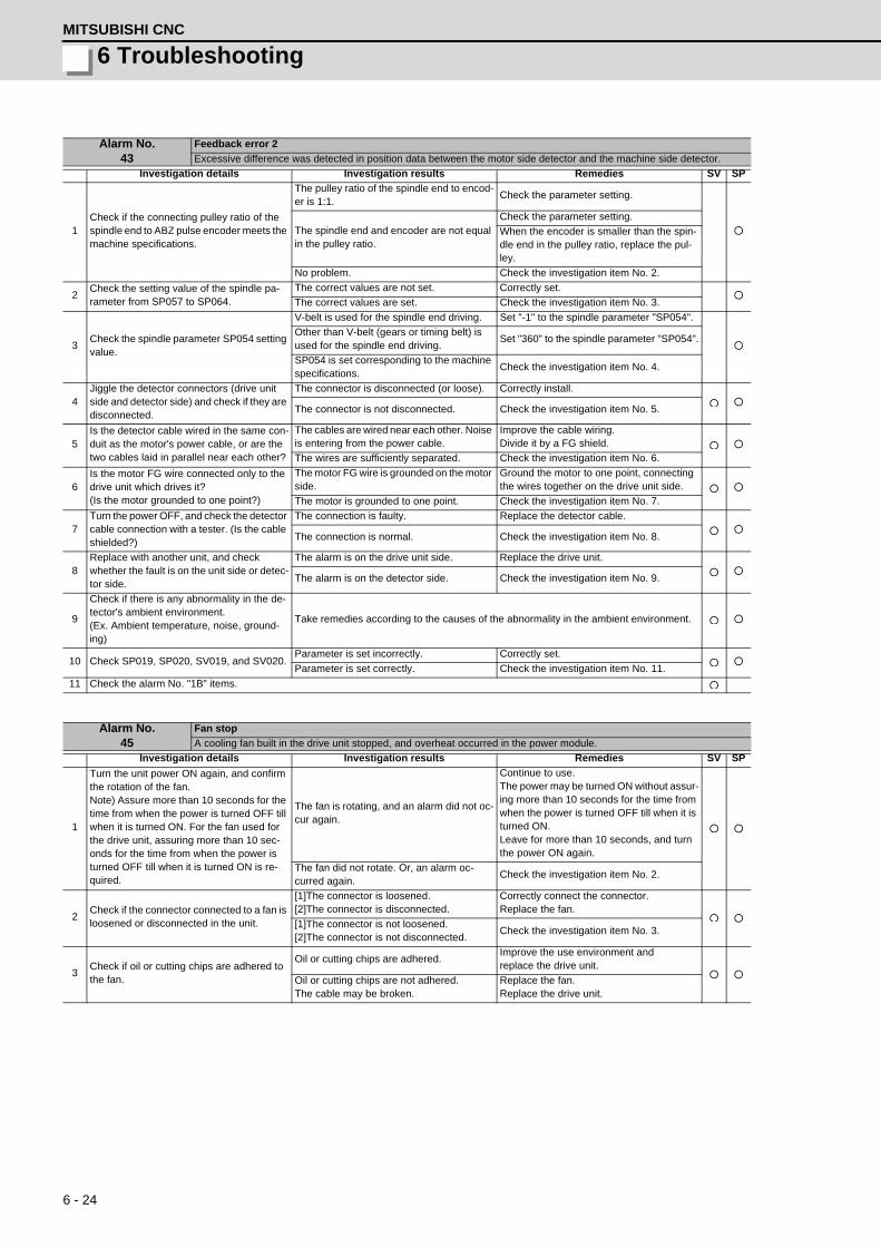
6 - 24
6 TroubleshootingMITSUBISHI CNC
Alarm No.43
Feedback error 2
Excessive difference was detected in position data between the motor side detector and the machine side detector.
Investigation details Investigation results Remedies SV SP
1Check if the connecting pulley ratio of the spindle end to ABZ pulse encoder meets the machine specifications.
The pulley ratio of the spindle end to encod-er is 1:1.
Check the parameter setting.
The spindle end and encoder are not equal in the pulley ratio.
Check the parameter setting.
When the encoder is smaller than the spin-dle end in the pulley ratio, replace the pul-ley.
No problem. Check the investigation item No. 2.
2Check the setting value of the spindle pa-rameter from SP057 to SP064.
The correct values are not set. Correctly set.
The correct values are set. Check the investigation item No. 3.
3Check the spindle parameter SP054 setting value.
V-belt is used for the spindle end driving. Set "-1" to the spindle parameter "SP054".
Other than V-belt (gears or timing belt) is used for the spindle end driving.
Set "360" to the spindle parameter "SP054".
SP054 is set corresponding to the machine specifications.
Check the investigation item No. 4.
4Jiggle the detector connectors (drive unit side and detector side) and check if they are disconnected.
The connector is disconnected (or loose). Correctly install.
The connector is not disconnected. Check the investigation item No. 5.
5Is the detector cable wired in the same con-duit as the motor's power cable, or are the two cables laid in parallel near each other?
The cables are wired near each other. Noise is entering from the power cable.
Improve the cable wiring.Divide it by a FG shield.
The wires are sufficiently separated. Check the investigation item No. 6.
6Is the motor FG wire connected only to the drive unit which drives it?(Is the motor grounded to one point?)
The motor FG wire is grounded on the motor side.
Ground the motor to one point, connecting the wires together on the drive unit side.
The motor is grounded to one point. Check the investigation item No. 7.
7Turn the power OFF, and check the detector cable connection with a tester. (Is the cable shielded?)
The connection is faulty. Replace the detector cable.
The connection is normal. Check the investigation item No. 8.
8Replace with another unit, and check whether the fault is on the unit side or detec-tor side.
The alarm is on the drive unit side. Replace the drive unit.
The alarm is on the detector side. Check the investigation item No. 9.
9
Check if there is any abnormality in the de-tector's ambient environment.(Ex. Ambient temperature, noise, ground-ing)
Take remedies according to the causes of the abnormality in the ambient environment.
10 Check SP019, SP020, SV019, and SV020.Parameter is set incorrectly. Correctly set.
Parameter is set correctly. Check the investigation item No. 11.
11 Check the alarm No. "1B" items.
Alarm No.45
Fan stop
A cooling fan built in the drive unit stopped, and overheat occurred in the power module.
Investigation details Investigation results Remedies SV SP
1
Turn the unit power ON again, and confirm the rotation of the fan.Note) Assure more than 10 seconds for the time from when the power is turned OFF till when it is turned ON. For the fan used for the drive unit, assuring more than 10 sec-onds for the time from when the power is turned OFF till when it is turned ON is re-quired.
The fan is rotating, and an alarm did not oc-cur again.
Continue to use.The power may be turned ON without assur-ing more than 10 seconds for the time from when the power is turned OFF till when it is turned ON.Leave for more than 10 seconds, and turn the power ON again.
The fan did not rotate. Or, an alarm oc-curred again.
Check the investigation item No. 2.
2Check if the connector connected to a fan is loosened or disconnected in the unit.
[1]The connector is loosened.[2]The connector is disconnected.
Correctly connect the connector.Replace the fan.
[1]The connector is not loosened.[2]The connector is not disconnected.
Check the investigation item No. 3.
3Check if oil or cutting chips are adhered to the fan.
Oil or cutting chips are adhered.Improve the use environment andreplace the drive unit.
Oil or cutting chips are not adhered.The cable may be broken.
Replace the fan.Replace the drive unit.

6 - 25
MDS-D/DH Series Instruction Manual
6-3 Troubleshooting
Alarm No.46
Motor overheat / Thermal error
Thermal protection function of the motor or in the detector, has started its operation.
Investigation details Investigation results Remedies SV SP
1
Check the repeatability.(Note) For the spindle, check the "tempera-ture" of the "spindle unit" displayed on the drive monitor screen.
[1] The alarm occurs before operation.[2] The "temperature" displayed on the drive monitor screen is different from ambient temperature.
Check the investigation item No. 2.
[1] The alarm occurs after the operation continues for a while.[2] The "temperature" displayed on the drive monitor screen rises drastically during the spindle operation.
Check the investigation item No. 5.
2Jiggle the detector connectors (drive unit side and detector side) and check if they are disconnected.
The connector is disconnected (or loose). Correctly install.
The connector is not disconnected. Check the investigation item No. 3.
3Turn the power OFF, and check the detector cable connection with a tester.
The connection is faulty. Replace the cable.
The connection is normal. Check the investigation item No. 4.
4When using MDS-B-HR, check if the motor is validated even if a motor thermal is not provided?
SV034/bit2 = 0 Set SP034/bit2 to 1.
SV034/bit2 = 1 Check the investigation item No. 5.
5Check the overload % (servo) or load meter (spindle).
The load is large.
Servo:Check the investigation item No. 6.Spindle:Check the investigation item No. 8.
The load is not large. Check the investigation item No. 9.
6 Is the unbalance torque high?The constant load torque (friction + unbal-ance) is 60% or more.
Select the motor so that the constant load torque is 60% or less.
The constant load torque is less than 60%. Check the investigation item No. 7.
7Was the overload alarm (50) forcibly reset by turning the drive unit power OFF?
The alarm was forcibly reset.Do not turn the drive unit's power OFF when an overload alarm occurs. (The NC power can be turned OFF.)
The alarm was not forcibly reset. Check the investigation item No. 9.
8 Check the parameter settings.The parameter is not set correctly. Correctly set.
The parameter is set correctly. Check the investigation item No. 9.
9
Measure the motor temperature when the alarm occurs.(Note) For the spindle motor, check the "temperature" of the "spindle unit" shown on the drive monitor screen.
The motor unit is hot. Check the investigation item No. 10.
The motor is not hot. Check the investigation item No. 12.
10When using a motor with fan, check whether the fan is stopped, or it is clogged with dust, etc.
The motor fan was stopped. Check the investigation item No. 11.
The motor fan wind flow is poor.Clean the fan and ventilation holes inside of the motor.
The direction of the ventilation is opposite. Change the connected phase sequence.
11 Check the fan wiring.
There is no problem. Check the investigation item No. 12.
The cable is broken. Replace the cable.
The cable is not broken. Replace the fan.
12Replace the drive unit or motor with another drive unit or motor, and check whether the fault is on the drive unit side or motor side
The alarm is on the drive unit side. Replace the drive unit.
The alarm is on the motor side. Replace the motor.
13
Check if there is any abnormality in the unit's ambient environment.(Ex. Ambient temperature, noise, ground-ing)
Take remedies according to the causes of the abnormality in the ambient environment.
Alarm No.48
Motor side detector: Error 5
The motor side detector (linear scale in the case of linear motor) detected an error.As details differ for each detector, refer to "Detector alarm" in 6-2-1.
Investigation details Investigation results Remedies SV SP
1 Check the alarm No. "1B" items.
Alarm No.49
Motor side detector: Error 6
The motor side detector (linear scale in the case of linear motor) detected an error.As details differ for each detector, refer to "Detector alarm" in 6-2-1.
Investigation details Investigation results Remedies SV SP
1 Check the alarm No. "1B" items.

6 - 26
6 TroubleshootingMITSUBISHI CNC
Alarm No.4A
Motor side detector: Error 7
The motor side detector (linear scale in the case of linear motor) detected an error.As details differ for each detector, refer to "Detector alarm" in 6-2-1.
Investigation details Investigation results Remedies SV SP
1 Check the alarm No. "1B" items.
Alarm No.4B
Motor side detector: Error 8
The motor side detector (linear scale in the case of linear motor) detected an error.As details differ for each detector, refer to "Detector alarm" in 6-2-1.
Investigation details Investigation results Remedies SV SP
1 Check the alarm No. "1B" items.
Alarm No.4C
Current error at magnetic pole estimate
Current detection failed at the pulse-applied magnetic pole estimation by IPM spindle motor.
Investigation details Investigation results Remedies SV SP
1 Check the pulse-applied time.The pulse-applied time can be short.
Set the pulse-applied time longer.Setting parameter:SP142 1) The pulse-applied time (0 to 350) 2) For low-speed coil:1)+1000 3) The polarity of magnetic pole estimate: Reverse polarity is "-"After the adjustment, perform the magnetic pole detection control again.
-
The alarm also occurs after the pulse-ap-plied time is set.
Replace the unit.
Alarm No.4E
NC command mode error
The mode outside the specification was input in spindle control mode selection.
Investigation details Investigation results Remedies SV SP
1
Check the wiring and setting environment.1) Correctly grounded?2) Any noise generating devices around the unit?3) Are the speed/position detector cables correctly shielded?
1) The grounding is incomplete. Correctly ground.
2) The alarm occurs easily when a specific device operates.
Use noise measures on the device de-scribed on the left.
3) The cable is not correctly shielded. Correctly shield the cable.
No abnormality is found in particular. Replace the drive unit.
Alarm No.4F
Instantaneous power interrupt
The control power supply has been shut down for 50ms or more.
Investigation details Investigation results Remedies SV SP
1 Check the repeatability. The alarm occurs occasionally.Check the power facilities.
-Check the wiring of the control power.

6 - 27
MDS-D/DH Series Instruction Manual
6-3 Troubleshooting
(Note) NR and PR resetting are not possible when the overload level is 50% or more. Do not forcibly reset (AR)
by turning the unit power OFF. If AR resetting is used at 50% or higher, the level is set to 80% when the
power is turned ON next. (Servo)
Alarm No.50
Overload 1
Overload detection level became over 100%. The motor or the drive unit is overloaded.
Investigation details Investigation results Remedies SV SP
1Check the overload parameters.Servo:SV021, SV022Spindle:SP021,SP022
The standard values (below) are not set.Servo:SV021 = 60, SV022 = 150Spindle:SP021=60,SP022=120IPM:SP021=300,SP022=100
Set the standard values.
The standard values are set. Investigate item 2.
2
Check the items below displayed on the drive monitor screen during operation. <Servo>Max.current 3 (%) Overload(%)<Spindle>Load meter(%)
Perform the machining such as rapid tra-verse, where an alarm occurs. The exam-ples are below.<Servo>[1] Max.current 3 constantly displays the maximum value.[2] Overload increases at a rapid speed.<Spindle> [1] The time to display 120% lasts long.[2] The value is higher than normal.
Servo[1] Mount a smaller workpiece.[2] Increase the time constant.[3] Check the investigation item No.6.
Spindle[1] Lower the cutting amount.[2] Extend the cycle time.
The value is within the supposed level and there is no problem.
Investigate item 3.
3
Check whether machine resonance is oc-curring.Check for vibration and abnormal noise at the spindle and table.
Resonance is occurring when a tool or workpiece is mounted or during machining.(The load inertia changes)
Adjust the parameters.[1] Set the optimal notch filter.[2] Lower VGN1 (SV005,SP005).
Resonance is not occurring. Investigate item 4.
4
Check whether the shaft sways when the motor is stopped."Hunting" of the spindle"Vibration" of the table
The motor is hunting.Adjust the parameters.[1] Increase VGN1 (SV005, SP005).[2] Lower VIA (SV008, SP008).
The motor is not hunting.Servo: Investigate item 5Spindle: Investigate item 7
5Check the brake operation.[1] Check the brake relay.[2] Check the connector (CN20) connection.
The motor brakes are not released. Correct the faulty section.
The motor brake operation is normal. Investigate item 6.
6Check the load current with the NC Servo Monitor, and investigate the machine load.
The cutting load is large. Lower the cutting load.
There is interference with the positioning pin.
When using the positioning pin, turn the ser-vo OFF when stopped.
An excessive force is applied from the ma-chine.
Check whether the ball screw is bent, or whether there is a fault in the guide.
The machine load is not large. Investigate item 8.
7Check the PLG output waveform.TS5690 cannot be checked.
There is a problem.Adjust the PLG output waveform.For TS5690, reinstall.
Normal Investigate item 8.
8 Confirm the motor capacity selection again.
The motor performance is insufficient.Lower the acceleration/deceleration rate or cutting load.
The motor performance is sufficient.
Check the tool mounted on the spindle.- The service life is reached.Increase the number of teeth (chips) of the milling cutter, etc.Investigate item 9.
9 Try replacing the drive unit.Improved. Use as it is.
Not improved. Replace the motor.

6 - 28
6 TroubleshootingMITSUBISHI CNC
Alarm No.51
Overload 2
Current command of more than 95% of the unit's max. current was being continuously given for longer than 1 second in a servo system. In a spindle system, current command of more than 95% of the motor's max. current was being continuously given for longer than 1 second.
Investigation details Investigation results Remedies SV SP
1Did the alarm occur immediately after READY ON?
The alarm occurred after ready ON before operation starts.
Investigate item 2.
The alarm occurred after normal operation. Investigate item 5.
2
Check that the PN voltage is supplied to the drive unit.MDS-D-SVJ3 Series is not connected to the power supply unit, so investigate item 3 for MDS-D-SVJ3.[1] Is the CHARGE lamp ON?
The CHARGE lamp becomes dark.L+ or L- screw was loosened.
Increase the capacity of power supply.Tighten the L+ and L- screws.
Approx. 300V is correctly supplied. Investigate item 3.
3
Check the motor power cable (U, V, W phases).[1] The power cable is not connected.[2] Is the cable connected to the motor for another axis?
The connections are incorrect.Connected to the incorrect axis.
Connect correctly.
The connections are correct. Investigate item 4.
4Check the detector cable connection.[1] Is the cable connected to the motor for another axis?
The connections are incorrect. Connect correctly.
The connections are correct. Investigate item 5.
5 Check whether the machine has collided.The machine has collided.
Check the machining program and soft limit settings.
The machine has not collided. Investigate item 6.
6Check whether the current value on the NC Servo Monitor screen is saturated during acceleration/deceleration.
The current is saturated during acceleration/deceleration.
Increase the acceleration/ deceleration time constant.
The current value during acceleration/de-celeration is appropriate.
Investigate item 7.
7 Check the detector Feedback.The Feedback signal is abnormal.- The droop does not stabilize.
Replace the detector.(With the absolute position system, the zero point must be established.)
The Feedback signal is normal. Replace the drive unit.
8 Check the load meter value.The value is large. Lower the load.
The value is normal. Investigate item 9.
9Check the PLG output waveform.For TS5690, waveform cannot be checked.
There is a problem. Adjust the PLG output waveform.
Normal Replace the drive unit.
Alarm No.52
Excessive error 1
A difference between the actual and theoretical motor positions during servo ON exceeded the setting value.
Investigation details Investigation results Remedies SV SP
1
The load inertia is large.The unbalance torque in the Z (gravity) di-rection is high.An excessive workpiece or tool is mounted on the spindle.
The load inertia is excessive.[1] Lower the machine weight applied to the servo motors (by the unbalance torque). [2] Lower the weight of the workpiece.
The load inertia is normal. Investigate item 2.
2
Check the excessive error detection width.ServoSV053SpindleSP023 (Interpolation, spindle synchroniza-tion)SP053 (Non-interpolation)
The excessive error detection width is too small.Servo standard value:SV053 =RAPID/(60*PGN1)/2Spindle standard value:No alarm is set at SP023 =120:0SP053 =motor max. speed×6/PGV/2
Set appropriate values.
Appropriate values are set. Investigate item 3.
3
Check the position detector polarity.SV017/bit4 (Servo)SP017/bit4 (Spindle: position FB)SP017/bit0 (Spindle: speed FB)#3106/bit7 (Synchronous tap control)
The polarity is reversed. Correctly set the parameters.
Normal. Investigate item 4.
4 Check the alarm No. "51" items.

6 - 29
MDS-D/DH Series Instruction Manual
6-3 Troubleshooting
Alarm No.53
Excessive error 2
A difference between the actual and theoretical motor positions during servo OFF exceeded the setting value.
Investigation details Investigation results Remedies SV SP
1Check the follow-up function while the NC is in the servo OFF state.
The axis detachment function (NC parame-ter) is invalid.(Note) For the axis detachment function, re-fer to the NC manual.
Check the investigation item No. 2.
The axis detachment function (NC parame-ter) is valid.(Note) For the axis detachment function, re-fer to the NC manual.
Check the investigation item No. 3.
2
Check whether the axis has moved during servo OFF (either by visual inspection or monitor the position droop waveform).[1] Check if the motor brake is released in the middle.[2] Check if the axis moves because the ser-vo OFF is applied during the C axis mode.
[1] The axis has moved.[2] The servo OFF is applied during the mode.
[1] Adjust the brakes, etc. so that the axis does not move.[2] Avoid the servo OFF from being applied during position control.
The axis has not moved. Check the investigation item No. 3.
3Check the excessive error detection width.SV026 (Servo)(Note) Set the same value to SV023.
The excessive error detection width is too small.SV026 =RAPID/(60*PGN1)/2
Set an appropriate value.
An appropriate value is set.Check for problems on the NC side, such as the position FB follow-up control.
Alarm No.54
Excessive error 3
When an excessive error 1 occurred, detection of the motor current failed.
Investigation details Investigation results Remedies SV SP
1Check that the PN voltage is supplied to the drive unit.[1] Is the CHARGE lamp ON?
The voltage is not supplied. Correctly supply the PN voltage.
It is correctly supplied (DC300V). Investigate item 2.
2
Check the motor power cable (U, V, W phases).[1] The power cable is not connected.[2] Is the cable connected to the motor for another axis?
The connections are incorrect. Connect correctly.
The connections are correct. Replace the drive unit.
Servo OFF Servo ON Time
OD1
OD1
OD2
OD2
Position
Depending on the ideal machine position in respect to the command position, the actual machineposition could enter the actual shaded section shown below, which is separated more than the distance set in OD1.
Supplement (servo)
Ideal machine position
Command position

6 - 30
6 TroubleshootingMITSUBISHI CNC
Alarm No.56
Commanded speed error
In C axis control mode, excessive NC commanded speed was detected.(In C axis control mode)
Investigation details Investigation results Remedies SV SP
1
Check the rotation speed displayed on the spindle drive monitor to see if the C axis ro-tation speed exceeds 1.15 times of the set speed during rapid traverse.
Exceed. Increase the rapid traverse time constant.
Not exceed.
Alarm No.58
Collision detection 1: G0
When collision detection function (set to SV060) was valid, the disturbance torque in rapid traverse (G0) exceeded the col-lision detection level.
Investigation details Investigation results Remedies SV SP
1Check whether the machine has collided during G0 operation.
A collision has occurred at the table, turret or spindle head in the machine during movement.
Check the machining program and soft limit settings.
There is no collision at the table, turret and spindle head in the machine during move-ment
Adjust the tolerable disturbance torque SV060.(Note) Set the detection level to be 1.5 times or more of the maximum torque.
Alarm No.59
Collision detection 1: G1
When collision detection function was valid (SV035.c1G1 was set), the disturbance torque in cutting feed (G1) exceeded the collision detection level.
Investigation details Investigation results Remedies SV SP
1Check whether the machine has collided during G0 operation.
The machine has collided during move-ment.
Check the machining program and soft limit settings.
The machine has not collided.
Increase the detection level (SV035. clG1).G1 collision detection level=SV060×c1G1(001 to 111)(Note) Set the detection level larger than the maximum cutting load.
Alarm No.5A
Collision detection 2
When collision detection function was valid, the command torque reached the max. motor torque.
Investigation details Investigation results Remedies SV SP
1 Check whether the machine has collided.The machine has collided.
Check the machining program and soft limit settings.
The machine has not collided. Check the investigation item No. 2.
2Check whether the current value on the NC Servo Monitor screen is saturated during acceleration/deceleration.
The current is saturated during acceleration/deceleration.
Check the investigation item No. 3.
The current value during acceleration/de-celeration is appropriate.
Investigate the cause of the load fluctuation.
3Can the acceleration/deceleration time con-stant be changed?
The constant can be changed.Increase the acceleration/ deceleration time constant.
The constant cannot be changed. Set to ignore collision detection method 2.
Alarm No.5B
Safety observation: Commanded speed error
In safety monitoring mode, the commanded speed was detected to exceed the safe speed.
Investigation details Investigation results Remedies SV SP
1Check the commanded speed on the NC side.
The commanded speed and safe speed lim-it value are the same.
Reduce the commanded speed on the NC side or increase the safe speed limit value.
The commanded speed is slower than the safe speed.
Replace the drive unit.
Alarm No.5D
Safety observation: Door state error
In safety monitoring mode, the door state signal from the NC and the same signal from the drive unit don't match. Other-wise, door open state was detected in normal mode.
Investigation details Investigation results Remedies SV SP
1 Check the DI input timing.
Both NC side and drive unit side input tim-ings match one another within 500ms.
Review the DI input sequence.Check if the cable for the DI input signal is broken.
NC side and drive unit side inputs do not match one another within 500ms.
Investigate the wiring and connection envi-ronment.
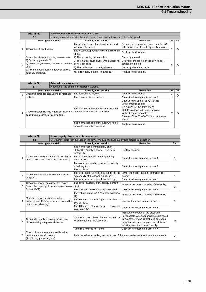
6 - 31
MDS-D/DH Series Instruction Manual
6-3 Troubleshooting
Alarm No.5E
Safety observation: Feedback speed error
In safety monitoring mode, the motor speed was detected to exceed the safe speed.
Investigation details Investigation results Remedies SV SP
1 Check the DI input timing.
The feedback speed and safe speed limit value are the same.
Reduce the commanded speed on the NC side or increase the safe speed limit value.
The feedback speed is slower than the safe speed.
Replace the drive unit.
2
Check the wiring and setting environment.1) Correctly grounded?2) Any noise generating devices around the unit?3) Are the speed/position detector cables correctly shielded?
1) The grounding is incomplete. Correctly ground.
2) The alarm occurs easily when a specific device operates.
Use noise measures on the device de-scribed on the left.
3) The cable is not correctly shielded. Correctly shield the cable.
No abnormality is found in particular. Replace the drive unit.
Alarm No.5F
External contactor error
A contact of the external contactor is welding.
Investigation details Investigation results Remedies SV SP
1Check whether the contactor's contact has melted.
The contactor is melted. Replace the contactor.
The contactor is not melted. Check the investigation item No. 2.
2Check whether the axis where an alarm oc-curred was a contactor control axis.
The alarm occurred at the axis where the contactor control is not executed.
Check the parameter.(SVJ3/SPJ3)With contactor control Servo:SV082, Spindle:SP227 0800h is added to the setting value.Without contactor controlChange "Bit A,B" to "00" in the parameter above.
The alarm occurred at the axis where the contactor control is executed.
Replace the drive unit.
Alarm No.61
Power supply: Power module overcurrent
Overcurrent protection function in the power module of power supply has started its operation.
Investigation details Investigation results Remedies CV
1Check the state of the operation when the alarm occurs, and check the repeatability.
The alarm occurs immediately after 200VAC is supplied or after READY is turned ON.
Replace the unit.
The alarm occurs occasionally during READY ON.
Check the investigation item No. 3.
The alarm occurs after continuous operation for a long time.The unit is hot.
Check the investigation item No. 2.
2Check the load state of all motors (during stopped).
The total load of all motors exceeds the rat-ed capacity of the power supply unit.
Lower the motor load and operation fre-quency.
The total does not exceed the capacity. Check the investigation item No. 3.
3Check the power capacity of the facility.Check the capacity of the step-down trans-former (KVA).
The power capacity of the facility is insuffi-cient.
Increase the power capacity of the facility.
The specified power capacity is secured. Check the investigation item No. 4.
4Measure the voltage across wires.Is the voltage 170V or more even when the motor is accelerating?
The voltage drops to 170V or less occasion-ally.
Increase the power capacity of the facility.
The difference of the voltage across wires is 10V or more.
Improve the power phase balance.
The difference of the voltage across wires is less than 10V.
Check the investigation item No. 5.
5Check whether there is any device (ma-chine) causing the power distortion.
Abnormal noise is heard from an AC reactor when stopping at the servo ON.
Improve the source of the distortion.For example, when abnormal noise is heard from another machine that is in operation, move the wiring to the power which is far from the machine's power supply.
Abnormal noise is not heard. Check the investigation item No. 6.
6Check if there is any abnormality in the unit's ambient environment.(Ex. Noise, grounding, etc.)
Take remedies according to the causes of the abnormality in the ambient environment.

6 - 32
6 TroubleshootingMITSUBISHI CNC
Alarm No.62
Power supply: Frequency error
The input power supply frequency increased above the specification range.
Investigation details Investigation results Remedies CV
1Check the state of the operation when the alarm occurs, and check the repeatability.
The alarm occurs each time immediately af-ter the power is turned ON. Or, the alarm oc-curs occasionally regardless of the operation state.
Check the investigation item No. 2.
The alarm occurs only while the motor is ac-celerating/decelerating.
Check the investigation item No. 3.
2Measure the power voltage waveform dur-ing normal operation.
The frequency is deviated from 50Hz±3% or 60Hz±3%.
Review the power facilities.
The voltage waveform dips at some sec-tions.
Improve the source of the distortion.Install an AC reactor.
There is no problem. Check the investigation item No. 4.
3Measure the power voltage when the motor is accelerating/decelerating.
The frequency greatly fluctuates during ac-celeration/deceleration.
Review the power facilities.
The voltage waveform during deceleration dips in some sections.
Improve the source of the distortion.Install an AC reactor.
There is no problem. Check the investigation item No. 4.
4Check if there is any abnormality in the unit's ambient environment.(Ex. Noise, grounding, etc.)
Take remedies according to the causes of the abnormality in the ambient environment.
Alarm No.66
Process error
An error occurred in the process cycle.
Investigation details Investigation results Remedies CV
1 Check the repeatability.The alarm occurs each time after the power is turned ON.
Replace the unit.
The alarm occurs occasionally. Check the investigation item No. 2.
2Check if there is any abnormality in the unit's ambient environment.(Ex. Noise, grounding, etc.)
Take remedies according to the causes of the abnormality in the ambient environment.
Alarm No.67
Power supply: Phase interruption
An open-phase condition was detected in input power supply circuit.
Investigation details Investigation results Remedies CV
1 Check the voltage for each input phase.There are phases with no voltage. Correct the power supply.
There is no problem. Check the investigation item No. 2.
2 Check the alarm No. "71" items.
Alarm No.68
Power supply: Watchdog
The system does not operate correctly.
Investigation details Investigation results Remedies CV
1 Check the repeatability.The alarm occurs each time READY is turned ON.
Replace the unit.
The alarm occurs occasionally. Check the investigation item No. 2.
2Check if there is any abnormality in the unit's ambient environment.(Ex. Noise, grounding, etc.)
Take remedies according to the causes of the abnormality in the ambient environment.

6 - 33
MDS-D/DH Series Instruction Manual
6-3 Troubleshooting
Alarm No.69
Power supply: Grounding
The motor power cable is in contact with FG (Frame Ground).
Investigation details Investigation results Remedies SV SP
1Measure the insulation across the power ca-bles (U,V,W) for all motors and the ground. (Carry out a megger test.)
Less than 100k . (Grounding)The motor or power cable may be ground faulted.
100k or more. (Normal) Check the investigation item No. 2.
2Has oil come in contact with the motor or power cable?
Oil has come in contact.
Take measures so that oil does not come in contact. Check the motor's cannon connec-tor and the inside of the terminal box, and clean as necessary.
Oil has not come in contact. Check the investigation item No. 3.
3 Measure the insulation again.Less than 1M . (Grounding) Replace the motor or cable.
1M or more. (Normal) Check the investigation item No. 2.
4
Measure the resistance across the U, V, W phase terminals of the servo/spindle drive unit and the ground.(Do not measure the insulation as the unit could be damaged.)
Less than 100k . Replace the drive unit.
100k or more. Replace the power supply unit.
5Check whether there is any axis in which alarm has occurred.
There is an axis in which alarm has oc-curred.
Check the alarm No. "24" items.
There is no axis in which alarm has oc-curred.
Check the investigation item No. 2.
Alarm No.6A
Power supply: External contactor welding
A contact of the external contactor is welding.
Investigation details Investigation results Remedies CV
1Check whether any alarm has occurred on the drive unit side.
An alarm has occurred.Remove the cause of the alarm on the drive side, and check the investigation item No. 2.
An alarm has not occurred. Check the investigation item No. 2.
2Check whether the contactor's contact has melted.
The contactor has melted. Replace the contactor.
The contactor has not melted. Check the investigation item No. 3.
3Check that the contactor excitation wiring is correctly connected from the power supply unit's MC1 terminal.
The connection is correct. Correctly connect.
The connection is incorrect. Replace the power supply unit.
Alarm No.6B
Power supply: Rush circuit error
A thyristor for rush short circuit is ON when rushing.
Investigation details Investigation results Remedies CV
1Check whether any alarm has occurred on the drive unit side.
An alarm has occurred.Remove the cause of the alarm on the drive side, and then carry out the investigation de-tails 2.
An alarm has not occurred. Check the investigation item No. 2.
2 Check the repeatability.The alarm occurs each time READY is turned ON.
Replace the unit.
The alarm occurs occasionally. Check the investigation item No. 3.
3Check if there is any abnormality in the unit's ambient environment.(Ex. Noise, grounding, etc.)
Take remedies according to the causes of the abnormality in the ambient environment.

6 - 34
6 TroubleshootingMITSUBISHI CNC
(Note) Alarm 6F is detected at the same time other power supply alarms occur.
Alarm No.6C
Power supply: Main circuit error
An error was detected in charging operation of the main circuit capacitor.
Investigation details Investigation results Remedies CV
1Check the CHARGE lamp state when the alarm occurs.
[1] The light of the lamp becomes faint.[2] An alarm occurs when ready is turned ON again.
Replace the power supply unit.
The lamp turns ON instantly, but when the alarm occurs and the contactor turns OFF, the lamp turns OFF immediately.
Check the investigation item No. 2.
The lamp never turns ON.Check the investigation item No. 2.Then replace the unit.
2
Disconnect the power supply unit's PN ter-minal block wiring, and measure the resis-tance value at 1) and 2) shown be-low.
(Note) When disconnecting the PN wiring, turn OFF the power, make sure the CHARGE lamp has turned OFF at contactor OFF and then wait at least fifteen minutes before dis-connecting. Do not disconnect immediately after the power OFF.
1)The power supply unit side is abnormal. Replace the power supply unit.
2)The drive unit side is abnormal.Disconnect the PN wiring, and then check the drive unit side.
1) and 2) are both nor-mal.
Replace the power supply unit.
Alarm No.6D
Parameter setting error
An error was detected in the parameter sent from the drive unit.
Investigation details Investigation results Remedies CV
1 Check the repeatability.The alarm occurs each time after the power is turned ON.
Replace the unit.
The alarm occurs occasionally. Check the investigation item No. 2.
2Check if there is any abnormality in the unit's ambient environment.(Ex. Noise, grounding, etc.)
Take remedies according to the causes of the abnormality in the ambient environment.
Alarm No.6E
Power supply: Memory error/AD error
An error was detected in the internal memory or A/D converter.
Investigation details Investigation results Remedies CV
1 Check the repeatability.The alarm occurs each time READY is turned ON.
Replace the unit.
The alarm occurs occasionally. Check the investigation item No. 2.
2Check if there is any abnormality in the unit's ambient environment.(Ex. Noise, grounding, etc.)
Take remedies according to the causes of the abnormality in the ambient environment.
Alarm No.6F
Power supply error
No power supply is connected to the drive unit, or a communication error was detected.
Investigation details Investigation results Remedies CV
1Check the LED display on the power supply unit.
"F" is flickering.An A/D converter error has occurred.Check the alarm No. "6E" items.
Another alarm code is flickering. Check items of each alarm No.
"0" is displayed. Check the investigation item No. 2.
"F" is displayed. Check the investigation item No. 2.
"8" is displayed. Check the alarm No. "68" items.
"b", "C", "d" is displayed. Check the investigation item No. 3.
Something else is displayed. Check the alarm No. "68" items.
2 Check the rotary switch setting.0 or 4 is set. Check the investigation item No. 3.
A value other than the above is set. Correctly set the rotary switch.
3Check the communication cable (CN4) con-nected with the drive unit.
There is a problem with the wiring or shield. Replace the cable.
There is no problem. Replace the unit.
Drive unitPower supply
unit
P N
2)
1) Tester
measure-ment point
PolarityNormal Abnormal
Several 100Ω
Several 100Ω
Short-circuit/∞ΩSeveral 100Ω
Several 100ΩShort-circuit/∞Ω2)
1)
∞Ω
∞Ω
+ -P N
PNP N
PN

6 - 35
MDS-D/DH Series Instruction Manual
6-3 Troubleshooting
Alarm No.70
Power supply: External emergency stop error
A mismatch of the external emergency stop input and CNC emergency stop input continued for 30 seconds.
Investigation details Investigation results Remedies CV
1Check the connection between external emergency stop and NC emergency stop.
Not wired.Correctly wire the external emergency stop and NC emergency stop.
2Check if there is any abnormality in the unit's ambient environment.
No abnormality is found in particular. Replace the drive unit.
The grounding is incomplete.Take remedies according to the causes of the abnormality. Additionally ground and re-view.
Alarm No.71
Power supply: Instantaneous power interruption
The power was momentarily interrupted.
Investigation details Investigation results Remedies CV
1Investigate the sequence to check whether the contactor has been turned OFF with an emergency stop button, etc.
The contactor has been turned OFF exter-nally.
Review the machine sequence.When turning the contactor OFF with exter-nal means, such as an emergency stop but-ton, this alarm can be avoided by inputting NC emergency stop at the same time.
The contactor has not been turned OFF. Check the investigation item No. 2.
2 Check the repeatability.
The alarm occurs each time READY is turned ON.
Check the investigation item No. 3.
The alarm occurs at a certain operation.Check the investigation item No. 1.If there is no problem, check the investiga-tion item No. 3.
The alarm occurs occasionally during oper-ation.
Check the investigation item No. 4.
3Check whether the power input wire and contactor are correctly wired.
The wiring is incorrect. Correctly connect.
There is no problem. Check the investigation item No. 4.
4Check the power voltage waveform with a synchroscope.
An instantaneous power failure or voltage drop occurs frequently.
Correct the power facility.
There is no problem. Replace the unit.
Alarm No.72
Power supply: Fan stop
A cooling fan built in the power supply unit stopped, and overheat occurred in the power module.
Investigation details Investigation results Remedies CV
1
Turn the unit power ON again, and confirm the rotation of the fan.Note) Assure more than 10 seconds for the time from when the power is turned OFF till when it is turned ON. For the fan used for the drive unit, assuring more than 10 sec-onds for the time from when the power is turned OFF till when it is turned ON is re-quired.
The fan is rotating, and an alarm did not oc-cur again.
Continue to use.The power may be turned ON without assur-ing more than 10 seconds for the time from when the power is turned OFF till when it is turned ON.Leave for more than 10 seconds, and turn the power ON again.
The fan did not rotate. Or, an alarm oc-curred again.
Check the investigation item No. 2.
2Check if the connector connected to a fan is disconnected.
The connector is disconnected. Correctly connect the connector.
The connector is not disconnected. Check the investigation item No. 3.
3Check if oil or cutting chips are adhered to the fan.
Oil or cutting chips are adhered.Improve the use environment and replace the drive unit.
Oil or cutting chips are not adhered.The cable may be broken.
Replace the drive unit.
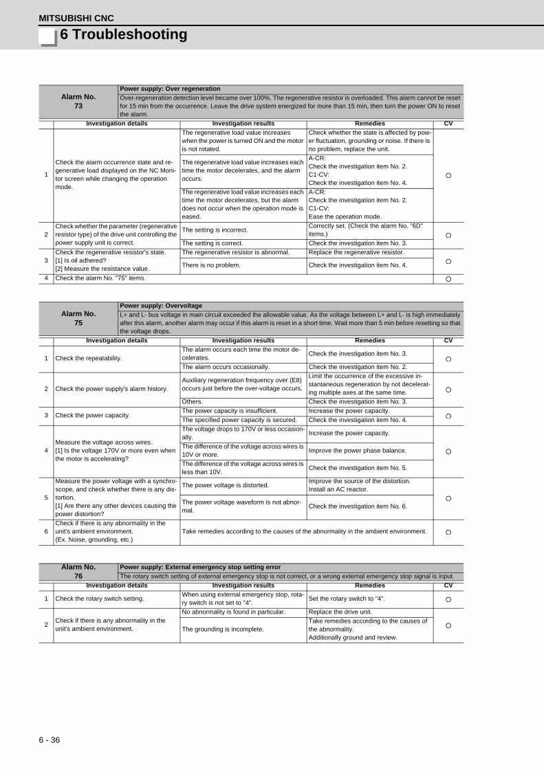
6 - 36
6 TroubleshootingMITSUBISHI CNC
Alarm No.73
Power supply: Over regeneration
Over-regeneration detection level became over 100%. The regenerative resistor is overloaded. This alarm cannot be reset for 15 min from the occurrence. Leave the drive system energized for more than 15 min, then turn the power ON to reset the alarm.
Investigation details Investigation results Remedies CV
1
Check the alarm occurrence state and re-generative load displayed on the NC Moni-tor screen while changing the operation mode.
The regenerative load value increases when the power is turned ON and the motor is not rotated.
Check whether the state is affected by pow-er fluctuation, grounding or noise. If there is no problem, replace the unit.
The regenerative load value increases each time the motor decelerates, and the alarm occurs.
A-CR:Check the investigation item No. 2.C1-CV:Check the investigation item No. 4.
The regenerative load value increases each time the motor decelerates, but the alarm does not occur when the operation mode is eased.
A-CR:Check the investigation item No. 2.C1-CV:Ease the operation mode.
2Check whether the parameter (regenerative resistor type) of the drive unit controlling the power supply unit is correct.
The setting is incorrect.Correctly set. (Check the alarm No. "6D" items.)
The setting is correct. Check the investigation item No. 3.
3Check the regenerative resistor's state.[1] Is oil adhered?[2] Measure the resistance value.
The regenerative resistor is abnormal. Replace the regenerative resistor.
There is no problem. Check the investigation item No. 4.
4 Check the alarm No. "75" items.
Alarm No.75
Power supply: Overvoltage
L+ and L- bus voltage in main circuit exceeded the allowable value. As the voltage between L+ and L- is high immediately after this alarm, another alarm may occur if this alarm is reset in a short time. Wait more than 5 min before resetting so that the voltage drops.
Investigation details Investigation results Remedies CV
1 Check the repeatability.The alarm occurs each time the motor de-celerates.
Check the investigation item No. 3.
The alarm occurs occasionally. Check the investigation item No. 2.
2 Check the power supply's alarm history.Auxiliary regeneration frequency over (E8) occurs just before the over-voltage occurs.
Limit the occurrence of the excessive in-stantaneous regeneration by not decelerat-ing multiple axes at the same time.
Others. Check the investigation item No. 3.
3 Check the power capacity.The power capacity is insufficient. Increase the power capacity.
The specified power capacity is secured. Check the investigation item No. 4.
4Measure the voltage across wires.[1] Is the voltage 170V or more even when the motor is accelerating?
The voltage drops to 170V or less occasion-ally.
Increase the power capacity.
The difference of the voltage across wires is 10V or more.
Improve the power phase balance.
The difference of the voltage across wires is less than 10V.
Check the investigation item No. 5.
5
Measure the power voltage with a synchro-scope, and check whether there is any dis-tortion.[1] Are there any other devices causing the power distortion?
The power voltage is distorted.Improve the source of the distortion.Install an AC reactor.
The power voltage waveform is not abnor-mal.
Check the investigation item No. 6.
6Check if there is any abnormality in the unit's ambient environment.(Ex. Noise, grounding, etc.)
Take remedies according to the causes of the abnormality in the ambient environment.
Alarm No.76
Power supply: External emergency stop setting error
The rotary switch setting of external emergency stop is not correct, or a wrong external emergency stop signal is input.
Investigation details Investigation results Remedies CV
1 Check the rotary switch setting.When using external emergency stop, rota-ry switch is not set to "4".
Set the rotary switch to "4".
2Check if there is any abnormality in the unit's ambient environment.
No abnormality is found in particular. Replace the drive unit.
The grounding is incomplete.Take remedies according to the causes of the abnormality.Additionally ground and review.

6 - 37
MDS-D/DH Series Instruction Manual
6-3 Troubleshooting
Alarm No.77
Power supply: Power module overheat
Thermal protection function in the power module has started its operation.
Investigation details Investigation results Remedies CV
1 Confirm that the fan is properly rotating.Large amounts of cutting oil or cutting chips, etc., are adhered, or the rotation is slow.
Clean or replace the fan.
The fan is properly rotating. Check the investigation item No. 2.
2Check whether the heat dissipating fins are dirty.
Cutting oil or cutting chips, etc., are ad-hered, and the fins are clogged.
Clean the fins.
The fins are normal. Check the investigation item No. 3.
3Measure the power supply unit's ambient temperature.
55°C or moreImprove the ventilation and cooling for the power distribution panel.
Less than 55°C. Check the investigation item No. 4.
4
Check if there is any abnormality in the unit's ambient environment.(Ex. Ambient temperature, noise, ground-ing)
Take remedies according to the causes of the abnormality in the ambient environment.
Alarm No.80
Main side detector cable error
A pulse type cable is used for the motor side detector.
Investigation details Investigation results Remedies SV SP
1
Check the parameters. Servo:SV025 = "x200" Spindle:SP031 = "x200"And then, check the connected cable and the detector.
The cable type is pulse. Replace the cable to the serial type.
There is no problem with the selection of the detector and cable.
Replace the detector or cable.
Alarm No.81
Sub side detector cable error
The cable type of machine side detector does not match the detector specifications set by the parameter.
Investigation details Investigation results Remedies SV SP
1
Check if the below parameters match the connected detector and cable. Servo: SV025 Spindle: SP031
The detector does not match the specifica-tions.
Replace the detector.
The parameter is not correct.
Set the parameters so that they meet the machine side detector.<Servo:SV025> - Rotary Pulse 2xxx Serial 6xxx - Scale Pulse 8xxx Serial Axxx<Spindle:SP031> Pulse 4200 Serial 6200
There is no problem with the selection of the detector and cable.
Replace the detector or cable.
Alarm No.87
Drive unit communication error
The communication frame between drive units was aborted.
Investigation details Investigation results Remedies SV SP
1Check the connection of the optical commu-nication cable between drive units.
The cable and connector were loose. Connect again so as not to be loosened.
The cable and connector were not loose.Replace the cable.Check the investigation item No. 2.
2 Check the repeatability.The error is always repeated (in high-speed synchronous tapping).
Replace the servo drive or spindle drive unit that is used for high-speed synchronous tapping.
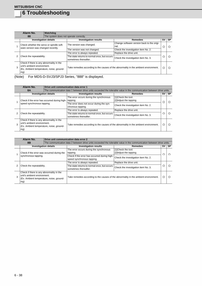
6 - 38
6 TroubleshootingMITSUBISHI CNC
(Note) For MDS-D-SVJ3/SPJ3 Series, "888" is displayed.
Alarm No.88
Watchdog
The system does not operate correctly.
Investigation details Investigation results Remedies SV SP
1Check whether the servo or spindle soft-ware version was changed recently.
The version was changed.Change software version back to the origi-nal.
The version was not changed. Check the investigation item No. 2.
2 Check the repeatability.The error is always repeated. Replace the drive unit.
The state returns to normal once, but occurs sometimes thereafter.
Check the investigation item No. 3.
3
Check if there is any abnormality in the unit's ambient environment.(Ex. Ambient temperature, noise, ground-ing)
Take remedies according to the causes of the abnormality in the ambient environment.
Alarm No.8A
Drive unit communication data error 1
The communication data 1 between drive units exceeded the tolerable value in the communication between drive units.
Investigation details Investigation results Remedies SV SP
1Check if the error has occurred during high-speed synchronous tapping.
The error occurs during the synchronous tapping.
[1]Check the tool.[2]Adjust the tapping.
The error does not occur during the syn-chronous tapping.
Check the investigation item No. 2.
2 Check the repeatability.The error is always repeated. Replace the drive unit.
The state returns to normal once, but occurs sometimes thereafter.
Check the investigation item No. 3.
3
Check if there is any abnormality in the unit's ambient environment.(Ex. Ambient temperature, noise, ground-ing)
Take remedies according to the causes of the abnormality in the ambient environment.
Alarm No.8B
Drive unit communication data error 2
The communication data 2 between drive units exceeded the tolerable value in the communication between drive units.
Investigation details Investigation results Remedies SV SP
1Check if the error was occurred during the synchronous tapping.
The error occurs during the synchronous tapping.
[1]Check the tool.[2]Adjust the tapping.
Check if the error has occurred during high-speed synchronous tapping.
Check the investigation item No. 2.
2 Check the repeatability.The error is always repeated. Replace the drive unit.
The state returns to normal once, but occurs sometimes thereafter.
Check the investigation item No. 3.
3
Check if there is any abnormality in the unit's ambient environment.(Ex. Ambient temperature, noise, ground-ing)
Take remedies according to the causes of the abnormality in the ambient environment.

6 - 39
MDS-D/DH Series Instruction Manual
6-3 Troubleshooting
6-3-3 Troubleshooting for each warning No.
Warning No.96
Scale feedback error
An excessive difference in feedback amount was detected between the main side detector and the MPI scale in MPI scale absolute position detection system.
Investigation details Investigation results Remedies SV SP
1
Check if there is any abnormality in the de-tector's ambient environment.(Ex. Ambient temperature, noise, ground-ing)
Take remedies according to the causes of the abnormality in the ambient environment.
2 Check the repeatability.Occurs frequently. Replace the detector.
Is not repeated. Check the investigation item No. 1.
Warning No.97
Scale offset error
An error was detected in the offset data that is read at the NC power-ON in MPI scale absolute position detection system.
Investigation details Investigation results Remedies SV SP
1
Check if there is any abnormality in the de-tector's ambient environment.(Ex. Ambient temperature, noise, ground-ing)
Take remedies according to the causes of the abnormality in the ambient environment.
2 Check the repeatability.Occurs frequently. Replace the detector.
Is not repeated. Check the investigation item No. 1.
Warning No.9B
Incremental detector/magnetic pole shift warning
For the incremental detector, an error was detected in the magnetic pole shift amount set in the magnetic pole shift amount parameter "SV028".
Investigation details Investigation results Remedies SV SP
1
Check if there is any abnormality in the de-tector's ambient environment.(Ex. Ambient temperature, noise, ground-ing)
Take remedies according to the causes of the abnormality in the ambient environment.
2 Check the repeatability.Occurs occasionally.
Execute magnetic pole detection control again and reset SV028.
Is not repeated. Check the investigation item No. 1.
Warning No.9E
Absolute position detector: Revolution counter error
An error was detected in the revolution counter of the absolute position detector. The absolute position data cannot be com-pensated.
Investigation details Investigation results Remedies SV SP
1
Check if there is any abnormality in the de-tector's ambient environment.(Ex. Ambient temperature, noise, ground-ing)
Take remedies according to the causes of the abnormality in the ambient environment.
2 Check the repeatability.Occurs frequently. Replace the detector.
Is not repeated. Check the investigation item No. 1.

6 - 40
6 TroubleshootingMITSUBISHI CNC
(Note) When warning 9F occurs, do not turn the drive unit power OFF to ensure that the absolute position data
is held.
Replace the battery with the drive unit power ON.
Warning No.9F
Battery voltage drop
The battery voltage that is supplied to the absolute position detector dropped. The absolute position data is retained.
Investigation details Investigation results Remedies SV SP
1Change the used battery and check whether the warning does not occur. (Turning the power OFF and ON is required.)
The warning does not occur. The battery has been drained.
The warning occurs. Check the investigation item No. 2.
2Check whether the battery cable is discon-nected, broken, or wired incorrectly.
The connection is faulty.Correct the connection.Replace the cable.
The connection is normal. Check the investigation item No. 3.
3 Measure the new battery voltage.
Less than 3.4V. Replace the battery.
3.4V or more.Check the investigation item No. 6.When a battery box is used, check the in-vestigation item No. 4.
4Check whether the cable connecting be-tween the battery box and CN9 is short-circuited, broken, or wired incorrectly.
The connection is faulty.Correct the connection.Replace the cable.
The connection is normal. Check the investigation item No. 5.
5
Disconnect the BT-LG cable of the battery box, and then measure the voltage between DO(ALM) and DOCOM terminals at power ON.
Low voltage. Replace the battery box.
Equivalent of 24V. Check the investigation item No. 6.
6
Perform a conductivity check with the detec-tor cable between BT and LG of the drive unit in which the warning was detected.(Note) Make sure that the detector side con-nector is disconnected.
Resistance value is low. Replace the cable.
Resistance value is 100M or more.Replace the detector.(With the absolute position system, the zero point must be established.)
Warning No.A3
Distance-coded reference check / initial setup warning
When the detector with distance-coded reference marks is used, this warning is issued until the axis reaches the reference position during the initial setup of the distance-coded reference check function. This warning disappears after the axis has reached the position.
Investigation details Investigation results Remedies SV SP
1 Warning does not disappear.Stopped on the way to the reference posi-tion.
Setup again. -
Warning No.A6
Fan stop warning
A cooling fan built in the drive unit stopped.
Investigation details Investigation results Remedies SV SP
1 Check the alarm No. "45" items.
Warning No.E0
Over regeneration warning
Over-regeneration detection level exceeded 80%.
Investigation details Investigation results Remedies SV SP
1 Check the acceleration/deceleration cycle.The cycle operation being conducted is se-vere for the average output.
Extend the cycle operation time to the length that will not cause a warning.
No problem. Check the investigation item No. 2.
2 Check the load inertia. The load inertia is large. Lower the load inertia.
Warning No.E1
Overload warning
Overload detection level exceeded 80%.
Investigation details Investigation results Remedies SV SP
1 Check if the motor is hot.Motor is hot. Check the alarm No. "50" items.
Motor is not hot. Check the investigation item No. 2.
2Check if an error occurs when executing ac-celeration/deceleration operation.
Error is not found in operation. Thus, opera-tion is possible.
Ease the operation patter, if possible. If no alarm occurs, operation can be continued as it is.
Error is found in operation.Check the investigation item 3 or later of Alarm No. 50.
3 Check the alarm No. "50" items.

6 - 41
MDS-D/DH Series Instruction Manual
6-3 Troubleshooting
Warning No.E4
Set parameter warning
An incorrect parameter was detected among the parameters received from the CNC.
Investigation details Investigation results Remedies SV SP
1 Check the error parameter No.SV001 to SV256SP001 to SP256
Set the value within the designated setting range.
2 Check the spindle control input 4/bit 0 to 2.Selected other than 000, 001, 010 and 100 when the alarm occurred.
Correctly select.
Warning No.E6
Control axis detachment warning
Control axis detachment was commanded.
Investigation details Investigation results Remedies SV SP
1 The status in which removal of the control axis was commanded from the NC is indicated.
Warning No.E7
In NC emergency stop state
Emergency stop was input from the CNC.
Investigation details Investigation results Remedies SV SP
1Check if the emergency stop is applied on the NC side.
The emergency stop is applied. Check the investigation item No. 2.
The emergency stop is cancelled. Check the investigation item No. 3.
2 Cancel the emergency stop.Normally starts up. Normal.
"E7" remains displayed. Check the investigation item No. 3.
3Check whether an alarm is occurring in an-other drive unit.
An alarm is occurring in another drive unit. Reset the alarm in the other drive unit.
An alarm is not occurring. Check the investigation item No. 4.
4 Turn the power of NC and 200VAC (400V) ON again
Warning No.E9
Instantaneous power interruption warning
The power was momentarily interrupted.
Investigation details Investigation results Remedies CV
1 Check the alarm No. "71" items.
Warning No.EA
In external emergency stop state
External emergency stop signal was input.
Investigation details Investigation results Remedies CV
1Check whether the specifications allow use of the external emergency stop.
Use is not allowed. Invalidate the external emergency stop.
Use is allowed. Check the investigation item No. 2.
2Measure the input voltage of the CN23 con-nector. (While emergency stop is can-celled.)
24V is input. Replace the power supply unit.
24V is not input.Check whether the external emergency stop cable is broken, or check the external con-tact operation.
Warning No.EB
Power supply: Over regeneration warning
Over-regeneration detection level exceeded 80%.
Investigation details Investigation results Remedies CV
1 Check the alarm No. "73" items.
Warning No.EE
Power supply: Fan stop warning
A cooling fan built in the power supply unit stopped.
Investigation details Investigation results Remedies CV
1 Check the alarm No. "72" items.

6 - 42
6 TroubleshootingMITSUBISHI CNC
6-3-4 Parameter numbers during initial parameter error
If an initial parameter error (alarm 37) occurs, the alarm and the No. of the parameter set exceeding the
setting range will appear on the NC Diagnosis screen as shown below.
S02 Initial parameter error
: Error parameter No.
: Axis name
If an error No. larger than the servo parameter No. is displayed for the servo drive unit, the alarm is occurring
for several related parameters. Refer to the following table, and correctly set the parameters.
Error parameter No. Details Related parameters
2301
The following settings are overflowing.[1] Electronic gears[2] Position loop gain[3] Speed feedback
SV001, SV002 SV003, SV018SV019, SV020SV049
2302The absolute position parameter is valid when a high-speed serial incre-mental detector (OSE104 or OSE105) is connected.[1] Replace the detector to the one with absolute position specification.
SV017, SV025
2303No servo option is found.[1] The closed loop (including the ball screw end)[2] Dual feedback control function
SV025SV017
2304No servo option is found.[1] SHG control function
SV057SV058
2305No servo option is found.[1] Adaptive filtering function
SV027
13001 to 13256Parameter errorThe parameter value is outside the tolerable range.The alarm No. is the No. of the spindle parameter where an error occurred.
Check the indicated spindle parameter.

6 - 43
MDS-D/DH Series Instruction Manual
6-3 Troubleshooting
6-3-5 Troubleshooting the spindle system when there is no alarm or warning
If an abnormality is observed in the spindle system but no alarm or warning has occurred, refer to the
following table and check the state.
[1] The rotation speed command and actual rotation speed do not match.
[2] The acceleration/deceleration time is long or has increased in length.
[3] The motor stops during cutting.
[4] The vibration and noise (gear noise), etc., are large.
[5] The spindle coasts during deceleration.
Investigation item Investigation results Remedies
1Check the commanded speed and the spindle rotation speed displayed on the drive monitor screen.
The speed command is not input correctly. Input the correct speed command.
The speed command is correct. Check the investigation item No. 2.
2Check whether there is slipping between the motor and spindle. (When connected with a belt or clutch.)
There is slipping. Repair the machine side.
No particular problems found. Check the investigation item No. 3.
3Check the spindle parameters (SP026, SP129 and following).
The correct values are not set. Set the correct values.
The correct values are set. Replace the spindle drive unit.
Investigation item Investigation results Remedies
1Check whether the friction torque or load iner-tia has increased.
The friction torque has increased. Repair the machine side.
No particular problems found. Check the investigation item No. 2.
2Check if there is any abnormality in the motor's rotation during coasting.
The bearings do not rotate smoothly. Replace the spindle motor.
The bearings rotate smoothly. Check the investigation item No. 3.
3Check whether the torque limit signal has been input.
The signal has been input. Release the input signal.
The signal is not input. Replace the drive unit.
Investigation item Investigation results Remedies
1Check the load rate (load meter value) during cutting.
The load meter sways over 120% during cut-ting.
Reduce the cutting amount.
No particular problems found. Check the investigation item No. 2.
2 Carry out the same investigations and remedies as section (4).
Investigation item Investigation results Remedies
1Check the machine's dynamic balance. (Coast from the maximum speed.)
The same noise is heard during coasting. Repair the machine side.
No particular problems found. Check the investigation item No. 2.
2Check whether there is a resonance point in the machine. (Coast from the maximum speed.)
Vibration and noise increase at a set rotation speed during coasting.
Repair the machine side.
No particular problems found. Check the investigation item No. 3.
3 Check the machine's backlash.The backlash is great. Repair the machine side.
No particular problems found. Check the investigation item No. 4.
4Change the setting of the speed loop parame-ter (SP005:VGN1).
The vibration and noise are lost when the setting value is lowered by approx.100.
Change to the setting value.(Note) The impact response will drop.
The symptoms do not change even if the above value is set.
Return the setting values to the original val-ues.Check the investigation item No. 5.
5Jiggle the detector connectors (drive unit side and detector side) and check if they are discon-nected.
The connection is loosened. Correctly connect the connector.
The connector fixing is normal. Check the investigation item No. 6.
6Turn the power OFF, and check the connection of the speed detector cable with a tester.
The connection is faulty or disconnected.Replace the detector cable.Correct the connection.
The connection is normal. Replace the drive unit.
Investigation item Investigation results Remedies
1When connected with a belt or clutch, check whether there is slipping between the motor and spindle.
There is slipping. Check the machine side and repair it.
No particular problems found. Replace the drive unit.
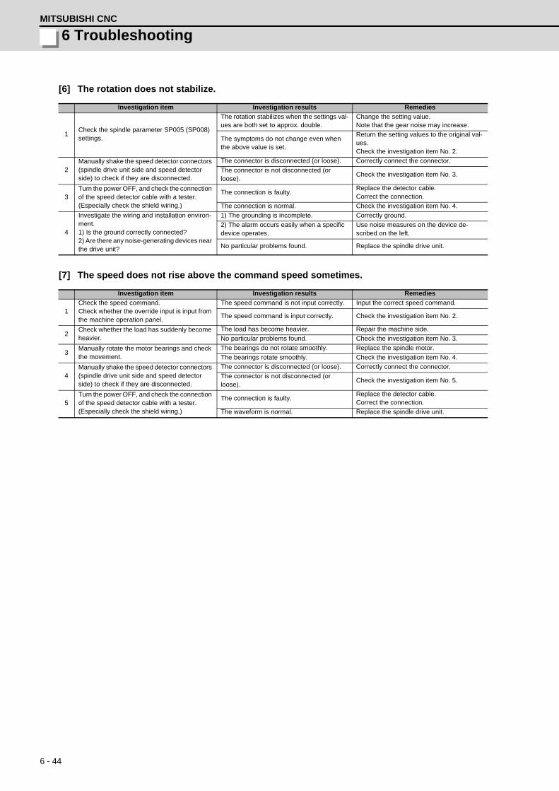
6 - 44
6 TroubleshootingMITSUBISHI CNC
[6] The rotation does not stabilize.
[7] The speed does not rise above the command speed sometimes.
Investigation item Investigation results Remedies
1Check the spindle parameter SP005 (SP008) settings.
The rotation stabilizes when the settings val-ues are both set to approx. double.
Change the setting value.Note that the gear noise may increase.
The symptoms do not change even when the above value is set.
Return the setting values to the original val-ues.Check the investigation item No. 2.
2Manually shake the speed detector connectors (spindle drive unit side and speed detector side) to check if they are disconnected.
The connector is disconnected (or loose). Correctly connect the connector.
The connector is not disconnected (or loose).
Check the investigation item No. 3.
3Turn the power OFF, and check the connection of the speed detector cable with a tester.(Especially check the shield wiring.)
The connection is faulty.Replace the detector cable.Correct the connection.
The connection is normal. Check the investigation item No. 4.
4
Investigate the wiring and installation environ-ment.1) Is the ground correctly connected?2) Are there any noise-generating devices near the drive unit?
1) The grounding is incomplete. Correctly ground.
2) The alarm occurs easily when a specific device operates.
Use noise measures on the device de-scribed on the left.
No particular problems found. Replace the spindle drive unit.
Investigation item Investigation results Remedies
1Check the speed command.Check whether the override input is input from the machine operation panel.
The speed command is not input correctly. Input the correct speed command.
The speed command is input correctly. Check the investigation item No. 2.
2Check whether the load has suddenly become heavier.
The load has become heavier. Repair the machine side.
No particular problems found. Check the investigation item No. 3.
3Manually rotate the motor bearings and check the movement.
The bearings do not rotate smoothly. Replace the spindle motor.
The bearings rotate smoothly. Check the investigation item No. 4.
4Manually shake the speed detector connectors (spindle drive unit side and speed detector side) to check if they are disconnected.
The connector is disconnected (or loose). Correctly connect the connector.
The connector is not disconnected (or loose).
Check the investigation item No. 5.
5Turn the power OFF, and check the connection of the speed detector cable with a tester.(Especially check the shield wiring.)
The connection is faulty.Replace the detector cable.Correct the connection.
The waveform is normal. Replace the spindle drive unit.

7 - 1
付録 7 章
7 - 1
7Maintenance

7 - 2
7 MaintenanceMITSUBISHI CNC
7-1 Periodic inspections7-1-1 Inspections
Periodic inspection of the following items is recommended.
[1] Are any of the screws on the terminal block loose? If loose, tighten them.
[2] Is any abnormal noise heard from the servomotor bearings or brake section?
[3] Are any of the cables damaged or cracked? If the cables move with the machine, periodically inspect
the cables according to the working conditions.
[4] Is the core of the load coupling shaft deviated?
7-1-2 Cleaning of spindle motor
If you continue to use the spindle motor with dirt such as oil mist and dust adhered, its cooling performance
degrades and the motor is unable to fully exercise its performance, which may cause the spindle motor
overheat alarm. In some cases this may result in damage to the bearing or cooling fan. To ensure the
cooling capability of the spindle motor's fan, carry out periodical cleaning of the spindle motor and its cooling
fan according to the following cleaning procedure.
Note that the spindle motor SJ-VL Series is used as an example in this procedure. When cleaning the other
spindle motors, carry it out based on this procedure.
1. Before starting maintenance or inspections, turn the main circuit power and control power both
OFF. Wait at least fifteen minutes for the CHARGE lamp to turn OFF, and then using a tester,
confirm that the input and output voltage are zero. Failure to observe this could lead to electric
shocks.
2. Inspections must be carried out by a qualified technician. Failure to observe this could lead to
electric shocks. Contact your nearest Mitsubishi branch or dealer for repairs and part replacement.
1. Never perform a megger test (measure the insulation resistance) of the servo drive unit. Failure to
observe this could lead to faults.
2. The user must never disassemble or modify this product.
Do not touch the motor for some time after turning OFF the power, as the motor remains at a high
temperature. This may lead to burns.
WARNING
CAUTION
CAUTION

7 - 3
MDS-D/DH Series Instruction Manual
7-1 Periodic inspections
(1) Detaching the cooling fan unit
Remove the cooling fan unit from the spindle motor.
[1] Disconnect the cooling fan's terminals from the terminal block (See the diagram below).
[2] Detach the cooling fan unit from the spindle motor.
Remove the four hexagon socket screws used to secure the cooling fan unit to the spindle motor.
When slowly removing the cooling fan unit from the spindle motor, also unplug the fan drive cable slowly
with the rubber packing left in the terminal box.
(Note 1) Pull out the solderless terminals one by one as the hole on the terminal box is small.
(Note 2) Take extra care not to damage the cable.
Terminal box inside
Rubber packingFan drive cable
Cooling fan terminals
(BU, BV and BW) for three-phase
(BU and BV) for single-phase
Spindle motor
A
A
View A-ACooling fan unit
Spindle motor
Finger guard
Hexagon socket screws at four locations.
Terminal box
Fan drive cable
Terminal boxFan drive cable
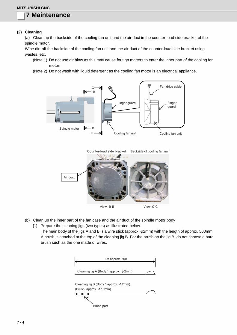
7 - 4
7 MaintenanceMITSUBISHI CNC
(2) Cleaning
(a) Clean up the backside of the cooling fan unit and the air duct in the counter-load side bracket of the
spindle motor.
Wipe dirt off the backside of the cooling fan unit and the air duct of the counter-load side bracket using
wastes, etc.
(Note 1) Do not use air blow as this may cause foreign matters to enter the inner part of the cooling fan
motor.
(Note 2) Do not wash with liquid detergent as the cooling fan motor is an electrical appliance.
(b) Clean up the inner part of the fan case and the air duct of the spindle motor body
[1] Prepare the cleaning jigs (two types) as illustrated below.
The main body of the jigs A and B is a wire stick (approx. φ2mm) with the length of approx. 500mm.
A brush is attached at the top of the cleaning jig B. For the brush on the jig B, do not choose a hard
brush such as the one made of wires.
CB
BC
Finger guard
Cooling fan unitSpindle motor
Cooling fan unit
Fan drive cable
Finger guard
B-B C-C
Counter-load side bracket Backside of cooling fan unit
Air duct
View View
L= approx. 500
Cleaning jig A (Body: approx. 2mm)
Cleaning jig B (Body:approx. 2mm)(Brush: approx. 10mm)
Brush part
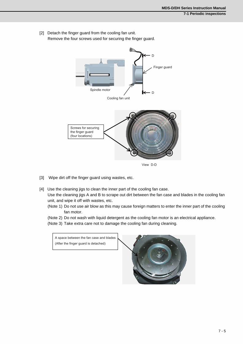
7 - 5
MDS-D/DH Series Instruction Manual
7-1 Periodic inspections
[2] Detach the finger guard from the cooling fan unit.
Remove the four screws used for securing the finger guard.
[3] Wipe dirt off the finger guard using wastes, etc.
[4] Use the cleaning jigs to clean the inner part of the cooling fan case.
Use the cleaning jigs A and B to scrape out dirt between the fan case and blades in the cooling fan
unit, and wipe it off with wastes, etc.
(Note 1) Do not use air blow as this may cause foreign matters to enter the inner part of the cooling
fan motor.
(Note 2) Do not wash with liquid detergent as the cooling fan motor is an electrical appliance.
(Note 3) Take extra care not to damage the cooling fan during cleaning.
D
DSpindle motor
Cooling fan unit
Finger guard
D-D
Screws for securing the finger guard (four locations)
View
A space between the fan case and blades
(After the finger guard is detached)

7 - 6
7 MaintenanceMITSUBISHI CNC
[5] Use the cleaning jigs to clean the air ducts of the spindle motor body.
Insert the cleaning jigs A and B into the motor's air ducts from the counter-load side bracket, scrape
out the dirt, and wipe it off with wastes, etc.
(3) Assembling
After all the cleaning processes have been completed, attach the cooling fan unit to the motor in the order
opposite to that of the detachment process. After attaching the unit, perform a test run to check the air blow
direction of the fan, etc.
Be careful not to pinch the cable between the cooling fan unit and the terminal box.
E
ESpindle motor
Cooling fan unit
E-E
Spindle motor air ducts
View
Spindle motor air ducts
Fan drive cable
Exhaust
Cooling fan unit

7 - 7
MDS-D/DH Series Instruction Manual
7-2 Service parts
7-2 Service partsA guide to the part replacement cycle is shown below. Note that these will differ according to the working
conditions or environmental conditions, so replace the parts if any abnormality is found. Contact Mitsubishi
branch or your dealer for repairs or part replacements.
[1] Power smoothing capacitor:
The characteristics of the power smoothing capacitor will deteriorate due to the effect of ripple currents,
etc. The capacitor life is greatly affected by the ambient temperature and working conditions. However,
when used continuously in a normal air-conditioned environment, the service life will be ten years.
[2] Relays:
Contact faults will occur due to contact wear caused by the switching current. The service life will be
reached after 100,000 cumulative switches (switching life) although this will differ according to the
power capacity.
[3] Servomotor bearings:
The motor bearings should be replaced after 20,000 to 30,000 hours of rated load operation at the rated
speed. This will be affected by the operation state, but the bearings must be replaced when any
abnormal noise or vibration is found in the inspections.
[4] Servomotor oil seal, V-ring:
These parts should be replaced after 5,000 hours of operation at the rated speed. This will be affected
by the operation state, but these parts must be replaced if oil leaks, etc., are found in the inspections.
Part name Standard replacement time Remarks
Servo drive unit
Smoothing capacitor 10 years
The standard replacement time is a reference. Even if the standard replacement time is not reached, the part must be replaced if any abnormality is found.
Cooling fan 10,000 to 30,000 hours (2 to 3 years)
Battery10,000 hours
(for ER6V-C119B / MDS-BTBOX-36)
Servomotor
Bearings 20,000 to 30,000 hours
Detector 20,000 to 30,000 hours
Oil seal, V-ring 5,000 hours

7 - 8
7 MaintenanceMITSUBISHI CNC
7-3 Adding and replacing units and parts
1. Correctly transport the product according to its weight. Failure to do so could result in injury.
2. Do not stack the product above the indicated limit.
3. Installation directly on or near combustible materials could result in fires.
4. Install the unit as indicated at a place which can withstand the weight.
5. Do not get on or place heavy objects on the unit. Failure to observe this could result in injury.
6. Always use the unit within the designated environment condition range.
7. Do not allow conductive foreign matter such as screws or metal chips, or combustible foreign
matter such as oil enter the servo drive or servomotor.
8. Do not block the intake or exhaust ports of the servo drive of servomotor. Failure to observe this
could result in faults.
9. The servo drive and servomotor are precision devices. Do not drop them or apply strong impacts.
10.Do not install or operate a servo drive or servomotor which is damaged or missing parts.
11.When the unit has been stored for a long time, contact the Service Center or Service Station.
12.Connect the detector(CN2/CN3) immediately after the installation of the servo drive unit. In
addition, when a battery box is used, immediately connect to the BTA/BTB connector. (prevention
of absolute position data lost)
CAUTION

7 - 9
MDS-D/DH Series Instruction Manual
7-3 Adding and replacing units and parts
7-3-1 Replacing the drive unit
(1) Arrangement of replacing parts
Contact Mitsubishi branch or your dealer for an order or a replacement of the drive unit.
Place an order for the same type of a drive unit as the one to be replaced.
(2) Replacement procedure
Replace the drive unit with the following procedures.
Procedures
[1] Turn the breaker for the input power OFF. Make sure the CHARGE lamp of the power supply unit is
turned OFF.
[2] Disconnect all the connectors and the wires connected to the drive unit.
[3] Remove the two (four) screws fixing the drive unit onto the control panel. Remove the drive unit
from the control panel.
[4] Make a same setting for the rotary switch and the dip switch of the new drive unit as those of the
uninstalled drive unit.
[5] Install a new drive unit by following the removal procedure in reverse.
(3) Restoration
Data backup and restoration is not required before replacing drive units because drive units’ data such
as parameters are stored in the controller. However, carry out a backup of the whole system before
replacement as a precautionary measure.
The power for keeping the detector’s position data of an absolute position system is supplied from the
battery connected to the drive unit. Keep the power ON once for 30 minutes or more if possible, and
make sure to complete the replacement within 60 minutes after charging the detector’s capacitor.

7 - 10
7 MaintenanceMITSUBISHI CNC
7-3-2 Replacing the unit fan
(1) Replacing parts
< MDS-D Series >
< MDS-DH Series >
Servo drive unit Spindle drive unit Power supply unit
TypeMDS-D-
Fan typeSize[mm]
TypeMDS-D-
Fan typeSize[mm]
TypeMDS-D-
Fan typeSize[mm]
V1-20
9WF0424H6D05 40SQ.
SP-20
9WF0424H6D05 40SQ.
CV-37 - -
V1-40 SP-40 CV-75 109P0424H3D13 40SQ.
V1-80 SP-80 CV-1109WF0624H4D04 60SQ.
V1-160 SP-160 9WF0624H4D04 60SQ. CV-185
V1-160W 9WF0624H4D04 60SQ. SP-200MMF-09D24TS-MM6 90SQ.
CV-300MMF-09D24TS-MM6 90SQ.
V1-320MMF-09D24TS-MM6 90SQ.
SP-240 CV-370
V1-320W SP-320 MMF-12D24DS-MM6 120SQ. CV-450MMF-12D24DS-MM6 120SQ.
V2-2020
9WF0424H6D05 40SQ.
SP-400 MMF-09D24TS-MMB 90SQ. CV-550
V2-4020 SP-640 MMF-12D24DS-MM6 120SQ.
V2-4040 SP2-2020
9WF0424H6D05 40SQ.V2-8040 SP2-4020
V2-8080 SP2-4040S
V2-160809WF0624H4D04 60SQ.
SP2-4040
9WF0624H4D04 60SQ.V2-160160 SP2-8040
V2-160160W MMF-09D24TS-MM6 90SQ. SP2-16080S
SP2-8080MMF-09D24TS-MM6 90SQ.
SP2-16080
Servo drive unit Spindle drive unit Power supply unit
TypeMDS-DH-
Fan typeSize[mm]
TypeMDS-DH-
Fan typeSize[mm]
TypeMDS-DH-
Fan typeSize[mm]
V1-10 - - SP-209WF0424H6D05 40SQ.
CV-37
9WF0624H4D04 60SQ.V1-20
9WF0424H6D05 40SQ.
SP-40 CV-75
V1-40 SP-80 9WF0624H4D04 60SQ. CV-110
V1-80 SP-100MMF-09D24TS-MM6 90SQ.
CV-185
V1-80W 9WF0624H4D04 60SQ. SP-160 CV-300
MMF-09D24TS-MM6 90SQ.V1-160MMF-09D24TS-MM6 90SQ.
SP-200MMF-09D24TS-MMB 90SQ.
CV-370
V1-160W SP-320 CV-450
V1-200 MMF-09D24TS-MMB 90SQ. SP-480 MMF-12D24DS-MM6 120SQ. CV-550MMF-12D24DS-MM6 120SQ.
V2-1010 - - CV-750
V2-2010
9WF0424H6D05 40SQ.V2-2020
V2-4020
V2-4040
V2-80409WF0624H4D04 60SQ.
V2-8080
V2-8080W MMF-09D24TS-MM6 90SQ.

7 - 11
MDS-D/DH Series Instruction Manual
7-3 Adding and replacing units and parts
(2) Replacement procedure
Replace the unit fan with the following procedures.
Procedures
[1] Turn the breaker for the input power OFF, and wait for the CHARGE lamp on the power supply unit
to turn OFF before removing the unit.
[2] Remove the fan guard from the back of the drive unit, and remove the two fan mounting screws.
[3] Remove the rubber bushing for the fan power cable, and pull out the connection connector.
[4] Disconnect the connection connector, and replace the fan.
Remove the two screws
Remove the rubber bushing Pull out the connection
Pull out the connectionconnector and disconnectthe connector

7 - 12
7 MaintenanceMITSUBISHI CNC
7-3-3 Replacing the battery
(1) Replacing parts
<Replacing a battery equipped with the spindle/servo drive unit
or the battery unit, MDS-BTBOX-36>
When the battery voltage is low (warning F9), place an order for the same type of a battery as the one
currently equipped with the unit.
Battery type LR20 is commercially available as a size-D alkaline battery. The battery may be purchased
and replaced by the user.
Battery type
(Note) Four LR20 size-D alkaline batteries are needed for per battery unit, MDS-BTBOX-36.
<Replacing the battery unit MDS-A-BT>
The battery unit itself must be replaced because the battery is built into the unit.
When the battery voltage is low (warning F9), place an order for the same type of the battery unit as the
one to be replaced.
(2) Replacement procedure
Replace the battery with the following procedures.
<Replacement procedure for the cell battery ER6V-C119B>
[1] Turn the breaker for the input power OFF. Make sure the power of the replacing drive unit is turned
OFF.
[2] Open the battery holder cover located at the front of the drive unit.
[3] Pull out the battery connector connected with the drive unit. Remove the battery.
[4] Connect a new battery connector to the connector position where the old battery connector was
pulled out from in step [2].
[5] Store a new battery into the battery holder and close the cover.
Type Battery equipped unit
ER6V-C119B Spindle/servo drive unit
LR20 (size-D alkaline battery) Battery unit, MDS-BTBOX-36
1. When the battery voltage is low (warning 9F), do not shut OFF the power of the drive unit until
replacement of the battery to protect the data
2. Replace the MDS-BTBOX-36 battery with new batteries (LR20) that is within the recommended
service period.
1. The power of the drive unit must be turned ON for 30min. or longer before replacing the battery.
2. Replace the battery within one hour.
CAUTION
CAUTION
Pull out the battery
Pull the cover open while holding down the tab of the battery holder.
Connect the battery connector to the connector position where pulled out from.
Store a new battery into the battery holder.

7 - 13
MDS-D/DH Series Instruction Manual
7-3 Adding and replacing units and parts
<Replacement procedure for the battery unit MDS-BTBOX-36>
Possible backup period
Possible backup period is at most one year. Thus, make sure to exchange the batteries in the one-
year cycle.
How to replace the battery
[1] Remove the battery box cover (four screws).
[2] Replace the batteries with new ones. Be careful not to mistake the polarity.
[3] Attach the cover, and fix it with the four screws.
(Note 1) Replace the batteries while applying control power to the servo drive unit.
(Note 2) If the cover is ill-set, mist enters through the interstices and enter into the panel. Tighten
the screws.
<Replacement procedure for the battery unit MDS-A-BT>
[1] Turn the breaker for the input power OFF. Make sure the power of the replacing drive unit is turned
OFF.
[2] Disconnect the connector, and remove the battery unit from the control panel.
[3] Install a new battery unit by following the removal procedure in reverse.
1.Use new batteries that are within the recommended service period. (Check the recommended
service period written on the batteries before using them.)
2. Replace the batteries with new ones immediately after the battery voltage drop alarm (9F) has
been output.
3. Replace the batteries while applying the servo drive unit’s control power.
4. Wrong connection may cause liquid leakage, heat generation and/or explosion.
5.Do not mix new batteries with used ones or mix different type batteries.
Alkaline dry batteriesLR20 x 4 pieces
CAUTION

7 - 14
7 MaintenanceMITSUBISHI CNC
7-3-4 Replacing the fuse
(1) Replacing partsFuse type
(2) Replacement procedure
Replace the fuse with the following procedures.
Procedures
[1] Turn the breaker for the input power OFF. Make sure the power of the replacing drive unit is turned
OFF.
[2] Open the terminal block cover located at the front of the drive unit.
[3] Pull out the fuse and replace it by a new fuse.
Type Fuse equipped unit
HM32 MDS-D series
HM16 MDS-DH series
Open the terminal block cover.
Pull out the fuse using forceps.

Appendix 1 - 1
付録 Appendix 1 章
Appendix 1 - 1
Appendix 1Cable and Connector
Specifications

Appendix 1 - 2
Appendix 1 Cable and Connector SpecificationsMITSUBISHI CNC
Appendix 1-1 Selection of cableAppendix 1-1-1 Cable wire and assembly
(1) Cable wire
The specifications of the wire used for each cable, and the machining methods are shown in this section.
When manufacturing the detector cable and battery connection cable, use the recommended wires shown
below or equivalent products.
(a) Heat resistant specifications cable
(b) General-purpose heat resistant specifications cable
(Note 1) Bando Electric Wire (Contact: 81+48-461-0561 http://www.bew.co.jp)
(Note 2) The Mitsubishi standard cable is the (a) Heat resistant specifications cable. For MDS-C1/CH
series, (b) or equivalent is used as the standard cable.
Core identification
Wire type(other manufactur-
er's product)
Finish outer
diameter
Sheath material
No. of pairs
Wire characteristics
Configura-tion
Conduc-tive
resistor
With-stand
voltage
Insulation resis-tance
Heat resistance tempera-
ture
Flexibility
BD20288Compound 6-pair shielded cable Specification No. Bangishi-17145(Note 1)
8.7mmHeat re-sistant PVC
2
(0.5mm2)
100 strands/0.08mm
40.7Ω/kmor less
500VAC/1min
1000MΩ/kmor more
105°C
70×104 times
or more at R200
4
(0.2mm2)
40 strands/0.08mm
103Ω/kmor less
Wire type(other manufactur-
er's product)
Finish outer
diameter
Sheath material
No. of pairs
Wire characteristics
Configura-tion
Conductiveresistor
With-stand
voltage
Insulation resistance
Heat resistance tempera-
ture
Flexibility
BD20032Compound 6-pair shielded cable Specification No. Bangishi-16903 Revision No. 3(Note 2))
8.7mm PVC
2
(0.5mm2)100strands/
0.08mm40.7Ω/km
or less
500VAC/1min
1000MΩ/kmor more
60°C100×104 times
or more at R200
4
(0.2mm2)40strands/0.08mm
103Ω/kmor less
Pair No.Insulator colorL1 L2
A1 (0.5mm2) Red White
A2 (0.5mm2) Black White
B1 (0.2mm2) Brown Orange
B2 (0.2mm2) Blue Green
B3 (0.2mm2) Purple White
B4 (0.2mm2) Yellow White
A1
A2 B2
B1 B4
B3
L2 L1
Sheath
Mesh shield
Intervening wire
Tape
Compound 6-pair cable structure drawing
Cable core
InsulatorConductor

Appendix 1 - 3
MDS-D/DH Series Instruction Manual
Appendix 1-1 Selection of cable
(2) Cable assembly
Assemble the cable with the cable shield wire securely connected to the ground plate of the connector.
(3) Battery connection cable
Two core shield cable structure drawing
Core identification
Wire type (other manufactur-
er's product)
Finish outer
diame-ter
Sheath material
No. of pairs
Wire characteristics
Configura-tion
Conduc-tive
resistor
With-stand
voltage
Insulation resistance
Heat resistance tempera-
ture
Minimum bend radius
J14B101224-00Two core shield ca-ble
3.3mm PVC1
(0.2mm2)7strands /
0.2mm91.2Ω/km
or lessAC500V/
1min
1000MΩ/km
or less80°C R33mm
No. Insulator color1 Red2 Black
Core wire
Shield(external conductor)
Sheath
Connect with a ground plate of connector.
1
2
JUNFLON ETFE wire
Sheath
Shield
R

Appendix 1 - 4
Appendix 1 Cable and Connector SpecificationsMITSUBISHI CNC
Appendix 1-2 Cable connection diagram
Appendix 1-2-1 Battery cable
<DG21 cable connection diagram
(Connection cable between drive unit and MDS-A-BT/A6BAT (MR-BAT) (MDS-BTCASE)>
<DG22 cable connection diagram (Connection cable between drive unit and drive unit)>
<DG23 cable connection diagram (Connection cable between drive unit and MDS-BTBOX-36)>
<DG24 cable connection diagram
(Connection cable for alarm output between drive unit and MDS-BTBOX-36)>
1. Take care not to mistake the connection when manufacturing the detector cable. Failure to observe
this could lead to faults, runaway or fire.
2. When manufacturing the cable, do not connect anything to pins which have no description.
When DG24 cable is used, proximity switch or external emergency stop cannot be wired, so these
functions cannot be used.
CAUTION
12
9 1 PE
BTLG
BT LG
0.2mm2
Drive unit side connector
Connector: DF1B-2S-2.5RContact: DF1B-2428SCA
Battery unit side connector
Connector: 10120-3000VEShell kit: 10320-52F0-008
Casegrounding
(Hirose Electric) (3M)
12
1 2
BTLG
BT LG
0.2mm2
Drive unit side connector
Connector: DF1B-2S-2.5RContact: DF1B-2428SCA
Drive unit side connector
Connector: DF1B-2S-2.5RContact: DF1B-2428SCA
(Hirose Electric) (Hirose Electric)
1 2
BTLG
BTLG0.2mm2
: DF1B-2S-2.5R: DF1B-2428SCA
Battery box sideDrive unit side connector
Connector Contact
(Hirose Electric)
20 13
4 1
FG
DICOMD11
P5LG
+24VDO(ALM)
+5VLG0.2mm2
:10120-3000VE:10320-52F0-008
0.2mm2
0.2mm2
Casegrounding
(DC power)
Drive unit side connector
ConnectorShell kit
Battery box side(3M)
CAUTION

Appendix 1 - 5
MDS-D/DH Series Instruction Manual
Appendix 1-2 Cable connection diagram
Appendix 1-2-2 Power supply communication cable and connector
<SH21 cable connection diagram>
<CNU23S connector connection diagram>
1 11 2 12 3 13 4 14 5 15 6 16 7 17 8 18 9 19 10 20
PE
1
112
123
134
145
156
167
178
189
191020
PE
Drive unit side connector
Connector: 10120-3000VEShell kit: 10320-52F0-008
Power supply unit side connector
Connector: 10120-3000VEShell kit: 10320-52F0-008
Plate
(3M) (3M)
3
1
CN23A
EMG2 EMG1
3
1
CN23B
MC2
MC1
24G 2
2
External emergencystop input
Power supply unit side connector
Connector: DK-3200M-06RXYContact: DK-3REC2LLP1-100
Contactorbreaker output
(DDK)
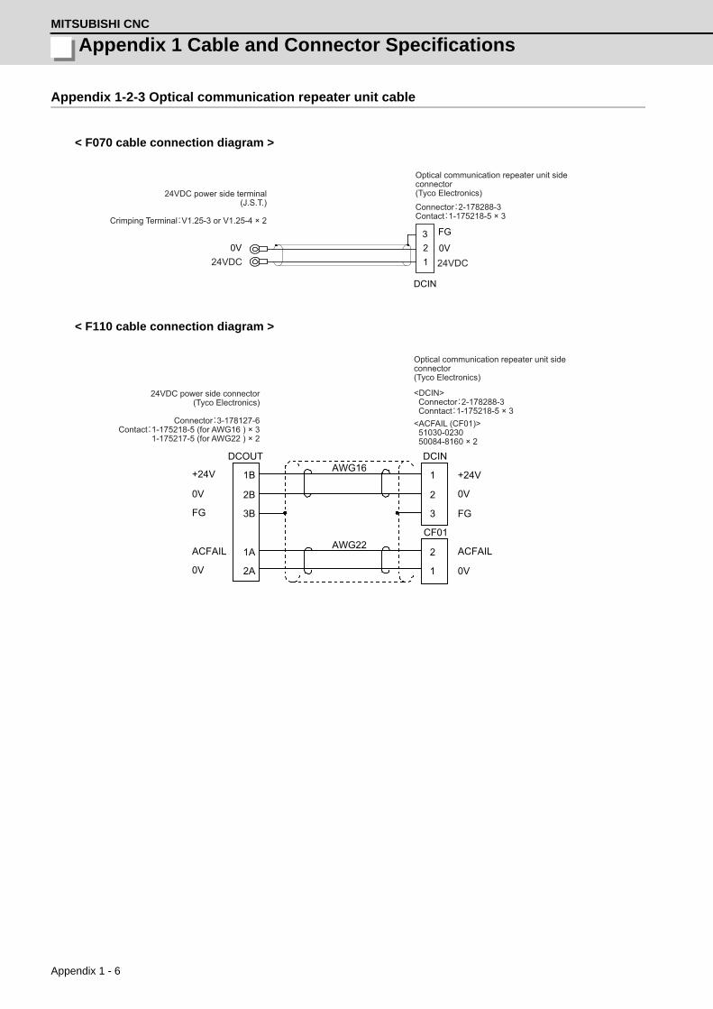
Appendix 1 - 6
Appendix 1 Cable and Connector SpecificationsMITSUBISHI CNC
Appendix 1-2-3 Optical communication repeater unit cable
< F070 cable connection diagram >
< F110 cable connection diagram >
DCIN
0V
FG
123
0V
Optical communication repeater unit side connector(Tyco Electronics)24VDC power side terminal
(J.S.T.)
Crimping Terminal:V1.25-3 or V1.25-4 × 2
24VDC24VDC
Connector:2-178288-3Contact:1-175218-5 × 3
+24V
0V
FG
ACFAIL
0V
1B
2B
3B
1A
2A
1
2
3
2
1
+24V
0V
FG
ACFAIL
0V
AWG16
AWG22
DCOUT DCIN
CF01
<ACFAIL (CF01)> 51030-0230 50084-8160 × 2
24VDC power side connector(Tyco Electronics)
Connector:3-178127-6Contact:1-175218-5 (for AWG16 ) × 3
1-175217-5 (for AWG22 ) × 2
Optical communication repeater unit side connector(Tyco Electronics)
<DCIN> Connector:2-178288-3 Conntact:1-175218-5 × 3
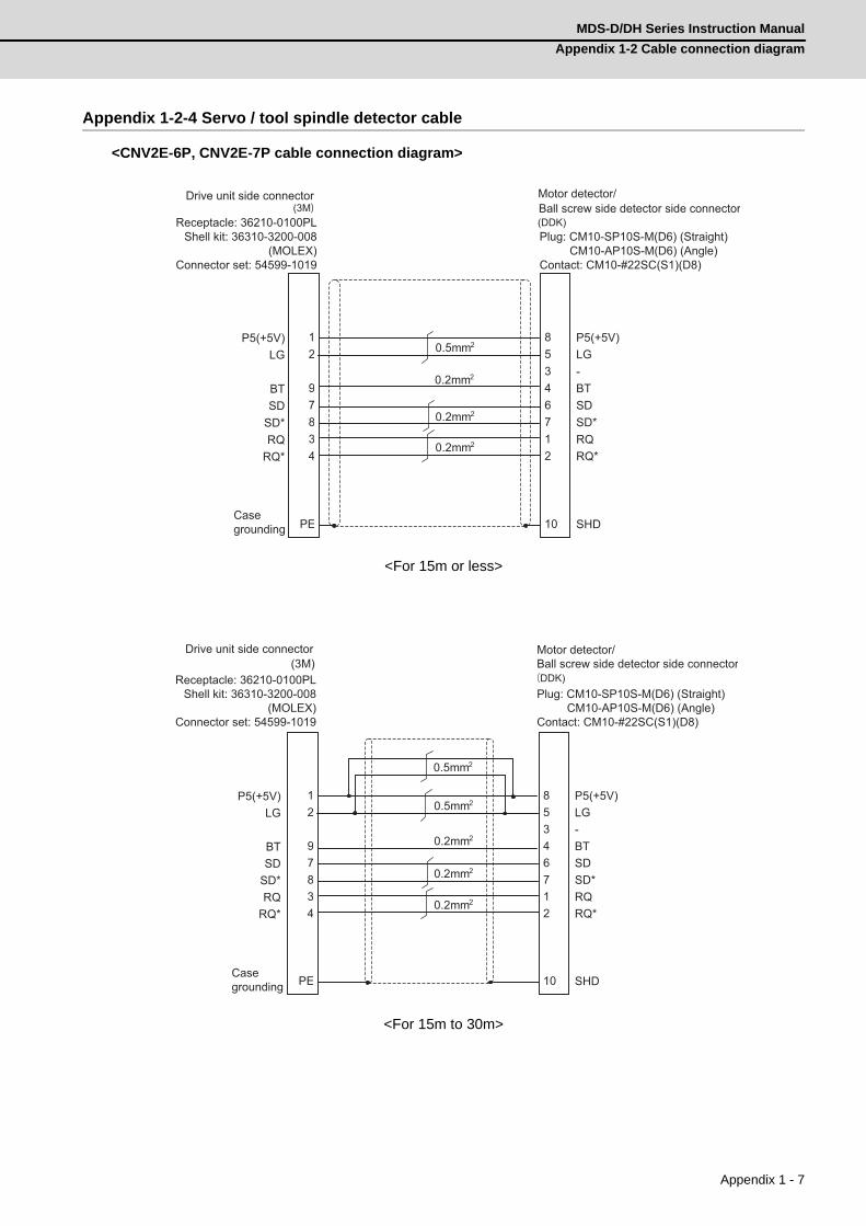
Appendix 1 - 7
MDS-D/DH Series Instruction Manual
Appendix 1-2 Cable connection diagram
Appendix 1-2-4 Servo / tool spindle detector cable
<CNV2E-6P, CNV2E-7P cable connection diagram>
<For 15m or less>
<For 15m to 30m>
12
97834
PE
8 5 3 4 6 7 1 2 10
P5(+5V)LG
BTSD
SD*RQ
RQ*
P5(+5V) LG - BT SD SD* RQ RQ* SHD
0.5mm2
0.2mm2
0.2mm2
0.2mm2
Drive unit side connector
Receptacle: 36210-0100PLShell kit: 36310-3200-008
(MOLEX)Connector set: 54599-1019
Motor detector/Ball screw side detector side connector
Plug: CM10-SP10S-M(D6) (Straight)CM10-AP10S-M(D6) (Angle)
Contact: CM10-#22SC(S1)(D8)
Casegrounding
(3M)(DDK)
12
97834
PE
8 5 3 4 6 7 1 2 10
P5(+5V)LG
BTSD
SD*RQ
RQ*
P5(+5V) LG - BT SD SD* RQ RQ* SHD
0.5mm2
0.2mm2
0.5mm2
0.2mm2
0.2mm2
Drive unit side connector(3M)
Receptacle: 36210-0100PLShell kit: 36310-3200-008
(MOLEX)Connector set: 54599-1019
Casegrounding
Motor detector/Ball screw side detector side connector
Plug: CM10-SP10S-M(D6) (Straight)CM10-AP10S-M(D6) (Angle)
Contact: CM10-#22SC(S1)(D8)
(DDK)
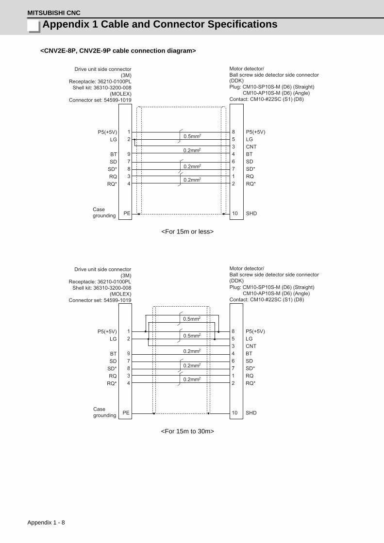
Appendix 1 - 8
Appendix 1 Cable and Connector SpecificationsMITSUBISHI CNC
<CNV2E-8P, CNV2E-9P cable connection diagram>
<For 15m or less>
<For 15m to 30m>
12
97834
PE
8 5 3 4 6 7 1 2 10
P5(+5V)LG
BTSD
SD*RQ
RQ*
P5(+5V) LG CNT BT SD SD* RQ RQ* SHD
0.5mm2
0.2mm2
0.2mm2
0.2mm2
Drive unit side connector(3M)
Receptacle: 36210-0100PLShell kit: 36310-3200-008
(MOLEX)Connector set: 54599-1019
Casegrounding
Motor detector/Ball screw side detector side connector
Plug: CM10-SP10S-M (D6) (Straight)CM10-AP10S-M (D6) (Angle)
Contact: CM10-#22SC (S1) (D8)
(DDK)
12
97834
PE
8 5 3 4 6 7 1 2 10
P5(+5V)LG
BTSD
SD*RQ
RQ*
P5(+5V) LG CNT BT SD SD* RQ RQ* SHD
0.5mm2
0.2mm2
0.5mm2
0.2mm2
0.2mm2
Drive unit side connector(3M)
Receptacle: 36210-0100PLShell kit: 36310-3200-008
(MOLEX)Connector set: 54599-1019
Casegrounding
Motor detector/Ball screw side detector side connector
Plug: CM10-SP10S-M (D6) (Straight)CM10-AP10S-M (D6) (Angle)
Contact: CM10-#22SC (S1) (D8)
(DDK)

Appendix 1 - 9
MDS-D/DH Series Instruction Manual
Appendix 1-2 Cable connection diagram
< CNV2E-K1P, CNV2E-K2P cable connection diagram (Direct connection type) >
< CNV22J-K1P, CNV22J-K2P cable connection diagram (Relay type) >
365487219
P5LGMR
MRRMD
MDRBAT
SD
P5P5GMRMRRMDMDRBATCONTSD
1234789
Plate
(3M)
: 36210 - 0100PL : 36310 - 3200- 008
( ) : 54599-1019
Servo drive unit side connector
ReceptacleShell kit
MOLEXConnector set
Servo motor detector connector(Tyco Electronics)Connector : 1674320-1
8 5
4 6 7 1 2
361287 54 910
BT SD
SD* RQ
RQ*
CNT BT SD SD* RQ RQ* SHD
0.08mm2
0.08mm2
0.08mm2
0.08mm2
P5(+5V)LG
P5(+5V)LG
Drive unit side connector
Casegrounding
Motor detector/Ball screw side detector side connector
Plug: 1747464-1Contact: 1674335-4
Plug: CM10-CR10P-M(DDK) (Tyco Electronics)

Appendix 1 - 10
Appendix 1 Cable and Connector SpecificationsMITSUBISHI CNC
<CNV2E-HP cable connection diagram>
<CNV2E-D cable connection diagram>
1 2
10 3 4 5 6 7 8
PE
5 7 6 8 1 2 3 4 PE
P5(+5V)LG
RQRQ*
SDSD*
P5(+5V) LG P5(+5V) LG RQ RQ* SD SD*
0.5mm2
0.5mm2
0.2mm2
0.2mm2
Drive unit side connector(3M)
Receptacle: 36210-0100PLShell kit: 36310-3200-008
(MOLEX)Connector set: 54599-1019
MDS-B-HR unit side connector
Plug: RM15WTP-8SClamp: RM15WTP-CP (10)
Casegrounding
Casegrounding
(Hirose Electric)
1 2 9
10 3 4 5 6 7 8
PE
20 11 10 1 9 7 17 6 16 PE
P5(+5V)LG
RQRQ*
SDSD*
P5(+5V) LG P5(+5V) LG BAT RQ RQ* SD SD*
0.5mm2
0.5mm2
0.2mm2
0.2mm2
Drive unit side connector(3M)
Receptacle: 36210-0100PLShell kit: 36310-3200-008
(MOLEX)Connector set: 54599-1019
MDS-B-SD unit side connector
Connector: 10120-3000VEShell kit: 10320-52F0-008
Casegrounding
Casegrounding
(3M)

Appendix 1 - 11
MDS-D/DH Series Instruction Manual
Appendix 1-2 Cable connection diagram
<Cable connection diagram between scale I/F unit and scale (CNLH3 cable, etc.) >
9
10 7
8
1
2
3
4
5
6
11
12
PE
0.5mm2
0.5mm2
0.2mm2
0.2mm2
0.2mm2
0.2mm2
0.2mm2R-R+B-
SDSD*
RQ*RQ
A-A+
B+
P5(+5V)LG
Detector conversion unit side connector
Plug: RM15WTP-12PClamp: RM15WTP-CP (10)
Casegrounding
(Note) This cable must be prepared by the user.
(Hirose Electric)

Appendix 1 - 12
Appendix 1 Cable and Connector SpecificationsMITSUBISHI CNC
<Rectangular wave communication detector (linear scale, etc.) cable connection diagram>
(Note) This cable must be prepared by the user.
<Serial communication detector (linear scale, etc.) cable connection diagram>
(Note) This cable must be prepared by the user.
For compatible detector, refer to the section "Servo option" in Specifications Manual.
12103456789
PE
P5(+5V)LG
ABZSEL*AA*BB*ZZ*
P5(+5V)LG
AA*BB*ZZ*
SHD
0.5mm2
0.5mm2
0.2mm2
0.2mm2
0.2mm2
Drive unit side connector
(3M)Receptacle: 36210-0100PL
Shell kit: 36310-3200-008(MOLEX)
Connector set: 54599-1019
Casegrounding
Contact the detector manufacturefor the details.
(Note) Contact the detector manufacture about whether to perform the P5V wiring or not.
Machine side rectangular wave communication detector
1 29
10345678
PE
P5(+5V)LG
RQRQ*
SDSD*
P5(+5V) LG RQ RQ* SD SD* SHD
0.5mm2
0.5mm2
0.2mm2
0.2mm2
Drive unit side connector
(3M)Receptacle: 36210-0100PL
Shell kit: 36310-3200-008(MOLEX)
Connector set: 54599-1019
Casegrounding
Contact the detector manufacturefor the details.
(Note) Contact the detector manufacture about whether to perform the P5V wiring or not.
Machine side serial communication detector
POINT

Appendix 1 - 13
MDS-D/DH Series Instruction Manual
Appendix 1-2 Cable connection diagram
Appendix 1-2-5 Brake connector (Brake connector for motor brake control output)
<CNU20S connector connection diagram>
• For MDS-D-V1-320 or smaller and MDS-DH-V1-160 or smaller
• For MDS-D-V1-320W or larger and MDS-DH-V1-160W or larger
<MR-BKS1CBLM-A1-H, MR-BKS1CBLM-A2-H cable connection diagram>
3 2 1
CN20
MBRDBRP24
Drive unit side connector
Connector: DK-3200S-03RContact: DK-3REC2LLP1-100
External power (+24V)
Motor brake
(DDK)
1 2 3
CN20
MBRDBRP24
Drive unit side connector
Connector: DK-3200S-03RContact: DK-3REC2LLP1-100
External power (+24V)
Motor brakeDynamic brake
(DDK)
3 2 1
CN20
MBRDBRP24 1
2
B1
B2
Motor side brake connector(Japan Aviation Electronics Industry)Plug: JN4FT02SJ1-RContact: ST-TMH-S-C1B-100-(A534G)
Drive unit side connector
Connector: DK-3200S-03RContact: DK-3REC2LLP1-100
External power (+24V)
Motor brake
(DDK)

Appendix 1 - 14
Appendix 1 Cable and Connector SpecificationsMITSUBISHI CNC
Appendix 1-2-6 Spindle detector cable
<CNP2E-1 cable connection diagram>
<For 15m or less>
<For 15m to 30m>
12
56
7834
PE
7 8 2 1 5 6 3 4 9
P5(+5V)LG
MT1MT2
SDSD*RQ
RQ*
P5(+5V) LG MT1 MT2 SD SD* RQ RQ* SHD
0.5mm2
0.2mm2
0.2mm2
0.2mm2
Spindle drive unit side connector(3M)
Receptacle: 36210-0100PLShell kit: 36310-3200-008
(MOLEX)Connector set: 54599-1019
Casegrounding
(Note) For the pin "7" or "8", use the contact "170364-1". For the other pins, use the contact "170363-1".
(Note)
Spindle motor side connector
Connector: 172169-1Contact: 170363-1(AWG26-22) 170364-1(AWG22-18)
(Tyco Electronics)
12
56
7834
PE
7
8 2 1 5 6 3 4 9
P5(+5V)LG
MT1MT2
SDSD*RQ
RQ*
P5(+5V) LG MT1 MT2 SD SD* RQ RQ* SHD
0.5mm2
0.2mm2
0.2mm2
0.2mm2
0.5mm2
Spindle drive unit side connector(3M)
Receptacle: 36210-0100PLShell kit: 36310-3200-008
(MOLEX)Connector set: 54599-1019
Casegrounding
(Note) For the pin "7" or "8", use the contact "170364-1". For the other pins, use the contact "170363-1".
(Note)
Spindle motor side connector
Connector: 172169-1Contact: 170363-1(AWG26-22) 170364-1(AWG22-18)
(Tyco Electronics)

Appendix 1 - 15
MDS-D/DH Series Instruction Manual
Appendix 1-2 Cable connection diagram
<CNP3EZ-2P, CNP3EZ-3P cable connection diagram>
<For 15m or less>
<For 15m to 30m>
12
1034
5 678
PE
H
K A N C R B P
P5(+5V)LG
ABZSEL*A
A*
BB*Z
Z*
P5(+5V) LG A A* B B* Z Z*
0.5mm2
0.2mm2
0.2mm2
0.2mm2
Spindle drive unit side connector(3M)
Receptacle: 36210-0100PLShell kit: 36310-3200-008
(MOLEX)Connector set: 54599-1019
Casegrounding
Spindle motor side connector
Connector: MS3106A20-29S (D190)Back shell: CE02-20BS-S (straight) CE-20BA-S (angle)Clamp: CE3057-12A-3
(DDK)
12
1034
5678
PE
H
K A N C R B P
P5(+5V)LG
ABZSEL*A
A*
BB*Z
Z*
P5(+5V) LG A A* B B* Z Z*
0.5mm2
0.2mm2
0.2mm2
0.2mm2
0.5mm2
Spindle drive unit side connector(3M)
Receptacle: 36210-0100PLShell kit: 36310-3200-008
(MOLEX)Connector set: 54599-1019
Casegrounding
Spindle motor side connector
Connector: MS3106A20-29S (D190)Back shell: CE02-20BS-S (straight) CE-20BA-S (angle)Clamp: CE3057-12A-3
(DDK)

Appendix 1 - 16
Appendix 1 Cable and Connector SpecificationsMITSUBISHI CNC
Appendix 1-3 Main circuit cable connection diagram
The methods for wiring to the main circuit are shown below.
<DRSV1/DRSV2 cable connection diagram>
These cables are used to connect the drive unit's TE1 terminal and HF, HP, HF-H, HP-H series motor.
• DRSV1 cable: This is the power line for the single-axis unit (MDS-D/DH-V1-) and dual-axis
integrated unit (MDS-D/DH-V2-) L axis.
• DRSV2 cable: This is the power line for the dual-axis integrated unit (MDS-D/DH-V2-) M axis.
<HF-KP motor cable connection diagram>
This cable is used to connect the drive unit's TE1 terminal and HF-KP series motor.
1. The main circuit cable must be manufactured by the user.
2. Refer to the section "Specification of Peripheral Devices" in Specifications Manual when selecting
the wire material.
3. Lay out the terminal block on the drive unit side as shown in "DRIVE SYSTEM DATA BOOK".
4. Refer to "DRIVE SYSTEM DATA BOOK" for details on the motor's connectors and terminal block.
1: U 2: V 3: W 4:
A B C D
Drive unit side Motor side
1: U 2: V 3: W 4:
2: U 3: V 4: W 1:
Motor side power connector(Japan Aviation Electronics Industry)Plug: JN4FT04SJ1-RContact: ST-TMH-S-C1B-100-(A534G)Drive unit side
CAUTION

Appendix 1 - 17
MDS-D/DH Series Instruction Manual
Appendix 1-4 Connector outline dimension drawings
Appendix 1-4 Connector outline dimension drawings
Appendix 1-4-1 Connector for drive unit
Optical communication cable connector
(Note 1) The POF fiber's light amount will drop depending on how the fibers are wound. So, try to avoid
wiring the fibers.
(Note 2) Do not wire the optical fiber cable to moving sections.
(Note 1) The PCF fiber's light amount will drop depending on how the fibers are wound. So, try to avoid
wiring the fibers.
(Note 2) Do not wire the optical fiber cable to moving sections.
For wiring between NC and drive unit
Refer to the instruction manual for CNC.
Optical communication connector
For wiring between drive units (inside panel)Manufacturer: Japan Aviation Electron-ics Industry<Type>Connector:2F-2D103
[Unit:mm]
Cable appearance<Type>Connector: 2F-2D103 (Japan Aviation Electronics Industry)Optical fiber: ESKA Premium(MITSUBISHI RAYON)
For wiring between drive units (outside panel)Manufacturer: Tyco Electronics<Type>Connector: 1123445-1
[Unit:mm]
Cable appearance<Type>Connector: 1123445-1(Tyco Electronics)Optical fiber: ESKA Premium(MITSUBISHI RAYON)
(13.4) (15) (6.7)
(20.
9)8+0
37.65
(2.3
)(1
.7)
L 0.1
L 0.2
m
m
22.7
8.5
20
.3

Appendix 1 - 18
Appendix 1 Cable and Connector SpecificationsMITSUBISHI CNC
Connector for detector cable
Connector for CN4/9
Spindle drive unit Connector for CN2/3
Manufacturer: 3M<Type>Receptacle: 36210-0100PLShell kit: 36310-3200-008Manufacturer: MOLEX<Type>Connector set: 54599-1019
[Unit:mm]
Connector for CN4/9
Manufacturer: 3M<Type>Connector: 10120-3000VEShell kit: 10320-52F0-008
[Unit:mm]
Manufacturer: 3M<Type>Connector: 10120-6000ELShell kit:10320-3210-000This connector is integrated with the ca-ble, and is not available as a connector set option.
[Unit:mm]
22.4
8
10
11
33.9
22.7
33.3
22.0
39.0
23.8
14.0
12.7
12.0
10.0
11.5
20.9
33.0
42.0
29.7

Appendix 1 - 19
MDS-D/DH Series Instruction Manual
Appendix 1-4 Connector outline dimension drawings
Motor power connector
Connector for motor brake control output
Power supply unit connector for CN23 (Contactor control output / external emergency stop)
Power connector for drive unit TE1
Manufacturer: DDK<Type>Housing: DK-5200S-04R
[Unit:mm]
Brake connector for motor brake control output
Manufacturer: DDK<Type>Connector: DK-3200S-03R
[Unit:mm]
Power supply unit connector for CN23 (Connector for contactor control output / external emergency stop)
Manufacturer: DDK<Type>Connector: DK-3200M-06RXY
[Unit:mm]
48.48
10.16
9.1
10.5
44.08
56.08
30.5
22.8
29.70
19.24
6.55
7.15
5.08
7.62
5.08
14.7
7
19.24
27.30
22.8

Appendix 1 - 20
Appendix 1 Cable and Connector SpecificationsMITSUBISHI CNC
Battery power input connector
Battery connector for drive unit
Manufacturer: Hirose Electric<Type>Connector: DF1B-2S-2.5R
[Unit:mm]
11.5
4.4
1.6
1.
9
5.0
2.5

Appendix 1 - 21
MDS-D/DH Series Instruction Manual
Appendix 1-4 Connector outline dimension drawings
Appendix 1-4-2 Connector for servo and tool spindle
Motor detector connector
(Note) For the manufacturing method of CM10 series connector, refer to the section "Cable and connector
assembly" in Instruction Manual.
Motor side detector connector / Ball screw side detector for connector
Manufacturer: DDK<Type>Plug:CM10-SP10S-M(D6)
[Unit:mm]
Manufacturer: DDK<Type>Plug:CM10-AP10S-M(D6)
[Unit:mm]
Motor side detector connector
Manufacturer: Tyco Electronics<Type>Assembly: 1674320-1
[Unit:mm]
21
(51.4)
21
34
(32.5)
(Φ21
)
15
10 18
23
6.2 6
14.2
13
13.6
30

Appendix 1 - 22
Appendix 1 Cable and Connector SpecificationsMITSUBISHI CNC
Brake connector
(Note) For the manufacturing method of CM10 series connector, refer to the section "Cable and connector
assembly" in Instruction Manual.
Brake connector
Manufacturer: DDK<Type>Plug: CM10-SP2S-S(D6)
[Unit:mm]
Manufacturer: DDK<Type>Plug: CM10-AP2S-S(D6)
[Unit:mm]
Manufacturer: Japan Aviation Electron-ics Industry<Type>JN4FT02SJ1-R
[Unit:mm]
21
(51.4)
21
34
(32.5)
(Φ21
)
26.617
12.3
19 14.3
12.5
12.7
11.8
2.5
R6
11.6
R4

Appendix 1 - 23
MDS-D/DH Series Instruction Manual
Appendix 1-4 Connector outline dimension drawings
Reinforcing cover for connector
(Note 1) For the manufacturing method of CM10 series connector, refer to the section "Cable and connector
assembly" in Instruction Manual.
(Note 2) Use the reinforcing cover if thumping vibration and strong impacts could be applied on the
connector.
Reinforcing cover for connector
Manufacturer: DDK<Type>Reinforcing cover for straight plug:CM10-SP-CV
[Unit:mm]
Manufacturer: DDK<Type>Reinforcing cover for angle plug:CM10-AP-D-CV
[Unit:mm]
40
30
(27)
32
35.6
45
22.8
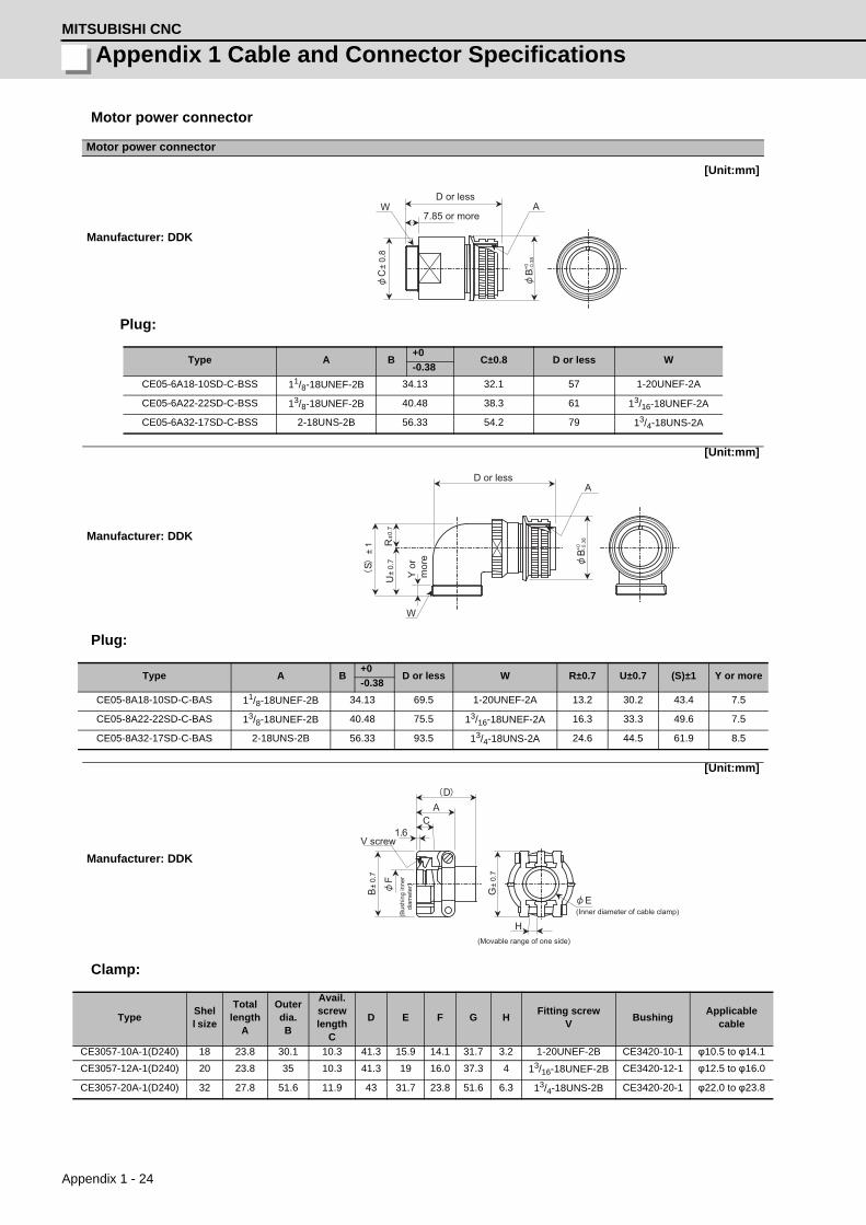
Appendix 1 - 24
Appendix 1 Cable and Connector SpecificationsMITSUBISHI CNC
Motor power connector
Plug:
Plug:
Clamp:
Motor power connector
Manufacturer: DDK
[Unit:mm]
Type A B+0
C±0.8 D or less W-0.38
CE05-6A18-10SD-C-BSS 11/8-18UNEF-2B 34.13 32.1 57 1-20UNEF-2A
CE05-6A22-22SD-C-BSS 13/8-18UNEF-2B 40.48 38.3 61 13/16-18UNEF-2A
CE05-6A32-17SD-C-BSS 2-18UNS-2B 56.33 54.2 79 13/4-18UNS-2A
Manufacturer: DDK
[Unit:mm]
Type A B+0
D or less W R±0.7 U±0.7 (S)±1 Y or more-0.38
CE05-8A18-10SD-C-BAS 11/8-18UNEF-2B 34.13 69.5 1-20UNEF-2A 13.2 30.2 43.4 7.5
CE05-8A22-22SD-C-BAS 13/8-18UNEF-2B 40.48 75.5 13/16-18UNEF-2A 16.3 33.3 49.6 7.5
CE05-8A32-17SD-C-BAS 2-18UNS-2B 56.33 93.5 13/4-18UNS-2A 24.6 44.5 61.9 8.5
Manufacturer: DDK
[Unit:mm]
TypeShell size
Total length
A
Outer dia.B
Avail. screw length
C
D E F G HFitting screw
VBushing
Applicable cable
CE3057-10A-1(D240) 18 23.8 30.1 10.3 41.3 15.9 14.1 31.7 3.2 1-20UNEF-2B CE3420-10-1 φ10.5 to φ14.1
CE3057-12A-1(D240) 20 23.8 35 10.3 41.3 19 16.0 37.3 4 13/16-18UNEF-2B CE3420-12-1 φ12.5 to φ16.0
CE3057-20A-1(D240) 32 27.8 51.6 11.9 43 31.7 23.8 51.6 6.3 13/4-18UNS-2B CE3420-20-1 φ22.0 to φ23.8
W A
C±
0.8
-0.3
8 +0
B
D or less
7.85 or more
R±0
.7
U±
0.7 S
±1
W
A
-0.3
8 +0
B
D or less
Y or
m
ore
E
H
G±
0.7
C A
1.6
F
D
B±
0.7
(Movable range of one side)
(Inner diameter of cable clamp)(Bus
hing
inne
rdi
amet
er)
V screw

Appendix 1 - 25
MDS-D/DH Series Instruction Manual
Appendix 1-4 Connector outline dimension drawings
MDS-B-HR connector
Appendix 1-4-3 Connector for spindle
Motor detector connector
Motor power connector
Manufacturer: Japan Aviation Electron-ics Industry<Type>JN4FT04SJ1-R
[Unit:mm]
MDS-B-HR connector
Manufacturer: Hirose Electric<Type>Plug: RM15WTP-8S (for CON1,2)RM15WTP-12P (for CON3)
[Unit:mm]
Manufacturer: Hirose Electric<Type>Clamp: RM15WTP-CP(10)
[Unit:mm]
Motor side PLG (TS5690) connector
Manufacturer: Tyco Electronics<Type>Plug: 172169-1
[Unit:mm]
11.716
27
24.5
20.1
18.9
4-R2
12.7
7
12.7
13.7
2.5
R0.5
R6
13.1
M16×0.75 M19×1
36.8
15.2
23
8.5
19
20
10.5
M16×0.75
23.7± 0.4
9.3
14
4.2
2.
8
8.4
16± 0.4
2.8
8.4
14
4.2

Appendix 1 - 26
Appendix 1 Cable and Connector SpecificationsMITSUBISHI CNC
Spindle side detector connector (for OSE-1024)
Spindle side detector connector (for OSE-1024)
Manufacturer: DDK<Type>Connector: MS3106A20-29S(D190)
[Unit:mm]
Manufacturer: DDK<Type>Straight back shell: CE02-20BS-S
[Unit:mm]
Manufacturer: DDK<Type>Angle back shell: CE-20BA-S
[Unit:mm]
Manufacturer: DDK<Type>Cable clamp:CE3057-12A-3
[Unit:mm]
-0.2
5 +0
.05
26.8
18.26± 0.12
12.16± 0.3 34.11± 0.5
11/8-18UNEF- 2A
11/4-18UNEF-2B
-0.3
8 +0
37
.28
Gasket
13/16- - 2A
17.8
35
35 10.9
11/8-18UNEF-2B
7.85
31.6
18UNEF
(effective screw length)(Spanner grip)
screw
screw
O-ring
or more
38.6
16.3
49.6
33.3
13/16-18UNEF-2A
11/4-18UNEF-2B
O-ring
screw50.5 or less
39.6 or less
7.5
or m
ore
screw
19
4
37.3
±0.
7
23.8 10.3
1.6
10
41.3
35±
0.7
13/16-18UNEF-2B screw
(Moveable range of one side)
(Cable clamp inside diameter)

Appendix 2 - 1
付録 Appendix 2 章
Appendix 2 - 1
Appendix 2Cable and Connector
Assembly

Appendix 2 - 2
Appendix 2 Cable and Connector AssemblyMITSUBISHI CNC
Appendix 2-1 CM10-SPxxS-x(D6) plug connectorThis section explains how to assemble the wire to CM10 plug connector.
(1) Cutting a cable
Cut the cable to the following dimensions:
(Note) Not to change cable length.
Cable length after cutting = 35±0.5mm for CM10-SPxxS-x(D6) + Cable length
= 35±0.5mm + Cable length
(2) Inserting parts
Insert the clamp nut, the cable clamp, the bushing and the
back shell to the cable.
(Note) Pay attention to the direction each part is inserted.
Make sure that every part is inserted.
(3) Stripping a cable
Strip the cable’s sheath to the A length, cut the wire set at its root and strip the core wire to the B length.
(Note) Make sure to strip the cable to the correct length.
Do not leave cutting or scratch to the cable core.
* When making CM10-SP10S-x(D6), strip the cable for No. 10 terminal in a way that the A length
becomes 1mm longer than that of other cables.
(This is to prevent excessive tension of the cable when inserting the contact to the housing in
the next process.)
(4) Soldering a contact
Apply preliminary soldering to each contact and to the cable’s core wire, then solder the core wire to the
contacts.
(Note) Make sure that the core wire does not come out of
the contact.
When soldering, make sure that the solder does not
stick to the circumference of the solder cup.
When using a drain wire, attach a heat shrink tube to
the drain cable after soldering.
* When making CM10-SP10S-x(D6), the cable for No.
10 terminal is 1mm longer than other cables. (To
avoid the cable tension when inserting a contact to
the housing in a later process.)
* The difference in the total A length of the cables for
other than No. 10 terminal must be 1mm or less.
Product name A [mm] B [mm]CM10-SP10S-x(D6) 18.5 to 19.5
4.5 to 5.0CM10-SP2S-x(D6) 17.5 to 18.5
Connector name Applicable contact Applicable cableCM10-SP10S-x(D6) CM10-#22SC-(S1)(D8) AWG20 or belowCM10-SP2S-x(D6) CM10-#22SC-(S2)(D8) AWG16 or below
Cable length
CableCable clamp
Bushing
Back shell Clamp nut
A
BSheath
Core wire
(A+1mm for No. 10 terminal only)
Cable core
A Detail A
Solder
Contact Core wire Cable
Drain wire
Heat shrink tube
Difference in total length: 1 mm or less(for other than No. 10 terminal)
29 to 32mm
If a drain wire is soldered

Appendix 2 - 3
MDS-D/DH Series Instruction Manual
Appendix 2-1 CM10-SPxxS-x(D6) plug connector
(5) Inserting the contact
Insert the contact into the specified terminal number
point in the housing.
(Insert grounding wire or drain wire into terminal No. 10).
* When the contact catches the housing, you will
hear a snap.
* Pulling the wire for confirming the correct
position.
(Note) Before inserting the contact, check that the clamp nut, cable clamp, bushing and back shell is
inserted.
Take care not to insert the contact upside down as shown below.
* Insert the contact so that the terminal number face the
same direction. However, in case of CM10-SP2S-x(D6),
insert the contact so that the lance and the terminal
number face the opposite direction.
* Using a pull out tool for pulling up inserted contact.
Tool No.: 357J-50548T
Refer to the instruction manual in case of using pull up
tool.
* As Lance falls down easily after pulling up, set up to
original position before re-insert.
(6) Back clamp nut tightening, shell tightening
[1] To prevent the straight back shell from loosening,
coat 2 threads of the circumference of the straight
back shell with adhesive.
Recommended adhesive:
1401B (Three Bond Co., Ltd.)
[2] Rotate the back shell coupling of the connector and
temporarily tighten the straight back shell.
* When tightening temporarily, match the concavity and
convexity of the plug shell with those of the angle back
shell.
(You can confirm the correct connection of concavity
and convexity waving lightly back shell just before
inserting to BS coupling.)
[3] Fix the 2 surface width of the angle back shell on the tightening guide.
[4] Set the tightening wrench adjusting to the back shell coupling.
[5] With the wrench, tighten the back shell coupling to the angle back shell.
Recommended tightening torque: 5N•m
(Note1) When setting the work to the wrench, adjust it to the 2 surface width.
To remove, take the reverse steps.
CableHousingContact
Terminal No.10 only(Grounding wire or drain wire)
Insert
Terminal number
Lance
Contact
Terminal number
Lance
ContactCM10-SP2S
CM10-SP10S
Straight back shell
Straight back shell Back shell coupling
Back shell coupling
Temporarilytighten
Adhesive (to be coated to 2threads of the circumference)
Back shell coupling
Plug shell concavity and convexity
Back shell concavity and convexity

Appendix 2 - 4
Appendix 2 Cable and Connector AssemblyMITSUBISHI CNC
(7) Insert a busing and a cable clamp
Insert the bushing and the cable clamp in the back shell.
(Note) After the Bushing insert, confirm that cable
position should be inside of Bushing.
(8) Tightening a clamp nut
[1] Temporarily tighten the clamp nut on the angle back shell.
*To prevent the loosening, it is recommended to coat the straight back shell with adhesive.
Recommended adhesive: 1401B (Three Bond Co., Ltd.)
[2] Fix the 2 surface width of the angle back shell on the tightening guide.
[3] Set the tightening wrench adjusting the 2 surface width of the clamp nut.
[4] With the wrench, tighten the clamp nut on the angle back shell.
Recommended tightening torque: 5N•m
(Note 1) When setting the work to the wrench, adjust the 2 surface width.
In case of squeezing the clamp nut with excessed torque provided as above, the clamp
nut may be broken. Please use the torque wrench.
To remove, take the reverse steps.
19
17
20
Back shell
Set Tightening guide
Back shellwrench
Tighten
(Back shell width)
Thickness:10
* Recommendation: Tightening guide (357J-50494T)
* Referential dimensions for back shell tightening guide
Recommended jigs and tools : Back shell wrench (357J-51333T)
Bit (357J-51344T)Torque wrench (CL6N x 8D,Tonichi Mfg.)
* Recommended tightening guide: (357J-50494T)
Back shell coupling
Back shell wrench
Tightening guide
Cable clamp
Cable
BushingBack shell
Insert
19
17
20
* Recommendation Adhesive (2 threads around the circumference)Temporary tightening
Clamp nut Tightening guide
Back shellSet
Clamp nut wrench
Tighten
(Back shell width)
Thickness:10
* Recommendation : Tightening guide (357J-50494T)
* Referential dimensions for back shell tightening guide
Recommended jigs and tools : Clamp nut wrench(357J-51334T)
Bit (357J-51345T)Torque wrench (CL6N x 8D, Tonichi Mfg.)
* Recommended tightening jig : (357J-50494T)Torque wrench
Tightening guide

Appendix 2 - 5
MDS-D/DH Series Instruction Manual
Appendix 2-1 CM10-SPxxS-x(D6) plug connector
(9) When connecting
[1] Set the mark of each other’s connectors.
[2] Each other’s key (concavity and convexity) are fit in.
Push it straight, take care not to tilt.
* To remove, rotate the coupling and pull out to straight.
(10) When using a conduit
[1] Tighten the nipple of conduit connector on the plug connector (CM10).
[2] Set the conduit on the nipple of conduit connector.
[3] Fix the conduit to the plug connector (CM10). If the conduit is used in a moving part, fix the conduit
with a saddle, etc. so that no load is applied to the plug connector (CM10) and to the conduit
connector.
If the conduit is fixed with a saddle, etc., make sure that no load is applied to the fixing area.
Set the protective cover (rubber etc.,) on the conduit to avoid cable damage.
Recommended conduit
Type: VF Type: SR Type: FBN Type: EM Type: VFS Type: SRK etc
Recommended connector
Recommended connector Applicable connector type Applicable cable rangeRCM103S CM10-SP10S-S(D6)/CM10-AP10S-S(D6) φ4.0 to φ6.0mmRCM103M CM10-SP10S-M(D6)/CM10-AP10S-M(D6) φ6.0 to φ9.0mmRCM104L CM10-SP10S-L(D6)/CM10-AP10S-L(D6) φ9.0 to φ12.0mm
Receptacle connectormark Plug connector
mark
Receptacle connector key(Convexity)
Plug connector key(Concavity)
Push it straight
(1)Rotate the coupling
(2)Pull out to straight
[1] [2] [3]Plug connector Plug connector
Plug connector
Conduit
Conduit
Cable Saddle
Protective cover(rubber etc.)
Conduit connector
Conduit connector
Conduit connector (nipple)

Appendix 2 - 6
Appendix 2 Cable and Connector AssemblyMITSUBISHI CNC
Appendix 2-2 CM10-APxxS-x(D6) angle plug connectorThis section explains how to assemble the wire to CM10 angle plug connector.
(1) Cutting a cable
Cut the cable to the following dimensions:
(Note) Not to change cable length.
Cable length after cutting = measurement A for CM10-APxxS-x(D6)+ Cable length
= A + Cable length
(2) Stripping a cable sheath
Strip the cable sheath to the length A as shown below.
(Note) Take care the cable peel length.
Take care not to damage anything.
* When making CM10-AP10S-x(D6), strip the cable for No. 10 terminal in a way that makes the
A length 1mm longer than other cables.
(To avoid the cable tension when inserting a contact to the housing in a later process.)
(3) Inserting parts
Insert the clamp nut, the cable clamp, the bushing and the
angle back shell to the cable stripped.
(Note) Pay attention to the direction each part is inserted.
Make sure that every part is inserted.
* To insert the angle back shell, bend the cable.
(4) Stripping a core wire
Strip the cable’s core wire to the length 4.5 to 5.0mm.
(Note) Do not mistake the length of the core wire to be stripped.
Do not leave cut or scratch to the cable core.
Product name A [mm]CM10-APxxS-S(D6)
40±0.5CM10-APxxS-M(D6)CM10-APxxS-L(D6) 55±0.5
Product name A [mm]CM10-APxxS-S(D6)
30±0.5CM10-APxxS-M(D6)CM10-APxxS-L(D6) 45±0.5
Cable length
A SheathCore wire (A+1mm for No. 10 terminal only)
CableCable clamp
Clamp nut
BushingAngle back shell
Cable
Bend
InsertAngle back shell
4.5 to 5.0 SheathCable core
Core wire

Appendix 2 - 7
MDS-D/DH Series Instruction Manual
Appendix 2-2 CM10-APxxS-x(D6) angle plug connector
(5) Soldering a contact
Apply preliminary soldering to each contact and to the cable’s core wire, then solder the core wire to the
contacts.
(Note) Make sure that the core wire does not come out of the contact.
When soldering, make sure that the solder does not stick to the circumference of the solder
cup.
When using a drain wire, attach a heat shrink tube to the drain cable after soldering.
* When making CM10-AP10S-x(D6), the cable for No. 10 terminal is 1mm longer than other
cables.
(To avoid the cable tension when inserting a contact to the housing in a later process.)
* The difference in the total A length of the cables for other than No. 10 terminal must be 1mm or
less.
(6) Inserting the contact
Insert the contact into the specified terminal number point in the housing.
(Insert grounding wire or drain wire into terminal No. 10)
* When the contact catches the housing, you will hear a snap.
* Pulling the wire for confirming the correct position.
(Note) Before inserting the contact, check that the clamp nut, cable clamp, bushing and angle back
shell is inserted.
Take care not to insert the contact upside down as shown below.
Connector name Applicable contact Applicable cableCM10-AP10S CM10-#22SC(S1)(D8) AWG20 or belowCM10-AP2S CM10-#22SC(S2)(D8) AWG16 or below
Product name A [mm]CM10-APxxS-S(D6)
39 to 42CM10-APxxS-M(D6)CM10-APxxS-L(D6) 54 to 57
A B
Solder
Detail B
CableCore wireContact
Drain wire
Heat shrink tube
Difference in total length: 1 mm or less(for other than No. 10 terminal)
If a drain wire is soldered
CableHousingContact
Insert
Terminal No.10 only(Grounding wire or drain wire)

Appendix 2 - 8
Appendix 2 Cable and Connector AssemblyMITSUBISHI CNC
* Insert the contact so that the terminal number face the
same direction.
However, in case of CM10-AP2S-x(D6), insert the contact
so that the lance and the terminal number face the
opposite direction.
* Using a pull out tool for pulling up inserted contact.
Tool No.: 357J-50548T
Refer to the instruction manual in case of using pull up tool.
* As Lance falls down easily after pulling up, set up to
original position before re-insert.
(7) Tightening an angle back shell
[1] To prevent loosening, the adhesive should be
applied to the angle back shell by two threads
around the circumference.
Recommended adhesive:
1401B (Three Bond Co., Ltd.)
[2] Rotate and temporarily tighten the back shell coupling by setting
the connector and the angle back shell to the specified angle.
* When tightening temporarily, match the concavity and
convexity of the plug shell with those of the angle back shell.
(You can confirm the correct connection of concavity and
convexity waving lightly back shell just before inserting to BS
coupling.)
[3] Fix the 2 surface width of the angle back shell on the tightening guide.
[4] Set the back shell wrench adjusting to the 2 surface width of the back shell coupling.
[5] With the wrench, tighten the back shell coupling to the angle back shell.
Recommended tightening torque: 5N•m
(Note 1) When setting the work to the wrench, adjust it to the 2 surface width.
To remove, take the reverse steps.
Terminal number
Terminal number
Lance
Lance
Contact
ContactCM10-AP2S
CM10-AP10S
Adhesive(To be coated to two threads of thecircumference)
Angle back shell
Angle back shell
Back shell coupling
Back shell coupling
Plug shell concavity and convexity
Back shell concavity and convexity
19
15
Tightening guideTorque wrench
Tighten
(Back shell width)
Angle back shell
Tightening guide
(Note)
* Referential dimensions for back shell tightening guide
Recommended jigs and tools : Back shell wrench (357J-51333T)Bit (357J-51344T)Torque wrench (CL6N x 8D,Tonichi Mfg.)
* Recommended tightening guide: (357J-52658T)
To change the back shell angle, adjust the toothing position of the plug shell and back shell.
Back shellcoupling
Set
Set
* Recommendation:Tightening guide(357J-52658T)
Angle back shellwrench

Appendix 2 - 9
MDS-D/DH Series Instruction Manual
Appendix 2-2 CM10-APxxS-x(D6) angle plug connector
(8) Inserting a busing and a cable clamp
Insert the bushing and the cable clamp to the back shell.
(Note) After the Bushing insert, confirm that cable position should be
inside of Bushing.
(9) Tightening a clamp nut
[1] Temporarily tighten the clamp nut on the angle back shell.
* To prevent loosening, the adhesive should be applied to the
angle back shell.
Recommended adhesive: 1401B (Three Bond Co., Ltd.)
[2] Fix the 2 surface width of the angle back shell on the tightening
guide.
[3] Set the tightening wrench adjusting the 2 surface width of the clamp nut.
[4] With the wrench, tighten the clamp nut on the angle back shell.
Recommended tightening torque: 5N•m
(Note1) To set the work to the wrench, adjust the 2 surface width.
In case of squeezing the clamp nut with excessed torque provided as above, the clamp
nut may be broken. Please use the torque wrench.
To remove, take the reverse steps.
(10) When connecting
[1] Set the mark of each other’s connectors.
CableCable clamp
Insert
Bushing
Temporary tightening
* Recommendation Adhesive(2 treads around the circumference)
15
19
Tightening guide
Set
Set
Tighten
Clamp nut wrench
Clamp nut
Torque wrench
Tightening guide
(Back shell width)
* Referential dimensions for back shell tightening guide
* Recommendation: Tightening guide (357J-52658T)
Recommended jigs and tools : Clamp nut wrench (357J-51334T)
Bit (357J-51345T)Torque wrench (CL6N x 8D,Tonichi Mfg.)
* Recommended tightening guide: (357J-52658T)
Angle back shell
Receptacle connectormark
Plug connectormark

Appendix 2 - 10
Appendix 2 Cable and Connector AssemblyMITSUBISHI CNC
[2] Each other’s key (concavity and
convexity) are fit in. Push it straight,
take care not to tilt.
* To remove, rotate the coupling and pull out to straight.
(11) When using a conduit
[1] Tighten the nipple of conduit connector on the plug connector (CM10).
[2] Set the conduit on the nipple of conduit connector.
[3] Fix the conduit to the plug connector (CM10). If the conduit is used in a moving part, fix the conduit with
a saddle, etc. so that no load is applied to the plug connector (CM10) and to the conduit connector.
If the conduit is fixed with a saddle, etc., make sure that no load is applied to the fixing area.
Set the protective cover (rubber etc.,) on the conduit to avoid cable damage.
Recommended conduit
Type: VF Type: SR Type: FBN Type: EM Type: VFS Type: SRK etc
Recommended connector
Recommended connector Applicable connector type Applicable cable rangeRCM103S CM10-SP10S-S(D6)/CM10-AP10S-S(D6) φ4.0 to φ6.0mmRCM103M CM10-SP10S-M(D6)/CM10-AP10S-M(D6) φ6.0 to φ9.0mmRCM104L CM10-SP10S-L(D6)/CM10-AP10S-L(D6) φ9.0 to φ12.0mm
Receptacle connector key(Convexity) Plug connector key
(Concavity) Push it straight
(1)Rotate the coupling
(2)Pull out to straight
[1] [2] [3]Plug connectorPlug connector Plug connector
Cable Conduit
Conduit
Saddle
Protective cover(rubber etc.,)
Conduit connector
Conduit connector (nipple)
Conduit connector

Appendix 2 - 11
MDS-D/DH Series Instruction Manual
Appendix 2-3 CM10-SP-CV reinforcing cover for straight plug
Appendix 2-3 CM10-SP-CV reinforcing cover for straight plugThis section explains how to assemble the CM10-SP-CV reinforcing cover for straight plug.
(1) Check the application before assembly parts.
(Note) Take care to the part [1] without hexagon nut, the part [2] comes with hexagon nut.
Application Parts
(2) The CM10-SP-CV-B (with hexagon nut) set to the engaged receptacle
connector and the straight plug connector. The cover fit in the flange of the
receptacle connector and concave of the straight plug connector.
(3) In the same manner as in step 2, the CM10-SP-CV-A (without hexagon nut) set it.
(4) Set the hexagon socket head screw (M4x20), spring washers (for M4) and plain
washers (for M4) onto the covers. Using a hexagonal wrench or hexagonal
screwdriver, tighten the right and left screw equally. Take care to no gap the cover
A and B after tighten the screw. And tighten them additionally with tightening
torque of 150cN•m.
Appendix 2-4 CM10-AP-D-CV reinforcing cover for angle plugThis section explains how to assemble the CM10-AP-D-CV reinforcing cover for angle plug.
(1) Check the application before assembly parts.
(Note) Take care to the part [1] without hexagon nut, the part [2] comes with hexagon nut.
Application Parts
[1] CM10-SP-CV-A (without hexagon nut): 1 pc.[2] CM10-SP-CV-B (with hexagon nut): 1 pc.[3] Hexagon socket head screw (M4 x20): 2 pcs[4] Spring washer: 2 pcs.[5] Plain washer: 2 pcs
[1] CM10-AP-CV-A (without hexagon nut): 1 pc.[2] CM10-AP-D-CV-B (with hexagon nut): 1 pc.[3] Hexagon socket headscrew (M3x25): 2 pcs.[4] Spring washer: 2 pcs.
[2]
[3][4]
[5]
[1]
Cover
Fit with the concave Straight Plug Connector
Fit with the side of Flange
Receptacle Connector[Cover position]
[Before setting the Cover]
Slide
[After Assembly]
[1]
[2]
[3] [4]

Appendix 2 - 12
Appendix 2 Cable and Connector AssemblyMITSUBISHI CNC
(2) The CM10-AP-CV-B (with hexagon nut) set to the engaged receptacle
connector and the angle plug connector. The cover fit in the flange of
the receptacle connector and body of the angle plug connector.
(3) The CM10-AP-CV-A (without hexagon nut) set to the receptacle connector and
the CM10-AP-CV-B (with hexagon nut). The cover fit in the flange of the
receptacle connector and the CM10-AP-CV-B (with hexagon nut) with the angle
plug connector be set.
(4) Set the hexagon socket head screw (M3x 25), spring washers (for M3) and onto
the covers. Using a hexagonal wrenchor hexagonal screwdriver, tighten the right
and left screw equally. Take care to no gap the cover A and B after tighten the
screw. And tighten them additionally with tightening torque of 63cN•m.
Appendix 2-5 1747464-1 plug connectorAppendix 2-5-1 Applicable products
Appendix 2-5-2 Applicable cable
Refer to Product Specification and Application Specification for details.
Appendix 2-5-3 Related documents
Appendix 2-5-4 Assembly procedure
Assemble the cable in the following procedure:
(1) Insert accessories to the cable.
Part No. Descriptions1674320-11674320-2
Encoder cable I/O kit
1674335-4 Receptacle contact
Wire conductor size Cable jacket outside diameter#26-22AWG 6.8 - 7.4 mm
No. Details108-5864 Product Specification114-5335 Rec, Contact Application Specification114-5338 Ground Clip Application Specification
Cover
Fit with the body of angleplug connector
Body of angle plug connector
Fit with the side of Flange
Receptacle Connector
[Cover position]
Slide
[Before setting the Cover]
Slide
[After Assembly]
Receptacle case assemblyWire clamp Wire fixed set screw
Wire rubber packingGround clipCable

Appendix 2 - 13
MDS-D/DH Series Instruction Manual
Appendix 2-5 1747464-1 plug connector
(2) Remove the sheath of the cable jacket and core wires referring to the
typical dimensions in the right figure.
Do not damage the core wires. Retry it if the core wires are partly cut off
or damaged.
The length of mesh shield should be decided referring to the right figure
and be turned up on the outside of a jacket.
(Note) Even when the dimensions above is applied,
product performance problem can occur depending on the wires which is used.
Be sure to contact with the sales department of the manufacturer below if you consider to
adopt this connector.
Tyco Electronics K.K. http://www.tycoelectronics.com
(3) Twist a copper foil tape with conductive adhesive of width 5mm around the
mesh shield.
Cable finish outside diameter: Φ7.3 to 7.7
(4) Refer to Application Specification (114-5335) and crimp the contacts. After
crimping, check the state in accordance with the Specification.
(5) Verifying the direction, insert the crimped contact into the receptacle
housing. After the insertion, pull each wire lightly to make sure that the
contacts are fully inserted. (Lock feeling and sound can be confirmed
when the contact is fully/correctly inserted.)
(6) Crimp the ground clip.
As receptacle housing is settled inside a ground clip, it opts for direction
according to the purpose, and positions as shown in the right figure.
(Note) Direction of receptacle housing is unchangeable after ground
slip crimping.
Positioning the cable jacket end as shown in the right figure. Refer to the
Application Specification (114-5338) and crimp the ground clip.
(7) Store the receptacle housing and ground clip in the receptacle case.
Pull the cable side and draw the receptacle housing side as shown in the right
figure, without pushing in it.
Work will become easy when the crimping part of the ground clip is pushed and
the cable is bent as shown in the right figure.
14±1mm
16±1mm
4 to 5mm
1.6 to 2.0mm
1.6 to 2.0mm
Mesh shieldFar side
Near side
6mm MAX
Φ7.3 to 7.7
Copper foil tape
Receptacle contact
or
1mm
Pull
Push

Appendix 2 - 14
Appendix 2 Cable and Connector AssemblyMITSUBISHI CNC
When the ground clip interferes with receptacle case at the position in the right
figure and cause difficulty in continuing to draw in, push the ground clip to
distort and drawing become easy.
(Note) To prevent a fracture, do not use the ground clip which is bend and
unbend 3 times or more.
Turn the form of the ground clip back to normal and position it for the
receptacle case as shown in the right figure.
Adjust the projection of receptacle housing to the slit of the receptacle
case and push in until it is fixed to the case.
(Note) See that the contact of receptacle housing goes inside a
ground clip.
(8) Shift the wire rubber packing and wire clamp to the position in the right
figure, and tighten the wire fixed set screw to fix the cable to
receptacle case.
Tighten it not to create the space between the receptacle case and
wire fixed set screw.
(Note) Confirm that the cable is fixed.
(9) To ensure that there is no leaning on the receptacle housing in the
receptacle case assembly, drop the POST BASE for inspection
naturally as shown in the right figure.
Confirm that the space between the receptacle case assembly and
the POST BASE is within 1mm. Regarding POST BASE for
inspection, contact with the sales department of the manufacturer
below.
Tyco Electronics K.K. http://www.tycoelectronics.com
(10) Insert the assembled connector until it stick fast to the POST BASE
and then, tighten the four bind screws to fix. The tightening torque of
the bind screw is 5.0 to 10.0 N-cm.
Push
Distortion
Push
ProjectionContact
Slit A ground clip is stuck in a receptacle case.
No space
No space
POST BASE for inspection
Receptacle case assembly
1mm MAX POST BASE for inspection
Receptacle case assembly

Appendix 3 - 1
付録 Appendix 3 章
Appendix 3 - 1
Appendix 3Precautions in Installing
Spindle Motor

Appendix 3 Precautions in Installing Spindle MotorMITSUBISHI CNC
Appendix 3 - 2
Appendix 3-1 Precautions in transporting motor(1) When you carry the motor, use the eye bolt, and do not grip the motor shaft, power line or fan case, etc.
If you grasp the motor shaft in carrying, the shaft may distort and the bearing may be damaged,
resulting in abnormal vibration or sound, or shorter bearing life.
(2) When you place the motor vertically, use a cylinder tool so that the motor weight is supported on the
load-side bracket flange attachment surface. If the weight is born by the shaft, the bearing may be
damaged.
1. When a spindle motor is driven at a high speed, slight unbalance generated on the rotor causes
increase of the whirling load on the rotor. Thus rotational vibration occurs, which may result in
abnormal sound, shorter bearing life and/or damages (fretting or flaking). Therefore, it is important
to minimize the unbalance of rotational objects including the gear, pulley, coupling, rotary joint for
coolant, etc. that are attached on the motor shaft.
2. For Mitsubishi frame-type spindle motors, we consider key-less specification as standard in order
to simplify balancing procedure of such as gear, pulley, coupling and rotary joint for coolant. We
recommend you to choose a gear, pulley and coupling that have a fully symmetric shape, and
arrange screw holes on their end faces at short and equal intervals in the circumferential direction.
We also recommend you to use a fastener such as a shaft lock element to fix those fittings to the
motor shaft.
3. Carry out balancing by suppressing the circumferential vibrations as well as by such as adding
screws to the screw holes formed on the gear, pulley and coupling for the purpose of balancing.
CAUTION
Cylinder tool
OK NG
Vertical placement of motor

MDS-D/DH Series Instruction Manual
Appendix 3-2 Precautions in selecting motor fittings
Appendix 3 - 3
Appendix 3-2 Precautions in selecting motor fittings(1) When you select fittings for the motor shaft, such as a gear, pulley, coupling and rotary joint for coolant,
choose those that meet the motor specifications (shaft diameter, rotation speed and output torque). If
any of the fittings is outside the specifications, the motor failure or accident may result. Apply such
fastening method as a shaft lock element so as not to apply impact of a hammer, etc. during installation.
(2) The unbalance of the rotary fittings should be as small as possible. We recommend you to choose such
fittings that have a fully symmetric shape, and arrange screw holes on their end faces at short and equal
intervals in the circumferential direction. When you do balancing of the fittings before installation to the
motor, suppress the circumferential vibrations as well as add screws to the screw holes formed on the
fittings for the purpose of balancing. After balancing, apply thread locker on the screws to avoid
loosening.
(3) If you use a rotary joint for coolant for a hollow shaft specification motor, prepare a coolant drain route
by such as making a draining hole in order to prevent leaked coolant from intruding into the motor. The
coolant intruded into the motor may degrade the motor insulation or may cause bearing deterioration.
Appendix 3-3 Precautions in mounting fittings(1) When you attach fittings such as a gear, pulley, coupling and rotary joint for coolant to the motor shaft,
be careful not to apply excessive impact by striking with a hammer, etc. This may cause the shaft
distortion and bearing damage, resulting in abnormal vibration, sound or shorter bearing life.
(2) After attaching the fittings, carry out no-load operation up to the motor's maximum speed, and use an
accelerometer or vibrometer to confirm there is no abnormal vibration. The points to measure are the
bracket sections where bearings are stored (on the load and opposite load sides).
Make sure to place the motor on an elastic mat to avoid resonance with surrounding devices during
measurement.
(3) The vibration acceleration shall be 0.5G (4.9m/s2) or less or the vibration amplitude shall be V5 (peak-
to-peak is 5μm) or less in all the speed range. If these values are not met, the unbalance of the attached
fittings may be too large. In such case, carry out balancing for the attached fittings or for the motor with
the fittings attached.
Bracket (opposite load side)
Bracket (load side)Elastic mat
How to measure motor vibration
Power side bracket (axial direction)
Elastic mat
Opposite power side bracket (horizontal and vertical)
Power side bracket (horizontal and vertical)
Locations where motor vibration is measured

Appendix 3 Precautions in Installing Spindle MotorMITSUBISHI CNC
Appendix 3 - 4
Appendix 3-4 Precautions in coupling shafts(1) When direct coupling between the motor shaft and spindle shaft is not accurate, abnormal vibration and/
or sound may result. Therefore, do not rely too much on the coupling's flexibility but perform centering
and parallel correcting carefully during shaft coupling.
(2) According to the motor specifications, the allowable load on the motor shaft in the motor's inward
direction (thrust direction) is 0 [kgf]. Thus you have to choose a coupling that causes no thrust load on
the motor shaft, and also pay attention to the extension by thermal expansion.
(3) If a gear coupling or Oldham coupling is used, the motor shaft may be kept pushed into the motor's
inward when the shaft is inserted into the spindle head. For a hollow-shaft specification, measure the
distance A or B before and after insertion to confirm that there is no difference between before and after
insertion (the allowance is ±0.1mm)
- Distance A: between the rotary joint fitting attachment surface and the rotation seal's end face (*1)
- Distance B: between the rotary joint fitting attachment surface and the opposite load side shaft end (*2)
B
A
Rotation seal
Bearing
pre-load springO
pposite load side Bearing
Load side Bearing
Rotation seal
Rotation seal
Rotary joint fitting attachment surface
Enlarged view of motor rear
Motor structural drawing
Thrust load
How to measure

MDS-D/DH Series Instruction Manual
Appendix 3-5 Precautions in installing motor in machine
Appendix 3 - 5
Appendix 3-5 Precautions in installing motor in machine(1) After mounting the motor on a machine and engaging the shafts, perform unloaded operation up to the
motor's maximum speed to confirm there is no abnormal vibration or sound. If abnormal vibration or
sound is generated, shaft coupling failure or unbalance on the spindle side can be the cause. Therefore
check again on these two items.
(2) If you apply coolant piping for a hollow shaft specification motor, be careful so that peripheral
components such as a tube will not apply tension on the motor rotor or cause unbalance.
(3) If you have punched a hole or cutout on a distance block for coolant pipe, cover the hole or cutout with a
metal sheet after piping. If you leave the hole, this may degrade the motor cooling performance or
machine rigidity, etc.
Appendix 3-6 Other Precautions(1) To yield good cooling performance, provide a space of at least 30 [mm] between the cooling fan and
wall. If the motor is covered by a structure and the air is not exchanged, its cooling performance
degrades and the motor is unable to fully exercise its performance, which may cause the spindle motor
overheat alarm. Thus avoid use of the spindle motor in an enclosed space with little ventilation.
(2) Under the standard cooling fan specifications, air is taken in from the load side and exhausted from the
counter-load side. To secure the motor's cooling performance, arrange the machine structure so that
the exhaust from the counter-load side will not flow to the load side and external air (at a room
temperature) can be taken in from the load side.
(3) If you continue to use the spindle motor with dirt such as oil mist and dust adhered, its cooling
performance degrades and the motor is unable to fully exercise its performance, which may cause the
spindle motor overheat alarm. In some cases this may result in damage to the bearing or cooling fan.
Use a filter, etc. to protect the motor from oil mist and dust.
(4) To secure the cooling performance, perform cleaning of spindle motor and cooling fan on a regular
basis.
Appendix 3-7 Example of unbalance correctionUnbalance correction is normally performed by rotating a rotor at a constant speed. The unbalance on the
rotor appears in the form of vibration that has a frequency of one cycle per revolution.
<How to balance>
Step 1
Step 2
Step 3
Step 4
To grasp the present situation, drive the motor with the gear, pulley and coupling attached, and detect the reflection sticker attached on the rotor using a revolution indicator (this is a rotation signal). And also detect an acceleration signal using an acceleration pickup attached on the bracket. Then input
these signals to each balancing machine to measure the present unbalance force.
Add trial weights to the balance correction holes on the gear, pulley and coupling and measure the unbalance in the same way.
When you input the two data in a balancing machine, the machine shows where to correct. Then, follow the instruction to carry out balancing.
For confirmation, check the unbalance again.* If further balancing is required, repeat from Step 2.
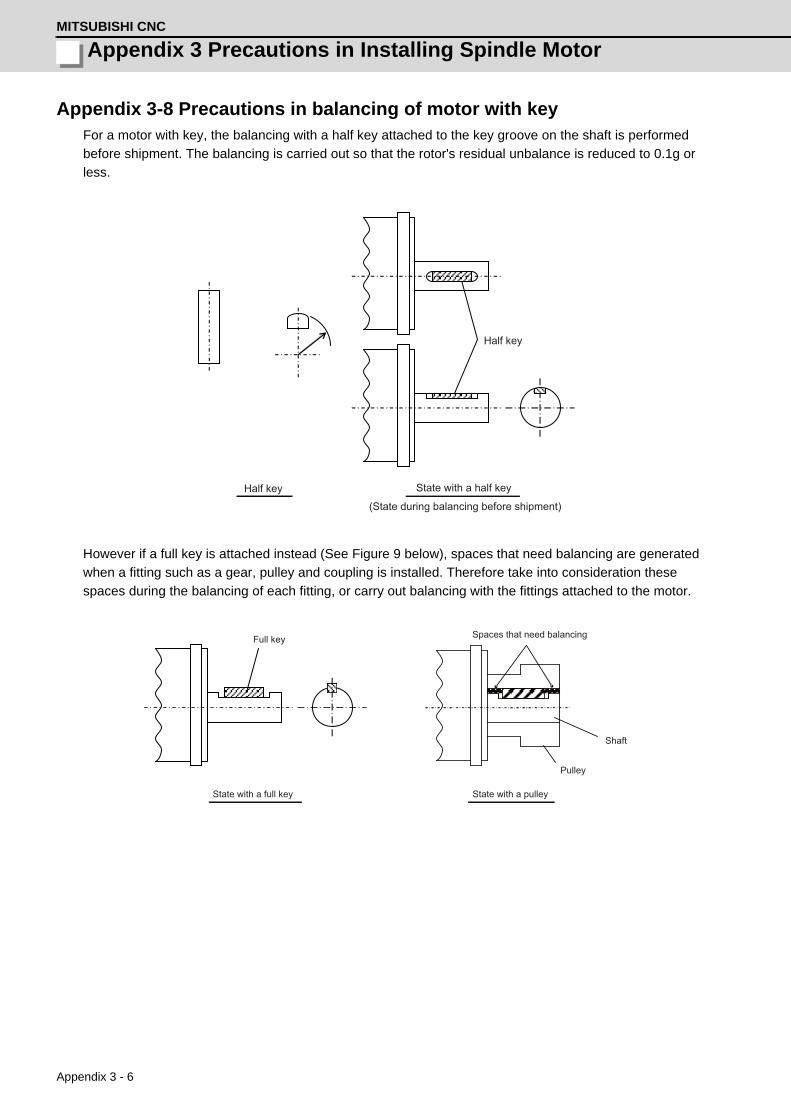
Appendix 3 Precautions in Installing Spindle MotorMITSUBISHI CNC
Appendix 3 - 6
Appendix 3-8 Precautions in balancing of motor with keyFor a motor with key, the balancing with a half key attached to the key groove on the shaft is performed
before shipment. The balancing is carried out so that the rotor's residual unbalance is reduced to 0.1g or
less.
However if a full key is attached instead (See Figure 9 below), spaces that need balancing are generated
when a fitting such as a gear, pulley and coupling is installed. Therefore take into consideration these
spaces during the balancing of each fitting, or carry out balancing with the fittings attached to the motor.
Half key
Half key
State with a half key
(State during balancing before shipment)
Spaces that need balancing
Shaft
Pulley
Full key
State with a full key State with a pulley

Appendix 4 - 1
付録 Appendix 4 章
Appendix 4 - 1
Appendix 4Compliance to EC Directives

Appendix 4 Compliance to EC DirectivesMITSUBISHI CNC
Appendix 4 - 2
Appendix 4-1 Compliance to EC DirectivesAppendix 4-1-1 European EC Directives
In the EU Community, the attachment of a CE mark (CE marking) is mandatory to indicate that the basic safety
conditions of the Machine Directives (issued Jan. 1995), EMC Directives (issued Jan. 1996) and the Low-voltage
Directives (issued Jan. 1997) are satisfied. The machines and devices in which the servo and spindle drive are
assembled are the targets for CE marking.
(1) Compliance to EMC Directives
The servo and spindle drive are components designed to be used in combination with a machine or device.
These are not directly targeted by the Directives, but a CE mark must be attached to machines and devices
in which these components are assembled. The next section "EMC Installation Guidelines", which explains
the unit installation and control panel manufacturing method, etc., has been prepared to make compliance to
the EMC Directives easier.
(2) Compliance to Low-voltage Directives
Each unit is targeted for the Low-voltage Directives. An excerpt of the precautions given in this specification
is given below. Please read this section thoroughly before starting use.
For the EMC Directives and Low-voltage Directives, Self-Declaration Documents has been prepared.
Contact Mitsubishi or your dealer when required.
Appendix 4-1-2 Cautions for EC Directive compliance
Use the Low-voltage Directive compatible parts for the servo/spindle drive and servo/spindle motor. In addition to
the items described in this instruction manual, observe the items described below.
(1) Configuration
CB MC M
Circuit breaker
Insert a type B circuit breaker (RCD) in the power supply side of the unit.
Isolatingtransformer
AC reactor
Electromagneticcontactor
Unit

MDS-D/DH Series Instruction Manual
Appendix 4-1 Compliance to EC Directives
Appendix 4 - 3
(2) Environment
Use the units under an Overvoltage Category III (MDS-DH)/II (MDS-D) and Pollution Class of 2 or less
environment as stipulated in IEC60664.
(a) To adjust the units to the Overvoltage Category II, insert an isolating transformer of the star connection
complying with EN or IEC standard in the input of the power supply unit.
(b) To adjust the units to the Pollution Class of 2, install the units in a control panel having a structure (IP54
or higher) in which water, oil, carbon or dust cannot enter.Unit
Motor
(3) Power supply
[1] Use the power supply and servo/spindle drive unit under an Overvoltage Category III (MDS-DH)/
II (MDS-D) as stipulated in IEC60664.
[2] Earth the PE terminal of the units to the neutral point of the star connection.
[3] Do not omit the circuit breaker and electromagnetic contactor.
(4) Earthing
[1] To prevent electric shocks, always connect the servo/spindle drive unit protective earth (PE) terminal
(terminal with mark) to the protective earth (PE) on the control panel.
[2] When connecting the earthing wire to the protective earth (PE) terminal, do not tighten the wire
terminals together. Always connect one wire to one terminal.
(5) Wiring
[1] Always use crimp terminals with insulation tubes so that the connected wire does not contact the
neighboring terminals.
[2] Do not connect the wires directly.
[3] Always install the power supply unit and servo/spindle drive unit on the metal panel.
During operation Storage During transportationAmbient temperature 0°C to 55°C -15°C to 70°C -15°C to 70°CHumidity 90%RH or less 90%RH or less 90%RH or lessAltitude 1000m or less 1000m or less 13000m or less
During operation Storage During transportationAmbient temperature 0°C to 40°C -15°C to 70°C -15°C to 70°CHumidity 80%RH or less 90%RH or less 90%RH or lessAltitude 1000m or less 1000m or less 13000m or less
PE terminal PE terminal
Crimp terminal
Insulation tube
Wire

Appendix 4 Compliance to EC DirectivesMITSUBISHI CNC
Appendix 4 - 4
(6) Peripheral devices
[1] Use EN/IEC Standards compliant parts for the circuit protector and contactor.
[2] Select type B circuit protector manufactured by RCD.
Apply Annex C of EN60204-1 for sizing of the circuit protector.
(7) Miscellaneous
[1] Refer to the next section "EMC Installation Guidelines" for methods on complying with the EMC
Directives.
[2] Ground the facility according to each country's requirements.
[3] The control circuit connector ( ) is safely separated from the main circuit ( ) and ground ( ).
[4] Inspect the appearance before installing the unit. Carry out a performance inspection of the final unit,
and save the inspection records.
MC2
OPT1,2
T
S
R
CN1A
CN23A
CN4
CN9
L1
L2
L3
L11TE3
TE1
CN9
CN1B
L+
L-
U
V
W
CN2
TE1
PLG
CN4
TE3
TE2L+
L-
L11
L21
TE2
L21
CN3
CN1A
CN4
CN9
CN20
CN1B
MU
MV
MW
CN2L
CN2M
LU
LV
LW
TE1
TE3
TE2L+
L-
L11
L21
CN3L
CN3M
MC MC1CN23B
EMG1
EMG2
(PE)(PE)(PE)
(PE)Optical communication cable
24VDC
: Control circuit
SH21cable
ACreactor
Machine side detector
Machine side detector
External emergency stop input
Contactor
Ground
: Main circuit
Spindlemotor
Motor side detector
Motor side detector
Servomotor
Optical communication cable
Mitsubishi CNC Spindle drive unitPower supply unit
Ground Ground
Servo drive unit
Ground
Servomotor
Circuitprotector
Circuitprotector
: Ground

Appendix 5 - 1
付録 Appendix 5 章
Appendix 5 - 1
Appendix 5EMC Installation Guidelines

Appendix 5 - 2
Appendix 5 EMC Installation GuidelinesMITSUBISHI CNC
Appendix 5-1 IntroductionEMC Instructions became mandatory as of January 1, 1996. The subject products must have a CE mark
attached indicating that the product complies with the Instructions.
As the NC unit is a component designed to control machine tools, it is believed to be out of the direct EMC
Instruction subject. However, we would like to introduce the following measure plans to backup EMC Instruction
compliance of the machine tool as the NC unit is a major component of the machine tools.
[1] Methods for installation in control/operation panel
[2] Methods of wiring cable outside of panel
[3] Introduction of countermeasure parts
Mitsubishi is carrying out tests to confirm the compliance to the EMC Standards under the environment described
in this manual. However, the level of the noise will differ according to the equipment type and layout, control
panel structure and wiring lead-in, etc. Thus, we ask that the final noise level be confirmed by the machine
manufacturer.
For measures for CNC, refer to "EMC INSTALLATION GUIDELINES" of each NC Connection Manual.
Appendix 5-2 EMC instructionsThe EMC Instructions regulate mainly the following two withstand levels.
Emission ..... Capacity to prevent output of obstructive noise that adversely affects external sources.
Immunity ..... Capacity not to malfunction due to obstructive noise from external sources.
The details of each level are classified as Table 1. It is assumed that the Standards and test details required for a
machine are about the same as these.
Table 1
Class Name DetailsGeneric
Standard
Standards for determining test
and measurement
Emission
Radiated noise Electromagnetic noise radiated through the air EN61000-6-4EN61800-3(Industrial environment)
-----Conductive noise
Electromagnetic noise discharged from power line
Immunity
Static electricity electrical discharge immunity test
(Example) Withstand level of discharge of elec-tricity charged in a human body.
EN61000-6-2EN61800-3(Industrial environment)
EN61000-4-2
Radiated radio-frequency magnetic field immunity test
(Example) Simulation of immunity from digital wireless transmitters
EN61000-4-3
Electrical fast transient/burst immunity test
(Example) Withstand level of noise from relays or connecting/disconnecting live wires
EN61000-4-4
Immunity to conducted disturbance induced by radio-frequency mag-netic field
(Example) Withstand level of noise entering through power line, etc.
EN61000-4-6
Power supply frequency field immunity test
(Example) 50/60Hz power frequency noise EN61000-4-8
Immunity test for voltage dip, short-time power failure and voltage fluc-tuation
(Example) Power voltage drop withstand level EN61000-4-11
Surge immunity test(Example) Withstand level of noise caused by lightning
EN61000-4-5

Appendix 5 - 3
MDS-D/DH Series Instruction Manual
Appendix 5-3 EMC measures
Appendix 5-3 EMC measuresThe main items relating to EMC measures include the following.
[1] Store the device in an electrically sealed metal panel.
[2] Earth all conductors that are floating electrically. (Lower the impedance.)
[3] Wire the power line away from the signal wire.
[4] Use shielded wires for the cables wired outside of the panel.
[5] Install a noise filter.
Ensure the following items to suppress noise radiated outside of the panel.
[1] Securely install the devices.
[2] Use shielded wires.
[3] Increase the panel's electrical seal. Reduce the gap and hole size.
Note that the electromagnetic noise radiated in the air is greatly affected by the clearance of the panel
and the quality of the cable shield.
Appendix 5-4 Measures for panel structureThe design of the panel is a very important factor for the EMC measures, so take the following measures into
consideration.
Appendix 5-4-1 Measures for control panel unit
[1] Use metal for all materials configuring the panel.
[2] For the joining of the top plate and side plates, etc., mask the contact surface with paint, and fix with
welding or screws.
In either case, keep the joining clearance to a max. of 20cm for a better effect.
[3] Note that if the plate warps due to the screw fixing, etc., creating a clearance, noise could leak from that
place.
[4] Plate the metal plate surface (with nickel, tin) at the earthing section, such as the earthing plate.
[5] The max. tolerable hole diameter of the openings on the panel surface, such as the ventilation holes,
must be 3cm to 5cm. If the opening exceeds this size, use a measure to cover it. Note that even when
the clearance is less than 3cm to 5cm, noise may still leak if the clearance is long.
Control panel
Operation board panel
Door
)
cm~5cm
Painting maskExample
* Provide electrical conductan
Hole exceeding 3cm to 5cm
Painting mask
Max. joining clearance 20cm

Appendix 5 - 4
Appendix 5 EMC Installation GuidelinesMITSUBISHI CNC
Appendix 5-4-2 Measures for door
[1] Use metal for all materials configuring the door.
[2] Use an EMI gasket or conductive packing for the contact between the door and control panel unit.
[3] The EMI gasket or conductive packing must contact at a uniform and correct position of the metal
surface of the control panel unit.
[4] The surface of the control panel unit contacted with the EMI gasket or conductive packing must have
conductance treatment.
(Example) Weld (or screw) a plate that is plated (with nickel, tin).
[5] As a method other than the above, the control panel unit and door can be connected with a plain
braided wire. In this case, the panel and door should be contacted at as many points as possible.
Appendix 5-4-3 Measures for operation board panel
[1] Always connect the operation board and indicator with an earthing wire.
[2] If the operation board panel has a door, use an EMI gasket or conductive packing between the door and
panel to provide electrical conductance in the same manner as the control panel.
[3] Connect the operation board panel and control panel with a sufficiently thick and short earthing wire.
Appendix 5-4-4 Shielding of the power supply input section
[1] Separate the input power supply section from other parts in the control panel so that the input power
supply cable will not be contaminated by radiated noise.
[2] Do not lead the power line through the panel without passing it through a filter.
EMI gasket
Packing
Control panel
Door
Carry out conductance treatment on sections that the EMI gasket contacts.
Control panel Control panel
Drive unit Drive unit
Radiated noise
Radiated noise
AC input AC inputBreaker BreakerPower line filter
Power line filter
Shielding plate
The power supply line noise is eliminatedby the filter, but cable contains noiseagain because of the noise radiated in thecontrol panel.
Use a metal plate, etc., for the shieldingpartition. Make sure not to create aclearance.

Appendix 5 - 5
MDS-D/DH Series Instruction Manual
Appendix 5-5 Measures for various cables
Appendix 5-5 Measures for various cablesThe various cables act as antennas for the noise and discharge the noise externally. Thus appropriate treatment
is required to avoid the noise.
The wiring between the drive unit and motor act as an extremely powerful noise source, so apply the following
measures.
Appendix 5-5-1 Measures for wiring in panel
[1] If the cables are led unnecessarily in the panel, they will easily pick up the radiated noise. Thus, keep
the wiring length as short as possible.
[2] The noise from other devices will enter the cable and be discharged externally, so avoid internal wiring
near the openings.
[3] Connect the control device earthing terminal and earthing plate with a thick wire. Take care to the
leading of the wire.
Appendix 5-5-2 Measures for shield treatment
Common items
Use of shield clamp fittings is recommended for treating the shields. The fittings are available as options, so
order as required. (Refer to the section "Shield clamp fitting" in this chapter.)
Clamp the shield at a position within 10cm from the panel lead out port.
1. When leading the cables, including the grounding wire (FG), outside of the panel, clamp the cables
near the panel outlet (recommendation: within 10cm).
2. When using a metal duct or conduit, the cables do not need to be clamped near the panel outlet.
3. When leading cables not having shields outside the panel, follow the instructions given for each
cable. (Installation of a ferrite core, etc., may be required.)
Device Device Device Device Device Device
Noise Noise
Noise
Device Device Device Device
Control panel Control panel
POINT

Appendix 5 - 6
Appendix 5 EMC Installation GuidelinesMITSUBISHI CNC
Appendix 5-5-3 Servo/spindle motor power cable
Power cable for servo motor
Power cable for spindle motor
[1] Use four wires (3-phase + earthing) for the power cable that are completely shielded and free from
breaks.
[2] Earth the shield on both the control panel side and motor chassis side.
[3] Earth the shield with a metal P clip or U clip.
(A cable clamp fitting can be used depending on the wire size.)
[4] Directly earth the shield. Do not solder the braided shield onto a wire and earth the end of the wire.
[5] When not using a shield cable for the power cable, use a conventional cabtyre cable. Use a metal
conduit outside the cable.
[6] Earth the power cable on the control panel side at the contact surface of the conduit connector and
control panel. (Mask the side wall of the control panel with paint.)
[7] Follow the treatment shown in the example for the conduit connector to earth the power cable on the
motor side. (Example: Use a clamp fitting, etc.)
Control panel
To drive unit
Earth with P or U clip Cannon connector
Shield cable Servomotor
To drive unitCannon connector
Control panel Earth with paint mask
Conduit connector
Servomotor
Cabtyre cable
Conduit
Using shield cable Using conduit
Control panel Control panel
To drive unit
Earth with P or U clip
Shield cable
Terminal box
Spindle motor
To drive unit
Cabtyre cable
Conduit
Earth with paint mask
Conduit connector Terminal box
Using shield cable Using conduit
Solder
Conduit connector Cannon connector
To earthing
Clamp fitting
Conduit
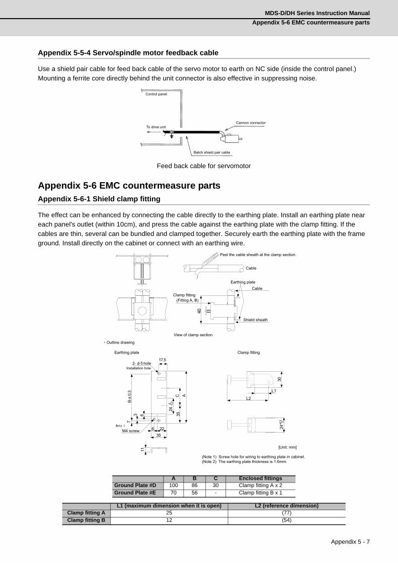
Appendix 5 - 7
MDS-D/DH Series Instruction Manual
Appendix 5-6 EMC countermeasure parts
Appendix 5-5-4 Servo/spindle motor feedback cable
Use a shield pair cable for feed back cable of the servo motor to earth on NC side (inside the control panel.)
Mounting a ferrite core directly behind the unit connector is also effective in suppressing noise.
Feed back cable for servomotor
Appendix 5-6 EMC countermeasure partsAppendix 5-6-1 Shield clamp fitting
The effect can be enhanced by connecting the cable directly to the earthing plate. Install an earthing plate near
each panel's outlet (within 10cm), and press the cable against the earthing plate with the clamp fitting. If the
cables are thin, several can be bundled and clamped together. Securely earth the earthing plate with the frame
ground. Install directly on the cabinet or connect with an earthing wire.
A B C Enclosed fittingsGround Plate #D 100 86 30 Clamp fitting A x 2Ground Plate #E 70 56 - Clamp fitting B x 1
L1 (maximum dimension when it is open) L2 (reference dimension)Clamp fitting A 25 (77)Clamp fitting B 12 (54)
Cannon connector
Batch shield pair cable
To drive unit
Control panel
40
356 22
17.5
AC35
24-0
.20
11
73 6
B0.
3
L1
30
L2
+0.3 0
24
2-
[Unit: mm]
(Note 1) Screw hole for wiring to earthing plate in cabinet.(Note 2) The earthing plate thickness is 1.6mm.
hole
(Fitting A, B)
Installation hole
Clamp fittingEarthing plate
Outline drawing
5
M4 screw
Shield sheath
Cable
Cable
Earthing plate
Peel the cable sheath at the clamp section.
View of clamp section
Clamp fitting

Appendix 5 - 8
Appendix 5 EMC Installation GuidelinesMITSUBISHI CNC
Appendix 5-6-2 Ferrite core
A ferrite core is integrated and mounted on the plastic case. Quick installation is possible without cutting the
interface cable or power cable. This ferrite core is effective against common mode noise, allowing measures
against noise to be taken without affecting the signal quality.
*1 A fixing band is enclosed when shipped.
ZCAT-B type: Cabinet fixed type, installation hole ø4.8 to 4.9mm, plate thickness 0.5 to 2mm
ZCAT-C type: Structured so that it cannot be opened easily by hand once closed.
Appendix 5-6-3 Power line filter
< Power line filter for 200V >
HF3000A-TM Series for 200V
Features
(a) 3-phase 3-wire type (250V series, 500V series)
(b) Compliant with noise standards German Official Notice Vfg243,
EU Standards EN55011 (Class B)
(c) Effective for use with IGBT inverter and MOS-FET inverter.
(d) Easy mounting with terminal block structure, and outstanding
reliability.
Application
(a) Products which must clear noise standards German Official Notice
Vfg243 and EU Standards EN55011 (Class B).
(b) For input of power converter using advanced high-speed power device such as IGBT MOS-FET.
Part name Fig A B C D EApplicable
cable outlineMass
Recommended ferrite core
ZCAT3035-1330(-BK)*1 1 39 34 13 30 - 13 63
ZCAT2035-0930-M(-BK) 2 35 29 13 23.5 22 10 to 13 29ZCAT2017-0930-M(-BK) 3 21 17 9 20 28.5 9 12ZCAT2749-0430-M(-BK) 4 49 27 4.5 19.5 - 4.5 26
A
B C
D A
B
D
E
C
A
B
C
D
CD
EA
B
Fig.2 Fig.1
Fig.3 Fig.4
ZCAT-B type ZCAT-C type
Recommended ferrite core TDK ZCAT Series
Shape and dimensions
ZCAT type ZCAT-A type
[Unit: mm]

Appendix 5 - 9
MDS-D/DH Series Instruction Manual
Appendix 5-6 EMC countermeasure parts
Specifications (250V series)
<Example of measuring voltage at noise terminal>•••Measured with IGBT inverter
Outline dimensions
Part nameHF3005A
-TMHF3010A
-TMHF3015A
-TMHF3020A
-TMHF3030A
-TMHF3040A
-TMHF3050A
-TMHF3060A
-TMHF3080A
-TMHF3100A
-TMHF3150A
-TMRated
voltage250V AC
Rated current
5A 10A 15A 20A 30A 40A 50A 60A 80A 100A 150A
Leakage current
1.5mA MAX 250V AC 60Hz
German Official Notice Vfg243 measurement data EU Standards EN55011 (Class B) measurement data
ModelDimension [Unit: mm]A B C
HF3005A-TM
180 170 130HF3010A-TMHF3015A-TMHF3020A-TMHF3030A-TM
260 155 140HF3040A-TMHF3050A-TM
290 190170
HF3060A-TM 230HF3080A-TM
405 220210HF3100A-TM
HF3150A-TM 570 230
(500V Series)
<Typical characteristics>
<Circuit diagram>
40A item
(250V Series)

Appendix 5 - 10
Appendix 5 EMC Installation GuidelinesMITSUBISHI CNC
MX13 Series 3-phase high attenuation noise filter for 200V
Features
(a) Perfect for mounting inside control panel: New shape with uniform height and depth dimensions
(b) Easy mounting and maintenance work: Terminals are centrally located on the front
(c) Complaint with NC servo and AC servo noise: High attenuation of 40dB at 150KHz
(d) Safety Standards:UL1283, CSAC22.2 No.8, EN60939(SEMKO)
(e) Patent and design registration pending
Specifications
(Note) This is the value at Ta 50°C.
Refer to the following output derating for Ta > 50°C.
Contact: Densei-lambda Co., Ltd. Telephone: 03-3447-4411 (+81-3-3447-4411)
Fax: 03-3447-7784 (+81-3-3447-7784) http://www.densei-lambda.com
ItemType
MX13030 MX13050 MX13100 MX13150
1 Rated voltage (AC) 3-phase 250VAC (50/60Hz)
2 Rated current (AC) 30A 50A 100A 150A
3Test voltage(AC for one minute across terminal and case)
2500VAC (100mA) at 25°C, 70% RH
4Insulation resistance(500VDC across terminal and case)
100MΩ min. at 25°C, 70% RH
5 Leakage current (250V, 60Hz) 3.5mA max 8mA max
6 DC resistance 30mΩ max 11mΩ max 5.5mΩ max 3.5mΩ max
7 Temperature rise 30°C max
8 Working ambient temperature –25°C to +85°C
9 Working ambient humidity 30% to 95% RH (non condensing)
10 Storage ambient temperature –40°C to +85°C
11 Storage ambient humidity 10% to 95% RH (non condensing)
12 Mass (typ) 2.8kg 3.9kg 11.5kg 16kg
≦

Appendix 5 - 11
MDS-D/DH Series Instruction Manual
Appendix 5-6 EMC countermeasure parts
Example of using MX13 Series
This is a noise filter with the same dimensions as the drive unit depth (200mm) and height (380mm).
This unit can be laid out easily in the device by arraigning it in a row with the servo unit.
As with the servo unit, the terminals are arranged on the front enabling ideal wire lead-out.
Refer to the following figure for details.[Unit:mm]
Example of noise terminal voltage attenuation
Output derating
200
380 Noise filter(MX13 Series)
Servo unit
Wire to 3-phase power supply
Noise filter input terminal
Noise filter output terminal
Servo input terminal Wire from noise filter to servo
Noi
se te
rmin
al v
olta
ge
[dB
uV]
Frequency [MHz] Frequency [MHz]
EMI data for independent control panel (with six-axis servo unit mounted)
EMI data for control panel + noise filter (MX13030)
Noi
se te
rmin
al v
olta
ge
[dB
uV]
Ambient temperature Ta ( )
Cur
rent
(%)

Appendix 5 - 12
Appendix 5 EMC Installation GuidelinesMITSUBISHI CNC
Outline dimension drawings
MX13030, MX13050
MX13100, MX13150
[Unit: mm]
MX13030 MX13050A 66 81B 45 55C 10.5 13D 50 67E 13 16F 10 13G 177 179H M4 screw M6 screwI 70 85J M4 screw M6 screwK 195 200
[Unit: mm]
MX13100 MX13150A 130 165B 90 110C 20 27.5D 115 150.5E 37.5 57.5F 18 23G 174 176H M6 screw M8 screwI 21 27J 37.5 56.5K 115 149.5L 276 284
(Installation hole)
(Installation hole) (Installation hole)

Appendix 5 - 13
MDS-D/DH Series Instruction Manual
Appendix 5-6 EMC countermeasure parts
< 400V power line filter >
400V 3SUP-HL-ER-6B Series
Features
(a) 3-phase, 3-wire type high attenuation characteristics
(b) CE marking compatible
(c) Rated current value 30A to 200A
(d) For EN55011 Class A, B measures
(e) Application: Primary side of inverter power supply, UPS, CNC machine tool, etc.
Specifications
These specifications are for reference. Contact the filter manufacturer for detailed data.
Other matters
– If the leakage current is limited, use 3SUP-HL -ER-6B-4 (leakage current 4mA product).
– When using with the peripheral device and a higher attenuation characteristics are required, use the
3SUP-HL -ER-6.
Contact: Okaya Electric Industries Co., Ltd. Telephone: 03-3424-8120 (+81-3-3424-2110)
http://www.okayaelec.co.jp
Outline dimensions[ Unit: mm ]
General tolerance: ± 1.5mm
Type 3SUP-HL30-ER-6B 3SUP-HL50-ER-6B 3SUP-HL75-ER-6B 3SUP-HL100-ER-6B 3SUP-HL150-ER-6BRated current 30A (50°C) 50A (50°C) 75A (50°C) 100A (50°C) 150A (50°C)Maximum operation voltage
500Vrms (50°C)
Operation frequency 50 / 60Hz
Leakage current8mA (at 500Vrms 60Hz)
[A leakage current will not flow if there is no phase failure in a power supply grounded at a neutral point.]Connection terminal M4 M6 M6 M6 M8Mass 5.2kg 6.5kg 12.0kg 12.5kg 23.5kgNominal inductance 6 x 1.4mH 6 x 1.4mH 6 x 1.0mH 6 x 0.56mH 6 x 0.6mHSafety standards EN133200 (compatible)
A B C D E F G H I J K L3SUP-HL30-ER-6B 246 230 215 200 100 85 13 18 140 4.5x7 4.5 M43SUP-HL50-ER-6B 286 270 255 240 120 90 13 18 150 5.5x7 5.5 M63SUP-HL75-ER-6B 396 370 350 330 170 140 18 23 155 6.5x8 6.5 M6
3SUP-HL100-ER-6B 396 370 350 330 170 140 18 23 155 6.5x8 6.5 M63SUP-HL150-ER-6B 484 440 420 400 200 170 30 25 200 6.5x8 6.5 M83SUP-HL200-ER-6B 484 440 420 400 200 170 30 25 200 6.5x8 6.5 M8
E+4.0/- 4.0
B
D C+1.5/-1.5
F H (G)
L L 2- J 2- K
A+1.5/ - 1.5
I
Label

Appendix 5 - 14
Appendix 5 EMC Installation GuidelinesMITSUBISHI CNC
400V HF3000C-TMA Series
Features
3-phase, 3-wire type high attenuation characteristics
Specifications
These specifications are for reference. Contact the filter manufacturer for detailed data.
Contact: Soshin Electric Co., Ltd. Telephone: 03-5730-8001 (+81-3-5730-8001) http://www.soshin.co.jp
Outline dimensions[ Unit: mm ]
General tolerance: ±1.5mm
Type HF3030C-TMA HF3050C-TMA HF3060C-TMA HF3080C-TMA HF3100C-TMA HF3150C-TMA HF3200C-TMARated current 30A 50A 60A 80A 100A 150A 200ARated voltage 460VAC (50°C)Operation frequency
50 / 60Hz
Leakage current5.3mA (at 460Vrms 60Hz)
[A leakage current will not flow if there is no phase failure in a power supply grounded at a neutral point.]Overload current Rated current × 150% for 1 minuteConnection terminal
M5 / M4(E) M6 / M4(E) M6 / M4(E) M8 / M6(E) M8 / M6(E) M10 /M8(E) M10 / M8(E)
Mass 3.2kg 6.7kg 10.0kg 13.0kg 14.5kg 23.0kg 23.5kgSafety standards EN133200 (compatible)
A B C D E F G H J K L M NHF3030C-TMA 260 210 85 155 140 125 44 140 70 R3.25 / L8 M5 M4 ---HF3050C-TMA 290 240 100 190 175 160 44 170 100 R3.25 / L8 M6 M4 ---HF3060C-TMA 290 240 100 190 175 160 44 230 160 R3.25 / L8 M6 M4 ---HF3080C-TMA 405 350 100 220 200 180 56 210 135 R4.25 / L12 M8 M6 ---HF3100C-TMA 405 350 100 220 200 180 56 210 135 R4.25 / L12 M8 M6 ---HF3150C-TMA 570 550 530 230 190 100 15 210 140 100 M10 M8 33HF3200C-TMA 570 550 530 230 190 100 15 210 140 100 M10 M8 33
30A 60A
150A, 200A
80A, 100A

Appendix 5 - 15
MDS-D/DH Series Instruction Manual
Appendix 5-6 EMC countermeasure parts
Appendix 5-6-4 Surge protector
Insert a surge protector in the power input section to prevent damage to the control panel or power supply unit,
etc. caused by the surge (lightning or sparks, etc.) applied on the AC power line.
Use a surge protector that satisfies the following electrical specifications.
< Surge protector for 200V >
200V R•A•V-BYZ Series (for protection between lines)
(Note) Refer to the manufacturer's catalog for details on the surge protector's characteristics and
specifications.
200V R•A•V-BXZ Series (for protection between line and earth)
(Note) Refer to the manufacturer's catalog for details on the surge protector's characteristics and
specifications.
Part nameCircuit voltage50/60Hz
Maximum tolerable
circuit voltage
Clampvoltage
Surge withstand
level8/20 µs
Surge withstand
voltage1.2/50 µs
Electrostatic capacity
Service temperature
RAV-781BYZ-2 3AC 250V 300V 783V±10% 2500A 20kV 75pF -20 to 70°C
Part nameCircuit voltage50/60Hz
Maximum tolerable
circuit voltage
Clampvoltage
Surge withstand
level8/20 µs
Surge withstand
voltage1.2/50 µs
Electrostatic capacity
Service temperature
RAV-781BXZ-4 3AC 250V 300V 1700V±10% 2500A 2kV 75pF -20 to 70°C
28.5
1
5.5
1
111
281
200
+30
-0
41 1
4.5
0.5
UL -1015 AWG16
Outline dimension drawings Circuit diagram [ Unit : mm]
(1)Black (2)Black (3)Black
U
UL-1015 AWG16
41 1
4.5
0.5
28.5
128
1
5.5
1
111
200
+30
-0
Outline dimension drawings Circuit diagram
(1)Black (2)Black (3)Black Green
[Unit:mm]

Appendix 5 - 16
Appendix 5 EMC Installation GuidelinesMITSUBISHI CNC
< Surge protector for 400V >
R•A•V-BYZ series for 400V (for protection between lines)
(Note) Refer to the manufacturer's catalog for details on the surge protector's characteristics and
specifications, etc.
RCM Series for 400V (for protection between line and earth)
(Note) Refer to the manufacturer's catalog for details on the surge protector's characteristics and
specifications, etc.
Contact: Okaya Electric Industries Co., Ltd. Telephone: 03-3424-8120 (+81-3-3424-2110)
http://www.okayaelec.co.jp
Part nameCircuit voltage
50/60Hz
Maximum tolerable
circuit voltage
Clamp voltage
Surge withstand
level8/20µs
Surge withstand
voltage1.2/50µs
Electrostatic capacity
Service temperature
RAV-152BYZ-2A 3AC 430V 500V 1476V±10% 2500A 20kV 35pF -20 to 70°C
Part name Rated voltageAC discharge start voltage
(V) ±20%
Surge withstand level
8/20µs (A)
Surge withstand voltage
1.2/50µs (V)RCM-781BUZ-4 3AC 250/430V AC700V±20% 2500A 2kVRCM-801BUZ-4 3AC 290/500V AC800V±20% 2500A 2.32kV
28.5
1
5.5
1
111
281
200
30 0
41 1
4.5
0.5
UL-1015 AWG16
(1)Black (2)Black (3)Black
Outline dimension drawings Circuit diagram [Unit: mm]
U
UL-1015 AWG16
41 1
4.5
0.5
28.5
128
1
5.5
1
111
200
30 0
Outline dimension Circuit diagram
(1)Black (2)Black (3)Black Green
[Unit:mm]
The voltage between the 3 phases is 500Vrms or less
For neutral-point grounding

Appendix 5 - 17
MDS-D/DH Series Instruction Manual
Appendix 5-6 EMC countermeasure parts
< Surge protector for both between phases and between phase and earth >
Features
This surge protector can protect both between phases and between phase and earth.
This contains a fuse and has windows to check malfunction or device degradation.
Specifications
LT-C Series 200V
(Note) Refer to the manufacturer's catalog for details on the surge protector's characteristics and
specifications, etc.
LT-C Series 500V
(Note) Refer to the manufacturer's catalog for details on the surge protector's characteristics and
specifications, etc.
Outline dimensions
Contact: Soshin Electric Co., Ltd. Telephone: 03-5730-8001 (+81-3-5730-8001)
http://www.soshin.co.jp
Part nameCircuit voltage50/60Hz
Maximum tolerable
circuit voltage
AC operation start voltage(between line
and earth)
AC operation start voltage
(between lines)
Voltage protection
level(Up)
Nominal discharge
current(8/20µs)
Maximum discharge
current(8/20µs)
LT-C32G801WS 3AC 250Vrms 275Vrms 560V±20% 410V±20% 1.5kV 2500A 5000A
Part nameCircuit voltage50/60Hz
Maximum tolerable
circuit voltage
AC operation start voltage(between line
and earth)
AC operation start voltage
(between lines)
Voltage protection
level(Up)
Nominal discharge
current(8/20µs)
Maximum discharge
current(8/20µs)
LT-C35G102WS 3AC 500Vrms 550Vrms 700V±20% 800V±20% 2.0kV 2500A 5000A
Black Black
Black
Green
Outline dimension drawings Circuit diagram
Status indicator
Wire (line)
Wire (earth)
[Unit: mm]

Appendix 5 - 18
Appendix 5 EMC Installation GuidelinesMITSUBISHI CNC
< Example of surge protector installation >
An example of installing the surge protector in the machine control panel is shown below.
A short-circuit fault will occur in the surge protector if a surge exceeding the tolerance is applied. Thus, install
a circuit protector in the stage before the surge protector. Note that almost no current flows to the surge
protector during normal use, so a circuit protector installed as the circuit protection for another device can be
used for the surge protector.
Installing the surge absorber
1. The wires from the surge protector should be connected without extensions.
2. If the surge protector cannot be installed just with the enclosed wires, keep the wiring length of A
and B to 2m or less. If the wires are long, the surge protector's performance may drop and inhibit
protection of the devices in the panel.
3. Surge protector to be selected varies depending on input power voltage.
B
A
MC
Circuitprotector
NC unit
Control panel
(relay panel, etc.)
Other device (panel power supply, etc.)
Other device (panel power supply, etc.)
Panel earthleakage breaker
Input power
Circuitprotector
AC reactor
Transformer
Grounding
Grounding plate
Factory power
Contactor
Circuitprotector
drive unit
(1) Surge protector (Protection across phases)
(2) Surge protector (Protection across each phase's grounding)
CAUTION

Appendix 6 - 1
付録 Appendix 6 章
Appendix 6 - 1
Appendix 6EC Declaration of Conformity

Appendix 6 - 2
Appendix 6 EC Declaration of ConformityMITSUBISHI CNC
Appendix 6-1 Compliance to EC DirectivesEach series can respond to LVD and EMC directive.
Approval from a third party certification organization has been also acquired for the Low Voltage Directive.
The declaration of conformity of each unit is shown below.
Appendix 6-1-1 Low voltage equipment
MDS-D/DH-CV Series

Appendix 6 - 3
MDS-D/DH Series Instruction Manual
Appendix 6-1 Compliance to EC Directives
MDS-D/DH-V1/V2 Series

Appendix 6 - 4
Appendix 6 EC Declaration of ConformityMITSUBISHI CNC
MDS-D/DH-SP Series

Appendix 7 - 1
付録 Appendix 7 章
Appendix 7 - 1
Appendix 7Higher Harmonic Suppression
Measure Guidelines

Appendix 7 Higher Harmonic Suppression Measure GuidelinesMITSUBISHI CNC
Appendix 7 - 2
Appendix 7-1 Higher harmonic suppression measure guidelinesThese guidelines apply to users for which the 6-pulse equivalent capacity total of the installed higher
harmonic generator exceeds the reference in the following table. (Note that household appliances and
general-purpose products having a rated current of 20A/phase or less connected to a 300V or less
commercial power supply are excluded from the generators.)
Use the following flow chart to confirm whether the total exceeds the reference.
Higher Harmonic Suppression Guidelines were set in September 1994 by the Ministry of International Trade
and Industry's Agency of Natural Resources and Energy.
• Higher Harmonic Suppression Measure Guidelines for Household Appliances and General-purpose
Products
• Higher Harmonic Suppression Measure Guidelines for Consumers Receiving High Voltage or Special
High Voltage Power
Higher harmonic suppression measures required
New installation, expansion or upgrading of facility
Calculation of total equivalent capacity
Calculation of higher harmonic current flow
Higher harmonic suppression measures not required
Higher harmonic current Step 2
Total equivalent capacity Step 1
Reference capacity exceeded
Reference capacity or less
Upper limit value exceeded
Upper limit

MDS-D/DH Series Instruction Manual
Appendix 7-1 Higher harmonic suppression measure guidelines
Appendix 7 - 3
Appendix 7-1-1 Calculating the equivalent capacity of the higher harmonic generator
As a principle, the higher harmonic suppression measure guidelines must be followed by the customer.
(1) Calculating the total equivalent capacity (Step 1)
Calculate the total equivalent capacity with the following expression.
Total equivalent circuit: Po = Σ • Ki • Pi
Ki :Conversion coefficient (Refer to following table)
Pi :Rated input capacity of each device
(Table 1) Rated capacity of each unit
(Note) The rated capacity Pi above, is the value used to calculate whether the product corresponds to the
higher harmonic guidelines. Thus, the value will differ from the actual power facility's capacity.
(The power supply unit is not included.)
(Table 2) Circuit class and conversion coefficient for each unit
(Note) This applies when an AC reactor is installed on the power supply unit.
(Table 3) Limit values for total equivalent capacity
If the total equivalent capacity Po exceeds the limit value given in (Table 3), proceed to "1.2 Calculating
the higher harmonic current flow" below.
Measures are not required if the value is not exceeded.
Unit typeMDS-
Rated input capacitypi [kVA]
Unit typeMDS-
Rated input capacitypi [kVA]
Unit typeMDS-
Rated input capacitypi [kVA]
D-SP-40 DH-SP-20 4.61 D-V1-20 DH-V1-10 1.0 D-V2-2020 DH-V2-1010 2.0D-SP-80 DH-SP-40 9.07 D-V1-40 DH-V1-20 1.6 D-V2-4020 DH-V2-2010 2.6D-SP-160 DH-SP-80 13.1 D-V1-80 DH-V1-40 4.7 D-V2-4040 DH-V2-2020 3.2D-SP-200 DH-SP-100 21.8 D-V1-160 DH-V1-80 9 D-V2-8040 DH-V2-4020 4.3D-SP-240 - 25.9 D-V1-160W DH-V1-80W 11.5 D-V2-8080 DH-V2-4040 5.4D-SP-320 DH-SP-160 34.7 D-V1-320 DH-V1-160 13.1 D-V2-16080 DH-V2-8040 8.6D-SP-400 DH-SP-200 42.8 D-V1-320W DH-V1-160W 17.6 D-V2-160160 DH-V2-8080 11.8D-SP-640 DH-SP-320 63.7 DH-V1-200 21.7
DH-SP-480 86.8
Name ModelCircuit class
Circuit typeConversion coefficient
Ki
Servo drive unit MDS-D/DH-V1/V2 Series 33-phase bridge (with smoothing capacitor)With AC reactor (Note 1)
K32=1.8
Spindle drive unit MDS-D/DH-SP Series 33-phase bridge (with smoothing capacitor)With AC reactor (Note 1)
K32=1.8
Incoming voltage Total of 6-pulse equivalent capacity6.6kV 50kVA
22/33kV 300kVA66kV or more 2,000kVA

Appendix 7 Higher Harmonic Suppression Measure GuidelinesMITSUBISHI CNC
Appendix 7 - 4
(2) Calculating the higher harmonic current flow (Step 2)
To calculate the higher harmonic current flow, calculate the rated current for the incoming power voltage
conversion.
Rated current for incoming power voltage conversion (mA) = a • Pi
(Table 4) Incoming power voltage conversion coefficient a
(Table 5) Upper limit of higher harmonic current flow (mA/kW)
Obtain the upper limit of the higher harmonic current flow (judgment value) for each order.
(The contracted electricity must be known for this.)
Upper limit of higher harmonic current flow (mA) = Contracted electricity, flow upper limit value
Flow upper limit value :
Insert a value from Table 5 according to the higher harmonic order to be calculated.
Obtain the higher harmonic current flow for each order using the following expression.
Higher harmonic current flow (mA) = (a • Pi), Device's maximum operation rate, target order
Device's maximum operation rate : The user must set the operation rate.
Target order : Insert a value from Table 6 according to the higher harmonic order to be calculated.
(Table 6) Higher harmonic current generation rate %
Values when basic wave current is 100%.
Check whether the calculated results exceed the limit value.
If the limit value for the higher harmonic current flow is exceeded, consider the higher harmonic measures
shown below.
Examples of higher harmonic measures
Incoming power voltage Coefficient a6.6kV 87.522 kV 26.233 kV 17.566 kV 8.7577 kV 7.5
Conversion coefficient
5th- order 7th- order 11th- order 13th- order 17th- order 19th- order 23rd- order 25th- order
6.6kV 3.5 2.5 1.6 1.3 1.0 0.9 0.76 0.7022kV 1.8 1.3 0.82 0.69 0.53 0.47 0.39 0.3633kV 1.2 0.86 0.55 0.46 0.35 0.32 0.26 0.2466kV 0.59 0.42 0.27 0.23 0.17 0.16 0.13 0.1277kV 0.50 0.36 0.23 0.19 0.15 0.13 0.11 0.10
Conversion coefficient
5th- order 7th- order 11th- order 13th- order 17th- order 19th- order 23rd- order 25th- order
K32 = 1.8 38.0 14.5 7.4 3.4 3.2 1.9 1.7 1.3K31 = 3.4 65.0 41.0 8.5 7.7 4.3 3.1 2.6 1.8
Item Details
Power-factor improving capacitorHigher harmonics are suppressed by adding a leading ca-pacitor for improving the power factor.
Installation of AC line filterA reactor and capacitor are combined to reduce the imped-ance for specific frequencies.

MDS-D/DH Series Instruction Manual
Appendix 7-1 Higher harmonic suppression measure guidelines
Appendix 7 - 5
(3) Higher harmonic current flow calculation form
A higher harmonic current flow calculation form is shown below for reference.
No
.
1
2
3
4
5
6
7
8
9
10
11
12
13
14
15
Cur
rent
upp
er li
mit
valu
e (m
A)
Ord
er
(Hig
her h
arm
onic
cur
rent
flow
upp
er li
mit
per c
ontra
cted
kW
x c
ontra
cted
ele
ctric
ity)
Hig
her h
arm
onic
cur
rent
flow
upp
er li
mit
valu
eN
eces
sity
of m
easu
res
Tota
l
In a
ll ot
her c
ases
, sep
arat
e m
easu
res
mus
t be
take
n
If th
ere
is a
faci
lity
that
low
ers
the
high
er h
arm
onic
s in
the
fact
ory,
or w
hen
supp
ress
ion
mea
sure
s ar
e im
plem
ente
d, p
roce
ed to
Cal
cula
tion
Form
(Par
t 2)
If th
e cu
rrent
flow
> c
urre
nt fl
ow u
pper
lim
it va
lue
at e
ach
orde
r, th
en
6-pu
lse
equi
vale
nt c
apac
ity to
tal
Po
Step
2If P,
> 5
0kVA
(6kV
inco
min
g po
wer
), 30
0kVA
(22,
33k
V in
com
ing
pow
er),
2000
kVA
(66k
V or
hig
her i
ncom
ing
pow
er),
proc
eed
to S
tep
2. (S
tep
2 do
es n
ot n
eed
to b
e co
mpl
eted
in
all o
ther
cas
es.)
If th
e de
vice
's ci
rcui
t typ
e cl
assi
ficat
ion
No.
is 1
0, c
ompl
ete
the
appl
icat
ion
show
n in
<F
orm
at 3
>.
Ref
er to
the
refe
renc
e an
d in
dica
te th
e ci
rcui
t typ
e cl
assi
ficat
ion
No.
, etc
.
Indi
cate
the
deta
ils o
f the
hig
her h
arm
onic
gen
erat
ing
devi
ce.
Step
1
<In
str
uc
tio
ns f
or
co
mp
leti
ng
fo
rm>
5th
-o
rder
(%)
De
vic
e's
maxim
um
op
era
tio
n
rate
[a x
Pi]
(m
A)
Rate
d c
urr
en
t v
alu
e f
or
inco
min
g
po
wer
vo
ltag
e
co
nvers
ion
[Ki
x P
i]
(kV
A)
6-p
uls
e
calc
ula
tio
n
co
eff
icie
nt
Ki
Cir
cu
it
typ
e c
las-
sif
icati
on
No
.P
i (k
VA
)
To
tal
ca
pa
cit
yQ
ty.
of
devic
es
(kV
A)
Rate
d
cap
acit
y
Typ
eM
ak
er
Devic
e n
am
e
Hig
her
harm
on
ic
gen
era
tin
g d
evic
e
Ste
p 1
: D
eta
ils o
f h
igh
er
harm
on
ic g
en
era
tin
g d
evic
e
Inco
min
g
po
wer
vo
lta
ge
Co
ntr
acte
d
ele
ctr
icit
y
kVkW
Hig
her
harm
on
ic c
urr
en
t fl
ow
per
ord
er
Ste
p 2
: C
alc
ula
tio
n o
f h
igh
er
ha
rmo
nic
cu
rre
nt
flo
w r
ate
Da
te o
f a
cc
ep
tan
ce
Ap
plic
ati
on
No
.
Date
of
ap
plica
tio
n
<For
m 1
>
Ind
ustr
yU
se
r
nam
e
Hig
her
harm
on
ic g
en
era
tin
g d
evic
e's
hig
her
harm
on
ic c
urr
en
t fl
ow
calc
ula
tio
n f
orm
(P
art
1)
6-p
uls
e
eq
uiv
ale
nt
ca
pa
cit
y7th
-o
rder
11th
-o
rder
13th
-o
rder
17th
-o
rder
19th
-o
rder
23
rd-
ord
er
25th
-o
rder
5th
-o
rder
7th
-o
rder
11th
-o
rder
13th
-o
rder
17th
-o
rder
19th
-o
rder
23
rd-
ord
er
25th
-o
rder

Appendix 7 - 6
Appendix 7 Higher Harmonic Suppression Measure GuidelinesMITSUBISHI CNC

Revision History
Date of revision Manual No. Revision details
March. 2005 IB(NA)1500025-A First edition created.MDS-D Specifications Manual (IB1500010) and MDS-DH Specifications Manual (IB1500002) were integrated.
March. 2006 IB(NA)1500025-B - Servo motor "HP(-H)224" was added.
- Servo drive unit MDS-DH-V1-200 was added.
- Heat radiation countermeasures were revised.
- Parameters "SV019", "SV025", "SV048", "SV055" and "SV056" were revised.
- Parameters "SV117" and "SV118" were added.
- Servo/spindle D/A output specification was revised.
- Deceleration control and Vertical axis drop prevention function were revised.
- Collision detection function was added.
- Adjusting the acceleration/deceleration operation was revised.
- Troubleshooting "45" and "72" were revised.
- The section "EC Declaration of conformity" was added.
- Miswrite is corrected.
Sep. 2008 IB(NA)1500025-D - "Disposal" was added.
- "Oil/water standards" was revised.
- "NC and drive unit connection" was revised.
- "Input/output circuit wiring" was revised.
- "Safety observation function" was revised.
- "Example of emergency stop circuit" was added to "Wiring of an external
emergency stop".
- Parameter "SV017" in "List of standard parameters for each servomotor" was
revised.
- Cautions were added to "List of standard parameters for each servomotor".
- Parameter "SV017" in "Servo parameter list" was revised.
- "Cable and Connector Specifications" was revised.
Mar. 2009 IB(NA)1500025-E - "Coupling with the load" was added.
- "Global service network" was revised.
Jan. 2010 IB(NA)1500025-F - "Installing the spindle detector" was added.
- "Connector pin assignment" was revised.
- Cautions were added to "NC and drive unit connection".
- "Connecting the servomotor" and "Connection of the spindle motor" were
revised.
- "Connection of the full-closed loop system", "Connection of the speed
command synchronization control system", "Connecting the spindle side
detector (OSE-1024-3-15-68, OSE-1024-3-15-68-8)" and "Connecting the
spindle side accuracy detector (TS5690 series)" were added.

Date of revision Manual No. Revision details
Jan. 2010 IB(NA)1500025-F - "Wiring of the motor brake" was revised.
- "Specified speed output" and "Specifications of proximity switch" were added.
- "Setting the rotary switch" was revised.
- "Initial parameter settings of servo drive unit" was revised.
- "Setting of machine side detector", "Setting of distance-coded reference
scale" and "Setting of speed command synchronous control" were added.
- List of parameters were revised.
- "D/A output specifications" in "Servo Adjustment" was revised.
- "Servo adjustment procedure" was revised.
- "Maximum tolerable current command value when adjusting acceleration/
deceleration time constant" was revised.
- "Notch filter frequency adaptive tracking function", "HAS control" and "Vertical
axis pull-up control" were added.
- "LMC compensation type 4" was added.
- "D/A output specifications" in "Spindle Adjustment" was revised.
- Cautions were added to "Gain adjustment" in "Spindle Adjustment".
- "Deceleration coil changeover valid function by emergency stop", "High-
response acceleration/deceleration function" and "Spindle cutting withstand
level improvement" were added.
- "List of alarms", "List of warnings" and "Troubleshooting" were revised.
- Descriptions of the following servo motors were added.
HF224, HF123, HF223, HF303, HF142, HF302
- Descriptions of the following drive units were added.
MDS-D-V2-160160W, MDS-DH-V2-8080W
- Descriptions of MDS-D-SP2 Series spindle drive unit was added.
- "Cable and Connector Specifications" was revised.
- "Compliance to EC Directives" was revised.
- "EMC Installation Guidelines" was revised.
- "EC Declaration of Conformity" was revised.
- "Global service network" was revised.
- Miswrite is corrected.
Mar. 2011 IB(NA)1500025-G - "Introduction" was revised.
- Function specifications list was added.
- SJ- D Series and SJ- DJ Series were added.
- MDS-D-SP2- 4040S and MDS-D-SP2-16080S were added.
- Descriptions for tool spindle motor was added.
- A caution was added to "Shaft characteristics" in "Spindle motor".
- "Installation of the spindle detector” was revised.
- "Spindle side detector" was replaced by "Spindle side ABZ pulse output
detector".

Date of revision Manual No. Revision details
Mar. 2011 IB(NA)1500025-G - "Spindle side accuracy detector" was replaced by "Spindle side PLG serial
output detector".
- "Installation accuracy diagnosis for PLG detector" was added.
- "Part system connection diagram" was revised.
- Cautions were added to "NC and drive unit connection"
- "Names and applications of main circuit terminal block signals and control
circuit connectors", "Motor and detector connection", "Connection of power
supply", "Wiring of the motor brake", and "Peripheral control wiring" were
revised.
- "Setting on each motor side detector" was deleted.
- "Setting of machine side detector" was revised.
- "Sony Manufacturing Systems Corporation" was replaced by "Magnescale
Co., LTD".
- SAM/SVAM/GAM/LAM Series (FAGOR) and MPS/MPI Series (MHI) were
added.
- "Setting of the distance-coded reference check function" was revised.
- List of parameters were revised.
- "Setting the initial parameters for the spindle drive unit" was revised.
- "List of standard parameters for each spindle motor" was added.
- The following motors were added "Standard VGN1 graph".
- Descriptions of SHG control was revised.
- "Optimal adjustment of cycle time" was revised.
- "D/A output specifications", "Dual feedback control", "Vertical axis drop
prevention control" and "Servo control signal" were revised.
- Spindle channel 120,121,122 and 123 were added.
- "Synchronous tapping adjustment", "High-speed synchronous tapping" ,
“Spindle C axis adjustment” and "Spindle control signal" were revised.
- "Settings for emergency stop" was added to "Spindle Adjustment".
- "Troubleshooting for each alarm No." was revised.
- "Cleaning of spindle motor" was added.
- "FCU6- BTBOX- 36" was replaced by "MDS- BTBOX- 36".
- "Restoration" was added to "Replacing the drive unit"
- "Adding and replacing units and parts" was revised.
- "Cable and Connector Specifications" was revised.
- "Compliance to EC Directives" was revised.
- "EC Declaration of Conformity" was revised.
- Miswrite is corrected.
Jan. 2012 IB(NA)1500025-H - "Introduction" was revised.
- "Handling of our product" was added.
- Function specifications list was revised.
- "HF*-A74" and "HP*-A74" were replaced by "-A74(N)".

Date of revision Manual No. Revision details
Jan. 2012 IB(NA)1500025-H - "OSA105-ET2" was replaced by "OSA105ET2".
- "OSA166-ET2" was replaced by "OSA166ET2(N)".
- "Installation of servomotor", "Installation of spindle motor", "Installation
direction and clearance", "Heating value" and "Installation of the spindle
detector" were revised.
- "Connecting with optical communication repeater unit" was added.
- "Motor and detector connection" was revised.
- "Input/output circuit wiring", "Safety observation function", "Specified speed
output", "Spindle coil changeover" and "Specifications of proximity switch"
were revised.
- "Setting the initial parameters for the servo drive unit", "Setting the initial
parameters for the spindle drive unit", list of standard parameters and list of
parameters were revised.
- "Characteristics improvement", "Settings for emergency stop" and "Protective
functions" were revised.
- "D/A output specifications for spindle drive unit", "Adjustment procedures for
each control" and "Spindle control output (Spindle to NC)" were revised.
- "Troubleshooting for each alarm No." was revised.
- "Replacing the unit fan" was revised.
- "Cable and Connector Specifications" was revised.
- "Cable and Connector Assembly" was revised.
- "Precautions in Installing Spindle Motor" was added.
- "EMC Installation Guidelines" was revised.
- Miswrite is corrected.


Global Service Network
AMERICA EUROPE
MITSUBISHI ELECTRIC AUTOMATION INC. (AMERICA FA CENTER) MITSUBISHI ELECTRIC EUROPE B.V. (EUROPE FA CENTER)Central Region Service Center GOTHAER STRASSE 10, 40880 RATINGEN, GERMANY 500 CORPORATE WOODS PARKWAY, VERNON HILLS, ILLINOIS 60061, U.S.A. TEL: +49-2102-486-0 / FAX: +49-2102-486-5910 TEL: +1-847-478-2500 / FAX: +1-847-478-2650
Germany Service CenterMichigan Service Satellite KURZE STRASSE. 40, 70794 FILDERSTADT-BONLANDEN, GERMANY ALLEGAN, MICHIGAN 49010, U.S.A. TEL: + 49-711-3270-010 / FAX: +49-711-3270-0141 TEL: +1-847-478-2500 / FAX: +1-269-673-4092
France Service CenterOhio Service Satellite 25, BOULEVARD DES BOUVETS, 92741 NANTERRE CEDEX FRANCE LIMA, OHIO 45801, U.S.A. TEL: +33-1-41-02-83-13 / FAX: +33-1-49-01-07-25 TEL: +1-847-478-2500 / FAX: +1-847-478-2650 CLEVELAND, OHIO 44114, U.S.A. France (Lyon) Service Satellite TEL: +1-847-478-2500 / FAX: +1-847-478-2650 120, ALLEE JACQUES MONOD 69800 SAINT PRIEST FRANCE
TEL: +33-1-41-02-83-13 / FAX: +33-1-49-01-07-25Minnesota Service Satellite MINNEAPOLIS, MINNESOTA 55413, U.S.A. Italy Service Center TEL: +1-847-478-2500 / FAX: +1-847-478-2650 VIALE COLLEONI 7-PALAZZO SIRIO CENTRO DIREZIONALE COLLEONI,
20041 AGRATE BRIANZA MILANO ITALYWest Region Service Center TEL: +39-039-60531-342 / FAX: +39-039-6053-206 5665 PLAZA DRIVE, CYPRESS, CALIFORNIA 90630, U.S.A. TEL: +1-714-220-4796 / FAX: +1-714-229-3818 Italy (Padova) Service Satellite
VIA SAVELLI 24 - 35129 PADOVA ITALYEast Region Service Center TEL: +39-039-60531-342 / FAX: +39-039-6053-206 200 COTTONTAIL LANE SOMERSET, NEW JERSEY 08873, U.S.A. TEL: +1-732-560-4500 / FAX: +1-732-560-4531 U.K. Service Center
TRAVELLERS LANE, HATFIELD, HERTFORDSHIRE, AL10 8XB, U.K.Pennsylvania Service Satellite TEL: +44-1707-27-6100 / FAX: +44-1707-27-8992 ERIE, PENNSYLVANIA 16510, U.S.A. TEL: +1-814-897-7820 / FAX: +1-814-987-7820 Spain Service Center
CTRA. DE RUBI, 76-80-APDO. 420Massachusetts Service Satellite 08190 SAINT CUGAT DEL VALLES, BARCELONA SPAIN BOSTON, MASSACHUSETTS 02108, U.S.A. TEL: +34-935-65-2236 / FAX: +34-935-89-1579 TEL: +1-508-216-6104
Poland Service CenterSouth Region Service Center UL.KRAKOWSKA 50, 32-083 BALICE, POLAND 2810 PREMIERE PARKWAY SUITE 400, DULUTH, GEORGIA 30097, U.S.A. TEL: +48-12-630-4700 / FAX: +48-12-630-4727 TEL: +1-678-258-4500 / FAX: +1-678-258-4519
Poland (Wroclaw) Service CenterTexas Service Satellites UL KOBIERZYCKA 23, 52-315 WROCLAW, POLAND GRAPEVINE, TEXAS 76051, U.S.A. TEL: +48-71-333-77-53 / FAX: +48-71-333-77-53 TEL: +1-817-251-7468 / FAX: +1-817-416-5000 FRIENDSWOOD, TEXAS 77546, U.S.A. Turkey Service Center TEL: +1-832-573-0787 / FAX: +1-678-573-8290 BAYRAKTAR BULVARI, NUTUK SOKAK NO.5, YUKARI DUDULLU
ISTANBUL, TURKEYFlorida Service Satellite TEL: +90-216-526-3990 / FAX: +90-216-526-3995 WEST MELBOURNE, FLORIDA 32904, U.S.A. TEL: +1-321-610-4436 / FAX: +1-321-610-4437 Czech Republic Service Center
TECHNOLOGICKA 374/6,708 00 OSTRAVA-PUSTKOVEC, CZECH REPUBLICCanada Region Service Center TEL: +420-59-5691-185 / FAX: +420-59-5691-199 4299 14TH AVENUE MARKHAM, ONTARIO L3R OJ2, CANADA TEL: +1-905-475-7728 / FAX: +1-905-475-7935 Russia Service Center
213, B.NOVODMITROVSKAYA STR., 14/2, 127015 MOSCOW, RUSSIAMexico City Service Center TEL: +7-495-748-0191 / FAX: +7-495-748-0192 MARIANO ESCOBEDO 69 TLALNEPANTLA, 54030 EDO. DE MEXICO TEL: +52-55-9171-7662 / FAX: +52-55-9171-7649 Sweden Service Center
STRANDKULLEN, 718 91 FROVI, SWEDENMonterrey Service Satellite TEL: +46-581-700-20 / FAX: +46-581-700-75 MONTERREY, N.L., 64720, MEXICO TEL: +52-81-8365-4171 / FAX: +52-81-8365-4171 Bulgaria Service Center
4 A. LYAPCHEV BOUL., 1756 - SOFIA, BULGARIABrazil Region Service Center TEL: +359-2-8176000 / FAX: +359-2-9744061 ACESSO JOSE SARTORELLI, KM 2.1 CEP 18550-000, BOITUVA-SP, BRAZIL TEL: +55-15-3363-9900 / FAX: +55-15-3363-9911 Ukraine (Kharkov) Service Center
APTEKARSKIY LANE 9-A, OFFICE 3, 61001 KHARKOV, UKRAINEBrazil Service Satellites TEL: +380-57-732-7774 / FAX: +380-57-731-8721 PORTO ALEGRE AND CAXIAS DO SUL BRAZIL TEL: +55-15-3363-9927 Ukraine (Kiev) Service Center SANTA CATARINA AND PARANA STATES 4-B, M. RASKOVOYI STR., 02660 KIEV, UKRAINE TEL: +55-15-3363-9927 TEL: +380-044-494-3355 / FAX: +380-044-494-3366
Belarus Service Center 703, OKTYABRSKAYA STR., 16/5, 220030 MINSK, BELARUS TEL: +375-17-210-4626 / FAX: +375-17-227-5830
South Africa Service Center P.O. BOX 9234, EDLEEN, KEMPTON PARK GAUTENG, 1625 SOUTH AFRICA TEL: +27-11-394-8512 / FAX: +27-11-394-8513
Denmark Service Center KARETMAGERVEJ. 7A, DK-7000, FREDERICIA, DENMARK TEL: +45-7620-7514
ASEAN CHINA
MITSUBISHI ELECTRIC ASIA PTE. LTD. (ASEAN FA CENTER) MITSUBISHI ELECTRIC AUTOMATION (CHINA) LTD. (CHINA FA CENTER)Singapore Service Center China (Shanghai) Service Center 307 ALEXANDRA ROAD #05-01/02 MITSUBISHI ELECTRIC BUILDING SINGAPORE 159943 1-3,5-10,18-23/F, NO.1386 HONG QIAO ROAD, CHANG NING QU, TEL: +65-6473-2308 / FAX: +65-6476-7439 SHANGHAI 200336, CHINA
TEL: +86-21-2322-3030 / FAX: +86-21-2308-2830Indonesia Service Center China (Ningbo) Service Dealer THE PLAZZA OFFICE TOWER, 28TH FLOOR JL.M.H. THAMRIN KAV.28-30, JAKARTA, INDONESIA China (Wuxi) Service Dealer TEL: +62-21-2992-2333 / FAX: +62-21-2992-2555 China (Jinan) Service Dealer
China (Wuhan) Service SatelliteMalaysia (KL) Service Center 60, JALAN USJ 10 /1B 47620 UEP SUBANG JAYA SELANGOR DARUL EHSAN, MALAYSIA China (Beijing) Service Center TEL: +60-3-5631-7605 / FAX: +60-3-5631-7636 9/F, OFFICE TOWER 1, HENDERSON CENTER, 18 JIANGUOMENNEI DAJIE,
DONGCHENG DISTRICT, BEIJING 100005, CHINAMalaysia (Johor Baru) Service Center TEL: +86-10-6518-8830 / FAX: +86-10-6518-3907 NO. 16, JALAN SHAH BANDAR 1, TAMAN UNGKU TUN AMINAH, 81300 SKUDAI, JOHOR MALAYSIA China (Beijing) Service Dealer TEL: +60-7-557-8218 / FAX: +60-7-557-3404
China (Tianjin) Service CenterVietnam Service Center-1 B-2 801/802, YOUYI BUILDING, NO.50 YOUYI ROAD, HEXI DISTRICT, ROOM 1004, 1005, FLOOR 10, 255 TRAN HUNG DAO CO GIANG WARD, DIST. 1, HCMC, VIETNAM TIANJIN 300061, CHINA TEL: +84-8-3838-6931 / FAX: +84-8-3838-6932 TEL: +86-22-2813-1015 / FAX: +86-22-2813-1017
China (Shenyang) Service SatelliteVietnam Service Center-2 China (Changchun) Service Satellite LOT G10 - AREA 4 - HIEP BINH CHANH WARD - THU DUC DISTRICT - HCMC, VIETNAM TEL: +84-8-2240-3587 / FAX: +84-8-3726-7968 China (Chengdu) Service Center
ROOM 407-408, OFFICE TOWER AT SHANGRI-LA CENTER, NO. 9 BINJIANG DONG ROAD,Vietnam (Hanoi) Service Center JINJIANG DISTRICT, CHENGDU, SICHUAN 610021, CHINA 5FL, 59 - XA DAN STR., DONG DA DIST., HN, VIETNAM TEL: +86-28-8446-8030 / FAX: +86-28-8446-8630 TEL: +84-4-3573-7646 / FAX: +84-4-3573-7650
China (Shenzhen) Service CenterPhilippines Service Center ROOM 2512-2516, 25/F., GREAT CHINA INTERNATIONAL EXCHANGE SQUARE, JINTIAN RD.S., UNIT NO.411, ALABAMG CORPORATE CENTER KM 25. WEST SERVICE ROAD FUTIAN DISTRICT, SHENZHEN 518034, CHINA SOUTH SUPERHIGHWAY, ALABAMG MUNTINLUPA METRO MANILA, PHILIPPINES 1771 TEL: +86-755-2399-8272 / FAX: +86-755-8218-4776 TEL: +63-2-807-2416 / FAX: +63-2-807-2417 China (Xiamen) Service Dealer
China (Dongguan) Service DealerMITSUBISHI ELECTRIC AUTOMATION (THAILAND) CO., LTD. (THAILAND FA CENTER) BANG-CHAN INDUSTRIAL ESTATE NO.111 SOI SERITHAI 54 T.KANNAYAO, A.KANNAYAO, BANGKOK 10230, THAILAND KOREA TEL: +66-2906-8255 / FAX: +66-2906-3239
MITSUBISHI ELECTRIC AUTOMATION KOREA CO., LTD. (KOREA FA CENTER)Thailand Service Center Korea Service Center 898/19,20,21,22 S.V. CITY BUILDING OFFICE TOWER 1, FLOOR 7 1480-6, GAYANG-DONG, GANGSEO-GU SEOUL 157-200, KOREA RAMA III RD., BANGPONGPANG, YANNAWA, BANGKOK 10120, THAILAND TEL: +82-2-3660-9602 / FAX: +82-2-3664-8668 TEL: +66-2-682-6522 / FAX: +66-2-682-9750
Korea Taegu Service Satellite 603 CRYSTAL BUILDING 1666, SANBYEOK-DONG, BUK-KU, DAEGU, 702-010, KOREA
INDIA TEL: +82-53-604-6047 / FAX: +82-53-604-6049
MITSUBISHI ELECTRIC INDIA PVT. LTD.India Service Center TAIWAN 2nd FLOOR, TOWER A & B, DLF CYBER GREENS, DLF CYBER CITY, DLF PHASE-III, GURGAON- 122 002, HARYANA, INDIA MITSUBISHI ELECTRIC TAIWAN CO., LTD. (TAIWAN FA CENTER) TEL: +91-124-4630300 / FAX: +91-124-4630399 Taiwan (Taichung) Service Center
NO.8-1, GONG YEH 16TH RD., TAICHUNG INDUSTRIAL PARK TAICHUNG CITY, TAIWAN R.O.C.India (Bangalore) Service Center TEL: +886-4-2359-0688 / FAX: +886-4-2359-0689 FIRST & SECOND FLOOR, AVR BASE, MUNICIPAL NO.BC-308, HENNURE BANASWADI ROAD, HRBR RING ROAD, BANGALORE-560 043, INDIA Taiwan (Taipei) Service Center TEL: +91-80-4020-1600 / FAX: +91-80-4020-1699 3RD. FLOOR, NO.122 WUKUNG 2ND RD., WU-KU HSIANG, TAIPEI HSIEN, TAIWAN R.O.C. Chennai satellite office TEL: +886-2-2299-2205 / FAX: +886-2-2298-1909 Coimbatore satellite office
Taiwan (Tainan) Service CenterIndia (Pune) Service Center 2F(C),1-1, CHUNGHWA-RD., YONGKANG CITY, TAINAN HSIEN, TAIWAN R.O.C. TEL: +91-998-7997651 TEL: +886-6-313-9600 / FAX: +886-6-313-7713 Baroda satellite office
OCEANIA
MITSUBISHI ELECTRIC AUSTRALIA LTD.Oceania Service Center 348 VICTORIA ROAD, RYDALMERE, N.S.W. 2116 AUSTRALIA TEL: +61-2-9684-7269 / FAX: +61-2-9684-7245

Notice
Every effort has been made to keep up with software and hardware revisions in thecontents described in this manual. However, please understand that in someunavoidable cases simultaneous revision is not possible. Please contact your Mitsubishi Electric dealer with any questions or commentsregarding the use of this product.
Duplication Prohibited
This manual may not be reproduced in any form, in part or in whole, without writtenpermission from Mitsubishi Electric Corporation.
© 2005 - 2012 Mitsubishi Electric CorporationALL RIGHTS RESERVED