MDS Master Station - GE Grid Solutions
6
MDS Master Station Setup Guide 05-6398A01-GB, Rev. A MDS Master Station Setup Guide 1 INTRODUCTION The MDS Master Station serves as a central station in a multiple ad- dress system (MAS) wireless network. It provides long range, duplex (or simplex) communication between a control point and associated re- motes. It is fully redundant for mission-critical applications, and is a compatible replacement for older MDS x790 Master Stations when or- dered with the appropriate network interface modules. The MDS Master Station works with a wide array of wireless equip- ment, including MDS SD Transceivers, legacy MDS x710 radios, MDS LN radios, and additional wireless options, depending on the modules installed in the chassis. Figure 1: MDS Master Station All modules are installed on slide-in assemblies, accessible from the front of the unit. A protective cover on the unit’s face slides off, allowing access to the modules and all interface connectors. In addition to com- munication modules, up to two power supply units may be installed and are available to suit a wide range of AC and DC power require- ments. Each module is secured to the chassis with knurled fasteners for easy changes, when required. Figure 2 shows a common configuration of in- stalled modules. IMPORTANT: To ensure proper heat-sink engagement, the knurled fasteners must be tightened with a screw driver to at least 10 inch- pounds (approximately ¼ turn past hand tight). Figure 2: Front Panel Connectors & Indicators (Front cover removed) Master Station modules are factory installed and cabled. Table 1 de- scribes each module installed in a redundant configuration, from left to right. For a non-redundant configuration, blank plates are used in place of the redundant power supply and radio modules and a non-redun- dant version of the Alarm/Relay module is installed. The MDS Master Station supports Ethernet or serial polling depending on order options. A host computer may be connected to the appropri- ate port on the chassis (LAN for Ethernet; COM1/2 for serial signaling). Configuration of the unit is performed through a web interface. This re- quires a LAN connection to one of the Ethernet ports on the Platform Manager module. In addition, a command line interface (CLI) is availa- ble through the mini USB port using the proper USB drivers available at www.gemds.com. Typical Application Figure 3 on the following page shows a common arrangement of the MDS Master Station as used in a licensed narrowband network. The system shows both MCR and ECR transceivers in use. Depending on order options, the MDS Master Station can communi- cate with remotes employing Ethernet signaling, serial signaling, or a mix of both. Figure 3: Licensed Narrowband Application Example Additional Resources This Setup Guide covers the essential installation and startup for the MDS Master Station. Alternate information is available in English, (see 05-6399A01Technical Manual). GE MDS manuals, Setup guides, Firm- ware, drivers and Application Notes are available free of charge at www.gemds.com. GE MDS has produced a series of instructional videos for configuration and setup of the Orbit products on YouTube. These are available in English, free of charge at: http://tinyurl.com/pey2ull Supply 1 (DC) Supply 2 (AC) Platform Manager Radio A Radio B Alarm/Relay Duplexer
-
Upload
khangminh22 -
Category
Documents
-
view
1 -
download
0
Transcript of MDS Master Station - GE Grid Solutions
MDS Master Station Setup Guide
05-6398A01-GB, Rev. A MDS Master Station Setup Guide 1
INTRODUCTION The MDS Master Station serves as a central station in a multiple ad-dress system (MAS) wireless network. It provides long range, duplex (or simplex) communication between a control point and associated re-motes. It is fully redundant for mission-critical applications, and is a compatible replacement for older MDS x790 Master Stations when or-dered with the appropriate network interface modules.
The MDS Master Station works with a wide array of wireless equip-ment, including MDS SD Transceivers, legacy MDS x710 radios, MDS LN radios, and additional wireless options, depending on the modules installed in the chassis.
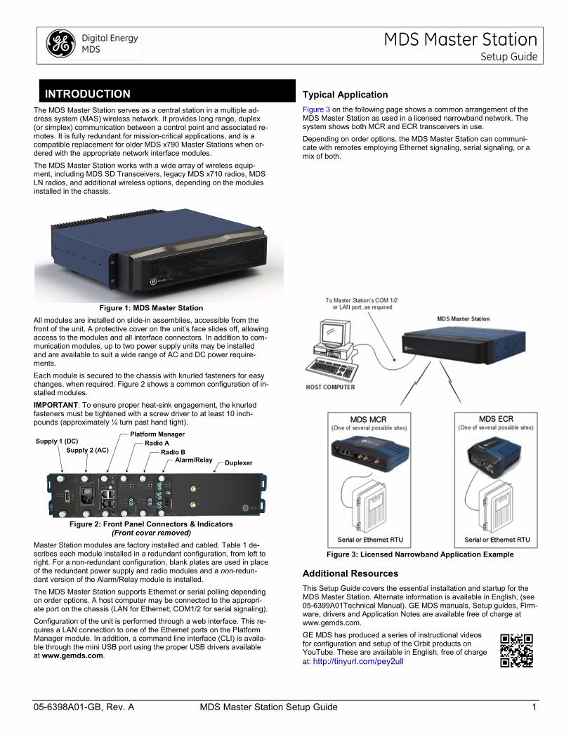
Figure 1: MDS Master Station
All modules are installed on slide-in assemblies, accessible from the front of the unit. A protective cover on the unit’s face slides off, allowing access to the modules and all interface connectors. In addition to com-munication modules, up to two power supply units may be installed and are available to suit a wide range of AC and DC power require-ments.
Each module is secured to the chassis with knurled fasteners for easy changes, when required. Figure 2 shows a common configuration of in-stalled modules.
IMPORTANT: To ensure proper heat-sink engagement, the knurled fasteners must be tightened with a screw driver to at least 10 inch-pounds (approximately ¼ turn past hand tight).
Figure 2: Front Panel Connectors & Indicators
(Front cover removed)
Master Station modules are factory installed and cabled. Table 1 de-scribes each module installed in a redundant configuration, from left to right. For a non-redundant configuration, blank plates are used in place of the redundant power supply and radio modules and a non-redun-dant version of the Alarm/Relay module is installed.
The MDS Master Station supports Ethernet or serial polling depending on order options. A host computer may be connected to the appropri-ate port on the chassis (LAN for Ethernet; COM1/2 for serial signaling).
Configuration of the unit is performed through a web interface. This re-quires a LAN connection to one of the Ethernet ports on the Platform Manager module. In addition, a command line interface (CLI) is availa-ble through the mini USB port using the proper USB drivers available at www.gemds.com.
Typical Application
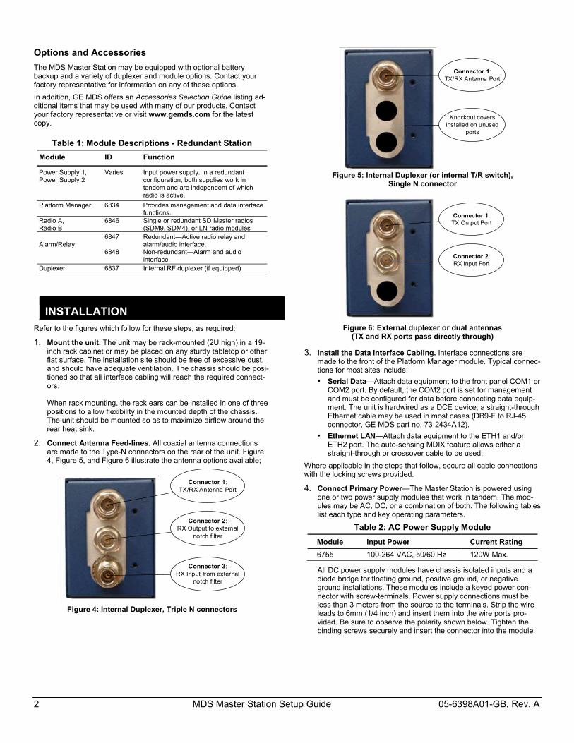
Figure 3 on the following page shows a common arrangement of the MDS Master Station as used in a licensed narrowband network. The system shows both MCR and ECR transceivers in use.
Depending on order options, the MDS Master Station can communi-cate with remotes employing Ethernet signaling, serial signaling, or a mix of both.
Figure 3: Licensed Narrowband Application Example
Additional Resources
This Setup Guide covers the essential installation and startup for the MDS Master Station. Alternate information is available in English, (see 05-6399A01Technical Manual). GE MDS manuals, Setup guides, Firm-ware, drivers and Application Notes are available free of charge at www.gemds.com.
GE MDS has produced a series of instructional videos for configuration and setup of the Orbit products on YouTube. These are available in English, free of charge at: http://tinyurl.com/pey2ull
Supply 1 (DC)Supply 2 (AC)
Platform ManagerRadio A
Radio BAlarm/Relay Duplexer
2 MDS Master Station Setup Guide 05-6398A01-GB, Rev. A
Options and Accessories
The MDS Master Station may be equipped with optional battery backup and a variety of duplexer and module options. Contact your factory representative for information on any of these options.
In addition, GE MDS offers an Accessories Selection Guide listing ad-ditional items that may be used with many of our products. Contact your factory representative or visit www.gemds.com for the latest copy.
Table 1: Module Descriptions - Redundant Station
Module ID Function
Power Supply 1, Power Supply 2
Varies Input power supply. In a redundant configuration, both supplies work in tandem and are independent of which radio is active.
Platform Manager 6834 Provides management and data interface functions.
Radio A, Radio B
6846
Single or redundant SD Master radios (SDM9, SDM4), or LN radio modules
Alarm/Relay
6847 6848
Redundant—Active radio relay and alarm/audio interface. Non-redundant—Alarm and audio interface.
Duplexer 6837 Internal RF duplexer (if equipped)
INSTALLATION Refer to the figures which follow for these steps, as required:
1. Mount the unit. The unit may be rack-mounted (2U high) in a 19-inch rack cabinet or may be placed on any sturdy tabletop or other flat surface. The installation site should be free of excessive dust, and should have adequate ventilation. The chassis should be posi-tioned so that all interface cabling will reach the required connect-ors. When rack mounting, the rack ears can be installed in one of three positions to allow flexibility in the mounted depth of the chassis. The unit should be mounted so as to maximize airflow around the rear heat sink.
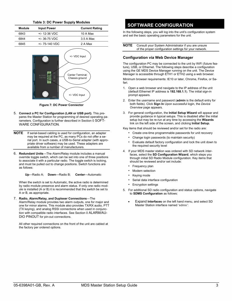
2. Connect Antenna Feed-lines. All coaxial antenna connections are made to the Type-N connectors on the rear of the unit. Figure 4, Figure 5, and Figure 6 illustrate the antenna options available;
Figure 4: Internal Duplexer, Triple N connectors
Figure 5: Internal Duplexer (or internal T/R switch),
Single N connector
Figure 6: External duplexer or dual antennas
(TX and RX ports pass directly through)
3. Install the Data Interface Cabling. Interface connections are made to the front of the Platform Manager module. Typical connec-tions for most sites include:
• Serial Data—Attach data equipment to the front panel COM1 or COM2 port. By default, the COM2 port is set for management and must be configured for data before connecting data equip-ment. The unit is hardwired as a DCE device; a straight-through Ethernet cable may be used in most cases (DB9-F to RJ-45 connector, GE MDS part no. 73-2434A12).
• Ethernet LAN—Attach data equipment to the ETH1 and/or ETH2 port. The auto-sensing MDIX feature allows either a straight-through or crossover cable to be used.
Where applicable in the steps that follow, secure all cable connections with the locking screws provided.
4. Connect Primary Power—The Master Station is powered using one or two power supply modules that work in tandem. The mod-ules may be AC, DC, or a combination of both. The following tables list each type and key operating parameters.
Table 2: AC Power Supply Module
Module Input Power Current Rating
6755 100-264 VAC, 50/60 Hz 120W Max.
All DC power supply modules have chassis isolated inputs and a diode bridge for floating ground, positive ground, or negative ground installations. These modules include a keyed power con-nector with screw-terminals. Power supply connections must be less than 3 meters from the source to the terminals. Strip the wire leads to 6mm (1/4 inch) and insert them into the wire ports pro-vided. Be sure to observe the polarity shown below. Tighten the binding screws securely and insert the connector into the module.
Connector 2:RX Output to external
notch filter
Connector 1:TX/RX Antenna Port
Connector 3: RX Input from external
notch filter
Connector 1:TX/RX Antenna Port
Knockout covers installed on unused
ports
Connector 1:TX Output Port
Connector 2:RX Input Port
05-6398A01-GB, Rev. A MDS Master Station Setup Guide 3
Table 3: DC Power Supply Modules
Module Input Power Current Rating
6843 +/- 12-36 VDC 10 A Max
6844 +/- 36-75 VDC 3.5 A Max
6845 +/- 75-140 VDC 2 A Max
+/- VDC Input
+/- VDC Input
Center Terminal;Chassis ground
Figure 7: DC Power Connector
5. Connect a PC for Configuration (LAN or USB port). This pre-pares the Master Station for programming of desired operating pa-rameters. Configuration is further described in Section 0 SOFT-WARE CONFIGURATION.
NOTE If serial-based cabling is used for configuration, an adapter may be required at the PC, as many PCs do not offer a se-rial port. In such cases, a USB-to-Serial adapter (with appro-priate driver software) may be used. These adapters are available from a number of manufacturers.
6. Redundant Units—The Alarm/Relay module includes a manual override toggle switch, which can be set into one of three positions to associate it with a particular radio. The toggle switch is locking, and must be pulled out to change positions. Switch functions are as follows: Up—Radio A; Down—Radio B; Center—Automatic
When the switch is set to Automatic, the active radio is determined by radio module presence and alarm status. If only one radio mod-ule is installed (A or B) it is recommended that the switch be set to A or B, as appropriate.
7. Radio, Alarm/Relay, and Duplexer Connections—The Alarm/Relay module provides two alarm outputs, one for major and one for minor alarms. This module also provides TX/RX audio, PTT (TX keying), and analog RSSI connections when used in conjunc-tion with compatible radio interfaces. See Section 0 ALARM/AU-DIO PINOUT for pin-out connections. All other required connections on the front of the unit are cabled at the factory per ordered options.
SOFTWARE CONFIGURATION In the following steps, you will log into the unit’s configuration system and set the basic operating parameters for the unit.
NOTE Consult your System Administrator if you are unsure of the proper configuration settings for your network.
Configuration via Web Device Manager
The configuration PC may be connected to the unit by WiFi (future fea-ture), USB, or Ethernet. The following steps describe a configuration using the GE MDS Device Manager running on the unit. The Device Manager is accessible through ETH1 or ETH2 using a web browser.
Minimum browser requirements: IE10 or later, Chrome, Firefox, or Sa-fari.
1. Open a web browser and navigate to the IP address of the unit (default Ethernet IP address is 192.168.1.1). The initial sign-in prompt appears.
2. Enter the username and password (admin is the default entry for both fields). Click Sign In Upon successful login, the Device Overview page appears.
3. For general configuration, the Initial Setup Wizard will appear and provide guidance in typical setups. This is disabled after the initial setup but may be re-run at any time by accessing the Wizards link on the left side of the screen, and clicking Initial Setup.
Key items that should be reviewed and/or set for the radio are:
• Create one-time programmable passwords for unit recovery
• Change login passwords (to maintain security)
• Evaluate default factory configuration and lock the unit down to the required security level
4. If your MDS master station was ordered with SD network inter-faces, select the SD Configuration Wizard, which steps you through initial SD Radio Module configuration. Key items that should be reviewed and/or set include:
• Frequency plan
• Modem selection
• Keying mode
• Serial data interface configuration
• Encryption settings
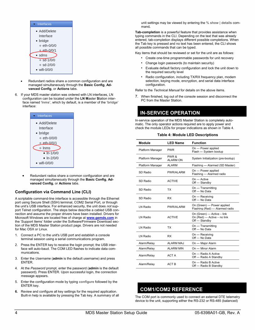
5. For additional SD radio configuration and status options, navigate to SDMS Configuration as follows:
Expand Interfaces on the left hand menu, and select SD Master Station interface named ‘sdms’:
4 MDS Master Station Setup Guide 05-6398A01-GB, Rev. A
Redundant radios share a common configuration and are managed simultaneously through the Basic Config, Ad-vanced Config, or Actions tabs.
6. If your MDS master station was ordered with LN interfaces, LN configuration can be located under the LN Master Station inter-face named ‘lnms’, which by default, is a member of the ‘bridge’ interface:
Redundant radios share a common configuration and are managed simultaneously through the Basic Config, Ad-vanced Config, or Actions tabs.
Configuration via Command Line (CLI)
A scriptable command-line interface is accessible through the Ethernet port using Secure Shell (SSH) terminal, COM2 Serial Port, or through the unit’s USB interface. For enhanced security, the unit does not sup-port Telnet configuration. The steps below describe a cabled USB con-nection and assume the proper drivers have been installed. Drivers for Microsoft Windows are located free of charge at www.gemds.com in the ‘Support Items’ folder under the Software/Firmware Download sec-tion of the MDS Master Station product page. Drivers are not needed for Mac OSX or Linux.
1. Connect a PC to the unit's USB port and establish a console terminal session using a serial communications program.
2. Press the ENTER key to receive the login prompt; the USB inter-face will auto-baud. The COM LED flashes to indicate data com-munications.
3. Enter the Username (admin is the default username) and press ENTER.
4. At the Password prompt, enter the password (admin is the default password). Press ENTER. Upon successful login, the connection message appears.
5. Enter the configuration mode by typing configure followed by the ENTER key.
6. Review and configure all key settings for the required application. Built-in help is available by pressing the Tab key. A summary of all
unit settings may be viewed by entering the % show | details com-mand.
Tab-completion is a powerful feature that provides assistance when typing commands in the CLI. Depending on the text that was already entered, tab-completion displays different possible completions. When the Tab key is pressed and no text has been entered, the CLI shows all possible commands that can be typed.
Key items that should be reviewed or set for the unit are as follows:
• Create one-time programmable passwords for unit recovery
• Change login passwords (to maintain security)
• Evaluate default factory configuration and lock the unit down to the required security level
• Radio configuration, including TX/RX frequency plan, modem selection, keying mode, encryption, and serial data interface configuration.
Refer to the Technical Manual for details on the above items.
7. When finished, log out of the console session and disconnect the PC from the Master Station.
IN-SERVICE OPERATION In-service operation of the MDS Master Station is completely auto-matic. The only operator actions required are to apply power and check the module LEDs for proper indications as shown in Table 4.
Table 4: Module LED Descriptions
Module LED Name Function
Platform Manager PWR On — Power applied Flash — System bootup
Platform Manager PWR & ALARM ON
System Initialization (pre-bootup)
Platform Manager ALARM Flashing — Alarmed (SD Master)
SD Radio PWR/ALARM On — Power applied Flashing — Alarmed radio
SD Radio ACTIVE On — Active Off — Standby
SD Radio TX On — Transmitting Off — No Data
SD Radio RX On — Receiving Off — No Data
LN Radio PWR/ALARM On (Green) — Power applied Flashing (Red) — Alarmed radio
LN Radio ACTIVE On (Green) — Active – link On (Red) — Active – no link Off — Standby
LN Radio TX On — Transmitting Off — No Data
LN Radio RX On — Receiving Off — No Data
Alarm/Relay ALARM MAJ On — Major Alarm
Alarm/Relay ALARM MIN On — Minor Alarm
Alarm/Relay ACT A On — Radio A Active Off — Radio A Standby
Alarm/Relay ACT B On — Radio B Active Off — Radio B Standby
COM1/COM2 REFERENCE The COM port is commonly used to connect an external DTE telemetry device to the unit, supporting either the RS-232 or RS-485 (balanced)
05-6398A01-GB, Rev. A MDS Master Station Setup Guide 5
format, depending on how the device is configured. The unit supports data rates of 300, 1200, 2400, 4800, 9600, 19200, 38400, 57600, and 115200 bps (asynchronous data only).
This connector mates with a standard RJ-45 plug (see Figure 8) availa-ble from many electronics parts distributors.
Pin Descriptions—RS-232 Mode
Pin descriptions for the COM connector in RS-232 mode are shown in Table 5 and Table 6Table 6 on the following page. Note that the unit is hardwired as a DCE device. Refer to the Technical Manual for RS-422/485 descriptions. (Note: RS-485 supported on COM2 only.)
Figure 8: COM Connector (RJ-45)
As viewed from outside the unit
Table 5: COM1 Pin-out - Default Data Port
Pin #
Input/ Output
Pin Description
1 OUT DSR (Data Set Ready)
2 OUT DCD (Data Carrier Detect)
3 IN DTR (Data Terminal Ready)
4 Ground Connects to chassis ground (negative supply)
5 OUT RXD (Received Data)—Supplies received data to the connected device
6 IN TXD (Transmitted Data)—Accepts TX data from the connected device
7 OUT CTS (Clear to Send)
8 IN RTS (Request to Send)
Table 6: COM2 Pin-out - Default Console Port
Pin #
Input/ Output
Pin Description
1 Reserved -- (Do not connect)
2 Reserved -- (Do not connect)
3 Reserved -- (Do not connect)
4 Ground Connects to chassis ground (negative supply)
5 OUT RXD (Received Data)—Supplies received data to the connected device
6 IN TXD (Transmitted Data)—Accepts TX data from the connected device
7 OUT CTS (Clear to Send)
8 IN RTS (Request to Send)
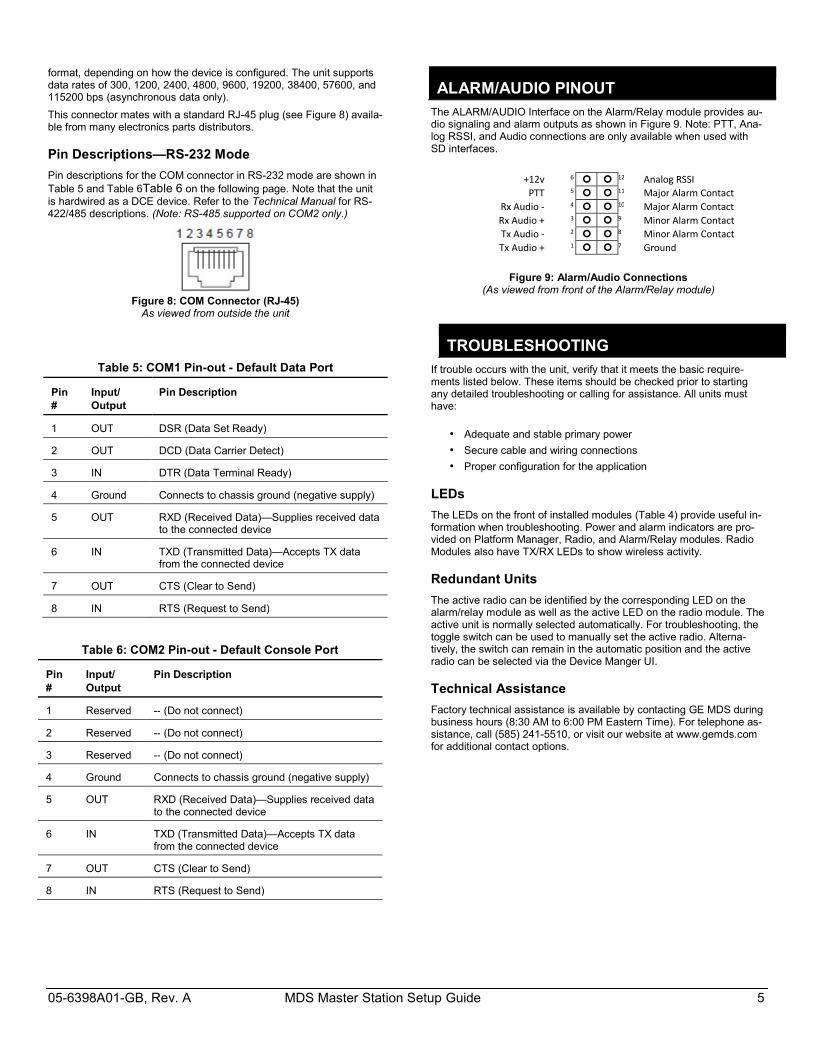
ALARM/AUDIO PINOUT The ALARM/AUDIO Interface on the Alarm/Relay module provides au-dio signaling and alarm outputs as shown in Figure 9. Note: PTT, Ana-log RSSI, and Audio connections are only available when used with SD interfaces.
+12v 6 12 Analog RSSI
PTT 5 11 Major Alarm Contact Rx Audio - 4 10 Major Alarm Contact Rx Audio + 3 9 Minor Alarm Contact Tx Audio - 2 8 Minor Alarm Contact Tx Audio + 1 7 Ground
Invisible place holderFigure 9: Alarm/Audio Connections
(As viewed from front of the Alarm/Relay module)
TROUBLESHOOTING If trouble occurs with the unit, verify that it meets the basic require-ments listed below. These items should be checked prior to starting any detailed troubleshooting or calling for assistance. All units must have:
• Adequate and stable primary power
• Secure cable and wiring connections
• Proper configuration for the application
LEDs
The LEDs on the front of installed modules (Table 4) provide useful in-formation when troubleshooting. Power and alarm indicators are pro-vided on Platform Manager, Radio, and Alarm/Relay modules. Radio Modules also have TX/RX LEDs to show wireless activity.
Redundant Units
The active radio can be identified by the corresponding LED on the alarm/relay module as well as the active LED on the radio module. The active unit is normally selected automatically. For troubleshooting, the toggle switch can be used to manually set the active radio. Alterna-tively, the switch can remain in the automatic position and the active radio can be selected via the Device Manger UI.
Technical Assistance
Factory technical assistance is available by contacting GE MDS during business hours (8:30 AM to 6:00 PM Eastern Time). For telephone as-sistance, call (585) 241-5510, or visit our website at www.gemds.com for additional contact options.
6 MDS Master Station Setup Guide 05-6398A01-GB, Rev. A
Regulatory & Product Information Sheet—MDS Master Station
RF Exposure Notice
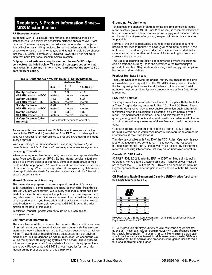
To comply with RF exposure requirements, the antenna shall be in-stalled to ensure a minimum separation distance shown below from persons. The antenna may not be collocated or operated in conjunc-tion with other transmitting devices. To reduce potential radio interfer-ence to other users, the antenna type and its gain should be so chosen that the Equivalent Isotropically Radiated Power (EIRP) is not more than that permitted for successful communication.
Only approved antennas may be used on the unit's RF output connectors, as listed below. The use of non-approved antennas may result in a violation of FCC rules, and subject the user to FCC enforcement action.
Table - Antenna Gain vs. Minimum RF Safety Distance
Antenna Gain
0–5 dBi 5–10 dBi
10–16.5 dBi
Safety Distance 400 MHz variant – FCC
1.09 meters
1.95 meters
4.11 meters
Safety Distance 400 MHz variant – IC
1.43 meters
2.54 meters
5.37 meters
Safety Distance 900 MHz variant – FCC
0.99 meters
1.76 meters
3.73 meters
Safety Distance 900 MHz variant - IC
1.29 meters
2.30 meters
4.87 meters
Safety Distance (other models):
Consult factory prior to operation.
Antennas with gain greater than 16dBi have not been authorized for use with the EUT; and (b) installation of the EUT into portable applica-tions with respect to RF compliance will require SAR testing and Regu-latory approval.
Warning: Changes or modifications not expressly approved by the manufacturer could void the user’s authority to operate the equipment Servicing Precautions
When servicing energized equipment, be sure to wear appropriate Per-sonal Protective Equipment (PPE). During internal service, situations could arise where objects accidentally contact or short circuit compo-nents and the appropriate PPE would alleviate or decrease the severity of potential injury. When servicing radios, all workplace regulations and other applicable standards for live electrical work should be followed to ensure personal safety.
Manual Revision and Accuracy
This manual was prepared to cover a specific version of firmware code. Accordingly, some screens and features may differ from the ac-tual unit you are working with. While every reasonable effort has been made to ensure the accuracy of this publication, product improvements may also result in minor differences between the manual and the prod-uct shipped to you. If you have additional questions or need an exact specification for a product, please contact GE MDS, using the infor-mation at the back of this guide.
In addition, manual updates can be found on our web site at www.gemds.com.
Environmental Information
The manufacture of this equipment has required the extraction and use of natural resources. Improper disposal may contaminate the environ-ment and present a health risk due to hazardous substances contained within. To avoid dissemination of these substances into our environ-ment and to limit the demand on natural resources, we encourage you to use the appropriate recycling systems for disposal. These systems will reuse or recycle most of the materials found in this equipment in a sound way. Please contact GE MDS or your supplier for more infor-mation on the proper disposal of this equipment.
Grounding Requirements
To minimize the chance of damage to the unit and connected equip-ment, a safety ground (NEC Class 2 compliant) is recommended which bonds the antenna system, chassis, power supply and connected data equipment to a single-point ground, keeping all ground leads as short as possible.
Normally, the unit is adequately grounded if the supplied mounting brackets are used to mount it to a well-grounded metal surface. If the unit is not mounted to a grounded surface, it is recommended that a safety ground wire be attached to one of the mounting brackets or a screw on the enclosure.
The use of a lightning protector is recommended where the antenna cable enters the building. Bond the protector to the tower/support ground, if possible. All grounds and cabling must comply with applica-ble codes and regulations.
Product Test Data Sheets
Test Data Sheets showing the original factory test results for this unit are available upon request from the GE MDS Quality Leader. Contact the factory using the information at the back of this manual. Serial numbers must be provided for each product where a Test Data Sheet is required.
FCC Part 15 Notice
This Equipment has been tested and found to comply with the limits for a Class A digital device, pursuant to Part 15 of the FCC Rules. These limits are designed to provide reasonable protection against harmful in-terference when the equipment is operated in a commercial environ-ment. This equipment generates, uses, and can radiate radio fre-quency energy and, if not installed and used in accordance with the in-struction manual, may cause harmful interference to radio communica-tions.
Operation of this equipment in a residential area is likely to cause harmful interference in which case users will be required to correct the interference at their own expense.
This device complies with Part 15 of the FCC Rules. Operation is sub-ject to the following two conditions: (1) this device may not cause harmful interference, and (2) this device must accept any interference received; including interference that may cause undesired operation.
Canada, IC ERP Limits
IC SRSP-501, 6.3.2. Limits the ERP to 125W for fixed point-to-point operation. For IC use the antenna gain and Transmit power must be set to meet the ERP limit of 125W. This can be accomplished by us-ing the appropriate at antenna gain in combination with the RF power settings.
CE Mark and Radio Equipment Directive (RED) Notice (applies to select product variants only)
Product that is CE marked is compliant with European Union Radio Equipment Directive 2014/53/EU.
GEMDS products employ a variety of wireless technologies and fre-quencies. These can include, cellular M2M, WIFI, and licensed narrow-band radio frequencies. The user is responsible to ensure that proper spectrum licenses are obtained for all licensed uses, carrier SIMs are authorized for M2M cellular, and proper antenna gain is used to main-tain local regulatory compliance.