Pumping Station - environmentdata.org
186
Pumping Station - Efficiency Of Operation And Cost For A Design Life Span Survey of Pumping Installations and Design Philosophy Initiatives. Research Contractor: Bullen and Partners R&D Project Record 363/ 1 /NW Further copies of this report are available from: w iti Foundation for Water Research, Allen House, The Listons, Liston Rd, Marlow, Bucks SL7 1FD. Tel: 01628 891589, Fax: 01628-472711 NRA National Rivers Authority
-
Upload
khangminh22 -
Category
Documents
-
view
0 -
download
0
Transcript of Pumping Station - environmentdata.org

Pumping Station - Efficiency Of Operation And Cost For A Design Life Span
Survey of Pumping Installations and Design Philosophy Initiatives.
Research Contractor: Bullen and Partners
R&D Project Record 363/ 1 /NW
Further copies of this report are available from : w i t iFoundation for Water Research, Allen House, The Listons,Liston Rd, Marlow, Bucks SL7 1FD. Tel: 0 1 628 891589, Fax: 0 1 6 2 8 -4 7 2 7 1 1
NRAN ational Rivers A uthority

ENVIRONMENT AGENCY
126862
Pumping Station - Efficiency Of Operation And Cost For A Design Life Span
Survey o f Pumping Installations and Design Philosophy Initiatives
Research Contractor: Bullen and Partners
National-Rivers-Authority Rivers House Waterside Drive
.Aztec West - -Bristol B S 1 2 4 U D
R&D Project Record 363/1/NW
Sullen and Partner*National R iven Authority
Pumping Station Research
CONTENTS
Page
1.0 SUMMARY 1
2.0 PROJECT DESCRIPTION 2
3.0 STUDY APPROACH 4
3.1 Phase 1 * Data Base & Design Philosophy 53.2 Phase 2 - Maintenance Practices 63.3 Phase 3 - Detailed Analysis & Reporting 7
4.0 DATA BASE PRELIMINARY REPORT 9
4.1 Summary of Pump Data 94.2 Analysis by Capacity 94.3 Analysis by Type 94.4 Analysis by Manufacturer 104.5 Cost of Stations by Capacity 10
5.0 PUMPING STATION DESIGN PHILOSOPHY PRELIMINARY REPORT 11
5.1 Summary 115.2 Introduction 115.3 Historical Background 115.4 Design Philosophy 155.5 General Considerations. _ . 165.6 Selection of Pumps and Ancillary Equipment 17
____ 5.7 Design _Check.List ______ ______________________ 225.8. Points for further study _ 22
R*fi VH 19J74/001IB
Bullen and Partner*National River* Authority
Pumping Station Re»earch
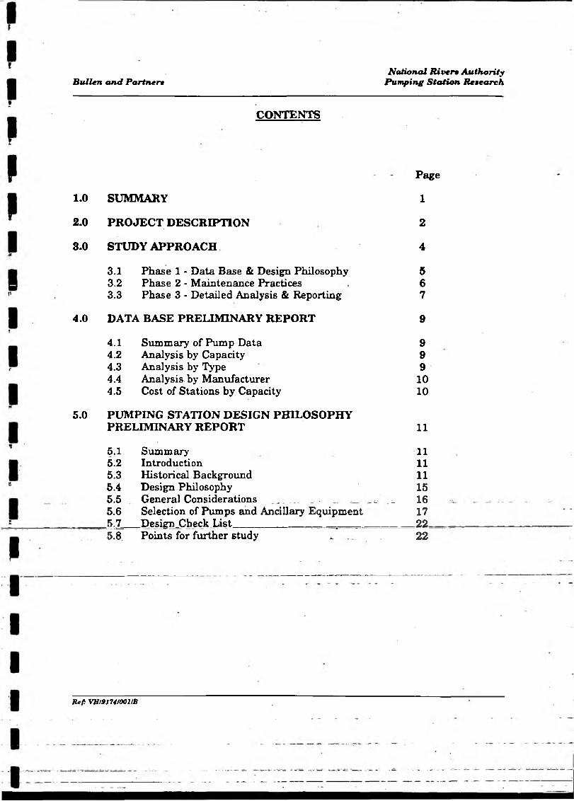
APPENDICES
APPENDIX A STUDY APPROACH
A1 Survey of Pumping Plant QuestionnaireA2 Survey of Pumping Plant Design QuestionnaireA3 Survey of Pumping Plant Maintenance Questionnaire
APPENDIX B DATABASE
B1 Summary of Pump Data and Location Maps by RegionB2 Pump Analysis by CapacityB3 Pump Analysis by TypeB4 Pump Analysis by ManufacturerB5 Costs of Stations by Capacity
APPENDIX C DESIGN PHILOSOPHY
Cl Design ConsiderationsC2 Checklist
APPENDIX D PHOTOGRAPHS
APPENDIX E REFERENCES
Ref. VUmntOOHB

Bullen and Partner»National River* Authority
Pumping Sttition Research
1.0 SUMMARY
The National Rivers Authority is currently responsible for 280 pumping stations (see map overleaf). These not only represent a very large capital investment in mechanical and electrical equipment but also involve the Authority in high annual expenditure in respect of their operation, maintenance and replacement. In view of the large financial commitment, the Authority wish to ensure that the most cost effective solutions are adopted for all new stations.
Preliminary investigation would appear to indicate that there is no common approach to the design and maintenance of flood defence pumping stations. It is evident that benefit would result from a detailed study of design philosophy and maintenance methods used. The object of the present study is to produce a manual of recommended practice for the guidance of engineers.
This interim report follows completion of the first phase of the study which comprised the following; a detailed survey of all land drainage pumping plant, preparation of a data base, and analysis of design philosophy throughout all regions. The report describes the project, summarises the results of the pumping plant survey and indicates the generally accepted current approach to the design of flood defence pumping stations. It also outlines some of the topics and problems
, that will be addressed in detail in the final report.
su p VHI91742/001/B 1

UGOiD
I —
• i > •
\V *f
/ - -/ 'V—NORTH UMBRI
r - NRA* v - PUMPING STATIONS
^ \ r ' v Sl>y-^ r■HtHTTH-jClST 1 -; _M9 ) « “ _NUMBERS OF PUMPING
— 5 -1 V , ..'C * ____ / - STATIONS BY REGION
~ \~~—s — '» _
I-3? *-»V * ^ ! i _
•—"* .jrlTs “ ’ £ ,v , S —1 —\ l_\ 3 :'- /" “ V“ ri*.-------= 7 ^ - i _
— • E\-iyu n; d
■; -~ ~ —rz . * ^ 4 — wj. “« > K» ■■■.-■*-W <W (TJ
' . «c= ?
W AWeis* ;
C ,-. mi«N nnscyje^-^sii. f T —' ” — "'wsusr J l 'e 's ^ - . , , ^ - " I T "
&- i __ ' V »I1 N__ . _____ __
0 - 'J— /----'• t i , ■‘L _ y ^ l ’ 'V. -. —-•£=- \ J ^ k 'T ' l g & K - S E l i ■“ ■ -■ —
r~ ^ r r . .{ - X r v ^ « ^ w i ^ ^ 3 J j = = .~....r ■■■
r “ V - r ~* ; - 1- \_y *> ^—V- , ^ = r L ! —•*- southern '
' . ■* WESSD. .**- ~ ”1 V ---
_*: souih win __-z-
[ HEAD OFFICESKKTDI IOKDON
NATIONAL RIVERS AUTHORITY - REGIONAL OFFICESanguan nonmjiinuN mnH-msr scvern non soutkiw
SOUTHWST nUM£S «QSH WESSEX VOBSMXE
Bullen and Partner*National Rivers Authority
Pumping Station RtMearch
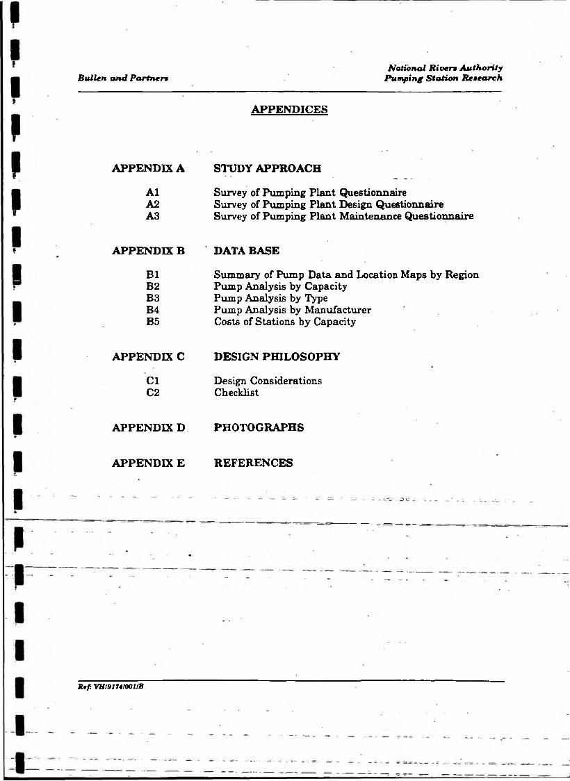
2.0 PROJECT DESCRIPTION
There is no common approach or code of practice applied to the design of flood defence pumping installations and it is thought that over-reliance may be placed on established custom and practice. This approach can lead to the specification and adoption of old and possibly well proven designs even though they may be less cost effective or efficient than alternative solutions. In addition, no consistent strategy exists for electrical and mechanical maintenance procedures. There would also appear to be current lack of forward planning in establishing the life expectancy of plant and associated systems and implementing long, medium or short term capital investment programmes for their replacement.
Having identified the above problems, the National Rivers Authority is addressing them by commissioning the present study of the land drainage pumping stations under its control. Particular emphasis is to be placed on the efficiency of operation and costs incurred for a design lifespan. In the past, initial cost has often been the main criterion possibly influenced by the grant-aid regulations, but it is obvious that prudent investment and financial control requires consideration of operating, maintenance and repair costs incurred during the entire life of the station. The overall objectives of the project are to:
produce a detailed database of all the National RiVers Authority mechanical and electrical- pumping plant, categorised into .type, size, duty, age and other relevant criteria.
ii) analyse design philosophy and detail of flood defence pumping stations throughout all regions and determine best practices and relevant costings.
R tf VH/91742/001fB 2
Bullen and Partner»National R iven Authority
Pumping Station Research
iii) review national strategies for maintenance investment and mechanical and electrical maintenance procedures.
iv) publish results and prepare a manual of recommended practice for guidance of engineers.
To achieve these objectives, the study is divided into three phases with the following specific objectives:
Phase 1 - To conduct a detailed survey of flood defence pumping plant installations through the NRA and prepare a detailed categorised data base. To analyse design philosophy and carry out field studies to determine how decisions are made and developed through to final selection of type, site, and pumping station arrangement.
Phase 2 - To conduct a detailed survey into strategy and the decision making process in mechanical and electrical maintenance. Research samples in the field.
Phase 3 - Carry out a detailed analysis of Phase 1 and 2. Propose a code of practice and recommendations for design and maintenance investment applying any benefits from "Life Cycle Costing - A Radical Approach" (CIRIA Report 122). Publication of results and education in the field through to final implementation.
= — ■— Phase l of the study has now, been.completed.and this report present6 a summary of the results from the survey of pumping plant and an interim report on design philosophy.
R tf. VH!91742/001/B 8
Bullen and Partner*National Rivera Authority
Pumping Station Retearch
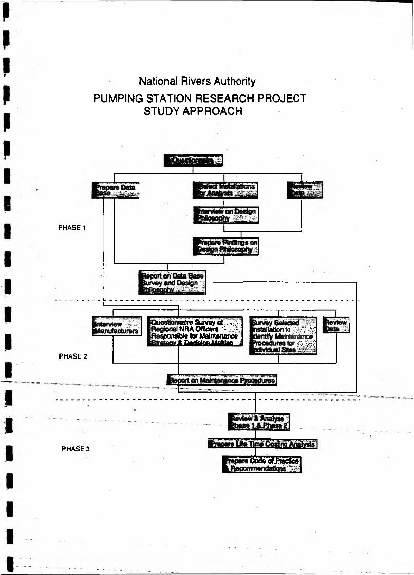
3.0 STUDY APPROACH
The approach to the study is summarised in the flow diagram overleaf and details of the methodology and approach for each phase of the study are provided on the following pages.
3.1 Phase 1 - The Data Base
The data base provides detailed information on National Rivers Authority pumping installations throughout England and Wales. For each pump installation general particulars have been collated, this comprises details of station layout and monitoring system, responsibility for design and specification, costs and any other relevant information.
In addition, more detailed information has been collected as indicated in the following categories:
National Grid Reference.Station Catchment Area.Total Capacity of Station.Number of pumps.Manufacturer.Date commissioned.Pump Type (Centrifugal, Axial, Mixed Flow or Screw).Size, Diameter.Housing (High building with crane, low building, removable roof, outdoor
— ----- or. submersible).__ __ __Mounting (Horizontal or vertical).Capacity (per pump).Design Static Head.
JUf. VJt/Bl742/001/S 4
PHASE 1
PHASE 2
PHASE 3
National Rivers Authority
PUMPING STATION RESEARCH PROJECT STUDY APPROACH
;naireSiffv«y€4..; . ] NRAOfftoers ^ ; ■
sponsible for Maintenanceftfttfthtonlltftfnn 1
atjonto z m m " Mairii&nanoe
n m z iMttMMfliiMMMir
’B S E W S S S Z S

Bullen and Partner>National Riverv Authority
Pumping Station Research
Impeller Speed RPM.Drive (Diesel or Electric).HP.Supply voltage.Discharge type (Syphonic, Sluice or Sluice and Reflux).
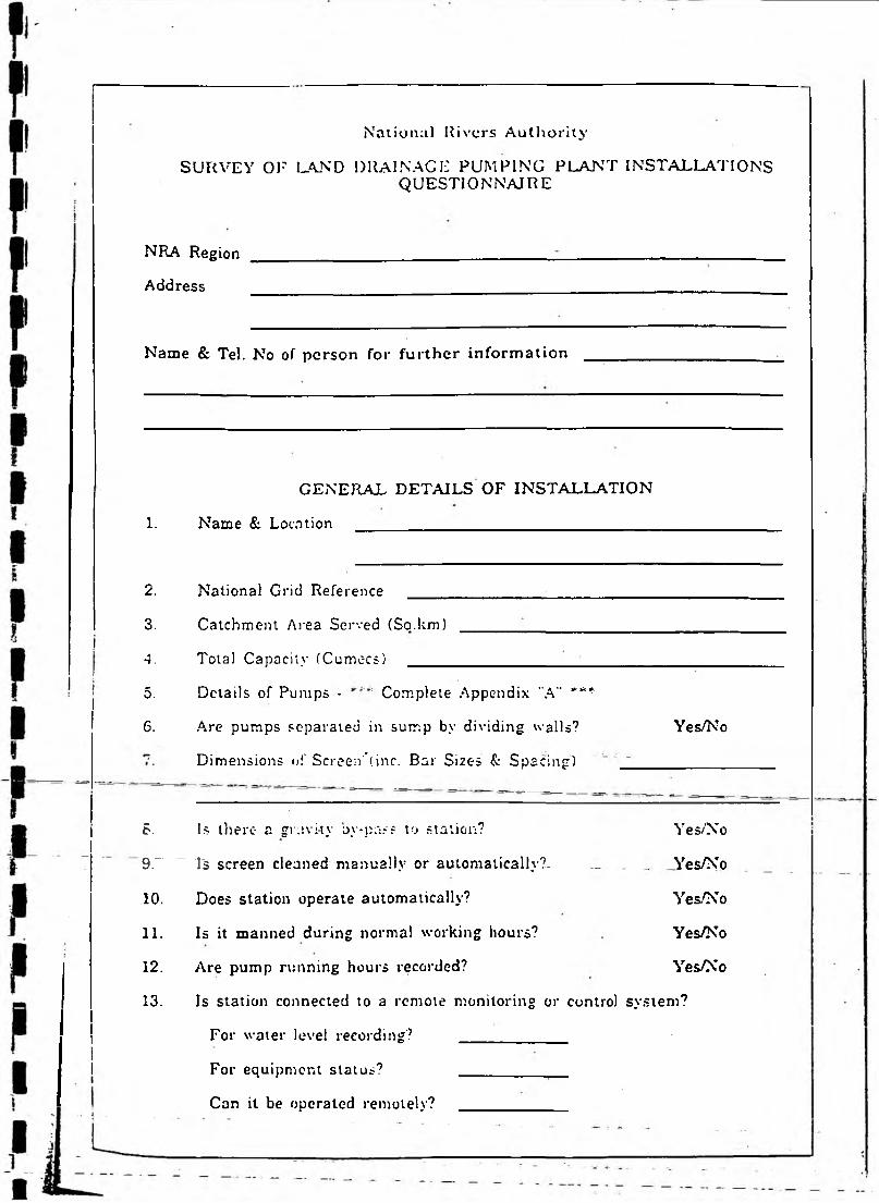
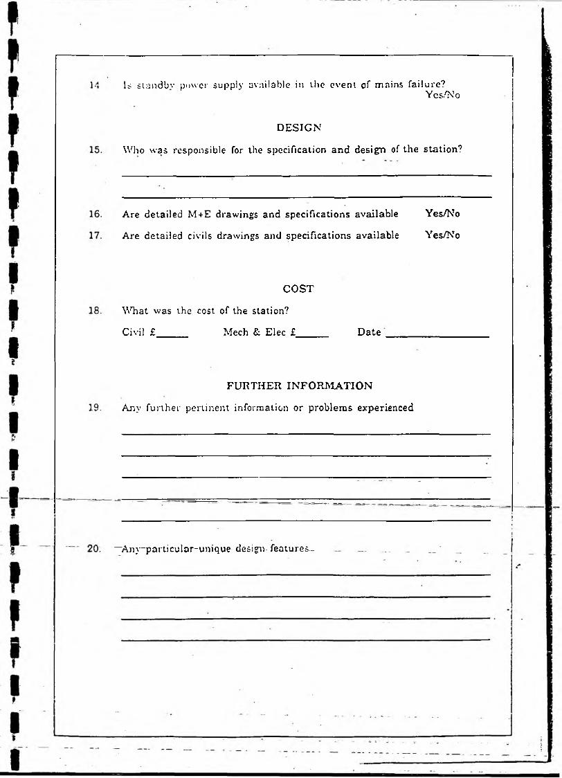
The information was gathered by means of a simple questionnaire, the format is presented in Appendix A l. The first two sheets allow the recipient to insert general particulars and the third contains detailed information. The questionnaire was designed to be simple to complete to ensure a high response rate whilst containing enough information to permit meaningful analysis. The questionnaires were circulated and completed during early 1992, and the database was constructed on the information supplied.
The amount of information provided in the completion of the questionnaire was variable both by region and by individual station. Most of the information supplied relates to pump size and characteristics, the information relating to design and costs is generally less well covered. It is recognised that this information is difficult to recover as many of the stations are over twenty years old and original documentation is no longer available.
A summary of the data base information is presented as part of this report. The complete document is held by Mr A. Taylor, the Mechanical Services Manager of the NRA, North West Region. It can be inspected by request.
3J2 Design Philosophy
It was agreed at the start of the study that the analysis of current design philosophy would be based on interviews with the designers of a 10% sample of stations selected from each NRA region. These pumping stations were chosen from those recorded on the Data Base, to cover the widest possible range of size and type in current operation. Site visits were made by Bullen and Partners engineers
Ref. VB/91742/00J/B 5

Bullen and Partner*National R iven Authority
Pumping Station Research
during 1992, the interviewees were engineers with responsibility for design of mechanical and electrical plant and/or civil works and they were in the main current NRA engineers. Detailed questions were asked about the design, construction and operational history, a list of standard questions being used to ensure uniformity of approach in the various areas. The format for the standard questions is presented in Appendix A2, in addition, relevant documentation was also obtained such as tender documents, reports and specifications. Following the site visits and collation of relevant documents detailed reports were completed and design implications studied.
A number of manufacturers have been approached regarding their philosophy in respect of the design and supply of pumps for flood defence purposes. A questionnaire was again used to ensure uniformity in the information supplied. Several replies have been received, in particular detailed comments were provided by the Bedford Pump Company Ltd and KSB's London office.
An interim report on design philosophy based on these initial interviews and information from manufacturers is presented in sections 5.0 of this report.
3.3 Phase 2 - Maintenance Practices
The review of the strategy and decision making processes in mechanical and electrical maintenance will be based on a combination of questionnaires and
— interviews ---- ----------------------------------------------------
The questionnaire will be completed by regional or district managers, who are responsible for maintenance of pumping installations within their area. Typically the regional/district managers would be responsible for several installations, and so these questionnaires will give general information on strategy and decision making for maintenance adopted on an area basis. The questionnaire will be circulated to district managers within the Authority so that coverage of all installations will be achieved.
Ref. VH/91742/001/B €
Bullen and Partner•National R iven Authority
Pumping Station Remearch
The suggested basis for the questionnaire is in Appendix A3. The first part giving general information on maintenance strategy followed by detailed questions on inspections and checks.
The questionnaire will be followed up by interviews with selected area managers and also first line supervisors who carry out maintenance duties at individual sites. Again standard format interview check lists will be used and the contents will be agreed with the Authority where appropriate.
Companies involved in the manufacture or maintenance of pumping plant will also be interviewed.
The field work will be complemented by a review of any information available to give background information for the final report.
This phase of the project is programmed to take place during the winter of 92/93.
3.4 Phase 3 - Detailed Analysis and Reporting
The results of Phase 1 and 2 will be analysed to provide a review of performance, suitability for purpose, design life and costs of pumps and ancillary equipment of various types and manufacture. Analysis will span the whole asset life cycle of the plant, which involves the activities of specification, design, manufacture, operation and maintenance and finally replacement.
Review of costs over the whole life cycle of an installation will enable conclusions to be made on the appropriateness of initial capital investment and ongoing maintenance expenditure.
The review of design practices will identify successful approaches and the report will provide guidelines to be used by engineers when specifying plant to ensure new methods and design criteria are examined and adopted when appropriate.
R ef VH/917421001IB 7
Bullen and Partner•Nationa l River* Authority
Pumping Station Research
Design criteria, some of which have been adopted on an arbitrary basis, will be considered. These include pump peripheral speeds, bellmouth clearances, shaped sump backs, syphonic discharges and other features.
The final report will be in the form of a manual which will include, recommendations on design practices and maintenance strategies to achieve optimum life cycle costing. The manual will provide guidance for design engineers and those responsible for the maintenance of land drainage pumping stations.
It is important that the information in the guide is widely circulated to practising engineers. This could be achieved by the holding of seminars in the National River Authority Regions, the publication of abstracts and papers, presentations at Conferences (Loughborough), and courses run by Water Training International and other similar bodies.
This phase of the project is programmed for 1993 with the review period for the final documentation during 1994.
Rtf: VH/9174H001/B 8

Sullen and Partner•National River* Authority
Pumping Station Research
4.0 DATA BASE PRELIMINARY REPORT4.1 Summary o f Pump Data
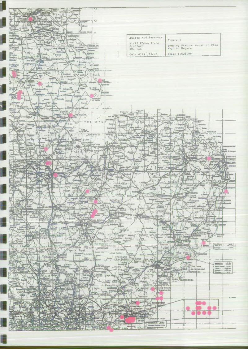
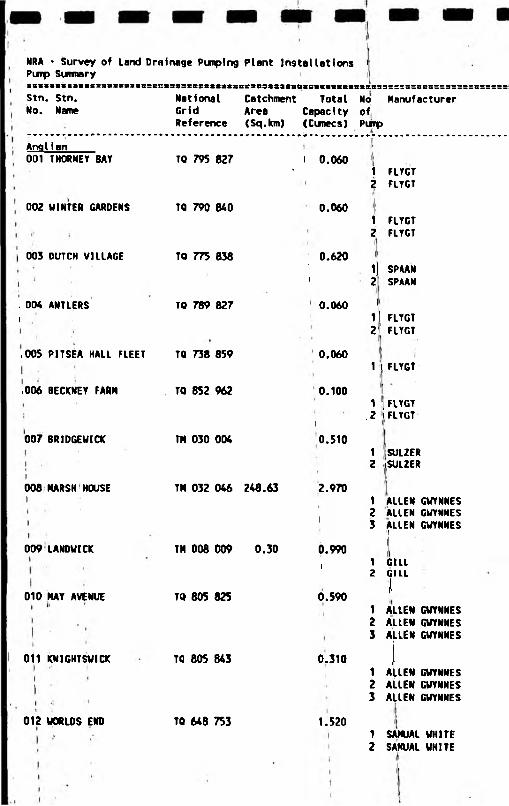
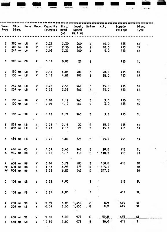
The data base information presented in this report Appendix B1 is a summary of the total information available. It provides basic data on geographical spread, numbers, size and type of the Authority’s pumping plant. The information is presented on a Regional basis and a map is provided to show the location of installations in each region.
It should be noted that within the total number of 94 stations for Southern Region 28 are assets of Internal Drainage Boards which are operated and maintained by the NRA. In the Yorkshire Region 6 stations have been included which were constructed on behalf of the Coal Board for mining subsidence purposes, again these stations are operated and maintained by the NRA.
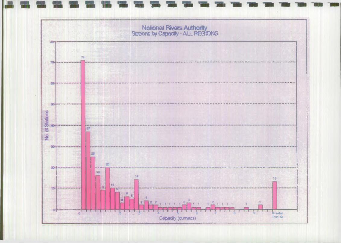
4.2 Analysis bv Capacity
The number of stations by capacity are illustrated graphically for the whole country and by Region, Appendix B2.
Presented overleaf is the analysis for the whole country and this indicates that the bulk of the stations have a capacity of 2 cumecs or less. This confirms that any standardization of designs should be concentrated on stations of this size.
4.3 Analysis by Type
- The number of pumps of different type- are illustrated graphically for the whole country and by Region, Appendix B3.
sup VH/91 742/OOlfB 9

Bullen and Partner»National River* Authority
Pumping Station Research
Presented overleaf is the analysis for the whole country, this confirms that as expected the bulk of the installations use axial flow vertical lift pumps. A point to note is the high number of archimedean screw type pumps, the bulk of which are located in the Southern Region. Another unusual type of installation was the floating type, again in the Southern Region.
4.4 Analysis bv M anufacturer
The number of pumps by Manufacturer are illustrated graphically for the whole country and by Region Appendix B4i
Presented overleaf is the analysis for the whole country which highlights that the bulk of the pumps were manufactured by the A.P.E. Allen Group which was generally known as "Allen Gwynnes". This company, which had a long association with the manufacture of land drainage pumping plant, is now no longer in existence. A large number of the modern small submersible stations were manufactured by Flygt. Spaan represent the archimedean screw type pumps.
4.5 Cost o f Stations bv Capacity
Although cost information could only be obtained for about 20% of the stations, this information does represent a reasonable sample to analyse costs of installations. The costs of pumping stations by capacity are indicated graphically
— in^Appendix BSralso illustrated arexosts'for theMechanical and Electrical (M&E) and Civil elements only.
All costs have been converted to 1992 prices and the best line has been fitted to a log/log plot. As would be expected, the best fit line is for the M&E element as this cost is less variable than the Civils aspect. It should be noted that more cost information is available for M&E as compared to Civils as a result of the number of recent replacements of M&E plant.
tUf; VH191742/001/B 10
National Rivers Stafcms by Capacity - ALL REGIONS
Capacity (cumecs )Greater then »Q

National Rivers Authority No. of Pumps by Type - All Regions

y--:'
ABS „ ACM 1
'UJJbNGWYNNES ARMFJELD
National Rivers Authority No. of Pumps by Manufacturer
W B F O R O - 4 JWTWHGUINARD »pusuge* ■—
BRCOKE CROMFTON 3 DOflWWN "*
W W O t f * » U . N "3 PBNNSR t • av«T T-—
Gtl 4 :- Q OOOGNOUQH 1
HARLAND JCHN8QNH( /TMC»^aiviY 1 12 HAYDQ* 2
JCMESiATrWQOD < Ktt t U W O U g T W i - »• w ■ ■ w w w ^ r i / • 1 w W
USTE* 1 MA1MSRHPLATT “ •MAWFkCW - * > > :•
MULES* WATBCN ■ *MONO 1
m w o n " f l l l i t N&ANS " I
RIJSTONQPWYNNCS 2 «JSTONHORN86* 't
SAMUAL WHITE 2SAflUN — i ■
m c n w m jx , v fSMTFHDOLE f 9PAAN " SURM€RS*3L(Q6 2
a m
J$S
WAliSWN WEI*
WOffTVflNGTTCN -TOC 120 140
No. of Pumost«o 180 200
Bullen and Partner»National R iven Authority
Pumping Station Research
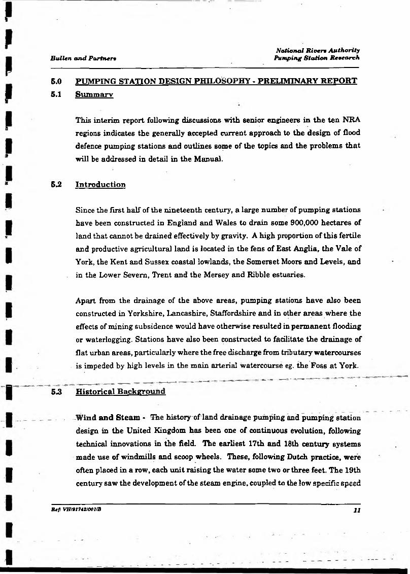
5.0 PUMPING STATION DESIGN PHILOSOPHY - PRELIMINARY REPORT5.1 Summary
This interim report following discussions with senior engineers in the ten NRA regions indicates the generally accepted current approach to the design of flood defence pumping stations and outlines some of the topics and the problems that will be addressed in detail in the Manual.
5.2 Introduction
Since the first half of the nineteenth century, a large number of pumping stations have been constructed in England and Wales to drain some 900,000 hectares of land that cannot be drained effectively by gravity. A high proportion of this fertile and productive agricultural land is located in the fens of East Anglia, the Vale of York, the Kent and Sussex coastal lowlands, the Somerset Moors and Levels, and in the Lower Severn, Trent and the Mersey and Ribble estuaries.
Apart from the drainage of the above areas, pumping stations have also been constructed in Yorkshire, Lancashire, Staffordshire and in other areas where the effects of mining subsidence would have otherwise resulted in permanent flooding or waterlogging. Stations have also been constructed to facilitate the drainage of flat urban areas, particularly where the free discharge from tributary watercourses is impeded by high levels in the main arterial watercourse eg. the Foss at York.
5.3 Historical Background
- -Wind and Steam - The history of land drainage pumping and pumping station design in the United Kingdom has been one of continuous evolution, following technical innovations in the field. The earliest 17th and 18th century systems made use of windmills and scoop wheels. These, following Dutch practice, were often placed in a row, each unit raising the water some two or three feet. The 19th century saw the development of the steam engine, coupled to the low specific speed
R tf: VB19174H001/B 11
Bullen and PartnersNational Rivers Authority
Pumping Station Research
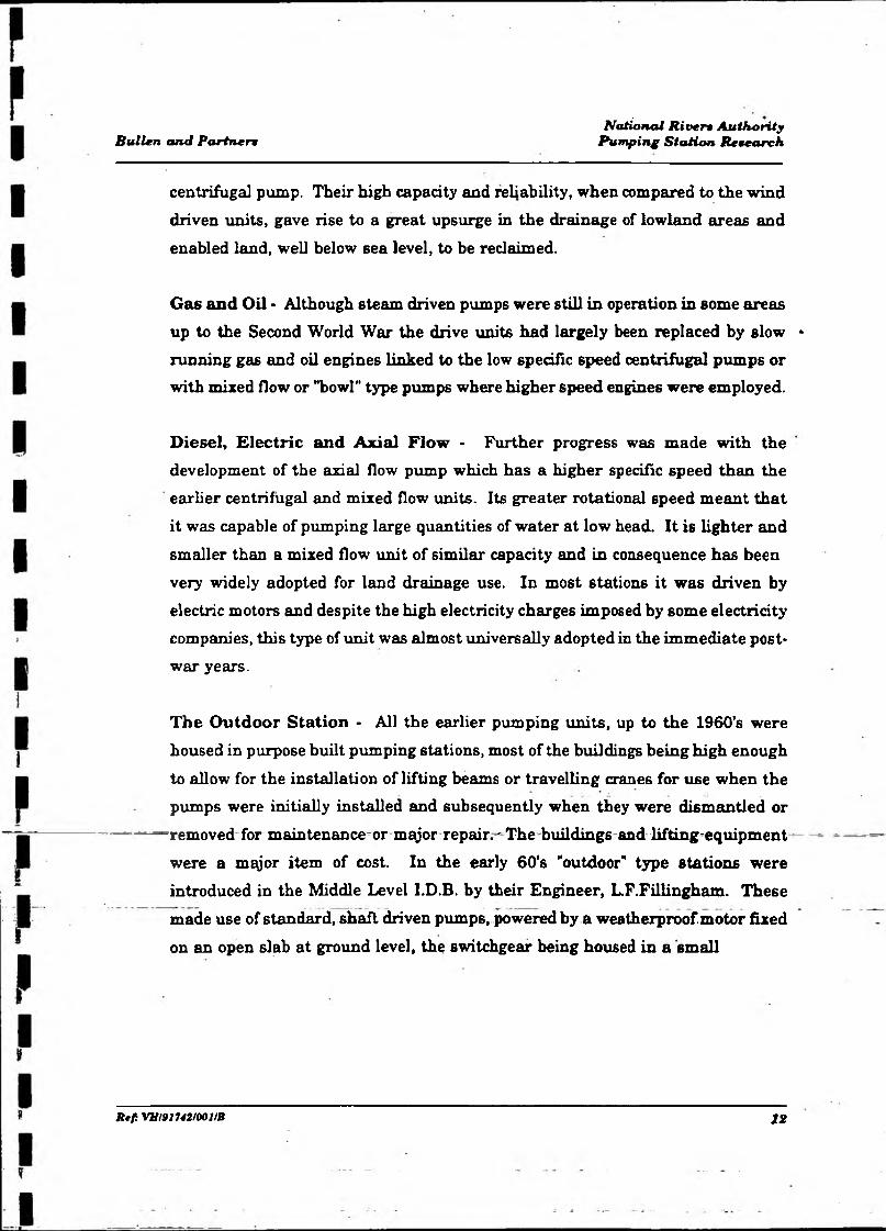
centrifugal pump. Their high capacity and reliability, when compared to the wind driven units, gave rise to a great upsurge in the drainage of lowland areas and enabled land, well below sea level, to be reclaimed.
Gas and Oil - Although steam driven pumps were still in operation in some areas up to the Second World War the drive units had largely been replaced by slow * running gas and oil engines linked to the low specific speed centrifugal pumps or with mixed flow or "bowl” type pumps where higher speed engines were employed.
Diesel, Electric and Axial Flow - Further progress was made with the development of the axial flow pump which has a higher specific speed than the earlier centrifugal and mixed flow units. Its greater rotational speed meant that it was capable of pumping large quantities of water at low head. It is lighter and smaller than a mixed flow unit of similar capacity and in consequence has been very widely adopted for land drainage use. In most stations it was driven by electric motors and despite the high electricity charges imposed by some electricity companies, this type of unit was almost universally adopted in the immediate postwar years.
The Outdoor Station - All the earlier pumping units, up to the 1960*6 were housed in purpose built pumping stations, most of the buildings being high enough to allow for the installation of lifting beams or travelling cranes for use when the pumps were initially installed and subsequently when they were dismantled or removed for maintenance or major repair.- The buildinge and lifting-equipment were a mqjor item of cost. In the early 60’s "outdoor” type stations were introduced in the Middle Level I.D.B. by their Engineer, LF.Fillingham. These made use of standard, shaft driven pumps, powered by a weatherproof motor fixed on an open slab at ground level, the switchgear being housed in a small
Be/i VH/91742/001/B 12

Bullen and PartnertNational R iven Authority
Pumping Station Research
weatherproof cubicle close by. Whilst the outdoor stations with weather-proofed motors proved effective they can be at risk in vandal prone areas even though the exposed motors are protected by sealed cover plates.
•
The submersible Pump - The principle of the "outdoor" pumping station was developed still further in the late 60’s and early 70’s by the development of submersible pumps with capacities large enough for land drainage use. Although it has been claimed, and in some instances it is no doubt true, that their use can
result in great savings over the traditional, shaft driven unit, there have been numerous cases of failure in service of this type of pump and evidence of short working lives in some marques.
Floating Pumping Stations - Floating pumping stations, many of them designed by Stephen Hawes, were constructed in some numbers in the 1960’s but are now no longer in vogue. Advantages claimed are those of cheapness (half the cost of a conventional station), the fact that no foundation is required and their low profile presents no intrusion on the landscape. Disadvantages are the complicated arrangement necessary for discharge, the small size of weedscreen that can be provided (and the difficulty of keeping it clean), though this can be offset by the construction of a separate screen structure, on the channel, upstream of the pontoon. Problems can also arise in some instances by silt building up under the pontoon.
Archimedean Screw Pump - Another post-war innovation was the introduction of the screw pump for land drainage use. Although they have been employed in large numbers in the Netherlands and to a certain extent at sewage works in the U.K., it is only in the South East that they have been adopted in any number - over 60 being .located in the Anglian, Thames and Southern NRA Regions. They are best employed where there is little variation in discharge level and can deal with weed and the complete range of flows up to their maximum capacity. Critics
JUf. VH/9J742/OOlfB 13

Bullen and Partner*National JMwn Authority
Pumping Station Research
say that their installation can seldom be justified if initial cost and operational factors are taken into consideration. Their employment in such large numbers in the South East calls for a closer study.
Operation and Control - There have been considerable changes, over the years, in the methods used to operate and control pumps. Initially, starting and operating were entirely manually controlled. The impellers of many of the early pumps were not submerged and the pumps had to be primed by the use of "exhausters" prior to starting. The introduction of the axial or "propeller" type pump, driven by electric motor, with the impeller always submerged, lent itself to automatic operation. Early systems were switched by floats. These were followed in their turn by "no-flote" electrode systems, air bubblers and ultrasonic level switches. Control equipment is now often connected to a telemetry system that allows information on the equipment and its status to be monitored, and even operated, from a control, room many miles away.
Screens - One of the constant problems in the past was dealing with the considerable quantity of weed and debris of all shapes and sizes that was carried to the pumping station in times of storm. This collected on the weed screen and up to comparatively recent times was always removed by hand raking - an arduous and unpopular job, at night or in inclement weather. Automatic, mechanical raking gear, capable of dealing with the wide variety of river debris has now been introduced from the Continent and is being installed in increasing numbers at both old and new stations. ______ _
Pow er Strikes and M otive Power - The general and almost universal move to----------- larger electrically driven pumps in post-war years, prompted by improved
electricity supplies, received a severe set-back in the late 1960’s with the interference to supplies brought about by the strikes of power company workers and the miners’ 6trike. The indication that this previously considered secure source of power was liable to be cut by industrial action prompted many authorities to install both diesel and electrically driven pumps in new medium
Refi VB/91742/00lfB 14

Bullen and PartnersNational Rivers Authority
Pumping Station Research
sized stations, to ensure that there would be some pumping capacity available under similar circumstances. Most authorities subsequently modified switchgear at existing stations to allow for the connection of a mobile generator. In recent times large mobile pumps have become available on the hire market and these could be used in case of emergency.
Siphonic Discharge - In most of the early pumping stations the discharge was through a reflux or flap valve that prevented reverse flow when the pump was stopped. A sluice valve was normally placed on the discharge side of the pump to allow the flap or reflux valve (or the pump) to be removed for repair or maintenance. Reflux valves and sluice valves are very expensive, particularly in the larger sizes, and from the 50’s these have been largely replaced by the use of siphonic discharge pipes. A siphon breaker valve is incorporated to prevent reverse flow when the pump is stopped. This arrangement is cheap and effective and is still in general use at the present time.
5.4 Design Philosophy
Whilst some minor differences in approach were noted in the various Regions, the current consensus in the approach to flood defence pumping station design is:>
i) that operational staff should play a part in the design team from the start to the finish of the project;
ii) that the station must be capable of pumping all flows, up to its design capacity, with a high degree of reliability;
iii) that the pumps must be able to deal with the weed and other river borne debris that can pass through the weedscreen;
iv) that the station should be easy to operate, and where possible, automatic in operation and capable of being supervised by non-technical staff;
tU fi VH/91742/001/B IS
Bullen and PartnersNational Rivers Authority
Pumping Station Research
Note:
5.5
v) that the equipment, whilst being secured against vandalism, should be accessible, easy to maintain, and should operate efficiently for long periods before requiring m^jor maintenance or overhaul;
vi) that the station must be environmentally acceptable, must not obtrude unduly on visual amenity, must not generate unacceptable noise levels or cause pollution of the watercourse;
vii) that it should present no safety hazards to those working on, or in it, or to members of the public;
viii) that the station should be constructed at the least possible overall cost commensurate with satisfying .the above criteria.
a) Whilst agreeing that pump and water efficiencies are important, it is generally accepted that in the case of flood defence pumping stations (where hours run are usually less than 500/annum), that reliability and the ability to deal with weed and other suspended solids take precedence.
b) The concept of lifetime costing is readily accepted in the design of flood defence schemes and is required by MAFF for the economic analysis of schemes -However^MAFE-wilLonlyigrant aid.the capital costs .of. a project.
General Considerations
The approach to pumping station design and construction requires specialised knowledge but involves the same four basic steps, common to all engineering design processes - "the brief*, "analysis”, "synthesis" and "implementation".
tu f. VH/91742/001/B 16

Mullen and PartnersNational Rivers Authority
Pumping Station Research
Too much emphasis cannot be placed on the need to involve operational staff in the project, from initial inception right through to final completion of the work. They must be encouraged to produce a clearly written brief of their requirements and in particular, should be asked for information about problems that may have been encountered at previous stations and to list any features they would like incorporating in the new structure.
It should be confirmed that there are no objections to the construction of a pumping station as the solution to the particular flood defence problem. Whilst it might appear to be a perfectly logical engineering answer, it may be unacceptable in environmentally sensitive wetlands.
The broad range of topics that must be considered during the design of a pumping station are shown in Figure 1. Although the "required capacity” is listed, and its calculations an essential step, the scope of the present research project is limited to the station itself - from the downstream side of the weedscreen to the discharge point on the delivery side. It is assumed for the purposes of this study that the run-off from the catchment and the hydraulic design of the approach channels to the station, have been carried-out in accordance with the methods outlined by Chamley (1987).
5.6 Selection nf Pumps and Ancillary Equipment
— ■-----A considerable-number of-options-are-open to-the designer whenchoosing theequipment to install, and the method of housing it. These are shown in matrix form in Figure 2. The selection from among the various options is usually not as difficult as it might appear, as many of the choices are dictated by local conditions, the capacity of the station, the pumping head and planning or environmental constraints.
R tf: VH/91742/00J/B 17

PUMPING|STATION DESIGN CONSIDERATIONS
FIGURE 1.

PUMPING STATION OPTIONS
ALTERNATIVESKEYPARAMETERS
- i: 1 j 2 3 4 5 6
MOTIVE POWER A.Electric Sqpiirrel Cage jL
Diesel
STARTER B.Direct* On Line j
StarDelta
ElectronicSoftStart
Auto Trans - Former
Diesel -CompressedAir
Diesel - Electric Starter
PUMP TYPE C.j
Centrifugalit
Axial Flow Mixed Flow (bowl)
Mixed Flow (volute)
ArchimedeanScrew
MOUNTING D. HorizontalIii
Vertical Inclined
DISCHARGEARRANGEMENT E.
Free |jDischarge u
. 1 ;; i i J - .
Siphonic SluiceSluice +RefluxValve
Sluice and Flap Flap
HOUSING F.High Bldg. : With Crane!)
f 0
Low Bldg. Removable Roof
LOWBuilding Outdoor Submersible 1
t
Floating
PUMP CONTROL G.■fI I 0 it
Float I No - Flote UltrasonicPressure
Transducer ■
FIGURE 2.
Bullen and PartnersNational R iven Authority
Pumping Station Research
Motive Power - For small or medium sized modem stations electrically driven pumps would normally be selected, providing that a power supply is available or could be brought to the site at reasonable cost. Consideration would of course have to be given to the tariff that the electricity board would charge. Where heavy maximum demand charges are likely to be faced, consideration would be given in preliminary investigation to the possibility of confining pumping to off-peak periods (providing sufficient storage was available) and increase the pump capacity to deal with the accumulated water.
Although slip-ring motors were sometimes specified in the past and are still in use in some stations, the squirrel-cage motor is now generally adopted. The squirrel - cage is cheap, strong and simple in construction but has a high starting current and careful consideration must be given to the selection of the starter where high starting currents are not acceptable to the supply company.
Diesel engines, many of them turbo-blown, are mainly confined to very large stations and drive large capacity pumps through right-angle reduction gearboxes. They require heavy foundations, need fuel storage tanks, are very costly and required skilled operators. Although automatic starting is technically feasible, the risk of malfunction of associated equipment is such that it is not adopted for flood defence pumping. Without automatic starting, pumping at week-ends and outside normal working hours ran result in heavy wage bills. In some stations it is now proving economical to replace diesel driven pumps with automatic electric units to
^ overcome this-difficulty^=— - - - - - - , - —-= - — =-= .=—
Starters - The starter and motor combination is usually dictated by the limits on starting current set by the supply company. Where no restrictions apply, a direct oh line starter and squirrel-cage motor can be employed. In the past when the starting current was restricted to 2.5 times the full load current, one option was to use a Wauchope starter, developed at Allen Gwynnes which could hold the
R tf VH/91742100lfB 18
Bullen and Partner*National River* Authority
Pumping Station Research
starting current close to this value. Present practice would favour the use of an electronic soft starter or an auto transformer starter that can reduce the starting current to a value between 1.5 and 3.5 times the full load current.
Pum p Types - Five types of pumps are in current use in flood defence pumping stations, namely:-
i) Centrifugal.ii) Axial flow.iii) Mixed flow (bowl).iv) Mixed flow (volute).v) Archimedean screw.
The centrifugal pump with a low specific speed was in universal use for many years and some large units are still in operation today. It has now been superseded by axial and mixed flow pumps where large capacity units are required, but is still continuing in use in some of the smaller submersible models.
The axial flow pump, with its high specific speed, is smaller in size and requires a smaller motor for a given head and discharge than other types. In many respects it is ideal for flood defence pumping duty up to a head of 6m. With its impeller set below water lever and no priming problems it lends itself to automatic operation. In small sizes problems may be experienced where weed is present due to the smaU clearancebetween tlie’impelierblades. One experienced manufacturer always recommended the use of mixed flow bowl pumps when sizes less than 36cm were required (Terry, 1967). Whilst the axial flow pump can prove highly efficient at high rotation speeds in clean water, serious vibration and overloading can occur when the water contains weed and other debris • the typical river condition. Experience has shown that where these conditions are likely to be encountered, conservative values of tip speed (20m/sec) should not be exceeded.
R ef: VS/9J742/001/B 19

Bullen and Partner*National River* Authority
Pumping Station Research
The mixed flow, bowl type pump has many of the advantages of the axial, but has a lower specific speed and requires a larger pump and motor than the former for a given head and capacity. It is mainly employed where heads are in excess of 6m or as indicated above, in small sizes, where its ability to deal with weed is superior to that of a similar capacity axial flow unit.
The mixed flow, volute pump is generally capable of passing large solids and in the small sizes it can be used in similar situations to its bowl type counterpart. It is also used when a very large capacity is required,'with the volute cast in-situ in concrete in the pumping station structure. In these large scale applications its small variation in power demand over its pumping range proves a worthwhile advantage.
The archimedean screw pump is better able to deal with large quantities of weed than any of the other types. Its disadvantages are that it cannot be employed efficiently where there are large variations in discharge level and that the slow speed of revolution of the screw necessitates the use of a gearbox. It has been claimed that the screw pump is unlikely to be cost effective for flood defence purposes, but this is belied by the large number of small units employed in the South East.
M ounting * Although many of the early centrifugal pumps were mounted horizontally this arrangement is now little used except for some submersible
^^^pumps.-The inclined position was-used for some large axial flow pumps in the past^ and is still adopted for some light-weight pumps developed for irrigation or stormwater use and for screw pumps. Suspending the pump vertically is the most widely used method, both for the traditional shaft driven pump and submersible units.
VE/91742/00IfB 20
Bullen and PartnermNotional Rivera Authority
Pumping Station Research
Discharge Arrangements - A great variety of discharge arrangements are currently used Since the early 1950’s the use of siphonic discharge pipes, incorporating a siphon breaker valve, have been in widespread use. It is much cheaper and generally more effective than the earlier combination of a sluice and reflux valve - both very expensive in the larger sizes. Care must be taken to ensure that flow velocities on starting are not less than 2m/sec or the siphon may not prime. Some care is required in the design o f the siphon if optimum performance is to be achieved (Charlton,1972). Lack of maintenance and air leakage at the valve can seriously reduce the pumps output. Free discharge above maximum downstream flood level has been adopted in some case but involves the extra cost of pumping against a high head at all times. The minimum requirement of a discharge flap has been adopted on some small stations. Problems can be experience with slamming of the flap and velocities should be kept down to 2m/sec, by use of a taper pipe or a flap with a "dashpot" should be fitted. Where reliance is placed on a single flap, provision for stop logs should be made in the discharge bay for emergency use or repair of the flap.
Housing - The traditional pumphouse is no longer required when "outdoor" or submersible pumps are installed. A small cubicle or building is required to house the switchgear and this is sometimes made larger to store tools or other items for local use. For large stations a pumphouse building is still generally provided, to house the engines and ancillary equipment and control gear. An overhead crane is normally provided. In some instances the crane is omitted and a low building constructed with removable roof sections, to permit the use of a mobile crane when the pumps have to be removed for maintenance or renewal.
Pum p Control - For very large diesel driven stations manual control is invariably used, although several phases of the starting sequence may be automated. In electrically powered stations the pump units are equipped for both manual and automatic operation, the latter being initiated by electrode systems of the "no-flote" variety. Alternatives are floats that may incorporate mercury tilting switches, or systems using "air bubblers" or pressure cells to gauge water
lUfi VH/9J742J001/B 21

Bullen and Partner»National River* Authority
Pumping Station Remearch
levels. Id recent years ultra sonic equipment has been used to monitor levels and trigger pump starts. Connections can be made to telemetry systems to report the status of the station and to indicate whether it is fully functional.
5.7 Design Check List
The Design Check List (Appendix C2.) has been produced to indicate the magor tasks and key events in the design of a flood defence pumping station. The list is not exhaustive and cannot show the overlap of activities that occur in practice. For completeness some of the early operations, which are outside the scope of this study, are included, namely items 3 to 7. For the guidance of readers brief mention of them will be made in the manual.
5.8 Points for Further Study
Several points of interest where further study will be undertaken as part of this study arose from interviews with designers and correspondence with pump manufacturers. They are as follows:-
i) There would appear to be no general agreement on the sizing of pumps in a multiple pump station. Some engineers thinlc that pumps of equal capacity and type should be selected to reduce the range and amount of spares required. Others are of the opinion that more than one size of pump should be used, a small one (or ones) to deal with dry weather flow and larger pumps to handle storm flows.
ii) There are similar differences of opinion as to whether wear should be evenly distributed over all pumping units, by a periodic change in the "duty pump", or whether one pump should remain as "duty pump", so that possible failure or need for mqjor overhaul of all the units should not occur at the same time.
Rtfi VH/91742/00l/B 22
Bullen and Partner*National R iven Authority
Pumping SttUion Reueareh
iii) There are conflicting reports about the performance and cost-effectiveness of screw pumps. The latest report by CIRIA on the design of low-lift pumping stations states that they are "not usually cost-effective when total installation and operational costs are considered; now therefore, they are not normally considered for new stations". In view of the very large number of small screw pumps installed in the Southern Region of the NRA, it is important that we find the reason for their widespread adoption in this particular locality and whether they are in fact cost-effective when compared with other small ro to dynamic pumps.
iv) Some engineers favour letting a single contract for a station to the main civil engineering contractor, leaving him to deal with the pump manufacturer as a nominated supplier. Other engineers prefer to let the work out as two separate contracts and co-ordinate the work themselves, on the grounds that they have more direct control over the mechanical and electrical work.
v) The conservative value of tip speed for axial flow pumps of 20m/sec, recommended by Allen Gwynnes for many years, has been confirmed by research in Germany by KSB Pumps Ltd. The company do claim however that a new impeller that they have designed and are marketing, prevents weed and other streamer type debris from sticking to the blades, thus
__ _ ___ _ _ permitting a much higher tip speed without any-problems. - They-havepublished a video of tests on a standard impeller but unfortunately it does not show pictures of the new impeller working under similar conditions.
R ef VH1917421001IB 23
Bullen and Partner•National R iven Authority
Pumping Station Research
Appendix A
Study Approach
Contents
A l Survey
A2 Survey
A3 Survey
SUf. VE19174HOOVB

Bullen and Partner*National R iven Authority
Pumping Station Research
i
FffFi
Appendix A1
Survey of Pumping Plant
Questionnaire
J RkfiVBI91742J001fB
N a t i o n a l Ri ve r s A u t h o r i t y
S U R V E Y O F L A N D D R A I N A G E P U M P IN G P L A N T I N S T A L L A T I O N SQ U E S T I O N N A I R E
N R A R e g i o n ______________________________________________ _________________________________
A dd ress _______________________________________________________
Name & Tel. No of person for further information
G E N E R A L D E T A IL S O F I N S T A L L A T I O N
1. Nam e & Location _____________________________________________
2. National Grid Reference _________________________________________________
3. Catchm ent Area Served (So.Urn)
4 . Total Capacity (Cum ecs)
5. Details o f Pum ps - Complete Appendix "A" ***
6. Are pumps separated in sum p by dividing walls? Y es /N o
Dim ensions of Screen''(inc. Bar S i2es & Spacing)
5. Is there a gravity L>y*p;*:.-s to station? Yes/N o
9.” “ Ts screen cleaned m anually or automatically?. _ . Yes /N o
10. Does station operate automatically? Y es /N o
11. Is it manned during normal working hours? Y es /N o
12. Are pum p running hours recorded? Y es /N o
13. Is station connected to a remote monitoring or control sy stem ?
For water level recording?
For equipm ent status?
Can it be operated remotely?
Is standbv power supply available in the event o f mains failure?Y c s /N o
D E S I G N
W h o was responsible for the specification and des ign of the stat ion?
A re detailed M +E drawings and specifications available Y e s /N o
Are detailed civils drawings and specifications available Y e s /N o
C O S T
W h a t was the cost o f the station?
Civil £ ____ M ech & Elec £________ D ate __________________
F U R T H E R I N F O R M A T I O N
A ny further pertinent information or p rob lem s experienced
~ A n y -p a r t icu la r -u n iq u e design- fea tu res -

Sh k -<TSIb 'T jjh i *T8iB
A p p e n d ix "A”N;i(inn;il R i ve r s A u t h o r i t y
SU IIV K V O F I.AN I) D R A IN A G E P U M P IN G PI A N T IN S T A L L A T IO N
i-'i .it i>-ii II.i: HI? A f> c**.i i '
P u rpNr.
K .il.r I'.it *’ com .
PumpT y p e( 1 )
.’I i ;:•» '
D l.iro.fi* -U:; i fl<?
H i )[ Mi •>jut in o
1 i i i l•.Mp.i'.' i t y (eupi*v;5)
D e s ig n S t a t i c Head (m )
Im p e l le r Speed
(R .P .M )
Dr Iv e ( i v )
H . P S u p p ly V o lt o g e
KV,i D I schfl ro e T y p e ( v l
M ouir; Run/ Pump/yea r
N'.:
] .
1 !
,
' 1
>». , i
1 ij
•*.1
1,
!
I*
►>. J' [
1)1
• /«*
' SF
!!• .«i:l I : ■: 11' ( I i » i t * . l j
I M i l > ! • - * ! j. Nnl** : • : iJ.
I . I l f *:■ - • *
’ HM ** U<* •'.Hi*• :; iv
( t i l l M '.u tu \ r i 'i' M i-r j . » ) *11* •V<.'rl Km I V ‘
t i v I tu i v I) I • iIK-tr I •
(V | ; » I i i-1 » vt- •:: i | •)>><: i i ’:: In :.! *i i i • > N-• i Kis
u-:K*
pp
National R iven AuthorityBullen and Partner* Pumping Station Research
Appendix A2
Survey of Pumping Plant Design
Questionnaire
Rtf. VH/9174H0011B
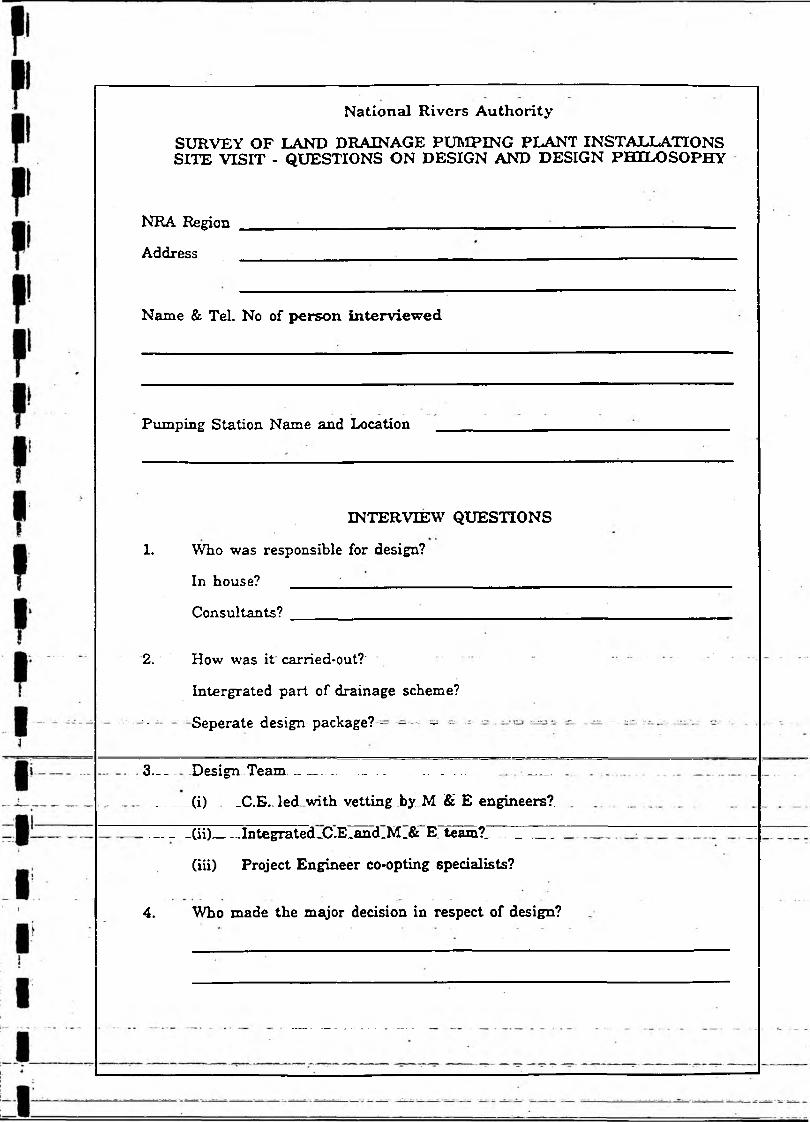
SURVEY OF LAND DRAINAGE PUMPING PLANT INSTALLATIONS SITE VISIT - QUESTIONS ON DESIGN AND DESIGN PHILOSOPHY
National Rivers Authority
NRA Region
Address
Name & Tel. No of person interviewed
Pumping Station Name and Location
INTERVIEW QUESTIONS
1. Who was responsible for design?
In house? ______ _____________________________
Consultants? ________________________________
2. How was it carried*out?'
Intergrated part of drainage scheme?
'• Seperate design package? - - - •
3 . - - Design Team ------------------- -----. .. ____
______(i) „C.E.Jed with vetting by M & E engineers?.
- ______(ii)___ .Integrated_C.E_and_M_& E team?_ _________
(iii) Project Engineer co-opting specialists?
4. Who made the major decision in respect of design?

Siting
Was siting dictated by catchment constraints? If large single station, was consideration given to use of several small peripheral stations?
Environmental considerations?
Did environmental considerations have a major influence on design - if so how? -
Capacity
How was capacity of station arrived at?
Locally accepted run-off/ unit area?
Following detailed analysis of C.E. machinery, storage, power supply and operating costs?
Particular constraints on any of the above?
Need to confine pumping to off-peak periods?
Alternatives considered
Were alternative designs considered? ie. shaft driven indoor, outdoor, submersible, pontoon, archimedean screw?
What influcenced final choice?
Initial cost?
Lifetime cost?
Operating costs? . . u _ _ _ _ .
Reliability?^ — ______________________________ __ _
Previous experience of equipment or marque?
What basic information was~given to pump manufacturer?-----------— — —
a) Total capacity of pumps?
b) Number of pumps?
c) Capacity per pump?
d) Max. suction W.L.?
e) Max. discharge W.L.?
f) Min. suction W.L.?
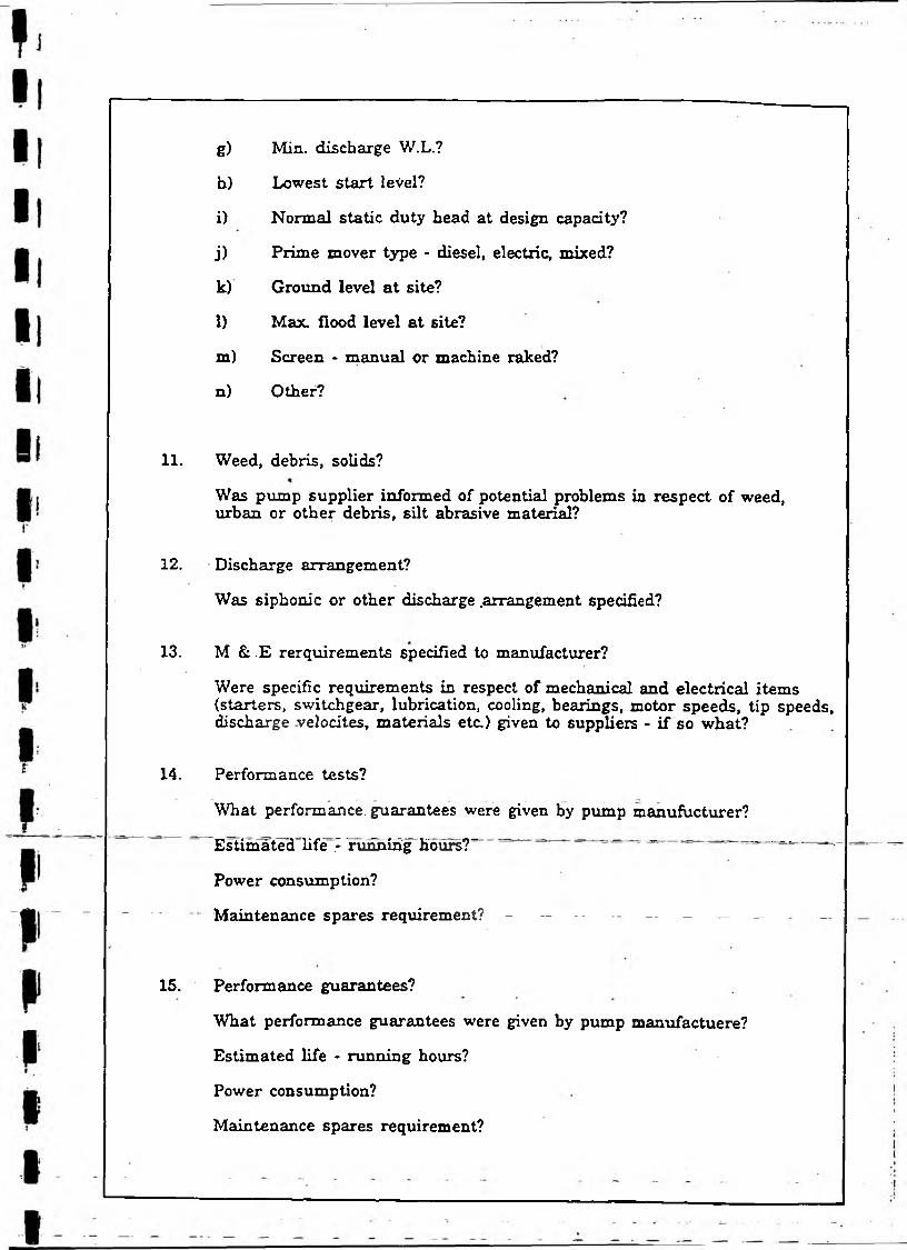
g) Min. discharge W.L.?
h) Lowest start level?
i) Normal static duty head at design capacity?
j) Prime mover type - diesel, electric, mixed?
k) Ground level at site?
1) Max. flood level at site?
m) Screen - manual or machine raked?
n) Other?
11. Weed, debris, solids?
Was pump supplier informed of potential problems in respect of weed, urban or other debris, silt abrasive material?
12. Discharge arrangement?
Was siphonic or other discharge .arrangement specified?
13. M & .E requirements specified to manufacturer?
Were specific requirements in respect of mechanical and electrical items (starters, switchgear, lubrication, cooling, bearings, motor speeds, tip speeds, discharge velocites, materials etc.) given to suppliers - if so what?
14. Performance tests?
What performance, guarantees were given by pump manufacturer?
Estimated Ufe Vrunhirig hours?' - - - - - - -.
Power consumption?
Maintenance spares requirement? - — — - - — —
15. Performance guarantees?
What performance guarantees were given by pump manufactuere?
Estimated life - running hours?
Power consumption?
Maintenance spares requirement?

16. Pump control
Manual?
Automatic?
Float? No Float? Air bubbler? Pressure transducer? Ultrasonic? Other?
Are interlocks with time delays fitted to prevent simultaneous starts on power restoration after mains failure?
17. Instrumentation
What instrumentation is installed?
Ammeter? Hours run meter? U/S level and D/S level?
Other? What records are kept?
18. Telemetry
Is the station linked by telemetry to a control centre?
If so what parameters are monitored and what alarms given?
Power supply? Pump running? Water levels? Equipment status and serviceability - seals? Bearing temperature? Start and stop levels?Building security - fire, .intruder?
19. Standby provision
What provision has been made in the event of power failure?
Installed standby generator? Mobile generator? Mixed diesel and electric pump units?
20. Provision for uprating?
Has provision been made for uprating the capacity of the station should this be required in the future?
21.“ " Station'performance - - - - - - _ —
Has station performed in accordance with design expectations?
Any particular problems?
Any feature you would omit or include as a result of operational experience?
National River* AuthorityBullen and Partner* Pumping Station Retearch
Appendix A3
Survey of Pumping Plant Maintenance
Questionnaire
R tf VH/91742J00 lfB

National Rivers Authority
SURVEY OF LAND DRAINAGE PUMPING PLANT INSTALLATIONS MAINTENANCE QUESTIONNAIRE
NRA Region
Address
Name & TeL No of person for further information
DETAILS OF MAINTENANCE
1. Who is responsible for P.S maintenance?
2. Do you have written terms of reference establishing overall strategy and policy in respect of pumping station maintenance? Yes/No
3. How often is the policy reviewed? ___________________________________
4. Are detailed records kept of all stations? Yes/No
5. Do these include: -(i)~ ~~ Individual^pump-running^houre?___(ii) Details of all maintenance?
(Planned and break-down)(iii) Dates of running checks and inspections?
6. Are these records kept on a data base? ' ~ Yes/No
7. Are specific time intervals laid down for running tests and minor and magor maintenance i.e Monthly, Yearly, Three yearly (Diesels - manufacturers recommendations)? _
Yes/No
Yes/NoYes/No
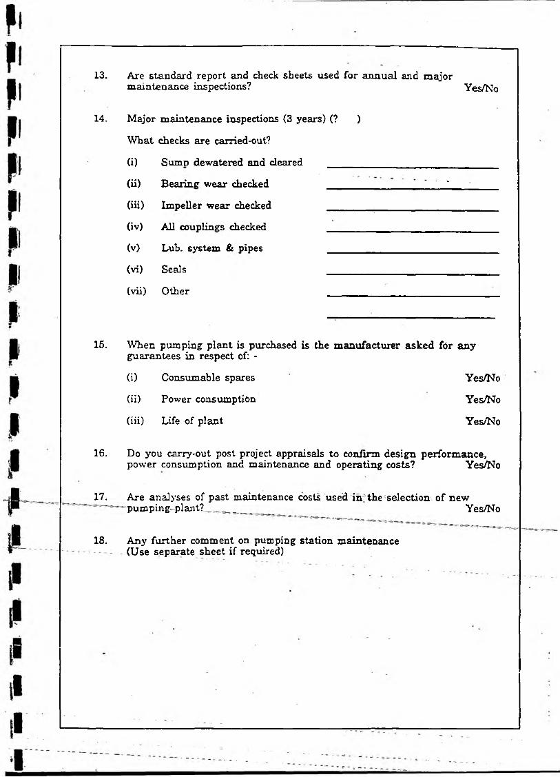
13. Are standard report and check sheets used for annual and majormaintenance inspections? Yes/No
14.
15.
Major maintenance inspections (3 years) (? )
What checks are carried-out?
(i) SumD dewatered and cleared
(ii) Bearing wear checked -
(iii) Impeller wear checked
(iv) All couplings checked
(v) Lub. system & pipes
(vi) Seals
(vii) Other
When pumping plant is purchased is the manufacturer asked for any guarantees in respect of: -
(i) Consumable spares Yes/No
(ii) Power consumption Yes/No
(iii) Life of plant Yes/No
16. Do you carry-out post project appraisals to confirm design performance, power consumption and maintenance and operating costs? Yes/No
17. Are analyses of past maintenance costs used in; the selection of new' pumping- p l a n t ? ___ Yes/No
18. Any further comment on pumping station maintenance (Use separate sheet if required)
Sullen and Partner•National Rioer* Authority
Pumping Station Research
Appendix B
Data Base
Contents
B1 Summary of Pump Data and Location Maps by Region
B2 Pump Analysis by Capacity
B3 Pump Analysis by Type
B4 Pump Analysis by Manufacturer
B5 Costs of Station by Capacity -
VH18174VOOUB
Bullen and Partner*
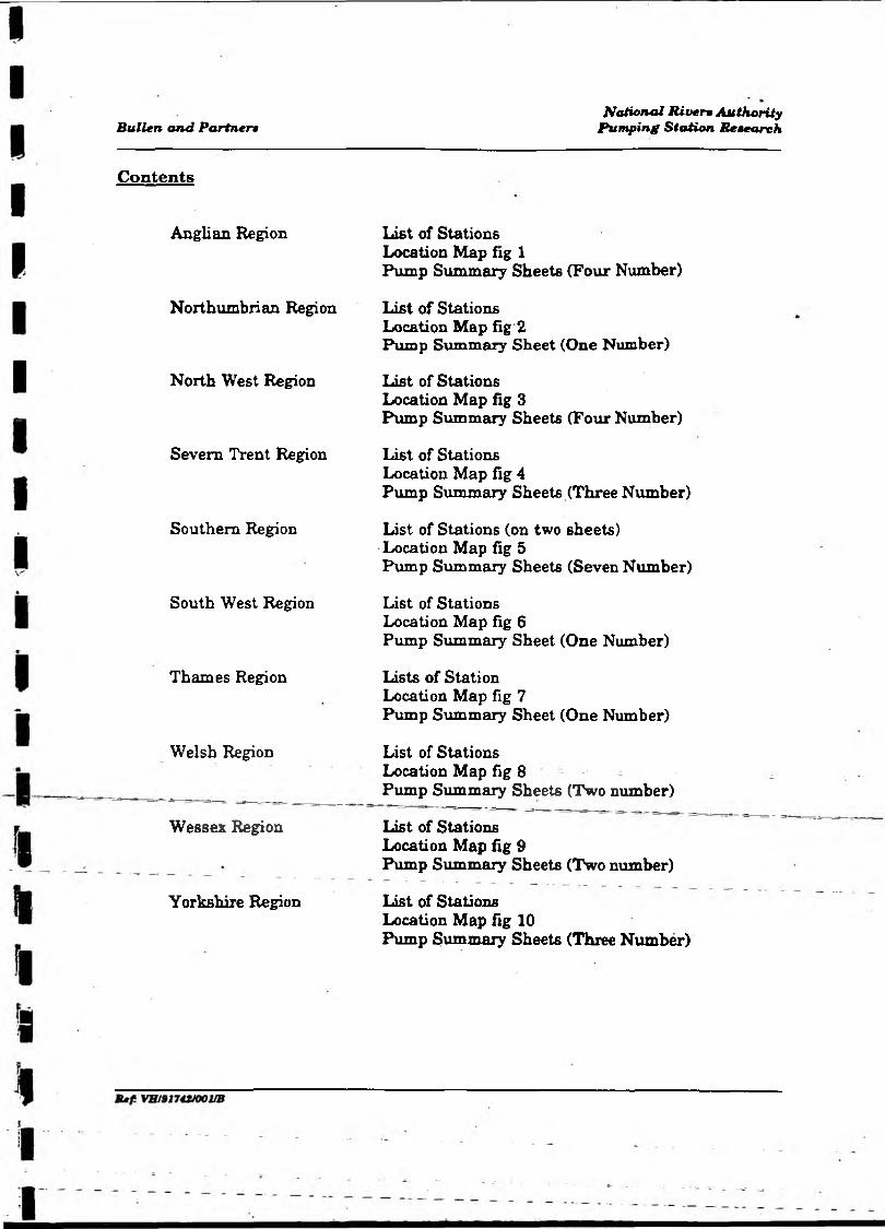
Contents
Anglian Region
Northumbrian Region
North West Region
Severn Trent Region
Southern Region
South West Region
Thames Region
Welsh Region
Wessex Region
Yorkshire Region
National River* AuthorityPumping SttUion Research
List of Stations Location Map fig 1Pump Summary Sheets (Four Number)
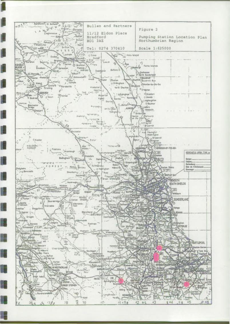
List of Stations Location Map fig 2Pump Summary Sheet (One Number)
List of Stations Location Map fig 3Pump Summary Sheets (Four Number)
List of Stations Location Map fig 4Pump Summary Sheets (Three Number)
List of Stations (on two sheets)Location Map fig 5Pump Summary Sheets (Seven Number)
List of StationsLocation Map fig 6Pump Summary Sheet (One Number)
Lists of Station Location Map fig 7Pump Summary Sheet (One Number)
List of Stations Location Map fig 8Pump Summary Sheets (Two number)
List of Stations Location Map fig 9Pump Summary Sheets (Two number)
List of Stations Location Map fig 10Pump Summary Sheets (Three Number)
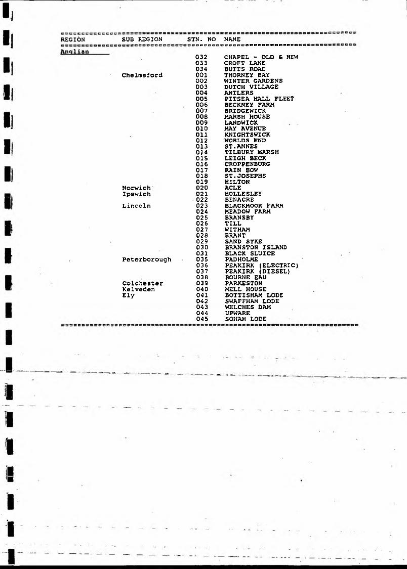
SUB REGION
Chelmsford
NorwichIpswich
Lincoln
Peterborough
ColchesterKelvedenEly
TN. NO NAMES S C C S B S S S B S S S S C S B S B C S C S S S C C
032 CHAPEL - OLD & NEW033 CROFT LANE034 BUTTS ROAD001 THORNEY BAY002 WINTER GARDENS003 DUTCH VILLAGE004 ANTLERS005 PITSEA HALL FLEET006 BECKNEY FARM007 BRIDGEWICK008 MARSH HOUSE009 LANDWICK010 MAY AVENUE011 KNIGHTSWICK012 WORLDS END013 ST.ANNES014 TILBURY HARSH015 LEIGH BECK016 CROPPENBURG017 RAIN BOW018 ST.JOSEPHS019 HILTON020 ACLE021 HOLLESLEY022 BENACRE023 BLACKMOOR FARM024 MEADOW FARM025 BRANSBY026 TILL027 WITHAM028 BRANT029 SAND SYKE030 BRANSTON ISLAND031 BLACK SLUICE035 PADHOLME036 PEAKIRK (ELECTRIC)037 PEAKIRK (DIESEL)038 BOURNE EAU039 PARKEST0N040 MELL HOUSE041 BOTTISHAM LODE042 SWAFFHAM LODE043 WELCHES DAM044 UPWARE045 SOHAM LODE
«< *fa<
Bull-*:: *n«l P rrn*rs Figure i11 /12 Elvi n P)a<~*Bra-iforrt Pumping Station urcatven Pl*nbs. :-a:. Ang*i n RegionT«l: 02 4 J"04i0 ScaU 1:625000
wV % 3 * j m \ / /Hkiha
_T rc[ w ~a r
»«*K>> lC*HVi«
'f»4« A«‘
r uO'lMW
* rrT /?< *+
S iy o - l
a
•n<H*T"
<*V'*\ir~
■■ —
ft*"* !.v« . CCW***
r~£*rj I
'2
,p” J.-0- \ ^ —
r - ‘c -
■>tu « » ,
33
Zfrr'
' cr? biituataw ■■
NA/f t A L f O i O H > € - M » f f
M % M _il tot( # « ------- >»»!>•I M ^ -------» I t In—_M k>i
NRA • Survey of Land Drainage Pumping Pump Surinary
' 1 Plant Installations i
EB:::i:sias$:a8t«3«i::Ei;i3S3rsKtiwscssHiMfinEauxc8«ut:33:::3:3ES=:3::::::::::Stn. Stn.No. Name
NationalGridReference
Catchment : Total No Manufacturer Area Capacity of (Sq.km) (Cunecs) Pump
Anglian001 THORNEY BAY
002 WINTER GARDENS
003 DUTCH VILLAGE
. 004 ANTLERSI
,005 PITSEA HALL FLEET
,006 BECKNEY FARM
007 BRIDGEWICK
i008 MARSH HOUSEI
009 LANDWICK
010 M Y AVENUE
011 KNIGHTSWICK
012 WORLDS END
TQ 795 827 i 0.060• i
lTQ 790 840 0.060
i
TO 773 838 0.620iii
TO 789 827 0.060I
TQ 738 859 0.060
TO 852 962 0.100
iTM 030 004 0.510
TM 032 046 248.63 2.970
i
TM 008 009 0.30 0.990
ii
Ttt 805 825 0.590
i
TQ 805 843 0.310
i
TQ 648 753 1JS20
1 FLYGT2 FLYGT
1 FLYGT2 FLYGT
1] SPAAN Z SPAAN
I1'l FLYGT23 FLYGT
1 I FLYGT
1 [FlYGT .2 IFLYGT
1 SULZER2 iSULZER
1 ALLEN GWYNNES2 ALLEN GUYNNES3 ALLEN GWYNNES'I
li1 GILL2 GILL
I1 ALIEN GWYNNES2 ALLEN GWYNNES3 ALLEN GWYNNES
l|
1 ALLEN GWYNNES2 ALLEN GWYNNES3 ALLEN GWYNNES
1 SAMJAL WHITE2 SAHUAL WHITE

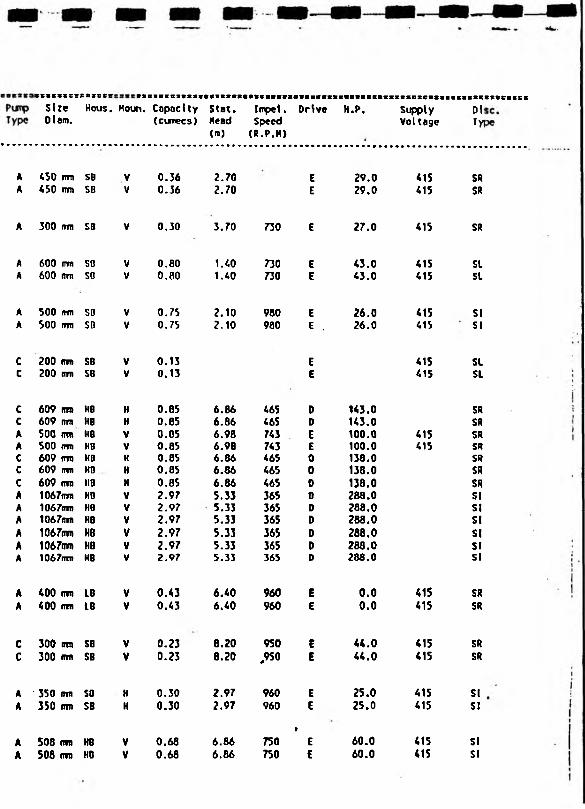
Year PurpType
SizeDiam.
Hous. Noun. Capacity(cunecs)
sscessvsaStat.Head(m)
SSS898SSS58SISISImpel. Drive Speed (R.P.M)
SSSSSSCSCCCBSSSSSSSSH.P. Supply
Voltage
S33SS3DiTyi
1980 S 100 mm SB 0.03 1.60 960 E 3.0 415 SL1980 s 100 (ran SB V 0.03 1.60 960 E 3.0 415 SL
1980 s 100 fnn SB V 0.03 1.35 960 E 3.0 415 SL1968 c 100 mn SB ■ 0.03 1.35 960 E 3.0 415 SL
1978 s 900 ran LB 0.31 2.60 20 E 3.0 415 SR1978 s 900 mm LB V 0.31 2.60 20 E 3.0 415 SR
1978 c 100 mm SB v . 0.03 1.50 960 E 3.0 415 SL1978 c 100 run SB ■ 0.03 1.50 960 E 3.0 SL
1980 c 75 rrm SB V 0.06 1.50 960 E . 3.0 415 SL
1982 c 100 mm SB _ 0.05 2.55 960 E 3.0 415 SL1982 c 100 mm S8 V 0.05 2.55 960 E 3.0 415 SL
1949 A 406 dm HB V 0.34 3.66 720 E 25.0 415 SR1949 A 355 mm HB V 0.17 3.66 960 E 14.0 415 SR
1949 A 610 imt HB V 0.99 3.66 580 E 75.0 415 SL1949 A 610 mm HB V 0.99 3.66 580 E 75.0 415 SL1949 A 610 nn HB V 0.99 3.66 580 E 75.0 415 SL
1961 A SOS mm H 0.71 2.44 720 E 45.0 415 SR1961 A 355 mm H 0.28 2.44 960 E 20.0 415 SR
1968 C 300 mn L8 V 0.28 2.20 960 E 10.0 415 SR1968 C 300 mn LB V 0.28 2.20 960 E 10.0 415 SR1968 c 248 mm LB V 0.03 2.20 960 E 5.0 415 SR
1968 c 300 m LB V 0.14 1.60 960 E 10.0 415 SR1968 c 300 mm LB V 0.14 . 1.60 960 E 10.0 415 SR1968 c 248 mm LB V 0.03 1.60 960 E 5.0 415 SR
1968 A 450 mm 00 0.76 2.88 720 E 140.0 415 SR1968 A 450 mm 00 H 0.76 2.88 720 E 140.0 415 SR
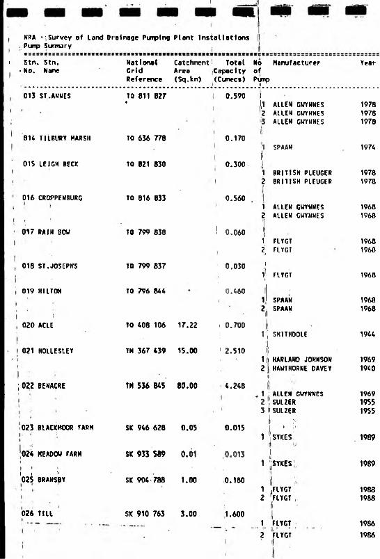
NRA ^Survey of land Drainage Pivnplng Plant Installations , Pimp Sixnmary ,
i Stn. Stn. • No. Name
013 ST.ANNES
014 TILBURY HARSH
015 LEIGH BECK
016 CROPPENBURG
017 RAIN BOV
018 St.JOSEPHS
019 HILTON
020 ACLE
021 HOILESLEY
: 022 BENACRE
023 BIACKHOOR FARM
024 KEADOU FARM
I I '025 BRANSBY
026 TILL
National Catchment! Total No Manufacturer Grid Area Capacity ofReference (Sq.km) (Cumecs) Pump
TO 811 827t
TO 636 778
TO 821 830
TO 816 833
TO 799 838
TO 799 B37
TO 796 844
TO 408 106 17.22
TH 367 *39 15.00
TM 536 845 80.00
SIC 946 628 0.05
SIC 933 589 0.01
SK 904 788 1.00
SK 910 763 3.00
0.590 |))1 ALLEN GVYNNESI ALLEN GUYNNES3 ALLEN GUYNNES
0.170 j
0.300
0.560
I
! 0.060I
0.030
1 0.460
i 0.700
1 2.510
4.248
0.015
,0.013
0.180
1.600
1 SPAAM
I
1 BRITISH PLEUGER2 BRITISH PLEUGER
1 ailen GUYNNES2 ALLEN GUYNVES
1 FLYGT2 FLYGT
I1 FLYGT
SPAANSPAAN
1| SHITHDOIE
i|1 ) HARLAND JOHNSON2 HAWTHORNE DAVEY
.1 ' ALLEN GUYNNES2 ! SULZER3 'SULZER
l , C:
1 STKES
1 jSYKES
1 jFLYGT2 FLYGT
1 FLYGT
2 FLYGT
Year
197819781970
1974
19781970
19681968
19681960
1968
19681968
1944
19691940
196919551955
1989
1989
19881988
1986
1986
»:::s:t:xs:;:;:::;::Bs:r;;rEsazaiKtcti(«:six*ia3tttBeiB«taB(*ismeistt((«*ieta:tci:«H9»s$3
Pimp Size Hous. Hoon. Capacity Stat. Iirpel. Drive H.P. Suppty Disc.Type Diam. (cunccs) Mead Speed Voltage Type
(m) (R.P.M)
c 300 run L8 V 0.28 2.30 960 E 10.0 415 SRc 300 (mi LB V 0.28 2.30 960 E 10.0 415 SRc 244 ITTTI IB V 0.03 2.30 960 E 5.0 415 SR
s 900 fm 00 H 0.17 0.00 20 E 415 SL
c 150 mm LB V 0.15 4.03 900 E 28.0 415 SRc 150 frni LB V 0.15 4.03 900 E 28.0 415 SR
c 254 mm LB V 0.28 2.55 960 E 15.0 415 SRc 254 mm LB V 0.28 2.55 960 E 15.0 415 SR
c 100 dm SB V 0.03 1.12 960 E 3.0 415 SLc 100 im SO 0.03 1.12 960 E 3.0 415 SL
c 100 urn SB V 0.03 1.71 960 E 3.0 415 SL
s 838 nvn LB H 0.23 2.15 20 E 15.0 415 SRs 838 mm LB H 0.23 2.15 20 E 15.0 415 SR
450 ftm LB V 0.70 3.00 725 E 55.0 415 SR
406 imi 00 V 0.51 3.60 940 E 30.0 415 SLHf 914 irm HB H 2.00 3.13 315 E ' 110.0 415 SR
600 mm HB V 0.85 5.79 565 E 100.0 415 SRHF 600 mm HB H 1.13 6.95 575 0 125.0 SRHF 900 rm HB H 2.26 6.60 440 D . 247.0 SR
100 irm SB V 0.01 4.00 E ■ 415 SL
100 rm SB V 0.01 4.00 E 415 SL
200 irm SB V 0.09 3.00 1,450 E 8.9 415 SI200 fftn SB V 0.09 3.00 1,450 E 6.9 415 SI
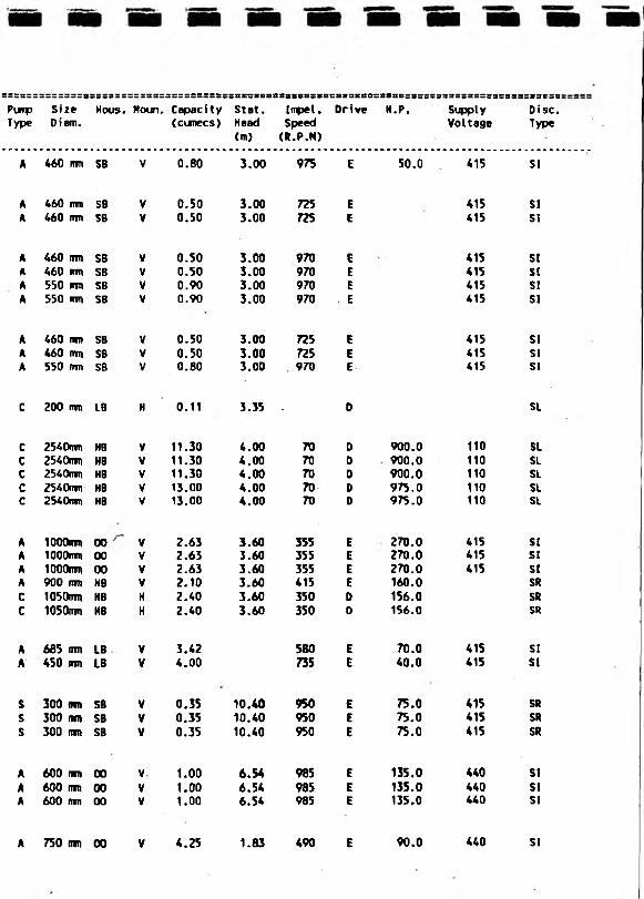
460 mm SB . V 0.80 3.00 975 E . 5.0*0_ _ 4.15___ St
460 am SB V ‘ 0.80 3.00 975 E 50.0 415 SI

NRA - Survey of land Drainage Purging Plant Installations Piirp Sunmarys:=::3*siiE=:3EEEiisxcs;iis;a3ssss3ii3SiiBess>iesicBB8BasiStn. Stn. No. Name
National Catchment Total Grid Area CapacityReference (Sq. km) (Cunecs)
be«k :::s:e::ss:3:No Manufacturer ofPump
027 UITNAM
028 BRANT
029 SAND SYKE
SK 952 639 1.50
SK 948 625 4.00
031 BLACK SLUICE
033 CROFT LANE
034 BUTTS ROAD
035 PADHOLME
1.000
2.800
SK 943 601. 2.50 1.800
030 BRANSTON ISLAND TF 103 703 0.80 0.110
TF 327 428 710.00 59.900
032 CHAPEL - OLD ft NEU TF 560 729 66.00 14.790
TF 501 600 5.05 7.430
TA 030 226 2.02 1.050
TL 229 984 8.02 3.000
036 PCAK1RK (ELECTRIC) TF 175 072 12.750
2 FLYGT 1986
1 FLYGT 19892 FLYGT 1989
1 FLYGT 19912 FLYGT 19913 FLYGT 19914 FLYGT 1991
1 FLYGT 19912 FLYGT 19913 FLYGT 1991
1 GOOOENOUGH 1962
1 ALLEN GUYNNES 19462 ALLEN GWYNNES 19463 ALLEN GUYNNES 19464 ALLEN GWYNNES 19655 ALLEN GWYNNES 1965
1 N E I - ARE 19862 N E I - ARE 19863 N E I - ARE 19864 ALLEN GWYNNES 19485 RUSTON HORNSBY 19486 ALLEN GWYNNES 1948
1 ALLEN GWYNNES 19712 ALLEN GWYNNES 1971
1 ABS 19852 ABS 19853 ABS 1985
1 HARLAND JOHNSON 19732 HARLAND JOHNSON 19733 HARLAND JOHNSON 1973
1 ALLEN GWYNNES 1973
ssssssssssssssssssssssssssssrssssssssBcssBasssssassasasscsfisssBBsssssdsassassssssssssscssPvip Size Nous. Moun, Capacity Stat. Inpel. Drive H.P. Supply Disc.Type Diam. (cunecs) Head Speed Voltage Type
(m> (R.P.N)
A 460 mm SB V 0.60 3.00 975 E 50.0 415 SI
A 460 ran SB V 0.50 3.00 725 E 415 SIA 460 inn SB V 0.50 3.00 725 E 415 SI
A 460 ran SB V 0.50 3.00 970 E 415 SIA 460 mm SB V 0,50 3.00 970 E 415 SIA 550 trni SB V 0.90 3.00 970 E 415 SIA 550 mm SB V 0.90 3.00 970 . E 415 SI
A 460 ran SB V 0.50 3.00 725 E 415 SIA 460 ran SB V 0.50 3.00 725 E 415 SIA 550 ran 58 V 0.80 3.00 970 E 415 SI
C 200 ran LB H 0.11 3.35 - D SL
C 2540mm HB V 11.30 4.00 70 0 900.0 110 SLC 2540mn HB V 11.30 4.00 70 0 900.0 110 SLC 2540mn HB V 11.30 4.00 70 0 900.0 110 SLc 2540mm HB V 13.00 4.00 70 0 975.0 110 SLc 2540riti HB V 13.00 4.00 70 D 975.0 110 SL
A 1000mn 00 V 2.63 3.60 355 E 270.0 415 SIA lOOOntn 00 V 2.63 3.60 355 E 270.0 415 SIA TOOOran 00 V 2.63 3.60 355 E 270.0 415 SIA 900 imj HB V 2.10 3.60 415 E 160.0 SRC 1050ran HB H 2.40 3.60 350 D 156.0 SRc 1050nm KB H 2.40 3.60 350 D 156.0 SR
A 665 ran LB V 3.42 580 E 70.0 415 SIA 450 ran LB V 4.00 735 E 40.0 415 SI
S 300 ran SB V 0.35 10.40 950 E 75.0 415 SRs 300 m SB V 0.35 10.40 950 E 75.0 415 SRs 300 ran SB V 0.35 10.40 950 E 75.0 415 SR
A 600 ran 00 V 1.00 6.54 985 E 135.0 440 SIA 600 ran 00 V 1.00 6.54 985 E 135.0 440 SIA 600 ran 00 V 1.00 6.54 985 E 135.0 440 SI
A 750 inn 00 V 4.25 1.83 490 E 90.0 440 SI
NRA • Survey of Land Drainage Purrping Plant Installations Pump SuimaryesssrssessessisteTstaiistmictriBssccisstttssvssisBsctcc:
Stn. Stn. National Catchment TotalMo. Maine Grid Area Capacity
Reference (Sq.km) (Cumecs)
Mo Manufacturer ofPurp
::;::::::;:;g::3i:3t:ir:ti:t::>r:rxcct>t£iizitaici3e3cicctettcc3i:tttEii:>;ti3cfi9r3ceictxcii:
Tear Puip Size Hous. Houn, Capacity Stat. Inpel. Drive H.P. Supply Oise.Type Diam. (cumecs) Head Speed Voltage Typo
<m> (R.P.M)
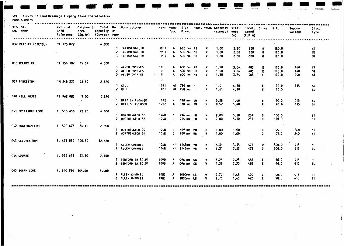
037 PEAKIRK (DIESEL) TF 175 072 4. BOO1 FARROW WAU1N 1903 A 600 ran HB V 1.60 2.80 600 D 180.0 SI2 FARROW WALLIN 1903 A 600 ran KB V 1.60 2.80 600 0 180.0 SIJ fARROW WALLIN 1903 A 600 ran HB V 1.60 2.80 600 0 180.0 SI
038 BOURNE EAU
039 PARKESTON
040 MELL HOUSE
041 DOTT!SHAM LOOE
042 SVAFFHAM LOOE
043 WELCHES DAM
044 UPUARE
045 SOHAM LOOE
TF 156 187 15.37 4.500
TM 243 323 28.50 2.820
TL 963 085 5.00 0.850
TL 510 658 72.20 4.000
TL 522 673 36.40 2.000
TL 471 859 100.30 12.620
TL 538 698 63.60 2.500
TL 540 764 104.00 S.400
1 ALLEN GUYNNES2 ALLEN CWYNNES3 ALLEN GUTWNES
1 Gill2 GILL
1 BRITISH PLEUGER2 BRITISH PLEUGER
1 WORTHINGTON 362 WORTHINGTON 36
1 WORTHINGTON 242 WORTHINGTON 24
1 ALLEN GUTNNES2 ALLEN GUYNNES
1 BEOrORO SA.80.042 BEDFORD SA.80.04
1 ALLEN GUYNNES2 ALLEN GWYNNES
19 A 600 ran HB V 1.50 3.84 485 E 100.0 440 SI19 A 600 ran HB V 1.50 3.84 485 E 100.0 440 SI19 A 600 ran HB V 1.50 3.84 485 E 100.0 440 SI
1961 MF 750 ran H 1.41 4.50 E 90.0 415 SL1961 MF 750 ran H 1.41 4.50 E 90.0 SL
1972 A 450 ran SB H 0.28 1.40 E 40.0 415 SLW72 A 530 ran SB H 0.57 1.40 E 70.0 415 SL
1940 C 914 ran HB V 2.00 5.10 237 0 150.0 SI1948 C 914 ran HB V 2.00 5.10 237 0 150.0 SI
1948 C 609 ran HB H 1.00 1.00 D 95.0 240 SI1940 C 609 ran HB H 1.00 1.00 0 95.0 240 SI
1948 HF 1l45ran HB H 6.31 3.35 475 D 500.0 415 SL1940 HF 1145ran HB H 6.31 3.35 475 D 500.0 415 SL
1990 A 996 ran SB V 1.25 2.25 485 E 46.0 415 SL1990 A 996 ran SB V 1.25 2.25 485 i 46.0 415 SL
1905 A 1000ran LB V 2.70 1.45 420 E 90.0 415 St1985 A tOOOnin LB V 2.70 1.45 420 E 90.0 415 SI

NORTHUMBRIAN

REGION
NOirthtimhr-i an
SUB REGION STN. NO NAME
Darlington 001 MORDEN CARRS002 SWAN CARR003 SEAMER CARRS004 MAINSFORTH STELL005 VAN DIEKANS LAND
t )t 3,'uSIP
NRA • Survey of Lend Drainage Pumping Plant InstallationsPump Surmarye:sss8:s3es33iscs>ttte6S«:iiB«tttiB8«sv8sxBstt8Ste«8i2BfSi8ssss:(sc;ecsscsss::::::
Stn. Stn. National Catchment Total No ManufacturerNo. Name Grid Area Capacity of
Reference (Sq.km) (Cumecs) Pimp
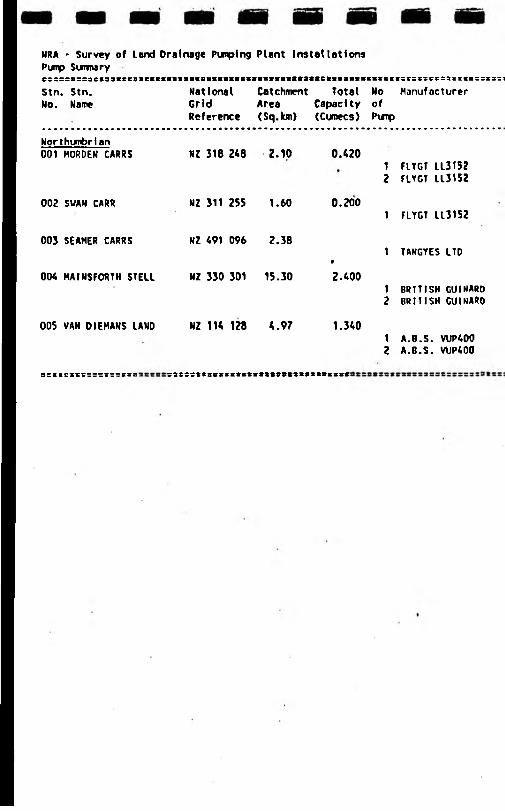
Northumbrian001 MORDEM CARRS NZ 318 248 2.10 0.420
1 FLYGT 11315?2 flYGT 113152
002 SUAN CARR NZ 311 255 1.60 0.2001 FLYGT LL3152
003 SEAMER CARRS HZ 491 096 2.381 TANGYES LTD
9
004 HA1NSF0RTH STELL NZ 330 301 15.30 2.4001 BRITISH GUIMARD2 BRITISH GUIMARD
005 VAN DIEKANS LAND NZ 114 128 4.97 1.3401 A.B.S. VUP4002 A.6.S. VUP400

::;;5£SE:s5=ssc:::;;:*r;;;=;;s:ssss&sss?s:KS5ss:sss3e«8scictssec8te8S93se883t8t3CCSSt8tss8CS««cS8S33S3
Year Pimp Siie Hous. Moun. Capacity Stat, Impel. Drive H.P. Supply Disc,Type Diam. (cumccs) Head Speed Voltage Type
<m) (R.P.H)
19861986
450 mm SB 450 iron SB
0.200.22
2.202.20
950950
12.012.0
415415
SRSR.
1986
1955
450 cm SO
mm LB
0.20 2.20 950
715
12.0
10.0
415
415
SR
SR
19871987
800 rrm SB 800 dm SB
1.201.20
3.003.00
750750
E 100.0 E 100.0
415415
SRSR
19851986
700 trni SB 700 ntn SB
0.670.67
2.002.00
960960
40.040.0
415415
SRSR
:sss8tts: !nB88Sette8&38B638B83888SfiC83338CS33

NORTH WEST

SUB REGION STN. NO NAME
Koirth West.North Cumbria 001 COLMIRE SOUGH
002 DURRANHILL003 GAMELSBY004 RUMBLING BRIDGE005 THACKA BECK006 WOLSTY
South Cumbria 007 JOHNSCALES008 LEVENS009 POOL BRIDGE010 SAMPOOL011 ULPHA
North Lancs 012 PREESALL013 RAIKES BROOK014 RED BRIDGE015 YOAD POOL
South Lancs 016 BANKS MARSH017 BOUNDARY BROOK018 CLAY BROW019 CROSSENS020 CROSTON021 HOLMES WOOD022 KEW023 MAWDESLEY024 SOLLOM025 RUFFORD
Cheshire 026 FRODSHAM027 INCE MARSH028 MORPETH
North Manchester. 029 BEDFORD030 JENNETTS LANE031- PENNINGTON
Merseyside 032 ALTCAR033 ALTMOUTH034 DOG CLOG035 FINE JANE036 HEY COP037 INCE BLUNDELL038 NEW CUT039 PENDLEBURY

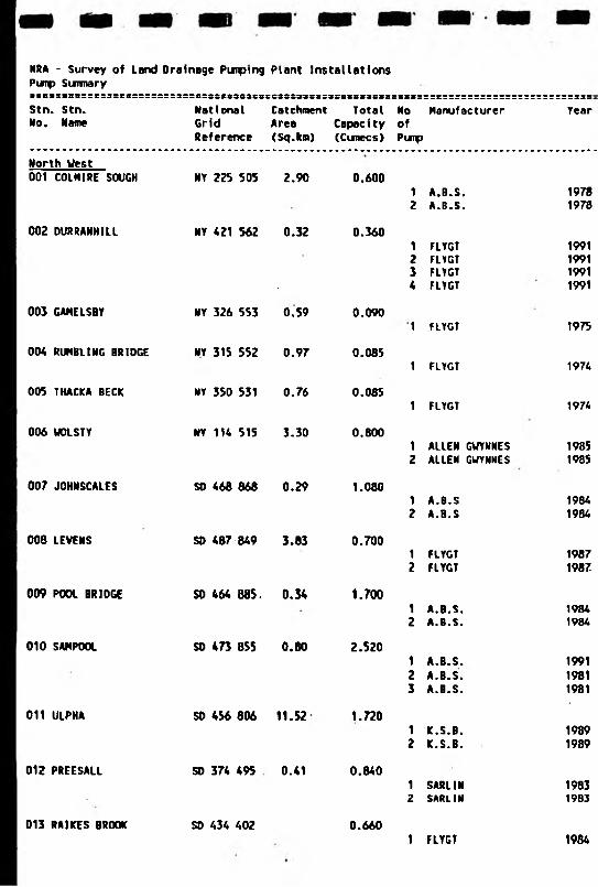
NRA - Survey of Land Drainage Pimping Plant Installations Pump Suimaryrxcc5c=s=:cs3sessssss::3sss:ss»383t8st:sss33si:3=si3;3s;ss::::==c:=:=:=:::==::==:==::=;;=Stn. Stn. National Catchment Total No Manufacturer YearNo. Name Grid Area Capacity of
Reference (Sq.km) (Cixnecs) Purp
North West001 COINIRE SOUGH NY
002 DURRANHILL NY
003 GAMELSBY NY
004 RUM8LING BRIDGE NY
005 THACKA BECK NY
006 WOLSTY NY
007 JOHNSCALES SO
008 LEVENS SD
009 POOL BRIDGE SD
010 SAWPOOL SO
011 ULPHA SO
012 PREESALL SD
013 RAIKES BROOK SD
225 505 2.90 0.600
421 562 0.32 0.360
326 553 0.59 0.090
315 552 0.97 0.085
350 531 0.76 0.085
114 515 3.30 0.800
468 868 0.29 1.080
487 849 3.83 0.700
464 685. 0.34 1.700
473 855 0.80 2.520
456 806 11.52 1.720
374 495 0.41 0.840
434 402 0.660
1 A.B.S. 19782 A.B.S. 1978
1 FLYGT 19912 FLYGT 19913 FLYGT 19914 FLYGT 1991
1 FLYGT 1975
1 FLYGT 1974
1 FLYGT 1974
1 ALLEN GWYNNES 19852 ALLEN GUYNNES 1985
1 A.B.S 19842 A.B.S 1984
1 FLYGT 19872 FLYGT 1987
1 A.B.S. 19842 A.B.S. 1984
1 A.B.S. 19912 A.B.S. 19813 A.B.S. 1981
1 K.S.B. 19892 K.S.B. 1989
1 SARLIN 19832 SARLIN 1983
1 FLYGT 1984

:3SSC3I3S8IBSS5XSBS8S3SBI8
Pimp Size Hous. Moun. Capacity Type Diam. (cunecs)
Stat.Head<m)
Impel.Speed(R.P.M)
Drive H.P. SimplyVoltage
Disc.Type
A 300 tTRI SB H 0.30 2.54 960 E 20.0 415 SRA 300 mm SB H 0.30 2.54 960 E 20.0 415 SR
C 200 irni SB V 0.09 4.00 1,450 E 6.0 415 SRC 200 cm SB V 0.09 4.00 1.4S0 E 6.0 415 SRc 200 cm SB V 0.09 . 4.00 1,450 E 6.0 415 SRc 200 mm SB V 0.09 4.00 1,450 E 6.0 SR
c 200 nra S8 V 0.09 3.35 1,450 E 6.0 415 SR
c 200 tnn SB V 0.09 3.79 1,450 E 6.0 415 SR
c 200 rtm SB V 0.09 3.35 1,450 E 6.0 415 SR
400 rrm SB V 0.40 3.40 975 E 43.0 415 SL400 inn SB V 0.40 3.40 975 E 43.0 415 SL
550 mm SB V 0.54 4.83 960 E 74.0 415 St550 on SB V 0.54 4.83 960 E 74.0 415 SI
300 inn SB V 0.35 2.80 725 E 30.0 415 SL300 mm SB V 0.35 2.80 725 E 30.0 415 SL
500 RID SB V 0.8S 5.18 720 E 120.0 415 SI500 mm SB V 0.85 5.18 720 E 120.0 415 SI
500 mm SB V 0.84 4.50 960 E 100.0 415 SR500 nm SB H 0.84 4.50 960 E 100.0 415 SR500 mm SB H 0.84 4.50 960 E 100.0 415 SR
500 (m SB V 0.86 4.02 985 E 56.0 415 SR500 mm SB V 0.86 4.02 985 E 56.0 415 SR
300 mm SB V 0.42 2.90 720 E 36.0 415 SR300 mm SB V 0.42 2.90 720 ■ E 36.0 415 SR
A 300 mm SB V 0.30 725 E 27.0 415 SR

NRA - Survey of land Drainage Punplng Plant Installations Punp Surinary
Stn. Stn. Ho. Hatne
National Catchment Total No Manufacturer Grid Area Capacity ofReference (Sq.km) (Cumecs) Pimp
ressBiflsi
Tear
O H RED BRIDGE
015 YOAD POOL
016 BANKS KARSH
017 BOUNDARY BROOK
018 CLAY BROV
019 CROSSFMS
020 CROSTON
021 HOLMES UOOO
022 CEU
OZ3 MAUDESLEY
5D 347 323 0.08
SO 482 416
SO 396 231 4.45
SD 351 144
SD 424 149 0.81
SO 376 206 143.94
SD 468 163 5.53
SO 424 162 4.46
SO 361 153 0.65
SO 468 158 6.66
0.720
0.300
1.600
1.500
0.260
23.770
0.864
0.460
0.600
1.360
1 GUIHARD2 GUI HARD
19801900
1 FLYGT 1985
1 AILEH CUYNNES 19072 ALLEM GUYNNES 1907
1 1C. S. 9 19002 K.S.Q 1900
1 FLYGT 19862 FLYGT 1906
1 ALLEN GVYNNES (L.l.) 19612 ALLEN GUYNNES (L.L.) 19613 SULZER (1.1.) 19094 SULZER (L.L.) 19095 ALLEM GUYNNES (L.l.) 19616 ALLEN GWYHHES (L.l.) 19617 ALIEN GUYHNES (L.l.) 19618 ALIEN GUYHNES (H.l.) 19619 ALLEN GUYHNES (H.L.) 196110 ALLEH GUYNNES (H.L.) 196111 ALLEN GWYNNES (H.L.) 196112 ALLEN GUYNNES (H.L.) 196113 ALIEN GUYNHES (H.L.) 1961
1 HIRLESS UATSOM2 HIRLESS VATSOH
A.B.SA.B.S
A.B.SA.B.S
1 ALLEN WYNNES2 ALLEN GVYHHES
19441944
19891989
19021982
19661966
tscscssc:SiteDiam.
tsutcHoUS. Koun. Capacity
(cunecs)Stat.Head(m>
Impel. Speed (R.P.M)
Drive H.P. SupplyVoltage
Dl!Tyi
*50 rrm SB V 0.36 2.70 E 29.0 *15 SR*50 mm SB V 0.36 2.70 E 29.0 *15 SR
300 rm SB V 0.30 3.70 730 E 27.0 *15 SR
600 mm SD V 0.60 1.*0 730 E *3.0 *15 SL600 tmi SO V 0.80 1.*0 730 E *3.0 *15 SL
500 (Tfn SB V 0.75 2.10 980 E 26.0 *15 SI500 im SD V 0.75 2.10 980 E . 26.0 *15 SI
200 inn SB V 0.13 E *15 SL200 mm SB V 0.13 E *15 SL
609 (m MB H 0.85 6.86 *65 D 1*3.0 SR609 nrn HB H 0.85 6.66 *65 D 1*3.0 SR500 inn HB V 0.65 6.98 7*3 E 100.0 *15 SR500 ITTQ HB V 0.85 6.98 7*3 E 100.0 *15 SR609 imi HB H 0.85 6.86 *65 0 138.0 SR609 mm HD H 0.85 6.86 *65 0 138.0 SR609 (TTD 119 H 0.85 6.86 *65 D 138.0 SR1067irm HO V 2.97 5.33 365 D 288.0 SI1067im> HB V 2.97 5.33 365 D 288.0 si1067mm H8 V 2.97 5.33 365 D 288.0 SI1067mm HB V 2.97 5.33 365 D 288.0 SI1067mm HB V 2.97 5.33 365 D 288.0 SI1067rri HB V 2.97 5.33 365 D 288.0 SI
*00 mm LB V 0.*3 6.40 960 E 0.0 415 SR*00 mm LB V 0.*3 6.*0 960 E 0.0 *15 SR
300 urn SB V 0.23 8.20 950 E *4.0 415 SR300 mm SB V 0.23 8.20 ,950 E *4.0 415 SR
' 350 mm SO H 0.30 2.97 960 E 25.0 *15 SI350 mm SB H 0.30 2.97 960 E 25.0 *15 SI
S08 im> HB V 0.68 6.86 750t
E 60.0 415 SIS08 mm HQ V 0.68 6.B6 750 E 60.0 415 St
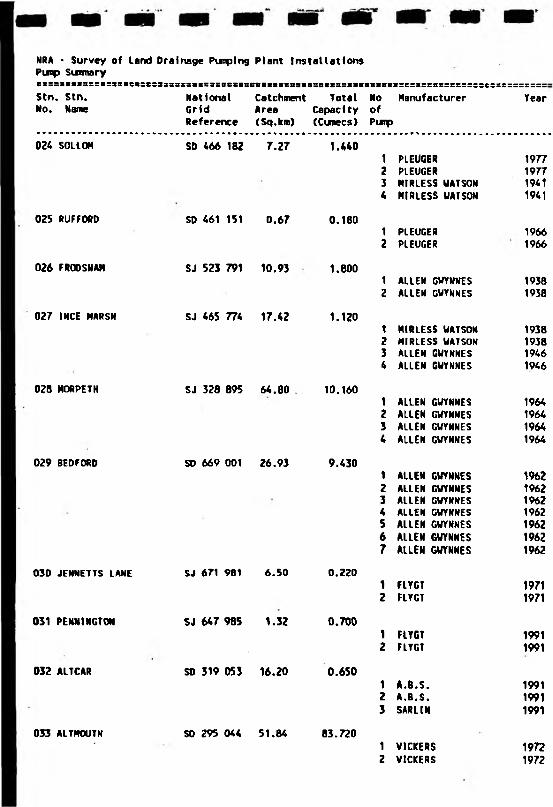
NRA * Survey of Land Drainage Punplng Plant Installations Pimp Summary«i::3*;s3::iz3siM:t:3333X3:issxBStssBasiinn3iB;s(t3:f3CSsas:s:e:3::ss=::::::t:::=::E:::Stn. Stn. National Catchment Total No Manufacturer YearNo. Name Grid Area Capacity of
Reference (Sq.km) (Cumecs) Pimp
024 SOIIOH SD
025 RUFFORD SD
026 FRGOSHAM SJ
027 INCE MARSH SJ
028 MORPETH SJ
029 BEDFORD SO
030 JENNETTS LANE SJ
031 PENNINGTON SJ
032 ALTCAR SD
033 ALTHOUTH SO
466 182 7.27 1.440
461 151 0.67 0.1B0
523 791 10.93 1.800
465 774 17.42 1.120
328 895 64.80 10.160
669 001 26.93 9.430
671 981 6.SO 0.220
647 985 1.32 0.700
319 053 16.20 0.650
295 044 51.84 83.720
1 PLEUGER 19772 PLEUGER 19773 HIRLESS UATSON 19414 HIRLESS UATSON 1941
1 PLEUGER 19662 PLEUGER 1966
1 ALLEN GUYNHES 19382 ALLEN GUYNHES 1938
1 MIRLESS UATSOM 19382 HIRLESS UATSOH 19383 ALLEN GUYNHES 19464 ALLEN GUYNHES 1946
1 ALLEN GUYNNES 19642 ALLEN GUYNNES 19643 ALLEN GUYHHES 19644 ALLEN GUYHHES 1964
1 ALIEN GUYNNES 19622 ALLEN GUYNNES 19623 ALLEN GUYNKES 19624 ALLEN GUYNKES 19625 ALLEN GUYHHES 19626 ALLEN GWYNNES 19627 ALLEN GUYNNES 1962
1 FLYGT 19712 FlYGT 1971
1 FlYGT 19912 FLYGT 1991
1 A.B.S. 19912 A.B.S. 19913 SARLIN 1991
1 VICKERS 19722 VICKERS 1972
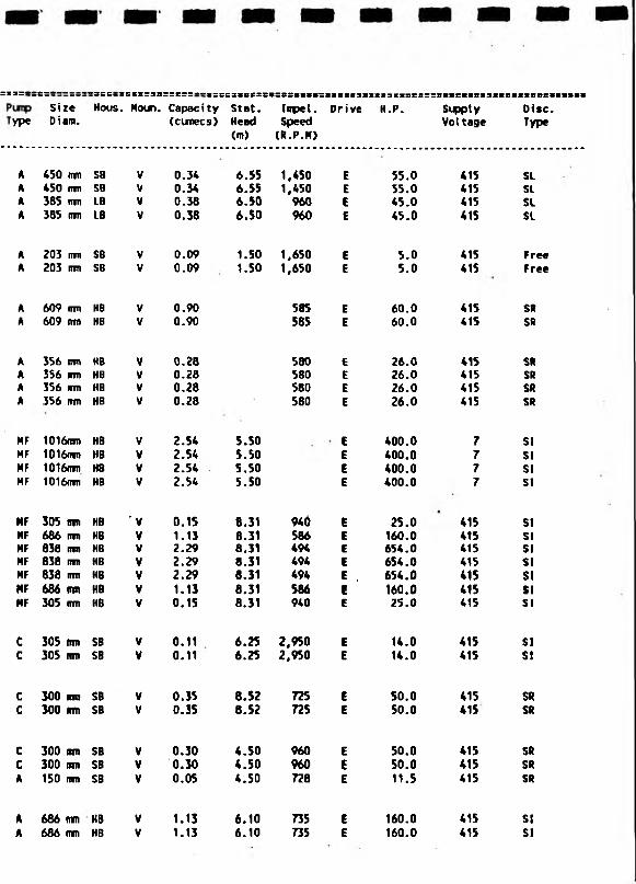
:x3=* : s : * " ~ " =::-:s::=3B=::::“i:E:=xsczsas«tisii:3x::s3;»X3:i3:s=:BS3raiBi3iinsisBBBiissiiSize Hous. Noun. Capacity Stat. Impel. Drive H.P. Suppty Disc.
ype Diam. (cunecs) Head<m>
Speed(R.P.H)
Voltage Type
A 450 mm SB V 0.3* 6.55 1,450 E 55.0 *15 SLA *50 nvn SB V 0.3* 6.55 1 ,*50 E 55.0 *15 SLA 385 nm LB V 0.38 6.50 960 E *5.0 *15 SLA 385 nm LB V 0.38 6.50 960 E *5.0 *15 SL
A 203 urn SB V 0.09 1.50 1,650 E 5.0 *15 FreeA 203 mu SB V 0.09 1.50 1,650 E 5.0 *15 Free
A 609 nrn HB V 0.90 585 E 60.0 *15 SRA 609 ntn H8 V 0.90 565 E 60.0 *15 SR
A 356 im HB V 0.26 580 E 26.0 *15 SRA 356 mn HB V 0.28 580 E 26.0 *15 SRA 356 mm HB V 0.28 580 E 26.0 *15 SRA 356 rrm HB V 0.28 560 E 26.0 *15 SR
HF 1016cm HB V 2.5* 5.50 E *00.0 7 SIHF 1016m HB V 2.5* 5.50 E *00.0 7 SIHF 1016m HB V 2.5* 5.50 E *00.0 7 SIHF 1016mm HB V 2.5* 5.50 E *00.0 7 SI
MF 305 nm HB ' V 0.15 8.31 9*6 E 25.0 *15 SIMF 666 ntn HB V 1.13 8.31 586 E 160.0 *15 SIMF 036 urn HB V 2.29 8.31 *9* E 65*.0 *15 SIHF 836 mr» HB V 2.29 8.31 *9* E 65*.0 *15 SIHF 638 irm HB V 2.29 6.31 *9* E . 65*. 0 *15 SIMF 686 (mi KB V 1.13 8.31 566 E 160.0 *15 SIHF 305 mi HB V 0.15 6.31 9*0 E 25.0 *15 SI
C 305 nm SB V 0.11 6.25 2,950 E 1*.0 *15 SIC 305 im SB V 0.11 6.25 2,950 E 1*.0 *15 SI
C 300 sir SB V 0.35 8.52 725 E 50.0 *15 SRC 300 (rm SB V 0.35 8.52 725 E 50.0 *15 SR
C 300 on SB V 0.30 *.50 960 E 50.0 *15 SRC 300 mn SB V 0.30 *.50 960 E 50.0 *15 SRA 150 mn SB V 0.05 *.50 728 E 11.5 *15 SR
A 686 mm HB V 1.13 6.10 735 E 160.0 *15 SIA 686 nvn HB V 1.13 6.10 735 E 160.0 *15 SI

NRA • Survey of land Oralnage Puiping Plant Installations Pump Suimary
Stn. Stn. No. Name
BSS?»CS3«SSHat ional Catchment Total No Manufacturer Grid Area Capacity ofReference (Sq.km) (Cirnecs) Pump
033 ALTHOUTH SD 295 044 51.84 63.720.1__YICKERS______2 VICKERS3 VICKERS4 VICKERS5 VICKERS6 VICKERS7 VICKERS 6 VICKERS
034 DOG CLOG SJ 471 678 7.94 0.0701 FLYGT2 FlYGT
035 FINE JANE SD 326 088 14.17 2.6001 ALIEN GUYNNES2 ALLEN GWYNNES3 ALLEN GUYNNES4 ALLEN GUYNNES
036 HEY COP
037 INCE BLUNDELL
038 NEU CUT
039 PENDLCBURY
SD 338 040 6.80 3.390
SO 329 046 4.46 0.660
SD 333 060 5.30 0.900
SJ 516 913 2.17 0.740
1 ALIEN GUYHNES2 ALLEN GUYNNES3 ALLEN GUYNNES
1 TSURUMI2 TSURUMI
1 TSURUM!2 TSURUMI
1 ALLEN GWYNNES2 ALLEN GUYNNES3 ALLEN GUYNNES
’ Btxcs:tsse:sB::s::£tec3tittiM:tttmtBBseBtit3*ttmiEBiEiitsBS3t£eex:
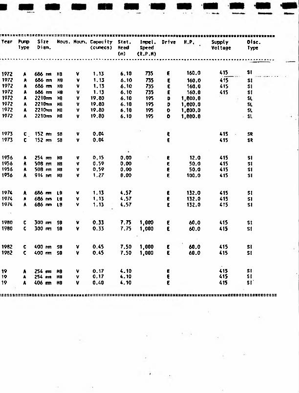
t3CZ>CSS;BetSSt38Br
Year Pump Size Type Diam.
Hous. Moun. Capaci ty (cumecs)
Stat.Head(m)
Inpel. Speed (R.P.M)
Drive H.P, SupplyVoltage
Disc.Type
1972 A 686 irm HB V 1.13 6.10 735 e 160.0 415 SI
1972 A 686 mm H8 V 1.13 6.10 735 E 160.0 415 SI1972 A 686 (tin HB V 1.13 6.10 735 E 160.0 415 SI1972 A 686 rrm HB V 1.13 6.10 735 E 160.0 415 SI1972 A 2210rrm HB V 19.80 6.10 195 D 1,800.0 SL1972 A 2210nm HB V 19.80 6.10 195 D 1,800.0 SL1972 A 2210mm HB V 19.80 6.10 195 D 1,800.0 SL1972 A 2210tm> HB V 19.80 6.10 195 D 1,800.0 SL
1973 C . 152 (ran SB V 0.04 E SR1973 C 152 (ran SB V 0.04 E 415 SR
1956 A 254 urn H8 V 0.15 0.00 E 12.0 415 SI1956 A 508 mm HB V 0.59 0.00 E 50.0 415 SI1956 A 508 mm HB V 0.59 0.00 E 50.0 415 SI1956 A 914 rm HO V 1.27 0.00 E 100.0 415 SI
1974 A 686 (ran L8 V 1.13 4.57 E 132.0 415 SI1974 A 686 mn LB V 1.13 4.57 E 132.0 415 SI1974 A 686 mm L8 V 1.13 4.57 E 132.0 415 SI
1980 C 300 inn SB V 0.33 7.75 1,000 E 60.0 415 SI1980 C 300 (ran SB V 0.33 7.75 1,000 E 60.0 415 SI
1982 C 400 tran SB V 0.45 7.50 1,000 E 60.0 415 SI1982 c 400 mn SB V 0.45 7.50 1,000 E 60.0 415 SI
19 A 254 (ran HB V 0.17 4.10 E 415 SI19 A 254 om HB V 0.17 4.10 E 415 SI19 A 406 mm HB V 0.40 4.10 E 415 SI
tlII11IIII ========_ _ _ _ _ _ 1$ II II II II n SS8fl2Blfi88SCS8SSBCSC93S8888BCBS88S8

SEVERN-TRENT
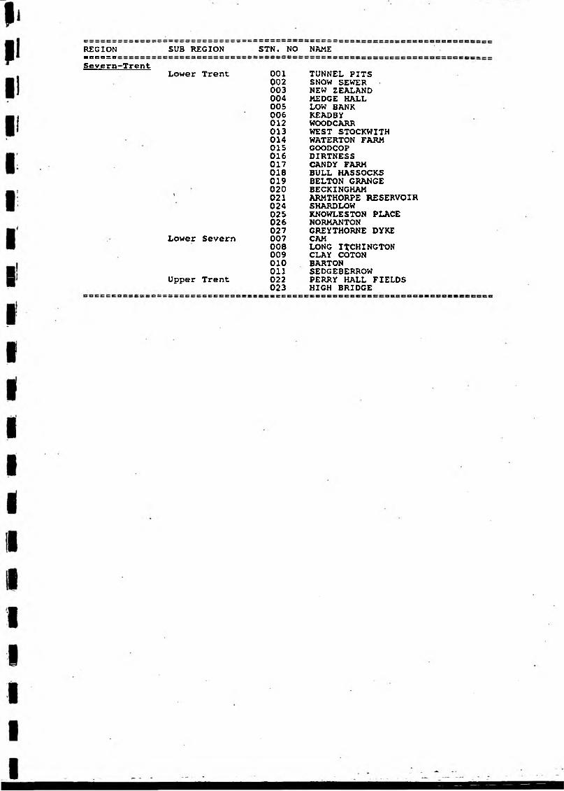
REGIONe s s s = s:
Severn
SUB REGION STN. NO
■Trent.Lower Trent 001
002003004005006012013014015016017018019020 021024025026027
Lower Severn 007008009010Oil
Upper Trent 022023
NAME
TUNNEL PITSSNOW SEWERNEW ZEALANDHEDGE HALLLOW BANKKEADBYWOODCARRWEST STOCKWITHWATERTON FARMGOODCOPDIRTNESSCANDY FARMBULL HASSOCKSBELTON GRANGEBECKINGHAMARMTHORPE RESERVOIRSHARDLOWKNOWLESTON PLACENORMANTONGREYTHORNE DYKECAMLONG ITCHINGTON CLAY COTON BARTON SEDGE8ERROW PERRY HALL FIELDS HIGH BRIDGE
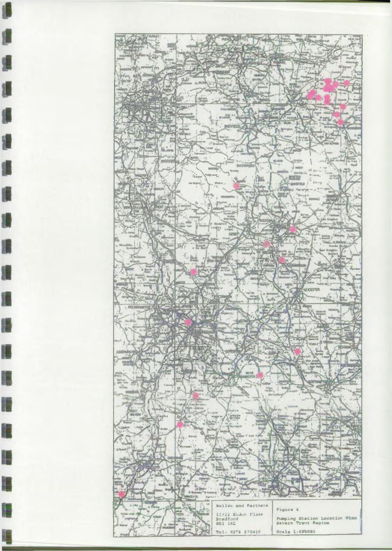
urn
. i
i "*'> V V y-''V \J 4 f c
<***
«. ft.i i T T i i * i r' ~ -V 1?} / i* ew.a.Airt •
I >aW
J/. .. „
* «Ul)?*• I/-,.
KjjJ; V^F^a I !5|
'A ‘ r^^S^VK*^s' In J v',*ww>l7'X,*««Sft i---iUja?Si** -r «;:---jrr|~-—
ftECESTER
P
• ' A - 4 ' » • .UaL ■ A»_~~>fer A y f>< *Sr4 * ~fc
- r?S3rA A r.-rti; i -irwciTr*JJ
WTA
rUA LmMl Asti
■ I k s ? 2
iXfir- m - . . , - ^ r y ^ BoB7> J *<* *
f e *
X L * .
J* '1 <?v\r f i
’cwcML * m **~« JT" .>•"■-WI
bu 11 »t. and P * rcna i a
1 1/12 EVdun P lJ ic*BradfordE D I 3AC
F ig u re 4
Pumping S t a t io n L o c a t io n ? 1j S a v a rn T ra n t Rag ion
S e a la 1 :« 2S 0»0
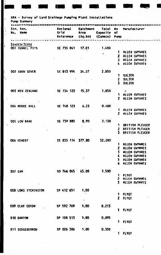
NRA > Survey of lond Drainage Punping Plant Installations Punp Sunnary
Stn. Stn. No. Name
National Catchment Total Grid Area CapacityReference (Sq.km) (Cunecs)
isisvtcsestestesssssss:No Manufacturer ofPuip
Severn-Trent 001 TUNNEL PITS
002 SNOU SEUHR
003 NEU ZEALAND
004 HEDGE HALL
005 LOU BANK
006 KEADBY
007 CAM
008 LONG ITCHINGT0N
009 ClAY COTON
010 BARTON
011 SEDGEBERROU
SE 735 041 17.01 1.480
SK 813 994 34.27 2.850
SE 734 122 15.37 1.850
SE 748 123 6.23 0.480
SE 739 085 8.90 2.130
SE 835 114 377.80 32.280
SO 746 04$ 45.00 1.SOO
SP 412 651 1.00
SP 592 769 1.00 0.213
SP 108 513 1.00 0.095
SP 026 386 1.00 0.300
1 ALLEN GUYNNES2 ALLEN GUYNNES3 ALIEN CWYNNES4 ALLEN GUYNNES
1 SUUER2 SUUER3 SULZER
1 ALLEN GUYNNES2 ALLEN GUYNNES
1 ALLEN GUYNNES2 ALLEN GUYNNES
1 BRITISH PLEUGER2 BRITISH PLEUGER3 BRITISH PLEUGER
1 ALLEN GUYNNES2 ALLEN GUYNNES3 ALLEN GUYNNES4 ALLEN GWYNNES5 ALLEN GUYNNES6 ALLEN GUYNNES
1 FLYGT2 ALLEN GUYNNES3 ALLEN GUYNNES
1 FlYGT2 FLYGT
1 FlYGT
1 FlYGT
1 FLYGT
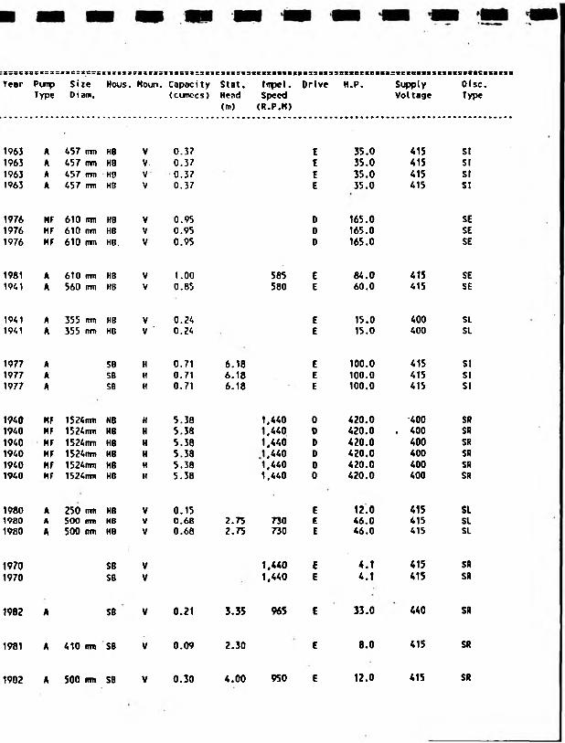
::sc3seK:ssv8Ssts:£:s:3sass8ses3ssc?3:s«ies*K3«38«sit9a«masit3a8S«8rt8seistc8Bsecstso8mtttt39CS8Year Piiflp Size Hous. Houn. Capacity Slat. Impel. Drive H.P. Supply Olsc.
Type Diaro. (cunccs) Head Speed Voltage Type<m> (R.P.H)
1963 A 457 rrm HB V 0.37 E 35.0 415 SI1963 A 457 mm H8 V. 0.37 E 35.0 415 SI1963 A 457 rm HB V 0.37 E 35.0 415 SI1963 A 457 rmv HB V 0.37 E 35.0 415 SI
1976 HF 610 RID HB V 0.95 D 165.0 SE1976 HF 610 irrn KB V 0.95 0 165.0 SE1976 HF 610 mm HB. V 0.95 0 165.0 SE
1981 A 6T0 (in HS V 1.00 585 E 84.0 415 SE1941 A 560 mu HB V 0.85 580 E 60.0 415 SE
1941 A 355 nrn HB V 0.24 E 15.0 400 SI1941 A 355 fTTTi HB V ' 0.24 E 15.0 400 SL
1977 A SB H 0.71 6.16 E 100.0 415 SI1977 A SB H 0.71 6.18 E 100.0 415 S!1977 A SB H 0.71 6.18 E 100.0 415 SI
1940 HF 1524irm HB H 5.38 1,440 0 420.0 •400 SR1940 HF 1524im HB H 5.38 1,440 0 420.0 . 400 SR1940 HF 1524ittn HB H 5.38 1,440 0 420.0 400 SR1940 HF 1524nm KB H 5.38 1,440 D 420.0 400 SR1940 HF 1524nrn HB H 5.38 1,440 0 420.0 400 SR1940 HF 1524n»n KB H 5.38 1,440 0 420.0 400 SR
1980 A 250 rmi HB V 0.15 E 12.0 415 SL1980 A SOO m H8 V 0.68 2.75 n o E 46.0 415 SL1980 A 500 tnn HB V 0.68 2.75 730 E 46.0 415 SI
1970 SB V 1,440 E 4.1 415 SR1970 SB V 1,440 E 4.1 415 SR
1982 A SB V 0.21 3.35 965 E 33.0 440 SR
1981 A 410 mm SB V 0.09 2.30 E 8.0 415 SR
1902 A 500 rm SB V 0.30 4.00 950 E 12.0 415 SR
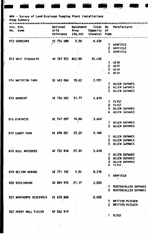
NRA * Survey of land Drainage Pimping Plant Installations Pimp SumwryVr:CtC:3:SBBICItlt:93«*|BICtCIBia«>fBttB|l«X|SSItBBStl«6t1
Stn. Stn. National Catchment TotalNo. Name Grid Area Capacity
Reference (Sq.km) (Cunecs)
t S S C S C S S C S S S E !
No Manufacturer ofPump
01? W000CARR SE 754 088 2.38 0.6301 ARHFIEID2 ARHFIEID3 ARHFIELO
013 WEST STOCKUITH
O H UATERTON FARM
SK 787 952 842.00 35.400
SE 663 066 18.62 2.931
1 WEIR2 WEIR3 WEIR4 WEIR
1 ALLEN GWYNNES2 ALLEN GWYNNES3 ALLEN GWYNNES
015 GOOOCOP SE 736 083 31.77 4.6101 FLYGT2 FlYGT3 ALLEN GWYNNES4 ALLEN GUYNNES
016 DIRTNESS SE 747 097 19.80 3.6401 ALIEN GUYNNES2 ALLEN GUYNNES
017 CAHDY FARM SE 698 031 23.25 3.1601 ALLEN CUYNNES2 ALLEN CUYNNES3 ALLEN GUYNNES
018 BULL HASSOCKS SE 732 016 27.35 5.6101 ALLEN GUYNNES2 ALLEN GUYNNES3 ALLEN CUYNNES4 FLYGT
019 BELTON GRANGE SE 771 105 1.54 0.2101 ARMFIELD
020 BECK INGHAM SK 801 915 21.17 2.8301 RUSTON/ALLEN GUYNNES2 RUSTON/ALLEN GUYNNES
021 ARMTHORPE RESERVOIR SE 658 048 0.4501 BRITISH PLEUGER2 BRITISH PLEUGER
022 PERRY HALL FIELDS SP 062 9191 FLYCT
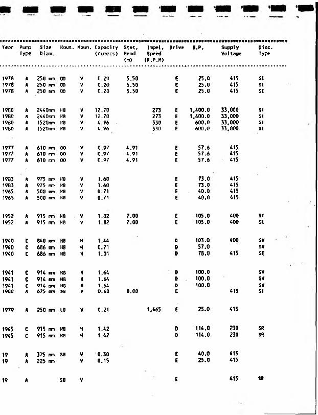
t3C3C5SS<8SSSSSC3:eCS8SSCS3KCBesC5CSSZBSSS«taBt88«B88IBB8SVSIBS8>B8mS9SetrBt88t«eSVS8mtll8tS83S3Year Pimp Size Kous. Moun. Capacity Stat. Impel. Drive H.P. Supply Disc.
Type Diam. (curoccs) Head Speed Voltage Type(m) (R.P.M)
1978 A 250 trni 00 V 0.20 5.50 E 25.0 415 SI1978 A 250 rm 00 V 0.20 5.50 E 25.0 415 SI1978 A 250 irni 00 V 0.20 5.50 E 25.0 415 SI
1900 A 2440mm HB V 12.70 273 E 1,400.0 33,000 SI1980 A 2440nm HB V 12.70 273 E 1,400.0 33,000 SI1930 A 1520rm> HB V 4.96 330 E 600.0 33,000 SI1980 A 1520trm HB V 4.96 330 E 600.0 33.000 SI
1977 A 610 rmi 00 V 0.97 4.91 E 57.6 4151977 A 610 mm 00 V 0.97 4.91 E 57.6 4151977 A 610 mn 00 V 0.97 4.91 E 57.6 415
1983 A 975 rmi HB V 1.60 E 73.0 4151983 A 975 fnm HB V 1.60 E 73.0 4151965 A 500 trm HB V 0.71 E 40.0 4151965 A 500 irm KB V 0.71 E 40.0 415
1952 A 915 rrm HB V 1.82 7.00 E 105.0 400 SI1952 A 915 rmt HB V 1.82 7.00 E 105.0 400 SI
1940 C 840 mm HB H 1.44 0 103.0 400 SV
1940 C 686 mm H8 H 0.71 D 57.0 SV1940 C 686 mm HB H 1.01 D 78.0 415 SE
1941 C 914 nm KB H 1.64 D 100.0 SV
1941 C 914 irm HB H 1.64 D 100.0 SV1941 C 914 m HB H 1.64 0 100.0 SV1988 A 675 mm SB V 0.68 0.00 E 415 SI
1979 A 250 irm L6 V 0.21 1,465 E 25.0 415
1945 C 915 fim HB H 1.42 0 114.0 230 SR
1945 C 915 mu HB H 1.42 D 114.0 230 SR
19 A 375 nrn SB V 0.30 E 40.0 415
19 A 225 cm V 0.15 E 25.0 415
19 A SB V E 415 SR
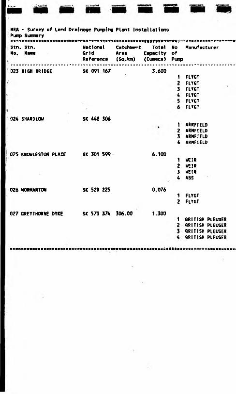
NRA - Survey of land Drainage Punplng Plant Installations Pimp Sunnaryeix3EZB:::xtniRai3inEi:m:ximmiiutssiiiiiiKM«3nn3Ks:i::<::::zrz:::::Stn. stn. No. Name
National Catchment Total No Manufacturer Gr i d Area Capaci ty ofReference (Sq.km) (Cunecs) Puip
023 HIGH BRIDGE SIC 091 167 3.6001 FLYGT
FlYCTFLYGTFLYGTFLYGTFLYGT
024 SHARDLOU SK 448 3061 ARNFIELD2 ARMFIELD3 ARMFIELD4 ARMFIELD
02S KNOULESTON PLACE SK 301 S99 6.1001 UE1R2 UEIR3 UEIR4 ASS
026 NORMANTON SK 520 225 0.0761 FLYGT2 FLYGT
027 GREYTHORNE DYKE SK 573 374 306.00 1.3001 BRITISH PLEUGER
BRITISH PLEUGER BRITISH PLEUGER BRITISH PLEUGER
5 S 8 a S 8 B 3 8 * > S S S S S S S a S I 8 S 9 5 B 3 S B : S 3 S S 8 B t 8 S 3 t « 8 S 8 S S 8 B 3 2 I 8 B S S m t S 3 3 « 3 » S S S S S S S S S S S S S S 8 :
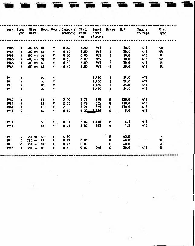
S63SSSSSS:::eS5SS«SS:SS3SS=CS=3583SSS3SS58506398S88S3««<a*9SS88SSS8SSSSSS8SS3S58338S«K5S5ff8e8S&SSSSS53
Year PurpType
SizeDiam.
Hous. Noun. Capacity(cumecs)
Stat.Head<m>
Inpet.Speed(R.P.K)
Drive H.P. SupplyVoltage
Disc.Type
1986 A 600 ftfn SB V 0.60 6.00 965 E 30.0 415 SR1986 A 600 rrcn SB V 0.60 6.00 965 E 30.0 415 SR1986 A 600 ITfT) SB V 0.60 6.00 965 E 30.0 415 SR1986 A 600 iron SB V 0.60 6.00 965 E 30.0 415 SR1986 A 600 mm SB V 0.60 6.00 965 E 30.0 415 SR1986 A 600 ran SB V 0.60 6.00 965 E 30.0 415 SR
19 A 00 V 1,450 E 24.0 41519 A 00 V 1,450 E 24.0 41519 A 00 V 1,450 E 24.0 41519 A 00 V 1,450 E 24.0 415
1984 A LB V 2.00 3.75 585 E 130.0 4151984 A LB V 2.00 3.75 585 E 130.0 4151984 A LB V 2.00 3.75 585 E 130.0 4151991 C SB V 0.10 6-2Qm 2»8S0 E 3.0 415
1991 SB V 0.05 2.00 1,440 E 4.1 4151991 SB V 0.03 2.00 935 E 1.2 415
19 c 350 nn SB H 4.30 E 40.0 .
19 c 350 im SB H 0.43 0.00 E 40.0 SI19 c 350 inn SB H 0.43 0.00 E 40.0 SI
1992 c 300 irm SB V 0.32 5.00 960 E 30.0 - 415 SI
:cc:;3t;=______ II II II II II II II II ______ II II II II II II ==33==s=aa
SOUTHERN

REGION
Southern
SUB REGION
Chichester
Tunbridge
Rye
Pevensey
STN . NO NAMEe c a a c s c s
042 CRAVEN045 EBONY054 * KITSBRIDGE 1DB001 * APPLESHAM002 * ANNINGTON003 * SEEDING BROOKS004 * NORTHOVER005 PULBOROUGH006 * HARDHAM007 * GREATHAM008 * HOUGHTON009 * BURY010 FELPHAM -Oil FERRY012 BAXTER FELL013 HAMS HILL014 LEIGH015 G.E.C.016 NORTHFLEET NO.2017 NORTHFLEET NO.l018 BOWATER NO.2019 BOWATER NO.l020 ROBINS CREEK021 SHELL022 TOWER DRAIN023 BRITANNIA LEAD024 M+B DREDGING025 M+B ROYALE026 EMPIRE PAPER NO.2027 EMPIRE PAPER NO.l028- BENDIGO WHARF029 WHITE HART030 EVERARDS031 GRAVESEND032 ALEXANDRA033 MILL MARSH034 APPLEDORE035 BILSINGTON036 BLACKWALL EAST037 BLACKWALL NORTH038 BLACKWALL SOUTH039 BOONSHILL040 * BRACK IDB041 COURT LODGE043 DIMSDALE044 DIXTER046 GREATSTONE047 HERONDEN048 HEXDEN NORTH049 HEXDEN SOUTH050 * ICKLESHAM051 * INDRAFT IDB052 JESSON053 KENT DITCH *055 KNELLE056 * LODGELAND IDB057 MAYTHEM058 NEWBRIDGE NORTH059 NEWBRIDGE SOUTH060 • NEWHOUSE061 NORTHPOINT062 POTMANS HEATH063 READING SEWER064 SHIRLEY MOOR .065 UNION066 VAREHORNE067 WILLOP068 WOODSIDE069 SARRE070 ASH LEVEL071 SEASALTER072 NORTH POUDLERS073 MINSTER074 STOURMOUTH075 RECULVERS076 BUTTERFLY077 COOPER STREET078 MILE END079 HONEYCROCK060 * DROCKMILL

REGION SUB REGION STN. NO NAME
081 * MALLING BROOKS082 * MANXEY083 * RICKNEY084 * STAR INN085 * HORSEBRIDGE086 * NEWBRIDGE087 * RODMEL088 * NEWHAVEN089 * STONEHAM090 * OFFHAM091 * RANSCOOMBE092 * BARNHORN093 * LOTTBRIDGE094 BEDDINGHAM
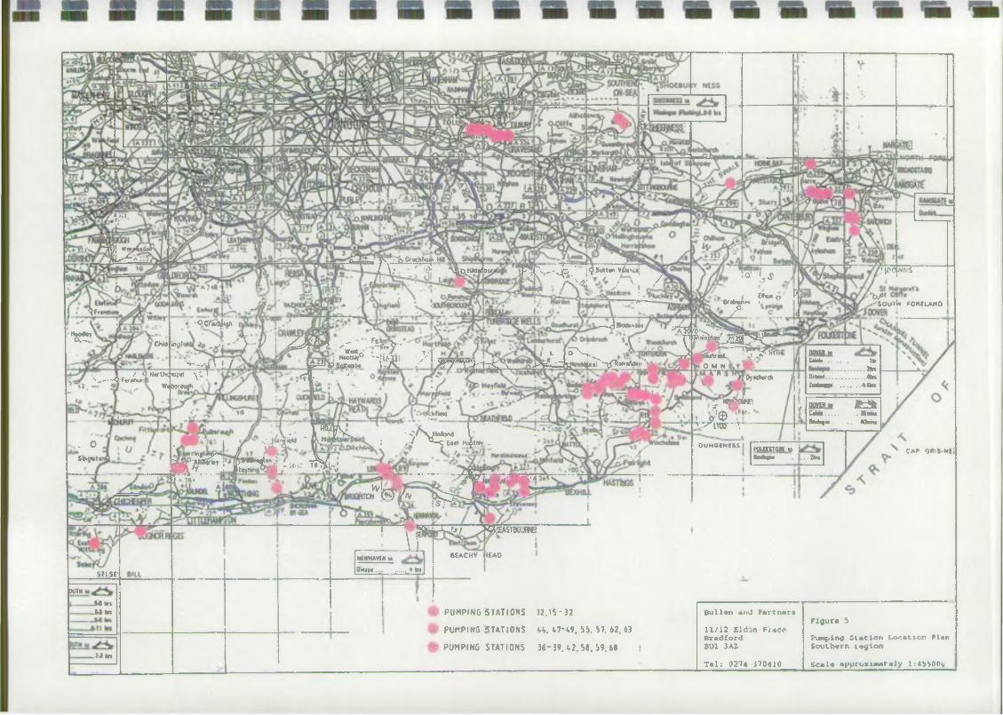
1 V»-/ * »
r^T7\)| Wofj&iolP7 / * a :: T/
2Fr«
S miUm T s ' P Crtchhoy W/ \.‘ . * ' '/?! 'VjVjD HiWartbor,
l« * ‘
" s ^ TOut ingf
_ / O Korthcpoi v-,--Q Ftfdhur/Wiiborough
. O
S«r>g**toi
S6LSE'
JUTH
.M hi _M m
- M m
iFsC'v«‘'4R;.' ;9Su*t#0 **"«;A v / v /L i
•■* -ocrif h —kT3***"*-1
^ i-y-V \ J JUn ^ .'3cV- A •
^° W i # • M .L j T ^ > .•v--vvt\ / . lA^JJPBttltgn.tK >-7^ / J f T T H t C V > V - - ^ 03*"W*'«t -'rfT»<»»«Aa*'1•v-^ \ I / Vs%±2J>? BaJConb,
mi x t r 4 , ' ■*
ckfwW
A.-.. Y*|3[Ss. ■ cAvMokKv! I .• *• I / '•’i*7"4d ^!it ; ,/ <Te«t hotwr. *
w / ^ n t s f s i - »* M lnT?*,..r/; ir* ■-■ *~ ~ ^ r ^ i r M riA —- r - —
w l - w r y ------TOM W A ( > 0 > _
<A2* \S ‘
I " 2G»w-V'//J^HSTBOJRNE
• a' '_$
'Brobaurnt io;
f*»» o 1
'jorivNs
' V .'SOU1M FORELAND
^ ' 0< . _Bf-T, - -- ^ I v . n g t o n J ^ ^ g -
-o * . t£«tr««L „» J*.' ^0 M N
I H Ot (dwell
1 1« * *, o'® '”• ‘v i w t
O U N O JN E SS I
DOVER to fM a ... . . Ilk 2I»>Osind.... Zutaipgt
........ . * n........ 4-sm
W M » i f c f f cC«laa...... .. 353BUHoiiufm. v. «M u
fQUEJTONItt iloubgn* ..2n
CAP ORIS NEi
IINfWHAVEMl*Onppt .... ♦ ta
BEACHY HEAD
V PUMPING (STATIONS 12. IS - 32
9 PUMPING -STATIONS H. 47- 1.9. 55. 57. 62. 63
© P U M P IN G STATIONS 36- 39. <.2, 58. 59. 68
B u l l t n and P a r tn e r s
11/12 E ld v n P ia c cB r a d fo rdB01 3AZ
T * 1 : 0274 170410
Fiflur# !>Pumping S t a t io n L o c a t io n P lan S ou L h «rn 1 * 9 io n
S c a la »p p to x in w tr «J y l:4bSOOg

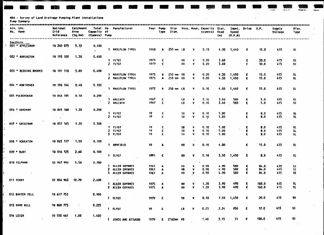
NRA • Survey of Land Drainage Pimping Plant Installations Pimp Simmaryit83ectBtstti»tti8ftfias»Cftt«m«amt«a«««stt»mii»ttisiisci«si«tscBBtK38eetsc:8;8escs:essss:sss:8&t8:s3tes38stssrsssscse«tt«seitt«s8iB»ii>BiBimisKBi8Bi«iits8taatiit9anieit
Stn. Stn. National Catchment Total No Manufacturer Year Pimp Size Hous. Moun. Capacity Stet. Impel. Drive H.P. Supply Disc.No. Name Grid Area Capacity of Type Dioro. (cumccs) Head Speed Voltage Type
Reference (Sq.kra) (Cumecs) Puip (m) (R.P.M)
Southern! 001 * APPLESHAM TO 200 075 5.10 0.100
• 1 MAXI FLOW TYPE4 1960 A 250 rrm LB V 0.10 4.00 1,440 E 15.0 415 SL
002 * ANNINGTON TO 193 100 1.30 0.40012
FLYGTFLYGT
19791979
CC
0000
VV
0.200.20
3.603.60
EE
30.030.0
415415
SISI
003 * SEEDING BROOKS TO 191 110 5.00 0.40012
HAX1FLOU TYPE4 MAXIFLOW TYPE4
19731973
AA
250 nm250 mm
0000
KH
0.200.20
4.304.30
1.4501.450
EE
15.015.0
415415
SLSL
004
i
* NORTHOVER TO 196 144 0.40 0.1001 MAXIFLOW TVPE4 1972 A 250 mm LB V 0.10 4.00 1,440 E 15.0 415 SL
005 PULBOROUGH TO 046 185 0.10 0.20012
WALLW1NWALLWIN
19671967
CC
LBLB
VV
0.100.10
3.403.40
580580
EE
5.05.0
415415
SISI
006 * HARDHAM TO 045 168 1.20 0.20012
FLYGTFLYGT
1919
c SBSB
VV
0.10
o t .°
5.005.00
EE
8.08.0
415415
SLSL
007
«
* GREATHAM TO 037 165 1.20 0.300123
FLYGTFLYGTFLYGT
191919
Ccc
SBSBSB
VVV
0.100.100.10
5.005.005.00
EEE
8.08.08.0
41541541S
SLSLSL
008 * HOUGHTON TO 023 117 1.50 0.1001 ARMFIELO 19 A 00 V 0.10 4.00 E 15.0 415 SL
• 009 • BURY TO 016 125 2.60 0.1001 FLYGT 1991 C 00 V 0.10 3.50 1,450 E 8.0 415 SL
| 010
ii •
FELPMAM SZ 947 992 5.50 2.700123
ALLENALLENALLEN
GWYNNES
GWYNNESGWYNNES
196119611961
AAA
HBHBHB
VVV
0.900.900.90
4.904.904.90
560580580
EEE
84.0.84.084.0
415415415
SISISI
011 FERRY SZ 856 963 10.70 2.40012
ALLENALLEN
GVYNNESGWYNNES
19751975
AA
0000
VV
1.201.20
3.903.90
490490
EE
160.0160.0
415415
SLSL
i 012 BAXTER FELL TO 617 752 0.1001 FLYGT 1979 C SB V 0.10 7.50 1,450 E 20.0 415 SR
013 HAMS HILL TO 868 773 0.2251 FLYGT 19 C LB V 0.23 2.24 950 E 12.0 415 SI
014 LEIGH TO 550 461 1.00 1.4001 JONES AND ATTWOOD 1979 S 2162nvn HB 1.40 3.15 31 E 100.0 415 SI
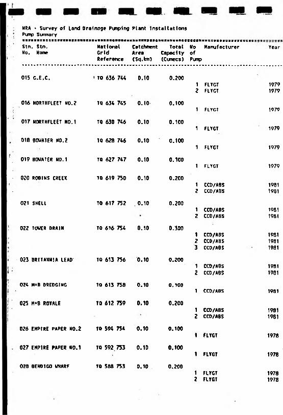
NRA » Survey of Land Drainoge Purplng Plant Installations P w p Surinary
KB3SCSSS3E=SSXS==G
Stn. Stn. No. Name
National Catchment Total No Manufacturer Grid Area Capacity ofReference (Sq.km) (Cunecs) Pump
015 G.E.C.
016 NORTMHEET N0.2
017 NORTHFLEET N0.1
018 BOVATER NO.?
019 B0UATER N0.1
020 ROBINS CREEK
021 SHELL
022 TOUER DRAIN
023 BRITANNIA LEAD
024 M*B DREDGING
025 M*B R0YALE
• TO 636 744 0.10
TQ 634 745 0.10
TO 630 746 0.10
TO 628 746 0.10
TO 627 747 0.10
TO 619 750 0.10
TO 617 752 . 0.10
TO 616 754 0.10
TO 613 756 0.10
TO 613 756 0.10
TO 612 759 0.10
026 EMPIRE PAPER NO.2 TO 594 754 0.10
027 EMPIRE PAPER N0.1 TQ 592 753 0.10
029 BENDIGO UHARf TO 588 753 0.10
0.200
0.100
0.100
0.100
0.100
0.200
0.200
0.300
0.200
0.100
0.200
0.100
0.100
0.200
1 FLYGT2 FLYGT
1 FLYGT
1 FLVGT
1 FLYGT
1 FLYGT
1 CCO/ABS2 CCD/ABS
1 CCD/ABS2 CCO/ABS
1 CCO/ABS2 CCD/ABS3 CCO/ABS
1 CCO/ABS2 CCD/ABS
1 CCD/ABS
1 CCD/ABS2 CCD/ABS
1 FLYGT
1 FLYGT
1 FLYGT2 FLYGT
Year
19791979
1979
1979
1979
1979
19611901
19811981
198119811981
19811901
1981
19811981
1978
1978
19781978
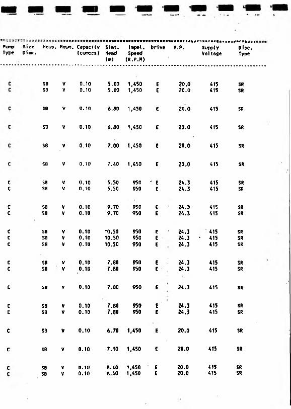
Purcp Size Nous. Houn. Capacity Stat. Type Oiom. (cunccs) Head
(m)
SB V 0.10 5.00SB V 0.10 5.00
SB V 0.10 6.60
SB V 0.10 6.80
SB V 0.10 7.00
SB V 0.10 7.40
SB V 0.10 5.50SB V 0.10 5.50
SB V 0.10 9.70SB V 0.10 9.70
SB V 0.10 10.50SB V 0.10 10.50se V 0.10 10.50
SB V 0.10 7.80SB V 0.10 7.00
SB V 0.10 7.80
SB V 0.10 7.80SB V 0.10 7,80
SB V 0.10 6.70
SB V 0.10 7.10
SB V 0.10 8.40SB V 0.10 8.40
Impel. Drive H.P. Supply Disc.Speed Voltoge Type (R.P.H)
1.450 E 20.0 415 SR1.450 E 20.0 415 SR
1.450 € 20.0 415 SR
1.450 E 20.0 415 SR
1.450 E 20.0 415 SR
1.450 E 20.0 415 SR
950 ' E 24.3 415 SR950 E 24.3 415 SR
950 E 24.3 415 SR950 E 24.3 415 SR
950 E 24.3 415 SR950 E 2 4 . 3 * 4 1 5 SR950 E 24.3 415 SR
950 E 24.3 415 SR950 E , 24.3 415 SR
950 E 24.3 415 SR
950 E 24.3 415 SR950 E 24.3 415 SR
1.450 E 20.0 415 SR
1.450 E 20.0 415 SR
1.450 E 20.0 415 SR1.450 E 20.0 415 SR
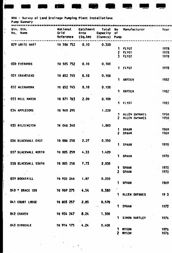
NRA • Survey of Land Drainage Pimping Plant Installations Punp Suimary
Stn. Stn. No, Name
NationalGridReference
Catchment Total Area Capacity (Sq.km) (Cunecs)
No Manufacturer ofPimp
029 WHITE HART
030 EVERARDS
031 GRAVESEND
032 ALEXANDRA
033 MILL MARSH
034 APPLEDORE
035 BILSINGTON
036 BLACKVALL EAST
037 BLACKVALL NORTH
038 BLACKUALL SOUTH
039 BOONSHIU
040 * BRACK IDB
041 COURT LODGE
042 CRAVEN
043 DIHSDALE
TQ 586 752 0.10
TQ 585 752
TO 652 745
TO 652 745
TO 871 763
TO 960 295
TR 046 340
TO 886 258
TO 885 259
TQ 885 258
TQ 935 246
TO 969 275
TO 803 257
TQ 934 247
TO 914 173
0.10
0.10
0.10
2.00
2.27
4.33
7.73
1.87
4.54
2.85
8.24
4.24
0.300
0.100
0.100
0.100
0.100
1.220
1.000
0.350
1.420
2.830
0.350
0.380
0.570
1.300
0.400
1 FLYGT2 FLYGT3 FLYGT
1 FLYGT
1 HAYDEN
1 HAYDEN
1 FLYGT
1 ALLEN GWYNNES2 ALLEN GWYNNES
1 SPAAN2 SPAAM
1 SPAAN
1 SPAAN
1 SPAAN2 SPAAN
1 SPAAN
1 ALLEN GUYNNES
1 SPAAN
1 SIMON HARTLEY
1 HYSON2 HYSON
1969
19 3
1972
1974
19761976
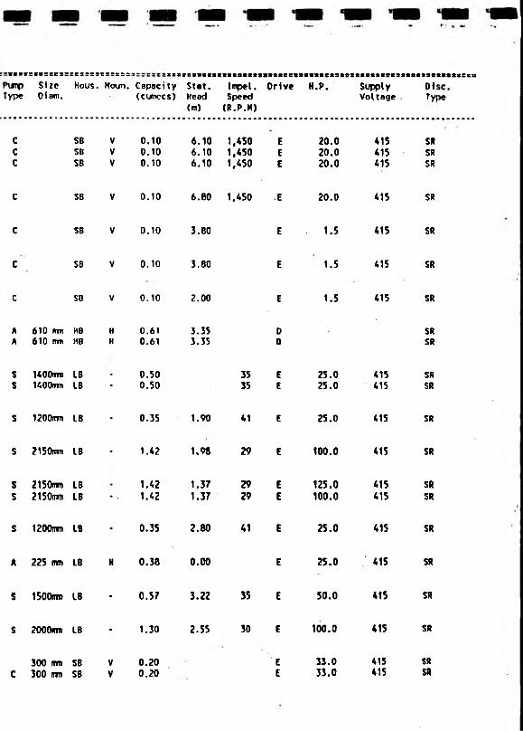
tse;\Mrpype
=lt=BC3=
SizeDiem.
:css:aNous.
ice::Houn. Capoci ty
(cunccs)Stet.Head<m>
Impel.Speed(R.P.H)
Drive H.P. SupplyVoltage
D1tyi
C SB V 0.10 6.10 1,450 E 20.0 415 SRC SB V 0.10 6.10 1,450 E 20.0 415 SRc SB V 0.10 6.10 1,450 E 20.0 415 SR
c SB V 0.10 6.80 1,450 E 20.0 415 SR
c SB V 0.10 3.80 E 1.5 415 SR
c SB V 0.10 3.80 E 1.5 415 SR
c SB V 0.10 2.00 E 1.5 415 SR
A 610 imi KB H 0.61 3.35 0 SRA 610 mm HO H 0.61 3.35 0 SR
s 1400mm LB 0.50 35 E 25.0 415 SRs K O O n m LB * 0.50 35 E 25.0 415 SR
s 1200RTTI LB - 0.35 1.90 41 E 25.0 415 SR
s ?150nm LB - 1.42 1.98 29 E 100.0 415 SR
s 2150ITTT1 LB 1.42 1.37 29 E 125.0 415 SRs 2150tim LB * • 1.42 1.37 29 E 100.0 415 SR
s 1200mm LB - 0.35 2.80 41 E 25.0 415 SR
A 225 mm LB H 0.38 0.00 E 25.0 ’ 415 SR
s 1500irm LB • 0.57 3.22 35 E 50.0 415 SR
s 2000otti LB - 1.30 2.55 30 E 100.0 41S SR
300 mm SB V 0.20 E 33.0 415 SR
c 300 mm SB V 0.20 E 33.0 415 SR
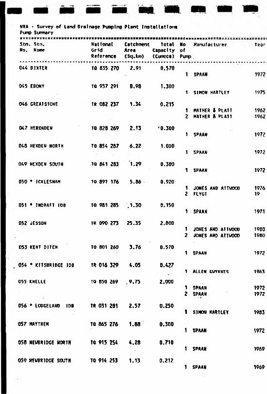
NRA • Survey of Land Oralnage Pumping Plant Installations Pump Sumaryt S s S l B B E C S B C l
Stn. Stn.No. Nome
ss:scsst;ssc38::s:
national Catchment Total No Manufacturer Grid Area Capacity ofReference (Sq.km) (Cumecs) Puip.
044 DIXTER
045 EBONY
046 GREATSTONE
047 HERONDEN
048 HEXDEN NORTH
049 HEXDEN SOUTH
050 * ICICLE SHAM
051 * INDRAFT IDS
052 JESSON
053 KENT DITCH
055 KHELLE
057 MAYTHEM
058 NEWBRIDGE NORTH
059 NEWBRIDGE SOUTH
TO 835 270 2.91
TO 937 291 8.98
TR 082 237 1.34
TO 828 269 2.13
TO 854 287 6.22
TQ 841 283 1.29
TO 89t 176 5.86
TO 981 285 .1.30
TR 090 273 25.35
TO 801 260 3.76
054 * KITSBRIDGE IDB TR 016 329 4.05
TO 850 269 ,9.75
056 * LOO CEL AWT) IDB TR 031 281 2.57
TQ 865 276 1.88
TQ 915 254 4.28
TO 914 253 1.13
0.570
1.300
0.215
•0.300
1.000
0.300
0.920
0.150
2.800
0.570
0.427
Z.000
0*250
0.300
0.710
0.212
1 SPAAN
1 SIMON HARTLEY
1 MATHER & PLATT2 MATHER & PLATT
1 SPAAN
1 SPAAN
1 SPAAN
1 JONES AND ATTWOOO2 FLYGT
1 SPAAN
1 JONES AND ATTUOOD2 JONES AND ATTWOOO
1 SPAAN
1 ALLEN GUYNNES
1 SPAAN2 SPAAN
1 SIMON HARTLEY
1 SPAAN
1 SPAAN
1 SPAAN
1972
1975
19621962
1972
1972
1972
1976 19
1971
19801980
1972
1963
19721972
1983
1972
1969
1969
Year
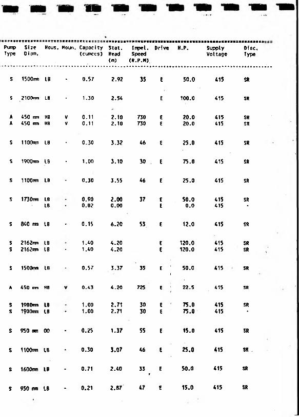
SSSIS*PumpType
rsissass
SizeDiam.
ssssrsHous.
3BC8SSHoun.
retcissscBCepacity (cumccs)
Stat.Head(m)
Inpel. Drive speed (R.P.M)
H.P. SupplyVoltage
Ofsc.Type
S 1500rmi IB - 0.57 2.92 35 E 50.0 415 SR
5 2100**»n LB - 1.30 2.54 E 100.0 415 SR
A 450 mm HB V 0.11 2.10 730 E 20.0 415 SRA 450 rm HB V 0.11 2.10 730 E 20.0 415 SR
S 1100mm LB - 0.30 3.32 46 E 25.0 415 SR
S 1900rrm LB - 1.00 3.10 30 E 75.0 415 SR
5 1 lOOffTTI LB - 0.30 3.55 46 E 25.0 415 SR
S 1730m) L8 0.90 2.00 37 E 50.0 415 SRLB ~ 0.02 0.00 E 0.0 415 *
S 640 mm LB * 0.15 6.20 S3 £ 12.0 415 SR
S 2162im LB 1.40 4.20 E 120.0 415 SRS 2162(iw LS * 1.40 4.20 E 120.0 415 SR
S 1500mm LB - 0.57 3.37 35 EI
50.0 415 SR
A 450 urn KB V 0.43 4.20 725 E 22.5 415 Sft
S 1900mm LB 1.00 2.71 30 E 75.0 415 SRs 1900mm LB * 1.00 2.71 30 E 75.0 415 *
s 950 mm 00 - 0.25 1.37 55 E 15.0 415 SR
s IIOQim LB ♦ 0.30 3.07 46 £ 25.0 415 SR .
s 1600mm LB - 0.71 2.40 33 E*
50.0 415 SR
s 950 urn LB * 0.21 2.87 47 E 15.0 415 SR
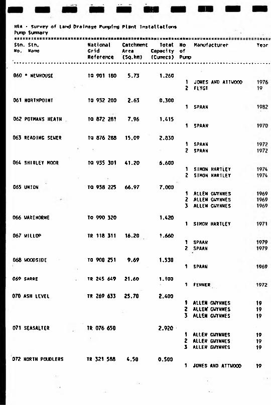
NRA - Survey of Land Drainage Punptng Plant Installations Pump Summary«i:s:c::BCs;ssei:set:«ifKV«M9itc»>M»i3Miitsxs:siitkict>i3r3es8iErEsesz!Stn. Stn. National Catchment Total No ManufacturerNo. Name Grid Area Capacity of
Reference (Sq.km) (Cunecs) Pump
Year
060 * NEWHOUSE
061 NORTHPOINT
06? POTMANS HEATH
063 READING SEWER
064 SHIRLEY MOOR
065 UNION
066 UAREHORNE
067 WIILOP
068 WOGOSIDE
069 SARRE
070 ASH LEVEL
071 SEASALTER
072 NORTH POUOLERS
TO 901 100 5.73
TO 932 200
TO 872 281
TQ 876 288
2.63
7.96
15.09
TO 935 301 41.20
TO 938 225 66.97
TO 990 320
TR 118 311 16.20
TO 900 251 9.69
TR 245 649 21.60
TR 269 633 25.70
TR 076 650
TR 321 588 4.50
1.260
0.300
1.415
2.830
6.600
7.000
1.420
1.660
1.530
I.IOO
2.400
2.920
0.500
1 JONES AND ATTWOOO2 FLYGT
1 SPAAN
1 SPAAN
1 SPAAN2 SPAAN
1 SIMON HARTLEY2 SIMON HARTLEY
1 ALLEN GWYNHES2 ALLEN GWYNNES3 ALLEN GWYNNES
1 SIMON HARTLEY
1 SPAAN2 SPAAN
1 SPAAN
1 FENNER
1 ALLEN GWYNNES2 ALLEtf GWYNNES3 ALLEN GWYNNES
1 ALLEN GUYNNES2 ALLEN GWYNNES3 ALLEN GWYNNES
191919
191919
1 JONES AND ATTWOOO 19

Pump Size Hous. Moun. Capacity Stat. Impel. Drive H.P. Supply Disc.Type Diam. (cumccs) Head Speed Voltage Type
<m) (R.P.H)
s 2030nrn LB 1.24 1.93 32 E 75.0 415 SR* V 0.02 * 415 ■
s 1 lOOrm LB - 0.30 3.85 46 E 29.0 415 SR
s 2150rrm IB 1.41 2.97 29 E 125.0 415 SR
s 2150rm> LB * 1.41 2.67 29 E 125.0 415 SRs 2150mn LB 1.41 2.67 29 E 100.0 415 SR
s 3000tnn LB 3.30 2.54 E 250.0 415 SRs 3000imi LB 3.30 2.08 E 250.0 415 SR
A 1067mii 00 V 2.00 5.79 E 220.0 415 SIA 1067™ 00 V 2.80 5.79 E 220.0 415 SiA 686 miT 00 V 1.40 5.79 E 115.0 415 SI
s 2100irm LB 1.42 1.45 32 E 75.0 415 SR
s 1700mm LB . 0.83 3.52 34 E 75.0 415 SRs 1700mn LB ■ 0.83 3.52 34 E 75.0
1415 SR
s 2100mm LB - 1.53 3.12 28 E 1 100.0 415 SR
s 1800n»n LB * 1.10 2.13 33 E
i
60.0 415 SR
A SOO mm HB V 0.7V 2.40 725 E 60.0 415 SIA 500 nm HB V 0.79 2.40 725 E 60.0 415 SIA 500 nm HB V 0.79 2.40 725 E 60.0 415 SI
A 600 mm L8 V 0.98 3.63 585 E 85.0 415 SIA 600 rrm LB V 0.90 3.63 585 E 85.0 415 SIA 600 mm LB V 0.98 3.63 585 E 85.0 415 SI
s 1400nm LB 0.50 1.70 40 E 18.0 415 SR

NRA * Survey of land Drainage Punping Plant Installations Pimp Suimary
Stn. Stn. No. Marne
rssssesssisss:National Catchment Total Ho Manufacturer Grid Area Capacity ofReference (Sq.km) (Cumecs) Pimp
073 MINSTER
074 STOURMOUTH
075 RECULVERS
076 BUTTERFLY
077 COOPER STREET
078 MILE END
079 HONEYCROCK
080 * DR0CKM1LL
082 * HANXEY
083 * RICICNEY
084 * STAR I MW
TR 310 632 .__20,80
TR 250 630 200.00
TR 230 693 4.70
TR 320 592 0.30
TR 313 597 3.60
TR 265 639
TO 596 072 13.40
TO 618 069 4.10
081 * MAILING BROOKS TO 418 106 0.20
TO 655 084 17.30
TO 627 070 10.50
TO 682 062 7.30
085 * HORSEBRIDGE TO 669 090 9.20
1.190
5.600
0.311
0.100
0.450
0.450
3.200
0.800
1.200
1.200
2.200
1.300
1.600
1 ALIEN GUYNNES2 ALLEN GUYNNES3 ALLEN GUYNNES
1 ALLEN GUYHNES2 ALLEN GUYNNES3 ALLEN GUYNNES4 ALLEN GUYNNES
1 ACM
1 JONES AND ATTUOOO
1 JONES AND ATTUOOO
1 FLYGT
1 ALLEN GUYNNES2 ALLEN GUYNNES3 ALLEN GUYNNES
1 FLYGT2 FLYGT
1 SUBMERSIGLIDE2 SU8MERSIGLIDE
1 ALLEN GUYNNES2 ALLEN GUYNNES
1 SIMON HARTLEY2 SIMON HARTLEY
1 SPAAN2 SPAAN
1 HARIAND JOHNSON2 HARLAND JOHNSON
Year
191919
19191919
1972
19
1977
19
197919791979
19691969
19911991
19751975
19731973
19761976
19641964

SfiSZflt
Pump
Type
SSSXSS3E
Size 0 iem.
Nous. Moun. Capacity Stat, (cumecs) Head
<m)
Impel. Drive Speed
(R.P.H)
H.P. SupplyVoltage
Disc.Type
A <*50 nro 00 V 0.39 2.90 730 E 19.0 415 S!A 450 nrn 00 V 0.39 2.90 730 E 19.0 415 SIA 450 m 00 V 0.40 2.90 730 E 19.0 415 SI
A 500 mm HB V 1.40 725 E 75.0 415 SIA 500 mm H0 V 1.40 725 E 75.0 415 SIA 500 mm H8 V 1.40 725 E 75.0 415 SIA 500 mm HB V 1.40 725 E 75.0 415 SI
S 1100nn» LB - 0.31 3.12 47 E 18.0 415 SR
s 690 mm HB - 0.10 2.17 68 E 4.1 SR
s 1297«m HB * 0.45 2.30 40 E 15.0 415 SR
A 00 V • 0.45 E 17.0 415 *
A 385 inn 00 V 0.40 3.00 970 E 40.0 415 SIA 613 mm 00 V 1.40 3.00 585 E 130.0 415 SIA 613 mm 00 V 1.40 3.00 585 E 130.0 415 .
/
SI
A 00 V 0.40 2.70 n o E 29.0 41S SLA 00 V 0.40 2.70 730 E i 29.0 415 SL
C 00 V 0.60 5.90 50.0 415 StC 00 V 0.60 5.90 E 50.0 415 SI
A 00 V 0.60 2.50 980 E 43.0 415 SI
A 00 V 0.60 2.50 980 E 43.0 415 . SI
S 1900rrm HB . 1.10 2.10 38 E 50.0 415 SL
S 1900mm NB ' 1.10 2.10 38 E 50.0 415 SL
s 1500mm HB 0.60 4.60 38 E 75.0 415 SL
s 1500mm HB • 0.60 4.60 38 E 75.0 SL
A 450 mu 00 H 0.80 4.50 E 56.0 SI
A 450 mm 00 K 0.80 4.50 E 56.0 415 SI

NRA - Survey of land Drainage Puiptng Plant InstallationsPump Surma r yt e S S S 3 S 5 3 8 5 2 l
Stn. Stn.No. NBme
National Catchment Total No Manufacturer Crfd Area Capacity ofReference (Sq.km) (Cunccs) Pump
087 * RODKEL
088 * NEUHAVEN
089 * STONEHAH
090 * OFFHAM
09.1 * RANSC00H8E
092 * BARMHORN
: 093 * LOTTBRIOCE
094 BEDO INGHAM
TO 626 098 6.80 0.800
TO 432 070 1.90 0.700
TO 453 007 3.60 0.400
TO 418 117 3.20 0.300
TO 405 117 1.80 0.100
TO 442 082 2.50 0.400
TO 689 082 0.60 0.300
TO 615 013 2.80 0.400
TO 443 081 62.00 9.300
1 HARLAND JOHNSON2 HARIAND JOHNSON
1 HARLAND JOHNSON
1 HARLAND JOHNSON2 HARLAND JOHNSON
1 FLYGT2 FLYGT3 fLYGT
1 FLYGT
1 FLYGT2 FLYGT3 FLYGT4 FLYGT
1 FLYGT2 FLYCT3 FLYGT
1 HARLAND JOHNSON
1 ALLEN CUYNNES2 ALLEM GUYNHES3 ALLEN GUYNNES
s s s x s s s s s s s s s & s e s s s B s c s e x s s i s s f i& c t a a c B f t e s s s s a s s a & s s :
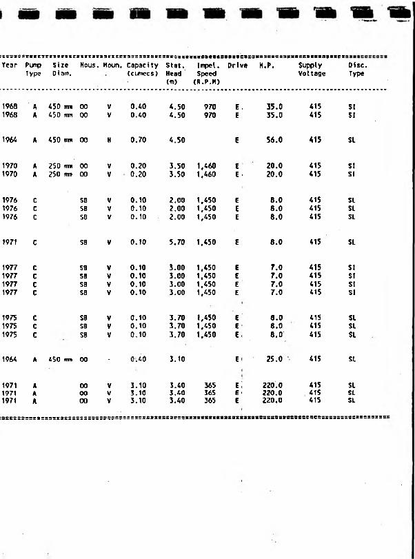
:::=:::est:$;::::::::::Ea:s:c;i£tx:s3cxatt3C>:iEt:BxaMitsat«is*s3iBSE(SB3iiaas*i«t:stBiei
Year Pump Size Hous. Houn. Capacity Stat. Impel. Drlv« H.P. Supply Disc.Type Diam. (cumecs) Head Speed Voltage Type
<m) (R.P.M)
1968 A 450 mm 00 V 0.40 4.50 970 E . 35.0 415 SI1968 A 450 mm 00 V 0.40 4.50 970 E 35.0 415 SI
1964 A 450 mm 00 H 0.70 4.50 E 56.0 415 SL
1970 A 250 mm 00 V 0.20 3.50 1,460 E 20.0 415 SI1970 A 250 rm» 00 V 0.20 3.50 1,460 E ' 20.0 415 SI
1976 C SB V 0.10 2.00 1,450 E 8.0 415 SL1976 C SB V 0.10 2.00 1,450 E 8.0 415 SL1976 c SB V 0.10 2.00 1,450 E 8.0 415 SL
1971 c SB V 0.10 5.70 1,450 E 8.0 415 SL
1977 c SB V 0.10 3.00 1,450 E 7.0 415 SI1977 c SB V 0.10 3.00 1,450 E 7.0 415 SI1977 c SB V 0.10 3.00 1.450 E 7.0 415 SI1977 c SB V 0.10 3.00 1,450 E 7.0 415 SI
1975 C SB V 0.10 3.70 1,450 E 6.0 415 SL1975 C SB V 0.10 3.70 1,450 E 8.0 415 SL1975 C SB V 0.10 3.70 1,450 E, 8.0' 415 SL
1964 A 450 rrm 00 - 0:40 3.10 E i 25.0 415 SL
1971 A 00 V 3.10 3.40 365 e ; 220.0 415 SL1971 A oo V 3.10 3.40 365 E 1 220.0 41S SL1971 A 00 V 3.10 3.40 365 E 220.0 415 SI
:Brss3:ssssss8SSBXS*BssS3EBSsss8S8Scas3sss3sss88xs!

1
SOUTH WEST

REGION
South West
SUB REGION
Exeter
STN. NO NAME
001 POLMORLA002 ST.BLAZEY003 MIDDLEWAY
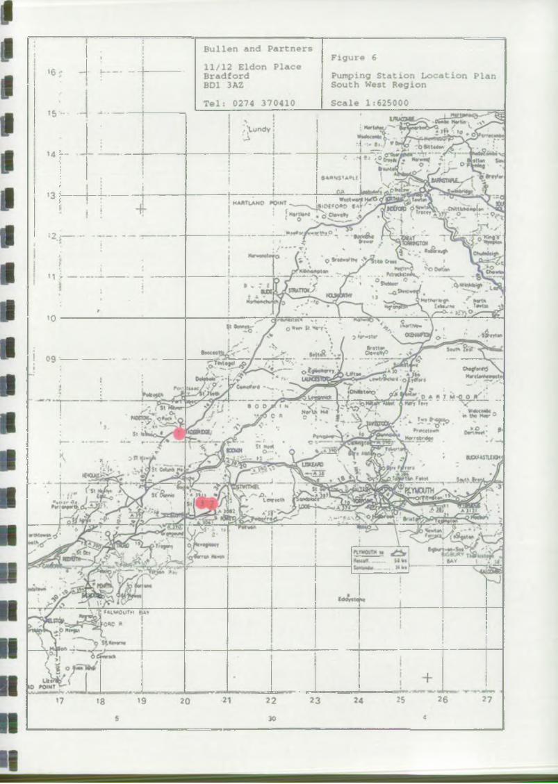
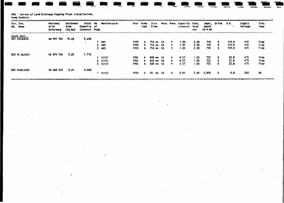
NRA • Survey of Land Drainage Purplng Plant Installations Pump SutTTTury
Stn. Stn. No. Name
NationalGridReference
CatchmentArea(Sq.km)
TotalCapacity(Cunecs)
NoofPurp
Manufacturer Year3SSSESPimpType
SizeDiam.
HOUS.SBS36SHoun. Capacity
(cumccs)Stat.Head(m)
IrnpeUSpeed(R.P.M)
Drive H.P.4
SupplyVoltage
Disc.Type
South West001 P01H0RLA SU 991 724 15.20 5.400
• 1 ASS 1990 A 750 rrni SB V 1.80 2.30 710 E 119.0 415 Flap2 ABS 1990 A 750 m SB V 1.80 2.30 710 E 119.0 415 Flap3 ABS 1990 A 750 (m SB V 1.80 2.30 710 E 119.0 415 Flap
002 ST.8LAZEY SX 075 536 2.20 1.7101 FLYGT 1904 A 600 Rin SO V 0.57 1.00 733 E 22.8 415 Flap2 FLYGT 1984 A 800 mu SB V 0.57 1.00 733 E 22.8 415 Flap3 FLYGT 19B4 A 800 irm SO V 0.57 1.00 733 E 22.6 415 Flap
003 MfDDLEWAY SX 069 542 0.01 0.0061 FLYGT 1976 C 50 (nn SB V 0.01 3.00 2,850 E 0.8 240 SR
3sr::3:ss?;sssecs9seBS itsssaesetiBiticBBsrssBc: _ _ _ _ _ _ _ _ _ _ _ _ _ _ . . . . . . - = - =; =C =£3S S :acc:8«s8(3essassessstsesssssssssssssrssss:

THAMES
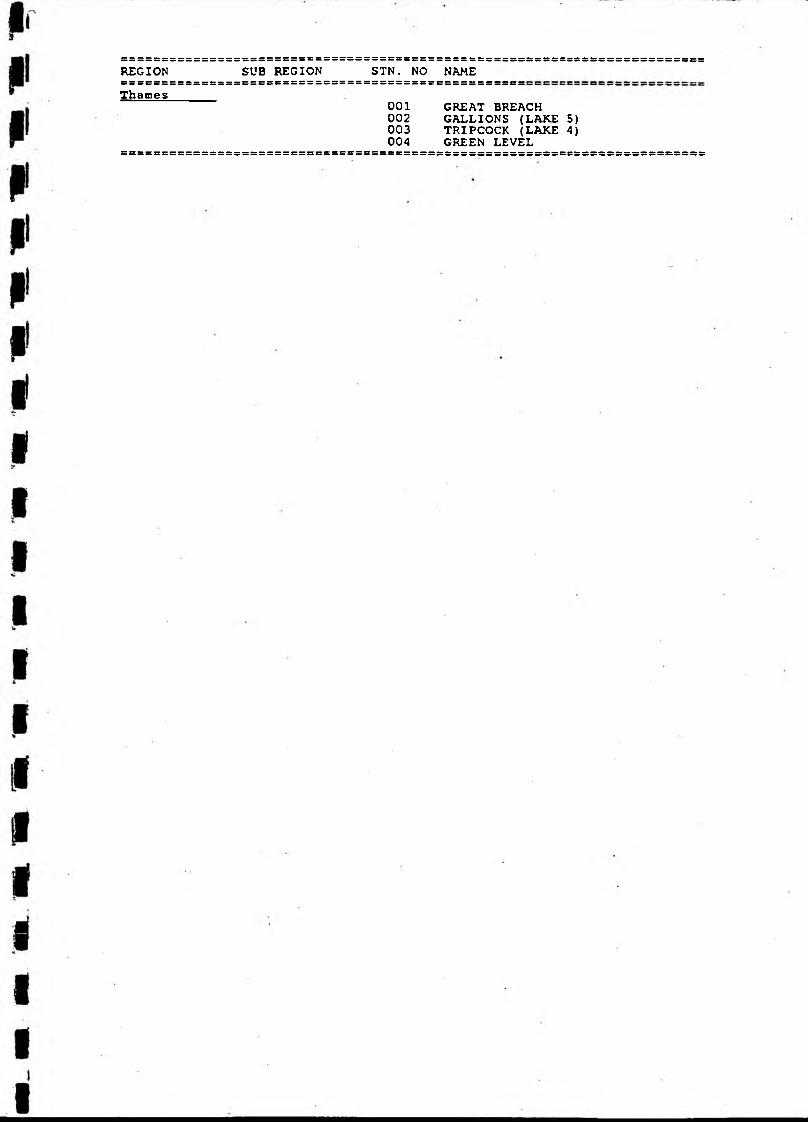
REGION SUB REGION STN. NO NAMEe = = = = = = = = = = s = = = = = = = c = = = = = = = = = = = = = = = = = 5E = = = = = = jThames
001 GREAT BREACH002 GALLIONS (LAKE 5)003 TRIPCOCK (LAKE 4)004 GREEN LEVEL
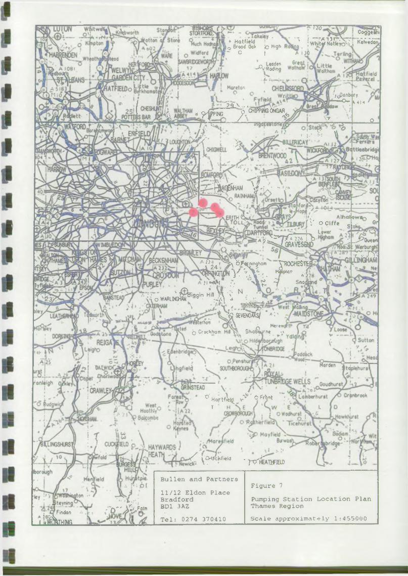
'?q\_. .^ 9 pping j? < wg °ngar<5
ERITH
*s 120
, • Hatfield ) 0 Brood 0a»* ic Hl9 hr~ c I
Co eSI’ *, i —rA T 3Tn W | ■/; r - -1 0 I W h it^f N o tle y b ':c j K« lv«do
A 130
a -rSSS >
•'/tPonbory — - O - M M '
low
\T
. ;.• v« ^ .
_£L
^ ^ qgn A M y -u - -'•■»
A llh a llo w ^ -)S- ociiff. stoh on
> Lewtr
4 ^ 7 ^ ^ Jl A W I
£ 7 7 ?^24 ’ >\ 6-Jf<*Cnir'9hQm JflOCHESTCw y % . T * r * f> ' * * V / / > k f c -V S n c i
l i o im J ® * ”* HinJ i ' i N
•fcsEVENOX *AI' ^o M<feW|q Croc Whom S hiobaurrx ^ ~ \
° Hortf^ ° nt T
S ^ckfi.W -j^r^TlflELD
Findon
A ]80A I hmBlTHlNG
-'"rf* X .Folw
Bullen and Partners11/12 Eldon PlaceBradfordBD1 3A2Tel: 0274 370410
Figure 7Pumping Station Location Plan Thames RegionScale approximately 1:455000

NRA - Survey of Land Drainage Punpfng Plant InstallationsPurp Sunmaryi : t » M I 3 : E l E : i 3 3 3 * 3 t
Stn. Stn.No. Name
t m i s e 3 s « 3 s s t t S 8 8 8 8 8 3 0 S S 8 a 8 B 3 ! 8 S f e s s 5 C s s s s s : 8 c e s 3 s : s s : ; ; : s : s : : :
National Catchment Total No Grid Area Capacity ofReference (Sq.km) (Cunecs) Purp
Manufacturer
Thames001 GREAT BREACH
002 GALL IONS (LAKE 5)
TP 493 807 9.00
TO 449 798 4.00
1.710
0.940
003 TRIPCOCK (LAKE 4) TO 464 810 18.00 8.510
1 BROOKE, CROMPTON2 BROOKE, CROMPTON3 BROOKE, CROMPTON
Flygt B2250Flygt B2250Flygt BZ250Flygt B2250
MATHER & PLATT MATHER ft PLATT DORMAN DIESEL DORMAN DIESEL
004 GREEN LEVEL TO 508 796 3.00 0.690METROPOLITAN VICKERS LISTER DIESEL
888S888SSSSSSSSSSS:3:388SeS:9:8888888S8888388S88SSS8:
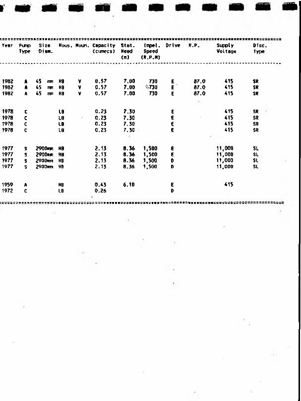
Year PunpType
SizeDtam.
Hous. Moun. Capacity(cunecs)
Stat.Head(m)
8883S388888SSS8C
Impel. Orfve Speed (R.P.N)
H.P.SC88SIIS8t38838C;
Supply Off Voltage Ty|
1982 A 45 win HB V 0.57 7.00 730 E 87.0 415 SR1982 A 45 rran HB V 0.57 7.00 ^730 E 87.0 415 SR1982 A 45 inn HB V 0.57 7.00 730 E 87.0 415 SR
1978 C IB 0.23 7.30 E 415 SR1978 C LB 0.23 7.30 E 415 SR1978 c LB 0.23 7.30 E 415 SR1978 c LB 0.23 7.30 E 415 SR
1977 s 2900nm KB 2.13 8.36 1,500 E 11,000 SL1977 s 2900irm HB 2.13 8.36 1,500 E 11,000 SL1977 s 2900mm HB 2.13 8.36 1,500 0 11,000 SL1977 s 2900im HB 2.13 8.36 1,500 0 11,000 SL
1959 A HB 0.43 6.10 E 4151972 C LB 0.26 D
:S8S8«:V8ia98SS8fi&SS8SSSS88Z8SS8:

WELSH

REGIONB B S S S S
Welsh
SUB REGION: S S B S S S B S B B 1
Buckley
STN. NO NAME
Rhuddlan
: c s s c =caccciiocccnccctncsc
001 BALDERTON004 WERN Y .DAVY005 DOL ERION006. FINGERPOST007 DOG KENNEL008 GWERN Y TO009 QUEEN FERRY010 THORNLEIGH PARKOil BURTON PUDDINGTON012 ROWLEYS GUTTER.013 GREEN MOOR014 COLLISTER PILL015 TREVALYN MEADOW021 SEALAND MAIN* ---002 RHYL003 CLWYD016 TALACRE017 GRONNANT018 BELGRAD019 BODORYN020 GYPSY LANE
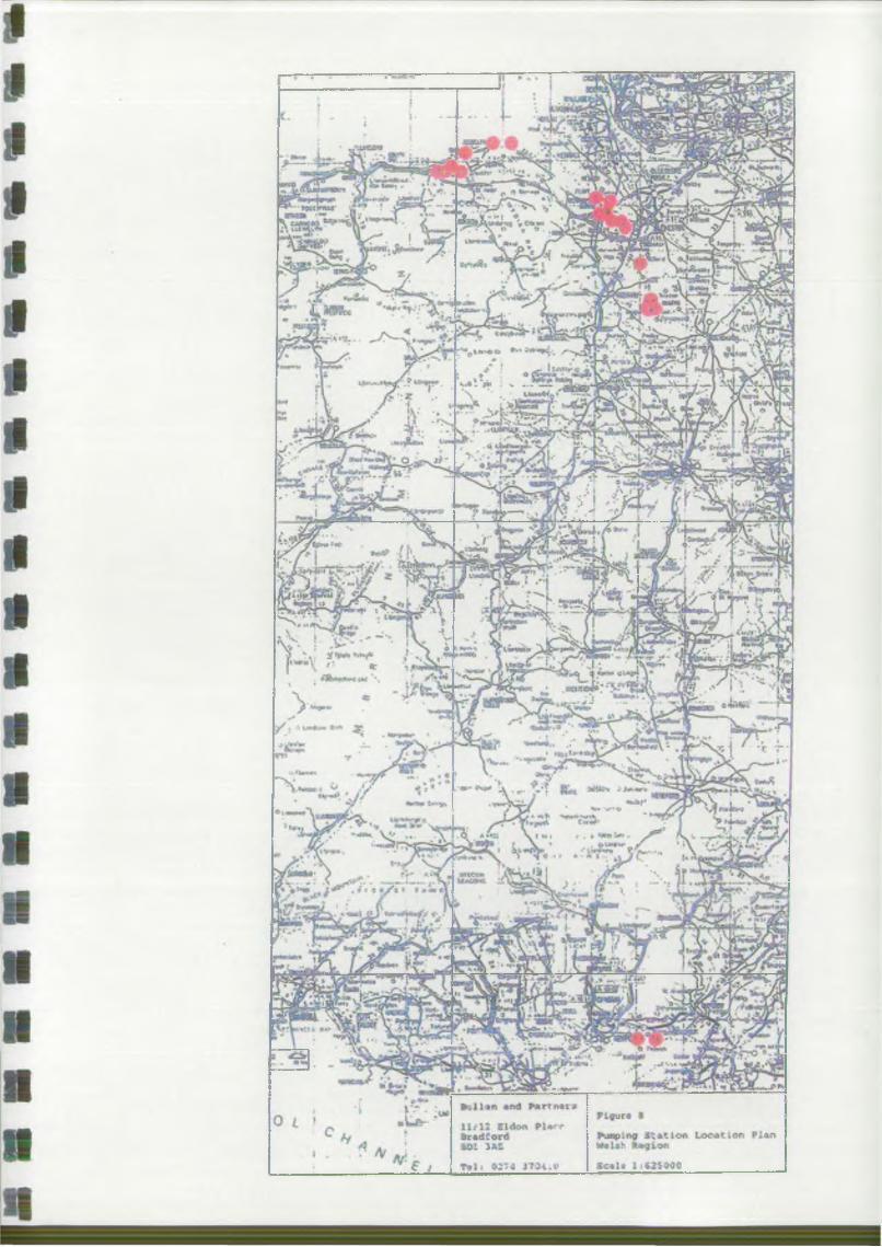
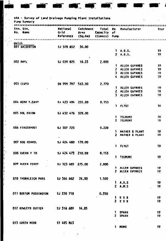
NRA • Survey of land Ora inage Pumping Plant Installations Pump Sunmary
Stn. Stn. No. Name
National Catchment Total No Manufacturer Grid Area CapacIty ofReference (Sq.km) (Cumecs) Pimp
Year
Welsh001 BALDERTON SJ 378 652 30.00
1 A.6.S.2 A.B.S.
1919
00? RHYL SJ 029 825 10.23 2.6001 ALLEN GUYNNES2 ALLEN GUYNNES3 ALLEN CUYNNES * ALLEN GUYNNES
19191919
003 CLWYD SH 999 797 563.00 2.7701 ALLEN GWYNNES2 ALIEN GWYNNES3 ALLEN GWYNNES
191919
00* UERN Y.DAVY SJ 423 *94 255.00 0.1501 FLYGT 19
005 DDL ERION SJ *32 *76 320.001 TSURUHI2 T SURLWI
1919
006 flNGERPOST SJ 307 723 0.2201 MATHER A PLANT2 MATHER & PLANT
1919
007 DOG KENNEL
008 GWERN Y TO
SJ *2* *80 170.00
SJ *2* *73 210.00 0.153
1 FLYGT
1 TSUKUMI
19
19
009 OUEEN FERRY SJ 323 685 275.00 2.8001 ALIEN GWYNNES2 ALLEN GWYNNES
1919
010 THORNLEIGH PARK SJ 36* 662 2*.00 1.5001 A.B.S2 A.P.S
1919
011 BURTON PUDDINGTON SJ 330 718 0.3501919
012 ROWLEYS GUTTER SJ 316 689 14.851 SPAAN2 SPAAN
1919
013 GREEN MOOR ST *05 8631 MONO 19

: c : i : : x : : : : 3 : : : 3 : ; : : : : : : : : : c c : : : : - s e E t B Ci i i n e t : s x t 3 * t t e t x u e i a n s x : E B C i s x i n i s E B s r s s M « i ( * t
Punp Size Hous. Moun. Capacity Stat. Irrpet. Drive H.P. Supply Disc,Type Diem. (cixnccs) Head Speed Voltage Type
Cm) (R.P.M)
700 rrm SB H 720 E 0.0 415700 mn SB H 720 E 0.0 415
508 rrrn HB V 0.70 E 0.0 415508 mm HB V 0.70 E 0.0 415508 rrni KB V 0.70 E 0.0 415508 rim HB V 0.70 E 0.0 415
609 trm HB V 0.92 E 0.0 415 SI609 mm HB V 0.92 E 0.0 415 SI609 nrn HB V 0.92 E 0.0 415 St
250 mm SB H 0.15 950 E 0.0 415
250 nm S3 H 1,500 E 0.0 415250 fim SB H 1,500 E 0.0 415
304 rrri HB V 0.11 945 E 7.0 415304 nm HB V 0.11 945 E 7.0 415
250 mn S8 H 950 E 0.0 415
250 cm SB 0.15 1,500 E 0.0 415
762 inn HB V 1.40 467 E 105.0 415762 rim HB V 1.(0 467 E 105.0 415
500 nvn LB H 0.75 960 E 0.0 415500 irm LB H 0.75 960 E 0.0 415
350 urn SB V 740 E 0.0 *15350 rrm SB V 740 E 0.0 *15
rrm 00 . 30 E 0.0 *15rm 00 30 E 0.0 *15
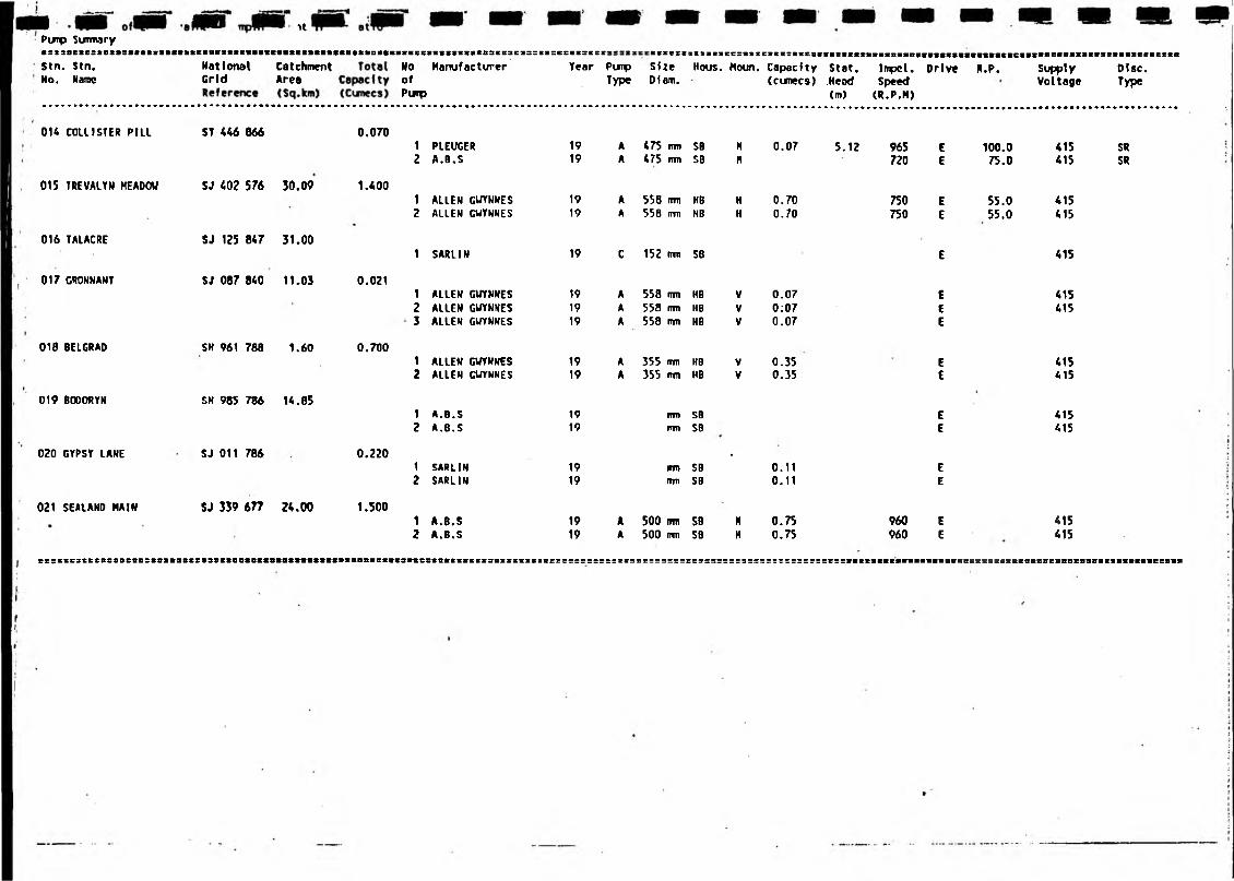
H itPimp Surma ry■:t3sete:tstiStn. Stn.Mo. Name
National Catchment Grid Area
NoofPimp
Manufacturer Year PurpType
SizeDiam.
Nous. Houn. Capacity(cumecs)
Stat..Head(m)
Inpcl. Drive Speed (R.P.M)
H.P. SupplyVoltage
Disc.Type
1 PLEUGER 19 A 475 mm SB H 0.07 5.12 965 6 100.0 415 SR2 A.B.S 19 A 475 mm SB H 720 E 75.0 415 SR
1 ALLEN GUYNNES 19 A 558 mm HB H 0.70 750 E 55.0 4152 ALLEN GUYNNES 19 A 558 rrm HB H 0.70 750 E 55.0 415
1 SARLIN 19 C 152 nin SB E 415
1 ALLEN GUYNNES 19 A 558 mm HB V 0.07 E 4152 ALLEN GUYNNES 19 A 553 rrvn NB V 0;07 E 4153 ALLEN GUYNNES 19 A 558 mm HB V 0.07 E
1 ALLEN GUYNNES 19 A 355 nvn HB V 0.35 4152 ALLEN GUYNNES 19 A 355 rm HB V 0.35 E 415
1 A.B.S 19 nm SB E 4152 A.B.S 19 mm SB E 415
1 SARLIN 19 m SB•
0.11 E2 SARLIN 19 mm SB 0.11 E
1 A.B.S 19 A 500 nm SB H 0.75 960 E 4152 A.B.S 19 A 500 rrm SB H 0.75 960 E 1 415
014 COLUSTER PILL ST 446 666
015 TREVALYN MEADOU SJ 402 576 30.09
016 TALACRE
017 GRONNANT
018 BELGRAD
019 BODORYM
020 GYPSY LANE
021 SEALAND MAIN
SJ 125 847 31.00
SJ 087 840 11.03
SH 961 786 1.60
SH 985 786 14.65
SJ 011 766
SJ 339 677 24.00
0.070
1.400
0.021
0.700
0.220
1.500
c s ; s : c : t c s « S 9 8 e B e : i s s & 8 8 C C i 3 S C t B a t B t S 8 i o t t t B t t t s i t f t f t & i 8 t « « 3 8 8 e 8 t f k t s s e e s s e s s s s s » t ? : SieSfllSIIVIBItBtBVSBBtSSBBtBBSBeseSBSCStt&fiftSBlVltBCSBBa

WESSEX
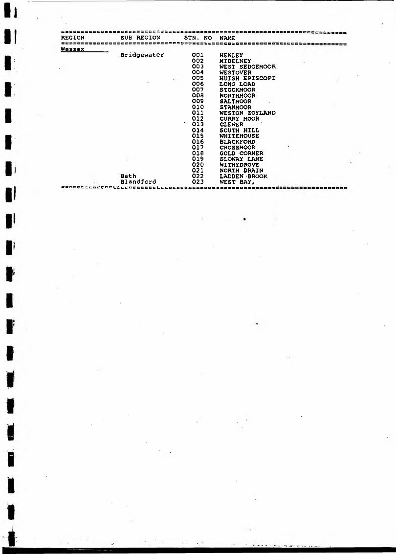
REGION SUB REGION STN. NO NAME
Wessex=Esez;sczess sscssssscszsccss:
Bridgewater 001 HENLEY002 MIDELNEY003 WEST SEDGEMOOR004 WE STOVER005 HUISH EPISCOPI006 LONG LOAD007 STOCKMOOR008 NORTHMOOR009 SALTMOOR010 STANMOOROil WESTON ZOYLAND012 CURRY MOOR
' 013 CLEWER014 SOUTH HILL015 KHITEHOUSE016 BLACKFORD017 CROSSMOOR018 GOLD CORNER019 SLOWAY LANE020 WITHYDROVE021 NORTH DRAIN
Bath 022 LADDEN -BROOKBlandford 023 WEST BAY,
CSSCCSSCBCCBSC&SCBCESSSSSeEE 8C&Ctt8S8SCCB esscsnnsB«B68cei
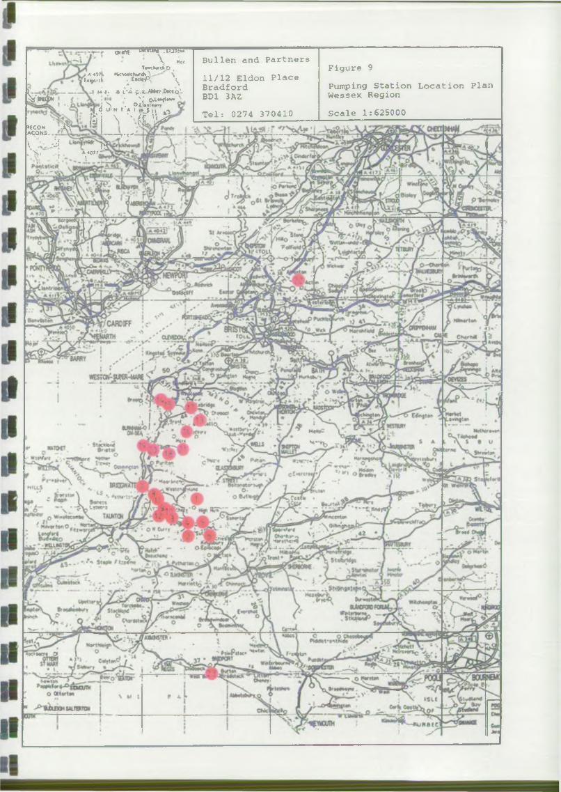
oum W W W .lUSc.'•V KocT«MkurctiO .I A 4971 Mic'whordi \ \
Totjeftk E*elc|P,' ^t * F- f l i ' i $ . . L - J J * r r D o c t o l
’ 'j o.L« o»«>«, N . Oj_!antt'<X"ro u> n r a i - -
V*®!*
r uv ' - ' { ? % $T t *
Bullen and PartnersFigure 9
11/12 Eldon PlaceBradford Pumping Station Location PlanBD1 3AZ Wessex RegionTel: 0274 370410 Scale 1:625000
*ECON JOVa c o n s .
\ j ^ 'N: • A«077j1 1
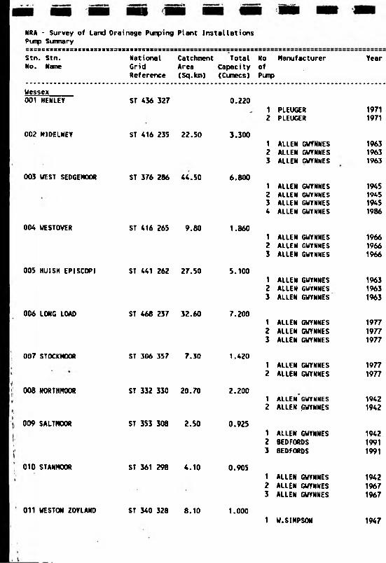
NRA - Survey of Land Drainage Pimping Pimp Sirmary
Plant Installations
Stn. Stn. No. Name
National Catchment Total No Manufacturer Grid Area Capacity ofReference (Sq.km) (Cunecs) Pimp
Wessex001 HENLEY
002 HIDELNEY
ST 436 327
ST 416 235 22.50
0.220
3.300
1 PLEUGER2 PLEUGER
1 ALLEN GWYNNES2 ALLEN GUYNNES3 ALLEN GWYNNES
003 UEST SEDGEMOOR ST 376 286 44.50 6.8001 ALLEN GWYNNESZ ALLEN GWYNNES3 ALLEN GWYNNES4 ALLEN GWYNNES
004 WESTOVER
005 KUISH EPI SCOPI
006 LONG LOAD
007 STOCKMOOR
008 NORTHMOOR
009 SALTMOOR
ST 416 265 9.80
ST 441 262 27.50
ST 468 237 32.60
ST 306 357 7.30
ST 332 330 20.70
ST 353 308 2.50
1.860
5.100
7.200
1.420
2.200
0.925
1 ALLEN GWYNNES2 ALLEN GWYNNES3 ALLEN GWYNNES
1 ALLEN GWYNNES2 ALLEN GWYNNES3 ALLEN GWYNNES
1 ALLEN GWYNNES2 ALLEN GWYNNES3 ALLEN GWYNNES
1 ALLEN GWYNNES2 ALLEN GUYNNES
1 ALLEN GWYNNES2 ALLEN GWYNNES
1 ALLEN GUYNNES2 BEDFORDS3 BEDFORDS
010 STANMOOft ST 361 298 4.10
011 WESTON 20YLAKD ST 340 328 8.10
0.905
1.000
1 ALLEN GUYNNES2 ALLEN GWYNNES3 ALLEN GUYNNES
1 U.SIMPSON
Year
19711971
196319631963
1945194519451986
196619661966
196319631963
197719771977
19771977
19421942
194219911991
194219671967
1947
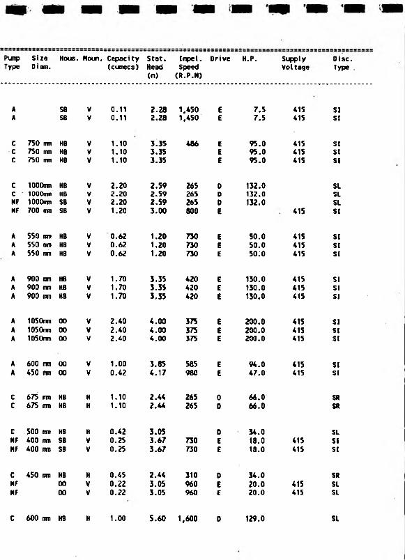
II i
SizeDiain.
Hous. Moun. Capacity(cunecs)
Stat.Head(m)
Impel.Speed(R.P.M)
Drive H.P. Supply VoItage
A SB V 0.11 2.28 1,450 E 7.5 415A SB V 0.11 2.28 1,450 E 7.5 415
C 750 mm HB V 1.10 3.35 486 E 95.0 415C 750 mm HB V 1.10 3.35 E 95.0 415C 750 ITTTI HB V 1.10 3.35 E 95.0 415
C lOOOrm HB V 2.20 2.59 265 D 132.0C 1000unt HB V 2.20 2.59 265 D 132.0MF 1000nm SB V 2.20 2.59 265 D 132.0HF 700 mm SB V 1.20 3.00 800 E 415
A 550 tun HB V 0.62 1.20 730 E 50.0 415A 550 irni HB V 0.62 1.20 730 E 50.0 415A 550 mn HB V 0.62 1.20 730 E 50:0 415
A 900 nm HB V 1.70 3.35 420 E 130.0 415A 900 mm HB V 1.70 3.35 420 E 130.0 415A 900 mm HB V 1.70 3.35 420 E 130.0 415
A 1050mn 00 V 2.40 4.00 375 E 200.0 415A lOSOmu 00 V 2.40 4.00 375 E 200.0 415A 105Qnm 00 V 2.40 4.00 375 E 200.0 415
A 600 ran 00 V 1.00 3.85 585 E 94.0 415A 450 inn 00 V 0.42 4.17 980 E 47.0 415
C 675 mn HB H 1.10 2.44 265 0 66.0C 675 inn HB H 1.10 2.44 265 D 66.0
C 500 rm HB H 0.42 3.05 D 34.0MF 400 mm SB V 0.25 3.67 730 E 18.0 415MF 400 mm SB V 0.25 3.67 730 E 18.0 415
C 450 fim HB H 0.45 2.44 310 D 34.0MF 00 V 0.22 3.05 960 E 20.0 415MF 00 V 0.22 3.05 960 E 20.0 415
C 600 mm HB H 1.00 5.60 1,600 D 129.0
Disc.Type
SIS!
SISISI
SLSLSLSI
SISISI
SISISI
SISISI
SISI
SRSR
SLSISI
SRSLSL
SL

NRA - Survey of Land Drainage Pimping Plant InstallationsPuip Suimary
Stn. Stn. No. Name
National Catchment Total No Manufacturer Gr1d Area Capec1ty ofReference (Sq.km) (Cunecs) Pimp
012 CURRY MOOR
013 CLEVER
O H SOUTH HILL
015 UNITEHOUSE
016 BLACKFORD
017 CROSSMOOR
018 GOLD CORNER
019 SLOUAY LANE
020 W1THYDROVE
021 NORTH DRAIN
022 LADDEN BROOK
023 WEST BAY,
ST 345 288 15.50 3.470
ST *38 515 34.50 6.000
i
ST 3*6 56* 0.720
ST 362 552 0.720
ST *01 *85 1.90 0.260
ST *15 5*4 1.*0 0.720
ST. 368 *31 10*. 10 17.500
ST 302 *51 16.20 0.132
ST 326 *41 16.20 0.132
ST 398 448 35.10 5.520
ST 667 8*0 41.00 2.000
ST *63 905 1.70 1.500
1 SULZER2 SULZER3 LANDUSTRIE
1 ALLEN GUYNNES2 ALLEN GUYNMES3 ALLEN GUYNNES
1 PLEUGER2 PLEUGER
1 PLEUGER2 PLEUGER
1 LANDUSTRIE
1 LANDUSTRIE
1 SULZER2 SULZER3 SULZER * SULZER
1 FLYGT2 FLYGT
1 HYGT2 FLYGT
1 ALLEN GUYNNES2 ALLEN GWYNNES3 ALLEN GWYNNES
1 SPAAN2 SPAAN
1 FLYGT
Year
195519551983
196919691969
19631963
19631963
1973
1980
19*219*219*219*2
19911991
19901990
196019601960
19801980
198*
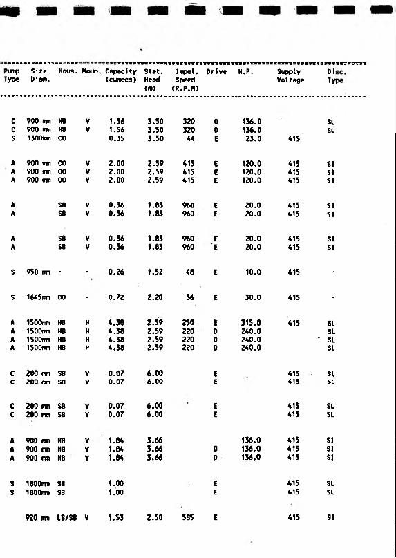
SSSI
>unp
VP*
8IBC8S?;
SizeDiem.
ss=sscNous. Noun. Capacity
(cunecs)Stat.Head<m>
Inpel.Speed(R.P.M)
Orlve H.P. SupplyVoltage
DiTyi
c 900 rmj HB V 1.56 3.50 320 0 136.0 SLc 900 ran H8 V 1.56 3.50 320 0 136.0 SLs '1300tnn 0 0 0.35 3.50 44 E 23.0 415
A 900 ran 00 V 2.00 2.59 415 E 120.0 415 SIA 900 ran 00 V 2.00 2.59 415 E 120.0 415 SIA 900 ran 0 0 V 2.00 2.59 415 E 120.0 415 SI
A SB V 0.36 1.83 960 E 20.0 415 SIA SB V 0.36 1.83 960 E 20.0 415 SI
A SB V 0.36 1.83 960 E 20.0 415 SIA SB V 0.36 1.83 960 E 20.0 415 SI
S 950 rm - - 0.26 1.52 48 E 10.0 415 -
S 1645ran 0 0 - 0.72 2.20 36 E 30.0 415 -
A ISOOran HB H 4.38 2.59 250 E 315.0 415 SLA 1500imt HB H 4.38 2.59 220 D 240.0 SLA 1500nm HB H 4.38 2.59 220 0 240.0 ' SLA ISOOnm HB H 4.38 2.59 220 0 240.0 SL
C 200 ran SB V 0.07 6.00 E SLC 200 ran SB V 0.07 6.00 E 415 SL
c 200 nm SB V 0.07 6.00 E 415 SLc 200 nvn SB V 0.07 6.00 E 415 SL
A 900 RRt HB V 1.84 3.66 136.0 415 SIA 900 mn HB V 1.84 3.66 0 136.0 415 SIA 900 inn HB V 1.84 3.66 0 136.0 415 SI
S 1800nm SB 1.00 E 415 SLs 1800nm SB 1.00 E 415 SL
920 urn LB/S8 V 1.53 2.50 585 E 415 SI

YORKSHIRE
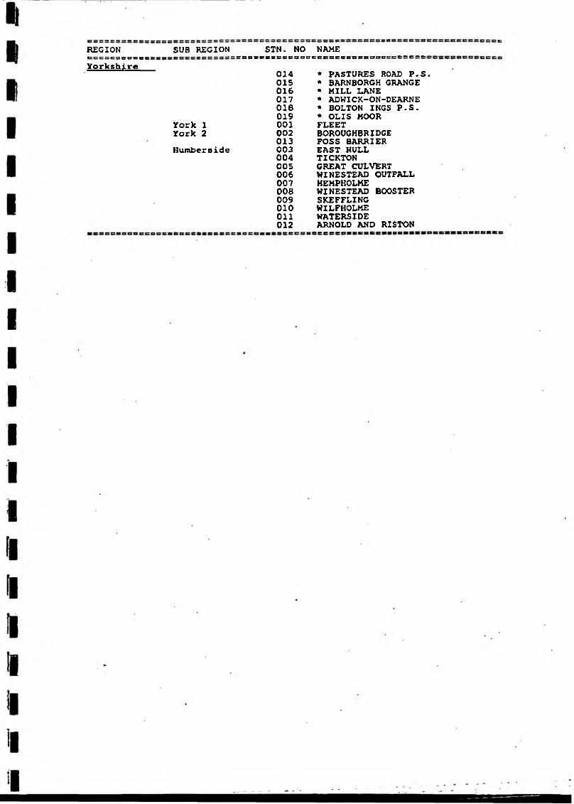
REGION SUB REGION STN. NO NAME&CC=BS5S&eS SBSSCS5SSSCSBS EncEceecssBBBssescseYorkshire
014 * PASTURES ROAD P.S015 * BARNBORGH GRANGE016 * MILL LANE017 * ADWICK-ON-DEARNE018 * BOLTON INGS P.S.019 * OLIS MOOR
York 1 001 FLEETYork 2 002 BOROUGH BRIDGE
013 FOSS BARRIERHumberside 003 EAST HULL
004 TICKTON005 GREAT CULVERT006 WINESTEAD OUTFALL007 HEMPHOLME00B WINESTEAD BOOSTER009 SKEFFLING010 WILFHOLME011 WATERSIDE012 ARNOLD AND RISTON
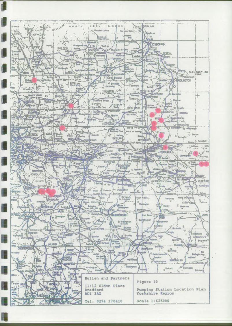
1 .r *v - ■» - -- *—«rrp " . "» “ • '< * V t A / ’., oJ jjtferk i ^ * O * T H V 0 i f K -
^4p" i . #' ; V___ i iflt , t « ' i *\ ’n ______ _
— n : ^ r r i—OCMfe II ^ i } ' ' I n *'&* / 1 .
t»wUi»4ute
|i OHw Kanv/. iy>
\3CARB0f OUGH
VArUn;
l> &QJBr—»t«»f
-I *T
*T T fc iS *p - «S... A P._11 attyjpP' oy ' aiovircyy p*r •. V \ • F ' s » . ? „ . _ -; y j .*
k s t---tW6ip-- — ••r-Tr-^SS^i4=r3 F ^ i& e i«£ > ; r ^ T ^ Sr^"
fes^S»44>A!3SJ A r 1,t o ^ T W w r
A“ I i% tT .! fe. Ji * &f55c«fr / A A J 'i C - a lot-**ffl u S '/^^ r* .4j ■ X> f ___
oWrT rl ZZ^<v5fcV~ \ *** * sFasftfflill -\i/ T V~r7 <*•*«-■_ V . ■ T$9**ni-H** lH«rth H<»WI«o
P«cMwft«w '7
FUVMBOROUGH H£AC------
_ . Sfr tbT '
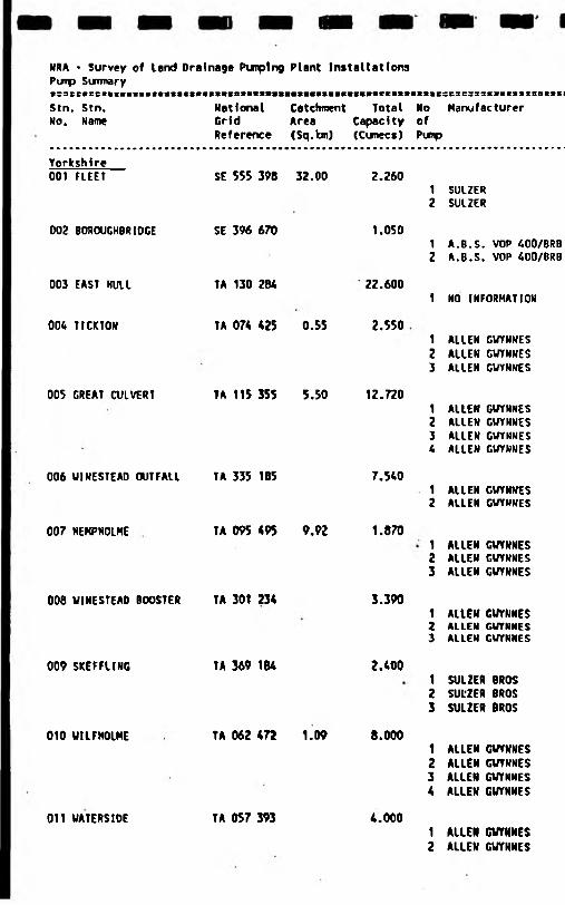
NRA * Survey of land Drainage Pumping Plant InstallationsPump Summary■saeeBseiStn. Stn. No. Name
National Catchment Total Grid Area CapacityReference (Sq.km) (Cunecs)
■■*«8XS3C33SSlIX*S£3BSe=:
No Manufacturer ofPunp
Yorkshire 001 FLEET
003 BOROUGHBRIDGE
003 EAST HULL
006 TICKTOM
005 GREAT CULVERT
007 HEKPHOLHE
SE 555 398 32.00
SE 396 670
TA 130 284
006 UINESTEAD OUTFALL TA 335 185
2.260
1.050
22.600
TA 074 425 0.55 2.550
TA 115 355 5.50 12.720
7.540
TA 095 495 9.92 1.870
1 SULZER2 SULZER
1 A.B.S. VOP 400/8RB2 A.B.S. VOP 400/BRB
1 NO INFORMATION
1 ALLEN GVYNNES2 ALLEN GUYNNES3 ALLEN GUYNNES
1 ALLEN GUYNNES2 ALLEN GUYNNES3 ALLEN GUYNNES4 ALLEN GUYNNES
1 ALLEN GUYNNES2 ALLEN GUYNNES
1 ALLEN GUYNNES2 ALLEN GUYNNES3 ALLEN GUYNNES
008 WINESTEAO BOOSTER TA 301 234 3.3901 ALIEN CUYNNES2 ALLEN GUYNNES3 ALLEN GUYNNES
009 SKEFFLING TA 369 184 2.4001 SULZER BROS2 SUL'ZEft BROS3 SULZER BROS
010 UILFHOLME TA 062 472 1.09 8.0001 ALLEN GUYNNES2 ALLEN GUYNNES3 ALLEN GUYNNES4 ALLEN GUYNNES
011 UATERSIDE TA 057 393 4.0001 ALLEN GUTNNES2 ALLEN GUYNNES

CSCC7Tear
S2SBSSPurpType
SC58SC3SSizeDiem.
ssesssHous.
sssessMoun. Capacity Stat.
(cunccs) Head (m)
Irrpel. Speed (R.P.M)
Drive k.p. SupplyVoltage
01Tyi
1975 Hf 450 rrm KB V 1.13 6.10 725 e 130.0 415 SL1975 MF 450 nm KB V 1.13 6.10 725 E 130.0 415 SL
1983 A 400 rim LB V 0.50 3.30 950 E 415 SL1988 A 400 frm LB V 0.50 3.30 950 E 415 SL
19 - ■ * • -
1972 A 525 trm HB V 0.85 5.00 735 E 55.0 415 SI1972 A 525 nm HB V 0.85 5.00 735 E 55.0 415 SI1972 A 525 ITTTI HB V 0.85 5.00 73 5 E 55.0 415 SI
1969 A lOSOirm 00 V 3.18 9.00 328 E 250.0 415 SI1969 A 1050nm 00 V 3.18 9.00 328 E 250.0 415 SI1969 A 1050mm 00 V 3.18 9.00 328 E 250.0 415 SI1969 A I050n?» 00 V 3.18 9.00 328 E 250.0 415 SI
1977 A I067rtm H8 V 3.77 3.80 321 E 415 SL1977 A 1067nm HB V 3.77 3.80 • 321 E 415 SL
1974 A 525 nm KB V 0.60 12.50 735 41.0 415 SI1974 A 525 m HB V 0.60 12.50 735 - 41.0 415 SI1974 A 525 tm» KB V 0.67 6.25 735 “ 29.0 415 SI
1978 A 675 nrn HB V 1.13 4.10 585 E 415 SL1978 A 675 mm HB V 1.13 4.10 505 E 415 SL1978 A 675 mm HB V 1.13** 4.10 585 E 415 SL
1982 A 675 rim LB V 0.80 4.50 580 E 415 SR1982 A 675 mm LB V 0.80 4.50 580 E 415 ■ SR1982 A 675 rm LB V 0.80 4.50 580 E 415 SR
1981 MF 900 am HB V 2.00 6.35 420 E SI1981 MF 900 (no HB V 2.00 6.35 420 E 415 SI1981 MF 900 mm HB V 2.00 6.35 420 E 415 SI.1981 MF 900 mm HB V 2.00 6.35 420 E 415 SI
1982 MF 900 mn HB V 2.00 7.00 420 E 415 SI1982 HF 900 rrm HB ■ V 2.00 7.00 420 E 415 SI
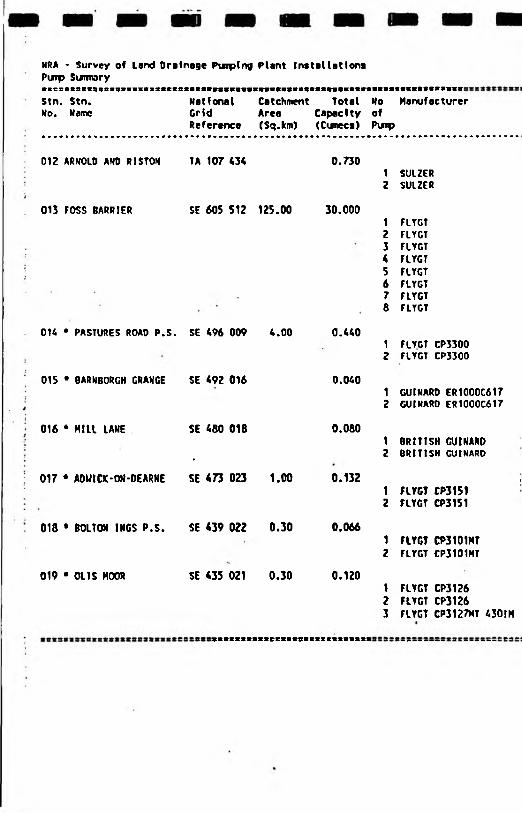
NRA ~ Survey of Land Drainage Puiptng Plant InstallationsPunp Sumnary
Stn.No.
. Stn. Marne
NationalGridReference
CatchmentAres(Sq.km)
TotalCapacity(Cunecs)
NoofPuip
Manufacturer
012 ARNOLD AND RISTON TA 107 434 0.7301 SULZER2 SULZER
013 FOSS BARRIER SE 605 512 125.00 30.0001 FLYGT2 FLYGT3 FLYGT4 rLTGT5 FLYGT6 FLYGT7 FLYGT8 FLYGT
O K • PASTURES ROAD P.S . SE 496 009 4.00 0.4401 FLYGT CP3300Z FLYGT CP3300
015 * BARNBORGH GRANGE SE 492 016 0.0401 GUINARD ER1000C6172 GUI HARO ER1000C617
016 * Hill LANE SE 480 018 0.0801 BRITISH CUINARD
. 2 BRITISH CUINARD
017 * AOUtCK-OH-DEARNE SE 473 023 1.00 0.132 11 FLYGT CP31512 FLYGT CP3151
018 • BOLTON IMGS P.S. SE 439 022 0.30 0.0661 FlYGT CP3101MT2 FLYGT CP3101MT
019 * OLIS MOOR SE 435 021 0.30 0.1201 FLYGT CP31262 FLYGT CP31263 FlYGT CP3127MT 430IM
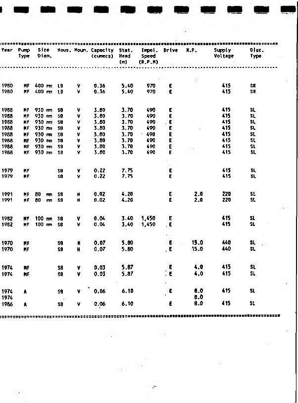
(sriatesoia:Year Puip
Type
fasivssi
SizeDiam.
I53S85
Hous.esrsts!Houn.
! E c i s i t i K i i i t t > i i t i i » i u r a i i i N i n « i i i i i » H t i n i t i n » i m e i E 9 t
Capacity Stat. Impel. Drive H.P, Supply Disc, (cumecs) Head Speed Voltage Type
(m) (R.P.H)
1980 HF 400 irtn 16 V 0.36 5.40 970 E 415 SR1980 HF 400 rrm IB V 0.36 5.40 970 E 415 SR
1988 HF 930 nm SB V 3.80 3.70 490 E 415 SL1988 HF 930 rtm SB V 3.80 3.70 490 E 415 SL1988 MF 930 rm> SB V 3.80 3.70 490 . E 415 SL1988 MF 930 m SB V 3.80 3.70 490 E 415 SL1988 MF 930 ran SB V 3.80 3.70 490 E 415 SL1988 MF 930 n m SB V 3.80 3.70 490 E 415 SL1988 MF 930 i m SB V 3.80 3.70 490 E 415 SL1988 MF 930 rm SB V 3.80 3.70 490 E 415 SL
1979 MF SB V 0.22 7.75 E 415 SL1979 MF SB V 0.22 7.75 E 415 SL
1991 HF 80 irm S8 H 0.02 4.20 E 2.0 220 SL1991 HF 80 IT1TI SB H 0.02 4.20 E 2.0 220 SL
1982 MF 100 rrm SB V 0.04 3.40 1,450 E 415 SL1982 HF 100 rrm SB V 0.04 3.40 1,450 , E 415 SL
1970 MF SB H 0.07 5.80 E 15.0 440 SL1970 HF Sfl H 0.07 5.80 , E 15.0 440 SL
1974 HF SB V 0.03 5.87 E 4.0 415 SL1974 MF S8 V 0.03 5.87 ; e 4.0 415 SI
1974 A SB V 0.06 6.10 E 8.0 415 SL1974 ' 8.01986 A SB V 0.06 6.10 E 8.0 415 SL
:sssss8ssssss:sssss=====:sses2s==sssssssxss33si intsnnnsitMmtimaifiictiittKEtKEt
Bullen and Partner•National River* Authority
Pumping Station Research
Appendix B2
Pump Analysis
Listed by Capacity
Contents
Stations by Capacity All Regions
Stations by Capacity Anglian Region
Stations by Capacity Southern Region
Stations by Capacity Severn Trent and Northwest Regions
Stations by Capacity Yorkshire and Northumbrian Regions
Stations by Capacity South West and Thames Regions
Stations by Capacity Welsh and Wessex Regions
MUfi VHt9174HOOVB
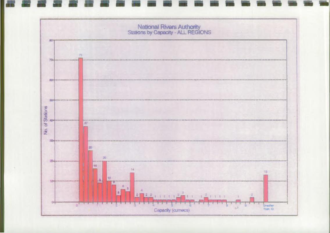
National Rivers AuthorityStations by Capacrty-ALL REGIONS
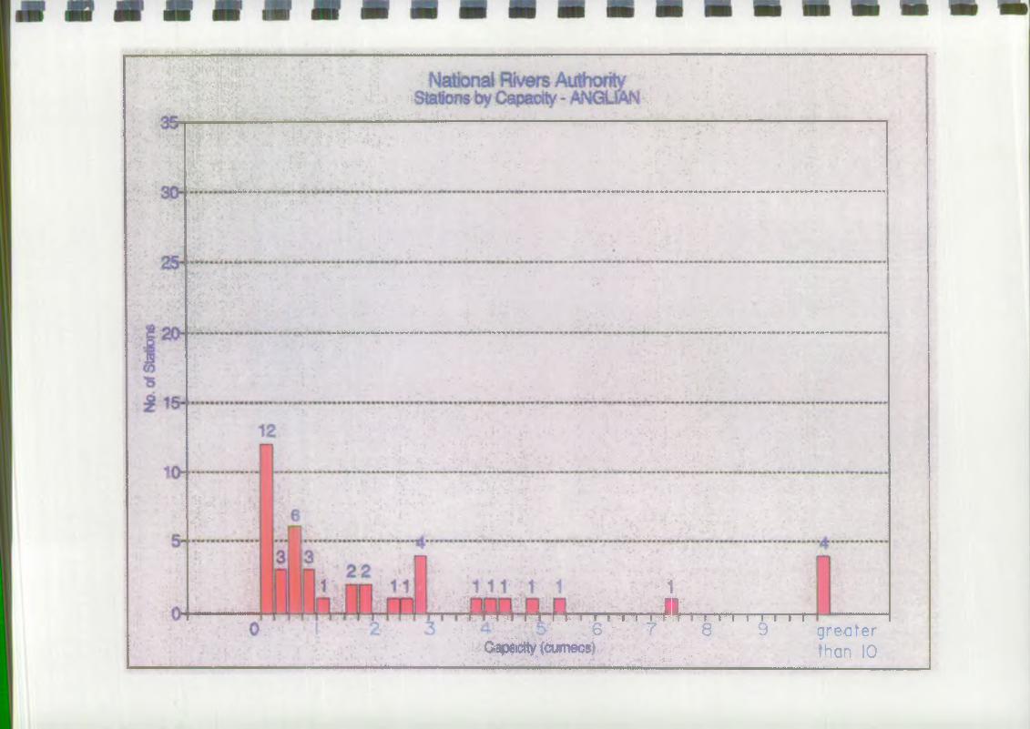
M M M M H M M
— — ■MU
1
f T n f If" f V i I t "I "i i / V r ' i "f..i r i i i r. 6 / ■, ■? 8 9 greater
■'Qai*iiie^^um*iBB$4'='.'" '1/f. ; than 10 .... ................. ......I..!■■■■■■.......
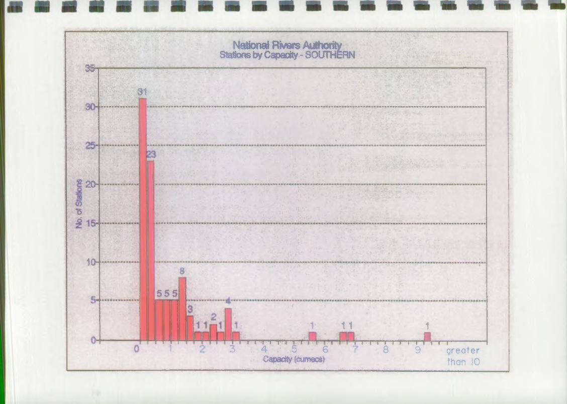
I f ........................ Ill
35-
Nalional Rivers AuthorityStations by Capacity - SOUTHERN
l . , ■ I, n li . m'> II |I. . 11. : ■
31
20""
15
■ • • , :■ .
10--
5 5 5
8
f T T r T T 1 " t mii" ■ j " r *3 4 . 5 €
Capacity (cum ecs)
11 1 ^ r .r .r ..r t .,r T ,..p ^ f... f------------------
8 9 g r e a t e r than 10
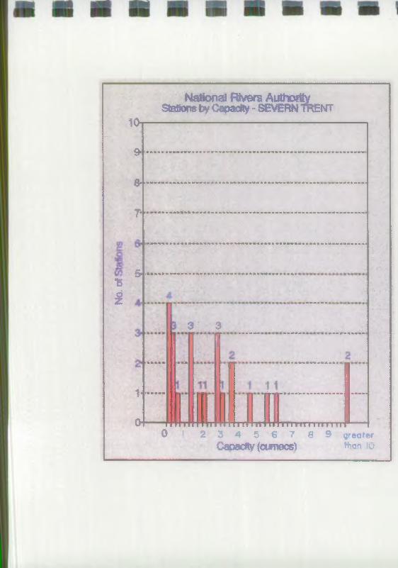
National Bvers AuthorityS ta tic by Capacity - SEVERN rnENT
10i
9 - .....................................- ..................................................
& ' ------
? •
15
£
& ..........
1-"
CH
$% 3
I•«*
- - - - - -
• • • « *m» » • « « « « * • * m * u m +m *'*'
** • *«•*»«» *»«»««»* »» «
m i i ‘ I ‘ i * i ff t f f t r - r f t r r n r r> i i n n i i i r n i f
O J 2 3 4 5 6 7 8 9 greater
Capacity (cumecs) ttan io.
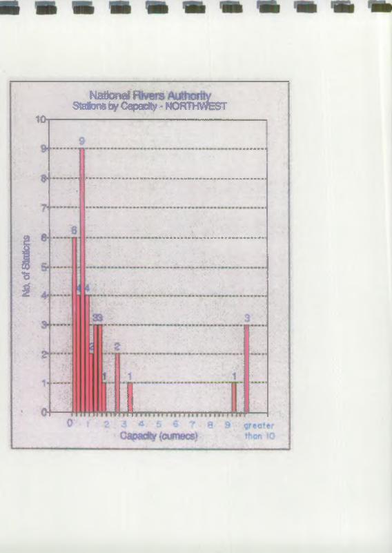
Na
of S
tati
on
s
IliM iSfWS t a l^ ^ C a p ^ - N O R # i f e T
10
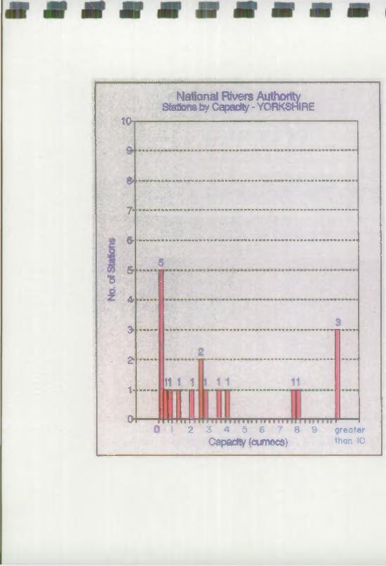
........
National Rivers AuthorityStations by Capacity - YORKSHIRE
to
•B
7
6-1
S’ ****
4. ---------------
3-
Z ----
I--
o
111 1
2 3 4 5 6 7 8 9 greater
Capacity (cumecs) th°n 10
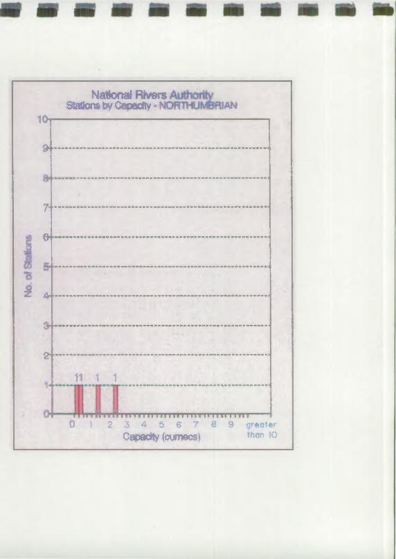
National RiversStations by Caoecfty IAN
10i
9—
7"
fr «
3? 44*
3*'
2- •
11 1 1
r rffTi A r m r i i i n i i n i i m i i i i i i i i i i i0 1 2 3 4 5 6 7 8 9 greater
Capacity (cumecs* than io

National Rivers Authoritytons * Caadty - SOUTHWEST
9t-'............H :• •
» H r I * »»•* 1
*P
a - . . .
i
2 - —
1-1 1
f f i i i i r i i V i i t i i 1 1 1 1 f i i 1111 i iIu m vii i i iviTTTTTTTir0 I 2 3 4 5 6 7 8 9 greater
Capacity (cumecs) than to
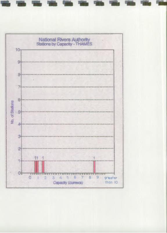
10
*i
National Rivers AuthorityStatons by Capacity - "WAMES
* ....................... —............. -........................
f r ............................................................. - ......................
7*------ ---- -....................................................
0 ............................. .....................................
S *............................... -............................
........................................................
I'lm i m n i ' i n i iuni nn n i nr i m n m —0 I 2 3 4 5 6 7 8 9 grt at«r
Capacity (cumecs) than io
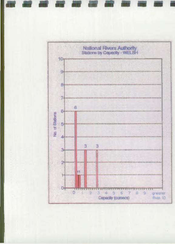
N a tio n a l FSvers Statons Capacity
. ----
0
mmmwt»»».»t»>><Hji<■>«»<»>»*»»»*<fwi»»V »>»m* »•*»•»*»»
1---------11
I
I T\» 1 1 v ? 11 r v H T n m T f r T T n i » n ? i i^i i 1110 i 2 3 4 5 6 7 8 9 greater
Capacity (cumecs) than io
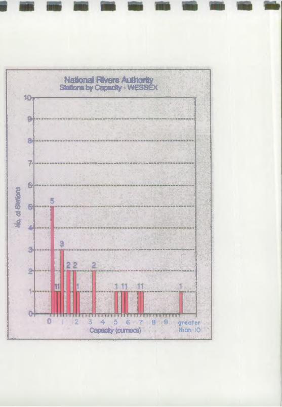
Uhr
National Rivers AuthorityStations byCapacity - WESSEX
i*4
..... —
•••
7*
0< >““**•
■: V
......•■ y :■ . * :•
*.... .... ...... ..........
- :
v: .>• .• •;• ;v.yv•>::?.v .• •:. ; .
-------- ----- *---■ V; : 3 - 5 "
... f l IR fL . . . .
■ ■ ■ ■......
: ifii
•• >:• ' '■ :%'•
2 3 4 5 6 7 8 9 greater Capacity(cumec8) than 10 ;
--- Vi ,,„■■■ I ,
National River* AuthorityBullen and Partner* Pumping Station Research
Appendix B3
Pump Analysis
Listed by Pump Type
Contents
Pumps by Type
Pumps by Type
Pumps by Type
Pumps by Type
Pumps by Type
Pumps by Type
All Regions
Anglian and Southern Regions
Severn Trent and Northwest Regions
Yorkshire and Northumbrian Regions
South West and Thames Regions
Welsh and Wessex Regions
VH/9/ 741/00 I/B
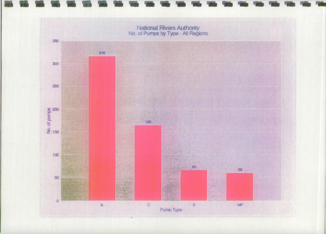
Nattonai Rivers Authority No. of Pumps by Type - All Regions
Pump Type♦
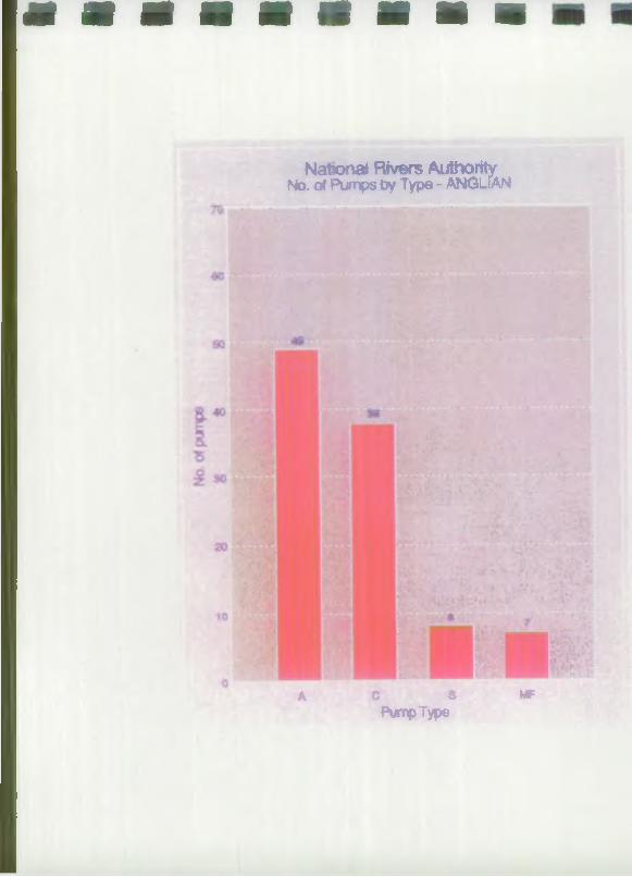
National Rivers Authority No. of Pumps Oy Type - ANGLIAN
A c s mfPump Type
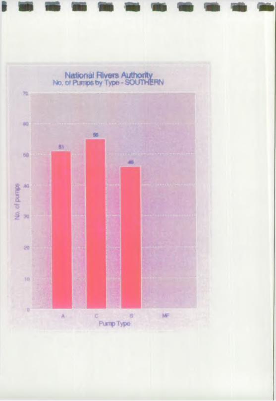

National Rivers AuthorityNo. of Pumps by Type - SEVEfW TRENT
a c s mfPump Type


National Rivers AuthorityNo. of Pumps by Type - YORKSHIRE

Nations* Rtvsrs AuthontyN* ot Pumps by Ty*» * IW M B R IA N
A C 9 MFPum p Type


National FBvws Authorityt o oTPtHiip& by Type-THAM ES
a e s MPPump Type

National Rvers AuthorityNo. of Pumpe Oy Type - WELSH
Pump Type
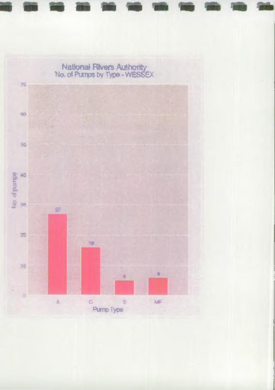
No
ol pu
mps
National Rivers Authority No, of Pumps by Type - WESS6X
A C S MFPum p Type
Bullen and Partner*National Rivera AuthorityPumping Station Research
Appendix B4
Pump Analysis
Listed by Manufacturer
Contents
Pumps by Manufacturer All Regions
Pumps by Manufacturer Anglian and Southern Region
Pumps by Manufacturer Severn Trent and North West Regions
Pumps by Manufacturer Yorkshire and Northumbrian Regions
Pumps by Manufacturer South West and Thames Regions
Pumps by Manufacturer Welsh and Wessex Regions
VH/91742JOOUB

National Rivers Authority No. of Pumps toy Manufacturer
MgS A C M 1
M lfiN fc W Y N N E SARMFjaD ■“ « BEWDRO - 4
BWTBHQtfWRD — •B R ITIS H P U EU Q 6 B “ - - »
>81
BROOKBCROMWN •'$ .DQPNm "2 RWWOWVWUN -•
PENNS* 1 RVOff-------- ---
QrjUfci.""4 GOQDENOUGM 1
HAHLAWD JOHNSON — ft H4W7VCWCCAVEY 1 ♦**©»■«
XW68*ATIVOO£>— 4 K8» - I
UWOU8TWE -3 LtSTEP 1
MATHER* PIATT — • MAXIROW - 4
MHL£SSWATSON ■ # MONO '1
MV9QN "2 .. NEVARE M
HUSTON OfWYNNES *2 RusroNWowsev r
SAMUN.VWITE '2
SJMOMHAWLey — *« S M T T H D O LE '1QOIAM
SUeMERSKiUOE *2 3ULZ0P8VK5S -2
TANOVEBtTD '1 ""SURUMt T - 7VJCK5*& — « »
W SMP90N '1-VWUJBN- *2 • — t
- WDmWNOTCN -430
■87
.20?
ao «3 tOO 13t*>,<rfPumo&
»»
140 teo 1$0 200
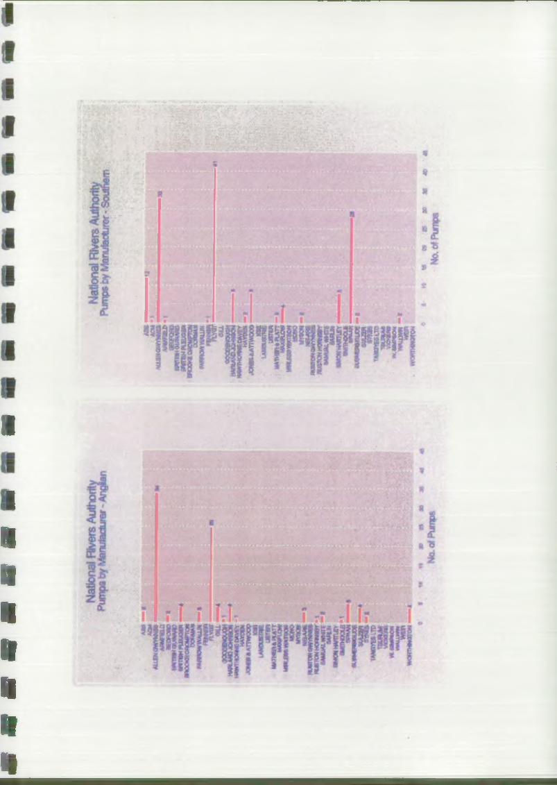
I
I
«
H
H
f t
1
«
«

National Rivers AuthorityPurnos by Manufacturer - Severn Trant
m
tiflrHBHQUNWCmrmHKtom *****<3R0C*EC*CMfret WWOWWU*
"S fOOOOWOUJH
H ¥ ll M < D J O H N K *l"■""""*88® XMe»»ATTWQep
♦JfH*4W>*Bg&£r«eu*»ii#Arv3N MONO
mtiwh
aufircw >*>*««*fnw T W *774MUAUM<S«WN
"5 '
■ s *TMCWtttUN 7SOMJMI.*ckb*VMOJMN
No, crfPurri*

National Rivers AuthorityPumps by Manuiaeturer - North West
amACM.
rtfilM* . HNnamrtUHMD —mxxiCKM***-jam*
mx W - ' OCCQfaMOOGM ’
HiXQBl JQWSiAAVKXOraa —’A*JOUBTtJE '
UJJTSI
MTOK M 1 . *&■*»(*«*<* rt*\*N6KWHITE «MLM
•«rtif>*CUfc JiPAAN t***4fcHbmJCfc
HMRYERlTD <K#*mwarn JN
WRW •«wtHwrw •
No.ofPumw

National fevers AuthorityPumps by Manufacturer - Yofkshire
« » - *ACMAO«NOW*«
a nanc,w«:;«IT»M * U EM O iP »
:a m C « ; O N . W y »OAMRQWVNWOM
T »MlQOQWnuy*MMJMOJOHN0OH
JON|»«AnWQCD: jUtf«X*S8■JSTWMATHjyj r
MnUBMWftTONMONO***Xttdsmmnw^WTONHOWeyttWUWLWWR
V*UN 9M0NNNRnjEY**>535
tW U W Kwopwe******

National Rivers AuthorityPumps tv Meaxitacoirer * htoithumbrtan
AM —tACMAULtHOWVKhCS
a **w u >96Dpo«.- BMTCMOUtHAW " Iamwwwtt*f
w*w*ifV«u*t#®8f—o<auUOQOCNOUOH
* M U f c O ,» W N i C *
jQ N » A A T r * C * > 0
;JWtXjBTWusrw
MONO ¥¥»C# HflMflR HUKTONGWWJBB
t USTONHQfM** &ut ,«Hnr5 S M UH
« M O N *M K n £ Y
* M * H H 3 U W
T*MKWi3P •
'VAUW*WEB«WHW<*rON
N o . erf P u m p s

a s s m m m m
Nattonal Rivers AuthorityPumps bv Manufacturer - Southwest
X: M;. ? >%?* 7 A » — »
A C MA U f N Q f W W N I S
nvrnp
10 16 » » 30 36 44
No.ofPumpe

National Rivers AuthorityPumps by Manufacturer - Thames
ALLWOWVNNK____ fiS3PORDanmEHoynMiD
iwmBHKattm WOOKKOflOMPTOII “ ■ *
DORMAN - 2 WflRCWWAOJt* i'fNMiRn ar— -OLLooaomouahVPUMOJXMOH
H w rm oR N CD AV frHAYDEM
JONOAATTW O O O
utfWunSIU S T W i*
*urtnm**A,rr — • w x n ON un&KraKraoK
MONOt m o n
NB4HE RUSTONOVirMNES A m O N M O m tfY
MMUALWHftS Q A R JK
Pr^Rn
'*NSYESLTD lauflUMi VVMEm -1 w.awpsoet*MUiWMJ2*?WOHTHHCffON

NationaJ Rivers AuttiorityPumps bv Manufactufw Wefeh
£5 ” " • •*u£nawn*m ■■■ »■■ a.........*ahmhbj>KOFOHD
aKTBMPuauow
M ^ n o w w « u M
W - fOKIooopeKW
HwrmoeNEfiwerH A W * *joww»<m*oco
URTER■""BHfflF*MHLanmrtoNMONO M
MW K S * * 6
H * T W O W N N »to«HORi«eY
fM MUUL«fr«reSM CM — a aMONHWTlEY
“ '388-,
4 S M N C M • :>.**u*w • •■:■ .
0 f 10 1» » X « * 40No, erf Pumps

National Rivers AuthorityPumosby Manufacturer - Wessex
ACW*Uia«*«m*«£s w n :a n r s H O i M w c WKRH»U3XM» ■ *
E W < X ^ < 3 »> fn C N
* * w w * # * u j n
MONOwwuujpe
BUS(QH<W/ffWHEa, tWCHWO<«Ntfv
tSAMU^fTHfTE:SAflUN
%MONMfmjEY **MOCU
** * *■ ■ ^UflUEflWauDt
r*WMESLTO fsonuM V H 3W B *>3
w.taMptiON « 1 WAU.WW .:.. WBR : :'
« iMjumtWOw ?15 ao as ao
No, of Pumps
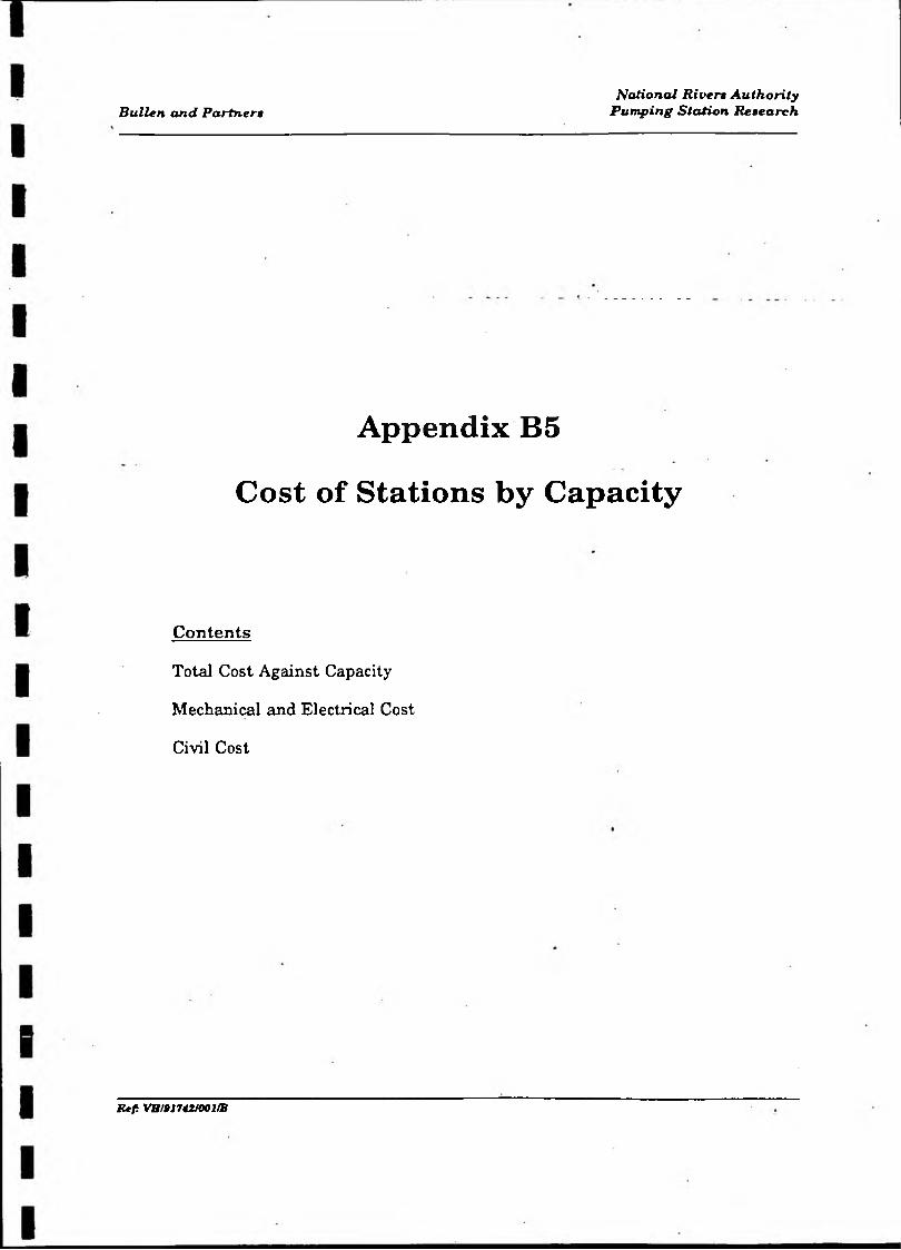
Bullen and PartnersNational R iven Authority
Pumping Station Research
Appendix B5
Cost of Stations by Capacity
Contents
Total Cost Against Capacity
Mechanical and Electrical Cost
Civil Cost
R t f VH/91742J001/B
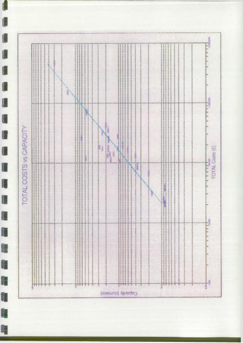
TOTA
L CO
STS
vs CA
PACI
TY
(soeujro) Ajpedeo
TOTA
L Co
sts
(£)
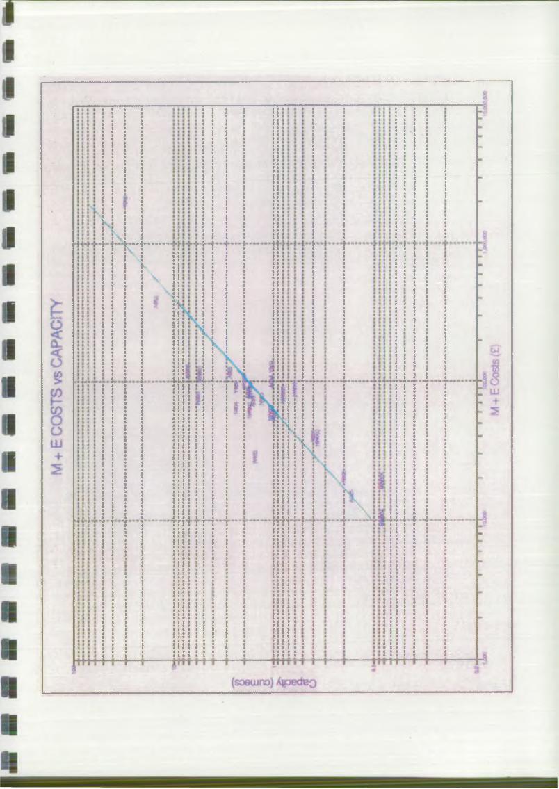
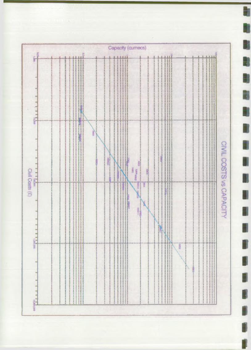

Bullen and Partnerw
Appendix C
Design Philosophy
Contents
Cl Design Considerations
C2 Checklist
National River* AuthorityPumping Station Reiearch
MUf VHI9I7d£JOO 1/B
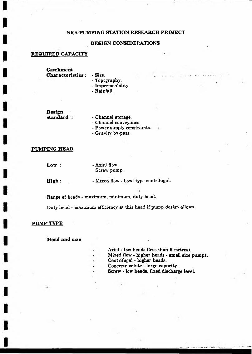
NRA PUMPING STATION RESEARCH PROJECT
DESIGN CONSIDERATIONS
REQUIRED CAPACITY
CatchmentCharacteristics : - Size.
- Topography.• Impermeability.- Rainfall.
Design standard : * Channel storage.
- Channel conveyance.- Power supply constraints.* Gravity by-pass.
PUMPING HEAD
Low :
High :
- Axial flow.Screw pump.
- Mixed flow - bowl type centrifugal.
Range of heads - maximum, minimum, duty head.
Duty head * maximum efficiency at this head if pump design allows.
PUMP TYPE
Head and size
Axial - low heads (less than 6 metres).Mixed flow - higher heads - small size pumps. Centrifugal • higher heads.Concrete volute - large capacity.Screw - low heads, fixed discharge level.
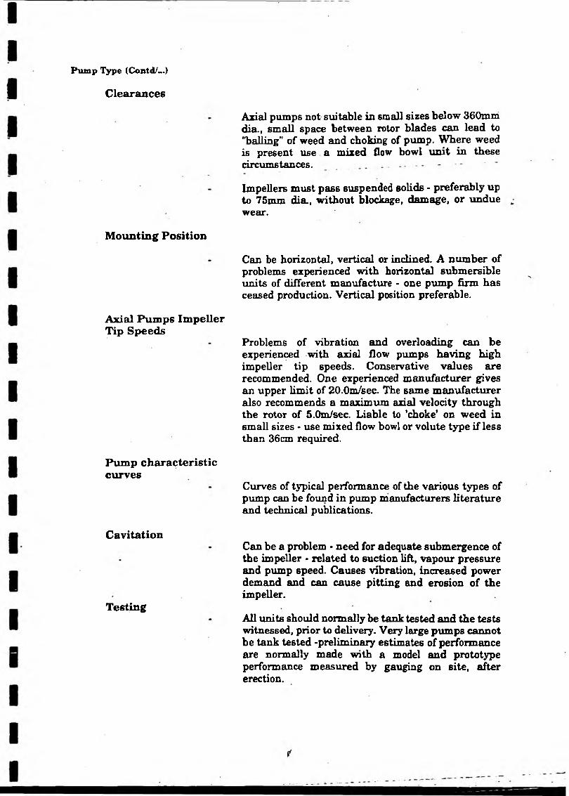
Clearances
Pump Type (Contd/~.)
Mounting Position
Axial Pumps Impeller Tip Speeds
Pump characteristic curves
Cavitation
Testing
Axial pumps not suitable in small sizes below 360mni dia., small space between rotor blades can lead to "hailing” of weed and choking of pump. Where weed is present use a mixed flow bowl unit in these circumstances.
Impellers must pass suspended solids - preferably up to 75mm dia., without blockage, damage, or undue wear.
Can be horizontal, vertical or inclined. A number of problems experienced with horizontal submersible units of different manufacture - one pump firm has ceased production. Vertical position preferable.
Problems of vibration and overloading can be experienced with axial flow pumps having high impeller tip speeds. Conservative values are recommended. One experienced manufacturer gives an upper limit of 20.0m/sec. The same manufacturer also recommends a maximum axial velocity through the rotor of 5.0m/sec. Liable to ’choke* on weed in small sizes • use mixed flow bowl or volute type if less than 36cm required.
Curves of typical performance of the various types of pump can be found in pump manufacturers literature and technical publications.
Can be a problem - need for adequate submergence of the impeller • related to suction lift, vapour pressure and pump speed. Causes vibration, increased power demand and can cause pitting and erosion of the impeller.
All units should normally be tank tested and the tests witnessed, prior to delivery. Very large pumps cannot be tank tested -preliminary estimates of performance are normally made with a model and prototype performance measured by gauging on site, after erection.
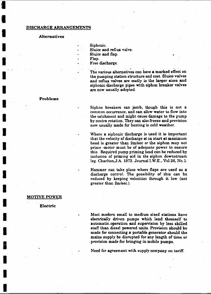
DISCHARGE ARRANGEMENTS
Alternatives
Siphonic.Sluice and reflux valve.Sluice and flap.Flap.Free discharge.
The various alternatives can have a marked effect on the pumping station structure and cost. Sluice valves and reflux valves are costly in the larger sizes and siphonic discharge pipes with siphon breaker valves are now usually adopted.
Problems
Siphon breakers can jamb, though this is not a common occurrence, and can allow water to flow into the catchment and might cause damage to the pump by contra rotation. They can also freeze and provision now usually made for heating in cold weather.
Where a siphonic discharge is used it is important that the velocity of discharge at on start at maximum head is greater than 2m/sec or the siphon may not prime -motor must be of adequate power to ensure this. Required pump priming head can be reduced by inclusion of priming aid in the siphon downstream leg. Charlton,J.A. 1972. Journal I.W.E., Vol.26, No.l.
Hammer can take place where flaps are used as a discharge control. The possibility of this can be reduced by keeping velocities through it low (not greater than 2m/sec.).
MOTIVE POWER
Electric
Most modern small to medium sized stations have electrically driven pumps which lend themself to automatic .operation and supervision by less skilled staff than diesel powered units. Provision should be made for connecting a portable generator should the mains supply be disrupted for any length of time or provision made for bringing in mobile pumps.
Need for agreement with supply company on tariff.

Motive Power (Contd/_.)
Power factor correction.
Limits on starting current can dictate type of starter or motor used.
Need for regular motor and starter maintenance.
Diesel
Used almost exclusively for the largest flood defence pumps, driving the pump through a right angle gearbox. The engine might be turbo blown and will require a skilled operator and maintenance personnel. Fuel storage tanks required and suitable road access for fuel tankers.
Following the Miners Strike and strike of power workers, many of the subsequent medium sized stations have been designed with half their pumps diesel powered and half electric powered to guarantee some pumping capacity under similar conditions.
WATER QUALITY
General
Flood defence pumps must be capable of dealing with river water that will normally contain quantities of weed, mud, sand and various floating debris.The pump manufacturer must be made aware of this. The pump should be capable of dealing with these conditions for long periods without undue wear or blockage. Chemical composition should be checked for possible adverse effects on pump materials.
Weed
As indicated above (Pump Type) clearances on small axial flow pumps are such that weed can cause problems and mixed flow, bowl pumps are preferable for small pumps where weed is present.
Bearings
The presence of sand, grit and coal dust can cause lower bearing problems and special precautions are required - proper sealing, pumped lubrication, cutlass rubber bearings etc. Where pumped grease lubrication is used for lower bearings these should be sealed and a return provided to prevent pollution of watercourse.

STATION STRUCTURE
Type
High house and crane.Low building - removable roof section.Low building.Outdoor type - weather proof motors.Submersible pump - sump & switchgear cubicle or
- house.Housing for screw pump.Floating station.
Ground Conditions
These can influence design.Check for flotation when sump dewatered.Pressure relief valves in floor?Earth loading on sump.Ground water - affect on concrete?
- Presence of gypsum - ditto Good foundation material?Need for bearing piles?Coffer dam - battered excavation.Need for dewatering?Steel sheet pile sump.Steel sheet pile with R.C. lining.
Sump design
Guidance - Prosser - "Design of pump sumps and intakes" CIRIA/BHRA and other publications - see refs. Even with guidance model tests advisable in all but smallest stations. Checks should be made during construction to ensure sump conforms to design drawing.
Access
Adequate access to station required for installation and removal of equipment for repair .Turning space for vehicles.
Geo textile reinforcement for access roads on poor soils.
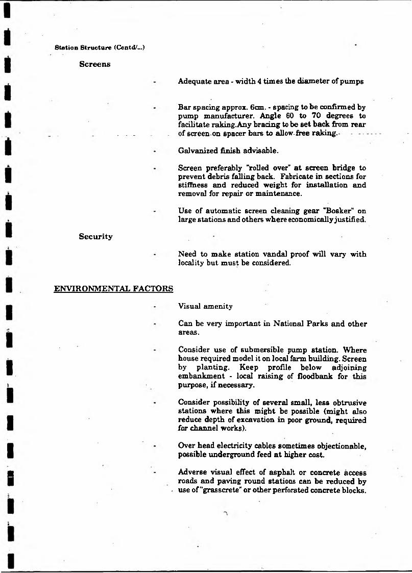
Station Structure (Contd/—)
Screens
Adequate area - width 4 times the diameter of pumps
Bar spacing approx. 6cm. - spacing to be confirmed by pump manufacturer. Angle 60 to 70 degrees to facilitate raking.Any bracing to be set back from rear
. . . _of screen-on spacer bars to allow-free raking.-
Galvanized finish advisable.
Screen preferably "rolled over" at screen bridge to prevent debris falling back. Fabricate in sections for Btiffness and reduced weight for installation and removal for repair or maintenance.
Use of automatic screen cleaning gear "Bosker" on large stations and others where economically justified.
Security
Need to make station vandal proof will vary with locality but must be considered.
ENVIRONMENTAL FACTORS
Visual amenity
Can be very important in National Parks and other areas.
Consider use of submersible pump station. Where house required model it on local farm building. Screen by planting. Keep profile below adjoining embankment * local raising of lloodbank for this purpose, if necessary.
Consider possibility of several small, less obtrusive stations where this might be possible (might also reduce depth of excavation in poor ground, required for channel works).
Over head electricity cables sometimes objectionable, possible underground feed at higher cost.
Adverse visual effect of asphalt or concrete access roads and paving round stations can be reduced by
. use of ’’grasscrete’* or other perforated concrete blocks.

Environmental Factors (Contd/...)
Noise
Can be problem with large diesel stations near residential property.
Good silencers and enclosure of exhausts can reduce noise to acceptable limits.
OPERATIONAL REQUIREMENTS
Vary with circumstances and siting.Reliability always paramount.Easy to operate.Automatic operation.Operational procedures.Long interval between need for mqjor overhaul.Easy to maintain.Automatic screen cleaning.Good access.Adequate lighting (inside and out).Adequate warning instruments.Proper hand over including all maintenance and operating manuals.Presence at commissioning.Telemetry link to remote operations room.Self diagnostic instrumentation.Adequate fire fighting equipment.Pump hours run meters.U/s and d/s level recorders.Need for post project appraisal - confirm design assumptions and obtain information for improvement of subsequent stations.
SAFETY
All equipment and the complete station must comply with the requirements of the Health and Safety at work Act 1974 and any subsequent legislation and with all Board of Trade and Home Office Regulations which may be applicable.
Close co-operation with local Safety Adviser is required from early stages of design right through to completion and commissioning.
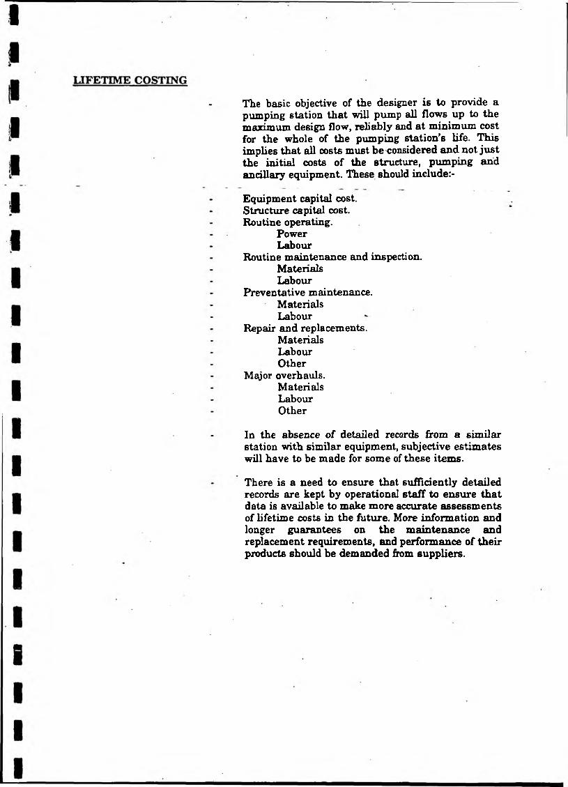
The basic objective of the designer is to provide a pumping station that will pump all flows up to the maximum design flow, reliably and at minimum cost for the whole of the pumping station’s life. This implies that all costs must be considered and not just the initial costs of the structure, pumping and ancillary equipment. These should include:-
Equipment capital cost.Structure capital cost.Routine operating.
PowerLabour
Routine maintenance and inspection.Materials Labour
Preventative maintenance.Materials Labour
Repair and replacements.Materials Labour Other
Mayor overhauls.MaterialsLabourOther
In the absence of detailed records from a similar station with similar equipment, subjective estimates will have to be made for some of these items.
There is a need to ensure that sufficiently detailed records are kept by operational staff to ensure that data is available to make more accurate assessments of lifetime costs in the future. More information and longer guarantees on the maintenance and replacement requirements, and performance of their products should be demanded from suppliers.
Bullen and Partners
Appendix D
Photographs
National Riverm AuthorityPumping Station Research
R*f. VH/9174MOOUB
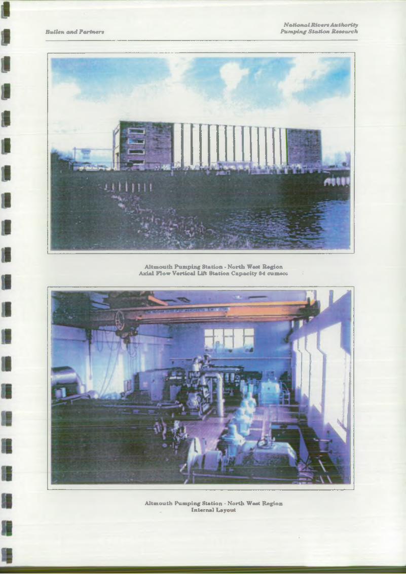
Bullen and PartnersNational Rivers Authority
Pumping Station Research
Altmouth Pumping Station • North Wast Region Axial Flow Vertical Lift Station Capacity M cumocc
Altmouth Pumping Station • North West Region Internal Layout
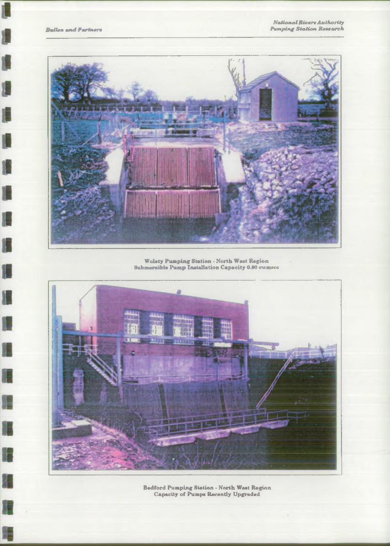
Butlen and PartnersNational Rivera Authority
Pumping Station Research
Wolaty Pumping Station • North West Region Submersible Pump Installation Capacity 0.80 cumecs
Bedford Pumping Station • North West Region Capacity of Pumps Recently Upgraded
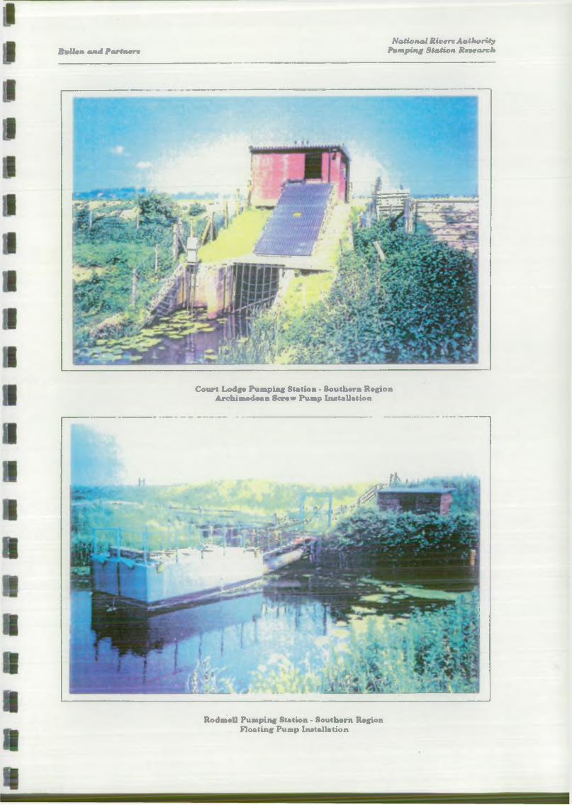
BttUen and PartnersNational Rivers Authority
Pumping Station Research
Court Lodge Pumping Station • Southern Region Archimedean Screw Pump Installation
Rodmell Pumping Station • Southern Region Floating Pump Installation
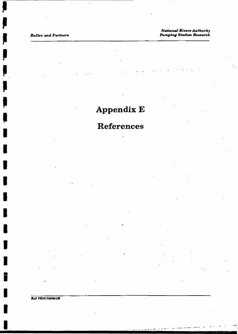
Bullen and Partner*
Appendix E
References
National Rivera AuthorityPumping Station Research
Kef: VB/9174X/001/B
PUMPS AND PUMPING STATIONS
REFERENCES
Clark,R.G. (1936) StGermains sluice and pumping station. London: Journal IC.E., No.6, April.
CIay,C. (1945) Pumping stations with special reference to land drainage and storm water disposal. London: Journal LC.E. No.5, March.
Lupton,H.R. (1949) Pumping machinery. London: Journal I.C.E., Vol.31, No.4t February.
Farran,C.E. (1952) The effects of mining subsidence on land drainage. London: Journal I.W.E., Vol vi. No.7, November.
Iverson,H.W. (1953) Studies of submergence requirements o f high specific- speed pumps. Transactions A.S.M.E., May.
Addison,H. (1955) Centrifugal and other rotodynamic pumps. London: Chapman and Hall.
Brewer,D. (1957) Vortices in pump sumps. Bedford: The Allen Engineering Review, March.
Stepanoff,A.J. (1957) Centrifugal and axial flow pumps (2nd Ed.). New York: John Wiley & Sons.
Addison,H. (1958) The pump users handbook. London: Pitmani
Prus-Chacinski,T.M. and Harris,W.B. (1963) Standards for lowland drainage of peat lands with special reference to the Crossens scheme. London: Proc. I.C.E., Vol.24 February.
McLeod,G. (1965) Land drainage pumping stations. London: Chapter 23, River engineering and water conservation works (Ed. Thom,R.B.). London: Butterworth.
Terry J.B. (1967) Land drainage pumps. Bedford: Alien Gwynnes Publication, A.G.P. 6128.
CharltonJ.A. (1972) The priming of pump siphonic discharge lines. London: Journal o f the Institution of Water Engineers, Vol.26, No.l, Feb. 1972.
Hockin,D.L. (1973) The River Alt improvement scheme. London: Association o f River Authorities Year Book and Directory, 1973.
15. Noonan.G.A. (1973) Considerations made in choosing the type and layout of pumping machinery for Altmouth pumping station. London: Conference on Pumping Equipment, Institution of Mechanical Engineers.
16. Hydraulic Institute Standards, 13th Ed. (1975). Cleveland, U.S.A.
17. Prosser»M.J. (1977) The hydraulic design of pump sumps and intakes. London: CIRIA/BHRA, Report Ref.UDC 621.65.03.
18. RadfordJ.D. and Richardson,D.B. (1977) The management o f manufacturing systems, Chpt8, maintenance and replacement London: Macmillan Press Ltd.
19. Sweeny,C.E. and Hay,D. (1982) Pump sump design experienceisummary. U.S.A.: Hydraulics Division, A.S.C.E. Vol. 108, No.HY3, March.
20. Chamley.P.L. et A1 (1987) Lowland drainage. London: Chapter 6. Water practice manual No.7. River Engineering,PLl, design principles. Institution of Water and Environmental Management.
21. SansbyJ.T. et A1 (1989) Maintenance and general operations. London: Water Practice Manual No.8. River Engineering,Pt.2, structures and coastal defence works, ps.249,250. Institution of Water and Environmental Management
22. Marshall,D.C.W. (1989) Toward optimal land drainage pumping (paper not published). Wallingford: Institute of Hydrology.
23. Prosser,M.J. (1992) Design of low-lift pumping stations. London: CIRIA Report 121, Construction Industry Research and Information Association.
24. "Life Cycle Costing” - A Radical Approach. London CIRIA Report 122. Construction Industry Research and Information Association.
Ref: VH/91742/R03/j2
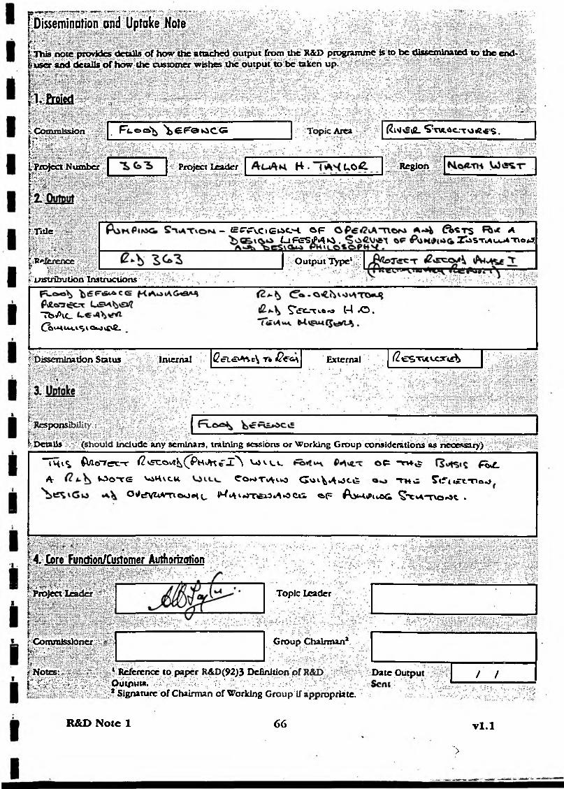
[Dissemination and Uptake Noter ' ■ ' • ■ ■j*Thls note provides details o f how the attached output from the R&D prognnune is.to be disseminated to the end' luserand details o f how the customer wishes the output to be taken up.
.;£ta|Efl „•; ; ^ * Y:<‘ .. /.V .,*: Ov-'*- . . Y ‘V- - v1 , Si’.v" £:>:&
I Commission
f; r : i ‘ •' ' b : ~ •>w' ,^Project Numberx - : : - . ■t ' v.
R-tocaVj ^ e F e k S C G Topic Area : (?lM£rfL S*TVL*C.aT O *< lS.• . v. r- . .v:_:. ^
:> : Project Leader H . l o £. Region
? Title -t • * * * YfV * ‘ V ’ *’ |:R*Jertftce
LHStrifcrution Instructions
- l=C‘tTv.O(E O-l C>F CAST'S ALiFeSip»4»^ . X asx»au_*at\o*
■ Output Type1;.
“T feA cC^«MUtiSiOtOtC«£.
^'(SCT^nJ C*4 *0 ,
f Dissemination Status Internal Cct«DMc\ r* J 2 e c + External (2 iE < > T v iu c r t &
li Responsibility;
t r‘ Details .:•/•'• (should include any seminars, training sessions or Working Group considerations as necessary)
"Thv^ b / l c r r e c r c ( I vFCCwI^^PhJK e Z^\ '-avv.c O P -TV4-^ f& £ _At ^ O T G V-AHVC.U Co*»Ti*m3 G ^ v ^ . j c g T»*w S’lfttft.-nao
O ^ c fV ^ V T lO O c iL Ih t L\ I *0Xfci3 tA *0 CUi «»(= A > * * lv O < i ^ 'X v ^ - r v o ^ ^ .
r. •••;< :■ >■•■ ■4 .- Core Function/Customer Authorization
|..v- iv '■■-.■.>•; Project Leader \\
' Commissioner v'\ \*v'- ■.•■:■■, •
t Notes:..-, .i-. :'=._. i~'■?*■''&■ \v Y; Out^MW. • •'■;••• - : 2 cun,t,,w i
Topic Leader
Group Chairman1,
* Reference to paper R&D(92)3 Definition o f R&D >UlpUtft. ■■ VcY,Y': ;• ' .vC :Y.,:Signature o f Chairman of Working Group If appropriate.
Date Output / /
R&D Note 1 66 v l . l
>