Station Designer Software - Industronics
384
Honeywell Honeywell Process Solutions Station Designer Software User Guide Doc. No.: 51-52-25-149 Revision: 3 Date: 03/10
-
Upload
khangminh22 -
Category
Documents
-
view
2 -
download
0
Transcript of Station Designer Software - Industronics

Honeywell
Honeywell Process Solutions
Station Designer Software User Guide
Doc. No.: 51-52-25-149
Revision: 3
Date: 03/10

ii Station Designer User’s Guide Revision 3 03/10
Copyright 2009 by Honeywell Revision 3 March 2010
Warranty/Remedy
Honeywell warrants goods of its manufacture as being free of defective materials and faulty workmanship. Contact your local sales office for warranty information. If warranted goods are returned to Honeywell during the period of coverage, Honeywell will repair or replace without charge those items it finds defective. The foregoing is Buyer's sole remedy and is in lieu of all other warranties, expressed or implied, including those of merchantability and fitness for a particular purpose. Specifications may change without notice. The information we supply is believed to be accurate and reliable as of this printing. However, we assume no responsibility for its use.
While we provide application assistance personally, through our literature and the Honeywell web site, it is up to the customer to determine the suitability of the product in the application.
Honeywell Process Solutions Honeywell
512 Virginia Drive Fort Washington, PA 19034
HC900, 559 and 1042 are U.S. registered trademarks of Honeywell
Other brand or product names are trademarks of their respective owners
Revision 3 Station Designer User’s Guide iii 03/10
About This Document
Abstract This manual describes the setup and operation of Station Designer Software for configuring 900 Control Stations for use with HC900 controllers.
References
The following list identifies all documents that may be sources of reference material discussed in this publication. Document Title Doc ID
HC900 Control Station Installation 51-52-33-147
900 Control Station Specification 51-52-03-46
HC900 Controller Installation and User Guide 51-52-25-107
900 Control Station User Guide 51-52-25-148
Hybrid Control Designer User Guide 51-52-25-110
Hybrid Control Designer Function Block Reference Guide 51-52-25-109
HC900 Hybrid Controller Communications User Guide 51-52-25-111
HC900 Controller Redundancy Overview & System Operation 51-52-25-133
Contacts
World Wide Web
The following lists Honeywell’s World Wide Web sites that will be of interest to our customers.
Honeywell Organization WWW Address (URL)
Corporate http://www.honeywell.com
Honeywell Process Solutions http://hpsweb.honeywell.com/Cultures/en-US/Products/Instrumentation/hybrid/default.htm
Technical tips http://content.honeywell.com/ipc/faq
Telephone
Contact us by telephone at the numbers listed below. Organization Phone Number
United States and Canada Honeywell 1-800-423-9883 Tech. Support 1-800-822-7673 Service
Symbol Definitions The following table lists those symbols that may be used in this document to denote certain conditions.

Symbol Definitions
iv Station Designer User’s Guide Revision 3 03/10
Symbol Definition
This DANGER symbol indicates an imminently hazardous situation, which, if not avoided, will result in death or serious injury.
This WARNING symbol indicates a potentially hazardous situation, which, if not avoided, could result in death or serious injury.
This CAUTION symbol may be present on Control Product instrumentation and literature. If present on a product, the user must consult the appropriate part of the accompanying product literature for more information.
This CAUTION symbol indicates a potentially hazardous situation, which, if not avoided, may result in property damage.
WARNING PERSONAL INJURY: Risk of electrical shock. This symbol warns the user of a potential shock hazard where HAZARDOUS LIVE voltages greater than 30 Vrms, 42.4 Vpeak, or 60 Vdc may be accessible. Failure to comply with these instructions could result in death or serious injury.
ATTENTION, Electrostatic Discharge (ESD) hazards. Observe precautions for handling electrostatic sensitive devices
Protective Earth (PE) terminal. Provided for connection of the protective earth (green or green/yellow) supply system conductor.
Functional earth terminal. Used for non-safety purposes such as noise immunity improvement. NOTE: This connection shall be bonded to protective earth at the source of supply in accordance with national local electrical code requirements.
Earth Ground. Functional earth connection. NOTE: This connection shall be bonded to Protective earth at the source of supply in accordance with national and local electrical code requirements.
Chassis Ground. Identifies a connection to the chassis or frame of the equipment shall be bonded to Protective Earth at the source of supply in accordance with national and local electrical code requirements.
Contents
v Station Designer User’s Guide Revision 3 03/10
Contents Introduction/Overview.................................................................................1
How to use this manual.......................................................................................... 1 File Structure and Architecture .............................................................................. 1 Station Designer Layout Overview......................................................................... 2 PC Communications .............................................................................................. 3
Getting Started ...........................................................................................5 PC Requirements................................................................................................... 5 HC900 Controller and 900 Control Station Setup.................................................. 5 Using RS485 Serial Communications.................................................................. 13 Using RS485 Serial Communication to communicate with the HC900 ............... 13 Troubleshooting ................................................................................................... 13 Alternate Programming Method- Using TCP/IP To Program The Station ........... 14
Station Designer Basics ...........................................................................21 Window Layout..................................................................................................... 21 The Categories..................................................................................................... 22 Getting Around ..................................................................................................... 24 Navigation Lists.................................................................................................... 25 Global Search ...................................................................................................... 26 Undo and Redo .................................................................................................... 26 Using Balloon Help............................................................................................... 27 Working with Databases ...................................................................................... 27 Conversion of SDS database from 10 inch Display to 15 inch Display ............... 28 Downloading to a Device ..................................................................................... 36 Extracting Databases........................................................................................... 37 Mounting the Flash memory ................................................................................ 37 Formatting the Flash memory .............................................................................. 38 Time and Date...................................................................................................... 38 Remote Monitoring............................................................................................... 39
Building Custom Displays.........................................................................41 Tag characters and conflicts ................................................................................ 41 Display Pages Navigation Pane........................................................................... 42 Custom Displays 1 – 16 ....................................................................................... 42 Adding Custom Displays ...................................................................................... 43 Adding Signals to Displays .................................................................................. 44 Adding variables to displays ................................................................................ 44 Using Primitives ................................................................................................... 45 Using Widgets ...................................................................................................... 45 Configuring Setpoint Programmer Pre-Plot Display ............................................ 48 Zoom Widgets ...................................................................................................... 57 Using Symbols ..................................................................................................... 58 Using Images ....................................................................................................... 59 Assigning Actions and F1, F2 .............................................................................. 59
Contents
vi Station Designer User’s Guide Revision 3 03/10
Data Logging............................................................................................61 The Logging Process ........................................................................................... 61 Log File Storage................................................................................................... 62 Mounting the Flash memory ................................................................................ 62 Formatting the Flash Memory Flash .................................................................... 63 Log Setup............................................................................................................. 63 Concurrent Batch ................................................................................................. 66 Setting up Data Logger Properties for Concurrent Batch .................................... 67 Setting up Data Log for Concurrent Batch........................................................... 69 Batch Logging ...................................................................................................... 70 Setup Log Viewing Displays ................................................................................ 71 Accessing Log Files ............................................................................................. 72 Digital Signatures ................................................................................................. 72
Alarms and Events ...................................................................................73 About alarms and events ..................................................................................... 73
Using Internal Tags ..................................................................................75
Using Communications ............................................................................77 Serial Port Selection............................................................................................. 78 Selecting a Protocol ............................................................................................. 78 Working with Devices........................................................................................... 79 Advanced Settings ............................................................................................... 80 Port And Device Usage........................................................................................ 80 Network Configuration.......................................................................................... 81 Using Virtual Ports ............................................................................................... 87 Slave Protocols .................................................................................................... 89 Protocol Conversion............................................................................................. 93 Controlling Master Blocks .................................................................................... 95 Data Transformation ............................................................................................ 96 Disabling Communications .................................................................................. 96 Using The USB Host ............................................................................................ 96 Using Modems ................................................................................................... 100
Using Services .......................................................................................107 Using Time Management................................................................................... 107 Using the FTP Server......................................................................................... 111 Using File Synchronization ................................................................................ 112 Using Electronic Mail.......................................................................................... 118 Using Emulator................................................................................................... 121
Working with Tags..................................................................................123 All About Tags.................................................................................................... 123 Advantages of Tags ........................................................................................... 124 Editing Properties............................................................................................... 125 Log Properties.................................................................................................... 128 Creating Tags..................................................................................................... 128

Contents
Revision 3 Station Designer User’s Guide vii 03/10
Numeric Tags..................................................................................................... 131 Flag Tags ........................................................................................................... 140 String Tags......................................................................................................... 148 Basic Tags ......................................................................................................... 153 Tag Data Flow.................................................................................................... 155 Using On Write................................................................................................... 156
Using Data Formats ...............................................................................157 Format Types ..................................................................................................... 157 General Format .................................................................................................. 158 Linked Format .................................................................................................... 158 Numeric Format ................................................................................................. 158 Scientific Format ................................................................................................ 159 Time and Date Format ....................................................................................... 160 IP Address Format ............................................................................................. 161 Two-State Format .............................................................................................. 161 The Multi-State Format ...................................................................................... 162
Using Color Selectors.............................................................................165 Color Selector Types.......................................................................................... 165 General Colors ................................................................................................... 165 Linked Coloring .................................................................................................. 166 Fixed Colors ....................................................................................................... 166 Two-State Colors ............................................................................................... 166 Multi-State Colors............................................................................................... 167
Creating Display Pages..........................................................................168 Editor Basics ...................................................................................................... 168 Working with Primitives ...................................................................................... 182 Primitive Properties ............................................................................................ 188 Using Groups ..................................................................................................... 196 Adding Movement to Primitives ......................................................................... 197 Adding Text to Primitives ................................................................................... 198 Adding Data to Primitives................................................................................... 201 Adding Actions to Primitives .............................................................................. 206 Protecting Actions .............................................................................................. 206 Adding Actions to Keys ...................................................................................... 213
Primitive Types.......................................................................................215 Core Primitives................................................................................................... 215 Arrows ................................................................................................................ 224 Polygons and Stars ............................................................................................ 225 Balloons and Call-Outs ...................................................................................... 226 Semi-Trimmed Figures....................................................................................... 227 Actions Buttons .................................................................................................. 227 Illuminated Buttons............................................................................................. 228 Indicators............................................................................................................ 229
Contents
viii Station Designer User’s Guide Revision 3 03/10
2-State Toggles.................................................................................................. 230 3-State Toggles.................................................................................................. 232 2-State Selectors................................................................................................ 234 3-State Selectors................................................................................................ 234 Legacy Primitives ............................................................................................... 234 System Primitives............................................................................................... 237
Localization ............................................................................................245 Enabling Language Option ................................................................................ 245 Selecting Languages.......................................................................................... 246 Configuring Auto - Translation ........................................................................... 248 Translating Your Database ................................................................................ 249
Using Widgets ........................................................................................255 Creating a Widget .............................................................................................. 255 Widget Data Definitions...................................................................................... 260 Filing Widgets..................................................................................................... 262 Folder Binding .................................................................................................... 263 Advanced Binding .............................................................................................. 264 Details Widgets .................................................................................................. 266
Using Programs .....................................................................................269 The Program List................................................................................................ 269 Finding Program Usage ..................................................................................... 269 Editing Programs................................................................................................ 270 The Resource Pane ........................................................................................... 270 Program Data Types.......................................................................................... 271 Program Properties ............................................................................................ 271 Adding Comments.............................................................................................. 273 Returning Values................................................................................................ 273 Passing Arguments ............................................................................................ 274 Programming Tips.............................................................................................. 274
Using the Web Server ............................................................................279 Important Note ................................................................................................... 279 Web Server Properties....................................................................................... 279 Adding Web Pages ............................................................................................ 282 Using a Custom Web Site .................................................................................. 283
Using WebSync......................................................................................285
Using the Security System .....................................................................287 Security Basics................................................................................................... 287 Security Settings ................................................................................................ 291 Creating Users ................................................................................................... 292 Specifying Tag Security ..................................................................................... 294 Specifying Page Security ................................................................................... 294 Security Related Functions ................................................................................ 294

Contents
Revision 3 Station Designer User’s Guide ix 03/10
Writing Expressions................................................................................295 Data Values........................................................................................................ 295 Simple Math ....................................................................................................... 298 Operator Priority................................................................................................. 298 Type Conversion ................................................................................................ 298 Comparing Values.............................................................................................. 299 Testing Bits ........................................................................................................ 299 Multiple Conditions............................................................................................. 300 Choosing Values ................................................................................................ 300 Manipulating Bits................................................................................................ 301 Indexing Arrays .................................................................................................. 302 Indexing Strings ................................................................................................. 302 Adding Strings.................................................................................................... 302 Calling Programs................................................................................................ 302 Using Functions ................................................................................................. 302 Priority Summary................................................................................................ 303
Writing Actions .......................................................................................305 Changing Page .................................................................................................. 305 Changing Numeric Values ................................................................................. 305 Changing Bit Values........................................................................................... 306 Running Programs ............................................................................................. 306 Using Functions ................................................................................................. 306 Operator Priority................................................................................................. 306
Appendix A.............................................................................................309 Function Reference............................................................................................ 309

Revision 3 Station Designer User’s Guide 1 03/10
Introduction/Overview
Welcome to Station Designer—Honeywell’s software for configuring the 900 Control Station interface for the
HC900 Control System. This Windows® based application allows you to quickly define a user interface for the
HC900 controller that includes more than 70 pre-built controller and Station setup and status displays. A variety of
pre-built Widgets, intelligent graphic objects matched to HC900 controller function blocks, are also provided to
accelerate custom display building. These features plus many more time saving attributes are contained in a base
900 Control Station configuration file that is installed prior to your customization.
The software is designed to accept a configuration file from a HC900 Controller, import all its tags, signals,
variables and function block definitions to facilitate building displays for your 900 Control Station. The Station uses
a Honeywell HC900 protocol when communicating with a controller, eliminating the need to research function code
types or data register addresses. To build displays using controller data, simply reference the data by name from the
lists provided in the imported file.
All of the features of your 900 Control Station are configured with one software program including custom graphic
displays, data logging, trending, alarming, FTP server operation, remote access via the Web, security, and more.
The Station configuration is built off-line on your PC and following an initial download, allows incremental updates
to save you time and minimize upsets to your operation.
How to use this manual This manual is divided into two segments. The first segment (Chapters 1 through 6) describe features and attributes
specific to building a custom display interface for your HC900 Control System starting with the base 900 Control
Station configuration file. It includes procedures and examples on how to execute tasks related to using the base
configuration with a HC900 controller configuration database. For additional detail on using the software and its
capabilities, the manual will direct you to reference sections later in the manual.
File Structure and Architecture Station Designer software is a stand-alone application that runs on a PC and is used to develop and download
configuration files to 900 Control Stations for use with HC900 controllers. File extensions are used to distinguish
the two types of configuration files. HC900 controller configuration files use the .cde file extension. Configuration
files for the 900 Control Station use the .sds extension. The database used to develop an .sds configuration file must
be the same as the database of the .cde file used to configure the controller. If the databases are not the same, a
database mismatch prompt will appear on the Station and communications with the controller will be lost.

Introduction/Overview
2 Station Designer User’s Guide Revision 3 03/10
Station Designer Layout Overview Station Designer operation requires an understanding of the various Menus, Tabs and Panes, used to navigate the
software. See chapter Station Designer Basics for a detailed description of the display areas pictured below.
Main Menu and Action Keys
Navigation Pane
Resource PaneEditing Pane
Main Menu and Action Keys
Navigation Pane
Resource PaneEditing Pane

Introduction/Overview PC Communications
Revision 3 Station Designer User’s Guide 3 03/10
PC Communications
Configuring the PC Link
The programming link between the PC and the 900 Control Station can be made using an RS-232 port, a USB port
or a TCP/IP connection. Before attempting a download to the Station, use the Link menu-Options command to
ensure that you have the correct method selected for your PC and Station. USB is the recommended method for first
time users. An alternate method using TCP/IP is detailed in section Alternate Programming Method which may be
easier if you are using model 900CS15.
Note that the dialog does not provide a method for specifying the PC’s or Station’s IP address when using TCP/IP
for download. The PC’s IP address will be setup using the Network Connections selection under the Windows
Settings tab. The Station’s IP address is stored in the .sds database file and is configured via the Station Network
tab in the Communications Navigation Pane.
When the base 900 Control Station.sds file is selected, the default Station IP address will be set to Manual
Configuration with IP address 192.168.1.253, Network Mask 255.255.255.0, and Gateway 0.0.0.0 entered. This
address is compatible with the default IP address supplied in the HC900 Controller (192.168.1.254). These network
settings should be changed as needed to support your network environment, remembering that the HC900 controller
requires manual IP addressing and the 900 Control Station must be on the same sub-net.
When using the USB port for configuration download, once the USB drivers have been installed, See section
Getting Started., no additional port setup is required. When using Ethernet TCP for downloading configurations, the
IP address of the Station must first be set using the USB connection, then the download via TCP/IP may be selected.
See section Download Settings.
The Download tab and other configuration communication settings are configured by the .sds file. For more
information on configuring 900 Control Station communication ports, see section Using Communications.


Revision 3 Station Designer User’s Guide 5 03/10
Getting Started
PC Requirements Station Designer is designed to run on any version of Microsoft Windows from Windows 2000 onwards. About
100MB of free disk space is needed for installation, and the display resolution should be sufficient to allow editing
of display pages without excessive scrolling. For the VGA display of the 900 Control Station, an XGVA PC is
recommended.
HC900 Controller and 900 Control Station Setup The following steps outline the process for setting up and interconnecting an integrated system that includes the HC900 Controller, 900 Control Station and a PC with Station Designer Software installed. Upon completing the following steps, you will have connected all the devices together, configured an HC900 database, loaded this database into the Station Designer software application, and downloaded the Honeywell supplied pre-configured displays into the 900 Control Station.
What you need:
a) PC Computer
b) Honeywell 900 Control Station
c) Honeywell Station Designer Software
d) 24Vdc Power Supply
e) USB 2.0 Programming Cable Type A–Type B (i.e. Black Box USB05-0010)
f) Honeywell HC900 Controller
g) Honeywell HC Designer Software
h) Ethernet cable
1) Configure your HC900 Controller using HC Designer Software, save the configuration file (*.cde) in your PC
and download this configuration to the HC900 Controller.
2) Connect a +24Vdc power supply to the 900 Control Station and power the unit. A display indicating the default IP Address and the MAC address of your Station will be displayed.
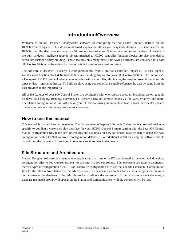
3) Install Station Designer software on your PC. - Station Designer is supplied on the CD you received from Honeywell. (Note: Do not connect the USB cable between your PC and the 900 Control Station until instructed below.) For installation, place the CD in an appropriate drive on your PC, the setup file will auto-run and advance to the dialog box below. (Note: If the install application does not auto-run, access START/RUN and browse the CD for the file “Setup.exe” and select Run.)
Getting Started HC900 Controller and 900 Control Station Setup
6 Station Designer User’s Guide Revision 3 03/10
Answer the install questions and execute the appropriate actions to complete the software installation. When finished you have the option to launch Station Designer or exit the install application.
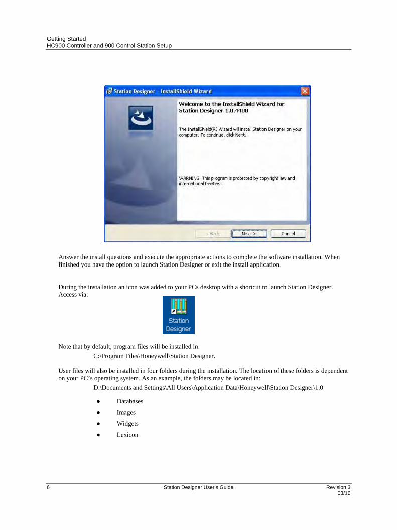
During the installation an icon was added to your PCs desktop with a shortcut to launch Station Designer. Access via:
Note that by default, program files will be installed in:
C:\Program Files\Honeywell\Station Designer.
User files will also be installed in four folders during the installation. The location of these folders is dependent on your PC’s operating system. As an example, the folders may be located in:
D:\Documents and Settings\All Users\Application Data\Honeywell\Station Designer\1.0
● Databases
● Images
● Widgets
● Lexicon
Getting Started HC900 Controller and 900 Control Station Setup
Revision 3 Station Designer User’s Guide 7 03/10
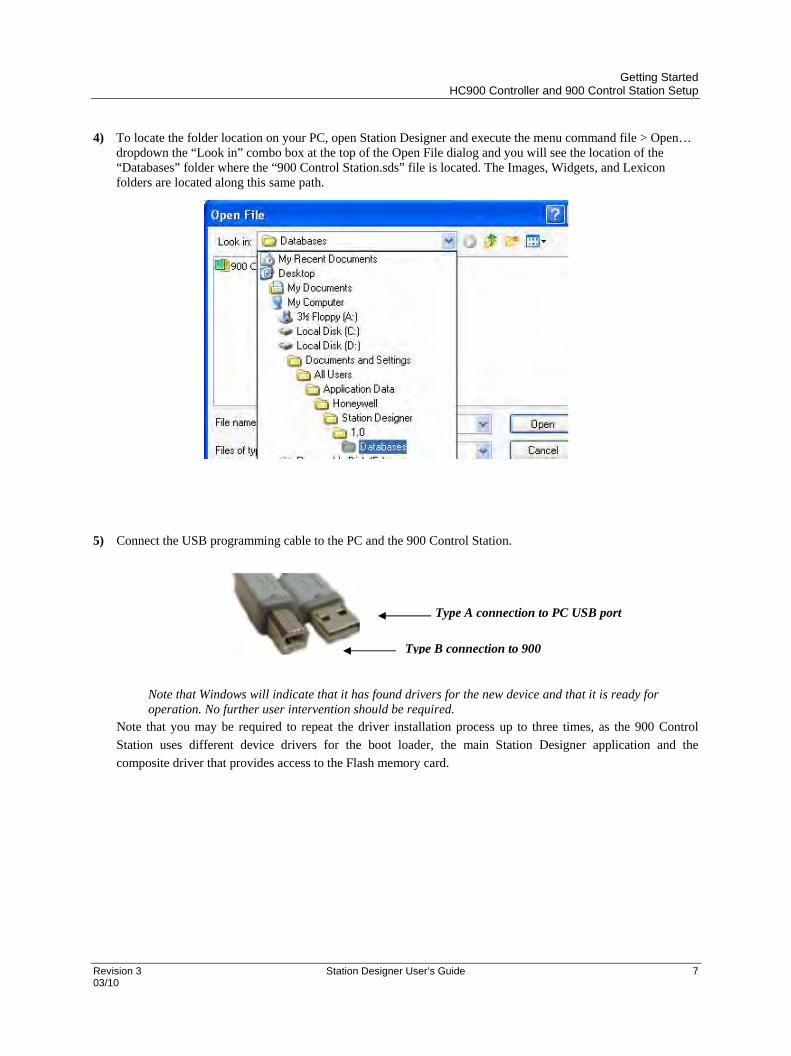
4) To locate the folder location on your PC, open Station Designer and execute the menu command file > Open… dropdown the “Look in” combo box at the top of the Open File dialog and you will see the location of the “Databases” folder where the “900 Control Station.sds” file is located. The Images, Widgets, and Lexicon folders are located along this same path.
5) Connect the USB programming cable to the PC and the 900 Control Station.
Type A connection to PC USB port
Note that Windows will indicate that it has found drivers for the new device and that it is ready for operation. No further user intervention should be required.
Note that you may be required to repeat the driver installation process up to three times, as the 900 Control
Station uses different device drivers for the boot loader, the main Station Designer application and the
composite driver that provides access to the Flash memory card.
Type B connection to 900

Getting Started HC900 Controller and 900 Control Station Setup
8 Station Designer User’s Guide Revision 3 03/10
Troubleshooting
If you connected the 900 Control Station to your PC before installing Station Designer—or if you selected
STOP when presented with the unsigned driver dialog box—it is possible that an aborted installation has made
it impossible for you to install the drivers correctly. To check for this, open the Windows Device Manager by
finding the My Computer icon on your desktop or on your Start menu, right-clicking and selecting the Manage
command. A window similar to the one below should appear…
The exact process for getting to this point may vary from one operating system to another, but the basic idea is
the same: Find the My Computer icon—either on the desktop or on your start menu—right-click it and select
Manage. If that doesn’t work, select the System option from the Control Panel, and activate the Device Manager
from the Hardware tab.
If you have a problem with your USB drivers, you will see a yellow icon carrying an exclamation point under
the Universal Serial Bus controllers category. The name of the icon may be HMI or Loader or something
similar. The broken driver is shown in close-up below…
Incorrectly Installed Device
Getting Started HC900 Controller and 900 Control Station Setup
Revision 3 Station Designer User’s Guide 9 03/10
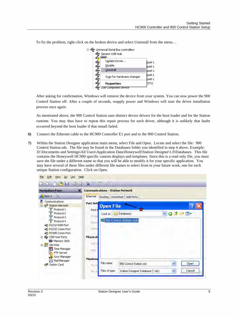
To fix the problem, right-click on the broken device and select Uninstall from the menu…
After asking for confirmation, Windows will remove the device from your system. You can now power the 900
Control Station off. After a couple of seconds, reapply power and Windows will start the driver installation
process once again.
As mentioned above, the 900 Control Station uses distinct device drivers for the boot loader and for the Station
runtime. You may thus have to repeat this repair process for each driver, although it is unlikely that faults
occurred beyond the boot loader if that install failed.
6) Connect the Ethernet cable to the HC900 Controller E1 port and to the 900 Control Station.
7) Within the Station Designer application main menu, select File and Open. Locate and select the file: 900 Control Station.sds. The file may be found in the Databases folder you identified in step 4 above. Example: D:\Documents and Settings\All Users\Application Data\Honeywell\Station Designer\1.0\Databases. This file contains the Honeywell HC900 specific custom displays and templates. Since this is a read only file, you must save the file under a different name so that you will be able to modify it for your specific application. You may have several of these files under different file names to select from in your future work, one for each unique Station configuration. Click on Open.
Getting Started HC900 Controller and 900 Control Station Setup
10 Station Designer User’s Guide Revision 3 03/10
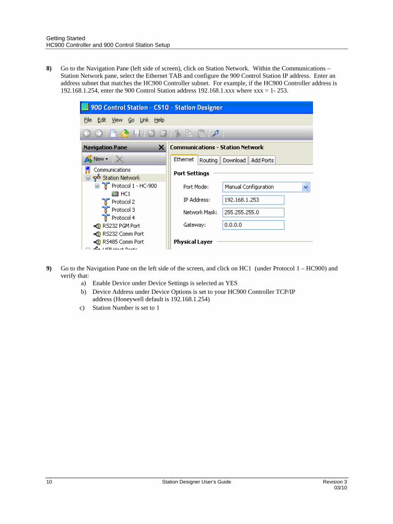
8) Go to the Navigation Pane (left side of screen), click on Station Network. Within the Communications – Station Network pane, select the Ethernet TAB and configure the 900 Control Station IP address. Enter an address subnet that matches the HC900 Controller subnet. For example, if the HC900 Controller address is 192.168.1.254, enter the 900 Control Station address 192.168.1.xxx where xxx = 1- 253.
9) Go to the Navigation Pane on the left side of the screen, and click on HC1 (under Protocol 1 – HC900) and
verify that: a) Enable Device under Device Settings is selected as YES b) Device Address under Device Options is set to your HC900 Controller TCP/IP
address (Honeywell default is 192.168.1.254) c) Station Number is set to 1

Getting Started HC900 Controller and 900 Control Station Setup
Revision 3 Station Designer User’s Guide 11 03/10
10) Under HC900 Alarms choose how you want to initially present the alarm information on Control Station when the alarm icon is touched. Choose Access via Alarm Groups if you want to view HC900 Controller alarms in alarm groups that are configured in HC Designer and reside in the *.cde file. Choose Integrate with Station Alarms if you want view alarms in the Alarm Viewer (tabular presentation). This view combines alarms that are configured via tags from Station Designer as well as HC900 Controller alarms. Note that both presentation modes are available at the Control Station; this configuration simply provides the initial view.
Getting Started HC900 Controller and 900 Control Station Setup
12 Station Designer User’s Guide Revision 3 03/10
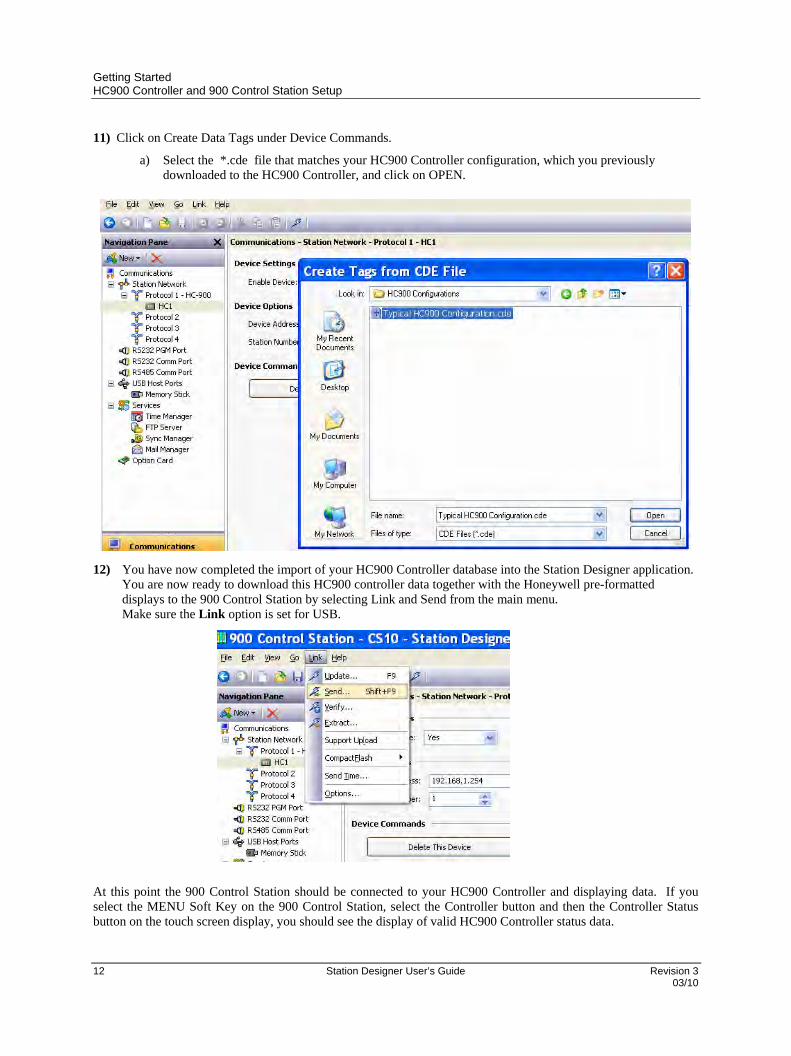
11) Click on Create Data Tags under Device Commands.
a) Select the *.cde file that matches your HC900 Controller configuration, which you previously downloaded to the HC900 Controller, and click on OPEN.
12) You have now completed the import of your HC900 Controller database into the Station Designer application. You are now ready to download this HC900 controller data together with the Honeywell pre-formatted displays to the 900 Control Station by selecting Link and Send from the main menu. Make sure the Link option is set for USB.
At this point the 900 Control Station should be connected to your HC900 Controller and displaying data. If you select the MENU Soft Key on the 900 Control Station, select the Controller button and then the Controller Status button on the touch screen display, you should see the display of valid HC900 Controller status data.
Getting Started Using RS485 Serial Communications
Revision 3 Station Designer User’s Guide 13 03/10
Using RS485 Serial Communications
Using RS485 Serial Communication to communicate with the HC900 The above procedure describes using Ethernet communications between the 900 Control Station and the HC900 Controller. If RS485 Serial communications will be used, the following procedure should be followed:
1) From the Communications tab of the Navigation Pane of Station Designer, Select HC1, Device Settings, Enable Device = NO
2) Select the RS485 Comm Port selection from the Navigation Pane. Under the port setup, Driver Select, set Manufacturer to Honeywell, Set the Driver to HC900 Serial.
3) Set the Port Settings to match the HC900 RS485 Serial Port Settings. The recommended settings are: a) Baud Rate = 57600
b) Databits = 8
c) Stop Bits = 1
d) Parity = Odd
e) Port Mode = 2 Wire –RS485
f) Port Sharing = NO (Note: this setting is not available in newer versions of Station Designer).
4) After completing the RS485 port setup, HC2 should appear beneath the RS485 Comm Port. Set HC2, Device Settings, Enable Device = Yes.
5) Set the Device Address to match the Modbus Address of the target HC900 controller. (default is 1) 6) Select “Create Data Tags” and access the desired HC900 Controller Configuration (.cde) file. 7) The Station Serial Port setup is complete.
To setup the HC900 Controller Serial Port to communicate with the 900 Control Station, use Hybrid Control Designer software and setup the desired RS485 Serial Port from the Utility tab while having the target .cde file open and your PC setup to communicate with the HC900 controller. (Note: In the HC900 controller, port setup is not part of the configuration and must be communicated to the controller as a separate operation.)
1) Select “Modbus RTU Slave” protocol for the RS485 port to be used. 2) Set Slave Type = Point to Point 3) Set Double Register Format = Big Endian 4) Set the port settings and Modbus Address to match the settings in steps 3 and 5 above.
Troubleshooting Make sure the programming cable is compatible with USB 2.0 devices. The USB chip set of the 900CS15 is susceptible to conflicts with other USB devices and hubs. Ensure that the 900CS15 is the only device (including hubs but not the root hub) present in the USB device tree, for any given host controller. There are a few exceptions, typically mice and keyboards. Modern multiport machines will typically have one enhanced EHCI high speed host and multiple OHCI low speed hosts, all sharing the same physical ports. High speed devices such as the 900CS15 will always be routed to the single EHCI controller, whereas low speed devices will be routed to one of the OHCI controllers. OHCI controllers typically handle two ports. For example a typical computer has one EHCI and two OHCI. If you view the 'Devices by Connection' you will get a better indication of how the device tree is configured. The only solution with internal hubs is to disable them, or install another USB host card and connect the 900CS15 via it.

Getting Started Alternate Programming Method- Using TCP/IP To Program The Station
14 Station Designer User’s Guide Revision 3 03/10
Disabling the USB2 Host Controller should allow the 900CS15’s USB connection to function properly. This will route the 900CS15 and any other devices to the other USB controllers. The following section details using TCP/IP as an alternate programming method if you are still having difficulty.
Alternate Programming Method- Using TCP/IP To Program The Station If you have difficulty programming the 900CS15 via the USB programming cable, the following method is an alternative. Note that a crossover Ethernet cable is required if you are not using an Ethernet switch, and a Flash memory card is required if the Control Station firmware needs to be upgraded
HC900 Controller And 900 Control Station Setup The following steps outline the process for setting up and interconnecting an integrated system that includes the HC900 Controller, 900 Control Station and a PC with Station Designer Software installed. Upon completing the following steps, you will have connected all the devices together, configured an HC900 database, loaded this database into the Station Designer software application, and downloaded the Honeywell supplied pre-configured displays into the 900 Control Station. What you need:
a) PC Computer
b) Honeywell 900 Control Station
c) Honeywell Station Designer Software
d) 24Vdc Power Supply
e) Honeywell HC900 Controller
f) Honeywell HC Designer Software
g) Crossover Ethernet cable
h) Flash memory card – required if Control Station firmware needs to be upgraded
1) Configure your HC900 Controller using HC Designer Software, save the configuration file (*.cde) in
your PC and download this configuration to the HC900 Controller. 2) Install Station Designer software on your PC - Station Designer is supplied on the CD you received
from Honeywell. For installation, place the CD in an appropriate drive on your PC, the setup file will auto-run and advance to the dialog box below. (Note: If the install application does not auto-run, access START/RUN and browse the CD for the file “Setup.exe” and select Run.)
Getting Started Alternate Programming Method- Using TCP/IP To Program The Station
Revision 3 Station Designer User’s Guide 15 03/10
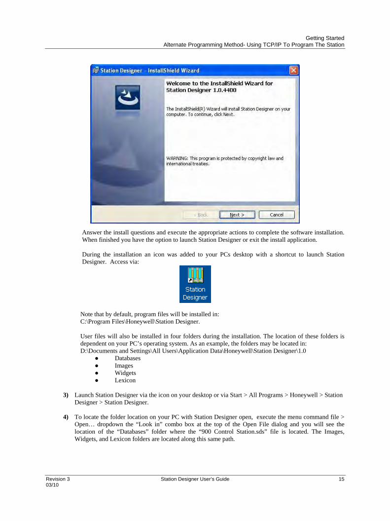
Answer the install questions and execute the appropriate actions to complete the software installation. When finished you have the option to launch Station Designer or exit the install application. During the installation an icon was added to your PCs desktop with a shortcut to launch Station Designer. Access via:
Note that by default, program files will be installed in: C:\Program Files\Honeywell\Station Designer.
User files will also be installed in four folders during the installation. The location of these folders is dependent on your PC’s operating system. As an example, the folders may be located in: D:\Documents and Settings\All Users\Application Data\Honeywell\Station Designer\1.0
● Databases ● Images ● Widgets ● Lexicon
3) Launch Station Designer via the icon on your desktop or via Start > All Programs > Honeywell > Station
Designer > Station Designer.
4) To locate the folder location on your PC with Station Designer open, execute the menu command file > Open… dropdown the “Look in” combo box at the top of the Open File dialog and you will see the location of the “Databases” folder where the “900 Control Station.sds” file is located. The Images, Widgets, and Lexicon folders are located along this same path.

Getting Started Alternate Programming Method- Using TCP/IP To Program The Station
16 Station Designer User’s Guide Revision 3 03/10
5) Before applying +24Vdc power to the 900 Control Station, depress the F1 and the fourth soft key (Logoff
for 900CS10 and F4 for 900CS15) simultaneously and hold them down while applying power. Keep the keys depressed until a pop-up keypad appears. Enter an IP address that has the same subnet as your PC and the HC900 Controller and a unique fourth number. Press the green arrow to enter the IP address. The new IP Address and the MAC ID(s) will appear on the display.
6) Connect a crossover Ethernet cable to the PC and the 900 Control Station being sure to connect to the main Ethernet port (and not the auxiliary Ethernet port of the 900CS15).
7) Within the Station Designer application main menu, select File and Open. Locate and select the file: 900 Control Station.sds. The file may be found in the Databases folder you identified in step 4 above. Example: D:\Documents and Settings\All Users\Application Data\Honeywell\Station Designer\1.0\Databases. This file contains the Honeywell HC900 specific custom displays and templates. Since this is a read only file, you must save the file under a different name so that you will be able to modify it for your specific application. You may have several of these files under different file names to select from in your future work, one for each unique Station configuration. Click on Open.

Getting Started Alternate Programming Method- Using TCP/IP To Program The Station
Revision 3 Station Designer User’s Guide 17 03/10
8) Go to the Navigation Pane (left side of screen), click on Station Network. a) Within the Communications – Station Network pane, select the Ethernet TAB and set Port Settings -
Port Mode to Manual Configuration and set the 900 Control Station IP address by entering the same IP address as in step 5.
b) Select the Download tab and set Remote Update - IP Downloaded to Enabled and Unit Addressing -
Selection Mode to Auto Ethernet 1.

Getting Started Alternate Programming Method- Using TCP/IP To Program The Station
18 Station Designer User’s Guide Revision 3 03/10
9) Go to the Navigation Pane on the left side of the screen, and click on HC1 (under Protocol 1 – HC900) and verify that:
a) Enable Device under Device Settings is selected as YES
b) Device Address under Device Options is set to your HC900 Controller TCP/IP address (Honeywell default is 192.168.1.254)
10) Click on Create Data Tags under Device Commands.
a) Select the *.cde file that matches your HC900 Controller configuration, which you previously downloaded to the HC900 Controller, and click on OPEN.
Getting Started Alternate Programming Method- Using TCP/IP To Program The Station
Revision 3 Station Designer User’s Guide 19 03/10
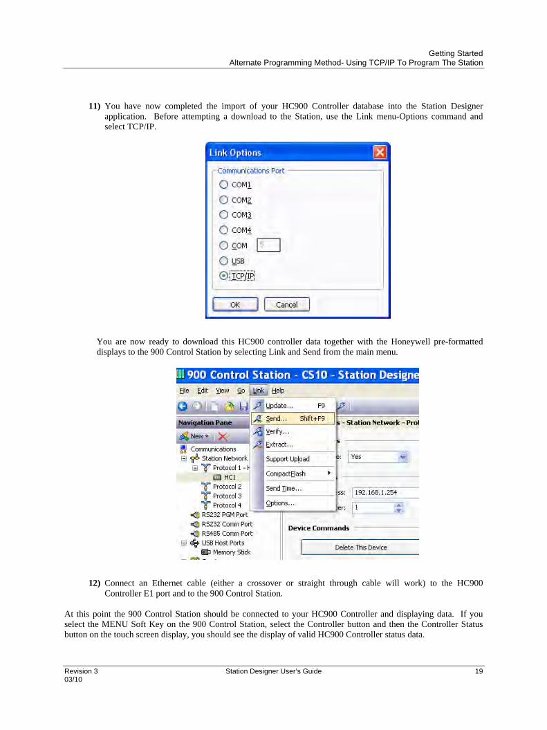
11) You have now completed the import of your HC900 Controller database into the Station Designer
application. Before attempting a download to the Station, use the Link menu-Options command and select TCP/IP.
You are now ready to download this HC900 controller data together with the Honeywell pre-formatted displays to the 900 Control Station by selecting Link and Send from the main menu.
12) Connect an Ethernet cable (either a crossover or straight through cable will work) to the HC900
Controller E1 port and to the 900 Control Station. At this point the 900 Control Station should be connected to your HC900 Controller and displaying data. If you select the MENU Soft Key on the 900 Control Station, select the Controller button and then the Controller Status button on the touch screen display, you should see the display of valid HC900 Controller status data.

Getting Started Alternate Programming Method- Using TCP/IP To Program The Station
20 Station Designer User’s Guide Revision 3 03/10
Revision 3 Station Designer User’s Guide 21 03/10
Station Designer Basics
To run Station Designer, select the Station Designer icon in the Honeywell section of your Start Menu. After a
couple of seconds the Station Designer application will appear, See below.
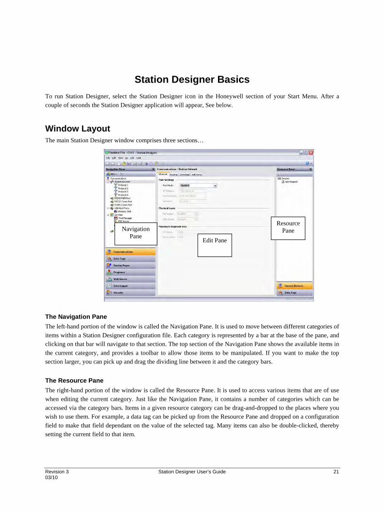
Window Layout The main Station Designer window comprises three sections…
The Navigation Pane
The left-hand portion of the window is called the Navigation Pane. It is used to move between different categories of
items within a Station Designer configuration file. Each category is represented by a bar at the base of the pane, and
clicking on that bar will navigate to that section. The top section of the Navigation Pane shows the available items in
the current category, and provides a toolbar to allow those items to be manipulated. If you want to make the top
section larger, you can pick up and drag the dividing line between it and the category bars.
The Resource Pane
The right-hand portion of the window is called the Resource Pane. It is used to access various items that are of use
when editing the current category. Just like the Navigation Pane, it contains a number of categories which can be
accessed via the category bars. Items in a given resource category can be drag-and-dropped to the places where you
wish to use them. For example, a data tag can be picked up from the Resource Pane and dropped on a configuration
field to make that field dependant on the value of the selected tag. Many items can also be double-clicked, thereby
setting the current field to that item.
Navigation Pane
Resource Pane
Edit Pane
Station Designer Basics The Categories
22 Station Designer User’s Guide Revision 3 03/10
The Editing Pane
The central portion of the window is used to edit the currently selected item. Depending on the selection, it may
contain a number of tabs, each showing a given set of the properties for that item, or it may contain an editor
specific to the item being edited.
Collapsing Panes
Either or both of the Navigation Pane and Resource Pane can be collapsed to the edge of the main window in order
to free-up more space for the Editing Pane. To close a pane, click on the ‘x’ in the top left-hand corner of its title
bar. It will then be replaced by a smaller bar marked with arrows. Clicking this bar will expand the associated pane.
Clicking on the pushpin icon on a temporarily expanded pane will lock it in place.
The Categories The main categories in a Station Designer database are as follows…
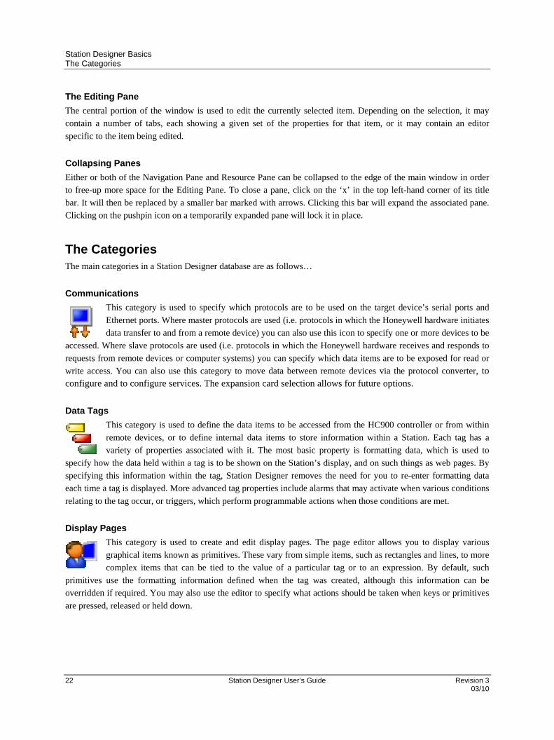
Communications
This category is used to specify which protocols are to be used on the target device’s serial ports and
Ethernet ports. Where master protocols are used (i.e. protocols in which the Honeywell hardware initiates
data transfer to and from a remote device) you can also use this icon to specify one or more devices to be
accessed. Where slave protocols are used (i.e. protocols in which the Honeywell hardware receives and responds to
requests from remote devices or computer systems) you can specify which data items are to be exposed for read or
write access. You can also use this category to move data between remote devices via the protocol converter, to configure and to configure services. The expansion card selection allows for future options.
Data Tags
This category is used to define the data items to be accessed from the HC900 controller or from within
remote devices, or to define internal data items to store information within a Station. Each tag has a
variety of properties associated with it. The most basic property is formatting data, which is used to
specify how the data held within a tag is to be shown on the Station’s display, and on such things as web pages. By
specifying this information within the tag, Station Designer removes the need for you to re-enter formatting data
each time a tag is displayed. More advanced tag properties include alarms that may activate when various conditions
relating to the tag occur, or triggers, which perform programmable actions when those conditions are met.
Display Pages
This category is used to create and edit display pages. The page editor allows you to display various
graphical items known as primitives. These vary from simple items, such as rectangles and lines, to more
complex items that can be tied to the value of a particular tag or to an expression. By default, such
primitives use the formatting information defined when the tag was created, although this information can be
overridden if required. You may also use the editor to specify what actions should be taken when keys or primitives
are pressed, released or held down.
Station Designer Basics The Categories
Revision 3 Station Designer User’s Guide 23 03/10
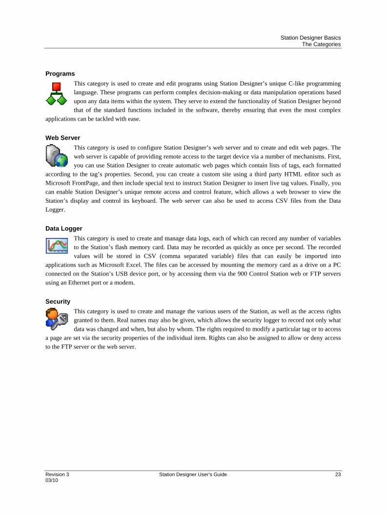
Programs
This category is used to create and edit programs using Station Designer’s unique C-like programming
language. These programs can perform complex decision-making or data manipulation operations based
upon any data items within the system. They serve to extend the functionality of Station Designer beyond
that of the standard functions included in the software, thereby ensuring that even the most complex
applications can be tackled with ease.
Web Server
This category is used to configure Station Designer’s web server and to create and edit web pages. The
web server is capable of providing remote access to the target device via a number of mechanisms. First,
you can use Station Designer to create automatic web pages which contain lists of tags, each formatted
according to the tag’s properties. Second, you can create a custom site using a third party HTML editor such as
Microsoft FrontPage, and then include special text to instruct Station Designer to insert live tag values. Finally, you
can enable Station Designer’s unique remote access and control feature, which allows a web browser to view the
Station’s display and control its keyboard. The web server can also be used to access CSV files from the Data
Logger.
Data Logger
This category is used to create and manage data logs, each of which can record any number of variables
to the Station’s flash memory card. Data may be recorded as quickly as once per second. The recorded
values will be stored in CSV (comma separated variable) files that can easily be imported into
applications such as Microsoft Excel. The files can be accessed by mounting the memory card as a drive on a PC
connected on the Station’s USB device port, or by accessing them via the 900 Control Station web or FTP servers
using an Ethernet port or a modem.
Security
This category is used to create and manage the various users of the Station, as well as the access rights
granted to them. Real names may also be given, which allows the security logger to record not only what
data was changed and when, but also by whom. The rights required to modify a particular tag or to access
a page are set via the security properties of the individual item. Rights can also be assigned to allow or deny access
to the FTP server or the web server.
Station Designer Basics Getting Around
24 Station Designer User’s Guide Revision 3 03/10
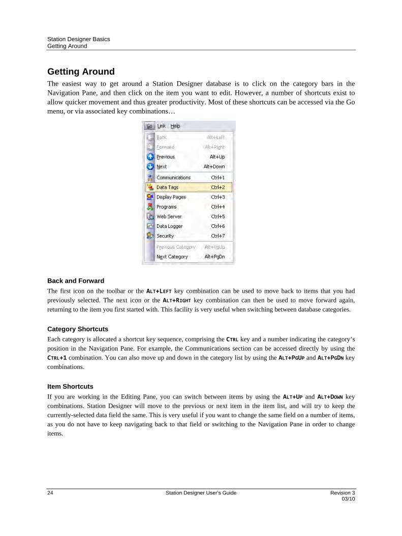
Getting Around The easiest way to get around a Station Designer database is to click on the category bars in the Navigation Pane, and then click on the item you want to edit. However, a number of shortcuts exist to allow quicker movement and thus greater productivity. Most of these shortcuts can be accessed via the Go menu, or via associated key combinations…
Back and Forward
The first icon on the toolbar or the ALT+LEFT key combination can be used to move back to items that you had
previously selected. The next icon or the ALT+RIGHT key combination can then be used to move forward again,
returning to the item you first started with. This facility is very useful when switching between database categories.
Category Shortcuts
Each category is allocated a shortcut key sequence, comprising the CTRL key and a number indicating the category’s
position in the Navigation Pane. For example, the Communications section can be accessed directly by using the
CTRL+1 combination. You can also move up and down in the category list by using the ALT+PGUP and ALT+PGDN key
combinations.
Item Shortcuts
If you are working in the Editing Pane, you can switch between items by using the ALT+UP and ALT+DOWN key
combinations. Station Designer will move to the previous or next item in the item list, and will try to keep the
currently-selected data field the same. This is very useful if you want to change the same field on a number of items,
as you do not have to keep navigating back to that field or switching to the Navigation Pane in order to change
items.
Station Designer Basics Navigation Lists
Revision 3 Station Designer User’s Guide 25 03/10
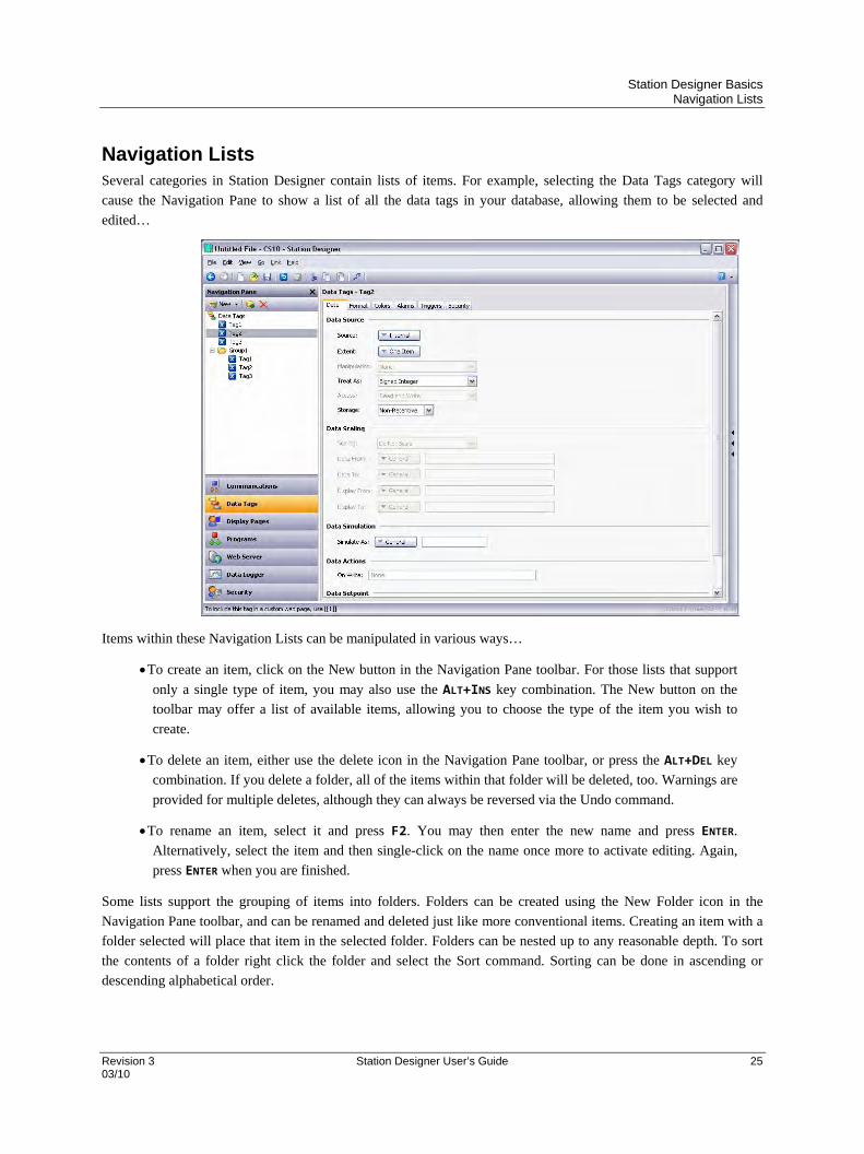
Navigation Lists Several categories in Station Designer contain lists of items. For example, selecting the Data Tags category will
cause the Navigation Pane to show a list of all the data tags in your database, allowing them to be selected and
edited…
Items within these Navigation Lists can be manipulated in various ways…
To create an item, click on the New button in the Navigation Pane toolbar. For those lists that support
only a single type of item, you may also use the ALT+INS key combination. The New button on the
toolbar may offer a list of available items, allowing you to choose the type of the item you wish to
create.
To delete an item, either use the delete icon in the Navigation Pane toolbar, or press the ALT+DEL key
combination. If you delete a folder, all of the items within that folder will be deleted, too. Warnings are
provided for multiple deletes, although they can always be reversed via the Undo command.
To rename an item, select it and press F2. You may then enter the new name and press ENTER.
Alternatively, select the item and then single-click on the name once more to activate editing. Again,
press ENTER when you are finished.
Some lists support the grouping of items into folders. Folders can be created using the New Folder icon in the
Navigation Pane toolbar, and can be renamed and deleted just like more conventional items. Creating an item with a
folder selected will place that item in the selected folder. Folders can be nested up to any reasonable depth. To sort
the contents of a folder right click the folder and select the Sort command. Sorting can be done in ascending or
descending alphabetical order.

Station Designer Basics Global Search
26 Station Designer User’s Guide Revision 3 03/10
Items in Navigation Lists can be drag-and-dropped within the list to change their position or to move them between
folders. Holding down the CTRL key while dragging will result in a copy of the original item being created. The left-
to-right position of an item may sometimes be used to decide where to place an item in the folder hierarchy. If the
item is being dropped into the wrong folder, try moving left or right to get to the correct position.
Station Designer provides a Find Item command, useful for searching all names containing the same string.. This
command, available on the Navigation Pane’s toolbar searches the current list, and places all matching items in the
Global Search Results List. You can browse through this list using the F4 or SHIFT+F4 key combinations, or display
the list in its entirety by pressing F8.
Database items—such as tags, display pages or anything else—may also be dragged between database files by
opening two copies of Station Designer and dragging the items in question from the source database’s Navigation
Pane to that of the target database. If the appropriate category in the target is not already selected, temporarily
holding the item that is being dragged over the required category bar for a second or so will select that category,
thereby avoiding the need to abort and repeat the drag operation.
Global Search Station Designer provides several options for searching within a database. Press the CTRL+SHIFT+F keys combination to search for a text string, expressions which contain errors, or for items that reference a tag or a communications device in the database. The output of these search operations are placed in the Global Search Result List, allowing you to review the results, or navigate back and forth between the items that have been located. Press the F8 key to view the results. In the following sample screen, right-clicking on a communications device and selecting the Find Usage command listed all the locations where the device was referenced. Double-click an entry to jump directly to that item, and use the F4 or SHIFT+F4 key combinations to step back and forth through the list.
The title bar of the window describes the search operation that produced the list, while each line contains the description of an item that matched the search criteria.
Undo and Redo Station Designer implements a universal undo and redo structure. This means that you can load a database, edit it for
hours, and then return it to its original state by simply holding down the ALT+Z key combination. You can then re-
apply your changes by holding down ALT+Y. All your actions are remembered, and Station Designer will navigate
between items and categories automatically when reversing or re-implementing changes.

Station Designer Basics Using Balloon Help
Revision 3 Station Designer User’s Guide 27 03/10
Using Balloon Help Station Designer provides a useful feature called Balloon Help…
This allows you to see help information for each field in a dialog box or window, and is controlled via the icon at the
right-hand edge of the toolbar or via the options on the Help menu. The When Requested mode allows help to be
displayed or hidden manually by pressing the F1 key. Selecting the When Mouse Over mode will display help when
the mouse pointer is held over a particular field for a certain period of time. Selecting the When Selected mode will
always display help for the currently selected field.
Working with Databases Station Designer stores all the information about a particular configuration in a database file. These files have the
extension sds, although Windows Explorer will hide this extension if it is left in its default configuration. While
Station Designer databases are essentially text files, they are compressed and therefore cannot be directly edited
using a text editor like Notepad. Databases may be manipulated via the commands found on the File menu. Most of
these commands are standard for all Windows applications, and need no further explanation.
Database Identifiers
Each database created by Station Designer is given a unique identifier. This identifier is used upon download of a
new database to determine if the target Station should clear its internal memory and delete any log files recorded to
module. If the identifier matches that of the database already in the Station, the database is assumed to be a different
version of the same file, so the data is retained. Conversely, if the identifiers are different, the data is cleared. When
you use the Save As command on the File menu to save a copy of a database file, Station Designer will ask if you
want to allocate a new identifier. Select Yes if this is going to be a new project, and select No if you are just saving a
backup copy of what is essentially the same database. This will ensure that the target Station’s retentive data is
preserved or cleared as is appropriate.
Saving an Image
The one Station Designer-specific item on the File menu is Save Image. This command allows the creation of a file
that can subsequently be used to update the database in a terminal via flash memory module or optionally via a USB
memory stick. The file contains a non-editable form of the database, plus any firmware and boot loader updates
required for execution. Placing an image file called image.sdi in the root directory of the target Station’s flash
memory module and then resetting the Station will result in the boot loader, firmware and database being updated
using the image file contents. Note that image files can optionally contain upload information, allowing an editable
version of the database file to be extracted from a terminal which has been updated using the image.
Station Designer Basics Conversion of SDS database from 10 inch Display to 15 inch Display
28 Station Designer User’s Guide Revision 3 03/10
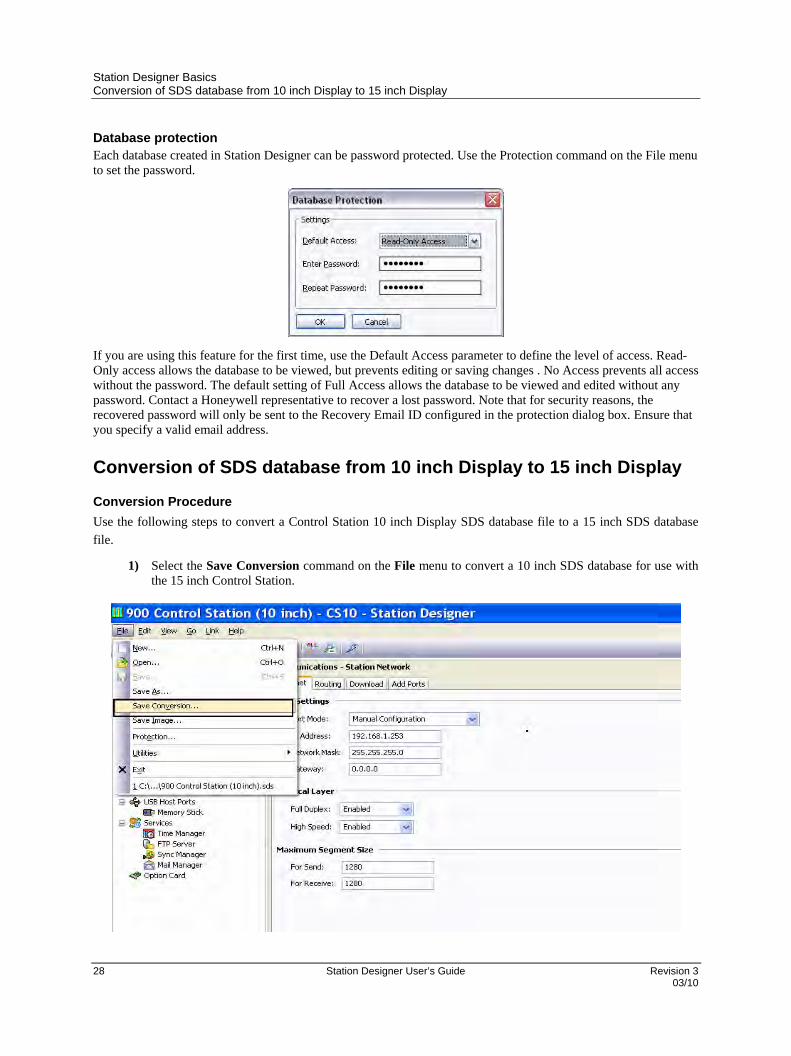
Database protection Each database created in Station Designer can be password protected. Use the Protection command on the File menu to set the password.
If you are using this feature for the first time, use the Default Access parameter to define the level of access. Read-Only access allows the database to be viewed, but prevents editing or saving changes . No Access prevents all access without the password. The default setting of Full Access allows the database to be viewed and edited without any password. Contact a Honeywell representative to recover a lost password. Note that for security reasons, the recovered password will only be sent to the Recovery Email ID configured in the protection dialog box. Ensure that you specify a valid email address.
Conversion of SDS database from 10 inch Display to 15 inch Display
Conversion Procedure
Use the following steps to convert a Control Station 10 inch Display SDS database file to a 15 inch SDS database
file.
1) Select the Save Conversion command on the File menu to convert a 10 inch SDS database for use with the 15 inch Control Station.
Station Designer Basics Conversion of SDS database from 10 inch Display to 15 inch Display
Revision 3 Station Designer User’s Guide 29 03/10
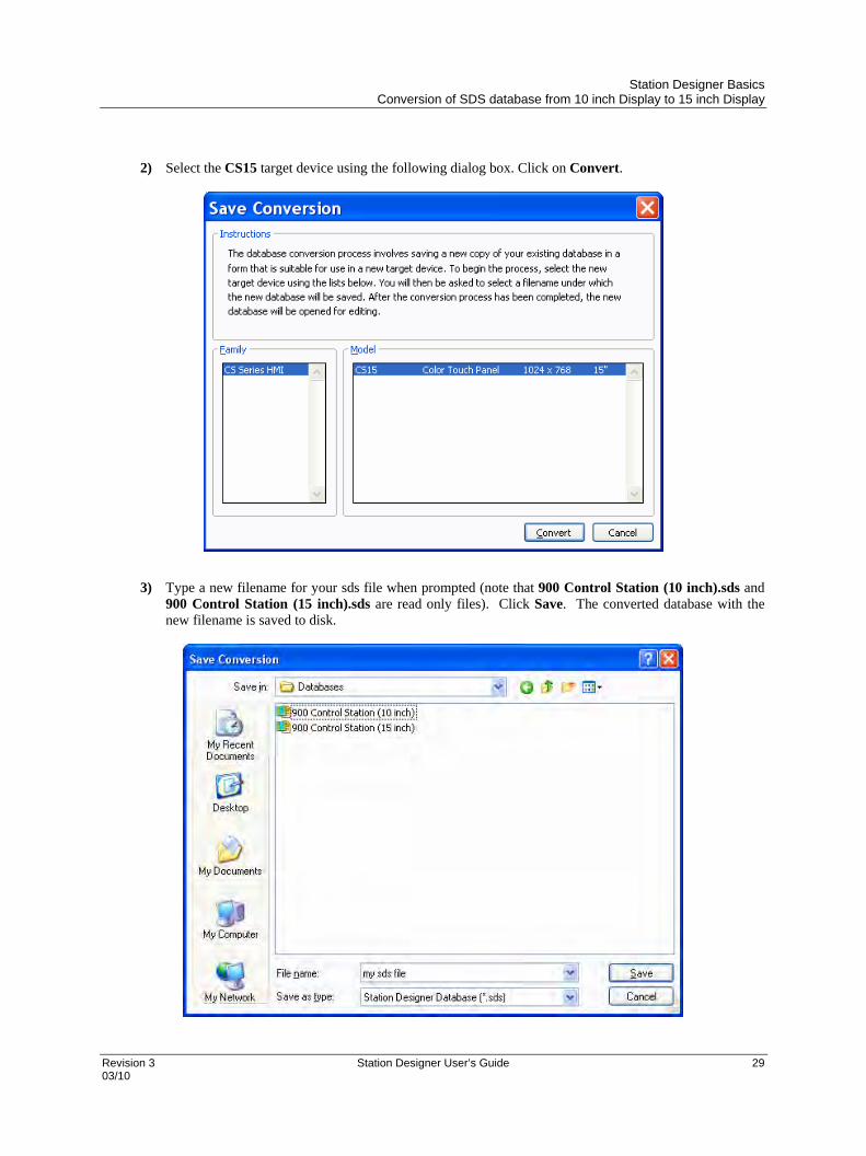
2) Select the CS15 target device using the following dialog box. Click on Convert.
3) Type a new filename for your sds file when prompted (note that 900 Control Station (10 inch).sds and
900 Control Station (15 inch).sds are read only files). Click Save. The converted database with the new filename is saved to disk.

Station Designer Basics Conversion of SDS database from 10 inch Display to 15 inch Display
30 Station Designer User’s Guide Revision 3 03/10
4) After a successful conversion the following message is displayed. Click OK.
5) Under the Navigation Pane, select "Display Pages � Pages� Fonts”
Click on Manage Font Database…

Station Designer Basics Conversion of SDS database from 10 inch Display to 15 inch Display
Revision 3 Station Designer User’s Guide 31 03/10
6) Click on Show System. Resize to larger font sizes by performing a global Replace. Select a font size to be replaced (e.g. Hei 16 Regular). Click on Replace.
7) Select a new font size to replace it with either from the dropdown list or via Pick…, and Click OK.

Station Designer Basics Conversion of SDS database from 10 inch Display to 15 inch Display
32 Station Designer User’s Guide Revision 3 03/10
8) When prompted “Do you want to proceed?” Click Yes.
9) Change the following font sizes:
from Hei 16 Regular to HeiS 22 Regular
from Hei 16 Bold to HeiS 22 Regular
from HeiS 12 Regular to HeiS 18 Regular
from HeiS 12 Bold to HeiS 18 Bold
from HeiS 14 Bold to HeiS 18 Bold
from HeiS 16 Bold to HeiS 18 Bold
from Swiss 12 Regular to HeiS 18 Regular
from Swiss 16 Regular to HeiS 18 Regular

Station Designer Basics Conversion of SDS database from 10 inch Display to 15 inch Display
Revision 3 Station Designer User’s Guide 33 03/10
10) Double Click on Soft Key 8. Select the Global Tab and set the Action Mode Operation and Action Details as follows.
11) Double Click on Soft Key 9. Select the Global Tab and set the Action Mode Operation and Action
Details as follows
Station Designer Basics Conversion of SDS database from 10 inch Display to 15 inch Display
34 Station Designer User’s Guide Revision 3 03/10
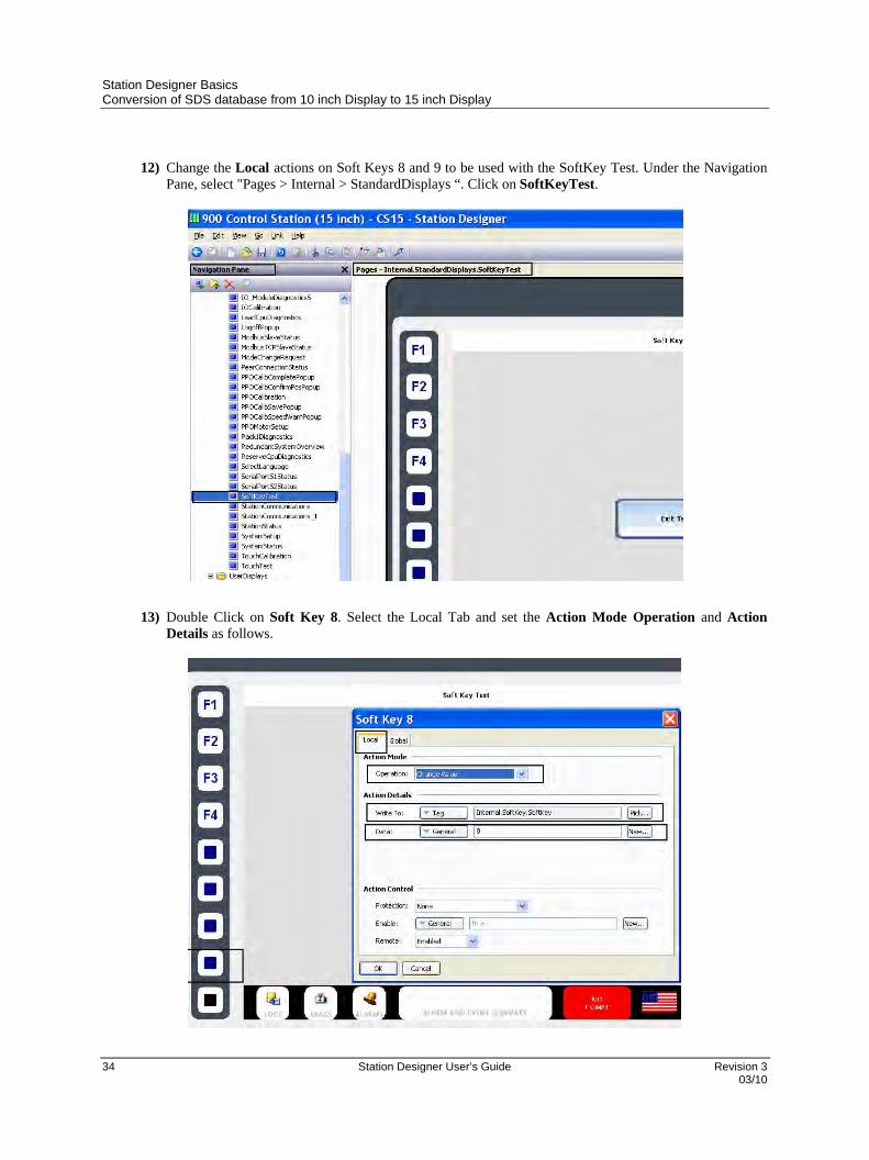
12) Change the Local actions on Soft Keys 8 and 9 to be used with the SoftKey Test. Under the Navigation
Pane, select "Pages > Internal > StandardDisplays “. Click on SoftKeyTest.
13) Double Click on Soft Key 8. Select the Local Tab and set the Action Mode Operation and Action
Details as follows.
Station Designer Basics Conversion of SDS database from 10 inch Display to 15 inch Display
Revision 3 Station Designer User’s Guide 35 03/10
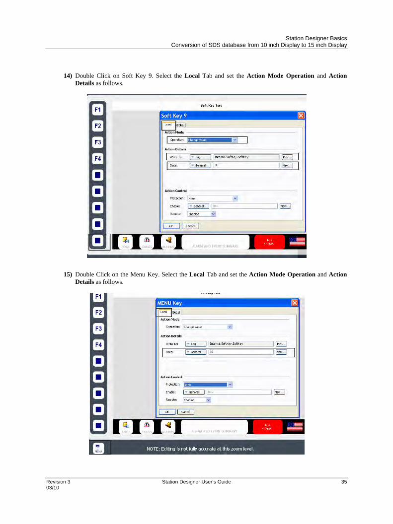
14) Double Click on Soft Key 9. Select the Local Tab and set the Action Mode Operation and Action
Details as follows.
15) Double Click on the Menu Key. Select the Local Tab and set the Action Mode Operation and Action
Details as follows.

Station Designer Basics Downloading to a Device
36 Station Designer User’s Guide Revision 3 03/10
Fnding Database Errors
Station Designer warns you of errors in the database. For example, deleting a communications device, or setting a
tag equal to an expression based on itself, thereby producing a circular reference is treated as an error in the
database. The error is indicated by a red balloon above the status bar.
The balloon disappears after a few seconds, but an error indication in the status bar remains. Click the indicator to
search for all the errors and circular references. These errors are placed in the Global Search Results List allowing
you to review them using the standard F4 or SHIFT+F4 key combinations. Right-click the indicator to access
commands to recompile the whole database, or to optimize the way in which device communications are organized.
Downloading to a Device Station Designer database files are downloaded to the 900 Control Station by means of the Link menu. The
download process typically takes only a few seconds, but can take somewhat longer on the first download if Station
Designer has to update the firmware in the device, or if the device does not contain an older version of the current
database. After this first download, Station Designer uses a process known as incremental download to ensure that
only changes to the database are transferred. This means that updates can be made in seconds, thereby reducing your
development cycle time and simplifying the debugging process.
Sending the Database
Once the link is configured, the database can be downloaded using either the Link-Send or Link-Update commands.
The former will send the entire database, whether or not individual objects within the file have changed. The latter
will only send changes, and will typically take a much shorter period of time to complete. The Update command is
typically the only one that you will need, as Station Designer will automatically fall back to a complete send if the
incremental download fails for any reason. As a shortcut, note that you can access Link-Update via the lightning bolt
symbol on the toolbar, or via the F9 key on the keyboard.
Note that downloading via TCP/IP relies on a Flash memory card being installed in the panel if the device’s
firmware is to be upgraded. Since you may want to perform such upgrades at some point in time, it is highly
recommended that you install a Flash memory card in any device to which TCP/IP downloads are likely to be
performed.
Station Designer Basics Extracting Databases
Revision 3 Station Designer User’s Guide 37 03/10
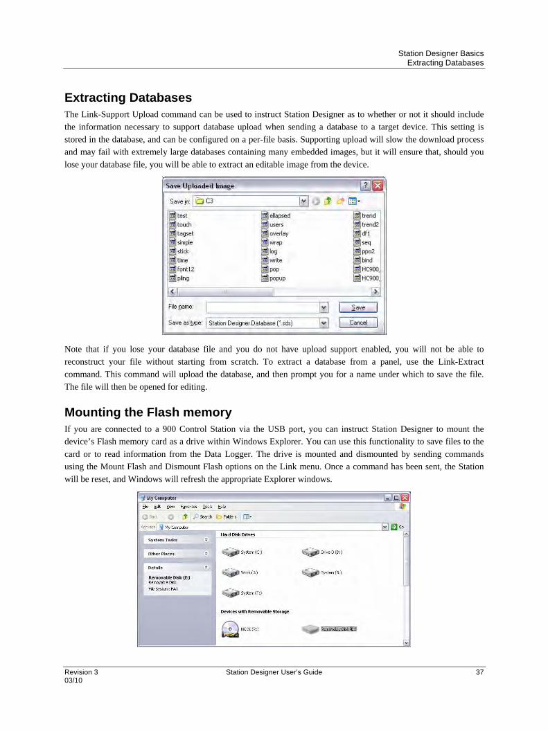
Extracting Databases The Link-Support Upload command can be used to instruct Station Designer as to whether or not it should include
the information necessary to support database upload when sending a database to a target device. This setting is
stored in the database, and can be configured on a per-file basis. Supporting upload will slow the download process
and may fail with extremely large databases containing many embedded images, but it will ensure that, should you
lose your database file, you will be able to extract an editable image from the device.
Note that if you lose your database file and you do not have upload support enabled, you will not be able to
reconstruct your file without starting from scratch. To extract a database from a panel, use the Link-Extract
command. This command will upload the database, and then prompt you for a name under which to save the file.
The file will then be opened for editing.
Mounting the Flash memory If you are connected to a 900 Control Station via the USB port, you can instruct Station Designer to mount the
device’s Flash memory card as a drive within Windows Explorer. You can use this functionality to save files to the
card or to read information from the Data Logger. The drive is mounted and dismounted by sending commands
using the Mount Flash and Dismount Flash options on the Link menu. Once a command has been sent, the Station
will be reset, and Windows will refresh the appropriate Explorer windows.

Station Designer Basics Formatting the Flash memory
38 Station Designer User’s Guide Revision 3 03/10
Note that some caution is required when mounting the Flash memory card…
When the card is mounted, the Station will periodically inform the PC if data on the card has been
modified. This means that both the PC and the device will suffer a minor performance hit if the card is
mounted during data logging operations for longer than necessary.
If you write to the Flash memory card from your PC, the Station will not be able to access the card until
Windows releases its lock on the card. This may take several seconds, and will restrict data logging
operations during that time, and prevent access to custom web pages. Station Designer will use the
Station’s RAM to ensure that no data is lost, but if too many writes are performed such that the card is
kept locked for four minutes or more, data may discarded.
You should never attempt to use Windows to format a Flash memory card that you have mounted via
Station Designer, whether it be via Explorer or from the command prompt. Windows does not correctly
lock the card during format operations, and the format may thus be unreliable and lead to subsequent data
loss. See below for details on how to format a card in a reliable manner.
Formatting the Flash memory The preferred method of formatting a card is via the Format Flash command on the Link menu. Selecting this
command will explain that the formatting process will destroy all the data stored on the Flash memory card and offer
you a chance to cancel the operation. If you elect to continue, the Station will be instructed to format the card. Note
that this process may take several minutes for a large card. Slow formats on Stations that are performing data
logging may therefore result in gaps in the recorded data.
Another method available for formatting a flash memory card is to use the facility provided in the 900 Control
Station. To access this facility, select the Stations main Menu, select Station Settings, Format Memory Device and
follow prompts to format the flash memory module.
A less attractive method of formatting a card is via a dedicated Flash memory drive connected to your PC. If you use
this method, be sure to instruct Windows to format the card using FAT16. For very small or very large cards,
Windows will most likely choose the wrong format by default. Worse still, some versions of Windows Explorer will
not allow you to override the default format, forcing you to use the command line version FORMAT instead.
Time and Date When the 900 Control Station is communicating with a HC900 controller, the Station’s clock is automatically
synchronized to the controller’s clock. Overriding this function is not recommended, but if overridden, the Station’s
clock can be set from a PC or directed to use an alternate time source.
Setting the Station’s clock will not automatically set the HC900 controller’s time.
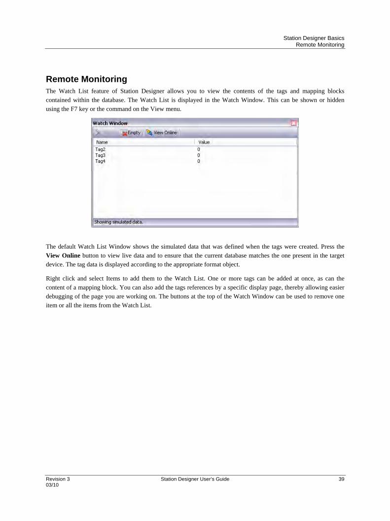
Station Designer Basics Remote Monitoring
Revision 3 Station Designer User’s Guide 39 03/10
Remote Monitoring The Watch List feature of Station Designer allows you to view the contents of the tags and mapping blocks
contained within the database. The Watch List is displayed in the Watch Window. This can be shown or hidden
using the F7 key or the command on the View menu.
The default Watch List Window shows the simulated data that was defined when the tags were created. Press the
View Online button to view live data and to ensure that the current database matches the one present in the target
device. The tag data is displayed according to the appropriate format object.
Right click and select Items to add them to the Watch List. One or more tags can be added at once, as can the
content of a mapping block. You can also add the tags references by a specific display page, thereby allowing easier
debugging of the page you are working on. The buttons at the top of the Watch Window can be used to remove one
item or all the items from the Watch List.


Revision 3 Station Designer User’s Guide 41 03/10
Building Custom Displays
Building custom displays in Station Designer can be as simple as placing a few intelligent objects on a blank custom
display and binding the objects to data sources in the controller to ground up development using drawing tools,
graphic symbols and custom navigation features. Regardless of the approach needed, the integration of the HC900
controller database through the .cde file import greatly simplifies the development task.
Tag characters and conflicts Tag text accepted by Station Designer software may include any alphanumeric character and underscore. Tags
accepted by Hybrid Control Designer for the HC900 controller configuration may include some special characters
and spaces that are not accepted by Station Designer. When the controller database (.cde file) is imported by Station
Designer, any non-compatible character or space used in the controller configuration is replaced with an underscore
character and the user is notified with a diagnostic message, see below. If the new tag with the new underscore
characters cause a duplication conflict with an existing tag that already has an underscore character, an additional
sequence number will be added to the end of the tag to indicate that more than one tag with the same character
structure exists, and to cancel the duplication by adding the sequence number.
When tag conflicts are resolved by the substitution of an underscore character, the tag changes are recorded in the
clipboard on your PC. To view the change list, simply launch a program that can accept the contents of the
clipboard such as Microsoft Excel or Notepad, and paste the clipboard contents into a worksheet. See example.
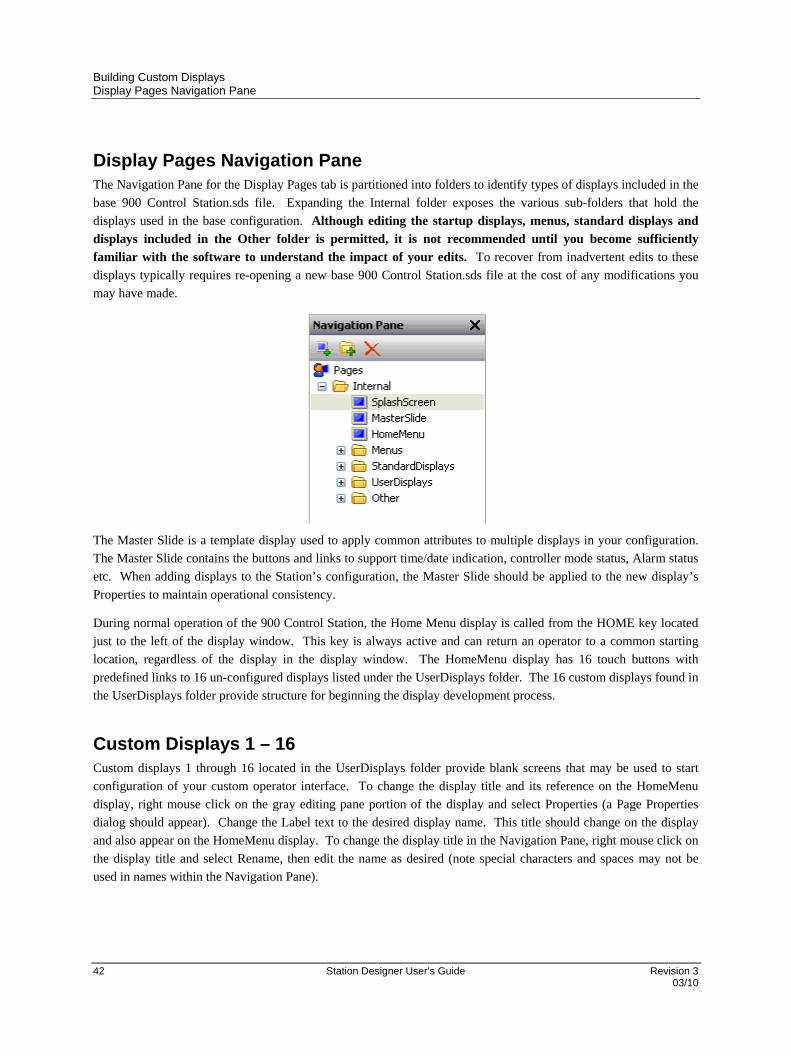
Building Custom Displays Display Pages Navigation Pane
42 Station Designer User’s Guide Revision 3 03/10
Display Pages Navigation Pane The Navigation Pane for the Display Pages tab is partitioned into folders to identify types of displays included in the
base 900 Control Station.sds file. Expanding the Internal folder exposes the various sub-folders that hold the
displays used in the base configuration. Although editing the startup displays, menus, standard displays and
displays included in the Other folder is permitted, it is not recommended until you become sufficiently
familiar with the software to understand the impact of your edits. To recover from inadvertent edits to these
displays typically requires re-opening a new base 900 Control Station.sds file at the cost of any modifications you
may have made.
The Master Slide is a template display used to apply common attributes to multiple displays in your configuration.
The Master Slide contains the buttons and links to support time/date indication, controller mode status, Alarm status
etc. When adding displays to the Station’s configuration, the Master Slide should be applied to the new display’s
Properties to maintain operational consistency.
During normal operation of the 900 Control Station, the Home Menu display is called from the HOME key located
just to the left of the display window. This key is always active and can return an operator to a common starting
location, regardless of the display in the display window. The HomeMenu display has 16 touch buttons with
predefined links to 16 un-configured displays listed under the UserDisplays folder. The 16 custom displays found in
the UserDisplays folder provide structure for beginning the display development process.
Custom Displays 1 – 16 Custom displays 1 through 16 located in the UserDisplays folder provide blank screens that may be used to start
configuration of your custom operator interface. To change the display title and its reference on the HomeMenu
display, right mouse click on the gray editing pane portion of the display and select Properties (a Page Properties
dialog should appear). Change the Label text to the desired display name. This title should change on the display
and also appear on the HomeMenu display. To change the display title in the Navigation Pane, right mouse click on
the display title and select Rename, then edit the name as desired (note special characters and spaces may not be
used in names within the Navigation Pane).
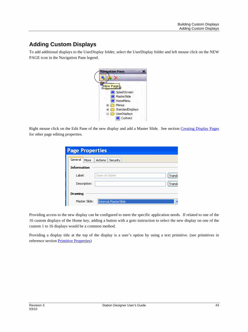
Building Custom Displays Adding Custom Displays
Revision 3 Station Designer User’s Guide 43 03/10
Adding Custom Displays To add additional displays to the UserDisplay folder, select the UserDisplay folder and left mouse click on the NEW
PAGE icon in the Navigation Pane legend.
Right mouse click on the Edit Pane of the new display and add a Master Slide. See section Creating Display Pages
for other page editing properties.
Providing access to the new display can be configured to meet the specific application needs. If related to one of the
16 custom displays of the Home key, adding a button with a goto instruction to select the new display on one of the
custom 1 to 16 displays would be a common method.
Providing a display title at the top of the display is a user’s option by using a text primitive. (see primitives in
reference section Primitive Properties)

Building Custom Displays Adding Signals to Displays
44 Station Designer User’s Guide Revision 3 03/10
Adding Signals to Displays When the Create Data Tags operation is executed, the database of the controller’s configuration is transferred to the
Data Tags Resource Pane of Station Designer and the tagged data is placed in folders based on the data type.
Expanding the Data Tags folders exposes additional subfolders to further sub-divide the tag database.
To add an analog signal to a display, expand the AnalogSignals folder to expose an OUT tag (the output value of an
analog signal).
Select the Out tag, drag and drop the tag in the desired location on the edit pane and size the object as required.
With the Out tag selected (red square around the object), double click the object and select desired properties. See
reference section Numeric Tags.
Adding variables to displays Variables are added to displays in a similar manner to adding Signals. Variables can be set to become active to the
touch on the Station, allowing the user to alter the value or state from the display through a pop-up entry pad. To add
an analog or digital variable to a display, select the appropriate sub-folder in .CDE folder, drag and drop the OUT
tag parameter from the Resource Pane onto the Edit Pane and size the object as required. Select the object (red
square around the object), double click the object and select the desired properties. See reference section Duplicating
Tags.
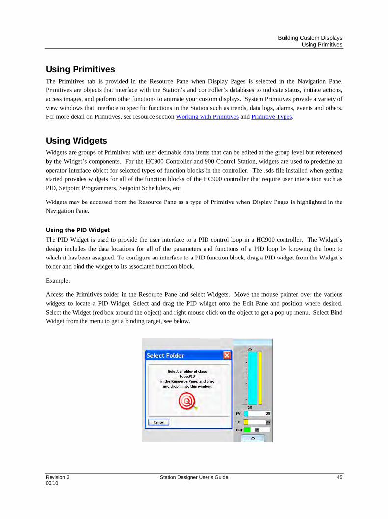
Building Custom Displays Using Primitives
Revision 3 Station Designer User’s Guide 45 03/10
Using Primitives The Primitives tab is provided in the Resource Pane when Display Pages is selected in the Navigation Pane.
Primitives are objects that interface with the Station’s and controller’s databases to indicate status, initiate actions,
access images, and perform other functions to animate your custom displays. System Primitives provide a variety of
view windows that interface to specific functions in the Station such as trends, data logs, alarms, events and others.
For more detail on Primitives, see resource section Working with Primitives and Primitive Types.
Using Widgets Widgets are groups of Primitives with user definable data items that can be edited at the group level but referenced
by the Widget’s components. For the HC900 Controller and 900 Control Station, widgets are used to predefine an
operator interface object for selected types of function blocks in the controller. The .sds file installed when getting
started provides widgets for all of the function blocks of the HC900 controller that require user interaction such as
PID, Setpoint Programmers, Setpoint Schedulers, etc.
Widgets may be accessed from the Resource Pane as a type of Primitive when Display Pages is highlighted in the
Navigation Pane.
Using the PID Widget
The PID Widget is used to provide the user interface to a PID control loop in a HC900 controller. The Widget’s
design includes the data locations for all of the parameters and functions of a PID loop by knowing the loop to
which it has been assigned. To configure an interface to a PID function block, drag a PID widget from the Widget’s
folder and bind the widget to its associated function block.
Example:
Access the Primitives folder in the Resource Pane and select Widgets. Move the mouse pointer over the various
widgets to locate a PID Widget. Select and drag the PID widget onto the Edit Pane and position where desired.
Select the Widget (red box around the object) and right mouse click on the object to get a pop-up menu. Select Bind
Widget from the menu to get a binding target, see below.
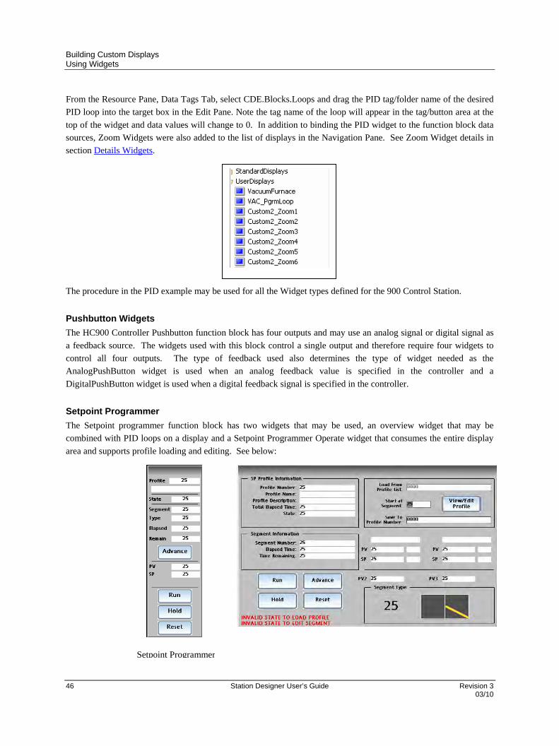
Building Custom Displays Using Widgets
46 Station Designer User’s Guide Revision 3 03/10
From the Resource Pane, Data Tags Tab, select CDE.Blocks.Loops and drag the PID tag/folder name of the desired
PID loop into the target box in the Edit Pane. Note the tag name of the loop will appear in the tag/button area at the
top of the widget and data values will change to 0. In addition to binding the PID widget to the function block data
sources, Zoom Widgets were also added to the list of displays in the Navigation Pane. See Zoom Widget details in
section Details Widgets.
The procedure in the PID example may be used for all the Widget types defined for the 900 Control Station.
Pushbutton Widgets
The HC900 Controller Pushbutton function block has four outputs and may use an analog signal or digital signal as
a feedback source. The widgets used with this block control a single output and therefore require four widgets to
control all four outputs. The type of feedback used also determines the type of widget needed as the
AnalogPushButton widget is used when an analog feedback value is specified in the controller and a
DigitalPushButton widget is used when a digital feedback signal is specified in the controller.
Setpoint Programmer
The Setpoint programmer function block has two widgets that may be used, an overview widget that may be
combined with PID loops on a display and a Setpoint Programmer Operate widget that consumes the entire display
area and supports profile loading and editing. See below:
Setpoint Programmer
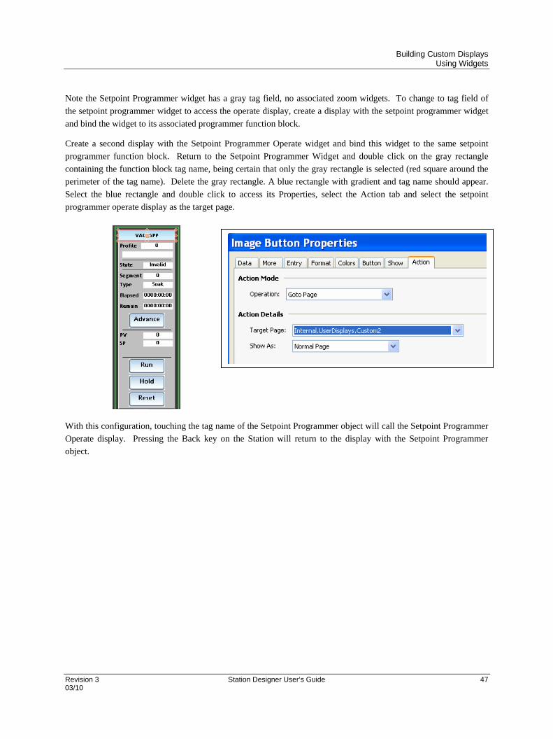
Building Custom Displays Using Widgets
Revision 3 Station Designer User’s Guide 47 03/10
Note the Setpoint Programmer widget has a gray tag field, no associated zoom widgets. To change to tag field of
the setpoint programmer widget to access the operate display, create a display with the setpoint programmer widget
and bind the widget to its associated programmer function block.
Create a second display with the Setpoint Programmer Operate widget and bind this widget to the same setpoint
programmer function block. Return to the Setpoint Programmer Widget and double click on the gray rectangle
containing the function block tag name, being certain that only the gray rectangle is selected (red square around the
perimeter of the tag name). Delete the gray rectangle. A blue rectangle with gradient and tag name should appear.
Select the blue rectangle and double click to access its Properties, select the Action tab and select the setpoint
programmer operate display as the target page.
With this configuration, touching the tag name of the Setpoint Programmer object will call the Setpoint Programmer
Operate display. Pressing the Back key on the Station will return to the display with the Setpoint Programmer
object.

Building Custom Displays Configuring Setpoint Programmer Pre-Plot Display
48 Station Designer User’s Guide Revision 3 03/10
Configuring Setpoint Programmer Pre-Plot Display 1. From the Resource Pane, select the SPP_PrePlot Widget and drag it onto a User Display page. Bind the
Widget to the desired Setpoint Programmer function block.
Note: The Setpoint Programmer function block of the HC900 controller does not have range limits for its
primary and auxiliary setpoint output values. It relies on its associated PID loops to limit the setpoint
values. As a result, binding the Pre-Plot graph to the Setpoint Programmer does not automatically set the
chart limits that are needed to allow graphing these parameters. The following operations guide you
through the process of completing the range limit entries for the Setpoint Programmer Pre-Plot display.
2. Click on the PrePlot Graph to select Quick Plot 4 as indicated in the bottom status pane below.

Building Custom Displays Configuring Setpoint Programmer Pre-Plot Display
Revision 3 Station Designer User’s Guide 49 03/10
3. The PrePlot Graph is comprised of the following layered primitive objects as shown in the table below:
Scatter Graph 1 is used to draw the PrePlot profile of the Auxiliary Setpoint output
Quick Plot 1 is used to plot the Auxiliary Setpoint output value
Quick Plot 2 is used to plot the Auxiliary PV4 input value
Scatter Graph 2 is used to draw the PrePlot profile of the Primary Setpoint output
Quick Plot 3 is used to plot the Primary Setpoint output value
Quick Plot 4 is used to plot the Primary PV1 input value
Right click on the PrePlot Graph and click on Select->Scatter Graph 1.

Building Custom Displays Configuring Setpoint Programmer Pre-Plot Display
50 Station Designer User’s Guide Revision 3 03/10
Note: After selecting Scatter Graph 1 the pop-up windows will close and the display will return to the
normal view. Your selection however has set the action of the Right Mouse button to call the properties of
Scatter Graph 1 layer when activated. See step 4.
4. Right click on Scatter Graph 1, and select Properties.
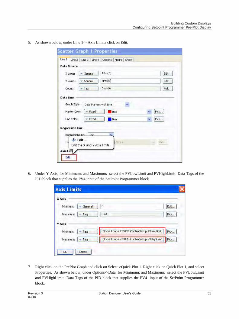
Building Custom Displays Configuring Setpoint Programmer Pre-Plot Display
Revision 3 Station Designer User’s Guide 51 03/10
5. As shown below, under Line 1-> Axis Limits click on Edit.
6. Under Y Axis, for Minimum: and Maximum: select the PVLowLimit and PVHighLimit Data Tags of the
PID block that supplies the PV4 input of the SetPoint Programmer block.
7. Right click on the PrePlot Graph and click on Select->Quick Plot 1. Right click on Quick Plot 1, and select
Properties. As shown below, under Options->Data, for Minimum: and Maximum: select the PVLowLimit
and PVHighLimit Data Tags of the PID block that supplies the PV4 input of the SetPoint Programmer
block.

Building Custom Displays Configuring Setpoint Programmer Pre-Plot Display
52 Station Designer User’s Guide Revision 3 03/10
8. Right click on the PrePlot Graph and click on Select->Quick Plot 2. Right click on Quick Plot 2, and select
Properties. As shown below, under Options->Data, for Minimum: and Maximum: select the PVLowLimit
and PVHighLimit Data Tags of the PID block that supplies the PV4 input of the SetPoint Programmer
block.
9. Right click on the PrePlot Graph and click on Select->Scatter Graph 2. Right click on Scatter Graph 2, and
select Properties. As shown below, under Line 1->Axis Limits click on Edit.
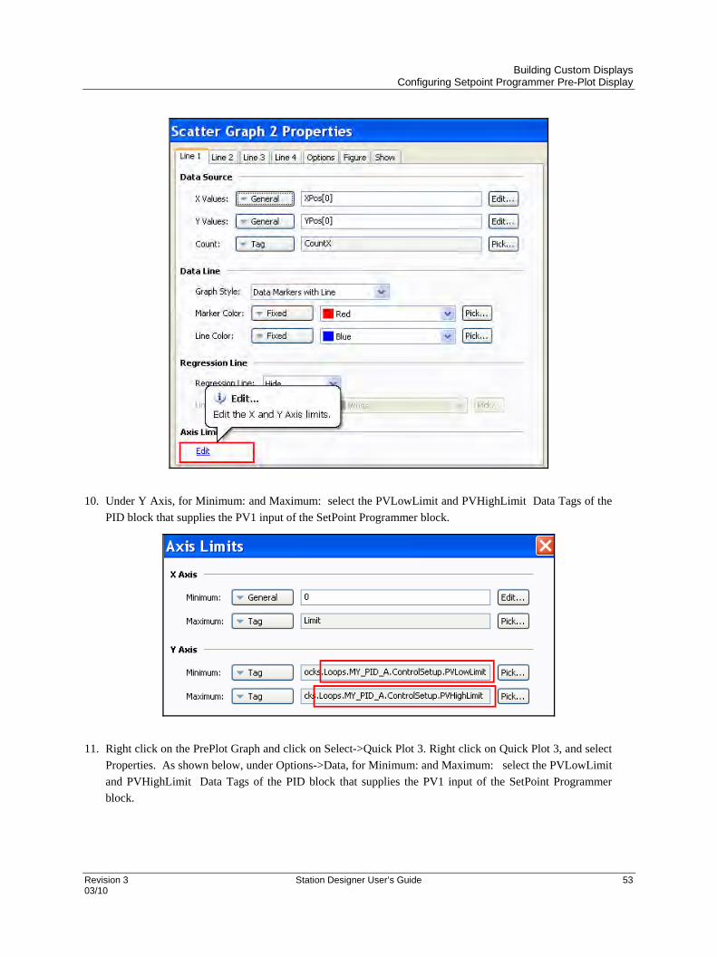
Building Custom Displays Configuring Setpoint Programmer Pre-Plot Display
Revision 3 Station Designer User’s Guide 53 03/10
10. Under Y Axis, for Minimum: and Maximum: select the PVLowLimit and PVHighLimit Data Tags of the
PID block that supplies the PV1 input of the SetPoint Programmer block.
11. Right click on the PrePlot Graph and click on Select->Quick Plot 3. Right click on Quick Plot 3, and select
Properties. As shown below, under Options->Data, for Minimum: and Maximum: select the PVLowLimit
and PVHighLimit Data Tags of the PID block that supplies the PV1 input of the SetPoint Programmer
block.
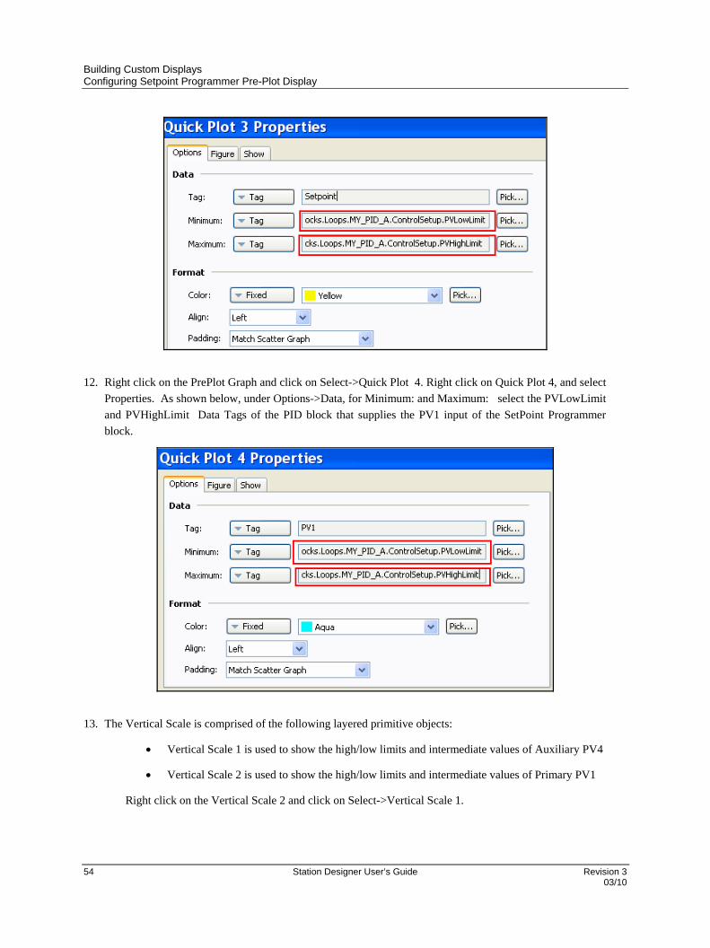
Building Custom Displays Configuring Setpoint Programmer Pre-Plot Display
54 Station Designer User’s Guide Revision 3 03/10
12. Right click on the PrePlot Graph and click on Select->Quick Plot 4. Right click on Quick Plot 4, and select
Properties. As shown below, under Options->Data, for Minimum: and Maximum: select the PVLowLimit
and PVHighLimit Data Tags of the PID block that supplies the PV1 input of the SetPoint Programmer
block.
13. The Vertical Scale is comprised of the following layered primitive objects:
Vertical Scale 1 is used to show the high/low limits and intermediate values of Auxiliary PV4
Vertical Scale 2 is used to show the high/low limits and intermediate values of Primary PV1
Right click on the Vertical Scale 2 and click on Select->Vertical Scale 1.

Building Custom Displays Configuring Setpoint Programmer Pre-Plot Display
Revision 3 Station Designer User’s Guide 55 03/10
14. Right click on Vertical Scale 1, and select Properties. As shown below, under the Limits tab, for Minimum
Value: and Maximum Value: Select the PVLowLimit and PVHighLimit Data Tags of the PID block that
supplies the PV4 input of the SetPoint Programmer block.
15. Right click on Vertical Scale 2, and select Properties. As shown below, under the Limits tab, for Minimum
Value: and Maximum Value: select the PVLowLimit and PVHighLimit Data Tags of the PID block that
supplies the PV1 input of the SetPoint Programmer block.

Building Custom Displays Configuring Setpoint Programmer Pre-Plot Display
56 Station Designer User’s Guide Revision 3 03/10
16. The Operate Display Button can be programmed to navigate to the associated SPP Operate Display. (Note:
Before performing the next operation you should have configured a Setpoint Programmer Operate display
that will be called from the Operate Display button.) Click on the Operate Display Button and click on
Properties.
17. Under the Action tab set Action Mode->Operation: to Goto Page. Set Action Details->Target Page: to the
Display Page containing the associated SPP Operate Display (e.g. Internal.UserDisplays.Custom1).
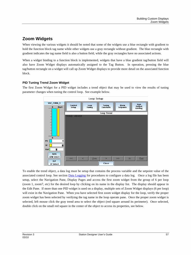
Building Custom Displays Zoom Widgets
Revision 3 Station Designer User’s Guide 57 03/10
Zoom Widgets When viewing the various widgets it should be noted that some of the widgets use a blue rectangle with gradient to
hold the function block tag name while other widgets use a gray rectangle without gradient. The blue rectangle with
gradient indicates the tag name field is also a button field, while the gray rectangles have no associated actions.
When a widget binding to a function block is implemented, widgets that have a blue gradient tag/button field will
also have Zoom Widget displays automatically assigned to the Tag Button. In operation, pressing the blue
tag/button rectangle on a widget will call up Zoom Widget displays to provide more detail on the associated function
block.
PID Tuning Trend Zoom Widget
The first Zoom Widget for a PID widget includes a trend object that may be used to view the results of tuning
parameter changes when tuning the control loop. See example below.
To enable the trend object, a data log must be setup that contains the process variable and the setpoint value of the
associated control loop. See section Data Logging for procedures to configure a data log. Once a log file has been
setup, select the Navigation Pane, Display Pages and access the first zoom widget from the group of 6 per loop
(zoom 1, zoom7, etc) for the desired loop by clicking on its name in the display list. The display should appear in
the Edit Pane. If more than one PID widget is used on a display, multiple sets of Zoom Widget displays (6 per loop)
will exist in the Navigation Pane. When you have selected first zoom widget display for the loop, verify the proper
zoom widget has been selected by verifying the tag name in the loop operate pane. Once the proper zoom widget is
selected, left mouse click the gray trend area to select the object (red square around its perimeter). Once selected,
double click on the small red square in the center of the object to access its properties, see below.

Building Custom Displays Using Symbols
58 Station Designer User’s Guide Revision 3 03/10
Assign the log file with the process variable and setpoint for the loop in the Data Log entry box. Assign the view
width for the display and adjust any remaining properties as desired. Select OK for the entries to close the Trent
Viewer Properties dialog.
Using Symbols Symbols are graphic objects picturing equipment, icons, schematics, signs, and other items commonly found in
industry. Assortments of symbols are provided and can be accessed from the Resource Pane. They are segmented
by industry category. Many symbols are available in multiple colors and action controls are limited to either show
(make visible, value = 1) or not show (make invisible, value = 0) on the display as controlled by integer values.
Once a symbol is selected and dropped on a display its size may be adjusted as required. Double clicking on the
symbol provides access to its properties where its orientation may be adjusted. If replacing one symbol with another
of a different color on the display, make a copy of the symbol after all size and orientation adjustments are complete,
click on the copy to access its properties and in its image window, drag the object of the desired color into the
window, all size and orientation attributes will be retained.
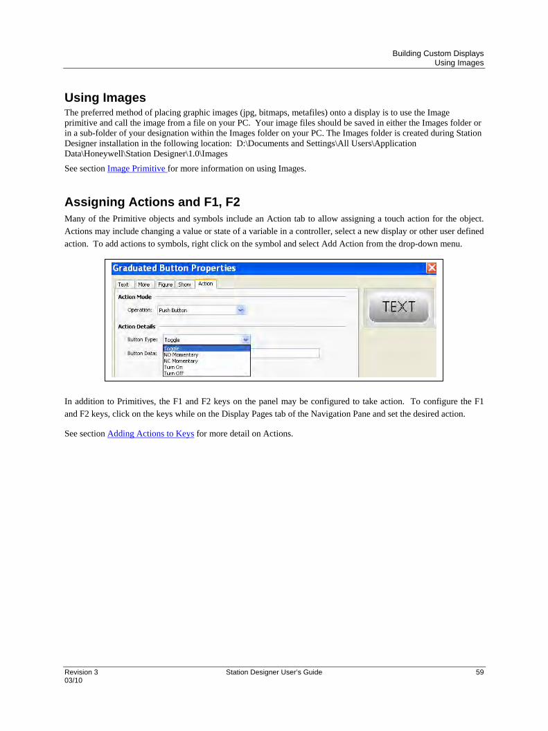
Building Custom Displays Using Images
Revision 3 Station Designer User’s Guide 59 03/10
Using Images The preferred method of placing graphic images (jpg, bitmaps, metafiles) onto a display is to use the Image primitive and call the image from a file on your PC. Your image files should be saved in either the Images folder or in a sub-folder of your designation within the Images folder on your PC. The Images folder is created during Station Designer installation in the following location: D:\Documents and Settings\All Users\Application Data\Honeywell\Station Designer\1.0\Images
See section Image Primitive for more information on using Images.
Assigning Actions and F1, F2 Many of the Primitive objects and symbols include an Action tab to allow assigning a touch action for the object.
Actions may include changing a value or state of a variable in a controller, select a new display or other user defined
action. To add actions to symbols, right click on the symbol and select Add Action from the drop-down menu.
In addition to Primitives, the F1 and F2 keys on the panel may be configured to take action. To configure the F1
and F2 keys, click on the keys while on the Display Pages tab of the Navigation Pane and set the desired action.
See section Adding Actions to Keys for more detail on Actions.


Revision 3 Station Designer User’s Guide 61 03/10
Data Logging
The Logging Process The data logger operates using two separate processes. The first samples each data point at the rate specified by the
properties of each log, and places the data in a buffer within the RAM of the 900 Control Station. The second
process executes every two minutes, and writes the data from memory to the Flash memory card (a Flash memory
card must be mounted and formatted within the 900 Control Station for proper logging to occur).
The logger process provides several advantages:
Writes to the Flash memory card are guaranteed to begin only on a two-minute boundary - 2, 4 or 6
minutes, etc. past the hour. Therefore, if necessary, the card can be removed and replaced with a new
card without data corruption (as long as the new card is installed before four minutes have elapsed), no
data will be lost.
Writes to the Flash memory achieve a much higher level of performance, by avoiding the need to
continually update the card’s file system data structures for every single sample. For logs configured to
sample at very high data rates, the bandwidth of a typical Flash memory card would not allow data to be
written reliably in the absence of such a buffering process.
Since data is not committed to Flash memory for up to two minutes, up to this amount of log data may be lost when
the 900 Control Station is powered-down. If it is powered-down while a write is in progress, the Flash memory card
may be corrupted. To ensure that such corruption is not permanent, a journaling system is used, which caches writes
to additional non-volatile memory within the 900 Control Station. If the device detects that a write was interrupted
during power-down, the write will be repeated when power is reapplied, thereby reversing any corruption and
repairing the Flash memory card.
If you want to remove a Flash memory card from a 900 Control Station performing data logging, you must observe
the procedure described above with respect to the activity LED, and only remove power when the activity has
ceased. If you are not sure if the 900 Control Station was powered-down correctly, reapply power, allow a Flash
memory write sequence to complete, and power down according to the correct procedure. The card can then be
removed safely.
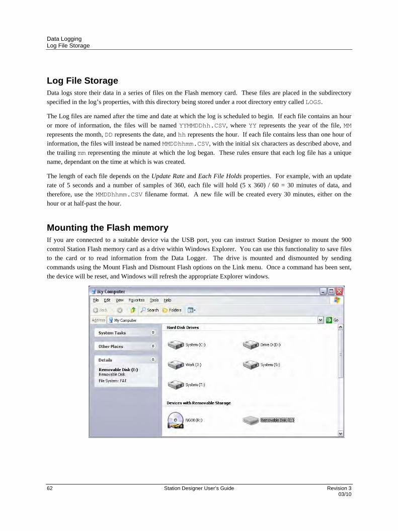
Data Logging Log File Storage
62 Station Designer User’s Guide Revision 3 03/10
Log File Storage Data logs store their data in a series of files on the Flash memory card. These files are placed in the subdirectory
specified in the log’s properties, with this directory being stored under a root directory entry called LOGS.
The Log files are named after the time and date at which the log is scheduled to begin. If each file contains an hour
or more of information, the files will be named YYMMDDhh.CSV, where YY represents the year of the file, MM
represents the month, DD represents the date, and hh represents the hour. If each file contains less than one hour of
information, the files will instead be named MMDDhhmm.CSV, with the initial six characters as described above, and
the trailing mm representing the minute at which the log began. These rules ensure that each log file has a unique
name, dependant on the time at which is was created.
The length of each file depends on the Update Rate and Each File Holds properties. For example, with an update
rate of 5 seconds and a number of samples of 360, each file will hold (5 x 360) / 60 = 30 minutes of data, and
therefore, use the MMDDhhmm.CSV filename format. A new file will be created every 30 minutes, either on the
hour or at half-past the hour.
Mounting the Flash memory If you are connected to a suitable device via the USB port, you can instruct Station Designer to mount the 900
control Station Flash memory card as a drive within Windows Explorer. You can use this functionality to save files
to the card or to read information from the Data Logger. The drive is mounted and dismounted by sending
commands using the Mount Flash and Dismount Flash options on the Link menu. Once a command has been sent,
the device will be reset, and Windows will refresh the appropriate Explorer windows.

Data Logging Formatting the Flash Memory Flash
Revision 3 Station Designer User’s Guide 63 03/10
Note that caution is required when mounting the Flash memory card:
When the card is mounted, the 900 Control Station will periodically inform the PC if data on the card
has been modified. This means that both the PC and the 900 Control Station will suffer a minor
performance hit if the card is mounted during data logging operations for longer than necessary.
If you write to the Flash memory card from your PC, the 900 Control Station will not be able to access
the card until Windows releases its lock on the card. This may take several seconds, and will restrict data
logging operations during that time, and prevent access to custom web pages. Station Designer will use
the 900 Control Station’s RAM to ensure that no data is lost, but if too many writes are performed such
that the card is kept locked for four minutes or more, data may discarded.
You should never attempt to use Windows to format a Flash memory card that you have mounted via
Station Designer, whether it be via Explorer or from the command prompt. Windows does not correctly
lock the card during format operations, and the format may thus be unreliable and lead to subsequent data
loss. See below for details of how to format a card in a reliable manner.
Formatting the Flash Memory Flash The preferred method of formatting a card is via the Format Flash command on the Link menu. Selecting this
command will explain that the formatting process will destroy all the data stored on the Flash memory card and offer
you a chance to cancel the operation. If you elect to continue, the 900 Control Station will be instructed to format
the card. Note that this process may take several minutes for a large card. Slow formats on 900 Control Stations,
which are performing data logging , may result in gaps in the recorded data. An alternative, less recommended
method of formatting a card, is via a dedicated Flash memory drive connected to your PC. If you use this method,
be sure to instruct Windows to format the card using FAT16. For very small or very large cards, Windows will most
likely choose the wrong format by default. Note that some versions of Windows Explorer will not allow you to
override the default format, forcing you to use the command line version FORMAT instead.
Log Setup The data logger is used to record selected HC900 Controller tag values to the 900 Control Station Flash memory
card. Data is stored in industry-standard comma-separated variable (CSV) format files, and can be easily imported
into applications such as Excel.
To configure data logging, select the Data Logger category near the bottom of the Navigation Pane. A Data Logger
window opens enabling access to global settings to enable or disable Batch Logging. The default selection to Enable
Batch Logging is set to “No”. If Batch Logging is enabled, all data files that are configured for batch logging will
be saved to a directory named after the current batch. This allows all log files related to a particular Batch to be
accessed and manipulated as a group.

Data Logging Log Setup
64 Station Designer User’s Guide Revision 3 03/10
To create a data log file, select Data Logger in the top portion of the Navigation Pane (note that the Data Logger
category must be selected near the bottom of the Navigation Pane) and right click. A window pops up allowing
selection of New Log.

Data Logging Log Setup
Revision 3 Station Designer User’s Guide 65 03/10
Selection of New Log opens up a window that is titled Data Logger – Log1. Further selection of Data Logger and
right click allows creation of additional log files (i.e.: Log2, Log3, and so on).
The Path Name property allows you to modify the directory in which the log will be saved. As default,
the log is saved in a directory named after the log’s own name (i.e.: Log1).
The Update Type property is used to indicate the type in which the log files are updated. It can either be
continuous type or triggered by snapshot type. Depending on the type of update the log files are created.
The Update Rate property is used to identify the sample rate of the data items to be logged. Although a
decimal place can be entered, sampling is only accurate to 200ms. The fastest sample rate is one second,
but note that this fast rate will produce very large amounts of data. All tags in the log file will be
sampled at the same rate.
The Each File Holds property is used to indicate how many samples will be included in each log file.
When this quantity of samples has been recorded, a new log file will be created using a different name.
Typically, this value is set that each log file contains a reasonable amount of data. For example, you may
want to set a configuration to have a new log file created every day.

Data Logging Concurrent Batch
66 Station Designer User’s Guide Revision 3 03/10
The Retain At Most property is used to indicate how many log files will be kept on the Flash memory
card before the oldest file is deleted. This property should be set to allow whatever is consuming the
logged information to extract the data from the 900 Control Station before the information is deleted.
The Allow Comments property is used to enable or disable the addition of comments to the data log via
the LogComment() function. Refer to Appendix A for details of how this function can be used.
The Merge Events property is used to enable or disable merging of comments with logged tags. With
Merge Events enabled, events and alarms associated with logged or monitored tags and signals are
included in the log. With it disabled, they are not.
The Apply Signatures property is used to control the addition of cryptographic signatures to the log. See
below for more information on these signatures and how they can be used to ensure the log data integrity
is maintained.
The Include in Batch property is used to include or exclude this log from the batch logging system. See
below for information on how batch logging operates.
The Log Enable property is used to allow or inhibit logging. If the entered expression is true, logging
will be enabled. If the expression is false, logging will be disabled. If no expression is entered, logging
will be enabled by default.
The Log Trigger property is used to trigger data snapshot. An expression which generates a false-to-true
transition will cause a data snapshot to be taken for logs configured in Trigger mode.
Concurrent Batch Concurrent batch allows the operator at the 900 Control Station to start and stop multiple batch processes in
the HC900 controller without having to wait for one batch process to finish before starting another batch
process. While these multiple batch processes are running concurrently in the HC900 controller, their
status is being tracked by the 900 Control Station and their data is being logged to the Compact Flash card
in the 900 Control Station for later analysis.

Data Logging Setting up Data Logger Properties for Concurrent Batch
Revision 3 Station Designer User’s Guide 67 03/10
Setting up Data Logger Properties for Concurrent Batch
The Setup Tab
The engineer sets up the following properties on the Setup tab of the Data Logger to enable concurrent
batch logging:
The Groups Tab
The batch processes are known as “batch groups” (or alternately “batch sets”) because they produce groups
(or sets) of batches. The engineer configures these batch groups as follows on the Groups tab of the Data
Logger. Up to eight batch groups can be configured.
Property Group Name defines the name of the batch group and is limited to 16 characters. An
empty group name defines the number of batch groups. For example, if Batch Group 3 has an
empty group name, then that implies that there are only two batch groups.
Property Group Enable defines the Out tag of a digital signal or digital variable in the HC900
controller that the 900 Control Station monitors to determine when a batch starts or stops in a
batch group and which controls the logging of the batch log file for that batch. (Rising edge starts
the batch, falling edge stops the batch.)

Data Logging Setting up Data Logger Properties for Concurrent Batch
68 Station Designer User’s Guide Revision 3 03/10
Property Group Ready defines the Out tag of a digital variable in the HC900 controller to which
the 900 Control Station writes a 1 (ON) when the operator at the 900 Control Station has entered
the header information for a batch that is about to run. The control strategy in the HC900
controller can use this digital variable as an interlock to not start the batch until its identification
has been confirmed by the operator. Its use is optional.
Property Retain Header defines whether the operator-entered values for the last batch header
should be presented to the operator again when a new batch header is about to be entered for the
next batch. Setting this value to true can save the operator typing time for similar batches. When
this value is set to false, all header fields presented to the operator for the next batch will be set to
empty.
The Header Tab
The Header tab defines the header fields used for all batch groups that are presented to the operator at the
900 Control Station for identifying a batch that is about to run. (Header fields are the same for all batch
groups.) A header field is limited to 16 characters. An empty header field defines the number of header
fields. For example, if Header Field 3 is empty, then that implies that there are only two header fields.
Note that there must be at least one header field (the first header field) and that header field defines the
batch name of the batch that is about to run. Note that because there can be 8 batches and there are 8
header fields, the user may think he is assigning a header for each batch group because the Groups tab was
for setting each batch group.
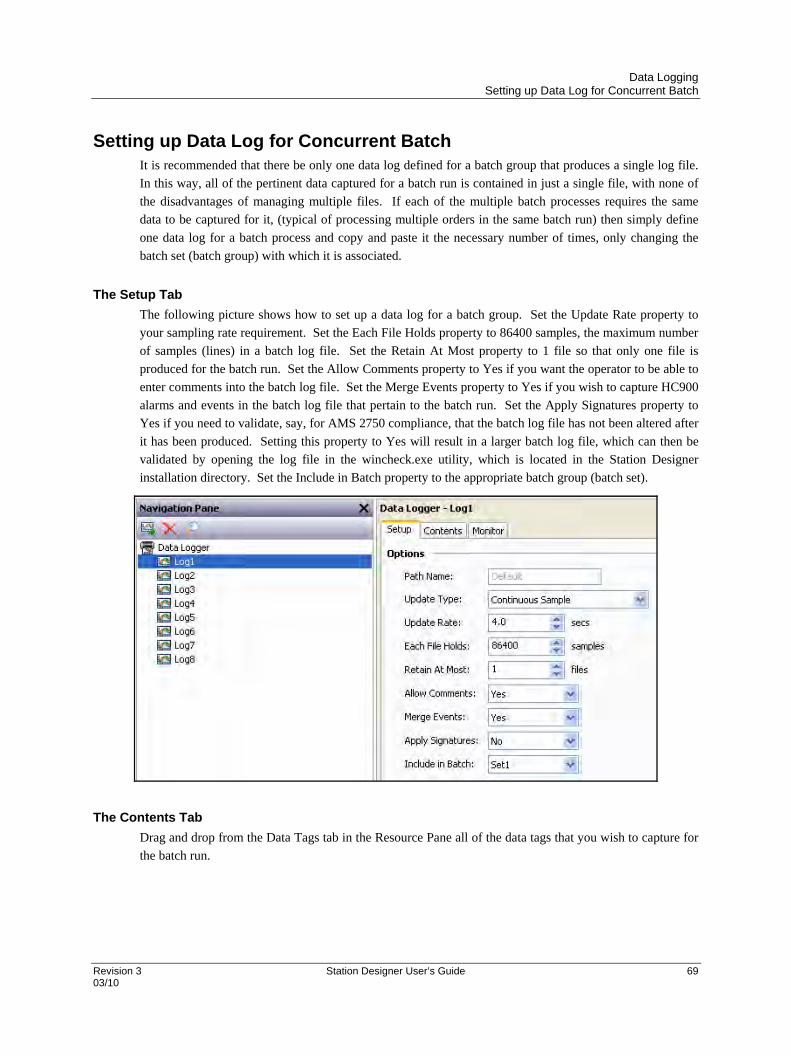
Data Logging Setting up Data Log for Concurrent Batch
Revision 3 Station Designer User’s Guide 69 03/10
Setting up Data Log for Concurrent Batch It is recommended that there be only one data log defined for a batch group that produces a single log file.
In this way, all of the pertinent data captured for a batch run is contained in just a single file, with none of
the disadvantages of managing multiple files. If each of the multiple batch processes requires the same
data to be captured for it, (typical of processing multiple orders in the same batch run) then simply define
one data log for a batch process and copy and paste it the necessary number of times, only changing the
batch set (batch group) with which it is associated.
The Setup Tab
The following picture shows how to set up a data log for a batch group. Set the Update Rate property to
your sampling rate requirement. Set the Each File Holds property to 86400 samples, the maximum number
of samples (lines) in a batch log file. Set the Retain At Most property to 1 file so that only one file is
produced for the batch run. Set the Allow Comments property to Yes if you want the operator to be able to
enter comments into the batch log file. Set the Merge Events property to Yes if you wish to capture HC900
alarms and events in the batch log file that pertain to the batch run. Set the Apply Signatures property to
Yes if you need to validate, say, for AMS 2750 compliance, that the batch log file has not been altered after
it has been produced. Setting this property to Yes will result in a larger batch log file, which can then be
validated by opening the log file in the wincheck.exe utility, which is located in the Station Designer
installation directory. Set the Include in Batch property to the appropriate batch group (batch set).
The Contents Tab
Drag and drop from the Data Tags tab in the Resource Pane all of the data tags that you wish to capture for
the batch run.

Data Logging Batch Logging
70 Station Designer User’s Guide Revision 3 03/10
The Monitor Tab
Drag and drop from the Data Tags tab in the Resource Pane all of the HC900 alarms and events that you
wish to capture for the batch run. Note that you must choose the alarms and events from the
CDE.Signals.Interest tag folder:
Batch Logging For normal data logging operation, the Data Logger will save the log files under the folder name specified for each
log. Batch logging, on the other hand, also saves all logs that are so configured to a directory named after the
current production batch (note that there will be 2 files within the Flash memory card containing tag data logs – one
will be the continuous log file and the other file will only contain data between a start and stop of Batch logging).
Batch logging allows all the logs related to a particular batch to be accessed and manipulated as a group. Only one
Batch grouping of log files can be configured for Batch logging.
The start and stop of Batch logging is controlled via a number of functions. NewBatch(name) will create a folder
called name, ending the current batch and starting a new one. Files recorded after this command will be saved under
the new folder name. The EndBatch() function will stop the current batch, while GetBatch() will return the
name of the batch that is currently active. For more information, please refer to Appendix A.

Data Logging Setup Log Viewing Displays
Revision 3 Station Designer User’s Guide 71 03/10
Setup Log Viewing Displays After a Log file has been configured, and HC900 controller data tags have been dragged into the Log file Contents
Log list box, User Displays can be created to display the logged data.
Select one of the freely available Internal User Displays from the Navigation Pane (note that the Display Pages
category must be selected near the bottom of the Navigation Pane). Within the Resource Pane, select the Primitives
category (bottom right side of screen) and then select System Primitives within the Resource Pane Categories listing.
Select the Trend Viewer primitive and drag it to the custom User Display pane, sizing as necessary.
Select the Trend Viewer primitive within the User Display pane and double click on the center red square. The
Trend Viewer Properties dialog box is displayed.

Data Logging Accessing Log Files
72 Station Designer User’s Guide Revision 3 03/10
Within the Options tab of the Trend Viewer Properties box select the Data Log file you wish to display using the
pull down box and select the View Width time of your trending display (this will be the default time width when this
display screen is selected at the 900 Control Station). Within the Gridlines section of the Options tab select
Automatic for Time Axis and Data Axis boxes, and enter the appropriate Minimum and Maximum data scale values
of your displayed chart. All other configuration selections within the Properties box are self explanatory.
Accessing Log Files There are multiple methods for accessing Log file data from the 900 Control Station:
Data logs can be exported to a USB memory device that is connected to the 900 Control Station USB port by selecting; Menu/Data Logging/Export Data Logs to USB.
Log files can be accessed over a TCP/IP connection, using either a web browser, such as Microsoft
Internet Explorer, or by using the automated process implemented by the WebSync utility provided with
the 900 Control Station.
FTP Server allows remote clients to connect to the 900 Control Station and download the logs. Refer to
the Using Services section for details.
Sync Manager can be used to push the files to an FTP server on a periodic basis. Refer to the Using
Services section for details.
You can enable automatic copying of the log files to a USB memory device by configuring the Memory
Stick option in the Communication category. Refer to the Using Communications chapter of this manual
for more details.
Digital Signatures Cryptographic signatures may be added to data, event and security logs, thereby allowing you to check a log file’s
integrity. The signatures will show if the log has been tampered with, or if data has been removed from the middle
of the file. They will also allow you to be sure that a given log file came from the given 900 Control Station.
Enabling signatures adds an extra field to the CSV file to allow the storage of the required data. If you examine
such a file, you will see that every few lines of the file has a large amount of data stored in this additional field. This
data is the digital signature - a value mathematically derived from the data in the proceeding lines in a manner that
makes it impossible to determine how to keep the signature valid if a change is made to the data.
Signatures can be verified using the SigCheck command-line utility provided with the Station Designer software.
The utility will either confirm that the file is valid, or indicate the line at which the validation error occurs.
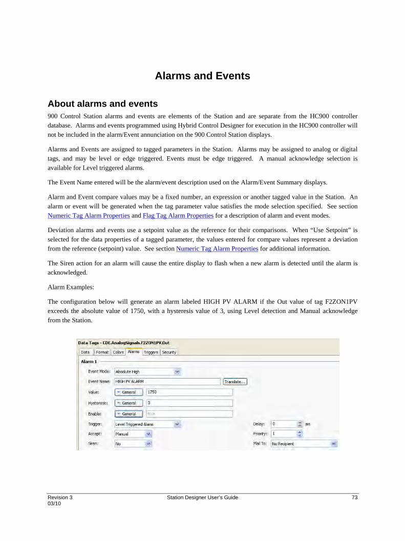
Revision 3 Station Designer User’s Guide 73 03/10
Alarms and Events
About alarms and events 900 Control Station alarms and events are elements of the Station and are separate from the HC900 controller
database. Alarms and events programmed using Hybrid Control Designer for execution in the HC900 controller will
not be included in the alarm/Event annunciation on the 900 Control Station displays.
Alarms and Events are assigned to tagged parameters in the Station. Alarms may be assigned to analog or digital
tags, and may be level or edge triggered. Events must be edge triggered. A manual acknowledge selection is
available for Level triggered alarms.
The Event Name entered will be the alarm/event description used on the Alarm/Event Summary displays.
Alarm and Event compare values may be a fixed number, an expression or another tagged value in the Station. An
alarm or event will be generated when the tag parameter value satisfies the mode selection specified. See section
Numeric Tag Alarm Properties and Flag Tag Alarm Properties for a description of alarm and event modes.
Deviation alarms and events use a setpoint value as the reference for their comparisons. When “Use Setpoint” is
selected for the data properties of a tagged parameter, the values entered for compare values represent a deviation
from the reference (setpoint) value. See section Numeric Tag Alarm Properties for additional information.
The Siren action for an alarm will cause the entire display to flash when a new alarm is detected until the alarm is
acknowledged.
Alarm Examples:
The configuration below will generate an alarm labeled HIGH PV ALARM if the Out value of tag F2ZON1PV
exceeds the absolute value of 1750, with a hysteresis value of 3, using Level detection and Manual acknowledge
from the Station.
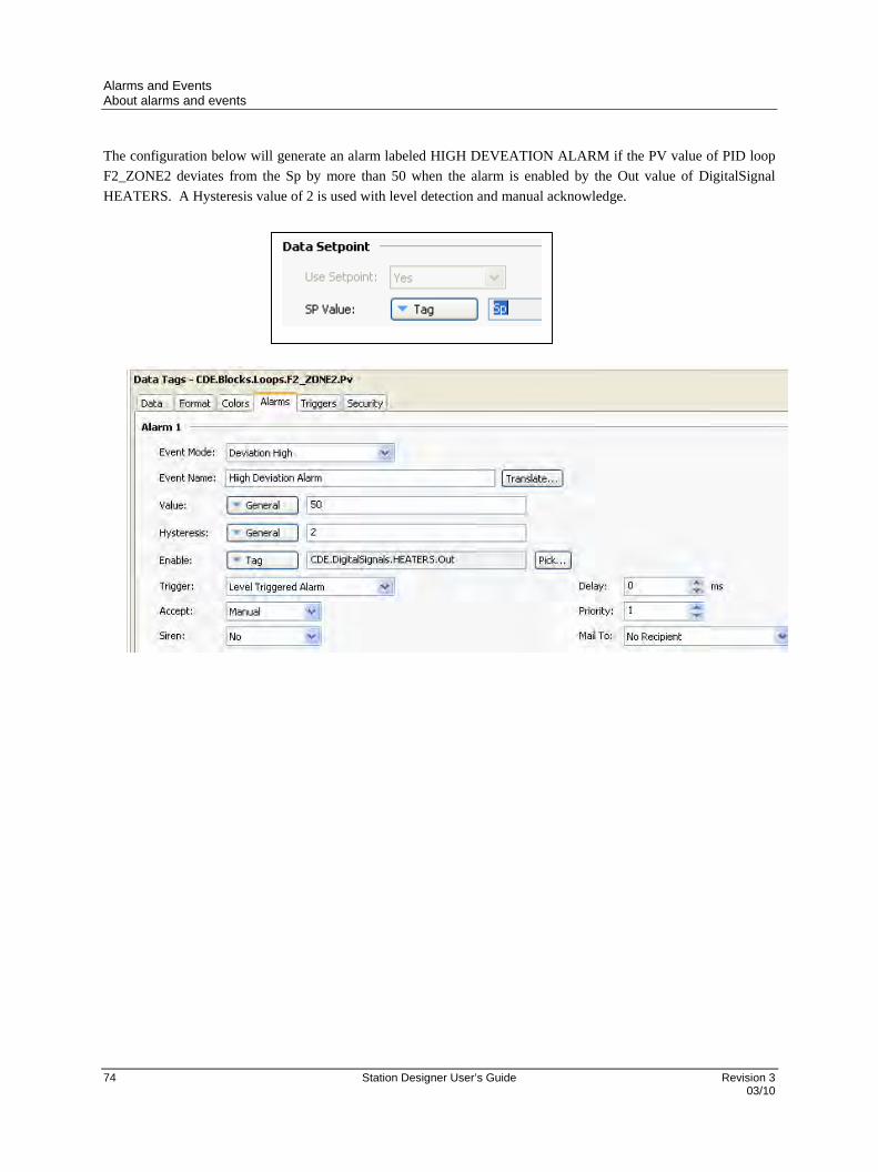
Alarms and Events About alarms and events
74 Station Designer User’s Guide Revision 3 03/10
The configuration below will generate an alarm labeled HIGH DEVEATION ALARM if the PV value of PID loop
F2_ZONE2 deviates from the Sp by more than 50 when the alarm is enabled by the Out value of DigitalSignal
HEATERS. A Hysteresis value of 2 is used with level detection and manual acknowledge.
Revision 3 Station Designer User’s Guide 75 03/10
Using Internal Tags
To this point tags have be identified as parameters that exist in the database of a HC900 controller and are imported
after the controller configuration is complete. Another type of tag used in the Station to initiate actions, retain user
entered data or present unique text strings is the Internal tag. To add an internal tag to the Station’s database, access
the Data Tags tab in the Navigation Pane and follow the instructions provided in section Working with Tags.
The 900 Control Station .sds file installs a number of tags in the Internal folder of the Navigation Pane to support the
many controller status displays and pre-build functions of the Station. These internal tags should not be altered.


Revision 3 Station Designer User’s Guide 77 03/10
Using Communications
The first stage of creating a Station Designer database is to configure the communications ports of the 900 Control
Station for use with the HC900 controller per the Getting Started section.
For additional communications, the Communications category lists the unit’s available ports in the form of a tree
structure. The example shown above has three primary serial ports. Target devices other than HC900 may also have
one or two Ethernet ports capable of running several communications protocols simultaneously.

Using Communications Serial Port Selection
78 Station Designer User’s Guide Revision 3 03/10
Serial Port Selection When configuring one of the serial ports of the device for communications, note that some devices (and certain
option cards) multiplex a single serial controller between multiple ports. This implies that if either port is used for a
slave protocol, the other port is not available. If a token-passing protocol such as DH-485 is employed, the other port
is similarly disabled. An error is displayed if you attempt to create a configuration that breaks these rules.
You can use the target device’s programming port as an additional communication port and use the device’s USB
port for downloads. Where USB is not used, re-enable serial downloads by executing the StopSystem() command in
response to some user action.
Selecting a Protocol The 900 Control Station supports the following protocols:
HC900 - use with HC900 Controllers (one controller per Station)
HC900 Serial – use with HC900 controllers via RS485 (one controller per Station)
Modbus – Master or slave to non-HC900 devices
Modbus TCP – Ethernet to non-HC900 devices
To select a protocol for a particular port, click on that port’s icon in the Navigation Pane, and press the Pick button
next to the Driver field in the Editing Pane.
The following dialog box will appear…
Select the appropriate manufacturer and driver, and press the OK button to close the dialog box. The port will then
be configured to use the appropriate protocol, and a single device icon will be created in the Navigation Pane. If you
are configuring a serial port, the various Port Settings fields (Baud Rate, Data Bits, Stop Bits and Parity) will be set
to default values appropriate to the protocol in question. You will need to check these settings to make sure that they
correspond to the settings for the device to be addressed.
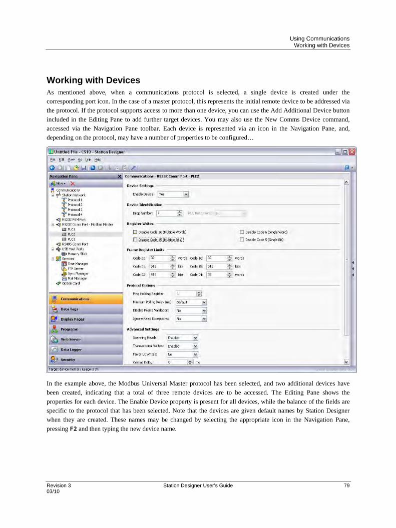
Using Communications Working with Devices
Revision 3 Station Designer User’s Guide 79 03/10
Working with Devices As mentioned above, when a communications protocol is selected, a single device is created under the
corresponding port icon. In the case of a master protocol, this represents the initial remote device to be addressed via
the protocol. If the protocol supports access to more than one device, you can use the Add Additional Device button
included in the Editing Pane to add further target devices. You may also use the New Comms Device command,
accessed via the Navigation Pane toolbar. Each device is represented via an icon in the Navigation Pane, and,
depending on the protocol, may have a number of properties to be configured…
In the example above, the Modbus Universal Master protocol has been selected, and two additional devices have
been created, indicating that a total of three remote devices are to be accessed. The Editing Pane shows the
properties for each device. The Enable Device property is present for all devices, while the balance of the fields are
specific to the protocol that has been selected. Note that the devices are given default names by Station Designer
when they are created. These names may be changed by selecting the appropriate icon in the Navigation Pane,
pressing F2 and then typing the new device name.
Using Communications Advanced Settings
80 Station Designer User’s Guide Revision 3 03/10
Advanced Settings In addition to the device settings mentioned above, certain master devices will also offer a number of advanced
settings that can be used to optimize communications behavior…
The Spanning Reads option is used to specify whether Station Designer will optimize read operations
by reading blocks of data, even if those blocks span registers that are not currently on the comms scan or
referenced in the database. For example, with spanning reads enabled for a database that references
registers D1, D2 and D4, a single comms command will be issued to read four registers from D1
onwards. Disabling spanning reads will results in two read operations, one for two registers from D1, and
one for a single register from D4.
The Transactional Writes options is used to specify whether a series of changes to a data value in
Station Designer should result in a corresponding series of write operations, or whether only the last
written value be transferred. Transactional writes make, for example, pushbutton replacement easier.
The Favor UI Writes option is used to specify whether to give priority to write operations that directly
result from user actions. This is useful when working with a database that performs a lot of background
communications as a result of protocol conversion or programmatic activity.
The Comms Delay option is used to specify a delay that will be inserted between any two comms
transactions for this device. It is useful when working with remote devices that are unable to keep up
with Station Designer’s performance, or when a lower comms priority is to be given to a device.
Port And Device Usage Right click an item to find all the connected devices to a particular port of that item. Select the Find Usage
command. The required items are placed on the Global Search Results List, and can be accessed by
pressing the F4 OR SHIFT+F4 key combinations. The list can be shown or hidden by pressing F8.

Using Communications Network Configuration
Revision 3 Station Designer User’s Guide 81 03/10
Network Configuration The target device’s IP network configuration is edited via the Network icon in the Navigation Pane. When the icon
is selected, the Editing Pane will show a number of tabs, each of which allows a given set of properties to be
configured.
Ethernet Settings
The first tab configures the target device’s Ethernet port…
Cp/
Port Settings
The Port Mode field controls whether or not the port is enabled, and the method by which the port is to obtain its IP
configuration. The DHCP mode selection is not supported when used with HC900 controllers.
For HC900 controller communications, select the Manual Configuration mode. The IP Address, Network Mask and
Gateway fields must be manually filled out with the appropriate information. The default values provided for these
fields will almost never be suitable for your application! Be sure to consult your network administrator when
selecting appropriate values, and be sure to enter and download these values before connecting the target device to
your network. If you do not do this, it is possible—although unlikely—that you may cause problems on your
network.
IEEE 802.3 should not be selected with HC900 controllers.
Physical Layer
The Physical Layer options control the type of connection that the device will attempt to negotiate with the hub or
switch to which it is connected. Generally, these options can be left in their default states, but if you have trouble
establishing a reliable connection, especially when connecting directly to a PC without an intervening hub or switch,
consider turning off both Full Duplex and High Speed operation to see if this solves the problem.
Maximum Segment Size
The Maximum Segment Size options control the MSS settings for TCP send and receive. You should not generally
have to change these settings as the default values are suitable for virtually all applications and all networks.
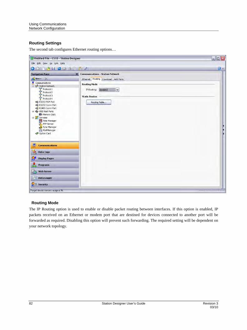
Using Communications Network Configuration
82 Station Designer User’s Guide Revision 3 03/10
Routing Settings
The second tab configures Ethernet routing options…
Routing Mode
The IP Routing option is used to enable or disable packet routing between interfaces. If this option is enabled, IP
packets received on an Ethernet or modem port that are destined for devices connected to another port will be
forwarded as required. Disabling this option will prevent such forwarding. The required setting will be dependent on
your network topology.

Using Communications Network Configuration
Revision 3 Station Designer User’s Guide 83 03/10
Routing Table
The routing table is used to define additional static routes for Station Designer’s TCP/IP stack.
In the example above, a single route has been specified, telling Station Designer to forward any packets destined for
IP addresses starting with 192.168.3 to the router located on the local network at address 192.9.200.8. Once again,
the exact settings required will be dependent on the topology of the network to which the target device is connected.
Download Settings
The third tab is used to configure downloads to the target 900 Control Station over TCP/IP…
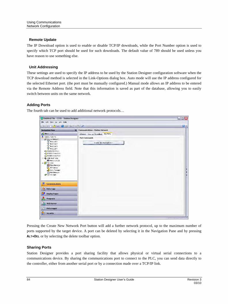
Using Communications Network Configuration
84 Station Designer User’s Guide Revision 3 03/10
Remote Update
The IP Download option is used to enable or disable TCP/IP downloads, while the Port Number option is used to
specify which TCP port should be used for such downloads. The default value of 789 should be used unless you
have reason to use something else.
Unit Addressing
These settings are used to specify the IP address to be used by the Station Designer configuration software when the
TCP download method is selected in the Link-Options dialog box. Auto mode will use the IP address configured for
the selected Ethernet port. (the port must be manually configured.) Manual mode allows an IP address to be entered
via the Remote Address field. Note that this information is saved as part of the database, allowing you to easily
switch between units on the same network.
Adding Ports
The fourth tab can be used to add additional network protocols…
Pressing the Create New Network Port button will add a further network protocol, up to the maximum number of
ports supported by the target device. A port can be deleted by selecting it in the Navigation Pane and by pressing
ALT+DEL or by selecting the delete toolbar option.
Sharing Ports
Station Designer provides a port sharing facility that allows physical or virtual serial connections to a
communications device. By sharing the communications port to connect to the PLC, you can send data directly to
the controller, either from another serial port or by a connection made over a TCP/IP link.

Using Communications Network Configuration
Revision 3 Station Designer User’s Guide 85 03/10
Enabling TCP/IP
Ensure that you enable the ethernet port before attempting to share ports even if you do not use the virtual serial port
facility. The local sharing of ports is based upon the TCP/IP protocol, which is not available unless at least one
network interface is enabled.
Sharing A Port
To share a port, select Yes in the Share Port property and enter a suitable TCP/IP port number to indicate how the
virtual port should be addressed, as in the following figure.
If you leave the port setting at zero, a default number of 4000 plus the logical index of the port is used. Use any
number that is not already used by another TCP/IP protocol. It is recommended to use port numbers between 4000
and 4099.
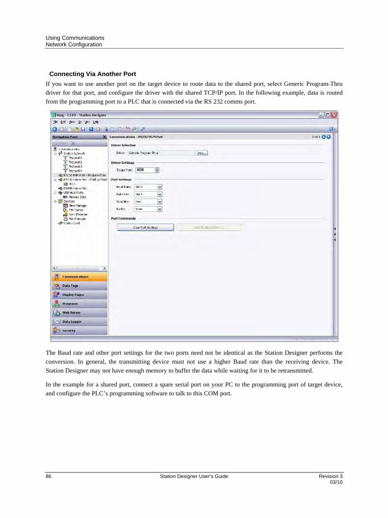
Using Communications Network Configuration
86 Station Designer User’s Guide Revision 3 03/10
Connecting Via Another Port
If you want to use another port on the target device to route data to the shared port, select Generic Program-Thru
driver for that port, and configure the driver with the shared TCP/IP port. In the following example, data is routed
from the programming port to a PLC that is connected via the RS 232 comms port.
The Baud rate and other port settings for the two ports need not be identical as the Station Designer performs the
conversion. In general, the transmitting device must not use a higher Baud rate than the receiving device. The
Station Designer may not have enough memory to buffer the data while waiting for it to be retransmitted.
In the example for a shared port, connect a spare serial port on your PC to the programming port of target device,
and configure the PLC’s programming software to talk to this COM port.
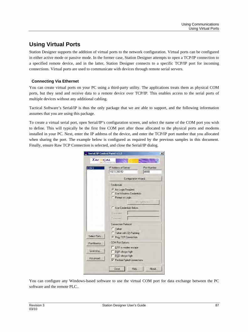
Using Communications Using Virtual Ports
Revision 3 Station Designer User’s Guide 87 03/10
Using Virtual Ports Station Designer supports the addition of virtual ports to the network configuration. Virtual ports can be configured
in either active mode or passive mode. In the former case, Station Designer attempts to open a TCP/IP connection to
a specified remote device, and in the latter, Station Designer connects to a specific TCP/IP port for incoming
connections. Virtual ports are used to communicate with devices through remote serial servers.
Connecting Via Ethernet
You can create virtual ports on your PC using a third-party utility. The applications treats them as physical COM
ports, but they send and receive data to a remote device over TCP/IP. This enables access to the serial ports of
multiple devices without any additional cabling.
Tactical Software’s Serial/IP is thus the only package that we are able to support, and the following information
assumes that you are using this package.
To create a virtual serial port, open Serial/IP’s configuration screen, and select the name of the COM port you wish
to define. This will typically be the first free COM port after those allocated to the physical ports and modems
installed in your PC. Next, enter the IP address of the device, and enter the TCP/IP port number that you allocated
when sharing the port. The example below is configured as required by the previous samples in this document.
Finally, ensure Raw TCP Connection is selected, and close the Serial/IP dialog.
You can configure any Windows-based software to use the virtual COM port for data exchange between the PC
software and the remote PLC..

Using Communications Using Virtual Ports
88 Station Designer User’s Guide Revision 3 03/10
You can configure multiple virtual ports if you have licenses for Serial/IP and download to each device from a
single PC using its respective programming package.
Pure Virtual Ports
A spare serial port on a device can be used as a remote serial server to access a remote device, that is not otherwise
referenced in the database. To do this, configure the port in the usual way, selecting the Virtual Serial Port driver for
that port. Then, share the port, exposing it via TCP/IP. The Virtual Serial Port driver does not perform any
communication of its own, but allows the device to be shared for remote access.
Limitations
Some PLC programming packages may not work with virtually or physically shared ports.
Protocol Selection
Once the network has been configured, you can select the protocols that you wish to use for communications.
Several protocols may be used at once, and many of these protocols will support multiple remote devices. This
means that you have several options when deciding how to mix protocols and devices to achieve the results you
want.
For example, suppose you want to connect to two remote slave devices using Modbus over TCP/IP. Your first
option is to use two network protocols, configuring both as Modbus masters with a single device attached to each.
For most protocols, this will produce higher performance, as it will allow simultaneous communications with the
two devices. It will, however, consume two of the available protocols, limiting your ability to connect via additional
protocols in complex applications.
Your second option is therefore to use a single protocol configured as a Modbus TCP/IP Master, but to add a further
device so that both slaves are accessed via the same driver. This will typically produce slightly reduced
performance, as the Station will poll each device in turn, rather than talking to both devices at the same time. It will,
however, conserve network protocols, allowing more complex applications without running out of resources.

Using Communications Slave Protocols
Revision 3 Station Designer User’s Guide 89 03/10
Slave Protocols For master protocols (i.e. those where the 900 Control Station initiates communication) there is no further
configuration required under the Communications category. For slave protocols (i.e. those where the Station
receives and responds to remote requests), the process is slightly more complex, as you must also indicate what data
you wish to expose for remote access.
Selecting the Protocol
As with master protocols, the first stage is to select the protocol for the communications port that you wish to use.
The example below shows the Station’s RS-232 port configured for operation with the Modbus ASCII Slave
protocol.
Note that a single device has been automatically created for the protocol. In the case of master protocols, this
represents the remote device that the Station will access. In this case, though, the device represents the Modbus slave
that the hardware will itself embody. This means that only a single device is required, and that things such as the
Station number to which the hardware will respond are normally configured via the port settings rather than those of
the Station.
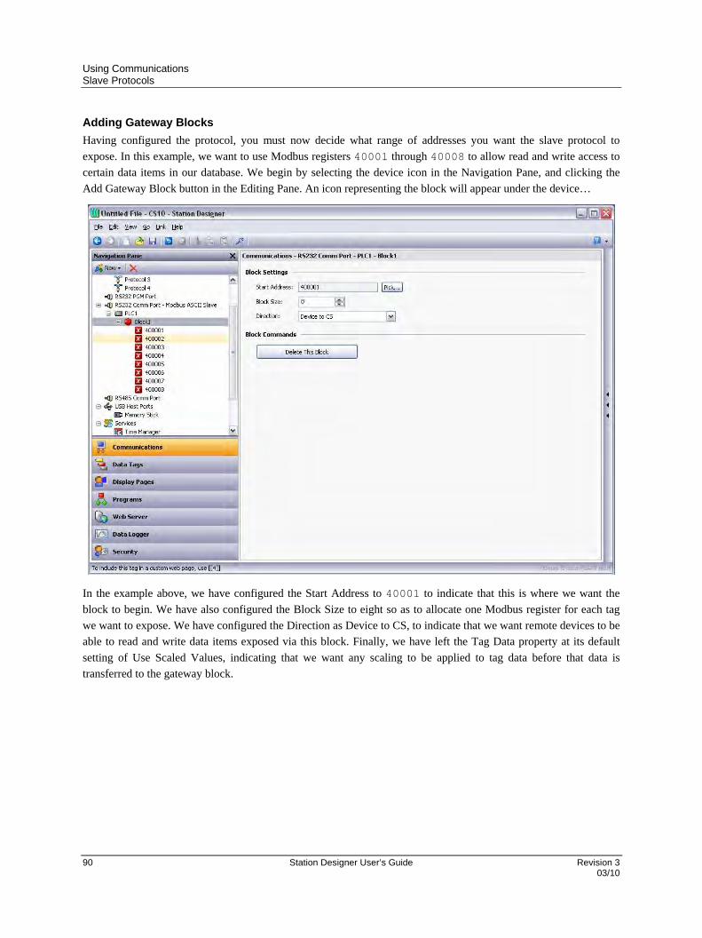
Using Communications Slave Protocols
90 Station Designer User’s Guide Revision 3 03/10
Adding Gateway Blocks
Having configured the protocol, you must now decide what range of addresses you want the slave protocol to
expose. In this example, we want to use Modbus registers 40001 through 40008 to allow read and write access to
certain data items in our database. We begin by selecting the device icon in the Navigation Pane, and clicking the
Add Gateway Block button in the Editing Pane. An icon representing the block will appear under the device…
In the example above, we have configured the Start Address to 40001 to indicate that this is where we want the
block to begin. We have also configured the Block Size to eight so as to allocate one Modbus register for each tag
we want to expose. We have configured the Direction as Device to CS, to indicate that we want remote devices to be
able to read and write data items exposed via this block. Finally, we have left the Tag Data property at its default
setting of Use Scaled Values, indicating that we want any scaling to be applied to tag data before that data is
transferred to the gateway block.

Using Communications Slave Protocols
Revision 3 Station Designer User’s Guide 91 03/10
Adding Items to a Block
Once the block has been created and its size defined, entries appear in the Navigation Pane to represent each of the
registers that the block exposes to remote access. When one of these entries is selected, an expanded Resource Pane
appears and provides access to available data items. These items comprise both tags from within your database, and
data registers from any master communications devices that you have configured…
To indicate that you want a particular register within your gateway block to correspond to a particular data item,
simply drag that item from the Resource Pane to the Navigation Pane, dropping it on the appropriate gateway block
entry. The example above shows how the first four registers in the block have been mapped to tags called Tag1
through Tag4, indicating that accesses to 40001 through 40004 should be mapped to the respective variables.

Using Communications Slave Protocols
92 Station Designer User’s Guide Revision 3 03/10
Accessing Individual Bits
If your application requires it, you can expand individual elements within a Gateway Block to their constituent bits,
and map a different data item to each bit. To do this, right-click on the element in question, and select Expand Bits
from the resulting menu. The Navigation Pane will be updated to show the individual bits that make up the register,
and these can be mapped using the drag-and-drop process described above.
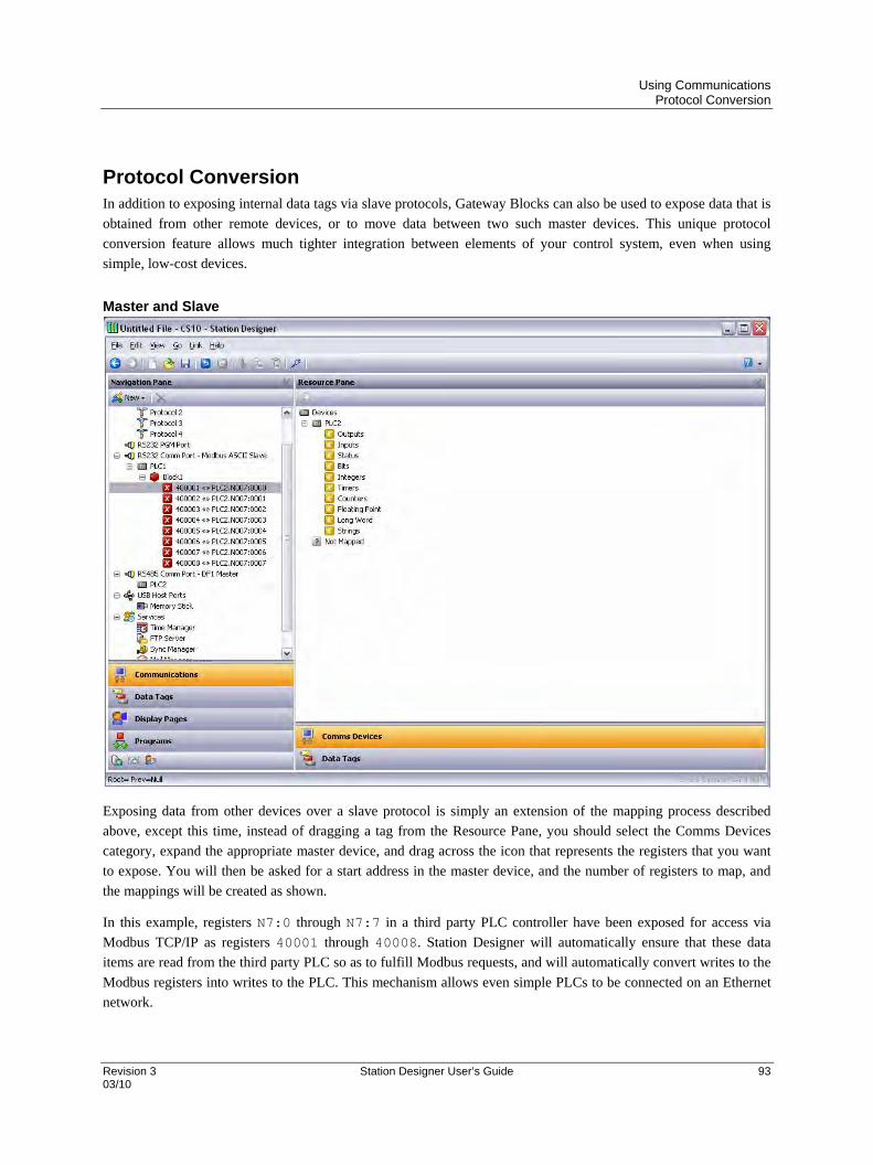
Using Communications Protocol Conversion
Revision 3 Station Designer User’s Guide 93 03/10
Protocol Conversion In addition to exposing internal data tags via slave protocols, Gateway Blocks can also be used to expose data that is
obtained from other remote devices, or to move data between two such master devices. This unique protocol
conversion feature allows much tighter integration between elements of your control system, even when using
simple, low-cost devices.
Master and Slave
Exposing data from other devices over a slave protocol is simply an extension of the mapping process described
above, except this time, instead of dragging a tag from the Resource Pane, you should select the Comms Devices
category, expand the appropriate master device, and drag across the icon that represents the registers that you want
to expose. You will then be asked for a start address in the master device, and the number of registers to map, and
the mappings will be created as shown.
In this example, registers N7:0 through N7:7 in a third party PLC controller have been exposed for access via
Modbus TCP/IP as registers 40001 through 40008. Station Designer will automatically ensure that these data
items are read from the third party PLC so as to fulfill Modbus requests, and will automatically convert writes to the
Modbus registers into writes to the PLC. This mechanism allows even simple PLCs to be connected on an Ethernet
network.
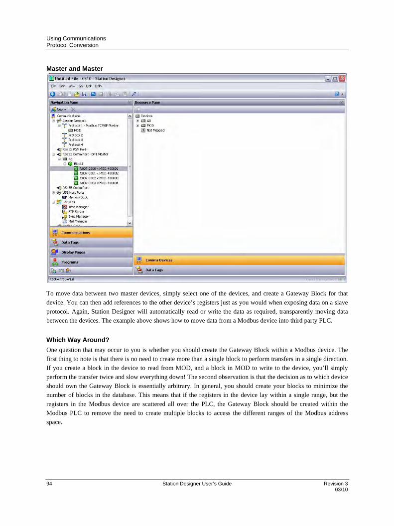
Using Communications Protocol Conversion
94 Station Designer User’s Guide Revision 3 03/10
Master and Master
To move data between two master devices, simply select one of the devices, and create a Gateway Block for that
device. You can then add references to the other device’s registers just as you would when exposing data on a slave
protocol. Again, Station Designer will automatically read or write the data as required, transparently moving data
between the devices. The example above shows how to move data from a Modbus device into third party PLC.
Which Way Around?
One question that may occur to you is whether you should create the Gateway Block within a Modbus device. The
first thing to note is that there is no need to create more than a single block to perform transfers in a single direction.
If you create a block in the device to read from MOD, and a block in MOD to write to the device, you’ll simply
perform the transfer twice and slow everything down! The second observation is that the decision as to which device
should own the Gateway Block is essentially arbitrary. In general, you should create your blocks to minimize the
number of blocks in the database. This means that if the registers in the device lay within a single range, but the
registers in the Modbus device are scattered all over the PLC, the Gateway Block should be created within the
Modbus PLC to remove the need to create multiple blocks to access the different ranges of the Modbus address
space.

Using Communications Controlling Master Blocks
Revision 3 Station Designer User’s Guide 95 03/10
Controlling Master Blocks Gateway blocks within master devices have the following additional properties.
As with slave blocks, the Tag Data property selects how data tags are mapped to and from the block. A
tag data can be subject to various stages of transformation. This property selects where in the
transformation process the gateway block obtains and inject its data.
The Update Policy property is used to define how the block updates. The default setting of Automatic
causes read blocks to update continuously, and write blocks to transfer only those values that have
changed. A setting of Continuous causes all blocks to update continuously. A setting of Timed causes
all blocks to update at the rate defined by the Update Period property, with the entire contents of a write
block being written each time.
The Request and Acknowledge properties are used to control the timing of block updates via tags or
other data items. If the Acknowledge property is left empty, Request acts as an enable field, with a zero
value disabling the block and a non-zero value allowing it to operate. If the Acknowledge is defined, the
Request and Acknowledge operate as a standard two-wire handshake, with the block updating once on
each rising edge of the Request, and the Acknowledge being set after the transaction completes.
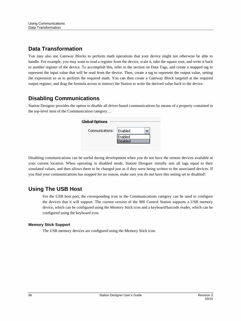
Using Communications Data Transformation
96 Station Designer User’s Guide Revision 3 03/10
Data Transformation You may also use Gateway Blocks to perform math operations that your device might not otherwise be able to
handle. For example, you may want to read a register from the device, scale it, take the square root, and write it back
to another register of the device. To accomplish this, refer to the section on Data Tags, and create a mapped tag to
represent the input value that will be read from the device. Then, create a tag to represent the output value, setting
the expression so as to perform the required math. You can then create a Gateway Block targeted at the required
output register, and drag the formula across to instruct the Station to write the derived value back to the device.
Disabling Communications Station Designer provides the option to disable all driver-based communications by means of a property contained in
the top-level item of the Communication category…
Disabling communications can be useful during development when you do not have the remote devices available at
your current location. When operating in disabled mode, Station Designer initially sets all tags equal to their
simulated values, and then allows them to be changed just as if they were being written to the associated devices. If
you find your communications has stopped for no reason, make sure you do not have this setting set to disabled!
Using The USB Host For the USB host port, the corresponding icon in the Communications category can be used to configure
the devices that it will support. The current version of the 900 Control Station supports a USB memory
device, which can be configured using the Memory Stick icon and a keyboard/barcode reader, which can be
configured using the keyboard icon.
Memory Stick Support
The USB memory devices are configured using the Memory Stick icon.
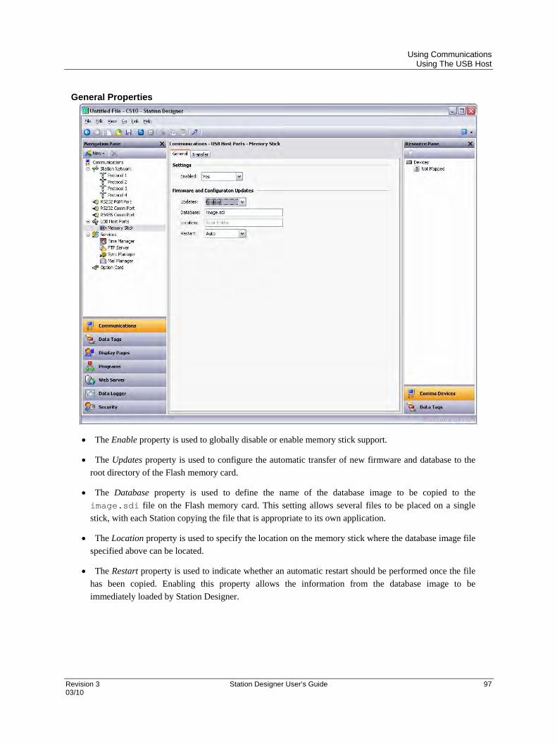
Using Communications Using The USB Host
Revision 3 Station Designer User’s Guide 97 03/10
General Properties
The Enable property is used to globally disable or enable memory stick support.
The Updates property is used to configure the automatic transfer of new firmware and database to the
root directory of the Flash memory card.
The Database property is used to define the name of the database image to be copied to the
image.sdi file on the Flash memory card. This setting allows several files to be placed on a single
stick, with each Station copying the file that is appropriate to its own application.
The Location property is used to specify the location on the memory stick where the database image file
specified above can be located.
The Restart property is used to indicate whether an automatic restart should be performed once the file
has been copied. Enabling this property allows the information from the database image to be
immediately loaded by Station Designer.

Using Communications Using The USB Host
98 Station Designer User’s Guide Revision 3 03/10
Transfer Properties
The Transfer property for each synchronization group is used to define the function that the group
should perform. Information may either be copied or moved, and the operation may either be applied
simply to the files in the specified folder, or additionally to sub-folders and their contents on a recursive
basis.
The Direction property is used to specify the direction of the transfer.
The Update property is used to indicate whether files that appear to be already present on the target
device should be copied in any case, or whether only new and modified files should be transferred. The
900 Control Station uses the file’s time-stamp and size to decide whether the file should be processed.
The Source and Destination properties are used to indicate the folders on the source and target devices
where the files should be located.
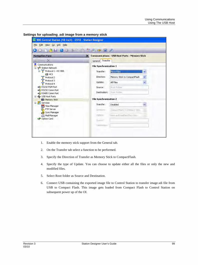
Using Communications Using The USB Host
Revision 3 Station Designer User’s Guide 99 03/10
Settings for uploading .sdi image from a memory stick
1. Enable the memory stick support from the General tab.
2. On the Transfer tab select a function to be performed.
3. Specify the Direction of Transfer as Memory Stick to CompactFlash.
4. Specify the type of Update. You can choose to update either all the files or only the new and
modified files.
5. Select Root folder as Source and Destination.
6. Connect USB containing the exported image file to Control Station to transfer image.sdi file from
USB to Compact Flash. This image gets loaded from Compact Flash to Control Station on
subsequent power up of the OI.
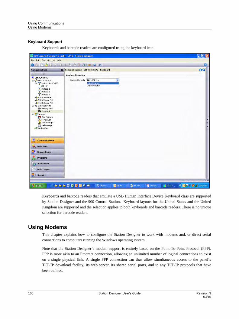
Using Communications Using Modems
100 Station Designer User’s Guide Revision 3 03/10
Keyboard Support
Keyboards and barcode readers are configured using the keyboard icon.
Keyboards and barcode readers that emulate a USB Human Interface Device Keyboard class are supported
by Station Designer and the 900 Control Station. Keyboard layouts for the United States and the United
Kingdom are supported and the selection applies to both keyboards and barcode readers. There is no unique
selection for barcode readers.
Using Modems This chapter explains how to configure the Station Designer to work with modems and, or direct serial
connections to computers running the Windows operating system.
Note that the Station Designer’s modem support is entirely based on the Point-To-Point Protocol (PPP).
PPP is more akin to an Ethernet connection, allowing an unlimited number of logical connections to exist
on a single physical link. A single PPP connection can thus allow simultaneous access to the panel’s
TCP/IP download facility, its web server, its shared serial ports, and to any TCP/IP protocols that have
been defined.

Using Communications Using Modems
Revision 3 Station Designer User’s Guide 101 03/10
Adding a Dial-In Connection
To add a dial-in connection to your database, select the Communications category and navigate to the serial
port via which the connection will be made. Click on the Pick button of Driver property, and select the PPP
and Modem Server driver from the System section.
The Editing Pane shows the modem configuration.

Using Communications Using Modems
102 Station Designer User’s Guide Revision 3 03/10
The modem has the following configuration options.
The Connect Using property is used to select the physical device to be used to make the
connection. The devices supported are direct serial connections to computers running the
Microsoft Windows operating system, generic landline modems which implement the Hayes
command set, and GSM modem implementing the industry standard GSM commands. For dial-in
connections, the GSM devices must be configured in Circuit Switched Data mode.
The Manufacturer property is used to select the manufacturer or models for which specific
configurations have been developed and stored within the Station Designer. Leaving this setting at
Generic allows you to customize settings related to initialization strings. For details on modem
specific settings, contact your local Honeywell representative.
The Activity Timeout property is used to define the duration after which the connection is
terminated if the Control Station does not send packets on the PPP link. A compatible connecting
device is used for dial-in connections to avoid filtering out optional packets. This ensures that the
link is not active for long periods. Even if you want a permanent connection, enter a timeout to
enable the detection of dead links. This implies that the permanent connections may also drop on
occasions, but are immediately reestablished.
The Init String property is automatically configured by entering the required setting in the
Manufacturer property. During initialization, the Init String property is used to enable/disable
some commands.
The Additional Init string is used with non-direct links, and provides a series of AT commands to
initialize the modem. The initial AT prefix is not required. Multiple commands may be combined
by placing them sequentially. The exact string required for your modem depends on its internal
software. Contact Honeywell Technical Support for assistance on modem related configuration
and be sure to have exact make and model information available.
The SMS Support property is used to enable Short Message Service messaging when using a GSM
modem. In order for SMS messaging to operate, enable SMS Transport in the Mail Manager.
The Logon Username and Logon Password properties are used to define the credentials to be used
to connect to a device. The username is not case sensitive, but the password is case-sensitive. The
PPP implementation expects its peer to use CHAP authentication to avoid transmitting or
receiving plaintext password, but reverts to using PAP if the remote client does not support
CHAP.
The Local Address property is used to define the IP address of the local end of the connection.
This serves as the IP address of the Control Station for this link. Ensure that this is not the same as
the IP address of the Control Station’s Ethernet port, as every physical IP interface must have a
distinct IP address.
The Remote Address property is used to define the IP address to be allocated to the remote end of
the connection. It is used along with the Remote Mask property to determine the packets that
would be routed to this connection. For most applications, a mask of 255.255.255.255 is used,
thereby instructing the Station Designer to use this interface to transmit only those packets directly

Using Communications Using Modems
Revision 3 Station Designer User’s Guide 103 03/10
bound for the remote client. On the other hand, a mask of 0.0.0.0, allows all packets that do not
specifically match another interface to be forwarded to the remote client, for forwarding to the
intended host. Intermediate masks may be used to control packets to be sent.
Adding a Dial-Out Connection
Dial-out connections are added in the same way as adding a dial-in connection, except that the PPP and
Modem Client driver must be selected for the required port.
The configuration options for this modem are shown below…
The modem has the following distinct properties as compared to dial-in connections…
The Connect Using property is the same as for dial-in connections, with the additional support for
GPRS connections via a GSM modem. GPRS connections differ from CSD connections and are
charged on the basis of the amount of data transferred rather than the duration of the connection.

Using Communications Using Modems
104 Station Designer User’s Guide Revision 3 03/10
Also, GPRS connections achieve much higher speeds and can be configured as permanent
connection, unless there is a need to provide downtime to allow SMS messages to be transferred.
The No Firewall property is used to turn off the firewall protection, normally enabled for dial-out
connections. This protection prevents incoming connections from being made to this interface. It
also prevents the Control Station from sending diagnostic packets containing information about
the system that may be used by an attacker to keep a connection active in the absence of actual
data transfer. If you connect to the Internet using this connection, do not turn off the firewall. The
firewall should be disabled only for connections to corporate networks or to other controlled
environments.
The Connection Type property is used to indicate the type of connection as permanent or on-
demand. An on-demand connection type implies that that the connection is established
automatically on request for transfer data to hosts that are reachable via this interface. If you select
an on demand connection, specify the timeout to terminate the link if no packets are transmitted by
the Control Station.
The Logon Username and Logon Password properties are used to define the credentials to be used
to connect to a device. The username is not case sensitive, but the password is case-sensitive. The
PPP implementation expects its peer to use CHAP authentication to avoid transmitting or
receiving plaintext password, but reverts to using PAP if the remote client does not support
CHAP.
The Route Type property is used to define the data to be transferred via this interface. For on
demand connections, this defines when the connection is activated. If Default Gateway is selected,
packets that do not match the address and network mask of the Ethernet connection are sent to this
interface. In this mode, the Ethernet port must have a gateway setting of 0.0.0.0, or it takes all the
packets and leave none are left to activate the modem. If Specific Network is selected, provide the
address and network mask that defines the network to which packets are to be routed.

Using Communications Using Modems
Revision 3 Station Designer User’s Guide 105 03/10
Adding an SMS Connection
SMS connections are required to enable text messaging when dial-in and dial-out PPP connections are not
established. While configuring the SMS connection, select the SMS via GSM Modem device for the
selected port.
The properties of this driver are a subset of those provided for dial-in connections. SMS support is always
enabled with this driver, but for SMS messaging to operate, enable the SMS Transport within the Mail
Manager.
SMS Message Processing
When SMS messaging is enabled, the GSM modem checks for new incoming or outgoing messages every
five seconds. Incoming messages are forwarded to the mail manager, which are forwarded to other users as
per the configuration. Permanent connections are not recommended when working with SMS because it is
not possible to check for messages when the modem is connected to a CSD or GPRS session. If more than
one GSM modem is configured, all the modems receive messages, but only the last modem is used for
sending the messages.
Checking the Modem Status
The GetInterfaceStatus() function is used to debug modem connections. This function takes a single
argument, which is the numeric index of the required interface. Interface zero is the internal loopback
interface followed by enabled Ethernet interfaces and the PPP interfaces. In a system using a single
Ethernet port, for example, the first PPP interface will have an index of 1.
The function returns a string, which can be interpreted according to the following table…
STATUS MEANING
CLOSED The interface has not yet been initialized. This state occurs for a short time during system start-up.
INIT The modem is being initialized. If the connection remains in this state, there are probably errors in the init strings being sent to the modem.
IDLE The link is idle. GSM modems will return a number at the end of the string to indicate signal strength. The next table explains how to interpret these values.
SMS The modem is sending SMS messages, or polling the modem to see if new SMS messages are available. If SMS messaging is enabled for a modem, you will see this state appear briefly every five seconds.
CONNECTING The modem is establishing a connection. This state typically appears only for client connections, and indicates that a call is being placed.
LISTENING The modem is waiting for a call. This state appears only for server connections. Note that GSM modems will also return an IDLE state while waiting for a call in order to show signal strength.
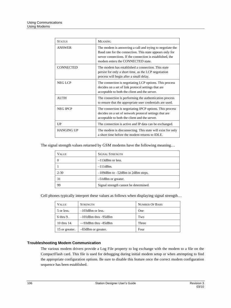
Using Communications Using Modems
106 Station Designer User’s Guide Revision 3 03/10
STATUS MEANING
ANSWER The modem is answering a call and trying to negotiate the Baud rate for the connection. This state appears only for server connections. If the connection is established, the modem enters the CONNECTED state.
CONNECTED The modem has established a connection. This state persist for only a short time, as the LCP negotiation process will begin after a small delay.
NEG LCP The connection is negotiating LCP options. This process decides on a set of link protocol settings that are acceptable to both the client and the server.
AUTH The connection is performing the authentication process to ensure that the appropriate user credentials are used.
NEG IPCP The connection is negotiating IPCP options. This process decides on a set of network protocol settings that are acceptable to both the client and the server.
UP The connection is active and IP data can be exchanged.
HANGING UP The modem is disconnecting. This state will exist for only a short time before the modem returns to IDLE.
The signal strength values returned by GSM modems have the following meaning…
VALUE SIGNAL STRENGTH
0 –113dBm or less.
1 –111dBm.
2-30 –109dBm to –52dBm in 2dBm steps.
31 –51dBm or greater.
99 Signal strength cannot be determined.
Cell phones typically interpret these values as follows when displaying signal strength…
VALUE STRENGTH NUMBER OF BARS
5 or less. –103dBm or less. One
6 thru 9. –101dBm thru –95dBm Two
10 thru 14. ––93dBm thru –85dBm Three
15 or greater. –83dBm or greater. Four
Troubleshooting Modem Communication
The various modem drivers provide a Log File property to log exchange with the modem to a file on the
CompactFlash card. This file is used for debugging during initial modem setup or when attempting to find
the appropriate configuration options. Be sure to disable this feature once the correct modem configuration
sequence has been established.

Revision 3 Station Designer User’s Guide 107 03/10
Using Services
In addition to the core communication functions, the Communications category also allows various services to be
configured. These services appear in the Navigation Pane under the Services icon, and each is described below.
Using Time Management Time management is not required when communicating with HC900 controllers as the controller is the system time
manager.
Station Designer contains facilities to allow you to synchronize the time and date within the Station with a variety of
sources. The Time Manager can also maintain information about the Station’s time-zone, and whether daylight
saving time is currently enabled. In fact, having accurate time-zone information available is vital to proper
synchronization, as the various synchronization methods are all designed to work with Universal Coordinated Time,
also known as UTC or Greenwich Mean Time. Station Designer can act both as a client and a server, either
requesting the time or providing the time to other Station Designer-based devices. Note that the server
implementation does not currently support third party clients.
Configuring the Service
The Time Manager is configured via the associated icon in the Navigation Pane…

Using Services Using Time Management
108 Station Designer User’s Guide Revision 3 03/10
The Enable Time Manager property is used to control access to the other facilities. If it is not checked, Station
Designer will operate in the local time zone only and will have no knowledge of time-zones or other time
management information.
Time Server
Appropriately configuring the Enable SNTP property of the Time Server section will instruct Station Designer to act
as an SNTP server. This will allow other Station Designer devices to synchronize their own clocks to the clock of
this unit. Note that Station Designer’s implementation of SNTP is not fully RFC compliant, and is not supported as a
source of synchronization for third-party clients.
Time Client
Selecting Yes in the Enable SNTP property of the Time Client section will instruct Station Designer to run its SNTP
client. Station Designer will then attempt to synchronize its clock with another Station Designer-based device, or to
another network-accessible SNTP time source such as a computer running Windows XP. The time client has the
following additional properties…
The Linked DST property is used to instruct the SNTP client to attempt to read the current Daylight
Savings Time setting from the SNTP server. As this facility is not a standard part of the SNTP protocol,
it will only operate if another Station Designer device is specified as the server. The facility is useful, in
that it allows the Daylight Savings Time adjustment to be made via a single device on the factory
network, with the other devices then following the central setting.
The SNTP Mode and SNTP Server properties are used to configure the IP address of the Simple
Network Time Service server. If Configured via DHCP is selected, at least one Ethernet port must be
configured to use DHCP, and the server must be configured to designate a server via option 42.
The Enable GPS property is used to instruct the time client to use a GPS unit connected via NMEA-
0183 as an alternative method of obtaining the current time. The unit may be connected to any serial port
using the appropriate driver.
The Frequency property is used to specify how often Station Designer should attempt to synchronize its
time by the methods enabled above. Station Designer will always attempt to sync twenty seconds after
power-up, and will then sync as specified by this property. If a given attempt to sync fails, the unit will
retry every 30 seconds until it is successful in finding a suitable time source.
Using Services Using Time Management
Revision 3 Station Designer User’s Guide 109 03/10
Time Stamps
Station Designer can record a variety of log files on the target device’s Flash memory card, and each log entry has a
time stamp. By default, the time stamp comes from the local real time clock and is in the local time zone. The
behavior can be changed via the following properties…
The Time Source property is used to indicate from where the time stamps should be obtained. The
default setting obtains the time from the unit’s own real time clock, while the alternative allows the use
of an expression to define the current time. This expression is typically a reference to a data item in a
connected device, allowing that device’s clock to be used for data logging. The expression must be
entered in the Expression property.
The Sync Clock property is used to indicate whether the local real time clock should be synced to the
alternative time source specified above. If this option is enabled, the local clock will be synchronized on
startup and periodically thereafter, and will be used as a time stamp source if the alternative source is not
available due to comms problems.
The Time Zone property is used to indicate the time zone to be used for time stamps. It is only
applicable when the local real time clock is configured as the source for time stamps. Selecting Local
will use the local time zone; selecting UTC will use Universal Coordinated Time instead. This latter
setting produces log files which are more easily portable across time-zones, and which do not suffer
from discontinuities when switching in and out of Daylight Savings Time.
Choosing an SNTP Server
When configuring the SNTP client, you have several options when selecting a server.
If you have a Windows- or Unix-based time server as part of your network infrastructure, you should ultimately
synchronize to this source to ensure enterprise-wide synchronization. If you have several Station Designer devices
on the same network, though, you will find it better to nominate one of these as the master device for the purpose of
setting Daylight Savings Time, and then have that device alone synchronize to the enterprise time source. You can
then configure the other devices to synchronize to the master device, and enable the Linked DST facility to
propagate the Daylight Savings Time setting around your factory.
If you have no enterprise time source available, you may choose to nominate a single Station Designer device as the
point where an operator will set the time, and then have other devices synchronize to that source. Alternatively, if
your installation provides TCP/IP access to the Internet via either Ethernet or a modem connection, you may
configure the SNTP client to synchronize to a public time server. An example of this would be 192.6.15.28, which is
the current IP address of a public time server provided by NIST.
A list of other servers can be found at…
http://support.microsoft.com/kb/262680
Note that since Station Designer uses an IP address and not a host name to reference the SNTP server, it will lose
connection with any server that is relocated to a new network address. While such relocations are very rare, they are
beyond your control and that of Honeywell. The use of an enterprise time source which accesses its own source via
DNS is thus considered preferable!
Using Services Using Time Management
110 Station Designer User’s Guide Revision 3 03/10
Time-Zone Configuration
As mentioned above, a Station Designer device must have knowledge of the current time-zone if it is to use
advanced time management. This information can be provided in two ways. The easiest method is to use the Send
Time command on the Link menu of the Station Designer configuration software. In addition to setting the clock,
this command also sends the PC’s current time zone and the status of Daylight Savings Time. Station Designer will
store this data in non-volatile memory, and use it from that point forward. Obviously, you should be sure that the PC
contains valid time and date information before sending it to the unit!
The alternative method is to use the system variables TimeZone and UseDST. The former holds the number of
hours by which the local time zone differs from UTC, and may be either negative or positive. For example, a setting
of –5 corresponds to Eastern Standard Time in the United States.
The latter contains either 0 or 1, depending on whether Daylight Savings Time is active. Editing either of these
variables via the user interface will result in the unit’s clock changing to take account of the new settings. For
example, enabling Daylight Savings Time will move the clock forward one hour, while disabling it will move it
back. A typical database will only need to expose UseDST for editing by the user, and even this may not be
necessary if the Linked DST facility described above is in use.
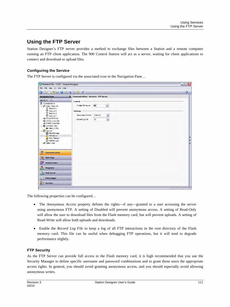
Using Services Using the FTP Server
Revision 3 Station Designer User’s Guide 111 03/10
Using the FTP Server Station Designer’s FTP server provides a method to exchange files between a Station and a remote computer
running an FTP client application. The 900 Control Station will act as a server, waiting for client applications to
connect and download or upload files.
Configuring the Service
The FTP Server is configured via the associated icon in the Navigation Pane…
The following properties can be configured…
The Anonymous Access property defines the rights—if any—granted to a user accessing the server
using anonymous FTP. A setting of Disabled will prevent anonymous access. A setting of Read-Only
will allow the user to download files from the Flash memory card, but will prevent uploads. A setting of
Read-Write will allow both uploads and downloads.
Enable the Record Log File to keep a log of all FTP interactions in the root directory of the Flash
memory card. This file can be useful when debugging FTP operations, but it will tend to degrade
performance slightly.
FTP Security
As the FTP Server can provide full access to the Flash memory card, it is high recommended that you use the
Security Manager to define specific username and password combinations and to grant those users the appropriate
access rights. In general, you should avoid granting anonymous access, and you should especially avoid allowing
anonymous writes.

Using Services Using File Synchronization
112 Station Designer User’s Guide Revision 3 03/10
Using File Synchronization The Synchronization Manager can be used to exchange files between a 900 Control Station and an FTP server. This
facility can be used to synchronize log files with a server computer, either automatically or on-demand, thereby
providing an alternative to accessing the log file via the web server, and allowing for unattended transfer of files
from many Stations to a central point. (Note that although it is called the Synchronization Manager, this service is
actually based upon a general-purpose FTP client that can also be used to perform other FTP transfers, whether or
not log files are being synchronized.)
Configuring the Service
The Synchronization Manager is configured via the associated icon in the Navigation Pane…
FTP Client
The following properties relate to the FTP client…
The Enable Sync Manager property is used to enable the FTP client. The client may be enabled without
actually enabling synchronization, allowing it to be used for manual file transfer via the
FtpFilePut() and FtpFileGet() functions.
The Enable Log File Sync property is used to enable actual synchronization. See the next section for
details of the other settings related to this feature.
The Server IP address property is used to indicate the IP address of the server.
The Port Number property is used to indicate the TCP port to which the FTP client service will attempt
to connect. The default value is suitable for most applications, as most servers will listen on port 21.
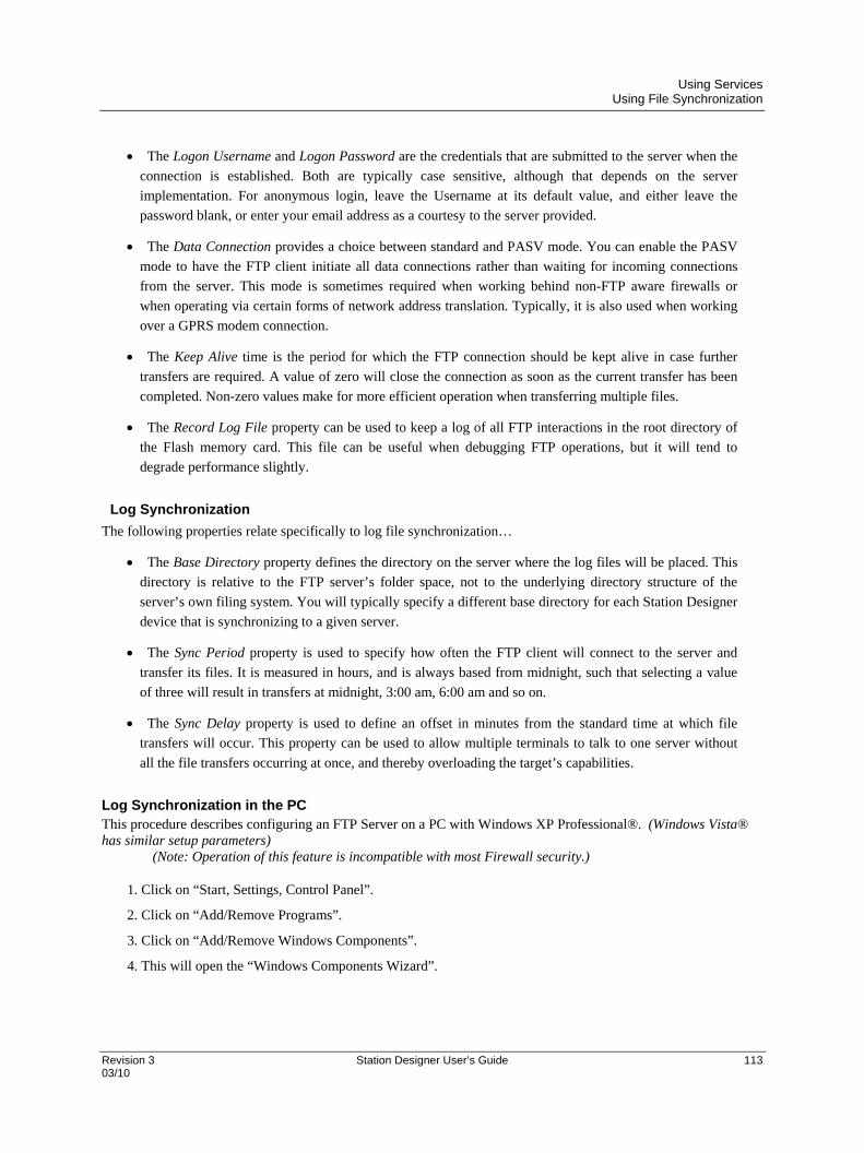
Using Services Using File Synchronization
Revision 3 Station Designer User’s Guide 113 03/10
The Logon Username and Logon Password are the credentials that are submitted to the server when the
connection is established. Both are typically case sensitive, although that depends on the server
implementation. For anonymous login, leave the Username at its default value, and either leave the
password blank, or enter your email address as a courtesy to the server provided.
The Data Connection provides a choice between standard and PASV mode. You can enable the PASV
mode to have the FTP client initiate all data connections rather than waiting for incoming connections
from the server. This mode is sometimes required when working behind non-FTP aware firewalls or
when operating via certain forms of network address translation. Typically, it is also used when working
over a GPRS modem connection.
The Keep Alive time is the period for which the FTP connection should be kept alive in case further
transfers are required. A value of zero will close the connection as soon as the current transfer has been
completed. Non-zero values make for more efficient operation when transferring multiple files.
The Record Log File property can be used to keep a log of all FTP interactions in the root directory of
the Flash memory card. This file can be useful when debugging FTP operations, but it will tend to
degrade performance slightly.
Log Synchronization
The following properties relate specifically to log file synchronization…
The Base Directory property defines the directory on the server where the log files will be placed. This
directory is relative to the FTP server’s folder space, not to the underlying directory structure of the
server’s own filing system. You will typically specify a different base directory for each Station Designer
device that is synchronizing to a given server.
The Sync Period property is used to specify how often the FTP client will connect to the server and
transfer its files. It is measured in hours, and is always based from midnight, such that selecting a value
of three will result in transfers at midnight, 3:00 am, 6:00 am and so on.
The Sync Delay property is used to define an offset in minutes from the standard time at which file
transfers will occur. This property can be used to allow multiple terminals to talk to one server without
all the file transfers occurring at once, and thereby overloading the target’s capabilities.
Log Synchronization in the PC This procedure describes configuring an FTP Server on a PC with Windows XP Professional®. (Windows Vista® has similar setup parameters) (Note: Operation of this feature is incompatible with most Firewall security.)
1. Click on “Start, Settings, Control Panel”.
2. Click on “Add/Remove Programs”.
3. Click on “Add/Remove Windows Components”.
4. This will open the “Windows Components Wizard”.
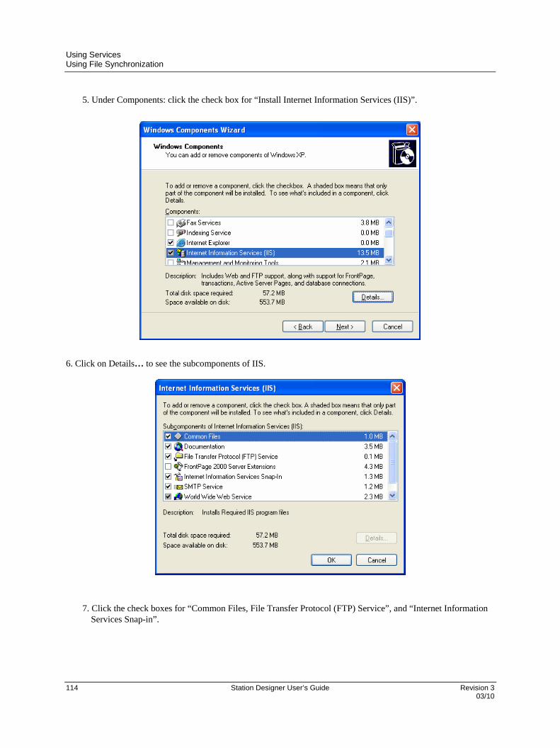
Using Services Using File Synchronization
114 Station Designer User’s Guide Revision 3 03/10
5. Under Components: click the check box for “Install Internet Information Services (IIS)”.
6. Click on Details… to see the subcomponents of IIS.
7. Click the check boxes for “Common Files, File Transfer Protocol (FTP) Service”, and “Internet Information Services Snap-in”.

Using Services Using File Synchronization
Revision 3 Station Designer User’s Guide 115 03/10
8. Click on OK, and then Next. The Windows Components Wizard will then proceed to install Internet Information Services (IIS).
9. When the installation is completed click: Finish.
10. When the Setup is completed, close the “Add or Remove Programs” window.
11. On “Desktop”, right click on “My Computer”, and then click on “Manage”.
12. This will open the Computer Management window.
13. Under Services and Applications click on “Services”.
14. Then click on “Windows Firewall/ Internet Connection Sharing (ICS)”.
15. Click on “Stop” the service.
16. Under Service and Applications expand the folder “Internet Information Services”
17. Under Internet Information Services expand the folder “FTP Sites”.
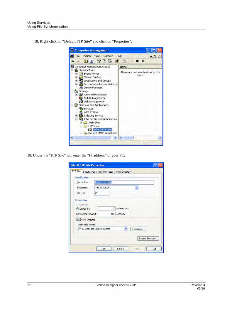
Using Services Using File Synchronization
116 Station Designer User’s Guide Revision 3 03/10
18. Right click on “Default FTP Site” and click on “Properties”.
19. Under the “FTP Site” tab, enter the “IP address” of your PC.

Using Services Using File Synchronization
Revision 3 Station Designer User’s Guide 117 03/10
20. Under the Security Accounts tab, check the following:
“Allow only anonymous connections”, and
“Allow IIS to control password”.
21. Under the “Home Directory” tab, check “Read, Write and Log visits”.
22. Click “Apply and OK”.
23. Close the Computer Management window.
24. The FTP Server default directory where files transferred from an Station FTP Client will be placed in 'c:\Inetpub\ftproot'
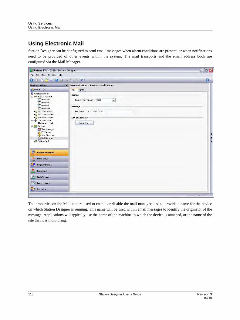
Using Services Using Electronic Mail
118 Station Designer User’s Guide Revision 3 03/10
Using Electronic Mail Station Designer can be configured to send email messages when alarm conditions are present, or when notifications
need to be provided of other events within the system. The mail transports and the email address book are
configured via the Mail Manager.
The properties on the Mail tab are used to enable or disable the mail manager, and to provide a name for the device
on which Station Designer is running. This name will be used within email messages to identify the originator of the
message. Applications will typically use the name of the machine to which the device is attached, or the name of the
site that it is monitoring.

Using Services Using Electronic Mail
Revision 3 Station Designer User’s Guide 119 03/10
Adding Contacts
The Contacts button can be used to access Station Designer’s address book…
Each entry allows a Display Name and an Address to be entered. The address should be in a format suitable for the
required transport. For example, SMTP names should be in the usual name@domain format. Multiple email
addresses can be entered by separating them by semicolons, allowing simple mailing lists to be created.
Configuring SMTP
The SMTP tab is used to configure the Simple Mail Transport Protocol. This is the standard protocol used to send
email over the Internet or over other TCP/IP networks. SMTP addresses follow the familiar name@domain
standard.
The configuration options for the SMTP transport are shown below…

Using Services Using Electronic Mail
120 Station Designer User’s Guide Revision 3 03/10
The Transport Mode property is used to enable or disable the transport. Note that the mail manager
must be enabled via the Mail tab before the SMTP transport can be enabled. Note also that at least one
transport must be enabled if the mail manager is to be able to deliver messages.
The Server Selection property is used to define how the transport will locate an SMTP server. If Manual
Selection is used, the Server IP Address property should be used to manual designate a server. If
Configured via DHCP is selected, at least one Ethernet port must be configured to use DHCP, and the
server must be configured to designate an SMTP server via option 69.
The Server IP Address property is used to designate an SMTP server when manual server selection is
enabled. The server must be configured to accept mail from the panel, and to relay messages if required
by the application.
The Server Port Number property is used to define the TCP port number that will be used for SMTP
sessions. The default value is 25. This value will be suitable for most applications, and will only need to
be adjusted if the SMTP server has been reconfigured to use another port.
The Domain Name property is used to specify the domain name that will be passed to the SMTP server
in the HELO or EHLO command. The vast majority of SMTP servers ignore this string. In the unlikely
event that your SMTP server attempts to do a DNS lookup to confirm the identity of its client, you may
need to enter something appropriate to your DNS configuration.
The Reverse Path property is used to specify the email address that will be supplied as the originator of
the messages sent by the target device. The property comprises a display name, and an email address.
Since Station Designer is not capable of receiving messages, the email address will often be set to
something that will return an “undeliverable” message if a reply is sent.
The Initial Timeout property is used to specify how many seconds the mail client will wait for the
SMTP server to send its welcome banner. Some Microsoft servers attempt to negotiate Microsoft-
specific authentication with mail clients, thereby delaying the point at which the banner appears. You
may want to extend this time period to 2 minutes or more when working with such servers.
The Record Log File property can be enabled to keep a log of all SMTP interactions in the root
directory of the Flash memory card. This file can be useful when debugging SMTP operations, but
enabling it all the time will tend to degrade performance slightly.

Using Services Using Emulator
Revision 3 Station Designer User’s Guide 121 03/10
Using Emulator Station Designer can be configured to display the Control Station screen along with the actual data from the
HC900 controller on your computer.
Complete the following procedure for enabling panel emulation:
1. Go to Links > Options. The Link Options dialog box appears.
2. Check the Send to Emulator check box to enable panel emulation. Alternatively, click the
icon to enable the panel emulator.
Click Configure. The Emulator Options dialog box appears. Map the communication port of
your PC that will be used to communicate with the HC900 controller into the appropriate dialog
box, typically one of the Ethernet ports.

Using Services Using Emulator
122 Station Designer User’s Guide Revision 3 03/10
3. Click the Update icon to download the current .sds configuration file into the PC emulator
function. Following the download the emulator feature will be launched and the PC display will
emulate the 900 Control Station operation.
4. The Control Station screen appears on your computer. You can view all the screens and perform
various operations on the controller. For example, Cold Start, Change Controller Code, Write to
Flash, Change any Protocol, and so on.
Revision 3 Station Designer User’s Guide 123 03/10
Working with Tags
Once you have configured the communications options for your database, the next step is to define the data items
that you want to display or otherwise manipulate. This is done by selecting the Data Tags category in the Navigation
Pane. Tags can be created, deleted and otherwise manipulated using the standard operations referred to earlier in this
manual.
All About Tags Data Tags are named entities that represent data items.
Data Sources
Tags may get their data from three possible sources…
A tag may be mapped to one or more registers in a HC900 controller or remote device, in which case
Station Designer will automatically read the corresponding data source when the tag is referenced or
displayed.
A tag may be internal, in which case it represents one or more data elements within the 900 Control
Station. Internal tags can be marked as retentive, in which case they will keep their values through a
power-cycle, or non-retentive, in which case they will be reset to zero on power-up.
A tag may be an expression, in which case it represents a calculation based upon other data items,
optionally using mathematical operators and one or more of Station Designer’s internal or user-defined
functions. Expression tags are used to calculate derived values for internal processing or for transfer to
remote devices.
Types of Tags
Station Designer supports three main types of tags…
Numeric Tags represent integer or floating point values.
Flag Tags represent an on-or-off value.
String Tags represent strings of Unicode characters.
Each of the three main tag types can represent a single value or an array of values. An array is a collection of items
with similar properties that are grouped together and accessed via an index value. Mapped arrays correspond to
multiple registers in the HC900 Controller or device.
A fourth type of tag is the Basic Tag. This is a simplified version of a tag that can only represent strings or numeric
expressions. It lacks many of the powerful features of the standard tags. It is typically used to encode simple data
items like constants.

Working with Tags Advantages of Tags
124 Station Designer User’s Guide Revision 3 03/10
Tag Attributes
Tags within Station Designer are rich objects that define various common properties…
A tag’s label is a translatable, human-readable string used to automatically label data fields referring to
this data item. It is also used by the Web Server and the Data Logger to label associated data items.
A tag’s description is a non-translatable string used to provide an annotation as to the tag’s purpose. It
is not normally viewed by the user of the Station, but can be displayed for diagnostic purposes.
A tag’s format is a collection of settings that define the method by which the tag is to be converted into
text. The format may be left as General, in which case Station Designer will use default formatting rules,
or may be set to one of many formatting types. For example, a numeric value may be displayed in
scientific format, or may be used to select a number of different text strings.
A tag’s color is a collection of settings that define how the tag’s text is to be displayed or what colors
are to be used to represent the state of the tag. Again, a number of different color selectors exist, allowing
a tag to change its appearance based upon a variety of conditions. Foreground and background colors are
defined in pairs, and can be accessed individually by display primitives.
A tag’s security descriptor defines the access rules to be used when changing the tag, and whether or
not those changes are to be logged.
Basic tags lack format, color and security information. In addition, numeric and flag tags define alarms and triggers,
respectively allowing alarms to be fired or actions to be taken by the occurrence of certain conditions.
Advantages of Tags You may wonder why you would want to use tags since Station Designer allows you to place a PLC register directly
on a display page. You can configure a simple database without ever creating any tags. The basic answers are as
follows…
Tags allow you to name data items, so you know which data item within the HC900 or device you are
referring to. Further, if the data in the device moves or if you decide to switch to an entirely different
family of devices, you can simply re-map the tags, and avoid having to make any other changes to your
database.
Tags allow you to avoid re-entering the same information again and again. When you create a tag, you
specify how the tag is to be displayed. In the case of a numeric tag, this means you tell Station Designer
how many decimal places are to be used, and what units, if any, are to be appended to the value. When
you place a tag on a display page, Station Designer knows how to format it without you having to do
anything further. Similarly, if you decide to change the formatting, and perhaps switch from one set of
units to another, you can do this in one place, without having to edit each display page in turn.
Tags are used as one basic method for color animation. The various colors that are defined for a tag can
be used to specify the way in which other animation primitives will be displayed. While there are other
methods, tags provide a simple way of changing the color of display primitives.
Tags are the key to implementing slave protocols. Station Designer treats these protocols as
mechanisms for exposing data items within the Station. This allows the same data to be accessed via

Working with Tags Editing Properties
Revision 3 Station Designer User’s Guide 125 03/10
multiple ports, so that, for example, a machine setting could be changed by both a local SCADA
package, and a similar package working over Ethernet from a remote site. Without tags, there would be
nothing to expose, and this mechanism could not be implemented!
Tags are used within Station Designer to implement many advanced features. If you want to use
functionality such as alarms, triggers, data logging or the web server, you will have to use tags. The
formatting data from the tag definition is typically required by all these features, so tags are mandatory
for their operation.
In other words, tags will automate many tasks during programming, saving you time. Even if you decide not to use
tags, many of the subsequent chapters of this manual refer to concepts discussed in this chapter. You should thus
read it thoroughly before proceeding.
Editing Properties Most properties are edited in ways that are self-evident to anyone who has used a Windows operating system. For
example, you may be required to enter a numeric value, or to select an item from a drop-down list. Certain types of
property, though, provide more complex editing options, and these are described below.
Expression Properties
Expression properties are capable of being set to…
A constant value.
The contents of a data tag.
The contents of a register in a remote communications device.
A combination of such items linked together using various math operators.
In its default state, the arrowed button immediately after the label of the property shows that the field is in General
mode, and the edit box to the right of the button may show a grayed-out string that indicates the default behavior of
the property. An example of an empty expression property without a default value is shown below…
If you are familiar with Station Designer’s expression syntax—a complete description of which can be found in the
Writing Expressions chapter—you can edit the property by typing an expression directly into the edit box.
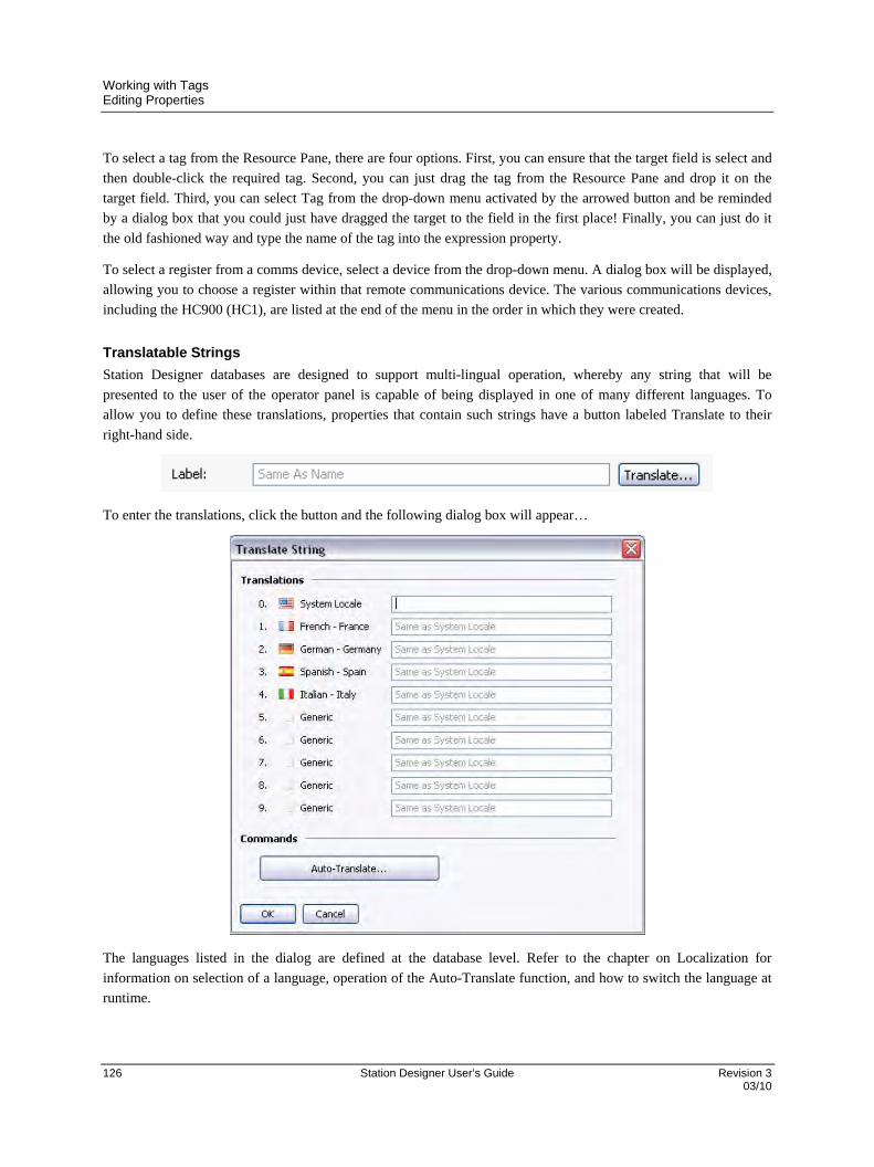
Working with Tags Editing Properties
126 Station Designer User’s Guide Revision 3 03/10
To select a tag from the Resource Pane, there are four options. First, you can ensure that the target field is select and
then double-click the required tag. Second, you can just drag the tag from the Resource Pane and drop it on the
target field. Third, you can select Tag from the drop-down menu activated by the arrowed button and be reminded
by a dialog box that you could just have dragged the target to the field in the first place! Finally, you can just do it
the old fashioned way and type the name of the tag into the expression property.
To select a register from a comms device, select a device from the drop-down menu. A dialog box will be displayed,
allowing you to choose a register within that remote communications device. The various communications devices,
including the HC900 (HC1), are listed at the end of the menu in the order in which they were created.
Translatable Strings
Station Designer databases are designed to support multi-lingual operation, whereby any string that will be
presented to the user of the operator panel is capable of being displayed in one of many different languages. To
allow you to define these translations, properties that contain such strings have a button labeled Translate to their
right-hand side.
To enter the translations, click the button and the following dialog box will appear…
The languages listed in the dialog are defined at the database level. Refer to the chapter on Localization for
information on selection of a language, operation of the Auto-Translate function, and how to switch the language at
runtime.

Working with Tags Editing Properties
Revision 3 Station Designer User’s Guide 127 03/10
If you do not enter text for a particular language, and that language is subsequently selected by the operator, Station
Designer will use the default language in its place. To select a new language, use the SetLanguage() function as
described in Appendix A. Refer to the Creating Display Pages chapter for information on how to allow a user to
invoke this function.
Translatable strings are also capable of being defined to be equal to expressions, thereby allowing them to change at
runtime. For example, while an alarm name would typically be set during configuration, a database designer might
want the alarm to contain the value of the tag that triggered the alarm. Expressions can be entered by prefixing them
with an equals sign, just as one would do when editing a spreadsheet, as shown in the example below…
Note the use of the AsText property of the tag to allow its value to be accessed as a string according to its format
setting. Refer to the Writing Expressions chapter for more details.
Two-Way Properties
Properties such as translatable strings that are capable of being set to a constant value or an expression are called
two-way properties. As well as accepting expressions prefixed with an equals sign, they can be set to tag values by
simply dragging the appropriate tag from the Resource Pane and dropping it on the field.
Color Properties
Color properties within tags represent a pair of colors, these being the foreground and a background color that may
be used when displaying the tag’s state in textual form. The example below shows a color pair being edited.
The drop-down list contains the following colors…
The sixteen standard VGA colors.
The sixteen custom colors defined by the user.
Fourteen shades of gray that fall between black and white.

Working with Tags Log Properties
128 Station Designer User’s Guide Revision 3 03/10
The More option at the bottom of the list can be used to invoke the color selection dialog…
This dialog offers several ways of defining a color. You can pick from the palette, pick from the “rainbow” window,
or enter the explicit HSL or RGB parameters. The dialog also allows custom colors to be added to the palette. These
will appear whenever the dialog is invoked, and will also appear in the drop-down list described above.
Log Properties When you first enter the Data Tags category of the Navigation Pane, you will notice a number of properties relating to event logging. These properties control if and how events generated by tags or by their alarms will be saved to Flash memory. They are analogous to the properties defined by data logs, and you are thus referred to the Using the Data Logger chapter later in this manual for more information on how they can be used.
Creating Tags Data tags are created and otherwise manipulated via the Navigation Pane. You will notice that you can create folders to organize your tags, and that the New button in the toolbar contains a drop-down arrow to allow you to select the type of tag to be inserted. The left-hand side of the New button will create a tag of the same type as the last one you created, making it easier to create multiple tags without using the drop-down list.
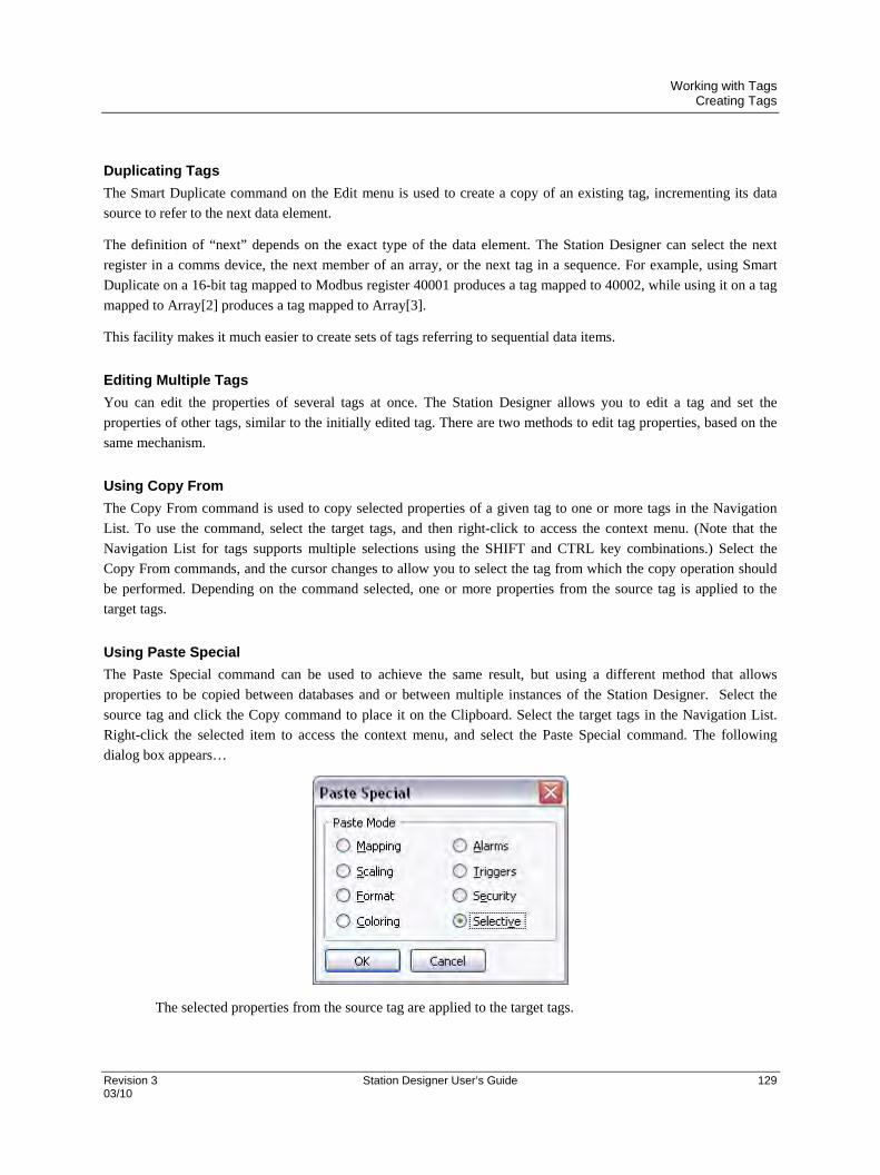
Working with Tags Creating Tags
Revision 3 Station Designer User’s Guide 129 03/10
Duplicating Tags
The Smart Duplicate command on the Edit menu is used to create a copy of an existing tag, incrementing its data
source to refer to the next data element.
The definition of “next” depends on the exact type of the data element. The Station Designer can select the next
register in a comms device, the next member of an array, or the next tag in a sequence. For example, using Smart
Duplicate on a 16-bit tag mapped to Modbus register 40001 produces a tag mapped to 40002, while using it on a tag
mapped to Array[2] produces a tag mapped to Array[3].
This facility makes it much easier to create sets of tags referring to sequential data items.
Editing Multiple Tags
You can edit the properties of several tags at once. The Station Designer allows you to edit a tag and set the
properties of other tags, similar to the initially edited tag. There are two methods to edit tag properties, based on the
same mechanism.
Using Copy From
The Copy From command is used to copy selected properties of a given tag to one or more tags in the Navigation
List. To use the command, select the target tags, and then right-click to access the context menu. (Note that the
Navigation List for tags supports multiple selections using the SHIFT and CTRL key combinations.) Select the
Copy From commands, and the cursor changes to allow you to select the tag from which the copy operation should
be performed. Depending on the command selected, one or more properties from the source tag is applied to the
target tags.
Using Paste Special
The Paste Special command can be used to achieve the same result, but using a different method that allows
properties to be copied between databases and or between multiple instances of the Station Designer. Select the
source tag and click the Copy command to place it on the Clipboard. Select the target tags in the Navigation List.
Right-click the selected item to access the context menu, and select the Paste Special command. The following
dialog box appears…
The selected properties from the source tag are applied to the target tags.
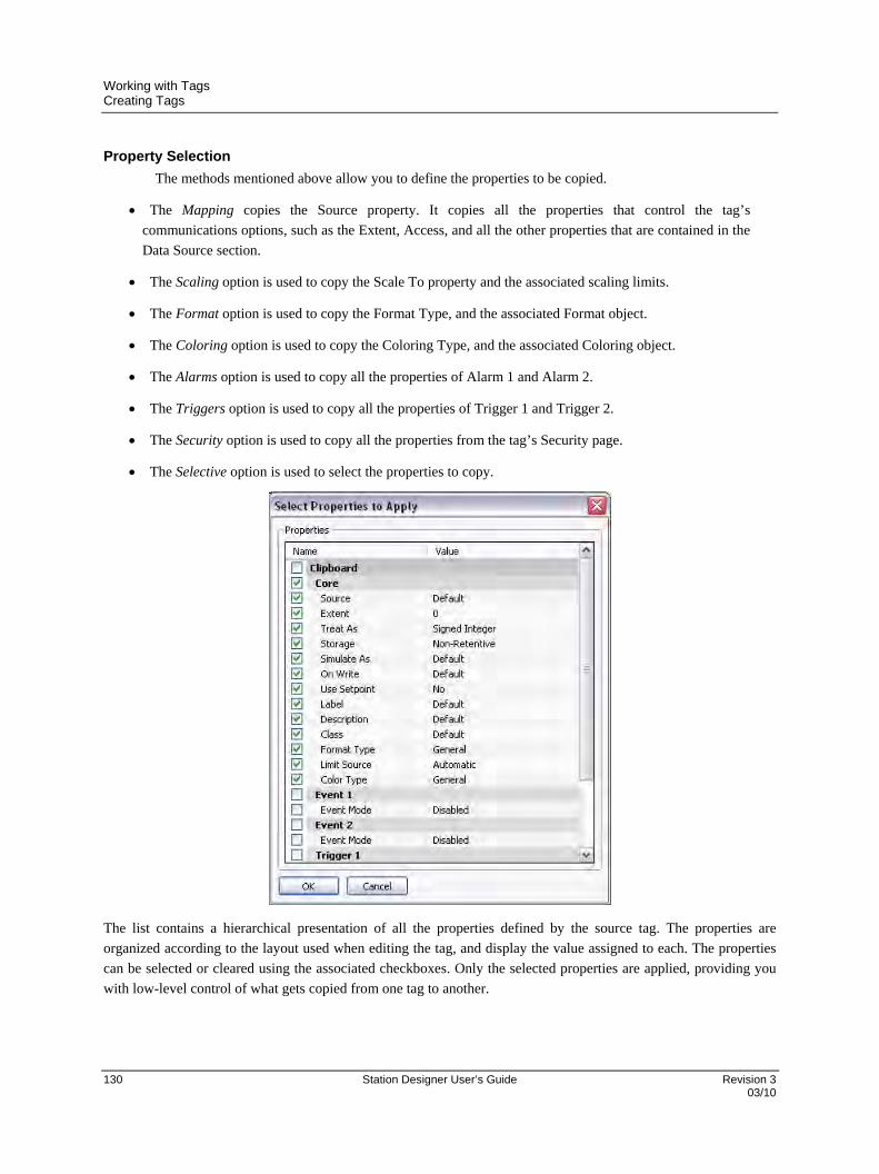
Working with Tags Creating Tags
130 Station Designer User’s Guide Revision 3 03/10
Property Selection
The methods mentioned above allow you to define the properties to be copied.
The Mapping copies the Source property. It copies all the properties that control the tag’s
communications options, such as the Extent, Access, and all the other properties that are contained in the
Data Source section.
The Scaling option is used to copy the Scale To property and the associated scaling limits.
The Format option is used to copy the Format Type, and the associated Format object.
The Coloring option is used to copy the Coloring Type, and the associated Coloring object.
The Alarms option is used to copy all the properties of Alarm 1 and Alarm 2.
The Triggers option is used to copy all the properties of Trigger 1 and Trigger 2.
The Security option is used to copy all the properties from the tag’s Security page.
The Selective option is used to select the properties to copy.
The list contains a hierarchical presentation of all the properties defined by the source tag. The properties are
organized according to the layout used when editing the tag, and display the value assigned to each. The properties
can be selected or cleared using the associated checkboxes. Only the selected properties are applied, providing you
with low-level control of what gets copied from one tag to another.
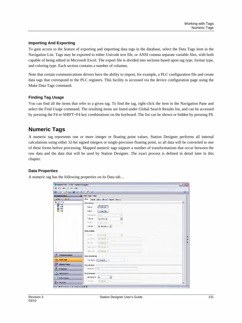
Working with Tags Numeric Tags
Revision 3 Station Designer User’s Guide 131 03/10
Importing And Exporting
To gain access to the feature of exporting and importing data tags in the database, select the Data Tags item in the
Navigation List. Tags may be exported to either Unicode text file, or ANSI comma separate variable files, with both
capable of being edited in Microsoft Excel. The export file is divided into sections based upon tag type, format type,
and coloring type. Each section contains a number of columns.
Note that certain communications drivers have the ability to import, for example, a PLC configuration file and create
data tags that correspond to the PLC registers. This facility is accessed via the device configuration page using the
Make Data Tags command.
Finding Tag Usage
You can find all the items that refer to a given tag. To find the tag, right-click the item in the Navigation Pane and
select the Find Usage command. The resulting items are listed under Global Search Results list, and can be accessed
by pressing the F4 or SHIFT+F4 key combinations on the keyboard. The list can be shown or hidden by pressing F8.
Numeric Tags A numeric tag represents one or more integer or floating point values. Station Designer performs all internal
calculations using either 32-bit signed integers or single-precision floating point, so all data will be converted to one
of these forms before processing. Mapped numeric tags support a number of transformations that occur between the
raw data and the data that will be used by Station Designer. The exact process is defined in detail later in this
chapter.
Data Properties
A numeric tag has the following properties on its Data tab…

Working with Tags Numeric Tags
132 Station Designer User’s Guide Revision 3 03/10
Data Source
The Source property is used to define where the tag gets its data. The default setting results in an
internal tag, but the drop-down list may be used to select a general expression, another data tag or an item
from a remote device.
The Extent property is used choose between a single element tag or an array. If you select an array, you
must enter the required number of elements. Arrays are not permitted for tags whose source is an
expression. For mapped items, the number of registers to be read from the remote device depends upon
the data type defined for the address. For example, an array of two elements that was mapped to a
register of type Word as Long will result in four registers being accessed, with two words being needed
for each long value. A similar array mapped to a data type of Word as Word will only need two registers.
The Manipulation property is used to define the first-stage transformation that is applied as comms data
is being transferred into a mapped tag. The following options may be available, depending on the exact
data type being used…
MANIPULATION DESCRIPTION
None The data will not be changed.
Invert Bits Each bit in the data will have its state inverted.
Reverse Bits The most significant bit in the data will be swapped with the least significant bit, with intermediate bits being treated in a similar fashion.
Reverse Bytes The most significant byte in the data will be swapped with the least significant byte and so on. Only available for data items of 16 bits or more in size.
Reverse Words The most significant word in the data will be swapped with the least significant word. Only available for data items of exactly 32 bits in size.
BCD to Binary Each four bit group in the data will be interpreted as a single decimal digit. Selecting this option will force the data to an unsigned integer.
The Treat As property for internal tags is used to define the tag’s data type. For mapped tags, it is used
to define how the manipulated data is to be interpreted by Station Designer. The property will be set to a
sensible default when the tag is mapped, but can be changed. Note that for mapped tags, the Treat As
property does not have the final say on the actual data type of the tag, as the scaling properties may be
used to convert the data further. The following options may be available, depending on the exact data
type of the comms data…
TREAT AS DESCRIPTION
Signed Integer The data will be treated as a 32-bit signed value, with smaller data values being sign-extended. For example, a 16-bit value of 0x8000 will be converted to 0xFFFF8000.
Unsigned Integer The data will be treated as a 32-bit signed value, with smaller data items being zero-extended. For example, a 32-bit value of 0x8000 will be converted to 0x00008000.
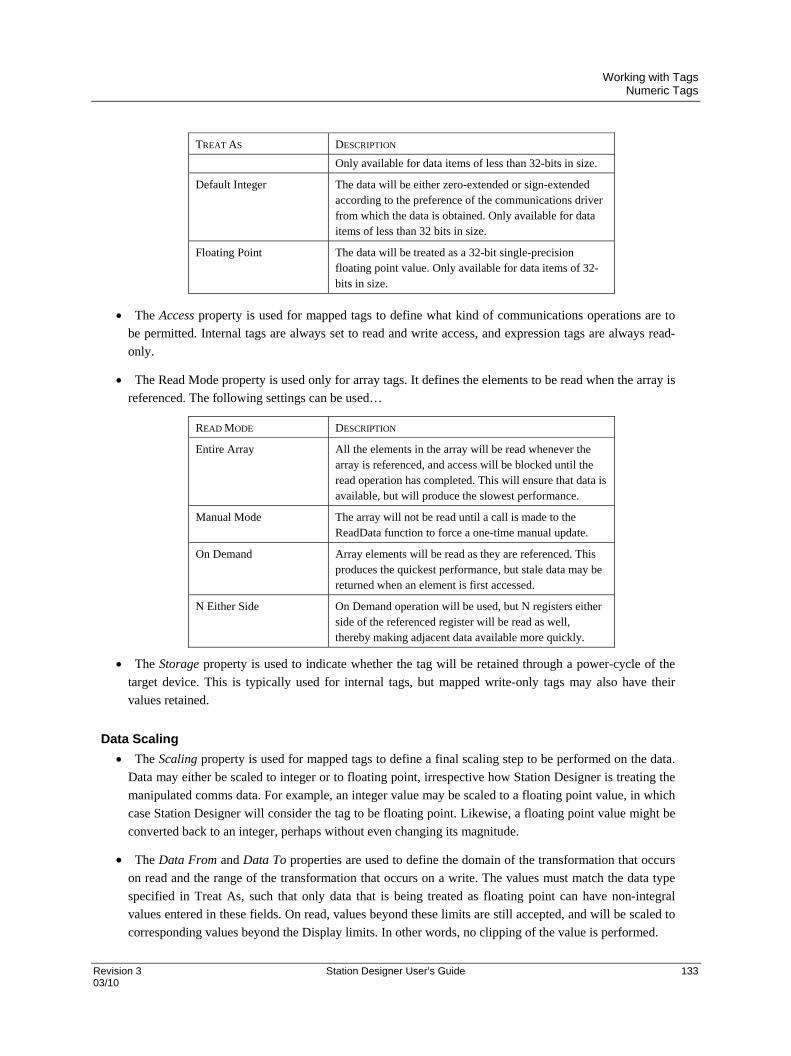
Working with Tags Numeric Tags
Revision 3 Station Designer User’s Guide 133 03/10
TREAT AS DESCRIPTION
Only available for data items of less than 32-bits in size.
Default Integer The data will be either zero-extended or sign-extended according to the preference of the communications driver from which the data is obtained. Only available for data items of less than 32 bits in size.
Floating Point The data will be treated as a 32-bit single-precision floating point value. Only available for data items of 32-bits in size.
The Access property is used for mapped tags to define what kind of communications operations are to
be permitted. Internal tags are always set to read and write access, and expression tags are always read-
only.
The Read Mode property is used only for array tags. It defines the elements to be read when the array is
referenced. The following settings can be used…
READ MODE DESCRIPTION
Entire Array All the elements in the array will be read whenever the array is referenced, and access will be blocked until the read operation has completed. This will ensure that data is available, but will produce the slowest performance.
Manual Mode The array will not be read until a call is made to the ReadData function to force a one-time manual update.
On Demand Array elements will be read as they are referenced. This produces the quickest performance, but stale data may be returned when an element is first accessed.
N Either Side On Demand operation will be used, but N registers either side of the referenced register will be read as well, thereby making adjacent data available more quickly.
The Storage property is used to indicate whether the tag will be retained through a power-cycle of the
target device. This is typically used for internal tags, but mapped write-only tags may also have their
values retained.
Data Scaling
The Scaling property is used for mapped tags to define a final scaling step to be performed on the data.
Data may either be scaled to integer or to floating point, irrespective how Station Designer is treating the
manipulated comms data. For example, an integer value may be scaled to a floating point value, in which
case Station Designer will consider the tag to be floating point. Likewise, a floating point value might be
converted back to an integer, perhaps without even changing its magnitude.
The Data From and Data To properties are used to define the domain of the transformation that occurs
on read and the range of the transformation that occurs on a write. The values must match the data type
specified in Treat As, such that only data that is being treated as floating point can have non-integral
values entered in these fields. On read, values beyond these limits are still accepted, and will be scaled to
corresponding values beyond the Display limits. In other words, no clipping of the value is performed.

Working with Tags Numeric Tags
134 Station Designer User’s Guide Revision 3 03/10
The Display From and Display To properties are used define the range of the transformation that occurs
on read and the domain of the transformation that occurs on a write. The values must match the data type
specified in Scale To, such that only data that is being scaled to floating point can have non-integral
values entered in these fields. On write, values beyond these limits are still accepted, and will be scaled
to corresponding values beyond the Data limits. In other words, no clipping of the value is performed.
Data Simulation
The Simulate As property is used to define the assumed value to be used for the tag when working in the
page editor. Entering a sensible value allows a better representation of the page’s likely appearance. This
value is also used as the tag’s default value by the target device if communication is globally disabled.
Data Actions
The On Write property is used to define an action that is to be invoked when the tag is changed. The
system variable Data will hold the new data value when the write occurs and when the action is
executed. The use of On Write properties is covered later in this chapter.
Data Setpoint
The Use Setpoint property is used to enable or disable a setpoint for this tag.
The SP Value property is used to define an expression or another tag that this tag is nominally meant to
follow. This setpoint can then be used in alarms or in primitives to implement various functions.
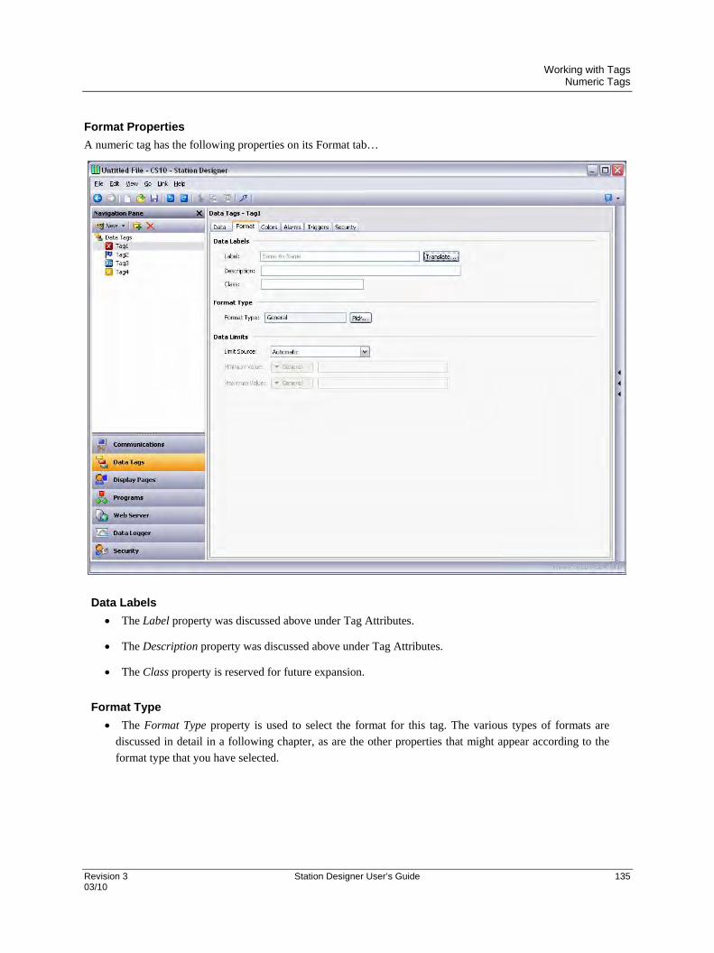
Working with Tags Numeric Tags
Revision 3 Station Designer User’s Guide 135 03/10
Format Properties
A numeric tag has the following properties on its Format tab…
Data Labels
The Label property was discussed above under Tag Attributes.
The Description property was discussed above under Tag Attributes.
The Class property is reserved for future expansion.
Format Type
The Format Type property is used to select the format for this tag. The various types of formats are
discussed in detail in a following chapter, as are the other properties that might appear according to the
format type that you have selected.

Working with Tags Numeric Tags
136 Station Designer User’s Guide Revision 3 03/10
Data Limits
The Limit Source property is used to define how the tag’s data entry limits are defined. The default
setting of Automatic results in the Display Range specified on the Data tab being used as a primary
source, with the format object being used as a fall-back. If neither source can define a range, the
maximum supported range for the tag’s data type is used. A setting of From Format can be used to force
the format object to be used, while a setting of User Defined can be used to allow manual entry of the
limits.
The Minimum Value and Maximum Value properties are used to manually define data entry limits when
Limit Source is set to User Defined.
Note: User defined tag limits are honored when numeric values are entered through the operator interface
display. They are not applied when the tag value is used in an expression or program.
Color Properties
A numeric tag has the following properties on its Colors tab…
Color Type
The Color property is used to define the color selector for this tag. The various types of selectors are
discussed in detail in a following chapter, as are the other properties that might appear according to the
option you have selected.

Working with Tags Numeric Tags
Revision 3 Station Designer User’s Guide 137 03/10
Alarm Properties
A numeric tag has the following properties on its Alarms tab…
For Each Alarm
The Event Mode property is used to indicate the logic that will be used to decide whether the alarm
should activate. The tables below list the available modes.
MODE ALARM WILL ACTIVATE WHEN…
Data Match The value of the tag is equal to the alarm’s Value.
Data Mismatch The value of tag is not equal to the alarm’s Value.
Absolute High The value of the tag exceeds the alarm’s Value.
Absolute Low The value of the tag falls below the alarm’s Value.
Rise in Value The value of the tag rises by the alarm’s Value.
Fall in Value The value of the tag falls by the alarm’s Value.
Change in Value The value of the tag changes by the alarm’s Value.

Working with Tags Numeric Tags
138 Station Designer User’s Guide Revision 3 03/10
The following modes are only available when a setpoint is defined…
MODE ALARM WILL ACTIVATE WHEN…
Deviation High The value of the tag exceeds the tag’s Setpoint by an amount equal to or greater than the alarm’s Value.
Deviation Low The value of the tag falls below the tag’s Setpoint by an amount equal to or greater than the alarm’s Value.
Out of Band The tag moves outside a band, which is equal in width to twice the alarm’s Value and is centered on the tag’s Setpoint.
In Band The tag moves inside a band, which is equal in width to twice the alarm’s Value and is centered on the tag’s Setpoint.
The Event Name property is used to define the name that will be displayed in the alarm viewer or in the
event log when referring to this event.
The Value property is used to define either the absolute value at which the alarm will be activated, the
deviation from the setpoint value or the change in value that must occur since the alarm last triggered.
The exact interpretation depends on the event mode as described above.
The Hysteresis property is used to prevent an alarm from oscillating between the on and off states when
the process is near the alarm condition. For example, for an absolute high alarm, the alarm will become
active when the tag exceeds the alarm’s value, but will only deactivate when the tag falls below the value
by an amount greater than or equal to the alarm’s hysteresis. Remember that the property always acts to
maintain an alarm once the alarm is activated, and not to modify the point at which the activation occurs.
The Enable property is used to define an expression that enables or disables the alarm. A non-zero or
empty value results in the alarm being enabled, while a zero values results in the alarm being disabled.
The Trigger property is used to indicate whether the alarm should be edge or level triggered. In the
former case, the alarm will trigger when the condition specified by the event mode first becomes true. In
the latter case, the alarm will remain in the active state while the condition persists. This property can
also be used to indicate that this alarm should be used as an event only. In this case, the alarm will be
edge triggered, but will not result in an alarm condition. Rather, an event will be logged to internal
memory and optionally to Flash memory.
The Delay property is used to indicate how long the alarm condition must exist before the alarm will
become active. In the case of an edge triggered alarm or event, this property also specifies the amount of
time for which the alarm condition must no longer exist before subsequent re-activations will result in a
further alarm being signaled. As an example, if an alarm is set to activate when a speed switch indicates
that a motor is not running even when the motor has been requested to start, this property can be used to
provide the motor with time to run-up before the alarm is activated.
The Accept property is used to indicate whether the user will be required to explicitly accept an alarm
before it will no longer be displayed. Edge triggered alarms must always be manually accepted.

Working with Tags Numeric Tags
Revision 3 Station Designer User’s Guide 139 03/10
The Priority property is used to control the order in which alarms are displayed by Station Designer’s
alarm viewer. The lower the numerical value of the priority field, the nearer to the top the alarm will be
displayed.
The Siren property is used to indicate whether or not the activation of this alarm should also activate the
target device’s sounder. While the sounder is active, the panel’s display will also flash to better draw
attention to the alarm condition.
The Mail To property is used to specify the email address book entry to which a message should be sent
when this alarm is activated. Refer to the Using Services chapter for information on configuring email.
The On Accept, On Active and On Clear properties are used to specify actions to be executed when the
specified change of state occurs. Note all actions will be available, depending on the alarm’s trigger
mode and accept type.
Trigger Properties
A numeric tag has the following properties on its Trigger tab…
For Each Trigger
The Trigger Mode property is as described for the Alarms tab.
The Value and Hysteresis properties are as described for the Alarms tab.
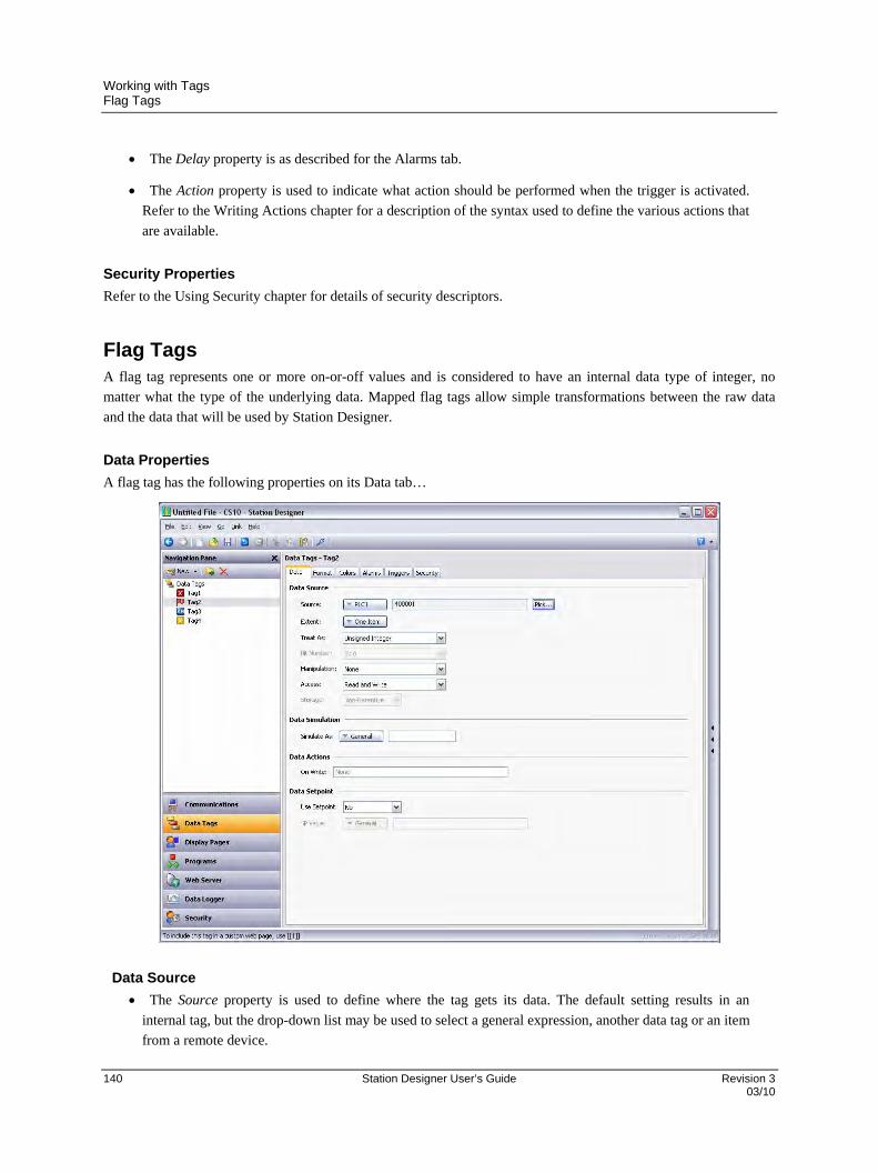
Working with Tags Flag Tags
140 Station Designer User’s Guide Revision 3 03/10
The Delay property is as described for the Alarms tab.
The Action property is used to indicate what action should be performed when the trigger is activated.
Refer to the Writing Actions chapter for a description of the syntax used to define the various actions that
are available.
Security Properties
Refer to the Using Security chapter for details of security descriptors.
Flag Tags A flag tag represents one or more on-or-off values and is considered to have an internal data type of integer, no
matter what the type of the underlying data. Mapped flag tags allow simple transformations between the raw data
and the data that will be used by Station Designer.
Data Properties
A flag tag has the following properties on its Data tab…
Data Source
The Source property is used to define where the tag gets its data. The default setting results in an
internal tag, but the drop-down list may be used to select a general expression, another data tag or an item
from a remote device.
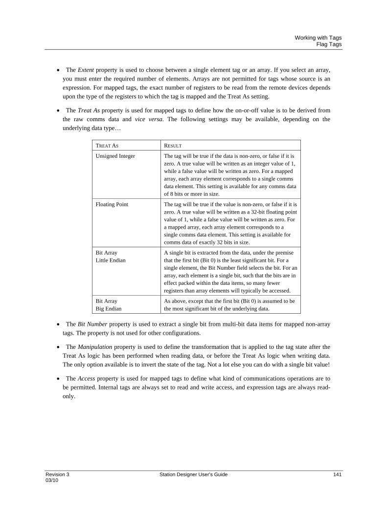
Working with Tags Flag Tags
Revision 3 Station Designer User’s Guide 141 03/10
The Extent property is used to choose between a single element tag or an array. If you select an array,
you must enter the required number of elements. Arrays are not permitted for tags whose source is an
expression. For mapped tags, the exact number of registers to be read from the remote devices depends
upon the type of the registers to which the tag is mapped and the Treat As setting.
The Treat As property is used for mapped tags to define how the on-or-off value is to be derived from
the raw comms data and vice versa. The following settings may be available, depending on the
underlying data type…
TREAT AS RESULT
Unsigned Integer The tag will be true if the data is non-zero, or false if it is zero. A true value will be written as an integer value of 1, while a false value will be written as zero. For a mapped array, each array element corresponds to a single comms data element. This setting is available for any comms data of 8 bits or more in size.
Floating Point The tag will be true if the value is non-zero, or false if it is zero. A true value will be written as a 32-bit floating point value of 1, while a false value will be written as zero. For a mapped array, each array element corresponds to a single comms data element. This setting is available for comms data of exactly 32 bits in size.
Bit Array Little Endian
A single bit is extracted from the data, under the premise that the first bit (Bit 0) is the least significant bit. For a single element, the Bit Number field selects the bit. For an array, each element is a single bit, such that the bits are in effect packed within the data items, so many fewer registers than array elements will typically be accessed.
Bit Array Big Endian
As above, except that the first bit (Bit 0) is assumed to be the most significant bit of the underlying data.
The Bit Number property is used to extract a single bit from multi-bit data items for mapped non-array
tags. The property is not used for other configurations.
The Manipulation property is used to define the transformation that is applied to the tag state after the
Treat As logic has been performed when reading data, or before the Treat As logic when writing data.
The only option available is to invert the state of the tag. Not a lot else you can do with a single bit value!
The Access property is used for mapped tags to define what kind of communications operations are to
be permitted. Internal tags are always set to read and write access, and expression tags are always read-
only.

Working with Tags Flag Tags
142 Station Designer User’s Guide Revision 3 03/10
The Read property is used only for array tags. It defines the elements to be read when the array is
referenced. The following settings can be used…
READ MODE DESCRIPTION
Entire Array All the elements in the array will be read whenever the array is referenced, and access will be blocked until the read operation has completed. This will ensure that data is available, but will produce the slowest performance.
Manual Mode The array will not be read until a call is made to the ReadData function to force a one-time manual update.
On Demand Array elements will be read as they are referenced. This produces the quickest performance, but stale data may be returned when an element is first accessed.
N Either Side On Demand operation will be used, but N registers either side of the referenced register will be read as well, thereby making adjacent data available more quickly.
The Storage property is used to indicate whether the tag will be retained through a power-cycle of the
target device. This is typically used for internal tags, but mapped write-only tags may also have their
values retained.
Data Simulation
The Simulate As property is used to define the assumed value to be used for the tag when working in the
page editor. Entering a sensible value allows a better representation of the page’s likely appearance. This
value is also used as the tag’s default value by the target device if communication is globally disabled.
Data Actions
The On Write property is used to define an action that is to be invoked when the tag is changed. The
system variable Data will hold the new data value when the write occurs and when the action is
executed. The use of On Write properties is covered later in this chapter.
Data Setpoint
The Use Setpoint property is used to enable or disable a setpoint for this tag.
The SP Value property is used to define an expression or another tag that this tag is nominally meant to
follow. This setpoint can then be used in alarms or in primitives to implement various functions.

Working with Tags Flag Tags
Revision 3 Station Designer User’s Guide 143 03/10
Format Properties
A flag tag has the following properties on its Format tab…
Data Labels
The Label property was discussed above under Tag Attributes.
The Description property was discussed above under Tag Attributes.
The Class property is reserved for future expansion.
Format Type
The Format Type property selects the format for this tag. A Two State format is used by default, but a
Linked format may be substituted instead. The various types of formats are discussed in detail in a
following chapter, as are the other properties that might appear according to the format type that you
have selected.

Working with Tags Flag Tags
144 Station Designer User’s Guide Revision 3 03/10
Color Properties
A numeric tag has the following properties on its Colors tab…
Color Type
The Color property defines the coloring for this tag. A Two State coloring is selected by default, but a
General, Linked or Fixed coloring may be substituted. The various colorings are discussed in detail in a
later chapter, as are the other properties that might appear according to the option you have selected.

Working with Tags Flag Tags
Revision 3 Station Designer User’s Guide 145 03/10
Alarm Properties
A flag tag has the following properties on its Alarms tab…
For Each Alarm
The Event Mode property is used to indicate the logic that will be used to decide whether the alarm
should activate. The tables below list the available modes.
MODE ALARM WILL ACTIVATE WHEN…
Active On The tag is true.
Active Off The tag is false.
Change of State The tag changed.

Working with Tags Flag Tags
146 Station Designer User’s Guide Revision 3 03/10
The following modes are only available when a setpoint is defined…
MODE ALARM WILL ACTIVATE WHEN…
Not Equal to SP The tag does not equal its setpoint.
Off When SP On The tag does not respond to an ON setpoint.
On When SP Off The tag does not respond to an OFF setpoint.
Equal to SP The tag equals its setpoint.
The Event Name property is used to define the name that will be displayed in the alarm viewer or in the
event log as appropriate. Station Designer will suggest a default name based upon the tag’s label, and the
event mode that has been selected.
The Enable property is used to define an expression that enables or disables the alarm. A non-zero or
empty value results in the alarm being enabled, while a zero values results in the alarm being disabled.
The Trigger property is used to indicate whether the alarm should be edge or level triggered. In the
former case, the alarm will trigger when the condition specified by the event mode first becomes true. In
the latter case, the alarm will remain in the active state while the condition persists. This property can
also be used to indicate that this alarm should be used as an event only. In this case, the alarm will be
edge triggered, but will not result in an alarm condition. Rather, an event will be logged to internal
memory and optionally to Flash memory.
The Delay property is used to indicate how long the alarm condition must exist before the alarm will
become active. In the case of an edge triggered alarm or event, this property also specifies the amount of
time for which the alarm condition must no longer exist before subsequent re-activations will result in a
further alarm being signaled. As an example, if an alarm is set to activate when a speed switch indicates
that a motor is not running even when the motor has been requested to start, this property can be used to
provide the motor with time to run-up before the alarm is activated.
The Accept property is used to indicate whether the user will be required to explicitly accept an alarm
before it will no longer be displayed. Edge triggered alarms must always be manually accepted.
The Priority property is used to control the order in which alarms are displayed by Station Designer’s
alarm viewer. The lower the numerical value of the priority field, the nearer to the top the alarm will be
displayed.
The Siren property is used to indicate whether or not the activation of this alarm should also activate the
target device’s sounder. While the sounder is active, the panel’s display will also flash to better draw
attention to the alarm condition.
The Mail To property is used to specify the email address book entry to which a message should be sent
when this alarm is activated. Refer to the using Services chapter for information on configuring email.
The On Accept, On Active and On Clear properties are used to specify actions to be executed when the
specified change of state occurs. Note all actions will be available, depending on the alarm’s trigger
mode and accept type.
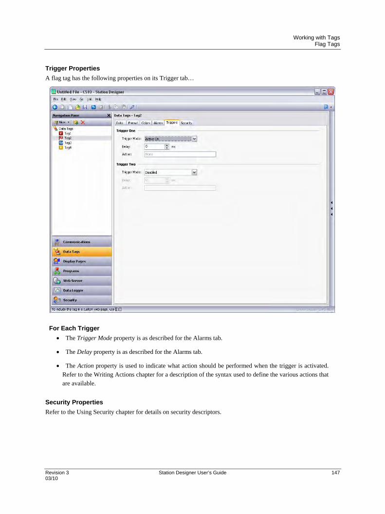
Working with Tags Flag Tags
Revision 3 Station Designer User’s Guide 147 03/10
Trigger Properties
A flag tag has the following properties on its Trigger tab…
For Each Trigger
The Trigger Mode property is as described for the Alarms tab.
The Delay property is as described for the Alarms tab.
The Action property is used to indicate what action should be performed when the trigger is activated.
Refer to the Writing Actions chapter for a description of the syntax used to define the various actions that
are available.
Security Properties
Refer to the Using Security chapter for details on security descriptors.
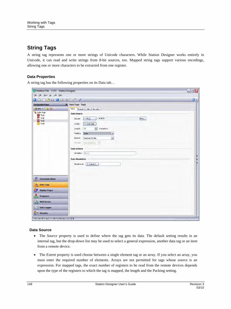
Working with Tags String Tags
148 Station Designer User’s Guide Revision 3 03/10
String Tags A string tag represents one or more strings of Unicode characters. While Station Designer works entirely in
Unicode, it can read and write strings from 8-bit sources, too. Mapped string tags support various encodings,
allowing one or more characters to be extracted from one register.
Data Properties
A string tag has the following properties on its Data tab…
Data Source
The Source property is used to define where the tag gets its data. The default setting results in an
internal tag, but the drop-down list may be used to select a general expression, another data tag or an item
from a remote device.
The Extent property is used choose between a single element tag or an array. If you select an array, you
must enter the required number of elements. Arrays are not permitted for tags whose source is an
expression. For mapped tags, the exact number of registers to be read from the remote devices depends
upon the type of the registers to which the tag is mapped, the length and the Packing setting.
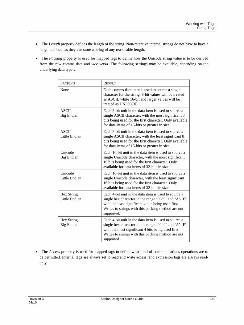
Working with Tags String Tags
Revision 3 Station Designer User’s Guide 149 03/10
The Length property defines the length of the string. Non-retentive internal strings do not have to have a
length defined, as they can store a string of any reasonable length.
The Packing property is used for mapped tags to define how the Unicode string value is to be derived
from the raw comms data and vice versa. The following settings may be available, depending on the
underlying data type…
PACKING RESULT
None Each comms data item is used to source a single character for the string. 8-bit values will be treated as ASCII, while 16-bit and larger values will be treated as UNICODE.
ASCII Big Endian
Each 8-bit unit in the data item is used to source a single ASCII character, with the most significant 8 bits being used for the first character. Only available for data items of 16-bits or greater in size.
ASCII Little Endian
Each 8-bit unit in the data item is used to source a single ASCII character, with the least significant 8 bits being used for the first character. Only available for data items of 16-bits or greater in size.
Unicode Big Endian
Each 16-bit unit in the data item is used to source a single Unicode character, with the most significant 16 bits being used for the first character. Only available for data items of 32-bits in size.
Unicode Little Endian
Each 16-bit unit in the data item is used to source a single Unicode character, with the least significant 16 bits being used for the first character. Only available for data items of 32-bits in size.
Hex String Little Endian
Each 4-bit unit in the data item is used to source a single hex character in the range ‘0’-‘9’ and ‘A’-‘F’, with the least significant 4 bits being used first. Writes to strings with this packing method are not supported.
Hex String Big Endian
Each 4-bit unit in the data item is used to source a single hex character in the range ‘0’-‘9’ and ‘A’-‘F’, with the most significant 4 bits being used first. Writes to strings with this packing method are not supported.
The Access property is used for mapped tags to define what kind of communications operations are to
be permitted. Internal tags are always set to read and write access, and expression tags are always read-
only.
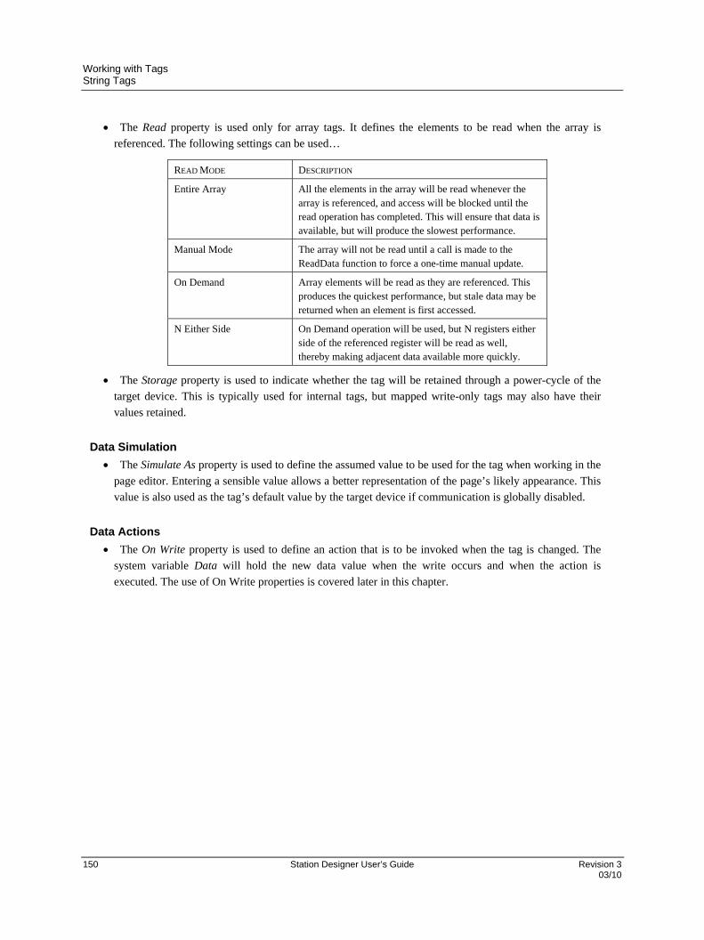
Working with Tags String Tags
150 Station Designer User’s Guide Revision 3 03/10
The Read property is used only for array tags. It defines the elements to be read when the array is
referenced. The following settings can be used…
READ MODE DESCRIPTION
Entire Array All the elements in the array will be read whenever the array is referenced, and access will be blocked until the read operation has completed. This will ensure that data is available, but will produce the slowest performance.
Manual Mode The array will not be read until a call is made to the ReadData function to force a one-time manual update.
On Demand Array elements will be read as they are referenced. This produces the quickest performance, but stale data may be returned when an element is first accessed.
N Either Side On Demand operation will be used, but N registers either side of the referenced register will be read as well, thereby making adjacent data available more quickly.
The Storage property is used to indicate whether the tag will be retained through a power-cycle of the
target device. This is typically used for internal tags, but mapped write-only tags may also have their
values retained.
Data Simulation
The Simulate As property is used to define the assumed value to be used for the tag when working in the
page editor. Entering a sensible value allows a better representation of the page’s likely appearance. This
value is also used as the tag’s default value by the target device if communication is globally disabled.
Data Actions
The On Write property is used to define an action that is to be invoked when the tag is changed. The
system variable Data will hold the new data value when the write occurs and when the action is
executed. The use of On Write properties is covered later in this chapter.
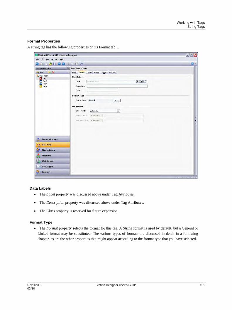
Working with Tags String Tags
Revision 3 Station Designer User’s Guide 151 03/10
Format Properties
A string tag has the following properties on its Format tab…
Data Labels
The Label property was discussed above under Tag Attributes.
The Description property was discussed above under Tag Attributes.
The Class property is reserved for future expansion.
Format Type
The Format property selects the format for this tag. A String format is used by default, but a General or
Linked format may be substituted. The various types of formats are discussed in detail in a following
chapter, as are the other properties that might appear according to the format type that you have selected.
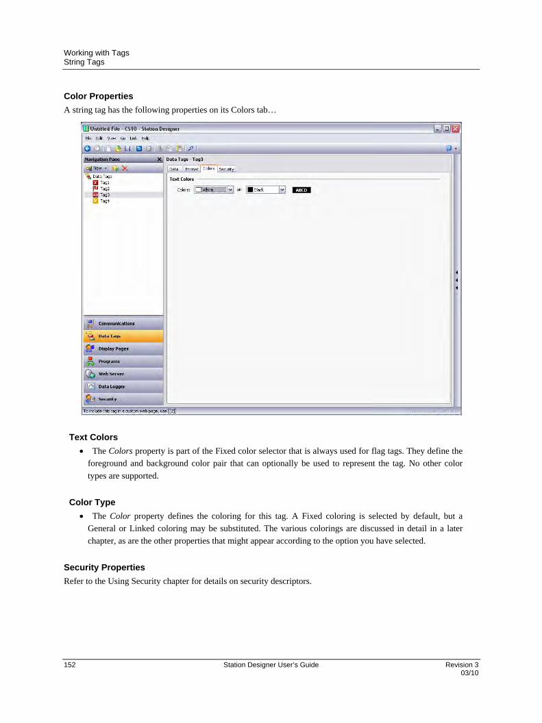
Working with Tags String Tags
152 Station Designer User’s Guide Revision 3 03/10
Color Properties
A string tag has the following properties on its Colors tab…
Text Colors
The Colors property is part of the Fixed color selector that is always used for flag tags. They define the
foreground and background color pair that can optionally be used to represent the tag. No other color
types are supported.
Color Type
The Color property defines the coloring for this tag. A Fixed coloring is selected by default, but a
General or Linked coloring may be substituted. The various colorings are discussed in detail in a later
chapter, as are the other properties that might appear according to the option you have selected.
Security Properties
Refer to the Using Security chapter for details on security descriptors.

Working with Tags Basic Tags
Revision 3 Station Designer User’s Guide 153 03/10
Basic Tags Basic tags are used to represent constants or expressions…
Data Value
The Data Value property is used to define the value of the tag. It must be an expression. The tag itself
will adopt the data type of the expression that is used.
Data Simulation
The Simulate As property is used to define a value to be used as the default for the tag when editing
display pages. Entering a sensible value allows a better representation of the page’s likely appearance.
This value is also used as the tag’s default value by the target device if communication is globally
disabled.
Working with Tags Basic Tags
154 Station Designer User’s Guide Revision 3 03/10
Data Labels
The Label property was discussed above under Tag Attributes.
The Description property was discussed above under Tag Attributes.
The Class property is reserved for future expansion.
Advanced Topics
Array Properties
Many of the properties of array tags can be made variable based upon the exact element of the array being
referenced. To achieve this, a system property called i is set to the element index during the evaluation of
those properties. For example, the Label property could be set to =”Element ” + AsText(i+1) to label the
array elements Element 1, Element 2 etc.
This feature can be used with the following properties…
The tag’s label.
The tag’s scaling values.
The tag’s setpoint.
The tag’s limits.
The tag’s On Write property.
The tag’s event labels.
The tag’s event and trigger values and hysteresis settings.
The tag’s trigger actions.
Note that triggers and events are evaluated separately for each element of the array for which they are
configured, allowing several events or triggers to be created at once. The only limitation to this feature is
that alarms and events only operate for the first 256 elements of the array. Triggers operate for all elements,
regardless of the size of the array.

Working with Tags Tag Data Flow
Revision 3 Station Designer User’s Guide 155 03/10
Tag Data Flow As you will have noticed, numeric tags in particular have a number of data transformations that occur between the
comms data and the value actually used by Station Designer. These can be configured to handle just about any sort
of data in any way you like, but the exact way in which they operate for numeric tags deserves further attention.
Numeric Tag Read Process
When data is read from a device such as the HC900, the following steps occur…
The comms driver is asked to read a value based on the address setting that has been defined for the
source of the tag. Based on the type of the address, the driver may combine more than one register to
create the data bit. For example, reading a single Word as Long value will result in two registers being
read and combined by the driver using its knowledge of the device’s word ordering.
The comms data is then modified according to the Manipulation property for the tag in question. These
processes perform bit or byte level changes to the data, typically to account for driver incompatibilities or
other situations where the data is not in the form that the comms driver normally expects to encounter.
The manipulated data is then interpreted in conjunction with the tag’s Treat As property, being viewed
as a 32-bit integer or a 32-bit single-precision floating-point value as appropriate. Data items smaller than
32 bits will be either zero- or sign-extended based per the configuration. If no scaling is defined, the
result of this step defines the final value and data type of the tag.
If scaling is defined, the interpreted data is then scaled according to the domain and range defined for
the tag. The result of the scaling may be of a different type from the interpreted data, such that a floating
point value may be scaled to an integer or vice versa. Assuming scaling is defined, the result of this step
then defines the final value and data type of the tag.
Numeric Tag Write Process
When data is written to a device, the following steps occur…
If scaling is defined, the domain and range are reversed, converting the data back to an unscaled value
whose data type is defined by the Treat As property.
If the unscaled data is larger than the comms data, the high-order bits are removed, producing a stripped
version of the data suitable for the next step.
The stripped data is then modified according to the Manipulation property, reversing the transformation
applied above, producing comms data.
The comms driver than takes the comms data, and writes it to one or more registers in the target device
according to the type of the address.
Working with Tags Using On Write
156 Station Designer User’s Guide Revision 3 03/10
Using On Write A tag’s On Write property contains an action which is executed when a change is made to the tag. While the action
is being executed, a system property called Data is set to the new value, allowing the new data to be examined.
There are three typical uses for this feature…
Regular read-and-write tags can have an On Write property defined to allow some action to be taken on
demand. For example, a database may need to store the value of a tag in two formats, one being the
original tag format and the other being a transformed version. While there are other ways of doing this,
one method is to use the On Write property to catch the write, and then run a program to calculate and
store the transformed version.
Read-only tags can be made writable by defining an On Write property. While this seems odd, imagine,
for example, that a PID loop has a read-only property to indicate its current output power, and a read-
write property to define the manual output power. You could define display fields to allow data entry to
the output power when in manual mode, and catch them using the On Write property, thereby writing the
values to the manual output power.
Complex transformations can be implemented by defining an expression tag to perform the forward
transformation and an On Write action to perform the inverse. For example, a tag could be set to
Sqrt([40001]) to take the square root of a value in a Modbus PLC. Since this is an expression tag, it
is by definition read-only, but writes can be allowed by defining an On Write equal to [40001] = Data*Data, thereby reversing the square root calculation.

Revision 3 Station Designer User’s Guide 157 03/10
Using Data Formats
Numeric tags can have one of various data formats selected, while flag and string tags have their formats fixed to
Two-State and General, respectively. Each format type will take a data value and convert it to or from a text string.
Format Types The following formats are supported…
General format provides simple formatting of values, converting numeric values to signed decimal
values, and passing on strings without further processing. The general format has no configuration
properties, and is the default format for string tags. It is also implicitly used by basic tags.
Linked format uses the data format of another tag to format the tag that you are configuring. It is useful
for creating format templates and then applying them to many tags in the same database. This can avoid
repetition, and make it easier to adjust settings such as units or decimal point counts.
Numeric format takes a floating point or integer value and converts it to a string, using a specific
number base and selecting the required number of digits before and after the decimal point. It can also
add a prefix string and a units string to the value, and handle signed or unsigned values.
Scientific format takes a floating point or integer value and converts it to exponential format, selecting
the required number of digits after the decimal point. It can also add a prefix string and a units string to
the value.
Time and Date format takes an integer value and treats it as a number of seconds elapsed since 1st
January 1997. It can display the result as a date value, a time value or both, or treat the value as elapsed
time that can contain more than 24 in its hours value. Date formatting and time formatting options are
supported to allow for various international standards.
IP Address format takes an integer value and displays it as four decimal bytes separated by periods.
This allows a 32-bit number to be displayed as an IP address without further configuration.
Two-State format takes a numeric value and displays one of two strings based on whether the value is
zero or non-zero. This is the permanently defined format type for flag tags.
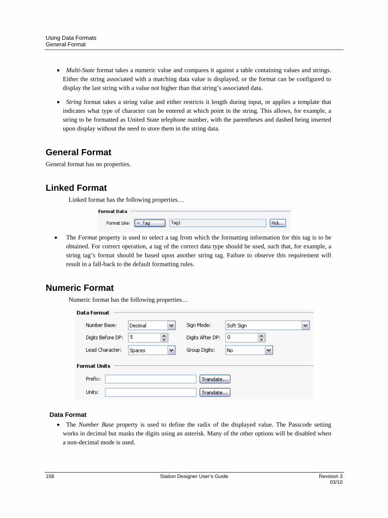
Using Data Formats General Format
158 Station Designer User’s Guide Revision 3 03/10
Multi-State format takes a numeric value and compares it against a table containing values and strings.
Either the string associated with a matching data value is displayed, or the format can be configured to
display the last string with a value not higher than that string’s associated data.
String format takes a string value and either restricts it length during input, or applies a template that
indicates what type of character can be entered at which point in the string. This allows, for example, a
string to be formatted as United State telephone number, with the parentheses and dashed being inserted
upon display without the need to store them in the string data.
General Format General format has no properties.
Linked Format Linked format has the following properties…
The Format property is used to select a tag from which the formatting information for this tag is to be
obtained. For correct operation, a tag of the correct data type should be used, such that, for example, a
string tag’s format should be based upon another string tag. Failure to observe this requirement will
result in a fall-back to the default formatting rules.
Numeric Format Numeric format has the following properties…
Data Format
The Number Base property is used to define the radix of the displayed value. The Passcode setting
works in decimal but masks the digits using an asterisk. Many of the other options will be disabled when
a non-decimal mode is used.
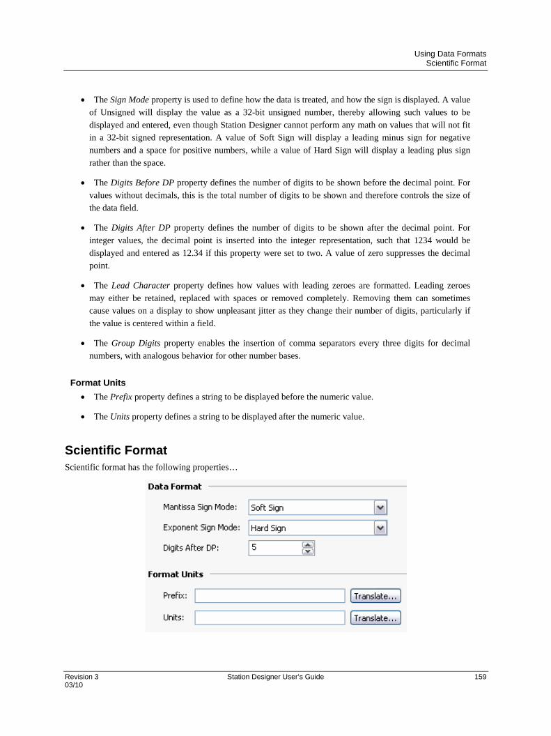
Using Data Formats Scientific Format
Revision 3 Station Designer User’s Guide 159 03/10
The Sign Mode property is used to define how the data is treated, and how the sign is displayed. A value
of Unsigned will display the value as a 32-bit unsigned number, thereby allowing such values to be
displayed and entered, even though Station Designer cannot perform any math on values that will not fit
in a 32-bit signed representation. A value of Soft Sign will display a leading minus sign for negative
numbers and a space for positive numbers, while a value of Hard Sign will display a leading plus sign
rather than the space.
The Digits Before DP property defines the number of digits to be shown before the decimal point. For
values without decimals, this is the total number of digits to be shown and therefore controls the size of
the data field.
The Digits After DP property defines the number of digits to be shown after the decimal point. For
integer values, the decimal point is inserted into the integer representation, such that 1234 would be
displayed and entered as 12.34 if this property were set to two. A value of zero suppresses the decimal
point.
The Lead Character property defines how values with leading zeroes are formatted. Leading zeroes
may either be retained, replaced with spaces or removed completely. Removing them can sometimes
cause values on a display to show unpleasant jitter as they change their number of digits, particularly if
the value is centered within a field.
The Group Digits property enables the insertion of comma separators every three digits for decimal
numbers, with analogous behavior for other number bases.
Format Units
The Prefix property defines a string to be displayed before the numeric value.
The Units property defines a string to be displayed after the numeric value.
Scientific Format Scientific format has the following properties…

Using Data Formats Time and Date Format
160 Station Designer User’s Guide Revision 3 03/10
Data Format
The Mantissa Sign Mode property is used to define how the sign is displayed on the mantissa. A value
of Soft Sign will display a leading minus sign for negative numbers and a space for positive numbers,
while a value of Hard Sign will display a leading plus sign rather than the space.
The Exponent Sign Mode property is used to define how the sign is displayed on the exponent. A value
of Soft Sign will display a leading minus sign for negative values and nothing for positive values, while a
value of Hard Sign will display a leading plus sign for positive values instead.
The Digits After DP property defines the number of digits to be shown after the decimal point. By
definition, there is always one digit before the decimal in scientific format. A value of zero suppresses
the decimal point.
Format Units
The Prefix property defines a string to be displayed before the numeric value.
The Units property defines a string to be displayed after the numeric value.
Time and Date Format Time and Date format has the following properties…
Format Mode
The Format Mode property is used to indicate whether the field should display the time, the date or
both. In the last case, this property also indicates in which order the two elements should be shown.
Options are also provided to allow a time value to be treated as an elapsed period of time, rather than a
time that is paired with a date. For example, a value of 25.5 hours will display as 25:30 in an elapsed
mode. In a conventional time mode, it will display 00:30, as the system will assume a time early in the
morning on 2nd January 1997.
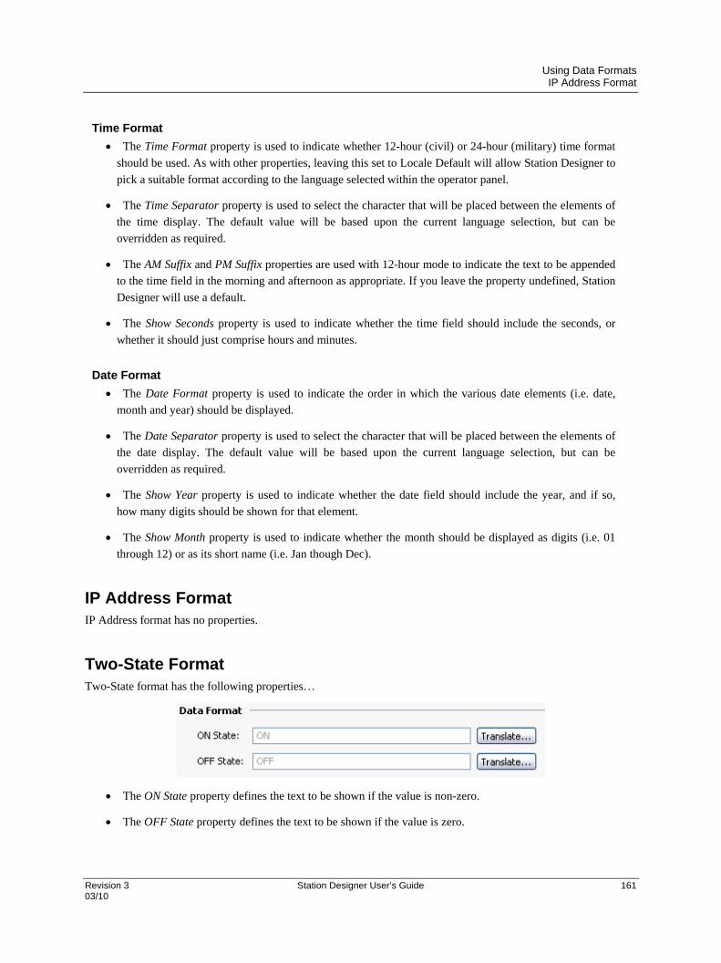
Using Data Formats IP Address Format
Revision 3 Station Designer User’s Guide 161 03/10
Time Format
The Time Format property is used to indicate whether 12-hour (civil) or 24-hour (military) time format
should be used. As with other properties, leaving this set to Locale Default will allow Station Designer to
pick a suitable format according to the language selected within the operator panel.
The Time Separator property is used to select the character that will be placed between the elements of
the time display. The default value will be based upon the current language selection, but can be
overridden as required.
The AM Suffix and PM Suffix properties are used with 12-hour mode to indicate the text to be appended
to the time field in the morning and afternoon as appropriate. If you leave the property undefined, Station
Designer will use a default.
The Show Seconds property is used to indicate whether the time field should include the seconds, or
whether it should just comprise hours and minutes.
Date Format
The Date Format property is used to indicate the order in which the various date elements (i.e. date,
month and year) should be displayed.
The Date Separator property is used to select the character that will be placed between the elements of
the date display. The default value will be based upon the current language selection, but can be
overridden as required.
The Show Year property is used to indicate whether the date field should include the year, and if so,
how many digits should be shown for that element.
The Show Month property is used to indicate whether the month should be displayed as digits (i.e. 01
through 12) or as its short name (i.e. Jan though Dec).
IP Address Format IP Address format has no properties.
Two-State Format Two-State format has the following properties…
The ON State property defines the text to be shown if the value is non-zero.
The OFF State property defines the text to be shown if the value is zero.

Using Data Formats The Multi-State Format
162 Station Designer User’s Guide Revision 3 03/10
The Multi-State Format The Multi-State format has the following properties…
Format Control
The States property defines how many states the multi-state format will contain, up to a maximum of
500 entries. The window displaying the format will update to show the required number of Data and Text
properties.
The Limit property defines how many states will be used when matching data against this format. It can
be dynamically adjusted, while the absolute number of states is statically defined. This property is useful
when the state fields are populated at runtime, as it allows unused fields to be skipped during the data
entry process.
The Default property is used to define a string to be displayed if the data cannot be matched against the
defined states. If no value is provided, the numeric representation of the unmatched state will be
displayed in parentheses.
The Match Type property defines how the data is compared against the various states. If Discrete is
selected, the tag data must match a given state’s data value in order for that state to be used. If Ranged is
selected, Station Designer assumes that the state data values are in increasing numerical order, and will
use a state value if the tag data is less than or equal to that state’s data value but greater than the prior
state’s data value. During data entry, ranged format objects assign values equal to the individual states’
actual data values.
Format States
The Data and Text properties define the data value and display text for each state in this format. States
with empty text fields are disabled and are ignored.

Using Data Formats The Multi-State Format
Revision 3 Station Designer User’s Guide 163 03/10
Format Commands
The Multi-state format object provides buttons to allow the various states and the associated properties for exporting
or importing from Unicode text files. These files are edited in Microsoft Excel.
String Format
The String Format has the following properties…
The Template property is used to enter an optional “picture” of what the string should look like. A
template comprises a number of special formatting characters that indicate what type of character is
acceptable at that position. The following formatting characters are supported…
Character Permitted Characters In Template A-Z a-z 0-9 Space Misc
A Yes - - - -
a Yes Yes - - -
S Yes - - Yes -
s Yes Yes - Yes -
N Yes - Yes - -
n Yes Yes Yes - -
M Yes - Yes Yes -
m Yes Yes Yes Yes -
0 - - Yes - -
X Yes Yes Yes Yes Yes
The additional characters referred to by the “Misc” column are…
,.:;+-=!?%/$
Any characters that are not formatting characters are interpreted as literals and displayed without their
having to be present in the underlying data. For example, a template of “(000) 000-0000” will allow entry
of US standard telephone numbers without the user having to enter the punctuation, and without those
characters having to be stored for each string.
The Max Length property may be used as an alternative to the Template property to allow free-form
entry to a maximum number of characters. Note that the format length and the underlying data length
are independent values, but that the former should not typically be larger than the latter.


Revision 3 Station Designer User’s Guide 165 03/10
Using Color Selectors
Numeric tags can have one of various color selectors selected, while flag and string tags have their colors fixed to
Two-State and General, respectively. Each color selector will take a data value and convert to a foreground and
background color pair.
Color Selector Types The following color selectors are supported…
The General color selector always returns white on black.
The Linked format uses the coloring of another tag to format the tag that you are configuring. It is useful
for creating templates and then applying them to many tags in the same database. This can avoid
repetition, and make it easier to adjust your color settings from a single location.
The Fixed color selector always returns a fixed pair of colors.
The Two-State color selector takes a numeric value and picks one of two color pairs based on whether
the value is zero or non-zero. This is the permanently defined color selector for flag tags.
The Multi-State color selector takes a numeric value and compares it against a table containing data
values and color pairs. Either a color pair associated with a matching data value is selected, or the
selector can be configured to use the last color pair with an associated data value not higher than the data.
General Colors The General color selector has no properties.
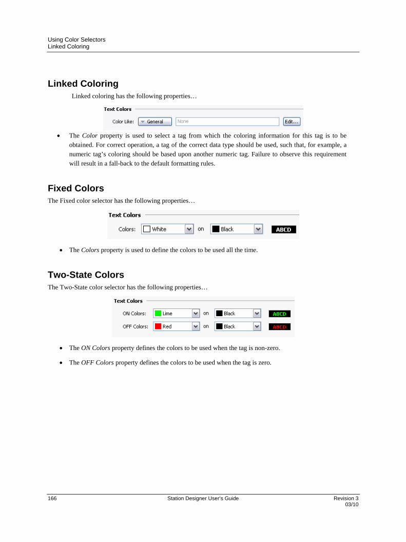
Using Color Selectors Linked Coloring
166 Station Designer User’s Guide Revision 3 03/10
Linked Coloring Linked coloring has the following properties…
The Color property is used to select a tag from which the coloring information for this tag is to be
obtained. For correct operation, a tag of the correct data type should be used, such that, for example, a
numeric tag’s coloring should be based upon another numeric tag. Failure to observe this requirement
will result in a fall-back to the default formatting rules.
Fixed Colors The Fixed color selector has the following properties…
The Colors property is used to define the colors to be used all the time.
Two-State Colors The Two-State color selector has the following properties…
The ON Colors property defines the colors to be used when the tag is non-zero.
The OFF Colors property defines the colors to be used when the tag is zero.

Using Color Selectors Multi-State Colors
Revision 3 Station Designer User’s Guide 167 03/10
Multi-State Colors The Multi-State color selector has the following properties…
Format Control
The States property defines how many states the multi-state selector will contain, up to a maximum of
500 entries. The window displaying the selector will update to show the required number of Data and
Text properties.
The Default Colors property is used to define the colors to be used if the data cannot be matched against
the defined states.
The Match Type property defines how the data is compared against the various states. If Discrete is
selected, the tag data must match a given state’s data value in order for that state to be used. If Ranged is
selected, Station Designer assumes that the state data values are in increasing numerical order and will
use a state value if the tag data is less than or equal to that state’s data value but greater than the prior
state’s data value.
Format States
The Data and Colors properties define the data and color values for each state.
Color Commands
The Multi-state format object enables the export and import of various states and associated properties from
Unicode text files. These files are edited in Microsoft Excel. It also enables the Data fields of coloring to be
synchronized with the Data fields of a Multi-State format object that is configured for the same tag. This avoids
entering the same values twice.

Creating Display Pages Editor Basics
Revision 3 Station Designer User’s Guide 168 03/10
Creating Display Pages
Selecting the Display Pages category in the Navigation Pane gives access to the Station Designer graphics editor.
This editor is designed to allow the quick and efficient creation of attractive displays, while also providing the
maximum flexibility.
Editor Basics The graphics editor is shown below in its initial state…
The Editing Pane shows a representation of the 900 Control Station, including both the keys and the display area
itself. At the lowest zoom level, the entire panel will be shown, even if this means allocating less than one pixel on
your PC’s display for each pixel on the display of the Station. In this situation, pages can still be viewed and most
editing can be performed, but accuracy will be somewhat reduced. A warning message to that effect is displayed.
Working with Pages
Manipulation of display pages via the Navigation List is supported, and operates as for any other item in a Station
Designer database. Display pages can be copied between databases when two instances of Station Designer are open
by simply selecting them in one database’s Navigation Pane and dragging them to the corresponding category in the
target database. This makes it very easy to build new databases by combining previously used page designs.
Changing the Zoom Level
Zooming in and out is most easily performed using the mouse wheel. If you do not have such a mouse, you can use
the editor’s zoom mode by selecting the magnifying glass from the toolbar. In this mode, left-clicks will zoom in,
and either right-clicks or left-clicks with CTRL held down will zoom out. You may also use the zoom commands on
the View menu.
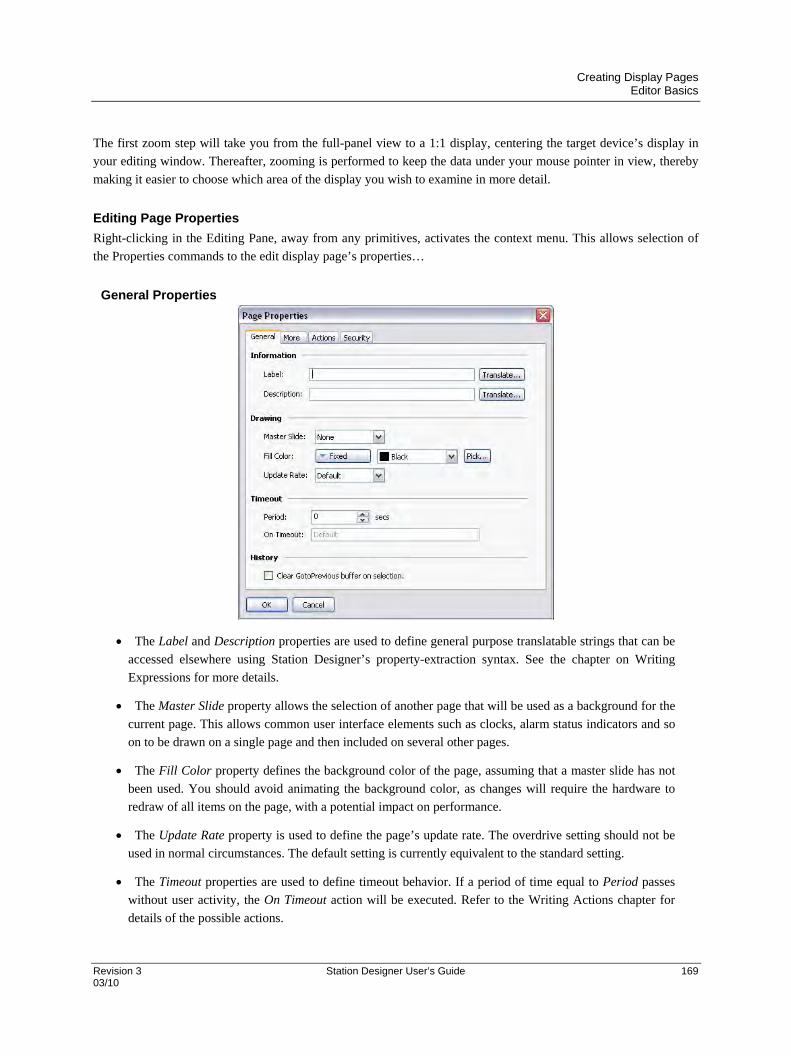
Creating Display Pages Editor Basics
Revision 3 Station Designer User’s Guide 169 03/10
The first zoom step will take you from the full-panel view to a 1:1 display, centering the target device’s display in
your editing window. Thereafter, zooming is performed to keep the data under your mouse pointer in view, thereby
making it easier to choose which area of the display you wish to examine in more detail.
Editing Page Properties
Right-clicking in the Editing Pane, away from any primitives, activates the context menu. This allows selection of
the Properties commands to the edit display page’s properties…
General Properties
The Label and Description properties are used to define general purpose translatable strings that can be
accessed elsewhere using Station Designer’s property-extraction syntax. See the chapter on Writing
Expressions for more details.
The Master Slide property allows the selection of another page that will be used as a background for the
current page. This allows common user interface elements such as clocks, alarm status indicators and so
on to be drawn on a single page and then included on several other pages.
The Fill Color property defines the background color of the page, assuming that a master slide has not
been used. You should avoid animating the background color, as changes will require the hardware to
redraw of all items on the page, with a potential impact on performance.
The Update Rate property is used to define the page’s update rate. The overdrive setting should not be
used in normal circumstances. The default setting is currently equivalent to the standard setting.
The Timeout properties are used to define timeout behavior. If a period of time equal to Period passes
without user activity, the On Timeout action will be executed. Refer to the Writing Actions chapter for
details of the possible actions.

Creating Display Pages Editor Basics
170 Station Designer User’s Guide Revision 3 03/10
The Clear GotoPrevious Buffer property indicates that the history buffer maintained by
GotoPrevious() and GotoNext() should be cleared when this page is selected. You would
typically set this property on the main menu page of your database, removing the ability to go back
beyond that point.
More Properties
The Links property group allows a number of pages to be selected by standard actions on a display
page. The Parent Page property defines a page to be selected if the timeout occurs and no action is
defined. The Next Page property defines a page to be selected if input navigation is enabled and the focus
is moved beyond the last field on the page. The Previous Page property defines a page to be selected if
the focus is similarly moved beyond the first field.
The Position property allows the globally defined position of popup windows to be overridden for this
page. If local settings are enabled, the Horizontal and Vertical properties are used to specify the position.
The Master Slide property is used to indicate whether the master slide should be kept active while a
popup is displayed. The default setting of enabled allows buttons on the master slide to function, even
though buttons on the actual page will be disabled while a popup is present. This can be useful if you
want global navigation options on the master slide to always be available.
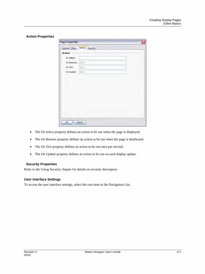
Creating Display Pages Editor Basics
Revision 3 Station Designer User’s Guide 171 03/10
Action Properties
The On Select property defines an action to be run when the page is displayed.
The On Remove property defines an action to be run when the page is deselected.
The On Tick property defines an action to be run once per second.
The On Update property defines an action to be run on each display update.
Security Properties
Refer to the Using Security chapter for details on security descriptors.
User Interface Settings
To access the user interface settings, select the root item in the Navigation List.

Creating Display Pages Editor Basics
172 Station Designer User’s Guide Revision 3 03/10
Global Properties
The Global tab contains various general settings that apply across the database.
Global Actions
The On Startup property defines an action that runs when the system starts.
The On Initialize property defines an action that runs slightly later.
The On Tick property defines an action that runs once every second.
The On Update property defines an action that runs on each display update.
Global Timeouts
The Keypad Timeout property defines the duration after which data entry operations are
cancelled without user action and the associated popup keypad removed from the display.
The Backlight Timeout property defines duration without user action after which the display
backlight is turned off to conserve power and display life. The default value of zero disables
this feature.
The Relock Timeout property defines the duration after which any action protected by the
Locked or Hard Locked methods relocks automatically, such that the user has to unlock them
again for use.
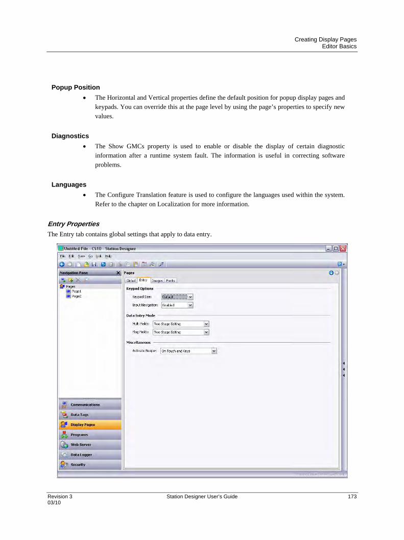
Creating Display Pages Editor Basics
Revision 3 Station Designer User’s Guide 173 03/10
Popup Position
The Horizontal and Vertical properties define the default position for popup display pages and
keypads. You can override this at the page level by using the page’s properties to specify new
values.
Diagnostics
The Show GMCs property is used to enable or disable the display of certain diagnostic
information after a runtime system fault. The information is useful in correcting software
problems.
Languages
The Configure Translation feature is used to configure the languages used within the system.
Refer to the chapter on Localization for more information.
Entry Properties
The Entry tab contains global settings that apply to data entry.

Creating Display Pages Editor Basics
174 Station Designer User’s Guide Revision 3 03/10
Keypad Options
The Keypad Size property is used to select the size of the data entry keypad. The various
settings progressively increase the size of the keypad. The setting Maximum makes the
keypad to take up most of the screen for use in situations when operators are wearing
unwieldy gloves.
The Input Navigation property is used to show or hide the NEXT and PREVIOUS keys in the
various popup keypads. These keys can be used to move between entry fields without
deactivating the keypad.
Data Entry Mode
The Multi Data Entry property is used to control the data entry mode used for multi-state
format objects. If Two-stage editing option is selected then the ENTER key must be pressed
to save changes. The single-stage editing writes the new data to the associated data item as
soon as RAISE or LOWER is used to make a change. The Single-stage entry is faster, but
may result in the writing of intermediate values when changing a multi-state setting.
The Flag Data Entry property is used to control the data entry mode used for two-state format
objects. It operates in the same way as the property above.
Miscellaneous
The Activate Beeper property is used to turn the target device’s beeper on or off. The beeper
provides to the activation status of the keyboard and touch screen.

Creating Display Pages Editor Basics
Revision 3 Station Designer User’s Guide 175 03/10
Images Properties
The Images tab is used to manage images within the database.
Images
The Include Data property indicates whether external images dragged into a display page
should be stored as pointers to the source location, or whether the actual image data should be
included in the database file. Including image data typically makes the database very large,
and may make it impossible to use the Support Upload feature without filling the memory of
the target device.
The Stored Paths property defines how image links are stored. Absolute mode stores the full
path, including the drive letter. The two relative modes store and interpret image paths
relative to either the database or the Station Designer image directory, allowing database and
image files to be moved between machines.
The Image Directory property defines the image path referenced above.
Maintenance
The Manage Image Database button is used to invoke the Image Manager in order to view
and manipulate the images used in the database. See the following section for more
information on this feature.
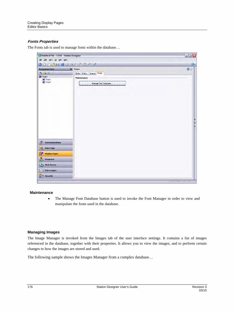
Creating Display Pages Editor Basics
176 Station Designer User’s Guide Revision 3 03/10
Fonts Properties
The Fonts tab is used to manage fonts within the database…
Maintenance
The Manage Font Database button is used to invoke the Font Manager in order to view and
manipulate the fonts used in the database.
Managing Images
The Image Manager is invoked from the Images tab of the user interface settings. It contains a list of images
referenced in the database, together with their properties. It allows you to view the images, and to perform certain
changes to how the images are stored and used.
The following sample shows the Images Manager from a complex database…
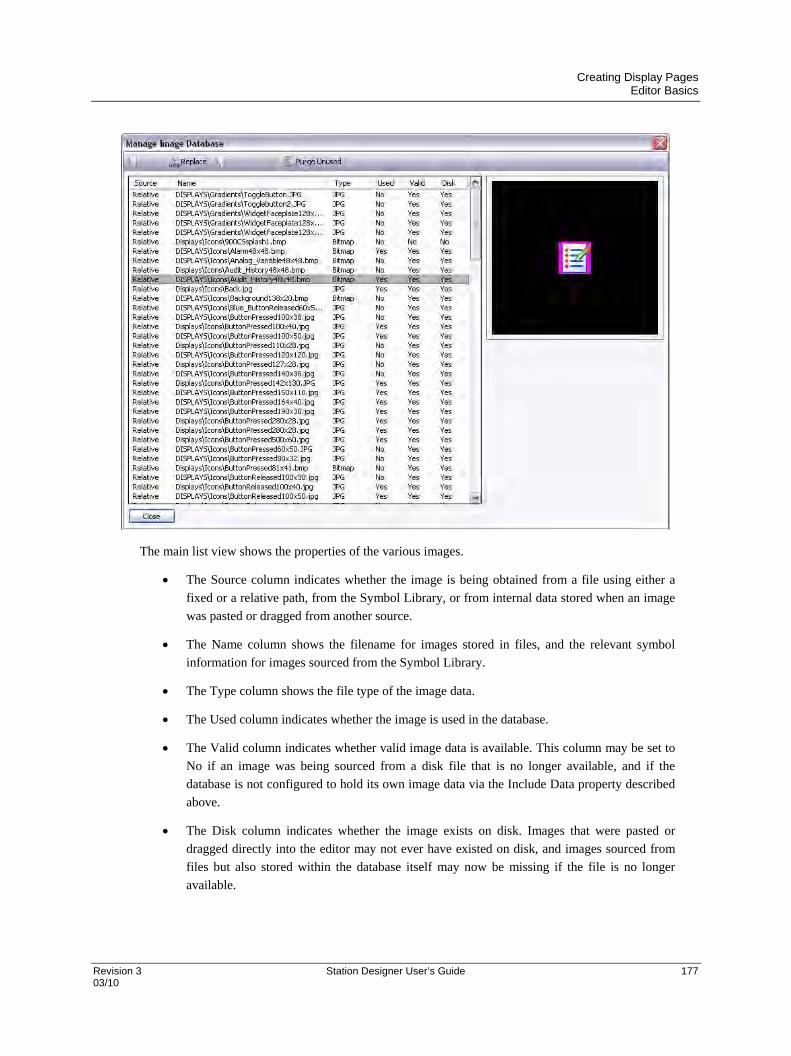
Creating Display Pages Editor Basics
Revision 3 Station Designer User’s Guide 177 03/10
The main list view shows the properties of the various images.
The Source column indicates whether the image is being obtained from a file using either a
fixed or a relative path, from the Symbol Library, or from internal data stored when an image
was pasted or dragged from another source.
The Name column shows the filename for images stored in files, and the relevant symbol
information for images sourced from the Symbol Library.
The Type column shows the file type of the image data.
The Used column indicates whether the image is used in the database.
The Valid column indicates whether valid image data is available. This column may be set to
No if an image was being sourced from a disk file that is no longer available, and if the
database is not configured to hold its own image data via the Include Data property described
above.
The Disk column indicates whether the image exists on disk. Images that were pasted or
dragged directly into the editor may not ever have existed on disk, and images sourced from
files but also stored within the database itself may now be missing if the file is no longer
available.

Creating Display Pages Editor Basics
178 Station Designer User’s Guide Revision 3 03/10
The toolbar at the top of the window allows various commands to be performed…
The Export command saves an image that is available but not stored on disk to a file. If a
filename has already been defined for the selected image, that name is used. In other cases,
you are prompted to select a filename.
The Replace command replaces a given image with another. All references to the image in the
database are updated to reflect the change.
The Export All command saves all images that are available but not stored on disk and that
have filenames defined. It can be used to ensure that all images are stored in external files
prior to turning off Include Data.
The Purge Unused command is used to remove all images that are not used in the database,
thereby saving disk space when saving the database to disk. Use of this command may also
reduce memory usage in the target device.
Managing Fonts
The Font Manager is invoked from the Fonts tab of the user interface settings. It contains a list of all the fonts
referenced in the database its properties. The window allows to view font, and perform certain changes on how the
fonts are stored and used.
The following window shows the Font Manager from a complex database.

Creating Display Pages Editor Basics
Revision 3 Station Designer User’s Guide 179 03/10
The main list view shows the properties of the various fonts.
The Face property shows the name of the font.
The Size property shows the height in pixels of the font.
The Weight property indicates whether the font is bold or not.
The Type property indicates whether the font is a system or custom font.
The Used property indicates whether the font is used in the database.
The Options property lists the options selected for the font.
The toolbar at the top of the window allows various commands to be performed…
The Edit button allows the properties of custom fonts to be edited.
The Delete button allows an unused font to be deleted. Once a font is deleted, it is not
presented in the drop-down used for font selection, but may be recreated by using the
associated Pick button.
The Replace button allows a font to be replaced with another. All references to the font in the
database are updated to reflect the change.
The Show System button controls whether system fonts are shown in the list.
The Purge Unused button removes all unused fonts from the database, thereby reducing the
amount of memory used in the target device. As with a delete font, purged fonts are not
presented in the drop-down list used for font selection, but may be recreated by using the
associated Pick button.
Editing the properties of a custom font produces the following dialog box.
The various options allow specific sets of characters to be included in the font image that is created and
downloaded to the target device. It restricts the characters to the ones that are needed for your application.
Note that the Numeric Output option can be used alone to restrict the font to digits, decimal points and
those other characters used to render conventional, scientific or hexadecimal numbers.

Creating Display Pages Editor Basics
180 Station Designer User’s Guide Revision 3 03/10
The Resource Pane
Display pages are typically built from items dragged from the Resource Pane. You can either slide out the Resource
Pane by clicking the arrowed bar to the right-hand side of the window, or you can choose to lock the Resource Pane
in place, perhaps maximizing your window to increase your available workspace. The Resource Pane has three
categories…
Primitives
The Primitives category is used to access the key building blocks used
to assemble display pages, and is shown to the left in its various
states. You will notice that the top-level contains a number of sub-
categories, each of which provides access to a number of primitives.
Clicking on an icon displays a sub-category and its primitives.
Clicking on a given primitive displays versions of that primitive in
predefined colors. The icons in the toolbar can be used to move
between sub-categories, to move up to a higher level or to change the
number of primitives displayed per row. The primitives are described
in the next chapter.
Symbol Library
The Symbol Library category operates in a manner that is very similar to the
Primitives category, providing access to a number of sub-categories, each of
which contains a number of predefined symbols. Clicking on a given symbol
provides a number of pre-colored versions of that symbol, although this
facility is used less often than it is with primitives. Take some time to explore
the Symbol Library—it contains many thousands of possible images, and its
correct use can produce more attractive and easy-to-use databases.
Data Tags
The Data Tags category contains a tree view of all the data tags in the current database. It is used
both to drag tags directly on to a display page, and to provide access to tags while configuring the
primitive properties. Dragging a tag onto a page will create a data box that is bound to that tag,
with all formatting properties based on the properties defined by the tag itself. Select and drag
multiple tags by using the SHIFT and CTRL keys. These facilities make it quicker and easier to
add data to a page.

Creating Display Pages Editor Basics
Revision 3 Station Designer User’s Guide 181 03/10
Adding Items to a Page
As mentioned above, the various items in the Resource Pane can be dragged onto the editor, thereby adding them to
a display page. Suitable primitives will be created for tags and images. The example below shows how, after
clicking on the Core Primitives selection in the Primitives category, a rectangle primitive can be dragged onto the
page…
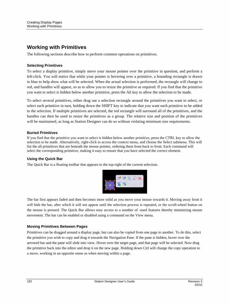
Creating Display Pages Working with Primitives
182 Station Designer User’s Guide Revision 3 03/10
Working with Primitives The following sections describe how to perform common operations on primitives.
Selecting Primitives
To select a display primitive, simply move your mouse pointer over the primitive in question, and perform a left-click. You will notice that while your pointer is hovering over a primitive, a bounding rectangle is drawn in blue to help show what will be selected. When the actual selection is performed, the rectangle will change to red, and handles will appear, so as to allow you to resize the primitive as required. If you find that the primitive you want to select is hidden below another primitive, press the Alt key to allow the selection to be made.
To select several primitives, either drag out a selection rectangle around the primitives you want to select, or select each primitive in turn, holding down the SHIFT key to indicate that you want each primitive to be added to the selection. If multiple primitives are selected, the red rectangle will surround all of the primitives, and the handles can then be used to resize the primitives as a group. The relative size and position of the primitives will be maintained, as long as Station Designer can do so without violating minimum size requirements.
Buried Primitives If you find that the primitive you want to select is hidden below another primitive, press the CTRL key to allow the selection to be made. Alternatively, right-click to access the context menu, and choose the Select submenu. This will list the all primitives that are beneath the mouse pointer, ordering them from back to front. Each command will select the corresponding primitive, making it easy to ensure that you have selected the correct element.
Using the Quick Bar
The Quick Bar is a floating toolbar that appears to the top-right of the current selection.
The bar first appears faded and then becomes more solid as you move your mouse towards it. Moving away from it
will hide the bar, after which it will not appear until the selection process is repeated, or the scroll-wheel button on
the mouse is pressed. The Quick Bar allows easy access to a number of -used features thereby minimizing mouse
movement. The bar can be enabled or disabled using a command on the View menu.
Moving Primitives Between Pages
Primitives can be dragged around a display page, but can also be copied from one page to another. To do this, select
the primitive you wish to copy and drag it towards the Navigation Pane. If the pane is hidden, hover over the
arrowed bar and the pane will slide into view. Hover over the target page, and that page will be selected. Now drag
the primitive back into the editor and drop it on the new page. Holding down Ctrl will change the copy operation to
a move, working in an opposite sense as when moving within a page.

Creating Display Pages Working with Primitives
Revision 3 Station Designer User’s Guide 183 03/10
Moving Primitives Between Databases Dragging primitives between databases is just as easy. Simply select the items you wish to copy, and drag them to
another copy of Station Designer that contains the new database. This will work with entire pages, groups of
primitives or just a single item.
Changing the Size of Primitives
Resizing primitives is performed by grabbing one of the sizing handles and moving it in the required direction. The
Ctrl key can be held down to restrict the sizing operation such that the primitive’s width and height are equal. The
Shift key can be held down to allow the sizing to operate from the “middle out” rather than from one edge.
Using Layout Handles
Certain primitives have internal handles that can be moved to change their layout. For example, the rounded
rectangle shown below has a single layout handle in its top left-hand corner. The handle is marked with a diamond
whenever the primitive is selected…
In this case, moving the handle changes the radius of the rectangle’s corners…
The function of each handle depends on the specific primitive, but is usually intuitive.
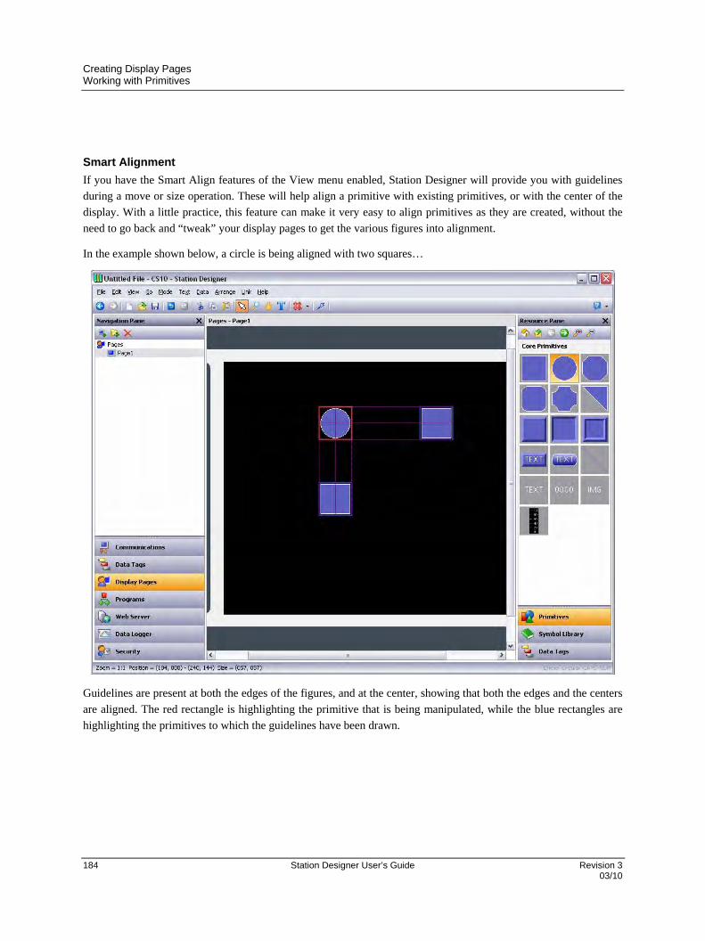
Creating Display Pages Working with Primitives
184 Station Designer User’s Guide Revision 3 03/10
Smart Alignment
If you have the Smart Align features of the View menu enabled, Station Designer will provide you with guidelines
during a move or size operation. These will help align a primitive with existing primitives, or with the center of the
display. With a little practice, this feature can make it very easy to align primitives as they are created, without the
need to go back and “tweak” your display pages to get the various figures into alignment.
In the example shown below, a circle is being aligned with two squares…
Guidelines are present at both the edges of the figures, and at the center, showing that both the edges and the centers
are aligned. The red rectangle is highlighting the primitive that is being manipulated, while the blue rectangles are
highlighting the primitives to which the guidelines have been drawn.

Creating Display Pages Working with Primitives
Revision 3 Station Designer User’s Guide 185 03/10
Quick Alignment
Station Designer’s Quick Alignment features allow primitives to be aligned to other primitives without the need to
bring up a dialog box. To use this feature, simply select the primitive you want to move, and right-click to bring up
the context menu. Select the Align submenu, and then select one of the various “With...Of” options, marked with the
rectangle-and-cursor symbol. The mouse pointer will change to indicate that you now need to click on the primitive
to which you wish to align.
As soon as you click, the alignment will be performed.
Using the Grid
The Grid button on the toolbar can be used to control the behavior and the display of the alignment grid. Clicking on
the left-hand side of the button will show or hide the grid. Clicking on the drop-down portion will allow the
operations for which the grid is used to be configured. You may separately enable or disable the grid for creation,
sizing and movement operations, or you may use the All or None options to enable or disable it globally. You may
also control whether the grid is used when editing within groups.
Aligning Primitives
While the Smart Alignment and Quick Alignment options discussed above allow many alignment operations to be
performed without further concern, there are times that you will want to use a more traditional approach. To do this,
select a number of primitives, and use the Align Selection command on the Arrange menu to display the following
dialog box…
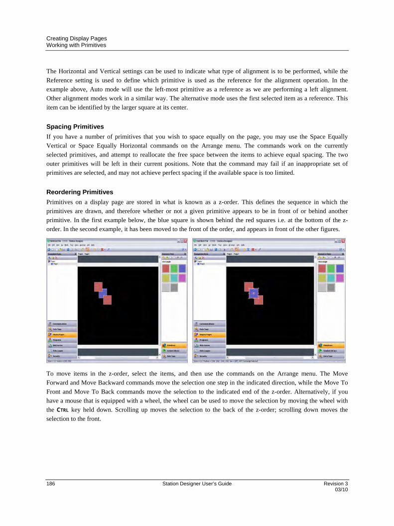
Creating Display Pages Working with Primitives
186 Station Designer User’s Guide Revision 3 03/10
The Horizontal and Vertical settings can be used to indicate what type of alignment is to be performed, while the
Reference setting is used to define which primitive is used as the reference for the alignment operation. In the
example above, Auto mode will use the left-most primitive as a reference as we are performing a left alignment.
Other alignment modes work in a similar way. The alternative mode uses the first selected item as a reference. This
item can be identified by the larger square at its center.
Spacing Primitives
If you have a number of primitives that you wish to space equally on the page, you may use the Space Equally
Vertical or Space Equally Horizontal commands on the Arrange menu. The commands work on the currently
selected primitives, and attempt to reallocate the free space between the items to achieve equal spacing. The two
outer primitives will be left in their current positions. Note that the command may fail if an inappropriate set of
primitives are selected, and may not achieve perfect spacing if the available space is too limited.
Reordering Primitives
Primitives on a display page are stored in what is known as a z-order. This defines the sequence in which the
primitives are drawn, and therefore whether or not a given primitive appears to be in front of or behind another
primitive. In the first example below, the blue square is shown behind the red squares i.e. at the bottom of the z-
order. In the second example, it has been moved to the front of the order, and appears in front of the other figures.
To move items in the z-order, select the items, and then use the commands on the Arrange menu. The Move
Forward and Move Backward commands move the selection one step in the indicated direction, while the Move To
Front and Move To Back commands move the selection to the indicated end of the z-order. Alternatively, if you
have a mouse that is equipped with a wheel, the wheel can be used to move the selection by moving the wheel with
the CTRL key held down. Scrolling up moves the selection to the back of the z-order; scrolling down moves the
selection to the front.
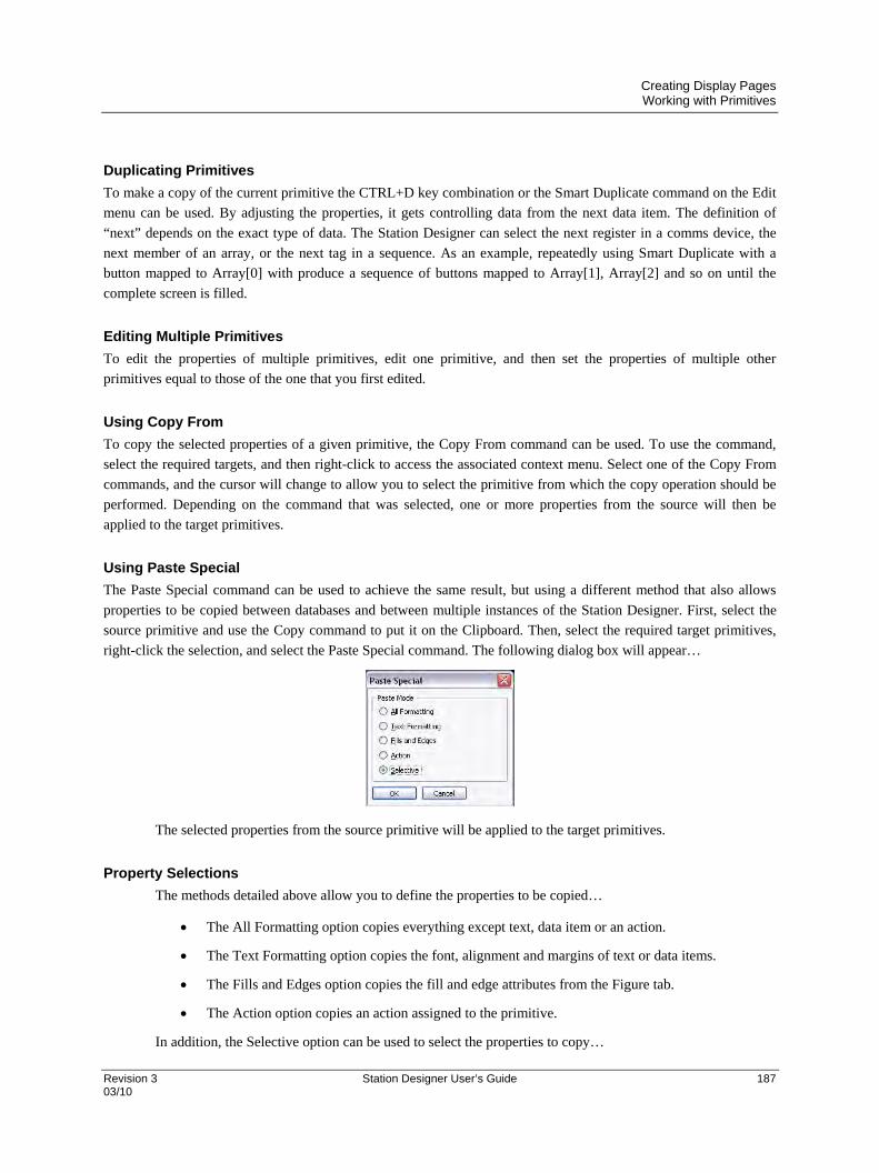
Creating Display Pages Working with Primitives
Revision 3 Station Designer User’s Guide 187 03/10
Duplicating Primitives
To make a copy of the current primitive the CTRL+D key combination or the Smart Duplicate command on the Edit
menu can be used. By adjusting the properties, it gets controlling data from the next data item. The definition of
“next” depends on the exact type of data. The Station Designer can select the next register in a comms device, the
next member of an array, or the next tag in a sequence. As an example, repeatedly using Smart Duplicate with a
button mapped to Array[0] with produce a sequence of buttons mapped to Array[1], Array[2] and so on until the
complete screen is filled.
Editing Multiple Primitives
To edit the properties of multiple primitives, edit one primitive, and then set the properties of multiple other
primitives equal to those of the one that you first edited.
Using Copy From
To copy the selected properties of a given primitive, the Copy From command can be used. To use the command,
select the required targets, and then right-click to access the associated context menu. Select one of the Copy From
commands, and the cursor will change to allow you to select the primitive from which the copy operation should be
performed. Depending on the command that was selected, one or more properties from the source will then be
applied to the target primitives.
Using Paste Special
The Paste Special command can be used to achieve the same result, but using a different method that also allows
properties to be copied between databases and between multiple instances of the Station Designer. First, select the
source primitive and use the Copy command to put it on the Clipboard. Then, select the required target primitives,
right-click the selection, and select the Paste Special command. The following dialog box will appear…
The selected properties from the source primitive will be applied to the target primitives.
Property Selections
The methods detailed above allow you to define the properties to be copied…
The All Formatting option copies everything except text, data item or an action.
The Text Formatting option copies the font, alignment and margins of text or data items.
The Fills and Edges option copies the fill and edge attributes from the Figure tab.
The Action option copies an action assigned to the primitive.
In addition, the Selective option can be used to select the properties to copy…

Creating Display Pages Primitive Properties
188 Station Designer User’s Guide Revision 3 03/10
The list contains a hierarchical list of the properties defined by the source primitive, organizing them
according to the layout used when editing the primitive, and showing the value assigned to each. Each
property or group of properties can be selected or deselected using the associated checkboxes. The selected
properties will be applied, thereby providing the low-level control for the copied items from one primitive
to another.
Jumping to Other Items
If a primitive references tags, display pages or other items, a Jump submenu will appear on its context menu. Select
this menu to view a list of referenced items. Select one of those items to jump directly to that section of the database.
The example below shows a primitive that references two tags…
After you have made the changes you want to the tag, you can use the Back button on the toolbar or the ALT+LEFT
key combination to return to the display page that you were editing. Note how the selection is preserved during
navigation, making it easy to view or edit a referenced object and to then resume the display creation process.
Primitive Properties
The properties of a primitive can be edited by double-clicking on the primitive, or by using the Properties command
on the primitive’s context menu. You may also select the primitive and press the ALT+ENTER key combination. The
property dialog for a primitive will contain various tabs, with some tabs only appearing when additional items—
such as text, data or an action—have been added to the primitive. The properties dialog shows a live preview of the
current primitive, allowing you to see the effect of changes before you commit them.

Creating Display Pages Primitive Properties
Revision 3 Station Designer User’s Guide 189 03/10
Showing or Hiding Primitives
All primitives have a Show tab in their property dialog…
The Visible property can be set to an integer expression to show or hide the associated primitive at runtime. A value
of zero will hide the primitive, while a non-zero value will allow it to be shown. All primitives are visible by default.
Defining Primitive Colors
Colors within primitives are edited using a field similar to that shown below…
You will note that the color property is presented by means of a drop-down menu button, a drop-down list and a
Pick button. The drop-down menu is used to select the color mode, which can be any one of the following…
In Fixed mode, the color does not change, and is selected from the drop-down list, or by invoking the
color selection dialog by pressing the Pick button.
In Tag Text mode, the color is animated to match the foreground color defined by a particular tag. The
specific tag can be selected by pressing the Pick button.
In Tag Back mode, the color is animated to match the background color defined by a particular tag. The
specific tag can be selected by pressing the Pick button.
In Flashing mode, the color is animated to alternate between two colors at a specific rate, with another
color being displayed when flashing is disabled.
In 2-State mode, the color is animated to switch between two colors depending on the value of a tag or
other data item.
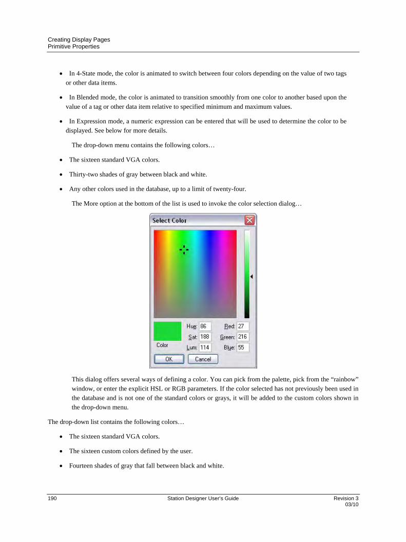
Creating Display Pages Primitive Properties
190 Station Designer User’s Guide Revision 3 03/10
In 4-State mode, the color is animated to switch between four colors depending on the value of two tags
or other data items.
In Blended mode, the color is animated to transition smoothly from one color to another based upon the
value of a tag or other data item relative to specified minimum and maximum values.
In Expression mode, a numeric expression can be entered that will be used to determine the color to be
displayed. See below for more details.
The drop-down menu contains the following colors…
The sixteen standard VGA colors.
Thirty-two shades of gray between black and white.
Any other colors used in the database, up to a limit of twenty-four.
The More option at the bottom of the list is used to invoke the color selection dialog…
This dialog offers several ways of defining a color. You can pick from the palette, pick from the “rainbow”
window, or enter the explicit HSL or RGB parameters. If the color selected has not previously been used in
the database and is not one of the standard colors or grays, it will be added to the custom colors shown in
the drop-down menu.
The drop-down list contains the following colors…
The sixteen standard VGA colors.
The sixteen custom colors defined by the user.
Fourteen shades of gray that fall between black and white.
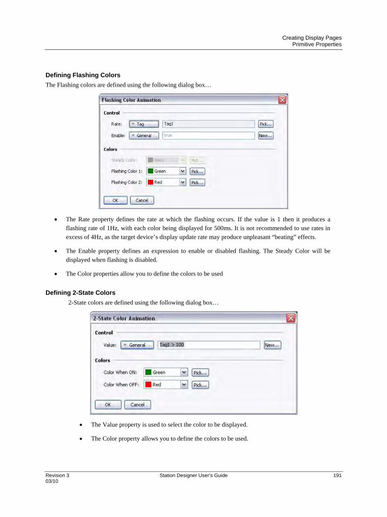
Creating Display Pages Primitive Properties
Revision 3 Station Designer User’s Guide 191 03/10
Defining Flashing Colors
The Flashing colors are defined using the following dialog box…
The Rate property defines the rate at which the flashing occurs. If the value is 1 then it produces a
flashing rate of 1Hz, with each color being displayed for 500ms. It is not recommended to use rates in
excess of 4Hz, as the target device’s display update rate may produce unpleasant “beating” effects.
The Enable property defines an expression to enable or disabled flashing. The Steady Color will be
displayed when flashing is disabled.
The Color properties allow you to define the colors to be used
Defining 2-State Colors
2-State colors are defined using the following dialog box…
The Value property is used to select the color to be displayed.
The Color property allows you to define the colors to be used.

Creating Display Pages Primitive Properties
192 Station Designer User’s Guide Revision 3 03/10
Defining 4 – State Colors
The 4-State colors are defined using the following dialog box…
The Value properties are used to select the color to be displayed.
The Color properties allow you to define the colors to be used.
Defining Blended Colors
The Blended colors are defined using the following dialog box…
The Value, Minimum and Maximum properties are used to define the color to be displayed. In
the example shown, the color changes to blue when the tag is at or below its minimum value,
and change to red when it is at or above its maximum value. The transition is smooth between
blue to red as the tag changes between its limits.
The Color properties allow you to define the colors to be used.

Creating Display Pages Primitive Properties
Revision 3 Station Designer User’s Guide 193 03/10
The More option at the bottom of the list can be used to invoke the color selection dialog…
This dialog offers several ways of defining a color. You can pick from the palette, pick from the “rainbow” window,
or enter the explicit HSL or RGB parameters. The dialog also allows custom colors to be added to the palette. These
will appear whenever the dialog is invoked, and will also appear in the drop-down list described above.
Defining Color Expressions
The color properties can be defined using the integer expressions in those circumstances where the standard color
animation methods are not sufficient. These features are rarely used. The Station Designer works with 15-bit color
values, with the lowest five bits representing red, the next five bits representing green and the upper five bits
representing blue. The color values can be manipulated just as any other integer value.
Building Colors
The ColGetRGB(r,g,b) function can be used to create a color value from its red, green and blue components.
Although Station Designer works in 15-bit colors, each component used by this function is scaled to range from 0 to
255. ColGetRGB(128, 0, 64) will return a purple-like color with a red value of 128, no green component and
a blue value of 64.
Splitting Colors
The ColGetRed(rgb), ColGetGreen(rgb) and ColGetBlue(rgb) functions can be used to access the
individual color components of a color value. As above, although Station Designer works in 15-bit colors, the values
returned by these functions are scaled to be between 0 and 255.
Choosing Colors
The ColPick2() function can be used to select between two colors based on the value of an expression. For
example, the expression ColPick2(Flag1, Col1, Col2) will return Col1 if Flag1 is non-zero, or Col2
if Flag1 is zero. The first and second color arguments can be replaced by calls to the ColGetRGB() function if
required.
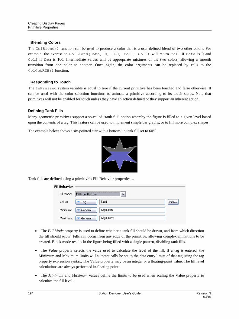
Creating Display Pages Primitive Properties
194 Station Designer User’s Guide Revision 3 03/10
Blending Colors
The ColBlend() function can be used to produce a color that is a user-defined blend of two other colors. For
example, the expression ColBlend(Data, 0, 100, Col1, Col2) will return Col1 if Data is 0 and
Col2 if Data is 100. Intermediate values will be appropriate mixtures of the two colors, allowing a smooth
transition from one color to another. Once again, the color arguments can be replaced by calls to the
ColGetRGB() function.
Responding to Touch
The IsPressed system variable is equal to true if the current primitive has been touched and false otherwise. It
can be used with the color selection functions to animate a primitive according to its touch status. Note that
primitives will not be enabled for touch unless they have an action defined or they support an inherent action.
Defining Tank Fills
Many geometric primitives support a so-called “tank fill” option whereby the figure is filled to a given level based
upon the contents of a tag. This feature can be used to implement simple bar graphs, or to fill more complex shapes.
The example below shows a six-pointed star with a bottom-up tank fill set to 60%...
Tank fills are defined using a primitive’s Fill Behavior properties…
The Fill Mode property is used to define whether a tank fill should be drawn, and from which direction
the fill should occur. Fills can occur from any edge of the primitive, allowing complex animations to be
created. Block mode results in the figure being filled with a single pattern, disabling tank fills.
The Value property selects the value used to calculate the level of the fill. If a tag is entered, the
Minimum and Maximum limits will automatically be set to the data entry limits of that tag using the tag
property expression syntax. The Value property may be an integer or a floating-point value. The fill level
calculations are always performed in floating point.
The Minimum and Maximum values define the limits to be used when scaling the Value property to
calculate the fill level.
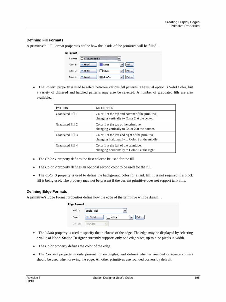
Creating Display Pages Primitive Properties
Revision 3 Station Designer User’s Guide 195 03/10
Defining Fill Formats
A primitive’s Fill Format properties define how the inside of the primitive will be filled…
The Pattern property is used to select between various fill patterns. The usual option is Solid Color, but
a variety of dithered and hatched patterns may also be selected. A number of graduated fills are also
available…
PATTERN DESCRIPTION
Graduated Fill 1 Color 1 at the top and bottom of the primitive, changing vertically to Color 2 at the center.
Graduated Fill 2 Color 1 at the top of the primitive, changing vertically to Color 2 at the bottom.
Graduated Fill 3 Color 1 at the left and right of the primitive, changing horizontally to Color 2 at the middle.
Graduated Fill 4 Color 1 at the left of the primitive, changing horizontally to Color 2 at the right.
The Color 1 property defines the first color to be used for the fill.
The Color 2 property defines an optional second color to be used for the fill.
The Color 3 property is used to define the background color for a tank fill. It is not required if a block
fill is being used. The property may not be present if the current primitive does not support tank fills.
Defining Edge Formats
A primitive’s Edge Format properties define how the edge of the primitive will be drawn…
The Width property is used to specify the thickness of the edge. The edge may be displayed by selecting
a value of None. Station Designer currently supports only odd edge sizes, up to nine pixels in width.
The Color property defines the color of the edge.
The Corners property is only present for rectangles, and defines whether rounded or square corners
should be used when drawing the edge. All other primitives use rounded corners by default.
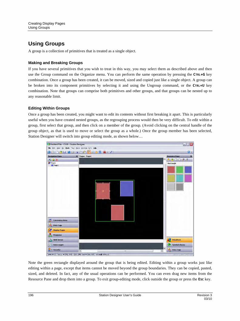
Creating Display Pages Using Groups
196 Station Designer User’s Guide Revision 3 03/10
Using Groups A group is a collection of primitives that is treated as a single object.
Making and Breaking Groups
If you have several primitives that you wish to treat in this way, you may select them as described above and then
use the Group command on the Organize menu. You can perform the same operation by pressing the CTRL+G key
combination. Once a group has been created, it can be moved, sized and copied just like a single object. A group can
be broken into its component primitives by selecting it and using the Ungroup command, or the CTRL+U key
combination. Note that groups can comprise both primitives and other groups, and that groups can be nested up to
any reasonable limit.
Editing Within Groups
Once a group has been created, you might want to edit its contents without first breaking it apart. This is particularly
useful when you have created nested groups, as the regrouping process would then be very difficult. To edit within a
group, first select that group, and then click on a member of the group. (Avoid clicking on the central handle of the
group object, as that is used to move or select the group as a whole.) Once the group member has been selected,
Station Designer will switch into group editing mode, as shown below…
Note the green rectangle displayed around the group that is being edited. Editing within a group works just like
editing within a page, except that items cannot be moved beyond the group boundaries. They can be copied, pasted,
sized, and deleted. In fact, any of the usual operations can be performed. You can even drag new items from the
Resource Pane and drop them into a group. To exit group-editing mode, click outside the group or press the ESC key.
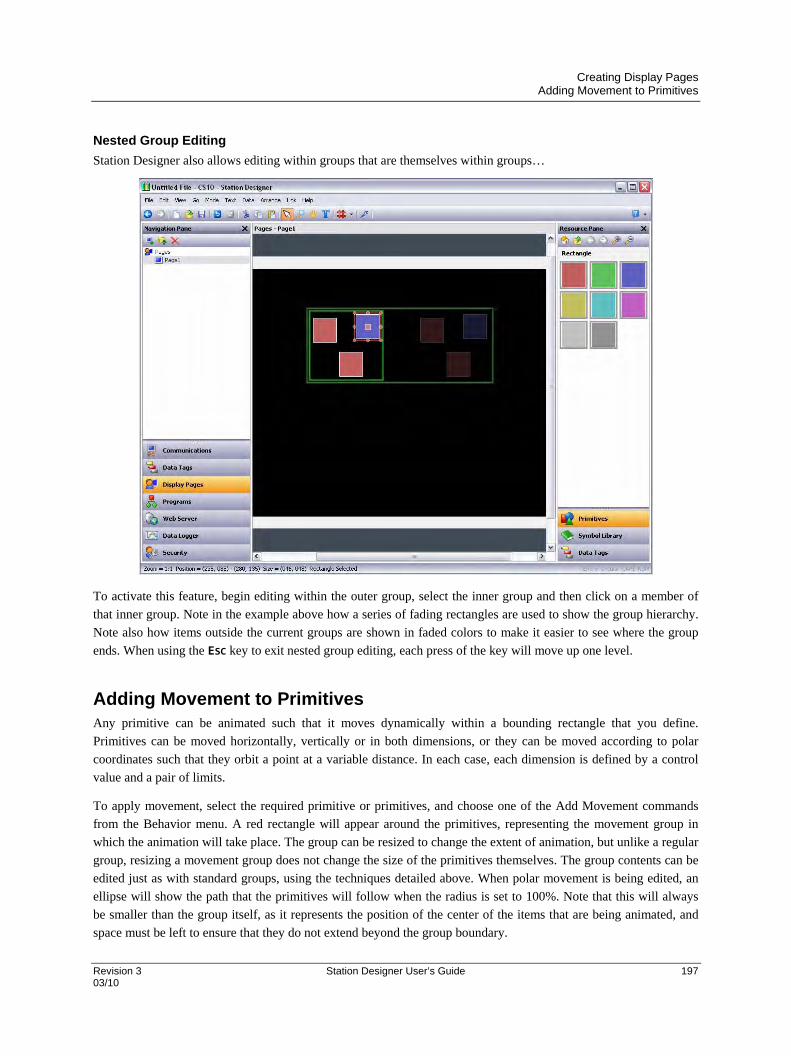
Creating Display Pages Adding Movement to Primitives
Revision 3 Station Designer User’s Guide 197 03/10
Nested Group Editing
Station Designer also allows editing within groups that are themselves within groups…
To activate this feature, begin editing within the outer group, select the inner group and then click on a member of
that inner group. Note in the example above how a series of fading rectangles are used to show the group hierarchy.
Note also how items outside the current groups are shown in faded colors to make it easier to see where the group
ends. When using the ESC key to exit nested group editing, each press of the key will move up one level.
Adding Movement to Primitives Any primitive can be animated such that it moves dynamically within a bounding rectangle that you define.
Primitives can be moved horizontally, vertically or in both dimensions, or they can be moved according to polar
coordinates such that they orbit a point at a variable distance. In each case, each dimension is defined by a control
value and a pair of limits.
To apply movement, select the required primitive or primitives, and choose one of the Add Movement commands
from the Behavior menu. A red rectangle will appear around the primitives, representing the movement group in
which the animation will take place. The group can be resized to change the extent of animation, but unlike a regular
group, resizing a movement group does not change the size of the primitives themselves. The group contents can be
edited just as with standard groups, using the techniques detailed above. When polar movement is being edited, an
ellipse will show the path that the primitives will follow when the radius is set to 100%. Note that this will always
be smaller than the group itself, as it represents the position of the center of the items that are being animated, and
space must be left to ensure that they do not extend beyond the group boundary.
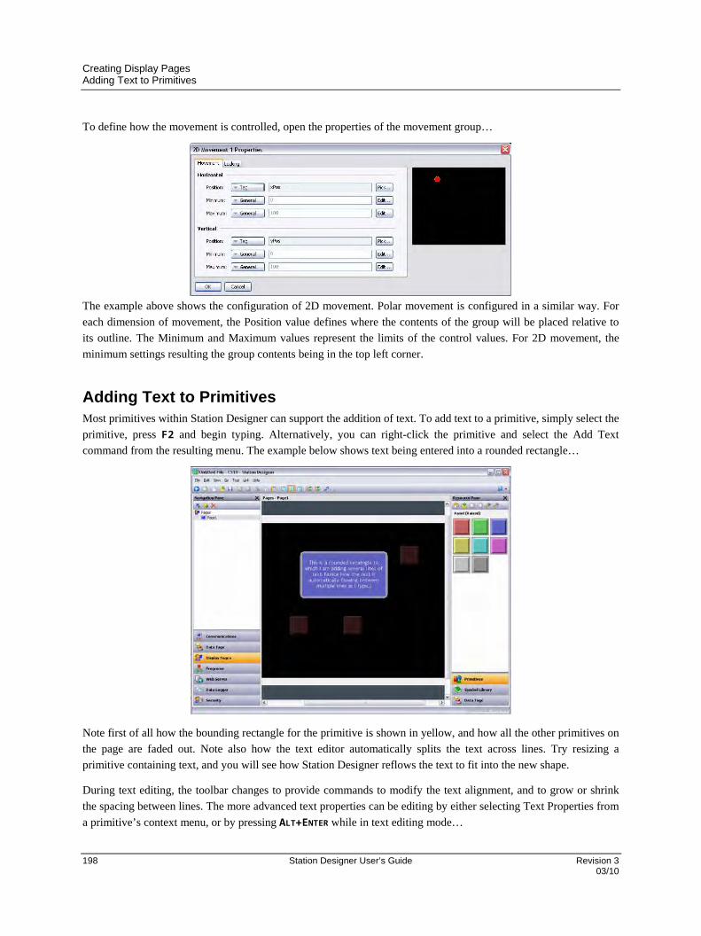
Creating Display Pages Adding Text to Primitives
198 Station Designer User’s Guide Revision 3 03/10
To define how the movement is controlled, open the properties of the movement group…
The example above shows the configuration of 2D movement. Polar movement is configured in a similar way. For
each dimension of movement, the Position value defines where the contents of the group will be placed relative to
its outline. The Minimum and Maximum values represent the limits of the control values. For 2D movement, the
minimum settings resulting the group contents being in the top left corner.
Adding Text to Primitives Most primitives within Station Designer can support the addition of text. To add text to a primitive, simply select the
primitive, press F2 and begin typing. Alternatively, you can right-click the primitive and select the Add Text
command from the resulting menu. The example below shows text being entered into a rounded rectangle…
Note first of all how the bounding rectangle for the primitive is shown in yellow, and how all the other primitives on
the page are faded out. Note also how the text editor automatically splits the text across lines. Try resizing a
primitive containing text, and you will see how Station Designer reflows the text to fit into the new shape.
During text editing, the toolbar changes to provide commands to modify the text alignment, and to grow or shrink
the spacing between lines. The more advanced text properties can be editing by either selecting Text Properties from
a primitive’s context menu, or by pressing ALT+ENTER while in text editing mode…
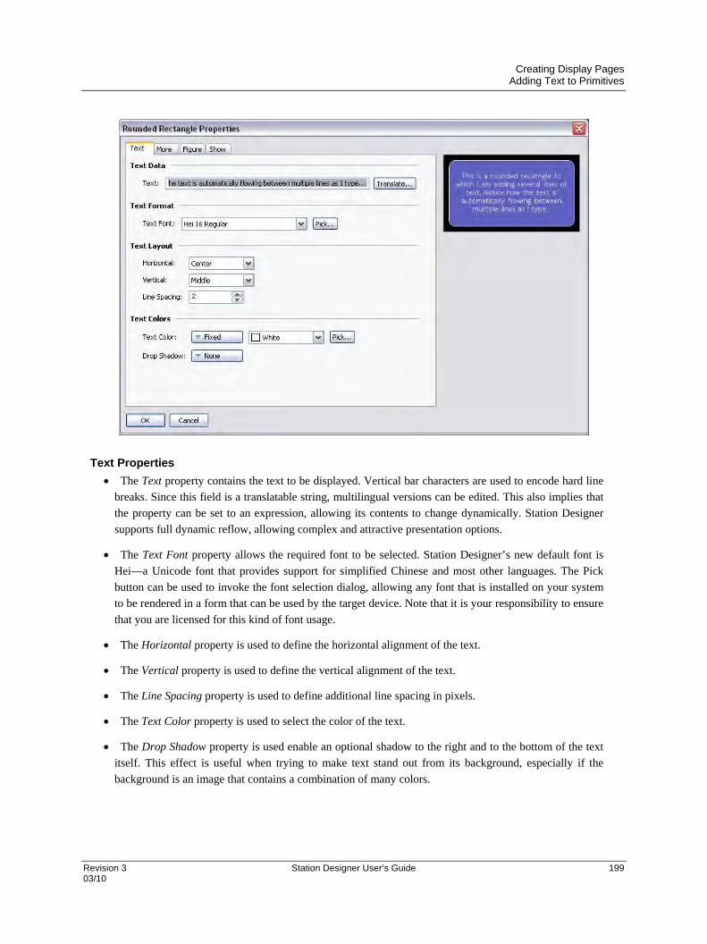
Creating Display Pages Adding Text to Primitives
Revision 3 Station Designer User’s Guide 199 03/10
Text Properties
The Text property contains the text to be displayed. Vertical bar characters are used to encode hard line
breaks. Since this field is a translatable string, multilingual versions can be edited. This also implies that
the property can be set to an expression, allowing its contents to change dynamically. Station Designer
supports full dynamic reflow, allowing complex and attractive presentation options.
The Text Font property allows the required font to be selected. Station Designer’s new default font is
Hei—a Unicode font that provides support for simplified Chinese and most other languages. The Pick
button can be used to invoke the font selection dialog, allowing any font that is installed on your system
to be rendered in a form that can be used by the target device. Note that it is your responsibility to ensure
that you are licensed for this kind of font usage.
The Horizontal property is used to define the horizontal alignment of the text.
The Vertical property is used to define the vertical alignment of the text.
The Line Spacing property is used to define additional line spacing in pixels.
The Text Color property is used to select the color of the text.
The Drop Shadow property is used enable an optional shadow to the right and to the bottom of the text
itself. This effect is useful when trying to make text stand out from its background, especially if the
background is an image that contains a combination of many colors.

Creating Display Pages Adding Text to Primitives
200 Station Designer User’s Guide Revision 3 03/10
More Properties
The Text Margin properties are used to control the margin around the text relative to the text-bounding
box provided by the primitive. They can be useful in achieving better visual centering when working
with fonts that have a lot of space above or below their characters, either for diacriticals or descenders.
The Direction property is used to define the direction in which the text will be moved when the
associated primitive is pressed. It is only enabled when an action is assigned to the primitive, or when the
primitive is something like a button that has an inherent action associated with it. This option is useful
when creating custom buttons that should provide feedback when touched.
The Step property indicates how far the text should move when the primitive is pressed. One to three
pixels can be chosen, according to the effect desired.
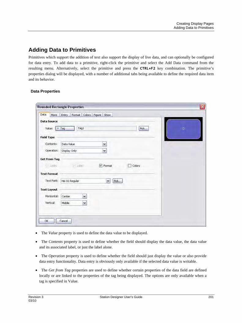
Creating Display Pages Adding Data to Primitives
Revision 3 Station Designer User’s Guide 201 03/10
Adding Data to Primitives Primitives which support the addition of text also support the display of live data, and can optionally be configured
for data entry. To add data to a primitive, right-click the primitive and select the Add Data command from the
resulting menu. Alternatively, select the primitive and press the CTRL+F2 key combination. The primitive’s
properties dialog will be displayed, with a number of additional tabs being available to define the required data item
and its behavior.
Data Properties
The Value property is used to define the data value to be displayed.
The Contents property is used to define whether the field should display the data value, the data value
and its associated label, or just the label alone.
The Operation property is used to define whether the field should just display the value or also provide
data entry functionality. Data entry is obviously only available if the selected data value is writable.
The Get from Tag properties are used to define whether certain properties of the data field are defined
locally or are linked to the properties of the tag being displayed. The options are only available when a
tag is specified in Value.

Creating Display Pages Adding Data to Primitives
202 Station Designer User’s Guide Revision 3 03/10
The Text Font property allows the required font to be selected. Station Designer’s new default font is
Hei—a Unicode font that provides support for simplified Chinese and most other languages. The Pick
button can be used to invoke the font selection dialog, allowing any font that is installed on your system
to be rendered in a form that can be used by the target device. Note that it is your responsibility to ensure
that you are licensed for this kind of font usage.
The Horizontal property is used to define the horizontal alignment of the text.
The Vertical property is used to define the vertical alignment of the text.
More Properties
The Text Margin properties are used to control the margin around the text relative to the text-bounding
box provided by the primitive. They can be useful in achieving better visual centering when working
with fonts that have a lots of space above or below their characters, either for diacriticals or descenders.
The Direction property is used to define the direction in which the text will be moved when the
associated primitive is pressed. It is only enabled when an action is assigned to the primitive, or when the
primitive is something like a button that has an inherent action associated with it. This option is useful
when creating custom buttons that should provide feedback when touched.
The Step property indicates how far the text should move when the primitive is pressed. One to three
pixels can be chosen, according to the effect desired.
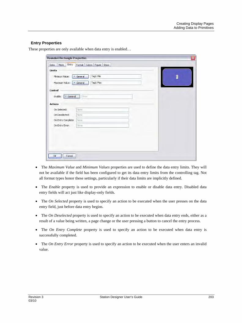
Creating Display Pages Adding Data to Primitives
Revision 3 Station Designer User’s Guide 203 03/10
Entry Properties
These properties are only available when data entry is enabled…
The Maximum Value and Minimum Values properties are used to define the data entry limits. They will
not be available if the field has been configured to get its data entry limits from the controlling tag. Not
all format types honor these settings, particularly if their data limits are implicitly defined.
The Enable property is used to provide an expression to enable or disable data entry. Disabled data
entry fields will act just like display-only fields.
The On Selected property is used to specify an action to be executed when the user presses on the data
entry field, just before data entry begins.
The On Deselected property is used to specify an action to be executed when data entry ends, either as a
result of a value being written, a page change or the user pressing a button to cancel the entry process.
The On Entry Complete property is used to specify an action to be executed when data entry is
successfully completed.
The On Entry Error property is used to specify an action to be executed when the user enters an invalid
value.

Creating Display Pages Adding Data to Primitives
204 Station Designer User’s Guide Revision 3 03/10
Format Properties
The Label property is used to define the label to be applied to this field. It may not be available if the
label is not to be displayed, or if the field is configured to get its label from the controlling tag.
The Format Type field is used to specify the format type to be used when displaying and optionally
editing the data value. Again, the selection may not be available if the format is being obtained from the
controlling tag.
Other properties are specific to the data format that has been selected. Refer to the chapter on Using
Data Formats for details of each format’s properties.
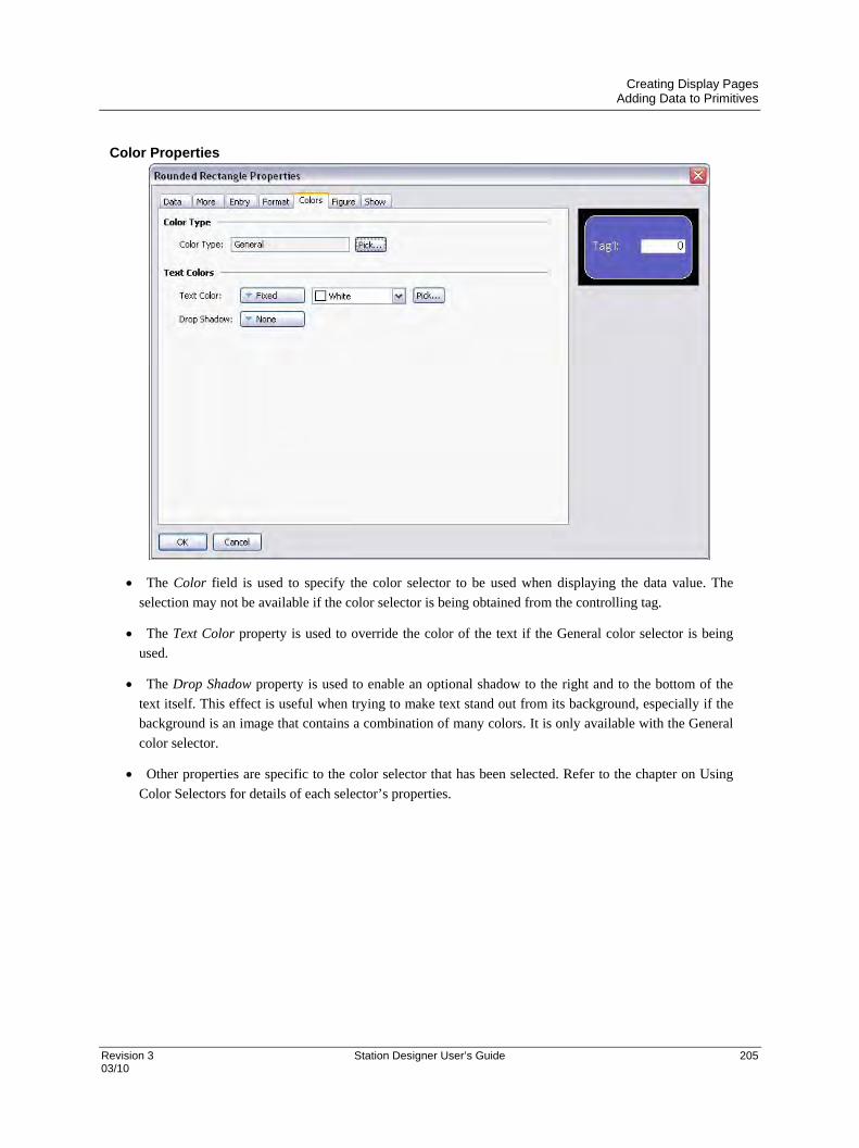
Creating Display Pages Adding Data to Primitives
Revision 3 Station Designer User’s Guide 205 03/10
Color Properties
The Color field is used to specify the color selector to be used when displaying the data value. The
selection may not be available if the color selector is being obtained from the controlling tag.
The Text Color property is used to override the color of the text if the General color selector is being
used.
The Drop Shadow property is used to enable an optional shadow to the right and to the bottom of the
text itself. This effect is useful when trying to make text stand out from its background, especially if the
background is an image that contains a combination of many colors. It is only available with the General
color selector.
Other properties are specific to the color selector that has been selected. Refer to the chapter on Using
Color Selectors for details of each selector’s properties.

Creating Display Pages Adding Actions to Primitives
206 Station Designer User’s Guide Revision 3 03/10
Adding Actions to Primitives Primitives that do not perform their own implicit action support the addition of customized actions to be performed
when the operator presses or releases the touch-screen. An action can be added by selecting the Add Action
command from the primitive’s context menu, or by selecting the primitive and pressing the CTRL+I key
combination. An Action tab will be added to the primitive’s properties, and the properties dialog will appear…
Protecting Actions The Protection property can be used to prevent an action from being invoked accidentally. This facility operates in
addition to any protection provided by the Security System, and is invoked before the associated actions begin. The
following protection modes are available.
The Confirmed mode displays a window to confirm the action. The action is performed
immediately if the user indicates that the action should proceed.
The Locked mode displays a popup stating that the action is locked. If the user indicates that
the action should proceed, it is unlocked, and they must activate the action again for it to
actually occur. Selecting another action will lock the previous action, as will waiting beyond
the global timeout.
The Hard Locked mode operates like the Locked mode, except that the action will relock once
it is performed and must be unlocked each time.

Creating Display Pages Protecting Actions
Revision 3 Station Designer User’s Guide 207 03/10
Enabling Actions
If you want to make a particular action dependent on some condition being true, enter an expression for that
condition in the Enable field. This expression may reference a flag tag directly, or may use any of the comparison or
logical operators defined in the Writing Expressions section. If you need more complex logic such that one of
several actions is performed based on more complex decision-making, configure the key for User Defined mode,
and use it to invoke a program that implements the required logic. You can also use the Remote property to block
access to this action from the web server.
The Goto Page Action
This action is used to instruct the target device to show a new page…
The Target Page property is used to indicate which page should be displayed. In addition to the pages
contained in the database, you have the option of selecting either Previous Page or Next Page to navigate
within the page history list.
The Show As property is used to indicate how the page should be displayed. A selection of Normal Page
will cause the page to be selected in the usual manner, while the Popup Window option will cause the
primitives on the new page to be displayed in a rectangular popup on top of the current page. A popup
can be closed by executing the HidePopup() function.
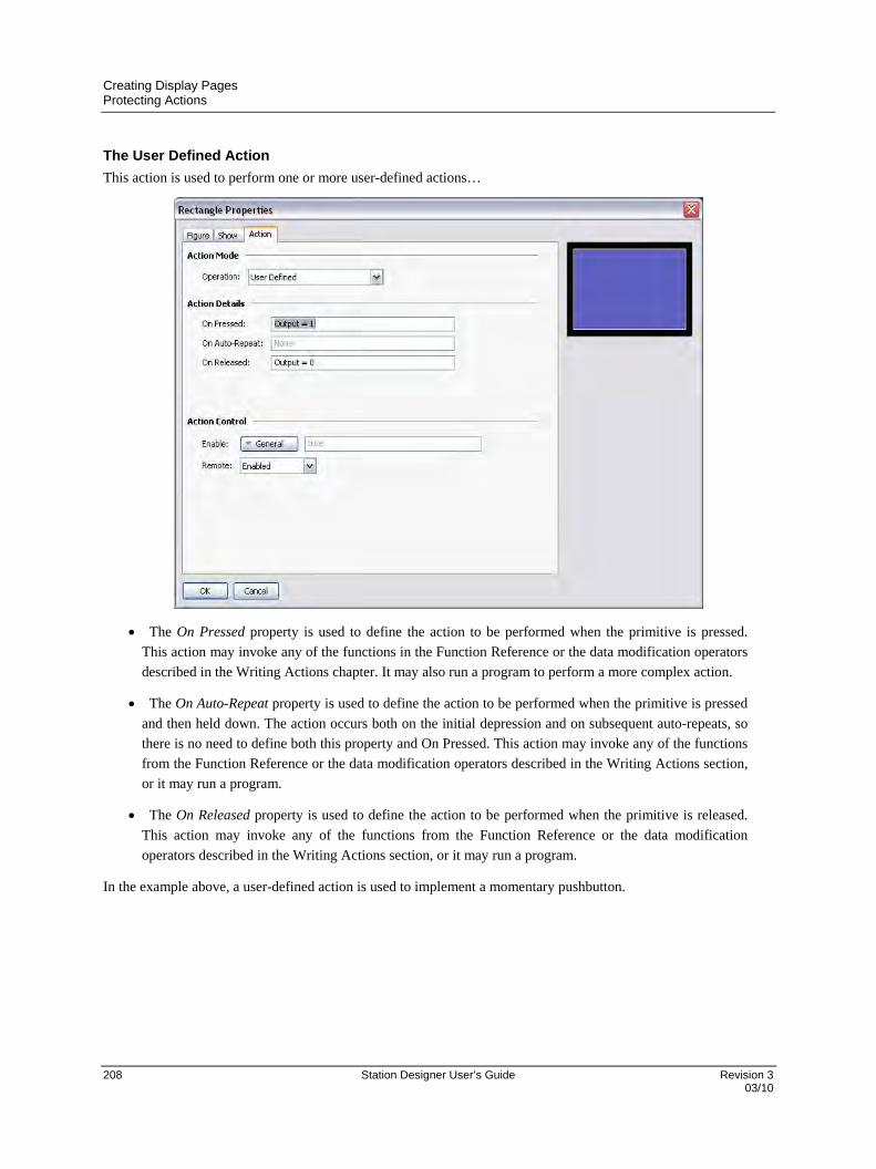
Creating Display Pages Protecting Actions
208 Station Designer User’s Guide Revision 3 03/10
The User Defined Action
This action is used to perform one or more user-defined actions…
The On Pressed property is used to define the action to be performed when the primitive is pressed.
This action may invoke any of the functions in the Function Reference or the data modification operators
described in the Writing Actions chapter. It may also run a program to perform a more complex action.
The On Auto-Repeat property is used to define the action to be performed when the primitive is pressed
and then held down. The action occurs both on the initial depression and on subsequent auto-repeats, so
there is no need to define both this property and On Pressed. This action may invoke any of the functions
from the Function Reference or the data modification operators described in the Writing Actions section,
or it may run a program.
The On Released property is used to define the action to be performed when the primitive is released.
This action may invoke any of the functions from the Function Reference or the data modification
operators described in the Writing Actions section, or it may run a program.
In the example above, a user-defined action is used to implement a momentary pushbutton.
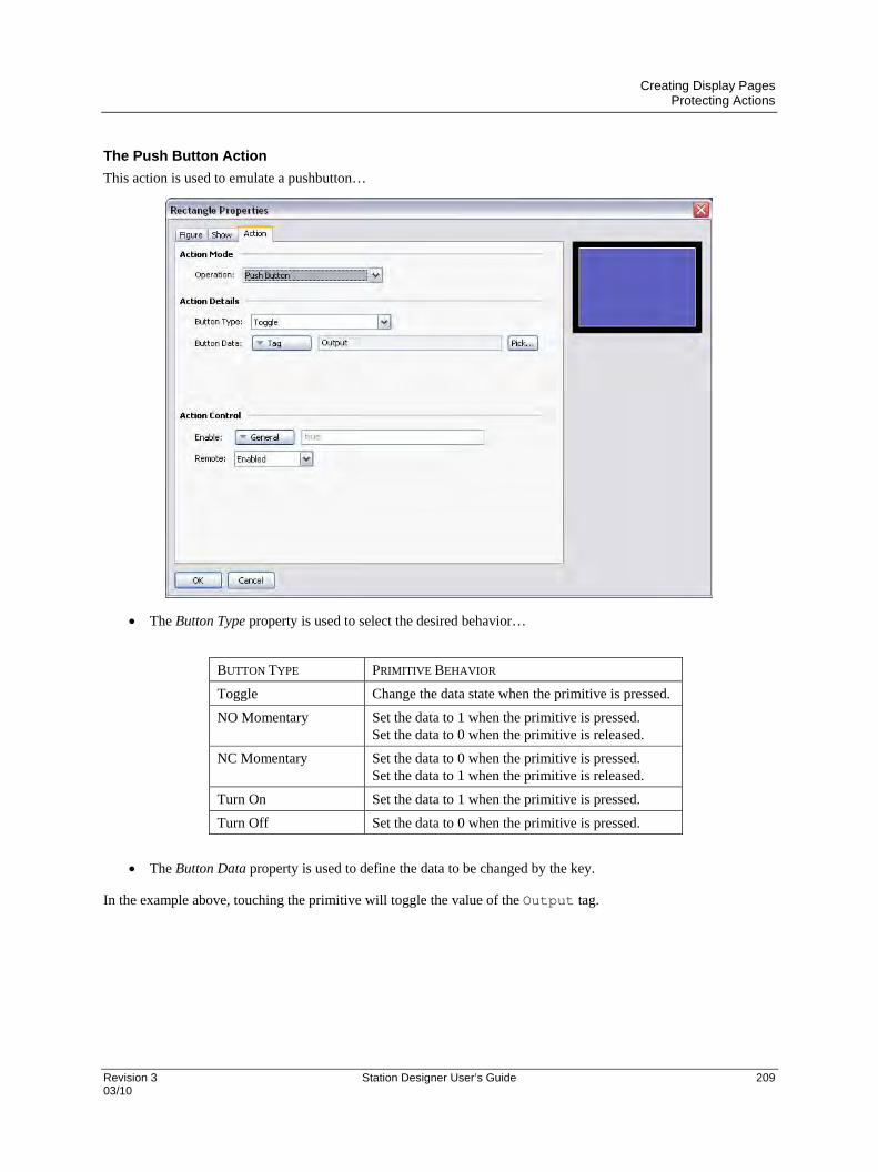
Creating Display Pages Protecting Actions
Revision 3 Station Designer User’s Guide 209 03/10
The Push Button Action
This action is used to emulate a pushbutton…
The Button Type property is used to select the desired behavior…
BUTTON TYPE PRIMITIVE BEHAVIOR
Toggle Change the data state when the primitive is pressed.
NO Momentary Set the data to 1 when the primitive is pressed. Set the data to 0 when the primitive is released.
NC Momentary Set the data to 0 when the primitive is pressed. Set the data to 1 when the primitive is released.
Turn On Set the data to 1 when the primitive is pressed.
Turn Off Set the data to 0 when the primitive is pressed.
The Button Data property is used to define the data to be changed by the key.
In the example above, touching the primitive will toggle the value of the Output tag.

Creating Display Pages Protecting Actions
210 Station Designer User’s Guide Revision 3 03/10
The Change Value Action
This action is used to write a numeric value to a data item…
The Write To property is used to define the data item to be changed.
The Data property is used to define the data to be written.
In the example above, touching the primitive will set the Data tag to 250. Note that this action supports either
floating point or integer values. The Data property must be of a type appropriate for the data item defined by the
Write To property.

Creating Display Pages Protecting Actions
Revision 3 Station Designer User’s Guide 211 03/10
The Ramp Value Action
This action is used to increase or decrease a data item. The options are shown below…
The Write To property is used to define the data item to be changed.
The Data property is used to define the step by which to raise or lower the item.
The Limit property is used to define the minimum or maximum data value.
The Ramp Mode property is used to define whether to raise or lower the item.
In the example above, pressing and holding down the primitive will repeatedly increase the Data tag by 5 until it
reaches 500. Note that this action supports either floating point or integer values. The Data and Limit properties
must be of a type appropriate for the data item defined by Write To property.
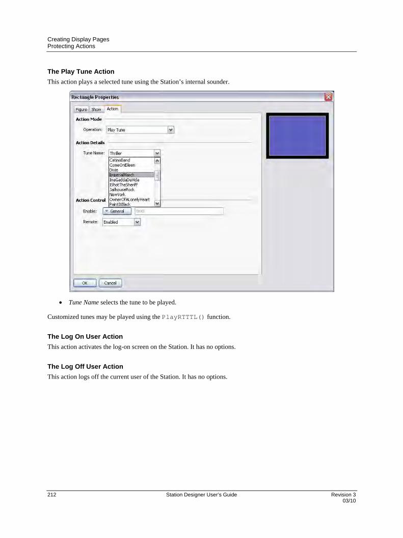
Creating Display Pages Protecting Actions
212 Station Designer User’s Guide Revision 3 03/10
The Play Tune Action
This action plays a selected tune using the Station’s internal sounder.
Tune Name selects the tune to be played.
Customized tunes may be played using the PlayRTTTL() function.
The Log On User Action
This action activates the log-on screen on the Station. It has no options.
The Log Off User Action
This action logs off the current user of the Station. It has no options.
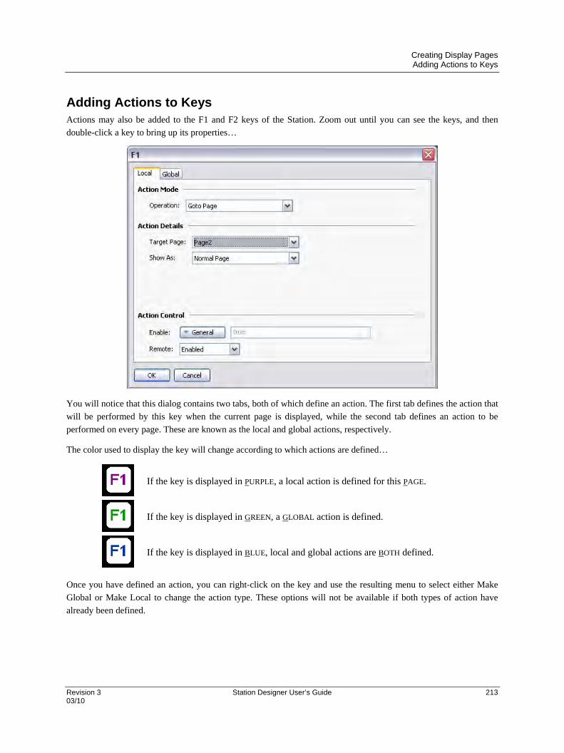
Creating Display Pages Adding Actions to Keys
Revision 3 Station Designer User’s Guide 213 03/10
Adding Actions to Keys Actions may also be added to the F1 and F2 keys of the Station. Zoom out until you can see the keys, and then
double-click a key to bring up its properties…
You will notice that this dialog contains two tabs, both of which define an action. The first tab defines the action that
will be performed by this key when the current page is displayed, while the second tab defines an action to be
performed on every page. These are known as the local and global actions, respectively.
The color used to display the key will change according to which actions are defined…
If the key is displayed in PURPLE, a local action is defined for this PAGE.
If the key is displayed in GREEN, a GLOBAL action is defined.
If the key is displayed in BLUE, local and global actions are BOTH defined.
Once you have defined an action, you can right-click on the key and use the resulting menu to select either Make
Global or Make Local to change the action type. These options will not be available if both types of action have
already been defined.

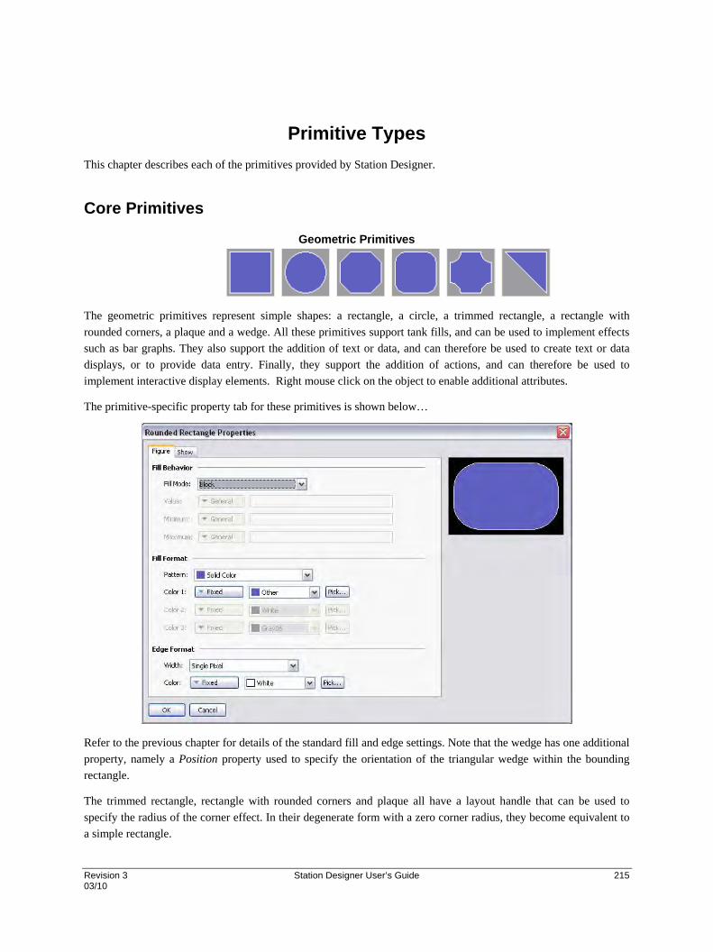
Revision 3 Station Designer User’s Guide 215 03/10
Primitive Types
This chapter describes each of the primitives provided by Station Designer.
Core Primitives
Geometric Primitives
The geometric primitives represent simple shapes: a rectangle, a circle, a trimmed rectangle, a rectangle with
rounded corners, a plaque and a wedge. All these primitives support tank fills, and can be used to implement effects
such as bar graphs. They also support the addition of text or data, and can therefore be used to create text or data
displays, or to provide data entry. Finally, they support the addition of actions, and can therefore be used to
implement interactive display elements. Right mouse click on the object to enable additional attributes.
The primitive-specific property tab for these primitives is shown below…
Refer to the previous chapter for details of the standard fill and edge settings. Note that the wedge has one additional
property, namely a Position property used to specify the orientation of the triangular wedge within the bounding
rectangle.
The trimmed rectangle, rectangle with rounded corners and plaque all have a layout handle that can be used to
specify the radius of the corner effect. In their degenerate form with a zero corner radius, they become equivalent to
a simple rectangle.
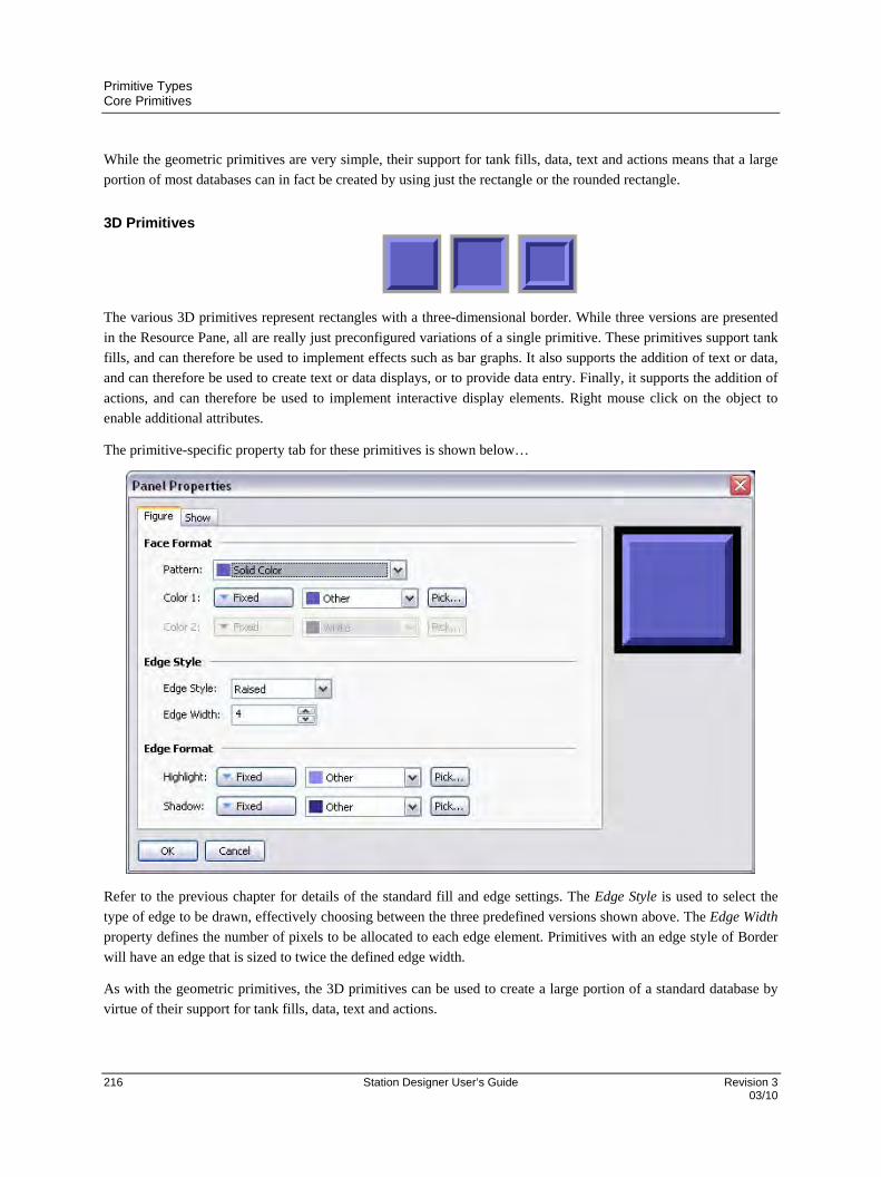
Primitive Types Core Primitives
216 Station Designer User’s Guide Revision 3 03/10
While the geometric primitives are very simple, their support for tank fills, data, text and actions means that a large
portion of most databases can in fact be created by using just the rectangle or the rounded rectangle.
3D Primitives
The various 3D primitives represent rectangles with a three-dimensional border. While three versions are presented
in the Resource Pane, all are really just preconfigured variations of a single primitive. These primitives support tank
fills, and can therefore be used to implement effects such as bar graphs. It also supports the addition of text or data,
and can therefore be used to create text or data displays, or to provide data entry. Finally, it supports the addition of
actions, and can therefore be used to implement interactive display elements. Right mouse click on the object to
enable additional attributes.
The primitive-specific property tab for these primitives is shown below…
Refer to the previous chapter for details of the standard fill and edge settings. The Edge Style is used to select the
type of edge to be drawn, effectively choosing between the three predefined versions shown above. The Edge Width
property defines the number of pixels to be allocated to each edge element. Primitives with an edge style of Border
will have an edge that is sized to twice the defined edge width.
As with the geometric primitives, the 3D primitives can be used to create a large portion of a standard database by
virtue of their support for tank fills, data, text and actions.

Primitive Types Core Primitives
Revision 3 Station Designer User’s Guide 217 03/10
Button Primitives
The button primitives implement beveled or graduated buttons. Text is preconfigured to allow the button to be
labeled, but can be removed to allow the addition of live data. An action tab is also provided by default, but will be
disabled if live data is added and configured for data entry. Buttons with data entry fields use the button press to
activate editing.
The primitive-specific property tab for a beveled button is shown below…
Refer to the previous chapter for details of the standard settings. The Edge Width property is used to define the
number of pixels to be allocated to each edge element. Since this primitive always uses an edge style of Border, the
edge will be sized to twice the defined edge width.

Primitive Types Core Primitives
218 Station Designer User’s Guide Revision 3 03/10
The primitive-specific property tab for a graduated button is shown below…
Refer to the previous chapter for details of the standard settings.
Text and Data Primitives
The text box and data box primitives are in fact rectangles with predefined data and text items, and with no fill or
edge colors defined. They exist to make it easier to add data and text elements, and to provide comfort to those users
who are not used to being able to construct an entire database from simple geometric primitives! They can also be
used to add a second data or text element to a primitive or when constructing a group.
Refer to the previous sections for details of the standard settings.
Line Primitive
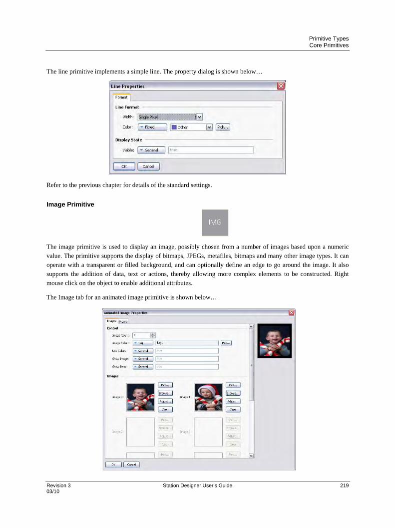
Primitive Types Core Primitives
Revision 3 Station Designer User’s Guide 219 03/10
The line primitive implements a simple line. The property dialog is shown below…
Refer to the previous chapter for details of the standard settings.
Image Primitive
The image primitive is used to display an image, possibly chosen from a number of images based upon a numeric
value. The primitive supports the display of bitmaps, JPEGs, metafiles, bitmaps and many other image types. It can
operate with a transparent or filled background, and can optionally define an edge to go around the image. It also
supports the addition of data, text or actions, thereby allowing more complex elements to be constructed. Right
mouse click on the object to enable additional attributes.
The Image tab for an animated image primitive is shown below…
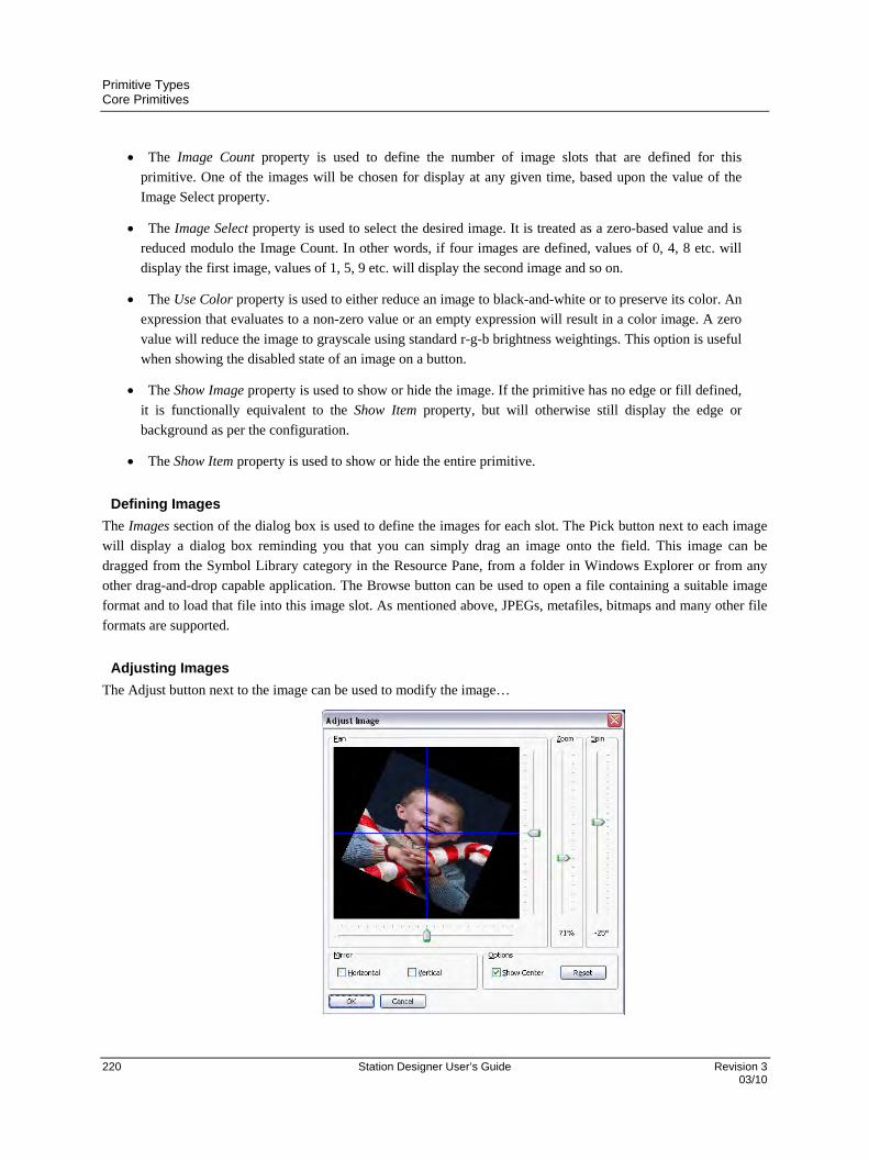
Primitive Types Core Primitives
220 Station Designer User’s Guide Revision 3 03/10
The Image Count property is used to define the number of image slots that are defined for this
primitive. One of the images will be chosen for display at any given time, based upon the value of the
Image Select property.
The Image Select property is used to select the desired image. It is treated as a zero-based value and is
reduced modulo the Image Count. In other words, if four images are defined, values of 0, 4, 8 etc. will
display the first image, values of 1, 5, 9 etc. will display the second image and so on.
The Use Color property is used to either reduce an image to black-and-white or to preserve its color. An
expression that evaluates to a non-zero value or an empty expression will result in a color image. A zero
value will reduce the image to grayscale using standard r-g-b brightness weightings. This option is useful
when showing the disabled state of an image on a button.
The Show Image property is used to show or hide the image. If the primitive has no edge or fill defined,
it is functionally equivalent to the Show Item property, but will otherwise still display the edge or
background as per the configuration.
The Show Item property is used to show or hide the entire primitive.
Defining Images
The Images section of the dialog box is used to define the images for each slot. The Pick button next to each image
will display a dialog box reminding you that you can simply drag an image onto the field. This image can be
dragged from the Symbol Library category in the Resource Pane, from a folder in Windows Explorer or from any
other drag-and-drop capable application. The Browse button can be used to open a file containing a suitable image
format and to load that file into this image slot. As mentioned above, JPEGs, metafiles, bitmaps and many other file
formats are supported.
Adjusting Images
The Adjust button next to the image can be used to modify the image…

Primitive Types Core Primitives
Revision 3 Station Designer User’s Guide 221 03/10
The various sliders can be used to pan, zoom and spin the image, while the checkboxes can be used to mirror it
horizontally or vertically. The Show Center checkbox shows or hides the blue lines that mark the center of the
image, while the Reset button can be used to restore the image to its original state. The manipulation options are
sometimes used to modify an image so as to create various different states for use in animation.
Scale Primitive
The scale primitive is used to draw a vertical scale. The limits of the scale can be defined as either constants, or can
be varied according to the value of specific expressions. The scale can be labeled or unlabelled, with any labels
being based upon a specified format object which may optionally be obtained from a tag.
Data Properties
The Value property is used to define an optional tag that will be used to obtain limits and format
information for the scale. The value itself is not actually used by the primitive, but the tag is simply used
as a source for further information.
The Get From Tag properties are used to indicate whether the tag optionally defined in the Value
property should be used as a source for the data in question.
The Show Labels property is used to show or hide the numeric scale labels.
The Show Units property is used to show or hide the units defined by a numeric data format. The units
may be appended to each scale label, or may be drawn vertically by the edge of the scale.
The Limit Values property is used to specify how the top and bottom values of the scale are determined.
If a setting of Precise is specified, the limit values will be used exactly, even if this produces limits that
do not exactly correspond to the automatically selected tick spacing. This can produce irregular scale
labels, but will ensure that a tank fill placed next to the scale and bound to the same tag will be drawn
exactly as required by the scale primitive. A setting of Rounded allows the scale primitive to
automatically adjust the limits to achieve regularly spaced tick marks.
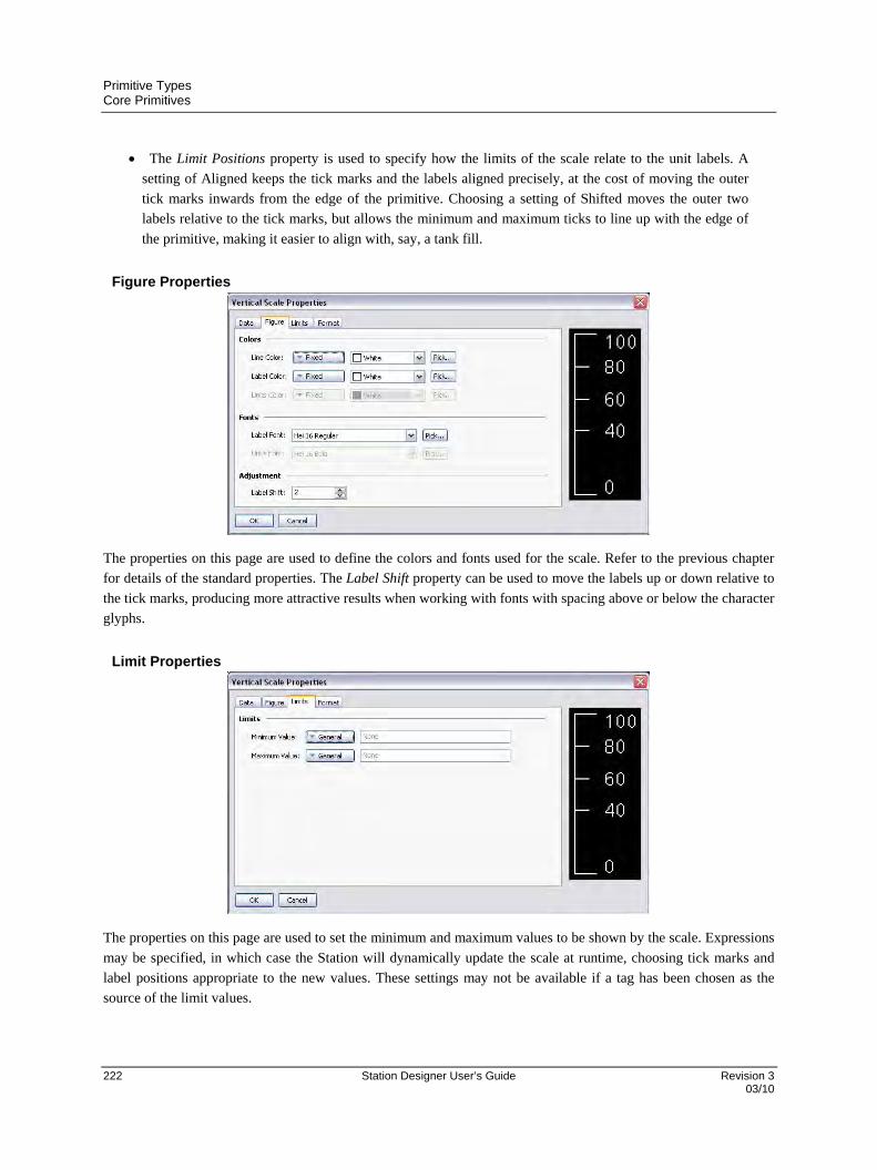
Primitive Types Core Primitives
222 Station Designer User’s Guide Revision 3 03/10
The Limit Positions property is used to specify how the limits of the scale relate to the unit labels. A
setting of Aligned keeps the tick marks and the labels aligned precisely, at the cost of moving the outer
tick marks inwards from the edge of the primitive. Choosing a setting of Shifted moves the outer two
labels relative to the tick marks, but allows the minimum and maximum ticks to line up with the edge of
the primitive, making it easier to align with, say, a tank fill.
Figure Properties
The properties on this page are used to define the colors and fonts used for the scale. Refer to the previous chapter
for details of the standard properties. The Label Shift property can be used to move the labels up or down relative to
the tick marks, producing more attractive results when working with fonts with spacing above or below the character
glyphs.
Limit Properties
The properties on this page are used to set the minimum and maximum values to be shown by the scale. Expressions
may be specified, in which case the Station will dynamically update the scale at runtime, choosing tick marks and
label positions appropriate to the new values. These settings may not be available if a tag has been chosen as the
source of the limit values.

Primitive Types Core Primitives
Revision 3 Station Designer User’s Guide 223 03/10
Format Properties
The Format Type field is used to specify the format type to be used when drawing the scale labels. Only general or
numeric formats are supported. The selection may not be available if the format is being obtained from a tag. Refer
to the section on Using Data Formats for details of the various other properties that are displayed when a numeric
data format is selected.

Primitive Types Arrows
224 Station Designer User’s Guide Revision 3 03/10
Arrows
The four arrow primitives are in fact predefined versions of a single primitive. This primitive supports tank fills. It
also supports the addition of text or data, and can therefore be used to create text or data displays, or to provide data
entry. Finally, it supports the addition of actions, and can therefore be used to implement interactive display
elements.
The primitive-specific property tab is shown below…
Refer to the previous chapter for details of the standard settings. The Mirror property is used to control the direction
of the arrow. It is this property that is used to produce the four predefined versions shown in the Resource Pane.
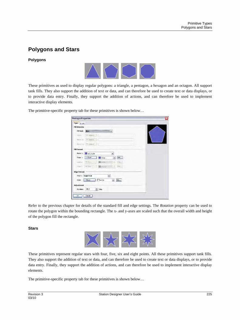
Primitive Types Polygons and Stars
Revision 3 Station Designer User’s Guide 225 03/10
Polygons and Stars
Polygons
These primitives as used to display regular polygons: a triangle, a pentagon, a hexagon and an octagon. All support
tank fills. They also support the addition of text or data, and can therefore be used to create text or data displays, or
to provide data entry. Finally, they support the addition of actions, and can therefore be used to implement
interactive display elements.
The primitive-specific property tab for these primitives is shown below…
Refer to the previous chapter for details of the standard fill and edge settings. The Rotation property can be used to
rotate the polygon within the bounding rectangle. The x- and y-axes are scaled such that the overall width and height
of the polygon fill the rectangle.
Stars
These primitives represent regular stars with four, five, six and eight points. All these primitives support tank fills.
They also support the addition of text or data, and can therefore be used to create text or data displays, or to provide
data entry. Finally, they support the addition of actions, and can therefore be used to implement interactive display
elements.
The primitive-specific property tab for these primitives is shown below…
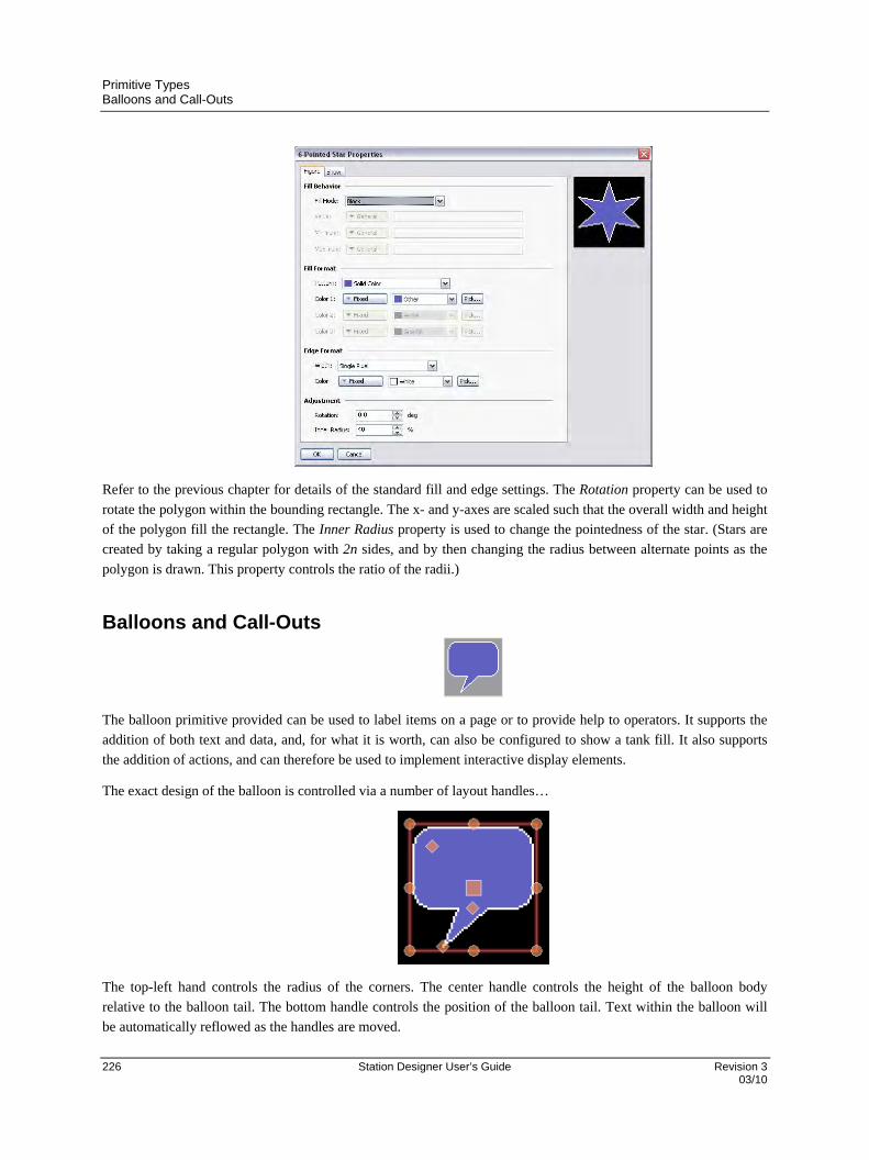
Primitive Types Balloons and Call-Outs
226 Station Designer User’s Guide Revision 3 03/10
Refer to the previous chapter for details of the standard fill and edge settings. The Rotation property can be used to
rotate the polygon within the bounding rectangle. The x- and y-axes are scaled such that the overall width and height
of the polygon fill the rectangle. The Inner Radius property is used to change the pointedness of the star. (Stars are
created by taking a regular polygon with 2n sides, and by then changing the radius between alternate points as the
polygon is drawn. This property controls the ratio of the radii.)
Balloons and Call-Outs
The balloon primitive provided can be used to label items on a page or to provide help to operators. It supports the
addition of both text and data, and, for what it is worth, can also be configured to show a tank fill. It also supports
the addition of actions, and can therefore be used to implement interactive display elements.
The exact design of the balloon is controlled via a number of layout handles…
The top-left hand controls the radius of the corners. The center handle controls the height of the balloon body
relative to the balloon tail. The bottom handle controls the position of the balloon tail. Text within the balloon will
be automatically reflowed as the handles are moved.

Primitive Types Semi-Trimmed Figures
Revision 3 Station Designer User’s Guide 227 03/10
Semi-Trimmed Figures
The semi-trimmed figures are versions of the rounded rectangle, trimmed rectangle and plaque that have only two of
their corners removed. These are useful for creating title bars and other effects on the edge of primitive groups. They
are each available in four orientations.
Actions Buttons
Actions buttons use pre-selected images from the Symbol Library to create a button that will perform a given action
when it is pushed. Many versions are provided beyond those shown above. Clicking on a given button in the
Resource Pane will show the different color variants that are available. For example, the square button is available in
red, green or black…
When using an action button, you will primarily use the Action tab of the properties dialog to define an action as per
the description in the previous chapter. The Button tab can also be used to adjust the button images, or to define your
own versions…
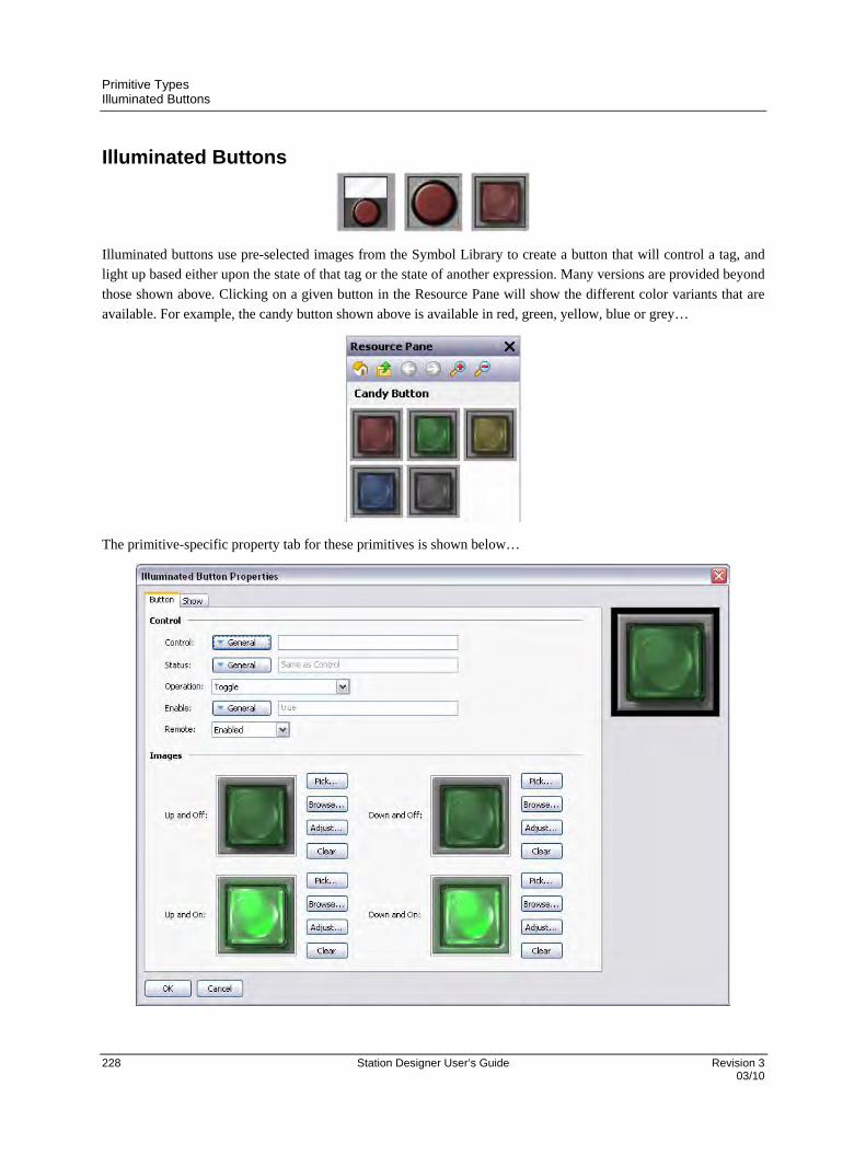
Primitive Types Illuminated Buttons
228 Station Designer User’s Guide Revision 3 03/10
Illuminated Buttons
Illuminated buttons use pre-selected images from the Symbol Library to create a button that will control a tag, and
light up based either upon the state of that tag or the state of another expression. Many versions are provided beyond
those shown above. Clicking on a given button in the Resource Pane will show the different color variants that are
available. For example, the candy button shown above is available in red, green, yellow, blue or grey…
The primitive-specific property tab for these primitives is shown below…
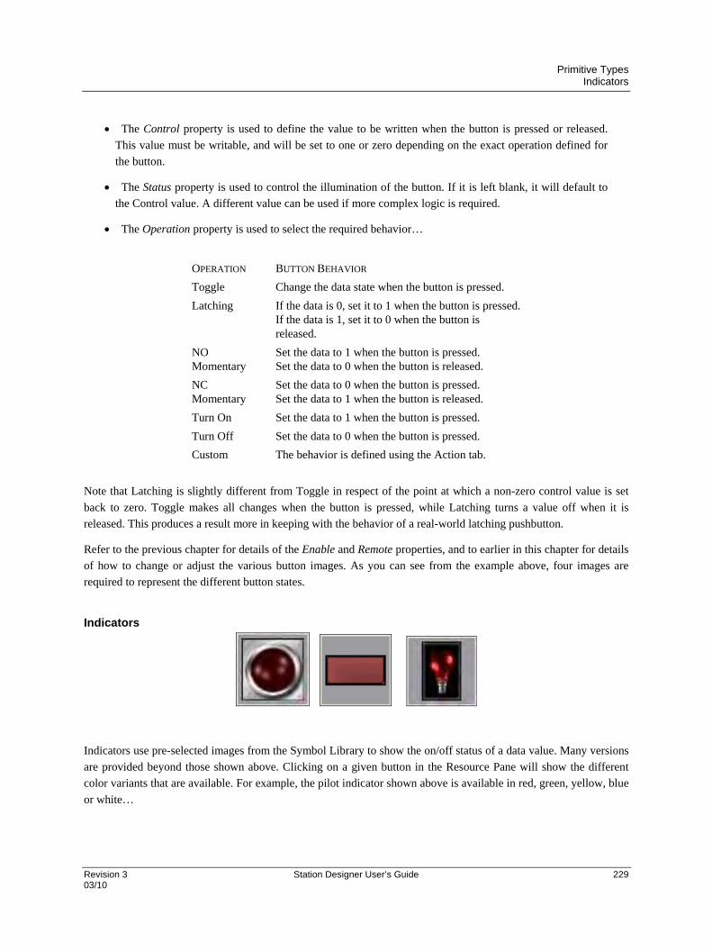
Primitive Types Indicators
Revision 3 Station Designer User’s Guide 229 03/10
The Control property is used to define the value to be written when the button is pressed or released.
This value must be writable, and will be set to one or zero depending on the exact operation defined for
the button.
The Status property is used to control the illumination of the button. If it is left blank, it will default to
the Control value. A different value can be used if more complex logic is required.
The Operation property is used to select the required behavior…
OPERATION BUTTON BEHAVIOR
Toggle Change the data state when the button is pressed.
Latching If the data is 0, set it to 1 when the button is pressed. If the data is 1, set it to 0 when the button is released.
NO Momentary
Set the data to 1 when the button is pressed. Set the data to 0 when the button is released.
NC Momentary
Set the data to 0 when the button is pressed. Set the data to 1 when the button is released.
Turn On Set the data to 1 when the button is pressed.
Turn Off Set the data to 0 when the button is pressed.
Custom The behavior is defined using the Action tab.
Note that Latching is slightly different from Toggle in respect of the point at which a non-zero control value is set
back to zero. Toggle makes all changes when the button is pressed, while Latching turns a value off when it is
released. This produces a result more in keeping with the behavior of a real-world latching pushbutton.
Refer to the previous chapter for details of the Enable and Remote properties, and to earlier in this chapter for details
of how to change or adjust the various button images. As you can see from the example above, four images are
required to represent the different button states.
Indicators
Indicators use pre-selected images from the Symbol Library to show the on/off status of a data value. Many versions
are provided beyond those shown above. Clicking on a given button in the Resource Pane will show the different
color variants that are available. For example, the pilot indicator shown above is available in red, green, yellow, blue
or white…

Primitive Types 2-State Toggles
230 Station Designer User’s Guide Revision 3 03/10
Indicators have a very simple set of properties…
The Status property controls the images to be drawn. All other properties are standard.
2-State Toggles
2-State Toggles use pre-selected images from the Symbol Library to implement toggle switches with up and down
positions. Many versions are provided beyond those shown above. Clicking on a given toggle in the Resource Pane
will show the different color variants that are available. For example, the paddle switch is available in red, green or
black…
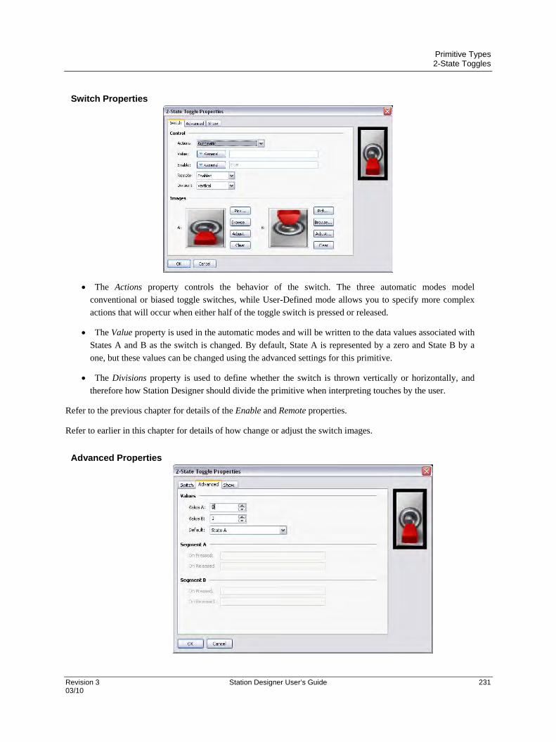
Primitive Types 2-State Toggles
Revision 3 Station Designer User’s Guide 231 03/10
Switch Properties
The Actions property controls the behavior of the switch. The three automatic modes model
conventional or biased toggle switches, while User-Defined mode allows you to specify more complex
actions that will occur when either half of the toggle switch is pressed or released.
The Value property is used in the automatic modes and will be written to the data values associated with
States A and B as the switch is changed. By default, State A is represented by a zero and State B by a
one, but these values can be changed using the advanced settings for this primitive.
The Divisions property is used to define whether the switch is thrown vertically or horizontally, and
therefore how Station Designer should divide the primitive when interpreting touches by the user.
Refer to the previous chapter for details of the Enable and Remote properties.
Refer to earlier in this chapter for details of how change or adjust the switch images.
Advanced Properties
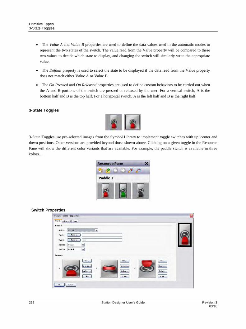
Primitive Types 3-State Toggles
232 Station Designer User’s Guide Revision 3 03/10
The Value A and Value B properties are used to define the data values used in the automatic modes to
represent the two states of the switch. The value read from the Value property will be compared to these
two values to decide which state to display, and changing the switch will similarly write the appropriate
value.
The Default property is used to select the state to be displayed if the data read from the Value property
does not match either Value A or Value B.
The On Pressed and On Released properties are used to define custom behaviors to be carried out when
the A and B portions of the switch are pressed or released by the user. For a vertical switch, A is the
bottom half and B is the top half. For a horizontal switch, A is the left half and B is the right half.
3-State Toggles
3-State Toggles use pre-selected images from the Symbol Library to implement toggle switches with up, center and
down positions. Other versions are provided beyond those shown above. Clicking on a given toggle in the Resource
Pane will show the different color variants that are available. For example, the paddle switch is available in three
colors…
Switch Properties

Primitive Types 3-State Toggles
Revision 3 Station Designer User’s Guide 233 03/10
The Actions property controls the behavior of the switch. The four automatic modes model conventional
or biased toggle switches, while User-Defined mode allows you to specify more complex actions that
will occur when either half of the toggle switch is pressed or released. Note that the switch can only be
moved one position at a time, so moving from State A to State C will necessarily mean moving through
State B, as would occur with a physical toggle switch.
The Value property is used in the automatic modes and will be written to the data values associated with
States A, B or C as the switch is changed. By default, State A is represented by a zero, State B by a one
and State C by a two, but these values can changed using the advanced settings for this primitive.
The Divisions property is used whether the switch is thrown vertically or horizontally, and therefore
how Station Designer should divide the primitive when interpreting touches by the user.
Refer to the previous chapter for details of the Enable and Remote properties.
Refer to earlier in this chapter for details on how to change or adjust the switch images.
Advanced Properties
The Value A, Value B and Value C properties are used to define the data values used in the automatic
modes to represent the three states of the switch. The value read from the Value property will be
compared to these values to decide which state to display, and changing the switch will write the
appropriate value.
The Default property is used to select the state to be displayed if the data read from the Value property
does not match Value A, Value B or Value C.
The On Pressed and On Released properties are used to define custom behaviors to be carried out when
the A and C portions of the switch are pressed or released by the user. For a vertical switch, A is the
bottom half and C is the top half. For a horizontal switch, A is the left half and C is the right half.

Primitive Types 2-State Selectors
234 Station Designer User’s Guide Revision 3 03/10
2-State Selectors
2-State Selectors use pre-selected images from the Symbol Library to implement rotary selector switches with two
states. Their behavior is identical to Two-State Toggles, and they are in fact implemented using the same primitive.
3-State Selectors
3-State Selectors use preselected images from the Symbol Library to implement rotary selector switches with three
states. Their behavior is identical to Three-State Toggles, and they are in fact implemented using the same primitive.
Legacy Primitives These primitives are provided for compatibility with other software packages.
Ellipse Fragments
These primitives represent quarter or half of an ellipse. Their properties are conventional.
Rich Sliders
Rich Slider primitives allow a tag value to be adjusted by means of an analog slider. While they can be useful, they
are likely to be superseded by more powerful primitives in a later release of Station Designer and are thus in the
Legacy sub-category.

Primitive Types Legacy Primitives
Revision 3 Station Designer User’s Guide 235 03/10
Data Properties
The Value property is used to specify the data whose value is to be edited.
The Operation property is used to indicate whether data entry is to be enabled or not. The default value
enables entry, as read-only sliders tend to mislead.
The Interaction property is used to specify how the user will interact with the primitive, be it via the
push buttons, by manipulating the slider directly, or by both methods.
The Acceleration property is used to specify how many levels of acceleration will be provided during
data entry. Acceleration moves the slider progressively quicker after an appropriate number of steps have
been taken. More than one level of acceleration can result in large changes being made inadvertently.
The Get From Tag properties are used to indicate whether the slider limits and data format will be
obtained from the tag provided in the Value property or whether they will be entered manually.
Figure Properties
Refer to the previous chapter for details of the standard fill and edge settings.
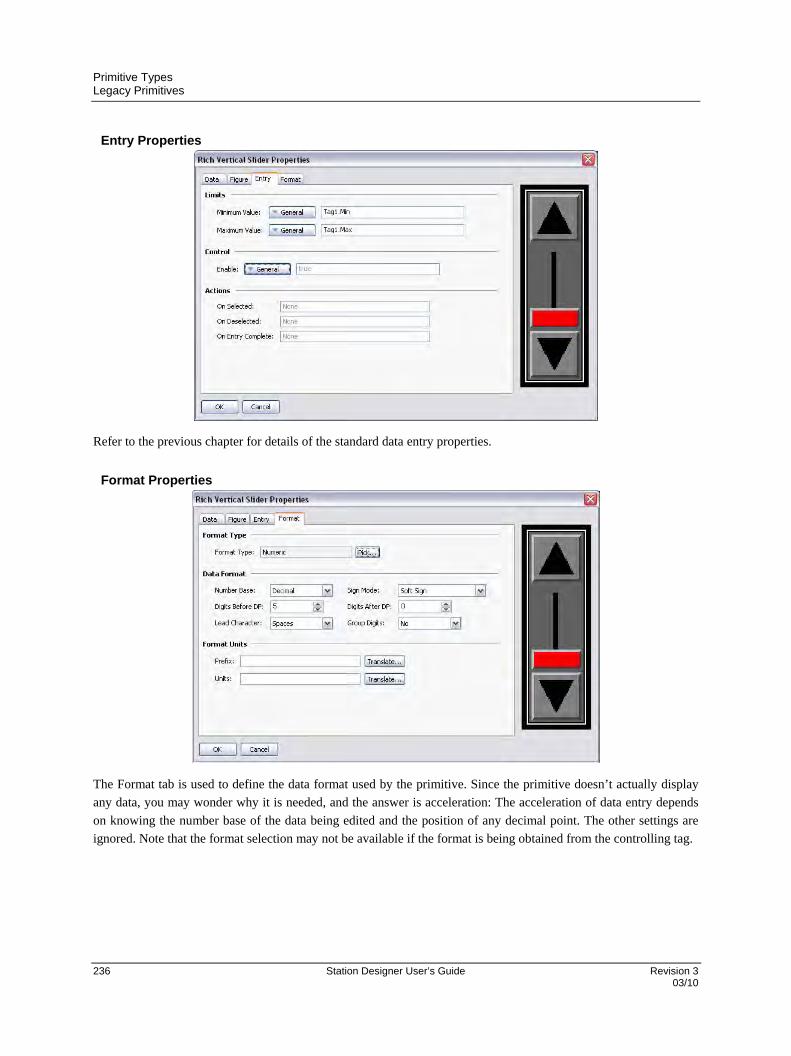
Primitive Types Legacy Primitives
236 Station Designer User’s Guide Revision 3 03/10
Entry Properties
Refer to the previous chapter for details of the standard data entry properties.
Format Properties
The Format tab is used to define the data format used by the primitive. Since the primitive doesn’t actually display
any data, you may wonder why it is needed, and the answer is acceleration: The acceleration of data entry depends
on knowing the number base of the data being edited and the position of any decimal point. The other settings are
ignored. Note that the format selection may not be available if the format is being obtained from the controlling tag.

Primitive Types System Primitives
Revision 3 Station Designer User’s Guide 237 03/10
System Primitives
Viewer Format
Most system primitives display or manipulate data created or accessed by Station Designer. Each viewer consists of
a viewing area with a number of buttons beneath. The appearance of the list-based viewers is controlled via the
Format tab of the properties dialog…
Colors and fonts are specified in the conventional way. The Buttons allows some of buttons at the bottom of the
viewer to be disabled, or to allow their labels to be edited or translated for international applications. Remember that
translatable strings can be set to expressions, implying that the label on a button can be customized at runtime.
Alarm Viewer
The Alarm Viewer is used to display and optionally accept alarms within the system.
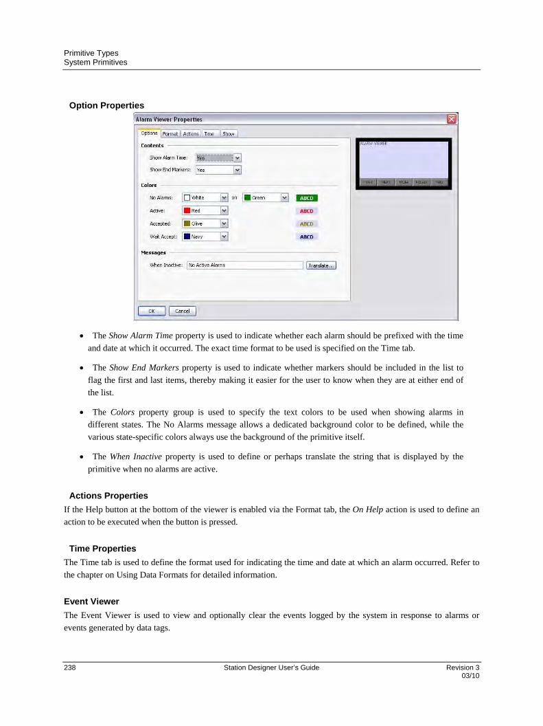
Primitive Types System Primitives
238 Station Designer User’s Guide Revision 3 03/10
Option Properties
The Show Alarm Time property is used to indicate whether each alarm should be prefixed with the time
and date at which it occurred. The exact time format to be used is specified on the Time tab.
The Show End Markers property is used to indicate whether markers should be included in the list to
flag the first and last items, thereby making it easier for the user to know when they are at either end of
the list.
The Colors property group is used to specify the text colors to be used when showing alarms in
different states. The No Alarms message allows a dedicated background color to be defined, while the
various state-specific colors always use the background of the primitive itself.
The When Inactive property is used to define or perhaps translate the string that is displayed by the
primitive when no alarms are active.
Actions Properties
If the Help button at the bottom of the viewer is enabled via the Format tab, the On Help action is used to define an
action to be executed when the button is pressed.
Time Properties
The Time tab is used to define the format used for indicating the time and date at which an alarm occurred. Refer to
the chapter on Using Data Formats for detailed information.
Event Viewer
The Event Viewer is used to view and optionally clear the events logged by the system in response to alarms or
events generated by data tags.
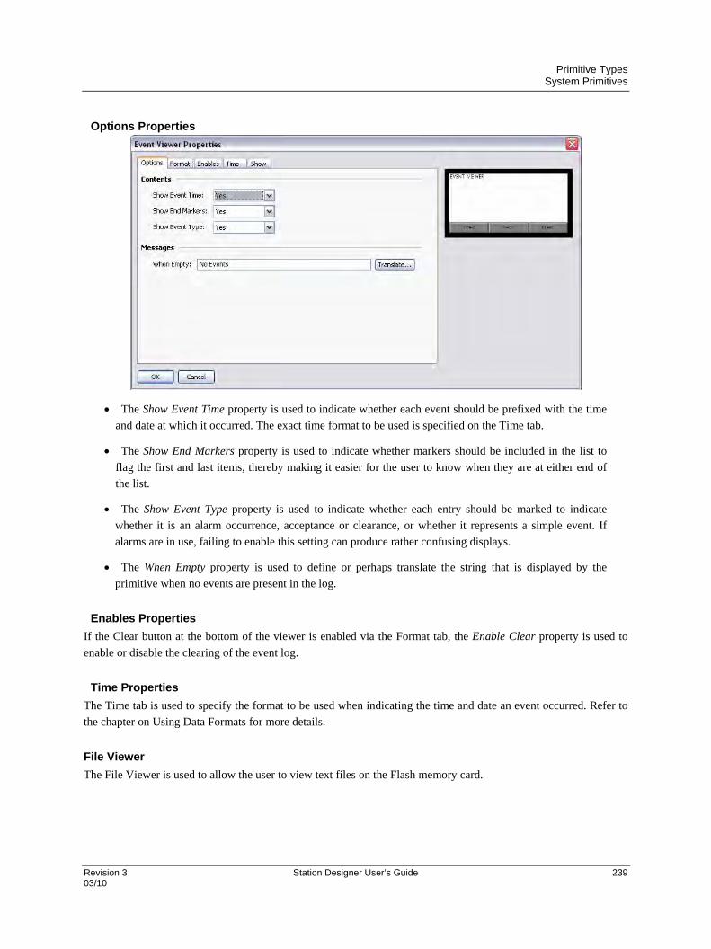
Primitive Types System Primitives
Revision 3 Station Designer User’s Guide 239 03/10
Options Properties
The Show Event Time property is used to indicate whether each event should be prefixed with the time
and date at which it occurred. The exact time format to be used is specified on the Time tab.
The Show End Markers property is used to indicate whether markers should be included in the list to
flag the first and last items, thereby making it easier for the user to know when they are at either end of
the list.
The Show Event Type property is used to indicate whether each entry should be marked to indicate
whether it is an alarm occurrence, acceptance or clearance, or whether it represents a simple event. If
alarms are in use, failing to enable this setting can produce rather confusing displays.
The When Empty property is used to define or perhaps translate the string that is displayed by the
primitive when no events are present in the log.
Enables Properties
If the Clear button at the bottom of the viewer is enabled via the Format tab, the Enable Clear property is used to
enable or disable the clearing of the event log.
Time Properties
The Time tab is used to specify the format to be used when indicating the time and date an event occurred. Refer to
the chapter on Using Data Formats for more details.
File Viewer
The File Viewer is used to allow the user to view text files on the Flash memory card.

Primitive Types System Primitives
240 Station Designer User’s Guide Revision 3 03/10
Options Properties
The Root Directory property is used to specify the directory to be displayed.
The Line Numbers property is used to show or hide line numbers on the file.
The Sort Order property is used to indicate how files should be accessed.
The File Types property group is used indicate the types of file that should be made available for
viewing. Note that only text files can be displayed.
The Messages property group is used to define and perhaps translate various messages used by the file
viewer.
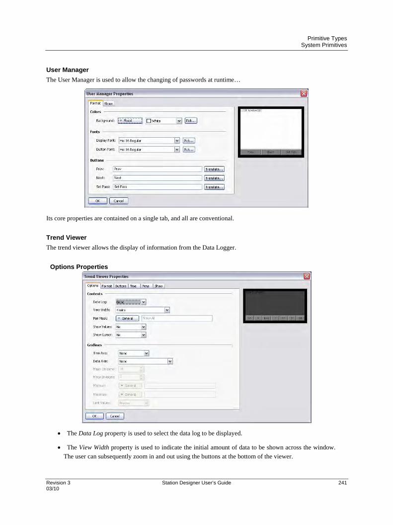
Primitive Types System Primitives
Revision 3 Station Designer User’s Guide 241 03/10
User Manager
The User Manager is used to allow the changing of passwords at runtime…
Its core properties are contained on a single tab, and all are conventional.
Trend Viewer
The trend viewer allows the display of information from the Data Logger.
Options Properties
The Data Log property is used to select the data log to be displayed.
The View Width property is used to indicate the initial amount of data to be shown across the window.
The user can subsequently zoom in and out using the buttons at the bottom of the viewer.
Primitive Types System Primitives
242 Station Designer User’s Guide Revision 3 03/10
The Pen Mask property is used to provide a 32-bit integer value to selectively enable or disable the
display of specific channels. Bit 0 corresponds to the first channel of the data log, bit 1 to the second and
so on. A bit value of one shows the channel while a value of zero hides it. A blank entry provides the
default behavior, with all channels being displayed.
The Show Values property enables or disables the display of the data values associated with each
channel of the data log, either during live mode or when scrolling back and forth using the cursor.
The Show Cursor property is used to enable or disable the display of a cursor on the viewer. The cursor
can be activated by the user to allow a specific point in time to be precisely determined, and optionally to
allow the associated historical data values to be displayed.
The Time Axis property is used to define whether gridlines should be displayed for the time axis. The
pitch of the gridlines is automatically determined by Station Designer based on the amount of time
covered by the viewer.
The Data Axis property is used to control the display of gridlines for the data axis. Gridlines may be
defined manually by specifying either just major divisions or both major and minor divisions, or may be
defined automatically by specifying minimum and maximum values for the data axis and letting Station
Designer calculate the best gridline pattern.
The Major Divisions and Minor Divisions properties are used to define the number of divisions to be
drawn when using manually-defined gridlines.
The Minimum and Maximum properties are used to indicate the range of data to be displayed when
using automatic gridlines. Station Designer will use these values to determine the best gridline pattern to
adopt. Data values will also be scaled to these values, as opposed to being scaled to their own data limits.
The Limit Values property is used to specify how the top and bottom values of the scale are determined.
If a setting of Precise is specified, the Minimum and Maximum values will be used exactly, even if this
produces limits that do not exactly correspond to the automatically selected tick spacing. This can
produce irregular gridline spacing. A setting of Rounded allows the scale primitive to adjust the limits to
achieve regularly spaced tick marks.
Format Properties
These properties are used to specify colors and fonts. Their operation is conventional.
Buttons Properties
These properties are used to edit and optionally translate the various button labels.
Time Properties
The Time tab is used to format the time to be used when providing time and date information relating to the data
log. Refer to the chapter on Using Data Formats for detailed information.
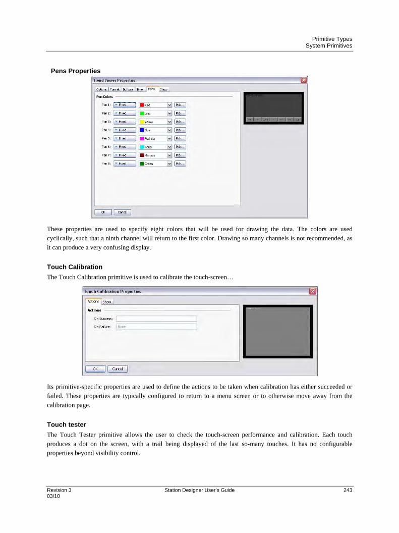
Primitive Types System Primitives
Revision 3 Station Designer User’s Guide 243 03/10
Pens Properties
These properties are used to specify eight colors that will be used for drawing the data. The colors are used
cyclically, such that a ninth channel will return to the first color. Drawing so many channels is not recommended, as
it can produce a very confusing display.
Touch Calibration
The Touch Calibration primitive is used to calibrate the touch-screen…
Its primitive-specific properties are used to define the actions to be taken when calibration has either succeeded or
failed. These properties are typically configured to return to a menu screen or to otherwise move away from the
calibration page.
Touch tester
The Touch Tester primitive allows the user to check the touch-screen performance and calibration. Each touch
produces a dot on the screen, with a trail being displayed of the last so-many touches. It has no configurable
properties beyond visibility control.

Primitive Types System Primitives
244 Station Designer User’s Guide Revision 3 03/10
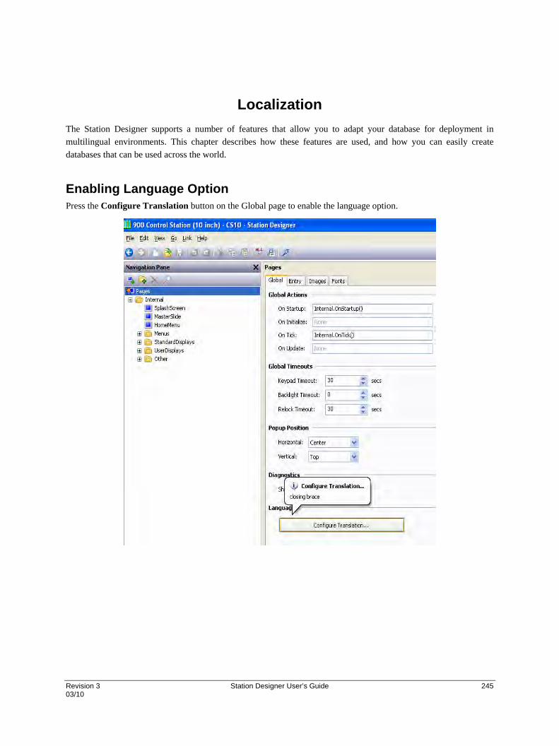
Revision 3 Station Designer User’s Guide 245 03/10
Localization
The Station Designer supports a number of features that allow you to adapt your database for deployment in
multilingual environments. This chapter describes how these features are used, and how you can easily create
databases that can be used across the world.
Enabling Language Option Press the Configure Translation button on the Global page to enable the language option.
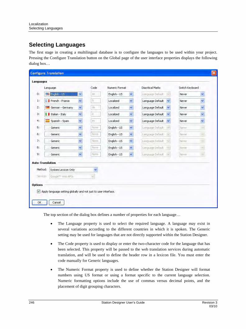
Localization Selecting Languages
246 Station Designer User’s Guide Revision 3 03/10
Selecting Languages The first stage in creating a multilingual database is to configure the languages to be used within your project.
Pressing the Configure Translation button on the Global page of the user interface properties displays the following
dialog box…
The top section of the dialog box defines a number of properties for each language…
The Language property is used to select the required language. A language may exist in
several variations according to the different countries in which it is spoken. The Generic
setting may be used for languages that are not directly supported within the Station Designer.
The Code property is used to display or enter the two-character code for the language that has
been selected. This property will be passed to the web translation services during automatic
translation, and will be used to define the header row in a lexicon file. You must enter the
code manually for Generic languages.
The Numeric Format property is used to define whether the Station Designer will format
numbers using US format or using a format specific to the current language selection.
Numeric formatting options include the use of commas versus decimal points, and the
placement of digit grouping characters.

Localization Selecting Languages
Revision 3 Station Designer User’s Guide 247 03/10
The Diacritical Marks property is used to override a language’s default setting for the
treatment of accents on upper case characters. For example, French as used in France (as
opposed to Canada) applies accents to upper case characters, which can make these characters
harder to render in some fonts. Selecting Lower Case Only for this setting will override this
default behavior.
The Switch Keyboard property is used to select the circumstances in which the Station
Designer configuration software will switch the keyboard layout to that used by the language.
The switching can occur when using the translation dialog box, whenever text is being edited
in this language, or not at all. Keyboard switching in the translation dialog is enabled by
default for languages such as Simplified Chinese, thereby ensuring that the appropriate Input
Method Editor is invoked.
The next section controls auto-translation, and is described below. The final property selects whether the current
language setting is applied to services such as the web server and the data logger, or whether these should always
use the system default language.

Localization Configuring Auto - Translation
248 Station Designer User’s Guide Revision 3 03/10
Configuring Auto - Translation
Auto translation can be done in three ways.
If you select System Lexicon only method all the translations from lex.txt present at C:\Documents and Settings\All
Users\Application Data\Honeywell\Station Designer\1.0\Lexicon are selected. It copies translated strings from
lex.txt file to corresponding locations in .sds database. However before selecting this option ensure that lex.txt file is
placed in the ‘c:\Documents and Settings\All Users\Application Data\Honeywell\Station Designer\1.0\Lexicon’
folder.
Select Web services only method to use two web services for getting the translations online. The options are Google
Web APIs and Microsoft Translator. When you select one of these options and perform Auto Translation activity all
the strings in database are translated directly from selected web service.
Select System Lexicon then Web Services option to search the lex.txt for translations. If the string is not present in
the lex.txt, online translations can be done from Web Services.
Auto-translation can be configured to use either or both of these methods. If you have an Internet connection, it is
generally better to use first the lexicon and then the web-based service. The lexicon alone can be used in some
circumstances to avoid the questionable translations that the web-based services can sometimes provide.
Check the Options checkbox to allow other services such as Data Logger, Web Servers to use the selected language.

Localization Translating Your Database
Revision 3 Station Designer User’s Guide 249 03/10
Translating Your Database You can also translate the database to the selected language. Use the Auto translate utility submenu present in the file Menu as shown below to translate the database. It is a Global Auto Translate command and translates the entire database in a single attempt. All database strings are translated from lex.txt or web services as per the selected language.
Click Auto-Translate to get the following dialog box.
Click Yes to start the translation process. You are again prompted with the following dialog box.
Select Yes to exclude already translated strings.

Localization Translating Your Database
250 Station Designer User’s Guide Revision 3 03/10
The following dialog box appears.
Click Yes to complete the process. If an error occurs while translating you are prompted with a
Translation failed message.
Export Lexicons You can create customized lexicon sheet with the Export Lexicon utility submenu. It lists all the strings / lexicons in the database for which translation is present. The file is in Unicode text format and uses code for languages. The exported lexicons are shown below.
Applying lexicon You can use the lexicon files to edit the already present translations. You can also make changes in the exported lexicon file and save it. The Apply Lexicon submenu allows you to select a file with translation changes and apply those changes to the strings in the database. It copies changed txt to all occurrences of the string.

Localization Translating Your Database
Revision 3 Station Designer User’s Guide 251 03/10
Exporting Strings Use the Exporting Strings option to prepare a list of all the strings and their translations present in the database in Unicode text format. The file can be edited in tools like Microsoft Excel to store different translations for a string according to different contexts. Exported file shows the source for the string along with its text. You can save a copy locally on your system.
Importing Strings
Use the Importing Strings submenu option to select and import the edited string files back to database.
Clear Translations
Use this option to clear all the translations from the database.

Localization Translating Your Database
252 Station Designer User’s Guide Revision 3 03/10
Manual Translation option
All the test primitives can be manually translated to the required language. Click the Translate button as shown in
the following screen.
The following screen appears.
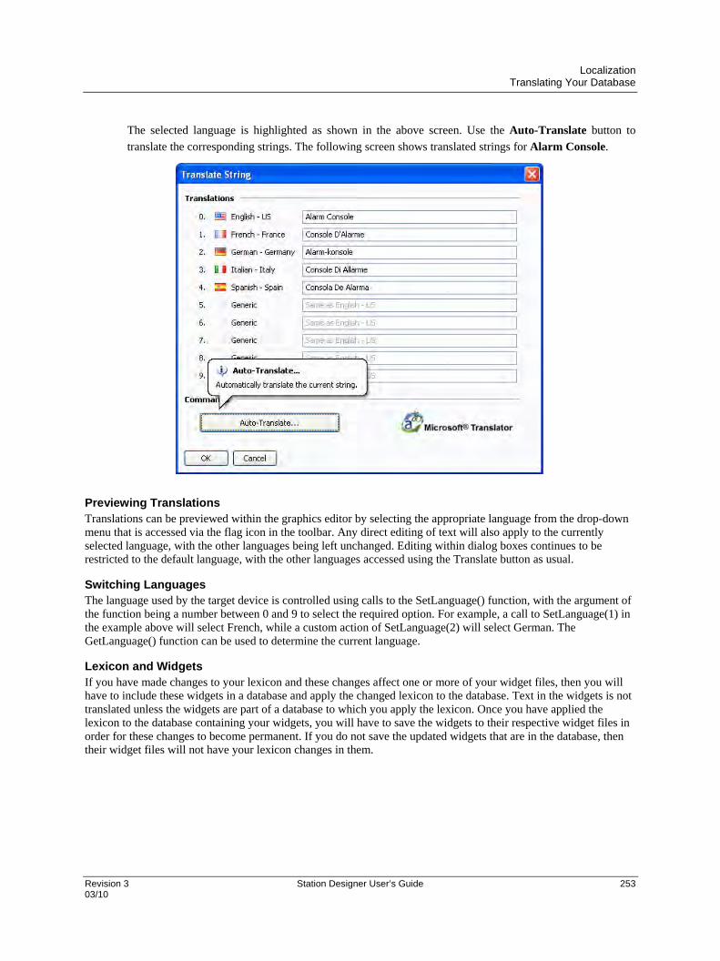
Localization Translating Your Database
Revision 3 Station Designer User’s Guide 253 03/10
The selected language is highlighted as shown in the above screen. Use the Auto-Translate button to
translate the corresponding strings. The following screen shows translated strings for Alarm Console.
Previewing Translations Translations can be previewed within the graphics editor by selecting the appropriate language from the drop-down menu that is accessed via the flag icon in the toolbar. Any direct editing of text will also apply to the currently selected language, with the other languages being left unchanged. Editing within dialog boxes continues to be restricted to the default language, with the other languages accessed using the Translate button as usual.
Switching Languages The language used by the target device is controlled using calls to the SetLanguage() function, with the argument of the function being a number between 0 and 9 to select the required option. For example, a call to SetLanguage(1) in the example above will select French, while a custom action of SetLanguage(2) will select German. The GetLanguage() function can be used to determine the current language.
Lexicon and Widgets If you have made changes to your lexicon and these changes affect one or more of your widget files, then you will have to include these widgets in a database and apply the changed lexicon to the database. Text in the widgets is not translated unless the widgets are part of a database to which you apply the lexicon. Once you have applied the lexicon to the database containing your widgets, you will have to save the widgets to their respective widget files in order for these changes to become permanent. If you do not save the updated widgets that are in the database, then their widget files will not have your lexicon changes in them.


Revision 3 Station Designer User’s Guide 255 03/10
Using Widgets
Station Designer supports a powerful feature—the ability to turn ordinary groups of primitives into powerful entities
called widgets. In addition to its component primitives, a widget contains user-definable data items that can be
edited at the group level but referenced by the widget’s components. This chapter explains how to create widgets,
and how to use them.
Creating a Widget The easiest way to understand widgets is to create one. Let’s start by creating an empty database and adding four
numeric tags. Leave the tag properties at their default settings, resulting in four internal integer values named Tag1
through Tag4.
Switch to the Display Pages section and add two data box primitives to the page...
Leave their properties at their default values for now, and select both items. Right-click on the items and select the
Widgetize command from the context menu. The items will be bound into a group, but the following dialog box will
also appear…
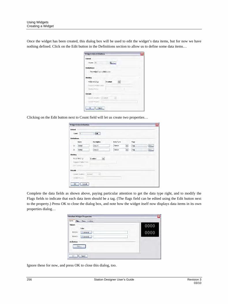
Using Widgets Creating a Widget
256 Station Designer User’s Guide Revision 3 03/10
Once the widget has been created, this dialog box will be used to edit the widget’s data items, but for now we have
nothing defined. Click on the Edit button in the Definitions section to allow us to define some data items…
Clicking on the Edit button next to Count field will let us create two properties…
Complete the data fields as shown above, paying particular attention to get the data type right, and to modify the
Flags fields to indicate that each data item should be a tag. (The flags field can be edited using the Edit button next
to the property.) Press OK to close the dialog box, and note how the widget itself now displays data items in its own
properties dialog…
Ignore these for now, and press OK to close this dialog, too.

Using Widgets Creating a Widget
Revision 3 Station Designer User’s Guide 257 03/10
The widget should still be selected in the graphic editor, so click on one of the data boxes contained in the widget to
enter group editing mode. Remember, the green rectangle marks the group that we’re editing, and the red rectangle
shows the selected item in that group…
Double-click on the data box to bring up its properties…
Enter Data1 in the Value field, and note the results.
Station Designer accepts this as a tag name, even though we don’t actually have a tag called Data1 in our database.
This value is actually equal to one of the data items defined within the widget, and will represent whatever tag we
assign when we go back in and edit the widget data. (The value of 25 shown in the preview window is the default
value used for widget data items that are not mapped to anything.) Since Data1 is marked a tag, we can access its
properties, use it as a source of formatting information, or do anything else that we would do with a tag.
Repeat this step for the second data box, this time setting its Value property to Data2.

Using Widgets Creating a Widget
258 Station Designer User’s Guide Revision 3 03/10
Press ESC until you have the widget alone selected. If you go too far and clear the selection, just click on the widget
itself, ensuring that it has a red rectangle round it…
Now bring up the widget properties, and this time enter values for the data items…
Enter the values shown above, setting the data items to Tag1 and Tag2 respectively. Note how the preview now
shows values of zero, as the data boxes within the widget are now getting their data from Tag1 and Tag2
respectively. To make things more interesting, right-click on the widget and access the Jump menu…
Select Tag1 to jump to that tag, and enter a value of 1234 in the Simulate As property. Use the ALT+LEFT key
combination or the Back button on the toolbar, and note how the widget is continuing to track the tag data…

Using Widgets Creating a Widget
Revision 3 Station Designer User’s Guide 259 03/10
Next, grab the right handle and make the widget a little wider…
Left-click on the upper of the two data boxes to enter group editing mode, and then right-click on the same box to
access its context menu…
Select the Data submenu, and choose the Label and Data command to configure this data box to display the tag’s
label as well as its data value. Note the new appearance of the widget…
As you can see, the data box is displaying the label from Tag1, indicating that the value of Data1 that we entered
into the data box’s Value property is entirely equivalent to the tag to which the data item was subsequently
configured. We refer to the process of setting a widget item to a tag as binding that data item to that tag. Binding can
be performed in more complex ways, as we shall see later.
Summary
Let us now recap what we did…
We placed primitives on the display and grouped them into a special kind of group called a widget. The
widget appeared to behave like a normal group in terms of editing and so on, but had additional
properties.
We edited the data definitions for the widget, creating two data items. Each was given a name, a
description, a data type and a number of flags.

Using Widgets Widget Data Definitions
260 Station Designer User’s Guide Revision 3 03/10
We used group editing to edit the contents of the widget, setting their properties to the widget’s own
data items, referring to them by the data item names.
We modified the widget’s data items, binding them to tags, thereby providing real tags and their
associated information to the contents of our widget.
Why This Matters
So why are widgets important? We could easily have created the data boxes and bound them directly to the tags, so
why bother with these extra steps? The answers become obvious when you try to create more complex widgets…
Widgets allow data items be used in several places, with multiple elements in the widget
being dependent on the same tag without your having to select the tag name in multiple
places.
Widgets can encapsulate complex design and functionality, and allow you to replicate and
reuse this across or within databases. In effect, they allow complex primitives to be created
by the user.
Widgets can be saved to disk and be added to the Resource Pane, or distributed via email,
thereby allowing easier cooperation between Station Designer users or between users and
Tech Support.
Down to Details
The next section revisits most of the topics above, but in more detail.
They also explore some of the attributes that can be used to make widgets even more powerful.
Widget Data Definitions
The features that give widgets their power is their data items. The data definition of a widget is edited by opening
the widget’s properties and by clicking on the Edit button in the Definitions section of the Data page…
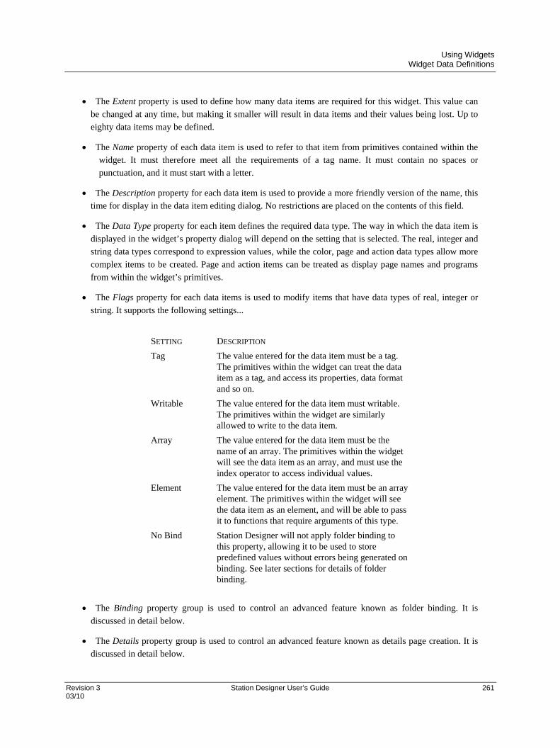
Using Widgets Widget Data Definitions
Revision 3 Station Designer User’s Guide 261 03/10
The Extent property is used to define how many data items are required for this widget. This value can
be changed at any time, but making it smaller will result in data items and their values being lost. Up to
eighty data items may be defined.
The Name property of each data item is used to refer to that item from primitives contained within the
widget. It must therefore meet all the requirements of a tag name. It must contain no spaces or
punctuation, and it must start with a letter.
The Description property for each data item is used to provide a more friendly version of the name, this
time for display in the data item editing dialog. No restrictions are placed on the contents of this field.
The Data Type property for each item defines the required data type. The way in which the data item is
displayed in the widget’s property dialog will depend on the setting that is selected. The real, integer and
string data types correspond to expression values, while the color, page and action data types allow more
complex items to be created. Page and action items can be treated as display page names and programs
from within the widget’s primitives.
The Flags property for each data items is used to modify items that have data types of real, integer or
string. It supports the following settings...
SETTING DESCRIPTION
Tag The value entered for the data item must be a tag. The primitives within the widget can treat the data item as a tag, and access its properties, data format and so on.
Writable The value entered for the data item must writable. The primitives within the widget are similarly allowed to write to the data item.
Array The value entered for the data item must be the name of an array. The primitives within the widget will see the data item as an array, and must use the index operator to access individual values.
Element The value entered for the data item must be an array element. The primitives within the widget will see the data item as an element, and will be able to pass it to functions that require arguments of this type.
No Bind Station Designer will not apply folder binding to this property, allowing it to be used to store predefined values without errors being generated on binding. See later sections for details of folder binding.
The Binding property group is used to control an advanced feature known as folder binding. It is
discussed in detail below.
The Details property group is used to control an advanced feature known as details page creation. It is
discussed in detail below.
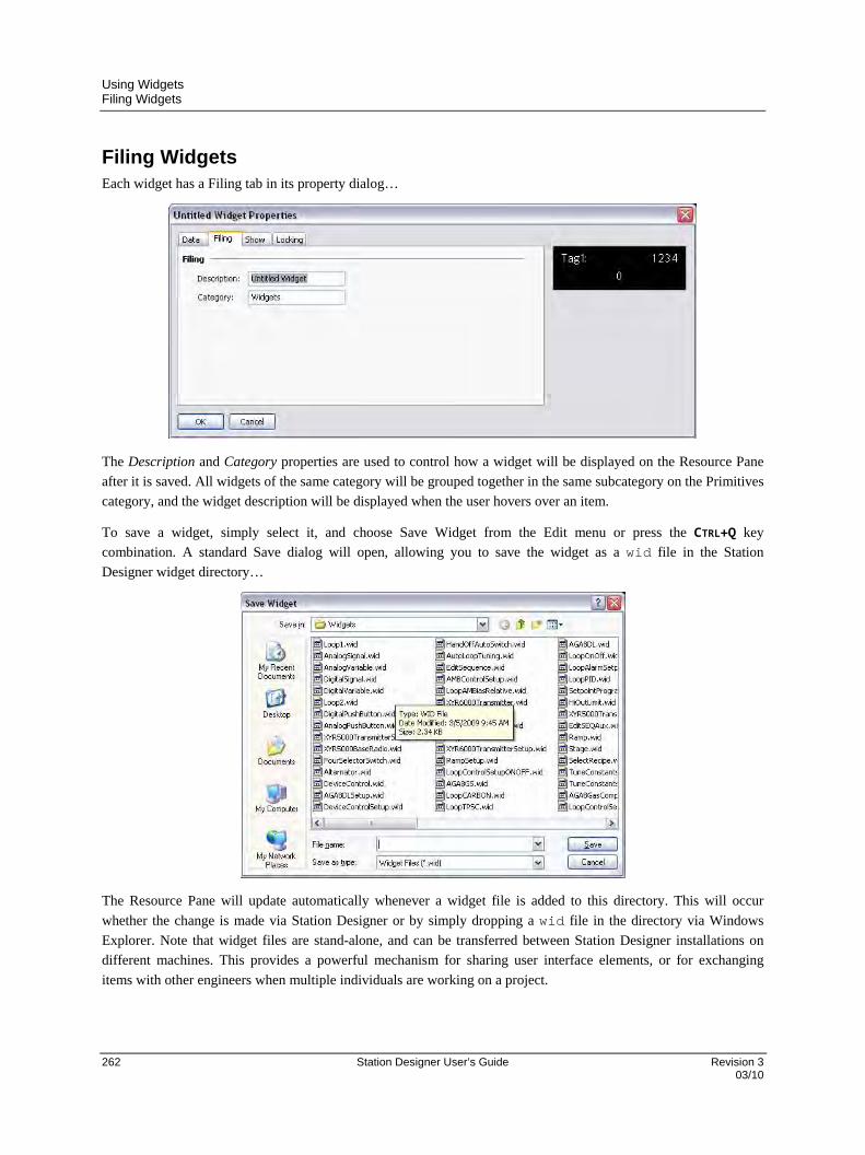
Using Widgets Filing Widgets
262 Station Designer User’s Guide Revision 3 03/10
Filing Widgets Each widget has a Filing tab in its property dialog…
The Description and Category properties are used to control how a widget will be displayed on the Resource Pane
after it is saved. All widgets of the same category will be grouped together in the same subcategory on the Primitives
category, and the widget description will be displayed when the user hovers over an item.
To save a widget, simply select it, and choose Save Widget from the Edit menu or press the CTRL+Q key
combination. A standard Save dialog will open, allowing you to save the widget as a wid file in the Station
Designer widget directory…
The Resource Pane will update automatically whenever a widget file is added to this directory. This will occur
whether the change is made via Station Designer or by simply dropping a wid file in the directory via Windows
Explorer. Note that widget files are stand-alone, and can be transferred between Station Designer installations on
different machines. This provides a powerful mechanism for sharing user interface elements, or for exchanging
items with other engineers when multiple individuals are working on a project.
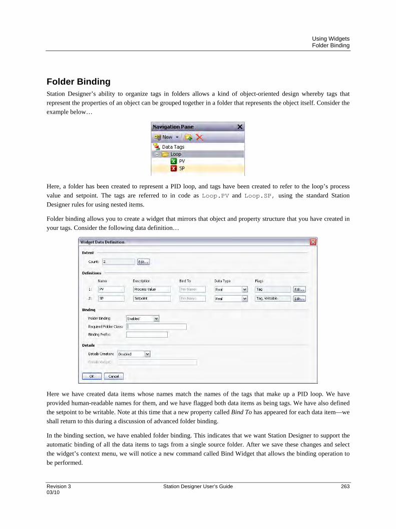
Using Widgets Folder Binding
Revision 3 Station Designer User’s Guide 263 03/10
Folder Binding Station Designer’s ability to organize tags in folders allows a kind of object-oriented design whereby tags that
represent the properties of an object can be grouped together in a folder that represents the object itself. Consider the
example below…
Here, a folder has been created to represent a PID loop, and tags have been created to refer to the loop’s process
value and setpoint. The tags are referred to in code as Loop.PV and Loop.SP, using the standard Station
Designer rules for using nested items.
Folder binding allows you to create a widget that mirrors that object and property structure that you have created in
your tags. Consider the following data definition…
Here we have created data items whose names match the names of the tags that make up a PID loop. We have
provided human-readable names for them, and we have flagged both data items as being tags. We have also defined
the setpoint to be writable. Note at this time that a new property called Bind To has appeared for each data item—we
shall return to this during a discussion of advanced folder binding.
In the binding section, we have enabled folder binding. This indicates that we want Station Designer to support the
automatic binding of all the data items to tags from a single source folder. After we save these changes and select
the widget’s context menu, we will notice a new command called Bind Widget that allows the binding operation to
be performed.
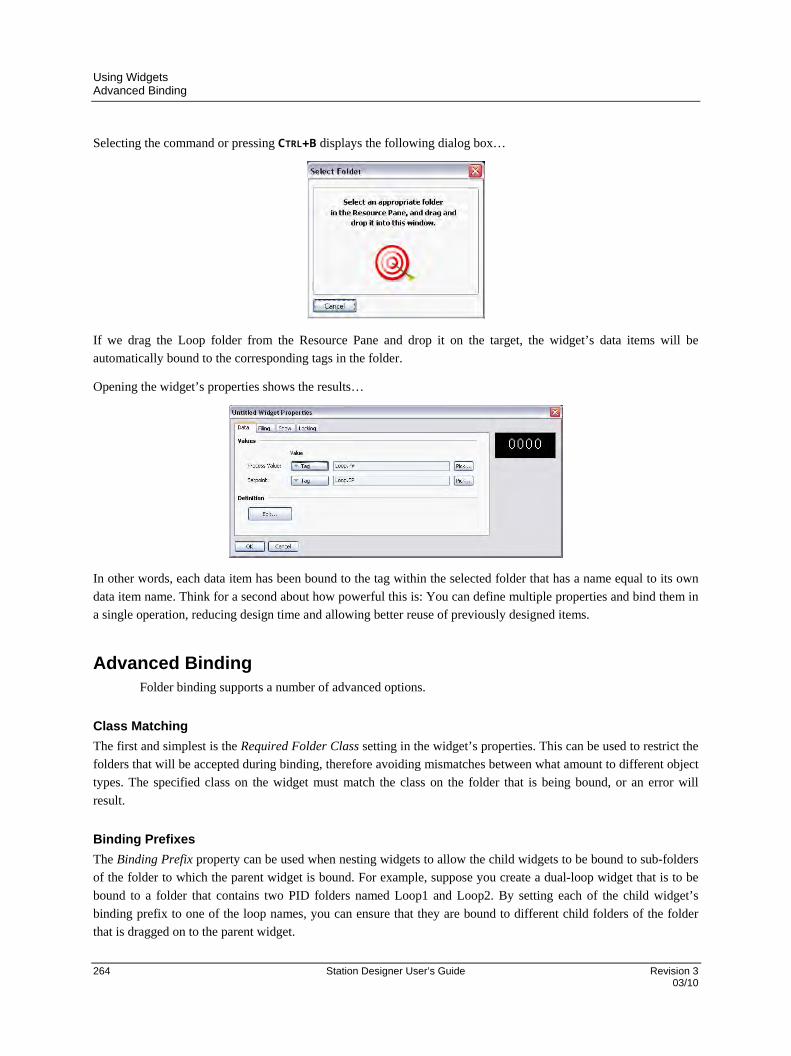
Using Widgets Advanced Binding
264 Station Designer User’s Guide Revision 3 03/10
Selecting the command or pressing CTRL+B displays the following dialog box…
If we drag the Loop folder from the Resource Pane and drop it on the target, the widget’s data items will be
automatically bound to the corresponding tags in the folder.
Opening the widget’s properties shows the results…
In other words, each data item has been bound to the tag within the selected folder that has a name equal to its own
data item name. Think for a second about how powerful this is: You can define multiple properties and bind them in
a single operation, reducing design time and allowing better reuse of previously designed items.
Advanced Binding Folder binding supports a number of advanced options.
Class Matching
The first and simplest is the Required Folder Class setting in the widget’s properties. This can be used to restrict the
folders that will be accepted during binding, therefore avoiding mismatches between what amount to different object
types. The specified class on the widget must match the class on the folder that is being bound, or an error will
result.
Binding Prefixes
The Binding Prefix property can be used when nesting widgets to allow the child widgets to be bound to sub-folders
of the folder to which the parent widget is bound. For example, suppose you create a dual-loop widget that is to be
bound to a folder that contains two PID folders named Loop1 and Loop2. By setting each of the child widget’s
binding prefix to one of the loop names, you can ensure that they are bound to different child folders of the folder
that is dragged on to the parent widget.

Using Widgets Advanced Binding
Revision 3 Station Designer User’s Guide 265 03/10
For example, if the first child widget has a binding prefix of Loop1 and its parent is bound to a folder called Dual,
the child widget’s properties will be bound to expressions of Dual.Loop1.PV and Dual.Loop1.SP
respectively.
Using Bind To
The Bind To property of a data item can be used to modify the expression to which that data item is bound. The
simplest option is to enter a name distinct from the name of the data item, in which case that name will be used for
selecting the tag to which to bind.
Using Periods
You may also enter a name that contains periods. These are used to select tags in child folders of the source folder.
For example, entering Remote.SP will result in the data item in question being bound to an expression of
Loop.Remote.SP upon binding to the Loop folder.
Using Carets
To ascend the folder tree, you may prefix the name with caret characters, each of which moves up one level. A data
item with a Bind To setting of ^Name in a widget that is bound to a Dual.Loop will itself be bound to the
expression of Dual.Name.
Special Name
You may also use one of a number of special Bind To names…
NAME RESULT
::Path The full path of the tag to which this widget was bound, including any parent folders.
::Name The name of the tag to which this widget was bound, excluding any parent folders.
::TopPath The full path of the tag to which the root widget was bound in a nested binding operation. Equivalent to ::Path for non-nested binding.
::TopName The name of the tag to which the root widget was bound in a nested binding operation. Equivalent to ::Name for non-nested binding.
Note that each of these special names evaluates to a string constant equal to the required name and not to the actual
tag itself. They are typically used to provide information to the user regarding the folder to which a widget or its root
widget have been bound.

Using Widgets Details Widgets
266 Station Designer User’s Guide Revision 3 03/10
Details Widgets Suppose you created a PID widget and want to display more detailed status information when the user presses a
button in that widget. The solution would be to create a more and perhaps larger complex widget and bind it to the
same loop. You would place this widget on another page, and then select that page from the original overview
widget, perhaps using a data item to tell the widget which page to use.
Details Widget creation performs all these steps automatically!
Enabling Details Creation
This feature is controlled via the Details Creation property of the widget’s data definition…
The Details Widget property is used to provide a comma-separated list of the one or more details widgets that you
would like to place on their own pages. Each widget is specified by giving the filename to which it was saved. In the
example above, we have one details widget to be extracted from a file called PIDDetails.wid in the Station
Designer widgets directory.
Defining Data Items
We must also provide data items in the overview widget so that we can access the names of the pages that are
created for the details widgets. These properties must be named Details1, Details2 and so on, with one data
item for each element in the Details Widgets list. Each data item must be the Page data type. In the example below,
we have created a single such property to hold the page name of our single details page…
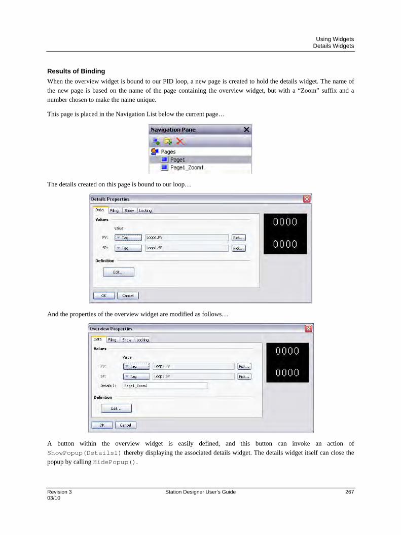
Using Widgets Details Widgets
Revision 3 Station Designer User’s Guide 267 03/10
Results of Binding
When the overview widget is bound to our PID loop, a new page is created to hold the details widget. The name of
the new page is based on the name of the page containing the overview widget, but with a “Zoom” suffix and a
number chosen to make the name unique.
This page is placed in the Navigation List below the current page…
The details created on this page is bound to our loop…
And the properties of the overview widget are modified as follows…
A button within the overview widget is easily defined, and this button can invoke an action of
ShowPopup(Details1) thereby displaying the associated details widget. The details widget itself can close the
popup by calling HidePopup().

Using Widgets Details Widgets
268 Station Designer User’s Guide Revision 3 03/10
Multiple Details Pages
If multiple details pages are created, you will recall that data items called Details1, Detail2 and so on in the
overview widget will hold the names of those pages. These data items can also be defined on the details widgets,
and will also be set to the names of the pages that have been created. This is useful if you want to allow the first
details page to navigate to the second and so on, thereby linking the pages together. Details widgets can also define a
special data item called DetailsP which will be set equal to the page that holds the overview widget. This can be
used to return to the overview—something that cannot be achieved via a simple GotoPrevious() when multiple
details pages are provided.
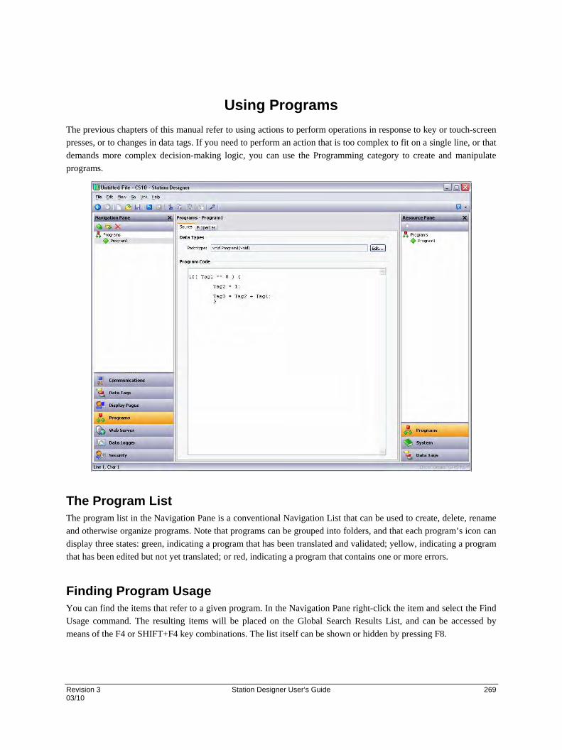
Revision 3 Station Designer User’s Guide 269 03/10
Using Programs
The previous chapters of this manual refer to using actions to perform operations in response to key or touch-screen
presses, or to changes in data tags. If you need to perform an action that is too complex to fit on a single line, or that
demands more complex decision-making logic, you can use the Programming category to create and manipulate
programs.
The Program List The program list in the Navigation Pane is a conventional Navigation List that can be used to create, delete, rename
and otherwise organize programs. Note that programs can be grouped into folders, and that each program’s icon can
display three states: green, indicating a program that has been translated and validated; yellow, indicating a program
that has been edited but not yet translated; or red, indicating a program that contains one or more errors.
Finding Program Usage You can find the items that refer to a given program. In the Navigation Pane right-click the item and select the Find
Usage command. The resulting items will be placed on the Global Search Results List, and can be accessed by
means of the F4 or SHIFT+F4 key combinations. The list itself can be shown or hidden by pressing F8.

Using Programs Editing Programs
270 Station Designer User’s Guide Revision 3 03/10
Editing Programs To edit a program, simply edit the program text using the Source tab shown in the Editing Pane. You will notice that
the program’s icon turns yellow as soon as you start typing, indicating that you have made changes that have yet to
be translated. You will also notice that Station Designer’s program editor performs syntax coloring, auto-indentation
and a variety of other features appropriate for a code editor.
Editor options can be configured by right-clicking on the Editing Pane and selecting the appropriate command from
the resulting menu.
When you have finished writing your program, press the CTRL+T key combination or select the Translate button on
the toolbar. The program will then be checked for errors. If an error is found, a dialog box will be displayed and the
program’s icon will turn red. The cursor will also be moved to the position of the error. If no errors exist, a chime
sound will be omitted and the program’s icon will turn green, indicating that the program has been translated into a
form suitable for execution within the target device.
The Resource Pane The Resource Pane displayed by the program editor contains a variety of items that can be dragged into your code.
The Data Tags and Programs categories are self-explanatory and provide quick access to the respective items in your
database by allowing the name of the item to be inserted into the editor. The System category provides access to
Station Designer’s extensive library of system variables and functions…
As you can see, variables and functions are grouped into categories. When a function is selected, its return type and
argument types are shown on the status bar. Dropping a function into your code enters the appropriate text, and
places the text cursor in the parentheses following the function name, thereby allowing you to enter the required
arguments.
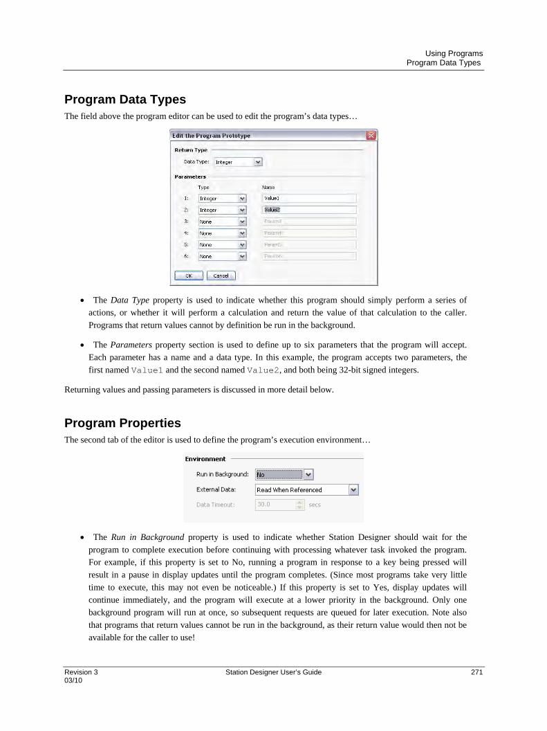
Using Programs Program Data Types
Revision 3 Station Designer User’s Guide 271 03/10
Program Data Types The field above the program editor can be used to edit the program’s data types…
The Data Type property is used to indicate whether this program should simply perform a series of
actions, or whether it will perform a calculation and return the value of that calculation to the caller.
Programs that return values cannot by definition be run in the background.
The Parameters property section is used to define up to six parameters that the program will accept.
Each parameter has a name and a data type. In this example, the program accepts two parameters, the
first named Value1 and the second named Value2, and both being 32-bit signed integers.
Returning values and passing parameters is discussed in more detail below.
Program Properties The second tab of the editor is used to define the program’s execution environment…
The Run in Background property is used to indicate whether Station Designer should wait for the
program to complete execution before continuing with processing whatever task invoked the program.
For example, if this property is set to No, running a program in response to a key being pressed will
result in a pause in display updates until the program completes. (Since most programs take very little
time to execute, this may not even be noticeable.) If this property is set to Yes, display updates will
continue immediately, and the program will execute at a lower priority in the background. Only one
background program will run at once, so subsequent requests are queued for later execution. Note also
that programs that return values cannot be run in the background, as their return value would then not be
available for the caller to use!
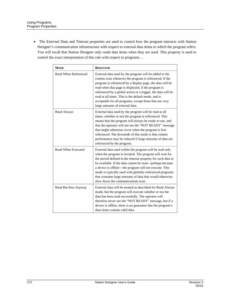
Using Programs Program Properties
272 Station Designer User’s Guide Revision 3 03/10
The External Data and Timeout properties are used to control how the program interacts with Station
Designer’s communication infrastructure with respect to external data items to which the program refers.
You will recall that Station Designer only reads data items when they are used. This property is used to
control the exact interpretation of this rule with respect to programs…
MODE BEHAVIOR
Read When Referenced External data used by the program will be added to the comms scan whenever the program is referenced. If the program is referenced by a display page, the data will be read when that page is displayed; if the program is referenced by a global action or a trigger, the data will be read at all times. This is the default mode, and is acceptable for all programs, except those that use very large amounts of external data.
Read Always External data used by the program will be read at all times, whether or not the program is referenced. This means that the program will always be ready to run, and that the operator will not see the “NOT READY” message that might otherwise occur when the program is first referenced. The downside of this mode is that comms performance may be reduced if large amounts of data are referenced by the program.
Read When Executed External data used within the program will be read only when the program is invoked. The program will wait for the period defined in the timeout property for such data to be available. If the data cannot be read—perhaps because a device is offline—the program will not execute. This mode is typically used with globally-referenced programs that consume large amounts of data that would otherwise slow down the communications scan.
Read But Run Anyway External data will be treated as described for Read Always mode, but the program will execute whether or not the data has been read successfully. The operator will therefore never see the “NOT READY” message, but if a device is offline, there is no guarantee that the program’s data items contain valid data.
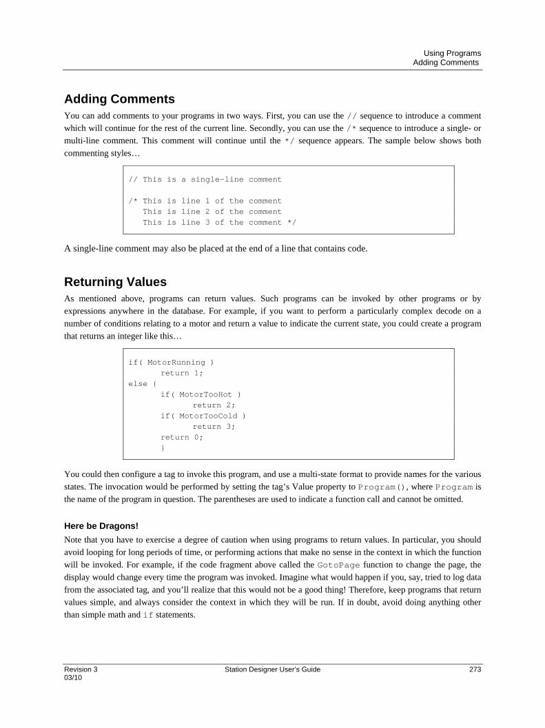
Using Programs Adding Comments
Revision 3 Station Designer User’s Guide 273 03/10
Adding Comments You can add comments to your programs in two ways. First, you can use the // sequence to introduce a comment
which will continue for the rest of the current line. Secondly, you can use the /* sequence to introduce a single- or
multi-line comment. This comment will continue until the */ sequence appears. The sample below shows both
commenting styles…
// This is a single-line comment /* This is line 1 of the comment This is line 2 of the comment This is line 3 of the comment */
A single-line comment may also be placed at the end of a line that contains code.
Returning Values As mentioned above, programs can return values. Such programs can be invoked by other programs or by
expressions anywhere in the database. For example, if you want to perform a particularly complex decode on a
number of conditions relating to a motor and return a value to indicate the current state, you could create a program
that returns an integer like this…
if( MotorRunning ) return 1; else { if( MotorTooHot ) return 2; if( MotorTooCold ) return 3; return 0; }
You could then configure a tag to invoke this program, and use a multi-state format to provide names for the various
states. The invocation would be performed by setting the tag’s Value property to Program(), where Program is
the name of the program in question. The parentheses are used to indicate a function call and cannot be omitted.
Here be Dragons!
Note that you have to exercise a degree of caution when using programs to return values. In particular, you should
avoid looping for long periods of time, or performing actions that make no sense in the context in which the function
will be invoked. For example, if the code fragment above called the GotoPage function to change the page, the
display would change every time the program was invoked. Imagine what would happen if you, say, tried to log data
from the associated tag, and you’ll realize that this would not be a good thing! Therefore, keep programs that return
values simple, and always consider the context in which they will be run. If in doubt, avoid doing anything other
than simple math and if statements.
Using Programs Passing Arguments
274 Station Designer User’s Guide Revision 3 03/10
Passing Arguments As mentioned above, programs can accept arguments. Suppose you want to write a program called FindMean to
take the average of two integer values. The program would be configured to accept two integer arguments, a and b.
The program would also be configured so as to return an integer. The code within the program would then be
defined as…
return (a+b)/2;
Once this program has been created and translated, you will be able to enter an expression such as
FindMean(Tag1, Tag2) to invoke it with the appropriate arguments. In this case, the expression would be
equal to the average of Tag1 and Tag2.
Programming Tips The sections below provide an overview of the programming constructions supported by Station Designer. The basic
syntax used is that of the C programming language. Note that the aim is not to try to teach you to become a
programmer, or to master the subtleties of the C language. Such topics are beyond the scope of this manual. Rather,
the aim is to provide a quick overview of the facilities available, so that the interested user might experiment further.
Multiple Actions
The simplest type of program comprises a list of actions, with each action taking up a single line, and being
followed by a semicolon. All of the various actions defined in the Writing Actions section are available for use.
Simple programs like this are typically used where combining the actions in a single action definition would
otherwise prove unreadable.
The sample shown below sets several variables, and then changes the display page…
Motor1 = 0; Motor2 = 1; Motor3 = 0;
GotoPage(Page1);
The actions will be executed in order, and the program will then return to the caller.
If Statements
This type of statement is used within a program to make a decision. The construct consists of an if statement with a
condition in parentheses, followed by an action (or actions) to be executed if the condition is true. If more than one
action is specified, each should be placed on a separate line, and curly-brackets should be used to group the
statements together. An optional else clause can be used to provide for code to be run if the condition is false.

Using Programs Programming Tips
Revision 3 Station Designer User’s Guide 275 03/10
The example below shows an if statement with a single action…
if( TankFull ) StartPump = 1;
The example below shows an if statement with two actions…
if( TankEmpty ) { StartPump = 0; OpenValue = 1; }
The example below shows an if statement with an else clause…
if( MotorHot ) StartFan = 1; else StartFan = 0;
Note that it is very important to remember to place the curly-brackets around groups of actions to be executed in the
if or else portion of the statement. If you omit the brackets, Station Designer will most likely misunderstand
exactly which actions you want to be dependent upon the if condition. Although line breaks are recommend
between actions, they are not used to figure out what is and is not included within the conditional statement.
Switch Statements
A switch statement is used to compare an integer value against a number of possible constants, and to perform an
action based upon which value is matched. The exact syntax supports a number of options beyond those shown in
the example below, but for the vast majority of applications, this simple form will be acceptable.
This example below will start a motor selected by the value in the MotorIndex tag...
switch( MotorIndex ) { case 1: MotorA = 1; break; case 2: case 3: MotorB = 1; break; case 4: MotorC = 1; break; default: MotorD = 1; break; }
Using Programs Programming Tips
276 Station Designer User’s Guide Revision 3 03/10
A value of 1 will start motor A, a value of 2 or 3 will start motor B, and a value of 4 will start motor C. Any value
which is not explicitly listed will start motor D. Things to note about the syntax are the use of curly-brackets around
the case statements, the use of break to end each conditional block, the use of two sequential case statements to
match more than one value, and the use of the optional default statement to indicate an action to perform if none
of the specified values is matched by the value in the controlling expression. (If this syntax looks too intimidating, a
series of if statements can be used instead to produce the same results, but with marginally lower performance, and
somewhat less readability.)
Local Variables
Some programs use variables to store intermediate results, or to control one of the various loop constructs described
below. Rather than defining a tag to hold these values, you can declare what are known as local variables using the
syntax shown below…
int a; // Declare local integer ‘a’ float b; // Declare local real ‘b’ cstring c; // Declare local string ‘c’
Local variables may optionally be initialized when they are declared by following the variable name with = and the
value to be assigned. Variables that are not initialized in this manner are set to zero, or an empty string, as
appropriate.
Note that local variables are truly local in both scope and lifetime. This means that they cannot be referenced outside
the program, and they do not retain their values between function invocations. If a function is called recursively,
each invocation has its own variables.
Loop Constructs
The three different loop constructs can be used to perform a given section of code while a certain condition is true.
The while loop tests its condition before the code is executed, while the do loop tests the condition afterwards.
The for loop is a quicker way of defining a while loop, allowing you to combine three common elements into
one statement.
You should note that some care is required when using loops within your programs, as you may make a
programming error which results in a loop that never terminates. Depending on the situation in which the program is
invoked, this may seriously disrupt the terminal’s user interface activity, or its communications. Loops which iterate
too many times may also cause performance issues for the subsystem that invokes them.

Using Programs Programming Tips
Revision 3 Station Designer User’s Guide 277 03/10
The While Loop
This type of loop repeats the action that follows it while the condition in the while statement remains true. If the
condition is never true, the action will never be executed, and the loop will perform no operation beyond evaluating
the controlling condition. If you want more than one action to be included in the loop, be sure to surround the
multiple statements in curly-brackets, as with the if statement. The example below initializes a pair of local
variables, and then uses the first to loop through the contents of an array, totaling the first ten elements, and
returning the total value to the caller…
int i=0, t=0; while( i < 10 ) {
t = t + Data[i]; i = i + 1; } return t;
The example below shows the same program, but rewritten in a compressed form. Since the loop statement now
controls only a single action, the curly-brackets have been omitted…
int i=0, t=0; while( i < 10 ) t += Data[i++]; return t;
The For Loop
You will notice that the while loop shown above has four elements…
1. The initialization of the loop control variable.
2. The evaluation of a test to see if the loop should continue.
3. The execution of the action to be performed by the loop.
4. The making of a change to the control variable.
The for loop allows elements 1, 2 and 4 to be combined within a single statement, such that the action following
the statement need only implement element 3. This syntax results in something similar to the FOR-NEXT loop
found in BASIC and other such languages.
Using this statement, the example given above can be rewritten as…
int i, t; for( i=t=0; i<10; i++ ) t += Data[i]; return t;

Using Programs Programming Tips
278 Station Designer User’s Guide Revision 3 03/10
You will notice that the for statement contains three distinct elements, each separated by semicolons. The first
element is the initialization step, which is performed once when the loop first begins; the next is the condition,
which is tested at the start of each loop iteration to see if the loop should continue; the final element is the induction
step, which is used to make a change to the control variable to move the loop on to its next iteration. Again, if you
want more than one action to be included in the loop, include them in curly-brackets!
The Do Loop
This type of loop is similar to the while loop, except that the condition is tested at the end of the loop. This means
that the loop will always execute at least once.
The example below shows the example from above, rewritten to use a do loop…
int i=0, t=0; do { t += Data[i]; } while( ++i < 10 ); return t;
Loop Control
Two additional statements can be used within loops. The break statement can be used to terminate the loop early,
while the continue statement can be used to skip the balance of the loop body and begin another iteration without
executing any further code. To make any sense, these statements must be used with if statements to make their
execution conditional.
The example below shows a loop that terminates early if another program returns true…
for( i=0; i<10; i++ ) { if( LoopAbort() ) break; LoopBody(); }
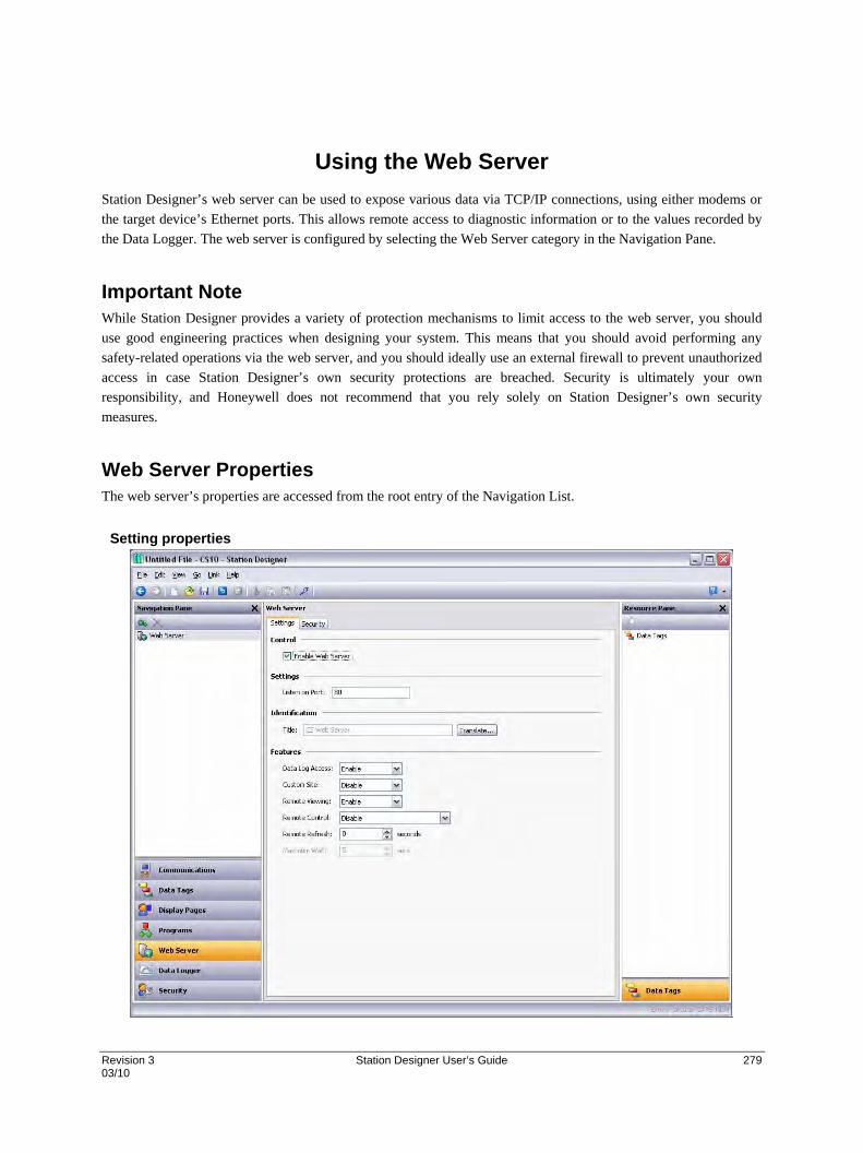
Revision 3 Station Designer User’s Guide 279 03/10
Using the Web Server
Station Designer’s web server can be used to expose various data via TCP/IP connections, using either modems or
the target device’s Ethernet ports. This allows remote access to diagnostic information or to the values recorded by
the Data Logger. The web server is configured by selecting the Web Server category in the Navigation Pane.
Important Note While Station Designer provides a variety of protection mechanisms to limit access to the web server, you should
use good engineering practices when designing your system. This means that you should avoid performing any
safety-related operations via the web server, and you should ideally use an external firewall to prevent unauthorized
access in case Station Designer’s own security protections are breached. Security is ultimately your own
responsibility, and Honeywell does not recommend that you rely solely on Station Designer’s own security
measures.
Web Server Properties The web server’s properties are accessed from the root entry of the Navigation List.
Setting properties

Using the Web Server Web Server Properties
280 Station Designer User’s Guide Revision 3 03/10
The Enable Web Server property is used to enable or disable the web server. If the server is enabled, the
panel will wait for incoming requests and then fulfill the requests as required. If the server is disabled,
connections to this port will be refused. Remember that in order for the server to operate, a TCP/IP
connection must have been configured using the Communications category.
The Listen on Port property indicates the TCP port number the web server will listen on. Port 80 is the
standard port used by the HTTP protocol and will most likely suit your application.
The Title property is used to provide the title to be shown on the web server menu. This title can be used
to differentiate between several terminals on a network, thereby ensuring that the correct terminal is
being accessed.
The Data Log Access property is used to enable or disable web access to the files created by the Data
Logger. This facility must be enabled if the web server is to be used by a remote client program to
automatically synchronize data logs.
The Remote Viewing property is used to enable or disable a facility by which a web browser can be used
to view the current contents of the target device’s display. This facility is very useful when remotely
diagnosing problems that an operator may be having with the operator panel or the machine it controls.
The Remote Control property is used to enable or disable an option by which the remote viewing
facility is extended to allow a web browser to be used to simulate the pressing of keys or display
primitives, thereby allowing remote control of the panel or the machine it controls. While this feature is
extremely useful, care must be taken to use the various security parameters to avoid unauthorized
tampering with a machine. The use of an external firewall is also strongly recommended if the panel is
reachable from the Internet.
The Custom Site property is used to enable or disable a facility by which files stored in the \WEB
directory of the Flash memory card are exposed via the web server. This facility is described in more
detail below.
The Remote Refresh property represents the frequency at which the web browser connected to the web
server will refresh the remote view page. A value of zero will result in refreshes being performed as
quickly as possible. Higher values will reduce bandwidth usage, and may be suitable for modem
connections.

Using the Web Server Web Server Properties
Revision 3 Station Designer User’s Guide 281 03/10
Security Properties
The IP Restrictions group is used to restrict web server access to hosts whose IP address matches the
mask and data indicated. All access may be restricted, or the filter may be used to restrict just the remote
control or data editing facilities.
The Authentication group is used to define whether users connecting to the web server will be required
to provide username and password information, and how that information will be validated. The Method
defines the algorithm to be used, with Digest being the recommended choice. The Source property is
used to indicate whether you will enter the required username and password directly into the web server
properties, or whether you will create users within Station Designer’s security system and grant them
access to the web server.
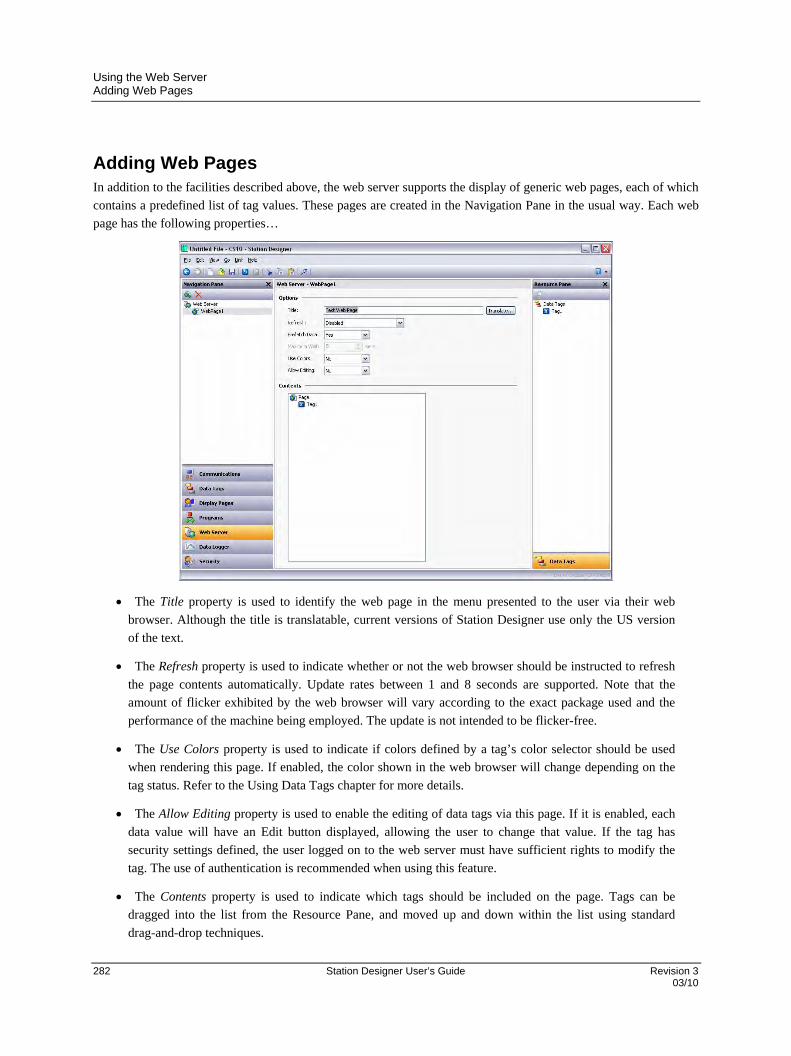
Using the Web Server Adding Web Pages
282 Station Designer User’s Guide Revision 3 03/10
Adding Web Pages In addition to the facilities described above, the web server supports the display of generic web pages, each of which
contains a predefined list of tag values. These pages are created in the Navigation Pane in the usual way. Each web
page has the following properties…
The Title property is used to identify the web page in the menu presented to the user via their web
browser. Although the title is translatable, current versions of Station Designer use only the US version
of the text.
The Refresh property is used to indicate whether or not the web browser should be instructed to refresh
the page contents automatically. Update rates between 1 and 8 seconds are supported. Note that the
amount of flicker exhibited by the web browser will vary according to the exact package used and the
performance of the machine being employed. The update is not intended to be flicker-free.
The Use Colors property is used to indicate if colors defined by a tag’s color selector should be used
when rendering this page. If enabled, the color shown in the web browser will change depending on the
tag status. Refer to the Using Data Tags chapter for more details.
The Allow Editing property is used to enable the editing of data tags via this page. If it is enabled, each
data value will have an Edit button displayed, allowing the user to change that value. If the tag has
security settings defined, the user logged on to the web server must have sufficient rights to modify the
tag. The use of authentication is recommended when using this feature.
The Contents property is used to indicate which tags should be included on the page. Tags can be
dragged into the list from the Resource Pane, and moved up and down within the list using standard
drag-and-drop techniques.

Using the Web Server Using a Custom Web Site
Revision 3 Station Designer User’s Guide 283 03/10
Using a Custom Web Site While the standard web pages provide quick-and-easy access to the data within the terminal, you may find that your
inability to edit their precise formatting leaves your artistic capabilities somewhat frustrated. You may thus use
Station Designer’s custom site facility to create a completely custom web site using your favorite third-party HTML
editor, and, by inserting certain special sequences and storing the resulting files on the device’s Flash memory card,
publish this site using the target device’s web server.
Creating the Site
The web site may use any HTML facilities supported by your browser, but must not use ASP, CGI or other server-
side tricks. The filenames used for the HTML files and associated graphics must also comply with the 8.3 naming
convention. This means that file extensions will be, for example, HTM instead of HTML and JPG instead of JPEG.
This also means that the body of the filename must be eight characters or less, and that you must not rely on the
difference between upper- and lower-case to differentiate between pages. You may use any directory structure, as
long as you once again ensure that your directories observe the 8.3 naming convention and do not rely on case
differences.
Embedding Data
To embed tag data within a web page, insert the sequence [[N]], replacing N with the index number of the tag in
question. This index number is displayed on the status bar when a tag is selected within the Data Tag category, and
more-or-less corresponds to the order in which the tags were created. When the web page containing this sequence is
served, the sequence will be replaced by the current value of the tag, formatted according to the tag’s properties.
Deploying the Site
To deploy your custom web site, copy it into the \WEB directory on the Flash memory card to be installed in the
target device. To copy the files, either mount the card as a drive as described in the early chapters of this manual, or
use a suitable card writer connected to your PC. Enable the custom site in the web server’s properties, and the site
will appear on the main web menu. When the site is selected, a file called DEFAULT.HTM within the \WEB
directory will be displayed. Beyond that point, navigation is according to the links within the site.

Revision 3 Station Designer User’s Guide 285 03/10
Using WebSync
The WebSync utility—which will be stored in the directory specified when the software was installed—can be executed to synchronize a directory on a PC with the contents of an operator panel’s data logs. You may decide to configure an application, such as the Windows Scheduler (or perhaps a cron daemon), to run this utility on a regular basis, or you may use a command line switch to instruct WebSync to perform the polling automatically. You may also decide to host WebSync on a central server so that the log files can be made available to selected users on your corporate network.
WebSync Syntax WebSync is invoked from the command line using the following syntax…
websync {switches} <hostname> …where <hostname> is replaced with the IP address of the panel to be polled.
Optional Switches The switches field may contain one or more of the following options…
terse can be used to suppress progress information.
poll <n> can be used to poll the terminal every n minutes.
path <dir> can be used to specify dir as the directory to hold the log files.
ras <name> can be used to invoke a dial-out connection to access the unit.
user <name> can be used to specify the username for the connection.
pass <pass> can be used to specify the password for the connection.
num <num> can be used to override the phone number for the connection.
Example Usage As an example, the following command line… websync –poll 10 –path C:\Logs 192.9.200.52 …will read the log files for all data logs on the terminal with the IP address of 192.9.200.52, and will store these logs under subdirectories of the C:\Logs directory. WebSync will continue to execute, and will repeat the polling process every ten minutes. The polling interval must obviously be set such that it is much less than the sampling rate times the number of samples in a file times the number of log files to be retained. If this constraint is met, the directory on the PC will accumulate copies of all the log files from the terminal.
Additional points related to settings:-
1. Enable the Web Server for the Web Sync to Work.
2. Log name is used to refer to the log within the sds file/database.
Example: When selecting a log for display (e.g. Trend Viewer), or when passing a log name to the log APIs (e.g LogComment API). 3. Log folder names created in Compact Flash will be
a) Path Name of corresponding Log (If user has configured Path Name) OR b) The log's ordinal plus one. (e.g For first log, folder name will be LOG1, for second log, it will be
LOG2 etc) (If user has not configured Path Name)


Revision 3 Station Designer User’s Guide 287 03/10
Using the Security System
Station Designer contains powerful features that allow you to define which operators have access to which display
pages, and limit those operators able to make changes to specific data. The software also contains a security logging
facility that can be used to record changes to data values indicating when the change occurred and by whom it was
performed.
Security Basics The follow sections detail some of the basic concepts used by the security system.
Object-Based Security
Station Designer’s security system is object-based. This means that security characteristics are applied to a display
page or to a tag, and not to the user interface element that accesses the page or makes a change to the tag. The
alternative subject-based approach typically means that you have to be careful to apply security settings to every
single user interface element that might change restricted data. Station Designer’s approach avoids this duplication
and ensures that once you have decided to protect a tag, it will remain protected throughout your database.
Named Users
Station Designer supports the ability to create any number of users, each of whom will have a username, a real name
and a password. The username is a case-insensitive string with no embedded spaces that is used to identify the user
when logging on, while the real name is typically a longer string that is used within log files to record the human-
readable identity of the user making a change. Note that you are free to use these fields in other ways if it suits your
application: You may, for example, create users that represent groups of individuals or perhaps roles, such as
Operators, Supervisors and Managers. You may also decide to use the real name to hold an item such as a clock
number to tie user identities into your MRP system.

Using the Security System Security Basics
288 Station Designer User’s Guide Revision 3 03/10
User Rights
Each user is granted zero or more access rights. A user with no rights can access those objects that merely require
the identity of the user to be recorded, whereas users with more rights can access those objects that demand those
rights to be present. Rights are divided into System Rights and User Rights, with the former controlling access to
facilities within the Station Designer software, and the latter being available for general use. For example, User
Right 1 might be used within your database to control access to production targets. Only users whom you want to be
able to vary such things would then be assigned this right.

Using the Security System Security Basics
Revision 3 Station Designer User’s Guide 289 03/10
Access Control
Objects that are subject to security have an associated Access Control property.
Editing the property displays the following…
These settings allow you to specify whether the item can be accessed by anyone, by any operator whose identity is
known, or by users with specific user rights. You may also specify whether a tag can be changed by a program that
is running as a result of something other than user action. This facility allows you to guarantee that no background
changes occur to sensitive data, even if a programming error attempts to make such a change.
Write Logging
Tags also have a Write Logging property.
Editing the property displays the following…
The selection indicates whether changes made to a tag by users or by programs should be logged. This facility
allows you to create an audit trail of changes to your system, thereby simplifying faultfinding and providing quality-
control information as to process configuration. Note that care should be taken when logging changes made by
programs, as certain database may log unmanageable amounts of data in such circumstances.

Using the Security System Security Basics
290 Station Designer User’s Guide Revision 3 03/10
Default Access
To speed the configuration process, Station Designer also provides the ability to specify default access and write
logging parameters for mapped tags, internal tags and display pages. The differentiation between mapped and
unmapped tags is important in systems where all changes to external data must be recorded, but where data internal
to Station Designer can be manipulated without the need for such an audit trail.
On-Demand Logon
Station Designer’s security system supports both conventional and on-demand logon. A conventional logon can
occur when a user interface element such as a pushbutton is used to activate the Log On User action or to call the
UserLogOn() function. On-demand logon occurs if the operator attempts an action without sufficient access
rights, and if a failed logon attempt has not occurred within the same action. For example, a user may press a button
that runs a program to reset a number of values. As soon as the program attempts to change a value that requires
security access, the system will prompt for logon credentials. This method reduces operator interaction and produces
a more responsive system.
Maintenance Access
The system also provides a facility called Maintenance Mode to allow the user inactivity timeout to be overridden
during system commissioning. This mode is activated if a display page is marked as being accessible with the
Maintenance Access right, and if the current user has gained access to the page as a result of that right. Use of this
mode avoids the need to logon repeatedly when testing the system.
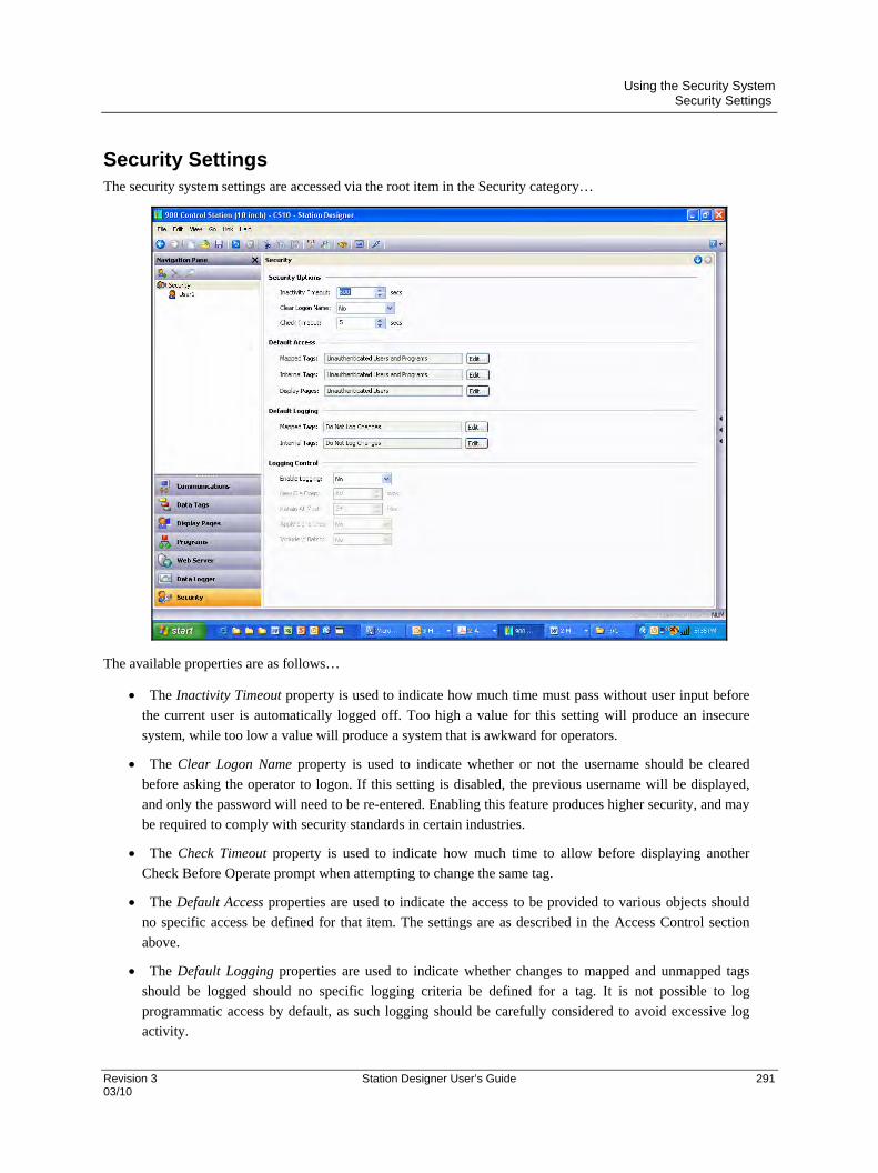
Using the Security System Security Settings
Revision 3 Station Designer User’s Guide 291 03/10
Security Settings The security system settings are accessed via the root item in the Security category…
The available properties are as follows…
The Inactivity Timeout property is used to indicate how much time must pass without user input before
the current user is automatically logged off. Too high a value for this setting will produce an insecure
system, while too low a value will produce a system that is awkward for operators.
The Clear Logon Name property is used to indicate whether or not the username should be cleared
before asking the operator to logon. If this setting is disabled, the previous username will be displayed,
and only the password will need to be re-entered. Enabling this feature produces higher security, and may
be required to comply with security standards in certain industries.
The Check Timeout property is used to indicate how much time to allow before displaying another
Check Before Operate prompt when attempting to change the same tag.
The Default Access properties are used to indicate the access to be provided to various objects should
no specific access be defined for that item. The settings are as described in the Access Control section
above.
The Default Logging properties are used to indicate whether changes to mapped and unmapped tags
should be logged should no specific logging criteria be defined for a tag. It is not possible to log
programmatic access by default, as such logging should be carefully considered to avoid excessive log
activity.
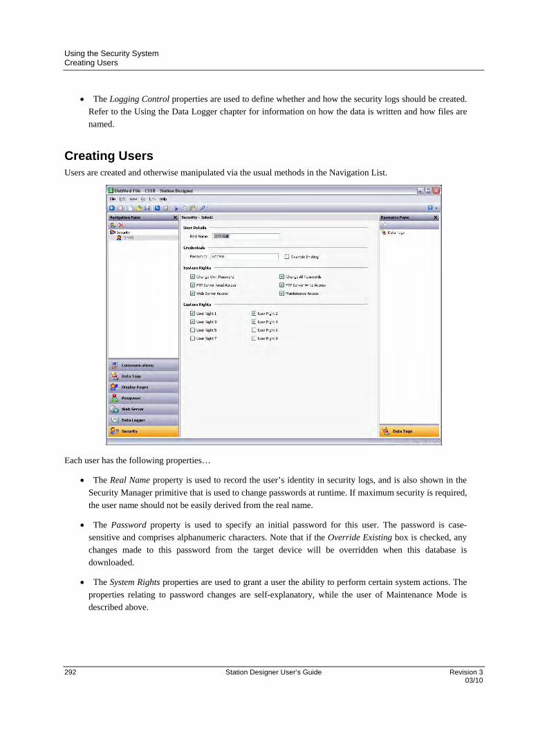
Using the Security System Creating Users
292 Station Designer User’s Guide Revision 3 03/10
The Logging Control properties are used to define whether and how the security logs should be created.
Refer to the Using the Data Logger chapter for information on how the data is written and how files are
named.
Creating Users Users are created and otherwise manipulated via the usual methods in the Navigation List.
Each user has the following properties…
The Real Name property is used to record the user’s identity in security logs, and is also shown in the
Security Manager primitive that is used to change passwords at runtime. If maximum security is required,
the user name should not be easily derived from the real name.
The Password property is used to specify an initial password for this user. The password is case-
sensitive and comprises alphanumeric characters. Note that if the Override Existing box is checked, any
changes made to this password from the target device will be overridden when this database is
downloaded.
The System Rights properties are used to grant a user the ability to perform certain system actions. The
properties relating to password changes are self-explanatory, while the user of Maintenance Mode is
described above.

Using the Security System Creating Users
Revision 3 Station Designer User’s Guide 293 03/10
The Custom Rights properties are used to grant a user certain rights which may then be used within the
database to allow access to groups of tags or display pages. The exact usage of these rights is up to the
system designer.

Using the Security System Specifying Tag Security
294 Station Designer User’s Guide Revision 3 03/10
Specifying Tag Security Each tag has a tab called Security which is used to define the access control and write logging settings for that tag. If
you do not define specific settings, the system will use the appropriate default settings, depending on whether it is
mapped to external data.
Specifying Page Security The required access control settings for display pages are defined via their Properties dialog…
Once again, if no setting is defined, default settings will be used.
Security Related Functions Please refer to Appendix A of this manual for details on the UserLogOn(), UserLogOff() and
TestAccess() functions. This last function is useful when changing many values from within a program, as it
allows you to force an access check early in the code to avoid making changes only to have later operations fail due
to insufficient user rights.
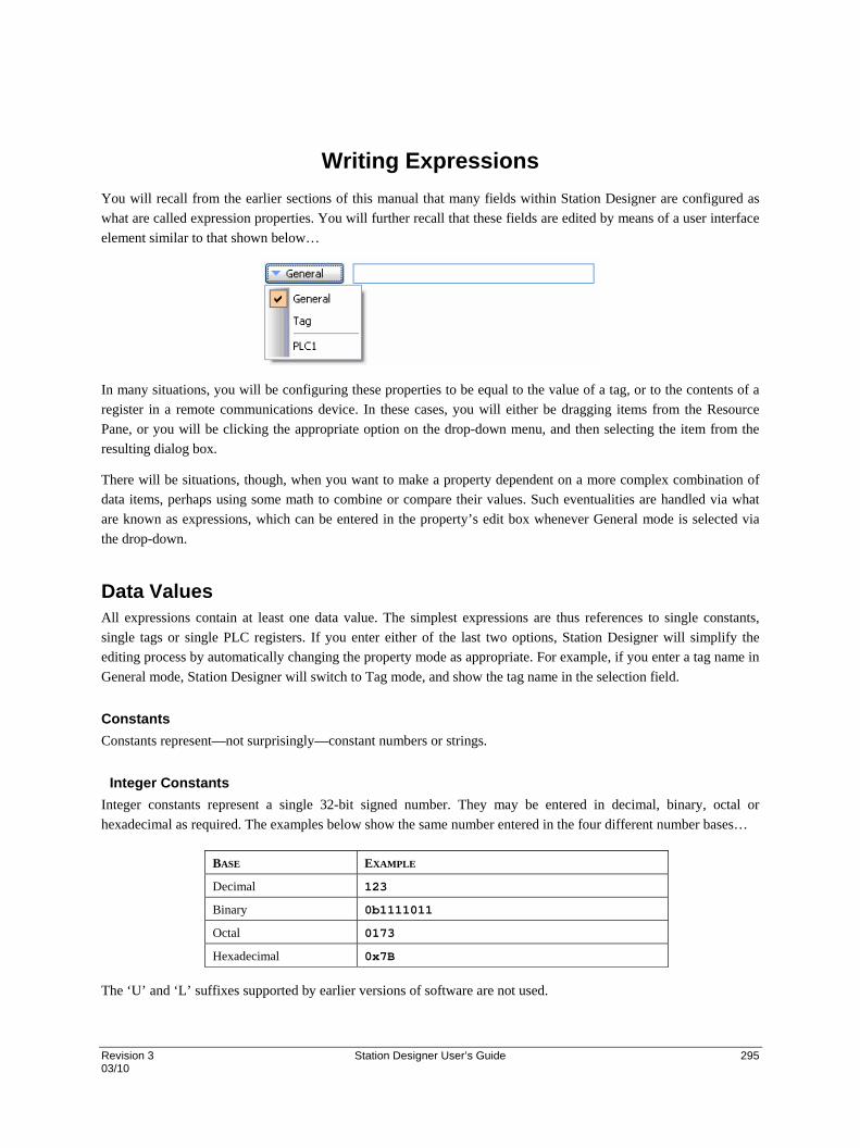
Revision 3 Station Designer User’s Guide 295 03/10
Writing Expressions
You will recall from the earlier sections of this manual that many fields within Station Designer are configured as
what are called expression properties. You will further recall that these fields are edited by means of a user interface
element similar to that shown below…
In many situations, you will be configuring these properties to be equal to the value of a tag, or to the contents of a
register in a remote communications device. In these cases, you will either be dragging items from the Resource
Pane, or you will be clicking the appropriate option on the drop-down menu, and then selecting the item from the
resulting dialog box.
There will be situations, though, when you want to make a property dependent on a more complex combination of
data items, perhaps using some math to combine or compare their values. Such eventualities are handled via what
are known as expressions, which can be entered in the property’s edit box whenever General mode is selected via
the drop-down.
Data Values All expressions contain at least one data value. The simplest expressions are thus references to single constants,
single tags or single PLC registers. If you enter either of the last two options, Station Designer will simplify the
editing process by automatically changing the property mode as appropriate. For example, if you enter a tag name in
General mode, Station Designer will switch to Tag mode, and show the tag name in the selection field.
Constants
Constants represent—not surprisingly—constant numbers or strings.
Integer Constants
Integer constants represent a single 32-bit signed number. They may be entered in decimal, binary, octal or
hexadecimal as required. The examples below show the same number entered in the four different number bases…
BASE EXAMPLE
Decimal 123
Binary 0b1111011
Octal 0173
Hexadecimal 0x7B
The ‘U’ and ‘L’ suffixes supported by earlier versions of software are not used.

Writing Expressions Data Values
296 Station Designer User’s Guide Revision 3 03/10
Character Constants
Character constants represent a single Unicode character, encoded in the lower 16 bits of a 32-bit signed number. A
character constant comprises a single character enclosed in single quotation marks, such that 'A' can be used to
represent a value of 65. Certain otherwise unprintable or unrepresentable characters can be encoded using what are
called escape sequences, each of which is introduced with a single backslash…
SEQUENCE VALUE ASCII
\a Hex 0x07, Decimal 7 BEL
\t Hex 0x09, Decimal 9 TAB
\n Hex 0x0A, Decimal 10 LF
\f Hex 0x0C, Decimal 12 FF
\r Hex 0x0D, Decimal 13 CR
\e Hex 0x1B, Decimal 27 ESC
\xnn The hex value represented by nn. -
\unnnn The hex value represented by nnnn. -
\nnn The octal value represented by nnn. -
\\ A single backslash character. -
\' A single quotation mark character. -
\" A double quotation mark character. -
Logical Constants
Logical constants represent a 1 or 0 value that is used to indicate the truth or otherwise of a yes-or-no expression. An
example of something that can be assigned to be equal to a logical constant is a tag that represents a digital output in
a PLC. Logical constants can either be entered simply as 1 or 0, or by use of the keywords true or false.
Floating-Point Constants
Floating-point constants represent a 32-bit single-precision floating point value. They are represented as you might
expect—by the integer portion, followed by a single decimal point, followed by the fractional portion. Scientific
notation is also supported by specifying a value for the mantissa and following this with an ‘E’ and an exponent.
String Constants
String constants represent sequences of characters. They comprise the characters to be represented, enclosed in
double quotation marks. For example, the string "ABCD" represents a four-character string, comprising the values
65, 66, 67 and 68. (Actually, five 16-bit words are used to store the string, with a null value being appended as a
terminator.) The various escape sequences discussed above may also be used within strings.

Writing Expressions Data Values
Revision 3 Station Designer User’s Guide 297 03/10
Tag Values
The value of a tag is represented in an expression by the tag name. Tags that are organized into folders are
represented by the pathname of the tag with each pair of elements being separated by a period. A tag named PV in a
folder named Loop would thus be referenced as Loop.PV. Note that upper-case and lower-case characters are
considered equivalent when finding the required tag. Once an expression has been entered, any changes to the name
of the tag will modify all of the expressions that make reference to it.
Tag Properties
Data tags have certain properties than can be accessed by following a tag name with a period and then with the name
of the required property. The following properties are defined…
PROPERTY DESCRIPTION DATA TYPE
Name The tag’s name. String.
AsText The tag’s value formatted as text. String.
Label The tag’s Label property. String.
Desc The tag’s Description property. String.
Prefix The prefix defined by the tag’s format. String.
Units The units defined by the tag’s format. String.
SP The tag’s setpoint property. Same As Tag.
Min The tag’s lower data entry limit. Same As Tag.
Max The tag’s upper data entry limit. Same As Tag.
Fore The tag’s current foreground color. Integer.
Back The tag’s current background color. Integer.
Page Properties
Display pages also have certain properties that can be accessed in the same way…
PROPERTY DESCRIPTION DATA TYPE
Name The page’s name. String.
Label The page’s Label property. String.
Desc The page’s Description property. String.
Comms References
References to registers in master communications devices can be entered into an expression by means of a syntax
comprising an opening square bracket, the register name, and a closing square bracket. An optional device name
may be prefixed to the register name and separated by a period. The device name is not needed when referring to the
only device in a database.

Writing Expressions Simple Math
298 Station Designer User’s Guide Revision 3 03/10
Examples of this syntax are shown below…
EXAMPLE MEANING
[D100] Register D100 in first device.
[AB.N7:0] Register N7:0 in device AB.
[FX.D100] Register D100 in device FX.
Simple Math As mentioned above, expressions often contain more than one data value, with their values being combined
mathematically. The simplest of these expressions may add a pair of values, while a more complex expression might
obtain the average of three values. These operations are performed using the familiar syntax you will have seen in
applications such as Excel. The examples below show the basic operations that can be performed…
OPERATOR PRIORITY EXAMPLE
Addition Group 4 Tag1 + Tag2
Subtraction Group 4 Tag1 - Tag2
Multiplication Group 3 Tag1 * Tag2
Division Group 3 Tag1 / Tag2
Remainder Group 3 Tag1 % Tag2
Although the examples show spaces surrounding the operators, these are not required.
Operator Priority You will have noticed the Priority column in the above table. As you no doubt recall from your algebra classes,
when several operators are used together, they are evaluated in a defined order. For example, multiplication is
always evaluated before addition. Station Designer implements this ordering by means of what are known as
operator priorities, with each operator being placed in a group, and with operators being applied from the lowest
numbered group to the highest. Except where noted otherwise in the text, operators within a group are evaluated
left-to-right. The default order of evaluation can be overridden by using parentheses.
Type Conversion Normally, Station Designer will automatically decide when to switch from evaluating an expression in integer math
to evaluating it using floating point. For example, if you divide an integer value by a floating point value, the integer
will be converted to floating point before the division is carried out. However, there will be some situations where
you want to force a conversion to take place.

Writing Expressions Comparing Values
Revision 3 Station Designer User’s Guide 299 03/10
For example, suppose you are adding together three integers that represent the levels in three tanks, and then
dividing the total by the tank count to obtain the average level. If you use an expression such as
(Tank1+Tank2+Tank3)/3 then your result may not be as accurate as you demand, as the division will take
place using integer math, and the average will not contain any decimal places. To force Station Designer to evaluate
the result using floating-point math, the simplest technique is to change the 3 to 3.0, thereby forcing Station
Designer to convert the sum to floating point before the division is performed. A slightly more complex technique is
to use syntax such as float(Tank1+Tank2+Tank3)/3. This invokes what is known as a type cast on the term
in parentheses, manually converting it to floating point.
Type casts may also be used to convert a floating-point value to an integer value, perhaps deliberately giving-up
some precision from an intermediate value before storing it in a PLC register. For example, the expression
int(cos(Theta)*100) will calculate the cosine of an angle, multiply this value by 100 using floating-point
math, before converting it to an integer, dropping any digits after the decimal place.
Comparing Values You will quite often find that you wish to compare the value of one data with another, and make a decision based on
the result. For example, you may wish to define a flag formula to show when a tank exceeds a particular value, or
you may wish to use an if statement in a program to execute some code when a motor reaches its desired speed.
The following comparison operators are provided…
OPERATOR PRIORITY EXAMPLE
Equal To Group 7 Data == 100
Not Equal To Group 7 Data != 100
Greater Than Group 6 Data > 100
Greater Than or Equal To Group 6 Data >= 100
Less Than Group 6 Data < 100
Less Than or Equal To Group 6 Data <= 100
Each operator produces a value of 0 or 1, depending on the condition it tests. The operators can be used on integers,
floating point values or strings. If strings are being compared, the comparison is case-insensitive such that “abc” is
considered equal to “ABC”.
Testing Bits Station Designer allows you to test the value of a bit within a data value by using the bit selection operator, which is
represented by a single period. The left-hand side of the operator should be the value in which the bit is to be tested,
and the right-hand side should be an expression indicating the bit number to test. This right-hand value should be
between 0 and 31. The result of the operator is equal to 0 or 1 depending on the value of the bit in question.
OPERATOR PRIORITY EXAMPLE
Bit Selection Group 1 Input.2
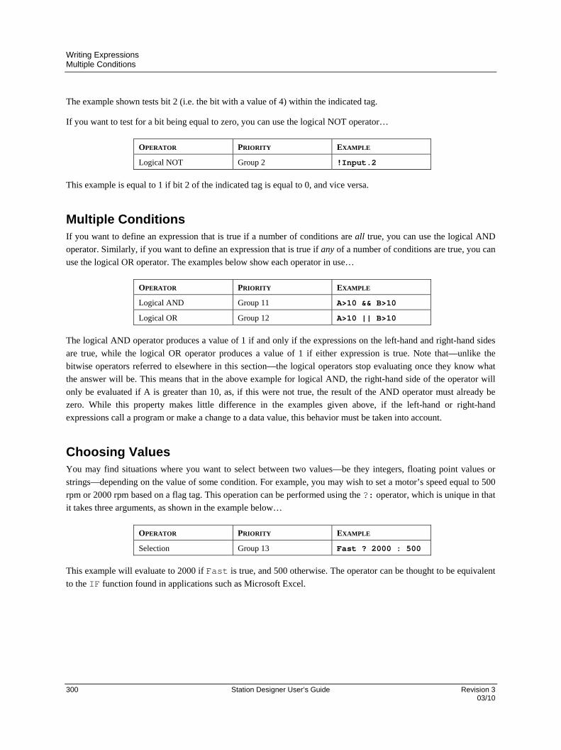
Writing Expressions Multiple Conditions
300 Station Designer User’s Guide Revision 3 03/10
The example shown tests bit 2 (i.e. the bit with a value of 4) within the indicated tag.
If you want to test for a bit being equal to zero, you can use the logical NOT operator…
OPERATOR PRIORITY EXAMPLE
Logical NOT Group 2 !Input.2
This example is equal to 1 if bit 2 of the indicated tag is equal to 0, and vice versa.
Multiple Conditions If you want to define an expression that is true if a number of conditions are all true, you can use the logical AND
operator. Similarly, if you want to define an expression that is true if any of a number of conditions are true, you can
use the logical OR operator. The examples below show each operator in use…
OPERATOR PRIORITY EXAMPLE
Logical AND Group 11 A>10 && B>10
Logical OR Group 12 A>10 || B>10
The logical AND operator produces a value of 1 if and only if the expressions on the left-hand and right-hand sides
are true, while the logical OR operator produces a value of 1 if either expression is true. Note that—unlike the
bitwise operators referred to elsewhere in this section—the logical operators stop evaluating once they know what
the answer will be. This means that in the above example for logical AND, the right-hand side of the operator will
only be evaluated if A is greater than 10, as, if this were not true, the result of the AND operator must already be
zero. While this property makes little difference in the examples given above, if the left-hand or right-hand
expressions call a program or make a change to a data value, this behavior must be taken into account.
Choosing Values You may find situations where you want to select between two values—be they integers, floating point values or
strings—depending on the value of some condition. For example, you may wish to set a motor’s speed equal to 500
rpm or 2000 rpm based on a flag tag. This operation can be performed using the ?: operator, which is unique in that
it takes three arguments, as shown in the example below…
OPERATOR PRIORITY EXAMPLE
Selection Group 13 Fast ? 2000 : 500
This example will evaluate to 2000 if Fast is true, and 500 otherwise. The operator can be thought to be equivalent
to the IF function found in applications such as Microsoft Excel.

Writing Expressions Manipulating Bits
Revision 3 Station Designer User’s Guide 301 03/10
Manipulating Bits Station Designer also provides operators to perform operations that do not treat integers as numeric values, but
instead as sequences of bits. These operators are known as bitwise operators.
And, Or and XOR
These three bitwise operators each produce a result in which each bit is defined to be equal to the corresponding bits
in the values on the operator’s left-hand and right-hand sides, combined using a specific truth-table…
OPERATOR PRIORITY EXAMPLE
Bitwise AND Group 8 Data & Mask
Bitwise OR Group 9 Data | Mask
Bitwise XOR Group 10 Data ^ Mask
The table below shows the associated truth tables…
A B A & B A | B A ^ B
0 0 0 0 0
0 1 0 1 1
1 0 0 1 1
1 1 1 1 0
Shift Operators
Station Designer also provides operators to shift an integer n bits to the left or right…
OPERATOR PRIORITY EXAMPLE
Shift Left Group 5 Data << 2
Shift Right Group 5 Data >> 2
Each example shifts Data two bits in the specified direction.
Bitwise NOT
Finally, Station Designer provides a bitwise NOT operator to invert the sense of the bits in a value…
OPERATOR PRIORITY EXAMPLE
Bitwise NOT Group 2 ~Mask
This example produces a value where every bit is equal to the opposite of its value in Mask.
Writing Expressions Indexing Arrays
302 Station Designer User’s Guide Revision 3 03/10
Indexing Arrays Elements within an array tag can be selected by following the array name with square brackets that contain an
indexing expression. This expression must range from 0 to one less than the number of elements in the array. If you
create a 10-element array, for example, the first element will be Name[0] and the last will be Name[9].
Indexing Strings Square brackets can also be used to select characters within a string. For example, if you have a tag called Text that
contains the string “ABCD”, then the expression Text[0] will return a value of 65, this being equal to the Unicode
value of the first character. Index values beyond the end of the string will always return zero.
Adding Strings As well as adding numbers, the addition operator can be used to concatenate strings. Thus, the expression
"AB"+"CD" evaluates to “ABCD”. You may also use the addition operator to add an integer to a string, in which
case a single character equal to the Unicode representation of the integer is appended to the data in the string.
Calling Programs Programs that return values may be invoked within expressions by following the program name with a pair of
parentheses. For example, Program1()*10 will invoke the associated program, and multiply the return value by
10. Obviously, the return type for Program1 must be set to integer or floating point for this to make sense.
Using Functions Station Designer provides a number of predefined functions that can be used to access system information, or to
perform common math operations. These functions are defined in detail in the Function Reference. They are
invoked using a syntax similar to that for programs, with any arguments to the function being enclosed within the
parentheses. For example, cos(0) will invoke the cosine function with an argument of 0, returning a value of +1.0.
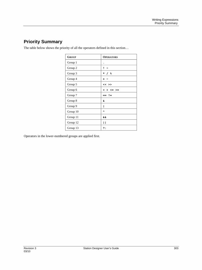
Writing Expressions Priority Summary
Revision 3 Station Designer User’s Guide 303 03/10
Priority Summary The table below shows the priority of all the operators defined in this section…
GROUP OPERATORS
Group 1 .
Group 2 ! ~
Group 3 * / %
Group 4 + -
Group 5 << >>
Group 6 < > <= >=
Group 7 == !=
Group 8 &
Group 9 |
Group 10 ^
Group 11 &&
Group 12 ||
Group 13 ?:
Operators in the lower-numbered groups are applied first.


Revision 3 Station Designer User’s Guide 305 03/10
Writing Actions
While expressions are used to define values, actions are used to define what you want to happen when an event
occurs. The vast majority of the actions in a database will relate to interactions with primitives or with the keyboard.
Since Station Designer provides a simple method of defining commonly-used actions for these items, you will often
be able to avoid writing actions by hand. Actions are needed, though, if you want to use triggers, write programs, or
use a key or primitive in User Defined mode.
Changing Page To create an action that changes the page shown on the panel’s display, use the syntax GotoPage(Name), where Name is the name of the display page in question. The current page will be removed, and the new page will be displayed in its place.
Changing Numeric Values Station Designer provides several ways of changing data values.
Simple Assignment
To create an action that assigns a new value to a tag or to a register in a communications device, use the syntax
Data=Value, where Data is the data item to be changed, and Value is the value to be assigned. Note that
Value need not just be a constant value, but can be any valid expression of the correct type. Refer to the previous
section for details of how to write expressions. For example, code such as [N7:0]=Tank1+Tank2 can be used to
add two tank levels and store the total quantity directly in a PLC register.
Compound Assignment
To create an action that sets a data value equal to its current value combined with another value by means of any of
the operators defined in the previous section, use the syntax Dataop=Value, where Data is the tag to be
changed, Value is the value to be used by the operator, and op is any of the available operators. For example, the
code Tag+=10 will increase Tag by a value of 10, while Tag*=10 will multiply the current value by 10.
Increment and Decrement
To create an action that increases a data value by one, use the syntax Data++. To create an action that decreases a
tag by one, use the syntax Data--. Note that the ++ or -- operators may be placed before or after the data value in
question. In the former case, the value of the expression represented by ++Data is equal to the value of Data after
it has been incremented. In the latter case, the expression is equal to the value before it has changed.

Writing Actions Changing Bit Values
306 Station Designer User’s Guide Revision 3 03/10
Changing Bit Values To change a bit within a tag, use the syntax Data.Bit=1 or Data.Bit=0 to set or clear the bit as required,
where Data is the tag in question and Bit is the zero-based bit number. Note again that the value on the right-hand
side of the = operator can be an expression if desired, such that an example such as Data.1=(Level>10) can be
used to set or clear a bit depending on whether or not a tank level exceeds a preset value.
Running Programs Programs may be invoked within actions by following the program name with a pair of parentheses. For example,
Program1() will invoke the associated program. The program will execute in the foreground or background as
defined by the program’s properties.
Using Functions Station Designer provides a number of predefined functions that can be used to perform various operations. These
functions are defined in detail in the Function Reference. They are invoked using a syntax similar to that for
programs, with any arguments to the function being enclosed within the parentheses. For example,
SetLanguage(1) will set the terminal language to 1.
Operator Priority All assignment operators fall into Group 14. In other words, they will be evaluated after all other operators in an
action. They are also unique in that they group right-to-left. This means that code such as Tag1=Tag2=Tag3=0
can be used to clear all three tags at once.

Revision 3 Station Designer User’s Guide 307 03/10

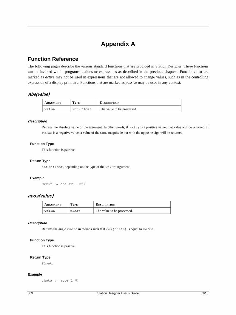
309 Station Designer User’s Guide 03/10
Appendix A
Function Reference The following pages describe the various standard functions that are provided in Station Designer. These functions
can be invoked within programs, actions or expressions as described in the previous chapters. Functions that are
marked as active may not be used in expressions that are not allowed to change values, such as in the controlling
expression of a display primitive. Functions that are marked as passive may be used in any context.
Abs(value)
ARGUMENT TYPE DESCRIPTION
value int / float The value to be processed.
Description
Returns the absolute value of the argument. In other words, if value is a positive value, that value will be returned; if
value is a negative value, a value of the same magnitude but with the opposite sign will be returned.
Function Type
This function is passive.
Return Type
int or float, depending on the type of the value argument.
Example
Error := abs(PV – SP)
acos(value)
ARGUMENT TYPE DESCRIPTION
value float The value to be processed.
Description
Returns the angle theta in radians such that cos(theta) is equal to value.
Function Type
This function is passive.
Return Type
float.
Example
theta := acos(1.0)
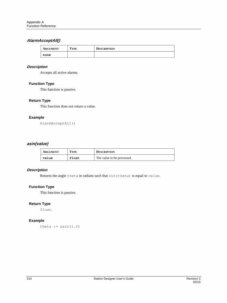
Appendix A Function Reference
310 Station Designer User’s Guide Revision 3 03/10
AlarmAcceptAll()
ARGUMENT TYPE DESCRIPTION
none
Description
Accepts all active alarms.
Function Type
This function is passive.
Return Type
This function does not return a value.
Example
AlarmAcceptAll()
asin(value)
ARGUMENT TYPE DESCRIPTION
value float The value to be processed.
Description
Returns the angle theta in radians such that sin(theta) is equal to value.
Function Type
This function is passive.
Return Type
float.
Example
theta := asin(1.0)
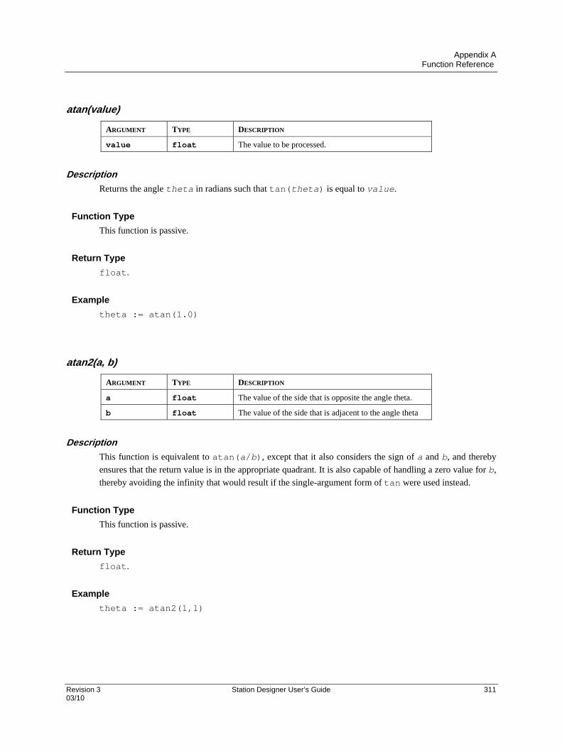
Appendix A Function Reference
Revision 3 Station Designer User’s Guide 311 03/10
atan(value)
ARGUMENT TYPE DESCRIPTION
value float The value to be processed.
Description
Returns the angle theta in radians such that tan(theta) is equal to value.
Function Type
This function is passive.
Return Type
float.
Example
theta := atan(1.0)
atan2(a, b)
ARGUMENT TYPE DESCRIPTION
a float The value of the side that is opposite the angle theta.
b float The value of the side that is adjacent to the angle theta
Description
This function is equivalent to atan(a/b), except that it also considers the sign of a and b, and thereby
ensures that the return value is in the appropriate quadrant. It is also capable of handling a zero value for b,
thereby avoiding the infinity that would result if the single-argument form of tan were used instead.
Function Type
This function is passive.
Return Type
float.
Example
theta := atan2(1,1)

Appendix A Function Reference
312 Station Designer User’s Guide Revision 3 03/10
Beep(freq, period)
ARGUMENT TYPE DESCRIPTION
freq int The required frequency in semitones.
period int The required period in milliseconds.
Description
Sounds the terminal’s beeper for the indicated period at the indicated pitch. Passing a value of zero for
period will turn off the beeper. Beep requests are not queued, so calling the function will immediately
override any previous calls. For those of you with a musical bent, the freq argument is calibrated in
semitones. On a more serious “note”, the Beep function can be a useful debugging aid, as it provides an
asynchronous method of signaling the handling of an event, or the execution of a program step.
Function Type
This function is active.
Return Type
This function does not return a value.
Example
Beep(60, 100)
CanGotoNext()
ARGUMENT TYPE DESCRIPTION
None
Description
Returns a true or false value indicating whether a call to GotoNext() will produce a page change. A
value of false indicates that no further pages exist in the page history buffer.
Function Type
This function is passive.
Return Type
int.
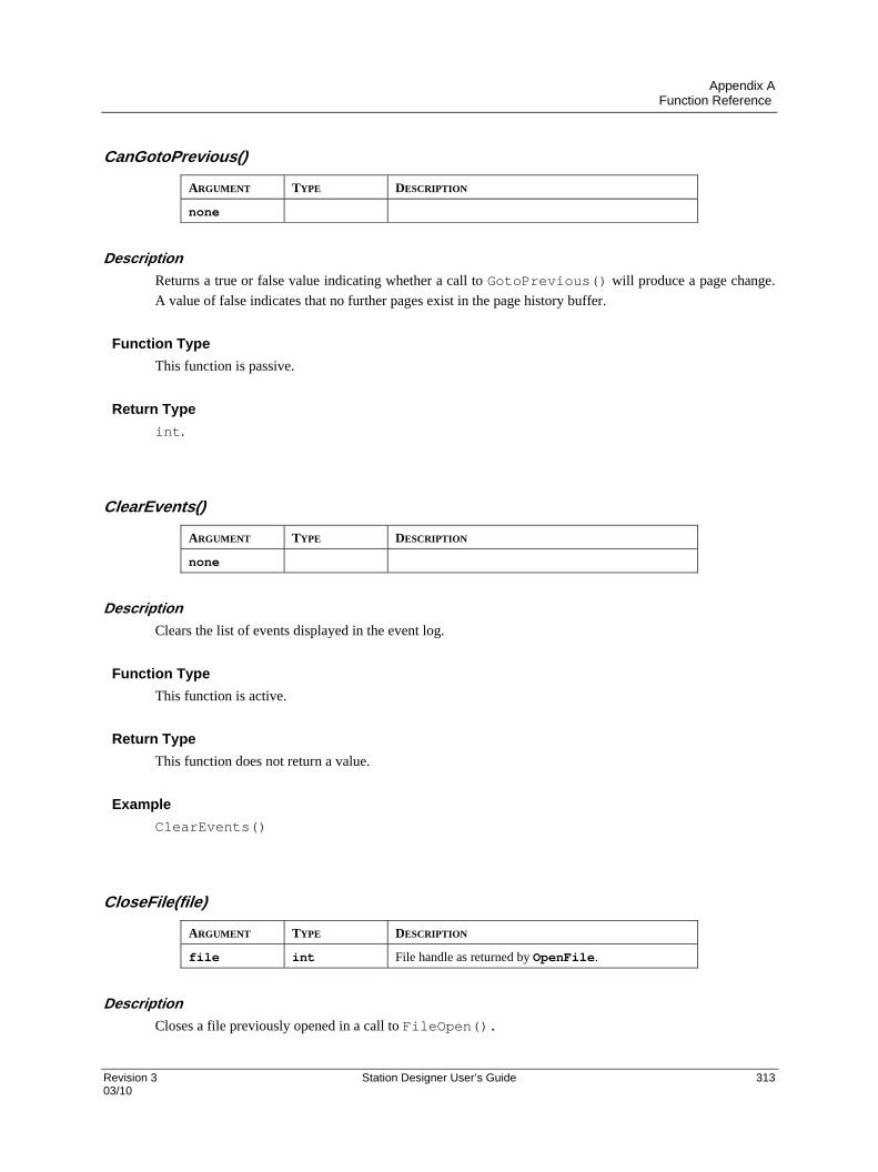
Appendix A Function Reference
Revision 3 Station Designer User’s Guide 313 03/10
CanGotoPrevious()
ARGUMENT TYPE DESCRIPTION
none
Description
Returns a true or false value indicating whether a call to GotoPrevious() will produce a page change.
A value of false indicates that no further pages exist in the page history buffer.
Function Type
This function is passive.
Return Type
int.
ClearEvents()
ARGUMENT TYPE DESCRIPTION
none
Description
Clears the list of events displayed in the event log.
Function Type
This function is active.
Return Type
This function does not return a value.
Example
ClearEvents()
CloseFile(file)
ARGUMENT TYPE DESCRIPTION
file int File handle as returned by OpenFile.
Description
Closes a file previously opened in a call to FileOpen().

Appendix A Function Reference
314 Station Designer User’s Guide Revision 3 03/10
Function Type
This function is active.
Return Type
This function does not return a value.
Example
CloseFile(hFile)
ColBlend(data, min, max, col1, col2)
ARGUMENT TYPE DESCRIPTION
data float The data value to be used to control the operation.
min float The minimum value of data.
max float The maximum value of data.
col1 int First color, selected if data is equal to min.
col2 int Second color, selected if data is equal to max.
Description
Returns a color created by blending two other colors, with the proportion of each color being based upon
the value of data relative to the limits specified by min and max. This function is useful when animating
display primitives by changing their colors.
Function Type
This function is passive.
Return Type
int
ColFlash(freq, col1, col2)
ARGUMENT TYPE DESCRIPTION
freq int Number of times per second to alternate.
col1 int First color.
col2 int Second color.
Description
Returns an alternating color chosen from col1 and col2 that completes a cycle freq times per second. This
function is useful when animating display primitives by changing their colors.
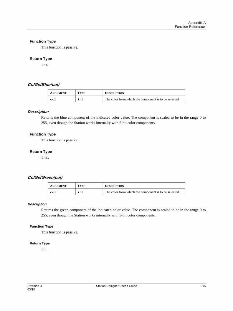
Appendix A Function Reference
Revision 3 Station Designer User’s Guide 315 03/10
Function Type
This function is passive.
Return Type
Int
ColGetBlue(col)
ARGUMENT TYPE DESCRIPTION
col int The color from which the component is to be selected.
Description
Returns the blue component of the indicated color value. The component is scaled to be in the range 0 to
255, even though the Station works internally with 5-bit color components.
Function Type
This function is passive.
Return Type
int.
ColGetGreen(col)
ARGUMENT TYPE DESCRIPTION
col int The color from which the component is to be selected.
Description
Returns the green component of the indicated color value. The component is scaled to be in the range 0 to
255, even though the Station works internally with 5-bit color components.
Function Type
This function is passive.
Return Type
int.

Appendix A Function Reference
316 Station Designer User’s Guide Revision 3 03/10
ColGetRed(col)
ARGUMENT TYPE DESCRIPTION
col int The color from which the component is to be selected.
Description
Returns the red component of the indicated color value. The component is scaled to be in the range 0 to
255, even though the Station works internally with 5-bit color components.
Function Type
This function is passive.
Return Type
int.ColGetRGB(r,g,b)
ARGUMENT TYPE DESCRIPTION
r int The red component.
g int The green component.
b int The blue component.
Description
Returns a color value constructed from the specified components. The components should be in the range 0
to 255, even though the Station works internally with 5-bit color components.
Function Type
This function is passive.
Return Type
int.
ColPick2(pick, col1, col2)
ARGUMENT TYPE DESCRIPTION
pick int The condition to be used to select the color.
col1 int First color, selected if pick is true.
col2 int Second color, selected if pick is false.
Description
Returns one of the indicated colors, depending on the state of pick. Equivalent results can be achieved using
the ?: selection operator.
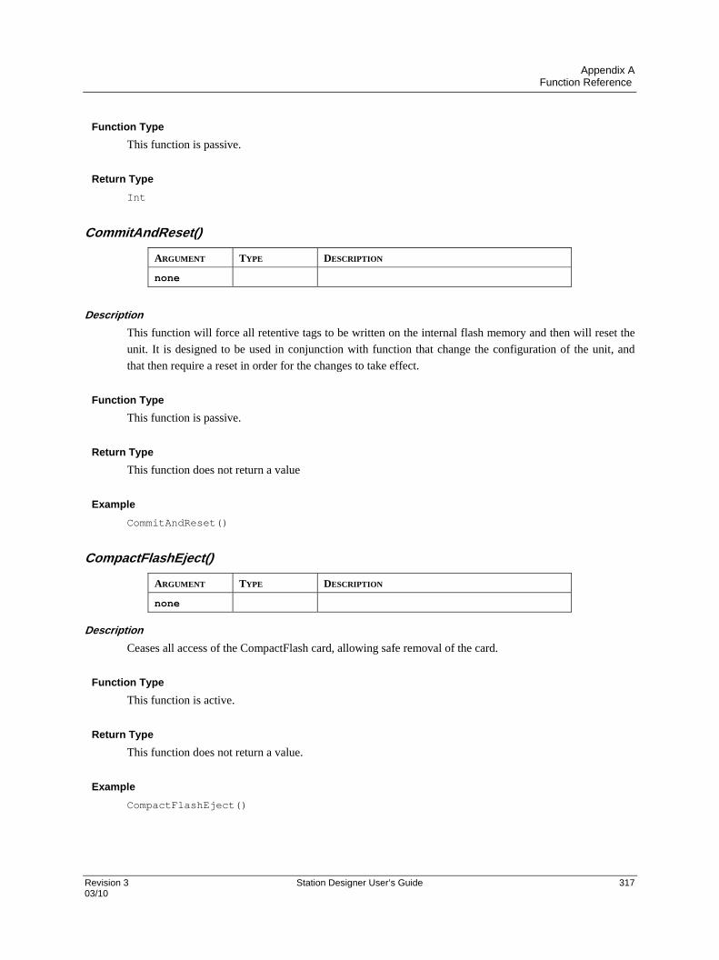
Appendix A Function Reference
Revision 3 Station Designer User’s Guide 317 03/10
Function Type
This function is passive.
Return Type
Int
CommitAndReset()
ARGUMENT TYPE DESCRIPTION
none
Description
This function will force all retentive tags to be written on the internal flash memory and then will reset the
unit. It is designed to be used in conjunction with function that change the configuration of the unit, and
that then require a reset in order for the changes to take effect.
Function Type
This function is passive.
Return Type
This function does not return a value
Example
CommitAndReset()
CompactFlashEject()
ARGUMENT TYPE DESCRIPTION
none
Description
Ceases all access of the CompactFlash card, allowing safe removal of the card.
Function Type
This function is active.
Return Type
This function does not return a value.
Example
CompactFlashEject()

Appendix A Function Reference
318 Station Designer User’s Guide Revision 3 03/10
CompactFlashStatus()
ARGUMENT TYPE DESCRIPTION
none
Description
Returns the current status of the CompactFlash slot as an integer.
VALUE STATE DESCRIPTION
0 Empty Either no card is installed or the card has been ejected via a call to the
CompactFlashEject function.
1 Invalid The card is damaged, incorrectly formatted or not formatted at all.
Remember only FAT16 is supported.
2 Checking The 900 Control Station is checking the status of the card. This state
occurs when a card is first inserted into the Station.
3 Formatting The 900 Control Station is formatting the card. This state occurs when
a format operation is requested by the programming PC.
4 Locked The operator interface is either writing to the card, or the card is
mounted and Windows is accessing the card.
5 Mounted A valid card is installed, but it is not locked by either the operator
interface or Windows.
Function Type
This function is passive.
Return Type
int.
Example
d := CompactFlashStatus()

Appendix A Function Reference
Revision 3 Station Designer User’s Guide 319 03/10
Copy(dest, src, count)
ARGUMENT TYPE DESCRIPTION
dest int / float The first array element to be copied to.
src int / float The first array element to be copied from.
count int The number of elements to be processed.
Description
Copies count array elements from src onwards to dest onwards.
Function Type
This function is active.
Return Type
This function does not return a value.
Example
Copy(Save[0], Work[0], 100)
cos(theta)
ARGUMENT TYPE DESCRIPTION
theta float The angle, in radians, to be processed.
Description
Returns the cosine of the angle theta.
Function Type
This function is passive.
Return Type
float.
Example
xp := radius*cos(theta)

Appendix A Function Reference
320 Station Designer User’s Guide Revision 3 03/10
CreateDirectory(name)
ARGUMENT TYPE DESCRIPTION
name cstring The directory to be created.
Description
Creates a new directory on the CompactFlash card. Note that the filing system used on the card does not
support long filenames, and that if backslashes are included in the pathname to separate path elements, they
must be doubled-up per Station Designer’s rules for string constants as described in the chapter on Writing
Expressions. To avoid this complication, forward slashes can be used in place of backslashes without the
need for such doubling. The function returns a value of one if it succeeds, and a value of zero if it fails.
Function Type
This function is active.
Return Type
int.
Example
Result := CreateDirectory(“/LOGS/LOG1”)
CreateFile(name)
ARGUMENT TYPE DESCRIPTION
name cstring The file to be created.
Description
Creates an empty file on CompactFlash. Note that the filing system used on the card does not support long
filenames, and that if backslashes are included in the pathname to separate path elements, they must be
doubled-up per Station Designer’s rules for string constants as described in the chapter on Writing
Expressions. To avoid this, forward slashes can be used in place of backslashes without the need for such
doubling. The function returns a value of one if it succeeds, and a value of zero if it fails. Note that the file
is not opened after it is created—a subsequent call to OpenFile() must be made to read or write data.
Function Type
This function is active.
Return Type
int.
Example
Success := CreateFile(“/logs/custom/myfile.txt”)
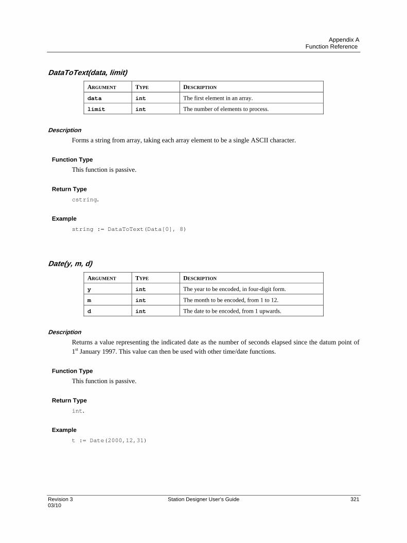
Appendix A Function Reference
Revision 3 Station Designer User’s Guide 321 03/10
DataToText(data, limit)
ARGUMENT TYPE DESCRIPTION
data int The first element in an array.
limit int The number of elements to process.
Description
Forms a string from array, taking each array element to be a single ASCII character.
Function Type
This function is passive.
Return Type
cstring.
Example
string := DataToText(Data[0], 8)
Date(y, m, d)
ARGUMENT TYPE DESCRIPTION
y int The year to be encoded, in four-digit form.
m int The month to be encoded, from 1 to 12.
d int The date to be encoded, from 1 upwards.
Description
Returns a value representing the indicated date as the number of seconds elapsed since the datum point of
1st January 1997. This value can then be used with other time/date functions.
Function Type
This function is passive.
Return Type
int.
Example
t := Date(2000,12,31)

Appendix A Function Reference
322 Station Designer User’s Guide Revision 3 03/10
Deg2Rad(theta)
ARGUMENT TYPE DESCRIPTION
theta float The angle to be processed.
Description
Returns theta converted from degrees to radians.
Function Type
This function is passive.
Return Type
float.
Example
Load := Weight * cos(Deg2Rad(Angle))
DeleteDirectory(name)
ARGUMENT TYPE DESCRIPTION
name cstring The directory to be deleted.
Description
Remove a directory, its subdirectories and contents from the CompactFlash. Note that the filing system
used on the card does not support long filenames, and that if backslashes are included in the pathname to
separate path elements, they must be doubled-up per Station Designer’s rules for string constants as
described in the chapter on Writing Expressions. To avoid this complication, forward slashes can be used in
place of backslashes without the need for such doubling. The function returns a value of one if it succeeds,
and a value of zero if it fails.
Function Type
This function is active.
Return Type
int.
Example
Success := DeleteDirectory(“/logs/custom”)

Appendix A Function Reference
Revision 3 Station Designer User’s Guide 323 03/10
DeleteFile(file)
ARGUMENT TYPE DESCRIPTION
file int File handle as returned by OpenFile.
Description
Closes and then deletes a file located on the CompactFlash card.
Function Type
This function is active.
Return Type
int.
Example
Result := DeleteFile(hFile)
DispOff()
ARGUMENT TYPE DESCRIPTION
none float Turns backlight to display off.
Description
Turns backlight to display off.
Function Type
This function is active.
Return Type
This function does not return a value.
Example
DispOff()
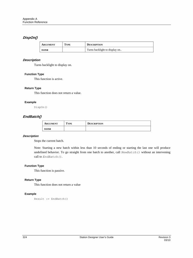
Appendix A Function Reference
324 Station Designer User’s Guide Revision 3 03/10
DispOn()
ARGUMENT TYPE DESCRIPTION
none Turns backlight to display on..
Description
Turns backlight to display on.
Function Type
This function is active.
Return Type
This function does not return a value.
Example
DispOn()
EndBatch()
ARGUMENT TYPE DESCRIPTION
none
Description
Stops the current batch.
Note: Starting a new batch within less than 10 seconds of ending or starting the last one will produce
undefined behavior. To go straight from one batch to another, call NewBatch() without an intervening
call to EndBatch().
Function Type
This function is passive.
Return Type
This function does not return a value
Example
Result := EndBatch()
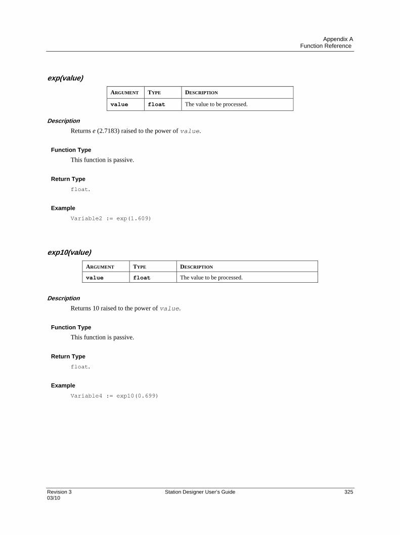
Appendix A Function Reference
Revision 3 Station Designer User’s Guide 325 03/10
exp(value)
ARGUMENT TYPE DESCRIPTION
value float The value to be processed.
Description
Returns e (2.7183) raised to the power of value.
Function Type
This function is passive.
Return Type
float.
Example
Variable2 := exp(1.609)
exp10(value)
ARGUMENT TYPE DESCRIPTION
value float The value to be processed.
Description
Returns 10 raised to the power of value.
Function Type
This function is passive.
Return Type
float.
Example
Variable4 := exp10(0.699)

Appendix A Function Reference
326 Station Designer User’s Guide Revision 3 03/10
Fill(element, data, count)
ARGUMENT TYPE DESCRIPTION
element int / float The first array element to be processed.
data int / float The data value to be written.
count int The number of elements to be processed.
Description
Sets count array elements from element onwards to be equal to data.
Function Type
This function is active.
Return Type
This function does not return a value.
Example
Fill(List[0], 0, 100)
Find(string,char,skip)
ARGUMENT TYPE DESCRIPTION
string cstring The string to be processed.
char int The character to be found.
skip int The number of times the character is skipped.
Description
Returns the position of char in string, taking into account the number of skip occurrences specified.
The first position counted is 0. Returns -1 if char is not found. In the example below, the position of “:”,
skipping the first occurrence is 7.
Function Type
This function is passive.
Return Type
int
Example
Position := Find("one:two:three",':',1)

Appendix A Function Reference
Revision 3 Station Designer User’s Guide 327 03/10
FindFileFirst(dir)
ARGUMENT TYPE DESCRIPTION
dir cstring Directory to be used in search.
Description
Returns the filename of name of the first file or directory located in the dir directory on the CompactFlash
card. Returns an empty string if no files exist or if no card is present. This function can be used with the
FindFileNext function to scan all files in a given directory.
Function Type
This function is active.
Return Type
cstring.
Example
Name := FindFileFirst(“/LOGS/LOG1”)
FindFileNext()
ARGUMENT TYPE DESCRIPTION
none
Description
Returns the filename of the next file or directory in the directory specified in a previous call to the
FindFileFirst function. Returns and empty string if no more files exist. This function can be used
with the FindFileFirst function to scan all files in a given directory.
Function Type
This function is active.
Return Type
cstring.
Example
Name := FindFileNext()

Appendix A Function Reference
328 Station Designer User’s Guide Revision 3 03/10
Flash(freq)
ARGUMENT TYPE DESCRIPTION
freq Int Number of times per second to flash.
Description
Returns an alternating true or false value that completes a cycle freq times per second. This function is
useful when animating display primitives or changing their colors.
Function Type
This function is passive.
Return Type
Int
FormatCompactFlash()
ARGUMENT TYPE DESCRIPTION
none
Description
Formats the CompactFlash card in the terminal, thereby deleting all data on the card. You should thus
ensure that the user is given appropriate warnings before this function is invoked.
Function Type
This function is active.
Return Type
This function does not return a value.
Example
FormatCompactFlash()
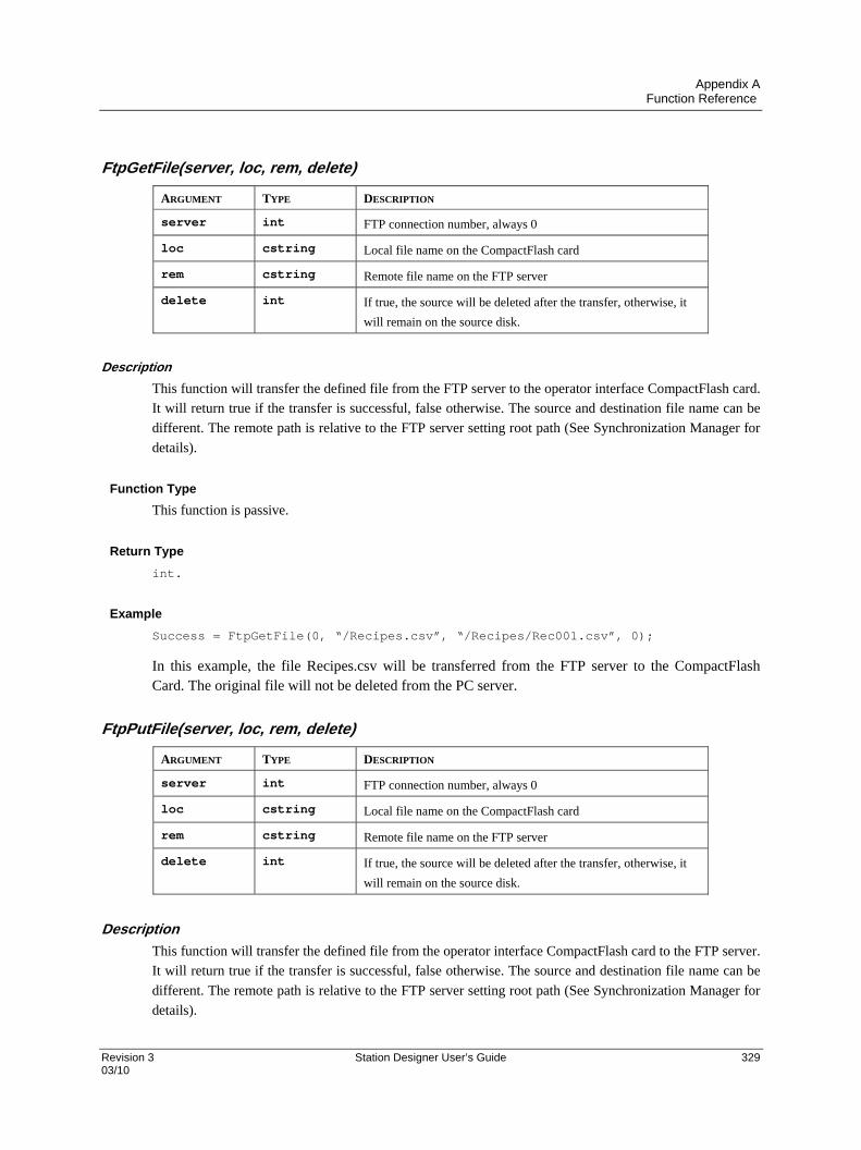
Appendix A Function Reference
Revision 3 Station Designer User’s Guide 329 03/10
FtpGetFile(server, loc, rem, delete)
ARGUMENT TYPE DESCRIPTION
server int FTP connection number, always 0
loc cstring Local file name on the CompactFlash card
rem cstring Remote file name on the FTP server
delete int If true, the source will be deleted after the transfer, otherwise, it
will remain on the source disk.
Description
This function will transfer the defined file from the FTP server to the operator interface CompactFlash card.
It will return true if the transfer is successful, false otherwise. The source and destination file name can be
different. The remote path is relative to the FTP server setting root path (See Synchronization Manager for
details).
Function Type
This function is passive.
Return Type
int.
Example
Success = FtpGetFile(0, “/Recipes.csv”, “/Recipes/Rec001.csv”, 0);
In this example, the file Recipes.csv will be transferred from the FTP server to the CompactFlash Card. The original file will not be deleted from the PC server.
FtpPutFile(server, loc, rem, delete)
ARGUMENT TYPE DESCRIPTION
server int FTP connection number, always 0
loc cstring Local file name on the CompactFlash card
rem cstring Remote file name on the FTP server
delete int If true, the source will be deleted after the transfer, otherwise, it
will remain on the source disk.
Description
This function will transfer the defined file from the operator interface CompactFlash card to the FTP server.
It will return true if the transfer is successful, false otherwise. The source and destination file name can be
different. The remote path is relative to the FTP server setting root path (See Synchronization Manager for
details).

Appendix A Function Reference
330 Station Designer User’s Guide Revision 3 03/10
Function Type
This function is passive.
Return Type
int.
Example
Success = FtpPutFile(0, “/LOGS/Report.txt”, “/Reports/Report.txt”, 1)
In this example, the file Report.txt will be sent to the FTP server and deleted from the CompactFlash Card
upon success of the transfer.
GetBatch()
ARGUMENT TYPE DESCRIPTION
none
Description
Returns the name of the current batch.
Function Type
This function is passive.
Return Type
cstring.
Example
CurrentBatch := GetBatch()
GetDate (time) and Family
ARGUMENT TYPE DESCRIPTION
time int The time value to be decoded.
Description
Each member of this family of functions returns some component of a time/date value, as previously
created by GetNow, Time or Date. The available functions are as follows…
FUNCTION DESCRIPTION
GetDate Returns the day-of-month portion of time.
GetDay Returns the day-of-week portion of time.
GetDays Returns the number of days in time.
GetHour Returns the hours portion of time.

Appendix A Function Reference
Revision 3 Station Designer User’s Guide 331 03/10
FUNCTION DESCRIPTION
GetMin Returns the minutes portion of time.
GetMonth Returns the month portion of time.
GetSec Returns the seconds portion of time.
GetWeek Returns the week-of-year portion of time.
GetWeeks Returns the number of weeks in time.
GetWeekYear Returns the week year when using week numbers.
GetYear Returns the year portion of time.
Note that GetDays and GetWeeks are typically used with the difference between two time values to
calculate how long has elapsed in terms of days or weeks. Note also that the year returned by
GetWeekYear is not always the same as that returned by GetYear, as the former may return a smaller
value if the last week of a year extends beyond year-end.
Function Type
These functions are passive.
Return Type
int.
Example
d := GetDate(GetNow() – 12*60*60)
GetDiskFreeBytes(drive)
ARGUMENT TYPE DESCRIPTION
drive int The drive number, always 0.
Description
Returns the number of free memory bytes on the CompactFlash Card.
Note: This function requires time to calculate free memory space, as a long CompactFlash access is
necessary. Do NOT call this function permanently with on tick, on update or in a formula. Call it upon an
event such as OnSelect on the page you want to display the resulting value.
Function Type
This function is passive.
Return Type
int.
Example
FreeMemory = GetDiskFreeBytes(0)

Appendix A Function Reference
332 Station Designer User’s Guide Revision 3 03/10
GetDiskFreePercent(drive)
ARGUMENT TYPE DESCRIPTION
drive int The drive number, always 0.
Description
Returns the percentage of free memory space on the CompactFlash Card.
Note: This function requires time to calculate free memory space, as a long CompactFlash access is
necessary. Do NOT call this function permanently with on tick, on update or in a formula. Call it upon an
event such as OnSelect on the page you want to display the resulting value.
Function Type
This function is passive.
Return Type
int.
Example
FreeMemory = GetDiskFreePercent(0)
GetDiskSizeBytes(drive)
ARGUMENT TYPE DESCRIPTION
drive int The drive number, always 0.
Description
Returns the size in bytes of the CompactFlash Card.
Note: This function requires time to calculate free memory space, as a long CompactFlash access is
necessary. Do NOT call this function permanently with on tick, on update or in a formula. Call it upon an
event such as OnSelect on the page you want to display the resulting value.
Function Type
This function is passive.
Return Type
int.
Example
CFSyze = GetDiskSyzeBytes(0)
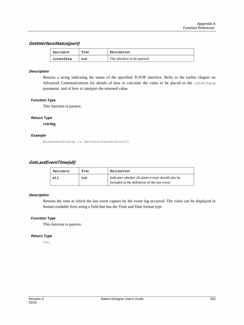
Appendix A Function Reference
Revision 3 Station Designer User’s Guide 333 03/10
GetInterfaceStatus(port)
ARGUMENT TYPE DESCRIPTION
interface int The interface to be queried.
Description
Returns a string indicating the status of the specified TCP/IP interface. Refer to the earlier chapter on
Advanced Communications for details of how to calculate the value to be placed in the interface
parameter, and of how to interpret the returned value.
Function Type
This function is passive.
Return Type
cstring.
Example
EthernentStatus := GetInterfaceStatus(1)
GetLastEventTime(all)
ARGUMENT TYPE DESCRIPTION
all int Indicates whether all alarm events should also be included in the definition of the last event.
Description
Returns the time at which the last event capture by the event log occurred. The value can be displayed in
human-readable form using a field that has the Time and Date format type.
Function Type
This function is passive.
Return Type
int.
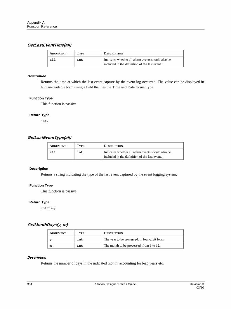
Appendix A Function Reference
334 Station Designer User’s Guide Revision 3 03/10
GetLastEventTime(all)
ARGUMENT TYPE DESCRIPTION
all int Indicates whether all alarm events should also be included in the definition of the last event.
Description
Returns the time at which the last event capture by the event log occurred. The value can be displayed in
human-readable form using a field that has the Time and Date format type.
Function Type
This function is passive.
Return Type
int.
GetLastEventType(all)
ARGUMENT TYPE DESCRIPTION
all int Indicates whether all alarm events should also be included in the definition of the last event.
Description
Returns a string indicating the type of the last event captured by the event logging system.
Function Type
This function is passive.
Return Type
cstring.
GetMonthDays(y, m)
ARGUMENT TYPE DESCRIPTION
y int The year to be processed, in four-digit form.
m int The month to be processed, from 1 to 12.
Description
Returns the number of days in the indicated month, accounting for leap years etc.
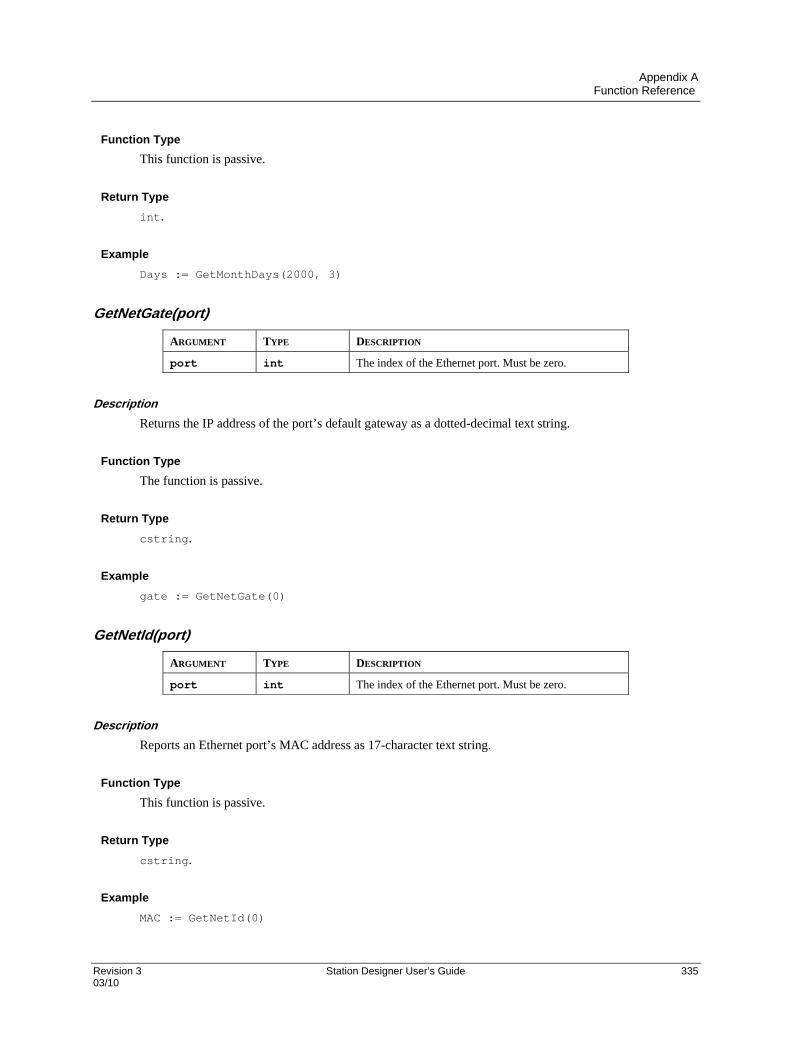
Appendix A Function Reference
Revision 3 Station Designer User’s Guide 335 03/10
Function Type
This function is passive.
Return Type
int.
Example
Days := GetMonthDays(2000, 3)
GetNetGate(port)
ARGUMENT TYPE DESCRIPTION
port int The index of the Ethernet port. Must be zero.
Description
Returns the IP address of the port’s default gateway as a dotted-decimal text string.
Function Type
The function is passive.
Return Type
cstring.
Example
gate := GetNetGate(0)
GetNetId(port)
ARGUMENT TYPE DESCRIPTION
port int The index of the Ethernet port. Must be zero.
Description
Reports an Ethernet port’s MAC address as 17-character text string.
Function Type
This function is passive.
Return Type
cstring.
Example
MAC := GetNetId(0)

Appendix A Function Reference
336 Station Designer User’s Guide Revision 3 03/10
GetNetIp(port)
ARGUMENT TYPE DESCRIPTION
port int The index of the Ethernet port. Must be zero.
Description
Reports an Ethernet port’s IP address as a dotted-decimal text string.
Function Type
This function is passive.
Return Type
cstring.
Example
IP := GetNetIp(0)
GetNetMask(port)
ARGUMENT TYPE DESCRIPTION
port int The index of the Ethernet port. Must be zero.
Description
Reports an Ethernet port’s IP address mask as a dotted-decimal text string.
Function Type
This function is passive.
Return Type
cstring.
Example
mask := GetNetMask(0)
GetNow()
ARGUMENT TYPE DESCRIPTION
none
Description
Returns the current time and date as the number of seconds elapsed since the datum point of 1st January
1997. This value can then be used with other time/date functions.

Appendix A Function Reference
Revision 3 Station Designer User’s Guide 337 03/10
Function Type
This function is passive.
Return Type
int.
Example
t := GetNow()
GetNowDate()
ARGUMENT TYPE DESCRIPTION
none
Description
Returns the number of seconds in the days that have passed since 1st of January 1997.
Function Type
This function is passive.
Return Type
int.
*Example
d: = GetNowDate()
GetNowTime()
ARGUMENT TYPE DESCRIPTION
none
Description
Returns the time of day in terms of seconds.
Function Type
This function is passive.
Return Type
int.
Example
t := GetNowTime()
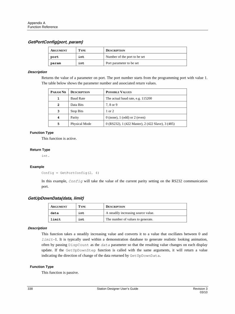
Appendix A Function Reference
338 Station Designer User’s Guide Revision 3 03/10
GetPortConfig(port, param)
ARGUMENT TYPE DESCRIPTION
port int Number of the port to be set
param int Port parameter to be set
Description
Returns the value of a parameter on port. The port number starts from the programming port with value 1.
The table below shows the parameter number and associated return values.
PARAM NB DESCRIPTION POSSIBLE VALUES
1 Baud Rate The actual baud rate, e.g. 115200
2 Data Bits 7, 8 or 9
3 Stop Bits 1 or 2
4 Parity 0 (none), 1 (odd) or 2 (even)
5 Physical Mode 0 (RS232), 1 (422 Master), 2 (422 Slave), 3 (485)
Function Type
This function is active.
Return Type
int.
Example
Config = GetPortConfig(2, 4)
In this example, Config will take the value of the current parity setting on the RS232 communication
port.
GetUpDownData(data, limit)
ARGUMENT TYPE DESCRIPTION
data int A steadily increasing source value.
limit int The number of values to generate.
Description
This function takes a steadily increasing value and converts it to a value that oscillates between 0 and
limit–1. It is typically used within a demonstration database to generate realistic looking animation,
often by passing DispCount as the data parameter so that the resulting value changes on each display
update. If the GetUpDownStep function is called with the same arguments, it will return a value
indicating the direction of change of the data returned by GetUpDownData.
Function Type
This function is passive.

Appendix A Function Reference
Revision 3 Station Designer User’s Guide 339 03/10
Return Type
int.
Example
Data := GetUpDownData(DispCount, 100)
GetUpDownStep(data, limit)
ARGUMENT TYPE DESCRIPTION
data int A steadily increasing source value.
limit int The number of values to generate.
Description
See GetUpDownData for a description of this function.
Function Type
This function is passive.
Return Type
int.
Example
Delta := GetUpDownStep(DispCount, 100)
GotoNext()
ARGUMENT TYPE DESCRIPTION
None
Description
Causes the panel to move forwards again in the page history buffer, reversing the result of a previous call to
GotoPrevious(). The portion of the history buffer accessible via this function will be cleared if the
GotoPage() function is called.
Function Type
This function is active.
Return Type
This function does not return a value.
Example
GotoNext()

Appendix A Function Reference
340 Station Designer User’s Guide Revision 3 03/10
GotoPage(name)
ARGUMENT TYPE DESCRIPTION
name Display Page The page to be displayed.
Description
Selects page name to be shown on the Station’s display.
Function Type
This function is active.
Return Type
This function does not return a value.
Example
GotoPage(Page1)
GotoPrevious()
ARGUMENT TYPE DESCRIPTION
none
Description
Causes the panel to return to the previous page shown on the Station’s display.
Function Type
This function is active.
Return Type
This function does not return a value.
Example
GotoPrevious()

Appendix A Function Reference
Revision 3 Station Designer User’s Guide 341 03/10
HasAccess (rights)
ARGUMENT TYPE DESCRIPTION
rights int The required access rights.
Description
Returns a value of true or false depending on whether the current user has access rights defined by the
rights parameter. This parameter comprises a bit-mask representing the various user-defined rights, with
bit 0 (i.e. the bit with a value of 0x01) representing User Right 1, bit 1 (i.e. the bit with a value of 0x02)
representing User Right 2 and so on. The function is typically used in programs that perform a number of
actions that might be subject to security, and that might otherwise not occur.
Function Type
This function is passive.
Return Type
int
Example
if( HasAccess(1)) {
Data1 := 0;
Data2 := 0;
Data3 := 0;
}
HidePopup()
ARGUMENT TYPE DESCRIPTION
none
Description
Hides the popup that was previously shown using ShowPopup.
Function Type
This function is active.
Return Type
This function does not return a value.
Example
HidePopup()
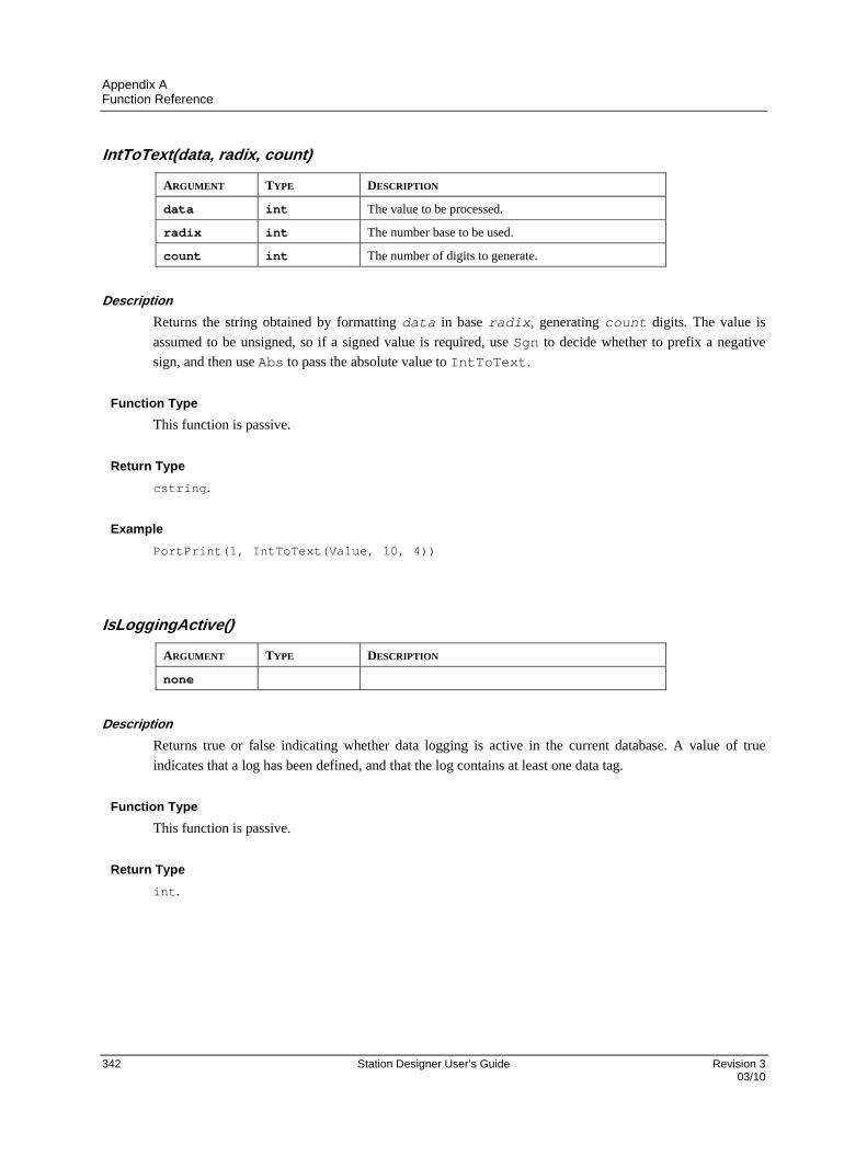
Appendix A Function Reference
342 Station Designer User’s Guide Revision 3 03/10
IntToText(data, radix, count)
ARGUMENT TYPE DESCRIPTION
data int The value to be processed.
radix int The number base to be used.
count int The number of digits to generate.
Description
Returns the string obtained by formatting data in base radix, generating count digits. The value is
assumed to be unsigned, so if a signed value is required, use Sgn to decide whether to prefix a negative
sign, and then use Abs to pass the absolute value to IntToText.
Function Type
This function is passive.
Return Type
cstring.
Example
PortPrint(1, IntToText(Value, 10, 4))
IsLoggingActive()
ARGUMENT TYPE DESCRIPTION
none
Description
Returns true or false indicating whether data logging is active in the current database. A value of true
indicates that a log has been defined, and that the log contains at least one data tag.
Function Type
This function is passive.
Return Type
int.
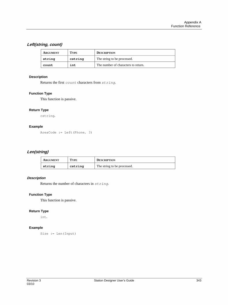
Appendix A Function Reference
Revision 3 Station Designer User’s Guide 343 03/10
Left(string, count)
ARGUMENT TYPE DESCRIPTION
string cstring The string to be processed.
count int The number of characters to return.
Description
Returns the first count characters from string.
Function Type
This function is passive.
Return Type
cstring.
Example
AreaCode := Left(Phone, 3)
Len(string)
ARGUMENT TYPE DESCRIPTION
string cstring The string to be processed.
Description
Returns the number of characters in string.
Function Type
This function is passive.
Return Type
int.
Example
Size := Len(Input)

Appendix A Function Reference
344 Station Designer User’s Guide Revision 3 03/10
Log(value)
ARGUMENT TYPE DESCRIPTION
value float The value to be processed.
Description
Returns the natural log of value.
Function Type
This function is passive.
Return Type
float.
Example
Variable1 := log(5.0)
Log10(value)
ARGUMENT TYPE DESCRIPTION
value float The value to be processed.
Description
Returns the base-10 log of value.
Function Type
This function is passive.
Return Type
float.
Example
Variable3 := log10(5.0)
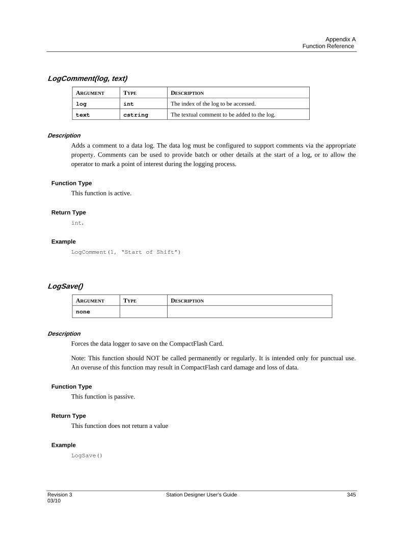
Appendix A Function Reference
Revision 3 Station Designer User’s Guide 345 03/10
LogComment(log, text)
ARGUMENT TYPE DESCRIPTION
log int The index of the log to be accessed.
text cstring The textual comment to be added to the log.
Description
Adds a comment to a data log. The data log must be configured to support comments via the appropriate
property. Comments can be used to provide batch or other details at the start of a log, or to allow the
operator to mark a point of interest during the logging process.
Function Type
This function is active.
Return Type
int.
Example
LogComment(1, “Start of Shift”)
LogSave()
ARGUMENT TYPE DESCRIPTION
none
Description
Forces the data logger to save on the CompactFlash Card.
Note: This function should NOT be called permanently or regularly. It is intended only for punctual use.
An overuse of this function may result in CompactFlash card damage and loss of data.
Function Type
This function is passive.
Return Type
This function does not return a value
Example
LogSave()
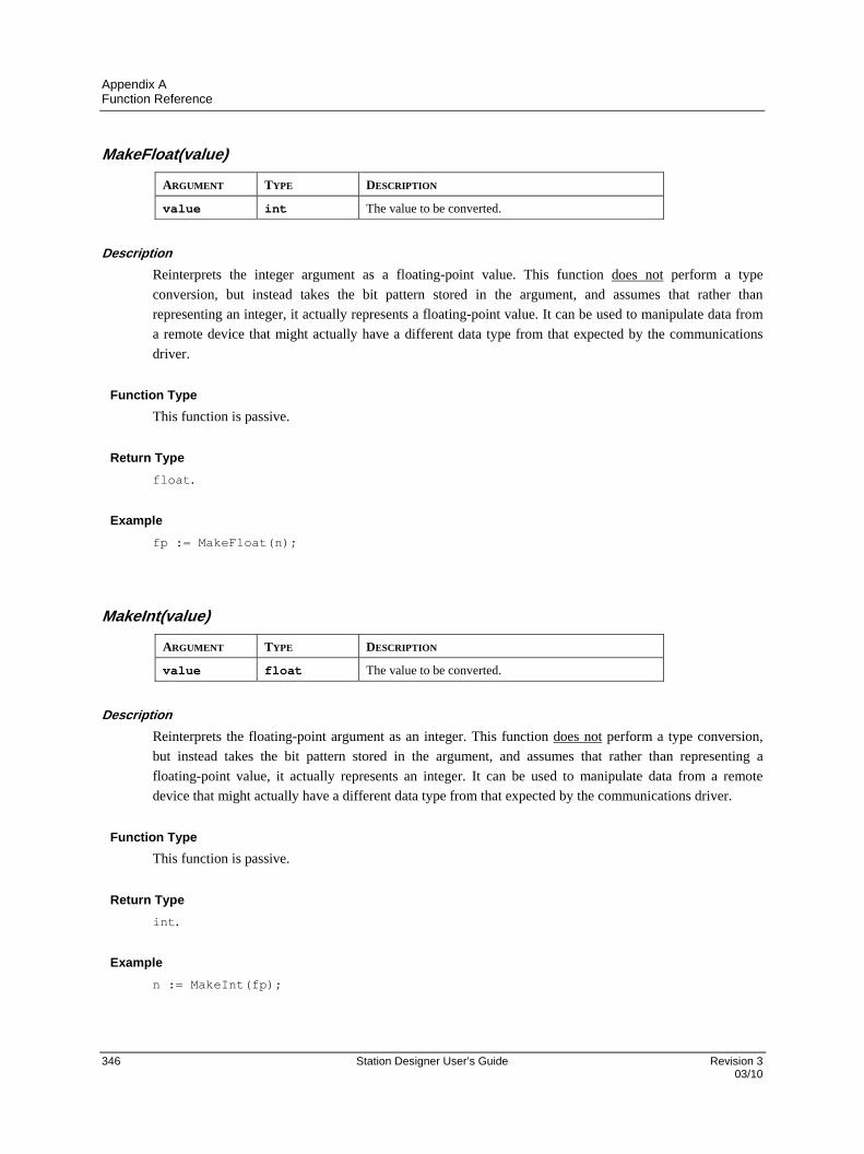
Appendix A Function Reference
346 Station Designer User’s Guide Revision 3 03/10
MakeFloat(value)
ARGUMENT TYPE DESCRIPTION
value int The value to be converted.
Description
Reinterprets the integer argument as a floating-point value. This function does not perform a type
conversion, but instead takes the bit pattern stored in the argument, and assumes that rather than
representing an integer, it actually represents a floating-point value. It can be used to manipulate data from
a remote device that might actually have a different data type from that expected by the communications
driver.
Function Type
This function is passive.
Return Type
float.
Example
fp := MakeFloat(n);
MakeInt(value)
ARGUMENT TYPE DESCRIPTION
value float The value to be converted.
Description
Reinterprets the floating-point argument as an integer. This function does not perform a type conversion,
but instead takes the bit pattern stored in the argument, and assumes that rather than representing a
floating-point value, it actually represents an integer. It can be used to manipulate data from a remote
device that might actually have a different data type from that expected by the communications driver.
Function Type
This function is passive.
Return Type
int.
Example
n := MakeInt(fp);

Appendix A Function Reference
Revision 3 Station Designer User’s Guide 347 03/10
Max(a, b)
ARGUMENT TYPE DESCRIPTION
a int / float The first value to be compared.
b int / float The second value to be compared.
Description
Returns the larger of the two arguments.
Function Type
This function is passive.
Return Type
int or float, depending on the type of the arguments.
Example
Larger := Max(Tank1, Tank2)
Mean(element, count)
ARGUMENT TYPE DESCRIPTION
element int / float The first array element to be processed.
count int The number of elements to be processed.
Description
Returns the mean of the count array elements from element onwards.
Function Type
This function is passive.
Return Type
float.
Example
Average := Mean(Data[0], 10)
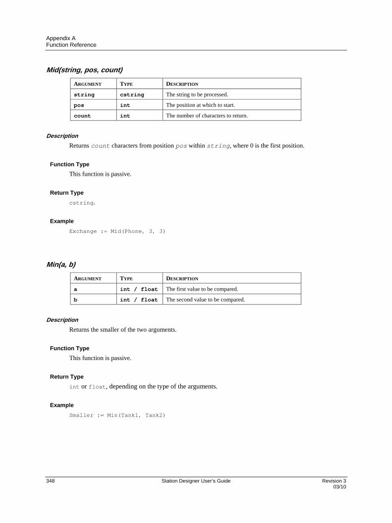
Appendix A Function Reference
348 Station Designer User’s Guide Revision 3 03/10
Mid(string, pos, count)
ARGUMENT TYPE DESCRIPTION
string cstring The string to be processed.
pos int The position at which to start.
count int The number of characters to return.
Description
Returns count characters from position pos within string, where 0 is the first position.
Function Type
This function is passive.
Return Type
cstring.
Example
Exchange := Mid(Phone, 3, 3)
Min(a, b)
ARGUMENT TYPE DESCRIPTION
a int / float The first value to be compared.
b int / float The second value to be compared.
Description
Returns the smaller of the two arguments.
Function Type
This function is passive.
Return Type
int or float, depending on the type of the arguments.
Example
Smaller := Min(Tank1, Tank2)

Appendix A Function Reference
Revision 3 Station Designer User’s Guide 349 03/10
MulDiv(a, b, c)
ARGUMENT TYPE DESCRIPTION
a int First value.
b int Second value.
c int Third value.
Description
Returns a*b/c. The intermediate math is done with 64-bit integers to avoid overflows.
Function Type
This function is passive.
Return Type
int.
Example
d := MulDiv(a, b, c)
MuteSiren()
ARGUMENT TYPE DESCRIPTION
none
Description
Turns off the operator panel’s internal siren.
Function Type
This function is active.
Return Type
This function does not return a value.
Example
MuteSiren()
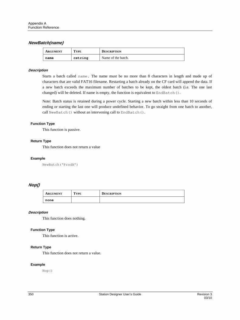
Appendix A Function Reference
350 Station Designer User’s Guide Revision 3 03/10
NewBatch(name)
ARGUMENT TYPE DESCRIPTION
name cstring Name of the batch.
Description
Starts a batch called name. The name must be no more than 8 characters in length and made up of
characters that are valid FAT16 filename. Restarting a batch already on the CF card will append the data. If
a new batch exceeds the maximum number of batches to be kept, the oldest batch (i.e. The one last
changed) will be deleted. If name is empty, the function is equivalent to EndBatch().
Note: Batch status is retained during a power cycle. Starting a new batch within less than 10 seconds of
ending or starting the last one will produce undefined behavior. To go straight from one batch to another,
call NewBatch() without an intervening call to EndBatch().
Function Type
This function is passive.
Return Type
This function does not return a value
Example
NewBatch(“ProdA”)
Nop()
ARGUMENT TYPE DESCRIPTION
none
Description
This function does nothing.
Function Type
This function is active.
Return Type
This function does not return a value.
Example
Nop()

Appendix A Function Reference
Revision 3 Station Designer User’s Guide 351 03/10
OpenFile(name, mode)
ARGUMENT TYPE DESCRIPTION
name cstring The file to be opened.
mode int The mode in which the file is to be opened… 0 = Read Only 1 = Read/Write at Start of File 2 = Read/Write at End of File
Description
Returns a handle to the file name located on the CompactFlash card. This function is restricted to a
maximum of four open files at any given time. The CompactFlash card cannot be unmounted while a file is
open. Note that the filing system used on the card does not support long filenames, and that if backslashes
are included in the pathname to separate path elements, they must be doubled-up per Station Designer’s
rules for string constants as described in the chapter on Writing Expressions. To avoid this complication,
forward slashes can be used in place of backslashes without the need for such doubling. Note also that this
function will not create a file that does not exist. To do this, call CreateFile() before calling this
function.
Function Type
This function is active.
Return Type
int.
Example
hFile := OpenFile(“/LOGS/LOG1/01010101.csv”, 0)
Pi()
ARGUMENT TYPE DESCRIPTION
none
Description
Returns pi as a floating-point number.
Function Type
This function is passive.
Return Type
float.
Example
Scale = Pi()/180
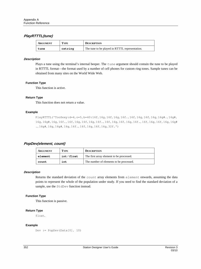
Appendix A Function Reference
352 Station Designer User’s Guide Revision 3 03/10
PlayRTTTL(tune)
ARGUMENT TYPE DESCRIPTION
tune cstring The tune to be played in RTTTL representation.
Description
Plays a tune using the terminal’s internal beeper. The tune argument should contain the tune to be played
in RTTTL format—the format used by a number of cell phones for custom ring tones. Sample tunes can be
obtained from many sites on the World Wide Web.
Function Type
This function is active.
Return Type
This function does not return a value.
Example
PlayRTTTL("TooSexy:d=4,o=5,b=40:16f,16g,16f,16g,16f.,16f,16g,16f,16g,16g#.,16g#,
16g,16g#,16g,16f.,16f,16g,16f,16g,16f.,16f,16g,16f,16g,16f.,16f,16g,16f,16g,16g#
.,16g#,16g,16g#,16g,16f.,16f,16g,16f,16g,32f.")
PopDev(element, count)
ARGUMENT TYPE DESCRIPTION
element int / float The first array element to be processed.
count int The number of elements to be processed.
Description
Returns the standard deviation of the count array elements from element onwards, assuming the data
points to represent the whole of the population under study. If you need to find the standard deviation of a
sample, use the StdDev function instead.
Function Type
This function is passive.
Return Type
float.
Example
Dev := PopDev(Data[0], 10)

Appendix A Function Reference
Revision 3 Station Designer User’s Guide 353 03/10
PostKey(code, transition)
ARGUMENT TYPE DESCRIPTION
code int Key code.
transition int Transition code.
Description
Adds a physical key operation to the input queue.
CODE KEY CODE KEY
0x80 Soft Key 1 0x95 Function Key 6
0x81 Soft Key 2 0x96 Function Key 7
0x82 Soft Key 3 0x97 Function Key 8
0x83 Soft Key 4 0xA0 ALARMS
0x84 Soft Key 5 0xA1 MUTE
0x85 Soft Key 6 0x1B EXIT
0x86 Soft Key 7 0xA2 MENU
0x90 Function Key 1 0xA3 RAISE
0x91 Function Key 2 0xA4 LOWER
0x92 Function Key 3 0x09 NEXT
0x93 Function Key 4 0x08 PREV
0x94 Function Key 5 0x0D ENTER
TRANSITION OPERATION
0 Post key down and then key up.
1 Post key down only.
2 Post key up only.
3 Post key repeat only.
Function Type
This function is active.
Return Type
void
Example PostKey(0x80, 0)

Appendix A Function Reference
354 Station Designer User’s Guide Revision 3 03/10
Power (value, power)
ARGUMENT TYPE DESCRIPTION
value int / float The value to be processed.
power int / float The power to which value is to be raised.
Description
Returns value raised to the power-the power.
Function Type
This function is passive.
Return Type
int or float, depending on the type of the value argument.
Example
Volume := Power(Length, 3)
PrintScreenToFile(path, name, res)
ARGUMENT TYPE DESCRIPTION
path cstring The directory in which the file should be created.
name cstring The filename to be used.
res int The required color resolution of the image.
Description
Saves a bitmap copy of the current display to the indicated file. Passing an empty string for name will allow
the 900 Control Station to select a unique filename for the new image. The rest argument can be set to zero
to create an 8 bits-per-pixel bitmap, while a value of one will create a 16 bits-per-pixel bitmap. The latter
value will produce much large files, all the more so before these files are not capable of supporting RLE8
compression. The return value indicates whether the function succeeded.
Function Type
This function is active.
Return Type
int.
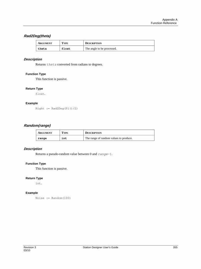
Appendix A Function Reference
Revision 3 Station Designer User’s Guide 355 03/10
Rad2Deg(theta)
ARGUMENT TYPE DESCRIPTION
theta float The angle to be processed.
Description
Returns theta converted from radians to degrees.
Function Type
This function is passive.
Return Type
float.
Example
Right := Rad2Deg(Pi()/2)
Random(range)
ARGUMENT TYPE DESCRIPTION
range int The range of random values to produce.
Description
Returns a pseudo-random value between 0 and range-1.
Function Type
This function is passive.
Return Type
int.
Example
Noise := Random(100)

Appendix A Function Reference
356 Station Designer User’s Guide Revision 3 03/10
ReadFile(file, chars)
ARGUMENT TYPE DESCRIPTION
File int File handle as required by OpenFile.
Chars int Number of characters to be read.
Description
Reads a string up to 512 characters in length from the specified file. This function does not look for a line
feed and carriage return therefore allowing line read of more than 510 characters (ReadFileLine()
limit).
If a file as multiple lines, the string returned by ReadFile() will be as many lines as required to reach
the number of characters to be read. Line feed and carriage return will be part of the returned string.
Function Type
This function is active.
Return Type
string.
Example
Text := ReadFile(hFile, 80)
ReadFileLine(file)
ARGUMENT TYPE DESCRIPTION
file int File handle as returned by OpenFile.
Description
Returns a single line of text from file.
Function Type
This function is active.
Return Type
cstring.
Example
Text := ReadFileLine(hFile)
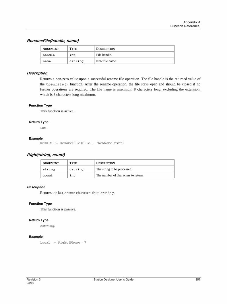
Appendix A Function Reference
Revision 3 Station Designer User’s Guide 357 03/10
RenameFile(handle, name)
ARGUMENT TYPE DESCRIPTION
handle int File handle.
name cstring New file name.
Description
Returns a non-zero value upon a successful rename file operation. The file handle is the returned value of
the Openfile() function. After the rename operation, the file stays open and should be closed if no
further operations are required. The file name is maximum 8 characters long, excluding the extension,
which is 3 characters long maximum.
Function Type
This function is active.
Return Type
int.
Example Result := RenameFile(File , “NewName.txt”)
Right(string, count)
ARGUMENT TYPE DESCRIPTION
string cstring The string to be processed.
count int The number of characters to return.
Description
Returns the last count characters from string.
Function Type
This function is passive.
Return Type
cstring.
Example
Local := Right(Phone, 7)
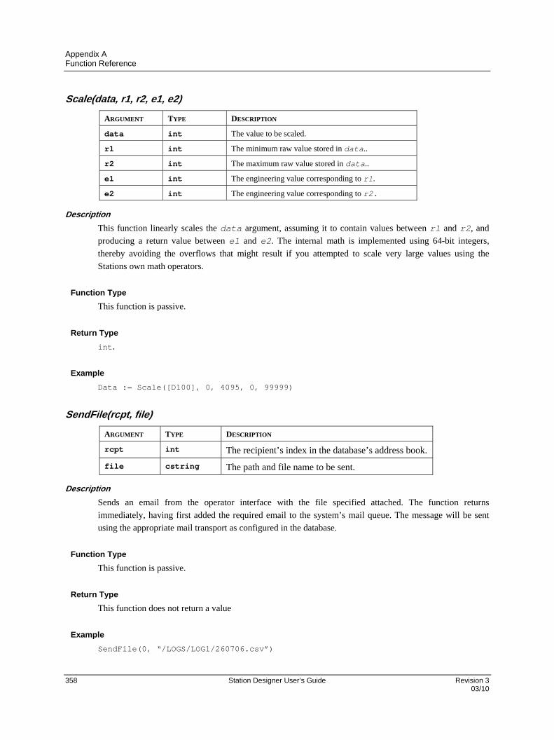
Appendix A Function Reference
358 Station Designer User’s Guide Revision 3 03/10
Scale(data, r1, r2, e1, e2)
ARGUMENT TYPE DESCRIPTION
data int The value to be scaled.
r1 int The minimum raw value stored in data..
r2 int The maximum raw value stored in data..
e1 int The engineering value corresponding to r1.
e2 int The engineering value corresponding to r2.
Description
This function linearly scales the data argument, assuming it to contain values between r1 and r2, and
producing a return value between e1 and e2. The internal math is implemented using 64-bit integers,
thereby avoiding the overflows that might result if you attempted to scale very large values using the
Stations own math operators.
Function Type
This function is passive.
Return Type
int.
Example
Data := Scale([D100], 0, 4095, 0, 99999)
SendFile(rcpt, file)
ARGUMENT TYPE DESCRIPTION
rcpt int The recipient’s index in the database’s address book.
file cstring The path and file name to be sent.
Description
Sends an email from the operator interface with the file specified attached. The function returns
immediately, having first added the required email to the system’s mail queue. The message will be sent
using the appropriate mail transport as configured in the database.
Function Type
This function is passive.
Return Type
This function does not return a value
Example
SendFile(0, “/LOGS/LOG1/260706.csv”)
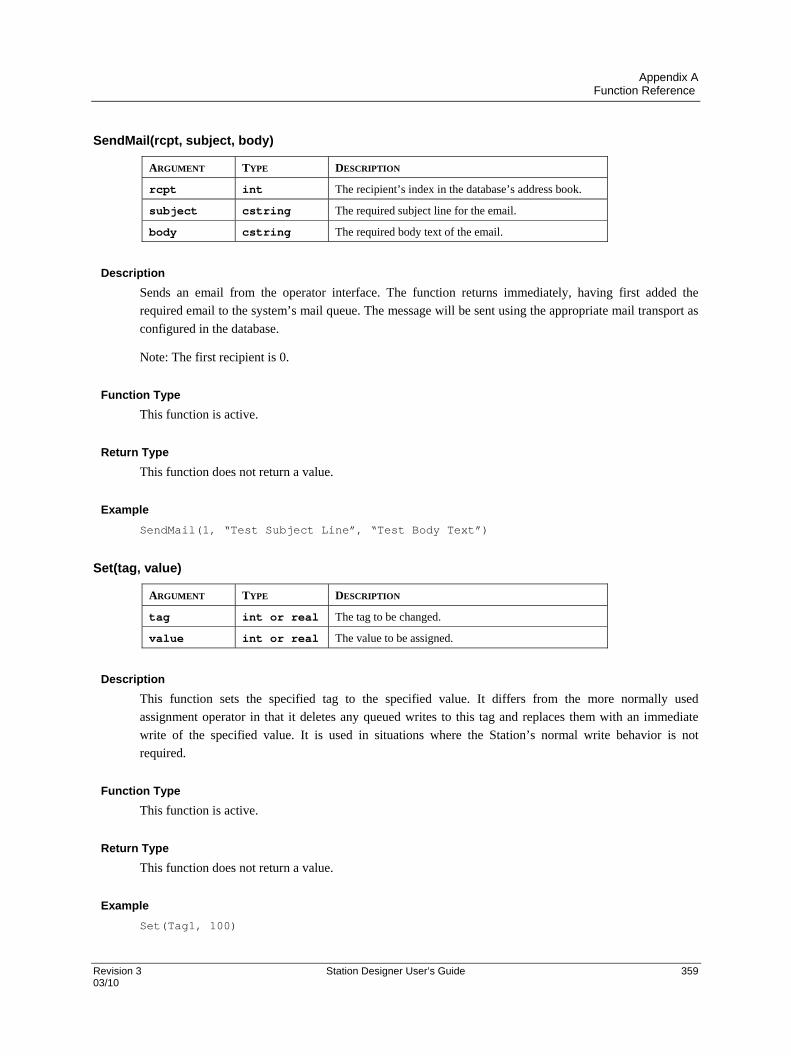
Appendix A Function Reference
Revision 3 Station Designer User’s Guide 359 03/10
SendMail(rcpt, subject, body)
ARGUMENT TYPE DESCRIPTION
rcpt int The recipient’s index in the database’s address book.
subject cstring The required subject line for the email.
body cstring The required body text of the email.
Description
Sends an email from the operator interface. The function returns immediately, having first added the
required email to the system’s mail queue. The message will be sent using the appropriate mail transport as
configured in the database.
Note: The first recipient is 0.
Function Type
This function is active.
Return Type
This function does not return a value.
Example
SendMail(1, “Test Subject Line”, “Test Body Text”)
Set(tag, value)
ARGUMENT TYPE DESCRIPTION
tag int or real The tag to be changed.
value int or real The value to be assigned.
Description
This function sets the specified tag to the specified value. It differs from the more normally used
assignment operator in that it deletes any queued writes to this tag and replaces them with an immediate
write of the specified value. It is used in situations where the Station’s normal write behavior is not
required.
Function Type
This function is active.
Return Type
This function does not return a value.
Example
Set(Tag1, 100)

Appendix A Function Reference
360 Station Designer User’s Guide Revision 3 03/10
SetLanguage(code)
ARGUMENT TYPE DESCRIPTION
code int The language to be selected.
Description
Set the terminal’s current language to that indicated by code.
Function Type
This function is active.
Return Type
This function does not return a value.
Example
SetLanguage(1)
SetNow(time)
ARGUMENT TYPE DESCRIPTION
time int The new time to be set.
Description
Sets the current time via an integer that represents the number of seconds that have elapsed since 1st
January 1997. The integer is typically generated via the other time/date functions.
Function Type
This function is active.
Return Type
This function does not return a value.
Example
SetNow(252288000)
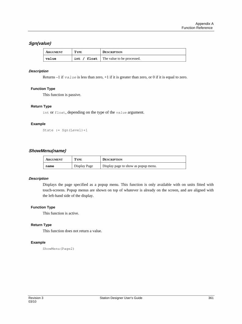
Appendix A Function Reference
Revision 3 Station Designer User’s Guide 361 03/10
Sgn(value)
ARGUMENT TYPE DESCRIPTION
value int / float The value to be processed.
Description
Returns –1 if value is less than zero, +1 if it is greater than zero, or 0 if it is equal to zero.
Function Type
This function is passive.
Return Type
int or float, depending on the type of the value argument.
Example
State := Sgn(Level)+1
ShowMenu(name)
ARGUMENT TYPE DESCRIPTION
name Display Page Display page to show as popup menu.
Description
Displays the page specified as a popup menu. This function is only available with on units fitted with
touch-screens. Popup menus are shown on top of whatever is already on the screen, and are aligned with
the left-hand side of the display.
Function Type
This function is active.
Return Type
This function does not return a value.
Example
ShowMenu(Page2)

Appendix A Function Reference
362 Station Designer User’s Guide Revision 3 03/10
ShowPopup(name)
ARGUMENT TYPE DESCRIPTION
name Display Page The page to be displayed as a popup.
Description
Shows page name as a popup on the Station’s display. The popup will be centered on the display, and
shown on top of the existing page. The popup can be removed by calling the HidePopup() function. It
will also be removed from the display if a new page is selected by invoking the GotoPage() function, or
by a suitably defined keyboard action.
Function Type
This function is active.
Return Type
This function does not return a value.
Example
ShowPopup(Popup1)
sin(theta)
ARGUMENT TYPE DESCRIPTION
theta float The angle, in radians, to be processed.
Description
Returns the sine of the angle theta.
Function Type
This function is passive.
Return Type
float.
Example
yp := radius*sin(theta)
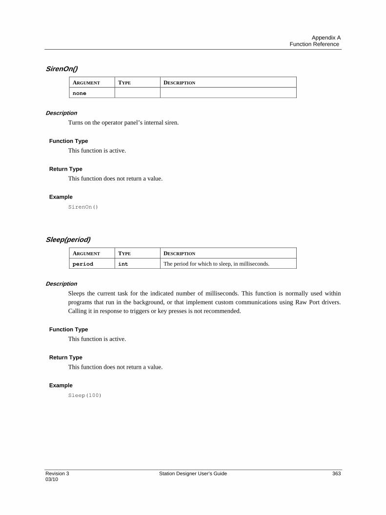
Appendix A Function Reference
Revision 3 Station Designer User’s Guide 363 03/10
SirenOn()
ARGUMENT TYPE DESCRIPTION
none
Description
Turns on the operator panel’s internal siren.
Function Type
This function is active.
Return Type
This function does not return a value.
Example
SirenOn()
Sleep(period)
ARGUMENT TYPE DESCRIPTION
period int The period for which to sleep, in milliseconds.
Description
Sleeps the current task for the indicated number of milliseconds. This function is normally used within
programs that run in the background, or that implement custom communications using Raw Port drivers.
Calling it in response to triggers or key presses is not recommended.
Function Type
This function is active.
Return Type
This function does not return a value.
Example
Sleep(100)
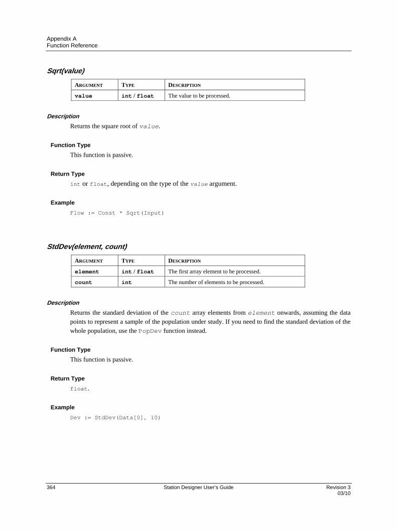
Appendix A Function Reference
364 Station Designer User’s Guide Revision 3 03/10
Sqrt(value)
ARGUMENT TYPE DESCRIPTION
value int / float The value to be processed.
Description
Returns the square root of value.
Function Type
This function is passive.
Return Type
int or float, depending on the type of the value argument.
Example
Flow := Const * Sqrt(Input)
StdDev(element, count)
ARGUMENT TYPE DESCRIPTION
element int / float The first array element to be processed.
count int The number of elements to be processed.
Description
Returns the standard deviation of the count array elements from element onwards, assuming the data
points to represent a sample of the population under study. If you need to find the standard deviation of the
whole population, use the PopDev function instead.
Function Type
This function is passive.
Return Type
float.
Example
Dev := StdDev(Data[0], 10)
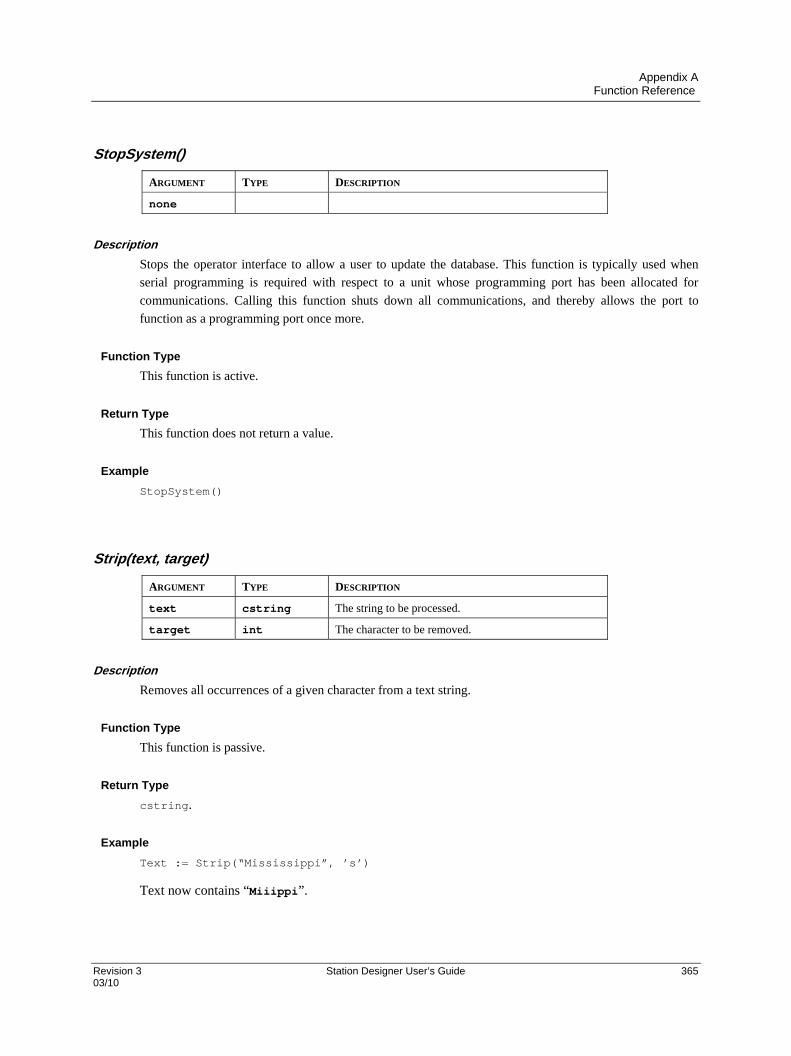
Appendix A Function Reference
Revision 3 Station Designer User’s Guide 365 03/10
StopSystem()
ARGUMENT TYPE DESCRIPTION
none
Description
Stops the operator interface to allow a user to update the database. This function is typically used when
serial programming is required with respect to a unit whose programming port has been allocated for
communications. Calling this function shuts down all communications, and thereby allows the port to
function as a programming port once more.
Function Type
This function is active.
Return Type
This function does not return a value.
Example
StopSystem()
Strip(text, target)
ARGUMENT TYPE DESCRIPTION
text cstring The string to be processed.
target int The character to be removed.
Description
Removes all occurrences of a given character from a text string.
Function Type
This function is passive.
Return Type
cstring.
Example
Text := Strip(“Mississippi”, ’s’)
Text now contains “Miiippi”.

Appendix A Function Reference
366 Station Designer User’s Guide Revision 3 03/10
Sum(element, count)
ARGUMENT TYPE DESCRIPTION
element int / float The first array element to be processed.
count int The number of elements to be processed.
Description
Returns the sum of the count array elements from element onwards.
Function Type
This function is passive.
Return Type
int or float, depending on the type of the value argument.
Example
Total := Sum(Data[0], 10)
tan(theta)
ARGUMENT TYPE DESCRIPTION
theta float The angle, in radians, to be processed.
Description
Returns the tangent of the angle theta.
Function Type
This function is passive.
Return Type
float.
Example
yp := xp * tan(theta)

Appendix A Function Reference
Revision 3 Station Designer User’s Guide 367 03/10
TestAccess(rights, prompt)
ARGUMENT TYPE DESCRIPTION
rights int The required access rights.
prompt cstring The prompt to be used in the log-on popup.
Description
Returns a value of true or false depending on whether the current user has access rights defined by the
rights parameter. This parameter comprises a bit-mask representing the various user-defined rights, with
bit 0 (i.e. the bit with a value of 0x01) representing User Right 1, bit 1 (i.e. the bit with a value of 0x02)
representing User Right 2 and so on. If no user is currently logged on, the system will display a popup to
ask for user credentials, using the prompt argument to indicate why the popup is being displayed. The
function is typically used in programs that perform a number of actions that might be subject to security,
and that might otherwise be interrupted by a log-on popup. By executing this function before the actions
are performed, you can provide a better indication to the user as to why a log-on is required, and you can
avoid a security failure part way through a series of operations.
Function Type
This function is passive.
Return Type
int
Example
if( TestAccess(1, “Clear all data?”) ) {
Data1 := 0;
Data2 := 0;
Data3 := 0;
}
TextToAddr(addr)
ARGUMENT TYPE DESCRIPTION
addr cstring The addressed in dotted-decimal form.
Description
Converts a dotted-decimal string into a 32-bit IP address.
Function Type
This function is passive.
Return Type
int.
Example
ip := TextToAddr(“192.168.0.1”)
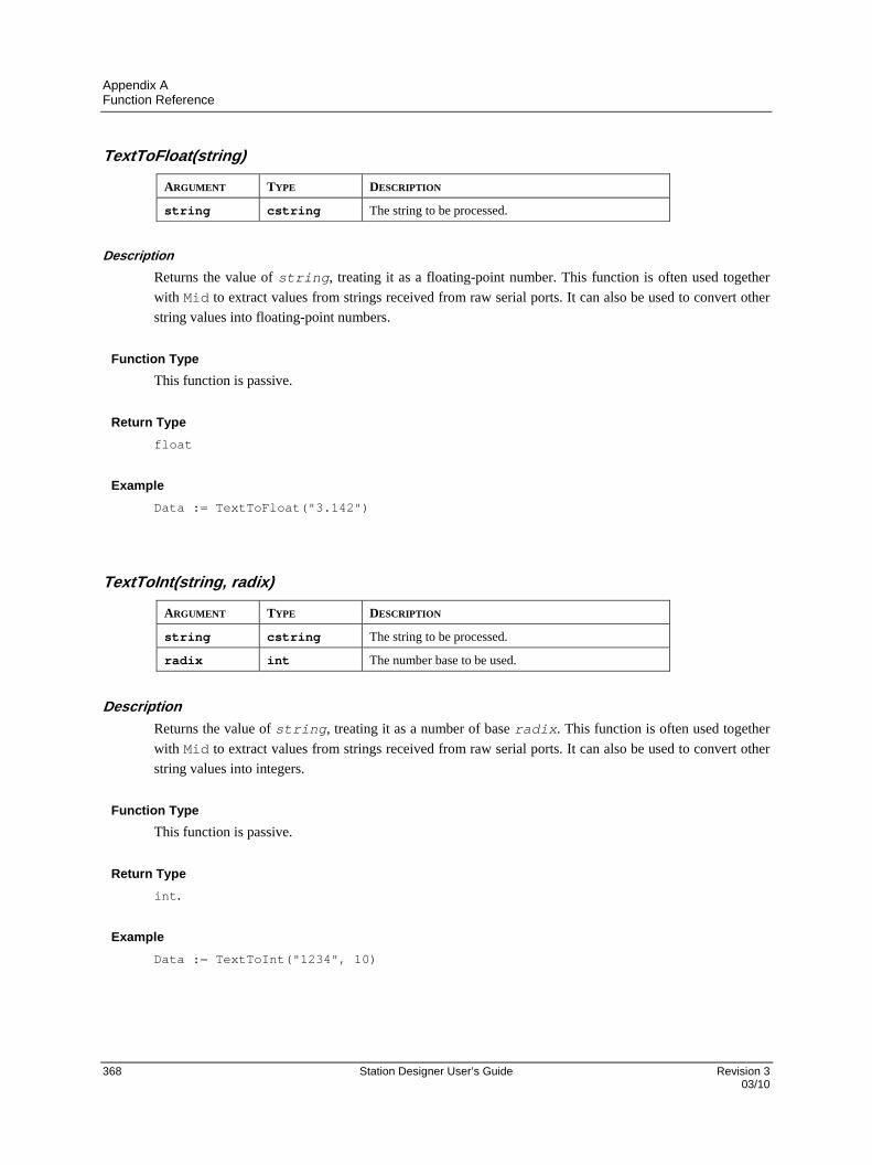
Appendix A Function Reference
368 Station Designer User’s Guide Revision 3 03/10
TextToFloat(string)
ARGUMENT TYPE DESCRIPTION
string cstring The string to be processed.
Description
Returns the value of string, treating it as a floating-point number. This function is often used together
with Mid to extract values from strings received from raw serial ports. It can also be used to convert other
string values into floating-point numbers.
Function Type
This function is passive.
Return Type
float
Example
Data := TextToFloat("3.142")
TextToInt(string, radix)
ARGUMENT TYPE DESCRIPTION
string cstring The string to be processed.
radix int The number base to be used.
Description
Returns the value of string, treating it as a number of base radix. This function is often used together
with Mid to extract values from strings received from raw serial ports. It can also be used to convert other
string values into integers.
Function Type
This function is passive.
Return Type
int.
Example
Data := TextToInt("1234", 10)
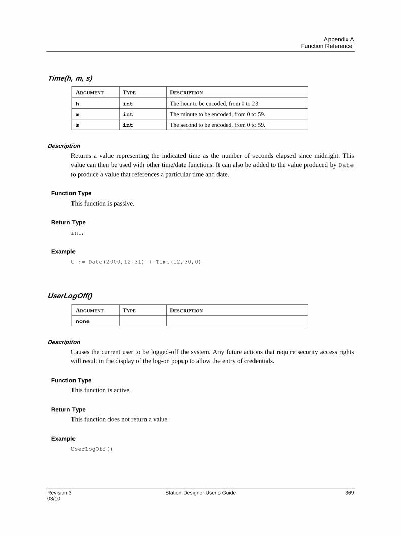
Appendix A Function Reference
Revision 3 Station Designer User’s Guide 369 03/10
Time(h, m, s)
ARGUMENT TYPE DESCRIPTION
h int The hour to be encoded, from 0 to 23.
m int The minute to be encoded, from 0 to 59.
s int The second to be encoded, from 0 to 59.
Description
Returns a value representing the indicated time as the number of seconds elapsed since midnight. This
value can then be used with other time/date functions. It can also be added to the value produced by Date
to produce a value that references a particular time and date.
Function Type
This function is passive.
Return Type
int.
Example
t := Date(2000,12,31) + Time(12,30,0)
UserLogOff()
ARGUMENT TYPE DESCRIPTION
none
Description
Causes the current user to be logged-off the system. Any future actions that require security access rights
will result in the display of the log-on popup to allow the entry of credentials.
Function Type
This function is active.
Return Type
This function does not return a value.
Example
UserLogOff()
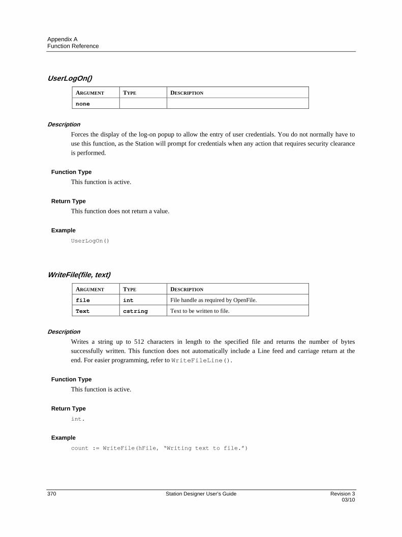
Appendix A Function Reference
370 Station Designer User’s Guide Revision 3 03/10
UserLogOn()
ARGUMENT TYPE DESCRIPTION
none
Description
Forces the display of the log-on popup to allow the entry of user credentials. You do not normally have to
use this function, as the Station will prompt for credentials when any action that requires security clearance
is performed.
Function Type
This function is active.
Return Type
This function does not return a value.
Example
UserLogOn()
WriteFile(file, text)
ARGUMENT TYPE DESCRIPTION
file int File handle as required by OpenFile.
Text cstring Text to be written to file.
Description
Writes a string up to 512 characters in length to the specified file and returns the number of bytes
successfully written. This function does not automatically include a Line feed and carriage return at the
end. For easier programming, refer to WriteFileLine().
Function Type
This function is active.
Return Type
int.
Example
count := WriteFile(hFile, “Writing text to file.”)

Appendix A Function Reference
Revision 3 Station Designer User’s Guide 371 03/10
WriteFileLine(file, text)
ARGUMENT TYPE DESCRIPTION
file int File handle as required by OpenFile.
text cstring Text to be written to file.
Description
Writes a string to the specified file and returns the number of bytes successfully written, including the
carriage return and linefeed characters that will be appended to each line.
Function Type
This function is active.
Return Type
int.
Example

Appendix A Function Reference
372 Station Designer User’s Guide Revision 3 03/10

373 Station Designer User’s Guide 03/10
Sales and Service For application assistance, current specifications, pricing, or name of the nearest Authorized Distributor, contact one of the offices below.
Asia Pacific Global Technical Support Field Instruments Phone: +65 6580 3156 Fax: +65 6445-3033 Australia Honeywell Limited Phone: +(61) 7-3846 1255 FAX: +(61) 7-3840 6481 Toll Free 1300-36-39-36 Toll Free Fax: 1300-36-04-70 China – PRC - Beijing Honeywell China Inc. Phone: +(86-10) 8458-3280 Fax: +(86-10) 8458-4650 China – PRC - Shanghai Honeywell China Inc. Phone: (86-21) 5257-4568 Fax: (86-21) 6237-2826 China – PRC - Chengdu Honeywell China Inc. Phone: +(86-28) 6613-5078 Fax: +(86-28) 8678-7061 China – PRC - Xi’an Honeywell China Ltd - Xi’an. Phone: +(86-29) 8833-7490 Fax: +(86-29) 8833-7489 China – PRC - Shenzhen- Honeywell China Inc. Phone: +(86) 755-2518-1226 Fax: +(86) 755-2518-1221
Indonesia PT Honeywell Indonesia Phone: +(62) 21-535-8833 FAX: +(62) 21-5367 1008 India Automation India Ltd. Honeywell Ltd. Phone:+(91) 6603-9400 Fax: +(91) 6603-9600 Japan Honeywell Inc. Phone: +(81) 3 6730 7197 Fax: +(81) 3 6730 7228 Malaysia Honeywell Engineering Sdn Bhd Phone: +(603) 7958-4788 Fax: +(603) 7958-8922
New Zealand Honeywell Limited Phone: +(64-9) 623-5050 Fax: +(64-9) 623-5060 Toll Free (0800) 202-088 Singapore Honeywell Pte Ltd. Phone: +(65) 6580 3278 Fax: +(65) 6445-3033 South Korea Honeywell Korea Co Ltd Phone: +(822) 799 6114 Fax: +(822) 792 9015 Thailand Honeywell Systems (Thailand) Ltd. Phone: +(662) 693-3099 FAX: +(662) 693-3089 Taiwan R.O.C. Honeywell Taiwan Ltd. Phone: +(886-2) 2245-1000 FAX: +(886-2) 2245-3243
SE Asia Countries see Honeywell Pte Ltd (Singapore) for: Philippines, Pakistan, Cambodia, Guam, Laos, Myanmar, Vietnam, East Timor
SE Asia Countries see Honeywell Automation India Ltd for: Bangladesh Nepal Sri Lanka
EUROPE Austria Honeywell Austria GmbH Phone: +43 (316)400123 FAX: +43 (316)40017 Belgium Honeywell SA/NV Phone:+32 (0)2728 24 07 FAX: +32 (0)2728 22 45 Bulgaria Honeywell EOOD Phone: +(359) 2 40 20 900 FAX: +(359) 2 40 20 990 Czech Republic Honeywell spol. s.r.o. Phone:+420 242 442 232 FAX: +420 242 442 131
Denmark Honeywell A/S Phone: +(45) 39 55 55 55 FAX: +(45) 39 55 55 58 Finland Honeywell OY Phone: +358 (0)20752 2753 FAX: +358 (0) 20752 2751 France Honeywell SA Phone: +33 (0)1 60198075 FAX: +33 (0)1 60198201 Germany Honeywell AG Phone: +49 (69)8064-299 FAX: +49 (69)806497336 Hungary Honeywell Kft. Phone: +36-1-451 4300 FAX: +36-1-451 4343 Italy Honeywell S.p.A. Phone:+390292146307 FAX: +39 0292146377 The Netherlands Honeywell B.V. Phone: +31 (0) 20 5656200 FAX: +31 (0) 20 5656210 Norway Honeywell A/S Phone: (45) 39 55 55 55 Poland Honeywell Sp. zo.o Phone: +48-22-6060900 FAX: +48-22-6060901 Portugal Honeywell Portugal Lda Phone: +351 21 424 5000 FAX: +351 21 424 50 99 Romania Honeywell Bucharest Phone: +40 (0) 21 2316437 FAX: +40 (0) 21 2316439 Russian Federation (RF), ZAO "Honeywell" Phone: +7 (095) 796 98 00 FAX: +7 (495) 797 99 64 Slovak Republic Honeywell s.r.o. Phone: +421-2-58247 410 FAX: +421-2-58247 415
Spain Honeywell S.A. Phone: +34 (0)91313 61 00 FAX: +34 (0)91313 61 30 Sweden Honeywell AB Phone: +(46) 8 775 55 00 FAX: +(46) 8 775 56 00 Switzerland Honeywell AG Phone: +41 18552448 FAX: +(41) 1 855 24 45 Turkey Honeywell Turkey A.S. Phone: +90 216 578 71 00 FAX: +90 216 575 66 35 Ukraine Honeywell Tel: +380-44-201 44 74 Fax: +380-44-201-44-75 United Kingdom Honeywell Control Systems Ltd. Phone: +44 (0)1344 655251 FAX: +44 (0) 1344 655554
MIDDLE EAST Abu Dhabi U A E Middle East Headquarters Honeywell Middle East Ltd. Phone: +971 2 4041246 FAX: +971 2 4432536 Sultanate of Oman Honeywell & Co Oman LLC Phone: +968 24 701153/ Ext.33 FAX +968 24 787351 Saudia Arabia Honeywell Turki Arabia Ltd Jubail Office Phone: +966-3-341-0140 Fax: +966-3-341-0216 Honeywell - ATCO Dammam Office Phone: 0096638304584 Fax: 0096638338059 Kuwait Honeywell Kuwait KSC Phone: +965 242 1327 to 30 Fax: +965 242 8315 And Phone: +965 326 2934/1821Fax: +965 326 1714
AFRICA Mediterranean & African Distributors Honeywell SpA Phone: +39 (02) 250 10 604 FAX: +39 (02) 250 10 659 South Africa (Republic of) and sub saharan Honeywell Southern Africa Honeywell S.A. Pty. Ltd. Phone: +27 11 6958000 FAX +27 118051504
NORTH AMERICA Canada Honeywell LTD Phone: 1-800-737-3360 FAX: 1-800-565-4130 USA Honeywell Process Solutions, Phone: 1-800-343-0228 FAX: 1-717-771-8251 Email:sc-cp-appssales@ honeywell.com
SOUTH AMERICA Argentina Honeywell S.A.I.C. Phone: +(54-11) 4383-3637 FAX: +(54-11) 4325-6470 Brazil Honeywell do Brasil & Cia Phone: +(55-11) 7266-1900 FAX: +(55-11) 7266-1905 Chile Honeywell Chile, S.A. Phone: +(56-2) 233-0688 FAX: +(56-2) 231-6679 Mexico Honeywell S.A. de C.V. Phone: +(52) 55 5259-1966 FAX: +(52) 55 5570-2985 Puerto Rico Honeywell Inc. Phone: +(809) 792-7075 FAX: +(809) 792-0053 Trinidad Honeywell Inc. Phone: +(868) 624-3964 FAX: +(868) 624-3969 Venezuela Honeywell CA Phone: +(58-2) 238-0211 FAX: +(58-2) 238-3391
Honeywell Process Solutions
Honeywell
512 Virginia Drive
Fort Washington, PA 19034
51-52-25-149 Rev.3 03/10 Printed in USA www.honeywell.com/ps