E6385A Lucent AMPS Base Station Test Software User's Guide
138
Agilent Technologies E6385A Lucent AMPS Base Station Test Software User’s Guide Software Version: A.03.00 and later Agilent Part Number E6385-90002 Revision B Printed in UK May 2000
-
Upload
khangminh22 -
Category
Documents
-
view
0 -
download
0
Transcript of E6385A Lucent AMPS Base Station Test Software User's Guide
Agilent Technologies E6385A LucentAMPS Base Station Test Software
User’s Guide
Software Version: A.03.00 and later
Agilent Part Number E6385-90002
Revision B
Printed in UK
May 2000

Restricted Rights LegendUse, duplication or disclosure by the U. S. Government is subject to restrictions as set forth in subparagraph (c) (1) (ii) of the Rights in Technical Data and Computer Software clause in DFARS 252.227-7013.
Agilent Technologies 3000 Hanover Street, Palo Alto, CA 94304. U.S.A.
Rights for non-DOD U. S. Government Departments and Agencies are as set forth in FAR 52.227-19 (c) (1, 2).
Information contained in this document is subject to change without notice.
All Rights Reserved. Reproduction, adaptation, or translation without prior written permission is prohibited, except as allowed under the copyright laws.
This material may be reproduced by or for the U.S. Government pursuant to the Copyright License under the clause at DFARS 52.227-7013 (APR 1988).
© Copyright 1999, 2000 Agilent Technologies
Trademark AcknowledgementsHewlett-Packard and HP are registered trademarks of Hewlett-Packard Company.
Microsoft, Windows, and MS-DOS are registered trademarks of Microsoft Corporation.
Pentium is a registered trademark of Intel Corporation.
2
Contents Ta
ble o
f Co
nte
nts
In this Manual . . . . . . . . . . . . . . . . . . . . . . . . . . . . . . . . . . . . . . . . 8Conventions Used . . . . . . . . . . . . . . . . . . . . . . . . . . . . . . . . . . . . 9
Product DescriptionTest Software Overview . . . . . . . . . . . . . . . . . . . . . . . . . . . . . . . 12
Who should use the Test Software? . . . . . . . . . . . . . . . . . . . . 13Included with the Test Software . . . . . . . . . . . . . . . . . . . . . . . 13
Test Software Operation Overview . . . . . . . . . . . . . . . . . . . . . . 14Required Equipment . . . . . . . . . . . . . . . . . . . . . . . . . . . . . . . . . . 15
Test Equipment . . . . . . . . . . . . . . . . . . . . . . . . . . . . . . . . . . . . 15Personal Computer (PC) . . . . . . . . . . . . . . . . . . . . . . . . . . . . . 15Cables and Adapters . . . . . . . . . . . . . . . . . . . . . . . . . . . . . . . . 15Optional Accessory Kits . . . . . . . . . . . . . . . . . . . . . . . . . . . . . . 17
Getting Help, Test Software Upgrades, and Training . . . . . . . 20Installation
Overview . . . . . . . . . . . . . . . . . . . . . . . . . . . . . . . . . . . . . . . . . . . 22Loading and Running the Test Software . . . . . . . . . . . . . . . . . . 23Navigating the Test Software . . . . . . . . . . . . . . . . . . . . . . . . . . . 25
Main Menu Functions . . . . . . . . . . . . . . . . . . . . . . . . . . . . . . . 25Changing Settings and Using USER Keys . . . . . . . . . . . . . . . 26
Operating the BTS Laptop Utility Program . . . . . . . . . . . . . . . 27System Requirements for BTS Laptop Utility Program . . . . 28Installing the BTS Laptop Utility Program . . . . . . . . . . . . . . 28Configuring the Test Set and PC Serial Ports for Communication with the
Test Set . . . . . . . . . . . . . . . . . . . . . . . . . . . . . . . . . . . . . . . . . . . . . . . . . . 28Configuring the PC to Communicate with the MSC . . . . . . . 30
Connecting the PC to the Test Set and the MSC . . . . . . . . . . . 31Connecting the PC to the Test Set . . . . . . . . . . . . . . . . . . . . . 31Connecting the PC to the MSC . . . . . . . . . . . . . . . . . . . . . . . . 32
Determining the Test Set to Site Equipment Connections . . . . 35Which Test Set Port to Use – ANT IN or RF IN/OUT? . . . . . 35Which Base Station Port to Use – TX Test or TX Antenna? . 35
Configuring the Test Software . . . . . . . . . . . . . . . . . . . . . . . . . . 37Test Configuration . . . . . . . . . . . . . . . . . . . . . . . . . . . . . . . . . . 38Base Station Configuration . . . . . . . . . . . . . . . . . . . . . . . . . . . 39Printing the FCC Title Page . . . . . . . . . . . . . . . . . . . . . . . . . . 41
Defining a Frequency Plan . . . . . . . . . . . . . . . . . . . . . . . . . . . . . 43Defining a Frequency Plan Using the Editor in the Test Software 43Defining a Frequency Plan Using a PC . . . . . . . . . . . . . . . . . 46Loading a Frequency Plan from an SRAM Card . . . . . . . . . . 50Purging (Deleting) a Frequency Plan File . . . . . . . . . . . . . . . 51Printing a Frequency Plan . . . . . . . . . . . . . . . . . . . . . . . . . . . . 52
Establishing a Connection with the MSC for Testing . . . . . . . . 53
3
Contents
Establishing a Direct-Dial Modem Connection . . . . . . . . . . . . 53Establishing a Telnet Connection . . . . . . . . . . . . . . . . . . . . . . 53
If You Noticed Problems . . . . . . . . . . . . . . . . . . . . . . . . . . . . . . . 54Connections
Test Set to Base Station Connections . . . . . . . . . . . . . . . . . . . . . 56Performing Tests
Overview . . . . . . . . . . . . . . . . . . . . . . . . . . . . . . . . . . . . . . . . . . . . 60Calibrating the Test Setup . . . . . . . . . . . . . . . . . . . . . . . . . . . . 61Selecting Tests . . . . . . . . . . . . . . . . . . . . . . . . . . . . . . . . . . . . . 62Selecting Utilities . . . . . . . . . . . . . . . . . . . . . . . . . . . . . . . . . . . 63Running Tests . . . . . . . . . . . . . . . . . . . . . . . . . . . . . . . . . . . . . . 64For More Information . . . . . . . . . . . . . . . . . . . . . . . . . . . . . . . . 64
Full Site Test (FCC) . . . . . . . . . . . . . . . . . . . . . . . . . . . . . . . . . . . 65Parameters and Specifications Used . . . . . . . . . . . . . . . . . . . . 66Select and Run the Test . . . . . . . . . . . . . . . . . . . . . . . . . . . . . . 66Review the Results . . . . . . . . . . . . . . . . . . . . . . . . . . . . . . . . . . 66
Single Radio Test . . . . . . . . . . . . . . . . . . . . . . . . . . . . . . . . . . . . . 68Parameters and Specifications Used . . . . . . . . . . . . . . . . . . . . 69Select and Run the Test . . . . . . . . . . . . . . . . . . . . . . . . . . . . . . 69Review the Results . . . . . . . . . . . . . . . . . . . . . . . . . . . . . . . . . . 70
TX Power Adjustment . . . . . . . . . . . . . . . . . . . . . . . . . . . . . . . . . 71Parameters and Specifications Used . . . . . . . . . . . . . . . . . . . . 71Select and Run the Test . . . . . . . . . . . . . . . . . . . . . . . . . . . . . . 72Review the Results . . . . . . . . . . . . . . . . . . . . . . . . . . . . . . . . . . 72
Spectrum Analyzer . . . . . . . . . . . . . . . . . . . . . . . . . . . . . . . . . . . 74Parameters and Specifications Used . . . . . . . . . . . . . . . . . . . . 74Select and Run the Test . . . . . . . . . . . . . . . . . . . . . . . . . . . . . . 74Review the Results . . . . . . . . . . . . . . . . . . . . . . . . . . . . . . . . . . 75
TX Gain Test . . . . . . . . . . . . . . . . . . . . . . . . . . . . . . . . . . . . . . . . 77Parameters and Specifications Used . . . . . . . . . . . . . . . . . . . . 77Select and Run the Test . . . . . . . . . . . . . . . . . . . . . . . . . . . . . . 77Review the Results . . . . . . . . . . . . . . . . . . . . . . . . . . . . . . . . . . 78
RX Gain Test . . . . . . . . . . . . . . . . . . . . . . . . . . . . . . . . . . . . . . . . 79Parameters and Specifications Used . . . . . . . . . . . . . . . . . . . . 79Select and Run the Test . . . . . . . . . . . . . . . . . . . . . . . . . . . . . . 80Review the Results . . . . . . . . . . . . . . . . . . . . . . . . . . . . . . . . . . 80
TX –39 dBm Power Test . . . . . . . . . . . . . . . . . . . . . . . . . . . . . . . 81Parameters and Specifications Used . . . . . . . . . . . . . . . . . . . . 82Select and Run the Test . . . . . . . . . . . . . . . . . . . . . . . . . . . . . . 82Review the Results . . . . . . . . . . . . . . . . . . . . . . . . . . . . . . . . . . 83
TX Antenna Port Cable Calibration . . . . . . . . . . . . . . . . . . . . . . 84Parameters and Specifications Used . . . . . . . . . . . . . . . . . . . . 84
4
Contents Ta
ble o
f Co
nte
nts
Select and Run the Utility . . . . . . . . . . . . . . . . . . . . . . . . . . . . 84Review the Results . . . . . . . . . . . . . . . . . . . . . . . . . . . . . . . . . . 85
TX Test Port Cable Calibration . . . . . . . . . . . . . . . . . . . . . . . . . 86Parameters and Specifications Used . . . . . . . . . . . . . . . . . . . . 86Select and Run the Utility . . . . . . . . . . . . . . . . . . . . . . . . . . . . 86Review the Results . . . . . . . . . . . . . . . . . . . . . . . . . . . . . . . . . . 87
TX Test Port Coupling Measurements . . . . . . . . . . . . . . . . . . . . 88Parameters and Specifications Used . . . . . . . . . . . . . . . . . . . . 88Select and Run the Test . . . . . . . . . . . . . . . . . . . . . . . . . . . . . . 89Review the Results . . . . . . . . . . . . . . . . . . . . . . . . . . . . . . . . . . 90
Insertion Loss Measurement . . . . . . . . . . . . . . . . . . . . . . . . . . . 91Parameters and Specifications Used . . . . . . . . . . . . . . . . . . . . 91Select and Run the Test . . . . . . . . . . . . . . . . . . . . . . . . . . . . . . 91Review the Results . . . . . . . . . . . . . . . . . . . . . . . . . . . . . . . . . . 92
Return Loss Measurement . . . . . . . . . . . . . . . . . . . . . . . . . . . . . 93Parameters and Specifications Used . . . . . . . . . . . . . . . . . . . . 93Select and Run the Test . . . . . . . . . . . . . . . . . . . . . . . . . . . . . . 93Review the Results . . . . . . . . . . . . . . . . . . . . . . . . . . . . . . . . . . 94
ReferenceOverview . . . . . . . . . . . . . . . . . . . . . . . . . . . . . . . . . . . . . . . . . . . 96Accessing Test Software Functions . . . . . . . . . . . . . . . . . . . . . . 97
SOFTWARE MENU Screen Overview . . . . . . . . . . . . . . . . . . 98Loading a Test Procedure . . . . . . . . . . . . . . . . . . . . . . . . . . . . 99Loading the Test Software Card and Procedure . . . . . . . . . 100Customizing a Test Procedure . . . . . . . . . . . . . . . . . . . . . . . . 102Changing Test Parameters . . . . . . . . . . . . . . . . . . . . . . . . . . 103Changing Pass/Fail Limits . . . . . . . . . . . . . . . . . . . . . . . . . . 106Saving/Deleting a Procedure . . . . . . . . . . . . . . . . . . . . . . . . . 109
BTS Laptop Utility Program Windows . . . . . . . . . . . . . . . . . . 113Switch Terminal Window . . . . . . . . . . . . . . . . . . . . . . . . . . . 113Test Set Terminal Window . . . . . . . . . . . . . . . . . . . . . . . . . . 113Other Data Window . . . . . . . . . . . . . . . . . . . . . . . . . . . . . . . . 113Test Results Window . . . . . . . . . . . . . . . . . . . . . . . . . . . . . . . 114Test Set Screen Capture Window . . . . . . . . . . . . . . . . . . . . . 115
Demo (Demonstration) Mode . . . . . . . . . . . . . . . . . . . . . . . . . . 116Selecting the DEMO Procedure . . . . . . . . . . . . . . . . . . . . . . . 116Selecting Demo Mode Using the Control Parameter . . . . . . 117Exiting the Demo Mode . . . . . . . . . . . . . . . . . . . . . . . . . . . . . 117
Parameters . . . . . . . . . . . . . . . . . . . . . . . . . . . . . . . . . . . . . . . . 118Specifications (Pass/Fail Limits) . . . . . . . . . . . . . . . . . . . . . . . 124Testing without MSC Control . . . . . . . . . . . . . . . . . . . . . . . . . . 126Using a PC Card . . . . . . . . . . . . . . . . . . . . . . . . . . . . . . . . . . . . 127
5

Contents
Initializing a PC Card . . . . . . . . . . . . . . . . . . . . . . . . . . . . . . . 127Troubleshooting PC Card Use . . . . . . . . . . . . . . . . . . . . . . . . 127
TroubleshootingError Summary . . . . . . . . . . . . . . . . . . . . . . . . . . . . . . . . . . . . . 130
Overview . . . . . . . . . . . . . . . . . . . . . . . . . . . . . . . . . . . . . . . . . 130Troubleshooting the Test Software Installation . . . . . . . . . . . 131Errors When Loading and Running the Test Software . . . . . . 132Communication Errors . . . . . . . . . . . . . . . . . . . . . . . . . . . . . . . 133
Errors When First Setting Up or Connecting to MSC . . . . . 133Communication Errors During Testing . . . . . . . . . . . . . . . . . 133Troubleshooting Checks for Communication Problems . . . . 134
Errors While Attempting Measurements . . . . . . . . . . . . . . . . . 135Acronyms 137
Acronyms and Meanings . . . . . . . . . . . . . . . . . . . . . . . . . . . . . . 138
6

Preface
Preface
7
In this ManualThis manual consists of the following parts:
Chapter 1, “Product Description,” on page 11.
This chapter provides a general description of the Agilent Technologies E6385A Lucent AMPS Base Station Test Software.
Chapter 2, “Installation,” on page 21.
This chapter provides information on loading and running the Test Software, connecting the equipment, and configuring the Test Set and Test Software.
Chapter 3, “Connections,” on page 55.
This chapter provides information on connecting the Test Set to the Base Station and other equipment.
Chapter 4, “Performing Tests,” on page 59.
This chapter provides procedures for running the Test Software tests and utilities, and descriptions of the individual tests and utilities.
Chapter 5, “Reference,” on page 95.
This chapter provides operational details that are not covered elsewhere in this manual. Topics are arranged alphabetically for quick and easy reference.
Chapter 6, “Troubleshooting,” on page 129.
This chapter provides information on possible remedies in the event of operational problems.
Appendix A, “Acronyms,” on page 137.
This appendix provides a list of acronyms and the associated meanings to assist in efficient Test Software operation.
O:\Manuals\E6385A_Amps\Book\Preface.fm
8

Preface
Conventions Used Special presentations of text in this manual reflect the appearance of the referenced item. Examples of these special presentations are:
Menu – A Test Set front panel key.
Pause/Continue (Reset) – A Test Set front panel shift function key. The key name in parentheses is the title of the shift function. Press the Shift key then the specified key to access the shift function.
Procedure: – Characters that appear on the Test Set display.
k1 (Run Test) – A USER key in the key column next to the display. The words in parentheses are displayed on the screen.
Title – Titles of documentation are printed in italics.
Test Set – Refers to the Agilent Technologies 8935 Series E6380A CDMA Base Station Test Set.
Test Software – Refers to the Agilent Technologies E6385A Lucent CDMA Base Station Test Software.
TEST – Refers to the one of the test modules that is part of a test procedure.
PC card – Refers to either the OTP card on which the Test Software is shipped or the SRAM card that is shipped with the Test Software for storing procedures.
PC card is an industry standard term that refers to two types of information storage cards. One meets the specifications of the Personal Computer Memory Card International Association (PCMCIA). The other meets the specifications of the Epson Corporation PC card standard. Agilent Technologies 8935 Series Test Sets use only the PCMCIA type card.
OTP card – Refers to the type of PC card that is used to store the Test Software.
SRAM card – Refers to the type of PC card that is shipped with the Test Software for storing procedures.
BTS – Refers to a Base Transceiver Station.
In procedural steps in this manual, the following words are used to describe cursor and entry actions:
• Select – refers any of three possible actions:
— Positioning the cursor at the appropriate field (inverse video area) and pressing the knob.
— Making an entry using the DATA ENTRY keys and pressing the knob.
— Making an entry using the DATA ENTRY keys and pressing the Enter key.
• Enter – means to use the numeric keypad, and the Enter key or measurement units keys to make entries to fields. In some procedures, the word “enter” is used to describe the action of entering characters into a field.
9

Pro
du
ct Descrip
tion
1 Product Description
This chapter provides general information about the Agilent Technologies E6385 Lucent AMPS Base Station Test Software. Included is a list of required equipment to perform the tests, plus a look at the basic Test Software flow.
Chapter 1 11

Product DescriptionTest Software Overview
Test Software OverviewThe Test Software is contained on two One-Time Programmable (OTP) PC cards. One card is used for AMPS testing, the other for CDMA testing. Separate manuals are included for AMPS and CDMA testing.
The Test Software is an Agilent Technologies Instrument BASIC (IBASIC) application used to set up the Test Set for transmitter measurements on AMPS Base Station equipment. The Test Software runs on the Test Set internal IBASIC controller to allow you to perform the following tests:
• Full Site Test (FCC)
• Single Radio Test
• TX Power Adjustment Test
• Spectrum Analyzer Test
• RX Gain Test
• TX Gain Test
• TX –39 dBm Power Test
Using a PC modem or a telnet connection, the Test Software can control the Base Station equipment by sending commands to the Mobile Switching Center (MSC). This provides automated testing to reduce time spent at the site and to greatly improve the repeatability of measurements.
As tests are run, the Test Software compares the measured results with user-defined specification limits. These test results may be stored on a personal computer (PC) (ordinarily a laptop PC).
In addition, the following tests are included as calibration and utilities functions.
• TX Antenna Port Cable Calibration
• TX Test Port Cable Calibration
• TX Test Port Coupling Measurements
• Insertion Loss Measurement
• Return Loss Measurement
Also in addition, the following two miscellaneous utilities are included:
• Define Frequency Plan
• Print FCC Title Page
Chapter 1O:\Manuals\E6385A_Amps\Book\prodescr.fm
12
Product DescriptionTest Software Overview
Pro
du
ct Descrip
tion
Who should use the Test Software?
If you are installing, commissioning, or maintaining Lucent Technologies’ AMPS cell site equipment, this Test Software will assist you in performing key tests of transmitter performance.
Included with the Test Software
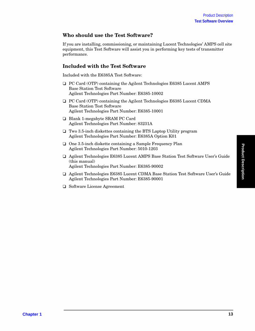
Included with the E6385A Test Software:
❏ PC Card (OTP) containing the Agilent Technologies E6385 Lucent AMPS Base Station Test SoftwareAgilent Technologies Part Number: E6385-10002
❏ PC Card (OTP) containing the Agilent Technologies E6385 Lucent CDMA Base Station Test SoftwareAgilent Technologies Part Number: E6385-10001
❏ Blank 1-megabyte SRAM PC Card Agilent Technologies Part Number: 83231A
❏ Two 3.5-inch diskettes containing the BTS Laptop Utility program Agilent Technologies Part Number: E6385A Option K01
❏ One 3.5-inch diskette containing a Sample Frequency PlanAgilent Technologies Part Number: 5010-1203
❏ Agilent Technologies E6385 Lucent AMPS Base Station Test Software User’s Guide (this manual) Agilent Technologies Part Number: E6385-90002
❏ Agilent Technologies E6385 Lucent CDMA Base Station Test Software User’s GuideAgilent Technologies Part Number: E6385-90001
❏ Software License Agreement
Chapter 1 13

Product DescriptionTest Software Operation Overview
Test Software Operation OverviewFigure 1-1 illustrates the basic steps for Test Software operation. After running the Test Software, you may repeat a test or you may select another test.
Chapter 4, “Performing Tests,” on page 59, provides step-by-step instructions for each of the tests. If you have questions, refer to Chapter 5, “Reference,” on page 95 for more information. If you encounter errors, refer to Chapter 6, “Troubleshooting,” on page 129.
Figure 1-1 Using the Test Software
Chapter 2Run More
Tests?
Chapter 4Chapter 3
Installation Connection Performing Tests
Chapter 5
Reference
Chapter 6
Troubleshooting
ExitStart
Yes
No
Chapter 1O:\Manuals\E6385A_Amps\Book\prodescr.fm
14

Product DescriptionRequired Equipment
Pro
du
ct Descrip
tion
Required EquipmentTest equipment and other items required for testing are shown in Figure 1-2 and described in the following paragraphs.
Test Equipment
The Test Software is written specifically to work with the Agilent Technologies 8935 Series E6380A CDMA Base Station Test Set.
Personal Computer (PC)
The Test Set and Test Software support using a PC to control the site via the MSC. This allows you to dial up or use a telnet connection to log in to the MSC and enter the maintenance craft shell as you would ordinarily for other cell site operations. The PC is connected to the Test Set via the SERIAL 9 port. Most PCs with an available serial port are compatible with the Test Set.
You must install the BTS Laptop Utility program in the PC, so as to relay commands to the MSC from Test Set, collect test data, log commands sent between the Test Set and the MSC, and capture screen images.
Cables and Adapters
Various cables and adapters are required. These may be purchased from Agilent Technologies or from local sources. See “Optional Accessory Kits” on page 17 for information on optional accessory kits that supply the necessary cables and adapters to connect the Test Set to the Base Station equipment.
Chapter 1 15

Product DescriptionRequired Equipment
Figure 1-2 Required Equipment
You Must Supply:
Laptop PC with Internal Modem
Test Equipment Required:
Supplied with the Test Software:
Blank 1-Mb SRAM Card with Battery
CDMA Test Software Manual (E6385-90001)
Cables to Connect the Base Station to the Test System.
Lucent Series II Base Station.
TIME
E6385A Lucent
CDMA Base Station Test
Software
Agilent Technologies 8935 Series E6380A CDMA Base Station Test Set
BTS Laptop Utility Program (E6385A Option K01)
(Two diskettes.)
Sample Frequency Plan(5010-1203)
(One diskette.)
AMPS Test Software Manual (E6385-90002)(This manua.l)
Null Modem Cable to Test Set 5182-4794
E6385A Lucent
AMPS Base Station Test
Software
Chapter 1O:\Manuals\E6385A_Amps\Book\prodescr.fm
16

Product DescriptionRequired Equipment
Pro
du
ct Descrip
tion
Optional Accessory Kits
Several kits containing selections of accessories for connecting the Test Set to the Base Station equipment are available from Agilent Technologies. These are described in the following three sections.
Agilent Technologies E8300A 8935 Base Station Accessory Kit
The Agilent Technologies E8300A 8935 Base Station Accessory Kit (see Table 1-1) supplies serial cables, RF cables, and adapters required to connect the Test Set for testing Base Stations.
.
Table 1-1 E8300A Base Station Accessory Kit Contents
Part Part Number Quantity Use
Cable Assembly, N(M) to N(M), 10-ft.
08921-61010 1 Connects the Base Station TX Antenna Port to the Test Set RF IN/OUT port.
Cable Assembly, SMA(M) to BNC(M), 10-ft.
08921-61021 2 Connects Base Station Even Second clock and 19.6608-MHz clock to Test Set.
Cable Assembly, SMA(M) to N(M), 12-ft.
E8300-61002 1 Connects the Base Station TX Test Port to the Test Set ANT IN port.
Cable Assembly, N(M) to N(M), 2-ft.
E8300-61005 1 Used as the calibration cable for Insertion Loss test.
Null Modem Cable Assembly, DB9(F) to DB9(F), 10-ft.
5182-4794 1 Connects the PC serial port to the Test Set SERIAL 9 port.
Attenuator, N(M) to N(F), 6-dB
0955-0819 2 Used for cable loss calibration routines.
Adapter, SMA(F) TO N(M)
1250-1250 2 Used for Base Station TX Test Port Cable calibration, adapts to a Type N attenuator.
Adapter, N(F) to N(F)
1250-0777 1 Used for joining Type N cables
Adapter,TNC(M) to N(F)
1250-2361 1 Used for TNC connections on some Base Stations.
Velcro Cable Wrap 1400-2157 10 Used for securing and organizing cables for transporting and during testing.
Verification Guide E8300-90001 1 Used as a checklist for connector kit contents.
Transit Case E8300-61006 1 Organizes and transports connectors and cables. Includes spaces for Option 001 parts.
Strain Relief Assembly E8300-61004 2 Reduces strain on connectors from cables.
Strain Relief Application Guide E8300-90005 1 Instructions for using strain relief assemblies.
Chapter 1 17
Product DescriptionRequired Equipment
Agilent Technologies E8300A Option 001 Accessory Kit
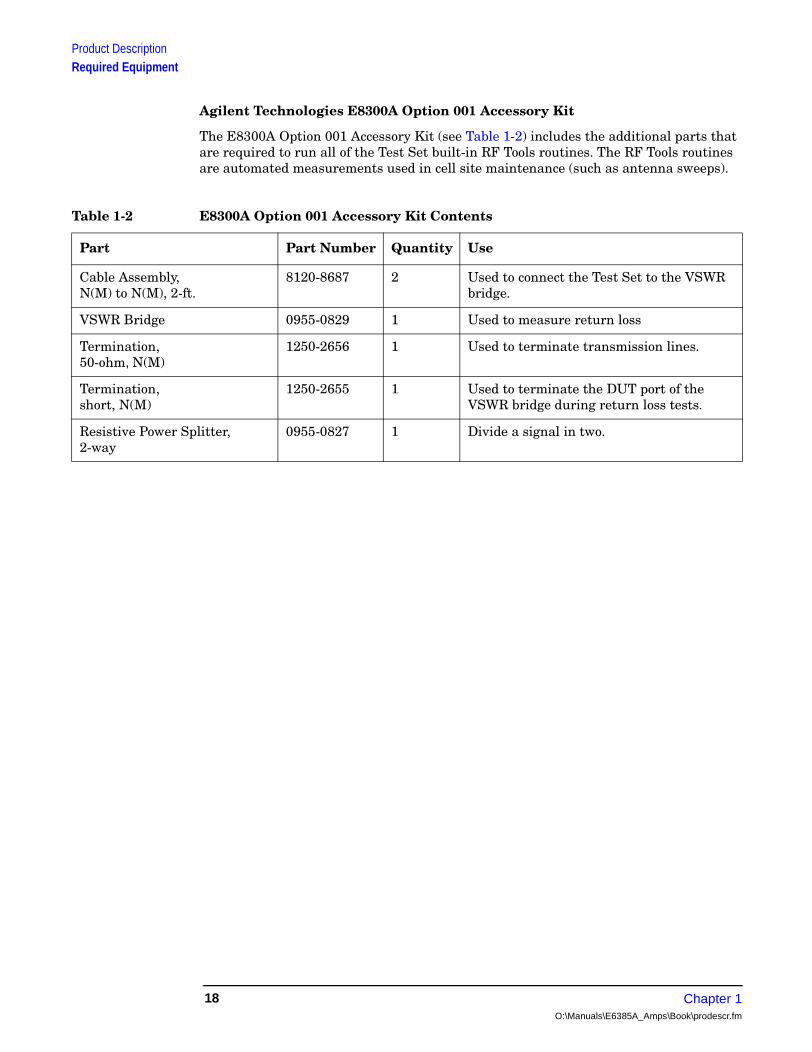
The E8300A Option 001 Accessory Kit (see Table 1-2) includes the additional parts that are required to run all of the Test Set built-in RF Tools routines. The RF Tools routines are automated measurements used in cell site maintenance (such as antenna sweeps).
Table 1-2 E8300A Option 001 Accessory Kit Contents
Part Part Number Quantity Use
Cable Assembly, N(M) to N(M), 2-ft.
8120-8687 2 Used to connect the Test Set to the VSWR bridge.
VSWR Bridge 0955-0829 1 Used to measure return loss
Termination, 50-ohm, N(M)
1250-2656 1 Used to terminate transmission lines.
Termination, short, N(M)
1250-2655 1 Used to terminate the DUT port of the VSWR bridge during return loss tests.
Resistive Power Splitter, 2-way
0955-0827 1 Divide a signal in two.
Chapter 1O:\Manuals\E6385A_Amps\Book\prodescr.fm
18
Product DescriptionRequired Equipment
Pro
du
ct Descrip
tion
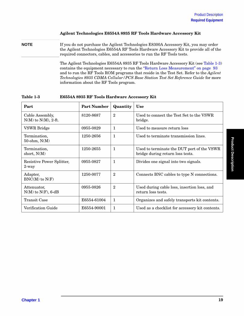
Agilent Technologies E6554A 8935 RF Tools Hardware Accessory Kit
NOTE If you do not purchase the Agilent Technologies E8300A Accessory Kit, you may order the Agilent Technologies E6554A RF Tools Hardware Accessory Kit to provide all of the required connectors, cables, and accessories to run the RF Tools tests.
The Agilent Technologies E6554A 8935 RF Tools Hardware Accessory Kit (see Table 1-3) contains the equipment necessary to run the “Return Loss Measurement” on page 93 and to run the RF Tools ROM programs that reside in the Test Set. Refer to the Agilent Technologies 8935 CDMA Cellular/PCS Base Station Test Set Reference Guide for more information about the RF Tools program.
Table 1-3 E6554A 8935 RF Tools Hardware Accessory Kit
Part Part Number Quantity Use
Cable Assembly,N(M) to N(M), 2-ft.
8120-8687 2 Used to connect the Test Set to the VSWR bridge.
VSWR Bridge 0955-0829 1 Used to measure return loss
Termination, 50-ohm, N(M)
1250-2656 1 Used to terminate transmission lines.
Termination, short, N(M)
1250-2655 1 Used to terminate the DUT port of the VSWR bridge during return loss tests.
Resistive Power Splitter, 2-way
0955-0827 1 Divides one signal into two signals.
Adapter, BNC(M) to N(F)
1250-0077 2 Connects BNC cables to type N connections.
Attenuator, N(M) to N(F), 6-dB
0955-0826 2 Used during cable loss, insertion loss, and return loss tests.
Transit Case E6554-61004 1 Organizes and safely transports kit contents.
Verification Guide E6554-90001 1 Used as a checklist for accessory kit contents.
Chapter 1 19

Product DescriptionGetting Help, Test Software Upgrades, and Training
Getting Help, Test Software Upgrades, and TrainingFor instrument servicing, see the Agilent Technologies 8935 Series E6380A CDMA Test Set Assembly Level Repair Guide.
For application assistance, call the Application Hotline (1-800-922-8920, USA and Canada only).
For information about Test Software upgrades and hands-on training, contact the local Agilent Technologies sales engineer.
Chapter 1O:\Manuals\E6385A_Amps\Book\prodescr.fm
20

Installatio
n
2 Installation
This chapter describes the processes required to load and run the Test Software, connect the equipment, and make initial settings to configure the Test Set and the Test Software. You must complete the procedures in this chapter before attempting measurements with the Test Software.
Chapter 2 21

InstallationOverview
OverviewThe procedures included in this chapter are as follows:
1. “Loading and Running the Test Software” on page 23.
2. “Navigating the Test Software” on page 25
3. “Operating the BTS Laptop Utility Program” on page 27.
NOTE BTS Laptop Utility program operation requires the use of a personal computer (PC) (usually a laptop PC). The use of a PC is not an absolute requirement, but the test examples in Chapter 4, “Performing Tests,” on page 59 use a PC to control the cell site via the Mobile Switching Center (MSC). The Test Software also supports testing without PC control. If you elect not to use a PC with the Test System, skip the section that describes using the BTS Laptop Utility program and refer to “Testing without MSC Control” on page 126 for a summary of differences when running without the PC.
4. “Connecting the PC to the Test Set and the MSC” on page 31.
5. “Determining the Test Set to Site Equipment Connections” on page 35.
6. “Configuring the Test Software” on page 37.
7. “Defining a Frequency Plan” on page 43.
8. “Establishing a Connection with the MSC for Testing” on page 53.
Chapter 2O:\Manuals\E6385A_Amps\Book\install.fm
22
InstallationLoading and Running the Test Software
Installatio
n
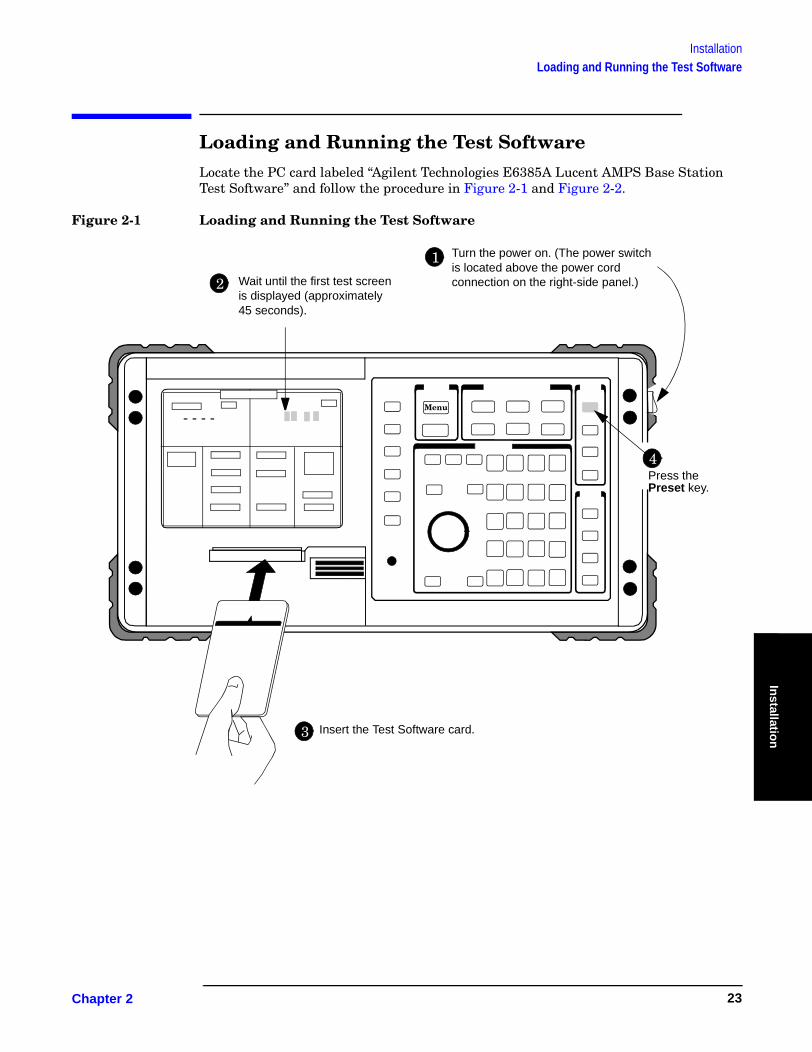
Loading and Running the Test SoftwareLocate the PC card labeled “Agilent Technologies E6385A Lucent AMPS Base Station Test Software” and follow the procedure in Figure 2-1 and Figure 2-2.
Figure 2-1 Loading and Running the Test Software
Turn the power on. (The power switch is located above the power cord connection on the right-side panel.)
1
2 Wait until the first test screen is displayed (approximately 45 seconds).
- - - -
3 Insert the Test Software card.
Menu
4Press the Preset key.
Chapter 2 23
InstallationLoading and Running the Test Software
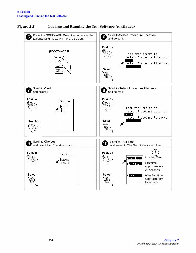
Figure 2-2 Loading and Running the Test Software (continued)
Scroll to Choices: and select the Procedure name.
Scroll to Run Test and select it. The Test Software will load.
Scroll to Select Procedure Filename: and select it.
Scroll to Card and select it.
Press the SOFTWARE Menu key to display the Lucent AMPS Tests Main Menu screen.
Scroll to Select Procedure Location: and select it.5
7 8
109
6
DEMOLAMPS
Loading Time:
First time: approximately 20 seconds.
After first time: approximately 8 seconds.
Chapter 2O:\Manuals\E6385A_Amps\Book\install.fm
24

InstallationNavigating the Test Software
Installatio
n
Navigating the Test SoftwareAfter the Test Software has loaded, the Lucent AMPS Tests Main Menu screen will appear on the Test Set display (see Figure 2-3).
Configuration operations, test utilities, and tests are grouped into sub-menus. Turn and press the knob to access the desired sub-menu.
Figure 2-3 Lucent AMPS Tests Main Menu Screen
Main Menu Functions
• Test Configuration – Define test information used by all tests; such as identifying the timing reference signal source, measurement port selection, number of averages, Walsh code power units, cable losses, and Base Station TX Test Port coupling factor.
• Base Station Configuration – Enter the specific cell site and Base Station information that the Test Software requires to control the Base Station when communicating with the MSC during tests (after configuring the PC and verifying its operation).
• Calibration/Utilities – Access procedures used to ensure optimal calibration of the Test Set and test cables.
• Test Selections – Access the available tests.
• Serial Port Configuration – Access routines used to define the serial port communication settings for interfacing with the PC serial port.
Chapter 2 25

InstallationNavigating the Test Software
Changing Settings and Using USER Keys
See Figure 2-4 for information on settings and USER keys.
Figure 2-4 Settings and USER Keys
KnobThe knob controls the cursor position on the display and is used sometimes to make numeric entries. Pressing the knob has the same effect as pressing the Enter key.
USER Keys and FieldsThe USER Keys (k1 - k5) correspond to fields 1-5 on the right side of the test screen. These keys are used for navigating through menus and for making selections. In many lower-level menus, a “Return” key is provided to display the previous screen.
Menu SelectionsSome Menu selections are entry fields. When one of these is selected, a highlighted area appears and you may key in a value using the DATA keys, or rotate the knob to change the value in the field. When the desired value is set, press the knob or the Enter key.
k1
k2
k3
k4
k5
Chapter 2O:\Manuals\E6385A_Amps\Book\install.fm
26

InstallationOperating the BTS Laptop Utility Program
Installatio
n
Operating the BTS Laptop Utility ProgramThe Test Software can control the cell site to perform tests in much less time than would be required under manual control. In order to control the Base Station, you may use a PC and modem to dial the MSC directly, or you may use a PC to establish a telnet connection to the MSC. The BTS Laptop Utility program running on that PC allows the Test Set to communicate with the MSC through the PC for automatic testing.
NOTE The method of site control described in this section is optional, but is highly desirable when possible. If you elect to use other means of controlling the site equipment, some information about the Base Station is still required. Enter the appropriate information in the Base Station Configuration Menu screen (see “Base Station Configuration” on page 39), skip the rest of this chapter, and start testing (see Chapter 4, “Performing Tests,” on page 59). See also “Testing without MSC Control” on page 126.
If you elect not to control the MSC using a PC, you may skip the rest of this chapter. Note however, that the procedures in Chapter 4, “Performing Tests,” on page 59 use a PC for site control.
The BTS Laptop Utility program is shipped with the Test Software on two separate 3.5-inch diskettes. You must install the BTS Laptop Utility program on the PC to communicate with the MSC. The utility program also provides several other helpful functions.
The BTS Laptop Utility program provides the following window functions:
• Switch Terminal – A window that: 1) works with the PC internal modem to dial into the MSC, or with the PC and a telnet connection to the MSC, and 2) displays the information sent to and from the MSC.
• Test Set Terminal – A window in which you may view commands sent by the Test Set to the MSC.
• Other Data – A window from which to download frequency plans to the Test Set and in which short-form test results are displayed.
• Test Results – A window in which automated test results are displayed and may be saved for later use.
• Test Set Screen Capture – A window in which to capture screen images and save each as a bit mapped image. This is very helpful when using the Test Set spectrum analyzer or when you wish to capture some other screen. Note that IBASIC program operation must be paused first, by pressing the Pause/Continue key, to print any of the TESTS screens used for automated testing.
For more information on the windows in the above list, see “BTS Laptop Utility Program Windows” on page 113. For additional information on using the BTS Laptop Utility program after installation, refer to the online Help topics included with that program.
Chapter 2 27

InstallationOperating the BTS Laptop Utility Program
System Requirements for BTS Laptop Utility Program
If the PC does not meet the following minimum system requirements, this could cause erratic operation and longer test times.
• 166-MHz Pentium Processor
• 16 megabytes of RAM
• Windows® 95, Windows 98, or Windows NT 4.0 (Intel based)
• Available RS-232 serial port
• Internal modem
Installing the BTS Laptop Utility Program
The BTS Laptop Utility program comes compressed on two install diskettes for easy setup on the PC. Simply insert the first diskette into the drive, select Start then Run, then type A:\Setup. The install shield will lead you through the installation process (see Figure 2-5).
Figure 2-5 Installing the BTS Laptop Utility Program
Configuring the Test Set and PC Serial Ports for Communication with the Test Set
After installing the BTS Laptop Utility program, you must configure the Test Set and PC serial ports to communicate with the Test Set.
Configure the serial ports as follows:
Step 1. On the Test Set, determine and record the Test Set SERIAL 9 port data transfer (baud) rate as follows:
• Load and run the Test Software (see“Loading and Running the Test Software” on page 23). The Test Software will display the Lucent AMPS Tests Main Menu screen.
• Select the Serial Port Configuration field. The Test Software will display the Serial Port Configuration Menu screen.
• Select the Serial 9 Port Configuration field. The Test Software will display the Serial 9 Port Configuration Menu screen.
Chapter 2O:\Manuals\E6385A_Amps\Book\install.fm
28
InstallationOperating the BTS Laptop Utility Program
Installatio
n
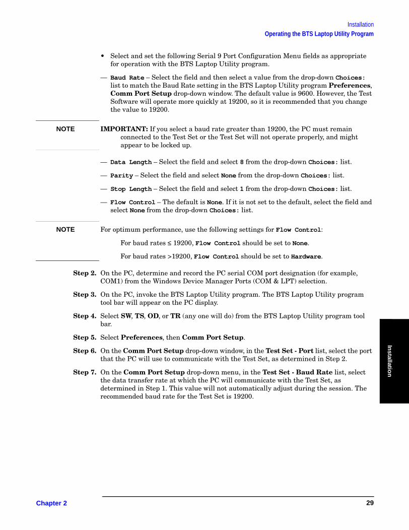
• Select and set the following Serial 9 Port Configuration Menu fields as appropriate for operation with the BTS Laptop Utility program.
— Baud Rate – Select the field and then select a value from the drop-down Choices: list to match the Baud Rate setting in the BTS Laptop Utility program Preferences, Comm Port Setup drop-down window. The default value is 9600. However, the Test Software will operate more quickly at 19200, so it is recommended that you change the value to 19200.
NOTE IMPORTANT: If you select a baud rate greater than 19200, the PC must remain connected to the Test Set or the Test Set will not operate properly, and might appear to be locked up.
— Data Length – Select the field and select 8 from the drop-down Choices: list.
— Parity – Select the field and select None from the drop-down Choices: list.
— Stop Length – Select the field and select 1 from the drop-down Choices: list.
— Flow Control – The default is None. If it is not set to the default, select the field and select None from the drop-down Choices: list.
NOTE For optimum performance, use the following settings for Flow Control:
For baud rates ≤ 19200, Flow Control should be set to None.
For baud rates >19200, Flow Control should be set to Hardware.
Step 2. On the PC, determine and record the PC serial COM port designation (for example, COM1) from the Windows Device Manager Ports (COM & LPT) selection.
Step 3. On the PC, invoke the BTS Laptop Utility program. The BTS Laptop Utility program tool bar will appear on the PC display.
Step 4. Select SW, TS, OD, or TR (any one will do) from the BTS Laptop Utility program tool bar.
Step 5. Select Preferences, then Comm Port Setup.
Step 6. On the Comm Port Setup drop-down window, in the Test Set - Port list, select the port that the PC will use to communicate with the Test Set, as determined in Step 2.
Step 7. On the Comm Port Setup drop-down menu, in the Test Set - Baud Rate list, select the data transfer rate at which the PC will communicate with the Test Set, as determined in Step 1. This value will not automatically adjust during the session. The recommended baud rate for the Test Set is 19200.
Chapter 2 29

InstallationOperating the BTS Laptop Utility Program
Configuring the PC to Communicate with the MSC
After installing the BTS Laptop Utility program, if you are using the utility program to communicate with the MSC, you must configure the PC to do so. This may be done in either of two ways: 1) by using modem to dial the MSC directly, or 2) by using a telnet connection. The telnet connection may be either a dial-up Internet connection, or a direct Internet connection. The dial-up Internet connection would use the PC modem; the direct Internet connection would use a PC LAN (the most common of which is ethernet).
Modem Connection
If you elect to use a modem connection, configure the MSC connection as follows:
Step 1. On the PC, determine and record the PC modem port COM designation (for example, COM2) from the Windows Device Manager Modem selection.
Step 2. On the PC, invoke the BTS Laptop Utility program. The BTS Laptop Utility program tool bar will appear on the PC display.
Step 3. Select SW, TS, OD, or TR (any one will do) from the BTS Laptop Utility program tool bar.
Step 4. Select Preferences, then Comm Port Setup.
Step 5. On the Comm Port Setup drop-down menu, in the Switch - Port list, select the PC COM port assigned to the PC modem, as determined in Step 1.
If the modem port is already in use, the Test Software will display a message stating that a device already has control of that port. The most common cause is a communication program running in the PC background. Close the other program and reselect the required COM port.
Step 6. On the Comm Port Setup drop-down menu, in the Switch - Baud Rate list, select the data transfer rate at which the PC will communicate with the modem. Note that this is not the rate at which the modem will communicate with the MSC. Most modems negotiate at the start of the session with the modem on the other end of the line for the best data transfer rate. A typical setting is 57600.
Telnet Connection
If you elect to use a telnet connection, configure the MSC connection as follows:
Step 1. On the PC, invoke the BTS Laptop Utility program. The BTS Laptop Utility program tool bar will appear on the PC display.
Step 2. Select SW, TS, OD, or TR (any one will do) from the BTS Laptop Utility program tool bar.
Step 3. Select Preferences, then Comm Port Setup.
Step 4. On the Comm Port Setup drop-down menu, in the Switch - Port list, select Telnet.
Step 5. On the Comm Port Setup drop-down menu, the Switch - Baud Rate list is not active for a telnet connection. Make no selection.
Chapter 2O:\Manuals\E6385A_Amps\Book\install.fm
30

InstallationConnecting the PC to the Test Set and the MSC
Installatio
n
Connecting the PC to the Test Set and the MSCThe following sections describe the processes for connecting the PC to both the Test Set and the MSC.
Connecting the PC to the Test Set
Connect a null modem cable (DB9 to DB9) from the Test Set to the COM port of the PC as shown in Figure 2-6.
Figure 2-6 Test Set to PC and PC to MSC Connection
At this point, you should be able to communicate with the Test Software.
To test the connection, configure the test set as follows, then attempt a screen capture.
NOTE The screen capture function is inoperable while the Test Software is running. The Test Software must be paused.
Step 1. If the Test Software is running (a star appears in the upper right-hand corner of the display), press the Pause/Continue key to pause it.
Step 2. Press the Test Set Shift key. then the Inst Config (I/O Config) key. The Test Set will display the I/O CONFIGURE screen.
Step 3. Select the Serial_9 In field and press the knob to toggle the setting to Inst (underlined).
Step 4. Press the Test Set Shift key, then the Print (Printer Config) key. The Test Set will display the PRINTER CONFIGURE screen.
Step 5. Select the Model field and select DeskJet from the drop-down Choices: list.
MSC
Phone Line
Laptop PC
Test Set Side Panel
or LAN Connection
COM DB9 Connector
Null Modem Cable
DB9 Connector
SERIAL 9
SERIAL 10
SERIAL 11
SERIAL 9 Port
Chapter 2 31
InstallationConnecting the PC to the Test Set and the MSC
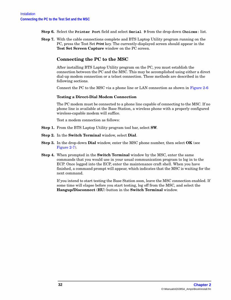
Step 6. Select the Printer Port field and select Serial 9 from the drop-down Choices: list.
Step 7. With the cable connections complete and BTS Laptop Utility program running on the PC, press the Test Set Print key. The currently-displayed screen should appear in the Test Set Screen Capture window on the PC screen.
Connecting the PC to the MSC
After installing BTS Laptop Utility program on the PC, you must establish the connection between the PC and the MSC. This may be accomplished using either a direct dial-up modem connection or a telnet connection. These methods are described in the following sections.
Connect the PC to the MSC via a phone line or LAN connection as shown in Figure 2-6
Testing a Direct-Dial Modem Connection
The PC modem must be connected to a phone line capable of connecting to the MSC. If no phone line is available at the Base Station, a wireless phone with a properly configured wireless-capable modem will suffice.
Test a modem connection as follows:
Step 1. From the BTS Laptop Utility program tool bar, select SW.
Step 2. In the Switch Terminal window, select Dial.
Step 3. In the drop-down Dial window, enter the MSC phone number, then select OK (see Figure 2-7).
Step 4. When prompted in the Switch Terminal window by the MSC, enter the same commands that you would use in your usual communication program to log in to the ECP. Once logged into the ECP, enter the maintenance craft shell. When you have finished, a command prompt will appear, which indicates that the MSC is waiting for the next command.
If you intend to start testing the Base Station soon, leave the MSC connection enabled. If some time will elapse before you start testing, log off from the MSC, and select the Hangup/Disconnect (HU) button in the Switch Terminal window.
Chapter 2O:\Manuals\E6385A_Amps\Book\install.fm
32

InstallationConnecting the PC to the Test Set and the MSC
Installatio
n
Figure 2-7 Dialing and Logging Into the MSC Using the Switch Terminal Window
Select Dial, and enter the phone number for the MSC.
After the MSC answers, enter your login and password as usual to enter the Maintenance Craft Shell.
Chapter 2 33
InstallationConnecting the PC to the Test Set and the MSC
Testing a Telnet Connection
The telnet connection uses the Internet to connect to the MSC. You may use either a direct connection (using a LAN such as ethernet) or a dial-up connection (using the PC modem).
Test a telnet connection as follows:
Step 1. Use the PC to establish a telnet connection to the MSC according to your preferred method (direct or dial-up).
Step 2. From the BTS Laptop Utility program tool bar, select SW.
Step 3. In the Switch Terminal window, select Dial.
Step 4. In the drop-down Dial window, enter the IP address as the phone number, then select OK (see Figure 2-7).
Step 5. When prompted by the MSC in the Switch Terminal window, enter the same commands that you would use in your usual communication program to log in to the ECP. Once logged into the ECP, enter the maintenance craft shell. When you have finished, a command prompt will appear, which indicates that the MSC is waiting for the next command.
If you intend to start testing the Base Station soon, leave the MSC connection enabled. If some time will elapse before you start testing, log off from the MSC, and select the Hangup/Disconnect (HU) button in the Switch Terminal window.
Chapter 2O:\Manuals\E6385A_Amps\Book\install.fm
34

InstallationDetermining the Test Set to Site Equipment Connections
Installatio
n
Determining the Test Set to Site Equipment ConnectionsAt this point in the process, you must decide the Test Set port and the Base Station port to be used in testing. At appropriate points in a test sequence, the Test Software will display prompts directing you to make connections. For details on the required connections, see Chapter 3, “Connections,” on page 55.
Which Test Set Port to Use – ANT IN or RF IN/OUT?
CAUTION The Test Set ANT IN port is only used for very low signal levels ≤ 60 mW (17.78 dBm). Therefore, to prevent damage to the Test Set, never connect this port directly to the Base Station TX Antenna Port. This port is typically connected to the Base Station TX Test Port.
The Test Set RF IN/OUT port is for signals of ≤75 watts continuous wave or ≤15 watts CDMA. This is the only port on the Test Set that you should connect directly to the Base Station TX Antenna Port. If power levels from the Base Station exceed the specification of the port, use an appropriate signal attenuator.
Which Base Station Port to Use – TX Test or TX Antenna?Testing may be performed while connected to either the Base Station Test Port or the Base Station Antenna Port. Testing at the Antenna Port involves taking the Base Station out of service. The choices are described in the following sections.
In-Service Testing Using the Base Station TX Test Port
The Base Station TX Test Port signal is derived from the directional coupler that is connected between the Linear Amplifier and the Base Station TX Antenna Port (see Figure 2-8). This allows you to make measurements on an active Base Station without disconnecting the transmit antenna and interrupting service. You must enter a value for the coupling factor (loss) through the directional coupler to compensate power measurements (see “Test Configuration” on page 38). Coupling factors are typically 40 to 70 dB, but might vary, depending on the Base Station design.
Figure 2-8 Transmitter Output Path Simplified Diagram
Antenna
Directional
Coupler
Base Station
Linear
Amplifier
TX Test PortTX Antenna Port
Coupling Factor is the loss through the directional coupler to the TX Test port.
Chapter 2 35
InstallationDetermining the Test Set to Site Equipment Connections
If you are uncertain of the exact coupling factor, the Test Software contains a utility to measure the coupling factor (see “TX Test Port Coupling Measurements” on page 88).
NOTE If you are uncertain of the Specified Output Power for the transmitter at the Base Station TX Antenna Port, the Test Software must measure the power to calculate the coupling factor. This requires that you take the Base Station out of service to connect the Test Set directly to the Base Station TX Antenna Port during the calibration routine.
One disadvantage to using the Base Station TX Test Port to make measurements is the possibility that its coupler is malfunctioning and therefore will cause erroneous measurements. If TX power measurements fail by a large amount, but you suspect the actual transmitted power is correct, take the Base Station out of service and make measurements directly at the Base Station TX Antenna Port to verify the failing reading. If the Test Software is correctly configured, TX power measurements using the Base Station TX Test Port and TX Antenna Port should not differ significantly.
Out-of-Service Testing Using the Base Station TX Antenna Port
Disconnecting a TX antenna feed line and connecting the Test Set to the Base Station TX Antenna Port (see Figure 2-8) requires that you first take the Base Station out of service (disable call processing and turn off all transmissions to that TX Antenna Port).
The Base Station may be taken out of service (and turned back on to make measurements) in two ways:
1. Access the MSC using a PC and the BTS Laptop Utility program to control the Base Station through its maintenance software.
2. Call the MSC and have switch personnel control the Base Station for you.
One benefit of testing directly at the Base Station TX Antenna Port is the confidence that the measurement will reflect the true output power of the Base Station at the point at which the antenna feed line connects to the Base Station. This verifies the operation of the full transmission path inside the Base Station. It also provides an opportunity to perform transmission line and antenna testing while the antenna is disconnected from the Base Station.
Chapter 2O:\Manuals\E6385A_Amps\Book\install.fm
36

InstallationConfiguring the Test Software
Installatio
n
Configuring the Test SoftwareIf the Test Software is not loaded and running, see “Loading and Running the Test Software” on page 23.
After the Test Software has loaded and is running, the Test Software will display the Lucent AMPS Tests Main Menu screen (see Figure 2-9). Configuration operations, test utilities, and tests are grouped into the listed sub-menus. Turn and press the knob to access the desired sub-menu.
Figure 2-9 Lucent AMPS Tests Main Menu Screen
Chapter 2 37

InstallationConfiguring the Test Software
Test Configuration
Before the Test Software can perform automated Base Station testing, it must have available certain information regarding test conditions. Supply this information on the Test Configuration Menu screen.
Configure the test as follows:
Step 1. Select the Test Configuration field. The Test Software will display the Test Configuration Menu (see Figure 2-10).
Figure 2-10 Specifying Test Configuration Information
Step 2. Select the 8935 Reference Select field and select from the drop-down Choices: list to match the type of frequency reference for the Test Set.
• Select Auto to use the Test Set internal timebase, unless an external reference signal of sufficient amplitude is applied to the REF IN connector. If an external signal is applied, the Test Set automatically switches to use that external reference. You must then specify the external timebase frequency in the 8935 EXT Ref Frequency field.
• Select Internal to use the Test Set internal timebase always.
• Select External to use an external timebase, which must be connected to the REF IN connector.
Step 3. If an external time base is to be used, select the 8935 EXT Ref Frequency field and select the external timebase frequency from the drop-down Choices: list. The available selections are: 1 MHz, 2 MHz, 5 MHz, 10 MHz, and 15 MHz.
Step 4. Select the Speaker Volume field and select from the drop-down Choices: list to set it to the desired level. The available selections are: Off, Quiet, and Loud. (This setting determines the volume of the beeps and tones issued by the Test Software during operation.)
Step 5. Press the k5 (Return) key to return to the Lucent AMPS Tests Main Menu screen.
Chapter 2O:\Manuals\E6385A_Amps\Book\install.fm
38
InstallationConfiguring the Test Software
Installatio
n
Base Station Configuration
Before the Test Software can control the Base Station, it must be able to notify the MSC as to the cell site and radio to test. The Test Software also requires information as to the Base Station type. You must supply this information on the Base Station Configuration Menu screen.
Configure the Base Station as follows:
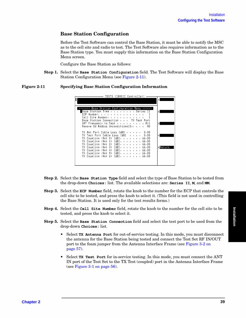
Step 1. Select the Base Station Configuration field. The Test Software will display the Base Station Configuration Menu (see Figure 2-11).
Figure 2-11 Specifying Base Station Configuration Information
Step 2. Select the Base Station Type field and select the type of Base Station to be tested from the drop-down Choices: list. The available selections are: Series II, M, and MM.
Step 3. Select the ECP Number field, rotate the knob to the number for the ECP that controls the cell site to be tested, and press the knob to select it. (This field is not used in controlling the Base Station. It is used only for the test results forms.)
Step 4. Select the Cell Site Number field, rotate the knob to the number for the cell site to be tested, and press the knob to select it.
Step 5. Select the Base Station Connection field and select the test port to be used from the drop-down Choices: list.
• Select TX Antenna Port for out-of-service testing. In this mode, you must disconnect the antenna for the Base Station being tested and connect the Test Set RF IN/OUT port to the foam jumper from the Antenna Interface Frame (see Figure 3-2 on page 57).
• Select TX Test Port for in-service testing. In this mode, you must connect the ANT IN port of the Test Set to the TX Test (coupled) port in the Antenna Interface Frame (see Figure 3-1 on page 56).
Chapter 2 39
InstallationConfiguring the Test Software
Step 6. Select the SAT Frequency to Test field and select the frequency (or frequencies) from the drop-down Choices: list. The available selections are: 5970 Hz, 6000 Hz, 6030 Hz, or All (which tests all frequencies).
Step 7. If you plan to test an AMPS Setup radio (or perhaps several radios), you may elect to test the radio unconditionally, even if the MSC procedures would prefer that you not take the radio out of service. To do this, select the Remove SU Radios Unconditionally field, and press the knob to toggle it to YES.
Step 8. Select the TX Ant Port Cable Loss [dB] field and either turn the knob to the desired value and press the knob to select that value, or use the DATA ENTRY keys to enter a value and either press the Enter key or press the knob to select that value. This value is the loss through the cable used to connect the Test Set RF IN/OUT port to the end of the transmit antenna foam jumper out of the Antenna Interface Frame during out-of-service testing (see Figure 3-2 on page 57).
Step 9. Select the TX Test Port Cable Loss [dB] field and either turn the knob to the desired value and press the knob to select that value, or use the DATA ENTRY keys to enter a value and either press the Enter key or press the knob to select that value. This is the loss through the cable used to connect the Test Set ANT IN port to the coupled test port in the Antenna Interface Frame during in-service testing (see Figure 3-1 on page 56).
Step 10. Select the TX Coupling field for each Base Station TX Test Port in the Antenna Interface Frame and enter the coupling factor to be used during tests. To do this, either turn the knob to the desired value and press the knob to select that value, or use the DATA ENTRY keys to enter a value and either press the Enter key or press the knob to select that value. If you do not know the coupling factor(s), run the “TX Test Port Coupling Measurements” on page 88 to measure it.
Step 11. Press the k5 (Return) key to return to the Lucent AMPS Tests Main Menu screen.
Chapter 2O:\Manuals\E6385A_Amps\Book\install.fm
40

InstallationConfiguring the Test Software
Installatio
n
Printing the FCC Title Page
After entering the information on the Base Station Configuration screen, you may print a title page that indicates the testing conditions used. This will provide a record for later use when comparing test results and conditions for each cell site.
To print the title page:
Step 1. Connect a PC on which the BTS Laptop Utility program is installed, configured, and running (see “Operating the BTS Laptop Utility Program” on page 27).
Step 2. Load and run the Test Software (see “Loading and Running the Test Software” on page 23).
Step 3. From the Lucent AMPS Test Main Menu, select the Calibration/Utilities field.
Step 4. In the Other Data window, select the Log button (to toggle it to “on”) to enable logging. The Log Filename window will appear.
Step 5. In the Log Filename window, select the location to which to save the file, enter the file name in the File name field (using a .txt extension), and select the Save button. The frequency plan file will be saved to the selected location.
Step 6. Select the Print FCC Title Page field. The BTS Laptop Utility program will print the title page in the Other Data window.
Step 7. Close the log file by selecting the Log button (to toggle it to “off”).
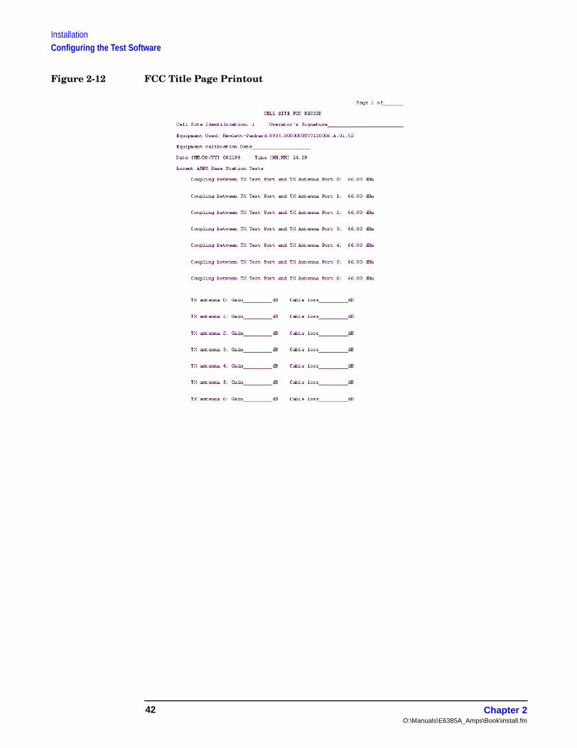
Step 8. Print the file from the PC using a word processor (see Figure 2-12).
Chapter 2 41
InstallationConfiguring the Test Software
Figure 2-12 FCC Title Page Printout
Chapter 2O:\Manuals\E6385A_Amps\Book\install.fm
42
InstallationDefining a Frequency Plan
Installatio
n
Defining a Frequency PlanWhen running the Full Cell Site Test mode (see “Full Site Test (FCC)” on page 65), you must provide information to the Test Software on the radios in the site being tested. This is done using frequency plans. Frequency plans are defined on a per site basis. There must be one plan for each site to be tested.
Once a plan is defined, you may store it on an SRAM card for later use for modification.
The Test Software supports two methods for entering the information into a frequency plan. The first method uses an editor that is part of the Test Software. In this method, all plan entry is done on the Test Set front panel. The second method uses an external PC with an editing program. In this method, the plan is defined and then downloaded to the Test Set for storage.
Defining a Frequency Plan Using the Editor in the Test Software
The process of defining a frequency plan using the editor function of the Test Software requires saving the frequency plan on an SRAM card. Before beginning the plan definition, make certain that an initialized SRAM card is available for file storage.
Step 1. From the Lucent AMPS Test Main Menu, select the Calibration/Utilities field. The Test Software will display the Calibration/Utilities Menu screen.
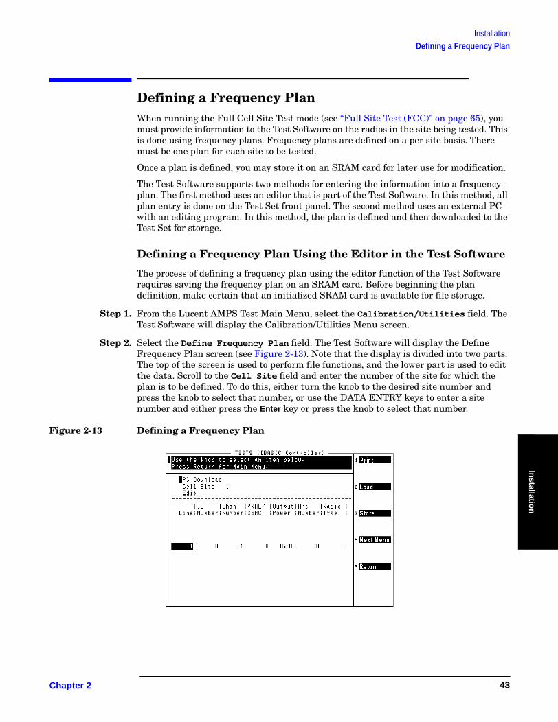
Step 2. Select the Define Frequency Plan field. The Test Software will display the Define Frequency Plan screen (see Figure 2-13). Note that the display is divided into two parts. The top of the screen is used to perform file functions, and the lower part is used to edit the data. Scroll to the Cell Site field and enter the number of the site for which the plan is to be defined. To do this, either turn the knob to the desired site number and press the knob to select that number, or use the DATA ENTRY keys to enter a site number and either press the Enter key or press the knob to select that number.
Figure 2-13 Defining a Frequency Plan
Chapter 2 43

InstallationDefining a Frequency Plan
Step 3. Select the Edit field to activate the lower part of the screen for editing. The first line will show a highlighted one (1). Note that the USER key assignments on the right side of the screen also changed to allow you to insert or delete lines of frequency plan information.
Step 4. Press the k1 (Ins Above) key to add lines to the list (see Figure 2-14). Each line of the plan corresponds to one radio in the site.
Figure 2-14 Adding Lines to the Frequency Plan
Step 5. Press the knob to highlight the seven entries for that line in the plan (see Figure 2-15). You may then modify the entries for that line by moving the cursor to the left of each entry, pressing the knob, and changing the value using the DATA ENTRY keys or the knob. After changing an entry, press the knob again to move to the next entry.
Figure 2-15 Changing Entries in the Frequency Plan
Chapter 2O:\Manuals\E6385A_Amps\Book\install.fm
44
InstallationDefining a Frequency Plan
Installatio
n
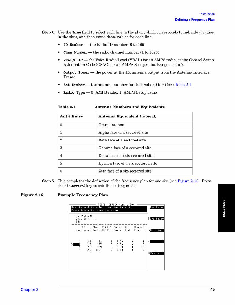
Step 6. Use the Line field to select each line in the plan (which corresponds to individual radios in the site), and then enter these values for each line:
• ID Number — the Radio ID number (0 to 199)
• Chan Number — the radio channel number (1 to 1023)
• VRAL/CSAC — the Voice RAdio Level (VRAL) for an AMPS radio, or the Control Setup Attenuation Code (CSAC) for an AMPS Setup radio. Range is 0 to 7.
• Output Power — the power at the TX antenna output from the Antenna Interface Frame.
• Ant Number — the antenna number for that radio (0 to 6) (see Table 2-1).
• Radio Type — 0=AMPS radio, 1=AMPS Setup radio.
Step 7. This completes the definition of the frequency plan for one site (see Figure 2-16). Press the k5 (Return) key to exit the editing mode.
Figure 2-16 Example Frequency Plan
Table 2-1 Antenna Numbers and Equivalents
Ant # Entry Antenna Equivalent (typical)
0 Omni antenna
1 Alpha face of a sectored site
2 Beta face of a sectored site
3 Gamma face of a sectored site
4 Delta face of a six-sectored site
5 Epsilon face of a six-sectored site
6 Zeta face of a six-sectored site
Chapter 2 45
InstallationDefining a Frequency Plan
Step 8. Insert an initialized SRAM card into the Test Set front panel card slot, and press the k3 (Store) key to store the plan. Store the plan using the Cell Site number entry.
Step 9. If you wish to define plans for other sites, repeat step 2 through step 8 for each site. Otherwise, press k5 (Return) to return to the Calibration/Utilities Menu.
Defining a Frequency Plan Using a PC
You may create a frequency plan using a PC and then download that plan to the Test Set. A plan created using a PC may be saved, reused, and updated as necessary.
Requirements
❏ A PC with an available serial communications port.
❏ A PC program for text editing (such as Windows Notepad) and a program for serial communications (such as the BTS Laptop Utility program shipped with the Test Software).
❏ A null modem cable for connecting the Test Set to the PC.
❏ Optional – An initialized SRAM card for storing the frequency plans once defined.
Test Set to PC Connection
If you have not done so already, configure the PC to communicate with the Test Set (see “Configuring the Test Set and PC Serial Ports for Communication with the Test Set” on page 28).
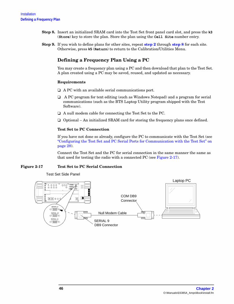
Connect the Test Set and the PC for serial connection in the same manner the same as that used for testing the radio with a connected PC (see Figure 2-17).
Figure 2-17 Test Set to PC Serial Connection
Laptop PC
COM DB9Connector
Null Modem Cable
Test Set Side Panel
DB9 Connector
SERIAL 9
SERIAL 10
SERIAL 11
SERIAL 9
Chapter 2O:\Manuals\E6385A_Amps\Book\install.fm
46
InstallationDefining a Frequency Plan
Installatio
n
Create the Frequency Plan File
You may use any text editor that allows you to save a file in an ASCII format to create a frequency plan. The following procedure outlines the process for creating a text file to download to the Test Set:
NOTE If necessary, refer to the documentation for the PC application software for details on opening new files, entering data, and storing the file.
Step 1. Start the text editor program on the PC.
Step 2. Open a new file to begin editing.
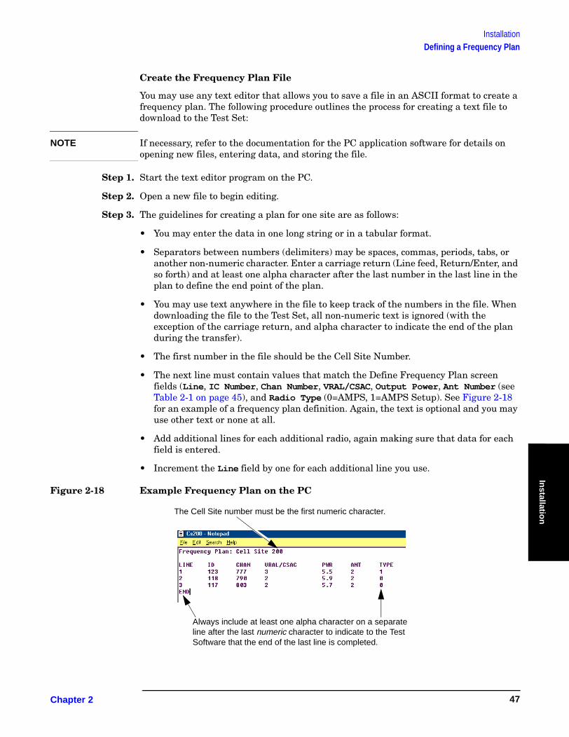
Step 3. The guidelines for creating a plan for one site are as follows:
• You may enter the data in one long string or in a tabular format.
• Separators between numbers (delimiters) may be spaces, commas, periods, tabs, or another non-numeric character. Enter a carriage return (Line feed, Return/Enter, and so forth) and at least one alpha character after the last number in the last line in the plan to define the end point of the plan.
• You may use text anywhere in the file to keep track of the numbers in the file. When downloading the file to the Test Set, all non-numeric text is ignored (with the exception of the carriage return, and alpha character to indicate the end of the plan during the transfer).
• The first number in the file should be the Cell Site Number.
• The next line must contain values that match the Define Frequency Plan screen fields (Line, IC Number, Chan Number, VRAL/CSAC, Output Power, Ant Number (see Table 2-1 on page 45), and Radio Type (0=AMPS, 1=AMPS Setup). See Figure 2-18 for an example of a frequency plan definition. Again, the text is optional and you may use other text or none at all.
• Add additional lines for each additional radio, again making sure that data for each field is entered.
• Increment the Line field by one for each additional line you use.
Figure 2-18 Example Frequency Plan on the PC
The Cell Site number must be the first numeric character.
Always include at least one alpha character on a separate line after the last numeric character to indicate to the Test Software that the end of the last line is completed.
Chapter 2 47

InstallationDefining a Frequency Plan
Step 4. Once the entries match the site configuration, save the file in an ASCII format using the extension .txt (for example: CS200.txt).
Step 5. If you wish to define plans for more than one site, repeat step 2 through step 4 until plans for all sites have been created and saved.
Step 6. Exit the editing program.
Send the Plan to the Test Set
Once you have connected the Test Set to the PC via the serial port and defined and saved a frequency plan, you may send the plan to the Test Set. The following procedure uses the BTS Laptop Utility program (shipped with the Test Software) to perform this function.
NOTE If you elect not to use the BTS Laptop Utility, refer to the documentation for the PC communication program for details on setting up serial communications, opening files, and transferring data.
Step 1. From the Lucent AMPS Test Main Menu, select the Calibration/Utilities field. The Test Software will display the Calibration/Utilities Menu screen.
Step 2. Select the Define Frequency Plan field. The Test Software will display the Define Frequency Plan screen.
Step 3. Select the PC Download field. The Test Software will display the screen shown in Figure 2-19 to indicate that it is ready to receive the frequency plan.
Figure 2-19 Test Software Ready Screen
Step 4. Load and run the BTS Laptop Utility program as explained in “Operating the BTS Laptop Utility Program” on page 27. When the program is running, the BTS Laptop Utility tool bar will appear on the PC screen (see Figure 2-20).
Chapter 2O:\Manuals\E6385A_Amps\Book\install.fm
48
InstallationDefining a Frequency Plan
Installatio
n
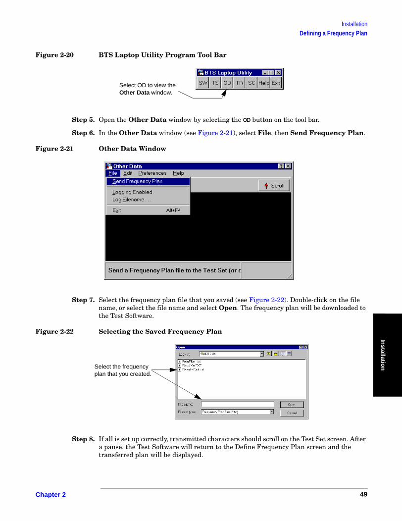
Figure 2-20 BTS Laptop Utility Program Tool Bar
Step 5. Open the Other Data window by selecting the OD button on the tool bar.
Step 6. In the Other Data window (see Figure 2-21), select File, then Send Frequency Plan.
Figure 2-21 Other Data Window
Step 7. Select the frequency plan file that you saved (see Figure 2-22). Double-click on the file name, or select the file name and select Open. The frequency plan will be downloaded to the Test Software.
Figure 2-22 Selecting the Saved Frequency Plan
Step 8. If all is set up correctly, transmitted characters should scroll on the Test Set screen. After a pause, the Test Software will return to the Define Frequency Plan screen and the transferred plan will be displayed.
Select OD to view the Other Data window.
Select the frequency plan that you created.
Chapter 2 49
InstallationDefining a Frequency Plan
NOTE If you wish to store the frequency plan data on an SRAM card, perform the next step. If not, skip the next step.
Step 9. With the correct cell site number and frequency plan data displayed, insert an initialized SRAM card into the Test Set and press the k3 (Store) key. The new frequency plan will be stored for that cell site number.
NOTE If you change the cell site number before storing, the data will be lost.
Step 10. If you have additional files to transfer for defining other sites, repeat step 3 through step 9 until all files have been sent to the Test Set (and stored to the card if you elected to do so).
Step 11. To exit the Define Frequency Plan menu, press the k5 (Return) key.
Loading a Frequency Plan from an SRAM Card
Frequency plans may be loaded from an SRAM card. Load the files from the SRAM card as follows:
Step 1. Insert the SRAM memory card with the frequency plan to be loaded.
Step 2. From the Lucent AMPS/TDMA Test Main Menu screen, select the Calibration/Utilities field. The Test Software will display the Calibration/Utilities Menu screen.
Step 3. Select the Define Frequency Plan field. The Test Software will display the Define Frequency Plan screen.
Step 4. Scroll to the Cell Site field, press the knob, and enter the number of the site that corresponds to the file that you wish to load. To do this, turn the knob to the desired site number and press the knob to select that number, or use the DATA ENTRY keys to enter a site number and either press the Enter key or press the knob to select that number. If the card has a plan for that site, the data will be loaded automatically when you enter the number.
NOTE If you edit a saved plan on the Test Set and then decide not to make the changes, if you have previously saved the plan to the SRAM card, simply press the k2 (Load) key and the on-screen data will be overwritten with numbers from the card.
Chapter 2O:\Manuals\E6385A_Amps\Book\install.fm
50
InstallationDefining a Frequency Plan
Installatio
n
Purging (Deleting) a Frequency Plan File
Frequency plans may be maintained by editing existing files. If there are plans that are no longer of use, however, you may purge (delete) the files from the SRAM card as follows:
Step 1. Insert the SRAM memory card with the frequency plan to be purged.
Step 2. From the Lucent AMPS Test Main Menu, select the Calibration/Utilities field. The Test Software will display the Calibration/Utilities Menu screen.
Step 3. Select the Define Frequency Plan field. The Test Software will display the Define Frequency Plan screen.
Step 4. Scroll to the Cell Site field, press the knob, and enter the number of the site that corresponds to the file you wish to delete. To do this, turn the knob to the desired site number and press the knob to select that number, or use the DATA ENTRY keys to enter a site number and either press the Enter key or press the knob to select that number.
Step 5. Press the k4 (Next Menu) key to access additional file operations.
Step 6. Press the k2 (Purge) key.
Step 7. The Test Software will display a query asking you to verify the purge operation for the cell site number entered. Press the k1 (Yes) key to purge the file.
Step 8. Press the k5 (Return) key twice to return to the Lucent AMPS Test Main Menu.
Chapter 2 51

InstallationDefining a Frequency Plan
Printing a Frequency Plan
If a PC with the BTS Laptop Utility program is connected to the Test Set, you may print frequency plans to the BTS Laptop Utility Other Data window. This can be useful for record-keeping. Print frequency plans as follows:
Step 1. Make certain that the BTS Laptop Utility program is loaded and running on the PC (see “Operating the BTS Laptop Utility Program” on page 27).
Step 2. From the Test Software Main Menu screen, select the Calibration/Utilities field. The Test Software will display the Define Frequency Plan screen.
Step 3. Select the Define Frequency Plan field.
Step 4. If the frequency plan that you wish to print is not currently loaded, insert the SRAM card containing the plan and select the plan by scrolling to Cell Site, pressing the knob, and entering the site number that corresponds to the plan of interest. The frequency plan data will be loaded automatically when you enter the number.
Step 5. In the Other Data window, select the Log button (toggle it to “on”) to enable logging. The Log Filename window will appear.
Step 6. In the Log Filename window, select the location to which to save the file, enter the file name in the File name field (using a .txt extension), and select the Save button. The frequency plan file will be saved to the selected location.
Step 7. Press the k1 (Print) key to send the frequency plan information to the Other Data window.
Step 8. Close the log file by selecting the Log button again (to toggle it to “off”).
Step 9. Print the file from the PC using a word processor.
Step 10. If you would like to print other plans, change the Cell Site field in the Define Frequency Plan screen to the appropriate number and repeat step 4 through step 9.
Step 11. When finished, press k5 (Return) twice to return to the Lucent AMPS Test Main Menu screen.
Chapter 2O:\Manuals\E6385A_Amps\Book\install.fm
52
InstallationEstablishing a Connection with the MSC for Testing
Installatio
n
Establishing a Connection with the MSC for TestingIf it is not set up already, you must establish the connection between the PC and the MSC. This may be accomplished using either a direct dial-up modem connection or a telnet connection. These methods are described in the following sections.
Connect the PC to the MSC via a phone line or LAN connection as shown in Figure 2-6 on page 31.
Establishing a Direct-Dial Modem Connection
The PC modem must be connected to a phone line capable of connecting to the MSC. If no phone line is available at the Base Station, a wireless phone with a properly configured wireless-capable modem will suffice.
Test a modem connection as follows:
1. From the BTS Utility program tool bar, select SW.
2. In the Switch Terminal window, select Dial.
3. In the drop-down Dial window, enter the MSC phone number, then select OK (see Figure 2-7 on page 33).
4. When prompted by the MSC in the Switch Terminal window, enter the same commands that you would use in your usual communication program to log in to the ECP. Once logged into the ECP, enter the maintenance craft shell. When you have finished, a command prompt will appear, which indicates that the MSC is waiting for the next command.
Establishing a Telnet Connection
The telnet connection uses the Internet to connect to the MSC. You may use either a direct connection (using a LAN such as ethernet) or a dial-up connection (using the PC modem).
Test a telnet connection as follows:
1. Use the PC to establish a telnet connection to the MSC according to your preferred method (direct or dial-up).
2. From the BTS Utility program tool bar, select SW.
3. In the Switch Terminal window, select Dial.
4. In the drop-down Dial window, enter the IP address as the phone number, then select OK (see Figure 2-7 on page 33).
5. When prompted by the MSC in the Switch Terminal window, enter the same commands that you would use in your usual communication program to log in to the ECP. Once logged into the ECP, enter the maintenance craft shell. When you have finished, a command prompt will appear, which indicates that the MSC is waiting for the next command.
Chapter 2 53

InstallationIf You Noticed Problems
If You Noticed ProblemsIf you were unable to load and run the Test Software, make the required entries, or encountered error messages, refer to Chapter 6, “Troubleshooting,” on page 129 for help.
Chapter 2O:\Manuals\E6385A_Amps\Book\install.fm
54

Co
nn
ection
s
3 Connections
This chapter shows the connections between the Test Set and the Base Station.
The Test Software will display a screen prompt whenever a connection or a change in connections is required.
Chapter 3 55
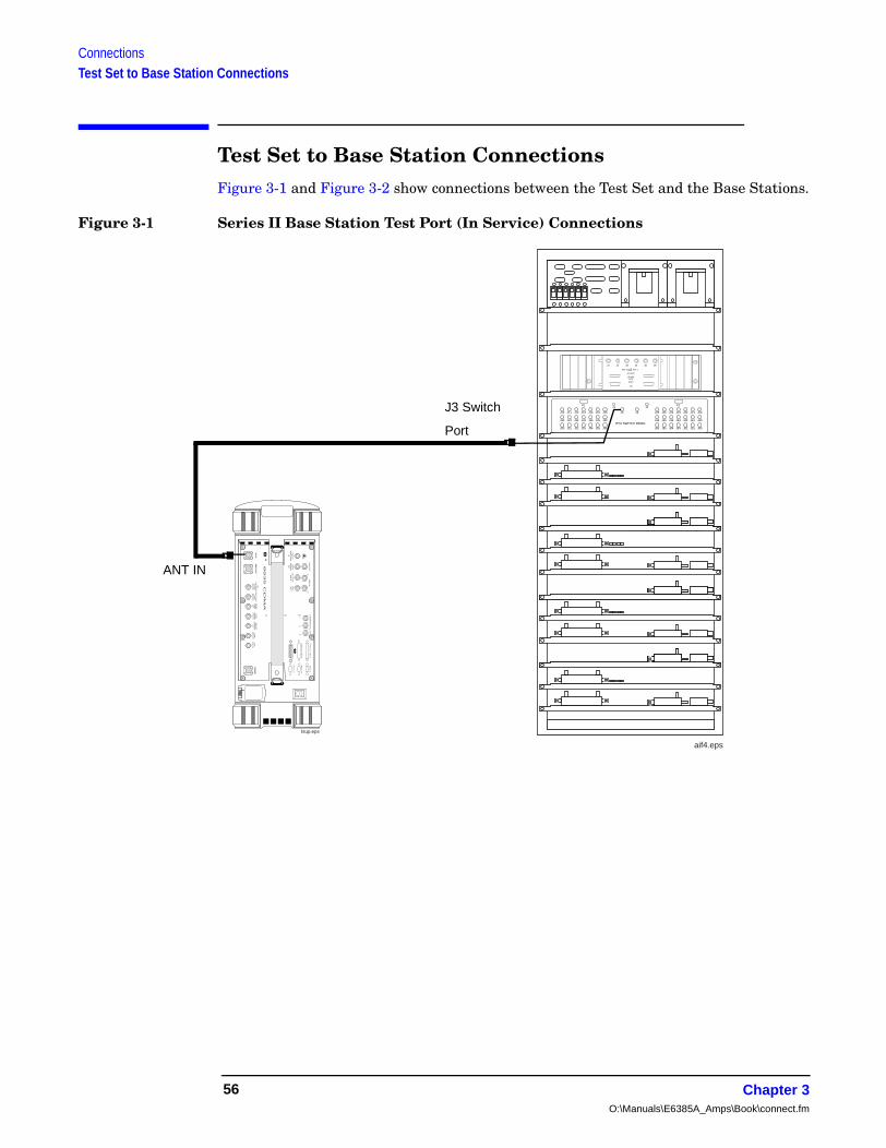
ConnectionsTest Set to Base Station Connections
Test Set to Base Station ConnectionsFigure 3-1 and Figure 3-2 show connections between the Test Set and the Base Stations.
Figure 3-1 Series II Base Station Test Port (In Service) Connections
J1 J2 J3 J4 J5 J6
REF 0 REF 1
NO GPS
15 MHZALM
STBY
ON
J10 J11 J12 J13
P1
J14 J15 J16 J3 J4
J30 J31 J32 J33 J34 J35 J36
J50 J51 J52 J53 J54 J55 J56
J26 J25 J24 J23
P2
J22 J21 J20
J46 J45 J44 J43 J42 J41 J40
J66 J65 J64 J63 J62 J61 J60
J1 J2
RTU SWITCH PANEL
aif4.eps
PA
RA
LL
EL
PO
RT
15
AU
DIO
OU
T
AN
ALO
GM
OD
ULA
TIO
NIN
AU
DIO
IN
SC
OP
EM
ON
ITO
RO
UT
EX
T S
CO
PE
TR
IG IN
VID
EO
OU
T
AN
T IN
DU
PLE
X O
UT
CH
IP C
LOC
K1.2288
MH
z OU
T
FR
AM
EC
LOC
KO
UT
EV
EN
SE
CO
ND
SY
NC
IN
TR
IGG
ER
QU
ALIF
IER
IN10 M
Hz
RE
F O
UT
EX
TR
EF
INR
F IN
/OU
T
IN
BA
SE
BA
ND
OU
T
HI
LO
QI
PA
RA
LL
EL
PO
RT
16
SE
RIA
L 9
SE
RIA
L 1
0
SE
RIA
L 1
1
16XC
HIP
CLO
CK
19.6608M
Hz O
UT
DA
TA
89
35
C
DM
A
tsup.eps
J3 Switch
Port
ANT IN
Chapter 3O:\Manuals\E6385A_Amps\Book\connect.fm
56

ConnectionsTest Set to Base Station Connections
Co
nn
ection
s
Figure 3-2 Series II Base Station TX Antenna Port (Out of Service) Connections
Chapter 3 57

ConnectionsTest Set to Base Station Connections
Chapter 3O:\Manuals\E6385A_Amps\Book\connect.fm
58

Perfo
rmin
g Tests
4 Performing Tests
This chapter describes detailed procedures to be used in running the Test Software tests and utilities.
Chapter 4 59
Performing TestsOverview
Overview
NOTE Testing might be interrupted if cell site diagnostics are initiated by the MSC while tests are being run. To prevent this, use a personal computer (PC) (usually a laptop PC) to send a command to inhibit diagnostics from the MSC before testing.
These test procedures describe the process from setting up a test to obtaining test results. To simplify the procedures, all are written to use a PC to communicate with the MSC (where applicable) and the Test Software will be set to send control commands.
Before making measurements, verify that you have performed the following setup and configuration processes:
• “Loading and Running the Test Software” on page 23
• “Operating the BTS Laptop Utility Program” on page 27
• “Connecting the PC to the Test Set and the MSC” on page 31.
• “Configuring the Test Software” on page 37.
• “Defining a Frequency Plan” on page 43.
• “Establishing a Connection with the MSC for Testing” on page 53.
Chapter 4O:\Manuals\E6385A_Amps\Book\perftst.fm
60
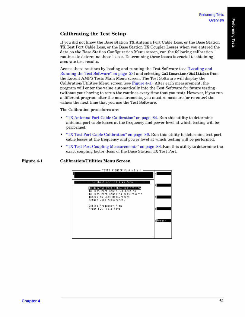
Performing TestsOverview
Perfo
rmin
g Tests
Calibrating the Test Setup
If you did not know the Base Station TX Antenna Port Cable Loss, or the Base Station TX Test Port Cable Loss, or the Base Station TX Coupler Losses when you entered the data on the Base Station Configuration Menu screen, run the following calibration routines to determine these losses. Determining these losses is crucial to obtaining accurate test results.
Access these routines by loading and running the Test Software (see “Loading and Running the Test Software” on page 23) and selecting Calibration/Utilities from the Lucent AMPS Tests Main Menu screen. The Test Software will display the Calibration/Utilities Menu screen (see Figure 4-1). After each measurement, the program will enter the value automatically into the Test Software for future testing (without your having to rerun the routines every time that you test). However, if you run a different program after the measurements, you must re-measure (or re-enter) the values the next time that you use the Test Software.
The Calibration procedures are:
• “TX Antenna Port Cable Calibration” on page 84. Run this utility to determine antenna port cable losses at the frequency and power level at which testing will be performed.
• “TX Test Port Cable Calibration” on page 86. Run this utility to determine test port cable losses at the frequency and power level at which testing will be performed.
• “TX Test Port Coupling Measurements” on page 88. Run this utility to determine the exact coupling factor (loss) of the Base Station TX Test Port.
Figure 4-1 Calibration/Utilities Menu Screen
Chapter 4 61

Performing TestsOverview
Selecting Tests
Select tests by loading and running the Test Software (see “Loading and Running the Test Software” on page 23) and selecting the Test Selections field on the Lucent CDMA Tests Main Menu screen. The Test Software will display the Test Selections Menu screen (see Figure 4-2).
Once you have selected a test to run, see the following list to locate the description of that test.
• “Full Site Test (FCC)” on page 65.
• “Single Radio Test” on page 68.
• “TX Power Adjustment” on page 71.
• “Spectrum Analyzer” on page 74.
• “RX Gain Test” on page 79.
• “TX Gain Test” on page 77.
• “TX –39 dBm Power Test” on page 81.
Figure 4-2 Test Selections Screen
Chapter 4O:\Manuals\E6385A_Amps\Book\perftst.fm
62
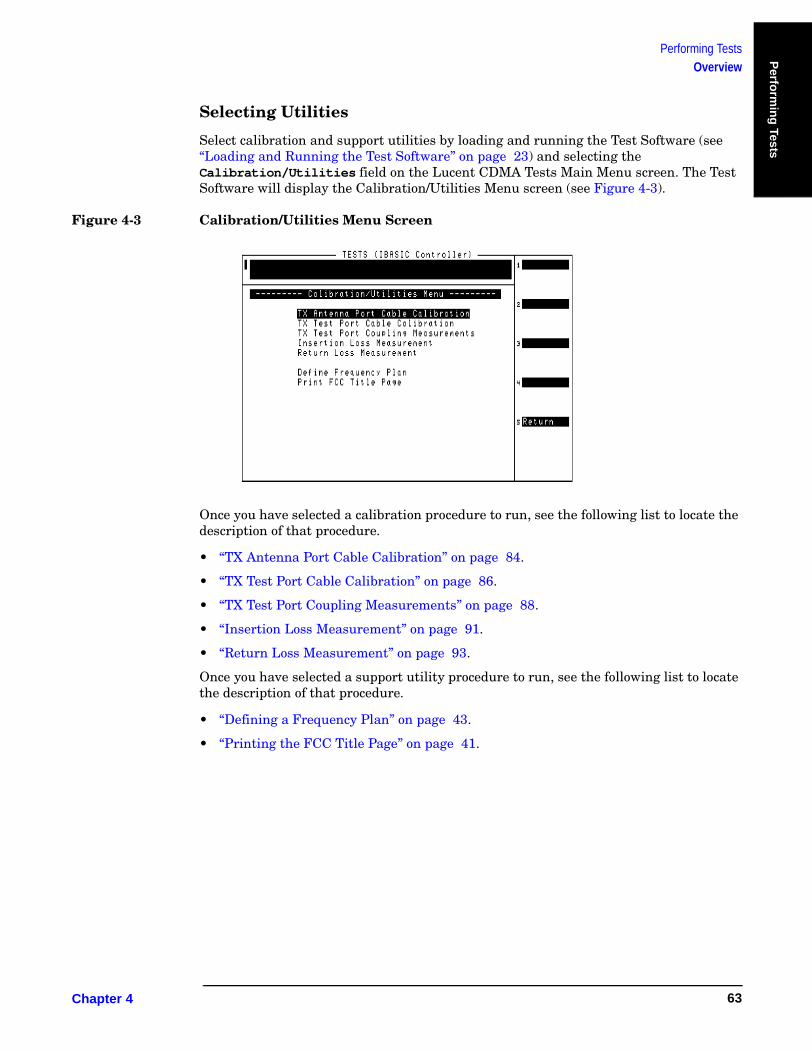
Performing TestsOverview
Perfo
rmin
g Tests
Selecting Utilities
Select calibration and support utilities by loading and running the Test Software (see “Loading and Running the Test Software” on page 23) and selecting the Calibration/Utilities field on the Lucent CDMA Tests Main Menu screen. The Test Software will display the Calibration/Utilities Menu screen (see Figure 4-3).
Figure 4-3 Calibration/Utilities Menu Screen
Once you have selected a calibration procedure to run, see the following list to locate the description of that procedure.
• “TX Antenna Port Cable Calibration” on page 84.
• “TX Test Port Cable Calibration” on page 86.
• “TX Test Port Coupling Measurements” on page 88.
• “Insertion Loss Measurement” on page 91.
• “Return Loss Measurement” on page 93.
Once you have selected a support utility procedure to run, see the following list to locate the description of that procedure.
• “Defining a Frequency Plan” on page 43.
• “Printing the FCC Title Page” on page 41.
Chapter 4 63

Performing TestsOverview
Running Tests
NOTE Before starting to run operational tests, make certain that you have set PARAMETER 32. ZZZZ Test Demo Mode [0=normal 1=demo] to 0.
You are now ready to select and run tests. On the Test Selections Menu screen, scroll to the test that you wish to run, and press the knob to select it. The test will run. You may then select another test and run it in the same manner. You may repeat this operation as many times as is necessary.
After successfully running the tests, it is recommended that you save all of the configuration information as a procedure file on an SRAM card for later retrieval (see “Saving/Deleting a Procedure” on page 109). This eliminates the requirement for re-entering the information if you run a different program, change parameters when testing another Base Station, or install new operating system firmware in the Test Set.
For More Information
For more details on the tests in this chapter:
• “Parameters” on page 118
• “Specifications (Pass/Fail Limits)” on page 124
If there were problems or error messages were displayed when running a test:
See Chapter 6, “Troubleshooting,” on page 129.
Chapter 4O:\Manuals\E6385A_Amps\Book\perftst.fm
64
Performing TestsFull Site Test (FCC)
Perfo
rmin
g Tests
Full Site Test (FCC)This test measures several aspects of radio performance on one or more radios. Measurements are made at the Base Station TX Test Ports in the Antenna Interface Frame, eliminating the need to take an entire antenna face down during testing.
Before the test can run, you must to create a frequency plan containing information about each radio to be tested (see “Defining a Frequency Plan” on page 43). Because the Test Software uses the frequency plan to control automatically all of the radios under test, this test cannot be performed using manual control of the Base Station. If you must test a radio using manual control, use the “Single Radio Test” on page 68.
The measurements made on each radio depends on its type: AMPS or AMPS Setup. The radio type is specified in the frequency plan.
The following measurements are made on all radios:
• TX Frequency Error
• TX Power (at a specific power amplifier step)
• TX Peak (+) Data Deviation
• TX Peak (-) Data Deviation
The following additional measurements are only made on an AMPS radio (not AMPS Setup):
• TX RMS Residual FM
• TX Average Peak Deviation @ −16 dBm
• TX Distortion @ −16 dBm
• TX Peak (+) Deviation @ 0 dBm
• TX Peak (−) Deviation @ 0 dBm
• TX SAT Average Peak Deviation @ 0 Hz
• TX SAT Frequency Error @ 0 Hz
After you have completed testing, if printing an FCC title page is appropriate, see “Printing the FCC Title Page” on page 41.
Chapter 4 65
Performing TestsFull Site Test (FCC)
Parameters and Specifications Used
The following parameters and specifications are used when running this test. See Chapter 5, “Reference,” on page 95 for descriptions of the parameters and specifications.
Parameters:
• 1. Adjust TX Power [0=no 1=on fail 2=always]
• 3. GN Power Output [0=meas 1=spec 2=blnk]
• The TX Coupling factor for the associated antenna(s) listed in the frequency plan must be entered. This is done in parameters 22 through 28.
• 30. TX Test Port Cable Loss
Specifications (Pass/Fail Limits):
This test uses all specifications described in “Specifications (Pass/Fail Limits)” on page 124.
Select and Run the Test
Select and run the Full Site Test (FCC) as follows:
Step 1. Create a frequency plan for the radios to be tested (see “Defining a Frequency Plan” on page 43).
Step 2. From the Lucent AMPS Test Main Menu screen, select the Test Selections field. The Test Software will display the Test Selections Menu screen.
Step 3. Select the Full Site Test (FCC) field.
Step 4. Connect the Test Set to the Base Station as shown in the on-screen prompts.
Step 5. Press the k1 [Proceed] key.
Review the Results
The Test Software will display test results for each radio as it tests. It provides prompts at the top of the display to indicate the measurement or action currently being performed. See Figure 4-4.
Chapter 4O:\Manuals\E6385A_Amps\Book\perftst.fm
66
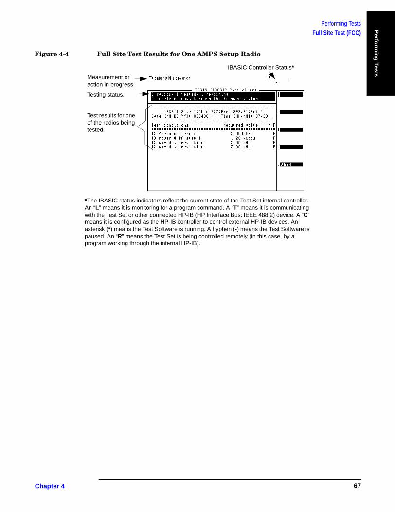
Performing TestsFull Site Test (FCC)
Perfo
rmin
g Tests
Figure 4-4 Full Site Test Results for One AMPS Setup Radio
Measurement or action in progress.
Testing status.
Test results for one of the radios being tested.
IBASIC Controller Status*
*The IBASIC status indicators reflect the current state of the Test Set internal controller. An “L” means it is monitoring for a program command. A “T” means it is communicating with the Test Set or other connected HP-IB (HP Interface Bus: IEEE 488.2) device. A “C” means it is configured as the HP-IB controller to control external HP-IB devices. An asterisk (*) means the Test Software is running. A hyphen (-) means the Test Software is paused. An “R” means the Test Set is being controlled remotely (in this case, by a program working through the internal HP-IB).
Chapter 4 67

Performing TestsSingle Radio Test
Single Radio TestThis test measures several aspects of a single radio. When the test is run, a setup screen is displayed to specify information about the radio you want to test.
The measurements made on each radio depends on its type: AMPS or AMPS Setup. The radio type is specified on the setup screen at the start of the test.
This test can be performed with the Base Station in service using the Base Station TX Test Port, or performed out-of-service using the Base Station TX Antenna Port (see “Which Test Set Port to Use – ANT IN or RF IN/OUT?” on page 35 and “Base Station Configuration” on page 39).
The following measurements are made on AMPS radios:
• TX Frequency Error
• TX Power (at a specific power amplifier step)
• TX RMS Residual FM
• TX Average Peak Deviation @ −16 dBm
• TX Distortion @ −16 dBm
• TX Peak (+) Deviation @ 0 dBm
• TX Peak (−) Deviation @ 0 dBm
• TX SAT Average Peak Deviation @ 5970 Hz
• TX SAT Frequency Error @ 5970 Hz
• TX SAT Average Peak Deviation @ 6000 Hz
• TX SAT Frequency Error @ 6000 Hz
• TX SAT Average Peak Deviation @ 6030 Hz
• TX SAT Frequency Error @ 6030 Hz
• TX Peak (+) Data Deviation
• TX Peak (-) Data Deviation
The following measurements are made on AMPS Setup radios:
• SU TX Frequency Error
• SU TX Power (at a specific power amplifier step)
• SU Peak Data Deviation
Chapter 4O:\Manuals\E6385A_Amps\Book\perftst.fm
68
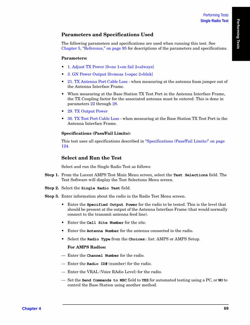
Performing TestsSingle Radio Test
Perfo
rmin
g Tests
Parameters and Specifications Used
The following parameters and specifications are used when running this test. See Chapter 5, “Reference,” on page 95 for descriptions of the parameters and specifications.
Parameters:
• 1. Adjust TX Power [0=no 1=on fail 2=always]
• 3. GN Power Output [0=meas 1=spec 2=blnk]
• 21. TX Antenna Port Cable Loss - when measuring at the antenna foam jumper out of the Antenna Interface Frame.
• When measuring at the Base Station TX Test Port in the Antenna Interface Frame, the TX Coupling factor for the associated antenna must be entered. This is done in parameters 22 through 28.
• 29. TX Output Power
• 30. TX Test Port Cable Loss - when measuring at the Base Station TX Test Port in the Antenna Interface Frame.
Specifications (Pass/Fail Limits):
This test uses all specifications described in “Specifications (Pass/Fail Limits)” on page 124.
Select and Run the Test
Select and run the Single Radio Test as follows:
Step 1. From the Lucent AMPS Test Main Menu screen, select the Test Selections field. The Test Software will display the Test Selections Menu screen.
Step 2. Select the Single Radio Test field.
Step 3. Enter information about the radio in the Radio Test Menu screen.
• Enter the Specified Output Power for the radio to be tested. This is the level that should be present at the output of the Antenna Interface Frame (that would normally connect to the transmit antenna feed line).
• Enter the Cell Site Number for the site.
• Enter the Antenna Number for the antenna connected to the radio.
• Select the Radio Type from the Choices: list: AMPS or AMPS Setup.
For AMPS Radios:
— Enter the Channel Number for the radio.
— Enter the Radio ID# (number) for the radio.
— Enter the VRAL (Voice RAdio Level) for the radio.
— Set the Send Commands to MSC field to YES for automated testing using a PC, or NO to control the Base Station using another method.
Chapter 4 69
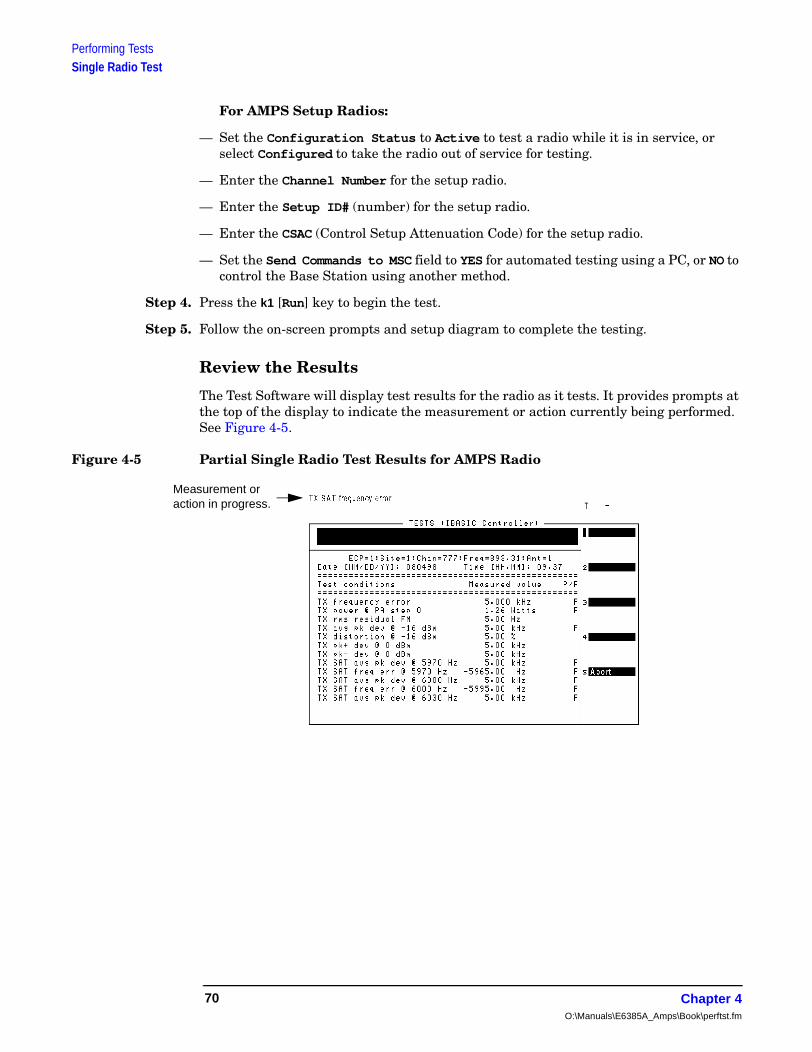
Performing TestsSingle Radio Test
For AMPS Setup Radios:
— Set the Configuration Status to Active to test a radio while it is in service, or select Configured to take the radio out of service for testing.
— Enter the Channel Number for the setup radio.
— Enter the Setup ID# (number) for the setup radio.
— Enter the CSAC (Control Setup Attenuation Code) for the setup radio.
— Set the Send Commands to MSC field to YES for automated testing using a PC, or NO to control the Base Station using another method.
Step 4. Press the k1 [Run] key to begin the test.
Step 5. Follow the on-screen prompts and setup diagram to complete the testing.
Review the Results
The Test Software will display test results for the radio as it tests. It provides prompts at the top of the display to indicate the measurement or action currently being performed. See Figure 4-5.
Figure 4-5 Partial Single Radio Test Results for AMPS Radio
Measurement or action in progress.
Chapter 4O:\Manuals\E6385A_Amps\Book\perftst.fm
70

Performing TestsTX Power Adjustment
Perfo
rmin
g Tests
TX Power AdjustmentThis adjustment procedure provides an analog display of power measurements. This mode is useful when making adjustments to power levels on a transmitter.
Features of the power meter display include:
• Tick marks on the meter to indicate when a power level setting is within limits.
• Audible tones to indicate whether the power reading falls within limits.
• A USER key to choose between measurement units of dBm or Watts.
This test may be performed with the Base Station in service using the Base Station TX Test Port, or out-of-service using the Base Station TX Antenna Port (see “Which Base Station Port to Use – TX Test or TX Antenna?” on page 35 and “Base Station Configuration” on page 39.
Parameters and Specifications Used
The following parameters and specifications are used when running this test. See Chapter 5, “Reference,” on page 95 for descriptions of the parameters and specifications.
Parameters:
• 21. TX Antenna Port Cable Loss - when measuring at the antenna foam jumper out of the Antenna Interface Frame.
• When measuring at the Base Station TX Test Port in the Antenna Interface Frame, the TX Coupling factor for the associated antenna must be entered. This is done in parameters 22 through 28.
• 30. TX Test Port Cable Loss - when measuring at the Base Station TX Test Port in the Antenna Interface Frame.
Specifications (Pass/Fail Limits):
• 9. Output Power Adjustment Error. The upper and lower limits are indicated by the longer tick marks on the power meter display.
Chapter 4 71

Performing TestsTX Power Adjustment
Select and Run the Test
Select and run the TX Power Adjustment as follows:
Step 1. From the Lucent AMPS Test Main Menu screen, select the Test Selections field. The Test Software will display the Test Selections Menu screen.
Step 2. Select the TX Power Adjustment field.
Step 3. Enter information about your radio in the TX Power Adjustment menu.
• Enter the Specified Output Power for the radio to be tested. This is the level that should be present at the output of the Antenna Interface Frame (that would normally connect to the transmit antenna feed line).
• Enter the Cell Site Number for the site.
• Enter the Antenna Number for the antenna connected to the radio.
• Select the Radio Type from the Choices: list: AMPS or AMPS Setup.
For AMPS Radios:
— Enter the Channel Number for the radio.
— Enter the Radio ID# (number) for the radio.
— Enter the VRAL (Voice RAdio Level) for the radio.
— Set the Send Commands to MSC field to YES for automated testing using a modem, or NO to control the Base Station using another method.
For AMPS Setup Radios:
— Set the Configuration Status to Active to test a radio while it is in service, or select Configured to take the radio out of service for testing.
— Enter the Channel Number for the setup radio.
— Enter the Setup ID# (number) for the setup radio.
— Enter the CSAC (Control Setup Attenuation Code) for the setup radio.
— Set the Send Commands to MSC field to YES for automated testing using a modem, or NO to control the Base Station using another method.
Step 4. Press the k1 [Run] key to begin the test, then follow the on-screen instructions to complete the test.
Review the Results
The Test Software will display the power meter screen (see Figure 4-6). The power meter display defaults to units of Watts. To view the power level in dBm, press the k3 (dBm) key. A beeping tone accompanies the measurement to assist in adjusting the transmitter power without watching the display. Adjust the tone volume by pressing the k4 (Tns off, Tns quiet, Tns loud) key.
Chapter 4O:\Manuals\E6385A_Amps\Book\perftst.fm
72

Performing TestsTX Power Adjustment
Perfo
rmin
g Tests
Figure 4-6 Power Meter Display
The longer tick marks are the high and low specification limits.
This prompt indicates if power is low, within specifications, or high.
These values indicate the high and low display limits of the meter.
The center tick mark is the Specified Output Power level entered at the start of the test.
Chapter 4 73

Performing TestsSpectrum Analyzer
Spectrum AnalyzerThis function configures the Test Set to display spectrum sweeps. It is useful in verifying the presence of a signal or searching for interference sources.
This function may be performed in-service or out-of-service. See “Which Base Station Port to Use – TX Test or TX Antenna?” on page 35.
Parameters and Specifications Used
The following parameters and specifications are used when running this test. See Chapter 5, “Reference,” on page 95 for descriptions of the parameters and specifications.
Parameters:
• 21. TX Antenna Port Cable Loss - when measuring at the antenna foam jumper out of the Antenna Interface Frame.
• When measuring at the Base Station TX Test Port in the Antenna Interface Frame, the TX Coupling factor for the associated antenna must be entered. This is done in parameters 22 through 28.
• 30. TX Test Port Cable Loss - when measuring at the Base Station TX Test Port in the Antenna Interface Frame.
Specifications (Pass/Fail Limits):
• None used for this test.
Select and Run the Test
Select and run the Spectrum Analyzer test as follows:
Step 1. From the Lucent AMPS Test Main Menu screen, select the Test Selections field. The Test Software will display the Test Selections Menu screen.
Step 2. Select the Spectrum Analyzer field.
Step 3. Enter information about the radio in the Spectrum Analyzer menu.
• Enter the Specified Output Power for the radio to be tested. This is the level that should be present at the output of the Antenna Interface Frame (that would normally connect to the transmit antenna feed line).
• Enter the Cell Site Number for the site.
• Enter the Antenna Number for the antenna connected to the radio.
• Select the Radio Type from the Choices: list: AMPS or AMPS Setup.
Chapter 4O:\Manuals\E6385A_Amps\Book\perftst.fm
74
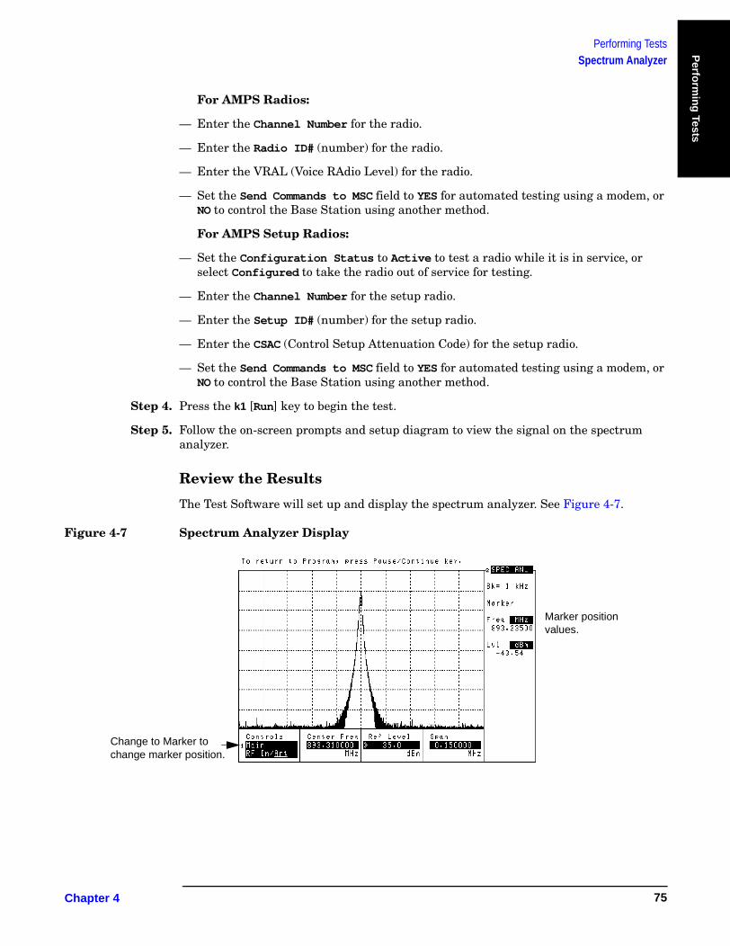
Performing TestsSpectrum Analyzer
Perfo
rmin
g Tests
For AMPS Radios:
— Enter the Channel Number for the radio.
— Enter the Radio ID# (number) for the radio.
— Enter the VRAL (Voice RAdio Level) for the radio.
— Set the Send Commands to MSC field to YES for automated testing using a modem, or NO to control the Base Station using another method.
For AMPS Setup Radios:
— Set the Configuration Status to Active to test a radio while it is in service, or select Configured to take the radio out of service for testing.
— Enter the Channel Number for the setup radio.
— Enter the Setup ID# (number) for the setup radio.
— Enter the CSAC (Control Setup Attenuation Code) for the setup radio.
— Set the Send Commands to MSC field to YES for automated testing using a modem, or NO to control the Base Station using another method.
Step 4. Press the k1 [Run] key to begin the test.
Step 5. Follow the on-screen prompts and setup diagram to view the signal on the spectrum analyzer.
Review the Results
The Test Software will set up and display the spectrum analyzer. See Figure 4-7.
Figure 4-7 Spectrum Analyzer Display
Marker position values.
Change to Marker to change marker position.
Chapter 4 75

Performing TestsSpectrum Analyzer
Use the Ref Level and Span fields for the best view of the transmitted signal.
Read the marker frequency and level in the upper-right of the display. To change the marker position, use the Controls field to select Marker, then use the Position field.
NOTE Do not make changes to the Center Freq field.
If you would like to view another channel/frequency, return to the Lucent Amps Test Main Menu screen and select Test Configuration (to access the Test Configuration Menu screen) and change the Channel Number, then re-run the test.
When you have finished using the spectrum analyzer, press the Pause/Continue key. The Test Software will return to the Test Selections Menu screen.
Chapter 4O:\Manuals\E6385A_Amps\Book\perftst.fm
76

Performing TestsTX Gain Test
Perfo
rmin
g Tests
TX Gain TestThis test measures the transmit gain of a low-output-power TX device.
CAUTION This test is designed to measure the gain through only low-output-power elements. It is not designed to measure the LAC gain on a Series II Base Station or power amplifiers on the other Base Stations.
This test uses the Test Set ANT IN port to measure the output level of the TTU. Input levels to this port greater than 60 milliwatts (17.8 dBm) might damage the Test Set. Therefore, the power output of the unit under test must not exceed 60 milliwatts.
Parameters and Specifications Used
The following parameters and specifications are used when running this test. See Chapter 5, “Reference,” on page 95 for descriptions of the parameters and specifications.
Parameters:
• 17. MSC BTS Type [1=Series II 2=M 3=MM]
Specifications (Pass/Fail Limits):
None used for this test.
Select and Run the Test
Select and run the TX Gain Test as follows:
Step 1. Take the affected radios and the amplifier to be tested out of service. Use a PC to dial into the MSC and enter the craft shell, or call the MSC and instruct switch personnel as to which radio to turn off.
Step 2. From the Lucent AMPS/TDMA Test Main Menu screen, select the Test Selections field. The Test Software will display the Test Selections Menu screen.
Step 3. Select the TX Gain Test field. The Test Software will display the TX Gain Test screen.
Step 4. Select the Channel Number field. Enter the channel number of the radio by either turning the knob to the desired number and pressing it, or using the DATA ENTRY keys to enter the number, then either pressing the knob or the Enter key to select it.
NOTE The number that you enter in the Channel Number field represents the output frequency of the device to be tested.
In the case of a PCS Minicell, you must enter a channel number that sets the input frequency of the TTU to the proper 850-MHz-band frequency to obtain the desired 1900-MHz-band output frequency from the translator.
In the case of an 850-MHz Base Station, the input and output frequencies will be the same.
Chapter 4 77
Performing TestsTX Gain Test
Step 5. Select the Generator Output Level [dBm] field. Enter the signal level from the Test Set into the amplifier by either turning the knob to the desired value and pressing it, or using the DATA ENTRY keys to enter the value, then either pressing the knob or the Enter key to select it.
CAUTION Make certain to enter a level in the Generator Output Level [dBm] field that will not produce an output level greater than 60 milliwatts from the unit being tested. Input levels to the ANT IN port greater than 60 milliwatts might damage the Test Set.
Step 6. Press the k1 (Run) key. The Test Software display a connection diagram.
Step 7. Connect two cables as shown in the connection diagram.
Step 8. Press the k1 (Proceed) key. The Test Software will measure the losses through the test cables, then display a query asking if any transmitters are active in the amplifier path.
If any transmitter is active and you do not wish to continue the test at this time, press the k1 (Yes) key. The Test Software will discontinue the test and return to the TX Gain Test screen.
If no transmitter is active, press the k2 (No) key to continue the test. The Test Software will display a connection diagram.
Step 9. Connect the amplifier to be tested as shown in the second connection diagram.
Step 10. Press the k1 (Proceed) key to perform the measurement.
Review the Results
The Test Software will display the gain and re-measure it continuously to allow for real time adjustment.
Press the k1 (Proceed) key to return to the TX Gain Test screen.
Chapter 4O:\Manuals\E6385A_Amps\Book\perftst.fm
78
Performing TestsRX Gain Test
Perfo
rmin
g Tests
RX Gain TestThis test measures the gain through RX devices such as the low-noise amplifiers in a Base Station.
CAUTION This test is designed to measure the gain through only low-output-power elements.
This test uses the Test Set ANT IN port to measure the output level of the TTU. Input levels to this port greater than 60 milliwatts (17.8 dBm) might damage the Test Set. Therefore, the power output of the unit under test must not exceed 60 milliwatts.
Parameters and Specifications Used
The following parameters and specifications are used when running this test. See Chapter 5, “Reference,” on page 95 for descriptions of the parameters and specifications.
Parameters:
• 17. MSC BTS Type [1=Series II 2=M 3=MM]
Specifications (Pass/Fail Limits):
None used for this test.
Chapter 4 79

Performing TestsRX Gain Test
Select and Run the Test
Select and run the RX Gain Test as follows:
Step 1. Take the affected radios and the amplifier to be tested out of service. Use a PC to dial into the MSC and enter the craft shell, or call the MSC and instruct switch personnel as to which radio to turn off.
Step 2. From the Lucent AMPS/TDMA Test Main Menu screen, select the Test Selections field. The Test Software will display the Test Selections Menu screen.
Step 3. Select the RX Gain Test field. The Test Software will display the RX Gain Test screen.
Step 4. Select the Channel Number field. Enter the channel number of the radio by either turning the knob to the desired number and pressing it, or using the DATA ENTRY keys to enter the number, then either pressing the knob or the Enter key to select it.
NOTE The number that you enter in the Channel Number field represents the output frequency of the device to be tested.
In the case of a PCS Minicell, you must enter a channel number that sets the input frequency of the RU to the proper 1900-MHz-band frequency to obtain the desired 850-MHz-band output frequency from the translator.
In the case of an 850-MHz Base Station, the input and output frequencies will be the same.
Step 5. Select the Generator Output Level [dBm] field. Enter the signal level from the Test Set into the amplifier by either turning the knob to the desired value and pressing it, or using the DATA ENTRY keys to enter the value, then either pressing the knob or the Enter key to select it.
CAUTION Make certain to enter a level in the Generator Output Level [dBm] field that will not produce an output level greater than 60 milliwatts from the unit being tested. Input levels to the ANT IN port greater than 60 milliwatts might damage the Test Set.
Step 6. Press the k1 (Run) key. The Test Software will display a connection diagram.
Step 7. Connect two cables as shown in the connection diagram.
Step 8. Press the k1 (Proceed) key. The Test Software will measure the losses through the test cables, then display a second connection diagram.
Step 9. Connect the amplifier to be tested as shown in the second connection diagram.
Step 10. Press the k1 (Proceed) key to perform the measurement.
Review the Results
The Test Software will display the gain and re-measure it continuously to allow for real time adjustment.
Press the k1 (Proceed) key to return to the RX Gain Test screen.
Chapter 4O:\Manuals\E6385A_Amps\Book\perftst.fm
80

Performing TestsTX –39 dBm Power Test
Perfo
rmin
g Tests
TX –39 dBm Power TestThis test provides the process by which all radios are adjusted to produce drive signals to the linear amplifier circuit (LAC) that are approximately equal and within the proper range. This test uses information from the frequency table to determine which radios are applicable for the test.
If you select a reference radio, the basic procedure performed in this test is as follows:
• Select one reference radio for each equipped antenna per LAC. If possible, select the farthest right-hand voice radio (not setup radio) in shelf 2, 3, or 4 of the primary radio channel frame (PRCF). If there is an antenna in the PRCF that does not have an associated transmitting radio, select the farthest right-hand radio in shelf 2, 3, or 4 of the growth radio channel frame (GRCF) as the reference radio for that antenna.
• Connect a test cable of known loss to the Test Set ANT IN port. Connect the other end of the test cable to the Base Station TX SIG MON jack corresponding to the first reference radio.
• The command config multi radio is issued to the Base Station to turn on all radio transmitters.
• Turn off all radios by switching the AUTO/OFF switch to OFF.
• Turn on the reference radio by switching the AUTO/OFF switch to AUTO. Adjust the potentiometer on the reference radio front panel for a −39 dBm TX SIG MON output. Once power is set, turn off the reference radio by setting the AUTO/OFF switch to OFF. Disconnect the Test Set from the SIG MON jack.
• Remove the Test cable. Connect a test cable between the Base Station Antenna Output and the Test Set RF IN/OUT port.
• Turn on the reference radio. Adjust the LAC preamplifier for maximum power, for minimum power, and finally to the desired power as defined in the frequency plan for the reference radio. Turn off the reference radio.
• The next series of steps is to turn on the radios, one at a time, set the power of each radio using the potentiometer on the radio front panel, and then turn off the radio. The power is determined by the power setting defined for that radio in the frequency plan.
• Once the power has been set on all radios, the restore commands are issued to the radios to turn off all transmitters.
• Disconnect the cable between the Base Station Antenna Output and the Test Set. Reconnect the Base Station Antenna Output to the foam jumper.
Chapter 4 81
Performing TestsTX –39 dBm Power Test
Parameters and Specifications Used
The following parameters and specifications are used when running this test. See Chapter 5, “Reference,” on page 95 for descriptions of the parameters and specifications.
Parameters:
• 3. GN Power Output [0=meas 1=spec 2=blnk]
• 21. TX Antenna Port Cable Loss
• 30. TX Test Port Cable Loss
Specifications (Pass/Fail Limits):
• 10. Output Power Error
Select and Run the Test
Select and run the TX −39 dBm Power Test as follows:
Step 1. Take the selected antenna face, out of service. (Use the PC to dial into the MSC and enter the craft shell, or call the MSC and instruct switch personnel as to which radio to turn off.)
Step 2. Enter a frequency plan (see “Defining a Frequency Plan” on page 43).
Step 3. From the Lucent AMPS/TDMA Test Main Menu screen, select the Test Selections field. The Test Software will display the Test Selections Menu screen.
Step 4. Select the TX −39 dBm Power Test field. The Test Software will display the TX −39 dBm Power Test Menu screen.
Step 5. Select the Antenna Number field. Enter the antenna number by either turning the knob to the desired number and pressing it, or using the DATA ENTRY keys to enter the number, then either pressing the knob or the Enter key to select it.
Step 6. Scroll to the Adjust Radio Power field and press the knob to toggle it to the desired mode.
If you select Always, the radio power will be adjusted in every instance.
If you select On Failure, the radio power will be adjusted only on failure.
Chapter 4O:\Manuals\E6385A_Amps\Book\perftst.fm
82

Performing TestsTX –39 dBm Power Test
Perfo
rmin
g Tests
Step 7. Scroll to the Use Reference Radio field and press the knob to toggle it to the desired mode.
If you select YES, the Test Software will lead you through a step-by-step process that uses one radio in the face to set a −39 dBm reference level at the TX SIG MON jack. The reference level becomes a known good drive level input to the LAC preamplifier. This allows the LAC preamplifier to be adjusted properly for the desired output level. Once the LAC preamplifier is adjusted properly, all other radios may be adjusted by simply setting the potentiometer on each radio front panel.
Also, if you select Yes, the Do you need assistance? field will appear immediately below. Press the knob to toggle the field to the desired setting. If you understand the testing process and wish to have the Test Software perform it as automatically as possible, select No. If you wish to have the Test Software display informational screens at appropriate points in the testing process to assist you in performing the operations, select Yes.
If you select NO, the Test Software will assume that the LAC preamplifier is adjusted properly for the power level for the face and the power output for each radio defined in the frequency plan, as measured at the Base Station RF Antenna Port, by adjusting the potentiometer on the radio front panel.
Step 8. Scroll to the Send Commands to MSC field and press the knob to toggle it to the desired mode.
Select YES for automated testing using a PC for control.
Select NO to control the Base Station using another method.
Step 9. Press the k1 (Proceed) key. The Test Software will display prompts to guide you through a step-by-step process for adjusting the power of each radio in the face. If you selected a reference radio, the Test Software will also guide you through the process of setting the reference radio. During the process, the Test Software will display prompts directing you to make connections, make inputs to the Test Software, turn radios on and off, and make power adjustments.
Review the Results
At appropriate points in the test, the Test Software will display the measurement results.
Press the k1 (Proceed) key when the test is completed to return to the TX −39 dBm Power Test Menu screen.
Chapter 4 83
Performing TestsTX Antenna Port Cable Calibration
TX Antenna Port Cable CalibrationThis utility measures the signal loss through the cable used to connect the Test Set to the Base Station TX antenna Port. (This loss must be known when making power measurements at this port. Once you have measured this value, label the cable indicating the loss for future use.) This utility sends no control commands to the MSC.
After measuring the cable loss, the Test Software will display the loss value and the frequency used for the test, then display a query asking if you wish to store the value.
• If you select Yes, the Test Software will enter the value automatically in the Base Station Configuration Menu. Unless you believe that the indicated loss is incorrect, you should select Yes.
• If you select No, the Test Software will display a query asking if you wish to Remeasure the loss or Return to the Calibration/Utilities Menu.
This routine requires the use of two external 6-dB attenuators (pads) and a short calibration cable. These parts are not standard equipment with the Test Set, but are included in the optional connector kit (see “Optional Accessory Kits” on page 17).
Parameters and Specifications Used
The following parameters and specifications are used when running this test. See Chapter 5, “Reference,” on page 95 for descriptions of the parameters and specifications.
Parameters:
• 21. TX Antenna Port Cable Loss
Specifications (Pass/Fail Limits):
None used for this test.
Select and Run the Utility
Select and run the TX Antenna Port Cable Calibration utility as follows:
Step 1. From the Lucent AMPS Test Main Menu screen, select the Calibration/Utilities field. The Test Software will display the Calibration/Utilities Menu screen.
Step 2. Select the TX Antenna Port Cable Calibration field.
Step 3. Follow the on-screen prompts to connect the 6-dB pads and calibration cable.
Step 4. Press the k1 (Proceed) key to continue.
Step 5. Follow the on-screen prompts to connect the test cable in series with the calibration cable and pads.
Step 6. Press the k1 (Proceed) key to continue.
Chapter 4O:\Manuals\E6385A_Amps\Book\perftst.fm
84

Performing TestsTX Antenna Port Cable Calibration
Perfo
rmin
g Tests
Review the Results
The Test Software will display the measured insertion loss and test frequency. When you press the k1 (Proceed) to continue, the Test Software will display a query asking if you wish to store the insertion loss as the TX Antenna Port Cable Loss. Turn and press the knob to select Yes or No.
Chapter 4 85

Performing TestsTX Test Port Cable Calibration
TX Test Port Cable CalibrationThis utility measures the signal loss through the cable used to connect the Test Set to the Base Station TX Test Port. This is the Base Station port that samples the transmitter output through a directional coupler in the Antenna Interface Frame. (This loss must be known when making power measurements at this port. Once you have measured this value, label the cable indicating the loss for future use.) This utility sends no control commands to the MSC.
After measuring the cable loss, the Test Software will display the loss value and the frequency used for the test, then display a query asking if you wish to store the value.
• If you select Yes, the Test Software will enter the value automatically in the Base Station Configuration Menu. Unless you believe that the indicated loss is incorrect, you should select Yes.
• If you select No, the Test Software will display a query asking if you wish to Remeasure the loss or Return to the Calibration/Utilities Menu.
This routine requires the use of two external 6-dB attenuators (pads) and a short calibration cable. These parts are not standard equipment with the Test Set, but are included in the optional connector kit (see “Optional Accessory Kits” on page 17).
Parameters and Specifications Used
The following parameters and specifications are used when running this test. See Chapter 5, “Reference,” on page 95 for descriptions of the parameters and specifications.
Parameters:
• 30. TX Test Port Cable Loss
Specifications (Pass/Fail Limits):
None used for this test.
Select and Run the Utility
Select and run the TX Test Port Cable Calibration utility as follows:
Step 1. From the Lucent AMPS Test Main Menu screen, select the Calibration/Utilities field. The Test Software will display the Calibration/Utilities Menu screen.
Step 2. Select the TX Test Port Cable Calibration field.
Step 3. Follow the on-screen prompts to connect the 6 dB pads and calibration cable.
Step 4. Press the k1 (Proceed) key to continue.
Step 5. Follow the on-screen prompts to connect the test cable in series with the calibration cable and pads.
Step 6. Press the k1 (Proceed) key to continue.
Chapter 4O:\Manuals\E6385A_Amps\Book\perftst.fm
86

Performing TestsTX Test Port Cable Calibration
Perfo
rmin
g Tests
Review the Results
The Test Software will display the measured insertion loss and test frequency. When you press the k1 (Proceed) to continue, the Test Software will display a query asking if you wish to store the insertion loss as the TX Test Port Cable Loss. Turn and press the knob to select Yes or No.
Chapter 4 87

Performing TestsTX Test Port Coupling Measurements
TX Test Port Coupling MeasurementsThis utility measures the loss associated with testing from a Base Station TX Test Port. This provides to the Test Software a coupling factor to use with measurements from that Base Station TX Test Port. Repeat this measurement for each test port to be used at the cell site.
At the start of the test, you must full or partial calibration.
• In Full calibration, the Test Software first measures the level at the Base Station TX Antenna Port, then the level at the Base Station TX Test Port. It uses the difference between these levels to determine the loss through the TX Test Port.
If you have connected and configured a PC for automated control of the Base Station, the Test Software will send commands to the MSC during the test. If you wish to use manual Base Station control, you must disable call processing and turn off any transmitters prior to connecting the Test Set to the Base Station TX Antenna Port.
NOTE During full calibration, the Test Software will prompt you to connect the Test Set RF IN/OUT port to the Base Station TX Antenna Port using the TX Antenna Port cable. After you have done so, the Test Software will prompt you to connect the Test Set ANT IN port to the Base Station TX Test Port using the TX Test Port cable.
For accurate TX Test port calibration, you must use the correct cables when prompted.
• In Partial calibration, the Test Software will use a Reference Power Level (that you must enter) to determine the coupling factor. This is the level out of the Antenna Interface Frame that feeds the foam jumper to the transmit antenna. The Test Software then measures the level at the Base Station TX Test Port is measured and uses the difference in these levels is used to determine the loss through the TX Test Port.
Unless you are certain that the Reference Power Level that you enter is correct (± 0.5 dB), you should use the full calibration for the most accurate results.
Parameters and Specifications Used
The following parameters and specifications are used when running this test. See Chapter 5, “Reference,” on page 95 for descriptions of the parameters and specifications.
Parameters:
• 21. TX Antenna Port Cable Loss
• 30. TX Test Port Cable Loss
Specifications (Pass/Fail Limits):
• None used for this test.
Chapter 4O:\Manuals\E6385A_Amps\Book\perftst.fm
88
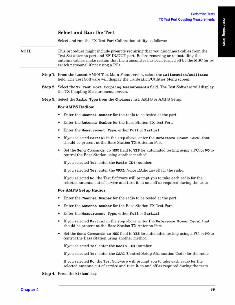
Performing TestsTX Test Port Coupling Measurements
Perfo
rmin
g Tests
Select and Run the Test
Select and run the TX Test Port Calibration utility as follows:
NOTE This procedure might include prompts requiring that you disconnect cables from the Test Set antenna port and RF IN/OUT port. Before removing or re-installing the antenna cables, make certain that the transmitter has been turned off by the MSC (or by switch personnel if not using a PC).
Step 1. From the Lucent AMPS Test Main Menu screen, select the Calibration/Utilities field. The Test Software will display the Calibration/Utilities Menu screen.
Step 2. Select the TX Test Port Coupling Measurements field. The Test Software will display the TX Coupling Measurements screen.
Step 3. Select the Radio Type from the Choices: list: AMPS or AMPS Setup.
For AMPS Radios:
• Enter the Channel Number for the radio to be tested at the port.
• Enter the Antenna Number for the Base Station TX Test Port.
• Enter the Measurement Type, either Full or Partial.
• If you selected Partial in the step above, enter the Reference Power Level that should be present at the Base Station TX Antenna Port.
• Set the Send Commands to MSC field to YES for automated testing using a PC, or NO to control the Base Station using another method.
If you selected Yes, enter the Radio ID# (number.
If you selected Yes, enter the VRAL (Voice RAdio Level) for the radio.
If you selected No, the Test Software will prompt you to take each radio for the selected antenna out of service and turn it on and off as required during the tests.
For AMPS Setup Radios:
• Enter the Channel Number for the radio to be tested at the port.
• Enter the Antenna Number for the Base Station TX Test Port.
• Enter the Measurement Type, either Full or Partial.
• If you selected Partial in the step above, enter the Reference Power Level that should be present at the Base Station TX Antenna Port.
• Set the Send Commands to MSC field to YES for automated testing using a PC, or NO to control the Base Station using another method.
If you selected Yes, enter the Radio ID# (number.
If you selected Yes, enter the CSAC (Control Setup Attenuation Code) for the radio.
If you selected No, the Test Software will prompt you to take each radio for the selected antenna out of service and turn it on and off as required during the tests.
Step 4. Press the k1 (Run) key.
Chapter 4 89
Performing TestsTX Test Port Coupling Measurements
Step 5. Connect the Test Set to the Base Station as indicated and perform any other operations as prompted. Press the k1 (Proceed) key to continue after each setup.
• Full calibration requires two separate measurement setups. Make certain to use the correct test cables for each setup.
• Partial calibration uses one measurement setup. Make certain to use the Base Station TX Test Port cable when making the measurement.
Review the Results
The Test Software will calculate and display the Base Station TX Test Port coupling factor. You should write this value next to the TX Test Port for future reference.
Press the k1 (Proceed) key to return to the Calibration/Utilities Menu screen, then press the k5 (Return) key to return to the Lucent AMPS Test Main Menu screen.
If you then select the Base Station Configuration field (from the Lucent AMPS Test Main Menu screen), you will note that the TX Test Port Coupling Factor [dB] field for the specified antenna now contains the value determined by the test.
Chapter 4O:\Manuals\E6385A_Amps\Book\perftst.fm
90
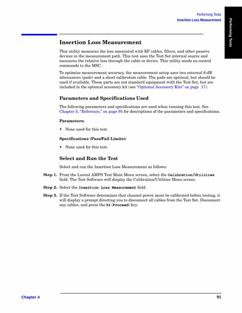
Performing TestsInsertion Loss Measurement
Perfo
rmin
g Tests
Insertion Loss MeasurementThis utility measures the loss associated with RF cables, filters, and other passive devices in the measurement path. This test uses the Test Set internal source and measures the relative loss through the cable or device. This utility sends no control commands to the MSC.
To optimize measurement accuracy, the measurement setup uses two external 6-dB attenuators (pads) and a short calibration cable. The pads are optional, but should be used if available. These parts are not standard equipment with the Test Set, but are included in the optional accessory kit (see “Optional Accessory Kits” on page 17).
Parameters and Specifications Used
The following parameters and specifications are used when running this test. See Chapter 5, “Reference,” on page 95 for descriptions of the parameters and specifications.
Parameters:
• None used for this test.
Specifications (Pass/Fail Limits):
• None used for this test.
Select and Run the Test
Select and run the Insertion Loss Measurement as follows:
Step 1. From the Lucent AMPS Test Main Menu screen, select the Calibration/Utilities field. The Test Software will display the Calibration/Utilities Menu screen.
Step 2. Select the Insertion Loss Measurement field.
Step 3. If the Test Software determines that channel power must be calibrated before testing, it will display a prompt directing you to disconnect all cables from the Test Set. Disconnect any cables, and press the k1 (Proceed) key.
Chapter 4 91

Performing TestsInsertion Loss Measurement
Step 4. Scroll to the Loss Measurement Type field and press the knob to toggle the setting to Swept or Discrete.
If you select Swept, the Test Software will measure the loss over the frequency range that you specify. The following four fields will appear below. In each instance, either enter the number by turning the knob to the desired value and pressing it, or enter the number using the DATA ENTRY keys, then either press the knob or the Enter key to select it.
• Start Frequency [MHz] – Enter the start frequency.
• Stop Frequency [MHz] – Enter the stop frequency.
• Maximum Expected Loss [dB] – Enter the loss for the device being tested. The Test Software will use this value to adjust the scale on the results plot. Use a value slightly greater than expected for the best display resolution.
• Duplex Out Level [dBm] – Enter the setting for the appropriate level into the device being tested. This may be adjusted if necessary.
If you select Discrete, the Test Software will measure the loss at the frequency that you specify by entering the Channel Number to be tested. The Channel Number field will appear below. Enter the number by turning the knob to the desired value and pressing the knob, or use the DATA ENTRY keys to enter the number and then either press the knob or the Enter key to select it.
Step 5. Press the k1 (Run) key.
Step 6. Follow the on-screen prompts to connect the 6-dB pads and calibration cable.
Step 7. Press the k1(Proceed) key.
Step 8. Follow the on-screen prompts to connect the test cable, or other RF device, in series with the calibration cable and pads.
Step 9. Press the k1(Proceed) key to perform the measurement.
Review the Results
If you have selected a discrete measurement, the Test Software will display the insertion loss as a single numeric value (in units of dB).
If you have selected a swept measurement, the Test Software will display the loss as a spectrum analyzer plot of loss versus frequency.
If you wish to record the spectrum analyzer plot of the results of a swept measurement, press the k5 (Scr Dump) key. This will cause the Test Software to pause automated operation to print a summary of the plot. Press the Print key to send the plot to a PC connected to the Test Set. After the summary has printed in the BTS Laptop Utility program Test Set Screen Capture window, press the k2 (Continue) key to re-start the Test Software at the point at which it paused. You may save the window contents to a file in the PC.
Press the k1 (Proceed) key to display the frequency range settings and average insertion loss for the test. From this point, you may press the k1 (Repeat) key to test another cable or device, press the k5 (Return) key once to return to the Insertion Loss Test setup menu, or press the k5 (Return) key twice to return to the Calibration/Utilities Menu.
Chapter 4O:\Manuals\E6385A_Amps\Book\perftst.fm
92

Performing TestsReturn Loss Measurement
Perfo
rmin
g Tests
Return Loss MeasurementThis utility measures the return loss of a cable, antenna, or other device in the swept mode. An SWR bridge and a 6-dB pad are connected to the Test Set. The Test Software uses the pad to improve the mismatch between the SWR bridge and the ANT IN port on the Test Set. It measures a reference level with an open or short on the bridge, measures the return loss with the cable or antenna-under-test, and displays the results. This utility sends no control commands to the MSC.
This measurement requires the use of two external 6-dB attenuators (pads), two type-N cables, and an SWR bridge. These parts are not standard equipment with the Test Set, but are included in the optional accessory kit (see “Optional Accessory Kits” on page 17).
Parameters and Specifications Used
The following parameters and specifications are used when running this test. See Chapter 5, “Reference,” on page 95 for descriptions of the parameters and specifications.
Parameters:
• None used for this test.
Specifications (Pass/Fail Limits):
• None used for this test.
Select and Run the Test
Select and run the Return Loss Measurement as follows:
Step 1. From the Lucent AMPS Test Main Menu screen, select the Calibration/Utilities field. The Test Software will display the Calibration/Utilities Menu screen.
Step 2. Scroll to Return Loss Measurement and press the knob.
Step 3. If the Test Software determines that channel power must be calibrated before testing, it will prompt you to disconnect all cables from the Test Set. Disconnect any cables, and press k1 (Proceed).
Chapter 4 93

Performing TestsReturn Loss Measurement
Step 4. Scroll to the Loss Measurement Type field and press the knob to toggle the setting to Swept or Discrete.
If you select Swept, the Test Software will measure the loss over the frequency range that you specify. The following four fields will appear below. In each instance, either enter the number by turning the knob to the desired value and pressing it, or enter the number using the DATA ENTRY keys, then either press the knob or the Enter key to select it.
• Start Frequency [MHz] – Enter the start frequency.
• Stop Frequency [MHz] – Enter the stop frequency.
• Maximum Expected Loss [dB] – Enter the loss for the device being tested. The Test Software will use this value to adjust the scale on the results plot. Use a value slightly greater than expected for the best display resolution.
• Duplex Out Level [dBm] – Enter the setting for the appropriate level into the device being tested. This may be adjusted if necessary.
If you select Discrete, the Test Software will measure the loss at the frequency that you specify by entering the Channel Number to be tested. The Channel Number field will appear below. Enter the number by turning the knob to the desired value and pressing the knob, or use the DATA ENTRY keys to enter the number and then either press the knob or the Enter key to select it.
Step 5. Press the k1 (Run) key.
Step 6. Follow the on-screen prompts to connect the 6-dB pads, cables, and the SWR bridge.
Step 7. Press the k1(Proceed) key.
Step 8. The Test Software will turn on the source and make a reference measurement and display a connection diagram. Follow the on-screen prompts to connect the DUT (Device-Under-Test).
Step 9. Press the k1(Proceed) key to perform the measurement.
Review the Results
If you have selected a discrete measurement, the Test Software will display the VSWR and the return loss as a single numeric value (in units of dB).
If you have selected a swept measurement, the Test Software will display the loss as a spectrum analyzer plot of loss versus frequency.
If you wish to record the spectrum analyzer plot of the results of a swept measurement, press the k5 (Scr Dump) key. This will cause the Test Software to pause automated operation to print a summary of the plot. Press the Print key to send the plot to a PC connected to the Test Set. After the summary has printed in the BTS Laptop Utility program Test Set Screen Capture window, press the k2 (Continue) key to re-start the Test Software at the point at which it paused. You may save the window contents to a file in the PC.
Press the k1 (Proceed) key to display the frequency range settings, the maximum and minimum return losses, and the maximum and minimum VSWR for the test. From this point, you may press the k1 (Repeat) key to test another cable or device, press the k5 (Return) key once to return to the Insertion Loss Test setup menu, or press the k5 (Return) key twice to return to the Calibration/Utilities Menu.
Chapter 4O:\Manuals\E6385A_Amps\Book\perftst.fm
94
Referen
ce
5 Reference
This chapter describes Test Software operational details that were not covered in Chapter 2, “Installation,” on page 21, Chapter 3, “Connections,” on page 55, and Chapter 4, “Performing Tests,” on page 59. The information in this chapter is organized by key topics, listed alphabetically.
Chapter 5 95
ReferenceOverview
OverviewRefer to the following topic areas for detailed instructions on Test Software use:
“Accessing Test Software Functions” on page 97.
“BTS Laptop Utility Program Windows” on page 113.
“Demo (Demonstration) Mode” on page 116.
“Parameters” on page 118.
“Specifications (Pass/Fail Limits)” on page 124.
“Testing without MSC Control” on page 126.
“Using a PC Card” on page 127.
Chapter 5O:\Manuals\E6385A_Amps\Book\Reference.fm
96
ReferenceAccessing Test Software Functions
Referen
ce
Accessing Test Software FunctionsTest Software functions may be accessed from the various menu screens. These include the SOFTWARE MENU screen, which is the master screen from which the others are reached. The following eight sub-sections describe the screens and the functions accessed from those screens.
• “SOFTWARE MENU Screen Overview” on page 98.
• “Loading a Test Procedure” on page 99.
• “Loading the Test Software Card and Procedure” on page 100.
• “Customizing a Test Procedure” on page 102.
• “Changing Test Parameters” on page 103.
• “Changing Pass/Fail Limits” on page 106.
• “Saving/Deleting a Procedure” on page 109.
Chapter 5 97

ReferenceAccessing Test Software Functions
SOFTWARE MENU Screen Overview
Pressing the front-panel Menu key will cause the Test Set to display the SOFTWARE MENU screen (see Figure 5-1). This screen allows the user to configure and run custom Test Software, access help, proceed with a paused procedure, or access additional test screens.
Figure 5-1 SOFTWARE MENU Screen
Loads the Test Software. The first time might require as longs as 20 seconds. Once the Test Software is in internal memory, it runs the test.
Continues a paused test.
Accesses the Test Set help screen.
See “Loading a Test Procedure” on page 99.
See “Changing Test Parameters” on page 103.
See “Changing Pass/Fail Limits” on page 106. Setting Test Execution
Conditions is not used in the Test Software.
Selects the menu list.
See “Saving/Deleting a Procedure” on page 109.
Chapter 5O:\Manuals\E6385A_Amps\Book\Reference.fm
98
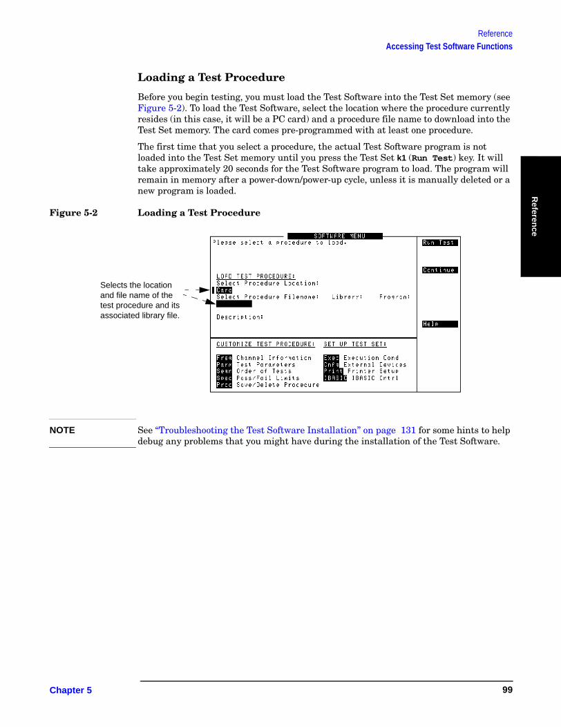
ReferenceAccessing Test Software Functions
Referen
ce
Loading a Test Procedure
Before you begin testing, you must load the Test Software into the Test Set memory (see Figure 5-2). To load the Test Software, select the location where the procedure currently resides (in this case, it will be a PC card) and a procedure file name to download into the Test Set memory. The card comes pre-programmed with at least one procedure.
The first time that you select a procedure, the actual Test Software program is not loaded into the Test Set memory until you press the Test Set k1 (Run Test) key. It will take approximately 20 seconds for the Test Software program to load. The program will remain in memory after a power-down/power-up cycle, unless it is manually deleted or a new program is loaded.
Figure 5-2 Loading a Test Procedure
NOTE See “Troubleshooting the Test Software Installation” on page 131 for some hints to help debug any problems that you might have during the installation of the Test Software.
Selects the location and file name of the test procedure and its associated library file.
Chapter 5 99

ReferenceAccessing Test Software Functions
Loading the Test Software Card and Procedure
Load the Test Software card and a procedure as shown in Figure 5-3 and Figure 5-4.
Figure 5-3 Loading the Test Software Card
Turn the power on. (The power switch is located above the power cord connection on the right-side panel.)
1
2 Wait until the first test screen is displayed (about 45 seconds).
- - - -
3 Insert the Test Software card.
Menu
Preset.Press4
Chapter 5O:\Manuals\E6385A_Amps\Book\Reference.fm
100
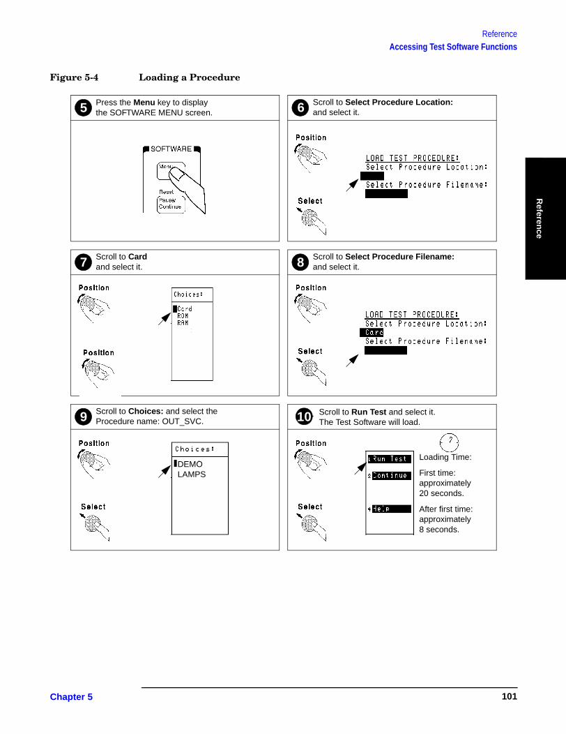
ReferenceAccessing Test Software Functions
Referen
ce
Figure 5-4 Loading a Procedure
Scroll to Choices: and select the Procedure name: OUT_SVC.
Scroll to Run Test and select it. The Test Software will load.
Scroll to Select Procedure Filename: and select it.
Scroll to Card and select it.
Press the Menu key to display the SOFTWARE MENU screen.
Scroll to Select Procedure Location: and select it.5
7 8
109
6
DEMOLAMPS
Loading Time:
First time: approximately 20 seconds.
After first time: approximately 8 seconds.
Chapter 5 101

ReferenceAccessing Test Software Functions
Customizing a Test Procedure
Test Software packages have been designed so that you may make changes easily from the Test Set front panel (see Figure 5-5). For example, you may insert or delete tests, and later, after running the tests, you may change the pass/fail limits or decide to test different channels. You may store the customized test procedure on an SRAM card so that you may skip these steps in the future, see “Saving/Deleting a Procedure” on page 109.
Figure 5-5 Customizing a Test Procedure
NOTE The Test Software package might not allow customization of testing procedures. If you attempt to enter a customization screen that is not supported with the current package, the message “Access to secure test information denied” will be displayed.
The fields listed under CUSTOMIZE TEST PROCEDURE are used to customize the Test Software for various testing requirements.
Chapter 5O:\Manuals\E6385A_Amps\Book\Reference.fm
102

ReferenceAccessing Test Software Functions
Referen
ce
Changing Test ParametersThe Test Software uses parameters to optimize the test environment and conditions for the testing situation. The default test parameters are determined by examining the test requirements and specifications from the equipment manufacturer. The Test Software comes with default settings for all test parameters.
Press the Menu key, then select the Parm Test Parameters field to display the TESTS (Test Parameters) screen (see Figure 5-6).
The fields in the TESTS (Test Parameters) screen allow you to change test parameters to optimize the testing conditions (see Figure 5-7 and Figure 5-8). For information on saving customized test parameters, see “Saving/Deleting a Procedure” on page 109.
Figure 5-6 TESTS (Test Parameters) Screen
NOTE The TESTS (Test Parameters) screen might not be used in the particular Test Software package that you are using, or some fields might not be present, depending on the Test Software application. The message “Access to secure test information denied” will be displayed if the screen is not supported in the Test Software package.
Selects the parameter to be changed.
Displays the current parameter setting.
Parameter description. The descriptions for the Test Software might be different than shown here.
Chapter 5 103
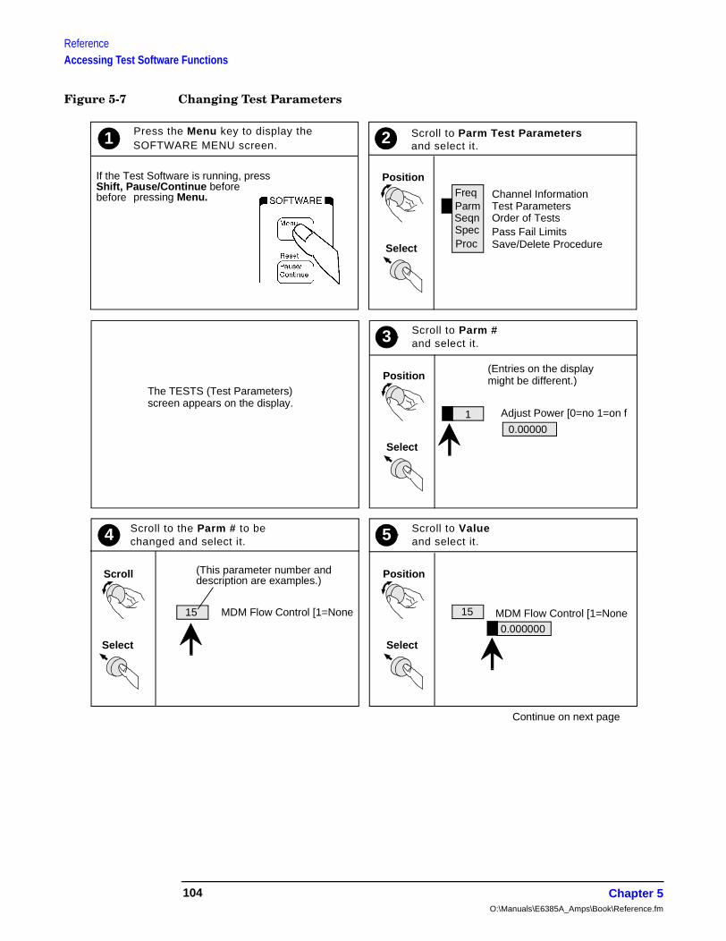
ReferenceAccessing Test Software Functions
Figure 5-7 Changing Test Parameters
Select
Position
Press the Menu key to display theSOFTWARE MENU screen.
If the Test Software is running, pressShift, Pause/Continue before
pressing Menu.
1
FreqParmSeqnSpecProc
and select it.
Channel InformationTest ParametersOrder of TestsPass Fail LimitsSave/Delete Procedure
2
Continue on next page
Select
PositionThe TESTS (Test Parameters)
Adjust Power [0=no 1=on f
3 Scroll to Parm #
Select
Position
5 Scroll to Value
screen appears on the display.
and select it.
0.00000
(Entries on the displaymight be different.)
4 Scroll to the Parm # to be
Scroll
Select
changed and select it.
15 MDM Flow Control [1=None
(This parameter number anddescription are examples.)
and select it.
MDM Flow Control [1=None15
0.000000
1
before
Scroll to Parm Test Parameters
Chapter 5O:\Manuals\E6385A_Amps\Book\Reference.fm
104
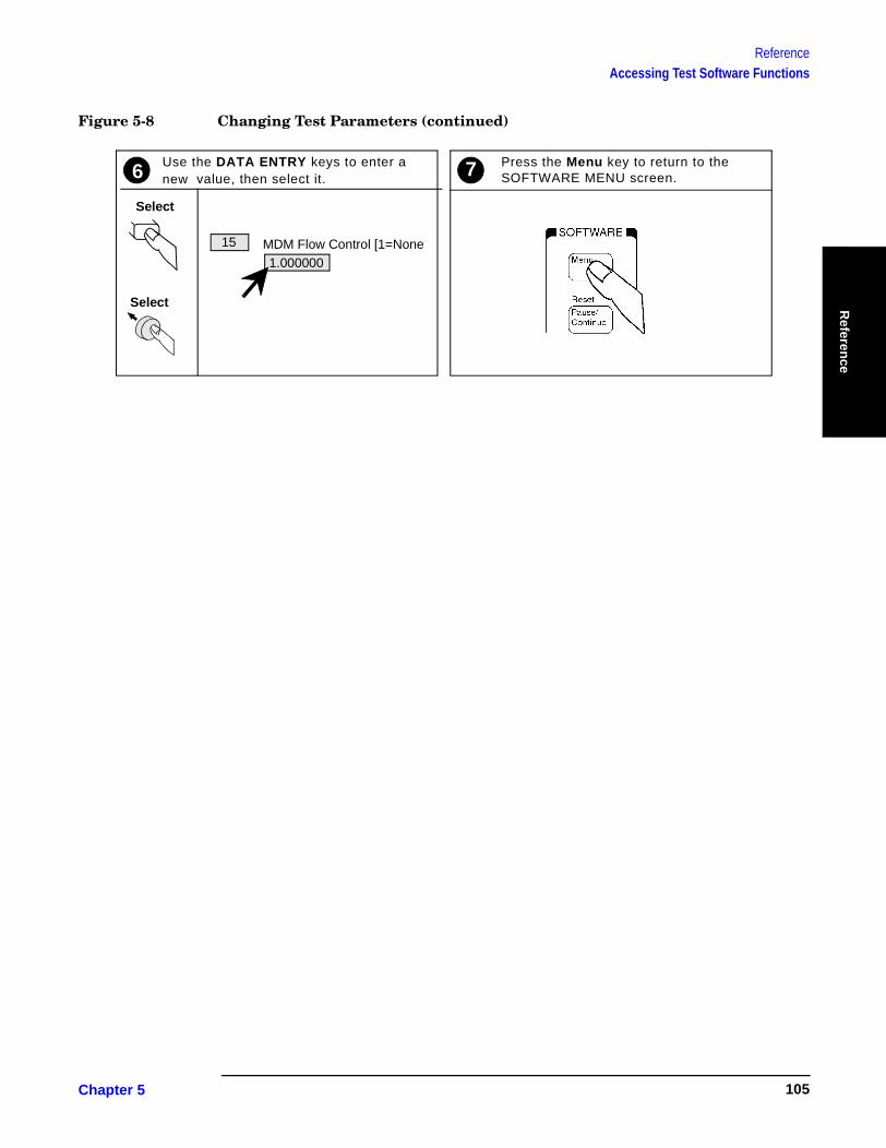
ReferenceAccessing Test Software Functions
Referen
ce
Figure 5-8 Changing Test Parameters (continued)
Select
7 Press the Menu key to return to the
MDM Flow Control [1=None15
1.000000
Select
46 Use the DATA ENTRY keys to enter avalue, then select it. SOFTWARE MENU screen.new
Chapter 5 105
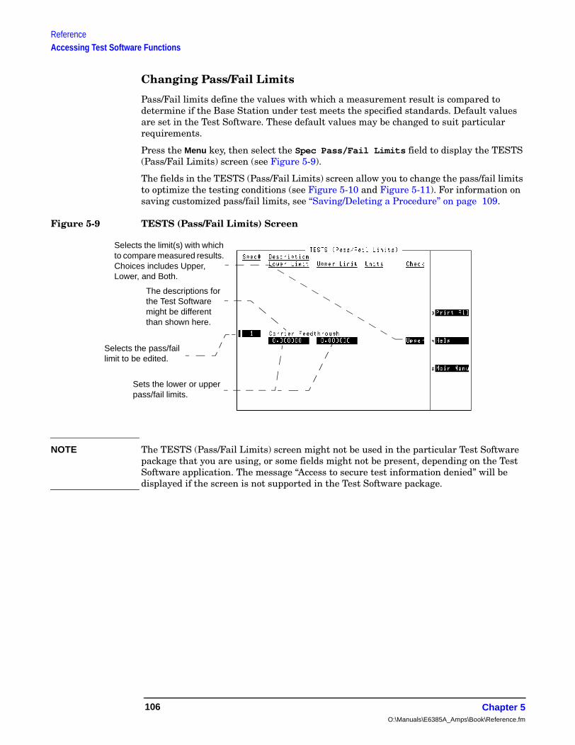
ReferenceAccessing Test Software Functions
Changing Pass/Fail Limits
Pass/Fail limits define the values with which a measurement result is compared to determine if the Base Station under test meets the specified standards. Default values are set in the Test Software. These default values may be changed to suit particular requirements.
Press the Menu key, then select the Spec Pass/Fail Limits field to display the TESTS (Pass/Fail Limits) screen (see Figure 5-9).
The fields in the TESTS (Pass/Fail Limits) screen allow you to change the pass/fail limits to optimize the testing conditions (see Figure 5-10 and Figure 5-11). For information on saving customized pass/fail limits, see “Saving/Deleting a Procedure” on page 109.
Figure 5-9 TESTS (Pass/Fail Limits) Screen
NOTE The TESTS (Pass/Fail Limits) screen might not be used in the particular Test Software package that you are using, or some fields might not be present, depending on the Test Software application. The message “Access to secure test information denied” will be displayed if the screen is not supported in the Test Software package.
Selects the limit(s) with which to compare measured results. Choices includes Upper, Lower, and Both.
The descriptions for the Test Software might be different than shown here.
Selects the pass/fail limit to be edited.
Sets the lower or upper pass/fail limits.
Chapter 5O:\Manuals\E6385A_Amps\Book\Reference.fm
106

ReferenceAccessing Test Software Functions
Referen
ce
Figure 5-10 Changing Pass/Fail Limits
SOFTWARE MENU screen.
If the Test Software is running, pressShift, Pause/Continue beforepressing Menu.
FreqParmSeqnSpecProc
Channel InformationTest ParametersOrder of TestsPass/Fail LimitsSave/Delete Procedure
and select it.
The TESTS (Pass/Fail Limits) screen appears on the display. 1
(Disregard this number.)
Continue on next page
1 Press the Menu key to display the
Select
Position
2
Select
Position
3 Scroll to Spec #and select it.
Select
Scroll
4 Scroll to the desired Spec # and select it.
Select
Position
5 Scroll to Lower Limitand select it.
6
(This Spec # is an example.)
Output Power Adjustment
--1.000000 1.000000
6 Output Power Adjustment
--1.000000 1.000000
Scroll to Spec Pass/Fail Limits
Chapter 5 107

ReferenceAccessing Test Software Functions
Figure 5-11 Changing Pass/Fail Limits (continued)
Select
6 Use the DATA ENTRY keys to enter avalue, then select it.
6 Output Power Adjustment
-0.500000 1.000000
Enter
(Enter the desired value.)
Select
Position
7 Scroll to Upper Limitand select it.
Select
8 Use the DATA ENTRY keys to enter avalue, then select it.
Select
Position
9 Scroll to Checkand select it.
Both
Output Power Adjustment
.500000 1.000000 dB
Enter
Output Power Adjustment
.500000 0.500000 dB
(Enter the desired value.)
Select
Position
10 Select the choice that should apply
Position
11 Press the Menu key to return to the
Choices:
UpperLowerBothNone
to testing and select it. SOFTWARE MENU screen.
Select
new
new
Chapter 5O:\Manuals\E6385A_Amps\Book\Reference.fm
108
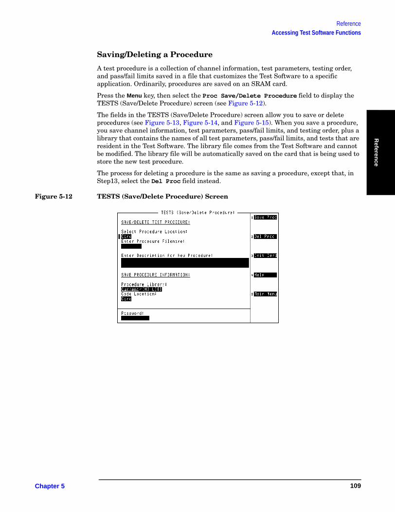
ReferenceAccessing Test Software Functions
Referen
ce
Saving/Deleting a Procedure
A test procedure is a collection of channel information, test parameters, testing order, and pass/fail limits saved in a file that customizes the Test Software to a specific application. Ordinarily, procedures are saved on an SRAM card.
Press the Menu key, then select the Proc Save/Delete Procedure field to display the TESTS (Save/Delete Procedure) screen (see Figure 5-12).
The fields in the TESTS (Save/Delete Procedure) screen allow you to save or delete procedures (see Figure 5-13, Figure 5-14, and Figure 5-15). When you save a procedure, you save channel information, test parameters, pass/fail limits, and testing order, plus a library that contains the names of all test parameters, pass/fail limits, and tests that are resident in the Test Software. The library file comes from the Test Software and cannot be modified. The library file will be automatically saved on the card that is being used to store the new test procedure.
The process for deleting a procedure is the same as saving a procedure, except that, in Step13, select the Del Proc field instead.
Figure 5-12 TESTS (Save/Delete Procedure) Screen
Chapter 5 109
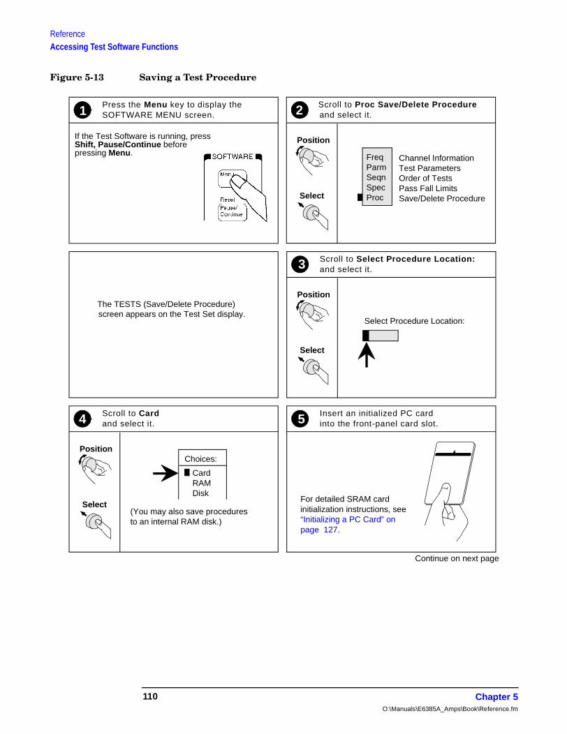
ReferenceAccessing Test Software Functions
Figure 5-13 Saving a Test Procedure
1 Press the Menu key to display theSOFTWARE MENU screen.
Select
Position
2
Freq
If the Test Software is running, press
The TESTS (Save/Delete Procedure)
Select
Position
4 Scroll to Card
Choices:
Card
and select it.
Select
Position
3 Scroll to Select Procedure Location:and select it.
5 Insert an initialized PC cardinto the front-panel card slot.
Shift, Pause/Continue beforepressing Menu.
ParmSeqnSpecProc
Channel InformationTest ParametersOrder of TestsPass Fall LimitsSave/Delete Procedure
and select it.
screen appears on the Test Set display.Select Procedure Location:
RAMDisk
(You may also save proceduresto an internal RAM disk.)
Continue on next page
For detailed SRAM card initialization instructions, see “Initializing a PC Card” on page 127.
Scroll to Proc Save/Delete Procedure
Chapter 5O:\Manuals\E6385A_Amps\Book\Reference.fm
110
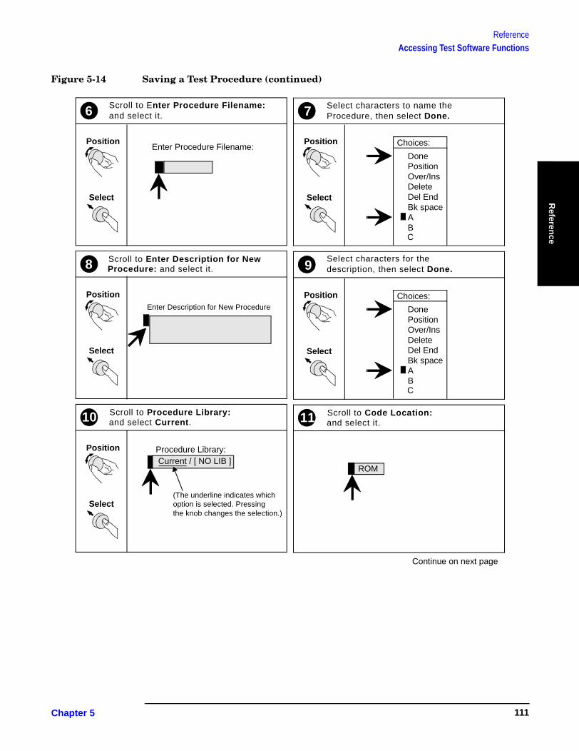
ReferenceAccessing Test Software Functions
Referen
ce
Figure 5-14 Saving a Test Procedure (continued)
Select
Position
6 Scroll to Enter Procedure Filename:
Enter Procedure Filename:
and select it.
Select
Position
7 Select characters to name the
Choices:
Procedure, then select Done.
Select
Position
9
11 Scroll to Code Location:
ROM
Continue on next page
and select it.
Select
Position
8 Scroll to Enter Description for New
Enter Description for New Procedure
Procedure: and select it.
Select
Position
10 Scroll to Procedure Library:
Current / [ NO LIB ]Procedure Library:
and select Current.
DonePositionOver/InsDeleteDel EndBk spaceABC
Choices:
DonePositionOver/InsDeleteDel EndBk spaceABC
description, then select Done.Select characters for the
(The underline indicates whichoption is selected. Pressingthe knob changes the selection.)
Chapter 5 111

ReferenceAccessing Test Software Functions
Figure 5-15 Saving a Test Procedure (continued)
Select
Position
12 Scroll to Card and select it.
Select
Position
13 Scroll to Save Procand select it or press k1.
14 Press the Menu key to return to the.
15 To run the saved procedure, follow the instructions below.
Choices:
CardRAMDisk
Save Proc
Del Proc
Init Card
Help
Main Menu
2
3
4
5
SOFTWARE MENU screen.
1) Insert the PC card with the saved procedure.
2) On the SOFTWARE MENU screen, a) select the Select ProcedureLocation: field then select Card, b) select Select Procedure Filename:,then select the saved file name.3) Remove the PC card, then insert the original PC card1.4) Press the k1 (Run Test) key.
1The original Test Software card contains the full program required to run procedures. Theprocedure cannot run without using the original IBASIC program code on the factory card.
Chapter 5O:\Manuals\E6385A_Amps\Book\Reference.fm
112
ReferenceBTS Laptop Utility Program Windows
Referen
ce
BTS Laptop Utility Program WindowsThe BTS Laptop Utility program provides five windows in which information may be display or entered. These windows are: Switch Terminal, Test Set Terminal, Other Data, Test Results, and Test Set Screen Capture.
For information on installing the BTS Laptop Utility program and configuring the PC and Test Set to work together, see “Operating the BTS Laptop Utility Program” on page 27.
Switch Terminal Window
The Switch Terminal window functions as essentially a VT100 terminal to accomplish the following:
• It allows you to connect with the MSC, either with the PC internal modem to dial into the MSC, or with the PC and a telnet connection to the MSC.
• It displays the commands sent to the MSC and the replies sent back from the MSC.
Test Set Terminal Window
The Test Set Terminal window displays commands sent from the Test Set to the MSC.
Other Data Window
The Other Data window accomplishes the following:
• It allows you to download frequency plans to the Test Set.
• It displays short-form test results.
The short-form test results are sent to the PC automatically and displayed in the window (see Figure 5-16 for an example of the display). By selecting File, Logging Enabled, you may enter a file name to save the test results to a file that may be retrieved into a text editor and printed out. This selection must be done before the test results are sent to the screen.
Chapter 5 113
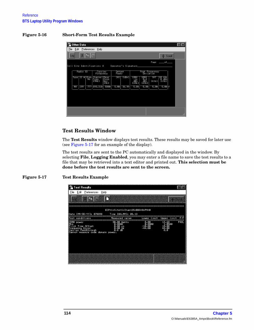
ReferenceBTS Laptop Utility Program Windows
Figure 5-16 Short-Form Test Results Example
Test Results Window
The Test Results window displays test results. These results may be saved for later use (see Figure 5-17 for an example of the display).
The test results are sent to the PC automatically and displayed in the window. By selecting File, Logging Enabled, you may enter a file name to save the test results to a file that may be retrieved into a text editor and printed out. This selection must be done before the test results are sent to the screen.
Figure 5-17 Test Results Example
Chapter 5O:\Manuals\E6385A_Amps\Book\Reference.fm
114

ReferenceBTS Laptop Utility Program Windows
Referen
ce
Test Set Screen Capture Window
The Test Set Screen Capture window allows you to capture a Test Software screen image and save it as a bit map file for later view or use. This is very helpful when using the Test Set spectrum analyzer or when you wish to capture some other screen. Note that IBASIC program operation must be paused first, by pressing the Pause/Continue key, to print any of the TESTS screens used for automated testing.
To capture a Test Software screen, configure the PC and the Test Set, then attempt a screen capture, as follows:
1. If the Test Set SERIAL 9 port and the PC serial port are not configured, configure both ports (see “Configuring the Test Set and PC Serial Ports for Communication with the Test Set” on page 28).
2. Select the screen that you wish to save and make any required entries on that screen to display the desired information.
3. If the screen that you intend to capture is one that appears only when the Test Software is running (a star appears in the upper right-hand corner of the display), press the Pause/Continue key to pause it.
4. Press the Test Set Shift key. then the Inst Config (I/O Config) key. The Test Set will display the I/O CONFIGURE screen.
5. Select the Serial_9 In field and press the knob to toggle the setting to Inst (underlined).
6. Press the Test Set Shift key, then the Print (Printer Config) key. The Test Set will display the PRINTER CONFIGURE screen.
7. Select the Model field and select DeskJet from the drop-down Choices: list.
8. Select the Printer Port field and select Serial 9 from the drop-down Choices: list.
9. If the screen of interest is one that appears only when the Test Software is running, press the Menu key. The Test Software will display the SOFTWARE MENU screen.
10.If the screen of interest is one that appears only when the Test Software is running, select the IBASIC IBASIC Cntrl field. The Test Software will display again the screen that you set up in Step 2.
11.Press the Test Set Print key. The currently-displayed screen should appear in the Test Set Screen Capture window on the PC screen.
12.If the screen is satisfactory and you wish to use or view it later, enter a name for the file in the Test Set Screen Capture window Title field.
13.On the Test Set Screen Capture window tool bar, click on the third button from the left (Save Image).
14.On the drop-down Save window, select the location to which you wish to save the image. Make certain that the Save as type: field is set to .bmp, and click on Save. The file will be saved as a bit-mapped image in the location that you selected.
Chapter 5 115

ReferenceDemo (Demonstration) Mode
Demo (Demonstration) ModeThe demonstration mode offers a good method for becoming familiar with the operation of the Test Software. Demo mode allows you to step through the menus and simulate testing without a PC, a connection to the switch, or even a Base Station.
In the demo mode, the system will not send commands to the MSC, but it will perform very much the same as if actually testing a Base Station. When measurements are displayed, it provides sample numbers in order to show how the printout format will appear.
There are two methods for entering the demo mode:
• Selecting the procedure named DEMO.
and
• Selecting the demo mode using the demo control parameter (see 32. ZZZZ Test Demo Mode [0=normal 1=demo]).
Selecting the DEMO Procedure
Select the DEMO procedure as follows:
NOTE Once the DEMO procedure is loaded, it will remain in the Test Set memory until you load another procedure. Even if you turn off the Test Set and run the Test Software later, the procedure is stored in battery-backed-up memory and will remain ready to run.
Step 1. If the Test Software is running, press the Shift key, then the Pause/Continue key to stop it.
Step 2. Press the Menu key. The Test Software will display the SOFTWARE MENU screen.
Step 3. Select the Select Procedure Location: field, then select Card from the drop-down Choices: list.
Step 4. Select the Select Procedure Filename: field, then select DEMO from the drop-down Choices: list.
Step 5. Press the k1 (Run Test) key to run the Test Software. The Test Software will set the demo control parameter to 1 and operate in demo mode until you load another procedure.
Chapter 5O:\Manuals\E6385A_Amps\Book\Reference.fm
116
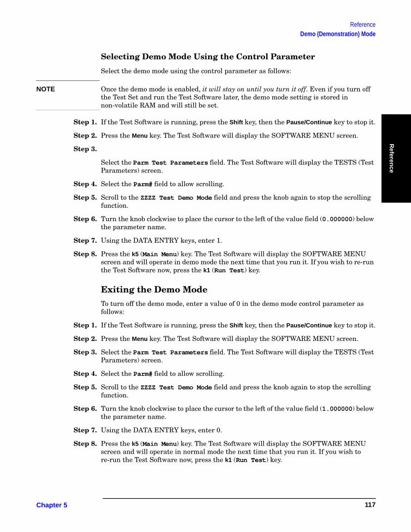
ReferenceDemo (Demonstration) Mode
Referen
ce
Selecting Demo Mode Using the Control Parameter
Select the demo mode using the control parameter as follows:
NOTE Once the demo mode is enabled, it will stay on until you turn it off. Even if you turn off the Test Set and run the Test Software later, the demo mode setting is stored in non-volatile RAM and will still be set.
Step 1. If the Test Software is running, press the Shift key, then the Pause/Continue key to stop it.
Step 2. Press the Menu key. The Test Software will display the SOFTWARE MENU screen.
Step 3.
Select the Parm Test Parameters field. The Test Software will display the TESTS (Test Parameters) screen.
Step 4. Select the Parm# field to allow scrolling.
Step 5. Scroll to the ZZZZ Test Demo Mode field and press the knob again to stop the scrolling function.
Step 6. Turn the knob clockwise to place the cursor to the left of the value field (0.000000) below the parameter name.
Step 7. Using the DATA ENTRY keys, enter 1.
Step 8. Press the k5 (Main Menu) key. The Test Software will display the SOFTWARE MENU screen and will operate in demo mode the next time that you run it. If you wish to re-run the Test Software now, press the k1 (Run Test) key.
Exiting the Demo ModeTo turn off the demo mode, enter a value of 0 in the demo mode control parameter as follows:
Step 1. If the Test Software is running, press the Shift key, then the Pause/Continue key to stop it.
Step 2. Press the Menu key. The Test Software will display the SOFTWARE MENU screen.
Step 3. Select the Parm Test Parameters field. The Test Software will display the TESTS (Test Parameters) screen.
Step 4. Select the Parm# field to allow scrolling.
Step 5. Scroll to the ZZZZ Test Demo Mode field and press the knob again to stop the scrolling function.
Step 6. Turn the knob clockwise to place the cursor to the left of the value field (1.000000) below the parameter name.
Step 7. Using the DATA ENTRY keys, enter 0.
Step 8. Press the k5 (Main Menu) key. The Test Software will display the SOFTWARE MENU screen and will operate in normal mode the next time that you run it. If you wish to re-run the Test Software now, press the k1 (Run Test) key.
Chapter 5 117
ReferenceParameters
ParametersThe Test Software uses the entries in the Test Parameters screen to customize testing and specify serial communications settings.
A special parameter allows the Test Software to run in a demonstration mode, which is useful for familiarization with the operation of the Test Set without connecting to any external equipment (see “Demo (Demonstration) Mode” on page 116).
Most parameters may be entered in two ways:
• By loading and running the Test Software and entering all of the information in the Test Configuration, Base Station Configuration, and Serial Port Configuration menus. The Test Software automatically changes the test parameter settings to match the configuration settings.
Parameters that may not be set while the Test Software is running include:
— 1. Adjust TX Power [0=no 1=on fail 2=always]
— 2. GN MSC Command Speed [0=slow 1=fast]
— 4. GN Stop Test if results fail [0=no 1=yes]
— 20. MSC Require CP INH at Ant Port [1=Yes]
— 31. TX Use 230 kHz BW on Data Dev [1=yes]
— 32. ZZZZ Test Demo Mode [0=normal 1=demo]
• By loading the Test Software and selecting Parm Test Parameters on the main SOFTWARE MENU screen. You may change the settings from the factory defaults.
This section lists the parameters and describes the use of each. For instructions on changing the parameters and saving the changes on an SRAM card, see “Changing Test Parameters” on page 103 and “Saving/Deleting a Procedure” on page 109.
1. Adjust TX Power [0=no 1=on fail 2=always]
Enter the selection to determine the manner in which power output adjustment will be made.
• If you select 0, the transmitter power output will not be adjusted, irrespective of the measurement result, and the adjustment power meter will not be displayed.
• If you select 1, the transmitter power output will be adjusted and the power meter will be displayed if the measured power is outside of the specified pass/fail limits. Adjust the power output to within the specified pass/fail limits and continue with testing.
• If you select 2, the transmitter power output will be adjusted and the power meter will be displayed, irrespective of the measurement result. Adjust the power output to within the specified pass/fail limits and continue testing.
See "Output Power Adjustment Error" on page 125 and "Output Power Error" on page 125.
Chapter 5O:\Manuals\E6385A_Amps\Book\Reference.fm
118
ReferenceParameters
Referen
ce
2. GN MSC Command Speed [0=slow 1=fast]
Enter the selection to determine the speed at which commands will be sent from the Test Set through the PC to the MSC during automated testing.
• If you select 0, the measurements will be made in the most reliable manner.
• If you select 1, the measurements will be made in the most expeditious manner. This setting is used most often when using a PC running the BTS Laptop Utility and an internal modem.
3. GN Power Output [0=meas 1=spec 2=blnk]
Enter the selection to determine the manner in which output power test results will be displayed.
• If you select 0, the measured output power will be entered in the Output Power column of the FCC short form when the Full Site Test (FCC) test or Single Radio Test is run. Also, when the TX Power Adjustment test is run, the center scale value on the meter will be determined by the pass/fail limits.
• If you select 1, the value that you specify for the radio in the frequency plan, or at the start of the Single Radio Test, will be printed in the Output Power column of the FCC short form (not the measured value). The measured value will still be printed in the long form. Also, when the TX Power Adjustment test is run, the center scale value will be set to the value that you enter for the Specified Output Power at the start of the test.
• If you select 2, the Output Power column of the FCC short form will be left blank.
4. GN Stop Test if results fail [0=no 1=yes]
Enter the selection to determine the action of the Test Software in the event of a measurement failure. An F will appear in the P/F column of the test results to indicate a failure of that data point.
• If you select 0, the Test Software will continue running if the measured value is not within specifications.
• If you select 1, the Test Software will stop testing if the measured value is not within specifications.
5. INST EXT REF IN [1,2,5,10,15 MHz]
If using an external reference for the Test Set timebase, use this field to select the appropriate reference frequency.
6. INST EXT REF SELECT [1=AUTO 2=INT 3=EXT]
This setting determines the source for the Test Set timebase:
• Auto - Uses the Test Set internal timebase, unless an external reference signal of sufficient amplitude and correct frequency is applied to the REF IN connector.
• INT - Always uses the Test Set internal timebase.
• EXT - Requires that an external timebase be connected to the REF IN connector. You must also specify the external timebase signal frequency in Parameter 5 - INST EXT REF IN [1,2,5,10,15 MHz].
Chapter 5 119

ReferenceParameters
7. LAP Baud Rate [valid test set range]
Enter the value to determine the baud rate that will be used for communications between the PC and the SERIAL 9 port on the Test Set. Valid rates (bps) are: 150, 300, 600, 1200, 2400, 4800, 9600, 19200, 38400, and 57600. This setting must match the setting used by the PC communication software.
8. LAP Data Length [7 or 8]
Enter the selection to determine whether 7 or 8 bits will be used for the data length for the serial communication data link between the PC and the SERIAL 9 port on the Test Set. This setting must match the setting used by the PC communication software.
9. LAP Flow Control [1=None 2=Xon 3=Hw]
Enter the selection to determine the type of data flow control that will be used for the serial communication data link between the laptop PC and the SERIAL 9 port on the Test Set. This setting must match the setting used by the PC communication software.
• If you select 1, the link will use no flow control.
• If you select 2, the link will use Xon/Xoff flow control.
• If you select 3, the link will use hardware flow control. This setting must be used for baud rates of 38400 and higher.
10. LAP Parity [0=0 1=1 2=none 3=even 4=odd]
Enter the selection to determine the parity style that will be used for communication between the PC and the SERIAL 9 port on the Test Set.
• If you select 0, a zero parity will be used.
• If you select 1, a ones parity will be used.
• If you select 2, no parity will be used.
• If you select 3, an even parity will be used.
• If you select 4, an odd parity will be used.
11. LAP Stop Length [1 or 2]
Enter the selection to match the PC communication program settings that will be used for the number of stop bits in communications between the PC and the SERIAL 9 port on the Test Set.
• If you select 1, one stop bit will be used.
• If you select to 2, two stop bits will be used.
12.Not Used
13.Not Used
14.Not Used
15.Not Used
16.Not Used
Chapter 5O:\Manuals\E6385A_Amps\Book\Reference.fm
120
ReferenceParameters
Referen
ce
17.MSC BTS Type [1=Series II 2=M 3=MM]
Enter the selection to specify the type of Base Station to be tested.
• If you select 1, indicates to the Test Software that the Base Station to be tested is of the Series II type.
• If you select 2, indicates to the Test Software that the Base Station to be tested is of the Series M type.
• If you select 3, indicates to the Test Software that the Base Station to be tested is of the Series MM type.
18.MSC Cell Site Number [444 Max]
Enter the number of the cell site at which testing is to be performed.
19.MSC ECP Number
Enter the number of the ECP that controls the cell site at which testing is to be performed.
20. MSC Require CP INH at Ant Port [1=Yes]
Enter the selection to determine whether the entire cell site or the specific sector is to be taken out of service.
• If you select 1, all call processing will be inhibited, which takes the entire cell site out of service for testing at the TX antenna ports.
• If you select 0, only the sector that is associated with the specific antenna port at which testing is to be performed will be taken out of service.
NOTE When testing at the TX Antenna port, always verify that no radios are transmitting on the antenna at which testing is to be performed before disconnecting the antenna.
21. TX Antenna Port Cable Loss
Enter the value of the cable loss in testing from the TX Antenna port. If you do not know this value, use the TX Antenna Port Cable Calibration function of the Test Software to measure it. See “TX Antenna Port Cable Calibration” on page 84.
22.TX Coupling Factor [ANT 0]
Enter the value of coupling factor for the Base Station TX Test Port for the specified antenna.
23.TX Coupling Factor [ANT 1]
Enter the value of coupling factor for the Base Station TX Test Port for the specified antenna.
24.TX Coupling Factor [ANT 2]
Enter the value of coupling factor for the Base Station TX Test Port for the specified antenna.
25.TX Coupling Factor [ANT 3]
Enter the value of coupling factor for the Base Station TX Test Port for the specified antenna.
Chapter 5 121

ReferenceParameters
26.TX Coupling Factor [ANT 4]
Enter the value of coupling factor for the Base Station TX Test Port for the specified antenna.
27.TX Coupling Factor [ANT 5]
Enter the value of coupling factor for the Base Station TX Test Port for the specified antenna.
28.TX Coupling Factor [ANT 6]
Enter the value of coupling factor for the Base Station TX Test Port for the specified antenna.
29. TX Output Power
Enter the value of the power level (in watts) that should be transmitting at the TX Antenna port/foam jumper.
30.TX Test Port Cable Loss
Enter the value of the cable loss to be used in testing from the Base Station TX Test Port. If you do not know this value, use the TX Antenna Port Cable Calibration function of the Test Software to measure it. See “TX Test Port Cable Calibration” on page 86.
31.TX Use 230 kHz BW on Data Dev [1=yes]
Enter the selection to determine which of the filters in the Test Set will be used in data deviation measurements in either the Single Radio Test or Full Site Test.
• If you select 1, the 230-kHz filter will be used. This is the default selection.
• If you select 0, the 30-kHz filter will be used.
When using the 230-kHz IF filter, the Base Station must not be transmitting another signal within seven channel spacings (210 kHz) above or below the signal being measured; otherwise the measurement will be in error. In Figure 5-18, the Spectrum Analyzer and delta marker functions are used to illustrate that another signal could interfere with the measurement. (See the Reference Guide for information on using the Spectrum Analyzer).
It is preferable to use the 230-kHz filter when possible. However, if it is not possible to turn off a transmitter that is within 210 kHz of the signal to be measured, use the narrow (30-kHz) filter.
Chapter 5O:\Manuals\E6385A_Amps\Book\Reference.fm
122

ReferenceParameters
Referen
ce
Figure 5-18 Determining the Best IF Filter Setting
32. ZZZZ Test Demo Mode [0=normal 1=demo]
Enter the selection to determine whether the Test Software will operate in normal or demonstration mode.
• If you select 0, the Test Software will run in normal mode, which allows for test measurements.
• If you select 1, the Test Software will run in demonstration mode. This mode appears to run tests, but the tests are simulated because there is no connection to a Base Station. This mode allows you to become familiar with Test Software operation. For details, see “Demo (Demonstration) Mode” on page 116.
Using the Delta Markers function, you can see that a smaller signal is only 120 kHz (four channel spacings) away from the signal you want to measure. In this case, set Parameter 31 - TX Use 230 kHz BW on Data Dev [1=yes] to 0 to reduce the measurement bandwidth, or turn off the other radio.
By setting the Spectrum Analyzer Span to 0.420 MHz, you can see if any interfering signals exist on either side of the measured signal.
Chapter 5 123

ReferenceSpecifications (Pass/Fail Limits)
Specifications (Pass/Fail Limits)The Test Software uses the entries in the TESTS (Pass/Fail Limits) screen to determine if a measurement meets the test requirements. If not, it displays a “fail” indication in the results display (and, in some instances, provides for adjustments and re-test).
This section lists the specification limit names and explains how each is used. For instructions on changing the pass/fail limits and saving the changes to an SRAM card, see “Changing Pass/Fail Limits” on page 106 and “Saving/Deleting a Procedure” on page 109.
1. AMPS Data Peak Deviation
Enter the upper and lower deviation limits, in kHz.
The 1004-Hz test signal in the Base Station is sent to the data modulator in the radio and the Test Software measures the resulting peak deviation and compares the result with the limits.
2. AMPS Deviation at -16 dBm Audio Level
Enter the upper and lower deviation limits, in kHz.
The 1004-Hz test signal in the Base Station is set to a level of -16 dBm, and is then sent to the analog modulator in the radio. The Test Software measures the resulting deviation and compares the result with the limits.
3. AMPS Deviation at 0 dBm Audio Level
Enter the upper deviation limit only, in kHz.
The 1004-Hz test signal in the Base Station is set to a level of 0 dBm, and is then sent to the analog modulator in the radio. The Test Software measures the resulting deviation and compares the result with the limit.
4. AMPS Distortion at -16 dBm Audio Level
Enter the upper distortion limit only, in percent (%).
The 1004-Hz test signal in the Base Station is set to a level of -16 dBm, and is then sent to the analog modulator in the radio. The Test Software measures the resulting distortion is compares the result with the limit.
5. AMPS Frequency Error
Enter the upper and lower limits, in Hz.
The Test Software measures the transmitter center frequency and compares it with the ideal frequency, based on the entry for channel number. The difference between the two is the frequency error. The Test Software then compares the calculated frequency error is then compared with the limits.
6. AMPS Residual FM [15 Hz - 15 kHz]
Enter the upper and lower limits, in Hz.
With all modulation turned off, the Test Software measures the amount of FM present in the rf carrier from the radio.
Chapter 5O:\Manuals\E6385A_Amps\Book\Reference.fm
124

ReferenceSpecifications (Pass/Fail Limits)
Referen
ce
7. AMPS SAT Frequency Error
Enter the upper and lower limits, in Hz.
The Test Software measures the difference between the measured SAT frequency and the SAT frequency specified in the Base Station Configuration Menu, and compares the result with the limits.
When testing all SAT frequencies, the Test Software changes the SAT frequency to measure each frequency in sequence, using the same frequency error limits for all measurements.
8. AMPS SAT Peak Deviation
Enter the upper and lower limits, in Hz.
The Test Software measures the peak deviation for the SAT with all other modulation turned off, and compares the result with the limits.
9. Output Power Adjustment Error
Enter the upper and lower limits, in dB.
These limits determine how the power meter will be displayed. When the power meter display is displayed, it includes major tick marks that indicate the adjustment range for power settings. If you enter ±1 dB as the limits, the meter will be drawn with the ideal setting in the center and major tick marks 1-dB up and 1-dB down from center.
10.Output Power Error
Enter the upper and lower limits, in dB.
While the previous limits (Output Power Adjustment Error) controlled the adjustment diagram in power meter use, the Output Power Error limits determine whether the power measurement made in automated testing meets specifications. If you set Output Power Error limits of ±2 dB, these limits will be used when a power measurement is made. If the power measured is more than 2 dB from the desired setting, a fail indication (F) will result.
NOTE In general, it is best to set the Output Power Adjustment Error limits set narrower (smaller) than the Output Power Error limits.
Chapter 5 125

ReferenceTesting without MSC Control
Testing without MSC ControlChapter 4, “Performing Tests,” on page 59 lists the steps for fully automated testing, using the Test Software to control the Base Station. The steps of that chapter use a PC to control the Base Station via the MSC.
If you are using a Test Set setup with no PC and connection to the MSC, the following considerations apply:
• Make certain to set the Send Control Commands to MSC field on the Base Station Configuration Menu to NO. The Test Set will not send control commands to the MSC using the PC.
• The connection diagrams at the start of each test sequence will include prompts to apply or remove power for the BBA being tested. You must control the transmitter signal (on and off) manually at the site.
• You will probably require an assistant at the MSC to control the Base Station and remove the radios from service.
Chapter 5O:\Manuals\E6385A_Amps\Book\Reference.fm
126

ReferenceUsing a PC Card
Referen
ce
Using a PC CardBefore a PC card may be used for the first time, it must be initialized. The following tow sections describe the initialization process and offer some troubleshooting information in the event of a problem with the use of a PC card.
Initializing a PC Card
When a card is new, or the battery has been removed when the card is not inserted into the Test Set, then the card must be initialized to store data. To initialize a PC card follow these steps:
Step 1. Insert the PC card into the front-panel card slot
Step 2. If a Test Software package is running, press the Shift key, then the Pause/Continue key to stop it.
Step 3. Press the Shift key, then the Inst Config key. The Test Set will display the I/O CONFIGURE screen.
Step 4. Select the Format Card field. The Test Set will display a query asking if you wish to “Erase and format the PCMCIA Card?” (YES/NO).
Step 5. Press the Yes On/Off key, located below and to the right of the knob, to format the card.
The card is formatted when the cursor stops blinking.
Troubleshooting PC Card Use
Each of the messages listed below is followed by an explanation of the probable cause.
Directory Overflow.
• The SRAM card is probably full and cannot store new files. You might have to delete some files on the card to clear memory space or use a new PC card.
Medium uninitialized. Do you want to initialize?
• The card either not been initialized or has other information stored on it. Initializing overwrites any data that might already be on the card. Press the Yes On/Off key to initialize the installed card.
Write protected.
• The card has been write protected (the switch in the WP position). Slide the write protect switch into the other position before writing.
Medium changed or not in drive. No information was loaded.
• The card has possibly not been inserted properly. Re-insert and try again.
File name is undefined. No information was loaded.
• There might be no information (files) stored on the card.
• You might not have inserted the correct card in the PC card slot. Try again with a different card.
Chapter 5 127

Trou
blesh
oo
ting
6 Troubleshooting
This chapter contains information that is useful if you encounter Test Software or measurement errors or if you question measurement results.
Chapter 6 129
TroubleshootingError Summary
Error Summary
Overview
This chapter lists errors that might be encountered when loading or running the Test Software. The errors are listed roughly in the order of possible occurrence when getting started using the Test Software:
“Troubleshooting the Test Software Installation” on page 131.
“Errors When Loading and Running the Test Software” on page 132.
“Errors When First Setting Up or Connecting to MSC” on page 133.
“Communication Errors During Testing” on page 133.
“Errors While Attempting Measurements” on page 135.
Help for Communication Errors:
The following sections include checks and tools that may be used to troubleshoot communication errors between the Test System and the MSC:
“Troubleshooting Checks for Communication Problems” on page 134.
Chapter 6O:\Manuals\E6385A_Amps\Book\Trouble.fm
130

TroubleshootingTroubleshooting the Test Software Installation
Trou
blesh
oo
ting
Troubleshooting the Test Software InstallationIf the Test Software did not install properly, check the following:
• Is the power on?
• Is the PC card inserted in the correct orientation?
• Is the PC card firmly seated in the slot? It should slide in loosely, then be firmly pushed in to make proper contact.
• Did the SOFTWARE MENU screen appear? Pressing the front panel Preset key should display the SOFTWARE MENU screen.
• Did TESTS (IBASIC Controller) appear at the top of the display after you pressed the k1 (Run Test) key? If not, make certain that you have specified the correct Procedure Location and Procedure Filename.
If you were unable to load and run the Test Software, make the required entries, or you encountered error messages, refer to other sections of this chapter.
NOTE If the Test Set displays an error that states “One or more self-tests failed”, there is a hardware problem. In this case, refer to the Test Set Assembly Level Repair Guide. If the problem persists, call the Agilent Technologies Factory Hotline from anywhere in the USA or Canada (1-800-452-4844), 8:30 am - 5:00 pm Pacific time).
Chapter 6 131

TroubleshootingErrors When Loading and Running the Test Software
Errors When Loading and Running the Test SoftwareThis group of errors would most often be encountered before the Main Menu appears. Such errors would be most likely to occur the first time that you load and run the Test Software (see Chapter 2, “Installation,” on page 21). The errors are presented with the error text, followed by a description of the cause, followed by some possible solutions.
❏ Symptom: Memory Overflow Errors
The random access memory (RAM) space of the Test Set is shared by IBASIC programs and save/recall registers. If you have saved a large number of registers in the Test Set, a memory overflow error might occur when you first attempt to load the Test Software.
To correct this, clear some RAM space by deleting some or all of the saved registers. You may do this selectively (one register at a time) or globally (all storage registers at once).
NOTE Clearing the registers, whether selectively or globally, is permanent. Registers are not retrievable once deleted. You may save registers to an SRAM card, as well. Refer to the Agilent Technologies 8935 Reference Guide for instructions on this procedure.
To delete a single register:
Step 1. Press the Recall key.
Step 2. Scroll the cursor to the register to be deleted.
Step 3. Press the Yes On/Off key to indicate that you wish to clear the register.
Step 4. Press the Yes On/Off key again to confirm.
Step 5. The register will be cleared.
To delete all saved registers:
Step 1. Press the Recall key.
Step 2. Scroll to *Clr All* and press the knob.
Step 3. Press the Yes On/Off key to confirm.
Step 4. All save registers will be cleared.
Chapter 6O:\Manuals\E6385A_Amps\Book\Trouble.fm
132
TroubleshootingCommunication Errors
Trou
blesh
oo
ting
Communication Errors
Errors When First Setting Up or Connecting to MSC
• Message: Base Station did not answer...
If commands are misunderstood at the MSC end, this error message might occur. Use the Switch Terminal window in the BTS Laptop Utility program to send commands and view responses to identify the problem command. Also, refer to “Troubleshooting Checks for Communication Problems” on page 134 for a list of items to check when you have noticed this error.
Communication Errors During Testing
Message: Lost the modem carrier. Use the BTS Laptop Utility program to correct the problem and to return all configured BBAs back to active status. Press the Abort key to return to the main menu.
This error indicates that communication with the MSC was taking place, but the link was lost sometime during the testing process.
As indicated in the message, you may use the BTS Laptop Utility program to try to re-establish the link with the MSC.
Also check the items in “Troubleshooting Checks for Communication Problems” on page 134 for possible causes of interruptions to the communication between the Test System and the MSC.
Chapter 6 133

TroubleshootingCommunication Errors
Troubleshooting Checks for Communication Problems
The following list provides items to check when you are having communication difficulties using the external modem to connect to the MSC.
❏ Cable connections:
Make certain that you have made the proper connections between the Test Set serial port, the phone line or telnet connection, and the personal computer (PC).
A list of cables and part numbers is provided in “Optional Accessory Kits” on page 17.
❏ Dialing difficulties:
In some cases, you might have to customize the dialing information in order to properly dial and connect to the MSC. For example, if there is a 9 in the dialing sequence to obtain an outside phone line, there might be a short delay before the dial tone is heard. Therefore, a delay after the 9 might be required before the rest of the digits in the sequence are sent. This may be done from the Switch Terminal window of the BTS Laptop Utility program. Clicking on the Dial button on the Switch Terminal window tool bar, and add a comma between the numbers as shown in the following example.
9, 1-509-835-0000
❏ MSC is not configured to send responses to commands:
After sending a control command to the MSC, the Test Software searches for response commands from the MSC before continuing. It might be that the MSC with which the system is communicating has been configured to not send responses to remote computers. You might have to check with a switch technician to determine if this is the case for the MSC in question.
Chapter 6O:\Manuals\E6385A_Amps\Book\Trouble.fm
134
TroubleshootingErrors While Attempting Measurements
Trou
blesh
oo
ting
Errors While Attempting MeasurementsThe following error messages might be posted once a test mode has begun making measurements:
• Full Site Test (FCC) is selected but does not run.
The Full Site Test uses a frequency plan to provide the required cell site and radio information. If the Test Software cannot locate a frequency plan, it exits the test. See “Defining a Frequency Plan” on page 43 for information on the contents and creation of frequency plans.
• The indicated TX Power level is very low or very high.
Assuming that the radio is transmitting at the proper level, this problem is usually caused by incorrect parameter entries dealing with test cable and test port losses.
If testing at the Base Station TX Test Port:
— Verify that the Base Station Connection field on the Base Station Configuration Menu is set to TX Test Port.
— Verify that the Base Station TX Test Port is connected to the Test Set ANT IN port (as shown in the setup drawing that appears at the start of the test).
— Measure the coupling factor for the Base Station TX Test Port and make certain that the value is entered in the Base Station Configuration menu. See “TX Test Port Coupling Measurements” on page 88.
— Measure the Base Station TX Test Port Cable Loss and enter it on the Base Station Configuration Menu. See “TX Test Port Cable Calibration” on page 86.
— Verify that you have entered the correct VRAL/CSAC setting for the selected radio at the start of the test.
If testing at the Base Station TX Antenna Port (foam jumper):
— Verify that the Base Station TX Antenna Port is connected to the Test Set RF IN/OUT port (as shown in the setup drawing that appears at the start of the test).
— Verify that the Base Station Connection field on the Base Station Configuration Menu is set to TX Antenna Port.
— Measure the TX Antenna Port Cable Loss and enter it on the Base Station Configuration Menu. See “TX Antenna Port Cable Calibration” on page 84.
— Verify that you have entered the correct VRAL/CSAC setting for the selected radio at the start of the test.
Chapter 6 135

Acro
nym
s
A Acronyms
There are numerous acronyms used throughout the wireless communications field. Many of those are used in this manual. The following list provides the meanings for the more significant acronyms for purposes of operating the Test Software.
Appendix A 137
AcronymsAcronyms and Meanings
Acronyms and Meanings
ACU − Analog Conversion Unit
AIF − Antenna Interface Frame
AWGN − Added White Gaussian Noise
BBA − BIU/BCR/ACU combination
BCR − Baseband Combiner and Radio
BIU − Bus Interface Unit
CAT − Catalog
CCC − CDMA Cluster Controller
CCU − CDMA Channel Unit
CDMA − Code Division Multiple Access
CE − Channel Element
CP − Call Processing
CS − Cell Site
CR − Carriage Return
CRT − Cathode Ray Tube
CRTU − CDMA Radio Test Unit
dB − deciBel
dBm − deciBels with respect to 1 milliwatt
dBt − deciBels with respect to total channel power
DTMF − Dual Tone Multi Frequency
DUT − Device Under Test
Eb/No − Ratio of Energy-per-Bit to Noise spectral density
ECP − Executive Cellular Processor
ERP − Effective Radiated Power
EVM − Error Vector Magnitude
GPS − Global Positioning System
LAP – Laptop PC
LED − Light Emitting Diode
MHz − Megahertz
MSC − Mobile Switching Center (also, MTSO)
OMP − Operations Management Platform
OOS − Out-Of-Service
OP − Output Process
Appendix AO:\Manuals\E6385A_Amps\Book\appendix.fm
138

AcronymsAcronyms and Meanings
Acro
nym
s
OTP − One-Time Programmable
PC − Personal Computer
PCS − Personal Communications Services
PN − Pseudo-Noise
RAM − Random-Access Memory
RF − Radio Frequency
RX − Receiver
SCT − Synchronized Clock and Tone
TX − Transmitter
VSWR − Voltage Standing Wave Ratio
UCL − UnConditionaL
Appendix A 139
IndexIn
dex
AAccessing Test Software
Functions, 97Changing Pass/Fail Limits, 106Changing Test Parameters, 103Customizing a Test Procedure,
102Loading a Test Procedure, 99Loading the Test Software Card
and Procedure, 100Saving/Deleting a Procedure,
109SOFTWARE MENU Screen
Overview, 98accessory kit, 17acronyms list, 138adapters, description, 17AMPS Data Peak Deviation
specification, 124AMPS Deviation at 0 dBm Audio
specification, 124AMPS Deviation at -16 dBm
Audio specification, 124AMPS Distortion at -16 dBm
Audio specification, 124AMPS frequency error
specification, 124AMPS Residual FM specification,
124AMPS SAT Frequency Error
specification, 125AMPS SAT Peak Deviation
specification, 125ANT IN port, 35Antenna Port connections, 35
BBase Station Configuration menu,
39base station control errors, 133BTS Laptop Utility program, 15
installing, 28operation, 27Other Data Window, 113Switch Terminal Window, 113Test Results Window, 114Test Set Screen Capture
window, 115Test Set Terminal Window, 113
BTS Laptop Utility program system requirements, 28
BTS Laptop Utility Program Windows, 113
Ccable loss measurement, 91
cables and adapters required, 15Calibrate TX Test Port mode, 88changing settings, 26Choices, 9code domain
power measurement errors, 135communication errors, 133
troubleshooting checks, 134configuring the PC, 30configuring the PC serial port, 28configuring the Test Set SERIAL
9 port, 28configuring the Test Software, 37connection
modem, 30MSC to PC, 31telnet, 30Test Set to PC, 31
connectionsclock or external reference, 35hardware
, 27site equipment to Test Set, 35Test or Antenna port, 35Test Set port, 35Test Set to site equipment, 35
conventions used, 9
Ddefining a frequency plan using a
PC, 46deleting
a frequency plan, 51demo (demonstration) mode, 116demo mode
selecting, 117DEMO procedure
selecting, 116description
parameters, 118direct-dial modem connection, 53
EENTER key, 9equipment
required, 15error
base station control, 133baud rates, 133code domain power
measurement, 135communication, 133loading and running, 132measurement, 135modem carrier, 133
establishing connection with the MSC, 53
FFCC Title Page, printing, 41field
selecting a, 9frequency plan, 43
defining using a PC, 46loading, 50printing, 52purging (deleting), 51
functionsMain Menu, 25
GGN MSC command Speed
parameter, 119
HHelp, 20How to LOAD TEST
PROCEDURES, 99
Iinsertion loss test mode, 91in-service testing, 35installing the BTS Laptop Utility
program, 28instrument, 27instrument connections, 27
Kkit, accessory
cables, description, 17
Llist
acronyms, 138parameters, 118specifications (pass/fail limits),
124load, 23load Test Software, 23loading
a frequency plan, 50loss
return, 93
MMain Menu functions, 25measurement errors, 135measuring
insertion loss, 91power
, 71spectrum, 74
menu
Index 141
Index
Base Station Configuration, 39Test Configuration, 38
message, error, 132mode
Calibrate TX Test Port, 88insertion loss test, 91spectrum analyzer test, 74TX power meter, 71
modemcarrier error, 133
modem connection, 30MSC, 27MSC connection, 53MSC connections, 27MSC control, testing without, 126
Nnavigating the Test Software, 25
Ooperating the BTS Laptop Utility
ProgramBTS Laptop Utility program
operation, 27operation overview
software, 14out-of-service testing, 36output power adjustment error
specification, 125output power error specification,
125
Pparameter
Adjust TX Power, 118GN Power Output, 119GN Stop Test if results fail, 119INST EXT REF IN, 119INST EXT REF SELECT, 119LAP Baud Rate, 120LAP Data Length, 120LAP Flow Control, 120LAP Parity, 120LAP Stop Length, 120list, 118MSC BTS Type, 121MSC Cell Site Number, 121MSC ECP Number, 121MSC Require CP INH at Ant
Port, 121TX Antenna Port Cable Loss,
121TX Coupling Factor ANT 0, 121TX Coupling Factor ANT 1, 121TX Coupling Factor ANT 2, 121TX Coupling Factor ANT 3, 121
TX Coupling Factor ANT 4, 122TX Coupling Factor ANT 5, 122TX Coupling Factor ANT 6, 122TX Output Power, 122TX Test Port Cable Loss, 122TX Use 230 kHz on Data Dev,
122ZZZZ Test Demo Mode, 123
PC, 27configuring, 30
PC (personal computer), 15PC connections, 27PC serial port
configuring, 28PC to MSC connections, 31PC to Test Set connections, 31phone support, 20plans, frequency, 43power, 35power measurements, 71power meter, 71printing
a frequency plan, 52FCC Title Page, 41
purging (deleting)a frequency plan, 51
Rrequired equipment, 15return loss
test description, 93RF IN/OUT port power, 35run Test Software, 23
Sservice, Test Set, 20setup, 27software
operation overview, 14Software upgrades, 20special display conventions used,
9specification
AMPS Data Peak Deviation, 124AMPS Deviation at 0 dBm
Audio, 124AMPS Deviation at -16 dBm
Audio, 124AMPS Distortion at -16 dBm
Audio, 124AMPS Frequency Error, 125AMPS frequency error, 124AMPS Residual FM, 124AMPS SAT Peak Deviation, 125list, 124output power adjustment error,
125
output power error, 125spectrum analyzer test mode, 74spectrum measurements, 74support, 20system requirements
BTS Laptop Utility program, 28
Ttelnet connection, 30, 53Test Configuration menu, 38test equipment required, 15Test Port connections, 35Test Set, 27Test Set connections, 27Test Set SERIAL 9 port
configuring, 28Test Set service, 20Test Set to PC connection, 31Test Set to site equipment
connections, 35Test Software
navigation, 25run, 23
Test Software configuration, 37testing without MSC control, 126training, 20troubleshooting checks for
communication errors, 134TX Antenna Port for out-of-service
testing, 36TX power meter mode, 71TX Test port coupling factor, 35TX Test Port for in-service testing,
35
Uupgrades,software, 20USER keys, 9, 26
142 Index