40 AMPS STATIC ENERGY METER WITH 6LOWP
191
TECHNICAL SPECIFICATION OF LT AC THREE PHASE, FOUR WIRE 10 – 40 AMPS STATIC ENERGY METER WITH 6LoWPAN WITH METER BOX & SERVICE CONNECTION BOX FOR DTC. Tech Spec No. CE/T-QC/MSC-II/DTC/10-40 Amps, Date: 03.02.2021 Page 1 of 191 MATERIAL SPECIFICATIONS CELL TECHNICAL SPECIFICATION OF LT AC THREE PHASE, FOUR WIRE 10 - 40 AMPS STATIC ENERGY METER WITH 6LOWPAN WITH METER BOX & SERVICE CONNECTION BOX FOR DTC.
-
Upload
khangminh22 -
Category
Documents
-
view
1 -
download
0
Transcript of 40 AMPS STATIC ENERGY METER WITH 6LOWP

TECHNICAL SPECIFICATION OF LT AC THREE PHASE, FOUR WIRE 10 – 40 AMPS STATIC ENERGY
METER WITH 6LoWPAN WITH METER BOX & SERVICE CONNECTION BOX FOR DTC.
Tech Spec No. CE/T-QC/MSC-II/DTC/10-40 Amps, Date: 03.02.2021 Page 1 of 191
MATERIAL SPECIFICATIONS CELL
TECHNICAL SPECIFICATION
OF
LT AC THREE PHASE, FOUR WIRE 10 - 40 AMPS
STATIC ENERGY METER WITH 6LOWPAN WITH
METER BOX & SERVICE CONNECTION BOX
FOR DTC.

TECHNICAL SPECIFICATION OF LT AC THREE PHASE, FOUR WIRE 10 – 40 AMPS STATIC ENERGY
METER WITH 6LoWPAN WITH METER BOX & SERVICE CONNECTION BOX FOR DTC.
Tech Spec No. CE/T-QC/MSC-II/DTC/10-40 Amps, Date: 03.02.2021 Page 2 of 191
INDEX
1.00 SCOPE ............................................................................................ 2.00 QUALIFYING REQUIREMENTS ......................................................... 3.00 STANDARDS TO WHICH METERS SHALL COMPLY: .......................... 4.00 SERVICE CONDITIONS: ................................................................... 5.00 GENERAL TECHNICAL REQUIREMENTS: ......................................... 6.00 CONSTRUCTIONAL REQUIREMENT / METER COVER & SEALING
ARRANGEMENT .............................................................................. 7.00 TOD TIMINGS ................................................................................ . 8.00 DEMAND INTEGRATION PERIOD ..................................................... 9.00 MD RESET: ..................................................................................... 10.00 ANTI TAMPER FEATURES ............................................................... 11.00 TAMPER EVENTS: ........................................................................... 12.00 DISPLAY OF MEASURED VALUES .................................................... 13.00 DEMONSTRATION ........................................................................... 14.00 BILLING DATA, BILLING HISTORY & LOAD SURVEY ........................ 15.00 COMPUTER SOFTWARE .................................................................. 16.00 GPRS ENABLE HAND HELD TERMINAL (HHT) .................................. 17.00 COMMUNICATION PROTOCOL ......................................................... 18.00 CONNECTION DIAGRAM AND TERMINAL MARKINGS ....................... 19.00 NAME PLATE AND MARKING ........................................................... 20.00 TESTS:............................................................................................ 21.00 GUARANTEED TECHNICAL PARTICULARS: ...................................... 22.00 PRE DESPATCH INSPECTIONS: ....................................................... 23.00 JOINT INSPECTION AFTER RECEIPT AT STORES (Random Sample
Testing): ......................................................................................... 24.00 GUARANTEE: .................................................................................. 25.00 PACKING: ....................................................................................... 26.00 TENDER SAMPLE ............................................................................ 27.00 QUALITY CONTROL ......................................................................... 28.00 MANUFACTURING ACTIVITIES ........................................................ 29.00 QUALITY ASSURANCE PLAN: ........................................................... 30.00 COMPONENT SPECIFICATION: ........................................................ 31.00 SCHEDULES: ................................................................................... ANNEXURE - I ............................................................................................ ANNEXURE – II ........................................................................................... ANNEXURE - III .......................................................................................... ANNEXURE IV ............................................................................................ ANNEXURE - VI .......................................................................................... ANNEXURE - VII ......................................................................................... ANNEXURE – VIII ....................................................................................... ANNEXURE - IX .......................................................................................... ANNEXURE – X ........................................................................................... ANNEXURE - XI ..........................................................................................
ANNEXURE - XII ......................................................................................... ANNEXURE - XIII ........................................................................................
SCHEDULE ‘A’ ............................................................................................

TECHNICAL SPECIFICATION OF LT AC THREE PHASE, FOUR WIRE 10 – 40 AMPS STATIC ENERGY
METER WITH 6LoWPAN WITH METER BOX & SERVICE CONNECTION BOX FOR DTC.
Tech Spec No. CE/T-QC/MSC-II/DTC/10-40 Amps, Date: 03.02.2021 Page 3 of 191
1.00 SCOPE
This specification covers the design, engineering, manufacture, assembly
stage testing, inspection and testing before dispatch and supply of ISI
marked LT AC, Three Phase, Four wire, 10 - 40 Amps Static TOD Tri –
vector Energy Meters with Communication capability based on 6LoWPAN
Internal Low Power Radio Frequency (LPRF)) with Two Way
Communication to read the meter data suitable for measurement of Active
Energy (kWh), Reactive Energy(kVArh Lag and kVArh Lead separately)and
kVAMD for Distribution Transformer Centre. The specification also covers
design, engineering, manufacture, assembly stage testing, inspection and
testing before dispatch and supply of Meter enclosure and Distribution
Box with Kitkat arrangement and Spring loaded service connection box for
giving Service Connections to consumers.
The meter shall conform in all respects to high standards of engineering,
design and workmanship and shall be capable of performing in
continuous commercial operation, in a manner acceptable to purchaser,
who will interpret the meaning of drawings and specification and shall
have the power to reject any work or material which, in his judgment is
not in accordance therewith. The offered material shall be complete with
all components necessary for their effective and trouble free operation.
Such components shall be deemed to be within the scope of Bidder‘s
supply irrespective of whether those are specifically brought out in these
specifications and / or the commercial order or not.
2.00 QUALIFYING REQUIREMENTS
2.01 Offers of only original manufacturers of LT AC Static Energy Meter shall
be accepted against the Tender.
2.02 The following qualifying requirement shall be fulfilled by the bidders /
manufacturers.
(a) The bidder / manufacturer shall have turnover of `80.00 Crores during
any one of the last three financial years.
(b) The bidder / manufacturer shall have supplied 12.5 Lakhs static
meters during the last three financial years.
(c) The bidder / manufacturer shall have minimum experience of three
years of supply or manufacturing for static meter upto the end of the
last financial year.
2.03 The offers of Indian subsidiary company, whose parent company is located
abroad fulfilling the qualifying requirements, shall be considered provided
the Indian participant subsidiary company fulfils the minimum experience
of three years of supply or manufacturing for static energy meter upto the
end of the last financial year. However, the conditions of turnover of `80.00
TECHNICAL SPECIFICATION OF LT AC THREE PHASE, FOUR WIRE 10 – 40 AMPS STATIC ENERGY
METER WITH 6LoWPAN WITH METER BOX & SERVICE CONNECTION BOX FOR DTC.
Tech Spec No. CE/T-QC/MSC-II/DTC/10-40 Amps, Date: 03.02.2021 Page 4 of 191
Crores during any one of the last three financial years and supply of
minimum quantity of 12.50 Lakhs static energy meter during last three
financial years can be fulfilled by the parent company located in abroad on
behalf of their Indian subsidiary company. The parent company shall
furnish undertaking for accepting responsibility for supplying quality
meter as per specifications and execution of the contract on behalf of its
India based subsidiary unit who has participated in the tender in
Annexure - U-I.
2.04 In case of offers of foreign bidders / manufacturers, they shall fulfill
Qualifying Requirement as per Sr. No. 2.02 (a) and 2.02 (b) above.
2.05 MINIMUM TESTING FACILITIES:
Manufacturer shall posses fully computerized Meter Test Bench System
for carrying out routine and acceptance Tests as per IS: 13779 / 1999
(amended up to date). In addition, this facility shall produce Test Reports
for each and every meter. The list of testing equipments shall be enclosed.
The manufacturer shall have the necessary minimum testing facilities for
carrying out the following tests:
a) Insulation resistance measurement
b) No load condition
c) Starting current test
d) Accuracy requirement
e) Power consumption in voltage circuit
f) Repeatability of error
g) Glow Wire Testing facility.
h) Tamper conditions - as per specification.
i) LPRF Communication Connectivity Test as per specification.
j) The manufacturer shall have duly calibrated RSS meter of class 0.1 or
better accuracy. The bidder shall have fully automatic Test Bench
having in-built constant voltage, current and frequency source with
facility to select various loads automatically and print the errors
directly.
2.06 METER SOFTWARE
The Bidders will have to get appraised & obtain CMMI – Level III within
one year from date of letter of award.
2.07 Notwithstanding anything stated herein under, the Purchaser reserves the
right to assess the capacity and capability of the bidder to execute the
work, shall the circumstances warrant such assessment in the overall
interest of the Purchaser.

TECHNICAL SPECIFICATION OF LT AC THREE PHASE, FOUR WIRE 10 – 40 AMPS STATIC ENERGY
METER WITH 6LoWPAN WITH METER BOX & SERVICE CONNECTION BOX FOR DTC.
Tech Spec No. CE/T-QC/MSC-II/DTC/10-40 Amps, Date: 03.02.2021 Page 5 of 191
3.00 STANDARDS TO WHICH METERS SHALL COMPLY:
IS: 13779 / 1999 amended upto date and other relevant IS specifications
including CBIP Tech report 325 amended upto date,
CEA regulations and MERC guidelines with latest amendments.
IS: 15707 / 2006: Specification for Testing, evaluation, installation &
maintenance of AC Electricity Meters-Code of Practice.
The specification given in this document supersedes the relevant clauses
of IS: 13779 / 1999 (amended up to date) wherever applicable.
The equipment meeting with the requirements of other authoritative
standards, which ensures equal or better quality than the standard
mentioned above, also shall be considered. For conflict related with other
parts of the specification, the order of priority shall be – (i) this technical
specification, (ii) IS: 13779 / 1999 amended upto date.
The Common Meter Reading Instrument (CMRI) shall conform to following
relevant standards.
a) CBIP Tech. Report 325 (amended upto date)
b) IS: 13779 / 1999: Specification for AC Static Watt-hour meters class 1
and 2.
c) IEC 687 / 1992: Alternating Current Static Watt-hour meters for active
energy Class 0.5S and 0.2S.
d) IEC 1036 / 1996: Alternating Current Static Watt-hour meters for
active energy (Class 1 and 2)
e) IEC 529: Degree of protection provided by enclosures.
f) IS: 12063 / 1987: amended upto date: Classification of degrees of
protection provided by enclosures of electrical equipment.
g) IS: 9000/1979: Basic environmental testing procedures for electronic
and electrical items.
h) IEC 1000: Electromagnetic compatibility.
i) IEC 1000-4-2/1995: Electrostatic discharge immunity test.
j) CISPAR 22: Limits and method of measurement of radio disturbance
characteristics of information technology equipment.
k) IEC 1000-4-3/1995: Radiated radio frequency electromagnetic field
immunity test.
4.00 SERVICE CONDITIONS:
As per IS: 13779 / 1999 (amended upto date), the meter to perform
satisfactorily under Non - Air Conditioned environment (within

TECHNICAL SPECIFICATION OF LT AC THREE PHASE, FOUR WIRE 10 – 40 AMPS STATIC ENERGY
METER WITH 6LoWPAN WITH METER BOX & SERVICE CONNECTION BOX FOR DTC.
Tech Spec No. CE/T-QC/MSC-II/DTC/10-40 Amps, Date: 03.02.2021 Page 6 of 191
stipulations of IS).
Meter body shall conform to IP 51 degree of protection. For outdoor use,
meter shall be installed in sealed enclosure conforming to IP 55.
The meter shall be suitably designed for satisfactory operation under the
hot and hazardous tropical climate conditions and shall be dust and
vermin proof. All the parts and surface, which are subject to corrosion,
shall either be made of such material or shall be provided with such
protective finish, which provided suitable protection to them from any
injurious effect of excessive humidity.
The meter to be supplied against this specification shall be suitable for
satisfactory continuous operation under the following tropical conditions:
Environmental Conditions
a) Maximum ambient temperature 550C
b) Maximum ambient temperature in shade 450C
c) Minimum temperature of air in shade 350C
d) Maximum daily average temperature 400C
e) Maximum yearly weighted average temperature 320C
f) Relative Humidity 10 to 95 %
g) Maximum Annual rainfall 1450 mm
h) Maximum wind pressure 150 kg/m2
i) Maximum altitude above mean sea level 1000 meter
j) Isoceraunic level 50 days/year
k) Seismic level (Horizontal acceleration) 0.3 g
l) Climate: Moderately hot and humid tropical climate conducive to rust
and fungus growth.
5.00 GENERAL TECHNICAL REQUIREMENTS:
1 TYPE
LT AC three phase, four Wire Static TOD Tri-
Vector Energy Meter with communication
capability based on Internal Low Power Radio
Frequency (LPRF) suitable for three phase,
four wire balanced / unbalanced loads of LT
Consumers.
2 ACCURACY CLASS 1.0 (FOR ACTIVE AND REACTIVE ENERGY)
TECHNICAL SPECIFICATION OF LT AC THREE PHASE, FOUR WIRE 10 – 40 AMPS STATIC ENERGY
METER WITH 6LoWPAN WITH METER BOX & SERVICE CONNECTION BOX FOR DTC.
Tech Spec No. CE/T-QC/MSC-II/DTC/10-40 Amps, Date: 03.02.2021 Page 7 of 191
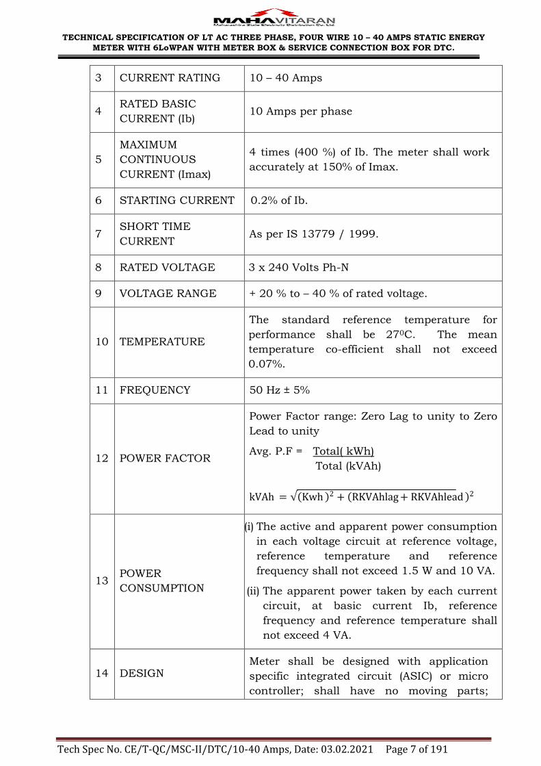
3 CURRENT RATING 10 – 40 Amps
4 RATED BASIC
CURRENT (Ib) 10 Amps per phase
5
MAXIMUM
CONTINUOUS
CURRENT (Imax)
4 times (400 %) of Ib. The meter shall work
accurately at 150% of Imax.
6 STARTING CURRENT 0.2% of Ib.
7 SHORT TIME
CURRENT As per IS 13779 / 1999.
8 RATED VOLTAGE 3 x 240 Volts Ph-N
9 VOLTAGE RANGE + 20 % to – 40 % of rated voltage.
10 TEMPERATURE
The standard reference temperature for
performance shall be 270C. The mean
temperature co-efficient shall not exceed
0.07%.
11 FREQUENCY 50 Hz ± 5%
12 POWER FACTOR
Power Factor range: Zero Lag to unity to Zero
Lead to unity
Avg. P.F = Total( kWh)
Total (kVAh)
kVAh = √ Kwh 2 + RKVAhlag + RKVAhlead 2
13 POWER
CONSUMPTION
(i) The active and apparent power consumption
in each voltage circuit at reference voltage,
reference temperature and reference
frequency shall not exceed 1.5 W and 10 VA.
(ii) The apparent power taken by each current
circuit, at basic current Ib, reference
frequency and reference temperature shall
not exceed 4 VA.
14 DESIGN Meter shall be designed with application
specific integrated circuit (ASIC) or micro
controller; shall have no moving parts;

TECHNICAL SPECIFICATION OF LT AC THREE PHASE, FOUR WIRE 10 – 40 AMPS STATIC ENERGY
METER WITH 6LoWPAN WITH METER BOX & SERVICE CONNECTION BOX FOR DTC.
Tech Spec No. CE/T-QC/MSC-II/DTC/10-40 Amps, Date: 03.02.2021 Page 8 of 191
electronic components shall be assembled
on printed circuit board using surface
mounting technology; factory calibration
using high accuracy (0.1 class) software
based test bench.
15 POWER SUPPLY SMPS (Switched-Mode Power Supply)
16 ISI MARK The meter so supplied must bear ISI Mark.
6.00 CONSTRUCTIONAL REQUIREMENT / METER COVER & SEALING
ARRANGEMENT
6.01 GENERAL MECHANICAL REQUIREMENT
The meter shall be designed and constructed in such a way as to avoid
introducing any danger in normal use and under normal conditions, so as
to ensure especially:
(a) personal safety against electric shock:
(b) personal safety against effects of excessive temperature;
(c) protection against spread of fire;
(d) protection against penetration of solid objects, dust and water in the
meter.
6.02 All parts, which are subject to corrosion under normal working conditions,
shall be protected effectively against corrosion by suitable method to
achieve durable results. Any protective coating shall not be liable to
damage by ordinary handling nor damage due to exposure to air, under
normal working conditions. The electrical connections shall be such as to
prevent any opening of the circuit under normal conditions of use as
specified in the standard, including any overload conditions specified in
the standard. The construction of the meter shall be such as to minimize
the risks of short-circuiting of the insulation between live parts and
accessible conducting parts due to accidental loosening or unscrewing of
the wiring, screws, etc. The meter shall not produce appreciable noise in
use.
6.03 All insulating materials used in the construction of the meter shall be
substantially non-hygroscopic, non ageing and of tested quality.
6.04 The meter shall be projection type and shall be dust and moisture proof.
The meter base & cover shall be made out of unbreakable, high grade, fire
resistant Polycarbonate material so as to give it tough and non-breakable
qualities. Meter base shall be opaque and meter top cover shall be
transparent. The meter cover shall be secured to base by means of
sealable unidirectional captive screws. The meter body shall be type tested

TECHNICAL SPECIFICATION OF LT AC THREE PHASE, FOUR WIRE 10 – 40 AMPS STATIC ENERGY
METER WITH 6LoWPAN WITH METER BOX & SERVICE CONNECTION BOX FOR DTC.
Tech Spec No. CE/T-QC/MSC-II/DTC/10-40 Amps, Date: 03.02.2021 Page 9 of 191
for IP51 degree of protection as per IS 12063 against ingress of dust,
moisture & vermin but without suction in the meter.
6.05 METER CASE
6.05.01 The poly carbonate body of the meter shall conform to IS: 11731 (FV-2
category) besides meeting the test requirement of heat deflection test as
per ISO 75, glow wire test as per the IS: 11000 (Part 2/Sec-1) 1984 or
IEC-60695-2-12, Ball pressure test as per IEC-60695-10-2 and
Flammability Test as per UL 94 or as per IS 11731(Part-2) 1986.
6.05.02 The base and cover shall be ultra-sonically welded (continuous welding) so
that once the meters are manufactured and tested at factory; it shall not
be possible to open the cover at site except the terminal cover. The
thickness of material for meter cover and base shall be 2 mm (minimum).
6.06 TERMINALS & TERMINAL BLOCK
6.06.01 Moulded terminal block for current and voltage connections conforming to
IS: 13779 / 1999 (amended up to date) to meet the requirement of
terminal connection arrangement shall be provided. The termination
arrangement shall be with an extended transparent terminal cover as per
clause number 6.5.2 of IS: 13779 / 1999 and shall be sealable
independently to prevent unauthorized tampering. Proper size of grooves
shall be provided at bottom of this terminal cover for incoming and
outgoing service wires.
6.06.02 The terminal cover shall be extended transparent type and shall enclose
the actual terminals, the conductor fixing screws and unless otherwise
specified, a suitable length of external conductors and their insulation.
6.06.03 The fixing screws used on the terminal cover for fixing and sealing in
terminal cover shall be held captive in the terminal cover.
6.06.04 When the meter is mounted, no access to the terminals shall be possible
without breaking seals(s) of the terminal cover.
6.07 Sealing provision shall be made against opening of the terminal cover and
front cover. It is necessary to provide screws with two holes for sealing
purpose. The meter shall be pilfer-proof & tamper-proof. The provision
shall be made on the Meter for at least two seals to be put by utility user.
6.08 The meter shall be completely factory sealed except the terminal
block cover. The provision shall be made on the meter for at least two
seals to be put by utility user. The Terminal cover shall be transparent
with one side hinge with sealing arrangement.

TECHNICAL SPECIFICATION OF LT AC THREE PHASE, FOUR WIRE 10 – 40 AMPS STATIC ENERGY
METER WITH 6LoWPAN WITH METER BOX & SERVICE CONNECTION BOX FOR DTC.
Tech Spec No. CE/T-QC/MSC-II/DTC/10-40 Amps, Date: 03.02.2021 Page 10 of 191
6.09 RESISTANCE TO HEAT AND FIRE The terminal block, the terminal cover and the meter case shall ensure
reasonable safety against the spread of fire. They shall not be ignited by
thermal overload of live parts in contact with them.
6.10 OUTPUT DEVICE:
Energy Meter shall have test output, accessible from the front, and be
capable of being monitored with suitable testing equipment while in
operation at site. The operation indicator must be visible from front. The
test output device shall be provided in the form of blinking LED. The pulse
rate of output device (separate blinking LED must be provided for each
parameter) which is Pulse / kWh andPulse / kVArh(meter constant) shall
be indelibly provided on the nameplate. It shall be possible to check the
accuracy of active energy and reactive energy measurement of the meter
on site by means of LED output. Resolution of the test shall be sufficient
to enable the starting current test in less than 10 minutes and accuracy
test at the lowest load shall be completed with desired accuracy within 5
minutes.
6.11 The meter accuracy shall not be affected by external AC / DC / permanent
magnetic field as per CBIP Technical Report 325 with latest amendments.
If the meter gets affected under influence of any magnetic field (AC / DC /
Permanent), then the same shall be recorded as magnetic tamper event
with date & time stamping and the meter shall record energy maximum
value current (Imax) and reference voltage at unity power factor.
6.12 The meter shall have CTs with magnetic shielding and same shall be
tested separately prior to assembly.
6.13 In meter, Power supply unit shall be micro control type (transformer less
to avoid magnetic influence) instead of providing conventional transformer
and then conversion to avoid magnetic influence.
6.14 REAL TIME INTERNAL CLOCK (RTC):
The real time quartz clock shall be used in the meter for maintaining time
(IST) and calendar. The RTC shall be non - rechargeable and shall be pre-
programmed for 30 Years Day / date without any necessity for correction.
The maximum drift shall not exceed +/- 300 Seconds per year. Facility for
adjustment of real time shall be provided through CMRI with proper
security.
The clock day / date setting and synchronization shall only be possible
through password / Key code command from CMRI or Meter testing work
bench and this shall need password enabling for meter.
The RTC battery & the battery for display in case of power failure shall be
separate.

TECHNICAL SPECIFICATION OF LT AC THREE PHASE, FOUR WIRE 10 – 40 AMPS STATIC ENERGY
METER WITH 6LoWPAN WITH METER BOX & SERVICE CONNECTION BOX FOR DTC.
Tech Spec No. CE/T-QC/MSC-II/DTC/10-40 Amps, Date: 03.02.2021 Page 11 of 191
6.15 Non-specified display parameters in the meter shall be blocked and same
shall not be accessible for reprogramming at site through any kind of
communication
6.16 Complete metering system & measurement shall not be affected by the
external electromagnetic interference such as electrical discharge of cables
and capacitors, harmonics, electrostatic discharges, external magnetic
fields and DC current in AC supply etc. The Meter shall meet the
requirements of CBIP Tech-report 325 (amended up to date).
6.17 A push button shall be provided for high resolution reading with two
decimal digits / alternate mode of display as brought out elsewhere in this
specification.
6.18 SELF DIAGNOSTIC FEATURES:
(a) The meter shall keep log in its memory for unsatisfactory / non -
functioning of Real Time Clock battery.
(b) LCD Test display shall be provided for checking of all display
Segments.
6.19 The meter shall have facility to read the default display parameters during
power supply failure. An internal maintenance free battery (Ni-mh or Li-
ion or NI CD) of long life of 10 years shall be provided for the same. A
suitable Push Button arrangement for activation of battery shall be
provided. Alternatively, push button provided for displaying alternate
mode (On Demand Mode) parameters shall also be acceptable for
activation of battery during power OFF condition.
After activating the battery during power OFF condition, the meter shall
display all default parameters only once, after which the battery shall
switch OFF automatically. The battery shall be locked after 3 successive
operations during one power OFF cycle. As soon as the supply is resumed
to meter, the battery shall automatically come to normal.
6.20 PCB used in meter shall be made by Surface Mounting Technology.
6.21 The meter shall also be capable to withstand and shall not get damaged if
phase to phase voltage is applied between phases to neutral for 5 minutes.
6.22 The meter shall record and display total energy including Harmonic
energy.
6.23 COMMUNICATION CAPABILITY:
The meter shall have wireless communication with HHT, for downloading
all types of data from the meter. Meter shall support 6LoWPAN based on
Internal Low Power Radio Frequency (LPRF) technology on frequency band
sub-1GHz. HHT shall support dual band operations i) Zigbee based 2.4
GHz ii) 6LoWPAN based sub-1 GHz. HHT shall be capable to download,

TECHNICAL SPECIFICATION OF LT AC THREE PHASE, FOUR WIRE 10 – 40 AMPS STATIC ENERGY
METER WITH 6LoWPAN WITH METER BOX & SERVICE CONNECTION BOX FOR DTC.
Tech Spec No. CE/T-QC/MSC-II/DTC/10-40 Amps, Date: 03.02.2021 Page 12 of 191
commission Zigbee based and 6LoWPAN based LPRF meters. Download
should be possible though optical port in case of power failure. The baud
rate while downloading data through optical port should be 9600. Bidder
should implement their own protocol using attributes defined in
annexure-V for data downloading through optical port.
6.23.01 6LoWPAN BASED INTERNAL LOW POWER RADIO FREQUENCY
(LPRF)
The 6LoWPAN based Internal Low Power Radio Frequency (LPRF) shall be
capable to read the meter from a distance of minimum one hundred (100)
meter with line of sight radius without obstructions, from the meter.
Longer communication range is preferred.
The Meter & HHT shall be based on 6LoWPAN networking on sub-1 GHz
(865-867 MHz) with protocol enclosed herewith as Annexure IV & V
for Interoperability with following settings:
1. Device shall be capable of being 6LoWPAN ‗root‘ device. Default device
type at factory defaults should be ‗router‘ and state is ‗not joined‘.
2. Default PAN id shall be 0xFFFF.
3. Radio device shall have 128 bits addressing (as per IPv6 and Annexure-
V.)
4. The radio shall be programmed with 16 byte security key (128 bit
encryption). The value for sample = ‗0000000000MSEDCL‘(ASCII) (This
value is only for samples and actual value will be informed to
successful bidder.)
5. The baud rate for radio to meter UART shall be 9,600 bps.
6. Over the air baud rate shall be 50 kbps.
7. Following Commissioning attributes must be supported:
i. PAN ID
ii. Channel (0-8)
iii. Device Type (1- Root, 2-Router)
iv. IPv6 Prefix ( as per IPv6 Specifications)
v. AES key – 16 Bytes Hex
vi. Commission state (0- un-commissioned, 1- commissioned)
vii. DAG ID – 16 Byte (as per IPv6 specifications)
viii. Router List
8. The HHT shall be capable of commissioning a meter network node as
either a 6LoWPAN ‗root‘ or ‗router‘ as appropriate.

TECHNICAL SPECIFICATION OF LT AC THREE PHASE, FOUR WIRE 10 – 40 AMPS STATIC ENERGY
METER WITH 6LoWPAN WITH METER BOX & SERVICE CONNECTION BOX FOR DTC.
Tech Spec No. CE/T-QC/MSC-II/DTC/10-40 Amps, Date: 03.02.2021 Page 13 of 191
9. The HHT shall be capable of joining a metering network as a Router /
end device to download data.
6.23.02 ZIGBEE BASED INTERNAL LOW POWER RADIO FREQUENCY (LPRF)
The Zigbee based Internal Low Power Radio Frequency (LPRF) shall be
capable to read the meter from a distance of minimum thirty (30) meter
radius with obstructions from the meter. Longer communication range is
preferred. However, no pre - installation programming or post installation
programming shall be required for this purpose.
The HHT shall be based on Open ZigBee - 2007 PRO with Smart energy
profile protocol enclosed herewith as Annexure IV & V
for Interoperability with following settings:
1. PAN id shall be 123 (This id is only for samples and actual id will be
informed to successful bidder.)
2. Radio device shall have 64 bits addressing (as per IEEE.802.15.4
standard.)
3. The radio shall be programmed with 16 byte security key (128 bit
encryption). The value for sample = ‗MSEDCL‘ (This value is only for
samples and actual value will be informed to successful bidder.)
4. The baud rate for radio to meter UART shall be 9,600 bps.
5. Over the air baud rate shall be 250 kbps.
6. Meter Serial Number shall be mapped with 64 bit MAC address of the
radio.
7. The sample metering cluster 0x0702 to be implemented as open
protocol as per Annexure V.
8. The meter network RF device shall be a combo device.
9. The HHT shall be a combo device.
10. The HHT shall be capable of commissioning a meter network node as
either a coordinator or router as appropriate.
11. The HHT shall be capable of joining a metering network as a Router /
end device to download data.
12. The profile used shall be OxBFOD.
13. Source and Destination Device End Point 0x08
14. Channel Mask 0x03FFF800 (not support the last channel number 26
in the band)
15. Time attribute to be supported as per Annexure V.
16. Following Commissioning attributes must be supported:

TECHNICAL SPECIFICATION OF LT AC THREE PHASE, FOUR WIRE 10 – 40 AMPS STATIC ENERGY
METER WITH 6LoWPAN WITH METER BOX & SERVICE CONNECTION BOX FOR DTC.
Tech Spec No. CE/T-QC/MSC-II/DTC/10-40 Amps, Date: 03.02.2021 Page 14 of 191
i. Preconfigured Link Key
ii. Channel Mask
iii. Startup control
iv. Extended PAN ID
17. Following cluster support need to be present in Zigbee module:
i. Basic Cluster 0x0000
ii. Commissioning Cluster 0x0015
iii. MSEDCL Cluster 0xFC00
The bidder shall submit Zigbee compliance certificate for radio modules
used in the HHT. Likewise, the certificate of PICS (Protocol Implementation
& Conformance Statement) in regards Manufacturer Specific Cluster from
Zigbee Alliance Official Test House shall be submitted.
The frequency range of LPRF equipment shall be approved frequency
range from Government of India, Ministry of Communications and
Information Technology (Wireless Planning and Coordination Wing) New
Delhi notification vide G.S.R. 45 (E), dtd. 28th January, 2005, i.e. the
frequency band of 2.4GHz and 865 – 867 MHz. The meter shall use license
free frequency band for communication so that license for use of LPRF
equipment to read energy meter at site is not required. The required
license, if any, for use of LPRF equipment to read energy meter at the site
shall not be under the scope of purchaser. The necessary support shall be
provided by the tenderer. Accordingly, Bidder shall submit ETA (
Equipment Type Approval) for RF Module, issued by WPC Wing ( Wireless
planning and co-ordination wing ) of Ministry of Communications and
Information Technology, Govt. of India.
The meters with Internal Low Power Radio Frequency (LPRF) technology
shall have two way communication to read the meter data. However, data
could only be downloaded from meter to HHT, but no command regarding
data alteration in the meter and data retrieval from meter to HHT shall be
possible in any case. The LPRF module of the meter shall have no physical
access from outside the meter. It shall not be possible to tamper the data
stored in meter and HHT even after getting the password of the software. It
shall be locked at the time of manufacturing. Adequate tamper proofing
shall be provided to disallow any change of such auto recorded reading by
any means. Meter shall not be accessible for reprogramming at site
through any kind of communication for any alteration in the factory
settings. Tamper proof arrangement shall be made to get such a reading
even at the time of power failure. Meter shall support communication
through Optical port in the event of Power failure, through battery.
TECHNICAL SPECIFICATION OF LT AC THREE PHASE, FOUR WIRE 10 – 40 AMPS STATIC ENERGY
METER WITH 6LoWPAN WITH METER BOX & SERVICE CONNECTION BOX FOR DTC.
Tech Spec No. CE/T-QC/MSC-II/DTC/10-40 Amps, Date: 03.02.2021 Page 15 of 191
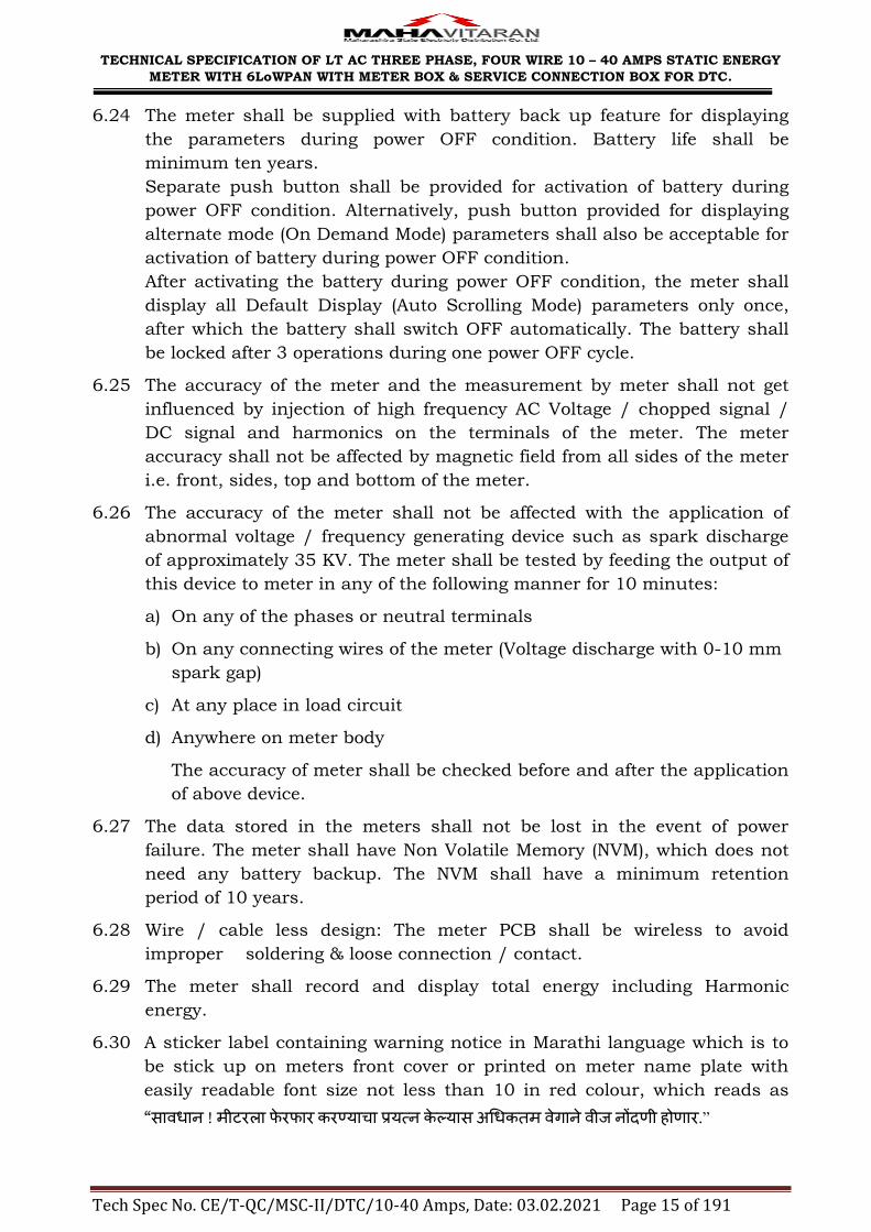
6.24 The meter shall be supplied with battery back up feature for displaying
the parameters during power OFF condition. Battery life shall be
minimum ten years.
Separate push button shall be provided for activation of battery during
power OFF condition. Alternatively, push button provided for displaying
alternate mode (On Demand Mode) parameters shall also be acceptable for
activation of battery during power OFF condition.
After activating the battery during power OFF condition, the meter shall
display all Default Display (Auto Scrolling Mode) parameters only once,
after which the battery shall switch OFF automatically. The battery shall
be locked after 3 operations during one power OFF cycle.
6.25 The accuracy of the meter and the measurement by meter shall not get
influenced by injection of high frequency AC Voltage / chopped signal /
DC signal and harmonics on the terminals of the meter. The meter
accuracy shall not be affected by magnetic field from all sides of the meter
i.e. front, sides, top and bottom of the meter.
6.26 The accuracy of the meter shall not be affected with the application of
abnormal voltage / frequency generating device such as spark discharge
of approximately 35 KV. The meter shall be tested by feeding the output of
this device to meter in any of the following manner for 10 minutes:
a) On any of the phases or neutral terminals
b) On any connecting wires of the meter (Voltage discharge with 0-10 mm
spark gap)
c) At any place in load circuit
d) Anywhere on meter body
The accuracy of meter shall be checked before and after the application
of above device.
6.27 The data stored in the meters shall not be lost in the event of power
failure. The meter shall have Non Volatile Memory (NVM), which does not
need any battery backup. The NVM shall have a minimum retention
period of 10 years.
6.28 Wire / cable less design: The meter PCB shall be wireless to avoid
improper soldering & loose connection / contact.
6.29 The meter shall record and display total energy including Harmonic
energy.
6.30 A sticker label containing warning notice in Marathi language which is to
be stick up on meters front cover or printed on meter name plate with
easily readable font size not less than 10 in red colour, which reads as
―सावधान ! मीटरऱा फेरफार करण्याचा प्रयत्न केल्यास अधधकतम वेगाने वीज नोंदणी होणार.”
TECHNICAL SPECIFICATION OF LT AC THREE PHASE, FOUR WIRE 10 – 40 AMPS STATIC ENERGY
METER WITH 6LoWPAN WITH METER BOX & SERVICE CONNECTION BOX FOR DTC.
Tech Spec No. CE/T-QC/MSC-II/DTC/10-40 Amps, Date: 03.02.2021 Page 16 of 191
7.00 ENCLOSURE OF METER & SERVICE CONNECTION BOX
As per Annexure XII & Annexure XIII
8.00 TOD TIMINGS
There shall be provision for at least 6 (Six) TOD time zones for energy and
demand. The number and timings of these TOD time Zones shall be
programmable. At present the time zones shall be programmed as below.
Zone ―A‖: - 00:00 Hrs. to 06:00 Hrs. and 22:00 Hrs. to 24:00 Hrs.
Zone ―B‖: - 06:00 Hrs. to 09:00 Hrs. and 12:00 Hrs. to 18:00 Hrs.
Zone ―C‖: - 09:00 Hrs. to 12:00 Hrs.
Zone ―D‖: - 18:00 Hrs. to 22:00 Hrs.
9.00 DEMAND INTEGRATION PERIOD
The maximum demand integration period shall be set at 30 minutes with
block window method.
10.00 MD RESET:
It shall be possible to reset MD by the following options:
a) Communication driven reset through hand held terminal (HHT).
b) Auto reset at 24:00 hrs at the end of each billing cycle: Automatic reset
at the end of certain predefined period (say, end of the month). No push
button shall be provided for MD reset.
11.00 ANTI TAMPER FEATURES
The meter shall detect and correctly register energy in forward direction
under following tamper conditions.
11.01 Change of phase sequence:
The meter accuracy shall not be affected by change of phase sequence. It
shall maintain the desired accuracy in case of reversal of phase sequence.
11.02 Reversal of line and load terminals:
Even on interchanging the load and line wires, the meter shall register
correct energy passing through the meter.
11.03 Drawing of current through local Earth:
The meter shall register accurate energy even if load is drawn partially or
fully through a local earth.
11.04 The three phase meter shall continue to work even without neutral.
11.05 The three phase meter shall work in absence of any two phases i.e.
it shall work on any one phase wire and neutral, to record relevant energy.
11.06 The meter shall work without earth.

TECHNICAL SPECIFICATION OF LT AC THREE PHASE, FOUR WIRE 10 – 40 AMPS STATIC ENERGY
METER WITH 6LoWPAN WITH METER BOX & SERVICE CONNECTION BOX FOR DTC.
Tech Spec No. CE/T-QC/MSC-II/DTC/10-40 Amps, Date: 03.02.2021 Page 17 of 191
11.07 The potential link shall not be provided.
11.08 Visual indication shall be provided to safeguard against wrong
connections to the meter terminals.
11.09 The meter accuracy shall not be affected by external AC / DC / permanent
magnetic field as per CBIP Technical Report 325 with latest amendments.
If the meter gets affected under influence of any magnetic field (AC / DC /
Permanent), then the same shall be recorded as magnetic tamper event
with date & time stamping and the meter shall record energy maximum
value current (Imax) and reference voltage at unity power factor.
12.00 TAMPER EVENTS:
The meter shall work satisfactorily under presence of various influencing
conditions like External Magnetic Field, Electromagnetic Field, Radio
Frequency Interference, harmonic Distortion, Voltage / Frequency
Fluctuations and electromagnetic High Frequency Fields etc.
The detection of the tamper event shall be registered in the tamper event
register. The no. of times the tampering has been done shall also be
registered in the meter. It is the responsibility of the meter manufacturer
not to use manufacturer specific codes where standard codes are
available.
The meter shall have features to detect the occurrence and restoration of
the following abnormal events.
12.01 Missing potential and potential imbalance:
The meter shall be capable of detecting and recording occurrence and
restoration with date and time the cases of potential failure and low
potential, which could happen due to disconnection of potential leads (one
or two) with phase identification. Meter shall also detect and log cases of
voltage unbalance (10% or more for 5 Minutes.) Higher of the 3 phase
voltages shall be considered as reference for this purpose.
12.02 Current unbalance:
The meter shall be capable of detecting and recording occurrence and
restoration with date and time of current unbalance (30% or more for 15
minutes) with phase identification. Higher of the 3 phase currents shall be
considered as reference for this purpose.
12.03 Current Reversal:
The meter shall be capable of detecting and recording occurrence and
restoration with date and time of reversal of current with phase
identification for persistence time of 5 minutes. It shall also possess a
current reversal counter.
TECHNICAL SPECIFICATION OF LT AC THREE PHASE, FOUR WIRE 10 – 40 AMPS STATIC ENERGY
METER WITH 6LoWPAN WITH METER BOX & SERVICE CONNECTION BOX FOR DTC.
Tech Spec No. CE/T-QC/MSC-II/DTC/10-40 Amps, Date: 03.02.2021 Page 18 of 191
12.04 Current circuit short:
The meter shall be capable of detecting and recording occurrences and
restoration of shorting of any one or two phases of current, with date &
time of occurrence and restoration with phase identification.
12.05 High Neutral Current. (CT bypass):
The meter shall be capable of recording incidences of excess neutral
current (if it is in excess 30% of Ib for more than 5 minutes.) The meter
shall record the total duration of the above abnormalities, time and date of
their occurrences and restorations with snapshot of instantaneous
electrical conditions viz. System Voltages, Phase Currents & System PF.
12.06 Power ON / OFF:
The meter shall be capable to record power ON/OFF events in the meter
memory. All potential failure shall record as power off event.The meter
shall keep records for the minimum 256 events in the meter memory for
retrieval by authorized personnel. (Occurrence + Restoration with date &
time).
For above abnormal conditions, the recording of events shall be on FIFO
basis. The unrestored events shall be recorded separately and shall not be
deleted till they get recovered (permissible upto 3 months). It shall be
possible to retrieve the abnormal event data through the meter RF port
with the help of HHT& downloaded the same to the base computer. All the
information shall be made available in simple & easy to understand
format.
12.07 In the event the meter is forcibly opened, even by 2 to 4 mm variation of
the meter cover, same should be recorded as tamper event with date &
time stamping and the meter should continuously display that the cover
has been tampered. It is suggested that the manufacturer should develop
their software such that there will be some time delay for activation of this
tamper feature and during that period only the meter cover should be
fitted. The delay in activation of software shall be for one instance only.
After the meter cover is fitted, it shall get activated immediately with out
any delay.
13.00 DISPLAY OF MEASURED VALUES
13.01 The meter shall have minimum 5 digits (with ± indication), parameter
identifier, permanently backlit Liquid Crystal Display (LCD) with wide
viewing angle and shall be visible from the front of the meter. The display
shall be electronic and when the meter is not energized, the electronic
display need not be visible. The size of digit shall be minimum 10x5 mm.
The decimal units shall not be displayed in auto scroll mode. However it
shall be displayed in push button mode for high resolution display for

TECHNICAL SPECIFICATION OF LT AC THREE PHASE, FOUR WIRE 10 – 40 AMPS STATIC ENERGY
METER WITH 6LoWPAN WITH METER BOX & SERVICE CONNECTION BOX FOR DTC.
Tech Spec No. CE/T-QC/MSC-II/DTC/10-40 Amps, Date: 03.02.2021 Page 19 of 191
testing. LCD shall be suitable for temperature withstand of 700 C.
Adequate back up arrangement for storing of energy registered at the time
of power interruption shall be provided.
In case of multiple values presented by single display, it shall be possible
to display the contents of all relevant memories. When displaying the
memory, the identification of each parameter applied shall be possible.
The principle unit for measured values shall be the kilowatt-hour (kWh)
for active energy, kVArh for reactive energy &kVAh for apparent energy.
13.02 The meter shall be pre-programmed for following details.
(a) P. T. Ratio: 415 V
(b) MD Integration Period: 30 Minutes real time based.
(c) The meter shall Auto reset kVAMD at 24.00 Hrs. of last day of the
month and this value shall be stored in the memory along with the
cumulative kWh and cumulative kVAh reading.
(d) No MD reset push button shall be provided.
(e) Average power factor with 2 decimal digits shall be displayed.
(f) The Default Display shall switch to Alternate Display (On Demand
Display Mode) after pressing the push button continuously for 5
seconds.
(g) The meter display shall return to Default Display Mode if the ―On
Demand‖ Push Button is not operated for 15 sec.
(h) The array of data to be retained inside the meter memory shall be for
the last 60 days for a capture period of 30 minutes. The load survey
data shall be first in first out basis (FIFO).
(i) The sequence of display of various instantaneous electrical parameters
in auto scroll & On Demand mode shall be as below. Display other
than specified below shall be blocked. The scroll period for auto scroll,
if any, shall be 9 sec.
(A) Default Display
1. LCD Test
2. Meter Sr. No.
3. Real Time Clock – Date & Time
4. Cumulative Energy – kWh
5. Cumulative Energy – kWh - TOD Zone A (TZ1)

TECHNICAL SPECIFICATION OF LT AC THREE PHASE, FOUR WIRE 10 – 40 AMPS STATIC ENERGY
METER WITH 6LoWPAN WITH METER BOX & SERVICE CONNECTION BOX FOR DTC.
Tech Spec No. CE/T-QC/MSC-II/DTC/10-40 Amps, Date: 03.02.2021 Page 20 of 191
6. Cumulative Energy – kWh - TOD Zone B (TZ2)
7. Cumulative Energy – kWh - TOD Zone C (TZ3)
8. Cumulative Energy – kWh - TOD Zone D (TZ4)
9. Cumulative Energy – kVArh - Lag
10. Cumulative Energy – kVArh - Lag- TOD Zone A (TZ1)
11. Cumulative Energy – kVArh - Lag- TOD Zone B (TZ2)
12. Cumulative Energy – kVArh - Lag- TOD Zone C (TZ3)
13. Cumulative Energy – kVArh - Lag- TOD Zone D (TZ4)
14. Cumulative Energy –kVArh - Lead
15. Cumulative Energy – kVArh - Lead- TOD Zone A (TZ1)
16. Cumulative Energy – kVArh - Lead- TOD Zone B (TZ2)
17. Cumulative Energy – kVArh - Lead- TOD Zone C (TZ3)
18. Cumulative Energy – kVArh - Lead- TOD Zone D (TZ4)
19. Cumulative Energy – kVAh
20. Cumulative Energy – kVAh - TOD Zone A (TZ1)
21. Cumulative Energy – kVAh - TOD Zone B (TZ2)
22. Cumulative Energy – kVAh - TOD Zone C (TZ3)
23. Cumulative Energy – kVAh – TOD Zone D (TZ4)
24. Current MD – kVA with occurance date & time
25. MD - kVA – TOD Zone A (TZ1) with occurance date & time
26. MD - kVA – TOD Zone B (TZ2) with occurance date & time
27. MD - kVA – TOD Zone C (TZ3) with occurance date & time
28. MD - kVA – TOD Zone D (TZ4) with occurance date & time
29. Number of MD – kVA reset

TECHNICAL SPECIFICATION OF LT AC THREE PHASE, FOUR WIRE 10 – 40 AMPS STATIC ENERGY
METER WITH 6LoWPAN WITH METER BOX & SERVICE CONNECTION BOX FOR DTC.
Tech Spec No. CE/T-QC/MSC-II/DTC/10-40 Amps, Date: 03.02.2021 Page 21 of 191
30. Rising MD with elapsed time
31. Three Phase Power Factor – PF
32. Cumulative Tamper Count
33. Meter Cover Opening –Occurance with date and time.
(B) On – Demand Display (Alternate Display)
1. Meter Sr. No.
2. Last date & time of MD - kVA reset
3. Current – IR
4. Current – IY
5. Current – IB
6. Voltage – VR
7. Voltage – VY
8. Voltage – VB
9. Signed Power Factor – R Phase
10. Signed Power Factor – Y Phase
11. Signed Power Factor – B Phase
12. Frequency
13. High resolution kWh (for calibration)
14. High resolution kVArh Lag(for calibration)
15. High resolution kVArh Lead(for calibration)
16. High resolution kVAh (for calibration)
17. Rising MD with elapsed time (for calibration/testing)
18. M1 MD - kVA – TOD Zone A (TZ1) with occurance date & time
19. M1 MD - kVA –TOD Zone B (TZ2) with occurance date & time

TECHNICAL SPECIFICATION OF LT AC THREE PHASE, FOUR WIRE 10 – 40 AMPS STATIC ENERGY
METER WITH 6LoWPAN WITH METER BOX & SERVICE CONNECTION BOX FOR DTC.
Tech Spec No. CE/T-QC/MSC-II/DTC/10-40 Amps, Date: 03.02.2021 Page 22 of 191
20. M1 MD - kVA – TOD Zone C (TZ3) with occurance date & time
21. M1 MD - kVA – TOD Zone D (TZ4) with occurance date & time
22. M2 MD - kVA – TOD Zone A (TZ1) with occurance date & time
23. M2 MD - kVA –TOD Zone B (TZ2) with occurance date & time
24. M2 MD - kVA – TOD Zone C (TZ3) with occurance date & time
25. M2 MD - kVA – TOD Zone D (TZ4) with occurance date & time
26. Last Tamper Event with date and time.
27. PAN ID of meter
28. Active Power- kW-R phase (Instantaneous)
29. Active Power- kW-Y phase (Instantaneous)
30. Active Power- kW-B phase (Instantaneous)
31. Reactive Power- kVAr- R phase (Instantaneous)
32. Reactive Power- kVAr- Y phase (Instantaneous)
33. Reactive Power- kVAr- B phase (Instantaneous)
34. Apparent Power- kVA- R phase (Instantaneous)
35. Apparent Power- kVA- Y phase (Instantaneous)
36. Apparent Power- kVA- B phase (Instantaneous)
37. Frequency (Instantaneous)
38. Phase Sequence (Instantaneous)
14.00 DEMONSTRATION
The purchaser reserves the right to ask to give the demonstration of
the equipment offered at the purchaser‘s place.
15.00 BILLING DATA, BILLING HISTORY & LOAD SURVEY
15.01 BILLING DATA
Billing parameters shall be downloaded as per table below.
(1) Cumulative Energy –kWh

TECHNICAL SPECIFICATION OF LT AC THREE PHASE, FOUR WIRE 10 – 40 AMPS STATIC ENERGY
METER WITH 6LoWPAN WITH METER BOX & SERVICE CONNECTION BOX FOR DTC.
Tech Spec No. CE/T-QC/MSC-II/DTC/10-40 Amps, Date: 03.02.2021 Page 23 of 191
(2) Cumulative Energy –kWh-TOD Zone A (TZ1)
(3) Cumulative Energy –kWh-TOD Zone B (TZ2)
(4) Cumulative Energy –kWh-TOD Zone C (TZ3)
(5) Cumulative Energy –kWh-TOD Zone D (TZ4)
(6) Maximum Demand- MD kVA with occurrence date & time
(7) MD kVA- TOD Zone A (TZ1) with occurrence date & time
(8) MD kVA- TOD Zone B (TZ2) with occurrence date & time
(9) MD kVA- TOD Zone C (TZ3) with occurrence date & time
(10) MD kVA- TOD Zone D (TZ4) with occurrence date & time
(11) Cumulative Energy –kVAh
(12) Cumulative Energy –kVAh-TOD Zone A (TZ1)
(13) Cumulative Energy –kVAh-TOD Zone B (TZ2)
(14) Cumulative Energy –kVAh-TOD Zone C (TZ3)
(15) Cumulative Energy –kVAh-TOD Zone D (TZ4)
(16) Cumulative Energy –kVArh ( Lag)
(17) Cumulative Energy –kVArh ( Lead)
(18) Voltage – VRN
(19) Voltage – VYN
(20) Voltage – VBN
(21) Current - IR
(22) Current – IY
(23) Current – IB
15.02 BILLING HISTORY
The meter shall have sufficient non-volatile memory for recording history
of billing parameters (Cumulative kWh Total, Cumulative kVAh Total,
Cumulative kVArh (Lag), Cumulative kVArh (Lead) at the time of reset

TECHNICAL SPECIFICATION OF LT AC THREE PHASE, FOUR WIRE 10 – 40 AMPS STATIC ENERGY
METER WITH 6LoWPAN WITH METER BOX & SERVICE CONNECTION BOX FOR DTC.
Tech Spec No. CE/T-QC/MSC-II/DTC/10-40 Amps, Date: 03.02.2021 Page 24 of 191
and kVAMD) for last 12 months.
15.03 LOAD SURVEY
The logging interval for load survey shall be 30 minutes. Load survey data
shall be logged for last 60 days on non time based basis, i.e. if there is no
power for more than 24 hours, the day shall not be recorded.
Whenever meter is taken out and brought to laboratory, the load survey
data shall be retained for the period of actual use of meter. This load
survey data can be retrieved as and when desired and load profiles shall
be viewed graphically / analytically with the help of meter application
software. The meter application software shall be capable of exporting /
transmitting these data for analysis to other user software in spreadsheet
format.
Sr. No. Parameters
1. Real Time Clock – Date & Time
2. Current - IR
3. Current – IY
4. Current – IB
5. Voltage – VRN
6. Voltage – VYN
7. Voltage – VBN
8. Block Energy – kWh
9. Block Energy – kVArh – lag
10. Block Energy – kVArh – lead
11. Block Energy – kVAh
16.00 COMPUTER SOFTWARE
16.01 For efficient and speedy recovery of data downloaded through HHT on
base computer, licensed copies of base computer software shall be
supplied free of cost.
16.02 This BCS software shall be password protected.
16.03 The computer software shall be "Windows" based of latest version & user
friendly & shall support all versions of ―Windows‖. Also whenever there is
new upgrade version operating system is released, the computer software

TECHNICAL SPECIFICATION OF LT AC THREE PHASE, FOUR WIRE 10 – 40 AMPS STATIC ENERGY
METER WITH 6LoWPAN WITH METER BOX & SERVICE CONNECTION BOX FOR DTC.
Tech Spec No. CE/T-QC/MSC-II/DTC/10-40 Amps, Date: 03.02.2021 Page 25 of 191
compatible to that version should be provided within 3 months free of
cost.
16.04 The data transfer from meter to HHT & from HHT to laptop computer or
PC shall be highly reliable and fraud proof.
No editing shall be possible on base computer as well as on HHT by any
means.
16.05 This software shall be used at number of places up to Division / Sub
Division level. Hence as many copies of base computer software as
required up to Division / Sub Division level shall be provided by supplier.
16.06 BCS software shall have the facility to import consumer master data from
MSEDCL billing system to BCS. Format is as follows:
Field Data Type Length
Billing Unit (BU) Variable character 4
Processing Cycle (PC) Number 2
Meter Route (MR) Variable character 2
Route Variable character 4
Sequence Variable character 4
Consumer Number Variable character 12
Consumer Name Variable character 50
Consumer Address Variable character 50
Meter Serial Number Variable character 8
Meter Make Code Variable character 3
Distribution Transformer Centre
(DTC) code
Variable character 7
Bill Month (YYMM) Variable character 4
Current reading Variable character 6
Average consumption Variable character 6
Meter Phase Variable character 2

TECHNICAL SPECIFICATION OF LT AC THREE PHASE, FOUR WIRE 10 – 40 AMPS STATIC ENERGY
METER WITH 6LoWPAN WITH METER BOX & SERVICE CONNECTION BOX FOR DTC.
Tech Spec No. CE/T-QC/MSC-II/DTC/10-40 Amps, Date: 03.02.2021 Page 26 of 191
16.07 Import / Export shall happen on any USB port of PC / Laptop.
16.08 Every report shall have the facility to print/export as text, pdf.
16.09 Exporting of meter number from BCS to HHT shall be selective on meter
number or group of meters of particular MR-Route-Sequence or DTC code.
16.10 The software shall have capability to convert all the data into ASCII format
as per MSEDCL requirement as below.
a) Billing Data Format
(i) Reading captured from RF meters shall be submitted in one line per
meter reading in following format for billing.
Parameter Length Position Remark
Record Type 4 Char 01-04 RF01 / RF03
( Refer table of Record Types )
Consumer Number 12 chars 05-16 Left Padded with zeros (0)
Make Code 5 chars 17-21 As given in Annexure-III
Meter ID(Serial No) 8 chars 22-29 Left Padded with zeros (0)
Current Reading date 8 chars 30-37 DDMMYYYY format
Current kWh reading 8 chars 38-45 Left Padded with zeros (0)
Current kVA MD 4 chars 46-49 Left Padded with zeros (0) with decimal part if any
Current kVAMD date 8 chars 50-57 DDMMYYYY format
Current kVAMD time 4 chars 58-61 HHMI format
(ii) Last Line in bill string (Meter Reading) file, will be the check
sum logic output as follows:
Character 1 to 4 (4 characters): will be ( RFT1 /RFT3 ). ( Refer table of record types )
Character 5 to 12 (8 characters): Count of Meter Serial Number, left padding by 0.
Character 13 to 28 (16 characters): Sum of KWh of all above meters. Total length will be 16, left padding with 0.
Character 29 to 36 (8 characters): Sum of KW MD, total length will be 8, left padding with 0.
Character 37 to 61 (25 characters): All zeros.
(iii) Table of Record Type
Meter Type (Zigbee/6LoWPAN) Variable character 15
TECHNICAL SPECIFICATION OF LT AC THREE PHASE, FOUR WIRE 10 – 40 AMPS STATIC ENERGY
METER WITH 6LoWPAN WITH METER BOX & SERVICE CONNECTION BOX FOR DTC.
Tech Spec No. CE/T-QC/MSC-II/DTC/10-40 Amps, Date: 03.02.2021 Page 27 of 191
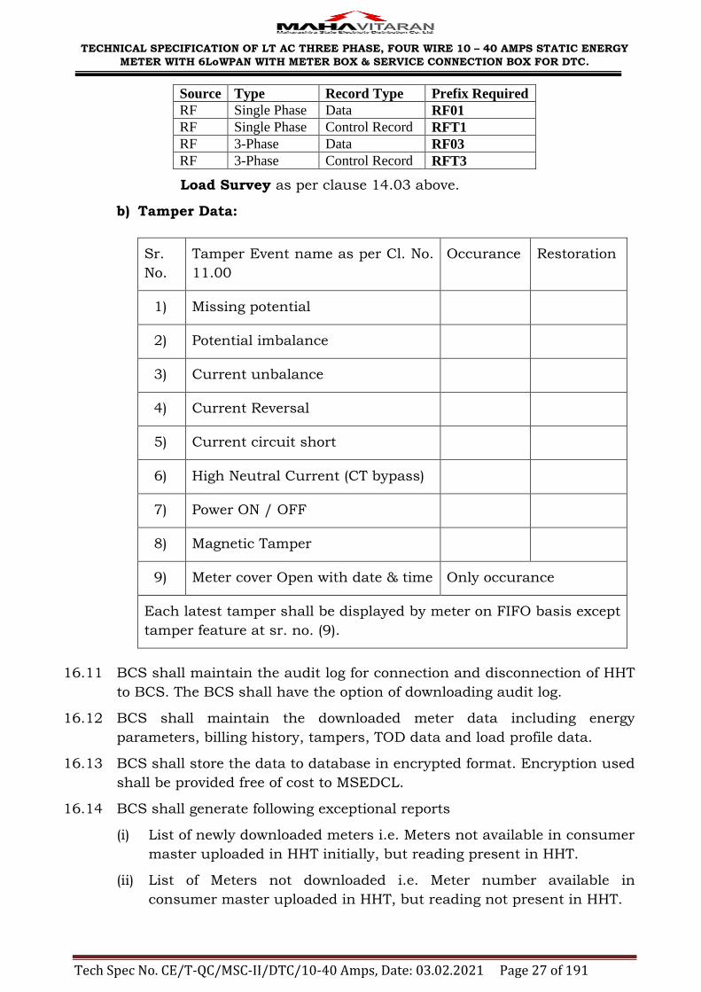
Source Type Record Type Prefix Required
RF Single Phase Data RF01
RF Single Phase Control Record RFT1
RF 3-Phase Data RF03
RF 3-Phase Control Record RFT3
Load Survey as per clause 14.03 above.
b) Tamper Data:
Sr.
No.
Tamper Event name as per Cl. No.
11.00
Occurance Restoration
1) Missing potential
2) Potential imbalance
3) Current unbalance
4) Current Reversal
5) Current circuit short
6) High Neutral Current (CT bypass)
7) Power ON / OFF
8) Magnetic Tamper
9) Meter cover Open with date & time Only occurance
Each latest tamper shall be displayed by meter on FIFO basis except
tamper feature at sr. no. (9).
16.11 BCS shall maintain the audit log for connection and disconnection of HHT
to BCS. The BCS shall have the option of downloading audit log.
16.12 BCS shall maintain the downloaded meter data including energy
parameters, billing history, tampers, TOD data and load profile data.
16.13 BCS shall store the data to database in encrypted format. Encryption used
shall be provided free of cost to MSEDCL.
16.14 BCS shall generate following exceptional reports
(i) List of newly downloaded meters i.e. Meters not available in consumer
master uploaded in HHT initially, but reading present in HHT.
(ii) List of Meters not downloaded i.e. Meter number available in
consumer master uploaded in HHT, but reading not present in HHT.

TECHNICAL SPECIFICATION OF LT AC THREE PHASE, FOUR WIRE 10 – 40 AMPS STATIC ENERGY
METER WITH 6LoWPAN WITH METER BOX & SERVICE CONNECTION BOX FOR DTC.
Tech Spec No. CE/T-QC/MSC-II/DTC/10-40 Amps, Date: 03.02.2021 Page 28 of 191
16.15 Meter manufacturer shall provide API / Exe file with documentation for
downloading the data from the meter along with the sample meter.
16.16 Checksum logic shall also be provided for the downloaded data along with
the sample meter.
16.17 Checksum checking Exe / API shall also be given for validating
downloaded meter data as well as generated XML file with sample meter.
16.18 It shall be possible to upload the HHT data to any PC having HHT
software. A consumer based data uploading facility is required so that
HHT shall upload data only in that PC which has the concerned
consumers‘ data. The consumer number + meter number + make code
shall be the key for creating consumers‘ files or overwriting consumers‘
files in PC.
16.19 The BCS software shall create one single file for the uploaded data, e.g. if
HHT contains the meter readings of 2,000 consumer meters and the said
data is uploaded to BCS, then the BCS shall create a single file containing
separate records for each consumer meter reading. Also there shall be a
provision to give filenames while creating the file.
16.20 Bidder has to provide any new additional reports from BCS software, if
required by MSEDCL in future and the same shall be made available free
of cost.
16.21 The meter manufacturer shall have to depute Hardware and Software
Engineers on call basis who shall have thorough knowledge of meter
hardware / software used for downloading and converting so as to discuss
the problems, if any, or new development in the hardware / software with
Chief General Manager (IT) / Chief Engineer, Testing & Quality Control
Cell, MSEDCL, Prakashgad, Bandra (E), Mumbai – 400 051 without any
additional charge.
16.22 The meter sample with HHT shall be tested by our IT department for the
protocol implemented and time required for downloading the data as
confirmed by the bidder.
16.23 BCS shall support all current operating system versions and shall provide
new version of BCS wherever the new version of operating system
released.
16.24 As and when the meter manufacturer releases new or latest or advanced
versions of meter hardware / firmware / software, the same shall be made
available to purchaser immediately on the release date free of cost. The
latest version shall support all existing hardware / meters in the field.
17.00 GPRS ENABLE HAND HELD TERMINAL (HHT)

TECHNICAL SPECIFICATION OF LT AC THREE PHASE, FOUR WIRE 10 – 40 AMPS STATIC ENERGY
METER WITH 6LoWPAN WITH METER BOX & SERVICE CONNECTION BOX FOR DTC.
Tech Spec No. CE/T-QC/MSC-II/DTC/10-40 Amps, Date: 03.02.2021 Page 29 of 191
17.01 HHT shall have in-built RF module and in-built GSM / GPRS Modem
compatible with 3G, 4G. No separate / external attachment will be
accepted.
17.02 RF module in HHT should support dual band operations- the ZigBee
based 2.4GHz operation and 6LoWPAN based sub-1GHz operation.
17.03 HHT shall facilitate Manual band selection through keypad.
17.04 SIM slot of HHT shall have provision for sealing.
17.05 Modem in HHT shall be self-configurable.
17.06 In Built Modem should have following communication capabilities :
Modem should be Dual Band modem capable of operating at 900 and
1800 MHz GSM transmission.
Modem should support both Data and SMS transmission. It should
have both GSM and GPRS/EDGE features.
17.07 RF HHT shall download meter data through RF port and the downloaded
data shall be stored in HHT and transferred to MSEDCL MDAS (Head End
system) through GPRS channel/USB.
17.08 Application in HHT shall be password protected and HHT should have
common menu structure as given in Annexure-VII.
17.09 After power on the HHT, HHT program version should be displayed and by
default it shall be in Meter Reading mode.
17.10 The HHT shall posses a specific Serial No. which cannot be changed.
Every HHT shall be properly labeled with serial number / tender number
/ program name / program version.
17.11 HHT shall download the data of all the meters, irrespective of meter serial
number present in HHT. It shall show listed (meter serial number
available in HHT) and not listed meters whose data has been downloaded.
17.12 HHT shall show the following statistic of meters:
a. Total No. of Meters for reading in HHT.
b. Total No. of meter readings downloaded in HHT (excluding the new
meters),
c. No. of new meters downloaded in HHT. ( Meter Numbers not available
in Job )
d. No. of Meters not downloaded in HHT.
17.13 HHT shall have the option to check the reading status (Downloaded or Not
Downloaded) for any particular meter.
17.14 HHT shall not accept any external file other than BCS.

TECHNICAL SPECIFICATION OF LT AC THREE PHASE, FOUR WIRE 10 – 40 AMPS STATIC ENERGY
METER WITH 6LoWPAN WITH METER BOX & SERVICE CONNECTION BOX FOR DTC.
Tech Spec No. CE/T-QC/MSC-II/DTC/10-40 Amps, Date: 03.02.2021 Page 30 of 191
17.15 HHT Data files shall be deleted / removed from HHT as per value of job
download status as given below :
i. Job Download Status = ‗0‘ and Clear HHT command is sent through
BCS : Delete the .MRI files from HHT after confirmation from user.
ii. Job Download Status = ‗1‘ : No file in HHT should be deleted, even
after receipt of clear HHT command from BCS.
iii. Job Download Status = ‗2‘ : While uploading new job from BCS to
HHT, existing files in HHT shall be deleted. ( BCS should issue clear
HHT command before uploading new job to HHT ).
iv. Refer job download status flag details in JOB.MRI file. (Annexure-VIII )
17.16 API which will be residing on HHT will be given to MSEDCL free of cost
with all its documentation and training. Without API, meter samples shall
not be approved.
17.17 The meter samples with HHT shall be tested by our IT Department for the
time required for downloading the data as confirmed by the bidder.
17.18 While downloading billing data, by default every time HHT should
download tamper present status for tampers as per protocol given in
Annexure-IV & V. If tamper is found, then HHT should download tamper
data of tampers present along with billing data.
17.19 Downloading time of only Billing data (as per clause No. 14.01) and
tamper data, if tampers present, shall be less than 25secs(after joining the
network). For single phase 6LoWPAN RF meters, downloading time of only
Billing data and tamper data, if tampers present shall be less than 10 secs
(after joining network).
17.20 The total time taken for downloading Billing, Tamper and Load Survey
Data for 60 days of three phase 6LoWPAN RF meter shall be upto 26
minutes(after joining network). For single phase 6LoWPAN RF meters,
total time taken for downloading Billing, Tamper and Load survey data for
45 days shall be minimum 10 to 12 minutes (after joining network).
17.21 Commissioning and Deployment document is as per Annexure V.
17.22 Memory of HHT shall be minimum 256 MB.
17.23 The HHT shall be based on open ZigBee -2007 PRO with Smart energy
profile protocol & 6LoWPAN for Interoperability with the settings given in
clause 5.28 and Annexure IV & V of the specifications.
17.24 The bidder shall submit Zigbee compliance certificate for radio modules
used in the HHT. Likewise, the certificate of PICS (Protocol Implementation
& Conformance Statement) in regards Manufacturer Specific Cluster from
ZigBee Alliance Official Test House shall be submitted.
TECHNICAL SPECIFICATION OF LT AC THREE PHASE, FOUR WIRE 10 – 40 AMPS STATIC ENERGY
METER WITH 6LoWPAN WITH METER BOX & SERVICE CONNECTION BOX FOR DTC.
Tech Spec No. CE/T-QC/MSC-II/DTC/10-40 Amps, Date: 03.02.2021 Page 31 of 191
17.25 The HHT shall be supplied free of cost in the ratio of one for each 250 nos.
meters supplied including user manual, AA size batteries and a set of
direct communication cords for data downloading to the Laptop or PC for
each HHT.
There shall be a provision for AUTO POWER SAVE, which shall force the
instrument in the power saving mode in case of no-activity within 5
minutes. The data shall not be lost in the event the batteries are drained
or removed from the HHT.
17.26 File structure to upload / export the meter details from BCS to HHT is as
follows:
(e) Meter Serial Number – 8 chars.
(f) Meter Make Code – 3 chars.
(g) Consumer Number – 12 chars.
(h) Consumer Name – 50 chars.
(i) Consumer Address – 50 chars.
17.27 HHT shall be capable to download following data individually after
respective command to HHT.
(a) Only Billing Data,
(b) Only Billing History,
(c) Only Tamper Data,
(d) Only TOD Data,
(e) Only Load Survey Data,
(f) All Data.
17.28 HHT shall be capable of downloading billing data of at least 2,000 (Two
thousand) meters at a time. The HHT supplied shall be capable for
downloading data of multiple designs and make of single phase & three
phase meters as well as for meters added in next 5 years for the common
communication protocol attached herewith.
17.29 The meter specific MRI programs shall have the ability to use HHT real
time clock to tag all time related events.
17.30 A real time clock shall be provided in the HHT. The clock shall have a
minimum of 15 days battery backup with 30 year calendar. The time drift
of the real time clock, considering all influencing quantities shall not
exceed +/- 300 seconds per year.
17.31 After successful downloading of meter data to HHT, an indication on both,
HHT and meter for confirmation of successful data transfer shall be

TECHNICAL SPECIFICATION OF LT AC THREE PHASE, FOUR WIRE 10 – 40 AMPS STATIC ENERGY
METER WITH 6LoWPAN WITH METER BOX & SERVICE CONNECTION BOX FOR DTC.
Tech Spec No. CE/T-QC/MSC-II/DTC/10-40 Amps, Date: 03.02.2021 Page 32 of 191
provided for each set of data, viz. billing, load survey & tamper data.
During this period, the energy recording in meter shall not be affected.
17.32 After downloading the data from meters, it shall be possible to create a
single file for all records. The contents of this file shall not be editable.
17.33 Further, there shall be facility in HHT to provide the transfer of meter data
to base computer through USB port only.
17.34 The interface for communication between HHT & Base computer shall be
supplied free of cost. One chord of minimum length of 1 Mtr shall be
provided with each HHT for downloading the data from HHT to base
computer.
17.35 Necessary software conforming to the enclosed communication protocol,
required for HHT and Base Computer System with necessary security
provisions shall also be supplied free of cost.
17.36 The manufacturer / supplier shall modify the compatibility of HHT with
the meter and the base computer system due to any change in language
or any other reasons at their own cost within guarantee period.
17.37 The HHT shall have facility for re-entering the meter serial numbers
directly from base computer system so that once these meters are read
and the data is uploaded on base computer system, the serial numbers of
existing meters could be deleted from the HHT and the meter serial
numbers of other meters can be entered in the HHT.
17.38 While exporting the fresh (new) meter data from BCS to HHT, there shall
have the option for downloading or deleting the existing (old) data present
in HHT. Before deleting the data from HHT ask (prompt) (Yes/No) twice the
user for confirmation to delete the data.
17.39 The HHT shall have battery low indication and automatic cut off to avoid
further drain of the battery. The battery status should be indicated in the
form of Bar-graph in the LCD display itself, clearly indicating the amount
of charge available.
17.40 HHT should support endurance with fully charged battery for minimum 8
hours of operation.
17.41 Amendments to HHT application, if required, shall be provided free of cost
and HHT shall be upgradable for all such software amendments.
17.42 The data stored in HHT shall be in common format as per Annexure-VIII.
17.43 The protocol for communication between HHT and BCS shall be common
as per Annexure-IX. HHT should communicate with BCS software using
protocol given in Annexure-IX only.
17.44 HHT should have degree of protection as per IP54.

TECHNICAL SPECIFICATION OF LT AC THREE PHASE, FOUR WIRE 10 – 40 AMPS STATIC ENERGY
METER WITH 6LoWPAN WITH METER BOX & SERVICE CONNECTION BOX FOR DTC.
Tech Spec No. CE/T-QC/MSC-II/DTC/10-40 Amps, Date: 03.02.2021 Page 33 of 191
17.45 The technical documents and manuals for GPRS enabled HHT shall be
provided with all relevant details about HHT program and configuration
required for HHT.
17.46 The HHT shall be type tested for (a) Tests of Mechanical requirement such
as Free fall test, Shock Test, Vibration test, (b) Tests of Climatic influences
such as Tests of Protection against Penetration of Dust and Water (IP 54),
Dry Heat test, Cold Test, Damp Heat Cyclic Test, (c) Tests for
Electromagnetic Compatibility (EMC), (d) Test of Immunity to
Electromagnetic HF Fields and (e) Radio Interference Measurement.
17.47 The equipments offered shall be fully type tested at approved laboratory by
National Accreditation Board for Testing and Calibration Laboratories
(NABL) as per relevant standards within last 5 years from the date of
opening of tender & the type test reports shall be enclosed with the offer.
18.00 COMMUNICATION PROTOCOL
As per Annexure –IV & V.
19.00 CONNECTION DIAGRAM AND TERMINAL MARKINGS
The connection diagram of the meter shall be clearly shown on inside
portion of the terminal cover and shall be of permanent nature. Meter
terminals shall also be marked and this marking shall appear in the above
diagram. The diagram & terminal marking on sticker will not be allowed.
20.00 NAME PLATE AND MARKING
Meter shall have a purple colored name plate clearly visible, effectively
secured against removal and indelibly and distinctly marked with all
essential particulars as per relevant standards. Meter Serial Number shall
be Bar Coded along with numeric number. The size of bar coded number
shall not be less than 35x7 mm. The manufacturer‘s meter constant shall
be marked on the name plate. Meter serial number & bar code on sticker
will not be allowed. In addition to the requirement as per IS, following
shall be marked on the name plate.
a) Purchase order No & date
b) Month and Year of manufacture
c) Name of purchaser, i.e. MSEDCL
d) Guarantee Five Years
e) ISI mark
f) Communication capability: 6LoWPAN LPRF. The character height of the
same shall be minimum 3 mm in capital letters.
g) A sticker label containing warning notice in Marathi language which is
to be stick up on meters front cover or printed on meter name plate

TECHNICAL SPECIFICATION OF LT AC THREE PHASE, FOUR WIRE 10 – 40 AMPS STATIC ENERGY
METER WITH 6LoWPAN WITH METER BOX & SERVICE CONNECTION BOX FOR DTC.
Tech Spec No. CE/T-QC/MSC-II/DTC/10-40 Amps, Date: 03.02.2021 Page 34 of 191
with easily readable font size not less than 10 in red colour, which
reads as
―सावधान ! मीटरऱा फेरफार करण्याचा प्रयत्न केल्यास अधधकतम वेगाने वीज नोंदणी होणार.”
21.00 TESTS:
21.01 TYPE TESTS:
Meter shall be fully type tested as per IS: 13779 / 1999 (amended up to
date) and external AC / DC magnetic influence tests as per CBIP Tech-
Report 325 with latest amendments. The Type Test Reports shall clearly
indicate the constructional features of the type tested meters. Separate
Type Test Reports for each offered type of meters shall be submitted. Type
test reports for HHT as stated in the clause No. 16.46 shall be submitted
before commencement of supply. All the Type Tests shall have been
carried out from Laboratories which are third party accredited by the
National Board of Testing and Calibration Laboratories (NABL) of Govt. of
India such as CPRI, Bangalore / Bhopal, ERDA Vadodara, to prove that
the meters meet the requirements of the specification.
Type Test Reports conducted in manufacturers own laboratory and
certified by testing institute shall not be acceptable.
Type test reports shall be submitted along with offer. The purchaser
reserves the right to demand repetition of some or all the type tests in
presence of purchaser‘s representative at purchaser‘s cost.
Additional acceptance test shall be submitted before commencement of
supply and shall be get approved by C.E.(Testing & QC).
21.02 The meter shall pass all the acceptance and routine tests as laid down in
IS: 13779 / 1999 (amended up to date) and also additional acceptance
tests as prescribed in this specification. (3 to 8 meters from a lot more
than 1,000 will be sealed randomly in the factory and will be tested
for tamper events).
21.03 ADDITIONAL ACCEPTANCE TESTS:
The following additional tests shall be carried out in addition to the
acceptance tests specified in IS: 13779/1999 (amended up to date)
(a) Other Acceptance Tests:
i. The meter shall withstand continuously for a period of at least 5
minutes at a voltage of 440 V between phase and neutral without
damage / problems.
ii. Meter shall be tested for tamper conditions as stated in this
specification.

TECHNICAL SPECIFICATION OF LT AC THREE PHASE, FOUR WIRE 10 – 40 AMPS STATIC ENERGY
METER WITH 6LoWPAN WITH METER BOX & SERVICE CONNECTION BOX FOR DTC.
Tech Spec No. CE/T-QC/MSC-II/DTC/10-40 Amps, Date: 03.02.2021 Page 35 of 191
iii. Glow wire testing for poly-carbonate body.
iv. Power consumption tests shall be carried out.
v. Verification of data transfer / downloading via RF port as per
technical specifications, The data verification will be carried out at
communication testing lab of IT Section of MSEDCL at corporate
office. During the testing in communication testing laboratory,
protocol implemented in the meter will be verified shall be allowed. If
meter protocol is as per Clause No. 17 then further testing will be
carried out. Draft testing parameters are given in Annexure-X. Being
the first tender for 3 phase 6LowPAN RF Meter, firmware and
software up gradation of sample meters without opening meter
cover, is allowed during evaluation, if required.
vi. The meter shall comply all the tests for external AC / DC magnetic
field as per CBIP Tech Report 325 with latest amendments.
Moreover, the magnetic influence test for permanent magnet of 0.5 T
for minimum period of 15 minutes shall be carried out by putting
the magnet on the meter body. If, during the test, the accuracy of
the meter gets affected, then the same shall be recorded as magnetic
tamper event with date & time stamping and the meter shall record
energy considering Imax and reference voltage at unity power factor
in all the three phases. After removal of magnet, meter shall be
subjected to accuracy test as per IS: 13779 /1999 (amended up to
date). No deviation in error is allowed in the class index as per IS:
13779 /1999 (amended up to date) & this specification.
vii. The meter shall withstand impulse voltage at 10 kV.
viii. The meter shall remain immune for the test of electromagnetic
HF/RF defined under the test no. 4.0 for EMI/EMC of IS
13779:1999 amended up to date. The meter shall remain immune
for any higher signals than the present standards and MSEDCL
technical specifications as indicated above.
Jammer test for sample meters shall be carried out for immunity at
MSEDCL‘s Testing Division
The test 20.03 (b) (i) to (v) shall be carried out at factory for each
inspected lot at the time of pre dispatch inspection.
The tests 20.03 b) (vi), (vii) & (viii) shall be carried out on one sample
from first lot as per procedure laid down in IS: 13779 / 1999 (amended
up to date) and CBIP Tech Report 325 (with latest amendments) in
NABL LAB. The test report shall be got approved from Chief Engineer,
MSEDCL, Testing & Quality Control Cell, 5th Floor, Prakashgad,
Bandra (East), Mumbai – 400 051 before commencement of supply

TECHNICAL SPECIFICATION OF LT AC THREE PHASE, FOUR WIRE 10 – 40 AMPS STATIC ENERGY
METER WITH 6LoWPAN WITH METER BOX & SERVICE CONNECTION BOX FOR DTC.
Tech Spec No. CE/T-QC/MSC-II/DTC/10-40 Amps, Date: 03.02.2021 Page 36 of 191
Jammer test for sample meters shall be carried out at MSEDCL‘s
Testing Division
(b) Limits of error:
(i) Limits of variation in percentage error due to change in voltage shall
not exceed the values given in the following table:
Sr. No.
Influence quantities
Value of current
(Balanced, unless
otherwise stated
Power factor
Limits of
variation in %
error for class
1 meter
(a)
Voltage variation
between – 15% to +10%
Ib 1
0.5 lag 0.7 1.0
(b)
Voltage variation between – 40%,
+ 20% and +
10%
Ib 1
0.5 lag 1.1 1.5
(ii) The meter shall be tested at (-) 15% and at (-) 40% of
reference voltage as well as (+) 10% and (+) 20% of reference voltage
and shall record energy within limits of variation indicated above.
(iii) For other influence quantities like frequency variation, voltage
unbalance etc. the limits of variation in percentage error will be as
per IS: 13779 / 1999. (Amended up to date).
22.00 GUARANTEED TECHNICAL PARTICULARS:
The tenderer shall also furnish the particulars giving specific required
details of Meters in schedule `A' attached. The offers without the details in
Schedule `A' stand rejected.
23.00 PRE DESPATCH INSPECTIONS:
All Acceptance tests and inspection shall be carried out at the place of
manufacturer unless otherwise specially agreed upon by the manufacturer
and purchaser at the time of purchase. The manufacturer shall offer to
the inspector representing the purchaser, all the reasonable facilities, free
of charge, for inspection and testing, to satisfy him that the material is
being supplied in accordance with this specification.
The MSEDCL‘s representative / Engineer attending the above testing will

TECHNICAL SPECIFICATION OF LT AC THREE PHASE, FOUR WIRE 10 – 40 AMPS STATIC ENERGY
METER WITH 6LoWPAN WITH METER BOX & SERVICE CONNECTION BOX FOR DTC.
Tech Spec No. CE/T-QC/MSC-II/DTC/10-40 Amps, Date: 03.02.2021 Page 37 of 191
carry out testing on suitable number of meter as per sampling procedure
laid down in IS 13779/1999 (amended up to date) and additional
acceptance test as per this specification and issue test certificate approval
to the manufacturer and give clearance for dispatch. The meter shall be
sealed after inspection at works.
The first lot of meter may be jointly inspected by the Executive Engineer,
Testing Division and the Executive Engineer, (Inspection Wing).
24.00 JOINT INSPECTION AFTER RECEIPT AT STORES (Random Sample
Testing):
For carrying out Random Sample Testing (RST), the sample meters &
CMRI shall be drawn from any one of the stores against inspected lot and
same shall be tested at any of the Testing and Quality Assurance Units at
Aurangabad, Bhandup, Kolhapur, Nagpur, Nashik and Pune.
Sample meters shall be drawn as per Annex H (Recommended Sampling
Plan) of IS: 13779 / 1999 (amended upto date).
Sample meters shall be tested by MSEDCL Testing Engineer in presence of
supplier‘s representative jointly for (i) Starting Current, (ii) Limits of error,
(iii) Repeatability of error, (iv) No Load Test as per IS: 13779 / 1999
(amended upto date), (v) tamper conditions as per technical specifications
and (vi) data downloading time as per specifications.
The 5 days advanced intimation shall be given to the supplier and if the
supplier fails to attend the joint inspection on the date informed, the
testing shall be carried out by our Testing Engineer in absence of
supplier‘s representative. If the meters failed in above Random Sample
Testing, the lot shall be rejected.
25.00 GUARANTEE:
The meter and CMRI shall be guaranteed for the period of five years from
the date of commissioning or five and half year from the date of dispatch
whichever is earlier. The equipments found defective within above
guarantee period shall he replaced / repaired by the supplier free of cost,
within one month of receipt of intimation. If defective equipments are not
replaced / repaired within the specified period as above, the MSEDCL
shall recover an equivalent amount plus 15% supervision charges from
any of the bills of the supplier.
26.00 PACKING:
26.01 The meters & CMRIs shall be suitably packed in order to avoid damage or
disturbance during transit or handling. Each meter & CMRI may be
suitably packed in the first instance to prevent ingress of moisture and
dust and then placed in a cushioned carton of a suitable material to
prevent damage due to shocks during transit. The lid of the carton may be

TECHNICAL SPECIFICATION OF LT AC THREE PHASE, FOUR WIRE 10 – 40 AMPS STATIC ENERGY
METER WITH 6LoWPAN WITH METER BOX & SERVICE CONNECTION BOX FOR DTC.
Tech Spec No. CE/T-QC/MSC-II/DTC/10-40 Amps, Date: 03.02.2021 Page 38 of 191
suitably sealed. A suitable number of sealed cartons may be packed in a
case of adequate strength with extra cushioning, if considered necessary.
The cases may then be properly sealed against accidental opening in
transit. The packing cases may be marked to indicate the fragile nature of
the contents.
26.02 The following information shall be furnished with the consignment:
Name of the consignee
Details of consignment
Destination
Total weight of the consignment
Sign showing upper / lower side of the crate
Sign showing fragility of the material
Handling and unpacking instructions
Bill of Materials indicating contents of each package & spare material
27.00 TENDER SAMPLE
Tenderer are required to submit 15 (Fifteen) nos. of sample meters and 1
(one) HHT along with the API software, protocol & documentation of
offered type as per technical specifications on or before the time & date
stipulated for submission of offer for testing the sample meters in third
party NABL Lab like ERDA, CPRI, CIPET, ERTL, etc. and offered API /
protocol with BCS by our IT Department as per technical specifications.
The offer of those eligible bidders shall only be considered if the sample
passes the tests at NABL Lab as well as necessary certification from our IT
Department for the offered API / protocol. The results of NABL Lab and
the certification from IT Department for offered API / protocol shall not be
disputed and shall be binding on the bidder. The required information
such as Manufacturer‘s Name or Trade Name, Sr. No., ISI Certification
No., API specification No. etc. shall be provided on inner/outer portion of
sample meters being submitted along with the offer.
Out of these, two samples shall be without Ultrasonic welding to confirm
constructional features.
28.00 QUALITY CONTROL
The purchaser has a right to send a team of experienced engineers for
assessing the capability of the firm for manufacturing and testing of meter
as per this specification.
The team shall be given all assistance and cooperation for inspection and
testing at the bidder‘s work.

TECHNICAL SPECIFICATION OF LT AC THREE PHASE, FOUR WIRE 10 – 40 AMPS STATIC ENERGY
METER WITH 6LoWPAN WITH METER BOX & SERVICE CONNECTION BOX FOR DTC.
Tech Spec No. CE/T-QC/MSC-II/DTC/10-40 Amps, Date: 03.02.2021 Page 39 of 191
29.00 MANUFACTURING ACTIVITIES
29.01 Meters shall be manufactured using latest and ‗state of the art‘ technology
and methods prevalent in electronics industry. The meter shall be made
from high accuracy and reliable surface mount technology (SMT)
components. All inward flow of major components and sub assembly parts
(CT, PT, RTCs/Crystal, LCDs, LEDs, power circuit electronic components
etc.) shall have batch and source identification. Multilayer ‗PCB‘ assembly
with ‗PTH‘ (Plated through Hole) using surface mounted component shall
have adequate track clearance for power circuits. SMT component shall be
assembled using automatic ‗pick-and-place‘ machines, Reflow Soldering
oven, for stabilized setting of the components on ‗PCB‘. For soldered PCBs,
cleaning and washing of cards, after wave soldering process is to be
carried out as a standard practice. Assembly line of the manufacturing
system shall have provision for testing of sub-assembled cards. Manual
placing of components and soldering, to be minimized to items, which
cannot be handled by automatic machine. Handling of ‗PCB‘ with ICs/C-
MOS components, to be restricted to bare minimum and precautions to
prevent ‗ESD‘ failure to be provided. Complete assembled and soldered
PCB should undergo functional testing using computerized Automatic Test
Equipment.
Test points should be provided to check the performance of each block /
stage of the meter circuitry. RTC shall be synchronized with NPL time at
the time of manufacture. Meters testing at intermediate and final stage
shall be carried out with testing instruments, duly calibrated with
reference standard, with traceability of source and date.
29.02 The manufacturer shall submit the list of plant and machinery along with
the offer.
29.03 Meter shall be manufactured using SMT (Surface Mount Technology)
components and by deploying automatic SMT pick and place machine and
reflow solder process.
Further, the Bidder shall own or have assured access (through hire, lease
or sub-contract, documentary proof shall be attached with the offer) of
above facilities.
29.04 The calibration of meter shall be done in-house.
29.05 Quality shall be ensured at the following stages.
29.05.01 At PCB manufacturing stage, each Board shall be subjected to
computerized bare board testing.
29.05.02 At insertion stage, all components shall under go computerized testing for
conforming to design parameter and orientation.
29.05.03 Complete assembled and soldered PCB shall under go functional testing

TECHNICAL SPECIFICATION OF LT AC THREE PHASE, FOUR WIRE 10 – 40 AMPS STATIC ENERGY
METER WITH 6LoWPAN WITH METER BOX & SERVICE CONNECTION BOX FOR DTC.
Tech Spec No. CE/T-QC/MSC-II/DTC/10-40 Amps, Date: 03.02.2021 Page 40 of 191
using Automatic Test Equipments (ATEs).
29.05.04 Prior to final testing and calibration, all meter shall be subjected to ageing
test (i.e. Meter will be kept in ovens for 72 hours at 55 deg C temperature
& at full load current. After 72 hours meter shall work satisfactory) to
eliminate infant mortality.
29.06 The bidders shall submit the list of all imported and indigenous
components separately used in meter along with the offer.
29.07 Bought out items:
A detailed list of bought out items which are used in the manufacturing of
the meter shall be furnished indicating the name of firms from whom
these items are procured. The bidder shall also give the details of quality
assurance procedures followed by him in respect of the bought out items.
29.08 List of Plant and Machinery used for production of energy meter:
SN List of Plant and Machinery used for Energy meter Production
1 Fully automatic testing Bench with ICT
for testing link less meter
Routine Testing and
Calibration of Meter
2 Semi automatic testing Bench with
MSVT
Routine Testing and
Calibration of Meter
3 IR Tester Insulation testing
4 HV Tester Insulation testing
5 Error calculators Error testing
6 Long duration Running test set ups Reliability Testing
7 Reference Meter Class 0.1 accuracy Error calculation
8 Ultrasonic welding Machines Welding of meter
9 Automatic Pick and Place Machines Automatic placing of
SMT components
10 Solder Paste Printing Machine SMT soldering
11 Soldering Furnace IR reflow SMT soldering
12 PCB Scanner For testing of PCBs
13 ATE functional tester For testing of
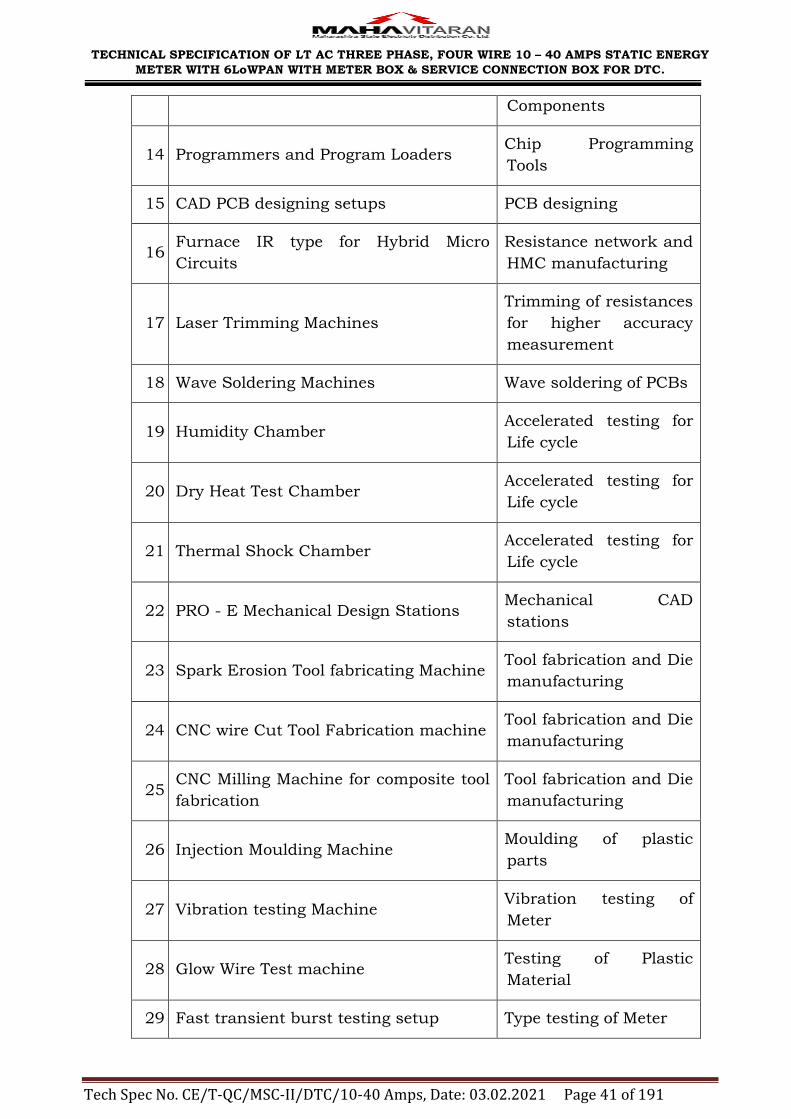
TECHNICAL SPECIFICATION OF LT AC THREE PHASE, FOUR WIRE 10 – 40 AMPS STATIC ENERGY
METER WITH 6LoWPAN WITH METER BOX & SERVICE CONNECTION BOX FOR DTC.
Tech Spec No. CE/T-QC/MSC-II/DTC/10-40 Amps, Date: 03.02.2021 Page 41 of 191
Components
14 Programmers and Program Loaders Chip Programming
Tools
15 CAD PCB designing setups PCB designing
16 Furnace IR type for Hybrid Micro
Circuits
Resistance network and
HMC manufacturing
17 Laser Trimming Machines
Trimming of resistances
for higher accuracy
measurement
18 Wave Soldering Machines Wave soldering of PCBs
19 Humidity Chamber Accelerated testing for
Life cycle
20 Dry Heat Test Chamber Accelerated testing for
Life cycle
21 Thermal Shock Chamber Accelerated testing for
Life cycle
22 PRO - E Mechanical Design Stations Mechanical CAD
stations
23 Spark Erosion Tool fabricating Machine Tool fabrication and Die
manufacturing
24 CNC wire Cut Tool Fabrication machine Tool fabrication and Die
manufacturing
25 CNC Milling Machine for composite tool
fabrication
Tool fabrication and Die
manufacturing
26 Injection Moulding Machine Moulding of plastic
parts
27 Vibration testing Machine Vibration testing of
Meter
28 Glow Wire Test machine Testing of Plastic
Material
29 Fast transient burst testing setup Type testing of Meter

TECHNICAL SPECIFICATION OF LT AC THREE PHASE, FOUR WIRE 10 – 40 AMPS STATIC ENERGY
METER WITH 6LoWPAN WITH METER BOX & SERVICE CONNECTION BOX FOR DTC.
Tech Spec No. CE/T-QC/MSC-II/DTC/10-40 Amps, Date: 03.02.2021 Page 42 of 191
30 Short term over Current testing setup Type testing of Meter
31 Magnetic and other tamper testing
setups Tamper Testing
32 Impulse Voltage Testing Setup Type testing of Meter
33 Composite Environmental testing
chambers Type testing of Meter
30.00 QUALITY ASSURANCE PLAN:
30.01 The tenderer shall invariably furnish QAP as specified in Annexure - I
along with his offer the QAP adopted by him in the process of
manufacturing.
30.02 Precautions taken for ensuring uses of quality raw material and
subcomponents shall be stated in QAP.
31.00 COMPONENT SPECIFICATION:
As per Annexure - II enclosed.
32.00 SCHEDULES:
The tenderer shall fill in the following schedules, which are part and
partial of the tender specification and offer. If the schedules are not
submitted duly filled in with the offer, the offer shall be liable for rejection.
Schedule ‗A' …. Guaranteed technical particulars. (As per GTP
uploaded on e - tendering site)
The discrepancies if any between the specification and the catalogs and /
or literatures submitted as part of the offer by the bidders, the same shall
not be considered and representations in this regard shall not be
entertained.

TECHNICAL SPECIFICATION OF LT AC THREE PHASE, FOUR WIRE 10 – 40 AMPS STATIC ENERGY
METER WITH 6LoWPAN WITH METER BOX & SERVICE CONNECTION BOX FOR DTC.
Tech Spec No. CE/T-QC/MSC-II/DTC/10-40 Amps, Date: 03.02.2021 Page 43 of 191
ANNEXURE - I
Quality Assurance Plan
A) The bidder shall invariably furnish the following information along with his
bid, failing which his bid shall be liable for rejection. Information shall be
separately given for individual type of material offered.
(i) Statement giving list of important raw materials, names of sub- suppliers
for the raw materials, list of standards according to which the raw materials
are tested. List of test normally carried out on raw materials in presence of
Bidder's representative, copies of test certificates:
(ii) Information and copies of test certificates as in (i) above in respect of bought
out accessories.
(iii) List of manufacturing facilities available.
(iv) Level of automation achieved and list of areas where manual processing
exists.
(v) List of areas in manufacturing process, where stage inspections are
normally carried out for quality control and details of such tests and
inspections.
(vi) List of testing equipment available with the bidder for final testing of
equipment specified and test plan limitation. If any, vis-a-vis the type,
special acceptance and routine tests specified in the relevant standards.
These limitations shall be very clearly bought out in schedule of deviation
from specified test requirements.
B) The successful bidder shall within 30 days of placement of order, submit
following information to the purchaser.
(i) List of raw materials as well as bought out accessories and the names of
sub-suppliers selected from those furnished along with offers.
(ii) Type test certificates of the raw materials and bought out accessories if
required by the purchaser.
(iii) Quality assurance plan (QAP) with hold points for purchaser‘s inspection.
The quality assurance plant and purchasers hold points shall be discussed
between the purchaser and bidder before the QAP is finalized.
C) The contractor shall operate systems which implement the following:
(i) Hold point: A stage in the material procurement or workmanship process
beyond which work shall not proceed without the documental approval of
designated individuals organizations. The purchaser‘s written approval is
required to authorise work to progress beyond the hold points indicated in
quality assurance plans.

TECHNICAL SPECIFICATION OF LT AC THREE PHASE, FOUR WIRE 10 – 40 AMPS STATIC ENERGY
METER WITH 6LoWPAN WITH METER BOX & SERVICE CONNECTION BOX FOR DTC.
Tech Spec No. CE/T-QC/MSC-II/DTC/10-40 Amps, Date: 03.02.2021 Page 44 of 191
(ii) Notification point: A stage in the material procurement or workmanship
process for which advance notice of the activity is required to facilitate
witness. If the purchaser does not attend after receiving documented
notification in accordance with the agreed procedures and with the correct
period of notice then work may proceed.
D) The successful bidder shall submit the routine test certificates of bought
out accessories and central excise passes for raw material at the time of
routine testing if required by the purchaser and ensure that Quality
Assurance program of the contractor shall consist of the quality systems
and quality plans with the following details.
(i) The structure of the organization.
The duties and responsibilities assigned to staff ensuring quality of work.
The system for purchasing, taking delivery and verification of material.
The system for ensuring quality workmanship.
The system for retention of records.
The arrangement by contractor for internal auditing.
A list of administration and work procedures required to achieve and verify
contract's quality requirements shall be made readily available to the
project manager for inspection on request.
(ii) Quality Plans:
An outline of the proposed work and programme sequence.
The structure of the contractor's organization for the contract.
The duties and responsibilities assigned to staff ensuring quality of work.
Hold and notification points.
Submission of engineering documents required by the specification.
The inspection of materials and components on receipt.
Reference to the contractor's work procedures appropriate to each activity.
Inspection during fabrication / construction.
Final inspection and test.

TECHNICAL SPECIFICATION OF LT AC THREE PHASE, FOUR WIRE 10 – 40 AMPS STATIC ENERGY
METER WITH 6LoWPAN WITH METER BOX & SERVICE CONNECTION BOX FOR DTC.
Tech Spec No. CE/T-QC/MSC-II/DTC/10-40 Amps, Date: 03.02.2021 Page 45 of 191
ANNEXURE – II
COMPONENT SPECIFICATION
The make/grade and the range of the components should be from the following
list makes or equivalent reputed makes
SN Component
Function Requirement Makes & Origin
1. Current
Transformers
The Meters shall be with the current
transformers as measuring
elements.
The current transformer shall
withstand for the clauses under 5 &
9 of IS: 13779 / 1999
2. Measurement or
computing chips
The measurement or computing
chips used in the Meter shall be
with the Surface mount type along
with the ASICs.
USA: Teridian, Analog
Devices, Cyrus Logic,
Atmel, Philips, Dallas, ST,
Motorola, Texas
Instruments, Maxim,
Freescale, National
Semiconductor,
Onsemiconductors.
Germany: Siemens.
South Africa: SAMES.
Japan: NEC, Toshiba,
Renasas, Hitachi.
Austria: AMS.
Holland: Philips (N X P)
Taiwan: Prolific
3. Memory chips
Memory chips shall not be affected
by external parameters like
sparking, high voltage spikes or
electrostatic discharges.
Meter shall have nonvolatile memory
(NVM). No other type of memory
shall be used for data recording and
programming. (The life of the NVM is
highest). There shall be security
isolation between metering circuit,
USA: Teridian, Atmel,
Philips, ST, National
Semiconductors, Texas
Instruments, Microchip,
Spason (Fujitsu),
Ramtron.
Japan: Hitachi, Renasas.
Germany: Siemens
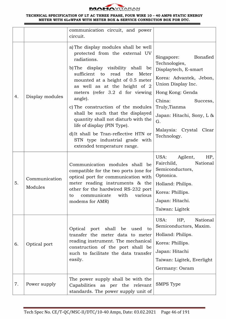
TECHNICAL SPECIFICATION OF LT AC THREE PHASE, FOUR WIRE 10 – 40 AMPS STATIC ENERGY
METER WITH 6LoWPAN WITH METER BOX & SERVICE CONNECTION BOX FOR DTC.
Tech Spec No. CE/T-QC/MSC-II/DTC/10-40 Amps, Date: 03.02.2021 Page 46 of 191
communication circuit, and power
circuit.
4. Display modules
a) The display modules shall be well
protected from the external UV
radiations.
b) The display visibility shall be
sufficient to read the Meter
mounted at a height of 0.5 meter
as well as at the height of 2
meters (refer 3.2 d for viewing
angle).
c) The construction of the modules
shall be such that the displayed
quantity shall not disturb with the
life of display (PIN Type).
d) It shall be Tran-reflective HTN or
STN type industrial grade with
extended temperature range.
Singapore: Bonafied
Technologies,
Displaytech, E-smart
Korea: Advantek, Jebon,
Union Display Inc.
Hong Kong: Genda
China: Success,
Truly,Tianma
Japan: Hitachi, Sony, L &
G.
Malaysia: Crystal Clear
Technology.
5. Communication
Modules
Communication modules shall be
compatible for the two ports (one for
optical port for communication with
meter reading instruments & the
other for the hardwired RS-232 port
to communicate with various
modems for AMR)
USA: Agilent, HP,
Fairchild, National
Semiconductors,
Optonica.
Holland: Philips.
Korea: Phillips.
Japan: Hitachi.
Taiwan: Ligitek
6. Optical port
Optical port shall be used to
transfer the meter data to meter
reading instrument. The mechanical
construction of the port shall be
such to facilitate the data transfer
easily.
USA: HP, National
Semiconductors, Maxim.
Holland: Philips.
Korea: Phillips.
Japan: Hitachi
Taiwan: Ligitek, Everlight
Germany: Osram
7. Power supply The power supply shall be with the
Capabilities as per the relevant
standards. The power supply unit of
SMPS Type

TECHNICAL SPECIFICATION OF LT AC THREE PHASE, FOUR WIRE 10 – 40 AMPS STATIC ENERGY
METER WITH 6LoWPAN WITH METER BOX & SERVICE CONNECTION BOX FOR DTC.
Tech Spec No. CE/T-QC/MSC-II/DTC/10-40 Amps, Date: 03.02.2021 Page 47 of 191
the meter shall not be affected in
case the maximum voltage of the
system appears to the terminals due
to faults or due to wrong
connections. It shall not also be
affected by magnet
8. Electronic
Components
The active & passive components
shall be of the surface mount type &
are to be handled & soldered by the
state of art assembly processes.
USA: Atmel, National
Semiconductors, BC
Component, Philips,
Texas Instruments,
Analog Devices. ST,
Onsemiconductors,
Maxim, Muruta, Kemet,
Freescale, AVX, Intersil,
Raltron, Fox, Fairchild,
Agilent, Abracon, Diode
Inc., Honeywell, Sipex
Power Integration,
R-ohm.
Japan: Hitachi, Oki, AVZ,
Ricon, Toshiba, Epson,
Kemet, Alps, Muruta,
TDK, Sanyo, Samsung.
India: RMC, VEPL,
KELTRON, Incap, PEC,
Cermet, Gujarat Polyavx,
Prismatic, MFR
Electronic Components
Pvt. Ltd., CTR.
Korea: Samsung
Japan: Panasonic
Germany: Kemet,
Vishay, Epcos, Diotech,
Infineon.
Taiwan: Yageo
9. Mechanical parts
a) The internal electrical
components shall be of
electrolytic copper & shall be
protected from corrosion, rust etc.

TECHNICAL SPECIFICATION OF LT AC THREE PHASE, FOUR WIRE 10 – 40 AMPS STATIC ENERGY
METER WITH 6LoWPAN WITH METER BOX & SERVICE CONNECTION BOX FOR DTC.
Tech Spec No. CE/T-QC/MSC-II/DTC/10-40 Amps, Date: 03.02.2021 Page 48 of 191
b) The other mechanical
components shall be protected
from rust, corrosion etc. by
suitable plating / painting
methods.
10. Battery
Maintenance free battery (Ni-mh or
Li-ion) of long life of 10 years.
USA: Varta, Tedirun,
Sanyo or National,
Maxell, Renata.
Japan: Panasonic, Sony,
Mitsubishi.
France: Saft.
Korea: Tekcell.
Germany: Varta.
11. RTC & Micro
controller.
The accuracy of RTC shall be as per
relevant IEC / IS standards.
USA: ST, Teridian,
Philips, Dallas, Atmel,
Motorola, Microchip.
Japan: NEC, Oki, Epson.
12. P.C.B.
Glass Epoxy, fire resistance grade
FR4, with minimum thickness 1.6
mm.

TECHNICAL SPECIFICATION OF LT AC THREE PHASE, FOUR WIRE 10 – 40 AMPS STATIC ENERGY
METER WITH 6LoWPAN WITH METER BOX & SERVICE CONNECTION BOX FOR DTC.
Tech Spec No. CE/T-QC/MSC-II/DTC/10-40 Amps, Date: 03.02.2021 Page 49 of 191
ANNEXURE - III
MAKE CODE OF METERS
Make Code Description
002 ANDHRA PRADESH ELECTRIC EQUIPMENT COR. LTD.
003 A.E.G.
004 BARODA ELECTRIC METERS LTD., VALLABH VIDYANAGAR
006 CHAMBERLAIN & HOOKHAM LTD.
008 DASS HITACHI PVT. LTD., NEW DELHI
010 ELECTRIC CONSTRUCTION & EQUIPMENT CO., SONEPAT
014 ELECTRICAL INSTRUMENTS MFG.CO.LTD. AHMEDABAD
015 HAVELLS ELECTRICALS
016 INDIA METERS LIMITED, MADRAS
018 INDUSTRIAL METERS PRIVATE LIMITED
020 JAIPUR METERS & ELECTRICALS LIMITED, JAIPUR
022 LANDIES & GYR LIMITED
023 LINKWELL TELESYSTEMS, HYDERABAD
024 MALIK METERS PRIVATE LIMITED, BOMBAY
026 METERS & INSTRUMENTS PVT. LTD., NEW DELHI
028 RADIO & ELECTRICALS MFG.CO.LTD., BANGALORE
030 SIMCO METERS LIMITED, TIRUCHIRAPALLI
034 UNITED ELECTRICAL INDUSTRIES LTD.,CALCUTTA
035 VOLTAS
036 AEC COMPANY
038 ARON
039 ALLIED ENGGINEERING WORKS LTD.
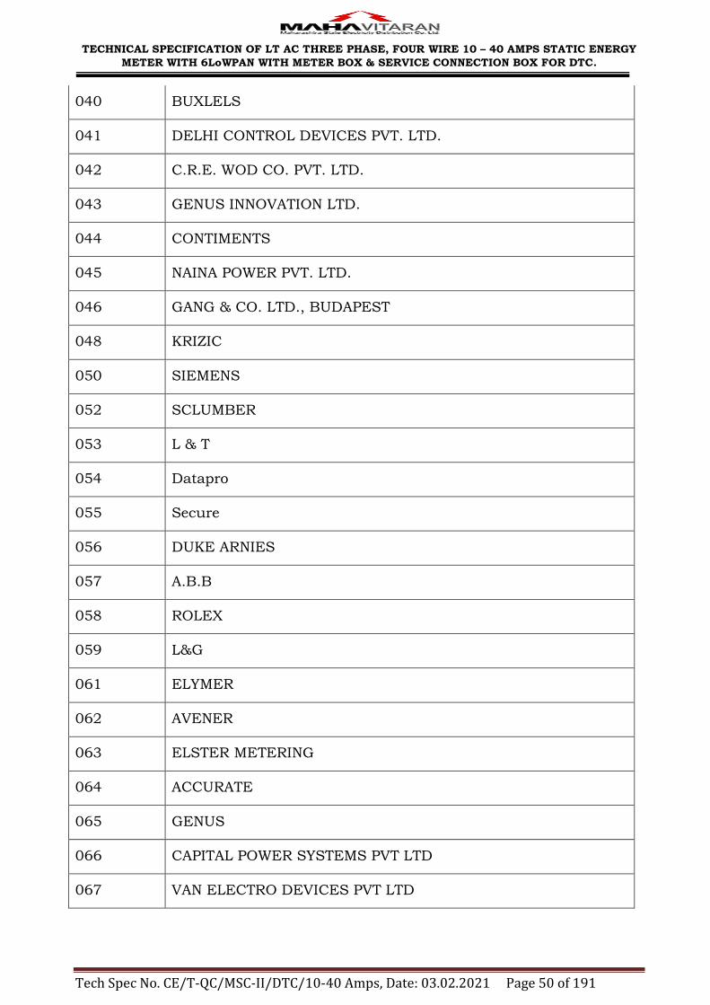
TECHNICAL SPECIFICATION OF LT AC THREE PHASE, FOUR WIRE 10 – 40 AMPS STATIC ENERGY
METER WITH 6LoWPAN WITH METER BOX & SERVICE CONNECTION BOX FOR DTC.
Tech Spec No. CE/T-QC/MSC-II/DTC/10-40 Amps, Date: 03.02.2021 Page 50 of 191
040 BUXLELS
041 DELHI CONTROL DEVICES PVT. LTD.
042 C.R.E. WOD CO. PVT. LTD.
043 GENUS INNOVATION LTD.
044 CONTIMENTS
045 NAINA POWER PVT. LTD.
046 GANG & CO. LTD., BUDAPEST
048 KRIZIC
050 SIEMENS
052 SCLUMBER
053 L & T
054 Datapro
055 Secure
056 DUKE ARNIES
057 A.B.B
058 ROLEX
059 L&G
061 ELYMER
062 AVENER
063 ELSTER METERING
064 ACCURATE
065 GENUS
066 CAPITAL POWER SYSTEMS PVT LTD
067 VAN ELECTRO DEVICES PVT LTD
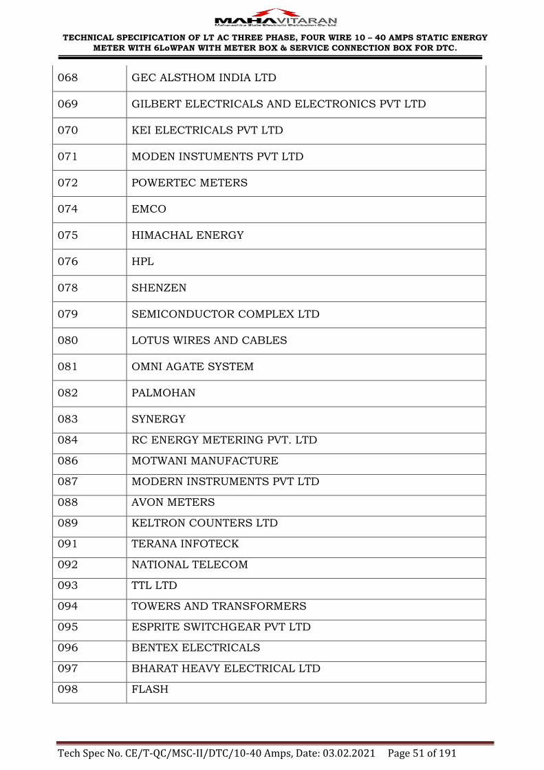
TECHNICAL SPECIFICATION OF LT AC THREE PHASE, FOUR WIRE 10 – 40 AMPS STATIC ENERGY
METER WITH 6LoWPAN WITH METER BOX & SERVICE CONNECTION BOX FOR DTC.
Tech Spec No. CE/T-QC/MSC-II/DTC/10-40 Amps, Date: 03.02.2021 Page 51 of 191
068 GEC ALSTHOM INDIA LTD
069 GILBERT ELECTRICALS AND ELECTRONICS PVT LTD
070 KEI ELECTRICALS PVT LTD
071 MODEN INSTUMENTS PVT LTD
072 POWERTEC METERS
074 EMCO
075 HIMACHAL ENERGY
076 HPL
078 SHENZEN
079 SEMICONDUCTOR COMPLEX LTD
080 LOTUS WIRES AND CABLES
081 OMNI AGATE SYSTEM
082 PALMOHAN
083 SYNERGY
084 RC ENERGY METERING PVT. LTD
086 MOTWANI MANUFACTURE
087 MODERN INSTRUMENTS PVT LTD
088 AVON METERS
089 KELTRON COUNTERS LTD
091 TERANA INFOTECK
092 NATIONAL TELECOM
093 TTL LTD
094 TOWERS AND TRANSFORMERS
095 ESPRITE SWITCHGEAR PVT LTD
096 BENTEX ELECTRICALS
097 BHARAT HEAVY ELECTRICAL LTD
098 FLASH

TECHNICAL SPECIFICATION OF LT AC THREE PHASE, FOUR WIRE 10 – 40 AMPS STATIC ENERGY
METER WITH 6LoWPAN WITH METER BOX & SERVICE CONNECTION BOX FOR DTC.
Tech Spec No. CE/T-QC/MSC-II/DTC/10-40 Amps, Date: 03.02.2021 Page 52 of 191
ANNEXURE IV
MSEDCL 6LOWPAN PROTOCOL
Introduction
MSEDCL has previously deployed LPRF meters based on ZigBee Smart Energy
1.0 profile operating in 2.4GHz – 2.485GHz, with an MSEDCL specific profile
used for data collection. These meters were primarily deployed in Urban areas of
Mumbai, Pune and Nashik zones.
Going forward, LPRF meters are sought to be deployed in rural, Rurban and
Urban areas.
The new meters shall support LPRF data downloading based on 6lowpan
networking on sub 1 GHz. The principal driver is the enhanced range that is
expected out of a sub 1GHz implementation. At the same time, some of the
learning from previous deployments is factored in. This document specifies the
complete data downloading protocol(s) that need to be implemented; where
relevant, references are made to standard documents – RFCs and IEEE
standards; where appropriate, desired protocols are fully defined in the
documents.
NOTE : ALL Hand Held Units shall support dual band operations – the
ZigBee based 2.4GHz operation and 6lowpan based sub 1GHz operation.
HHU shall facilitate Manual band selection through keypad

TECHNICAL SPECIFICATION OF LT AC THREE PHASE, FOUR WIRE 10 – 40 AMPS STATIC ENERGY
METER WITH 6LoWPAN WITH METER BOX & SERVICE CONNECTION BOX FOR DTC.
Tech Spec No. CE/T-QC/MSC-II/DTC/10-40 Amps, Date: 03.02.2021 Page 53 of 191
Protocol Overview
The protocol stack layers are as given below:
Each of the layers is explained in separate sections in the document.
APPLICATION LAYER
This protocol is the same protocol as used in the ZigBee implementation of LPRF
metering previously at MSEDCL. The protocol is implemented as a series of
attribute IDs as included in the Annexure-VI of this document.
TRANSPORT LAYER
All metering devices shall implement UDP protocol as defined in relevant RFC‘s.
Meter data shall be available for reading on UDP port 61616. The meter shall
implement an UDP server on this port to respond to data acquisition commands
from HHU / DCU. Port no 61616 for meter data downloads and critical
TECHNICAL SPECIFICATION OF LT AC THREE PHASE, FOUR WIRE 10 – 40 AMPS STATIC ENERGY
METER WITH 6LoWPAN WITH METER BOX & SERVICE CONNECTION BOX FOR DTC.
Tech Spec No. CE/T-QC/MSC-II/DTC/10-40 Amps, Date: 03.02.2021 Page 54 of 191
parameter communication. However, 61618 will be used for network parameters
setting and commissioning as specified.
However, other than root assignment, commissioning is not usually required.
The root assignment process is illustrated in the section no. 5.2
NETWORK LAYER
IPv6
IPv6 has to be implemented in the meters as detailed in RFC2460 and
derivative/companion documents. The network proposed to be implemented will
be an isolated 6lowpan network.
ICMPv6
Internet Control Message Protocol (ICMPv6) for the Internet Protocol Version 6
(IPv6) Specification, as defined in RFC4443 needs to be implemented. The
devices must support ICMPv6 Error messages, Echo Reply and Echo Request
messages.
Addressing
IPv6 addresses are 16x8 bit addresses. In the proposed network, this must be
constructed out of a combination of 8 byte IPv6 prefix for the most significant 8
byte and the 8 byte MAC address of the node. The IPv6 address should be
constructed based on RFC4862, with the following considerations:
8 byte IPv6 prefix, shall be assigned two different address for both Local &
Global Address. ―FE 80 00 00 00 00 00 00― will used for Local Addresses and
the prefix for global addresses shall be allotted later.
All UDP communication has to be based on Global IPv6 address. The Initial
handshaking ( DIS/DIO /DAO ) will use the local link address.
8 byte MAC address, this will consist of:
5 most significant bytes containing organizationally unique identifier (OUI)
purchased from IEEE
The last three significant bytes shall be mapped to the serial number of the
energy meter.

TECHNICAL SPECIFICATION OF LT AC THREE PHASE, FOUR WIRE 10 – 40 AMPS STATIC ENERGY
METER WITH 6LoWPAN WITH METER BOX & SERVICE CONNECTION BOX FOR DTC.
Tech Spec No. CE/T-QC/MSC-II/DTC/10-40 Amps, Date: 03.02.2021 Page 55 of 191
MESH AND ROUTING
RPL protocol is used for routing of data. This protocol is specified in RFC 6550
and its companion RFCs 6551 – 6554 and RFC 6719. MRHOF will be used.
Transit information including parent option will be included in the DAO
messages. Hop by hop option is mandatory in all UDP packets.
ADAPTATION LAYER
The Adaptation layer is 6lowpan. This is an adaptation of IPv6 packets onto the
underlying Lossy Low power Network (LLN). The RFCs / standards are written
keeping IEEE 802.15.4g MAC standards, expecting 128 octet packet sizes over
the air. The relevant RFCs are 4944, 6282.
MAC LAYER
The MAC layer is a derivative of IEEE 802.15.4G specification in terms of MAC
Layer headers and usage of IEEE headers. The packet & protocol options,
protocol specified commands will be as follows.
MAC layer under 6lowpan is essentially a link layer broadcast protocol. While
the 802.15.4G defines multiple packet types, the MAC_DATA_PACKET type
suffices for the 6lowpan packet exchange. Further, nodes must respond with
BEACON packets in response to BEACON_REQUEST messages. Link layer
acknowledgements should be disabled.
NOTE: All MAC packets will be preceded by a 4-byte preamble (0x55, 0x55,
0x55, 0x55), followed by a 2-byte Sync word (0x90, 0x4E) followed by 2-byte
frame control (Phy A &Phy B bytes in 802.15.4G). Nodes are required to transmit
using 2 byte CRC.
4-byte
preamble
2-byte sync
word
2 byte Phy frame
control
MAC
Protocol data
unit

TECHNICAL SPECIFICATION OF LT AC THREE PHASE, FOUR WIRE 10 – 40 AMPS STATIC ENERGY
METER WITH 6LoWPAN WITH METER BOX & SERVICE CONNECTION BOX FOR DTC.
Tech Spec No. CE/T-QC/MSC-II/DTC/10-40 Amps, Date: 03.02.2021 Page 56 of 191
MAC DATA PACKET
This MAC packet type is used for all 6lowpan communication messages. The
packet will have the following structure(s) for different 6lowpan use cases.
Point to point application data communication
2byte
Frame
control
1 byte
sequence
number
2 byte
destination
PAN
8 byte
Destination
MAC
address
8 byte
Source
MAC
address
Security
Header
Payload
Data
2
byte
FCS
Local broadcast as used in a DIO message ( for example )
MHR to be coded as follows :
2byte
Frame
control
1 byte
sequence
number
2 byte
destination
PAN
2 byte
Destination
address
( 0xFFFF )
8 byte
Source
MAC
address
Security
Header
Payload
Data
2
byte
FCS
MAC packet format for Beacon Request
Frame
control
(2bytes)
Sequence
number
( 1byte )
Destination
PAN
( 2bytes )
Destination
Address
( 2bytes )
Command identifier
(0x07)
( 1 byte )
FCS
(2 bytes)
MAC packet format for Beacon Messages
Frame
control
( 2
bytes)
Sequence
number
(1 byte)
Source
PANID
(2
bytes)
Source
Address
( 8
bytes)
Superframe
specification
( 2 bytes)
GTS
field
(1byte)
Pending
Addresses
Fields
(1 byte)
FCS (
2
bytes
)
Super Frame Specification: 0xCFFF
GTS Fields: 0x00
Pending Addresses Fields: 0x00
All the above fields should be ignored in MAC header processing by receiving
nodes.

TECHNICAL SPECIFICATION OF LT AC THREE PHASE, FOUR WIRE 10 – 40 AMPS STATIC ENERGY
METER WITH 6LoWPAN WITH METER BOX & SERVICE CONNECTION BOX FOR DTC.
Tech Spec No. CE/T-QC/MSC-II/DTC/10-40 Amps, Date: 03.02.2021 Page 57 of 191
PHY LAYER
The Phy layer specifications are derived from 802.15.4g specification and it is
mandatory to use IEEE802.15.4g phy mode #1. The standard is not applicable
to Indian context & constraints (as per WPC specifications).
Therefore, suitable adaptation has been made here and should be implemented
as follows:
Frequency Band: 865-867 Mhz
Channel Spacing: 200 KHz
Number of Channels: 9
Channel Centre Frequencies (MHz): ChanCenterFreq = ChanCenterFreq 0 +
NumChan · ChanSpacing
Where, ChanCenterFreq 0 = 865.125 MHz
Data rate: 50 kbps
Modulation: Filtered 2FSK (2GFSK)
Modulation Index: 1.0
Preamble: 0x55555555
Sync word: 0x904E
Default Channel Center Frequency: 865.525 MHz (Channel #2)
Frequency Deviation: 25 kHz
SECURITY
All the data transmission in network must be encrypted. This implementation
will use AES-CCM-32 encryption using 128 bit security key (Key will be provided
by MSEDCL). AES key should be programmable over the air ( protocol as defined
in section 6 ).
Implicit key shall be used and Encryption & decryption keys will same.
FACTORY DEFAULT NETWORK PARAMETERS
Frequency / Channel: 0x02
Device type: Router
Device State: Not joined
PAN: 0xFFFF

TECHNICAL SPECIFICATION OF LT AC THREE PHASE, FOUR WIRE 10 – 40 AMPS STATIC ENERGY
METER WITH 6LoWPAN WITH METER BOX & SERVICE CONNECTION BOX FOR DTC.
Tech Spec No. CE/T-QC/MSC-II/DTC/10-40 Amps, Date: 03.02.2021 Page 58 of 191
Default Encryption Key :0x000000000000000000004D534544434C
Prefix: 0xFFFF000000000000 (0xFFFF::)
MAC address: As defined in section 2.3.3
Theory of Operation – network formation and commissioning
Description:
On power on, if the router is in a commissioned state, shall issue the DIS
message (Reference: RFC6550) once every minute, with a 20% random jitter.
Network joins happen on the basis of DIO, DAO and ICMP echo-request and
ICMP echo-reply messages. The network shall be a storing mode network, with
each node capable of hosting routes of 200 children. The timing of transmission
of DIO messages shall follow trickle algorithm specification as specified under
RFC 6206.
Subsequent to a network join, a node shall transmit DIO messages at 4s, 8s,
16s, 32s, 64s, 128s, 256s, 512s and 1024s with a 10% random jitter.
Subsequent to this, DIO messages shall be transmitted every 1024s with
random jitter, till a global repair command is received at which time the trickle
timer shall be reset.
If the device is not in a commissioned state, it should be a router in factory
default network parameters. In this state, it shall be issuing a IEEE 802.15.4G
MAC BEACON REQUEST packet, once every 1 minute with a 20% random jitter.
On the basis of MAC BEACON packets received, the device then makes a list of
available PANs, and initiates the 6lowpan network join procedure in each of
those PANs. When a meter tries to join different PAN IDs, the maximum time
needed to wait in DIS state is 3 DIS periods. There is no MAC join procedure.
6lowpan network join procedure is the standard 6lowpan RPL join process as
defined in RFC6550. A minute after the DAO, the new node shall send a ping-
request to the root node; if the node does not receive a ping-reply within 10
attempts of ping requests, each issued a minute (with random jitter) apart, the
new node shall detach itself from the parent and restart the join procedure on
the next discovered PAN.
Once a ping response from the root is received, the router device saves the
network parameters for future and marks itself as commissioned. No DIO
messages shall be transmitted by this node prior to this state.
Specifying a root node.

TECHNICAL SPECIFICATION OF LT AC THREE PHASE, FOUR WIRE 10 – 40 AMPS STATIC ENERGY
METER WITH 6LoWPAN WITH METER BOX & SERVICE CONNECTION BOX FOR DTC.
Tech Spec No. CE/T-QC/MSC-II/DTC/10-40 Amps, Date: 03.02.2021 Page 59 of 191
All the devices in the network should be capable of being 6lowpan root devices,
though factory defaults set them to be routers. One of the (centrally located)
nodes shall be identified and configured as a ROOT by DCU/DCU. ROOT
assignment involves setting the target Short PAN, channel, device type, IPv6
Prefix, AES key. Information to be further given will include the list of devices to
be allowed into the network. The ROOT shall respond to ping requests to those
devices that are in this list.
Hand Held Terminal (DCU) should join the network as ROOT while
commissioning of meters. Though DCU act as ROOT, reply to ping-requests
should not be given by DCU
COMMISSIONING PROTOCOL
UDP payload with 61616
1-byte
Frame
Type
1 - byte
Sequence
no
1 - byte
Command
ID
1 - byte
Attribute
count
1 - byte
Attribute ID
Attribute ID
value
[Optional]
Frame Type Details
Frame Type Description
0x00 Read / Write commission request
0x01 Restart command request
0x02 Read / Write commission response
0x03 Restart command response
0x04 to 0xFF Reserved
Command Identifier details
Command Identifier Description
0x00 Commission Write command Request
0x01 Commission Write command Response
0x02 Commission Read command Request
0x03 Commission Read command Response
0x04 to 0xFF Reserved

TECHNICAL SPECIFICATION OF LT AC THREE PHASE, FOUR WIRE 10 – 40 AMPS STATIC ENERGY
METER WITH 6LoWPAN WITH METER BOX & SERVICE CONNECTION BOX FOR DTC.
Tech Spec No. CE/T-QC/MSC-II/DTC/10-40 Amps, Date: 03.02.2021 Page 60 of 191
List of Commission Attributes
Attribute ID
Name
Attribute
ID
Attribute
Length
Range
PAN ID 0x00 2 0 to 0xFFFF
Channel 0X01 1 O to 8
Device Type 0x02 1 1 – Root
2 - Router
IPv6 Prefix 0x03 8 As per IPv6 specifications
AES Key 0X04 16 Hex 16 bytes
Commission
State
0X18 1 0 – Un-commissioned
1 – Commissioned
DAG ID 0x19 16 As per IPv6 specifications
Router List 0x1A N/A List of 4 byte IPv6 address
with the first 12 byte
elided.
Number of
routers
0x1B 3 Count of routers added in
the ROOT.
Other ID values Reserved
Note 1: Attribute PAN ID, channel, Device type, IPv6 Prefix, AES key are
mandatory while commissioning ROOT device.
Note 2: Restart command should be sent after writing all attributes in Note 1. If
restart command is received before writing all attributes in Note 1, response to
restart command should be failure.
Note 3: Attributes ‗commission state‘, ‗DAG ID‘, ‗Number of routers‘ should be
read only. DAG ID should be IPv6 address of ROOT device which is combination
of IPv6 prefix & MAC address.
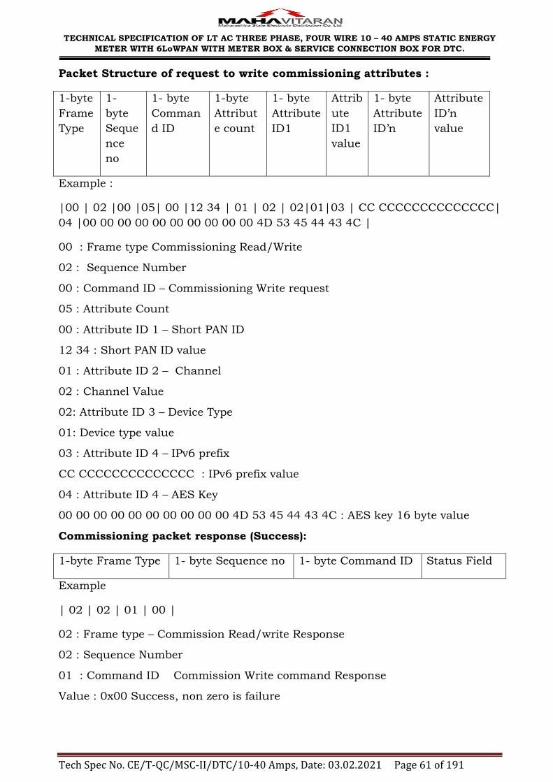
TECHNICAL SPECIFICATION OF LT AC THREE PHASE, FOUR WIRE 10 – 40 AMPS STATIC ENERGY
METER WITH 6LoWPAN WITH METER BOX & SERVICE CONNECTION BOX FOR DTC.
Tech Spec No. CE/T-QC/MSC-II/DTC/10-40 Amps, Date: 03.02.2021 Page 61 of 191
Packet Structure of request to write commissioning attributes :
1-byte
Frame
Type
1-
byte
Seque
nce
no
1- byte
Comman
d ID
1-byte
Attribut
e count
1- byte
Attribute
ID1
Attrib
ute
ID1
value
1- byte
Attribute
ID‘n
Attribute
ID‘n
value
Example :
|00 | 02 |00 |05| 00 |12 34 | 01 | 02 | 02|01|03 | CC CCCCCCCCCCCCCC|
04 |00 00 00 00 00 00 00 00 00 00 4D 53 45 44 43 4C |
00 : Frame type Commissioning Read/Write
02 : Sequence Number
00 : Command ID – Commissioning Write request
05 : Attribute Count
00 : Attribute ID 1 – Short PAN ID
12 34 : Short PAN ID value
01 : Attribute ID 2 – Channel
02 : Channel Value
02: Attribute ID 3 – Device Type
01: Device type value
03 : Attribute ID 4 – IPv6 prefix
CC CCCCCCCCCCCCCC : IPv6 prefix value
04 : Attribute ID 4 – AES Key
00 00 00 00 00 00 00 00 00 00 4D 53 45 44 43 4C : AES key 16 byte value
Commissioning packet response (Success):
1-byte Frame Type 1- byte Sequence no 1- byte Command ID Status Field
Example
| 02 | 02 | 01 | 00 |
02 : Frame type – Commission Read/write Response
02 : Sequence Number
01 : Command ID Commission Write command Response
Value : 0x00 Success, non zero is failure

TECHNICAL SPECIFICATION OF LT AC THREE PHASE, FOUR WIRE 10 – 40 AMPS STATIC ENERGY
METER WITH 6LoWPAN WITH METER BOX & SERVICE CONNECTION BOX FOR DTC.
Tech Spec No. CE/T-QC/MSC-II/DTC/10-40 Amps, Date: 03.02.2021 Page 62 of 191
Note 4:
Command ID success is indicated by status code as zero. Failure shall be
indicated with failed attribute and status. Fail Attribute Status is one for failure.
Commissioning packet failure response :
1-byte
Frame Type
1-byte
Sequence no
1-byte
Comman
d ID
1-byte
Status
1-byte Fail
attribute ID
1-byte Fail Attribute
Status
Example.
02 | 02 | 01 |01| 00| 01 |
02 : Frame type – Commission Read/write Response
02 : Sequence Number
01 : Command ID – Commission Write Response
01 : Status - failure
00: Fail Attribute ID 0x00 ( PAN ID )
01: Status - Fail
Packet Structure for reading commissioning attributes :
1-byte
Frame
Type
1-
byte
Seque
nce
no
1-
byte
Comm
and
ID
1-byte
Attribut
e count
1- byte
Attribut
e ID1
1- byte
Attribute
ID2
………
………
………
……….
Attribute
ID‘n
Example :
|00 | 02 |02 |04| 00 |01 | 02 | 03 |
00 : Frame type Commissioning Read/Write
02 : Sequence Number
02 : Command ID – Commissioning Read request
04 : Attribute Count
00 : Attribute ID 1 – Short PAN ID
01 : Attribute ID 2 – Channel
02 : Attribute ID 3 – Device Type
03: Attribute ID4- IPv6 prefix value

TECHNICAL SPECIFICATION OF LT AC THREE PHASE, FOUR WIRE 10 – 40 AMPS STATIC ENERGY
METER WITH 6LoWPAN WITH METER BOX & SERVICE CONNECTION BOX FOR DTC.
Tech Spec No. CE/T-QC/MSC-II/DTC/10-40 Amps, Date: 03.02.2021 Page 63 of 191
Packet structure of response to the command to read commissioning
attributes :
1-
byte
Fram
e
Type
1-
byte
Seque
nce
no
1- byte
Comma
nd ID
1-byte
Attribut
e count
1- byte
Attribut
e ID1
Attribu
te 1
read
status
Attrib
ute 1
value
Attrib
ute n
ID
Attrib
ute
ID‘n
read
status
|02 | 02 |03 |04| 00 |00|12 34 | 01 |00| 02 | 02 |00| 01|03 |00|CC CC
CCCCCCCCCCCC |
02 : Frame type Commissioning Read/Write
02 : Sequence Number
03 : Command ID – Commissioning Read request
04 : Attribute Count
00 : Attribute ID 1 – Short PAN ID
00: Read Status of attribute ID1 : Value 0= success, non-zero value for failure.
12 34 : Short PAN ID value
01 : Attribute ID 2 – Channel
00: Read Status of attribute ID2
02 : Channel Value
02 : Attribute ID 3 – Device Type
00: Read Status of attribute ID3
01: Device Type
03 : Attribute ID 4 – IPv6 prefix value
00: Read Status of attribute ID4
CC CCCCCCCCCCCCCC : IPv6 prefix value
Router List write Request:
1-byte
Frame
Type
1-byte
Sequence
no
1-byte
Command
ID
1-byte
Attribute
count
1-byte
Attribute
ID
1–byte
Add
/Remove
1-byte
Routers
count
4-byte
Router
Addres
s 1
-
-
-
-
4-byte
Router
Address
n
| 00 | 02 | 00 | 01 | 1A | 00| 05 | 00 00 02 01 | 00 00 02 02 | 00 00 02 03 |
00 00 02 04 | 00 00 02 05 |

TECHNICAL SPECIFICATION OF LT AC THREE PHASE, FOUR WIRE 10 – 40 AMPS STATIC ENERGY
METER WITH 6LoWPAN WITH METER BOX & SERVICE CONNECTION BOX FOR DTC.
Tech Spec No. CE/T-QC/MSC-II/DTC/10-40 Amps, Date: 03.02.2021 Page 64 of 191
Note 5: Values for 1-byte add/remove field should be 00 for adding & 01 for
removing router addresses.
Note 6: The router IPv6 addresses have their most significant 12 bytes
elided. The 4-byte router addresses to be written into the ROOT device
should be unique. In case of duplication of router addresses, response
should be given as failure.
Example Router List write Response:
1-byte Frame
Type
1-byte Sequence
no
1-byte Command
ID
Status
| 02 | 02 | 01 |00
Note 7:
Command ID zero for success, Failure with failed attribute and status, Fail
Attribute Status one for failure.
1-byte Frame
Type
1-byte
Sequence no
1-byte
Command ID
1-byte Failed
attribute ID
1-byte
Attribute
Status
Example: | 02 | 02 |01|01|00|01|
Reading of list of routers added in Root device :
Before reading the router list, number of routers added in Root device should be
downloaded using attribute 1B.
Packet structure of request to read number of routers added in ROOT :
The packet structure should be similar to commissioning packet read request.
Example:
|00 | 02 |02 |01| 1B|
00 : Frame type Commissioning Read/Write
02 : Sequence Number
02 : Command ID – Commissioning Read request

TECHNICAL SPECIFICATION OF LT AC THREE PHASE, FOUR WIRE 10 – 40 AMPS STATIC ENERGY
METER WITH 6LoWPAN WITH METER BOX & SERVICE CONNECTION BOX FOR DTC.
Tech Spec No. CE/T-QC/MSC-II/DTC/10-40 Amps, Date: 03.02.2021 Page 65 of 191
01 : Attribute Count
1B : Attribute ID 1 – Number of routers present in the Root device.
Depending upon the number of routers present in Root device, the request to
read the router list should be formatted. The packet structure to read router list
is as below.
Router List Read Request:
1-byte
Frame
Type
1-byte
Seque
nce no
1-byte
Comma
nd ID
1-byte
Attribute
count
1-byte
Attribute
ID
1-byte
Routers
count
1-byte
Index
Example:
The command to download first 5 router addresses should be as below.
| 00 | 02 | 02 | 01 | 1A | 05 |00|
00 : Frame type Commissioning Read/Write
02 : Sequence Number
02 : Command ID – Commissioning Read request
01 : Attribute Count
1A : Attribute ID 1 –Router list added in the Root device.
05: Count of router addresses to be read.
00: Index- router addresses starting from 0th address
If the response to router list read command should not be sent in single packet,
the router list should be downloaded in batches. DCU/DCU application should
change the values for fields ―count of routers‖ & ―index‖ accordingly.
Example:
To download router list of 35 devices, DCU/DCU application may download the
list of 20 devices first and in next batch remaining devices will be downloaded.
The commands given should be as below.
| 00 | 02 | 02 | 01 | 1A | 14 |00|

TECHNICAL SPECIFICATION OF LT AC THREE PHASE, FOUR WIRE 10 – 40 AMPS STATIC ENERGY
METER WITH 6LoWPAN WITH METER BOX & SERVICE CONNECTION BOX FOR DTC.
Tech Spec No. CE/T-QC/MSC-II/DTC/10-40 Amps, Date: 03.02.2021 Page 66 of 191
This command should return first 20 router addresses (0-19) starting from 0th
address.
| 00 | 02 | 02 | 01 | 1A | 0E |14|
This command should return remaining 15 router addresses (20-34) starting
from 20th address.
Router List Read Response:
1-byte
Frame
Type
1-byte
Sequence
no
1-byte
Command
ID
1-byte
Attribute
count
1-byte
Attribute
ID
Read
Status
Attribut
e ID1
1-byte
Routers
count
4-byte
Router
Addres
s 1
-
-
-
-
4-byte
Router
Address
n
Example:
The response to command | 00 | 02 | 02 | 01 | 1A | 14 |00| should be
|02| 02| 03| 01| 1A| 00| 14| 00 01 32 01| 00 01 32 02| 00 01 32 03| 00 01
32 04| 00 01 32 05| 00 01 32 06| 00 01 32 07| 00 01 32 08| 00 01 32 09| 00
01 32 10| 00 01 32 11| 00 01 32 12| 00 01 32 13| 00 01 32 14| 00 01 32 15|
00 01 32 16| 00 01 32 17| 00 01 32 18| 00 01 32 19| 00 01 32 20|
02 : Frame type Read/Write commission response
02 : Sequence Number
03 : Command ID – Commissioning Read response
01 : Attribute Count
1A : Attribute ID 1 –Router list added in the Root device.
00 : Read status of attribute ID1. Value 0 for success, non-zero value for failure
14: count of router addresses sent
00 01 32 01: 1st router address
………………
Restart command:
1-byte Frame Type 1- byte Sequence no 2 - byte Delay restart
value in seconds

TECHNICAL SPECIFICATION OF LT AC THREE PHASE, FOUR WIRE 10 – 40 AMPS STATIC ENERGY
METER WITH 6LoWPAN WITH METER BOX & SERVICE CONNECTION BOX FOR DTC.
Tech Spec No. CE/T-QC/MSC-II/DTC/10-40 Amps, Date: 03.02.2021 Page 67 of 191
Example : |01 | 02| 00 0A |
Restart Response:
1-byte Frame
Type
1- byte Sequence
no
1 byte Status
Example : | 03 | 02 | 00 |
APPLICATION LAYER
MSEDCL ZigBee document attribute list as specified in Annexure VI. Over the
Air payload structure, data types information, profile ID, cluster ID, end point
information should be the same as legacy ZigBee implementation.

TECHNICAL SPECIFICATION OF LT AC THREE PHASE, FOUR WIRE 10 – 40 AMPS STATIC ENERGY
METER WITH 6LoWPAN WITH METER BOX & SERVICE CONNECTION BOX FOR DTC.
Tech Spec No. CE/T-QC/MSC-II/DTC/10-40 Amps, Date: 03.02.2021 Page 68 of 191
ANNEXURE – V
RF METERING PROTOCOL - THREE PHASE RF METER
Protocol Version 2.1
1. Scope and Purpose
This section specifies a single cluster, the Maharashtra State Electricity
Distribution Company Limited (MSEDCL) cluster, which provides
representation of data elements. It is in intention that multiple meter
manufactures intending to provide product for Indian state of
Maharashtra support the attributes listed below in its entirety.
2. Introduction
This document facilitates the representation and exchange of data
elements and are to be supported by multiple meter manufacturers.
3. Attributes
For convenience, the attributes defined in this specification are arranged
into sets of related attributes; each set can contain multiple attributes.
Attribute identifiers are encoded such that the most significant byte
specifies the attributes set and the least significant byte specifies the
attribute within the set. The currently defined attribute sets are listed in
the table below.
Attribute Set
Identifier
Description
0x00 Meter Information
0x01 Cumulative Active Energy
0x02 Maximum Demand
0x03 Tamper Information (Set1)
0x04 Time zone wise Cumulative Active Energy
0x05 Time zone wise Maximum Demand
0x06 Load Profile
0x07 Power on/off events

TECHNICAL SPECIFICATION OF LT AC THREE PHASE, FOUR WIRE 10 – 40 AMPS STATIC ENERGY
METER WITH 6LoWPAN WITH METER BOX & SERVICE CONNECTION BOX FOR DTC.
Tech Spec No. CE/T-QC/MSC-II/DTC/10-40 Amps, Date: 03.02.2021 Page 69 of 191
0x08 Tamper Information (Set2)
0x09 Cumulative Apparent Energy
0x0A Time zone wise Cumulative Apparent
Energy
0x0B Cumulative Reactive Energy
0x0C Time zone wise Cumulative Reactive
Energy
0x0D-0xff Reserved
3.1. Meter Information Attribute Set (0x00XX)
The attributes that are used in the Meter Information attribute Set are
summarized in the below table. Some of these attributes overlap with
functionality provided on the Basic cluster. Information presented by
these attributes should be mirrored on the Basic cluster.
Identifier
Name Type Range Access Mandatory
/ Optional
0x00 Serial
Number
Character
string
8 bytes Read
only
M
0x01 Make
code
Character
string
5 bytes Read
only
M
0x02 Meter
time
UTC Time 4 bytes Read
only
M
0x03 Protocol Version Unsigned 16 bit Integer
2 bytes Read Only
M
0x004 Meter Phase Unsigned 8 bit
Integer
1 bytes Read Only
M
0x005 Vendor ID Unsigned
8 bit Integer
1byte Read
only
M
0x06 Tamper Present Status
Unsigned 32 bit
Integer
4 bytes Read Only
M
0x09 Instantaneous Unsigned 2 bytes Read M

TECHNICAL SPECIFICATION OF LT AC THREE PHASE, FOUR WIRE 10 – 40 AMPS STATIC ENERGY
METER WITH 6LoWPAN WITH METER BOX & SERVICE CONNECTION BOX FOR DTC.
Tech Spec No. CE/T-QC/MSC-II/DTC/10-40 Amps, Date: 03.02.2021 Page 70 of 191
Voltage (R Phase)
16 bit Integer
Only
0x0A Instantaneous
Voltage ( Y Phase)
Unsigned 16 bit Integer
2 bytes Read Only
M
0x0B Instantaneous
Voltage ( B Phase)
Unsigned 16 bit Integer
2 bytes Read Only
M
0x0C Instantaneous
Current (R
Phase)
Unsigned 16 bit
Integer
2 bytes Read Only
M
0x0D Instantaneous
Current (Y Phase)
Unsigned 16 bit
Integer
2 bytes Read Only
M
0x0E Instantaneous
Current (B
Phase)
Unsigned
16 bit Integer
2 bytes Read
Only
M
3.1.1. Serial Number Attribute
This attribute is a character string representing the serial number of the
meter.
3.1.2. Make Code Attribute
This attribute is a character string representing the make code of the
meter.
3.1.3. Meter Time
This attribute returns the time currently seen in the meter.
3.1.4. Protocol Version
This attribute returns the protocol version seen in the meter. Protocol
version is 2.1.
3.1.5. Meter Phase
This attribute returns the meter type of the meter. 0x01 is for single phase
and 0x03 for three phase

TECHNICAL SPECIFICATION OF LT AC THREE PHASE, FOUR WIRE 10 – 40 AMPS STATIC ENERGY
METER WITH 6LoWPAN WITH METER BOX & SERVICE CONNECTION BOX FOR DTC.
Tech Spec No. CE/T-QC/MSC-II/DTC/10-40 Amps, Date: 03.02.2021 Page 71 of 191
3.1.6. Vendor ID
This attribute returns the vendor ID of the supplier set in the meter.
3.1.7. Tamper Present Status
This attribute returns the time currently seen in the meter.
Tamper Present Status field shall have 32 bits bitmap indicating which
tampers have occurred. When no tamper has occurred, the status shall be
set as 0, else the specific tamper bit will be set to 1. Once the tamper
specific bit is set to 1 after occurrence of tamper, this bit should not be set
to 0 after restoration of that tamper. The meter reading software shall
check the tamper present and download related tamper information as
specified in the document. Bits corresponding to tampers not applicable
for three phase meters shall be always set to 0.
Example : 0000 0000 0000 00000000 0000 0001 0101
Tamper Description Bit
Position
Tamper
Present
Reversal of Phase and Neutral 1 Y
Load through Local Earth 2 N
Neutral Disconnect 3 Y
Magnetic Tamper 4 N
Meter Cover Open 5 Y
EMI/EMC Field Tamper 6 N
Missing Potential 7 N
Current Imbalance 8 N
Current Reversal 9 N
Current Short Circuit 10 N
High Neutral Current 11 N
Potential Imbalance 12 N
Reserved 13 -
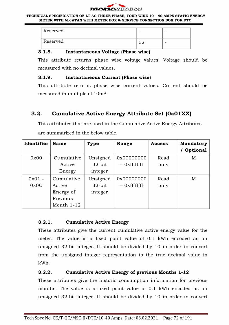
TECHNICAL SPECIFICATION OF LT AC THREE PHASE, FOUR WIRE 10 – 40 AMPS STATIC ENERGY
METER WITH 6LoWPAN WITH METER BOX & SERVICE CONNECTION BOX FOR DTC.
Tech Spec No. CE/T-QC/MSC-II/DTC/10-40 Amps, Date: 03.02.2021 Page 72 of 191
Reserved - -
Reserved 32 -
3.1.8. Instantaneous Voltage (Phase wise)
This attribute returns phase wise voltage values. Voltage should be
measured with no decimal values.
3.1.9. Instantaneous Current (Phase wise)
This attribute returns phase wise current values. Current should be
measured in multiple of 10mA.
3.2. Cumulative Active Energy Attribute Set (0x01XX)
This attributes that are used in the Cumulative Active Energy Attributes
are summarized in the below table.
Identifier
Name Type Range Access Mandatory
/ Optional
0x00 Cumulative
Active
Energy
Unsigned
32-bit
integer
0x00000000
– 0xffffffff
Read
only
M
0x01 -
0x0C
Cumulative
Active
Energy of
Previous
Month 1-12
Unsigned
32-bit
integer
0x00000000
– 0xffffffff
Read
only
M
3.2.1. Cumulative Active Energy
These attributes give the current cumulative active energy value for the
meter. The value is a fixed point value of 0.1 kWh encoded as an
unsigned 32-bit integer. It should be divided by 10 in order to convert
from the unsigned integer representation to the true decimal value in
kWh.
3.2.2. Cumulative Active Energy of previous Months 1-12
These attributes give the historic consumption information for previous
months. The value is a fixed point value of 0.1 kWh encoded as an
unsigned 32-bit integer. It should be divided by 10 in order to convert

TECHNICAL SPECIFICATION OF LT AC THREE PHASE, FOUR WIRE 10 – 40 AMPS STATIC ENERGY
METER WITH 6LoWPAN WITH METER BOX & SERVICE CONNECTION BOX FOR DTC.
Tech Spec No. CE/T-QC/MSC-II/DTC/10-40 Amps, Date: 03.02.2021 Page 73 of 191
from the unsigned integer representation to the true decimal value in
kWh.
3.3. Maximum Demand Attribute set (0x02XX)
The attributes that are used in the Maximum Demand Attribute Set are
summarized in the below table.
Identifier
Name Type Range Access Mandatory
/ Optional
0x00 Maximum
Demand of
Current
Month
Unsigned
16-bit
integer
0x0000 –
0xffff
Read
only
M
0x01 Maximum
Demand of
Current
Month
Timestamp
UTC
Time
4 bytes Read
only
M
0x02 Maximum
Demand of
Current
Month 1
Unsigned
16-bit
integer
0x0000 –
0xffff
Read
only
M
0x03 Maximum
Demand of
Current
Month 1
Timestamp
UTC
Time
4 bytes Read
only
M
0x04 Maximum
Demand of
Current
Month 2
Unsigned
16-bit
integer
0x0000 –
0xffff
Read
only
M
0x05 Maximum
Demand of
Current
Month 2
Timestamp
UTC
Time
4 bytes Read
only
M
0x06 Maximum
Demand of
Current
Unsigned
16-bit
integer
0x0000 –
0xffff
Read
only
M

TECHNICAL SPECIFICATION OF LT AC THREE PHASE, FOUR WIRE 10 – 40 AMPS STATIC ENERGY
METER WITH 6LoWPAN WITH METER BOX & SERVICE CONNECTION BOX FOR DTC.
Tech Spec No. CE/T-QC/MSC-II/DTC/10-40 Amps, Date: 03.02.2021 Page 74 of 191
Month 3
0x07 Maximum
Demand of
Current
Month 3
Timestamp
UTC
Time
4 bytes Read
only
M
0x08 Maximum
Demand of
Current
Month 4
Unsigned
16-bit
Integer
0x0000 –
0xffff
Read
only
M
0x09 Maximum
Demand of
Current
Month 4
Timestamp
UTC
Time
4 bytes Read
only
M
0x0a Maximum
Demand of
Current
Month 5
Unsigned
16-bit
integer
0x0000 –
0xffff
Read
only
M
0x0b Maximum
Demand of
Current
Month 5
Timestamp
UTC
Time
4 bytes Read
only
M
0x0c Maximum
Demand of
Current
Month 6
Unsigned
16-bit
integer
0x0000 –
0xffff
Read
only
M
0x0d Maximum
Demand of
Current
Month 6
Timestamp
UTC
Time
4 bytes Read
only
M
0x0e Maximum
Demand of
Current
Month 7
Unsigned
16-bit
integer
0x0000 –
0xffff
Read
only
M
0x0f Maximum
Demand of
Current
UTC
Time
4 bytes Read
only
M

TECHNICAL SPECIFICATION OF LT AC THREE PHASE, FOUR WIRE 10 – 40 AMPS STATIC ENERGY
METER WITH 6LoWPAN WITH METER BOX & SERVICE CONNECTION BOX FOR DTC.
Tech Spec No. CE/T-QC/MSC-II/DTC/10-40 Amps, Date: 03.02.2021 Page 75 of 191
Month 7
Timestamp
0x10 Maximum
Demand of
Current
Month 8
Unsigned
16-bit
integer
0x0000 –
0xffff
Read
only
M
0x11 Maximum
Demand of
Current
Month 8
Timestamp
UTC
Time
4 bytes Read
only
M
0x12 Maximum
Demand of
Current
Month 9
Unsigned
16-bit
integer
0x0000 –
0xffff
Read
only
M
0x13 Maximum
Demand of
Current
Month 9
Timestamp
UTC
Time
4 bytes Read
only
M
0x14 Maximum
Demand of
Current
Month 10
Unsigned
16-bit
integer
0x0000 –
0xffff
Read
only
M
0x15 Maximum
Demand of
Current
Month 10
Timestamp
UTC
Time
4 bytes Read
only
M
0x16 Maximum
Demand of
Current
Month 11
Unsigned
16-bit
integer
0x0000 –
0xffff
Read
only
M
0x17 Maximum
Demand of
Current
Month 11
Timestamp
UTC
Time
4 bytes Read
only
M
0x18 Maximum
Demand of
Unsigned
16-bit
0x0000 –
0xffff
Read
only
M
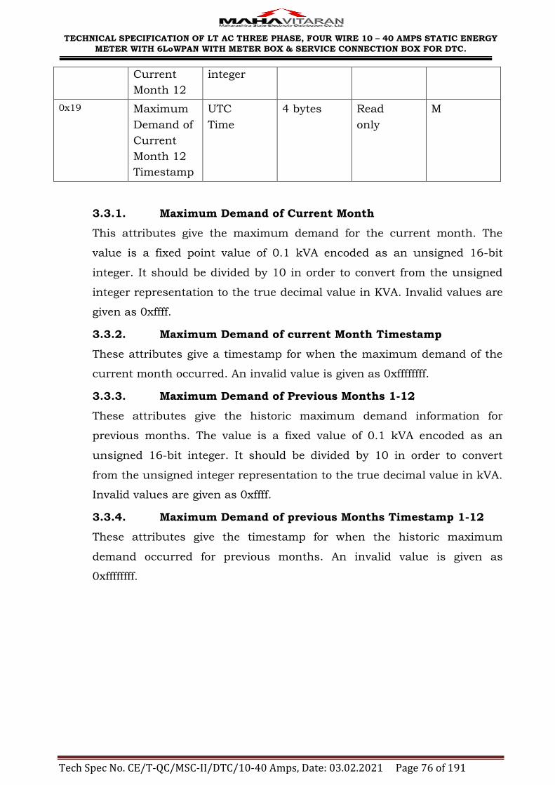
TECHNICAL SPECIFICATION OF LT AC THREE PHASE, FOUR WIRE 10 – 40 AMPS STATIC ENERGY
METER WITH 6LoWPAN WITH METER BOX & SERVICE CONNECTION BOX FOR DTC.
Tech Spec No. CE/T-QC/MSC-II/DTC/10-40 Amps, Date: 03.02.2021 Page 76 of 191
Current
Month 12
integer
0x19 Maximum
Demand of
Current
Month 12
Timestamp
UTC
Time
4 bytes Read
only
M
3.3.1. Maximum Demand of Current Month
This attributes give the maximum demand for the current month. The
value is a fixed point value of 0.1 kVA encoded as an unsigned 16-bit
integer. It should be divided by 10 in order to convert from the unsigned
integer representation to the true decimal value in KVA. Invalid values are
given as 0xffff.
3.3.2. Maximum Demand of current Month Timestamp
These attributes give a timestamp for when the maximum demand of the
current month occurred. An invalid value is given as 0xffffffff.
3.3.3. Maximum Demand of Previous Months 1-12
These attributes give the historic maximum demand information for
previous months. The value is a fixed value of 0.1 kVA encoded as an
unsigned 16-bit integer. It should be divided by 10 in order to convert
from the unsigned integer representation to the true decimal value in kVA.
Invalid values are given as 0xffff.
3.3.4. Maximum Demand of previous Months Timestamp 1-12
These attributes give the timestamp for when the historic maximum
demand occurred for previous months. An invalid value is given as
0xffffffff.

TECHNICAL SPECIFICATION OF LT AC THREE PHASE, FOUR WIRE 10 – 40 AMPS STATIC ENERGY
METER WITH 6LoWPAN WITH METER BOX & SERVICE CONNECTION BOX FOR DTC.
Tech Spec No. CE/T-QC/MSC-II/DTC/10-40 Amps, Date: 03.02.2021 Page 77 of 191
3.4. Tamper information Attribute Set1 (0x03XX)
The attributes that are used in the Tamper Attribute Set are summarized
in the below table.
Identifier Name Type Range Access Mandatory
/ Optional
0x00 –
0x09
Latest 10 Tamper
Events – Missing
Potential
Structure 11
bytes
ReadOnly M
0x10 -
0x19
0x0a –
0x0F
0x1a –
0x1f
Reserved
0x20 –
0x29
Latest 10 tamper
Events – Current
Imbalance
Structure 11
bytes
ReadOnly M
0x30 –
0x39
0x2a –
0x2f
0x3a –
0x3f
Reserved
0x40 –
0x49
Latest 10 Tamper
Events – Current
Reversal
Start (0x4x) and
Stop (0x5x) times
Structure 11
bytes
ReadOnly M
0x50 –
0x59
0x4a –
Reserved

TECHNICAL SPECIFICATION OF LT AC THREE PHASE, FOUR WIRE 10 – 40 AMPS STATIC ENERGY
METER WITH 6LoWPAN WITH METER BOX & SERVICE CONNECTION BOX FOR DTC.
Tech Spec No. CE/T-QC/MSC-II/DTC/10-40 Amps, Date: 03.02.2021 Page 78 of 191
0x4f
0x5a –
0x5f
0x60 -
0x69
Latest 10 tamper
events – Current
Short circuit
Structure 11
bytes
ReadOnly M
0x70 –
0x79
0x6a –
0x6f
0x7a –
0x7f
Reserved
0x80 Meter Cover Open UTC
Time
11
bytes ReadOnly M
0x90 –
0x99
Latest 10 Tamper
events – High Neutral
Current
Structure 11
bytes
ReadOnly M
0xa0 –
0xa9
0x9a – 9f
0xaa –
0xaf
Reserved
0xb0 –
0xb9
Latest 10 Tamper
events – Potential
imbalance
Structure 11
bytes
ReadOnly M
0xc0 –
0xc9
0xba –
0xbf
0xca –
0xcf
Reserved
0xd0 –
0xd9
Latest 10 Tamper
events – Magnetic
Structure 11
bytes
ReadOnly M

TECHNICAL SPECIFICATION OF LT AC THREE PHASE, FOUR WIRE 10 – 40 AMPS STATIC ENERGY
METER WITH 6LoWPAN WITH METER BOX & SERVICE CONNECTION BOX FOR DTC.
Tech Spec No. CE/T-QC/MSC-II/DTC/10-40 Amps, Date: 03.02.2021 Page 79 of 191
Tamper
0xe0 -
0xe9
0xda –
0xdf
0xea –
0xef
Reserved
Single tamper record will be structure consisting of the following fields.
Field name Type
Phase Unsigned 8 bit integer (1 byte)
Occurrence date UTC time (4 bytes)
Restoration date UTC time (4 bytes)
In structure data type 2 bytes are reserved to indicate number of elements
in structure. Total data length is 11 bytes
3.4.1. Latest 10 Tamper Event Attributes
These attributes represents tamper events on the meter. There are 10
events for each event type. Each incrementing attributes index
corresponds to one event further in the past. The attribute should return
phase on which event is occurred and restored and time stamp for
occurrence and restoration of event. The values for phase should be as
below.
Type of phase Value
No phase 0x00
R Phase 0x01
Y Phase 0x02
B Phase 0x03

TECHNICAL SPECIFICATION OF LT AC THREE PHASE, FOUR WIRE 10 – 40 AMPS STATIC ENERGY
METER WITH 6LoWPAN WITH METER BOX & SERVICE CONNECTION BOX FOR DTC.
Tech Spec No. CE/T-QC/MSC-II/DTC/10-40 Amps, Date: 03.02.2021 Page 80 of 191
The application layer frame format of response to download two events of
potential missing should be as below.
|00|08|00 FC|0D BF|08|00|18|02|0E|00
03|00|4C|03|00|20|01|E2| 80 EF 9A 22 |E2|E0 62 9A 22|
00 - Frame control
08 – Destination end point
00 FC – Cluster ID
0D BF – Profile ID
08 – Source end point
00 - APS counter
18 - Frame control
02 – Sequence Number
0E-Command identifier (Read attributes structured)
00 03 – Attribute ID to download tamper
00 – Status Success
4C – Data Type (Structure)
03 00 – Number of Attributes in Structure
20|01| E2| 80 EF 9A 22 |E2|E0 62 9A 22– is tamper data
20|01 Attribute 1 phase on which tamper occurred/restored
20 – Data Type (Unsigned 8-bitinteger)
01 – R phase on which tamper occurred/restored.
| E2| 80 EF 9A 22 | Tamper Occurrencetimestamp
E2- Data type (UTCTime)
80 EF 9A 22 – Data Value (Occurrence timestamp)
| E2| E0 62 9A 22 | Tamper Restorationtimestamp
E2- Data type (UTCTime)
E0 62 9A 22 – Data Value (Restoration timestamp)
3.4.2. Meter Cover Open
This attribute shall return phase and timestamp for the last time the
meter coverwas opened. As phase is not applicable for this tamper, value

TECHNICAL SPECIFICATION OF LT AC THREE PHASE, FOUR WIRE 10 – 40 AMPS STATIC ENERGY
METER WITH 6LoWPAN WITH METER BOX & SERVICE CONNECTION BOX FOR DTC.
Tech Spec No. CE/T-QC/MSC-II/DTC/10-40 Amps, Date: 03.02.2021 Page 81 of 191
for phase should be returned as 0x00 An invalid event i.e. restoration
timestamp is encoded as 0xE2ffffffff .Total response should be given
as0x2000E280EF9A22E2FFFFFF.
3.5. Tamper information Attribute Set2 (0x08XX)
The attributes that are used in the Tamper Attribute Set are summarized
in the below table.
Identifier
Name Type Range Access Mandatory
/ Optional
0x00-0x09
Latest 10
Tamper
Events – ESD
Tamper
Structure 11 bytes Read
only
M
0x10-0x19 Reserved
This attribute represents ESD tamper events on the meter. The attribute shall
return phase on which event is occurred and restored and time stamp for
occurrence and restoration of event. If the meter is immune then response
should be given as 0x2000E2ffffffffE2ffffffff.
3.6. Time Zone wise Active Energy Attributes Set (0x04XX)
The attributes that are used in the Time Zone wise Active Energy attribute
Set are summarized in the below table.
Identifier
Name Type Range Access Mandatory
/ Optional
0x00 TZ1
Active
Energy
Unsigned
32- bit
integer
0x00000000
-0xffffffff
Read
only
M
0x01 TZ2
Active
Energy
Unsigned
32- bit
integer
0x00000000
-0xffffffff
Read
only
M
0x02 TZ3
Active
Energy
Unsigned
32- bit
integer
0x00000000
-0xffffffff
Read
only
M
0x03 TZ4
Active
Unsigned
32- bit
0x00000000
-0xffffffff
Read
only
M

TECHNICAL SPECIFICATION OF LT AC THREE PHASE, FOUR WIRE 10 – 40 AMPS STATIC ENERGY
METER WITH 6LoWPAN WITH METER BOX & SERVICE CONNECTION BOX FOR DTC.
Tech Spec No. CE/T-QC/MSC-II/DTC/10-40 Amps, Date: 03.02.2021 Page 82 of 191
Energy integer
3.6.1. Time zone wise Active Energy
These attributes give the time zone wise current cumulative active energy
value for the meter. The value is a fixed point value of 0.1 kWh encoded as
an unsigned 32-bit integer. It should be divided by 10 in order to convert
from the unsigned integer representation to the true decimal value in
kWh.
3.7. Time Zone wise Maximum Demand Attribute Set (0x05XX)
The attribute that are used in the Time zone wise Maximum Demand
Attribute Set are summarized in the below table.
Identifier
Name Type Range Access Mandatory
/ Optional
0x00 TZ1
Maximum
Demand
Unsigned
16-bit
integer
0x0000-
0xffff
Read
only
M
0x01 TZ1
Maximum
Demand
Timestamp
UTC
Time
4 bytes Read
only
M
0x02 TZ2
Maximum
Demand
Unsigned
16- bit
integer
0x0000-
0xffff
Read
only
M
0x03 TZ2
Maximum
Demand
Timestamp
UTC
Time
4 bytes Read
only
M
0x04 TZ3
Maximum
Demand
Unsigned
16- bit
integer
0x0000-
0xffff
Read
only
M
0x05 TZ3
Maximum
Demand
Timestamp
UTC
Time
4 bytes Read
only
M
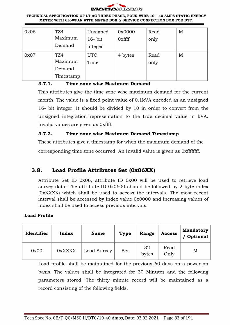
TECHNICAL SPECIFICATION OF LT AC THREE PHASE, FOUR WIRE 10 – 40 AMPS STATIC ENERGY
METER WITH 6LoWPAN WITH METER BOX & SERVICE CONNECTION BOX FOR DTC.
Tech Spec No. CE/T-QC/MSC-II/DTC/10-40 Amps, Date: 03.02.2021 Page 83 of 191
0x06 TZ4
Maximum
Demand
Unsigned
16- bit
integer
0x0000-
0xffff
Read
only
M
0x07 TZ4
Maximum
Demand
Timestamp
UTC
Time
4 bytes Read
only
M
3.7.1. Time zone wise Maximum Demand
This attributes give the time zone wise maximum demand for the current
month. The value is a fixed point value of 0.1kVA encoded as an unsigned
16- bit integer. It should be divided by 10 in order to convert from the
unsigned integration representation to the true decimal value in kVA.
Invalid values are given as 0xffff.
3.7.2. Time zone wise Maximum Demand Timestamp
These attributes give a timestamp for when the maximum demand of the
corresponding time zone occurred. An Invalid value is given as 0xffffffff.
3.8. Load Profile Attributes Set (0x06XX)
Attribute Set ID 0x06, attribute ID 0x00 will be used to retrieve load
survey data. The attribute ID 0x0600 should be followed by 2 byte index
(0xXXXX) which shall be used to access the intervals. The most recent
interval shall be accessed by index value 0x0000 and increasing values of
index shall be used to access previous intervals.
Load Profile
Load profile shall be maintained for the previous 60 days on a power on
basis. The values shall be integrated for 30 Minutes and the following
parameters stored. The thirty minute record will be maintained as a
record consisting of the following fields.
Identifier Index Name Type Range Access Mandatory
/ Optional
0x00 0xXXXX Load Survey Set 32
bytes
Read
Only M

TECHNICAL SPECIFICATION OF LT AC THREE PHASE, FOUR WIRE 10 – 40 AMPS STATIC ENERGY
METER WITH 6LoWPAN WITH METER BOX & SERVICE CONNECTION BOX FOR DTC.
Tech Spec No. CE/T-QC/MSC-II/DTC/10-40 Amps, Date: 03.02.2021 Page 84 of 191
Field name Type
Interval start time UTC time
kWh Unsigned 32 bit integer
kVArh (Lag) Unsigned 32 bit integer
kVArh (Lead) Unsigned 32 bit integer
kVAh Unsigned 32 bit integer
Voltage - VRN Unsigned 16 bit integer
Voltage - VYN Unsigned 16 bit integer
Voltage – VBN Unsigned 16 bit integer
Current - IR Unsigned 16 bit integer
Current - IY Unsigned 16 bit integer
Current – IB Unsigned 16 bit integer
Unsigned 32 bit integer values should be divided by 10 in order to convert
unsigned integer representation to true decimal value.
The voltage value will be the measured voltage with no decimal values.
The current will be in multiples of 10mA.
For example, 1.540A will be represented as 154
60 A will be represented as 6000.
3.9. Power On/OFF events Attribute set (0x07XX)
Identifier Name Type Range Access Mandatory
/ Optional
0x00 –
0xff
Power OFF
/On events -
Timestamp
UTC Time 4 bytes ReadOnly M
Power ON/OFF events, should always be made available with the first
event always being a power OFF event and subsequent event in power
ON. Thus all odd events should be always Power OFF event and all even
events should be always Power ON events.

TECHNICAL SPECIFICATION OF LT AC THREE PHASE, FOUR WIRE 10 – 40 AMPS STATIC ENERGY
METER WITH 6LoWPAN WITH METER BOX & SERVICE CONNECTION BOX FOR DTC.
Tech Spec No. CE/T-QC/MSC-II/DTC/10-40 Amps, Date: 03.02.2021 Page 85 of 191
3.10. Cumulative Apparent Energy Attribute Set (0x09XX)
This attributes that are used in the Cumulative Apparent Energy Attribute
set are summarized in the below table.
Identifier
Name Type Range Access Mandatory
/ Optional
0x00 Cumulative
Apparent
Energy
Unsigned
32-bit
integer
0x00000000
– 0xffffffff
Read
only
M
0x01 -
0x0C
Cumulative
Apparent
Energy of
Previous
Month1-12
Unsigned
32-bit
integer
0x00000000
– 0xffffffff
Read
only
M
3.10.1. Cumulative Apparent Energy
These attributes give the current cumulative apparent energy value for the
meter. The value is a fixed point value of 0.1 kVAh encoded as an
unsigned 32-bit integer. It should be divided by 10 in order to convert
from the unsigned integer representation to the true decimal value in
kVAh.
3.10.2. Cumulative Apparent Energy of previous Months 1-12
These attributes give the historic consumption information for previous
months. The value is a fixed point value of 0.1 kVAh encoded as an
unsigned 32-bit integer. It should be divided by 10 in order to convert
from the unsigned integer representation to the true decimal value in
kVAh.
3.11. Time Zone wise Apparent Energy Attributes Set
(0x0AXX)
The attributes that are used in the Time Zone wise Apparent Energy
Attribute Set are summarized in the below table.
Identifier
Name Type Range Access Mandatory
/ Optional
0x00 TZ1
Apparent
Unsigned
32- bit
0x00000000
-0xffffffff
Read
only
M

TECHNICAL SPECIFICATION OF LT AC THREE PHASE, FOUR WIRE 10 – 40 AMPS STATIC ENERGY
METER WITH 6LoWPAN WITH METER BOX & SERVICE CONNECTION BOX FOR DTC.
Tech Spec No. CE/T-QC/MSC-II/DTC/10-40 Amps, Date: 03.02.2021 Page 86 of 191
Energy integer
0x01 TZ2
Apparent
Energy
Unsigned
32- bit
integer
0x00000000
-0xffffffff
Read
only
M
0x02 TZ3
Apparent
Energy
Unsigned
32- bit
integer
0x00000000
-0xffffffff
Read
only
M
0x03 TZ4
Apparent
Energy
Unsigned
32- bit
integer
0x00000000
-0xffffffff
Read
only
M
3.11.1. Time zone wise Apparent Energy
These attributes give the time zone wise current cumulative apparent
energy value for the meter. The value is a fixed point value of 0.1 kVAh
encoded as an unsigned 32-bit integer. It should be divided by 10 in order
to convert from the unsigned integer representation to the true decimal
value in kVAh.
3.12. Cumulative Reactive Energy Attribute Set (0x0BXX)
This attributes that are used in the Cumulative Reactive Energy Attribute
set are summarized in the below table.
Identifier
Name Type Range Access Mandatory
/ Optional
0x00 Cumulative
Reactive
Energy(Lag)
Current month
Unsigned
32-bit
integer
0x00000000
– 0xffffffff
Read
only
M
0x01 Cumulative
Reactive
Energy(Lead)
Current month
Unsigned
32-bit
integer
0x00000000
– 0xffffffff
Read
only
M
0x02 Cumulative
Reactive
Energy(Lag)
Previous month1
Unsigned
32-bit
integer
0x00000000
– 0xffffffff
Read
only
M

TECHNICAL SPECIFICATION OF LT AC THREE PHASE, FOUR WIRE 10 – 40 AMPS STATIC ENERGY
METER WITH 6LoWPAN WITH METER BOX & SERVICE CONNECTION BOX FOR DTC.
Tech Spec No. CE/T-QC/MSC-II/DTC/10-40 Amps, Date: 03.02.2021 Page 87 of 191
0x03 Cumulative
Reactive
Energy(Lead)
Previous month 1
Unsigned
32-bit
integer
0x00000000
– 0xffffffff
Read
only
M
0x04 Cumulative
Reactive
Energy(Lag)
Previous month2
Unsigned
32-bit
integer
0x00000000
– 0xffffffff
Read
only
M
0x05 Cumulative
Reactive
Energy(Lead)
Previous month 2
Unsigned
32-bit
integer
0x00000000
– 0xffffffff
Read
only
M
0x06 Cumulative
Reactive
Energy(Lag)
Previous month3
Unsigned
32-bit
integer
0x00000000
– 0xffffffff
Read
only
M
0x07 Cumulative
Reactive
Energy(Lead)
Previous month 3
Unsigned
32-bit
integer
0x00000000
– 0xffffffff
Read
only
M
0x08 Cumulative
Reactive
Energy(Lag)
Previous month 4
Unsigned
32-bit
integer
0x00000000
– 0xffffffff
Read
only
M
0x09 Cumulative
Reactive
Energy(Lead)
Previous
month 4
Unsigned
32-bit
integer
0x00000000
– 0xffffffff
Read
only
M
0x0a Cumulative
Reactive
Energy(Lag)
Previous month 5
Unsigned
32-bit
integer
0x00000000
– 0xffffffff
Read
only
M
0x0b Cumulative
Reactive
Unsigned
32-bit
0x00000000
– 0xffffffff
Read
only
M

TECHNICAL SPECIFICATION OF LT AC THREE PHASE, FOUR WIRE 10 – 40 AMPS STATIC ENERGY
METER WITH 6LoWPAN WITH METER BOX & SERVICE CONNECTION BOX FOR DTC.
Tech Spec No. CE/T-QC/MSC-II/DTC/10-40 Amps, Date: 03.02.2021 Page 88 of 191
Energy(Lead)
Previous month 5
integer
0x0c Cumulative
Reactive
Energy(Lag)
Previous month 6
Unsigned
32-bit
integer
0x00000000
– 0xffffffff
Read
only
M
0x0d Cumulative
Reactive
Energy(Lead)
Previous month 6
Unsigned
32-bit
integer
0x00000000
– 0xffffffff
Read
only
M
0x0e Cumulative
Reactive
Energy(Lag)
Previous month 7
Unsigned
32-bit
integer
0x00000000
– 0xffffffff
Read
only
M
0x0f Cumulative
Reactive
Energy(Lead)
Previous
month 7
Unsigned
32-bit
integer
0x00000000
– 0xffffffff
Read
only
M
0x10 Cumulative
Reactive
Energy(Lag)
Previous month 8
Unsigned
32-bit
integer
0x00000000
– 0xffffffff
Read
only
M
0x11 Cumulative
Reactive
Energy(Lead)
Previous
month 8
Unsigned
32-bit
integer
0x00000000
– 0xffffffff
Read
only
M
0x12 Cumulative
Reactive
Energy(Lag) Previous
month 9
Unsigned
32-bit
integer
0x00000000
– 0xffffffff
Read
only
M
0x13 Cumulative
Reactive
Energy(Lead)
Previous
Unsigned
32-bit
integer
0x00000000
– 0xffffffff
Read
only
M

TECHNICAL SPECIFICATION OF LT AC THREE PHASE, FOUR WIRE 10 – 40 AMPS STATIC ENERGY
METER WITH 6LoWPAN WITH METER BOX & SERVICE CONNECTION BOX FOR DTC.
Tech Spec No. CE/T-QC/MSC-II/DTC/10-40 Amps, Date: 03.02.2021 Page 89 of 191
month 9
0x14 Cumulative
Reactive
Energy(Lag) Previous
month 10
Unsigned
32-bit
integer
0x00000000
– 0xffffffff
Read
only
M
0x15 Cumulative
Reactive
Energy(Lead)
Previous month 10
Unsigned
32-bit
integer
0x00000000
– 0xffffffff
Read
only
M
0x16 Cumulative
Reactive
Energy(Lag) Previous
month 11
Unsigned
32-bit
integer
0x00000000
– 0xffffffff
Read
only
M
0x17 Cumulative
Reactive
Energy(Lead)
Previous month 11
Unsigned
32-bit
integer
0x00000000
– 0xffffffff
Read
only
M
0x18 Cumulative
Reactive
Energy(Lag) Previous month 12
Unsigned
32-bit
integer
0x00000000
– 0xffffffff
Read
only
M
0x19 Cumulative
Reactive
Energy(Lead)
Previous month 12
Unsigned
32-bit
integer
0x00000000
– 0xffffffff
Read
only
M
3.12.1. Cumulative Reactive Energy ( Lag/Lead)
These attributes give the current& historic months cumulative reactive
energy (Lag/Lead) value for the meter. The value is a fixed point value of
0.1 kVArh encoded as an unsigned 32-bit integer. It should be divided by
10 in order to convert from the unsigned integer representation to the true
decimal value in kVArh.
3.13. Time Zone wise Reactive Energy Attributes Set
(0x0CXX)

TECHNICAL SPECIFICATION OF LT AC THREE PHASE, FOUR WIRE 10 – 40 AMPS STATIC ENERGY
METER WITH 6LoWPAN WITH METER BOX & SERVICE CONNECTION BOX FOR DTC.
Tech Spec No. CE/T-QC/MSC-II/DTC/10-40 Amps, Date: 03.02.2021 Page 90 of 191
The attributes that are used in the Time Zone wise Reactive Energy
Attribute Set are summarized in the below table.
Identifier
Name Type Range Access Mandatory
/ Optional
0x00 TZ1
Reactive
Energy(Lead)
Unsigned
32- bit
integer
0x00000000
-0xffffffff
Read
only
M
0x01 TZ1
Reactive
Energy(Lag)
Unsigned
32- bit
integer
0x00000000
-0xffffffff
Read
only
M
0x02 TZ2
Reactive
Energy(Lead)
Unsigned
32- bit
integer
0x00000000
-0xffffffff
Read
only
M
0x03 TZ2
Reactive
Energy(Lag)
Unsigned
32- bit
integer
0x00000000
-0xffffffff
Read
only
M
0x04 TZ3
Reactive
Energy(Lead)
Unsigned
32- bit
integer
0x00000000
-0xffffffff
Read
only
M
0x05 TZ3
Reactive
Energy(Lag)
Unsigned
32- bit
integer
0x00000000
-0xffffffff
Read
only
M
0x06 TZ4
Reactive
Energy(Lead)
Unsigned
32- bit
integer
0x00000000
-0xffffffff
Read
only
M
0x07 TZ4
Reactive
Energy(Lag)
Unsigned
32- bit
integer
0x00000000
-0xffffffff
Read
only
M
3.13.1. Time zone wise Reactive Energy
These attributes give the time zone wise current cumulative reactive
energy value for the meter. The value is a fixed point value of 0.1 kVArh
encoded as an unsigned 32-bit integer. It should be divided by 10 in order
to convert from the unsigned integer representation to the true decimal
value in kVArh.
Note: For any attribute other than attributes defined in this
annexure, meter should give response as ‘Unsupported attribute’ with attribute status as ‘0x86’. The application layer frame format of response for Unsupported attribute 0x 0D 00should be as below.
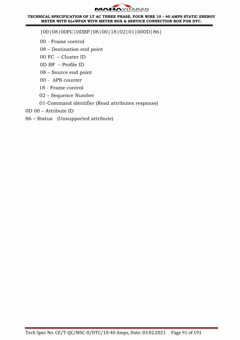
TECHNICAL SPECIFICATION OF LT AC THREE PHASE, FOUR WIRE 10 – 40 AMPS STATIC ENERGY
METER WITH 6LoWPAN WITH METER BOX & SERVICE CONNECTION BOX FOR DTC.
Tech Spec No. CE/T-QC/MSC-II/DTC/10-40 Amps, Date: 03.02.2021 Page 91 of 191
|00|08|00FC|0DBF|08|00|18|02|01|000D|86|
00 - Frame control
08 – Destination end point
00 FC – Cluster ID
0D BF – Profile ID
08 – Source end point
00 - APS counter
18 - Frame control
02 – Sequence Number
01-Command identifier (Read attributes response)
0D 00 – Attribute ID
86 – Status (Unsupported attribute)

TECHNICAL SPECIFICATION OF LT AC THREE PHASE, FOUR WIRE 10 – 40 AMPS STATIC ENERGY
METER WITH 6LoWPAN WITH METER BOX & SERVICE CONNECTION BOX FOR DTC.
Tech Spec No. CE/T-QC/MSC-II/DTC/10-40 Amps, Date: 03.02.2021 Page 92 of 191
Part II : Interoperability
The objectives of MSEDCL:
1) Interoperability with any make of meter; any make of radio module
2) Mesh networking with hopping
3) Systems should be ready for future AMR
4) Standardization.
The meter based on 6LoWPAN and DCU shall be based on both open Zigbee
2007 PRO and 6LoWPAN
The bidder shall support Simple Metering Cluster and related attributes
from the Smart Energy profile of ZigBee Pro, on a manufacturer specific
profile that has been defined in the document ―ZigBee Automated Metering
Initiative Profile‖ which represents data previously covered by the MSEDCL
protocol; this cluster may be implemented by all meter vendors for
interoperability
Interoperability in the field
The DCU should be able to act as a ZigBee Coordinator /6LoWPAN root in
order to facilitate the installation & commissioning of meters. The devices
are combo devices, capable of commissioning a network and also act as
routers/end device to download data.
Meter devices shall join the ZigBee Global Commissioning PAN
(0x0050C27710000000) formed by HHU. The HHU shall then configure
meter devices for the destination operating network by use of the ZigBee
Cluster Library‘s Commissioning cluster. Devices shall then be instructed to
leave the ZigBee Global Commissioning PAN and join the new network. If the
new operating PAN has not been started, the HHU shall start the new
network, commissioning an energy meter as a coordinator for that new PAN.
If for any reason the new operating PAN is not accessible the meter should
return to factory defaults.
Note:
All settings provided for Zigbee devices specified in the tender document are only
for tender samples. The proper settings will be communicated to successful
bidder.

TECHNICAL SPECIFICATION OF LT AC THREE PHASE, FOUR WIRE 10 – 40 AMPS STATIC ENERGY
METER WITH 6LoWPAN WITH METER BOX & SERVICE CONNECTION BOX FOR DTC.
Tech Spec No. CE/T-QC/MSC-II/DTC/10-40 Amps, Date: 03.02.2021 Page 93 of 191
Part III : Setting Critical Parameters
The purpose of this document is to specify a protocol sequence for certain
operations.
These operations involve setting critical parameters in the meters.
1) Change the password in the meter
2) Reset of Maximum Demand.
3) Set the number of TOD slots and their durations.
4) Set meter time (RTC).
5) Set MD integration period
For the aforementioned purposes, the following parameters and protocol
sequences are specified.
Protocol Sequences.
1) Change of password in the meter.
The default password in the meter shall be the meter's serial number. The
following packets shall be sent from the HHU to the meter.
Packet 1:
Attribute ID: 0x0000
Attribute type: String type
Attribute length: 6 – 20 bytes
Description: Old password.
Attribute ID: 0x0001
Attribute type: string type
Attribute length: 6 – 20 bytes
Description: New password.
Packet 2:
To be issued within 120 seconds of Packet 1:
Attribute ID: 0x0002
Attribute type: string type
Attribute length: 6 – 20 bytes
Description: New Password Reconfirm.
The HHU software should have front end display capability to take the necessary
inputs, give prompts to users. Automatic extensions, forms, saves etc should not
be implemented in HHU.
The meter shall reset the password on successful completion of sequence. If the
reconfirm packet is not received in the timeout provided, the new password will
be discarded and the old one retained. If the old password does not match, the
password will not be changed.

TECHNICAL SPECIFICATION OF LT AC THREE PHASE, FOUR WIRE 10 – 40 AMPS STATIC ENERGY
METER WITH 6LoWPAN WITH METER BOX & SERVICE CONNECTION BOX FOR DTC.
Tech Spec No. CE/T-QC/MSC-II/DTC/10-40 Amps, Date: 03.02.2021 Page 94 of 191
2) Protocol sequence for reset MD.
Packet 1:
Attribute ID: 0x0000
Attribute type: string type
Attribute length: 6 – 20 bytes
Description: Password.
Attribute ID: 0x0004
Attribute type: No data type
3) Protocol sequence for TOD timeslot setting
Packet 1:
Attribute ID: 0x0000
Attribute type: string type
Attribute length: 6 – 20 bytes
Description: Password.
Attribute ID: 0x0005
Attribute type: Variable length array.
Attribute Description: The 0th element will be a 16 bit element consisting of the
length of the array and the following elements will be of 8 bit unsigned integer
type.The number in the 0th element lists the number of time of day (TOD) slots.
The following array elements will describe the number of hours in each slot.
4) Protocol sequence for setting time in the meter.
Packet 1: Attribute ID: 0x0000
Attribute type: string type Attribute length: 6 – 20 bytes
Description: password. Attribute ID: 0x0006 Attribute type: UTC Time.
Description: This command will set the RTC time in the meter. 5) Protocol sequence for setting MD integration period in the meter.
Packet 1: Attribute ID: 0x0000 Attribute type: string type
Attribute length: 6 – 20 bytes Description: password. Attribute ID: 0x0007
Attribute type: 8 bit unsigned integer. The values for this attribute should be as below.
Value Description
0x00 This value used to set MD integration period of 30 minutes
0x01 This value used to set MD integration period of 15 minutes
Attribute Description: This command will set MD integration period in the meter.
Application layer frame formats for response given by meter after setting of
critical parameters should be as below.
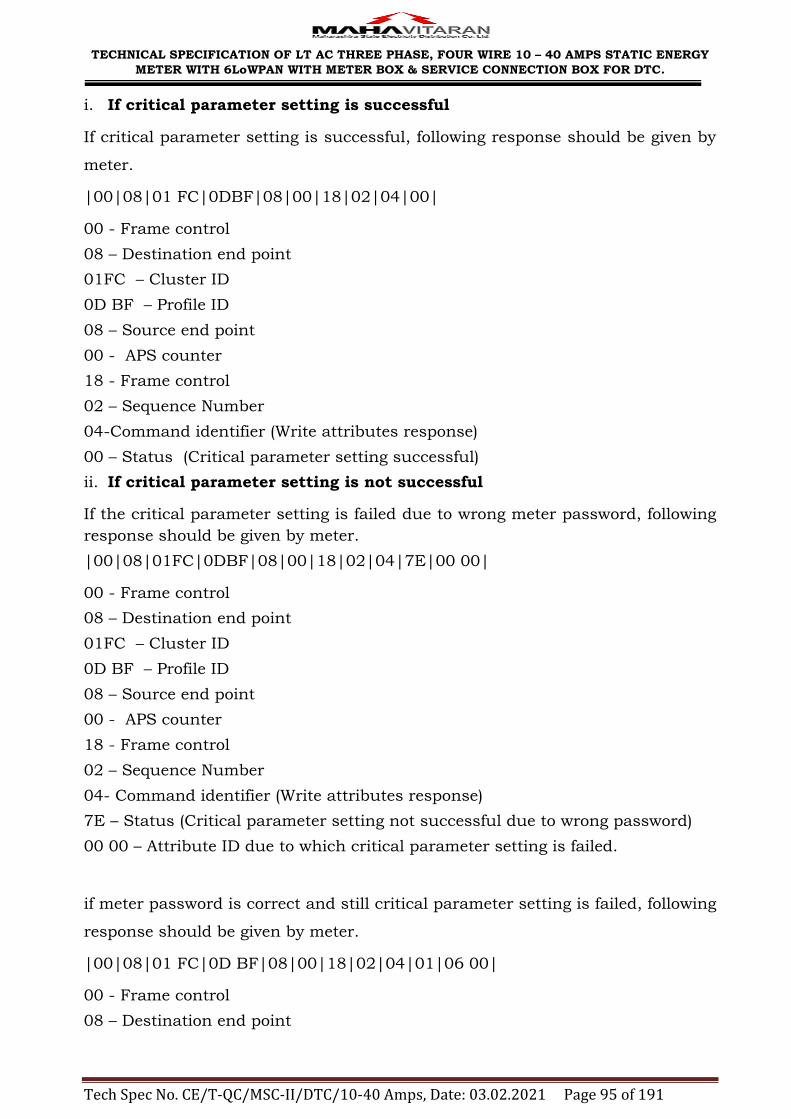
TECHNICAL SPECIFICATION OF LT AC THREE PHASE, FOUR WIRE 10 – 40 AMPS STATIC ENERGY
METER WITH 6LoWPAN WITH METER BOX & SERVICE CONNECTION BOX FOR DTC.
Tech Spec No. CE/T-QC/MSC-II/DTC/10-40 Amps, Date: 03.02.2021 Page 95 of 191
i. If critical parameter setting is successful
If critical parameter setting is successful, following response should be given by
meter.
|00|08|01 FC|0DBF|08|00|18|02|04|00|
00 - Frame control
08 – Destination end point
01FC – Cluster ID
0D BF – Profile ID
08 – Source end point
00 - APS counter
18 - Frame control
02 – Sequence Number
04-Command identifier (Write attributes response)
00 – Status (Critical parameter setting successful)
ii. If critical parameter setting is not successful
If the critical parameter setting is failed due to wrong meter password, following
response should be given by meter.
|00|08|01FC|0DBF|08|00|18|02|04|7E|00 00|
00 - Frame control
08 – Destination end point
01FC – Cluster ID
0D BF – Profile ID
08 – Source end point
00 - APS counter
18 - Frame control
02 – Sequence Number
04- Command identifier (Write attributes response)
7E – Status (Critical parameter setting not successful due to wrong password)
00 00 – Attribute ID due to which critical parameter setting is failed.
if meter password is correct and still critical parameter setting is failed, following
response should be given by meter.
|00|08|01 FC|0D BF|08|00|18|02|04|01|06 00|
00 - Frame control
08 – Destination end point
TECHNICAL SPECIFICATION OF LT AC THREE PHASE, FOUR WIRE 10 – 40 AMPS STATIC ENERGY
METER WITH 6LoWPAN WITH METER BOX & SERVICE CONNECTION BOX FOR DTC.
Tech Spec No. CE/T-QC/MSC-II/DTC/10-40 Amps, Date: 03.02.2021 Page 96 of 191
01 FC – Cluster ID
0D BF – Profile ID
08 – Source end point
00 - APS counter
18 - Frame control
02 – Sequence Number
04- Command identifier (Write attributes response)
01 – Status (Meter password is correct still critical parameter setting not
successful due to attribute given next)
00 06 – Attribute ID for which critical parameter setting is failed.

TECHNICAL SPECIFICATION OF LT AC THREE PHASE, FOUR WIRE 10 – 40 AMPS STATIC ENERGY
METER WITH 6LoWPAN WITH METER BOX & SERVICE CONNECTION BOX FOR DTC.
Tech Spec No. CE/T-QC/MSC-II/DTC/10-40 Amps, Date: 03.02.2021 Page 97 of 191
ANNEXURE - VI
WORKING OF DCU APPLICATION FOR MSEDCL
1.0 ASSUMPTIONS:
The network is being implemented with two considerations.
Meter reading through DCU (Data Concentrator Unit) in future. DCU / DCU
will join the existing network as a router.
Ease of meter installation and commissioning process.
Meter Installers are different from Commissioning Technicians.
Tamper Present status is always captured along with billing information.
In case of response not received to DCU for tamper present status, DCU
should store ‗XXXX‘ in BILL.MRI. E.g. In old meters, supplied against earlier
tenders, (no provision to record tamper present status ) who do not return
any response to tamper present status download command, the DCU should
store ‗XXXX‘ as a response for tamper present status.
In old meters, supplied against earlier tender, EMI/EMC field tamper
attributes are not implemented. DCU should retry three times for this
tamper.
2.0 INTRODUCTION
2.1 Scope
MSEDCL would like to deploy RF enabled meters in Urban (high density of
consumers) and rural area.
Along with RF Enabled meters, the system has following components:
1. BCS:
Base computer software used for communication with DCU. Stores
commissioning and meter reading data.
2. Hand Held Terminal (DCU):
Used during commissioning phase and collects meter reading data thereafter.
This document explains the flow of the DCU software for commissioning and
fetching data from these meters as per new commissioning and deployment
strategy (reference ―Commissioning and Deployment.doc‖) finalized by MSEDCL.

TECHNICAL SPECIFICATION OF LT AC THREE PHASE, FOUR WIRE 10 – 40 AMPS STATIC ENERGY
METER WITH 6LoWPAN WITH METER BOX & SERVICE CONNECTION BOX FOR DTC.
Tech Spec No. CE/T-QC/MSC-II/DTC/10-40 Amps, Date: 03.02.2021 Page 98 of 191
This Document restricts itself to explain the communication flow and data
parameters to be transferred between DCU and BCS software.
Any other communication is out of scope of this document.

TECHNICAL SPECIFICATION OF LT AC THREE PHASE, FOUR WIRE 10 – 40 AMPS STATIC ENERGY
METER WITH 6LoWPAN WITH METER BOX & SERVICE CONNECTION BOX FOR DTC.
Tech Spec No. CE/T-QC/MSC-II/DTC/10-40 Amps, Date: 03.02.2021 Page 99 of 191
3.00 PROCESS FLOWCHART:

TECHNICAL SPECIFICATION OF LT AC THREE PHASE, FOUR WIRE 10 – 40 AMPS STATIC ENERGY
METER WITH 6LoWPAN WITH METER BOX & SERVICE CONNECTION BOX FOR DTC.
Tech Spec No. CE/T-QC/MSC-II/DTC/10-40 Amps, Date: 03.02.2021 Page 100 of 191
4.00 DCU FUNCTIONALITY:
4.01 Installation of meters
Whenever a meter is installed, the installation personnel are required to make
note of the following information:
Consumer Number
Meter Serial Number & Make Code
Meter Phase
PC, MRCY, Route & Sequence
Transformer Identity Number which services this particular meter.
Any other customer identity / address.
The above data should then be entered into the BCS software.
4.02 6LoWPAN and Zigbee Network related BCS Functionality :
BCS shall group the meters (Serial Number & Make Code) separately based on
their transformer details.
This classification is important since in future if MSEDCL goes the DCU way,
Generate a pool of 64-bit PAN Id: Extended PAN Id of the network.
128-bit link key: Link key used for joining the network.
The DCU shall use a free PAN ID and link key and allot them for each network it
commissions.
Adequate measures to be taken to ensure non duplication of ID‘s and other
parameters.
4.03 6LoWPAN and Zigbee Network related DCU Functionality :
A DCU before going out has to be interfaced with the BCS software. On
choosing the area where it is supposed to work for the day, the BCS shall send
transfer the following data to DCU:
Transformer Identities
Meter Serial Number & Make Code of the meters that are serviced by the
Transformer
Pool of free PAN ID and Link Key

TECHNICAL SPECIFICATION OF LT AC THREE PHASE, FOUR WIRE 10 – 40 AMPS STATIC ENERGY
METER WITH 6LoWPAN WITH METER BOX & SERVICE CONNECTION BOX FOR DTC.
Tech Spec No. CE/T-QC/MSC-II/DTC/10-40 Amps, Date: 03.02.2021 Page 101 of 191
DCU broadly has two functions to perform in the field.
1. Commission newly deployed meters and create new networks as required.
2. Fetch data from the meters for which networks have already been created.
The process is explained below:
Meter Reader downloads the following details from BCS to DCU before going on
the field.
List of area & transformers to be covered.
List of meters / serial number & make code that are serviced by the
Transformer
Pool of free PAN IDs and Link Keys
Non-commissioned meters in the above list.
List of free / unused networks which will be used for creating new networks.
For the first time for a area the DCU will contain list of all unused networks
only.
There are two scenarios that the DCU shall face
First Visit
Revisit
First Visit:
The DCU shall move to the meter in the field and commission the first meter as
the ‗coordinator‘ or ‗root‘ depending upon band of operation i.e. Zigbee or
6LoWPAN, on a free PAN ID and Link Key. The following details shall be stored
for transfer to the BCS:
Serial Number & Make Code of the Meter
Whether Coordinator or Router
PAN ID
Link Key
Meter Phase
Meter Type

TECHNICAL SPECIFICATION OF LT AC THREE PHASE, FOUR WIRE 10 – 40 AMPS STATIC ENERGY
METER WITH 6LoWPAN WITH METER BOX & SERVICE CONNECTION BOX FOR DTC.
Tech Spec No. CE/T-QC/MSC-II/DTC/10-40 Amps, Date: 03.02.2021 Page 102 of 191
Then the DCU addresses the nearby router, one after the other, and
commissions them as routers in the just commissioned Network. These details
too are stored for transfer to BCS at the end of the Day.
4.05 Revisit:
When the DCU is connected to the BCS, list of localities are offered to the DCU.
On choosing the appropriate locality, the following details are downloaded to the
DCU
List of PAN ID, Link Key and meter serial number with make code under each
PAN ID
List of newly installed meters that need commissioning.
The DCU arrives at the location, commissions the new meters into available
networks. The DCU the joins each network and downloads the required data.
4.06 Meter information:
For the newly commissioned meters following details will be stored in DCU,
which will be later transferred to BCS software:
Serial Number & Make Code of the Meter
Whether Coordinator or Router or root
PAN ID
Link Key
Meter Phase
4.07 Billing Information
DCU can download the billing data along with tamper present status from any
meter. After joining the network, the data can be downloaded from any target
meter in the network.
5.00 PROTECTION OF DATA:
DCU can be misplaced or stolen, such DCUs need to be de-restered. In order to
protect the data stored in DCU, every DCU should have a unique serial number
and DCU application should have a password.
6.00 MENUS OF HHU APPLICATION:
Refer Annexure-VIII for DCU Menu.
6.01 Facility in HHU:

TECHNICAL SPECIFICATION OF LT AC THREE PHASE, FOUR WIRE 10 – 40 AMPS STATIC ENERGY
METER WITH 6LoWPAN WITH METER BOX & SERVICE CONNECTION BOX FOR DTC.
Tech Spec No. CE/T-QC/MSC-II/DTC/10-40 Amps, Date: 03.02.2021 Page 103 of 191
Meter Reader on field will be able to perform following tasks from DCU:
Download Billing Data from all the meters in existing Network
Download Billing Data from un-commissioned Meters ( Meters in Global PAN )
Commission newly installed meters – should automatically create a new network
with a meter being commissioned as a coordinator if necessary.
Download Load Profile Data
Download Tamper Data
Download TOD Data
Reset Maximum Demand
Reset TOD Slots
Reset Corrupt RTC of Meter

TECHNICAL SPECIFICATION OF LT AC THREE PHASE, FOUR WIRE 10 – 40 AMPS STATIC ENERGY
METER WITH 6LoWPAN WITH METER BOX & SERVICE CONNECTION BOX FOR DTC.
Tech Spec No. CE/T-QC/MSC-II/DTC/10-40 Amps, Date: 03.02.2021 Page 104 of 191
Commissioning & deployment - Flow Chart
Add to
existing
PAN?
Meter configured
as router, and
joins an existing
PAN
Meter configured
as coordinator
replacement
Meter configured as
coordinator/root.
Creating a new PAN
Read meter
YES
NO
NO
Is PAN
missing its
Coordinator
/root?

TECHNICAL SPECIFICATION OF LT AC THREE PHASE, FOUR WIRE 10 – 40 AMPS STATIC ENERGY
METER WITH 6LoWPAN WITH METER BOX & SERVICE CONNECTION BOX FOR DTC.
Tech Spec No. CE/T-QC/MSC-II/DTC/10-40 Amps, Date: 03.02.2021 Page 105 of 191
ANNEXURE - VII COMMON MENU STRUCTURE FOR DCU APPLICATION
Menu of DCU APPLICATION
1)Billing Data Download Sub Menu -
NOTE :
On Selection of options 1 i.e. “Auto Download”, DCU will scan for the PANs available and will download each PAN and thereafter Meters(if any) on global mode will be downloaded .
Switch on the DCU
Enter Password
Display DCU Program Version
MAIN MENU
1. Billing Data Download 2. Other Data Download
3. Commissioning
4. BCS Interface
5. Critical Parameter Setting
6. View Consumer Details
7. Job Statistics
1. Auto Download
2. Manual Download
3.Selective Commissioned meter Download
4. Global Download
5 Network Status
6 Back
Billing Data Download

TECHNICAL SPECIFICATION OF LT AC THREE PHASE, FOUR WIRE 10 – 40 AMPS STATIC ENERGY
METER WITH 6LoWPAN WITH METER BOX & SERVICE CONNECTION BOX FOR DTC.
Tech Spec No. CE/T-QC/MSC-II/DTC/10-40 Amps, Date: 03.02.2021 Page 106 of 191
Manual Download Sub Menu
NOTE :
On Selection Of Scan Network Menu DCU will scan for the PANs available , after completion of the scan list of available PANs will be displayed as PAN id and Coordinator serial number on the DCU screen User has to manually select the PAN to be Downloaded.
On Selection Of Scan Network Menu the PANs available in job configured to DCU will be displayed as PAN id and Coordinator serial number on the DCU screen. User has to manually select the PAN to be Downloaded.
Selective Commissioned Meter Download
NOTE :
User will enter the serial number of commissioned meter in the which is available in Job. The Billing Data of that meter will be downloaded.
Global Download Sub Menu
NOTE :
On selecting Global Download Menu , DCU will scan all the meter in the surrounding which are on Global Mode and download only “Billing Data” for meters in global mode.
Manual Download
1.Scan Network
2.Network List
3.Back
Selective Commissioned meter Download
1.Enter Meter Serial Number
2.Back

TECHNICAL SPECIFICATION OF LT AC THREE PHASE, FOUR WIRE 10 – 40 AMPS STATIC ENERGY
METER WITH 6LoWPAN WITH METER BOX & SERVICE CONNECTION BOX FOR DTC.
Tech Spec No. CE/T-QC/MSC-II/DTC/10-40 Amps, Date: 03.02.2021 Page 107 of 191
2) Other Data Download Sub Menu -
Load Survey Sub Menu
NOTE :
After selecting load Survey Menu user will be prompted to enter the meter serial number after entering the meter serial number , it will again prompt for Number days for which Load Survey Data Needs to be downloaded.
The range for number of days to be entered is 1 to 45 days.
3)Commissioning Sub Menu
1. New Network
2. Existing Network
3. Un commissioned List
4. Back
Commissioning
1. Bill History
2. Tamper Data
3. TOD
4. Load Survey
5. Back
Other Data Download
1.Enter Meter Serial Number
5. Back
Load Survey
1.Enter No of Days
5. Back

TECHNICAL SPECIFICATION OF LT AC THREE PHASE, FOUR WIRE 10 – 40 AMPS STATIC ENERGY
METER WITH 6LoWPAN WITH METER BOX & SERVICE CONNECTION BOX FOR DTC.
Tech Spec No. CE/T-QC/MSC-II/DTC/10-40 Amps, Date: 03.02.2021 Page 108 of 191
NOTE :
On selecting options 1 i.e. “New Network” , User will be prompted to enter serial numbers of the meters to be commissioned. New network will be formed with first meter number entered as a coordinator and user may enter the serial number of meters all at a time or one meter can be added after previous one is commissioned.
On selecting option 2 i.e. “Existing Network” , the PAN available in the job configured to DCU will be displayed on the DCU screen user has to select the PAN . After selecting the PAN user will be prompted for the meter serial number to be commissioned. The meter will be added to the selected PAN as a router.
On selecting option 3 i.e. “Un commissioned List” ,list of all the un commissioned meters in the job configured to DCU will be displayed.
4) BCS Interface
DCU will Display a message “BCS COMMONICATION…..”on screen.
6) Critical Parameter Setting Sub Menu
1 Enter Meter Serial Number
2 Back
Critical Parameter Setting
Select an Operation
1 Change Password
2 Reset MD
3 Set TOD Slots
4 Set RTC
5 Back
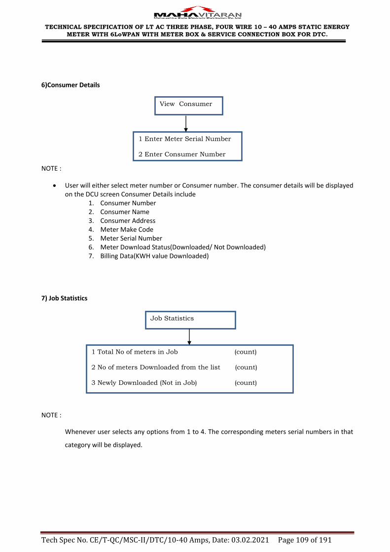
TECHNICAL SPECIFICATION OF LT AC THREE PHASE, FOUR WIRE 10 – 40 AMPS STATIC ENERGY
METER WITH 6LoWPAN WITH METER BOX & SERVICE CONNECTION BOX FOR DTC.
Tech Spec No. CE/T-QC/MSC-II/DTC/10-40 Amps, Date: 03.02.2021 Page 109 of 191
6)Consumer Details
NOTE :
User will either select meter number or Consumer number. The consumer details will be displayed on the DCU screen Consumer Details include
1. Consumer Number 2. Consumer Name 3. Consumer Address 4. Meter Make Code 5. Meter Serial Number 6. Meter Download Status(Downloaded/ Not Downloaded) 7. Billing Data(KWH value Downloaded)
7) Job Statistics
NOTE :
Whenever user selects any options from 1 to 4. The corresponding meters serial numbers in that
category will be displayed.
1 Enter Meter Serial Number
2 Enter Consumer Number
3 Back
View Consumer
1 Total No of meters in Job (count)
2 No of meters Downloaded from the list (count)
3 Newly Downloaded (Not in Job) (count)
4 No of meters Not Downloaded from job (count)
5 Back
Job Statistics

TECHNICAL SPECIFICATION OF LT AC THREE PHASE, FOUR WIRE 10 – 40 AMPS STATIC ENERGY METER WITH 6LoWPAN WITH METER BOX & SERVICE
CONNECTION BOX FOR DTC.
Tech Spec No. CE/T-QC/MSC-II/DTC/10-40 Amps, Date: 03.02.2021 Page 110 of 191
DCU Workflow for Data Download and Commissioning

TECHNICAL SPECIFICATION OF LT AC THREE PHASE, FOUR WIRE 10 – 40 AMPS STATIC ENERGY METER
WITH 6LoWPAN WITH METER BOX & SERVICE CONNECTION BOX FOR DTC.
Tech Spec No. CE/T-QC/MSC-II/DTC/10-40 Amps, Date: 03.02.2021 Page 111 of 191
ANNEXURE – VIII
Common File Saving Formats of DCU
The purpose of this document is to specify a common file saving format for data
acquired in DCU through LPRF Port.
Total Number of Files required to be stored in DCU
1. Billing
2. Meter History kWH
3. Tampers
4. Load Survey
5. TOD Data
6. Meter_Consumer_details File.
7. Network Details for Meters File.
8. Job Details in DCU File
Filenames
Following are the file names for saving the above files in DCU.
1. BILL.MRI (For Billing file)
2. KWH.MRI (For Meter History kWH File)
3. TPR.MRI (For Tamper File)
4. LSD.MRI (For Load Survey File)
5. TOD.MRI ( For TOD data)
6. RFMSTR.MRI (For Meter Consumer details File)
7. NETWORK.MRI (For Network Details of Meters in DCU)
8. JOB.MRI (For Job Details Stored in DCU)

TECHNICAL SPECIFICATION OF LT AC THREE PHASE, FOUR WIRE 10 – 40 AMPS STATIC ENERGY METER
WITH 6LoWPAN WITH METER BOX & SERVICE CONNECTION BOX FOR DTC.
Tech Spec No. CE/T-QC/MSC-II/DTC/10-40 Amps, Date: 03.02.2021 Page 112 of 191
DCU File Format for Meter Data
Note:-
All data must be in format provided by MSEDCL.
In meter data file, every meter data must start with new line.
At the end of each meter data files suffix ―Q‖ must be added.
During downloading of Billing, Following Sequence for writing data shall be
adhered:
o Meter Serial Number
o Make Code
o Active Energy in kWH (current month)
o MD (kW/kVA) (current month)
o MD Date/time (current month)
o Time (Meter RTC)
o Date (Meter RTC)
o Active Energy in kWH of previous month1
o Active Energy in kWH of previous month2
o Active Energy in kWH of previous month3
o Active Energy in kWH of previous month4
o Active Energy in kWH of previous month5
o Active Energy in kWH of previous month6
o MD(kW/kVA) of previous month1
o MD Date/time of previous month1
o MD(kW/kVA) of previous month2
o MD Date/time of previous month2
o MD(kW/kVA) of previous month3
o MD Date/time of previous month3
o MD(kW/kVA) of previous month4
o MD Date/time of previous month4
o MD(kW/kVA) of previous month5
o MD Date/time of previous month5
o MD(kW/kVA) of previous month6
o MD Date/time of previous month6
Note : In case of Single Phase meters MD values should be in kW and in
case of Three Phase meters MD values should be in kVA

TECHNICAL SPECIFICATION OF LT AC THREE PHASE, FOUR WIRE 10 – 40 AMPS STATIC ENERGY METER
WITH 6LoWPAN WITH METER BOX & SERVICE CONNECTION BOX FOR DTC.
Tech Spec No. CE/T-QC/MSC-II/DTC/10-40 Amps, Date: 03.02.2021 Page 113 of 191
During downloading of Tamper, Following Sequence for writing data shall be
adhered:
o Reverse Tamper
o Earth Tamper
o Neutral Missing Tamper
o Magnet Tamper
o Meter Cover Open Tamper o EMI/EMC Field Tamper o Missing PotentialTamper
o Potential Imbalance Tamper
o Current Unbalance Tamper
o Current reversal Tamper
o Current circuit short Tamper
o CT Bypass Tamper
o PowerON OFF Tamper
Tags
1. BIL For Billing Data
2. KWH For Only kWH Data
3. TAR For Reverse Tamper Data
4. TAE For Earth Tamper Data
5. TAN For Neutral missing Tamper Data
6. TAM For Magnet Tamper
7. TAS For EMI/EMC Field Tamper
8. TAC For Meter Cover Open Tamper
9. TAP For Missing Potential
10. TAT For Potential Unbalance
11. TAU For Current unbalance Tamper
12. TAV For Current reversal Tamper
13. TAX For current circuit short Tamper
14. TAY For CT Bypass Tamper
15. TAZ For Power On OFF
16. LSD For Load Survey Data
17. MTR For Meter Serial Number file
18. EN# End Of Data.
18. Q At the end of the file.
19. CPT For setting TOD timings through critical parameter setting.

TECHNICAL SPECIFICATION OF LT AC THREE PHASE, FOUR WIRE 10 – 40 AMPS STATIC ENERGY METER
WITH 6LoWPAN WITH METER BOX & SERVICE CONNECTION BOX FOR DTC.
Tech Spec No. CE/T-QC/MSC-II/DTC/10-40 Amps, Date: 03.02.2021 Page 114 of 191
20. NWK For Network related Entries
21. JOB For Job related entries
22. RFM For RF Meter related data.
Format of Billing File ( BILL.MRI) :
TAG Serial Number Make
Code
Meter Phase Meter Type Data EN#
i.e
Tag BIL
<Serial Number>
<Make Code>
<Meter Phase>
Data
<kWH><MDkW/kVA><MD Time HH:MI><MD Date DD:MM:YY><Reading Time
HH:MI><Reading Date DD:MM:YY><Meter RTC Time HH:MI><Meter RTC
Date DD:MM:YY><Tamper present status><kVAh><kVArh (Lag)><kVArh
(Lead)><Voltage VRN><Voltage VYN><Voltage VBN><Current IR><Current
IY><Current IB>
End of Data EN#
Note:
1. The meter Phase attribute should mention values as follows:
1: Single Phase Meter
3: Three Phase Meter

TECHNICAL SPECIFICATION OF LT AC THREE PHASE, FOUR WIRE 10 – 40 AMPS STATIC ENERGY METER
WITH 6LoWPAN WITH METER BOX & SERVICE CONNECTION BOX FOR DTC.
Tech Spec No. CE/T-QC/MSC-II/DTC/10-40 Amps, Date: 03.02.2021 Page 115 of 191
Example of billing data file ( containing data of two meters).
BIL(00114214)(071)(3)(00011.4)(01.3)(00:30)(01:10:12)(10:19)(01:10:12)(10:19
)(01:10:12)(00000000000000000000000000000101)(00011.3)(00001.0)(00001.0)(21
0)(230)(220)(5500)(5600)(4500) EN#
BIL(00114216)(056)(3)(00075.3)(02.7)(08:48)(01:10:12)(10:19)(01:10:12)(10:19
)(01:10:12)(00000000000000000000000000000101)(00075.1)(00020.1)(00013.6)(21
0)(230)(220)(5500)(5600)(4500)EN#Q
Note : In case of Single Phase meters MD values should be in kW and in case of Three Phase meters MD values
should be in kVA
Format of Meter History KWH File (KWH.MRI) :
TAG Serial Number Make Code Data EN#
i.e
Tag KWH
<Serial Number>
<Make Code>
Data
<kWH><MDkW/kVA><MD kW/kVA Date DD:MM:YY><MD kW/kVA
TimeHH:MI><kVAh><rkVAh(Lag)><kVAh(Lead)>
<kWH><MDkW/kVA><MD kW/kVA Date DD:MM:YY><MD kW/kVA Time
HH:MI><kVAh><rkVAh(Lag)><kVAh(Lead)>
<kWH><MDkW/kVA><MD kW/kVA Date DD:MM:YY><MD kW/kVA Time
HH:MI><kVAh><rkVAh(Lag)><kVAh(Lead)>
<kWH><MDkW/kVA><MD kW/kVA Date DD:MM:YY><MD kW/kVA Time
HH:MI><kVAh><rkVAh(Lag)><kVAh(Lead)>
<kWH><MDkW/kVA><MD kW/kVA Date DD:MM:YY><MD kW/kVA Time
HH:MI><kVAh><rkVAh(Lag)><kVAh(Lead)>
<kWH><MDkW/kVA><MD kW/kVA Date DD:MM:YY><MD kW/kVA Time
HH:MI><kVAh><rkVAh(Lag)><kVAh(Lead)>

TECHNICAL SPECIFICATION OF LT AC THREE PHASE, FOUR WIRE 10 – 40 AMPS STATIC ENERGY METER
WITH 6LoWPAN WITH METER BOX & SERVICE CONNECTION BOX FOR DTC.
Tech Spec No. CE/T-QC/MSC-II/DTC/10-40 Amps, Date: 03.02.2021 Page 116 of 191
<kWH><MDkW/kVA><MD kW/kVA Date DD:MM:YY><MD kW/kVA Time
HH:MI><kVAh><rkVAh(Lag)><kVAh(Lead)>
<kWH><MDkW/kVA><MD kW/kVA Date DD:MM:YY><MD kW/kVA Time
HH:MI><kVAh><rkVAh(Lag)><kVAh(Lead)>
<kWH><MDkW/kVA><MD kW/kVA Date DD:MM:YY><MD kW/kVA Time
HH:MI><kVAh><rkVAh(Lag)><kVAh(Lead)>
<kWH><MDkW/kVA><MD kW/kVA Date DD:MM:YY><MD kW/kVA Time
HH:MI><kVAh><rkVAh(Lag)><kVAh(Lead)>
End of Data EN#
Example of Meter History KWH data file ( containing data of one meter).
KWH(00100869)(052)(000180.1)(04.5)(10:02:14)(13:10)(000179.2)(000179.3)(0018
1.9)
(00160.1)(03.5)(11:01:14)(12:10)(00160.4)(000162.9)(00159.2)
(00145.1)(05.50)(12:12:13)(12:15)(00144.9)(00144.7)00145.9)
(00120.3)(04.5)(11:11:13)(10:10)(00125.9)(00127.4)00126.4)
(00103.8)(05.3)(12:10:13)(09:15)(00101.9)(00103.1)(00102.1)
(00087.4)(03.4)(15:09:13)(10:50)(00086.3)(00086.3)(00088.1)
(00075.1)(04.5)(10:08:13)(13:10)(00074.1)(00074.9)(00075.2)
(00065.1)(03.5)(11:07:13)(12:10)(00063.7)(00064.9)(00065.9)
(00057.1)(05.50)(12:06:13)(12:15)(00054.2)(00056.6)(00058.7)
(00050.4)(04.5)(07:05:13)(10:10)(00047.9)(00047.4)(00049.3)
(00043.1)(05.3)(12:04:13)(09:15)(000041.9)(00041.8)(00044.1)
(00028.4)(03.4)(15:03:13)(10:50)(00027.3)(00026.3)(00027.1)
EN#Q
Note : In case of Single Phase meters MD values should be in kW and in case of Three Phase meters MD values
should be in kVA.
Format of Tamper Data File (TPR.MRI) :

TECHNICAL SPECIFICATION OF LT AC THREE PHASE, FOUR WIRE 10 – 40 AMPS STATIC ENERGY METER
WITH 6LoWPAN WITH METER BOX & SERVICE CONNECTION BOX FOR DTC.
Tech Spec No. CE/T-QC/MSC-II/DTC/10-40 Amps, Date: 03.02.2021 Page 117 of 191
TAG Serial Number Make Code Data EN#
i.e
Tag (Any one of the following tag as per tamper event)
TAR For Reverse Tamper Data
TAE For Earth Tamper Data
TAN For Neutral Missing Tamper Data
TAM For Magnet Tamper
TAS For EMI/EMC Field Tamper
TAC For Meter Cover Open Tamper
TAP For Missing Potential
TAT For potential Unbalance
TAU For Current unbalance Tamper
TAV For Current reversal Tamper
TAX For current circuit short Tamper
TAY For CT Bypass Tamper
TAZ For Power On Off Tamper
<Serial Number>
<Make Code>
Data
<Event Number><Tamper Phase><Occurrence Date DD:MM:YY>
<Occurrence Time HH:MI>><Restoration Date DD:MM:YY>
<Restoration Time HH:MI>
End of Data EN#
Example of tamper data file ( containing data of two meters)..
TAM(00100869)(001)(01,00,24:02:11,10:28,24:02:11,10:52)(02,00,24:02:11,10:22
,24:02:11,10:25)(03,00,24:02:11,10:14,24:02:11,10:17)(04,00,24:02:11,10:07,2
4:02:11,10:11)(05,00,00:00:00,00:00,00:00:00,00:00)(06,00,00:00:00,00:00,00:
00:00,00:00)(07,00,00:00:00,00:00,00:00:00,00:00)(08,00,00:00:00,00:00,00:00
:00,00:00)(09,00,00:00:00,00:00,00:00:00,00:00)(10,00,00:00:00,00:00,00:00:0
0,00:00)EN#

TECHNICAL SPECIFICATION OF LT AC THREE PHASE, FOUR WIRE 10 – 40 AMPS STATIC ENERGY METER
WITH 6LoWPAN WITH METER BOX & SERVICE CONNECTION BOX FOR DTC.
Tech Spec No. CE/T-QC/MSC-II/DTC/10-40 Amps, Date: 03.02.2021 Page 118 of 191
TAP(00100869)(00101,02,24:02:11,10:28,24:02:11,10:52)(02,03,24:02:11,10:22,2
4:02:11,10:25)(03,01,24:02:11,10:14,24:02:11,10:17)(04,02,24:02:11,10:07,24:
02:11,10:11)(05,00,00:00:00,00:00,00:00:00,00:00)(06,00,00:00:00,00:00,00:00
:00,00:00)(07,00,00:00:00,00:00,00:00:00,00:00)(08,00,00:00:00,00:00,00:00:0
0,00:00)(09,00,00:00:00,00:00,00:00:00,00:00)(10,00,00:00:00,00:00,00:00:00,
00:00)EN#
TAT(00100869)(001)(01,01,24:02:11,10:28,24:02:11,10:52)(02,02,24:02:11,10:22
,24:02:11,10:25)(03,01,24:02:11,10:14,24:02:11,10:17)(04,03,24:02:11,10:07,2
4:02:11,10:11)(05,00,00:00:00,00:00,00:00:00,00:00)(06,00,00:00:00,00:00,00:
00:00,00:00)(07,00,00:00:00,00:00,00:00:00,00:00)(08,00,00:00:00,00:00,00:00
:00,00:00)(09,00,00:00:00,00:00,00:00:00,00:00)(10,00,00:00:00,00:00,00:00:0
0,00:00)EN#
TAC(00100870)(001)(00,27:01:11,15:05)EN#
TAV(00100869)(001)(01,01,24:02:11,10:28,24:02:11,10:52)(02,02,24:02:11,10:22
,24:02:11,10:25)(03,01,24:02:11,10:14,24:02:11,10:17)(04,03,24:02:11,10:07,2
4:02:11,10:11)(05,00,00:00:00,00:00,00:00:00,00:00)(06,00,00:00:00,00:00,00:
00:00,00:00)(07,00,00:00:00,00:00,00:00:00,00:00)(08,00,00:00:00,00:00,00:00
:00,00:00)(09,00,00:00:00,00:00,00:00:00,00:00)(10,00,00:00:00,00:00,00:00:0
0,00:00)EN#Q
Format of Load Survey Data File (LSD.MRI) :
TAG Serial Number Make Code Meter Phase Data EN#
i.e
Tag
LSD
<Serial Number><Make Code><Meter Phase>
Data <Load Profile Data >
End of Data EN#
Note:
In case of Single Phase RF meters Load Profile Data will consists of Interval Start Time, KWH, MD KW,
Voltage and Current Parameters
In case of Three Phase RF meters Load Profile Data will consists of Interval Start Time, KWH, KVArh (Lag),
KVArh (Lead), KVAh, VoltageRN, VoltageYN, VoltageBN, Current R, Current Y, Current B Parameters.

TECHNICAL SPECIFICATION OF LT AC THREE PHASE, FOUR WIRE 10 – 40 AMPS STATIC ENERGY METER
WITH 6LoWPAN WITH METER BOX & SERVICE CONNECTION BOX FOR DTC.
Tech Spec No. CE/T-QC/MSC-II/DTC/10-40 Amps, Date: 03.02.2021 Page 119 of 191
Example of load survey data file for single phase RF meter ( containing data of one meter)
LSD(00100869)(071)(01)((24:02:11 00:00,00.0,00.00,000,0000)
(24:02:11 00:30,00.0,00.00,000,0000)(24:02:11 01:00,00.0,00.00,000,0000)
(24:02:11 01:30,00.0,00.00,000,0000)(24:02:11 02:00,00.0,00.00,000,0000)
(24:02:11 02:30,00.0,00.00,000,0000)(24:02:11 03:00,00.0,00.00,000,0000)
(24:02:11 03:30,00.0,00.00,000,0000)(24:02:11 04:00,00.0,00.00,000,0000)
(24:02:11 04:30,00.0,00.00,000,0000)(24:02:11 05:00,00.0,00.00,000,0000)
(24:02:11 05:30,00.0,00.00,000,0000)(24:02:11 06:00,00.0,00.00,000,0000)
(24:02:11 06:30,00.0,00.00,000,0000)(24:02:11 07:00,00.0,00.00,000,0000)
(24:02:11 07:30,00.0,00.00,000,0000)(24:02:11 08:00,00.0,00.00,000,0000)
(24:02:11 08:30,00.0,00.00,000,0000)(24:02:11 09:00,00.0,00.00,000,0000)
(24:02:11 09:30,00.0,00.00,000,0000)(24:02:11 10:00,00.0,00.00,000,0000)
(24:02:11 10:30,00.0,00.00,000,0000)(24:02:11 11:00,00.0,00.00,000,0000)
(24:02:11 11:30,00.0,00.00,000,0000)(24:02:11 12:00,00.0,00.00,000,0000)
(24:02:11 12:30,00.0,00.00,000,0000)(24:02:11 13:00,00.0,00.00,000,0000)
(24:02:11 13:30,00.0,00.00,000,0000)(24:02:11 14:00,00.0,00.00,000,0000)
(24:02:11 14:30,00.0,00.00,000,0000)(24:02:11 15:00,00.0,00.00,000,0000)
(24:02:11 15:30,00.0,00.00,000,0000)(24:02:11 16:00,00.0,00.00,000,0000)
(24:02:11 16:30,00.0,00.00,000,0000)(24:02:11 17:00,00.0,00.00,000,0000)
(24:02:11 17:30,00.0,00.00,000,0000)(24:02:11 18:00,00.0,00.00,000,0000)
(24:02:11 18:30,00.0,00.00,000,0000)(24:02:11 19:00,00.0,00.00,000,0000)
(24:02:11 19:30,00.0,00.00,000,0000)(24:02:11 20:00,00.0,00.00,000,0000)
(24:02:11 20:30,00.0,00.00,000,0000)(24:02:11 21:00,00.0,00.00,000,0000)
(24:02:11 21:30,00.0,00.00,000,0000)(24:02:11 22:00,00.0,00.00,000,0000)

TECHNICAL SPECIFICATION OF LT AC THREE PHASE, FOUR WIRE 10 – 40 AMPS STATIC ENERGY METER
WITH 6LoWPAN WITH METER BOX & SERVICE CONNECTION BOX FOR DTC.
Tech Spec No. CE/T-QC/MSC-II/DTC/10-40 Amps, Date: 03.02.2021 Page 120 of 191
(24:02:11 22:30,00.0,00.00,000,0000)(24:02:11 23:00,00.0,00.00,000,0000)(24:02:11
23:30,00.0,00.00,000,0000))EN#Q
Example of load survey data file for Three phase RF meter ( containing data of one meter)
LSD(00100869)(001)(03)((24:02:1100:00,0000,0000,0000,000,000,000,00000,00000,00000,00000)
(24:02:11 00:30,0000,0000,0000,000,000,000,00000,00000,00000,00000)
(24:02:11 01:00,0000,0000,0000,000,000,000,00000,00000,00000,00000)
(24:02:11 01:30,0000,0000,0000,000,000,000,00000,00000,00000,00000)
(24:02:11 02:00,0000,0000,0000,000,000,000,00000,00000,00000,00000)
(24:02:11 02:30,0000,0000,0000,000,000,000,00000,00000,00000,00000)
(24:02:11 03:00,0000,0000,0000,000,000,000,00000,00000,00000,00000)
(24:02:11 03:30,0000,0000,0000,000,000,000,00000,00000,00000,00000)
(24:02:11 04:00,0000,0000,0000,000,000,000,00000,00000,00000,00000)
(24:02:11 04:30,0000,0000,0000,000,000,000,00000,00000,00000,00000)
(24:02:11 05:00,0000,0000,0000,000,000,000,00000,00000,00000,00000)
(24:02:11 05:30,0000,0000,0000,000,000,000,00000,00000,00000,00000)
(24:02:11 06:00,0000,0000,0000,000,000,000,00000,00000,00000,00000)
(24:02:11 06:30,0000,0000,0000,000,000,000,00000,00000,00000,00000)
(24:02:11 07:00,0000,0000,0000,000,000,000,00000,00000,00000,00000)
(24:02:11 07:30,0000,0000,0000,000,000,000,00000,00000,00000,00000)
(24:02:11 08:00,0000,0000,0000,000,000,000,00000,00000,00000,00000)
(24:02:11 08:30,0000,0000,0000,000,000,000,00000,00000,00000,00000)
(24:02:11 09:00,0000,0000,0000,000,000,000,00000,00000,00000,00000)
(24:02:11 09:30,0000,0000,0000,000,000,000,00000,00000,00000,00000)
(24:02:11 10:00,0000,0000,0000,000,000,000,00000,00000,00000,00000)

TECHNICAL SPECIFICATION OF LT AC THREE PHASE, FOUR WIRE 10 – 40 AMPS STATIC ENERGY METER
WITH 6LoWPAN WITH METER BOX & SERVICE CONNECTION BOX FOR DTC.
Tech Spec No. CE/T-QC/MSC-II/DTC/10-40 Amps, Date: 03.02.2021 Page 121 of 191
(24:02:11 10:30,0000,0000,0000,000,000,000,00000,00000,00000,00000)
(24:02:11 11:00,0000,0000,0000,000,000,000,00000,00000,00000,00000)
(24:02:11 11:30,0000,0000,0000,000,000,000,00000,00000,00000,00000)
(24:02:11 12:00,0000,0000,0000,000,000,000,00000,00000,00000,00000)
(24:02:11 12:30,0000,0000,0000,000,000,000,00000,00000,00000,00000)
(24:02:11 13:00,0000,0000,0000,000,000,000,00000,00000,00000,00000)
(24:02:11 13:30,0000,0000,0000,000,000,000,00000,00000,00000,00000)
(24:02:11 14:00,0000,0000,0000,000,000,000,00000,00000,00000,00000)
(24:02:11 14:30,0000,0000,0000,000,000,000,00000,00000,00000,00000)
(24:02:11 15:00,0000,0000,0000,000,000,000,00000,00000,00000,00000)
(24:02:11 15:30,0000,0000,0000,000,000,000,00000,00000,00000,00000)
(24:02:11 16:00,0000,0000,0000,000,000,000,00000,00000,00000,00000)
(24:02:11 16:30,0000,0000,0000,000,000,000,00000,00000,00000,00000)
(24:02:11 17:00,0000,0000,0000,000,000,000,00000,00000,00000,00000)
(24:02:11 17:30,0000,0000,0000,000,000,000,00000,00000,00000,00000)
(24:02:11 18:00,0000,0000,0000,000,000,000,00000,00000,00000,00000)
(24:02:11 18:30,0000,0000,0000,000,000,000,00000,00000,00000,00000)
(24:02:11 19:00,0000,0000,0000,000,000,000,00000,00000,00000,00000)
(24:02:11 19:30,0000,0000,0000,000,000,000,00000,00000,00000,00000)
(24:02:11 20:00,0000,0000,0000,000,000,000,00000,00000,00000,00000)
(24:02:11 20:30,0000,0000,0000,000,000,000,00000,00000,00000,00000)
(24:02:11 21:00,0000,0000,0000,000,000,000,00000,00000,00000,00000)
(24:02:11 21:30,0000,0000,0000,000,000,000,00000,00000,00000,00000)
(24:02:11 22:00,0000,0000,0000,000,000,000,00000,00000,00000,00000)
(24:02:11 22:30,0000,0000,0000,000,000,000,00000,00000,00000,00000)

TECHNICAL SPECIFICATION OF LT AC THREE PHASE, FOUR WIRE 10 – 40 AMPS STATIC ENERGY METER
WITH 6LoWPAN WITH METER BOX & SERVICE CONNECTION BOX FOR DTC.
Tech Spec No. CE/T-QC/MSC-II/DTC/10-40 Amps, Date: 03.02.2021 Page 122 of 191
(24:02:11 23:00,0000,0000,0000,000,000,000,00000,00000,00000,00000)
(24:02:11 23:30,0000,0000,0000,000,000,000,00000,00000,00000,00000))EN#Q
Format of TOD Data File (TOD.MRI) :
TAG Data EN#
i.e
Tag TOD
Data
<Serial Number><Make Code><Meter Phase><Meter Type><Reading UTC Time>
<TZ1 KWH><TZ1 MD><TZ1 MD Timestamp><kVAh TZ1><kVArh(lead) TZ1><kVArh(lag) TZ1>
<TZ2 KWH><TZ2 MD><TZ2 MD Timestamp><kVAh TZ2><kVArh(lead) TZ2><kVArh(lag) TZ2>
<TZ3 KWH><TZ3 MD><TZ3 MD Timestamp><kVAh TZ3><kVArh(lead) TZ3><kVArh(lag) TZ3>
<TZ4 KWH><TZ4 MD><TZ4 MD Timestamp><kVAh TZ4><kVArh(lead) TZ4><kVArh(lag) TZ4>
End of Data EN#
Example of TOD data file (containing TOD data of One Consumers)
TOD(12346578)(001)(01)(0)(11:10:15 15:30)(135)(09.00)(10:10:15 2:30)(137)(130)(07.00)(10:10:15
14:00)(132)(115)(05.00)(10:10:15 10:00)(117)(120)(5.5)(10:10:15 20:30)(125)EN#Q
Format of Network Data File (NETWORK.MRI) :
For Zigbee
TAG Data EN#
i.e
Tag NWK
Data
<NetworkID><Co-ordinator Serial Number><Co-ordinator make
code><Security Key><Network-Key><Ext-PAN> <Short-
Pan><Channel><Channel Mask><Meter Count><Last Downloaded Timestamp>
End of Data EN#

TECHNICAL SPECIFICATION OF LT AC THREE PHASE, FOUR WIRE 10 – 40 AMPS STATIC ENERGY METER
WITH 6LoWPAN WITH METER BOX & SERVICE CONNECTION BOX FOR DTC.
Tech Spec No. CE/T-QC/MSC-II/DTC/10-40 Amps, Date: 03.02.2021 Page 123 of 191
For 6LoWPAN :
TAG Data EN#
i.e
Tag NWK
Data
<NetworkID><Root Serial Number><Root make Code><PANID><Channel><AES
KEY><ipv6Prefix><Meter Count>EN#
End of Data EN#
Note:
1) The RF Module returns date in Hex format, but it shall be the responsibility of the DCU
software/firmware to decode the date and store in proper date format of dd-MM-yyyy hh24:mi:ss
2) All values should be written in Big endian format only.
Example of Network data file (containing data of only one network)
NWK(0001)(10100389)(076)(05244414020789450524441402078945)(E91A57C6D681517E2AA9C2D18BD536FF)
(0524441402078945)(0)(0)(2105344)(4)(18:05:2015 14:32:12)EN#Q
Format of Meter Master Data File (RFMSTR.MRI) :
TAG Serial Number Make Code Data EN#
i.e
Tag MTR
Data
<Meter Sl No><Mk Code><Consumer number><Consumer name><Cons
Address><Commission Status><Device Type> <Network ID><MAC Address><DL Status><CP
New Password> <CP Old Password><CP RTC Flag><CP MD Reset flag><CP TOD Flag><CP TOD slot
count><CP TOD Slots><CP MD time Flag><CP MD time
value>
End of Data EN#

TECHNICAL SPECIFICATION OF LT AC THREE PHASE, FOUR WIRE 10 – 40 AMPS STATIC ENERGY METER
WITH 6LoWPAN WITH METER BOX & SERVICE CONNECTION BOX FOR DTC.
Tech Spec No. CE/T-QC/MSC-II/DTC/10-40 Amps, Date: 03.02.2021 Page 124 of 191
Note:
a) In case of flags the following convention is to be followed:
0: Forbidden to reset
1: Allowed to reset
2: Reset successful
3: Reset Failed
b) In case of CP TOD Slots, the slots separated by ‘:’ represent the duration of the slots.
c) As the count of TOD slots is also mentioned, the TOD hour slots data will only be equal in number to the
earlier mentioned value of TOD hour slots count.
d) In case of ‘0’ count of TOD slots a null value bracket of TOD hour slots will be present.
e) After updating CP meter data viz., CP Password reset, CP MD Reset, etc. it shall be the responsibility of
the DCU software/firmware to update the corresponding flags in the RFMSTR.MRI file according to
conventions given in Note (a) under RFMSTR.MRI file specification heading.
f) All values should be written in Big endian format only.
Example of Meter Master data file (containing data of Two Consumers)
MTR(00000030)(082)(123456789123)(MSEDCL Sample Consumer1)(HOIT Prakashgad)
(1)(C)(0001)(00124B000000001E)(0)(00000030)(00000030)(0)(0)(1)(4)(6:6:6:6)(1)(1) EN#
MTR(00130704)(053)(123456789124)(MSEDCL Sample Consumer2)(HOIT Prakashgad)
(1)(R)(0001)(3CC1F6030001FE90)(0)(00130704)(00130704)(1)(1)(0)(0)()(0)() EN#Q
Format of Job Data File (JOB.MRI) :
TAG Job ID Job Date Data EN#
i.e
Tag JOB
Data
<JobID><Job Date><<Job Description><BU><Commission Allowed><Job
Download Status>

TECHNICAL SPECIFICATION OF LT AC THREE PHASE, FOUR WIRE 10 – 40 AMPS STATIC ENERGY METER
WITH 6LoWPAN WITH METER BOX & SERVICE CONNECTION BOX FOR DTC.
Tech Spec No. CE/T-QC/MSC-II/DTC/10-40 Amps, Date: 03.02.2021 Page 125 of 191
End of Data EN#Q
Note:
a) The commission allowed flag indicates whether the DCU Operator is allowed to perform the activity of
commissioning of meters in this job. The convention to be followed is as follows:
0: Not allowed to commission
1: Allowed to commission the available un-commissioned meters.
b) The job download status is as follows :
‘0’ : New Job ( No readings/ meter data available in .MRI files)
‘1’ : Readings / Meter Data for at least any one meter is present in DCU.
‘2’ : Job in DCU is successfully downloaded to BCS. ( Jobs in DCU can be downloaded to BCS multiple
times )
Example of Job data file (containing data of One Job [Jobs are only one per DCU])
JOB(123456789)(16-May-2015)(Example Job)(9999)(1)(0)EN#Q
ANNEXURE - IX
File Transfer Protocol for Communication between DCU and BCS
File Transfer Process: USB Connectivity Diagram
Pin Configuration for USB Data Cable of DCU
The data cable of DCU should be USB 2.0 Compliant. No other cable (viz. Serial, COM, etc.) shall be accepted.
The configuration for the USB is as follows:
Type A USB Pin for Computer / PC End of data cable
PC
Application
CMRI
USB
Port
USB
Port
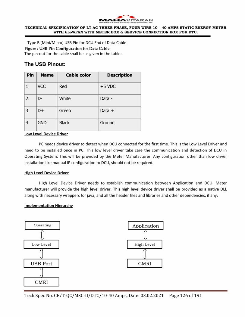
TECHNICAL SPECIFICATION OF LT AC THREE PHASE, FOUR WIRE 10 – 40 AMPS STATIC ENERGY METER
WITH 6LoWPAN WITH METER BOX & SERVICE CONNECTION BOX FOR DTC.
Tech Spec No. CE/T-QC/MSC-II/DTC/10-40 Amps, Date: 03.02.2021 Page 126 of 191
Type B (Mini/Micro) USB Pin for DCU End of Data Cable
Figure : USB Pin Configuration for Data Cable
The pin-out for the cable shall be as given in the table:
The USB Pinout:
Pin Name Cable color Description
1 VCC Red +5 VDC
2 D- White Data -
3 D+ Green Data +
4 GND Black Ground
Low Level Device Driver
PC needs device driver to detect when DCU connected for the first time. This is the Low Level Driver and
need to be installed once in PC. This low level driver take care the communication and detection of DCU in
Operating System. This will be provided by the Meter Manufacturer. Any configuration other than low driver
installation like manual IP configuration to DCU, should not be required.
High Level Device Driver
High Level Device Driver needs to establish communication between Application and DCU. Meter
manufacturer will provide the high level driver. This high level device driver shall be provided as a native DLL
along with necessary wrappers for java, and all the header files and libraries and other dependencies, if any.
Implementation Hierarchy
Application
High Level
Driver
CMRI
Operating
System
Low Level
Driver
USB Port
CMRI

TECHNICAL SPECIFICATION OF LT AC THREE PHASE, FOUR WIRE 10 – 40 AMPS STATIC ENERGY METER
WITH 6LoWPAN WITH METER BOX & SERVICE CONNECTION BOX FOR DTC.
Tech Spec No. CE/T-QC/MSC-II/DTC/10-40 Amps, Date: 03.02.2021 Page 127 of 191
High Level Device Driver
The following functionality shall be available in High Level Device Driver:-
1. A function which can Assign Job to DCU
2. A function which upload data from DCU
3. Set RTC of DCU
4. Get RTC of DCU
5. Can Clear Job from DCU
6. Can get the list of files in relevant location of DCU
7. Get the Serial Number of DCU
High Level Device Function Description
SlN
o Description Function Name Parameters Return Parameters
1 Configure
Job to DCU ConfigureJobTo
DCU Data Type: String
Parameters
1. Job File name( i.e.JOB.MRI) : Full path name of JOB.MRI in PC to be sent to DCU
2. Network file Name: (i.e.NETWORK.MRI)
Full path name of
NETWORK.MRI in PC to be
sent to DCU
3. Meter Details File Name (i.e. RFMSTR.MRI ) Full path name of
RFMSTR.MRI in PC to be
sent to DCU
Data Type:int
Values
1. Successful
2. PC File does not
exist
3. Error in detecting
USB
4. Others
2 Download
Job From
DCU
DownloadJobFr
omDCU Data Type: String
Parameters
1. Job File name( i.e.JOB.MRI) : Full path name of in PC
Data Type:int
Values
1. Sucessful

TECHNICAL SPECIFICATION OF LT AC THREE PHASE, FOUR WIRE 10 – 40 AMPS STATIC ENERGY METER
WITH 6LoWPAN WITH METER BOX & SERVICE CONNECTION BOX FOR DTC.
Tech Spec No. CE/T-QC/MSC-II/DTC/10-40 Amps, Date: 03.02.2021 Page 128 of 191
where JOB.MRI to be received from DCU.
2. Network file Name (i.e.NETWORK.MRI):
Full path name of in PC
where NETWORK.MRI to be
received from DCU.
3. Meter Details File Name (i.e. RFMSTR.MRI ) : Full path name of in PC
where RFMSTR.MRI to be
received from DCU.
4. BILLING DATA File Name (i.e. BILL.MRI ) : Full path name of in PC
where BILL.MRI to be
received from DCU.
5. BILL HISTORY DATA File Name (i.e.KWH.MRI ) : Full path name of in PC
where KWH.MRI to be
received from DCU.
6. TAMPER DATA File Name (i.e. TPR.MRI):
Full path name of in PC
where TPR.MRI to be
received from DCU.
7. LOAD SURVEY DATA File Name (i.e. LSD.MRI):
Full path name of in PC
where LSD.MRI to be
received from DCU.
2. DCU File does not
exist
3. Error in detecting USB
4. Others
5. File already exists in
PC with same name

TECHNICAL SPECIFICATION OF LT AC THREE PHASE, FOUR WIRE 10 – 40 AMPS STATIC ENERGY METER
WITH 6LoWPAN WITH METER BOX & SERVICE CONNECTION BOX FOR DTC.
Tech Spec No. CE/T-QC/MSC-II/DTC/10-40 Amps, Date: 03.02.2021 Page 129 of 191
8. TRANSACTION DATA File Name (i.e. TRANS.MRI):
Full path name of in PC
where TRANS.MRI to be
received from DCU.
3 Setting RTC
of DCU SetDCURTC DateValue : in DD/MM/YYYY
HH:MM:SS Data Type:Boolean
True - Successful False - Fail
4 Get RTC of
DCU GetDCURTC DateValue : in
DD/MM/YYYY
HH:MM:SS Null - Fail
5 Clear DCU
Data ClearDCU Data Type:Boolean
True - Successful False - Fail
6 List of Files GetFileList DCUFilename : Each time it will
send a File to BCS Data Type: String
- Files names
separated with
comma- successful - Empty – Fail -
7 Get
Manufacture
r Serial
Number of
DCU
GetDCUSlNo Data Type: String
DCUSlNo : Serial
Number of DCU
Empty- Fail

TECHNICAL SPECIFICATION OF LT AC THREE PHASE, FOUR WIRE 10 – 40 AMPS STATIC ENERGY METER
WITH 6LoWPAN WITH METER BOX & SERVICE CONNECTION BOX FOR DTC.
Tech Spec No. CE/T-QC/MSC-II/DTC/10-40 Amps, Date: 03.02.2021 Page 130 of 191
ANNEXURE – X
RF METERING PROTOCOL- FOR ZIGBEE BASED SINGLE PHASE & THREE PHASE RF
METERS
Part I : MSEDCL Cluster
1.00 Scope and Purpose
This section specifies a single cluster, the Maharashtra State Electricity
Distribution Company Limited (MSEDCL) cluster, which provides
representation of data elements not found in the Zigbee Smart Energy Simple
Metering Cluster. It is in intention that multiple meter manufactures intending
to provide product for Indian state of Maharashtra support this cluster in its
entirety.
This section should be used in conjunction with the Zigbee Cluster Library:
Foundation Specification (see (R4)), which gives an overview of the library and
specifies the frame formats and general commands used therein.
2.00 Introduction
This cluster facilitates the representation and exchange of data elements not
found in the Zigbee Smart Energy Simple Metering Cluster for the Indian State
of Maharashtra. These data elements are historic to the MSEDCL cluster
supported by multiple meter manufacturers.
3.00 Server
3.01 Dependencies
None
3.02 Attributes
For convenience, the attributes defined in this specification are arranged into
sets of related attributes; each set can contain multiple attributes. Attribute
identifiers are encoded such that the most significant byte specifies the
attributes set and the least significant byte specifies the attribute within the
set. The currently defined attribute sets are listed in the table below.
Attribute Set
Identifier
Description
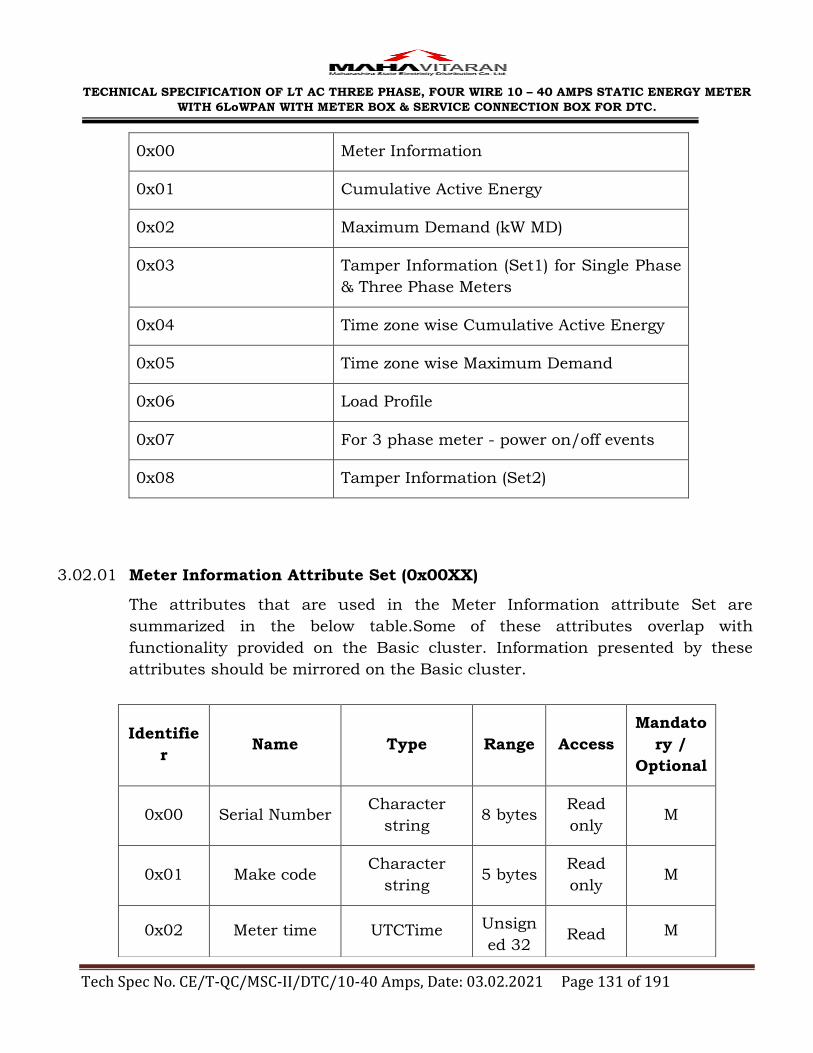
TECHNICAL SPECIFICATION OF LT AC THREE PHASE, FOUR WIRE 10 – 40 AMPS STATIC ENERGY METER
WITH 6LoWPAN WITH METER BOX & SERVICE CONNECTION BOX FOR DTC.
Tech Spec No. CE/T-QC/MSC-II/DTC/10-40 Amps, Date: 03.02.2021 Page 131 of 191
0x00 Meter Information
0x01 Cumulative Active Energy
0x02 Maximum Demand (kW MD)
0x03 Tamper Information (Set1) for Single Phase
& Three Phase Meters
0x04 Time zone wise Cumulative Active Energy
0x05 Time zone wise Maximum Demand
0x06 Load Profile
0x07 For 3 phase meter - power on/off events
0x08 Tamper Information (Set2)
3.02.01 Meter Information Attribute Set (0x00XX)
The attributes that are used in the Meter Information attribute Set are
summarized in the below table.Some of these attributes overlap with
functionality provided on the Basic cluster. Information presented by these
attributes should be mirrored on the Basic cluster.
Identifie
r Name Type Range Access
Mandato
ry /
Optional
0x00 Serial Number Character
string 8 bytes
Read
only M
0x01 Make code Character
string 5 bytes
Read
only M
0x02 Meter time UTCTime Unsign
ed 32 Read M

TECHNICAL SPECIFICATION OF LT AC THREE PHASE, FOUR WIRE 10 – 40 AMPS STATIC ENERGY METER
WITH 6LoWPAN WITH METER BOX & SERVICE CONNECTION BOX FOR DTC.
Tech Spec No. CE/T-QC/MSC-II/DTC/10-40 Amps, Date: 03.02.2021 Page 132 of 191
3.02.01.1 Serial Number Attribute
This attribute is a character string representing the serial number of the
meter.
3.02.01.2 Make Code Attribute
This attribute is a character string representing the make code of the
meter.
3.02.01.3 Meter Time Attribute
This attribute returns the time currently seen in the meter.
3.02.01 Cumulative Active Energy Attribute Set (0x01XX)
This attributes that are used in the Cumulative Active Energy Attribute Ser are
summarized in the below table.
Identifier Name Type Range Access Mandatory
/ Optional
0x00
Cumulative
ActiveEner
gy
Unsigned
32-
bitintege
r
0x00000000
– 0xffffffff
Read
Only M
0x01—
0x06
Cumulative
ActiveEner
gy of
PreviousMo
nth 1 - 6
Unsigned
32-
bitintege
r
0x00000000
– 0xffffffff
Read
Only M
3.02.02.1 Cumulative Active Energy
These attributes give the current cumulative active energy value for the meter. The
value is a fixed point value of 0.1 kWh encoded as an unsigned 32-bit integer. It
should be divided by 10 in order to convert from the unsigned integer representation
to the true decimal value in kWh.
3.02.02.2 Cumulative Active Energy of previous Months 1-6
These attributes give the historic consumption information for previous months. The
bit
integer
only

TECHNICAL SPECIFICATION OF LT AC THREE PHASE, FOUR WIRE 10 – 40 AMPS STATIC ENERGY METER
WITH 6LoWPAN WITH METER BOX & SERVICE CONNECTION BOX FOR DTC.
Tech Spec No. CE/T-QC/MSC-II/DTC/10-40 Amps, Date: 03.02.2021 Page 133 of 191
value is a fixed point value of 0.1 kWh encoded as an unsigned 32-bit integer. It
should be divided by 10 in order to convert from the unsigned integer representation
to the true decimal value in kWh.
3.02.02 Maximum Demand Attribute set (0x02XX)
The attributes that are used in the Maximum Demand Attribute Set are summarized
in the below table.
Identifier Name Type Range Access Mandatory/
Optional
0x00
Maximum
Demand of
Current
Month
Unsigned
16-bit
integer
0x0000 –
0xffff
Read
Only M
0x01
Maximum
Demand of
Current
Month
Timestamp
UTC
Time
Read
Only M
0x02
Maximum
Demand of
previous
Month 1
Unsigned
16-bit
integer
0x0000 –
0xffff
Read
Only M
0x03
Maximum
Demand of
previous
Month 1
Timestamp
UTC
Time
0x0000 –
0xffff
Read
Only M
0x04
Maximum
Demand of
previous
Month 2
Unsigned
16-bit
integer
0x0000 –
0xffff
Read
Only M

TECHNICAL SPECIFICATION OF LT AC THREE PHASE, FOUR WIRE 10 – 40 AMPS STATIC ENERGY METER
WITH 6LoWPAN WITH METER BOX & SERVICE CONNECTION BOX FOR DTC.
Tech Spec No. CE/T-QC/MSC-II/DTC/10-40 Amps, Date: 03.02.2021 Page 134 of 191
0x05
Maximum
Demand of
previous
Month 2
Timestamp
UTC
Time
0x0000 –
0xffff
Read
Only M
0x06
Maximum
Demand of
previous
Month 3
Unsigned
16-bit
integer
0x0000 –
0xffff
Read
Only M
0x07
Maximum
Demand of
previous
month 3
Timestamp
UTC
Time
0x0000 –
0xffff
Read
Only M
0x08
Maximum
Demand of
previous
Month 4
Unsigned
16-bit
integer
0x0000 –
0xffff
Read
Only M
0x09
Maximum
Demand of
Previous
Month 4
Timestamp
UTC
Time
0x0000 –
0xffff
Read
Only M
0x0a
Maximum
Demand of
Current
Month 5
Unsigned
16-bit
integer
0x0000 –
0xffff
Read
Only M
0x0b
Maximum
Demand of
previous
Month 5
Timestamp
UTC
Time
0x0000 –
0xffff
Read
Only M

TECHNICAL SPECIFICATION OF LT AC THREE PHASE, FOUR WIRE 10 – 40 AMPS STATIC ENERGY METER
WITH 6LoWPAN WITH METER BOX & SERVICE CONNECTION BOX FOR DTC.
Tech Spec No. CE/T-QC/MSC-II/DTC/10-40 Amps, Date: 03.02.2021 Page 135 of 191
0x0c
Maximum
Demand of
previous
Month 6
Unsigned
16-bit
integer
0x0000 –
0xffff
Read
Only M
0x0d
Maximum
Demand of
previous
month 6
Timestamp
UTC
Time
0x0000 –
0xffff
Read
Only M
Note : For Single Phase Meter : Maximum Demand shall be in kW MD
For Three Phase Meter : Maximum Demand shall be in kVA MD.
3.02.03.1 Maximum Demand of Current Month
This attributes give the maximum demand for the current month. The value is a fixed
point value of 0.1 kW or 0.1 kVA encoded as an unsigned 16-bit integer. It should be
divided by 10 in order to convert from the unsigned integer representation to the true
decimal value in kW or kVA. Invalid values are given as 0xffff.
3.02.03.2 Maximum Demand of current Month Timestamp
These attributes give a timestamp for when the maximum demand of the current
month occurred. An invalid value is given as 0xffffffff.
3.02.03.3 Maximum Demand of Previous Months 1-6
These attributes give the historic maximum demand information for previous months.
The value is a fixed value of 0.1 kW or 0.1 kVA encoded as an unsigned 16-bit integer.
It should be divided by 10 in order to convert from the unsigned integer representation
to the true decimal value in kW or kVA. Invalid values are given as 0xffff.
3.02.03.4 Maximum Demand of previous Months Timestamp 1-6
These attributes give the timestamp for when the historic maximum demand occurred
for previous months. An invalid value is given as 0xffffffff.
3.02.03 Tamper Information Attribute Set1 (0x03XX)
The attributes of Single Phase RF meter, that are used in the Tamper Attribute Set1
are summarized in the below table.

TECHNICAL SPECIFICATION OF LT AC THREE PHASE, FOUR WIRE 10 – 40 AMPS STATIC ENERGY METER
WITH 6LoWPAN WITH METER BOX & SERVICE CONNECTION BOX FOR DTC.
Tech Spec No. CE/T-QC/MSC-II/DTC/10-40 Amps, Date: 03.02.2021 Page 136 of 191
Identifier Name Type Range Access Mandatory
/Optional
0x00-
0x09
0x10-
0x19
Latest 10 Tamper
Events – Reversal
Phase and
Neutral and
Reversal of Line
And Load
Start (0x0X) and
Stop (0x1X) times
UTC
Time
ReadO
nly
M
0x0a-0x0f
0x1a-0x1f
Reserved
0x20-
0x29
0x30-
0x39
Latest 10 Tamper
Events-Load
Through Local
Earth
Start (0x2x) and
Stop (0x3X) times
UTC
Time
ReadO
nly
M
0x2a-0x2f
0x3a-0x3f
Reserved
0x40-
0x49
0x50-
0x59
Latest 10 Tamper
Events – Neutral
Disconnected
Start (0x04X) and
Stop (0x5X) times
UTC
Time
ReadO
nly
M
0x4a-0x4f Reserved

TECHNICAL SPECIFICATION OF LT AC THREE PHASE, FOUR WIRE 10 – 40 AMPS STATIC ENERGY METER
WITH 6LoWPAN WITH METER BOX & SERVICE CONNECTION BOX FOR DTC.
Tech Spec No. CE/T-QC/MSC-II/DTC/10-40 Amps, Date: 03.02.2021 Page 137 of 191
0x5a-0x5f
0x60-
0x69
0x70-
0x79
Latest 10 Tamper
Events
Magnetic Tamper
Start (0x6X) and
Stop (0x7X) times
UTC
Time
ReadO
nly
M
0x6a-0x6f
0x7a-0x7f
Reserved
0x80 Meter Cover Open UTC
Time
ReadO
nly
M
The attributes of Three Phase RF meter, that are used in the Tamper Attribute
Set1 are summarized in the below table.
Identifier Name Type Range Access Mandatory
/ Optional
0x00 –
0x09
0x10 –
0x19
Latest 10 Tamper
Events – Missing
Potential
Start (0x0x) and
Stop (0x1x) times
UTC
Time
4
bytes ReadOnly M
0x0a –
0x0F
0x1a –
0x1f
Reserved
0x20 –
0x29
0x30 –
0x39
Latest 10 tamper
Events – Current
Imbalance
Start (0x2x) and
Stop (0x3x) times
UTC
Time
4
bytes ReadOnly M

TECHNICAL SPECIFICATION OF LT AC THREE PHASE, FOUR WIRE 10 – 40 AMPS STATIC ENERGY METER
WITH 6LoWPAN WITH METER BOX & SERVICE CONNECTION BOX FOR DTC.
Tech Spec No. CE/T-QC/MSC-II/DTC/10-40 Amps, Date: 03.02.2021 Page 138 of 191
0x2a –
0x2f
0x3a –
0x3f
Reserved
0x40 –
0x49
0x50 –
0x59
Latest 10 Tamper
Events – Current
Reversal
Start (0x4x) and
Stop (0x5x) times
UTC
Time
4
bytes ReadOnly M
0x4a –
0x4f
0x5a –
0x5f
Reserved
0x60 -
0x69
0x70 –
0x79
Latest 10 tamper
events – Current
Short circuit
Start (0x6x) and
Stop (0x7x) times
UTC
Time
4
bytes ReadOnly M
0x6a –
0x6f
0x7a –
0x7f
Reserved
0x80 Meter Cover Open UTC
Time
4
bytes ReadOnly M
0x90 –
0x99
0xa0 –
0xa9
Latest 10 Tamper
events – High Neutral
Current
Start (0x9x) and
Stop (0xax) times
UTC
Time
4
bytes ReadOnly M

TECHNICAL SPECIFICATION OF LT AC THREE PHASE, FOUR WIRE 10 – 40 AMPS STATIC ENERGY METER
WITH 6LoWPAN WITH METER BOX & SERVICE CONNECTION BOX FOR DTC.
Tech Spec No. CE/T-QC/MSC-II/DTC/10-40 Amps, Date: 03.02.2021 Page 139 of 191
0x9a – 9f
0xaa –
0xaf
Reserved
0xb0 –
0xb9
0xc0 –
0xc9
Latest 10 Tamper
events – Potential
imbalance
Start (0xbx) and
Stop (0xcx) times
UTC
Time
4
bytes ReadOnly M
0xba –
0xbf
0xca –
0xcf
Reserved
0xd0 –
0xd9
0xe0 –
0xe9
Latest 10 Tamper
events – Magnetic
Tamper
Start (0xdx) and
Stop (0xex) times
UTC
Time
4
bytes ReadOnly M
0xda –
0xdf
0xea –
0xef
Reserved
3.02.04.1 Latest 10 Tamper Event Attributes
These attributes represents tamper events on the meter. There are 10 events for each
event type. Each incrementing attributes index corresponds to one event further in the
past. The beginning of an event is stored on one attribute (x), the end of the event is
stored in attribute (x+0x0010). An invalid event is encoded as 0xffffffff.
3.02.04.2 Meter Cover Open
This attribute shall return timestamp for the last time the meter cover was opened. An
invalid event is encoded as 0xffffffff.
3.02.04 Tamper Information Attribute Set2 (0x08XX)

TECHNICAL SPECIFICATION OF LT AC THREE PHASE, FOUR WIRE 10 – 40 AMPS STATIC ENERGY METER
WITH 6LoWPAN WITH METER BOX & SERVICE CONNECTION BOX FOR DTC.
Tech Spec No. CE/T-QC/MSC-II/DTC/10-40 Amps, Date: 03.02.2021 Page 140 of 191
The attributes that are used in the Tamper Attribute Set are summarized in the below table.
Identifier Name Type Range Access Mandatory
/Optional
0x00-
0x09
0x10-
0x19
Latest 10 Tamper
Events – ESD
Tamper
Start (0x0X) and
Stop (0x1X) times
UTC
Time
4 bytes ReadO
nly
M
This attribute represents ESD tamper events on the meter.
3.02.06 Time Zone wise Active Energy Attributes Set (0x04XX)
The attributes that are used in the Time Zone wise Active Energy Attribute Ser
are summarized in the below table.
Identifier Name Type Range Access Mandatory/
Optional
0x00
TZ1
Active
Energy
Unsigned
32- bit
integer
0x00000000
-0xffffffff
ReadOn
ly M
0x01
TZ2
Active
Energy
Unsigned
32- bit
integer
0x00000000
-0xffffffff
ReadOn
ly M
0x02
TZ3
Active
Energy
Unsigned
32- bit
integer
0x00000000
-0xffffffff
ReadOn
ly M
0x03
TZ4
Active
Energy
Unsigned
32- bit
integer
0x00000000
-0xffffffff
ReadOn
ly M
3.02.06.01 Time zone wise Active Energy
These attributes give the time zone wise current cumulative active energy value

TECHNICAL SPECIFICATION OF LT AC THREE PHASE, FOUR WIRE 10 – 40 AMPS STATIC ENERGY METER
WITH 6LoWPAN WITH METER BOX & SERVICE CONNECTION BOX FOR DTC.
Tech Spec No. CE/T-QC/MSC-II/DTC/10-40 Amps, Date: 03.02.2021 Page 141 of 191
for the meter. The value is a fixed point value of 0.1 kWh encoded as an
unsigned 32-bit integer. It should be divided by 10 in order to convert from the
unsigned integer representation to the true decimal value in kWh.
3.02.07 Time Zone wise Maximum Demand Attribute Set (0x05XX)
The attribute that are used in the Time zone wise Maximum Demand Attribute
Set are summarized in the below table.
Identifier Name Type Range Access Mandatory
/Optional
0x00 TZ1 Maximum
Demand
Unsigned
16-bit
integer
0x0000-
0xffff
Read
Only M
0x01
TZ1 Maximum
Demand
Timestamp
UTC
Time
0x0000-
0xffff
Read
Only M
0x02 TZ2 Maximum
Demand
Unsigned
16-bit
integer
0x0000-
0xffff
Read
Only M
0x03
TZ2 Maximum
Demand
Timestamp
UTC
Time
0x0000-
0xffff
Read
Only M
0x04 TZ3 Maximum
Demand
Unsigned
16-bit
integer
0x0000-
0xffff
Read
Only M
0x05
TZ3 Maximum
Demand
Timestamp
UTC
Time
0x0000-
0xffff
Read
Only M
0x06 TZ4 Maximum
Demand
Unsigned
16-bit
integer
0x0000-
0xffff
Read
Only M
0x07 TZ4 Maximum
Demand
UTC
Time
0x0000-
0xffff
Read
Only M

TECHNICAL SPECIFICATION OF LT AC THREE PHASE, FOUR WIRE 10 – 40 AMPS STATIC ENERGY METER
WITH 6LoWPAN WITH METER BOX & SERVICE CONNECTION BOX FOR DTC.
Tech Spec No. CE/T-QC/MSC-II/DTC/10-40 Amps, Date: 03.02.2021 Page 142 of 191
Timestamp
Note : For Single Phase Meter : Maximum Demand shall be in kW MD
For Three Phase Meter : Maximum Demand shall be in kVA MD.
3.02.07.01 Time zone wise Maximum Demand
This attributes give the time zone wise maximum demand for the current
month. The value is a fixed point value of 0.1kW or 01.kVA encoded as an
unsigned 16- bit integer. It should be divided by 10 in order to convert from the
unsigned integration representation to the true decimal value in kW or kVA.
Invalid values are given as 0xffff.
3.02.07.02 Time zone wise Maximum Demand Timestamp
These attributes give a timestamp for when the maximum demand of the
corresponding time zone occurred. An Invalid value is given as 0xffffffff
3.02.08 Load Profile Attribute Set (0x06XX)
Attribute Set ID 0x06, attribute ID 0x00 will be used to retrieve this data with
the most recent interval value being accessed with an index of 0, with an
increasing value going into previous intervals.
Load profile shall be maintained for the previous 45 days on a power on basis.
The values shall be integrated for 30 Minutes.
3.02.08.01 Load Profile parameters for Single Phase RF meters
TheThirty minute record will be maintained as a record consisting of the
following fields.
Field name Type
Interval start time UTC time
kWh Unsigned 32 bit integer
Identifier Name Type Range Access Mandatory
/ Optional
0x00 Load Survey Set 22
bytes
Read
Only M

TECHNICAL SPECIFICATION OF LT AC THREE PHASE, FOUR WIRE 10 – 40 AMPS STATIC ENERGY METER
WITH 6LoWPAN WITH METER BOX & SERVICE CONNECTION BOX FOR DTC.
Tech Spec No. CE/T-QC/MSC-II/DTC/10-40 Amps, Date: 03.02.2021 Page 143 of 191
kW MD Unsigned 16 bit integer
Voltage Unsigned 16 bit integer
Current Unsigned 16 bit integer
Note :
1. The voltage value will be the measured voltage with no decimal values.
2. The current will be in multiples of 10mA.For example, 1.54A will be
represented as 154
60A will be represented as 6000
3.02.09 Power On/OFF events Attribute set (0x07XX)
(For Three Phase RF Meters Only )
Identifier Name Type Range Access Mandatory
/ Optional
0x00 –
0xff
Power OFF
/On events -
Timestamp
UTC Time 4 bytes ReadOnly M
Note : First 50 events shall be for Power Off & next 50 events shall be for Power
On.
Setting Critical Parameters
The purpose of this document is to specify a protocol sequence for certain operations.
These operations involve setting critical parameters in the meters.
1) Change the password in the meter
2) Reset of Maximum Demand.
3) Set the number of TOD slots and their durations.
4) Set meter time (RTC).
For the aforementioned purposes, the following parameters and protocol sequences
are specified.
The cluster ID used for this purpose will be 0xfc01. This cluster shall be called
MSEDCL CONTROL cluster. The application end point to be used is 1. The protocol

TECHNICAL SPECIFICATION OF LT AC THREE PHASE, FOUR WIRE 10 – 40 AMPS STATIC ENERGY METER
WITH 6LoWPAN WITH METER BOX & SERVICE CONNECTION BOX FOR DTC.
Tech Spec No. CE/T-QC/MSC-II/DTC/10-40 Amps, Date: 03.02.2021 Page 144 of 191
sequence shall use the write attributes command of ZigBee cluster library. The
commands involve use of multiple write attributes.
Protocol Sequences.
1) Change of password in the meter.
The default password in the meter shall be the meter's serial number. The
following packets shall be sent from the CMRI to the meter.
Packet 1:
Attribute ID: 0x0000
Attribute type: String type
Attribute length: 6 – 20 bytes
Description: Old password.
Attribute ID: 0x0001
Attribute type: string type
Attribute length: 6 – 20 bytes
Description: New password.
Packet 2:
To be issued within 120 seconds of Packet 1:
Attribute ID: 0x0002
Attribute type: string type
Attribute length: 6 – 20 bytes
Description: New Password Reconfirm.
The CMRI software should have front end display capability to take the necessary
inputs, give prompts to users.
Automatic extensions, forms, saves etc should not be implemented in CMRI.

TECHNICAL SPECIFICATION OF LT AC THREE PHASE, FOUR WIRE 10 – 40 AMPS STATIC ENERGY METER
WITH 6LoWPAN WITH METER BOX & SERVICE CONNECTION BOX FOR DTC.
Tech Spec No. CE/T-QC/MSC-II/DTC/10-40 Amps, Date: 03.02.2021 Page 145 of 191
The meter shall reset the password on successful completion of sequence. If the
reconfirm packet is not received in the timeout provided, the new password will be
discarded and the old one retained. If the old password does not match, the
password will not be changed.
2) Protocol sequence for reset MD.
Packet 1:
Attribute ID: 0x0001
Attribute type: string type
Attribute length: 6 – 20 bytes
Description: Password.
Attribute ID: 0x0004
Attribute type: No data type
3) Protocol sequence for TOD timeslot setting
Packet 1:
Attribute ID: 0x0001
Attribute type: string type
Attribute length: 6 – 20 bytes
Description: Password.
Attribute ID: 0x0005
Attribute type: Variable length array.
Attribute Description: The 0th element will be a 16 bit element consisting of the
length of the array and the following elements will be of 8 bit unsigned integer
type.
The number in the 0th element lists the number of time of day (TOD) slots. The
following array elements will describe the number of hours in each slot.
4) Protocol sequence for setting time in the meter.
Packet 1:
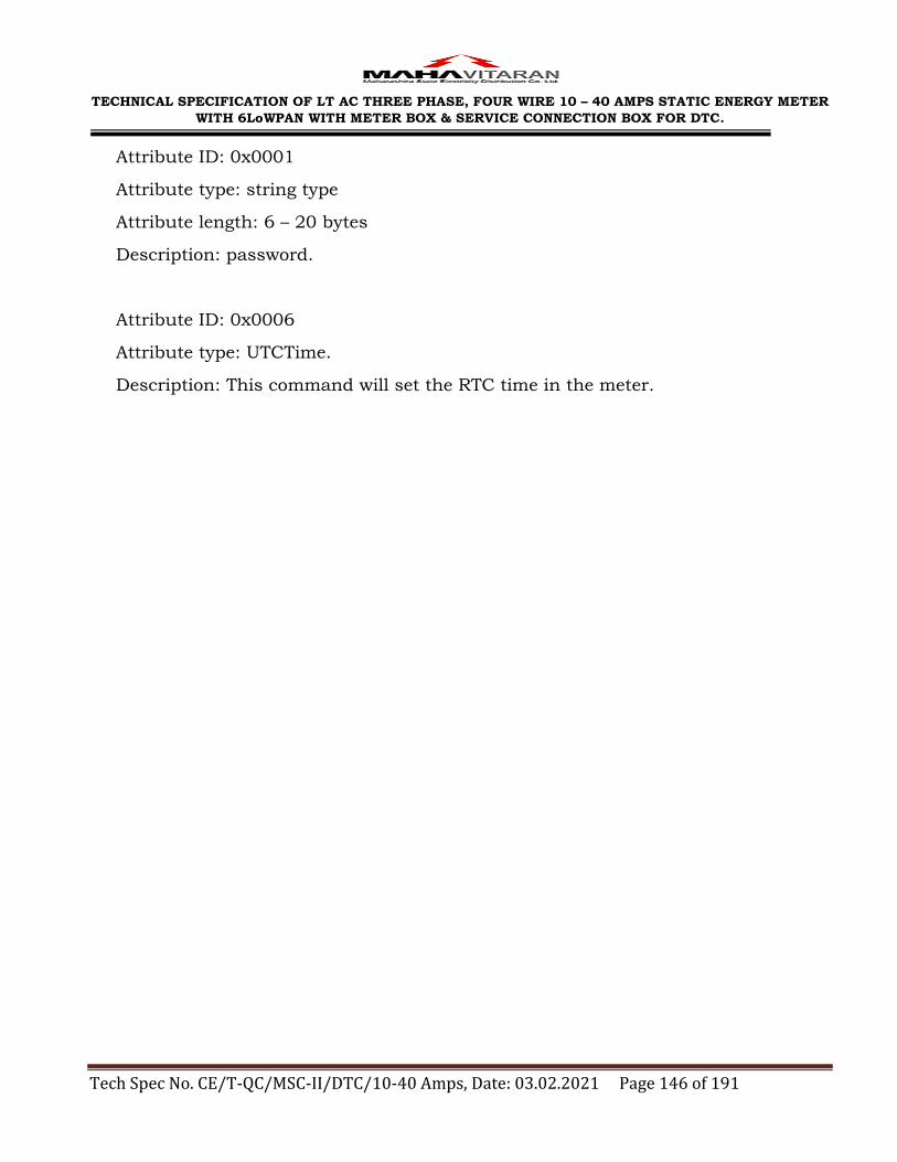
TECHNICAL SPECIFICATION OF LT AC THREE PHASE, FOUR WIRE 10 – 40 AMPS STATIC ENERGY METER
WITH 6LoWPAN WITH METER BOX & SERVICE CONNECTION BOX FOR DTC.
Tech Spec No. CE/T-QC/MSC-II/DTC/10-40 Amps, Date: 03.02.2021 Page 146 of 191
Attribute ID: 0x0001
Attribute type: string type
Attribute length: 6 – 20 bytes
Description: password.
Attribute ID: 0x0006
Attribute type: UTCTime.
Description: This command will set the RTC time in the meter.

TECHNICAL SPECIFICATION OF LT AC THREE PHASE, FOUR WIRE 10 – 40 AMPS STATIC ENERGY METER
WITH 6LoWPAN WITH METER BOX & SERVICE CONNECTION BOX FOR DTC.
Tech Spec No. CE/T-QC/MSC-II/DTC/10-40 Amps, Date: 03.02.2021 Page 147 of 191
ANNEXURE - XI
Draft Testing Template
Following parameters will be verified in the communication testing laboratory of
IT Department.
Test Parameter Test Result / Observations
Manual 1. BCS Installation Manual (Yes/No) 2. BCS Operational Manual (Yes/No) 3. HHU Software Operational Manual (Yes/No) 4. HHU Software Update Manual (Yes/No) 5. Meter Technical Manual (Yes/No) 6. HHU Technical Manual (Yes/No)
Meter
7. Make Code and Meter Serial Number 8. Meter Phase (1 Ph / 3 Ph) 9. TOD Meter ( Yes / No ) 10. Meter RTC maintain time as per IST (Yes / No) 11. PAN ID in Global Mode 12. Link Key in Global Mode 13. Communication Display on meter (Yes/No) 14. Meter status on meter display such as:
Router/Edge Router
15. Details of RF module in meter a. RF Module Vendor Name & ID b. IEEE Address of RF Module c. Chipset of RF Module
16. Module Certification
17. MSEDCL RF Protocol ( as given in Tender document ) is implemented in Meter (Yes / No)
Further testing will be done only if meter is as per MSEDCL RF protocol
18. Interoperability with different HHU (Yes/No)

TECHNICAL SPECIFICATION OF LT AC THREE PHASE, FOUR WIRE 10 – 40 AMPS STATIC ENERGY METER
WITH 6LoWPAN WITH METER BOX & SERVICE CONNECTION BOX FOR DTC.
Tech Spec No. CE/T-QC/MSC-II/DTC/10-40 Amps, Date: 03.02.2021 Page 148 of 191
Test Parameter Test Result / Observations
BCS 19. Operating System Version supported 20. BCS User Name 21. BCS Password 22. Database 23. BCS Software Version and display available in BCS
(Yes/No)
24. BCS Database is Password Protected (Yes/No) 25. Importing Consumer Master xls file to BCS (Yes/No) 26. Number of consumers data loaded in BCS 27. Exporting Consumer Meter details from BCS to HHU
(Yes/No)
28. HHU data downloaded in BCS (Yes/No) 29. Bill string file generated as per MSEDCL format
a. Bill string for 1ph Meters (Yes/No) b. Bill string for 3ph Meters (TOD format) (Yes/No) c. Control Total generated (Yes/No)
30. PAN Management (Manual / Auto) 31. Reports available through BCS *
A. Commissioning Report (Yes/No) B. Meter Reading downloaded Statistics (Yes/No) C. RTC Corrupted Report (Yes/No) D. Consumer wise Tamper Report (Yes/No) E. Consumer wise Load Survey Report (Yes/No) F. Consumer wise TOD Report (Yes/No) G. PAN wise coordinator and router Report (Yes/No)
32. Facility for Backup and Restoration of Database (Yes/No) 33. Option for clearing the HHU data in HHU (Yes/No) 34. Security while data transfer between HHU and BCS
(Yes/No)
Test Parameter Test Result / Observations
HHU 35. HHU Serial Number 36. HHU Make and model 37. HHU Processor/Microcontroller Family
38. RF Module to HHU is Internal (Yes/No)

TECHNICAL SPECIFICATION OF LT AC THREE PHASE, FOUR WIRE 10 – 40 AMPS STATIC ENERGY METER
WITH 6LoWPAN WITH METER BOX & SERVICE CONNECTION BOX FOR DTC.
Tech Spec No. CE/T-QC/MSC-II/DTC/10-40 Amps, Date: 03.02.2021 Page 149 of 191
39. HHU supports dual band operations i.e. Zigbee operations 2.4 GHz and 6LoWPAN operations on 865-867MHz (Yes/No)
40. HHU RF Module Details a. Make & Name of RF Module b. RF Module IEEE Address
41. MSEDCL RF Protocol ( as given in latest Tender document ) is implemented in HHU (Yes / No)
42. Ports available on HHU (COM / USB etc.) 43. Communication cable for HHU and PC (COM / USB Cable) 44. Memory Capacity of HHU (MB) 45. Maximum time for which HHU waits to receive response
from meter, before retrying the same command ( In milliseconds)
46. Type and make of batteries present in HHU 47. Hours of operations if batteries are fully charged 48. Battery status is indicated in the form of bar-graph in
HHU display ( Yes/No)
49. Low battery indication provided ( Yes/No) 50. Automatic cut-off time if HHU is not in operation 51. Details of Type Tests
52. HHU Operating System 53. HHU Firmware / Kernel Version 54. Details of database implemented in HHU 55. HHU Password Protected (If Yes, Mention password ) 56. HHU Software Version and display available on HHU
(Yes / No)
57. Program starts automatically after power on (Yes/No) 58. Maximum Number of consumers data loaded in HHU 59. Consumer details like number, name and address
available in HHU data (Yes/No)
60. Modes of commissioning available in HHU a. Auto (Yes / No) b. Manual (Yes / No)
61. Commissioning attributes sent by HHU while commissioning of meters ( for Zigbee)
a. Preconfigured Link Key (Yes / No ) b. Channel Mask (Yes / No ) c. Startup Control (Yes / No ) d. Extended PAN ID (Yes / No )

TECHNICAL SPECIFICATION OF LT AC THREE PHASE, FOUR WIRE 10 – 40 AMPS STATIC ENERGY METER
WITH 6LoWPAN WITH METER BOX & SERVICE CONNECTION BOX FOR DTC.
Tech Spec No. CE/T-QC/MSC-II/DTC/10-40 Amps, Date: 03.02.2021 Page 150 of 191
62. Commissioning attributes sent by HHU while commissioning of meters ( for 6LoWPAN)
a. PAN ID (Yes / No ) b. Channel (Yes / No ) c. Device Type (Yes / No ) d. IPv6 Prefix (Yes / No ) e. AES Key (Yes / No ) f. Commission state (Yes / No ) g. DAG ID (Yes / No ) h. Router List (Yes / No )
63. Indication of HHU after successful downloading of any data from meter (e.g. Sound beep or message on HHU screen)
64. Data stored in HHU is according to HHU common file format declared by MSEDCL a. BILL.MRI – For Billing Data (Yes/No) b. KWH.MRI- For Bill History (Yes/No) c. TPR.MRI- For Tamper Data (Yes/No) d. LSD.MRI – For Load Survey Data (Yes/No)
65. HHU is having common menu structure declared by MSEDCL ( Yes/No)
66. Statistics of commissioning / readings downloaded in HHU
a. Total meters uploaded in HHU for reading (Yes/No)
b. Total meter reading downloaded in HHU (excluding the new meters) (Yes/No)
c. No. of New meter reading downloaded in HHU (Yes/No)
d. No. of Meters not downloaded in HHU (Yes/No)
67. Settings of Critical Parameters like a. Change the password in the meter (Yes / No) b. Reset of Maximum Demand (Yes / No) c. Set the number of TOD slots and their durations
(Yes / No) d. Set meter time (RTC) (Yes / No)
68. Interoperability with different make of meters in setting of critical parameters ( Yes/No)
69. Data download options available in HHU a. Billing data (Yes/No) b. Billing History (Yes/No) c. Tampers (Yes/No)

TECHNICAL SPECIFICATION OF LT AC THREE PHASE, FOUR WIRE 10 – 40 AMPS STATIC ENERGY METER
WITH 6LoWPAN WITH METER BOX & SERVICE CONNECTION BOX FOR DTC.
Tech Spec No. CE/T-QC/MSC-II/DTC/10-40 Amps, Date: 03.02.2021 Page 151 of 191
d. Load Survey (Yes/No) e. TOD (Yes/No) f. All Data (Yes/No)
70. HHU download tamper present status along with billing data (Yes/No)
71. HHU download tamper data according to tamper present status along with billing data ( Yes/No)
72. Time (in seconds) required to capture Billing Data without tamper present status from Meter
73. Time (in seconds) required to capture Billing Data along with tamper present status from Meter
74. Total time (in seconds) required to download the complete data
75. Average time required to commission a single meter (in sec.)
76. Interoperability with different makes of Meters (Yes/No)
77. If Yes, List of meter make used for interoperability
78. Facility to update HHU software (Yes / No) 79. HHU software updation is password protected (Yes/No) 80. HHU is having in-built GSM/GPRS Modem ( Yes/No)
* High Level Device Driver & GPRS functionality will be tested after testing of above
parameters.*
Overall Remark :

TECHNICAL SPECIFICATION OF LT AC THREE PHASE, FOUR WIRE 10 – 40 AMPS STATIC ENERGY METER
WITH 6LoWPAN WITH METER BOX & SERVICE CONNECTION BOX FOR DTC.
Tech Spec No. CE/T-QC/MSC-II/DTC/10-40 Amps, Date: 03.02.2021 Page 152 of 191

TECHNICAL SPECIFICATION OF LT AC THREE PHASE, FOUR WIRE 10 – 40 AMPS STATIC ENERGY METER
WITH 6LoWPAN WITH METER BOX & SERVICE CONNECTION BOX FOR DTC.
Tech Spec No. CE/T-QC/MSC-II/DTC/10-40 Amps, Date: 03.02.2021 Page 153 of 191
ANNEXURE - XII
TECHNICAL SPECIFICATIONS OF THREE PHASE SMC METER BOX AND DB
WITH KIT KAT ARRANGEMENT FOR THREE PHASE METER 10-40 AMPS
1.0 SCOPE:
This specification covers design, manufacturing, testing at works and
supply of Three Phase Meter Box. The Meter Box shall be made out of Sheet
Moulding Compound (SMC) confirming to IS: 13410 / 1992 amended upto
date & IS: 14772 / 2000 (amended upto date) for use on Distribution
Transformer in electrical distribution system in Maharashtra. The system
shall be AC three phase, four wires, 415 V, 50 Hz with effectively grounded
neutral. The Meter Box shall be suitable for housing Three Phase Four Wire
Static TOD Tri - Vector Energy Meters and Distribution Box with Kit Kat for
Distribution Transformer Centre.
2.0 SERVICE CONDITION:
The Meter Box to be supplied against this specification shall be suitable for
satisfactory continuous operation under the following service conditions.
Max. & ambient air temperature 50 degree C
Max. relative humidity 100%
Max. annual rainfall 1450 mm
Max. wind pressure 150 Kg/Sq.m
Max. altitude above mean sea level 1000 mtrs
Seismic level (Horizontal acceleration) 0.3 g
Climatic condition Moderately hot and humid Tropical climate conducive to rust and
fungus growth
Ambient temperature for temperature rise
50 deg.C
3.0 APPLICABLE STANDARDS:
Unless otherwise modified in this specification, the meter box shall
generally confirm with the provisions of IS: 14772 / 2000 (Amended upto
date) and material of construction i.e. for SMC to IS: 13410 / 1992 &
requirement of this specification.

TECHNICAL SPECIFICATION OF LT AC THREE PHASE, FOUR WIRE 10 – 40 AMPS STATIC ENERGY METER
WITH 6LoWPAN WITH METER BOX & SERVICE CONNECTION BOX FOR DTC.
Tech Spec No. CE/T-QC/MSC-II/DTC/10-40 Amps, Date: 03.02.2021 Page 154 of 191
4.0 DESIGN & CONSTRUCTION:
4.1 The Meter Box shall be made from Thermosetting Plastic i.e. glass reinforced polyester sheet moulding compound (SMC) confirming to IS: 13410/ 1992, & requirement of this specification.
4.2 Meter Box shall comprise of a moulded base and moulded door manufactured with SMC.
4.3 The base and cover of meter box shall be individually in one piece except for fixing of accessories like hinges, clamp, handles etc.
4.4 The meter box shall be so constructed as to have roof tapering down for easy flow of rainwater.
4.5 SMC Meter Box shall be moulded using 100% virgin SMC, grade S-3
material. The box shall be weather proof, unbreakable and scratch resistant & shall have good workmanship. The wall thickness of the meter box base
shall be minimum 3 mm on load bearing side and 2 mm on all other sides, thickness of cover shall be minimum 2 mm.
4.6 The Colour of the SMC Meter box shall be Siemens Grey.
4.7 The SMC meter box shall be made of anti-corrosive, dust proof, rust proof, vermin and water proof, ultra violet stabilized and flame retardant high grade SMC material having good dielectric and mechanical strength
property.
4.8 The surface appearance or part of meter box must be smooth, non porous
and homogeneous, free from ripples, defects and marks. No fillers or fibres shall be visible at any place.
4.9 The meter box shall have base raised by about 20 mm in the box for easy
wiring for fixing the meter. The meter screws shall not protrude outside.
4.10 The Meter Box shall facilitate wireless data communication with minimal disruption for AMR purpose.
4.11 Proper Door interlock arrangement shall be provided.
4.12 Distribution Box of (H) 565mm x (L) 365mm x (D) 325mm shall be provided
with Kit Kat (32A) shall be provided.

TECHNICAL SPECIFICATION OF LT AC THREE PHASE, FOUR WIRE 10 – 40 AMPS STATIC ENERGY METER
WITH 6LoWPAN WITH METER BOX & SERVICE CONNECTION BOX FOR DTC.
Tech Spec No. CE/T-QC/MSC-II/DTC/10-40 Amps, Date: 03.02.2021 Page 155 of 191
4.13 Single Core XLPE Armoured Cable of suitable size & length shall be
provided from meter box to DB. (Incoming circuit). Termination strip of suitable size with bimetallic lugs/connector shall be provided in DB for extending the connection to consumer meter.
4.14 The boxes shall be suitable for outdoor application.
4.15 Corners of the Meter Box shall be round and not pointed ones.
4.16 Door with locking arrangement shall be provided. Provision of wire seal should be made for 2 seals.
4.17 The minimum inside dimensions of the meter box shall be as per enclosed
drawing suitable for installation of all types of meters purchased from various meter manufacturers.
4.18 Hinges, locking arrangement shall be of stainless steel only for SMC Boxes.
4.19 For SMC, the base and cover must be UV stabilized to ensure that it does not get ‗Yellow‘ over a period of time. It shall not change in colour, shape,
size, dimensions when subjected to 200 hrs on UV ageing test as per ASTM: G53 (Cl. No. 9.3), 4 Hours UV at 600 deg C and 4 Hours Condensation at 500 deg C. The base and cover shall be capable of withstanding
temperature of boiling water for five minutes continuously without distortion or softening.
4.20 The Box and Cover should be fixed by concealed stainless steel hinges and hardware from inside in such a manner that it can‘t be manipulated from
outside. The door shall having locking arrangement by way of 3 nos. door closing ‗U‘ Clamp of stainless steel material.
4.21 The door of Box shall open 90 deg. Collar of each door (cover) in closed position shall rest on the collar of the body (base) of Box. The collar of the
door shall overlap the collar of the body of Box by 8 mm such that direct entry of screwdriver, tool or film is not possible. The cover shall be provided with rubber gasket of suitable size to completely fit to the base. The gasket
shall be made out of good quality neoprene rubber. Thickness of rubber lining shall be such that it provides proper sealing between the cover &
base of Box to avoid penetration of dust & ingress of water.

TECHNICAL SPECIFICATION OF LT AC THREE PHASE, FOUR WIRE 10 – 40 AMPS STATIC ENERGY METER
WITH 6LoWPAN WITH METER BOX & SERVICE CONNECTION BOX FOR DTC.
Tech Spec No. CE/T-QC/MSC-II/DTC/10-40 Amps, Date: 03.02.2021 Page 156 of 191
4.22 The enclosure shall comply with the requirements of IP – 55 for SMC as per IS: 12063 or the latest version thereof.
4.23 For meter reading, the box shall have window with Toughened Glass of 5
mm thickness fixed with stainless steel frame from inside. Glass shall have scratch proof ―MSEDCL‖ logo on the right side top comer of the glass. This glass shall be fixed from inside of the cover of Meter Box, with single piece
stainless steel frame (Glass Holder). The glass has to be fitted with a wrap around single piece rubber ring without joint made from good quality
neoprene rubber so that it can withstand weather effect. The box shall have windows of size 140 x 130 mm.
4.24 The mounting arrangement of the meter shall be on particle board of size 330 mm Ht x 230 mm width x 10 mm thickness.
4.25 For mounting the box on pole/wall, four strips shall be welded / fixed on
the box. Strips shall be 25 mm wide & 3 mm thick of M.S. sheet.
4.26 For cable entry and exit holes of suitable dia with rubber grommets shall be provided as shown in drawing.
4.27 Earthing Bolts of size 25 x 6 mm fitted with the box from inside, shall be provided for external earthing with 2 plain washers, one spring washer &
two nuts. Earthing bolt shall have no layer of powder coating and shall be property zinc plated.
4.28 The tolerance permissible on the various dimensions of the Box shall be (+)
5%. However, the tolerance for the fittings shall be (+/-) 5%
4.29 The minimum internal dimensions of the meter box shall be 400 mm height (H) x 240 mm width (W) x 160 mm depth (D) as per enclosed drawing.
4.30 Suitable Diameter for cable entry hole shall be provided.

TECHNICAL SPECIFICATION OF LT AC THREE PHASE, FOUR WIRE 10 – 40 AMPS STATIC ENERGY METER
WITH 6LoWPAN WITH METER BOX & SERVICE CONNECTION BOX FOR DTC.
Tech Spec No. CE/T-QC/MSC-II/DTC/10-40 Amps, Date: 03.02.2021 Page 157 of 191
4.31 Distribution transformer rating wise cable size
Sr.
no.
Distribution Transformer Cable size
Rating (kVA) Current carrying
capacity (Amps)
Rating (Sq.
mm)
Current
carrying capacity (Amps)
1 10 13.33 Single core, LT XLPE
Armoured, 10 sqmm
47
2 16 21.33 Single core, LT XLPE
Armoured, 35
sqmm
99
3 25 33.33
5.0 TESTS & TEST CERTIFICATES:
The meter box shall be fully type tested in accordance with the relevant
standards and as per MSEDCL requirement. All the Type Tests specified in
the technical specifications shall be carried out from laboratories which are
accredited by the National Board of Testing and Calibration Laboratories
(NABL) of Government of India such as CIPET, EQDC, ERDA, ERTL, CPRI,
etc. to prove that equipments meet the requirement of the specification.
The type test report shall clearly indicate the constructional features
identifying material of construction and its grade / composition as per
respective IS The tenderer shall also furnish certificate from laboratories
where type tested that required test facility available in-house for that
particular test. Type Test Reports conducted in manufacturers own
laboratory and certified by testing institute shall not be acceptable.
The Box shall be fully type tested as per IS: 14772/2000 (amended up to
date) and IS: 13410 / 1992 (amended up to date) and as per requirement of
this specification. The type test report shall clearly indicate the
constructional features identifying material of construction and its grade /
composition as per respective IS and other type tests as well as acceptance
tests as per table below.
All the Type Tests shall be carried out from Laboratories which are
accredited by the National Board of Testing and Calibration Laboratories

TECHNICAL SPECIFICATION OF LT AC THREE PHASE, FOUR WIRE 10 – 40 AMPS STATIC ENERGY METER
WITH 6LoWPAN WITH METER BOX & SERVICE CONNECTION BOX FOR DTC.
Tech Spec No. CE/T-QC/MSC-II/DTC/10-40 Amps, Date: 03.02.2021 Page 158 of 191
(NABL) of Govt. of India such as CPRI, Bangalore /Bhopal, ERDA Baroda,
ERTL, EQDC, CIPET to prove that the box meets the requirements of
specification. Type Test Reports conducted in manufacturers own
laboratory and certified by testing institute shall not be acceptable.
The type test report of meter box having identical constructional and other
features carried out during last three years prior to due date of opening of
offer shall be valid.
The detailed type test reports shall be furnished with relevant oscillogram
and certified drawings of the equipment tests. The offers without type test
reports shall be rejected.
The purchaser reserves the right to demand repetition of some or all the
type tests in presence of purchaser‘s representative at purchaser‘s cost. All
the type test reports shall be got approved from the Chief Engineer (Testing
& QC), MSEDCL, 5th Floor, Prakashgad, Bandra (E), Mumbai – 400 051
before commencement of supply.
Type Tests for SMC Meter Box:
Sr.
No. Test Reference Standard Required Value
1 Marking IS 14772:2000, Cl. 7 Manufacturer Name &
Danger Logo Screen Printing
2 Dimensions IS 14772:2000, Cl. 8 As per specification and drawing
3 Protection
against Electric Shock
IS 14772:2000, Cl. 9 As per IS
4 Provision for Earthing IS 14772:2000, Cl. 10 As per IS
5 Construction IS 14772:2000, Cl. 11 No Crack or Damage
6 Resistance to Ageing, to humid condition, to
ingress of solid objects and to
harmful ingress of water
IS 14772:2000, Cl. 12 No Crack or Damage
7 Mechanical Strength IS 14772:2000, Cl. 13 No Crack or Damage
8 Resistance to Heat IS 14772:2000, Cl. 14 No ball impression
9 Resistance to
Insulating Material to IS 14772:2000, Cl. 15 No Flame and Glowing
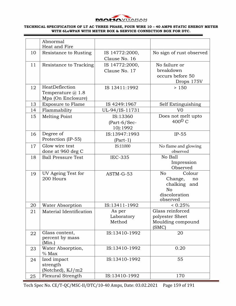
TECHNICAL SPECIFICATION OF LT AC THREE PHASE, FOUR WIRE 10 – 40 AMPS STATIC ENERGY METER
WITH 6LoWPAN WITH METER BOX & SERVICE CONNECTION BOX FOR DTC.
Tech Spec No. CE/T-QC/MSC-II/DTC/10-40 Amps, Date: 03.02.2021 Page 159 of 191
Abnormal Heat and Fire
10 Resistance to Rusting IS 14772:2000,
Clause No. 16
No sign of rust observed
11 Resistance to Tracking IS 14772:2000,
Clause No. 17
No failure or
breakdown
occurs before 50
Drops 175V
12 HeatDeflection
Temperature @ 1.8
Mpa (On Enclosure)
IS 13411:1992 > 150
13 Exposure to Flame IS 4249:1967 Self Extinguishing
14 Flammability UL-94/IS-11731 V0
15 Melting Point IS:13360
(Part-6/Sec-10):1992
Does not melt upto
4000 C
16 Degree of
Protection (IP-55) IS:13947:1993
(Part-1)
IP-55
17 Glow wire test done at 960 deg C
IS:11000 No flame and glowing observed
18 Ball Pressure Test IEC-335 No Ball Impression Observed
19 UV Ageing Test for 200 Hours
ASTM-G-53 No Colour Change, no
chalking and No
discoloration observed
20 Water Absorption IS:13411-1992 < 0.25%
21 Material Identification As per
Laboratory Method
Glass reinforced
polyester Sheet Moulding compound (SMC)
22 Glass content, percent by mass (Min.)
IS:13410-1992 20
23 Water Absorption,
% Max
IS:13410-1992 0.20
24 Izod impact strength (Notched), KJ/m2
IS:13410-1992 55
25 Flexural Strength IS:13410-1992 170

TECHNICAL SPECIFICATION OF LT AC THREE PHASE, FOUR WIRE 10 – 40 AMPS STATIC ENERGY METER
WITH 6LoWPAN WITH METER BOX & SERVICE CONNECTION BOX FOR DTC.
Tech Spec No. CE/T-QC/MSC-II/DTC/10-40 Amps, Date: 03.02.2021 Page 160 of 191
,MPa , Min
26 Power Arc Resistance Sec. Min.
IS:13410-1992 180
27 Modulus of Elasticity, 103 ,
MPa
IS:13410-1992 12 to 15
28 Tracking Resistance
CTI, Min
IS:13410-1992 1000
29 Dielectric Strength at 90oC in Oil KV/mm
IS:13410-1992 11
30 Dissipation factor (4 days at 80 % RH
& 1 KHz)
IS:13410-1992 0.01
31 Heat Distortion Temperature, oC
,Min
IS:13410-1992 150
32 Oxygen Index,% Min IS:13410-1992 24
6.0 GUARANTEED TECHNICAL PARTICULARS
The tenderer shall furnish the particulars giving specific required details of
Meter box in schedule ‗A‘ attached (As per Guaranteed Technical
Particulars uploaded on e - Tendering site). The offers without the details in
Schedule ‗A‘ stand rejected.
7.0 TESTING & MANUFACTURING FACILITIES:
The Tenderer must clearly indicate the details of testing facilities available
in the works of manufacturer and whether the facilities are adequate to
carry out all the Routine and Acceptance tests. These facilities shall be
available to MSEDCL Engineers, if deputed to carry out or witness the tests
in the manufacturer‘s works. The tenderer must have all in-house testing
facility to carry out acceptance & routine tests on the meter box as per
relevant IS. If any test cannot be carried out in the manufacturer works,
the same shall be clearly stated. All testing equipments shall be duly
calibrated in the NABL approved laboratories. The Bidder shall have the
testing facility of flammability test of V0 for SMC Meter Box.

TECHNICAL SPECIFICATION OF LT AC THREE PHASE, FOUR WIRE 10 – 40 AMPS STATIC ENERGY METER
WITH 6LoWPAN WITH METER BOX & SERVICE CONNECTION BOX FOR DTC.
Tech Spec No. CE/T-QC/MSC-II/DTC/10-40 Amps, Date: 03.02.2021 Page 161 of 191
8.0 MANUFACTURING FACILITIES: For SMC Meter Box, the tenderer shall have the following minimum
manufacturing facilities in house to prove his reliability as a manufacturer
of Energy Metering Box.
(a) SMC material manufacturing machine
(b) Hydraulic press for hot press compression moulding
(c) Assembly lines for fabrication and fitting
9.0 GUARANTEE:
The meter box shall be guaranteed for a period of five years from the date of
commissioning or five and half years from the date of dispatch whichever is
earlier.
10.0 MARKINGS:
The meter box shall have an indelibly and distinctly marked with all
essential particulars as per relevant standards. In addition to the
requirement as per relevant standard, following information shall clearly &
indelibly be embossed on the cover of the meter box.
a) Purchase order number and date
b) Year and month of manufacture
c) Name of Purchaser: MSEDCL
d) Guarantee: 5 years
e) Name and trademark of manufacturer
f) Danger logo (Screen Printed)
11.0 INSPECTION:
All Acceptance tests and inspection shall be carried out at the place of
manufacturer unless otherwise specially agreed upon by the manufacturer
and purchaser at the time of purchases. The manufacturer shall offer to the
inspector representing the purchaser all the reasonable facilities, free of
charge, for inspection and testing, to satisfy him that the material is being
supplied in accordance with this specification. Inspection of the first lot
shall be carried out jointly by representative of the Chief Engineer (MM Cell)
and Executive Engineer Testing Division.
The MSEDCL representative / Engineer attending the above testing shall
carry out testing as per IS: 13947, IS: 13410 / 1992 (amended upto date) &

TECHNICAL SPECIFICATION OF LT AC THREE PHASE, FOUR WIRE 10 – 40 AMPS STATIC ENERGY METER
WITH 6LoWPAN WITH METER BOX & SERVICE CONNECTION BOX FOR DTC.
Tech Spec No. CE/T-QC/MSC-II/DTC/10-40 Amps, Date: 03.02.2021 Page 162 of 191
IS: 14772 / 2000 (amended upto date) & this specification and issue a test
certificate approval to the manufacturer and give clearance for dispatch.
The manufacturer shall give minimum 14 days notice for inspection of
material.
12.0 PACKING:
The meter box shall be suitably packed in corrugated boxes in order to
avoid damage during transit or handling.
11.0 REJECTION:
After dispatch of material against inspected lot to various store centers, the
Chief Engineer, MM Cell may select one complete meter box at random
from the lot of each type that may be supplied to various store centers and
shall test the same for all the acceptance and routine tests at any third
party NABL Lab.
The 5 days advance intimation shall be given to the supplier and if the
supplier fails to attend the same on the date informed, the testing will be
carried out in absence of supplier‘s representative. The results of the testing
lab shall not be disputed by the supplier. If the meter box fails in above
random sample testing, the lot will be rejected.
14.0 PROTOTYPE SAMPLE:
The successful bidders should manufacture 1 No. of prototype SMC Meter
Boxes as per the specification and keep ready at their works for the
purpose of sample inspection and testing. The MSEDCL at their option may
sent a team of Engineers to the works. Prior intimation of this inspection
may not be given to the Bidder.
15.0 SCHEDULES:
The tenderer shall fill in the following schedules which are part and
parcel of the tender specification and offer and submit along with the
offer. If the schedules are not submitted duly filled in with the offer, the
offer shall be rejected.
Schedule ‘A’ – Guaranteed Technical Particulars
The discrepancies, if any, between the specification and the catalogues
and/or literatures submitted as part of the offer by the bidders, shall not be
considered and representations in this regard will not be entertained.

TECHNICAL SPECIFICATION OF LT AC THREE PHASE, FOUR WIRE 10 – 40 AMPS STATIC ENERGY METER
WITH 6LoWPAN WITH METER BOX & SERVICE CONNECTION BOX FOR DTC.
Tech Spec No. CE/T-QC/MSC-II/DTC/10-40 Amps, Date: 03.02.2021 Page 163 of 191
16.0 DRAWINGS:
The successful bidder shall submit set of all above drawings of the
distribution box and its components shall be submitted in triplicate to CE
(Testing & QC.) office and get approved before commencement of supply
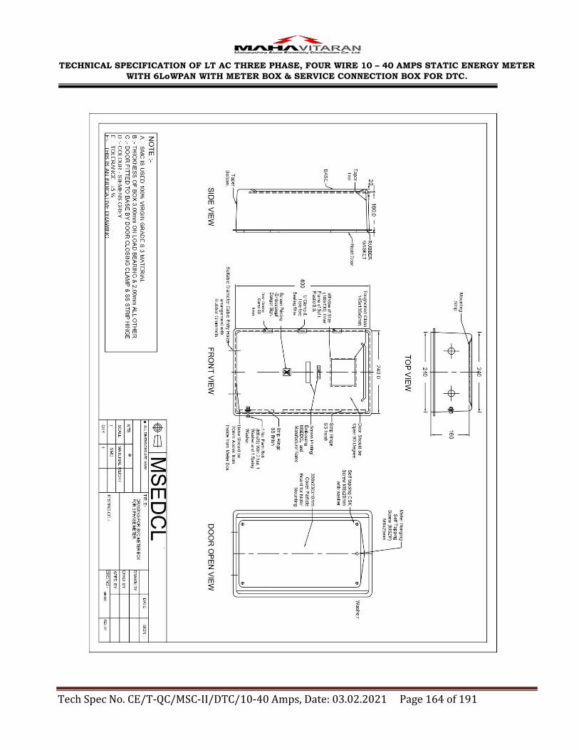
TECHNICAL SPECIFICATION OF LT AC THREE PHASE, FOUR WIRE 10 – 40 AMPS STATIC ENERGY METER
WITH 6LoWPAN WITH METER BOX & SERVICE CONNECTION BOX FOR DTC.
Tech Spec No. CE/T-QC/MSC-II/DTC/10-40 Amps, Date: 03.02.2021 Page 164 of 191

TECHNICAL SPECIFICATION OF LT AC THREE PHASE, FOUR WIRE 10 – 40 AMPS STATIC ENERGY METER
WITH 6LoWPAN WITH METER BOX & SERVICE CONNECTION BOX FOR DTC.
Tech Spec No. CE/T-QC/MSC-II/DTC/10-40 Amps, Date: 03.02.2021 Page 165 of 191

TECHNICAL SPECIFICATION OF LT AC THREE PHASE, FOUR WIRE 10 – 40 AMPS STATIC ENERGY METER
WITH 6LoWPAN WITH METER BOX & SERVICE CONNECTION BOX FOR DTC.
Tech Spec No. CE/T-QC/MSC-II/DTC/10-40 Amps, Date: 03.02.2021 Page 166 of 191
ANNEXURE – XIII
TECHNICAL SPECIFICATIONS OF TAMPER PROOF SERVICE CONNECTION BOX FOR LT LINES/CONSUMER MAINS
1.0 SCOPE
1.02 This specification covers the design, manufacture, testing of tamper proof, shock
proof and rust proof Service Connection Boxes duly fitted with spring loaded
constant pressure multi connection Bus Bar in Thermoset casing system. The
Box is intended to be used for giving Service Connections to consumers. It
should be suitable for outdoor use for mounting on pole as well as for mounting
in meter cabinet of multistoried buildings.
1.03 It is not the intent to specify herein complete details of design and construction.
The Service connection boxes offered shall conform to relevant standard and high
quality and workmanship capable to perform continuous and satisfactory
operations in the actual service conditions at site
1.04 Bidder shall have proven experience of 3 years of manufacturing of similar
products and supplying to electrical utilities
2.00 SERVICE CONDITIONS
The material to be supplied against this specification shall be suitable for
satisfactory continuous operation under the following tropical conditions:
2.1 Maximum ambient temperature (deg C) 50
2.2 Minimum ambient temperature (deg C) 3.5
2.3 Relative humidity (%) 10 to 100
2.4 Maximum rainfall (mm) 1450
2.5 Maximum wind pressure (kg/sq m) 150
2.6 Maximum altitude above mean sea level (Meters) 1000
2.7 Isoceraunic level (days/year) 50
2.8 Seismic level (Horizontal acceleration) (g) 0.3
2.9 Climate Moderately hot and humid tropical climate,
conducive to rust and fungus growth.
3.00 APPLICABLE STANDARDS
All components used in the manufacture of the materials shall conform to the
relevant Indian standards and especially to the followings.

TECHNICAL SPECIFICATION OF LT AC THREE PHASE, FOUR WIRE 10 – 40 AMPS STATIC ENERGY METER
WITH 6LoWPAN WITH METER BOX & SERVICE CONNECTION BOX FOR DTC.
Tech Spec No. CE/T-QC/MSC-II/DTC/10-40 Amps, Date: 03.02.2021 Page 167 of 191
3.1 IS:14772/2000 General Requirements for Enclosures for Accessories for
Household and Similar Fixed Electrical Installations -
Specification
3.2 IS:13947/1993
(Part 1)
Specification for Low-voltage Switchgear and Controlgear –
Part 1 : General Rules& Annex ‗C‘ for Degrees of Protection
provided by enclosures of electrical Equipments
3.3 IS: 13410/
1992
Glass reinforced polyester sheet moulding compounds (SMC)
3.4 IS:13411/1992 Glass reinforced polyester dough moulding compounds (DMC)
3.5 IS: 732/1989 Code of Practice for Electrical Wiring Installations
3.6 IS: 4249/1967 Classification and methods of tests for non-ignitable and self-
extinguishing properties of solid electrical insulating materials
4.00 GENERAL TECHNICAL REQUIREMENTS
4.01 Enclosure
4.0.1 The service connection box shall be made out of thermosetting plastic i.e.
glass reinforced polyester sheet moulding compound (SMC) conforming IS:
13410-1992 grade and also conform to self extinguishing properties as per
IS-4249 & requirements of this specification.
4.0.2 The enclosures shall be made of high grade virgin material with anti-
corrosive, rust proof, shock proof, dust and vermin proof, U.V. stabilized with
flame retardant property.
4.0.3 The S. C. box shall comply with the requirement of IP- 55 type as per the
IS – 13947 or the latest version thereof.
4.0.4 The wall thickness of the box shall be minimum 2mm. The S.C. Box should
have minimum 40 mm clearance on all three sides and bottom clearance of
minimum 60 mm for pole mounted boxes & 100 mm for boxes used in the
metering cabinet.
4.0.5 The enclosures should be suitable for outdoor use, Pole mounting and should
not soften, bend or melt at high temperature. It should have flame retardant
properties and material of it should not generate burning droplets in the
event of fire.
4.0.6 The Service Connection Box shall be suitable for housing Bus Bar system
with adequate clearances. The General arrangement drawing shall be as per
the attached drawing.
4.0.7 The base and door should be single piece moulded individually with rounded
corners without any construction/ fabrication joint.
4.0.8 The door in closed position should overlap on base such that direct entry of
TECHNICAL SPECIFICATION OF LT AC THREE PHASE, FOUR WIRE 10 – 40 AMPS STATIC ENERGY METER
WITH 6LoWPAN WITH METER BOX & SERVICE CONNECTION BOX FOR DTC.
Tech Spec No. CE/T-QC/MSC-II/DTC/10-40 Amps, Date: 03.02.2021 Page 168 of 191
screw driver, tool or rod is not possible.
4.0.9 Concealed hinges should be provided to the S. C. boxes.
4.0.10 The Box should have positive locking system by way of bolt and nuts in
addition to ―U‖ Clamp as shown in the Drawing. ―U‖ clamp should have
matching Holes on base and door to facilitate wire sealing.
4.0.11 Holes for in-coming and out-going Cables should be provided at bottom as
shown in the G.A. Drawing. Suitable number of holes with rubber grommets
of suitable size shall be provided at the bottom of S. C. box for incoming and
outgoing cables.
4.0.12 The box should have holes on the back-side as shown in Drawing for fixing it
on Pole with suitable clamping arrangement or in metering cabinet in the
buildings.
4.0.13 The Bus Bar mounting system should be angled and stepped so as to
facilitate easy connection and disconnection of cable without twisting and
sharp bending of wire/cable. The mounting steps shall be made out of
Thermosetting Plastic insulating material as given above.
4.0.14 Fixing of accessories like clamp, handles etc and all metal part excluding
hardware shall be of stainless steel only.
4.0.15 The surface appearance or part of S. C. Box must be smooth, non porous and
homogeneous, free from ripples, defects and marks. No fillers or fibres should
be visible at any place.
4.0.16 One no Earthing Bolt of size M6 having length of min 25mm with two
washers & nuts shall be provided on the connection box for necessary
earthing
4.02 Spring loaded busbar
(a) The Bus Bars module shall have casings made out Thermosetting Plastic
confirming to IS-13410. Each module shall contain two Bus Bar; assembly of
sliding type pressure plate & spring at bottom of each pressure plate. All such
assemblies shall be housed in the casing along with Bus bar. The assembly
shall facilitate definite pressure overlap electrical connection on Bus bar.
(b) The Bus Bars shall be made out of Aluminum. The size of Bus Bars shall be
adequate as per rating.
(c) The pressure plates shall have built in flat flap to hold conductor flat on Bus
Bar. It shall ensure definite overlap contact on the Bus Bar so as to avoid
loose contact subsequent over heating at contact. Thus it shall help in line
loss reduction.

TECHNICAL SPECIFICATION OF LT AC THREE PHASE, FOUR WIRE 10 – 40 AMPS STATIC ENERGY METER
WITH 6LoWPAN WITH METER BOX & SERVICE CONNECTION BOX FOR DTC.
Tech Spec No. CE/T-QC/MSC-II/DTC/10-40 Amps, Date: 03.02.2021 Page 169 of 191
(d) Multiple modules shall be fitted in a box so as to fulfill the system
requirement.
(e) The current carrying parts shall be of electrolytic grade and the hardware,
spring, links etc. used along with shall be of non- magnetic type. The Bus bar
shall be made of Aluminum with total cross section of 100 sq mm & length as
per the requirement. (Two nos of aluminum conductors of 50 sq mm. each
making a total of 100 sq mm may be used.)
(f) The pressure plates which keep pressing the cable conductor & springs with
sufficient strength of thickness 2mm. The diameter of the spring wire shall
not be less than 2.0 mm. Both are to be made of Stainless steel only.
(g) The springs are required to be retained in the housing by means of a
stainless steel rod at the bottom end of the housing so as to exert pressure on
the pressure plate when cable is inserted in the bus bar.
(h) The connection system shall be spring loaded so that no fasteners are
required to add a new connection from the distribution system. Also each
connected cable shall have a pressure applied to it at the point of connection
to provide connection integrity & eliminate loose connections.
(i) Provision for one incoming circuit of three phase with neutral of cable size 50
or 35 or 16 Sq mm cable & outgoing connections of cable size 2.5 to 6 sq
mm. size as per requirement on each phase bus bar & neutral shall be
provided.
(j) Three phase S. C. Boxes shall have one incoming & 3 outgoing combination.
The successful bidder shall submit the detailed drawings of the boxes for
necessary approval of C.E.(Testing & Quality Control)
5.00 TESTS
5.01 TYPE TESTS
Type tests as mentioned in annexure A shall be carried out on SMC material
as per IS 13410/13411. In addition to above following type tests shall be
carried out on complete box.
1. High Voltage test on Bus bar as per IS 8623 (A.C. voltage 2.5KV
applied for one minute.
2. Temperature Rise Test at 100% rated current as per IS 8623.
3. Degree of protection Test for IP 55 as per IS 13947/1993 (Part 1).

TECHNICAL SPECIFICATION OF LT AC THREE PHASE, FOUR WIRE 10 – 40 AMPS STATIC ENERGY METER
WITH 6LoWPAN WITH METER BOX & SERVICE CONNECTION BOX FOR DTC.
Tech Spec No. CE/T-QC/MSC-II/DTC/10-40 Amps, Date: 03.02.2021 Page 170 of 191
4. Mechanical Strength Test as per IS 14772
5.02 ACCEPTANCE
Following acceptance tests shall be carried out.
1) Acceptance tests as mentioned in annexure A shall be carried out on
SMC material as per IS 13410/13411.
2) Verification of dimensions & construction as per IS 14772.
3) High Voltage test.
5.03 TEST CERTIFICATES
The material offered shall be fully type tested as per relevant IS and this
specification. The successful Bidder shall furnish detailed type test reports
before commencement of supply for necessary approval of the CE Concerned.
The detailed Type Test Reports shall be furnished with relevant oscillogram and
certified Drawings of the material tested. The purchaser reserves the right to
demand repetition of some or all the Type tests in presence of purchaser‘s
representative at purchaser‘s cost.
The type test report of meter box having identical constructional and other
features carried out during last five years prior to due date of opening of offer
shall be valid.
All the Type Tests shall be carried out from laboratories which are accredited
by the National Board of Testing and Calibration Laboratories (NABL) of
Government of India such as CPRI Bangalore/ Bhopal, ERDA Baroda, to prove
that the material offered meet requirements of the specification. The tenderer
should also furnish certificate from laboratories that laboratories are having all
the requisite test facility available in house. The type tests reports conducted in
manufacturers own laboratory and certified by testing institute shall not be
acceptable
6.00 TESTING AND MANUFACTURING FACILITIES
6.01 The manufacturers must have necessary machinery for production of SMC
Service Connection LT Distribution Box.
6.02 The manufacturer should have in house testing facilities for carrying out
acceptance test as per mentioned above
7.00 GUARANTEE :

TECHNICAL SPECIFICATION OF LT AC THREE PHASE, FOUR WIRE 10 – 40 AMPS STATIC ENERGY METER
WITH 6LoWPAN WITH METER BOX & SERVICE CONNECTION BOX FOR DTC.
Tech Spec No. CE/T-QC/MSC-II/DTC/10-40 Amps, Date: 03.02.2021 Page 171 of 191
The material supplied shall be guaranteed for the period of 60 months from the
date of commissioning or 66 months from the date of dispatch whichever is
earlier.
8.00 MARKING
The following information shall be legibly and indelibly marked to show
the following
a) Purchase order number and date
b) Year and month of manufacture
c) Name of Purchaser: MSEDCL
d) Guarantee: 5 years
e) Name and trademark of manufacturer
f) Danger logo (Screen Printed)
9.00 SCHEDULES
The tenderer shall fill in the following schedules and submit along with the
offer. If the schedules are not submitted duly filled in with the offer, the offer
shall be rejected.
Schedule A – Guaranteed and technical particulars.

TECHNICAL SPECIFICATION OF LT AC THREE PHASE, FOUR WIRE 10 – 40 AMPS STATIC ENERGY METER
WITH 6LoWPAN WITH METER BOX & SERVICE CONNECTION BOX FOR DTC.
Tech Spec No. CE/T-QC/MSC-II/DTC/10-40 Amps, Date: 03.02.2021 Page 172 of 191
Specifications for Fiberglass Reinforced Plastic Sheet moulding compound
1) FRP Sheet Moulding Compound shall conform to IS:13410-1992
2) The Surface appearance of the door must be smooth, non porous, and
homogeneous, free of ripples, defects, and marks. No filler or fiber shall
be visible at any place.
3) Other properties of SMC material shall be as follows & shall pass the
test mentioned against the same
Sr.
No.
Characteristic Requirement Type of test Method of
test Ref. to
1. Material. Thermosetti
ng Plastic
2. Grade of material SMC
Electrical grade S3
IS:13410-
1992
Material requirement for Sheet Moulding Compound
4. Glass content,
percent by mass
(Min.)
20 Type Annexure A
of IS:13411-
1992
5. Mould shrinkage, linear
% Max
0.25 Acceptance Annexure B
of IS:13411-
1992
6. Flow, mm, Minimum 170 Acceptance Annexure C
of IS:13411-
1992
Requirement for Moulded Sheet Moulding Compound
7. Water Absorption, %
Max
0.20 Type Annexure D of
IS:13411-1992
8 Izod impact strength
(Notched), KJ/m2
55 Type Annexure E of
IS:13411-1992
9 Flexible Strength ,MPa , Min
170 Type Annexure F of
IS:13411-1992
10 Power Arc
Resistance Sec. Min.
180 Type Annexure G of
IS:13411-1992
11 Modulus of
Elasticity, 103 ,
12 to 15 Type IS: 8543 Part-4
(Sec-1)/1984

TECHNICAL SPECIFICATION OF LT AC THREE PHASE, FOUR WIRE 10 – 40 AMPS STATIC ENERGY METER
WITH 6LoWPAN WITH METER BOX & SERVICE CONNECTION BOX FOR DTC.
Tech Spec No. CE/T-QC/MSC-II/DTC/10-40 Amps, Date: 03.02.2021 Page 173 of 191
MPa
12 Tracking
Resistance CTI, Min
1000 Type IS: 2824/1975
13 Dielectric Strength
at 90oC in Oil KV/mm
11 Type IS:6262/1971
14 Dissipation factor (4 days at 80 % RH & 1
KHz)
0.01 Type IS: 4486/1967
15 Heat Distortion
Temperature, oC ,Min
150 Type Annexure H of
IS:13411-1992
16 Oxygen Index,% Min 24 Type IS: 13360 Part-6
(Sec-6)/1992
17 Post shrinkage, % Max 0.01 Acceptance Annexure B of
IS:13411-1992
18 Tensile Strength ,MPa , Min
70 Acceptance IS: 8543 Part-4
(Sec-1)/1984
19 Density of Moulding,
g/ml
1.8 to 2.1 Routine IS: 8543 Part-
I/Sec 2/1979
20 Surface resistivity (24 H
in water), Ohm,Min
1 x 10 13 Routine IS: 3396/1979
21 Volume resistivity,
Ohm-cm, Min
1 x 10 14 Routine IS: 3396/1979
22 Exposure to flame Self- Extinguishing
IS:4249
23 Melting Point test up to 400ºC
IS:13360 Part6
: Sec 10 : 1992
24 Cross Breaking
Strength
(1723
Kg/sq.cm)
As per ASTM
D790
25 Shear Strength (879 Kg/sq.cm) As per ASTM
D732
26 Flammability ( V0) UL 94 or IS : 11731 (Pt.II)
IS : 11731
(Part- II)
27 Marking, Dimensions
and construction
IS : 14772

TECHNICAL SPECIFICATION OF LT AC THREE PHASE, FOUR WIRE 10 – 40 AMPS STATIC ENERGY METER
WITH 6LoWPAN WITH METER BOX & SERVICE CONNECTION BOX FOR DTC.
Tech Spec No. CE/T-QC/MSC-II/DTC/10-40 Amps, Date: 03.02.2021 Page 174 of 191
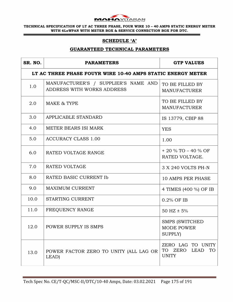
TECHNICAL SPECIFICATION OF LT AC THREE PHASE, FOUR WIRE 10 – 40 AMPS STATIC ENERGY METER
WITH 6LoWPAN WITH METER BOX & SERVICE CONNECTION BOX FOR DTC.
Tech Spec No. CE/T-QC/MSC-II/DTC/10-40 Amps, Date: 03.02.2021 Page 175 of 191
SCHEDULE ‘A’
GUARANTEED TECHNICAL PARAMETERS
SR. NO. PARAMETERS GTP VALUES
LT AC THREE PHASE FOUYR WIRE 10-40 AMPS STATIC ENERGY METER
1.0 MANUFACTURER'S / SUPPLIER'S NAME AND
ADDRESS WITH WORKS ADDRESS TO BE FILLED BY
MANUFACTURER
2.0 MAKE & TYPE TO BE FILLED BY
MANUFACTURER
3.0 APPLICABLE STANDARD IS 13779, CBIP 88
4.0 METER BEARS ISI MARK YES
5.0 ACCURACY CLASS 1.00 1.00
6.0 RATED VOLTAGE RANGE + 20 % TO – 40 % OF
RATED VOLTAGE.
7.0 RATED VOLTAGE 3 X 240 VOLTS PH-N
8.0 RATED BASIC CURRENT Ib 10 AMPS PER PHASE
9.0 MAXIMUM CURRENT 4 TIMES (400 %) OF IB
10.0 STARTING CURRENT 0.2% OF IB
11.0 FREQUENCY RANGE 50 HZ ± 5%
12.0 POWER SUPPLY IS SMPS SMPS (SWITCHED
MODE POWER
SUPPLY)
13.0 POWER FACTOR ZERO TO UNITY (ALL LAG OR
LEAD)
ZERO LAG TO UNITY TO ZERO LEAD TO
UNITY

TECHNICAL SPECIFICATION OF LT AC THREE PHASE, FOUR WIRE 10 – 40 AMPS STATIC ENERGY METER
WITH 6LoWPAN WITH METER BOX & SERVICE CONNECTION BOX FOR DTC.
Tech Spec No. CE/T-QC/MSC-II/DTC/10-40 Amps, Date: 03.02.2021 Page 176 of 191
14.0 STANDARD REFERENCE TEMPERATURE FOR PERFORMANCE IS 27OC
27OC
15.0 MEAN TEMPERATURE CO-EFFICIENT DOES
NOT EXCEED 0.07% 0.07%
16.0 TEMPERATURE RISE IS AS PER IS: 13779 /
1999 (AMENDED UP TO DATE) YES
17.0
OPAQUE METER BASE & TRANSPARENT TOP
COVER MADE OF UNBREAKABLE, TOUGH,
HIGH GRADE, FIRE RESISTANT
POLYCARBONATE MATERIAL
YES
18.0 METER BODY TYPE TESTED FOR IP 51
DEGREE OF PROTECTION AS PER IS 12063
YES
19.0 MOULDED TERMINAL BLOCK CONFORMS TO
IS: 13779 / 1999 (AMENDED UP TO DATE)
YES
20.0
EXTENDED TRANSPARENT TERMINAL COVER
AS PER CLAUSE NUMBER 6.5.2 OF IS: 13779 /
1999 (AMENDED UP TO DATE) IS PROVIDED
YES
21.0 TRANSPARENT TERMINAL COVER IS SEALABLE
INDEPENDENTLY
YES
22.0 PROPER SIZES OF GROOVES ARE PROVIDED
AT BOTTOM OF TERMINAL COVER
YES
23.0 METER BASE & COVER ARE ULTRA-SONICALLY
WELDED (CONTINUOUS WELDING) YES
24.0 THICKNESS OF MATERIAL FOR METER 2 MM
MINIMUM 2 MM MINIMUM
25.0 RTC PRE-PROGRAMMED FOR 30 YEARS DAY /
DATE 30 YEARS DAY / DATE
26.0 TIME ACCURACY OF RTC AS PER CBIP TECH
REPORT 325 YES

TECHNICAL SPECIFICATION OF LT AC THREE PHASE, FOUR WIRE 10 – 40 AMPS STATIC ENERGY METER
WITH 6LoWPAN WITH METER BOX & SERVICE CONNECTION BOX FOR DTC.
Tech Spec No. CE/T-QC/MSC-II/DTC/10-40 Amps, Date: 03.02.2021 Page 177 of 191
27.0 PROVISION TO PUT AT LEAST TWO SEALS BY
UTILITY USER YES
28.0
COMPLETE METERING SYSTEM &
MEASUREMENT NOT AFFECTED BY EXTERNAL
ELECTROMAGNETIC INTERFERENCE AS PER
CL. NO. 6.16 OF TECH. SPECS.
YES
29.0 METER ACCURACY NOT AFFECTED BY AC / DC
MAGNETIC FIELD AS PER CBIP 325 YES
30.0
METER ACCURACY DOES NOT GET
INFLUENCED BY INJECTION OF HIGH
FREQUENCY AC VOLTAGE / CHOPPED SIGNAL
/ DC SIGNAL AND HARMONICS ON THE
TERMINALS OF THE METER
YES
31.0 METER RECORDS AND DISPLAYS TOTAL
ENERGY INCLUDING HARMONIC ENERGY.
YES
32.0 METER DISPLAYS UNSATISFACTORY
FUNCTIONING OR NONFUNCTIONING OF REAL TIME CLOCK BATTERY
YES
33.0 METER PCB IS WIRELESS YES
34.0 BATTERY BACK UP WITH MINIMUM 10 YEARS
LIFE IS PROVIDED
YES
35.0 METER WITHSTANDS PHASE TO PHASE
VOLTAGE (440 V) IF APPLIED BETWEEN PHASE TO NEUTRAL FOR MINIMUM 5 MIN
YES
36.0 POWER SUPPLY UNIT IS TRANSFORMER LESS YES
37.0
PUSH BUTTON PROVIDED FOR SCROLLING
THE PARAMETERS IN ALTERNATE DISPLAY (ON
DEMAND) MODE
YES
38.0 OPERATION INDICATOR PROVIDED IN THE
FORM OF BLINKING LED / LCD
YES

TECHNICAL SPECIFICATION OF LT AC THREE PHASE, FOUR WIRE 10 – 40 AMPS STATIC ENERGY METER
WITH 6LoWPAN WITH METER BOX & SERVICE CONNECTION BOX FOR DTC.
Tech Spec No. CE/T-QC/MSC-II/DTC/10-40 Amps, Date: 03.02.2021 Page 178 of 191
39.0 METER CONSTANT INDELIBLY PROVIDED ON
THE NAMEPLATE
YES
40.0 METER MANUFACTURED USING SMT YES
41.0 TOD TIME ZONES PROVIDED YES
42.0 ALL ANTI-TAMPER FEATURES AS PER CLAUSE
10.00 ARE PROVIDED
YES
43.0
IF THE METER GETS AFFECTED UNDER
INFLUENCE OF ANY MAGNETIC FIELD (AC / DC
/ PERMANENT), THEN THE SAME SHALL BE
RECORDED AS MAGNETIC TAMPER EVENT
WITH DATE & TIME STAMPING AND THE
METER SHALL RECORD ENERGY MAXIMUM
VALUE CURRENT AND REFERENCE VOLTAGE
AT UNITY POWER FACTOR
YES
44.0 LCD CHECK IS PROVIDED TO DISPLAY
HEALTHINESS OF ALL SEGMENTS
YES
45.0 BACKLIT LCD TYPE DISPLAY IS PROVIDED YES
46.0 NUMBER OF DIGITS FOR ENERGY DISPLAY
PROVIDED 5 DIGITS
47.0 MINIMUM SIZE OF DIGITS 10X5 MM
48.0 DISPLAY PARAMETERS PREPROGRAMMED AT
FACTORY AS PER CL. 12.00 YES
49.0 PERIOD FOR AUTO SCROLL IS 9 SEC. 9 SEC
50.0 POWER CONSUMPTION IN VOLTAGE CIRCUIT SHALL NOT EXCEED
1.5 W AND 10 VA
51.0 POWER CONSUMPTION IN CURRENT CIRCUIT SHALL NOT EXCEED 4
VA

TECHNICAL SPECIFICATION OF LT AC THREE PHASE, FOUR WIRE 10 – 40 AMPS STATIC ENERGY METER
WITH 6LoWPAN WITH METER BOX & SERVICE CONNECTION BOX FOR DTC.
Tech Spec No. CE/T-QC/MSC-II/DTC/10-40 Amps, Date: 03.02.2021 Page 179 of 191
52.0 CONVENTIONAL TRANSFORMER LESS POWER
SUPPLY IS PROVIDED YES
53.0
PUSH BUTTON IS PROVIDED FOR HIGH
RESOLUTION READINGS OF DISPLAY WITH
TWO DECIMAL POINTS
YES
54.0 PUSH BUTTON ARRANGEMENT FOR
ACTIVATION OF BATTERY IS PROVIDED
YES
55.0 KVAMD PROVIDED YES
56.0 INTEGRATION PERIOD OF KVAMD
15 MINUTES BY
BLOCK WINDOW
METHOD
57.0 COMMUNICATION CAPABILITY AS PER CL. NO.
6.23 OF SPECIFICATION YES
58.0 MAKE OF 6LOWPAN RF MODULE USED IN
METER
TO BE FILLED BY
MANUFACTURER
59.0 MAKE OF 6LOWPAN AND ZIGBEE RF MODULE
USED IN HHT
TO BE FILLED BY
MANUFACTURER
60.0
ZIGBEE COMPLIANCE CERTIFICATE FOR
RADIO MODULES USED IN METER & HHT IS
SUBMITTED
YES
61.0 ZIGBEE COMPLIANCE CERTIFICATE NUMBER
& DATE FOR RADIO MODULES
TO BE FILLED BY
MANUFACTURER
62.0
CERTIFICATE OF PICS (PROTOCOL
IMPLEMENTATION & CONFORMANCE
STATEMENT) IN REGARDS MANUFACTURER
SPECIFIC CLUSTER FROM ZIGBEE ALLIANCE
OFFICIAL TEST HOUSE IS SUBMITTED.
YES

TECHNICAL SPECIFICATION OF LT AC THREE PHASE, FOUR WIRE 10 – 40 AMPS STATIC ENERGY METER
WITH 6LoWPAN WITH METER BOX & SERVICE CONNECTION BOX FOR DTC.
Tech Spec No. CE/T-QC/MSC-II/DTC/10-40 Amps, Date: 03.02.2021 Page 180 of 191
63.0
PICS CERTIFICATE NO. & DATE IN REGARDS
MANUFACTURER SPECIFIC CLUSTER FROM
ZIGBEE ALLIANCE OFFICIAL TEST HOUSE.
TO BE FILLED BY
MANUFACTURER
64.0 COMPUTER SOFTWARE AS PER CLAUSE 15.00
OF TECHNICAL SPECIFICATION IS PROVIDED YES
65.0
BASE COMPUTER SOFTWARE PROVIDED IS
USER FRIENDLY & WINDOWS BASED &
SUPPORTS ALL VERSIONS OF ―WINDOWS‖.
YES
66.0 BCS SUPPORTS ALL CURRENT OPERATING
SYSTEM VERSIONS. YES
67.0
IMPORT / EXPORT OF DATA THROUGH BCS
CAN BE THROUGH ANY USB PORT OF PC /
LAPTOP.
YES
68.0
BCS SOFTWARE HAS CAPABILITY TO CONVERT
ALL THE DATA INTO ASCII FORMAT AS PER
MSEDCL REQUIREMENT.
YES
69.0 BCS MAINTAINS AUDIT LOG FOR CONNECTION
AND DISCONNECTION OF HHT TO BCS. YES
70.0 BCS HAS OPTION OF DOWNLOADING AUDIT
LOG. YES
71.0 BCS MAINTAINS DOWNLOADED BILLING
HISTORY. YES
72.0 BCS STORES DATA TO DATABASE IN
ENCRYPTED FORMAT. YES
73.0
BCS GENERATES EXCEPTIONAL REPORT OF
NEW METERS (METERS NOT AVAILABLE IN
HHT INITIALLY) READING.
YES

TECHNICAL SPECIFICATION OF LT AC THREE PHASE, FOUR WIRE 10 – 40 AMPS STATIC ENERGY METER
WITH 6LoWPAN WITH METER BOX & SERVICE CONNECTION BOX FOR DTC.
Tech Spec No. CE/T-QC/MSC-II/DTC/10-40 Amps, Date: 03.02.2021 Page 181 of 191
74.0
API / EXE FILE WITH DOCUMENTATION FOR
DOWNLOADING DATA FROM METER ALONG
WITH SAMPLE METER IS SUBMITTED.
YES
75.0
API RESIDING ON HHT IS GIVEN FREE OF COST
WITH ALL ITS DOCUMENTATION AND
TRAINING.
YES
76.0 TOTAL TIME TAKEN FOR DOWNLOADING ALL
DATA FOR 60 DAYS UP TO 26 MINUTES
77.0 DOWNLOADING TIME OF ONLY BILLING DATA
AFTER JOINING THE NETWORK
IS LESS THAN 25
SECS
78.0 COMMISSIONING AND DEPLOYMENT
DOCUMENT OF HHT IS AS PER ANNEXURE VI. YES
79.0 RF MODULE IS INBUILT IN HHT. YES
80.0 BY DEFAULT, AFTER STARTING HHT IS METER
READING MODE YES
81.0 MEMORY OF HHT 256 MB MIN
82.0 HHT POSSESSES SPECIFIC SERIAL NO. YES
83.0
HHT IS PROPERLY LABELED WITH SERIAL
NUMBER / TENDER NUMBER / PROGRAM
NAME / PROGRAM VERSION.
YES
84.0 TEST OPTION FOR CHECKING CONNECTIVITY
BETWEEN HHT & METER PROVIDED YES
85.0
HHT IS BASED ON OPEN ZIGBEE – 2007 PRO
WITH SMART ENERGY PROFILE PROTOCOL
AND 6LOWPAN PROTOCOL FOR
INTEROPERABILITY AS PER SETTINGS GIVEN
IN CLAUSE 5.28 AND ANNEXURE V & VI OF
THE SPECIFICATIONS.
YES

TECHNICAL SPECIFICATION OF LT AC THREE PHASE, FOUR WIRE 10 – 40 AMPS STATIC ENERGY METER
WITH 6LoWPAN WITH METER BOX & SERVICE CONNECTION BOX FOR DTC.
Tech Spec No. CE/T-QC/MSC-II/DTC/10-40 Amps, Date: 03.02.2021 Page 182 of 191
86.0 PROVISION FOR AUTO POWER SAVE ON HHT. YES
87.0
BIDDER AGREES TO SUPPLY HHT IN THE
RATIO OF 1:250 INCLUDING USER MANUAL, AA
SIZE BATTERIES & A SET OF DIRECT
COMMUNICATION CORDS
YES
88.0
HHT CAPABLE FOR DOWNLOADING DATA OF
MULTIPLE DESIGNS & MAKE OF METERS AS
WELL AS FOR METERS ADDED IN NEXT 5
YEARS FOR THE COMMON COMMUNICATION
PROTOCOL ATTACHED WITH THIS
SPECIFICATION.
YES
89.0
METER SPECIFIC MRI PROGRAMS HAVE
ABILITY TO USE HHT REAL TIME CLOCK TO
TAG ALL TIME RELATED EVENTS.
YES
90.0
A REAL TIME CLOCK WITH A MINIMUM OF 15
DAYS BATTERY BACKUP WITH 30 YEAR
CALENDAR IS PROVIDED IN HHT.
YES
91.0 TIME DRIFT OF THE RTC IN HHT DOES NOT
EXCEED
+ / - 300 SECONDS
PER YEAR
92.0
INDICATION FOR CONFIRMATION OF
SUCCESSFUL DATA TRANSFER IS PROVIDED
ON METER & HHT
YES
93.0 HHT DOES NOT ACCEPT ANY EXTERNAL FILE
OTHER THAN BCS. YES
94.0 HHT HAS AUDIT TRAIL LOG OF CONNECTION &
DISCONNECTION OF HHT WITH BCS YES
95.0 USB PORT ARE PROVIDED ON HHT YES
96.0 ONE CHORD OF MIN. 1 MTR LENGTH ARE
PROVIDED WITH EACH HHT (YES/NO) YES

TECHNICAL SPECIFICATION OF LT AC THREE PHASE, FOUR WIRE 10 – 40 AMPS STATIC ENERGY METER
WITH 6LoWPAN WITH METER BOX & SERVICE CONNECTION BOX FOR DTC.
Tech Spec No. CE/T-QC/MSC-II/DTC/10-40 Amps, Date: 03.02.2021 Page 183 of 191
97.0
NECESSARY SOFTWARE CONFORMING TO THE
ENCLOSED COMMUNICATION PROTOCOL,
REQUIRED FOR HHT & BASE COMPUTER
SYSTEM WITH NECESSARY SECURITY
PROVISIONS IS SUPPLIED.
YES
98.0
HHT HAS OPTION TO CHECK READING STATUS
(DOWNLOADED OR NOT DOWNLOADED) FOR
ANY PARTICULAR METER.
YES
99.0
HHT INDICATES STATUS OF TOTAL
CONSUMERS / METERS, NUMBER OF
CONSUMERS / METERS READ AND BALANCE
CONSUMERS / METERS.
YES
100.0 SEARCH FACILITY FOR THE BALANCE METERS
PROVIDED ON HHT. YES
101.0
HHT CAPABLE OF DOWNLOADING BILLING
DATA OF AT LEAST 2,000 (TWO THOUSAND)
METERS AT A TIME
YES
102.0
HHT SUPPLIED IS CAPABLE FOR
DOWNLOADING DATA OF MULTIPLE DESIGNS
& MAKE OF METERS YES
103.0
HHT HAS FACILITY FOR RE-ENTERING METER
SERIAL NUMBERS DIRECTLY FROM BASE
COMPUTER SYSTEM YES
104.0 HHT IS TYPE TESTED AS PER TECHNICAL
SPECIFICATION YES
105.0 TYPE TEST REPORT NO & DATE OF HHT TO BE FILLED BY
MANUFACTURER
106.0 METER IS TYPE TESTED BOOLEAN
107.0 TYPE TEST REPORT NUMBER & DATE OF
METER
TO BE FILLED BY
MANUFACTURER

TECHNICAL SPECIFICATION OF LT AC THREE PHASE, FOUR WIRE 10 – 40 AMPS STATIC ENERGY METER
WITH 6LoWPAN WITH METER BOX & SERVICE CONNECTION BOX FOR DTC.
Tech Spec No. CE/T-QC/MSC-II/DTC/10-40 Amps, Date: 03.02.2021 Page 184 of 191
108.0 GUARANTEE 5 YEARS FROM INSTALLATION OR
FIVE & HALF YEARS FROM DATE OF
DESPATCH
YES
109.0
IN HOUSE TESTING FACILITIES ARE
AVAILABLE FOR
(a) INSULATION RESISTANCE MEASUREMENT
YES
110.0 (b) NO LOAD CONDITION YES
111.0 (c) STARTING CURRENT TEST YES
112.0 (d) ACCURACY TEST REQUIREMENT YES
113.0 (e) POWER CONSUMPTION YES
114.0
(f) FULLY COMPUTERISED METER TEST BENCH
SYSTEM FOR CARRYING OUT ROUTINE AND
ACCEPTANCE TEST IS AVAILABLE
YES
115.0 (g) MANUFACTURER HAS CALIBRATED
STANDARD METER OF 0.1 CLASS ACCURACY YES
116.0 (h) VERIFIACTION OF DATA DOWNLOADING AS
PER RF PORT YES
117.0 (i) GLOW WIRE TESTING YES
118.0
FURNISH PRINCIPLE OF OPERATION OF METER
OUTLINING METHODS AND STAGES OF
COMPUTATIONS OF VARIOUS PARAMETERS
STARTING FROM INPUT VOLTAGE AND
CURRENT SIGNALS INCLUDING SAMPLING
RATE IF APPLICABLE
YES
119.0 MANUFACTURING ACTIVITIES ARE AS PER
CLAUSE 28.00 YES
120.0 QAP SUBMITTED AS PER ANNEXURE-I YES

TECHNICAL SPECIFICATION OF LT AC THREE PHASE, FOUR WIRE 10 – 40 AMPS STATIC ENERGY METER
WITH 6LoWPAN WITH METER BOX & SERVICE CONNECTION BOX FOR DTC.
Tech Spec No. CE/T-QC/MSC-II/DTC/10-40 Amps, Date: 03.02.2021 Page 185 of 191
121.0 METER & HHT COMPLIES WITH ANNEXURE IV,
V & VI OF TECHNICAL SPECIFICATION YES
122.0
PERMANENT NATURE CONNECTION DIAGRAM
OF METER IS SHOWN ON INSIDE PORTION OF
THE TERMINAL COVER. YES
123.0
METER TERMINALS ARE MARKED AND THIS
MARKING APPEARS IN THE ABOVE
PERMANENT NATURE CONNECTION DIAGRAM. YES
124.0 NAME PLATE & MARKING AS PER CLAUSE NO.
18.00 YES
125.0
(a) THE BIDDER/MANUFACTURER SHALL HAVE
SUPPLIED 12.5 LAKHS STATIC METER
DURING THE LAST THREE FINANCIAL YEARS. YES
126.0
(b) THE BIDDER / MANUFACTURER SHALL
HAVE MINIMUM EXPERIENCE OF THREE
YEARS OF SUPPLY OR MANUFACTURING FOR
STATIC METER UPTO THE END OF THE LAST
FINANCIAL YEAR.
YES
127.0
SPARK DISCHARGE TEST AT 35 KV IS CARRIED
OUT AS PER CLAUSE 6.26 OF TECHNICAL
SPECIFICATION
YES
128.0 FURNISH PHYSICAL WATER ABSORPTION
VALUE
TO BE FILLED BY
MANUFACTURER
129.0 FURNISH THERMAL HDDT VALUE TO BE FILLED BY
MANUFACTURER
130.0 FURNISH FLAMMABILITY VALUE TO BE FILLED BY
MANUFACTURER
131.0 FLAMMABILITY V2 TO BE FILLED BY
MANUFACTURER
132.0 GLOW WIRE TEST AT 650° C YES
133.0 TENSILE STRENGTH YES

TECHNICAL SPECIFICATION OF LT AC THREE PHASE, FOUR WIRE 10 – 40 AMPS STATIC ENERGY METER
WITH 6LoWPAN WITH METER BOX & SERVICE CONNECTION BOX FOR DTC.
Tech Spec No. CE/T-QC/MSC-II/DTC/10-40 Amps, Date: 03.02.2021 Page 186 of 191
134.0 FLEXURE STRENGTH TO BE FILLED BY
MANUFACTURER
135.0 MODULUS OF ELASTICITY TO BE FILLED BY
MANUFACTURER
136.0 IZOD IMPACT STRENGTH NOTCHED 23° C TO BE FILLED BY
MANUFACTURER
137.0 WHETHER 10 NOS. OF TENDER SAMPLE
METERS ARE SUBMITTED ALONGWITH API
SOFTWARE & DOCUMENTATION. (YES/NO)
YES
138.0 AGEING TEST IS CARRIED OUT AS PER CLAUSE
29.04.04 OF TECHNICAL SPECIFICATION
YES
139.0
WHETHER THE FIRM IS SUBSIDIARY
IF YES, WHETHER UNDERTAKING I.E.
ANNEXURE-UI IS ENCLOSED
YES
140.0
ADDITIONAL INFORMATION REQUIRED IN
CASE OF FOREIGN BIDDER / MANUFACTURER.
2. RATE OF CUSTOM DUTY
YES
141.0 3. OFFER SUBMITTED BY FOREIGN BIDDER /
MANUFACTURER.
TO BE FILLED BY
MANUFACTURER
142.0 4. WHETHER OFFER SUBMITTED THROUGH
AUTHORIZED ASSIGNEE / NOMINEE.
TO BE FILLED BY
MANUFACTURER
143.0
5. IN CASE OFFER SUBMITTED THROUGH
AUTHORIZED ASSIGNEE/ NOMINEE,
WHETHER ANNEXURE UII SUBMITTED
(YES/NO)
TO BE FILLED BY
MANUFACTURER
144.0 6. ANNEXURE B-1 I.E. PRICE SCHEDULE
SUBMITTED GIVING SPLIT UP IN US $ & INR
AS PER ANNEXURE B-1.
YES

TECHNICAL SPECIFICATION OF LT AC THREE PHASE, FOUR WIRE 10 – 40 AMPS STATIC ENERGY METER
WITH 6LoWPAN WITH METER BOX & SERVICE CONNECTION BOX FOR DTC.
Tech Spec No. CE/T-QC/MSC-II/DTC/10-40 Amps, Date: 03.02.2021 Page 187 of 191
GUARANTEED TECHNICAL PARTICULARS OF THREE PHASE
METER BOX MADE OUT OF SHEET MOULDING COMPOUND (SMC)
SR. NO.
PARTICULARS REQUIRED Offered
1 MATERIAL GLASS REINFORCED
POLYESTER
SHEET
MOULDING COMPOUND (SMC)
2 GRADE OF MATERIAL SMC AS PER IS:13410-1992
3 PROPERTIES OF MATERIAL OF CONSTRUCTION OF METER BOX
A FLAMMABILITY
(REF. STD: UL-94 / IS-11731
V0
B HEAT DEFLECTION
TEMPERATURE
(REF. STD. IS:13411)
150 DEG. C (MINIMUM)
C EXPOSURE TO FLAME
(REF. STD. IS – 4249
SELF EXTINGUISHING
D MELTING POINT
(REF. STD. IS-13360
DOES NOT MELT
4 CONSTRUCTIONAL FEATURES OF THE BOX:
4(A
)
CLEAR MINIMUM
INSIDE
DIMENSIONS OF METER
BOX
I. HEIGHT 400 MM
II. WIDTH 240 MM
III. DEPTH 160 MM
IV. THICKNESS OF METER BOX 3 MM ON LOAD BEARING SIDE
AND 2 MM ON
ALL OTHER SIDES
4(B)
WINDOW ON FRONT DOOR:
I. MATERIAL OF VIEWING
WINDOW
TOUGHENED GLASS
II. THICKNESS OF
TOUGHENED GLASS
5 MM (MIN.)
III. SIZE OF OPENING (MIN) 140 X 130 MM (+ 5 MM)

TECHNICAL SPECIFICATION OF LT AC THREE PHASE, FOUR WIRE 10 – 40 AMPS STATIC ENERGY METER
WITH 6LoWPAN WITH METER BOX & SERVICE CONNECTION BOX FOR DTC.
Tech Spec No. CE/T-QC/MSC-II/DTC/10-40 Amps, Date: 03.02.2021 Page 188 of 191
IV. FIXING METHOD FIXED FROM INSIDE WITH
STAINLESS STEEL FRAME
5 LOCKING ARRANGEMENT 3 NOS. DOOR CLOSING ‗U‘ CLAMP
OF STAINLESS STEEL MATERIAL.
6 SEALING ARRANGEMENT HOLES FOR WIRE SEAL
7 EARTHING BOLT EARTHING BOLT OF SIZE M6 X 25
MM WITH 2 NOS. WASHER AND 2
NOS. NUT.
8 WIRE ENTRY CABLE ENTRY HOLES 2 NOS. WITH
RUBBER GROMMET
9 METER MOUNTING
ARRANGEMENT
PARTICLE BOARD OF SIZE 320 X
230 X 10 MM (MIN.)
10 INGRESS PROTECTION (IP) IP-55
11 COLOUR OF METER BOX SIEMENS GREY
12 DIAMETER FOR CABLE ENTRY HOLE
SUITABLE SIZE

TECHNICAL SPECIFICATION OF LT AC THREE PHASE, FOUR WIRE 10 – 40 AMPS STATIC TOD
TRI-VECTOR ENERGY METER WITH 6LoWPAN BASED LPRF AS COMMUNICATION CAPABILITY.
Tech Spec No. CE/T-QC/MSC-II/DTC/10-40 Amps/Date: 03.02.2021 Page 189 of 191
GUARANTEED TECHNICAL PARTICULARS OF SERVICE
CONNECTION BOX MADE OUT OF SHEET MOULDING
COMPOUND (SMC)
SR.
NO.
PARAMETER NAME PARAMETER
TYPE
1. NAME OR TRADEMARK OF MANUFACTURER. TO BE FILLED BY
MANUFACTURER
2. TYPE OF SERVICE CONNECTION BOX (TYPE
& TOTAL NO. OF OUTGOING CONNECTIONS )
PROVIDED
TO BE FILLED BY
MANUFACTURER
3. RATED NORMAL VOLTAGE 240V (P-N)/ 415V (P-
P)
4. MATERIAL OF CONSTRUCTION THERMOSETTING
PLASTIC I.E. GLASS
REINFORCED
POLYESTER (SMC)
AS PER IS-13410-
1992
5. THICKNESS OF SMC SHEET FOR ENCLOSURE 2MM (MIN)
6. DIMENSIONS OF SERVICE CONNECTION BOX
WIDTH X DEPTH X HEIGHT (IN MM)
TO BE FILLED BY
MANUFACTURER
7. DEGREE OF PROTECTION OF THE BOX IP 55
8. SEALING U CLAMPS DETAILS
2 NOS. S.S.‖U‖
CLAMP OF
MINIMUM
THICKNESS (0.8 ±
0.1 MM
9. NO. OF HOLES PROVIDED FOR CABLES
A) INCOMING CABLE
B) FOR OUTGOING
CABLES
TO BE FILLED BY
MANUFACTURER
10. MINIMUM SIDE CLEARANCES FROM SPRING
LOADED BUS BAR MODULE IN THE BOX ( IN
MM)
40MM FROM ALL
THREE SIDES AND
60MM FROM
BOTTOM
11. MARKING ON THE BOX IS AS PER THE
SPECIFICATIONS
YES
12. FIBERGLASS REINFORCED PLASTIC SHEET
MOULDING COMPOUND
12.1 MATERIAL THERMOSETTING
PLASTIC
12.2 GRADE OF MATERIAL (SMC AS PER IS:13410-
1992)
SMC GRADE-S3

TECHNICAL SPECIFICATION OF LT AC THREE PHASE, FOUR WIRE 10 – 40 AMPS STATIC TOD
TRI-VECTOR ENERGY METER WITH 6LoWPAN BASED LPRF AS COMMUNICATION CAPABILITY.
Tech Spec No. CE/T-QC/MSC-II/DTC/10-40 Amps/Date: 03.02.2021 Page 190 of 191
12.3 HEAT DEFLECTION TEMPERATURE AS PER IS:13411-
MIN 150ºC
12.4 EXPOSURE TO FLAME (REF. STD. IS:4249) SELF-
EXTINGUISHING
12.5 MELTING POINT DOES NOT MELT AT
400 DEG.
12.6 DOOR MATERIAL U.V. RESISTANT &
RESISTANT TO
SALTY & HUMID
ATMOSPHERE
12.7 SPECIFIC GRAVITY AS PER IS:10192 OF SMC
MATERIAL
1.8
12.8 DIELECTRIC STRENGTH AS PER IS:1998 11 KV/MM MIN
12.9 TENSILE STRENGTH AS PER IS:867-1963 1058 KG/SQ.CM
12.10 CROSS BREAKING STRENGTH AS PER ASTM
D790
1723 KG/SQ.CM
12.11 INSULATION RESISTANCE (AS PER ASTM
D257)
MIN 5M OHMS
12.12 WATER ABSORPTION AS PER IS:14772 YES
12.13 MECHANICAL STRENGTH AS PER IS:14772 YES
13. TYPE OF CLAMPING/FIXING ARRANGEMENT
FOR BOX
SMC/MS CLAMP
PROVIDED
14. TYPE OF HINGES FOR DOOR ( CLAUSE NO.
4.01.9)
CONCEALED MS
HINGES PROVIDED
15. NUMBER OF HINGES PROVIDED. 2 NOS. MINIMUM
16. EARTHING BOLT AS PER SPECIFICATION
WITH EARTHING LOGO PROVIDED
YES
17. SPRING LOADED BUS BAR SYSTEM
17.1 MOUNTING MATERIAL OF SPRING LOADED
BUS BAR & MOUNTING BUS BAR SUPPORTS
THERMOSETTING
PLASTIC (SMC) AS
PER IS-13410-
1992
17.2 MATERIAL OF BUS BAR ALUMINIUM
17.3 CROSS SECTION AREA AND LENGTH OF BUS
BAR (TOTAL 100 SQ. MM) (2 NOS. OF 50
SQ.MM EACH)
TOTAL 100 SQ.
MM (2 NOS. OF 50
SQ.MM EACH)
17.4 LENGTH OF BUS BAR (MM) TO BE FILLED BY
MANUFACTURER
17.5 NO. OF BUS BAR MODULE COMPLETE WITH
FITTING
TO BE FILLED BY
MANUFACTURER
17.6 PRESSURE PLATE THICK & MOC THICKNESS 2.0

TECHNICAL SPECIFICATION OF LT AC THREE PHASE, FOUR WIRE 10 – 40 AMPS STATIC TOD
TRI-VECTOR ENERGY METER WITH 6LoWPAN BASED LPRF AS COMMUNICATION CAPABILITY.
Tech Spec No. CE/T-QC/MSC-II/DTC/10-40 Amps/Date: 03.02.2021 Page 191 of 191
MM STAINLESS
17.7 DISTANCE BETWEEN BUS BARS MODULE
CENTER TO CENTRE
DISTANCE 35 MM
(MIN.)
18 DETAILS OF TYPE TESTS CARRIED OUT TO BE FILLED BY
MANUFACTURER
19 OTHER DETAIL IF ANY TO BE FILLED BY
MANUFACTURER