turbine gas meter - sm-ri-x
12
TURBINE GAS METER SM-RI-X TURBINE GAS METER SM-RI-X M-SMRI-X-17 E NATIONAL ACCREDITATION OF CERTIFICATION BODIES
-
Upload
khangminh22 -
Category
Documents
-
view
2 -
download
0
Transcript of turbine gas meter - sm-ri-x
TURBINE GAS METERSM-RI-X
TURBIN
E G
AS
MET
ER S
M-R
I-X
M-S
MRI
-X-1
7
E
NATIONALACCREDITATION
OF CERTIFICATIONBODIES

GENERAL
The INSTROMET SM-RI-X turbinemeter is an integrating flow meterfor the measurement of gases. Thevolume of gas passed through themeter, at the operating pressure andtemperature, is indicated on acounter in units of volume (m3 orcuft). The volume registered can beconverted to a reference volume(Nm3) by application of a volumeintegrator such as the INSTROMETelectronic flow computers andelectronic volume correctors. TheSM-RI-X turbine meter is based onthe proven SM-RI concept andincorporates the patented X4X® flowconditioner. Its superior characteristicsare maintained in practical, non-ideal installations. The SM-RI-Xturbine gas meter is approved forcustody transfer applications accordingto EEC Directives and by many otherinternational approval authorities.
APPLICATIONS
The standard SM-RI-X meter issuitable for all non-corrosive gasessuch as natural gas, propane,butane, air, nitrogen, ethylene,hydrogen etc. Special constructioncan be supplied for use withcorrosive gases.The SM-RI-X turbine meters arewidely used for custody transfer ofnatural gas. They are also used forindustrial loads, in distributionstations, major supply stations andas master reference meters.
2
GENERAL TECHNICAL DATA
Pressure ratings : PN 10 to PN 100 and ANSI 125 to ANSI 600. Higherpressure ratings on request.
Nominal diameters : 50 mm (2”) to 600 mm (24”). Larger sizes on request.
Flow rates : Up to 25,000 m3/h (line conditions).
Measurement range : 20:1 minimum at atmospheric conditions*.
Installation : Up to 200 mm (8”) horizontal or vertical on request,over 200 mm horizontal only.
Repeatability : 0.1 %
Measuring accuracy : 0.2 Qmax → Qmax: ± 0.5%Qmin →0.2 Qmax: ± 1% (see page 3)
Temperature range : -10° C to + 65° C. Other temperature ranges on request.
*Some smaller size meters have reduced ranges.
12
3
4
5
6
CONSTRUCTION
The main parts of the SM-RI-X turbine gas meter are:
1. Meter body (length = 3 x D)2. Measuring mechanism including turbine wheel3. Inlet flow conditioner X4X® (patented)4. Mechanical drive and magnetic coupling to bring turbine wheel rotation
outside the pressure body5. Mechanical counter for registering the volume measured6. Oil lubrication system for the turbine wheel shaft bearings
fig. 1
3
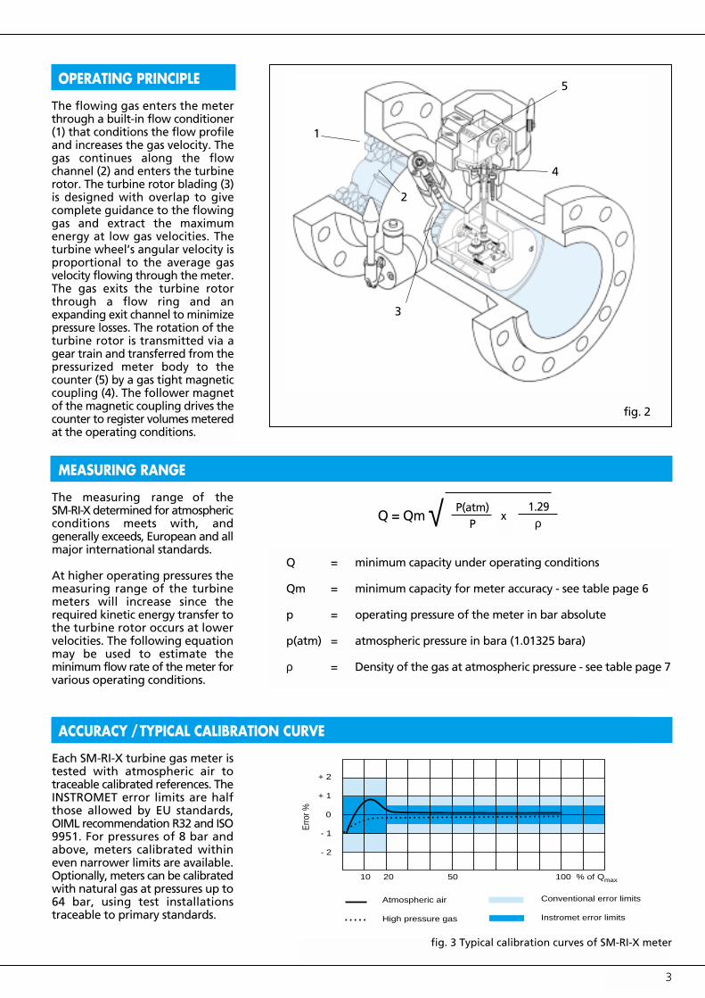
OPERATING PRINCIPLE
fig. 3 Typical calibration curves of SM-RI-X meter
1
2
3
5
4
10 20 50 100 % of Q
+ 2
+ 1
0
- 1
- 2
Erro
r %
Atmospheric air
High pressure gas
Conventional error limits
Instromet error limits
max
Q = Qm √ P(atm)P
x1.29
ρ
Q = minimum capacity under operating conditions
Qm = minimum capacity for meter accuracy - see table page 6
p = operating pressure of the meter in bar absolute
p(atm) = atmospheric pressure in bara (1.01325 bara)
ρ = Density of the gas at atmospheric pressure - see table page 7
MEASURING RANGE
The measuring range of theSM-RI-X determined for atmosphericconditions meets with, andgenerally exceeds, European and allmajor international standards.
At higher operating pressures themeasuring range of the turbinemeters will increase since therequired kinetic energy transfer tothe turbine rotor occurs at lowervelocities. The following equationmay be used to estimate theminimum flow rate of the meter forvarious operating conditions.
ACCURACY
Each SM-RI-X turbine gas meter istested with atmospheric air totraceable calibrated references. TheINSTROMET error limits are halfthose allowed by EU standards,OIML recommendation R32 and ISO9951. For pressures of 8 bar andabove, meters calibrated withineven narrower limits are available.Optionally, meters can be calibratedwith natural gas at pressures up to64 bar, using test installationstraceable to primary standards.
The flowing gas enters the meterthrough a built-in flow conditioner(1) that conditions the flow profileand increases the gas velocity. Thegas continues along the flowchannel (2) and enters the turbinerotor. The turbine rotor blading (3)is designed with overlap to givecomplete guidance to the flowinggas and extract the maximumenergy at low gas velocities. Theturbine wheel’s angular velocity isproportional to the average gasvelocity flowing through the meter.The gas exits the turbine rotorthrough a flow ring and anexpanding exit channel to minimizepressure losses. The rotation of theturbine rotor is transmitted via agear train and transferred from thepressurized meter body to thecounter (5) by a gas tight magneticcoupling (4). The follower magnetof the magnetic coupling drives thecounter to register volumes meteredat the operating conditions.
/TYPICAL CALIBRATION CURVE
fig. 2

4
METER INDEX, PULSERS
Multi-Index
HF Slot Sensor
LF Reed Contact
HF PROXIMITY SENSOR - TURBINE WHEEL/REFERENCE WHEEL
Each turbine gas meter equipped with an aluminium turbine wheel canbe fitted with a Reprox probe type pulse sensor. As each turbine bladepasses the proximity sensor a pulse is produced, the number of whichis proportional to the speed of the wheel and thus the quantity of gascan be determined (for pulse values see page 6).
A proximity sensor can also be fitted above a toothed reference wheelfitted on the main shaft. These impulse values are identical to thevalues produced by the turbine blades. The electrical separation betweenthe hazardous and non-hazardous areas is accomplished by an intrinsicallysafe isolation amplifier, type Mk 15-PRN-Ex0/K11.
Standard Multi-Index
The standard index is a multi-index as shown, fitted with a reedcontact to provide a low frequency pulse. (Impulse values see page 6)
The impulse is accessed through an electrical connection. The counteris readable over a 90˚ field of vision and has 8 digits.
Possible Index Options:
• LF double pulser (Reed contact)
• HF pulser (Slot sensor)
• HF double pulser (Slot sensor)
• HF/LF pulse combinations
• Anti-fraud reed contact
• Mechanical drive - (Type 25 H7 according to DIN 33800)
• Reverse current barrier
• Remote read-out of counter via HART protocol (Digitur)
• “Cryo” index extension to prevent icing problems in metersoperating with sub-zero temperature gas
• Drying agent option (aluminium silicate)
• Tropical operation
• Polyepoxy coated material - for corrosive environment
Connector Options
Standard:Pins 1 and 4 = LF Reed contactPins 3 and 6 = HF slot sensoror according to customer’s requirements
All connector combinations are indicated on the type plate.
fig. 4
fig. 5
fig. 6
fig. 7HF Reprox Proximity Sensor

5
SM-RI-P high pressure turbine gas meter for themeasurement of ethylene with a very high density.
SM-RI-X with Model 999 electronic volume corrector.
DIFFERENT TURBINE GAS METER MODELS
ELECTRONIC VOLUME CORRECTORS AND ASSOCIATED PRODUCTS
Model 555 or 999 Corrector
User configurable, highly accurateelectronic volume corrector with anextremely versatile logging capabilitycorrecting for temperature andpressure.
Tru-Therm Calorimeter
For real-time measurement.Provides total energy flow and gasquality at bare conditions.
Series 793 Flow Computer
For remote calculation of flowquantity in base volume andenergy without any additional error.Temperature and pressure aredigitally read using a HART bus.
SM-RI “Cryo” to measure sub-zero temperature gas.
IN SITU INSPECTION AND SPIN TEST
Optionally a special port can be provided to allow visualinspection of the turbine wheel without removing themeter mechanism from the line. This port can also be usedto test the conditions of the bearings by means of a spintest.
fig. 8 fig. 9
fig. 10
fig. 11 fig. 12 fig. 13

A HF proximity switch or a HP calibration is only possible with aluminium turbine wheels.
A temperature well in the meter housing is available for meters 80 mm (3”) and larger.For the connection of pressure sensors (e.g. for a volume corrector) a “Pr” point is integrated in the meter body.
Meters larger than 600 mm (24”) and other variations to the above specifications are available by special request.
6
MEASUREMENT RANGE/PRESSURE LOSS/PULSE VALUES
G 40
G 65
G 100
G 160
G 250
G 160
G 250
G 400
G 400
G 650 < 10 bar
G 650 > 10 bar
G 1000
G 650
G 1000
G 1600
G 1000
G 1600
G 2500
G 1600
G 2500
G 4000
G 2500
G 4000
G 6500
G 4000
G 6500
G 10000
G 6500
G 10000
G 16000
13 - 65
10 - 100
8 - 160
13 - 250
20 - 400
13 - 250
20 - 400
32 - 650
32 - 650
50 - 1,000
50 - 1,000
80 - 1,600
100 - 1,000
80 - 1,600
130 - 2,500
80 - 1,600
130 - 2,500
200 - 4,000
130 - 2,500
200 - 4,000
320 - 6,500
200 - 4,000
320 - 6,500
500 - 10,000
320 - 6,500
500 - 10,000
800 - 16,000
500 - 10,000
800 - 16,000
1,300 - 25,000
3
6.5
3
8
21
2
5
13
3.5
8.5
7.0
16.5
1.5
3
8
1.5
4.5
10
1.5
5
14
1.5
5
13
1.5
6.5
15
1.5
5
10.5
0.1
0.1
1
1
1
1
1
1
1
1
1
1
10
10
10
10
10
10
10
10
10
10
10
10
10
10
10
100
100
100
10 100
10 100
1 10
1 10
1 10
1 10
1 10
1 10
1 10
1 10
1 10
1 10
0.1 1
0.1 1
0.1 1
0.1 1
0.1 1
0.1 1
0.1 1
0.1 1
0.1 1
0.1 1
0.1 1
0.1 1
0.1 1
0.1 1
0.1 1
0.1 0.1
0.01 0.1
0.01 0.1
136
210
105
163
149
98
158
143
151
232
133
213
55
85
83
88
142
126
48
76
70
160
256
220
130
210
192
48
75
68
50
(2”)
80
(3”)
100
(4”)
150
(6”)
200
(8”)
250
(10”)
300
(12”)
400
(16”)
500
(20”)
600
(24”)
pipesizemm(inch)
G-rating measurement
range (m3/h)Qmin - Qmax
*1
pressureloss atQmax
naturalgas
� = 0.8 kg/m3
m3
perrev
LF pulsesper m3 HF-
index
Hz atQmax
No. ofturbineblades
HF *2Signal
referencewheel
Hz at Qmax
Turbinewheel
* 4
12
12
16
20
20
24
24
24
24
24
ALU Delrin1 10
1690 * 3
2600 * 3
1280 * 3
2000 * 3
1800 * 3
1100 * 3
1760 * 3
1570 * 3
1180
1815
1060
1700
770
1180
1060
825
1320
1200
810
1270
1175
660
1055
890
530
865
770
470
720
650
● ●●
● ●●
● ●●
● ●●
● –
● ●●
● ●●
● –
● ●●
● ●●
● ●●
● –
● –
● –
● –
● –
● –
● –
● –
● –
● –
● –
● –
● –
● –
● –
● –
● –
● –
● –
* 1: Measurement range 1:30 on request
* 2: Indicated HF frequencies are nominal valuesActual values are specific
* 3: HF sensor on reference wheel not available
* 4: ● Standard construction●● Option / special design for PN10 / ANSI 125

Applicable to clean dry gases from-10° C to +65° C. Other temperatureranges by special request.
S = Standard MaterialsT = Corrosion resistant coated
body and internals (exceptplastic and stainless steelparts)
1) = Special o-rings2) = Special lubrications3) = Special turbine wheels4) = Except food industry5) = For super-critical Ethylene and
Propylene use SM-RI-P6) = For oxygen special conditions
apply
NOTE:• For wet gases, a special coating
can be applied to the body’sinside surfaces
• For corrosive environment,external surfaces and index headcan be coated
• For higher or lower temperaturesspecial lubrication and materialscan be supplied
7
MEASUREMENT OF VARIOUS GASES
PRESSURE LOSS FORMULA
The average pressure loss (see table page 6) of the SM-RI-X turbine meterusing atmospheric natural gas with a relative density of 0.6 andmeasured at one (1) diameter upstream to one (1) diameter downstreamof the meter on straight pipe of the same size as the meter.
The pressure loss across the SM-RI-X for various gases and otheroperating pressures may be approximated from the following equation.
∆P2 = Pressure drop at Pm and Q- mbar∆P1 = Pressure drop at Qmax (see table page 6)
Pm = Operating pressure absolute
Catm = Atmospheric pressure 1.013 bara
Q = Instantaneous flow rate in m3/h
Qmax = Max. flow rate in m3/h
d = Relative density of the gas (air = 1)
d Pm Q∆ P2 = ∆ P1 •
0.6• Patm • Q max
2mbar( ) [ ]
Density at Gas Formula 0° C Meter Remarks
1.013 bar housing(kg/m3)
Natural gas CH4 0.8 S
Acethylene C2H2 1.17 T CRC coated
Ammonia NH3 0.77 S 1) 2)
Argon Ar 1.78 S
Butane C4H10 2.70 S
Biogas — — T 1) 2) 3)
Ethane C2H6 1.36 S
Ethylene C2H4 1.26 S 1) 5)
Freon 12 (gas) CCI2F2 5.66 S 1) 2)
Helium He 0.18 S higher Qmin
Carbon Dioxide CO2 1.98 S 4)
Carbon Monoxide CO 1.25 S
Air N2 + O2 1.29 S
Methane CH4 0.72 S
Pentane C5H12 3.46 S
Propane C3H8 2.02 S
Propylene (gaseous) C3H6 1.92 S 1) 5)
Sewer/Manure gas — — T 1) 2)
Town gas — — S
Sulphide gas — — T 1)
Nitrogen N2 1.25 S
Hydrogen H2 0.09 T higher Qmin
Oxygen (pure) O2 1.43 S 1) 2) 6) special constr.
Sulpher dioxide SO2 2.93 T 1) special constr.
Hydrogen sulphide H2S 1.54 T 1) 2)
HOW TO ORDER
In order to provide the meter best suited foryour application, please provide the followinginformation:
• Pipe diameter• Gas flow quantity, min & max• Gas flow direction• Operating pressures, min & max• Operating temperatures, min & max• Ambient temperatures, min & max• Type of gas• Flange class, DIN or ANSI• Type of Index - pulse options• Proximity Switch(es) - Turbine, reference
wheel• High Pressure Calibration required ?• Metrological and/or materials certificates
required.
( )

• The SM-RI-X fulfills all the requirements of theEuropean and major international directives, standardsand guidelines, in particular those of OIML, ISO andDVGW.
• With the integrated X4X® (patented) flow straightener,the SM-RI-X eliminates the effect of perturbations ongas measurement and satisfies the exactingrequirements of the International Standard ISO 9951with only 2 x diameter of upstream piping. This permitsthe design of very compact installations without asignificant effect on accuracy.
• The superior performance of the X4X flow straightenerwas confirmed by tests carried out by a number ofEuropean gas transmission companies. Copies of thisreport are available on request.
8
INSTALLATION GUIDELINES
The gas piping must be clean and free of sand, dirt, metalfilings, and other foreign particles and liquids. It isrecommended that a filter of 5 micron mesh be installedupstream of the meter.
Position the gaskets with care, ensuring that there is noprotrusion into the flow which would cause a disturbanceto the flow.
Tighten the bolts evenly and with equal force.
The Multi-index can be rotated up to 350° for easierreading.
Slowly pressurise the installation, to prevent overspeedingor damaging the meter. Bringing the meter into serviceshould also be done slowly.
Possible Installation Configurations
≥ 2D ≥ 2D ≥ 2D ≥ 2D
≥ 1D
≥ 2D ≥ 2D
≥ 1D
T
≥ 2D ≥ 2D
≥ 1D
T
T
≥ 1D
T
For heavily jetting regulators it is recommended that a sieve plate beinstalled at the exit of the regulator for optimum performance.
fig. 14 fig. 15
fig. 16 fig. 17

Oil Injection-System
Supplied with 50 mm (2”) to200 mm (8”) meters with a pressurerating of PN 10/16 and ANSI 125.
Push Button Pump
Standard on 50 mm (2”) and 80 mm(3”) meters in pressure ranges up to100 bar. 0.1 cc per push.
Small Oil pump
Standard on 100 mm (4”), 150 mm (6”)and 200 mm (8”) meters in all pressureranges up to 100 bar. 0.5 cc per stroke.
Large Oil Pump
Standard on 250 mm (10”) metersand larger in all pressure ranges upto 100 bar. 1 cc per stroke.
9
LUBRICATION
The frequency of lubricating a meterdepends on the operating conditions.A meter operating in dirty gas needsto be lubricated more often than ameter operating in clean gas.
Under normal conditions metersshould be lubricated 2 to 3 times ayear.
Recommended quantity of oil:
50/80 mm (2/3”) meters 0.2 cc100 mm (4”) ” 2 ” 150 mm (6”) “ 3 “200 mm (8”) ” 4 “250 mm (10”) ” 5 “300 mm (12”) ” 6 “400 mm (16”) ” 8 “500 mm (20”) ” 10 “600 mm (24”) ” 12 “
Lubricating oil: ISOFLEX PDP 38.For special applications contactInstromet for advice.
Special lubrication systems areavailable minimising the risk ofpollution of the oil.
fig. 22Instromet Natural Gas High PressureCalibration Facility in Utrecht,The Netherlands
HIGH PRESSURE CALIBRATION FACILITY
Instromet possesses a unique highpressure calibration facility,approved by the Dutch legalmetrology service NMi. Systematictesting of meters with high pressurenatural gas gives Instromet apowerful tool to further improve itsturbine meters within the frame-work of its ISO 9001 approval.
fig. 18
fig. 20 fig. 21
fig. 22
fig. 19

10
Sizes Over-mm G- all Pressure Body Wgt. Pressure Body Wgt.(inch) Rating A B E H length rating material kg. rating material kg
ND 10/16 GGG 40 10 ND 100 26ANSI 125/150 10
50 40 60 N.A. N.A. 235 150 ANSI 150 St 18(2") 65 ND 10/16 20 ANSI 300 20
ND 25/40 St 20 ANSI 400 20ND 64 23 ANSI 600 20
ND 10/16 GGG 40 15 ND 100 34ANSI 125/150 15
80 100 96 N.A. N.A. 205 240 ANSI 150 24(3") 160 ND 10/16 26 ANSI 300 St 28
250 ND 25/40 St 26 ANSI 400 28ND 64 30 ANSI 600 28
ND 10/16 GGG 40 28 ND 100 46ANSI 125/150 28
100 160 120 130 210 218 300 ANSI 150 35(4") 250 ND 10/16 30 ANSI 300 St 42
400 ND 25/40 St 38 ANSI 400 42ND 64 40 ANSI 600 50
ND 10/16 GGG 40 44 ND 100 87ANSI 125/150 44
150 400 180 180 247 273 450 ANSI 150 48(6") 650 ND 10/16 42 ANSI 300 St 66
1000 ND 25/40 St 50 ANSI 400 77ND 64 72 ANSI 600 98
ND 10 70 ND 40 98ND 16 GGG 40 70 ND 64 125
200 650 240 240 273 298 600 ANSI 125/150 70 ND 100 161(8") 1000 ANSI 150 St 91
1600 ND 10 77 ANSI 300 117ND 16 St 77 ANSI 400 135ND 25 89 ANSI 600 155
ND 10 90 ANSI 150 1081000 ND 16 95
250 1600 300 360 327 314 750 ND 25 St 108 ANSI 300 St 148(10") 2500 ND 40 128 ANSI 400 170
ND 64 156 ANSI 600 236ND 100 220 236
ND 10 120 ANSI 150 1601600 ND 16 130
300 2500 360 390 352 338 900 ND 25 St 150 ANSI 300 St 210(12") 4000 ND 40 180 ANSI 400 240
ND 64 240 ANSI 600 290ND 100 340
ND 10 350 ANSI 150 4002500 ND 16 380 ANSl 300 460
400 4000 480 510 395 380 1200 ND 25 St 410 St(16") 6500 ND 40 460 ANSI 400 490
ND 64 510 ANSI 600 580
4000 ND 10 550 ANSI 150 650500 6500 600 630 445 431 1500 ND 16 St 600 ANSI 300 St 800(20") 10000 ND 25 640 ANSI 400 830
ND 40 690 ANSI 600 980
ND 10 900 ANSI 150 10506500 ND 16 950 ANSI 300 1300
600 10000 720 750 495 482 1800 ND 25 St 1000 ANSI 400 St 1350(24") 16000 ANSl 600 1500
DIMENSIONS AND WEIGHTS
N.A. = Not Applicable St = Steel GGG 40 = Ductile Iron

11
DIMENSIONS
Body: Meter with DIN flanges:Connection DN 50 - DN 200, PN10/16Ductile Iron GGG 40Connection DN 50 - DN 600, PN10-PN 100 Steel [DN 50, (2") - flangeless]
Meter with ANSI flanges:Connection DN 50 - DN 200, (2"- 8")ANSI 125/150 Ductile Iron GGG 40
Connection DN 50 - DN 600, (2"- 24")Steel [DN 50, (2") - flangeless]ANSI 150 - ANSI 600
Meter bodies are constructed inaccordance with many pressurevessel codes. The standard constructionis in accordance with the DutchStoomwezen Code.
Turbine wheel: Meters sized 150 mm (6") andsmaller with a working pressure to10 bar (ANSI 150) can be fitted witheither an aluminium or a delrinturbine wheel. An aluminium turbine,machined from solid stock, is standardfor all other sizes and pressures.
Surface coating: Ductile iron: phosphate, primer, topcoat Steel: sand blasting, primer, top coat
Bearings: Stainless steel
Shafts: Stainless steel
Magnetic coupling: Ferroxdure magnets in stainless steelbushing and aluminium hubs
Screws and bolts: Stainless steel
Meter module: Aluminium
O-rings: Viton® / NBR
Gears: In contact with gas: Polyacetal resinand stainless steel; in the index:Polyacetal resin
Oil pumps: Chrome plated brass or steel
Index head: Aluminium
Note: Special materials available on request. The internalscan be coated for service with corrosive gases.
Publications by INSTROMET:
• Turbine Gas Meter Handbook.• P-Meter Handbook (Ethylene).• SM-RI Turbine Gas Meters - Installation and
Maintenance Instructions.• Systems Handbook.• Regulator Station Handbook
International Reference Material:
• ISO 9951: 1993, Measurement of gas flow in closedconduits - Turbine meters.
• OIML R6, General specifications for gas volume meters.• OIML R32, Rotary piston meters and turbine gas meters.• AGA Report No. 7, Measurement of fuel gas by turbine
meters.
MATERIAL SPECIFICATIONS
FURTHER INFORMATION
Meter length L equals 3 x the nominal pipe diameter DL.For A, B, E and H see table on page 10.
fig. 23
Oil pump
L

Sales Offices:In Argentina:INSTROMET S.A.
In Australia:INSTROMET SYSTEMS AUSTRALIA PTY. LTD.
In Austria:INSTROMET B.V. GES.M.B.H.
In Belgium:INSTROMET INTERNATIONAL N.V.
In Brazil:INSTROMET MEDIÇÃO E CONTROLE LTDA.
In China:INSTROMET CHINA, BEIJING-OFFICE
In Croatia:INSTROMET CROATIA
In France:INSTROMET S.A.R.L.
In Germany:INSTROMET G.M.B.H.
In Hungary:INSTROMET HUNGARY
In India:SIDDHA GAS INSTROMET INDIA PVT. LTD.
In Italy:INSTROMET ITALIA S.R.L.
In Korea:INSTROMET KOREA LTD.
In Malaysia:INSTROMET INTERNATIONALREGIONAL OFFICE, SOUTH EAST ASIA
In the Netherlands:INSTROMET B.V.
In New Zealand:INSTROMET SYSTEMS NEW ZEALAND
In Nigeria:INSTROMET WEST AFRICA B.V.
In Poland:INSTROMET POLSKA
In Portugal:INSTROMET PORTUGAL LDA.
In Spain:INSTROMET GAS S.L.
In Switzerland:INSTROMET AG.
In the UK:INSTROMET UK
In the Ukraine:INSTROMET UKRAINE LTD.
In the USA:INSTROMET INC.
Products & Services:● Ultrasonic gas meters
● Turbine gas meters
● Rotary gas meters
● Insertion gas meters
● Electronic volume correctors
● Flow computer systems
● Calorimeters
● Gas chromatographs
● Supervisory Systems
● Gas filters
● Gas pressure regulators
● Safety shut-off valves
● Telemetering systems
● Electronic metering and control systems
● Calibration and test installations
● Complete gas measurement and control stations
● Commissioning, servicing, training and consulting
1502
03 C
opyr
ight
© In
stro
met
/ Ro
odui
jn V
orm
& D
ruk
The
Net
herla
nds
INSTROMET has agents and representatives worldwide.
INSTROMET has a continuing program of product research and development.Technical specifications and construction may change due to improvements.This publication serves as general information only, and all specifications aresubject to confirmation by INSTROMET.
YOUR SALES OFFICE OR REPRESENTATIVE:
Gas measurement and control equipment
For your nearest sales office orrepresentative please contact:INSTROMET INTERNATIONALRijkmakerlaan 9 - B-2910 ESSEN - BELGIUMTel: +32 3 6700 700 - Fax : +32 3 667 6940E-mail: [email protected]: http://www.instromet.com