
BT-SM 1800
56
BT-SM 1800 Art.-Nr.: 43.008.12 I.-Nr.: 11028 7 D Originalbetriebsanleitung Zug-, Kapp- und Gehrungssäge GB Original operating instructions Drag, crosscut and miter saw Anl_BT_SM_1800_SPK7.indb 1 Anl_BT_SM_1800_SPK7.indb 1 26.07.2018 07:46:12 26.07.2018 07:46:12
-
Upload
khangminh22 -
Category
Documents
-
view
0 -
download
0
Transcript of BT-SM 1800

BT-SM 1800
Art.-Nr.: 43.008.12 I.-Nr.: 11028
7
D Originalbetriebsanleitung Zug-, Kapp- und Gehrungssäge
GB Original operating instructions Drag, crosscut and miter saw
Anl_BT_SM_1800_SPK7.indb 1Anl_BT_SM_1800_SPK7.indb 1 26.07.2018 07:46:1226.07.2018 07:46:12

- 2 -
1
2
19
8
10 18
18
6
22
3
9A
37
6
9B 16
15
34
9A
4
21
20
5
28
13 1421
26
7
g (8x)
12
24 23 z
8 10
38 1 3
7
12
1034 11
17
dc
9B 9A 9B 9A
h (4x)
2 27 25 24 23
35
3314 13
j (12x) j (12x)
Anl_BT_SM_1800_SPK7.indb 2Anl_BT_SM_1800_SPK7.indb 2 26.07.2018 07:46:3226.07.2018 07:46:32

- 3 -
4a 4b
4c 5
6 7a
26
9A
10
36
29 21
9A
3021 30
i
j
g
i
j
h
i
j
hi
j
g
Anl_BT_SM_1800_SPK7.indb 3Anl_BT_SM_1800_SPK7.indb 3 26.07.2018 07:46:3426.07.2018 07:46:34
- 4 -
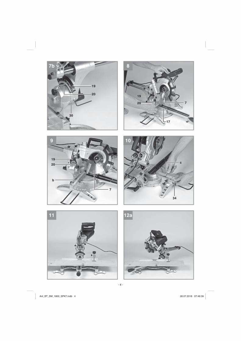
7b 8
17
9 10
11 12a
19
30
20 19
20 7a
19
b
20
7
c
34
Anl_BT_SM_1800_SPK7.indb 4Anl_BT_SM_1800_SPK7.indb 4 26.07.2018 07:46:3926.07.2018 07:46:39

- 5 -
12b 13a
13b 14a
14b 15
34
5
27
34
34
34
34
Anl_BT_SM_1800_SPK7.indb 5Anl_BT_SM_1800_SPK7.indb 5 26.07.2018 07:46:4326.07.2018 07:46:43
- 6 -
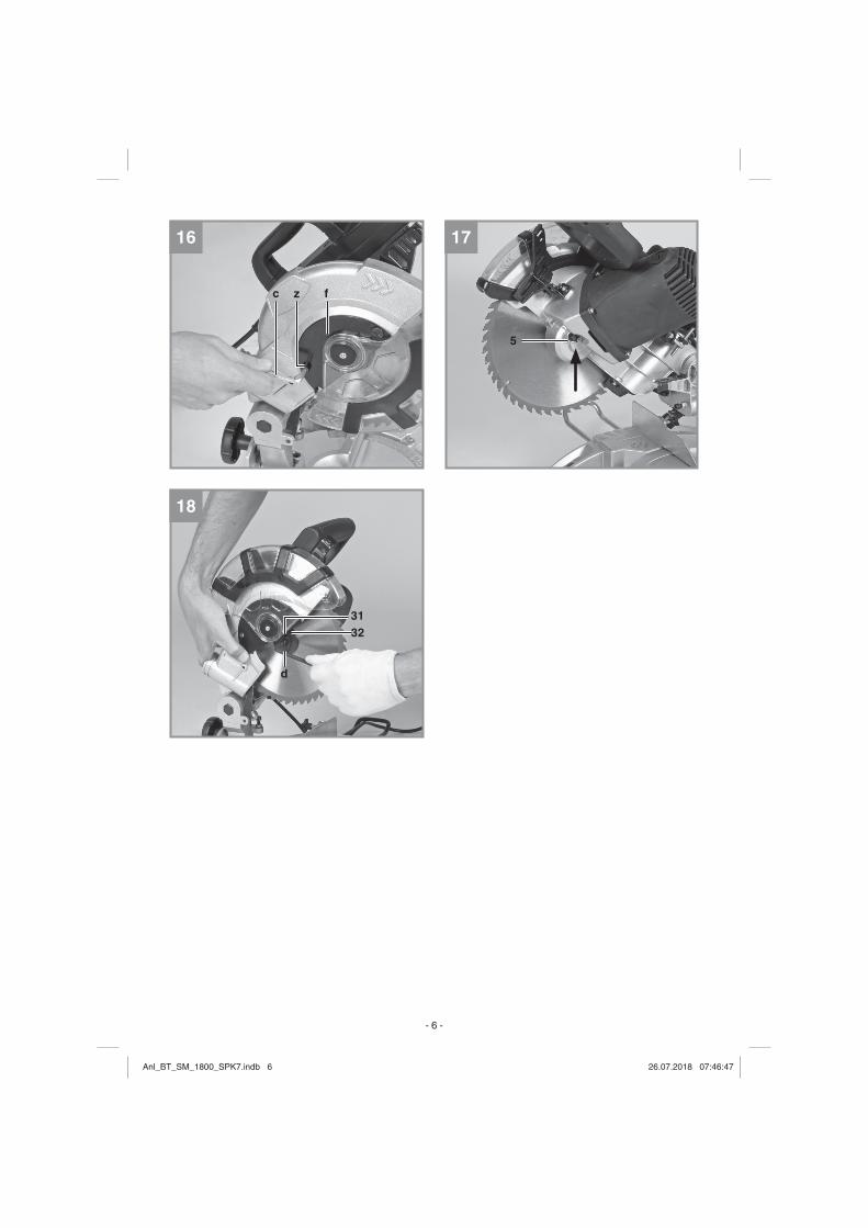
16 17
18
d
5
c z f
3231
Anl_BT_SM_1800_SPK7.indb 6Anl_BT_SM_1800_SPK7.indb 6 26.07.2018 07:46:4726.07.2018 07:46:47

D
- 7 -
Inhaltsverzeichnis1. Sicherheitshinweise 2. Gerätebeschreibung und Lieferumfang3. Bestimmungsgemäße Verwendung4. Technische Daten5. Vor Inbetriebnahme6. Betrieb7. Austausch der Netzanschlussleitung8. Reinigung, Wartung und Ersatzteilbestellung9. Entsorgung und Wiederverwertung10. Lagerung
Anl_BT_SM_1800_SPK7.indb 7Anl_BT_SM_1800_SPK7.indb 7 26.07.2018 07:46:4826.07.2018 07:46:48

D
- 8 -
Gefahr! - Zur Verringerung des Verletzungsrisikos Bedienungsanlei-tung lesen
Vorsicht! Tragen Sie einen Gehörschutz. Die Einwirkung von Lärm kann Gehörverlust bewirken.
Vorsicht! Tragen Sie eine Schutzbrille. Während der Arbeit entste-hende Funken oder aus dem Gerät heraustretende Splitter, Späne und Stäube können Sichtverlust bewirken.
Vorsicht! Tragen Sie eine Staubschutzmaske. Beim Bearbeiten von Holz und anderer Materialien kann gesundheitsschädlicher Staub entstehen. Asbesthaltiges Material darf nicht bearbeitet wer-den!
Vorsicht! Verletzungsgefahr! Nicht in das laufende Sägeblatt grei-fen.
Anl_BT_SM_1800_SPK7.indb 8Anl_BT_SM_1800_SPK7.indb 8 26.07.2018 07:46:4826.07.2018 07:46:48

D
- 9 -
Warnung! Die verschiebbaren Anschlagschienen sind mit Innen-sechskantschrauben befestigt. Die verschiebbaren Anschlagschienen müssen für Gehrungsschnitte (bei geneigtem Sägekopf oder Drehtisch mit Winkeleinstellung) in einer äußeren Position fi xiert werden.Bei 45°Kappschnitten nach links muss die linke Anschlagschiene nach außen geschoben und festgeschraubt werden!Bei 45°Kappschnitten nach rechts muss die rechte Anschlagschiene nach außen geschoben und festgeschraubt werden!Für 90° - Kappschnitte müssen die verschiebbaren Anschlag-schienen in der inneren Position festgeschraubt werden!
Vorsicht! Schraube an dieser Position nicht öff nen!
Schutzklasse II
Anl_BT_SM_1800_SPK7.indb 9Anl_BT_SM_1800_SPK7.indb 9 26.07.2018 07:46:4926.07.2018 07:46:49

D
- 10 -
Gefahr! Beim Benutzen von Geräten müssen einige Sicherheitsvor-kehrungen eingehalten werden, um Verletzungen und Schäden zu verhindern. Lesen Sie diese Bedienungsanleitung / Sicher-heitshinweise deshalb sorgfältig durch. Bewahren Sie diese gut auf, damit Ihnen die Informati-onen jederzeit zur Verfügung stehen. Falls Sie das Gerät an andere Personen übergeben sollten, händigen Sie diese Bedienungsanleitung / Sicher-heitshinweise bitte mit aus. Wir übernehmen keine Haftung für Unfälle oder Schäden, die durch Nichtbeachten dieser Anleitung und den Sicherheitshinweisen entstehen.
1. Sicherheitshinweise
Die entsprechenden Sicherheits-hinweise fi nden Sie im beiliegen-den Heftchen!Gefahr!Lesen Sie alle Sicherheits-hinweise und Anweisungen. Versäumnisse bei der Einhaltung der Sicherheitshinweise und An-weisungen können elektrischen Schlag, Brand und/oder schwere Verletzungen verursachen.
Bewahren Sie alle Sicher-heitshinweise und Anweisun-gen für die Zukunft auf.
Spezielle Hinweise zum Laser � Vorsicht! LaserstrahlungNicht in den Strahl blickenLaserklasse 2
VORSICHT ! - LASERSTRAHLUNG !Nicht in den Strahl blicken!
LaserspezifikationLaser Klasse 2
: 650 nm; P0
• Niemals direkt in den Strah-lengang blicken.
• Den Laserstrahl nie auf re-flektierende Flächen und Personen oder Tiere richten. Auch ein Laserstrahl mit ge-ringer Leistung kann Schäden am Auge verursachen.
• Vorsicht - wenn andere als die hier angegebenen Ver-fahrensweisen ausgeführt werden, kann dies zu einer gefährlichen Strahlungsexpo-sition führen.
• Lasermodul niemals öffnen.• Es ist nicht erlaubt Verände-
rungen am Laser vorzuneh-men um die Leistung des Lasers zu erhöhen.
• Der Hersteller übernimmt kei-ne Haftung für Schäden die
Anl_BT_SM_1800_SPK7.indb 10Anl_BT_SM_1800_SPK7.indb 10 26.07.2018 07:46:4926.07.2018 07:46:49

D
- 11 -
durch Nichtbeachtung der Si-cherheitshinweise entstehen.
2. Gerätebeschreibung und Lieferumfang
2.1 Gerätebeschreibung (Bild 1-3)
1. Handgriff 2. Ein-/Ausschalter3. Entriegelungshebel4. Maschinenkopf5. Sägewellensperre6. Sägeblattschutz beweglich7. Sägeblatt8. Spannvorrichtung9. zusätzliche Standfüße10. Werkstückaufl age11. feststehende Anschlagschie-
ne12. Tischeinlage13. verstellbarer Standfuss14. Feststellschraube15. Zeiger 16. Skala17. Drehtisch18. feststehender Sägetisch19. Skala 20. Zeiger21. Feststellschraube22. Spänefangsack23. Zugführung24. Feststellschraube für Zugfüh-
rung25. Sicherungsbolzen
26. Feststellschraube für Werk-stückaufl age
27. Rändelschraube für Schnitt-tiefenbegrenzung
28. Anschlag für Schnitttiefenbe-grenzung
29. Justierschraube30. Justierschraube31. Flanschschraube32. Außenfl ansch33. Knopf34. bewegliche Anschlagschiene35. Laser36. ausklappbarer Standbügel37. Ein-/Ausschalter Laser38. Transportgriff
2.2 LieferumfangBitte überprüfen Sie die Vollstän-digkeit des Artikels anhand des beschriebenen Lieferumfangs. Bei Fehlteilen wenden Sie sich bitte spätestens innerhalb von 5 Arbeitstagen nach Kauf des Arti-kels unter Vorlage eines gültigen Kaufbeleges an unser Service Center oder an die Verkaufstelle, bei der Sie das Gerät erworben haben. Bitte beachten Sie hierzu die Gewährleistungstabelle in den Service-Informationen am Ende der Anleitung.• Öffnen Sie die Verpackung
und nehmen Sie das Gerät vorsichtig aus der Verpa-ckung.
Anl_BT_SM_1800_SPK7.indb 11Anl_BT_SM_1800_SPK7.indb 11 26.07.2018 07:46:4926.07.2018 07:46:49

D
- 12 -
• Entfernen Sie das Verpa-ckungsmaterial sowie Verpa-ckungs-/ und Transportsiche-rungen (falls vorhanden).
• Überprüfen Sie, ob der Liefer-umfang vollständig ist.
• Kontrollieren Sie das Gerät und die Zubehörteile auf Transportschäden.
• Bewahren Sie die Verpa-ckung nach Möglichkeit bis zum Ablauf der Garantiezeit auf.
Gefahr!Gerät und Verpackungsma-terial sind kein Kinderspiel-zeug! Kinder dürfen nicht mit Kunststoff beuteln, Folien und Kleinteilen spielen! Es besteht Verschluckungs- und Ersti-ckungsgefahr!
• Zug-, Kapp und Gehrungssä-ge
• Spannvorrichtung (8)• 2 x Werkstückauflage (10)• Spänefangsack (22)• Innensechskantschlüssel
(c,d)• zusätzliche Standfüße (9)• Originalbetriebsanleitung• Sicherheitshinweise
3. Bestimmungsgemäße Verwendung
Die Zug-, Kapp- und Gehrungs-säge dient zum Kappen von Holz und holzähnlichen Werkstoff en, entsprechend der Maschinen-größe. Die Säge ist nicht zum Schneiden von Brennholz geeig-net.
Die Maschine darf nur nach ihrer Bestimmung verwendet werden. Jede weitere darüber hinaus-gehende Verwendung ist nicht bestimmungsgemäß. Für daraus hervorgerufene Schäden oder Verletzungen aller Art haftet der Benutzer/Bediener und nicht der Hersteller.Wichtiger Hinweis zum Strom-anschlussDas Gerät unterfällt der Norm 61000-3-11, d. h. es ist nicht für den Gebrauch in Wohnberei-chen, in denen die Stromver-sorgung über ein öff entliches Niederspannungs-Versorgungs-system erfolgt, vorgesehen, weil es dort bei ungünstigen Netzver-hältnissen Störungen verursa-chen kann. (Spannungsschwan-kungen).In Industriegebieten oder an-deren Bereichen, in denen die Stromversorgung nicht über ein
Anl_BT_SM_1800_SPK7.indb 12Anl_BT_SM_1800_SPK7.indb 12 26.07.2018 07:46:4926.07.2018 07:46:49

D
- 13 -
öff entliches Niederspannungs-Versorgungssystem erfolgt, kann das Gerät verwendet werden.
Allgemeine Sicherheitsmaß-nahmenDer Benutzer ist verantwortlich, das Gerät gemäß den Angaben des Herstellers fachgerecht zu installieren und zu nutzen. So-weit elektromagnetische Störun-gen festgestellt werden sollten, liegt es in der Verantwortung des Benutzers, diese mit den oben unter dem Punkt ”Wichtiger Hin-weis zum Stromanschluss“ ge-nannten technischen Hilfsmitteln zu beseitigen.
GewährleistungDie Gewährleistungszeit beträgt 12 Monate bei gewerblicher Nut-zung, 24 Monate für Verbraucher und beginnt mit dem Zeitpunkt des Kaufs des Gerätes.
Es dürfen nur für die Maschine geeignete Sägeblätter verwen-det werden. Die Verwendung von Trennscheiben aller Art ist unter-sagt.
Bestandteil der bestimmungsge-mäßen Verwendung ist auch die Beachtung der Sicherheitshin-weise, sowie die Montageanlei-
tung und Betriebshinweise in der Bedienungsanleitung.Personen, die die Maschine be-dienen und warten, müssen mit dieser vertraut und über mögli-che Gefahren unterrichtet sein. Darüber hinaus sind die gelten-den Unfallverhütungsvorschrif-ten genauestens einzuhalten. Sonstige allgemeine Regeln in arbeitsmedizinischen und sicher-heitstechnischen Bereichen sind zu beachten.Veränderungen an der Maschi-ne schließen eine Haftung des Herstellers und daraus entste-hende Schäden gänzlich aus. Trotz bestimmungsgemäßer Verwendung können bestimmte Restrisikofaktoren nicht vollstän-dig ausgeräumt werden. Bedingt durch Konstruktion und Aufbau der Maschine können folgende Punkte auftreten:• Berührung des Sägeblattes
im nicht abgedeckten Säge-bereich.
• Eingreifen in das laufende Sägeblatt (Schnittverletzung)
• Rückschlag von Werkstücken und Werkstückteilen.
• Sägeblattbrüche.• Herausschleudern von feh-
lerhaften Hartmetallteilen des Sägeblattes.
• Gehörschäden bei Nichtver-
Anl_BT_SM_1800_SPK7.indb 13Anl_BT_SM_1800_SPK7.indb 13 26.07.2018 07:46:4926.07.2018 07:46:49

D
- 14 -
wendung des nötigen Gehör-schutzes.
• Gesundheitsschädliche Emis-sionen von Holzstäuben bei Verwendung in geschlosse-nen Räumen.
4. Technische Daten
Wechselstrommotor: .................. .............................. 230 V ~ 50HzLeistung: .................................... .... 1500 W S1 / 1800 W S2 5 minLeerlaufdrehzahl n0: ...5000 min-1
Hartmetallsägeblatt: ................... .................ø 210 x ø 30 x 2,8 mmAnzahl der Zähne: .................. 48Schwenkbereich: . -45° / 0°/ +45°Gehrungsschnitt nach links: ....... .................................... 0° bis 45°Gehrungsschnitt nach rechts: .... .................................... 0° bis 45° Sägebreite bei 90°: 310 x 62 mmSägebreite bei 45°: 210 x 62 mmSägebreite bei 2 x 45°(Doppelgehrungsschnitt links):... ............................... 210 x 36 mmSägebreite bei 2 x 45°(Doppelgehrungsschnitt rechts): ............................... 210 x 20 mmGewicht: ....................... ca. 11 kgLaserklasse: ............................. 2Wellenlänge Laser: .........650 nmLeistung Laser: ..............≤ 1 mW
Die Einschaltdauer S2 5 min (Kurzzeitbetrieb) sagt aus, dass der Motor mit der Nennleistung (1800 W) nur für die auf dem Datenschild angegebene Zeit (5 min) dauernd belastet werden darf. Andernfalls würde er sich unzulässig erwärmen. Während der Pause kühlt sich der Motor wieder auf seine Ausgangstem-peratur ab.
Gefahr!Geräusch und VibrationDie Geräusch- und Vibrations-werte wurden entsprechend EN 61029 ermittelt.
Schalldruckpegel LpA .. 100 dB(A)Unsicherheit KpA .................. 3 dBSchallleistungspegel LWA ............ ................................... 106 dB(A)Unsicherheit KWA ................. 3 dB
Tragen Sie einen Gehör-schutz.Die Einwirkung von Lärm kann Gehörverlust bewirken.
Schwingungsgesamtwerte (Vek-torsumme dreier Richtungen) er-mittelt entsprechend EN 61029.
Schwingungsemissionswert ah = 2,7 m/s2
Unsicherheit K = 1,5 m/s2
Anl_BT_SM_1800_SPK7.indb 14Anl_BT_SM_1800_SPK7.indb 14 26.07.2018 07:46:4926.07.2018 07:46:49

D
- 15 -
Warnung!Der angegebene Schwingungs-emissionswert ist nach einem genormten Prüfverfahren ge-messen worden und kann sich, abhängig von der Art und Wei-se, in der das Elektrowerkzeug verwendet wird, ändern und in Ausnahmefällen über dem ange-gebenen Wert liegen.
Der angegebene Schwingungs-emissionswert kann zum Ver-gleich eines Elektrowerkzeuges mit einem anderen verwendet werden.
Der angegebene Schwingungs-emissionswert kann auch zu einer einleitenden Einschätzung der Beeinträchtigung verwendet werden.
Beschränken Sie die Geräu-schentwicklung und Vibration auf ein Minimum!• Verwenden Sie nur einwand-
freie Geräte.• Warten und reinigen Sie das
Gerät regelmäßig.• Passen Sie Ihre Arbeitsweise
dem Gerät an.• Überlasten Sie das Gerät
nicht.• Lassen Sie das Gerät gege-
benenfalls überprüfen.
• Schalten Sie das Gerät aus, wenn es nicht benutzt wird.
Vorsicht! RestrisikenAuch wenn Sie dieses Elek-trowerkzeug vorschriftsmä-ßig bedienen, bleiben immer Restrisiken bestehen. Fol-gende Gefahren können im Zusammenhang mit der Bau-weise und Ausführung dieses Elektrowerkzeuges auftreten:1. Lungenschäden, falls keine
geeignete Staubschutzmaske getragen wird.
2. Gehörschäden, falls kein ge-eigneter Gehörschutz getra-gen wird.
3. Gesundheitsschäden, die aus Hand-Arm-Schwingungen resultieren, falls das Gerät über einen längeren Zeitraum verwendet wird oder nicht ordnungsgemäß geführt und gewartet wird.
5. Vor Inbetriebnahme
Überzeugen Sie sich vor dem Anschließen, dass die Daten auf dem Typenschild mit den Netz-daten übereinstimmen.
Anl_BT_SM_1800_SPK7.indb 15Anl_BT_SM_1800_SPK7.indb 15 26.07.2018 07:46:4926.07.2018 07:46:49

D
- 16 -
Warnung! Ziehen Sie immer den Netz-stecker, bevor Sie Einstellun-gen am Gerät vornehmen.
5.1 Allgemein• Die Maschine muss standsi-
cher aufgestellt werden, d.h. auf einer Werkbank, einem Universaluntergestell o. ä. festschrauben.
• Vor Inbetriebnahme müssen alle Abdeckungen und Si-cherheitsvorrichtungen ord-nungsgemäß montiert sein.
• Das Sägeblatt muss frei lau-fen können.
• Bei bereits bearbeitetem Holz auf Fremdkörper wie z.B. Nägel oder Schrauben usw. achten.
• Bevor Sie den Ein-/Ausschal-ter betätigen, vergewissern Sie sich, ob das Sägeblatt richtig montiert ist und be-wegliche Teile leichtgängig sind.
5.2 Säge montieren (Bild 1-5)• Zum Verstellen des Dreh-
tisches (17) die Feststell-schraube (14) ca. 2 Um-drehungen lockern um den Drehtisch (17) zu entriegeln.
• Drehtisch (17) und Zeiger (15) auf das gewünschte Win-
kelmaß der Skala (16) drehen und mit der Feststellschraube (14) fixieren. Die Säge besitzt Raststellungen bei den Po-sitionen -45°, -31,6°, -22,5°, -15°, 0°, 15°, 22,5°, 31,6° und 45°, an denen der Drehtisch (17) hörbar einrastet.
• Durch leichtes Drücken des Maschinenkopfes (4) nach unten und gleichzeitiges He-rausziehen des Sicherungs-bolzens (25) aus der Mo-torhalterung, wird die Säge aus der unteren Stellung entriegelt. Drehen Sie den Si-cherungsbolzen (25) um 90° bevor sie ihn loslassen, damit die Säge entriegelt bleibt.
• Maschinenkopf (4) nach oben schwenken, bis der Entriege-lungshebel (3) einrastet.
• Die Spannvorrichtung (8) kann sowohl links als auch rechts am feststehenden Sä-getisch (18) montiert werden.
• Feststellschrauben für Werk-stückauflage (26) lösen.
• Werkstückauflage (10) am feststehenden Sägetisch (18) montieren, entsprechende Feststellschraube (26) anzie-hen (Bild 4).
• Die zweite Werkstückauflage (10) auf der gegenüberliegen-den Seite der Säge montieren
Anl_BT_SM_1800_SPK7.indb 16Anl_BT_SM_1800_SPK7.indb 16 26.07.2018 07:46:4926.07.2018 07:46:49

D
- 17 -
und mit der entsprechenden Feststellschraube (26) si-chern.
• Der Maschinenkopf (4) kann durch lösen der Feststell-schraube (21), nach links auf max. 45° geneigt werden.
• Um einen sicheren Stand der Säge zu gewährleisten ver-stellen Sie den einstellbaren Standfuß (13), durch Drehung so, dass die Säge waage-recht und stabil steht.
• Schrauben Sie die zusätzli-chen Standfüße (9) an den Füßen des feststehenden Sä-getisches (18) fest.
• Klappen sie den Standbügel (36) nach hinten aus, bis er einrastet.
5.3 Feinjustierung des An-schlags für Kappschnitt 90° (Bild 7-8)
• Den Drehtisch (17) auf 0° Stellung fixieren.
• Feststellschraube (21) lo-ckern und mit dem Handgriff (1) den Maschinenkopf (4) ganz nach rechts neigen.
• 90° Anschlagwinkel (a) zwi-schen Sägeblatt (7) und Drehtisch (17) anlegen.
• Justierschraube (29) soweit verstellen, bis der Winkel zwischen Sägeblatt (7) und
Drehtisch (17) 90° beträgt.• Überprüfen Sie abschließend
die Position des Zeigers (20) an der Skala (19) Falls erfor-derlich, Zeiger (20) mit Kreuz-schlitzschraubendreher lö-sen, auf 0°-Position der Skala (19) setzen und Halteschrau-be wieder festziehen.
• Anschlagwinkel nicht im Lie-ferumfang enthalten.
5.4 Feinjustierung des An-schlags für Gehrungs-schnitt 45° (Bild 1, 6, 7, 9)
• Den Drehtisch (17) auf 0° Stellung fixieren.
• Feststellschraube (21) lösen und mit dem Handgriff (1) den Maschinenkopf (4) ganz nach links, auf 45° neigen.
• 45°-Anschlagwinkel (b) zwischen Sägeblatt (7) und Drehtisch (17) anlegen.
• Justierschraube (30) soweit verstellen, dass der Winkel zwischen Sägeblatt (7) und Drehtisch (17) genau 45° be-trägt.
• Anschlagwinkel nicht im Lie-ferumfang enthalten.
Anl_BT_SM_1800_SPK7.indb 17Anl_BT_SM_1800_SPK7.indb 17 26.07.2018 07:46:5026.07.2018 07:46:50

D
- 18 -
5.5 Einstellung des Gehrungs-winkels am Maschinenkopf (Bild 2, 12-13)
• Lösen die Feststellschraube (21).
• Fassen Sie den Maschinen-kopf (4) am Griff (1)
• Nach Ziehen des Knopfes (33) kann der Maschinenkopf stufenlos bzw. auch in ver-schiedenen Raststellungen geneigt werden.
• Winkel nach links: 0-45°• Winkel nach rechts: 0-45°• Feststellschraube (21) wieder
festziehen
5.6 Einstellung der beweg-lichen Anschlagschienen (Bild 1, 10-14)
• Vorsicht! Diese Säge ist mit beweglichen Anschlagschie-nen (34) ausgestattet, die an der feststehenden Anschlag-schiene (11) verschraubt sind.
• Für Winkel- bzw. Gehrungs-schnitte müssen die beweg-lichen Anschlagschienen eingestellt werden, um eine Kollision mit dem Sägeblatt zu vermeiden.
• Bei Gehrungs- bzw. Winkel-schnitten nach links muss die linke Anschlagschiene nach außen verschoben werden. Bei Winkelschnitten nach
rechts muss die rechte An-schlagschiene nach außen verschoben werden. Öffnen Sie die Feststellschrauben der beweglichen Anschlag-schienen und ziehen Sie die Schienen soweit zurück, dass eine Kollision mit dem Sä-geblatt ausgeschlossen ist. Ziehen Sie vor jedem Schnitt die Feststellschrauben der Anschlagschienen wieder an.
• Bei Gehrungsschnitten und Doppelgehrungsschnitten mit nach rechts geneigtem Sä-gekopf muss die rechte An-schlagschiene komplett abge-nommen werden. Achtung! In diesem Fall verringert sich die maximal erlaubte Werkstück-höhe (s. 4. Technische Daten).
• Befestigen Sie nach Ende der Arbeiten immer die bewegli-che Anschlagschiene wieder am Gerät.
• Die Anschlagschienen müs-sen stets beim Gerät ver-bleiben. Eine entfernte An-schlagschiene gefährdet die Betriebssicherheit des Gerä-tes.
Anl_BT_SM_1800_SPK7.indb 18Anl_BT_SM_1800_SPK7.indb 18 26.07.2018 07:46:5026.07.2018 07:46:50

D
- 19 -
6. Betrieb
6.1 Kappschnitt 90° und Dreh-tisch 0° (Bild 1–3, 11)
Bei Schnittbreiten bis ca. 100 mm kann die Zugfunktion der Säge mit der Feststellschrau-be für Zugführung (24) in der hinteren Position fi xiert werden. Sollte die Schnittbreite über 100 mm liegen, muss darauf geach-tet werden, dass die Feststell-schraube für Zugführung (24) locker und der Maschinenkopf (4) beweglich ist.• Maschinenkopf (4) in die obe-
re Position bringen.• Maschinenkopf (4) am Hand-
griff (1) nach hinten schieben und gegebenenfalls in dieser Position fixieren. (je nach Schnittbreite)
• Legen Sie das zu schnei-dende Holz an die Anschlag-schiene (11) und auf den Drehtisch (17).
• Das Material mit der Spann-vorrichtung (8) auf dem fest-stehenden Sägetisch (18) feststellen, um ein Verschie-ben während des Schneidvor-gangs zu verhindern.
• Entriegelungshebel (3) drü-cken um den Maschinenkopf (4) freizugeben.
• Ein-/ Ausschalter (2) drücken,
um den Motor einzuschalten. • Bei fixierter Zugführung (23):
Maschinenkopf (4) mit dem Handgriff (1) gleichmäßig und mit leichtem Druck nach unten bewegen, bis das Sä-geblatt (7) das Werkstück durchschnitten hat.
• Bei nicht fixierter Zugführung (23): Maschinenkopf (4) nach ganz vorne ziehen und dann mit dem Handgriff (1) gleich-mäßig und mit leichtem Druck ganz nach unten absenken. Nun Maschinenkopf (4) lang-sam und gleichmäßig ganz nach hinten schieben, bis das Sägeblatt (7) das Werkstück vollständig durchschnitten hat.
• Nach Beendigung des Säge-vorgangs Maschinenkopf (4) wieder in die obere Ruhestel-lung bringen und Ein-/ Aus-schalter (2) loslassen.
Achtung! Durch die Rückhol-feder schlägt die Maschine automatisch nach oben, d.h. Handgriff (1) nach Schnittende nicht loslassen, sondern Maschi-nenkopf (4) langsam und unter leichtem Gegendruck nach oben bewegen.
Anl_BT_SM_1800_SPK7.indb 19Anl_BT_SM_1800_SPK7.indb 19 26.07.2018 07:46:5026.07.2018 07:46:50

D
- 20 -
6.2 Kappschnitt 90° und Dreh-tisch 0°- 45° (Bild 1-3, 12)
Mit der Kappsäge können Kapp-schnitte von 0° - 45° nach links und 0° - 45° nach rechts zur An-schlagschiene ausgeführt wer-den.• Den Drehtisch (17) durch Lo-
ckern der Feststellschraube (14) lösen.
• Drehtisch (17) und Zeiger (15) auf das gewünschte Win-kelmaß der Skala (16) drehen und mit der Feststellschraube (14) fixieren. Die Säge besitzt Raststellungen bei den Po-sitionen -45°, -31,6°, -22,5°, -15°, 0°, 15°, 22,5°, 31,6° und 45°, an denen der Drehtisch (17) hörbar einrastet.
• Die Feststellschraube (14) wieder festziehen, um den Drehtisch (17) zu fixieren.
• Schnitt wie unter Punkt 6.1 beschrieben ausführen.
6.3 Gehrungsschnitt 0°- 45° und Drehtisch 0° (Bild 1–3, 13)
Mit der Kappsäge können Geh-rungsschnitte nach links von 0-45° und nach rechts von 0-45° zur Arbeitsfl äche ausgeführt wer-den. • Spannvorrichtung (8) gege-
benenfalls demontieren oder
auf der gegenüberliegenden Seite des feststehenden Sä-getisches (18) montieren.
• Maschinenkopf (4) in die obe-re Stellung bringen.
• Den Drehtisch (17) auf 0° Stellung fixieren.
• Die Einstellung des Geh-rungswinkels am Maschinen-kopf und der Anschlagschie-ne erfolgt, wie unter Punkt 5.5, 5.6 beschrieben.
• Schnitt wie unter Punkt 6.1 beschrieben ausführen.
6.4 Gehrungsschnitt 0°- 45° und Drehtisch 0°- 45° (Bild 1–3, 14)
Mit der Kappsäge können Geh-rungsschnitte nach links von 0-45° und nach rechts von 0-45° zur Arbeitsfl äche ausgeführt werden, mit gleichzeitiger Ein-stellung des Drehtisches zur Anschlagschiene von 0°-45° nach links bzw. 0-45° nach rechts (Doppelgehrungsschnitt). • Spannvorrichtung (8) gege-
benenfalls demontieren oder auf der gegenüberliegenden Seite des feststehenden Sä-getisches (18) montieren.
• Maschinenkopf (4) in die obe-re Stellung bringen.
• Den Drehtisch (17) durch Lo-ckern der Feststellschraube
Anl_BT_SM_1800_SPK7.indb 20Anl_BT_SM_1800_SPK7.indb 20 26.07.2018 07:46:5026.07.2018 07:46:50

D
- 21 -
(14) lösen.• Mit dem Handgriff (1) den
Drehtisch (17) auf den ge-wünschten Winkel einstellen (siehe hierzu auch Punkt 6.2).
• Die Feststellschraube (14) wieder festziehen, um den Drehtisch zu fixieren.
• Die Einstellung des Geh-rungswinkels am Maschinen-kopf und der Anschlagschie-ne erfolgt, wie unter Punkt 5.5, 5.6 beschrieben
• Schnitt wie unter Punkt 6.1 beschrieben ausführen.
6.5 Schnitttiefenbegrenzung (Bild 15)
• Mittels der Schraube (27) kann die Schnitttiefe stufenlos eingestellt werden. Stellen Sie die gewünschte Schnitttiefe durch Eindrehen oder Her-ausdrehen der Schraube (27) ein und ziehen Sie die Rän-delmutter an der Schraube (27) anschließend wieder fest.
• Überprüfen Sie die Einstel-lung anhand eines Probe-schnittes.
6.6 Spänefangsack (Abb. 2)Die Säge ist mit einem Fangsack (22) für Späne ausgestattet.Der Spänesack (22) kann über den Reißverschluss auf der Un-
terseite entleert werden.
6.7 Austausch des Sägeblatts (Bild 1, 16-18)
• Vor Austausch des Sägeblat-tes: Netzstecker ziehen!
• Tragen Sie beim Sägeblatt-wechsel Handschuhe, um Verletzungen zu vermeiden!
• Schwenken Sie den Maschi-nenkopf (4) nach oben.
• Öffnen Sie die Schraube (z) am Abdeckblech (f) des Sä-geblattes
• Ziehen Sie den beweglichen Sägeblattschutz (6) zurück und drehen Sie gleichzeitig das Abdeckblech, so dass die Flanschschraube zugänglich wird.
• Drücken Sie mit einer Hand die Sägewellensperre (5) und setzen Sie mit der anderen Hand den Innensechskant-schlüssel (d) auf die Flansch-schraube (31). Nach max. einer Umdrehung rastet die Sägewellensperre (5) ein.
• Jetzt mit etwas mehr Kraftauf-wand Flanschschraube (31) im Uhrzeigersinn lösen.
• Drehen Sie die Flansch-schraube (31) ganz heraus und nehmen Sie den Außen-flansch (32) ab.
• Das Sägeblatt (7) vom Innen-
Anl_BT_SM_1800_SPK7.indb 21Anl_BT_SM_1800_SPK7.indb 21 26.07.2018 07:46:5026.07.2018 07:46:50

D
- 22 -
flansch abnehmen und nach unten herausziehen.
• Flanschschraube (31), Au-ßenflansch (32) und Innen-flansch sorgfältig reinigen.
• Das neue Sägeblatt (7) in um-gekehrter Reihenfolge wieder einsetzen und festziehen.
• Achtung! Die Schnittschräge der Zähne d.h. die Drehrich-tung des Sägeblattes (7), muss mit der Richtung des Pfeils auf dem Gehäuse über-einstimmen.
• Bevor Sie mit der Säge weiter arbeiten, ist die Funktionsfä-higkeit der Schutzeinrichtun-gen zu prüfen.
• Achtung! Nach jedem Säge-blattwechsel prüfen, ob das Sägeblatt in senkrechter Stel-lung sowie auf 45° gekippt, frei in der Tischeinlage (12) läuft.
• Achtung! Das Wechseln und Ausrichten des Sägeblattes (7) muss ordnungsgemäß ausgeführt werden.
6.8 Transport (Abb. 1-3)• Feststellschraube (14) fest-
ziehen, um den Drehtisch (17) zu verriegeln
• Entriegelungshebel (3) betäti-gen, Maschinenkopf (4) nach unten drücken und mit Siche-
rungsbolzen (25) arretieren. Die Säge ist nun in der unte-ren Stellung verriegelt.
• Zugfunktion der Säge mit der Feststellschraube für Zugfüh-rung (24) in der hinteren Posi-tion fixieren.
• Tragen Sie die Maschine am feststehenden Sägetisch (18).
• Um die Maschine erneut aufzubauen, gehen Sie nach Punkt 5.2 vor.
6.9 Betrieb Laser (Bild 2)Einschalten: Bewegen Sie den Ein-/Ausschalter Laser (37) in Stellung „I“, um den Laser (35) einzuschalten. Auf das zu bear-beitende Werkstück wird eine La-serlinie projiziert, die die genaue Schnittführung anzeigt.Ausschalten: Bewegen Sie den Ein-/Ausschalter Laser (37) in Stellung „0“.
7. Austausch der Netzanschlussleitung
Gefahr!Wenn die Netzanschlussleitung dieses Gerätes beschädigt wird, muss sie durch den Hersteller oder seinen Kundendienst oder eine ähnlich qualifi zierte Person ersetzt werden, um Gefährdun-
Anl_BT_SM_1800_SPK7.indb 22Anl_BT_SM_1800_SPK7.indb 22 26.07.2018 07:46:5026.07.2018 07:46:50

D
- 23 -
gen zu vermeiden.
8. Reinigung, Wartung und Ersatzteilbestellung
Gefahr!Ziehen Sie vor allen Reinigungs-arbeiten den Netzstecker.
8.1 Reinigung• Halten Sie Schutzvorrichtun-
gen, Luftschlitze und Moto-rengehäuse so staub- und schmutzfrei wie möglich. Rei-ben Sie das Gerät mit einem sauberen Tuch ab oder bla-sen Sie es mit Druckluft bei niedrigem Druck aus.
• Wir empfehlen, dass Sie das Gerät direkt nach jeder Be-nutzung reinigen.
• Reinigen Sie das Gerät re-gelmäßig mit einem feuchten Tuch und etwas Schmierseife. Verwenden Sie keine Reini-gungs- oder Lösungsmittel; diese könnten die Kunststoff-teile des Gerätes angreifen. Achten Sie darauf, dass kein Wasser in das Geräteinnere gelangen kann. Das Eindrin-gen von Wasser in ein Elek-trogerät erhöht das Risiko eines elektrischen Schlages.
8.2 KohlebürstenBei übermäßiger Funkenbildung lassen Sie die Kohlebürsten durch eine Elektrofachkraft über-prüfen. Gefahr! Die Kohlebürs-ten dürfen nur von einer Elektro-fachkraft ausgewechselt werden.
8.3 WartungIm Geräteinneren befi nden sich keine weiteren zu wartenden Tei-le.
8.4 Ersatzteil- und Zubehör-bestellung:Bei der Ersatzteilbestellung soll-ten folgende Angaben gemacht werden;• Typ des Gerätes• Artikelnummer des Gerätes• Ident-Nummer des Gerätes• Ersatzteilnummer des erfor-
derlichen ErsatzteilsAktuelle Preise und Infos fi nden Sie unter www.isc-gmbh.info
Tipp! Für ein gutes Arbeitsergebnis empfehlen wir hochwertiges Zu-behör von ! www.kwb.eu [email protected]
Anl_BT_SM_1800_SPK7.indb 23Anl_BT_SM_1800_SPK7.indb 23 26.07.2018 07:46:5026.07.2018 07:46:50

D
- 24 -
9. Entsorgung und Wiederverwertung
Das Gerät befi ndet sich in ei-ner Verpackung um Transport-schäden zu verhindern. Diese Verpackung ist Rohstoff und ist somit wieder verwendbar oder kann dem Rohstoff kreislauf zu-rückgeführt werden. Das Gerät und dessen Zubehör bestehen aus verschiedenen Materialien, wie z.B. Metall und Kunststoff e. Defekte Geräte gehören nicht in den Hausmüll. Zur fachgerechten Entsorgung sollte das Gerät an einer geeigneten Sammelstellen abgegeben werden. Wenn Ihnen keine Sammelstelle bekannt ist, sollten Sie bei der Gemeindever-waltung nachfragen.
10. Lagerung
Lagern Sie das Gerät und des-sen Zubehör an einem dunklen, trockenen und frostfreiem sowie für Kinder unzugänglichem Ort. Die optimale Lagertemperatur liegt zwischen 5 und 30 ˚C. Be-wahren Sie das Elektrowerkzeug in der Originalverpackung auf.
Anl_BT_SM_1800_SPK7.indb 24Anl_BT_SM_1800_SPK7.indb 24 26.07.2018 07:46:5026.07.2018 07:46:50

D
- 25 -
Nur für EU-Länder
Werfen Sie Elektrowerkzeuge nicht in den Hausmüll!
Gemäß europäischer Richtlinie 2012/19/EG über Elektro- und Elektronik-Altgeräte und Umsetzung in nationales Recht müssen verbrauchte Elektrowerkzeuge getrennt gesammelt werden und einer umweltgerechten Wiederverwertung zugeführt werden.
Recycling-Alternative zur Rücksendeauff orderung:Der Eigentümer des Elektrogerätes ist alternativ anstelle Rücksen-dung zur Mitwirkung bei der sachgerechten Verwertung im Falle der Eigentumsaufgabe verpfl ichtet. Das Altgerät kann hierfür auch einer Rücknahmestelle überlassen werden, die eine Beseitigung im Sinne der nationalen Kreislaufwirtschafts- und Abfallgesetze durchführt. Nicht betroff en sind den Altgeräten beigefügte Zubehörteile und Hilfsmittel ohne Elektrobestandteile.
Der Nachdruck oder sonstige Vervielfältigung von Dokumentation und Begleitpapieren der Produkte, auch auszugsweise, ist nur mit ausdrücklicher Zustimmung der iSC GmbH zulässig.
Technische Änderungen vorbehalten
Anl_BT_SM_1800_SPK7.indb 25Anl_BT_SM_1800_SPK7.indb 25 26.07.2018 07:46:5026.07.2018 07:46:50

D
- 26 -
• Das Produkt erfüllt die Anforderungen der EN 61000-3-11 und unterliegt Sonderanschlussbedingungen. Das heißt, dass eine Verwendung an beliebigen frei wählbaren Anschlusspunkten nicht zulässig ist.
• Das Gerät kann bei ungünstigen Netzverhältnissen zu vorüberge-henden Spannungsschwankungen führen.
• Das Produkt ist ausschließlich zur Verwendung an Anschluss-punkten vorgesehen, die a) eine maximale zulässige Netzimpedanz Z sys = 0,25 + j0,15 nicht überschreiten, oder b) die eine Dauerstrombelastbarkeit des Netzes von mindestens 100 A je Phase haben.
• Sie müssen als Benutzer sicherstellen, wenn nötig in Rückspra-che mit Ihrem Energieversorgungsunternehmen, dass Ihr An-schlusspunkt, an dem Sie das Produkt betreiben möchten, eine der beiden genannten Anforderungen a) oder b) erfüllt.
Anl_BT_SM_1800_SPK7.indb 26Anl_BT_SM_1800_SPK7.indb 26 26.07.2018 07:46:5026.07.2018 07:46:50

D
- 27 -
Service-Informationen
Wir unterhalten in allen Ländern, welche in der Garantieurkunde benannt sind, kompetente Service-Partner, deren Kontakte Sie der Garantieurkunde entnehmen. Diese stehen Ihnen für alle Service-Be-lange wie Reparatur, Ersatzteil- und Verschleißteil-Versorgung oder den Bezug von Verbrauchsmaterialien zur Verfügung.
Es ist zu beachten, dass bei diesem Produkt folgende Teile einem gebrauchsgemäßen oder natürlichen Verschleiß unterliegen bzw. fol-gende Teile als Verbrauchsmaterialien benötigt werden.
Kategorie Beispiel Verschleißteile* Kohlebürsten Verbrauchsmaterial/ Verbrauchs-teile*
Sägeblatt
Fehlteile
* nicht zwingend im Lieferumfang enthalten!
Bei Mängel oder Fehlern bitten wir Sie, den Fehlerfall im Internet un-ter www.isc-gmbh.info anzumelden. Bitte achten Sie auf eine genaue Fehlerbeschreibung und beantworten Sie dazu in jedem Fall folgen-de Fragen:
• Hat das Gerät bereits einmal funktioniert oder war es von Anfang an defekt?
• Ist Ihnen vor dem Auftreten des Defektes etwas aufgefallen (Sym-ptom vor Defekt)?
• Welche Fehlfunktion weist das Gerät Ihrer Meinung nach auf (Hauptsymptom)? Beschreiben Sie diese Fehlfunktion.
Anl_BT_SM_1800_SPK7.indb 27Anl_BT_SM_1800_SPK7.indb 27 26.07.2018 07:46:5026.07.2018 07:46:50

D
- 28 -
Garantieurkunde
Sehr geehrte Kundin, sehr geehrter Kunde,unsere Produkte unterliegen einer strengen Qualitätskontrolle. Sollte dieses Gerät dennoch einmal nicht einwandfrei funktionieren, bedau-ern wir dies sehr und bitten Sie, sich an unseren Servicedienst unter der auf dieser Garantiekarte angegebenen Adresse zu wenden. Ger-ne stehen wir Ihnen auch telefonisch über die angegebene Service-rufnummer zur Verfügung. Für die Geltendmachung von Garantiean-sprüchen gilt folgendes:1. Diese Garantiebedingungen richten sich ausschließlich an Ver-
braucher, d. h. natürliche Personen, die dieses Produkt weder im Rahmen ihrer gewerblichen noch anderen selbständigen Tätigkeit nutzen wollen. Diese Garantiebedingungen regeln zusätzliche Garantieleistungen, die der u. g. Hersteller zusätzlich zur gesetz-lichen Gewährleistung Käufern seiner Neugeräte verspricht. Ihre gesetzlichen Gewährleistungsansprüche werden von dieser Ga-rantie nicht berührt. Unsere Garantieleistung ist für Sie kostenlos.
2. Die Garantieleistung erstreckt sich ausschließlich auf Mängel an einem von Ihnen erworbenen neuen Gerät des u. g. Herstellers, die auf einem Material- oder Herstellungsfehler beruhen und ist nach unserer Wahl auf die Behebung solcher Mängel am Gerät oder den Austausch des Gerätes beschränkt. Bitte beachten Sie, dass unsere Geräte bestimmungsgemäß nicht für den gewerbli-chen, handwerklichen oder berufl ichen Einsatz konstruiert wur-den. Ein Garantievertrag kommt daher nicht zustande, wenn das Gerät innerhalb der Garantiezeit in Gewerbe-, Handwerks- oder Industriebetrieben verwendet wurde oder einer gleichzusetzenden Beanspruchung ausgesetzt war.
3. Von unserer Garantie ausgenommen sind: - Schäden am Gerät, die durch Nichtbeachtung der Montagean-leitung oder aufgrund nicht fachgerechter Installation, Nichtbeach-tung der Gebrauchsanleitung (wie durch z.B. Anschluss an eine falsche Netzspannung oder Stromart) oder Nichtbeachtung der Wartungs- und Sicherheitsbestimmungen oder durch Aussetzen des Geräts an anomale Umweltbedingungen oder durch mangeln-
Anl_BT_SM_1800_SPK7.indb 28Anl_BT_SM_1800_SPK7.indb 28 26.07.2018 07:46:5026.07.2018 07:46:50

D
- 29 -
de Pfl ege und Wartung entstanden sind.- Schäden am Gerät, die durch missbräuchliche oder unsach-gemäße Anwendungen (wie z.B. Überlastung des Gerätes oder Verwendung von nicht zugelassenen Einsatzwerkzeugen oder Zubehör), Eindringen von Fremdkörpern in das Gerät (wie z.B. Sand, Steine oder Staub, Transportschäden), Gewaltanwendung oder Fremdeinwirkungen (wie z. B. Schäden durch Herunterfallen) entstanden sind.- Schäden am Gerät oder an Teilen des Geräts, die auf einen ge-brauchsgemäßen, üblichen oder sonstigen natürlichen Verschleiß zurückzuführen sind.
4. Die Garantiezeit beträgt 24 Monate und beginnt mit dem Kaufda-tum des Gerätes. Garantieansprüche sind vor Ablauf der Garantie-zeit innerhalb von zwei Wochen, nachdem Sie den Defekt erkannt haben, geltend zu machen. Die Geltendmachung von Garantie-ansprüchen nach Ablauf der Garantiezeit ist ausgeschlossen. Die Reparatur oder der Austausch des Gerätes führt weder zu einer Verlängerung der Garantiezeit noch wird eine neue Garantiezeit durch diese Leistung für das Gerät oder für etwaige eingebaute Ersatzteile in Gang gesetzt. Dies gilt auch bei Einsatz eines Vor-Ort-Services.
5. Für die Geltendmachung Ihres Garantieanspruches melden Sie bitte das defekte Gerät an unter: www.isc-gmbh.info. Halten Sie bitte den Kaufbeleg oder andere Nachweise Ihres Kaufs des Neu-geräts bereit. Geräte, die ohne entsprechende Nachweise oder ohne Typenschild eingesendet werden, sind von der Garantieleis-tung aufgrund mangelnder Zuordnungsmöglichkeit ausgeschlos-sen. Ist der Defekt des Gerätes von unserer Garantieleistung erfasst, erhalten Sie umgehend ein repariertes oder neues Gerät zurück.
Selbstverständlich beheben wir gegen Erstattung der Kosten auch gerne Defekte am Gerät, die vom Garantieumfang nicht oder nicht mehr erfasst sind. Dazu senden Sie das Gerät bitte an unsere Servi-ceadresse.
Anl_BT_SM_1800_SPK7.indb 29Anl_BT_SM_1800_SPK7.indb 29 26.07.2018 07:46:5026.07.2018 07:46:50

D
- 30 -
Für Verschleiß-, Verbrauchs- und Fehlteile verweisen wir auf die Ein-schränkungen dieser Garantie gemäß den Service-Informationen dieser Bedienungsanleitung.
iSC GmbH · Eschenstraße 6 · 94405 Landau/Isar (Deutschland)Sehr geehrte Kundin, sehr geehrter Kunde,um Ihnen noch mehr Service zu bieten, haben Sie die Möglichkeit auf unserem Onlineportal weitere Informationen abzurufen.
Sollten einmal Probleme oder Fragen zu Ihrem Produkt auftreten, können Sie schnell und einfach unter www.isc-gmbh.info viele Aktio-nen durchführen. Hier einige Beispiele:
• Ersatzteile bestellen• Aktuelle Preisauskünfte• Verfügbarkeiten der Ersatzteile• Servicestellen Vorort für Benzingeräte• Defekte Geräte anmelden• Garantieverlängerungen (nur bei bestimmten Geräten)• Bestellverfolgung
Anl_BT_SM_1800_SPK7.indb 30Anl_BT_SM_1800_SPK7.indb 30 26.07.2018 07:46:5026.07.2018 07:46:50

D
- 31 -
Wir freuen uns auf Ihren Besuch online unter www.isc-gmbh.info!
Telefon: 09951 / 95 920 00 ·Telefax: 09951/95 917 00E-Mail: [email protected] · Internet: www.isc-gmbh.info
iSC GmbH · Eschenstraße 6 · 94405 Landau/Isar (Deutschland)
Anl_BT_SM_1800_SPK7.indb 31Anl_BT_SM_1800_SPK7.indb 31 26.07.2018 07:46:5026.07.2018 07:46:50

GB
- 32 -
Table of contents1. Safety regulations2. Layout and items supplied3. Proper use4. Technical data5. Before starting the equipment6. Operation7. Replacing the power cable8. Cleaning, maintenance and ordering of spare parts9. Disposal and recycling10. Storage
Anl_BT_SM_1800_SPK7.indb 32Anl_BT_SM_1800_SPK7.indb 32 26.07.2018 07:46:5126.07.2018 07:46:51

GB
- 33 -
Danger! Read the operating instructions to reduce the risk of inquiry
Caution!Wear ear-muff s. The impact of noise can cause damage to hearing.
Caution! Wear safety goggles. Sparks generated during working or splinters, chips and dust emitted by the device can cause loss of sight.
Caution! Wear a breathing mask. Dust which is injurious to health can be generated when working on wood and other materials. Never use the device to work on any materials containing asbestos!
Caution! Risk of injury! Do not reach into the running saw blade.
Anl_BT_SM_1800_SPK7.indb 33Anl_BT_SM_1800_SPK7.indb 33 26.07.2018 07:46:5126.07.2018 07:46:51
GB
- 34 -
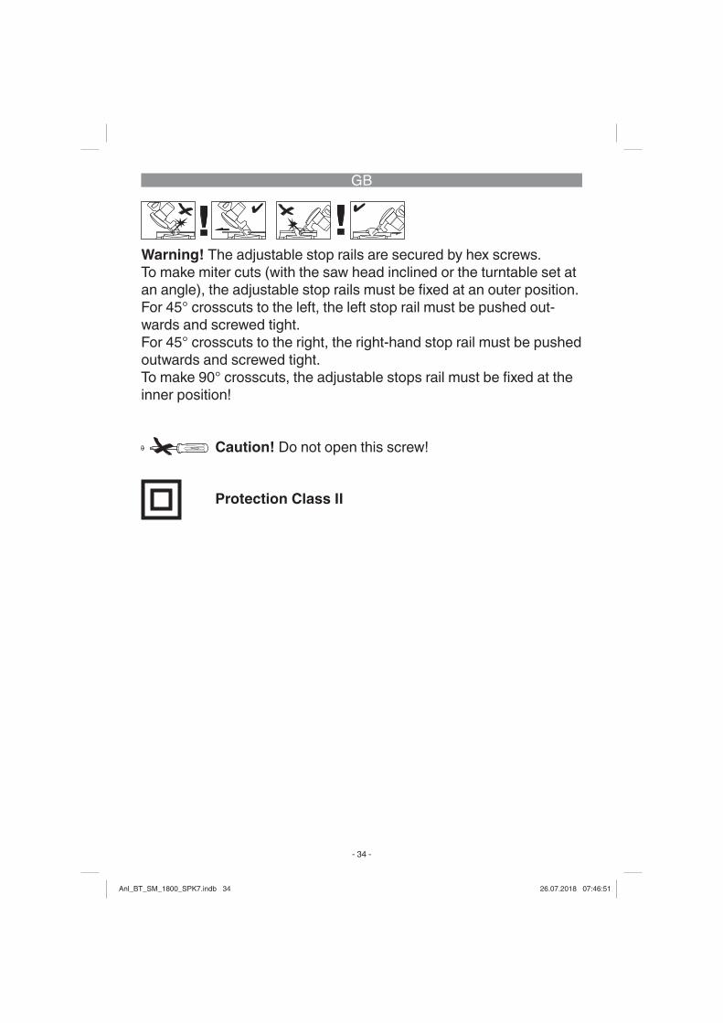
Warning! The adjustable stop rails are secured by hex screws.To make miter cuts (with the saw head inclined or the turntable set at an angle), the adjustable stop rails must be fi xed at an outer position.For 45° crosscuts to the left, the left stop rail must be pushed out-wards and screwed tight.For 45° crosscuts to the right, the right-hand stop rail must be pushed outwards and screwed tight.To make 90° crosscuts, the adjustable stops rail must be fi xed at the inner position!
Caution! Do not open this screw!
Protection Class II
Anl_BT_SM_1800_SPK7.indb 34Anl_BT_SM_1800_SPK7.indb 34 26.07.2018 07:46:5126.07.2018 07:46:51

GB
- 35 -
Danger! When using the equipment, a few safety precautions must be observed to avoid injuries and damage. Please read the com-plete operating instructions and safety regulations with due care. Keep this manual in a safe place, so that the information is availa-ble at all times. If you give the equipment to any other person, hand over these operating inst-ructions and safety regulations as well. We cannot accept any liability for damage or accidents which arise due to a failure to follow these instructions and the safety instructions.
1. Safety regulations
The corresponding safety infor-mation can be found in the enc-losed booklet.Danger! Read all safety regulations and instructions.Any errors made in following the safety regulations and instruc-tions may result in an electric shock, fi re and/or serious injury.Keep all safety regulations and instructions in a safe place for future use.
Special information about the laser
� Caution! Laser radiationDo not look into the beamLaser class 2
VORSICHT ! - LASERSTRAHLUNG !Nicht in den Strahl blicken!
LaserspezifikationLaser Klasse 2
: 650 nm; P0
• Never look directly into the laser path.
• Never direct the laser beam at reflecting surfaces or per-sons or animals. Even a low output laser beam can inflict injury on the eye.
• Caution: It is vital to follow the work procedures described in these instructions. Using the equipment in any other way may result in hazardous expo-sure to laser radiation.
• Never open the laser module.• It is prohibited to carry out
any modifications to the laser to increase its power.
• The manufacturer cannot ac-cept any liability for damage due to non-observance of the safety information.
Anl_BT_SM_1800_SPK7.indb 35Anl_BT_SM_1800_SPK7.indb 35 26.07.2018 07:46:5126.07.2018 07:46:51

GB
- 36 -
2. Layout and items supplied
2.1 Layout (Fig. 1-3)1. Handle2. ON/OFF switch3. Release lever4. Machine head5. Saw shaft lock6. Adjustable blade guard7. Saw blade8. Clamping device9. Additional feet10. Workpiece support11. Fixed stop rail12. Table insert13. Adjustable foot14. Locking screw15. Pointer16. Scale17. Turntable18. Fixed saw table19. Scale20. Pointer21. Locking screw22. Sawdust bag23. Drag guide24. Locking screw for drag guide25. Fastening bolt26. Locking screw for workpiece
support27. Knurled screw for cutting
depth limiter28. Stop for cutting depth limiter29. Adjusting screw30. Adjusting screw31. Flange bolt
32. Outer fl ange33. Button34. Movable stop rail35. Laser36. Swing-out stability bar37. ON/OFF switch for laser38. Transport handle
2.2 Items suppliedPlease check that the article is complete as specifi ed in the scope of delivery. If parts are missing, please contact our ser-vice center or the sales outlet where you made your purchase at the latest within 5 working days after purchasing the pro-duct and upon presentation of a valid bill of purchase. Also, refer to the warranty table in the ser-vice information at the end of the operating instructions.• Open the packaging and take
out the equipment with care.• Remove the packaging mate-
rial and any packaging and/or transportation braces (if available).
• Check to see if all items are supplied.
• Inspect the equipment and accessories for transport da-mage.
• If possible, please keep the packaging until the end of the guarantee period.
Anl_BT_SM_1800_SPK7.indb 36Anl_BT_SM_1800_SPK7.indb 36 26.07.2018 07:46:5126.07.2018 07:46:51

GB
- 37 -
Danger! The equipment and packaging material are not toys. Do not let children play with plastic bags, foils or small parts. The-re is a danger of swallowing or suff ocating!
• Drag, crosscut and miter saw• Clamping device (8)• 2 x workpiece support (10)• Sawdust bag (22)• Hexagon key (c, d)• Additional feet (9)• Original operating instructions• Safety instructions
3. Proper use
The drag, crosscut and miter saw is designed for cross-cutting wood and wood-type materials which are appropriate for the machine’s size. The saw is not designed for cutting fi rewood.
The equipment is to be used only for its prescribed purpose. Any other use is deemed to be a case of misuse. The user / ope-rator and not the manufacturer will be liable for any damage or injuries of any kind caused as a result of this.
Please note that our equipment has not been designed for use in commercial, trade or industrial applications. Our warranty will be voided if the machine is used in commercial, trade or industrial businesses or for equivalent pur-poses.
The equipment is to be operated only with suitable saw blades. It is prohibited to use any type of cutting-off wheel.
To use the equipment properly you must also observe the sa-fety information, the assembly instructions and the operating instructions to be found in this manual.All persons who use and service the equipment have to be ac-quainted with these operating in-structions and must be informed about the equipment’s potential hazards. It is also imperative to observe the accident prevention regulations in force in your area. The same applies for the gene-ral rules of health and safety at work.The manufacturer will not be lia-ble for any changes made to the equipment nor for any damage resulting from such changes. Even when the equipment is
Anl_BT_SM_1800_SPK7.indb 37Anl_BT_SM_1800_SPK7.indb 37 26.07.2018 07:46:5126.07.2018 07:46:51

GB
- 38 -
used as prescribed it is still im-possible to eliminate certain re-sidual risk factors. The following hazards may arise in connection with the machine’s construction and design:• Contact with the saw blade in
the uncovered saw zone.• Reaching into the running
saw blade (cut injuries).• Kick-back of workpieces and
parts of workpieces.• Saw blade fracturing.• Catapulting of faulty carbide
tips from the saw blade.• Damage to hearing if ear-
muffs are not used as neces-sary.
• Harmful emissions of wood dust when used in closed rooms.
4. Technical data
AC motor: ............. 230 V ~ 50HzPower: ....................................... ... 1500 W S1 / 1800 W S2 5 min. Idle speed n0: ............5000 min-1
Carbide saw blade: ................... .................ø 210 x ø 30 x 2.8 mmNumber of teeth: ................... 48Swiveling range: .. -45° / 0°/ +45°Miter cut to the left: .......0° to 45°Miter cut to the right: .....0° to 45°Saw width at 90°: .. 310 x 62 mm
Saw width at 45°: .. 210 x 62 mmSaw width at 2 x 45°(double miter cut left): ............... ............................... 210 x 36 mmSaw width at 2 x 45° (double miter cut right): ............. ............................... 210 x 20 mmWeight: ................. approx. 11 kgLaser class: ............................. 2Wavelength of laser: .......650 nmLaser output: .................≤ 1 mW
A load factor of S2 5 min (inter-mittent periodic duty) means that you may operate the motor continuously at its nominal power level (1800 W) for no longer than the time stipulated on the spe-cifi cations label (5 minutes ON period). If you fail to observe this time limit the motor will overheat. During the OFF period the motor will cool again to its starting tem-perature.
Danger! Sound and vibrationSound and vibration values were measured in accordance with EN 61029.
Anl_BT_SM_1800_SPK7.indb 38Anl_BT_SM_1800_SPK7.indb 38 26.07.2018 07:46:5126.07.2018 07:46:51

GB
- 39 -
LpA sound pressure level ............ ................................... 100 dB(A)KpA uncertainty ................... 3 dBLWA sound power level .............. ................................... 106 dB(A)KWA uncertainty ................... 3 dB
Wear ear-muff s.The impact of noise can cause damage to hearing.
Total vibration values (vector sum of three directions) determi-ned in accordance with EN 61029.
Vibration emission value ah = 2.7 m/s2
K uncertainty = 1.5 m/s2
The specifi ed vibration value was established in accordance with a standardized testing method. It may change according to how the electric equipment is used and may exceed the specifi ed value in exceptional circumstan-ces.
The specifi ed vibration value can be used to compare the equip-ment with other electric power tools.
The specifi ed vibration value can be used for initial assessment of a harmful eff ect.
Keep the noise emissions and vibrations to a minimum.• Only use appliances which
are in perfect working order.• Service and clean the appli-
ance regularly.• Adapt your working style to
suit the appliance.• Do not overload the appli-
ance.• Have the appliance serviced
whenever necessary.• Switch the appliance off when
it is not in use.
Caution! Residual risksEven if you use this electric power tool in accordance with instructions, certain residu-al risks cannot be rules out. The following hazards may arise in connection with the equipment’s construction and layout:1. Lung damage if no suitable
protective dust mask is used.2. Damage to hearing if no sui-
table ear protection is used.3. Health damage caused by
hand-arm vibrations if the equipment is used over a pro-
Anl_BT_SM_1800_SPK7.indb 39Anl_BT_SM_1800_SPK7.indb 39 26.07.2018 07:46:5226.07.2018 07:46:52

GB
- 40 -
longed period or is not pro-perly guided and maintained.
5. Before starting the equipment
Before you connect the equip-ment to the mains supply make sure that the data on the rating plate are identical to the mains data.Warning! Always pull the power plug before making adjustments to the equipment.
5.1 General information• The equipment must be set
up where it can stand secure-ly, i.e. it should be bolted to a workbench, a universal base frame or similar.
• All covers and safety devices have to be properly fitted before the equipment is swit-ched on.
• It must be possible for the blade to run freely.
• When working with wood that has been processed before, watch out for foreign bodies such as nails or screws, etc.
• Before you actuate the On/Off switch, make sure that the saw blade is correctly fitted
and that the equipment’s mo-ving parts run smoothly.
5.2 Assembling the saw (Fig. 1-5)
• To adjust the turntable (17), loosen the locking screw (14) by approx. 2 turns, which frees the turntable (17).
• Turn the turntable (17) and scale pointer (15) to the desi-red angular setting on the dial (16) and lock into place with the locking screw (14). The saw has locking positions at angles of - 45°, -31.6°, -22.5°, -15°, 0°, 15°, 22.5°, 31.6° and 45°, at which the turntable (17) audibly clicks into positi-on.
• To release the saw from its position at the bottom, pull the fastening bolt (25) out of the motor mounting while pressing down lightly on the machine head (4). Turn the fastening bolt (25) through 90° before releasing it, so that the saw remains unlocked.
• Swing the machine head (4) up until the release lever (3) latches into place.
• The clamping device (8) can be fitted on the left or right of the fixed saw table (18).
• Undo the locking screws for
Anl_BT_SM_1800_SPK7.indb 40Anl_BT_SM_1800_SPK7.indb 40 26.07.2018 07:46:5226.07.2018 07:46:52

GB
- 41 -
the workpiece support (26).• Mount the workpiece support
(10) on the fixed saw table (18) and tighten the appropri-ate locking screw (26) (Figure 4).
• Mount the second workpiece support (10) on the opposite side of the saw and secure with the appropriate locking screw (26).
• When the locking screw (21) is loosened, you can tilt the machine head (4) to the left by up to 45°.
• To ensure that the saw is standing securely, adjust the adjustable foot (13) by turning it so that the saw stands in a horizontal and firm position.
• Screw the additional feet (9) to the feet of the fixed saw ta-ble (18).
• Then swing out the stability bar (36) to the rear until it en-gages.
5.3 Precision adjustment of the stop for crosscut 90° (Fig. 7-8)
• Fasten the turntable (17) in 0° position.
• Undo the locking screw (21) and move the machine head (4) all the way to the right using the handle (1).
• Place the 90° angular stop (a) between the blade (7) and the turntable (17).
• Adjust the adjustment screw (29) until the angle between the blade (7) and the turntab-le (17) equals 90°.
• Finally check the position of the pointer (20) on the scale (19). If necessary, undo the pointer (20) with a Philips screwdriver, set it to the 0° position on the scale (19) and retighten the retainer screw.
• No stop angle included.
5.4 Precision adjustment of the stop for miter cut 45° (Fig. 1, 6, 7, 9)
• Fasten the turntable (17) in 0° position.
• Undo the locking screw (21) and move the machine head (4) all the way to the left using the handle (1), until it coinci-des at 45°.
• Place the 45° stop angle (b) between the blade (7) and the turntable (17).
• Adjust the adjustment screw (30) so that the angle bet-ween the blade (7) and the turntable (17) equals exactly 45°.
• No stop angle included.
Anl_BT_SM_1800_SPK7.indb 41Anl_BT_SM_1800_SPK7.indb 41 26.07.2018 07:46:5226.07.2018 07:46:52

GB
- 42 -
5.5 Adjusting the miter angle on the machine head (Fig. 2, 12-13)
• Undo the locking screw (21).• Hold the machine head (4) by
the handle (1).• After pulling the button (33),
the machine head can be tipped infinitely as well as to several locking points.
• Angles to the left: 0-45°• Angles to the right: 0-45°• Re-tighten the locking screw
(21).
5.6 Adjusting the movable stop rails (Fig. 1, 10-14)
• Caution! This saw is equip-ped with movable stop rails (34) that are screwed to the fixed stop rail (11).
• For carrying out angle and mi-ter cuts the movable stop rails must be adjusted to prevent a collision with the saw blade.
• For miter and angle cuts to the left, the left stop rail must be moved outwards. For angle cuts to the right, the right stop rail must be moved outwards. Undo the locking screws on the movable stop rails and pull the rails back so far that a collision with the saw bla-de can be ruled out. Prior to
every cut retighten the locking screws of the stop rails.
• For miter cuts and double mi-ter cuts with the saw head til-ted to the right, the right stop rail must be removed com-pletely. Important! In this case the maximum permissible workpiece height is reduced (see 4. Technical data).
• Always fasten the movable stop rails back to the equip-ment again after you have completed your work.
• The stop rails must always re-main together with the equip-ment. A removed stop rail will impair the operational safety of the equipment.
6. Operation
6.1 Cross cut 90° and turntable 0° (Fig. 1-3, 11)
For cutting widths up to approx. 100 mm it is possible to fi x the saw’s drag function with the lo-cking screw for drag guide (24) in rear position. If the cutting width exceeds 100 mm, you must en-sure that the locking screw for drag guide (24) is slackened and that the machine head (4) can be moved.
Anl_BT_SM_1800_SPK7.indb 42Anl_BT_SM_1800_SPK7.indb 42 26.07.2018 07:46:5226.07.2018 07:46:52

GB
- 43 -
• Move the machine head (4) to its upper position.
• Use the handle (1) to push back the machine head (4) and fix it in this position if re-quired (dependent on the cut-ting width).
• Place the piece of wood to be cut at the stop rail (11) and on the turntable (17).
• Lock the material with the clamping device (8) on the fixed saw table (18) to prevent the material from moving du-ring the cutting operation.
• Push down the release lever (3) to release the machine head (4).
• Press the ON/OFF switch (2) to start the motor.
• With the drag guide (23) fixed in place: Use the handle (1) to move the machine head (4) steadily and with light pres-sure downwards until the saw blade (7) has completely cut through the workpiece.
• With the drag guide (23) not fixed in place: Pull the machi-ne head (4) all the way to the front and then use the handle to move it downwards steadily and with light pressure. Now push the machine head (4) slowly and steadily to the very back until the saw blade (7)
has completely cut through the workpiece.
• When the cutting operation is completed, move the machi-ne head (4) back to its upper (home) position and release the ON/OFF button (2).
Important. The integral resetting springs will automatically lift the machine head. Do not simply let go of the handle (1) after cutting, but allow the machine head (4) to rise slowly, applying slight coun-ter pressure as it does so.
6.2 Cross cut 90° and turntab-le 0° - 45° (Fig. 1-3, 12)
The crosscut saw can be used to make crosscuts of 0°- 45° to the left and 0° - 45° to the right in re-lation to the stop rail.• Release the turntable (17) by
slackening the locking screw (14).
• Turn the turntable (17) and scale pointer (15) to the desi-red angular setting on the dial (16) and lock into place with the locking screw (14). The saw has locking positions at angles of - 45°, -31.6°, -22.5°, -15°, 0°, 15°, 22.5°, 31.6° and 45°, at which the turntable (17) audibly clicks into positi-on.
• Retighten the locking screw
Anl_BT_SM_1800_SPK7.indb 43Anl_BT_SM_1800_SPK7.indb 43 26.07.2018 07:46:5226.07.2018 07:46:52

GB
- 44 -
(14) to secure the turntable (17) in place.
• Cut as described under sec-tion 6.1.
6.3 Miter cut 0°- 45° and turn-table 0° (Fig. 1-3, 13)
The crosscut saw can be used to make miter cuts to the left of 0°-45° and to the right of 0°-45° in relation to the work surface.• If required, dismantle the
clamping device (8) or mount on the opposite side of the fixed saw table (18).
• Move the machine head (4) to its upper position.
• Fasten the turntable (17) in 0° position.
• Adjust the miter angle on the machine head and the stop rail as described under points 5.5 and 5.6.
• Cut as described under sec-tion 6.1.
6.4 Miter cut 0°- 45° and turn-table 0°- 45° (Fig. 1-3, 14)
The crosscut saw can be used to make miter cuts to the left of 0°-45° and to the right of 0°-45° in relation to the work surface, with simultaneous setting of the turntable from 0°-45° to the left
or 0°-45° to the right in relation to the stop rail (double miter cut).• If required, dismantle the
clamping device (8) or mount on the opposite side of the fixed saw table (18).
• Move the machine head (4) to its upper position.
• Release the turntable (17) by slackening the locking screw (14).
• Use the handle (1) to adjust the turntable (17) to the angle required (in this connection see also section 6.2).
• Retighten the locking screw (14) to secure the turntable in place.
• Adjust the miter angle on the machine head and the stop rail as described under points 5.5 and 5.6.
• Cut as described under sec-tion 6.1.
6.5 Limiting the cutting depth (Fig. 15)
• The cutting depth can be infinitely adjusted using the screw (27). Turn the screw (27) in or out to set the requi-red cutting depth and then re-tighten the knurled nut on the screw (27).
• Check the setting by comple-ting a test cut.
Anl_BT_SM_1800_SPK7.indb 44Anl_BT_SM_1800_SPK7.indb 44 26.07.2018 07:46:5226.07.2018 07:46:52

GB
- 45 -
6.6 Sawdust bag (Fig. 2)The saw is equipped with a de-bris bag (22) for sawdust and chips.The debris bag (22) can be emp-tied by means of a zipper at the bottom (1).
6.7 Changing the saw blade (Fig. 1, 16-18)
• Before changing the saw bla-de: Remove the power plug!
• Wear work gloves to prevent injury when changing the saw blade.
• Swing the machine head up-wards (4).
• Undo the screw (z) on the co-ver plate (f) of the saw blade.
• Pull back the adjustable bla-de guard (6) and at the same time turn the cover plate to achieve access to the flange bolt.
• Press the saw shaft lock (5) with one hand while positio-ning the hexagon key (d) on the flange bolt (31) with the other hand. The saw shaft lock (5) engages after no more than one rotation.
• Now, using a little more force, slacken the flange screw (31) in the clockwise direction.
• Turn the flange screw (31)
right out and remove the ex-ternal flange (32).
• Take the blade (7) off the in-ner flange and pull out down-wards.
• Carefully clean the flange screw (31), outer flange (32) and inner flange.
• Fit and fasten the new saw blade (7) in reverse order.
• Important. The cutting angle of the teeth, in other words the direction of rotation of the saw blade (7) must coincide with the direction of the arrow on the housing.
• Check to make sure that all safety devices are properly mounted and in good working condition before you begin working with the saw again.
• Important. Every time that you change the saw blade, check to see that it spins freely in the table insert(12) in both perpendicular and 45° angle settings.
• Important. The work to change and align the saw blade (7) must be carried out correctly.
6.8 Transport (Fig. 1-3)• Retighten the locking screw
(14) to secure the turntable (17) in place.
Anl_BT_SM_1800_SPK7.indb 45Anl_BT_SM_1800_SPK7.indb 45 26.07.2018 07:46:5226.07.2018 07:46:52

GB
- 46 -
• Activate the release lever (3), press the machine head (4) downwards and secure with the safety pin (25). The saw is now locked in its bottom posi-tion.
• Fix the saw’s drag function with the locking screw for drag guide (24) in rear position.
• Carry the equipment by the fixed saw table (18).
• To set up the equipment again, proceed as described in section 5.2.
6.9 Operating the laser (Fig. 2)To switch on: Move the ON/OFF switch (37) to the “I” position to switch on the laser (35). A laser line is projected onto the material you wish to process, providing an exact guide for the cut.To switch off : Move the ON/OFF switch (37) to the “0” position.
7. Replacing the power cable
Danger! If the power cable for this equip-ment is damaged, it must be replaced by the manufacturer or its after-sales service or similarly trained personnel to avoid dan-ger.
8. Cleaning, maintenance and ordering of spare parts
Danger! Always pull out the mains power plug before starting any cleaning work.
8.1 Cleaning• Keep all safety devices, air
vents and the motor housing free of dirt and dust as far as possible. Wipe the equipment with a clean cloth or blow it with compressed air at low pressure.
• We recommend that you clean the device immediately each time you have finished using it.
• Clean the equipment regularly with a moist cloth and some soft soap. Do not use cleaning agents or solvents; these could attack the plastic parts
Anl_BT_SM_1800_SPK7.indb 46Anl_BT_SM_1800_SPK7.indb 46 26.07.2018 07:46:5226.07.2018 07:46:52

GB
- 47 -
of the equipment. Ensure that no water can seep into the de-vice. The ingress of water into an electric tool increases the risk of an electric shock.
8.2 Carbon brushesIn case of excessive sparking, have the carbon brushes che-cked only by a qualifi ed electrici-an.Important! The carbon brushes should not be replaced by anyo-ne but a qualifi ed electrician.
8.3 MaintenanceThere are no parts inside the equipment which require additio-nal maintenance.
8.4 Ordering spare parts and accessories
Please provide the following in-formation when ordering spare parts:• Type of unit• Article number of the unit• ID number of the unit• Spare part number of the re-
quired spare partFor our latest prices and informa-tion please go to www.isc-gmbh.info
Tip! For good re-sults we recom-mend high-quality accessories from
! www.kwb.eu [email protected]
Anl_BT_SM_1800_SPK7.indb 47Anl_BT_SM_1800_SPK7.indb 47 26.07.2018 07:46:5226.07.2018 07:46:52

GB
- 48 -
9. Disposal and recycling
The equipment is supplied in packaging to prevent it from being damaged in transit. The raw materials in this packaging can be reused or recycled. The equipment and its accessories are made of various types of ma-terial, such as metal and plastic. Never place defective equipment in your household refuse. The equipment should be taken to a suitable collection center for pro-per disposal. If you do not know the whereabouts of such a coll-ection point, you should ask in your local council offi ces.
10. Storage
Store the equipment and acces-sories out of children’s reach in a dark and dry place at above freezing temperature. The ideal storage temperature is between 5 and 30 °C. Store the electric tool in its original packaging.
Anl_BT_SM_1800_SPK7.indb 48Anl_BT_SM_1800_SPK7.indb 48 26.07.2018 07:46:5226.07.2018 07:46:52

GB
- 49 -
For EU countries only
Never place any electric power tools in your household refuse.
To comply with European Directive 2012/19/EC concerning old elec-tric and electronic equipment and its implementation in national laws, old electric power tools have to be separated from other waste and disposed of in an environment-friendly fashion, e.g. by taking to a re-cycling depot.
Recycling alternative to the return request:As an alternative to returning the equipment to the manufacturer, the owner of the electrical equipment must make sure that the equipment is properly disposed of if he no longer wants to keep the equipment. The old equipment can be returned to a suitable collection point that will dispose of the equipment in accordance with the national recy-cling and waste disposal regulations. This does not apply to any ac-cessories or aids without electrical components supplied with the old equipment.
The reprinting or reproduction by any other means, in whole or in part, of documentation and papers accompanying products is permit-ted only with the express consent of the iSC GmbH.
Subject to technical changes
Anl_BT_SM_1800_SPK7.indb 49Anl_BT_SM_1800_SPK7.indb 49 26.07.2018 07:46:5226.07.2018 07:46:52

GB
- 50 -
• The product meets the requirements of EN 61000-3-11 and is subject to special connection conditions. This means that use of the product at any freely selectable connection point is not allo-wed.
• Given unfavorable conditions in the power supply the product can cause the voltage to fluctuate temporarily.
• The product is intended solely for use at connection points that a) do not exceed a maximum permitted mains system impedance of Z sys = 0.25 + j0.15, or b) have a continuous current-carrying capacity of the mains of at least 100 A per phase.
• As the user, you are required to ensure, in consultation with your electric power company if necessary, that the connection point at which you wish to operate the product meets one of the two requi-rements, a) or b), named above.
Anl_BT_SM_1800_SPK7.indb 50Anl_BT_SM_1800_SPK7.indb 50 26.07.2018 07:46:5226.07.2018 07:46:52

GB
- 51 -
Service information
We have competent service partners in all countries named on the guarantee certifi cate whose contact details can also be found on the guarantee certifi cate. These partners will help you with all ser-vice requests such as repairs, spare and wearing part orders or the purchase of consumables.
Please note that the following parts of this product are subject to normal or natural wear and that the following parts are therefore also required for use as consumables.
Category ExampleWear parts* Carbon brushesConsumables* Saw bladeMissing parts
* Not necessarily included in the scope of delivery!
In the eff ect of defects or faults, please register the problem on the internet at www.isc-gmbh.info. Please ensure that you provide a pre-cise description of the problem and answer the following questions in all cases:
• Did the equipment work at all or was it defective from the begin-ning?
• Did you notice anything (symptom or defect) prior to the failure?• What malfunction does the equipment have in your opinion (main
symptom)? Describe this malfunction.
Anl_BT_SM_1800_SPK7.indb 51Anl_BT_SM_1800_SPK7.indb 51 26.07.2018 07:46:5226.07.2018 07:46:52
GB
- 52 -
Warranty certifi cate
Dear Customer,All of our products undergo strict quality checks to ensure that they reach you in perfect condition. In the unlikely event that your de-vice develops a fault, please contact our service department at the address shown on this guarantee card. You can also contact us by telephone using the service number shown. Please note the following terms under which guarantee claims can be made:1. These guarantee terms apply to consumers only, i.e. natural per-
sons intending to use this product neither for their commercial activities nor for any other self-employed activities. These warranty terms regulate additional warranty services, which the manufac-turer mentioned below promises to buyers of its new products in addition to their statutory rights of guarantee. Your statutory gua-rantee claims are not aff ected by this guarantee. Our guarantee is free of charge to you.
2. The warranty services cover only defects due to material or ma-nufacturing faults on a product which you have bought from the manufacturer mentioned below and are limited to either the rec-tifi cation of said defects on the product or the replacement of the product, whichever we prefer.Please note that our devices are not designed for use in commer-cial, trade or professional applications. A guarantee contract will not be created if the device has been used by commercial, trade or industrial business or has been exposed to similar stresses du-ring the guarantee period.
3. The following are not covered by our guarantee: - Damage to the device caused by a failure to follow the assembly instructions or due to incorrect installation, a failure to follow the operating instructions (for example connecting it to an incorrect mains voltage or current type) or a failure to follow the mainte-nance and safety instructions or by exposing the device to abnor-mal environmental conditions or by lack of care and maintenance. - Damage to the device caused by abuse or incorrect use (for ex-ample overloading the device or the use or unapproved tools or
Anl_BT_SM_1800_SPK7.indb 52Anl_BT_SM_1800_SPK7.indb 52 26.07.2018 07:46:5226.07.2018 07:46:52

GB
- 53 -
accessories), ingress of foreign bodies into the device (such as sand, stones or dust, transport damage), the use of force or dama-ge caused by external forces (for example by dropping it). - Damage to the device or parts of the device caused by normal or natural wear or tear or by normal use of the device.
4. The guarantee is valid for a period of 24 months starting from the purchase date of the device. Guarantee claims should be submit-ted before the end of the guarantee period within two weeks of the defect being noticed. No guarantee claims will be accepted after the end of the guarantee period. The original guarantee period remains applicable to the device even if repairs are carried out or parts are replaced. In such cases, the work performed or parts fi t-ted will not result in an extension of the guarantee period, and no new guarantee will become active for the work performed or parts fi tted. This also applies if an on-site service is used.
5. To make a claim under the guarantee, please register the defective device at: www.isc-gmbh.info. Please keep your bill of purchase or other proof of purchase for the new device. Devices that are retur-ned without proof of purchase or without a rating plate shall not be covered by the guarantee, because appropriate identifi cation will not be possible. If the defect is covered by our guarantee, then the item in question will either be repaired immediately and returned to you or we will send you a new replacement.
Of course, we are also happy off er a chargeable repair service for any defects which are not covered by the scope of this guarantee or for units which are no longer covered. To take advantage of this ser-vice, please send the device to our service address.
Also refer to the restrictions of this warranty concerning wear parts, consumables and missing parts as set out in the service information in these operating instructions.
Anl_BT_SM_1800_SPK7.indb 53Anl_BT_SM_1800_SPK7.indb 53 26.07.2018 07:46:5226.07.2018 07:46:52

Dong/Product-ManagementWeichselgartner/General-Manager
- 54 -
D erklärt folgende Konformität gemäß EU-Richtlinie und Normen für Artikel
GB explains the following conformity according to EU directi-ves and norms for the following product
F déclare la conformité suivante selon la directive CE et les normes concernant l’article
I dichiara la seguente conformità secondo la direttiva UE e le norme per l’articolo
NL verklaart de volgende overeenstemming conform EU richtlijn en normen voor het product
E declara la siguiente conformidad a tenor de la directiva y normas de la UE para el artículo
P declara a seguinte conformidade, de acordo com as diretiva CE e normas para o artigo
DK attesterer følgende overensstemmelse i medfør af EU-direktiv samt standarder for artikel
S förklarar följande överensstämmelse enl. EU-direktiv och standarder för artikeln
FIN vakuuttaa, että tuote täyttää EU-direktiivin ja standardien vaatimukset
EE tõendab toote vastavust EL direktiivile ja standarditeleCZ vydává následující prohlášení o shodě podle směrnice EU
a norem pro výrobekSLO potrjuje sledečo skladnost s smernico EU in standardi za
izdelekSK vydáva nasledujúce prehlásenie o zhode podľa smernice
EÚ a noriem pre výrobokH a cikkekhez az EU-irányvonal és Normák szerint a
következő konformitást jelenti ki
PL deklaruje zgodność wymienionego poniżej artykułu z następującymi normami na podstawie dyrektywy WE.
BG декларира съответното съответствие съгласно Директива на ЕС и норми за артикул
LV paskaidro šādu atbilstību ES direktīvai un standartiemLT apibūdina šį atitikimą EU reikalavimams ir prekės normomsRO declară următoarea conformitate conform directivei UE şi
normelor pentru articolulGR δηλώνει την ακόλουθη συμμόρφωση σύμφωνα με την
Οδηγία ΕΚ και τα πρότυπα για το προϊόνHR potvrđuje sljedeću usklađenost prema smjernicama EU i
normama za artiklBIH potvrđuje sljedeću usklađenost prema smjernicama EU i
normama za artiklRS potvrđuje sledeću usklađenost prema smernicama EZ i
normama za artikal RUS следующим удостоверяется, что следующие продукты
соответствуют директивам и нормам ЕСUKR проголошує про зазначену нижче відповідність виробу
директивам та стандартам ЄС на вирібMK ја изјавува следната сообрзност согласно
ЕУ-директивата и нормите за артиклиTR Ürünü ile ilgili AB direktifl eri ve normları gereğince aşağıda
açıklanan uygunluğu belirtirN erklærer følgende samsvar i henhold til EU-direktivet og
standarder for artikkelIS Lýsir uppfyllingu EU-reglna og annarra staðla vöru
Konformitätserklärung
Zug-, Kapp- und Gehrungssäge BT-SM 1800 (Einhell)
2014/29/EU 2005/32/EC_2009/125/EC 2014/35/EU 2006/28/EC
X 2014/30/EU 2014/32/EU 2014/53/EC 2014/68/EU 90/396/EC_2009/142/EC 89/686/EC_96/58/EC
X 2011/65/EU
X 2006/42/EC Annex IVNotifi ed Body:Notifi ed Body No.:Reg. No.:
2000/14/EC_2005/88/EC Annex V Annex VI Noise: measured LWA = dB (A); guaranteed LWA = dB (A)P = KW; L/Ø = cmNotifi ed Body:
2012/46/EUEmission No.:
Standard references: EN 61029-1; EN 61029-2-9; EN 60825-1;EN 55014-1; EN 55014-2; EN 61000-3-2; EN 61000-3-11
Landau/Isar, den 17.05.2018
First CE: 18 Archive-File/Record: NAPR019183Art.-No.: 43.008.12 I.-No.: 11028 Documents registrar: Wasmeier KorbinianSubject to change without notice Wiesenweg 22, D-94405 Landau/Isar
ISC GmbH · Eschenstraße 6 · D-94405 Landau/Isar
Anl_BT_SM_1800_SPK7.indb 54Anl_BT_SM_1800_SPK7.indb 54 26.07.2018 07:46:5226.07.2018 07:46:52

- 55 -
Anl_BT_SM_1800_SPK7.indb 55Anl_BT_SM_1800_SPK7.indb 55 26.07.2018 07:46:5226.07.2018 07:46:52

EH 07/2018 (01)
Anl_BT_SM_1800_SPK7.indb 56Anl_BT_SM_1800_SPK7.indb 56 26.07.2018 07:46:5226.07.2018 07:46:52