FLOW SENSOR & METER
28
SENSOR & METER FLOW GENERAL CATALOGUE FD-M Series FD-S Series FD-S Series (PFA type) FD-V70 Series
-
Upload
independent -
Category
Documents
-
view
2 -
download
0
Transcript of FLOW SENSOR & METER
SENSOR & METERFLOW
G E N E R A L C A T A L O G U E
FD-M Series FD-S Series FD-S Series (PFA type) FD-V70 Series

2
KEYENCE Flow Detecting Technology
FLOW Sensor & Meter General Catalogue
Free flowing structureFlow sensors that do not become clogged
Minimal flowMeasurements in units of 0.1 mL(the accumulated flow unit)
Accumulated displayCapable of instantaneous and accumulated displays and equipped with analogue output

FD-M
Series
FD-S
Series
FD-V
70 Series
3
A Rich Variety of Model Variations
Flow Sensor & Meter General Catalogue Model Variation
Detecting range 0 to 40 L/min.
Pipe diameter4 x 3 mm, 3/8" x 1/4"
Kinematic viscosity : Oil level*1
Wetted materials : SCS14, SUS316L, PPS, FKM,*2 PFA
Pressure resistance 10 MPa*3
*1 A large pressure loss occurs with highly viscous fluids. (See page 12.)*2 For details on the separate material FFKM, contact your nearest KEYENCE office.*3 The operating pressure range is 5 MPa or less.
Detecting range PPS: 0.5 to 100 L/min.
PFA:0.4 to 50 L/min.
Pipe diameter ø3/8", ø1/2", ø3/4"
Kinematic viscosity : Water level*
Wetted materials : PPS or PFA
Pressure resistance PPS: 1 MPa or less, PFA: 0.7 MPA or less
* Highly viscous fluids cannot be measured. (See page 19.)
Flow Sensor Variations
Coriolis Method Digital Flow Sensor
FD-S Series (Coriolis method)
Separate-Amplifier Type Digital Flow Sensor
FD-V70 Series (Eddies + ultrasonic waves method)
Non-Wetted Electrode Electromagnetic Flow Sensor
FD-M Series (Electromagnetism + electrostatic capacitance method)
PFA type
8A 10A
10A 15A 20A 25A
P.6
P.10
P.18
Detecting range 0.15 to 1000 L/min.
Pipe diameter
Conductivity : 5 μS/cm or more
Wetted materials : SCS13, PPS, FKM
Pressure resistance 2 MPa*
* The operating pressure range is 1 MPa or less.
10A 20A 25A 50A

4
Detection Technology Only Available from KEYENCE
Flow Sensor & Meter General Catalogue Detection Technology
Out
put v
olta
ge
Coil
Pipe
Velocity of flow
Velocity of flow: V
External electrode
Coil
Eddy generator
Housing
Flow
When the fluid is not flowing
A A'Bθ
B'
When the fluid is flowing
Phase difference signal
A’ detection signalB’ detection signal
Resonance
Flow Ultrasonic wave
Receiver
Transmitter
External electrode
Electromotive force Electromotive force: E
Magnetic field Magnetic field: B
This method performs detections by way of electrostatic capacitance, which makes a free flowing structure possible.
Using Faraday’s law to perform detectionA typical electromagnetic flow sensor employs electrodes, wetted
within the pipe, to detect the electromotive force of the liquid.
The FD-M Series determines this value from outside the pipe by
means of electrostatic capacitance.
Hybrid detection using eddies and ultrasonic wavesThe detection method employs eddies and ultrasonic waves.
To detect eddies, this method uses ultrasonic waves instead of
piezoelectric effect elements, which are easily influenced by
vibrations. The result is stable flow detections with high accuracy.
Faraday’s lawWhen conductive fluid flows through a magnetic field, electric voltage is generated in proportion to the value calculated by (the inner diameter of the pipe x the magnetic field strength x the average flow velocity of the fluid). The flow can be determined by measuring this voltage.
The flowing liquid causes the eddy generator to generate eddies, which are detected by way of the ultrasonic waves.
Using the Coriolis method to perform detectionThe flow causes the Coriolis force to be generated at the entrance
and exit of the flow pipe, which causes the twist angle θ to be
generated due to resistance against the pipe vibrations. This angle is
read with electrical signals and is converted to the flow.
ELECTROMAGNETISM + ELECTROSTATIC CAPACITANCE METHOD
CORIOLIS METHOD
EDDIES + ULTRASONIC WAVES METHOD
FD-M
FD-S
FD-V70
This method uses ultrasonic waves, which makes joint-less structures possible.
This method can be used to detect the flows of all kinds of liquids.
Coriolis forceOne kind of inertial force whose size is generated in proportion to the movement speed.

FD-M
FD-M FD-M
FD-M FD-M
FD-S
FD-S
FD-S
FD-S
FD-S
FD-S FD-S
FD-V70
FD-V70
FD-V70
FD-V70
FD-M
Series
FD-S
Series
FD-V
70 Series
5
Examples of Success in Various Locations
Flow Sensor & Meter General Catalogue Success Example
Small flowForeign materials, sludge, and abrasion grains are not properly rinsed away, which may lead to surface damage.
Large flowA layer of water is formed between the grindstone and the workpiece, which results in uneven surface roughness.
Flow control of the cooling water used in the vulcanising process of tyres
Control of the amount of mould release agent applied
Checking the amount of cooling water used
Oil-based coolant flow control Cooling-water flow control for induction hardening equipment
Cooling-water control for extrusion moulding equipment
Control of the cooling water used in precision moulding
Checking the flow of cleaning water
Cooling-water flow control for welding machines
Water-soluble coolant flow control
Control of the amount of liquid-crystal washing agent supplied
CMP slurry flow control
The FD-M Series can output an alarm when a value falls below the set lower limit. The FD-M Series protects equipment from overheating.
This sensor performs cooling-water control for extrusion moulding equipment. Using analogue output makes it possible to also perform detailed control.

6
Flow Sensor & Meter General Catalogue Flow Sensor FD-M Series
Flow sensors highly resistant to clogging because of their free flowing structure
Free flowing structureNo obstructions, no paddle wheels, no electrodes
Non-Wetted Electrode Electromagnetic Flow Sensor
FD-M Series
Detecting range 0.15 to 1000 L/min.
Pipe diameter
Usable fluids : Water or non-corrosive fluid
Conductivity : 5 μS/cm or more
Wetted materials : SCS13, PPS, FKM
Pressure resistance 2 MPa*
Detection principle Electromagnetism + electrostatic capacitance method
* The operating pressure range is 1 MPa or less.
10A 20A 25A 50A
Merits of the FD-M Series
Lowers maintenance Dramatically reduces clogging
Unlike general floating element and paddle wheel flow meters, the FD-M Series has a “free flowing structure” that is completely free of moving parts and obstructions. There is no trouble with dirt and rust clogging the mechanical parts, greatly reducing maintenance.
Long lifespan No damage from moving partsDue to the absence of moving parts, it does not experience axial wear and other types of mechanical wear. Through its “free flowing structure” the FD-M Series has achieved a significantly longer lifespan.
Energy saving Dramatically reduces pressure lossDue to its “free flowing structure”, the FD-M Series has almost no pressure loss. Does not apply a large load on pumps and thus saves energy.
Resistant to the adherence of insulating materialsNo electrodes in the flow pipeWith conventional electrode types, detection could not be performed when the electrodes were covered in insulating materials. However, the FD-M Series with “free flowing structure” detects from outside its flow pipe, which originally does not conduct electricity, and because of this, the FD-M Series is capable of detection even with the adherence of insulating materials.
Variations
Built-in amplifier type, electromagnetism method (general type)
Model Detecting range (L/min.)*1 Pipe diameter Piping direction Output format
FD-M5ATRated range 0.25 to 5
Rc3/8(10A)
VerticalNPN*2
FD-M5ATP PNP
FD-M5AYDisplay range 0.15 to 10 Horizontal
NPN
FD-M5AYP PNP
FD-M10ATRated range 0.5 to 10
Rc3/8(10A)
VerticalNPN
FD-M10ATP PNP
FD-M10AYDisplay range 0.5 to 30 Horizontal
NPN
FD-M10AYP PNP
FD-M50ATRated range 2.5 to 50
Rc3/4(20A)
VerticalNPN
FD-M50ATP PNP
FD-M50AYDisplay range 2.5 to 100 Horizontal
NPN
FD-M50AYP PNP
FD-M100ATRated range 5 to 100
Rc1(25A)
VerticalNPN
FD-M100ATP PNP
FD-M100AYDisplay range 5 to 200 Horizontal
NPN
FD-M100AYP PNP
*1 Values that are within a range that is twice that of the rated range can be displayed.*2 Among the NPN-output types, the FD-MZ Series, in which the power cable has been changed to a
connector, is available. For details, contact your nearest KEYENCE office.
Separate-amplifier type, electromagnetism method (general type)
Head
Model Detecting range (L/min.)*1 Pipe diameter
Piping direction
FD-MH10ARated range 0.5 to 10 Rc3/8
(10A)
Vertical or horizontal
Display range 0.5 to 30
FD-MH50ARated range 2.5 to 50 Rc3/4
(20A)Display range 2.5 to 100
FD-MH100ARated range 5 to 100 Rc1
(25A)Display range 5 to 200
FD-MH500A*2Rated range 25 to 500 Rc2
(50A)Display range 25 to 1000
*1 Values that are within a range that is twice that of the rated range can be displayed.
*2 When the FD-MH500A has a flow rate of 500 to 1000 L/min., the conductivity becomes 20 μS/cm or more.
AmplifierModel Type
FD-MA1A
DIN rail mountingFD-MA2A
FD-MA1AP
FD-MA2AP
* Models with “1” at the end of their model number are main units. Models with “2” at the end of their model number are expansion units.
Model Type
FD-MA5APanel mounting
FD-MA5AP
* A panel mounting bracket is included with the panel mount type.

FD-M
Series
7
Flow Sensor & Meter General Catalogue Flow Sensor FD-M Series
Supports temperature sensors (Separate-Amplifier Type only)
A temperature sensor can be combined with the FD-T1 Series. It outputs an alarm when the current temperature exceeds the preset temperature. The FD-M Series can reliably detect errors by checking the flow and temperature of the fluid.
Supports communication units (separate-amplifier type only)It’s possible to communicate a variety of data with PLCs and PCs by using a communication unit.
Built-in Amplifier Type
FD-M Series
Separate-Amplifier Type
FD-MH Series
Dual digital display with easy setup
Dual coloured digital display allows you to adjust setting values, while monitoring the present flow. Also, the select and toggle buttons can be used to easily configure settings.
Enclosure rating: IP65
The IP65 enclosure rating of the FD-M makes it possible to use this sensor in harsh environments.
Enclosure rating IP67
The sensor head of the separate-amplifier type has achieved an enclosure rating of IP67. This further widens the range of environments in which this sensor can be used.
Wire-saving and can be expanded up to 10 units
Through expansion, the power line is supplied from the side connector, saving 2 wires (+ and - power source) for each unit.
Close vertical mounting
The panel mounting type is capable of close vertical mounting.
Flow conditions that are understood even with just the sensor head Dual digital display with easy setup
Switchable flow direction
The flow direction can be switched by using the mode setting; you can mount the flow sensor at any location that can provide easy-to-view monitoring.* The separate-amplifier type cannot be switched.
Can be installed regardless of flow direction.
* The panel mounting type cannot be expanded.
* The BCD unit DL-RB1A is not supported.* The panel type amplifier does not support the DL-RS1A/RB1A/CL1/DN1/EP1.* Temperature settings can be performed from a window.
Output 1 indicator
Present value indicatorOutput 2 indicatorBank indicatorAlarm indicator
Select and toggle buttons
Setting value indicatorSetup indicator
Mode button
Sensor head
Alarm indicator
Output 2 indicatorOutput 2 indicator
Mode button
Set value indicator Set value display
Output 1 indicator
Output 1 indicator
Present value display Bank indicator
Arrow keys
Alarm indicator
Temperature display PCProgrammable logic controller
Set value
Set value
Temperature
Flow
Control output
Alarm output
Flow reduction Instantaneous flow data Accumulated flow data Control output status
Temperature data Hold-reset
Accumulation reset, etc.
Temperature increase
Connection with the temperature sensor
Connection with the amplifier
Set temperature
Temperature sensorFD-T1
RS-232CCommunication unitDL-RS1/CL1/ DN1/EP1
Panel mounting type amplifier
DIN rail mounting type amplifier
Flow indicatorDisplays the flow conditions with a scroll speed that matches the instantaneous flow.
Flow indicatorThe flow indicator displays the flow conditions at a scroll speed that matches the instantaneous flow. The two-colour LED screens light in conjunction with the ON/OFF state of output 1.

End unit End unit
Amplifier mounting bracket
8
Flow Sensor & Meter General Catalogue Flow Sensor FD-M Series
Flow pipe
Bore
Instantaneous flow(L/min.)
Connection pipe diameter Piping direction Output format Model
0.15 to 10
Rc3/8(10A)
VerticalNPN FD-M5AT
PNP FD-M5ATP
HorizontalNPN FD-M5AY
PNP FD-M5AYP
0.5 to 30
VerticalNPN FD-M10AT
PNP FD-M10ATP
HorizontalNPN FD-M10AY
PNP FD-M10AYP
2.5 to 100 Rc3/4(20A)
VerticalNPN FD-M50AT
PNP FD-M50ATP
HorizontalNPN FD-M50AY
PNP FD-M50AYP
5 to 200 Rc1(25A)
VerticalNPN FD-M100AT
PNP FD-M100ATP
HorizontalNPN FD-M100AY
PNP FD-M100AYP
* The FD-M Series cannot be used in an environment in which the pipes are positive grounded. For this purpose, the FD-MZ Series is available. For details, contact your nearest KEYENCE office.
If the built-in type was selected, proceed to step 6.
If the separate type was selected, proceed to step 4.
Instantaneous flow(L/min.)
Connection pipe diameter Piping direction Output format Model
0.5 to 30 Rc3/8 (10A) Vertical or horizontal Depends on the display FD-MH10A
2.5 to 100 Rc3/4 (20A) Vertical or horizontal Depends on the display FD-MH50A
5 to 200 Rc1 (25A) Vertical or horizontal Depends on the display FD-MH100A
25 to 1000 Rc2 (50A) Vertical or horizontal Depends on the display FD-MH500A
TypeModel
NPN output PNP output
DIN rail mountingMain unit FD-MA1A FD-MA1AP
Expansion unit FD-MA2A FD-MA2AP
Panel mounting FD-MA5A FD-MA5AP
The DIN rail mounting type supports reduced wiring.Systems can be expanded up to nine expansion units for each one main unit.In an expanded system, expansion unit power supply wires are not necessary.
Options dedicated for use with the separate-display type
Type Shape Explanation Model
DIN rail mounting type amplifier mounting fixture (for the main unit; sold separately)
This option makes it possible to install the unit when no DIN rail is present. OP-76877
End unit(sold separately)
This option is used at the front and end of a series of main and expansion amplifiers when the system is expanded in order to fix all the units in place. Be sure to use this option when expanding the system. (Two units are included.)
OP-26751
Panel mounting bracket(included with the panel mounting type amplifier)
This option is included with the display of the panel mounting type.Use this option separately if the included part is lost or damaged. OP-76876
Selecting an FD-M Series UnitFollow the steps shown here to select an appropriate unit.
Step 1
Step 1
Step 2
Step 3
Step 4
Step 5
Step 6
Step 2
Step 3
Step 4
Step 5
Step 6
Checking the target fluid
Sensor Temperature sensor and
communication unit
Checking the flow and
temperature
Display(amplifier)
Mounting bracket
Checking the target fluid The FD-M Series can be used with a fluid that has a conductivity of 5 μS/cm or more. Be sure to check the conductivity of the fluid.
Checking the instantaneous flow and temperature
Selecting the basic sensor Select a built-in display or a separate display to match the installation environment.
Selecting the separate display (amplifier) and options This step is necessary when using the separate type. Select the appropriate products to match the mounting method.
Selecting the temperature sensor and communication unit as necessary These parts are designed for use with the separate-display type. They cannot be used with the built-in display type.
Selecting mounting brackets as necessary Excluding the FD-MH500 separate head, the mounting brackets can be used with all separate heads and with all built-in display (amplifier) types.
Fluids that are very likely to be usable with the FD-M Series
Instantaneous flow of fluids that can be supported by the FD-M Series
Built-in display (amplifier) type
DIN rail mounting type Panel mounting type
Temperature sensor dedicated for use with the separate type
Temperature sensor model: FD-T1 Temperature detecting range: 0 to 90°C
L-shaped mounting bracketOP-42193
Flat mounting bracketOP-42194
Communication units (for use with the DIN rail mounting, separate-display [amplifier] type)
Model: DL-RS1A (communication unit that supports RS-232C) DL-CL1 (communication unit that supports CC-Link) DL-DN1 (communication unit that supports DeviceNet) DL-EP1 (communication unit that supports EtherNet/IP)
Separate display (amplifier) type
Fluids that are not very likely to be usable with the FD-M Series
The materials shown below are used in the flow path of the FD-M Series.Note that this sensor cannot be used with fluids that will corrode these materials.
The FD-M Series can support fluid temperatures from 0 to 85°C.
Select the sensor to match the flow that was determined in step 2.
Bore: SCS13Flow pipe: PPS (polyphenylene sulfide)O-ring: Fluoro-rubber
Cooling water and warming water (tap, underground, and industrial water) as well as water-soluble coolant (diluted with water)
Oil, ultrapure water, alcohol, and organic solvents
0.15 L/min. to 1000 L/min.

FD-M
Series
9
SpecificationsBuilt-in amplifier type
Model*1
NPN outputFor vertical piping FD-M5AT FD-M10AT FD-M50AT FD-M100ATFor horizontal piping FD-M5AY FD-M10AY FD-M50AY FD-M100AY
PNP outputFor vertical piping FD-M5ATP FD-M10ATP FD-M50ATP FD-M100ATPFor horizontal piping FD-M5AYP FD-M10AYP FD-M50AYP FD-M100AYP
Configuration Built-in amplifier typeRated flow range*2 0.25 to 5 L/min. 0.5 to 10 L/min. 2.5 to 50 L/min. 5 to 100 L/min.Display range*3 0.15 to 10 L/min. 0.5 to 30 L/min. 2.5 to 100 L/min. 5 to 200 L/min.Settable range 0 to 10 L/min. 0 to 30 L/min. 0 to 100 L/min. 0 to 200 L/min.Minimum flow*4 0.15 L/min. 0.5 L/min. 2.5 L/min. 5 L/min.Connection pipe diameter Rc3/8 (10A) Rc3/4 (20A) Rc1 (25A)Usable fluids Water or non-corrosive fluidConductivity of usable fluids 5 μS/cm or moreTemperature of usable fluids 0 to +85°C (no freezing)Operating pressure range 1.0 MPa or lessPressure resistance 2.0 MPaPressure loss 0.01 MPa or lessDisplay method Dual row display with 4-digit, 7-segment LED; bar display (2 colours)Display resolution 0.05/0.1 (L/min.) selectable*5 0.01/0.1 (L/min.) selectable 0.1/1 (L/min.) selectableRepeatability*6 0.5 s: ±5% of F.S., 1 s: ±3.5% of F.S., 2.5 s: ±2.5% of F.S., 5 s: ±1.6% of F.S., 10 s: ±1% of F.S., 30 s: ±0.8% of F.S., 60 s: ±0.6% of F.S.Hysteresis VariableResponse time (chattering prevention) 500 ms/1 s/2.5 s/5 s/10 s/30 s/60 s variableAccumulated display unit 0.01/0.1/1/10/100 (L) selectable 0.1/1/10/100/1000 (L) selectableAccumulated data storage Data written to memory once every 10 secondsMemory backup EEPROM (data storage period: 10 years or more, number of times data can be rewritten: 1 million times or more)Control output/accumulation pulse output/error alarm output NPN/PNP open collector, max. 100 mA/ch*7 (NPN: 40 V or less, PNP: 30 V or less); residual voltage: 1 V or less; 3 outputs (N.O./N.C. switchable)Accumulation reset/bank switching/zero flow function Input time: 20 ms or more, accumulation reset or bank switching selectable by way of the mode settingAnalogue output 4 to 20 mA, max. load resistance: 260 Ω, analogue output range can be set to an arbitrary valuePower supply voltage 24 VDC ±10%, ripple (P-P): ±10% or lessPower consumption (current consumption) Normal: 1700 mW (70 mA), power save: 1000 mW (40 mA)Enclosure rating IP65
Environmental resistance
Ambient operating temperature 0 to +50°C (no freezing)Ambient operating humidity 35 to 85% RH (no condensation)Vibration resistance 10 to 55 Hz; 1.5 mm compound amplitude; 2 hours in each of the X, Y, and Z directions
MaterialsWetted part Bore: SCS13, flow pipe: PPS, O-ring: fluoro-rubber (FKM)Other materials Plastic parts of case: PBT, metal parts of case: SUS430, cable: PVC
Weight Approx. 835 g Approx. 1100 g Approx. 1310 gAccessory Instruction manual
*1 The types that have an “A” at the end of their names are the conventional types with additional functions such as display averaging. *2 The rated flow range indicates the range that is supposed to be used in general. *3 This can be used within the display range in the same manner as it is used within the rated flow range. *4 A flow less than or equal to the minimum flow is displayed as 0 L/min. *5 When 0.05 L/min. is selected, the instantaneous flow is displayed in increments of 0.05 for values between 0.15 and 0.5 L/min. and in increments of 0.01 for values above 0.5 L/min. *6 The repeatability indicates the calculation error in the detections performed with repeated flows under fixed conditions. The repeatability is effective within the display range. When performing conversions using F.S. (full scale) in this table, use the rated flow range for the F.S. value. The repeatability for the FD-M5AT(P)/Y(P) is ±7.5% of F.S. at a response time of 0.5 s and ±5% of F.S. at a response time of 1 s. The repeatability for the FD-M10AT(P)/Y(P) in the range of 20 to 30 L/min. is twice that of the values listed in the table. *7 The maximum alarm output is 20 mA.
Sensor head (separate type)Model*1 FD-MH10A FD-MH50A FD-MH100A FD-MH500A
Configuration Separate-amplifier typeRated flow range*2 0.5 to 10 L/min. 2.5 to 50 L/min. 5 to 100 L/min. 25 to 500 L/min.
Amplifier display range*3 0.5 to 30 L/min. 2.5 to 100 L/min. 5 to 200 L/min. 25 to 1000 L/min.
Connection pipe diameter Rc3/8 (10A) Rc3/4 (20A) Rc1 (25A) Rc2 (50A)
Usable fluids Water or non-corrosive fluid
Conductivity of usable fluids 5 μS/cm or more With 25 to 500 L/min.: 5 μS/cm or moreWith 500 to 1000 L/min.: 20 μS/cm or more
Temperature of usable fluids 0 to +85°C (no freezing)
Operating pressure range 1.0 MPa or less
Pressure resistance 2.0 MPa
Pressure loss 0.01 MPa or less*4
Display method Bar display (2 colours), other indicators
Enclosure rating IP67
Environmental resistance
Ambient operating temperature 0 to +50°C (no freezing)
Ambient operating humidity 35 to 85% RH (no condensation)
Vibration resistance 10 to 55 Hz; 1.5 mm compound amplitude; 2 hours in each of the X, Y, and Z directions
MaterialsWetted part Bore: SCS13, flow pipe: PPS, O-ring: fluoro-rubber (FKM)
Other materials Plastic parts of case: PBT, indicators: polyarylate, metal parts of case: SUS430, cable: PVC
Weight Approx. 800 g Approx. 1070 g Approx. 1280 g Approx. 3700 gAccessory Warnings
*1 The models that have an “A” at the end of their names support the type A amplifier. These models operate normally even when a conventional amplifier that does not have an “A” at the end of its name is connected. *2 The rated flow range indicates the range that is supposed to be used in general. *3 This can be used within the display range in the same manner as it is used within the rated flow range. *4 This excludes the situation in which the FD-MH500A is used with a flow of 500 L/min. to 1000 L/min. For details, see the pressure loss data.
Amplifier unit (separate type)
Model*1
NPN outputDIN rail mounting type*2 FD-MA1A (main unit)/FD-MA2A (expansion unit)Panel mounting type*3 FD-MA5A
PNP outputDIN rail mounting type*2 FD-MA1AP (main unit)/FD-MA2AP (expansion unit)Panel mounting type*3 FD-MA5AP
Head combination FD-MH10A FD-MH50A FD-MH100A FD-MH500ARated flow range*4 0.5 to 10 L/min. 2.5 to 50 L/min. 5 to 100 L/min. 25 to 500 L/min.
Display range*5 0.5 to 30 L/min. 2.5 to 100 L/min. 5 to 200 L/min. 25 to 1000 L/min.
Settable range 0 to 30 L/min. 0 to 100 L/min. 0 to 200 L/min. 0 to 999.9 L/min.
Minimum flow*6 0.5 L/min. 2.5 L/min. 5 L/min. 25 L/min.
Display method Dual row display with 4-digit, 7-segment LED; other indicators
Display resolution 0.01/0.1 (L/min.) selectable 0.1/1 (L/min.) selectable
Repeatability*7 0.5 s: ±5% of F.S., 1 s: ±3.5% of F.S., 2.5 s: ±2.5% of F.S., 5 s: ±1.6% of F.S., 10 s: ±1% of F.S., 30 s: ±0.8% of F.S., 60 s: ±0.6% of F.S.
Hysteresis Variable
Response time (chattering prevention) 500 ms/1 s/2.5 s/5 s/10 s/30 s/60 s variable
Accumulated display unit 0.01/0.1/1/10/100 (L) selectable 0.1/1/10/100/1000 (L) selectable 1/10/100/1000/10000 (L) selectable
Accumulated data storage Data written to memory once every 10 seconds
Memory backup EEPROM (data storage period: 10 years or more, number of times data can be rewritten: 1 million times or more)
Control output/accumulation pulse output/error alarm output NPN/PNP open collector, max. 100 mA/ch*8 (NPN: 40 V or less, PNP: 30 V or less); residual voltage: 1 V or less; 3 outputs (N.O./N.C. switchable)
Accumulation reset/bank switching/zero flow function Input time: 20 ms or more, accumulation reset or bank switching selectable by way of the mode setting
Analogue output 4 to 20 mA, max. load resistance: 260 Ω, analogue output range can be set to an arbitrary value
Power supply voltage 24 VDC ± 10%, ripple (P-P): ±10% or lessPower consumption (current consumption) Normal: 1700 mW (70 mA), power save: 1440 mW (60 mA)
Environmental resistance
Ambient operating temperature 0 to +50°C (no freezing)Ambient operating humidity 35 to 85% RH (no condensation)Vibration resistance 10 to 55 Hz; 1.5 mm compound amplitude; 2 hours in each of the X, Y, and Z directions
Materials Main case: polycarbonate, key tops: polyacetal, front sheet: polycarbonate, cable: PVC
WeightDIN rail mounting type Approx. 115 gPanel mounting type Approx. 105 g
AccessoriesDIN rail mounting type Main unit: instruction manual, expansion unit: nonePanel mounting type Panel mounting bracket, front protective cover, instruction manual
*1 The types that have an “A” at the end of their names are the conventional types with additional functions such as display averaging. Connect the heads that have an “A” at the end of their names. If a conventional head, which does not have an “A” at the end of its name, is connected, the FD-M operates in the same way as the conventional models. *2 Do not connect to the sides of units other than the DL-RS1 and FD-M. *3 There are no expansion units for the panel mounting type. *4 The rated flow range indicates the range that is supposed to be used in general. *5 This can be used within the display range in the same manner as it is used within the rated flow range. *6 A flow less than or equal to the minimum flow is displayed as 0 L/min. *7 The repeatability indicates the calculation error in the detections performed with repeated flows under fixed conditions. When performing conversions using F.S. (full scale), use the rated flow range for the F.S. value. *8 The maximum alarm output is 20 mA. When using a total of 6 to 10 units in an expanded system, ensure that each output current is 10 mA or less.
Flow Sensor & Meter General Catalogue Flow Sensor FD-M Series

10
Minimal flow detections in units of 0.1 mL, even for non-conductive fluids
Coriolis Method Digital Flow Sensor
FD-S Series
*1 A large pressure loss occurs with highly viscous fluids. (See page 12.) *2 For details on the separate material FFKM, contact your nearest KEYENCE office. *3 The operating pressure range is 5 MPa or less.
Detecting range 0 to 40 L/min.
Pipe diameter
Usable fluids : Water, oil, or non-corrosive fluidKinematic viscosity: Oil level*1
Wetted materials : SCS14, SUS16L, PPS, FKM*2
Pressure resistance: 10 MPa*3
Detection principle Coriolis method
8A 10A
Coriolis method
Measures a minimal flow in which a single water droplet drops each second
Three flow measurements made possible by the Coriolis method
Minimal flows Resolution: 0.1 mL/min.Measurements of minimal flows are now possible. Examples of such flows include those in which a single water droplet drops each second and the minimal amounts of mould release agent ejected in a single shot.
Oil flows Oil, high pressure (5 MPa), and high temperature (100°C)
All kinds of fluids, oil, pure water, and other non-conductive fluids as well as viscous fluids, can be measured.
High-speed flows Response time: 50 msThis sensor has achieved a fastest response time of 50 ms. As a result, this sensor can measure, without missing any information, short-time flows of fluids, which were difficult to measure with conventional sensors. Examples of applications of these measurements include spraying and coating confirmations.
Variations
Built-in display type sensorsType Model Detecting range (mL/min.) Pipe diameter Output format
Ultra minimal flow FD-SS02A
Rated range*1 0.0 to 200
8A(Rc1/4)
NPN or PNP can be selected in the initial
settings.
Display range 0.0 to 400
Minimal flow FD-SS2A
Rated range*1 0 to 2000
Display range 0 to 4000
Type Model Detecting range (L/min.) Pipe diameter Output format
Medium flow FD-SS20A
Rated range*1 0 to 2010A
(Rc3/8)
NPN or PNP can be selected in the initial
settings.Display range 0 to 40
*1 The rated range is the detection range for which accuracy is guaranteed. For details on accuracies for ranges other than the rated range — for example, the display range — contact your nearest KEYENCE office.
Select the output cable from those shown in the following table. When using a separate-display unit, the cable is different from those shown here (see the lower part of page 11).
Model Cable length Weight
FD-SCB3 3 m Approx. 115 g
FD-SCB10 10 m Approx. 350 g
Flow Sensor & Meter General Catalogue Flow Sensor FD-S Series

FD-S
Series
11
Introducing 10 functions that Support a variety of applications
Main unit and expansion unitsUse the side connector to expand the system.
When expanding the system, purchase theOP-26751 end unit (sold separately).
Connector
Main unitExpansion unit
Model Cable length Weight
FD-SCC3 3 m Approx. 95 g
FD-SCC10 10 m Approx. 270 g
6 5
1
9
2 4 3 7
10
8
Separate-display unitType Model Output format Main unit/expansion unit
DIN rail mounting type
FD-SA1NA NPNMain unit
FD-SA1PA PNP
FD-SA2NA NPNExpansion unit*1
FD-SA2PA PNP
Panel mounting typeFD-SA5NA NPN -
FD-SA5PA PNP -
*1 Systems can be expanded up to three expansion units for each one main unit (for a total of four units). Expanding the system eliminates the need to wire the expansion unit power supplies (which reduces wiring).
When using the separate-display unit, select a cable from the table on the right to use in connecting the sensor and the separate-display unit.
Flow Sensor & Meter General Catalogue Flow Sensor FD-S Series
1 High-pressure support up to 5 MPa Pressure resistance: 10 MPa
The FD-S can support highly viscous fluids and applications that use high-pressure coolants.
2 Adjustable displayThe angle of the sensor’s display can be adjusted in 90-degree increments.
3 Supports both NPN and PNP output*NPN or PNP can be selected in the initial settings. This eliminates the need to keep both types on hand. * Built-in type only
4 Accuracy of ±5%*In RESO mode, a smallest display unit of 0.1 mL is possible, which enables detections of minimal flows.* Linearity ± 4% of Rdg (indicated value), zero stability ± 1% of F.S. (under the condition that the flow is
within 25 to 100% of the rated flow)
5 Does not require a straight section of pipeCoriolis method flow meters can directly measure the mass flow rate, so the straight section of pipe, which is used to perform rectification, is not required.
6 Switchable flow directionThis sensor supports both flow directions. The mode setting can be used to switch the flow direction.
7 Selectable modes Free-range analogue and accumulation pulse output
Output is generated between 4 and 20 mA according to the lower and upper limits of the required range. It is also possible to output accumulation pulses starting at 0.1 mL.
8 IP65 enclosure ratingThe sensor’s enclosure rating makes it possible to use this sensor in harsh environments.
9 High-temperature support up to 100°CEquipped with alarm output
The FD-S can perform measurements with temperatures from 0 to 100°C, which enables a wide range of applications. (As a guideline, temperatures in the range of 0.1 to 99.9°C can be displayed.)
10 Separate-display and communication unitsDIN rail mounting type and panel mounting type displays are also available to match the sensor application. The lineup includes communication units that support RS-232C, CC-Link, DeviceNet, and EtherNet/IP.

0.001 0.001 0.0010.001 0.01 0.10.01
0.01 0.01 0.01
0.1 0.1 0.1
1 1 1
0.1 1 0.1 11 1010 100
End unit End unit
Amplifier mounting bracket
12
Select the output cable from those shown in the table to the right.When using a separate-display unit, the cable is different from those shown here.
Pres
sure
loss
(MPa
)
Pres
sure
loss
(MPa
)
Pres
sure
loss
(MPa
)
Flow (L/min.) Flow (L/min.) Flow (L/min.)
Model Cable length Weight
FD-SCB3 3 m Approx. 115 g
FD-SCB10 10 m Approx. 350 g
Selecting the separate-display unit as necessary Select the unit according to the mounting method.
DIN rail mounting type
Panel mounting type
Step 1
Step 2
Step 3
Step 4
Step 5
Step 6
Checking the target fluid and viscosity
Checking the pressure loss caused by instantaneous flow, temperature, and fluid kinematic viscosity
Selecting the basic sensor
So long as the fluid does not corrode the wetted materials, the sensor can perform detections.
However, pay attention to the following two precautions:• This product is not designed to be explosion-proof, so it cannot be used in an explosion-proof environment.• Highly viscous fluids may create a large pressure loss, which may make it impossible to perform measurements.
(As a guideline, use fluids with a viscosity of 1000 cSt or less.)
Communication unit (for use with the DIN rail mounting type separate-display unit)
It’s possible to communicate a variety of data with PLCs and PCs by using a communication unit.
Model: DL-RS1A (communication unit that supports RS-232C)
DL-CL1/DL-DN1 (communication unit that supports CC-Link or DeviceNet)
Instantaneous flow of fluids that can be supported by the FD-S Series
Sensor
Flat mounting bracket Vibration-proof mounting bracket set for vertical piping
Vibration-proof mounting bracket set for horizontal piping
Replacement vibration-proof rubber feet (two pieces included)
Flow characteristics (pressure loss)Use the graphs on the right to check the pressure loss caused by the kinematic viscosity of the fluid being measured and the instantaneous flow to be measured. Check that fluid can be ejected with the pumps being used.
Select the sensor to match the flow and pressure loss that were determined in step 2.
0.1 mL/min. to 40 L/min.
Instantaneous flow (L/min.) Connection pipe diameter Model
0 to 400 Rc1/4 (8A) FD-SS02A
0 to 4000 Rc1/4 (8A) FD-SS2A
0 to 40 Rc3/8 (10A) FD-SS20A
Type Model Output format Main unit/expansion unit
DIN rail mounting type
FD-SA1NA NPNMain unit
FD-SA1PA PNP
FD-SA2NA NPNExpansion unit
FD-SA2PA PNP
Panel mounting type
FD-SA5NA NPN -
FD-SA5PA PNP -
Model Cable length Weight
FD-SCC3 3 m Approx. 95 g
FD-SCC10 10 m Approx. 270 g
Separate-display unit optionsType Shape Explanation Model
DIN rail mounting type display mounting fixture (for the main unit; sold separately)
This option makes it possible to install the unit when no DIN rail is present.
OP-76877
End unit(sold separately)
This option is used at the front and end of a series of main and expansion display units when the system is expanded in order to fix all the units in place. Be sure to use this option when expanding the system. (Two units are included.)
OP-26751
Panel mounting bracket(included with the panel mounting type)
The panel mounting types can be installed close to each other in a vertical configuration.
OP-76876
Kinematic viscosity guidelines
Water ······································ 1 cSt Egg yolk and white ··········· 1000 cSt
Orange juice ························· 10 cSt Honey ····························· 10000 cSt
Olive oil ······························ 100 cSt
Selecting the communication unit as necessary
Selecting mounting brackets as necessary
Programmable logic controller PC
OP-86951 When used
OP-86952 When used
OP-86953 When used
OP-86954
• Instantaneous flow data • Temperature data • Accumulated flow data • Hold-reset • Density data • Accumulation reset, etc.
These are the vibration-proof rubber feet that are included with the OP-86952/86953.Use these options as replacement parts in the event that the original parts are damaged.
The FD-S Series can support fluid temperatures from 0 to 100ºC.
Selecting an FD-S Series UnitFollow the steps shown here to select an appropriate unit.
Step 1
Step 2
Step 3
Step 4
Step 5
Step 6
Checking the target fluid and
viscosity
Sensor Communication unit
Checking the flow and
temperature
Display(amplifier)
Mounting bracket
1 [cSt] 10 [cSt] 30 [cSt] 100 [cSt]
FD-SS02A FD-SS2A FD-SS20A
Flow Sensor & Meter General Catalogue Flow Sensor FD-S Series

FD-S
Series
13
SpecificationsSensor (built-in display type)Type Ultra minimal flow type Minimal flow type Medium flow type
Model NPN/PNP switchable output FD-SS02A FD-SS2A FD-SS20A
Rated flow range*1 0 to 200 mL/min. 0 to 2000 mL/min. 0 to 20 L/min.
Usable fluids Water, oil, or non-corrosive fluid
Specified density range 0.3 to 2.0 g/cm3
Minimum density*2 Initial value: 0.5 g/cm3 (this can be set to a value from 0 to 2.0 g/cm3)
Minimum flow, initial value*3 10 mL/min. 100 mL/min. 1 L/min.
Minimum setting range 0 to 400 mL/min. 0 to 4000 mL/min. 0 to 40 L/min.
Connection pipe diameter Rc1/4 Rc1/4 Rc3/8
Pipe inner diameter ø1.0 mm x 2 pipes ø2.1 mm x 2 pipes ø5.0 mm x 2 pipes
Temperature of usable fluids 0 to 100°C (no freezing or boiling)
Operating pressure range*4 5 MPa or less (1 MPa or less at 60°C or higher)
Pressure resistance*4 10 MPa or less (2 MPa or less at 60°C or higher)
Pressure lossFor water with a viscosity of 1 cSt and at F.S. 0.03 MPa or less 0.06 MPa or less 0.1 MPa or less
For a fluid with a viscosity of 30 cSt and at half F.S. 0.3 MPa or less 0.2 MPa or less 0.1 MPa or less
Display method Dual row display with 4-digit, 7-segment LED (upper row: current value in red, lower row: set value in green)
Operation indicatorsOutput: red LED x 2 (control outputs 1 and 2), setting indicator: green LED x 2, bank indicator: green LED, alarm indicator: red LED,
status indicator (lit in red: vibration warning, lit in green: full with water [normal operation], blinking in green: bubble mixture warning): red and green LED, flow indicator: red and green LED x 3
Display resolution(during rESo mode)
Standard mode 1 mL/min. (0.1 mL/min.) 10 mL/min. (1 mL/min.) 0.1 L/min. (0.01 L/min.)
Focus mode*11 – 1 mL/min. (0.1 mL/min.) 10 mL/min. (1 mL/min.)
Accuracy*5Linearity
Between 0 and 25% of F.S.: ±1% of F.S.Between 25 and 100% of F.S.: ±4% of Rdg
Zero point stability*6 ±1% of F.S.
Repeatability*12 50 ms to 100 ms: ±3% of F.S., 0.5 s to 1 s: ±1% of F.S., 2.5 s to 60 s: ±0.5% of F.S.
Hysteresis Variable
Response time (chattering prevention) 50 ms/100 ms/500 ms/1 s/2.5 s/5 s/10 s/30 s/60 s variable
Accumulated flow unitStandard mode 0.1/1/10/100/1000 (mL) selectable 1/10/100/1000/10000 (mL) selectable 0.01/0.1/1/10/100 (L) selectable
Focus mode*11 – 0.1/1/10/100/1000 (mL) selectable 1/10/100/1000/10000 (mL) selectable
Accumulated data storage Data written to memory once every 10 seconds
Memory backup EEPROM (data storage period: 10 years or more, number of times data can be rewritten: 1 million times or more)
Control output/accumulation pulse output/error alarm output*7 NPN open collector, max. 100 mA/ch (40 V or less); PNP open collector, max. 50 mA/ch (power supply voltage: 24 V or less); residual voltage: 1 V or less (NPN) or 2 V or less (PNP); 3 outputs (N.O./N.C. switchable)
Accumulation reset/bank switching*8/zero adjustment/zero flow No-voltage input (contact or solid), input time: 20 ms or more, 2 selectable inputs
Analogue output 4 to 20 mA, max. load resistance: 260 Ω, analogue output range can be set to an arbitrary value
Power supply voltage 24 VDC ±10%, ripple (P-P): ±10% or less
Power consumption (current consumption) Normal: 2200 mW (90 mA), power save: 1700 mW (70 mA)
Withstand voltage (between [a] the power supply and signal wires and [b] the metal parts of the main unit)*9 Not prescribed due to grounding by way of capacitor
Insulation resistance (between [a] the power supply and signal wires and [b] the metal parts of the main unit)*9 Not prescribed due to grounding by way of capacitor
Enclosure rating IP65
Environmental resistance
Ambient operating temperature 0 to +50°C (no freezing)
Ambient operating humidity 35 to 85% RH (no condensation)
Vibration resistance 10 to 55 Hz; 0.15 mm compound amplitude; 2 hours in each of the X, Y, and Z directions
MaterialsWetted part*10 Flow pipe: SCS14, SUS316L, PPS, O-ring: fluoro-rubber (FKM)
Other materials Plastic parts of case: PBT or PPS, cable: PVC
Weight Approx. 1600 g Approx. 1650 g Approx. 2100 g
*1 Values that are within a range that is twice that of the rated flow range are possible. The range given here is the range when the fluid has a density of 1.00 g/cm3. If the density exceeds 1.0 g/cm3, values can be displayed up to a limit of the rated flow range × 2/the density. If the density is lower than 1.0, values can be displayed up to a limit of the rated flow range x 2. There are no changes to the rated flow range when using focus mode, but the flow display range becomes 0 to 400 mL/min. for the FD-SS2A and 0 to 4000 mL/min. for the FD-SS2A.*2 When the density is less than or equal to the minimum density, the flow is displayed as 0 L/min. The minimum density is reflected in the accumulated flow. When using focus mode, the initial value of the minimum flow is 10 mL/min. for the FD-SS2A and 100 mL/min. for the FD-SS20A.*3 A flow less than or equal to the minimum flow is displayed as 0 L/min. The minimum value is reflected in the accumulated flow. *4 For details, see the characteristic diagrams.*5 The accuracy is regulated according to the calculation error accumulated over 30 seconds using room-temperature water (at approximately 25°C) and adjustment equipment at the time of product shipment. There may be large differences between this value and the actual value experienced due to the used fluid, the presence of bubbles in the fluid, vibrations, and the cleanliness of the piping being used to perform detections. The following reference value is added into the linearity and zero point stability fluctuations that arise due to the temperature characteristic. (±0.02% of Rdg/°C [linearity]) + (±0.1 of F.S./°C [zero point stability]) F.S. (full scale) indicates the rated flow and Rdg (reading) indicates the display of the instantaneous flow. The accuracy when using focus mode is the same as the accuracy during normal operation. When using focus mode, F.S. is also 2000 mL/min. for the FD-SS2A and 20 L/min. for the FD-SS20A.*6 The zero point stability is the offset amount after both installation and zero point adjustment are performed. *7 The maximum alarm output is 20 mA. *8 When selecting the bank switching, up to 2 banks can be set.*9 The metal parts of the main unit and 0 V of the internal circuit (the blue wire) are connected by way of a 3 kV, 100 pF capacitor. *10 The lineup also includes a type with a fluoro-rubber (FFKM) O-ring. For details, contact your nearest KEYENCE office.*11 When using focus mode, the instantaneous flow display range becomes 0 to 400 mL/min. for the FD-SS2A and 0 to 4000 mL/min. for the FD-SS20A. *12 The repeatability indicates the calculation error in the detections performed with repeated flows under fixed conditions.
Separate-display unit
ModelNPN output
DIN rail mounting*1 FD-SA1NA (main unit)/FD-SA2NA (expansion unit)Panel mounting FD-SA5NA
PNP outputDIN rail mounting*1 FD-SA1PA (main unit)/FD-SA2PA (expansion unit)Panel mounting FD-SA5PA
System expansion (when mounted on a DIN rail) Systems can be expanded up to three expansion units for each one main unit (for a total of four units).
Display method Dual row display with 4-digit, 7-segment LED (upper row: current value in red, lower row: set value in green)
Operation indicatorsOutput: red LED x 2 (control outputs 1 and 2), setting indicator: green LED x 2,bank indicator: green LED, alarm indicator: red LED, unit indicator: green LED
Display resolution Depends on the sensor specifications
Response time (chattering prevention) (Response time in the sensor specifications) +20 ms
Accumulated display unit Depends on the sensor specifications
Accumulated data storage Depends on the sensor specifications
Memory backup EEPROM (data storage period: 10 years or more, number of times data can be rewritten: 1 million times or more)
Control output/accumulation pulse output/error alarm output NPN/PNP open collector, max. 100 mA/ch*2 (NPN: 40 V or less, PNP: 30 V or less); residual voltage: 1 V or less; 3 outputs (N.O./N.C. switchable)
Accumulation reset/bank switching/zero adjustment No-voltage input (contact or solid), input time: 20 ms or more, 1 selectable input
Analogue output 4 to 20 mA, max. load resistance: 260 Ω, analogue output range can be set to an arbitrary value
Power supply voltage 24 VDC ±10%, ripple (P-P): ±10% or less
Power consumption (current consumption) Normal: 2640 mW (110 mA), power save: 1680 mW (70 mA)
Environmental resistance
Ambient operating temperature 0 to +50°C (no freezing)
Ambient operating humidity 35 to 85% RH (no condensation)
Vibration resistance 10 to 55 Hz; 1.5 mm compound amplitude; 2 hours in each of the X, Y, and Z directions
Materials Main case: polycarbonate, key tops: polyacetal, front sheet: polycarbonate, cable: PVC
WeightDIN rail mounting type Approx. 115 g
Panel mounting type Approx. 105 g
*1 When using the DIN rail mounting type, do not connect, for the purpose of expanding the system, any units other than the DL-RS1A and FD-S Series units. *2 The maximum alarm output is 20 mA.
Flow Sensor & Meter General Catalogue Flow Sensor FD-S Series

14
Sensors that can measure minimal flows in units of 0.01 mL to enable measurements of all kinds of fluids including liquid medicine
Coriolis Method Digital Flow Sensor
FD-S Series
Detecting range 0 to 8 L/min.
Process connection pipe diameter : 4 x 3 mm 3/8" x 1/4" (9.53 x 6.35 mm)
Usable fluids : Water, oil, or non-corrosive fluid (fluid that does not corrode PFA)
Kinematic viscosity : Oil level*1
Measurement pipeline : Super PFA
Pressure resistance FD-SF1: 1.0 MPa or less (25°C)FD-SF8: 0.6 MPa or less (25°C)
Detection principle Coriolis method
*1 A large pressure loss occurs with highly viscous fluids. (See page 15.)
Variations
Sensor head There are two types to select from according to the flow.
Type Model Detecting range (L/min.)Process connection
pipe diameter (tube end)
Inner diameter
Ultra minimal flow
FD-SF1Rated range*1 0 to 1
4 x 3 mm ø3.0 mmloopDisplay range 0 to 2
FD-SF8Rated range*1 0 to 8 3/8" x 1/4"
(9.53 x 6.35 mm)ø5.0 mm
forkedDisplay range 0 to 16
*1 The rated range is the detection range for which accuracy is guaranteed. For details on accuracies for ranges other than the rated range—for example, the display range —contact your nearest KEYENCE office.
Separate-display unit Using expansion units makes it possible to use up to four units with minimal wiring (DIN rail mounting only).
Type Model Output format Main unit or expansion unit
DIN rail mounting type
FD-SA1NA NPNMain unit
FD-SA1PA PNP
FD-SA2NA NPNExpansion unit*1
FD-SA2PA PNP
Panel mounting type
FD-SA5NA NPN –
FD-SA5PA PNP –
*1 Systems can be expanded up to three expansion units for each one main unit (for a total of four units). Expanding the system eliminates the need to wire the expansion unit power supplies (which reduces wiring).
Merits of the FD-S Series
Minimal flow meter in units of 0.01 mLThis sensor makes possible measurements in units of 0.01 mL. These measurements, such as those used in resist fluid control, were incredibly difficult to perform until now.** When using focus mode on the FD-SF1.
Unaffected by the presence of bubbles in the fluidThe Coriolis method is used to measure the mass flow rate, so this sensor is not affected by the bubbles found in liquid medicine or by micro bubbles, which are not visible to the naked eye.
Simple settingsThere is no need to configure bothersome settings or to manage parameters for different types of liquid medicine. Additionally, the compact separate-display unit employs a dual digital display.
Wetted part: Super PFA (no packing)
Measurement principle: Coriolis method
Solving all the conventional problemsby changing the common way of thinking about flow measurements!
Main unit: Plastic body
PFA type
Flow Sensor & Meter General Catalogue Flow Sensor FD-S Series PFA type

FD-S
Series
15
1 Requires no straight section of pipe Compact! 5 Equipped with focus modeThe Coriolis method does not require a straight section of pipe. Also, this sensor is not affected by the presence of bubbles in the fluid, so pipes can be arranged without restrictions.
The accumulated flow can be displayed in units of 0.01 mL for the type with a 2 L display and in units of 0.1 mL for the type with a 16 L display.
2 A wide range of response times 6 Capabilities over a wide rangeThis sensor has a fast response time of 50 ms to 60 ms, and the response time can be varied to match applications such as pump pulsing and discharge amount detection.
This sensor can perform measurements in the low-flow area. The output itself does not disappear, and detections can be performed from 0 mL. (When the minimum value setting is turned off.)
3 High accuracy 7 Switchable flow directionAccuracy: ±1% of Rdg (indicated value) The accuracy is regulated according to the calculation error accumulated over 30 seconds using room-temperature water (at 25°C) and adjustment equipment at the time of product shipment.
This sensor supports both flow directions.The initial settings can be used to change the flow direction.
4 Equipped with ventilation openings for purging 8 IP65 enclosure ratingThis sensor is equipped with ventilation openings for purging the inside of the unit.
This sensor’s enclosure rating makes it possible to use this sensor in harsh environments.
Introducing 8 functions that support a variety of applications
Communication unit It’s possible to communicate a variety of data with PLCs and PCs.Model Type Weight
DL-RS1A RS-232C Approx. 53 g
DL-CL1 CC-Link (Ver2) Approx. 80 g (including the connector)
DL-DN1 Device Net Approx. 80 g
DL-EP1 EtherNet/IP Approx. 70 g
* Note that the panel mounting type separate-display unit (FD-SA5) is not supported.
Characteristic diagram Flow characteristics (pressure loss)
Density dataInstantaneous flow dataAccumulated flow dataControl output statusTemperature dataHold-resetAccumulation reset, etc.
Flow Sensor & Meter General Catalogue Flow Sensor FD-S Series PFA type
Programmable logic controller
PC
Mounting brackets Be sure to prepare mounting brackets for the main unit.
Type Model Material Mounting bracket
L-shaped mounting bracket OP-87137 PEI(polyetherimide)
When the mounting bracket is used
Vibration-proof mounting brackets (two brackets included)
Use this in combination with the L-shaped mounting bracket.
OP-87138 Bracket: SPCCRubber feet: chloroprene
When the mounting bracket is used
[FD-SF1] [FD-SF8]
0.001 0.001
0.0001 0.0001
100 [cSt]10 [cSt]1 [cSt]
100 [cSt]10 [cSt]1 [cSt]
10 0.11 0.01
0.01 0.01
0.1 0.1
1 1
100 11000 1010000
Pres
sure
loss
(Mpa
)
Pres
sure
loss
(Mpa
)
Flow (L/min.) Flow (L/min.)

Selecting an FD-S Series (PFA type) UnitFollow the steps shown here to select an appropriate unit.
Step 1
Step 2
Step 3
Step 4
Step 5
Step 6
Checking the target fluid and
viscosity
Sensor Communication unit
Checking the flow and
temperature
Display(amplifier)
Mounting brackets
End unit End unit
Amplifier mounting bracket
Type Model Output format Main unit or expansion unit
DIN rail mounting type
FD-SA1NA NPNMain unit
FD-SA1PA PNP
FD-SA2NA NPNExpansion unit
FD-SA2PA PNP
Panel mounting type
FD-SA5NA NPN –
FD-SA5PA PNP –
Separate-display unit optionsType Shape Explanation Model
DIN rail mounting type display mounting fixture (for the main unit; sold separately)
This option makes it possible to install the unit when no DIN rail is present.
OP-76877
End unit(sold separately)
This option is used at the front and end of a series of main and expansion display units when the system is expanded in order to fix all the units in place. Be sure to use this option when expanding the system. (Two units are included.)
OP-26751
Panel mounting bracket(included with the panel mounting type)
The panel mounting types can be installed close to each other in a vertical configuration.
OP-76876
Kinematic viscosity guidelines
Water ······································ 1 cSt Egg yolk and white ··········· 1000 cSt
Orange juice ························· 10 cSt Honey ····························· 10000 cSt
Olive oil ······························ 100 cSt
16
Step 1
Step 2
Step 3
Step 4
Step 5
Step 6
Checking the target fluid and viscosity
Checking the pressure loss caused by instantaneous flow, temperature, and fluid kinematic viscosity
Selecting the basic sensor
So long as a fluid is used (a fluid that does not corrode PFA), the sensor can perform detections.
However, pay attention to the following two precautions:• This product is not designed to be explosion-proof, so it cannot be used in an explosion-proof environment.• Highly viscous fluids may create a large pressure loss, which may make it impossible to perform measurements.
(As a guideline, use fluids with a viscosity of 1000 cSt or less.)
Communication unit (for use with the DIN rail mounting type separate-display unit)
It’s possible to communicate a variety of data with PLCs and PCs by using a communication unit.
Model: DL-RS1A (communication unit that supports RS-232C) DL-CL1 (communication unit that supports CC-Link) DL-DN1 (communication unit that supports DeviceNet) DL-EP1 (communication unit that supports EtherNet/IP)
Instantaneous flow of fluids that can be supported by the FD-S Series (PFA type)
Sensor head
L-shaped mounting bracket Vibration-proof mounting brackets (two brackets included)
Select the sensor to match the flow and pressure loss that were determined in step 2.
0.1 mL/min. to 16 L/min.
Selecting the communication unit as necessary
Selecting mounting brackets as necessary
Programmable logic controller
PC
OP-87137MaterialPEI (polyetherimide)AccessoriesM4 x L60 pan head screw (SUS), 3 screws includedParts to use in installing the main unit3 washers (SUS) for M4 screws3 M4 nuts (SUS)1 mounting manual
OP-87138MaterialBracket: SPCC (cold rolled steel sheet)Rubber feet: chloropreneAccessories for assemblyM4 x L10 hexagon socket head cap screw, width across flats: 3, 4 screwsM4 x L8 hexagon socket head cap screw, width across flats: 2.5, 8 screws
Use this in combination with the L-shaped mounting bracket.
• Instantaneous flow data • Accumulated flow data• Density data • Temperature data• Hold-reset • Accumulation reset, etc.
Selecting the separate-display unit Select the unit according to the mounting method.
DIN rail mounting type Panel mounting type
The FD-S (PFA) Series can support fluid temperatures from 10 to 60ºC.
Flow Sensor & Meter General Catalogue Flow Sensor FD-S Series PFA type
Type Model Shape Detecting range Process connection pipe diameter (tube end) Inner diameter
Ultra minimal flow FD-SF1
Rated range* 0 to 1 L/min.
4 x 3 mm ø3.0 mmloop
Display range 0 to 2 L/min.
Minimal flow FD-SF8
Rated range* 0 to 8 L/min.
3/8" x 1/4"(9.53 x 6.35 mm)
ø5.0 mmforked
Display range 0 to 16 L/min.
* The rated range is the detection range for which accuracy is guaranteed. For details on accuracies for ranges other than the rated range—for example, the display range—contact your nearest KEYENCE office.

FD-S
Series
17
SpecificationsSensor (built-in display type)
Type Ultra minimal flow type Minimal flow type
Model FD-SF1 FD-SF8
Rated flow range*1 0 to 1000 mL/min. 0 to 8 L/min.
Usable fluids Fluid (fluid that does not corrode PFA)
Specified density range 0.300 to 2.000 g/cm3
Minimum density*2 Initial value: 0.50 g/cm3 (this can be set to a value from 0.01 to 2.00 g/cm3)
Minimum flow, initial value*3 50 mL/min. 0.4 L/min
Minimum flow*3 0 to 2000 mL/min. 0 to 16 L/min.
Process connection pipe diameter (PFA tube end) 4 x 3 mm 3/8" x 1/4" (9.53 x 6.35)
Tube inner diameter ø3.0 mm loop ø5.0 mm forked
Temperature of usable fluids 10 to 60ºC (no freezing)
Operating pressure range*4 1.0 MPa or less (25°C) 0.6 MPa or less (25°C)
Pressure resistance*4 1.5 MPa or less (25°C) 0.9 MPa or less (25°C)
Pressure loss (for water with a viscosity of 1 cSt and at F.S.) 0.035 MPa or less 0.04 MPa or less
Display method None (connect the sensor to an FD-SAxxA setting and display panel)
Operation indicatorsAlarm indicator: red and green LEDs (lit in red: alarm, lit in green: power on),
status indicator: red and green LEDs (lit in red: vibration warning, lit in green: full with water [normal operation], blinking in green: bubble mixture warning, green indicator off: dry [no water])
Display resolution(during rESo mode)
Standard mode 1 mL/min. 0.01 L/min
Focus mode*5 0.1 mL/min. 1 mL/min.
Accuracy*6Linearity
50 to 100% of F.S. flow ± 1% of Rdg (indicated value)20 to 50% of F.S. flow ± 2% of Rdg (indicated value)
0 to 20% of F.S. flow ± 0.4% of F.S.Reproducibility (in focus mode) between 0 and 50 mL/min.: ±1 mL/min.
25 to 100% of F.S. flow ± 1% of Rdg (indicated value)0 to 25% of F.S. flow ± 0.25% of F.S.
Zero point stability ±1% of F.S.*7
Hysteresis Variable
Response time (chattering prevention) 50 ms/100 ms/500 ms/1 s/2.5 s/5 s/ 10 s/30 s/60 s variable
Accumulated display unitStandard mode 0.1/1/10/100/1000/10000 (mL) selectable 0.001/0.01/0.1/1/10/100 (L) selectable
Focus mode*5 0.01/0.1/1/10/100/1000 (mL) selectable 0.1/1/10/100/1000/10000 (mL) selectable
Accumulated data storage Data written to memory once every 10 seconds
Memory backup EEPROM (data storage period: 10 years or more, number of times data can be rewritten: 1 million times or more)
Control output/accumulation pulse output/error alarm output Output from the FD-SAxxA (NPN/PNP open collector, max. 100 mA/ch [NPN: 40 V or less, PNP: 30 V or less]; residual voltage: 1 V or less)
Accumulation reset/bank switching Input from the FD-SAxxA (contact or solid, input time: 20 ms or more)
Analogue output Output from the FD-SAxxA (4 to 20 mA, max. load resistance: 260 Ω, analogue output range can be set to an arbitrary value)
Power supply voltage Supplied by the FD-SAxxA
Power consumption (current consumption) Supplied by the FD-SAxxA
Enclosure rating IP65
Environmental resistance
Ambient operating temperature 0 to +60ºC (no freezing)
Ambient operating humidity 35 to 85% RH (no condensation)
Vibration resistance 10 to 55 Hz; 0.075 mm compound amplitude; 2 hours in each of the X, Y, and Z directions
MaterialsWetted part Super PFA Super PFA or new PFA
Other materials Plastic parts of case: PEI, cable: PVC
Weight Approx. 700 g Approx. 750 g
Accessory Instruction manual
*1 Values that are within a range that is twice that of the rated flow range can be displayed. There are no changes to the rated flow range when using focus mode, but the flow display range becomes 0 to 400 mL/min. for the FD-SF1 and 0 to 4000 mL/min. for the FD-SF8.*2 When the density is less than or equal to the minimum density, the flow is displayed as 0 L/min. The minimum density is reflected in the accumulated flow.*3 A flow less than or equal to the minimum flow is displayed as 0 L/min. The minimum value is reflected in the accumulated flow. When using focus mode, the initial value of the minimum flow is 10.0 mL/min. for the FD-SF1 and 100 mL/min. for the FD-SF8.*4 For this value at a temperature of 25°C or higher, see the derating straight line. Ensure that pressure fluctuations caused by water hammers and similar phenomena are also within the operating pressure range.*5 When using focus mode, the instantaneous flow display range becomes 0 to 400 mL/min. for the FD-SF1 and 0 to 4000 mL/min. for the FD-SF8.*6 F.S. (full scale) indicates the rated flow and Rdg indicates the display of the instantaneous flow. The accuracy is regulated according to the calculation error accumulated over 30 seconds using water at 25°C and adjustment equipment at the time of product shipment. The accuracy when using focus mode is the same as the accuracy during normal operation. When using focus mode, F.S. is also 1 L/min. for the FD-SF1 and 8 L/min. for the FD-SF8.*7 This can be cancelled by way of periodic zero point adjustments.* When using multiple sensor units together, install the sensor units at the separately determined interval.
Separate-display unit
Model
NPN outputDIN rail mounting type*1 FD-SA1NA (main unit)/FD-SA2NA (expansion unit)
Panel mounting type FD-SA5NA
PNP outputDIN rail mounting type*1 FD-SA1PA (main unit)/FD-SA2PA (expansion unit)
Panel mounting type FD-SA5PA
System expansion (when mounted on a DIN rail) Systems can be expanded up to three expansion units for each one main unit (for a total of four units).
Display method Dual row display with 4-digit, 7-segment LED (upper row: current value in red, lower row: set value in green)
Operation indicators Output: red LED x 2 (control outputs 1 and 2), setting indicator: green LED x 2, bank indicator: green LED, alarm indicator: red LED, unit indicator: green LED
Display resolution Depends on the sensor specifications
Response time (chattering prevention) Response time in the sensor specifications +20 ms
Accumulated display unit Depends on the sensor specifications
Accumulated data storage Depends on the sensor specifications
Memory backup EEPROM (data storage period: 10 years or more, number of times data can be rewritten: 1 million times or more)
Control output/accumulation pulse output/ error alarm output
NPN/PNP open-collector, max. 100 mA/ch*2
Accumulation reset/bank switching/zero adjustment Input time: 20 ms or more, 1 selectable input
Analogue output 4 to 20 mA, max. load resistance: 260 Ω, analogue output range can be set to an arbitrary value
Power supply voltage 24 VDC ± 10%, ripple (P-P): ±10% or less
Power consumption (current consumption)*3 Normal: 2200 mW (90 mA), power save: 1680 mW (70 mA)
Environmental resistance
Ambient operating temperature 0 to +50°C (no freezing)
Ambient operating humidity 35 to 85% RH (no condensation)
Vibration resistance 10 to 55 Hz; 1.5 mm compound amplitude; 2 hours in each of the X, Y, and Z directions
Materials Main case: polycarbonate, key tops: polyacetal, front sheet: polycarbonate, cable: PVC
WeightDIN rail mounting type Approx. 115 g
Panel mounting type Approx. 105 g
*1 When using the DIN rail mounting type, do not connect, for the purpose of expanding the system, any units other than the DL-RS1A and FD-S Series units. *2 The maximum alarm output is 20 mA.*3 This is different when the FD-SS02A/FD-SS2A/FD-SS20A is connected.* The FD-SAxx cannot be used with the FD-SF1/FD-SF8. Use the FD-SAxxA.
Flow Sensor & Meter General Catalogue Flow Sensor FD-S Series PFA type

18
Available in both PPS and PFA types!Compact and joint-less flow sensors with built-in structures
Separate-Amplifier Type Digital Flow Sensor
FD-V70 Series
*Highly viscous fluids cannot be measured. (See page 19.)
Detecting range PPS: 0.5 to 100 L/min. PFA: 0.4 to 50 L/min.
Pipe diameter ø3/8", ø1/2", ø3/4"
Usable fluids : Fluid that does not corrode PPS or PFA
Kinematic viscosity : Water level*
Wetted materials : PPS or PFA
Pressure resistance PPS: 1 MPa or less, PFA: 0.7 MPA or less
Detection principle Eddies + ultrasonic waves method
Variations
Separate amplifier type, eddies + ultrasonic waves method (general type)
HeadModel Flow pipe material Detecting range (L/min.) Pipe diameter
FD-P05
PPS
0.5 to 5 PT3/8 (10A)
FD-P20 2 to 20 PT1/2 (15A)
FD-P50 5 to 50 PT3/4 (20A)
FD-P100 10 to 100 PT1" (25A)
AmplifierModel Output format Type
FD-V70A NPNDIN rail mounting
FD-V70AP PNP
FD-V75A NPNPanel mounting
FD-V75AP PNP
* A panel mounting bracket is included with the panel mounting type.
Separate amplifier type, eddies + ultrasonic waves method (medicine-resistant)
HeadModel Flow pipe material Detecting range (L/min.) Pipe diameter
FD-F04
PFA
0.4 to 4 ø3/8" (9.5 mm)
FD-F20 2 to 20 ø1/2" (12.7 mm)
FD-F50 5 to 50 ø3/4" (19 mm)
AmplifierModel Output format Type
FD-V70A NPNDIN rail mounting
FD-V70AP PNP
FD-V75A NPNPanel mounting
FD-V75AP PNP
* A panel mounting bracket is included with the panel mounting type.
Merits of the FD-V70 Series
CompactThe sensor head is thin with a width of only 20 mm (FD-F04/F20), so multiple sensor units can be installed even on pipes that are close together.
Highly durable due to no moving partsThe built-in, moulded structure of the flow pipe uses just a single stopper (eddy generator). The sensor has no moving parts, which gives it a highly durable structure.
Easy to understand
Supports pipes that are close together
Flow display
Output indicator Manual buttonManual sensitivity adjustment
Direct accessProvides direct access to the set values
Mode buttonSwitches the display and operating mode
Current value display (red)
Set value display (green)
Sensor head
Display (amplifier)The flow is displayed on a bright LED display.
Alarm display
The sensor displays detection errors caused by problems such as a shortage of water.
The sensor displays the flow conditions at a scroll speed that matches the instantaneous flow.
Flow Sensor & Meter General Catalogue Flow Sensor FD-V70 Series
10A 15A 20A 25A

0
0
0
0
0
0
00
0
0
0
0
0
0
0.03
0.03
0.03
0.03
0.03
0.03
0.03
0.02
0.02
0.02
0.02
0.02
0.02
0.02
0.01
0.01
0.01
0.01
0.01
0.01
0.01
0.04
0.04
0.04
0.04
0.04
0.04
0.04
0.05
0.05
0.05
0.05
0.05
0.05
0.05
0.06
0.06
0.06
0.06
0.06
0.06
0.06
2
1.5 2
10
10
20
20
403
2.5 3
15
15
30
30
601
0.5 1
5
5
10
10
204
4
20
20
40
40
805
3.5
25
25
50
50
1006
4.5
60
60
120
Window Accumulated flow Bank setting
Standard display mode Averaged two-digit display mode
Averaged display mode
Flow
Control output
Upper limit
Lower limit
Free range analogueUpper/lower limit detection Accumulated pulse output
FD-V
70 Series
19
Product materials that can be selected to match the fluid (also supports pure water and liquid medicine)
The PPS type is available for use with general-purpose fluids such as water and water-soluble coolant, and the PFA type is available for use with corrosive fluids such as liquid medicine.
Selectable detection modes
The optimum mode can be selected to match the application of the sensor.
Selectable detection modes
The sensor is standard-equipped with two output modes: “Free range analogue”, which can be used to set the desired analogue output range to use to an arbitrary value, and “Accumulated pulse output”. This function enables the sensor to support a wide range of flow pipe needs.
Selectable mounting methods (amplifiers are available in two types: DIN rail mounting and panel mounting)
Two types of mounting methods are available: the DIN rail mounting method and the panel mounting method. This makes it possible to match the mounting method to the available equipment.
PFA headBuilt-in structure made entirely of fluoroplastic all the way down to the tubes
The amplifier can be easily mounted on a DIN rail.It can easily be mounted on a DIN rail at a later time.
The amplifier can be mounted in a panel. Additionally, multiple amplifiers can be installed close to each other, which conserves space.
DIN rail mounting typeFD-V70A, V70AP
Panel mounting typeFD-V75A, 75AP
PPS headBuilt-in structure made entirely of PPS all the way down to the screws
In this mode, the flow signals are averaged. This mode stabilises displays that are unstable due to phenomena such as fluid turbulence and pulses.
In this mode, the flow signals are averaged to further reduce the display by one digit.This mode is useful in stabilising the display when there are extreme fluctuations.
Leading functions that give a shape to ease of use
Selectable display modes
In this mode, the display is the same as that of our conventional amplifiers. Thanks to the high-speed response, this display can even detect fast changes.
Detection range for which accuracy is guaranteed (detection range according to the kinematic viscosity of the fluid)
Flow characteristic diagrams (pressure loss)
Flow Sensor & Meter General Catalogue Flow Sensor FD-V70 Series
48 mm24 mm
24 mm
48 mm
Model
Minimum flow (L/min.)Maximum flow
(L/min.)Kinematic viscosity of the fluid being measure (x 10-6 m2/s = cSt)
0.3 0.5 0.7 1 2 3 4 5 7
FD-P05 0.3 0.3 0.4 0.5 1.0 1.5 2.0 2.5 3.5 5.0
FD-P20 1.0 1.0 1.4 2.0 4.0 6.0 8.0 10.0 14.0 20.0
FD-P50 2.5 2.5 3.5 5.0 10.0 15.0 20.0 25.0 35.0 50.0
FD-P100 8.0 8.0 8.0 10.0 20.0 30.0 40.0 50.0 70.0 100.0
FD-F04 0.3 0.3 0.3 0.4 0.8 1.2 1.6 2.0 2.8 4.0
FD-F20 1.0 1.0 1.4 2.0 4.0 6.0 8.0 10.0 14.0 20.0
FD-F50 2.5 2.5 3.5 5.0 10.0 15.0 20.0 25.0 35.0 50.0
FD-P05
FD-F04
FD-P20
FD-F20
FD-P50
FD-F50
FD-P100
Pres
sure
loss
(MPa
)Pr
essu
re lo
ss (M
Pa)
Pres
sure
loss
(MPa
)Pr
essu
re lo
ss (M
Pa)
Pres
sure
loss
(MPa
)Pr
essu
re lo
ss (M
Pa)
Pres
sure
loss
(MPa
)
Flow (L/min.)
Flow (L/min.)
Flow (L/min.)
Flow (L/min.)
Flow (L/min.)
Flow (L/min.)
Flow (L/min.)

Selecting an FD-V70 Series UnitFollow the steps shown here to select an appropriate unit.
Cable length: 10 m, oil-resistant and high-flex cable
ø3.6 (4 cores x 0.18 mm2 each)
ø14
20
The FD-V70 Series can support fluid temperatures from 0 to 100ºC.
Step 1
Step 2
Step 3
Step 4
Step 5
Step 1
Step 2
Step 3
Step 4
Step 5
Checking the flow and
temperature
Display(amplifier)
Checking the target fluid
Sensor Option
Checking the target fluid Note that the FD-V70’s measurement principle precludes it from performing detections with highly viscous fluids. (As a guideline, use fluids with a kinematic viscosity of 7 cSt or less. For details on the flows that can be detected for each kinematic viscosity, see page 19.)
Checking the instantaneous flow and temperature
Selecting the sensor in detail according to the instantaneous flow
Instantaneous flow of fluids that can be supported by the FD-V70 Series
FD-P Series
DIN rail mounting type
Options
Panel mounting type
FD-F Series
Select the sensor according to the instantaneous flow that was checked in step 2.
0.4 L/min. to 100 L/min.
Selecting options as necessary To lengthen the cable used between an FD-P Series sensor head and amplifier, select from the following options.
OP-51475
Selecting the display unit (amplifier) Select the unit according to the mounting method.
FD-P Series FD-F Series
Included cable
Included cable
Relay cable
Sensor head Amplifier unit
Panel mounting bracketOP-51476(included with the FD-V75A and FD-V75AP)
Fluids that are very likely to be usable with the FD-M Series
Fluids that are not very likely to be usable with the FD-M Series
The materials shown below are used in the flow path of the FD-V70 Series.Note that this sensor cannot be used with fluids that will corrode these materials.
Material: PPS(polyphenylene sulfide)
Material: Fluoroplastic(new PFA)
Water-soluble coolant, cooling water (tap and underground water), purified water, ultrapure water, and salt water
Oil, fluorine-based solvents, hydrochloric acid, chloroform, and other highly viscous fluids
TypeModel
NPN output PNP output
DIN rail mounting FD-V70A FD-V70AP
Mounting fixtures are included so that the unit can be installed even if no DIN rail is present.
TypeModel
NPN output PNP output
Panel mounting FD-V75A FD-V75AP
Model Shape Remarks
OP-51475 (sold separately)
10 m connector cable(for use with the PPS type)
Ensure that the total length of the sensor head cable is 10.3 m or less. To extend the cable used with the PPS-type head, use the OP-51475 (10 m head cable) instead of the included head cable. Also, the cable can be extended by using a relay cable with connectors on both ends in addition to the included head cable.
Flow Sensor & Meter General Catalogue Flow Sensor FD-V70 Series
Type (material) Model Instantaneous flow (L/min.) Connection pipe diameter
PPS
FD-P05 0.5 to 5 PT3/8 (10A)
FD-P20 2 to 20 PT1/2 (15A)
FD-P50 5 to 50 PT3/4 (20A)
FD-P100 10 to 100 PT1" (25A)
Type (material) Model Instantaneous flow (L/min.) Connection pipe diameter
PFA
FD-F04 0.4 to 4 ø3/8" (9.5 mm)
FD-F20 2 to 20 ø1/2" (12.7 mm)
FD-F50 5 to 50 ø3/4" (19 mm)
0.5 m: OP-947361 m: OP-947372 m: OP-947383 m: OP-947395 m: OP-94740

FD-V
70 Series
21
SpecificationsSensor head
Model FD-P05 FD-P20 FD-P50 FD-P100 FD-F04 FD-F20 FD-F50
Detecting range 0.5 to 5 L/min. 2 to 20 L/min. 5 to 50 L/min. 10 to 100 L/min. 0.4 to 4 L/min. 2 to 20 L/min. 5 to 50 L/min.
Pressure resistance 1.0 MPa 0.7 MPa
Fluid to detect*1 Fluid (fluid that does not corrode PPS) Fluid (fluid that does not corrode PFA)
Temperature of usable fluids*2 0 to +100°C (no freezing or boiling)
Connection pipe diameter PT 3/8 PT 1/2 PT 3/4 PT 1" ø3/8" (9.5 mm) ø1/2" (12.7 mm) ø3/4" (19 mm)
Display method Flow indicator: green LED, error display: red LED
Environmental resistance
Ambient operating temperature 0 to +60°C (no freezing)
Ambient operating humidity 5 to 80% RH (no condensation)
Vibration resistance 10 to 55 Hz; 1.5 mm compound amplitude; 3 hours in each of the X, Y, and Z directions
Shock resistance 300 m/s2; 10 times in each of the X, Y, and Z directions for a total of 60 times
Materials Glass fibre reinforced PPS Piping: new PFA, case: polysulfone
WeightApprox. 175 g Approx. 180 g Approx. 200 g Approx. 270 g Approx. 135 g Approx. 140 g Approx. 180 g
3 m M12 connector cable included 3 m connector cable included
Enclosure rating IP65
Accessories M12 relay connector cable (3 m), head connector (x1) Head connector (x1), mounting bracket (x2)
*1 This sensor cannot be used to measure fluids that have high viscosity. For details, see “Detection range for which accuracy is guaranteed” on page 19. *2 If the inside of the piping freezes, the sensor head may be damaged.
Amplifier unit
ModelNPN output FD-V70A (DIN rail mounting type)/FD-V75A (panel mounting type)
PNP output FD-V70AP (DIN rail mounting type)/FD-V75AP (panel mounting type)
Head combination FD-P05 FD-P20 FD-P50 FD-P100 FD-F04 FD-F20 FD-F50
Power supply voltage 12 to 24 VDC, ripple (P-P): ±10% or less
Current consumption * Excluding the analogue output and including the head
Display methodDual row display with 3-digit, 7-segment LED (character height: 8 mm [upper row, in red], 5.7 mm [lower row, in green])
Display update period: 5 times/second (10 times/second in the standard display mode with a response time of 0.5 seconds)
Operation indicators Red LED x 3 (control outputs 1 and 2 and error alarm)
Detecting range 0.5 to 5 L/min. 2 to 20 L/min. 5 to 50 L/min. 10 to 100 L/min. 0.4 to 4 L/min. 2 to 20 L/min. 5 to 50 L/min.
Display resolution
When the standard display mode oraveraged display mode is selected
0.01 L 0.1 L 0.01 L 0.1 L
When the averaged two-digit display mode is selected
0.1 L 1 L 0.1 L 1 L
Hysteresis Variable
Response time (chattering prevention function) 0.5/1/2/5/20/60 (seconds) selectable
Accumulated display unit0.01/0.1/1/10/100 (L)
selectable 0.1/1/10/100/1000 (L) selectable 0.01/0.1/1/10/100 (L) selectable 0.1/1/10/100/1000 (L) selectable
Accumulation reset/bank input Input time: 20 ms or more (analogue output/error alarm output switchable)
Control output/accumulated pulse output NPN (PNP) open collector, max. 50 mA (NPN: 40 V or less, PNP: 30 V or less); residual voltage: 1 V or less; 2 outputs (N.O./N.C. switchable)
Error alarm output*1 NPN open collector, max. 20 mA (27 V or less); residual voltage: 1 V or less (fixed to N.C., analogue output, accumulation reset/bank input switching)
Analogue output4 to 20 mA, max. load resistance: 260 Ω
The analogue output range can be set to an arbitrary value in units of 10% of F.S.
Repeatability*2 ±0.5% of F.S. or less (when the temperature of the fluid is 20°C and the ambient operating temperature is 25°C)
Environmental resistance
Ambient operating temperature 0 to +50°C (no freezing)
Ambient operating humidity 35 to 85% RH (no condensation)
Vibration resistance 10 to 55 Hz; 1.5 mm compound amplitude; 2 hours in each of the X, Y, and Z directions
Materials Main unit and cover: polycarbonate, key tops: silicon rubber
Weight FD-V70A (P): approx. 85 g (including the power cable) FD-V75A (P): approx. 85 g (including the panel mounting bracket, protective front cover, and power cable)
Accessories FD-V70A (P): power cable, mounting bracket, instruction manual FD-V75A (P): panel mounting bracket, protective front cover, power cable, instruction manual
*1 The PNP type is not equipped with an error alarm output. *2 The repeatability indicates the calculation error in the detections performed with repeated flows under fixed conditions.
Flow Sensor & Meter General Catalogue Flow Sensor FD-V70 Series
12 V 24 V
Normal 1500 mW (125 mA) or less 2000 mW (83 mA) or less
Power save 1320 mW (110 mA) or less 1700 mW (70 mA) or less
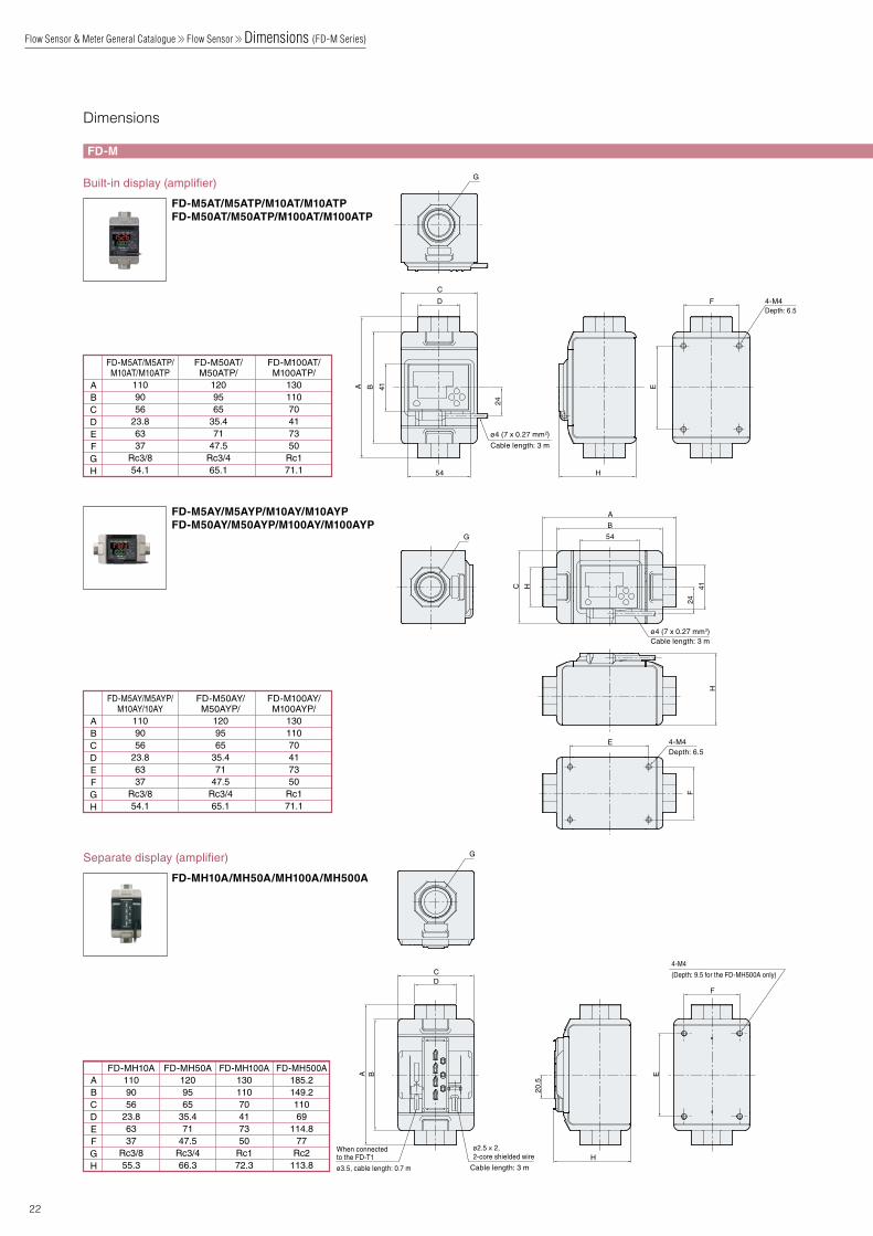
CAD data download www.keyence.co.uk/CADG
ABCDEFGH
FD-M5AT/M5ATP/M10AT/M10ATP
1109056
23.86337
Rc3/854.1
FD-M50AT/M50ATP/
1209565
35.471
47.5Rc3/465.1
FD-M100AT/M100ATP/
13011070417350
Rc171.1
ABCDEFGH
FD-M5AY/M5AYP/M10AY/10AY
1109056
23.86337
Rc3/854.1
FD-M50AY/M50AYP/
1209565
35.471
47.5Rc3/465.1
FD-M100AY/M100AYP/
13011070417350
Rc171.1
ABCDEFGH
FD-MH500A185.2149.211069
114.877
Rc2113.8
FD-MH100A13011070417350
Rc172.3
FD-MH50A1209565
35.471
47.5Rc3/466.3
FD-MH10A1109056
23.86337
Rc3/855.3
G
Cable length: 3 m
ø4 (7 x 0.27 mm2)
E
F
24
41BA
D
C
H54
Depth: 6.54-M4
G
Depth: 6.5
4-M4
(Depth: 9.5 for the FD-MH500A only)
4-M4
H
E
F
HC
24
54
B
A
41
Cable length: 3 mø4 (7 x 0.27 mm2)
Cable length: 3 m
ø2.5 × 2, 2-core shielded wire
G
F
H
E
20.5
BA
DC
When connectedto the FD-T1
ø3.5, cable length: 0.7 m
ø4.2 (7 x 0.20 mm2) Cable length: 2 m
ø4.2 (5 x 0.20 mm2) Cable length: 2 m
1524
11.6
When cover is opened:max. 79
3
17.6
70
35.421.112.4
Min. 15
Min. 15
18
3742
3
17.6
70
35.421.1
Min. 15
12.4
Min. 15
18
3742
2415 11.6
Max. 135°
2.3
79.7
17.5 7.5
2.3
404
27.5
7
R3.5ø7
* 4 M4 x L8 screws included* 4 M4 x L10 screws included
* 4 M4 x L8 screws included* 4 M4 x L10 screws included
2
130
114
67 541
7
7
ø7
90
46.5
Connector unit
Sensor unit
Cable length: 0.7 m
ø3.511
10
6
16.4
Rc3/8Temperature detection unit
ø13
15 1467±1
6±1
ø2219
Min.156.6
2113.4
3.5
12.4
44.716.3
12.5
51.8
6.8
2.31.6
*1
24
60
*1 ø4.2 (7 x 0.20 mm2) Cable length: 2 m
Protective front cover
When mounted in a panel
24
62
23.8
10.7
Panel thickness:1 to 6 mm
11.1
(73)
+0.4 -0
45
21
63 mm or more
45
X
X=24x (A-1) +21When A units are installed close to each other
Panel cutout dimensions
38.8
49
FD-M
22
Dimensions
Built-in display (amplifier)
FD-M5AT/M5ATP/M10AT/M10ATPFD-M50AT/M50ATP/M100AT/M100ATP
Separate display (amplifier)
FD-MH10A/MH50A/MH100A/MH500A
FD-M5AY/M5AYP/M10AY/M10AYPFD-M50AY/M50AYP/M100AY/M100AYP
Flow Sensor & Meter General Catalogue Flow Sensor Dimensions (FD-M Series)

CAD data download www.keyence.co.uk/CADG
ABCDEFGH
FD-M5AT/M5ATP/M10AT/M10ATP
1109056
23.86337
Rc3/854.1
FD-M50AT/M50ATP/
1209565
35.471
47.5Rc3/465.1
FD-M100AT/M100ATP/
13011070417350
Rc171.1
ABCDEFGH
FD-M5AY/M5AYP/M10AY/10AY
1109056
23.86337
Rc3/854.1
FD-M50AY/M50AYP/
1209565
35.471
47.5Rc3/465.1
FD-M100AY/M100AYP/
13011070417350
Rc171.1
ABCDEFGH
FD-MH500A185.2149.211069
114.877
Rc2113.8
FD-MH100A13011070417350
Rc172.3
FD-MH50A1209565
35.471
47.5Rc3/466.3
FD-MH10A1109056
23.86337
Rc3/855.3
G
Cable length: 3 m
ø4 (7 x 0.27 mm2)
E
F
24
41BA
D
C
H54
Depth: 6.54-M4
G
Depth: 6.5
4-M4
(Depth: 9.5 for the FD-MH500A only)
4-M4
H
E
F
HC
24
54
B
A
41
Cable length: 3 mø4 (7 x 0.27 mm2)
Cable length: 3 m
ø2.5 × 2, 2-core shielded wire
G
F
H
E
20.5
BA
DC
When connectedto the FD-T1
ø3.5, cable length: 0.7 m
ø4.2 (7 x 0.20 mm2) Cable length: 2 m
ø4.2 (5 x 0.20 mm2) Cable length: 2 m
1524
11.6
When cover is opened:max. 79
3
17.6
70
35.421.112.4
Min. 15
Min. 15
18
3742
3
17.6
70
35.421.1
Min. 15
12.4
Min. 15
18
3742
2415 11.6
Max. 135°
2.3
79.7
17.5 7.5
2.3
404
27.5
7
R3.5ø7
* 4 M4 x L8 screws included* 4 M4 x L10 screws included
* 4 M4 x L8 screws included* 4 M4 x L10 screws included
2
130
114
67 541
7
7
ø7
90
46.5
Connector unit
Sensor unit
Cable length: 0.7 m
ø3.511
10
6
16.4
Rc3/8Temperature detection unit
ø13
15 1467±1
6±1
ø2219
Min.156.6
2113.4
3.5
12.4
44.716.3
12.5
51.8
6.8
2.31.6
*1
24
60
*1 ø4.2 (7 x 0.20 mm2) Cable length: 2 m
Protective front cover
When mounted in a panel
24
62
23.8
10.7
Panel thickness:1 to 6 mm
11.1
(73)
+0.4 -0
45
21
63 mm or more
45
X
X=24x (A-1) +21When A units are installed close to each other
Panel cutout dimensions
38.8
49
Unit: mm
FD-M
FD-M
Series
23
Display (panel mounting type)
Display (DIN rail mounting type) Mounting brackets
Temperature sensor (dedicated for use with the separate type)
FD-MA5A/MA5PA
FD-MA1A/MA1AP
FD-MA2A/MA2AP
L-shaped mounting bracket (sold separately) OP-42193
Flat mounting bracket (sold separately) OP-42194
Panel mounting bracket (included) OP-76876
Flow Sensor & Meter General Catalogue Flow Sensor Dimensions (FD-M Series)

Rc 1/4
43.618
14
159.5
181
133.7
159.5
42
Min. 15
42
127
(25)
122.5 116 117 79
25
Max. rotation radius: 25 mmHexagon socket head cap screw
Hexagon socket head cap screw
Nominal diameter: 4, width across flats of hexagon hole: 2.5 mm
4-M4
Depth: 6
Rc 3/8
22
196.5
218 30
81.2140.5 123 149
42170.8
196.5
42
(25)
13
48.6
Min. 15
4-M4 Depth: 6
Max. rotation radius: 25 mm
Nominal diameter: 4, width across flats of hexagon hole: 2.5 mm
ø4.2 (7 x 0.20 mm2) Cable length: 2 m
1524
11.6
When cover is opened:max. 79
3
17.6
70
35.421.112.4
Min. 15
Min. 15
18
3742
Max. 135°
* Panel mounting bracket (included) OP-76876
Min. 156.6
2113.4
3.5
12.4
44.716.3
12.5
51.8
6.8
2.31.6
*1
24
60
*1 ø4.2 (7 x 0.20 mm2) Cable length: 2 m
204* (241)
23
3.2
27.5
109
37 *(36)
6.5 (4-ø
4.5)
(25.3) 284155
12
12
135171185
185
7981.2
116
23 3.2
159
6.555 41 30 28 25
(R)
(R)
135
4-ø4.5
171
4.5
204* (241)7837 *(36)
123.490
15
48 1007
4
40
65
8-M3 x L8
207
21630
8.2
40 35.2
30
4-ø7141126109
1719.5
5123 Hexagon socket head cap screw
4-M4 x L10Hexagon socket head cap screw
216126
65304-ø7 141 30
4
54*(53)
221*(258)
37
2337.555.573.5
8-M3 x L8Hexagon socket head cap screw
4-M4 x L10Hexagon socket head cap screw78
90
7 15
66.4123.4
4876.4100
6843
19.8
*The values within parentheses are for when the bracket is used with the FD-SS20.
*The values within parentheses are for when the bracket is used with the FD-SS20.
*The values within parentheses are for when the bracket is used with the FD-SS20.
235135
23
108
114.91
10
129.7
36
123.5
46.6
(36)
(104.91)
(14.79)
(50) (50)
26
10
Cable outletø2.5 x 2, cable length: 5 m
PFA 4 x 3 tube
Mounting hole3 x ø4.5(M4; through-hole)
12.15
4560.2
120
Rc 1/8
Rc 1/8
Cable outletø2.5 × 2, cable length: 5 m
114.91
120
108PFA 3/8" x 1/4" tube
Mounting hole3 x ø4.5(M4; through-hole)
10
123.5129.7
2345.5
75
115.5
70
46.6
(104.91)
(14.79)Rc 1/8
Rc 1/8
10
12.15
4560.2
(55.5)
28
11.5
81.2
6.5
108
108
123.5
123.5149.7
18.5
95.7
165.2
170
53
17063.7
176
244.43.28.230
260.8
244.4260.8
17030
175.5
7.565
11.216.2
CAD data download www.keyence.co.uk/CADG
24
FD-S
Dimensions
Sensor unit Ultra minimal flow type and minimal flow type (SUS type)
Separate display (DIN rail mounting type)
Sensor unit Ultra minimal flow type (PFA)
Sensor unit Medium flow type (SUS type)
Separate display (panel mounting type)
Sensor unit Minimal flow type (PFA)
Ultra minimal flow typeFD-SS02AMinimal flow typeFD-SS2A
Medium flow typeFD-SS20A
FD-SA1NA/SA1PA/FD-SA2NA/SA2PA*DIN-rail amplifier mounting fixture (sold separately) OP-76877
FD-SF1
FD-SA5NA/SA5PA
FD-SF8
Flow Sensor & Meter General Catalogue Flow Sensor Dimensions (FD-S Series)

Rc 1/4
43.618
14
159.5
181
133.7
159.5
42
Min. 15
42
127
(25)
122.5 116 117 79
25
Max. rotation radius: 25 mmHexagon socket head cap screw
Hexagon socket head cap screw
Nominal diameter: 4, width across flats of hexagon hole: 2.5 mm
4-M4
Depth: 6
Rc 3/8
22
196.5
218 30
81.2140.5 123 149
42170.8
196.5
42
(25)
13
48.6
Min. 15
4-M4 Depth: 6
Max. rotation radius: 25 mm
Nominal diameter: 4, width across flats of hexagon hole: 2.5 mm
ø4.2 (7 x 0.20 mm2) Cable length: 2 m
1524
11.6
When cover is opened:max. 79
3
17.6
70
35.421.112.4
Min. 15
Min. 15
18
3742
Max. 135°
* Panel mounting bracket (included) OP-76876
Min. 156.6
2113.4
3.5
12.4
44.716.3
12.5
51.8
6.8
2.31.6
*1
24
60
*1 ø4.2 (7 x 0.20 mm2) Cable length: 2 m
204* (241)
23
3.2
27.5
109
37 *(36)
6.5 (4-ø
4.5)
(25.3) 284155
12
12
135171185
185
7981.2
116
23 3.2
159
6.555 41 30 28 25
(R)
(R)
135
4-ø4.5
171
4.5
204* (241)7837 *(36)
123.490
15
48 1007
4
40
65
8-M3 x L8
207
21630
8.2
40 35.2
30
4-ø7141126109
1719.5
5123 Hexagon socket head cap screw
4-M4 x L10Hexagon socket head cap screw
216126
65304-ø7 141 30
4
54*(53)
221*(258)
37
2337.555.573.5
8-M3 x L8Hexagon socket head cap screw
4-M4 x L10Hexagon socket head cap screw78
90
7 15
66.4123.4
4876.4100
6843
19.8
*The values within parentheses are for when the bracket is used with the FD-SS20.
*The values within parentheses are for when the bracket is used with the FD-SS20.
*The values within parentheses are for when the bracket is used with the FD-SS20.
235135
23
108
114.91
10
129.7
36
123.5
46.6
(36)
(104.91)
(14.79)
(50) (50)
26
10
Cable outletø2.5 x 2, cable length: 5 m
PFA 4 x 3 tube
Mounting hole3 x ø4.5(M4; through-hole)
12.15
4560.2
120
Rc 1/8
Rc 1/8
Cable outletø2.5 × 2, cable length: 5 m
114.91
120
108PFA 3/8" x 1/4" tube
Mounting hole3 x ø4.5(M4; through-hole)
10
123.5129.7
2345.5
75
115.5
70
46.6
(104.91)
(14.79)Rc 1/8
Rc 1/8
10
12.15
4560.2
(55.5)
28
11.5
81.2
6.5
108
108
123.5
123.5149.7
18.5
95.7
165.2
170
53
17063.7
176
244.43.28.230
260.8
244.4260.8
17030
175.5
7.565
11.216.2
CAD data download www.keyence.co.uk/CADG
Unit: mm
FD-S
Series
25
FD-S
Mounting brackets
Flat mounting bracket OP-86951Material: SPCC*M4 x L10 hexagon socket head cap screw, width across flats: 3, 4 screws included
Vibration-proof mounting bracket set for vertical piping OP-86952Materials: metal: SPCC, rubber: chloroprene* M4 x L10 hexagon socket head cap screw, width across flats: 3, 8 screws included
Vibration-proof mounting bracket set for horizontal piping OP-86953Materials: metal: SPCC, rubber: chloroprene* M4 × L10 hexagon socket head cap screw, width across flats: 3, 8 screws included
L-shaped mounting bracket OP-87137MaterialPEI (polyetherimide)AccessoriesM4 x L60 pan head screw (SUS),3 screws includedParts to use in installing the main unit3 washers (SUS) for M4 screws3 M4 nuts (SUS)1 mounting manual
MaterialsBracket: SPCC (cold rolled steel sheet)Rubber feet: chloroprene
Accessories for assemblyM4 x L10 hexagon socket head cap screw, width across flats: 3, 4 screwsM4 x L8 hexagon socket head cap screw, width across flats: 2.5, 8 screws
When the mounting bracket is used
When the mounting bracket is used
Flat mounting bracket (when used)
Vibration-proof mounting bracket set for vertical piping (when used)
Vibration-proof mounting bracket set for horizontal piping (when used)
Vibration-proof mounting bracket OP-87138Use this in combination with the L-shaped mounting bracket.
Flow Sensor & Meter General Catalogue Flow Sensor Dimensions (FD-S Series)
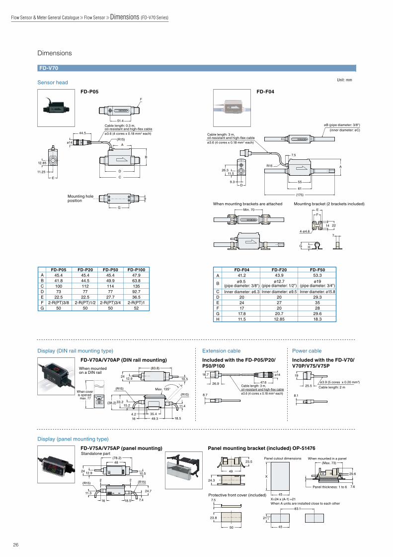
When mounting brackets are attached Mounting bracket (2 brackets included)
F
14 22
E
HG
74-ø4.6
øB (pipe diameter: 3/8")
(inner diameter: øC)Cable length: 3 m, oil-resistant and high-flex cableø3.6 (4 cores x 0.18 mm2 each)
(175)
61
55
7.5
A
9.3D
26.311.5
R15
Min. 70
Mounting hole position 9
G
Cable length: 0.3 m, oil-resistant and high-flex cableø3.6 (4 cores x 0.18 mm2 each)
F
11.25
E C
D
44.5
ø14
B
12.85
A
51.4
(R15)
ø3.9 (5 cores x 0.20 mm2)
Cable length: 2 m25.5
8.1
19
Cable length: 3 m, oil-resistant and high-flex cableø3.6 (4 cores x 0.18 mm2 each)8.7
26.9
16.7
47.6
ø14
50
23.8
7.5
24.3
49
23.5
7.6
29.6
Panel thickness: 1 to 6
(Max. 73)
24.7
48(78.2)
22
11.3
7.4
24 12.9 10.5
(R15) (R15)
16 18.5
24
18.51635.44.249.3
15.233.2(38.2)
11.4
(R15) Max. 135°
(R15)When cover is opened:
max. 77
12.9 10.5
(83.8)
Protective front cover (included)
Panel cutout dimensions When mounted in a panel
When mounted on a DIN rail
Standalone part
X
83.1
021+0.4
45
45
X=24 x (A-1) +21When A units are installed close to each other
A
B
CDEFGH
FD-F0441.2
ø9.5 (pipe diameter: 3/8")
Inner diameter: ø6.3202417
17.811.5
FD-F2043.9
ø12.7(pipe diameter: 1/2")
Inner diameter: ø9.5202720
20.712.85
FD-F5053.3
ø19(pipe diameter: 3/4")
Inner diameter: ø15.829.33528
29.618.3
ABCDEFG
FD-P0545.441.810073
22.52-R(PT)3/8
50
FD-P2045.444.511277
22.52-R(PT)1/2
50
FD-P5045.449.911477
27.72-R(PT)3/4
50
FD-P10047.963.813592.736.5
2-R(PT)152
Unit: mm
26
FD-V70
Dimensions
Sensor head
Display (DIN rail mounting type)
Display (panel mounting type)
Extension cable Power cable
FD-P05
FD-V70A/V70AP (DIN rail mounting)
FD-V75A/V75AP (panel mounting) Panel mounting bracket (included) OP-51476
Included with the FD-P05/P20/P50/P100
Included with the FD-V70/V70P/V75/V75P
FD-F04
Flow Sensor & Meter General Catalogue Flow Sensor Dimensions (FD-V70 Series)

27
Toughness and environmental resistance meet a wide variety of applications
Vibration resistance
Shock resistance
20G 50G
Tough but light weight
150 g
Performance durability
100 million times*2
Fluid temperature
−20 to 100ºC*1
High chemical resistance and hardness
AluminaCeramic diaphragm
*1 No freezing or condensation*2 This varies depending on the sensor model. For details, contact your nearest KEYENCE office.
NPN/PNP swi tchable
Various cables and adapters are optional accessories
Switchable between [2 outputs] or
[1 output + analogue output]
Range Select ion
GP-M001
GP-M010
GP-M025
GP-M100
GP-M250
GP-M400
-0.1 to +0.1MPa
-0.1 to +1MPa
-0.1 to +2.5MPa
0 to +10MPa
0 to +25MPa
0 to +40MPa
0 MPa
ø34.2 mm
86.7 mm
M124pin
G 43
RELATED PRODUCT
Harsh Environment Resistant Pressure Sensors are Released
Tough & Heavy-duty
SUSXM7
DIAPHRAGM AI2O3
(Alumina)
O-ringFKM
GP-M Series
The New Standard for Ease of Use
OIL MISTY AIRWATER

* 6 0 0 C 8 8 *
WW1-1094
www.keyence.comSAFETY INFORMATIONPlease read the instruction manual carefully in order to safely operate any KEYENCE product.
Please visit:
INDONESIAPhone: +62-21-2966-0120 Fax: +62-21-2966-0121
AUSTRIAPhone: +43 22 36-3782 66-0 Fax: +43 22 36-3782 66-30BELGIUMPhone: +32 1 528 1222 Fax: +32 1 520 1623BRAZILPhone: +55-11-3045-4011 Fax: +55-11-3045-5219CANADAPhone: +1-905-366-7655 Fax: +1-905-366-1122CHINAPhone: +86-21-68757500 Fax: +86-21-68757550CZECH REPUBLICPhone: +420 222 191 483 Fax: +420 222 191 505FRANCEPhone: +33 1 56 37 78 00 Fax: +33 1 56 37 78 01GERMANYPhone: +49 61 02 36 89-0 Fax: +49 61 02 36 89-100
HONG KONGPhone: +852-3104-1010 Fax: +852-3104-1080HUNGARYPhone: +36 1 802 73 60 Fax: +36 1 802 73 61INDIAPhone: +91-44-4963-0900 Fax: +91-44-4963-0901
ITALYPhone: +39-02-6688220 Fax: +39-02-66825099JAPANPhone: +81-6-6379-2211 Fax: +81-6-6379-2131KOREAPhone: +82-31-789-4300 Fax: +82-31-789-4301MALAYSIAPhone: +60-3-2092-2211 Fax: +60-3-2092-2131
MEXICOPhone: +52-81-8220-7900 Fax: +52-81-8220-9097NETHERLANDSPhone: +31 40 20 66 100 Fax: +31 40 20 66 112POLANDPhone: +48 71 36861 60 Fax: +48 71 36861 62ROMANIAPhone: +40 269-232-808 Fax: +40 269-232-808SINGAPOREPhone: +65-6392-1011 Fax: +65-6392-5055SLOVAKIAPhone: +421 2 5939 6461 Fax: +421 2 5939 6200SLOVENIAPhone: +386 1-4701-666 Fax: +386 1-4701-699SWITZERLANDPhone: +41 43-45577 30 Fax: +41 43-45577 40
TAIWANPhone: +886-2-2718-8700 Fax: +886-2-2718-8711THAILANDPhone: +66-2-369-2777 Fax: +66-2-369-2775UK & IRELANDPhone: +44-1908-696900 Fax: +44-1908-696777USA Phone: +1-201-930-0100 Fax: +1-201-930-0099VIETNAM Phone: +84-4-3760-6214 Fax: +84-4-6277-6616
KEYENCE CORPORATION
Copyright (c) 2013 KEYENCE CORPORATION. All rights reserved. FlowsensorGeneral-WW-C-GB 1015-2 600C88 Printed in JapanThe information in this publication is based on KEYENCE’s internal research/evaluation at the time of release and is subject to change without notice.