Elcometer 319 Dewpoint Meter Operating Instructions
41
English Elcometer 319 Dewpoint Meter Standard and Top Models Operating Instructions A L
-
Upload
khangminh22 -
Category
Documents
-
view
4 -
download
0
Transcript of Elcometer 319 Dewpoint Meter Operating Instructions

En
gli
sh
Elcometer 319
Dewpoint Meter
Standard and Top Models
Operating Instructions
CONFIDENTIAL
PROTOTYPE
- DRAFT INSTRUCTIONS -
En
gli
sh
R
The Top version of this gauge meets the Radio and Telecommunications Terminal
Equipment Directive and the Standard version of this gauge meets the
Electromagnetic Compatibility Directive.
The Standard gauge is Class B, Group 1 ISM equipment according to CISPR 11.
Group 1 ISM product: A product in which there is intentionally generated and/or used conductively coupled
radio-frequency energy which is necessary for the internal functioning of the equipment itself.
Class B products are suitable for use in domestic establishments and in establishments directly connected
to a low voltage power supply network which supplies buildings used for domestic purposes.
Bluetooth SIG QDID = B009627.
, ElcoShip® and ElcoMaster® are registered trademarks of Elcometer Limited.® and Bluetooth® are trademarks owned by Bluetooth SIG Inc and licensed to Elcometer Limited.
All other trademarks acknowledged.
© Copyright Elcometer Limited 2009.
All rights reserved. No part of this Document may be reproduced, transmitted, transcribed, stored (in a retrieval
system or otherwise) or translated into any language, in any form or by any means (electronic, mechanical,
magnetic, optical, manual or otherwise) without the prior written permission of Elcometer Limited.
A copy of this Instruction Manual is available for download on our Website via www.elcometer.com
Doc.No. TMA-0455 Issue 01Text with Cover No: 21308
R
R
1
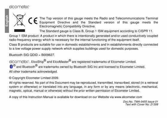
CONTENTS
Section Page
1 About your gauge . . . . . . . . . . . . . . . . . . . . . . . . . . . . . . . . . . . . . . . . . . . . . . . . . . . . . . . . . . . . . . 2
2 Quick start . . . . . . . . . . . . . . . . . . . . . . . . . . . . . . . . . . . . . . . . . . . . . . . . . . . . . . . . . . . . . . . . . . . . 5
3 Getting started . . . . . . . . . . . . . . . . . . . . . . . . . . . . . . . . . . . . . . . . . . . . . . . . . . . . . . . . . . . . . . . . . 6
4 Taking readings . . . . . . . . . . . . . . . . . . . . . . . . . . . . . . . . . . . . . . . . . . . . . . . . . . . . . . . . . . . . . . . 13
5 Batching [T] . . . . . . . . . . . . . . . . . . . . . . . . . . . . . . . . . . . . . . . . . . . . . . . . . . . . . . . . . . . . . . . . . . 16
6 Statistics . . . . . . . . . . . . . . . . . . . . . . . . . . . . . . . . . . . . . . . . . . . . . . . . . . . . . . . . . . . . . . . . . . . . 19
7 Limits . . . . . . . . . . . . . . . . . . . . . . . . . . . . . . . . . . . . . . . . . . . . . . . . . . . . . . . . . . . . . . . . . . . . . . . 21
8 The menu . . . . . . . . . . . . . . . . . . . . . . . . . . . . . . . . . . . . . . . . . . . . . . . . . . . . . . . . . . . . . . . . . . . . 22
9 Gauge setup . . . . . . . . . . . . . . . . . . . . . . . . . . . . . . . . . . . . . . . . . . . . . . . . . . . . . . . . . . . . . . . . . . 24
10 Using external temperature probes . . . . . . . . . . . . . . . . . . . . . . . . . . . . . . . . . . . . . . . . . . . . . . . 27
11 Transferring readings to a computer [T] . . . . . . . . . . . . . . . . . . . . . . . . . . . . . . . . . . . . . . . . . . . 28
12 Personalised user screen . . . . . . . . . . . . . . . . . . . . . . . . . . . . . . . . . . . . . . . . . . . . . . . . . . . . . . . 30
13 Maintenance . . . . . . . . . . . . . . . . . . . . . . . . . . . . . . . . . . . . . . . . . . . . . . . . . . . . . . . . . . . . . . . . . . 31
14 Spare parts and accessories . . . . . . . . . . . . . . . . . . . . . . . . . . . . . . . . . . . . . . . . . . . . . . . . . . . . 33
15 Technical specifications . . . . . . . . . . . . . . . . . . . . . . . . . . . . . . . . . . . . . . . . . . . . . . . . . . . . . . . . 33
16 Related equipment . . . . . . . . . . . . . . . . . . . . . . . . . . . . . . . . . . . . . . . . . . . . . . . . . . . . . . . . . . . . 36
17 Index . . . . . . . . . . . . . . . . . . . . . . . . . . . . . . . . . . . . . . . . . . . . . . . . . . . . . . . . . . . . . . . . . . . . . . . . 37
R
2
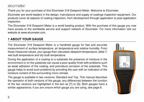
Thank you for your purchase of this Elcometer 319 Dewpoint Meter. Welcome to Elcometer.
Elcometer are world leaders in the design, manufacture and supply of coatings inspection equipment. Our
products cover all aspects of coating inspection, from development through application to post application
inspection.
The Elcometer 319 Dewpoint Meter is a world beating product. With the purchase of this gauge you now
have access to the worldwide service and support network of Elcometer. For more information visit our
website at www.elcometer.com.
1 ABOUT YOUR GAUGE
The Elcometer 319 Dewpoint Meter is a handheld gauge for fast and accurate
measurement of surface temperature, air temperature and relative humidity. From
these measured values, your gauge then calculates dewpoint temperature, delta T,
wet bulb temperature and dry bulb temperature.
During the application of a coating to a substrate the presence of moisture in the
environment or on the substrate can cause a poor quality finish with problems such
as weak adhesion of the coating, and premature corrosion of the substrate. This
gauge helps to avoid such problems by providing the user with an indication of the
moisture content of the surrounding micro climate.
The gauge is available in two versions; Standard and Top. This manual describes
the operation of both versions of the gauge; any differences between the function
of the two versions are highlighted in the text as [T] or [S]. Both gauges have a
similar appearance; if you are unsure which gauge you are using, see page 8.

R
3
1.1 FEATURES
FeatureModel See
pageStandard Top
User-adjustable high and low limits for all parameters + alarm � � 21
Trend indicators on all parameters � � 10
User-configurable display with large easy-to-see main reading � � 25
Multiple languages � � 24
Built-in high power magnets to attach the gauge to ferrous objects � � -
Statistical analysis of readings � � 19
Individual readings review � � 20
Date and time stamping of all reading data � � -
10 reading rolling memory � � 13
Multiple batch memory, up to approximately 40 000 sets of reading data � 16
Automatic logging at user-adjustable time intervals � 16
Delayed start to automatic logging � 16
Transfer readings and statistics to your computer via USB or Bluetootha
a. Bluetooth may be disabled on gauges sold in countries where use of this technology is not permitted (the Bluetoothmenu item is marked with an ‘X’).
� 28
ElcoMaster software for batch setup, data transfer and reporting � 28

R
4
1.2 STANDARDS
Your Elcometer 319 Dewpoint Meter can be used in accordance with the following National and
International standards: BS 7079-B4; IMO MSC.215(82); IMO MSC.244(83); ISO 8502-4;
US Navy NSI 009-32; US Navy PPI 63101-000
1.3 WHAT THE BOX CONTAINS
• Elcometer 319 Dewpoint Meter
• Protective pouch with Belt Clip
• Wrist strap
• Batteries
• USB Cable [T]
• CD containing ElcoMasterTM Software [T]
• Calibration certificate
• Operating instructions
Your gauge is packed in a cardboard package. Please ensure that this packaging is disposed of in an
environmentally sensitive manner. Please consult your local Environmental Authority for further guidance.
To maximise the benefits of your new Elcometer 319 Dewpoint Meter please take some time to read
these Operating Instructions. Do not hesitate to contact Elcometer or your Elcometer supplier if you
have any questions.

R
5
2 QUICK START
see page 22
see page 19
see page 16
see page 26
Note: ‘Batch’ is displayed on [T]
models only
R
6
3 GETTING STARTED
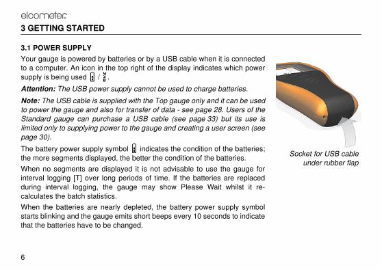
3.1 POWER SUPPLY
Your gauge is powered by batteries or by a USB cable when it is connected
to a computer. An icon in the top right of the display indicates which power
supply is being used / .
Attention: The USB power supply cannot be used to charge batteries.
Note: The USB cable is supplied with the Top gauge only and it can be used
to power the gauge and also for transfer of data - see page 28. Users of the
Standard gauge can purchase a USB cable (see page 33) but its use is
limited only to supplying power to the gauge and creating a user screen (see
page 30).
The battery power supply symbol indicates the condition of the batteries;
the more segments displayed, the better the condition of the batteries.
When no segments are displayed it is not advisable to use the gauge for
interval logging [T] over long periods of time. If the batteries are replaced
during interval logging, the gauge may show Please Wait whilst it re-
calculates the batch statistics.
When the batteries are nearly depleted, the battery power supply symbol
starts blinking and the gauge emits short beeps every 10 seconds to indicate
that the batteries have to be changed.
Socket for USB cable
under rubber flap

R
7
FITTING BATTERIES
The batteries are located under the cover at the rear of the gauge. To replace the batteries, remove the
retaining screw and the cover and fit high quality alkaline dry batteries (2x AA / LR6) taking care to ensure
correct battery polarity. Refit the cover and tighten the retaining screw when finished.
Reading data in the memory is not affected by removal of the batteries, however it is recommended that
you check the time and data if the batteries are removed for some time.
Alkaline batteries must be disposed of carefully to avoid environmental contamination. Please consult your
local Environmental Authority for information on disposal in your region. Do not dispose of any battery in fire.
MAXIMISING BATTERY LIFE
There are various measures you can take to help maximise battery life:
• Use Auto Switch Off - see page 25
• Reduce the Backlight Brightness- see page 26
• Reduce the Backlight Timeout - see page 26
• Switch off the Backlight - see page 22
• If Bluetooth [T] is not being used, switch it off - see page 24
• During interval logging [T], press and hold the on/off key or use Auto Switch Off. The gauge will appear
to switch off, but in fact it will continue to log reading data into batch memory at the set logging interval.
When the gauge is next switched on the batch will reopen.
R
8
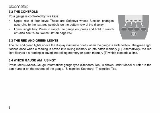
3.2 THE CONTROLS
Your gauge is controlled by five keys:
• Upper row of four keys: These are Softkeys whose function changes
according to the text and symbols on the bottom row of the display.
• Lower single key: Press to switch the gauge on; press and hold to switch
off (also see “Auto Switch Off” on page 25).
3.3 THE RED AND GREEN LIGHTS
The red and green lights above the display illuminate briefly when the gauge is switched on. The green light
flashes once when a reading is saved into rolling memory or into batch memory [T]. Alternatively, the red
light flashes if a reading is saved into rolling memory or batch memory [T] which exceeds a limit.
3.4 WHICH GAUGE AM I USING?
Press Menu>About>Gauge Information; gauge type (Standard/Top) is shown under Model or refer to the
part number on the reverse of the gauge, ‘S’ signifies Standard, ‘T’ signifies Top.

R
9
3.5 THE SENSORS
The sensors for humidity, air temperature and surface temperature are
located at the top of the gauge.
Note: The surface temperature sensor is flexibly mounted. This will reduce
the risk of damage if the gauge is dropped.
FOR ACCURATE READINGS
• Do not obstruct airflow through the holes in the casing around the
humidity and air temperature sensors.
• Keep your fingers away from the holes - the heat from your body may
affect readings.
• Allow the gauge some time (approximately 20 minutes) to acclimatise
once it is brought from a cold environment into a warm place or vice
versa.
TO AVOID DAMAGE
• When measuring surface temperature DO NOT USE EXCESSIVE
FORCE! A light contact between the probe and the surface is sufficient.
Using force does not increase the measuring speed or improve the
accuracy of the measurement, but it does increase wear and/or damage
the sensor tip.
• Do not drag the surface temperature probe over the surface.
• Keep the gauge away from paint dust and dirt as much as possible as
these can affect the long term accuracy of the humidity sensor.
Surface
temperature
Air temperature
and humidity

R
10
3.6 THE READING SCREEN
While the instrument is measuring, the display may show the following information and symbols. Refer to
the page number (xx) for more information:
Battery power & condition (7)
USB power [T] (7)
Bluetooth enabled [T] (24)
External temperature probe (27)
Interval logging [T] (16)
Delayed start timer [T] (16)
Softkeys locked [T] (26)
Scroll softkeys
Batch menu [T] (16)
Parameter (25)
Alarm (21)Trend - value
increasing/decreasing (13)
Batch # [T] (16)
Reading # [T] (16)
Softkey functions
Manual logging [T] (16)

R
11
You can select which parameters to show on the reading
screen and which of these should be displayed as the Main
Reading - see page 25.
To increase the size of the Main Reading, reduce the number
of parameters displayed on the reading screen (the
illustrations shows reading screens from the Elcometer 319
Top model).
R
12
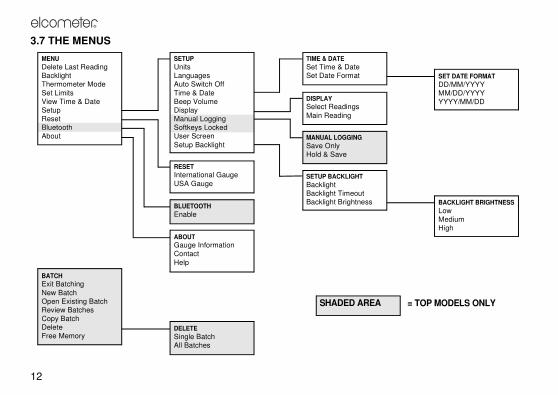
3.7 THE MENUS
MENU
Delete Last ReadingBacklightThermometer Mode
Set LimitsView Time & DateSetupResetBluetoothAbout
SETUP
UnitsLanguagesAuto Switch Off
Time & DateBeep VolumeDisplayManual LoggingSoftkeys LockedUser Screen
Setup Backlight
TIME & DATE
Set Time & DateSet Date Format
RESET
International Gauge
USA Gauge
BLUETOOTH
Enable
DISPLAY
Select Readings
Main Reading
MANUAL LOGGING
Save Only
Hold & Save
SETUP BACKLIGHT
Backlight
Backlight Timeout
Backlight Brightness
BATCH
Exit Batching
New Batch
Open Existing Batch
Review Batches
Copy Batch
DeleteFree Memory
DELETE
Single Batch
All Batches
ABOUT
Gauge Information
Contact
Help
BACKLIGHT BRIGHTNESS
Low
Medium
High
SET DATE FORMAT
DD/MM/YYYYMM/DD/YYYYYYYY/MM/DD
SHADED AREA = TOP MODELS ONLY

R
13
4 TAKING READINGS
4.1 SAVING READING DATA INTO ROLLING MEMORY
Follow this procedure to take readings manually with the option to save your reading data into the rolling
memory of your gauge.
Users of the Elcometer 319 Top model can also save reading data into batch memory [T] - see page 14.
Before you start:
• If required, set low and/or high limits for parameters - see “Set Limits” on page 23.
• If required, select a method [T] of saving reading data into the rolling memory of your gauge - see
“Manual Logging [T]” on page 26.
Procedure:
1. Switch on the gauge.
The gauge starts measuring.
2. Place the rubber tip of the surface temperature sensor against the surface, preferably at an angle of
90°, and keep it in this position. The trend indicator next to the parameter indicates if the value is
increasing or decreasing . The absence of a trend indicator indicates that the value is stable.
3. Optional: To hold the reading data on the display press Hold.
4. Optional: To save reading data into the rolling memory of your gauge, press Save or Hold>Save
(depending upon the Manual Logging [T] setting - see page 26).
When you have finished you may want to view the statistical analysis of the reading data - see “Statistics”
on page 19.

R
14
4.2 SAVING READING DATA INTO BATCH MEMORY [T]
Follow this procedure to take readings manually (manual logging) or automatically at set time intervals
(interval logging) and log the reading data into a batch in your gauge memory.
Before you start, if you intend to take measurements over a long period of time:
• Check that the batteries are in good condition; if in doubt, insert new batteries.
• Consider the use of an external temperature probe; holding the surface temperature probe integrated
into your gauge against a surface over an extended period of time may not be practical - see “Using
external temperature probes” on page 27.
Procedure:
1. Switch on the gauge.
2. Do one of the following:
• Create a new batch - see “New Batch” on page 16
• Open an existing batch - see “Open Existing Batch” on page 17
• Copy an existing batch (see “Copy Batch” on page 18) and then open the new batch.
The gauge starts measuring.
3. Place the rubber tip of the surface temperature sensor against the surface, preferably at an angle of
90° and keep it in this position. The trend indicator next to the parameter indicates if the value is
increasing or decreasing . The absence of a trend indicator indicates that the value is stable.

R
15
4. To save your reading data into the batch:
• Manual logging: Press Save or Hold>Save (depending upon the Manual Logging [T] setting - see
page 26)
• Interval logging: Your reading data are saved automatically at the set interval.
5. When finished:
• Manual logging: Press >Exit Batching
• Interval logging: Press Stop>Yes.
Note: If an Auto Switch Off time is set, the gauge will appear to switch off after the set time delay, but in fact
while you are logging it will remain on in a reduced power state. In this state, during interval logging your
gauge will continue reading data into batch memory at the set logging interval. When the gauge is next
switched on the batch will reopen.
When you have finished you may want to:
• View the statistical analysis of the reading data - see “Statistics” on page 19.
• Transfer the reading data to your PC - see “Transferring readings to a computer [T]” on page 28.

R
16
5 BATCHING [T]
This section describes the functions available by pressing Batch from the reading
screen.
Note: When a batch is already open, the Batch softkey is replaced by .
To access or initiate a function, scroll to the required function and press Sel. To
return immediately to the reading screen at any stage, press and hold Back/Esc.
Exit Batching: Exits batching and returns to the reading screen.
New Batch: Creates a new empty batch ready for data input by manual or interval
logging.
The New Batch menu is displayed. The batch number and batch type are displayed.
To toggle the batch type (interval logging or manual logging), press or .
To set limits for the batch, press Limits (see “Set Limits” on page 23).
When you have set batch type and limits, press Ok.
• If the batch type is set to manual logging, the batch is created and the gauge starts measuring. To
save a value into the batch, press Save or Hold>Save - see page 26.
• If the batch type is set to interval logging, the Set Interval menu is displayed. The interval between
readings, Approximate number of Readings and Approximate number of Days are displayed. To adjust
the interval, scroll to the required value (1 second to 24 hours) and then press Ok.
The Set Delayed Start menu is displayed. To adjust the delayed start time, scroll to the required value
(Off, 1 minute to 60 minutes) and then press Ok.
To initiate logging, press Start (or to return to the Batch menu, press ).

R
17
If a delayed start time is set, is displayed during this time period.
Logging starts after the delayed start time, is displayed and readings are taken at the set interval.
To return to the Batch menu, press Esc.
Open Existing Batch: Opens an existing batch ready to input more data by manual
or interval logging.
The Open Existing Batch menu is displayed. The batch number, batch type and
number of readings of each batch in gauge memory is listed.
To select a batch, scroll to the batch and press Sel.
If the batch is a manual logging batch, measuring starts and you can Save or
Hold>Save the readings.
If the batch is an interval logging batch, to start logging, press Start. Logging starts
immediately (even if the existing batch had a delayed start).
Review Batches: Opens an existing batch and shows the readings and statistics on
the display.
The Review Batches menu is displayed. The batch number, batch type and number
of readings of each batch in gauge memory is listed.
To select a batch, scroll to the appropriate batch and press Sel.

R
18
The Review Batch screen is displayed. The screen lists: Batch number, number of
readings, date and time batch was created, date and time of last reading, batch type
and interval (interval logged batches only).
To view the statistics for the batch, press Stats (see “Statistics” on page 19).
To view the readings for the batch, press Rdgs. If required, scroll through the
readings for each parameter; to change parameter press the right hand softkey.
When finished, press Back.
Copy Batch: Creates an empty copy of an existing batch, ready for data input by
manual or interval logging. Copy Batch replicates the settings, limits, etc. of the copied batch, but it does
not copy the readings - the newly created batch is empty.
The Copy Batch menu is displayed. The batch number, batch type and number of readings of each batch
in gauge memory is listed.
To select a batch to copy, scroll to the appropriate type of batch and press Sel.
When Sel is pressed, a copy of the batch is created and the copy is added to the end of the list of batches;
this empty batch can now be used for data input - see “Open Existing Batch” on page 17.
Delete: Deletes a single batch or all the batches.
The Delete menu is displayed.
To delete a single batch, scroll to Single Batch and press Sel. All the batches in gauge memory are listed.
Scroll to the batch required and press Sel. Press Yes to confirm or No to decline.
To delete all the batches in gauge memory, scroll to All Batches and press Sel. Press Yes to confirm or No
to decline. Press Yes again to confirm or No to decline.
When finished, press Back.
Free Memory: Displays remaining memory capacity (%).

R
19
6 STATISTICS
Your gauge can display a statistical analysis of reading data saved into the rolling memory of your gauge.
Users of the Elcometer 319 Top model can also display a statistical analysis of reading data logged into
batch memory [T].
An explanation of the statistics symbols is given on page 21 and also in your gauge (Menu>About>Help).
6.1 STATISTICS AND THE ROLLING MEMORY
VIEWING STATISTICS AND READING DATA IN ROLLING MEMORY
1. With the reading screen displayed, press Stats.
The statistics are displayed.
2. Optional: To view the readings, press Rdgs.
The reading data for the parameter are displayed (to return to the statistics,
press Stats).
3. Optional: To view the statistics or reading data for the next parameter, press the
right hand softkey.

R
20
CLEARING STATISTICS AND READING DATA IN ROLLING MEMORY
1. With the reading screen displayed, press Stats.
The statistics are displayed.
2. Press Clear and then press Yes to confirm or No to decline.
6.2 STATISTICS AND THE BATCH MEMORY [T]
VIEWING STATISTICS AND READING DATA IN BATCH MEMORY
(Manual Logging or Interval Logging with Stats displayed)
1. With the batch reading screen displayed, press Stats.
The statistics are displayed. While the statistics are displayed, logging is halted.
2. Optional: To view the readings, press Rdgs.
The reading data for the parameter are displayed (to return to the statistics,
press Stats).
3. Optional: To view the statistics or reading data for the next parameter, press the
right hand softkey.
4. When finished, press Back.
5. The batch reading screen is displayed and logging recommences.
CLEARING STATISTICS AND READING DATA IN BATCH MEMORY
Follow the instructions given in “Delete” on page 18 to delete the statistics and reading data in one batch or
in all batches.

R
21
6.3 STATISTICS VALUES
The statistics calculated by your gauge are given in Table 1.
7 LIMITS
For each parameter that your gauge measures, you can set a low limit and a high limit. Each of these limits
can be toggled on/off.
When the value of a parameter exceeds a limit which is toggled ‘on’ the gauge alerts the user:
• an audible alarm sounds
• a red light flashes
Table 1: Calculated statistics values
Number of Readings The current number of sets of reading data saved in a batch.
MeanThe average of a group of readings; the sum of the individual
readings divided by the number of readings.
Standard Deviation A statistical measure of the spread of values in a group of readings.
Coefficient of VariationThe standard deviation divided by the mean for a group of readings,
expressed as a percentage.
Highest Value The highest reading value.
Lowest Value The lowest reading value.

R
22
• the parameter icon flashes (even if it has been deselected to be shown on the display)
• an alarm symbol is displayed next to the parameter.
• if the readings are being logged into batch memory [T] a reading which exceeds a high limit is marked
by and a reading which exceeds a low limit is marked by .
When the value of the parameter returns within limits the alarm status is cleared automatically.
The volume level of the alarm is determined by the Beep Volume setting (Menu>Setup>Beep Volume).
8 THE MENU
This section describes the functions, gauge settings and gauge information available
by pressing Menu from the reading screen.
To access or initiate a function, gauge setting or gauge information, scroll to the
required function and press Sel. To return immediately to the reading screen at any
stage, press and hold Back/Esc.
Delete Last Reading: Deletes the last reading taken.
Display shows Are You Sure? and gauge beeps 3 times.
Press Yes to delete or No to decline.
Backlight: Toggles the display backlight on/off.
Thermometer Mode: Toggles gauge thermometer mode on/off.
When Thermometer Mode is toggled ‘on’ the gauge only measures and displays the external probe
temperature (Te) via an external temperature probe - all other functions are disabled. If an external

R
23
temperature probe is not fitted when Thermometer Mode is toggled ‘on’, the gauge will display an error
reading ‘---’.
Set Limits: Toggles limits on/off and adjusts limits for all measured and calculated parameters.
The Set Limits menu is displayed. Any low and high limit values toggled ‘on’ are listed.
To toggle a limit on/off or adjust its value, scroll to the parameter and press Sel.
To toggle a limit on/off, scroll to High Limit on/Low Limit on and then press Sel.
To adjust a limit value, scroll to the limit and press Sel. Now scroll to the required value and press Ok (press
and hold to adjust values quickly).
When finished, press Back.
View Time & Date: Displays the current time and date.
If required, press Set to change the time and date (see “Time/Date” on page 25).
When finished, press Back.
Setup: Adjustment of gauge operating parameters.
See “Gauge setup” on page 24.
Reset: Resets the gauge to International or USA settings. International settings = DD/MM/YY date format
and metric units; USA settings = MM/DD/YY date format and imperial units.
(Note that reset does not delete or affect the contents of gauge memory)
The Reset menu is displayed.
To reset to International Gauge or USA Gauge, scroll to the required option and press Sel. Press Yes to
reset or No to decline.

R
24
Bluetooth [T]: Toggles Bluetooth communication on/off and displays Bluetooth information.
The Bluetooth setup menu is displayed. The Gauge ID and Bluetooth Authentication number are displayed.
To toggle Bluetooth communication on/off, scroll to Enable and press Sel (when Bluetooth is enabled, a
Bluetooth symbol is displayed on the right side of the display).
When finished, press Back.
About: Displays miscellaneous information about your gauge.
To view the information, scroll to the parameter of choice and press Sel.
Gauge Information - Elcometer model #, gauge identity, language, language version, software versions
Contact - details of Elcometer offices worldwide and, if applicable, the contact details for the supplier or local
distributor.
Help - explains symbols used on the display.
9 GAUGE SETUP
This section describes the functions and gauge settings available by pressing
Menu>Setup from the reading screen.
To access a function or gauge setting, scroll to the required function and press Sel.
To return immediately to the reading screen at any stage, press and hold Back/Esc.
Units: Choose °C or °F.
To select the units, scroll to the required unit and press Sel.
When finished, press Back.
Languages: Choose your menu language.

R
25
To select the language, scroll to the required language and press Sel.
Auto Switch Off: Select the time delay before your gauge switches off automatically.
To select the time delay, scroll to the required value (Off, 1 minute to 10 minutes) and press Ok.
To return to the Setup menu, press Esc.
Note that Auto Switch Off is disabled when the gauge is powered by the USB connection.
Time/Date: Set the time and date and select the date format.
The Time/Date menu is displayed.
To adjust the time and date, scroll to Set Time & Date and press Sel. To adjust a value, press . To
move to the next/previous value, press . When finished, press Ok.
To set the date format, scroll to Set Date Format and press Sel. Scroll to the required format (DD/MM/YYYY,
MM/DD/YYYY, YYYY/MM/DD) and press Sel. When finished, press Back.
Beep Volume: Select the volume of the audio beeps.
To select the beep volume, scroll to the required value (0 = beep off, 5 = max volume) and press Sel.
Display: Select which readings (parameters) are shown on the display. The available parameters are:
Ts (Surface Temperature), Ta (Air Temperature), RH (Relative Humidity), T∆ (Delta T) Td (Dewpoint
Temperature), Tdb (Dry Bulb Temperature), Twb (Web Bulb Temperature)
The Display menu is displayed.
To select which parameters are shown on the display, scroll to Select Readings and press Sel. To toggle
the display of a parameter on/off, scroll to the parameter and press Sel. When finished, press Back.
To select which parameter is shown in the largest digits at the bottom of the display, scroll to Main Reading
and press Sel. Scroll to the parameter you want to select and press Sel. When finished, press Back.

R
26
Note: If a reading exceeds limits during measurement, it will be shown flashing on the display, even if it has
been deselected from the list of reading shown on the display.
Manual Logging [T]: Select how readings are saved when taking readings manually (manual logging).
The Manual Logging menu is displayed.
To select immediate saving of a reading, scroll to Save Only and then press Sel.
To select holding of a reading followed by an option to save, scroll to Hold & Save and then press Sel.
When finished, press Back.
Softkeys Locked [T]: Toggles locking of the softkeys on/off.
Softkeys Locked adds an additional level of security to prevent accidental stopping of interval logging. When
Softkeys Locked is ‘on’ an extra key press is required to stop interval logging. To stop interval logging:
• Softkeys Locked ‘Off’: Press Stop>Yes (within 2 seconds)
• Softkeys Locked ‘On’: Press Stop>Unlock (within 2 seconds)>Yes (within 2 seconds)
User Screen: Toggles display of the user screen on/off.
See “Personalised user screen” on page 30
Setup Backlight: Select backlight brightness and backlight timeout.
The Setup Backlight menu is displayed.
To toggle the display backlight on/off, scroll to Backlight and press Sel.
To adjust the backlight timeout, scroll to Backlight Timeout and press Sel. Scroll to the timeout required
(0 s [off] to 60 s) and press Ok.
R
27
To adjust the brightness of the backlight, scroll to Backlight Brightness and press Sel. Scroll to the
brightness required (Low, Medium, High) and press Sel. When finished, press Back.
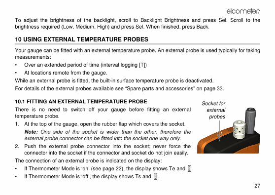
10 USING EXTERNAL TEMPERATURE PROBES
Your gauge can be fitted with an external temperature probe. An external probe is used typically for taking
measurements:
• Over an extended period of time (interval logging [T])
• At locations remote from the gauge.
While an external probe is fitted, the built-in surface temperature probe is deactivated.
For details of the external probes available see “Spare parts and accessories” on page 33.
10.1 FITTING AN EXTERNAL TEMPERATURE PROBE
There is no need to switch off your gauge before fitting an external
temperature probe.
1. At the top of the gauge, open the rubber flap which covers the socket.
Note: One side of the socket is wider than the other, therefore the
external probe connector can be fitted into the socket one way only.
2. Push the external probe connector into the socket; never force the
connector into the socket if the connector and socket do not join easily.
The connection of an external probe is indicated on the display:
• If Thermometer Mode is ‘on’ (see page 22), the display shows Te and .
• If Thermometer Mode is ‘off’, the display shows Ts and .
Socket for
external
probes
R
28
10.2 PREPARING YOUR GAUGE FOR USE WITH AN EXTERNAL PROBE
Attention: The external temperature probe can be capable of measuring temperature in excess of the
physical operating range of the gauge. When using your gauge with an external temperature probe, take
care to avoid exposing your gauge to excess temperatures.
1. If a ferrous material surface is available, attach the gauge to the surface using the magnets built into
the back of the gauge. Ensure the gauge is attached securely before use.
2. If the external temperature probe is magnetic, attach the probe to the magnetic surface.
3. If the external temperature probe is for measuring liquids, place the probe tip in the liquid.
Your gauge is now ready to take measurements.
Note: If the temperature of the external temperature probe exceeds the range of the gauge there is no error
message or warning, but the reading value will be saved as ‘---’.
11 TRANSFERRING READINGS TO A COMPUTER [T]
Your gauge is supplied with ElcoMaster and ElcoMaster Mobile software. ElcoMaster allows you to:
• Monitor measurements remotely via Bluetooth
• Download readings data from your gauge to the ElcoMaster data management system
• Keep your survey notes, inspection reports, photographs and all your other inspection information in
one place - ElcoMaster
• Create accurate and professional reports configured to allow your data to be understood easily at all
levels
• Create PDF versions of your reports and e-mail direct from ElcoMaster

R
29
• Create a user screen and upload it to your gauge (see page 30).
ElcoMaster and ElcoMaster Mobile are on the CD supplied with your gauge and they can also be
downloaded, together with any subsequent upgrades, from the Elcometer website www.elcometer.com
Your gauge is also fully compatible with ElcoShip - see www.elcoship.com for further details.
To use ElcoMaster for data transfer, the software must be installed on your PC and your gauge must be
connected to your PC using Bluetooth or the USB cable.
11.1 INSTALLING ELCOMASTER SOFTWARE
1. Place the CD in your PC.
The software installation wizard should run automatically. If it does not run automatically:
• Click Start > Run
• Type D:AutoCIS (where ‘D’ is the letter of your CD drive)
• Click OK. The software installation wizard will run.
2. Follow the on-screen installation instructions.
Follow the instructions included with ElcoMaster to interface your gauge with your PC.
If at any time ElcoMaster requests a PIN number for your gauge, press Menu>Bluetooth. The Bluetooth PIN is
displayed next to Authentication. Note that each gauge has a unique PIN - use only the PIN for your gauge.
11.2 TRANSFERRING READING DATA USING THE USB CABLE
1. Connect your gauge to your PC using the USB cable.
2. Switch on your gauge and ensure the Reading Screen is displayed.
3. Start ElcoMaster and follow the separate instructions included with ElcoMaster.

R
30
11.3 TRANSFERRING READING DATA USING A BLUETOOTH CONNECTION
1. Switch on your gauge and ensure the Reading Screen is displayed.
2. Enable Bluetooth communications - see “Bluetooth [T]” on page 24.
When Bluetooth is enabled, a Bluetooth symbol is displayed on the right side of the display.
During transfer of data between your gauge and your PC, the Bluetooth symbol flashes.
3. Start ElcoMaster and follow the separate instructions included with ElcoMaster.
11.4 ELCOMASTER MOBILE
ElcoMaster Mobile is an application which can be installed on Windows Mobile devices such as PDAs or
mobile phones. ElcoMaster Mobile provides much of the functionality of ElcoMaster:
• Link your gauge to your mobile device via Bluetooth
• Download reading data from your gauge to your mobile device
• View your data in the form of readings, charts, graphs, etc.
• Associate photographs with batches and view them within ElcoMaster Mobile
• Email reports from your mobile device
• Download reading data from your mobile device to ElcoMaster on your PC.
12 PERSONALISED USER SCREEN
A personalised user screen can be designed on a computer and then downloaded into your gauge. User
screen dimensions are 128 pixels x 128 pixels. The user screen is typically used to personalise the gauge
with a logo, serial number, user name, etc. This is the first screen displayed when the gauge is switched on.
R
31
Display of the user screen can be toggled ‘on’ or ‘off’ (Menu>Setup>User Screen) - see “User Screen” on
page 26.
12.1 CREATING THE USER SCREEN
1. Install and run ElcoMaster software.
2. Connect the gauge to the PC using the USB cable (optional equipment for [S] gauges) or
Bluetooth [T].
3. Switch on the gauge.
4. Ensure that the gauge and ElcoMaster are connected.
5. Click ‘Welcome Screen’ on the ElcoMaster tool bar and follow the on-screen instructions.
12.2 DELETING THE USER SCREEN
1. Run ElcoMaster.
2. Click ‘Welcome Screen’.
3. Select ‘No welcome screen’.
Follow the remaining on-screen instructions to delete the user screen.
13 MAINTENANCE
You own one of the finest dewpoint meters in the world. If looked after, it will last a lifetime.
• Always keep the gauge in its protective pouch when not in use.
• The humidity sensor is fragile and should never be touched. Do not use compressed air to clean the
sensors or the gauge.

R
32
• Be careful not to damage the LCD screen.
• Do not subject the gauge to a strong impact.
• Do not wash the sensor in water or solvents.
• If the surface of the humidity sensor becomes saturated with moisture allow the moisture to evaporate
fully before using the gauge to take measurements.
• To clean the plastic housing of the gauge use isopropyl alcohol (rubbing alcohol) and a soft dry cloth
such as those made to clean eyeglasses.
• Keep the gauge away from extreme heat. If the display is heated above 80°C (176°F) it may be
damaged. This can happen if the gauge is left in a vehicle parked in strong sunlight.
• The gauge is dustproof and waterproof equivalent to IP66 and should not be affected by dust and
moisture under normal conditions, however the gauge must not be submerged in liquids.
• Remove the batteries from the gauge and store them separately if the gauge is to remain unused for a
long period of time. This will prevent damage to the gauge in the event of malfunction of the batteries
Regular calibration checks over the life of the gauge are a requirement of quality management procedures,
e.g. ISO 9000, and other similar standards. For checks and certification contact Elcometer or your
Elcometer supplier.
Your gauge does not contain any user-serviceable components. In the unlikely event of a fault, the gauge
should be returned to your Elcometer supplier or directly to Elcometer. The warranty will be invalidated if
the gauge has been opened.
Elcometer contact details can be found stored in the gauge (Menu>About>Contact) and at
www.elcometer.com

R
33
14 SPARE PARTS AND ACCESSORIES
The following spare parts and accessories are available from your local Elcometer supplier or direct from
Elcometer:
External Temperature Probe - Surface Mount, Magnetic T31920162
External Temperature Probe - Liquids T9996390-
Protective Pouch T31921192
USB Cable T31921325
Wrist Strap T99916063
Display Protection Film, Pack of 8 T31921348-
15 TECHNICAL SPECIFICATIONS
MEASURED PARAMETERS
• Surface temperature (built-in probe) Ts
• External temperature (external probe) Ts with displayed or if in Thermometer Mode
• Air temperature Ta
• Relative humidity RH
CALCULATED PARAMETERS
• Dewpoint temperature Td (calculated from Ta and RH)
• Delta T T∆ (= Ts - Td)
• Dry bulb temperature Tdb (= Ta)
• Wet bulb temperature Twb (calculated from Ta and RH, see note below)

R
34
Note: The formula used for calculation of Twb uses a fixed value of air pressure set at 1.0 atmosphere
(1013 mbar). The accuracy of the wet bulb temperature will vary at other values of atmospheric
pressure. This variation may be greater than ±1°C.
OPERATING RANGE
• Surface temperature (built-in probe) Ts -20°C to 80°C (-4°F to 176°F)
• External temperature (Elcometer external probe)Ts -40°C to 200°C (-40°F to 392°F)
• Air temperature Ta -20°C to 80°C (-4°F to 176°F)
• Relative humidity RH 0 % to 100 % RH
• Gauge LCD display -20°C to 80°C (-4°F to 176°F)
ACCURACY
• Surface temperature (built-in probe) Ts ±0.5°C (±1°F)
• External temperature (Elcometer external probe)Ts ±2.0°C (±4°F)
• Air temperature Ta ±0.5°C (±1°F)
• Relative humidity RH ±3%
RESOLUTION
• Surface temperature (built-in probe) Ts 0.1°C (0.1°F)
• External temperature (Elcometer external probe)Ts 0.1°C (0.1°F)
• Air temperature Ta 0.1°C (0.1°F)
• Relative humidity RH 0.1%

R
35
MEMORY
• Rolling 10 sets of readings
• Batch [T] Up to approximately 40 000 sets of readings in
up to 999 batches
PHYSICAL
• Gauge dimensions 174 mm x 75 mm x 35 mm (6.8” x 3” x 1.4”)
• Gauge weight (including batteries) 300 g (10.5 oz)
POWER SUPPLY
• Type Battery / USB
• Battery type 2 x AA LR6 1.5 V
Note: The batteries supplied with the gauge have a maximum working temperature of 45°C. Prolonged
use of the gauge in excess of this temperature may require the use of alternative batteries.
• Battery life, Manual use > 40 hours (under average conditions)
• Battery life, Interval logging [T] > 200 hours (1 reading taken every 10 minutes)

R
36
16 RELATED EQUIPMENT
In addition to the Elcometer 319 Dewpoint Meter, Elcometer produces a wide range of other climatic
condition monitoring equipment and associated paint inspection equipment.
Users of the Elcometer 319 Dewpoint Meter may also benefit from the following Elcometer products:
• Elcometer Surface Profile Gauges and Testers
• Elcometer Surface Cleanliness Test Kits
• Elcometer Moisture Meters
• Elcometer Wet Film and Dry Film Thickness Gauges
• Elcometer Material Thickness Gauges
• Elcometer ElcoShip IMO PSPC Inspection Software
Other Bluetooth products within the Elcometer product range include:
• Elcometer 456 Dry Film Thickness Gauges
• Elcometer 224 Digital Surface Profile Gauge
These gauges can be connected to compatible PDAs and mobile phones using ElcoMaster Mobile and
ElcoShip Mobile Software.
For further information contact Elcometer, your local Elcometer supplier, or visit www.elcometer.com or
www.elcoship.com

R
37
17 INDEX
AAbout your gauge 24Accessories 33Alarm
Audible 21Symbol 22Volume 22
Auto Switch Off 25During logging 15
BBacklight 22
Setup 26Batch 16Batch memory 14Batch type
Selecting Interval or Manual 16Batching 16Batteries
Condition indicator 6Fitting 7Maximising life 7
Battery life 35Beep Volume 25Bluetooth
Configuring 24Transferring readings 30
CCalibration 32Clearing statistics
In batch memory 20In rolling memory 20
Coefficient of Variation 21Computer, transferring data to 28Copy Batch 18
DData, transferring to a computer 28Date & Time
Adjusting 25Viewing 23
Delayed start timeAdjusting 16
DeletingBatches 18
Deleting readings 22Display 25Display Protection Film 33
EElcoMaster 28
Personalised user screen 31Elcometer
Addresses in gauge 24ElcoShip 29Exit Batching 16External Temperature Probe 27
For liquids 33
Magnetic 33
FFeatures 3Flashing icon 22Free Memory 18
GGauge versions, Standard / Top 2, 8Green light 8
HHelp 24Highest Value 21
IInformation 24Interval
Adjusting 16
KKeys 8
LLanguage, choosing 24Lights 8Limits 21
Setting 23

R
38
Lowest Value 21
MMain Reading 11Maintenance 31Manual Logging 26Mean 21Measuring 13Memory 18
Batch 14Rolling 13
Menu 12, 22Mobile devices, transferring data 28
NNew Batch 16Number of Readings 21
OOpen Existing Batch 17Opening screen 30
PPIN 29Power supply 6, 7Protective Pouch, Spare 33
QQuick start 5
RRange exceeded 28Rdgs 18, 19, 20Reading Screen 10Red light 8, 21Resetting your gauge 23Review Batches 17Rolling memory 13
SSaving reading data
Into batch memory 14Into rolling memory 13
Sensors 9Set Delayed Start 16Set Interval 16Setup 24Setup Backlight 26Softkeys 8Softkeys Locked 26Software 28Spare parts 33Specifications 33Standard Deviation 21Standards 4Statistics 19
Batch memory 20Clearing batch memory 20Clearing rolling memory 20Rolling memory 19Values 21
Stats 18, 19Symbols, explanation of 24
TTaking readings 13Technical specifications 33Thermometer Mode 22Time & Date
Adjusting 25Viewing 23
Transferring data 28Bluetooth 30USB cable 29
R
39
UUnits, choosing 24USB Cable
Spare 33USB power supply 6User screen
Creating 30Switching on/off 26
VVolume 25
WWrist Strap 33