OPERATING INSTRUCTIONS
69
OPERATING INSTRUCTIONS T intelligent motion systems, inc. Excellence in Motion TM TM
-
Upload
khangminh22 -
Category
Documents
-
view
1 -
download
0
Transcript of OPERATING INSTRUCTIONS

OPERATING INSTRUCTIONS
T
intelligent motion systems, inc.Excellence in MotionTM
TM

The information in this book has been carefully checked and is believed to be accurate; however, noresponsibility is assumed for inaccuracies.
Intelligent Motion Systems, Inc., reserves the right to make changes without further notice to any productsherein to improve reliability, function or design. Intelligent Motion Systems, Inc., does not assume any liabilityarising out of the application or use of any product or circuit described herein; neither does it convey anylicense under its patent rights of others. Intelligent Motion Systems and are trademarks of IntelligentMotion Systems, Inc.
Intelligent Motion Systems, Inc.’s general policy does not recommend the use of its products in life support oraircraft applications wherein a failure or malfunction of the product may directly threaten life or injury. PerIntelligent Motion Systems, Inc.’s terms and conditions of sales, the user of Intelligent Motion Systems, Inc.,products in life support or aircraft applications assumes all risks of such use and indemnifies Intelligent MotionSystems, Inc., against all damages.
TM
© 2002 Intelligent Motion Systems, Inc.All Rights Reserved

1
Table of ContentsPart 1: General Information And Hardware Information
Section 1.1: Introduction to the MDrive17 Motion Control ....................................................................................................................... 5Introduction to the MDrive17 Motion Control ................................................................................................................................................................................ 5Feature Summary ......................................................................................................................................................................................................................... 5
Section 1.2: MDrive17 Motion Control Specifications ............................................................................................................................... 6Section Overview ......................................................................................................................................................................................................................... 6Rotary Motor Specifications ......................................................................................................................................................................................................... 6
Mechanical Specifications - Dimensions in Inches (mm) ................................................................................................................................................... 6MDrive Motion Control 1713 Motor Specs and Speed/Torque Curves ................................................................................................................................ 6MDrive Motion Control 1715 Motor Specs and Speed/Torque Curves ................................................................................................................................ 7MDrive Motion Control 1719 Motor Specs and Speed/Torque Curves ................................................................................................................................ 7
Linear Motor Specifications .......................................................................................................................................................................................................... 7Mechanical Specifications - Dimensions in Inches (mm) ................................................................................................................................................... 7Speed-Force Curve: 24 VDC .............................................................................................................................................................................................. 8Linear Actuator MDrive Motion Control 1713 Specs and Speed-Force Curves .................................................................................................................. 8Speed-Force Curve: 45 VDC .............................................................................................................................................................................................. 8MDrive17 Motion Control ACME Screw ............................................................................................................................................................................... 9
General Specifications .................................................................................................................................................................................................................. 9General Specifications ................................................................................................................................................................................................................ 10Power Supply Requirements ...................................................................................................................................................................................................... 10
Recommended IMS Power Supplies .................................................................................................................................................................................. 10Thermal Specifications ............................................................................................................................................................................................................... 10
Section 1.3: Introduction to the MDrive23 Motion Control ..................................................................................................................... 11Introduction to the MDrive23 Motion Control .............................................................................................................................................................................. 11Feature Summary ....................................................................................................................................................................................................................... 11
Section 1.4: MDrive23 Motion Control Specifications ............................................................................................................................. 12Section Overview ....................................................................................................................................................................................................................... 12Rotary Motor Specifications ....................................................................................................................................................................................................... 12
Mechanical Specifications - Dimensions in Inches (mm) ................................................................................................................................................. 12MDrive Motion Control 2218 Motor Specs and Speed/Torque Curves .............................................................................................................................. 12MDrive Motion Control 2222 Motor Specs and Speed/Torque Curves .............................................................................................................................. 13MDrive Motion Control 2231 Motor Specs and Speed/Torque Curves .............................................................................................................................. 13
Linear Motor Specifications ........................................................................................................................................................................................................ 13Mechanical Specifications - Dimensions in Inches (mm) ................................................................................................................................................. 13Speed-Force Curve: 24 VDC ............................................................................................................................................................................................ 14Linear Actuator MDrive Motion Control 2218 Specs and Speed-Force Curves ................................................................................................................ 14Speed-Force Curve: 45 VDC ............................................................................................................................................................................................ 14MDrive23 Motion Control ACME Screw ............................................................................................................................................................................. 15
General Specifications ................................................................................................................................................................................................................ 15General Specifications ................................................................................................................................................................................................................ 16Power Supply Requirements ...................................................................................................................................................................................................... 16
Recommended IMS Power Supplies .................................................................................................................................................................................. 16Thermal Specifications ............................................................................................................................................................................................................... 16
Part 2: Connecting, Configuring And Programming The MDrive Motion Control
Section 2.1: Interfacing the MDrive Motion Control ................................................................................................................................. 19Section Overview ....................................................................................................................................................................................................................... 19Layout and Interface Guidelines ................................................................................................................................................................................................ 19
Recommended Wiring ....................................................................................................................................................................................................... 19Pin Configuration and Descriptions ............................................................................................................................................................................................ 19Interfacing Power ........................................................................................................................................................................................................................ 20Interfacing RS-485 Communications ......................................................................................................................................................................................... 20
Single MDrive .................................................................................................................................................................................................................... 20Multiple MDrive Motion Control System (Party Mode) ...................................................................................................................................................... 21
Interfacing the Digital I/O ........................................................................................................................................................................................................... 22Uses of the Digital I/O ...................................................................................................................................................................................................... 22Interfacing Inputs .............................................................................................................................................................................................................. 22Interfacing Outputs ........................................................................................................................................................................................................... 24
Interfacing the Analog Input ....................................................................................................................................................................................................... 25Sample Usage ................................................................................................................................................................................................................... 25
Section 2.2: MDrive Motion Control Software Introduction ................................................................................................................... 26Section Overview ....................................................................................................................................................................................................................... 26Installing and Using IMS Terminal ............................................................................................................................................................................................... 26
System Requirements ...................................................................................................................................................................................................... 26Installation ......................................................................................................................................................................................................................... 26Using the IMS Terminal Software ...................................................................................................................................................................................... 27Setting the Programmable Function Keys ........................................................................................................................................................................ 28
Upgrading the MDrive Motion Control Firmware ......................................................................................................................................................................... 28MDrive Motion Control Programming .......................................................................................................................................................................................... 29
Operational Modes ............................................................................................................................................................................................................. 29Basic Components of MDrive Motion Control Software ............................................................................................................................................................ 29
Instructions ........................................................................................................................................................................................................................ 29Variables ............................................................................................................................................................................................................................ 29Flags .................................................................................................................................................................................................................................. 30Keywords ........................................................................................................................................................................................................................... 30
Most Commonly Used Variables and Commands ...................................................................................................................................................................... 30

2
Variables ............................................................................................................................................................................................................................ 30Math Functions .................................................................................................................................................................................................................. 31Motion Commands ............................................................................................................................................................................................................. 31I/O Commands .................................................................................................................................................................................................................. 32System Instructions .......................................................................................................................................................................................................... 32Program Instructions ......................................................................................................................................................................................................... 32
Section 2.3: MDrive Motion Control Command Set Summary ............................................................................................................... 35Setup Instructions, Variables and Flags ..................................................................................................................................................................................... 35Miscellaneous Instructions, Variables and Flags ........................................................................................................................................................................ 35Motion Instructions, Variables and Flags .................................................................................................................................................................................... 35I/O Instructions, Variables and Flags ......................................................................................................................................................................................... 36Program Instructions, Variables and Flags ................................................................................................................................................................................. 36Position Related Instructions, Variables and Flags .................................................................................................................................................................... 37Encoder Related Instructions, Variables and Flags .................................................................................................................................................................... 37Mathematical Functions .............................................................................................................................................................................................................. 37
Section 2.4: MDrive Motion Control Command Set .................................................................................................................................. 38Appendix A: ASCII TABLE ................................................................................................................................................................................ 64Appendix B: Error Codes ................................................................................................................................................................................. 65
List of FiguresFigure 1.1 Rotary MDrive17 Motion Control Mechanical Specifications .................................................................................................................................. 6Figure 1.2 Rotary MDrive17 Motion Control 1713 Speed/Torque Data ..................................................................................................................................... 6Figure 1.3 Rotary MDrive17 Motion Control 1715 Speed/Torque Data ..................................................................................................................................... 7Figure 1.4 Rotary MDrive17 Motion Control 1719 Speed/Torque Data ..................................................................................................................................... 7Figure 1.5 Linear Actuator MDrive17 Motion Control Mechanical Specifications ..................................................................................................................... 7Figure 1.6 Speed-Force Curve - 24VDC (100% Current) ......................................................................................................................................................... 8Figure 1.7 Speed-Force Curve - 45VDC (100% Current) ......................................................................................................................................................... 8Figure 1.8 Rotary MDrive23 Motion Control Mechanical Specifications ................................................................................................................................ 12Figure 1.9 Rotary MDrive23 Motion Control 2218 Speed/Torque Data ................................................................................................................................... 12Figure 1.10 Rotary MDrive23 Motion Control 2222 Speed/Torque Data ................................................................................................................................... 13Figure 1.11 Rotary MDrive23 Motion Control 2231 Speed/Torque Data ................................................................................................................................... 13Figure 1.12 Linear Actuator MDrive23 Motion Control Mechanical Specifications ................................................................................................................... 13Figure 1.13 Speed-Force Curve - 24VDC (100% Current) ....................................................................................................................................................... 14Figure 1.14 Speed-Force Curve - 45VDC (100% Current) ....................................................................................................................................................... 14Figure 2.1 Power Supply Interface ......................................................................................................................................................................................... 20Figure 2.2 RS-485 Interface, Single MDrive Motion Control .................................................................................................................................................. 20Figure 2.3 RS-485 Interface, Multiple MDrive Motion Control System .................................................................................................................................. 21Figure 2.4 Input Interfaced to a Switch .................................................................................................................................................................................. 22Figure 2.5 Input Interfaced to a PLC ...................................................................................................................................................................................... 22Figure 2.6 TTL Interface to an Input Group ............................................................................................................................................................................ 23Figure 2.7 Output Interfaced to an LED ................................................................................................................................................................................. 24Figure 2.8 Output Interfaced to a Relay ................................................................................................................................................................................ 24Figure 2.9 Outputs Interfaced tp LED’s as a Group ............................................................................................................................................................... 24Figure 2.10 Analog Input Interface ........................................................................................................................................................................................... 25Figure 2.11 IMS Terminal Window ............................................................................................................................................................................................. 26Figure 2.12 IMS Terminal Preferences ...................................................................................................................................................................................... 27Figure 2.13 IMS Terminal Upgrader Window ............................................................................................................................................................................. 28
List of TablesTable 1.1 Rotary MDI1713 Motor Specifications ..................................................................................................................................................................... 6Table 1.2 Rotary MDI1715 Motor Specifications ..................................................................................................................................................................... 7Table 1.3 Rotary MDI1719 Motor Specifications ..................................................................................................................................................................... 7Table 1.4 Linear Actuator MDrive17 Motion Control Motor Specifications .............................................................................................................................. 8Table 1.5 ACME Screws for Linear Actuator MDrive17 Motion Control .................................................................................................................................. 9Table 1.6 Rotary MDI2218 Motor Specifications ................................................................................................................................................................... 12Table 1.7 Rotary MDI2222 Motor Specifications ................................................................................................................................................................... 13Table 1.8 Rotary MDI2231 Motor Specifications ................................................................................................................................................................... 13Table 1.9 Linear Actuator MDrive23 Motion Control Motor Specifications ............................................................................................................................ 14Table 1.10 ACME Screws for Linear Actuator MDrive23 Motion Control ................................................................................................................................ 15Table 2.1 P1 Pin Configuration and Description .................................................................................................................................................................... 19Table 2.2 P2 Pin Configuration and Description .................................................................................................................................................................... 20Table 2.3 Input Functions ...................................................................................................................................................................................................... 22Table 2.4 I/O Group Truth Table ............................................................................................................................................................................................. 23Table 2.5 Output Functions ................................................................................................................................................................................................... 24Table 2.6 Microstep Resolution Settings ............................................................................................................................................................................... 51

3
Part 1: General Informationand Hardware Specifications

4
Intentionally Left Blank

5
S e c t i o n 1 . 1I n t roduc t i on to the MDr i ve17 Mot i on Cont ro l
I n t r o d u c t i o n t o t h e MDr i v e17 Mo t i o n C on t r o l
The MDrive17 Motion Control offers the system designer a low-cost, intelligent motion controller integrated with a NEMA 17 hightorque stepping motor and a +12 to +48 VDC microstepping drive.The MDrive17 Motion Control adds a versatile array of functions by combining a complete programmable motion controller withour already compact and cost effective standard MDrive17, adding little cost and no increase in size. Standard offerings include four5 to 24 volt programmable I/O points, one 10-bit 0 to 5 volt analog input, 0 to 5 MHz step clock rate, microstep resolution up to51,200 steps per revolution and a full featured easy-to-program instruction set.The MDrive17 Motion Control communicates using the RS-485 communications protocol, this allows for point-to-point or multi-drop communications using one communications port. Addressing and hardware support up to 62 MDrive nodes in a system. Thecommunications BAUD rate is software selectable and ranges from 4.8 kbps to 115 kbps.The MDrive17 is also available with an optional closed loop control. The closed loop configuration adds a 512 line (2048 count)internal magnetic rotary encoder with index mark without increasing the length of the unit. Closed loop configuration adds positionmaintenance, stall detection and find index mark.Available motor configurations include: single shaft, double shaft with control knob, and long life ACME screw linear actuator.Rotary versions are available in three stack lengths: 13, 15 & 19. Interface connections are accomplished using either a 7 positionterminal block or optional 12” flying leads.
F e a t u r e S u m m a r y
! Integrated Microstepping Drive/Motion Controller with Optional Encoder/NEMA 17 High Torque Stepping Motor
! +12 to +48VDC Input Voltage
! Low Cost
! Extremely Compact
! Available Configurations: Single Shaft*, Linear Actuator, Integral Encoder*, Double Shaft with Knob for ManualPositioning*
! Three Motor Stack Lengths Available*
! Single Power Supply
! Microstep Resolution up to 51,200 Steps Per Revolution
! Open Loop or Optional Closed Loop Control
! Programmable Motor Run and Hold Current Settings
! Four 5 to 24 VDC Programmable I/O Points
! One Analog 10 Bit, 0 to 5 Volt Analog Input
! 0 to 5 MHz Step Clock Rate, SelecTable 1. in 0.59 Hz Increments
! RS-485 Communications Protocol
! Communications BAUD Rate SelecTable 1. from 4.8 kbps to 115 kbps
! 62 Software Addresses for Multidrop Communications
! Simple 1 and 2 Character Programming Instructions
! Pluggable Terminal Strip or 12” Flying Lead Interface
! Optional Integrated RS-232 to RS-485 Converter/Communications Cable
*Rotary Motor Only

6
S e c t i o n 1 . 2MDr i ve17 Mot ion Contro l Spec i f i ca t i ons
S e c t i o n O v e r v i e w
This section contains mechanical, motor and electrical specifications specific to each version of the MDrive17 Motion Control.Shown are:
! Rotary Motor Specifications! Linear Motor Specifications! General Specifications! Power Supply Requirements! Thermal Specifications
Ro t a r y Mo t o r S p e c i f i c a t i o n s
M e c h a n i c a l S p e c i f i c a t i o n s - D i m e n s i o n s i n I n c h e s ( m m )
Figure 1.1: Rotary MDrive17 Motion Control Mechanical Specifications
Figure 1.2: Rotary MDrive Motion Control 1713 Speed/Torque Data
Table 1.1: Rotary MDI1713 Motor Specifications
M D r i v e M o t i o n C o n t r o l 1 7 1 3 M o t o r S p e c s a n d S p e e d / To r q u e C u r v e s
Standard Rotary Motor (LMAX)Stack In (mm)1713 2.187 (55.56)1715 2.407 (61.15)1719 2.786 (70.77)
Control Knob (LMAX2)Stack In (mm)1713 2.774 (69.71)1715 2.965 (75.30)1719 3.343 (84.92)
MDI1713Holding Torque oz-in (N-cm) 32 (22.6)Detent Torque oz-in (N-cm) 2.0 (1.4)Rotor Inertia oz-in-sec2 (kg-cm2) 0.00053 (0.038)Weight (Motor+Driver) oz (gm) 8.26 (234.2)

7
Table 1.2: Rotary MDI1715 Motor Specifications
Figure 1.3: Rotary MDrive Motion Control 1715 Speed/Torque Data
M D r i v e M o t i o n C o n t r o l 1 7 1 5 M o t o r S p e c s a n d S p e e d / To r q u e C u r v e s
Table 1.3: Rotary MDI1719 Motor Specifications
Figure 1.4: Rotary MDrive Motion Control 1719 Speed/Torque Data
M D r i v e M o t i o n C o n t r o l 1 7 1 9 M o t o r S p e c s a n d S p e e d / To r q u e C u r v e s
L i n e a r Mo t o r S p e c i f i c a t i o n s
M e c h a n i c a l S p e c i f i c a t i o n s - D i m e n s i o n s i n I n c h e s ( m m )
Figure 1.5: Linear Actuator MDrive17 Motion Control Mechanical Specifications
MDI1715Holding Torque oz-in (N-cm) 60 (42.4)Detent Torque oz-in (N-cm) 2.5 (1.8)Rotor Inertia oz-in-sec2 (kg-cm2) 0.00080 (0.057)Weight (Motor+Driver) oz (gm) 10.42 (295.4)
MDI1719Holding Torque oz-in (N-cm) 74.9 (52.9)Detent Torque oz-in (N-cm) 4.0 (2.8)Rotor Inertia oz-in-sec2 (kg-cm2) 0.0116 (0.082)Weight (Motor+Driver) oz (gm) 11.80 (334.5)

8
S p e e d - F o r c e C u r v e : 2 4 V D C
Refer to Table 1. 5 for screw pitch information
Figure 1.6: Speed-Force Curve - 24VDC (100% Current)
L i n e a r A c t u a t o r M D r i v e M o t i o n C o n t r o l 1 7 1 3 S p e c s a n d S p e e d - F o r c eC u r v e s
Table 1.4: Linear Actuator MDrive17 Motion Control Motor Specifications
S p e e d - F o r c e C u r v e : 4 5 V D C
Refer to Table 1. 5 for screw pitch information
Figure 1.7: Speed-Force Curve - 45VDC (100% Current)
MDI17 Linear ActuatorMaximum Thrust lbs (kg) 50 (22.7)Maximum Screw Deflection ±1°Backlash inches (mm) 0.005 (0.127)Weight (Motor+Driver) oz (gm) 9.2 (0.127)

9
WARNING: The maximum axial load limit for theMDrive17 Linear motor is 50 lbs (22.7 kg). Do notexceed this rating!
Table 1.5: ACME Screws for the MDI17 Linear Actuator
WARNING: The ACME Screw MUST NOT deflectmore than ± 1 degree perpendicular to the motor face.Additional support for radial loads may be required!
M D r i v e 1 7 M o t i o n C o n t r o l A C M E S c r e w
G e n e r a l S p e c i f i c a t i o n s
I n p u t Vo l t a g e ( + V )
Range ......................................................................................................................... +12 to +48 VDC
A n a l o g I n p u t
Resolution ................................................................................................................. 10 BitVoltage Range ............................................................................................................. 0 to +5 Volts
P r o g r a m m a b l e I / O
Number ...................................................................................................................... 4Interface Type ........................................................................................................... Open CollectorVoltage Range ............................................................................................................. 0 to +24 VDCOutput Sink Current ................................................................................................. 700 mAProtection .................................................................................................................. Over Temp., Short Circuit, Inductive Clamp
C o m m u n i c a t i o n
Protocol ..................................................................................................................... RS-485, Full/Half Duplex SelecTable 1.BAUD Rate ............................................................................................................... 4800, 9600, 19.2k, 38.0k, 115.2k
M o t i o n
Microstep Resolution (Open Loop Configuration)Number of Settings ................................................................................................... 14Steps per Revolution ................................................................................................ 400, 800, 1000, 1600, 2000, 3200, 5000
6400, 10000, 12800, 25000, 25600, 5000051200
Microstep Resolution (Closed Loop Configuration)Steps per Revolution (Fixed) .................................................................................... 51200
Encoder (Optional)Type .......................................................................................................................... Internal, MagneticResolution ................................................................................................................. 512 Lines/2048 counts per Revolution
CountersType .......................................................................................................................... Position(C1), Encoder (C2)Resolution ................................................................................................................. 32 BitEdge Rate (Max) ........................................................................................................ 5 MHz
VelocityRange ......................................................................................................................... ±5,000,000 Steps per SecondResolution ................................................................................................................. 1 Step per Second
Acceleration/DecelerationRange ......................................................................................................................... 1.5 x 10⁹ Steps per Second2
Resolution ................................................................................................................. 90.9 Steps per Second2
MDI17 ACME ScrewsScrew Travel/Full Step - Inches (mm)
A 0.00125 (0.3175)B 0.000625 (0.015875)C 0.0003125 (0.079375)D 0.00015625 (0.00396875)

10
G e n e r a l S p e c i f i c a t i o n s
S o f t w a r e
Program and Data Storage ......................................................................................... Non-VolatileUser Program Space .................................................................................................. 767 BytesUser Registers ........................................................................................................... 4 - 32 BitMath Functions ......................................................................................................... +, -, x, ÷, <>, =, <, <=, >, >=, AND, OR,
XOR, NOTBranch Functions ...................................................................................................... Branch & Call (Conditional)
Predefined I/O FunctionsInputs ........................................................................................................................ Home, Limit +, Limit -, Go, Stop, Pause,
Jog +, Jog -, Analog InputOutputs ..................................................................................................................... Moving, Fault
Trip Functions .......................................................................................................... Input, PositionParty Mode Node Addresses .................................................................................... 62Encoder Functions .................................................................................................... Stall Detect, Position Maintenance,
Find IndexP r o t e c t i o n
Types ......................................................................................................................... Thermal
Powe r S upp l y R equ i r emen t s
Each MDrive will require a maximum power supply current of 2A. Actual power supply current will depend upon the load andduty cycle.
R e c o m m e n d e d I M S P o w e r S u p p l i e s
Listed below are the power supplies recommended for use with both voltage ranges of the MDrive17 Motion Control.U n r e g u l a t e d L i n e a r S u p p l y
IP404(MDI17)Input Specifications
AC Input Voltage Range .................................................................................................... 102-132VAC/Optional 240VACFrequency ........................................................................................................................... 50-60Hz
Output SpecificationsVoltage (Nominal - No Load) ............................................................................................ 40 VDCCurrent (Peak) ................................................................................................................... 4 AmpsCurrent (Continuous) ......................................................................................................... 2 Amps
U n r e g u l a t e d S w i t c h i n g S u p p l y
ISP200-4(MDI17)Input Specifications
AC Input Voltage Range .................................................................................................... 102-132VAC/Optional 240VACFrequency ........................................................................................................................... 50-60Hz
Output SpecificationsVoltage (Nominal - No Load) ............................................................................................ 45 VDCCurrent (Peak) ................................................................................................................... 3 AmpsCurrent (Continuous) ......................................................................................................... 1.5 Amps
T h e r m a l S p e c i f i c a t i o n s
Because the MDrive consists of two core components, a drive and a motor, close attention must be paid to the thermal environmentwhere the device is used. The following maximum temperatures apply to the MDrive17:
Heatsink TemperatureMax .................................................................................................................................... 85°CMotor TemperatureMax .................................................................................................................................... 100°C

11
S e c t i o n 1 . 3I n t roduc t i on to the MDr i ve23 Mot i on Cont ro l
I n t r o d u c t i o n t o t h e MDr i v e23 Mo t i o n C on t r o l
The MDrive23 Motion Control offers the system designer a low-cost, intelligent motion controller integrated with a NEMA 23 hightorque stepping motor and a +12 to +48 VDC microstepping drive.The MDrive23 Motion Control adds a versatile array of functions by combining a complete programmable motion controller withour already compact and cost effective standard MDrive23, adding little cost and no increase in size. Standard offerings include four5 to 24 volt programmable I/O points, one 10-bit 0 to 5 volt analog input, 0 to 5 MHz step clock rate, microstep resolution up to51,200 steps per revolution and a full featured easy-to-program instruction set.The MDrive23 Motion Control communicates using the RS-485 communications protocol, this allows for point-to-point or multi-drop communications using one communications port. Addressing and hardware support up to 62 MDrive nodes in a system. Thecommunications BAUD rate is software selectable and ranges from 4.8 kbps to 115 kbps.The MDrive23 is also available with an optional closed loop control. The closed loop configuration adds a 512 line (2048 count)internal magnetic rotary encoder with index mark without increasing the length of the unit. Closed loop configuration adds positionmaintenance, stall detection and find index mark.Available motor configurations include: single shaft, double shaft with control knob, and long life ACME screw linear actuator.Rotary versions are available in three stack lengths: 18, 22 & 31. Interface connections are accomplished using either a 7 positionterminal block or optional 12” flying leads.
F e a t u r e S u m m a r y
! Integrated Microstepping Drive/Motion Controller with Optional Encoder/NEMA 23 High Torque Stepping Motor
! +12 to +48VDC Input Voltage
! Low Cost
! Extremely Compact
! Available Configurations: Single Shaft*, Linear Actuator, Integral Encoder*, Double Shaft with Knob for ManualPositioning*
! Three Motor Stack Lengths Available*
! Single Power Supply
! Microstep Resolution up to 51,200 Steps Per Revolution
! Open Loop or Optional Closed Loop Control
! Programmable Motor Run and Hold Current Settings
! Four 5 to 24 VDC Programmable I/O Points
! One Analog 10 Bit, 0 to 5 Volt Analog Input
! 0 to 5 MHz Step Clock Rate, Selectable in 0.59 Hz Increments
! RS-485 Communications Protocol
! Communications BAUD Rate Selectable from 4.8 kbps to 115 kbps
! 62 Software Addresses for Multidrop Communications
! Simple 1 and 2 Character Programming Instructions
! Pluggable Terminal Strip or 12” Flying Lead Interface
! Optional Integrated RS-232 to RS-485 Converter/Communications Cable
*Rotary Motor Only

12
S e c t i o n 1 . 4MDr i ve23 Mot ion Contro l Spec i f i ca t i ons
S e c t i o n O v e r v i e w
This section contains mechanical, motor and electrical specifications specific to each version of the MDrive23 Motion Control.Shown are:
! Rotary Motor Specifications! Linear Motor Specifications! General Specifications! Power Supply Requirements! Thermal Specifications
Ro t a r y Mo t o r S p e c i f i c a t i o n s
M e c h a n i c a l S p e c i f i c a t i o n s - D i m e n s i o n s i n I n c h e s ( m m )
Figure 1.8: Rotary MDrive23 Motion Control Mechanical Specifications
Figure 1.9: Rotary MDrive Motion Control 2218 Speed/Torque Data
70
60
50
40
30
20
10
0
49
42
35
28
21
14
7
0 1000 2000 3000 4000 5000 6000 7000
Speed in Full Steps per Second
Torq
ue in
Oz
- In
Torque in N - cm
24 VDC45 VDC
Table 1.6: Rotary MDI2218 Motor Specifications
M D r i v e M o t i o n C o n t r o l 2 2 1 8 M o t o r S p e c s a n d S p e e d / To r q u e C u r v e s
Standard Rotary Motor (LMAX)Stack In (mm)2218 2.632 (66.85)2222 3.000 (76.20)2231 3.960 (100.58)
Control Knob (LMAX2)Stack In (mm)2218 3.088 (78.44)2222 3.537 (89.84)2231 4.416 (112.17)
MDI2218Holding Torque oz-in (N-cm) 90 (64)Detent Torque oz-in (N-cm) 3.5 (2.5)Rotor Inertia oz-in-sec2 (kg-cm2) 0.0025 (0.18)Weight (Motor+Driver) oz (gm) 20.1 (569.8)
1.625(41.28)
2.22 SQ.(56.39 SQ.)
1.500(38.10)
2.907(73.84)
1.860 SQ.(47.24 SQ.)
4 x Ø 0.205 (5.21)±.010 (.25) HOLESEQ. SPACED ON A2.625 (66.68) DBC.
Ø 1.500 ±.002(Ø 38.10 ±.05)
0.810 ± .030(20.57 ±.76)
0.590(14.86)
0.060(1.53)
L MAX
L MAX2
0.230 ± .005(5.84 ± .127 )
0.2500 (6.35)0.2495 (6.34)Ø
InterfaceOption
13
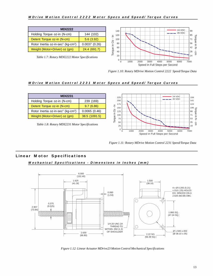
Table 1.7: Rotary MDI2222 Motor Specifications
140
120
100
80
60
40
20
0
99
85
71
56
42
28
14
0 1000 2000 3000 4000 5000 6000 7000
Speed in Full Steps per Second
Torq
ue in
Oz
- In
Torque in N - cm
24 VDC45 VDC
Figure 1.10: Rotary MDrive Motion Control 2222 Speed/Torque Data
M D r i v e M o t i o n C o n t r o l 2 2 2 2 M o t o r S p e c s a n d S p e e d / To r q u e C u r v e s
Table 1.8: Rotary MDI2231 Motor Specifications
200
225
175
150
125
100
75
50
25
0
141
159
124
106
88
71
53
35
18
0 1000 2000 3000 4000 5000 6000 7000
Speed in Full Steps per Second
Torq
ue in
Oz
- In Torque in N
- cm
24 VDC45 VDC
Figure 1.11: Rotary MDrive Motion Control 2231 Speed/Torque Data
M D r i v e M o t i o n C o n t r o l 2 2 3 1 M o t o r S p e c s a n d S p e e d / To r q u e C u r v e s
L i n e a r Mo t o r S p e c i f i c a t i o n s
M e c h a n i c a l S p e c i f i c a t i o n s - D i m e n s i o n s i n I n c h e s ( m m )
Figure 1.12: Linear Actuator MDrive23 Motion Control Mechanical Specifications
1.625(41.28)
2.22 SQ.(56.39 SQ.)
1.500(38.10)
2.907(73.84)
1.860 SQ..(47.24 SQ.)
4 x Ø 0.205 (5.21)±.010 (.25) HOLESEQ. SPACED ON A2.625 (66.68) DBC.
Ø 1.500 ±.002(Ø 38.10 ±.05)
0.060(1.53)
2.630(66.80)
6.000(152.40)
1/4-20 UNC-2ATHREAD TO
WITHIN .050 (1.3)OF SHOULDER
0.375(9.525)
MDI2222Holding Torque oz-in (N-cm) 144 (102)Detent Torque oz-in (N-cm) 5.6 (3.92)Rotor Inertia oz-in-sec2 (kg-cm2) 0.0037 (0.26)Weight (Motor+Driver) oz (gm) 24.4 (691.7)
MDI2231Holding Torque oz-in (N-cm) 239 (169)Detent Torque oz-in (N-cm) 9.7 (6.86)Rotor Inertia oz-in-sec2 (kg-cm2) 0.0065 (0.46)Weight (Motor+Driver) oz (gm) 38.5 (1091.5)

14
S p e e d - F o r c e C u r v e : 2 4 V D C
Refer to Table 1.10 for screw pitch information
Figure 1.13: Speed-Force Curve - 24VDC (100% Current)
160
180
200
140
120
100
80
60
40
20
0
712
890
623
801
534
445
356
267
178
89
0 1000 2000 3000 4000 5000 6000 7000
Speed in Full Steps per Second
Forc
e (lb
s) L
oad
Lim
it 2
00
lbs
Force (N)Load Lim
it 89
0N
Screw DScrew E
Screw CScrew BScrew A
L i n e a r A c t u a t o r M D r i v e M o t i o n C o n t r o l 2 2 1 8 S p e c s a n d S p e e d - F o r c eC u r v e s
Table 1.9: Linear Actuator MDrive23 Motion Control Motor Specifications
S p e e d - F o r c e C u r v e : 4 5 V D C
Refer to Table 1.10 for screw pitch information
Figure 1.14: Speed-Force Curve - 45VDC (100% Current)
160
180
200
140
120
100
80
60
40
20
0
712
890
623
801
534
445
356
267
178
89
0 1000 2000 3000 4000 5000 6000 7000
Speed in Full Steps per Second
Forc
e (lb
s) L
oad
Lim
it 200 lb
sForce (N
)Load Limit 8
90N
Screw DScrew E
Screw CScrew BScrew A
MDI23 Linear ActuatorMaximum Thrust lbs (kg) 200 (90.7)Maximum Screw Deflection ±1°Backlash inches (mm) 0.005 (0.127)Weight (Motor+Driver) oz (gm) 20.4 (578.3)
15
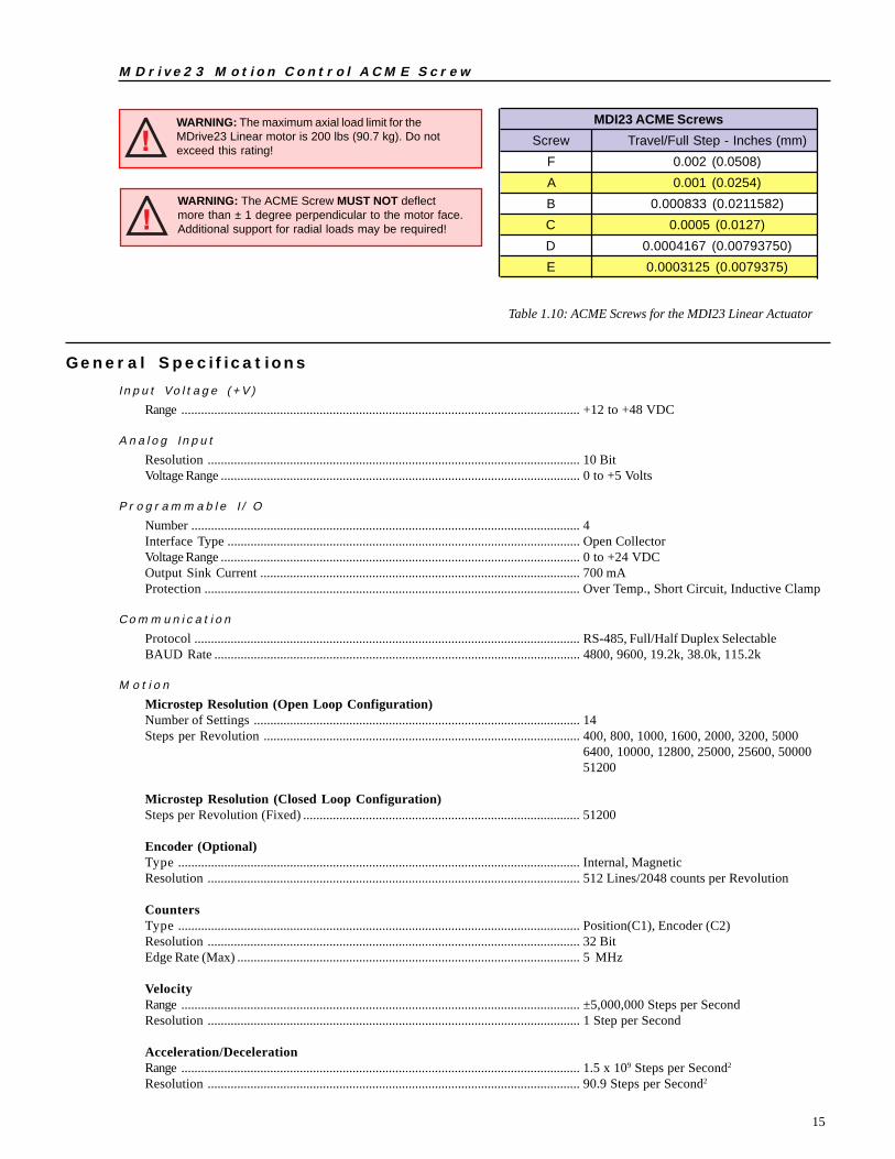
Table 1.10: ACME Screws for the MDI23 Linear Actuator
WARNING: The ACME Screw MUST NOT deflectmore than ± 1 degree perpendicular to the motor face.Additional support for radial loads may be required!
WARNING: The maximum axial load limit for theMDrive23 Linear motor is 200 lbs (90.7 kg). Do notexceed this rating!
M D r i v e 2 3 M o t i o n C o n t r o l A C M E S c r e w
G e n e r a l S p e c i f i c a t i o n s
I n p u t Vo l t a g e ( + V )
Range ......................................................................................................................... +12 to +48 VDC
A n a l o g I n p u t
Resolution ................................................................................................................. 10 BitVoltage Range ............................................................................................................. 0 to +5 Volts
P r o g r a m m a b l e I / O
Number ...................................................................................................................... 4Interface Type ........................................................................................................... Open CollectorVoltage Range ............................................................................................................. 0 to +24 VDCOutput Sink Current ................................................................................................. 700 mAProtection .................................................................................................................. Over Temp., Short Circuit, Inductive Clamp
C o m m u n i c a t i o n
Protocol ..................................................................................................................... RS-485, Full/Half Duplex SelectableBAUD Rate ............................................................................................................... 4800, 9600, 19.2k, 38.0k, 115.2k
M o t i o n
Microstep Resolution (Open Loop Configuration)Number of Settings ................................................................................................... 14Steps per Revolution ................................................................................................ 400, 800, 1000, 1600, 2000, 3200, 5000
6400, 10000, 12800, 25000, 25600, 5000051200
Microstep Resolution (Closed Loop Configuration)Steps per Revolution (Fixed) .................................................................................... 51200
Encoder (Optional)Type .......................................................................................................................... Internal, MagneticResolution ................................................................................................................. 512 Lines/2048 counts per Revolution
CountersType .......................................................................................................................... Position(C1), Encoder (C2)Resolution ................................................................................................................. 32 BitEdge Rate (Max) ........................................................................................................ 5 MHz
VelocityRange ......................................................................................................................... ±5,000,000 Steps per SecondResolution ................................................................................................................. 1 Step per Second
Acceleration/DecelerationRange ......................................................................................................................... 1.5 x 10⁹ Steps per Second2
Resolution ................................................................................................................. 90.9 Steps per Second2
MDI23 ACME ScrewsScrew Travel/Full Step - Inches (mm)
F 0.002 (0.0508)A 0.001 (0.0254)B 0.000833 (0.0211582)C 0.0005 (0.0127)D 0.0004167 (0.00793750)E 0.0003125 (0.0079375)

16
G e n e r a l S p e c i f i c a t i o n s
S o f t w a r e
Program and Data Storage ......................................................................................... Non-VolatileUser Program Space .................................................................................................. 767 BytesUser Registers ........................................................................................................... 4 - 32 BitMath Functions ......................................................................................................... +, -, x, ÷, <>, =, <, <=, >, >=, AND, OR,
XOR, NOTBranch Functions ...................................................................................................... Branch & Call (Conditional)
Predefined I/O FunctionsInputs ........................................................................................................................ Home, Limit +, Limit -, Go, Stop, Pause,
Jog +, Jog -, Analog InputOutputs ..................................................................................................................... Moving, Fault
Trip Functions .......................................................................................................... Input, PositionParty Mode Node Addresses .................................................................................... 62Encoder Functions .................................................................................................... Stall Detect, Position Maintenance,
Find IndexP r o t e c t i o n
Types ......................................................................................................................... Thermal
Powe r S upp l y R equ i r emen t s
Each MDrive will require a maximum power supply current of 2A. Actual power supply current will depend upon the load andduty cycle.
R e c o m m e n d e d I M S P o w e r S u p p l i e s
Listed below are the power supplies recommended for use with both voltage ranges of the MDrive23 Motion Control.U n r e g u l a t e d L i n e a r S u p p l y
IP404(MDI23)Input Specifications
AC Input Voltage Range .................................................................................................... 102-132VAC/Optional 240VACFrequency ........................................................................................................................... 50-60Hz
Output SpecificationsVoltage (Nominal - No Load) ............................................................................................ 40 VDCCurrent (Peak) ................................................................................................................... 4 AmpsCurrent (Continuous) ......................................................................................................... 2 Amps
U n r e g u l a t e d S w i t c h i n g S u p p l y
ISP200-4(MDI23)Input Specifications
AC Input Voltage Range .................................................................................................... 102-132VAC/Optional 240VACFrequency ........................................................................................................................... 50-60Hz
Output SpecificationsVoltage (Nominal - No Load) ............................................................................................ 45 VDCCurrent (Peak) ................................................................................................................... 3 AmpsCurrent (Continuous) ......................................................................................................... 1.5 Amps
T h e r m a l S p e c i f i c a t i o n s
Because the MDrive consists of two core components, a drive and a motor, close attention must be paid to the thermal environmentwhere the device is used. The following maximum temperatures apply to the MDrive23:
Heatsink TemperatureMax .................................................................................................................................... 85°CMotor TemperatureMax .................................................................................................................................... 100°C

17
Part 2: Connecting, Configuringand Programming the
MDrive Motion Control

18
Intentionally Left Blank

19
Connector P1Pin # Flying Lead Function Description 1 White/Yellow I/O1 Open Collector I/O Point #1, +5 to +24VDC 2 White/Orange I/O2 Open Collector I/O Point #2, +5 to +24VDC 3 White/Violet I/O3 Open Collector I/O Point #3, +5 to +24VDC 4 White/Blue I/O4 Open Collector I/O Point #4, +5 to +24VDC 5 Green Analog Input 10 Bit, 0 to 5V Analog Input 6 Black GND Ground 7 Red +V +12 to +48 VDC Power Supply Input
S e c t i o n 2 . 1I n t e r fac i ng the MDr i ve Mot i on Cont ro l
S e c t i o n O v e r v i e w
This section will acquaint the user with connecting and using the MDrive Motion Control.! Layout and Interface Guidelines! Pin Configuration and Descriptions! Interfacing Power! Interfacing RS-485 Communications! Interfacing Digital I/O! Interfacing Analog Input
L a y o u t a n d I n t e r f a c e Gu i d e l i n e s
Logic level cables must not run parallel to power cables. Power cables will introduce noise into the logic level cables and make yoursystem unreliable.Logic level cables must be shielded to reduce the chance of EMI induced noise. The shield needs to be grounded at the signal sourceto earth. The other end of the shield must not be tied to anything, but allowed to float. This allows the shield to act as a drain.Power supply leads to the driver need to be twisted. If more than one driver is to be connected to the same power supply, runseparate power and ground leads from the supply to each driver.R e c o m m e n d e d W i r i n g
The following wiring/cabling is recommended for use with the MDrive Motion Control:P o w e r
Belden Part# 9740 or equivalent 18 GaugeL o g i c W i r i n g ( I / O , C o m m u n i c a t i o n s )
Wire Size .............................................................................................................. 20-22 AWG
G e n e r a l P r a c t i c e s
The following wire strip length is recommended:Wire Strip Length ................................................................................................. 0.250” (6.0 mm)
P i n C on f i g u r a t i o n a n d De s c r i p t i o n s
Table 2.1: P1 Pin Configuration and Description

20
PIN1
+12 to +48 VDCUnregulated
Linear or Unregulated
SwitchingPower Supply
PWR GND
+VDC OUTPUT
Shielded Twisted Pair 18 AWG
MDrive23 Motion Control
Earth
Table 2.2: P2 Pin Configuration and Description
Connector P2 - 10 Pin HeaderPin # Function Description1- 5 N/C Reserved6 RX+ RS-485 Receive +7 RX- RS-485 Receive -8 TX- RS-485 Transmit -9 TX+ RS-485 Transmit +10 GND Communications Ground
I n t e r f a c i n g P owe r
An advantage of the MDrive Motion Control isthat only a single +12 to +48VDC unregulatedlinear or unregulated switching power supply isrequired to power the control circuitry and motorpower.A maximum of 2A output is required from thesupply for each MDrive. Note that the actualpower required will be based upon the load andduty cycle.Wiring should be accomplished using shieldedtwisted pair Belden Part# 9740 or equivalent 18Gauge. The shield should be attached to earth atthe power supply end and left floating at theMDrive end.
Figure 2.1: Power Supply Interface
I n t e r f a c i n g RS - 485 Commun i c a t i o n s
The MDrive Motion Controlcommunicates to the host using theRS-485 protocol. Communicationsmay be configured as either half orfull duplex using the EM (EchoMode) Instruction. RS-485 may beused in two ways: either to communi-cate to a single MDrive MotionControl, or to address up to 62individually named MDrive nodes in amultidrop system.
S i n g l e M D r i v e
Optionally available for the MDriveMotion Control is a communicationscable, IMS P/N MD-CC200-000,which has built-in RS-232 to RS-485conversion circuitry. This will allowyou to connect the serial port of yourPC directly to the MDrive MotionControl.
Figure 2.2: RS-485 Interface, Single MDrive Motion Control

21
M u l t i p l e M D r i v e M o t i o n C o n t r o l S y s t e m ( P a r t y M o d e )
In systems with multiple controllers it is necessary to communicate with the control modules using party mode (PY=1) of opera-tion. The MDrive Motion Control nodes in the system are configured in software for this mode of operation by setting the PartyFlag (PY) to True (1). It is necessary for all of the nodes in a system to have this configuration selected. When operating in partymode each MDrive Motion Control in the system will need a unique address, or name, to identify it in the system. This isaccomplished by using the software command DN, or Device Name. For example, to set the name of an MDrive to “A” you woulduse the following command: DN=65 or DN=”A” (65 is the ASCII decimal equivalent of uppercase A). The factory default name is“!”. The asterisk character “*” is used to issue global commands to every device in the system. See Appendix A for ASCII table.In setting up your system for party operation the most practical approach would be to observe the following steps:
1. Connect the first MDrive Motion Control to the Host PC configured for Single Mode Operation.2. Establish communications. Using the command DN name the MDrive Motion Control. This can be any upper or
lower case ASCII character or number 0-9.3. Set the party flag PY=1. Remove power.4. Connect the next MDrive Motion Control in the system, set the party flag to true.5. Establish communications with this module using the factory default name “!”. This name cannot be reused.
Rename and save the new name. Remove power.6. Repeat the last two steps for each additional MDrive in the system.
Figure 2.3: RS-485 Interface, Multiple MDrive Motion Control System

22
I n t e r f a c i n g t h e D i g i t a l I /O
The MDrive Motion Control comes standard with a set of four (4) open collector +5 to +24VDC I/O point which may beprogrammed individually as either general purpose or dedicated inputs or outputs, or collectively as a group.The digital I/O may be defined as either active HIGH or active LOW. When the I/O is configured as active HIGH, the level is +5 to+24 VDC and the state will be read/set as a “1”. If the level is 0 VDC then the state will be read/set as “0”. Inversely, if configured asactive LOW, then the state of the I/O will be read/set as a “1” when the level is LOW, and a “0” when the level is HIGH. The activeHIGH/LOW state is configured by the third parameter of the I/O Setup (S1-4) variable, which is explained further on. The goal of thisI/O configuration scheme is to maximize compatibility between the MDrive Motion Control and standard sensors and switches.The MDrive Motion Control’s I/O scheme is a powerful tool for machine and process control.U s e s o f t h e D i g i t a l I / O
The I/O may be utilized to receive input from external devices such as sensors, switches or PLC outputs. When configured as outputs,devices such as relays, solenoids, LED’s and PLC inputs may be controlled from the MDrive Motion Control.Each I/O point may be individually programmed to any one of 9 dedicated input functions, 3 dedicated output functions, or asgeneral purpose inputs or outputs. The I/O may be addressed individually, or as a group. The active state of the line or group mayalso be set. All of these possible functions are accomplished with of the I/O Setup Variable (S1-4).I n t e r f a c i n g I n p u t s
The MDrive Motion Conrol inputs may be interfaced to a variety of sinking devices. A single input may be programmed to be ageneral purpose user input, or to one of nine dedicated input functions. These then may be programmed to have an active state ofeither HIGH or LOW.Additionally the inputs may read as a group using the “IN” keyword. This will display as a decimal between 0 and 15 representingthe 4 bit binary number. Used thus Input 1 is the Least Significant Bit (LSB) and Input 4 will be the Most Significant Bit (MSB).I n t e r f a c i n g a S i n g l e I n p u t E x a m p l e s
Figure 2.4: Input Interfaced to a Switch
Figure 2.5: Input Interfaced to a PLC
Input FunctionsS<point>= Function Active
0 General Purpose 0/11 Home 0/12 Limit + 0/13 Limit - 0/14 G0 0/15 Soft Stop 0/16 Pause 0/17 Jog + 0/18 Jog - 0/1
10 Index (encoder only) 0/1
Table 2.3: Input Functions
23
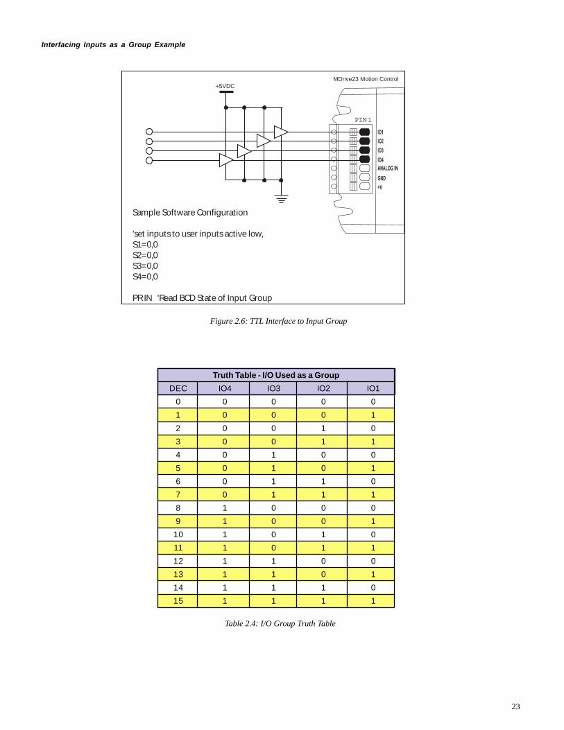
Interfacing Inputs as a Group Example
PIN1
MDrive23 Motion Control
Sample Software Configuration
'set inputs to user inputs active low,S1=0,0S2=0,0S3=0,0S4=0,0
PR IN 'Read BCD State of Input Group
+5VDC
Figure 2.6: TTL Interface to Input Group
Truth Table - I/O Used as a GroupDEC IO4 IO3 IO2 IO1
0 0 0 0 01 0 0 0 12 0 0 1 03 0 0 1 14 0 1 0 05 0 1 0 16 0 1 1 07 0 1 1 18 1 0 0 09 1 0 0 1
10 1 0 1 011 1 0 1 112 1 1 0 013 1 1 0 114 1 1 1 015 1 1 1 1
Table 2.4: I/O Group Truth Table

24
I n t e r f a c i n g O u t p u t s
The MDrive Motion Control Outputs may be configured as either general purpose or set to one of two dedicated functions, Fault orMoving. These outputs will sink up to 700 mA max and may be connected to +5 to +24VDC. Note that a current limiting resistor maybe required to limt the current to 700 mA.
As with the inputs the MDrive Motion Control Outputs may be used singularly or collectively as a group.
I n t e r f a c i n g a S i n g l e O u t p u t E x a m p l e s
Figure 2.7: Output Interfaced to an LED
Figure 2.8: Output Interfaced to a Relay
PIN1
MDrive23 Motion Control
Sample Software Configuration #1: FAULTS4=18,0 'Set IO4 to Fault, Active State=LOW
Sample Software Configuration #2: General PurposeS4=16,0 'Set IO4 to General Purpose, Active State=LOW
+5 to +24 V
*External Resistor may be needed tolimit output sink current to 700mA
PIN1
MDrive23 Motion Control
Sample Software Configuration
'set outputs to user outputs active low,S1=16,0S2=16,0S3=16,0S4=16,0
OT=<0-15> `Set outputs as 1 value
+5 to +24VDC
Figure 2.9: Outputs Interfaced to LED’s as a Group
Input FunctionsS<point>= Function Active
16 General Purpose 0/117 Fault 0/118 Moving 0/1
Table 2.5: Output Functions
I n t e r f a c i n g O u t p u t s a s a G r o u p E x a m p l e
To write to the outputs as a group the OT instruction isused. This will give you a binary output of 0000 to 1111from a decimal entry of 0-15. Output 1 will be the LeastSignificant Bit (LSB), Output 4 will be the Most SignificantBit (MSB).See Table 2.4 for Truth Table.
PIN1
MDrive23 Motion Control
Sample Software Configuration #1: FAULTS4=18,0 'Set IO4 to Fault, Active State=LOW
Sample Software Configuration #2: MOVINGS4=17,0 'Set IO4 to Moving, Active State=LOW(LED will illuminate when Axis is moving)
+5 to +24 V

25
I n t e r f a c i n g t h e Ana l o g I n p u t
The analog input of the MDrive Motion Control is a 0 to 5V, 10 bit resolution input. This offers the user the ability to receive inputfrom temperature, pressure or other forms of sensors, and then control events based upon the input.The value of this input will be read using the I5 instruction, which has a range of 0 to 1024, where 0 = 0 volts and 5 = 5.0 volts. Youmay then use the program branch (BR) or subroutine call (CL) instructions to control events within the system.
S a m p l e U s a g e
‘*********Main Program***********
PG 100 ‘start prog. at address 100
LB A1 ‘label program A1
CL A2, I5<500 ‘Call Sub A2, If I5 is less than 500
CL A3, I5>524 ‘Call Sub A3, If I5 is greater than 524
BR A1 ‘loop to A1
E ‘End
PG ‘Exit program
‘*********Subroutines************
LB A2 ‘label subroutine A2
MA 2000 ‘Move Absolute 2000 steps
H ‘Hold program execution until motion ceases
RT ‘return from subroutine
LB A3 ‘label subroutine A3
MA -2000 ‘Move Absolute -2000 steps
H ‘Hold program execution until motion ceases
RT ‘return from subroutine
Figure 2.10: Analog Input Interface

26
S e c t i o n 2 . 2MDr i v e Mo t i o n Con t r o l S o f twa r e I n t r o du c t i o n
S e c t i o n O v e r v i e w
This section will acquaint the user with basics of MDrive Motion Control Programming! Installing IMS Terminal Software! Upgrading the MDrive Firmware! The MDrive Program
I n s t a l l i n g a n d U s i n g IMS Te r m i n a l
S y s t e m R e q u i r e m e n t s
! IBM Compatible PC.
! Windows 95/98 or Windows NT4.0 SP6, Windows 2000 SP2, Windows XP
! 10 MB hard drive space.
! A free serial communications port.
I n s t a l l a t i o n
The IMS Terminal software is a programming/communications interface. This program was created by IMS to simplify program-ming and upgrading the MDrive Motion Control. The IMS Terminal is also necessary to upgrade the software in your MDriveMotion Control. These updates will be posted to the IMS website at www.imshome.com as they are made available.
To install the IMS Terminal to your hard drive, insert the IMS CD into your CD-ROM Drive. The installation front-end willautomatically open.Follow the on-screen instructions to complete the installation.
Figure 2.11: IMS Terminal Window
27
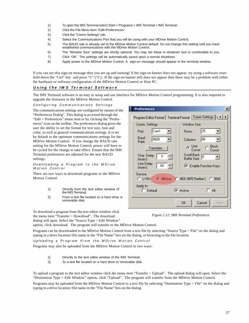
1) To open the IMS Terminal select Start > Programs > IMS Terminal > IMS Terminal.2) Click the File Menu Item “Edit>Preferences”.3) Click the “Comm Settings” tab.4) Select the Communications Port that you will be using with your MDrive Motion Control.5) The BAUD rate is already set to the MDrive Motion Control default. Do not change this setting until you have
established communications with the MDrive Motion Control.6) The “Window Size” settings are strictly optional. You may set these to whatever size is comfortable to you.7) Click “OK”. The settings will be automatically saved upon a normal shutdown.8) Apply power to the MDrive Motion Control. A sign-on message should appear in the terminal window.
If you can see this sign-on message then you are up and running! If the sign-on banner does not appear, try using a software reset:hold down the “Ctrl” key and press “C” (^C). If the sign-on banner still does not appear then there may be a problem with eitherthe hardware or software configuration of the MDrive Motion Control or Host PC.U s i n g t h e I M S Te r m i n a l S o f t w a r e
The IMS Terminal software is an easy to setup and use interface for MDrive Motion Control programming. It is also required toupgrade the firmware in the MDrive Motion Control.C o n f i g u r i n g C o m m u n i c a t i o n s S e t t i n g s
The communications settings are configured by means of the“Preferences Dialog”. This dialog is accessed through the“Edit > Preferences” menu item or by clicking the “Prefer-ences” icon on the toolbar. The preferences dialog gives theuser the ability to set the format for text size, font andcolor, as well as general communications settings. It is setby default to the optimum communications settings for theMDrive Motion Control. If you change the BAUD ratesetting for the MDrive Motion Control, power will have tobe cycled for the change to take effect. Ensure that the IMSTerminal preferences are adjusted for the new BAUDsettings.D o w n l o a d i n g a P r o g r a m t o t h e M D r i v eM o t i o n C o n t r o l
There are two ways to download programs to the MDriveMotion Control:
1] Directly from the text editor window ofthe IMS Terminal.
2] From a text file located on a hard drive orremovable disk.
To download a program from the text editor window clickthe menu item “Transfer > Download”. The downloaddialog will open. Select the “Source Type > Edit Window”option, click download. The program will transfer to the MDrive Motion Control.Programs can be downloaded to the MDrive Motion Control from a text file by selecting “Source Type > File” on the dialog andtyping in a drive location:\file name in the “File Name” box on the dialog, or browsing to the file location.U p l o a d i n g a P r o g r a m F r o m t h e M D r i v e M o t i o n C o n t r o l
Programs may also be uploaded from the MDrive Motion Control in two ways:
1] Directly to the text editor window of the IMS Terminal.2] To a text file located on a hard drive or removable disk.
To upload a program to the text editor window click the menu item “Transfer > Upload”. The upload dialog will open. Select the“Destination Type > Edit Window” option, click “Upload”. The program will transfer from the MDrive Motion Control.Programs may be uploaded from the MDrive Motion Control to a text file by selecting “Destination Type > File” on the dialog andtyping in a drive location:\file name in the “File Name” box on the dialog.
Figure 2.12: IMS Terminal Preferences

28
S e t t i n g t h e P r o g r a m m a b l e F u n c t i o n K e y s
The IMS Terminal features the capability of programming up to 10 function keys, a feature typically found in more advancedterminal programs. These can be set to provide quick access to commonly used MDrive Immediate mode commands, executeprograms, or even hold entire MDrive programs as there is no character limit for each function.A fly-out dialog can be brought up by clicking the arrow on the right of the function key “Contents” field. This enables theprogrammer to embed common ASCII control codes in the function key text string.To access the function key setup dialog, right-click the function key area on the terminal window.To setup the function keys:
1] Enter a caption in the “Caption” text field, this will be displayed on the function button.2] Enter the text string consisting of MDrive Motion Control commands and ASCII control codes. Remember to
terminate each command with a line feed (^M) and an appropriate pause time (typically 50 msec, ^p).3] Click “Done” to set the function.
Upg r a d i n g t h e MDr i v e Mo t i o n C on t r o l F i rmwa r e1] Connect power to the MDrive Motion Control.2] Open the IMS Terminal Software.3] Select the Terminal screen.4] Click the “Upgrade” menu item on the Menu bar.5] Enter 2956102 in the Type Number field.6] Click Next, follow the instructions.7] Cycle power on the MDrive Motion Control.
Figure 2.13: IMS Terminal Upgrader Window

29
MDr i v e Mo t i o n C on t r o l P r o g r amm i n g
The MDrive programming language consists of simple 1-2 character mnemonics.O p e r a t i o n a l M o d e s
There are two operational modes for the MDrive. Immediate and Program:1] Immediate: Commands are issued and executed directly to the MDrive Motion Control by user entry into the terminal
window.2] Program: Commands and processes are run from within an MDrive program. This mode is also used for program
entry.
Bas i c C omponen t s o f MDr i v e Mo t i o n C on t r o l S o f twa r e
I n s t r u c t i o n s
An instruction results in an action, there are three types:M o t i o n
Motion instructions are those that result in the movement of a motor. The syntax of these commands are as such: first type thecommand followed by a space, and then the velocity or position data. For example, MA 2000 will move the motor to position 2000.I / O
An I/O instruction results in the change of parameters or the state of an Input or Output. The syntax of these commands are assuch: first type the command followed by a space, then the I/O #, then an equal sign, then the data. Example: PR I1 will read thestate of input 1, O2=0 will set output 2 to 0.P r o g r a m
A program instruction allows program manipulation. The syntax of these vary due to the nature of the command. Some exampleswould be as such: PG 100, this command toggles the system into program mode starting at address 100. BR LP, IO 21=1, thiscommand will Branch to a program labeled LP if I/O 21 is true.S y s t e m
A system instruction is an instruction that can only be used in immediate mode to perform a system operation such as programexecution (EX) or listing the contents of program memory (L). For example: EX 100 will execute a program located at line 100 ofprogram memory space, or EX K1 will execute a program labeled K1.
V a r i a b l e s
Variables are labeled data that allow the user to define or manipulate data. These can also be used with the built-in math functions tomanipulate data. There are two classes of variables: factory defined and user defined. The syntax for each variable may differ. SeeSection 6 for usage instructions and examples.F a c t o r y D e f i n e d Va r i a b l e s
These variables are predefined at the factory. They cannot be deleted. When an FD (Factory Default) instruction is given, thesevariables will be reset to their factory default values. There are two types of factory defined variables. They are:
. Read/Writable: These factory defined variables can have their value altered by the user to effect events inside oroutside of a program. For example, A (Acceleration Variable) can be used to set the Acceleration, or P (PositionVariable) can be used to set a position reference point.
. Read Only: These factory defined variables cannot be manipulated by the user, but contain data that can beviewed or used to effect events inside a program. For example, V (Velocity Variable) registers the current velocityof the motor in steps per second.
U s e r D e f i n e d Va r i a b l e s
The VA instruction allows the user to assign a 32 bit, 2 character name to a user defined variable.The restrictions for this command are:
1] A variable cannot be named after an MDrive Motion Control Instruction, Variable or Flag.2] The first character must be alpha, the second character may be alpha-numeric.3] A variable is limited to two characters.
With these the user can define a variable to store and retreive data and perform math functions. When the FD (Factory Defaults)instruction is given, these variables will be deleted! There are two types of user defined variables:
. Global Variables: Global variables are variables that are defined outside of a program. The benefit to using aglobal variable is that no user memory is required. For example, the user can define a variable called SP for speedby entering VA SP into the terminal. The user can then set that variable to equal the value of the read only variableV (velocity) by entering SP = V into the terminal.
. Local Variables: This type of user defined variable is defined within a program and can only effect events withinthat program. It is stored in RAM. Examples of this type of variable will be given later in the section. It is worthy ofnote that a local variable is not static, but is erased and declared again each time a program is executed.

30
F l a g s
Flags show the status of an event or condition. A flag will only have one of two possible states: either 1 or 0. Unlike variables,there are only factory defined flags.F a c t o r y D e f i n e d F l a g s
Factory defined flags are predefined at the factory and cannot be deleted. When a FD (Factory Defaults) instruction is given, theseflags will be returned to their factory default state. There are two types of factory defined flags:
. Read/Writable: This type of flag is user alterable. They are typically used to set a condition or mode of operationfor the MDrive Motion Control. For example: EE = 1 would enable encoder operation, or EE = 0 would disable theencoder functions.
. Read Only: Read Only flags cannot be modified by the user. They only give an indication of an event or condition.Typically this type of flag would be used in a program in conjunction with the BR (Branch Instruction) to generatean if/then event based upon a condition. For Example: the following line of code in a program BR SP, MV = 0would cause a program to branch to a subroutine named “SP” when the MV, the read only moving flag, is false.
K e y w o r d s
Keywords are used in conjunction with the PR and IP instructions to indicate or control variables and flags. For instance, PR UVwould print the state of all the user-defined variables to the screen. IP would restore all the factory variables from the EEPROM.
Mos t C ommon l y U s e d Va r i a b l e s a n d C ommands
V a r i a b l e s
P
P indicates the position in either steps or encoder counts depending upon the enable/disable state of encoder functions.. P takes its reading from C1 (Counter 1) when encoder functions are disabled. The reading is taken from C2 (Counter 2) when
encoder functions are enabled.. To read the position, type PR P or PR C1/C2 then hit enter. To zero the position, type P=0 then hit enter
V I
Initial velocity in steps per second.. To read the initial velocity, type PR VI then hit enter. To write to the Initial velocity, type VI=500 then hit enter
V M
Maximum or final velocity in steps per second.. To read the final velocity, key-in PR VM then hit enter. To write to the final velocity, key-in VM=5000 then hit enter
A
Acceleration in steps per second2.. To read the acceleration, key-in PR A then hit enter. To write to the acceleration, key-in A=7500 then hit enter
D
Deceleration in steps per second2.. To read the deceleration, key-in PR D then hit enter. To write to the deceleration, key-in D=A then hit enter

31
M a t h F u n c t i o n s
Another powerful feature of the MDrive Motion Control is its ability to perform common math functions and to use these tomanipulate data.
Addition .................................................................... K2†=P+R2Subtraction ................................................................. K3†=R1-PMultiplication .............................................................. A=A*2Division ......................................................................... A=A/2†User-defined variable used as an example.
M o t i o n C o m m a n d s
M AMove to an absolute position relative to a defined zero position.For example, type the following commands followed by hitting enter:
P=0MA 20000HPR P
The terminal screen will read 20000MA 3000HPR P
The screen will echo back 3000.
M RMove number of steps indicated relative to current position.For example, type the following commands followed by hitting enter:
P=0MR 20000HPR P
The terminal screen will read 20000MR 3000HPR P
Notice the position echoed is 23000 and not 3000.
S L Move at a constant velocity.
SLEW 200000The motor will move at a constant velocity 200000 steps per second.
HAn H (hold) should typically follow any MA or MR commands in a program so that program execution is suspended until motionis complete.(Note: There are circumstances where you may not want to hold up program execution.)Below is a usage example.
PG 100 ‘enter program mode at address 100LB M1 ‘label program M1MR 20000 ‘set motion mode to relative, move relative 20000 stepsH ‘hold until motion completes-20000 ‘move relative -20000 stepsH ‘hold until motion completesE ‘end program
PG ‘exit program mode

32
I / O C o m m a n d s
S < 1 - 4 >
This command configures the Type and Active state of I/O points 1-4.Using the PR command to read IO parametersRead IO1 Setup – “PR S1”Read IO2 Setup – “PR S2”
Setting the I/O parametersSet IO 3 parameters – “S3=0,1” Sets IO3 as a General Purpose Input, Active High
For example: To set IO4 as a Jog+ Input/Active LowS4 =7,0
I < 1 - 4 >
Used to read the state of an individual input.PR I1 will read the state of input 1 and display it to the terminal window.BR K5, I2=0 will branch to the program address labled K5 when Input 2 is LOW
I N
Used to read the decimal equivalent of the 4 bit binary number represented by all 4 inputs collectively. Note the Input 4 is the MostSignificant Bit.PR IN will print the decimal value of the inputs.
0 < 1 - 4 >
Used to set the state of an output.O2=1 will set Output 2 TRUE
OT
Used to set the 4 bit binary equivalent of the decimal number represented by all 4 outputs collectively. Note the Output 4 is theMost Significant Bit.OT=13 will set the outputs to 1101
S y s t e m I n s t r u c t i o n s
The following System Instructions will be used frequently.C P
The CP Instruction is used to clear Program memory space.F D
The FD Instruction is used to return the MDrive Motion Control to its factory default state.
P r o g r a m I n s t r u c t i o n sP G
This instruction toggles the MDrive Motion Control into or out of program mode.
Switch to program mode at address 200 PG 200xxxxx
Program starting at address 200 xxxxxxxxxx
Switch out of program mode PG

33
L B
The MDrive Motion Control also offers the user the convenience of naming programs, subroutines and processes to ease inbranching from one part of a program to another, or calling a subroutine.These labels, once set, will act as pointers to locations in program memory space.The LB, or Label Instruction, allows the user to assign a 2 character name to a program or branch process within a program orsubroutine.The restrictions for this command are:1] A label cannot be named after a MDrive Motion Control Instruction, Variable or Flag.2] The first character must be alpha, the second character may be alpha-numeric.3] A label is limited to to characters.4] A program labeled SU will run on power-up
Please Note: Any program labeled “SU” will execute on power-up.
Switch to program mode at address 200 PG 200Label command will name the program LB K1
xxxxxProgram named by LB command xxxxx
xxxxxSwitch out of program mode PG
B R
Used to branch conditionally or unconditionally to a routine.
Switch to program mode at address 200 PG 200Label command will name the program LB K1
xxxxxProgram named by LB command xxxxx
xxxxxUnconditional branch to Program1 BR K1Switch out of program mode PG
E
Designates the end of a program.
Switches to program mode at address 200 PG 200Label command will name the program LB K1
xxxxxProgram named by LB command xxxxx
xxxxxUnconditional branch to K1 BR K1Designates the end of the program ESwitches out of program mode P

34
H
Delays program execution in milliseconds.
Switches to program mode at address 200 PG 200Label command will name the program LB K1
xxxxxProgram named by LB command xxxxx
xxxxxDelay 2 seconds between re-execution of program H 2000Unconditional branch to K1 BR K1Designates the end of the program ESwitches out of program mode P
P R I N T
Outputs specified text and parameter values to a terminal or terminal software on a Host PC.
Switches to program mode at address 200 PG 200Label command will name the program LB K1
xxxxxProgram named by LB command xxxxx
xxxxxPrints text in quotes and then POS PR “Position = ” PDelay 2 seconds between re-execution of program H 2000Unconditional branch to K1 BR K1Designates the end of the program ESwitches out of program mode PG
VA R
Command used to define a variable with 8 alphanumeric characters.
Switches to program mode at address 200 PGM 200Define a variable named CT for Count VAR CTLabel command will name the program LBL K1
xxxxxProgram named by LB command xxxxx
xxxxxPrints text in quotes and then POS PRINT “Position = ” PDelay 2 seconds between re-execution of program H 2000Unconditional branch to K1 BR K1Designates the end of the program ESwitches out of program mode PGM

35
Mnemonic Function Unit Range Syntax ExampleBD Communications BAUD Rate BAUD 48, 96, 19, 38, 11 BD=<baud>DE Enable/Disable Drive - 1/0 DE=<1/0>DN Device Name Character a-z, A-Z, 0-9 DN=<char>EM Echo Mode 0 (def)=Full Duplex, 1=Half Duplex Mode 0/1 EM=<mode>IP Initial Parameters from EEPROM - - IPPY Enable/Disable Party Mode Mode 1/0 PY=<mode>UG Upgrade Firmware Code 2956102 IMS Term. Upgrader
Se t u p I n s t r u c t i o n s , Va r i a b l e s a n d F l a g s
Mnemonic Function Unit Range Syntax ExampleAL All Parameters, Used with PR (Print) - - PR ALBY BSY Flag 1=Prog. Running - 0/1 PR BYPR Print Selected Data and/or Text - - PR <data/text string>R1 User Register 1 Number Signed 32 bit R1=<number>R2 User Register 2 Number Signed 32 bit R2=<number>R3 User Register 3 Number Signed 32 bit R3=<number>R4 User Register 4 Number Signed 32 bit R4=<number>VR Firmware Version Number - PR VRUV Read User Variables - = PR UV
Mis c e l l a n e o u s I n s t r u c t i o n s , Va r i a b l e s a n d F l a g s
Mnemonic Function Unit Range Syntax Example(-) Do Previously Set Mode to/at This Value per mode -<number>A Set Acceleration Steps/Sec2 1000000000 A=<accel>D Set Deceleration Steps/Sec2 1000000000 D=<decel>HC Set Hold Current % (Percent) 0 to 100 HC=<percent>HT Set Hold Current Delay Time milliseconds 0-65000 HT=<msec>MA Set Mode and Move to Abs. Position ±Position Signed 32 bit MA <±pos>MD Motion Mode Setting - - -MR Set Mode and Move to Relative Position ±Distance Signed 32 bit MR <±dist>MS Set Microstep Resolution Microsteps/step MSEL Table MS=<param>MT Motor Settling Delay Time milliseconds 0-65000 MT=<msec>MV Moving Flag - - PR MVRC Set Run Current % (Percent) 1 to 100 RC=<percent>SL Set Mode and Slew Axis Steps/sec ±5000000 SL=<velocity>V Read Current Velocity Steps/sec ±5000000 PR VVI Set Initial Velocity Steps/sec 1-5000000 VI=<velocity>VM Set Maximum Velocity Steps/sec 1-5000000 VM=<velocity>
Mot i o n I n s t r u c t i o n s , Va r i a b l e s a n d F l a g s
S e c t i o n 2 . 3MDr i v e Mo t i o n Con t r o l C ommand Se t S ummar y

36
Mnemonic Function Unit Range Syntax ExampleD1 Set Input 1 Digital Filtering Milliseconds 0-255 D1=<time>D2 Set Input 2 Digital Filtering Milliseconds 0-255 D2=<time>D3 Set Input 3 Digital Filtering Milliseconds 0-255 D3=<time>D4 Set Input 4 Digital Filtering Milliseconds 0-255 D4=<time>D5 Set Input 5 Digital Filtering Milliseconds 0-255 D5=<time>I1 Read Input 1 - 0/1 PR I1, BR I1,<cond>I2 Read Input 2 - 0/1 PR I2, BR I2,<cond>I3 Read Input 3 - 0/1 PR I3, BR I3,<cond>I4 Read Input 4 - 0/1 PR I4, BR I4,<cond>I5 Read Input 5 (Analog) - 0-1024 PR I5, BR I5,<cond>I6 Read Encoder Index Mark Low trueIN Read Inputs 1-4 as One Value data 0-15 PR INO1 Set Output 1 to Logic State - 0/1 O1=<1/0>O2 Set Output 2 to Logic State - 0/1 O2=<1/0>O3 Set Output 3 to Logic State - 0/1 O3=<1/0>O4 Set Output 4 to Logic State - 0/1 O4=<1/0>OT Write Data to Outputs 1-4 as One Value data 0-15 OT=<data>S1 Setup IO Point 1 Type, Active Type Table, 0/1 S1=<type>,<active>S2 Setup IO Point 2 Type, Active Type Table, 0/1 S2=<type>,<active>S3 Setup IO Point 3 Type, Active Type Table, 0/1 S3=<type>,<active>S4 Setup IO Point 4 Type, Active Type Table, 0/1 S4=<type>,<active>TI Trip on Input - - TI <input>,<addr>TE Trip Enable See Table <1-4> TE=<num>
I /O I n s t r u c t i o n s , Va r i a b l e s a n d F l a g s
Mnemonic Function Unit Range Syntax ExampleBR Branch (Conditional/Unconditional) - - BR <addr>, <cond>CL Call Subroutine (Conditional/Unconditional) - - CL <addr>, <cond>CP Clear Program Address 1-767 CP <addr>DC Decrement Variable - - DC <var/ureg>E End Program Execution - - EEX Execute Program at Address Using Selected Trace Mode 1-767 EX <addr>, <mode>H Hold Prog. Execution Blank/0=Motion stops milliseconds Blank(0)/1-65000 H=<msec>IC Increment Variable - - IC <var>L List Program Address 1-767 L <addr>LB Create a Program Address Label NameOE On Error Handler 0=Disabled Address 0/1-767 OE <addr>PG Start Program Entry at Specified Address - Blank/1-767 PG <addr>RT Return from Subroutine - - RTS Save to EEPROM - - SVA Create A User Variable NameUV Read User Variables - - PR UV
P r og r am I n s t r u c t i o n s , Va r i a b l e s a n d F l a g s

37
Mnemonic Function Unit Range Syntax ExampleC1 Set Counter 1 Motor Counts Signed 32 bit C1=<counts>HM Home to Home Switch Type 1-4 HM <type>P Set/Read Position Motor/Encoder Counts Signed 32 bit P=<counts>PC Read Captured Position at TripTP Trip on Position Position - TP <pos>, <addr>TE Trip Enable See Table <1-4> TE=<num>
Pos i t i o n R e l a t e d I n s t r u c t i o n s , Va r i a b l e s a n d F l a g s
Mnemonic Function Unit Range Syntax ExampleC2 Set Counter 2 Encoder Counts Signed 32 bit C2=<counts>DB Set Encoder Deadband Encoder Counts 0-65000 DB=<counts>EE Enable/Disable Encoder Functions - 1/0 EE=<1/0>HI Home to Encoder Index Type 1-4 HI=<type>I6 Read Encoder Index Mark - - I6SF Set Stall Factor Encoder Counts 0-65000 SF=<counts>SM Set Stall Mode 0=Stop Motor/1=Don’t Stop 1/0 SM=<mode>ST Stall Flag - 0/1 PR ST
En c od e r R e l a t e d I n s t r u c t i o n s , Va r i a b l e s a n d F l a g s
Symbol Function+ Add Two Variables and/or Flags- Subtract Two Variables and/or Flags* Multiply Two Variables and/or Flags/ Divide Two Variables and/or Flags
<> Not Equal= Equal< Less Than
<= Less Than and/or Equal> Greater Than
>= Greater Than and/or Equal& AND (Bitwise)| OR (Bitwise)^ XOR (Bitwise)! NOT (Bitwise)
M a t h e m a t i c a l F u n c t i o n s

38
MNEMONIC FUNCTION TYPEBD BAUD Rate Setup VariableDESCRIPTION
This variable sets the baud rate for serial communications with the MDrive. It sets the rate for the RS-485 interface. The baud rateis set by indicating the first two digits of the desired rate as shown in the range section below.In order for the new BAUD rate to take effect, the user must issue the S (SAVE) instruction and then reset the MDrive. When theMDrive is reset, it will communicate at the new BAUD rate.48 = 4800 bps, 96 = 9600 bps, 19 = 19200 bps, 38 = 38000 bps, 11 = 115200 bps
USAGE UNITS RANGE DEFAULTBD=<baud> bits per second 48, 96, 19, 38, 11 9600 bps
EXAMPLE:BD=96 ‘set communications BAUD rate to 9600 bps
RELATED COMMANDS: —
MNEMONIC FUNCTION TYPEA Acceleration Motion VariableDESCRIPTION
The A Variable sets the peak acceleration that will be reached by the MDrive in steps per second2.
USAGE UNITS RANGE DEFAULTA=<accl> Steps/sec2 0 to 1525878997 1000000
EXAMPLE:A=20000 ‘set acceleration to 20000 steps/sec2
A=D ‘set acceleration equal to deceleration
RELATED COMMANDS: D
MNEMONIC FUNCTION TYPEAL Retrieve All Parameters VariableDESCRIPTION
The AL variable is used with the PR (PRINT) instruction to print the value/state of all variables and flags to the terminal program.
USAGEPR AL
RELATED COMMANDS: PR
S e c t i o n 2 . 4MDr i v e Mo t i o n Con t r o l C ommand Se t

39
MNEMONIC FUNCTION TYPEBR Branch Program InstructionDESCRIPTION
The branch instruction can be used to perform a conditional or unconditional branch to a routine in an MDrive program. It can alsobe used to perform loops and IF THEN logic within a program.There are two parameters to a branch instruction. These are used to perform two types of branches:Conditional BranchThis type of branch first specifies an address or process label where program execution should continue if the second parameter, thecondition, is true. The condition parameter may include flags as well as logical functions that are to be evaluated.Unconditional BranchIn this type of branch the second parameter is not specified, then the execution will continue at the address specified by the firstparameter.
USAGEBR <addr/label, cond>
EXAMPLE:BR 256, I2 ‘Branch to program line 256 if Input 2 is TRUEBR 120 ‘Unconditional Branch to program line 120
BR JC, I1=1 ‘Branch to process labeled JC if input 1 is True
RELATED COMMANDS: —
MNEMONIC FUNCTION TYPEC1 Set Counter 1 (Motor Counts) Motion VariableDESCRIPTION
This variable contains the raw count representation of the clock pulses sent to the motor drive.
USAGE UNITS RANGE DEFAULTC1=<counts> Motor Counts -2147483648 to 2147483647 0
EXAMPLE:C1=20000 ‘Set Counter 1 to 20000 motor countsPR C1 ‘Print the value of C1 to the terminal screen
RELATED COMMANDS: C2, P
MNEMONIC FUNCTION TYPEBY Busy Flag (Read Only) Motion FlagDESCRIPTION
This read only status flag will indicate whether or not the axis is moving.
USAGE UNITS RANGE DEFAULTPR BY — 0/1 0
EXAMPLE:PR BY ‘read the state of the busy flag
RELATED COMMANDS: PR

40
MNEMONIC FUNCTION TYPECL Call Subroutine Program InstructionDESCRIPTION
This function can be used to invoke a subroutine within a program. This allows the user to segment code and call a subroutine froma number of places rather than repeating code within a program.There are two parameters to the CL instruction. The first specifies the program address or label of the subroutine to be invoked ifthe second parameter, the condition, is true. If the second parameter is not specified, the subroutine specified by the first parameteris always invoked. The condition parameter can include flags as well as logical functions that are to be evaluated.The subroutine should end with a RT (RET) instruction. The RT instruction will cause program execution to return to the linefollowing the CL instruction.
USAGECL <addr/label, cond>
EXAMPLE:CL 256, I1=1 ‘Call subroutine at program line 256 if Input 1 is TRUECL JK ‘Call subroutine labeled JK
RELATED COMMANDS: RT
MNEMONIC FUNCTION TYPECP Clear Program Program InstructionDESCRIPTION
This instruction will clear the program space in the EEPROM as specified by the instruction parameter. Programs are stored directlyto the EEPROM and executed from there.
USAGECP <addr/label>
EXAMPLE:CP 256 ‘Clear program space beginning at line 256 to the end of program spaceCP ‘Clear all of program space
RELATED COMMANDS: —
MNEMONIC FUNCTION TYPEC2 Set Counter 2 (Encoder Counts) Motion VariableDESCRIPTION
This variable contains the raw count representation of the integral 512 line encoder.
USAGE UNITS RANGE DEFAULTC2=<counts> Encoder Counts -2147483648 to 2147483647 0
EXAMPLE:C2=512 ‘Set Counter 2 to 512 encoder countsPR C2 ‘Print the value of C2 to the terminal screen
RELATED COMMANDS: C1, EE, P

41
MNEMONIC FUNCTION TYPED Deceleration Motion VariableDESCRIPTION
The D variable sets the peak deceleration of the MDrive in steps per second2.
USAGE UNITS RANGE DEFAULT D=<decl> Steps/sec2 0 to 1525878997 1000000
EXAMPLE:D=20000 ‘set acceleration to 20000 step/sec2
D=A ‘set deceleration equal to acceleration
RELATED COMMANDS: A,
MNEMONIC FUNCTION TYPEDB Set Encoder Deadband Setup VariableDESCRIPTION
This variable defines the + and - length of the encoder deadband in encoder counts.When the encoder is enabled, a move is not completed until motion stops within DB.
USAGE UNITS RANGE DEFAULT DB=<counts> Encoder Counts 0 to 65000 1
EXAMPLE:DB=5 ‘Set Encoder Deadband to ± 5 encoder counts
RELATED COMMANDS: EE
MNEMONIC FUNCTION TYPEDC Decrement Variable Program InstructionDESCRIPTION
The DC instruction will decrement the specified variable by one.
USAGEDC <var>
EXAMPLE:DC R1 ‘Decrement User Register 1
RELATED COMMANDS: IC
MNEMONIC FUNCTION TYPED1-D5 Digital Input Filtering I/O VariableDESCRIPTION
This variable will set the digital filtering to be applied to the selected input 1 - 5. The input must be stable for “time” amount ofmilliseconds before a change in state is available.
USAGE UNITS RANGE D <1-5>=<time> Milliseconds 0 to 255
EXAMPLE:D1=0 ‘no debounceD4=150 ‘150 mSec of filtering
RELATED COMMANDS: I1-I5

42
MNEMONIC FUNCTION TYPEDN Device Name Setup VariableDESCRIPTION
The DN Variable stores the device name to be used when the MDrive is to be addressed in party mode operation. The name is onlyused when party mode communications is being used (PY = 1).All MDrive system nodes will respond if the name in a command is given as “*”.When the name is changed it must be saved into the nonvolatile memory if it is to be used in later sessions without being changedagain.See Appendix A: ASCII table for decimal codes.
USAGE UNITS RANGE DEFAULT DN=<char> ASCII Characters a-z, A-Z, 0-9 !
EXAMPLE:DN=A ‘Set the device name to the character A
RELATED COMMANDS: PY
MNEMONIC FUNCTION TYPEE End Program Execution Program InstructionDESCRIPTION
Stops the execution of a program.
USAGEE
EXAMPLE:PG 100 ‘Start program at line 100LB J2 ‘Label Program J2MR 20000 ‘move relative 20000 motor countsH ‘hold until motion stopsMR -20000 ‘move relative -20000 motor countsH ‘hold until motion stopsE ‘End program executionPG ‘exit program mode
RELATED COMMANDS: PG, EX
MNEMONIC FUNCTION TYPEDE Drive Enable Flag Setup FlagDESCRIPTION
The DE flag enables or disables the drive portion of the MDrive Motion Control.
USAGE DEFAULTDE= <0/1> 1 (Enabled)
EXAMPLE:DE=0 ‘Disable driveDE=1 ‘Enable drive
RELATED COMMANDS: —

43
MNEMONIC FUNCTION TYPEEE Encoder Enable Flag Setup FlagDESCRIPTION
The EE flag enables or disables the optional encoder mode of the MDrive Motion Control.
USAGE DEFAULTEE= <0/1> 0 (Disabled)
EXAMPLE:EE=0 ‘Disable encoder modeEE=1 ‘Enable encoder mode
RELATED COMMANDS: DB, C2, SF, SM, ST
MNEMONIC FUNCTION TYPEEM Echo Mode Flag Setup FlagDESCRIPTION
The Echo Mode Flag will set the full/half duplex configuration of the RS-485 channel. 0=Full Duplex (default), 1=Half Duplex.
USAGE DEFAULTEM= <0/1> 0 (Full Duplex)
EXAMPLE:EM=0 ‘full duplex modeEM=1 ‘half duplex mode
RELATED COMMANDS: BD
MNEMONIC FUNCTION TYPEEF Read-Only Error Flag Status FlagDESCRIPTION
The Error flag will indicate whether or not an error condition exists. It is automatically cleared when a new program is executed. Theonly way to manually clear the EF flag is to read the value of the ER variable or set ER=0There is an instruction, OE, which allows the user to specify the execution of a subroutine in the program memory when an erroroccurs. The subroutine might contain instructions to read the ER variable which would clear the EF flag.
USAGE RESPONSE PR EF 0 = No Error Exists
1 = Error Condition Exists
EXAMPLE:PR EF ‘read the state of the error flag
RELATED COMMANDS: ER, OE

44
MNEMONIC FUNCTION TYPEER Error Number Variable Status VariableDESCRIPTION
The ER variable indicates the program error code for the most recent error that has occurred in the MDrive Motion Control. TheER variable must be read in order to clear the EF flag.See Appendix A of this document for a complete listing of MDrive Motion Control Error Codes.
USAGE RESPONSE PR ER <numerical error code>
EXAMPLE:PR ER ‘read the error number
RELATED COMMANDS: EF, OE
MNEMONIC FUNCTION TYPEEX Execute Program Program InstructionDESCRIPTION
Execute program at a specified address or label using a selected trace mode. Used in immediate mode.There are three modes of program execution.
Mode 0 Normal execution, is specified by a mode of 0 (or simply leaving the mode blank).Mode 1 Trace mode is specified by a mode of 1. This means that the program executes continuously until
the program END is encountered, but the instructions are “traced” to the communications port so theuser can see what instructions have been executed.
Mode 2 Single step mode is specified by a mode of 2. In this mode, the user can step through the programusing the space bar to execute the next line of the program. The program can be resumed at normalspeed in this mode by pressing the enter key.
USAGE MODES EX <addr/label>,<mode> <mode> = 0: run program normally
<mode> = 1: run program in trace mode<mode> = 2: run program in single-step mode
EXAMPLE:EX 127 ‘execute program at line 127 normallyEX 127,1 ‘execute program at line 127 in trace mode
RELATED COMMANDS: PG, E

45
MNEMONIC FUNCTION TYPEH Hold Program Execution Program InstructionDESCRIPTION
The hold instruction is used in a program to suspend program execution. If no parameter is specified the execution of the programwill be suspended while motion is in progress. This will typically be used following a MA or MR instruction.A time in milliseconds may be placed as a parameter to the hold instruction, This will suspend program execution for the specifiednumber of milliseconds
USAGE H <time> ‘Blank or 0 - hold while moving, 1 - 65000 usec.
EXAMPLE:‘example 1MA 20000 ‘move absolute 20000 motor unitsH ‘hold program execution until motion completesMA -20000 ‘move absolute -20000 motor unitsH ‘hold program execution until motion completes
‘example 2O2=1 ‘set output 2 HIGHH 1000 ‘hold 1 secondO2=0 ‘set output 2 LOW
RELATED COMMANDS: PG, E
MNEMONIC FUNCTION TYPEHC Hold Current Setup VariableDESCRIPTION
This variable defines the motor holding current in percent.
USAGE UNITS RANGE DEFAULTHC=<percent> Percent 0 to 100 5
EXAMPLE:HC=5 ‘Set motor holding current to 5%
RELATED COMMANDS: HT, RC, HI
MNEMONIC FUNCTION TYPEHI Home to Index Mark Variable Setup VariableDESCRIPTION
This instruction will find the the encoder index mark. There are four types for this command:1) Speed (S): Specifies the direction and speed that the axis will move until the index mark is found (VM).2) Creep (C): Specifies the direction and speed that the axis will move off the index mark until it becomes inactive again (VI).When HI is executed, the axis moves in the direction specified by the sign of speed at VM. It then creeps off of the switch in thedirection specified by the sign of creep at VI. Motion is stopped as soon as the switch becomes deactivated.
USAGE TYPES HI=<type> 1: S- C+, 2: S- C-, 3: S+ C-, 4: S+ C+
EXAMPLE:HM=2 ‘Find index mark at VM in the minus direction, Creep off at VI in the minus direction
RELATED COMMANDS: VM, VI, EE, I6

46
MNEMONIC FUNCTION TYPEHT Hold Current Delay Time Setup VariableDESCRIPTION
The HT variable sets the delay time in milliseconds between the cessation of motion and when the MDrive Motion Control shifts tothe holding current level specified by the HC (Motor Holding Current) variable. The delay time is also effected by the MT (MotorSettling Delay Time) variable in that the total time from motion ceasing to current change is represented by the sum of MT + HT
USAGE UNITS RANGE DEFAULT HT=<time> milliseconds 0 to 65000 500
EXAMPLE:HT=1500 ‘Set hold current delay time to 1.5 seconds
RELATED COMMANDS: HC, MT, RC
MNEMONIC FUNCTION TYPEI1 - I4 Read Input I/O VariableDESCRIPTION
This variable will read the state of the specified input 1 - 4. Can be used with PR (Print), BR (Branch) and Cl (Call Subroutine)instructions. Can also be used with Ri-R4 and User Variables.
USAGEPR I<1-4>BR <addr>, I<1-4>=<1/0>CL <addr>, I<1-4>=<1/0>
EXAMPLE:PR I2 ‘Print the state of Input 2 to the Terminal ScreenBR 128, I3=1 ‘Conditional branch to program line 128 if Input 3 = 1CL 432, I4=0 ‘Call subroutine at line 432 if Input 4 = 0
RELATED COMMANDS: IN, O1-O4, PR, S1-S4
MNEMONIC FUNCTION TYPEHM Home to Home Switch Variable Setup VariableDESCRIPTION
This instruction will find the selected I/O switch. There are four types for this command:1) Speed (S): Specifies the direction and speed that the axis will move until the switch is activated (VM).2) Creep (C): Specifies the direction and speed that the axis will move off the switch until it becomes inactive again (VI).When HM is executed, the axis moves in the direction specified by the sign of speed at VM. It then creeps off of the switch in thedirection specified by the sign of creep at VI. Motion is stopped as soon as the switch becomes deactivated.
USAGE TYPES HM=<type> 1: S- C+, 2: S- C-, 3: S+ C-, 4: S+ C+
EXAMPLE:HM=3 ‘Find home switch at VM in the plus direction, Creep off at VI in the minus direction
RELATED COMMANDS: VM, VI, S1-S4

47
MNEMONIC FUNCTION TYPEIC Increment Variable Program InstructionDESCRIPTION
The IC instruction will increment the specified variable by one.
USAGEIC <var>
EXAMPLE:IC R4 ‘Increment User Register 4
RELATED COMMANDS: IC
MNEMONIC FUNCTION TYPEI5 Read Analog Input I/O VariableDESCRIPTION
This variable will read the value of the voltage seen on the Analog Input. Can be used with PR (Print), BR (Branch) and Cl (CallSubroutine) instructions. The value read will between 0 and 1028.
USAGEPR I5BR <addr/label>, I5=<0 - 1028>CL <addr/label>, I5=<0 - 1028>
EXAMPLE:PR I5 ‘Print the value of the Analog Input to the Terminal ScreenBR K1, I5=512 ‘Branch to Program labled K1 if Analog Input = 512CL 432, I5=0 ‘Call subroutine at line 432 if Analog Input = 0
RELATED COMMANDS: BR, CL, PR
MNEMONIC FUNCTION TYPEI6 Read Encoder Index Mark I/O VariableDESCRIPTION
This variable will read the on/off state of the Encoder Index Mark. Can be used with PR (Print), BR (Branch) and Cl (Call Subrou-tine) instructions. The value read will be 0 (off mark) or 1 (on mark).
USAGEPR I6BR <addr/label>, I6=<0/1>CL <addr/label>, I6=<0/1>
EXAMPLE:PR I6 ‘Print the on/off state of the encoder index markBR K1, I6 ‘Branch to Program labled K1 if encoder index mark is TRUECL 432, I6=0 ‘Call subroutine at line 432 if I6=0
RELATED COMMANDS: BR, CL, PR

48
MNEMONIC FUNCTION TYPEIN Read Inputs 1-4 As 1 Value I/O VariableDESCRIPTION
This keyword will read the binary state of inputs 1-4 and print them as a decimal value. When used thus Input 1 is the LeastSignificant Bit (LSB), Input 4 is the Most Significant Bit (MSB). It may be used in conjunction with the R1-R4 (User Registers),PR (Print), BR (Branch) and Cl (Call Subroutine) instructions.
USAGE PR IN BR IN=<0-15> CL IN=<0-15>
EXAMPLE:PR IN ‘Print the state of Inputs 1-4 to the Terminal ScreenBR 128, IN=8 ‘Conditional branch to program line 128 if the binary state of Inputs 1-4 = 8 (1000)CL 432, IN=13 ‘Call subroutine at line 432 if the binary state of Inputs 1-4 = 13 (1101)
RELATED COMMANDS: I1-5, O1-O5, PR, S1-S4
MNEMONIC FUNCTION TYPEIP Initialize Parameters InstructionDESCRIPTION
The IP instruction will return all of the MDrive Motion Control parameters to their stored values.
USAGEIP
EXAMPLE:IP
RELATED COMMANDS: CP, S
MNEMONIC FUNCTION TYPEJE Joystick Enable Flag Setup FlagDESCRIPTION
The will enable joystick mode for the Analog Input. States are 0=Disabled, 1=Enabled.
USAGE DEFAULTJE= <0/1> 0 (Disabled)
EXAMPLE:JE=0 ‘Disable JoystickJE=1 ‘Ensable Joystick
RELATED COMMANDS: I5

49
MNEMONIC FUNCTION TYPELB Label Program/Subroutine InstructionDESCRIPTION
The LB, or Label Instruction, allows the user to assign a 2 character name to a program, branch process within a program orsubroutine.The restrictions for this command are:1] A label cannot be named after a MDrive Motion Control Instruction, Variable or Flag.2] The first character must be alpha, the second character may be alpha-numeric.3] A label is limited to two characters.4] A program labeled SU will run on power-up
USAGELB <char><char>
EXAMPLE:PG 100 ‘start program at adress 100LB J0 ‘Label program J0
RELATED COMMANDS: BR, CL, EX, TI, TP, L, CP
MNEMONIC FUNCTION TYPEL List Program Space InstructionDESCRIPTION
The L instruction will print the contents of program space beginning at the specified address to the end. If no address is specified itwill list beginning at line 1.
USAGELL <addr/label>
EXAMPLE:L 128 ‘display contents of program space beginning at line 128
RELATED COMMANDS: —
MNEMONIC FUNCTION TYPELK Lock User Program Setup FlagDESCRIPTION
This flag allows the user to lock the program from being listed or modified. It can only be reset by clearing the entire program space:CP (no address). If CP addr, L (addr), PG addr entered then error 44 (Program Locked) will be set and nothing else will happen.To clear LK, don’t save (S) then do a Ctrl-C or Cycle Power and the LK will be reset to previous unlocked state. (Program isautomatically store in NVM as it is entered.) Or you may clear program (CP). This will clear the program and reset LK to 0 inNVM as well as in local ram.
USAGE DEFAULTLK= <0/1> 0 (Disabled)
RELATED COMMANDS: CP, L

50
MNEMONIC FUNCTION TYPEMD Motion Mode Motion InstructionDESCRIPTION
Indicates what the last motion command was, so that when just a number is entered, then it will read MD to define the new motion.
USAGE MD
EXAMPLE:MA 200000 ‘move absolute 200000 steps, set current mode to MA-200000 ‘move absolute -200000 steps
MR 1000000 ‘move relative 1000000 steps, set current mode to MR-1000000 ‘move relative -1000000 steps
SL 20000 ‘slew 20000 steps/sec. set current mode to SL-10000 ‘slew 10000 steps/sec in minus direction
PR MD return current mode setting
RELATED COMMANDS: MD, MR, MS, P, PR, SL
MNEMONIC FUNCTION TYPEMR Move To Relative Position Motion InstructionDESCRIPTION
Set mode for relative move and move a relative distance. MD (Current Mode) will be set to MR.
USAGE UNITS MR <±distances> motor counts
EXAMPLE:MR 200000 ‘move motor to 200000 motor counts postive directionMR -50000 ‘move motor to 50000 motor counts in a negative direction
RELATED COMMANDS: MD, MA, MS, P
MNEMONIC FUNCTION TYPEMA Move To Absolute Position Motion InstructionDESCRIPTION
Set mode for absolute move and move to an absolute position. MD (Current Mode) will be set to MA.
USAGE UNITS MA <±pos> motor counts
EXAMPLE:MA 51200 ‘move motor to absolute position 51200 in positive directionMA -51200 ‘move motor to absolute position 51200 in negative direction
RELATED COMMANDS: MD, MR, MS, P

51
MNEMONIC FUNCTION TYPEMS Microstep Resolution Motion VariableDESCRIPTION
The MS variable controls the microstep resolution of the MDrive Motion Control. There are 14 parameters that can be used withthis variable, 8 binary and 6 decimal. The table below illustrates the parameter settings and their associated resolutions for the 1.8°stepping motor used with the MDrive Motion Control.The MS parameters given in the table below are the only valid parameters that will be accepted by the MDrive.
USAGE DEFAULT MS=<parameter> 256
EXAMPLE:MS=4 ‘Set Microstep Resolution to 4 Microsteps/Step (400 Steps/Rev)MS=50 ‘Set Microstep Resolution to 50 Microsteps/Step (10000 Steps/Rev)PR MS ‘Print the MS setting to the terminal
)SM(sgnitteSnoituloseRpetsorciM
)petS/spetsorciM(=SM veR/spetS
sgnitteSnoituloseRpetsorciMyraniB
2 004
4 008
8 006,1
61 002,3
23 004,6
46 008,21
821 006,52
652 002,15
sgnitteSnoituloseRpetsorciMlamiceD
5 000,1
01 000,2
52 000,5
05 000,01
521 000,52
052 000,05
Table 2.6: Microstep Resolution Settings

52
MNEMONIC FUNCTION TYPEM T Motor Settling Delay Time Motion VariableDESCRIPTION
Specifies the motor settling delay time in milliseconds. MT allows the motor to settle following a move. This is the time betweenmoves if consecutive motions are executed.
USAGE UNITS RANGE DEFAULT MT=<time> milliseconds 0 to 65000 0
EXAMPLE:MT=50 ‘Set motor setling delay time to 50 milliseconds
RELATED COMMANDS: HC, HT, RC
MNEMONIC FUNCTION TYPEO1 - O4 Set/Print Output Logic State I/O VariableDESCRIPTION
This variable will set the logic state of the specified output to 1 or 0. When used with the PR (Print) instruction it will print thestate of the specified output to the terminal screen.The value of the bit state will be dependant on the active (low/high) state of the input.
USAGE O<1-4>=<0/1> PR O<1-4>
EXAMPLE:O4=1 ‘Set Output 4 to 1PR O2 ‘Print the state of Output 2 to the Terminal Screen
RELATED COMMANDS: OT, I1-I4, PR, S1-S4
MNEMONIC FUNCTION TYPEOE On Error Handler InstructionDESCRIPTION
When an error occurs in a program or due to an immediate command, the specified subroutine is called. If a program was runningwhen the fault occurs, once the error routine completes, program execution continues with the instruction after the one that causedthe error. A program need not be running for the subroutine specified by OE to run.The ON ERROR function is disabled by setting the address parameter to 0 or resetting the MDrive Motion Control.
USAGE OE <address>
EXAMPLE:‘the following subroutine will set an output high upon an errorPG 100 'Start sub at address 100OE E1 ‘On Error go to E1LB E1 ‘label subroutine E1O3=1 ‘Set Output 3 to Logic 1RT 'Return from subroutineE 'End programPG 'Return to immediate mode
RELATED COMMANDS: EF, ER

53
MNEMONIC FUNCTION TYPEOT Set Ouputs 1-4 As 1 Value I/O VariableDESCRIPTION
The OT variable allows the user to set Outputs 1-4 as one 4 bit binary value. The value is entered in decimal, with a range of 0-15and will display in binary where Output 1 will be the LSB and Output 4 will be the MSB.
Example: OT=12Output 4 = 1Output 3 = 1Output 2 = 0Output 1 = 0
USAGEOT=<0-15>PR OT
EXAMPLE:OT=7 ‘Set outputs 1-4 to O1=1, O2=1, O3=1, O4=0
RELATED COMMANDS: I1-I4, S1-S4
MNEMONIC FUNCTION TYPEP Set/Print Position Counter InstructionDESCRIPTION
This instruction is used to set or print the value of the MDrive Motion Control position counter. The position will read in MotorCounts from C1 (Counter 1) by default, if encoder functions are enabled, the position counter will read in Encoder Counts from C2(Counter 2).The main difference in the relationship of the two counters is that where C1 is variable, the value of each count in terms of distancemoved is based upon the MS, or microstep resolution setting, C2 will always be 2048 counts per motor revolution, regardless of themicrostep resolution setting.Modifying P in essence changes the frame of reference for the axis. P will probably be set once during system set up to reference or“home” the system.
USAGE UNITS RANGEP <±position> Steps -2147483648 to 2147483647PR P
EXAMPLE:P=0 ‘Clear position counter, set to 0PR P ‘Print the state of the position counter
RELATED COMMANDS: C1, C2

54
MNEMONIC FUNCTION TYPEPG Enter/Exit Program Mode Program InstructionDESCRIPTION
When starting program mode, you must specify at what address to enter the program instructions in the program space. Simplytype “PG” again when you have finished entering your program commands to go back to immediate mode.While in program mode, leading tabs, spaces and blank lines are ignored. This allows the user to format a text file for readability, andthen download the program to the MDrive by transferring the text file in a program such as IMSTerminal or Hyperterminal. Theexample given below could be stored in a text file and downloaded. The lines preceded by an apostrophe (‘) are comments and willbe ignored by the MDrive Motion Control.
USAGE PG <address>
EXAMPLE:PG 100 ‘Enter program mode, start program at address 100*********PROGRAM*********E ‘End prgramPG ‘Exit program, return to immediate mode
RELATED COMMANDS: E,
MNEMONIC FUNCTION TYPEPR Print Selected Data/Text InstructionDESCRIPTION
This instruction is used to output text and parameter value(s) to the host PC. Text should be enclosed in quotation marks whileparameters (variables and flags) should not. Text strings and parameters which are to be output by the same PR instruction shouldbe separated by commas. The information being output is followed by a carriage return and line feed unless a semicolon (;) isincluded at the end of the PR instruction to indicate that the cursor should remain on the same line.It is important to note that the receive buffer for the MDrive Motion Control is 64 characters, this includes the PR instructionitself, any spaces, text characters, etc. If the buffer length is exceeded ASCII code “OxFF” will echo to the terminal screen.
USAGE PR <data/text>
EXAMPLE:PR “Position =”, P ‘print axis position, 18 characters used‘the terminal will display: Position = 1234567
RELATED COMMANDS: —
MNEMONIC FUNCTION TYPEPM Postition Maintenance Enable Setup FlagDESCRIPTION
This flag will enable the position maintenece functions of an MDrive Motion Control with encoder. The position maintenancevelocity will be at the setting for VI (Initial Velocity).
USAGE DEFAULTPM= <0/1> 0 (Disabled)
EXAMPLE:PM=0 ‘Position Maintenance Disabled (Default)PM=1 ‘Position Maintenance Enabled
RELATED COMMANDS: VI

55
MNEMONIC FUNCTION TYPEPY Party Mode Enable Flag Setup FlagDESCRIPTION
The party flag will be set to 1 if the MDrive Motion Control is being used in a multidrop system.When party mode is enabled each MDrive in the system must be addressed using the device name, specified by the DN instruction.This name will precede any command given to a specified unit in the sytem. By default the DN assigned at the factory is theexclamation character (!) .The global name is the asterisk character (*). Commands preceded by this character will be recognized by every MDrive in thesystem.
USAGE DEFAULTPY= <0/1> 0 (Disabled)
EXAMPLES:PY=0 ‘Party Mode Disabled (Default)PY=1 ‘Party Mode Enabled
RELATED COMMANDS: DN
MNEMONIC FUNCTION TYPEPS Pause Program Instruction InstructionDESCRIPTION
This instruction is used to pause an executing program. Immediate mode instructions are allowed while a program is in a pausedstate. To resume the program the RS instruction is used.
USAGE PS
EXAMPLE:PS
RELATED COMMANDS: RS

56
MNEMONIC FUNCTION TYPERC Run Current Setup VariableDESCRIPTION
This variable defines the motor run current in percent.
USAGE UNITS RANGE DEFAULT RC=<percent> Percent 1to 100 25
EXAMPLE:RC=75 ‘Set motor run current to 75%
RELATED COMMAND: HC
MNEMONIC FUNCTION TYPER1 - R4 User Registers User VariableDESCRIPTION
The MDrive Motion Control has four 32 bit user registers to contain numerical data. These registers may contain up to 11 digitsincluding the sign and may be used to store and retrieve data to set variables, perform math functions, store and retrieve moves andset conditions for branches and subroutine calls.
USAGE RANGE DEFAULT R<x>=<data> -2147483647 to 2147483647 0
EXAMPLES:R1=50000 ‘Set Register 1 to 50000‘Subroutine using a register value to perform a math function that will display axis position in revolutions rather than motor steps‘****variable setup*****MS=256 ‘set resolution to 256 microsteps/stepP=0 ‘set position counter to 0R1=51200/1 ‘51200 steps = 1 rev*****Program Content*******MR R1 ‘move relative 102400 stepsH ‘Hold execution until motion stopsCL 348 ‘call subroutine at address 348‘******Sub at address 348******R2=P ‘set Register 2 equal to the position counterR3=R2/R1 ‘set Register 3 equal to R2/R1PR “Position = “, R3, “Revolutions”;H 60000 ‘hold for 1 minuteRT ‘return to prog
RELATED COMMANDS: —

57
MNEMONIC FUNCTION TYPES Save to EEProm InstructionDESCRIPTION
Saves all variables and flags currently in working memory (RAM) to nonvolatile memory (NVM). The previous values in NVM arecompletely overwritten with the new values.When the user modifies variables and flags, they are changed in working memory (RAM) only. If the SAVE instruction is notexecuted before power is removed from the control module, all modifications to variables & flags since the last SAVE will be lost.
USAGE S
RELATED COMMANDS: —
MNEMONIC FUNCTION TYPERT Return From Subroutine InstructionDESCRIPTION
This instruction defines the end of a subroutine. This instruction is required and will be the final instruction in the subroutineexecuted by the CL instruction. When used, it will return to the program address immediately following the CL instruction whichexecuted the subroutine.
USAGE RT
EXAMPLE:‘****Program*****
PG100 ‘enter program mode at address 100100 MR 51200 ‘move relative 51200105 H ‘suspend prog. execution until motion completes109 CL 238 ‘Call subroutine at address 238
238 O1=1 ‘set output 1 to 1241 RT ‘return from subroutine
RELATED COMMANDS: CL
MNEMONIC FUNCTION TYPERS Resume Program Instruction InstructionDESCRIPTION
This instruction is used to resume a program that has been paused using the PS instruction.
USAGE RS
EXAMPLE:RS
RELATED COMMANDS: PS

58
MNEMONIC FUNCTION TYPES1 - S4 Set/Print I/O Point Type/Active State I/O InstructionDESCRIPTION
This instruction is used to setup the I/O type and active states for I/O points 1 - 4. Each of MDrive Motion Control I/O points 1-4 may be programmed as either general purpose inputs and outputs, or to one of nine dedicated input functions or one of twodedicated output functions.When programmed as inputs, these points will be sinking and may be programmed such that they are active when pulled to ground,or active when left floating. By default each point is configured as a general purpose input, active when LOW.There are two parameters attached to this instruction: the type specifies the function of the I/O point. The second parameter setsthe active state, which defines the point as LOW or HIGH TRUE.
I/O FUNCTION TYPE ACTIVE STATE PARAMETERINPUTSGeneral Purpose Input 0 LOW = TRUE 0Home Input 1 HIGH = TRUE 1Limit + Input 2Limit - Input 3G0 Input 4Soft Stop Input 5Pause Input 6Jog + Input 7Jog - Input 8
OUTPUTSGeneral Purpose Output 16Moving Output 17Fault Output 18Stall 19
USAGE DEFAULTS<1-4>=<type>,<active> <type>=0, <active>=0
EXAMPLE:S1=2,0 ‘set i/o point 1 to a limit + function, active when LOWS4=17,1 ‘set i/o point 4 as moving output, active when HIGH
RELATED COMMANDS: I1-4, IN, O1-4, OT
MNEMONIC FUNCTION TYPES5 Set/Print I/O Point 5 I/O InstructionDESCRIPTION
This I/O point differs from I/O points 1-4 in that it is factory configured as a 0 - 5 V Analog Input with 10 bit A/D resolution.
I/O FUNCTION TYPE0-5V Analog Input 94-20 mA Analog Input 10
RELATED COMMANDS: I5, JE

59
MNEMONIC FUNCTION TYPESF Stall Factor Variable Encoder VariableDESCRIPTION
If the encoder is enabled (EE = 1) and the encoder differs from the motor by more than the specified factor, a STALL is indicated. IfSM is set to 0, then the motor will be stopped when a STALL is detected.
USAGE UNITS RANGE DEFAULT SF=<counts> Encoder counts 0 to 65000 10
EXAMPLE:SF=20 ‘Set the stall factor to twenty counts. If the motor falls behind by more than 20 encoder counts a stall is detected.
RELATED COMMANDS: EE, SM, ST
MNEMONIC FUNCTION TYPESM Stall Detection Mode Variable Encoder VariableDESCRIPTION
The SM variable specifies the action which will be taken by the MDrive Motion Control when a stall is detected. When set to 0(default) the motion will be stopped upon a stall detection. When SM=1, the motor will continue to move. In either case ST (StallFlag) will be set.
USAGE DEFAULTSM = <0/1> 0 (Stop Motor)
EXAMPLE:SM=0 ‘stop motor when a stall is detectedSM=1 ‘do not stop motor upon a stall
RELATED COMMANDS: EE, SF, ST
MNEMONIC FUNCTION TYPESL Slew Axis Instruction Motion InstructionDESCRIPTION
The SL instruction will slew the axis at the specified velocity in counts per second. The axis will accelerate at the rate specified bythe A (Acceleration) variable.Note that the maximum slew velocity is independant of the maximum velocity specified by the VM variable. If a slew is commandedat a velocity greater than the setting of VM, the axis will accelerate to that velocity regardless of the setting of VM.
USAGE UNITS RANGE SL <±velocity> ± Counts per sec ±5000000
EXAMPLE:SL=20000 ‘slew the axis at 20000 counts/sec
RELATED COMMANDS: A, D, MS, MR

60
MNEMONIC FUNCTION TYPEST Read Only Stall Flag Encoder FlagDESCRIPTION
The ST flag will be set to 1 when a stall is detected. It will be cleared upon execution of another motion command.
USAGEPR STBR <addr>, ST=1CL <addr>, ST=1
EXAMPLE RESPONSE:ST=0 ‘motor not stalledST=1 ‘motor stalled
RELATED COMMANDS: EE, SF, ST
MNEMONIC FUNCTION TYPETI Trip on Input VariableDESCRIPTION
Sets up an input event (trip) for the specified input. There are two parameters for the TI variable. The first specifies the address ofthe subroutine that should be executed when the input goes to true. The second specifies which input line to monitor.
USAGETI=<input>,<addr/label>
EXAMPLE:TI=2,K1 ‘execute subroutine labeled K1 when input 2 is active.
RELATED COMMANDS: I1-4, S1-4, TP
MNEMONIC FUNCTION TYPETE Trip Enable Flag Setup FlagDESCRIPTION
This flag will enable or disable specified trip functions.TE=0 TI Disabled TP DisabledTE=1 TI Enabled TP DisabledTE=2 TI Disabled TP EnabledTE=3 TI Enabled TP Enabled
USAGE DEFAULTTE= <1-4> 0 (Trips Disabled)
EXAMPLE:TE=1 ‘Enable trip on input functions
RELATED COMMANDS: I1-I4, P, S1-S4, TI, TP

61
MNEMONIC FUNCTION TYPETP Trip on Position VariableDESCRIPTION
Sets up a position event (trip) for the specified position. There are two parameters for the TP variable. The first specifies theaddress of the subroutine that should be executed when the position is detected The second specifies the position which will causethe event.
USAGETP=<position>,<addr/label>
EXAMPLE:TP=200000,300 ‘execute subroutine at address 300 when at postion 200000
RELATED COMMANDS: P, TI, PC
MNEMONIC FUNCTION TYPEUG Upgrade Firmware InstructionDESCRIPTION
Upgrade Firmware Instruction. Upgrade code is 2956102. THis will put the MDrive in Upgrade Mode, once set the firmwareMUST be upgraded.
USAGE UG 2956102
RELATED COMMANDS: —
MNEMONIC FUNCTION TYPEUV Read User Variables VariableDESCRIPTION
Read User Variables is used with the PR (Print) Instruction to read the value of all user variables
USAGE PR UV
RELATED COMMANDS: , PR, VA

62
MNEMONIC FUNCTION TYPEV Read Only Velocity Variable Motion VariableDESCRIPTION
The velocity variable is used in conjunction with the PR (print) instruction to read the current velocity of the axis in counts persecond. This variable can also be used with the BR and CL instructions to set a condition based upon a velocity. This variable canalso be used in conjunction with the user registers to compute another velocity.
USAGE UNITSPR V Counts per SecondBR <addr>, V=<counts/sec>CL <addr>, V=<counts/sec>
RELATED COMMANDS: VI, VM
MNEMONIC FUNCTION TYPEVA Create User Variable Name InstructionDESCRIPTION
The VA instruction allows the user to assign a 2 character name to a user defined variable.The restrictions for this command are:1] A variable cannot be named after a MDrive Motion Control Instruction, Variable or Flag.2] The first character must be alpha, the second character may be alpha-numeric.3] A variable is limited to two characters.
USAGEVA <char><char>=<value>
EXAMPLE:VA P2 ‘create user var P2P2=20000 ‘set P2 to 20000
RELATED COMMANDS: UV
MNEMONIC FUNCTION TYPEVI Initial Velocity Variable Motion VariableDESCRIPTION
Initial velocity for all motion commands. The factory default value is 1000 clock pulses per second.The initial velocity for a stepper should be set to avoid the low speed resonance frequency and must be set lower than the pull intorque of the motor. It must also be set to a vaulue lower than VM (Max. Velocity).
USAGE UNITS RANGE DEFAULT VI=<velocity> Counts per sec 1 to 5000000 1000
EXAMPLE:VI=2000 ‘set initial velocity to 2000 counts per second
RELATED COMMANDS: VM

63
MNEMONIC FUNCTION TYPEVM Maximum Velocity Variable Motion VariableDESCRIPTION
The VM variable specifies the maximum velocity in counts per second that the axis will reach during a move command
USAGE UNITS RANGE DEFAULT VM=<velocity> Counts per sec 1 to 5000000 768000
EXAMPLE:VM=51200 ‘set max velocity to 51200 counts per second
RELATED COMMANDS: VM
MNEMONIC FUNCTION TYPEVR Read Only Firmware Version Factory VariableDESCRIPTION
This variable is used in conjuction with the PR instruction to read the version of the firmware installed at the factory. If the Versionnumber is followed by an E, the Mdrive is an Encoder Version. An I will indicate and Index version. Blank will indicate no options.
USAGEPR VR
RELATED COMMANDS: —

64
A p p e n d i x AASC I I TABLE
D e c Hex Cha r D e c Hex Cha r D e c Hex Cha r D e c Hex Cha r
0 0 NUL 32 20 64 40 @ 96 60 `1 1 S O H 33 21 ! 65 41 A 97 61 a
2 2 S T X 34 22 " 66 42 B 98 62 b
3 3 E T X 35 23 # 67 43 C 99 63 c
4 4 E O T 36 24 $ 68 44 D 100 64 d
5 5 ENQ 37 25 % 69 45 E 101 65 e
6 6 ACK 38 26 & 70 46 F 102 66 f
7 7 B E L 39 27 ' 71 47 G 103 67 g
8 8 BS 40 28 ( 72 48 H 104 68 h
9 9 TAB 41 29 ) 73 49 I 105 69 i
10 A L F 42 2A * 74 4A J 106 6A j
11 B V T 43 2B + 75 4B K 107 6B k
12 C F F 44 2C ´ 76 4C L 108 6C l
13 D CR 45 2D - 77 4D M 109 6D m
14 E S O 46 2E . 78 4E N 110 6E n
15 F S I 47 2 F / 79 4 F O 111 6 F o
16 10 D L E 48 30 0 80 50 P 112 70 p
17 11 DC1 49 31 1 81 51 Q 113 71 q
18 12 DC2 50 32 2 82 52 R 114 72 r
19 13 DC3 51 33 3 83 53 S 115 73 s
20 14 DC4 52 34 4 84 54 T 116 74 t
21 15 NAK 53 35 5 85 55 U 117 75 u
22 16 S Y N 54 36 6 86 56 V 118 76 v
23 17 ETB 55 37 7 87 57 W 119 77 w
24 18 CAN 56 38 8 88 58 X 120 78 x
25 19 E M 57 39 9 89 59 Y 121 79 y
26 1A S U B 58 3A : 90 5A Z 122 7A z
27 1B E S C 59 3B ; 91 5B [ 123 7B {
28 1C F S 60 3C < 92 5C \ 124 7C |
29 1D GS 61 3D = 93 5D ] 125 7D }
30 1E RS 62 3E > 94 5E ^ 126 7E ~
31 1 F U S 63 3 F ? 95 5 F _ 127 7 F D E L

65
A p p e n d i x BE r r o r C ode s
Error Code Fault0 No ErrorI/O Errors1 I/O1 Fault2 I/O2 Fault3 I/O3 Fault4 I/O4 Fault5 I/O5 Fault6 An I/O is already set to this type.7 Tried to set an Input or defined I/O.8 Tried to set an I/O to an incorrect I/O type.9 Tried to write to I/O set as input or is “TYPED”.10 Illegal I/O number.Data Errors20 Tried to set unknown variable or flag.21 Tried to set an incorrect value.22 VI set greater than or equal to VM.23 VM is set less than or equal to VI.24 Illegal data entered.25 Variable or flag is read only.26 Variable or flag is not allowed to be incremented or decremented.27 Trip not defined.28 Trying to redefine a program label or variable.29 Trying to redefine an embedded command or variable.30 Unknown label or user variable.31 Program label or user variable table is full.Program Errors40 Program not running.41 Program running.42 Illegal program address.43 Tried to overflow program stack.Communications Errors60 Tried to enter unknown command.61 Trying to set illegal BAUD rate.Motion Errors80 HOME switch not defined.81 HOME type not defined.82 Went to both LIMITS and did not find home83 Reached positive LIMIT switch.84 Reached minus LIMIT switch.85 MA or MR not allowed while in motion.86 Stall detected.

TWENTY-FOUR MONTH LIMITED WARRANTY
Intelligent Motion Systems, Inc., warrants its products against defects in materials and work-manship for a period of 24 months from receipt by the end-user. During the warranty period, IMSwill either, at its option, repair or replace Products which prove to be defective.
EXCLUSIONS
The above warranty shall not apply to defects resulting from: improper or inadequate handlingby customer; improper or inadequate customer wiring; unauthorized modification or misuse; oroperation outside of the electrical and/or environmental specifications for the Product.
OBTAINING WARRANTY SERVICE
To obtain warranty service, a returned material authorization number (RMA) must be obtainedfrom customer service at (860) 295-6102 before returning product for service. Customer shall prepayshipping charges for Products returned to IMS for warranty service and IMS shall pay for return ofProducts to customer. However, customer shall pay all shipping charges, duties and taxes for Prod-ucts returned to IMS from another country.
WARRANTY LIMITATIONS
IMS makes no other warranty, either expressed or implied, with respect to the Product. IMSspecifically disclaims the implied warranties of merchantability and fitness for a particular purpose.Some jurisdictions do not allow limitations on how long an implied warranty lasts, so the abovelimitation or exclusion may not apply to you. However, any implied warranty of merchantability orfitness is limited to the 24-month duration of this written warranty.
EXCLUSIVE REMEDIES
If your Product should fail during the warranty period, call customer service at (860) 295-6102to obtain a returned material authorization number (RMA) before returning product for service.Please include a written description of the problem along with contact name and address. Send failedproduct to: Intelligent Motion Systems, Inc., 370 N. Main St. Marlborough, Connecticut 06447. Alsoenclose information regarding the circumstances prior to Product failure.
P.O. Box 457, 370 N. Main StreetMarlborough, CT 06447 U.S.A.
Phone: 860/295-6102Fax: 860/295-6107Email: [email protected] Page: www.imshome.com
WESTERN REGIONIMS Motors Division andWestern U.S. Technical Support
105 Copperwood Way, Suite HOceanside, CA 92054Phone: 760/966-3162Fax: 760/966-3165E-mail Motors Division:[email protected]
E-mail Western Tech Support:[email protected]
Western U.S. Sales ManagementPhone: 949/707-0156Fax: 949/707-0157Email: [email protected]
IMS EUROPEAdministration
Hahnstrasse 10VS-SchwenningenGermany D-78054Phone: +49/7720/94138-0Fax: +49/7720/94138-2
European Sales Management4 Quai Des Etroits69005 Lyon, FrancePhone: +33/4 7256 5113Fax: +33/4 7838 1537Email: [email protected]
Sales/Tech Support for GermanyPhone: +49/35205/4587-8Fax: +49/35205/4587-9Email: [email protected]