Operating instructions - Reinhausen
340
Voltage regulator TAPCON ® Operating instructions 4016640/15 EN . Bank parallel operation
-
Upload
khangminh22 -
Category
Documents
-
view
1 -
download
0
Transcript of Operating instructions - Reinhausen
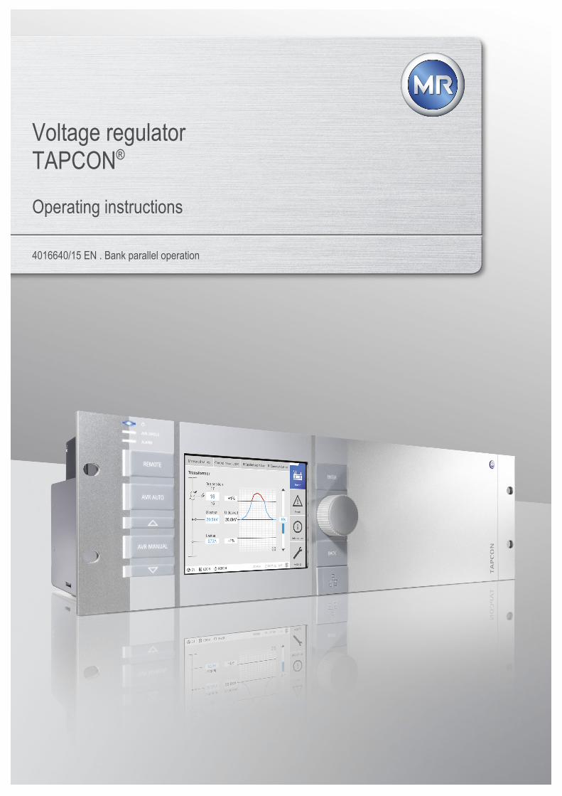
Voltage regulatorTAPCON®
Operating instructions
4016640/15 EN . Bank parallel operation

© All rights reserved by Maschinenfabrik ReinhausenDissemination and reproduction of this document and use and disclosure of its content are strictly prohibitedunless expressly permitted.Infringements will result in liability for compensation. All rights reserved in the event of the granting of patents,utility models or designs.The product may have been altered since this document was published.We reserve the right to change the technical data, design and scope of supply.Generally the information provided and agreements made when processing the individual quotations and ordersare binding.The original operating instructions were written in German.

Table of contents
Maschinenfabrik Reinhausen GmbH 2022 34016640/15 EN TAPCON®
Table of contents
1 Introduction......................................................................................................................... 81.1 Manufacturer....................................................................................................................................... 8
1.2 Completeness..................................................................................................................................... 8
1.3 Safekeeping........................................................................................................................................ 8
1.4 Notation conventions .......................................................................................................................... 81.4.1 Hazard communication system ............................................................................................................................. 8
1.4.2 Information system.............................................................................................................................................. 10
1.4.3 Instruction system ............................................................................................................................................... 10
1.4.4 Typographic conventions .................................................................................................................................... 11
2 Safety................................................................................................................................. 122.1 Appropriate use ................................................................................................................................ 12
2.2 Fundamental safety instructions ....................................................................................................... 12
2.3 Personnel qualification...................................................................................................................... 15
2.4 Personal protective equipment ......................................................................................................... 16
3 IT security.......................................................................................................................... 173.1 General ............................................................................................................................................. 17
3.2 Commissioning ................................................................................................................................. 17
3.3 Operation .......................................................................................................................................... 18
3.4 Interfaces .......................................................................................................................................... 18
3.5 Encryption standards ........................................................................................................................ 20
4 Product description.......................................................................................................... 234.1 Scope of delivery .............................................................................................................................. 23
4.2 Function description of the voltage regulation .................................................................................. 23
4.3 Performance features ....................................................................................................................... 24
4.4 Operating modes .............................................................................................................................. 25
4.5 Design............................................................................................................................................... 264.5.1 Operating elements............................................................................................................................................. 27
4.5.2 Display elements................................................................................................................................................. 28
4.5.3 Additional operating controls and display elements when using the MControl touch panel (optional)................ 32
4.5.4 Front interface ..................................................................................................................................................... 33
4.5.5 ISM® assemblies ................................................................................................................................................ 33
4.6 Operating concept ............................................................................................................................ 40

Table of contents
Maschinenfabrik Reinhausen GmbH 20224 4016640/15 ENTAPCON®
5 Packaging, transport and storage .................................................................................. 455.1 Suitability and structure .................................................................................................................... 45
5.2 Markings ........................................................................................................................................... 45
5.3 Transportation, receipt and handling of shipments........................................................................... 45
5.4 Storage of shipments........................................................................................................................ 46
6 Mounting ........................................................................................................................... 476.1 Preparation ....................................................................................................................................... 47
6.2 Electromagnetic compatibility ........................................................................................................... 476.2.1 Wiring requirement of installation site ................................................................................................................ 48
6.2.2 Wiring requirement of operating site .................................................................................................................. 48
6.2.3 Wiring requirement in control cabinet.................................................................................................................. 49
6.2.4 Information about shielding the CAN bus............................................................................................................ 50
6.3 Minimum distances ........................................................................................................................... 51
6.4 Installing the 19-inch plug-in housing ............................................................................................... 52
6.5 Installing the individual components on a cap rail ............................................................................ 546.5.1 Fastening the cap rail .......................................................................................................................................... 55
6.5.2 Installing the bus rail on the cap rail .................................................................................................................... 55
6.5.3 Installing the assembly at a distance on the cap rail ........................................................................................... 56
6.6 Connecting the device ...................................................................................................................... 586.6.1 Cable recommendation ....................................................................................................................................... 58
6.6.2 Information about connecting serial interfaces RS232 and RS485 (with 9-pin data cable) ................................ 59
6.6.3 Information about laying fiber-optic cable ........................................................................................................... 61
6.6.4 Mounting terminating resistor of CAN bus .......................................................................................................... 61
6.6.5 Connecting cables to the system periphery ........................................................................................................ 61
6.6.6 Wiring the CPU assembly ................................................................................................................................... 62
6.6.7 Wiring the UI assembly ....................................................................................................................................... 64
6.6.8 Wiring the AIO 2/AIO 4/AIO 8 assembly ............................................................................................................. 65
6.6.9 Wiring the DIO assembly .................................................................................................................................... 69
6.6.10 Wiring the MC 2-2/SW3-3 assembly ................................................................................................................... 70
6.6.11 Connecting the power supply.............................................................................................................................. 71
6.7 Checking functional reliability ........................................................................................................... 73
7 Commissioning................................................................................................................. 747.1 Performing tests................................................................................................................................ 747.1.1 Ground test ......................................................................................................................................................... 74
7.1.2 Performing a dielectric test.................................................................................................................................. 76

Table of contents
Maschinenfabrik Reinhausen GmbH 2022 54016640/15 EN TAPCON®
7.2 Establishing connection to visualization ........................................................................................... 79
7.3 Setting the language......................................................................................................................... 81
7.4 Setting date and time........................................................................................................................ 81
7.5 Commissioning wizard...................................................................................................................... 82
7.6 Function tests ................................................................................................................................... 837.6.1 Checking measured values and status of digital inputs and outputs .................................................................. 83
7.6.2 Testing a control function .................................................................................................................................... 83
7.6.3 Checking parallel operation................................................................................................................................. 84
8 Operation........................................................................................................................... 908.1 Carrying out tap-change operation manually.................................................................................... 90
8.2 System.............................................................................................................................................. 908.2.1 General ............................................................................................................................................................... 90
8.2.2 Configuring the network ...................................................................................................................................... 94
8.2.3 MQTT .................................................................................................................................................................. 96
8.2.4 Setting the device time........................................................................................................................................ 98
8.2.5 Configuring syslog............................................................................................................................................. 100
8.2.6 Setting the screensaver .................................................................................................................................... 102
8.2.7 SCADA.............................................................................................................................................................. 103
8.2.8 Displaying current measured values ................................................................................................................. 129
8.2.9 Displaying measured value recorder (optional)................................................................................................. 130
8.2.10 Setting the measured value recorder ................................................................................................................ 135
8.2.11 Linking signals and events ................................................................................................................................ 135
8.2.12 Configuring analog inputs and outputs (optional).............................................................................................. 140
8.2.13 Configuring digital inputs and outputs ............................................................................................................... 143
8.2.14 Event management ........................................................................................................................................... 145
8.2.15 User administration ........................................................................................................................................... 149
8.2.16 Hardware........................................................................................................................................................... 156
8.2.17 Software ............................................................................................................................................................ 158
8.2.18 Import/export manager...................................................................................................................................... 158
8.2.19 Configuring media converter with managed switch........................................................................................... 163
8.2.20 Transformer Personal Logic Editor (TPLE) ....................................................................................................... 168
8.2.21 Displaying temperature curve (optional) ........................................................................................................... 186
8.3 Power grid....................................................................................................................................... 1878.3.1 Transformer data............................................................................................................................................... 187
8.3.2 Measurement .................................................................................................................................................... 203
8.3.3 Voltage monitoring ............................................................................................................................................ 205
Table of contents
Maschinenfabrik Reinhausen GmbH 20226 4016640/15 ENTAPCON®
8.3.4 Current monitoring ............................................................................................................................................ 208
8.3.5 Power monitoring .............................................................................................................................................. 210
8.3.6 Power flow monitoring....................................................................................................................................... 212
8.3.7 Phase symmetry monitoring.............................................................................................................................. 215
8.3.8 TAPCON® 2xx retrofit....................................................................................................................................... 216
8.3.9 Displaying current measured values ................................................................................................................. 217
8.3.10 Displaying minimum and maximum measured values ...................................................................................... 218
8.3.11 Setting bank parallel operation.......................................................................................................................... 219
8.4 On-load tap-changer regulator........................................................................................................ 2208.4.1 Regulation ......................................................................................................................................................... 220
8.4.2 Voltage regulation ............................................................................................................................................. 222
8.4.3 Line drop compensation.................................................................................................................................... 239
8.4.4 Parallel operation (optional) .............................................................................................................................. 242
8.4.5 U bandwidth monitoring .................................................................................................................................... 264
8.5 On-load tap-changer....................................................................................................................... 2668.5.1 Tap position monitoring (optional)..................................................................................................................... 266
8.5.2 Switching interval monitoring ............................................................................................................................ 267
8.5.3 Target-tap-position operation ............................................................................................................................ 269
8.5.4 Changing tap position designation (optional) .................................................................................................... 270
8.5.5 Information about the on-load tap-changer ....................................................................................................... 270
8.5.6 Displaying tap-change operation statistics (optional)........................................................................................ 271
8.5.7 Displaying information about contact wear (only OILTAP®) ............................................................................. 272
8.5.8 Maintenance (optional)...................................................................................................................................... 272
8.5.9 OLTC data......................................................................................................................................................... 281
8.5.10 Displaying the minimum and maximum tap position ......................................................................................... 283
8.6 Motor-drive unit and control cabinet ............................................................................................... 2848.6.1 Control of the motor-drive unit........................................................................................................................... 284
8.6.2 Tap position capture.......................................................................................................................................... 288
9 Maintenance and care .................................................................................................... 2919.1 Cleaning the device ........................................................................................................................ 291
10 Fault elimination ............................................................................................................. 29210.1 General faults ................................................................................................................................. 292
10.2 No regulation in AUTO mode.......................................................................................................... 292
10.3 Bank parallel operation ................................................................................................................... 293
10.4 Unwanted on-load tap-change operation........................................................................................ 293

Table of contents
Maschinenfabrik Reinhausen GmbH 2022 74016640/15 EN TAPCON®
10.5 Human-machine interface............................................................................................................... 293
10.6 Incorrect measured values ............................................................................................................. 294
10.7 Parallel operation faults .................................................................................................................. 295
10.8 Tap position capture incorrect ........................................................................................................ 296
10.9 Assemblies ..................................................................................................................................... 297
10.10 Other faults ..................................................................................................................................... 297
11 Uninstallation.................................................................................................................. 29811.1 Uninstalling the CPU assembly ...................................................................................................... 298
11.2 Uninstalling the UI 1/UI 3 assembly................................................................................................ 301
11.3 Uninstalling the AIO 2/AIO 4 assembly........................................................................................... 303
11.4 Uninstalling the DIO 28-15/DIO 42-20 assembly............................................................................ 304
11.5 Uninstalling the MC 2-2/SW 3-3 assembly ..................................................................................... 306
11.6 Uninstalling the QS3.241 assembly................................................................................................ 308
11.7 Uninstalling the bus rail................................................................................................................... 309
12 Disposal........................................................................................................................... 310
13 Technical data................................................................................................................. 31113.1 Display elements ............................................................................................................................ 311
13.2 ISM® assemblies............................................................................................................................ 31113.2.1 Power supply OT1205....................................................................................................................................... 311
13.2.2 UI 1 voltage measurement and current measurement...................................................................................... 314
13.2.3 UI 3 voltage measurement and current measurement...................................................................................... 315
13.2.4 DIO 28-15 digital inputs and outputs................................................................................................................. 316
13.2.5 Digital inputs and outputs DIO 42-20 (HL) ........................................................................................................ 319
13.2.6 AIO 2 analog inputs and outputs....................................................................................................................... 321
13.2.7 AIO 4 analog inputs and outputs....................................................................................................................... 322
13.2.8 CPU (central processing unit) I ......................................................................................................................... 323
13.2.9 System networking MC 2-2 ............................................................................................................................... 325
13.2.10 System networking SW 3-3............................................................................................................................... 327
13.3 Dimensions and weight................................................................................................................... 329
13.4 Ambient conditions ......................................................................................................................... 329
13.5 Standards and directives ................................................................................................................ 329
Glossary .......................................................................................................................... 332
List of key words ............................................................................................................ 334

1 Introduction
Maschinenfabrik Reinhausen GmbH 20228 4016640/15 ENTAPCON®
1 IntroductionThis technical file contains detailed descriptions on the safe and proper in-stallation, connection, commissioning and monitoring of the product.
It also includes safety instructions and general information about the prod-uct.
This technical file is intended solely for specially trained and authorized per-sonnel.
1.1 ManufacturerMaschinenfabrik Reinhausen GmbHFalkensteinstrasse 893059 RegensburgGermany
Tel.: +49 941 4090-0E-mail: [email protected]: www.reinhausen.comMR Reinhausen customer portal: https://portal.reinhausen.com
Further information on the product and copies of this technical file are avail-able from this address if required.
1.2 CompletenessThis technical file is incomplete without the supporting documents.
The following documents are considered supporting documents: Connection diagrams Supplement (optional)
1.3 SafekeepingKeep this technical file and all supporting documents ready at hand and ac-cessible for future use at all times.
1.4 Notation conventions
1.4.1 Hazard communication system
Warnings in this technical file are displayed as follows.
1.4.1.1 Warning relating to section
Warnings relating to sections refer to entire chapters or sections, sub-sec-tions or several paragraphs within this technical file. Warnings relating tosections use the following format:

1 Introduction
Maschinenfabrik Reinhausen GmbH 2022 94016640/15 EN TAPCON®
WARNING Type of danger!Source of the danger and outcome. Action Action
1.4.1.2 Embedded warning information
Embedded warnings refer to a particular part within a section. These warn-ings apply to smaller units of information than the warnings relating to sec-tions. Embedded warnings use the following format:
DANGER! Instruction for avoiding a dangerous situation.
1.4.1.3 Signal words and pictograms
The following signal words are used:
Signal word Definition
DANGER Indicates a hazardous situation which, if not avoided, will result indeath or serious injury.
WARNING Indicates a hazardous situation which, if not avoided, could resultin death or serious injury.
CAUTION Indicates a hazardous situation which, if not avoided, could resultin minor or moderate injury.
NOTICE Indicates measures to be taken to prevent damage to property.
Table 1: Signal words in warning notices
Pictograms warn of dangers:
Pictogram Definition
Warning of a danger point
Warning of dangerous electrical voltage
Warning of combustible substances

1 Introduction
Maschinenfabrik Reinhausen GmbH 202210 4016640/15 ENTAPCON®
Pictogram Definition
Warning of danger of tipping
Warning of danger of crushing
Table 2: Pictograms used in warning notices
1.4.2 Information system
Information is designed to simplify and improve understanding of particularprocedures. In this technical file it is laid out as follows:
Important information.
1.4.3 Instruction system
This technical file contains single-step and multi-step instructions.
Single-step instructions
Instructions which consist of only a single process step are structured as fol-lows:
Aim of actionü Requirements (optional). Step 1 of 1.
ð Result of step (optional).ð Result of action (optional).
Multi-step instructions
Instructions which consist of several process steps are structured as follows:
Aim of actionü Requirements (optional).1. Step 1.
ð Result of step (optional).
1 Introduction
Maschinenfabrik Reinhausen GmbH 2022 114016640/15 EN TAPCON®
2. Step 2.ð Result of step (optional).
ð Result of action (optional).
1.4.4 Typographic conventionsTypographic convention Purpose Example
UPPERCASE Operating controls, switches ON/OFF
[Brackets] PC keyboard [Ctrl] + [Alt]
Bold Software operating controls Press Continue button
…>…>… Menu paths Parameter > Control parameter
Italics System messages, error messages,signals
Function monitoring alarm triggered
[ Number of pages] Cross reference [ Page 41].
Dotted underscore............................................. Glossary entry, abbreviations, defini-tions, etc.
Glossary entry........................
Table 3: Typographic conventions used in this technical file

2 Safety
Maschinenfabrik Reinhausen GmbH 202212 4016640/15 ENTAPCON®
2 Safety Read this technical file through to familiarize yourself with the product. This technical file is a part of the product. Read and observe the safety instructions provided in this chapter. Read and observe the warnings in this technical file in order to avoid func-
tion-related dangers. The product is manufactured on the basis of state-of-the-art technology.
Nevertheless, risks to life and limb for the user or impairment of the prod-uct and other material assets due to the function may arise in the event ofimproper use.
2.1 Appropriate useThe TAPCON® serves to keep the output voltage of a bank of transformersconstant. The product is designed solely for use in stationary large-scaleelectrical energy systems and facilities.
If used as intended, in compliance with the requirements and conditionsspecified in this technical file and observing the warning notices in this tech-nical file and attached to the product, the product does not pose risk of injuryor damage to property or the environment. This applies across the entireservice life of the product, from delivery to installation and operation throughto disassembly and disposal.
The following is considered appropriate use: You will find the standard valid for the product and the year of issue on the
nameplate. Operate the product in accordance with this technical file, the agreed-
upon delivery conditions and the technical data. Ensure that all necessary work is performed by qualified personnel only. Only use the equipment and special tools included in delivery for the in-
tended purpose and in accordance with the specifications of this technicalfile.
Only operate the product in industrial areas. Observe the notices in this technical file regarding electromagnetic com-
patibility and the technical data.
2.2 Fundamental safety instructionsTo prevent accidents, malfunctions and damage as well as unacceptable ad-verse effects on the environment, those responsible for transport, installa-tion, operation, maintenance and disposal of the product or parts of the prod-uct must ensure the following:

2 Safety
Maschinenfabrik Reinhausen GmbH 2022 134016640/15 EN TAPCON®
Personal protective equipment
Loosely worn or unsuitable clothing increases the danger of becomingtrapped or caught up in rotating parts and the danger of getting caught onprotruding parts. This poses a danger to life and limb. Wear appropriate personal protective equipment such as a helmet, work
gloves, etc. for the respective activity. Never wear damaged personal protective equipment. Never wear rings, necklaces, or other jewelry. If you have long hair, wear a hairnet.
Work area
Untidy and poorly lit work areas can lead to accidents. Keep the work area clean and tidy. Make sure that the work area is well lit. Observe the applicable laws for accident prevention in the relevant coun-
try.
Working during operation
The product may only be operated in a sound, operational condition. Other-wise it poses a danger to life and limb. Regularly check the operational reliability of safety equipment. Comply with the inspection work, maintenance work and maintenance in-
tervals described in this technical file.
Invisible laser radiation
Looking directly into the beam or the reflected beam can cause eye damage.The beam is emitted at the optical connections or at the end of the fiber-opticcables connected to them on the assemblies. Read the chapter "TechnicalData" [Section 13, Page 311] for further information. Never look directly into the beam or the reflected beam. Never look into the beam with the aid of optical instruments such as a
magnifying glass or a microscope. In the event that the laser beam strikes your eyes, close your eyes imme-
diately and move your head out of the path of the beam.
Working with current transformers
Dangerous high voltages may occur when a current transformer is operatedwith an open secondary circuit. This can lead to injuries and property dam-age. Never operate a current transformer with an open secondary circuit; short-
circuit the current transformer to prevent this. Observe the information in the current transformer operating instructions.

2 Safety
Maschinenfabrik Reinhausen GmbH 202214 4016640/15 ENTAPCON®
Handling electrical components
Electrical components can be damaged by electrostatic discharge. Never touch electrical components during commissioning, operation or
maintenance work. Take suitable measures (such as covers) to ensure that personnel cannot
touch components. Wear suitable personal protective equipment.
Explosion protection
Highly flammable or explosive gases, vapors and dusts can cause seriousexplosions and fire. Do not install or operate the product in areas where a risk of explosion is
present.
Safety markings
Warning signs and safety information plates are safety markings on theproduct. They are an important aspect of the safety concept. Observe all safety markings on the product. Make sure all safety markings on the product remain intact and legible. Replace safety markings that are damaged or missing.
Ambient conditions
To ensure reliable and safe operation, the product must only be operatedunder the ambient conditions specified in the technical data. Observe the specified operating conditions and requirements for the in-
stallation location.
Modifications and conversions
Unauthorized or inappropriate changes to the product may lead to personalinjury, material damage and operational faults. Only modify the product after consultation with Maschinenfabrik Rein-
hausen GmbH.
Spare parts
Spare parts not approved by Maschinenfabrik Reinhausen GmbH may leadto physical injury, damage to the product and malfunctions. Only use spare parts that have been approved by Maschinenfabrik Rein-
hausen GmbH. Contact Maschinenfabrik Reinhausen GmbH.
2 Safety
Maschinenfabrik Reinhausen GmbH 2022 154016640/15 EN TAPCON®
2.3 Personnel qualificationThe person responsible for assembly, commissioning, operation, mainte-nance and inspection must ensure that the personnel are sufficiently quali-fied.
Electrically skilled person
The electrically skilled person has a technical qualification and therefore hasthe required knowledge and experience, and is also conversant with the ap-plicable standards and regulations. The electrically skilled person is also pro-ficient in the following: Can identify potential dangers independently and is able to avoid them. Is able to perform work on electrical systems. Is specially trained for the working environment in which (s)he works. Must satisfy the requirements of the applicable statutory regulations for
accident prevention.
Electrically trained persons
An electrically trained person receives instruction and guidance from anelectrically skilled person in relation to the tasks undertaken and the poten-tial dangers in the event of inappropriate handling as well as the protectivedevices and safety measures. The electrically trained person works exclu-sively under the guidance and supervision of an electrically skilled person.
Operator
The operator uses and operates the product in line with this technical file.The operating company provides the operator with instruction and trainingon the specific tasks and the associated potential dangers arising from im-proper handling.
Technical Service
We strongly recommend having maintenance, repairs and retrofitting carriedout by our Technical Service department. This ensures that all work is per-formed correctly. If maintenance is not carried out by our Technical Servicedepartment, please ensure that the personnel who carry out the mainte-nance are trained and authorized by Maschinenfabrik Reinhausen GmbH tocarry out the work.
Authorized personnel
Authorized personnel are trained by Maschinenfabrik Reinhausen GmbH tocarry out special maintenance.

2 Safety
Maschinenfabrik Reinhausen GmbH 202216 4016640/15 ENTAPCON®
2.4 Personal protective equipmentPersonal protective equipment must be worn during work to minimize risks tohealth. Always wear the personal protective equipment required for the job at
hand. Never wear damaged personal protective equipment. Observe information about personal protective equipment provided in the
work area.
Protective clothing Close-fitting work clothing with a low tearing strength,with tight sleeves and with no protruding parts. It mainlyserves to protect the wearer against being caught bymoving machine parts.
Safety shoes To protect against falling heavy objects and slipping onslippery surfaces.
Safety glasses To protect the eyes from flying parts and splashing liq-uids.
Visor To protect the face from flying parts and splashing liq-uids or other dangerous substances.
Hard hat To protect against falling and flying parts and materials.
Hearing protection To protect against hearing damage.
Protective gloves To protect against mechanical, thermal, and electricalhazards.
Table 4: Personal protective equipment

3 IT security
Maschinenfabrik Reinhausen GmbH 2022 174016640/15 EN TAPCON®
3 IT securityObserve the following recommendations to operate the product safely.
3.1 General Ensure that only authorized personnel have access to the device. Only use the device within an ESP (electronic security perimeter). Do not
connect the device to the Internet in an unprotected state. Use mecha-nisms for vertical and horizontal network segmentation and security gate-ways (firewalls) at the transition points.
Ensure that the device is only operated by trained personnel who are fa-miliar with IT security.
Check regularly whether software updates are available for the device andperform the updates.
3.2 CommissioningObserve the following recommendations for device commissioning: User IDs must be unique and assignable. Do not use a "Group account"
function or the "Auto login" function. Activate the "Auto logout [Section 8.2.1.2, Page 92]" function. Restrict the rights of the individual user groups as much as is feasible; this
helps avoid errors during operations. A user with the "Operator" role, forexample, should only perform operations and should not be able tochange any device settings.
Delete or disable the default "admin" user ID. This requires first creating anew user account with the "Administrator" role. You can then use it todelete or disable the default "admin" account.
Deactivate service user access [Section 8.2.1.3, Page 93]. Enable SSL/TLS encryption [Section 8.2.1, Page 90]; access to the
device is then only possible using the SSL/TLS protocol. In addition to en-crypting communication, this protocol also checks the authenticity of theserver.
Use TLS version 1.2 or higher wherever possible. Integrate the device into a public key infrastructure. Create your own SSL
certificates for this if necessary and then import them. Connect the device to a central log server by using the syslog interface
[Section 8.2.5, Page 100]. Only use the SNMP function if you can ensure that the communication is
protected by external security equipment. Media converter with managed switch (assembly SW 3-3) [Section
8.2.19, Page 163]:– Change user account and password.– Disable unnecessary services.
3 IT security
Maschinenfabrik Reinhausen GmbH 202218 4016640/15 ENTAPCON®
3.3 OperationObserve the following recommendations during device operation: Change the password at regular intervals. Export the security log [Section 8.2.18.1, Page 158] at regular intervals. Check the log files regularly for unauthorized system access and other se-
curity-related events. Media converter with managed switch (assembly SW 3-3): Check at regu-
lar intervals whether the manufacturer Belden/Hirschmann has releasedan update for the product “EES 25” and, where necessary, perform afirmware update [Section 8.2.19.3, Page 166].
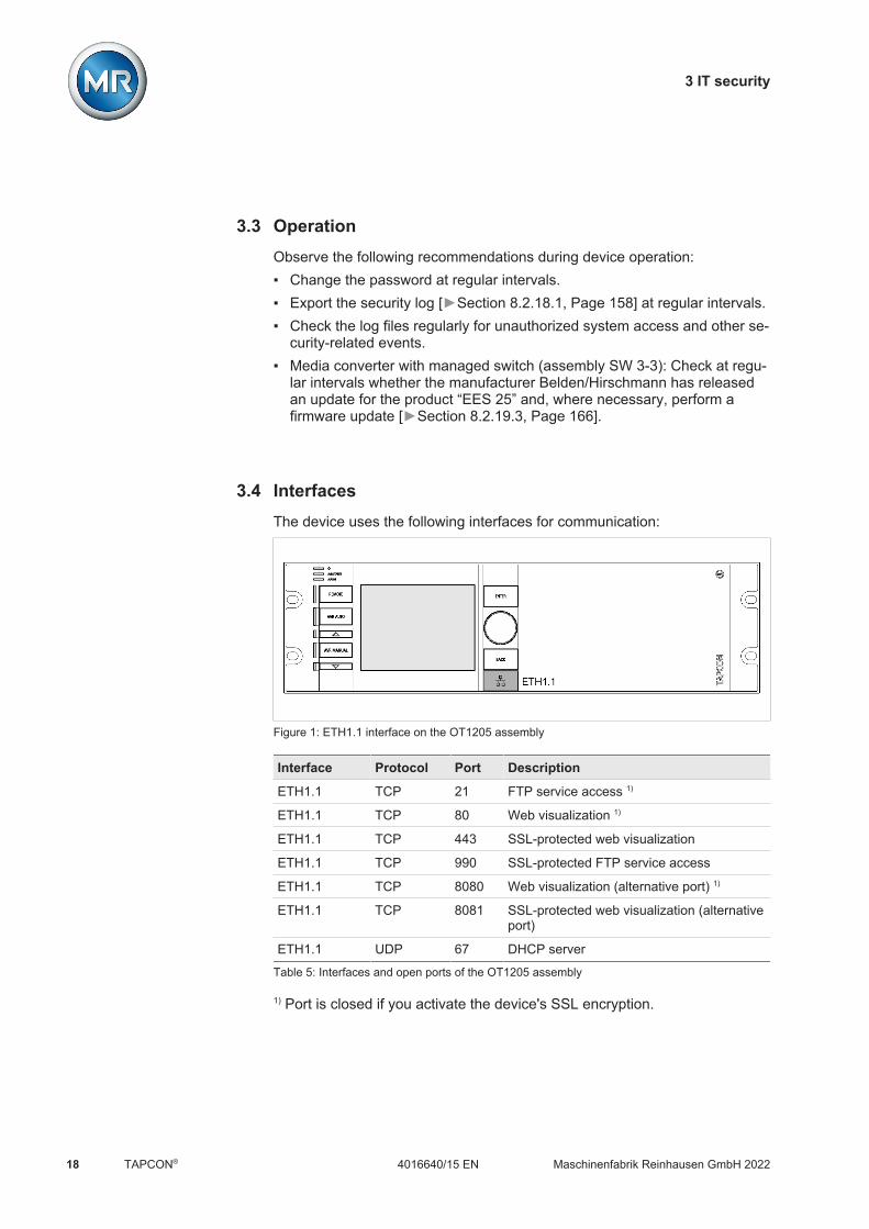
3.4 InterfacesThe device uses the following interfaces for communication:
Figure 1: ETH1.1 interface on the OT1205 assembly
Interface Protocol Port Description
ETH1.1 TCP 21 FTP service access 1)
ETH1.1 TCP 80 Web visualization 1)
ETH1.1 TCP 443 SSL-protected web visualization
ETH1.1 TCP 990 SSL-protected FTP service access
ETH1.1 TCP 8080 Web visualization (alternative port) 1)
ETH1.1 TCP 8081 SSL-protected web visualization (alternativeport)
ETH1.1 UDP 67 DHCP server
Table 5: Interfaces and open ports of the OT1205 assembly
1) Port is closed if you activate the device's SSL encryption.

3 IT security
Maschinenfabrik Reinhausen GmbH 2022 194016640/15 EN TAPCON®
CPU
CAN
1
1
9
CAN
2
1
9
COM
1
1
9
COM
2
1
9
-+
24V DC
RUN
INIT
ERR
USB2
.0
4 62
A8
CH
TESTPROGRUN
4 62
AE0 8
CL
ETH 1 ETH 2.1 ETH 2.2
Figure 2: CPU assembly interfaces
Interface Protocol Port Description
CAN 1 - - DIO assembly connection
CAN 2 - - Communication with other ISM® devices(e.g. parallel operation)
COM 1 - - Internal system interface
COM 2 - - Serial interface (SCADA)
USB - - Import or export of data
ETH 1 TCP 80 HTTP for web-based visualization1), 2)
ETH 1 TCP 443 HTTPS for web-based visualization2)
ETH 1 TCP 102 IEC 61850
ETH 1 TCP 502 Modbus3)
ETH 1 TCP 20000 DNP33)
ETH 1 UDP 161 SNMP4)
ETH 2.x TCP 21 FTP1) (only for MR service)
ETH 2.x TCP 80 HTTP for web-based visualization1)
ETH 2.x TCP 443 HTTPS for web-based visualization
ETH 2.x TCP 990 FTPS (only for MR service)
ETH 2.x TCP 8080 HTTP for web-based visualization1)
ETH 2.x TCP 8081 HTTPS for web-based visualization
ETH 2.x UDP 161 SNMP4)
Table 6: Interfaces and open ports of the CPU assembly
1) Port is closed if you activate the device's SSL encryption.2) Depending on the setting of the parameter Visualization release [Page95].3) Default setting; if you have modified the port for the control system proto-col, only the set port is open.4) Depending on the setting of the SNMP agent parameter.

3 IT security
Maschinenfabrik Reinhausen GmbH 202220 4016640/15 ENTAPCON®
Figure 3: Assembly SW 3-3 interfaces
Interface Protocol Port Description
ETH 2.3,ETH 2.4
TCP 22 SSH1)
23 Telnet1)
80 HTTP for web-based visualization1)
443 HTTPS for web-based visualization1)
UDP 161 SNMP1)
Table 7: Interfaces and open ports of the SW 3-3 assembly
1) Port is closed if the corresponding service is disabled.
3.5 Encryption standardsThe device supports the following TLS versions: TLS 1.0 TLS 1.1 TLS 1.2
3 IT security
Maschinenfabrik Reinhausen GmbH 2022 214016640/15 EN TAPCON®
The device uses the following cipher suites for a TLS-secured connection:
Key exchange Authentication Encryption Key length Operatingmode
Hash func-tion
TLS ECDHE RSA WITH AES 128 CBC SHA1)
DHE SHA265
ECDHE ECDSA GCM SHA256
ECDH 256 CBC SHA1)
RSA1) SHA256
GCM SHA384
Table 8: Cipher suite
1) Not available with TLS version >= 1.2
The device uses the SHA256 hash function to save passwords.
The SW 3-3 assembly supports the following TLS version: TLS 1.2
The assembly uses the following cipher suites for a TLS-secured connec-tion:
Key exchange Authentication Encryption Key length Operatingmode
Hash func-tion
TLS ECDHE RSA WITH AES 128 GCM SHA265
DHE CBC SHA
Table 9: Cipher suite
The device uses the following encryption standards in accordance with tech-nical directive TR-02102-4 from Germany's Federal Office for InformationSecurity: Key agreement:
– diffie-hellman-group1-sha1– diffie-hellman-group14-sha1– diffie-hellman-group16-sha512– diffie-hellman-group18-sha512– diffie-hellman-group-exchange-sha256– ecdh-sha2-nistp256
Server authentication:– ssh-rsa– rsa-sha2-512– rsa-sha2-256

3 IT security
Maschinenfabrik Reinhausen GmbH 202222 4016640/15 ENTAPCON®
Encryption algorithms:– aes128-ctr– [email protected]– [email protected]
MAC protection:– hmac-sha1– hmac-sha2-256– [email protected]– [email protected]
Compression:– None– [email protected]– Zlib
4 Product description
Maschinenfabrik Reinhausen GmbH 2022 234016640/15 EN TAPCON®
4 Product description
4.1 Scope of deliveryThe following items are included in the delivery: TAPCON® Terminating resistor for CAN bus (optional) Technical files Additional nameplate
Please note the following: Check the shipment for completeness on the basis of the shipping docu-
ments. Store the parts in a dry place until installation.
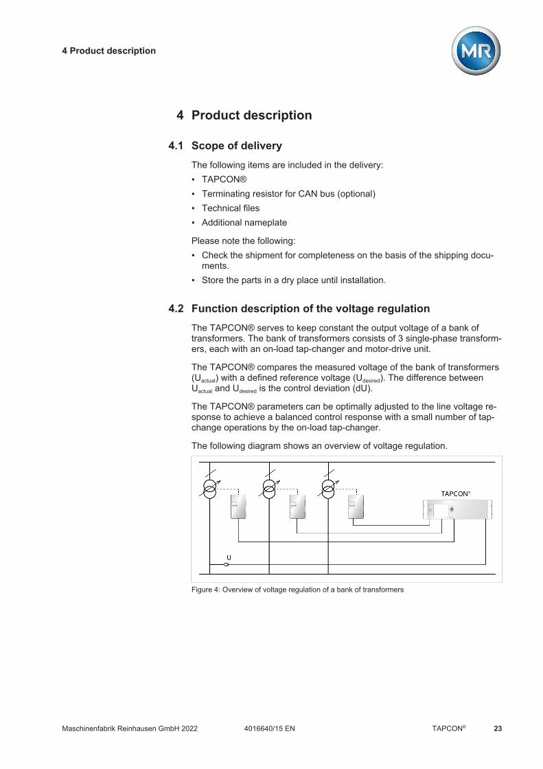
4.2 Function description of the voltage regulationThe TAPCON® serves to keep constant the output voltage of a bank oftransformers. The bank of transformers consists of 3 single-phase transform-ers, each with an on-load tap-changer and motor-drive unit.
The TAPCON® compares the measured voltage of the bank of transformers(Uactual) with a defined reference voltage (Udesired). The difference betweenUactual and Udesired is the control deviation (dU).
The TAPCON® parameters can be optimally adjusted to the line voltage re-sponse to achieve a balanced control response with a small number of tap-change operations by the on-load tap-changer.
The following diagram shows an overview of voltage regulation.
Figure 4: Overview of voltage regulation of a bank of transformers

4 Product description
Maschinenfabrik Reinhausen GmbH 202224 4016640/15 ENTAPCON®
4.3 Performance featuresThe device features the following functions: Automatic voltage regulation 1 desired value 3 desired values 5 desired values Analog setting of the desired value Step-by-step setting of the desired value Active power-dependent adjustment of desired voltage value (TDSC) Active power-dependent adjustment of desired voltage value with 3 differ-
ent desired values (TDSC) Desired value setting via BCD Line drop compensation
– R&X compensation: compensation for voltage drops on the line– Z compensation: compensation for voltage fluctuations in the meshed
grid Integrated monitoring functions:
– Voltage monitoring– Current monitoring– Apparent power monitoring– Active power monitoring– Reactive power monitoring– Power factor monitoring
Display of all measured values such as voltage, current, active power, ap-parent power and reactive power
Tap position capture via BCD code Tap position capture via analog signals (4...20 mA) Tap position capture via analog signals (0...20 mA) Tap position capture via analog signals (0...10 V) Tap position capture via N/O contact series Tap position capture via resistor contact series Tap position capture via dual code Tap position capture via decadic contact series Tap position capture via gray code Parallel operation of up to 16 transformers in 2 groups using the following
methods:– Master/follower– Circulating reactive current minimization

4 Product description
Maschinenfabrik Reinhausen GmbH 2022 254016640/15 EN TAPCON®
Freely configurable events Web-based visualization SCADA: IEC 60870-5-101 SCADA: IEC 60870-5-103 SCADA: IEC 60870-5-104 SCADA: IEC 61850 (edition 1 and edition 2) SCADA: Modbus RTU SCADA: Modbus TCP SCADA: Modbus ASCII SCADA: DNP3 On-load tap-changer monitoring
– Contact wear calculation (only for OILTAP® V, M, R, RM, MS, G)– Maintenance interval calculation– Oil carbonization (only for OILTAP® V, M, R)– Monitoring of OLTC temperature (optional)– Tap-change statistics of on-load tap-changer– Optional: on-load tap-changer oil level– Optional: oil filter unit– Status of the motor-drive unit (motor protective switch, motor is running)
4.4 Operating modesThe device can be operated in the following operating modes:
Auto mode (AVR AUTO)
In auto mode, the device automatically regulates the voltage in accordancewith the set parameters. It is not possible to perform manual tap-change op-erations using operating controls, inputs or a control system.
Manual mode (AVR MANUAL)
In manual mode, you can perform manual tap-change operations to increaseor decrease the voltage. There is no automatic voltage regulation.
Local mode (LOCAL)
In local mode, you can make entries and issue commands using the device'soperating controls. You cannot use inputs or the control system to make en-tries or issue commands.

4 Product description
Maschinenfabrik Reinhausen GmbH 202226 4016640/15 ENTAPCON®
Remote mode (REMOTE)
In remote mode, you can make entries and issue commands using digital in-puts or the control system, depending on the setting of the Remote behavior[Page 91] parameter.
AVR AUTO AVR MANUAL
LOCAL REMOTE LOCAL REMOTE
Automatic regulation Yes Yes No No
Tap-change operation viaoperating controls
No No Yes No
Tap-change operation viainputs
No No No Yes2)
Tap-change operation viaSCADA1)
No No No Yes2)
Value adjustment viaSCADA1)
No Yes No Yes2)
Table 10: Overview of operating modes
1) Optional when connecting TAPCON® to a control system (SCADA)2) You can use the Remote behavior [Page 91] parameter to set the be-havior
4.5 DesignDepending on the order, the device is either designed as a 19-inch plug-inhousing or supplied as individual components for assembly on a cap rail.The individual device assemblies are described in the following section.
Figure 5: 19-inch plug-in housing

4 Product description
Maschinenfabrik Reinhausen GmbH 2022 274016640/15 EN TAPCON®
Figure 6: Individual components for assembly on a cap rail
4.5.1 Operating elements
The device has seven pushbuttons and one rotary knob. The illustration be-low is an overview of all the device's operating controls.
1
2345
6
7
8
Figure 7: Operating elements
1 REMOTE key1) Select the operating mode: On: REMOTE Off: LOCAL
2 AVR AUTO key Activate auto mode.
3 RAISE key Send a control command to the motor-drive unit to in-crease the voltage. Only possible in manual mode.
4 AVR Manual key Activate manual mode.
5 LOWER key Send a control command to the motor-drive unit toreduce the voltage. Only possible in manual mode.

4 Product description
Maschinenfabrik Reinhausen GmbH 202228 4016640/15 ENTAPCON®
6 ENTER key Confirm selection and save modified parameters.
7 Rotary knob Navigation through individual menu items and param-eters.
8 BACK key Exit the current menu. Go to the previous menu level.
1) Key without function if a digital input is used to toggle between local/re-mote.
4.5.2 Display elements
The device has a graphics display and 8 LEDs, which indicate the variousoperating statuses or events.
12345678
9
Figure 8: Display elements
1 Power supply LED 2 AVR STATUS LED
3 ALARM LED 4 REMOTE LED
5 AVR AUTO LED 6 RAISE VOLTAGE LED
7 AVR MANUAL LED 8 LOWER VOLTAGE LED
9 Display

4 Product description
Maschinenfabrik Reinhausen GmbH 2022 294016640/15 EN TAPCON®
Display
The display for the TAPCON® is divided into the following areas:
Figure 9: Display
1 Display area 2 Secondary navigation or naviga-tion path
3 Primary navigation 4 Status bar

4 Product description
Maschinenfabrik Reinhausen GmbH 202230 4016640/15 ENTAPCON®
Display showing measured value trend
Figure 10: Measured value trend
1 Desired value 2 Upper limit of bandwidth
3 Trend of measured voltage 4 Delay time T1/T2
5 Trend of corrected voltage (correc-tion due to compensation or paral-lel operation)
6 Lower limit of bandwidth

4 Product description
Maschinenfabrik Reinhausen GmbH 2022 314016640/15 EN TAPCON®
Figure 11: Transformer overview with display showing current measured values
1 Description of bank of transformers 2 Current tap position of on-load tap-changer (transformers 1...4)
3 Voltage 4 Control deviation in % (with correc-tion)
5 Current 6 Power factor

4 Product description
Maschinenfabrik Reinhausen GmbH 202232 4016640/15 ENTAPCON®
4.5.3 Additional operating controls and display elements when usingthe MControl touch panel (optional)
If you are using the device with the optionally available MControl touchpanel, additional operating controls and display elements are displayed onthe left edge of the screen
Home
Ereignisse
Information
Rekorder
EinstellungenDE CHANGE REBOOT admin 03.02.2020 08:09
Messwerte Regelparameter Parallellauf Kommunikation
Transformator
Stufenstellung
Spannung
dU
Strom
Leistungsfaktor
14
16
24.3 kV
1.3 %
198.0 A
0.98
15
24.0 kV
24.5 kV
23.5 kV
08:09:1608:08:4608:08:16
30 s
TAPC
ON
AVR STATUS
REMOTE
AVR AUTO
AVR MANUAL
Figure 12: Additional display elements and operating controls
Status LED status Status display
1) REMOTE key Select the operating mode: On: REMOTE Off: LOCAL
AVR AUTO key Activate auto mode.
RAISE key Send a control command to the motor-driveunit to increase the voltage. Only possible inmanual mode.
AVR Manual key Activate manual mode.
LOWER key Send a control command to the motor-driveunit to reduce the voltage. Only possible inmanual mode.
1) Not available if local/remote is toggled using a digital input.
4 Product description
Maschinenfabrik Reinhausen GmbH 2022 334016640/15 EN TAPCON®
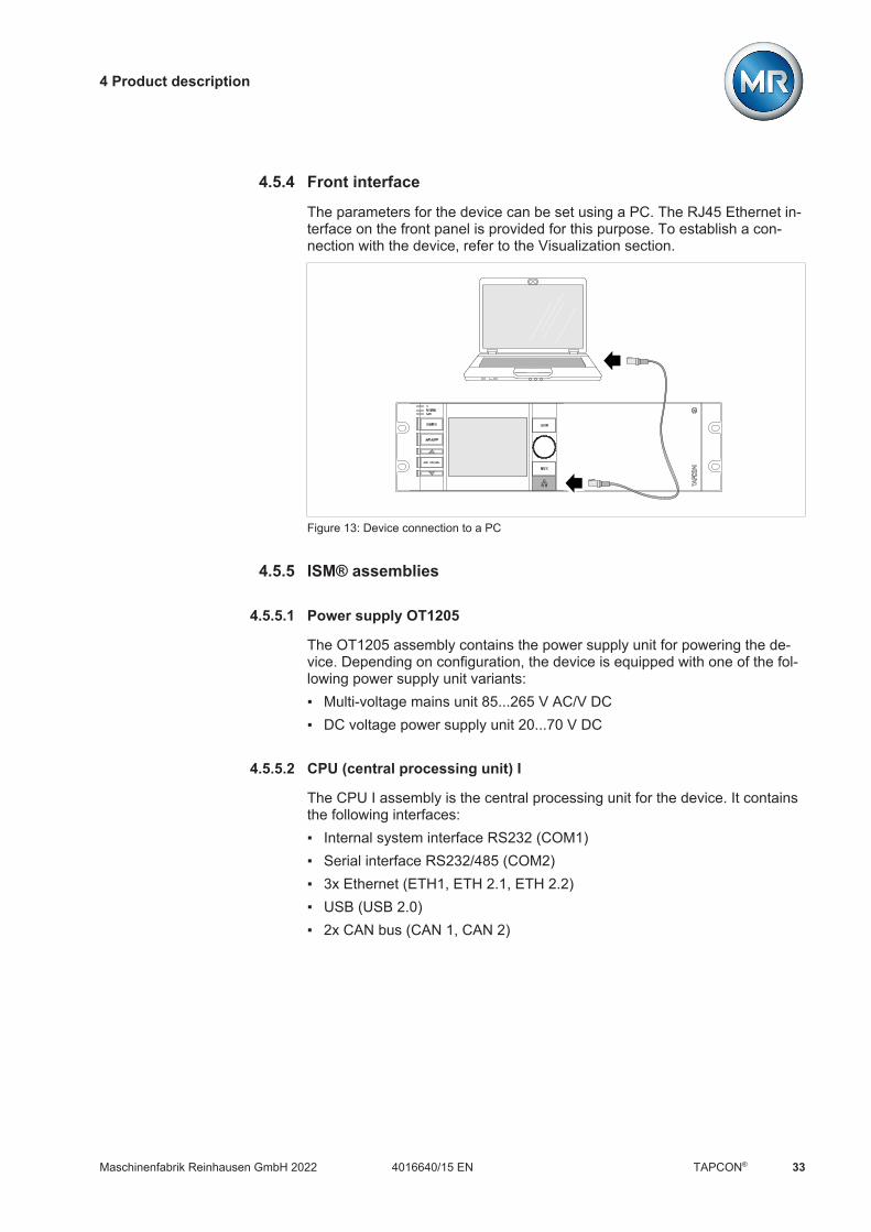
4.5.4 Front interface
The parameters for the device can be set using a PC. The RJ45 Ethernet in-terface on the front panel is provided for this purpose. To establish a con-nection with the device, refer to the Visualization section.
Figure 13: Device connection to a PC
4.5.5 ISM® assemblies
4.5.5.1 Power supply OT1205
The OT1205 assembly contains the power supply unit for powering the de-vice. Depending on configuration, the device is equipped with one of the fol-lowing power supply unit variants: Multi-voltage mains unit 85...265 V AC/V DC DC voltage power supply unit 20...70 V DC
4.5.5.2 CPU (central processing unit) I
The CPU I assembly is the central processing unit for the device. It containsthe following interfaces: Internal system interface RS232 (COM1) Serial interface RS232/485 (COM2) 3x Ethernet (ETH1, ETH 2.1, ETH 2.2) USB (USB 2.0) 2x CAN bus (CAN 1, CAN 2)

4 Product description
Maschinenfabrik Reinhausen GmbH 202234 4016640/15 ENTAPCON®
CPU
CAN
1
1
9
CAN
2
1
9
COM
1
1
9
COM
2
1
9
-+
24V DC
RUN
INIT
ERR
USB2
.0
4 62
A8
CH
TESTPROGRUN
4 62
AE0 8
CL
ETH 1 ETH 2.1 ETH 2.2
Figure 14: CPU I assembly
4.5.5.3 UI 1 voltage measurement and current measurement
The UI 1 assembly is used for measuring 1-phase voltage and current.
Figure 15: UI 1 assembly
Warning of a danger point. Read the information given in the product oper-ating instructions.
Warning of dangerous electrical voltage.
This assembly is protected via double insulation or reinforced insulation.
Table 11: Safety-relevant symbols on the assembly

4 Product description
Maschinenfabrik Reinhausen GmbH 2022 354016640/15 EN TAPCON®
4.5.5.4 UI 3 voltage measurement and current measurement
The UI 3 assembly is used for measuring 3-phase voltage and current.
Figure 16: UI 3 assembly
Warning of a danger point. Read the information given in the product oper-ating instructions.
Warning of dangerous electrical voltage.
This assembly is protected via double insulation or reinforced insulation.
Table 12: Safety-relevant symbols on the assembly

4 Product description
Maschinenfabrik Reinhausen GmbH 202236 4016640/15 ENTAPCON®
4.5.5.5 DIO 28-15 digital inputs and outputs
The DIO 28-15 assembly makes 28 inputs and 15 outputs (6 N/O contacts, 9change-over contacts) available.
Figure 17: DIO 28-15 assembly
Warning of a danger point. Read the information given in the product oper-ating instructions.
Warning of dangerous electrical voltage.
Table 13: Safety-relevant symbols on the assembly

4 Product description
Maschinenfabrik Reinhausen GmbH 2022 374016640/15 EN TAPCON®
4.5.5.6 Digital inputs and outputs DIO 42-20 (HL)
The assembly DIO 42-20/DIO 42-20 HL makes 42 inputs and 20 outputs (8N/O contacts, 12 change-over contacts) available.
Figure 18: Assembly DIO 42-20/DIO 42-20 HL
Warning of a danger point. Read the information given in the product oper-ating instructions.
Warning of dangerous electrical voltage.
Table 14: Safety-relevant symbols on the assembly
4.5.5.7 AIO 2 analog inputs and outputs
The AIO 2 assembly provides 2 channels for analog inputs and outputs.
In accordance with the device configuration, the AIO assembly supports oneof the following signal types:
Input Output
Voltage Current Voltage Current
0 to 10 V 0...20 mA4...20 mA
0 to 10 V 0...20 mA4...20 mA
Resistance measurement (e.g. PT100, resistor contact series)Table 15: Signal types supported by the AIO assembly

4 Product description
Maschinenfabrik Reinhausen GmbH 202238 4016640/15 ENTAPCON®
Figure 19: AIO 2 assembly
4.5.5.8 System networking MC 2-2
The MC 2-2 assembly is a media converter, which converts 2 electrical con-nections (RJ45) to one fiber-optic cable connection each. Each is convertedindependently of the other. The following interfaces are available: 2x RJ45 (ETH12, ETH22) 2x Duplex-LC (SFP module) (ETH11, ETH21)
The media converter is designed to be transparent for the network and doesnot have its own IP address.
Figure 20: MC 2-2 assembly

4 Product description
Maschinenfabrik Reinhausen GmbH 2022 394016640/15 EN TAPCON®
4.5.5.9 System networking SW 3-3
The assembly SW 3-3 is a media converter with managed switch. It com-bines two independent functions and provides you with the following inter-faces: A media converter converts an electric connection (RJ45) into a fiber-optic
cable connection– RJ45 (ETH12)– Duplex-LC (SFP module) (ETH11)
Managed switch with redundancy function (PRP or RSTP)– 2x RJ45 (ETH23, ETH24), device-internal connection– 2x Duplex-LC (SFP module) (ETH21, ETH22), redundancy connection
The following redundancy functions are available to you according to yourorder: PRP (standard setting) RSTP
Figure 21: SW 3-3 assembly
4 Product description
Maschinenfabrik Reinhausen GmbH 202240 4016640/15 ENTAPCON®
4.6 Operating conceptYou can operate the device using the controls on the front panel or using theweb-based ISM™ Intuitive Control Interface visualization on a PC. Thescope of function and structure of both options is virtually identical.
User rights and user roles
The device is equipped with a rights system and a roles system. The displayand access rights to device settings or events can therefore be controlled atthe user level.
You can configure the rights system and roles system to meet your require-ments. You will find more information on user rights in the User administra-tion [Section 8.2.15, Page 149] section.
You can only modify the device settings or parameters if you have the nec-essary user rights.
Logging on, logging off and changing users
The control of access rights to device settings and parameters is user-based. Various users can log in at the same time (e.g. via the visualization)and access the device.
If you want to operate the device via the controls and visualization at thesame time, you have to log in on the device and via the visualization.
1. Select the LOGIN or CHANGE button in the status line.2. Enter your user name and password and select the OK button.ð The name of the logged-in user appears in the status line.
To log out as a user, proceed as follows: Press the LOGOUT button in the status line.
Navigation
If you are operating the device using the controls on the front panel, you canuse the rotary knob to navigate through the entire menu. The menu currentlyselected has a blue border. To open the highlighted menu, you have topress the key. Pressing the key returns you to the previous menulevel.
If you are operating the device using the web-based visualization, you cannavigate by clicking on the appropriate buttons.
Example 1. Go to Settings.2. Go to Parameters.3. Go to System.

4 Product description
Maschinenfabrik Reinhausen GmbH 2022 414016640/15 EN TAPCON®
4. Go to Time synchronization.5. Select Time.
In these operating instructions, the path for navigating to a parameter is al-ways shown in an abridged form: Go to Settings > Parameters > System >Time synchronization.
Setting parameters
There are various ways to configure the settings, depending on the parame-ter.
Selecting from a list To select a list entry, proceed as follows:
1. Use the rotary knob to navigate to the list and press the key.
Figure 22: Select an entry from a list
2. Use the rotary knob to highlight the list entry and press the key.3. Press the Accept button to save the modified parameter.

4 Product description
Maschinenfabrik Reinhausen GmbH 202242 4016640/15 ENTAPCON®
Entering a value To enter a value, proceed as follows:
1. Use the rotary knob to select the value field and press the key.ð If operating via the front panel, the numerical keypad appears.
Figure 23: Entering a value
2. Enter the desired value and confirm with .3. Press the Accept button to save the modified parameter.
Entering text 1. Use the rotary knob to select the text box and press the key.ð If operating via the front panel, the keyboard appears.
Figure 24: Entering text
2. Enter the desired text and confirm with .3. Press the Accept button to save the modified parameter.

4 Product description
Maschinenfabrik Reinhausen GmbH 2022 434016640/15 EN TAPCON®
Parameter search
You can use the quick search function in the parameter menu to search for aparameter. Enter the name of the desired parameter in the Search entryfield.
Figure 25: Quick search
Expert mode
The device has an expert mode for entering the parameters. You can enterthe parameters directly on the overview screen of the respective menu inthis mode.
Figure 26: Expert mode
1. Go to Settings > Parameters.2. Select the Expert mode checkbox.ð Expert mode is active.

4 Product description
Maschinenfabrik Reinhausen GmbH 202244 4016640/15 ENTAPCON®
Hiding/showing parameters
Depending on how you set the parameters, the device will hide or show ad-ditional parameters related to this function.

5 Packaging, transport and storage
Maschinenfabrik Reinhausen GmbH 2022 454016640/15 EN TAPCON®
5 Packaging, transport and storage
5.1 Suitability and structureThe goods are packaged in a sturdy cardboard box. This ensures that theshipment is secure when in the intended transportation position and thatnone of its parts touch the loading surface of the means of transport or touchthe ground after unloading.
The box is designed for a maximum load of 10 kg.
Inlays inside the box stabilize the goods, preventing impermissible changesof position, and protect them from vibration.
5.2 MarkingsThe packaging bears a signature with instructions for safe transport and cor-rect storage. The following symbols apply to the shipment of non-hazardousgoods. Adherence to these symbols is mandatory.
Protect againstmoisture
Top Fragile Attach liftinggear here
Center of mass
Table 16: Shipping pictograms
5.3 Transportation, receipt and handling of shipmentsIn addition to oscillation stress, jolts must also be expected during trans-portation. In order to prevent possible damage, avoid dropping, tipping,knocking over and colliding with the product.
If a crate tips over, falls from a certain height (e.g. when slings tear) or expe-riences an unbroken fall, damage must be expected regardless of theweight.
Every delivered shipment must be checked for the following by the recipientbefore acceptance (acknowledgment of receipt): Completeness based on the delivery slip External damage of any type
The checks must take place after unloading when the crate or transport con-tainer can be accessed from all sides.

5 Packaging, transport and storage
Maschinenfabrik Reinhausen GmbH 202246 4016640/15 ENTAPCON®
Visible damage If external transport damage is detected on receipt of the shipment, proceedas follows: Immediately record the transport damage found in the shipping docu-
ments and have this countersigned by the carrier. In the event of severe damage, total loss or high damage costs, immedi-
ately notify the sales department at Maschinenfabrik Reinhausen and therelevant insurance company.
After identifying damage, do not modify the condition of the shipment fur-ther and retain the packaging material until an inspection decision hasbeen made by the transport company or the insurance company.
Record the details of the damage immediately onsite together with thecarrier involved. This is essential for any claim for damages!
If possible, photograph damage to packaging and packaged goods. Thisalso applies to signs of corrosion on the packaged goods due to moistureinside the packaging (rain, snow, condensation).
Be absolutely sure to also check the sealed packaging.
Hidden damage When damages are not determined until unpacking after receipt of the ship-ment (hidden damage), proceed as follows: Make the party responsible for the damage liable as soon as possible by
telephone and in writing, and prepare a damage report. Observe the time periods applicable to such actions in the respective
country. Inquire about these in good time.
With hidden damage, it is very hard to make the transportation company (orother responsible party) liable. Any insurance claims for such damages canonly be successful if relevant provisions are expressly included in the insur-ance terms and conditions.
5.4 Storage of shipmentsWhen selecting and setting up the storage location, ensure the following: Protect stored goods against moisture (flooding, water from melting snow
and ice), dirt, pests such as rats, mice, termites and so on, and againstunauthorized access.
Store the crates on timber beams and planks as a protection against ris-ing damp and for better ventilation.
Ensure sufficient carrying capacity of the ground. Keep entrance paths free. Check stored goods at regular intervals. Also take appropriate action after
storms, heavy rain or snow and so on.

6 Mounting
Maschinenfabrik Reinhausen GmbH 2022 474016640/15 EN TAPCON®
6 MountingThis chapter describes how to correctly mount and connect the device. Ob-serve the connection diagrams provided.
DANGER Electric shock!Risk of fatal injury due to electrical voltage. Always observe the followingsafety regulations when working in or on electrical equipment. Disconnect the equipment. Lock the equipment to prevent an unintentional restart. Make sure all poles are de-energized. Ground and short-circuit. Cover or cordon off adjacent energized parts.
WARNING Electric shock!Dangerous high voltages may occur when a current transformer is operatedwith an open secondary circuit. This can lead to death, injuries and propertydamage. Never operate a current transformer with an open secondary circuit;
short-circuit the current transformer to prevent this. Observe the information in the current transformer operating instructions.
NOTICE Damage to the device!Electrostatic discharge may cause damage to the device. Take precautionary measures to prevent the build-up of electrostatic
charges on work surfaces and personnel.
6.1 PreparationThe following tools are needed for installation: Tool and material suitable for attaching the cap rail. (e.g. screwdriver for
the fixing screws) Small screwdriver for connecting the signal lines and supply lines
Depending on the installation site and assembly variant, you may need ad-ditional tools and corresponding attachment material (screws, nuts, wash-ers) which are not included in the scope of delivery.
6.2 Electromagnetic compatibilityThe device has been developed in accordance with applicable EMC stan-dards. The following points must be noted in order to maintain the EMCstandards.

6 Mounting
Maschinenfabrik Reinhausen GmbH 202248 4016640/15 ENTAPCON®
6.2.1 Wiring requirement of installation site
Note the following when selecting the installation site: The system's overvoltage protection must be effective. The system's ground connection must comply with all technical regula-
tions. Separate system parts must be joined by a potential equalization. The device and its wiring must be at least 10 m away from circuit-break-
ers, load disconnectors and busbars.
6.2.2 Wiring requirement of operating site
Note the following when wiring the operating site: Route the connecting leads in grounded metal cable ducts. Do not route lines which cause interference (e.g. power lines) and lines
susceptible to interference (e.g. signal lines) in the same cable duct. Maintain a distance of more than 100 mm between lines which cause in-
terference and those which are susceptible to interference.
Figure 27: Recommended wiring
1 Cable duct for lines causing inter-ference
3 Cable duct for lines susceptible tointerference
2 Line causing interference (e.g.power line)
4 Line susceptible to interference(e.g. signal line)
Short-circuit and ground reserve lines. Never connect the device with a multi-wire collective pipe. For signal transmission, use shielded lines with individual conductors (out-
going conductor / return conductor) twisted in pairs. Connect full surface of shielding (360º) to device or to a nearby grounding
bar.

6 Mounting
Maschinenfabrik Reinhausen GmbH 2022 494016640/15 EN TAPCON®
Using single conductors may limit the effectiveness of the shielding. Con-nect close-fitting shielding to cover all areas.
Figure 28: Recommended connection of the shielding
1 Connection of the shielding via asingle conductor
2 Full-surface connection of theshielding
6.2.3 Wiring requirement in control cabinet
Note the following when wiring in the control cabinet: The control cabinet where the device will be installed must be prepared in
accordance with EMC requirements:– Functional division of the control cabinet (physical separation)– Constant potential equalization (all metal parts are joined)– Line routing in accordance with EMC requirements (separation of lines
which cause interference and those susceptible to interference)– Optimum shielding (metal housing)– Overvoltage protection (lightning protection)– Collective grounding (main grounding rail)– Cable bushings in accordance with EMC requirements– Any contactor coils present must be interconnected
The device's connection cables must be laid in close contact with thegrounded metal housing or in metallic cable ducts with a ground connec-tion.
Signal lines and supply lines / switching lines must be laid in separate ca-ble ducts.

6 Mounting
Maschinenfabrik Reinhausen GmbH 202250 4016640/15 ENTAPCON®
6.2.4 Information about shielding the CAN bus
In order for the CAN bus to operate faultlessly, you have to connect theshielding using one of the following variants. If you are not able to use any ofthe variants detailed below, we recommend using fiber-optic cables. Fiber-optic cables decouple the devices and are not sensitive to electromagneticinterference (surge and burst).
NOTICE Damage to the device!If you connect the CAN bus cable to devices with different potentials, cur-rent may flow across the shielding. This current may damage the device. Connect the devices to a potential equalization rail to equalize the poten-
tial. If both devices have different potentials, only connect the CAN bus cable
shielding to one device.
Variant 1: The connected devices share the same potential
If the devices to be connected share the same potential, proceed as follows:1. Connect all devices to a potential equalization rail to equalize the poten-
tial.2. Connect the CAN bus cable shielding to all connected devices.
Variant 2: The connected devices have different potential levels
Note that the shielding is less effective with this variant.
If the devices to be connected have different potential levels, proceed as fol-lows: Connect the CAN bus cable shielding to just one device.
Connecting shielding
Connect the shielding for the CAN bus cable to the 9-pin D-sub connector:
1
5 9
6
Figure 29: Connection of CAN bus cable shielding to the 9-pin D-sub connector

6 Mounting
Maschinenfabrik Reinhausen GmbH 2022 514016640/15 EN TAPCON®
6.3 Minimum distances
NOTICE Damage to the device!Insufficient circulation of ambient air can result in damage to the device dueto overheating. Keep the ventilation slots clear. Ensure sufficient distance to neighboring components. Only mount device in horizontal position (ventilation slots are at the top
and bottom).
Reliable operation of the device in the permitted temperature range requiresthat you maintain the following minimum distances to the control cabinet andto neighboring components:
Minimum distance
To the floor of the control cabinet 88.9 mm (3.5 in)Corresponds to 2 RUTo the roof of the control cabinet
Between assemblies on the bus bar and as-semblies on the remote cap rail
Table 17: Minimum distances in the control cabinet
Figure 30: Example depiction of the minimum distances in a control cabinet
For other installation types, contact Maschinenfabrik Reinhausen GmbH.
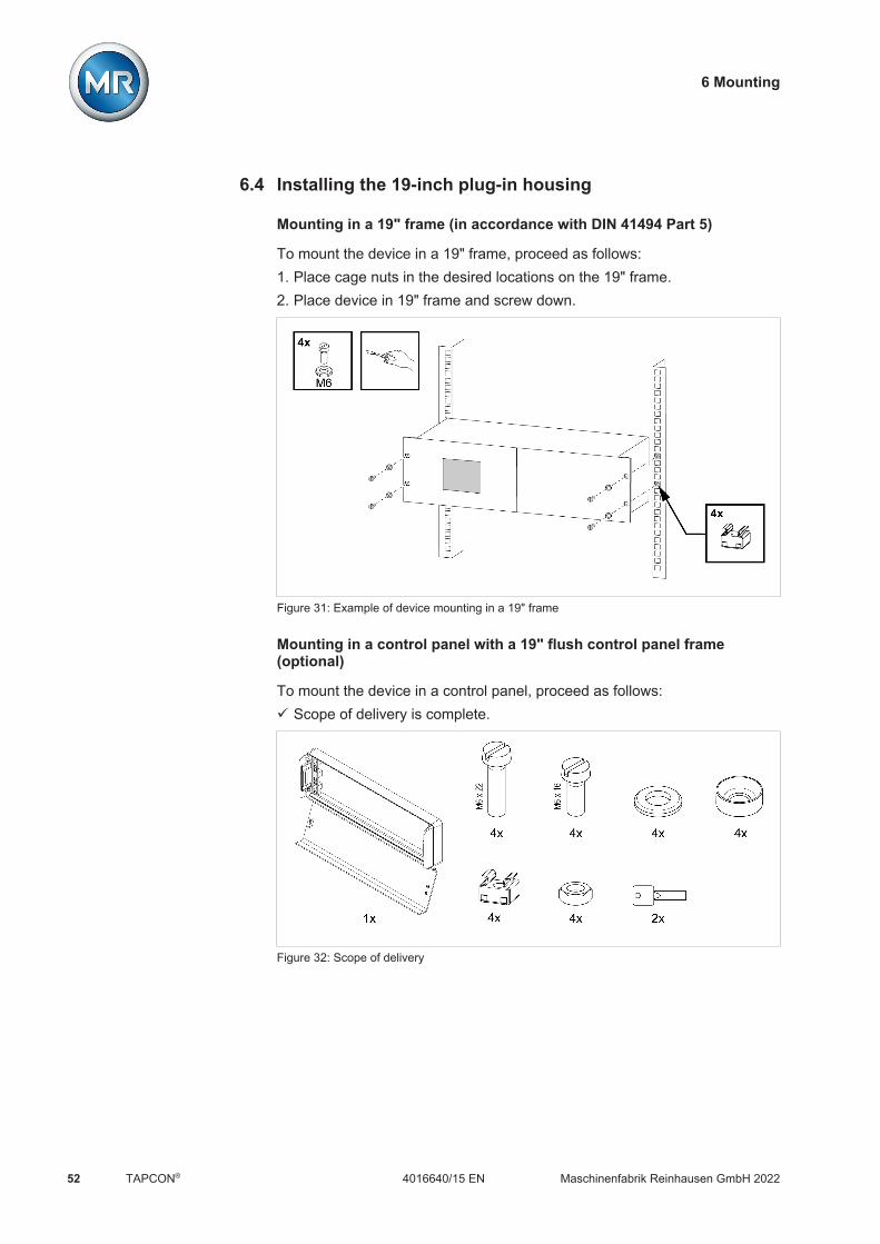
6 Mounting
Maschinenfabrik Reinhausen GmbH 202252 4016640/15 ENTAPCON®
6.4 Installing the 19-inch plug-in housing
Mounting in a 19" frame (in accordance with DIN 41494 Part 5)
To mount the device in a 19" frame, proceed as follows:1. Place cage nuts in the desired locations on the 19" frame.2. Place device in 19" frame and screw down.
Figure 31: Example of device mounting in a 19" frame
Mounting in a control panel with a 19" flush control panel frame(optional)
To mount the device in a control panel, proceed as follows:ü Scope of delivery is complete.
Figure 32: Scope of delivery

6 Mounting
Maschinenfabrik Reinhausen GmbH 2022 534016640/15 EN TAPCON®
1. Produce the cut-out in the control panel.
Figure 33: Producing the cut-out in the control panel
2. Mounting cage nuts
Figure 34: Mounting cage nuts
3. Secure frame to control panel.
Figure 35: Securing frame to control panel
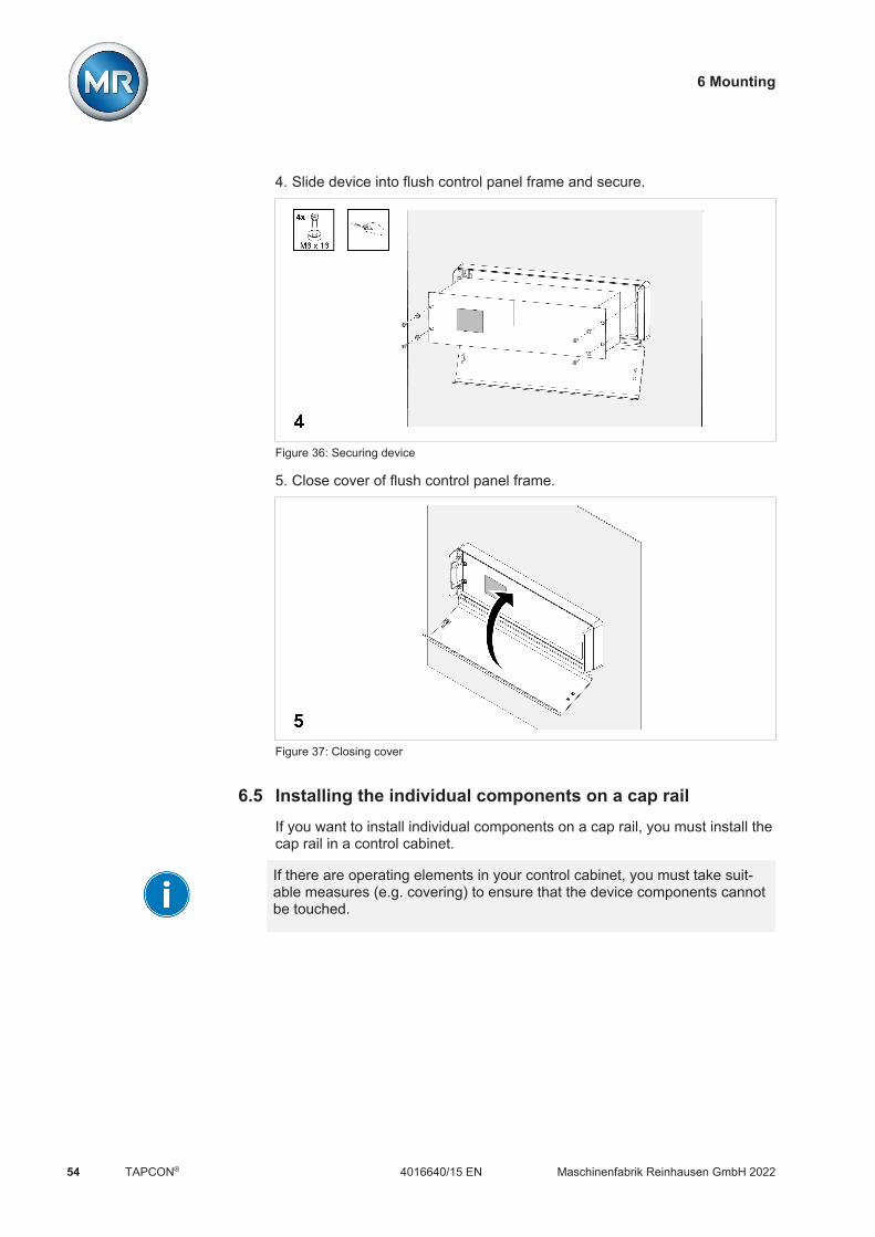
6 Mounting
Maschinenfabrik Reinhausen GmbH 202254 4016640/15 ENTAPCON®
4. Slide device into flush control panel frame and secure.
Figure 36: Securing device
5. Close cover of flush control panel frame.
Figure 37: Closing cover
6.5 Installing the individual components on a cap railIf you want to install individual components on a cap rail, you must install thecap rail in a control cabinet.
If there are operating elements in your control cabinet, you must take suit-able measures (e.g. covering) to ensure that the device components cannotbe touched.
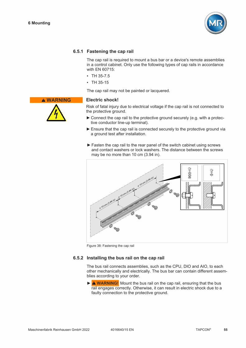
6 Mounting
Maschinenfabrik Reinhausen GmbH 2022 554016640/15 EN TAPCON®
6.5.1 Fastening the cap rail
The cap rail is required to mount a bus bar or a device's remote assembliesin a control cabinet. Only use the following types of cap rails in accordancewith EN 60715: TH 35-7.5 TH 35-15
The cap rail may not be painted or lacquered.
WARNING Electric shock!Risk of fatal injury due to electrical voltage if the cap rail is not connected tothe protective ground. Connect the cap rail to the protective ground securely (e.g. with a protec-
tive conductor line-up terminal). Ensure that the cap rail is connected securely to the protective ground via
a ground test after installation.
Fasten the cap rail to the rear panel of the switch cabinet using screwsand contact washers or lock washers. The distance between the screwsmay be no more than 10 cm (3.94 in).
≤ 10 cm (3.94 in)≤ 10 cm (3.94 in)
≤ 10 cm (3.94 in)
Figure 38: Fastening the cap rail
6.5.2 Installing the bus rail on the cap rail
The bus rail connects assemblies, such as the CPU, DIO and AIO, to eachother mechanically and electrically. The bus bar can contain different assem-blies according to your order.
WARNING! Mount the bus rail on the cap rail, ensuring that the busrail engages correctly. Otherwise, it can result in electric shock due to afaulty connection to the protective ground.

6 Mounting
Maschinenfabrik Reinhausen GmbH 202256 4016640/15 ENTAPCON®
Figure 39: Hooking the bus rail into position
6.5.3 Installing the assembly at a distance on the cap rail
As an option, the device can have the following assemblies that must bemounted at a distance on the cap rail: DIO 28-15 DIO 42-20 MC 2-2 SW 3-3 G1 (PULS)ü Cap rail fastened to the rear panel of the cabinet [Section 6.5.1, Page
55].
WARNING! A faulty connection to the protective ground can lead toan electric shock in the event of faults. Hook the assembly onto the caprail at the specified location, ensuring that the assembly engages cor-rectly.

6 Mounting
Maschinenfabrik Reinhausen GmbH 2022 574016640/15 EN TAPCON®
Figure 40: Example: Hooking on DIO and SW assemblies
6 Mounting
Maschinenfabrik Reinhausen GmbH 202258 4016640/15 ENTAPCON®
6.6 Connecting the deviceThe following section describes how to establish the electrical connection tothe device.
WARNING Electric shock!Connection errors can lead to death, injury or property damage. Ground the device with a protective conductor using the grounding screw
on the housing. Note the phase difference of the secondary terminals for the current
transformer and voltage transformer. Connect the output relays correctly to the motor-drive unit.
Supply the voltage via separators and ensure that current paths can beshort circuited. Fit the separator, clearly labeled, close to the device's powersupply so that it is freely accessible. This ensures that the device can be re-placed with ease in the event of a defect.
Wiring information
Note this procedure for the wiring: To obtain a better overview when connecting cables, only use as many
cables as necessary. Note the connection diagram. Only use the specified cables for wiring. Note the cable recommendation.
6.6.1 Cable recommendation
Please note the following Maschinenfabrik Reinhausen GmbH recommenda-tion when wiring the device. Excessive line capacitance can prevent the relay contacts from interrupt-
ing the contact current. In control circuits operated with alternating current,take into account the effect of the line capacitance of long control cableson the function of the relay contacts.
If you want to route Ethernet connections from a control cabinet or build-ing, we recommend using fiber-optic cables (in accordance with theIEC 61850-90-4 recommendation).
Ensure that the copper cables used have a temperature resistance of70°C.
Cable Assembly Type Cross section Material Max. length
Power supply (external) OT1205, G1 PULSQS3.241
Unshielded 1.5 mm² Copper -
Power supply (internal,24 V DC)
CPU, DIO, AIO,MC, SW
Unshielded 1.5 mm² Copper -
Voltage measurement UI Shielded 2.5 mm² Copper -

6 Mounting
Maschinenfabrik Reinhausen GmbH 2022 594016640/15 EN TAPCON®
Cable Assembly Type Cross section Material Max. length
Current measurement UI Unshielded 4 mm² Copper -
Digital signal inputs DIO Shielded 1.5 mm2 Copper 400 m (<25 Ω/km)
Digital signal outputs* DIO Shielded 1.5 mm2 Copper -
Analog signal inputs AIO Shielded 1 mm2 Copper 400 m (<25 Ω/km)
Analog signal outputs AIO Shielded 1 mm2 Copper -
RS232, SUB-D CPU Shielded 0.25 mm2 - 25 m
RS485; SUB-D CPU Shielded 0.25 mm2 - 140 m
CAN bus CPU Shielded 0.75 mm² - 2000 m (entireCAN bus)
Ethernet RJ45 CPU Min. CAT5,shielded S/FTP
- - 100 m
Ethernet FO MC, SW Duplex LCMultimode, OM3,1310 nm
- 2000 m
Table 18: Recommendation for connection cables
*) Observe line capacitance, see note above.
6.6.2 Information about connecting serial interfaces RS232 and RS485(with 9-pin data cable)
NOTICE Damage to the device!Using the wrong data cable may damage the device. Only use data cables which comply with the description below.
RS232 (D-SUB 9-pin)
To connect the device via the RS232 interface (COM2), use a data cablewith the following structure:
Figure 41: RS232 data cable (9-pin)

6 Mounting
Maschinenfabrik Reinhausen GmbH 202260 4016640/15 ENTAPCON®
RS485 (D-SUB 9-pin)
To connect the device via the RS485 interface (COM2), use a data cablewith the following structure:
Figure 42: RS485 data cable
D-SUB 9-pin plug connection
Only use 9-pin D-SUB plugs with the following characteristics: Plug housing is metallic or metal-plated Cable shielding is connected with the plug using one of the following two
variants:– Shielding is screwed down with traction relief.– Shielding is soldered to the plug housing.
Figure 43: Example of a soldered shielding on a plug housing

6 Mounting
Maschinenfabrik Reinhausen GmbH 2022 614016640/15 EN TAPCON®
6.6.3 Information about laying fiber-optic cable
To ensure the smooth transfer of data via the fiber-optic cable, you must en-sure that mechanical loads are avoided when laying the fiber-optic cable andlater on during operation. Also observe the information from the manufac-turer of the fiber-optic cable and the following instructions: Radii must not fall below the minimum permissible bend radii (do not bend
fiber-optic cable). The fiber-optic cables must not be over-stretched or crushed. Observe the
permissible load values. The fiber-optic cables must not be twisted. Be aware of sharp edges because they can damage the fiber-optic cable's
coating during laying or can place mechanical loads on the coating lateron.
Provide a sufficient cable reserve near distributor cabinets. Lay the re-serve such that the fiber-optic cable is neither bent nor twisted when tight-ened.
6.6.4 Mounting terminating resistor of CAN bus
If you want to operate the device in parallel operation, you need to mount a120 Ω terminating resistor at both ends of the CAN bus. Use the plug con-nector with terminating resistor provided as an option.
Figure 44: Terminating resistor of CAN bus
6.6.5 Connecting cables to the system periphery
To obtain a better overview when connecting cables, only use as manyleads as necessary.

6 Mounting
Maschinenfabrik Reinhausen GmbH 202262 4016640/15 ENTAPCON®
To connect cables to the system periphery, proceed as follows:ü Use only the specified cables for wiring. Note the cable recommendation. Connect the lines to be wired to the device to the system periphery as
shown in the connection diagrams supplied.
6.6.6 Wiring the CPU assembly1. Connect the ETH 2.2 interface to a PC to access the web-based visualiza-
tion.
Figure 45: Connection to a PC via Ethernet interface

6 Mounting
Maschinenfabrik Reinhausen GmbH 2022 634016640/15 EN TAPCON®
2. Connect the ETH 1 interface to the control system (SCADA) in accor-dance with the connection diagram.
Figure 46: SCADA connection
Observe the information on connecting serial interfaces [Section 6.6.2,Page 59].
3. As an alternative to step 2, connect the COM 2 interface (D-Sub 9-pole) tothe control system (SCADA) in accordance with the connection diagram.
Figure 47: Serial SCADA connection via COM 2 interface

6 Mounting
Maschinenfabrik Reinhausen GmbH 202264 4016640/15 ENTAPCON®
6.6.7 Wiring the UI assembly
You must fuse the voltage measurement circuit in accordance with the con-ductor cross section used. You can use the following fuse types:
Miniature circuit breaker Safety fuse
Standard IEC 60947-2 IEC 60269
Rated voltage 400 V (L-L) or 230 V (L-N)
Rated current 30 mA...16 A
Characteristics B, C, K or Z Fast-acting, medium-act-ing or delayed-acting
Rated switching capacity 50 kAFor installation in accordance with IEC 61010-2-30
CAT II: 10 kA
Table 19: Permissible fuse types
To wire the UI assembly, proceed as follows:1. Guide the cables into the corresponding plug terminals and fasten them
using a screwdriver.
Figure 48: Example: Plug for voltage measurement
Figure 49: Example: Plug for current measurement

6 Mounting
Maschinenfabrik Reinhausen GmbH 2022 654016640/15 EN TAPCON®
2. Insert the plugs into the respective slots and engage the plug.
Figure 50: Engaging the plug
6.6.8 Wiring the AIO 2/AIO 4/AIO 8 assembly
In order to correctly record the analog signals, you must place the cableshielding on the grounding bar. The cable shielding should only be removedjust prior to connecting, to ensure that the section with unshielded cables iskept as short as possible. The shielding must be connected with shieldingclips.
1
32
45
11
1312
1415
6
87
910
16
1817
1920
RDYAIO 4
+
-
24V
DC
1112131415161718
2019
123456789
10
Figure 51: Examples of supporting shielding on grounding bar (on left: Direct connection to AIOassembly, on right: Connection using line-up terminal)

6 Mounting
Maschinenfabrik Reinhausen GmbH 202266 4016640/15 ENTAPCON®
Plug assignment
The AIO 2, AIO 4 and AIO 8 assemblies have a separate plug connector foreach channel (input or output). The plugs are assigned as follows:
1
32
45
11
1312
1415
6
87
910
16
1817
1920
RDYAIO
+
-
24V
DC
1
32
45
1
2
3
4
5
Figure 52: Plug assignment of AIO 2 and AIO 4 assemblies
Interface Pin Description
1 6 11 16 I OUT (+): Current output +
2 7 12 17 I/U IN (+) U OUT (+): Voltage input+, current input +, voltage output +
3 8 13 18 I/U IN (-): Voltage input -, current in-put -
4 9 14 19 I/U OUT (-): Voltage output -, currentoutput -
5 10 15 20 Not used
Table 20: Analog inputs and outputs
You can connect the following types of analog sensors: 0/4...20 mA 0...10 V PT100/PT1000 (2-wire, 3-wire, 4-wire)
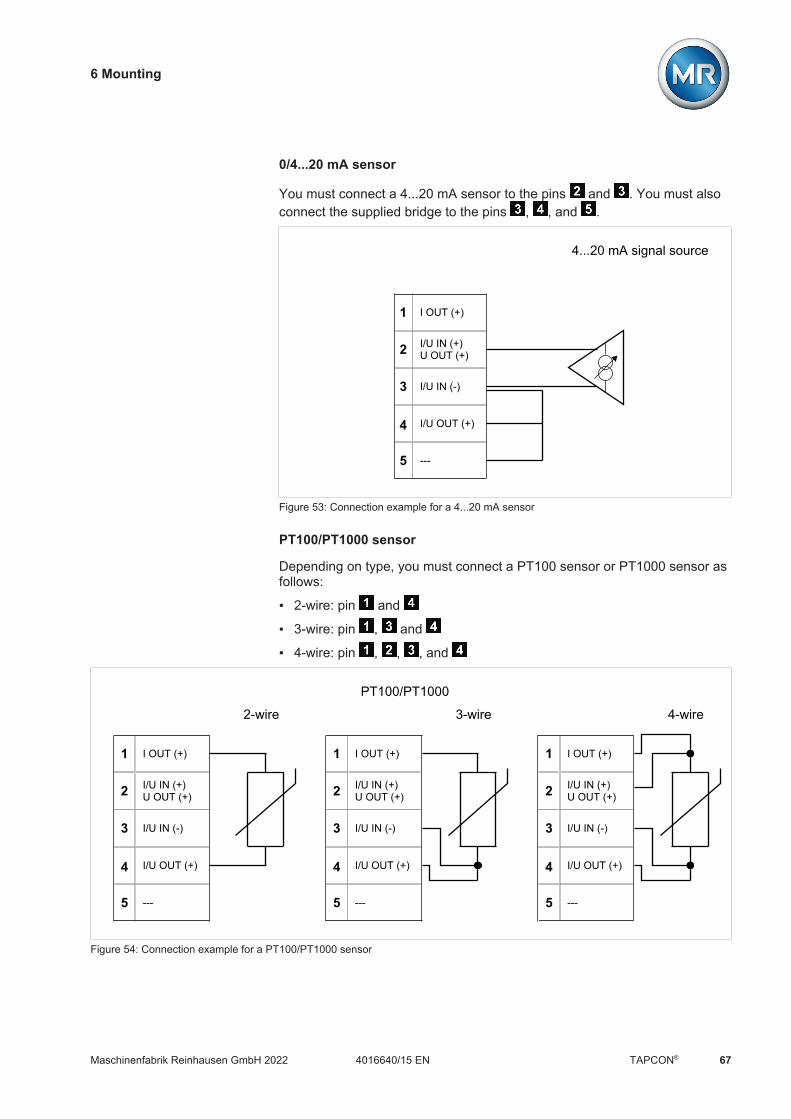
6 Mounting
Maschinenfabrik Reinhausen GmbH 2022 674016640/15 EN TAPCON®
0/4...20 mA sensor
You must connect a 4...20 mA sensor to the pins and . You must alsoconnect the supplied bridge to the pins , , and .
I OUT (+)
I/U IN (+)U OUT (+)
I/U IN (-)
I/U OUT (+)
1
2
3
4
5 ---
4...20 mA signal source
Figure 53: Connection example for a 4...20 mA sensor
PT100/PT1000 sensor
Depending on type, you must connect a PT100 sensor or PT1000 sensor asfollows:
2-wire: pin and
3-wire: pin , and
4-wire: pin , , , and
I OUT (+)
I/U IN (+)U OUT (+)
I/U IN (-)
I/U OUT (+)
1
2
3
4
5 ---
2-wire
I OUT (+)
I/U IN (+)U OUT (+)
I/U IN (-)
I/U OUT (+)
1
2
3
4
5 ---
3-wire
I OUT (+)
I/U IN (+)U OUT (+)
I/U IN (-)
I/U OUT (+)
1
2
3
4
5 ---
4-wirePT100/PT1000
Figure 54: Connection example for a PT100/PT1000 sensor

6 Mounting
Maschinenfabrik Reinhausen GmbH 202268 4016640/15 ENTAPCON®
Wiring analog inputs/outputs1. Guide the leads into the plug terminal and fasten them using a screw-
driver.
Figure 55: Inserting the leads into the plug connector
2. Insert and screw the plug into the respective slot in accordance with thesupplied connection diagram.
Figure 56: Fastening the plug (analog inputs/outputs)

6 Mounting
Maschinenfabrik Reinhausen GmbH 2022 694016640/15 EN TAPCON®
6.6.9 Wiring the DIO assembly1. Guide the leads into the plug terminal in accordance with the supplied
connection diagram and fasten them using a screwdriver.
Figure 57: Inserting the leads
2. Insert and screw the plug into the respective slot in accordance with thesupplied connection diagram.
Figure 58: Fastening the plug

6 Mounting
Maschinenfabrik Reinhausen GmbH 202270 4016640/15 ENTAPCON®
6.6.10 Wiring the MC 2-2/SW3-3 assembly1. Insert the supplied SFP module into the corresponding Ethernet interface
in accordance with the connection diagram and fold the clasp down.
Figure 59: Engaging the SFP module
2. Remove the SFP module dust plug.
Figure 60: Removing the dust plug
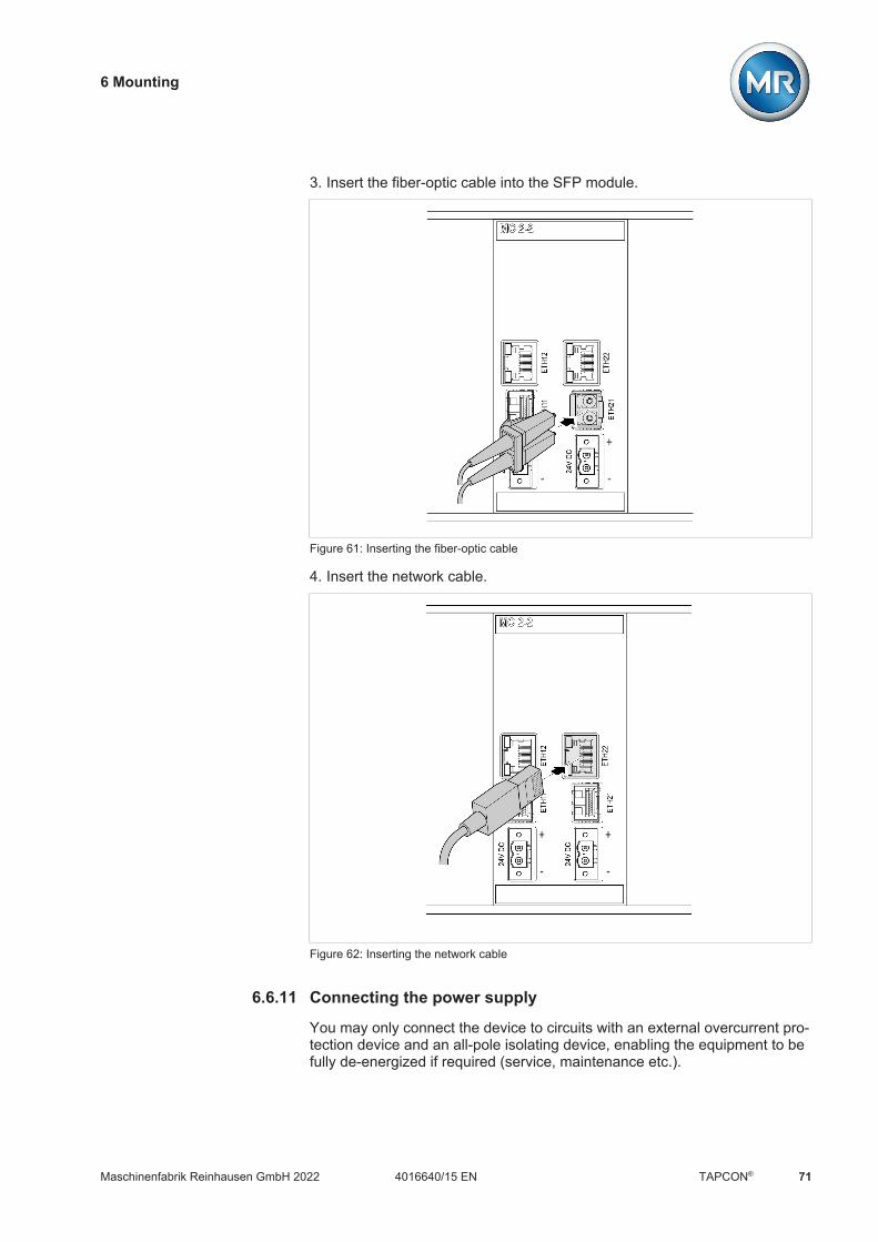
6 Mounting
Maschinenfabrik Reinhausen GmbH 2022 714016640/15 EN TAPCON®
3. Insert the fiber-optic cable into the SFP module.
Figure 61: Inserting the fiber-optic cable
4. Insert the network cable.
Figure 62: Inserting the network cable
6.6.11 Connecting the power supply
You may only connect the device to circuits with an external overcurrent pro-tection device and an all-pole isolating device, enabling the equipment to befully de-energized if required (service, maintenance etc.).

6 Mounting
Maschinenfabrik Reinhausen GmbH 202272 4016640/15 ENTAPCON®
Suitable equipment includes isolating devices in accordance with IEC60947-1 and IEC 60947-3 (e.g. circuit breaker). Note the properties of therelevant circuits (voltage, maximum currents) when selecting the circuitbreaker type. In addition, observe the following: It must be easy for the operator to access the isolating device The isolating device must be labeled for the device and circuits to be iso-
lated The isolating device may not be a part of the power line The isolating device may not interrupt the main protective conductor
Miniature circuit breaker You must fuse the power supply circuit with a miniature circuit breaker. Theminiature circuit breaker must have the following properties: Rated current: 6 to 20 A Triggering characteristic: B or C
Conductor cross-section For the power supply circuit, use a conductor cross-section suitable for theminiature circuit breaker that you have selected, but at least 1.5 mm2 (AWG15).
Connecting the voltage supply
To connect the voltage supply, proceed as follows: Connect the voltage supply in accordance with the connection diagram
provided.
6 Mounting
Maschinenfabrik Reinhausen GmbH 2022 734016640/15 EN TAPCON®
6.7 Checking functional reliabilityTo ensure that the device is wired correctly, check its functionality.
NOTICE Damage to device and system periphery!An incorrectly connected device can cause damage to the device and sys-tem periphery. Check the entire configuration before commissioning. Prior to commissioning, check the supply voltage and the measured volt-
age.
Check the following: Once you have connected the device to the grid, the display shows the
MR logo and then the operating screen. The voltage display LED on the top left of the device's front panel lights
up.
The device is fully mounted and can be configured. The actions required forthis are described in the following chapter.
7 Commissioning
Maschinenfabrik Reinhausen GmbH 202274 4016640/15 ENTAPCON®
7 CommissioningYou need to set several parameters and perform function tests before com-missioning the device. These are described in the following sections.
NOTICE Damage to device and system peripheryAn incorrectly connected device can lead to damage to the device and sys-tem periphery. Check the entire configuration before commissioning.
7.1 Performing tests
Please contact Maschinenfabrik Reinhausen GmbH (MR) if any aspect ofthe tests is not clear.
7.1.1 Ground test
For commissioning, carry out a ground test (check of the impedance of theprotective bonding) in accordance with IEC 61010-1. Note the following in-formation: Test current: 2 times the measurement current of the overcurrent protec-
tion device of the supply line. Test duration: 1 minute for each measurement point. The measured voltage between the measurement point and the protective
conductor must be smaller than 10 V.

7 Commissioning
Maschinenfabrik Reinhausen GmbH 2022 754016640/15 EN TAPCON®
Proceed as follows to carry out the ground test:1. Feed the test current at the fixing screw of assembly DIO 28-15 or DIO
42-20 using a constant current source and measure the voltage betweenthe measurement point and the protective conductor.ð The measured voltage must remain less than 10 V over a duration of 1
minute.
Figure 63: Perform a ground test on the DIO assembly (sample representation of the DIO 28-15assembly).
2. Feed the test current at the grounding terminal of the G1 PULS DIMEN-SION QS3.241 assembly using a constant current source and measurethe voltage between the measurement point and the protective conductor.
ð The measured voltage must remain less than 10 V over a duration of 1minute.

7 Commissioning
Maschinenfabrik Reinhausen GmbH 202276 4016640/15 ENTAPCON®
Figure 64: Perform a ground test on the G1 PULS DIMENSION QS3.241 assembly
7.1.2 Performing a dielectric test
The device is tested before delivery. Note the following points if you wouldlike to perform a dielectric test:
NOTICE Damage to the device!A dielectric test with a test voltage that is greater than the maximum permit-ted test voltage can lead to the device being damaged. Perform the dielectric test with a test voltage that is less than or equal to
the maximum permitted test voltage. Perform the dielectric test using the permitted interfaces only.
Depending on the device configuration, you may only test the assemblieslisted below. You may not test any other assemblies.
Assembly Interfaces Test parameters
Max. test voltage Max. test dura-tion
Ramp Breaking currentthreshold
OT1205 (MR/N)1 N, L 2.2 kV AC 2 s 5 s > 10 mA
UI 1 N, Lk, l
2.2 kV AC 2 s 5 s > 4 mA
UI 3 N, L1, L2, L3k1, l1, k2, l2, k3, l3
2.2 kV AC 2 s 5 s > 4 mA
UI 5-3, UI 5-4 N, L1, L2, L3k1, l1, k2, l2, k3, l3
2.2 kV AC 2 s 5 s > 4 mA

7 Commissioning
Maschinenfabrik Reinhausen GmbH 2022 774016640/15 EN TAPCON®
Assembly Interfaces Test parameters
Max. test voltage Max. test dura-tion
Ramp Breaking currentthreshold
DIO 28-15DIO 42-20DIO 42-20 HL
any DI, DO 2.2 kV AC 2 s 5 s > 1 mA
G1 (PULS) N, L 2.2 kV AC 2 s 5 s > 4 mA
Table 21: Permitted interfaces and test parameters for the dielectric test
1) only the version with 85...265 V AC/V DC wide-range power supply, other-wise the device may be damaged. Note the nameplate.
Sample dielectric test set-up
Figure 65: Sample set-up of the dielectric test for a device designed with the OT 1205 wide-range power supply

7 Commissioning
Maschinenfabrik Reinhausen GmbH 202278 4016640/15 ENTAPCON®
Figure 66: Sample dielectric test set-up for a device designed with the G1 (PULS) power supply

7 Commissioning
Maschinenfabrik Reinhausen GmbH 2022 794016640/15 EN TAPCON®
7.2 Establishing connection to visualizationA connection to the visualization can be established using 2 interfaces: Front interface ETH1.1 (for local access) Optional: ETH2.2 interface on the CPU I module (for access by means of
the remote display, control center etc.)
System requirements
To access the web-based visualization, you need a PC with an HTML5-ca-pable browser. The display is optimized for the following browsers: Microsoft Edge Google Chrome™
Establishing connection via front interface
The device is equipped with a DHCP server for connection via the front inter-face. To establish a connection via the front interface, proceed as follows:1. Connect the PC and device via the front interface using an Ethernet cable
(RJ45 plug).
Figure 67: Establishing a connection via the front interface
2. Activate automatic assignment of the IP address via DHCP on the PC.3. Enter the visualization's IP address http://192.168.165.1, or if SSL
encryption is active enter https://192.168.165.1, in the browser onthe PC.
ð The visualization is accessed.

7 Commissioning
Maschinenfabrik Reinhausen GmbH 202280 4016640/15 ENTAPCON®
Establishing connection via the rear ETH2.2 interface on the CPU Imodule
To connect via the rear interface, proceed as follows:1. Connect PC and device via rear ETH2.2 interface using Ethernet cable
(RJ45 plug).
Figure 68: Establishing a connection via the rear ETH2.2 interface
2. Go to Communication on the device to display the device's IP address.
Figure 69: Displaying the Communication menu item
3. Assign a unique IP address to the PC in the same subnet as the device(e.g. 192.0.1.100).
4. Enter the visualization's IP address (e.g. http://192.0.1.230, if SSLencryption is active enter https://192.0.1.230) in the browser on thePC.
ð The visualization is accessed.

7 Commissioning
Maschinenfabrik Reinhausen GmbH 2022 814016640/15 EN TAPCON®
7.3 Setting the languageYou can use this parameter to set the display language for the device. Thedevice comes with a maximum of four languages.
English Italian*
German Portuguese*
French* Russian*
Spanish* Chinese*
Korean* Polish*
Table 22: Available display languages
*) Language is available as an option1. Select the Language button in the status bar, or as an alternative, go to
Settings> System > General > Language.
Figure 70: Setting the language
2. Select the desired language from the list box.3. Press the Accept button to save the modified parameter.
ð The "Restart device" dialog appears.4. Restart the device to apply the changed language setting.
Downloading the operating instructions
Download the operating instructions from the device to start device commis-sioning and parameterization. Select in the status line.ð The operating instructions will be downloaded.
The document is also available for download in the MR Customer Portal andon our website www.reinhausen.com.
7.4 Setting date and timeYou can set the date and time in the following ways: Manually Time synchronization via control system (SCADA) Time synchronization via SNTP time server
If you are using a control system, the device automatically synchronizes thedate and time with the control system. If you would like to use an SNTP timeserver, you must set the required parameters.
For more information, refer to the information in the section Setting the de-vice time [Section 8.2.4, Page 98].
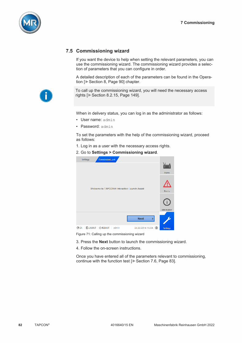
7 Commissioning
Maschinenfabrik Reinhausen GmbH 202282 4016640/15 ENTAPCON®
7.5 Commissioning wizardIf you want the device to help when setting the relevant parameters, you canuse the commissioning wizard. The commissioning wizard provides a selec-tion of parameters that you can configure in order.
A detailed description of each of the parameters can be found in the Opera-tion [Section 8, Page 90] chapter.
To call up the commissioning wizard, you will need the necessary accessrights [Section 8.2.15, Page 149].
When in delivery status, you can log in as the administrator as follows: User name: admin Password: admin
To set the parameters with the help of the commissioning wizard, proceedas follows:1. Log in as a user with the necessary access rights.2. Go to Settings > Commissioning wizard.
Figure 71: Calling up the commissioning wizard
3. Press the Next button to launch the commissioning wizard.4. Follow the on-screen instructions.
Once you have entered all of the parameters relevant to commissioning,continue with the function test [Section 7.6, Page 83].

7 Commissioning
Maschinenfabrik Reinhausen GmbH 2022 834016640/15 EN TAPCON®
7.6 Function testsBefore switching from manual mode to auto mode, Maschinenfabrik Rein-hausen recommends carrying out function tests. These function tests are de-scribed in the following sections. Note the following points for all functiontests: You must ensure that REMOTE mode is disabled before you can control
the on-load tap-changer manually in manual mode. You can only activate the on-load tap-changer manually in manual mode
using the and keys. You have to be logged in to the device as a user with a parameter config-
urator or administrator user role.
When in delivery status, you can log in as the administrator as follows: User name: admin Password: admin
During the function test, you must set the most important parameters. Detailson the parameters listed can be found in the Operation [Section 8, Page90] chapter.
7.6.1 Checking measured values and status of digital inputs andoutputs
Upon commissioning the device, check whether the measured values andstatus of digital inputs and outputs are plausible. To do so, use an additionalmeasuring device if necessary in order to check the individual measured val-ues.
To display the status of the digital inputs and outputs, proceed as follows:1. Go to Information > Hardware.2. Select the individual assemblies one after another and check the individ-
ual measured values or the status of digital inputs and outputs.3. If errors arise, check the measurement path and the wiring [Section 6.6,
Page 58].
7.6.2 Testing a control function
This section describes how you can check the device's control functions:ü Supply voltage must be present.
1. Press to select manual mode.2. Set transmission ratio for voltage transformer, current transformer, and
transformer circuit.3. Measure actual voltage and compare with the measured value displayed
on the device's main screen.

7 Commissioning
Maschinenfabrik Reinhausen GmbH 202284 4016640/15 ENTAPCON®
4. Select the Measured values menu item to display the operating valuesfor current and power and compare them with the values of the operationmeasurement instruments.
5. Control the on-load tap-changer manually using the or keysuntil the measured voltage Uactual reaches the desired voltage Udesired ("de-sired value 1").
6. Set desired value to the value you want [Section 8.4.2.1, Page 222].7. Set bandwidth depending on step voltage [Page 235].8. Set delay time T1 to 20 seconds [Page 236].9. Set time response T1 to linear [Page 236].
10. Press to raise the on-load tap-changer 1 step.
11. Press to select auto mode.ð If the actual voltage is outside the bandwidth, the device returns the
on-load tap-changer to the original operating position after 20 sec-onds.
12. Press to select manual mode.
13. Press to lower the on-load tap-changer 1 step.
14. Press to select auto mode.ð If the actual voltage is outside the bandwidth, the device returns the
on-load tap-changer to the original operating position after 20 sec-onds.
15. Press to select manual mode.16. Set delay time T2 to 10 seconds and activate it [Page 238].
17. Press twice to raise the on-load tap-changer 2 steps.
18. Press to select auto mode.ð If the actual voltage is outside the bandwidth, after 20 seconds the de-
vice lowers the on-load tap-changer one step and after another 10seconds another step.
19. Press to select manual mode.20. Set delay time T1 [Page 236] and delay time T2 [Page 238] to the
desired value.
We recommend a temporary setting of 100 seconds for delay time T1 whencommissioning the transformer. Depending on the operating conditions, youcan also specify the delay time following a longer observation period. In thisregard, it is useful to register how the actual voltage progresses and thenumber of tap-change operations per day.
7.6.3 Checking parallel operation
This section describes how you can run the function test for parallel opera-tion.

7 Commissioning
Maschinenfabrik Reinhausen GmbH 2022 854016640/15 EN TAPCON®
Requirements To obtain perfect functioning in parallel operation, the device must be com-missioned in independent mode. Make sure that the conditions below havebeen fulfilled. All devices are set to the same operating parameters for "desired value"
and "delay time T1" [Page 236]. The "Activate parallel operation" [Page 251] parameter is set to ON The desired Parallel operation method is selected. A different CAN bus address [Page 252] (≠ 0) is set for all devices. All devices are in the same parallel operation group:
– With parallel operation detection via group input: A signal is present atthe same group input on all devices.
– With parallel operation detection via topology: The circuit breakers areconfigured and connected such that the devices participate in paralleloperation.
7.6.3.1 Setting circulating reactive current sensitivity
This section describes how you set the circulating reactive current sensitivityto check the function of the "circulating reactive current minimization" paralleloperation method.
Note that the following prerequisites must be met for the "circulating reactivecurrent minimization" parallel operation method: You have to use current transformers with the same rated values for all
transformers in parallel operation. If you wish to operate in parallel operation with existing devices, you have
to activate the Retrofit TAPCON® 2xx [Section 8.3.8, Page 216] param-eter.
Consult the section Circulating reactive current minimization [Section8.4.4.1.2, Page 245] for more information.
To set the circulating reactive current sensitivity, proceed as follows:1. Select the "Circulating reactive current" parallel operation method [Page
251].2. Set circulating reactive current sensitivity to a value of 0% [Page 252].3. If necessary, activate the Retrofit TAPCON® 2xx function [Section
8.3.8, Page 216].4. Adjust both transformers in independent mode to the same actual voltage
using on-load tap-changers.5. Connect the transformers in parallel and enable the parallel control.
ð The status display in the Parallel operation menu lights up blue.ð The two TAPCON® must be within the bandwidth.
6. Set the desired value of both TAPCON® to the voltage currently mea-sured [Section 8.4.2.1, Page 222].
7 Commissioning
Maschinenfabrik Reinhausen GmbH 202286 4016640/15 ENTAPCON®
7. On one of the two transformers, raise the tap position of the on-load tap-changer by one setting; on the second transformer, lower the tap positionof the on-load tap-changer by one setting.ð The two TAPCON® are still within the bandwidth.
8. Increase the circulating reactive current sensitivity in small steps until thecontrol deviation dU in the main screen is outside the bandwidth (depend-ing on TAPCON® greater than or less than the bandwidth).
9. Press to select auto mode for all TAPCON® units.ð All of the TAPCON® units return the on-load tap-changer units to the
original tap positions.
If an on-load tap-changer does not switch back to its original tap position,you have to increase the circulating reactive current sensitivity.If one of the on-load tap-changer units switches one or more tap positionshigher and the other switches the same amount lower, you need to reducethe circulating reactive current sensitivity.
After you have set the circulating reactive current sensitivity, continue withthe function test for the circulating reactive current blocking limit described inthe next section.
7.6.3.2 Testing the circulating reactive current blocking limit
This section describes how to run the function test for circulating reactivecurrent blocking.ü Set the circulating reactive current blocking limit to a value of 20%
[Page 252].
1. Press on a TAPCON® to select manual mode.2. Using manual control, adjust the relevant motor-drive unit upwards (for ex-
ample 1...2 steps) by the maximum permitted tap difference in operatingpositions between the parallel operating transformers.
When setting the circulating reactive current blocking in the followingprocess step, wait approximately 2 to 3 seconds between the individualsteps.
3. In the Parallel operation > Parallel operation method menu item, setthe circulating reactive current parallel operation method.
4. Reduce the circulating reactive current blocking limit parameter from theset value of 20% in steps of 1% until the message Circulating reactive cur-rent blocking limit exceeded is displayed.ð Any further regulation is blocked.ð After the set delay time for the parallel operation error message has
elapsed, the circulating reactive current blocking message is displayed.5. Increase the circulating reactive current blocking limit parameter again un-
til the message Circulating reactive current limit exceeded disappears.

7 Commissioning
Maschinenfabrik Reinhausen GmbH 2022 874016640/15 EN TAPCON®
6. Press to select auto mode.ð The motor-drive unit automatically returns to the original operating posi-
tion.7. Set the value determined for the "circulating reactive current blocking
limit" for the TAPCON® units in parallel operation as well.
If one TAPCON® or all of the TAPCON® units indicate Circulating reactivecurrent blocking limit exceeded even though the control inputs are correctlyconnected for all TAPCON® units, all of the TAPCON® units block.This could be due to various causes. Further information is given in thechapter Troubleshooting [Section 10, Page 292].
ð The function test for the circulating reactive current blocking limit is com-plete.
7.6.3.3 Checking tap synchronization method
This section describes how to run the function test for tap synchronization(master/follower).
In parallel operation in accordance with the Automatic tap synchroniza-tion method, the tap positions of the transformers running in parallel arecompared. It is therefore necessary that the transformers have the sameposition designation and that the Raise and Lower signals produce thesame voltage change in all transformers.
NOTICE Damage resulting from formation of circulating reactive currentIf the parameters are not set correctly, damage may result from the forma-tion of circulating reactive current and the resulting overload of transmissionlines and transformers. Check transformer nameplate. Set TAPCON® parameters in accordance with the configuration of the
transformers.
Before starting the function test, you must carry out the following steps:1. Assign the master function to one TAPCON® [Page 251].2. Assign the follower function to the other TAPCON® units.
3. Compare the tap position displays of master and follower . All ofthe TAPCON® units must display the same tap position. If this is not thecase, switch all TAPCON® units to the same tap position.

7 Commissioning
Maschinenfabrik Reinhausen GmbH 202288 4016640/15 ENTAPCON®
Home
Ereignisse
Information
Rekorder
EinstellungenDE CHANGE REBOOT admin 03.02.2020 08:09
Messwerte Regelparameter Parallellauf Kommunikation
Transformator
Stufenstellung
Spannung
dU
Strom
Leistungsfaktor
14
16
24.3 kV
1.3 %
198.0 A
0.98
15
24.0 kV
24.5 kV
23.5 kV
08:09:1608:08:4608:08:16
30 s
Home
Ereignisse
Information
Rekorder
EinstellungenDE CHANGE REBOOT admin 03.02.2020 08:09
Messwerte Regelparameter Parallellauf Kommunikation
Transformator
Stufenstellung
Spannung
dU
Strom
Leistungsfaktor
14
16
24.3 kV
1.3 %
198.0 A
0.98
15
24.0 kV
24.5 kV
23.5 kV
08:09:1608:08:4608:08:16
30 s
Home
Ereignisse
Information
Rekorder
EinstellungenDE CHANGE REBOOT admin 03.02.2020 08:09
Messwerte Regelparameter Parallellauf Kommunikation
Transformator
Stufenstellung
Spannung
dU
Strom
Leistungsfaktor
14
16
24.3 kV
1.3 %
198.0 A
0.98
15
24.0 kV
24.5 kV
23.5 kV
08:09:1608:08:4608:08:16
30 s
15 15 15
1 2 2
3 3 3
Figure 72: Comparing the tap position
1 Master 3 Tap position display
2 Follower
To perform the function test, proceed as follows:
1. Press on the follower to select manual mode.2. If necessary, set the follower tapping direction.
3. Press on the master to select manual mode.
4. Press or on the master to manually change the tap position.
5. Press on the follower to select auto mode.ð The follower switches to the same tap position as the master.
6. Press on the master to select auto mode.
7. Press on the follower to select manual mode.
8. Press or on the follower to manually change the tap position.ð After expiry of the set delay time for parallel operation errors [Page
254], there is a tap difference from the follower to the master.
9. Press several times on the follower to manually increase the tap po-sition by the number of permitted steps ("Maximum permitted tap differ-ence") and then one further step.ð After expiry of the set delay time for parallel operation errors, there is a
tap difference to follower on the master.ð After expiry of the set delay time for parallel operation errors, there is a
tap difference to master on the follower.
10. Press on the follower to select auto mode.ð There is no response. All devices remain blocked.
11. Press on the master and follower to select manual mode.

7 Commissioning
Maschinenfabrik Reinhausen GmbH 2022 894016640/15 EN TAPCON®
12. Press or on the master and follower to manually set the de-sired step.
ð The function tests for the tap synchronization method are complete.
Installation and commissioning of the device is complete.

8 Operation
Maschinenfabrik Reinhausen GmbH 202290 4016640/15 ENTAPCON®
8 OperationThis chapter describes all the functions and setting options for the device.
8.1 Carrying out tap-change operation manuallyIn manual mode, you can manually carry out an on-load tap-changer tap-change operation. To do this, you can choose whether you want to switch 1motor-drive unit individually (depending on configuration, transformers 1...4)or all motor-drive units at the same time (all transformers).
To undertake a manual tap-change operation, you will need the necessaryaccess rights [Section 8.2.15, Page 149].
To carry out a tap-change operation manually, proceed as follows:
1. If necessary, press to activate manual mode.
2. Press and hold down or .ð The transformer selection display appears.
3. Select the desired transformer or all transformers as required.ð The tap-change operation is carried out.
8.2 System
8.2.1 General
You can set general parameters in this menu item.

8 Operation
Maschinenfabrik Reinhausen GmbH 2022 914016640/15 EN TAPCON®
8.2.1.1 Setting general device functions
You can set general device functions with the following parameters.Settings Parameters General
Name Value
Language English
Commissioning wizard Yes
Auto-logout Off
Time until auto-logout 15.0 min
Measured value display Primary values
Transformer name Transformer
Remote behavior Hardware and SCADA
USB interface Off
Service user access activation Activated
SNMP Agent Off
Home
Events
Information
Recorder
SettingsEN CHANGE REBOOT admin 14.04.2020 14:22
Figure 73: General
1. Go to Settings > Parameters > System > General.2. Select the desired parameter.3. Set the parameter.4. Press the Accept button to save the modified parameter.
Commissioning wizard
You can use this parameter to set whether the commissioning wizard[Section 7.5, Page 82] is to launch automatically when the device isrestarted.
Measured value display
You can use this parameter to set whether the displayed measured valuesand control parameters are to refer to the primary side or secondary side ofthe measuring transducers.
Transformer name
You can use this parameter to enter a transformer name for identificationpurposes. The transformer name will be displayed on the main screen in thevisualization.
Remote behavior
You can use this parameter to select the behavior of the device in remoteoperating mode. Depending on the device configuration, you can set the re-mote behavior as follows: Through the visualization (optional) By setting the digital inputs (optional)
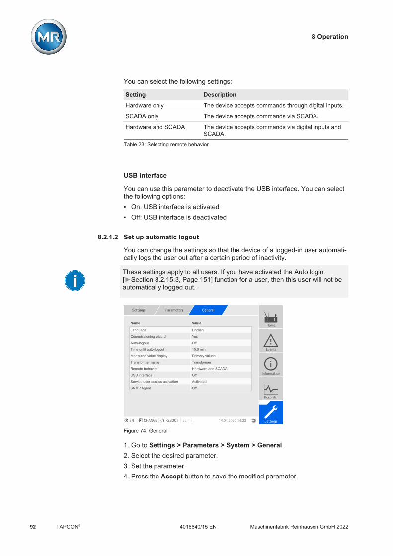
8 Operation
Maschinenfabrik Reinhausen GmbH 202292 4016640/15 ENTAPCON®
You can select the following settings:
Setting Description
Hardware only The device accepts commands through digital inputs.
SCADA only The device accepts commands via SCADA.
Hardware and SCADA The device accepts commands via digital inputs andSCADA.
Table 23: Selecting remote behavior
USB interface
You can use this parameter to deactivate the USB interface. You can selectthe following options: On: USB interface is activated Off: USB interface is deactivated
8.2.1.2 Set up automatic logout
You can change the settings so that the device of a logged-in user automati-cally logs the user out after a certain period of inactivity.
These settings apply to all users. If you have activated the Auto login[Section 8.2.15.3, Page 151] function for a user, then this user will not beautomatically logged out.
Settings Parameters General
Name Value
Language English
Commissioning wizard Yes
Auto-logout Off
Time until auto-logout 15.0 min
Measured value display Primary values
Transformer name Transformer
Remote behavior Hardware and SCADA
USB interface Off
Service user access activation Activated
SNMP Agent Off
Home
Events
Information
Recorder
SettingsEN CHANGE REBOOT admin 14.04.2020 14:22
Figure 74: General
1. Go to Settings > Parameters > System > General.2. Select the desired parameter.3. Set the parameter.4. Press the Accept button to save the modified parameter.

8 Operation
Maschinenfabrik Reinhausen GmbH 2022 934016640/15 EN TAPCON®
Auto logout
You can use this parameter to activate th automatic logout function.
Time until auto logout
You can use this parameter to set the time period of inactivity after which auser is automatically logged out.
8.2.1.3 Activating/deactivating service user access
The device is equipped with user access for the Maschinenfabrik Rein-hausen GmbH Technical Service department. This access is for error diag-nostics and troubleshooting in the event of device faults. Only activate ser-vice user access for a limited time period for remedying faults in order tosafeguard IT security.
If you deactivate the service user access and lose your password for the ad-ministrator role, it is not possible to reset the administrator password. If theadministrator password is lost, the device must be reset to the default set-tings. When doing so, all information stored on the device (parameters,measured values, etc.) will be lost.
Settings Parameters General
Name Value
Language English
Commissioning wizard Yes
Auto-logout Off
Time until auto-logout 15.0 min
Measured value display Primary values
Transformer name Transformer
Remote behavior Hardware and SCADA
USB interface Off
Service user access activation Activated
SNMP Agent Off
Home
Events
Information
Recorder
SettingsEN CHANGE REBOOT admin 14.04.2020 14:22
Figure 75: General
You must be assigned the administrator role to set parameters.
When in delivery status, you can log in as the administrator as follows: User name: admin Password: admin1. Go to Settings > Parameters > System > General.2. Select the desired parameter.3. Set the parameter.4. Press the Accept button to save the modified parameter.

8 Operation
Maschinenfabrik Reinhausen GmbH 202294 4016640/15 ENTAPCON®
5. Restart the device to apply the change.
Service user access activation
You can use this parameter to activate or deactivate service user access.
8.2.2 Configuring the network
You can use this menu item to configure the network interfaces of the CPUassembly.
You can only set the parameters for ETH 1 if the device is equipped with theoptional control system connection via Ethernet (TCP/IP): IEC 61850 IEC 60870-5-104 Modbus (Modbus type TCP active) DNP3 (DNP3 transmission type TCP active) MQTT
You can only set the parameters for ETH 2.2 if the device is equipped withthe optional interface for visualization.
Settings Parameters Network se...ngs
Name Value
IP address Eth 1 192.168.10.254
Subnet mask ETH 1 255.255.255.0
Gateway address ETH 1 0.0.0.0
Target address gateway ETH 1 0.0.0.0
IP address Eth 2.2 192.0.1.230
Subnet mask ETH 2.2 255.255.255.0
Gateway address ETH 2.2 0.0.0.0
Target address gateway ETH 2.2 0.0.0.0
Visualization release Only ETH 2.x
SSL/TLS encryption Off
TLS version >= 1.0
Home
Events
Information
Recorder
SettingsEN CHANGE REBOOT admin 01.03.2021 12:00
Figure 76: Network settings
1. Go to Settings > Parameters > System > Network settings.2. Select the desired parameter.3. Set the parameter.4. Press the Accept button to save the modified parameter.
IP address ETH 1/ETH 2.2
You can use this parameter to assign an IP address to the device.
8 Operation
Maschinenfabrik Reinhausen GmbH 2022 954016640/15 EN TAPCON®
Assign IP addresses to both web-based visualization and SCADA (optional)in different subnets. Otherwise you will not be able to establish a connec-tion.
Subnet mask ETH 1/ETH 2.2
You can use this parameter to set the subnet mask.
Be sure to enter a valid network mask that is not 0.0.0.0, otherwise it will notbe possible to connect to the device.
Gateway address ETH 1/ETH 2.2
You can use this parameter to set the gateway's IP address.
If you set the value to 0.0.0.0, no gateway is used.
Gateway ETH 1/ETH 2.2 target address
You can use this parameter to set the gateway's IP address.
Visualization release
You can use this parameter to set the interfaces via which you can accessthe visualization: Only ETH 2.x ETH 1 and ETH 2.x
You can only set this parameter if the device is equipped with the optionalcontrol system connection via Ethernet (TCP/IP) and the optional interfacefor visualization.
SSL/TLS encryption
You can use this parameter to set whether the process for accessing the vi-sualization should be carried out over an SSL/TLS-encrypted connection.

8 Operation
Maschinenfabrik Reinhausen GmbH 202296 4016640/15 ENTAPCON®
TLS version
You can use this parameter to set the accepted TLS versions. If you wouldlike to establish an encrypted connection to the visualization, you must usean accepted TLS version. You can select the following options:
Option Accepted TLS versions
>= 1.0 1.0 1.1 1.2
>= 1.1 1.1 1.2
>= 1.21) 1.2
Table 24: TLS version
1) This option can be selected only if the TLS version is supported by theconnected peripheral equipment.
Activate DNS (optional)
You can use this parameter to activate DNS for name resolution. If youwould like to use the MQTT protocol, you can establish the connection to theMQTT via a DNS server as an option. Also set the parameters necessary forthe MQTT [Section 8.2.3, Page 96] protocol.
DNS server (optional)
You can use this parameter to set the IP address of the DNS server.
8.2.3 MQTT
You can activate and configure the MQTT message protocol in this menupoint. To do so, you must connect the device to an MQTT server (Broker) viaEthernet via the ETH 1 or ETH2.x interface on the CPU assembly. Note thatthe device will only send messages (publish). The receive message functionis not active.
There are 2 options available for configuring the protocol: Via the IP address of the MQTT server:
– Enter the IP address as the broker address.– It is not necessary to configure a DNS server.
Via DNS server:– Configure the DNS server in "Network settings".– Enter the URL as the broker address.

8 Operation
Maschinenfabrik Reinhausen GmbH 2022 974016640/15 EN TAPCON®
Settings Parameters MQTT
Name Value
Activate MQTT Off
Broker address
Broker port 8883
Client username
Password
SSL/TLS encryption Off
Home
Events
Information
Recorder
SettingsEN CHANGE REBOOT admin 23.09.2020 09:23
Figure 77: MQTT
ü When using a URL on the broker, it may be necessary to enter and acti-vate [Page 96] the IP address [Page 96] of the DNS server.
ü If a DNS server is not available, enter the IP address [Page 94] of theMQTT server.
1. Go to Settings > Parameters > System > MQTT.2. Select the desired parameter.3. Set the parameter.4. Press the Accept button to save the modified parameter.
Also refer to2 Configuring the network [ 94]
Activate MQTT
You can use this parameter to activate the transmission of messages to theMQTT server (broker).
Broker address
If you use a URL address, you can use this parameter to enter the domainname of the MQTT server (broker). Otherwise, you can enter the IP addressof the MQTT server.
Broker port
You can use this parameter to set the port of the MQTT server (broker). Thefollowing ports are used as standard: 8883 (SSL/TLS) 1883

8 Operation
Maschinenfabrik Reinhausen GmbH 202298 4016640/15 ENTAPCON®
Client username (optional)
You can use this parameter to set the client user name for authentication atthe broker. When using authentication, you must configure the broker ac-cordingly.
Password (optional)
You can use this parameter to set the password for authentication at the bro-ker. When using authentication, you must configure the broker accordingly.
SSL/TLS encryption
You can use this parameter to set whether the data should be transmittedover an SSL/TLS-encrypted connection.
Note that an encrypted data transmission does not work if you are using anSSL proxy.
8.2.4 Setting the device time
You can set the device time manually or automatically via a time server. Thedevice must be connected to a time server via Ethernet for this purpose.
You can operate SNTP and PTP at the same time. In this case, the PTPtime is queried in slave operation.
Settings Parameters Time synch...ion
Name Value
Time synchronization via SNTP Off
Time synchronization via SNTP Off
SNTP time server 0.0.0.0
Synchronization interval 60 s
PTP hops 1
PTP version IEEE 1588-2008
PTP interface ETH 2.x
Automatic Daylight Savings Time Off
Time zone UTC +01:00
Time zone (UTC+01:00) Amsterdam, Berlin,
Activate second time server Off
SNTP time server 2 0.0.0.0
Home
Events
Information
Recorder
SettingsEN CHANGE REBOOT admin 23.09.2020 09:23
Figure 78: Time synchronization
1. Go to Settings > Parameters > System > Time synchronization.2. Select the desired parameter.3. Set the parameter.4. Press the Accept button to save the modified parameter.

8 Operation
Maschinenfabrik Reinhausen GmbH 2022 994016640/15 EN TAPCON®
Time synchronization via SNTP
You can use this parameter to activate time synchronization using an SNTPtime server.
SNTP time server
You can use this parameter to enter the IP address of a SNTP time server. Ifyou are using a time server, the device uses the time of the time server asthe system time.
Be sure to enter a valid time server address that is not 0.0.0.0, otherwise itwill not be possible to connect to the device.
Synchronization interval
You can use this parameter to set the interval at which the device is to callup the time from the time server.
Automatic daylight saving / standard time
You can use this parameter to activate the automatic switchover betweendaylight saving time and standard time. Depending on the time zone (region)set, the device switches automatically between daylight saving time andstandard time on the specified days.
Time zone
If the time information is transmitted to the device by a network service(SNTP or SCADA), this time is transferred depending on the set referencetime. To adjust the device time to your local time, you can use the time shift parameter to set the time shift to UTC.
Example:
Region Time shift to UTC
Mumbai, India UTC +5:30 h
Beijing, China UTC +8:00 h
Brasilia, Brazil UTC -3:00 h
Table 25: Time shift to UTC (Coordinated Universal Time)
Time
You can use this parameter to set the date and time manually.
SNTP time server 2 (optional)
You can use this parameter to enter the IP address of the second timeserver (optional).

8 Operation
Maschinenfabrik Reinhausen GmbH 2022100 4016640/15 ENTAPCON®
Time synchronization via PTP
You can use this parameter to activate time synchronization via a PTP timeserver.
PTP hops
You can use this parameter to enter the number of network sections be-tween master and slave. You can set up to 16 hops.
PTP version
You can use this parameter to select the PTP version. PTP version 1 (IEEE 1588-2002) PTP version 2 (IEEE 1588-2008)
PTP interface
You can use this parameter to select the interface that the device is to usefor PTP.
8.2.5 Configuring syslog
The device supports the transmission of log messages via the syslog proto-col in accordance with the standards RFC 5424 and RFC 3164.
Settings Parameters Syslog
Name Value
Activate syslog Off
Syslog standard RFC 5425
Syslog server 0.0.0.0
Syslog server port 6514
Reconnect delay time 10 s
Device designation m200
Emergency severity level Off
Alert severity level Off
Critical severity level Off
Error severity level Off
Warning severity level Off
Notice severity level Off
Info severity level Off
Home
Events
Information
Recorder
SettingsEN CHANGE REBOOT admin 31.01.2020 08:56
Figure 79: Syslog
1. Go to Settings > Parameters > System > Syslog.2. Select the desired parameter.3. Set the parameter.4. Press the Accept button to save the modified parameter.

8 Operation
Maschinenfabrik Reinhausen GmbH 2022 1014016640/15 EN TAPCON®
Activate syslog
You can use this parameter to activate transmission of syslog messages viathe device.
Syslog standard
You can use this parameter to adjust the transmission process and the for-mat for the syslog messages. You can select the following options:
Standard Transport Message format
RFC 5425 (recom-mended)
TLS RFC 5424
RFC 5426 UDP
RFC 6587 TCP
RFC 3164 UDP RFC 3164
Table 26: Syslog standard
If you use the standard RFC 5245 (TLS), you have to import the root certifi-cate and the client certificate with the corresponding key to the syslogserver. For more information, refer to the section titled Importing data[Section 8.2.18.2, Page 161].
Syslog server
You can use this parameter to set the IP address of the syslog server.
Syslog server port
You can use this parameter to set the port of the syslog server.
Reconnect delay time
You can use this parameter to determine how long the device will wait be-fore it attempts to reconnect after the connection has been interrupted earlieror a syslog message could not be transmitted (only for TCP or TLS).
Device designation
You can use this parameter to set the device designation that the device willbe identified with on the syslog server.
8 Operation
Maschinenfabrik Reinhausen GmbH 2022102 4016640/15 ENTAPCON®
Severity level
You can set which syslog messages the device will send. You can also acti-vate or deactivate messages for each severity level.
Severity level Description
Emergency The system is unusable.
Alert Immediate intervention required.
Critical Critical state
Error Error state
Warning Warning state
Notice Notice state
Info Information state
Debug Debug state
Table 27: Severity levels
8.2.6 Setting the screensaver
In order to increase the service life of the display on the front panel of thedevice, you can activate and set a screensaver. The following functions areavailable for this purpose: Switching off the display Dimming the brightness of the display
Settings Parameters Screensaver
Name Value
Screensaver On
Screensaver waiting time 15 min
Dimming On
Dimming waiting time 3 min
Brightness dimming 50 %
Home
Events
Information
Recorder
SettingsEN CHANGE REBOOT admin 30.01.2020 10:32
Figure 80: Setting the screensaver
1. Go to Settings > Parameters > System > Screensaver.2. Select the desired parameter.3. Set the desired parameter.4. Press the Accept button to save the modified parameter.

8 Operation
Maschinenfabrik Reinhausen GmbH 2022 1034016640/15 EN TAPCON®
Screensaver
If you activate this function, the device fully switches off the display when theadjustable waiting period has expired if no key is pressed. The displayswitches on again if you press any key.
Deactivating the screensaver has a negative impact on the service life ofthe display. Maschinenfabrik Reinhausen recommends that you activate thescreensaver and set a waiting period of 15 minutes.
Screensaver waiting time
You can use this parameter to set the screensaver waiting time.
Dimming
When you activate this function, the device reduces the brightness of thedisplay when the adjustable waiting time has expired if no key is pressed.The device then switches back to full brightness when you subsequentlypress any key.
If the screensaver and brightness dimming are activated, you have to pressany key twice in order to reactivate the display at full brightness.
Dimming waiting time
You can use this parameter to set the dimming waiting time.
Brightness dimming
Setting for the brightness when the display is dimmed. 100% corresponds tofull brightness, 10% to the lowest brightness.
8.2.7 SCADA
The following section describes how you can configure the device to connectto a control system (SCADA). You can download the data points with thehelp of the export manager [Section 8.2.18, Page 158].
8.2.7.1 Configuring IEC 61850 (optional)
If you want to use the IEC 61850 control system protocol, you must set thefollowing parameters. Also refer to the section Configuring the network[Section 8.2.2, Page 94]. Go to Settings > Parameters > System > IEC 61850.
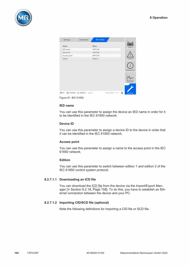
8 Operation
Maschinenfabrik Reinhausen GmbH 2022104 4016640/15 ENTAPCON®
Settings Parameters IEC 61850
Name Value
IED name TAPCON
Device ID TAPCON
Access point MRTCAP
Edition Edition 1
Home
Events
Information
Recorder
SettingsEN CHANGE REBOOT admin 04.02.2020 11:14
Figure 81: IEC 61850
IED name
You can use this parameter to assign the device an IED name in order for itto be identified in the IEC 61850 network.
Device ID
You can use this parameter to assign a device ID to the device in order thatit can be identified in the IEC 61850 network.
Access point
You can use this parameter to assign a name to the access point in the IEC61850 network.
Edition
You can use this parameter to switch between edition 1 and edition 2 of theIEC 61850 control system protocol.
8.2.7.1.1 Downloading an ICD file
You can download the ICD file from the device via the Import/Export Man-ager [Section 8.2.18, Page 158]. To do this, you have to establish an Eth-ernet connection between the device and your PC.
8.2.7.1.2 Importing CID/SCD file (optional)
Note the following definitions for importing a CID file or SCD file.

8 Operation
Maschinenfabrik Reinhausen GmbH 2022 1054016640/15 EN TAPCON®
Only the following elements may differ between the imported IED and theexported IED from the TEMPLATE.icd. DataSet elements can be created in each LN ReportControl elements can be created in the LN containing the associ-
ated DataSet IP address (if this is not present, the preset one is used) Subnet mask (if this is not present, the preset one is used) Gateway IP address (if this is not present, the preset one is used) Name of IED (IED name) Name of AccessPoint (AccessPoint attribute name) Name of logical device (LDevice attribute inst)
OSI-PSEL, OSI-SSEL, and OSI-TSEL cannot be adjusted.
The SCD file may contain no more than 45 IEDs. It may take several min-utes to import a complete SCD file. The SCD file should only contain theIEDs needed.
You can import the CID/SCD file via the Import/Export Manager. To do so,proceed as follows:1. Go to Settings > Import.2. Select and import the desired CID/SCD file.
8.2.7.2 Configuring IEC 60870-5-101 (optional)
If you want to use the IEC 60870-5-101 control system protocol, you mustset the following parameters.
Settings Parameters IEC 60870-5-101
Name Value
Serial interface RS232
Baud rate 9600
Transmission procedure Unbalanced
Number of link address octets 1
Link address 1
Number of ASDU address octets 1
ASDU address 1
No. of information object address... 1
Number of cause of transmission o... 1
Number of databits 8
Parity Even
Number of stop bits 1
ASDU single character confirmatio... Off
Home
Events
Information
Recorder
SettingsEN CHANGE REBOOT admin 31.01.2020 13:05
Figure 82: IEC 60870-5-101
1. Go to Settings > Parameters > System > IEC 60870-5-101.2. Select the desired parameter.3. Set the parameter.
8 Operation
Maschinenfabrik Reinhausen GmbH 2022106 4016640/15 ENTAPCON®
4. Press the Accept button to save the modified parameter.
Serial interface
You can use this parameter to select the serial interface for data transmis-sion. You can select the following options: RS232 RS485
Baud rate
You can use this parameter to set the serial interface's baud rate. You canselect the following options: 9600 baud 19200 baud 38400 baud 57600 baud 115200 baud
Transmission procedure
You can use this parameter to set the transmission procedure. You can se-lect the following options: Unbalanced transmission Balanced transmission
Number of link address octets
You can use this parameter to set how many octets are provided for the linkaddress.
Link address
You can use this parameter to set the link address.
Number of ASDU address octets
You can use this parameter to set how many octets are provided for theASDU address.
ASDU address
You can use this parameter to set the address of the ASDU.
No. of information object address octets
You can use this parameter to set how many octets are provided for the in-formation object address.

8 Operation
Maschinenfabrik Reinhausen GmbH 2022 1074016640/15 EN TAPCON®
Number of cause of transmission octets
You can use this parameter to set how many octets are provided for thecause of transmission.
Number of data bits
You can use this parameter to set the number of databits.
Parity
You can use this parameter to set the parity. You can select the followingoptions: None Even Odd
Number of stop bits
You can use this parameter to set the number of stop bits.
ASDU single character confirmation
You can use this parameter to set whether a confirmation is to be sent assingle characters instead of as a complete message. Single character confir-mation is only possible for requesting data of class 2 (Class 2 Request).
RES bit test
You can use this parameter to set whether the device is to check the RES bit(Reserved Bit) in the control field. You can select the following options:
Option Description
On Messages from the master with RES bit = 1 are declinedby the device.
Off Messages from the master with RES bit = 1 are acceptedby the device.
Table 28: RES bit test
ASDU sequence optimization
With this parameter, you can set which method is to be used for optimizingthe ASDU types. The standard enables optimization in order to be able totransfer multiple value changes in a telegram in a sequence of ascending in-formation object addresses. This is displayed by the sequence bit. The se-lection of ASDU types for which this optimization is allowed is based on theedition of the standard.
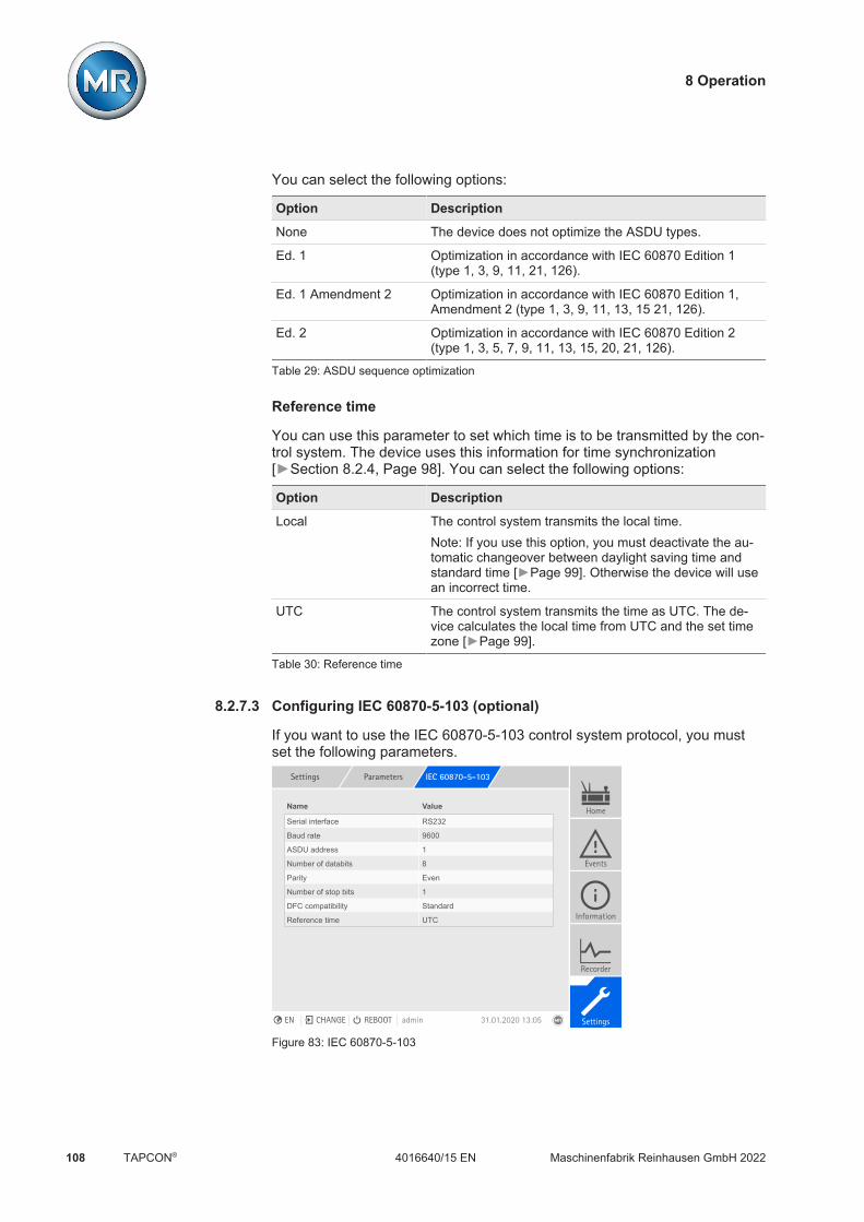
8 Operation
Maschinenfabrik Reinhausen GmbH 2022108 4016640/15 ENTAPCON®
You can select the following options:
Option Description
None The device does not optimize the ASDU types.
Ed. 1 Optimization in accordance with IEC 60870 Edition 1(type 1, 3, 9, 11, 21, 126).
Ed. 1 Amendment 2 Optimization in accordance with IEC 60870 Edition 1,Amendment 2 (type 1, 3, 9, 11, 13, 15 21, 126).
Ed. 2 Optimization in accordance with IEC 60870 Edition 2(type 1, 3, 5, 7, 9, 11, 13, 15, 20, 21, 126).
Table 29: ASDU sequence optimization
Reference time
You can use this parameter to set which time is to be transmitted by the con-trol system. The device uses this information for time synchronization[Section 8.2.4, Page 98]. You can select the following options:
Option Description
Local The control system transmits the local time.Note: If you use this option, you must deactivate the au-tomatic changeover between daylight saving time andstandard time [Page 99]. Otherwise the device will usean incorrect time.
UTC The control system transmits the time as UTC. The de-vice calculates the local time from UTC and the set timezone [Page 99].
Table 30: Reference time
8.2.7.3 Configuring IEC 60870-5-103 (optional)
If you want to use the IEC 60870-5-103 control system protocol, you mustset the following parameters.
Settings Parameters IEC 60870-5-103
Name Value
Serial interface RS232
Baud rate 9600
ASDU address 1
Number of databits 8
Parity Even
Number of stop bits 1
DFC compatibility Standard
Reference time UTC
Home
Events
Information
Recorder
SettingsEN CHANGE REBOOT admin 31.01.2020 13:05
Figure 83: IEC 60870-5-103

8 Operation
Maschinenfabrik Reinhausen GmbH 2022 1094016640/15 EN TAPCON®
1. Go to Settings > Parameters > System > IEC 60870-5-103.2. Select the desired parameter.3. Set the parameter.4. Press the Accept button to save the modified parameter.
Serial interface
You can use this parameter to select the serial interface for data transmis-sion. You can select the following options: RS232 RS485
Baud rate
You can use this parameter to set the serial interface's baud rate. You canselect the following options: 9600 baud 19200 baud 38400 baud 57600 baud 115200 baud
ASDU address
You can use this parameter to set the address of the ASDU.
Number of data bits
You can use this parameter to set the number of databits.
Parity
You can use this parameter to set the parity. You can select the followingoptions: None Even Odd
Number of stop bits
You can use this parameter to set the number of stop bits.

8 Operation
Maschinenfabrik Reinhausen GmbH 2022110 4016640/15 ENTAPCON®
DFC compatibility
You can use this parameter to set how the device is to use the DFC bit (DataFlow Control) in the control field. You can select the following options:
Option Description
Standard The device sets the DFC bit in each response to a com-mand. The device thus indicates that the master may notsend any further commands. The master must react tothe ACD bit (Access Demand) and retrieve the responseto the command e.g. via a request for data of class 1from the slave queue.
Alternative The device sets the DFC bit in a response if a secondcommand is received without the master having previ-ously sent a request for data of class 1.
Table 31: DFC compatibility
Reference time
You can use this parameter to set which time is to be transmitted by the con-trol system. The device uses this information for time synchronization[Section 8.2.4, Page 98]. You can select the following options:
Option Description
Local The control system transmits the local time.Note: If you use this option, you must deactivate the au-tomatic changeover between daylight saving time andstandard time [Page 99]. Otherwise the device will usean incorrect time.
UTC The control system transmits the time as UTC. The de-vice calculates the local time from UTC and the set timezone [Page 99].
Table 32: Reference time

8 Operation
Maschinenfabrik Reinhausen GmbH 2022 1114016640/15 EN TAPCON®
8.2.7.4 Configuring IEC 60870-5-104 (optional)
If you want to use the IEC 60870-5-104 control system protocol, you mustset the following parameters. Also refer to the section Configuring the net-work [Section 8.2.2, Page 94].
Settings Parameters IEC 60870-5-104
Name Value
TCP port 2404
ASDU address 1
ASDU sequence optimization None
Reference time UTC
Home
Events
Information
Recorder
SettingsEN CHANGE REBOOT admin 31.01.2020 13:05
Figure 84: IEC 60870-5-104
1. Go to Settings > Parameters > System > IEC 60870-5-104.2. Select the desired parameter.3. Set the parameter.4. Press the Accept button to save the modified parameter.
TCP port
You can use this parameter to set the TCP port.
ASDU address
You can use this parameter to set the address of the ASDU.
ASDU sequence optimization
With this parameter, you can set which method is to be used for optimizingthe ASDU types. The standard enables optimization in order to be able totransfer multiple value changes in a telegram in a sequence of ascending in-formation object addresses. This is displayed by the sequence bit. The se-lection of ASDU types for which this optimization is allowed is based on theedition of the standard.
8 Operation
Maschinenfabrik Reinhausen GmbH 2022112 4016640/15 ENTAPCON®
You can select the following options:
Option Description
None The device does not optimize the ASDU types.
Ed. 1 Optimization in accordance with IEC 60870 Edition 1(type 1, 3, 9, 11, 21, 126).
Ed. 1 Amendment 2 Optimization in accordance with IEC 60870 Edition 1,Amendment 2 (type 1, 3, 9, 11, 13, 15 21, 126).
Ed. 2 Optimization in accordance with IEC 60870 Edition 2(type 1, 3, 5, 7, 9, 11, 13, 15, 20, 21, 126).
Table 33: ASDU sequence optimization
Reference time
You can use this parameter to set which time is to be transmitted by the con-trol system. The device uses this information for time synchronization[Section 8.2.4, Page 98]. You can select the following options:
Option Description
Local The control system transmits the local time.Note: If you use this option, you must deactivate the au-tomatic changeover between daylight saving time andstandard time [Page 99]. Otherwise the device will usean incorrect time.
UTC The control system transmits the time as UTC. The de-vice calculates the local time from UTC and the set timezone [Page 99].
Table 34: Reference time
IP address Client 1/2/3 (optional)
If you use the optional "Multi-client" function, you can use these parametersto set the IP addresses of the SCADA clients. The device only accepts com-mands through the control system from end devices that have their IP ad-dresses set here.
Note that all SCADA clients communicate with the device on an equal basis,because the device does not prioritize commands. If you transmit com-mands from several SCADA clients to the device at the same time, the de-vice will execute the last transmitted command.

8 Operation
Maschinenfabrik Reinhausen GmbH 2022 1134016640/15 EN TAPCON®
8.2.7.5 Configuring Modbus (optional)
If you want to use the Modbus control system protocol, you must set the cor-responding parameters depending on the Modbus type selected. Also referto the section Configuring the network [Section 8.2.2, Page 94] if you wantto use Modbus TCP.
Settings Parameters Modbus
Name Value
Modbus type RTU
Modbus address 1
TCP port 502
Maximum TCP connections 10
TCP Keepalive Off
Serial interface RS232
Baud rate 9600
Number of databits 8
Parity Even
Number of stop bits 1
Home
Events
Information
Recorder
SettingsEN CHANGE REBOOT admin 31.01.2020 13:05
Figure 85: Modbus
1. Go to Settings > Parameters > System > Modbus.2. Select the desired parameter.3. Set the parameter.4. Press the Accept button to save the modified parameter.
Modbus type
You can use this parameter to set the Modbus type. You can select the fol-lowing options: RTU TCP ASCII
Modbus address
You can use this parameter to set the Modbus address.
TCP port
You can use this parameter to set the TCP port.
Maximum TCP connections
You can use this parameter to set the maximum number of TCP connec-tions.

8 Operation
Maschinenfabrik Reinhausen GmbH 2022114 4016640/15 ENTAPCON®
TCP Keepalive
You can use this parameter to activate/deactivate the "TCP Keepalive" func-tion.
Serial interface
You can use this parameter to select the serial interface for data transmis-sion. You can select the following options: RS232 RS485
Baud rate
You can use this parameter to set the serial interface's baud rate. You canselect the following options: 9600 baud 19200 baud 38400 baud 57600 baud 115200 baud
Number of data bits
You can use this parameter to set the number of databits.
Parity
You can use this parameter to set the parity. You can select the followingoptions: None Even Odd
Number of stop bits
You can use this parameter to set the number of stop bits.

8 Operation
Maschinenfabrik Reinhausen GmbH 2022 1154016640/15 EN TAPCON®
8.2.7.6 Configuring DNP3 (optional)
If you would like to use the DNP3 control system protocol, you must set theparameters listed below. Also refer to the section Configuring the network[Section 8.2.2, Page 94] if you want to use the DNP3 via TCP.
Settings Parameters DNP3
Name Value
DNP3 transmission type TCP
TCP port 20000
Device address 1
Timeout for response confirmation 5 s
Unsolicited messages Off
Destination address 10000
Timeout confirmation 5 s
Indefinite unsolicited retries Off
Number of unsolicited retries 3
User ID code ISM
Reference time UTC
Home
Events
Information
Recorder
SettingsEN CHANGE REBOOT admin 31.01.2020 13:05
Figure 86: DNP3
1. Go to Settings > Parameters > System > DNP3.2. Select the desired parameter.3. Set the parameter.4. Press the Accept button to save the modified parameter.
8.2.7.6.1 DNP3 transmission type
You can use this parameter to set the transmission type. You can select thefollowing options: TCP Serial
TCP port
You can use this parameter to set the TCP port.
Serial interface
You can use this parameter to select the serial interface for data transmis-sion. You can select the following options: RS232 RS485

8 Operation
Maschinenfabrik Reinhausen GmbH 2022116 4016640/15 ENTAPCON®
Baud rate
You can use this parameter to set the serial interface's baud rate. You canselect the following options: 9600 baud 19200 baud 38400 baud 57600 baud 115200 baud
Device address
You can use this parameter to set the device link address.
Destination address
You can use this parameter to set the destination master link address.
Unsolicited messages
You can use this parameter to set whether the device is to support unso-licited messages. If you activate unsolicited messages, the device sends amessage via the control system every time a value is changed.
Repetition of unsolicited messages
You can use this parameter to set how often the device is to send an unso-licited message until it receives a response from the DNP3 master.
Repeat unsolicited messages indefinitely
You can use this parameter to set the device to send an indefinite number ofunsolicited messages until it receives a response from the DNP3 master.
Timeout
You can use this parameter to set the timeout for unsolicited messages.
Timeout for response confirmation
You can use this parameter to set the timeout for response confirmation forunsolicited messages.
User ID code
You can use this parameter to set the user ID code.

8 Operation
Maschinenfabrik Reinhausen GmbH 2022 1174016640/15 EN TAPCON®
Reference time
You can use this parameter to set which time is to be transmitted by the con-trol system. The device uses this information for time synchronization[Section 8.2.4, Page 98]. You can select the following options:
Option Description
Local The control system transmits the local time.Note: If you use this option, you must deactivate the au-tomatic changeover between daylight saving time andstandard time [Page 99]. Otherwise the device will usean incorrect time.
UTC The control system transmits the time as UTC. The de-vice calculates the local time from UTC and the set timezone [Page 99].
Table 35: Reference time
8.2.7.7 Configuring GOOSE (optional)
You can use the optional GOOSE function to send GOOSE messages(GOOSE publisher) or receive GOOSE messages (GOOSE subscriber) viathe IEC 61850 control system protocol with the device.
The configuration of GOOSE is described in the following chapters.
8.2.7.7.1 Configuring GOOSE publisher
If you configure the device as a GOOSE publisher, you can send all datapoints which the device provides via MMS as GOOSE messages. To do this,you have to configure the data points using DataSets in an SCD/CID file.
SCD/CID file requirements The GOOSE control block (GSEControl) and the associated DataSet can
only be created in LLN0. GSE elements for the configuration of the GOOSE message can be cre-
ated under ConnectedAP. The maximum number of data points per GOOSE message is defined in
Private Element type="MR-MAX-GOOSE-PUBLISH-FCDA". You cannotadjust this value.
The maximum number of usable GSEControl elements is defined in TEM-PLATE.icd under Services GOOSE. You cannot adjust this value.
The shortest repeat time is defined in Private Element type="MR-MINTIME-GOOSE". You cannot adjust this value.
Example:
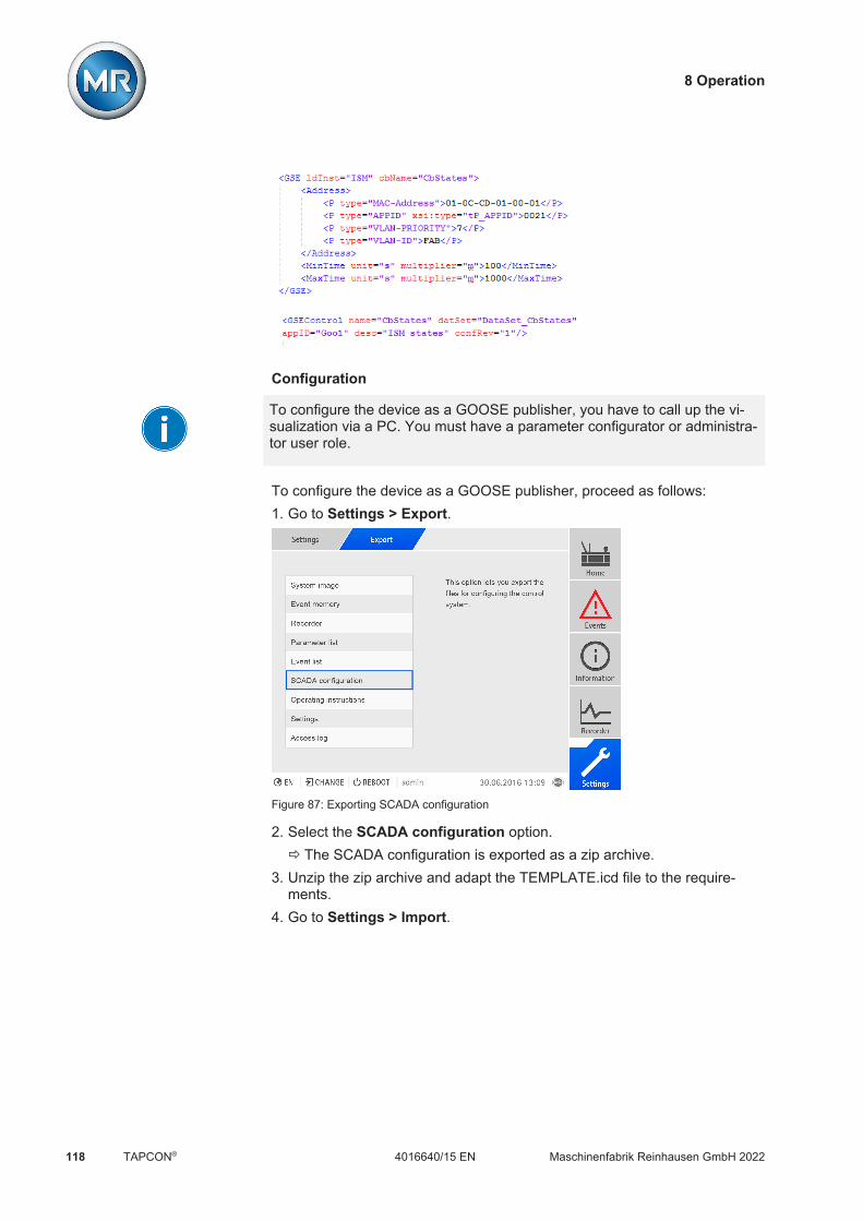
8 Operation
Maschinenfabrik Reinhausen GmbH 2022118 4016640/15 ENTAPCON®
Configuration
To configure the device as a GOOSE publisher, you have to call up the vi-sualization via a PC. You must have a parameter configurator or administra-tor user role.
To configure the device as a GOOSE publisher, proceed as follows:1. Go to Settings > Export.
Figure 87: Exporting SCADA configuration
2. Select the SCADA configuration option.ð The SCADA configuration is exported as a zip archive.
3. Unzip the zip archive and adapt the TEMPLATE.icd file to the require-ments.
4. Go to Settings > Import.

8 Operation
Maschinenfabrik Reinhausen GmbH 2022 1194016640/15 EN TAPCON®
5. Select the PC or USB option, select the SCD/CID file, and select Trans-fer.
Figure 88: Importing an SCD/ICD file
6. Select the desired IED with the configuration that is to be imported andselect Accept to start the import.
Figure 89: Selecting an IED
7. Upon successful completion of the import, restart the device.ð The system restarts and checks the configuration. If the configuration
failed, an error message appears and the device resets the configurationto the one with which it was delivered.
8.2.7.7.2 Configuring GOOSE subscriber
If you configure the device as a GOOSE subscriber, you can receiveGOOSE messages from an IED in the network and link them to device func-tions. You can use this function to display all of the device's digital input sig-nals via GOOSE.
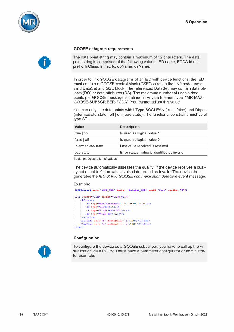
8 Operation
Maschinenfabrik Reinhausen GmbH 2022120 4016640/15 ENTAPCON®
GOOSE datagram requirements
The data point string may contain a maximum of 52 characters. The datapoint string is comprised of the following values: IED name, FCDA IdInst,prefix, InClass, InInst, fc, doName, daName.
In order to link GOOSE datagrams of an IED with device functions, the IEDmust contain a GOOSE control block (GSEControl) in the LN0 node and avalid DataSet and GSE block. The referenced DataSet may contain data ob-jects (DO) or data attributes (DA). The maximum number of usable datapoints per GOOSE message is defined in Private Element type="MR-MAX-GOOSE-SUBSCRIBER-FCDA". You cannot adjust this value.
You can only use data points with bType BOOLEAN (true | false) and Dbpos(intermediate-state | off | on | bad-state). The functional constraint must be oftype ST.
Value Description
true | on Is used as logical value 1
false | off Is used as logical value 0
intermediate-state Last value received is retained
bad-state Error status, value is identified as invalid
Table 36: Description of values
The device automatically assesses the quality. If the device receives a qual-ity not equal to 0, the value is also interpreted as invalid. The device thengenerates the IEC 61850 GOOSE communication defective event message.
Example:
Configuration
To configure the device as a GOOSE subscriber, you have to call up the vi-sualization via a PC. You must have a parameter configurator or administra-tor user role.
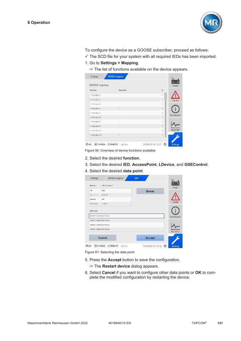
8 Operation
Maschinenfabrik Reinhausen GmbH 2022 1214016640/15 EN TAPCON®
To configure the device as a GOOSE subscriber, proceed as follows:ü The SCD file for your system with all required IEDs has been imported.1. Go to Settings > Mapping.
ð The list of functions available on the device appears.
Figure 90: Overview of device functions available
2. Select the desired function.3. Select the desired IED, AccessPoint, LDevice, and GSEControl.4. Select the desired data point.
Figure 91: Selecting the data point
5. Press the Accept button to save the configuration.ð The Restart device dialog appears.
6. Select Cancel if you want to configure other data points or OK to com-plete the modified configuration by restarting the device.

8 Operation
Maschinenfabrik Reinhausen GmbH 2022122 4016640/15 ENTAPCON®
Deleting a configuration
If necessary, you can delete the data point configuration. To do so, proceedas follows:1. Go to Settings > Mapping.2. Select the desired function.3. Press the Delete button to delete the configuration.
8.2.7.8 Configure data points (optional)
You can use the optional "Configure data points" function to adjust the con-trol system data points of the device. You can only configure the data pointson a PC using the web-based visualization.
8.2.7.8.1 Configuring IEC 60870-5-101 data points
You can adjust the following data point properties for the IEC 60870-5-101control system protocol:
Column Description Modifiable Setting range
Active You can use the checkbox to set whether the data point isto be transferred via the control system protocol or not.
Yes Active/inactive
IOA Data point address. The setting range is based on the set-ting for the "Octet number of information object address"parameter (octet 2 or 3).
Yes Octet 2: 1...65,535Octet 3:1...16,777,215
Name Data point designation. No -
Type Data point type. No -
Group Data point group or groups. You must enter the groupmembership as a binary code (5 bits). A maximum of 5groups is possible. Example: 00000: belongs to no groups 00001: group 1 01000: group 4 01001: group 1 and group 4
Yes 00000...11111
INTG The value indicates whether the data point is to be in-cluded in a general query (1) or not (0).
Yes 0, 1
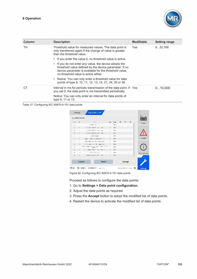
8 Operation
Maschinenfabrik Reinhausen GmbH 2022 1234016640/15 EN TAPCON®
Column Description Modifiable Setting range
TH Threshold value for measured values. The data point isonly transferred again if the change of value is greaterthan the threshold value. If you enter the value 0, no threshold value is active. If you do not enter any value, the device adopts the
threshold value defined by the device parameter. If nodevice parameter is available for the threshold value,no threshold value is active either.
Notice: You can only enter a threshold value for datapoints of type 9, 10, 11, 12, 13, 14, 21, 34, 35 or 36.
Yes 0...32,768
CT Interval in ms for periodic transmission of the data point. Ifyou set 0, the data point is not transmitted periodically.Notice: You can only enter an interval for data points oftype 9, 11 or 13.
Yes 0...10,000
Table 37: Configuring IEC 60870-5-101 data points
Figure 92: Configuring IEC 60870-5-101 data points
Proceed as follows to configure the data points:1. Go to Settings > Data point configuration.2. Adjust the data points as required.3. Press the Accept button to adopt the modified list of data points.4. Restart the device to activate the modified list of data points.

8 Operation
Maschinenfabrik Reinhausen GmbH 2022124 4016640/15 ENTAPCON®
8.2.7.8.2 Configuring IEC 60870-5-103 data points
You can adjust the following data point properties for the IEC 60870-5-103control system protocol:
Column Description Modifiable Setting range
Active You can use the checkbox to set whether the data point isto be transferred via the control system protocol or not.
Yes Active/inactive
TYP Data point type code. No -
FUN Data point function type.Notice: You can only use function type 254 for data pointswith type code 10 or 11.
Yes 0...255
INF Data point information number.Notice: You can only use information number 0 for datapoints with function type 254.
Yes 0...255
GIN Data point generic identification number.Notice: You can only use generic identification number 0for data points with a function type other than 254.
Yes 0...65,535
Data Type Data point data type. No -
Name Data point designation. No -
Interrogation The value indicates whether the data point is to be in-cluded in a general query (1) or not (0).
Yes 0, 1
Threshold Threshold value for measured values. The data point isonly transferred again if the change of value is greaterthan the threshold value. If you enter the value 0, no threshold value is active. If you do not enter any value, the device adopts the
threshold value defined by the device parameter. If nodevice parameter is available for the threshold value,no threshold value is active either.
Yes 0...1,000,000,000
Table 38: Configuring IEC 60870-5-103 data points
Figure 93: Configuring IEC 60870-5-103 data points

8 Operation
Maschinenfabrik Reinhausen GmbH 2022 1254016640/15 EN TAPCON®
Proceed as follows to configure the data points:1. Go to Settings > Data point configuration.2. Adjust the data points as required.3. Press the Accept button to adopt the modified list of data points.4. Restart the device to activate the modified list of data points.
8.2.7.8.3 Configuring IEC 60870-5-104 data points
You can adjust the following data point properties for the IEC 60870-5-104control system protocol:
Column Description Modifiable Setting range
Active You can use the checkbox to set whether the data point isto be transferred via the control system protocol or not.
Yes Active/inactive
IOA Data point address. Yes 1...16,777,215
Name Data point designation. No -
Type Data point type. No -
Group Data point group or groups. You must enter the groupmembership as a binary code (5 bits). A maximum of 5groups is possible. Example: 00000: belongs to no groups 00001: group 1 01000: group 4 01001: group 1 and group 4
Yes 00000...11111
INTG The value indicates whether the data point is to be in-cluded in a general query (1) or not (0).
Yes 0, 1
TH Threshold value for measured values. The data point isonly transferred again if the change of value is greaterthan the threshold value. If you enter the value 0, no threshold value is active. If you do not enter any value, the device adopts the
threshold value defined by the device parameter. If nodevice parameter is available for the threshold value,no threshold value is active either.
Notice: You can only enter a threshold value for datapoints of type 9, 10, 11, 12, 13, 14, 21, 34, 35 or 36.
Yes 0...32,768
CT Interval in ms for periodic transmission of the data point. Ifyou set 0, the data point is not transmitted periodically.Notice: You can only enter an interval for data points oftype 9, 11 or 13.
Yes 0...10,000
Table 39: Configuring IEC 60870-5-104 data points

8 Operation
Maschinenfabrik Reinhausen GmbH 2022126 4016640/15 ENTAPCON®
Figure 94: Configuring IEC 60870-5-104 data points
Proceed as follows to configure the data points:1. Go to Settings > Data point configuration.2. Adjust the data points as required.3. Press the Accept button to adopt the modified list of data points.4. Restart the device to activate the modified list of data points.
8.2.7.8.4 Configuring Modbus data points
You can adjust the following data point properties for the Modbus controlsystem protocol:
Column Description Modifiable Setting range
Active You can use the checkbox to set whether the data point isto be transferred via the control system protocol or not.
Yes Active/inactive
Type Data point type No -
Index1 Data point address Yes 0...65,535
Index2 Optional second data point address. This is used auto-matically for data points able to transfer values greaterthan 16 bits. Please note that the Index2 address alwaysfollows on from the Index1 address exactly.
No -
Name Data point designation No -Table 40: Configuring Modbus data points
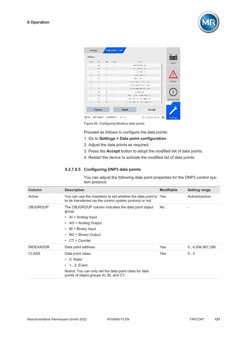
8 Operation
Maschinenfabrik Reinhausen GmbH 2022 1274016640/15 EN TAPCON®
Figure 95: Configuring Modbus data points
Proceed as follows to configure the data points:1. Go to Settings > Data point configuration.2. Adjust the data points as required.3. Press the Accept button to adopt the modified list of data points.4. Restart the device to activate the modified list of data points.
8.2.7.8.5 Configuring DNP3 data points
You can adjust the following data point properties for the DNP3 control sys-tem protocol:
Column Description Modifiable Setting range
Active You can use the checkbox to set whether the data point isto be transferred via the control system protocol or not.
Yes Active/inactive
OBJGROUP The OBJGROUP column indicates the data point objectgroup: AI = Analog Input AO = Analog Output BI = Binary Input BO = Binary Output CT = Counter
No -
INDEXADDR Data point address. Yes 0...4,294,967,296
CLASS Data point class. 0: Static 1...3: EventNotice: You can only set the data point class for datapoints of object groups AI, BI, and CT.
Yes 0...3

8 Operation
Maschinenfabrik Reinhausen GmbH 2022128 4016640/15 ENTAPCON®
Column Description Modifiable Setting range
PREFSTATICVAR For a data point of class 0 (Static), you can define the fol-lowing variation depending on the object group: BI: 1, 2 BO: 2 AI: 2, 4 AO: 2 CT: 1, 2, 5, 6
Yes 0...6
PREFEVENTVAR For a data point of classes 1...3 (Event), you can definethe following variation depending on the object group: BI: 1, 2, 3 BO: no value AI: 2, 4 AO: no value CT: 1, 2, 5, 6
Yes 0...6
NAME Data point designation. No -
Deadband Threshold value for analog inputs. The data point is onlytransferred again if the change of value is greater than thethreshold value. If you enter the value 0, no threshold value is active. If you do not enter any value, the device adopts the
threshold value defined by the device parameter. If nodevice parameter is available for the threshold value,no threshold value is active either.
Notice: The threshold value has the same unit as the datapoint value. Take note of the list of data points.
Yes 0...32,768
Table 41: Configuring DNP3 data points
Figure 96: Configuring DNP3 data points

8 Operation
Maschinenfabrik Reinhausen GmbH 2022 1294016640/15 EN TAPCON®
Proceed as follows to configure the data points:1. Go to Settings > Data point configuration.2. Adjust the data points as required.3. Press the Accept button to adopt the modified list of data points.4. Restart the device to activate the modified list of data points.
8.2.7.8.6 Resetting the data point configuration to factory settings
If you want to reset the data point configuration to factory settings, proceedas follows:1. Go to Settings > Data point configuration.2. Press the Reset button.
ð The message Reset appears.3. Press the Yes button to reset the data point configuration to the factory
settings.4. Restart the device to activate the modified list of data points.
8.2.7.8.7 Exporting and importing the data point configuration
You can export the data point configuration, e.g., to back it up or import itinto another device. You will find more information in the Import/Export Man-ager [Section 8.2.18, Page 158] section.
8.2.8 Displaying current measured values
The current measured values can be displayed on the measured valuescreen. Note that the displayed measured values may differ from the rawvalues displayed in the information display of the UI assembly. The mea-sured values are prepared for the measured value display by the device asfollows: The tap-change operation set for the current transformer and voltage
transformer is taken into account, as is a corresponding phase displace-ment.
The UI assemblies use the generator sign convention. The device dis-plays the measured values using the load sign convention.
You can change the measured value display to the generator sign conven-tion by activating the Retrofit TAPCON® 2xx [Section 8.3.8, Page 216]parameter.
The following measured values are displayed: Voltage Current Power factor (cos ϕ) Frequency

8 Operation
Maschinenfabrik Reinhausen GmbH 2022130 4016640/15 ENTAPCON®
Reactive power Active power Apparent power
Figure 97: Measured values
Go to Information > Grid > Measured values.
Also refer to2 TAPCON® 2xx retrofit [ 216]
8.2.9 Displaying measured value recorder (optional)
You can use the optional measured value recorder function to display theprogress of measured values and signals over time.
Depending on device configuration, you can select the following measuredvalues and signals for the display:
Signal Description
P_m L1 Active power L1 (average value)
P_m L2 Active power L2 (average value)
P_m L3 Active power L2 (average value)
P_m Active power in total (average value)
S_m L1 Apparent power L1 (average value)
S_m L2 Apparent power L2 (average value)
S_m L3 Apparent power L3 (average value)
S_m Apparent power in total (average value)
U_m Desired Desired voltage value (average value)
f_m Frequency (average value)
φ_m U1/I1 Phase angle U1/I1 (average value)

8 Operation
Maschinenfabrik Reinhausen GmbH 2022 1314016640/15 EN TAPCON®
Signal Description
φ_m U2/I2 Phase angle U2/I2 (average value)
φ_m U3/I3 Phase angle U3/I3 (average value)
cos(φ_m) L1 Power factor L1 (average value)
cos(φ_m) L2 Power factor L2 (average value)
cos(φ_m) L3 Power factor L3 (average value)
cos(φ_m) Power factor in total (average value)
I_m N Neutral conductor current (average value)
I_m L1 Current L1 (average value)
I_m L2 Current L2 (average value)
I_m L3 Current L3 (average value)
U_m L1 Voltage L1 (average value)
U_m L2 Voltage L2 (average value)
U_m L3 Voltage L3 (average value)
Q_m L1 Reactive power L1 (average value)
Q_m L2 Reactive power L2 (average value)
Q_m L3 Reactive power L3 (average value)
Q_m Total reactive power (average value)
Auto block Auto mode blocked
HSR tap position ↓ High-speed return lower step
HSR tap position ↑ High-speed return raise step
Req. HSR tap position↓
High-speed return request lower step
Req. HSR tap position↑
High-speed return request raise step
I>> Limit value I>> exceeded
U>> Limit value U>> exceeded
U Desired (prim.) Desired voltage value (on primary side)
U Desired Desired voltage value (on primary or secondary side, in ac-cordance with configuration of measured value display pa-rameter)
Tx1: Tap position Tap position transformer 1
Tx2: Tap position Tap position transformer 2
Tx3: Tap position Tap position transformer 3
Tx4: Tap position Tap position transformer 4
P L1 Active power L1
P L2 Active power L2
P L3 Active power L2
P Active power in total

8 Operation
Maschinenfabrik Reinhausen GmbH 2022132 4016640/15 ENTAPCON®
Signal Description
S L1 Apparent power L1
S L2 Apparent power L2
S L3 Apparent power L3
S Apparent power in total
f Frequency
φ U1/I1 Phase angle U1/I1
φ U2/I2 Phase angle U2/I2
φ U3/I3 Phase angle U3/I3
cos(φ) L1 Power factor L1
cos(φ) L2 Power factor L2
cos(φ) L3 Power factor L3
cos(φ) Power factor in total
I N Neutral conductor current
I L1 Current L1
I L2 Current L2
I L3 Current L3
U L1 Voltage L1
U L2 Voltage L2
U L3 Voltage L3
Q L1 Reactive power L1
Q L2 Reactive power L2
Q L3 Reactive power L3
Q Total reactive power
Tx1: t motor Motor runtime transformer 1
Tx2: t motor Motor runtime transformer 2
Tx3: t motor Motor runtime transformer 3
Tx4: t motor Motor runtime transformer 4
Tx1: Q1 Off Motor protective switch triggered transformer 1
Tx2: Q1 Off Motor protective switch triggered transformer 2
Tx3: Q1 Off Motor protective switch triggered transformer 3
Tx4: Q1 Off Motor protective switch triggered transformer 4
Par. grp. 1 Parallel operation group 1 active
Par. grp. 2 Parallel operation group 2 active
Table 42: Measured values and signals

8 Operation
Maschinenfabrik Reinhausen GmbH 2022 1334016640/15 EN TAPCON®
If you call up the measured value recorder directly on the device display,you can select a maximum of 3 measured values. If you access it via theweb visualization, you can select a maximum of 10 measured values.
To display the measured value recorder, proceed as follows:1. Go to Recorder.
Figure 98: Recorder
2. Select the signals to be displayed in the list.3. If necessary, set the desired axis for each signal.4. Enter the start time and end time for the measured value display.5. Press Display to call up the measured value display (data log).
Figure 99: Data log
The operation described below is only possible if you access the visualiza-tion using a computer.
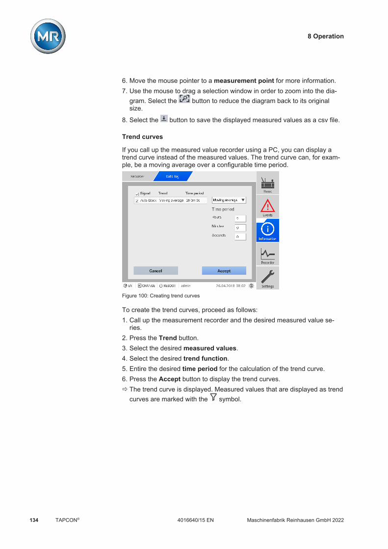
8 Operation
Maschinenfabrik Reinhausen GmbH 2022134 4016640/15 ENTAPCON®
6. Move the mouse pointer to a measurement point for more information.7. Use the mouse to drag a selection window in order to zoom into the dia-
gram. Select the button to reduce the diagram back to its originalsize.
8. Select the button to save the displayed measured values as a csv file.
Trend curves
If you call up the measured value recorder using a PC, you can display atrend curve instead of the measured values. The trend curve can, for exam-ple, be a moving average over a configurable time period.
Figure 100: Creating trend curves
To create the trend curves, proceed as follows:1. Call up the measurement recorder and the desired measured value se-
ries.2. Press the Trend button.3. Select the desired measured values.4. Select the desired trend function.5. Entire the desired time period for the calculation of the trend curve.6. Press the Accept button to display the trend curves.ð The trend curve is displayed. Measured values that are displayed as trend
curves are marked with the symbol.
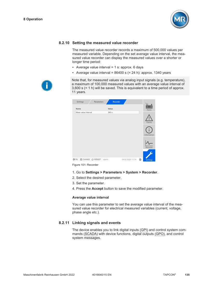
8 Operation
Maschinenfabrik Reinhausen GmbH 2022 1354016640/15 EN TAPCON®
8.2.10 Setting the measured value recorder
The measured value recorder records a maximum of 500,000 values permeasured variable. Depending on the set average value interval, the mea-sured value recorder can display the measured values over a shorter orlonger time period: Average value interval = 1 s: approx. 6 days Average value interval = 86400 s (= 24 h): approx. 1340 years
Note that, for measured values via analog input signals (e.g. temperature),a maximum of 100,000 measured values with an average value interval of3,600 s (= 1 h) will be saved. This is equivalent to a time period of approx.11 years.
Settings Parameters Recorder
Name Value
Mean value interval 360 sHome
Events
Information
Recorder
SettingsEN CHANGE REBOOT admin 04.02.2020 11:14
Figure 101: Recorder
1. Go to Settings > Parameters > System > Recorder.2. Select the desired parameter.3. Set the parameter.4. Press the Accept button to save the modified parameter.
Average value interval
You can use this parameter to set the average value interval of the mea-sured value recorder for electrical measured variables (current, voltage,phase angle etc.).
8.2.11 Linking signals and events
The device enables you to link digital inputs (GPI) and control system com-mands (SCADA) with device functions, digital outputs (GPO), and controlsystem messages.
8 Operation
Maschinenfabrik Reinhausen GmbH 2022136 4016640/15 ENTAPCON®
The digital inputs available are each permanently linked to a Generic digitalinput event message and the control system commands available are eachpermanently linked to aGeneric SCADA command event message for thispurpose.
Input/command Event message
Digital input 11) Generic digital input 1
Digital input 21) Generic digital input 2
... ...
Digital input 421) Generic digital input 42
Generic SCADA command 1 Generic SCADA command 1
Generic SCADA command 2 Generic SCADA command 2
... ...
Generic SCADA command 10 Generic SCADA command 10
Table 43: Linking of digital inputs and control system commands with event messages
1) The number of available digital inputs depends on the order-specific deviceconfiguration.
You can link the event messages with device functions, digital outputs, andcontrol system messages. You can also link all other event messages (e.g.Undervoltage U<) with digital outputs and control system messages. Corre-sponding parameters, for which you need to enter the relevant event num-ber, are provided for this purpose.
8.2.11.1 Linking functions
You can link the Generic digital input or Generic SCADA command eventswith device functions. This allows you to remotely control the device usingdigital inputs or commands via the control system (SCADA). Depending onyour device configuration, various functions are available for this purpose viaparameters.
In order to establish the link, you have to enter the corresponding eventnumber in the desired parameter.
Note that you can only enter the event numbers of the Generic digital inputor Generic SCADA command events.If you enter event number 500, the link is disabled.

8 Operation
Maschinenfabrik Reinhausen GmbH 2022 1374016640/15 EN TAPCON®
Settings Parameters Link functions
Name Value
Master parallel operation method 500
Follower parallel operation metho... 500
Parallel op. meth. auto. tap sync... 500
Independent regulation 500
Blocking 500
High-speed return 500
Target-tap-position operation 500
Activate desired value 1 500
Activate desired value 2 500
Activate desired value 3 500
Home
Events
Information
Recorder
SettingsEN CHANGE REBOOT admin 04.02.2020 11:14
Figure 102: Linking functions
ü The desired event number is known.1. Go to Settings > Parameters > System > Link functions.2. Select the desired parameter.3. Enter the desired event number.4. Press the Accept button to save the modified parameter.
Master parallel operation method
If the assigned event is active, the device activates the master parallel oper-ation method.
Follower parallel operation method
If the assigned event is active, the device activates the follower parallel oper-ation method.
Automatic tap synchronization parallel operation method
If the assigned event is active, the device activates the automatic tap syn-chronization parallel operation method.
Independent regulation
If the assigned event is active, the device activates the independent regula-tion independent mode.
Deactivate parallel operation
If the assigned event is active, the device deactivates the parallel operation.
Blocking
If the assigned event is active, automatic control is blocked.

8 Operation
Maschinenfabrik Reinhausen GmbH 2022138 4016640/15 ENTAPCON®
Activate remote mode
If the assigned event is active, the device activates remote mode.
High-speed return
If the assigned event is active, the device activates high-speed return. Withhigh-speed return, the device ignores the set delay time of automatic voltageregulation.
Target-tap-position operation
If the assigned event is active, the device switches to the defined target tapposition.
Activate desired value 1
If the assigned event is active, the device activates the desired value 1.
Activate desired value 2
If the assigned event is active, the device activates the desired value 2.
Activate desired value 3
If the assigned event is active, the device activates the desired value 3.
Activate desired value 4
If the assigned event is active, the device activates the desired value 4.
Activate desired value 5
If the assigned event is active, the device activates the desired value 5.
Increase desired value
If the assigned event is active, the device prompts an increase in the desiredvalue.
Decrease desired value
If the assigned event is active, the device prompts a decrease in the desiredvalue.
8.2.11.2 Linking digital outputs
You can link each event with a digital output. The device provides a maxi-mum of 20 digital outputs for this purpose. When you link a digital output toan event, the device issues a signal to this output if the event occurs. Thesignal persists until the event stops. A parameter is available for each avail-able digital output.

8 Operation
Maschinenfabrik Reinhausen GmbH 2022 1394016640/15 EN TAPCON®
To forward input signals or control system commands, you need to link thedigital outputs or control system messages with the Generic digital input orGeneric SCADA command events.
Settings Parameters Link outputs
Name Value
Generic digital output 1 500Home
Events
Information
Recorder
SettingsEN CHANGE REBOOT admin 04.02.2020 11:14
Figure 103: Linking digital outputs
ü The desired event number is known [Section 8.2.14, Page 145].1. Go to Settings > Parameters > System > Link outputs.2. Select the desired parameter.3. Enter the desired event number.4. Press the Accept button to save the modified parameter.
Generic digital output X
You can use this parameter to link the digital output with an event message.To do so, enter the desired event number.
If you enter event number 500, the link is disabled.
8.2.11.3 Linking control system messages
You can link each event with a control system message. The device pro-vides 25 SCADA messages for this purpose. When you link a SCADA mes-sage to an event, the device sets the data point to "On" when the event oc-curs. When the event stops, the device sets the data point to "Off". A param-eter is available for each available SCADA message.
To forward control system commands, you need to link the control systemmessages to the General purpose input or Generic SCADA commandevents.
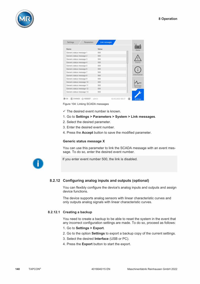
8 Operation
Maschinenfabrik Reinhausen GmbH 2022140 4016640/15 ENTAPCON®
Settings Parameters Link messages
Name Value
Generic status message 1 500
Generic status message 2 500
Generic status message 3 500
Generic status message 4 500
Generic status message 5 500
Generic status message 6 500
Generic status message 7 500
Generic status message 8 500
Generic status message 9 500
Generic status message 10 500
Generic status message 11 500
Generic status message 12 500
Generic status message 13 500
Home
Events
Information
Recorder
SettingsEN CHANGE REBOOT admin 02.05.2022 08:37
Figure 104: Linking SCADA messages
ü The desired event number is known.1. Go to Settings > Parameters > System > Link messages.2. Select the desired parameter.3. Enter the desired event number.4. Press the Accept button to save the modified parameter.
Generic status message X
You can use this parameter to link the SCADA message with an event mes-sage. To do so, enter the desired event number.
If you enter event number 500, the link is disabled.
8.2.12 Configuring analog inputs and outputs (optional)
You can flexibly configure the device's analog inputs and outputs and assigndevice functions.
The device supports analog sensors with linear characteristic curves andonly outputs analog signals with linear characteristic curves.
8.2.12.1 Creating a backup
You need to create a backup to be able to reset the system in the event thatany incorrect configuration settings are made. To do so, proceed as follows:1. Go to Settings > Export.2. Go to the option Settings to export a backup copy of the current settings.3. Select the desired Interface (USB or PC).4. Press the Export button to start the export.

8 Operation
Maschinenfabrik Reinhausen GmbH 2022 1414016640/15 EN TAPCON®
8.2.12.2 AIO configuration
The following information is displayed in tabular form for configuring the ana-log inputs and outputs. Grayed-out elements cannot be changed.
Figure 105: Configuring analog inputs/outputs
You can only change the configuration of the analog inputs and outputs ifyou have a Parameter Configurator or Administrator role.
When in delivery status, you can log in as the administrator as follows: User name: admin Password: admin1. Go to Settings > AIO configuration.2. Configure properties such as function, signal type and card/channel.3. Select the button to configure the values as desired.
Figure 106: Entering values
8 Operation
Maschinenfabrik Reinhausen GmbH 2022142 4016640/15 ENTAPCON®
4. Press the Accept button.5. Confirm the security prompt with Save to save the changes.
Signal type
Select signal type of analog sensor or deactivate analog output. 0…1 mA/0…2 mA 4...20 mA PT100-2/3/4, PT1000-2/3/4
Card/channel
Select the slot and channel of the analog sensor. Note the connection dia-gram supplied. This property is only available for GPAI.
Unit
Set the unit of the signal. This property is only available for GPAI.
Decimal places
Set up to three decimal places. This property is only available for GPAI.
Minimum/maximum value
Set the minimum and maximum values of the sensor, e.g. with a 4...20 mAsignal, the corresponding measured value for 4 mA and the correspondingvalue for 20 mA.
This property is not available if the sensors are connected over the MR sen-sor bus (Modbus).

8 Operation
Maschinenfabrik Reinhausen GmbH 2022 1434016640/15 EN TAPCON®
Correction factor and correction offset
Setting a correction offsets systematic errors of the analog signals. The cor-rection is determined by multiplying a factor by the sum of the offset. Theminimum and maximum values of the function values apply as a limit valuefor the correction. There is no limit for the correction offset.
Max.
Min.
Measured variable
Max.Min. Analog signal
Correction factor
Correction offset
Figure 107: Analog signal with linear characteristic curve, correction factor <1 and correction off-set
Correction factor
Set the correction factor (m) for the correction of the function value (x). Thecorrected function value (y) is: y = (m * x) + t. This property is only availablefor inputs.
Correction offset
Set the offset (t) for the correction of the function value (x). The correctedfunction value (y) is: y = (m * x) + t. This property is only available for inputs.
8.2.13 Configuring digital inputs and outputs
Upon delivery, the configurable digital inputs and outputs of the device areconfigured as follows: Input: High active Output: N/O contact (NO)
You can change this configuration if necessary.
8.2.13.1 Creating a backup
You need to create a backup to be able to reset the system in the event thatany incorrect configuration settings are made. To do so, proceed as follows:1. Go to Settings > Export.2. Go to the option Settings to export a backup copy of the current settings.

8 Operation
Maschinenfabrik Reinhausen GmbH 2022144 4016640/15 ENTAPCON®
3. Select the desired Interface (USB or PC).4. Press the Export button to start the export.
8.2.13.2 DIO configuration
Ensure that the configuration of the digital inputs and outputs is suitable forthe functions used. Otherwise, malfunctions may occur in the device andthe connected periphery.
The following information is displayed in tabular form for configuring the digi-tal inputs and outputs. Grayed-out elements cannot be changed.
Figure 108: Configuring digital inputs and outputs
The operation described below is only possible if you access the visualiza-tion using a computer. You can only change the configuration of the digitalinputs and outputs if you have a Parameter Configurator or Administratorrole.
When in delivery status, you can log in as the administrator as follows: User name: admin Password: admin
To configure the device's digital inputs and outputs, proceed as follows:1. Go to menu item Settings > DIO configuration.2. Where necessary, select the buttons or to sort the properties in a
column alphabetically.3. Configure the properties as desired.4. Press the Accept button.5. Confirm the security prompt with Yes to save the changes.

8 Operation
Maschinenfabrik Reinhausen GmbH 2022 1454016640/15 EN TAPCON®
Function
Function of the digital input (I: ...) or the digital output (O: ...). You can adjustthe designation.
Signal type
Select the signal type: Digital: Digital input
Configuration
Configure the device's digital inputs and outputs as follows: DI: High active or low active DO: N/O contact (NO), N/C contact (NC); Note: If the device is discon-
nected or in the event of an error, the digital outputs are always open (nobi-stable relay).
Assembly Channel
Channel of the DIO assembly to which the function is linked. Functions thatare not linked with a channel are identified with "-". Note the connection dia-gram supplied.
8.2.14 Event management
The device is equipped with event management, which allows you to detectvarious device operating statuses and to adapt the behavior of the device.You can call up an overview of the possible events in the device.
8.2.14.1 Displaying and acknowledging events
To display the events currently active, proceed as follows: Go to Events.
ð A list of currently pending events appears.
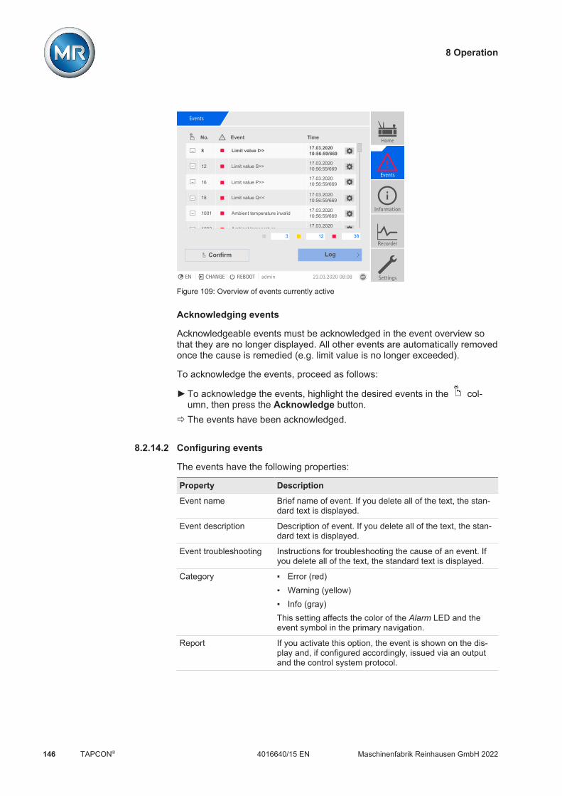
8 Operation
Maschinenfabrik Reinhausen GmbH 2022146 4016640/15 ENTAPCON®
Events
No. Event Time
8 Limit value I>> 17.03.202010:56:59/669
12 Limit value S>>
16 Limit value P>>
18 Limit value Q<<
1001 Ambient temperature invalid
1002 Ambient temperature
17.03.202010:56:59/669
17.03.202010:56:59/669
17.03.202010:56:59/669
17.03.202010:56:59/669
17.03.2020
3 12 38
LogConfirm
Home
Events
Information
Recorder
SettingsEN CHANGE REBOOT admin 23.03.2020 08:08
Figure 109: Overview of events currently active
Acknowledging events
Acknowledgeable events must be acknowledged in the event overview sothat they are no longer displayed. All other events are automatically removedonce the cause is remedied (e.g. limit value is no longer exceeded).
To acknowledge the events, proceed as follows:
To acknowledge the events, highlight the desired events in the col-umn, then press the Acknowledge button.
ð The events have been acknowledged.
8.2.14.2 Configuring events
The events have the following properties:
Property Description
Event name Brief name of event. If you delete all of the text, the stan-dard text is displayed.
Event description Description of event. If you delete all of the text, the stan-dard text is displayed.
Event troubleshooting Instructions for troubleshooting the cause of an event. Ifyou delete all of the text, the standard text is displayed.
Category Error (red) Warning (yellow) Info (gray)This setting affects the color of the Alarm LED and theevent symbol in the primary navigation.
Report If you activate this option, the event is shown on the dis-play and, if configured accordingly, issued via an outputand the control system protocol.
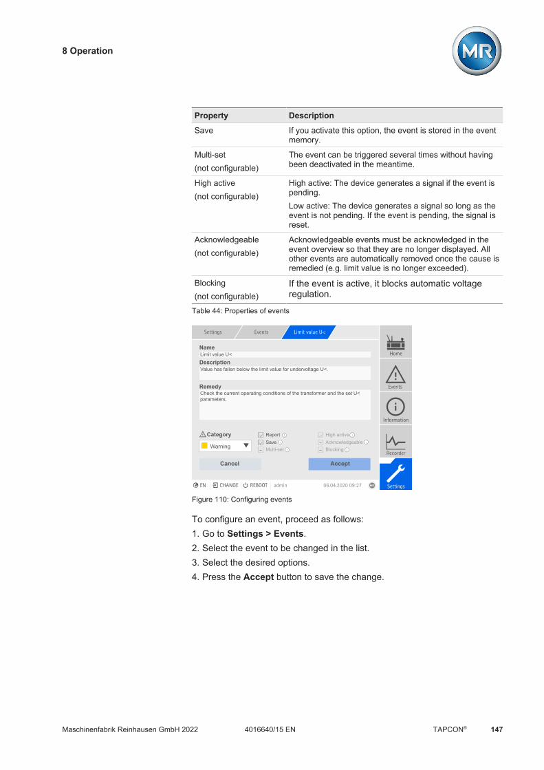
8 Operation
Maschinenfabrik Reinhausen GmbH 2022 1474016640/15 EN TAPCON®
Property Description
Save If you activate this option, the event is stored in the eventmemory.
Multi-set(not configurable)
The event can be triggered several times without havingbeen deactivated in the meantime.
High active(not configurable)
High active: The device generates a signal if the event ispending.Low active: The device generates a signal so long as theevent is not pending. If the event is pending, the signal isreset.
Acknowledgeable(not configurable)
Acknowledgeable events must be acknowledged in theevent overview so that they are no longer displayed. Allother events are automatically removed once the cause isremedied (e.g. limit value is no longer exceeded).
Blocking(not configurable)
If the event is active, it blocks automatic voltageregulation.
Table 44: Properties of events
Settings Events Limit value U<
Name
Description
Remedy
Category
Limit value U<
Value has fallen below the limit value for undervoltage U<.
Check the current operating conditions of the transformer and the set U< parameters.
Cancel Accept
Warning
ReportSaveMulti-set
High activeAcknowledgeableBlocking
Home
Events
Information
Recorder
SettingsEN CHANGE REBOOT admin 06.04.2020 09:27
Figure 110: Configuring events
To configure an event, proceed as follows:1. Go to Settings > Events.2. Select the event to be changed in the list.3. Select the desired options.4. Press the Accept button to save the change.

8 Operation
Maschinenfabrik Reinhausen GmbH 2022148 4016640/15 ENTAPCON®
8.2.14.3 Displaying event memory
Past events are stored in the event memory. You can adjust the display ofevents using different filters. The following filters are available for this pur-pose:
Filter Description
Time Date and time of event
Category Event category: Error (red) Warning (yellow) Info (gray)
Status Event coming/going: Event coming Event going
Components System components
Event Up to 3 events can be selected
To call up the event memory, proceed as follows:1. Go to Events > Event memory.
Figure 111: Event memory
2. Set the desired filters.3. Select the desired events in the Event list.4. Press the Search button to display the desired events.
Exporting events
You can export the event memory entries currently displayed as a csv file. Ifyou first create a filter, only the filtered entries are exported.

8 Operation
Maschinenfabrik Reinhausen GmbH 2022 1494016640/15 EN TAPCON®
To export the events, proceed as follows:ü First connect using Connect PC [Section 7.2, Page 79] or connect a
storage medium to the USB port on the CPU I [Section 4.5.5.2, Page33] module.
1. Click on the Export button.2. Select the desired option for data transmission (PC or USB).ð The data is exported.
8.2.15 User administration
User administration is based on a system of roles. You must assign a role toevery user. You can define access rights to parameters and events for eachrole.
8.2.15.1 User roles
The access rights to device functions and settings are controlled using a hi-erarchical system of roles. The system has 5 different roles with different ac-cess rights. Some of these access rights are fixed, but you can configure theaccess rights to particular parameters and events. Note the Setting accessrights to parameters and events [Section 8.2.15.4, Page 153] section.
If you are not logged in on the device, you will assume the "Data display"user role.
Upon delivery, the following roles are provided:
Role Description
Data display User who can only view data of relevance to operation. Display all parameters Display all events
Diagnostics User who can view data and log data of relevance to oper-ation. Display all parameters Display all events Export log data
Operator User who can view data of relevance to operation and ac-knowledge events. The user can perform manual tap-change operations using the device's controls. Display all parameters Display and acknowledge all events

8 Operation
Maschinenfabrik Reinhausen GmbH 2022150 4016640/15 ENTAPCON®
Role Description
Parameter configura-tor
User who can view and modify data of relevance to opera-tion. Display and modify all parameters Import and export parameters Display, modify, and acknowledge all events
Administrator User who can view and modify all data. Read all parameters Display, modify, and acknowledge all events
Table 45: Roles in delivery status
Access to the following areas of the device is linked to the roles:
Function Data display Diagnostics Operator Parameterconfigurator
Administrator
Administration - - - - +
Restart device - - + + +
Import - - - + +
Export - + - + +
Set date and time - - + + +
Calling up the commissioningwizard
- - - + +
Calibrate resistor contact se-ries
- - - + +
Actuation of the RAISE,LOWER, REMOTE, AVRAUTO, and AVR MANUALkeys
- - + + +
Setting topology - - - + +
Configuring analog inputs andoutputs
- - - + +
Configuring digital inputs andoutputs
- - - + +
Setting TPLE - - - + +
Configuring data points - - - + +
Calling up the maintenancewizard
- - - + +
Changing tap position table - - - + +
Enabling ECOTAP Modbus - - - + +
Adding sensors to the MRsensor bus
- - - + +
Table 46: Access rights permanently linked to the roles

8 Operation
Maschinenfabrik Reinhausen GmbH 2022 1514016640/15 EN TAPCON®
8.2.15.2 Changing the password
All users can change their passwords provided that the user account is notset up as a group account. You can only change a group account's pass-word if you are logged in as the administrator.
Note that the password must satisfy the following requirements: At least eight characters At least three of the four following character types
– Upper case letters– Lower case letters– Numbers– Special characters
To change the password, proceed as follows:1. Select the user name in the status line.
Figure 112: Changing the password
2. Enter the new password twice.3. Press the Accept button to save the changed password.
8.2.15.3 Creating, editing and deleting users
You can set the following options for all users: Username and password Role: You can assign a role to every user. The access rights to parame-
ters and events are linked to the roles. Group access: With this option, you can declare a user account to be a
group account (e.g. for access by different people). Users with group ac-cess cannot change their own password. The password can only bechanged by the administrator.
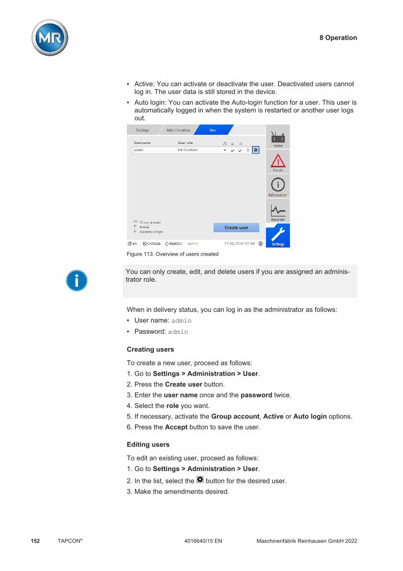
8 Operation
Maschinenfabrik Reinhausen GmbH 2022152 4016640/15 ENTAPCON®
Active: You can activate or deactivate the user. Deactivated users cannotlog in. The user data is still stored in the device.
Auto login: You can activate the Auto-login function for a user. This user isautomatically logged in when the system is restarted or another user logsout.
Figure 113: Overview of users created
You can only create, edit, and delete users if you are assigned an adminis-trator role.
When in delivery status, you can log in as the administrator as follows: User name: admin Password: admin
Creating users
To create a new user, proceed as follows:1. Go to Settings > Administration > User.2. Press the Create user button.3. Enter the user name once and the password twice.4. Select the role you want.5. If necessary, activate the Group account, Active or Auto login options.6. Press the Accept button to save the user.
Editing users
To edit an existing user, proceed as follows:1. Go to Settings > Administration > User.2. In the list, select the button for the desired user.3. Make the amendments desired.

8 Operation
Maschinenfabrik Reinhausen GmbH 2022 1534016640/15 EN TAPCON®
4. Press the Accept button to save the user.
Deleting user
To delete an existing user, proceed as follows:1. Go to Settings > Administration > User.2. In the list, select the button for the desired user.3. Press the Accept button to delete the user.
8.2.15.4 Setting access rights to parameters and events
You can configure access rights to parameters and events for the availableroles. The following options are available for this purpose: Read: Parameter/event may be displayed. Write: Parameter/event may be modified. Acknowledge: Event may be acknowledged.
Figure 114: Setting access rights for an event
You can only change access rights if you are assigned an administratorrole.
When in delivery status, you can log in as the administrator as follows: User name: admin Password: admin
Setting access rights to parameters/events1. Go to Settings > User administration > Parameter authorizations/
Event authorizations.ð A list of all parameters or events appears.

8 Operation
Maschinenfabrik Reinhausen GmbH 2022154 4016640/15 ENTAPCON®
2. Edit the desired entry in the list using the button.3. Select the desired options.4. Press the Accept button to save the change.5. Restart the device to apply the changed language setting.
8.2.15.5 User authentication via RADIUS (optional)
The device supports user authentication via RADIUS in accordance withRFC 2865. In this case, the device also functions as a RADIUS client. Touse RADIUS, you must create a dictionary for ISM® devices on your RA-DIUS server and set the parameters for RADIUS on the device.
Note the following information: Only use RADIUS in a secure network, as sensitive information is trans-
mitted. If a user ID has been created both on the RADIUS server and locally on
the device, the device first tries to log in via the RADIUS server. If it is notpossible to log in, the device will use the locally saved login data.
If a user ID has not been created on the RADIUS server, the device usesthe locally saved login data.
8.2.15.5.1 Creating a dictionary on the RADIUS server
You must create a dictionary for ISM® devices on your RADIUS server inaccordance with the following specification.VENDOR MR 34559BEGIN-VENDOR MR# AttributesATTRIBUTE MR-ISM-User-Group 1 integer# Predefined values for attribute 'MR-ISM-User-Group'VALUE MR-ISM-User-Group Administrator 1VALUE MR-ISM-User-Group Parameter-configurator 2VALUE MR-ISM-User-Group Operator 3VALUE MR-ISM-User-Group Diagnostics 4VALUE MR-ISM-User-Group Data-display 5END-VENDOR MR
If your RADIUS server supports the importing of a dictionary, you can exportthe dictionary for ISM® devices from the device and import it onto your RA-DIUS server. For more information, refer to the information in the section ti-tled Exporting data [Section 8.2.18.1, Page 158].
The user groups of the dictionary correspond to the user roles [Section8.2.15.1, Page 149] of the device and the corresponding authorizations.

8 Operation
Maschinenfabrik Reinhausen GmbH 2022 1554016640/15 EN TAPCON®
8.2.15.5.2 Configuring RADIUS
To establish a connection to the RADIUS server, you must set the followingparameters.
Settings Parameters RADIUS
Name Value
Activate RADIUS client Off
RADIUS server 0.0.0.0
RADIUS server port 1812
Authentication protocol CHAP
Key (shared secret) default
Home
Events
Information
Recorder
SettingsEN CHANGE REBOOT admin 04.02.2020 11:14
Figure 115: Configuring RADIUS
You can only configure RADIUS if you are assigned an administrator role.
When in delivery status, you can log in as the administrator as follows: User name: admin Password: admin1. Go to Settings > Parameters > System > RADIUS.2. Select the desired parameter.3. Set the parameter.4. Press the Accept button to save the modified parameter.
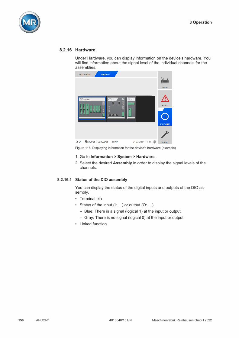
8 Operation
Maschinenfabrik Reinhausen GmbH 2022156 4016640/15 ENTAPCON®
8.2.16 Hardware
Under Hardware, you can display information on the device's hardware. Youwill find information about the signal level of the individual channels for theassemblies.
Figure 116: Displaying information for the device's hardware (example)
1. Go to Information > System > Hardware.2. Select the desired Assembly in order to display the signal levels of the
channels.
8.2.16.1 Status of the DIO assembly
You can display the status of the digital inputs and outputs of the DIO as-sembly. Terminal pin Status of the input (I: …) or output (O: …)
– Blue: There is a signal (logical 1) at the input or output.– Gray: There is no signal (logical 0) at the input or output.
Linked function

8 Operation
Maschinenfabrik Reinhausen GmbH 2022 1574016640/15 EN TAPCON®
Figure 117: Status of the DIO assembly
8.2.16.2 Status of the AIO assembly
You can display the status of the analog inputs and outputs of the AIO as-sembly. If a value is not within the permitted range, this value will be dis-played in red.
Figure 118: Status of the AIO assembly

8 Operation
Maschinenfabrik Reinhausen GmbH 2022158 4016640/15 ENTAPCON®
8.2.17 Software
Under Software, you can display the version status of the software compo-nents of the device.
Figure 119: Information about the device's software
Go to Information > System > Software.
8.2.18 Import/export manager
The device is equipped with an import/export manager, which can be usedto export and import various data.
To transfer the data, the following options are available:
Option Description
USB Data transfer via USB port on rear of CPU I/CPU II assembly.
PC Data transfer via PC using web-based visualization.
Table 47: Data transfer options
8.2.18.1 Exporting data
The device stops logging the measured value log data for the duration ofthe export.
You can export the following data from the device, depending on your deviceconfiguration:

8 Operation
Maschinenfabrik Reinhausen GmbH 2022 1594016640/15 EN TAPCON®
Backup
Option Description
System image (.rhi) Complete image of the system (software and configura-tion). If you are using the option "with history", all of theevent memory entries are also exported. If you selectthe "with TPLE" option, the customer program is ex-ported. You can select whether you would like to exportall records or only records from the last 10 days.
Settings (.rhi) Device settings: Parameters (settings, access rights) Events (category, behavior, text, access rights) User configurationIf available, the settings of the following functions arealso exported: Topology AIO configuration DIO configuration Tap position table Sensor bus Certificates
Customer program (TPLE)(.rhi)
Customer program export (TPLE).
Data point configuration(.rhi)
Data point configuration of the control system.
Table 48: Exporting data: Backup group
Information
Option Description
Operating instructions(.zip)
Operating instructions, protocol specifications.
Licenses (.zip) License text of the software components used.
SCADA configuration (.zip) Control system configuration (e.g. ICD file forIEC 61850).
Table 49: Exporting data: Information group

8 Operation
Maschinenfabrik Reinhausen GmbH 2022160 4016640/15 ENTAPCON®
System
Option Description
Event list (.csv) Complete list of all possible events.
Parameter list (.csv) Parameter list with descriptive text and values (min,max, current).
System configuration(.xml)
System configuration.
RADIUS library (.zip) Dictionary for importing on a RADIUS server.
Table 50: Exporting data: System group
Records
Option Description
Event log (.csv) All event memory entries.
Security log (.csv) Logbook of all instances of access and changes relat-ing to security.
Recorder (.zip) Measured value memory export.
VAM export (.zip) Export of vibro-acoustic records. You can export thedata in its entirety or select certain records.
Maintenance logbook(.xml)
Export of entries in the maintenance logbook.
Table 51: Exporting data: Records group
Only remove the USB stick once the data transfer is complete. Otherwise,data may be lost.
To export data, proceed as follows:1. Go to Settings > Export.2. Select the desired option for the export and follow the instructions on the
screen.

8 Operation
Maschinenfabrik Reinhausen GmbH 2022 1614016640/15 EN TAPCON®
8.2.18.2 Importing data (software version 3.800 and later)
Depending on your device configuration, you can import the following data:
Option Description
System image Complete image of the system (software and configura-tion), with or without history (recorded data).During import, you can select which of the followingsettings are to be imported: Parameters (settings, access rights) Events (category, behavior, text, access rights) User configurationIf available, you can also import the settings of the fol-lowing functions: Topology AIO configuration DIO configuration Tap position table Sensor bus Certificates
Customer program Customer program import (TPLE).
Language Import of additional languages. You can install a maxi-mum of five different languages on the device. If fivelanguages are already installed, you will be asked todelete one during the import process.
SSL certificate Import of an SSL certificate with associated key: Server certificate (.crt + .pem) Client certificate (.crt + .pem) Client CA (.crt)For the import, you will have to compress the certificate(*.crt) and key (*.pem) in a zip file.You can import certificates with the following key au-thentication: RSA with 1,024 bits ECDSA with 256 bits ("secp256r1" or "prime256v1"
curve).
8 Operation
Maschinenfabrik Reinhausen GmbH 2022162 4016640/15 ENTAPCON®
Option Description
Settings You can import device settings from a backup file ofthis device, an update file or a different device. Duringimport, you can select which of the following settingsare to be imported: Parameters (settings, access rights) Events (category, behavior, text, access rights) User configurationIf available, you can also import the settings of the fol-lowing functions: Topology AIO configuration DIO configuration Tap position table Sensor bus Certificates
Data point configuration Data point configuration import
SCADA configuration Import of the control system configuration (e.g. SCD filefor IEC 61850).
Table 52: Importing data
NOTICE Damage to the file system!The file system can become damaged due to an incorrect data transmissionprocess. A damaged file system can lead to the device no longer beingfunctional. Do not disconnect the device from the power supply during the import. During the import, do not remove the USB stick or disconnect the network
connection.
To import data, proceed as follows:1. Go to Settings > Import.2. Select the desired option for data transmission (PC or USB).3. Select Browse, select the file to be imported and select Start upload.
ð The file is checked.4. Optional: Select the desired options for the import.5. Press the Start update button.
ð NOTICE! The device function (monitoring/control) is stopped.ð The data is imported, then the device is restarted. During the restart, the
relays are reset.

8 Operation
Maschinenfabrik Reinhausen GmbH 2022 1634016640/15 EN TAPCON®
8.2.19 Configuring media converter with managed switch
Observe the following information on configuring the media converter withmanaged switch SW 3-3. Use the following browser to call up web-based vi-sualization: Firmware version 02.0.01: Internet Explorer 11 Firmware version 07.1.00 or higher: HTML5-compatible browser, e.g.,
Google Chrome
8.2.19.1 Commissioning
Before integrating the Ethernet switch into your network, you must reviewthe most important settings and adjust them if necessary. During thisprocess, follow the information outlined in this chapter for commissioning theEthernet switch.
Establishing a connection to the web-based visualization
The Ethernet switch is supplied with the following factory default settings: IPaddress 192.168.1.1; subnet mask 255.255.255.0; gateway address0.0.0.0.
For commissioning the Ethernet switch, proceed as follows:1. Establish connection with a computer via an Ethernet connection.2. Configure the computer so that it is in the same subnet as the Ethernet
switch.3. Access the IP address 192.168.1.1 using a browser.4. Login with the user information (login = admin; password = private).
Switch the language if necessary (German/English).
Figure 120: Login using a web interface

8 Operation
Maschinenfabrik Reinhausen GmbH 2022164 4016640/15 ENTAPCON®
Changing the user name and password1. Go to Device security > User administration.2. Create a new use with the administrator user role. Activate the user and
assign a password.3. NOTICE! Ensure that an additional user with the administrator user role
is present in addition to the "admin" user. Then delete the "admin" user.
4. Click on the button or Write to save the change.
Disabling unnecessary services
NOTICE Damage to the deviceIf you disable all services, you will no longer be able to access the devicelater to configure or update it. Leave at least one service for secure communication enabled (e.g., SN-
MPv3, SSH or HTTPS).
1. Go to Device security > Management Access.
Figure 121: Management Access
2. Select the tab for the desired service.3. Select Off to disable a service or use the checkboxes to disable sub-func-
tions of a service.
4. Click on the button or Write to save the change.

8 Operation
Maschinenfabrik Reinhausen GmbH 2022 1654016640/15 EN TAPCON®
Setting network settings1. Go to Basic settings > Grid > Global.
Figure 122: Network settings
2. Adjust the network settings and click on the button or Write to savethe changes.
3. In the Basic settings > Load/Save menu, click on the Save button to per-manently store the settings.
4. If necessary, establish a connection to the new IP address to continuechanging settings. Click on the Help button to find out more information.
5. Attach the cable for connecting to your network.
8.2.19.2 Configuration
You can use the web interface to configure the Ethernet switch. You can findmore information about the configuration using the online help in the web in-terface.
Calling up the web interface
To access the web interface, follow the instructions outlined in the Commis-sioning [Section 8.2.19.1, Page 163] chapter.
Selecting the redundancy protocol
To select the redundancy protocol, proceed as follows:1. Go to Redundancy.2. Select the specific menu item for the redundancy protocol.3. Change the configuration and select the On option in the Function group
field.4. In the Basic settings > Load/Save menu, click on the Save button to per-
manently store the settings.

8 Operation
Maschinenfabrik Reinhausen GmbH 2022166 4016640/15 ENTAPCON®
Deactivate the unused redundancy protocols by selecting the Off option inthe Function group field.
Resetting to factory settings
To reset the Ethernet switch to its factory default settings, proceed as fol-lows:1. Go to Basic settings > Load/Save and click on the Reset to factory de-
faults… button.2. Reestablish the connection to the IP address of 192.168.1.1 if necessary.3. Set the MR factory settings in accordance with the following table.
Menu Parameter MR factory setting
Redundancy Redundancy protocol PRP
Security > Pre-loginbanner
Login banner MR-specific
Basic setting > Portconfiguration
Ports 5+6 Deactivated
Table 53: MR factory setting
8.2.19.3 Updating the Firmware
To ensure the IT security of the device, we recommend always keeping theSW 3-3 assembly firmware up to date. The SW 3-3 assembly is based onthe Belden/Hirschmann EES-25 product. Therefore, follow the information inthe security bulletins published by Belden/Hirschmann: https://www.belden.com/security-assurance
You can obtain the firmware updates directly from the manufacturer Belden/Hirschmann: https://catalog.belden.com/index.cfm?event=pd&p=PF_942050003
Install the updates as described by the manufacturer Belden/Hirschmann.
Establishing a Connection1. Establish connection with a computer via an Ethernet connection.2. Configure the computer so that it is in the same subnet as the Ethernet
switch.3. Access the IP address 192.168.1.1 using a browser.4. Log in with the user data (default settings: login = admin; password =private). Switch the language if necessary (German/English).
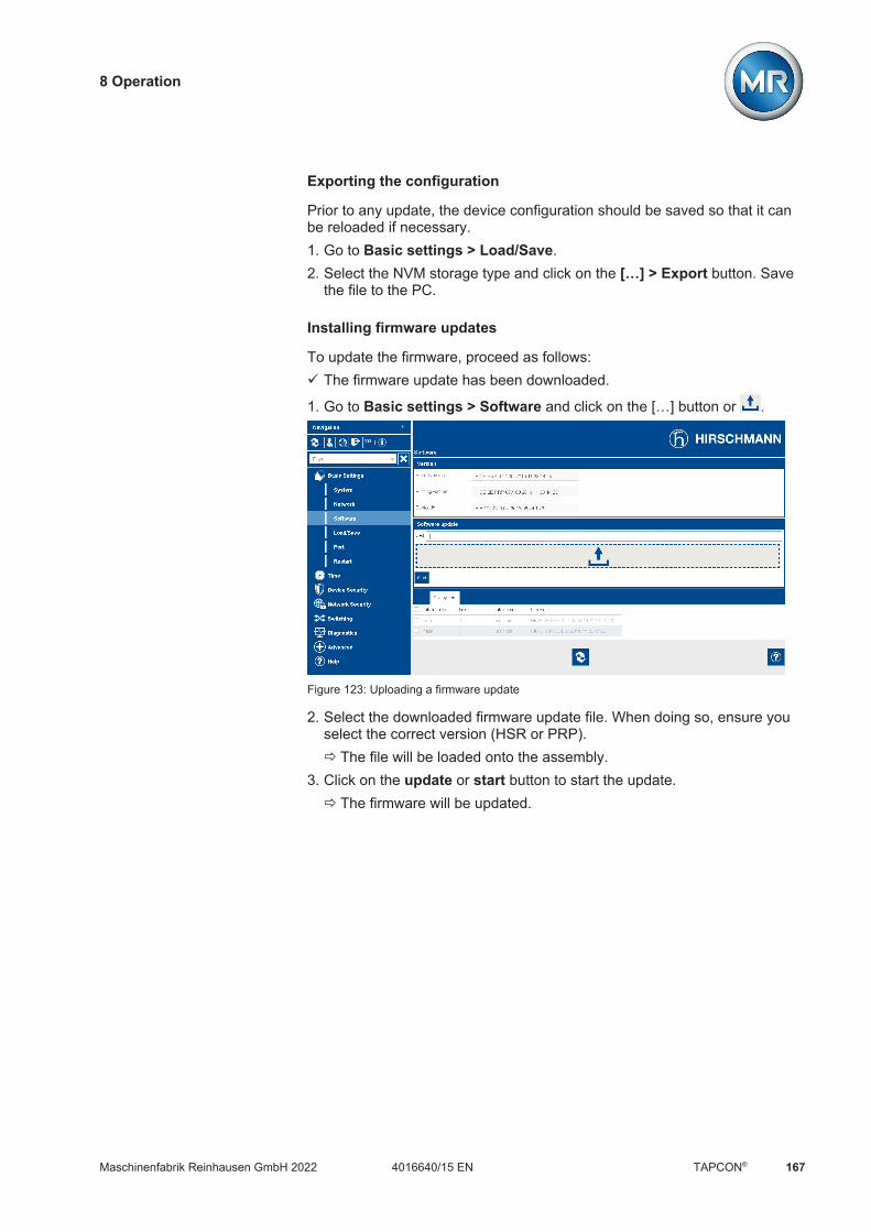
8 Operation
Maschinenfabrik Reinhausen GmbH 2022 1674016640/15 EN TAPCON®
Exporting the configuration
Prior to any update, the device configuration should be saved so that it canbe reloaded if necessary.1. Go to Basic settings > Load/Save.2. Select the NVM storage type and click on the […] > Export button. Save
the file to the PC.
Installing firmware updates
To update the firmware, proceed as follows:ü The firmware update has been downloaded.
1. Go to Basic settings > Software and click on the […] button or .
Figure 123: Uploading a firmware update
2. Select the downloaded firmware update file. When doing so, ensure youselect the correct version (HSR or PRP).ð The file will be loaded onto the assembly.
3. Click on the update or start button to start the update.ð The firmware will be updated.

8 Operation
Maschinenfabrik Reinhausen GmbH 2022168 4016640/15 ENTAPCON®
4. Once the update has been completed successfully: Go to Basic setting >Restart and click on the Cold start button to restart the assembly.
Figure 124: Restarting the assembly
5. Disconnect the PC connection via the Ethernet connection and re-estab-lish connection to your network.
8.2.20 Transformer Personal Logic Editor (TPLE)
You can use the Transformer Personal Logic Editor (TPLE) function to pro-gram simple logical links via the web-based visualization. You can also linkthe inputs and outputs available on the device using function modules.
Note that the device does not meet the requirements of a protective device.Therefore, do not use TPLE to produce protective functions.
8.2.20.1 Function
8.2.20.1.1 Function groups
There are 10 function groups available that you can use to combine varioussub-tasks into one function. In one function group, you can link up to 12function modules with variables. You can rename function groups and acti-vate or deactivate them individually.
8.2.20.1.2 Variables
The following types of variables for information processing are available forTPLE: Event inputs: You can use all the device's events as inputs for a function. Event outputs: 100 generic events are available as outputs for functions.

8 Operation
Maschinenfabrik Reinhausen GmbH 2022 1694016640/15 EN TAPCON®
Binary inputs: You can use all the device's configured digital inputs and upto 42 generic inputs of the device as inputs for a function.
Binary outputs: You can use all the device's configured digital outputs andup to 20 generic outputs of the device as outputs for a function. If there isa control system present, 10 generic control system messages are avail-able.
Analog inputs: You can use all the device's configured analog inputs as in-puts for a function.
Binary flags: You can use up to 100 binary flags as variables to store in-termediate values. You can use binary flags as inputs and outputs for afunction.
Analog flags: You can use up to 50 analog flags as variables to store in-termediate values. You can use analog flags as inputs and outputs for afunction.
Discrete inputs: You can use all the device's available discrete inputs asinputs for a function.
8.2.20.1.3 Function modules
TPLE provides various function modules for processing the information.
8.2.20.1.3.1 AND
Description AND, logical AND link
Inputs Input 1…4 (BOOL)
Outputs Output (BOOL)
Parameter None
Function If all configured inputs are TRUE, the output is TRUE,otherwise it is FALSE.
Initial state All inputs and outputs are FALSE.Non-configured inputs are assumed to be TRUE.If no input is configured, the module is not run so it re-mains in its initial state.
Table 54: AND function module
8.2.20.1.3.2 NAND
Description NAND, logical NOT-AND link
Inputs Input 1…4 (BOOL)
Outputs Output (BOOL)
Parameter None
8 Operation
Maschinenfabrik Reinhausen GmbH 2022170 4016640/15 ENTAPCON®
Function If all configured inputs are TRUE, the output is FALSE,otherwise it is TRUE.
Initial state All inputs and outputs are FALSE.Non-configured inputs are assumed to be TRUE sothat they have no impact on the output.If no input is configured, the output therefore remains inthe initial state of FALSE.
Table 55: NAND function module
8.2.20.1.3.3 OR
Description OR, logical OR link
Inputs Input 1…4 (BOOL)
Outputs Output (BOOL)
Parameter None
Function If one of configured inputs is TRUE, the output isTRUE, otherwise it is FALSE.
Initial state All inputs and outputs are FALSE.Non-configured inputs are assumed to be FALSE.
Table 56: OR function module
8.2.20.1.3.4 NOR
Description NOR, logical NOT-OR link
Inputs Input 1…4 (BOOL)
Outputs Output (BOOL)
Parameter None
Function If all configured inputs are FALSE, the output is TRUE,otherwise it is FALSE.
Initial state All inputs and outputs are FALSE.Non-configured inputs are assumed to be FALSE sothat they have no impact on the output.If no input is configured, the output remains in the initialstate of FALSE anyway.
Table 57: NOR function module
8.2.20.1.3.5 XOR
Description XOR, logical EXCLUSIVE-OR link
Inputs Input 1…2 (BOOL)
Outputs Output (BOOL)
Parameter None

8 Operation
Maschinenfabrik Reinhausen GmbH 2022 1714016640/15 EN TAPCON®
Function If an odd number of inputs is TRUE, the output isTRUE, otherwise it is FALSE.
Initial state All inputs and outputs are FALSE.Non-configured inputs are assumed to be FALSE sothat they have no impact on the output.If no input is configured, the output therefore remains inthe initial state of FALSE.
Table 58: XOR function module
8.2.20.1.3.6 NOT
Description NOT, logical NOT link
Inputs Input (BOOL)
Outputs Output (BOOL)
Parameter None
Function If the input is TRUE, the output is FALSE, otherwise itis TRUE.
Initial state All inputs and outputs are FALSE.If the input is not configured, it is assumed to be TRUEso that the output remains in the initial state of FALSE.
Table 59: NOT function module
8.2.20.1.3.7 Current impulse relay
Description RS, current impulse relay
Inputs Trigger (BOOL)Set (BOOL)Reset (BOOL)
Outputs Output (BOOL)
Parameter None
Function If the Reset input is TRUE, Output forcibly becomesFALSE.If the Reset input is FALSE and the Set input is TRUE,Output forcibly becomes TRUE.If the Reset and Set inputs are FALSE, the status ofOutput changes when there is a rising edge at the Trig-ger input. If there is no edge at the Trigger input, Out-put remains unchanged.
Initial state All inputs and outputs are FALSE.
Non-configured inputs are assumed to be FALSEso that they have no impact on the output.
Table 60: Current impulse relay function module
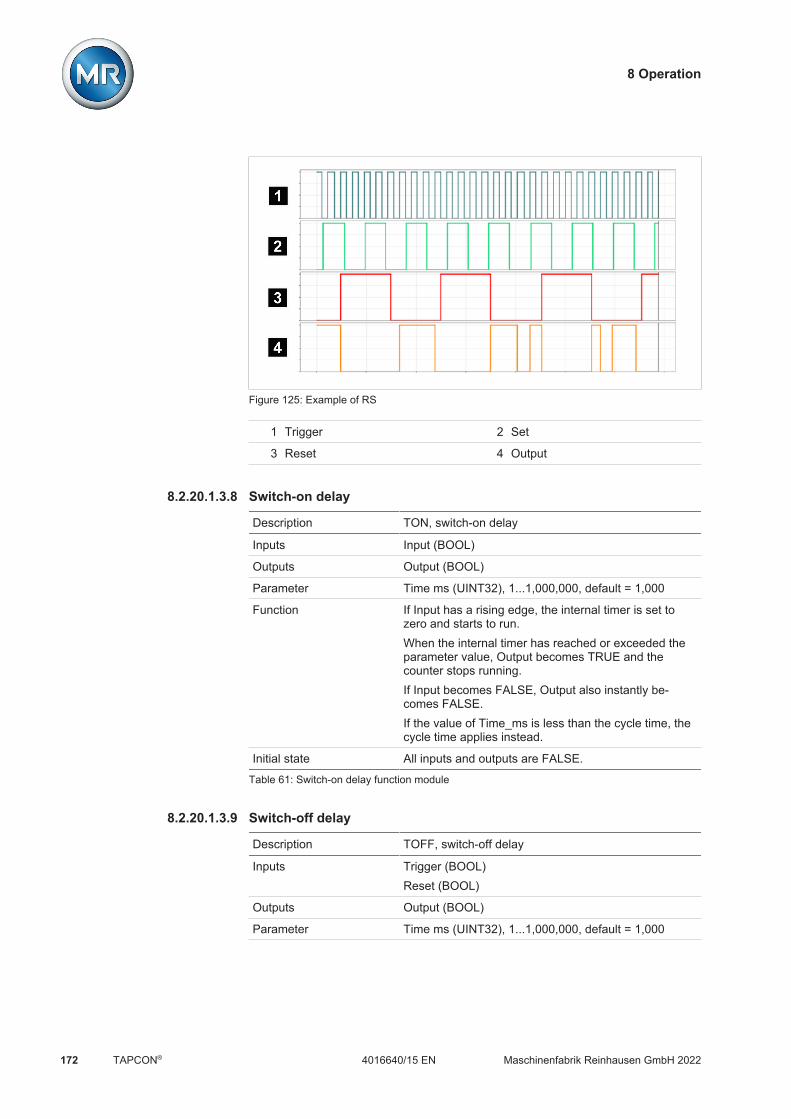
8 Operation
Maschinenfabrik Reinhausen GmbH 2022172 4016640/15 ENTAPCON®
Figure 125: Example of RS
1 Trigger 2 Set
3 Reset 4 Output
8.2.20.1.3.8 Switch-on delay
Description TON, switch-on delay
Inputs Input (BOOL)
Outputs Output (BOOL)
Parameter Time ms (UINT32), 1...1,000,000, default = 1,000
Function If Input has a rising edge, the internal timer is set tozero and starts to run.When the internal timer has reached or exceeded theparameter value, Output becomes TRUE and thecounter stops running.If Input becomes FALSE, Output also instantly be-comes FALSE.If the value of Time_ms is less than the cycle time, thecycle time applies instead.
Initial state All inputs and outputs are FALSE.
Table 61: Switch-on delay function module
8.2.20.1.3.9 Switch-off delay
Description TOFF, switch-off delay
Inputs Trigger (BOOL)Reset (BOOL)
Outputs Output (BOOL)
Parameter Time ms (UINT32), 1...1,000,000, default = 1,000

8 Operation
Maschinenfabrik Reinhausen GmbH 2022 1734016640/15 EN TAPCON®
Function If Input becomes TRUE, Output also instantly becomesTRUE, this condition takes priority.If Input has a falling input, the internal timer is set tozero and starts to run.When the internal timer has reached or exceeded theparameter value, Output becomes FALSE and thecounter stops running.If Input is FALSE and the Reset input becomes TRUE,Output instantly and forcibly becomes FALSE and theinternal timer is set to the configured desired value.If the value of Time_ms is less than the cycle time, thecycle time applies instead.
Initial state All inputs and outputs are FALSE.
Table 62: Switch-off delay function module
8.2.20.1.3.10 Pulse
Description PLSE, pulse
Inputs Trigger (BOOL)
Outputs Output (BOOL)
Parameter Time ms (UINT32), 1...1,000,000, default = 1,000
Function If there is a rising edge at the Trigger input at any time,the internal timer is set to zero and starts to run, theoutput becomes TRUE.If the Trigger input becomes FALSE again during thepulse time, this has no impact on the expiration of thepulse time.Once the internal timer has expired, the output be-comes FALSE.If the value of Time_ms is less than the cycle time, thecycle time applies instead.
Initial state All inputs and outputs are FALSE.
Table 63: Pulse function module
8.2.20.1.3.11 Symmetrical pulse generator
Description CLCK, symmetrical pulse generator
Inputs Enable (BOOL)
Outputs Output (BOOL)
Parameter Time ms (UINT32), 1...1,000,000, default = 1,000

8 Operation
Maschinenfabrik Reinhausen GmbH 2022174 4016640/15 ENTAPCON®
Function The internal timer runs for a long as Enable is TRUE.When the internal timer has reached or exceeded theconfigured time value, the status of the output changesand the timer is restarted. The configured time there-fore corresponds to half the period duration of the re-sulting signal. If the Enable input becomes FALSE, theoutput also instantly becomes FALSE and the internaltimer is reset.If the value of Time_ms is less than the cycle time, thecycle time applies instead.
Initial state All inputs and outputs are FALSE.
Table 64: Symmetrical pulse generator function module
8.2.20.1.3.12 Counter (forwards/backwards)
Description COUNT, incremental counter
Inputs Trigger (BOOL)Direction (BOOL)Reset (BOOL)Lock (BOOL)
Outputs SINT32 (SINT32)REAL32 (REAL32)
Parameter Reset value (SINT32), -10,000,000… +10,000,000, de-fault = 0
Function If there is a rising edge at Reset, the output value is setto the value of the Reset value parameter. A risingedge at Reset takes priority over all other inputs.For as long as Lock is TRUE, the pulse signal is notevaluated and the counter reading is retained. If no in-put is assigned, the default value FALSE is assumed.When Direction input = FALSE, the output value is in-cremented by one with every rising edge at the Triggerinput.When Direction input = TRUE, the output value isdecremented by one with every rising edge at the Trig-ger input.
Initial state All inputs and outputs are zero or FALSE.Table 65: Counter (forwards/backwards) function module

8 Operation
Maschinenfabrik Reinhausen GmbH 2022 1754016640/15 EN TAPCON®
Figure 126: Example of COUNT
1 Trigger 2 Direction
3 Reset 4 Lock
5 Output
8.2.20.1.3.13 Analog threshold value switch with hysteresis
Designation THRES, threshold value switch with hysteresis
Inputs Input (REAL32)
Outputs Output (BOOL)Error (BOOL)
Parameter On Limit (REAL32), -10,000,000… +10,000,000, de-fault = 10,000,000Off Limit (REAL32), -10,000,000 … +10,000,000, de-fault = -10,000,000
Function On Limit ≥ Off Limit setting: If the value of Input is greater than On Limit, Output
becomes TRUE. If the value of Input is less than or equal to Off Limit,
Output becomes FALSE.On Limit < Off Limit setting: If the value of Input is greater than On Limit and at
the same time less than Off Limit, Output becomesTRUE. Otherwise, the Output is FALSE.
Initial state All inputs and outputs are zero or FALSE.Table 66: Analog threshold value switch with hysteresis function module

8 Operation
Maschinenfabrik Reinhausen GmbH 2022176 4016640/15 ENTAPCON®
On
Off
Input
Output FALSE TRUE FALSE
Figure 127: Analog threshold value switch with the On Limit > Off Limit setting
Off
On
Input
Output FALSE TRUE FALSEFALSETRUE TRUE
Figure 128: Analog threshold value switch with the On Limit < Off Limit setting
8.2.20.1.3.14 Analog multiplication
Description MUL, analog multiplication
Inputs Value (REAL32)Multiplier (REAL32)
Outputs Result (REAL32)Overflow (BOOL)
Parameter Constant multiplier (REAL32), -1,000,000...+1,000,000;default = 1
Function Result = Value * Multiplier * Constant multiplierIf the REAL32 range of numbers is exceeded, theOverflow output becomes TRUE.
Initial state All inputs and outputs are zero or FALSE.
Table 67: Analog multiplication function module

8 Operation
Maschinenfabrik Reinhausen GmbH 2022 1774016640/15 EN TAPCON®
8.2.20.1.3.15 Analog division
Description DIV, analog division
Inputs Divident (REAL32)Divisor (REAL32)
Outputs Result (REAL32)DivByZero (BOOL)Overflow (BOOL)
Parameter Constant divisor (REAL32), -1,000,000...+1,000,000;default = 1
Function Result = Dividend / Divisor / Constant DivisorIf dividing by zero, the DivByZero output becomesTRUE and Result is set to zero.If the REAL32 range of numbers is exceeded, theOverflow output becomes TRUE and Result is set tozero.
Initial state All inputs and outputs are zero or FALSE.
Table 68: Analog division function module
8.2.20.1.3.16 Analog addition
Description ADD, analog addition
Inputs Input 1 (REAL32)Input 2 (REAL32)
Outputs Result (REAL32)Overflow (BOOL)
Parameter Offset (REAL32), -1,000,000...+1,000,000; default = 0
Function Result = Input 1 + Input 2 + OffsetIf the REAL32 range of numbers is exceeded, theOverflow output becomes TRUE.
Initial state All inputs and outputs are zero or FALSE.
Table 69: Analog addition function module
8.2.20.1.3.17 Analog subtraction
Description SUB, analog subtraction
Inputs Input 1 (REAL32)Input 2 (REAL32)
Outputs Result (REAL32)Overflow (BOOL)
Parameter Offset (REAL32), -1,000,000...+1,000,000; default = 0

8 Operation
Maschinenfabrik Reinhausen GmbH 2022178 4016640/15 ENTAPCON®
Function Result = Input 1 - Input 2 – OffsetIf the REAL32 range of numbers is exceeded, theOverflow output becomes TRUE.
Initial state All inputs and outputs are zero or FALSE.
Table 70: Analog subtraction function module
8.2.20.1.3.18 Rising edge
Description RTRG, rising edge trigger
Inputs Input (BOOL)
Outputs Output (BOOL)
Parameter -
Function When the input changes from FALSE to TRUE, theoutput becomes TRUE for one cycle of the functiongroup and then changes back to FALSE.
Initial state All inputs and outputs are FALSE.
Table 71: Rising edge function module
8.2.20.1.3.19 Falling edge
Description FTRG, falling edge trigger
Inputs Input (BOOL)
Outputs Output (BOOL)
Parameter -
Function When the input changes from TRUE to FALSE, theoutput becomes TRUE for one cycle of the functiongroup and then changes back to FALSE.
Initial state All inputs and outputs are FALSE.
Table 72: Falling edge function module
8.2.20.1.3.20 Average value
Description AVRG, average value
Inputs Input (REAL32)Enable (BOOL)Reset (BOOL)Autorepeat (BOOL)
Outputs Average (REAL32)Done (BOOL)Started (BOOL)SampleCount (UINT32)

8 Operation
Maschinenfabrik Reinhausen GmbH 2022 1794016640/15 EN TAPCON®
Parameter Time ms (UINT32): 1...2,000,000,000, default = 10,000Sample time ms (UINT32): 1...10,000,000, default =1,000
Function Averaging starts with a rising edge of Enable. Thisdoes not affect averaging which is already underway.Any output value remaining from earlier is retained.The Done output becomes FALSE, the Started outputbecomes TRUE.Active averaging is interrupted with a rising edge of Re-set. Average is set to zero, Done and Started becomeFALSE. If Enable is also TRUE during the rising Resetedge, a new averaging process is started.Done becomes TRUE and Started becomes FALSEonce averaging is complete. Done remains TRUE untila Reset is detected or new averaging is triggered by arising edge of Enable.If AutoRepeat and Enable are TRUE, a new averagingprocess is automatically started each time averaging iscompleted. Done is set for one cycle each time averag-ing is completed.The SampleCount output states how many sampleshave already been recorded.Sample time ms is the desired sample time in millisec-onds. It is rounded up to the next whole multiple of thetask cycle time and has a lower limit of at least onetask cycle time.Time ms is the time period desired for averaging. It isinternally rounded up to the next whole multiple of thesample time and has a lower limit of at least one sam-ple time.
Initial state All inputs and outputs are FALSE.Table 73: Average value function module

8 Operation
Maschinenfabrik Reinhausen GmbH 2022180 4016640/15 ENTAPCON®
Figure 129: AVRG
1 Input 2 Enable
3 Reset 4 AutoRepeat
5 Average 6 Done
7 Started 8 SampleCount
8.2.20.1.3.21 Scaling
Description SCAL, scaling
Inputs Input (REAL32)
Outputs Output (REAL32)Error (BOOL)
Parameter Min In (REAL32): -10,000,000...+10,000,000, default =-10,000,000Max In (REAL32): -10,000,000...+10,000,000, default =+10,000,000Min Out (REAL32): -10,000,000...+10,000,000, default= -10,000,000Max Out (REAL32): -10,000,000...+10,000,000, default= +10,000,000
8 Operation
Maschinenfabrik Reinhausen GmbH 2022 1814016640/15 EN TAPCON®
Function Output is calculated using the following formula:Output = Min Out + (Max Out - Min Out) x(Input – Min In) / (Max In – Min In)
Output is set to 0 and Error = TRUE when: Input is not within the parameters Min In and Max In Min In is greater than Max In Min Out is greater than Max Out Max In is the same size as Min In (division by zero)
Initial state All inputs and outputs are FALSE.
Table 74: Scaling function module
8.2.20.1.3.22 Bridge
Designation BRDG, Bridge
Inputs Analog Input (REAL32)Digital Input (BOOL)
Outputs Analog Output (REAL32)Digital Output (BOOL)
Parameter -
Function Copies the value of Analog Input to Analog Output andDigital Input to Digital Output.
Initial state All inputs and outputs are zero or FALSE.
Table 75: Bridge function module
8.2.20.1.3.23 RTOI
Description RTOI, Real-to-Integer conversion
Inputs Analog Input (REAL32)
Outputs Analog Output (SINT32)
Parameter -
Function Copies the value of Analog Input to Analog Output andconverts REAL32 to SINT32.
Initial state All inputs and outputs are zero.
Table 76: RTOI function module
8.2.20.1.3.24 ITOR
Description ITOR, Integer-to-real conversion
Inputs UINT32 (UINT32)SINT32 (SINT32)
Outputs Output U (REAL32)Output S (REAL32)
8 Operation
Maschinenfabrik Reinhausen GmbH 2022182 4016640/15 ENTAPCON®
Parameter -
Function The value of UINT32 is output converted to Output U,the value of SINT32 is output converted to Output S.
Initial state All inputs and outputs are zero.
Table 77: NAND function module
8.2.20.2 Configuring TPLE
You can configure TPLE on a PC using the web-based visualization. Only alive view is available on the device's display. To configure TPLE, you have tohold the role of Administrator or Parameterizer.
When in delivery status, you can log in as the administrator as follows: User name: admin Password: admin
8.2.20.2.1 Editing variables
You can adapt the name and description of the following variables: Binary inputs Binary outputs Analog inputs Binary flags Analog flags Discrete inputs
The names and descriptions of the generic events can also be adapted likeall other device events. Note the Event management [Section 8.2.14,Page 145] section.
The permissible number of characters is limited: Name: Maximum of 20 characters Description: Maximum of 80 characters

8 Operation
Maschinenfabrik Reinhausen GmbH 2022 1834016640/15 EN TAPCON®
Figure 130: Editing variable
To edit the variable, proceed as follows:1. Go to Settings > TPLE > Variables.2. Select the variable you want.3. Enter the name and description.4. Press the Accept button to save the modified variable.
8.2.20.2.2 Creating functions
Within one function group, you can create up to 12 function modules to de-pict one function. To create, edit or delete a function, you have to call up thefunction group you want. To do so, proceed as follows:1. Go to Settings > TPLE > Function group.2. Select the function group you want.
Figure 131: Function group

8 Operation
Maschinenfabrik Reinhausen GmbH 2022184 4016640/15 ENTAPCON®
Creating function modules
To create a function module, proceed as follows: Press the + button to create a new function module.
Deleting function modules
To delete a function module, proceed as follows: Drag the desired function module to the trash can using drag & drop.
Sorting function modules
To sort a function module, proceed as follows: Drag the desired function module to the desired position using drag &
drop.
Editing function module
To edit a function module, proceed as follows:1. Select the desired function module.2. Press the Edit button.
Figure 132: Editing function module
3. Select the inputs and outputs you want and set the parameters.4. Press the Accept button to save the change to the function module.
8.2.20.2.3 Renaming function group
If necessary, you can rename the function group in order to better assign it.
To rename a function group, proceed as follows:1. Go to Settings > TPLE > Function group.2. Select the function group you want.

8 Operation
Maschinenfabrik Reinhausen GmbH 2022 1854016640/15 EN TAPCON®
3. Select the text field with the name of the function group and enter thename you want.
Figure 133: Renaming function group
4. Press [Enter] to accept the change.
8.2.20.2.4 Activating/deactivating function group
You can fully activate or deactivate a function group. When you deactivate afunction group, none of the function group's function modules are processed.
To activate/deactivate a function group, proceed as follows:1. Go to Settings > TPLE > Function group.2. Select the function group you want.3. Press the Inactive button.ð Red X: Function group is inactive; gray X: Function group is active.

8 Operation
Maschinenfabrik Reinhausen GmbH 2022186 4016640/15 ENTAPCON®
8.2.21 Displaying temperature curve (optional)
If you are using additional temperature sensors (generic temperature 1...8),you can display the temperature curve for these temperatures over the last10 days. To do so, proceed as follows:
Figure 134: Generic temperatures
Go to Information System > Gener. temperatures.

8 Operation
Maschinenfabrik Reinhausen GmbH 2022 1874016640/15 EN TAPCON®
8.3 Power grid
8.3.1 Transformer data
The transformation ratios and measuring set-up for the voltage and currenttransformers used in the system can be set with the following parameters.The device uses this information to calculate the corresponding measuredvalues on the primary side of the current transformer (and therefore thetransformer) from the recorded measured values. These are then displayed.
8.3.1.1 Setting transformer data
You can use the following parameters to set the transformer data. Also notethe Examples for standard circuits for current transformers and voltagetransformers [Section 8.3.1.2, Page 189].
Settings Parameters Transfor...ata
Name Value
Primary transformer voltage 100 kV
Secondary transformer voltage 100 V
Primary transformer current 100 A
Secondary transformer current 1 A
Phase angle correction 0°
Voltage-transformer circuit 1 Ph phase voltage
Current-transformer circuit 1 Ph phase current
Home
Events
Information
Recorder
SettingsEN CHANGE REBOOT admin 03.02.2020 08:09
Figure 135: Transformer data
1. Go to Settings > Parameters > Grid > Transformer data.2. Select the desired parameter.3. Set the desired parameter.4. Press the Accept button to save the modified parameter.
Primary transformer voltage
You can use this parameter to set the primary voltage of the voltage trans-former in kV.
Secondary transformer voltage
You can use this parameter to set the secondary voltage of the voltagetransformer in kV.

8 Operation
Maschinenfabrik Reinhausen GmbH 2022188 4016640/15 ENTAPCON®
Primary transformer current
You can use this parameter to set the primary current of the current trans-former.
Secondary transformer current
You can use this parameter to set the secondary current of the current trans-former. You can select the following options: 0.2 A 1 A 5 A
Measurement mode
If you are measuring the voltage and current with the 3-phase measuringmodule, you can use this parameter to set whether you have connected thevoltage transformer between two phases or between a phase and neutral.
Phase angle correction
You can use this parameter to set the phase angle correction for your trans-former circuit.
Voltage-transformer circuit
You can use this parameter to set your voltage transformer's circuit. You canselect the following options:
Option Description
1 Ph phase voltage Measurement in 1-phase grid betweenthe conductor and neutral conductor.
3 Ph differential voltage Measurement in 3-phase grid between 2conductors
3 Ph phase voltage Measurement in 3-phase grid betweenthe conductor and neutral conductor
Table 78: Voltage-transformer circuit

8 Operation
Maschinenfabrik Reinhausen GmbH 2022 1894016640/15 EN TAPCON®
Current-transformer circuit
You can use this parameter to set the circuit for your current transformer.You can select the following options:
Option Description
1 Ph phase current Measurement of phase current in 1-phasegrid.
3 Ph total current Measurement of differential current in 3-phase grid.
3 Ph phase current Measurement of phase current in 3-phasegrid.
Table 79: Current-transformer circuit
Voltage balance
You can use this parameter to set a correction value for the voltage mea-surement in order to compensate for deviations through the measuring sec-tion. The devices adds the correction value to the measured voltage (sec-ondary side).
If the voltage is measured with a 3-phase measurement module, you canonly set the voltage balance if you select the "1-ph. measurement" option forthe parameter UI measuring channels [Page 203].
8.3.1.2 Circuit examples for voltage transformers and current transformers
Below you will find different examples of circuits for voltage transformers andcurrent transformers and the corresponding settings.
8.3.1.2.1 1-phase measurement
Circuit 1-A
UI
L1
N
VTCT
UL1 IL1
L N k l
The voltage transformer VT is connected to the phase conductor and neu-tral conductor.
The current transformer CT is looped into the phase conductor. The voltage UL1 and current IL1 are in phase. The voltage drop on a phase conductor is determined by the current IL1.

8 Operation
Maschinenfabrik Reinhausen GmbH 2022190 4016640/15 ENTAPCON®
If you use this circuit, set the device as follows:
Parameters Option
Voltage-transformer circuit 1 Ph phase voltage
Current-transformer circuit 1 Ph phase current
Phase angle correction 0°
Table 80: Circuit 1-A
Circuit 1-B
UL1 IL1
L1
L2
L3N
VTCT UL1 IL1
IL2
IL3UL3
UL2
UIL N k l
The voltage transformer VT is connected to the phase conductor L1 andthe neutral conductor.
The current transformer CT is looped into the phase conductor L1. The voltage U and current I are in phase. The voltage drop on a phase conductor is determined by the current IL1.
If you use this circuit, set the device as follows:
Parameters Option
Voltage-transformer circuit 3 Ph phase voltage
Current-transformer circuit 3 Ph phase current
Phase angle correction 0°
Table 81: Circuit 1-B
Circuit 1-C
L1
L2
L3UL1 IL1
VTCT1
UL1 IL1
IL2
IL3UL3
UL2
CT2 UL1-UL2-UL2 IL1-IL2
-IL2
UIL N k l
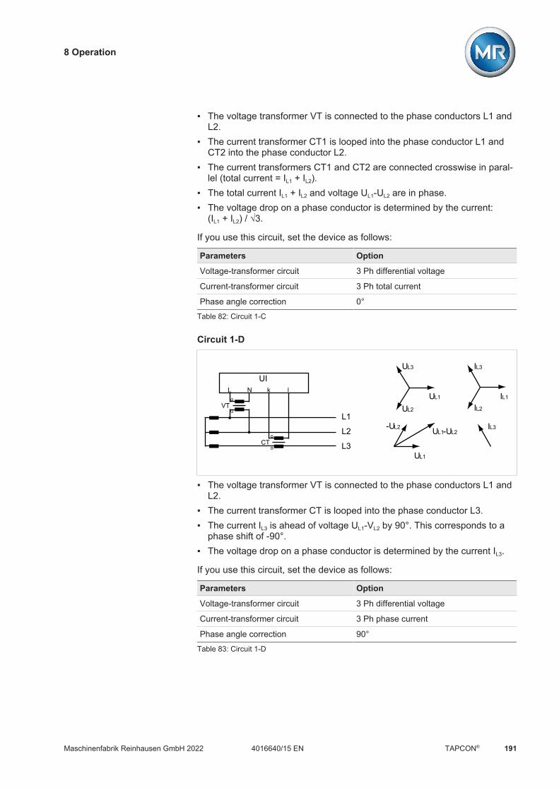
8 Operation
Maschinenfabrik Reinhausen GmbH 2022 1914016640/15 EN TAPCON®
The voltage transformer VT is connected to the phase conductors L1 andL2.
The current transformer CT1 is looped into the phase conductor L1 andCT2 into the phase conductor L2.
The current transformers CT1 and CT2 are connected crosswise in paral-lel (total current = IL1 + IL2).
The total current IL1 + IL2 and voltage UL1-UL2 are in phase. The voltage drop on a phase conductor is determined by the current:
(IL1 + IL2) / √3.
If you use this circuit, set the device as follows:
Parameters Option
Voltage-transformer circuit 3 Ph differential voltage
Current-transformer circuit 3 Ph total current
Phase angle correction 0°
Table 82: Circuit 1-C
Circuit 1-D
L1
L2
L3UL1
VT
CT
UL1 IL1
IL2
IL3UL3
UL2
UL1-UL2-UL2 IL3
UIL N k l
The voltage transformer VT is connected to the phase conductors L1 andL2.
The current transformer CT is looped into the phase conductor L3. The current IL3 is ahead of voltage UL1-VL2 by 90°. This corresponds to a
phase shift of -90°. The voltage drop on a phase conductor is determined by the current IL3.
If you use this circuit, set the device as follows:
Parameters Option
Voltage-transformer circuit 3 Ph differential voltage
Current-transformer circuit 3 Ph phase current
Phase angle correction 90°
Table 83: Circuit 1-D

8 Operation
Maschinenfabrik Reinhausen GmbH 2022192 4016640/15 ENTAPCON®
Circuit 1-E
L1
L2
L3 UL2
VT
CT
UL1 IL1
IL2
IL3UL3
UL2
UL2-UL1
-UL1
IL2
UIL N k l
The voltage transformer VT is connected to the phase conductors L1 andL2.
The current transformer CT is looped into the phase conductor L2. The current IL2 is ahead of voltage UL2-UL1 by 30°. This corresponds to a
phase shift of -30°. The voltage drop on a phase conductor is determined by the current IL2.
If you use this circuit, set the device as follows:
Parameters Option
Voltage-transformer circuit 3 Ph differential voltage
Current-transformer circuit 3 Ph phase current
Phase angle correction 30°
Table 84: Circuit 1-E
Circuit 1-F
IL1
L1
L2
L3
VTCT
UL1 IL1
IL2
IL3UL3
UL2
UL1
UL1-UL2-UL2
UIL N k l
The voltage transformer VT is connected to the phase conductors L1 andL2.
The current transformer CT is looped into the phase conductor L1. The current IL1 lags behind voltage UL1-UL2 by 30°. This corresponds to a
phase shift of +30° and a correction value of -30°. The voltage drop on a phase conductor is determined by the current IL1.
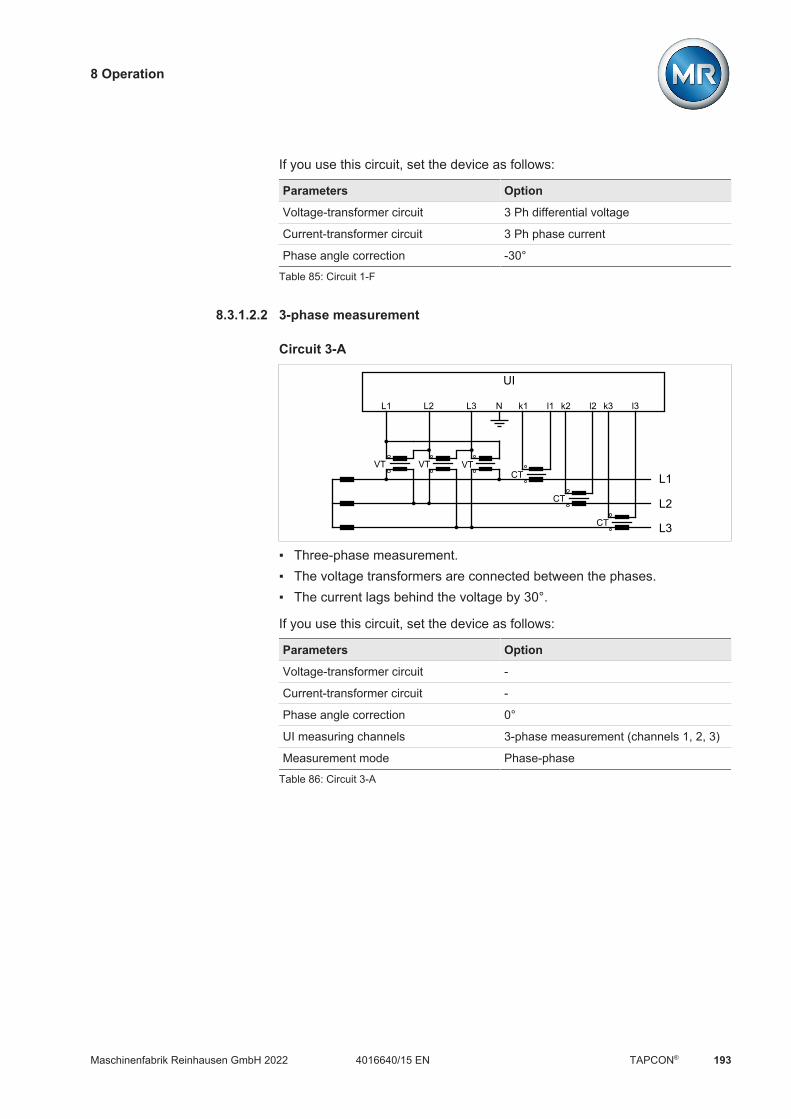
8 Operation
Maschinenfabrik Reinhausen GmbH 2022 1934016640/15 EN TAPCON®
If you use this circuit, set the device as follows:
Parameters Option
Voltage-transformer circuit 3 Ph differential voltage
Current-transformer circuit 3 Ph phase current
Phase angle correction -30°
Table 85: Circuit 1-F
8.3.1.2.2 3-phase measurement
Circuit 3-A
L1
L2
L3
VTVT VTCT
CT
CT
UI
L1 L2 L3 N k1 l1 k2 l2 k3 l3
Three-phase measurement. The voltage transformers are connected between the phases. The current lags behind the voltage by 30°.
If you use this circuit, set the device as follows:
Parameters Option
Voltage-transformer circuit -
Current-transformer circuit -
Phase angle correction 0°
UI measuring channels 3-phase measurement (channels 1, 2, 3)
Measurement mode Phase-phase
Table 86: Circuit 3-A
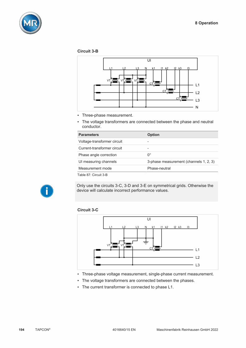
8 Operation
Maschinenfabrik Reinhausen GmbH 2022194 4016640/15 ENTAPCON®
Circuit 3-B
L1
L2
L3
N
UI
VTVT VTCT
CT
CT
L1 L2 L3 N k1 l1 k2 l2 k3 l3
Three-phase measurement. The voltage transformers are connected between the phase and neutral
conductor.
Parameters Option
Voltage-transformer circuit -
Current-transformer circuit -
Phase angle correction 0°
UI measuring channels 3-phase measurement (channels 1, 2, 3)
Measurement mode Phase-neutral
Table 87: Circuit 3-B
Only use the circuits 3-C, 3-D and 3-E on symmetrical grids. Otherwise thedevice will calculate incorrect performance values.
Circuit 3-C
L1
L2
L3
VTVTCT
UI
L1 L2 L3 N k1 l1 k2 l2 k3 l3
Three-phase voltage measurement, single-phase current measurement. The voltage transformers are connected between the phases. The current transformer is connected to phase L1.

8 Operation
Maschinenfabrik Reinhausen GmbH 2022 1954016640/15 EN TAPCON®
If you use this circuit, set the device as follows:
Parameters Option
Voltage-transformer circuit -
Current-transformer circuit -
Phase angle correction -30°
UI measuring channels 3-ph. voltage, 1-ph. current
Measurement mode Phase-phase
Table 88: Circuit 3-C
Circuit 3-D
L1
L2
L3
VTVT
CT
UI
L1 L2 L3 N k1 l1 k2 l2 k3 l3
Three-phase voltage measurement, single-phase current measurement. The voltage transformers are connected between the phases. The current transformer is connected to phase L2.
Parameters Option
Voltage-transformer circuit -
Current-transformer circuit -
Phase angle correction -150°
UI measuring channels 3-ph. voltage, 1-ph. current
Measurement mode Phase-phase
Table 89: Circuit 3-D
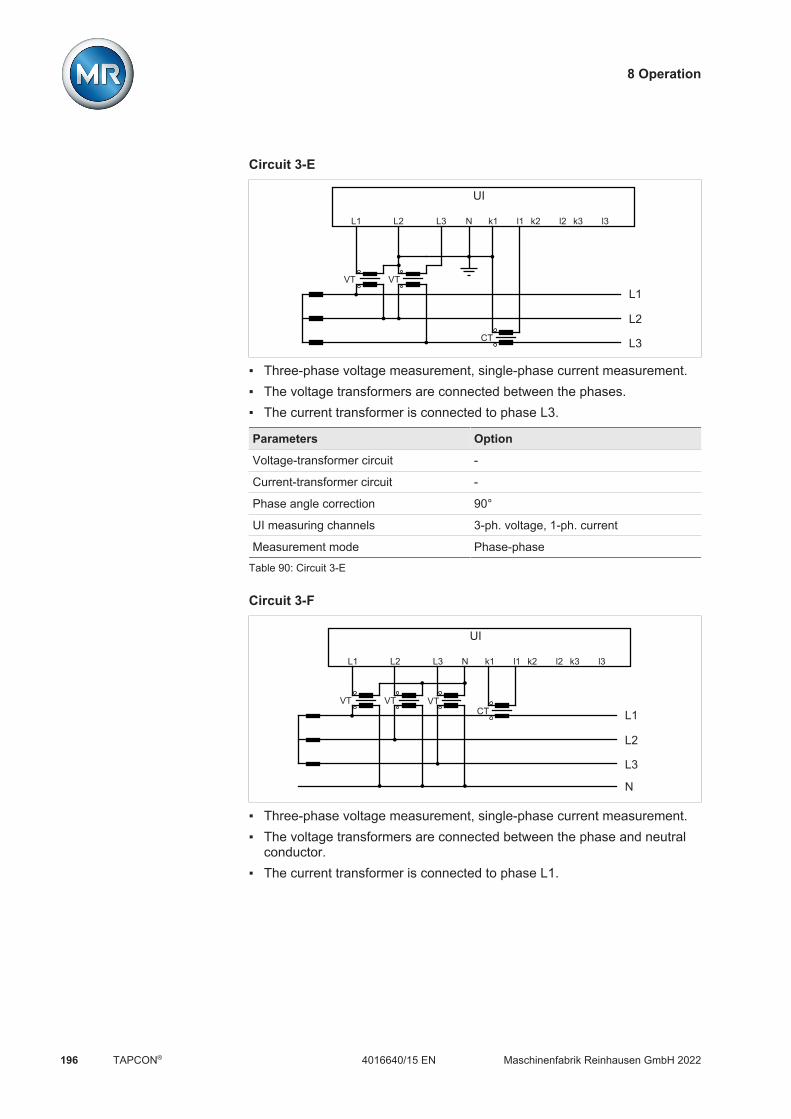
8 Operation
Maschinenfabrik Reinhausen GmbH 2022196 4016640/15 ENTAPCON®
Circuit 3-E
L1
L2
L3
VTVT
CT
UI
L1 L2 L3 N k1 l1 k2 l2 k3 l3
Three-phase voltage measurement, single-phase current measurement. The voltage transformers are connected between the phases. The current transformer is connected to phase L3.
Parameters Option
Voltage-transformer circuit -
Current-transformer circuit -
Phase angle correction 90°
UI measuring channels 3-ph. voltage, 1-ph. current
Measurement mode Phase-phase
Table 90: Circuit 3-E
Circuit 3-F
L1
L2
L3
N
UI
VTVT VTCT
L1 L2 L3 N k1 l1 k2 l2 k3 l3
Three-phase voltage measurement, single-phase current measurement. The voltage transformers are connected between the phase and neutral
conductor. The current transformer is connected to phase L1.

8 Operation
Maschinenfabrik Reinhausen GmbH 2022 1974016640/15 EN TAPCON®
Parameters Option
Voltage-transformer circuit 3 Ph phase voltage
Current-transformer circuit 3 Ph phase current
Phase angle correction 0°
UI measuring channels 3-ph. voltage, 1-ph. current
Measurement mode Phase-neutral
Table 91: Circuit 3-F
Circuit 3-G
L1
L2
L3
N
UI
VTVT VT
CT
L1 L2 L3 N k1 l1 k2 l2 k3 l3
Three-phase voltage measurement, single-phase current measurement. The voltage transformers are connected between the phase and neutral
conductor. The current transformer is connected to phase L2.
Parameters Option
Voltage-transformer circuit 3 Ph phase voltage
Current-transformer circuit 3 Ph phase current
Phase angle correction -120°
UI measuring channels 3-ph. voltage, 1-ph. current
Measurement mode Phase-neutral
Table 92: Circuit 3-G
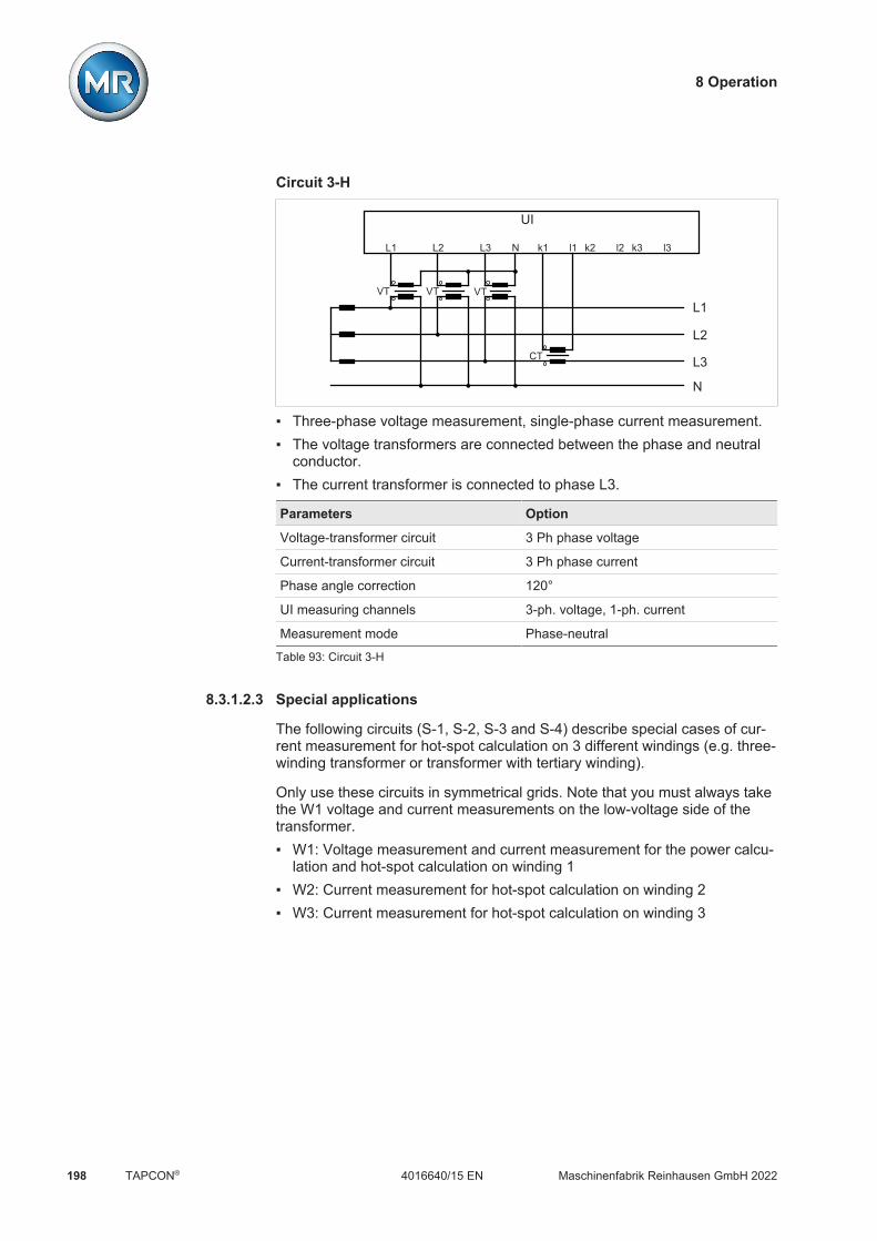
8 Operation
Maschinenfabrik Reinhausen GmbH 2022198 4016640/15 ENTAPCON®
Circuit 3-H
L1
L2
L3
N
UI
VTVT VT
CT
L1 L2 L3 N k1 l1 k2 l2 k3 l3
Three-phase voltage measurement, single-phase current measurement. The voltage transformers are connected between the phase and neutral
conductor. The current transformer is connected to phase L3.
Parameters Option
Voltage-transformer circuit 3 Ph phase voltage
Current-transformer circuit 3 Ph phase current
Phase angle correction 120°
UI measuring channels 3-ph. voltage, 1-ph. current
Measurement mode Phase-neutral
Table 93: Circuit 3-H
8.3.1.2.3 Special applications
The following circuits (S-1, S-2, S-3 and S-4) describe special cases of cur-rent measurement for hot-spot calculation on 3 different windings (e.g. three-winding transformer or transformer with tertiary winding).
Only use these circuits in symmetrical grids. Note that you must always takethe W1 voltage and current measurements on the low-voltage side of thetransformer. W1: Voltage measurement and current measurement for the power calcu-
lation and hot-spot calculation on winding 1 W2: Current measurement for hot-spot calculation on winding 2 W3: Current measurement for hot-spot calculation on winding 3
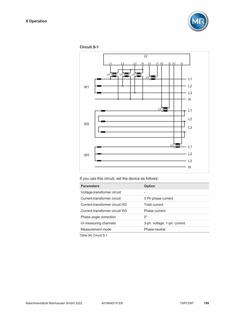
8 Operation
Maschinenfabrik Reinhausen GmbH 2022 1994016640/15 EN TAPCON®
Circuit S-1
L1
L2
L3
N
UI
VTVT VTCT
CT
CT
L1 L2 L3 N k1 l1 k2 l2 k3 l3
W1
L1
L2
L3
L1
L2
L3
W2
W3
N
If you use this circuit, set the device as follows:
Parameters Option
Voltage-transformer circuit -
Current-transformer circuit 3 Ph phase current
Current-transformer circuit W2 Total current
Current-transformer circuit W3 Phase current
Phase angle correction 0°
UI measuring channels 3-ph. voltage, 1-ph. current
Measurement mode Phase-neutral
Table 94: Circuit S-1
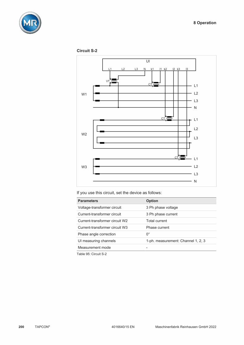
8 Operation
Maschinenfabrik Reinhausen GmbH 2022200 4016640/15 ENTAPCON®
Circuit S-2
N
L1
L2
L3
N
UI
VTCT
CT
CT
L1 L2 L3 N k1 l1 k2 l2 k3 l3
W1
L1
L2
L3
L1
L2
L3
W2
W3
If you use this circuit, set the device as follows:
Parameters Option
Voltage-transformer circuit 3 Ph phase voltage
Current-transformer circuit 3 Ph phase current
Current-transformer circuit W2 Total current
Current-transformer circuit W3 Phase current
Phase angle correction 0°
UI measuring channels 1-ph. measurement: Channel 1, 2, 3
Measurement mode -
Table 95: Circuit S-2

8 Operation
Maschinenfabrik Reinhausen GmbH 2022 2014016640/15 EN TAPCON®
Circuit S-3
L1
L2
L3
UI
CT
CT
CT
L1 L2 L3 N k1 l1 k2 l2 k3 l3
W1
L1
L2
L3
W2
W3
L1
L2
L3
VTVT
If you use this circuit, set the device as follows:
Parameters Option
Voltage-transformer circuit -
Current-transformer circuit 3 Ph phase current
Current-transformer circuit W2 Phase current
Current-transformer circuit W3 Phase current
Phase angle correction 0°
UI measuring channels 3-ph. voltage, 1-ph. current
Measurement mode Phase-phase
Table 96: Circuit S-3
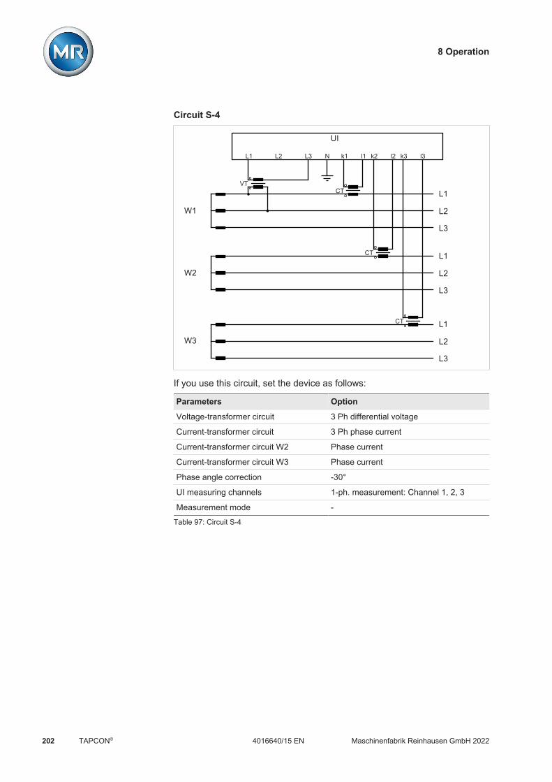
8 Operation
Maschinenfabrik Reinhausen GmbH 2022202 4016640/15 ENTAPCON®
Circuit S-4
L1
L2
L3
UI
CT
CT
CT
L1 L2 L3 N k1 l1 k2 l2 k3 l3
W1
L1
L2
L3
W2
W3
L1
L2
L3
VT
If you use this circuit, set the device as follows:
Parameters Option
Voltage-transformer circuit 3 Ph differential voltage
Current-transformer circuit 3 Ph phase current
Current-transformer circuit W2 Phase current
Current-transformer circuit W3 Phase current
Phase angle correction -30°
UI measuring channels 1-ph. measurement: Channel 1, 2, 3
Measurement mode -
Table 97: Circuit S-4

8 Operation
Maschinenfabrik Reinhausen GmbH 2022 2034016640/15 EN TAPCON®
8.3.2 Measurement
You can use the following parameters to configure the measurement of cur-rent and voltage.
Settings Parameters Measurement
Name Value
Regulation mode Single-phase
Control variable L1/N or L1/L2
UI measuring channels 3-phase measurem.: Ch. 1,2,3
Home
Events
Information
Recorder
SettingsEN CHANGE REBOOT admin 04.02.2020 11:14
Figure 136: Measurement
1. Go to Settings > Parameters > Grid > Measurement.2. Select the desired parameter.3. Set the desired parameter.4. Press the Accept button to save the modified parameter.
UI measuring channels
If you are measuring the voltage and current with the 3-phase UI 3 measur-ing module, you can use this parameter to set the measurement channels inuse:
Option Description
1-ph. measurement: Channel 1 The device uses 1 channel each for measure-ment of voltage and current.
3-ph. measurement: Channel 1,2, 3
The device uses 3 channels each for measure-ment of voltage and current.
3-ph. voltage, 1-ph. current The device uses 3 channels for voltage measure-ment and 1 channel for current measurement.
Table 98: UI measuring channels

8 Operation
Maschinenfabrik Reinhausen GmbH 2022204 4016640/15 ENTAPCON®
Control variable
If you are measuring the voltage and current with the 3-phase UI 3 measur-ing module and using the "single-phase" regulation mode, this parametercan be used to select the phase used for voltage regulation. You can selectthe following options: L1/N or L1/L2 L2/N or L2/L3 L3/N or L3/L1
Regulation mode
If you are measuring the voltage and current with the 3-phase UI 3 measur-ing module, you can use this parameter to set whether you want 1-phasevoltage regulation or voltage regulation to the average value of the 3 phases.You can select the following options: Single-phase: Voltage is automatically regulated to one selected phase.
Limit value monitoring, line drop compensation, and parallel operationalso take place on the selected phase using the circulating reactive cur-rent minimization method.
Average value regulation: Voltage is automatically regulated to the aver-age of the 3 phases. Limit value monitoring, line drop compensation, andparallel operation also take place using the circulating reactive currentminimization method to the average of the 3 phases.
If you activate the average value regulation option, automatic voltage regu-lation is blocked should the voltage or current measurement of one of the 3phases fail.
Display power factor negative
You can use this parameter to set whether the device is to display a nega-tive power factor. You can select the following options:
Option Description
Off The power factor is always shown as positive.
P > 0 The power factor is shown as negative if the active power ispositive.
P < 0 The power factor is shown as negative if the active power isnegative.
Q > 0 The power factor is shown as negative if the reactive power ispositive.
Q < 0 The power factor is shown as negative if the reactive power isnegative.
Table 99: Setting the display for the power factor

8 Operation
Maschinenfabrik Reinhausen GmbH 2022 2054016640/15 EN TAPCON®
8.3.3 Voltage monitoring
In order to monitor the transformer's current output voltage, you can set4 limit values: Undervoltage U<<: Lower limit 2 Undervoltage U<: Lower limit 1 Overvoltage U>: Upper limit 1 Overvoltage U>>: Upper limit 2
If the measured value is higher than the upper limit (> or >>) or lower thanthe lower limit (< or <<), the device transmits an event message.
U>>
U<
U
t
U>
U<<
tV tE
H
Figure 137: Example of voltage monitoring with the limit value Overvoltage U> being exceeded
U>> Overvoltage U>> U> Overvoltage U>
U< Undervoltage U< U<< Undervoltage U<<
tV Delay time tE Event duration
H Hysteresis
You can set the following parameters for each limit value: Relative/absolute limit value Limit value [V]: Absolute limit value Limit value [%]: Limit value relative to the desired voltage value (only for
devices with voltage regulation) Hysteresis limit value Delay time limit value Behavior limit value (only for devices with voltage regulation)

8 Operation
Maschinenfabrik Reinhausen GmbH 2022206 4016640/15 ENTAPCON®
Settings Parameters Voltage ...ing
<< < > >>
Mode
Absolute
Relative
Hysteresis
Delay time
Reaction
Absolute
80.0 V
80.0 %
0.0 V
0.5 s
Auto blockin...
Relative
60.1 V
60.1 %
0.0 V
10.0 s
Off
Absolute
110.9 V
110.9 %
0.0 V
0.5 s
High-sp. ret...
Absolute
120.0 V
120.0 %
0.0 V
10.0 s
High-sp. ret...
Home
Events
Information
Recorder
SettingsEN CHANGE REBOOT admin 29.01.2020 15:39
Figure 138: Voltage monitoring
1. Go to Settings > Parameters > Grid > Voltage monitoring.2. Select the desired parameter.3. Set the desired parameter.4. Press the Accept button to save the modified parameter.
Mode
You can use this parameter to set which limit value you would like to use: Absolute: The device uses the absolute limit value in V. Relative: The device uses the relative limit value in %, relative to the de-
sired voltage value.
Absolute
You can use this parameter to specify an absolute limit value in V (relative tothe secondary value of the voltage transformer) or in kV (relative to the pri-mary value of the voltage transformer). Unlike the relative value, this limit isnot dependent on a reference value.
Percentage
You can use this parameter to set the limit value relative to the desired volt-age value.

8 Operation
Maschinenfabrik Reinhausen GmbH 2022 2074016640/15 EN TAPCON®
Behavior
You can use this parameter to set the behavior of the device if the measuredvalue is higher than the upper limit (> or >>) or lower than the lower limit (<or <<). You can select the following options:
Setting Behavior
Off No reaction.
High-speed return For U</U<<: The device performs tap-change opera-tions in the raise voltage direction (U+) until the mea-sured voltage is back above the limit value.For U>/U>>: The device performs tap-change opera-tions in the lower voltage direction (U-) until the mea-sured voltage is back below the limit value.With high-speed return, the device ignores the set delaytime of automatic voltage regulation.
Auto blocking Automatic regulation is blocked.You can continue to perform tap-change operations inmanual mode.
Auto/manual blocking Automatic regulation is blocked.You cannot perform tap-change operations in manualmode.
Auto blocking position+ The automatic control does not perform a tap-changeoperation in the direction of a higher tap position (posi-tion+).You can still perform a tap-change operation in the di-rection of a higher tap position (position+) in manualmode.
Auto blocking position- The automatic control does not perform a tap-changeoperation in the direction of a lower tap position (posi-tion-).You can still perform a tap-change operation in the di-rection of a lower tap position (position-) in manualmode.
Auto/manual blocking po-sition+
The automatic control does not perform a tap-changeoperation in the direction of a higher tap position (posi-tion+).You cannot perform a tap-change operation in the direc-tion of a higher tap position (position+) in manual mode.
Auto/manual blocking po-sition-
The automatic control does not perform a tap-changeoperation in the direction of a lower tap position (posi-tion-).You cannot perform a tap-change operation in the direc-tion of a lower tap position (position-) in manual mode.
Table 100: Behavior when an event message is issued
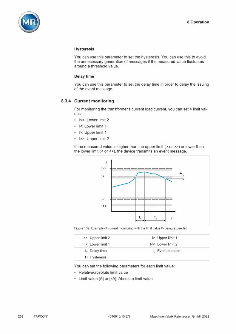
8 Operation
Maschinenfabrik Reinhausen GmbH 2022208 4016640/15 ENTAPCON®
Hysteresis
You can use this parameter to set the hysteresis. You can use this to avoidthe unnecessary generation of messages if the measured value fluctuatesaround a threshold value.
Delay time
You can use this parameter to set the delay time in order to delay the issuingof the event message.
8.3.4 Current monitoring
For monitoring the transformer's current load current, you can set 4 limit val-ues: I<<: Lower limit 2 I<: Lower limit 1 I>: Upper limit 1 I>>: Upper limit 2
If the measured value is higher than the upper limit (> or >>) or lower thanthe lower limit (< or <<), the device transmits an event message.
I>>
I<
I
t
I>
I<<
tV tE
H
Figure 139: Example of current monitoring with the limit value I> being exceeded
I>> Upper limit 2 I> Upper limit 1
I< Lower limit 1 I<< Lower limit 2
tV Delay time tE Event duration
H Hysteresis
You can set the following parameters for each limit value: Relative/absolute limit value Limit value [A] or [kA]: Absolute limit value

8 Operation
Maschinenfabrik Reinhausen GmbH 2022 2094016640/15 EN TAPCON®
Limit value [%]: Limit value relative to the rated current of current trans-former. With current measurements via the analog input, the value is rela-tive to the maximum value of the analog input (e.g. 100% = 20 mA).
Hysteresis limit value Delay time limit value Behavior limit value (only for devices with voltage regulation)
Settings Parameters Current ...ing
<< < > >>
Mode
Absolute
Relative
Hysteresis
Delay time
Reaction
Absolute
0.0 A
0.0 %
0.0 A
0.0 s
Off
Absolute
0.0 A
0.0 %
0.0 A
0.0 s
Auto blockin...
Absolute
7.7 A
110.0 %
0.0 A
0.0 s
Auto blockin...
Absolute
10.0 A
110.0 %
0.0 A
0.0 s
Off
Home
Events
Information
Recorder
SettingsEN CHANGE REBOOT admin 29.01.2020 15:45
Figure 140: Current monitoring
1. Go to Settings > Parameters > Grid > Current monitoring.2. Select the desired parameter.3. Set the desired parameter.4. Press the Accept button to save the modified parameter.
Mode
You can use this parameter to set which limit value you would like to use: Absolute: The device uses the absolute limit value in A/kA. Relative: The device uses the relative limit value in %, relative to the rated
current of current transformer.
Absolute
You can use this parameter to specify an absolute limit value in A (in relationto the secondary value of the current transformer) or in kA (in relation to theprimary value of the current transformer).
Percentage
You can use this parameter to set the limit value relative to the rated currentof current transformer. With current measurements via the analog input, thevalue is relative to the maximum value of the analog input (e.g. 100% =20 mA).

8 Operation
Maschinenfabrik Reinhausen GmbH 2022210 4016640/15 ENTAPCON®
Hysteresis
You can use this parameter to set the hysteresis. You can use this to avoidthe unnecessary generation of messages if the measured value fluctuatesaround a threshold value.
Delay time
You can use this parameter to set the delay time in order to delay the issuingof the event message.
Reaction
You can use this parameter to set the behavior of the device if the measuredvalue is higher than the upper limit (> or >>) or lower than the lower limit (<or <<). You can select the following options:
Setting Behavior
Off No reaction.
Auto blocking Automatic regulation is blocked.You can continue to perform tap-change operations inmanual mode.
Auto/manual blocking Automatic regulation is blocked.You cannot perform tap-change operations in manualmode.
Table 101: Behavior when an event message is issued
8.3.5 Power monitoring
For monitoring the transformer's current power, you can set the followinglimit values:
Measured value Lowerlimit 2
Lowerlimit 1
Upperlimit 1
Upperlimit 2
Apparent power S<< S< S> S>>
Active power P<< P< P> P>>
Reactive power Q<< Q< Q> Q>>
Power factor (amount) |cos φ|<< |cos φ|< - -
Table 102: Limit values for power monitoring
You can set the following parameters for each limit value: Limit value: Absolute limit value Hysteresis limit value Delay time limit value Behavior limit value (only for devices with voltage regulation)

8 Operation
Maschinenfabrik Reinhausen GmbH 2022 2114016640/15 EN TAPCON®
If the measured value is higher than the upper limit (> or >>) or lower thanthe lower limit (< or <<), the device issues an event message.
Settings Parameter Power monitoring
<< < > >>
S absolute
S hysteresis
S delay
S behavior
P absolute
P hysteresis
P delay
P behavior
Q absolute
0 VA
100 kVA
5 s
0 VA
100 kVA
5 s
10 MVA
100 kVA
5 s
10 MVA
100 kVA
5 s
Off
-10 MW
100 kW
Off
-10 MW
100 kW
Off
10 MW
100 kW
Off
10 MW
100 kW
5 s
Off
0 Mvar
5 s
Off
0 Mvar
5 s
Off
10 Mvar
5 s
Off
10 Mvar
Home
Events
Information
Recorder
SettingsEN CHANGE REBOOT admin 03.02.2020 08:09
Figure 141: Power monitoring
1. Go to Settings > Parameters > Grid > Power monitoring.2. Select the desired parameter.3. Set the desired parameter.4. Press the Accept button to save the modified parameter.
Absolute
You can use this parameter to specify a limit value.
Hysteresis
You can use this parameter to set the hysteresis. You can use this to avoidthe unnecessary generation of messages if the measured value fluctuatesaround a threshold value.
Delay time
You can use this parameter to set the delay time in order to delay the issuingof the event message.
8 Operation
Maschinenfabrik Reinhausen GmbH 2022212 4016640/15 ENTAPCON®
Reaction
You can use this parameter to set the behavior of the device if the measuredvalue is higher than the upper limit (> or >>) or lower than the lower limit (<or <<). You can select the following options:
Setting Behavior
Off No reaction.
Auto blocking Automatic regulation is blocked.You can continue to perform tap-change operations inmanual mode.
Auto blocking position- The automatic control does not perform a tap-changeoperation in the direction of a lower tap position (posi-tion-).You can continue to perform tap-change operations inmanual mode.
Auto blocking position+ The automatic control does not perform a tap-changeoperation in the direction of a higher tap position (posi-tion+).You can continue to perform tap-change operations inmanual mode.
Auto/manual blocking Automatic regulation is blocked.You cannot perform tap-change operations in manualmode.
Auto/manual blocking po-sition-
The automatic control does not perform a tap-changeoperation in the direction of a lower tap position (posi-tion-).You cannot perform a tap-change operation in the di-rection of a lower tap position (position-) in manualmode.
Auto/manual blocking po-sition+
The automatic control does not perform a tap-changeoperation in the direction of a higher tap position (posi-tion+).You cannot perform a tap-change operation in the di-rection of a higher tap position (position+) in manualmode.
Table 103: Behavior when an event message is issued
8.3.6 Power flow monitoring
A reversal of power flow occurs if the active power is negative. You can setthe following parameters for this: Hysteresis Delay time Behavior

8 Operation
Maschinenfabrik Reinhausen GmbH 2022 2134016640/15 EN TAPCON®
Settings Parameters Power fl...ing
Name Value
Reversal of power flow hysteresis 100 kW
Reversal of power flow delay 5.0 s
Behavior for reversal of power fl... Off
Home
Events
Information
Recorder
SettingsEN CHANGE REBOOT admin 31.01.2020 09:54
Figure 142: Power flow monitoring
1. Go to Settings > Parameters > Grid > Power flow monitoring.2. Select the desired parameter.3. Set the desired parameter.4. Press the Accept button to save the modified parameter.
Also refer to2 Target-tap-position operation [ 269]
Hysteresis
You can use this parameter to set the hysteresis. You can use this to avoidthe unnecessary generation of messages if the measured value fluctuatesaround a threshold value.
Delay time
You can use this parameter to set the delay time in order to delay the issuingof the event message.

8 Operation
Maschinenfabrik Reinhausen GmbH 2022214 4016640/15 ENTAPCON®
Behavior for reversal of power flow
You can use this parameter to set the behavior in the event of a reversal ofpower flow. You can select the following options:
Setting Behavior
Off The negative power flow is ignored. Automatic regulation remains active.
Event only The Reversal of power flow event is issued. If Z compensation is activated, this function is deacti-
vated. Automatic regulation remains active.
Auto blocking The Reversal of power flow event is issued. If Z compensation is activated, this function is deacti-
vated. Automatic regulation is blocked.
Auto/manual blocking The Reversal of power flow event is issued. If Z compensation is activated, this function is deacti-
vated. Automatic regulation is blocked. You cannot perform tap-change operations in manual
mode.
Target tap position The Reversal of power flow event is issued. If Z compensation is activated, this function is deacti-
vated. The device triggers a tap-change operation to the tap
position you defined in the "Target tap posi-tion" [Section 8.5.3, Page 269] parameter.
The device blocks further tap-change operations. The target-tap-position operation is ignored if there is
no tap-position capture. Automatic regulation isblocked.
Table 104: Behavior in the event of a reversal of power flow

8 Operation
Maschinenfabrik Reinhausen GmbH 2022 2154016640/15 EN TAPCON®
8.3.7 Phase symmetry monitoring
If you are measuring the voltage and current with the 3-phase UI 3 measur-ing module, you can set the maximum permitted differences for voltage andphase angle between the 3 phases. The difference is determined from thehighest and lowest measured value of the 3 phases.
Settings Parameters Phase sy...ing
ΔU Δφ
Max. diff.
Response for exceed
Delay time
5.0 V
Off
0 s
5.0 deg
Off
0 s
Home
Events
Information
Recorder
SettingsEN CHANGE REBOOT admin 30.01.2020 08:18
Figure 143: Phase symmetry monitoring
1. Go to Settings > Parameters > Phase symmetry.2. Select the desired parameter.3. Set the desired parameter.4. Press the Accept button to save the modified parameter.
Maximum difference
You can use this parameter to specify a limit value for the voltage differencein V (in relation to the secondary value of the voltage transformer) or in kV(in relation to the primary value of the voltage transformer) or the phase an-gle difference.
Behavior
You can use this parameter to set the behavior of the device when the eventmessage is issued. You can select the following options:
Setting Behavior
Off The limit value is not monitored.
Auto blocking Automatic regulation is blocked.You can continue to perform tap-change operations inmanual mode.
Auto/manual blocking Automatic regulation is blocked.You cannot perform tap-change operations in manualmode.
Table 105: Behavior when an event message is issued

8 Operation
Maschinenfabrik Reinhausen GmbH 2022216 4016640/15 ENTAPCON®
8.3.8 TAPCON® 2xx retrofit
The TAPCON® 2xx retrofit function allows you to operate the device in par-allel operation with existing devices. Parallel operation with the following ex-isting devices is supported: TAPCON® 230 pro/expert TAPCON® 240 TAPCON® 250 TAPCON® 260 TRAFOGUARD® with "Voltage regulation" options package
If you wish to operate several devices in parallel operation with existing de-vices, you have to activate the TAPCON® 2xx retrofit function on each de-vice.
Figure 144: Parallel operation of 2 devices with one TAPCON® 2xx. The TAPCON® 2xx retrofitfunction must be active on both devices.
Settings Parameters TAPCON® ...fit
Name Value
Retrofit TAPCON®2xx OffHome
Events
Information
Recorder
SettingsEN CHANGE REBOOT admin 31.01.2020 09:54
Figure 145: Retrofit TAPCON® 2xx
1. Go to Settings > Parameters > Grid > TAPCON® 2xx retrofit.2. Select the desired parameter.3. Set the desired parameter.

8 Operation
Maschinenfabrik Reinhausen GmbH 2022 2174016640/15 EN TAPCON®
4. Press the Accept button to save the modified parameter.
TAPCON® 2xx retrofit
You can use this parameter to activate or deactivate the Retrofit TAPCON®2xx function.
If you activate this parameter, you have to reverse the prefix of the "Phaseangle correction" parameter for the transformer data (from - to + or from + to-).
8.3.9 Displaying current measured values
The current measured values can be displayed on the measured valuescreen. Note that the displayed measured values may differ from the rawvalues displayed in the information display of the UI assembly. The mea-sured values are prepared for the measured value display by the device asfollows: The tap-change operation set for the current transformer and voltage
transformer is taken into account, as is a corresponding phase displace-ment.
The UI assemblies use the generator sign convention. The device dis-plays the measured values using the load sign convention.
You can change the measured value display to the generator sign conven-tion by activating the Retrofit TAPCON® 2xx [Section 8.3.8, Page 216]parameter.
The following measured values are displayed: Voltage Current Power factor (cos ϕ) Frequency Reactive power Active power Apparent power

8 Operation
Maschinenfabrik Reinhausen GmbH 2022218 4016640/15 ENTAPCON®
Figure 146: Measured values
Go to Information > Grid > Measured values.
Also refer to2 TAPCON® 2xx retrofit [ 216]
8.3.10 Displaying minimum and maximum measured values
You can display the minimum and maximum values reached and the corre-sponding time for the following measured values: Voltage Current Reactive power Active power Apparent power
Figure 147: Min. and max. measured values

8 Operation
Maschinenfabrik Reinhausen GmbH 2022 2194016640/15 EN TAPCON®
1. Go to Information > Power grid > Min. and max. measured values.2. As needed, select the Reset button to reset the minimum and maximum
values.
8.3.11 Setting bank parallel operation
You can set the following parameters for bank parallel operation.
Figure 148: Bank parallel operation
1. Go to Settings > Parameters > Grid > Bank parallel operation.2. Select the desired parameter.3. Set the parameter.4. Press the Accept button to save the modified parameter.
Delay time for tap synchronization monitoring
You can use this parameter to set the delay time for the tap synchronizationmonitoring. If the individual transformers have a tap position difference inauto mode for longer than the set delay time, the device issues an eventmessage. As long as the tap position difference exists, tap-change opera-tions are blocked in auto mode and you can only switch the on-load tap-changers of the transformers individually in manual mode.
Name of transformer 1...4 (depending on device configuration)
You can use these parameters to set the transformer name. The transformername appears in the display for manual tap-change operations.

8 Operation
Maschinenfabrik Reinhausen GmbH 2022220 4016640/15 ENTAPCON®
8.4 On-load tap-changer regulator
8.4.1 Regulation
The general functions for regulating the on-load tap-changer are describedin this section.
8.4.1.1 Response to control system disconnection (optional)
If your device is equipped with a connection to a control system (SCADA),you can use the following parameters to set how the device is to behave ifthe connection to the control system is interrupted.
This function only works in the REMOTE operating mode.
Settings Parameters Control
Name Value
Control variable Voltage
Response to SCADA disconnection No reaction
SCADA disconnection delay time 5 s
Home
Events
Information
Recorder
SettingsEN CHANGE REBOOT admin 23.09.2020 09:23
Figure 149: Regulation
1. Go to Settings > Parameters > On-load tap-changer regulator > Regu-lation.
2. Select the desired parameter.3. Set the desired parameter.4. Press the Accept button to save the modified parameter.
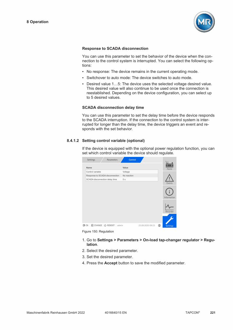
8 Operation
Maschinenfabrik Reinhausen GmbH 2022 2214016640/15 EN TAPCON®
Response to SCADA disconnection
You can use this parameter to set the behavior of the device when the con-nection to the control system is interrupted. You can select the following op-tions: No response: The device remains in the current operating mode. Switchover to auto mode: The device switches to auto mode. Desired value 1…5: The device uses the selected voltage desired value.
This desired value will also continue to be used once the connection isreestablished. Depending on the device configuration, you can select upto 5 desired values.
SCADA disconnection delay time
You can use this parameter to set the delay time before the device respondsto the SCADA interruption. If the connection to the control system is inter-rupted for longer than the delay time, the device triggers an event and re-sponds with the set behavior.
8.4.1.2 Setting control variable (optional)
If the device is equipped with the optional power regulation function, you canset which control variable the device should regulate.
Settings Parameters Control
Name Value
Control variable Voltage
Response to SCADA disconnection No reaction
SCADA disconnection delay time 5 s
Home
Events
Information
Recorder
SettingsEN CHANGE REBOOT admin 23.09.2020 09:23
Figure 150: Regulation
1. Go to Settings > Parameters > On-load tap-changer regulator > Regu-lation.
2. Select the desired parameter.3. Set the desired parameter.4. Press the Accept button to save the modified parameter.

8 Operation
Maschinenfabrik Reinhausen GmbH 2022222 4016640/15 ENTAPCON®
Control variable
You can use this parameter to set which control variable the device is to reg-ulate. You can select the following options: Voltage Reactive power Active power
Depending on your selection, the device uses the associated parameter setfor each option (desired value, bandwidth, etc.).
8.4.2 Voltage regulation
All of the parameters required for voltage regulation are described in thissection.
Settings Parameters Voltage re...ion
Name Value
Desired value 1 100 V
Desired value 2 100 V
Desired value 3 100 V
Selecting a desired value Desired value 1
Bandwidth setting Percentage
Bandwidth 1.0 %
Delay time T1 40 s
Time response T1 Linear
Activate delay time T2 Off
Delay time T2 10 s
Home
Events
Information
Recorder
SettingsEN CHANGE REBOOT admin 13.12.2021 08:25
Figure 151: Voltage regulation (example)
1. Go to Settings > Parameters > On-load tap-changer regulator > Volt-age regulation.
2. Select the desired parameter.3. Set the desired parameter.4. Press the Accept button to save the modified parameter.
8.4.2.1 Setting the desired value
In accordance with the order, the device is equipped with one of the follow-ing variants for setting the desired value:
8.4.2.1.1 Desired value 11. Go to Settings > Parameters > Grid > Control > Desired value.2. Enter the desired value.3. Press the Accept button to save the modified parameter.

8 Operation
Maschinenfabrik Reinhausen GmbH 2022 2234016640/15 EN TAPCON®
8.4.2.1.2 Desired value 1...3
You can set 3 different desired values. The device always uses one of theset desired values for control. You can define the desired value used forcontrol by means of the "Select desired value" parameter or with the digitalinputs.
The device only processes commands via digital inputs or the control sys-tem when it is in the Remote mode. You must also set the Remote behavior[Page 91] parameter accordingly.
Setting the desired value1. Go to Settings > Parameters > Grid > Control > Desired value.2. Enter the desired value.3. Press the Accept button to save the modified parameter.
Selecting a desired value
You can use this parameter to select the desired value used for control.1. Go to Settings > Parameters > Grid > Control > Select desired value.2. Select the desired value from the list.3. Press the Accept button to save the modified parameter.
8.4.2.1.3 Desired value 1...5
You can set 5 different desired values. The device always uses one of theset desired values for control. You can define the desired value used forcontrol by means of the "Select desired value" parameter or with the digitalinputs.
The device only processes commands via digital inputs or the control sys-tem when it is in the Remote mode. You must also set the Remote behavior[Page 91] parameter accordingly.
Setting the desired value1. Go to Settings > Parameters > Grid > Control > Desired value.2. Enter the desired value.3. Press the Accept button to save the modified parameter.

8 Operation
Maschinenfabrik Reinhausen GmbH 2022224 4016640/15 ENTAPCON®
Selecting a desired value
You can use this parameter to select the desired value used for control.1. Go to Settings > Parameters > Grid > Control > Select desired value.2. Select the desired value from the list.3. Press the Accept button to save the modified parameter.
8.4.2.1.4 Analog setting of the desired value
With the analog setting of the desired value, the desired value for the auto-matic voltage regulation can be variably adapted using an analog signal (e.g.4...20 mA).
Max.
Min.
Desired value
Max.Min. Analog signal
Figure 152: Analog setting of the desired value
In order to configure the analog setting of the desired value, you can set theparameters as described below.
To specify the desired value using an analog signal, you need to create asignal at the Desired value setting release input. If this is not done, the de-vice uses the set desired value 1.
Setting desired value 11. Go to Settings > Parameters > Grid > Control > Desired value.2. Enter the desired value.3. Press the Accept button to save the modified parameter.

8 Operation
Maschinenfabrik Reinhausen GmbH 2022 2254016640/15 EN TAPCON®
Setting max. desired value setting
With this parameter, you can set the desired value that corresponds to themaximum level of the analog signal level (e.g. 20 mA for 4...20 mA signal).1. Go to Settings > Parameters > Control > Setting max. desired value.2. Enter desired value.3. Press the Accept button to save the modified parameter.
Setting min. desired value setting
With this parameter, you can set the desired value that corresponds to theminimum level of the analog signal (e.g. 4 mA for 4...20 mA signal).1. Go to Settings > Parameters > Control > Setting min. desired value.2. Enter desired value.3. Press the Accept button to save the modified parameter.
8.4.2.1.5 Step-by-step setting of the desired value
For the step-by-step setting of the desired value, you can increase or de-crease the desired value for the automatic voltage regulation by an ad-justable step width using digital inputs or control system commands.
For each "Increase desired value" or "Decrease desired value" command,the active desired value is increased or decreased by the set step width. It isnot possible to set desired values outside of the permitted setting range(49...140 V).
The device only processes commands via digital inputs or the control sys-tem when it is in the Remote mode. You must also set the Remote behavior[Page 91] parameter accordingly.
In order to configure the step-by-step setting of the desired value, you canset the parameters as described below.
Setting desired value 11. Go to Settings > Parameters > Grid > Control > Desired value.2. Enter the desired value.3. Press the Accept button to save the modified parameter.
Setting desired value step width
To set the desired value sep width, proceed as follows:1. Go to Settings > Parameters > Control > Desired value step width.2. Enter desired value step width.3. Press the Accept button to save the modified parameter.
Also refer to

8 Operation
Maschinenfabrik Reinhausen GmbH 2022226 4016640/15 ENTAPCON®
2 Remote behavior [ 91]
8.4.2.1.6 Active power-dependent adjustment of desired voltage value
The TAPCON® Dynamic Setpoint Control (TDSC) function is used to adaptthe desired voltage value depending on the measured active power. This al-lows you to compensate for a voltage drop during increased load or a volt-age increase due to a decentralized feed-in.
Depending on whether positive or negative active power is measured, thedesired value calculation is based on 2 linear equations (see example in dia-gram below).
Parameter Function Settings (see diagrambelow)
Umax: Maximum desired value Maximum set desired value is activated when Pmax isexceeded.
103.0 V
Umin: Minimum desired value Minimum set desired value is activated when value fallsbelow Pmin.
99.0 V
U0: Desired value at 0 activepower
Set desired value is activated when measured activepower is 0 MW.
100.00 V
Pmax: Active power at max. de-sired value
Set maximum active power value above which thepower-dependent desired value is to attain the maxi-mum value Umax.
20.0 MW
Pmin: Active power at min. desiredvalue
Set minimum active power value below which thepower-dependent desired value is to attain the mini-mum value Umin.
-20.0 MW
Table 106: Parameters to be set for active power-dependent adjustment of desired voltage value
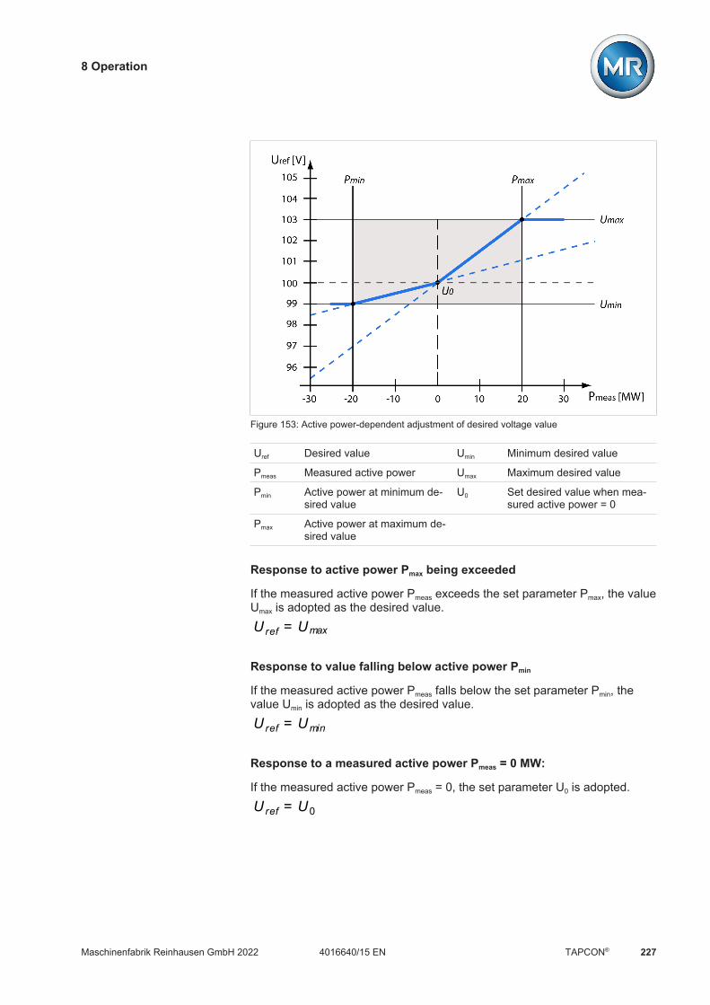
8 Operation
Maschinenfabrik Reinhausen GmbH 2022 2274016640/15 EN TAPCON®
Figure 153: Active power-dependent adjustment of desired voltage value
Uref Desired value Umin Minimum desired value
Pmeas Measured active power Umax Maximum desired value
Pmin Active power at minimum de-sired value
U0 Set desired value when mea-sured active power = 0
Pmax Active power at maximum de-sired value
Response to active power Pmax being exceeded
If the measured active power Pmeas exceeds the set parameter Pmax, the valueUmax is adopted as the desired value.U ref = Umax
Response to value falling below active power Pmin
If the measured active power Pmeas falls below the set parameter Pmin, thevalue Umin is adopted as the desired value.U ref = Umin
Response to a measured active power Pmeas = 0 MW:
If the measured active power Pmeas = 0, the set parameter U0 is adopted.U ref = U0
8 Operation
Maschinenfabrik Reinhausen GmbH 2022228 4016640/15 ENTAPCON®
Linear dependency with negative active power:
If the measured active power Pmin ≤ Pmeas ≤ 0, the desired value is calculatedusing the following equation:
U ref = U0 - Umin0 - Pmin
×Pmeas + U0
Linear dependency with positive active power:
If the measured active power 0 ≤ Pmeas ≤ Pmax, the desired value is calculatedusing the following equation:
U ref = Umax - U0Pmax
×Pmeas + U0
To activate the active power-dependent adjustment of the desired voltagevalue, you need to set the following parameters:
Activating TDSC
The TDSC function is only active when the device can calculate the activepower (correct current measurement and voltage measurement) and the re-quired parameters are set. If this is not the case, the voltage is regulated tothe set desired value [Section 8.4.2.1.1, Page 222]. You can activate ordeactivate the power-dependent adjustment of the desired voltage value asfollows: Parameter Digital inputs TDSC on and TDSC off (optional) Control system command (optional)
If you activate TDSC, the line drop compensation (R&X compensation or Zcompensation) function is deactivated.
To activate/deactivate TDSC using parameters, proceed as follows:1. Go to Settings > Parameters > Control > Activate TDSC.2. Select the desired option.3. Press the Accept button to save the modified parameter.
TDSC Umax/Umin
You can use these parameters to set the maximum and minimum desiredvalue. The maximum or minimum desired value is activated when the mea-sured active power reaches the set minimum or maximum active power.1. Go to Settings > Parameters > Control > TDSC Umax/Umin.2. Enter maximum/minimum desired value.3. Press the Accept button to save the modified parameter.

8 Operation
Maschinenfabrik Reinhausen GmbH 2022 2294016640/15 EN TAPCON®
TDSC U0
You can use this parameter to set the desired value which is to be usedwhen the measured active power is 0.1. Go to Settings > Parameters > Control > TDSC U0.2. Enter desired value at active power 0.3. Press the Accept button to save the modified parameter.
TDSC Pmax/Pmin
You can use these parameters to set the maximum and minimum activepower value at which the maximum and minimum active power-dependentdesired value is to be used for regulation.1. Go to Settings > Parameters > Control > TDSC Pmax/Pmin.2. Enter active power for maximum/minimum desired value.3. Press the Accept button to save the modified parameter.
8.4.2.1.7 Active power-dependent adjustment of desired voltage value with 3different desired values
The TAPCON® Dynamic Setpoint Control (TDSC) function is used to adaptthe desired voltage value depending on the measured active power. This al-lows you to compensate for a voltage drop during increased load or a volt-age increase due to a decentralized feed-in.
The device provides you with 3 different sets of parameters for this purpose.Depending on the selection of the desired value 1, 2 or 3, the device usesthe parameter set 1, 2 or 3 for TDSC.
Depending on whether positive or negative active power is measured, thedesired value calculation is based on 2 linear equations (see example in dia-gram below).
Parameter Function Settings (see diagrambelow)
Umax: Maximum desired value Maximum set desired value is activated when Pmax isexceeded.
103.0 V
Umin: Minimum desired value Minimum set desired value is activated when value fallsbelow Pmin.
99.0 V
U0: Desired value at 0 activepower
Set desired value is activated when measured activepower is 0 MW.
100.00 V
Pmax: Active power at max. de-sired value
Set maximum active power value above which thepower-dependent desired value is to attain the maxi-mum value Umax.
20.0 MW
Pmin: Active power at min. desiredvalue
Set minimum active power value below which thepower-dependent desired value is to attain the mini-mum value Umin.
-20.0 MW
Table 107: Parameters to be set for active power-dependent adjustment of desired voltage value

8 Operation
Maschinenfabrik Reinhausen GmbH 2022230 4016640/15 ENTAPCON®
Figure 154: Active power-dependent adjustment of desired voltage value
Uref Desired value Umin Minimum desired value
Pmeas Measured active power Umax Maximum desired value
Pmin Active power at minimum de-sired value
U0 Set desired value when mea-sured active power = 0
Pmax Active power at maximum de-sired value
Response to active power Pmax being exceeded
If the measured active power Pmeas exceeds the set parameter Pmax, the valueUmax is adopted as the desired value.U ref = Umax
Response to value falling below active power Pmin
If the measured active power Pmeas falls below the set parameter Pmin, thevalue Umin is adopted as the desired value.U ref = Umin
Response to a measured active power Pmeas = 0 MW:
If the measured active power Pmeas = 0, the set parameter U0 is adopted.U ref = U0
8 Operation
Maschinenfabrik Reinhausen GmbH 2022 2314016640/15 EN TAPCON®
Linear dependency with negative active power:
If the measured active power Pmin ≤ Pmeas ≤ 0, the desired value is calculatedusing the following equation:
U ref = U0 - Umin0 - Pmin
×Pmeas + U0
Linear dependency with positive active power:
If the measured active power 0 ≤ Pmeas ≤ Pmax, the desired value is calculatedusing the following equation:
U ref = Umax - U0Pmax
×Pmeas + U0
To activate the active power-dependent adjustment of the desired voltagevalue, you need to set the following parameters:
Activating TDSC
The TDSC function is only active when the device can calculate the activepower (correct current measurement and voltage measurement) and the re-quired parameters are set. If this is not the case, the voltage is regulated tothe set desired value 1/2/3 [Section 8.4.2.1.2, Page 223]. You can activateor deactivate the power-dependent adjustment of the desired voltage valueas follows: Parameter Digital inputs TDSC on and TDSC off (optional) Control system command (optional)
If you activate TDSC, the line drop compensation (R&X compensation or Zcompensation) function is deactivated.
To activate/deactivate TDSC using parameters, proceed as follows:1. Go to Settings > Parameters > Control > Activate TDSC.2. Select the desired option.3. Press the Accept button to save the modified parameter.
TDSC 1/2/3 Umax/Umin
You can use these parameters to set the maximum and minimum desiredvalue. The maximum or minimum desired value is activated when the mea-sured active power reaches the set minimum or maximum active power.1. Go to Settings > Parameters > Control > TDSC Umax/Umin.2. Enter maximum/minimum desired value.3. Press the Accept button to save the modified parameter.

8 Operation
Maschinenfabrik Reinhausen GmbH 2022232 4016640/15 ENTAPCON®
TDSC 1/2/3 U0
You can use this parameter to set the desired value which is to be usedwhen the measured active power is 0.1. Go to Settings > Parameters > Control > TDSC U0.2. Enter desired value at active power 0.3. Press the Accept button to save the modified parameter.
TDSC 1/2/3 Pmax/Pmin
You can use these parameters to set the maximum and minimum activepower value at which the maximum and minimum active power-dependentdesired value is to be used for regulation.1. Go to Settings > Parameters > Control > TDSC Pmax/Pmin.2. Enter active power for maximum/minimum desired value.3. Press the Accept button to save the modified parameter.
8.4.2.1.8 Desired value setting via BCD
With the desired value setting via BCD, you can variably adjust the desiredvalue for the automatic voltage regulation via digital inputs by means of BCDcoding.
Depending on variant, desired value setting via BCD is always active or youcan activate it by creating a signal at the BCD desired value input.
The following outputs are available to you as an option: Desired value setting faulty: The device issues a signal if the BCD code
for the desired value setting is invalid. Desired value active: The device issues a signal if desired value setting
via BCD is active.
The permissible setting range is 49...140 V. The specified value is written tothe parameter desired value 1. If the BCD coding is invalid or desired valuesetting via BCD is deactivated, the device uses the value set in parameterdesired value 1.
Desiredvalue
BCD input
100 80 40 20 10 8 4 2 1
49 V 0 0 1 0 0 1 0 0 1
50 V 0 0 1 0 1 0 0 0 0
51 V 0 0 1 0 1 0 0 0 1
52 V 0 0 1 0 1 0 0 1 0
53 V 0 0 1 0 1 0 0 1 1
54 V 0 0 1 0 1 0 1 0 0
55 V 0 0 1 0 1 0 1 0 1
56 V 0 0 1 0 1 0 1 1 0

8 Operation
Maschinenfabrik Reinhausen GmbH 2022 2334016640/15 EN TAPCON®
Desiredvalue
BCD input
100 80 40 20 10 8 4 2 1
57 V 0 0 1 0 1 0 1 1 1
58 V 0 0 1 0 1 1 0 0 0
59 V 0 0 1 0 1 1 0 0 1
60 V 0 0 1 1 0 0 0 0 0
61 V 0 0 1 1 0 0 0 0 1
62 V 0 0 1 1 0 0 0 1 0
63 V 0 0 1 1 0 0 0 1 1
64 V 0 0 1 1 0 0 1 0 0
65 V 0 0 1 1 0 0 1 0 1
66 V 0 0 1 1 0 0 1 1 0
67 V 0 0 1 1 0 0 1 1 1
68 V 0 0 1 1 0 1 0 0 0
69 V 0 0 1 1 0 1 0 0 1
70 V 0 0 1 1 1 0 0 0 0
71 V 0 0 1 1 1 0 0 0 1
72 V 0 0 1 1 1 0 0 1 0
73 V 0 0 1 1 1 0 0 1 1
74 V 0 0 1 1 1 0 1 0 0
75 V 0 0 1 1 1 0 1 0 1
76 V 0 0 1 1 1 0 1 1 0
77 V 0 0 1 1 1 0 1 1 1
78 V 0 0 1 1 1 1 0 0 0
79 V 0 0 1 1 1 1 0 0 1
80 V 0 1 0 0 0 0 0 0 0
81 V 0 1 0 0 0 0 0 0 1
82 V 0 1 0 0 0 0 0 1 0
83 V 0 1 0 0 0 0 0 1 1
84 V 0 1 0 0 0 0 1 0 0
85 V 0 1 0 0 0 0 1 0 1
86 V 0 1 0 0 0 0 1 1 0
87 V 0 1 0 0 0 0 1 1 1
88 V 0 1 0 0 0 1 0 0 0
89 V 0 1 0 0 0 1 0 0 1
90 V 0 1 0 0 1 0 0 0 0
91 V 0 1 0 0 1 0 0 0 1

8 Operation
Maschinenfabrik Reinhausen GmbH 2022234 4016640/15 ENTAPCON®
Desiredvalue
BCD input
100 80 40 20 10 8 4 2 1
92 V 0 1 0 0 1 0 0 1 0
93 V 0 1 0 0 1 0 0 1 1
94 V 0 1 0 0 1 0 1 0 0
95 V 0 1 0 0 1 0 1 0 1
96 V 0 1 0 0 1 0 1 1 0
97 V 0 1 0 0 1 0 1 1 1
98 V 0 1 0 0 1 1 0 0 0
99 V 0 1 0 0 1 1 0 0 1
100 V 1 0 0 0 0 0 0 0 0
101 V 1 0 0 0 0 0 0 0 1
102 V 1 0 0 0 0 0 0 1 0
103 V 1 0 0 0 0 0 0 1 1
104 V 1 0 0 0 0 0 1 0 0
105 V 1 0 0 0 0 0 1 0 1
106 V 1 0 0 0 0 0 1 1 0
107 V 1 0 0 0 0 0 1 1 1
108 V 1 0 0 0 0 1 0 0 0
109 V 1 0 0 0 0 1 0 0 1
110 V 1 0 0 0 1 0 0 0 0
111 V 1 0 0 0 1 0 0 0 1
112 V 1 0 0 0 1 0 0 1 0
113 V 1 0 0 0 1 0 0 1 1
114 V 1 0 0 0 1 0 1 0 0
115 V 1 0 0 0 1 0 1 0 1
116 V 1 0 0 0 1 0 1 1 0
117 V 1 0 0 0 1 0 1 1 1
118 V 1 0 0 0 1 1 0 0 0
119 V 1 0 0 0 1 1 0 0 1
120 V 1 0 0 1 0 0 0 0 0
121 V 1 0 0 1 0 0 0 0 1
122 V 1 0 0 1 0 0 0 1 0
123 V 1 0 0 1 0 0 0 1 1
124 V 1 0 0 1 0 0 1 0 0
125 V 1 0 0 1 0 0 1 0 1
126 V 1 0 0 1 0 0 1 1 0

8 Operation
Maschinenfabrik Reinhausen GmbH 2022 2354016640/15 EN TAPCON®
Desiredvalue
BCD input
100 80 40 20 10 8 4 2 1
127 V 1 0 0 1 0 0 1 1 1
128 V 1 0 0 1 0 1 0 0 0
129 V 1 0 0 1 0 1 0 0 1
130 V 1 0 0 1 1 0 0 0 0
131 V 1 0 0 1 1 0 0 0 1
132 V 1 0 0 1 1 0 0 1 0
133 V 1 0 0 1 1 0 0 1 1
134 V 1 0 0 1 1 0 1 0 0
135 V 1 0 0 1 1 0 1 0 1
136 V 1 0 0 1 1 0 1 1 0
137 V 1 0 0 1 1 0 1 1 1
138 V 1 0 0 1 1 1 0 0 0
139 V 1 0 0 1 1 1 0 0 1
140 V 1 0 1 0 0 0 0 0 0
Table 108: BCD-coded desired value
Setting desired value 11. Go to Settings > Parameters > Grid > Control > Desired value.2. Enter the desired value.3. Press the Accept button to save the modified parameter.
Bandwidth setting
You can use this parameter to set whether you want the bandwidth as anabsolute variable (V or kV) or relative variable (%) in relation to the desiredvalue.
Bandwidth
You can use this parameter to set the maximum permissible deviation of themeasured voltage Uactual from the desired value Udesired.
In order to set the correct value, the transformer step voltage and nominalvoltage must be known. Note that a large bandwidth will result in a largecontrol deviation.

8 Operation
Maschinenfabrik Reinhausen GmbH 2022236 4016640/15 ENTAPCON®
The bandwidth must always be greater than the following value:
|± B| ≥ 0,6× Un - 1 - UnU N
×100 %
Un-1 Step voltage of tap position n-1
Un Step voltage of tap position n
UN Nominal voltage
The following transformer values are used to determine the minimum band-width:Nominal voltage UN = 11000 VStep voltage in tap position 4 UStep4 = 11275 VStep voltage in tap position 5 UStep5 = 11000 V
Delay time T1
Delay time T1 delays the issuing of a tap-change command for a defined pe-riod. This prevents unnecessary tap-change operations if the tolerancebandwidth is exited briefly.
Response to delay time T1 If the control variable is within the set bandwidth , no control com-mands are issued to the motor drive unit for the tap change. Control com-mands will also not be issued to the motor-drive unit if the control variablereturns to the bandwidth within the set delay time T1 . However, if thecontrol variable deviates from the set bandwidth for a long period , a tap-
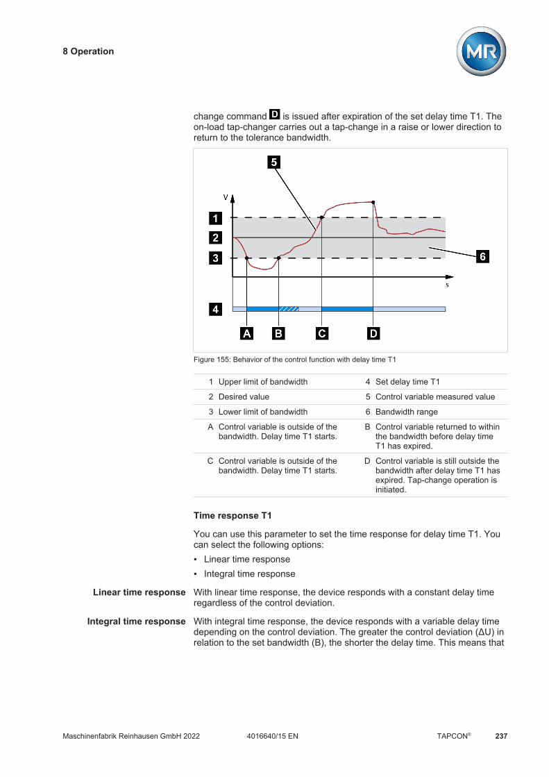
8 Operation
Maschinenfabrik Reinhausen GmbH 2022 2374016640/15 EN TAPCON®
change command is issued after expiration of the set delay time T1. Theon-load tap-changer carries out a tap-change in a raise or lower direction toreturn to the tolerance bandwidth.
Figure 155: Behavior of the control function with delay time T1
1 Upper limit of bandwidth 4 Set delay time T1
2 Desired value 5 Control variable measured value
3 Lower limit of bandwidth 6 Bandwidth range
A Control variable is outside of thebandwidth. Delay time T1 starts.
B Control variable returned to withinthe bandwidth before delay timeT1 has expired.
C Control variable is outside of thebandwidth. Delay time T1 starts.
D Control variable is still outside thebandwidth after delay time T1 hasexpired. Tap-change operation isinitiated.
Time response T1
You can use this parameter to set the time response for delay time T1. Youcan select the following options: Linear time response Integral time response
Linear time response With linear time response, the device responds with a constant delay timeregardless of the control deviation.
Integral time response With integral time response, the device responds with a variable delay timedepending on the control deviation. The greater the control deviation (ΔU) inrelation to the set bandwidth (B), the shorter the delay time. This means that
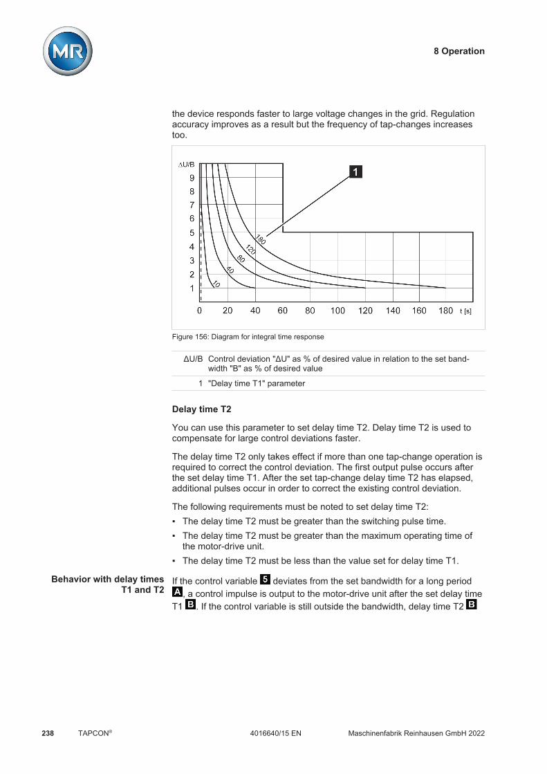
8 Operation
Maschinenfabrik Reinhausen GmbH 2022238 4016640/15 ENTAPCON®
the device responds faster to large voltage changes in the grid. Regulationaccuracy improves as a result but the frequency of tap-changes increasestoo.
Figure 156: Diagram for integral time response
ΔU/B Control deviation "ΔU" as % of desired value in relation to the set band-width "B" as % of desired value
1 "Delay time T1" parameter
Delay time T2
You can use this parameter to set delay time T2. Delay time T2 is used tocompensate for large control deviations faster.
The delay time T2 only takes effect if more than one tap-change operation isrequired to correct the control deviation. The first output pulse occurs afterthe set delay time T1. After the set tap-change delay time T2 has elapsed,additional pulses occur in order to correct the existing control deviation.
The following requirements must be noted to set delay time T2: The delay time T2 must be greater than the switching pulse time. The delay time T2 must be greater than the maximum operating time of
the motor-drive unit. The delay time T2 must be less than the value set for delay time T1.
Behavior with delay timesT1 and T2
If the control variable deviates from the set bandwidth for a long period, a control impulse is output to the motor-drive unit after the set delay time
T1 . If the control variable is still outside the bandwidth, delay time T2

8 Operation
Maschinenfabrik Reinhausen GmbH 2022 2394016640/15 EN TAPCON®
starts to count down. Once delay time T2 is complete, a control impulse isagain issued to the motor-drive unit for the tap change to return to the tol-erance bandwidth.
Figure 157: Behavior of the regulation function with delay times T1 and T2
1 Upper limit of bandwidth 4 Set delay times T1 and T2.
2 Desired value 5 Control variable measured value
3 Lower limit of bandwidth 6 Bandwidth range
A Control variable is outside of thebandwidth. Delay time T1 starts.
B Delay time T1 complete. Tapchange triggered.
C Delay time T2 complete. Tapchange triggered.
Activate delay time T2
You can use this parameter to activate or deactivate the delay time T2.
8.4.3 Line drop compensation
You can use the compensation function to compensate for the load-depen-dent voltage drop between the transformer and consumer. The device pro-vides 2 methods of compensation for this purpose: R&X compensation Z compensation

8 Operation
Maschinenfabrik Reinhausen GmbH 2022240 4016640/15 ENTAPCON®
8.4.3.1 R&X compensation
R&X compensation can compensate for voltage losses on the lines andtherefore ensure correct voltage at the load. This requires precise line data.After you have entered all of the line data, the device automatically calcu-lates the ohmic and inductive voltage drop and takes this into account for au-tomatic voltage regulation.
UTrVT
CT
ULine-Drop
ULoad
U I
R X
Figure 158: Equivalent circuit of R&X compensation
Figure 159: Phasor diagram of R&X compensation
To use R&X compensation, you have to enter the following line data: Ohmic resistance load in mΩ/m Inductive resistance load in mΩ/m Length of line in km

8 Operation
Maschinenfabrik Reinhausen GmbH 2022 2414016640/15 EN TAPCON®
Settings Parameters Compensation
Name Value
Compensation method R & X compensation
Ohmic resistance load 0.0 Ohm/m
Inductive resistance load 0.0 Ohm/m
Length of line 0.00 m
Voltage increase 0.0 %
Voltage limit value 0.0 %
Home
Events
Information
Recorder
SettingsEN CHANGE REBOOT admin 03.02.2020 08:09
Figure 160: Compensation
1. Go to Settings > Parameters > On-load tap-changer regulator > Com-pensation.
2. Select the desired parameter.3. Set the desired parameter.4. Press the Accept button to save the modified parameter.
8.4.3.2 Z compensation
To keep the voltage constant for the consumer, you can use Z compensationto activate a current-dependent voltage increase. You can also define a limitvalue to avoid excess voltage on the transformer.
ΔU% max
ΔU%
ΔU%
I
Figure 161: Z compensation

8 Operation
Maschinenfabrik Reinhausen GmbH 2022242 4016640/15 ENTAPCON®
To use Z compensation, you need to calculate the voltage increase (ΔU) tak-ing the current into account. Use the following formula for this purpose:
ΔU = UTr - ULoadULoad
× I N×kCTI ×100 %
∆U Voltage increase I Load current in A
UTr Transformer voltage at current I IN Nominal current of current-trans-former connection in A
ULoad Voltage on line end at current Iand on-load tap-changer insame operating position
kCT Current transformer transmissionratio
Sample calculation: UTr = 100.1 V, ULoad = 100.0 V, IN = 5 A kCT = 200 A/5 A,I = 100 AProduces a voltage increase ∆U of 0.2%
Settings Parameters Compensation
Name Value
Compensation method R & X compensation
Ohmic resistance load 0.0 Ohm/m
Inductive resistance load 0.0 Ohm/m
Length of line 0.00 m
Voltage increase 0.0 %
Voltage limit value 0.0 %
Home
Events
Information
Recorder
SettingsEN CHANGE REBOOT admin 03.02.2020 08:09
Figure 162: Compensation
1. Go to Settings > Parameters > On-load tap-changer regulator > Com-pensation.
2. Select the desired parameter.3. Set the desired parameter.4. Press the Accept button to save the modified parameter.
8.4.4 Parallel operation (optional)
Parallel transformer operation is used to increase the throughput capacity orshort-circuit capacity at one location. The device provides you with specificfunctions for regulating transformers.

8 Operation
Maschinenfabrik Reinhausen GmbH 2022 2434016640/15 EN TAPCON®
Conditions for paralleloperation
Compliance with the following general conditions is required for operatingtransformers in parallel: Identical rated voltages Transformer power ratio (< 3 : 1) Maximum deviation of short-circuit voltages (UK) for transformers con-
nected in parallel < 10% Same number of switching groups For parallel operation with CAN communication: Current transformers with
the same rated values must be used for all devices operating in parallel
8.4.4.1 Parallel operation methods
You can undertake parallel operation with various parallel operation meth-ods.
8.4.4.1.1 Tap synchronization
With the tap synchronization parallel operation method, one voltage regu-lator works as the master and all others as followers.
Master Follower
Tap position
CAN bus
M AVR MAVR
T1 T2
Figure 163: Tap synchronization
The master handles voltage regulation and transmits its current tap positionsto all followers via the CAN bus. The followers compare the tap position re-ceived with their own tap position. If the tap position is not the same, the fol-lowers switch to the tap position received from the master. This ensures thatthe transformers operating in parallel are always in the same tap position.
You can set whether the master transfers the change in tap position to thefollowers before or after its own tap-change operation. The devices then ei-ther change position sequentially (first the master, then the followers) or insynch (master and followers at the same time).

8 Operation
Maschinenfabrik Reinhausen GmbH 2022244 4016640/15 ENTAPCON®
If there is a tap difference between the master and followers, the master re-frains from issuing any control commands to the motor-drive unit until all ofthe followers have reached the same tap position. If the tap difference per-sists for longer than the set delay time for parallel operation error messages,the master triggers the Step difference to follower event.
You can explicitly designate the voltage regulators as master and followers,or set automatic designation using the CAN bus address.
For the tap synchronization parallel operation method, you have to set thefollowing parameters:
Parameter Auto Master Follower
Activating parallel opera-tion
Yes
Parallel operation method Auto. tap sync. Master Follower
CAN bus address Yes
Circulating reactive cur-rent blocking limit
Optional, if master/follower current blocking is active
Master/follower currentblocking
Yes
Master/follower switchingcharacteristics
Yes
Maximum tap difference Yes (if follower) No Yes
Error if no communicationpresent
Yes
Behavior if no communi-cation present
Yes
Parallel operation errordelay time
Yes
Table 109: Parameter

8 Operation
Maschinenfabrik Reinhausen GmbH 2022 2454016640/15 EN TAPCON®
8.4.4.1.2 Circulating reactive current minimization with CAN bus communication
With the circulating reactive current parallel operation method, parallel op-eration is carried out using the circulating reactive current minimizationmethod.
U, I, cosφ
CAN bus
M AVR MAVR
T1 T2
Figure 164: Circulating reactive current minimization with CAN bus communication
The circulating reactive current is calculated from the transformer currentsand their phase angles. The voltage regulators in the parallel operationgroup share this information via CAN bus. An extra control deviation propor-tional to circulating reactive current is added to the independently regulatingvoltage regulators as a correction for the control deviation determined on thebasis of the measurement voltage. You can use the circulating reactive cur-rent sensitivity parameter to decrease or increase this extra control devia-tion.
The circulating reactive current method is suited to transformers connectedin parallel with a similar nominal output and short-circuit voltage UK and tovector groups with the same and different step voltages. This does not re-quire any information about the tap position.
Note that the following prerequisites must be met for the "circulating reactivecurrent minimization" parallel operation method: You have to use current transformers with the same rated values for all
transformers in parallel operation. If you wish to operate in parallel operation with existing devices, you have
to activate the Retrofit TAPCON® 2xx [Section 8.3.8, Page 216] param-eter.
For the circulating reactive current minimization parallel operation methodwith CAN communication, you have to set the following parameters: Activate parallel operation Parallel operation method: Circulating reactive current CAN bus address Circulating reactive current sensitivity

8 Operation
Maschinenfabrik Reinhausen GmbH 2022246 4016640/15 ENTAPCON®
Circul. reactive current blocking limit Error if no communication present Behavior if no communication present Parallel operation error delay time
8.4.4.1.3 Circulating reactive current minimization without CAN buscommunication
With this method, you can operate several voltage regulators without a com-munication connection (CAN bus) in parallel with circulating reactive currentminimization.
Desired cosφ Desired cosφ
U, I, (cosφ)
T1: U, I, (cosφ) T2: U, I, (cosφ)
M AVR MAVR
T1 T2
Figure 165: Circulating reactive current minimization without CAN bus communication
The circulating reactive current is calculated using the desired power factorparameter, the desired load stress type parameter, and the measured trans-former current. An extra control deviation proportional to circulating reactivecurrent is added to the independently regulating voltage regulators as a cor-rection for the control deviation determined on the basis of the measurementvoltage. This extra control deviation depends on how much the measuredpower factor deviates from the desired power factor.
To use the power factor method, you need to know the conditions of yournetwork in order to correctly set the device parameters.
The power factor method is suited to transformers connected in parallel witha similar nominal output and short-circuit voltage UK and to vector groupswith the same and different step voltages. This does not require any informa-tion about the tap position.
For the circulating reactive current minimization parallel operation methodwithout CAN communication, you have to set the following parameters: Activating parallel operation Parallel operation method: Power factor Circulating reactive current sensitivity Circulating reactive current blocking limit
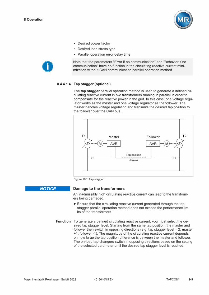
8 Operation
Maschinenfabrik Reinhausen GmbH 2022 2474016640/15 EN TAPCON®
Desired power factor Desired load stress type Parallel operation error delay time
Note that the parameters "Error if no communication" and "Behavior if nocommunication" have no function in the circulating reactive current mini-mization without CAN communication parallel operation method.
8.4.4.1.4 Tap stagger (optional)
The tap stagger parallel operation method is used to generate a defined cir-culating reactive current in two transformers running in parallel in order tocompensate for the reactive power in the grid. In this case, one voltage regu-lator works as the master and one voltage regulator as the follower. Themaster handles voltage regulation and transmits the desired tap position tothe follower over the CAN bus.
Master Follower
Tap position
CAN bus
M AVR MAVR
T1 T2
Figure 166: Tap stagger
NOTICE Damage to the transformersAn inadmissibly high circulating reactive current can lead to the transform-ers being damaged. Ensure that the circulating reactive current generated through the tap
stagger parallel operation method does not exceed the performance lim-its of the transformers.
Function To generate a defined circulating reactive current, you must select the de-sired tap stagger level. Starting from the same tap position, the master andfollower then switch in opposing directions (e.g. tap stagger level = 2: master+1, follower -1). The magnitude of the circulating reactive current dependson how large the tap position difference is between the master and follower.The on-load tap-changers switch in opposing directions based on the settingof the selected parameter until the desired tap stagger level is reached.

8 Operation
Maschinenfabrik Reinhausen GmbH 2022248 4016640/15 ENTAPCON®
Limiting conditions If one of the tap changers reaches an end position (Pos<, Pos>, Pos< Fol-lower or Pos> Follower), before the desired tap stagger level is reached,both tap changers remain in a lower tap stagger level.
If the tap position of both on-load tap-changers is to be changed due to thevoltage regulation (e.g. Master +1, Follower +1) and one tap changer has al-ready reached an end position, the tap stagger level will be reduced.
Example
The following example demonstrates a possible switching sequence in thetap stagger parallel operation method. Here, it is assumed that the on-loadtap-changers can be switched to the positions 1...12.1. To start, the desired tap stagger level is 0; both on-load tap-changers are
in tap position 8.2. The desired tap stagger level 8 is selected. Both on-load tap-changers
perform tap-change operations simultaneously until the desired tap stag-ger level is reached. The circulating reactive current increases with eachtap-change operation. Because both on-load tap-changers switch simulta-neously, the voltage of the transformers remains constant. Finally, themaster is in tap position 12 and the follower in tap position 4.
3. Due to voltage fluctuations in the grid (the voltage U leaves the band-width), a "RAISE" tap-change operation is necessary. Because the masteris already in the highest tap position, the system must reduce the tapstagger level in order to achieve the desired voltage change. To do so, themaster switches one level lower and the follower one level higher. Themaster and follower then switch one level higher. The voltage returns tothe bandwidth.
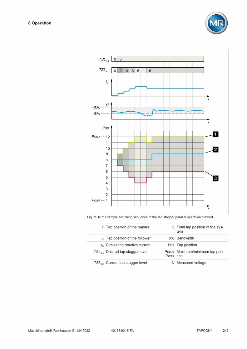
8 Operation
Maschinenfabrik Reinhausen GmbH 2022 2494016640/15 EN TAPCON®
TSLreq
TSLact
IC
Ut
tPos
t
123456789101112
0 8
0 2 4 6 8 6
1
2
3
Pos>
Pos<
+B%-B%
Figure 167: Example switching sequence of the tap stagger parallel operation method
1 Tap position of the master 2 Total tap position of the sys-tem
3 Tap position of the follower B% Bandwidth
IC Circulating reactive current Pos Tap position
TSLreq Desired tap stagger level Pos>/Pos<
Maximum/minimum tap posi-tion
TSLact Current tap stagger level U Measured voltage

8 Operation
Maschinenfabrik Reinhausen GmbH 2022250 4016640/15 ENTAPCON®
For the tap stagger parallel operation method, you have to set the followingparameters:
Parameter Master Follower
Activate parallel operation[Page 251]
Yes
Parallel operation method[Page 251]
Tap stagger Follower
CAN bus address [Page 252] Yes Yes1
Master/follower current blocking[Page 253]
Off Off
Tap stagger 1...8 [Page 254] Yes No
Select tap stagger [Page 255] Yes No
Pos< [Section 8.5.1, Page 266] Yes No
Pos> [Section 8.5.1, Page 266] Yes No
Pos< follower [Page 256] Yes No
Pos> follower [Page 256] Yes No
Error if no communication present[Page 254]
Yes
Behavior if no communicationpresent [Page 254]
Independent regulation, auto blocking or powerfactor
Parallel operation error delay time[Page 254]
Yes
Table 110: Parameter
1If there are several followers in your system, only the follower with the high-est CAN bus address participates in the tap stagger function.
Special operating situations If you switch the master from auto mode to manual mode during the tap
stagger parallel operation method, the follower immediately switches tothe master's current tap position. To avoid this, you must activate manualmode on both the master and follower simultaneously.
If you change the parallel operation method of the master from tap stag-ger to master, the tap stagger level is first reduced to 0 before parallel op-eration according to the tap synchronization method becomes active.
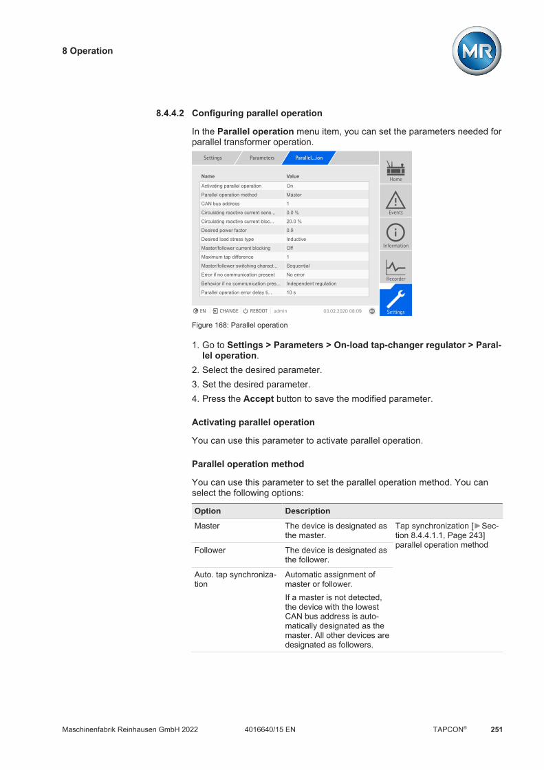
8 Operation
Maschinenfabrik Reinhausen GmbH 2022 2514016640/15 EN TAPCON®
8.4.4.2 Configuring parallel operation
In the Parallel operation menu item, you can set the parameters needed forparallel transformer operation.
Settings Parameters Parallel...ion
Name Value
Activating parallel operation On
Parallel operation method Master
CAN bus address 1
Circulating reactive current sens... 0.0 %
Circulating reactive current bloc... 20.0 %
Desired power factor 0.9
Desired load stress type Inductive
Master/follower current blocking Off
Maximum tap difference 1
Master/follower switching charact... Sequential
Error if no communication present No error
Behavior if no communication pres... Independent regulation
Parallel operation error delay ti... 10 s
Home
Events
Information
Recorder
SettingsEN CHANGE REBOOT admin 03.02.2020 08:09
Figure 168: Parallel operation
1. Go to Settings > Parameters > On-load tap-changer regulator > Paral-lel operation.
2. Select the desired parameter.3. Set the desired parameter.4. Press the Accept button to save the modified parameter.
Activating parallel operation
You can use this parameter to activate parallel operation.
Parallel operation method
You can use this parameter to set the parallel operation method. You canselect the following options:
Option Description
Master The device is designated asthe master.
Tap synchronization [Sec-tion 8.4.4.1.1, Page 243]parallel operation methodFollower The device is designated as
the follower.
Auto. tap synchroniza-tion
Automatic assignment ofmaster or follower.If a master is not detected,the device with the lowestCAN bus address is auto-matically designated as themaster. All other devices aredesignated as followers.
8 Operation
Maschinenfabrik Reinhausen GmbH 2022252 4016640/15 ENTAPCON®
Option Description
Circulating reactivecurrent
Circulating reactive current minimization with CAN buscommunication [Section 8.4.4.1.2, Page 245] parallel op-eration method
Power factor Circulating reactive current minimization without CAN buscommunication [Section 8.4.4.1.3, Page 246] parallel op-eration method
Tap stagger (optional) The device is designated as the master for the tap stagger[Section 8.4.4.1.4, Page 247] parallel operation method.
Table 111: Setting parallel operation method
Only change the parallel operation method when the on-load tap-changersare not performing tap-change operations.
CAN bus address
You can use this parameter to assign a CAN bus address to the device. Sothat all devices can communicate using the CAN bus, each device requires aunique identifier. If the value is set to 0, then no communication takes place.
Circulating reactive current sensitivity
You can use this parameter to set the influence of circulating reactive currenton how the control deviation is calculated. The higher the set value, thegreater the calculated control deviation as a result of circulating reactive cur-rent.
To determine the ideal circulating reactive current sensitivity, note the rele-vant section in the Commissioning [Section 7.6.3.1, Page 85] chapter.
Circulating reactive current blocking limit
You can use this parameter to set the limit value for the maximum permissi-ble circulating reactive current. This value relates to the rated current of thecurrent transformer. If, during parallel operation, the circulating reactive cur-rent exceeds the set limit value, the device triggers the Circulating reactivecurrent blocking limit exceeded event. All devices operating in the paralleloperation group are blocked.
Desired power factor
You can use this parameter to set the power factor, which the transformerhas under normal operating conditions. If the measured power factor devi-ates from the desired one, the device calculates a correction which is addedto the control deviation.
Enter a desired power factor other than 0. If you enter a desired power fac-tor of 0, the device is not able to calculate the voltage correction.
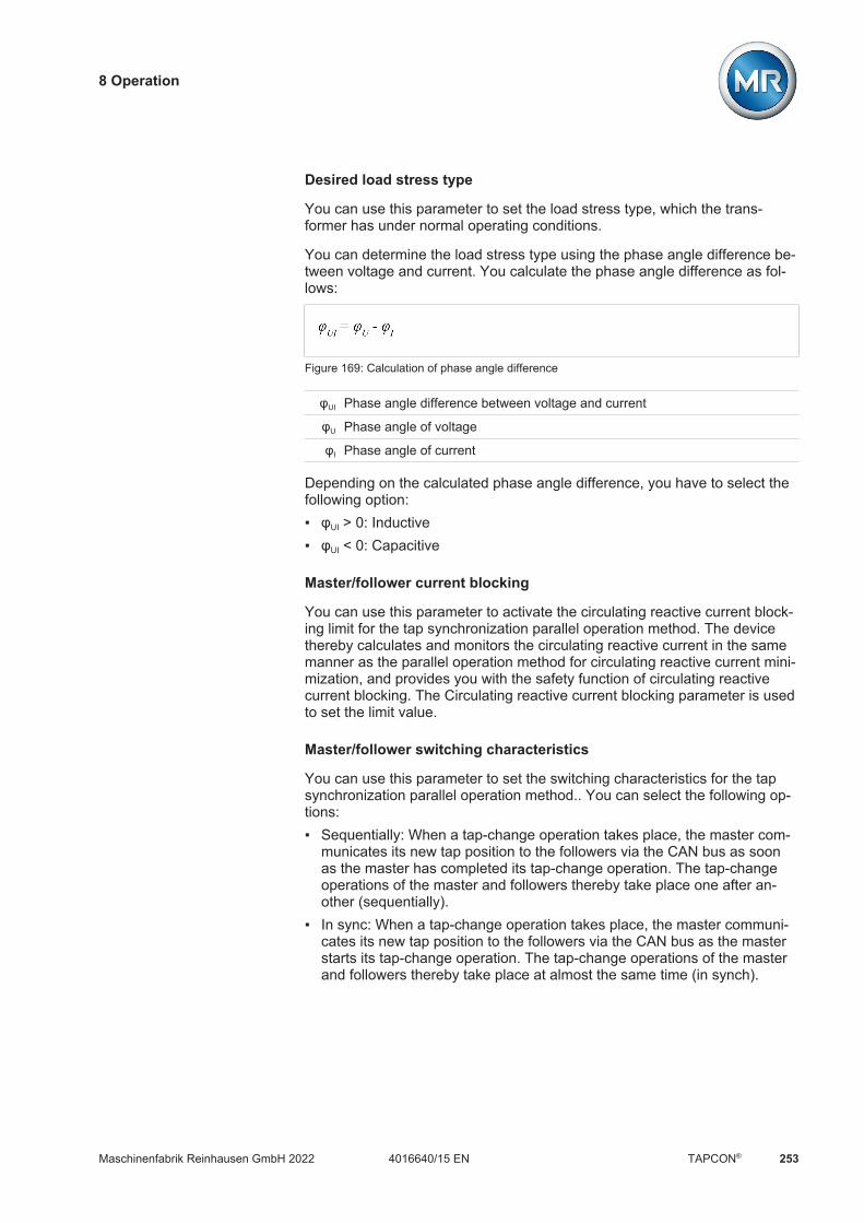
8 Operation
Maschinenfabrik Reinhausen GmbH 2022 2534016640/15 EN TAPCON®
Desired load stress type
You can use this parameter to set the load stress type, which the trans-former has under normal operating conditions.
You can determine the load stress type using the phase angle difference be-tween voltage and current. You calculate the phase angle difference as fol-lows:
Figure 169: Calculation of phase angle difference
φUI Phase angle difference between voltage and current
φU Phase angle of voltage
φI Phase angle of current
Depending on the calculated phase angle difference, you have to select thefollowing option: φUI > 0: Inductive φUI < 0: Capacitive
Master/follower current blocking
You can use this parameter to activate the circulating reactive current block-ing limit for the tap synchronization parallel operation method. The devicethereby calculates and monitors the circulating reactive current in the samemanner as the parallel operation method for circulating reactive current mini-mization, and provides you with the safety function of circulating reactivecurrent blocking. The Circulating reactive current blocking parameter is usedto set the limit value.
Master/follower switching characteristics
You can use this parameter to set the switching characteristics for the tapsynchronization parallel operation method.. You can select the following op-tions: Sequentially: When a tap-change operation takes place, the master com-
municates its new tap position to the followers via the CAN bus as soonas the master has completed its tap-change operation. The tap-changeoperations of the master and followers thereby take place one after an-other (sequentially).
In sync: When a tap-change operation takes place, the master communi-cates its new tap position to the followers via the CAN bus as the masterstarts its tap-change operation. The tap-change operations of the masterand followers thereby take place at almost the same time (in synch).

8 Operation
Maschinenfabrik Reinhausen GmbH 2022254 4016640/15 ENTAPCON®
Maximum tap difference
You can use this parameter to set the maximum permissible tap differencebetween followers and master on the follower.
If the tap difference is greater than the set maximum tap difference to themaster, the follower blocks and no longer attempts to attain the master's tapposition. After the set delay time for parallel operation error messages haselapsed, the follower issues the Permitted tap difference to master exceededmessage.
Error if no communication present
You can use this parameter to set whether it is an error if the device doesnot receive any messages via the CAN bus or if there are no other CAN busparticipants in the same parallel operation group.
Behavior if no communication present
You can use this parameter to set how the voltage regulator behaves if com-munication via the CAN bus is not possible.
The setting for this parameter is only effective if you have selected the Erroroption for the Error if no communication present parameter.
You can select the following options:
Option Description
Independent regula-tion
The device switches from parallel operation to normal auto-matic voltage regulation
Auto blocking Automatic voltage regulation is blocked.
cosφ interpolation Continuation of parallel operation with interpolated values(only possible with circulating reactive current parallel oper-ation method)
Power factor Circulating reactive current minimization without CAN buscommunication [Section 8.4.4.1.3, Page 246] parallel op-eration method
Table 112: Behavior if no communication present
Parallel operation error delay time
You can use this parameter to set the delay time for a parallel operation er-ror message so that brief fault messages are not received if the motor-driveunits involved in the parallel operation have different runtimes.
Tap stagger setting 1...8 (optional)
You can set up to eight different default settings for the desired tap staggerlevel (TSL).

8 Operation
Maschinenfabrik Reinhausen GmbH 2022 2554016640/15 EN TAPCON®
The following tap stagger settings are possible:
TSL Master1 Follower1
-1 -1 0
1 +1 0
-2 -1 +1
2 +1 -1
-3 -2 +1
3 +2 -1
-4 -2 +2
4 +2 -2
... ... ...
-32 -16 +16
32 +16 -16
Table 113: Tap stagger setting
1Tap position difference in relation to the tap position of the entire system
Selecting a tap stagger setting (optional)
This parameter allows you to select the tap stagger setting that the device isto use for control. The currently selected tap stagger setting is displayed inthe voltage regulation overview screen.
Figure 170: Current tap stagger setting

8 Operation
Maschinenfabrik Reinhausen GmbH 2022256 4016640/15 ENTAPCON®
Pos</Pos> follower (optional)
You can use these parameters to set the highest and lowest permissible tapposition of the follower. With the tap stagger parallel operation method, thedevice uses the following parameters for tap position monitoring [Section8.5.1, Page 266] of the master and follower:
Parameter Pos< (follower) Pos> (follower)
Behavior limit value Auto blocking for lower tap Auto blocking for raise tap
Delay time 0 s
Table 114: Tap position monitoring
8.4.4.3 Detecting parallel operation via group inputs (optional)
You can control up to 16 transformers connected in parallel in one or 2groups without detecting the system topology.
The devices in parallel operation only use the information communicated bydevices in the same parallel operation group via CAN bus.
You can use the PARALLEL GROUP 1 and PARALLEL GROUP 2 inputs toassign the device to a parallel operation group. If you create a signal at bothinputs, the device is assigned to both parallel operation groups.
If no parallel operation group is assigned to a device, it doesn't take part inthe parallel operation and undertakes its own voltage regulation.
8.4.4.4 Detecting parallel operation via topology (optional)
The topology function is used to detect which transformers are in parallel op-eration based on the position of the circuit breakers. Each circuit breaker isfitted with an auxiliary contact so that its status can be reported for this pur-pose.
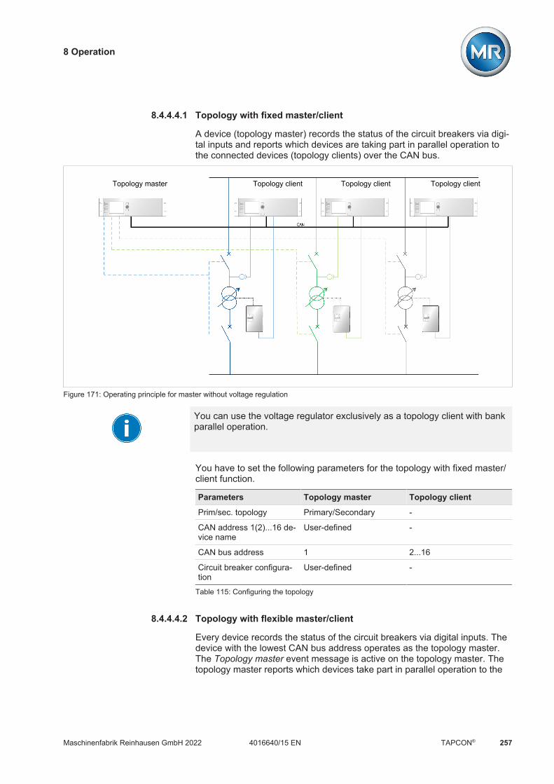
8 Operation
Maschinenfabrik Reinhausen GmbH 2022 2574016640/15 EN TAPCON®
8.4.4.4.1 Topology with fixed master/client
A device (topology master) records the status of the circuit breakers via digi-tal inputs and reports which devices are taking part in parallel operation tothe connected devices (topology clients) over the CAN bus.
Topology master Topology client Topology clientTopology client
Figure 171: Operating principle for master without voltage regulation
You can use the voltage regulator exclusively as a topology client with bankparallel operation.
You have to set the following parameters for the topology with fixed master/client function.
Parameters Topology master Topology client
Prim/sec. topology Primary/Secondary -
CAN address 1(2)...16 de-vice name
User-defined -
CAN bus address 1 2...16
Circuit breaker configura-tion
User-defined -
Table 115: Configuring the topology
8.4.4.4.2 Topology with flexible master/client
Every device records the status of the circuit breakers via digital inputs. Thedevice with the lowest CAN bus address operates as the topology master.The Topology master event message is active on the topology master. Thetopology master reports which devices take part in parallel operation to the

8 Operation
Maschinenfabrik Reinhausen GmbH 2022258 4016640/15 ENTAPCON®
connected devices. The devices compare self-determined topology informa-tion to the topology information received over CAN bus. If the topology infor-mation differs, the devices issue a Internal topology deviation event mes-sage.
If a topology master is switched off (e.g. if a transformer is disconnectedfrom the grid for maintenance work), the topology client with the next highestCAN bus address takes over the function of the topology master.
Note that the Topology master and Internal topology deviation events arenot output over the control system or digital output by default. If you wouldlike to use this function, you have to link the event messages to a data pointor digital output. Note the "Linking signals and events" [Section 8.2.11,Page 135] section.
CAN 1 CAN 2 CAN 3
Figure 172: Operating principle
You have to set the following parameters for the topology with flexible mas-ter/client function.
Parameters Master/Client
Prim/sec. topology Primary/Secondary
CAN address 1...16 device name User-defined
CAN bus address 1...16
Circuit breaker configuration User-defined1)
Table 116: Configuring the topology
1) If you configure all switches with node 0 on a device, that device does notsend any topology information over the CAN bus and operates solely as atopology client.
8 Operation
Maschinenfabrik Reinhausen GmbH 2022 2594016640/15 EN TAPCON®
8.4.4.4.3 Configuring the topology
To configure the topology, you must adjust the following settings: Prim/sec. topology CAN address 1(2)...16 device name CAN bus address Circuit breaker configuration
Prim/sec. topology You can use this parameter to set the condition that defines when the trans-formers are connected in parallel. You can select the following options: Secondary side: Transformers are considered to be connected in parallel
when the circuit breakers on the secondary side of the transformers areclosed.
Both sides: Transformers are considered to be connected in parallel whenthe circuit breakers on the primary and secondary sides of the transform-ers are closed.
At least one side: Transformers are considered to be connected in parallelwhen the circuit breakers on the primary or secondary side of the trans-formers are closed.
To set the condition, proceed as follows:1. Go to Settings > Parameters > Parallel operation > Prim/sec topology.2. Select the desired option.3. Press the Accept button to save the modified parameter.
CAN address 1(2)...16device name
You can use these parameters to set the name of the transformers. The de-vice uses the name in the information display for the topology.
To set the transformer name, proceed as follows:1. Go to Settings > Parameters > Parallel operation > CAN address
1(2)...16 device name.2. Enter the desired name.3. Press the Accept button to save the modified parameter.
CAN bus address Set the CAN bus address. Observe the information provided in the AssigningCAN bus address [Page 252] section.
Circuit breaker configuration
You can set the assignment of circuit breakers to the individual node points.The device uses the assignment to detect which transformers are connectedin parallel with one another.
Upon delivery, the device is configured in accordance with your order. Notethe connection diagram provided for the configuration.
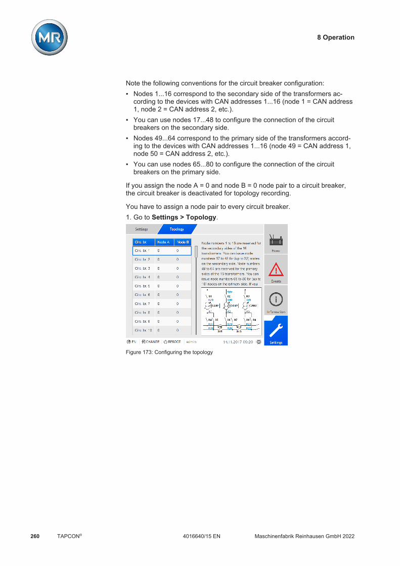
8 Operation
Maschinenfabrik Reinhausen GmbH 2022260 4016640/15 ENTAPCON®
Note the following conventions for the circuit breaker configuration: Nodes 1...16 correspond to the secondary side of the transformers ac-
cording to the devices with CAN addresses 1...16 (node 1 = CAN address1, node 2 = CAN address 2, etc.).
You can use nodes 17...48 to configure the connection of the circuitbreakers on the secondary side.
Nodes 49...64 correspond to the primary side of the transformers accord-ing to the devices with CAN addresses 1...16 (node 49 = CAN address 1,node 50 = CAN address 2, etc.).
You can use nodes 65...80 to configure the connection of the circuitbreakers on the primary side.
If you assign the node A = 0 and node B = 0 node pair to a circuit breaker,the circuit breaker is deactivated for topology recording.
You have to assign a node pair to every circuit breaker.1. Go to Settings > Topology.
Figure 173: Configuring the topology

8 Operation
Maschinenfabrik Reinhausen GmbH 2022 2614016640/15 EN TAPCON®
2. Select the desired circuit breaker.
Figure 174: Configuring the topology for circuit breaker 1
3. Enter the desired node numbers in the node A and node B fields.4. Press the Accept button to save the modified parameter.

8 Operation
Maschinenfabrik Reinhausen GmbH 2022262 4016640/15 ENTAPCON®
8.4.4.4.4 Topology
Under Topology, you can display which transformers are in parallel opera-tion and which parallel operation group the transformers belong to. The fol-lowing representation forms are possible:
Symbol Description
Transformer is in parallel operation and belongs to paralleloperation group 2.
Transformer is in independent mode.
The CAN bus connection to the TAPCON® of thistransformer is faulty.
Table 117: Representation forms (examples)
Figure 175: Topology
Go to Information > On-load tap-changer regulator > Topology.
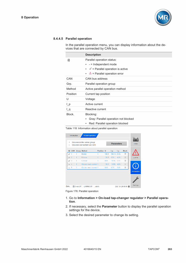
8 Operation
Maschinenfabrik Reinhausen GmbH 2022 2634016640/15 EN TAPCON®
8.4.4.5 Parallel operation
In the parallel operation menu, you can display information about the de-vices that are connected by CAN bus.
Description
Parallel operation status: - = Independent mode = Parallel operation is active = Parallel operation error
CAN CAN bus address
Grp. Parallel operation group
Method Active parallel operation method
Position Current tap position
U Voltage
I_p Active current
I_q Reactive current
Block. Blocking: Gray: Parallel operation not blocked Red: Parallel operation blocked
Table 118: Information about parallel operation
Figure 176: Parallel operation
1. Go to Information > On-load tap-changer regulator > Parallel opera-tion.
2. If necessary, select the Parameter button to display the parallel operationsettings for the device.
3. Select the desired parameter to change its setting.
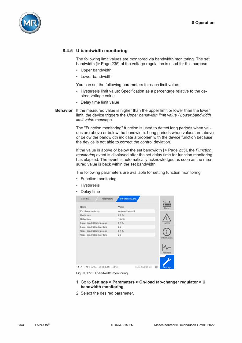
8 Operation
Maschinenfabrik Reinhausen GmbH 2022264 4016640/15 ENTAPCON®
8.4.5 U bandwidth monitoring
The following limit values are monitored via bandwidth monitoring. The setbandwidth [Page 235] of the voltage regulation is used for this purpose. Upper bandwidth Lower bandwidth
You can set the following parameters for each limit value: Hysteresis limit value: Specification as a percentage relative to the de-
sired voltage value. Delay time limit value
Behavior If the measured value is higher than the upper limit or lower than the lowerlimit, the device triggers the Upper bandwidth limit value / Lower bandwidthlimit value message.
The "Function monitoring" function is used to detect long periods when val-ues are above or below the bandwidth. Long periods when values are aboveor below the bandwidth indicate a problem with the device function becausethe device is not able to correct the control deviation.
If the value is above or below the set bandwidth [Page 235], the Functionmonitoring event is displayed after the set delay time for function monitoringhas elapsed. The event is automatically acknowledged as soon as the mea-sured value is back within the set bandwidth.
The following parameters are available for setting function monitoring: Function monitoring Hysteresis Delay time
Settings Parameters U bandwidt...ing
Name Value
Function monitoring Auto and Manual
Hysteresis 0.0 %
Delay time 15 min
Lower bandwidth hysteresis 0.1 %
Lower bandwidth delay time 2 s
Upper bandwidth hysteresis 0.1 %
Upper bandwidth delay time 2 s
Home
Events
Information
Recorder
SettingsEN CHANGE REBOOT admin 23.09.2020 09:23
Figure 177: U bandwidth monitoring
1. Go to Settings > Parameters > On-load tap-changer regulator > Ubandwidth monitoring.
2. Select the desired parameter.

8 Operation
Maschinenfabrik Reinhausen GmbH 2022 2654016640/15 EN TAPCON®
3. Set the desired parameter.4. Press the Accept button to save the modified parameter.
Also refer to2 Current monitoring [ 208]
Function monitoring
You can use this parameter to activate function monitoring. You can selectthe following options:
Setting Behavior
Off Function monitoring is deactivated.
Only Auto Function monitoring is only active in AVR AUTO oper-ating mode.
Auto and Manual Function monitoring is active in AVR AUTO and AVRMANUAL operating modes
Table 119: Activate function monitoring
Hysteresis
You can use this parameter to set the hysteresis. You can use this to avoidthe unnecessary generation of messages if the measured value fluctuatesaround a threshold value.
Delay time
You can use this parameter to set the delay time in order to delay the issuingof the event message.
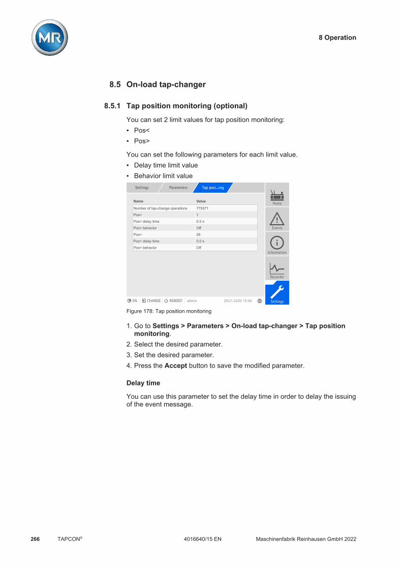
8 Operation
Maschinenfabrik Reinhausen GmbH 2022266 4016640/15 ENTAPCON®
8.5 On-load tap-changer
8.5.1 Tap position monitoring (optional)
You can set 2 limit values for tap position monitoring: Pos< Pos>
You can set the following parameters for each limit value. Delay time limit value Behavior limit value
Settings Parameters Tap posi...ing
Name Value
Number of tap-change operations 775571
Pos< 1
Pos< delay time 0.0 s
Pos< behavior Off
Pos> 26
Pos> delay time 0.0 s
Pos> behavior Off
Home
Events
Information
Recorder
SettingsEN CHANGE REBOOT admin 29.01.2020 15:45
Figure 178: Tap position monitoring
1. Go to Settings > Parameters > On-load tap-changer > Tap positionmonitoring.
2. Select the desired parameter.3. Set the desired parameter.4. Press the Accept button to save the modified parameter.
Delay time
You can use this parameter to set the delay time in order to delay the issuingof the event message.

8 Operation
Maschinenfabrik Reinhausen GmbH 2022 2674016640/15 EN TAPCON®
Behavior limit value
You can use this parameter to set the behavior of the device when the eventmessage is issued. You can select the following options:
Setting Behavior
Off Tap position monitoring is disabled.
Auto blocking po-sition+
The automatic control does not perform a tap-change operationin the direction of a higher tap position (position+).You can still perform a tap-change operation in the direction ofa higher tap position (position+) in manual mode.
Auto blocking po-sition-
The automatic control does not perform a tap-change operationin the direction of a lower tap position (position-).You can still perform a tap-change operation in the direction ofa lower tap position (position-) in manual mode.
Auto/manualblocking position+
The automatic control does not perform a tap-change operationin the direction of a higher tap position (position+).You cannot perform a tap-change operation in the direction of ahigher tap position (position+) in manual mode.
Auto/manualblocking position-
The automatic control does not perform a tap-change operationin the direction of a lower tap position (position-).You cannot perform a tap-change operation in the direction of alower tap position (position-) in manual mode.
Also refer to2 Target-tap-position operation [ 269]
Operations counter
The device's operations counter is automatically increased with every tap-change operation. You can use this parameter to set the number of tap-change operations, such as for a comparison with the operations counter ofthe motor-drive unit.
8.5.2 Switching interval monitoring
You can use this function to monitor the typical tap-change behavior of yourtransformer. Furthermore, you can set the number of consecutive tap-change operations permissible in auto mode within a defined time period.
You can have the following operations monitored: Total operations: Total RAISE operations and LOWER operations LOWER operations: Total LOWER operations RAISE operations: Total RAISE operations

8 Operation
Maschinenfabrik Reinhausen GmbH 2022268 4016640/15 ENTAPCON®
Settings Parameters Total sw...ing
Total Lower Raise
Total No. ops
Time interval
Event duration
Response
Count behavior -
25
1440.0 min
1.0 min
Auto blockin...
10
5.0 min
15.0 min
Off
Auto block. ...
10
5.0 min
15.0 min
On
Auto block. ...
Home
Events
Information
Recorder
SettingsEN CHANGE REBOOT admin 29.01.2020 15:45
Figure 179: Switching interval monitoring
1. Go to Settings > Parameters > On-load tap-changer > Switching inter-val monitoring.
2. Select the desired parameter.3. Set the desired parameter.4. Press the Accept button to save the modified parameter.
Total tap-change operations
If the maximum permissible number of tap-change operations within the settime interval is exceeded, the device triggers a corresponding response.
Time interval
You can use this parameter to set the time interval in which the maximumnumber of tap-change operations may not be exceeded.
Event duration
You can use this parameter to set how long the device is to respond with theset behavior.

8 Operation
Maschinenfabrik Reinhausen GmbH 2022 2694016640/15 EN TAPCON®
Behavior
You can use this parameter to set the behavior of the device if the maximumpermissible number of tap-change operations is exceeded:
Setting Behavior
Off Switching interval monitoring is disabled.
Switching to man-ual mode
The event is displayed for the set duration of the response. Thedevice automatically switches to manual mode.
Auto blocking The event is displayed for the set duration of the response. Au-tomatic voltage regulation is blocked. You can wait for theblocking time to expire or switch to manual mode by hand andthen to auto mode. The event is reset and blocking is disabled.
Table 120: Behavior
Counting behavior (only with raise or lower tap-change operations)
You can use this parameter to set whether intermediate RAISE or LOWERtap-change operations reset the internal counter. You can select the follow-ing options: On:
– The internal counter for consecutive LOWER tap-change operations isreset during a RAISE operation.
– The internal counter for consecutive RAISE tap-change operations isreset during a LOWER operation.
Off: The internal counter is not reset by intermediate RAISE or LOWERtap-change operations.
8.5.3 Target-tap-position operation
When target-tap-position operation is activated, the device automaticallyswitches to this target tap position.
Settings Parameters Move to ...ion
Name Value
Target tap position 0Home
Events
Information
Recorder
SettingsEN CHANGE REBOOT admin 03.02.2020 08:09
Figure 180: Move to the defined target tap position

8 Operation
Maschinenfabrik Reinhausen GmbH 2022270 4016640/15 ENTAPCON®
1. Go to Settings > Parameters > On-load tap-changer > Move to the de-fined target tap position.
2. Select the desired parameter.3. Set the desired parameter.4. Press the Accept button to save the modified parameter.
Target tap position
You can use this parameter to define a target tap position.
8.5.4 Changing tap position designation (optional)
This function allows you edit the designation of the tap position. The desig-nations are displayed on the main screen when each of the tap positions isactive and are used for the control system.
Settings Tap position table
Raw value Tap position Control system
1 1 1
2 2 2
3 3 3
4 4 1
5 5 2
6 6 1
7 7 3
8 8 4
9 9 5
10 10 6
AcceptCancel
Home
Events
Information
Recorder
SettingsEN CHANGE REBOOT admin 23.03.2020 08:08
Figure 181: Tap position table
1. Go to Settings > Tap position table.2. Enter the designation for the tap position and for the control system.3. Click on the Accept button.
8.5.5 Information about the on-load tap-changer
Under "OLTC" you can display information about the on-load tap-changer: Current tap position Total tap-change operations (operations counter)

8 Operation
Maschinenfabrik Reinhausen GmbH 2022 2714016640/15 EN TAPCON®
Figure 182: OLTC
Go to Information > On-load tap-changer > OLTC.
8.5.6 Displaying tap-change operation statistics (optional)
In the switching statistics view, you can display how often the on-load tap-changer has been switched to a particular tap position and how long it hasremained in a particular tap position.
The top diagram shows how often the on-load tap-changer was switchedinto a particular tap position and how long it spent there. The bottom dia-gram shows the time spent in the tap positions over the last 10 days.
Figure 183: Tap-change operation statistics
Go to Information > On-load tap-changer > Tap-change operation sta-tistics.

8 Operation
Maschinenfabrik Reinhausen GmbH 2022272 4016640/15 ENTAPCON®
8.5.7 Displaying information about contact wear (only OILTAP®)
If you are monitoring an on-load tap-changer of type OILTAP®, you can dis-play the current wear values of the main switching contacts (MSCA, MSCB)and transition contacts (TCA, TCB).
The device also shows the differences in contact wear for different contacts.
Figure 184: Contact wear
Go to Information > On-load tap-changer > Contact wear.
8.5.8 Maintenance (optional)
The device monitors the following maintenance depending on the on-loadtap-changer type:
Maintenance Description
OLTC maintenance The on-load tap-changer must be maintained in accordancewith the MR standards.
OLTC replacement The on-load tap-changer must be replaced with a new on-load tap-changer.
DSI replacement The diverter switch insert must be replaced with a new di-verter switch insert.
IEM replacement The interrupter exchange module (IEM) of the on-load tap-changer must be replaced with a new IEM.
Contact wear The main switching contacts or transition contacts of the on-load tap-changer must be exchanged or replaced.
Oil exchange andcleaning
The oil must be changed and the diverter switch insert, oilcompartment, and oil conservator must be cleaned.
Selector mainte-nance
The on-load tap-changer selector must be maintained in ac-cordance with the MR standards.
Cleaning/lubrication The on-load tap-changer needs to be cleaned and lubricated.
Oil sample An oil sample must be taken and analyzed; the limit valuesspecified by MR for added insulating oil must be observed.
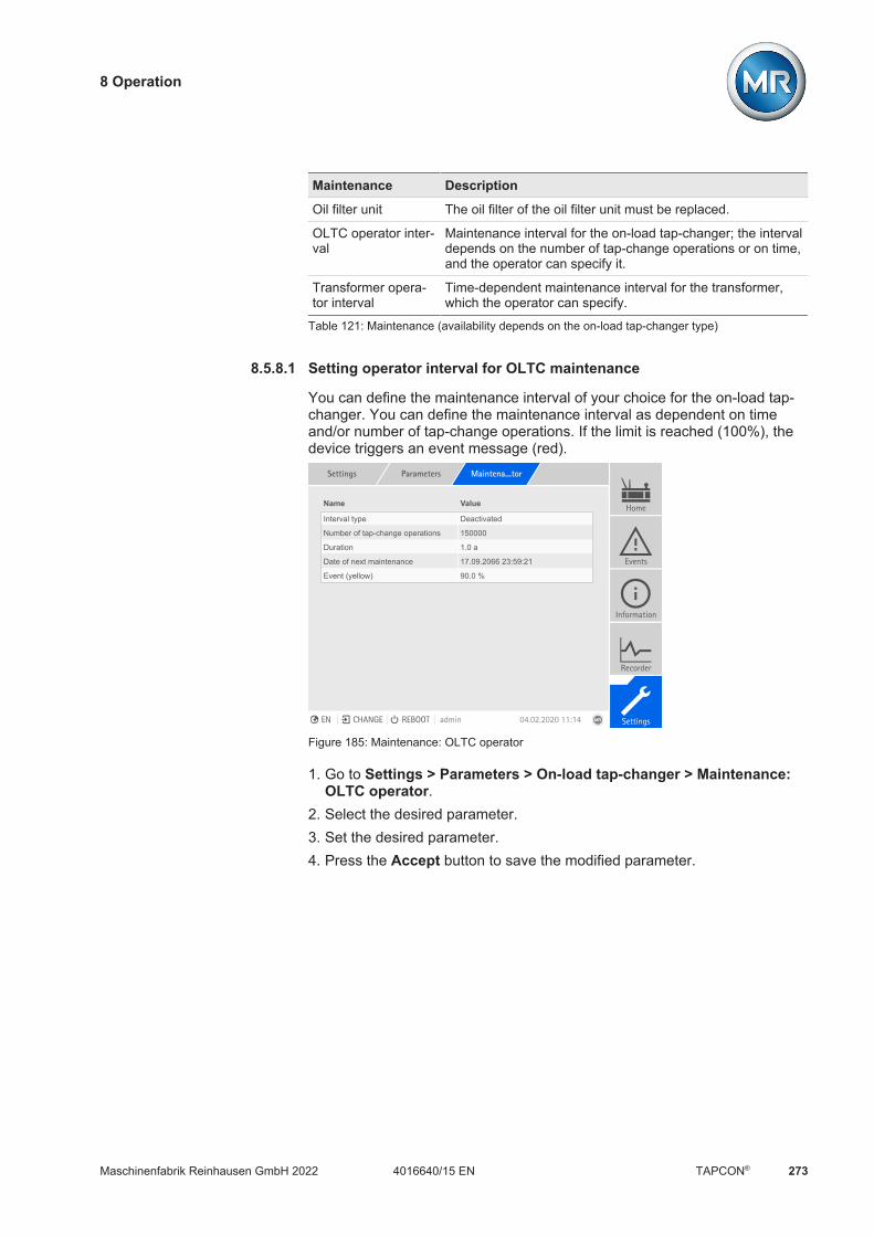
8 Operation
Maschinenfabrik Reinhausen GmbH 2022 2734016640/15 EN TAPCON®
Maintenance Description
Oil filter unit The oil filter of the oil filter unit must be replaced.
OLTC operator inter-val
Maintenance interval for the on-load tap-changer; the intervaldepends on the number of tap-change operations or on time,and the operator can specify it.
Transformer opera-tor interval
Time-dependent maintenance interval for the transformer,which the operator can specify.
Table 121: Maintenance (availability depends on the on-load tap-changer type)
8.5.8.1 Setting operator interval for OLTC maintenance
You can define the maintenance interval of your choice for the on-load tap-changer. You can define the maintenance interval as dependent on timeand/or number of tap-change operations. If the limit is reached (100%), thedevice triggers an event message (red).
Settings Parameters Maintena...tor
Name Value
Interval type Deactivated
Number of tap-change operations 150000
Duration 1.0 a
Date of next maintenance 17.09.2066 23:59:21
Event (yellow) 90.0 %
Home
Events
Information
Recorder
SettingsEN CHANGE REBOOT admin 04.02.2020 11:14
Figure 185: Maintenance: OLTC operator
1. Go to Settings > Parameters > On-load tap-changer > Maintenance:OLTC operator.
2. Select the desired parameter.3. Set the desired parameter.4. Press the Accept button to save the modified parameter.
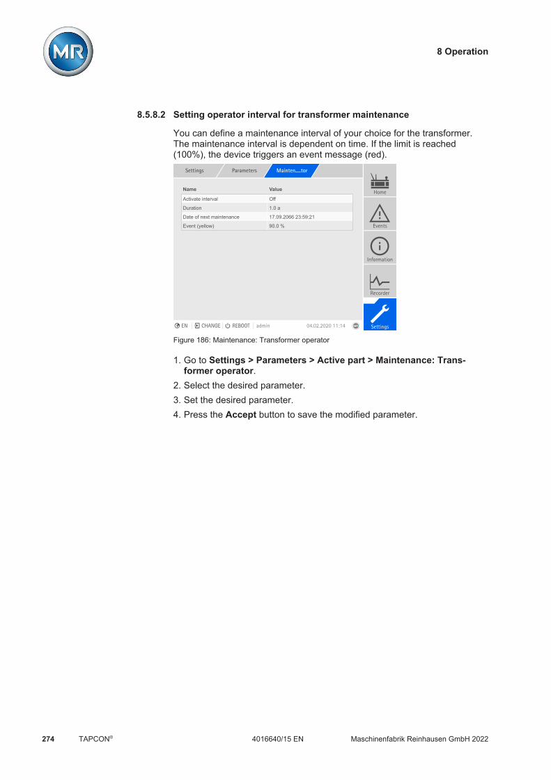
8 Operation
Maschinenfabrik Reinhausen GmbH 2022274 4016640/15 ENTAPCON®
8.5.8.2 Setting operator interval for transformer maintenance
You can define a maintenance interval of your choice for the transformer.The maintenance interval is dependent on time. If the limit is reached(100%), the device triggers an event message (red).
Settings Parameters Mainten....tor
Name Value
Activate interval Off
Duration 1.0 a
Date of next maintenance 17.09.2066 23:59:21
Event (yellow) 90.0 %
Home
Events
Information
Recorder
SettingsEN CHANGE REBOOT admin 04.02.2020 11:14
Figure 186: Maintenance: Transformer operator
1. Go to Settings > Parameters > Active part > Maintenance: Trans-former operator.
2. Select the desired parameter.3. Set the desired parameter.4. Press the Accept button to save the modified parameter.

8 Operation
Maschinenfabrik Reinhausen GmbH 2022 2754016640/15 EN TAPCON®
8.5.8.3 Undertaking and confirming maintenance
Once you have undertaken maintenance, you can confirm this on the deviceand thereby reset the maintenance interval. The following maintenance pa-rameters can be entered based on the maintenance type:
Value Description
Date Date of maintenance.
Operation counter Reading of the operations counter at the time of mainte-nance.You can enter the current counter reading or a smallercounter reading.
Contact wear (onlyOILTAP®) MSCA MSCB TC1A TC1B TC2A TC2B
Overall contact wear on the stationary contact and movingcontact.If you have measured the contact wear during mainte-nance and continue to use the contacts in their originalpositions, then enter the measured values and select "No"in the prompt that reads "Contacts exchanged/replaced"to confirm it. This causes the monitoring system to opti-mize its calculation model, and subsequent calculation ofthe contact wear is more precise.If you have exchanged (other position) or replaced con-tacts, then enter the contact wear found on the mountedcontacts (for new contacts: 0.000 mm) and select "Yes" inthe prompt that reads "Contacts exchanged/replaced" toconfirm it.
Table 122: Maintenance parameters

8 Operation
Maschinenfabrik Reinhausen GmbH 2022276 4016640/15 ENTAPCON®
Determining the contact wear (only OILTAP®)
The thickness of the wear to be entered is the sum of the wear of the mov-able and the fixed contact part.
Figure 187: Determining contact wear
1 Fixed contact y1 Thickness of the worn contactcoating (fixed contact)
2 Movable contact x2 Thickness of the contact coatingwhen new (movable contact)
x1 Thickness of the contact coatingwhen new (fixed contact)
y2 Thickness of the worn contactcoating (movable contact)
The wear thickness z to be entered is determined as follows:
z = x1 - y1 + x2 - y2
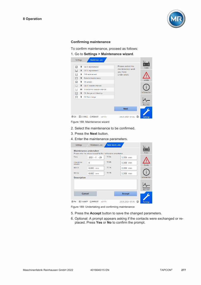
8 Operation
Maschinenfabrik Reinhausen GmbH 2022 2774016640/15 EN TAPCON®
Confirming maintenance
To confirm maintenance, proceed as follows:1. Go to Settings > Maintenance wizard.
Figure 188: Maintenance wizard
2. Select the maintenance to be confirmed.3. Press the Next button.4. Enter the maintenance parameters.
Figure 189: Undertaking and confirming maintenance
5. Press the Accept button to save the changed parameters.6. Optional: A prompt appears asking if the contacts were exchanged or re-
placed. Press Yes or No to confirm the prompt.
8 Operation
Maschinenfabrik Reinhausen GmbH 2022278 4016640/15 ENTAPCON®
8.5.8.4 Displaying maintenance overview
The maintenance overview displays the progress of the individual mainte-nance intervals. You can also see the limit values for the "yellow" and "red"event messages. For the maintenance intervals of the on-load tap-changer,the device uses the recorded operating data to predict the date for the nextmaintenance appointment. The date is not displayed until enough operatingdata has been recorded.
If you have deactivated the "OLTC operator maintenance" or "Transformeroperator maintenance" interval, the interval is shown grayed out in the main-tenance overview.
Figure 190: Maintenance overview
Go to Information > System > Maintenance.
8.5.8.5 Displaying the maintenance logbook
All maintenance tasks that have been performed are displayed in the main-tenance logbook. The entries are generated automatically if you performmaintenance using the maintenance wizard. You can also create separateentries.
The maintenance logbook displays the following information: Time of maintenance Mainten.type Description

8 Operation
Maschinenfabrik Reinhausen GmbH 2022 2794016640/15 EN TAPCON®
Figure 191: Maintenance logbook
To call up the maintenance logbook, proceed as follows: Go to Settings > Maintenance logbook.
Editing an entry in the maintenance logbook
You can edit the entries in the maintenance logbook as needed.
Figure 192: Editing an entry in the maintenance logbook
Proceed as follows to edit an entry in the maintenance logbook:1. Go to Settings > Maintenance logbook.
2. Press the button in order to edit an entry.

8 Operation
Maschinenfabrik Reinhausen GmbH 2022280 4016640/15 ENTAPCON®
Creating an entry in the maintenance logbook
Proceed as follows to create an entry in the maintenance logbook withoutusing the maintenance wizard:1. Go to Settings > Maintenance logbook.2. Press the New entry button.3. Enter the maintenance data.4. Press the Accept button to save the entry.
Deleting an entry in the maintenance logbook
You can delete the entries in the maintenance logbook as needed. To do so,proceed as follows:1. Go to Settings > Maintenance logbook.
2. Press the button in order to delete the entry.
8.5.8.6 Suppressing a maintenance event
You can use this function to suppress the event messages of maintenancetasks whose limit values have been reached for a specific number of on-loadtap-change operations. If you acknowledge a maintenance event withoutperforming maintenance, the device will report the event message after theset number of on-load tap-change operations.
Settings Parameters Maintena...nts
Name Value
Suppressing transformer maint. ev... 1Home
Events
Information
Recorder
SettingsEN CHANGE REBOOT admin 04.02.2020 11:14
Figure 193: Suppressing a maintenance event
1. Go to Settings > Parameters > Active part > Maintenance events orSettings > Parameters > On-load tap-changer > Maintenance events.
2. Select the desired parameter.3. Set the parameter.4. Press the Accept button to save the modified parameter.

8 Operation
Maschinenfabrik Reinhausen GmbH 2022 2814016640/15 EN TAPCON®
8.5.9 OLTC data
In this menu, you can set parameters for the on-load tap-changer (OLTC).Settings Parameters OLTC data
Name Value
Tap position message (analog) Raw value
Tap position message (analog) 2 Raw value
Tap position message (analog) 3 Raw value
Home
Events
Information
Recorder
SettingsEN CHANGE REBOOT admin 14.04.2020 14:22
Figure 194: OLTC data
1. Go to Settings > Parameters > On-load tap-changer > OLTC data.2. Select the desired parameter.3. Set the desired parameter.4. Press the Accept button to save the modified parameter.
OLTC A/B/C serial number
You can use this parameter to set the serial number of the on-load tap-changer.
In applications with several columns, you can enter a unique serial numberfor each on-load tap-changer.
8.5.9.1 Setting the tap position message (optional)
If you issue the tap position of the on-load tap-changer via an analog outputor digital outputs (BCD, gray, etc.), you can set whether the device is to usethe raw value or the adjusted value for the control system in accordance withthe tap position table [Section 8.5.4, Page 270]. You can use this setting toensure that pass-through positions of the on-load tap-changer are not re-ported as a separate tap position.

8 Operation
Maschinenfabrik Reinhausen GmbH 2022282 4016640/15 ENTAPCON®
If you issue the tap position via several outputs, you can set this behavior foreach output separately.
Settings Parameters OLTC data
Name Value
Tap position message (analog) Raw value
Tap position message (analog) 2 Raw value
Tap position message (analog) 3 Raw value
Home
Events
Information
Recorder
SettingsEN CHANGE REBOOT admin 14.04.2020 14:22
Figure 195: OLTC data (example with 3x tap position message via analog outputs)
1. Go to Settings > Parameters > On-load tap-changer > OLTC data.2. Select the desired parameter.3. Set the desired parameter.4. Press the Accept button to save the modified parameter.
Tap position message (analog)
You can use this parameter to set which range of values from the tap posi-tion table the device should use for the tap position message using the ana-log output.
If you change this parameter, you must then ensure that the configured ana-log output value range [Section 8.2.12, Page 140] matches the valuerange in the tap position table [Section 8.5.4, Page 270]. Otherwise, thetap position will not be reported correctly.

8 Operation
Maschinenfabrik Reinhausen GmbH 2022 2834016640/15 EN TAPCON®
8.5.10 Displaying the minimum and maximum tap position
You can display the minimum and maximum tap position reached and thecorresponding time.
Figure 196: Minimum and maximum tap position
1. Go to Information > On-load tap-changer > Minimum and maximumtap position.
2. As needed, select the Reset button to reset the minimum and maximumvalues.

8 Operation
Maschinenfabrik Reinhausen GmbH 2022284 4016640/15 ENTAPCON®
8.6 Motor-drive unit and control cabinet
8.6.1 Control of the motor-drive unit
The following parameters let you configure control of the motor-drive unit.You can set the following: Switching pulse Motor runtime Switching direction
Settings Parameters Motor co...nit
Name Value
Switching pulse type Time-controlled pulse
Switching pulse time 1.5 s
Switching pulse pause 2.5 s
Activate motor runtime monitoring Off
Motor runtime 6 s
Activate switching direction moni... Off
Switching direction Standard
Home
Events
Information
Recorder
SettingsEN CHANGE REBOOT admin 03.02.2020 08:09
Figure 197: Motor control unit
Go to Settings > Parameters > Motor and control cabinet > Torquemonitoring .
8.6.1.1 Setting the switching pulse for controlling the motor-drive unit
You can use the parameters Switching pulse type, Switching pulse time andSwitching pulse pause to adapt the device switching pulse to the require-ments of the motor-drive unit controller.1. Go to Settings > Parameters > Motor and control cabinet > Motor
control.2. Select the desired parameter.3. Set the parameter.4. Press the Accept button to save the modified parameter.
Switching pulse type
You can use this parameter to toggle the switching pulse between a continu-ous pulse or a time-controlled switching pulse.

8 Operation
Maschinenfabrik Reinhausen GmbH 2022 2854016640/15 EN TAPCON®
Continuous pulse Selecting the "Continuous pulse" option causes the device to issue theswitching pulse in AVR Auto operating mode until the measured value isback within the bandwidth. In AVR Manual operating mode, the device is-sues the switching pulse for as long as you press the or key.
If the device is operated as a follower in parallel operation in this case, thenthe TAPCON® will issue the switching pulse until one of the following re-quirements has been met: The set motor runtime has been reached The Motor running signal switches from state 1 to 0 The tap position required by the master has been reached
A pause is enforced after every switching pulse before another switchingpulse is issued.
Time-controlled switchingpulse
Selecting the "Time-controlled switching pulse" option causes the device toissue the switching pulse for a set duration. A pause is enforced after ev-ery switching pulse before another switching pulse is issued.
If you use a motor-drive unit from Maschinenfabrik Reinhausen GmbH, youneed to select the "Time-controlled switching pulse" option.
V
s1 2 1
Figure 198: Switching pulse time and switching pulse pause
1 Switching pulse time 2 Switching pulse pause
Switching pulse time
You can use this parameter to set the maximum duration of the switchingpulse. The switching pulse resets after the switching pulse time has elapsedor if the device receives the Motor running signal beforehand or the tap posi-tion is changed.
Switching pulse pause
You can use this parameter to set the switching pulse pause between 2switching pulses. The device can only issue another switching pulse oncethe switching pulse pause has elapsed.

8 Operation
Maschinenfabrik Reinhausen GmbH 2022286 4016640/15 ENTAPCON®
8.6.1.2 Setting motor runtime monitoring
The motor-drive unit's runtime can be monitored by the device. This functionis used to identify motor-drive unit malfunctions during the tap-change oper-ation and to trigger any actions needed.
Behavior The motor-drive unit issues the Motor-drive unit running signal during thetap-change operation. This signal is present until the tap-change operation iscomplete. The device compares the duration of this signal with the set motorruntime. If the set motor runtime is exceeded, the device triggers the follow-ing actions:1. Motor runtime exceeded event.2. Pulse signal via Trigger motor protective switch output relay
Note that motor-drive units with pass-through positions or motor-drive unitswithout stepped switching behavior will run for longer under certain circum-stances. Set a longer motor runtime for such units.
1. Go to Settings > Parameters > Motor and control cabinet > Motorcontrol.
2. Select the desired parameter.3. Set the parameter.4. Press the Accept button to save the modified parameter.
Motor runtime monitoring limit
This parameter lets you set the motor runtime monitoring limit.
Motor runtime monitoring
You can use this parameter to activate or deactivate motor runtime monitor-ing.
8.6.1.3 Setting the switching direction
You can set the switching direction of the motor-drive unit.1. Go to Settings > Parameters > Motor and control cabinet > Motor
control.2. Select the desired parameter.3. Set the parameter.4. Press the Accept button to save the modified parameter.
8 Operation
Maschinenfabrik Reinhausen GmbH 2022 2874016640/15 EN TAPCON®
U switching direction
You can use this parameter to set the switching direction for voltage regula-tion. You can use this to adjust the behavior of the device based on howyour on-load tap-changer and motor-drive unit are configured. You can se-lect the following options:
Setting Meaning
Standard The device issues a signal via the Raise output to increase thevoltage.The device issues a signal via the Lower output to reduce thevoltage.
Swapped The device issues a signal via the Lower output to increasethe voltage.The device issues a signal via the Raise output to reduce thevoltage.
Table 123: Behavior
Q switching direction (optional)
You can use this parameter to set the switching direction for reactive powerregulation. You can use this to adjust the behavior of the device based onhow your on-load tap-changer and motor-drive unit are configured. You canselect the following options:
Setting Meaning
Standard The device issues a signal via the RAISE output to increasethe reactive power.The device issues a signal via the LOWER output to reducethe reactive power.
Swapped The device issues a signal via the LOWER output to increasethe reactive power.The device issues a signal via the RAISE output to reduce thereactive power.
Table 124: Behavior
Switching direction monitoring
You can use this parameter to set the switching direction monitoring. Thisfunction monitors whether a tap-change operation in the wrong direction hasbeen undertaken (e.g. due to a wiring mistake).
If a tap-change operation in the wrong direction is detected, the device is-sues the event message Switching direction monitoring and blocks auto-matic regulation. Automatic regulation is blocked until you acknowledge[Section 8.2.14.1, Page 145] the event.
Switching direction monitoring is not active if you control the motor-drive unitwith a continuous pulse [Section 8.6.1.1, Page 284].

8 Operation
Maschinenfabrik Reinhausen GmbH 2022288 4016640/15 ENTAPCON®
Also refer to2 Setting the switching pulse for controlling the motor-drive unit [ 284]2 Displaying and acknowledging events [ 145]
8.6.2 Tap position capture
The current tap position of the on-load tap-changer is transmitted from themotor-drive unit to the device. You can define the type of tap position cap-ture during the order. You cannot change this subsequently via a menu.
In accordance with your order, the tap position is transmitted in one of thefollowing ways: Digital signal
– BCD Analog signal
– Injected current (0/4…20 mA)– Voltage (0…10 V)– Resistor contact series
8.6.2.1 Digital tap position capture
The tap position can optionally be transmitted from the motor-drive unit tothe device as a digital signal. No further settings are needed.
8.6.2.2 Analog tap position capture
8.6.2.2.1 Injected current (0/4…20 mA) or voltage (0...10 V)
For the analog tap position capture, you must set which tap positions corre-spond to the minimum analog signal and maximum analog signal.
The device is configured at the factory according to the order. However,should modifications be necessary, note the following sections.
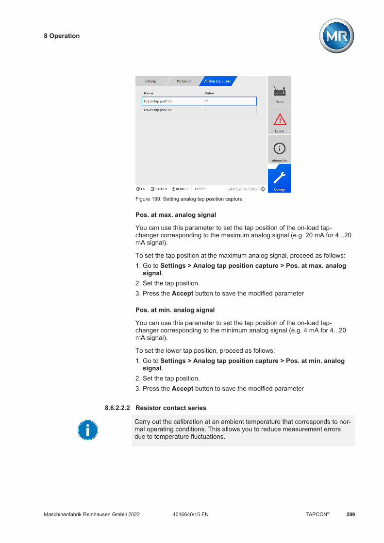
8 Operation
Maschinenfabrik Reinhausen GmbH 2022 2894016640/15 EN TAPCON®
Figure 199: Setting analog tap position capture
Pos. at max. analog signal
You can use this parameter to set the tap position of the on-load tap-changer corresponding to the maximum analog signal (e.g. 20 mA for 4...20mA signal).
To set the tap position at the maximum analog signal, proceed as follows:1. Go to Settings > Analog tap position capture > Pos. at max. analog
signal.2. Set the tap position.3. Press the Accept button to save the modified parameter
Pos. at min. analog signal
You can use this parameter to set the tap position of the on-load tap-changer corresponding to the minimum analog signal (e.g. 4 mA for 4...20mA signal).
To set the lower tap position, proceed as follows:1. Go to Settings > Analog tap position capture > Pos. at min. analog
signal.2. Set the tap position.3. Press the Accept button to save the modified parameter
8.6.2.2.2 Resistor contact series
Carry out the calibration at an ambient temperature that corresponds to nor-mal operating conditions. This allows you to reduce measurement errorsdue to temperature fluctuations.

8 Operation
Maschinenfabrik Reinhausen GmbH 2022290 4016640/15 ENTAPCON®
To capture the tap positions via resistor contact series, you need to performa calibration. In order to do this, you have to set the on-load tap-changer'stap positions corresponding to the maximum and minimum analog signal.Then you have to carry out on-load tap-change operations across the entiretap position range. The entire calibration process is performed using wiz-ards.
To carry out the calibration, proceed as follows:1. Go to Settings > Calibrate hardware > Calibrate RCS .
Figure 200: Calibrate resistor contact series (RCS)
2. Select the Pos. at max. analog signal parameter.3. Set the tap position.4. Press the Accept button to save the modified parameter.5. Select the Pos. at min. analog signal parameter.6. Set the tap position.7. Press the Accept button to save the modified parameter.8. Press the Start button.
ð The calibration wizard is started.9. Press the Next button.10. Step 1: Manually switch on-load tap-changer to the highest tap position.11. Press the Next button.
ð Step 2: The device calibrates the current output and once completemoves onto step 3.
12. Step 3: Manually switch on-load tap-changer to the lowest tap position.ð Step 4: The device determines the offset and once complete moves
onto step 5.13. Step 5: Press the Next button to complete calibration.ð Calibration of tap position capture using the resistor contact series has
been undertaken successfully.

9 Maintenance and care
Maschinenfabrik Reinhausen GmbH 2022 2914016640/15 EN TAPCON®
9 Maintenance and care
9.1 Cleaning the deviceYou can clean the device's housing with a dry cloth.

10 Fault elimination
Maschinenfabrik Reinhausen GmbH 2022292 4016640/15 ENTAPCON®
10 Fault elimination
10.1 General faultsCharacteristics/details Cause Remedy
No function Power supply LED does not
light up
No power supply Check power supply.
Fuse tripped Contact Maschinenfabrik Reinhausen GmbH.
No function AVR STATUS LED does not
light up
Configuration error Contact Maschinenfabrik Reinhausen GmbH.
Relays chatter High EMC load Use shielded cables or external filters.
Poor grounding Check the functional ground.
Table 125: General faults
10.2 No regulation in AUTO modeCharacteristics/detail Cause Remedy
Device control commands haveno effect.
Local/Remote switch in motor-drive unit switched to LOCAL.
Check operating mode. Correct if necessary.
No connection. Check wiring as per connection diagram.
Automatic voltage regulation isblocked. ALARM LED lights up in accor-
dance with event configurationand a corresponding event isactive.
Limit value with auto blocking orauto-manual blocking behaviorhas been exceeded
Check parameters. Correct if necessary.
The switching direction monitor-ing has recorded a malfunctionand triggered the associatedevent.
Check cause of event and then acknowledgeevent.
The motor protective switch hastriggered. Motor protective switchevent active.
Check what caused the motor protective switchto trigger and engage motor protective switch ifnecessary.
Automatic voltage regulation isblocked.
Signal at "Block automatic voltageregulation" input
Check signal source.
Target-tap-position operation ac-tive
Check configuration of target-tap-position oper-ation function. If necessary, remedy cause.
"Blocking" function is linked to adigital input or control systemmessage.
Check signal source or control system. If neces-sary, reset.
Automatic voltage regulation isblocked. Measured voltage too low (<
30 V)
Voltage measurement incorrect Check voltage measurement.
Bandwidth set too high - Determine the recommended bandwidth.
10 Fault elimination
Maschinenfabrik Reinhausen GmbH 2022 2934016640/15 EN TAPCON®
Characteristics/detail Cause Remedy
Parallel operation active. Device is follower in parallel oper-ation.
No error. If necessary, deactivate parallel opera-tion.
CAN bus communication failure "Auto blocking" behavior is set. Check configuration.
Table 126: No regulation in AUTO mode
10.3 Bank parallel operationCharacteristics/details Cause Remedy
Automatic voltage regulation isblocked.Manual tap-change operationsusing digital inputs or a controlsystem are blocked. Event No. 159 Tap positions of
transformers not the same
The transformers are in differenttap positions.
Check whether the motor-drive unit or on-loadtap-changer are ready to function. The motor-drive units must be in the REMOTE operatingmode.If the motor-drive unit and on-load tap-changerare ready to function, switch transformers intothe same tap position manually [Section 8.1,Page 90].
Automatic voltage regulation isblocked.Manual tap-change operationsusing digital inputs or a controlsystem are blocked. Event No. 172, 172 or 174 Mo-
tor-drive unit 1/2/3 LOCAL
The motor-drive unit is in the LO-CAL operating mode.
Switch the motor-drive unit to the REMOTE op-erating mode.
Table 127: Bank parallel operation
10.4 Unwanted on-load tap-change operationCharacteristics/detail Cause Remedy
Compensation activated Setting: R-X compensation Z compensation
Check parameters.Correct if necessary.
Table 128: Unexplained tap change
10.5 Human-machine interfaceCharacteristics/details Cause Remedy
Keys MANUAL/AUTO operating
mode cannot be changed
REMOTE operating mode activeand LED in key illuminated.
Press to activate LOCAL mode.
Display No display.
Power supply interrupted. Check the voltage supply.
Fuse faulty. Contact Maschinenfabrik Reinhausen.
Connection cable between frontpanel and CPU (ETH 2.1) defec-tive.
Check connection cable
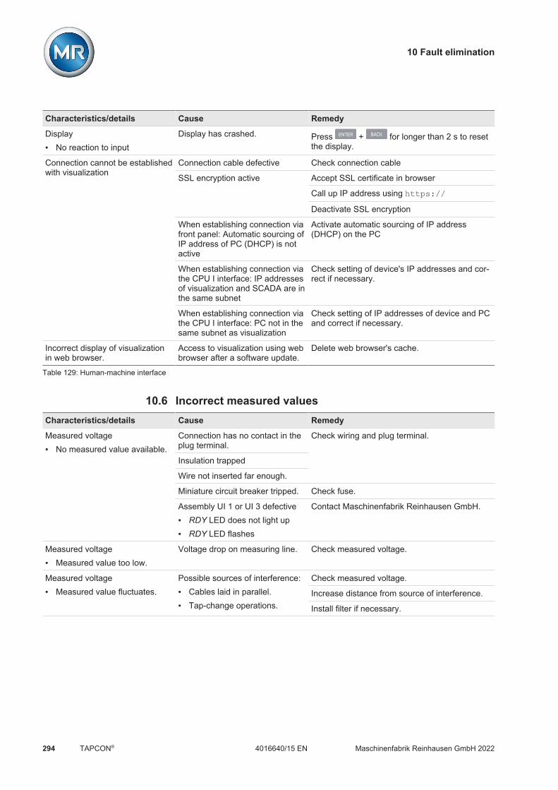
10 Fault elimination
Maschinenfabrik Reinhausen GmbH 2022294 4016640/15 ENTAPCON®
Characteristics/details Cause Remedy
Display No reaction to input
Display has crashed. Press + for longer than 2 s to resetthe display.
Connection cannot be establishedwith visualization
Connection cable defective Check connection cable
SSL encryption active Accept SSL certificate in browser
Call up IP address using https://
Deactivate SSL encryption
When establishing connection viafront panel: Automatic sourcing ofIP address of PC (DHCP) is notactive
Activate automatic sourcing of IP address(DHCP) on the PC
When establishing connection viathe CPU I interface: IP addressesof visualization and SCADA are inthe same subnet
Check setting of device's IP addresses and cor-rect if necessary.
When establishing connection viathe CPU I interface: PC not in thesame subnet as visualization
Check setting of IP addresses of device and PCand correct if necessary.
Incorrect display of visualizationin web browser.
Access to visualization using webbrowser after a software update.
Delete web browser's cache.
Table 129: Human-machine interface
10.6 Incorrect measured valuesCharacteristics/details Cause Remedy
Measured voltage No measured value available.
Connection has no contact in theplug terminal.
Check wiring and plug terminal.
Insulation trapped
Wire not inserted far enough.
Miniature circuit breaker tripped. Check fuse.
Assembly UI 1 or UI 3 defective RDY LED does not light up RDY LED flashes
Contact Maschinenfabrik Reinhausen GmbH.
Measured voltage Measured value too low.
Voltage drop on measuring line. Check measured voltage.
Measured voltage Measured value fluctuates.
Possible sources of interference: Cables laid in parallel. Tap-change operations.
Check measured voltage.
Increase distance from source of interference.
Install filter if necessary.

10 Fault elimination
Maschinenfabrik Reinhausen GmbH 2022 2954016640/15 EN TAPCON®
Characteristics/details Cause Remedy
Measured current No measured value.
Line to current transformer inter-rupted.
Check wiring.
Short-circuiting jumper in currenttransformer not removed.
Remove short-circuiting jumper.
Assembly UI 1 or UI 3 defective RDY LED does not light up RDY LED flashes
Contact Maschinenfabrik Reinhausen GmbH.
Measured current Measured value too high. Measured value too low.
Current transformer not correctlyparameterized.
Correct parameterization.
Table 130: Incorrect measured values
10.7 Parallel operation faultsCharacteristics/details Cause Remedy
Problem with CAN bus. Device not listed.
Device incorrectly connected. Check connections.Connect as shown in connection diagram.
Devices have the same CAN busaddresses.
Set different CAN bus addresses.
CAN bus address of device set to"0".
Set CAN bus address (anything but 0).
Problem with parallel operation. Different parallel operation meth-ods set for devices in the paralleloperation group.
Check configuration.
Problem with master/follower par-allel operation method.
More than 1 device is configuredas master in the parallel operationgroup.
Check configuration.
No device configured as masterin the parallel operation group.
Check configuration.
Invalid tap position of master orfollower.
Check tap position.Check wiring. Connect as shown in connectiondiagram.
Problem with master/follower par-allel operation method: Master/follower switching char-
acteristics is "in synch".
Master and followers have differ-ent tap positions.
Check tap position capture or check why thetap-change operation has not been undertaken(e.g. mechanical defect), then perform one ofthe following steps: Manually correct the master's tap position. Restart master. Set master/follower switching characteristics
to "sequential". Change master device to follower and define
a different device as the master.
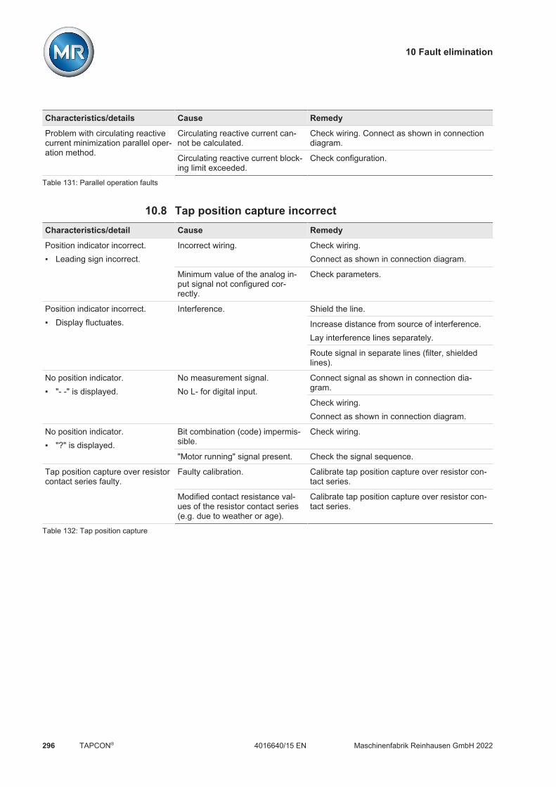
10 Fault elimination
Maschinenfabrik Reinhausen GmbH 2022296 4016640/15 ENTAPCON®
Characteristics/details Cause Remedy
Problem with circulating reactivecurrent minimization parallel oper-ation method.
Circulating reactive current can-not be calculated.
Check wiring. Connect as shown in connectiondiagram.
Circulating reactive current block-ing limit exceeded.
Check configuration.
Table 131: Parallel operation faults
10.8 Tap position capture incorrectCharacteristics/detail Cause Remedy
Position indicator incorrect. Leading sign incorrect.
Incorrect wiring. Check wiring.Connect as shown in connection diagram.
Minimum value of the analog in-put signal not configured cor-rectly.
Check parameters.
Position indicator incorrect. Display fluctuates.
Interference. Shield the line.
Increase distance from source of interference.Lay interference lines separately.
Route signal in separate lines (filter, shieldedlines).
No position indicator. "- -" is displayed.
No measurement signal.No L- for digital input.
Connect signal as shown in connection dia-gram.
Check wiring.Connect as shown in connection diagram.
No position indicator. "?" is displayed.
Bit combination (code) impermis-sible.
Check wiring.
"Motor running" signal present. Check the signal sequence.
Tap position capture over resistorcontact series faulty.
Faulty calibration. Calibrate tap position capture over resistor con-tact series.
Modified contact resistance val-ues of the resistor contact series(e.g. due to weather or age).
Calibrate tap position capture over resistor con-tact series.
Table 132: Tap position capture

10 Fault elimination
Maschinenfabrik Reinhausen GmbH 2022 2974016640/15 EN TAPCON®
10.9 AssembliesConsult the following table to check whether individual assemblies have amalfunction.
Assembly Characteristics/details Cause Remedy
UI 1/UI 3 RDY LED (yellow) doesnot light up
No communication with assemblypossible.
Contact Maschinenfabrik Rein-hausen GmbH.
RDY LED (yellow) flashes An error was detected in the as-sembly.
Contact Maschinenfabrik Rein-hausen GmbH.
CPU I RUN LED (green) doesnot light up
No power supply. Check power supply.
ERR LED (red) lights up An error was detected in the as-sembly.
Contact Maschinenfabrik Rein-hausen GmbH.
DIO 28-15DIO 42-20DIO 42-20 HL
RUN LED (green) doesnot light up
No power supply Check the power supply
ERR LED (red) lights up An error was detected in the as-sembly.
Contact Maschinenfabrik Rein-hausen GmbH.
AIO 2AIO 4
RDY LED (yellow) doesnot light up
No communication with assemblypossible.
Contact Maschinenfabrik Rein-hausen GmbH.
RDY LED (yellow) flashes Wiring faulty. Check wiring.
Interface configuration faulty. Check configuration.
Table 133: Assembly faults
10.10 Other faultsIf you cannot resolve a problem, please contact Maschinenfabrik Rein-hausen. Please have the following data to hand: Serial number
– Nameplate– Info screen
Software version
Please provide answers to the following questions: Has the software been updated? Has there previously been a problem with this device? Have you previously contacted Maschinenfabrik Reinhausen about this is-
sue? If yes, then who was the contact?

11 Uninstallation
Maschinenfabrik Reinhausen GmbH 2022298 4016640/15 ENTAPCON®
11 UninstallationThe following describes the safe removal of the device.
DANGER Electric shock!Risk of fatal injury due to electrical voltage. Always observe the followingsafety regulations when working in or on electrical equipment. Disconnect the equipment. Lock the equipment to prevent an unintentional restart. Make sure all poles are de-energized. Ground and short-circuit. Cover or cordon off adjacent energized parts.
WARNING Electric shock!Dangerous high voltages may occur when a current transformer is operatedwith an open secondary circuit. This can lead to death, injuries and propertydamage. Never operate a current transformer with an open secondary circuit;
short-circuit the current transformer to prevent this. Observe the information in the current transformer operating instructions.
NOTICE Damage to the device!Electrostatic discharge may cause damage to the device. Take precautionary measures to prevent the build-up of electrostatic
charges on work surfaces and personnel.
11.1 Uninstalling the CPU assembly1. Remove the 24V DC plug.
Figure 201: Removing the plug (voltage supply)

11 Uninstallation
Maschinenfabrik Reinhausen GmbH 2022 2994016640/15 EN TAPCON®
2. Remove the Ethernet cable.
Figure 202: Removing the Ethernet cable
3. If necessary, remove the data cable (D-Sub 9-poles).
Figure 203: Removing the data cable

11 Uninstallation
Maschinenfabrik Reinhausen GmbH 2022300 4016640/15 ENTAPCON®
4. Remove the CAN bus cable.
Figure 204: CAN bus cable
5. Unscrew the fixing screws.
Figure 205: Unscrewing the fixing screws

11 Uninstallation
Maschinenfabrik Reinhausen GmbH 2022 3014016640/15 EN TAPCON®
6. Unplug the assembly.
Figure 206: Unplugging the CPU assembly
11.2 Uninstalling the UI 1/UI 3 assembly1. Remove the plug for the voltage measurement.
Figure 207: Voltage measurement

11 Uninstallation
Maschinenfabrik Reinhausen GmbH 2022302 4016640/15 ENTAPCON®
2. WARNING! Make sure that the current transformer is shorted. Other-wise dangerously high voltages could occur. Remove the plug for the cur-rent measurement.
Figure 208: Current measurement
3. Loosen the fixing screws and unplug the assembly.
Figure 209: Unplugging the UI assembly

11 Uninstallation
Maschinenfabrik Reinhausen GmbH 2022 3034016640/15 EN TAPCON®
11.3 Uninstalling the AIO 2/AIO 4 assembly1. Remove the 24V DC plug.
Figure 210: Removing the plug (voltage supply)
2. Remove the plug.
Figure 211: Removing the plug (analog inputs/outputs)
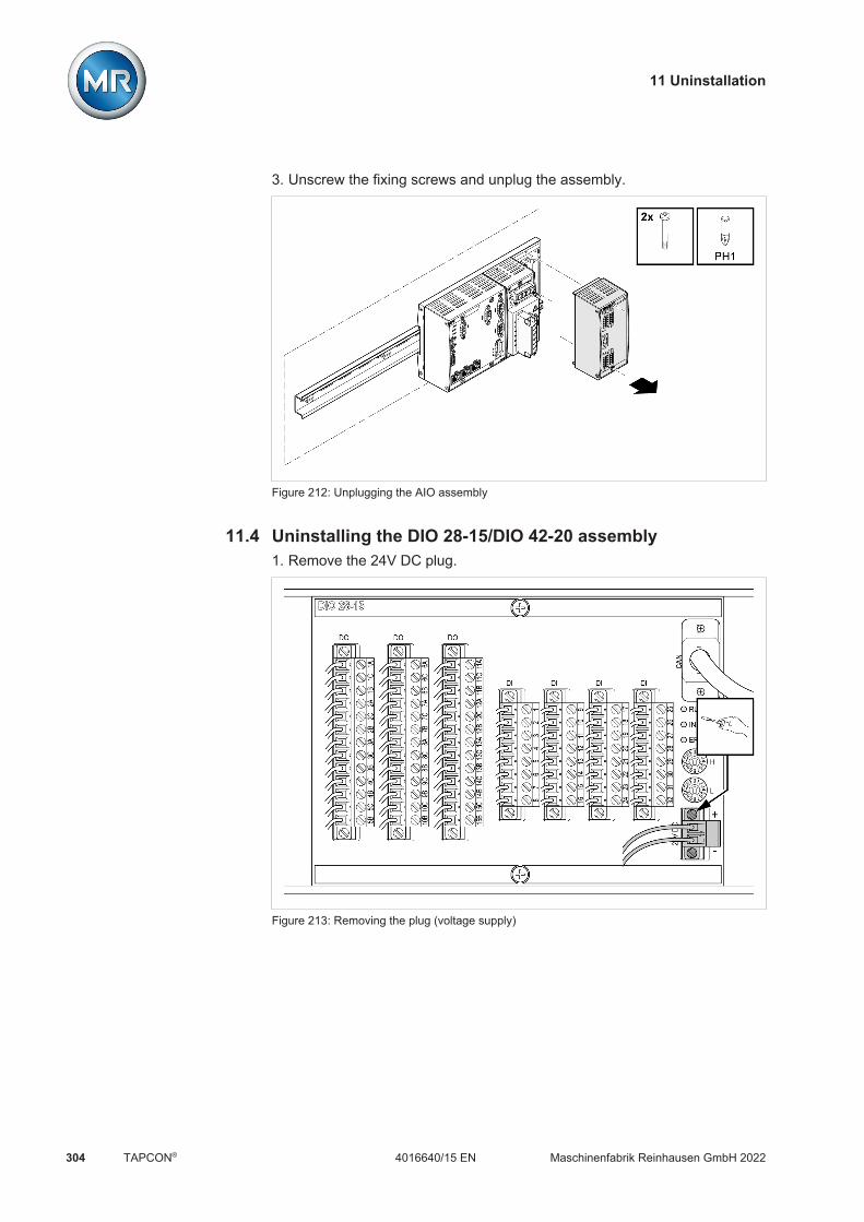
11 Uninstallation
Maschinenfabrik Reinhausen GmbH 2022304 4016640/15 ENTAPCON®
3. Unscrew the fixing screws and unplug the assembly.
Figure 212: Unplugging the AIO assembly
11.4 Uninstalling the DIO 28-15/DIO 42-20 assembly1. Remove the 24V DC plug.
Figure 213: Removing the plug (voltage supply)

11 Uninstallation
Maschinenfabrik Reinhausen GmbH 2022 3054016640/15 EN TAPCON®
2. Remove the CAN bus cable.
Figure 214: CAN bus cable
3. Remove all plugs in the "DI" and "DO" terminals.
Figure 215: Removing the "DI" and "DO" plugs

11 Uninstallation
Maschinenfabrik Reinhausen GmbH 2022306 4016640/15 ENTAPCON®
4. Unplug the assembly.
Figure 216: Unplugging the DIO assembly
11.5 Uninstalling the MC 2-2/SW 3-3 assembly1. Remove the 24V DC plug.
Figure 217: Removing the plug (voltage supply)

11 Uninstallation
Maschinenfabrik Reinhausen GmbH 2022 3074016640/15 EN TAPCON®
2. Remove the fiber-optic cable.
Figure 218: Fiber-optic cable
3. Remove the SFP module.
Figure 219: SFP module

11 Uninstallation
Maschinenfabrik Reinhausen GmbH 2022308 4016640/15 ENTAPCON®
4. Unplug the assembly.
Figure 220: Unplugging the MC 2-2/SW 3-3 assembly
11.6 Uninstalling the QS3.241 assembly1. Open the lever and remove the neutral conductor (N), phase conductor
(L) and the protective conductor .
Figure 221: Removing the neutral conductor, phase conductor and protective conductor

11 Uninstallation
Maschinenfabrik Reinhausen GmbH 2022 3094016640/15 EN TAPCON®
2. Open the lever and remove the wiring .
Figure 222: Removing the wiring
11.7 Uninstalling the bus railOnce you have dismounted all assemblies, you can unhook the bus rails:
Figure 223: Unhooking the bus rails

12 Disposal
Maschinenfabrik Reinhausen GmbH 2022310 4016640/15 ENTAPCON®
12 DisposalObserve the national requirements applicable in the country of use.

13 Technical data
Maschinenfabrik Reinhausen GmbH 2022 3114016640/15 EN TAPCON®
13 Technical data
13.1 Display elementsDisplay 5.7" LCD, Backlight LED
VGA (640 x 480 pixels)262,000 colors (18-bit)
LEDs 8 LEDs for operation display and messages
13.2 ISM® assemblies
13.2.1 Power supply OT1205OT1205 (MR/N)
Permissible voltage range 85 to 265 V AC / V DCUN: 100...240 V ACUN: 100 to 220 V DC
Permissible frequency range 50/60 Hz
Power consumption 55 W
Internal fuse (2x) 250 V; 2 A; 5 x 20 mm, T character-istic (delayed-action)
Table 134: Standard design with wide range power supply
Figure 224: Internal fuse (2x) of wide range power supply in assembly OT1205

13 Technical data
Maschinenfabrik Reinhausen GmbH 2022312 4016640/15 ENTAPCON®
OT1205 (MR/48)
Permissible voltage range 20...70 V DCUN: 48 V DC
Power consumption 55 W
Internal fuse 250 V; 5 A; 5 x 20 mm, "fast-acting"characteristics
Table 135: Special version with DC voltage power supply
Figure 225: Internal fuse and spare fuse of DC voltage power supply in assembly OT1205

13 Technical data
Maschinenfabrik Reinhausen GmbH 2022 3134016640/15 EN TAPCON®
Figure 226: Dimensions

13 Technical data
Maschinenfabrik Reinhausen GmbH 2022314 4016640/15 ENTAPCON®
13.2.2 UI 1 voltage measurement and current measurementUI 1
Measurement 1-phase
Voltage measurement UN (RMS): 100 VACMeasuring range (RMS): 19.6...150 VACMeasuring accuracy (at UN, -25...+70°C): <± 0.3%Intrinsic consumption: < 1 VAMeasurement category III in accordance withIEC 61010-2-30
Current measurement IN: 0.2 / 1 / 5 AMeasuring range: 0.01...2.1 · IN
Overload capacity: 12.5 A (continuous), 500 A (for 1 s)Measuring accuracy (at IN, -25...+70°C): <± 0.5%Intrinsic consumption: < 1 VA
Phase angle Measuring accuracy (-25...+70°C): Ux/Ix <± 0.5°; Ux/Uy <± 0.3°
Frequency measurement fN: 50 / 60 HzMeasuring range: 45...65 HzMeasuring accuracy (-25...+70°C): <± 0.03%
Table 136: Technical data for the UI 1 assembly
Interface Pin Description
N L NC NC
N Voltage input for neutral conductor
L Voltage input for phase L
NC -
NC -
Table 137: Voltage measurement
Interface Pin Description
k Current input for phase L
l Current output for phase L
NC -
NC -
NC -
NC -
Table 138: Current measurement

13 Technical data
Maschinenfabrik Reinhausen GmbH 2022 3154016640/15 EN TAPCON®
k1
k2
k3
l1
l2
l3
RDY
N L1 L2 L3
UI 3
55 mm (2.17 in)
ca. 120 mm (4.72 in)
119
mm
(4.6
9 in
)
54 mm (2.12 in)
Figure 227: UI 1 dimensions
13.2.3 UI 3 voltage measurement and current measurementUI 3
Measurement 3-phase
Voltage measurement UN (RMS): 100 VACMeasuring range (RMS): 19.6...150 VACMeasuring accuracy (at UN, -25...+70°C): <± 0.3%Intrinsic consumption: < 1 VAMeasurement category III in accordance withIEC 61010-2-30
Current measurement IN: 0.2 / 1 / 5 AMeasuring range: 0.01...2.1 · IN
Overload capacity: 12.5 A (continuous), 500 A (for 1 s)Measuring accuracy (at IN, -25...+70°C): <± 0.5%Intrinsic consumption: < 1 VA
Phase angle Measuring accuracy (-25...+70°C): Ux/Ix <± 0.5°; Ux/Uy <± 0.3°
Frequency measurement fN: 50 / 60 HzMeasuring range: 45...65 HzMeasuring accuracy (-25...+70°C): <± 0.03%
Table 139: Technical data for the UI 3 assembly
Interface Pin Description
N L1 L2 L3
N Voltage input for neutral conductor
L1 Voltage input for phase L1 (UI 3)
L2 Voltage input for phase L2
L3 Voltage input for phase L3
Table 140: Voltage measurement
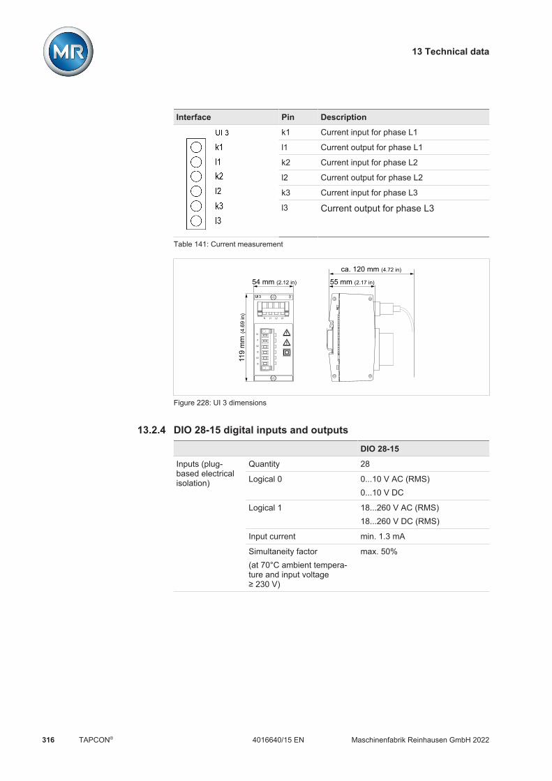
13 Technical data
Maschinenfabrik Reinhausen GmbH 2022316 4016640/15 ENTAPCON®
Interface Pin Description
k1 Current input for phase L1
l1 Current output for phase L1
k2 Current input for phase L2
l2 Current output for phase L2
k3 Current input for phase L3
l3 Current output for phase L3
Table 141: Current measurement
k1
k2
k3
l1
l2
l3
RDY
N L1 L2 L3
UI 3
55 mm (2.17 in)
ca. 120 mm (4.72 in)
119
mm
(4.6
9 in
)
54 mm (2.12 in)
Figure 228: UI 3 dimensions
13.2.4 DIO 28-15 digital inputs and outputsDIO 28-15
Inputs (plug-based electricalisolation)
Quantity 28
Logical 0 0...10 V AC (RMS)0...10 V DC
Logical 1 18...260 V AC (RMS)18...260 V DC (RMS)
Input current min. 1.3 mA
Simultaneity factor(at 70°C ambient tempera-ture and input voltage≥ 230 V)
max. 50%

13 Technical data
Maschinenfabrik Reinhausen GmbH 2022 3174016640/15 EN TAPCON®
DIO 28-15
Outputs (floatingrelay outputs)
Number (number of change-over contacts in parenthe-ses)
15 (9)
Contact load capacity Alternating current mode:UN: 230 V AC; IN: 5 ADirect current mode: See diagram
Simultaneity factor(if output is loaded with 5 A)
Up to 60°C: 100%, > 60°C:-5%/K
Table 142: Technical data for the DIO 28-15 assembly
10
20
304050
100
V
300
0.1 0.2 0.5 1 2 5 10 20A
U
I
Ohmic load
Figure 229: Contact load capacity of digital outputs with resistive load
CAUTION Electric shock!The inputs of the DIO assembly have plug-based electrical isolation. A mix-ture of voltage ranges (e.g. extra low voltage and low voltage) or variousphases within a plug can lower the protection against electric shock. Use the same voltage ranges within a plug. Use the same phase within a plug.
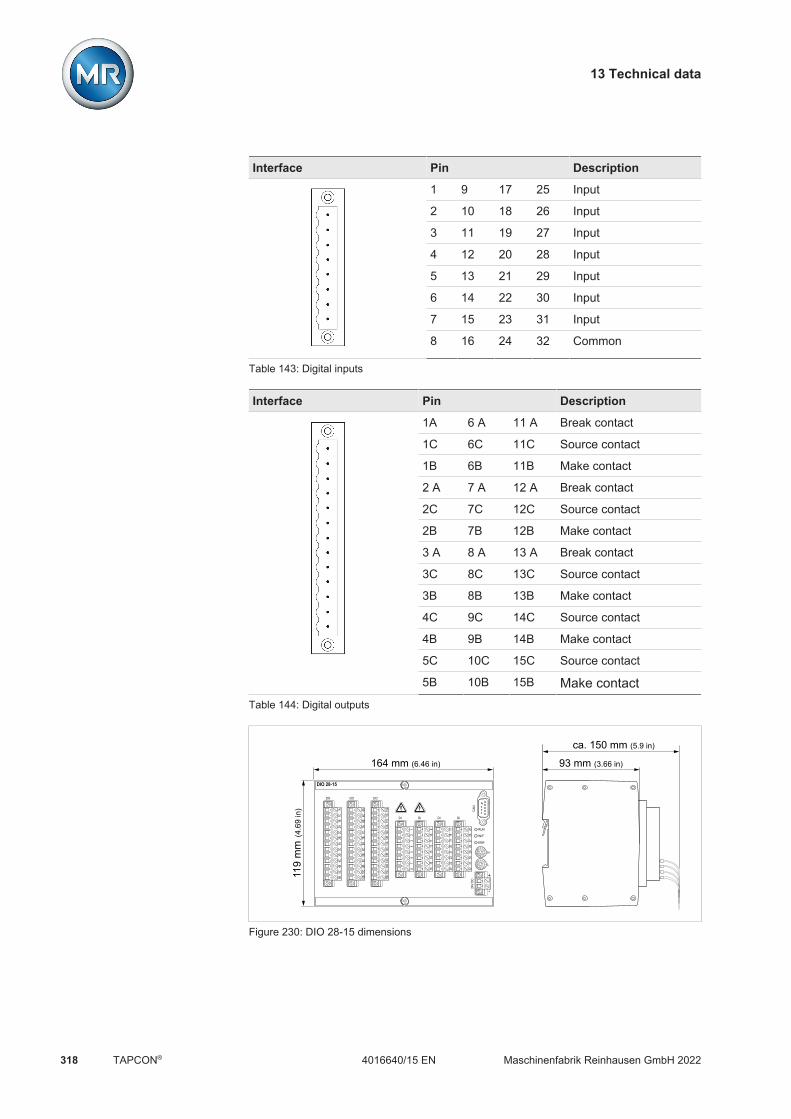
13 Technical data
Maschinenfabrik Reinhausen GmbH 2022318 4016640/15 ENTAPCON®
Interface Pin Description
1 9 17 25 Input
2 10 18 26 Input
3 11 19 27 Input
4 12 20 28 Input
5 13 21 29 Input
6 14 22 30 Input
7 15 23 31 Input
8 16 24 32 Common
Table 143: Digital inputs
Interface Pin Description
1A 6 A 11 A Break contact
1C 6C 11C Source contact
1B 6B 11B Make contact
2 A 7 A 12 A Break contact
2C 7C 12C Source contact
2B 7B 12B Make contact
3 A 8 A 13 A Break contact
3C 8C 13C Source contact
3B 8B 13B Make contact
4C 9C 14C Source contact
4B 9B 14B Make contact
5C 10C 15C Source contact
5B 10B 15B Make contactTable 144: Digital outputs
CAN
RUN
INIT
ERR
-
+
24V
DC
8
0
7
F
6E
5D 4C
3
B
2
A
1
9
H
8
0
7
F
6E
5D 4C
3
B
2
A
1
9
L
DIDIDIDI
DODODO
2527
2628
3029
3132
1719
1820
2221
2324
911
1012
1413
1516
13
24
65
78
11A
11B
11C
12A
12B
12C
13A
13B
13C
14C
15C
15B
14B
6A6B
6C7A
7B7C
8A8B
8C9C
10C
10B
9B
1A1B
1C2A
2B2C
3A3B
3C4C
5C5B
4B
DIO 28-15
119
mm
(4.6
9 in
)
164 mm (6.46 in) 93 mm (3.66 in)
ca. 150 mm (5.9 in)
Figure 230: DIO 28-15 dimensions

13 Technical data
Maschinenfabrik Reinhausen GmbH 2022 3194016640/15 EN TAPCON®
13.2.5 Digital inputs and outputs DIO 42-20 (HL)DIO 42-20 DIO 42-20 HL
Inputs (plug-basedelectrical isolation)
Quantity 42
Logical 0 0...10 V AC (RMS)0 to 10 V DC
0...40 V AC (RMS)0 to 40 V DC
Logical 1 18...260 V AC (RMS)18 to 260 V DC
170...260 V AC (RMS)170 to 260 V DC
Input current Typ. 1.3 mA (regardless of U)
Simultaneity factor At 70°C and U ≥ 230 V: max. 50%
Outputs (floating re-lay outputs)
Number (number ofchange-over contacts inparentheses)
20 (12)
Contact load capacity Max. AC: 230 VAC; 5 AMax. DC: See diagram
Simultaneity factor Up to 60°C: 100%, > 60°C: -5%/KTable 145: Technical data for the DIO 42-20 (HL) assemblies
10
20
304050
100
V
300
0.1 0.2 0.5 1 2 5 10 20A
U
I
Ohmic load
Figure 231: Contact load capacity of digital outputs with resistive load
CAUTION Electric shock!The inputs of the DIO assembly have plug-based electrical isolation. A mix-ture of voltage ranges (e.g. extra low voltage and low voltage) or variousphases within a plug can lower the protection against electric shock. Use the same voltage ranges within a plug. Use the same phase within a plug.

13 Technical data
Maschinenfabrik Reinhausen GmbH 2022320 4016640/15 ENTAPCON®
Interface Pin Description
1 9 17 25 33 41 Input
2 10 18 26 34 42 Input
3 11 19 27 35 43 Input
4 12 20 28 36 44 Input
5 13 21 29 37 45 Input
6 14 22 30 38 46 Input
7 15 23 31 39 47 Input
8 16 24 32 40 48 Common
Table 146: Digital inputs
Interface Pin Description
1A 6A 11A 16A Break contact
1C 6C 11C 16C Source contact
1B 6B 11B 16B Make contact
2A 7A 12A 17A Break contact
2C 7C 12C 17C Source contact
2B 7B 12B 17B Make contact
3A 8A 13A 18A Break contact
3C 8C 13C 18C Source contact
3B 8B 13B 18B Make contact
4C 9C 14C 19C Source contact
4B 9B 14B 19B Make contact
5C 10C 15C 20C Source contact
5B 10B 15B 20B Make contactTable 147: Digital outputs
CAN
RUN
INIT
ERR
-
+
24V
DC
8
0
7
F
6E
5D 4C
3
B
2
A
1
9
H
8
0
7
F
6E
5D 4C
3
B
2
A
1
9
L
DIDIDIDI
DODODO DO
DIDI
4143
4244
4645
4748
3335
3436
3837
3940
2527
2628
3029
3132
1719
1820
2221
2324
911
1012
1413
1516
13
24
65
78
11A
11B
11C
12A
12B
12C
13A
13B
13C
14C
15C
15B
14B
16A
16B
16C
17A
17B
17C
18A
18B
18C
19C
20C
20B
19B
6A6B
6C7A
7B7C
8A8B
8C9C
10C
10B
9B
1A1B
1C2A
2B2C
3A3B
3C4C
5C5B
4B
DIO 42-20
93 mm (3.66 in)
ca. 150 mm (5.9 in)
119
mm
(4,6
9 in
)
219 mm (8,62 in)
Figure 232: DIO 42-20 dimensions
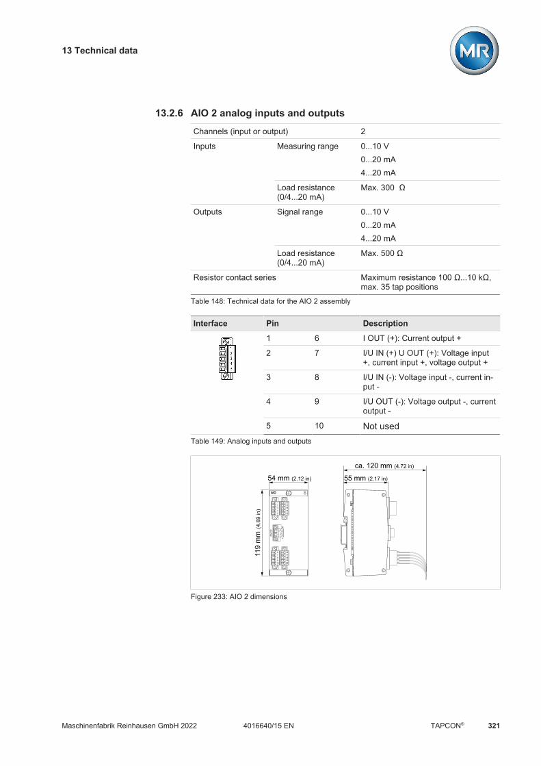
13 Technical data
Maschinenfabrik Reinhausen GmbH 2022 3214016640/15 EN TAPCON®
13.2.6 AIO 2 analog inputs and outputsChannels (input or output) 2
Inputs Measuring range 0...10 V0...20 mA4...20 mA
Load resistance(0/4...20 mA)
Max. 300 Ω
Outputs Signal range 0...10 V0...20 mA4...20 mA
Load resistance(0/4...20 mA)
Max. 500 Ω
Resistor contact series Maximum resistance 100 Ω...10 kΩ,max. 35 tap positions
Table 148: Technical data for the AIO 2 assembly
Interface Pin Description
1 6 I OUT (+): Current output +
2 7 I/U IN (+) U OUT (+): Voltage input+, current input +, voltage output +
3 8 I/U IN (-): Voltage input -, current in-put -
4 9 I/U OUT (-): Voltage output -, currentoutput -
5 10 Not usedTable 149: Analog inputs and outputs
1
32
45
11
1312
1415
6
87
910
16
1817
1920
RDYAIO
+
-
24V
DC
55 mm (2.17 in)
ca. 120 mm (4.72 in)
119
mm
(4.6
9 in
)
54 mm (2.12 in)
Figure 233: AIO 2 dimensions
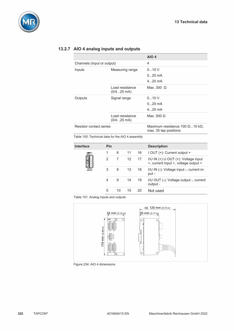
13 Technical data
Maschinenfabrik Reinhausen GmbH 2022322 4016640/15 ENTAPCON®
13.2.7 AIO 4 analog inputs and outputsAIO 4
Channels (input or output) 4
Inputs Measuring range 0...10 V0...20 mA4...20 mA
Load resistance(0/4...20 mA)
Max. 300 Ω
Outputs Signal range 0...10 V0...20 mA4...20 mA
Load resistance(0/4...20 mA)
Max. 500 Ω
Resistor contact series Maximum resistance 100 Ω...10 kΩ,max. 35 tap positions
Table 150: Technical data for the AIO 4 assembly
Interface Pin Description
1 6 11 16 I OUT (+): Current output +
2 7 12 17 I/U IN (+) U OUT (+): Voltage input+, current input +, voltage output +
3 8 13 18 I/U IN (-): Voltage input -, current in-put -
4 9 14 19 I/U OUT (-): Voltage output -, currentoutput -
5 10 15 20 Not usedTable 151: Analog inputs and outputs
1
32
45
11
1312
1415
6
87
910
16
1817
1920
RDYAIO
+
-
24V
DC
55 mm (2.17 in)
ca. 120 mm (4.72 in)
119
mm
(4.6
9 in
)
54 mm (2.12 in)
Figure 234: AIO 4 dimensions
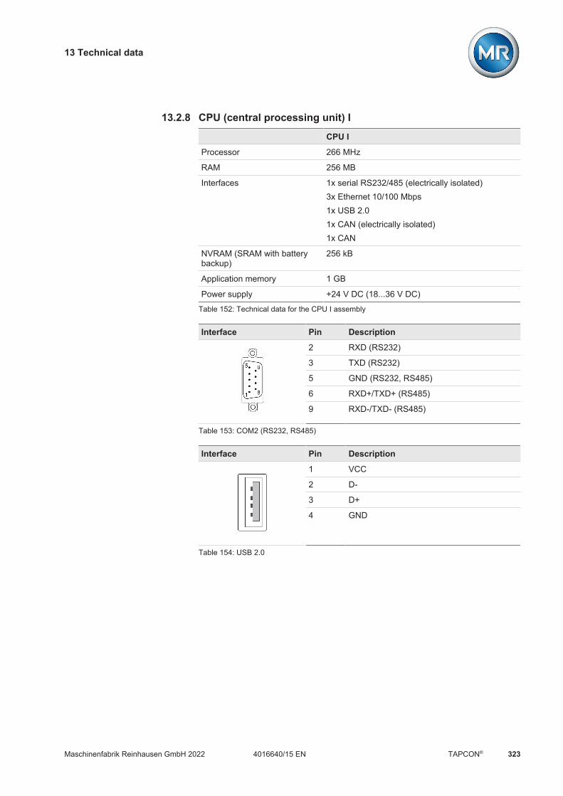
13 Technical data
Maschinenfabrik Reinhausen GmbH 2022 3234016640/15 EN TAPCON®
13.2.8 CPU (central processing unit) ICPU I
Processor 266 MHz
RAM 256 MB
Interfaces 1x serial RS232/485 (electrically isolated)3x Ethernet 10/100 Mbps1x USB 2.01x CAN (electrically isolated)1x CAN
NVRAM (SRAM with batterybackup)
256 kB
Application memory 1 GB
Power supply +24 V DC (18...36 V DC)
Table 152: Technical data for the CPU I assembly
Interface Pin Description
2 RXD (RS232)
3 TXD (RS232)
5 GND (RS232, RS485)
6 RXD+/TXD+ (RS485)
9 RXD-/TXD- (RS485)
Table 153: COM2 (RS232, RS485)
Interface Pin Description
1 VCC
2 D-
3 D+
4 GND
Table 154: USB 2.0

13 Technical data
Maschinenfabrik Reinhausen GmbH 2022324 4016640/15 ENTAPCON®
Interface Pin Description
1 TxD+
2 TxD-
3 RxD+
4 NC
5 NC
6 RxD-
7 NC
8 NC-
Table 155: ETH1, ETH 2.1, ETH 2.2 (RJ45)
Interface Pin Description
2 CAN-L
3 CAN-GND
7 CAN-H
Table 156: CAN1, CAN2
CPU
CAN
1
1
9
CAN
2
1
9
COM
1
1
9
COM
2
1
9
-+
24V DC
RUN
INIT
ERR
USB2
.0
4 62
A8
CH
TESTPROGRUN
4 62
AE0 8
CL
ETH 1 ETH 2.1 ETH 2.2
55 mm (2.17 in)
ca. 120 mm (4.72 in)
119
mm
(4.6
9 in
)
109 mm (4.29 in)
Figure 235: CPU dimensions
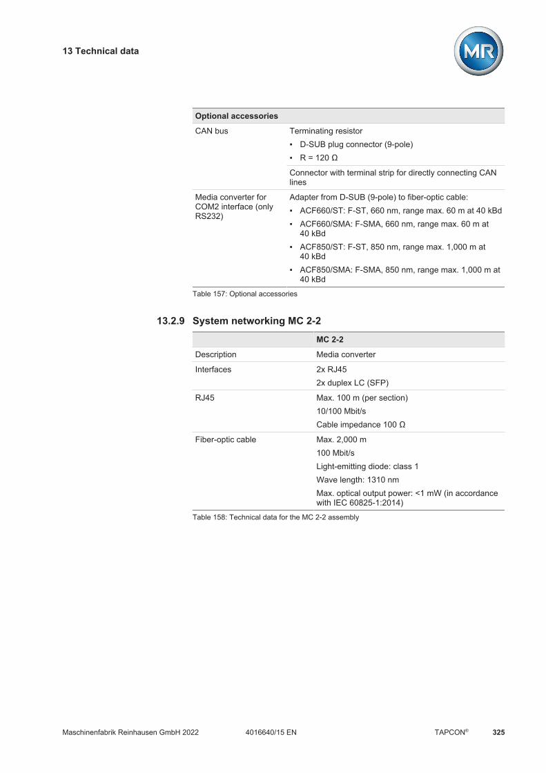
13 Technical data
Maschinenfabrik Reinhausen GmbH 2022 3254016640/15 EN TAPCON®
Optional accessories
CAN bus Terminating resistor D-SUB plug connector (9-pole) R = 120 Ω
Connector with terminal strip for directly connecting CANlines
Media converter forCOM2 interface (onlyRS232)
Adapter from D-SUB (9-pole) to fiber-optic cable: ACF660/ST: F-ST, 660 nm, range max. 60 m at 40 kBd ACF660/SMA: F-SMA, 660 nm, range max. 60 m at
40 kBd ACF850/ST: F-ST, 850 nm, range max. 1,000 m at
40 kBd ACF850/SMA: F-SMA, 850 nm, range max. 1,000 m at
40 kBd
Table 157: Optional accessories
13.2.9 System networking MC 2-2MC 2-2
Description Media converter
Interfaces 2x RJ452x duplex LC (SFP)
RJ45 Max. 100 m (per section)10/100 Mbit/sCable impedance 100 Ω
Fiber-optic cable Max. 2,000 m100 Mbit/sLight-emitting diode: class 1Wave length: 1310 nmMax. optical output power: <1 mW (in accordancewith IEC 60825-1:2014)
Table 158: Technical data for the MC 2-2 assembly
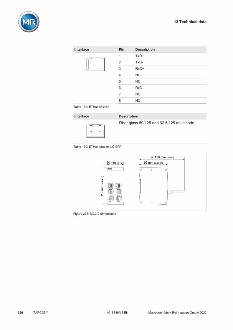
13 Technical data
Maschinenfabrik Reinhausen GmbH 2022326 4016640/15 ENTAPCON®
Interface Pin Description
1 TxD+
2 TxD-
3 RxD+
4 NC
5 NC
6 RxD-
7 NC
8 NC-
Table 159: ETHxx (RJ45)
Interface Description
Fiber glass 50/125 and 62.5/125 multimode
Table 160: ETHxx (duplex LC SFP)
MC 2-2
+
-
24V
DC
+
-
24V
DC
ETH1
2
ETH2
2
ETH1
1
ETH2
1
93 mm (3.66 in)
ca. 150 mm (5.9 in)
119
mm
(4.6
9 in
)
54 mm (2.12 in)
Figure 236: MC2-2 dimensions

13 Technical data
Maschinenfabrik Reinhausen GmbH 2022 3274016640/15 EN TAPCON®
13.2.10 System networking SW 3-3SW 3-3
Description Managed fast Ethernet switch per IEEE 802.3,store-and-forward switching
Interfaces Media converters: 1x RJ45 1x duplex LC (SFP)Managed switch with redundancy function: 2x RJ45 2x duplex LC (SFP)
Redundancy protocols PRP1, RSTP
Time synchronization PTPv2 (IEEE 1588-2008)
RJ45 Max. 100 m (per section)10/100 MbpsCable impedance 100 Ω
Fiber-optic cable Max. 2,000 m100 MbpsLight-emitting diode: class 1Wavelength: 1,310 nmMax. optical output power: <1 mW (in accordancewith IEC 60825-1:2014)
Table 161: Technical data for the SW 3-3 assembly
1) Factory setting
Interface Pin Description
1 TxD+
2 TxD-
3 RxD+
4 NC
5 NC
6 RxD-
7 NC
8 NC-
Table 162: ETHxx (RJ45)

13 Technical data
Maschinenfabrik Reinhausen GmbH 2022328 4016640/15 ENTAPCON®
Interface Description
Fiber glass 50/125 and 62.5/125 multimode
Table 163: ETHxx (duplex LC SFP)
MC 2-2
+
-
24V
DC
+
-
24V
DC
ETH1
2
ETH2
2
ETH1
1
ETH2
1
93 mm (3.66 in)
ca. 150 mm (5.9 in)
119
mm
(4.6
9 in
)
54 mm (2.12 in)
Figure 237: SW3-3 dimensions
13 Technical data
Maschinenfabrik Reinhausen GmbH 2022 3294016640/15 EN TAPCON®
13.3 Dimensions and weightHousingW x H x D
19-inch plug-in housing in accordance with DIN 41494Part 5483 mm x 133 mm x 178 mm (19 in x 5.2 in x 7 in)
Weight Max. 7.9 kg
13.4 Ambient conditionsOperating temperature -25...+70 °C
Storage temperature -40...+85 °C
Relative humidity 10...95% non-condensing
Air pressure Corresponds to 2000 m above sea levelCorresponds to2000 m above sea level
Minimum spacing to otherdevices/control cabinet
Top/Bottom: 88.9 mm (3.5 in; corresponds to 2 RU),back 30 mm (1.2 in)
Table 164: Permissible ambient conditions
13.5 Standards and directives
Electrical safety
IEC 61010-1IEC 61010-2-030
Safety requirements for electrical measurement and con-trol and regulation equipment and laboratory instruments Protection class 1 Overvoltage category III Contamination level 2
IEC 60950-1 Information technology equipment – Safety
Table 165: Electrical safety
13 Technical data
Maschinenfabrik Reinhausen GmbH 2022330 4016640/15 ENTAPCON®
Electromagnetic compatibility
IEC 61000-4-2 Immunity to electrostatic discharge (ESD) Front panel and operating elements Contact: ±8 kV Air: ±15 kV Terminals, plug connectors, and interfaces: Contact: ±6 kV Air: ±8 kV
IEC 61000-4-3 Immunity to high-frequency electromagnetic fields 20 V/m; 80...4000 MHz; 80% AM 20 V/m; 900 MHz ±5 MHz; PM
IEC 61000-4-4 Immunity to quick, transient electrical disturbances (burst) Power supply: 4 kV Measurement (UI1/3): 4 kV Digital I/O: 4 kV Analog I/O, shielding on both sides: 4 kV Communication interfaces, shielding on both sides: 4
kV
IEC 61000-4-5 Immunity to impulse voltages (surge) AC power supply: 4 kV CM, 2 kV DM DC power supply: 2 kV CM, 1 kV DM Measurement (UI1/3): 4 kV CM, 2 kV DM Digital I/O: 2 kV CM, 1 kV DM Analog I/O, shielding on both sides: 2 kV CM Communication interfaces, shielding on both sides: 2
kV CM
IEC 61000-4-6 Immunity to conducted disturbances, induced by high-fre-quency fields 10 V, 150 kHz...80 MHz, 80% AM
IEC 61000-4-8 Immunity to power frequency magnetic fields 100 A/m, 50/60 Hz, continuously 1000 A/m, 50/60 Hz, for 1 s
IEC 61000-4-11IEC 61000-4-29
Immunity to drops in voltage, short interruptions, and volt-age fluctuations 40% UN for 300 ms 0% UN for 100 ms
Table 166: Immunity in accordance with IEC 61000-6-2

13 Technical data
Maschinenfabrik Reinhausen GmbH 2022 3314016640/15 EN TAPCON®
CISPR 11 (EN 55011) Industrial, scientific and medical equipment - Radio-fre-quency disturbance characteristics - Limits and methodsof measurement: Class A
CISPR 16-2-1 Procedure for measuring high-frequency emitted interfer-ence (radio interference) and immunity - measurement ofconducted emitted interference: Class A
CISPR 16-2-3 Procedure for measuring high-frequency emitted interfer-ence (radio interference) and immunity - measurement ofradiated emitted interference: Class A
CISPR 22 (EN 55022) Information technology equipment - Radio disturbancecharacteristics - Limits and methods of measurement:Class A
Table 167: Emitted interference in accordance with IEC 61000-6-4
Environmental durability tests
IEC 60529 With OT1205: Degree of protection IP52 for the front,IP20 for the rearWithout OT1205: IP20
IEC 60068-2-1 Dry cold - 25 °C / 96 hours
IEC 60068-2-2 Dry heat 70 °C / 96 hours
IEC 60068-2-78 Constant moist heat+ 40 °C / 93% / 4 days, no dew
ASTM D 4169-09 Standard Practice for Performance Testing of ShippingContainers and SystemsDC 3, safety level II
IEC 60255-21-1 Class1
Oscillations (3 cycles, 0.5 g 1 octave/min; 60 cycles, 1.0g, 1 octave/min)
IEC 60255-21-2 Class1
Shocks (11 ms, 5 g, 15 g, 3 axes)
IEC 60255-21-3 Class1
Earthquakes (1...35 Hz; 3.5 mm/1 g horizontal; 1.5mm/0.5 g vertical; 1 octave/min, 10 min/axis)
Table 168: Environmental durability tests

Glossary
Maschinenfabrik Reinhausen GmbH 2022332 4016640/15 ENTAPCON®
Glossary
ASTMAmerican Society for Testing and Materials
EMCElectromagnetic compatibility
ENEuropean standard
Generator sign conventionDefinition for describing electrical circuits. The ar-rows for current rating and voltage on a "con-sumer" absorbing electrical power (e.g. a resis-tor) face opposite directions. U*I is the powergenerated in the component and -U*I is thepower absorbed by the component.
GPIGeneral Purpose Input
GPOGeneral Purpose Output
ICDIED Capability Description
IECThe International Electrotechnical Commission(IEC for short) is involved in the preparation andpublication of international standards for electri-cal, electronic and related technologies.
IEEEWorldwide association of engineers, mainly fromthe fields of electrical engineering and IT (Insti-tute of Electrical and Electronics Engineers)
IPInternet Protocol
Load sign conventionDefinition for describing electrical circuits. The ar-rows for current rating and voltage on a "con-sumer" absorbing electrical power (e.g. a resis-tor) face the same direction. U*I is the power ab-sorbed by the component.
MQTTMessage Queuing Telemetry Transport. A net-work protocol for machine-to-machine communi-cation which enables the transmission of ISM®data in the form of messages between two de-vices.
PRPRedundancy protocol in accordance with IEC62439-3 (Parallel Redundancy Protocol)
PTPPTP (Precision Time Protocol) is a standard forsynchronizing clocks in a computer network. Thissynchronization is high-precision.
RADIUSProtocol for authentication of users in computernetworks in accordance with RFC 2865 (RemoteAuthentication Dial-In User Service).
RSTPRedundancy protocol in accordance with IEEE802.1D-2004 (Rapid Spanning Tree Protocol)
SCADATechnical processes are monitored and con-trolled using a computer system (SupervisoryControl and Data Acquisition)
SNTPNTP (Network Time Protocol) is a standard forsynchronizing clocks in computer systems usingpacket-based communication networks. SNTP(Simple Network Time Protocol) is the simplifiedversion of NTP.
TDSCTAPCON® Dynamic Set Point Control

Glossary
Maschinenfabrik Reinhausen GmbH 2022 3334016640/15 EN TAPCON®
TPLETransformer Personal Logic Editor
URLUniform Resource Locator

List of key words
Maschinenfabrik Reinhausen GmbH 2022334 4016640/15 ENTAPCON®
List of key words
AAbsolute 206, 209, 211Access point 104Access rights 153Activate delay time T2 239Activate desired value 1 138Activate desired value 2 138Activate desired value 3 138Activate desired value 4 138Activate desired value 5 138Activate parallel operation 251Activate remote mode 138Activate syslog 101Activate tap synchronization mon.
219AIO 2 37Analog input 288Analog inputs and outputs 140ASDU address 106, 109, 111ASDU sequence optimization 107,
111ASDU single character confirma-
tion 107Assembly
AIO 37CPU I 33DIO 36, 37MC 2-2 38OT1205 33SW 39UI 34, 35
Auto logout 93Automatic daylight saving / stan-
dard time 99Automatic tap synchronization par-
allel operation method 137Average value interval 135
BBandwidth 235Bandwidth monitoring 264Bandwidth setting 235Bank parallel operation 219Baud rate 106, 109, 114, 116Behavior 207, 215, 269Behavior for reversal of power flow
214Behavior if no communication
present 254Blocking 137Broker 96
Client user name 98Port 97
Broker address 97Broker port 97
CCable recommendation 58CAN address 1...16 device name
259CAN bus 252Changing users 40Channel (AIO) 66Circulating reactive current 245Circulating reactive current block-
ing limit 252Circulating reactive current sensi-
tivity 252Commissioning wizard 82, 91Compensation 239
Z compensation 241Configure data points 122Connection 58contact wear
Determining 276Display 272
Control system 103Control variable 204, 222Counting behavior 269CPU I 33Current monitoring 208Current transformer
Secondary current 188Current-transformer circuit 189
DData
Import/export 158Databits 107, 109, 114Date 81, 99Deactivate parallel operation 137Decrease desired value 138Delay time T1 236Delay time T2 238Desired load stress type 253Desired power factor 252Desired value 222, 223, 224, 225,
235Desired value adjustment
Active power-dependent 226,229
desired value settingBCD 232Max. 225Min. 225
Desired value step width 225Destination address 116Device address 116Device designation 101Device ID 104DFC compatibility 110Digital inputs and outputs 143Dimming 103Dimming brightness 103Dimming waiting time 103DIO 28-15 36DIO 42-20 37Display elements
LED 28DNP3 115DNP3 transmission type 115DNS
activate 96DNS server
IP address 96

List of key words
Maschinenfabrik Reinhausen GmbH 2022 3354016640/15 EN TAPCON®
EEdition 104Electromagnetic compatibility 47Error if no communication present
254Event duration 268Event memory 148Events 145
Acknowledge 145Configure 146Display 145Exporting 148
Expert mode 43Export 158
FFiber-optic cable
Information about laying 61Follower parallel operation method
137Function monitoring 264, 265Function test
Circulating reactive currentblocking 86
Circulating reactive currentsensitivity 85
Control functions 83Parallel operation 84Tap synchronization 87
Function tests 83
GGateway address 95Gateway target address 95General 90
Remote behavior 91Generic digital output 139Generic status message 140GPI 135GPO 135ground test 74
HHardware 156High-speed return 138
IICD file 104IEC 60870-5-101 105IEC 60870-5-103 108IEC 60870-5-104 111IEC 61850 103IED name 104Import 158Increase desired value 138Independent regulation 137Inputs
Analog 140Digital 143
IO mapping 135IP address 94IP address client 112
KKeys 27
LLanguage 81Link address 106Logging off 40Logging on 40
MMaster parallel operation method
137Master/follower current blocking
253Master/follower switching charac-
teristics 253Maximum difference 215Maximum tap difference 254MC 2-2 38Measured value display 91Measured values
Recorder 130Setting display 91
Measuring mode 188Messages 145Modbus 113Modbus address 113Modbus type 113Mode 206, 209Motor runtime 286Motor runtime monitoring 286Motor runtime monitoring limit 286MQTT 96
Activate 97Broker 98Broker address 97Client user name 98Port 97
NName of transformer 1...4 219Navigation 40Negative power factor display 204Network settings 94No. of information object address
octets 106Number of ASDU address octets
106Number of cause of transmission
octets 107Number of link address octets 106Number of operations 267
List of key words
Maschinenfabrik Reinhausen GmbH 2022336 4016640/15 ENTAPCON®
OOLTC
Information 270OLTC A/B/C serial number 281OLTC data 281Operating controls 27Operating instructions
Download 81Operating mode
Auto mode 25Local mode 25Manual mode 25Remote mode 26
Operations counter 267OT1205 33Outputs
Analog 140Digital 143
Overvoltage 205
PParallel operation 242, 251
CAN bus 252Circulating reactive current 245Information 263Parallel operation error mes-
sage 254Power factor 246Tap stagger 247Tap synchronization 243
Parallel operation method 251Parity 107, 109, 114Password 151
Password 98Percentage 206, 209Phase angle correction 188Pos behavior 267Pos. at max. analog signal 289Pos. at min. analog signal 289Pos</Pos> follower 256power factor 246Power flow
Negative 212Power flow monitoring 212Power monitoring 210Prim/sec topology 259Primary transformer current 188Primary transformer voltage 187PTP 98, 100PTP hops 100
PTP interface 100PTP version 100
QQuick search 43
RR&X compensation 240RADIUS 154Reaction 210, 212Reactive power regulation switch-
ing direction 287Reconnect delay time 101Recorder 130
Average value interval 135Reference time 108, 110, 112, 117Regulation mode 204Remote behavior 91Repeat unsolicited messages in-
definitely 116Repetition of unsolicited messages
116RES bit test 107Response to SCADA disconnec-
tion 221Retrofit TAPCON® 2xx 217Reversal of power flow 212RFC 3164 100RFC 5424 100

List of key words
Maschinenfabrik Reinhausen GmbH 2022 3374016640/15 EN TAPCON®
SSCADA 103SCADA disconnection delay time
221Screensaver 102, 103Screensaver waiting time 103Secondary transformer voltage
187Select tap stagger setting 255Serial interface 106, 109, 114, 115Service user access 94Service user access activation 94setting of the desired value
analog 224Step-by-step 225
Severity level 102SNTP 98, 99SNTP time server 99SNTP time server 2 99Software
Information 158SSL/TLS encryption 95, 98Stop bits 107, 109, 114Subnet mask 95SW 3-3 39
Configuration 163Switching direction monitoring 287Switching interval monitoring 267Switching pulse pause 285Switching pulse time 285Switching pulse type 284Switching statistics 271Synchronization interval 99Syslog 100Syslog server 101Syslog server port 101Syslog standard 101
TTap difference 219
Follower 254Tap position
Change designation 270Digital 288
Tap position captureAnalog 288
Tap position message (analog) 282
Tap position monitoring 266Tap stagger 247Tap stagger setting 1...8 254Tap synchronization 243Tap synchronization monitoring
219TAPCON® 2xx retrofit 216TAPCON® Dynamic Setpoint Con-
trol 226, 229Target tap position 270Target-tap-position operation 138TCP connections 113TCP Keepalive 114TCP port 111, 113, 115Time 81, 99Time interval 268Time response T1 237Time server address 99Time shift 99Time synchronization 98
Activate 99Reference time 108, 110, 112,
117Time until auto logout 93Time zone 99Timeout 116Timeout for response confirmation
116TLS version 96
Topology 256Information 262
Total tap-change operations 268TPLE 168Transformer data 187
Secondary current 188Transformer name 91, 219Transmission procedure 106
UUI 1 34UI 3 35UI measuring channels 203Undervoltage 205Unsolicited messages 116USB interface
Activating/Deactivating 92User administration 149User ID code 116User role 149
VVisualization
Connection 79Visualization release 95Voltage balance 189Voltage monitoring 205Voltage regulation 222Voltage regulation switching direc-
tion 287Voltage-transformer circuit 188
WWiring 58
ZZ compensation 241


Maschinenfabrik Reinhausen GmbHFalkensteinstrasse 893059 Regensburg
+49 (0)941 [email protected]
www.reinhausen.com
4016640/15 EN - TAPCON® -- 05/22 - Maschinenfabrik Reinhausen GmbH 2022
THE POWER BEHIND POWER.