
Operating Instructions - Baumüller
66
Operating Instructions Read the Operating Instructions before starting any work! Language English Translation Document No. 5.01051.03 Part No. 354845 Status 21.07.2011 b maXX drive PLC E 5.01051.03 BM4-O-PLC-01
-
Upload
khangminh22 -
Category
Documents
-
view
0 -
download
0
Transcript of Operating Instructions - Baumüller

Operating Instructions
Read the Operating Instructions before starting any work!
Language EnglishTranslation
Document No. 5.01051.03Part No. 354845Status 21.07.2011
b maXX drive PLC
E 5.01051.03
BM4-O-PLC-01

Copyright These Operating Instructions may be copied by the owner in any quantity, but only for internal use. This Operating Instructions may not be copied or reproduced, in whole or in part, for any other purposes. The use and disclosure of information contained in these Operating Instructions are not per-mitted. Designations and company marks contained in these Operating Instructions could be trade-marks, the use of which by third parties for their own purposes could violate the rights of the rights holder.
Preliminary informationWarning Insofar as this document is identified as being preliminary information, the following applies: this version is regarded as providing advance technical information to users of the described devices and their functions at an early enough time in order to adapt to any possible changes or expanded functionality. This information must be regarded as being preliminary, as it has not yet passed through Baumüller's internal review process. In particular, this information is still subject to changes, thus no legal liability can be derived from this preliminary information. Baumüller assumes no liability for damages that might arise from this possibly faulty or incomplete version. If you detect or suspect any content errors and/or major form errors in this preliminary infor-mation, we request that you notify the Baumüller support specialist responsible for you. Please provide us, via this employee, with your insights and comments so that we can take them into account and include them when transitioning from the preliminary information to the final information (as reviewed by Baumüller). The conditions stipulated in the following section under "Obligatory" are invalid in case of pre-liminary information.
Obligatory These Operating Instructions are a part of the equipment/machine. These Operating Instruc-tions must be available to the operator at all times and must be in legible condition. If the equipment/machine is sold or moved another location, these Operating Instructions must be passed on by the owner together with the equipment/machine. After any sale of the equipment/machine, this original and all copies must be handed over to the buyer. After disposal or any other end use, this original and all copies must be destroyed.
When the present Operating Instructions are handed over, corresponding sets of operating instructions of a previous version are automatically invalidated. Please note that the specifications/data/information are current values according to the printing date. These statements are not legally binding with regard to measurements, computation or calculations. Baumüller Nürnberg GmbH reserves the right, in developing its products further, to change the technical specifications and handling of it products concerned without prior notice.
No liability can be accepted concerning the correctness of these Operating Instructions un-less otherwise specified in the General Conditions of Sale and Delivery.
© Baumüller Nürnberg GmbH
Ostendstr. 80 - 90 90482 Nuremberg Germany
Tel. +49 9 11 54 32 - 0 Fax: +49 9 11 54 32 - 1 30
Email : [email protected] Internet: www.baumueller.de

Table of Contents
Overview of Revisions. . . . . . . . . . . . . . . . . . . . . . . . . . . . . . . . . . . . . . . . . . . . . . . . . . . . . . . . . 5
1 Introduction . . . . . . . . . . . . . . . . . . . . . . . . . . . . . . . . . . . . . . . . . . . . . . . . . . . . . . . . . . . . . . 71.1 First Steps . . . . . . . . . . . . . . . . . . . . . . . . . . . . . . . . . . . . . . . . . . . . . . . . . . . . . . . . . . . 71.2 Terms Used . . . . . . . . . . . . . . . . . . . . . . . . . . . . . . . . . . . . . . . . . . . . . . . . . . . . . . . . . . 7
2 Basic Safety Instructions . . . . . . . . . . . . . . . . . . . . . . . . . . . . . . . . . . . . . . . . . . . . . . . . . . . 92.1 Hazard information and instructions . . . . . . . . . . . . . . . . . . . . . . . . . . . . . . . . . . . . . . . 92.1.1 Structure of hazard information . . . . . . . . . . . . . . . . . . . . . . . . . . . . . . . . . . . . . . . . . 102.1.2 Hazard advisories that are used . . . . . . . . . . . . . . . . . . . . . . . . . . . . . . . . . . . . . . . . 112.2 Information signs . . . . . . . . . . . . . . . . . . . . . . . . . . . . . . . . . . . . . . . . . . . . . . . . . . . . . 132.3 Legal information . . . . . . . . . . . . . . . . . . . . . . . . . . . . . . . . . . . . . . . . . . . . . . . . . . . . . 132.4 Appropriate Use. . . . . . . . . . . . . . . . . . . . . . . . . . . . . . . . . . . . . . . . . . . . . . . . . . . . . . 132.5 Inappropriate Use . . . . . . . . . . . . . . . . . . . . . . . . . . . . . . . . . . . . . . . . . . . . . . . . . . . . 142.6 Protective equipment . . . . . . . . . . . . . . . . . . . . . . . . . . . . . . . . . . . . . . . . . . . . . . . . . . 142.7 Personnel training . . . . . . . . . . . . . . . . . . . . . . . . . . . . . . . . . . . . . . . . . . . . . . . . . . . . 152.8 Safety measures in normal operation . . . . . . . . . . . . . . . . . . . . . . . . . . . . . . . . . . . . . 152.9 Responsibility and liability . . . . . . . . . . . . . . . . . . . . . . . . . . . . . . . . . . . . . . . . . . . . . . 152.9.1 Observing the hazard information and safety instructions . . . . . . . . . . . . . . . . . . . . 152.9.2 Danger arising from using this module . . . . . . . . . . . . . . . . . . . . . . . . . . . . . . . . . . . 162.9.3 Warranty and Liability . . . . . . . . . . . . . . . . . . . . . . . . . . . . . . . . . . . . . . . . . . . . . . . . 16
3 Packaging and transportation . . . . . . . . . . . . . . . . . . . . . . . . . . . . . . . . . . . . . . . . . . . . . . 173.1 Transportation . . . . . . . . . . . . . . . . . . . . . . . . . . . . . . . . . . . . . . . . . . . . . . . . . . . . . . . 173.2 Unpacking . . . . . . . . . . . . . . . . . . . . . . . . . . . . . . . . . . . . . . . . . . . . . . . . . . . . . . . . . . 173.3 Disposing of the packaging . . . . . . . . . . . . . . . . . . . . . . . . . . . . . . . . . . . . . . . . . . . . . 183.4 Observe during transportation . . . . . . . . . . . . . . . . . . . . . . . . . . . . . . . . . . . . . . . . . . . 18
4 Description of the b maXX PLC option module . . . . . . . . . . . . . . . . . . . . . . . . . . . . . . . . 194.1 General . . . . . . . . . . . . . . . . . . . . . . . . . . . . . . . . . . . . . . . . . . . . . . . . . . . . . . . . . . . . 194.2 Structure . . . . . . . . . . . . . . . . . . . . . . . . . . . . . . . . . . . . . . . . . . . . . . . . . . . . . . . . . . . 214.2.1 Slot for controlling the PLC . . . . . . . . . . . . . . . . . . . . . . . . . . . . . . . . . . . . . . . . . . . . 214.3 Functionality. . . . . . . . . . . . . . . . . . . . . . . . . . . . . . . . . . . . . . . . . . . . . . . . . . . . . . . . . 224.3.1 BM4-O-PLC-01 . . . . . . . . . . . . . . . . . . . . . . . . . . . . . . . . . . . . . . . . . . . . . . . . . . . . . 224.3.2 BM4-O-PLC-01 / version Economy (ECO-PLC) . . . . . . . . . . . . . . . . . . . . . . . . . . . . 224.4 Danger zones . . . . . . . . . . . . . . . . . . . . . . . . . . . . . . . . . . . . . . . . . . . . . . . . . . . . . . . 234.5 Labeling of the controller – type code . . . . . . . . . . . . . . . . . . . . . . . . . . . . . . . . . . . . . 23
5 Assembly and installation. . . . . . . . . . . . . . . . . . . . . . . . . . . . . . . . . . . . . . . . . . . . . . . . . . 255.1 General safety regulations. . . . . . . . . . . . . . . . . . . . . . . . . . . . . . . . . . . . . . . . . . . . . . 255.2 Requirements of the personnel carrying out work . . . . . . . . . . . . . . . . . . . . . . . . . . . . 265.3 Preparation . . . . . . . . . . . . . . . . . . . . . . . . . . . . . . . . . . . . . . . . . . . . . . . . . . . . . . . . . 265.3.1 PLC version „standard“ . . . . . . . . . . . . . . . . . . . . . . . . . . . . . . . . . . . . . . . . . . . . . . . 275.3.2 PLC version „Economy“ (ECO-PLC) . . . . . . . . . . . . . . . . . . . . . . . . . . . . . . . . . . . . . 285.4 Assembly . . . . . . . . . . . . . . . . . . . . . . . . . . . . . . . . . . . . . . . . . . . . . . . . . . . . . . . . . . . 295.5 Installation . . . . . . . . . . . . . . . . . . . . . . . . . . . . . . . . . . . . . . . . . . . . . . . . . . . . . . . . . . 315.5.1 Connection diagram . . . . . . . . . . . . . . . . . . . . . . . . . . . . . . . . . . . . . . . . . . . . . . . . . 315.5.2 Requirements of electrical connection . . . . . . . . . . . . . . . . . . . . . . . . . . . . . . . . . . . 325.5.3 Requirements of the connection cable . . . . . . . . . . . . . . . . . . . . . . . . . . . . . . . . . . . 325.5.4 Sequence of installation . . . . . . . . . . . . . . . . . . . . . . . . . . . . . . . . . . . . . . . . . . . . . . 32
Operating Instructions b maXX BM4-O-PLC-01Document No.: 5.01051.03
3of 64

4of 64
Table of Contents
6 Commissioning. . . . . . . . . . . . . . . . . . . . . . . . . . . . . . . . . . . . . . . . . . . . . . . . . . . . . . . . . . . 336.1 General safety regulations . . . . . . . . . . . . . . . . . . . . . . . . . . . . . . . . . . . . . . . . . . . . . . 336.2 Requirements of the personnel carrying out work . . . . . . . . . . . . . . . . . . . . . . . . . . . . 336.3 Description/inspection of the safety and monitoring systems. . . . . . . . . . . . . . . . . . . . 336.4 Description and inspection of the controls and displays. . . . . . . . . . . . . . . . . . . . . . . . 346.4.1 LEDs for displaying operating status conditions . . . . . . . . . . . . . . . . . . . . . . . . . . . . 346.4.2 S1 switch/pushbutton for changing operating status conditions . . . . . . . . . . . . . . . . 356.5 Commissioning sequence . . . . . . . . . . . . . . . . . . . . . . . . . . . . . . . . . . . . . . . . . . . . . . 366.5.1 Activation. . . . . . . . . . . . . . . . . . . . . . . . . . . . . . . . . . . . . . . . . . . . . . . . . . . . . . . . . . 366.5.2 Testing the function . . . . . . . . . . . . . . . . . . . . . . . . . . . . . . . . . . . . . . . . . . . . . . . . . . 36
7 Operation. . . . . . . . . . . . . . . . . . . . . . . . . . . . . . . . . . . . . . . . . . . . . . . . . . . . . . . . . . . . . . . . 37
8 Troubleshooting and eliminating faults . . . . . . . . . . . . . . . . . . . . . . . . . . . . . . . . . . . . . . . 398.1 Safety regulations. . . . . . . . . . . . . . . . . . . . . . . . . . . . . . . . . . . . . . . . . . . . . . . . . . . . . 398.2 Troubleshooting . . . . . . . . . . . . . . . . . . . . . . . . . . . . . . . . . . . . . . . . . . . . . . . . . . . . . . 39
9 Maintenance . . . . . . . . . . . . . . . . . . . . . . . . . . . . . . . . . . . . . . . . . . . . . . . . . . . . . . . . . . . . . 41
10 Overhaul . . . . . . . . . . . . . . . . . . . . . . . . . . . . . . . . . . . . . . . . . . . . . . . . . . . . . . . . . . . . . . . . 43
11 Dismantling, storage . . . . . . . . . . . . . . . . . . . . . . . . . . . . . . . . . . . . . . . . . . . . . . . . . . . . . . 4511.1 Safety regulations. . . . . . . . . . . . . . . . . . . . . . . . . . . . . . . . . . . . . . . . . . . . . . . . . . . . . 4511.2 Requirements of the personnel carrying out work . . . . . . . . . . . . . . . . . . . . . . . . . . . . 4611.3 Dismantling. . . . . . . . . . . . . . . . . . . . . . . . . . . . . . . . . . . . . . . . . . . . . . . . . . . . . . . . . . 4711.4 Storage conditions . . . . . . . . . . . . . . . . . . . . . . . . . . . . . . . . . . . . . . . . . . . . . . . . . . . . 4811.5 Recommissioning . . . . . . . . . . . . . . . . . . . . . . . . . . . . . . . . . . . . . . . . . . . . . . . . . . . . . 48
12 Disposal. . . . . . . . . . . . . . . . . . . . . . . . . . . . . . . . . . . . . . . . . . . . . . . . . . . . . . . . . . . . . . . . . 4912.1 Safety regulations. . . . . . . . . . . . . . . . . . . . . . . . . . . . . . . . . . . . . . . . . . . . . . . . . . . . . 4912.2 Requirements of the personnel carrying out work . . . . . . . . . . . . . . . . . . . . . . . . . . . . 4912.3 Disposal guide . . . . . . . . . . . . . . . . . . . . . . . . . . . . . . . . . . . . . . . . . . . . . . . . . . . . . . . 5012.3.1 Disposal-conformant modules . . . . . . . . . . . . . . . . . . . . . . . . . . . . . . . . . . . . . . . . . . 50
Appendix A - Abbreviations . . . . . . . . . . . . . . . . . . . . . . . . . . . . . . . . . . . . . . . . . . . . . . . . . . . 51
Appendix B - Accessories . . . . . . . . . . . . . . . . . . . . . . . . . . . . . . . . . . . . . . . . . . . . . . . . . . . . 53B.1 List of all accessories . . . . . . . . . . . . . . . . . . . . . . . . . . . . . . . . . . . . . . . . . . . . . . . . . . 53B.1.1 Programming cable (serial RS.232) . . . . . . . . . . . . . . . . . . . . . . . . . . . . . . . . . . . . . . 53B.1.2 Cable for linking HMIs (annunciators, touch screen, etc.) to the RS485 interface . . . 53
Appendix C - Declaration of Conformity . . . . . . . . . . . . . . . . . . . . . . . . . . . . . . . . . . . . . . . . . 55C.1 What is an EU directive? . . . . . . . . . . . . . . . . . . . . . . . . . . . . . . . . . . . . . . . . . . . . . . . . 55C.2 What the CE symbol indicates . . . . . . . . . . . . . . . . . . . . . . . . . . . . . . . . . . . . . . . . . . . 55C.3 Definition of the term Declaration of Conformity . . . . . . . . . . . . . . . . . . . . . . . . . . . . . . 56C.4 Declaration of Conformity . . . . . . . . . . . . . . . . . . . . . . . . . . . . . . . . . . . . . . . . . . . . . . . 56
Appendix D - Technical Data . . . . . . . . . . . . . . . . . . . . . . . . . . . . . . . . . . . . . . . . . . . . . . . . . . 59D.1 Connection values. . . . . . . . . . . . . . . . . . . . . . . . . . . . . . . . . . . . . . . . . . . . . . . . . . . . . 59D.2 Internal circuit elements of the b maXX PLC option module . . . . . . . . . . . . . . . . . . . . . 60D.3 Front panel . . . . . . . . . . . . . . . . . . . . . . . . . . . . . . . . . . . . . . . . . . . . . . . . . . . . . . . . . . 61D.4 Pin assignment Sub-D socket RS485 port . . . . . . . . . . . . . . . . . . . . . . . . . . . . . . . . . . 61
Index . . . . . . . . . . . . . . . . . . . . . . . . . . . . . . . . . . . . . . . . . . . . . . . . . . . . . . . . . . . . . . . . . . . . . . 63
Operating Instructions b maXX BM4-O-PLC-01Document No.: 5.01051.03 Baumüller Nürnberg GmbH
Overview of Revisions
Overview of Revisions
Version Status Changes
5.01051.01 13.11.2002 Creation
5.01051.02 20.11.2003 General revision
5.01051.03 25.05.2011 Added PLC version "Economy" (ECO-PLC)
Operating Instructions b maXX BM4-O-PLC-01Document No.: 5.01051.03
5of 64

Notes:
Operating Instructions b maXX BM4-O-PLC-01Document No.: 5.01051.03 Baumüller Nürnberg GmbH
6 of 64

1INTRODUCTION
These operating instructions are an important component of your b maXX 4400; this means that you must thoroughly read this document, not least to ensure your own safety.
In this chapter, we will describe the first steps that you should carry out after getting this unit. We will define terms that are used in this documentation on a consistent basis and will inform you about the responsibilities you must consider when using this unit.
For more detailed information on operating and deploying the module, refer to the docu-mentation entitled "b maXX PLC Application Manual".
1.1 First Steps
h Check the shipment see ZPackaging and transportation– from page 17 onward.
h Pass on all the documentation that was supplied with the plug-in module to the appro-priate departments in your company.
h Deploy suitable personnel for assembly and commissioning.
h Pass on these operating instructions to this personnel and ensure that they have read and understood the safety instructions and that they are following them.
1.2 Terms Used
In this documentation, we will also refer to Baumüller's "b maXX" product as "option mod-ule", "plug-in module", or "BM4-O-PLC-01".
We will also use the term "b maXX" for the "Basic Unit b maXX 4400" product. The con-troller in the basic unit is also referred to as the "b maXX controller". For a list of the ab-breviations that are used, refer to Z Appendix A Abbreviations – from page 51 onward.
7of 64
Operating Instructions b maXX BM4-O-PLC-01Document No.: 5.01051.03

Terms Used1.2
Operating Instructions b maXX BM4-O-PLC-01Document No.: 5.01051.03 Baumüller Nürnberg GmbH
8of 64

2BASIC SAFETY INSTRUCTIONS
We have designed and manufactured each Baumüller plug-in module in accordance with the strictest safety regulations. Despite this, working with the plug-in module can be dan-gerous for you.
In this chapter, we will describe the risks that can occur when working with a Baumüller plug-in module. Risks are illustrated by icons. All the symbols that are used in this docu-mentation are listed and explained.
In this chapter, we cannot explain how you can protect yourself from specific risks in in-dividual cases. This chapter contains only general protective measures. We will go into concrete protective measures in subsequent chapters directly after information about the individual risk.
2.1 Hazard information and instructions
Hazards are always divided into three danger classifications. Each danger classification is identified by one of the following words:
DANGER
m Considerable damage to property m Serious personal injury m Death will occur
WARNING
m Considerable damage to property m Serious personal injury m Death can occur
CAUTION
m Damage to property m Slight to medium personal injury can occur
Hazard information will show you the dangers, that can lead to injuries or even to death.
Always follow the hazard information given in this document.
9of 64
Operating Instructions b maXX BM4-O-PLC-01Document No.: 5.01051.03

Hazard information and instructions2.1
2.1.1 Structure of hazard information
The following two examples show how hazard information is structured in principle. A tri-angle is used to warn you about danger to living things. If there is no triangle, the hazard information refers exclusively to damage to property.
The text next to the icons is structured as follows:
A triangle indicates that there is danger to living things. The color of the border shows how severe the hazard is: the darker the color, the more severe the hazard is.
The icon in the rectangle represents the hazard. The color of the border shows how severe the hazard is: the darker the color, the more severe the hazard is.
The icon in the circle represents an instruction. Users must follow this instruction. (The circle is shown dashed, since an instruction is not available as an icon for each hazard advisory).
The circle shows that there is a risk of damage to property.
The icon in the rectangle represents the hazard. The color of the border shows how severe the hazard is: the darker the color, the more severe the hazard is. (The rectangle is shown dashed, since the danger is not represented as an icon with every hazard advisory)
THE SIGNAL WORD IS HERE THAT SHOWS THE DEGREE OF RISKHere we indicate whether one or more of the results below occurs if you do not observe this warning.m Here, we describe the possible results. The worst result is always at the extreme right.
Here, we describe the hazard.
Here, we describe what you can do to avoid the hazard.
Operating Instructions b maXX BM4-O-PLC-01Document No.: 5.01051.03 Baumüller Nürnberg GmbH
10of 64

Basic Safety Instructions 2
2.1.2 Hazard advisories that are usedIf a signal word is preceded by one of the following danger signs: or or , the safety information refers to injury to people.
If a signal word is preceded by a round danger sign: , the safety information refers to damage to property.
2.1.2.1 Hazard advisories about injuries to people
To be able to differentiate visually, we use a separate border for each class of hazard in-formation with the triangular and rectangular pictograms.
For danger classification DANGER, we use the danger sign. The following hazard in-formation of this danger classification is used in this documentation.
For danger classification WARNING, we use the danger sign. The following hazard information of this danger classification is used in this documentation.
For danger classification CAUTION, we use the danger sign. The following hazard information of this danger classification is used in this documentation.
DANGER The following will occur, if you do not observe this danger information:m serious personal injury m death
Danger from: electricity. The hazard may be described in more detail here.
Here, we describe what you can do to avoid the hazard.
DANGER The following will occur, if you do not observe this danger information:m serious personal injury m death
Danger from: mechanical effects. The hazard may be described in more detail here.
Here, we describe what you can do to avoid the hazard.
WARNINGThe following may occur, if you do not observe this warning information:m serious personal injury m death
Danger from: electricity.The hazard may be described in more detail here.
Here, we describe what you can do to avoid the hazard.
Operating Instructions b maXX BM4-O-PLC-01Document No.: 5.01051.03
11of 64

Hazard information and instructions2.1
2.1.2.2 Hazard advisories about damage to property
If a signal word is preceded by a round danger sign: , the safety information refers to damage to property.
2.1.2.3 Instruction signs that are used
CAUTIONThe following may occur, if you do not observe this caution information:m minor to medium personal injury.
Danger from: sharp edges. The hazard may be described in more detail here.
Here, we describe what you can do to avoid the hazard.
CAUTIONThe following may occur, if you do not observe this danger information:m environmental pollution.
Danger from: incorrect disposal. The hazard may be described in more detail here.
Here, we describe what you can do to avoid the hazard.
CAUTIONThe following may occur, if you do not observe this caution information:m property damage.
Danger from: electrostatic discharge. The hazard may be described in more detail here.
Here, we describe what you can do to avoid the hazard.
wear safety gloves
wear safety shoes
Operating Instructions b maXX BM4-O-PLC-01Document No.: 5.01051.03 Baumüller Nürnberg GmbH
12of 64

Basic Safety Instructions 2
2.2 Information signs2.3 Legal information
This documentation is intended for technically qualified personnel that has been specially trained and is completely familiar with all warnings and maintenance measures.
The equipment is manufactured to the state of the art and is safe in operation. It can be put into operation and function without problems if you ensure that the information in the documentation is complied with.
Operators are responsible for carrying out servicing and commissioning in accordance with the safety regulations, applicable standards and any and all other relevant national or local regulations with regard to cable rating and protection, grounding, isolators, over-current protection, etc.
Operators are legally responsible for any damage that occurs during assembly or connec-tion.
2.4 Appropriate Use
You must always use the plug-in module appropriately. Some important information is list-ed below. The information below should give you an idea of what is meant by appropriate use of the plug-in module. The information below has no claim to being complete; always observe all the information that is given in these operating instructions.m You must only install the plug-in module in series b maXX 4400 units.m Configure the application such that the plug-in module is always operating within its
specifications.m Ensure that only qualified personnel works with this plug-in module.m Mount the plug-in module only in the specified slot/slots.m Install the plug-in module as specified in this documentation.m Ensure that connections always comply with the stipulated specifications.m Operate the plug-in module only when it is in technically perfect condition.m Always operate the plug-in module in an environment that is specified in the technical
data.m Always operate the plug-in module in a standard condition.
For safety reasons, you must not make any changes to the plug-in module.m Observe all the information on this topic if you intend to store the plug-in module.
You will be using the plug-in module in an appropriate way if you observe all the com-ments and information in these operating instructions.
NOTEThis indicates particularly important information.
Operating Instructions b maXX BM4-O-PLC-01Document No.: 5.01051.03
13of 64

Inappropriate Use2.5
2.5 Inappropriate Use
Below, we will list some examples of inappropriate use. The information below should give you an idea of what is meant by inappropriate use of the plug-in module. We cannon, however, list all possible cases of inappropriate use here. Any and all applications in which you ignore the information in this documentation are inappropriate; particularly, in the following cases:m You installed the plug-in module in units that are not Series b maXX 4400.m You ignored information in these operating instructions.m You did not use the plug-in module as intended.n You handled the plug-in module as follows
m you mounted it incorrectly,m you connected it incorrectly,m you commissioned it incorrectly,m you operated it incorrectly,m you allowed non-qualified or insufficiently qualified personnel to mount the module,
commission it and operate it,m you overloaded it,n You operated the module
m with defective safety devices,m with incorrectly mounted guards or without guards at all,m with non-functional safety devices and guardsm outside the specified environmental operating conditions
m You modified the plug-in module without written permission from Baumüller Nürnberg GmbH.
m You ignored the maintenance instructions in the component descriptions.m You incorrectly combined the plug-in module with third-party products.m You combined the drive system with faulty and/or incorrectly documented third-party
products.m Your self-written PLC software contains programming errors that lead to a malfunction.
Version 1.1 of Baumüller Nürnberg GmbH's General Conditions of Sale and Conditions of Delivery dated 2/15/02 or the respective latest version applies in all cases. These will have been available to you since the conclusion of the contract at the latest.
2.6 Protective equipment
In transit, the plug-in modules are protected by their packaging. Do not remove the plug-in module from its packaging until just before you intend to mount it.
The cover on the b maXX units' controller sections provides IP20 protection to the plug-in modules from dirt and damage due to static discharges from contact. This means that you must replace the cover after successfully mounting the plug-in module.
Operating Instructions b maXX BM4-O-PLC-01Document No.: 5.01051.03 Baumüller Nürnberg GmbH
14of 64

Basic Safety Instructions 2
2.7 Personnel trainingQualified personnel (specialists) are defined as follows:
Qualified Person-nel
Electrical engineers and electricians of the customer or of third parties who are authorized by Baumüller Nürnberg GmbH and who have been trained in installing and commission-ing Baumüller drive systems and who are authorized to commission, ground and mark cir-cuits and equipment in accordance with recognized safety standards.
Qualified personnel has been trained or instructed in accordance with recognized safety standards in the care and use of appropriate safety equipment.
Requirements of the operating staff
The drive system may only be operated by persons who have been trained and are au-thorized.
Only trained personnel are allowed to eliminate disturbances, carry out preventive main-tenance, cleaning, maintenance and to replace parts. These persons must be familiar with the Operating Instructions and act in accordance with them.
Commissioning and instruction must only be carried out by qualified personnel.
2.8 Safety measures in normal operation
h At the unit's place of installation, observe the applicable safety regulations for the plant in which this unit is installed.
h Provide the unit with additional monitoring and protective equipment if the safety reg-ulations demand this.
h Observe the safety measures for the unit in which the plug-in module is installed.
2.9 Responsibility and liability
To be able to work with this plug-in module in accordance with the safety requirements, you must be familiar with and observe the hazard information and safety instructions in this documentation.
2.9.1 Observing the hazard information and safety instructions
In these operating instructions, we use visually consistent safety instructions that are in-tended to prevent injury to people or damage to property.
WARNINGThe following may occur, if you do not observe this warning information:m serious personal injury m death
Only qualified personnel are allowed to mount, install, operate and maintain equipment made by Baumüller Baumüller Nürnberg GmbH.
Operating Instructions b maXX BM4-O-PLC-01Document No.: 5.01051.03
15of 64

Responsibility and liability2.9
.
2.9.2 Danger arising from using this module
The plug-in module has been developed and manufactured to the state of the art and complies with applicable guidelines and standards. It is still possible that hazards can arise during use. For an overview of possible hazards, refer to the chapter entitled ZBasicSafety Instructions – from page 9 onward and to ZFigure3 on page 23. We will also warn you of acute hazards at the appropriate locations in this documentation.
2.9.3 Warranty and Liability
All the information in this documentation is non-binding customer information; it is subject to ongoing further development and is updated on a continuous basis by our permanent change management system.
Warranty and liability claims against Baumüller Nürnberg GmbH are excluded; this ap-plies in particular if one or more of the causes listed in ZInappropriate Use – from page 14 onward or below caused the fault:m Disaster due to the influence of foreign bodies or force majeure.
WARNINGThe following may occur, if you do not observe this warning information:m serious personal injury m death
Any and all persons who work on and with Series b maXX units must always have available these Operating Instructions and must observe the instructions and information they contain – this applies in particular to the safety instructions.
Apart from this, any and all persons who work on this unit must be familiar with and observe all the rules and regulations that apply at the place of use.
Operating Instructions b maXX BM4-O-PLC-01Document No.: 5.01051.03 Baumüller Nürnberg GmbH
16of 64

3PACKAGING AND TRANSPORTATION
We package every Baumüller unit before shipping such that it is highly unlikely that it will be damaged in transit.
3.1 Transportation
The plug-in modules are packed at the factory in accordance with the order.
h Avoid severe vibrations and jolts (max. 1 g) in transit.
h Avoid static discharges to the plug-in modules' electronic components.
h Do not remove the plug-in module from its protective packaging until just before you intend to mount it.
3.2 Unpacking
After receiving the unit while it is still packaged:
h Check whether there is any visible damage!
If there is:
h Complain to the delivery company. Have your complaint confirmed in writing and con-tact immediately your nearest Baumüller Nürnberg GmbH subsidiary.
CAUTIONThe following may occur, if you do not observe this caution information:m property damage.
Danger from: electrostatic discharge. If you touch the plug-in module, and especially its electronic components, and subject them to electrostatic discharges, the module can be dam-aged or even totally destroyed.
When handling the plug-in module, always observe the regulations and information on han-dling electrostaticaly sensitive components.
17of 64
Operating Instructions b maXX BM4-O-PLC-01Document No.: 5.01051.03

Disposing of the packaging3.3
If no damage is visible:
h Open the unit's packaging.
h Check the scope of supply against the delivery note.
The scope of supply is:m drive PLCm these Operating Instructions including the declaration of conformity/manufacturer dec-
laration
h complain to your local Baumüller subsidiary if you find damage or if the delivery is not complete.
3.3 Disposing of the packaging
The packaging consists of cardboard and plastic.
h Observe local disposal regulations if you intend to dispose of the packaging.
3.4 Observe during transportation
The unit was packaged at the manufacturer's plant for initial transportation. If you have to transport the unit at a later date, please note the following points:
h Use the original packaging material
or
h Use packaging that is suitable for electrostatic sensitive devices.
Ensure that the following conditions always apply during transportation:m 2 K 3 (Climatic category)m - 30° C to + 70° C (Temperature range)m Max. 1 g (Vibration, shock, repetitive shock)
Operating Instructions b maXX BM4-O-PLC-01Document No.: 5.01051.03 Baumüller Nürnberg GmbH
18of 64

4DESCRIPTION OF THE B MAXX PLCOPTION MODULE
In this chapter, we will describe the b maXX PLC plug-in module and explain the type code on the plug-in module.
4.1 General
The b maXX PLC is a drive-integrated PLC for implementing distributed intelligent auto-mation technology. As an option, you can enhance the b maXX 4400 basic unit with con-troller by adding on the b maXX PLC.
The b maXX PLC System helps to implement the functionality of a drive-integrated PLC, e.g. configurable control engineering, cam disk, position acquisition, digital and analog in-puts and outputs or synchronous bus system.
You can link HMIs like operator panels, touchscreens, etc. via the integrated RS485 port by means of a software interface module to the 3964R® procedure (data block link).As an alternative, you can operate this interface via a software interface module to the USS pro-tocol®, with the b maXX PLC functioning as the master that can activate several USS pro-tocol®-capable slaves.
The 3964R® procedure and the USS protocol® are registered trademarks of Sie-mens AG.
You carry out open- and closed-loop programming of the b maXX PLC via the standard RS232 port on the b maXX controller as a point-to-point connection.
Option modules In addition, it is possible to extend the range of functions using option modules in five op-tion slots on the basic unit. The following option modules are available, for example:m IEI-01 for acquiring positions and print marks via one channel. m EtherCAT-Slavem EtherCAT-Master (can not combined with PLC version Economy)
19of 64
Operating Instructions b maXX BM4-O-PLC-01Document No.: 5.01051.03

General4.1
IEC 61131-3 pro-gramming lan-guages
You carry out open- and closed-loop programming in a modular way using PROPROG wt II from Version 3.0 and ProProg wt III programming environment in the fol-lowing programming languages: m Sequential Function Chart SFC,m Structured text, STm Statement List, STLm Control System Flowchart, CSFm Ladder Diagram, LAD
Technology func-tions
Apart from this, you can implement use libraries to implement intelligent technological functions, like:m Cam diskm Register controllerm Winder
In addition to the PROPROG wt II IEC 61131-3 programming environment, you can inte-grate into the global machine concept an OPC server for linking visualization tasks and parameterizations via OPC clients.
NOTEThe generally limitation of the PLC version Economy is that you only can combine it with slave option modules, but not with master option modules. More details for the version Economy see chapter ZFunctionality – on page 22 and chapter ZPreparation – from page 26 onward.
NOTEThe PLC-version Economy is only available for ProProg wt III from version 1.2.2 with its own PLC-template "BM4_O_ECO01".
NOTETechnology functions are not available for the PLC version Economy.
Operating Instructions b maXX BM4-O-PLC-01Document No.: 5.01051.03 Baumüller Nürnberg GmbH
20of 64

Description of the b maXX PLC option module 4
4.2 StructureFigure1: PLC plug-in module
4.2.1 Slot for controlling the PLC
Slot H is provided for the PLC option module.
Figure2: b maXX option module, slot H
NOTEif you plug a plug-in module into an unsuitable slot, it does not function. We have taken mea-sures to ensure that the plug-in module is not damaged if you do this.
Operating Instructions b maXX BM4-O-PLC-01Document No.: 5.01051.03
21of 64
Functionality4.3
4.3 Functionality
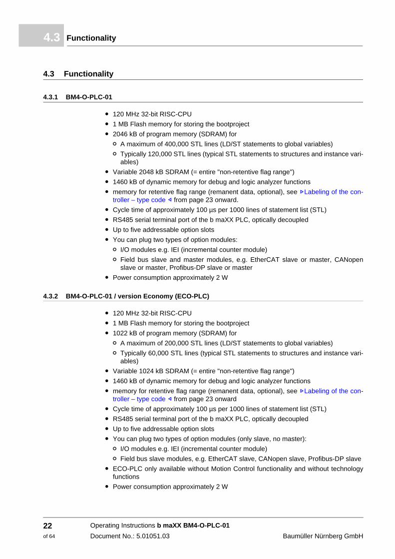
4.3.1 BM4-O-PLC-01
m 120 MHz 32-bit RISC-CPUm 1 MB Flash memory for storing the bootprojectm 2046 kB of program memory (SDRAM) for
n A maximum of 400,000 STL lines (LD/ST statements to global variables)n Typically 120,000 STL lines (typical STL statements to structures and instance vari-
ables)m Variable 2048 kB SDRAM (= entire "non-retentive flag range")m 1460 kB of dynamic memory for debug and logic analyzer functionsm memory for retentive flag range (remanent data, optional), see ZLabeling of the con-
troller – type code – from page 23 onward.m Cycle time of approximately 100 µs per 1000 lines of statement list (STL)m RS485 serial terminal port of the b maXX PLC, optically decoupled m Up to five addressable option slots m You can plug two types of option modules:
n I/O modules e.g. IEI (incremental counter module)n Field bus slave and master modules, e.g. EtherCAT slave or master, CANopen
slave or master, Profibus-DP slave or masterm Power consumption approximately 2 W
4.3.2 BM4-O-PLC-01 / version Economy (ECO-PLC)
m 120 MHz 32-bit RISC-CPU m 1 MB Flash memory for storing the bootproject m 1022 kB of program memory (SDRAM) for
n A maximum of 200,000 STL lines (LD/ST statements to global variables) n Typically 60,000 STL lines (typical STL statements to structures and instance vari-
ables) m Variable 1024 kB SDRAM (= entire "non-retentive flag range") m 1460 kB of dynamic memory for debug and logic analyzer functions m memory for retentive flag range (remanent data, optional), see ZLabeling of the con-
troller – type code – from page 23 onward m Cycle time of approximately 100 µs per 1000 lines of statement list (STL) m RS485 serial terminal port of the b maXX PLC, optically decoupled m Up to five addressable option slots m You can plug two types of option modules (only slave, no master):
n I/O modules e.g. IEI (incremental counter module) n Field bus slave modules, e.g. EtherCAT slave, CANopen slave, Profibus-DP slave
m ECO-PLC only available without Motion Control functionality and without technology functions
m Power consumption approximately 2 W
Operating Instructions b maXX BM4-O-PLC-01Document No.: 5.01051.03 Baumüller Nürnberg GmbH
22of 64

Description of the b maXX PLC option module 4
4.4 Danger zonesThe b maXX 4400 basic unit that is plugged into this module represents the greatest haz-ard. Observe all the safety instructions of the b maXX 4400 basic unit. The illustration be-low gives you an overview of the danger zones in the plug-in module.
Figure3: Danger zones
4.5 Labeling of the controller – type code
On the front panel, you will find the type code ("D" in ZFigure1 on page 21) of the plug-in module.
NOTEThis type code applies only to controller module PLC of series b maXX 4400. Other plug-in modules have their own type codes.
BM4 - O - PLC - XX - YY - ZZ Device generation in which you can install the plug-in module
BM4 - O - PLC - XX - YY - ZZ Option module
BM4 - O - PLC - XX - YY - ZZ Plug-in module type (b maXX PLC)
BM4 - O - PLC - XX - YY - ZZ Version01: Standard version
BM4 - O - PLC- XX - YY - ZZ Hardware versionSee version table
BM4 - O - PLC - XX - YY - ZZ Software versionSee version table
Operating Instructions b maXX BM4-O-PLC-01Document No.: 5.01051.03
23of 64

Labeling of the controller – type code4.5
Version table (- YY - ZZ)
This type code is located on both the front and back of the front panel. The type code con-tains the plug-in module's basic data. On the basis of the type code, you will be able to find more data in the chapter entitled "Technical Data". For a list of all the technical data, refer to ZAppendix D Technical Data– from page 59 onward.
- YY Meaning - ZZ Meaning
00 0 kB remanent data (NOVRAM) (Motion Control Single Axis)
00 ------
01 56 kB remanent data (NOVRAM)4 MB Flash(Motion Control Multi Axis and CAM data from CAM man-ager)
01 Operation system with Cache
02 Type ECO-PLC56 kB remanent data (NOVRAM) 0 MB Flash memory (no Motion Control, no CAM)
02 Operation system with Cache and Motion Control functional-ity
03 Type ECO-PLC0 kB remanent data (NOVRAM)0 MB Flash memory (no Motion Control, no CAM).
03 Operation system version Economy (ECO-PLC) with Cache but without Motion Control functionality and with-out technology functions
Operating Instructions b maXX BM4-O-PLC-01Document No.: 5.01051.03 Baumüller Nürnberg GmbH
24of 64

5ASSEMBLY AND INSTALLATION
In this chapter, we will describe mechanical assembly and electrical installation of a b maXX PLC option module.
Assembly/installation consists of the following steps:1 Mount the plug-in module.2 Connect the plug-in module to the signal cables.
To open the spagnolet lock, you may need a 3-mm wide screwdriver.
5.1 General safety regulations
h Observe the information in chapters ZBasic Safety Instructions – from page 9 onward.
h Observe all areas on the b maXX unit that could be dangerous when you are carrying out assembly.
The figure below gives you an overview of the danger zones on the plug-in module.
Figure 4: Danger zones
25of 64
Operating Instructions b maXX BM4-O-PLC-01Document No.: 5.01051.03

Requirements of the personnel carrying out work5.2
5.2 Requirements of the personnel carrying out work
Qualified personnel is considered to be people whose training, experience and knowl-edge of relevant standards and regulations, accident prevention regulations and condi-tions in the plant has led to their being authorized by the plant safety manager to carry out activities that are needed in each case while recognizing and avoiding any possible haz-ards that might arise. The qualifications that are necessary for working with the unit in-clude, for example:m Trained or instructed in accordance with recognized safety standards in the care and
use of appropriate safety equipment
5.3 Preparation
h Consult the type code (see "D" in ZFigure 5 on page 26) to ensure that you have the correct plug-in module.
Figure5: b maXX option module
h Determine the correct slot (see ZFigure 6 on page 27).
DANGER The following will occur, if you do not observe this danger information:m serious personal injury m death
Danger from: electricity. The unit and the vicinity of the control cabinet may carry dangerous voltages.
Before starting any work, ensure that the unit and its vicinity are free of voltage.
Observe the relevant safety regulations when handling current-carrying units.
Ensure that only qualified personnel assembles and installs this plug-in module.
Operating Instructions b maXX BM4-O-PLC-01Document No.: 5.01051.03 Baumüller Nürnberg GmbH
26of 64

Assembly and installation 5
5.3.1 PLC version „standard“Figure 6: Combinations of slots
Function modules Option modules
BM4-
F-E
NC
-XX
(enc
oder
1 fo
r mot
or c
ontro
l rec
omm
ende
d)
BM4-
F-E
NC
-XX
(enc
oder
2)
BM4-
F-A
IO-0
1 (a
nalo
g I/O
)
BM4-
F-A
IO-0
2/03
(ana
log
I/O)
BM4-
F-D
IO-X
X (d
igita
l I/O
)
BM4-
F-FI
O-X
X (f
ast d
igita
l I/O
)
BM4-
F-IE
E-X
X (i
ncre
men
tal e
ncod
er e
mul
atio
n)
BM4-
F-S
IE-X
X (S
SI-S
SI e
ncod
er e
mul
atio
n)
BM4-
F-C
AN
-01
(CA
Nsy
nc s
lave
) in
prep
.
BM4-
O-S
ER
-XX
(Ser
cos
slav
e)
BM4-
O-C
AN
-05
(CA
Nsy
nc s
lave
)
BM4-
O-P
RO
-01
(Pro
fibus
sla
ve)
BM4-
O-C
AN
-03
(CA
Nop
en s
lave
)
BM4-
O-D
NT-
XX
(DIS
C-N
T sl
ave
mod
ule)
BM4-
O-P
LC-X
X (S
PS)
BM4-
O-C
AN
-06*
(CA
Nsy
nc m
aste
r)
BM4-
O-C
AN
-04*
(CA
Nop
en m
aste
r)
BM4-
O-IE
I-XX
* (in
crem
enta
l enc
oder
em
ulat
ion)
BM4-
O-E
TH-0
1* (E
ther
net)
BM4-
O-E
TH-0
2* (E
ther
net +
CA
Nop
en m
aste
r)
BM4-
O-E
CT-
01 (E
ther
CAT
sla
ve) f
or c
ontro
ller
BM4-
O-E
CT-
01*
(Eth
erC
AT s
lave
) for
PLC
BM4-
O-E
CT-
02*
(Eth
erne
t + E
ther
CAT
mas
ter)
BM4-
O-E
CT-
03*
(Eth
erne
t + E
ther
CAT
clu
ster
)
A X - - - o o - o - - - - - - - - - - - - - - - -
B - X - - o o - X - - - - - - - - - - - - - - - -
C - - - - o o X - X - - - - - - - - - - - - - - -
D - - - - X X - - - - - - - - - - - - - - - - - -
E - - X X o o - - - - - - - - - - - - - - - - - -
F Controller unit, permanently installed
G - - - - - - - - - o o o o o o X X X X X o X X X
H - - - - - - - - - X X X X X X - o - o o X o o o
J - - - - - - - - - - P P P - - o o o o o - - - -
K - - - - - - - - - - P P P - - o o o o o - o o o
L - - - - - - - - - - P P P - - o o o o o - o o o
M - - - - - - - - - - P P P - - o o o o o - o o o
Stec
kkar
ten_
Rev
17_e
X:
o:
P:
-:*
preferred slot Baumüllter Nürnberg GmbH recommends, in order to reach the highest functional range, to insert the plug-in modules into these slots.possible slot only if the preferred slot is occupied, we recommend in order to reach the highest functional range, to insert the plug-in modules into this slot.only possible, if on slot G or H a PLC module (PLC) is plugged and the PLC (and not the con-troller) executes the communication to the field bus slave module.not possible - card doesn’t work in this slot.Precondition for these cards is an inserted PLC module (PLC).
Operating Instructions b maXX BM4-O-PLC-01Document No.: 5.01051.03
27of 64

Preparation5.3
5.3.2 PLC version „Economy“ (ECO-PLC)
Figure 7: Combinations of slots „Economy“ version (ECO-PLC)
Function modules Option modules
BM4-
F-E
NC
-XX
(e
ncod
er 1
for m
otor
con
trol r
ecom
men
ded)
BM4-
F-E
NC
-XX
(enc
oder
2)
BM4-
F-A
IO-0
1 (a
nalo
g I/O
)
BM4-
F-A
IO-0
2/03
(ana
log
I/O)
BM4-
F-D
IO-X
X (d
igita
l I/O
)
BM4-
F-FI
O-X
X (f
ast d
igita
l I/O
)
BM4-
F-IE
E-X
X
(incr
emen
tal e
ncod
er e
mul
atio
n)
BM4-
F-S
IE-X
X (S
SI-S
SI e
ncod
er e
mul
atio
n)
BM4-
F-C
AN
-01
(CA
Nsy
nc s
lave
) in
prep
.
BM4-
O-S
ER
-XX
(Ser
cos
slav
e)
BM4-
O-C
AN
-05
(CAN
sync
sla
ve)
BM4-
O-P
RO
-01
(Pro
fibus
sla
ve)
BM4-
O-C
AN
-03
(CAN
open
sla
ve)
BM
4-O
-DN
T-X
X (D
ISC
-NT
slav
e m
odul
e)
BM4-
O-P
LC-X
X (S
PS)
BM4-
O-IE
I-XX
* (in
crem
enta
l enc
oder
em
ulat
ion)
BM4-
O-E
TH-0
1* (E
ther
net)
BM4-
O-E
CT-
01 (E
ther
CAT
sla
ve)
A X - - - o o - o - - - - - - - - - -
B - X - - o o - X - - - - - - - - - -
C - - - - o o X - X - - - - - - - - -
D - - - - X X - - - - - - - - - - - -
E - - X X o o - - - - - - - - - - - -
F Controller unit, permanently installed
G - - - - - - - - - o o o o o o X X o
H - - - - - - - - - X X X X X X o o X
J - - - - - - - - - - P P P - - o o -
K - - - - - - - - - - P P P - - o o P
L - - - - - - - - - - P P P - - o o P
M - - - - - - - - - - P P P - - o o P
Stec
kkar
ten_
Rev
14_e
X:
o:
P:
-:*
preferred slot Baumüllter Nürnberg GmbH recommends, in order to reach the highest functional range, to insert the plug-in modules into these slots.possible slot only if the preffered slot is occupied, we recommend in order to reach the highest func-tional range, to insert the plug-in modules into this slot.only possible, if on slot G or H a PLC module (PLC) is plugged and the PLC (and not the controller) executes the communication to the field bus slave module.not possible - card doesn’t work in this slot.Precondition for these cards is an inserted PLC module (PLC).
Operating Instructions b maXX BM4-O-PLC-01Document No.: 5.01051.03 Baumüller Nürnberg GmbH
28of 64

Assembly and installation 5
5.4 Assembly1 Switch off the b maXX 4400 unit and secure it from being unintentionally restarted dur-ing assembly.
2 Pull the cover forward from the controller section: you can now see the slots.3 Look for the intended slot (H) on the controller section.
Figure8: Assembly
4 Turn the spagnolet locks above and below this slot by 90°. The spagnolet locks are now horizontal. You can use a screwdriver that is up to 3 mm wide.
DANGER The following will occur, if you do not observe this danger information:m serious personal injury m death
Danger from: electricity. The unit and the vicinity of the control cabinet may carry dangerous voltages.
Before starting any work, ensure that the unit and its vicinity are free of voltage. Observe the relevant safety regulations when handling current-carrying units.
CAUTIONThe following may occur, if you do not observe this caution information:m minor to medium personal injury.
Danger from: sharp edges. The components of the b maXX PLC option module, sheet steel parts, PCBs can have sharp edges!
Watch out for sharp edges and wear appropriate gloves.
Operating Instructions b maXX BM4-O-PLC-01Document No.: 5.01051.03
29of 64
Assembly5.4
5 Take out the front panel cover forward. Keep this cover. If you remove plug-in modules, you must close the unit again using the cover.
6 Observe the described ESD measures when handling the modules.7 Remove the b maXX option module from the transportation packaging: Avoid contact
with the plug-in module's electronic components.8 Plug the b maXX option module into the slot's guide rails. The gripping piece must face
the same way as the other gripping pieces in this slot rail slot rail (in the case: the right-hand side).
9 Keep pressing two fingers on the front panel until you feel the module engage in the end position inside the unit.
10 Turn the spagnolet locks above and below this slot by 90° to the vertical position (locked position).
11 Remount the cover on the unit.
This completes assembly of the b maXX PLC option module. Connecting lines and com-missioning is shown in the following sections.
CAUTIONThe following may occur, if you do not observe this caution information:m property damage.
Danger from: electrostatic discharge. The b maXX option module contains ESD compo-nents.
Observe the described ESD measures when handling the plug-in module.
Only hold the plug-in module by the gripping piece (see "C" in ZFigure 5 on page 26).
Operating Instructions b maXX BM4-O-PLC-01Document No.: 5.01051.03 Baumüller Nürnberg GmbH
30of 64

Assembly and installation 5
5.5 InstallationAt installation, carry out cabling of the b maXX option module.
5.5.1 Connection diagram
Figure 9: Connection diagram of b maXX PLC option module
NOTEIt is not absolutely necessary to carry out cabling of the RS485 interface. This is only neces-sary when connecting an annunciator, etc.
Operating Instructions b maXX BM4-O-PLC-01Document No.: 5.01051.03
31of 64
Installation5.5
5.5.2 Requirements of electrical connection
To be able to comply with Standard EN 60 204-1 (Electrical Equipment of Machines), you must use the cables that are suggested in the standard. The connectors must not drop; otherwise, there is a risk of short-circuits or external voltages, etc.
h Ensure EMC-appropriate laying of the connection cables.
5.5.3 Requirements of the connection cable
Baumüller has released the following cables for use:
You must use a twisted pair cable with a cross-section surface area of a maximum of 0.5 mm²; sheath PVC and sheathing of galvanized woven copper.
Example: Type LIYCY 6 x 2 x 0.14 mm²
For more information, refer to ZAppendix B Accessories– from page 53 onward.
5.5.4 Sequence of installation
h Ensure that the b maXX unit is deenergized
h Remove the front cover from the unit.m The b maXX PLC option module is in slot H,
see ZFigure 6 on page 27.
h Connect the 9-pin Sub-D socket on the front panel of the b maXX option module to the connection cable for a terminal or ..., connection assignment see ZPin assignment Sub-D socket RS485 port – on page 61.
h Remount the cover on the unit.
h Lay the connecting lines as stipulated in the control cabinet
This completes installation.
CAUTIONThe following may occur, if you do not observe this caution information:m property damage.
Danger from: electrical voltage. If you are not able to ensure the plug-in module's require-ments of the electrical connection, the plug-in module can be damaged or destroyed.
Ensure that you comply with the connection values that are specified in the technical data and that the connections were made in accordance with the stipulations.
Prevent short-circuits between inputs/outputs. In the case of a short-circuit between inputs/outputs, the plug-in module can be destroyed.
The +5 V at Pin 2 of the Sub-D socket on the b maXX option module is intended only to supply external Baumüller-specific RS485/RS232 converters; you must not short-circuit or ring con-nect it with others.
Operating Instructions b maXX BM4-O-PLC-01Document No.: 5.01051.03 Baumüller Nürnberg GmbH
32of 64

6COMMISSIONING
In this chapter, we will describe how you commission the b maXX PLC option module that you just assembled and installed (see ZAssembly and installation – from page 25 on-ward). Commissioning ensures that the b maXX PLC option module functions correctly. For more information on programming, refer to the "b maXX PLC Application Manual".
Before starting commissioning, ensure that the following conditions have been met:1 The plug-in module has been assembled correctly.2 The plug-in module has been installed correctly.3 All the safety equipment has been commissioned.4 The b maXX unit is ready for use.
6.1 General safety regulations
h Observe the ZBasic Safety Instructions – from page 9 onward.
6.2 Requirements of the personnel carrying out work
Commissioning work must only be carried out by trained specialists who have understood the safety regulations and information and can implement them.
6.3 Description/inspection of the safety and monitoring systems
Before you commission the b maXX PLC option module, you must eliminate any errors/error messages that may be present on the b maXX 4400 unit. These errors may be due
DANGER The following will occur, if you do not observe this danger information:m serious personal injury m death
Danger from: mechanical effects. At commissioning, the drive can rotate.
Keep far enough the rotating parts. Note that when drives are starting up machine parts can be set in motion. In all cases, activate the machine's safety devices.
33of 64
Operating Instructions b maXX BM4-O-PLC-01Document No.: 5.01051.03

Description and inspection of the controls and displays6.4
to faulty assembly (e.g. defective cables) or faulty installation (e.g. no power supply). You must not continue with commissioning until you have eliminated the errors.
6.4 Description and inspection of the controls and displays
6.4.1 LEDs for displaying operating status conditions
The b maXX PLC option module has two red and two green LEDs as display elements.
These LEDs are used primarily to show PLC-specific operating status conditions after the b maXX 4400 units is switched on and before the system executes the user program on the b maXX PLC option module.
After the start-up phase is completed, users can use the LEDs for their own purposes.
Figure 10: LEDs of the b maXX PLC option module
Displaying operating status conditions after switching on the unit:m All the option modules in the b maXX 4400 unit must have reached a specific internal
operating status after switching in the supply voltage before they may be actuated by the b maXX controller and the b maXX PLC option module. This stage, in which the system waits for a global ready message of all option modules is displayed by a clockwise-rotating LED bit pattern. This means that an LED lights up every 500 ms in the sequence H4 → H2 → H1 → H3 → H4 etc.
m After the global ready message of all modules has been issued, the b maXX PLC op-tion module must wait until the b maXX controller recognizes and preinitializes it. This stage is indicated by a counterclockwise-rotating bit pattern. This means an LED se-quence of H4 → H3 → H1 → H2 → H4 etc. every 500 ms.
The two sequences that we have just described can be completed very quickly, which means that you do not necessarily have to observe the associated operating displays.
After this, a PC and the b maXX PLC option module can, in principle, carry out PRO-PROG communication via the serial RS232 port on the b maXX controller.
Green LEDs Red LEDs
⊗ ⊗
H1Bit 3
H2Bit 2
⊗ ⊗
H3Bit 1
H4Bit 0
Operating Instructions b maXX BM4-O-PLC-01Document No.: 5.01051.03 Baumüller Nürnberg GmbH
34of 64

Commissioning 6
From now on, PROPROG communication is also possible by means of TCP/IP if an op-tion module with Ethernet functionality is present that has been configured for communi-cation with the b maXX PLC option module.m If a boot project is present, the system now loads it. The top two LEDs (H2 and H1) flash rapidly to show that the boot project is being loaded.
At the end of the start-up phase, the LEDs show the following PLC-specific operating sta-tus conditions:m No project available, status "POWER ON":
→ LEDs H3 (green) and H4 (red) light up.m Project available, status "STOP":
→ Only LED H4 (red) lights up.m Project available, status "INIT", the controller is at the cold boot or warm restart stage:
→ Only LED H3 (green) lights up.m Project available, status "RUN":
→ LEDs H1 (green) and H3 (green) light up.
In the "RUN" status, users can freely program the four LEDs. For information on program-ming, see the b maXX PLC Application Manual in the chapter entitled "b maXX PLC Board Functions / LED Function Block".
6.4.2 S1 switch/pushbutton for changing operating status conditions
Figure 11: Switch S1 on the BM4-O-PLC-01 front panel
Pushbutton upward: RESET
Switch in middle: STOP
Switch at bottom: RUN
NOTEThe user project can only start up when switch/pushbutton S1 is in the bottom "RUN" position.
The pushbutton upward only resets the b maXX PLC option module and not the controller.
DANGER The following will occur, if you do not observe this danger information:m serious personal injury m death
Danger from: mechanical effects. Cold restarting the controller can cause the drive to rotate.
Keep far enough away from the rotating parts. Note that when drives are starting up machine parts can be set in motion. In all cases, activate the machine's safety devices.
Operating Instructions b maXX BM4-O-PLC-01Document No.: 5.01051.03
35of 64

Commissioning sequence6.5
6.5 Commissioning sequence
Commissioning is divided into the following procedures:1 Activation.2 Testing the function.
6.5.1 Activation.
m Read and observe the ZGeneral safety regulations – from page 33 onward.m You must have carried out correctly section "Assembly and Installation".m Set switch S1 on the b maXX PLC option module to "STOP" (center position).m Switch on the b maXX 4400 basic unit.
6.5.2 Testing the function
m After you switch on the b maXX unit, two status conditions can apply:n No boot project (= no user project on the PLC):
LED H2 (at the top right) lights up briefly after a short time, the bottom LEDs H3 and H4 (red and green) are permanently lit up. This means that no project is present. In this "POWER ON" status, the PLC is waiting for communication.
n Boot project present: When you switch on, the system loads the boot project. When you do this, the top LEDs flash. After a short time, LED H4 (at the bottom right) lights up red. The PLC is in the "STOP" status.
m While switch S1 on the b maXX PLC option module is set to "STOP" (centre position), an existing boot project cannot start up. If you want to start an existing boot project by setting switch S1 on the b maXX PLC option module to the "RUN" (bottom) position, first ensure that you have loaded the correct boot project for your application for this plant in this unit on the PLC!
Refer to the b maXX PLC Application Manual for more information on how to ensure that this is the case or how you can send a boot project to the PLC, for example
NOTEYou must not remove or plug in the b maXX PLC option module while the b maXX 4400 basic unit is switched on. Switch the unit off first.
DANGER The following will occur, if you do not observe this danger information:m serious personal injury m death
Danger from: mechanical effects. A boot project on the PLC can start up if you set switch S1 from "STOP" (center position) to "RUN" (bottom position) or if switch S1 is set to "RUN" when you switch on the b maXX unit You can program the boot project such that the drive rotates!
Keep far enough away from the rotating parts. Note that when drives are starting up machine parts can be set in motion. In all cases, activate the machine's safety devices.
Operating Instructions b maXX BM4-O-PLC-01Document No.: 5.01051.03 Baumüller Nürnberg GmbH
36of 64

7OPERATION
For guides to operating the b maXX PLC option module, refer to the b maXX PLC Appli-cation Manual (BM4-O-PLC-01) and the PROPROG wt II Programming Manual.
37of 64
Operating Instructions b maXX BM4-O-PLC-01Document No.: 5.01051.03

Operating Instructions b maXX BM4-O-PLC-01Document No.: 5.01051.03 Baumüller Nürnberg GmbH
38of 64

8TROUBLESHOOTING AND ELIMINATING FAULTS
In this chapter, we will describe fault indications of the b maXX basic unit when there is a disturbance on the b maXX option module, the meanings of these indications and how you can respond to them.
8.1 Safety regulations
Observe the relevant safety regulations, see ZBasic Safety Instructions – from page 9 onward.
Requirements of the personnel carrying out work: The personnel who work with the b maXX unit, must have been instructed in operating the unit and be familiar with correctly operating it. Responding to error displays and status conditions in particular requires special knowledge that operators must demonstrate. Be-low, we will inform you about the various disturbances and the error messages that result from them. These disturbances can have mechanical or electrical causes.
8.2 Troubleshooting
n While the basic unit is starting up, the b maXX PLC option module waits for a global ready message from all the option modules (see ZLEDs for displaying operating status conditions – from page 34 onward). This can be due to one of the following reasons: m One of the option modules is defective or has a connection fault.
→ Does the error also occur if only the b maXX controller and the PLC are plugged in?
You must only plug in and remove the modules when they are deenergized! - No: Keep adding the rest of the option modules until you
have determined which one is faulty. - Yes: Check whether there are bent pins in the controller's basic
unit slots and in the PLC. Replace the controller or, if necessary, the PLC. Replace the basic unit.
n The b maXX controller does not detect the b maXX PLC option module while the basic unit is starting up. This can be due to one of the following reasons:
39of 64
Operating Instructions b maXX BM4-O-PLC-01Document No.: 5.01051.03

Troubleshooting8.2
m The b maXX PLC option module being plugged in wrong or not plugged in all the way. Check ZAssembly and installation – from page 25 onward.
m The wrong option module being plugged in. Check the board type on the basis of ZLabeling of the controller – type code – from page 23 onward.
m A connection fault. Check the connections, see ZFigure9 on page 31.m Disruptive return path ingress. Check EMC measures.m Switching circuit defective in the b maXX PLC option module, replace the option
module.
Operating Instructions b maXX BM4-O-PLC-01Document No.: 5.01051.03 Baumüller Nürnberg GmbH
40of 64

9MAINTENANCE
If you comply with the specified environmental operating conditions, see ZAppendix D Technical Data– from page 59 onward), the b maXX PLC option module for the b maXX basic unit 4400 is maintenance-free. If you find a defect in your b maXX PLC op-tion module or think that it is defective, contact Baumüller Nürnberg GmbH.
41of 64
Operating Instructions b maXX BM4-O-PLC-01Document No.: 5.01051.03

Operating Instructions b maXX BM4-O-PLC-01Document No.: 5.01051.03 Baumüller Nürnberg GmbH
42of 64

10OVERHAUL
You cannot overhaul a defective b maXX PLC option module; contact Baumüller Nürn-berg GmbH to obtain a replacement unit.
43of 64
Operating Instructions b maXX BM4-O-PLC-01Document No.: 5.01051.03

Operating Instructions b maXX BM4-O-PLC-01Document No.: 5.01051.03 Baumüller Nürnberg GmbH
44of 64

11DISMANTLING, STORAGE
In this chapter, we will describe how you decommission the b maXX PLC option module and store it. When doing this, observe the information in chapters ZBasic Safety Instruc-tions – from page 9 onward, ZPackaging and transportation – from page 17 onward and ZDisposal – from page 49 onward.
11.1 Safety regulations
You must switch off the b maXX 4400 basic unit to remove the b maXX PLC option mod-ule. Only specially trained personnel are allowed to dismantle the b maXX PLC. The safe-ty regulations for commissioning apply analogously to dismantling.
WARNINGThe following may occur, if you do not observe this warning information:m serious personal injury m death
Danger from: electricity.The unit carries dangerous voltage and current and residual charges in the intermediate circuit.
Ensure that all the electrical connections have been deenergized and are secured against re-starting.
Wait until the intermediate circuit has discharged before starting any dismantling work. The capacitors that are used in the unit have discharged automatically 10 min. after the supply voltage is switched off such that you can dismount the connections without any risk.
Before starting work on the electrical connections, use appropriate measuring equipment to ensure that the connections are dead.
Do not dismount the connections until you are certain that they are dead.
45of 64
Operating Instructions b maXX BM4-O-PLC-01Document No.: 5.01051.03

Requirements of the personnel carrying out work11.2
11.2 Requirements of the personnel carrying out work
The personnel that carries out dismantling must have the necessary knowledge and have been trained appropriately to carry out this work. Choose these persons such that they understand and can apply the safety instructions printed on the unit and parts of it and on the connections.
CAUTIONThe following may occur, if you do not observe this caution information:m property damage.
The danger is: electrical destruction. The sub-asssembly may get destroyed electrically if it is removed with the supply voltage on .
Ensure that all the electrical connections have been deenergized and are secured against re-starting.
Wait until the intermediate circuit has discharged before starting any dismantling work. The capacitors that are used in the unit have discharged automatically 10 min. after the supply voltage is switched off such that you can dismount the connections without any risk.
Before starting work on the electrical connections, use appropriate measuring equipment to ensure that the connections are dead.
Do not dismount the connections until you are certain that they are dead.
WARNINGThe following may occur, if you do not observe this warning information:m serious personal injury m death
The danger is: Uncontrollable characteristics of the machine/system. Removal of the module with switched on supply voltage can change the characteristics of the machine/sys-tem.
Ensure that all the electrical connections have been deenergized and are secured against re-starting.
Wait until the intermediate circuit has discharged before starting any dismantling work. The capacitors that are used in the unit have discharged automatically 10 min. after the supply voltage is switched off such that you can dismount the connections without any risk.
Before starting work on the electrical connections, use appropriate measuring equipment to ensure that the connections are dead.
Do not dismount the connections until you are certain that they are dead.
Operating Instructions b maXX BM4-O-PLC-01Document No.: 5.01051.03 Baumüller Nürnberg GmbH
46of 64

Dismantling, storage 11
11.3 DismantlingThe personnel who carry out dismantling must meet the requirements above. The follow-ing materials are needed:m Suitable packaging material for the b maXX PLC option module; if possible, use the
original packaging material m Metal covers to cover the slotsm Suitable tools for pulling out the board (e.g.pointed electronic pliers)
Dismantling is divided into the following stages:m Switching the unit free of voltage and securing it from unintended restartingm Removing the basic unit's coverm Dismounting the female connector with the connectionsm Turning by 90° the locks above and below the front panel of the b maXX option module
(the unlocked position is horizontal)m Pulling out the b maXX PLC option module forward out of the rackmount on the handle
m Place the b maXX PLC option module in the packaging material; when doing this, only hold the board by the front blanking plate
m Insert the covers in the open slot (the holder must point to the right) and turn the lock by 90° degrees (to the closed position)
m Mount the cover back on the unitm Document dismantling of the b maXX PLC option module
If you want to dispose of the b maXX PLC option module, refer to chapter ZDisposal – from page 49 onward for more information.
CAUTIONThe following may occur, if you do not observe this caution information:m property damage.
Danger from: electrostatic discharge. The electronic components on the PCB can be dam-aged or destroyed if you touch them with your hands.
Only ever hold the b maXX PLC option module by the front panel.
CAUTIONThe following may occur, if you do not observe this caution information:m minor to medium personal injury.
Danger from: sharp edges. The components of the b maXX PLC option module, sheet steel parts, PCBs can have sharp edges!
Watch out for sharp edges and wear appropriate gloves.
Operating Instructions b maXX BM4-O-PLC-01Document No.: 5.01051.03
47of 64

Storage conditions11.4
11.4 Storage conditions
Store the b maXX PLC option module in suitable packaging according to the storage con-ditions in ZTechnical Data – from page 59 onward.
11.5 Recommissioning
If you want to recommission the b maXX PLC option module, observe the information in "Storage Conditions". Then, carry out ZCommissioning – from page 33 onward again.
Operating Instructions b maXX BM4-O-PLC-01Document No.: 5.01051.03 Baumüller Nürnberg GmbH
48of 64

12DISPOSAL
In this chapter we will describe how you can correctly and safely dispose of the b maXX option module of equipment range b maXX 4400. Most of the waste is electronic scrap.m The condition for dismantling has already been met, see ZDismantling, storage – from
page 45 onward.
12.1 Safety regulations
You must only carry out disposal in accordance with the safety regulations. If necessary, you must also comply with any local regulations. If you cannot safely dispose of the unit yourself, commission a suitable disposal company to carry it out on your behalf.
12.2 Requirements of the personnel carrying out work
The personnel that carries out disposal/dismantling must have the necessary knowledge and have been trained appropriately to carry out this work. Choose these persons such that they understand and can apply the safety instructions printed on the unit and parts of it.
CAUTIONThe following may occur, if you do not observe this caution information:m minor to medium personal injury.
Danger from: sharp edges. The components of the b maXX PLC option module, sheet steel parts, PCBs can have sharp edges!
Watch out for sharp edges and wear appropriate gloves.
49of 64
Operating Instructions b maXX BM4-O-PLC-01Document No.: 5.01051.03

Disposal guide12.3
12.3 Disposal guide
12.3.1 Disposal-conformant modules
Electronic scrap PCBs and components and modules of similar quality that do not need to be further-dis-mantled must be recycled as electronic scrap. When doing this, observe the relevant reg-ulations.
Material: m Basic material: epoxy-resin fiberglass woven material, copper-clad on both sides and
plated-through;m various electronic components such as capacitors, resistors, relays, semiconductor
components, etc.m Front panel: Sheet iron, galvanized.
Packaging Dispose of the cardboard packaging in your local reusable paper system.
CAUTIONThe following can occur if you do not observe this warning:m Environmental pollution
Danger from: incorrect disposal. The contents and materials in PCBs endanger the environ-ment.
Have the b maXX PLC option module recycled at an appropriate plant for electronic scrap.
Operating Instructions b maXX BM4-O-PLC-01Document No.: 5.01051.03 Baumüller Nürnberg GmbH
50of 64

APPENDIX A ABBREVIATIONS
BACI Baumüller Component InterfaceCPU Central Processing Unit EMC Electromagnetic compatibilityEN European standardEXT, ext ExternalI/O Input/OutputLED Light Emitting DiodeSW SoftwareUSS® Trademark of Siemens,
universal serial interface
51of 64
Operating Instructions b maXX BM4-O-PLC-01Document No.: 5.01051.03

A
Operating Instructions b maXX BM4-O-PLC-01Document No.: 5.01051.03 Baumüller Nürnberg GmbH
52of 64

APPENDIX B ACCESSORIES
In this appendix, you will find a list of all the accessories that are available for Baumüller Nürnberg GmbH's b maXX PLC option module.
If you have any queries about accessories or suggestions for improvements, Baumüller's Product Management will be pleased to hear from you.
B.1 List of all accessories
B.1.1 Programming cable (serial RS.232)
Line type: K-SS-01-xx (9-pin Sub-D, 9-pin Sub-D):
B.1.2 Cable for linking HMIs (annunciators, touch screen, etc.) to the RS485 interface
Since the pin assignment of an RS485 interface is not standardized, Baumüller cannot offer a tailormade cable.
You must use a twisted pair cable with a cross-section surface area of a maximum of 0.5 mm²; sheath PVC and sheathing of galvanized woven copper.
If necessary, you must contact the total screening with the metallic male or female cable connectors.
Type Length [m] Article Number
K-SS-01-03 3 213 846
K-SS-01-05 5 213 283
K-SS-01-15 15 231 086
NOTEThese cables are identical with the cable that you use for parameterizing the b maXX control-ler with WinBASS II.
53of 64
Operating Instructions b maXX BM4-O-PLC-01Document No.: 5.01051.03

List of all accessoriesB.1
Example: Type LIYCY 6 x 2 x 0.14 mm²
For the pin assignment, see ZD.4 Pin assignment Sub-D socket RS485 port– from page 61 onward
Operating Instructions b maXX BM4-O-PLC-01Document No.: 5.01051.03 Baumüller Nürnberg GmbH
54of 64

APPENDIX C DECLARATION OF CONFORMITY
In this section we provide general information about EU directives, the CE symbol and the Declaration of Conformity/by Manufacturer.
C.1 What is an EU directive?
EU directives specify requirements. The directives are written by the relevant bodies with-in the EU and are implemented by all the member countries of the EU in national law. In this way the EU directives guarantee free trade within the EU.
An EU directive only contains essential minimum requirements. You will find detailed re-quirements in standards, to which references are made in the directive.
C.2 What the CE symbol indicates
a) The CE marking symbolizes conformity to all the obligations incumbent on manufac-turers for the product by virtue of the Community directives providing for its affixing.…
b) The CE marking affixed to industrial products symbolizes the fact that the natural or legal person having affixed or been responsible for the affixing of the said marking has verified that the product conforms to all the Community total harmonization provisions which apply to it and has been the subject of the appropriate conformity evaluation pro-cedures.…
Council Decision 93/465/EEC, Annex I B. a) + c)
We affix the CE mark to the equipment and to the operating instructions as soon as we have established that we have satisfied the requirements of the relevant directives.
Control systems supplied by the Baumüller Nürnberg GmbH are not concerned of the Low Voltage Directive, because their operating voltage is less than 60 V DC or less than 75 V AC. Therefore a declaration of conformity to 2006/95/EC (Low Voltage Directive) cannot be issued. The electrical safety and function of the control system will be checked with the harmo-nized standard EN 61131-2.
55of 64
Operating Instructions b maXX BM4-O-PLC-01Document No.: 5.01051.03

Definition of the term Declaration of ConformityC.3
With specified application of this Baumüller equipment in your machinery, you can act on the assumption that the equipment satisfies the requirements of 2006/42/EC (machinery directive). Therefore the equipment is developed and constructed in such a way, that the require-ments of the harmonized standard EN 60204-1 can be met by the electrical installation.
Control systems supplied by the Baumüller Nürnberg GmbH satisfy the requirements of 2004/108/EC (EMC Directive) by satisfying the requirements of the harmonized standard EN 61131-2.
To enable you to market your machine within the EU, you must be in possession of the following:m Conformity mark (CE mark)m Declaration(s) of Conformity regarding the directive(s) relevant to the machine
C.3 Definition of the term Declaration of Conformity
A Declaration of Conformity as defined by this documentation is a declaration that the electrical equipment brought into circulation conforms to all the relevant fundamental safety and health requirements.
By issuing the Declaration of Conformity in this section the Baumüller Nürnberg GmbH declares that the equipment conforms to the relevant fundamental safety and health re-quirements resulting from the directives and standards which are listed in the Declaration of Conformity.
C.4 Declaration of Conformity
Operating Instructions b maXX BM4-O-PLC-01Document No.: 5.01051.03 Baumüller Nürnberg GmbH
56of 64

Declaration of Conformity C
Declaration of EC conformity Doc.-No. 5.11011.00Date: 08 June 2011
according to EMC Directive 2004/108/EC
The manufacturer Baumüller Nürnberg GmbH Ostendstraße 80-90 90482 Nürnberg, Germany,
declares, that the product with the
designation Programmable Logic Controller type BM4-O-PLC-01
manufactured since June 8, 2011
are developed, designed and manufactured in accordance with the EMC Directive 2004/108/EC.
Applied harmonized standards:
Attention must be paid to the safety instructions in the manual.
Nürnberg / June 8, 2011Location / Date
subject to change of this declaration of EC conformity without notice. Actual valid edition on request
Standard Title
EN 61131-2:2007 Programmable ControllersPart 2: Equipment requirements and tests
Operating Instructions b maXX BM4-O-PLC-01Document No.: 5.01051.03
57of 64

Declaration of ConformityC.4
Operating Instructions b maXX BM4-O-PLC-01Document No.: 5.01051.03 Baumüller Nürnberg GmbH
58of 64

APPENDIX D TECHNICAL DATA
In this appendix, you will find the technical data for Baumüller Nürnberg GmbH's b maXX PLC option module (BM4-O-PLC-01).
D.1 Connection values
Processor SH3
Clock frequency 120 MHz
Power supply 5 V internal
Interfaces m RS232 serial port for PROPROG wt II is located on the b maXX basic unit on the controller
m RS485 serial port for drive networking and visualization
Ambient conditions Same as b maXX 4400 basic unit
Storage conditions Same as b maXX 4400 basic unit
59of 64
Operating Instructions b maXX BM4-O-PLC-01Document No.: 5.01051.03

Internal circuit elements of the b maXX PLC option moduleD.2
D.2 Internal circuit elements of the b maXX PLC option module
Figure 12: Internal circuit elements of b maXX PLC option module
Operating Instructions b maXX BM4-O-PLC-01Document No.: 5.01051.03 Baumüller Nürnberg GmbH
60of 64

Technical Data D
D.3 Front panelFigure 13: Front panel
Pushbutton (upward): Reset
Switch (center position): Stop
Switch (downward): Run
D.4 Pin assignment Sub-D socket RS485 port
Pin No. Assignment
9-pin SUB-D female connector
1 TxD- (Transmit Data negative)
2 VCC (+5V output for supplying external RS485/RS232 converters)
3 GND (Signal Ground RS232/RS485)
4 GND (Signal Ground RS232/RS485)
5 RxD- (Receive Data negative)
6 RxD+ (Receive Data positive)
7 GND (Signal Ground RS232/RS485)
8 GND (Signal Ground RS232/RS485)
9 TxD+ (Transmit Data positive)
Operating Instructions b maXX BM4-O-PLC-01Document No.: 5.01051.03
61of 64

Pin assignment Sub-D socket RS485 portD.4
CAUTIONThe following may occur, if you do not observe this caution information:m property damage.
Danger of: electrical shortcircuit. An electrical shortcircuit can damage the unit.
The +5 V at Pin 2 of the Sub-D socket on the b maXX option module is intended only to supply external Baumüller-specific RS485/RS232 converters; you must not short-circuit or ring con-nect it with others.
Operating Instructions b maXX BM4-O-PLC-01Document No.: 5.01051.03 Baumüller Nürnberg GmbH
62of 64

Index
Numerics2004/108/EC 562006/42/EC 562006/95/EC 55
AActivation. 36
BBaumüller 9, 17BM4-O-PLC-01 7
CCables 53Cabling 31Capacitors 45, 46Combinations of slots 27Connection cable 32
released 32Connection diagram 31Connection values 59Connnection
electrical 32
DDeclaration of Conformity 55, 56Device generation 23Dismantling 45Display elements 34
EElectrical connection 32Electrostatic discharge 17, 30EMC Directive 56
FFront panel 23Function test 36Functionality 22
PLC 19
GGripping piece 30
HHuman Machine Interface
Link 19
IIntermediate circuit 45, 46
LLED display 34Low Voltage Directive 55
MMachinery directive 56
OOperating status 34Option modules 19
PPersonnel 15
qualified 15Pin assignment 61Plug-in module type 23Programming languages 20PROPROG wt II 20
QQualified Personnel 15, 26
RReady message of all option modules 34Responsibility and liability 15RS485 port 61RUN 35
SSlot 21, 26Specialist 15Stop 35Storage 48Switch/pushbutton 35
TTechnical Data 59Technology functions 20Terms
Definition 7Troubleshooting 39Type Code
Plug-in module 23
WWarranty and Liability 16
Operating Instructions b maXX BM4-O-PLC-01Document No.: 5.01051.03
63of 64

Operating Instructions b maXX BM4-O-PLC-01Document No.: 5.01051.03 Baumüller Nürnberg GmbH
64of 64


Baumüller Nürnberg GmbH Ostendstraße 80-90 90482 Nuremberg Tel: +49(0)911-5432-0 Fax: +49(0)911-5432-130 www.baumueller.de
All the information in these Operating Instructions is non-binding customer information; it is subject to ongoing further development and is updated on a continuous basis by our permanent change management system. Note that all the data/numbers/information that are quoted are current values at the time of printing.This information is not legally binding for dimensioning, calculation and costing. Before using the information listed in these Operating Instructions as the basis for your own calculations and/or applications, make sure that you have the latest most current information.This means that we accept no resonsibility for the accuracy of the information.