
en Operating instructions
282
Operating instructions R 944 C-Litronic / 10069986 MJFCIFSS Document identification Order number: 10069986 Edition: 06 / 2006 Valid for: R 944 C-Litronic from serial number 17 429 Author: LFR - Technical documentation department Product identification Manufacturer: LIEBHERR France S.A.S. Type: R 944 C-Litronic Type no.: 786 / 791 / 792 / 793 / 1000 / 1079 Conformity: CE Address Liebherr France S.A.S. 2 avenue Joseph Rey B.P 287 F - 68005 Colmar Cedex en Operating instructions Hydraulic excavator R 944 C-Litronic from serial number 17 429
-
Upload
khangminh22 -
Category
Documents
-
view
1 -
download
0
Transcript of en Operating instructions

Operating instructions
R 944 C-Litronic / 10069986
MJFCIFSS
Document identification
Order number: 10069986
Edition: 06 / 2006
Valid for: R 944 C-Litronic from serial number 17 429
Author: LFR - Technical documentation department
Product identification
Manufacturer: LIEBHERR France S.A.S.
Type: R 944 C-Litronic
Type no.: 786 / 791 / 792 / 793 / 1000 / 1079
Conformity: CE
Address
Liebherr France S.A.S.
2 avenue Joseph Rey
B.P 287 F - 68005 Colmar Cedex
en
Operating instructions
Hydraulic excavator
R 944 C-Litronic
from serial number 17 429

Operating instructions
R 944 C-Litronic / 10069986
MJFCIFSS
Machine data
Please fill in the following data when you receive your machine.
This will also be of use to you when ordering replacement parts.
Vehicle ident. number:
WLHZ . . . . . ZK . . . . . .
Construction year:
. . . .
First start-up date:
. . / . . / . .

Operating instructions
R 944 C-Litronic / 10069986
MJFCIFSS
Preface
These operating instructions have been written for the machine operator and for the
maintenance personnel of the machine.
They contain:
� the technical data.
� the safety requirements.
� the operating instructions.
� the maintenance instructions.
The operating instructions are to be read and used carefully by all persons
who carry out work with or on the machine before putting the machine into
service for the first time and later, at regular intervals.
Work with or on the machine includes, for example:
� Operation including setting up and equipping, rectifying malfunctions during the
course of work, resolving production dropouts, care, disposal of operating and
process materials.
� Maintenance, including maintenance, inspection and repair work.
� Transportation or loading the machine.
The operating instructions allow the machine operator to familiarize himself with the
machine more easily and prevent malfunctions occurring due to improper operation.
The observance of the operating and maintenance instructions by maintenance per-
sonnel:
� increases reliability in use.
� extends the service life of your machine.
� reduces repair costs and downtime.
The operating instructions belong with the machine. Place a copy in an easily
reached position on the cab storage shelf.
The operating and maintenance instructions should also incorporate information on
current national regulations for accident prevention and protection. In addition to the
operating instructions and legally binding regulations on accident prevention which
apply in the user country and at point of use, authorized specialist rules for safe and
correct working procedures are also to be observed.
These operating and maintenance instructions contain all the information required
for operating and maintaining your machine.
� Some illustrations in these operating instructions may depict details and working
devices which differ to your machine.
� In some illustrations, protective devices and covers have been removed in the in-
terests of better presentation.
� Improvements, which are always being incorporated into our machines, may re-
sult in changes to your machine which are not yet indicated in these operating in-
structions.
However, should you require any further explanations or information, LIEBHERR's
technical documentation, sales school and customer service departments are avail-

Operating instructions
R 944 C-Litronic / 10069986
MJFCIFSS
able for your convenience.
You will appreciate that LIEBHERR warranty claims made on the basis of improper
operation, unsatisfactory maintenance, use of unauthorized operating materials or
non-adherence to safety regulations cannot be recognized.
LIEBHERR will annul any and all obligations incurred by LIEBHERR and / or its deal-
erships, such as guarantee commitments, service contracts etc. without prior notice
in the event that replacement parts other than original LIEBHERR parts or parts pur-
chased from LIEBHERR are used for maintenance or repair work.
Modifications, conditions, copyright
We reserve the right to make modifications without prior notice in the course of tech-
nical developments.
The information and illustrations contained in these operating instructions may nei-
ther be copied and distributed, nor used for the purposes of competition. All rights
are expressly reserved in accordance with copyright laws.
The warranty and liability conditions of LIEBHERR�s general business conditions will
not be enlarged upon through the above information.

Operating instructions
R 944 C-Litronic / 10069986
MJFCIFSS
1 Product description ....................................................................................................................................... 1-1
1.1 Assembly - overview.............................................................................................................................. 1-1
1.1.1 Machine with backhoe attachment .............................................................................................. 1-1
1.1.2 Machine with industrial attachment ............................................................................................. 1-2
1.1.3 Uppercarriage.............................................................................................................................. 1-3
1.1.4 Undercarriage.............................................................................................................................. 1-4
1.2 Technical data ....................................................................................................................................... 1-4
2 Safety information, signs .............................................................................................................................. 2-1
2.1 Symbols in the operating instructions .................................................................................................... 2-1
2.2 Use in accordance with the regulations ................................................................................................. 2-2
2.3 Safety instructions ................................................................................................................................. 2-2
2.3.1 General safety instructions .......................................................................................................... 2-2
2.3.2 Avoidance of crushing and burns ................................................................................................ 2-3
2.3.3 Avoidance of fire and explosions................................................................................................. 2-4
2.4 Signs on the machine ............................................................................................................................ 2-5
2.4.1 Arrangement of signage .............................................................................................................. 2-5
2.4.2 Explanation of signage ................................................................................................................ 2-6
2.4.3 Nameplates on the machine...................................................................................................... 2-10
3 Control and operation ................................................................................................................................... 3-1
3.1 Operating and control elements............................................................................................................. 3-1
3.1.1 Overview of the operator�s standing position............................................................................... 3-1
3.1.2 Arrangement of joystick ............................................................................................................... 3-3
3.1.3 Keyboard ..................................................................................................................................... 3-4
3.1.4 Monitoring display........................................................................................................................ 3-8
3.1.5 Main screen (DISP02 R5.2 Software V4.1) ............................................................................... 3-11
3.2 Access and equipment of the cab........................................................................................................ 3-29
3.2.1 Entering or leaving the cab........................................................................................................ 3-29
3.2.2 Safety lever................................................................................................................................ 3-31
3.2.3 Operator�s seat .......................................................................................................................... 3-32
3.2.4 Windscreen................................................................................................................................ 3-36
3.2.5 Sunshade .................................................................................................................................. 3-37
3.2.6 Emergency exit � rear window .................................................................................................. 3-37
3.2.7 Interior lighting ........................................................................................................................... 3-38
3.2.8 Fire extinguisher*....................................................................................................................... 3-38
3.2.9 Windscreen wiper ...................................................................................................................... 3-38
3.2.10Lighting ...................................................................................................................................... 3-41
3.2.11Heating and Air conditioning system ......................................................................................... 3-43
3.3 Operation ............................................................................................................................................. 3-48
3.3.1 Safety instructions ..................................................................................................................... 3-48
3.3.2 Stopping the machine safely ..................................................................................................... 3-48
3.3.3 Starting / stopping the machine ................................................................................................. 3-49
3.3.4 Starting aids............................................................................................................................... 3-56
3.3.5 Jump start procedure................................................................................................................. 3-58
3.3.6 Emergency operations............................................................................................................... 3-58
3.3.7 Driving ....................................................................................................................................... 3-61
3.3.8 Drive warning device (optional extra) ........................................................................................ 3-64
3.3.9 Towing the machine .................................................................................................................. 3-65
3.3.10Height and inclination adjustable cab (optional extra) ............................................................... 3-65
3.4 Working with the machine.................................................................................................................... 3-68
3.4.1 Safely getting up or down. ......................................................................................................... 3-68
3.4.2 Working safely with the machine ............................................................................................... 3-69
3.4.3 Low idle automatic..................................................................................................................... 3-73
3.4.4 Working position ........................................................................................................................ 3-74
3.4.5 Joystick functions when setting up the machine........................................................................ 3-74

Operating instructions
R 944 C-Litronic / 10069986
MJFCIFSS
3.4.6 Lowering the work equipment when the engine is not running.................................................. 3-76
3.4.7 Turning, rotating, bolting and unbolting the add-on unit ............................................................ 3-77
3.4.8 Magnetic system (optional extra) ............................................................................................... 3-78
3.4.9 Add-on kits AHS 1, AHS 11 and AHS 12 (optional extra).......................................................... 3-79
3.4.10Transferring controls PCSA - LH (optional extra) ...................................................................... 3-82
3.4.11Transferring controls PCSA - J.Deere (optional extra) .............................................................. 3-83
3.4.12Transferring AHS controls (optional extra) ................................................................................ 3-84
3.4.13Special control (option) .............................................................................................................. 3-85
3.4.14Mechanical stanchion cylinder shut-down (option) .................................................................... 3-85
3.4.15Overload warning device (Option) ............................................................................................. 3-88
3.5 Attaching and dismounting equipment parts........................................................................................ 3-90
3.5.1 Attaching and removing equipment parts safely........................................................................ 3-90
3.5.2 Removing and installing equipment bolts safely........................................................................ 3-90
3.5.3 Attaching and dismounting the bucket....................................................................................... 3-91
3.5.4 Attaching and dismounting the bucket with improved sealing ................................................... 3-92
3.5.5 Attaching and dismounting the grab on stick ............................................................................. 3-95
3.5.6 Attaching and dismounting the stick to the boom ...................................................................... 3-98
3.5.7 Mechanical quick-change adapter (optional extra) .................................................................. 3-100
3.5.8 Hydraulic quick-change adapter (optional extra) ..................................................................... 3-105
3.5.9 LIKUFIX � hydraulic coupling system (optional extra) ............................................................. 3-111
3.6 General working methods .................................................................................................................. 3-114
3.6.1 Minimum impact working methods for your machine............................................................... 3-114
3.6.2 Preparatory activities ............................................................................................................... 3-114
3.6.3 Working with the backhoe bucket ............................................................................................ 3-115
3.6.4 Loading the transport vehicle................................................................................................... 3-117
3.6.5 Working with the clamshell bucket (construction equipment) .................................................. 3-118
3.6.6 Hoisting work ........................................................................................................................... 3-120
3.6.7 Working with the hydraulic hammer......................................................................................... 3-120
3.6.8 Working with the grapple (industrial equipment)...................................................................... 3-122
3.6.9 Skimming ................................................................................................................................. 3-123
3.7 Transport............................................................................................................................................ 3-124
3.7.1 Transporting the machine safely.............................................................................................. 3-124
3.7.2 Transporting the machine on a low loader............................................................................... 3-125
3.7.3 Loading the machine with a crane ........................................................................................... 3-127
4 Malfunctions ................................................................................................................................................... 4-1
4.1 Error code charts ................................................................................................................................... 4-2
4.1.1 Machine Control system (BST).................................................................................................... 4-2
4.1.2 Engine control system (PLD-CR)................................................................................................. 4-3
4.1.3 Keypad......................................................................................................................................... 4-6
4.1.4 Display ......................................................................................................................................... 4-6
4.1.5 Coding error................................................................................................................................. 4-7
4.1.6 Other errors ................................................................................................................................. 4-7
4.1.7 Error due to warning symbols in SY field..................................................................................... 4-7
4.2 Faults and remedies .............................................................................................................................. 4-9
4.2.1 Diesel engine and fuel system..................................................................................................... 4-9
4.2.2 Hydraulic system ....................................................................................................................... 4-10
4.2.3 Transmission ............................................................................................................................. 4-11
4.2.4 Electrical system........................................................................................................................ 4-11
4.2.5 Heating/air-conditioning system................................................................................................. 4-12
4.2.6 Work equipment......................................................................................................................... 4-12
4.3 Fuses and relays.................................................................................................................................. 4-13
4.3.1 Fuse box E50............................................................................................................................. 4-13
4.3.2 A1010 Plate ............................................................................................................................... 4-14
5 Maintenance ................................................................................................................................................... 5-1
5.1 Servicing the machine safely ................................................................................................................. 5-1

Operating instructions
R 944 C-Litronic / 10069986
MJFCIFSS
5.1.1 General safety instructions .......................................................................................................... 5-1
5.1.2 Cleaning ...................................................................................................................................... 5-1
5.1.3 Crack testing................................................................................................................................ 5-2
5.1.4 Welding, drilling, firing and grinding work .................................................................................... 5-3
5.1.5 Process materials ........................................................................................................................ 5-3
5.1.6 Repair work ................................................................................................................................. 5-3
5.1.7 Electrical system.......................................................................................................................... 5-4
5.1.8 Hydraulic accumulator ................................................................................................................. 5-5
5.1.9 Hydraulic hoses and sheathed cables......................................................................................... 5-5
5.2 Maintenance access doors .................................................................................................................... 5-6
5.2.1 Overview of access doors ........................................................................................................... 5-6
5.2.2 Door lock ..................................................................................................................................... 5-8
5.3 Lubricating and operating materials....................................................................................................... 5-8
5.3.1 General information on changing lubricating and operating materials ........................................ 5-8
5.3.2 Lubrication chart ........................................................................................................................ 5-10
5.3.3 Lubricant chart........................................................................................................................... 5-12
5.3.4 Operating material chart ............................................................................................................ 5-13
5.4 Lubricating and operating material specifications................................................................................ 5-13
5.4.1 Lubrication oil for the diesel engine ........................................................................................... 5-13
5.4.2 Fuel............................................................................................................................................ 5-14
5.4.3 Hydraulic oil ............................................................................................................................... 5-16
5.4.4 Transmission oil......................................................................................................................... 5-19
5.4.5 Lubricating grease and other lubricants .................................................................................... 5-19
5.4.6 Coolant ...................................................................................................................................... 5-20
5.5 Diesel engine ....................................................................................................................................... 5-27
5.5.1 Checking the oil level in the diesel engine................................................................................. 5-27
5.5.2 Changing the diesel engine oil .................................................................................................. 5-28
5.5.3 Belt for the A/C compressor and alternator installation ............................................................. 5-29
5.5.4 Lubricating starter ring gear....................................................................................................... 5-30
5.5.5 Vibration damper ....................................................................................................................... 5-30
5.5.6 Checking mounting screws........................................................................................................ 5-32
5.5.7 Oil separator .............................................................................................................................. 5-33
5.5.8 Heater flange ............................................................................................................................. 5-34
5.5.9 Checking and adjustment of valve clearance ............................................................................ 5-34
5.6 Cooling system .................................................................................................................................... 5-37
5.6.1 Checking and cleaning the cooling system ............................................................................... 5-37
5.6.2 Checking the coolant level......................................................................................................... 5-37
5.6.3 Coolant antifreeze and anti-corrosion fluid ................................................................................ 5-38
5.6.4 Changing the coolant................................................................................................................. 5-38
5.6.5 Reversible fan (optional extra)................................................................................................... 5-40
5.7 Fuel system ......................................................................................................................................... 5-42
5.7.1 Refuelling................................................................................................................................... 5-42
5.7.2 Electrical refuelling pump (optional extra) ................................................................................. 5-43
5.7.3 Draining the fuel tank................................................................................................................. 5-44
5.7.4 Emptying and cleaning the fuel tank.......................................................................................... 5-45
5.7.5 Draining the fuel prefilter ........................................................................................................... 5-45
5.7.6 Changing fuel filter cartridges.................................................................................................... 5-46
5.7.7 Bleeding the fuel system ........................................................................................................... 5-48
5.8 Dry air filter .......................................................................................................................................... 5-50
5.8.1 Changing the main element....................................................................................................... 5-51
5.8.2 Changing the safety element..................................................................................................... 5-52
5.8.3 Monitoring the filtered air line .................................................................................................... 5-53
5.9 Hydraulic system ................................................................................................................................. 5-53
5.9.1 Depressurizing the hydraulic system......................................................................................... 5-53
5.9.2 Checking the oil level, emptying and refilling the hydraulic tank ............................................... 5-54
5.9.3 Return-line filter ......................................................................................................................... 5-57
5.9.4 Leak oil filter .............................................................................................................................. 5-59
5.9.5 Control oil filter........................................................................................................................... 5-59

Operating instructions
R 944 C-Litronic / 10069986
MJFCIFSS
5.9.6 Replenishing oil filter in swing circuit ......................................................................................... 5-60
5.9.7 Control circuit............................................................................................................................. 5-61
5.9.8 Bleeding the hydraulic pumps.................................................................................................... 5-62
5.9.9 Bleeding the hydraulic cylinders ................................................................................................ 5-64
5.9.10Removing the intake hose to the pumps ................................................................................... 5-66
5.9.11Vent filter on the hydraulic tank ................................................................................................. 5-67
5.9.12Bypass oil filter (option) ............................................................................................................. 5-68
5.9.13Return oil filter for hydraulic hammer (option)............................................................................ 5-69
5.9.14Servicing the hydraulic cylinder ................................................................................................. 5-70
5.9.15Replacing hydraulic hoses......................................................................................................... 5-71
5.10 Oil changes on components ................................................................................................................ 5-73
5.10.1General information ................................................................................................................... 5-73
5.10.2Swing gear - Oil level check and oil change .............................................................................. 5-74
5.10.3Travelling gear - changing the oil............................................................................................... 5-75
5.10.4Splitterbox - Oil change ............................................................................................................. 5-76
5.11 Travel gear........................................................................................................................................... 5-77
5.11.1Checking the travel gear component mountings ....................................................................... 5-77
5.11.2Monitoring the track tension....................................................................................................... 5-78
5.11.3Retensioning the track ............................................................................................................... 5-78
5.11.4Releasing the track tension ....................................................................................................... 5-79
5.11.5Cleaning the travel gear............................................................................................................. 5-79
5.12 Electrical system .................................................................................................................................. 5-80
5.12.1Notes on the electrical system................................................................................................... 5-80
5.12.2Main battery switch .................................................................................................................... 5-80
5.12.3Battery care ............................................................................................................................... 5-81
5.12.4Slip ring assembly (optional extra)............................................................................................. 5-82
5.13 Heating/air-conditioning system........................................................................................................... 5-83
5.13.1Recirculated and fresh air filters ................................................................................................ 5-83
5.13.2Heating system .......................................................................................................................... 5-84
5.13.3Air-conditioning system.............................................................................................................. 5-84
5.14 Greasing the machine.......................................................................................................................... 5-87
5.14.1Semi-automatic greasing ........................................................................................................... 5-87
5.14.2Automatic greasing (optional extra) ........................................................................................... 5-89
5.14.3Greasing the grab (optional extra) ............................................................................................. 5-92
5.15 Quick-change systems......................................................................................................................... 5-92
5.15.1Greasing the mechanical quick-change adapter (optional extra) .............................................. 5-92
5.15.2Hydraulic quick-change adapter (optional extra) ....................................................................... 5-93
5.15.3LIKUFIX (optional extra) ............................................................................................................ 5-94
5.16 Drive unit brakes and swing gear brakes............................................................................................. 5-95
5.17 General maintenance points ................................................................................................................ 5-96
5.17.1Replacing working parts ............................................................................................................ 5-96
5.17.2Replacing the teeth on the bucket ............................................................................................. 5-96
5.17.3Welding work on the machine.................................................................................................... 5-97
5.18 Control and maintenance chart............................................................................................................ 5-98

Operating instructions
R 944 C-Litronic / 10069986
Assembly - overview
1 - 1
Product description
MJFCIFSS
1 Product description
1.1 Assembly - overview
This section comprises an overview of the machine and descriptions of the compo-
nents shown.
1.1.1 Machine with backhoe attachment
Fig. 1-1 Machine with backhoe attachment
100 Uppercarriage 310 Boom cylinder 340 Bucket
200 Undercarriage 320 Stiel 350 Bucket cylinder
300 Boom 330 Stiel cylinder

Product description
1 - 2
Operating instructions
Assembly - overview
R 944 C-Litronic / 10069986
MJFCIFSS
1.1.2 Machine with industrial attachment
Fig. 1-2 Machine with industrial attachment
100 Uppercarriage 310 Boom cylinder 340 Grapple
200 Undercarriage 320 Industrial stiel
300 Industrial boom 330 Stiel cylinder

Operating instructions
R 944 C-Litronic / 10069986
Assembly - overview
1 - 3
Product description
MJFCIFSS
1.1.3 Uppercarriage
Fig. 1-3 Uppercarriage
500 Diesel engine 6220 Control panel, left
530 Dry air filter 6230 Control panel, right
560 Radiator 7100 Fuel tank
700 Swing gear 7300 Hydraulic pump
1000 Rotary connection 7600 Control valve block
6000 Control cab 8700 Cab
9300 Hydraulic oil tank

Product description
1 - 4
Operating instructions
Technical data
R 944 C-Litronic / 10069986
MJFCIFSS
1.1.4 Undercarriage
Fig. 1-4 Undercarriage
1.2 Technical data
This should be taken from the accompanying technical description.
208 Idler 1000 Rotary connection
400 Track 4500 Travel gear and sprocket

�������������� ���� ����������������������� ���������
� ������������� �� ! "�# $���������� �� #�%&�'!$��()*��&���� ����� # %%"! $%+�

������������
� ������������� ��
������������������������ ,,,,,,,,,,,, ������������������ ������!! "�# ,,,,,,,,,,,,,,,,,,,,,,,,,,,,,, �$%�������&'��(�� ,,,,,,,,,,,,,,,,,,,,,,,,,,,,,,,, '��(#�"����)#��
* ��+��� �� ,,,,,,,,,,,,,,,,,, ��+ ���,,�-�#���,��� ,,,,,,,,,,,,,, �.��#
/����� ����� � ,,,,,,,,,,,,,,,, �)-�� ���"�-�#0����0,��-(-��,�0�$ )�%����"���"��1���)� #�"��"0��"��,-- �-
� #�� ,,,,,,,,,,,,,,,,,,,,,,,,,,,, 2����)� #�"���"���������"�, � �� #�� #��3���#����� ,,,,,,,,,,,,,,,,,,,,,,,, "�()�(�������#������2�%����)�#�����.���,��(���"
-�1��(��#�,���-.��0� ,����"0-��"-�%����40�#����� ,,,,,,,,,,,,,,,,,,,,,,,,,, ''��#����"��" ,,,,,,,,,,,,,,,,,,,,,,,,,, -��- ��� ��� ##�"�������"#��/#������#�-(-��,
5 #����,,,,,,,,,,,,,,,,,,,,,,,, ���5*������- ,,,,,,,,,,,,,,,,,,,,,, ��6� 7��3%+ ��5������� ,,,,,,,,,,,,,,,,,,,,,,,, ���5+'.'���3#������ � ,,,,,,,,,,,,,,,,,,,, �%�����%�-���0���������5+���3
-.���������8��$( ,,,,,,,,,,,,,,,,,,,,,,,,,,,, �$%����-2�-%��#����, � �����-,-- � ,,,,,,,,,,,,,,,,,,,,,, �$%����� ,������#������(���"0�� �������2������ ,,,,,,,,,,,,,,,,,,,,,,,, �$%���.�-��#�"�-��#�������$�##�$������-2��
���.�������#�����%�2���-���" ,,,,,,,,,,,,,,,,,,,,,, �9����!�-���#�--�2���� �:0� ,,,,,,,,,,,,,,,,,,,,,, ����;,� #"���$���� ,,,,,,,,,,,,,,,,,,,,2���,0#�)"-���-��������#�".����--0�����#��-�"���� � ,,,,,,,,,,,,,,,,,,,,,,,,,,,,,, ��"�#�� ��� ##�"�� -� ����$����
� ������/���0��$ ,,,,,,,,,,,,,,,,,,,,,,,,,,,,,,,, $0#��1� ,�"����"��2��� ,� ����-.���-#���#(
, 0���".�- 0�"��-0#���".�����"�2�" 2-.�1� ��2�" 2�-� ��-� 8��%��".�" ��2�%�-#"��2�" 2
������ �<-�-��� ,,,,,,,,,,,,,,,,,, -% ����$- �$���-0-���- �.��"=0-��$#��� ����� �<-�2��%�.�')2�(��"=0-��$#��-���
> (-���- ,,,,,,,,,,,,,,,,,,,,,,,,,, ��������"��� ��"=0-��$#��-����� �- #�-! �� ��� ,,,,,,,,,,,,,,,,,,,,,,,,,��0�"�8���:0��(� 1��0������ ��������� �")
� �-�8���%�����"-�#�(?�30� ,����, �� ���."-�#�(.�2��������� 0-���#���"� ����#�-���#���"�-�8���,��%���,�#10��� ��"���.�1 ���6�,)�#�.������� 8��%�����.�# 2������� #����--0�� ��# 2�%("��0#�� #�#�8�#
�������-(-��, ,,,,,,,,,,,,,,,,,, -���"��"����� �"� ���.�� ,$��"�� #��+%�����.��""� ��#�"0-��1#������1��-%���+�����0)#���"
; -���,-- �����'&�' ,,,,,,,,,,,,,,,,,,,,,,,,,, �3 ��-"����$� @� 7��"*�3�����+ �+/�,,,,,,,,,,,,,,,,,,,,,,,, �3 �-0�� 0�"�� -�� @� ���"*�3�
1������������5��- �-
��)� ,,,,,,,,,,,,,,,,,,,,,,,,,, %��8(�"0�(.����� 2���0����)� ,,,,,,,,,,,,,,,,,,,,,,,, %��8(�"0�(.�2"����0��
��8� ,,,,,,,,,,,,,,,,,,,,,,,,,,,,,,,, �$%����-2�-%��#����, � �-�2�%���������"$�����8�#8�-� ��$ �%�-"�-
����-,-- � ,,,,,,,,,,,,,,,,,,,,,, �$%�����#������(���"0�� ������-���8�#�-���" ,,,,,,,,,,,,,,,,,,,,,, # 2������ 9&.���,+%
%�%������ 9�.���,+%���2$����0##�,�6? ,,,,,,,,,,,,,,,, &&'��;������� ,� ����- ,,,,,,,,,,,,,,��7.�,���������)1���������� ##��-+�������� ##��-,,,,,, �+������- ,,,,,,,,,,,,,,,,,,,,,,,,,,,,,, -��#�"���"�����-�"��������"- ,,,,,,,,,,,,,,,,,,,,,,,, ���#���� 0-��������# ��-,,,,,,,,,,,,,,,,,,,,,,2���,0#�)"-�-��-��������#�".����--0��
��#��-�"�*�����8�#8�- ,,,,,,,,,,,,,,,,,,,,,, ��������"��� ����8�#�, � �
2�����+����(�� ,,,,,,,,,,,,,,,,,,,,,,,,,,,,,,,, � ,$��� �� 1���--�����-���#��#���-���"���-�
-���#�� ,� ����-�("��0#���(#�"��- ,,,,,,,,,,,,,, �$%�����(#�"��-�2�%�-����#�-��#)-(-��,.
-% ����$- �$�"�8 �- ,,,,,,,,,,,,,,,,,,,,,,,,,,,,,, -��#�".�# 2�,���������0$���� � ,,,,,,,,,,,,,,,,,,,,,,,, -�,)�0� ,����������#�#0$���� ��-(-��,
��6��������%��� ����� ��$���������"�-%1���#�8���1 ���%��"������ #�
�("��0#��� ����� �- ,,,,,,,,,, ���-���"�% -�-��:0���"�2�%��3/�-�#�)1#����� ����� �-
*0���� ,,,,,,,,,,,,,,,,,,,,,,,,,,,,,, -���"��"��:0���"�2�%� ����#1�����(�
������������������ 2���"-��$0� �� ,,,,,,,,,,,,,, 8��, � $# ���� ��� #�8�#8��2�%���������"
-�1��(�8�#8�-4# 2�-0,,�� � ,,,,,,,,,,,, � �$ ,���"�-����# -�")# �����0� ,,,,,,,, 1 ��0������������-2���"�8�
���8 ����0�3����%,������"�-2�� ,,,, 9��� � �� ��#�8��= (-����#�8��-���8�#� ,,,,,,,,,,,,,,,,,,,,,,,, 9��� � �� ��#�8��1 ����"�#-� ����, 8�$#��%��"
#�8��-9�-���"����)-�#��� �
3""� ��#�10��� �-� ,,,,,,,,,,,, 8��1 ����"�#-� ��= (-����� ��#��-2��%
���������-����+�("��0#���0,�
1 �������%,������"���8�#�"�8� ,,,,,,,,,,,,,,,,,, �2 ��$%����8���$#��1# 2.�-2�-%��#�����0,�-!�6?�1# 2 ,,,,,,,,,,,,,,,,,,,, ��6�&�&�#+,�?!�6?����--0�� ,,,,,,,,,,,,,, &���$��
�0,�����0#�� � ,,,,,,,,,,,,,,,,,, �#���� )%("��0#��2�%��#���� ���������-���"-��-������0#�� �.����--0���� ,���-�� �.�1# 2� ,���-�� �.��0� ,���� #�1# 2� ��,A��
�("��0#���0,�1 ��-2���"�8� ,,,,,,,,,,,,,, ��8��-$#�.�8���$#��1# 2.�-2�-%��#�����0,�.
�# -�")# �����0�!�6?�1# 2 ,,,,,,,,,,,,,,,,,,,, ����#+,�?!�6?����--0�� ,,,,,,,,,,,,,, ����$��
�("��0#������ ,,,,,,,,,,,,,,,,,,,, �'��#�("��0#��-(-��, ,,,,,,,,,,,,,,,, 7 ��#�("��0#�� #�1#��� ,,,,,,,,,,,,,,,, ��10##�1# 2�1#���-������0���#���2�%���������"�1��
1#������������B,��("��0#�� #�� #�� ,,,,,,,,,,,,,, � #���0��.�� �--���� 1���"�� ��1 �������
� #����2�%��1���)� #���� ��.�1 ��%("��0#��1#0"2�%�%("� -�����##(�� ��� ##�"�1���"�8�
!��/�-�#��� � ,,,,,,,,,,,,,,,,,, �"=0-�,���� 1�,��%������1 �,�������"��%�%("��0#�-�8����, "��-�#��� ��� �,���%����#��)� �
/�� ,,,,,,,,,,,,,,,,,,,,,,,,,, 1 ���-����##(��� � ,��#���"���8� �,����##(1���"#(� ����� �
���/� ,,,,,,,,,,,,,,,,,,,,,, 1 ��,�6,0,�"������ 2�����"�%��8(�"0�(�= $-�4� ,,,,,,,,,,,,,,,,,,,,,,,,,, 1 ��#1���4�;/ ,,,,,,,,,,,,,,,,,,,,,,,,,, 1 ������- ��2 �����"�#1�����%� 0�%�8��(�-��-)
�8��, 8�,���-�?�?!?��"=0-�,��� ,,,,,,,,,,,,,,,, -���#�--��"=0-�,���� 1������� 0��0��8���%�
�?�?,?�������%�-�#����"�, "��$%����� #�� ��� # ,,,,,,,,,,,, ��������"=0-��$#���0,��1# 2-���"����--0��-�1 �
�""� ��� #-�� �� ��

C
D
5
/
E
�
�
F
�
;
�
�
*
G
3
�
H
�+�������
������������� �� &
C
D
5
/
E
�
�
F
�
;
�
�
*
G
3
�
H
�3- ,, �3-4 ,,
3 &�'� &�'�
� &��� &���
� &&�� &&��
/ &&�� &&��
� ��&� ��&�
F ��� ���
���� ����
� �� ��
G �&7 �&7
C �� � �� �
� ���� �'��
; ������ '����� 7�� ������ '����� 7��
* &������&������& �� &������&������&&��
H & �����& �����& �� &&�����&&�����&&��
D ���� ����
-���& 5�������& ������������� -�������4����� *��+ 2�6����0�� 5�������&
7 �$+ *��+ *��+� �%+ 7 �%+
, ,, ,, ,,
5 �. � '��� ���� 7&��
�.'� '��� 7��� '���
&.&� ���� 7��� '���
� �. � &��� �7�� &���
�.'� &��� ���� ����
&.&� &&�� &��� & ��
E �. � ��� �&�� '��
�.'� �� ���� '��
&.&� �� ���� '��

*��&���2�����+���.���5�������&*��+7 �$+
� ������������� ��
� 1�� � �����&�&���
�
)�
) �
) �
)��
)��
)&�
�
�
�
��
��
&�
&�
1�
� , �&��'7�� � � &
�
)
)�
)&
)�
)�
)'
)7
)�
)�
�
&
�
�
'
7
�
�
�
�
,
#!�
������������ �.���8���&������2�� ��� # ! �
�����#����% , �. � �.'� &.&�
!�6?�"�����"���% , '.�� 7.�� 7.7�
!�6?�����%������ 0�"�#�8�# , �.&� �.�� .��
!�6?�"0,��%��%� , 7.�� 7.�� 7.'�
!�6?�����%�%��%� , �.'� �.�� .&�
� ����������������5�����(�������
���������2��%����#0"�-�$�-��,��%���2�%�� -������$ ,
'.�� ,.�-�����.'��,.�:0����%������"������''���"�$0����� .7��,&?
��� ��#I�%��8(�"0�(�� 0����2��%�
����8(�"0�(�� 0����2��%�������-�-��%�� ��������2��%��$(� &�����
��"��� 0�"����--0���$(��.�&���+�,��
*��&��� .������8���&������2�� ��� .���8���&������2�� ���
�0�����2"�% ,, ��� &�� ��� '�� '�� ��� ��� ��� &�� ��� '�� '��
������(�����7�� ,& .�� .�� .7� �.�� �.�� �.�� .�� .�� .�� .7� �.�� �.��
!�6?�� --$#� ��)� �+,& .� .� .� .� .� .� .� .� .� .� .� .�
,�����#�2��%� ��)� �+,& .� .� .� .� .� .� .� .� .� .� .� .�
���%�� 1����)$0����
2�%��$%��������%�D��� �� 9 �'� ��� '7� 7�� ��� 9 &&� � � ��� '�� 7&�
���%�� 1���)$0����
2�%��$%��������%�D��� � �� ��� �'� '&� 7�� ��� 9 &�� &�� ��� �7� 7&� 9
9��:����&������;��+���������0����� ��<-�#%$7=>��)��0�"��������� , &.&� &.&� &.&� �.'� �. � �. � &.&� &.&� &.&� �.'� �. � �. �
��)��0�"��������� , &.&� &.&� &.&� &.&� �.'� �. � &.&� &.&� &.&� &.&� �.'� �. �
� 4 �����#��� �-� 8���-0�1�����#�--�'.���� �"���� �5�*.�������.���;� �&��
������?�����.���8���&������2�� ��� # ! �
������1 ������� �; � �7 '
� � .� �. '.�
*���� 0��1 ������� �; ��' ��' ��'
� � .� � .� � .�
.������8���&������2�� ���
������1 ������� �; ��� �7 '�
� ��.� ��. 7.
*���� 0��1 ������� �; �&' �&' �&'
� ��. ��. ��.
!�6?�$���� 0��1 ����2�%�������$0���� &����;��&�.'���

4�;��� �������.���5�������&*��+7 �$+
������������� �� �
-���&! #%+
� % � $ 7 % = $ � % #% $��)�
#! %��)�
��)�#% $
��)�
��)�� %
��)�
��)�= $
��)�
��)�7 %
��)�
��)�� $
��)�
��)�� %
��)�
��)�# $
��)�
��)�%
��)�
��)�" # $
��)�
��)�" � %
��)�
��)�" � $
��)�
��)�" 7 %
��)�
-���&! 7%+
� % � $ 7 % = $ � % #% $��)�
#! %��)�
��)�#% $
��)�
��)�� %
��)�
��)�= $
��)�
��)�7 %
��)�
��)�� $
��)�
��)�� %
��)�
��)�# $
��)�
��)�%
��)�
��)�" # $
��)�
��)�" � %
��)�
��)�" � $
��)�
��)�" 7 %
��)�
-���&� �%+
� % � $ 7 % = $ � % #% $��)�
#! %��)�
��)�#% $
��)�
��)�� %
��)�
��)�= $
��)�
��)�7 %
��)�
��)�� $
��)�
��)�� %
��)�
��)�# $
��)�
��)�%
��)�
��)�" # $
��)�
��)�" � %
��)�
��)�" � $
��)�
��)�" 7 %
��)�
�%��#1���������-� ���%��# �"�% �� 1��%���$%����:0����%������"������''�2�% 0�������%,��������-����"���,������ ���-����.���"�����$��#1��"
&'�J ��1�,.�#�8�#�-0�� �����-0�1���?�5�#0�-�:0 ��"���$������-�����8�#"�1 ���%��0�"����������2%�����# ���0"��#�� -� �?��������-�����8�#"
1 ��'���,,�2"�����#���� 0-�����"-?���"����"�# �"-�����$�-�"� ������ ��'7�-���"��"���"�" �� ���6���"�7�K� 1������� ���7K� 1�%("��0#�
������(���"����"�8��L�?�!�6,0,�# �"�1 ���%��:0����%������"�����<-�# �"�% ��-� ���?���% 0��:0����%������"�������%��#1���������-�2##
�����-��$(��&����.�2�% 0��$0������(#�"��.�#�����"�#�8����%�(������-��$(�����""� ��#��7����?�1����������(� 1��%���6��8�� ��-�#,��"�$(
,��%���-��$#�(.�%("��0#��������(���"�,�6,0,����,--$#��# �"� 1��%��# �"�% �?
3�� �"���� �/0� ���������"��".�/;��7�)�I�����%��/0� �����C� ���6��8�� �-�%�8��� �$���:0���"�2�%���� 8��# �"�2������"�8��.���# �"
"����,���"��0� ,�����%����8�#8�-� ���%��% -���(#�"��-.�2%����%�(�����0-�"�1 ��#1���� ����� �-�2%�%���:0����%��0-�� 1�#1��������-- ��-?

*��&���2�����+���.�������:2�6����0��*��+� �%+
' ������������� ��
� ,� , �&��'7�� � � & �
� ,� � �����&�&�����
�
)
)�
)&
)�
)�
)'
)7
)�
)�
�
)�
) �
) �
)��
)��
)&�
�
&
�
�
'
7
�
�
�
�
&
�
�
�
�
��
��
&�
&�
��
��
��
1�
�
,
#!
�� ����������������5�����(�������
���������2��%����#0"�-�$�-��,��%���2�%�%("��0#��##(��"=0-��$#�
$ ,��.&��,.�-�����.'��,.�:0����%������"������''���"�$0����
.�� ,&?
��� ��#I�%��8(�"0�(�� 0����2��%�
����8(�"0�(�� 0����2��%�������-�-��%�� ��������2��%��$(� &�����
��"��� 0�"����--0���$(��.�&���+�,��
������������ �.���8���&������2�� ��� # ! �
�����#����% , �. � �.'� &.&�
!�6?�"�����"���% , '.�� 7.�� �. �
!�6?�����%������ 0�"�#�8�# , .�� .�� �.'�
!�6?�"0,��%��%� , �.�� �.�� �.��
!�6?�����%�%��%� , &.&� &.7� �.��
������?�����.���8���&������2�� ��� # ! �
������1 ������� �; � �7 '
� � .� �. '.�
*���� 0��1 ������� �; ��' ��' ��'
� � .� � .� � .�
.������8���&������2�� ���
������1 ������� �; ��� �7 '�
� ��.� ��. 7.
*���� 0��1 ������� �; �&' �&' �&'
� ��. ��. ��.
!�6?�$���� 0��1 ����2�%�������$0���� &����;��&�.'���
*��&��� .������8���&������2�� ��� .���8���&������2�� ���
�0�����2"�% ,, ��� &�� ��� '�� '�� ��� ��� ��� &�� ��� '�� '��
������(�����7�� ,& .�� .�� .7� �.�� �.�� �.�� .�� .�� .�� .7� �.�� �.��
!�6?�� --$#� ��)� �+,& .� .� .� .� .� 9 .� .� .� .� .� 9
,�����#�2��%� ��)� �+,& .� .� .� .� .� .� .� .� .� .� .� .�
*0�����2��%�� 1����)$0����
2�%��$%��������%�D��� �� 9 �'� ��� '7� 7�� ��� 9 &&� � � ��� '�� 7&�
*0�����2��%�� 1���)$0����
2�%��$%��������%�D��� � �� ��� �'� '&� 7�� ��� 9 &�� &�� ��� �7� 7&� 9
9��:����&������;��+���������0����� ��<-�#%$7=>��)��0�"��������� , &.&� �.'� �. � �. � �. � 9 &.&� �.'� �. � �. � �. � 9
��)��0�"��������� , &.&� &.&� �.'� �. � �. � �. � &.&� &.&� �.'� �. � �. � �. �
� 4 �����#��� �-� 8���-0�1�����#�--�'.���� �"���� �5�*.�������.���;� �&��

4�;��� �������.�������:2�6����0��*��+� �%+
������������� �� 7
-���&! #%+
� % � $ 7 % = $ � % #% $��)�
#! %��)�
��)�#% $
��)�
��)�� %
��)�
��)�= $
��)�
��)�7 %
��)�
��)�� $
��)�
��)�� %
��)�
��)�# $
��)�
��)�%
��)�
��)�" # $
��)�
��)�" � %
��)�
��)�" � $
��)�
��)�" 7 %
��)�
-���&! 7%+
� % � $ 7 % = $ � % #% $��)�
#! %��)�
��)�#% $
��)�
��)�� %
��)�
��)�= $
��)�
��)�7 %
��)�
��)�� $
��)�
��)�� %
��)�
��)�# $
��)�
��)�%
��)�
��)�" # $
��)�
��)�" � %
��)�
��)�" � $
��)�
��)�" 7 %
��)�
-���&� �%+
� % � $ 7 % = $ � % #% $��)�
#! %��)�
��)�#% $
��)�
��)�� %
��)�
��)�= $
��)�
��)�7 %
��)�
��)�� $
��)�
��)�� %
��)�
��)�# $
��)�
��)�%
��)�
��)�" # $
��)�
��)�" � %
��)�
��)�" � $
��)�
��)�" 7 %
��)�
�%��#1���������-� ���%��# �"�% �� 1��%���$%����:0����%������"������''�2�% 0�������%,��������-����"���,������ ���-����.���"�����$��#1��"
&'�J ��1�,.�#�8�#�-0�� �����-0�1���?�5�#0�-�:0 ��"���$������-�����8�#"�1 ���%��0�"����������2%�����# ���0"��#�� -� �?��������-�����8�#"
1 ��'���,,�2"�����#���� 0-�����"-�2�%��"=0-�����(#�"����� ��,�#�� -� �?���"����"�# �"-�����$�-�"� ������ ��'7�-���"��"���"�" �� �
�6���"�7�K� 1������� ���7K� 1�%("��0#��������(���"����"�8��L�?�!�6,0,�# �"�1 ���%��:0����%������"�����<-�# �"�% ��-� ���?���% 0�
:0����%������"�������%��#1���������-�2##������-��$(��&����.�2�% 0��$0������(#�"��.�#�����"�#�8����%�(������-��$(�����""� ��#��7����?�1���
������(� 1��%���6��8�� ��-�#,��"�$(�,��%���-��$#�(.�%("��0#��������(���"�,�6,0,����,--$#��# �"� 1��%��# �"�% �?
3�� �"���� �/0� ���������"��".�/;��7�)�I�����%��/0� �����C� ���6��8�� �-�%�8��� �$���:0���"�2�%���� 8��# �"�2������"�8��.���# �"
"����,���"��0� ,�����%����8�#8�-� ���%��% -���(#�"��-.�2%����%�(�����0-�"�1 ��#1���� ����� �-�2%�%���:0����%��0-�� 1�#1��������-- ��-?

� ������������� ��
*��&���2�����+���.���-�������5�������&*��+7 �%+
� 1�� � �����&�&���
�
)�
) �
) �
)��
)��
�
�
�
��
��
&�
&�
1�
� , �&��'7�� � � &
�
)
)�
)&
)�
)�
)'
)7
)�
�
&
�
�
'
7
�
�
�
�
,
#!
�
&
�
��
��
� ����������������5�����(�������
���������2��%����#0"�-�$�-��,��%���2�%�-����%��� -�����
$ ,�'.���,.�-�����.'��,.�:0����%������"������''���"�$0����
.�� ,&?
��� ��#I�%��8(�"0�(�� 0����2��%�
����8(�"0�(�� 0����2��%�������-�-��%�� ��������2��%��$(� &�����
��"��� 0�"����--0���$(��.�&���+�,��
������������ �.���8���&������2�� ��� # ! �
�����#����% , �. � �.'� &.&�
!�6?�"�����"���% , �.7� '.�� '.��
!�6?�����%������ 0�"�#�8�# , �.�� .&� �.��
!�6?�"0,��%��%� , �.&� �.7� �.��
!�6?�����%�%��%� , �. � �.�� &. �
*��&��� .������8���&������2�� ��� .���8���&������2�� ���
�0�����2"�% ,, ��� &�� ��� '�� '�� ��� ��� ��� &�� ��� '�� '��
������(�����7�� ,& .�� .�� .7� �.�� �.�� �.�� .�� .�� .�� .7� �.�� �.��
!�6?�� --$#� ��)� �+,& .� .� .� .� .� .� .� .� .� .� .� .�
,�����#�2��%� ��)� �+,& .� .� .� .� .� .� .� .� .� .� .� .�
*0�����2��%�� 1����)$0����
2�%��$%��������%�D��� �� 9 �'� ��� '7� 7�� ��� 9 &&� � � ��� '�� 7&�
*0�����2��%�� 1���)$0����
2�%��$%��������%�D��� � �� ��� �'� '&� 7�� ��� 9 &�� &�� ��� �7� 7&� 9
9��:����&������;��+���������0����� ��<-�#%$7=>��)��0�"��������� , &.&� &.&� �.'� �. � �. � �. � &.&� &.&� �.'� �. � �. � �. �
��)��0�"��������� , &.&� &.&� &.&� �.'� �. � �. � &.&� &.&� &.&� �.'� �. � �. �
� 4 �����#��� �-� 8���-0�1�����#�--�'.���� �"���� �5�*.�������.���;� �&��
������?�����.���8���&������2�� ��� # ! �
������1 ������� �; � �7 '
� � .� �. '.�
*���� 0��1 ������� �; ��' ��' ��'
� � .� � .� � .�
.������8���&������2�� ���
������1 ������� �; ��� �7 '�
� ��.� ��. 7.
*���� 0��1 ������� �; �&' �&' �&'
� ��. ��. ��.
!�6?�$���� 0��1 ����2�%�������$0���� &����;��&�.'���

4�;��� �������.���-�������5�������&*��+7 �%+
������������� �� �
-���&! #%+
� % � $ 7 % = $ � % #% $��)�
#! %��)�
��)�#% $
��)�
��)�� %
��)�
��)�= $
��)�
��)�7 %
��)�
��)�� $
��)�
��)�� %
��)�
��)�# $
��)�
��)�%
��)�
��)�" # $
��)�
��)�" � %
��)�
��)�" � $
��)�
��)�" 7 %
��)�
-���&! 7%+
� % � $ 7 % = $ � % #% $��)�
#! %��)�
��)�#% $
��)�
��)�� %
��)�
��)�= $
��)�
��)�7 %
��)�
��)�� $
��)�
��)�� %
��)�
��)�# $
��)�
��)�%
��)�
��)�" # $
��)�
��)�" � %
��)�
��)�" � $
��)�
��)�" 7 %
��)�
-���&� �%+
� % � $ 7 % = $ � % #% $��)�
#! %��)�
��)�#% $
��)�
��)�� %
��)�
��)�= $
��)�
��)�7 %
��)�
��)�� $
��)�
��)�� %
��)�
��)�# $
��)�
��)�%
��)�
��)�" # $
��)�
��)�" � %
��)�
��)�" � $
��)�
��)�" 7 %
��)�
�%��#1���������-� ���%��# �"�% �� 1��%���$%����:0����%������"������''�2�% 0�������%,��������-����"���,������ ���-����.���"�����$��#1��"
&'�J ��1�,.�#�8�#�-0�� �����-0�1���?�5�#0�-�:0 ��"���$������-�����8�#"�1 ���%��0�"����������2%�����# ���0"��#�� -� �?��������-�����8�#"
1 ��'���,,�2"�����#���� 0-�����"-?���"����"�# �"-�����$�-�"� ������ ��'7�-���"��"���"�" �� ���6���"�7�K� 1������� ���7K� 1�%("��0#�
������(���"����"�8��L�?�!�6,0,�# �"�1 ���%��:0����%������"�����<-�# �"�% ��-� ���?���% 0��:0����%������"�������%��#1���������-�2##
�����-��$(��&����.�2�% 0��$0������(#�"��.�#�����"�#�8����%�(������-��$(�����""� ��#��7����?�1����������(� 1��%���6��8�� ��-�#,��"�$(
,��%���-��$#�(.�%("��0#��������(���"�,�6,0,����,--$#��# �"� 1��%��# �"�% �?
3�� �"���� �/0� ���������"��".�/;��7�)�I�����%��/0� �����C� ���6��8�� �-�%�8��� �$���:0���"�2�%���� 8��# �"�2������"�8��.���# �"
"����,���"��0� ,�����%����8�#8�-� ���%��% -���(#�"��-.�2%����%�(�����0-�"�1 ��#1���� ����� �-�2%�%���:0����%��0-�� 1�#1��������-- ��-?

4�;��� �������.���5�������&*��+7 �$+���������������.�����
� ������������� ��
-���&! #%+
� % � $ 7 % = $ � % #% $��)�
#! %��)�
��)�#% $
��)�
��)�� %
��)�
��)�= $
��)�
��)�7 %
��)�
��)�� $
��)�
��)�� %
��)�
��)�# $
��)�
��)�%
��)�
��)�" # $
��)�
��)�" � %
��)�
��)�" � $
��)�
��)�" 7 %
��)�
-���&! 7%+
� % � $ 7 % = $ � % #% $��)�
#! %��)�
��)�#% $
��)�
��)�� %
��)�
��)�= $
��)�
��)�7 %
��)�
��)�� $
��)�
��)�� %
��)�
��)�# $
��)�
��)�%
��)�
��)�" # $
��)�
��)�" � %
��)�
��)�" � $
��)�
��)�" 7 %
��)�
-���&� �%+
� % � $ 7 % = $ � % #% $��)�
#! %��)�
��)�#% $
��)�
��)�� %
��)�
��)�= $
��)�
��)�7 %
��)�
��)�� $
��)�
��)�� %
��)�
��)�# $
��)�
��)�%
��)�
��)�" # $
��)�
��)�" � %
��)�
��)�" � $
��)�
��)�" 7 %
��)�
�%��#1���������-� ���%��# �"�% �� 1��%���$%����:0����%������"������''�2�% 0�������%,��������-����"���,������ ���-����.���"�����$��#1��"
&'�J ��1�,.�#�8�#�-0�� �����-0�1���?�5�#0�-�:0 ��"���$������-�����8�#"�1 ���%��0�"����������2%�����# ���0"��#�� -� �?��������-�����8�#"
1 ��'���,,�2"�����#���� 0-�����"-?���"����"�# �"-�����$�-�"� ������ ��'7�-���"��"���"�" �� ���6���"�7�K� 1������� ���7K� 1�%("��0#�
������(���"����"�8��L�?�!�6,0,�# �"�1 ���%��:0����%������"�����<-�# �"�% ��-� ���?���% 0��:0����%������"�������%��#1���������-�2##
�����-��$(��&����.�2�% 0��$0������(#�"��.�#�����"�#�8����%�(������-��$(�����""� ��#��7����?�1����������(� 1��%���6��8�� ��-�#,��"�$(
,��%���-��$#�(.�%("��0#��������(���"�,�6,0,����,--$#��# �"� 1��%��# �"�% �?
3�� �"���� �/0� ���������"��".�/;��7�)�I�����%��/0� �����C� ���6��8�� �-�%�8��� �$���:0���"�2�%���� 8��# �"�2������"�8��.���# �"
"����,���"��0� ,�����%����8�#8�-� ���%��% -���(#�"��-.�2%����%�(�����0-�"�1 ��#1���� ����� �-�2%�%���:0����%��0-�� 1�#1��������-- ��-?

4�;��� �������.�������:2�6����0��*��+� �%+���������������.�����
������������� ��
-���&! #%+
� % � $ 7 % = $ � % #% $��)�
#! %��)�
��)�#% $
��)�
��)�� %
��)�
��)�= $
��)�
��)�7 %
��)�
��)�� $
��)�
��)�� %
��)�
��)�# $
��)�
��)�%
��)�
��)�" # $
��)�
��)�" � %
��)�
��)�" � $
��)�
��)�" 7 %
��)�
-���&! 7%+
� % � $ 7 % = $ � % #% $��)�
#! %��)�
��)�#% $
��)�
��)�� %
��)�
��)�= $
��)�
��)�7 %
��)�
��)�� $
��)�
��)�� %
��)�
��)�# $
��)�
��)�%
��)�
��)�" # $
��)�
��)�" � %
��)�
��)�" � $
��)�
��)�" 7 %
��)�
-���&� �%+
� % � $ 7 % = $ � % #% $��)�
#! %��)�
��)�#% $
��)�
��)�� %
��)�
��)�= $
��)�
��)�7 %
��)�
��)�� $
��)�
��)�� %
��)�
��)�# $
��)�
��)�%
��)�
��)�" # $
��)�
��)�" � %
��)�
��)�" � $
��)�
��)�" 7 %
��)�
�%��#1���������-� ���%��# �"�% �� 1��%���$%����:0����%������"������''�2�% 0�������%,��������-����"���,������ ���-����.���"�����$��#1��"
&'�J ��1�,.�#�8�#�-0�� �����-0�1���?�5�#0�-�:0 ��"���$������-�����8�#"�1 ���%��0�"����������2%�����# ���0"��#�� -� �?��������-�����8�#"
1 ��'���,,�2"�����#���� 0-�����"-�2�%��"=0-�����(#�"����� ��,�#�� -� �?���"����"�# �"-�����$�-�"� ������ ��'7�-���"��"���"�" �� �
�6���"�7�K� 1������� ���7K� 1�%("��0#��������(���"����"�8��L�?�!�6,0,�# �"�1 ���%��:0����%������"�����<-�# �"�% ��-� ���?���% 0�
:0����%������"�������%��#1���������-�2##������-��$(��&����.�2�% 0��$0������(#�"��.�#�����"�#�8����%�(������-��$(�����""� ��#��7����?�1���
������(� 1��%���6��8�� ��-�#,��"�$(�,��%���-��$#�(.�%("��0#��������(���"�,�6,0,����,--$#��# �"� 1��%��# �"�% �?
3�� �"���� �/0� ���������"��".�/;��7�)�I�����%��/0� �����C� ���6��8�� �-�%�8��� �$���:0���"�2�%���� 8��# �"�2������"�8��.���# �"
"����,���"��0� ,�����%����8�#8�-� ���%��% -���(#�"��-.�2%����%�(�����0-�"�1 ��#1���� ����� �-�2%�%���:0����%��0-�� 1�#1��������-- ��-?

4�;��� �������.���-�������5�������&*��+7 �%+���������������.�����
� ������������� ��
-���&! #%+
� % � $ 7 % = $ � % #% $��)�
#! %��)�
��)�#% $
��)�
��)�� %
��)�
��)�= $
��)�
��)�7 %
��)�
��)�� $
��)�
��)�� %
��)�
��)�# $
��)�
��)�%
��)�
��)�" # $
��)�
��)�" � %
��)�
��)�" � $
��)�
��)�" 7 %
��)�
-���&! 7%+
� % � $ 7 % = $ � % #% $��)�
#! %��)�
��)�#% $
��)�
��)�� %
��)�
��)�= $
��)�
��)�7 %
��)�
��)�� $
��)�
��)�� %
��)�
��)�# $
��)�
��)�%
��)�
��)�" # $
��)�
��)�" � %
��)�
��)�" � $
��)�
��)�" 7 %
��)�
-���&� �%+
� % � $ 7 % = $ � % #% $��)�
#! %��)�
��)�#% $
��)�
��)�� %
��)�
��)�= $
��)�
��)�7 %
��)�
��)�� $
��)�
��)�� %
��)�
��)�# $
��)�
��)�%
��)�
��)�" # $
��)�
��)�" � %
��)�
��)�" � $
��)�
��)�" 7 %
��)�
�%��#1���������-� ���%��# �"�% �� 1��%���$%����:0����%������"������''�2�% 0�������%,��������-����"���,������ ���-����.���"�����$��#1��"
&'�J ��1�,.�#�8�#�-0�� �����-0�1���?�5�#0�-�:0 ��"���$������-�����8�#"�1 ���%��0�"����������2%�����# ���0"��#�� -� �?��������-�����8�#"
1 ��'���,,�2"�����#���� 0-�����"-?���"����"�# �"-�����$�-�"� ������ ��'7�-���"��"���"�" �� ���6���"�7�K� 1������� ���7K� 1�%("��0#�
������(���"����"�8��L�?�!�6,0,�# �"�1 ���%��:0����%������"�����<-�# �"�% ��-� ���?���% 0��:0����%������"�������%��#1���������-�2##
�����-��$(��&����.�2�% 0��$0������(#�"��.�#�����"�#�8����%�(������-��$(�����""� ��#��7����?�1����������(� 1��%���6��8�� ��-�#,��"�$(
,��%���-��$#�(.�%("��0#��������(���"�,�6,0,����,--$#��# �"� 1��%��# �"�% �?
3�� �"���� �/0� ���������"��".�/;��7�)�I�����%��/0� �����C� ���6��8�� �-�%�8��� �$���:0���"�2�%���� 8��# �"�2������"�8��.���# �"
"����,���"��0� ,�����%����8�#8�-� ���%��% -���(#�"��-.�2%����%�(�����0-�"�1 ��#1���� ����� �-�2%�%���:0����%��0-�� 1�#1��������-- ��-?

�@�� +���
������������� �� &
-A-������� �A� ����
� ��������B��� �����������+���� �� ����0�����������������4��0���� ���������0����������.������&��.��������� ������;4��0������������.�������:
1������������ - �
�2 )-���"����8�# M
�������0"�-� ��"#�����" M
1���,��#0$�����"�������� ##��- M
���8�#�"�8��� ,�#���#(���������"��� ��%��0�"����������1��,� M
�����-�-��#�"���"�����-�" M
�������0"�-����-�� �������"��������� M
��� �����2�%�"����=��� � M
���1 ���"�$�-�)�#����������)���� M
� �8��- �����9���������7�� ���7�H M
� ������/���0 - �
� 1�%���% M
3##�����"�2�" 2- M
��%��2�" 2�,�"�� 1� ���������2�% 0��� -�� M
����% "� 8���1� ���2�" 2� ����� M
����+2�-%�� M
/,�����(��6�������2�" 2 M
�0��� ##���$#�" M
�������"�� �- #�-��"����"���#(��"=0-��$#�
�')2�(��"=0-��$#��-���� M
�� ��������( M
�# -�"�-� �����-���� M
�# �%�% � M
��, 8�$#���0-� ,A�"�1 ��,�� M
� ,��#�%� M
��-"�������,�� � M
���������#�%������"��-%���( M
�����$�#� M
!��%����#�% 0��,����-.����"�$#��1� ,� 0�-"���%����$ M
�-�#�(-�1 �������� ��������� �"� � M
30� ,�������� �"� ����2�%�"�1� -��� M
�������� ��1 ����" ��-��##�� � M
����� ���" M
/#������� #�$ 6 M
306#��(�%����� M
3""� ��#�1# "�#�%�- M
� 1�2�" 2�2��� M
*0##����� 1�2�" 2��16�"��-��##�� ��9������ ��$�� ����"� M
4������ ���� � M
3�����--0��� ����� ��-����2�%�%��������"�%��")��-� M
/#���� ���"�8���2�(�# �� M
*��� � M
/6���0-%�� M
1 ���������� - �
/�����% "�2�%�#1��%�#� M
���$#��� #�$ 6 M
���"��#-.�� ��-#��-0�1���- M
� #��� M
!���������)1����-2���$�����# �� M
!���������)1������)$������- M
!���-2��%�1 ���#���������0� M
� 0�"��-0#�� � M
/#������10�#������1##����0,� M
4 ����"�#�-2���� -� ����$���� M
/6���"�"�� #��� M
�0-� ,A�"�� # �- M
���������� - �
/#���� ����0,�����0#�� � M
����#�--�2 ���, "��-�#��� � M
���--0���-� �����1 ��� ��� ##�"�# 2����� 1������%,���-�2�%
�������0���"� 11 M
�("��0#�������-%0�) 11�8�#8� M
���--0���� ,���-�� � M
4# 2�� ,���-�� � M
4#����2�%���������"�1���1#������������B,� M
���--0�����-��� ��- M
3""� ��#�%("��0#�����0�- M
* )"����"�$#��%("�?� # M
4#����1 ��-�� �"��(����0� M
2�����+��� - �
�(#�"��-�2�%�-% ����$- �$��- M
���#�"��8 �-+�)����-��#����$��2����$0�������"�-��� M
0$���� ��-�,��0� ,����1 �������%,������"�-2������ M
�3/�-�#��1#����-� ���##�%�%����--0���#��- M
����#1�����(�� ��$0����- M
� ���#�%�� ��$ , M
��1��(��%����8�#8�-�1 ��% -���(#�"�� M
�8��# �"�2������"�8�� M
�("�?� ��,��%����#�:0����%������ 0�#�� M
�$%����#��� 1��#�,-���"������#�- M
G0���"-� ������% -��� 0�#��- M
�����#����#��� ��$0����- M
�("�?�#��-.� ��-���.�1 ���#�,� ����� ����"��2 )2�(�-�#��� �
8�#8��1 ��$0����+�#�, M
*0�����#���% #"���1<+�#�,����#��� � M
�0-� ,A�"�� # �- M
������ - �
C����0,��-(-��, M
�0�$ ��%����� M
��()�(�������#������2+���)�#�����.�,�����"�-�1��(��#�,��� M
���- ��� ��� ##�"�������"#�� M
/������ #"�-��������" M

Operating instructions
R 944 C-Litronic / 10069986
Symbols in the operating instructions
2 - 1
Safety information, signs
MJFCIFSS
2 Safety information, signs
Working with the machine holds dangers to which you as the owner, machine ope-
rator or maintenance expert could be exposed. If you regularly read and note the sa-
fety information, however, you can prevent danger and accidents. This is particularly
true for those who are only occasionally in contact with the machine, eg. for mainte-
nance work. The following information comprises safety regulations which, if fol-
lowed conscientiously, will guarantee your safety and that of other persons, as well
as avoiding damage to the machine.
Following these precautions does not release you from the responsibility to take note
of safety regulations which apply on site or of guidelines given by legal bodies or pro-
fessional associations.
For EU countries, guideline 89 / 655 / EEC contains the minimum safety information
applicable to the owner.
2.1 Symbols in the operating instructions
Work processes and actions that could cause danger are accompanied by safety in-
formation in these operating instructions. This safety information describes various
dangers which are emphasized by the terms Danger, Caution and Note.
These terms are identified by symbols in the operating instructions and have the fol-
lowing significance:
� This symbol identifies a listing.
� This symbol identifies a sub-listing.
This symbol signifies the following: �The precondition must be fulfilled�.
The machine operator or the maintenance personnel must first fulfil the precondi-
tion described, i e. the machine must be brought into a particular work position in
order to be able to carry out the actions subsequently described.
This symbol identifies an action.
The machine operator or the maintenance personnel should be active at this lo-
cation and carry out the action described.
Danger!
Warning relating to a danger that carries with it a high risk of death or serious injury
if the appropriate preventative measures are not taken.
Caution!
Warning relating to dangers that could result in physical injury and/or damage to the
machine if the appropriate preventative measures are not taken.
Note!
This symbol identifies user tips and operating and maintenance procedures whose
use will guarantee a high degree of user-friendliness and longevity to the machine
or which will considerably simplify working procedures.

Safety information, signs
2 - 2
Operating instructions
Use in accordance with the regulations
R 944 C-Litronic / 10069986
MJFCIFSS
This symbol means �Carry out an activity".
If the machine operator or maintenance personnel have carried out the activities
described in an action, the result of this action will be described here.
Following these notes does not relieve you of responsibility for following ad-
ditional rules and guidelines!
Additional points that should be noted are:
� the safety regulations which apply on site,
� statutory road traffic regulations,
� the guidelines provided by professional associations.
2.2 Use in accordance with the regulations
� The hydraulic excavator is a machine with work equipment (eg. hoe type bucket,
grab, bucket attachment) designed to detach, lift, transport and shake off earth,
stones and other materials, while the transportation of the load itself usually takes
place without moving the machine. Moving the machine when it is carrying a load
must be carried out while observing the appropriate safety measures (see section
"Notes for safe working").
� Machines used for hoisting are subject to specific conditions and must be fitted
with the stipulated safety devices (see section �Hoisting work�).
� Other or additional usage, eg. for demolition work or transfer work, requires spe-
cial equipment and may also require special safety devices. These devices (eg.
tree grab, demolition hammer, concrete cutter etc.) may only be attached and
used with approval and in accordance with the original manufacturer of the devi-
ce.
� Transporting persons is not deemed to be in accordance with regulations. The
manufacturer is not liable for damage resulting from this action. The user is solely
responsible for the risk incurred.
� Observing the operating instructions and the inspection / maintenance instruc-
tions is also deemed to be appropriate use in accordance with regulations.
2.3 Safety instructions
2.3.1 General safety instructions
� Please familiarize yourself with the operating instructions before starting up the
machine.
� Ensure that you have obtained, read and understood any additional instructions
relating to special accessories for the machine.
� Only specifically authorized persons may operate, maintain or repair the machine.
The legal minimum age is to be adhered to.
� Only employ trained or appropriately instructed personnel. Clearly establish
which personnel are responsible for operating, setting up, maintaining and repai-
ring the machine. Give personnel the power to refuse to carry out unsafe instruc-
tions by third parties. This also applies in relation to traffic regulations.
� Only permit apprentices and personnel who are in training or who have only ge-
neral training to operate on the machine under the constant supervision of an ex-

Operating instructions
R 944 C-Litronic / 10069986
Safety instructions
2 - 3
Safety information, signs
MJFCIFSS
perienced member of staff.
� As far as possible, monitor personnel to ensure that they are adhering to safe wor-
king practices, are aware of risks and are observing the operating instructions.
� Wear safe work clothes when you are working on or with the machine. Avoid
wearing rings, watches, ties, scarves, open jackets and loose clothing. There is a
risk of injury from, for example, becoming stuck or being drawn in.
� Protective goggles, safety helmets, safety shoes and gloves, reflective vests and
ear protection etc. are required for specific jobs.
� Ensure that you obtain information on any special safety regulations for the job
site from the site foreman.
� Always tilt up the safety lever before leaving the operator�s seat.
� When getting in and out, do not hold on to the steering column, control panel or
joystick. Doing this could cause unintentional movement, which could result in an
accident.
� Never jump from the machine; use the steps, ladders, gangplanks and supporting
straps provided for this purpose.
� Face the machine when getting in or out and always use three-point support, i.e.
two hands and one foot or two feet and one hand must always be in contact with
the access system at the same time.
� Familiarize yourself with the location of the emergency exit through the front win-
dow.
� In the absence of any other instructions, proceed as follows for all maintenance
and repair work:
� switch off the machine on firm, level ground and anchor the grab in the ground.
� place all operating levers into neutral and tilt the safety lever up.
� switch off the engine and remove the start key.
� Before touching any parts of the hydraulic circuits, you must also operate all pilot
control devices (joystick and pedals) in all directions with the start key in contact
position in order to reduce the actuating and dynamic pressures in the work cir-
cuits. You must then reduce the internal tank pressure as described in these ope-
rating instructions.
� Secure all loose parts on the machine.
� Never operate a machine before carrying out a careful inspection tour and chec-
king whether any warning signs are missing or illegible.
� Respect all danger and safety instructions.
� For special applications the machine must be equiped with specific safety equip-
ments. Work only if they are mounted and functional.
� Do not carry out any modifications, alterations or conversions to the machine
which may affect safety without the express permission of the manufacturer. This
also applies for the installation of safety devices and valves and for welding work
on load-bearing parts.
� It is forbiden to repair the cab.
� Not original equipment and component parts or such kind, wich has generaly not
been validated by LIEBHERR for installation or extension, has not to be installed
or added onto the excavator without previous written agreement of LIEBHERR.
Wherefore the necessary technical documentations has to be at LIEBHERR�s dis-
posal.
2.3.2 Avoidance of crushing and burns
� Do not work beneath the equipment if it is not safely positioned on the ground or
supported.

Safety information, signs
2 - 4
Operating instructions
Safety instructions
R 944 C-Litronic / 10069986
MJFCIFSS
� Do not use any damaged or insufficient load-bearing take-up materials, such as
ropes or chains.
� Wear work gloves when working with wire cables.
� When working on the equipment, never use your fingers to locate bores; use the
correct punch for the procedure.
� Ensure that no objects enter the fan when the engine is on. The fan will eject or
destroy these objects and will itself be damaged.
� The engine cooling system is hot and pressurized when near operating tempera-
ture. Avoid coming into contact with coolant carrying parts. There is a risk of sus-
taining burns.
� Only check the coolant when the sealing cap of the expansion container has coo-
led to a point where it is possible to touch it. Then turn the cap carefully to let off
the overpressure.
� Engine and hydraulic oil are hot when near operating temperature. Avoid coming
into contact with hot oil or oil-bearing parts.
� Wear protective goggles and gloves when working on the battery. Avoid sparks
and naked flames.
� Never permit the grab to be guided by hand by auxiliary personnel.
� When reaching into the engine compartment, always secure the side doors
against unintentional closing by positioning the supports provided for this purpo-
se.
� Never lay under the machine if it is raised with work equipment and has not been
correctly and securely supported with hardwood beams.
2.3.3 Avoidance of fire and explosions
� Switch off the engine when refuelling.
� Do not smoke or use a naked flame when refuelling and charging the batteries.
� Always start the engine in accordance with the operating instructions.
� Check the electrical system regularly.
� Have all faults, such as loose connections, blown fuses and lamps and clogged
or abraded cables rectified by personnel.
� Do not transport any combustible liquids anywhere on the machine other than in
the tanks provided for this purpose.
� Check all lines, hoses and screwed joints regularly for leakage and damage.
� Rectify leakages immediately and replace damaged components.
� Oil spraying out of leaking areas can easily cause a fire.
� Ensure that all holds and shields are correctly installed to guard against vibration,
abrasion and heat accumulation.
� Do not use cold start materials (ether) in the vicinity of heat sources, naked flames
or in inadequately ventilated areas.
� Do not use any starting aids containing ether to start diesel engines with prehea-
ting or flame glow systems. There is a risk of EXPLOSION.
� Familiarize yourself with the location and operation of fire extinguishers on the
machine and with local fire warning and fire abatement options.
� The possibility exists to install an extinguisher into the driver�s cab.
� Covers and boxes locks have to be unlocked, to facilitate the fight against fire in
case of.

Operating instructions
R 944 C-Litronic / 10069986
Signs on the machine
2 - 5
Safety information, signs
MJFCIFSS
2.4 Signs on the machine
2.4.1 Arrangement of signage
Fig. 2-1 Arrangement of signage on the machine
4 Nameplate 47 Safety plate, external start
15 Lubrication chart 50 Obstruction safety plate
20 Prohibiting sign 52 Engine-off safety plate
22 Operating symbols plate 54, 1 Accident prevention safety plate
30 Lubrication chart, engine 54, 2 Safety lever
35 Information plate, load and
anchoring points
54, 3 Safety plate work equipment
40 Information plate, lashing points 60 Information plate � sound / power
level [truck]
45 Information plate, stop-lift point 65 Load chart
80 Information plate, safety belt

Safety information, signs
2 - 6
Operating instructions
Signs on the machine
R 944 C-Litronic / 10069986
MJFCIFSS
2.4.2 Explanation of signage
Plate 4: Machine nameplate LFR (Liebherr France) "CE"
The nameplate displays the following information:
� Vehicle identification number
� Type
� Construction year
� Engine output
� Top speed
� Permissible overall weight
� Permissible axle load, front
� Permissible axle load, rear
Plate 4: Machine nameplate LAM (Liebherr America)
The nameplate displays the following information:
� Type
� Vehicle identification number
Plate 4: Machine nameplate LFR (Liebherr France)
The nameplate displays the following information:
� Vehicle identification number
� Type
� Construction year
� Engine output
� Top speed
� Permissible overall weight
� Permissible axle load, front
� Permissible axle load, rear
Plate 15: Lubrication chart
Displays the relevant capacities and the change intervals, grease quality, fill and lu-
brication positions.
Plate 20: Prohibiting sign
Entering the marked area is forbidden.

Operating instructions
R 944 C-Litronic / 10069986
Signs on the machine
2 - 7
Safety information, signs
MJFCIFSS
Plate 22: Operating symbols
Describes the functions of the operating devices which are not labelled.
Plate 30: Lubrication chart, engine
Indicates the maintenance intervals for the diesel engine.
Plate 35: Loading and anchoring points
Identifies the positions of the loading and anchoring points, as well as the relevant
weight of the machine.
Plate 40: Lashing point
Indicates the machine�s lashing points.
Plate 45: Stop-lift point
Indicates the machine�s stop-lift points.

Safety information, signs
2 - 8
Operating instructions
Signs on the machine
R 944 C-Litronic / 10069986
MJFCIFSS
Plate 47: External starting
The information in the operating instructions must be carefully noted when starting
externally.
Plate 50: Obstruction
It is forbidden to stand in the danger zone.
Plate 52: Engine-off
The engine hood may only be opened when the engine is switched off.
Plate 54, Part 1: Accident prevention
The accident prevention regulations given in the operating instructions must be ca-
refully noted when operating the machine.
Plate 54, Part 2: Safety lever
Pull safety lever up fully before leaving the operator�s seat.

Operating instructions
R 944 C-Litronic / 10069986
Signs on the machine
2 - 9
Safety information, signs
MJFCIFSS
Plate 54, Part 3: Equipment
Work equipment reaches as far as the cab! Caution � work equipment retracted.
Plate 60: Sound/power level [truck]
Indicates the sound/power level of the machine to the environment in dB(A).
*XX = The applicable weight for the machine is provided on the operator�s cab.
Plate 65: Load chart
Shows the permissible loads dependent on the working radius.
Plate 80: Safety belt
The safety belt must be fastened before starting the machine.

Safety information, signs
2 - 10
Operating instructions
Signs on the machine
R 944 C-Litronic / 10069986
MJFCIFSS
2.4.3 Nameplates on the machine
Fig. 2-2 Important nameplates on the machine
1 Hydraulic pump 4 Heating/air conditioning device
2 Diesel engine 5 Slewing gear transmission
3 Control block 6 Drive transmission with oil motor

Operating instructions
R 944 C-Litronic / 10069986
Operating and control elements
3 - 1
Control and operation
MJFCIFSS
3 Control and operation
3.1 Operating and control elements
3.1.1 Overview of the operator�s standing position
Fig. 3-1 Operator�s standing position
1 Servo control safety lever 13 Heating/air-conditioning system
5 Pedal for left drive unit A3 Radio (optional extras)
6 Pedal for right drive unit P5 Operating hours counter
8 Air vent, heating S71 Automatic / manual speed adjust-
ment switch
9 Equipment operation (optional
extras)
S72 + / - speed switch
10 Positioning swing brake (optional
extras)
S73 Emergency operation switch
12 Fuse box

Control and operation
3 - 2
Operating instructions
Operating and control elements
R 944 C-Litronic / 10069986
MJFCIFSS
Fig. 3-2 Operator�s standing position, seen from the operator�s point of view
3 Joystick, right S5L Push button / rotating device left
(grapple,...)
4 Joystick, left S5M Push button / horn
E8 Cigarette lighter S5R Push button / rotating device right
(grapple,...)
H1 Monitoring display S6L Push button / lifting magnet
S1 Ignition switch S6M Push button / reserve
S2 Keypad S6R Push button / travel alarm

Operating instructions
R 944 C-Litronic / 10069986
Operating and control elements
3 - 3
Control and operation
MJFCIFSS
3.1.2 Arrangement of joystick
Fig. 3-3 Joystick, right (3) and left (4)
Standard control
The left joystick (4) controls the stick and slewing movements.
� Direction of movement a and b: Stick is drawn in or out.
� Direction of movement c and d: Upper carriage is rotated to the left or to the right.
The right joystick (3) controls the boom or bucket and grab movements.
� Direction of movement e and f: Bucket will be tilted up or down, grab will close or
open.
� Direction of movement g and h: Boom will be raised or lowered.
Note !
From delivery, the machine is equipped with the standard control system correpon-
ding to the norm ISO. Nevertheless, the machine can be equipped with a commu-
tation circuit allowing the use of a special control system (for example LIEBHERR
control system).

Control and operation
3 - 4
Operating instructions
Operating and control elements
R 944 C-Litronic / 10069986
MJFCIFSS
3.1.3 Keyboard
Fig. 3-4 Excavator keypad
(M) These functions are memorized when stopping the excavator

Operating instructions
R 944 C-Litronic / 10069986
Operating and control elements
3 - 5
Control and operation
MJFCIFSS
S10 - Attachment and uppercarriage headlights
Press the switch.
Uppercarriage headlight is activated.
LED 1 in the switch illuminates.
Press switch again.
Uppercarriage headlight is deactivated.
LED 1 in the switch goes out.
Attachment headlight is activated.
LED 2 in the switch illuminates.
Press switch again.
Driving light and equipment headlight are switched on.
LEDs 1 and 2 in the switch illuminate.
Press switch again.
Attachment and uppercarriage headlights are switched off.
LEDs 1 and 2 in the switch go out.
S11 � Windscreen washing unit
Press and hold button.
Washing water will be sprayed onto the windscreen through the outlet nozzles.
The windscreen washer runs continuously.
Release the button.
Washing water will be stopped.
Windscreen washer will run continuously for approx. another 3 seconds.
S14 � Windscreen washer
Press switch.
Intermittent setting is activated.
LED I in the switch illuminates.
Press switch again.
Continuous operation is activated.
LED C in the switch illuminates.
LED I in the switch goes out.
Press switch again.
Windscreen washer is switched off.
LED C in the switch goes out.
In addition the pause time for the intermittent mode can be adjusted as follows using
push button S14.
Select the intermittent mode and keep the button S14 depressed
After a few seconds the light diode I will start blinking rapidly
Release the push button when the blinking duration has reached the desired pau-
se time. Adjustment is possible between 2 and 9 seconds.
S17 � Slewing gear brake
Press switch.
Slewing gear brake is blocked.
Upper carriage is locked.
LED in the switch illuminates.
Press switch again.
Slewing gear brake is in position semi-automatic.
LED in the switch goes out.

Control and operation
3 - 6
Operating instructions
Operating and control elements
R 944 C-Litronic / 10069986
MJFCIFSS
S18 � Overload warning device (optional extra)
Press switch.
Overload warning device is activated.
LED in the switch illuminates.
Press switch again.
Overload warning device is deactivated.
LED in the switch goes out.
If no overload warning device is built in.
Press switch.
The symbol for "No overload warning device is present" appears on the moni-
toring screen.
LED in the switch illuminates.
Press switch again.
The symbol for "No overload warning device is present" goes out.
LED in the button goes out.
S19 � Activation of rotating device
Press switch.
The function rotating device (eg. rotating grapple) is activated.
LED in the switch illuminates.
Press switch again.
The function rotating device is deactivated.
LED in the switch goes out.
S20 � Automatic low idling
Press switch.
Automatic low idling is activated.
LED in the switch illuminates.
Press switch again.
Automatic low idling is deactivated.
LED in the switch goes out.
The timing set of automatic low idling can be done as follows using push button S20.
Activate the automatic low idling and keep the button S20 depressed.
After a few seconds the light diode will start blinking rapidly.
Release the push button when the blinking duration has reached the desired time.
Adjustment is possible between 2 and 9 seconds.
S21 - High speed gear
Press the switch.
Transfer from slow drive to fast drive is activated.
LED 1 in the switch illuminates.
While driving, the machine will automatically transfer from slow drive to fast drive.
LED 2 illuminates after transfer to fast drive.
Press switch again.
Transfer from slow drive to fast drive is deactivated.
LED 1 in the switch goes out.

Operating instructions
R 944 C-Litronic / 10069986
Operating and control elements
3 - 7
Control and operation
MJFCIFSS
S22 - Additional headlight (optional extra)
Press the switch.
Additional headlight is switched on.
LED in switch illuminates.
Press switch again.
Additional headlight is switched off.
LED in the switch goes out.
S36 � No function
S41 � Rotating beacon (optional extra)
Press switch.
Rotating beacon is switched on.
LED in the switch illuminates.
Press switch again.
Rotating beacon is switched off.
LED in the switch goes out.
S56� Primary pressure increase (optional extra)
Press switch.
The opening pressure of the primary relief valve is higher.
The force on the working attachment is increased and simultaneously, the mo-
vements of the machine become slow.
LED in the switch illuminates.
Press switch again.
The opening pressure of the primary relief valve is set back at its initial value.
LED in the switch goes out.
S85 � No function
S86� Selection of the function mode
Four different modes can be selected by pressing the switch. The currently active
mode will be displayed under the letter on the LED.
� L: LIFT mode (speed level 5)
� F: FINE mode (speed level 10)
� E: ECO mode (speed level 8)
� P: POWER mode (speed level 10)
P4� Engine speed display
The speed range of the diesel engine is displayed in 10 levels.
S228 � Engine RPM increase
Press switch.
RPM will be increased by one level.
A second LED to the right illuminates in display P4.

Control and operation
3 - 8
Operating instructions
Operating and control elements
R 944 C-Litronic / 10069986
MJFCIFSS
3.1.4 Monitoring display
Fig. 3-5 Monitoring display
S229 � Engine RPM decrease
Press switch.
RPM will be decreased by one level.
A second LED from the right goes out in display P4.
S354� No function
A Analog-value display H24 No function
B Indicator lights P2 Coolant temperature display
C LCD screen P2.1 Coolant temperature display red
area
D Menu control buttons P3 Fuel level display
H2 Indicator light, engine oil pressure P3.1 Fuel level display red area
H12 Indicator light, battery S349 Back button
H19 No function S350 Down button

Operating instructions
R 944 C-Litronic / 10069986
Operating and control elements
3 - 9
Control and operation
MJFCIFSS
3.1.4.1 Area A : Analog-value display
H20 No function S351 Up button
H23 No function S352 Menu button
P2 �Diesel engine coolant temperature display
The display must be in the green area when operating the machine.
In the event of overheating (over 100 ºC during more as 3 seconds), the red LEDs
P2.1 at the end of indicator P2 light up.
Simultaneously, the buzzer in the cab also sounds and the error will be saved as
error code E 503.
The engine power is automatically reduced.
Stop working as soon as possible.
Allow the engine to continue to idle high.
If the alarm warning exceeds 60 seconds.
Allow the engine to low idle for another 3 to 5 minutes.
Switch off the engine.
Find and correct the cause of the problem.
If the overheating is stronger (over 104 ºC during more as 7 seconds), the cor-
responding symbol is displayed on the main screen and the error will be saved
as error code E 523.
Switch off the engine immediately.
P3 � Fuel level display
The display�s illuminating LEDs indicate the amount of fuel remaining in the tank.
When the red LEDs P3.1 illuminate, a reserve quantity of 10-20% is still in the tank,
depending on the type of machine.

Control and operation
3 - 10
Operating instructions
Operating and control elements
R 944 C-Litronic / 10069986
MJFCIFSS
3.1.4.2 Area B :Indicator lights
3.1.4.3 Area D : Menu control buttons
Fig. 3-6 Menu control buttons
The screen can be operated using the following 4 buttons:
� S349: Back button
� S350: Down button
H2 � Indicator light, low engine oil pressure
The indicator light illuminates if the engine oil pressure drops below a given value du-
ring more than 3 seconds when the machine is operating.
The buzzer in the cab also sounds.
When this indicator light illuminates, the error will be saved as error code E 501.
Bring the engine to a low idle immediately.
Switch off the engine immediately.
If the pressure remains too low for 5 other seconds, the corresponding symbol is
displayed on the main screen and the error will be saved as error code E 522.
Find and correct the cause of the problem.
H12 �Indicator light, battery charge
The indicator light illuminates if the ignition key is placed in the contact position.
The indicator light goes out as soon as the engine is started.
When the machine is operating, this indicator light illuminates if the alternator belt or
the electrical charging system are defective.
Bring the engine to a low idle immediately.
Allow the engine to idle for approximately 5 seconds.
Switch off the engine.
Find and correct the cause of the problem.
H19 � No function
H20 �No function
H23 � No function
H24 � No function

Operating instructions
R 944 C-Litronic / 10069986
Operating and control elements
3 - 11
Control and operation
MJFCIFSS
� S351: Up button
� S352: Menu* button* = Change from main to submenus
These buttons can be used to jump from the main menu to the submenus or to move
from page to page.
3.1.4.4 Area C: LCD Screen
To change the screen contrast:
Press button Menu and arrow button Up (higher contrast) or Down (lower con-
trast) simultaneously.
The value set will be saved.
To alter the brightness of the main screen:
Press button Back and arrow button Up (brighter) or Down (darker) simulta-
neously.
The value set will be saved.
To change the brightness and the contrast setting to the initial setting:
Turn off the ignition.
Press and hold the Up and Down buttons simultaneously.
Turn on the ignition again.
Release the buttons once the automatic check is completed.
3.1.5 Main screen (DISP02 R5.2 Software V4.1)
The main screen appears when the machine has been switched on and remains on
display until the screen is changed over to the menu selection screen using the Menu
button.
Fig. 3-7 Main screen
Note!
A light sensor built in to the top left of the monitoring screen adapts the illumination
on the main screen to the brightness of the environment. The adaptation is done
from saved set value. Illumination will be automatically reduced in conditions of low
environmental brightness and inversely.

Control and operation
3 - 12
Operating instructions
Operating and control elements
R 944 C-Litronic / 10069986
MJFCIFSS
3.1.5.1 Main screen design
SY field
The upper field of the screen shows the warning symbols for the actual operating
faults and also the clock.
Should more than two symbols be shown, so the clock is not displayed any more and
up to four symbols can be shown at the same time in the field SY.
If more than 4 symbols must be shown, then every 10 seconds, the symbols move
to the left by one symbol. (siehe Kap. 3.1.5.3, "Warning symbols for operating faults
in the SY field" auf Seite 13).
EC field
The EC window displays the error codes for electrical faults which occur in the exca-
vator's electronics system (line errors, sensor errors etc.). A maximum of 7 error co-
des are displayed simultaneously. If there are more than these 7 errors present, an
arrow which points to where the other error codes are located will be displayed next
to the error code window.
Press the Up or Down button.
The error code list is shifted in the selected direction.
INF field
The INF field displays temporary information in graphic form.
If more than 3 symbols are to be displayed, the symbols will shift one symbol to the
left approx. every 10 seconds.
The information is displayed in graphic or text form and indicates specific operating
states on the machine. (siehe Kap. 3.1.5.4, "Information symbols in the INF field" auf
Seite 16).
TI field
The machine operating hours and the daily operating hours counter are displayed in
this field at the bottom right of the screen. During the start-up phase, the operator will
be alerted about a possible up-coming service time, by a graphic symbol and an hour
indication displayed instead of the machine hour-meter during about 8 seconds.
The symbol ® is displayed when an external flow limitation is activated (siehe "Menu
"Info In/Outputs"- Status of hydraulic pumps and of electrical inputs and outputs" auf
Seite 23).
The symbol " " indicates that no external flow limitation is actually activated. But an
internal flow limitation (travel, swing,...) may be activated.
In this field can also be indicated the denomination (for example HM2000) of the op-
tion which is actually assigned to the external flow limitation input I1 (siehe Kap. ,
"Menu "Set option" - selection of the flow and pressure limitations" auf Seite 20).
3.1.5.2 Control of the screen at error recognition
In case a new operating fault displayed in the field SY is recognized, the presentation
will return to the main screen, and the relevant symbol is displayed.
EC Error codes of electrical
errors
SY Symbols of operating faults, clock
INF Information symbols TI Display of hour meters, flow limitations, ...

Operating instructions
R 944 C-Litronic / 10069986
Operating and control elements
3 - 13
Control and operation
MJFCIFSS
Depending on the fault (level of urgency), the buzzer will sound either continuously
or in short consecutive bursts. At the same time the symbol "acknowledge error" will
be displayed in the INF field.
3.1.5.3 Warning symbols for operating faults in the SY field
Each of the following symbols will be assigned an error code in the form �E 5xx�.
Each occuring error will be stored via the relevant error code.
Danger!
If the displayed fault is not remedied immediately, this could lead to persons sustai-
ning injury or the machine being damaged.
Immediately remedy the occured error or get it remedied.
Press the Back key.
The error will be acknowledged, this means that the buzzer signal alerting to
the upcoming of this fault is stopped.
E 502�Coolant low
This symbol appears if the coolant level drops below the water sensor level.
The buzzer sounds simultaneously.
Bring the engine to a low idle immediately.
Switch the engine off as quickly as possible.
Localise the leak and carry out repairs.
Caution!
This coolant level monitoring device achieves an increased security for the engine in
case of larger amounts of water loss (e.g. hose rupture). It does not relieve the ope-
rator or maintenance personnel from the responsibility of regularly checking the coo-
lant level in the expansion reservoir.
E 503 �Coolant overheat - Warning stage
This symbol appears simultaneously with the two red leds on the coolant temperatu-
re gauge P2 if the coolant temperature exceeds 100°C during at least 3 seconds. The
buzzer sounds simultaneously and the engine power is reduced.
If the temperature increases some more, the symbol E523 will also be displayed.
E 504�Hydraulic oil level low
This symbol appears if the oil level in the hydraulic tank drops below the minimum
level.
The buzzer sounds simultaneously.
Bring the engine to a low idle immediately.
Switch the engine off as quickly as possible.
Find the leak.
Depressurize the hydraulic tank.
Carry out repairs.
Only refill the hydraulic oil using the return-line filter.

Control and operation
3 - 14
Operating instructions
Operating and control elements
R 944 C-Litronic / 10069986
MJFCIFSS
E 505 �Hydraulic oil overheat
This symbol appears if the hydraulic oil temperature in the tank exceeds 99 °C.
Bring the engine to a low idle immediately.
Switch the engine off after a few seconds.
Localise and rectify the error (radiator dirty etc.).
E 506 � Splitterbox oil overheat
This symbol appears if the oil temperature in the splitterbox exceeds 100 °C.
(This temperature monitoring is connected only on modells R954C and above).
Bring the engine to a low idle immediately.
Switch the engine off after a few seconds.
Localise and rectify the error.
E 511 � Over voltage for the BBT
This symbol appears if the operating voltage for the BBT exceeds 30 volts for at least
0.5 seconds.
E 512 � Under voltage for the Diesel control system
This symbol appears if the operating voltage for the Diesel control system is lower
than the minimum permissible value.
E 513 � Over voltage for the Diesel control system
This symbol appears if the operating voltage for the Diesel control system exceeds
the maximum permissible value.
E 516 � Safety shut off for EDC default
This symbol appears if an EDC default is detected. The engine shut off automatically.
E 517 � Safety shut off for injector default
This symbol appears if an injector default is detected. The engine shut off automati-
cally.
E 518 � Safety shut off for startsynchronisation default
This symbol appears if a startsynchronisation default is detected. The engine shut
off automatically.
E 519 � Overspeed of Diesel engine - Warning stage
This symbol appears if the RPM of the Diesel engine is too high.
E 520 � Overspeed of Diesel engine - Safety stage
This symbol appears if the RPM of the Diesel engine is too high. The engine shut off
automatically.

Operating instructions
R 944 C-Litronic / 10069986
Operating and control elements
3 - 15
Control and operation
MJFCIFSS
E 521 � Defect of both engine RPM sensors
This symbol appears if both engine RPM sensors are simultaneously defective.
The engine shut off automatically.
For machine equipped with a lifting magnet, the symbol appears if one only of the
both sensor is defective. In this case, the engine does not shut off automatically.
E 522 � Low engine oil pressure - Safety stage
This symbol appears if the engine oil pressure is, during at least 7 seconds, below a
programmed value depending on the engine RPM. The buzzer sounds simulta-
neously.
E 523 � Coolant overheat - Safety stage
This symbol appears if the coolant temperature exceeds 104°C during at least 7 se-
conds. The buzzer sounds simultaneously and the engine power is reduced.
E 524 � Boost air overheat - Safety stage
This symbol appears if the boost air temperature exceeds 80°C during at least 7 se-
conds. The buzzer sounds simultaneously and the engine power is reduced.
E 525 � Engine in safety mode
This symbol appears if, when the engine is in safety mode, one of the following en-
gine error is detected: E501, E503, E597, E522, E523 or E524.
Simultaneously the buzzer sounds and the LED H60 is on.
Bring the engine to a low idle and turn it off as soon as possible.
E 526 � Fuel overheat - Warning stage
This symbol appears if the fuel temperature is above the warning limit.
E 527 � Fuel overheat - Safety stage
This symbol appears if the fuel temperature is above the safety limit.
E 528 � Water in the fuel filter
This symbol appears if the water level in the fuel filter is too high.
E 530 � Centralized symbol - safety limit exceeded
This symbol appears simultaneously with the one of the safety stage errors : E522,
E523, E524, E527, E533, E535, E537 or E539.
E 532 � Low fuel pressure - Warning stage
This symbol appears if the fuel pressure is under the warning limit.

Control and operation
3 - 16
Operating instructions
Operating and control elements
R 944 C-Litronic / 10069986
MJFCIFSS
3.1.5.4 Information symbols in the INF field
E 533 � Low fuel pressure - Safety stage
This symbol appears if the fuel pressure is under the safety limit.
E 534 � High fuel pressure - Warning stage
This symbol appears if the fuel pressure is above the warning limit.
E 535 � High fuel pressure - Safety stage
This symbol appears if the fuel pressure is above the safety limit.
E 597 � Boost air overheat - Warning stage
This symbol appears if the boost air temperature exceeds 75°C during at least 3 se-
conds. The buzzer sounds simultaneously and the engine power is reduced.
If the temperature increases some more, the symbol E524 will also be displayed
Quick change adapter (optional equipment)
This symbol appears during the unlocking procedure or when the locking pins of the
quick change adapter are not completely out.
No error code is corresponding to this symbol.
Preheating
This symbol appears as long as the preheating of the air in the intake manifold is ac-
tivated (preglow process).
End of preheating
Preheating will stop automatically after about 20 seconds and the symbol End of
preheating is displayed for approx. 2 seconds on the main screen.
Manual Diesel speed adjustment
This symbol informs the excavator's operator that the Diesel engine is actually ope-
rated in safety mode, either after starting the engine using the switch S71, or due to
an automatic commutation consecutive to a communication default in the control sys-
tem.
Service due
This symbol indicates that the moment for carrying out the next recurring service
work is due.
Get the the service work carried out within the prescribed delay,or report the fal-
ling due to your supervisor .
When the electrical system of the machine is turned on again, this symbol and the
hours for the next service falling due are displayed for approx. 10 seconds in place
of the current operating hours.
The symbol will go out after the execution of the programmed service work has been
confirmed, see the menu "set service" thereafter.

Operating instructions
R 944 C-Litronic / 10069986
Operating and control elements
3 - 17
Control and operation
MJFCIFSS
3.1.5.5 Display on the screen of the information provided in menus
Menu selection from main screen
Fig. 3-8 Main screen
Acknowledge error
This symbol appears if an operating fault of the machine (E5xx type error code) has
occurred and the buzzer sounds simultaneously.
It informs the operator that he can, after having recognised the occured fault, press
the back key to stop the buzzer.
�Increased care required� - servo-control circuit in safety mode
This symbol alerts the operator that the servo-pressure circuits have been turned into
safety mode (switch S73 is tilted in safety position).
Swing brake not operative
This symbol alerts the operator that the swing brake control circuit is out of function
due to the turning into safety mode of the servo-control via switch S73.
Servo control operation changed
This symbol appears if switch S73 is tilted into the safety mode position.
Overload warning device (optional equipment)
For a machine fitted with the optional equipment "overload warning device", and if
this equipment has been turned on via the switch S18, this symbol alerts the operator
that the load limit of the machine has been reached
At the same time the buzzer sounds to alert the operator to this fact.
No overload warning device recognized
This symbol appears if switching on the overload warning device via switch S18 thou-
gh no overload warning device has been installed and/or correctly initialised on the
machine.
Warm up procedure
This symbol appears during a warm up procedure of the Diesel engine or of the hy-
draulic oil.

Control and operation
3 - 18
Operating instructions
Operating and control elements
R 944 C-Litronic / 10069986
MJFCIFSS
To change to the list of menus, the main screen must be visible.
With the main screen visible, press the Menu key of the display.
The list of accessible menus is displayed.
Fig. 3-9 List of menus.
To select a menu:
Press arrow key Down or Up.
The following or previous menu will be displayed on the screen with a black
background.
If the desired menu is displayed with a black background, as an example here the
Reset daily operating hours menu.
Press the Menu key again.
The sub-menu for the function selected is displayed.
Press the Back key again.
The sub-menu will be aborted.
Symbol of
menu
Denomination
of menu
Role of the menu
Reset Data Reset of daily operating hours counter
Set Service Confirmation of the execution of a recur-
ring service work
Set Option Selection of the flow and pressure limita-
tions relating to the mounted working tool
(e.g. hammer)
Info - Hours Display of the operating hours of the ma-
chine components and general machine
data.
Info - In/Outputs Information about the status of the hydrau-
lic pumps and of the electrical inputs and
outputs
Info - Errors Memory of the stored operating faults and
electrical system errors

Operating instructions
R 944 C-Litronic / 10069986
Operating and control elements
3 - 19
Control and operation
MJFCIFSS
Tab. 3-1 Overview of the possible menus
Menu "Reset Data" - reset of daily operating hours counter
The daily operating hours counter can be reset to 0 using this menu.
Fig. 3-10 Resetting the daily operating hours counter
Press the Up arrow key.
The OK which is not crossed out will be displayed with a black background.
Press the Menu key.
The operating hours will be reset to 0.
The arrow key symbols Up and Down and the Menu symbol will no longer be
displayed.
To exit the menu:
Press the Back key.
The sub-menu will be aborted.
Menu "Set Service" - confirmation of the execution of a recurring servi-
ce work
This menu gives information about the falling due of the next service work and allows
to confirm the execution of the service work after it just has been carried out.
Set Clock Setting of the clock
Symbol of
menu
Denomination
of menu
Role of the menu

Control and operation
3 - 20
Operating instructions
Operating and control elements
R 944 C-Litronic / 10069986
MJFCIFSS
Fig. 3-11 Menu "Set Service"
The operating hours of the next service due (in this example, �500 Hrs�) and the cur-
rent operating hours (�478 Hrs�) are displayed in the menu.
An upcoming service work can be confirmed a maximum of 50 operating hours be-
fore the service interval is due.
When this time period has been reached a query will appear to ask whether the ser-
vice work has been carried out.
If the service work has been carried out.
Press the Up arrow key.
The choice "OK not crossed out" will be displayed with a black background.
Press the Menu key.
The current operating hour will be stored as the time for the last carrying out
of a recurring service work.
The operating hours indicating the next service due will be increased by the
duration of a service interval (as an example they augment from 500 to 1000
working hours).
If the service work has not been carried out.
Press the Back key.
The sub-menu will be aborted.
Menu "Set option" - selection of the flow and pressure limitations
This menu allows to allocate flow and pressure limitation options to external input I1
(choice of the maximum oil flows and system pressure depending on the mounted
working tool).
In this menu, the operator can choose between 10 predefined options. For each op-
tion a pressure limitation and a flow limitation is assigned. When an option is chosen,
the limitation values assigned to this option are effective as soon as the command of
the optional tool is actuated (actuation of the foot pedal for hammer or grapple for
example).
A
Caution!
Selecting a wrong option for a tool can damage it (for example: hydraulic hammer)
or cause its restricted operation (for example: milling tool).

Operating instructions
R 944 C-Litronic / 10069986
Operating and control elements
3 - 21
Control and operation
MJFCIFSS
Fig. 3-12 Menu "Set option"
The black field represents the active option.
Press the Up or Down key.
Another predefined option (1-10) can be assigned (e g. when work equipment
is changed).
Press the Menu key.
The selection is confirmed. The new active option is displayed on a black bac-
kground (in this example Option 1).
At the same time the denomination that has been assigned to the option is dis-
played in the bottom right corner of the screen (in this example "HM2000").
To exit the menu:
Press the Back key.
The sub-menu will be aborted.
In the main screen the denomination of the chosen option (HM200) is also dis-
played.
The tool will be supplied with the reduced pressure and the reduced flow pre-
defined for the option 1.
Fig. 3-13 Main screen, the chosen option is displayed
EV1 = Solenoid valve for oil flow limita-
tion 1
EV2 = Solenoid valve for oil flow limita-
tion 2
EV6 = Solenoid valve for pressure limi-
tation
Quota = not used

Control and operation
3 - 22
Operating instructions
Operating and control elements
R 944 C-Litronic / 10069986
MJFCIFSS
Menu "Info Hours" - operating hours of machine components
In this menu the screens 1/4 to 3/4 provide an overview of the operating hours of spe-
cific components, of duration of processes and operating types.
Fig. 3-14 Menu "Info Hours" - operating hours of Diesel engine
The screen 1/4 indicates the operating hours for:
� Diesel engine in P mode
� Diesel engine in E mode
� Diesel engine in F mode
� Diesel engine in L mode
� Diesel engine at maximum RPM
� Diesel engine at low idle
� Diesel engine with RPM adjustment in manual control
Press the Menu key.
the screen 2/4 is displayed.
The screen 2/4 provides the operating hours for:
� Working attachment movements using the joystick
� Travelling motion with normal and increased travel speed.
Fig. 3-15 Menu "Info Hours" - duration of the various movements
1 Denomination of the active option 2 The symbol "R" indicates that an
external flow limitation is active
Note!
The standard denomination of the options are "Option 1", "Option 2"...
Liebherr or its customer department can assign a more concrete name to each op-
tion, for example "HM2000" or "Grapple", ...

Operating instructions
R 944 C-Litronic / 10069986
Operating and control elements
3 - 23
Control and operation
MJFCIFSS
Press the Menu key again.
the screen 3/4 is displayed.
The screen 3/4 provides the operating hours for:
� the swing movements.
� the movements of the optional equipment (operated via the foot pedals)
Press the Menu key again.
the screen 4/4 is displayed.
The menu General Data, provides information on:
� The model of the excavator
� "typ" : the type of the excavator
� "serie" : the serial number of the excavator
� "ver" : the installed Software-Versions for, respectively, the monitoring display,
the control unit BBT, the pump regulator BST, and, on the second line, the SPF
nb. (specification number) of the engine regulator unit and the engine type.
� 1 : 6 cylinders PLD engine (Pump line nozzle injection system)
� 2 : 4 cylinders PLD engine (Pump line nozzle injection system)
� 3 : 6 cylinders common rail engine
� 4 : 8 cylinders common rail engine
� Example : 6/2 : SPF 06 / 4 cylinders engine with pump line nozzle injection system
� "nom" : the both indications beside "nom" are not used
� "volt" : indication for the momentary operating voltage.
� "hours" : this last line indicates respectively:
� the operation with the input X2.8 activated (special equipment � not used ac-
tually),
� the operation with the input X2.14 activated (special equipment � not used ac-
tually),
� the operation with the Diesel engine at its standart power curve (at maximum
power)
Press the Menu key again.
The screen 1/4 is displayed.
To exit the menu:
Press the Back key.
The sub-menu will be aborted.
Menu "Info In/Outputs"- Status of hydraulic pumps and of electrical
inputs and outputs
The screens 1 to 3 provide information on the regulation parameters for the hydraulic
pumps.

Control and operation
3 - 24
Operating instructions
Operating and control elements
R 944 C-Litronic / 10069986
MJFCIFSS
Fig. 3-16 Menu "Info In/Outputs"- flow and pressure limitations
The screen 1/7 displays
� for each of the both working pumps the active flow limitation option and which per-
centage of the maximum flow is set (solenoid valves EV1 and EV2).
� which is the active pressure limitation for the hydraulic system and which percent-
age of the maximum pressure is set (solenoid valve EV6).
� graphic bars indicating the momentary electric current flowing to the different reg-
ulation solenoid valves..
On the left picture, an external limitation (Hardware input I1, option 2) is activated.
The currents supplying the flow limitation solenoid valves limit these flows to 55% of
their maximal values. The current supplying the pressure limitation solenoid valve
limits the pressure to 80% of its maximal value.
On the right picture, an internal limitation (Pressure increase ) and an internal
limitation (Hardware input I1, option 1) are activated at the same time.
Due to the internal limitation, the flow of the pump P1 is limited to 50% of its maximum
value via the solenoid valve EV1.
Due to the external limitation, the flow of the pump P2 is limited to 70% of its maxi-
mum value via the solenoid valve EV2 and the pressure in the hydraulic system to
60% of its maximal value via the solenoid valve EV6.
When several limitations are activated at the same time, only the one with the small-
est percentage value is decisive for each regulating solenoid valve.
Fig. 3-17
Press the Menu key again.
The screen 2/7 is displayed.
The screen 2 shows the instantaneous LR current (current flowing to the solenoid
valve for power regulation).
Note!
An external limitation is activated as soon as the option pedals are actuated.
The three internal limitations which are the most currently used are the followings:
� The internal limitation M1 is activated when travelling.
� The internal limitation M2 is activated when the pressure increase is actuated
(button S56 on the control unit).
� The internal limitation M3 is activated when actuating the shovel flap on machi-
nes with shovel attachment.

Operating instructions
R 944 C-Litronic / 10069986
Operating and control elements
3 - 25
Control and operation
MJFCIFSS
.
Menu "Info In/Outputs"- Currents to the solenoid valves LR and EV5
Press the Menu key again.
The screen 3/7 is displayed.
This screen shows the instantaneous current flowing to the regulation solenoid valve
EV5 which determines the RPMs of the hydrostatic driven cooler fan.
Fig. 3-18 Menu "Info In/Outputs"- Status of electrical inputs and outputs
Press the Menu key again.
The screens 4, 5, 6 and 7/7 are successively displayed.
The screens 4/7 to 7/7 provide an overview of the status of the different electrical
inputs and outputs.
A � � means "Input not active".
A � �means "Input active".
An �NC� beneath the terminal designation means that the corresponding input has
been deactivated in the software.
The durations indicated in the last line of the screen 4/7, under M4/Time repectively
B19/Time correspond to the pause time for the windshield wiper in intermittent mode,
respectively to the delay time for the engine low idle automatic system.

Control and operation
3 - 26
Operating instructions
Operating and control elements
R 944 C-Litronic / 10069986
MJFCIFSS
Fig. 3-19 Menu "Info In/Outputs"- Status of electrical inputs and outputs
The screen 7/7 gives information concerning the PLD control system of the Diesel
engine (Pump line nozzle injection system):
� Input K16 controls the starter operation.
� Input D+ indicates if the generator delivers current.
� Input X2/13 refers to operation of the Diesel engine with standard power curve.
� Input X2/15 refers to external commutation of hydraulic power.
� PWRred refers to power reduction of the Diesel engine.
� Input DC/Error indicates if an error is detected in the function of the Diesel engine
monitoring system.
� PWRred refers to power reduction of the Diesel engine in case of an intake air,
engine coolant or fuel overheating.
� Input PWRalt control the Diesel engine power limitation in accordance with the at-
mosphéric pressure.
� Input DC/cold1 controls the function of the preglow of the Diesel engine.
� Input DC/cold2 controls the function of the postglow of the Diesel engine.
� Input X2/24 indicates if the engine control is in safety mode.
� Input X2/12 indicates if an operating fault is detected in the engine monitoring cir-
cuit when the engine is in safety mode.
To exit the menu:
Press the Back key.
The sub-menu will be aborted.
Menu "i-errors" - operating faults and electrical system errors
Fig. 3-20 Menu "i-errors" - operating faults and electrical system errors

Operating instructions
R 944 C-Litronic / 10069986
Operating and control elements
3 - 27
Control and operation
MJFCIFSS
There are 3 possible choices in this menu:
� By selecting list Exxx, all the operating faults detected by the switches and sen-
sors monitoring the machine parameters are listed.
� By selecting list E-elec, all the electrical system errors (cable errors, sensor er-
rors, ...) detected during the operation of the machine are listed.
� With list S-Exxx, all the operating faults are listed, just as with the selection list
Exxx, but this time only faults which appeared when the service connector was
connected .
To select the desired error type:
Press the Down or Up arrow key to preselect desired type
Press the Menu key.
The sub-menu on a black background will be displayed.
If more than 6 error codes are listed, use the arrow keys Down or Up to scroll
in the list.
"list Exxx": Operating faults
Fig. 3-21 List of the operating faults (fig. left) and occurrences of a fault (fig. right)
Select list Exxx.
Press the Menu button.
The first page of the sub-menu appears.
All the operating faults are listed with their error code and number of occurences.
Select the desired error code using the Down or Up arrow key and press the
Menu key.
A screen appears with the operating hours and the duration for the ten first and the
ten last occurrences of the selected error.
The asterisk "*" shows that the error was also indicated by the buzzer and then ac-
knowledged using the Back key. .
� s*: signals that the duration is given in seconds.
� m*: signals that the duration is given in minutes.
Press the Back key.
The first page of the sub-menu appears.
Press the Down or Up key to select a new error code or press the Back key again
to select another error type .
Notice!
Only operating faults with an error code E 5xx are displayed in the list Exxx menu.

Control and operation
3 - 28
Operating instructions
Operating and control elements
R 944 C-Litronic / 10069986
MJFCIFSS
"list E-elec." : Errors of the electrical system
Fig. 3-22 List of the electrical errors
Select "list E-elec." and press the Menu key to enter the sub-menu.
The screen displays the list of all electrical errors with their error code.
The �Test� column displays the number of errors which have occurred since the last
deletion.
The hour information "reset test at x Hrs" (e g. 12 Hrs) indicates the operating hour
in which the "Test" column was the last time deleted.
Press the Back key to return to the first page of the sub-menu.
Press the Down key and then the Menu key to confirm the new choice.
"list S-Exxx" : Operating faults in service mode
Fig. 3-23 List of operating faults appeared in service mode
No information will be displayed in this menu if the service connector is not connec-
ted.
When a service connector is pluged in:
The submenu list S-Exxx lists all the operating faults, just like the submenu list
Exxx, but this time only faults appeared in service mode, i. e. when a service con-
nector was connected.
The sub-menu allows to separate the faults occuring during maintenance works,in
particular during the troubleshootings.
For each error, an overview is shown and can be paged in just like for the "list Exxx"
selection.
When exiting the service mode, the memory "list S-Exxx" is reset, the service mode
operating faults are not stored.

Operating instructions
R 944 C-Litronic / 10069986
Access and equipment of the cab
3 - 29
Control and operation
MJFCIFSS
Menu "set clock"
Fig. 3-24 Clock setting
After selection of the function the digit completely right is inversely displayed.
Press key UP or DOWN to adjust the selected digit.
Press MENU key to select the next digit.
Press the Enter key to store the set number.
The message "update xx: xx" appears shortly on screen to confirm the new
setting and the display automatically returns to main screen.
3.2 Access and equipment of the cab
3.2.1 Entering or leaving the cab
3.2.1.1 Climbing up
Caution!
Entering or leaving the cab incorrectly could lead to injury.
Ensure that the safety lever is always in its highest position when entering or lea-
ving the cab.
Always use the handholds provided for the purpose when entering or leaving the
machine.
Never use the control elements as handles.
Never jump from the machine.

Control and operation
3 - 30
Operating instructions
Access and equipment of the cab
R 944 C-Litronic / 10069986
MJFCIFSS
Cab:
Fig. 3-25 Climb up using the handholds
3.2.1.2 Getting in
Fig. 3-26 Door - exterior
Press the door lock 11 on the door handle 1 and open the door.
If the door is to remain open during operations, swing the door back 180° and se-
cure in the latch 2.
Climb in with your face towards the machine and sit in the operator�s seat.
Adjust the seat and steering column if necessary.
1 Door handle 2 Latch 11 Door lock

Operating instructions
R 944 C-Litronic / 10069986
Access and equipment of the cab
3 - 31
Control and operation
MJFCIFSS
3.2.1.3 Getting out
Fig. 3-27 Door - interior
Switch off the machine and push the safety lever up.
Push the door handle 3 on the lock down.
Open the door fully and secure it in the latch 2.
Climb out with your face towards the machine.
To release the door latch:
The door is secured in latch 2.
Move the lever 4 next to the cab frame outwards.
The door is now unlocked.
Close the door.
3.2.2 Safety lever
Fig. 3-28 Safety lever
For safety purposes, the left control panel is provided with a safety lever.
3 Door handle on door lock 4 Lever for the latch

Control and operation
3 - 32
Operating instructions
Access and equipment of the cab
R 944 C-Litronic / 10069986
MJFCIFSS
When the safety lever is pushed up, the pilot control circuit is disconnected. This
means that:
� No work movements can be carried out when pilot control devices, e g. the joys-
tick or foot pedals, are operated.
� The slewing gear brake is locked (LED in switch S17 illuminates).
� It is not possible to release the slewing gear brake using switch S17.
When the safety lever is pushed (push up / push down) to its lowest position, the
slewing gear brake and the LED in switch S17 will return to their original states and
the pilot control devices will be active.
Before the operator starts working, he must push the safety lever down into its
lowest position while seated in the operator�s seat.
3.2.3 Operator�s seat
Fig. 3-29 Standard operator� seat (Fig. left) and air-cushioned (Fig. right, optional
extra)
The operator�s seat should be set up before starting the machine; this means that:
� The diesel engine may not be started.
� The safety lever must be pushed up.
This will avoid unexpected movement of the machine.
Caution!
The safety lever must always be pushed up into its highest position (see arrow)
when entering or exiting the cab.
1 Set horizontal, upper 4b Set seat inclination,
rear
7 Set lumbar support
2 Set horizontal, lower 5 Set seat springs 8 Seat heating
3 Adjust armrests 6 Set lumbar support 10 Set backrest
4a Set seat inclination,
front

Operating instructions
R 944 C-Litronic / 10069986
Access and equipment of the cab
3 - 33
Control and operation
MJFCIFSS
3.2.3.1 Setting the armrests
Fig. 3-30 Setting the armrests
Turn the knurled head screw 3 on the armrest in direction a.
The armrests incline upwards.
Turn the knurled head screw 3 on the armrest in direction b.
The armrests incline downwards.
3.2.3.2 Setting the seat and backrest
Fig. 3-31 Setting the seat and backrest
Rear seat inclination: Pull lever 4a up, set the inclination and release the lever.
Front seat inclination: Pull lever 4b up, set the inclination and release the lever.
Backrest: Pull lever 10 up, set the inclination and release the lever.

Control and operation
3 - 34
Operating instructions
Access and equipment of the cab
R 944 C-Litronic / 10069986
MJFCIFSS
3.2.3.3 Setting the horizontal seat position
Fig. 3-32 Setting the horizontal
Pull up the lever 1 to push the operator's seat in the horizontal direction.
Pull up the lever 2 to push the operator's seat and control panels in the horizontal
direction.
3.2.3.4 Setting the seat springs
Fig. 3-33 Setting the seat springs
Use the rotary knob 5 to set the seat springs to match the body weight.

Operating instructions
R 944 C-Litronic / 10069986
Access and equipment of the cab
3 - 35
Control and operation
MJFCIFSS
3.2.3.5 Options setting (optional extras)
Fig. 3-34 Switch bar on the air-cushioned operator�s seat
To set the vibration damping:
Press button 5 (+ or -) and set the vibration system according to body weight.
To set the lumbar support:
Press button 6 (+ or -) to inflate or deflate the lower lumbar chamber.
Press button 7 (+ or -) to inflate or deflate the upper lumbar chamber.
To set the seat heating:
Use switch 8 to switch the seat heating on or off.
The seat heating switches off automatically when the temperature set is reached.
3.2.3.6 Putting on / releasing the safety belt
Fig. 3-35 Safety belt
The safety belt is automatic. It is not necessary to adjust the length of the belt.
Pull the belt and buckle 2 out of the roller mount 1.
If pulled out of the roller mount sharply, the belt may lock.
Push the buckle into the belt lock 3 until it fastens.

Control and operation
3 - 36
Operating instructions
Access and equipment of the cab
R 944 C-Litronic / 10069986
MJFCIFSS
To open lock 4, push down on the belt lock using your thumbs.
The safety belt will slide automatically back into the roller mount 1.
3.2.3.7 Vibration damping
The seat complies with ISO 7096.
If the machine is used in accordance with regulations, the values of the vibration
damping transferred by the operator�s seat are less than or equal to the tested exci-
tation vibration for the relevant machine class in accordance with ISO 7096.
The values for vibration accelerations a zw , measured in accordance with ISO 2631-
1, therefore comply with the requirements for protection against whole body vibration
set out in EN 474-1 («acceleration» a zw between 0,5 and 2,5 ms-2).
3.2.4 Windscreen
Fig. 3-36 Windscreen
The windscreen can be positioned in two ways.
� Position a: Window closed.
� Position b: Window fully opened (locked in place on the roof of the cab).
Pull bar 1 in and down.
The window is unlocked.
Move the windscreen with the bracket 2, secure in one of the two window posi-
tions (a or b) and relock using bar 1.
Danger!
The safety belt is designed to protect the operator.
Before starting the machine, always fasten the safety belt.
Ensure that the safety belt is not twisted when it is fastened.
To ensure your safety, check the condition, function and fastening of the belt re-
gularly and replace any damaged parts without delay.

Operating instructions
R 944 C-Litronic / 10069986
Access and equipment of the cab
3 - 37
Control and operation
MJFCIFSS
3.2.5 Sunshade
Fig. 3-37 Windscreen and cab roof sunshade
The cab is provided with two sunshades, located on the windscreen and on the glass
window in the cab roof.
Windscreen
Pull the sunshade down using the cross strut 1.
The sunshade can be set for individual use.
Press button 2 (red).
The sunshade rolls itself up.
Cab roof
Pull out the sunshade and secure it in the holders designed for the purpose.
To retract the sunshade, take it out of the holders and let it roll up slowly.
3.2.6 Emergency exit � rear window
Fig. 3-38 Emergency exit � rear window
By pulling the clip 1 on the interior of the rear window, the rubber weatherstrip 2 can
be released and removed.
In case of emergency, pull the rubber weatherstrip 2 out of the entire area of the
window and push out the window.

Control and operation
3 - 38
Operating instructions
Access and equipment of the cab
R 944 C-Litronic / 10069986
MJFCIFSS
3.2.7 Interior lighting
Fig. 3-39 Interior lighting
The interior lighting is switched on using the slide regulator 1.
Push the slide regulator to the right.
The light 2 is switched on.
Push the slide regulator to the left.
The spot 3 is switched on.
Push the sliding regulator into the central position.
Interior lighting is switched off.
3.2.8 Fire extinguisher*
Fig. 3-40 Fire extinguisher / First-aid box
The stowing compartment for the fire extinguisher is located on the lower right in the
cab.
*Owner regulations
3.2.9 Windscreen wiper
3.2.9.1 Windscreen wiper
When the ignition is switched on, pressing switch S14 will activate the windscreen
wiper.
Press switch.

Operating instructions
R 944 C-Litronic / 10069986
Access and equipment of the cab
3 - 39
Control and operation
MJFCIFSS
Intermittent switching
LED I in the switch illuminates.
Press switch again.
Continuous operation.
LED C in the switch illuminates.
LED I in the switch goes out.
Press switch again.
Windscreen wiper is switched off.
LED C in the switch goes out.
Setting the interval time for the intermittent switching
The interval time can be set when the ignition is on by pressing switch S14.
Press the switch until the windscreen wiper is switched off (LED I in switch goes
out)
Press and hold switch.
LED I in the switch flashes.
Release the switch when the desired interval time has been reached.
The interval time can be set to between 2 and 10 seconds.
3.2.9.2 Windscreen washing system
When the ignition is switched on, pressing button S11 will activate the electric winds-
creen washing system.
Press and hold button.
Washing water will be sprayed onto the windscreen through the outlet nozzles.
The windscreen washer runs continuously.
Release the button.
Washing water will be stopped.
Windscreen washer will run continuously for approx. another 3 seconds.
3.2.9.3 Windscreen washing fluid container
Fig. 3-41 Windscreen washing fluid container
The container for the windscreen washing fluid is located at the rear of the cab.
Once the cover (see arrow) has been opened, the container can be refilled with or-
dinary windscreen washing fluid.
Volume: see lubricant chart

Control and operation
3 - 40
Operating instructions
Access and equipment of the cab
R 944 C-Litronic / 10069986
MJFCIFSS
3.2.9.4 Window washer on the cab roof (optional extra)
Fig. 3-42 Window washer on cab roof
Pressing switch S218 on the right control panel when the ignition is switched on ac-
tivates the cab roof window washer.
Press switch S218.
Cab roof window washer runs continuously.
Press switch S218.
Cab roof window washer is switched off.

Operating instructions
R 944 C-Litronic / 10069986
Access and equipment of the cab
3 - 41
Control and operation
MJFCIFSS
3.2.10 Lighting
Fig. 3-43 Arrangement of lighting
3.2.10.1 Rotating deck and attachment floodlights
The rotating deck and attachment floodlights are switched on by pressing switch
S10.
Press the switch.
Rotating deck floodlights are activated.
LED 1 in the switch illuminates.
Press switch again.
Rotating deck floodlights are deactivated.
LED 1 in the switch goes out.
Attachment floodlights are activated.
1 Rotating deck floodlights 4 Rotating beacon (optional extra)
2 Attachment floodlights 5 Floodlights on Counterweight (optio-
nal extras)
3 Front roof floodlights (optional extra) 6 Roof floodlights, rear (optional extra)

Control and operation
3 - 42
Operating instructions
Access and equipment of the cab
R 944 C-Litronic / 10069986
MJFCIFSS
LED 2 in the switch illuminates.
Press switch again.
Rotating deck and attachment floodlights are switched on.
LEDs 1 and 2 in the switch illuminate.
Press switch again.
Rotating deck and attachment floodlights are switched off.
LEDs 1 and 2 in the switch go out.
3.2.10.2 Additional headlight (optional extra)
Pressing switch S22 when the ignition is on switches on the additional floodlights.
Press the switch.
Additional floodlights are switched on.
LED in switch illuminates.
Press switch again.
Additional floodlights are switched off.
LED in the switch goes out.
3.2.10.3 Rotating beacon (optional extras)
Pressing switch S41 switches on the rotating beacon when the ignition is on.
Press switch.
Rotating beacon flashes.
LED in switch illuminates.
Press switch again.
Rotating beacon is switched off.
LED in the switch goes out.
3.2.10.4 Floodlights for demolition attachment (optional extras)
Pressing switch S276 on the right control panel switches on the floodlights for the the
demolition attachment when the ignition is on.
Press switch.
Floodlights for the the demolition attachment are switched on.
LED in switch illuminates.
Press switch again.
Floodlights for the the demolition attachment are switched off.
LED in the switch goes out.
3.2.10.5 Roof floodlights, rear (optional extras)
Pressing switch S275 on the right control panel switches on the roof floodlights at the
rear on the cab.
Press switch.
Rear floodlights on roof cab are switched on.
LED in switch illuminates.
Press switch again.
Rear floodlights on roof cab are switched off.
LED in the switch goes out.

Operating instructions
R 944 C-Litronic / 10069986
Access and equipment of the cab
3 - 43
Control and operation
MJFCIFSS
3.2.11 Heating and Air conditioning system
3.2.11.1 Overview
The cab is equipped with a heating and air conditioning system as standard. The
heating and air conditioning system is used to heat, cool and ventilate the cab.
Fig. 3-44 Control panel of Air conditioning system
Control buttons
1 � Air conditioning (cooling)
2 � Increase cab temperature
3 � Decrease cab temperature
4 � Control ON / OFF
5 � Evaporator fan speed � manual / automatic
6 � REHEAT operation
7 � Heating � manual / automatic
8 � Fresh air / air circulation
9 � Rear wall vent OPEN / CLOSED
10 � Vent, right control panel (8b) OPEN / CLOSED
11 � Vent, front window, legroom CENTER / CLOSED
12 � Vent, front windshield, legroom CENTER / OPEN
Main screen displays
13 � Air circulation
14 � REHEAT operation
15 � Air conditioning (cooling)
16 � Vent, rear wall OPEN
17 � Vent, right control panel (8b) OPEN
18 � Vent, front windshield, legroom CENTER
19 � Vent, front windshield, legroom OPEN
20 � Automatic operation
21 � Indicator, fan speed in manual operation
22 � Symbol, fan speed in manual operation
23 � Symbol, heater operation in manual operation
24 � Indicator, heat output in manual operation
25 � Nominal value / error code
26 � Temperature unit (°)
If the control panel identifies an error, a blinking error number F1 � F5 will be dis-

Control and operation
3 - 44
Operating instructions
Access and equipment of the cab
R 944 C-Litronic / 10069986
MJFCIFSS
played.
3.2.11.2 Turning the control panel on
Fig. 3-45 Turning the control panel on
Turn the system on using button 4.
The software version will be displayed for approx. 12 seconds while the control
panel carries out a self test.
The heating and air-conditioning in the cab is operating. The heat output or the fan
speed will be controlled automatically if the AUTO (20) symbol is activated.
3.2.11.3 Setting the desired cab temperature
Fig. 3-46 Setting the desired cab temperature
Note!
In the event of an error, please contact LIEBHERR Service.

Operating instructions
R 944 C-Litronic / 10069986
Access and equipment of the cab
3 - 45
Control and operation
MJFCIFSS
The four-digit segment indicator 25 shows the desired cab temperature.
Use button 2 to increase the temperature.
Use button 3 to reduce the temperature.
The adjusted temperature will remain until the next change is made.
Turn on the air conditioner to cool the cab.
Press button 7 to adjust the heat output manually.
The heater symbol will blink for 5 seconds.
As long as the heater symbol is blinking, use button 2 or 3 to increase or decrease
the heat output manually.
Press button 7 to return to automatic operation.
3.2.11.4 Air conditioning
Fig. 3-47 Air conditioning
Turn on the air conditioner using button 1.
The symbol 15 will be activated.
The compressor will now be turned on by the control unit, if required, and auto-
matically controls the heater and air conditioner RPM.
To dehumidify the cab, turn on the air conditioning system when heating the cab.
Press the REHEAT button 6.
Symbol 14 is activated.
In this case, turn on the air conditioner until the windows are no longer fogged.
After 10 minutes, the REHEAT function turns off automatically.

Control and operation
3 - 46
Operating instructions
Access and equipment of the cab
R 944 C-Litronic / 10069986
MJFCIFSS
3.2.11.5 Air circulation and fresh air
Fig. 3-48 Air circulation and fresh air
The heating and air conditioning system can be switched on to air circulation or fresh
air operation.
Press button 8 to open / close the fresh air vent.
Symbol 13 indicates that the fresh air vent is closed.
Press button 5 to set the fan speed manually.
The fan symbol blinks for 5 seconds.
As long as the fan symbol is blinking, use button 2 or 3 to increase or decrease
the fan output manually.
Press button 5 to return to automatic operation.
3.2.11.6 Air duct
Regulation of the air flow is made by using buttons 9 - 12 (siehe Fig. 3-48) and via
rotating and closable air vents.
Fig. 3-49 Position of front air vents (left view) and vents on the rear cab wall (right

Operating instructions
R 944 C-Litronic / 10069986
Access and equipment of the cab
3 - 47
Control and operation
MJFCIFSS
view)
The air vents are located on the seat console 8a, on the right control panel 8b, on the
front windshield 8c and on the rear wall of the cab 8d. The open position of the cor-
responding vent is shown by an arrow in the display.
To obtain optimal comfort:
In heater operation, open the air vents in the legroom area 8a, the right control
panel 8b and possibly the front windshield 8c.
In air conditioner operation, open the air vents in the rear wall of the cab 8d and
the right control panel 8b.
The best heating or cooling effect is achieved when using the air circulation function.
3.2.11.7 Operation with auxiliary heater (option)
Fig. 3-50 Operation with auxiliary heater
Turn on the auxiliary heater.
When the Diesel engine is running, the auxiliary heater is turned off automatically.
Note!
To prevent the starter motor and the battery from overloading, turn on the air con-
ditioner only after the Diesel engine is running.
If the machine is used for a longer period of time without using the air conditio-
ner, operate the compressor every 2 weeks by pressing the REHEAT button 6
(siehe Fig. 3-47) .
Note!
The auxiliary heater can only be operated when the ignition is turned off.
It is not possible to make manual adjustments in auxiliary heater operation.

Control and operation
3 - 48
Operating instructions
Operation
R 944 C-Litronic / 10069986
MJFCIFSS
3.3 Operation
3.3.1 Safety instructions
3.3.1.1 Bringing the machine safely into service
� Carry out a careful inspection tour around the machine each time before starting
it.
� Check the machine for loose bolts, cracks, wear, leakage and damage.
� Never attempt to operate a damaged machine.
� Ensure that any damage is immediately rectified.
� Ensure that all hoods and covers are closed, but that locks are unlocked.
� Ensure that all warning signs are present.
� Keep windows and interior and exterior mirrors clean. Secure doors and windows
against unintended movement.
� Ensure that no one is working on or under the machine and warn personnel in the
vicinity of the machine that it is about to start by sounding the horn.
� Before starting the machine, adjust the seat, mirrors, armrests and operator�s
controls in such a way that you are able to work comfortably and safely.
� Acoustic insulation devices on the machine must be set to the insulation position
throughout operation.
� Only operate combustion engines and fuel-operated heaters in adequately venti-
lated spaces. Before starting in closed areas, ensure adequate ventilation.
Follow the regulations which apply for the particular area of use.
3.3.1.2 Starting the machine safely
� Before starting, check all control lamps and instruments for correct function, place
all operator�s controls in Neutral and tilt the safety lever up.
� Before starting, sound the horn briefly to alert people in the vicinity of the machine.
� Only start the machine from the driver�s seat.
� In the absence of any other instructions, start the engine in accordance with the
regulations given in the operating instructions.
� Tilt the safety lever down and then test all display and checking devices.
� In enclosed spaces, only allow the engine to run when there is adequate ventila-
tion. If necessary, open doors and windows to ensure sufficient fresh air supplies.
� Bring the engine and hydraulic oil to operating temperature. Low oil temperatures
make the control unit react sluggishly.
� Check that the equipment is operating correctly.
� Move the machine carefully to an open area and then check the function of the
running and slewing gear brakes, the steering and the signaling and lighting de-
vices.
3.3.2 Stopping the machine safely
� Only stop the machine on level, firm ground.
� If the machine has to be stopped on an incline, chocks should be used to secure
it from rolling away.
� Use the stop bolts to secure the upper structure facing the chassis.

Operating instructions
R 944 C-Litronic / 10069986
Operation
3 - 49
Control and operation
MJFCIFSS
� Lower the equipment and anchor the grab lightly in the ground.
� Depress the parking and slewing brakes.
� Stop the engine in accordance with the operating instructions and tilt the safety
lever up before leaving the cab.
� Lock the machine, remove all keys and secure it against unauthorized use.
3.3.2.1 Towing the machine safely
� Always follow the correct procedure: see chapter �Towing the machine� in these
operating instructions.
� The machine may only be towed in exceptional circumstances, e.g. in order to
move the machine away from an area where it is at risk.
� Before towing, check all attachments and towing devices for safety and stability.
� Towing devices such as bars must have adequate tensile strength and should be
secured on the towing hook provided on the undercarriage chassis.
Any damage or accidents which occur while towing the machine are not covered
by the manufacturer�s guarantee.
� Ensure that there is no one in the vicinity of the towing devices when towing.
� When towing, maintain the correct transport position, permitted speed and route.
� After towing, return the machine to correct operational status.
� When restarting the machine, be sure only to proceed in accordance with the ope-
rating instructions.
3.3.3 Starting / stopping the machine
3.3.3.1 General information
To avoid damaging LIEBHERR diesel engines, the engine�s power must be reduced
when operating in the following environmental conditions (sea level and exterior tem-
perature):
� 3,000 m generally
� 2,700 m and exterior temperature up to 30 °C
� 2,000 m and exterior temperature up to 40 °C
� 1,200 m and exterior temperature up to 50 °C
Pay attention to both the coolant circuit and the hydraulic oil cooling simultaneously.
Note!
When using the machine at a specific height above sea level and in connection with
certain outside temperatures, the performance and service life of the diesel engine
with turbocharging is decisively affected.
Under these conditions, there is also an increased risk of the coolant circuit and the
hydraulic oil overheating.

Control and operation
3 - 50
Operating instructions
Operation
R 944 C-Litronic / 10069986
MJFCIFSS
3.3.3.2 Activities before starting
Arrangement of locks: see Maintenance chapter
Before starting the machine, the following activities should be carried out on a daily
basis:
� Check the oil level in the engine*.
� Check the coolant level in the diesel engine*.
� Check the oil level in the hydraulic tank*.
� Drain the fuel system, if required*.
� If required, remove any ice and snow from the engine hood in the area of the coo-
ling and combustion air intake. * For how to carry out the activities, see the Maintenance chapter.
3.3.3.3 Starting the diesel engine
Ignition key switching positions
Fig. 3-51 Ignition switch
Caution!
It is only possible to extinguish a source of fire if it is accessible.
Before starting, unlock all locks on the panelling of the hydraulic excavator.
In the event of fire, the doors can be opened immediately and the fire extin-
guished.
Caution!
With the activities referred to below, a machine that is already warm from operating,
there is a risk of scalding or burning from hot coolant or oil.
Please ensure that you read the information provided in the Maintenance chap-
ter on carrying out these activities.
0 Neutral 2 not used P Park position
1 Contact position 3 Start position

Operating instructions
R 944 C-Litronic / 10069986
Operation
3 - 51
Control and operation
MJFCIFSS
Switching on the electrical system
The main battery switch must be in position 1 (on).
Turn the ignition key to contact position 1.
As soon as the ignition is switched on, an automatic check of the keypad and
the monitoring display takes place.
Check the function of display and indicator lights when you switch on the ignition.
All control lights must illuminate for a brief period with the exception of the LED
of switch S22 (Additional headlight).
The LIEBHERR logo appears on the LCD screen.
Service interval display
Fig. 3-52 Service interval request
After the automatic check, any service interval that may be due will be indicated by
a graphic symbol.
In place of the operating hours information, the number of hours relating to the ser-
vice interval required will now be displayed.
The service interval request will go out after approx. 8 seconds.
Note!
IIf no automatic check of the keypad and monitoring screen is carried out when the
iignition key is in the contact position, check that the main battery switch is set to
"on�.

Control and operation
3 - 52
Operating instructions
Operation
R 944 C-Litronic / 10069986
MJFCIFSS
Electronic anti-theft device(optional extra)
The machine can be equipped with an electronic anti-theft device.
Fig. 3-53 Electronic anti-theft device
Insert the code key 1 in the code lock S74 and then remove.
The LED goes out.
A signal tone sounds.
The anti-theft device is activated.
You have 9 seconds to start the electrical system with the ignition key.
If the ignition is not switched on within 9 seconds, the code key will have to be rein-
serted in the code lock.
When the ignition is switched off, the anti-theft device activates itself automatically
after 30 seconds.
To reorder the code key, give the code number entered on the accompanying
code card (credit card format).
3.3.3.4 Starting the engine
Starting procedure
Turn the ignition key to start position 3.
Release the ignition key as soon as the engine starts.
Control lamps H2 and H12 must go out.
The buzzer will sound briefly when the engine starts until the engine oil pres-
sure builds up.
Starting procedure for low temperatures
For low temperatures, the intake air is preheated automaticaly by flame glow plugs
situated in the intake manifolds so, to improve the starting of the engine.
Note !
A wrong start can cause damages for the diesel engine !
Only operate the starter motor when the Diesel engine is off.
Do not operate the starter more than 20 seconds.
If the engine does not start after 20 seconds, wait at least 1 minute before at-
tempting to restart.
First turn the ignition key back to position 0 before restarting the engine.
If the engine does not start after three attempts, find the problem and correct it.

Operating instructions
R 944 C-Litronic / 10069986
Operation
3 - 53
Control and operation
MJFCIFSS
When the symbol "Preheating ON" appears on the screen, the ignition key must be
maintained in position 1 until the symbol "Preheating END" appears. Then the diesel
engine can be started.
Turn the ignition key to position 1 and let it in this position.
The symbol "Preheating ON" appears on the screen during 20 seconds.
After symbol "Preheating END" has appeared (about 2 seconds), turn the ignition
key to start position 3.
Release the ignition key as soon as the engine starts.
Starting procedure for exterior temperature below -18 °C (0 °F).
So to improve the starting ability of the engine at temperatures below -18 °C, we re-
commend to equip the machine with one or several of the original LIEBHERR cold
starting kits (see Starting aids).
3.3.3.5 Speed adjustment and operating modes
Fig. 3-54 Speed adjustment and operating modes selection
The LED chain P4, divided into 10 speed levels, displays the actual engine speed.
There are two differents ways to adjust the engine RPM.
- press the mode switch S86.
- or-
- press arrow keys S228 or S229.
Engine speed and operating mode selection via the mode switch
Four different modes can be selected by pressing the switch S86.
� L : LIFT mode (speed level 5 � sensitive lifting of loads).
� F : FINE mode (speed level 10 � levelling works).
� E : ECO mode (speed level 8 � economical work).
� P : POWER mode (speed level 10 - working at rated power).
Press the mode switch S86.
The mode selected will be used, with the corresponding speed and power.
The appropriate LED will illuminate permanently.
In mode E and P, the engine is running at its rated power curve, in mode L and F it

Control and operation
3 - 54
Operating instructions
Operation
R 944 C-Litronic / 10069986
MJFCIFSS
works at a power reduced by approx. 20%.
The speed level 8 corresponds to the range where the specific fuel consumption of
the engine is optimal ("ECO" range).
Engine speed adjustment using the arrow keys
To increase the speed:
Press switch S228.
Speed will be increased by one level.
One more LED to the right illuminates on the indicator P4 at the display.
To decrease the speed:
Press switch S229.
Speed will be decreased by one level.
The most right LED goes out on the indicator P4 at the display.
The following picture shows the modifications of the speed level and of the engine
power by pressing the arrow keys S228 and S229.
.
Fig. 3-55 Engine speed adjustment via the arrow keys S228 and S229
The lighting LED under the letters next to the mode key S86 shows which is the cur-
rently active mode. The selected mode will be memorized when the engine is swit-
ched off and will be displayed by a flashing LED above switch S86 the next time the
engine is started.
The mode indicating LED will flash also each time the engine RPM does not any
more correspond to the speed lever of the currently selected operating mode (as an
example if the speed has been adjusted via the arrow keys or if it has been de-
creased by the low idle automatic).
Immediately after the Diesel engine has been started, the speed will either be at level
1 (low idle of the Diesel engine) or at level 3, if a warm-up phase is required for the

Operating instructions
R 944 C-Litronic / 10069986
Operation
3 - 55
Control and operation
MJFCIFSS
Diesel engine.
3.3.3.6 Warm-up phase for Diesel engine and hydraulic circuit
Diesel engine
In cold condition, the engine speed will automatically be increased above the low idle
speed. The RPM increase is depending on the coolant temperature.
Increase the engine load slowly until the second green LED (from left) goes on at
the temperature gauge P2.
Hydraulic oil
The power of the main pumps is automatically limited when the hydraulic oil is cold
(temperature below 8 °C).
As soon the hydraulic oil temperature rises above 8 °C, the full power of the machine
is available.
During a warm up phase for Diesel engine or hydraulic oil, the symbol "current warm
up phase" will be displayed on the screen.
3.3.3.7 Notes after starting the engine
Note !
Low idling for an extended period of time damages the engine.
Switch off the Diesel engine if the machine is not being used.
Note !
The warm up phase for the hydraulic circuit can be activated and deactivated while
programming the display.
Danger!
Danger of suffocation.
When operating in enclosed spaces, only run the engine in areas with sufficient
ventilation.
Open doors and windows to ensure sufficient supplies of fresh air.
Caution!
Bring the engine and hydraulic oil up to operating temperature. The controls
operate sluggishly at low oil temperatures.
Move the machine carefully in an open space to test the function of the chassis
and slewing gear brakes.
Check that the equipment is operating perfectly.

Control and operation
3 - 56
Operating instructions
Operation
R 944 C-Litronic / 10069986
MJFCIFSS
3.3.3.8 Switching off the diesel engine
First use arrow key S229 to set the engine speed to low idle.
Only the LED on the furthest left is now lit on display P4 (engine speed).
Allow the diesel engine to run continuously in low idle for another 30 seconds.
Now turn the ignition key to position 0 in order to switch off the engine.
Remove the ignition key.
3.3.4 Starting aids
3.3.4.1 Fuel preheating S26 (optional extra)
The fuel filter will be electrically heated using fuel preheating. This will prevent the
fuel filter salting up at low temperatures.
Fuel preheating should be activated at least 5 minutes before starting in condi-
tions of low outside temperatures.
Press switch S26 on the right control panel before starting and with the ignition
switched on.
The fuel filter will be heated electrically.
LED in switch illuminates.
This will prevent the fuel filter salting up at low temperatures.
3.3.4.2 Coolant / engine oil / hydraulic oil preheating (optional extra)
The coolant, the engine oil and the hydraulic oil can be preheated before starting
using coolant / engine oil / hydraulic oil preheating. In particular, this will considerably
shorten the diesel engine�s cold running phase at low temperatures. This will protect
the diesel engine and reduce fuel consumption.
Caution!
The engine could be damaged.
Do not switch off the engine suddenly from full throttle.

Operating instructions
R 944 C-Litronic / 10069986
Operation
3 - 57
Control and operation
MJFCIFSS
Fig. 3-56 Coolant / motor oil / hydraulic oil preheating
The electrical box for the coolant / engine oil / hydraulic oil preheating is located be-
hind the right-hand side door.
Connect power cable 8 to stationary connection (110 - 120 V / 220 - 240 V AC).
Tip toggle switch 4, Coolant / preheating.
The coolant preheating is switched on.
Indicator light 1 illuminates.
Tip toggle switch 5, engine oil preheating.
The engine oil preheating is switched on.
Indicator light 2 illuminates.
Tip toggle switch 6 hydraulic oil preheating.
The hydraulic oil preheating is switched on.
Indicator light 3 illuminates
After starting the engine, disconnect the power cable 8 on the machine.
1 Coolant preheating indicator light 5 On / off toggle switch for engine oil
preheating
2 Engine oil preheating indicator light 6 On / off toggle switch for hydraulic oil
preheating
3 Hydraulic oil preheating indicator
light
7 fuse
4 On / off toggle switch for coolant pre-
heating
8 Power cable

Control and operation
3 - 58
Operating instructions
Operation
R 944 C-Litronic / 10069986
MJFCIFSS
3.3.5 Jump start procedure
3.3.5.1 Connecting the batteries
First connect the cable to the positive terminal (+) of the flat battery and then to
the positive terminal (+) of the exterior battery.
Connect the second cable to the negative terminal (-) of the flat battery and then
to the negative terminal (-) of the exterior battery.
Start the engine as described above.
3.3.5.2 Disconnecting the batteries
First remove the cable from the negative terminal (-) of the exterior battery and
then from the negative terminal (-) of the flat battery.
Remove the second cable from the positive terminal (+) of the exterior battery and
then from the positive terminal (+) of the flat battery.
Check the electrical function of the machine.
For battery care and maintenance, see the chapter �Battery care�.
3.3.6 Emergency operations
3.3.6.1 Emergency control speed adjustment
In normal operation, the desired speed is entered using arrow keys S228 and S229
or using mode switch S86 and the engine speed is controlled correspondingly using
the excavator electronics.
Danger!
When connecting to exterior batteries, old batteries can be subject to increased gas
formation.
Wear protective goggles and gloves whenever jump starting, avoid naked flame
and creating any sparks in the vicinity of the flat vehicle battery. RISK OF EX-
PLOSION!
Only use jump starting cables with a sufficient cross section. Always follow the
established jump starting procedure.
Caution!
Before removing the jump start cable, be sure to place the diesel engine of the
jump started machine into low idle.
For safety reasons, switch on large consumers such as work headlights, upper
carriage lighting etc. to avoid overvoltage. The electronics could otherwise be
damaged.

Operating instructions
R 944 C-Litronic / 10069986
Operation
3 - 59
Control and operation
MJFCIFSS
Fig. 3-57 Emergency control speed adjustment
This automatic system can be switched off in problem cases.
Move toggle switch S71 to the MANU position.
The telltale light illuminates.
The symbol MANU appears on the display.
Control the speed manually.
The speed will be controlled using toggle switch S72:
� Pos. L signifies: Speed reduction
� Pos. H signifies: Speed increase
3.3.6.2 Emergency operation
If the function of the servo control and of the parking and slewing gear brakes can no
longer be activated due to a defect in the electronics, it is possible to bypass the elec-
tronics.
Fig. 3-58 Emergency operation (Fig. left) and emergency switching screen display
(Fig. right)
Push the safety lever down.
Move the toggle switch S73 into the emergency position.
The symbols appear on screen.
The servo control will be activated when the slewing gear motor is running.
When the hydraulics are ready to operate, the slewing gear motor runs and the
parking and slewing gear brakes are released.

Control and operation
3 - 60
Operating instructions
Operation
R 944 C-Litronic / 10069986
MJFCIFSS
3.3.6.3 Emergency operation of operating pumps
When a fault occurs in the electrical power or regulating circuits, pump efficiency is
reduced to a minimum.
In this case, however, it is still possible to continue to work with reduced pump effi-
ciency.
Fig. 3-59 Preparing emergency operation of operating pumps
Toggle the lever 3 on the control oil unit on the back of the hydraulic tank and:
pull out the plug connector 1 (Y50).
pull out the cotter pin 2.
toggle the lever 3 to a horizontal position (emergency position).
Emergency operation is prepared.
Danger!
In this toggle switch position, S73, the servo control and slewing gear brakes can
no longer be activated using the switches for this purpose on the keypad.
All three functions can only be activated or deactivated using the safety lever.
Inform all personnel who are involved in the operation or maintenance of the ma-
chine about the emergency switching and of the changed operation.
Rectify the damage to the machine which caused the emergency functions to be
used as quickly as possible.

Operating instructions
R 944 C-Litronic / 10069986
Operation
3 - 61
Control and operation
MJFCIFSS
3.3.7 Driving
3.3.7.1 Driving straight ahead
Fig. 3-60 Driving straight ahead
Driving forwards:
Push both pedals forward (5a and 6a).
Reversing:
Push both pedals down (5b and 6b).
3.3.7.2 Turning on the spot
Fig. 3-61 Turning on the spot
1 Leading wheel 5a / 5b Pedal for left drive unit
2 Tumbler wheel 6a / 6b Pedal for right drive unit
Caution!
When driving, the upper carriage must be rotated to the chassis in such a way that
when driving forwards, the leading wheel 1 is in front and the tumbler wheel 2 is at
the rear.
Caution!
Before reversing, ensure that the area behind you can be safely entered.

Control and operation
3 - 62
Operating instructions
Operation
R 944 C-Litronic / 10069986
MJFCIFSS
Turning left (A):
Push the left pedal down (5b).
Push the right pedal forwards at the same time (6a).
Turning right (B):
Push the right pedal down (6b).
Push the left pedal forwards at the same time (5a).
3.3.7.3 Turning with a crawler
Fig. 3-62 Turning with a crawler
Turning to the left (A):
Push the right pedal forwards (6a).
Turning to the right (B):
Push the left pedal forwards (5a).
Note!
If possible, avoid turning backwards in order to preserve the running gear parts.

Operating instructions
R 944 C-Litronic / 10069986
Operation
3 - 63
Control and operation
MJFCIFSS
3.3.7.4 Controlling the drive unit manually
Fig. 3-63 Manual drive unit control
Particularly careful driving is required here.
Insert the hand levers (1 and 2) available in the tool kit into the pedals for the drive
units.
The drive units can be operated manually.
3.3.7.5 Controlling the speed
The driving speed is influenced by switch S21. The travel motors can be operated in
two different positions:
� Normal drive (position 1):
Maximum tensile force of both drive units at moderate speed.
� Fast drive (position 2):
Reduced tensile force of both drive units at maximum speed.
Press switch S21.
Transfer from normal drive to fast drive is activated.
LED 1 in the switch illuminates.
While driving, the machine will automatically switch from normal drive to fast drive as
the ground conditions permit. After transferring to fast drive, LED 2 illuminates. If the
ground conditions become more difficult again, the system will automatically switch
from fast drive to normal drive. LED 1 illuminates.
Press switch S21.
Transfer from normal drive to fast drive is deactivated.
LED 1 in the switch goes out.
When switch S21 is switched off, the travel motors remain continually in position 1.
Note!
When driving the machine onto or off a low loader, the drive unit must be controlled
manually for safety reasons.

Control and operation
3 - 64
Operating instructions
Operation
R 944 C-Litronic / 10069986
MJFCIFSS
3.3.7.6 Braking the machine
The hydrostatic travelling mechanism of the machine also functions as a service bra-
ke.
Disengage the pedals for the drive units.
The pedals will return to the neutral position.
The travelling mechanism will be stopped.
The machine will be braked.
When the pedals for the drive units are in the neutral position, the hydrostatic drive
prevents the machine from rolling off.
In the neutral position, the parking brake will be applied automatically after approx. 5
seconds. The work equipment can, however, still be moved.
3.3.8 Drive warning device (optional extra)
Fig. 3-64 Drive warning device
Press drive pedal 5 or 6.
The drive warning device switches on automatically.
An acoustic signal (warning tone) will be emitted.
Deactivating the drive warning device:
Press and hold press button S6R on right-hand joystick 3.
The drive warning device will switch off.
Caution!
Disengaging the pedals quickly causes the machine to halt abruptly.
Before starting the machine, always fasten the safety belt.
Caution!
If a magnetic system LIEBHERR AMERICA (LAM) is mounted, the drive warning
device is controlled by the button S5R on left-hand joystick 4 instead of the button
S6R.
Note!
The drive warning device can only be switched off 10 seconds after starting to drive.
If the accelerator pedal is engaged once more, the drive warning device will reacti-
vate.

Operating instructions
R 944 C-Litronic / 10069986
Operation
3 - 65
Control and operation
MJFCIFSS
3.3.9 Towing the machine
Towing the machine is problematic and is always carried out at the owner's risk.
The machine may only be towed in exceptional circumstances, eg. in order to move
the machine away from a dangerous place for repair.
Damage or accidents which occur during towing of the machine cannot be covered
by the manufacturer's guarantee under any circumstances.
Fig. 3-65 Towing the machine
The tow-bar for towing the machine must have sufficient tensile strength.
Fasten the tow-bar to the clevis type eyelet on the chassis.
Tight the rope / bar carefully and hold it. Avoid kinks
Tow the machine without shocks. Risks of breaches.
3.3.10 Height and inclination adjustable cab (optional extra)
A hydraulically adjustable cab is an auxiliary device enabling the cab to be variably
height and/or inclination adjusted.
Danger!
Danger of injury due to a torn rope. Staying near the rope is vorbiden
When towing the machine, only use a tow-bar that has the correct dimensions.
Caution!
When towing the machine, the multi-plate brake in the drive transmissions must be
released.
This means that the engine will have to be started so that the pressure in the hy-
draulic lines can be removed.
If the engine cannot be restarted or if there is a defect in the hydraulic system, the
drive transmissions can also be manually depressurized. For more information on
this, consult LIEBHERR customer service.

Control and operation
3 - 66
Operating instructions
Operation
R 944 C-Litronic / 10069986
MJFCIFSS
3.3.10.1 Adjusting the height of the cab
The height of the cab is controlled using the switches S200, S201 and S78 in the left
control panel.
Fig. 3-66 Adjusting the height of the cab
The machine is ready to operate.
The safety lever is pushed up.
The engine is running.
To raise the cab:
Press and hold switch S200.
The cab travels upwards as long as switch S200 is being pressed.
To lower the cab:
Press and hold switch S201.
The cab travels downwards as long as switch S201 is being pressed.
Danger!
When the cab is raised, the route the machine will be travelling must be even, free
of all obstructions and must not have a gradient that could affect the stability of the
machine.
Only adjust the cab when the machine is stationary.
Ensure that no persons are within the machine�s danger area when carrying out
the cab adjustment.
Danger!
The safety belt is designed to protect the operator.
Before starting the machine, always put on the safety belt.
Ensure that the safety belt is not twisted when it is secured.
To ensure your safety, check the condition, function and fastening of the belt re-
gularly and replace any damaged parts without delay.

Operating instructions
R 944 C-Litronic / 10069986
Operation
3 - 67
Control and operation
MJFCIFSS
3.3.10.2 Emergency operations
If control of the height adjustable cab should be lost due to a fault in the diesel engine
or another defect, there is an emergency cab lowering function.
There are two ways to lower the cab in an emergency:
Emergency cab lowering inside the cab:
Press and hold switch S78.
The cab travels downwards as long as switch S78 is being pressed.
Emergency cab lowering from outside the cab:
Fig. 3-67 Emergency cab lowering button in the battery room.
It is possible to lower the cab using an emergency lowering button on the outside of
the machine.
Open the rear left side door (battery room).
Press and hold emergency lowering button S79.
The cab travels downwards as long as switch S79 is being pressed.
3.3.10.3 Adjusting the inclination of the cab
With a cab tiltable to 30° for demolition machines (3), the buttons S200, S201, S78
Danger!
Danger of crushing.
Ensure that no one is standing in the vicinity of the lifting frame when lowering
the cab from the outside in an emergency.
Ensure that you do not place any part of the body in the area of the moving parts
when lowering the cab in an emergency.

Control and operation
3 - 68
Operating instructions
Working with the machine
R 944 C-Litronic / 10069986
MJFCIFSS
and S79 allow to tilt the cab to the rear or to the front.
Fig. 3-68 Adjusting the inclination of the cab
3.3.10.4 Repair and maintenance
3.4 Working with the machine
3.4.1 Safely getting up or down.
� When getting up or down, position the machine on even, horizontal ground. The
upper structure should be positioned with the chassis in such a way that the steps
and ladders are aligned with each other.
� Ensure that steps, ladders and hand-rails (grips) are in good condition. In parti-
cular, you should ensure that they are free of dirt, oil, ice and snow.
NOTE: To ensure that the doors open properly in all weather conditions, the door
seals must be dusted with talc or silicon at least every two months or more often
if required. The door hinges and locks should be greased regularly.
� Face the machine when getting in or out and always use three-point support, i.e.
two hands and one foot or two feet and one hand must always be in contact with
the access system at the same time.
� If you are able to reach the door handle with your free hand, open the doors be-
fore you climb any higher. External influences, such as wind, can make it more
difficult to open doors. Because of this, always use your hand for control when
opening doors. Ensure that the door is latched open to prevent it slamming open
and shut.
� Now continue to climb up and sit down in the operator�s seat as soon as you enter
the cab. Close the doors and fasten the safety belt.
� When getting out of the machine, proceed as carefully as when you climbed into
the machine.
� Stop the machine on level, horizontal ground. The upper structure should be po-
sitioned with the chassis in such a way that the steps and ladders are aligned with
Danger!
Repair and maintenance work on the cab, lifting frame or on the related hydraulics
system should be carried out � as far as possible � with the cab lowered.
For repair and maintenance work which can only be carried out when the cab is
raised, the cab should be supported by equipment which is suitable for this
purpose.

Operating instructions
R 944 C-Litronic / 10069986
Working with the machine
3 - 69
Control and operation
MJFCIFSS
each other.
� Unfasten the safety belt. Position yourself with your face toward the machine
when getting out and use three-point support. Climb down until you can close the
doors safely. Always use your hand for control when closing the doors.
� Now climb down to the ground.
3.4.2 Working safely with the machine
� Before you start working, acquaint yourself with the special features of the job site
and any special precautions and warning signals. Examples of particular work en-
vironments would be on-site or traffic obstructions, the load-carrying capacity of
the ground and any requirements to make the job site safe from public use.
� Always maintain a safe distance from overhangs, edges, slopes and unsafe
ground.
� Be particularly careful in conditions of reduced visibility and changeable ground
conditions.
� Familiarize yourself with the location of power lines on the job site and take parti-
cular care when working near them. If necessary, inform the responsible authori-
ties.
� Maintain a safe distance from electrical aerial lines. Do not allow the equipment
to come near cables when working near electrical aerial lines. Risk of fatality! In-
form yourself about required safety distances.
� The following actions must be carried out in the event of any transfer of electricity:
� do not move the machine or its equipment,
� do not leave the driver�s cab,
� warn any personnel in the vicinity not to come close to the excavator and not to
touch it,
� instruct or initiate that someone turns off the voltage.
� move the machine, if possible, from the danger zone to a sufficient distance,
� Do not leave the machine until you are absolutely sure that voltage in the line,
which had been touched or damaged, has been turned off !
� Before moving the machine, always ensure that any attachments are safely se-
cured.
� When driving onto public roads, paths and squares, observe current traffic regu-
lations and if necessary, ensure that the machine has been made safe as per re-
gulations beforehand.
� Always turn on the lights in conditions of poor visibility or darkness.
� Do not permit any passengers in the machine.
� Only work when seated properly and with the safety belt securely fastened (if
available).
� Report all function faults and ensure that all necessary repairs are carried out im-
mediately.
� Assure yourself that no one is endangered when you start the machine moving.
� Before you start working, test the brake system in accordance with the regulations
given in the operating instructions.
� Never leave the driver�s seat while the machine is moving.
� Never leave the machine unattended while the engine is running.
� The machine must be positioned, moved and operated in such a way that it is sta-
ble and that there is no danger of overturning. Only known loads may be moved
with the equipment; this applies particularly when using the grab.
� Position the upper structure in the longitudinal direction when moving and hold
the load as close to the ground as possible.

Control and operation
3 - 70
Operating instructions
Working with the machine
R 944 C-Litronic / 10069986
MJFCIFSS
EXCEPTION: see USE WHEN LOADING AND UNLOADING
� Adjust your driving speed to suit local conditions.
� Avoid any working movements which may tip the machine. Should the machine
start to tip or slide sideways, however, turn the upper structure to face downhill
and lower the equipment at the same time.
� As far as possible, work downhill or uphill and not side on to the slope.
� Drive safely on stony, sleepery or inclined ground
� Only drive downhill at the permitted speed or you could lose control of the machi-
ne.
� Always shift down to a lower running step before a slope. When doing this, the
diesel engine must run at nominal speed and the speed may only be reduced
using the accelerator pedals.
� Load an occupied truck only if all safety requirements are fulfilled, notably in order
to protect the truck operator.
� For demolition work, digging and crane operations etc., always use protective de-
vices specifically designed for the purpose.
� For terrain which is difficult to gain an overview of and whenever necessary, ask
for the assistance of a spotter. Only permit one person to give you signals.
� Only permit experienced personnel to attach loads and give signals to the machi-
ne operator. The spotter must be positioned within the visual range of the operator
or be in voice contact with him.
� Depending on the equipment combination, there is a risk of collision between the
work tool and the cab, the cab protection or the boom cylinders. The greatest de-
gree of care must be taken to avoid damage when the hoe teeth come within this
area.
� In case of a thunderstorm :
� lower the attachment to the ground and if possible anchor the digging tool into
the soil.
� leave the cab and move away from the machine before the storm breaks out.
Otherwise, you must stop the excavator, turn off the radio and keep inside the
closed cab until the end of the storm.
� Auxiliary control units can have various functions. Always check their functions
when starting up the machine.
� Stop the swinging motion of the uppercarriage when lowering the attachment into
a ditch without striking the attachment on the ditch walls.
� Inspect the machine for damage if the attachment has been swung into a wall or
any other obstacles.
� Applications in which the attachment is to be used to strike the material being ex-
tracted are not permitted, even when working in a longitudinal direction.
� Repeated strikes against an object leads to damage to the steel structures and
machine components.
� Please refer to your LIEBHERR dealer if special teeth for heavy-duty or special
applications are required.
� Do not attach too large bucket or bucket with side cutters or that are during ope-
rations with rocky material. This would prolong the work cycles and may lead to
damage to the bucket as well as further machine components.
� With the 2x45° offset articulation, the offset position may only be employed if the
working tool or the attachment does not touch the material.
� Operation of the offset articulation to drill into the material is not permitted.
� Do not lift the machine during operation. Should this happen, lower the machine
slowly back to the ground.
� Do not let the machine fall heavily on the ground and do not hold it back with the

Operating instructions
R 944 C-Litronic / 10069986
Working with the machine
3 - 71
Control and operation
MJFCIFSS
hydraulics. This would damage the machine.
� During operation with the attachment it is forbidden to raise the machine with the
dozing blade (e.g. carving at the ceiling when tunnelling).
3.4.2.1 Safe use white a hydraulic hammer
� The hydraulic hammer must be selected with particular care. When using a hy-
draulic hammer not permitted by LIEBHERR, steel structures or the other machi-
ne components can become damaged.
� Before beginning breaking tasks, position the machine on firm and level ground.
� Use a hydraulic hammer designed exclusively for breaking stone, concrete and
other breakable materials.
� Only operate the hydraulic hammer in the longitudinal direction of the machine
and with the windshield closed or with a front protective grid.
� Ensure during hammer operation that no cylinder is entirely extended or retracted
and that the stick is not in the vertical position.
� In order to avoid damages to the machine, try not to break stone or concrete while
performing retraction and extension motions of the hydraulic hammer.
� Do not apply the hydraulic hammer uninterrupted for more than 15 secs. at a time
to the same place. Change the breaking point. Too long uninterrupted operation
of the hydraulic hammer leads to an unnecessary overheating of the hydraulic oil.
� Do not use the drop force of the hydraulic hammer to break stone or other mate-
rials. Do not move obstacles with the hydraulic hammer. Misuse of this nature
would damage both the hammer and the machine.
� Do not use the hydraulic hammer to lift objects.
3.4.2.2 Safe use when loading and unloading (particularly when loa-
ding and unloading wood)
� According to use, it can be necessary when working with a grab to move with the
equipment raised and the load lifted up; this applies, for example, when loading
and unloading wood.
� Here, the centre of gravity of the machine will be displaced upwards in the vertical
direction. The driving characteristics of the machine will thus be influenced per-
sistently, e.g. through reduction of the dynamic stability.
The following instructions are therefore to be observed at all times:
� Adjust vehicle handling to suit the altered machine characteristics and environ-
mental conditions.
� Reduce your speed to prevent the need for sudden braking and steering ma-
noeuvres.
� Avoid sudden speed changes, such as braking, accelerating and changing di-
rection.
� Only rotate the upper structure when the chassis is stationary.
� Only rotate the upper structure after you have picked up the load.
� Only move the machine when you have picked up and lifted the load and rota-
ted the upper structure to the driving position.
� There is a danger of possible swinging movement and dropping of the load
when the equipment is raised.
� A protective grid (FOPS) in accordance with ISO 10262 must be attached to the
cab.
� A protective roof (FOPS) in accordance with ISO 10262 must be attached if the-
re is a risk of objects falling from above.
� Only the maximum permissible load may be taken up using the grab.
� NOTE: The weight of absorbent materials, such as logs, is dependent on length,
diameter and specific weight. The influencing variables present in a natural pro-

Control and operation
3 - 72
Operating instructions
Working with the machine
R 944 C-Litronic / 10069986
MJFCIFSS
duct, such as moisture, must be noted.
� Working procedures when using machines with grabs require the machine ope-
rator to receive special instruction and training.
� Use as part of the work process is only permitted when the machine operator has
sufficient training and practical experience.
3.4.2.3 Safe use of machines with tower elevation
� Due to the tower elevation, the centre of gravity of the machine will be displaced
upwards in the vertical direction. The driving and work characteristics of the ma-
chine will thus be influenced persistently, e.g. through reduction of the dynamic
stability.
� Due to the heightened centre of gravity, the machine must be aligned horizontally
before use. In horizontal alignment, the centre of gravity of the upper structure is
over the centre of the chassis, which reduces the risk of tilting.
� The machine can still sway and tilt despite being aligned!
The following instructions are therefore to be observed at all times:
When moving the machine:
� Rotate the upper structure parallel to the undercarriage chassis (transport posi-
tion).
� Draw the equipment as close as possible to the machine.
� Only at this point may the support feet be retracted and the machine moved.
� Moving with loads is not permitted.
� Check the terrain to be covered to ensure that the ground is solid and even. Po-
tholes and uneven surfaces jeopardize the stability of the machine.
� Adjust vehicle handling to suit the altered machine characteristics (high centre
of gravity) and environmental conditions.
� Reduce your speed to prevent the need for sudden braking and steering ma-
noeuvres.
� Avoid sudden speed changes, such as braking, accelerating and changing di-
rection.
� Ascending gradients and obstacles may only be approached in the longitudinal
direction in order to prevent unacceptable banking of the machine.
� Special care should be taken when driving through narrow passages - drive
slowly!
When loading and unloading:
� The machine must be supported and aligned horizontally before moving
(slewing) the upper structure out of the transport position.
� It is imperative that you check the contact surface of the support (load carrying
capacity of the substrate). A support subsiding would have disastrous conse-
quences!
� Carry out all movements with increased care.
� To slew the load, move the equipment as close as possible to the machine
(Caution! swinging grab)and hold the load close to the chassis and above the
substrate.
� Avoid braking or accelerating the equipment or upper structure abruptly.
� Do not lift any loads which are heavier than those given in the load chart.
3.4.2.4 Protection from vibration
� Vibrational loads on mobile building machinery are mainly the result of the type
and method of use. The following parameters in particular are decisive influen-
ces:
� Terrain conditions: Uneven areas and potholes;
� Operational techniques: Speed, steering, brakes, controlling the machine�s
control elements when driving and working.

Operating instructions
R 944 C-Litronic / 10069986
Working with the machine
3 - 73
Control and operation
MJFCIFSS
� To a large extent, the machine operator determines the vibrational loads since he
selects the speed, gearbox ratio, working method and route himself.
This means that there is a wide range of different vibrational loads for the same
machine type.
Whole-body vibrational load for the machine operator can be reduced if the following
recommendations are observed:
� Select suitable machines, equipment parts and auxiliary devices for each part of
the job.
� Use a machine that has a suitable seat (i.e. for earth-moving machinery such as
hydraulic excavators, this should be a seat which corresponds with EN ISO
7096).
� Keep the seat in good condition and adjust it as follows:
� The seat and its damping action should be adjusted depending on the weight
and height of the operator.
� Check the seat�s damping action and adjustment mechanisms regularly and en-
sure that these seat characteristics remain as per the seat manufacturer�s ins-
tructions.
� Check the maintenance status of the machine, particularly with respect to: tyre
pressure, brakes, steering, mechanical connections etc.
� Do not steer, brake, accelerate, shift gears, move or load the machine�s equip-
ment jerkily.
� To reduce vibrational load, adjust the machine speed to suit the route as follows:
� Reduce speed when driving on difficult terrain;
� Drive around obstacles and avoid driving on very difficult terrain.
� Keep the terrain on which the machine is working and driving in good condition:
� Remove large stones and obstacles;
� Fill in ruts and holes;
� Have machines ready to prepare and maintain suitable ground conditions and
calculate in sufficient time to carry out any work required.
� Drive longer distances (e.g. on public roads) at an appropriate (medium) speed.
� Use special auxiliary systems (if available) which reduce vibration for machines
that are driven frequently.
If such auxiliary systems are not available, regulate speed to avoid "oscillating"
the machine.
3.4.3 Low idle automatic
This device automatically reduces the engine speed to idle after several seconds if
no hydraulic functions are activated by the joystick or the pedals. This saves fuel and
reduces the amount of noise. Touching the joystick or operating the pedals takes the
engine speed back to its original level.
Automatic idling is started by pressing switch S20.
Press switch.
Low idle automatic is activated.
LED in switch illuminates.
Press switch again.
Low idle automatic is deactivated.
LED in the switch goes out.
To set the time within which the engine is set back to idle after the joystick has
been released:
Press and hold switch.

Control and operation
3 - 74
Operating instructions
Working with the machine
R 944 C-Litronic / 10069986
MJFCIFSS
LED in the switch flashes.
Desired time span is reached.
Release the switch.
LED in switch illuminates.
Low idle automatic is activated.
In each case, when a hydraulic function is activated, the speed which was previously
set using the electrical speed adjustment function will be reset automatically.
3.4.4 Working position
Fig. 3-69 Working position � machine
Work with the machine is generally to be carried out over the leading wheel.
3.4.5 Joystick functions when setting up the machine
The joystick functions described here refer exclusively to normal control.
3.4.5.1 Operating the stanchion cylinder
The stanchion cylinder is operated using the left joystick 4.
Caution!
Low idle automatic must be switched off when starting the diesel engine and when
driving on gradients. The LED in the switch must not illuminate.
Note
Drive backwards when you are working lengthwise with the hoe type bucket.
Caution!
The machine is dispatched as standard with normal control.
On request, the machine can be equipped with a control system that deviates from
the norm (eg. with LIEBHERR control). The additional operating instructions for this
control system apply in this case.

Operating instructions
R 944 C-Litronic / 10069986
Working with the machine
3 - 75
Control and operation
MJFCIFSS
Fig. 3-70 Operating the stanchion cylinder
Push the joystick back a.
Stanchion will be drawn in.
Push the joystick forwards b.
Stanchion will be extended.
3.4.5.2 Operating the boom cylinder
The boom cylinder is operated using the right joystick 3.
Fig. 3-71 Operating the boom cylinder
Push the joystick back g.
Equipment will be raised.
Push the joystick forwards h.
Equipment will be lowered.
3.4.5.3 Operating the shovel cylinder
The shovel cylinder is operated using the right joystick 3.

Control and operation
3 - 76
Operating instructions
Working with the machine
R 944 C-Litronic / 10069986
MJFCIFSS
Fig. 3-72 Operating the shovel cylinder
Push the joystick to the left e.
Shovel will be tilted inwards.
Push the joystick to the right f.
Shovel will be tilted outwards.
3.4.5.4 Operating the grab cylinder
The grab cylinder is operated using the right joystick 3.
Fig. 3-73 Operating the grab cylinder
Push the joystick to the left e.
Grab will close.
Push the joystick to the right f.
Grab will open.
3.4.5.5 Combined movements
Moving a joystick diagonally results in the work functions concerned being combined.
This allows different equipment movements to be activated at the same time.
3.4.6 Lowering the work equipment when the engine is not run-
Danger!
The grab must never be guided by hand by auxiliary staff!

Operating instructions
R 944 C-Litronic / 10069986
Working with the machine
3 - 77
Control and operation
MJFCIFSS
ning
In an emergency, the equipment can be lowered when the diesel engine is not run-
ning.
Fig. 3-74 Lowering the equipment when engine is not running
Turn the ignition key to contact position 1.
Operate the joystick or the foot pedals until the equipment has lowered.
3.4.7 Turning, rotating, bolting and unbolting the add-on unit
Switch S19 is used to activate an additional function:
� rotating grab (A)
� slewing ditcher bucket (B)
� locking pin of a hydraulic quick change adapter (C)
Fig. 3-75 Add-on units example
To operate, press the pushbutton. The pushbutton is located on the right and/or left
joystick (depending on the machine�s equipment):
Note
The equipment can be lowered because of the control oil unit�s pressure reserve.
This reserve is limited and is only sufficient for small movements of the pilot control
devices.
Only operate the joystick in the directions for lowering the equipment.

Control and operation
3 - 78
Operating instructions
Working with the machine
R 944 C-Litronic / 10069986
MJFCIFSS
Fig. 3-76 Pushbutton on the joystick
Press switch S19.
Additional function (eg. rotating grab) is activated.
LED in switch illuminates.
Press and hold left pushbutton L.
Grab will rotate left (anticlockwise).
- or -
Slewing bucket will slew left (anticlockwise), i e. it moves down to the left.
- or -
Locking pins will be drawn out.
Press and hold right pushbutton R.
Grab will rotate right (clockwise).
- or -
Slewing bucket will slew right (clockwise), i e. it moves down to the right.
- or -
Locking pins will be inserted.
3.4.8 Magnetic system (optional extra)
Special equipment such as magnets for transferring scrap are operated using a ma-
gnetic system. The magnetic system is switched on by pressing switch S46 on the
right-hand control panel and is operated electronically using a pushbutton in the ri-
ght-hand joystick.
E Operation with left joystick
(standard)
F Operation with left and right joystick
(optional extras)
G Operation with right joystick
(optional extras - magnetic system
LIEBHERR America (LAM))
Danger!
The grab must never be guided by hand by auxiliary staff!

Operating instructions
R 944 C-Litronic / 10069986
Working with the machine
3 - 79
Control and operation
MJFCIFSS
Fig. 3-77 Activating the magnetic system
Press switch S46.
The magnetic system starts to function.
The engine speed P4 increases to level 8.
Automatic idling S20 no longer functions.
Press left-hand pushbutton S6L.
The magnet is activated.
Press left-hand pushbutton S6Lagain.
The magnet is no longer activated.
3.4.9 Add-on kits AHS 1, AHS 11 and AHS 12 (optional extra)
Using add-on kits AHS 1, AHS 11 and AHS 12, additional loads can also be operated
with different pressure and quantity settings.
Danger!
The magnet can lose its load in the event of a loss of current.
Always ensure that noone is standing beneath the load.
Do not press pushbutton S6L unintentionally.
Caution!
If a magnetic system LIEBHERR AMERICA (LAM) is mounted, the magnetic sys-
tem device is controlled by the button S55 on left-hand joystick 4 instead of the but-
ton S6L.
Caution!
Incorrect preselection of the pressure and quantity setting can result in damage to
the work tool (eg. hydraulic hammer) or to limited function (eg. boom adjustment cy-
linder).
Danger!
If a large or wide work tool (eg. grab) is made to vibrate in the vicinity of the cab, the
cab could be knocked or buckled, which would expose the operator of the machine
to danger.

Control and operation
3 - 80
Operating instructions
Working with the machine
R 944 C-Litronic / 10069986
MJFCIFSS
The add-on kit is activated using two foot pedals.
3.4.9.1 Add-on kit AHS 1 (Tool Control)
Add-on kit AHS 1 is used to operate the boom adjustment cylinder for a hydraulic
boom adjustment or for a side adjustable gooseneck boom.
Fig. 3-78 Add-on kit AHS 1
To operate the boom adjustment cylinder:
Push down foot pedal k.
Boom adjustment cylinder will be extended, ie. the equipment moves up.
Push down foot pedal m.
Boom adjustment cylinder will be drawn in, ie. the equipment moves down.
3.4.9.2 Add-on kit AHS 11 (Tool Control)
Using add-on kit AHS 11 allows to actuate one additional distirbution spool valve;It
allows to supply with oil one additional hydraulic cylinder or and an hydraulic ham-
mer.
Fig. 3-79 Add-on kit AHS 11
Note!
If the machine is generally being used for hammer work, there is a risk that the hy-
draulic oil may be dirtier than usual.
Adjust maintenance intervals for hydraulic oil and filter cartridge changes to suit
heavy dust usage.

Operating instructions
R 944 C-Litronic / 10069986
Working with the machine
3 - 81
Control and operation
MJFCIFSS
To operate a work tool :
Choose the predefined pressure and flow limitations assigned to the work tool in
the operator's menu (see chapter "Tool Control")
Example: Hydraulic hammer
Push down foot pedal m.
Hydraulic hammer is activated.
Example: Scrap cutter
Turn the key switch to the Cylinder position.
Push down foot pedal k.
Cylinder will be extended, i e. the scrap cutter will close.
Push down foot pedal m.
Cylinder will be drawn in, i e. the scrap cutter will open.
3.4.9.3 Add-on kit AHS 12 (Tool Control)
Using add-on kit AHS 12 allows to actuate two additional distirbution spool valves;It
allows to supply with oil two additional hydraulic cylinders or one hydraulic cylinder
and an hydraulic hammer.
Fig. 3-80 Multi-function kit AHS 12
Push down foot pedal n.
Boom adjustment cylinder will be drawn in, ie. the equipment moves down.
Push down foot pedal p.
Boom adjustment cylinder will be extended, ie. the equipment moves up.
To operate a work tool :
Choose the predefined pressure and flow limitations assigned to the work tool in
the operator's menu (see chapter "Tool Control")
Example: Hydraulic hammer
Push down foot pedal m.
Hydraulic hammer is activated.
Example: Scrap cutter
Push down foot pedal k.
Cylinder will be extended, i e. the scrap cutter will close.
Push down foot pedal m.
Cylinder will be drawn in, i e. the scrap cutter will open.

Control and operation
3 - 82
Operating instructions
Working with the machine
R 944 C-Litronic / 10069986
MJFCIFSS
3.4.10 Transferring controls PCSA - LH (optional extra)
Fig. 3-81 Transferring controls between joystick right (3) and left (4)
On request, the machine can be equipped with the �Transfer controls� kit. This ena-
bles the operator to transfer the functions of the right joystick 3 and the left joystick 4
Control is transferred using key switch S247 on the right control panel.
Turn the key switch S247 to position 1.
Telltale light H292 on the right control panel illuminates.
The control functions are transferred.
The left joystick (3) controls the stanchion and slewing movements.
� Direction of movement h and g: Stanchion is drawn in or out.
� Direction of movement e and f: Upper carriage is rotated to the left or to the right.
The right joystick (4) controls the boom or bucket and grab movements.
� Direction of movement c and d: Bucket will be tilted up or down, grab will close or
open.
� Direction of movement a and b: Boom will be raised or lowered.
Caution!
The machine is dispatched as standard with normal control.
On request, the machine can be equipped with a control system that deviates from
the norm (eg. with LIEBHERR control). The additional operating instructions for this
control system apply in this case.

Operating instructions
R 944 C-Litronic / 10069986
Working with the machine
3 - 83
Control and operation
MJFCIFSS
3.4.11 Transferring controls PCSA - J.Deere (optional extra)
Fig. 3-82 Transferring controls PCSA - J.Deere
On request, the machine can be equipped with the �Transfer controls� kit. This ena-
bles the operator to transfer the functions of the right joystick (3) directions of move-
ment g and h and the left joystick (4) directions of movement a and b.
Control is transferred using key switch S247 on the right control panel.
Turn the key switch S247 to position 1.
Telltale light H292 on the right control panel illuminates.
The control functions are transferred.
The right joystick (4) controls the boom or slewing movements.
� Direction of movement a and b: Boom will be raised or lowered
� Direction of movement c and d: Upper carriage is rotated to the left or to the right.
The left joystick (3) controls the stanchion or bucket and grab movements.
� Direction of movement e and f : Bucket will be tilted up or down, grab will close or
open.
� Direction of movement g and h : Stanchion is drawn in or out..
Caution!
The machine is dispatched as standard with normal control.
On request, the machine can be equipped with a control system that deviates from
the norm (eg. with LIEBHERR control). The additional operating instructions for this
control system apply in this case.

Control and operation
3 - 84
Operating instructions
Working with the machine
R 944 C-Litronic / 10069986
MJFCIFSS
3.4.12 Transferring AHS controls (optional extra)
Fig. 3-83 Transferring AHS controls
On request, the machine can be equipped with the �Transfer controls� kit. This ena-
bles the operator to transfer the function �Tilt bucket� (directions of movement e and
f) on the right joystick 3 to the additional load�s operation m and k.
Control is transferred using key switch S114 on the right control panel.
Turn the key switch S114 to position foot pedal.
Operate foot pedal k.
The additional equipment / cylinder will be extended.
Operate foot pedal m.
The additional equipment / cylinder will be drawn in.
Turn the key switch S114 to position joystick.
Push the right joystick 3 to the left e.
The same function will be carried out as if the right foot pedal k were being
operated.
Push the right joystick 3 to the right f.
The same function will be carried out as if the left foot pedal m were being ope-
rated.
Note
Requisite : Option AHS 1, AHS11 or AHS12 must be available, and being adjustate.
See corresponding chapter.
Caution!
Additional equipment can have several functions. Always check out its functions on
each machine starting
Incorrect preselection of the pressure and quantity setting can result in damage to
the work tool (eg. hydraulic hammer) or to limited function (eg. boom adjustment cy-
linder).

Operating instructions
R 944 C-Litronic / 10069986
Working with the machine
3 - 85
Control and operation
MJFCIFSS
3.4.13 Special control (option)
Fig. 3-84 Special control
On request, the machine can be equipped with the �Special control� kit. This declare
the function �Hydraulic adjusted boom � to the additional load�s operation m and k,
and the function "Activating additional equipment" to the additional load�s operation
n and p.
The function "Activating hydraulic hammer" is activated using foot pedale n.
3.4.14 Mechanical stanchion cylinder shut-down (option)
3.4.14.1 Mode of operation
The movements of an industrial boom cover considerable heights and breadths.
Note
Requisite : Option AHS12 must be available, and being adjustate. See correspon-
ding chapter.
Caution!
Additional equipment can have several functions. Always check out its functions on
each machine starting
Incorrect preselection of the pressure and quantity setting can result in damage to
the work tool (eg. hydraulic hammer) or to limited function (eg. boom adjustment
cylinder).

Control and operation
3 - 86
Operating instructions
Working with the machine
R 944 C-Litronic / 10069986
MJFCIFSS
When moving the industrial stanchion, both the stanchion and its suspended load
can come close to the cab or an object in the vicinity.
If the operator does not take due care, this could be dangerous for the operator
himself, the cab, the surrounding area and for the equipment and the suspended
load.
To prevent this happening, the movement area of the industrial stanchion is limited
on its minimum angle by the stanchion cylinder shut-down using an inductive sensor.
Fig. 3-85 Sensor stanchion cylinder shut-down
3.4.14.2 The stanchion cylinder shut-down point
The stanchion cylinder shut-down has one shut-down point:
� Drawing in shut-down point (min. limit)
Danger!
Electronic stanchion cylinder shut-down is not a safety device. The shut-down is
only intended as an aid to the operator of the machine!
Danger!
There is a risk that the equipment may come too close to the cab due to:
� A work tool shifting (eg. grab) and due to different dimensions of the work tool
when opened and closed.
� A delay in the shut-down process. The shut-down route can, depending on oil
temperature and equipment type, be extended by up to 0.5 m and dependent on
speed of inward travel and grab contents by up to 1.0 m.
A minimum safety distance of at least 1.5 m to the danger object should be
maintained.The machine operator is responsible for entering the correct settings!
Caution !
Risk of damage! The machine could rock!
Avoid moving the industrial stanchion quickly when moving it in the vicinity of the
shut-down points.

Operating instructions
R 944 C-Litronic / 10069986
Working with the machine
3 - 87
Control and operation
MJFCIFSS
Fig. 3-86 Stanchion cylinder shut-down - shut-down point
3.4.14.3 Bypassing stanchion cylinder shut-down
Fig. 3-87 Flip switch on left joystick
f the industrial stanchion is to be moved beyond a shut-down point, the stanchion
cylinder shut-down can be bypassed.
Bypassing can only be activated if the movement of the industrial stanchion has
already been shut down using the stanchion cylinder shut-down.
Pressing switch S54 on the right control panel allows to bypass the stanchion
cylinder shut-down.
Danger!
Risk of injury and of damage!
When switch S54 is being pressed, there is a risk that the equipment may come
either too close to the cab or, if it has been extended too far, cause injury to other
people or damage objects.

Control and operation
3 - 88
Operating instructions
Working with the machine
R 944 C-Litronic / 10069986
MJFCIFSS
Turn the key-switch S54 to the right (Position I).
Using the flip-switch S55, integrated on side of the left-hand joystick, up or
down, bypasses the stanchion cylinder shut-down.
Turn the key-switch S54 into neutral position (Position 0).
No bypass of the stanchion cylinder shut-down can be allowed true flip switch
S55.
3.4.15 Overload warning device (Option)
3.4.15.1 General
The overload warning device shows the machine operator when the permissible load
carrying capacity has been reached both optically, via the warning symbol and
acoustically, via a buzzer.
The overload warning device is designed to prevent the permissible load torque
being exceeded unintentionally. In this event, the working radius will have to be re-
duced or the load set down without enlarging the working radius.
The overload warning device does not relieve the operator of the responsibility of lif-
ting loads which are either known or are permitted on the basis of the load carrying
capacity of the machine.
The permissible load carrying capacity is dependent on the condition of the machine
(chassis, equipment) and should be taken from the load chart in the cab.
The load carrying capacity values attain a maximum of 75% of the tipping capacity
or 87 % of the hydraulic lifting power in accordance with ISO 10567.
For hoe type bucket equipment (including shovel cylinder, reversing lever and con-
necting clip) the values on the stanchion tip apply. The machine can be rotated 360°
on solid, level subsoil when the full floating axle is engaged.
If the shovel cylinder, reversing lever and connecting clip are dismounted, the values
increase by the weight of the dismounted parts (as an example, see the indicated
values in the rubric "lift capacities" in the chapter "Technical data").
When the machine is equipped with a quick-change adapter, the values decrease by
the weight of the quick-change adapter.
For industrial equipment, the values on the lifting hook apply. The machine can be
rotated 360° on solid, level subsoil when the full floating axle is engaged.
Caution!
If a magnetic system LIEBHERR AMERICA (LAM) is mounted, the bypass of the
stanchion cylinder shut-down is controlled by the button S5L on left-hand joystick 4
instead of the button S55.
Note!
The load values are subject to change if equipment parts and work tools are atta-
ched or dismounted.

Operating instructions
R 944 C-Litronic / 10069986
Working with the machine
3 - 89
Control and operation
MJFCIFSS
3.4.15.2 Using the overload warning device
Mode of operation
The overload warning device comprises a constant pressure switch which is connec-
ted to the piston of the boom hydraulic cylinders.
If the load pressure in the boom hydraulic cylinders reaches the level of the shift pres-
sure, the pressure switch emits a signal, the warning symbol appears on screen and
the buzzer sounds.
The shift pressure in the pressure switch is selected in such a way that the stability
factors can be maintained even if in an unsupported state (small stationary torque).
Starting
Press switch S18.
Overload warning device is activated.
LED in switch illuminates.
The operator must check the function of the overload warning device before
each work shift.
To check the overload warning device, extend the boom hydraulic cylinders to the
stop.
Push the joystick further in the direction Raise boom.
The warning symbol must illuminate.
The buzzer must sound.
Danger!
When carrying out load hoisting work with the machine, the relevant accident pre-
vention precautions are to be observed.
The overload warning device does not shut down the machine if the permissible
load torque is exceeded. The operator of the machine will only be informed of the
situation.
Danger!
No load hoisting work may be carried out if the overload warning device is defective.
Have the overload warning device repaired by a professional.
Note!
The overload warning device must be checked before first use and annually by a
professional in accordance with the testing and setting information provided in the
service manual.
Note!
For work using a bucket, deactivate the overload warning device, since the in-
creased effort of the machine will cause the overload warning device to be perma-
nently active.
Press switch S18 again.
Overload warning device is deactivated.
LED in the switch goes out.

Control and operation
3 - 90
Operating instructions
Attaching and dismounting equipment parts
R 944 C-Litronic / 10069986
MJFCIFSS
3.5 Attaching and dismounting equipment parts
3.5.1 Attaching and removing equipment parts safely
� Equipment or attachments made by other manufacturers or those which do not
have general approval from LIEBHERR for installation or attachment may not be
installed or attached to the machine without LIEBHERR�s prior written consent.
� LIEBHERR must be provided with the appropriate technical documentation ne-
cessary for this purpose.
� Before carrying out any major repair work on the equipment, position the machine
on level, firm ground.
� Do not work beneath the equipment if it is not safely positioned on the ground or
supported with wooden blocks.
� Before loosening lines or unscrewing bolts, you must store the equipment, switch
off the engine and press the start key to the contact position and both joysticks
and the pushbuttons to �Turn grab� in order to reduce the pressure in the hydraulic
system.
� Do not attempt to lift heavy parts. Use devices which are suitable for this purpose
and which have sufficient load carrying capacity.
� Do not use cable which is damaged or does not have sufficient load carrying ca-
pacity. Wear work gloves when working with wire cables.
� When working on the equipment: switch off the engine and keep the safety lever
tilted up. Never use your fingers to locate bores; use the correct punch for the pro-
cedure.
� During repair work: ensure that the hydraulic lines are secured correctly and that
all bolts and connections are tight.
� When you have removed and chocked an equipment part, close open areas of
the hydraulic circuit to stop dirt entering. Only allow authorized persons in the vi-
cinity of the machine or the lifting device used.
3.5.2 Removing and installing equipment bolts safely
� If possible, always use a hydraulic bolt press to press out the equipment�s bolts.
� If you have to remove a bolt using a sledge-hammer, a driving punch and a bore
hole conductor held by another person must be used.
� To drive in a bolt, screw the drive screws provided in the toolbox into the bolt's
threaded hole and only hammer these screws.
� When installing bolts locked by means of castle nuts and cotter pins, first drive the
bolt to the stop, then screw the castle nut by hand until contact and then only pull
it far enough to push in the cotter pin.

Operating instructions
R 944 C-Litronic / 10069986
Attaching and dismounting equipment parts
3 - 91
Control and operation
MJFCIFSS
3.5.3 Attaching and dismounting the bucket
Fig. 3-88 Attaching and dismounting the bucket
The following is a description of how to attach and dismount buckets. Buckets are,
for example, hoe type buckets, ditcher buckets or breaker teeth.
3.5.3.1 Dismounting a bucket
Position the attachment in such a way that the entire lower part of the bucket is
laying on the ground.
Unscrew locking plate 5 and locking plate 6.
Knock out pin 3 and pin 4 and remove the complete pin bearing sealing 25.
1 Digging bucket 222 Restrictor check valve
2 Stick 232 Restrictor check valve
3-4 Pin 25 Complete pin bearing sealing
5-6 Locking plate 25.1 Sealing ring
7 Connecting link 25.2 O-Ring
25.3 O-Ring

Control and operation
3 - 92
Operating instructions
Attaching and dismounting equipment parts
R 944 C-Litronic / 10069986
MJFCIFSS
If necessary, raise the equipment slightly when knocking out pin 4 to relieve it.
3.5.3.2 Attaching a new bucket
Position the bucket to be attached in such a way that its entire lower part is laying
on the ground.
Start the engine and move the equipment until the stick mount and the bearing
points A of the bucket are squared.
Engage the pin 4 in its bore and push it in the complete pin bearing sealings 25
between bucket and stick while pressing in the pin. Observe the correct installa-
tion direction of the complete pin bearing sealings 25 (siehe Fig. 3-88).
Make the O-rings 25.1 slide to the interior (siehe Fig. 3-88).
Secure the pin 4 with the locking plate 6.
Extend the shovel cylinder slowly until the bore hole in connecting clip 7 is located
precisely between the bearing points B.
Engage the pin 3 in its bore and push it in the complete pin bearing sealings 25
between bucket and stick while pressing in the pin. Observe the correct installa-
tion direction of the complete pin bearing sealings 25 (siehe Fig. 3-88).
Make the O-rings 25.1 slide to the interior (siehe Fig. 3-88).
Secure the pin 3 with the locking plate 5.
Lubricate all greasing points of pins 3 and 4 directly or with the automatic grease
system (if mounted) until clean grease comes out of the greasing points.
3.5.4 Attaching and dismounting the bucket with improved sea-
Note!
After installation of a new digging bucket, the restrictor check valves 222 and 232
for stick, respectively bucket tilt cylinders must be eventually readjusted so to have
the correct velocity of the working attachment (due to weight differences of the dig-
ging bucket).If necessary, consult a LIEBHERR mechanic.
In particular on machines, which are delivered without digging bucket or grapple,
this restrictor check valves must be (if mounted) adjusted after installation of the
digging tool, so to avoid uneven or jerky movements of the attachment parts.

Operating instructions
R 944 C-Litronic / 10069986
Attaching and dismounting equipment parts
3 - 93
Control and operation
MJFCIFSS
ling
Fig. 3-89 Attaching and dismounting the bucket
The following is a description of how to attach and dismount buckets with improved
sealing.
1 Digging bucket 7 Connecting link
2 Stick 8 Protection ring
1.1 Bushing 9 O-ring
2.1 Bushing 222 Restrictor check valve
3-4 Pin 232 Restrictor check valve
5-6 Cover

Control and operation
3 - 94
Operating instructions
Attaching and dismounting equipment parts
R 944 C-Litronic / 10069986
MJFCIFSS
3.5.4.1 Dismounting a bucket
Position the bucket to be attached in such a way that its entire lower part is laying
on the ground.
Remove the covers 5 and 6.
Remove the protection rings 8 of all the bearing points and draw the O-rings 9 up
onto the bushing 1.1 on the bucket side.
Drive out the pins 3 and 4.
If necessary, lift the attachment slightly to remove the pin 4.
Take off the O-rings 9 and if necessary replace them.
3.5.4.2 Attaching a new bucket
Position the bucket 1 so that the flat part of the bucket rests on the ground.
Draw the O-rings 9 up onto the bushing 1.1 of the digging bucket, as well on bea-
rings bucket to stick as on bearings bucket to connecting link 7.
Start the engine and move the attachments until the stick and bucket bore holes
A align.
Insert pin 4 and reinstall the covers 6 with O-rings.
Slowly extend the stick cylinder until the bore of the connecting link 7 is exactly
between bore holes B.
Insert pin 3 and reinstall the covers 5 with O-rings.
Slip the O-rings 9 laterally until they are in the grooves between bushings 1.1 and
2.1 (see detail D) and install the two piece protection rings 8.
Lubricate all greasing points of pins 3 and 4 directly or with the automatic grease
system (if mounted) until clean grease comes out of the greasing points.
Note!
After installation of a new digging bucket, the restrictor check valves 222 and 232
for stick, respectively bucket tilt cylinders must be eventually readjusted so to have
the correct velocity of the working attachment (due to weight differences of the dig-
ging bucket).If necessary, consult a LIEBHERR mechanic.
In particular on machines, which are delivered without digging bucket or grapple,
this restrictor check valves must be (if mounted) adjusted after installation of the
digging tool, so to avoid uneven or jerky movements of the attachment parts.

Operating instructions
R 944 C-Litronic / 10069986
Attaching and dismounting equipment parts
3 - 95
Control and operation
MJFCIFSS
3.5.5 Attaching and dismounting the grab on stick
Fig. 3-90 Attaching and dismounting the grab on the stick
1 Grab mounting 11 Hose
4 Pin 12 Hose
6 Locking plate 13 Hose
7 Connecting link 14 Hose
8 Carrier bracket 15 Valve blocks
9 Reversing lever 25 Pin bearing sealing
10 Cotter pin

Control and operation
3 - 96
Operating instructions
Attaching and dismounting equipment parts
R 944 C-Litronic / 10069986
MJFCIFSS
Before attaching a clamshell bucket or grapple, ensure that the required hydraulic
lines for operating the grab are built into the stick.
Attaching and dismounting a grab should be carried out by two people.
3.5.5.1 Attaching the grab
If necessary, dismount the bucket.
Retract the bucket cylinder as far as the stop.
Fix the connecting link 7 to the right reversing lever 9 with carrier bracket 8. Se-
cure with cotter pin 10.
Position the grapple with the shells fully opened.
Move the equipment until the lower mount of the stick is between the bearing
points of the grab mounting 1.
Guide in the pin 4 in its bore and push in the pin bearing sealings 25 complete
with protection ring while pressing in the pin (see also the corresponding section
on page "Installation of a digging tool").
Secure the pin 4 with plate 6.
Connect the hydraulic hoses 11 and 12 for the shell cylinder to the hydraulic lines
of the bucket cylinder circuit.
For grapple with hydraulic rotator, hoses 13 and 14 must be connected to the hy-
draulic lines for added functions on the stick.
3.5.5.2 Operating the grab
Two hydraulic lines on the shovel arm are set in for operating either the tilting cylinder
or the grab.
The lines are reversible via two valve blocks 15:
� A - Tilting cylinder operation (for buckets)
� B - grab operation (for grab, scrap cutter etc.)
Turn the lever of the valve blocks 15 in position B (Position B, Grab operation).
Lubricate all greasing points of the pin 4 and of the grab directly or with the auto-
matic grease system (if mounted) until clean grease comes out of the greasing
points.
Carry out all work movements several times without a load (open and close the
shell or move the grab to the left and to the right) so that any air that may be pre-
sent in the hydraulic circuits can escape.
3.5.5.3 Dismounting the grab
Set the grab down onto level ground with the shells fully opened.
Danger!
Risk of injury.
Ensure that the machine�s operator follows the signaller�s hand signals when
moving the attachment.
Note
If the machine is equipped with a hydraulic quick-change adapter and LIKUFIX, the-
re is no need to switch between tilt cylinder operation and grab operation. There is
no valve block 15.

Operating instructions
R 944 C-Litronic / 10069986
Attaching and dismounting equipment parts
3 - 97
Control and operation
MJFCIFSS
Turn off the engine and, with the ignition key in the contact position, push the right
joystick briefly to the left and then to the right in order to remove the pressure in
the hydraulic circuits.
To relieve the grab�s torsional mechanism, press the two push buttons in the left
(or left and right � optional extras) joystick for �Turn grab�.
Turn the lever of each valve block 15 in position A (Position A, bucket operation)
and push the right joystick briefly to the left and then to the right in order to remove
the pressure in the hydraulic circuits.
Push the safety lever up.
Separate hydraulic hose 11, hydraulic hose 12 and, if present, hydraulic hoses 13
and 14 from the pipes on the stick.
Close open lines immediately to prevent any dirt entering.
Support the grab so that it is stable.
Remove the plate 6. Drive out the pin 4 and remove the pin bearing sealings 25.
If necessary, start the engine and lift the attachment slightly to remove the pin 4.

Control and operation
3 - 98
Operating instructions
Attaching and dismounting equipment parts
R 944 C-Litronic / 10069986
MJFCIFSS
3.5.6 Attaching and dismounting the stick to the boom
Fig. 3-91 Attaching and dismounting the stick to the boom
3.5.6.1 Dismounting the stick
Figure A
If necessary, remove the bucket.
Retract the bucket and stick cylinder as far as the stop, position the attachment
on the ground.
If necessary, tie the connector bracket 7 to the bucket cylinder so it can not slip
out.
Turn the engine off.
Release the pressure in bucket and stick cylinder circuit by turning the ignition
7 Connecting link 20 Pin
16 Stick cylinder 21 Hoses
17 Pin 222 Restrictor check valve
18 Bucket cylinder

Operating instructions
R 944 C-Litronic / 10069986
Attaching and dismounting equipment parts
3 - 99
Control and operation
MJFCIFSS
key to contact position, tilting the safety lever down, and moving the right joystick
to the left and right, the left joystick forward and backward.
Release the pressure in the hydraulic tank.
Attach the lower part of the stick cylinder 16 to the lift with a strap.
Position a wooden block under the stick cylinder, remove the plate of pin 17, light-
ly lift the the cylinder, drive out the pin 17and position the stick cylinder 16 on
wooden blocks.
Figure B
Insert the pin 17 in the rear bearing of the stick and secure it with the plate,
then attach the pin 17 to the lifting device with a strap.
Attach the head of the bucket cylinder 18 (or to the hook of the bucket, if the stick
is removed with the bucket in place), to the lift with a strap.
Disconnect both hoses 21 from the tilt cylinder 18 and close them off to prevent
contamination.
Remove the cotter pin and the castle nut on pin 20 and drive the pin out. If ne-
cessary, start the engine and slightly lift the attachment to reduce the weight of
the boom on pin 20.
Raise the stick (or the stick with the bucket) with a lift, pull the stick from the boom
and position it on the ground, supported by wooden blocks and remove the lift.
3.5.6.2 Attaching the stick (or stick with bucket)
Figure B
Insert the pin 17 in the rear bearing of the stick and secure it with the plate,
then attach the pin 17 to the lifting device with a strap.
Attach the top of the bucket cylinder 18 (or the hook of the bucket, if the stick is
removed with the bucket in place), to the lifting device with a strap.
Raise the stick (or the stick with the bucket) with a lift inside the bore holes of the
boom so that the pin 20 can be inserted.
Insert pin 20 and fix the castle nut and the cotter pin to the pin 20.
Remove the pin 17.
Reconnect both hoses 21 to the tilt cylinder 18.
Figure A
Attach the lower part of the stick cylinder 16 to the lift.
Slightly lift the stick cylinder and if necessary run engine to extend or retract cy-
linder so that cylinder head fits between the bore holes of the stick.
Insert the pin 17 and secure it with the plate.
If necessary, install the bucket.
Lubricate all greasing points between stick and boom and between bucket and
stick directly or with the automatic grease system (if mounted) until clean grease
comes out of the greasing points.
Lift the attachment and tilt the bucket out and in several times to release the air
from the hydraulic system.

Control and operation
3 - 100
Operating instructions
Attaching and dismounting equipment parts
R 944 C-Litronic / 10069986
MJFCIFSS
3.5.7 Mechanical quick-change adapter (optional extra)
3.5.7.1 Safety information
� Ensure that nobody is located in the working area of the equipment when atta-
ching and dismounting work tools. Move the work equipment as slowly as possi-
ble when attaching and dismounting a work tool.
Get to know the mode of operation of the quick-change adapter before attaching
or dismounting work tools.
� Always keep the work tool as close to the ground as possible when locking and
unlocking to avoid creating conditions which may lead to danger.
� If necessary, use a platform to reach the locking pins and connections. Never
stand on the work tool.
� Each time a work tool is changed, the machine�s operator must ensure that the
locking pin for the quick-change adapter inserts in the bore holes on the work tool
which are designed for the purpose and that the work tool raises correctly. A direct
visual check must be made to ensure that the work tool is correctly positioned.
� A working cycle should also be carried out with the work tool, where the work tool
is only raised to the point where the correct position of, for example, the pin in the
pin eye can be tested by tilting in and out.
� The correct positioning of the locking screw must be checked daily.
� The load carrying capacity of the quick-change adapter or the integrated lifting
hook can exceed or fall short of the load carrying capacity of the carrier device.
When operating, it should be ensured that the values provided in the load chart
and the technical data for the carrier device are adhered to.
3.5.7.2 Overview
Fig. 3-92 Mechanical quick-change adapter
A
Note
After installation of a new stick and digging bucket combination, the restrictor check
valve 222 for stick cylinder must be eventually readjusted so to have the correct ve-
locity of the working attachment (due to weight difference of the attachment parts).
If necessary, consult a LIEBHERR mechanic.
1 Locking pin (removed) 3 Crank 5 Lifting hook
2 Locking screw 4 Sealing plug 6 Take-up hook for work
tool

Operating instructions
R 944 C-Litronic / 10069986
Attaching and dismounting equipment parts
3 - 101
Control and operation
MJFCIFSS
3.5.7.3 Attaching the work tool
To move the equipment into position:
Fig. 3-93 Positioning the equipment
The equipment must be standing stable or lay loose on the ground.
Move the stanchion and work tool into position.
Insert the shovel tilting cylinder fully.
To unlock the quick-change adapter:
Approach the quick-change adapter from the side and unscrew the locking screw
2 using the crank 3 from the locking pin 1 (siehe Fig. 3-92).
Insert the crank 3 in the locking pin 1 and turn to the left (anti-clockwise), until both
locking pins 1 are inserted as far at the stop.
Taking up the work tool:
Fig. 3-94 Taking up the work tool
Move the quick-change adapter into a position that allows the work tool to be pic-
ked up using the take-up hook.
Raise the work tool from the ground and extend the shovel tilting cylinder fully until
the bearing panel for the work tool is laying on the quick-change adapter stop.
The bore holes of the work tool and the locking pins of the quick-change adap-
ter must form a row.
Danger!
Risk of injury.
Ensure that the work equipment cannot be moved by others when this action is
being carried out.

Control and operation
3 - 102
Operating instructions
Attaching and dismounting equipment parts
R 944 C-Litronic / 10069986
MJFCIFSS
To lock the quick-change adapter:
Fig. 3-95 Locking the quick-change adapter
Insert the crank 3 in the locking pin 1 and turn to the right (clockwise), until both
locking pins 1 are extended as far as the stop.
The work tool is bolted on when taking up normally.
Screw the locking screw 2 into the locking pin.
Connect hydraulic lines or electrical lines, if necessary (eg. when attaching a
grab).
Danger!
Before locking, there is no fixed connection between the work tool and the quick-
change adapter. The work tool could under certain circumstances fall out and injure
people.
Approach the quick-change adapter with the utmost care.
Push the safety lever up to secure the work equipment against unintentional mo-
vement.
No work movements can be carried out when pilot control devices, eg. the
joystick or foot pedals, are operated.
Danger!
An incorrectly locked quick-change adapter could open when operating!
Ensure that the locking pins are always locked by the sealing plug 4 on the one
side and by the locking screw 2 on the other side.
Check daily to ensure that the locking screw 2 is correctly positioned.
Caution!
Hydraulic lines are pressurized!
Remove the pressure using the joystick before connecting the hydraulic lines
(switch off the diesel engine, turn the ignition key into the contact position, ope-
rate the joystick).

Operating instructions
R 944 C-Litronic / 10069986
Attaching and dismounting equipment parts
3 - 103
Control and operation
MJFCIFSS
3.5.7.4 Detaching a work tool
To move the equipment into position:
Disconnect hydraulic lines or electrical lines, if necessary (eg. when dismounting
a grab).
Extend the shovel tilting cylinder fully.
To unlock the quick-change adapter:
Fig. 3-96 Unlocking the quick-change adapter
Approach the quick-change adapter from the side and unscrew the locking screw
2 using the crank 3 from the locking pin 1.
Insert the crank 3 in the locking pin 1 and turn to the left (anti-clockwise), until both
locking pins 1 are inserted as far at the stop.
Caution!
Hydraulic lines are pressurized!
Remove the pressure using the joystick before removing the hydraulic lines
(switch off the diesel engine, turn the ignition key into the contact position, ope-
rate the joystick).
Danger!
Risk of injury.
Once unlocked, there is no fixed connection between the adapter and the work tool.
The work tool could work itself out independently.
Ensure that the work equipment cannot be moved by others when this action is
being carried out.
Always keep the work tool as close to the ground as possible when unlocking to
avoid creating conditions which may lead to danger.

Control and operation
3 - 104
Operating instructions
Attaching and dismounting equipment parts
R 944 C-Litronic / 10069986
MJFCIFSS
To put down the work tool:
Fig. 3-97 Putting down the work tool
Slowly insert the shovel tilting cylinder and lay the work tool on the ground.
The new work tool can be taken up.
3.5.7.5 Using the quick-change adapter for hoisting work
Fig. 3-98 Mechanical quick-change adapter
The quick-change adapter has two integrated lifting hooks. The machine may only
be used for hoisting work if the safety devices required for the purpose are present
and functioning correctly (see chapter "Hoisting work� or �Overload warning device�).
The maximum load carrying capacity of each individual lifting hook is given on the
quick-change adapter. The load carrying capacity of the quick-change adapter or the
integrated lifting hook can exceed or fall short of the load carrying capacity of the car-
rier device.
When operating, it should be ensured that the values for the carrier device / quick-
change adapter given in the load chart and the technical data are adhered to.
Load hoisting work can be carried out with attached or dismounted work tools. With
dismounted work tools, it is sensible to fully insert the locking pins when carrying out
hoisting work. This prevents the load take-up device being turned round too strongly
by the locking pins and damaged.
Fasten the load on the lifting hook as described in the chapter �Hoisting work�.
Danger!
Never use the take-up hook 6 to fasten a load because there is no secure hold
for the load take-up device, eg. rope or chains, in the take-up hook.

Operating instructions
R 944 C-Litronic / 10069986
Attaching and dismounting equipment parts
3 - 105
Control and operation
MJFCIFSS
3.5.8 Hydraulic quick-change adapter (optional extra)
3.5.8.1 Safety information
� Ensure that nobody is standing in the working area of the equipment when
attaching or dismounting work tools. Move the work equipment as slowly as
possible when attaching and dismounting a work tool.
Familiarize yourself with the mode of operation of the quick-change adapter
without attached work tools if possible.
� The proper functioning of the quick-change adapter is monitored by a visual and
acoustic warning device (buzzer and telltale light). The function of the warning
device should be checked daily by operating the quick-change adapter.
� If the buzzer and telltale light are activated without a deliberate locking or
unlocking procedure being carried out, stop all work at once. If the buzzer and
telltale light are not activated while a deliberate locking or unlocking procedure is
being carried out, stop all work at once.
This could be caused by an unmonitored position change of the locking pins or by
mechanical or hydraulic damage. A defect may also be present in the electrical
system (eg. proximity switch or buzzer).
Only resume working once defective parts have been repaired or replaced.
� The quick-change adapter unlocks as soon as the switch / button designed for the
purpose is pressed.
Always keep the work tool as close to the ground as possible when unlocking to
avoid creating conditions which may lead to danger. Only activate the quick-
change adapter to carry out a deliberate locking or unlocking procedure.
� Each time a work tool is changed, the machine�s operator must ensure that the
locking pins for the quick-change adapter insert in the bore holes on the work tool
which are designed for the purpose and that the work tool raises correctly. A direct
visual check must be made to ensure that the work tool is correctly positioned.
� A working cycle should also be carried out with the work tool ,where the work tool
is only raised to the point where the correct position of, for example, the pin in the
pin eye can be tested by tilting in and out.
� The load carrying capacity of the quick-change adapter or the integrated lifting
hook can exceed or fall short of the load carrying capacity of the carrier device.
When operating, it should be ensured that the values provided in the load chart
and the technical data for the carrier device are adhered to.
3.5.8.2 Overview
Fig. 3-99 Hydraulic quick-change adapter
1 Locking pin
(extended)
5 Lifting hook 6 Take-up hook for work
tool

Control and operation
3 - 106
Operating instructions
Attaching and dismounting equipment parts
R 944 C-Litronic / 10069986
MJFCIFSS
3.5.8.3 Operating elements
Fig. 3-100 Operating elements for the hydraulic quick-change adapter
Switch S19
Use switch S19 to activate the auxiliary hydraulic device for the grab torsional
mechanism and quick-change adapter.
Press switch.
Auxiliary device is activated.
LED in switch illuminates.
Press switch again
Auxiliary device is deactivated.
LED in the switch goes out.
Key switch S47:
Pressing the button activates the quick-change adapter � it is possible to operate the
locking pins.
Pushbuttons L and R
Pushbutton L = extend locking pin (lock)
Pushbutton R = retract locking pin (unlock)
The pushbuttons are located on the left and/or right joystick (depending on the
machine�s equipment):
Fig. 3-101 Pushbutton on the joystick

Operating instructions
R 944 C-Litronic / 10069986
Attaching and dismounting equipment parts
3 - 107
Control and operation
MJFCIFSS
Symbol "Quick change adapter"
The symbol appears:
� during the locking process or
� when the locking pins are retracted.
3.5.8.4 Two-hand operation
The quick-change adapter is activated using two-hand operation. The locking pins
can only be moved at first if button S47 and one of the pushbuttons L or R are
pressed.
The control has a hold function which allows both joysticks to be operated
simultaneously when attaching and dismounting work tools. If one of the
pushbuttons, L or R is continued to be pressed, button S47 can be released and the
direction of movement of the locking pins is retained.
If the direction of movement is to be changed, button S47 and the relevant
pushbutton L or R must be pressed.
3.5.8.5 Attaching the work tool
To move the equipment into position:
Fig. 3-102 Positioning the equipment
The equipment must be standing stable or lay loose on the ground.
Move the stanchion and work tool into position.
Insert the shovel tilting cylinder fully.
To unlock the quick-change adapter:
Press switch S19.
Quick-change adapter is activated.
LED in switch illuminates.
Press and hold button S47.
E Operation with left joystick
(standard)
F Operation with left and right joystick
(optional extras)
T
Caution !
The extension of the locking pins (locking of the coupler) is possible even without
depressing S47.
However this must be absolutely avoided since it causes a quick wear of the sealing
rings in the LIKUFIX hydraulic coupling system.

Control and operation
3 - 108
Operating instructions
Attaching and dismounting equipment parts
R 944 C-Litronic / 10069986
MJFCIFSS
Quick-change adapter is activated.
Press and hold pushbutton R until the locking pins are fully inserted.
The buzzer sounds.
The symbol �Quick changer� appears on screen.
The quick-change adapter is unlocked.
Taking up the work tool:
Fig. 3-103 Taking up the work tool
Move the quick-change adapter into a position that allows the work tool to be
picked up using the take-up hook.
Raise the work tool from the ground and extend the shovel tilting cylinder fully until
the bearing panel for the work tool is laying on the quick-change adapter stop.
The bore holes of the work tool and the locking pins of the quick-change
adapter must align.
To lock the quick-change adapter:
Press switch S19.
Quick-change adapter is activated.
LED in switch illuminates.
Press and hold button S47.
Quick-change adapter is activated.
Press and hold pushbutton L until the locking pins are fully removed.
The buzzer goes off.
The symbol �Quick changer� disappears from the screen.
The quick-change adapter is locked.
The work tool is bolted on when taking up correctly.
Release button S47.
Press switch S19.
Quick-change adapter is deactivated.
LED in the switch goes out.
Connect hydraulic lines or electrical lines, if necessary. (eg. when attaching a
grab).
A direct visual check must be made to ensure that the work tool is correctly
positioned.
Caution!
Hydraulic lines are pressurized!
Remove the pressure using the joystick before connecting the hydraulic lines
(switch off the diesel engine, turn the ignition key into the contact position,
operate the joystick).

Operating instructions
R 944 C-Litronic / 10069986
Attaching and dismounting equipment parts
3 - 109
Control and operation
MJFCIFSS
A �working cycle� should also be performed with the work tool.
This means that the work tool should be raised before use to the point at which the
correct positioning of, for example, the pin in the pin eye, can be checked by tilting in
and out.
Performing the working cycle
Before starting to use the work tool (eg. grab, ditcher bucket), the special
installation information in the chapter �Attaching and dismounting equipment
parts� is also to be noted.
3.5.8.6 Detaching a work tool
To move the equipment into position:
Disconnect hydraulic lines or electrical lines, if necessary (eg. when dismounting
a grab).
Extend the shovel tilting cylinder fully.
To unlock the quick-change adapter:
Press switch S19.
Quick-change adapter is activated.
LED in switch illuminates.
Press and hold button S47.
Quick-change adapter is activated.
Press and hold pushbutton R until the locking pins are fully inserted.
The buzzer sounds.
The symbol �Quick changer� appears on screen.
Danger!
The electronic monitoring system for the quick-change adapter displays defective
functions. These could be caused by an unmonitored position change of the locking
pins or by mechanical or hydraulic damage. A defect may also be present in the
electrical system (eg. proximity switch or buzzer).
If the buzzer and telltale light are activated without a deliberate locking or
unlocking procedure being carried out, stop all work at once.
If the buzzer and telltale light are not activated while a deliberate locking or
unlocking procedure is being carried out, stop all work at once.
Only resume working once defective parts have been repaired or replaced.
Caution!
Hydraulic lines are pressurized!
Remove the pressure using the joystick before removing the hydraulic lines
(switch off the diesel engine, turn the ignition key into the contact position,
operate the joystick).
Danger!
Risk of injury!
Once unlocked, there is no fixed connection between the adapter and the work tool.
The work tool could work itself out independently.
Always keep the work tool as close to the ground as possible when unlocking to
avoid creating conditions which may lead to danger.

Control and operation
3 - 110
Operating instructions
Attaching and dismounting equipment parts
R 944 C-Litronic / 10069986
MJFCIFSS
The quick-change adapter is unlocked.
To put down the work tool:
Fig. 3-104 Putting down the work tool
Slowly insert the shovel tilting cylinder and lay the work tool on the ground.
The new work tool can be taken up.
3.5.8.7 Using the quick-change adapter for lifting work
Fig. 3-105 Hydraulic quick-change adapter
The quick-change adapter has two integrated lifting hooks. The machine may only
be used for hoisting work if the safety devices required for the purpose are present
and functioning correctly (see chapter �Hoisting work� or �Overload warning device�).
The maximum load carrying capacity of each individual lifting hook is given on the
quick-change adapter. The load carrying capacity of the quick-change adapter or the
integrated lifting hook can exceed or fall short of the load carrying capacity of the
carrier device.
When operating, it should be ensured that the values for the carrier device / quick-
change adapter given in the load chart and the technical data are adhered to.
Load hoisting work can be carried out with attached or dismounted work tools. With
dismounted work tools, it is sensible to fully insert the locking pins when carrying out
hoisting work. This prevents the load take-up device being turned round too strongly
by the locking pins and damaged.

Operating instructions
R 944 C-Litronic / 10069986
Attaching and dismounting equipment parts
3 - 111
Control and operation
MJFCIFSS
3.5.8.8 To cancel the buzzer (warning tone)
The symbol �Quick changer� on screen and the buzzer (warning tone) indicate that
the quick-change adapter is not locked or is incorrectly locked.
After putting down the work tool, the buzzer (warning tone) continues to sound if the
locking pins are not removed.
When the overload warning device is switched on, the warning tone for the quick-
change adapter can be cancelled.
If no new work tool is to be taken up, it is sensible to switch off the warning tone so
avoid constant noise disturbance. Also, another buzzer (overload warning device)
can be heard more easily.
Press switch S349.
The buzzer will switch off.
The symbol �Quick changer� on screen will continue to be displayed.
The acoustic warning device will only activate automatically once the locking
pins have been removed again.
To reactivate the warning tone for the quick-change adapter, remove the locking
pins fully once until the �Quick changer� symbol goes out on screen.
The buzzer (warning tone) for monitoring the quick-change adapter is
reactivated.
3.5.9 LIKUFIX � hydraulic coupling system (optional extra)
LIKUFIX enables automatic coupling of hydraulic lines in connection with the hydrau-
lic quick-change adapter. The machine operator does not have to connect or sepa-
rate hydraulic lines for work tools himself.
Danger!
Never use the take-up hook 6 to fasten a load because there is no secure hold
for the load take-up device, eg. rope or chains, in the take-up hook.
Before using for hoisting work, deactivate the quick-change adapter.
LED in switch S19 has gone out.
Release button S47.

Control and operation
3 - 112
Operating instructions
Attaching and dismounting equipment parts
R 944 C-Litronic / 10069986
MJFCIFSS
3.5.9.1 Overview
Fig. 3-106 LIKUFIX
3.5.9.2 Attaching and dismounting work tools
Attaching and dismounting is carried out as described in the chapter �Hydraulic
quick-change adapter�.
Fig. 3-107 Connecting LIKUFIX
Please also note:
Before attaching, remove the protective coverings on the quick-change adapter 1
and the work tool 2.
Always keep hydraulic couplings 3 and 4 clean.
Perform a visual check for cleanliness before attaching. If necessary, clean all
coupling parts and the sealing surfaces with a clean, oil-soaked cloth.
1 Protective cover on quick-change
adapter
4 LIKUFIX hydraulic coupling on work
tool
2 Protective covering on work tool 5 Alternative hydraulic coupling on
work tool
3 LIKUFIX hydraulic coupling on
quick-change adapter

Operating instructions
R 944 C-Litronic / 10069986
Attaching and dismounting equipment parts
3 - 113
Control and operation
MJFCIFSS
Connect or separate the hydraulic coupling slowly as with any change of work to-
ol.
When attaching the quick-change adapter, tilt until the coupling disks are connec-
ted as a result of the self weight of the work tool.
Remove the locking pins.
If the disks do not connect as a result of self weight, foreign matter (such as sto-
nes) may be the cause. In this case, clean all coupling parts to prevent damage
occurring when connecting.
Oil quantity and pressure must be adapted to suit the work device concerned.
When the work is completed, and particularly before transportation, put the pro-
tective coverings 1 and 2 back on.
3.5.9.3 Attaching LIKUFIX work tools to a quick-change adapter wi-
thout LIKUFIX
It is possible to attach a work tool with a LIKUFIX hydraulic coupling to a machine
with a quick-change adapter (mechanical or hydraulic) at any time.
Fig. 3-108 LIKUFIX work tool on quick-change adapter without LIKUFIX
For attachment without LIKUFIX hydraulic coupling, LIEBHERR work tools usually
have an alternative connection option.
Example:
On the ditcher bucket, hydraulic lines are either connected using LIKUFIX 4 or using
an auxiliary hydraulic connection 5.
Caution!
The LIKUFIX hydraulic coupling could be damaged.
Do not use a quick-change adapter with a reinforcement kit since the reinforced
steel part 6 could damage the LIKUFIX hydraulic coupling on the work tool.
In this case, ensure that you have the quick-change adapter reworked at the
LIEBHERR customer service centre.

Control and operation
3 - 114
Operating instructions
General working methods
R 944 C-Litronic / 10069986
MJFCIFSS
3.6 General working methods
3.6.1 Minimum impact working methods for your machine
To increase the service life of the machine and avoid unnecessary damage and the
resulting repairs, please note the following points:
� Do not stop the rotary motion of the upper carriage when slewing into a ditch by
stopping the equipment on the walls of the ditch.
� Using the machine for applications where the equipment is knocked against the
material to be removed, in the longitudinal direction too, is not permitted. Repea-
tedly hitting the work equipment against rock or other hard material will damage
steel parts and machine components.
� With specific combinations of boom, stick and work tool, the work tool could hit or
break through into the cab. This could damage the cab and injure the machine�s
operator.
� Do not attach buckets which are too big or side cutters when using the machine
in rocky material. This will extend the work cycles and could result in damage to
the bucket and other machine components.
� Please contact your LIEBHERR contractual partner if special teeth are required
for heavy or special applications.
� Operating the drag bearing to bore into material is not permitted.
� Do not raise the machine when working. If this should occur, slowly lower the ma-
chine to the ground.
� Do not permit the machine to lower quickly and do not intercept the falling move-
ment using the hydraulics, since this could result in damage to the machine.
3.6.2 Preparatory activities
Fig. 3-109 Working position � machine
Position the machine so that the load or grab material can be taken up above the
rigid axle or the leading wheel.
Danger!
Risk of fatal injury and damage to the machine when working.
Observe the safety information �Notes for safe working� at the start of these ope-
rating instructions.

Operating instructions
R 944 C-Litronic / 10069986
General working methods
3 - 115
Control and operation
MJFCIFSS
For mobile devices, lower the support when possible and lock the full floating axle.
Fig. 3-110 Safe working
3.6.3 Working with the backhoe bucket
The machine must be in the working position.
Danger!
Insufficient support and machine damage.
Do not use a skimming shield to support the machine.
Danger!
Risk of fatal injury due to rotating the machine.
Ensure that nobody stands within the danger area r of the machine.
Caution!
Risk of injury when working.
Always wear safety shoes and, particularly when leaving the cab when demoli-
tion work is going on, a protective helmet and goggles.
Always wear the seat belt.
Use the horn to give a short warning signal before starting work.
Danger!
Risk of fatal injury and damage to the machine when moving the backhoe bucket.
Ensure that the backhoe bucket is not slewed too close to the cab.
The backhoe bucket could damage the cab and injure the machine�s opera-
tor.
Ensure that nobody is standing within the danger area of the backhoe bucket.

Control and operation
3 - 116
Operating instructions
General working methods
R 944 C-Litronic / 10069986
MJFCIFSS
Fig. 3-111 Aligning the stick and backhoe bucket
Align the stick in such a way that its underside is at an angle of approx. 45° to the
ground.
Align the backhoe backhoebucket in such a way that its ground side can enter the
ground at an angle of approx. 90°.
Fig. 3-112 Taking up grab material
To lift out the grab material, slowly and evenly slew in the stick and slowly and
evenly slew in the backhoe bucket simultaneously.
As soon as the stick is perpendicular to the ground, raise the boom slowly and
evenly in addition to slewing in the stick and the backhoe bucket. Stopping sud-
denly will result in impact loads and vibrations.
Fig. 3-113 Raising grab material
When the backhoe bucket is full or the stick can no longer be slewed in, raise the
boom and backhoe bucket until the filled surface is parallel to the ground.

Operating instructions
R 944 C-Litronic / 10069986
General working methods
3 - 117
Control and operation
MJFCIFSS
3.6.4 Loading the transport vehicle
Fig. 3-114 Emptying grab material
If possible, the machine should stand higher than the transport vehicle to avoid
having to lift the grab material unnecessarily.
Stop the transport vehicle in a position that allows it to be loaded from the rear or
the side.
Slew the machine's equipment above the loading area of the transport vehicle.
Distribute the grab material evenly over the loading area of the transport vehicle
by slewing the backhoe bucket and the stick out, slewing the upper carriage and
possibly also moving the boom.
If the backhoe bucket is not sufficiently emptied or there is still grab material in the
backhoe bucket, slew the backhoe bucket in and out several times to loosen the
grab material.
Danger!
Risk of fatal injury due to falling grab material.
Do not load the transport vehicle so high that the grab material could drop out
over the walls of the vehicle.
Ensure that nobody is standing in the danger area or in the transport vehicle
when loading.
Do not slew the equipment over the driver�s cab.

Control and operation
3 - 118
Operating instructions
General working methods
R 944 C-Litronic / 10069986
MJFCIFSS
3.6.5 Working with the clamshell bucket (construction equipment)
The machine must be in the working position.
Fig. 3-115 Straightening the stick
Open the grab shells fully.
Lower the stick perpendicular to the excavation area.
Fig. 3-116 Closing the grab shells
Danger!
Risk of fatal injury and damage to the machine due to a swinging shell type bucket.
Ensure that the shell type bucket does not swing too close to the cab.
The shell type bucket could damage the cab when swinging and injure the
machine�s operator.
Ensure that the shell type bucket does not swing towards anyone in the working
area.
The shell type bucket could injure people standing in the vicinity when swin-
ging.
Move the joystick slowly and evenly to prevent the shell type bucket swinging.
Hold the stick in such a way that the shell type bucket cannot swing towards the
machine when driving or braking.
Do not lift a load with the boom and stick extended too far and do not slew a hea-
vy load too far to the left or right.
The stability of the machine could be affected.

Operating instructions
R 944 C-Litronic / 10069986
General working methods
3 - 119
Control and operation
MJFCIFSS
Close the grab shells.
Raise the stick slightly when doing this in order to reduce ground pressure.
Fig. 3-117 Raising grab material
Close the grab shells fully.
Raise the boom.
Move the machine to the unloading area (eg. transport vehicle).
Fig. 3-118 Emptying grab material
Slew the stick out as far as possible to prevent any risk due to the swinging grab.
Open the grab shells, empty the grab material.
Danger!
The device could lift out when closing the shell type bucket.

Control and operation
3 - 120
Operating instructions
General working methods
R 944 C-Litronic / 10069986
MJFCIFSS
3.6.6 Hoisting work
Hoisting work is understood as being lifting, transporting and unloading loads using
a securing method (rope, chain etc.) and where personnel are required to assist in
securing and unloading the load. This includes, for example, the lifting and unloading
of pipes, shaft-top supporting rings or containers.
Machines used for hoisting work must be equipped with the following safety devices,
in accordance with European standard EN 474-5:
� Load take-up device for safe securing of a load (optional extra)
Safe take-up devices include for example lifting hooks which are mounted in pla-
ce of the bucket. Lifting hooks can also be replaced with safety hooks welded to
the bucket.
� Overload warning device (optional extra)
The overload warning device must alert the machine operator visually or acousti-
cally if the permitted load value according to the load chart has been reached or
exceeded.
� Line break fuse on the hydraulic jacks (optional extra)
The line break fuse must correspond with the requirements of ISO 8643.
� Load chart inside the cab.
If the points referred to above are not or are only partially fulfilled, the machine
may not be used for hoisting work.
3.6.7 Working with the hydraulic hammer
Please also refer to the operating instructions provided by the manufacturer of the
hydraulic hammer.
Danger!
The machine may only be operated for hoisting work if the prescribed safety devi-
ces are present and functioning correctly.

Operating instructions
R 944 C-Litronic / 10069986
General working methods
3 - 121
Control and operation
MJFCIFSS
Fig. 3-119 Hydraulic hammer
The machine must be positioned in the working position on level, solid ground.
The stick may not stand vertically.
No cylinder may be fully taken in or extended.
Do not operate the hydraulic hammer on the same spot continually or for longer
than 15 seconds.
Overly continual operation of the hydraulic hammer leads to the hydraulic oil
overheating unnecessarily.
Change the position of the machine and resume hammering work.
sssssssssssssssssssssssssssssssssssssssssss
Danger!
The hydraulic hammer must be selected very carefully. Operating requires in-
creased care and attention.
Only use hydraulic hammers approved by LIEBHERR.
The use of a hydraulic hammer not approved by LIEBHERR could damage
steel parts or other machine components.
Only use the hydraulic hammer to break up rocks, concrete and other breakable
objects.
To avoid damaging the machine, do not try to break up rocks or concrete by mo-
ving the lever on the work equipment or by the hydraulic hammer.
Do not use the drop power of the hydraulic hammer to break up rocks or other
objects. Do not move objects with the hydraulic hammer. Do not lift the machine
when using the hydraulic hammer.
This could damage both the hydraulic hammer and the machine.
Do not use the hydraulic hammer to lift objects.
Only use the hydraulic hammer in the machine�s longitudinal direction.
Do not operate the hydraulic hammer in the direction of the machine, since ex-
ploding rocks or concrete could damage the machine and / or injure the driver.
Close all windows in the cab before working.

Control and operation
3 - 122
Operating instructions
General working methods
R 944 C-Litronic / 10069986
MJFCIFSS
Fig. 3-120 Permissible A and not permissible B work areas of the machine with hy-
draulic hammer
3.6.8 Working with the grapple (industrial equipment)
The machine must be in the working position.
Fig. 3-121 Taking up the load
Take the load up above the supported corners of the machine to attain maximum
stability.
The maximum lifting capacity is attained when the load is taken up as close to the
chassis as possible.
Danger!
The stability of the machine could be affected.
When using a hydraulic hammer, only work with the machine in area A.

Operating instructions
R 944 C-Litronic / 10069986
General working methods
3 - 123
Control and operation
MJFCIFSS
Fig. 3-122 Transporting a load
Transport the load close to the chassis, but with sufficient safety distance to the
cab (swinging grab!) and as close to the ground as possible.
3.6.9 Skimming
Skimming work can either be carried out using the bucket or with a skimming shield
(optional extra).
Fig. 3-123 Skimming
The machine must be in the working position.
The support should be raised.
Caution!
Particularly when loading wood, it can be necessary when working with a grab to
move with the working equipment raised and the load taken up. This will shift the
centre of gravity of the machine upwards. The way the machine drives will be ne-
gatively affected because of this.
Please note the safety information �Use for loading work� at the beginning of the-
se operating instructions.

Control and operation
3 - 124
Operating instructions
Transport
R 944 C-Litronic / 10069986
MJFCIFSS
To skim with a backhoestick bucket, lay this on the ground (siehe Fig. 3-123) and
move the stick slowly forwards and backwards. Move the boom steadily up and
down while the stick is moving.
If a skimming shield is present (optional extra), lower it to the ground and move
slowly forwards and backwards with the machine.
3.7 Transport
3.7.1 Transporting the machine safely
� Due to transport restrictions, use only suitable means of transport and lifting de-
vices with sufficient load-carrying capacity.
� Park the machine on a flat surface and wedge the crawler or wheels securely.
� If required, detach a part of the machine�s working equipment during transporta-
tion.
� The ramp used to drive the machine up onto the flatbed trailer should not exceed
an inclination of 30° and should have a wooden cover to prevent sliding back.
� The undercarriage chassis should be swept clean, i.e. before driving up the ramp,
clean any snow, ice and mud from the crawler / wheels of the machine.
� Align the machine precisely with the loading ramp.
� Attach the hand lever for fine-tune driving (crawler excavator) onto the accelerator
pedals.
� Ensure that a spotter gives the machine operator the required signal.
� Prepare the placing block to ensure against rolling back when the machine is dri-
ving up onto the flatbed.
� Tilt the equipment up and drive up the loading ramp. While doing this, always
hold the equipment securely over the loading area, drive very carefully up the
ramp and onto the transportation vehicle.
� Rotate the upper structure carefully to the rear and lower the equipment. Due to
restrictions during transport on hoe equipment, tilt the arm in and dismantle the
bucket during transportation.
� After loading the machine onto the flatbed trailer, the upper structure must be se-
cured facing the chassis using the stop bolts (only A devices).
� Secure the chassis and the remaining individual parts using chains and blocks to
prevent slipping.
� Before you leave the machine, reduce pressure on all pressure lines, remove the
ignition key and tilt up the safety lever.
� Lock all cab and panel doors.
Danger!
Serious risk of injury when moving the machine.
Ensure that nobody is standing within the working area of the machine.
Caution!
The machine could be damaged.
Never move the machine while the work equipment is touching the ground.

Operating instructions
R 944 C-Litronic / 10069986
Transport
3 - 125
Control and operation
MJFCIFSS
� Before transportation, find out all details about the route to be travelled, particu-
larly as they relate to width, height and weight restrictions.
� Pay particular attention when driving under electrical lines and bridges and throu-
gh tunnels.
� When unloading the machine, take the same amount of care as was taken when
it was loaded. Remove all chains and blocks. Start the engine as per the operating
instructions. Drive carefully off the trailer�s loading area and down the ramp. Hold
the working equipment as securely as possible over the ground while doing this.
Have a spotter guide you.
3.7.2 Transporting the machine on a low loader
3.7.2.1 Preparatory activities
Before driving onto the low loader, the following arrangements must be made:
Fig. 3-124 Loading ramp
The ramp inclination must be flatter than the machine�s given hill climbing ability.
Ramp inclination angle W < = 30°.
Have the chocks ready.
Lay down and secure wooden planks carefully on the steel surface of the ramp.
Clean any ice, snow or mud off the crawlers before starting to drive up the ramp.
3.7.2.2 Loading the machine onto the low loader
To drive the machine up onto the low loader:
Fig. 3-125 Driving up onto the low loader
The machine must be driven up on to the low loader with the leading wheel 1 lea-
ding. For this, the upper carriage must be rotated 180°.
Hin
Hinweis
Respect the respective local legal circulation rules and safety instructions of profes-
sion corporations and in case adapt the machine, its transportation means, loading
and fasten materials befor into the local legal permitted state.
1 Leading wheel 2 Tumbler wheel

Control and operation
3 - 126
Operating instructions
Transport
R 944 C-Litronic / 10069986
MJFCIFSS
For sensitive driving, insert the lever which is found in the tool kit into the pedals
for the drive units.
Align the machine precisely to the loading ramp.
Drive the machine onto the low loader.
Rotate the upper carriage carefully 180° (direction of travel over leading wheel)
and lower the equipment (siehe Fig. 3-126).
Fig. 3-126 Transport position - machine
Switch off the engine.
Turn the ignition key to the contact position and relieve pressure lines by moving
the joystick carefully several times.
Remove the ignition key and push the safety lever up.
Close and lock all doors, covers and panels on the machine.
To secure the machine:
The machine must be secured against slipping before starting the journey.
Fig. 3-127 To secure the machine
Secure the machine at the points provided for the purpose using tension cables
or tension chains (siehe Fig. 3-127). The loading points are identified on plate 45
Danger!
If the upper carriage is rotated 180° to the chassis, the driving and steering direc-
tions are reversed.
Drive and steer with increased caution.
Note
Note
Have a signaller provide the necessary signs.
Danger!
Serious accidents can happen if the machine is allowed to slip on the loading ramp.
Secure the machine against slipping.
To do this, use chocks and a tension cable or tension chains.

Operating instructions
R 944 C-Litronic / 10069986
Transport
3 - 127
Control and operation
MJFCIFSS
on the chassis.
Secure tension cables and tension chains on the low loader according to type.
3.7.2.3 Transport route
Find out about the route to be travelled before starting the journey.
3.7.3 Loading the machine with a crane
If the machine is to be loaded using a crane (eg. onto ships or rail freight cars), the
type of suspension should be selected according to the equipment.
Loading a machine with a gooseneck boom:
Fig. 3-128 Suspending the machine with gooseneck boom
Only use cargo handling gear which is sufficiently dimensioned or which has been
specially developed by LIEBHERR for this purpose.
Lower the equipment, draw in the stanchion and tip the bucket as far as the stop.
Switch off the engine.
Turn the ignition key to the contact position and relieve pressure lines by moving
the joystick carefully several times.
Remove the ignition key and push the safety lever up.
Close and lock all doors, covers and panels on the machine.
Attach the cargo handling gear to the points provided for the purpose.
Danger
Danger!
Driving beneath obstacles which are too low can cause serious accidents.
Drive under obstacles, particularly electrical lines, with increased caution.
Danger!
The load could slip or fall if incorrectly loaded.
Only permit experienced personnel to secure loads and signal the crane driver.
The signaller must position himself within the view of the operator or be in voice
contact with him.
Ensure that the length of the suspension gear is sufficient.

Control and operation
3 - 128
Operating instructions
Transport
R 944 C-Litronic / 10069986
MJFCIFSS
Raise the machine carefully with the crane and load.
When restarting the machine, proceed only in accordance with the operating and
maintenance instructions.
Loading a machine with adjusting equipment:
Fig. 3-129 Loading a machine with adjusting equipment
Only use cargo handling gear which is sufficiently dimensioned or which has been
specially developed by LIEBHERR for this purpose.
Extend the hydraulic jack, draw the boom adjusting cylinder in and position the
shovel arm more or less vertically.
Switch off the engine.
Turn the ignition key to the contact position and relieve pressure lines by moving
the joystick carefully several times.
Remove the ignition key and push the safety lever up.
Close and lock all doors, covers and panels on the machine.
Attach the cargo handling gear to the points provided for the purpose.
The machine must be suspended in as horizontal a position as possible on the
crane.
Raise the machine carefully with the crane and load.
When restarting the machine, proceed only in accordance with the operating and
maintenance instructions.
Danger!
Standing under the raised machine is not permitted!
Danger!
Standing under the raised machine is not permitted!
Operating instructions
R 944 C-Litronic / 10069986 4 - 1
Malfunctions
MJFCIFSS
4 Malfunctions
Warning messages and fault messages:
� Various faults are displayed on screen in the form of indicator lights or symbols
(see chapter �Control and operating elements�).
� Warning functions can also be supported acoustically (buzzer).
Identifying and rectifying faults and errors:
� Faults can very often be traced back to incorrect operating or maintenance of the
machine.
For each fault, therefore, read the relevant chapter in the operating instruc-
tions carefully once more.
� Analyse the cause of the fault and rectify it immediately.
� Describe the fault and all accompanying circumstances as precisely as possible
if you contact LIEBHERR customer service.
Precise information makes it possible to find and rectify the cause of the fault quic-
kly. Additionally, therefore, precise information on the type and serial number of
the machine is also required.
� Do not carry out any work which you have not been trained to do.
Fig. 4-1 LIEBHERR service
If the cause of the fault cannot be recognised or rectified using the error codes
and fault charts, please consult LIEBHERR customer service.

Malfunctions
4 - 2
Operating instructions
Error code charts
R 944 C-Litronic / 10069986
MJFCIFSS
4.1 Error code charts
4.1.1 Machine Control system (BST)
Danger!
When switching over to emergency operation, the speed can no longer be changed
using the arrow keys on the monitoring screen. The servo control, parking brake
and swing gear brake can no longer be activated.
Please also note the subheading �Emergency operations� in the chapter �Oper-
ating the machine� in this regard.
Error code Effect Cause Measure / remedy
E 004 Coolant level not being moni-
tored.
Short circuit to earth Check coolant level, consult LIEB-
HERR customer service.E 005 Short circuit + 24 V
E 006 Cable break
E 010 Hydraulic oil level not being
monitored.
Short circuit to earth Check hydraulic oil level, consult
LIEBHERR customer service.E 011 Short circuit + 24 V
E 012 Cable break
E 013 Hydraulic oil temperature not
being monitored.
Short circuit to earth Check that the radiator is not dirty,
consult LIEBHERR customer
service.E 014 Short circuit + 24 V
E 015 Cable break
E 016 Splitterbox oil temperature
not being monitored. (from
R954)
Short circuit to earth Check oil level, consult LIEB-
HERR customer service.E 017 Short circuit + 24 V
E 018 Cable break
E 022 Diesel engine speed not be-
ing monitored, diesel engine
speed cannot be adjusted us-
ing keypad, reduced hydrau-
lic power.
Short circuit to earth Switch to emergency control
speed adjustment S71 and S72
and emergency operation work
pumps Y50, consult LIEBHERR
customer service.
E 023 Short circuit + 24 V
E 024 Cable break
E 027 Faulty hydraulic power LR cable error at output
stage for power control of
hydraulic pump
Switch to emergency control
speed adjustment S71 and S72
and emergency operation work
pumps Y50, consult LIEBHERR
customer service.
E 033 Maximum fan speed EV 5 cable error at output
stage of electric valve for
hydraulic fan control
Consult LIEBHERR customer
service.
E 036 Flow reduction for hydraulic
equipment not being carried
out.
EV 1 cable error at the
output stage for flow regu-
lation of hydraulic pump
Do not operate flow reduced
equipment, consult LIEBHERR
customer service.
E 039 Flow reduction for hydraulic
equipment not being carried
out (from R934, optional ex-
tra).
EV 2 cable error at the
output stage for flow regu-
lation of second hydraulic
pump
Do not operate flow reduced
equipment, consult LIEBHERR
customer service.
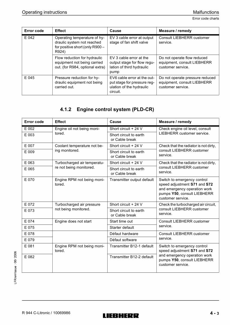
Operating instructions
R 944 C-Litronic / 10069986
Error code charts
4 - 3
Malfunctions
MJFCIFSS
4.1.2 Engine control system (PLD-CR)
E 042 Operating temperature of hy-
draulic system not reached
for positive short (only R900 �
R924)
EV 3 cable error at output
stage of fan shift valve
Consult LIEBHERR customer
service.
Flow reduction for hydraulic
equipment not being carried
out. (for R984, optional extra)
EV 3 cable error at the
output stage for flow regu-
lation of third hydraulic
pump
Do not operate flow reduced
equipment, consult LIEBHERR
customer service.
E 045 Pressure reduction for hy-
draulic equipment not being
carried out.
EV6 cable error at the out-
put stage for pressure reg-
ulation of the hydraulic
circuit.
Do not operate pressure reduced
equipment, consult LIEBHERR
customer service.
Error code Effect Cause Measure / remedy
Error code Effect Cause Measure / remedy
E 002 Engine oil not being moni-
tored.
Short circuit + 24 V Check engine oil level, consult
LIEBHERR customer service.E 003 Short circuit to earth
or Cable break
E 007 Coolant temperature not be-
ing monitored.
Short circuit + 24 V Check that the radiator is not dirty,
consult LIEBHERR customer
service.E 009 Short circuit to earth
or Cable break
E 063 Turbocharged air temperatu-
re not being monitored.
Short circuit + 24 V Check that the radiator is not dirty,
consult LIEBHERR customer
service.E 065 Short circuit to earth
or Cable break
E 070 Engine RPM not being moni-
tored.
Transmitter output default Switch to emergency control
speed adjustment S71 and S72
and emergency operation work
pumps Y50, consult LIEBHERR
customer service.
E 072 Turbocharged air pressure
not being monitored.
Short circuit + 24 V Check the turbocharged air circuit,
consult LIEBHERR customer
service.E 073 Short circuit to earth
or Cable break
E 074 Engine does not start Start time out Consult LIEBHERR customer
service.E 075 Starter default
E 078 Défaut hardware Consult LIEBHERR customer
service.E 079 Défaut software
E 081 Engine RPM not being moni-
tored.
Transmitter B12-1 default Switch to emergency control
speed adjustment S71 and S72
and emergency operation work
pumps Y50, consult LIEBHERR
customer service.
E 082 Transmitter B12-2 default

Malfunctions
4 - 4
Operating instructions
Error code charts
R 944 C-Litronic / 10069986
MJFCIFSS
E 084 Cold start command default Unit 1 of cold start com-
mand over current
Consult LIEBHERR customer
service.
E 085 Unit 1 of cold start com-
mand default
E 086 Open load for Unit 1 of
cold start command
E 087 Engine RPM not being moni-
tored.
The values registered by
the transmitters B12-1
and B12-2 are different.
Switch to emergency control
speed adjustment S71 and S72
and emergency operation work
pumps Y50, consult LIEBHERR
customer service.
E 088 Atmospheric pressure not be-
ing monitored.
Short circuit + 24 V or
short circuit to earth or ca-
ble break
Consult LIEBHERR customer
service.
E 089 Water in fuel filter not being
monitored.
Engine does not start
Short circuit + 24 V or
short circuit to earth or ca-
ble break
Consult LIEBHERR customer
service.
E 090 Fuel temperature not being
monitored.
Short circuit to earth Consult LIEBHERR customer
service.E 091 Short circuit + 24 V or ca-
ble break
E 092 Fuel pressure not being mon-
itored.
Short circuit + 24 V Consult LIEBHERR customer
service.E 093 Short circuit to earth or ca-
ble break
E 094 Fuel pressure in rail 1 not be-
ing monitored.
Short circuit + 24 V Consult LIEBHERR customer
service.E 095 Short circuit to earth or ca-
ble break
E 096 Fuel pressure in rail 2 not be-
ing monitored.
Short circuit + 24 V Consult LIEBHERR customer
service.E 097 Short circuit to earth or ca-
ble break
E 098 D+ default on the alterna-
tor
Consult LIEBHERR customer
service.
E 099 Alternator default
E 100 Engine RPM not being moni-
tored.
The value registered by
the transmitter B12-1 is
impossible.
Switch to emergency control
speed adjustment S71 and S72
and emergency operation work
pumps Y50, consult LIEBHERR
customer service.
E 101 Engine RPM not being moni-
tored.
The value registered by
the transmitter B12-2 is
impossible.
Switch to emergency control
speed adjustment S71 and S72
and emergency operation work
pumps Y50, consult LIEBHERR
customer service.
E 102 Engine can not be started. Cranckshaft synchronisa-
tion default
Consult LIEBHERR customer
service.
E 103 Camshaft transmitter de-
fault
Consult LIEBHERR customer
service.
E 104 The value registered by
the camshaft transmitter
is impossible.
Consult LIEBHERR customer
service.
Error code Effect Cause Measure / remedy

Operating instructions
R 944 C-Litronic / 10069986
Error code charts
4 - 5
Malfunctions
MJFCIFSS
E 105 Engine can not be started. Camshaft synchronisation Consult LIEBHERR customer
service.
E 106 Cold start command default Unit 2 of cold start com-
mand over current
Consult LIEBHERR customer
service.
E 107 Unit 2 of cold start com-
mand default
E 108 Open load for Unit 2 of
cold start command
E 109 Hardware CAN1 default Consult LIEBHERR customer
service.E 110 CAN1 data impossible or
time out
E 111 Injector A1 default Consult LIEBHERR customer
service.E 112 Injector A1 error BIP /
FZM
E 113 Injector A2 default Consult LIEBHERR customer
service.E 114 Injector A2 error BIP /
FZM
E 115 Injector A3 default Consult LIEBHERR customer
service.E 116 Injector A3 error BIP /
FZM
E 117 Injector A4 default Consult LIEBHERR customer
service.E 118 Injector A4 error BIP /
FZM
E 119 Injector B1 default Consult LIEBHERR customer
service.E 120 Injector B1 error BIP /
FZM
E 121 Injector B2 default Consult LIEBHERR customer
service.E 122 Injector B2 error BIP /
FZM
E 123 Injector B3 default Consult LIEBHERR customer
service.E 124 Injector B3 error BIP /
FZM
E 125 Injector B4 default Consult LIEBHERR customer
service.E 126 Injector B4 error BIP /
FZM
E 127 Parameter default bank A Consult LIEBHERR customer
service.E 128 Parameter default bank B
E 129 Fuel pressure in rail 1 not be-
ing monitored.
Short circuit to earth or ca-
ble break
Consult LIEBHERR customer
service.
E 130 Short circuit + 24 V
E 131 Incoherent signal
E 132 Fuel pressure in rail 2 not be-
ing monitored.
Short circuit to earth or ca-
ble break
Consult LIEBHERR customer
service.
E 133 Short circuit + 24 V
E 134 Incoherent signal
Error code Effect Cause Measure / remedy

Malfunctions
4 - 6
Operating instructions
Error code charts
R 944 C-Litronic / 10069986
MJFCIFSS
4.1.3 Keypad
4.1.4 Display
E 135 Circuit 5 Volt - REF1 Consult LIEBHERR customer
service.E 136 Circuit 5 Volt - REF2
E 137 Circuit 5 Volt - REF3
E 138 Circuit 5 Volt - REF4
Error code Effect Cause Measure / remedy
Error code Effect Cause Measure / remedy
E 302 No entry possible using key-
pad
No coding plug Consult LIEBHERR customer
service.
E 303 Diesel engine speed cannot
be adjusted using keypad,
hydraulic power is reduced.
No CAN bus connection be-
tween keypad and BST plate
(message also appears if bus
arbiter not operating, e g. if
no power supply is present).
Switch to emergency control
speed adjustment S71 and
S72 and emergency opera-
tion work pumps Y50, consult
LIEBHERR customer service.
E 305 Malfunctions, e g. swing gear
brake, servo control
No CAN bus connection be-
tween keypad and ESP01
board (message also ap-
pears if ESP01 not operat-
ing).
Switch to emergency switch-
ing of servo pressure circuits
S73, consult LIEBHERR cus-
tomer service.
E 307 No CAN bus connection be-
tween keypad and engine
control system PLD
Switch to emergency control
speed adjustment S71 and
S72 and emergency opera-
tion work pumps Y50, consult
LIEBHERR customer service.
E 310 For boring excavators, Hard-
ware coding and software co-
ding are not in concordance.
Consult LIEBHERR customer
service.
E 314 Time out for CAN bus con-
nection between keypad and
engine control system PLD
Consult LIEBHERR customer
service.
Error code Effect Cause Measure / remedy
E 308 No display or incorrect dis-
play on screen
No connection keypad /
screen or keypad not operat-
ing
Consult LIEBHERR customer
service.
E 309 No Software compatibility be-
tween screen and keypad

Operating instructions
R 944 C-Litronic / 10069986
Error code charts
4 - 7
Malfunctions
MJFCIFSS
4.1.5 Coding error
4.1.6 Other errors
4.1.7 Error due to warning symbols in SY field
These error codes will not be displayed in the EC field of the operator�s menu. They
can only be read off the S-Exxx menu list.
Error code Effect Cause Measure / remedy
E 319 Diesel engine speed cannot
be adjusted using keypad, re-
duced hydraulic power.
Hardware coding not suited
to software coding
Switch to emergency control
speed adjustment S71 and
S72 and emergency opera-
tion work pumps Y50, consult
LIEBHERR customer service.
E 321 Keypad has not received a
recognised machine type.
E 322 Unknown hardware coding
Error code Effect Cause Measure / remedy
E 442 Automatic idling on left joy-
stick does not function, i.e.
the engine remains at low
speed.
Short circuit + 24 V Deactivate automatic idling
S20, consult LIEBHERR cus-
tomer service.E 443 Short circuit to earth or cable
break
E 445 Automatic idling on right joy-
stick does not function, i.e.
the engine remains at low
speed.
Short circuit + 24 V Deactivate automatic idling
S20, consult LIEBHERR cus-
tomer service.E 446 Short circuit to earth or cable
break
E 450 The pressure for pressure-
less boom down movement
not being monitored.
Wiring default;
Current < 3mA or > 21 mA
Consult LIEBHERR customer
service.
E 454 Swing use cannot be record-
ed
Short circuit + 24 V Consult LIEBHERR customer
service.E 455 Short circuit to earth or cable
break
E 456 Incorrect fuel gauge. Short circuit + 24 V Check fuel level visually, con-
sult LIEBHERR customer
service.E 458 Short circuit to earth or cable
break
E 601 Connection default for plate
ESP01
Consult LIEBHERR customer
service.
Error code Effect Cause Measure / remedy
E 501 H2 telltale light illuminates
Buzzer sounds
Diesel engine pressure too
low - warning level
See telltale light description.
E 502 Symbol appears
Buzzer sounds
Coolant level low See symbol description
E 503 Symbol appears
Engine power reduction
Buzzer sounds
Coolant overheating - war-
ning level
See symbol description
E 504 Symbol appears Hydraulic oil level low See symbol description
E 505 Symbol appears Hydraulic oil overheating See symbol description

Malfunctions
4 - 8
Operating instructions
Error code charts
R 944 C-Litronic / 10069986
MJFCIFSS
E 506 Symbol appears Splitterbox oil temperature
too high (from R954)
See symbol description
E 511 Symbol appears Overvoltage See symbol description
E 512 Symbol appears Undervoltage for system DC
(Diesel control)
Voir la description des sym-
boles
E 513 Symbol appears Overvoltage for system DC
(Diesel control)
See symbol description
E 516 Symbol appears
Engine safety shut off
Safety shut off for EDC de-
fault
See symbol description
E 517 Symbol appears
Engine safety shut off
Safety shut off for injector de-
fault
See symbol description
E 518 Symbol appears
Engine safety shut off
Safety shut off for synchroni-
sation default
See symbol description
E 519 Symbol appears RPM too high - Warning level See symbol description
E 520 Symbol appears
Engine safety shut off
RPM too high - Safety level See symbol description
E 521 Symbol appears
Engine safety shut off
Both RPM transmitters de-
fault
See symbol description
E 522 Symbol appears
Buzzer sounds
Engine oil pressure too low -
Safety level
See symbol description
E 523 Symbol appears
Buzzer sounds
Coolant temperature too high
- Safety level
See symbol description
E 524 Symbol appears
Buzzer sounds
Turbocharged air temperatu-
re too high - Safety level
See symbol description
E 525 Symbol appears
Buzzer sounds
LED H60 illuminates
Engine in safety mode See symbol description
E 526 Symbol appears Fuel temperature too high -
Warning level
See symbol description
E 527 Symbol appears Fuel temperature too high -
Safety level
See symbol description
E 528 Symbol appears Water in fuel filter See symbol description
E 530 Symbol appears Synchronised safety shut off See symbol description
E 532 Symbol appears Fuel pressure too low - War-
ning level
See symbol description
E 533 Symbol appears Fuel pressure too low - Safety
level
See symbol description
E 534 Symbol appears Fuel pressure too high - War-
ning level
See symbol description
E 535 Symbol appears Fuel pressure too high - Sa-
fety level
See symbol description
E 536 Symbol appears Fuel pressure too low in rail 1
- Warning level
See symbol description
E 537 Symbol appears Fuel pressure too low in rail 1
- Safety level
See symbol description
E 538 Symbol appears Fuel pressure too low in rail 2
- Warning level
See symbol description
Error code Effect Cause Measure / remedy

Operating instructions
R 944 C-Litronic / 10069986
Faults and remedies
4 - 9
Malfunctions
MJFCIFSS
4.2 Faults and remedies
4.2.1 Diesel engine and fuel system
E 539 Symbol appears Fuel pressure too low in rail 2
- Safety level
See symbol description
E 597 Symbol appears
Engine power reduction
Buzzer sounds
Turbocharged air temperatu-
re too high - Warning level
See symbol description
Error code Effect Cause Measure / remedy
Fault / error Cause Solution
Diesel engine does not start Fuel tank almost or completely emp-
ty
Fill tank and vent fuel system
Low pressure in tank Remove fuel filler cap
Fuel filter dirty Clean or change filter and vent fuel
system, drain fuel / clean tank
Outside temperature below 0°C For operation under specific climatic
conditions, see operating instruc-
tions
Starter motor not drawing through Check line connections, overhaul
starter motor
Batteries have no power Charge / replace
Engine starts but stops immediately
after or runs irregularly
Fuel tank empty (low pressure in
tank)
Fill tank and vent fuel system
Fuel filter dirty Clean or change filter and vent fuel
system (tank)
Particularly in winter: too viscous
engine oil used
Use engine oil suitable for the outsi-
de temperature
Dry-air filter dirty Clean or change main filter element
Air in fuel system Vent fuel system
Ventilation in fuel tank obstructed Clean
Fuel line bent Check line and repair if required
Diesel engine emitting grey or black
smoke
Dry-air filter dirty Clean or change filter
Diesel engine continually emitting
while smoke (steam)
Water in combustion chamber Consult customer service
Diesel engine does not reach full
speed
Speed adjustment not set to maxi-
mum value
Set speed adjustment to maximum
value
Injection system is set incorrectly Consult customer service
Dry-air filter dirty Clean or replace filter
Bad fuel supply Clean or change fuel filter, check
lines, drain water from tank

Malfunctions
4 - 10
Operating instructions
Faults and remedies
R 944 C-Litronic / 10069986
MJFCIFSS
4.2.2 Hydraulic system
Diesel engine becomes too hot Too little coolant Fill coolant, check for leaks
Water pump defective Repair
Thermostats do not work Change thermostats
Coolant contaminated Clean coolant
Diesel engine has insufficient oil
pressure
Note!
Switch off diesel engine immedia-
tely
Oil level too low Correct oil level
Oil pressure display faulty Change oil pressure switch
Diesel engine consumes too much
oil
External leak on diesel engine Retighten screws, replace seals if
required
Oil in coolant or coolant in oil Consult customer service
Unusual noise / sounddevelopment
on exhaust side
Exhaust system leaking Check exhaust system / repair
Fault / error Cause Solution
Fault / error Cause Solution
Unusual noise / sounddevelopment
at hydraulic pumps
Note!
Switch off diesel engine immedia-
tely
Shutoff valve on hydraulic tank
closed
Open stop cock
Hydraulic pumps taking in air Check oil level in hydraulic tank,
check intake lines for leaks
Modes E and P showing lack of
power
No power adjustment via proportio-
nal solenoid valve Y50
Unplug cable of Y50 connection, re-
move safety cotter pin, move lever
to emergency setting
Hydraulic oil temperature too high Coolant contaminated Clean coolant
Fan or fan control defective Rectify error / consult customer ser-
vice
Hydraulic oil level too low Oil loss Repair leaks, exchange hoses, refill
oil via return-line filter
Cannot drive Push the safety lever up Push the safety lever down
No direction of travel preselected Use drive selection switch in right
joystick to determine direction of tra-
vel
Parking brake pressure switch de-
fective
Consult customer service
Parking brake not released Release parking brake using switch
Parking brake will not release despi-
te switch being operated
Servo pressure present:
Operate emergency function Y6
Servo pressure not present:
Consult customer service
Service brake engaged Release service brake

Operating instructions
R 944 C-Litronic / 10069986
Faults and remedies
4 - 11
Malfunctions
MJFCIFSS
4.2.3 Transmission
4.2.4 Electrical system
Slewing gear not functioning No servo control Push the safety lever down
Switch on servo control
Slewing gear brake activated Push the safety lever down
Release slewing gear brake
No working movement No servo control Push the safety lever down
Switch on servo control
No servo pressure present Consult customer service
No pump high pressure present Consult customer service
Fault / error Cause Solution
Fault / error Cause Solution
Oil flowing out on track rollers, sup-
port rollers or leading wheel
Seal defective Replace seal
Insufficient crawler tracking on lea-
ding wheel
Leading wheel tracking on track rol-
ler mounting has too much play
Adjust the leading wheel tracking
play
Crawler jumps off or over Crawler tension too low / crawler
wheel worn
Adjust crawler tension
Correctly tensioned crawler losing
tension quickly during use
Crawler tensioning cylinder defecti-
ve
Check crawler tensioning cylinder,
change if required or seal (only
authorized specialist personnel)
Track roller or support roller sticking Running gear extremely dirty Clean running gear
Fault / error Cause Solution
Battery charge telltale light does not
goes out
Drive belt for alternator loose or torn Tension or replace drive belt
Alternator defective Replace alternator
Batteries do not charge or charge
poorly
Batteries defective Replace batteries
Battery connections dirty / oxidised Clean battery connections
Cable loose or damaged Connect or replace cable
Telltale light or display instrument
not functioning or functioning incor-
rectly
Bulb burnt out, display instrument
defective
Replace defective part
Some or all functions on instrument
panel drop out
Plug connector separated or dama-
ged, earth lead interrupted, short
circuit fuse defective
Mount plug connector correctly or
change, rectify short circuit, replace
fuse or activate overload cut-outs

Malfunctions
4 - 12
Operating instructions
Faults and remedies
R 944 C-Litronic / 10069986
MJFCIFSS
4.2.5 Heating/air-conditioning system
4.2.6 Work equipment
Diesel speed adjustment via opera-
ting keypad (mode and arrow keys)
not functioning
Automatic idling switch S20 is acti-
vated
Touch the joystick or deactivate
automatic idling switch S20.
Excavator speed adjustment elec-
tronics do not function
Switch the emergency function over
from �AUTO� to �MANU� using
switch S71 in the right control panel.
Set speed using switch S72. Emer-
gency function display appears on
monitoring screen. Consult custo-
mer service.
No signal emits from speed sensor
B12
Automatic idling not functioning,
speed does not reduce
Permanent sensor signal Consult customer service
Switch S20 is deactivated Activate switch S20
Servo control cannot be activated
using switch
Excavator electrics faulty Switch on emergency function using
switch S73 in the right control panel
Caution: Servo circuit and brake cir-
cuit can only be switched off using
the safety lever. Keypad not functio-
ning. Consult customer service.
Parking brake cannot be released
using switch
Slewing gear brake cannot be re-
leased using switch
Fault / error Cause Solution
Fault / error Cause Solution
Heating not giving out warm air Shutoff valves for coolant line on
diesel engine closed
Open shutoff valve
Engine not at operating temperature Bring engine to operating tempera-
ture
Heating fan does not operate No power supply Check fuse and wiring / repair
Fan motor defective Change fan motor
Only low air flow in cab Outside air filter / recirculated air fil-
ter dirty
Clean air intake opening, replace
outside air filter
Air vent closed Open air vent
Fault / error Cause Solution
Cylinder stretches when loaded Piston seal in cylinder defective Overhaul cylinder
Bearing clearance too high on equi-
pment
Bearing points worn out Replace bearing parts
Grab / bucket does not move Valve block on tilting cylinder incor-
rectly switched
Switch over valve block
Add-on unit cannot be turned / rota-
ted / operated
Auxiliary function has not been re-
leased
Release auxiliary function using
switch S19
Lines are not connected Connect lines

Operating instructions
R 944 C-Litronic / 10069986
Fuses and relays
4 - 13
Malfunctions
MJFCIFSS
4.3 Fuses and relays
4.3.1 Fuse box E50
Fig. 4-2 Fuse box E50
Fuse box E50 is located behind the left side door, above the batteries.
F19 100 A Circuit breaker preheating

Malfunctions
4 - 14
Operating instructions
Fuses and relays
R 944 C-Litronic / 10069986
MJFCIFSS
4.3.2 A1010 Plate
All other fuses are situated in the left control panel of the operator�s standing position.
If required, order replacement fuses from LIEBHERR.
F20 50 A Main circuit breaker
F22 7,5 A Fuse for hazard warning system (auto excavator)
F31 7,5 A Fuse for air conditioning system, terminal 15
F33 7,5 A Fuse for refuelling pump (optional extra)
F34 Reserve
F35 Reserve
F36 20 A Fuse for refuelling pump (optional extra)
F36-2 15 A Fuse for cylinder control stop (optional extra)
F37 20 A Fuse for air conditioning system, terminal 30
F109 50 A Head lights circuit breaker
F110 50 A PLD system circuit breaker , terminal 15 and 30
F115 7,5 A Fuse for safety mode
F116 7,5 A Fuse for PLD system, PS2
F117 7,5 A Fuse for PLD system, terminal 15
F122 7,5 A Fuse for preheating signal
F133 Fuse for hydr. adjustable cab (optional extra)
F253 25 A Fuse for attachment headlights (optional extra)
K66-1 Relay for option cylinder control stop
K66-2 Relay for option cylinder control stop
K127 Relay for engine rpm in safety mode
K128 Relay for engine start in safety mode
K288 Main relay terminal 15
K302 Preheating relay
K415 20 A Relay for attachment headlights (optional extra)
Danger
Incorrect or bypassed fuses do not offer the machine's operator or the electrical
system the required degree of protection.
Only use original fuses.
Never bypass electrical fuses.

Operating instructions
R 944 C-Litronic / 10069986
Fuses and relays
4 - 15
Malfunctions
MJFCIFSS
Fig. 4-3 Fuses and relays, A1010 plate
F1 15 A Reserve
F2 15 A Reserve
F3 15 A Reserve
F4 15 A Windscreen washing system, windscreen wiper system,
preheating system control circuit, rotating beacon*,
slewing grab*
F5 7,5 A Windscreen wiper motor
F6 7,5 A Speed adjustment in �MANU� control
F7 7,5 A Control unit and display
F8 15 A Safety lever, solenoid valve for servo control, swing gear
brake, fast drive, pressure cut in stage boom
F9 15 A Engine throttle control, BST power supply
F10 25 A Working headlight, Rotating deck headlights, additional
headlights*
F11 15 A Reserve

Malfunctions
4 - 16
Operating instructions
Fuses and relays
R 944 C-Litronic / 10069986
MJFCIFSS
* en option
F12 15 A Reserve
F13 7,5 A Contact key, starting circuit, voltage transformer, Radio*,
loudspeaker*, engine stop* (for engine oil low pressure or
low coolant level)
F14 15 A Interior lighting, cigarette lighter, signal horn
F15 15 A Reserve
K5 Relay emergency control servo function, engine stop*
(for engine oil low pressure or low coolant level)
K6 Horn relay
K7 Relay for additional headlights on cab roof
K8 Floating position relay

Operating instructions
R 944 C-Litronic / 10069986
Servicing the machine safely
5 - 1
Maintenance
MJFCIFSS
5 Maintenance
5.1 Servicing the machine safely
5.1.1 General safety instructions
� Maintenance and repair work may only be carried out by specially trained person-
nel.
� Observe statutory timetables or intervals given in the operating instructions for re-
peat tests / inspections. It is imperative that a suitably equipped workshop is
available in order to carry out maintenance work.
� The inspection and maintenance schedule given at the end of these operating
instructions defines precisely who is required / permitted to carry out what work.
Jobs listed as daily / weekly work may be carried out by the machine's driver or
maintenance personnel when they have received appropriate instruction.
The remaining work may only be carried out by specialist personnel with appro-
priate training.
� Replacement parts must correspond to the technical requirements determined by
the manufacturer. Original replacement parts are always guaranteed to meet the-
se criteria.
� Wear safe work clothes when carrying out maintenance work. Protective glasses
and gloves are required in addition to a hardhat and safety shoes for some work.
� Do not permit unauthorised persons to approach the machine during maintenan-
ce work.
� Cordon off a wide maintenance area if required.
� Inform operational personnel before starting to carry out any special work and re-
pair work. Designate persons in charge of supervision.
� In the absence of any other information in the operating instructions, carry out all
maintenance work on the machine on level, firm ground with the working equip-
ment set aside and the engine switched off.
� Pull out the ignition key and shut off the main battery switch.
� Always tighten any loose screw connections during maintenance and repair work.
� If safety devices have to be dismantled during set-up, maintenance and repair
work, they must be immediately reinstalled and checked at the end of the work.
� When carrying out repair work, particularly when working under the machine,
hang a �Do not start� warning sign in a clearly visible position on the starting lock.
Pull out the start key and shut off the main battery switch.
� Operate combustion motors and fuel operated heaters only in well ventilated
areas. Before operating these units, check ventilation.
� In addition, always follow applicable local regulations.
5.1.2 Cleaning
� Clean oil, fuel or care products off the machine before starting maintenance or re-
pair work and pay particular attention to connections and screw fittings.
Do not use aggressive cleaning products and use lint-free cleaning cloths.
� Do not use aggressive cleaning products or steam jet devices to clean the machi-
ne for the first two months after initial set-up of the machine (or after repainting).

Maintenance
5 - 2
Operating instructions
Servicing the machine safely
R 944 C-Litronic / 10069986
MJFCIFSS
� Do not use combustible liquids to clean the machine.
� Before cleaning the machine with water or steam jets (high pressure cleaner) or
other cleaning materials:
� lubricate all bearing points, bolt connections and the rim bearing to prevent wa-
ter or steam entering the bearing points.
� cover or glue shut all openings into which for safety or functional reasons water
or steam may not be permitted to enter.
Electric motors, electrical components, control boxes, plug connections and air
filters are particularly at risk.
� Ensure that the fire warning systems and fire extinguishers of the engine compart-
ment�s temperature sensor do not come into contact with hot cleaning products
during cleaning work.
The fire extinguisher could start.
� If you use a high pressure cleaner with steam or hot water to clean the machine,
observe following recommendations :
� the distance between the nozzle and the surface to be cleaned must be no lower
than 20 inches
� the water temperature should not exceed 60°c (140°F)
� limit the water pressure to 80 bar maximum (11500 PSI)
� if you employ cleaning fluid, only use neutral cleaning agents such as customary
car shampoos diluted to 2 or 3 percent maximum
� After cleaning:
� remove all covers completely.
� check all fuel, engine oil and hydraulic lines for leakage, loosened connections,
chafing and damage.
� rectify any defects found immediately.
� lubricate all bearing points, bolt connections and the rim bearing to displace any
water or cleaning products that may have entered.
5.1.3 Crack testing
� Even when the machine is operated carefully, there is a possibility of individual
cases of overloading occurring, which could lead to cracks or loose connections.
The machine should therefore be checked regularly for cracks, loose connections
or other visible damage to maintain operational safety.
� In order to be able to check for cracks, it is essential that the machine is kept clean
and cleaned regularly.
� The tests should be carried out in accordance with the monitoring and maintenan-
ce plan:
� every 250 operating hours by the machine owner�s maintenance personnel.
� every 500 operating hours by authorised specialist personnel.
� It is advisable to carry out these tests: supported, on firm, horizontal substrate,
with the equipment in longitudinal and cross direction for variable loads. Current
accident prevention regulations must be adhered to.
� Special care must be taken when testing load-bearing components, particularly:
� the steel chassis members and axle and transmission mountings, the support,
the lower rim bearing support and tower and ball rim bearing.
� the steel upper structure members and bearing block for boom and boom cylin-
der, the upper rim bearing support, the cab mount and the mount for swing gear
and ballast.
� the steel components of the working equipment, e. g. the boom, stay, quick
change adaptor, and bucket.
� hydraulic cylinders, axles, steering, bolts and bolt connections, steps, ladders
and mounting elements.

Operating instructions
R 944 C-Litronic / 10069986
Servicing the machine safely
5 - 3
Maintenance
MJFCIFSS
� The crack test should be carried out visually. If a crack is suspected, the dye pe-
netration test should be carried out as a crack test on areas which do not have
good visibility, such as the rim bearing support, in order to increase testing safety.
� Any damage found must be rectified immediately. Welding work on load-bearing
parts of the earth-moving machinery, loading devices and transport devices may
only be carried out by trained specialist personnel and only in accordance with the
accepted rules of welding engineering. In case of doubt, contact the LIEBHERR
customer support service to discuss suitable remedies.
5.1.4 Welding, drilling, firing and grinding work
� Any welding on structural parts (as undercarriage, uppercarriage, equipment
parts,�) may only be done the manufacturer, or authorized official dealer. If this
rule is neglected, the warranty is voided.
� Only carry out welding, drilling, firing and grinding work on the machine with ex-
press authorization. Clean dust and combustible materials off the machine and its
surrounding areas before welding, drilling, firing or grinding.
Ensure adequate ventilation. Risk of fire or explosion.
� Before welding repairs on other parts, always disconnect the battery. Always re-
move the negative terminal first and reconnect it last.
� Nevertheless if welding repair should be done on components which may contain
inflammable gases (welded counterweight, hydraulic tank, fuel tank, �), these
components must be previously and sufficiently ventilated with pressurized air to
avoid all fire or explosion hazard
� Before welding, connect the ground cable as close as possible to the welding
point, so the welding current will not run through the swing ring, joints, gears, bu-
shings, rubber parts and seals
5.1.5 Process materials
� When working with oils, greases and other chemical substances, observe the ap-
propriate current safety regulations for the product.
� Ensure that process materials and replacement parts are disposed of in a safe
and environmentally acceptable manner.
� Take care when handling hot process materials
(Risk of burning and scalding).
5.1.6 Repair work
� Do not attempt to lift heavy parts. Use devices which are suitable for this purpose
and which have sufficient load capacity. When replacing single parts and larger
subassemblies, carefully secure them on lifting devices them so that they do not
present a risk. Only use suitable and correctly functioning lifting devices and load
take-up devices with adequate load capacity.
Do not stand or work under swinging loads.
� Do not use lifting devices which are damaged or do not have sufficient load
carrying capacity.
Wear work gloves when working with wire cables.
� Only permit experienced personnel to attach loads and give signals to the crane
operator. The spotter must be positioned within the visual range of the operator
or be in voice contact with him.
Maintenance
5 - 4
Operating instructions
Servicing the machine safely
R 944 C-Litronic / 10069986
MJFCIFSS
� When working above body height, use safe climbing devices and working plat-
forms which are appropriate for the job.
Do not use machine parts as climbing devices if they are not designed for this
purpose.
When working at height, wear a harness to prevent falling.
Ensure that all grips, steps, rails, platforms and ladders are free of dirt, snow and
ice.
� Be sure to support yourself safely when working on the equipment (e.g. replacing
teeth). Prevent metal touching metal when doing this.
� For safety reasons, never open and remove a track chain unless having previous-
ly totally released the pretension of the chain tensioning unit.
� Never lay under the machine if it is raised with work equipment and has not been
securely supported with wooden beams.
� Always jack the machine up in such a way that any weight displacement does not
jeopardize stability and prevent metal touching metal while doing this.
� Work on the suspension, brake and steering systems may only be carried out by
trained specialist personnel.
� If the machine has to be repaired on a slope, secure the crawler with chocks and
connect the upper structure to the chassis using stop bolts.
� Only personnel with special training and experience may work on hydraulic equi-
pment.
� When searching for leakage, wear protective gloves. A fine jet of liquid under
pressure can penetrate the skin.
� Do not unscrew any lines or connections before you have set aside the equip-
ment, switched off the engine and depressurized the hydraulic system. After swit-
ching off the engine, you must operate all pilot control devices (joystick and
pedals) in all directions with the start key in contact position in order to reduce the
actuating and dynamic pressures in the work circuits. You must then reduce the
internal tank pressure as described in these operating instructions.
5.1.7 Electrical system
� Check the electrical system regularly.
Have all faults, such as loose connections, blown fuses and lamps and clogged
or abraded cables rectified by personnel.
� Only use original fuses with approved current strength.
� For machines with electrical neutral and high tension leads:
� switch the machine off immediately in the event of malfunctions in the power
supply.
� Work on the machine�s electrical equipment may only be carried out by skilled
electrical personnel or by trained personnel under the supervision of an electri-
cian in accordance with electrical regulations.
� When working on live parts, ensure that a second person is available to operate
the emergency-off or the main switch and overvoltage release. Cordon off the
working area with a red and white safety chain and a warning sign. Only use in-
sulated tools.
� When working on neutral and high tension subassemblies, after releasing the vol-
tage, briefly disconnect the supply cable at earth and electronic devices such as
capacitors using an earthing rod.
� First test the released parts to make sure that they are off circuit, earth them and
then disconnect them briefly. Insulate adjacent live parts.
� Disconnect the battery before working on the electrical system or carrying out any
electric arc welding on the machine.

Operating instructions
R 944 C-Litronic / 10069986
Servicing the machine safely
5 - 5
Maintenance
MJFCIFSS
First disconnect the negative, then the positive pole. When reconnecting, proceed
in the reverse order.
5.1.8 Hydraulic accumulator
� All work on the hydraulic accumulators must be carried out by trained specialist
personnel.
� Inexpert assembly and handling of hydraulic accumulators can cause serious ac-
cidents.
� Do not operate damaged hydraulic accumulators.
� Before working on a hydraulic accumulator, you must reduce the pressure in the
hydraulic system (hydraulic system including hydraulic tank), as described in the-
se operating instructions.
� Do not carry out welding or soldering or do any mechanical work on the hydraulic
accumulator.
The hydraulic accumulator can be damaged by heat penetration and can be
made to rupture by mechanical working. RISK OF EXPLOSION!
� Only charge the hydraulic accumulator with nitrogen. There is a RISK OF EX-
PLOSION if oxygen or air is used.
� The accumulator body can become hot during operation; there is a risk of burning.
� New hydraulic accumulators must be charged with the pressure required for the
purpose of use before installation.
� The operating data (minimum and maximum pressure) are marked permanently
on hydraulic accumulators. Ensure that this marking remains visible.
5.1.9 Hydraulic hoses and sheathed cables.
� It is forbidden to carry out repair work on hydraulic hoses and sheathed cables!
� All hoses, sheathed cables and bolt connections must be checked regularly every
2 weeks for externally visible damage and any possible damage must be imme-
diately checked for leakage.
Never check for leaks with your bare hands, use a sheet of paper or something
else.
Any damaged parts must be removed immediately! Spurting oil can lead to injury
and burns.
� Even with correct storage and permitted load, hoses and sheathed cables are
subject to the natural aging process. This restricts their duration of use.
� Incorrect storage, mechanical damage and unauthorized load are the most
common causes of failure.
� In relation to duration of use, current norms, regulations and guidelines pertai-
ning to hoses and sheathed cables at place of use must be adhered to.
� Use at the limit range of permissible load can shorten duration of use (e.g. high
temperatures, frequent movement cycles, extremely high pulse frequencies,
multiple shift usage).
� Hoses and sheathed cables should be replaced if the following are found during
inspection:
� Damage to the outer sheath as far as the liner (e.g. chafing, cuts and cracks);
� Brittleness of the outer sheath (fracture formation in hose material);
� Deformations which do not correspond to the natural form of the hose or shea-
thed cable, whether in a unpressurized or pressurized state or on bends e.g.
sheath separation, blistering;
� Unsealed areas;

Maintenance
5 - 6
Operating instructions
Maintenance access doors
R 944 C-Litronic / 10069986
MJFCIFSS
� Non-adherence to requirements during installation;
� Damage or deformations to the hose fittings which reduce the tightness of the
fittings or the hose / fitting connection;
� Hoses working themselves out of the fittings;
� Corrosion of the fittings which reduces function and tightness;
� When replacing hoses and sheathed cables, use only original replacement parts.
� Install and mount hoses and sheathed cables correctly. Do not mix up the con-
nections.
� The following is to be noted when replacing hoses and sheathed cables:
� Always ensure that the hoses and sheathed cables are installed free of torsion.
For high-pressure hoses, the screws from the half-clamps or full flange must
always be attached to both hose ends and should only be tightened afterwards.
� When tightening the flange on high-pressure hoses and sheathed cables with
bent fittings, the side with the bent fitting must always be tightened first and then
the side with the straight fitting tightened afterwards.
� Any mounting clamps which are located in the centre of the hose may only be
attached and tightened subsequently.
� Check daily to ensure that all clamps, covers and protective devices are proper-
ly fastened. Doing this will prevent vibration and damage during operation.
� Install the hoses and sheathed cables in such a way that they cannot chafe on
other hoses, sheathed cables or parts.
� A minimum distance from other parts of approx. half the exterior diameter of the
hose is recommended. The distance should not, however, be less than 10 to
15 mm.
� When replacing the hoses or sheathed cables on moving parts (e.g. from the
boom to the stay), check before initial start-up that there are no chafing areas
in the entire area of movement.
5.2 Maintenance access doors
5.2.1 Overview of access doors
Fig. 5-1 Access doors on the machine

Operating instructions
R 944 C-Litronic / 10069986
Maintenance access doors
5 - 7
Maintenance
MJFCIFSS
The machine has 6 access doors for maintenance. The locks integrated in the han-
dles must be unlocked before starting to drive.
Tab. 5-2 Access doors
10 Engine cover 120 Side door, left
60 Radiator cover 140 Side door, right
80 Right cover 220 Side door, front left
Caution!
Access doors can close accidentally and trap the operator or maintenance person-
nel.
When you have opened the access doors, latch them using the retainer.
Access door Lock Access to:
Engine cover Gas pressure spring,
auxiliary mechanical re-
tainer
� Diesel engine
Radiator cover Gas pressure spring � Radiator
Right cover Gas pressure spring � Dry air filter
� Control oil unit
� Hydraulic pump
Side door, left Mechanical retainer � Radiator
� Electrics box E50
� Batteries
� Main battery switch
Side door, right Mechanical retainer � Dry air filter
� Control oil unit
� Hydraulic pump
Side door, front left Mechanical retainer � Toolbox
� Stowing compartment
Tab. 5-1

Maintenance
5 - 8
Operating instructions
Lubricating and operating materials
R 944 C-Litronic / 10069986
MJFCIFSS
5.2.2 Door lock
Fig. 5-2 Door lock
To stop the access doors from moving unintentionally (eg. due to wind), open
them fully and allow the door lock (see arrow) to latch in.
5.3 Lubricating and operating materials
5.3.1 General information on changing lubricating and operating
materials
Note
The quantities given in the lubrication and operating material chart and on the lubri-
cation chart in the cab are only guide values.
After each oil change or refill, check the level in the relevant unit.
Note!
Adhering to regulations for lubrication, level checks and operating material changes
guarantees a high degree of reliability and a long service life for the machine.
It is particularly important to adhere to the intervals for oil changes and use the lu-
bricant quality indicated.
Note!
Cleanliness is of the utmost importance when changing oil.
Clean all filler plugs, filler covers and drain plugs and their surroundings before
opening.
For preference, drain off oil when it is at operating temperature.
Ensure that old oils are collected and disposed of in an environmentally accep-
table manner using the removable oil filter cartridges.

Operating instructions
R 944 C-Litronic / 10069986
Lubricating and operating materials
5 - 9
Maintenance
MJFCIFSS
Danger!
When checking and changing lubrication and operating materials, ensure that the
following precautions are adhered to:
Unless otherwise indicated, carry out all work on the machine on level, solid
ground and with the engine switched off.
Whenever you reach into the engine compartment, always secure the cover and
side doors against accidentally falling back or closing.
Only refuel the machine when the engine is switched off, do not smoke and
avoid naked flame.
Turn the main battery switch to position 0 (off) and remove the ignition key.

Maintenance
5 - 10
Operating instructions
Lubricating and operating materials
R 944 C-Litronic / 10069986
MJFCIFSS
5.3.2 Lubrication chart
Fig. 5-3 Lubrication chart - R 944 C-Litronic

Operating instructions
R 944 C-Litronic / 10069986
Lubricating and operating materials
5 - 11
Maintenance
MJFCIFSS
Tab. 5-3 Lubrication chart key
*Guide values
Symbol Display Quantity
(litres)*
Diesel engine 43,0
Hydraulic tank 625
Slewing gear transmission 8,0
Travelling gear transmission 2 x 4,5
Splitterbox 11,3
General oiling points
Check gear oil level
Check engine oil level
Check hydraulic oil level
Oil change
First oil change
Semi-automatic lubrication
Manual lubrication
Operating instructions

Maintenance
5 - 12
Operating instructions
Lubricating and operating materials
R 944 C-Litronic / 10069986
MJFCIFSS
5.3.3 Lubricant chart
Tab. 5-4 Lubricant chart
*CI = regulation lubricant for construction machines and vehicles according to the national German construction industry federation (see brochures in Bauverlag GmbH � Wiesbaden and Berlin, Notes on lubrication and operating materials charts).
** = Guide values
Designation Medium Symbol Classification Viscosity CI * Quantity
(litres)**
Diesel engine Engine oil API-CI-4, CH-4,
ACEA E4, E5, E7
SAE 5W40
SAE 10W30
SAE 10W40
SAE 15W30
SAE 15W40
EO 0540
EO 1030
EO 1040
EO 1540
43
Hydraulic tank Engine oil API-CD, CD + SF
ACEA E1, E3
Mercedes Benz
226 and 227
227.5, 228.1 and
228.3
SAE 10W
SAE 10W-30
SAE 10W-40
SAE 15W-40
SAE 20W-20
SAE 30W
EO 10
EO 1030
EO 1040
EO 1540
EO 20
EO 30
625
Swing gear
(as parking bra-
ke)
Transmission
oil
API-GL-5
MIL-L 2105 B, C or D
SAE 90 GO 90 8
Swing gear
(as positioning
swing brake)
Transmission
oil
API-GL-5
MIL-L 2104 C or D
MIL-L 2105 B
SAE 90 LS GO 90 LS 8
Travel gear Transmission
oil
API-GL-5
MIL-L 2105 B, C or D
SAE 90 GO 90 2 x 4,5
Splitterbox Transmission
oil
API-GL-5
MIL-L 2105 B, C or D
SAE 90 GO 90 11,3
Tracks and cor-
responding gea-
ring of swing
ring, equipment
mounting
Lubricating
grease
High pressure grease
KP2k or EP2
Consistency
2
NLGI Class
MPG-A -
Hinges, joints,
locks
Engine oil - - - - -
Rubber seal on
doors and trim
panels
Silicon spray
or talc
- - - - -

Operating instructions
R 944 C-Litronic / 10069986
Lubricating and operating material specifications
5 - 13
Maintenance
MJFCIFSS
5.3.4 Operating material chart
Tab. 5-5 Operating material chart
* = Guide values
5.4 Lubricating and operating material specifica-
tions
5.4.1 Lubrication oil for the diesel engine
Lubricating oil requirements for diesel engines are based on the following classifica-
tions :
Tab. 5-6 Lubricating oil for the diesel engine
Designation Medium Symbol Quantity
(litres)*
Fuel tank Commercially available diesel fuel with sulphur content
between 0,05% and 0.5%
660
Coolant Anti-corrosion fluid and antifreeze
Fill with DCA 4
CI = SP-C
42
Windscreen washing sys-
tem
Commercially available windscreen washing fluid or
methylated alcohol
- 5,0
Air conditioning system re-
frigerant
R 134 a - 1,6 kg
Refrigerant oil in A/C com-
pressor
PLANETELF PAG SP 20 - 0,21
Classification Specification
API classification (American Petrol Ins-
titute)
CI-4, CH-4, oil change interval reduced
ACEA (CCMC) - classification (Asso-
ciation des Constructeurs Européens
de l´Automobile)
E4, E5, E6, E7
Caution !
The use of a particle filter necessitates oil E6.

Maintenance
5 - 14
Operating instructions
Lubricating and operating material specifications
R 944 C-Litronic / 10069986
MJFCIFSS
Viscosity of lubricating oil
Excessive viscosity can lead to starting problems, insufficient viscosity endangers
the lubrication function.
Refer to the SAE classification (Society of Automotive Engineers) when selecting a
lubricating oil in terms of its viscosity. The ambient temperature is a decisive factor
when selecting the SAE class.
The engine oil for the diesel engine can be selected according to the following figure.
Fig. 5-4 Engine oil for use as lubricating oil for the diesel engine
5.4.1.1 Oil change intervals for the turbocharged engine
Tab. 5-7 Oil change intervals for the turbocharged engine
Oil change intervals for the diesel engine depend on the following criteria:
� First oil and filter change at 500 operating hours if engine initially filled up with oil
of quality E4 or E5.
� Further filter changes every 500 operating hours.
� Further oil changes dependent on climatic zone, sulphur content in fuel and oil
quality(siehe Tab. 5-7)
� If the operating hours given are not attained within one year, the engine oil and oil
filter must be changed at least once a year.
Note
Note!
A selection based on the SAE class does not provide any indication on the quality
of the lubricating oil.
Conditions of use Sulphur content
in fuel
Oil change interval
dependent on oil quality:
CI-4, CH-4 E4,E5, E7
Climate normal to -10 °C up to 0.5 %
above 0.5 %
250 h
125 h
500 h
250 h
below -10 °C up to 0.5 %
above 0.5 %
125 h
-
250 h
125 h

Operating instructions
R 944 C-Litronic / 10069986
Lubricating and operating material specifications
5 - 15
Maintenance
MJFCIFSS
5.4.2 Fuel
Diesel fuels should comply with the minimum requirements of the permitted fuel spe-
cifications given below.
The sulphur content should not exceed 0.5 weight percent. A higher sulphur content
will affect the oil change intervals and engine life.
Diesel fuels with a sulphur content > 1 % are not permitted.
Permitted fuel specifications
DIN EN 590
ASTM D 975 - 89a 1 D and 2 D
Diesel fuels acc. to DIN EN 590 with up to 5% Vol. FAME
Only use other fuel specifications after consulting LIEBHERR diesel engine develo-
pment.

Maintenance
5 - 16
Operating instructions
Lubricating and operating material specifications
R 944 C-Litronic / 10069986
MJFCIFSS
5.4.2.1 Lubricating value
The reduction of sulphur content has raised the problem of diesel fuel lubrication cha-
racteristics. It has been shown that diesel fuels containing the maximum permitted
European sulphur limit of 0.05 weight per cent can cause the fuel injection system to
wear (particularly applicable to distributor-type injection pumps).
�Branded� fuels in Germany contain lubrication additives in their additive package.
The fuel lubricating value must be 460 µm according to the HFFR(60°) test.
Suppliers should supply the additives as they are responsible for ensuring fuel qua-
lity. It is not recommended that clients add secondary lubrication additives.
A cetane number of at least 45 is required for fuels in accordance with ASTM D 975.
A cetane number above 50 is preferred, particularly at temperatures below 0 °C.
5.4.2.2 Diesel fuels at low temperatures
When outside temperatures are below approx. 0 °C, the flow characteristics of sum-
mer diesel fuels may become insufficient due to the effects of paraffin dissipation.
The same effect occurs with winter diesel fuels at below approx. -15 °C. Frequently,
diesel fuel is also available with additives that allows operation at temperatures down
to -20 °C.
The use of a fuel filter heating system is recommended when the cold flow characte-
ristics of the fuel are inadequate or temperatures are below -20 °C.
5.4.3 Hydraulic oil
Oils meeting the following requirements may be used as hydraulic fluids:
The guarantee and warranty conditions are void when the operating conditions do
not comply with these requirements.
5.4.3.1 Engine oil
Engine oils corresponding to the following specifications and regulations are stipula-
ted:
Caution!
Flow improvement additives will damage the engine as they provide insufficient lu-
brication.
Never add petroleum or normal petrol.
Never use generally available flow improvement additives.
optimum viscosity 6 - 36 mm²/s
minimum viscosity > 8 mm²/s
maximum viscosity < 1600 mm²/s
maximum water content < 0,1 %
Single-grade oils: API - CD / ACEA - E1
Mercedes-Benz regulations, sheet no. 226.0 and 227.0

Operating instructions
R 944 C-Litronic / 10069986
Lubricating and operating material specifications
5 - 17
Maintenance
MJFCIFSS
Tab. 5-8 Stipulated engine oils for use as hydraulic oil
The engine oil for use as a hydraulic oil can be selected according to the following
graphic.
Fig. 5-5 Engine oils for use as hydraulic oil
Warm-up specification
At temperatures up to 10 °C below the given limit (black bar), the following warm-up
specification applies:
Only adjust the diesel engine after starting to approx. 1 / 2 rated speed. Operate the
hydraulic cylinder and motors, move cylinder briefly to the stop. Warm-up duration
approx. 10 minutes.
At even lower temperatures: Prewarm the oil reservoir before starting the engine.
5.4.3.2 Environmentally-friendly hydraulic oils
The environmentally acceptable hydraulic oils recommended by LIEBHERR are limi-
ted to oils with a synthetic ester basis with a viscosity equivalent to ISO VG 46.
The initial oil fill is carried out at the works using an approved list. Any use of an en-
vironmentally acceptable hydraulic oil must first be agreed with LIEBHERR.
Plant-based oils are not to be used due to their insufficient temperature properties.
The use of partial flow filters is required.
Multigrade oils API - CD + SF / ACEA - E3
Mercedes-Benz regulations, sheet no. 227.5, 228.1 and
228.3
Note!
Never mix environmentally-friendly hydraulic oils from different manufacturers and
do not mix in any mineral oils.

Maintenance
5 - 18
Operating instructions
Lubricating and operating material specifications
R 944 C-Litronic / 10069986
MJFCIFSS
5.4.3.3 Hydraulic oil monitoring
Hydraulic oil monitoring in normal use
Fig. 5-6 Taking oil samples and changing filters under normal operating cond-
tions
Oil change according to analysis and lab report.
Change intervals for hydraulic oil return-line filter (20.5 µm): initially after
500 operating hours, further changes every 1000 operating hours.
Hydraulic oil monitoring in heavy dust use
Fig. 5-7 Taking oil samples and changing filters in heavy dust environments
Oil change according to analysis and lab report.
Change intervals for hydraulic oil return-line filter (10 µm): initially after 500 operating
hours, further changes every 500 operating hours.
5.4.3.4 Notes on reducing hydraulic oil contamination in heavy dust
Note!
Environmentally acceptable hydraulic fluids should generally be checked at
regular intervals by oil analysis.
Oil analysis is recommended for mineral oils.
Machines in normal use: at least every 500 operating hours
Machines in heavy dust use: at least every 250 operating hours
LIEBHERR recommends that oil analyses be carried out by the company WEAR
CHECK and that oil changes are performed on the basis of the lab report (see also
customer service and product information).
--- Taking oil samples 1 First oil sample
- Filter change 2 Second oil sample
h Operating hours 3 Further oil samples every 500 operating hours
--- Taking oil samples 1 First oil sample
- Filter change 2 Second oil sample
h Operating hours 3 Further oil samples every 250 operating hours

Operating instructions
R 944 C-Litronic / 10069986
Lubricating and operating material specifications
5 - 19
Maintenance
MJFCIFSS
use
If the machine is generally operated with the hydraulic hammer, or is used under si-
milar circumstances (heavy dust occurrence), there is a risk that the hydraulic oil will
become more than usually contaminated.
To prevent early wear of hydraulic components, the oil change intervals (and inter-
vals between oil samples) should be reduced and the following regulations should
also be noted:
� The filter cartridge(s) must be replaced every 500 operating hours.
� For the return-line filter, 10 µm filter cartridges must be used instead of the usual
20 / 5 µm filter cartridges.
� The vent filter on the hydraulic tank is to be replaced with a 2 µm fine filter (fine-
ness of standard filter is 7 µm).
� The 2 µm vent filter must be replaced each time the hydraulic oil is changed (eve-
ry 500 operating hours).
5.4.4 Transmission oil
Transmission oils must correspond to the specifications
� API-GL-5 and MIL-L-2105 B or C or D for viscosity class SAE 90
.
For viscosity classes SAE 80 and SAE 90 in accordance with MIL-L-2105 D, an oil
of viscosity class SAE 80W90 can be used.
5.4.5 Lubricating grease and other lubricants
Note!
Machines fitted with a hydraulic hammer at the works and retrofitted hydraulic ham-
mer kits possess these 10-µm filter cartridges and 2-µm vent filters.
Lubricant Description / manufacturer
Lubricating grease for the
slewing ring / general oiling
points
The grease must correspond with the specifica-
tion KP2k, consistency 2 or NLGI grade in accor-
dance with DIN 51818 and DIN 51825 or EP 2 in
accordance with NF-T-60 132.
The grease must consist of a lithium complex and
have a four ball tester value of at least 2300 N in
accordance with DIN 51350 and ASTM D 2596.
For use in central lubrication systems LIEBHERR
recommends: Multi service grease RPL
LIEBHERR order nb: 8501565 (1 pack with 5 car-
tridges of 400 grams.
Contact spray for slip rings Cramolin
Lubricant for pistons, piston
nuts and piston bearing ins-
tallations on the hydraulic cy-
linders
Gleitmo 800

Maintenance
5 - 20
Operating instructions
Lubricating and operating material specifications
R 944 C-Litronic / 10069986
MJFCIFSS
Tab. 5-9 Lubricating grease and other lubricants
5.4.6 Coolant
Coolants which contain inadequate anti-corrosion/anti-frost additives or which have
been inadequately or incorrectly prepared may cause cavity or corrosion damage .
This could result in the failure of cooling circuit equipment or components. Further-
more heat-insulating deposits may accumulate on components which are designed
to transfer heat. This could lead to overheating and ultimately engine failure.
5.4.6.1 Mixture ratio water : anti-corrosion / anti-freeze fluid
Tab. 5-10 Mixture ratio water / anti-corrosion fluid / antifreeze
The coolant must contain a minimum of 50 percent by volume of anti-corrosion /anti-
freeze fluid all year round. This provides anti-freeze protection up to -37 °C and also
ensures sufficient anti-corrosion protection.
If some coolant has been lost, ensure that the 50 Vol-% level is maintained when
refilling.
In certain cases it is possible to use anti-corrosion products (inhibitors). The use of
emulsible corrosion protection oils is not permitted.
Fig. 5-8 Temperature-dependent selection of the mixture ratio
Special anti-corrosive mate-
rial for installation areas of
sealingelements on hydraulic
cylinders
Castrol-Tarp
Anti-corrosion grease for
open piston rods (cylinders
that do not move often or
transportation)
Liebherr special grease CTK
Lubricant Description / manufacturer
Outside temperature
up to
Water content in % Anti-corrosion /anti-
freeze fluid content in
%
-37 °C / -34 °F 50 50
-50 °C / -58 °F 40 60

Operating instructions
R 944 C-Litronic / 10069986
Lubricating and operating material specifications
5 - 21
Maintenance
MJFCIFSS
A Anti-corrosion /anti-freeze fluid content in %
5.4.6.2 Checking and replacing the coolant
Fig. 5-9 Select the anti-freeze concentration level
Determining the top-up quantity - example -15 °C:
Refer to the diagram in (siehe Fig. 5-9) to determine the anti-corrosion/anti-freeze
top-up quantity required for protection down to -37 °C.
The measured anti-freeze protection provided by the coolant was -15 °C:
� Determine the intersection point between the auxiliary line for the measured tem-
perature (3) and the vertical line representing the fill capacity of the cooling sys-
tem.
Note!
Do not use more than 60% anti-corrosion / anti-freeze fluid!
The cooling properties and frost protection will reduce at higher content levels.
Note!
Always replace any lost coolant with a mixture of water and min. 50 Vol.% anti-cor-
rosion/anti-freeze fluid.
Never let the anti-corrosion/anti-freeze content drop below 50 Vol.%.

Maintenance
5 - 22
Operating instructions
Lubricating and operating material specifications
R 944 C-Litronic / 10069986
MJFCIFSS
� Read off the required top-up quantity on the left scale at the height of the inter-
section point.
Correct the mixing ratio
Required top up quantity has been determined.
Drain the same amount of coolant as required for the top up.
Top up with the required amount of anti-corrosion/anti-freeze.
Adjust the coolant level with the previously drained coolant.

Operating instructions
R 944 C-Litronic / 10069986
Lubricating and operating material specifications
5 - 23
Maintenance
MJFCIFSS
5.4.6.3 Anti-corrosion products
In exceptional circumstances and at temperatures which are continually above
freezing, e g. in tropical areas, where there is clearly no anti-corrosion / anti-free-
ze fluid available, a mixture of water and water soluble anti-corrosion fluid may
be used as coolant.
Using DCA 4 without anti-corrosion / anti-freeze fluid
Check and (if necessary) correct the DCA 4 concentration level during maintenance.
Using other water soluble anti-corrosion fluids
IWhen using Caltex / Chevron Texaco /Havoline / Total, check and (if necessary) cor-
rect the mixing ratio as part of the regular maintenance.
Use a refractometer to check the mixing ratio
Fig. 5-10 Refractometer Gefo 2710
Refractometer:
� Adjustment screw for setting the 0-line (water line)
� Adjust the focus by turning the eyepiece
� soft eye guard on eyepiece
� rigid metal housing
� good grip provided by rubber casing
Measurement procedure:
Carefully clean the cover and prism
Apply 1 or 2 drops of testing fluid to the prism
Note!
Completely drain the coolant when changing from anti-corrosion / anti-freeze fluids
to anti-corrosion products or vice-versa.
Note!
� The coolant must be changed annually.
� The DCA 4 concentration must be between 0.6 and 1.06 units per litre.
� It is recommended that testing kit CC 2602 M by Fleetguard is used.
Note!
� The coolant must be changed annually.
� The mixture ratio must consist of 7.5 % anti-corrosion fluid and 92.5 % water.
� It is recommended that refractometer type Gefo 2710 is used for testing.

Maintenance
5 - 24
Operating instructions
Lubricating and operating material specifications
R 944 C-Litronic / 10069986
MJFCIFSS
Close the flap
The fluid will distribute itself.
Look at a light background through the eyepiece.
Focus the scale and read off the value on the blue line.
Conversion diagram:
Fig. 5-11 Conversion diagram
x Concentration (vol%)
y Read off refractometer in 0-10% Brix
Overview of approved water soluble anti-corrosion fluids
Tab. 5-11 approved water-soluble anti-corrosion fluids
5.4.6.4 Disposal
Undiluted anit-corrosion/anti-freeze fluids should be treated as special waste. Obser-
ve the local regulations when disposing of used coolant.
5.4.6.5 Regulations on fresh water quality
To prepare the coolant, use clean and not overly hard water. Usually, although not
always, drinking water fulfils these requirements. Sea water, brackish water, brine
and industrial wastewater are not suitable.
Note!
Concentration measured using a Brix refractometer for Caltex / Chevron Texaco /
Havoline / Total.
Product description Manufacturer
DCA 4 Diesel Coolant Additives Fleetguard
Caltex CL Corrosion Inhibitor Concentrate Caltex
Chevron Texaco Heavy Duty Extended Life Corrosion
Inhibitor Nitrite Free
Chevron Texaco
Havoline Extended Life Corrosion Inhibitor (XLI) Arteco
Total WT Supra Total
x
y

Operating instructions
R 944 C-Litronic / 10069986
Lubricating and operating material specifications
5 - 25
Maintenance
MJFCIFSS
Fresh water quality when using anti-corrosion / anti-freeze fluid
Fresh water quality when using coolant with DCA 4
5.4.6.6 Approved anti-corrosion fluid / antifreeze
Concentrate, undiluted
Contents Quantity
Total earth alkaline content (water
hardness)
0.6 to 3.6 mmol / l (3 to 20 °d)
ph value at 20 °C 6.5 to 8.5
Chloride-ion content max. 80 mg / l
Total chloride + sulphate max. 100 mg / l
Contents Quantity
Total earth alkaline content (water
hardness)
0.6 bis 2.7 mmol/l (3 to 15 °d)
ph value at 20 °C 6.5 to 8.0
Chloride-ion content max. 80 mg / l
Total chloride + sulphate max. 80 mg / l
Product description Manufacturer Country
Agip Antifreeze Plus Agip Petrol S.p.A., Rome I
Agip long-term anti-freeze protection Autol-Werke GmbH, Würzburg D
Antigel DB 486 Sotragal S.A., St. Priest F
Aral radiator anti-freeze protection A Aral AG, Bochum D
Avia anti-freeze protection APN (G48-00) Deutsche Avia-Mineralöl GmbH, Munich D
BP Antifrost X 2270 A Deutsche BP AG, Hamburg D
BP Napgel C 2270 / 1 BP Chemicals LTD., London GB
Caltex Engine Coolant DB Caltex UK Ltd, London GB
Caltex Extended Life Coolant Caltex UK Ltd, London GB
Castrol Anti-Freeze O Deutsche Castrol Vertriebs GmbH, Hamburg D
Century F.L. Anti-Freeze Century Oils, Hanley, Stoke-on-Tent GB
Chevron DEX-COOL Extended Life Anti-Freeze /
Coolant
Chevron Texaco, San Ramon, CA USA
DEUTZ anti-freeze protection 0101 1490 Deutz Service International GmbH, Cologne D
Esso anti-freeze protection Esso AG, Hamburg D
Fircofin Fuchs Mineralölwerke GmbH, Mannheim D
Frostschutz Motorex (G48-00) Bucher & Cie, Langenthal CH
Anti-freeze 500 Mobil Oil AG, Hamburg D

Maintenance
5 - 26
Operating instructions
Lubricating and operating material specifications
R 944 C-Litronic / 10069986
MJFCIFSS
Tab. 5-12 Approved anti-corrosion / antifreeze fluid (concentrate, undiluted)
50:50 premix (water:anti-corrosion / anti-freeze fluid)
Tab. 5-13 Approved anti-corrosion / anti-freeze fluid / 50:50 premix
Glacelf Auto Supra Total Nederland N.V., Den Haag NL
Glycoshell AF 405 Shell Deutschland GmbH, Hamburg D
Glycoshell N Shell Deutschland GmbH, Hamburg D
Glysantin (G 48-00) BASF AG, Ludwigshafen D
Havoline XLC Arteco, Gent B
Havoline DEX-COOL Extended Life Anti-Freeze/
Coolant
Chevron Texaco, San Ramon, CA USA
Igol Antigel Type DB Igol France, Paris F
Labo FP 100 Labo Industrie, Nanterre F
Motul Anti-Freeze Motul SA, Aubervilles F
OMV anti-freeze protection OMV AG, Schwechat A
Organifreeze Total Deutschland GmbH, Düsseldorf D
OZO anti-freeze protection S Total Deutschland GmbH, Düsseldorf D
Total Antigel S-MB 486 Total Deutschland GmbH, Düsseldorf D
Total Frostfrei Total Deutschland GmbH, Düsseldorf D
Veedol Anti-Freeze O Deutsche Veedol GmbH, Düsseldorf D
Wintershall anti-freeze Wintershall Mineralöl GmbH, Düsseldorf D
Product description Manufacturer Country
Product description Manufacturer Country
Liebherr Anti-Freeze APN Mix Ident. No.
8611045
Liebherr D
Caltex Extended Life Coolant Pre-Mixed 50/50
(ready-to-use-version)
Caltex UK Ltd, London GB
Chevron DEX-COOL Extended Life Prediluted
50/50 Anti-Freeze/Coolant
Chevron Texaco, San Ramon, CA USA
Havoline XLC, 50/50 Arteco, Gent B
Havoline DEX-COOL Extended Life Prediluted
50/50 Anti-Freeze/Coolant
Chevron Texaco, San Ramon, CA USA
Organicool 50/50 Total Deutschland GmbH, Düsseldorf D

Operating instructions
R 944 C-Litronic / 10069986
Diesel engine
5 - 27
Maintenance
MJFCIFSS
5.5 Diesel engine
5.5.1 Checking the oil level in the diesel engine
The machine must be standing level.
Switch off the engine.
Wait until the oil has collected in the oil sump.
Fig. 5-12 Oil level markings on the dipstick
Check the oil level in the engine.
The oil must leave a mark between the min and max marks on the dipstick.
Danger !
Before carrying out diverse maintenance tasks, the diesel engine, unless otherwise
expressly specified in the description, must be brought into the maintenance posi-
tion :
� the diesel engine is positioned horizontally,
� the diesel engine is switched off,
� the diesel engine is cooled,
� the battery main switch is switched off.
Danger !
Risk of burning.
The engine oil is hot when it is at operating temperature.
Do not allow the hot oil or oil-bearing parts to touch the skin.

Maintenance
5 - 28
Operating instructions
Diesel engine
R 944 C-Litronic / 10069986
MJFCIFSS
5.5.2 Changing the diesel engine oil
Fig. 5-13 Drain valve on the oil sump, oil filter cartridges, oil filler cap
To drain the oil (A):
Screw the oil drain hose supplied 1 onto the oil sump�s drain valve.
Collect the oil in a suitable container.
To change the oil filter cartridges (B):
Unscrew the oil filter cartridges with a strap spanner.
Clean the sealing surface on the filter bracket.
Oil the rubber sealing ring on the new oil filter cartridges.
Screw the new filter element on until the sealing ring is laying on the filter head.
Tighten the oil filter cartridges by 1/2 - 3/4 turn by hand.
To add the oil (C):
Add the oil to the oil filler cap until the level reaches the upper marking of the
dipstick.
Note !
Only carry out the oil change when the engine is warm.
Danger !
Be careful when removing the filter cartridge to avoid contact with hot oil.
Protect the ribbed V-belt against escaping oil when replacing the oil filter cartrid-
ge!
After replacing the oil filter, remove all traces of oil on the Diesel engine, as well
as behind the vibration damper in order that this will not be later diagnosed as
leaks in the rotary shaft seal.

Operating instructions
R 944 C-Litronic / 10069986
Diesel engine
5 - 29
Maintenance
MJFCIFSS
Start the Diesel engine.
Check the oil pressure on the monitoring display of the machine and check the oil
filters for tightness.
Switch off the Diesel engine.
Check the oil level after 2 - 3 minutes on the dipstick.
Quantity, oil quality and oil change intervals: see lubrication and maintenance chart.
5.5.3 Belt for the A/C compressor and alternator installation
The diesel engine is fitted with a tensioning device for the belt. This is self-tensioning
and is therefore maintenance-free. The belt should be checked regularly for damage
and wear and replaced if necessary.
Damages to the belt include:
� Rib fractures
� Transversal fractures in several ribs
� Rubber nodules in between the ribs
� Deposition of dirt or stones
� Ribs becoming loosened at the base of the ribs
� Transversal fractures on the belt exterior
Fig. 5-14 Replacing the belt
To replace the belt:
To replace the belt, you will need a ratchet equivalent to DIN 3122 D12.5 (1/2").
Rotate the tensioning device back counter-clockwise against the spring force as
far as the stop.
Remove the belt.
Check tension pulley and belt pulley for sound condition (e.g. worn bearing of ten-
sion pulley, as well as wear of the belt pulley profile).
If parts are damaged, replace the parts.
Lay the new belt on the belt pulleys for the crankshaft, A/C compressor, alternator
and deflection pulley with the tensioning device rotated back.
Move the tensioning device clockwise back into the tensioned position.

Maintenance
5 - 30
Operating instructions
Diesel engine
R 944 C-Litronic / 10069986
MJFCIFSS
5.5.4 Lubricating starter ring gear
The starter ring gear must be lubricated following the intervall given in the
maintenance chart.
Fig. 5-15 Starte ring gear
The maintenance cover is mounted on the right-hand side of the diesel engine on
flywheel housing.
It must be ensured that the diesel engine is in the maintenance position.
Unscrew the maintenance cover 1 from the flywheel housing.
Mount the manual engine barring device 4 on the flywheel housing.
Make the flywheel turn with the manual engine barring device 4 and grease the
starter ring gear 2 thanks to the gear 5.
Dismount the manual engine barring device 4 of the flywheel housing.
Screw on the maintenance cover 1 again.
5.5.5 Vibration damper
The vibration damper must be checked for leaks and distorsion following the interval
given in the maintenance chart.
1 Maintenance cover 3 Sensor ring gear 3 Gear
2 Starter ring gear 4 Manual engine barring device
Note!
When greasing, the sensor ring gear 3 must keep free of grease.

Operating instructions
R 944 C-Litronic / 10069986
Diesel engine
5 - 31
Maintenance
MJFCIFSS
Fig. 5-16 Vibration damper

Maintenance
5 - 32
Operating instructions
Diesel engine
R 944 C-Litronic / 10069986
MJFCIFSS
5.5.6 Checking mounting screws
Fig. 5-17 Checking mounting screws
� Check the Mounting screws 2 of engine supporting brackets mounts and retighten
them necessary.
Tightening torque of screws 2 : 280 Nm (207 ft. lbs).
� Check the Mounting screws 3 of splitterbox on diesel engine SAE housing and
retighten them necessary.
Tightening torque of screws 3 : 68 Nm (50 ft. lbs).
� Check the Mounting screws 7 of engine rubber mounts and retighten them neces-
sary.
Tightening torque of screws 7 : 390 Nm (290 ft. lbs).
2 Mounting screws of engine supporting brackets mounts
3 Mounting screws of splitterbox on diesel engine SAE housing
7 Mounting screws of engine rubber mounts

Operating instructions
R 944 C-Litronic / 10069986
Diesel engine
5 - 33
Maintenance
MJFCIFSS
5.5.7 Oil separator
Fig. 5-18 Replacing the oil separator
The oil separator is mounted on the right-hand side of the Diesel engine on the same
side of the flywheel.
The oil separator filter element must be replaced every 1000 working hours.
To replace the oil separator filter element:
Ensure that an original LIEBHERR oil separator filter element is on-hand.
Clean the oil separator and the surrounding area thoroughly.
Unscrew and remove the oil separator sealing cap, if required use a screwdriver.
Pull out the oil separator filter element and dispose of in an environmentally-
friendly manner.
Insert new oil separator filter element and push in up to the stop.
Mount the oil separator sealing cap and tighten by hand to the stop.

Maintenance
5 - 34
Operating instructions
Diesel engine
R 944 C-Litronic / 10069986
MJFCIFSS
5.5.8 Heater flange
Fig. 5-19 Heater flange
Switch off battery main switch and disconnect the negative cable from the battery.
Disconnect the electrical cable on the heater flange.
Connect the ohmmeter to the terminals and check the resistance.
If a resistance value of 250±10 mOhms at 20°C is not reached, the heater flange
must be replaced.
Reconnect the electrical cable on the heater flange, as well as the negative cable
on the battery.
5.5.9 Checking and adjustment of valve clearance
5.5.9.1 Preparation
It must be ensured that :
� the diesel engine is in the maintenance position,
� the diesel engine is cooled,
� a manual engine barring device is on-hand,
� new seals for the cylinder head cover are on-hand.
Dismount the cylinder head cover.
Mount the manual engine barring device.
Turn the crankshaft in the direction of rotation until the cylinder to be adjusted
overlaps the opposite valve.
Note !
� Cylinder 1on the flywheel side.
� Rotational direction on the left-hand side looking at he flywheel.
� Exhaust valve of the respective cylinder on the flywheeel side.

Operating instructions
R 944 C-Litronic / 10069986
Diesel engine
5 - 35
Maintenance
MJFCIFSS
Fig. 5-20 Valves location
A = Exhaust valve
E = Intake valve
5.5.9.2 Checking and adjustment of valve clearance
The clearance value for intake valves is indicated on the engine type identification
plate.
Fig. 5-21 Clearance value for intake valves on the engine type identification plate.
Insert feeler gauge 4 betwwen crosshead 3 and rocker arm 2 and check the valve
clearance.
Valves - cylinder for engine D934
Overlap 4 2 1 3
To be adjust 1 3 4 2
Valves - cylinder for engine D936
Overlap 6 2 4 1 5 3
To be adjust 1 5 3 6 2 4
1 Clearance value for intake valves _ cold

Maintenance
5 - 36
Operating instructions
Diesel engine
R 944 C-Litronic / 10069986
MJFCIFSS
Fig. 5-22 Check and adjust intake valve clearance - cold
Fig. 5-23 Check and adjust exhaust valve clearance of 0,40 mm - cold
If the measured clearance does not correlate with the recomended adjustment
values,
Loosen the lock nut on the adjusting screw of the respective rocker arm and ad-
just the setting.
Retighten the lock nut.
Check clearance again.
After checking or adjusting all valves, mount the cylinder head cover with new
seals.
Dismount the manual engine barring device.
2 Rocker arm 3 Crosshead 4 Feeler gauge

Operating instructions
R 944 C-Litronic / 10069986
Cooling system
5 - 37
Maintenance
MJFCIFSS
5.6 Cooling system
5.6.1 Checking and cleaning the cooling system
Fig. 5-24 Cooling system
The machine has a combined air-water cooler.
Optimal cooling can only be achieved when the cooler is kept clean.
Check the engine, fan and cooler for damage and clean if necessary.
If required, clean the cooling fins with compressed air or a steam jet (from inside
out, see arrow).
In case of leaks, change the pressure relief valve 6 (cap of expansion reservoir).
Check the condition and seals on the connecting clips between the coolant cooler
and engine as well as on the coolant hoses regularly.
5.6.2 Checking the coolant level
Turn the cap a half turn.
Relieve any pressure that may be present in this position. After balancing the
pressure, slowly turn the cap fully.
When engine is cooled, the coolant must reach the end of the refilling pipe located
under the cap of the expansion reservoir.
Add coolant if necessary.
Danger!
Risk of burning due to hot coolant.
The engine cooling system is hot and pressurized when at operating temperature.
Avoid touching coolant or coolant-bearing parts.
Only check the coolant level when the cap of the expansion reservoir has cooled
sufficiently.

Maintenance
5 - 38
Operating instructions
Cooling system
R 944 C-Litronic / 10069986
MJFCIFSS
Close the cap.
After adding coolant, allow the engine to run for a short time with the heating swit-
ched on and monitor the coolant level once again.
5.6.3 Coolant antifreeze and anti-corrosion fluid
The system must be filled with antifreeze all year round.
Upon dispatch, the coolant contains antifreeze for temperatures up to -37 °C (this is
equal to approx. 50 % antifreeze).
Volume: see lubricant chart
Keep the concentration of anti-corrosion additive contained in the cooling system
constant, particularly when refilling.
Check this concentration each time larger amounts of coolant are lost or at regular
intervals. If necessary, add anti-corrosion additives to the coolant.
5.6.4 Changing the coolant
The following points should be noted when changing the coolant:
� Change the coolant in the entire coolant circuit at least every two years.
� For preference, change the coolant with the shutoff valves 1 for the heating circuit
closed.
� Bleed the coolant circuit when refilled.
Danger!
Risk of burning due to hot coolant.
Only change the coolant when the engine is cold.
Note!
If the coolant has been changed without closing the shutoff valves for the heating
circuit, the heating circuit must be bled, see chapter "maintenance of heating
circuit".
To be sure that the coolant flows threw the heating system, the startkey must be in
contact position and the heating system of the cab must be adjusted at maximal
temperature.

Operating instructions
R 944 C-Litronic / 10069986
Cooling system
5 - 39
Maintenance
MJFCIFSS
Fig. 5-25 Shutoff valves for the heating circuit
5.6.4.1 Draining the coolant
Fig. 5-26 Draining the coolant
Shutoff valves for the heating circuit must be closed.
To drain the coolant at the cooler:
Open cap 6 and unscrew the protection cap of the drain valve 1 on the coolant
cooler.
1 Drain valve on the coolant cooler 2 Drain valve on the diesel engine
6 Cap

Maintenance
5 - 40
Operating instructions
Cooling system
R 944 C-Litronic / 10069986
MJFCIFSS
Screw the drain hose supplied to the drain valve.
Let the coolant drain into a suitable container.
To drain the coolant at the diesel engine:
Unscrew the protection cap of the drain valve 2 on the engine's oil cooler plate.
Screw the drain hose supplied to the drain valve.
Let the coolant drain into a suitable container.
5.6.4.2 Refilling the coolant and bleeding the coolant circuit
Shutoff valves for the heating circuit must be closed.
Close drain valve 1 on the coolant cooler.
Close drain valve 2 on the engine.
Add coolant up to the upper edge of the filler neck of expansion reservoir.
Close the cap again.
Open the valve for heating circuit and adjust the heating system of the cab at
maximal temperature.
Let the engine run at a low idle for approx. one minute.
Open the cap.
If necessary, add coolant up to the upper edge of the filler neck of expansion re-
servoir.
Close the cap again.
If the coolant level sensor actuates, check the coolant level (refill if necessary).
5.6.5 Reversible fan (optional extra)
5.6.5.1 General
The option "reversible fan" allows an easy cleaning of the cooler cores by inverting
the way of rotation of the fan.
Caution!
The engine could be damaged.
If the temperature or level display for the coolant level illuminates, bring the en-
gine to a low idle immediately.
Switch off the engine.
Check the coolant level and refill with coolant if necessary.

Operating instructions
R 944 C-Litronic / 10069986
Cooling system
5 - 41
Maintenance
MJFCIFSS
Fig. 5-27 Push button and control light for option reversible fan
5.6.5.2 Cleaning the cooler
With running diesel engine, depress the push button S160 and keep it depressed.
The fan stops progressively (approx. 15 seconds), then the control light H90
lights up and the fan starts rotating in the opposite way.
While keeping the push button S160 depressed, bring the diesel engine to high
idle.
Let the engine run at high idle for approx. 1 minute (max. 3 minutes).
Release the push button S160.
The control light H90 goes out, the fan stops progressively (approx. 15 se-
conds), then the fan rotates in the normal way again.
Shut off the engine.
Wait until the fan does not turn any more.
Check the condition of the cooler.
If necessary, repeat the cleaning procedure.
H90 Control light S160 Push button
Danger !
Before checking the condition of the cooler, you must absolute shut off the engine
and wait until the fan does not turn any more.

Maintenance
5 - 42
Operating instructions
Fuel system
R 944 C-Litronic / 10069986
MJFCIFSS
5.7 Fuel system
5.7.1 Refuelling
5.7.1.1 Fuel filler cap
Fig. 5-28 Fuel filler cap
Unscrew fuel filler cap 15.
Add fuel via the filler sieve 20.
Danger!
Risk of explosion!
Avoid naked flame when working on the fuel system and when refuelling.
Do not smoke.
Only work on the diesel engine when it is switched off.

Operating instructions
R 944 C-Litronic / 10069986
Fuel system
5 - 43
Maintenance
MJFCIFSS
5.7.2 Electrical refuelling pump (optional extra)
Fig. 5-29 Electrical refuelling pump
The electrical refuelling pump is used to put fuel into the machine�s fuel tank.
It is located under the hatch on the front end of the hydraulic oil and fuel tank. The
operating unit 3 is removable.
Proceed as follows when refuelling and stowing the hoses :
Unscrew the fuel filler cap 15.
Insert the free end of the intake hose 1 in the fuel supply tank.
Open the shut off valve 2 (position B).
Use switch S25 (green) to switch on the refuelling pump in order to pump fuel into
the machine�s tank.
The pump switches off automatically as soon as the maximum fill level is rea-
ched.
The refuelling pump can be switched off at any time using switch S59 (red).
Close stop cock 2 (position A).
Ensure that no fuel remains in the intake hose 1 before stowing.
Roll up the intake hose 1 and place it in the stowing compartment.
Close the hatch again.
Screw the fuel filler cap 15.
1 Intake hose S25 Button ON
2 Shut off valve S59 Button OFF
3 Operating unit
Caution!
The pump must not be permitted to run dry.
Ensure that the fuel level does not drop below the intake level of the intake hose.

Maintenance
5 - 44
Operating instructions
Fuel system
R 944 C-Litronic / 10069986
MJFCIFSS
5.7.3 Draining the fuel tank
Fig. 5-30 Draining the fuel tank
To drain the fuel tank and the fuel system daily:
Place a suitable container underneath.
Unscrew the drain valve 36 found on the underside of the fuel tank.
Drain off the water until fuel starts to come out.
Screw drain valve 36 closed again.
If conditions of use and fuel quality permit, the maintenance interval can be increased
to one week.
Display P3 indicates the fuel level.
When the red bar P3.1 illuminates, a low reserve quantity is still in the tank.
In the event of a low fuel level, refill the tank before starting to work.
15 Filler cap 20 Fill strainer 36 Drain valve
Note!
To reduce the formation of condensate in the tank, keep the fuel level as high as
possible.

Operating instructions
R 944 C-Litronic / 10069986
Fuel system
5 - 45
Maintenance
MJFCIFSS
5.7.4 Emptying and cleaning the fuel tank
The tank floor is fitted with a drain valve 36.
Place a suitable container underneath.
To drain off the water, unscrew the drain plug on the drain valve 36 by two turns
until fuel which contains no water comes out.
Retighten the plug.
To empty, remove the fuel filler cap 15 and the drain valve 36 and collect the fuel
in a suitable container.
Check the fuel tank and fill strainer 20 regularly for contamination.
If necessary, replace the fill strainer 20 and / or wash out the fuel tank.
5.7.5 Draining the fuel prefilter
Fig. 5-31 Fuel filter cartridges
The water separator of the fuel pre-filter must be drained each time the symbol
E528 appears in the display:
Position a collecting container.
Daily, open the drain plug 5 of the fuel pre-filter 3.
Drain the water until fuel emerges.
Retighten the drain plug.
3 Fuel pre-filter 5 Drain plug 11 Fuel fine filter

Maintenance
5 - 46
Operating instructions
Fuel system
R 944 C-Litronic / 10069986
MJFCIFSS
5.7.6 Changing fuel filter cartridges
5.7.6.1 Changing the fuel pre-filter
Fig. 5-32 Changing the fuel pre-filter
Position a collecting container under the fuel pre-filter 3.
Clean fuel pre-filter and the surrounding area thoroughly.
Disconnect electrical connections of water level sensor and fuel pre-heating.
Drain fuel: Unscrew bleeder screw 6 and drain plug 5.
Loosen filter cartridge 3 with strap spanner or similar tool and unscrew.
Unscrew the water separator reservoir 4 from the filter cartridge 3.
Dispose of the old filter cartridge.
Clean the water separator reservoir 4 with water and dry with compressed air.
Apply a little oil to the O-ring 9 of the water separator reservoir.
Screw the water separator reservoir onto the new filter cartridge 3 until the O-ring
9 is resting on the filter cartridge.
O
Danger !
Risk of fire and explosion!
No smoking !
Avoid naked flame !
Only work on the diesel engine when it is switched off.
1 Filter head 2 Fuel manual delivery pump
3 Fuel pre-filter cartridge 4 Water separator reservoir
5 Drain plug 6 Bleed screw
7 Fuel pre-heating plug 8 Water level sensor plug
9 O-ring 10 O-ring

Operating instructions
R 944 C-Litronic / 10069986
Fuel system
5 - 47
Maintenance
MJFCIFSS
Tighten the water separator reservoir 4 by hand from half a turn.
Tighten the drain plug 5.
Check cleanliness of filter head 1 and ensure that the thread adapter is sitting se-
curely in the filter head.
Clean the filter head if necessary.
Lubricate O-ring 10 of the new filter cartridge 3 with clean fuel.
Fill new filter cartridge 3 with clean fuel and screw on until the O-ring 10 is resting
on the filter head 1.
Tighten the filter cartridge 3 by hand from half a turn.
Reconnect the electrical connections a and b and close the bleeder screw 6.
Bleed the low pressure fuel system.
Changing the fuel fine filter:
Fig. 5-33 Changing the fuel fine filter
Position a collecting container under the fuel fine filter 11.
Clean fuel fine filter 11 and the surrounding area thoroughly.
Loosen filter cartridge 11 with strap spanner or similar tool and unscrew.
Dispose of the old filter cartridge 11.
Check cleanliness of filter head and ensure that the thread adapter is sitting se-
curely in the filter head.
Clean the filter head if necessary.
Lubricate O-ring 12 of the new filter cartridge 11 with clean fuel.
Fill new filter cartridge 11 with clean fuel and screw on until the sealing ring 12 is
resting on the filter head.
Tighten the filter cartridge 11 by hand from half a turn.
Bleed the low pressure fuel system.
Intervals: see control and maintenance chart.
11 Fuel fine filter 12 O-ring

Maintenance
5 - 48
Operating instructions
Fuel system
R 944 C-Litronic / 10069986
MJFCIFSS
5.7.7 Bleeding the fuel system
It is necessary to bleed the fuel system following running the fuel tank empty and at
initial start up of the diesel engine.
A complete bleeding operation consists in bleeding the low pressure fuel system (fuel
pre-filter, the fuel fine filter and at the fuel canal on the crankcase) and the high pres-
sure fuel system (injection lines).
5.7.7.1 Bleeding the low pressure fuel system
A bleeding operation of the low pressure fuel system consists in bleeding the fuel
pre-filter, then the fuel fine filter and at the end the crankcase
Fig. 5-34 Bleeding the fuel system
To bleed the fuel pre-filter
Loosen the bleeder screw 6 on the filter head and unscrew 2 to 3 turns of thread.
Actuate the hand pump 2.
When bubble-free fuel flows out of the bleed screw tighten bleeder screw 6 again.
Continue to actuate the hand pump 2 until resistance becomes intense.
2 Hand pump 14 Bleeder screw - fuel canal on crank-
case
6 Bleeder screw - pre-filter 15 Bleeder screw nozzle side - Cylinder 1
13 Bleeder screw - fine filter 16 Bleeder screw nozzle side - Cylinder 6

Operating instructions
R 944 C-Litronic / 10069986
Fuel system
5 - 49
Maintenance
MJFCIFSS
To bleed the fuel fine filter
Loosen the bleeder screw 13 on the filter head and unscrew 2 to 3 turns of thread.
Actuate the hand pump 2.
When bubble-free fuel flows out of the bleed screw tighten bleeder screw 13
again.
Continue to actuate the hand pump 2 until resistance becomes intense.
To bleed the fuel canal on the crankcase
Loosen the bleeder screw 14 on the filter head and unscrew 2 to 3 turns of thread.
Actuate the hand pump 2.
When bubble-free fuel flows out of the bleed screw tighten bleeder screw 14
again.
Continue to actuate the hand pump 2 until resistance becomes intense.
5.7.7.2 Bleeding the high pressure fuel system
A bleeding operation of the high pressure fuel system consists in bleeding the injec-
tion lines.
To bleed the injection lines
Fig. 5-35 Bleeding the injection lines
Loosen the injection lines 15 and 16 (ensure that the nozzle does not also turn!)s.
Actuate the hand pump 2 untill bubble-free fuel flows out of the injection lines.
Remarque
Note !
The injection lines must be marked each time they are opened as they must be re-
placed after every third time of opening (markings).
2 Hand pump 16 Bleeder screw nozzle side - Cylinder
6
15 Bleeder screw nozzle side - Cylinder
1
16 Bleeder screw pump side - Cylinder
6

Maintenance
5 - 50
Operating instructions
Dry air filter
R 944 C-Litronic / 10069986
MJFCIFSS
Retighten the injection lines 15 and 16 with a torque of 27-33 Nm.
Tighten the injection line17 with a torque of 25-40 Nm.
Continue to actuate the hand pump 2 until resistance becomes intense.
Start the diesel engine.
5.8 Dry air filter
Fig. 5-36 Dry air filter
Maximum engine protection against early wear due to dust is only possible if the air
filter is serviced at regular intervals.
The dry air filter is designed in such a way that it offers maximum protection and long
maintenance intervals.
The maintenance consists in changing the filter elements 3 and 4. It is not recom-
mended that filter elements be washed out for safety reasons.
Note!
If the engine does not start, repeat the bleeding procedure.

Operating instructions
R 944 C-Litronic / 10069986
Dry air filter
5 - 51
Maintenance
MJFCIFSS
Fig. 5-37 Vacuum gauge, dust discharge valve, engine intake pipe
The vacuum gauge 9 monitores intake low pressure reached on the filter outlet while
the diesel engine is operating.
The appearance of the red display strip in alarm window 10 indicates that the maxi-
mum permissible low pressure of 5 kPa (50 mbar) has been reached. The red display
strip keep visable after turning off the engine
Replace the main element.
Press the reset button 11 to clear the stored low pressure reading.
Push the extractor slot on the dust discharge valve up by hand once a week to
ensure that it does not stick due to humidity and dust.
5.8.1 Changing the main element
Installing and removing the main element too often could damage the seals between
the filter element and the filter housing.
5 Dust discharge valve 20 Engine intake pipe
9 Vacuum gauge 21 Tensioning clamp
10 Alarm window 22 Tensioning clamp
11 Reset button
Caution!
Only replace the main element when the maximum permissible intake low pressure
has been reached, or at least once a year.

Maintenance
5 - 52
Operating instructions
Dry air filter
R 944 C-Litronic / 10069986
MJFCIFSS
Fig. 5-38 Changing the filter cartridges
Remove the cover 1 with the engine switched off.
Remove the contaminated main element 3.
Clean the interior of the air filter housing and the sealing surface in the housing
using a damp cloth.
Insert the new main element and ensure that it is sealed and positioned correctly.
Close the filter housing 2 with cover 1.
5.8.2 Changing the safety element
Remove the main element 3.
Remove the safety element 4.
Clean the interior of the air filter housing carefully using a damp cloth.
Clean sealing surfaces in the housing and inspect for any damage.
1 Filter housing cover 3 Main element
2 Filter housing 4 Safety element
Note!
Replace the safety element after replacing the main filter cartridge three times or at
least once a year.
Replace the safety element immediately in the event that a visual check has shown
that the safety element is very dirty.
Caution!
Dirt could enter the engine intake!
Do not clean the housing by blasting out with compressed air.

Operating instructions
R 944 C-Litronic / 10069986
Hydraulic system
5 - 53
Maintenance
MJFCIFSS
Insert the new safety element 4 carefully.
Insert the main filter cartridge3 and ensure that it is sealed and positioned correct-
ly.
Close the filter housing 2 with cover 1.
5.8.3 Monitoring the filtered air line
Monitor the filtered air line between the filter outlet and the engine intake pipe 20
for damage and leaks each time the filter element is replaced.
If necessary, retighten the tensioning clamp screws 21 and 22.
5.9 Hydraulic system
Maintenance work on the hydraulic system is restricted mainly to the hydraulic tank.
All other units on the system do not require any special maintenance.
The pipe and hose network should be checked at regular intervals for leaks.
5.9.1 Depressurizing the hydraulic system
Before any intervention on any hydraulic component, you have to depressurize the
hydraulic system.
Note the following points:
The machine must stand level and the attachment must be laid down on even
ground.
To depressurize the high pressure system
Switch off the engine.
Move the pilot control devices (joystick and pedals) briefly in all directions (with
the ignition key in the contact position).
To depressurize the servo oil system
Move the pilot control devices (joystick and pedals) in all directions (with the igni-
Note!
Strict cleanliness is of particular importance for the hydraulic system.
For this reason, the intervals given
� for changing the return-line filters
� for cleaning the oil cooler and
� for changing the oil must be adhered to.
Danger!
Do not inspect leaks with bare hands.
A fine stream of liquid can penetrate the skin when under high pressure and cause
serious injury.

Maintenance
5 - 54
Operating instructions
Hydraulic system
R 944 C-Litronic / 10069986
MJFCIFSS
tion key in the contact position).
Fig. 5-39 Depressurizing the hydraulic system
To depressurize the hydraulic tank
Unscrew the vent filter 1 by a maximum of one turn.
The hydraulic system will depressurize.
The vent filter 1 can be turned manually if safety stud 2 is inserted. An open-ended
spanner can be used if the filter does not open easily..
5.9.2 Checking the oil level, emptying and refilling the hydraulic
Note!
The retaining pin 2 (or key anti vandalism) must be systematically dismounted
of the the filter and hung with the contact key.
Danger!
The hydraulic oil is hot when at operating temperature and could be pressurized.
Do not allow the hot oil or oil-bearing parts to touch the skin.

Operating instructions
R 944 C-Litronic / 10069986
Hydraulic system
5 - 55
Maintenance
MJFCIFSS
tank
5.9.2.1 Machine position
Fig. 5-40 Machine position for checking the oil level of the hydraulic system
When checking the oil level or refilling the oil:
� the machine must stand level,
� the attachment be laid down on even ground with the stick and bucket cylinder
fully extended (bucket and stick fully tilted in),
� Switch off the engine.
� the support (shield or claw support if mounted) must also be extended.
5.9.2.2 Checking the oil level in the hydraulic tank
Fig. 5-41 Hydraulic tank oil level
When the machine is in the check position, the level must not lie below the central
marking on the inspection window.
If this is not the case, fill oil via the return-line filter until the level reaches the
central marking.
The upper marking MAXI shows the maximum oil level if all cylinders are fully drawn
in.

Maintenance
5 - 56
Operating instructions
Hydraulic system
R 944 C-Litronic / 10069986
MJFCIFSS
The lower marking MINI shows the minimum oil level if all cylinders are fully
extended.
If the oil level drops below the lower marking MINI, the symbol appears on screen
when the lowest quantity is reached.
5.9.2.3 Emptying and refilling the hydraulic tank
Fig. 5-42 Draining and refilling the hydraulic oil
)
If possible, always fill and empty the hydraulic system using a filler unit.
To drain the oil:
The hydraulic system must be depressurized.
Unscrew the vent filter 1 by a maximum of one turn.
The hydraulic system will depressurize.
Remove the cover of the return-line filter 2.
Screw the drain hose to the drain valve 5 and 6 on the collecting compartment
and on the hydraulic tank.
Let the oil flow out into a suitable container..
1 Vent filter 2 Return-line filter
3 Drain hose 4 Screw cap on collecting
compartment
5 Drain valve on hydraulic tank 6 Drain valve on collecting
compartment
7 Filter centering tube R Collecting compartment

Operating instructions
R 944 C-Litronic / 10069986
Hydraulic system
5 - 57
Maintenance
MJFCIFSS
To refill the hydraulic oil:
Unscrew the vent filter 1 by a maximum of one turn.
The hydraulic system will depressurize.
Remove the cover of the return-line filter 2.
Refill the oil through the filter cartridge 2 or threw the screw cap 4 on collecting
compartment until the level reaches precisely the central marking on the
inspection window (siehe Fig. 5-41).
Tighten the vent filter 1.
Refill the tank up to the top. If refilling through the filter cartridge 2, be sure to refill
also completely the collecting compartment R around the filter centering tube 7.
Screw on the cover of return-line filter 2 or the screw cap 4.
To drain off condensate water
Drain off the condensate regularly following the interval specified in the maintenance
chart.
Place a suitable container underneath.
Keep the drain hose on the drain valves 5 and 6 (siehe Fig. 5-42) until oil without
water flows.
Intervals: see maintenance chart
5.9.3 Return-line filter
The return-line filter is located on the top of the hydraulic tank.
Caution!
After each hydraulic oil change, vent the hydraulic pumps.
Note!
When using "environmentally friendly hydraulics fluids" and after machine diwn time
(after about 24 hours), we recommend to drain off any moisture in the hydraulic tank
before operating the machine.

Maintenance
5 - 58
Operating instructions
Hydraulic system
R 944 C-Litronic / 10069986
MJFCIFSS
Fig. 5-43 Return-line filter
The magnetic rod 4 of the return-line filter must be cleaned at fixed intervals (see
maintenance chart) and the glass fibre filter unit 5 replaced.
To clean the magnetic rod and replace the filter element:
The hydraulic system must be depressurized.
Unscrew the four screws on the filter cover and lift out cover 1 and magnetic rod 4.
Carefully clean off any dirt sticking to the magnetic rod.
Remove the used filter cartridge 5 on the bracket.
Insert the new filter cartridge on the bracket vertically into the tank and press
down lightly. Then lay the clamp to the side on the tank ring.
Centre the cover unit on the filter unit 5 and position. When doing this, ensure
that the sealing 3 is positioned correctly and is in good condition.
1 Cover 4 Magnetic rod
2 Screw 5 Filter unit
3 Sealing
Note
When working in heavy dust conditions, please note the special regulations for
changing the filter.
Caution!
Ensure that the filter cartridge is standing vertical in the tank and that the O-ring
8 is not damaged.

Operating instructions
R 944 C-Litronic / 10069986
Hydraulic system
5 - 59
Maintenance
MJFCIFSS
5.9.4 Leak oil filter
Fig. 5-44 Leak oil filter
The filter 2 collecting the leakage oil of various hydraulic components is mounted to
the rear side of the hydraulic tank and must be maintained at regular intervals.
Interval, see maintenance chart.
During maintenance, the filter element must be replaced or cleaned with fuel or
gasoline.
.
To clean the filter:
Remove the filter housing
Pull out the filter element
Clean the filter element and the housing.
To install the new or cleaned filter element
Coat with hydraulic oil the O-rings, the threads and the sealing faces on the filter
head and on the housing.
Insert with care the new element onto the centring pin.
Reattach the filter housing, screw it by hand to the stop and than tighten it with a
wrench using the hexagon head at the bottom of the housing (tightening torque:
40+10 N.m).
5.9.5 Control oil filter
The pressure filter 11 is part of the control oil unit 1 which is located on the rear of
the hydraulic tank.
Note!
The filter element can be cleaned up to maximum 3 times. After 3 cleanings it must
be replaced.

Maintenance
5 - 60
Operating instructions
Hydraulic system
R 944 C-Litronic / 10069986
MJFCIFSS
Fig. 5-45 Control oil unit
To replace the filter element:
The hydraulic system must be depressurized.
Unscrew the filter housing 14 from pressure filter 11 and remove filter element 12.
Clean the filter housing 14.
Oil the thread and sealing surfaces on filter housing 14 and on control oil unit 1
as well as sealing rings 13 and 15 with hydraulic oil.
Push the new filter element 12 carefully onto the centering pivot 2.
Screw filter housing 14 as far as the stop and turn it back by hand with a 1/4 turn
(approx. 90°).
5.9.6 Replenishing oil filter in swing circuit
The replenishing oil filter is mounted on the swing pump.
1 Control oil unit 12 Filter unit
2 Centering pivot 13 Filter unit sealing ring
10 Pressure accumulator 14 Filter housing
11 Pressure filter 15 Filter housing sealing ring
Note!
It is not permitted to clean the filter unit.
Change the filter unit each time you open the filter housing.

Operating instructions
R 944 C-Litronic / 10069986
Hydraulic system
5 - 61
Maintenance
MJFCIFSS
Fig. 5-46 Replenishing oil filter in swing circuit
Unscrew filter housing 2 and remove filter unit 3 and O-ring 10.
Clean the filter housing 2.
Oil the thread and sealing surfaces on filter housing 2 and on control oil unit.
Install the new filter unit 3 carefully with the a new O-ring 10 and the coil 7.
Screw filter housing 2.
5.9.7 Control circuit
The control circuit does not require any special maintenance.
Inspect the pipe network and connections on all units (pressure accumulator,
pressure limiting valve, pressure filter etc.) regularly for leaks.
2 Filter housing 7 Coil
3 Filter unit 10 O-ring

Maintenance
5 - 62
Operating instructions
Hydraulic system
R 944 C-Litronic / 10069986
MJFCIFSS
5.9.8 Bleeding the hydraulic pumps
After working on the pumps or after changing oil in the hydraulic system, the
hydraulic pumps must be bled.
.
It is possible to bleed the pumps without this kit. Then the engine must run at low idle
(800-900 tr/mn).
Danger!
The pressure accumulator 10 (siehe Fig. 5-45) keeps the control circuit under
pressure for certain operations which also take place after the diesel engine has
been switched off.
Before working on the control circuit, the control pressure must be depressurized
as follows:
Lay the work equipment on the ground.
Switch off the engine.
Operate both joysticks (with ignition key in contact position).
Note!
To bleed the pumps, it is advised to use the special kit (n° id. 7408148) to put the
hydraulic tank under pressure.

Operating instructions
R 944 C-Litronic / 10069986
Hydraulic system
5 - 63
Maintenance
MJFCIFSS
Fig. 5-47 Hydraulic pumps
To bleed the working pumps, loosen the screw 1 and let the air escape. As soon
as oil flows without air, retighten the screw 1.
To bleed the swing pump, loosen the screw 2 and let the air escape. As soon as
oil flows without air, retighten the screw 2.
Before starting the pump for the first time after repairing or replacing the pump, the
pump housing must be filled with hydraulic oil via the same connection.
1 Bleeding screw / working pumps 2 Bleeding screw / swing pump

Maintenance
5 - 64
Operating instructions
Hydraulic system
R 944 C-Litronic / 10069986
MJFCIFSS
Fig. 5-48 Cooling pump
To bleed the cooling pump 3, loosen the hose 4 and let the air escape. As soon
as oil flows without air, retighten the hose 4.
Lightly turn down the little screw in the middle of the knurled screw 5 with an Alen
key (max 1/4 turn).
As soon as oil flows without air, retighten the little screw to 1 Nm.
5.9.9 Bleeding the hydraulic cylinders
A cylinder must be bled after having changed the cylinder or after having worked on
the cylinder (Sealing change,...) or after having worked on the cylinder hydraulic cir-
cuit (Hose change, ...).
3 Cooling pump 4 Hose 5 Knurled screw

Operating instructions
R 944 C-Litronic / 10069986
Hydraulic system
5 - 65
Maintenance
MJFCIFSS
Fig. 5-49 Hydraulic cylinder
Hydraulic cylinders equipped with locking screws for bleeding 2 must be bled follow-
ing the procedure 1 and Hydraulic cylinders, which are not equipped with these lock-
ing screws for bleeding must be bled following the procedure 2.
Procedure 1
Unscrew the locking screws for bleeding 2 both side.
Screw two test points 3 instead of the locking screws and attach an test hose on
each test point.
Make the the engine run at low idle (800-900 tr/mn).
If possible, make the attachment move in order to have the side to be bled in the
higher position.
Lightly actuate the cylinder. It is recommended to bleed first the side, which does
not necessitate a displacement of the cylinder (for example, if the cylinder is alrea-
dy retracted, first actuate the cylinder retractation in order to bleed the cylinder rod
side).
Redo this action until oil without air flows out of the test hose.
Supply the other side of the cylinder and bleed it.
Switch off the engine, remove the test hoses and replace the test points 3 by the
locking screws 2.
Perform the procedure 2.
Procedure 2
Make the the engine run at low idle (800-900 tr/mn).
Retract slowly the cylinder until stop and do not actuate the movement any more.
Then extend slowly the cylinder until stop and do not actuate the movement any
2 Locking screw for bleeding 3 Test point

Maintenance
5 - 66
Operating instructions
Hydraulic system
R 944 C-Litronic / 10069986
MJFCIFSS
more. Repeat the operation 5 times.
5.9.10 Removing the intake hose to the pumps
For maintenance reason (change of a supply hose, pump dismount), the intake hose
to the pumps can be isolated from the hydraulic tank thanks to a shut off valve.
Fig. 5-50 Shut off valve on the hydraulic tank
The shut off valve on the hydraulic tank to the intake hose has two positions :
� a open
� b closed
Depressurize the hydraulic system.
Close the shut off valve on the hydraulic tank b.
Danger!
If you do not follow this procedure, it can cause diesel effect (explosion of air bub-
bles) in the cylinder.

Operating instructions
R 944 C-Litronic / 10069986
Hydraulic system
5 - 67
Maintenance
MJFCIFSS
Fig. 5-51 Drain of the working pumps
Unscrew sealing rod 1 at the pump-end neck of the intake hose.
Drain the hydraulic oil out of the pump and intake hose.
Once the repair work is completed, turn the shut off valve back to its starting
position a and engage.
Retighten the vent filter on the hydraulic tank.
5.9.11 Vent filter on the hydraulic tank
Fig. 5-52 Hydraulic tank vent filter

Maintenance
5 - 68
Operating instructions
Hydraulic system
R 944 C-Litronic / 10069986
MJFCIFSS
The hydraulic system must be depressurized.
Replace the filter 1 and retaining pin 2 (see �Control and maintenance chart�).
5.9.12 Bypass oil filter (option)
This filter is designed to drain water by absorbing the water contained in the oil.
The filter element must be replaced every time the return filter element is changed. ,
but at least every six months
Fig. 5-53 Bypass oil filter
Replacing the filter cartridge :
The by pass oil filter is located under the working pumps.
Switch off the engine.
Depressurize the hydraulic system.
Unscrew the screw 1 and remove the cover 3.
Note!
When working in heavy dust conditions, please note the special regulations for
changing the filter.
The retaining pin 2 (or key anti vandalism) must be systematically dismounted
of the the filter and hung with the contact key.
Remarque!
LIEBHERR recommends to mount bypass oil filter especially when using environ-
mentally acceptable hydraulic fluids
1 Screw 4 O-ring
2 Washer 5 Filter cartridge
3 Cover 6 Filter housing

Operating instructions
R 944 C-Litronic / 10069986
Hydraulic system
5 - 69
Maintenance
MJFCIFSS
Remove the used filter cartridge 5 with a strap spanner by turning it clockwise
and lifting it up lightly
Wait that the oil flows out before removing the filter cartridge 5 and let it flow out
into a suitable container.
Check the input and the output of the filter housing 6 for deposits and clean up if
necessary.
Remove the new filter cartridge 5 from its packaging. Take care not to remove the
cover of carboard on the filter cartridge 5.
Install the new filter cartridge 5.
Fill the filter housing 6 with the same oil as, which used int hydraulic circuit.
Clean the cover 3 and install a new O-ring 4.
Install the cover 3 and tighten the screw 1 with a torque of 50 Nm.
Start the machine and check the bypass oil filter for leaks.
5.9.13 Return oil filter for hydraulic hammer (option)
In case of use of an hydraulic hammer, it is strongly advised to install an extra return
oil filter.
Fig. 5-54 Return oil filter for hydraulic hammer
Note!
If the packaging has been damaged, some moisture could have penetrated in the
filter cartridge and reduce its lifetime.
Be careful that the packaging of the filter cartridge has not been damaged.
1 Nuts 3 Seal kit 5 Contamination indicator
2 complete cover 4 Filter cartridge 6 Filter housing

Maintenance
5 - 70
Operating instructions
Hydraulic system
R 944 C-Litronic / 10069986
MJFCIFSS
The return oil filter for hydraulic hammer is mounted on the fuel tank. The intervall of
maintenance depends on the indication given by the contamination indicator 5.
If the indicator is green, the filter works correctly.
If the indicator is red, the filter is clogged and the filter unit has to be replaced.
Replacement of the filter cartridge
The hydraulic system must be depressurized.
Unscrew the four nuts 1 on the filter cover and lift out cover 2.
Remove the used filter cartridge 4.
Check the seal 3 and replace it if necessary.
Carefully clean off any dirt sticking to the magnetic plug.
Insert a new filter cartridge 4.
Put the seal 3 and the cover 2.
Coat the stud bolts of the filter housing 6 with anti-corrosion grease and tighten
the nuts 1.
5.9.14 Servicing the hydraulic cylinder
5.9.14.1 Checking the condition of the piston rod mount
Fig. 5-55 Piston rod mount
Note
When a leak appears on the piston rod mount of a hydraulic cylinder (see arrow),
the sealing kit must be replaced by a LIEBHERR fitter.

Operating instructions
R 944 C-Litronic / 10069986
Hydraulic system
5 - 71
Maintenance
MJFCIFSS
5.9.14.2 Protecting the piston rods
Fig. 5-56 Machine with piston rods drawn in
When the machine is out of service for more than 4 weeks and particularly for trans-
portation by sea, the following measures must be taken:
Position or transport the machine in such a way that the piston rods are fully
drawn into the cylinders.
Cover any loose piston rods with a thick layer of non-corrosive anti-corrosion fluid.
Grease quality: see �Lubricating and operating materials�
For sea transportation, check the condition of the piston rods once more after loa-
ding.
Additionally, cover piston rods with anti-corrosion fluid if a cylinder only has a low
stroke for certain work, meaning that the piston rod is not regularly moistened with
hydraulic oil (eg. cylinder on slewing arm when working over ground).
Check the condition of hydraulic cylinders which are not moved a great deal re-
gularly.
5.9.15 Replacing hydraulic hoses
Fig. 5-57 High pressure hose with SAE fitting

Maintenance
5 - 72
Operating instructions
Hydraulic system
R 944 C-Litronic / 10069986
MJFCIFSS
Installed high pressure hoses with SAE connections have a nominal diameter of 16,
20, 25, 32 or 40 (5/8", 3/4", 1", 1"1/4, or 1"1/2).
You must tighten the mounting screws of the SAE fittings with the following tightening
torques.:
Danger!
A defective hydraulic hose can cause accidents and injuries.
Replace defective hydraulic hoses (bubbles, moisture, damaged top edge etc.)
immediately.
Install new hoses in such a way that torsion loading is avoided.
Ensure that the hydraulic hose is not twisted when mounting.
Size of screw 4 Torque value in Nm - Quality 10.9
Half flanges 5a Flat flange 5b Conical flange 5c
M8 31 / /
M10 62 45 65
M12 108 70 110
M14 172 120 180
M16 264 170 250
M20 350 250 450

Operating instructions
R 944 C-Litronic / 10069986
Oil changes on components
5 - 73
Maintenance
MJFCIFSS
Tab. 5-14 Tightening torques for SAE fittings - Quality 10.9
Tab. 5-15 Tightening torques for SAE fittings - Quality 8.8
5.10 Oil changes on components
5.10.1 General information
The machine must be standing level.
Switch off the engine.
Wait briefly until the oil has collected in the oil sump.
Drain off the oil (preferably when oil is at operating temperature)
Add the oil.
Check the oil level.
Oil quality and quantity: see lubricant chart.
Change intervals: see lubrication and maintenance chart.
Size of screw 4 Torque value in Nm - Quality 8.8
Half flanges 5a
M8 22
M10 44
M12 76
M14 122
M16 187

Maintenance
5 - 74
Operating instructions
Oil changes on components
R 944 C-Litronic / 10069986
MJFCIFSS
5.10.2 Swing gear - Oil level check and oil change
Fig. 5-58 Checking oil level and changing oil in swing gear
To check the oil level:
When the gear oil is cold, the level in the expansion reservoir 1 should not be below
the marking Min.
Otherwise add oil until the level reaches the marking Max.
To drain the oil:
Remove the cover 2.
Unscrew the cover of the drain valve 3 via the opening on the upperdeck.
Screw the drain hose provided 4 to the drain valve 3 and let the oil flow out into a
suitable container.
Remove the hose 4.
Screw the cover of the drain valve 3 back on.
To add the oil:
Add the oil in the reservoir until the level reaches the Max. marking.
Screw the cover 2 back on.
1 Oil reservoir 3 Drain valve
2 Cover 4 Drain hose

Operating instructions
R 944 C-Litronic / 10069986
Oil changes on components
5 - 75
Maintenance
MJFCIFSS
5.10.3 Travelling gear - changing the oil
Fig. 5-59 Travelling gear - adding and draining oil
Before draining the oil, the drive unit must be operated until one sealing plug is
positioned exactly vertical to the centre axle of the transmission (position 2).
To drain the oil:
Ensure that you have a suitable oil drainage container to hand.
Place the container beneath the drive unit.
Remove sealing plug 1.
Remove sealing plug 2.
The oil drains into the container.
To add the oil:
Screw in sealing plug 2.
Add the oil until the level reaches the bore hole 1.
Screw in sealing plug 1.

Maintenance
5 - 76
Operating instructions
Oil changes on components
R 944 C-Litronic / 10069986
MJFCIFSS
5.10.4 Splitterbox - Oil change
Fig. 5-60 Changing oil in splitterbox
To drain the oil:
Remove the cover 4.
Screw the drain hose provided 6 to the drain valve 7 and let the oil flow out into a
suitable container.
Remove the hose 6.
Screw the cover of the drain valve 7 back on.
To add the oil:
Add the oil via the tube 3 until the level reaches the mark on the dipstick 5.
Screw the cover 4 back on.
Run the engine for a few minutes, stop it and recheck the oil level.
4 Cover 5 Dipstick
6 Drain hose 7 Drain valve

Operating instructions
R 944 C-Litronic / 10069986
Travel gear
5 - 77
Maintenance
MJFCIFSS
5.11 Travel gear
The travel gear is maintenance-free until the regeneration of the treads or the cylin-
der or until all running gear parts are completely worn.
The lifetime design of the support rollers, track rollers and idlers increases the run-
ning gear�s lifetime and metal sealings make it insensitive to dirt.
5.11.1 Checking the travel gear component mountings
Fig. 5-61 Travel gear component mountings
Carry out regular checks for loose mounting screws on the base plates and travel
gears.
Monitor tightening torques.
� Mounting screws 7 on track pads:
� For the track typ D7 (machine type 786, 791, 793) :
Screw - 3/4�� x 16 - 12.9 : 680-750 Nm (screw lightly lubricated).
� For the track typ D7G (machine type 792, 1000, 1079) :
Screw - M22 x 1,5 - 12.9 : 870-1020 Nm (screw lightly lubricated).
� Mounting screws 8 on the travel gear :
� M20 - 10.9 : 560 Nm (machine type 786, 791, 793)
� M24 - 10.9 : 960 Nm (machine type 792, 1000, 1079)
� Mounting screws 9 on the sprocket : 560 Nm
� Mounting screws 10 on the hydraulic motor: 560 Nm

Maintenance
5 - 78
Operating instructions
Travel gear
R 944 C-Litronic / 10069986
MJFCIFSS
5.11.2 Monitoring the track tension
Fig. 5-62 Monitoring the track tension
Relieve the track by driving the machine forwards and backwards.
Place the measuring rod 1 in the area between the carrier rollers.
Measure distance A between the measuring rod lower edge.
The track should, under operating conditions, sag 15 to 20 mm between the
carrier rollers.
Retension the track if necessary.
5.11.3 Retensioning the track
Fig. 5-63 track when insufficiently (A) and correctly (B) tensioned.
With normal wear on the travel gear, it is necessary to check the track tension regu-
larly and retension the track if necessary.
Fig. 5-64 Retensioning the track
Remove the cover 3 on the side frameundercarriage of the undercarriage.

Operating instructions
R 944 C-Litronic / 10069986
Travel gear
5 - 79
Maintenance
MJFCIFSS
Screw high pressure hose 1 onto the manual grease gun.
Through the opening, connect the high pressure hose 1 with the lubricating nipple
2 of the grease tension jack.
Inject grease until the track is sufficiently tensioned.
Monitoring the track tension
5.11.4 Releasing the track tension
Carefully unscrew lubricating nipple 2 (siehe Fig. 5-64) by several thread pitches
until the grease oozes out of the nipple�s annular groove.
Tighten lubricating nipple 2 as soon as the desired track tension is attained.
After the adjustment procedure, drive the machine forwards and backwards and
monitor the track tension once again.
5.11.5 Cleaning the travel gear
Do not operate the machine if larger stones, pieces of wood or metal, wires or cables
are trapped in the running gear.
Dried or frozen mud and stones or other foreign bodies in the travel gear parts could
result in considerable damage to the machine if the machine is operated or an at-
tempt is made to free the machine using engine power.
In sub zero temperatures, set the machine on boards to prevent the tracks beco-
ming frozen to the subsoil.
Fig. 5-65 Raising the machine
Danger!
Risk of injury due to sudden dropping of the track and spraying grease.
When releasing the tension on the track, keep your head away from the track
roller frame.
Caution!
To avoid causing considerable damage to the frozen machine, never use force to
tear it free.
A frozen track can be freed by carefully heating the base plates.

Maintenance
5 - 80
Operating instructions
Electrical system
R 944 C-Litronic / 10069986
MJFCIFSS
Before setting down the machine, clean any very dirty parts of the running gear.
Clean sand and dirt off the sliding surfaces on the tensioning units and grease.
By using the work equipment to support the machine at the side, one side of the
undercarriage can be raised to clean the travel gear (siehe Fig. 5-65).
5.12 Electrical system
5.12.1 Notes on the electrical system
Check that the machine�s electrical system is functioning correctly at regular in-
tervals.
Burnt-out fuses and bulbs should be replaced immediately once the cause of the
defect has been rectified.
Rectify defects such as loose connections, abraded cables or badly fastened
clamps immediately.
Disconnect the batteries when working on the electrical system or when carrying
out electric arc welding on the machine.
5.12.2 Main battery switch
Caution!
The machine could slide away or back.
Once you have supported the machine, prop it securely with wooden beams.
Danger!
Risk of injury due to formation of sparks.
Avoid sparks and naked flame when charging batteries or working on the batte-
ries.
Always wear protective goggles and gloves.
Danger!
Risk of injury due to formation of sparks.
Disconnect the negative terminal (-) first and connect it last.
Caution!
Take particular care with machines with built-in independent heating.
Only switch off the main battery switch when the independent heating�s run-on
is over.

Operating instructions
R 944 C-Litronic / 10069986
Electrical system
5 - 81
Maintenance
MJFCIFSS
Fig. 5-66 Main battery switch
Before starting any work on the electrical system, including welding work on the
machine, switch the main battery switch to position 0.
When washing the machine, cover the electrical units (particularly the alternator,
generator, cabling, electronic components and measured value sensor) to pre-
vent water penetrating.
When cleaning the engine with a water / steam jet, do not subject electrical
measured value sensors such as oil pressure switches to any direct jets.
If this happens, moisture could penetrate and lead to contact corrosion and the
failure of the measuring function.
Oil pressure switches are not watertight due to the necessary presence of
membrane ventilation.
5.12.3 Battery care
The battery must always be kept clean to ensure that it is able to function perfectly.
Particular care should be taken to clean the pole ends and cable terminals A re-
gularly and to then cover them with a thick layer of acidproof grease (siehe Fig.
5-67).
The fluid level in the cells should be 10 to 15 mm above the top of the plate. Only
distilled water is to be used for any refilling.
Note!
Batteries can become flat if the machine is out of service for longer periods.
Before laying up the machine for longer periods, switch the main battery switch
to position 0 (off).
Danger!
Bent rubber hoses on the central gas outlet increase the risk of explosion!
The hydrogen contained in the batteries should not be allowed to build up in the ac-
cumulator box and must be able to escape via the rubber hoses. The central gas
outlet hoses must be routed without kinks.
Check the condition of the hoses B regularly, particularly after installing a battery
(siehe Fig. 5-67).

Maintenance
5 - 82
Operating instructions
Electrical system
R 944 C-Litronic / 10069986
MJFCIFSS
Fig. 5-67 Battery care
From time to time, measure the acid concentration C using an acid tester.
When the battery is fully charged, the unit weight is 1.28 kg/l (31.5° Bé).
If the acid tester displays a lower value, the batteries is virtually flat and should be
charged if necessary.
5.12.4 Slip ring assembly (optional extra)
Fig. 5-68 Slip ring assembly
Slip ring assemblies are sensitive to moisture. An oxide layer can form on the con-
ductive surfaces, which restricts the flow of current. Electrical consumers in the chas-
sis will no longer be supplied with sufficient current, which can lead to malfunctions.
To prevent this, it is recommended that the following work is carried out every 500
operating hours.
Unscrew the lock nuts 1.
Remove the housing 2 of the slip ring.
Clean the oxidation off the slip ring assembly (use cleaning spray if necessary).
Replace the damaged (corroded) cable lugs.
Spray �Cramolin� contact spray on all slip ring elements.
Replace the housing 1.
Fasten the housing 1 evenly using lock nuts 2.

Operating instructions
R 944 C-Litronic / 10069986
Heating/air-conditioning system
5 - 83
Maintenance
MJFCIFSS
5.13 Heating/air-conditioning system
The machine has a combined heating / air-conditioning system as standard.
5.13.1 Recirculated and fresh air filters
Fig. 5-69 Recirculated air filter
Fig. 5-70 Fresh air filter
The air flow in the heating / air-conditioning system is reduced when the filters are
dirty and this frequently results in the system icing up or shutting down.
� Remove and clean the recirculated and fresh air filter 1and3 every 500 operating
hours.
� Shorten cleaning intervals when working in heavy dust conditions.
� Do not operate the machine, even briefly, without these filters, since the heat ex-
changer 6 will otherwise quickly become blocked (siehe Fig. 5-71).
To clean and change the recirculated and fresh air filters:
Push the backrest of the operator�s seat forwards to remove the recirculated air
filter 1.
Open the quick-release fasteners 2 by a quarter turn.
Remove the recirculated air filter 1.
Remove the deflector 4.
Remove the fresh air filter 3.

Maintenance
5 - 84
Operating instructions
Heating/air-conditioning system
R 944 C-Litronic / 10069986
MJFCIFSS
Blow out the filter elements 1 and 3 using compressed air or clean in cold or luke-
warm water.
5.13.2 Heating system
Carry out the following maintenance work on the heating system each year before
the start of the heating period:
� Check the entire coolant circuit for leaks.
� Retighten the connection points for the coolant circuit, the hose connections on
the heat exchanger, the seals on the shutoff valves and the hose clamps.
Fig. 5-71 Heating unit with solenoid valve
To vent the heating system:
To vent, unscrew the red cap of the vent valve over opening A (see arrow).
Push in the valve to allow the air to escape.
To clean solenoid valve 5:
Annually, before the start of the heating period, remove and clean solenoid valve
5 (Y46) for the hot water supply.
Also clean the solenoid valve if heating performance is not sufficient.
Rinse out the solenoid valve membrane with water.
Also ensure that the equalizing hole on the membrane is not blocked with dirt.
To check the heat exchanger:
Check the heat exchanger plates 6 annually for damage.
Blow out with compressed air if dirty.
Align the plates if necessary.
5.13.3 Air-conditioning system
Switch on the air-conditioning system for approx. 10 minutes every 2 or 3 weeks, re-
Note!
Never wash the filter elements with hot water or a steam jet.
If damaged or in a bad condition, replace the filter elements.

Operating instructions
R 944 C-Litronic / 10069986
Heating/air-conditioning system
5 - 85
Maintenance
MJFCIFSS
gardless of the season.
During the operating period, the following maintenance work is to be carried out eve-
ry 500 operating hours:
Fig. 5-72 A/C compressor and capacitor
To check the capacitor:
Check the capacitor 2 for contamination.
If necessary, fold down the capacitor 2 and blow out with compressed air from the
inside (blower end) out.
Ensure that the capacitor plates are clean.
If heavily contaminated, overpressure forms in the chiller circuit and the air-conditio-
ning system switches off automatically.
To check the A/C compressor:
Tighten the mounting screws 7 on the A/C compressor and the bracket on the en-
gine.
2 Capacitor 7 Mounting screws of the compres-
sor

Maintenance
5 - 86
Operating instructions
Heating/air-conditioning system
R 944 C-Litronic / 10069986
MJFCIFSS
Fig. 5-73 Dryer-accumulator unit
To check the dryer-accumulator unit:
With the diesel engine running and the air-conditioning system switched on,
check the refrigerant level in the inspection glass 10 of dryer-accumulator unit 9.
Determine the degree of moisture of the desiccant in dryer-accumulator unit 9.
To do this, observe the colour of the indicator pearl 12 in the inspection glass.
If the pearl is orange, the degree of moisture in the coolant circuit is OK. If, however,
the pearl is not coloured, the dryer-accumulator unit is saturated with moisture.
Change dryer-accumulator unit 9 immediately.
Perform a visual check on the condition of dryer-accumulator unit 9.
If it is observed that dryer-accumulator unit 9 is rusted or damaged (e g. on the
panel fastening or on the hose connection), replace dryer-accumulator unit 9
(pressure tank).
In the two cases referred to above and at least once a year, have the dryer-accumu-
lator unit 9 replaced by a fitter trained in refrigeration engineering.
The coolant circuit must be emptied, checked for leaks and refilled. Check for abra-
sion, replace and if necessary retighten the hose connections on the hoses.
Fig. 5-74 Fan motor on the heating/air-conditioning device
Note!
If there is insufficient refrigerant, the white float 11 lays at the bottom of the inspec-
tion glass.
If the cooling effect is diminishing, have the system refilled by a refrigeration en-
gineer.

Operating instructions
R 944 C-Litronic / 10069986
Greasing the machine
5 - 87
Maintenance
MJFCIFSS
Additional maintenance work:
The following maintenance work must also be carried out at least once a year by a
fitter trained in refrigeration engineering:
Check the function of the fan motor 13 (M13).
Check the function of the ventilation flaps on the heating / air-conditioning system.
Check the electrical connections for correct positioning (good contact).
Check the electrical lines for abrasions.
Check the defrost thermostat 14 (B43) in the evaporator (function, correct positio-
ning and for damage).
Check the function of the pressure switch B44 on the dryer-accumulator unit 9
(siehe Fig. 5-73).
5.14 Greasing the machine
5.14.1 Semi-automatic greasing
The machine is equipped with a semi-automatic central greasing system supplied by
an electrical pump. This system saves considerable time during daily greasing and
allows an almost complete greasing of the machine.
On standard backhoe attachments, the bearing points located in the area of the con-
nector bracket and bucket cylinder are not connected to the semi-automatic central
greasing system.
With special attachments (Telescopic stick, hydraulic offset boom, demolition stick...)
some bearing points at the attachment or at the working tool are also possibly not
connected to the semi-automatic lubrication system.
All these bearing points not connected to the semi-automatic lubrication system
have to be lubricated daily via separately mounted, red marked lubricating nipples.
5.14.1.1 Operating the greasing system
Fig. 5-75 Central greasing pump
13 Grease container 21 Adapter

Maintenance
5 - 88
Operating instructions
Greasing the machine
R 944 C-Litronic / 10069986
MJFCIFSS
After switching on the machine,
Press button S84
the telltale light in button blinks.
The greasing operation starts.
By formation of grease bulges on bearings of boomcylinders 9 and 9 bis, on pis-
ton�s frontal surface side, press button S84.
the telltale light in button lights off.
The greasing operation is finished.
The following defects are possible:
� Blockage or pinching of a supply line (grease flows out of safety valve 26) or bloc-
kage in an oiling point.
� Defective proximity switch or defect in its supply cable.
� When very cold, the use of a grease which is too viscous.
� Lack of lubricant in the grease container.
� Breakdown in drive motor's supply circuit.
Find and rectify the cause of the problem immediately.
Fig. 5-76 Semi-automatic greasing system
When the greasing system is functioning, additional greasing with the greasing pump
can be carried out at any time by pressing button S84 on the right control panel.
If the greasing pump is defective, the attached greasing points can be greased cen-
22 Lubricating nipple � fill grease
container
25 Lubricating nipple - fill central
greasing system
S84 Greasing 26 Safety valve
Warning !
Be sure to lubricate daily with a hand greasing pump all the bearing points that are
not connected to the to the semi-automatic lubrication system (siehe "Greasing with
the hand greasing pump" auf Seite 89)

Operating instructions
R 944 C-Litronic / 10069986
Greasing the machine
5 - 89
Maintenance
MJFCIFSS
trally with a greasing pump via lubricating nipple 25.
Press grease in on the central lubricating nipple using the manual grease gun pro-
vided in the toolbox until formation of grease bulges on bearings of boomcylinders
9 and 9 bis.
Grease quality: see lubrication chart
5.14.1.2 Greasing with the hand greasing pump
On standard backhoe attachments, the bearing points located in the area of the con-
nector bracket and bucket cylinder are not connected to the semi-automatic central
greasing system. The lubrication of these bearing points must be done via the 5 lu-
bricating nipples 3 with the hand greasing pump.
Fig. 5-77 Grasing of the connector bracket and bucket cylinder
With special attachments (Telescopic stick, hydraulic offset boom, demolition stick...)
some bearing points at the attachment or at the working tool are also possibly not
connected to the semi-automatic lubrication system.
All these bearing points not connected to the semi-automatic lubrication system
have to be lubricated daily via separately mounted, red marked lubricating nipples.
5.14.1.3 Refilling the grease container
The level of grease in the grease container is to be checked once weekly and refilled
if necessary. Refilling the grease container is usually carried out via the special adap-
ter 21.
Insert a grease cartridge in the hand pump supplied, connect the pump to the
adapter 21 and press the contents of the grease cartridge into the container.
If the hand pump or grease cartridge are not available, a grease pump can be used
to fill the grease container using lubricating nipple 22.
After filling the grease container, intermediate greasing must be started using button
S84 in the armrest.
5.14.2 Automatic greasing (optional extra)
On request, the semi-automatic central greasing system of the machine can be re-
placed by the automatic central greasing system.

Maintenance
5 - 90
Operating instructions
Greasing the machine
R 944 C-Litronic / 10069986
MJFCIFSS
This system equipped with a pump of bigger capacity and with an electronical modul.
This modul allows a complete automatic greasing.
On standard backhoe attachments, the bearing points located in the area of the con-
nector bracket and bucket cylinder are not connected to the automatic central
greasing system. Nevertheless, an option allows to connect the bearing points to the
automatic greasing system.
With special attachments (Telescopic stick, hydraulic offset boom, demolition
stick...) some bearing points at the attachment or at the working tool are also possibly
not connected to the semi-automatic lubrication system.
All these bearing points not connected to the semi-automatic lubrication system
have to be lubricated daily via separately mounted, red marked lubricating nipples.
5.14.2.1 Operating the greasing system
Fig. 5-78 Central greasing pump
After switching on the machine, the telltale light in button S84 illuminates on the right
control panel and the green LED 17 illuminates on the greasing pump for approx. 1.5
seconds. This indicates that the electrical pump is ready to operate.
The greasing process begins automatically after a pause and stops when all bearing
points have been greased without the operator having to become involved.
13 Grease container 21 Adapter
17 LED, green 22 Lubricating nipple � fill grease
container
18 LED, red 25 Lubricating nipple - fill central
greasing system
19 / Reset button and
S84 Intermediate greasing
26 Safety valve
NS / Number of Strokes CD Cycle duration

Operating instructions
R 944 C-Litronic / 10069986
Greasing the machine
5 - 91
Maintenance
MJFCIFSS
Throughout the greasing process, button S84 and green LED 17 are continuously il-
luminated. If there is a malfunction, both button S84 and LEDs 17 and 18 flash simul-
taneously. The following defects are possible:
� Blockage or pinching of a supply line (grease flows out of safety valve 26) or bloc-
kage in an oiling point.
� Defective proximity switch or defect in its supply cable.
� When very cold, the use of a grease which is too viscous.
� Lack of lubricant in the grease container.
� Breakdown in drive motor's supply circuit.
� Grease filter on the central lubricating nipple is contaminated.
Find and rectify the cause of the problem immediately.
When the greasing system is functioning, additional greasing with the greasing pump
can be carried out at any time by pressing button S84 on the right control panel or by
pressing button 19 on the greasing pump.
If the greasing pump is defective, the attached oiling points can be greased centrally
with a greasing pump via lubricating nipple 25.
In this case, press daily or per working shift approx. 80 cm3 grease into the fitting 25
5.14.2.2 Adjustement and grease consumption
The Cycle Duration can be adjusted between 0,5 and 8 hours via the rotary switch
CD (Cycle Duration) after removal of the transparent protection cover.
From factory, the Cycle Duration is adjusted to 1 hour.
The Number of Strokes to be carried out at main distributor for a complete lubricating
procedure can be adjusted between 1 and 16 via the rotary switch NS (Number of
Strokes) after removal of the transparent protection cover.
From factory, the number of strokes is adjusted to 8.
The factory adjusted values for cycle duration and number of strokes determine a lu-
bricant consumption of approx. 25 cm3 grease per lubrication cycle, it equals approx.
2.5 kg (12.8 lbs) grease every 100 working hours.
5.14.2.3 Refilling the grease container
The level of grease in the grease container is to be checked once weekly and refilled
if necessary. Refilling the grease container is usually carried out via the special adap-
ter 21.
Insert a grease cartridge in the hand pump supplied, connect the pump to the
adapter 21 and press the contents of the grease cartridge into the container.
If the hand pump or grease cartridge are not available, a grease pump can be used
to fill the grease container using lubricating nipple 22.
After filling the grease container, intermediate greasing must be started using button
19 on the greasing pump or button S84 in the armrest.
Warning !
Be sure to lubricate daily with a hand greasing pump all the bearing points that are
not connected to the to the semi-automatic lubrication system (siehe "Greasing with
the hand greasing pump" auf Seite 89)

Maintenance
5 - 92
Operating instructions
Quick-change systems
R 944 C-Litronic / 10069986
MJFCIFSS
5.14.3 Greasing the grab (optional extra)
The grab is not lubricated via the central greasing system. It must be regularly
greased manually. The relevant oiling points are marked in red.
Fig. 5-79 Greasing the grab
In normal use, each oiling point must be greased daily or per shift until clean grease
flows out at the relevant bearing point.
When the machine is working hard, the greasing interval should be shortened accor-
dingly.
Grease quality: see lubrication chart
5.15 Quick-change systems
5.15.1 Greasing the mechanical quick-change adapter (optional ex-
tra)
The mechanical quick-change adapter is not lubricated via the central greasing sys-
tem. The bearing points must be greased using the grease gun.

Operating instructions
R 944 C-Litronic / 10069986
Quick-change systems
5 - 93
Maintenance
MJFCIFSS
Fig. 5-80 Greasing the mechanical quick-change adapter
Grease the bearing points via the lubricating nipple using a grease gun.
Grease quality: see �Lubricating and operating materials�
5.15.2 Hydraulic quick-change adapter (optional extra)
5.15.2.1 Greasing the quick-change adapter
The hydraulic quick-change adapter is not lubricated via the central greasing system.
The bearing points must be greased using the grease gun.
Fig. 5-81 Greasing the quick-change adapter
Grease the locking pins 1 via the lubricating nipple using a grease gun.
Note!
If the mechanical quick-change adapter is greased when the pin is drawn out, the
hollow area between the locking pins fills with grease and the pins can no longer be
reinserted.
Ensure that the locking pins are inserted when greasing.
Note!
The hydraulic quick-change adapter cannot be sufficiently greased if the locking
pins are drawn out.
Ensure that the locking pins are inserted when greasing.

Maintenance
5 - 94
Operating instructions
Quick-change systems
R 944 C-Litronic / 10069986
MJFCIFSS
5.15.2.2 Cleaning the sieve filter
Fig. 5-82 Cleaning the sieve filter
The filter disc 12 in the bolt connections between the connecting hoses and the hy-
draulic cylinder must be checked for blockages and, if necessary, cleaned every
2000 operating hours.
Remove the cover 20 and the screws 21 from the quick-change adapter.
Remove bolt connections and hydraulic hoses from the hydraulic cylinder 10.
Screw out the outer mounting assembly 13 using a suitable tool (e g. a scribe).
Remove the filter disc 12 , check and if necessary clean or replace it.
Place the filter disc 12 on the inner mounting assembly 11 and mount the outer
mounting assembly 13.
Connect bolt connections and hydraulic hoses to hydraulic cylinder 10.
Fasten the cover 20 with the screws 21 on the quick-change adapter.
5.15.3 LIKUFIX (optional extra)
5.15.3.1 Cleaning LIKUFIX
The LIKUFIX hydraulic coupling system is mostly maintenance-free.
It is recommended that the system is cleaned at regular intervals and sprayed with
lubricating varnish (see Workshop manual). This will prevent dirt adhering and icing
up.
If the system is kept properly clean, the seals are very durable.

Operating instructions
R 944 C-Litronic / 10069986
Drive unit brakes and swing gear brakes
5 - 95
Maintenance
MJFCIFSS
5.15.3.2 Replacing the sealing ring
Fig. 5-83 Replacing the sealing ring
If leaks occur at the coupler plugs (A , see arrows), the sealing rings should be re-
placed.
Use a screwdriver to push down the sealing washer and lever out the defective
sealing ring using a pointed object (B).
Press the new sealing ring together and place it on the sealing washer with the
open side down (C).
Press down the washer as far as the groove, place the screwdriver in the middle
of the sealing ring and move your hand away (D).
Allow the sealing ring to jump into the groove (E).
Remove the screwdriver (F).
The sealing washer must move upwards. If necessary, press the sealingring
again until the sealing washer is flexible.
5.16 Drive unit brakes and swing gear brakes
Both the drive unit brakes and the swing gear brakes are spring-applied, pressure-
released multi-plate brakes. They are ventilated hydraulically and are fully sealed
and integrated in the travel gear or swing gear transmission.
Their usage purely as parking brakes makes them wear-free and therefore mainte-

Maintenance
5 - 96
Operating instructions
General maintenance points
R 944 C-Litronic / 10069986
MJFCIFSS
nance free.
5.17 General maintenance points
5.17.1 Replacing working parts
In addition to the normal maintenance and repair work that is to be carried out at the
given intervals, the machine operator and maintenance personnel can also carry out
the repairs referred to below:
� Replacing worn teeth on the bucket.
� Replacing defective sealing material on the pipe and hose system and on the hy-
draulic unit connections (not, however, on pressure relief valves which are lead
sealed at the works).
� In addition, high pressure hoses, hydraulic lines and bolt connections on the hy-
draulic system can be replaced.
It should be noted that only original LIEBHERR replacement parts are to be used.
This is particularly relevant for hoses and hydraulic lines, which must be preassem-
bled at the works. For all other repairs, particularly when dismounting the ballast wei-
ght, works and dealership fitters are to be consulted.
5.17.2 Replacing the teeth on the bucket
Determine the degree of wear of the teeth visually.
With heavily worn teeth, considerably greater force will be required when using the
bucket to penetrate the material to be excavated. The teeth must be replaced in good
time to prevent any damage occurring to the tooth fitting piece.
Do not work with the machine if teeth on the bucket are missing or are heavily worn.
To attach and dismount the teeth:
Fig. 5-84 Replacing the teeth
Use a hammer and ejector drift 1 to knock out the wedge 2 (A ).
Remove the old tooth.
Place a new rubber wedge holder 3 onto the tooth holder (B).
Push the new tooth onto the fitting piece.

Operating instructions
R 944 C-Litronic / 10069986
General maintenance points
5 - 97
Maintenance
MJFCIFSS
Use the hammer to knock in the wedge 2 (C).
Fig. 5-85 Thooth types
5.17.3 Welding work on the machine
Welding work on all main components serving the power transmission (such as the
chassis frame, rotating platform, equipment parts etc.) may only be carried out by the
manufacturer or by an authorized workshop.
Disconnect the batteries before starting any electric arc welding work on the ma-
chine.
Always disconnect the negative terminal (-) first and reconnect it last.
Switch off the main battery switch!
Teeth system sizes :
Machine :
ST 13
914 - 934
ST 16
914 - 944
ST 20
934 - 944
ST 25
944 - 964
Wedge K K13
3001157
K16
3001114
K20
3001158
K25
3001159
Wedge holder G G13
9335853
G16
9329709
G20
9351304
G25
9351306
Tooth C Z13C
3001288
Z16C
3001318
Z20C
3001319
Z25C
3001130
Tooth CL Z13CL
3001579
Z16CL
3001132
Z20CL
3001588
Z25CL
3001589
Tooth L Z13L
3001262
Z16L
3001216
Z20L
3001232
Z25L
3001235
Tooth SL Z13SL
3001554
Z16SL
3001556
Z20SL
3001556
Tooth R Z13R
3001263
Z16R
3001217
Z20R
3001233
Z25R
3001236
Tooth P Z13P
3001264
Z16P
3001218
Z20P
3001234
Z25P
3001237
Tooth PF Z13PF Z16PF
3001440
Z20PF
3001443
Z25PF
Tab. 5-16 Designation and ordering n° of elements
Caution!
If high currents flow through the bearings or sealing elements, these could be burnt.
Move the earthing cable of the welding tool as close as possible to the welding
surface so that the welding current cannot flow over parts like the slewing ring,
hinges, bearings, sockets, rubber elements or seals.

Maintenance
5 - 98
Operating instructions
Control and maintenance chart
R 944 C-Litronic / 10069986
MJFCIFSS
5.18 Control and maintenance chart
Caution!
Careful maintenance can only be carried out when the machine is clean. In particu-
lar, visual checks such as crack testing are only possible on a clean machine.
Clean the machine before you start maintenance work (see also the chapter
�Safe maintenance of the machine�, subheading �Cleaning and crack testing�).
Note
The daily maintenance work of the driver include the check of the proper function
of hydraulic, electric and brakes systems before starting operation.
He must alos perform daily a visual check of engine, hydraulic system, gears and
track parts for leaks.
Maintenance /
inspection at
operating hours
WORK TO BE CARRIED OUT
R 944 C-Litronic
By maintenance personnel
(machine owner)First and only interval
Repeat interval
Special interval every 250 hours
By authorized specialist personnel
First and only interval
Repeat interval
Note
DIESEL ENGINE AND SPLITTERBOX
Check oil level in engine
Check oil pressure and coolant temperature during operation
Check air filter on maintenance display
Check and drain water separator on fuel filter (or when the corresponding sym-
bol appears on the display)
Check coolant level
Drain off water and sediment at fuel tank
Empty dust discharge valve on air filter (shorten or extend interval as required)
Check oil level in splitterbox
Check and clean cooler and ventilator
Check condition of belt for A/C compressor and alternator installation
Replace lubricating oil filter cartridge (at least 1 x yearly)
Replace engine oil (at least 1 x yearly) 1)
Replace splitterbox oil
Check oil, cooling and fuel system for leaks and condition
Tab. 5-17

Operating instructions
R 944 C-Litronic / 10069986
Control and maintenance chart
5 - 99
Maintenance
MJFCIFSS
Check anti-corrosion fluid / antifreeze in coolant, if necessary rectify the mixtu-
re concentration
Check electronic control unit mounting
Check sensor and cable connections for sound condition
If mounted, carry out the maintenance of the diesel particulate filter Engelhard
Check intake and emission system for leaks and condition (first time at 500 op.
hours)
If mounted, replace bypass oil filter element (first 500 hours, and at least every
6 months)
Check / adjust valve clearance
Check engine console, oil sump and splitterbox mounts
Grease flywheel tooth
Replace fuel fine filter cartridge (or if powerloss) 4)
Replace fuel preliminary filter cartridge (or if powerloss) 4)
Replace oil separator fliter
Check heat flange (before start of winter)
Replace air filter main element (according to maintenance display / at least an-
nually)
Replace air filter safety element (every third change of main element / at least
annually)
Never
clean!
Check air hoses between air filter and engine (at filter maintenance)
Replace antifreeze and anticorrosive coolant mixture (every 2 years or every
3000 hours) (only for authorized specialist personnel)
Check vibration damper for distortion (every 3000 op. hours)
HYDRAULIC SYSTEM
Check oil level in hydraulic tank
Clean magnetic bar in return-line filter (daily during first 300 op. hours)
Replace filter unit on control oil unit
Replace replenishing oil filter on swing pump
Maintenance /
inspection at
operating hours
WORK TO BE CARRIED OUT
R 944 C-Litronic
By maintenance personnel
(machine owner)First and only interval
Repeat interval
Special interval every 250 hours
By authorized specialist personnel
First and only interval
Repeat interval
Note
Tab. 5-17

Maintenance
5 - 100
Operating instructions
Control and maintenance chart
R 944 C-Litronic / 10069986
MJFCIFSS
Check unit mounts
Check and clean hydraulic oil cooler and ventilator 4)
Drain off water in hydraulic tank
(when using environmentally acceptable fluids, max. 0.1 % water proportion
permissible, insert partial flow filter, take oil sample)
If mounted check return filter for hydraulic hammer for cleanliness, replace ele-
ment if necessary
Replace filter unit in return-line filter (first time at 500 op. hours) 2)
Clean or replace filter unit of leak oil filter (first time at 500 op. hours)
Replacement necessary after max. 3 cleanings
2)
If mounted, replace bypass oil filter element (first time at 500 op. hours) 2)
Check hydraulic system for leaks and function
Check / adjust servo, primary and secondary pressures
Replace hydraulic oil in tank (or optimise interval with oil analyses) 2), 3)
Bleed hydraulic pumps (when replacing oil)
Replace ventilation and vent filters on hydraulic tank 2)
ELECTRICAL SYSTEM
Check indicator lights and display devices
Check lighting
Check acid concentration and level on batteries
Check cable terminals and pole ends on batteries
Spray slip rings on swing connection (if present) with Cramolin contact spray
Check function of entire system and units
SWING GEAR TRANSMISSION
Check oil level and look for leaks
Replace transmission oil (first time at 500 op. hours).
Check function and operation of slewing gear brake
Check transmission and oil motor mounts
Maintenance /
inspection at
operating hours
WORK TO BE CARRIED OUT
R 944 C-Litronic
By maintenance personnel
(machine owner)First and only interval
Repeat interval
Special interval every 250 hours
By authorized specialist personnel
First and only interval
Repeat interval
Note
Tab. 5-17

Operating instructions
R 944 C-Litronic / 10069986
Control and maintenance chart
5 - 101
Maintenance
MJFCIFSS
Replace transmission oil (first time at 500 op. hours).
BALL SWING RING
Check mounting screws for correct positioning and slewing gear pinion contact
Check pinion gear mesh
TRAVEL GEAR
Check for leaks
Check transmission and oil motor mounts
Replace transmission oil (first time at 500 op. hours)
TRACKS
Visual check on track tension, retension if necessary
Clean track (when work is finished)
Check mounts on track pads and sprockets
Clean and grease sliding surfaces of tensioning device
Check for leaks on idlers, carrier rollers and track rollers
CAB + HEATING
Check / refill washing fluid in windscreen washer system container
Check heating function (before start of winter)
Check heating system for leaks
Check door and window hinges and locks
Check water inlet valve for function and dirt, clean if necessary
AIR-CONDITIONING SYSTEM
Switch on air-conditioning system regularly (at least 1 x every 14 days)
Check capacitor for contamination, blow out if required
Maintenance /
inspection at
operating hours
WORK TO BE CARRIED OUT
R 944 C-Litronic
By maintenance personnel
(machine owner)First and only interval
Repeat interval
Special interval every 250 hours
By authorized specialist personnel
First and only interval
Repeat interval
Note
Tab. 5-17

Maintenance
5 - 102
Operating instructions
Control and maintenance chart
R 944 C-Litronic / 10069986
MJFCIFSS
Clean recirculated / fresh air filter, replace if required, shorten maintenance in-
terval for heavy dust use
Check mounting screws and compressor drive belt
Check dryer-collector unit (moisture, fill and condition), replace if required
Check evaporator unit, clean if required
Check electrical lines for abrasions and plug connections for correct positio-
ning
Check overpressure switch for function
Check refrigerating capacity after opening or repair, or as required
Replace dryer-collector unit annually, check coolant circuit for leaks and repla-
ce refrigerant and refrigerant oil
Have function of ventilation flaps and defrost thermostat checked annually by
a refrigeration engineer
UNDERCARRIAGE + UPPERCARRIAGE + ATTACHMENT
Grease bearing points (undercarriage and attachment) via centralised lubrica-
tion system or direct on bearing points if itis not connected to the centralised
lubrication system
Visually check wear condition of teeth
Check parts for cracks
Check ballast weight and tanks mounts
Check line and screw connections for correct positioning
Check trim panel hinges, quick-release fasteners and gas pressure springs of
hatches. Lubricate or change the components if necessary.
Check the lowering speed of the attachment ~4 sec.
Indicate appropriate use of attachment
Have device lubricated according to lubrication chart by device operator and
indicate any operating errors.
HYDRAULIC QUICK-CHANGE ADAPTER
Check function of visual and acoustic warning devices
Maintenance /
inspection at
operating hours
WORK TO BE CARRIED OUT
R 944 C-Litronic
By maintenance personnel
(machine owner)First and only interval
Repeat interval
Special interval every 250 hours
By authorized specialist personnel
First and only interval
Repeat interval
Note
Tab. 5-17

Operating instructions
R 944 C-Litronic / 10069986
Control and maintenance chart
5 - 103
Maintenance
MJFCIFSS
Tab. 5-18 Control and maintenance chart
1 Engine oil change intervals can be shortened dependent on temperature, fuel and oil quality.
2 Note shortened maintenance intervals for heavy dust use.
3 When using environmentally acceptable hydraulic fluids, the maintenance interval is to be deter-mined by regular analyses.
4 Shorten the maintenance interval dependent on conditions of use (eg. heavy dust use, barrel re-fuelling).
Visually check drawn out position of locking pins
Check condition of hydraulic hoses and of cable kit
Lubricate locking pins
Clean sieve filter in bolt connections of hydraulic hoses
MECHANICAL QUICK-CHANGE ADAPTER
Visually check drawn out position of locking pins
Lubricate locking pins
Maintenance /
inspection at
operating hours
WORK TO BE CARRIED OUT
R 944 C-Litronic
By maintenance personnel
(machine owner)First and only interval
Repeat interval
Special interval every 250 hours
By authorized specialist personnel
First and only interval
Repeat interval
Note
Tab. 5-17