Operating instructions - Fronius International
140
Operating instructions TransSteel 3000c Pulse 42,0426,0354,EA 007-04052022 EN-US Operating instructions
-
Upload
khangminh22 -
Category
Documents
-
view
2 -
download
0
Transcript of Operating instructions - Fronius International
OperatinginstructionsTransSteel 3000c Pulse
42,0426,0354,EA 007-04052022
EN-US Operating instructions


Table of contents
Safety Instructions 7Explanation of Safety Instructions 7General 7Intended Use 8Environmental Conditions 8Obligations of the Operating Company 8Obligations of Personnel 8Grid Connection 9Personal Protection and Protection of Others 9Danger from toxic gases and vapors 9Danger from Flying Sparks 10Risks from grid current and welding current 10Stray welding currents 12EMC Device Classifications 12EMC measures 12EMF measures 13Particular hazard areas 13Requirement for the shielding gas 14Danger from Shielding Gas Cylinders 14Danger Posed by Shielding Gas Leak 15Safety Measures at the Setup Location and During Transport 15Safety Measures in Normal Operation 16Maintenance and repair 16Safety Inspection 17Disposal 17Safety symbols 17Data backup 17Copyright 17
General information 19
General 21Device concept 21Operating principle 21Application areas 21Warning notices on the device 22Description of the warnings on the device 23
Welding processes, procedures, and welding characteristics for MIG/MAG welding 25General 25Brief description of MIG/MAG standard synergic welding 25Brief description of MIG/MAG pulsed synergic welding 25Brief description of SynchroPulse welding 25
System components 26General 26Safety 26Overview 26
Operating controls and connections 27
Control Panel 29General 29Safety 29Control panel 30Service parameters 35Keylock 36
Connections, Switches, and Mechanical Components 37Front and back 37Side view 38
Installation and Startup 39
3
EN
-US

Minimum equipment for welding operations 41General 41Gas-cooled MIG/MAG welding 41Water-cooled MIG/MAG welding 41Manual metal arc welding 41TIG DC Welding 41
Before installation and initial operation 42Safety 42Intended Use 42Setup regulations 42Grid Connection 43
Connecting the Mains Cable 44Stipulated mains cables and strain-relief devices 44Safety 44Connecting the mains cable 44Fitting the strain-relief device 45Fitting the strain-relief device for Canada / US 46
Generator-Powered Operation 47Generator-powered operation 47
Commissioning 48Safety 48General 48Information on system components 48Assembling system components 49Establishing a ground earth connection 49Inserting/changing feed rollers 50Inserting the wirespool 51Installing the basket-type spool 52Feed in the wire electrode 53Setting the contact pressure 55Adjust the brake 56Design of the brake 56Setting the date and time when starting for the first time 57
MIG/MAG welding 59
Power Limitation 61Safety function 61
MIG/MAG Operating Modes 62General 62Symbols and explanations 622-step mode 634-step mode 63Special 2-step mode 64Special 4-step mode 64Spot welding 652-step stitch welding 654-step stitch welding 66
MIG/MAG welding 67Safety 67Preparation 67Overview 67
MIG/MAG synergic welding 68MIG/MAG synergic welding 68Corrections during welding 70SynchroPulse welding 70
MIG/MAG Standard Manual Welding 72General 72Available parameters 72MIG/MAG standard manual welding 72Corrections during welding 73
Spot welding and stitch welding 74
4

General 74Spot welding 74Stitch welding 75
EasyJob mode 77General 77Saving EasyJob operating points 77Retrieving EasyJob operating points 77Deleting EasyJob operating points 77Retrieving EasyJob operating points on the Up/Down welding torch 78
TIG welding 79
TIG welding 81Safety 81Preparation 81TIG welding 82Igniting the arc 83Ending the welding process 83
Pulse welding 84Applications 84Operating principle 84Activating pulse welding 85
Manual Metal Arc Welding 87
Manual Metal Arc Welding 89Safety 89Preparation 89Manual metal arc welding 90Corrections during welding 90HotStart function 92Anti-Stick function 92
Easy Documentation 93
General 95General 95Documented welding data 95New CSV file 96PDF report / Fronius signature 96
Activating / deactivating Easy Documentation 97Activating Easy Documentation 97Set the date and time 97Deactivating Easy Documentation 98
Setup Settings 99
Setup Menu 101General 101Operation 101Setup parameters for MIG/MAG synergic welding 102Setup parameters for MIG/MAG standard manual welding 104Setup parameters for MMA welding 105Parameters for TIG welding 105
Setup Menu 2nd Level 107Limitations 107Operation (Setup Menu 2nd Level) 107Parameters for MIG/MAG synergic welding in Setup menu 2nd level 108Parameters for MIG/MAG standard manual welding in Setup menu 2nd level 110Parameters for manual metal arc welding in Setup menu 2nd level 112Parameters for TIG welding (Setup menu 2nd level) 113
Measuring the Welding Circuit Resistance r 114General 114Measuring the welding circuit resistance (MIG/MAG welding) 114
5
EN
-US

Measuring the welding circuit resistance (MMA welding) 115Displaying the welding circuit Inductivity L 116
General 116Displaying the welding circuit inductivity 116Laying the hosepacks correctly 116
Troubleshooting and Maintenance 117
Troubleshooting 119General 119Safety 119Displayed Service Codes 119Displayed service codes in connection with OPT Easy Documentation 124
Service, maintenance and disposal 125General 125Safety 125At every start-up 125Whenever required 125Every 2 Months 125Every 6 Months 126Disposal 126
Appendix 127
Average consumption values during welding 129Average wire electrode consumption during MIG/MAG welding 129Average shielding gas consumption during MIG/MAG welding 129Average shielding gas consumption during TIG welding 129
Technical data 130Overview with critical raw materials, year of production of the device 130Special Voltage 130Explanation of the term duty cycle 130TransSteel 3000c Pulse TransSteel 3000c Pulse nc 132
Welding program tables 134Welding program label on the device 134Welding program tables for TransSteel 3000c Pulse 135Welding program tables for TransSteel 3000c Pulse - US 137
6

Safety Instructions
Explanation ofSafety Instruc-tions
DANGER!
Indicates an immediate danger.
▶ Death or serious injury may result if appropriate precautions are not taken.
WARNING!
Indicates a possibly dangerous situation.
▶ Death or serious injury may result if appropriate precautions are not taken.
CAUTION!
Indicates a situation where damage or injury could occur.
▶ Minor injury or damage to property may result if appropriate precautions arenot taken.
NOTE!
Indicates the possibility of flawed results and damage to the equipment.
General The device has been manufactured using state-of-the-art technology and ac-cording to recognized safety standards. If used incorrectly or misused, however,it can cause- Injury or death to the operator or a third party- Damage to the device and other material assets belonging to the operating
company- Inefficient operation of the equipment
All persons involved in the commissioning, operation, maintenance, and servicingof the device must- Be suitably qualified- Have knowledge of welding- Have completely read and followed these Operating Instructions
The Operating Instructions must always be at hand wherever the device is beingused. In addition to the Operating Instructions, all applicable local rules and reg-ulations regarding accident prevention and environmental protection must alsobe followed.
All safety and danger notices on the device must- Be kept in a legible state- Not be damaged/marked- Not be removed- Not be covered, pasted, or painted over
For the location of the safety and danger notices on the device, refer to the sec-tion headed "General" in the Operating Instructions for the device.Before switching on the device, remove any faults that could compromise safety.
Your personal safety is at stake!
7
EN
-US
Intended Use The device is to be used exclusively for its intended purpose.
The device is intended exclusively for the welding process specified on the ratingplate.Utilization for any other purpose, or in any other manner, shall be deemed to be"not in accordance with the intended purpose." The manufacturer is not respons-ible for any damage resulting from improper use.
Proper use also means- Completely reading and obeying all instructions in the Operating Instruc-
tions- Completely reading and obeying all safety instructions and danger notices- Carrying out all the specified inspection and servicing work
Never use the device for the following applications:- Thawing pipes- Charging batteries- Starting motors
The device is designed for operation in industry and business. The manufactureshall not be liable for any damage resulting from use in a living area.
The manufacture shall also not be liable for faulty or incorrect work results.
EnvironmentalConditions
Operation or storage of the device outside the stipulated area will be deemed asnot in accordance with the intended purpose. The manufacturer accepts no liab-ility for any damage resulting from improper use.
Temperature range of the ambient air:- During operation: -10°C to +40°C (14°F to 104°F)- During transport and storage: -20°C to +55°C (-4°F to 131°F)
Relative humidity:- Up to 50% at 40°C (104°F)- Up to 90% at 20°C (68°F)
Ambient air: free of dust, acids, corrosive gases or substances, etc.Altitude above sea level: up to 2000 m (6561 ft. 8.16 in.)
Obligations ofthe OperatingCompany
The operating company must only allow persons to work with the device if they- Are familiar with the basic occupational safety and accident prevention regu-
lations and are trained in handling the device- Have read and understood these Operating Instructions, especially the sec-
tion "Safety Rules," and have confirmed this with their signature- Are trained according to the requirements for the work results
The safety-conscious work of the personnel must be checked regularly.
Obligations ofPersonnel
All persons who are assigned to work with the device must do the following be-fore beginning the work:- Follow the basic regulations for occupational safety and accident prevention- Read these Operating Instructions, especially the section "Safety Rules," and
confirm that they have understood and will follow them by signing
Before leaving the workplace, ensure that no personal injury or property damagecan occur in one's absence.
8

Grid Connection Devices with a high output can influence the energy quality of the grid due totheir current consumption.
This may affect a number of device types in terms of:- connection restrictions- criteria regarding maximum permissible grid impedance *)
- criteria regarding the minimum required short-circuit power *)
*) both at the interface with the public gridSee technical data
In this case, the operator or the person using the device should check whether ornot the device is allowed to be connected, where appropriate through discussionwith the power supply company.
IMPORTANT! Ensure secure grounding of the grid connection!
Personal Protec-tion and Protec-tion of Others
You are exposed to numerous hazards while handling the device, for example:- Flying sparks and pieces of hot metal- Arc radiation that poses a risk of injury to the eyes and skin- Hazardous electromagnetic fields that pose a risk of death for individuals
with pacemakers- Electrical risks from grid current and welding current- Increased noise exposure- Harmful welding fumes and gases
Wear suitable protective clothing when dealing with the device. The protectiveclothing must have the following properties:- Flame resistant- Insulating and dry- Covering the entire body and in good condition with no damage- Safety helmet- Cuffless pants
Protective clothing involves the following:- Protecting the face and eyes from UV radiation, heat and flying sparks with a
face guard featuring a regulation-compliant filter- Wearing regulation-compliant protective goggles with side protection behind
the face guard- Wearing rigid, wet-insulating footwear- Protecting hands with appropriate gloves (featuring electrical insulation and
thermal protection)- Wearing ear protection to reduce noise exposure and protect against injury
Keep persons, especially children, away during the operation of the devices andduring the welding process. If persons are in the vicinity, however:- Instruct them about all hazards (blinding hazard due to arcs, risk of injury
from flying sparks, welding fumes hazardous to health, noise exposure, pos-sible hazard due to grid current or welding current, etc.)
- Provide suitable protective equipment or- Construct suitable protective walls and curtains.
Danger from tox-ic gases and va-pors
The fumes produced during welding contain toxic gases and vapors.
Welding fumes contain substances that cause cancer, as stated in monograph118 from the International Agency for Research on Cancer.
9
EN
-US
Use at-source extraction source and a room extraction system.If possible, use a welding torch with an integrated extraction device.
Keep your head out of the welding fumes and gases.
Take the following precautionary measures for fumes and harmful gases:- Do not breathe them in.- Extract them from the work area using appropriate equipment.
Ensure that there is a sufficient supply of fresh air. Ensure that there is a ventila-tion flow rate of at least 20 m³ per hour.
Use a welding helmet with air supply if there is insufficient ventilation.
If there is uncertainty as to whether the extraction capacity is sufficient, com-pare the measured toxic emission values against the permissible limit values.
The following components are factors that determine how toxic the weldingfumes are:- The metals used for the workpiece- Electrodes- Coatings- Cleaning agents, degreasers, and the like- The welding process used
Consult the corresponding material safety data sheets and manufacturer's in-structions for the components listed above.
Recommendations for exposure scenarios, risk management measures andidentifying working conditions can be found on the European Welding Associ-ation website under Health & Safety (https://european-welding.org).
Keep flammable vapors (such as solvent vapors) out of the arc radiation range.
When no welding is taking place, close the valve of the shielding gas cylinder orthe main gas supply.
Danger from Fly-ing Sparks
Flying sparks can cause fires and explosions.
Never undertake welding near flammable materials.
Flammable materials must be kept at least 11 meters (36 ft. 1.07 in.) from thearc or protected with a certified cover.
Keep suitable, tested fire extinguishers on hand.
Sparks and pieces of hot metal may also get into surrounding areas throughsmall cracks and openings. Take appropriate measures to ensure that there is norisk of injury or fire.
Do not undertake welding in areas at risk of fire and explosion, or on sealedtanks, drums, or pipes if these have not been prepared in accordance with cor-responding national and international standards.
Do not undertake welding on containers in which gases, fuels, mineral oils, andthe like are/were stored. Residues pose a risk of explosion.
Risks from gridcurrent andwelding current
An electric shock can be fatal.
Do not touch voltage-carrying parts inside or outside the device.
10

During MIG/MAG welding and TIG welding, the welding wire, the wirespool, thefeed rollers, as well as all pieces of metal that are in contact with the weldingwire, are live.
Always place the wirefeeder on a sufficiently insulated base or use a suitable in-sulating wirefeeder holder.
Ensure suitable personal protection with dry temporary backing or cover withsufficient insulation against the ground potential. The temporary backing or cov-er must completely cover the entire area between the body and the ground po-tential.
All cables and leads must be secured, undamaged, insulated, and adequately di-mensioned. Replace loose connections and scorched, damaged, or inadequatelydimensioned cables and leads immediately.Before every use, check power connections for secure fit by hand.In the case of power cables with bayonet connectors, turn the power cable by atleast 180° around the longitudinal axis and pretension.
Do not wrap cables or leads around your body or parts of the body.
Concerning the electrode (rod electrode, tungsten electrode, welding wire, etc.)- Never immerse it in liquids to cool it- Never touch it when the power source is switched on.
The open circuit voltage of a welding system may double, for example, betweenthe electrodes of two welding systems. Touching the potentials of both elec-trodes at the same time may be life-threatening in some cases.
Have the grid and device supply lead regularly inspected by an electrician to en-sure that the ground conductor is functioning properly.
Protection class I devices require a grid with a ground conductor and a connectorsystem with ground conductor contact for proper operation.
Operation of the device on a grid without a ground conductor and on a socketwithout a ground conductor contact is only permitted if all national regulationsfor protective separation are observed.Otherwise, this is considered gross negligence. The manufacturer accepts no li-ability for any damage resulting from improper use.
Use suitable equipment to ensure that the workpiece is sufficiently grounded ifnecessary.
Switch off unused devices.
When working at elevated heights, wear a safety harness to prevent falls.
Before working on the device, switch off the device and remove the grid plug.
Secure the device to prevent the grid plug from being connected and switchedon again by applying a clearly legible and understandable warning sign.
After opening the device:- Discharge all electrically charged components- Ensure that all components are disconnected from the power supply.
If work is needed on voltage-carrying parts, bring in a second person who willswitch off the main switch at the correct time.
11
EN
-US

Stray weldingcurrents
If the following instructions are not observed, stray welding currents may occur,which pose a risk of the following:- Fire- Overheating of parts connected to the workpiece- Irreparable damage to ground conductors- Damage to the device and other electrical equipment
Ensure that the workpiece clamp is securely connected to the workpiece.
Secure the workpiece clamp as close to the spot to be welded as possible.
Position the device with sufficient insulation against electrically conductive envir-onments, e.g., insulation against electrically conductive floors or electrically con-ductive mounts.
Observe the following when using power distribution boards, twin-head mounts,etc.: Even the electrode of the welding torch/electrode holder not in use carrieselectric potential. Ensure that there is sufficient insulation when the unusedwelding torch/electrode holder is stored.
In automated MIG/MAG applications, only guide the wire electrode from thewelding wire drum, large spool, or wirespool to the wirefeeder with insulation.
EMC DeviceClassifications
Devices in emission class A:- Are only designed for use in industrial settings- Can cause line-bound and radiated interference in other areas
Devices in emission class B:- Satisfy the emissions criteria for residential and industrial areas. This is also
true for residential areas in which the energy is supplied from the public low-voltage grid.
EMC device classification as per the rating plate or technical data.
EMC measures In certain cases, even though a device complies with the standard limit values foremissions, it may affect the application area for which it was designed (e.g., whenthere is sensitive equipment at the same location, or if the site where the deviceis installed is close to either radio or television receivers).If this is the case, then the operating company is obliged to take appropriate ac-tion to rectify the situation.
Test and assess the immunity of equipment in the vicinity of the device in ac-cordance with national and international provisions. Examples of interference-prone equipment that could be affected by the device:- Safety devices- Grid power lines, signal lines, and data transfer lines- IT and telecommunications equipment- Devices for measuring and calibrating
Supporting measures to avoid EMC problems:1. Grid power supply
- If electromagnetic interference occurs despite a grid connection thatcomplies with regulations, take additional measures (e.g., use a suitablegrid filter).
2. Welding power-leads- Keep them as short as possible- Route them close together (also to avoid EMF problems)- Route them far from other lines
12

3. Equipotential bonding4. Workpiece grounding
- If necessary, establish grounding using suitable capacitors.5. Shield, if necessary
- Shield other devices in the vicinity- Shield the entire welding installation
EMF measures Electromagnetic fields may cause health problems that are not yet known:- Effects on the health of persons close by, e.g., those with pacemakers and
hearing aids- Persons with pacemakers must seek advice from their doctor before staying
in the immediate vicinity of the device and the welding process- Keep distances between welding power-leads and the head/torso of the
welder as great as possible for safety reasons- Do not carry welding power-leads and hosepacks over your shoulder or wrap
them around your body or body parts
Particular haz-ard areas
Keep hands, hair, loose clothing, and tools away from moving parts, such as:- Fans- Gears- Rollers- Shafts- Wirespools and welding wires
Do not reach into rotating gears of the wire drive or into rotating drive parts.
Covers and side panels must only be opened/removed during maintenance andrepair work.
During operation- Ensure that all covers are closed, and all side parts have been mounted prop-
erly.- Keep all covers and side parts closed.
The protrusion of welding wire from the welding torch represents a high risk ofinjury (cuts to the hand, facial and eye injuries, etc.).
Therefore, always hold the welding torch away from the body (devices withwirefeeder) and use suitable protective goggles.
Do not touch the workpiece during or after welding – risk of burns.
Slag may fly off cooling workpieces. Therefore, also wear regulation-compliantprotective equipment when reworking workpieces and ensure that other personsare sufficiently protected.
Leave the welding torch and other parts with a high operating temperature tocool before working on them.
Special regulations apply in areas at risk of fire or explosion– follow the appropriate national and international regulations.
Power sources for work in areas with increased electrical hazard (e.g., boilers)must be labeled with the symbol (Safety). However, the power source may not belocated in such areas.
Risk of scalding due to leaking coolant. Switch off the cooling unit before discon-necting connections for the coolant supply or return.
13
EN
-US
When handling coolant, observe the information on the coolant safety datasheet. The coolant safety data sheet can be obtained from your service center orvia the manufacturer's website.
Only use suitable load-carrying equipment from the manufacturer to transportdevices by crane.- Attach chains or ropes to all designated attachments of the suitable load-
carrying equipment.- Chains or ropes must be the smallest angle possible from vertical.- Remove gas cylinder and wirefeeder (MIG/MAG and TIG devices).
In the event of crane attachment of the wirefeeder during welding, always use asuitable, insulating wirefeeder hoisting attachment (MIG/MAG and TIG devices).
If the device is equipped with a carrier belt or handle, then this is used exclus-ively for transport by hand. The carrier belt is not suitable for transport by crane,counterbalanced lift truck, or other mechanical lifting tools.
All lifting equipment (belts, buckles, chains, etc.), which is used in associationwith the device or its components, must be checked regularly (e.g., for mechanic-al damage, corrosion, or changes due to other environmental influences).The test interval and scope must at least comply with the respective valid nation-al standards and guidelines.
There is a risk of colorless, odorless shielding gas escaping without notice if anadapter is used for the shielding gas connection. Use suitable Teflon tape to sealthe thread of the shielding gas connection adapter on the device side before in-stallation.
Requirement forthe shielding gas
Especially with ring lines, contaminated shielding gas can cause damage toequipment and reduce welding quality.Meet the following requirements regarding shielding gas quality:- Solid particle size < 40 µm- Pressure condensation point < -20 °C- Max. oil content < 25 mg/m³
Use filters if necessary.
Danger fromShielding GasCylinders
Shielding gas cylinders contain compressed gas and may explode if damaged.Shielding gas cylinders are an integral part of the welding equipment, so theymust be handled very carefully.
Protect shielding gas cylinders with compressed gas from excessive heat, mech-anical impact, slag, open flames, sparks, and arcs.
Mount the shielding gas cylinders vertically and secure them in accordance withinstructions so they cannot fall over.
Keep shielding gas cylinders away from welding or other electrical circuits.
Never hang a welding torch on a shielding gas cylinder.
Never touch a shielding gas cylinder with an electrode.
Risk of explosion: Never weld on a compressed shielding gas cylinder.
Always use suitable shielding gas cylinders for the application in question and thecorrect matching accessories (controller, hoses, and fittings, etc.) Only useshielding gas cylinders and accessories that are in good condition.
14
If a valve on a shielding gas cylinder is open, turn your face away from the outlet.
When no welding is taking place, close the valve of the shielding gas cylinder.
Leave the cap on the valve of the shielding gas cylinder when the cylinder is notconnected.
Follow the manufacturer's instructions and applicable national and internationalprovisions for shielding gas cylinders and accessories.
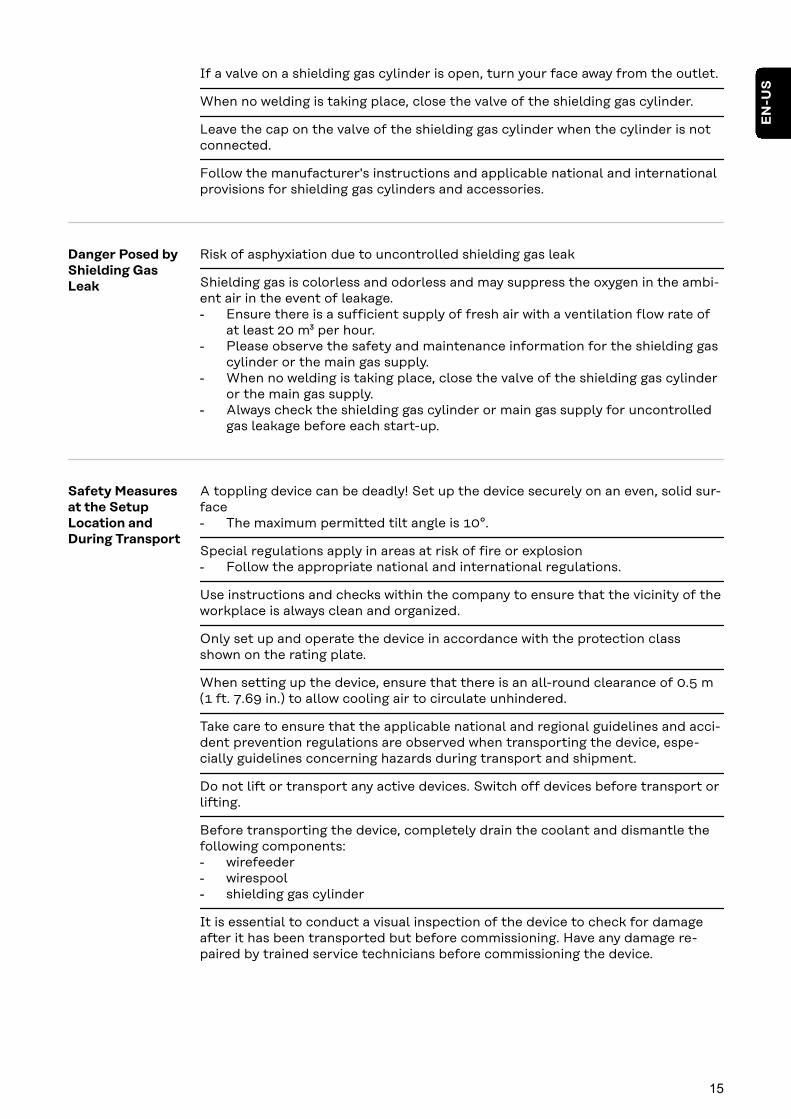
Danger Posed byShielding GasLeak
Risk of asphyxiation due to uncontrolled shielding gas leak
Shielding gas is colorless and odorless and may suppress the oxygen in the ambi-ent air in the event of leakage.- Ensure there is a sufficient supply of fresh air with a ventilation flow rate of
at least 20 m³ per hour.- Please observe the safety and maintenance information for the shielding gas
cylinder or the main gas supply.- When no welding is taking place, close the valve of the shielding gas cylinder
or the main gas supply.- Always check the shielding gas cylinder or main gas supply for uncontrolled
gas leakage before each start-up.
Safety Measuresat the SetupLocation andDuring Transport
A toppling device can be deadly! Set up the device securely on an even, solid sur-face- The maximum permitted tilt angle is 10°.
Special regulations apply in areas at risk of fire or explosion- Follow the appropriate national and international regulations.
Use instructions and checks within the company to ensure that the vicinity of theworkplace is always clean and organized.
Only set up and operate the device in accordance with the protection classshown on the rating plate.
When setting up the device, ensure that there is an all-round clearance of 0.5 m(1 ft. 7.69 in.) to allow cooling air to circulate unhindered.
Take care to ensure that the applicable national and regional guidelines and acci-dent prevention regulations are observed when transporting the device, espe-cially guidelines concerning hazards during transport and shipment.
Do not lift or transport any active devices. Switch off devices before transport orlifting.
Before transporting the device, completely drain the coolant and dismantle thefollowing components:- wirefeeder- wirespool- shielding gas cylinder
It is essential to conduct a visual inspection of the device to check for damageafter it has been transported but before commissioning. Have any damage re-paired by trained service technicians before commissioning the device.
15
EN
-US
Safety Measuresin Normal Oper-ation
Only operate the device when all safety devices are fully functional. If the safetydevices are not fully functional, there is a danger of:- Injury or death to the operator or a third party- Damage to the device and other material assets belonging to the operating
company- Inefficient operation of the device
Safety devices that are not fully functional must be repaired before the device isswitched on.
Never bypass or disable safety devices.
Before switching on the device, ensure that no one can be put in danger.
The device must be examined at least once a week for externally detectable dam-age and functionality of the safety devices.
Always secure the shielding gas cylinder well and remove before transporting bycrane.
Only the original coolant from the manufacturer is suitable for use in our devicesdue to its properties (electrical conductivity, anti-freeze, material compatibility,flammability, etc.)
Only use appropriate original coolant from the manufacturer.
Do not mix original coolant from the manufacturer with other coolants.
Only connect system components from the manufacturer to the cooling unit cir-cuit.
If there is damage due to use of other system components or other coolants, themanufacturer accepts no liability for this and all warranty claims are forfeited.
Cooling Liquid FCL 10/20 is not flammable. The ethanol-based coolant is flam-mable in certain conditions. Only transport the coolant in closed original contain-ers and keep away from sources of ignition.
Properly dispose of used coolant according to national and international regula-tions. The coolant safety data sheet can be obtained from your service center orvia the manufacturer’s website.
When the system is cool, always check the coolant level before starting welding.
Maintenance andrepair
It is impossible to guarantee that bought-in parts are designed and manufac-tured to meet the demands made of them, or that they satisfy safety require-ments.- Use only original spare and wearing parts (also applies to standard parts).- Do not carry out any modifications, alterations, etc. to the device without the
manufacturer's consent.- Components that are not in perfect condition must be replaced immediately.- When ordering, please give the exact designation and part number as shown
in the spare parts list, as well as the serial number of your device.
The housing screws provide the ground conductor connection for earthing thehousing parts.Only use original housing screws in the correct number and tightened to the spe-cified torque.
16

Safety Inspec-tion
The manufacturer recommends that a safety inspection of the device be per-formed at least every 12 months.
The manufacturer recommends calibrating power sources within the same 12-month interval.
A safety inspection by a certified electrician is recommended:- After changes- After alterations- After repair, care, and maintenance- At least every 12 months
For the safety inspection, follow the appropriate national and internationalstandards and guidelines.
You can obtain more information about the safety inspection and calibrationfrom your service center. The service center will provide the necessary docu-ments upon request.
Disposal To comply with European directives and national law, waste electrical and elec-tronic equipment must be collected separately and sent for environmentally-friendly recycling. Used devices must be returned to a distributor or an approvedcollection and recycling facility in your area. Proper disposal of used devices pro-motes the sustainable recycling of material resources. Ignoring this may have po-tentially adverse effects on the environment and your health.
Packaging materialsMaterials collected separately. Check the regulations in your area. Reduce thevolume of cardboard.
Safety symbols Devices with the CE label satisfy the essential requirements of the low-voltageand electromagnetic compatibility directive (e.g., relevant product standards ofthe EN 60974 series).
Fronius International GmbH declares that the device complies with Directive2014/53/EU. The full text of the EU Declaration of Conformity is available on thefollowing website: http://www.fronius.com
Devices marked with the CSA test mark satisfy the requirements of the relevantstandards for Canada and the USA.
Data backup The user is responsible for backing up any changes made to the factory settings.The manufacturer accepts no liability for any deleted personal settings.
Copyright Copyright of these Operating Instructions remains with the manufacturer.
Text and illustrations were accurate at the time of printing. Fronius reserves theright to make changes. The contents of the Operating Instructions shall notprovide the basis for any claims whatsoever on the part of the purchaser. If youhave any suggestions for improvement, or can point out any mistakes that youhave found in the Operating Instructions, we will be most grateful for your com-ments.
17
EN
-US

18

General information
19

20

General
Device concept The TransSteel (TSt) 3000c Pulsepower source is a fully digitized, micro-processor-controlled inverter powersource.
A modular design and ability to easilyextend the system guarantee a highdegree of flexibility. The device is de-signed for the following welding pro-cesses:- MIG/MAG pulse welding- MIG/MAG standard synergic weld-
ing- TIG welding- Manual metal arc welding
The device has a "Power limitation" safety feature. This means that the powersource can be operated at the power limit without compromising process safety.For details, refer to the "Welding operations" chapter.
Operating prin-ciple
The central control and regulation unit of the power sources is coupled with a di-gital signal processor. The central control and regulation unit and signal pro-cessor control the entire welding process.During the welding process, the actual data is measured continuously and thedevice responds immediately to any changes. Control algorithms ensure that thedesired target state is maintained.
This results in:- A precise welding process- A high degree of reproducibility on all results- Excellent weld properties.
Applicationareas
The TransSteel 3000c Pulse is used in trade and industry for manual applicationswith classical steel and galvanized sheet metal.
The power source is designed for:- Mechanical and equipment engineering- Steel construction- Plant and container construction- Metal and portal construction- Rail vehicle construction- Metalworking trades
21
EN
-US

Warning noticeson the device
There are warning notices and safety symbols on the power sources. These warn-ing notices and safety symbols must not be removed or painted over. They warnagainst incorrect operation, as this may result in serious injury and property dam-age.
40,0006,3035
inside
Welding is dangerous. The following basic requirements must be met:- Adequate welding qualifications- Appropriate protective equipment- Exclusion of unauthorized persons
Do not use the functions described here until you have fully read and understoodthe following documents:- These Operating Instructions- All system component Operating Instructions, especially the safety rules
22
Description ofthe warnings onthe device
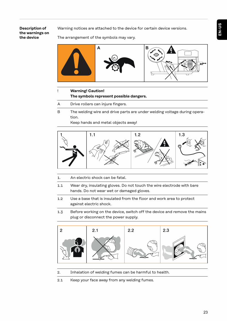
Warning notices are attached to the device for certain device versions.
The arrangement of the symbols may vary.
A B
! Warning! Caution!The symbols represent possible dangers.
A Drive rollers can injure fingers.
B The welding wire and drive parts are under welding voltage during opera-tion.Keep hands and metal objects away!
1. An electric shock can be fatal.
1.1 Wear dry, insulating gloves. Do not touch the wire electrode with barehands. Do not wear wet or damaged gloves.
1.2 Use a base that is insulated from the floor and work area to protectagainst electric shock.
1.3 Before working on the device, switch off the device and remove the mainsplug or disconnect the power supply.
2. Inhalation of welding fumes can be harmful to health.
2.1 Keep your face away from any welding fumes.
23
EN
-US
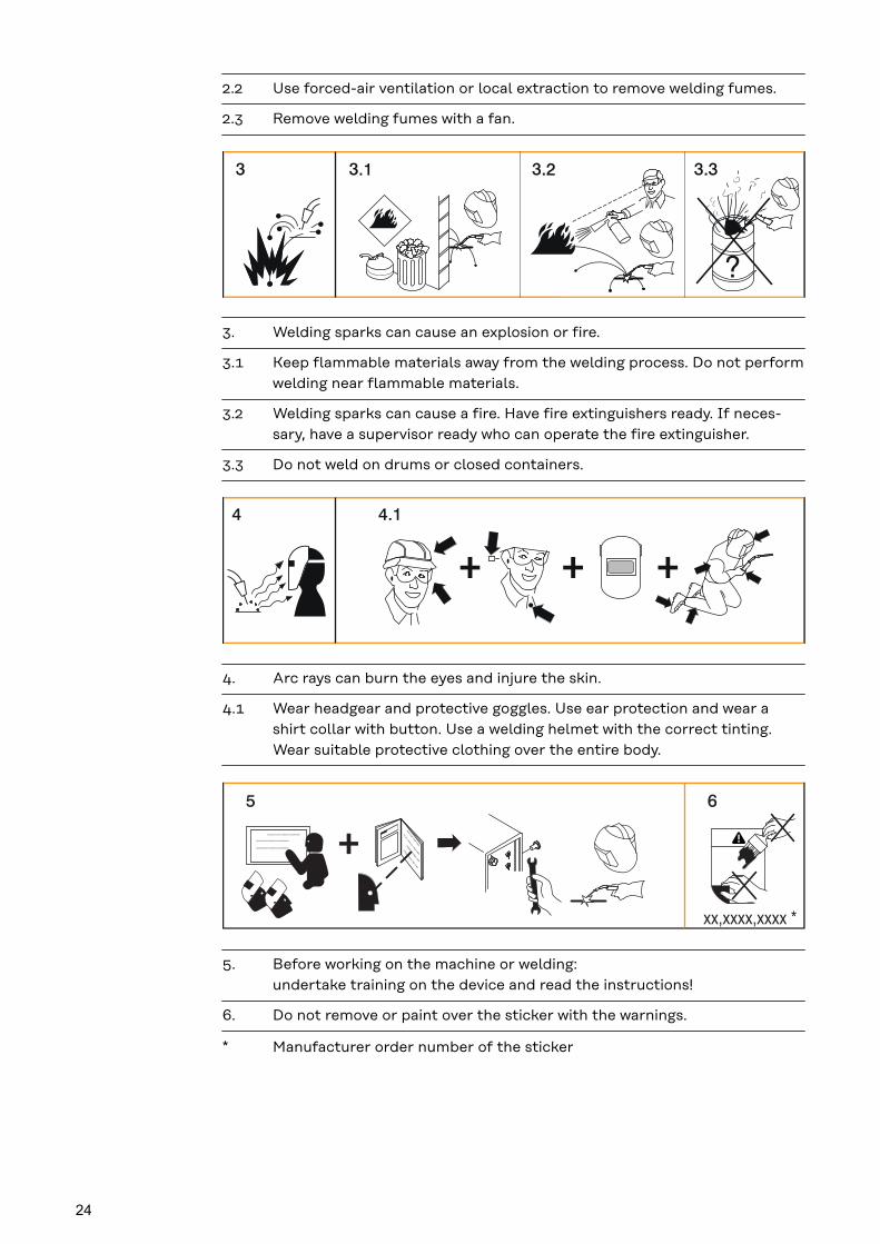
2.2 Use forced-air ventilation or local extraction to remove welding fumes.
2.3 Remove welding fumes with a fan.
3. Welding sparks can cause an explosion or fire.
3.1 Keep flammable materials away from the welding process. Do not performwelding near flammable materials.
3.2 Welding sparks can cause a fire. Have fire extinguishers ready. If neces-sary, have a supervisor ready who can operate the fire extinguisher.
3.3 Do not weld on drums or closed containers.
4. Arc rays can burn the eyes and injure the skin.
4.1 Wear headgear and protective goggles. Use ear protection and wear ashirt collar with button. Use a welding helmet with the correct tinting.Wear suitable protective clothing over the entire body.
xx,xxxx,xxxx *
5. Before working on the machine or welding:undertake training on the device and read the instructions!
6. Do not remove or paint over the sticker with the warnings.
* Manufacturer order number of the sticker
24

Welding processes, procedures, and welding char-acteristics for MIG/MAG welding
General In order to process a wide range of materials effectively, various welding pro-cesses, procedures, and welding characteristics are available on the powersource.
Brief descriptionof MIG/MAGstandard syner-gic welding
MIG/MAG standard synergic
MIG/MAG standard synergic welding is a MIG/MAG welding process covering theentire power range of the power source with the following arc types:
Dip transfer arcDroplet transfer occurs in the lower power range during the short circuit.
Intermediate arcThe droplet increases in size at the end of the wire electrode and is transferred inthe mid power range during the short circuit.
Spray arcA short circuit-free transfer of material in the high power range.
Brief descriptionof MIG/MAGpulsed synergicwelding
MIG/MAG pulsed synergic
MIG/MAG pulsed synergic welding is a pulsed arc process with a controlled ma-terial transfer.In the base current phase, the energy input is reduced to such an extent that thearc barely burns steadily and the surface of the workpiece is preheated. In thepulsing current phase, an accurately timed current pulse guarantees a precisedetachment of the weld material droplet.This principle guarantees low-spatter welding and precise operation throughoutthe entire power range.
Brief descriptionof SynchroPulsewelding
SynchroPulse is available for the standard synergic and pulsed synergic pro-cesses.The cyclic change of the welding power between two operating points with Syn-chroPulse achieves a finely rippled weld appearance and a non-continuous heatinput.
25
EN
-US

System components
General The power sources can be operated with various system components and op-tions. This makes it possible to optimize procedures and to simplify machinehandling and operation, depending on the field of application for the powersource.
SafetyWARNING!
Danger from incorrect operation and work that is not carried out properly.This can result in serious personal injury and damage to property.
▶ All the work and functions described in this document must only be carriedout by technically trained and qualified personnel.
▶ Read and understand this document in full.
▶ Read and understand all safety rules and user documentation for this equip-ment and all system components.
Overview
(1)
(2)
(3)
(4)
(5)(6)
(7)
(1) MIG/MAG welding torch(2) Stabilization of the gas cylinder holder(3) Power source(4) Cooling unit(5) Trolley with gas cylinder holder(6) Grounding and electrode cable(7) TIG welding torch
26

Operating controls and connec-tions
27

28
Control Panel
General The functions are all arranged in a logical way on the control panel. The individualparameters required for welding can be- Selected by means of buttons- Changed using buttons or the selection dial- Shown on the digital display during welding.
Due to the synergic function, all other parameters are also adjusted if a singleparameter is changed.
NOTE!
Because of software updates, certain functions may be available for your devicebut not described in these Operating Instructions or vice versa.In addition, individual figures may also differ slightly from the operating ele-ments of your device. However, the function of these operating elements isidentical.
SafetyWARNING!
Danger from incorrect operation and work that is not carried out properly.This can result in serious personal injury and damage to property.
▶ All the work and functions described in this document must only be carriedout by technically trained and qualified personnel.
▶ Read and understand this document in full.
▶ Read and understand all safety rules and user documentation for this equip-ment and all system components.
29
EN
-US

Control panel
(1)
(2)
(3)
(4)
(5)
(6)(7)
(14)(13) (17)
(12)
(11)
(10) (8)(9)
(15)(16)
No. Function
(1) "Parameter selection" button (right)a) for selecting the following parameters
Arc length correctionFor correcting the arc length
Welding voltage in V *)Before welding begins, the device automatically displays a standard valuebased on the programmed parameters. The actual value is displayed dur-ing welding.
30

Pulse / arc-force dynamic correctionFor continuously correcting the droplet detachment force in MIG/MAGpulsed synergic welding- ... reduced droplet detachment force0 ... neutral droplet detachment force+ ... increased droplet detachment force
For influencing the short-circuiting dynamic at the instant of droplettransfer in MIG/MAG standard synergic welding, MIG/MAG standardmanual welding, and manual metal arc welding- ... harder and more stable arc0 ... neutral arc+ ... soft and low-spatter arc
b) for changing parameters in the Setup menu
(2) "Parameter selection" button (left)a) for selecting the following parameters
Sheet thicknessSheet thickness in mm or in.If the welding current to be selected is not known, it is sufficient to enterthe sheet thickness. The required welding current and any other paramet-ers marked with *) will then be adjusted automatically.
Welding current *)Welding current in ABefore welding begins, the device automatically displays a standard valuebased on the programmed parameters. The actual value is displayed dur-ing welding.
Wire speed *)
Wire speed in m/min or ipm.
b) for changing parameters in the Setup menu
(3) Selection dial (right)For changing the arc length correction, welding voltage, and arc-force dy-namic parameters
31
EN
-US
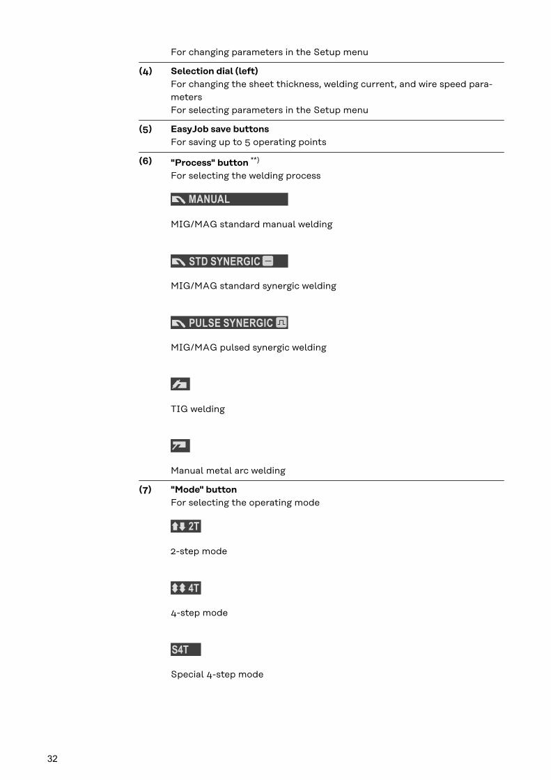
For changing parameters in the Setup menu
(4) Selection dial (left)For changing the sheet thickness, welding current, and wire speed para-metersFor selecting parameters in the Setup menu
(5) EasyJob save buttonsFor saving up to 5 operating points
(6) "Process" button **)
For selecting the welding process
MIG/MAG standard manual welding
MIG/MAG standard synergic welding
MIG/MAG pulsed synergic welding
TIG welding
Manual metal arc welding
(7) "Mode" buttonFor selecting the operating mode
2-step mode
4-step mode
Special 4-step mode
32
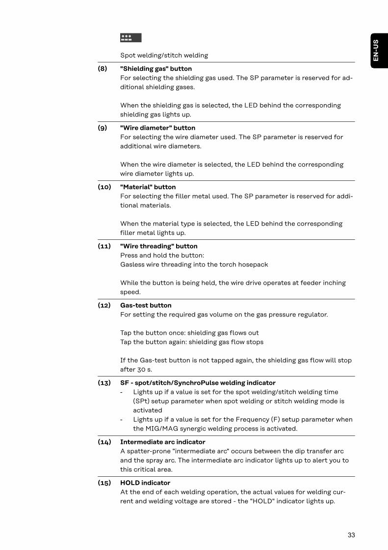
Spot welding/stitch welding
(8) "Shielding gas" buttonFor selecting the shielding gas used. The SP parameter is reserved for ad-ditional shielding gases.
When the shielding gas is selected, the LED behind the correspondingshielding gas lights up.
(9) "Wire diameter" buttonFor selecting the wire diameter used. The SP parameter is reserved foradditional wire diameters.
When the wire diameter is selected, the LED behind the correspondingwire diameter lights up.
(10) "Material" buttonFor selecting the filler metal used. The SP parameter is reserved for addi-tional materials.
When the material type is selected, the LED behind the correspondingfiller metal lights up.
(11) "Wire threading" buttonPress and hold the button:Gasless wire threading into the torch hosepack
While the button is being held, the wire drive operates at feeder inchingspeed.
(12) Gas-test buttonFor setting the required gas volume on the gas pressure regulator.
Tap the button once: shielding gas flows outTap the button again: shielding gas flow stops
If the Gas-test button is not tapped again, the shielding gas flow will stopafter 30 s.
(13) SF - spot/stitch/SynchroPulse welding indicator- Lights up if a value is set for the spot welding/stitch welding time
(SPt) setup parameter when spot welding or stitch welding mode isactivated
- Lights up if a value is set for the Frequency (F) setup parameter whenthe MIG/MAG synergic welding process is activated.
(14) Intermediate arc indicatorA spatter-prone "intermediate arc" occurs between the dip transfer arcand the spray arc. The intermediate arc indicator lights up to alert you tothis critical area.
(15) HOLD indicatorAt the end of each welding operation, the actual values for welding cur-rent and welding voltage are stored - the "HOLD" indicator lights up.
33
EN
-US

(16) Pulse indicatorLights up when the MIG/MAG pulsed synergic welding process is selected
(17) Real Energy InputFor displaying the energy applied during the welding operation.
The Real Energy Input indicator must be activated in level 2 of the Setupmenu – EnE parameter. The value continuously rises during welding in linewith the permanently increasing energy input. The final value is storedafter the end of welding until welding starts again or the power source isswitched back on - the HOLD indicator lights up.
*) During the MIG/MAG standard synergic welding process and MIG/MAGpulsed synergic welding process, if one of these parameters is selected,then the synergic function ensures that all other parameters, includingthe welding voltage parameter, are adjusted automatically.
**) In conjunction with the VRD option, the indicator of the currently selec-ted welding process is also used as status indicator:- The indicator lights up continuously: the voltage reduction (VRD) is
active and limits the output voltage to less than 35 V.- The indicator flashes as soon as a welding operation occurs, which can
cause the output voltage to be greater than 35 V.
34

Service para-meters
Various service parameters can be retrieved by pressing the "Parameter selec-tion" buttons at the same time.
Opening the display
+
1 The first parameter "Firmware version"will be displayed, e.g., "1.00 | 4.21"
Selecting parameters
2 Use the "Mode" and "Process" buttonsor the left-hand selection dial to selectthe required setup parameter
Available parameters
Explanation
Example:1.00 | 4.21
Firmware version
Example:2 | 491
Welding program configuration
Example:r 2 | 290
Number of the currently selectedwelding program
Example:654 | 32.1= 65,432.1 hours= 65,432 hours 6 mins
Indicates the actual arc time sincefirst useNote: The arc time indicator is notsuitable as a basis for calculating hir-ing fees or for warranty purposes, etc.
Example:iFd | 0.0
Motor current for wire drive in AThe value changes as soon as the mo-tor is running.
2nd 2. menu level for service technicians
35
EN
-US

Keylock A keylock can be selected to prevent the settings from being inadvertentlychanged on the control panel. As long as the keylock is active:- Settings cannot be adjusted on the control panel- Only parameter settings can be retrieved- Any assigned "Save" button can be retrieved provided that an assigned "Save"
button was selected when the keylock was enabled
Activating/deactivating the keylock:
+
1 Keylock activated:The message "CLO | SEd" appears onthe displays.
Keylock deactivated:The message "OP | En" appears on thedisplays.
The keylock can also be activated and deactivated using the keylock switch op-tion.
36
Connections, Switches, and Mechanical Compon-ents
Front and back
(1)
(2)
(3)
(4) (5)
(6)
(7)
(11)(8)
(9)(10)
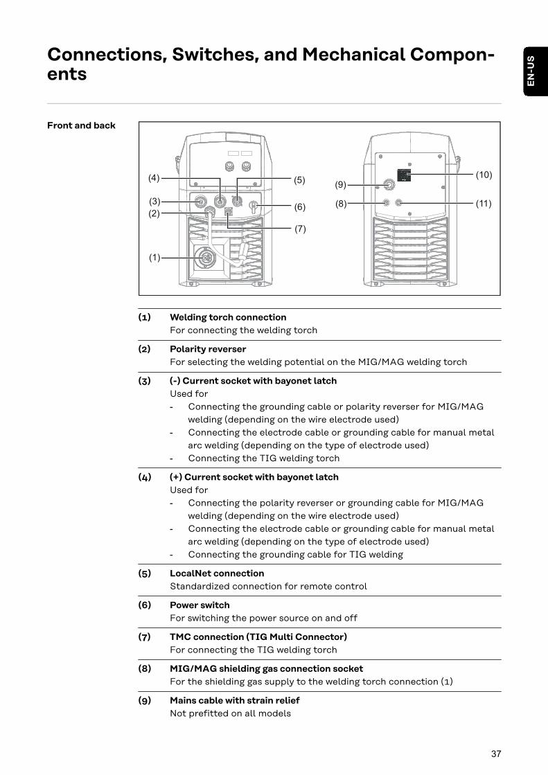
(1) Welding torch connectionFor connecting the welding torch
(2) Polarity reverserFor selecting the welding potential on the MIG/MAG welding torch
(3) (-) Current socket with bayonet latchUsed for- Connecting the grounding cable or polarity reverser for MIG/MAG
welding (depending on the wire electrode used)- Connecting the electrode cable or grounding cable for manual metal
arc welding (depending on the type of electrode used)- Connecting the TIG welding torch
(4) (+) Current socket with bayonet latchUsed for- Connecting the polarity reverser or grounding cable for MIG/MAG
welding (depending on the wire electrode used)- Connecting the electrode cable or grounding cable for manual metal
arc welding (depending on the type of electrode used)- Connecting the grounding cable for TIG welding
(5) LocalNet connectionStandardized connection for remote control
(6) Power switchFor switching the power source on and off
(7) TMC connection (TIG Multi Connector)For connecting the TIG welding torch
(8) MIG/MAG shielding gas connection socketFor the shielding gas supply to the welding torch connection (1)
(9) Mains cable with strain reliefNot prefitted on all models
37
EN
-US
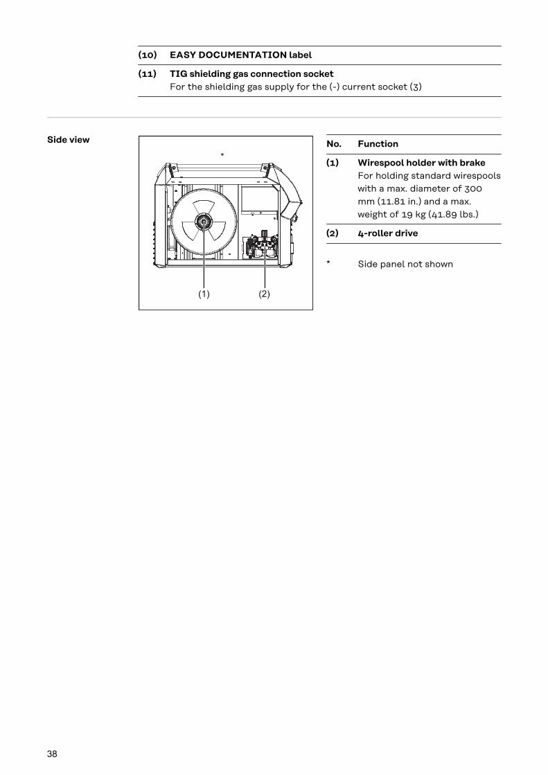
(10) EASY DOCUMENTATION label
(11) TIG shielding gas connection socketFor the shielding gas supply for the (-) current socket (3)
Side view
(2)(1)
*
No. Function
(1) Wirespool holder with brakeFor holding standard wirespoolswith a max. diameter of 300mm (11.81 in.) and a max.weight of 19 kg (41.89 lbs.)
(2) 4-roller drive
* Side panel not shown
38

Installation and Startup
39

40

Minimum equipment for welding operations
General Depending on the welding process, a minimum level of equipment is required towork with the power source.The following describes the welding processes and the corresponding minimumequipment for welding operations.
Gas-cooledMIG/MAG weld-ing
- Power source- Grounding cable- Gas-cooled MIG/MAG welding torch- Gas connection (shielding gas supply)- Wire electrode
Water-cooledMIG/MAG weld-ing
- Power source- Cooling unit including coolant- Grounding cable- Water-cooled MIG/MAG welding torch- Gas connection (shielding gas supply)- Wire electrode
Manual metalarc welding
- Power source- Grounding cable- Electrode holder- Rod electrodes
TIG DC Welding - Power source- Grounding cable- TIG welding torch with or without rocker switch- Gas connection (shielding gas supply)- Filler metal depending on application
41
EN
-US
Before installation and initial operation
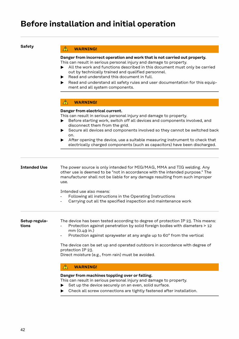
SafetyWARNING!
Danger from incorrect operation and work that is not carried out properly.This can result in serious personal injury and damage to property.
▶ All the work and functions described in this document must only be carriedout by technically trained and qualified personnel.
▶ Read and understand this document in full.
▶ Read and understand all safety rules and user documentation for this equip-ment and all system components.
WARNING!
Danger from electrical current.This can result in serious personal injury and damage to property.
▶ Before starting work, switch off all devices and components involved, anddisconnect them from the grid.
▶ Secure all devices and components involved so they cannot be switched backon.
▶ After opening the device, use a suitable measuring instrument to check thatelectrically charged components (such as capacitors) have been discharged.
Intended Use The power source is only intended for MIG/MAG, MMA and TIG welding. Anyother use is deemed to be "not in accordance with the intended purpose." Themanufacturer shall not be liable for any damage resulting from such improperuse.
Intended use also means:- Following all instructions in the Operating Instructions- Carrying out all the specified inspection and maintenance work
Setup regula-tions
The device has been tested according to degree of protection IP 23. This means:- Protection against penetration by solid foreign bodies with diameters > 12
mm (0.49 in.)- Protection against spraywater at any angle up to 60° from the vertical
The device can be set up and operated outdoors in accordance with degree ofprotection IP 23.Direct moisture (e.g., from rain) must be avoided.
WARNING!
Danger from machines toppling over or falling.This can result in serious personal injury and damage to property.
▶ Set up the device securely on an even, solid surface.
▶ Check all screw connections are tightly fastened after installation.
42

WARNING!
Danger of electrical current due to electrically conductive dust in the device.This can result in severe personal injury and damage to property.
▶ Only operate the device if an air filter is fitted. The air filter is a very import-ant safety device for achieving IP 23 protection.
The ventilation channel is a very important safety device. When selecting thesetup location, ensure that the cooling air can enter or exit unhindered throughthe vents on the front and back. Any electrically conductive dust (e.g., fromgrinding work) must not be allowed to be sucked into the device.
Grid Connection The devices are designed for the grid voltage stated on the rating plate. If themains cable or mains plug has not been attached to your version of the appli-ance, these must be installed according to national standards. Fuse protectionfor the grid lead can be found in the technical data.
CAUTION!
Danger due inadequately dimensioned electrical installations.This can lead to serious damage
▶ The grid lead and its fuse protection should be designed to suit the existingpower supply.The technical data on the rating plate should be followed.
43
EN
-US

Connecting the Mains Cable
Stipulated mainscables andstrain-reliefdevices
The following mains cables are required to operate the power source:
Europe:Cable cross-section 4G2.5
USA/Canada:Cable cross-section AWG 12, extra-hard usage
Depending on the version, a strain-relief device corresponding to the cable cross-section is fitted on the power source.
The item numbers of the different cables can be found in the Spare Parts List.
SafetyWARNING!
Danger from work that is not carried out properly.This can result in severe personal injury and damage to property.
▶ The work described below may only be performed by trained specialist per-sonnel.
▶ Follow national standards and guidelines.
CAUTION!
Danger from improperly prepared mains cable.Short circuits and damage to property may result.
▶ Fit ferrules to all phase conductors and the ground conductor of thestripped mains cable.
Connecting themains cable
If no mains cable is connected, a mains cable that is suitable for the connectionvoltage must be fitted before commissioning.
The ground conductor should be approx. 10 - 15 mm (0.4 - 0.6 in.) longer thanthe phase conductors.
A graphic representation of the mains cable connection is provided in the follow-ing sections for fitting the strain-relief device. To connect the mains cable, pro-ceed as follows:
1 Remove the side panel of the device
2 Push in the mains cable so that the ground conductor and phase conductorcan be properly connected to the block terminal.
3 Fit a ferrule to the ground conductor and phase conductor
4 Connect the ground conductor and phase conductor to the block terminal
5 Secure the mains cable with a strain-relief device
6 Fit the side panel of the device
44
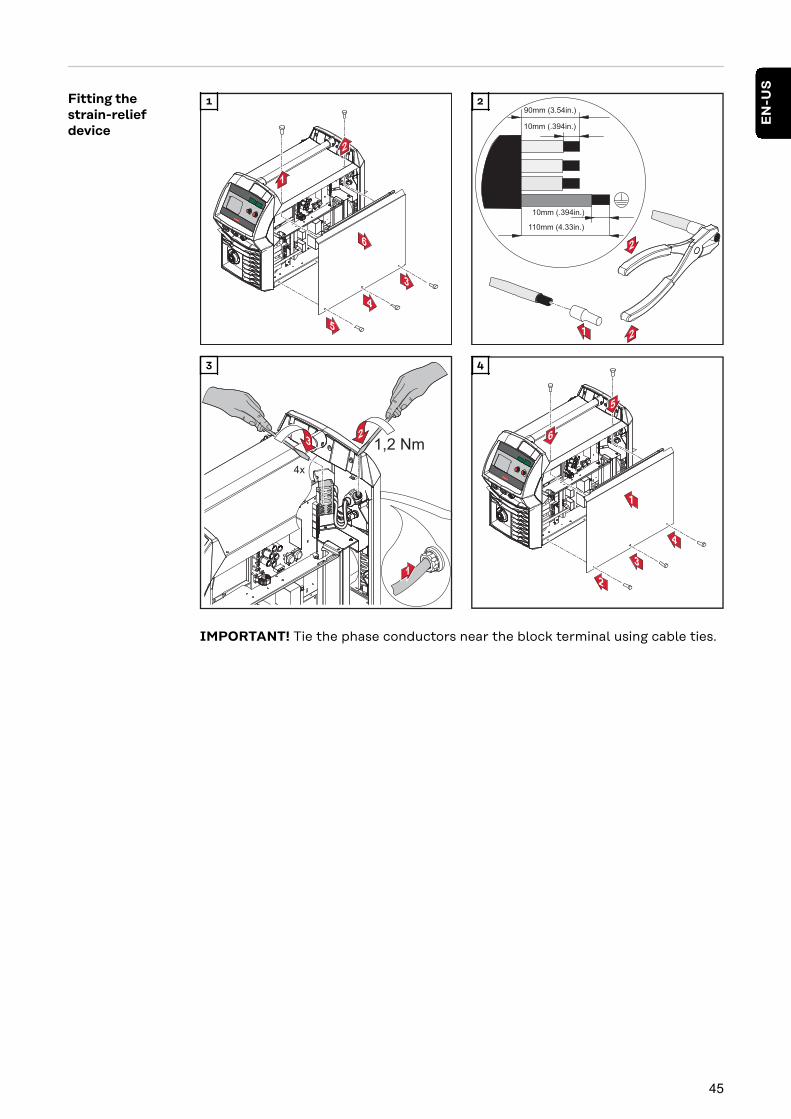
Fitting thestrain-reliefdevice
1 2
1,2 Nm
3 4
IMPORTANT! Tie the phase conductors near the block terminal using cable ties.
45
EN
-US

Fitting thestrain-reliefdevice forCanada / US
1 2
3 4
IMPORTANT! Tie the phase conductors near the block terminal using cable ties.
46

Generator-Powered Operation
Generator-powered opera-tion
The power source is generator-compatible.
The maximum apparent power S1max of the power source must be known in orderto select the correct generator output.The maximum apparent power S1max of the power source is calculated for 3-phase devices as follows:
S1max = I1max x U1 x √3
I1max and U1 according to the device rating plate and technical data
The generator apparent power SGEN needed is calculated using the following ruleof thumb:
SGEN = S1max x 1.35
A smaller generator can be used when not welding at full power.
IMPORTANT! The generator apparent power SGEN must not be less than themaximum apparent power S1max of the power source!
NOTE!
The voltage delivered by the generator must never fall outside of the mainsvoltage tolerance range.The mains voltage tolerance is specified in the "Technical data" section.
47
EN
-US

Commissioning
SafetyWARNING!
An electric shock can be fatal.If the power source is connected to the grid during installation, there is a dangerof serious personal injury and property damage.
▶ Only carry out work on the device when the power source's power switch is inthe - O - position.
▶ Only carry out work on the device when the power source has been discon-nected from the grid.
WARNING!
Danger of electrical current due to electrically conductive dust in the device.This can result in severe personal injury and damage to property.
▶ Only operate the device if an air filter is fitted. The air filter is a very import-ant safety device for achieving IP 23 protection.
General Commissioning is described with reference to a manual, water-cooled MIG/MAGapplication.
Information onsystem compon-ents
The steps and activities described below include references to various systemcomponents, such as- Trolley- Upright bracket- Cooling units- Welding torches, etc.
For more detailed information about installing and connecting the system com-ponents, please refer to the appropriate Operating Instructions for the systemcomponents.
48

Assembling sys-tem components WARNING!
Work performed incorrectly can cause serious injury and damage.
▶ The following activities must only be carried out by trained and qualified per-sonnel.
▶ Please note the information in the "Safety instructions" chapter!
The following diagram shows an overview of how the individual system compon-ents are put together.
Establishing aground earthconnection
1
49
EN
-US

Inserting/chan-ging feed rollers CAUTION!
Danger due to feed roller holders shooting upwards.This could result in injury.
▶ When unlocking the clamping lever, keep fingers away from the area to theleft and right of the clamping lever.
2
1
4
4
5
6
3
1
6
3
31
2
4
5
7
2
CAUTION!
Danger due to open feed rollers.This could result in injury.
▶ After inserting/changing the feed rollers, always install the protective coverof the 4-roller drive.
3
8
67
9
3
1
2
2
5
4
4
3
4
5
5 6
1
2
3
4
50
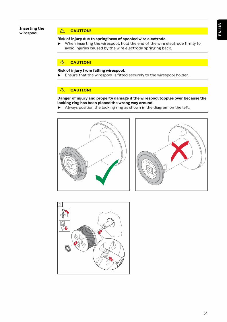
Inserting thewirespool CAUTION!
Risk of injury due to springiness of spooled wire electrode.
▶ When inserting the wirespool, hold the end of the wire electrode firmly toavoid injuries caused by the wire electrode springing back.
CAUTION!
Risk of injury from falling wirespool.
▶ Ensure that the wirespool is fitted securely to the wirespool holder.
CAUTION!
Danger of injury and property damage if the wirespool topples over because thelocking ring has been placed the wrong way around.
▶ Always position the locking ring as shown in the diagram on the left.
1
51
EN
-US

Installing thebasket-typespool
CAUTION!
Risk of injury due to springiness of spooled wire electrode.
▶ When inserting the basket-type spool, hold the end of the wire electrodefirmly to avoid injuries caused by the wire electrode springing back.
CAUTION!
Risk of injury from falling basket-type spool.
▶ Make sure that the basket-type spool with basket-type spool adapter is fittedsecurely to the wirespool holder.
NOTE!
When working with basket-type spools, only use the basket-type spool adaptersupplied with the device.
CAUTION!
Danger of injury and property damage if the basket-type spool topples over be-cause the locking ring has been placed the wrong way around.
▶ Always position the locking ring as shown in the diagram on the left.
CAUTION!
Danger of injury and damage to property due to falling basket-type spool.
▶ Place the basket-type spool on the adapter provided in such a way that thebars on the spool are inside the adapter guideways.
52

1 2
Feed in the wireelectrode CAUTION!
Risk of injury due to springiness of spooled wire electrode.
▶ When inserting the wire electrode into the 4-roller drive, hold the end of thewire electrode firmly to avoid injuries caused by the wire electrode springingback.
CAUTION!
Risk of damage to the welding torch from sharp end of wire electrode.
▶ Deburr the end of the wire electrode well before threading in.
1 2
CAUTION!
Risk of injury from emerging wire electrode.
▶ When pressing the "Wire threading" button or the torch trigger, keep thewelding torch away from your face and body, and wear suitable protectivegoggles.
IMPORTANT! To facilitate exact positioning of the wire electrode, the followingprocedure is possible when the "Wire threading" button is pressed and helddown.
53
EN
-US

Fdi
1
2 3 4 52,51
t (s)
(m/min, ipm)
- Hold the button for up to onesecond ... the wire speed stays at 1m/min or 39.37 ipm for the firstsecond.
- Hold the button for up to 2.5seconds ... after one second, thewire speed increases evenly withinthe next 1.5 seconds.
- Hold the button for more than 2.5seconds ... after 2.5 seconds, thewire is fed at a constant rate equalto the wire speed set for the Fdiwelding parameter.
If you release the "Wire threading" button and press it again before one secondhas elapsed, the sequence starts again from the beginning. This makes it possibleto continuously position the wire at a low wire speed of 1 m/min or 39.37 ipmwhere necessary.
If there is no wire threading button present, the torch trigger can be used in asimilar way. Before using the torch trigger for wire threading, proceed as follows:
1 Press the "Mode" button to select 2-step mode
2 Set the "Ito" parameter to "Off" in the Setup menu
CAUTION!
Danger of injury and damage from electric shock and from the wire electrodeemerging from the torch.When you press the torch trigger:
▶ Keep the welding torch away from your face and body
▶ Wear suitable protective goggles
▶ Do not point the welding torch at people
▶ Make sure that the wire electrode does not touch any conductive or groun-ded parts (e.g., housing, etc.)
IMPORTANT! If the torch trigger is pressed instead of the "Wire threading" but-ton, the welding wire runs at the feeder creep speed (depending on the weldingprogram) for the first 3 seconds. After these 3 seconds, wirefeeding is briefly in-terrupted.
The welding system detects that the welding process should not start, but thatthe wire is to be threaded in. At the same time, the gas solenoid valve closes, andthe welding voltage on the wire electrode is switched off.
If the torch trigger is kept pressed, wirefeeding restarts immediately withoutshielding gas and welding voltage, and the process continues as described above.
54
2
4
53
1
3 4
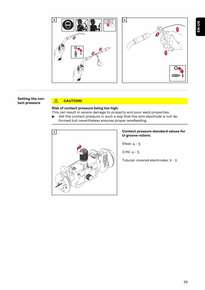
Setting the con-tact pressure CAUTION!
Risk of contact pressure being too high.This can result in severe damage to property and poor weld properties.
▶ Set the contact pressure in such a way that the wire electrode is not de-formed but nevertheless ensures proper wirefeeding.
1
1 Contact pressure standard values forU-groove rollers:
Steel: 4 - 5
CrNi: 4 - 5
Tubular covered electrodes: 2 - 3
55
EN
-US

Adjust the brake NOTE!
After releasing the wire threading button, the wirespool must stop unreeling.
▶ If it continues unreeling, readjust the brake.
4
6
7
1
2
STOP
3
5
1
2
1
2
2
4
STOP
OK
1
3
3
Design of thebrake WARNING!
Danger from incorrect installation.This can result in severe personal in-jury and damage to property.
▶ Do not dismantle the brake.
▶ Maintenance and servicing ofbrakes is to be carried out bytrained, qualified personnel only.
The brake is only available as a com-plete unit.The illustration of the brake is for in-formation purposes only.
56

Setting the dateand time whenstarting for thefirst time
After switching on the power source for the first time, the date and time must beset. For this purpose, the power source changes to the second level of the ser-vice menu; the yEA parameter is selected.
To set the date and time see page 97, step 5
57
EN
-US

58

MIG/MAG welding
59

60

Power Limitation
Safety function "Power limitation" is a safety function for MIG/MAG welding. This means that thepower source can be operated at the power limit whilst maintaining processsafety.
Wire speed is a determining parameter for welding power. If it is too high, the arcgets smaller and smaller and may be extinguished. In order to prevent this, thewelding power is lowered.
If the "MIG/MAG standard synergic welding" or "MIG/MAG pulsed synergic weld-ing" process is selected, the symbol for the "Wire speed" parameter flashes assoon as the safety function trips. The flashing continues until the next weldingstart-up, or until the next parameter change.
If the "Wire speed" parameter is selected, for example, the reduced value for wirespeed is displayed.
61
EN
-US

MIG/MAG Operating Modes
GeneralWARNING!
Operating the device incorrectly can cause serious injury and damage to prop-erty.
▶ Do not use the functions described here until you have fully read and under-stood the Operating Instructions.
▶ Do not use the functions described here until you have fully read and under-stood all of the Operating Instructions of the system components, especiallythe safety rules.
For details of the meaning, settings, setting range and units of the availablewelding parameters (e.g., gas pre-flow time), please refer to the "Setup paramet-ers" chapter.
Symbols and ex-planations
Press the torch trigger | Hold the torch trigger | Release the torch trigger
GPr Gas pre-flow time
I-S Starting currentCan be increased or decreased depending on the application
SL SlopeStarting current is continuously lowered as far as the welding current andthe welding current as far as the final current
I Welding current phaseEven heat input into the parent material whose temperature is raised bythe advancing heat
I-E Final currentTo fill up end-craters
GPo Gas post-flow time
SPt Spot welding time / interval welding time
SPb Interval pause time
62
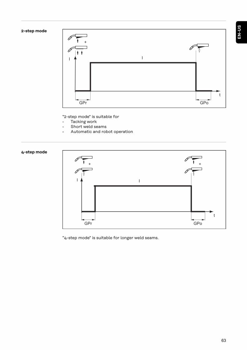
2-step mode
t
I
+
I
GPr GPo
"2-step mode" is suitable for- Tacking work- Short weld seams- Automatic and robot operation
4-step mode
t
I
+
I
GPr GPo
+
"4-step mode" is suitable for longer weld seams.
63
EN
-US

Special 2-stepmode
GPr GPo
I
I-S
SLt-S t-ESL
I-E
+
t
I
"Special 2-step mode" is ideal for welding in higher power ranges. In special 2-step mode, the arc starts at a lower power, which makes it easier to stabilize.
To activate special 2-step mode:
1 Select 2-step mode
2 In the Setup menu, set the t-S (starting current duration) and t-E (final cur-rent duration) parameters to a value > 0
Special 2-step mode is activated.
3 In the Setup menu, set the SL (Slope), I-S (starting current), and I-E (finalcurrent) parameters
Special 4-stepmode
+ +
I
I-S I-E
GPr SL SL GPo
Special 4-step mode allows the starting and final current to be configured in ad-dition to the advantages of 4-step mode.
64
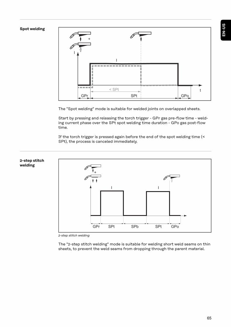
Spot welding
I
+
I
GPr GPoSPt
t< SPt
The "Spot welding" mode is suitable for welded joints on overlapped sheets.
Start by pressing and releasing the torch trigger - GPr gas pre-flow time - weld-ing current phase over the SPt spot welding time duration - GPo gas post-flowtime.
If the torch trigger is pressed again before the end of the spot welding time (<SPt), the process is canceled immediately.
2-step stitchwelding
GPr SPt SPtSPb GPo
I I
+
2-step stitch welding
The "2-step stitch welding" mode is suitable for welding short weld seams on thinsheets, to prevent the weld seams from dropping through the parent material.
65
EN
-US
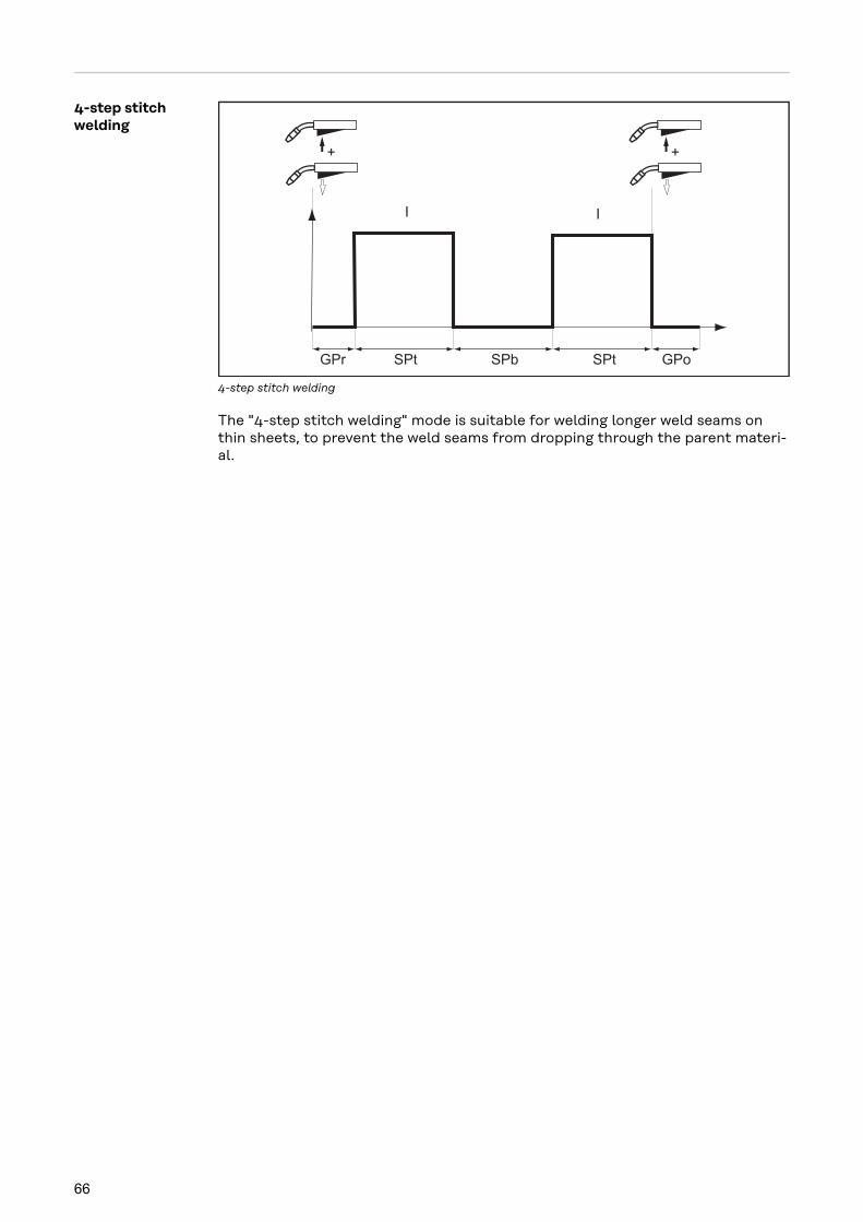
4-step stitchwelding
I I
GPr SPt SPtSPb GPo
+ +
4-step stitch welding
The "4-step stitch welding" mode is suitable for welding longer weld seams onthin sheets, to prevent the weld seams from dropping through the parent materi-al.
66
MIG/MAG welding
SafetyWARNING!
Danger from incorrect operation and work that is not carried out properly.This can result in serious personal injury and damage to property.
▶ All the work and functions described in this document must only be carriedout by technically trained and qualified personnel.
▶ Read and understand this document in full.
▶ Read and understand all safety rules and user documentation for this equip-ment and all system components.
WARNING!
Danger from electrical current.This can result in serious personal injury and damage to property.
▶ Before starting work, switch off all devices and components involved, anddisconnect them from the grid.
▶ Secure all devices and components involved so they cannot be switched backon.
▶ After opening the device, use a suitable measuring instrument to check thatelectrically charged components (such as capacitors) have been discharged.
Preparation 1 Connect the water hoses of the welding torch to the corresponding connec-tion sockets on the cooling unit(when using the cooling unit and water-cooled welding torch)
2 Insert mains plug
3 Set the power switch to - I -:- All displays on the control panel briefly illuminate- If present: The cooling unit starts to work
IMPORTANT! Observe the safety rules and operating conditions in the OperatingInstructions for the cooling unit.
Overview MIG/MAG welding is composed of the following sections:- MIG/MAG synergic welding- MIG/MAG standard manual welding- Spot welding and stitch welding
67
EN
-US

MIG/MAG synergic welding
MIG/MAG syner-gic welding
1 Press the "Material" button to select the filler metal to be used.
2 Press the "Wire diameter" button to select the diameter of the wire electrodeused.
3 Press the "Shielding gas" button to select the shielding gas to be used.The assignment of the SP position is in the welding program tables in the ap-pendix.
4 Press the "Process" button to select the desired welding process:
MIG/MAG standard synergic welding
MIG/MAG pulsed synergic welding
5 Press the "Mode" button to select the desired MIG/MAG mode:
2-step mode
4-step mode
Special 4-step mode
IMPORTANT! Under certain circumstances, it may not be possible to changewelding parameters that have been set on the control panel of a system compon-ent - such as remote control or wirefeeder - on the control panel of the powersource.
68

6 Use the "Parameter selection" buttons to select the welding parameters to beused to specify the welding power:
Sheet thickness
Welding current
Wire speed
Welding voltage
7 Use the appropriate selection dial to set the welding parameter.The value of the parameter is displayed on the digital display located above.
The sheet thickness, welding current, wire speed, and welding voltage paramet-ers are directly linked. It is sufficient to change one of the parameters, as the re-maining parameters are immediately adjusted accordingly
All welding parameter set values remain stored until the next time they arechanged. This applies even if the power source is switched off and on again. Todisplay the actual welding current during welding, select the welding currentparameter.
8 Open the gas cylinder valve
9 Adjust quantity of shielding gas:- Tap the Gas-test button- Turn the adjusting screw on the bottom of the gas pressure regulator un-
til the manometer displays the desired quantity of gas- Tap the Gas-test button again
CAUTION!
Danger of injury and damage from electric shock and from the wire electrodeemerging from the torch.When you press the torch trigger:
▶ Keep the welding torch away from your face and body
▶ Wear suitable protective goggles
▶ Do not point the welding torch at people
▶ Make sure that the wire electrode does not touch any conductive or groun-ded parts (e.g., housing, etc.)
10 Press the torch trigger and start welding
69
EN
-US
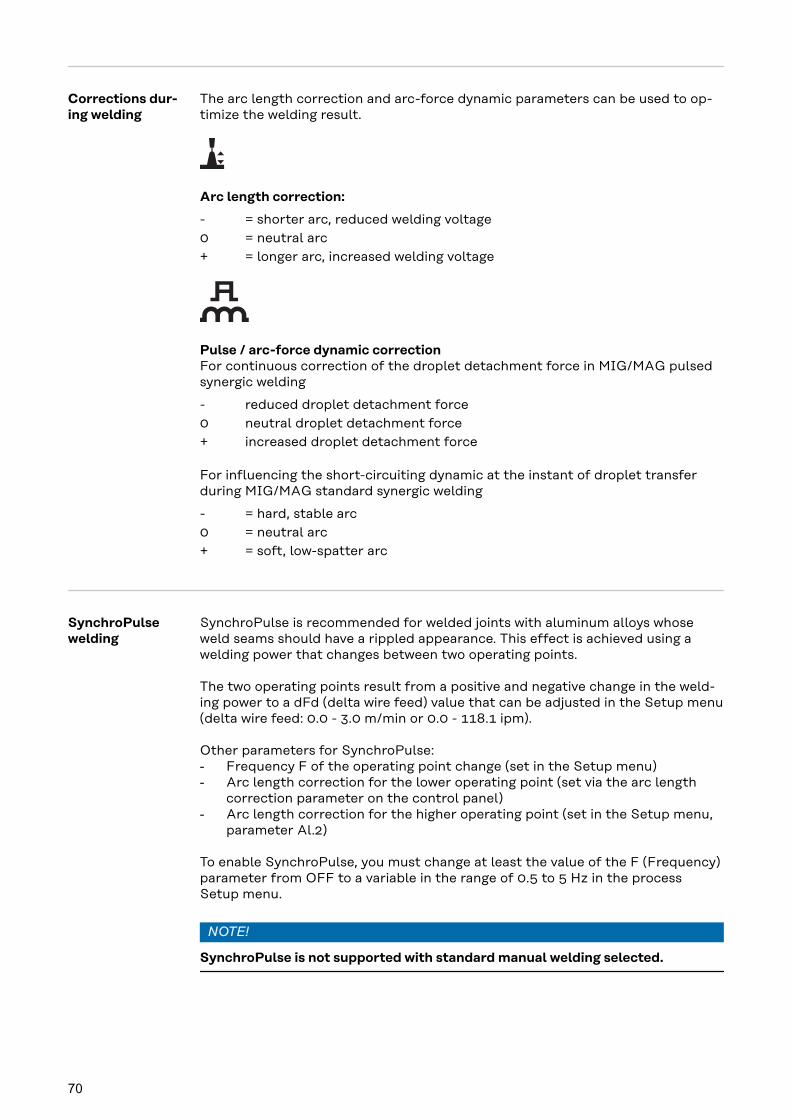
Corrections dur-ing welding
The arc length correction and arc-force dynamic parameters can be used to op-timize the welding result.
Arc length correction:
- = shorter arc, reduced welding voltage0 = neutral arc+ = longer arc, increased welding voltage
Pulse / arc-force dynamic correctionFor continuous correction of the droplet detachment force in MIG/MAG pulsedsynergic welding
- reduced droplet detachment force0 neutral droplet detachment force+ increased droplet detachment force
For influencing the short-circuiting dynamic at the instant of droplet transferduring MIG/MAG standard synergic welding
- = hard, stable arc0 = neutral arc+ = soft, low-spatter arc
SynchroPulsewelding
SynchroPulse is recommended for welded joints with aluminum alloys whoseweld seams should have a rippled appearance. This effect is achieved using awelding power that changes between two operating points.
The two operating points result from a positive and negative change in the weld-ing power to a dFd (delta wire feed) value that can be adjusted in the Setup menu(delta wire feed: 0.0 - 3.0 m/min or 0.0 - 118.1 ipm).
Other parameters for SynchroPulse:- Frequency F of the operating point change (set in the Setup menu)- Arc length correction for the lower operating point (set via the arc length
correction parameter on the control panel)- Arc length correction for the higher operating point (set in the Setup menu,
parameter Al.2)
To enable SynchroPulse, you must change at least the value of the F (Frequency)parameter from OFF to a variable in the range of 0.5 to 5 Hz in the processSetup menu.
NOTE!
SynchroPulse is not supported with standard manual welding selected.
70

How SynchroPulse works when used in "Special 4-step" mode
I-S = starting-current phase, SL = Slope, I-E = crater-fill phase, v = wire speed
I vD
Al.2
LSLS
+ +
dFd
1/F
v
I-S
dFd
t
I-E
SynchroPulse mode of operation
71
EN
-US
MIG/MAG Standard Manual Welding
General The MIG/MAG standard manual welding process is a MIG/MAG welding processwith no synergic function.Changing one parameter does not result in any automatic adjustments to theother parameters. All of the variable parameters must therefore be adjusted indi-vidually, as dictated by the welding process in question.
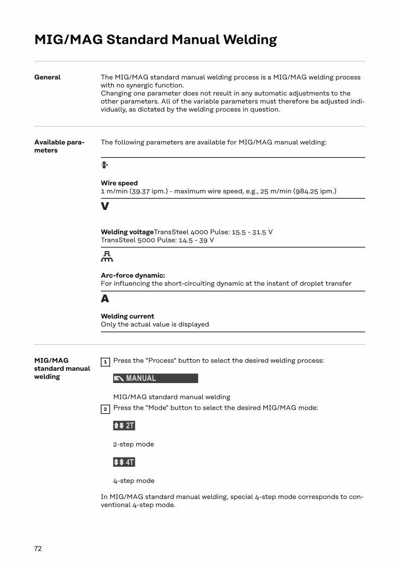
Available para-meters
The following parameters are available for MIG/MAG manual welding:
Wire speed1 m/min (39.37 ipm.) - maximum wire speed, e.g., 25 m/min (984.25 ipm.)
Welding voltageTransSteel 4000 Pulse: 15.5 - 31.5 VTransSteel 5000 Pulse: 14.5 - 39 V
Arc-force dynamic:For influencing the short-circuiting dynamic at the instant of droplet transfer
Welding currentOnly the actual value is displayed
MIG/MAGstandard manualwelding
1 Press the "Process" button to select the desired welding process:
MIG/MAG standard manual welding
2 Press the "Mode" button to select the desired MIG/MAG mode:
2-step mode
4-step mode
In MIG/MAG standard manual welding, special 4-step mode corresponds to con-ventional 4-step mode.
72

IMPORTANT! Under certain circumstances, it may not be possible to changewelding parameters that have been set on the control panel of a system compon-ent - such as remote control or wirefeeder - on the control panel of the powersource.
3 Press the "Parameter selection" button to select the wire speed parameter
4 Use the selection dial to set the desired wire speed value
5 Press the "Parameter selection" button to select the welding voltage para-meter
6 Use the selection dial to set the desired welding voltage value
The welding parameter values are shown in the digital display located above.
All welding parameter set values remain stored until the next time they arechanged. This applies even if the power source is switched off and on again. Todisplay the actual welding current during welding, select the welding currentparameter.
To display the actual welding current during welding:- Press the "Parameter selection" button to select the welding current para-
meter- The actual welding current is shown on the digital display during welding.
7 Open the gas cylinder valve
8 Adjust quantity of shielding gas:- Tap the Gas-test button- Turn the adjusting screw on the bottom of the gas pressure regulator un-
til the manometer displays the desired quantity of gas- Tap the Gas-test button again
CAUTION!
Danger of injury and damage from electric shock and from the wire electrodeemerging from the torch.When you press the torch trigger:
▶ Keep the welding torch away from your face and body
▶ Wear suitable protective goggles
▶ Do not point the welding torch at people
▶ Make sure that the wire electrode does not touch any conductive or groun-ded parts (e.g., housing, etc.)
9 Press the torch trigger and start welding
Corrections dur-ing welding
To obtain the best possible welding results, the arc-force dynamic parameter willsometimes need to be adjusted.
1 Press the "Parameter selection" button to select the arc-force dynamic para-meter
2 Use the selection dial to set the desired arc-force dynamic value
The welding parameter value is shown in the digital display located above it.
73
EN
-US

Spot welding and stitch welding
General The spot welding and stitch welding modes are MIG/MAG welding processes. Thespot welding and stitch welding modes are activated on the control panel.
Spot welding is used on welded joints on overlapping sheets that are only access-ible on one side.
Stitch welding is used for light-gage sheets.As the wire electrode is not fed continuously, the weld pool can cool down duringthe intervals. Local overheating leading to the parent material being meltedthrough is largely avoided.
Spot welding 1 In the Setup menu, set the spot welding time / stitch welding time SPt
IMPORTANT! Stitch pause time SPb = OFF must be set for spot welding!
2 Only for synergic welding:Use the corresponding buttons to select the filler metal used, the wire dia-meter, and the shielding gas
3 Select the desired welding process:
MIG/MAG standard manual welding
MIG/MAG standard synergic welding
MIG/MAG pulsed synergic welding
4 Select spot welding/stitch welding mode:
Spot welding/stitch weldingThe spot/stitch/SynchroPulse (SF) indicator lights up on the control panel.
5 Depending on the welding process selected, select the desired welding para-meters and adjust them using the appropriate selection dial
6 Open the gas cylinder valve
7 Adjust quantity of shielding gas
74

CAUTION!
Danger of injury and damage from electric shock and from the wire electrodeemerging from the torch.When you press the torch trigger:
▶ Keep the welding torch away from your face and body
▶ Wear suitable protective goggles
▶ Do not point the welding torch at people
▶ Make sure that the wire electrode does not touch any conductive or groun-ded parts (e.g., housing, etc.)
8 Spot welding
Procedure for establishing a welding spot:
1 Keep the welding torch vertical
2 Press and release the torch trigger
3 Maintain the position of the welding torch
4 Wait for the gas post-flow time
5 Raise the welding torch
Stitch welding 1 In the Setup menu, set the stitch pause time SPb
Stitch welding is enabled.The Int (Interval) parameter is displayed in the Setup menu.
2 In the Setup menu for the Int parameter, set the operating mode for stitchwelding (2T / 4T)
3 In the Setup menu, set the spot welding/stitch welding time SPt
4 Only for synergic welding:Use the corresponding buttons to select the filler metal used, the wire dia-meter, and the shielding gas
5 Select the desired welding process:
MIG/MAG standard manual welding
MIG/MAG standard synergic welding
MIG/MAG pulsed synergic welding
6 Select spot welding/stitch welding mode:
Spot welding/stitch weldingThe spot/stitch/SynchroPulse (SF) indicator lights up on the control panel.
75
EN
-US

7 Depending on the welding process selected, select the desired welding para-meters and adjust them using the appropriate selection dial
8 Open the gas cylinder valve
9 Adjust quantity of shielding gas
CAUTION!
Danger of injury and damage from electric shock and from the wire electrodeemerging from the torch.When you press the torch trigger:
▶ Keep the welding torch away from your face and body
▶ Wear suitable protective goggles
▶ Do not point the welding torch at people
▶ Make sure that the wire electrode does not touch any conductive or groun-ded parts (e.g., housing, etc.)
10 Stitch welding
Procedure for stitch welding:
1 Keep the welding torch vertical
2 Depending on the stitch mode set under the Int parameter:Press and hold the torch trigger (2-step mode)Press and release the torch trigger (4-step mode)
3 Maintain the position of the welding torch
4 Wait for the welding interval
5 Position the welding torch at the next point
6 To stop stitch welding, depending on the stitch mode set under the Int para-meter:Release the torch trigger (2-step mode)Press and release the torch trigger (4-step mode)
7 Wait for the gas post-flow time
8 Raise the welding torch
76

EasyJob mode
General The "Save" buttons allow up to five EasyJob operating points to be saved. Eachoperating point corresponds to the settings made on the control panel.
EasyJobs can be stored for each welding process.
IMPORTANT! Setup parameters are not saved at this time.
Saving EasyJoboperating points
1 Press and hold one of the "Save" buttons to save the current set-tings on the control panel, e.g.- The left display reads "Pro"- After a short time, the left display switches to the original
value
2 Release the "Save" button
Retrieving Easy-Job operatingpoints
1 To retrieve saved settings, press the corresponding "Save" buttonbriefly, e.g.- The control panel will show the saved settings
Deleting Easy-Job operatingpoints
1 Press and hold the relevant "Save" button to delete the memorycontent of that "Save" button, e.g.- The left display reads "Pro".- After a short time, the left display switches to the original
value
2 Keep the "Save" button held down- The left display reads "CLr".- After a while, both displays show "---"
3 Release the "Save" button
77
EN
-US

Retrieving Easy-Job operatingpoints on the Up/Down weldingtorch
Press one of the "Save" buttons on the control panel to retrieve the saved set-tings using the Up/Down welding torch.
1 Press one of the "Save" buttons on the control panel, e.g.:
The control panel will show the saved settings.
The "Save" buttons can now be selected using the buttons on the Up/Down weld-ing torch. Vacant "Save" buttons are skipped.
In addition to the "Save" button number lighting up, a number is displayed dir-ectly on the Up/Down welding torch:
Display on the Up/Down weldingtorch
EasyJob operating point on the con-trol panel
78

TIG welding
79

80

TIG welding
SafetyWARNING!
Danger from incorrect operation and work that is not carried out properly.This can result in serious personal injury and damage to property.
▶ All the work and functions described in this document must only be carriedout by technically trained and qualified personnel.
▶ Read and understand this document in full.
▶ Read and understand all safety rules and user documentation for this equip-ment and all system components.
WARNING!
Danger from electrical current.This can result in serious personal injury and damage to property.
▶ Before starting work, switch off all devices and components involved, anddisconnect them from the grid.
▶ Secure all devices and components involved so they cannot be switched backon.
▶ After opening the device, use a suitable measuring instrument to check thatelectrically charged components (such as capacitors) have been discharged.
Preparation 1 Set the power switch to - O -
2 Unplug mains plug
3 Removing a MIG/MAG welding torch
4 Disconnect the grounding cable from the (-) current socket
5 Insert the grounding cable into the (+) current socket and lock
6 Connect the other end of the grounding cable to the workpiece
7 Insert the bayonet connector of the TIG welding torch into the (-) currentsocket and twist it clockwise to lock
8 Screw the pressure regulator onto the gas cylinder (argon) and tighten it
9 Connect the gas hose to the pressure regulator and the TIG gas connectionto the power source
10 Insert mains plug
81
EN
-US

TIG weldingCAUTION!
Danger of injury and damage from electric shock.When the power switch is switched to position - I -, the tungsten electrode of thewelding torch is live.
▶ Ensure that the tungsten electrode is not touching any people or electricallyconductive or grounded parts (housing, etc.).
1 Set the power switch to position - I -: all indicators on the control panelbriefly illuminate
2 Press the "Process" button to select the TIG welding process:
The welding voltage is applied to the welding socket with a three second timelag.
IMPORTANT! Under certain circumstances, it may not be possible to changewelding parameters that have been set on the control panel of a system compon-ent - such as wirefeeder or remote control - on the control panel of the powersource.
3 Press the "Parameter selection" button to select the amperage parameter.
4 Use the selection dial to set the desired amperage.The amperage value is shown on the left-hand digital display.
All the parameter set values set using the selection dial are saved until thenext time they are changed. This applies even if the power source is switchedoff and on again.
5 Set the desired amount of shielding gas on the pressure regulator
6 Commence welding process (ignite arc)
82

Igniting the arc When using a welding torch with a torch trigger and TIG Multi Connector plug(with 2-step mode factory setting):
1 2 3 4+
1 Position the gas nozzle at the ignition point so that there is a distance of ap-proximately 2 to 3 mm (0.078 to 0.118 in.) between the tungsten electrodeand the workpiece
2 Gradually tilt the welding torch up until the tungsten electrode touches theworkpiece
3 Pull back the torch trigger and hold it in this position
Shielding gas flows.
4 Raise the welding torch and tilt it into the normal position
The arc now ignites.
5 Carry out welding
Ending the weld-ing process
1 Raise the TIG welding torch off the workpiece until the arc goes out.
Important! To protect the tungsten electrode, allow the shielding gas to flowafter the end of welding until the tungsten electrode has cooled down suffi-ciently.
2 Release the torch trigger
83
EN
-US
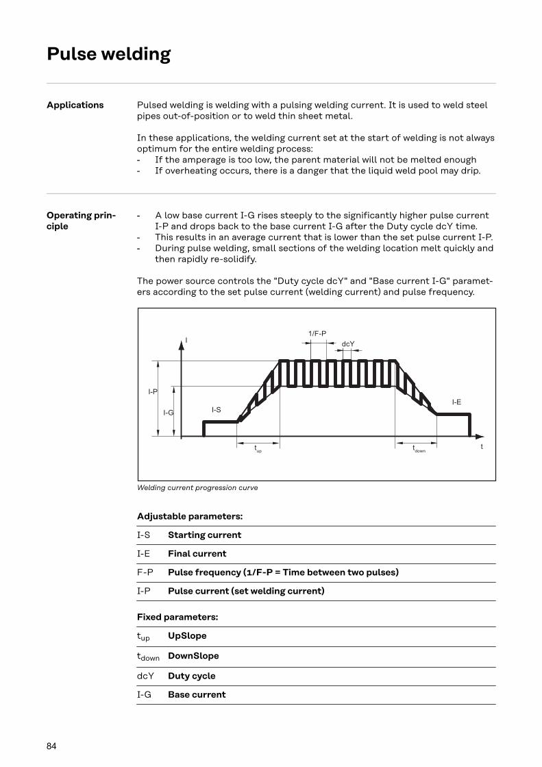
Pulse welding
Applications Pulsed welding is welding with a pulsing welding current. It is used to weld steelpipes out-of-position or to weld thin sheet metal.
In these applications, the welding current set at the start of welding is not alwaysoptimum for the entire welding process:- If the amperage is too low, the parent material will not be melted enough- If overheating occurs, there is a danger that the liquid weld pool may drip.
Operating prin-ciple
- A low base current I-G rises steeply to the significantly higher pulse currentI-P and drops back to the base current I-G after the Duty cycle dcY time.
- This results in an average current that is lower than the set pulse current I-P.- During pulse welding, small sections of the welding location melt quickly and
then rapidly re-solidify.
The power source controls the "Duty cycle dcY" and "Base current I-G" paramet-ers according to the set pulse current (welding current) and pulse frequency.
1/F-P
I-P
I-G
I
ttup
tdown
I-SI-E
dcY
Welding current progression curve
Adjustable parameters:
I-S Starting current
I-E Final current
F-P Pulse frequency (1/F-P = Time between two pulses)
I-P Pulse current (set welding current)
Fixed parameters:
tup UpSlope
tdown DownSlope
dcY Duty cycle
I-G Base current
84

Activating pulsewelding
1 Set a value for the F-P setup parameter (pulse frequency)- Setting range: 1 - 990 Hz
For a parameter description see section Parameters for TIG welding from page105.
85
EN
-US

86

Manual Metal Arc Welding
87

88
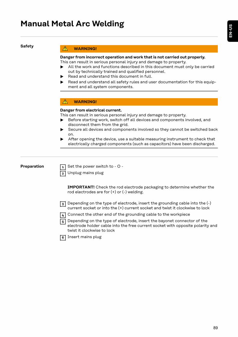
Manual Metal Arc Welding
SafetyWARNING!
Danger from incorrect operation and work that is not carried out properly.This can result in serious personal injury and damage to property.
▶ All the work and functions described in this document must only be carriedout by technically trained and qualified personnel.
▶ Read and understand this document in full.
▶ Read and understand all safety rules and user documentation for this equip-ment and all system components.
WARNING!
Danger from electrical current.This can result in serious personal injury and damage to property.
▶ Before starting work, switch off all devices and components involved, anddisconnect them from the grid.
▶ Secure all devices and components involved so they cannot be switched backon.
▶ After opening the device, use a suitable measuring instrument to check thatelectrically charged components (such as capacitors) have been discharged.
Preparation 1 Set the power switch to - O -
2 Unplug mains plug
IMPORTANT! Check the rod electrode packaging to determine whether therod electrodes are for (+) or (-) welding.
3 Depending on the type of electrode, insert the grounding cable into the (-)current socket or into the (+) current socket and twist it clockwise to lock
4 Connect the other end of the grounding cable to the workpiece
5 Depending on the type of electrode, insert the bayonet connector of theelectrode holder cable into the free current socket with opposite polarity andtwist it clockwise to lock
6 Insert mains plug
89
EN
-US
Manual metalarc welding CAUTION!
Danger of injury and damage from electric shock.When the power switch is switched to position - I -, the rod electrode in the elec-trode holder is live.
▶ Ensure that the rod electrode is not touching any people or electrically con-ductive or grounded parts (housing, etc.).
1 Set the power switch to position - I -: all indicators on the control panelbriefly illuminate
2 Press the "Process" button to select the MMA welding process:
The welding voltage is applied to the welding socket with a three second timelag.
If the MMA welding process is selected, a cooling unit, if present, is automat-ically deactivated. It is not possible to turn it on.
IMPORTANT! Under certain circumstances, it may not be possible to changewelding parameters that have been set on the control panel of a system compon-ent - such as remote control or wirefeeder - on the control panel of the powersource.
3 Press the "Parameter selection" button to select the amperage parameter.
4 Use the selection dial to set the desired amperage.
The amperage value is displayed on the left-hand digital display.
All parameter set values that are set using the selection dial are saved untiltheir next alteration. This applies even if the power source is switched off andon again.
5 Initiate welding process
To display the actual welding current during welding:- Press the "Parameter selection" button to select the welding current para-
meter- The actual welding current is shown on the digital display during welding.
Corrections dur-ing welding
To obtain the best possible welding results, the arc-force dynamic parameter willsometimes need to be adjusted.
1 Press the "Parameter selection" button to select the arc-force dynamic para-meter
2 Use the selection dial to set the desired arc-force dynamic value
The welding parameter value is shown in the digital display located above it.
To influence the short-circuiting dynamic at the instant of droplet transfer:
90

- = hard, stable arc0 = neutral arc+ = soft, low-spatter arc
91
EN
-US

HotStart func-tion
To obtain the best possible welding result, the HotStart function will sometimesneed to be adjusted.
Advantages- Improved ignition properties, even when using electrodes with poor ignition
properties- Better fusion of the parent material during the start-up phase, meaning few-
er cold-shut defects- Slag inclusions largely avoided
The setting of the available parameters is described in the section "Setup set-tings", "Setup menu - level 2".
I (A)
300
200
HCUIH
HCU > IH
t (s)
0,5 1 1,5
Hti
Key
Hti Hot-current time,0 - 2 s,Factory setting 0.5 s
HCU HotStart current,100 - 200%,Factory setting 150%
IH Main current = set welding cur-rent
FunctionDuring the specified hot-current time(Hti), the welding current is increasedto a certain value. This value (HCU) ishigher than the selected welding cur-rent (IH).
Anti-Stick func-tion
As the arc becomes shorter, the welding voltage may also fall so that the rodelectrode is more likely to stick to the workpiece. This may also cause the rodelectrode to burn out.
Electrode burn-out is prevented by activating the anti-stick function. If the rodelectrode begins to stick, the power source immediately switches the weldingcurrent off. The welding process can be resumed without problems once the rodelectrode has been detached from the workpiece.
The anti-stick (Ast) function can be activated and deactivated in the Setup menufor the setup parameters for MMA welding.
92

Easy Documentation
93

94

General
General If the Easy Documentation option is available on the power source, the most im-portant welding data for each welding operation can be documented and savedas a CSV file on a USB thumb drive.A Fronius signature is stored with the welding data, which can be used to checkand guarantee the authenticity of the data.
Easy Documentation is activated / deactivated by plugging / unplugging the sup-plied Fronius USB thumb drive with FAT32 formatting into the back of the powersource.
IMPORTANT! To document the welding data, the date and time must be set cor-rectly.
Documentedwelding data
The following data are documented:
Device typeFile namePart numberSerial numberFirmware version of power sourceFirmware of PC board DOCMAG (Easy Documentation)Document versionhttps://www.easydocu.weldcube.com (A PFDF report of selected welding datacan be created under this link)
Nr. MeterStart by plugging in the USB thumb drive;when switching the power source off and on, the meter continuesat the last weld seam number.A new CSV file is created after 1000 welding operations.
Date Date yyyy-mm-dd
Time Time hh:mm:ssat the start of current flow
Duration Duration in [s]from start of current flow to end of current (current flow signal)
I Welding current * in [A]
U Welding voltage * in [V]
vd Wire speed * in [m/min]
wfs Wire speed * in [ipm]
IP Power * from current values in [W]
IE Energy from instantaneous values in [kJ]over the entire welding operation
I-Mot Motor current * in [A]
Synid Characteristic numberfor each welding operation
Job EasyJob numberper weld seam
95
EN
-US

Process Welding process
Mode Operating mode
Status PASS: regular weldingIGN: Welding canceled during the ignition phaseErr | xxx: Welding canceled due to an error; the corresponding ser-vice code is documented
Interval Weld seam number for "Interval" operating mode
Signa-ture
Signature for each weld seam number
* in each case from the main process phase;in the event of termination in the ignition phase, the average valuein the ignition phase is stored and an identifier is output to indicatethat the main process phase has been reached
The welding data are documented as average values in the main process phaseand for each welding operation.
New CSV file A new CSV file is generated- When the USB thumb drive is disconnected and reconnected with the power
source switched on- When the date and time are changed- From 1000 welding operations- During a firmware update- When the USB thumb drive is disconnected and reconnected to another
power source(= change of serial number).
PDF report /Fronius signa-ture
By scanning this link...- A PDF report of the selected welding data can be created- The authenticity of the welding data can be checked and
guaranteed via the Fronius signature read out with thewelding data.
https://easydocu.weldcube.com
96
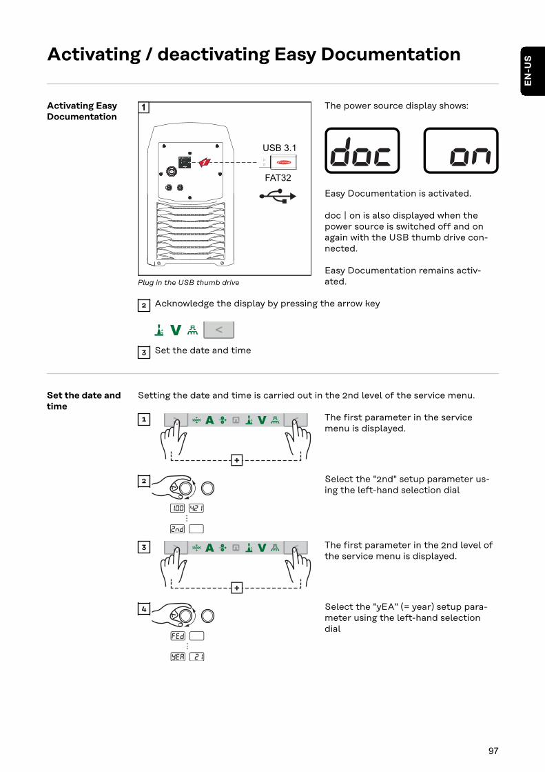
Activating / deactivating Easy Documentation
Activating EasyDocumentation
1
USB 3.1
FAT32
1
Plug in the USB thumb drive
The power source display shows:
Easy Documentation is activated.
doc | on is also displayed when thepower source is switched off and onagain with the USB thumb drive con-nected.
Easy Documentation remains activ-ated.
2 Acknowledge the display by pressing the arrow key
3 Set the date and time
Set the date andtime
Setting the date and time is carried out in the 2nd level of the service menu.
+
1 The first parameter in the servicemenu is displayed.
...
2 Select the "2nd" setup parameter us-ing the left-hand selection dial
+
3 The first parameter in the 2nd level ofthe service menu is displayed.
...
4 Select the "yEA" (= year) setup para-meter using the left-hand selectiondial
97
EN
-US
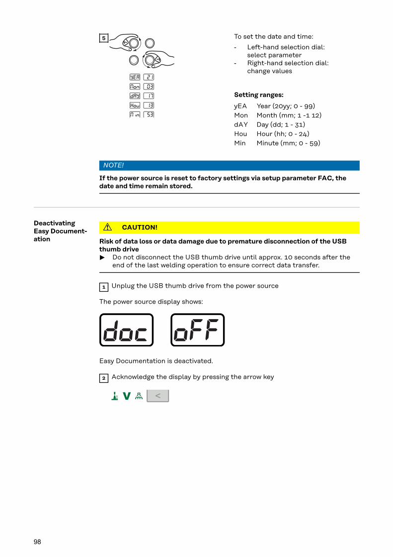
5 To set the date and time:
- Left-hand selection dial:select parameter
- Right-hand selection dial:change values
Setting ranges:
yEA Year (20yy; 0 - 99)Mon Month (mm; 1 -1 12)dAY Day (dd; 1 - 31)Hou Hour (hh; 0 - 24)Min Minute (mm; 0 - 59)
NOTE!
If the power source is reset to factory settings via setup parameter FAC, thedate and time remain stored.
DeactivatingEasy Document-ation
CAUTION!
Risk of data loss or data damage due to premature disconnection of the USBthumb drive
▶ Do not disconnect the USB thumb drive until approx. 10 seconds after theend of the last welding operation to ensure correct data transfer.
1 Unplug the USB thumb drive from the power source
The power source display shows:
Easy Documentation is deactivated.
2 Acknowledge the display by pressing the arrow key
98

Setup Settings
99

100

Setup Menu
General The Setup menu offers easy access to expert knowledge related to the powersource, as well as additional functions. The Setup menu makes it possible to eas-ily adjust the parameters for various tasks.
Operation Accessing the Setup menu is described with reference to the MIG/MAG standardsynergic welding process.Access is the same for the other welding processes.
Accessing the Setup menu
MANUAL
STD SYNERGIC
PULSE SYNERGIC
1 Press the "Process" button to selectthe "MIG/MAG standard synergicwelding" process
MANUAL
STD SYNERGIC
PULSE SYNERGIC
2T
4T +
+
2 The control panel is now located in theSetup menu of the "MIG/MAG stand-ard synergic welding" process - the lastselected setup parameter is displayed.
Adjusting parameters
1 Select the desired setup parameter us-ing the left-hand selection dial
Change the setup parameter value us-ing the right-hand selection dial
Exiting the Setup menu
MANUAL
STD SYNERGIC
PULSE SYNERGIC
2T
4T +
+
1
101
EN
-US

Setup paramet-ers forMIG/MAG syner-gic welding
The specifications "min." and "max." are used for setting ranges that vary accord-ing to the power source, welding program, etc.
GPr Gas pre-flow timeUnit: sSetting range: 0 - 9.9Factory setting: 0.1
GPo Gas post-flow timeUnit: sSetting range: 0 - 9.9Factory setting: 0.5
SL Slope (for special 2-step mode and special 4-step mode)Unit: sSetting range: 0 - 9.9Factory setting: 0.1
I-S Starting current (for special 2-step mode and special 4-step mode)Unit: % (of welding current)Setting range: 0 - 200Factory setting: 100
I-E Final current (for special 2-step mode and special 4-step mode)Unit: % (of welding current)Setting range: 0 - 200Factory setting: 50
t-S Starting current duration (only for special 2-step mode)Unit: sSetting range: 0.0 - 9.9Factory setting: 0.0
t-E Final current duration (only for special 2-step mode)Unit: sSetting range: 0.0 - 9.9Factory setting: 0.0
Fdi Feeder inching speedUnit: m/min (ipm)Setting range: 1 - max (39.37 - max)Factory setting: 10 (393.7)
bbc Burnback effectBurnback effect due to wire retraction at the end of weldingWhen the welding current is switched off, the wire electrode is retractedat 7.5 m/min for the duration of the set bbc value.
Unit: sSetting range: 0 - 0.2Factory setting: 0
Ito Length of wire that is fed before the safety cut-out tripsUnit: mm (in.)Setting range: OFF, 5 - 100 (OFF, 0.2 - 3.94)Factory setting: OFF
102
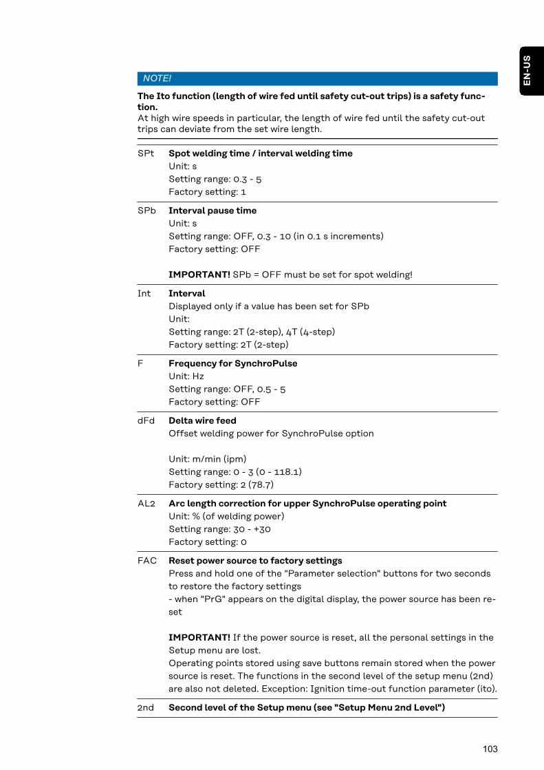
NOTE!
The Ito function (length of wire fed until safety cut-out trips) is a safety func-tion.At high wire speeds in particular, the length of wire fed until the safety cut-outtrips can deviate from the set wire length.
SPt Spot welding time / interval welding timeUnit: sSetting range: 0.3 - 5Factory setting: 1
SPb Interval pause timeUnit: sSetting range: OFF, 0.3 - 10 (in 0.1 s increments)Factory setting: OFF
IMPORTANT! SPb = OFF must be set for spot welding!
Int IntervalDisplayed only if a value has been set for SPbUnit:Setting range: 2T (2-step), 4T (4-step)Factory setting: 2T (2-step)
F Frequency for SynchroPulseUnit: HzSetting range: OFF, 0.5 - 5Factory setting: OFF
dFd Delta wire feedOffset welding power for SynchroPulse option
Unit: m/min (ipm)Setting range: 0 - 3 (0 - 118.1)Factory setting: 2 (78.7)
AL2 Arc length correction for upper SynchroPulse operating pointUnit: % (of welding power)Setting range: 30 - +30Factory setting: 0
FAC Reset power source to factory settingsPress and hold one of the "Parameter selection" buttons for two secondsto restore the factory settings- when "PrG" appears on the digital display, the power source has been re-set
IMPORTANT! If the power source is reset, all the personal settings in theSetup menu are lost.Operating points stored using save buttons remain stored when the powersource is reset. The functions in the second level of the setup menu (2nd)are also not deleted. Exception: Ignition time-out function parameter (ito).
2nd Second level of the Setup menu (see "Setup Menu 2nd Level")
103
EN
-US
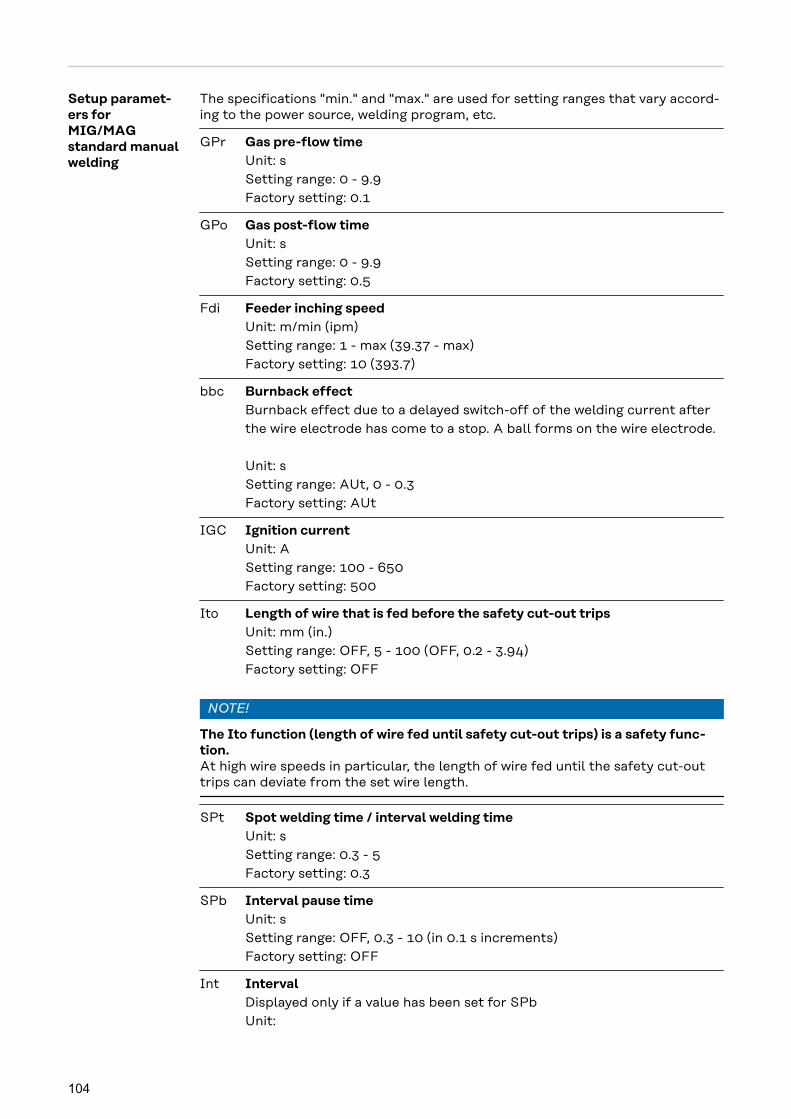
Setup paramet-ers forMIG/MAGstandard manualwelding
The specifications "min." and "max." are used for setting ranges that vary accord-ing to the power source, welding program, etc.
GPr Gas pre-flow timeUnit: sSetting range: 0 - 9.9Factory setting: 0.1
GPo Gas post-flow timeUnit: sSetting range: 0 - 9.9Factory setting: 0.5
Fdi Feeder inching speedUnit: m/min (ipm)Setting range: 1 - max (39.37 - max)Factory setting: 10 (393.7)
bbc Burnback effectBurnback effect due to a delayed switch-off of the welding current afterthe wire electrode has come to a stop. A ball forms on the wire electrode.
Unit: sSetting range: AUt, 0 - 0.3Factory setting: AUt
IGC Ignition currentUnit: ASetting range: 100 - 650Factory setting: 500
Ito Length of wire that is fed before the safety cut-out tripsUnit: mm (in.)Setting range: OFF, 5 - 100 (OFF, 0.2 - 3.94)Factory setting: OFF
NOTE!
The Ito function (length of wire fed until safety cut-out trips) is a safety func-tion.At high wire speeds in particular, the length of wire fed until the safety cut-outtrips can deviate from the set wire length.
SPt Spot welding time / interval welding timeUnit: sSetting range: 0.3 - 5Factory setting: 0.3
SPb Interval pause timeUnit: sSetting range: OFF, 0.3 - 10 (in 0.1 s increments)Factory setting: OFF
Int IntervalDisplayed only if a value has been set for SPbUnit:
104
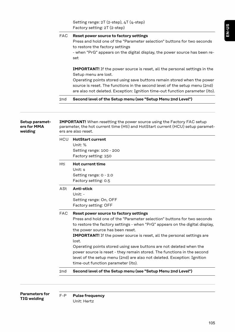
Setting range: 2T (2-step), 4T (4-step)Factory setting: 2T (2-step)
FAC Reset power source to factory settingsPress and hold one of the "Parameter selection" buttons for two secondsto restore the factory settings- when "PrG" appears on the digital display, the power source has been re-set
IMPORTANT! If the power source is reset, all the personal settings in theSetup menu are lost.Operating points stored using save buttons remain stored when the powersource is reset. The functions in the second level of the setup menu (2nd)are also not deleted. Exception: Ignition time-out function parameter (ito).
2nd Second level of the Setup menu (see "Setup Menu 2nd Level")
Setup paramet-ers for MMAwelding
IMPORTANT! When resetting the power source using the Factory FAC setupparameter, the hot current time (Hti) and HotStart current (HCU) setup paramet-ers are also reset.
HCU HotStart currentUnit: %Setting range: 100 - 200Factory setting: 150
Hti Hot current timeUnit: sSetting range: 0 - 2.0Factory setting: 0.5
ASt Anti-stickUnit: -Setting range: On, OFFFactory setting: OFF
FAC Reset power source to factory settingsPress and hold one of the "Parameter selection" buttons for two secondsto restore the factory settings - when "PrG" appears on the digital display,the power source has been reset.IMPORTANT! If the power source is reset, all the personal settings arelost.Operating points stored using save buttons are not deleted when thepower source is reset - they remain stored. The functions in the secondlevel of the setup menu (2nd) are also not deleted. Exception: Ignitiontime-out function parameter (ito).
2nd Second level of the Setup menu (see "Setup Menu 2nd Level")
Parameters forTIG welding
F-P Pulse frequencyUnit: Hertz
105
EN
-US

Setting range: OFF; 1 - 990(up to 10 Hz: in 0.1 Hz increments)(up to 100 Hz: in 1 Hz increments)(over 100 Hz: in 10 Hz increments)Factory setting: OFF
tUP UpSlopeUnit: secondsSetting range: 0.01 - 9.9Factory setting: 0.5
tdo DownSlopeUnit: secondsSetting range: 0.01 - 9.9Factory setting: 1
I-S Starting currentUnit: % of main currentSetting range: 1 - 200Factory setting: 35
I-2 Lowering currentUnit: % of main currentSetting range: 1 - 100Factory setting: 50
I-E Final currentUnit: % of main currentSetting range: 1 - 100Factory setting: 30
GPo Gas post-flow timeUnit: secondsSetting range: 0 - 9.9Factory setting: 9.9
tAC TackingUnit: secondsSetting range: OFF, 0.1 - 9.9Factory setting: OFF
FAC Reset power source to factory settingsPress and hold one of the "Parameter selection" buttons for two secondsto restore the factory settings- when "PrG" appears on the digital display, the power source has been re-set.
When the power source is reset, the majority of the applied settings aredeleted. The following values remain:- Welding circuit resistance and welding circuit inductivity- Country-specific setting
2nd Second level of the Setup menu (see "Setup Menu 2nd Level")
106

Setup Menu 2nd Level
Limitations The following restrictions occur in relation to the Setup menu 2nd level:
Setup menu 2nd level cannot be selected:- during welding- if the "Gas test" function is active- if the "Wire threading" function is active- if the "Wire withdrawal" function is active- if the "Gas purging" function is active
If level 2 of the Setup menu is selected, the following functions are not available,even in robot mode:- Welding start-up - the "Power source ready" signal will not be emitted for ro-
bot mode- Gas test- Wire inching- Wire withdrawal- Gas purging
Operation(Setup Menu 2ndLevel)
Accessing the 2nd level of the Setup menu:
MANUAL
STD SYNERGIC
PULSE SYNERGIC
1 Press the "Process" button to selectthe "MIG/MAG standard synergicwelding" process
MANUAL
STD SYNERGIC
PULSE SYNERGIC
2T
4T +
+
2 The control panel is now located in theSetup menu of the "MIG/MAG stand-ard synergic welding" process - the lastselected setup parameter is displayed.
3 Select the "2nd" setup parameter us-ing the left-hand selection dial
MANUAL
STD SYNERGIC
PULSE SYNERGIC
2T
4T +
+
4 The control panel is now located in the2nd level of the Setup menu of the"MIG/MAG standard synergic welding"process - the last selected setup para-meter is displayed.
Adjusting parameters
1 Select the desired setup parameter us-ing the left-hand selection dial
Change the setup parameter value us-ing the right-hand selection dial
107
EN
-US

Exiting the Setup menu
MANUAL
STD SYNERGIC
PULSE SYNERGIC
2T
4T +
+
1 A parameter is displayed in the firstlevel of the Setup menu.
MANUAL
STD SYNERGIC
PULSE SYNERGIC
2T
4T +
+
2
Parameters forMIG/MAG syner-gic welding inSetup menu 2ndlevel
SEt Country-specific setting (Standard/USA) ... Std/USUnit: -Setting range: Std, US (Standard/USA)Factory setting:Standard version: Std (measurements: cm/mm)USA version: US (measures: in.)
Syn Synergic programs/characteristicsStandards EN/AWSUnit: -Setting range: EUr/USFactory setting:Standard version: EUrUSA version: US
C-C Cooler mode(only when the cooling unit is connected)
Unit: -Setting range: AUt, On, OFFFactory setting: AUt
AUt:The cooling unit cuts out after a 2-minute welding off-time.
IMPORTANT! If the coolant temperature and flow monitoring option hasbeen installed in the cooling unit, the cooling unit cuts out as soon as thereturn-flow temperature drops below 50 °C, but at the earliest after a 2-minute welding off-time.
On:The cooling unit is always switched on.
OFF:The cooling unit is always switched off.
IMPORTANT! If the FAC welding parameter is used, the C-C parameter isnot reset to the factory setting. If the MMA welding process is selected,
108

the cooling unit is always switched off, even if the switch is in the "On" po-sition.
C-t Cooling time(only when the cooling unit is connected)Time from when flow monitoring is triggered until the "no | H2O" servicecode is output. For example, if there are air bubbles in the cooling system,the cooling unit will not cut out until the end of this preset time.
Unit: sSetting range: 5 - 25Factory setting: 10
IMPORTANT! Every time the power source is switched on, the coolingunit carries out a test run for 180 seconds.
r Welding circuit resistance (in mOhm)See the section "Measuring the welding circuit resistance r" from page114.
L Welding circuit inductivity (in microhenrys)See the section "Displaying the welding circuit inductivity L" from page116.
EnE Electrical energy of the arc in relation to the welding speedUnit: kJSetting range: On/OFFFactory setting: OFF
Since the full range of values (1 kJ - 99999 kJ) cannot be displayed on thethree-digit display, the following display format has been selected:
Value in kJ / indicator on display:1 to 999 / 1 to 9991000 to 9999 / 1.00 to 9.99 (without unit digit, e.g., 5270 kJ -> 5.27)10000 to 99999 / 10.0 to 99.9(without unit or tens digit, e.g., 23580 kJ -> 23.6)
ALC Correction of the arc length via the welding voltageOnly for MIG/MAG synergic weldingSetting range: On/OFFFactory setting: OFFThe arc length depends on the welding voltage. The welding voltage canbe individually adjusted in synergic operation.If the ALC parameter is set to "OFF", individual adjustment of the weldingvoltage is not possible. The welding voltage adjusts automatically accord-ing to the selected welding current or wire speed. When the arc lengthcorrection is adjusted, the voltage changes while the welding current andthe wire speed remain constant. When adjusting the arc length correctionusing the selection wheel, the left display is used for the correction valueof the arc length. On the right display, the value for the welding voltage
109
EN
-US

changes at the same time. The left display then shows the original valueagain, e.g., welding current.
Ejt EasyJob TriggerTo activate/deactivate switching between EasyJobs using the torch trigger
Unit: -Setting range: On/OFFFactory setting: OFF
Function with MIG/MAG torch triggerPress torch trigger briefly (< 0.5 s)
No welding taking place:- Toggles through all MIG/MAG EasyJobs in sequence.- If an EasyJob is not selected, the torch trigger functions normally.- If a MIG/MAG EasyJob is not selected, no change is made.
Welding taking place:- Toggles through MIG/MAG EasyJobs with the same operating mode
(4-step, special 4-step, 4-step stitch welding) and with the same weld-ing process.
- It is not possible to switch during spot welding.
Function with MIG/MAG Up/Down keyIf an EasyJob is selected, the EasyJob is changed, otherwise the weldingcurrent is changed.
No welding taking place:- Toggles through all MIG/MAG EasyJobs in sequence.
Welding taking place:- Toggles through MIG/MAG EasyJobs with the same operating mode
(2-step, 4-step, special 4-step, 4-step stitch welding) and with thesame welding process.Switching back is possible.
Parameters forMIG/MAGstandard manualwelding in Setupmenu 2nd level
SEt Country-specific setting (Standard/USA) ... Std/USUnit: -Setting range: Std, US (Standard/USA)Factory setting:Standard version: Std (measurements: cm/mm)USA version: US (measures: in.)
C-C Cooler mode(only when the cooling unit is connected)
Unit: -Setting range: AUt, On, OFFFactory setting: AUt
110

AUt:The cooling unit cuts out after a 2-minute welding off-time.
IMPORTANT! If the coolant temperature and flow monitoring option hasbeen installed in the cooling unit, the cooling unit cuts out as soon as thereturn-flow temperature drops below 50 °C, but at the earliest after a 2-minute welding off-time.
On:The cooling unit is always switched on.
OFF:The cooling unit is always switched off.
IMPORTANT! If the FAC welding parameter is used, the C-C parameter isnot reset to the factory setting. If the MMA welding process is selected,the cooling unit is always switched off, even if the switch is in the "On" po-sition.
C-t Cooling time(only when the cooling unit is connected)Time from when flow monitoring is triggered until the "no | H2O" servicecode is output. For example, if there are air bubbles in the cooling system,the cooling unit will not cut out until the end of this preset time.
Unit: sSetting range: 5 - 25Factory setting: 10
IMPORTANT! Every time the power source is switched on, the coolingunit carries out a test run for 180 seconds.
r Welding circuit resistance (in mOhm)See the section "Measuring the welding circuit resistance r" from page114.
L Welding circuit inductivity (in microhenrys)See the section "Displaying the welding circuit inductivity L" from page116.
EnE Electrical energy of the arc in relation to the welding speedUnit: kJSetting range: On/OFFFactory setting: OFF
Since the full range of values (1 kJ - 99999 kJ) cannot be displayed on thethree-digit display, the following display format has been selected:
Value in kJ / indicator on display:1 to 999 / 1 to 9991000 to 9999 / 1.00 to 9.99 (without unit digit, e.g., 5270 kJ -> 5.27)
111
EN
-US

10000 to 99999 / 10.0 to 99.9(without unit or tens digit, e.g., 23580 kJ -> 23.6)
Ejt EasyJob TriggerTo activate/deactivate switching between EasyJobs using the torch trigger
Unit: -Setting range: On/OFFFactory setting: OFF
Function with MIG/MAG torch triggerPress torch trigger briefly (< 0.5 s)
No welding taking place:- Toggles through all MIG/MAG EasyJobs in sequence.- If an EasyJob is not selected, the torch trigger functions normally.- If a MIG/MAG EasyJob is not selected, no change is made.
Welding taking place:- Toggles through MIG/MAG EasyJobs with the same operating mode
(4-step, special 4-step, 4-step stitch welding) and with the same weld-ing process.
- It is not possible to switch during spot welding.
Function with MIG/MAG Up/Down keyIf an EasyJob is selected, the EasyJob is changed, otherwise the weldingcurrent is changed.
No welding taking place:- Toggles through all MIG/MAG EasyJobs in sequence.
Welding taking place:- Toggles through MIG/MAG EasyJobs with the same operating mode
(2-step, 4-step, special 4-step, 4-step stitch welding) and with thesame welding process.Switching back is possible.
Parameters formanual metalarc welding inSetup menu 2ndlevel
SEt Country-specific setting (Standard/USA) ... Hour/USUnit:Setting range: Std, US (Standard/USA)Factory setting:Standard version: Std (dimensions: cm / mm)USA version: US (dimensions: in.)
r r (resistance) - welding circuit resistance (in mOhm)See the section "Measuring the welding circuit resistance r" from page114.
L L (inductivity) - welding circuit inductivity (in microhenrys)See the section "Displaying the welding circuit inductivity L" from page116.
112
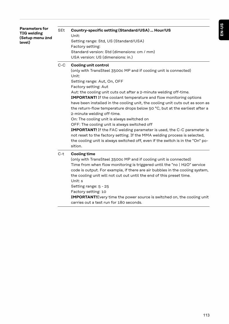
Parameters forTIG welding(Setup menu 2ndlevel)
SEt Country-specific setting (Standard/USA) ... Hour/USUnit:Setting range: Std, US (Standard/USA)Factory setting:Standard version: Std (dimensions: cm / mm)USA version: US (dimensions: in.)
C-C Cooling unit control(only with TransSteel 3500c MP and if cooling unit is connected)Unit:Setting range: Aut, On, OFFFactory setting: AutAut: the cooling unit cuts out after a 2-minute welding off-time.IMPORTANT! If the coolant temperature and flow monitoring optionshave been installed in the cooling unit, the cooling unit cuts out as soon asthe return-flow temperature drops below 50 °C, but at the earliest after a2-minute welding off-time.On: The cooling unit is always switched onOFF: The cooling unit is always switched offIMPORTANT! If the FAC welding parameter is used, the C-C parameter isnot reset to the factory setting. If the MMA welding process is selected,the cooling unit is always switched off, even if the switch is in the "On" po-sition.
C-t Cooling time(only with TransSteel 3500c MP and if cooling unit is connected)Time from when flow monitoring is triggered until the "no | H2O" servicecode is output. For example, if there are air bubbles in the cooling system,the cooling unit will not cut out until the end of this preset time.Unit: sSetting range: 5 - 25Factory setting: 10IMPORTANT!Every time the power source is switched on, the cooling unitcarries out a test run for 180 seconds.
113
EN
-US

Measuring the Welding Circuit Resistance r
General Measuring the welding circuit resistance makes it possible to have a constantwelding result at all times, even with hosepacks of different lengths. The weldingvoltage at the arc is then always precisely regulated, regardless of the length andcross-sectional area of the hosepack. The use of arc length correction is nolonger required.
The calculated welding circuit resistance is shown on the display.
r = welding circuit resistance in milliohm (mOhm)
If the welding circuit resistance has been measured correctly, the set weldingvoltage will correspond exactly to the welding voltage at the arc. If you manuallymeasure the voltage on the output jacks of the power source, this voltage will behigher than the welding voltage at the arc - that is, higher by the same amount asthe voltage drop of the hosepack.
The welding circuit resistance depends on the hosepack used:- If the length or cross-sectional area of the hosepack has changed, measure
the welding circuit resistance again- Measure the welding circuit resistance for every welding process separately
with the appropriate welding power-leads
Measuring thewelding circuitresistance(MIG/MAG weld-ing)
NOTE!
Incorrect measurement of the welding circuit resistance can have a negative ef-fect on the welding result.
▶ Ensure that the workpiece has an optimum contact surface in the area of theearthing clamp (clean surface, no rust, etc.).
1 Make sure that one of the MANUAL / STD SYNERGIC / pulsed synergic weld-ing processes is selected
2 Establish a ground earth connection to the workpiece
3 Access the Setup menu 2nd level (2nd)
4 Select parameter "r"
5 Remove the gas nozzle from the welding torch
6 Screw on the contact tip
7 Ensure that the wire electrode does not protrude from the contact tip
NOTE!
Incorrect measurement of the welding circuit resistance can have a negative ef-fect on the welding result.
▶ Ensure that the workpiece has an optimum contact surface for the contacttip (clean surface, no rust, etc.).
8 Place the contact tip flush against the workpiece surface
9 Press the torch trigger briefly- The welding circuit resistance is calculated. "run" is shown on the display
during the measurement
114

The measurement is finished when the welding circuit resistance is shown on thedisplay in mOhm (for example 11.4).
10 Fit the gas nozzle back onto the welding torch
Measuring thewelding circuitresistance (MMAwelding)
NOTE!
Incorrect measurement of the welding circuit resistance can have a negative ef-fect on the welding result.
▶ Ensure that the workpiece has an optimum contact surface in the area of theearthing clamp (clean surface, no rust, etc.).
1 Ensure that the Stabelektroden-Schweißen welding process is selected
2 Establish a ground earth connection to the workpiece
3 Access the Setup menu 2nd level (2nd)
4 Select parameter "r"
NOTE!
Incorrect measurement of the welding circuit resistance can have a negative ef-fect on the welding result.
▶ Ensure that the workpiece has an optimum contact surface for the electrode(clean surface, no rust, etc.).
5 Place the electrode flush against the workpiece surface
6 Press the "Parameter selection" button (right)
The welding circuit resistance is calculated. During the measurement the dis-play shows "run".
The measurement is finished when the welding circuit resistance is shown on thedisplay in mOhm (for example 11.4).
115
EN
-US
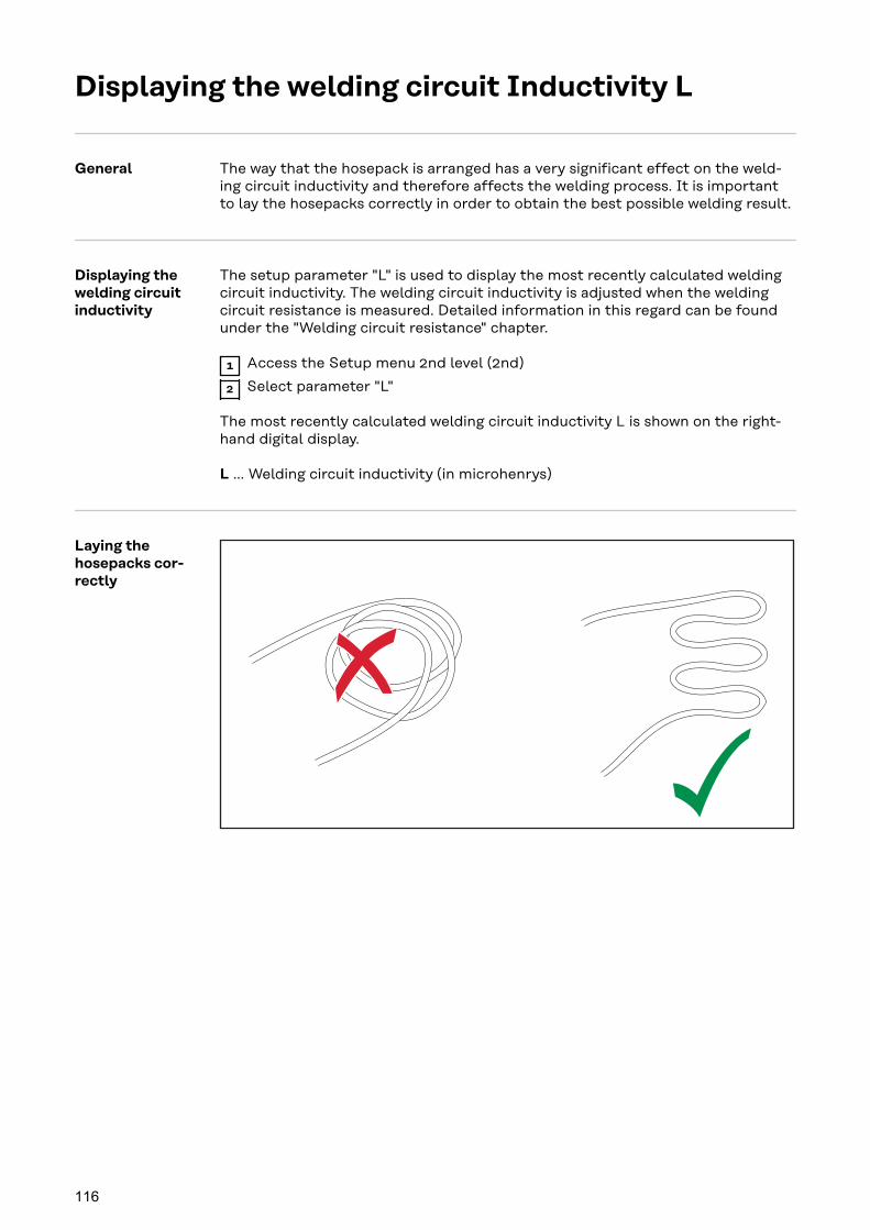
Displaying the welding circuit Inductivity L
General The way that the hosepack is arranged has a very significant effect on the weld-ing circuit inductivity and therefore affects the welding process. It is importantto lay the hosepacks correctly in order to obtain the best possible welding result.
Displaying thewelding circuitinductivity
The setup parameter "L" is used to display the most recently calculated weldingcircuit inductivity. The welding circuit inductivity is adjusted when the weldingcircuit resistance is measured. Detailed information in this regard can be foundunder the "Welding circuit resistance" chapter.
1 Access the Setup menu 2nd level (2nd)
2 Select parameter "L"
The most recently calculated welding circuit inductivity L is shown on the right-hand digital display.
L ... Welding circuit inductivity (in microhenrys)
Laying thehosepacks cor-rectly
116

Troubleshooting and Maintenance
117

118

Troubleshooting
General The devices are equipped with an intelligent safety system, which largely negatesthe need for melting-type fuses. Melting-type fuses therefore no longer need tobe replaced. After a possible malfunction has been remedied, the device is readyfor use again.
SafetyWARNING!
Danger from incorrect operation and work that is not carried out properly.This can result in serious personal injury and damage to property.
▶ All the work and functions described in this document must only be carriedout by technically trained and qualified personnel.
▶ Read and understand this document in full.
▶ Read and understand all safety rules and user documentation for this equip-ment and all system components.
WARNING!
Danger from electrical current.This can result in serious personal injury and damage to property.
▶ Before starting work, switch off all devices and components involved, anddisconnect them from the grid.
▶ Secure all devices and components involved so they cannot be switched backon.
▶ After opening the device, use a suitable measuring instrument to check thatelectrically charged components (such as capacitors) have been discharged.
WARNING!
Danger due to insufficient ground conductor connection.This can result in serious personal injury and damage to property.
▶ The housing screws provide a suitable ground conductor connection forgrounding the housing.
▶ The housing screws must not under any circumstances be replaced by otherscrews without a reliable ground conductor connection.
Displayed Ser-vice Codes
If an error message that is not described here appears on the displays, first try toresolve the problem as follows:
1 Switch the power source power switch to the -O- position
2 Wait 10 seconds
3 Switch the power switch to the -I- position
If the error occurs again despite several attempts to eliminate it, or if thetroubleshooting measures listed here are unsuccessful.
1 Make a note of the error message displayed
2 Note down the configuration of the power source
119
EN
-US

3 Contact our After-Sales Service team with a detailed description of the error
ESr | 20
The cooling unit used is not compatible with the power source
Connect compatible cooling unit
Cause:
Remedy:
ELn | 8
The connected wirefeeder is not supported
Connect supported wirefeeder
Cause:
Remedy:
ELn | 12
Different control panels for selecting materials are in the system
Connect similar control panels to select materials
Cause:
Remedy:
ELn | 13
Impermissible change of welding process during welding
During welding do not make any impermissible change to the weldingprocess, reset error message by pressing any button
Cause:
Remedy:
ELn | 14
More than one robot interface is connected
Only one robot interface may be connected, check the system config-uration
Cause:
Remedy:
ELn | 15
More than one remote control is connected
Only one remote control may be connected, check the system config-uration
Cause:
Remedy:
Err | IP
The power source control has detected a primary overvoltage
Check the grid voltage.If the service code persists, switch off the power source, wait for 10seconds and then switch the power source on again.If the error still persists, contact the After-Sales Service team
Cause:
Remedy:
Err | PE
The earth current watchdog has triggered the safety cut-out of thepower source.
Switch off the power sourcePlace the power source on an insulating surfaceConnect the grounding cable to a section of the workpiece that iscloser to the arcWait for 10 seconds and then switch the power source on again
If you have tried this several times and the error keeps recurring,contact the After-Sales Service team
Cause:
Remedy:
PHA | SE1
The power source is being used in single-phase mode
-
Cause:
Remedy:
PHA | SE3
The power source is being used in three-phase mode
-
Cause:
Remedy:
120
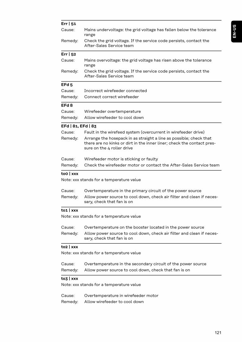
Err | 51
Mains undervoltage: the grid voltage has fallen below the tolerancerange
Check the grid voltage. If the service code persists, contact theAfter-Sales Service team
Cause:
Remedy:
Err | 52
Mains overvoltage: the grid voltage has risen above the tolerancerange
Check the grid voltage. If the service code persists, contact theAfter-Sales Service team
Cause:
Remedy:
EFd 5
Incorrect wirefeeder connected
Connect correct wirefeeder
Cause:
Remedy:
EFd 8
Wirefeeder overtemperature
Allow wirefeeder to cool down
Cause:
Remedy:
EFd | 81, EFd | 83
Fault in the wirefeed system (overcurrent in wirefeeder drive)
Arrange the hosepack in as straight a line as possible; check thatthere are no kinks or dirt in the inner liner; check the contact pres-sure on the 4 roller drive
Wirefeeder motor is sticking or faulty
Check the wirefeeder motor or contact the After-Sales Service team
Cause:
Remedy:
Cause:
Remedy:
to0 | xxx
Note: xxx stands for a temperature value
Overtemperature in the primary circuit of the power source
Allow power source to cool down, check air filter and clean if neces-sary, check that fan is on
Cause:
Remedy:
to1 | xxx
Note: xxx stands for a temperature value
Overtemperature on the booster located in the power source
Allow power source to cool down, check air filter and clean if neces-sary, check that fan is on
Cause:
Remedy:
to2 | xxx
Note: xxx stands for a temperature value
Overtemperature in the secondary circuit of the power source
Allow power source to cool down, check that fan is on
Cause:
Remedy:
to3 | xxx
Note: xxx stands for a temperature value
Overtemperature in wirefeeder motor
Allow wirefeeder to cool down
Cause:
Remedy:
121
EN
-US

to4 | xxx
Note: xxx stands for a temperature value
Overtemperature in welding torch
Allow welding torch to cool down
Cause:
Remedy:
to5 | xxx
Note: xxx stands for a temperature value
Overtemperature in cooling unit
Allow cooling unit to cool down, check that fan is on
Cause:
Remedy:
to6 | xxx
Note: xxx stands for a temperature value
Overtemperature on the power source transformer
Allow power source to cool down, check air filter and clean if neces-sary, check that fan is on
Cause:
Remedy:
to7 | xxx
Note: xxx stands for a temperature value
Overtemperature in the power source
Allow power source to cool down, check air filter and clean if neces-sary, check that fan is on
Cause:
Remedy:
tu0 | xxx
Note: xxx stands for a temperature value
Undertemperature in the power source primary circuit
Place power source in a heated room and allow it to warm up
Cause:
Remedy:
tu1 | xxx
Note: xxx stands for a temperature value
Undertemperature on the booster located in the power source
Place power source in a heated room and allow it to warm up
Cause:
Remedy:
tu2 | xxx
Note: xxx stands for a temperature value
Undertemperature in the power source secondary circuit
Place power source in a heated room and allow it to warm up
Cause:
Remedy:
tu3 | xxx
Note: xxx stands for a temperature value
Undertemperature in the wirefeeder motor
Place wirefeeder in a heated room and allow to warm up
Cause:
Remedy:
tu4 | xxx
Note: xxx stands for a temperature value
Undertemperature in the welding torch
Place welding torch in a heated room and allow to warm up
Cause:
Remedy:
122
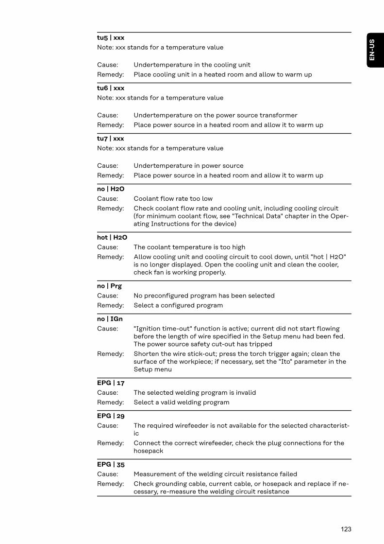
tu5 | xxx
Note: xxx stands for a temperature value
Undertemperature in the cooling unit
Place cooling unit in a heated room and allow to warm up
Cause:
Remedy:
tu6 | xxx
Note: xxx stands for a temperature value
Undertemperature on the power source transformer
Place power source in a heated room and allow it to warm up
Cause:
Remedy:
tu7 | xxx
Note: xxx stands for a temperature value
Undertemperature in power source
Place power source in a heated room and allow it to warm up
Cause:
Remedy:
no | H2O
Coolant flow rate too low
Check coolant flow rate and cooling unit, including cooling circuit(for minimum coolant flow, see "Technical Data" chapter in the Oper-ating Instructions for the device)
Cause:
Remedy:
hot | H2O
The coolant temperature is too high
Allow cooling unit and cooling circuit to cool down, until "hot | H2O"is no longer displayed. Open the cooling unit and clean the cooler,check fan is working properly.
Cause:
Remedy:
no | Prg
No preconfigured program has been selected
Select a configured program
Cause:
Remedy:
no | IGn
"Ignition time-out" function is active; current did not start flowingbefore the length of wire specified in the Setup menu had been fed.The power source safety cut-out has tripped
Shorten the wire stick-out; press the torch trigger again; clean thesurface of the workpiece; if necessary, set the "Ito" parameter in theSetup menu
Cause:
Remedy:
EPG | 17
The selected welding program is invalid
Select a valid welding program
Cause:
Remedy:
EPG | 29
The required wirefeeder is not available for the selected characterist-ic
Connect the correct wirefeeder, check the plug connections for thehosepack
Cause:
Remedy:
EPG | 35
Measurement of the welding circuit resistance failed
Check grounding cable, current cable, or hosepack and replace if ne-cessary, re-measure the welding circuit resistance
Cause:
Remedy:
123
EN
-US
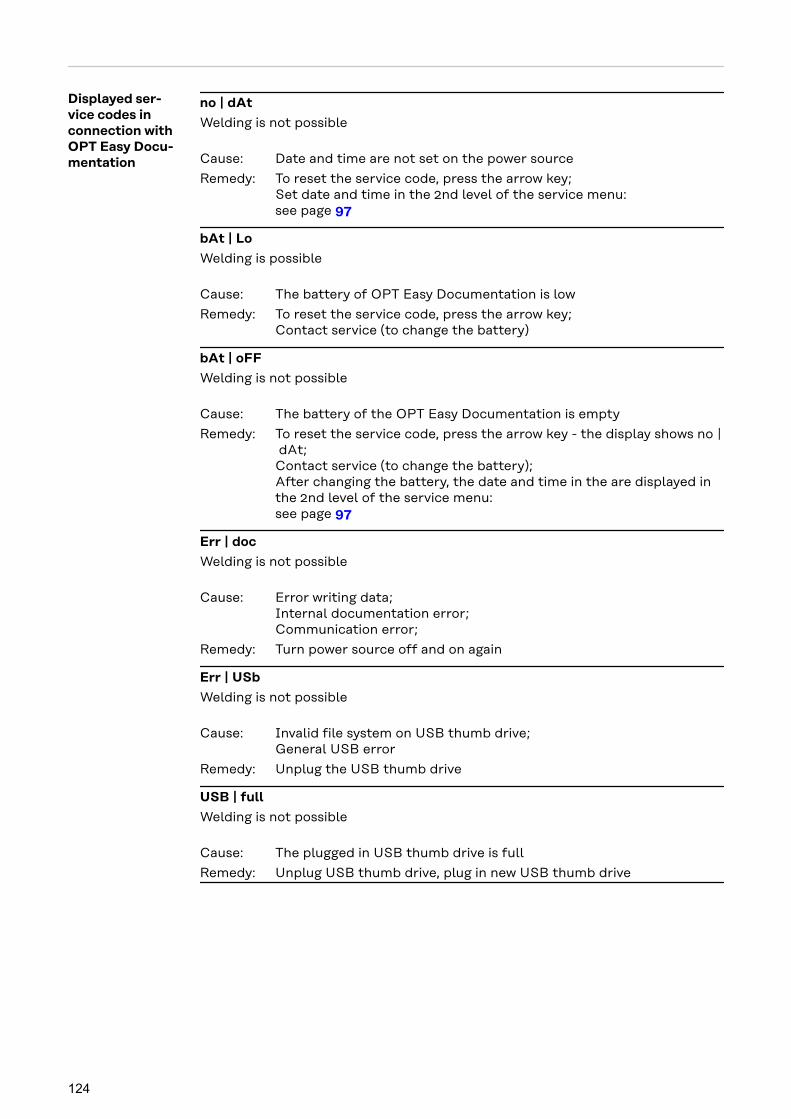
Displayed ser-vice codes inconnection withOPT Easy Docu-mentation
no | dAt
Welding is not possible
Date and time are not set on the power source
To reset the service code, press the arrow key;Set date and time in the 2nd level of the service menu:see page 97
Cause:
Remedy:
bAt | Lo
Welding is possible
The battery of OPT Easy Documentation is low
To reset the service code, press the arrow key;Contact service (to change the battery)
Cause:
Remedy:
bAt | oFF
Welding is not possible
The battery of the OPT Easy Documentation is empty
To reset the service code, press the arrow key - the display shows no | dAt;Contact service (to change the battery);After changing the battery, the date and time in the are displayed inthe 2nd level of the service menu:see page 97
Cause:
Remedy:
Err | doc
Welding is not possible
Error writing data;Internal documentation error;Communication error;
Turn power source off and on again
Cause:
Remedy:
Err | USb
Welding is not possible
Invalid file system on USB thumb drive;General USB error
Unplug the USB thumb drive
Cause:
Remedy:
USB | full
Welding is not possible
The plugged in USB thumb drive is full
Unplug USB thumb drive, plug in new USB thumb drive
Cause:
Remedy:
124

Service, maintenance and disposal
General Under normal operating conditions, the welding system requires only a minimumof care and maintenance. However, several points must be observed in order forthe welding system to remain operational for years to come.
SafetyWARNING!
Danger from electrical current.This can result in serious personal injury and damage to property.
▶ Before starting work, switch off all devices and components involved, anddisconnect them from the grid.
▶ Secure all devices and components involved so they cannot be switched backon.
▶ After opening the device, use a suitable measuring instrument to check thatelectrically charged components (such as capacitors) have been discharged.
WARNING!
Danger from incorrect operation and work that is not carried out properly.This can result in serious personal injury and damage to property.
▶ All the work and functions described in this document must only be carriedout by technically trained and qualified personnel.
▶ Read and understand this document in full.
▶ Read and understand all safety rules and user documentation for this equip-ment and all system components.
At every start-up
- Check mains plug and mains cable, as well as the welding torch, intercon-necting hosepack, and ground earth connection for damage
- Check if the all-round clearance of the device is 0.5 m (1 ft. 8 in.) so thatcooling air can circulate unimpeded
NOTE!
Air inlet and outlet openings must not be blocked or even partially covered.
Whenever re-quired
Remove the air filter on the rear of the housing from the side and clean it.
Every 2 MonthsCAUTION!
Danger of damage to property.
▶ The air filter must only be fitted when dry.
▶ If required, clean air filter using dry compressed air or by washing it.
125
EN
-US
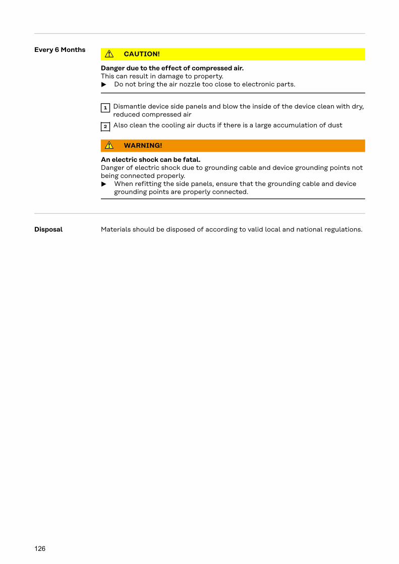
Every 6 MonthsCAUTION!
Danger due to the effect of compressed air.This can result in damage to property.
▶ Do not bring the air nozzle too close to electronic parts.
1 Dismantle device side panels and blow the inside of the device clean with dry,reduced compressed air
2 Also clean the cooling air ducts if there is a large accumulation of dust
WARNING!
An electric shock can be fatal.Danger of electric shock due to grounding cable and device grounding points notbeing connected properly.
▶ When refitting the side panels, ensure that the grounding cable and devicegrounding points are properly connected.
Disposal Materials should be disposed of according to valid local and national regulations.
126

Appendix
127

128
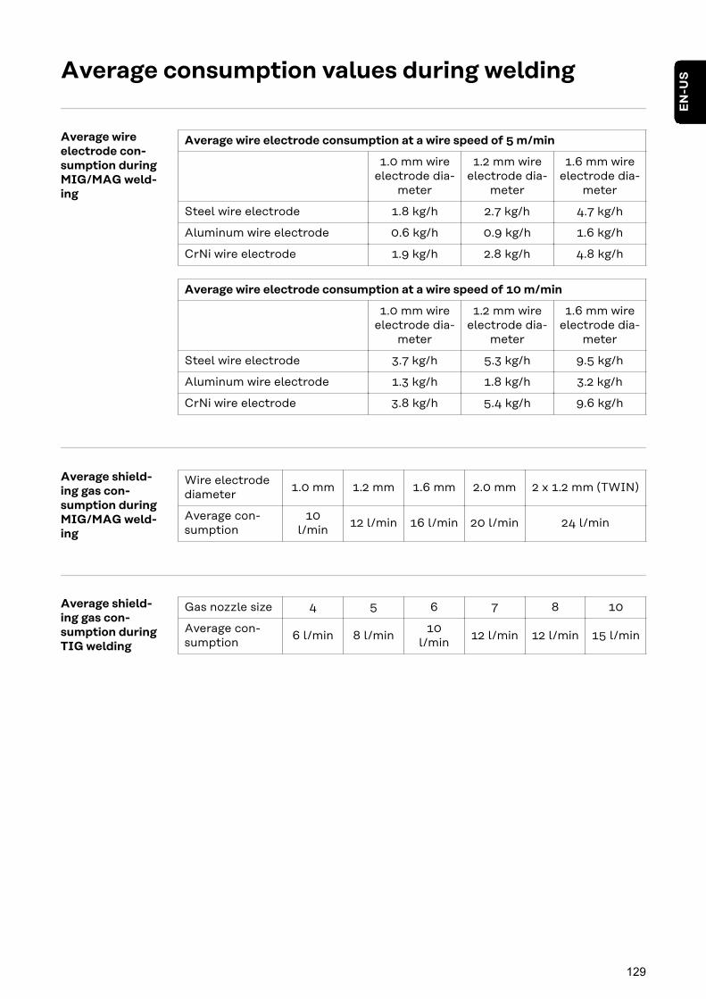
Average consumption values during welding
Average wireelectrode con-sumption duringMIG/MAG weld-ing
Average wire electrode consumption at a wire speed of 5 m/min
1.0 mm wireelectrode dia-
meter
1.2 mm wireelectrode dia-
meter
1.6 mm wireelectrode dia-
meter
Steel wire electrode 1.8 kg/h 2.7 kg/h 4.7 kg/h
Aluminum wire electrode 0.6 kg/h 0.9 kg/h 1.6 kg/h
CrNi wire electrode 1.9 kg/h 2.8 kg/h 4.8 kg/h
Average wire electrode consumption at a wire speed of 10 m/min
1.0 mm wireelectrode dia-
meter
1.2 mm wireelectrode dia-
meter
1.6 mm wireelectrode dia-
meter
Steel wire electrode 3.7 kg/h 5.3 kg/h 9.5 kg/h
Aluminum wire electrode 1.3 kg/h 1.8 kg/h 3.2 kg/h
CrNi wire electrode 3.8 kg/h 5.4 kg/h 9.6 kg/h
Average shield-ing gas con-sumption duringMIG/MAG weld-ing
Wire electrodediameter
1.0 mm 1.2 mm 1.6 mm 2.0 mm 2 x 1.2 mm (TWIN)
Average con-sumption
10l/min
12 l/min 16 l/min 20 l/min 24 l/min
Average shield-ing gas con-sumption duringTIG welding
Gas nozzle size 4 5 6 7 8 10
Average con-sumption
6 l/min 8 l/min10
l/min12 l/min 12 l/min 15 l/min
129
EN
-US

Technical data
Overview withcritical raw ma-terials, year ofproduction ofthe device
Overview with critical raw materials:An overview of which critical raw materials are contained in this device can befound at the following Internet address.www.fronius.com/en/about-fronius/sustainability.
To calculate the year of production of the device:- Each device is provided with a serial number- The serial number consists of 8 digits - for example 28020099- The first two digits give the number from which the year of production of the
device can be calculated- This figure minus 11 gives the year of production
- For example: Serial number = 28020065, calculation of the year of pro-duction = 28 - 11 = 17, year of production = 2017
Special Voltage For devices designed for special voltages, the technical data on the rating plateapplies.
The following applies for all devices with a permitted grid voltage of up to 460 V:The standard mains plug allows the user to operate with a grid voltage of up to400 V. For grid voltages up to 460 V fit a mains plug permitted for such use orinstall the mains supply directly.
Explanation ofthe term dutycycle
The duty cycle (ED) is the period of a ten minute cycle in which the device may beoperated at the stated power without overheating.
NOTE!
The ED values cited on the rating plate relate to an ambient temperature of40 °C.If the ambient temperature is higher, the ED or power must be lowered accord-ingly.
Example: Welding with 150 A at 60% ED- Welding phase = 60% of 10 mins = 6 mins- Cool-down phase = rest time = 4 mins- Following the cool-down phase, the cycle begins again.
130

10 Min.6 Min.
150 A
0 Min.
0 A
4 Min.6 Min.
60 %
To use the device without interruptions:
1 Search for a 100% ED value in the technical data, which corresponds to theexisting ambient temperature.
2 Reduce the power or amperage value correspondingly so that the device canoperate without a cool-down phase.
131
EN
-US
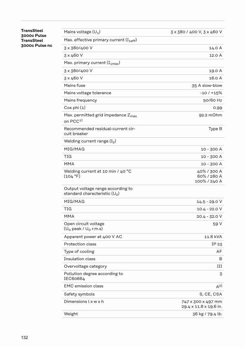
TransSteel3000c PulseTransSteel3000c Pulse nc
Mains voltage (U1) 3 x 380 / 400 V, 3 x 460 V
Max. effective primary current (I1eff)
3 x 380/400 V 14.0 A
3 x 460 V 12.0 A
Max. primary current (I1max)
3 x 380/400 V 19.0 A
3 x 460 V 16.0 A
Mains fuse 35 A slow-blow
Mains voltage tolerance -10 / +15%
Mains frequency 50/60 Hz
Cos phi (1) 0.99
Max. permitted grid impedance Zmax
on PCC1)
92.2 mOhm
Recommended residual-current cir-cuit breaker
Type B
Welding current range (I2)
MIG/MAG 10 - 300 A
TIG 10 - 300 A
MMA 10 - 300 A
Welding current at 10 min / 40 °C(104 °F)
40% / 300 A60% / 280 A
100% / 240 A
Output voltage range according tostandard characteristic (U2)
MIG/MAG 14.5 - 29.0 V
TIG 10.4 - 22.0 V
MMA 20.4 - 32.0 V
Open circuit voltage(U0 peak / U0 r.m.s)
59 V
Apparent power at 400 V AC 11.8 kVA
Protection class IP 23
Type of cooling AF
Insulation class B
Overvoltage category III
Pollution degree according toIEC60664
3
EMC emission class A2)
Safety symbols S, CE, CSA
Dimensions l x w x h 747 x 300 x 497 mm29.4 x 11.8 x 19.6 in.
Weight 36 kg / 79.4 lb.
132

Max. shielding gas pressure 5 bar/72.52 psi
Coolant Original Fronius
Wire speed 1 - 25 m/min / 40 - 980 ipm
Wire drive 4-roller drive
Wire diameter 0.8 - 1.6 mm/0.03 - 0.06 in.
Wirespool diameter max. 300 mm / max. 11.81 in.
Wirespool weight max. 19.0 kg / max. 41.9 lb.
Max. noise emission (LWA) 72 dB (A)
Idle state power consumption at 400V
36.5 W
Power source efficiency at300 A / 32 V
90%
1) Interface to a 230/400-V and 50-Hz public grid2) A device in emissions class A is not intended for use in residential areas in
which the power is supplied via a public low-voltage grid.The electromagnetic compatibility may be influenced by conducted or ra-diated radio frequencies.
133
EN
-US

Welding program tables
Welding programlabel on thedevice
A label with the most common welding programs is affixed to the power source:
Configuration
Steel ER 70-120
CrNi Stainless
CO2 100%
Ar+2-12%CO2
Ar+2-8%O2
1 A
1 B
1 C
1 D
2 B
3 E
E
E
B
C
4
5
6
6
7
Steel ER 70-120
Steel ER 70-120
Steel ER 70-120
Ar+13-25%CO2
CuSi3 ER CuSi-AAr 100%
AIMg ER5xxxAr 100%
AISi ER 4xxxAr 100%
Metal CoredAr+2-12%CO2
Metal CoredAr+13-25%CO2
Self-shielded
Ar+2-12%CO2
0.9
.035
0.8
.030
1.0
.040
1.2
.045
1.4
.052
1.6
1/16
[mm / inch]
Tst - 3000 Pulse
KL-DB: 3992
Standard welding characteristics
SP Configuration
CrNi Stainless FCW
Basic FCW E70T FCW
Ar+ 15-25%CO2
Ar+ 2,5%CO2
Ar+ 15-25%CO2
A
B
C
D
F
F
F
F
F
F
F
1
2
3
4
5
CrNi Stainless root
Rutil FCW E71T FCW
Rutil FCW E71T FCW
CO2 100%
Basic FCW E70T FCWAr+ 15-25%CO2
Steel dyn ER70-120Ar+ 8-10%CO2
Steel dyn ER70-120Ar+ 15-25%CO2
Steel dyn ER70-120Ar+ 4%O2
Steel rootCO2 100%
Steel root / PCSAr+ 8-10%CO2
CO2 100%
0.9
.035
0.8
.030
1.0
.040
1.2
.045
1.4
.052
1.6
1/16
[mm / inch]
Tst - 3000 Pulse
KL-DB: 3992
Additional welding characteristics
8 SP SP
SP
SP
SP
SP
SP
6Steel root / PCSAr+ 15-25%CO2
SP
8 SP
8 SP
8 SP
8 SP
8 SP
E
42,0409,0729 Standard Pulse
Welding program label on the power source
134
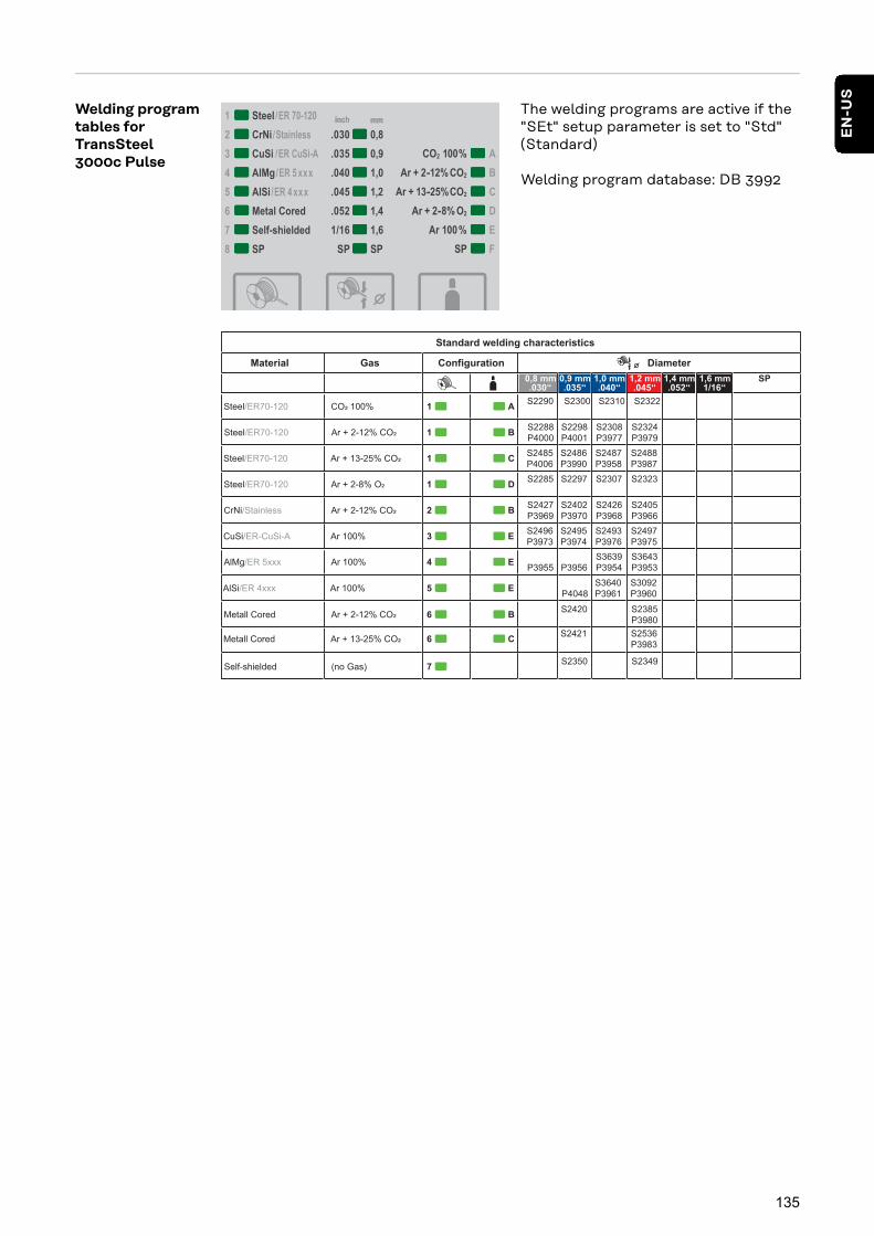
Welding programtables forTransSteel3000c Pulse
The welding programs are active if the"SEt" setup parameter is set to "Std"(Standard)
Welding program database: DB 3992
Standard welding characteristics
Material Configuration
AS2290 S2300 S2310 S2322
Gas Diameter
1Steel/ER70-120 CO 100%
0,8 mm.030‘‘
0,9 mm.035‘‘
1,0 mm.040‘‘
1,2 mm.045‘‘
1,4 mm.052‘‘
1,6 mm1/16‘‘
SP
BS2288
P4000
S2298
P4001
S2308
P3977
S2324
P39791Steel/ER70-120 Ar + 2-12% CO
CS2485
P4006
S2486
P3990
S2487
P3958
S2488
P39871Steel/ER70-120 Ar + 13-25% CO
DS2285 S2297 S2307 S2323
1Steel/ER70-120 Ar + 2-8% O
BS2427
P3969
S2402
P3970
S2426
P3968
S2405
P3966
2CrNi/Stainless Ar + 2-12% CO
ES2496
P3973
S2495
P3974
S2493
P3976
S2497
P3975
3CuSi/ER-CuSi-A Ar 100%
E
P3955
P3956
S3639
P3954
S3643
P3953
4AlMg/ER 5xxx Ar 100%
E
S3640
P3961
P4048
S3092
P3960
5AlSi/ER 4xxx Ar 100%
B
S2420
S2385
P39806Metall Cored Ar + 2-12% CO
C
S2421
S2536
P39836Metall Cored Ar + 13-25% CO
S2350
S2349 7Self-shielded (no Gas)
135
EN
-US
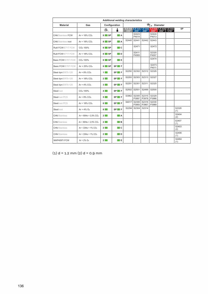
Additional welding characteristics
Material ConfigurationGas Diameter
0,8 mm.030‘‘
0,9 mm.035‘‘
1,0 mm.040‘‘
1,2 mm.045‘‘
1,4 mm.052‘‘
1,6 mm1/16‘‘
SP
A S2423
P4014
S2424
P4013
8 SPCrNi/Stainless FCW Ar + 18% CO!
AS2440 S2441 S2442 S2443
8 SPCrNi/Stainless root Ar + 18% CO!
C S2471 S2472
8 SPRutil FCW/E71T FCW CO! 100%
D S2411
P4065
S2320
P4007
8 SPRutil FCW/E71T FCW Ar + 18% CO!
E S2474
8 SPBasic FCW/E70T FCW CO! 100%
SP F S2473
P4011
8 SPBasic FCW/E70T FCW Ar + 25% CO!
SP FS2292 S2302 S2312 S2326
1Steel dyn/ER70-120 Ar + 8% CO!
SP FS2293 S2303 S2313 S2327
2Steel dyn/ER70-120 Ar + 18% CO!
SP FS2291 S2301 S2311 S2325
3Steel dyn/ER70-120 Ar + 4% CO!
SP FS2502 S2501 S2499 S2500
4Steel/root CO! 100%
SP FS3962 S2305
P3997
S2315
P3978
S2329
P3986
5Steel/root PCS Ar + 8% CO!
SP FS4017 S2306
P3993
S2316
P3967
S2330
P3989
6Steel/root PCS Ar + 18% CO!
SP FS2294 S2304 S2314 S2328
(1)8Steel/root Ar + 4% O!
A S2404
(2)
2CrNi/Stainless Ar + 90He + 2,5% CO!
C
S2403
(2)
2CrNi/Stainless Ar + 33He + 1% CO!
E
S2464
(1)
2MAP409Ti FCW Ar + 2% O!
BS2407
(1)2CrNi/Stainless Ar + 90He + 2,5% CO!
DS2406
(1)2CrNi/Stainless Ar + 33He + 1% CO!
(1) d = 1.2 mm (2) d = 0.9 mm
136

Welding programtables forTransSteel3000c Pulse -US
The welding programs are active if the"SEt" setup parameter is set to "US"(USA).
Welding program database: UID 3992
Standard welding characteristics
Material ConfigurationGas Diameter
0,8 mm.030‘‘
0,9 mm.035‘‘
1,0 mm.040‘‘
1,2 mm.045‘‘
1,4 mm.052‘‘
1,6 mm1/16‘‘
SP
AS2290 S2300 S2310 S2322
1Steel/ER70-120 CO! 100%
BS2418
P4000
S2370
P4001
S2308
P3977
S2377
P39791Steel/ER70-120 Ar + 2-12% CO!
CS2419
P4006
S2369
P3990
S2309
P3958
S2376
P39871Steel/ER70-120 Ar + 13-25% CO!
DS2285 S2297 S2307
1Steel/ER70-120 Ar + 2-8% O!
BS2427
P3969
S2402
P3970
S2426
P3968
S2405
P3966
2CrNi/Stainless Ar + 2-12% CO!
ES2496
P3973
S2495
P3974
S2493
P3976
S2497
P3975
3CuSi/ER-CuSi-A Ar 100%
E
P3955
P3956
S3639
P3954
S3643
P3953
4AlMg/ER 5xxx Ar 100%
E
S3640
P3961
P4048
S3092
P3960
5AlSi/ER 4xxx Ar 100%
B
S2420
S2385
P39806Metall Cored Ar + 2-12% CO!
C
S2386
P39836Metall Cored Ar + 13-25% CO!
S2350
S2349 7Self-shielded (no Gas)
137
EN
-US
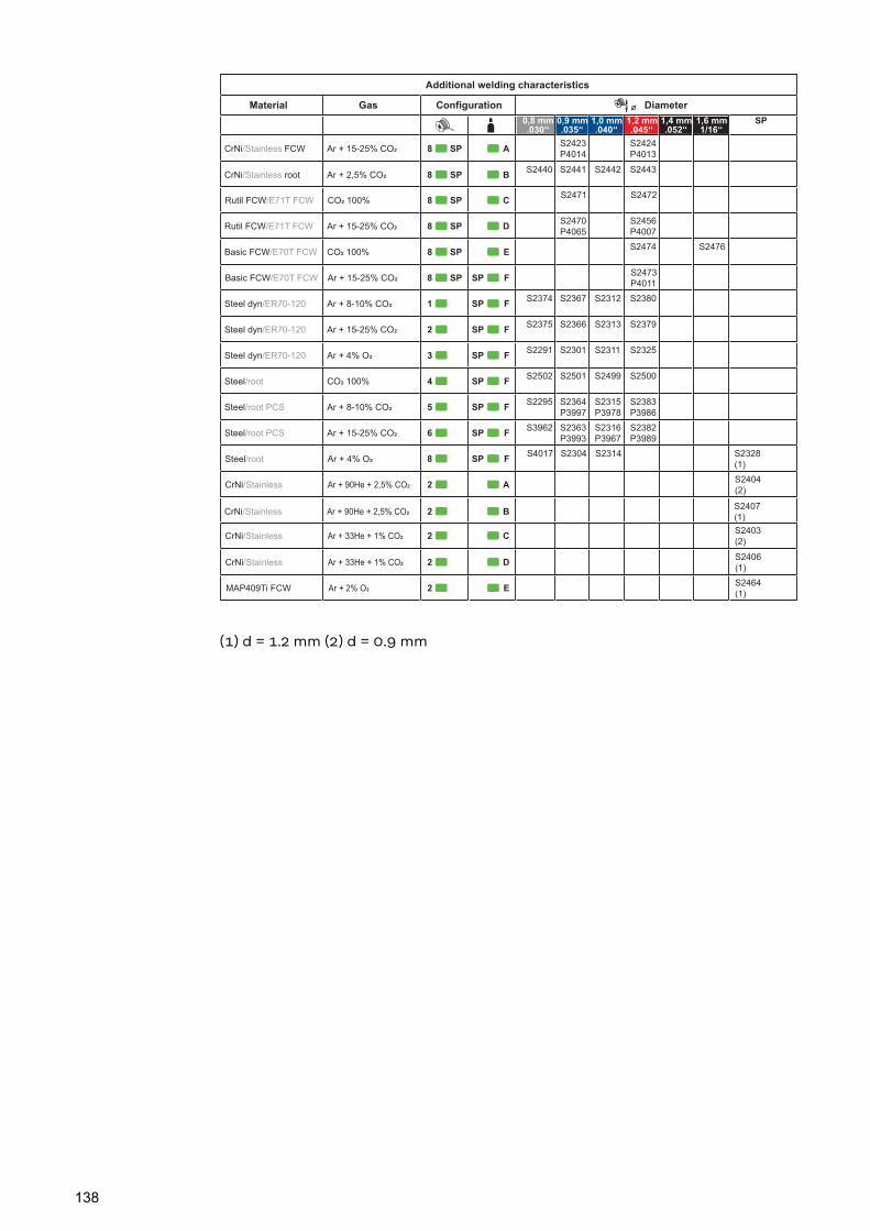
Additional welding characteristics
Material ConfigurationGas Diameter
0,8 mm.030‘‘
0,9 mm.035‘‘
1,0 mm.040‘‘
1,2 mm.045‘‘
1,4 mm.052‘‘
1,6 mm1/16‘‘
SP
A S2423
P4014
S2424
P4013
8 SPCrNi/Stainless FCW Ar + 15-25% CO!
BS2440 S2441 S2442 S2443
8 SPCrNi/Stainless root Ar + 2,5% CO!
C S2471 S2472
8 SPRutil FCW/E71T FCW CO! 100%
D S2470
P4065
S2456
P4007
8 SPRutil FCW/E71T FCW Ar + 15-25% CO!
E S2474 S2476
8 SPBasic FCW/E70T FCW CO! 100%
SP F S2473
P4011
8 SPBasic FCW/E70T FCW Ar + 15-25% CO!
SP FS2374 S2367 S2312 S2380
1Steel dyn/ER70-120 Ar + 8-10% CO!
SP FS2375 S2366 S2313 S2379
2Steel dyn/ER70-120 Ar + 15-25% CO!
SP FS2291 S2301 S2311 S2325
3Steel dyn/ER70-120 Ar + 4% O!
SP FS2502 S2501 S2499 S2500
4Steel/root CO! 100%
SP FS2295 S2364
P3997
S2315
P3978
S2383
P3986
5Steel/root PCS Ar + 8-10% CO!
SP FS3962 S2363
P3993
S2316
P3967
S2382
P3989
6Steel/root PCS Ar + 15-25% CO!
SP FS4017 S2304 S2314 S2328
(1)8Steel/root Ar + 4% O!
AS2404
(2)
2CrNi/Stainless Ar + 90He + 2,5% CO!
CS2403
(2)
2CrNi/Stainless Ar + 33He + 1% CO!
ES2464
(1)2MAP409Ti FCW Ar + 2% O!
BS2407
(1)2CrNi/Stainless Ar + 90He + 2,5% CO!
DS2406
(1)2CrNi/Stainless Ar + 33He + 1% CO!
(1) d = 1.2 mm (2) d = 0.9 mm
138

139
EN
-US

Fronius International GmbHFroniusstraße 1
4643 PettenbachAustria
Under www.fronius.com/contact you will find the adresses of all Fronius Sales & Service Partners and locations.
spareparts.fronius.com
SPAREPARTSONLINE