Installation Instructions - Fronius International
44
Installation Instructions Fronius Galvo - Installation 42,0426,0171,EN 021-16052022 EN Installation Instructions
-
Upload
khangminh22 -
Category
Documents
-
view
1 -
download
0
Transcript of Installation Instructions - Fronius International

InstallationInstructionsFronius Galvo - Installation
42,0426,0171,EN 021-16052022
EN Installation Instructions


Contents
Installation location and position 5Explanation of safety notices 5Safety 5Proper use/intended purpose 6Explanation of symbols and choice of location 7Installation position 8General comments regarding choice of location 9
Attaching the Mounting Bracket 11Safety 11Selecting wall plugs and screws 11Recommended screws 11Opening the inverter 11Do not warp or deform the mounting bracket 12Fitting the mounting bracket to a wall 13Attaching the mounting bracket 13Mounting the inverter on a mast 14Fitting the mounting bracket to metal supports 14
Connecting the inverter to the public grid (AC side) 15Safety 15Monitoring the grid 15AC terminals 16Type of AC cable 16Preparing the aluminium cables for connection 16Requirements for the neutral conductor 17Connecting the inverter to the public grid (AC) 17Routing the AC cables 17Maximum fuse rating on alternating current side 18
Connecting solar module strings to the inverter 20Safety 20General information about solar modules 22DC terminals 22Connecting aluminium cables 23Solar module strings - checking the polarity and voltage 23Notes regarding dummy devices 23Inverter DC connection 24Cable routing in the DC area 25
Grounding the solar modules in the inverter 26General 26Solar module ground on the negative pole via a fuse 27Configuring the inverter for grounded solar modules 27
Data communication 28Routing data communication cables 28Installing the Datamanager in the inverter 28
Australian Conduits 31Tightly sealing the conduits 31Seal conduits 31
Attaching the inverter to the mounting bracket 32Attaching the inverter to the mounting bracket 32
Starting for the first time 34Starting the inverter for the first time 34
Notes regarding software updates 36Notes regarding software updates 36
USB Stick as a Data Logger and for Updating Inverter Software 37USB flash drive as a datalogger 37Data on the USB flash drive 37Data volume and storage capacity 38Buffer memory 39Suitable USB flash drives 39USB stick for updating the inverter software 40Removing the USB flash drive 40
3
EN

Notes regarding maintenance 41Maintenance 41Cleaning 41
Serial Number Sticker for Customer Use 42Serial number sticker for customer use 42
4

Installation location and position
Explanation ofsafety notices DANGER!
Indicates immediate danger.
▶ If not avoided, death or serious injury will result.
WARNING!
Indicates a potentially hazardous situation.
▶ If not avoided, death or serious injury may result.
CAUTION!
Indicates a situation where damage or injury could occur.
▶ If not avoided, minor injury and/or damage to property may result.
NOTE!
Indicates a risk of flawed results and possible damage to the equipment.
SafetyWARNING!
Danger due to incorrect operation and incorrectly performed work.This can result in serious injury and damage to property.
▶ Only qualified personnel are authorised to commission your inverter and onlywithin the scope of the respective technical regulations.
▶ Read the Installation and Operating Instructions before installing and com-missioning the equipment.
WARNING!
Danger due to work that has been carried out incorrectly.This may result in serious injury and damage to property.
▶ Surge protective devices must only ever be installed and connected by aqualified electrical installation engineer!
▶ Follow the safety rules.
▶ Ensure that both the AC side and the DC side of the inverter are de-ener-gised before carrying out any installation and connection work.
5
EN

Fire prevention
CAUTION!
Danger due to poor or unprofessional installation.This may result in damage to inverters and other live photovoltaic system com-ponents.Poor or unprofessional installation can cause overheating of cables and terminalconnections and result in arcs. These can cause heat damage, which in turn maylead to fires.
Observe the following when connecting AC and DC cables:
▶ Tighten all terminals to the torque specified in the operating instructions
▶ Tighten all grounding terminals (PE / GND), including free ones, to the torquespecified in the operating instructions
▶ Do not overload cables
▶ Check cables for damage and verify that they are laid correctly
▶ Take note of the safety instructions, Operating Instructions and any localconnection regulations
▶ Using fastening screws, always screw the inverter firmly to the mountingbracket to the torque specified in the Operating Instructions.
▶ Ensure that the fastening screws are tight before starting the inverter!
Note! Fronius will not accept any costs associated with production downtimes,installer costs, etc., that may arise as the result of a detected arc and its con-sequences. Fronius accepts no liability for fires that can occur despite the pres-ence of the integrated arc detection/extinguishing system (e.g. fires caused by aparallel arc).
Note! After an arc has been detected, the entire photovoltaic system must bechecked for possible damage before resetting the inverter.
Observe the manufacturer's connection, installation and operating instructionsat all times. To reduce the hazard potential to a minimum, perform all installationand connection work carefully according to the instructions and regulations.Refer to the device Installation Instructions for the tightening torques to be usedat the relevant terminal connections.
Proper use/intended pur-pose
The inverter is intended exclusively to convert direct current from solar modulesinto alternating current and to feed this into the public grid.Utilisation not in accordance with the intended purpose comprises:- Any use above and beyond this purpose- Making any modifications to the inverter that have not been expressly ap-
proved by Fronius- the installation of components that are not distributed or expressly ap-
proved by Fronius.
Fronius shall not be liable for any damage resulting from such action.No warranty claims will be entertained.
Proper use also includes:- Carefully reading and obeying all the instructions and all the safety and
danger notices in the Operating Instructions and Installation Instructions- Performing all stipulated maintenance work- Installation as specified in the Installation Instructions
6

When designing the photovoltaic system, ensure that all components are oper-ated within their permitted operating ranges at all times.
Observe all the measures recommended by the solar module manufacturer toensure that the solar module retains its properties in the long term.
Obey the regulations of the power supply company regarding connection meth-ods and energy fed into the grid.
Explanation ofsymbols andchoice of loca-tion
The inverter is suitable for indoor installation.
The inverter is suitable for outdoor installation.
Because of its IP 65 protection class, the inverter is resistant towater jets from any direction and can also be used in damp en-vironments.
In order to minimise the heating up of the inverter, do not ex-pose it to direct insolation. Install the inverter in a protectedlocation, e.g. in the vicinity of the solar modules or beneath theeaves.
Can be used at altitudes of up to 2000 m
IMPORTANT! The inverter must not be installed or used at alti-tudes above 2000 m.
NH3 Do not install the inverter in:
- Areas where ammonia, corrosive vapours, acids or salts arepresent(e.g. fertiliser stores, ventilation openings from cattle sheds,chemical plants, tanneries, etc.)
7
EN

During certain operating phases the inverter may produce aslight noise. For this reason it should not be installed close toliving areas.
Do not install the inverter in:- Places where there is an increased risk of damage from farm
animals (horses, cattle, sheep, pigs, etc.)- Stables or adjoining areas- Storage areas for hay, straw, chaff, animal feed, fertilisers,
etc.
All inverters are designed to be dust-tight. However, in areaswith a heavy build-up of dust, the thermal efficiency may still beimpaired by dust forming on the cooling surfaces. Regular clean-ing is necessary in such situations. We therefore recommend notinstalling the inverter in areas and environments with high dustaccumulation.
Do not install the inverter in:- Greenhouses- Storage or processing areas for fruit, vegetables or viticul-
ture products- Areas used in the preparation of grain, green fodder or an-
imal feeds
Installation posi-tion
The inverter is suitable for vertical installation on a vertical wall orcolumn.
The inverter is suitable for a horizontal installation position.
The inverter is suitable for installation on a sloping surface.
8

Do not install the inverter on a sloping surface with its connectionsockets at the top.
Do not install the inverter at an angle on a vertical wall or column.
Do not install the inverter horizontally on a vertical wall or pillar.
Do not install the inverter on a vertical wall or pillar with its con-nection sockets facing upwards.
Do not install the inverter overhanging with the connection sock-ets at the top.
Do not install the inverter overhanging with the connection sock-ets at the bottom.
Do not install the inverter on the ceiling.
General com-ments regardingchoice of loca-tion
Please note the following criteria when choosing a location for the inverter:
Only install on a solid, non-flammable surface
9
EN

Max. ambient temperatures:-25 °C / +50 °C
Relative humidity:0-100%
The airflow within the invert-er is from the left to the top(cold air taken in from theleft, hot air dissipated out ofthe top).The exhaust air can reach atemperature of 70 °C.
The environmental conditions of the inverter must be maintained at the install-ation location.
If the inverter is to be installed on the outer wall of a cattle shed, maintain aminimum all-round clearance of 2 m between the inverter and all ventilationand other openings in the building.The installation location must not be exposed to ammonia, corrosive vapours,salts or acids.
10

Attaching the Mounting Bracket
SafetyWARNING!
Danger due to residual voltage in capacitors.This may result in an electric shock.
▶ Wait for the capacitors to discharge. The discharge time is five minutes.
CAUTION!
Danger due to dirt or water on the terminals and contacts of the inverter's con-nection area.This may result in damage to the inverter.
▶ When drilling, ensure that terminals and contacts in the connection area donot become dirty or wet.
▶ The mounting bracket without a power stage set does not conform to theprotection class of the inverter as a whole, and therefore must not be in-stalled without a power stage set.
▶ The mounting bracket should be protected from dirt and moisture during in-stallation.
Note! Degree of protection IP 65 is only applicable if- the inverter is placed in the mounting bracket and permanently attached us-
ing screws,- the cover for the data communication area is permanently attached to the
inverter with screws.
Degree of protection IP 20 applies to the mounting bracket with no inverter andthe venting duct.
Selecting wallplugs and screws
Important! Different fixings may be required to fit the mounting bracket depend-ing on the type of underlying surface. Fixings are therefore not included in thescope of supply of the inverter. The installer is responsible for selecting the righttype of fixing.
Recommendedscrews
To install the inverter, the manufacturer recommends the use of steel or alumini-um screws with a diameter of 6 - 8 mm.
Opening the in-verter WARNING!
Danger from inadequate ground conductor connection.This can result in serious injury and damage to property.
▶ The housing screws provide a suitable ground conductor connection forgrounding the housing and must NOT be replaced by any other screws thatdo not provide a reliable ground conductor connection.
11
EN

1 2
3 4
Do not warp ordeform themounting brack-et
Note! When fitting the mounting bracket to the wall, ensure that the mountingbracket does not become warped or deformed.
12

Fitting themounting brack-et to a wall
Tip: Install the inverter so that its display is ateye level
1 2
3 Note! When mounting the mountingbracket on the wall, ensure that themounting bracket does not becomewarped or deformed.
Attaching themounting brack-et
1 2
13
EN

3
Mounting the in-verter on a mast
Example of a mast fixing kit
When mounting the inverter on a mastor a vertical carrier, Fronius recom-mends the use of a standard mast fix-ing kit.
This kit enables the inverter to bemounted on round or rectangularmasts with various cross-sections.
Fitting themounting brack-et to metal sup-ports
The mounting bracket must be affixed at a minimum of four points.
1
14

Connecting the inverter to the public grid (ACside)
SafetyWARNING!
Incorrect operation or poorly executed work can cause serious injury or dam-age.Only qualified staff are authorised to commission your inverter and only withinthe scope of the respective technical regulations. Read the Installation and Op-erating Instructions before installing and commissioning the equipment.
WARNING!
An electric shock can be fatal.Danger due to grid voltage and DC voltage from solar modules that are exposedto light.
▶ Ensure that both the AC side and the DC side of the inverter are de-ener-gised before carrying out any connection work.
▶ Only an authorised electrical engineer is permitted to connect this equip-ment to the public grid.
WARNING!
An electric shock can be fatal.Danger due to grid voltage and DC voltage from solar modules.
▶ The DC main switch is only to be used to de-energise the power stage set.The connection area is still live when the DC main switch is switched off.
▶ Ensure that the power stage set and connection area are disconnected fromone another before carrying out any maintenance or service tasks.
▶ The power stage set is only to be disconnected from the mounting bracketonce it is de-energised.
▶ Maintenance and servicing in the power stage set of the inverter must onlybe carried out by Fronius-trained service technicians.
CAUTION!
Risk of damage to the inverter as the result of incorrectly tightened terminals.Incorrectly tightened terminals can cause heat damage to the inverter that mayresult in a fire. When connecting AC and DC cables, ensure that all the terminalsare tightened to the specified torque.
IMPORTANT! To ensure a proper ground connection, all three PE grounding ter-minals must be tightened to the specified torque when the inverter is installed.
Monitoring thegrid
To provide the best possible grid monitoring, the resistance in the leads to theAC-side terminals should be as low as possible.
15
EN

AC terminals PE Ground conductor / earthingL1 Phase conductorN Neutral conductor
Max. cross-section of each conductorcable:16 mm²
Min. cross-section of each conductorcable:in accordance with the fuse rating onthe AC side, but at least 2.5 mm²
The AC cables can be connected tothe AC terminals without ferrules.
IMPORTANT! When using ferrules for AC cables with a cross-section of 16 mm²,the ferrules must be crimped with a right-angled cross-section.The use of ferrules with insulating collars is only permitted up to a max. cablecross-section of 10 mm².
Type of AC cable The following types of AC cable can be connected to the AC terminals of the in-verter:
- Copper or aluminium: solid round conductor- Copper: fine-stranded round conductor, up to conductor
class 4
Preparing thealuminiumcables for con-nection
The AC-side terminals are suitable for connecting single-wire, round aluminiumcables. Because of the formation of a non-conductive oxide layer due to the re-action of aluminium with air, the following points must be considered when con-necting aluminium cables:- the reduced rated currents for aluminium cables- the connection conditions listed below
Always follow the cable manufacturer instructions when using aluminium cables.
When designing cable cross-sections, take local regulations into account.
Connection conditions:
1 Carefully clean the oxide layer from the bare end of the cable by scraping it,e.g. with a knife
IMPORTANT! Do not use brushes, files or emery paper, as the aluminiumparticles get trapped and can be transferred to other conductors.
2 Once the oxide layer is removed, rub the end of the cable with a neutralgrease, such as non-acidic and non-alkaline Vaseline
3 Immediately connect the cable end to the terminal
16

IMPORTANT!Repeat the procedure if the cable has been disconnected and is tobe re-connected.
Requirementsfor the neutralconductor
Note!- Ensure that the grid neutral conductor is grounded. This may not be the case
for IT grids (insulated grids with no grounding); it will then not be possible touse the inverter.
- In order to use the inverter, the neutral conductor must be connected. Aneutral conductor that is too small may adversely affect the inverter feedingenergy into the grid. The neutral conductor must therefore be the same sizeas the other live conductors.
Connecting theinverter to thepublic grid (AC)
1 2
Note! Observe the torque values marked on theside underneath the terminals.
3 4
Routing the ACcables
Note!- Form loops with the AC cables when connecting them to the AC terminals.- When securing the AC cables using a metric screw joint, ensure that the
loops do not protrude beyond the connection area.Otherwise, under certain circumstances it may no longer be possible to closethe inverter.
17
EN

IMPORTANT! The PE ground conductor of the AC cable must be laid in such away that it is the last to be disconnected in the event that the strain-relief deviceshould fail.This can be ensured, for example, by making it somewhat longer and by laying itin a loop.
If AC cables are laid over the shaft of the DC main switch or across the connec-tion block of the DC main switch, they may be damaged when the inverter isswung in, or they may even prevent the inverter from being swung in.
IMPORTANT! Do not lay AC cables over the shaft of the DC main switch oracross the connection block of the DC main switch.
If overlength AC or DC cables are tobe laid in loops in the connection area,attach the cables with cable ties to theeyelets provided on the top and bot-tom of the connection block.
Maximum fuserating on altern-ating currentside
18

Inverter Phases Max. output Max. output over-current protection
Fronius Galvo 1.5 1 1500 W 1 x C 25 A
Fronius Galvo 2.0 1 2000 W 1 x C 25 A
Fronius Galvo 2.5 1 2500 W 1 x C 25 A
Fronius Galvo 3.0 1 3000 W 1 x C 25 A
Fronius Galvo 3.1 1 3100 W 1 x C 25 A
NOTE!
Local regulations, the energy company or other factors may require a residualcurrent protective device (RCD) in the AC connection lead.For this situation, a type A residual current protective device is generally ad-equate. In particular cases, and depending on local factors, however, the type Aresidual current protective device may trip at the wrong time.For this reason, Fronius recommends that an RCD suitable for frequency con-verters be used.
19
EN

Connecting solar module strings to the inverter
SafetyWARNING!
Danger due to incorrect operation and incorrectly performed work.This can result in serious injury and damage to property.
▶ Only qualified staff are authorised to commission your inverter and onlywithin the scope of the respective technical regulations.
▶ Read the Installation and Operating Instructions before installing and com-missioning the equipment.
WARNING!
Danger due to grid voltage and DC voltage from solar modules that are exposedto light.This may result in an electric shock.
▶ Ensure that both the AC side and the DC side of the inverter are de-ener-gised before carrying out any connection work.
▶ Only an authorised electrical engineer is permitted to connect this equip-ment to the public grid.
WARNING!
Risk of electric shock if the solar module ground is not grounded or is notgrounded properly.An electric shock can be fatal.
▶ To comply with IEC 62109-2:2011, any grounding required by the manufac-turer of the solar module ground within the inverter must only be carried outvia the specified fuse.
WARNING!
Danger from DC voltage in solar modules.An electric shock can be fatal. The inverter's insulation monitoring is deactivatedwhen the solar modules are grounded.
▶ Ensure that grounded solar modules are assembled so that they are insu-lated according to Protection Class II
▶ Place the relevant safety sticker in a clearly visible place on the photovoltaicsystem
▶ Configure the inverter so that an error message is displayed if the fuse trips.
WARNING!
Danger due to grid voltage and DC voltage from solar modules.This may result in an electric shock.
▶ The DC main switch is only to be used to de-energise the power stage set.The connection area is still live when the DC main switch is switched off.
▶ Ensure that the power stage set and connection area are disconnected fromone another before carrying out any maintenance or service tasks.
▶ The power stage set, which is enclosed in a separate housing, must only bedisconnected from the connection area when in a de-energized state.
▶ Maintenance and servicing in the power stage set of the inverter must onlybe carried out by Fronius-trained service technicians.
20

WARNING!
Danger from inadequate ground conductor connection.This can result in serious injury and damage to property.
▶ The housing screws provide a suitable ground conductor connection forgrounding the housing and must NOT be replaced by any other screws thatdo not provide a reliable ground conductor connection.
CAUTION!
Danger due to dirt or water on the terminals and contacts of the connectionarea.This may result in damage to the inverter.
▶ When drilling, ensure that terminals and contacts in the connection area donot become dirty or wet.
▶ The mounting bracket without a power stage set does not conform to theprotection class of the inverter as a whole, and therefore must not be in-stalled without a power stage set. The mounting bracket should be protectedfrom dirt and moisture during installation.
CAUTION!
Danger due to incorrectly tightened terminals.This may result in heat damage to the inverter, which may lead to fire.
▶ When connecting AC and DC cables, ensure that all the terminals aretightened to the specified torque.
CAUTION!
Danger due to overloading.This may result in damage to the inverter.
▶ The maximum amperage when connecting to a single DC terminal is 36 A.
▶ Connect the DC+ and DC- cables to the DC+ and DC- terminals on the in-verter, taking care to ensure that the polarity is correct.
NOTE! If solar modules are grounded by a built-in grounding protection device inthe inverter, they will not be grounded if the DC main switch is in the OFF posi-tion.
NOTE! When connecting aluminium cables:- Observe national and international guidelines regarding the connection of
aluminium cables- Follow the instructions of the cable manufacturer.- Check every year that the cables are securely attached in accordance with
the specified torque.
NOTE! The solar modules connected to the inverter must comply with the IEC61730 Class A standard.
NOTE! When photovoltaic modules are exposed to light, they supply current tothe inverter.
NOTE! Ensure the polarity is correct when connecting the DC cables.
NOTE! For grounding solar module frames or racks, the relevant specificationsfrom the solar module manufacturer must be taken into account along with na-tional guidelines.
21
EN

NOTE! If the inverter is installed in Australia or New Zealand (required standard:AS4777.2:2020), the following applies:- Functional grounding isnot permitted- The inverter must not be used as part of a three-phase combination, as there
is no communication link between the inverters
General informa-tion about solarmodules
In order to select suitable solar modules and get the most efficient use out ofthe inverter, please note the following points:- The open circuit voltage of the solar modules increases as the temperature
decreases (assuming constant irradiance). Open circuit voltage may not ex-ceed the following values:Fronius Galvo 1.5-1 ... 420 VFronius Galvo 2.0-1 ... 420 VFronius Galvo 2.5-1 ... 550 VFronius Galvo 3.0-1 ... 550 VFronius Galvo 3.1-1 ... 550 V
If the open circuit voltage exceeds the above mentioned values, the invertermay be damaged, and all warranty rights will become null and void.
- Note the temperature coefficients in the solar module data sheet- More exact data for sizing the solar array for the particular location can be
obtained using calculations tools such as the Fronius Solar.creator (creat-or.fronius.com).
NOTE!
Before connecting solar modules, make sure that the voltage specified by themanufacturer corresponds to the actual measured voltage.
Note the safety instructions and specifications of the solar module manufacturerregarding solar module grounding.
DC terminals Cable cross section per DC cable:minimum 2.5 mm² - maximum 16 mm²
The DC cables can be connected tothe DC terminals without ferrules.
Note! To ensure effective strain reliefof the solar module strings, only usecables with identical cross-sections.
22

IMPORTANT! When using ferrules for DC cables with a cross-section of 16 mm²,the ferrules must be crimped with a right-angled cross-section.The use of ferrules with insulating collars is only permitted up to a max. cablecross-section of 10 mm².
Connecting alu-minium cables
The DC-side terminals are suitable for connecting single-wire, round aluminiumcables. Because of the formation of a non-conductive oxide layer due to the re-action of aluminium with air, the following points must be considered when con-necting aluminium cables:- the reduced rated currents for aluminium cables- the connection conditions listed below
Note! Always follow the cable manufacturer instructions when using aluminiumcables.
Note! When designing cable cross-sections, take local regulations into account.
Connection conditions:
1 Carefully clean the oxide layer from the bare end of the cable by scraping it,e.g. with a knife
IMPORTANT! Do not use brushes, files or emery paper, as the aluminiumparticles get trapped and can be transferred to other conductors.
2 Once the oxide layer is removed, rub the end of the cable with a neutralgrease, such as non-acidic and non-alkaline Vaseline
3 Immediately connect the cable end to the terminal
IMPORTANT! Repeat the procedure if the cable has been disconnected and is tobe re-connected.
Solar modulestrings - check-ing the polarityand voltage
CAUTION!
Danger due to incorrect polarity andvoltage.This may result in damage to the in-verter.Check the polarity and voltage of thesolar module strings before making theconnection. The voltage must not ex-ceed the following values:
▶ Fronius Galvo 1.5-1: 420 V
▶ Fronius Galvo 2.0-1: 420 V
▶ Fronius Galvo 2.5-1: 550 V
▶ Fronius Galvo 3.0-1: 550 V
▶ Fronius Galvo 3.1-1: 550 V
Notes regardingdummy devices
A dummy device is not suitable for connecting operationally to a photovoltaicsystem, and must only ever be used for demonstration purposes. Dummy devicesare indicated as such on their rating plate.
23
EN

IMPORTANT! Never connect DC cables to the DC connection sockets on adummy device.
The connection of de-energised cables or sections of cable for demonstrationpurposes is permissible.
Inverter DC con-nection
Only break out as many target break points as the number of cables that areprovided (e.g. if there are 2 DC cables, then break out 2 recesses).
1 2
3 4
5 6
24

7 8
9
Cable routing inthe DC area
If DC cables are laid over the shaft ofthe DC main switch or across the con-nection block of the DC main switch,they may be damaged when the invert-er is swung in or they may even preventthe inverter from being swung in.
IMPORTANT! Do not lay DC cablesover the shaft of the DC main switchor across the connection block of theDC main switch.
25
EN

Grounding the solar modules in the inverter
General Some manufacturers of solar modulesstipulate that the modules must begrounded.
Fuse holder for solar module ground on the neg-ative pole
Inside the inverter is a means forgrounding solar modules on the negat-ive pole via a fuse.The fuse holder for grounding the solarmodules is located on the rear of theinverter.
The inverter can also be operated withsolar modules that need to be groun-ded on the positive pole.
IMPORTANT! The fuse in the inverteris not used for grounding the solarmodules on the positive pole; this hasto take place outside the inverter.
1 2
26

Solar moduleground on thenegative pole viaa fuse
Solar module ground on the negative pole via a fuse
(1) Solar module(2) Inverter(3) Fuse
Fronius recommends the following fuse for the solar module ground on the neg-ative pole:nominal current rating 1 A / 600 V, fuse dimensions 10 x 38 mm
IMPORTANT! Fuses for grounding the solar module are not part of the scope ofsupply of the inverter. If the manufacturer of the solar module stipulates thatearthing is required, an appropriate fuse must be ordered separately.
Configuring theinverter forgrounded solarmodules
The inverter's insulation monitoring must be deactivated when the solar modulesare grounded. In the Basic menu, the inverter must therefore be configured sothat when the grounding fuse trips, an error message is displayed or the inverteris switched off (according to the country setup).The access code 22742 must be entered to access the Basic menu.
27
EN

Data communication
Routing datacommunicationcables
IMPORTANT! Operating the inverter with one option card and two broken-outoption card slots is not permitted.To cater for this eventuality, a suitable blanking cover (42,0405,2020) is availablefrom Fronius as an option.
IMPORTANT! If data communication cables are wired into the inverter, observethe following points:- Depending on the number and cross-section of the data communication
cables that are being introduced, take the relevant blanking plugs out of thesealing insert and insert the data communication cables.
- The relevant blanking plugs must be inserted into the free openings on thesealing insert.
1 2
3 4
Installing theDatamanager inthe inverter
WARNING!
Danger of residual voltage from capacitors.This may result in an electric shock.
▶ Wait for the capacitors to discharge. The discharge time is five minutes.
28

WARNING!
Danger from inadequate ground conductor connection.This can result in serious injury and damage to property.
▶ The housing screws provide a suitable ground conductor connection forearthing the housing and must NOT be replaced by any other screws that donot provide a reliable ground conductor connection.
IMPORTANT! Observe the ESD guidelines when handling option cards.
IMPORTANT! Only one Fronius Datamanager in master mode is permitted perFronius Solar Net ring. Switch any other Fronius Datamanagers to slave mode orremove them.Seal off the unoccupied option card slot by replacing the cover (item number42,0405,2094); alternatively, use an inverter without a Fronius Datamanager(light version).
IMPORTANT! Only break out oneopening for the PC board when in-stalling a Datamanager in the inverter.
1 2
29
EN

3 4
5 6
30

Australian Conduits
Tightly sealingthe conduits
Ensure that the conduits are tightly sealed.
Seal conduits NOTE!
Condensation within the conduits candamage the inverter or components ofthe photovoltaic systems.
To avoid undesirable air circulation andcondensation in the conduits:
▶ Seal all conduits being used with apermanently elastic sealant
▶ Seal every incoming and outgoingconduit
▶ Seal both conduit ends.
Conduit
Conduit
AC~
Inside
Outside
DC=
4
3
2
Permanently elastic sealant
Seal all used conduits!
Seal every incoming and every outgoing conduit!
Seal both conduit ends!
1
Conduit
Inve
rte
r h
ou
sin
g
Co
nd
uit fittin
g
Pe
rma
ne
ntly e
lastic
se
ala
nt
11
1
31
EN

Attaching the inverter to the mounting bracket
Attaching the in-verter to themounting brack-et
WARNING!
Danger from inadequate ground conductor connection.This can result in serious injury and damage to property.
▶ The housing screws provide a suitable ground conductor connection forgrounding the housing and must NOT be replaced by any other screws thatdo not provide a reliable ground conductor connection.
The side sections of the housing lid are designed to function as holding and car-rying handles.
Note! For safety reasons, the inverter is fitted with a latch that prevents the in-verter from being swung into the mounting bracket unless the DC main switch isswitched off.- Never attach the inverter to the mounting bracket or swing it in unless the
DC main switch is switched off.- Never use force to attach the inverter or swing it in.
The fastening screws in the data communication area of the inverter are used forsecuring the inverter to the mounting bracket. Correctly tightened fasteningscrews are a prerequisite if proper contact is to be established between the in-verter and mounting bracket.
CAUTION!
Danger due to incorrectly tightened fastening screws.This may result in arcs occurring when the inverter is in operation, which maylead to fire.
▶ Always use the specified torque when tightening the fastening screws.
1 2
32

3 4
33
EN
Starting for the first time
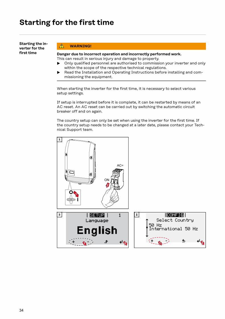
Starting the in-verter for thefirst time
WARNING!
Danger due to incorrect operation and incorrectly performed work.This can result in serious injury and damage to property.
▶ Only qualified personnel are authorised to commission your inverter and onlywithin the scope of the respective technical regulations.
▶ Read the Installation and Operating Instructions before installing and com-missioning the equipment.
When starting the inverter for the first time, it is necessary to select varioussetup settings.
If setup is interrupted before it is complete, it can be restarted by means of anAC reset. An AC reset can be carried out by switching the automatic circuitbreaker off and on again.
The country setup can only be set when using the inverter for the first time. Ifthe country setup needs to be changed at a later date, please contact your Tech-nical Support team.
1
1 2
2
Select Country
1 2
50 HzInternational 50 Hz
3
34

* Country setup examples
The available country setups may change during a software update. Therefore, the following list maynot exactly match the display on the inverter.
50Hz International 50 Hz60Hz International 60 HzAT1 Österreich: Anlagen-
größe< 3,68 kVA
AU AustraliaBE Belgique / BelgiëBR Brasil 220V NL-MonCH Schweiz / Suisse /
Svizzera / SvizraCL ChileCY Κύπρος / Kıbrıs / CyprusCZ ČeskoDE1 Deutschland: Anlagen-
größe < 3,68 kVADE2 Deutschland: Anlagen-
größe > 3,68 kVA und <13,8 kVA
DE3 Deutschland: Anlagen-größe > 13,8 kVA
DKA1 DanmarkES EspañaESOS Territorios españoles en
el extranjero (SpanishOverseas Islands)
FR FranceFROS Territoire d'Outre-Mer
(French Overseas Is-lands)
GB Great BritainGR ΕλλάδαHR HrvatskaHU MagyarországIE Éire / Ireland; MaltaIL ليئارسإ / לארשי / IsraelIT4 Italia ≤ 11,08 kVA
MG50 Microgrid 50 HzMG60 Microgrid 60 HzNIE1 Northern Ireland /
Tuaisceart Éireann < 16A
NL NederlandNO NorgeNZ New ZealandPF1 Polynésie française
(French Polynesia)PL PolandPT PortugalRO RomâniaSE Konungariket SverigeSK SlovenskoTR TürkiyeZA South Africa / Suid-
Afrika
CONFIG4
21
5
21
6 SETUP
Auto Daylightsaving
1 2
7
8 9
35
EN

Notes regarding software updates
Notes regardingsoftware up-dates
USB
+
3
54 4
1
2 2
If the inverter is supplied with a USBflash drive, the inverter software mustbe updated as soon as the inverter hasbeen commissioned:
1 Plug the USB flash drive into thedata communication area of the in-verter
2 Open the Setup menu
3 Select the "USB" menu item
4 Select "Software Update"
5 Update the software
36

USB Stick as a Data Logger and for Updating In-verter Software
USB flash driveas a datalogger
If a USB flash drive is connected to the USB A socket it can function as a data-logger for an inverter.
The logging data stored on the USB flash drive can be viewed at any time inthird-party programmes (e.g Microsoft® Excel) using the CSV file logged at thesame time.
Older versions of Excel (before Excel 2007) are limited to a maximum of 65,536rows.
Data on the USBflash drive
If the USB flash drive is being used as a data logger, three files will be createdautomatically:
- FRONIUS.sys system file:This file stores information from the inverter that is irrelevant to the custom-er. The file must not be deleted separately. Only delete all of the files (sys,fld, csv) at one time.
- DALO.fld log file:A log file for reading the data in the Fronius Solar.access software.
Further details on the Fronius Solar.access software can be found in the"DATCOM Details" operating instructions at http://www.fronius.com
- DATA.csv log file:A log file for reading the data in a spreadsheet program (e.g.: Microsoft® Ex-cel)
Data structure on the USB flash drive
(1) USB root directory(2) Fronius inverters (Fronius
Galvo, Fronius Symo, FroniusPrimo or Fronius Eco)
(3) Inverter number - can be set inthe Setup menu under DAT-COM
If there are several inverters with thesame inverter number, the three fileswill be saved in the same folder. A digitis added to the file name as a suffix(e.g.: DALO_02.fld)
37
EN

Structure of the CSV file:
(1) (2) (3) (4) (5) (6) (7)
(8) (9)
(1) ID(2) Inverter no.(3) Inverter type (DATCOM code)(4) Logging interval in seconds(5) Energy in watts per second, relative to the logging interval(6) Inductive reactive power(7) Capacitive reactive power(8) Average values during the logging interval (AC voltage, AC current, DC
voltage, DC current)(9) Additional information
Data volume andstorage capacity
A USB flash drive with a storage capacity of 1 GB can record logging data forroughly seven years at a logging interval of five minutes.
CSV fileCSV files can only store 65,535 lines (data records) (up to Microsoft® Excel 2007;there is no restriction from this version onwards).At a five-minute logging interval, the 65,535 lines will be written within approx-imately seven months (CSV data size of approx. 8 MB).In order to avoid data loss, the CSV file should be backed up to a PC and deletedfrom the USB flash drive within this seven-month period. If the logging interval isset to a longer period, this time frame will be increased accordingly.
FLD fileThe FLD file should not be larger than 16 MB. This will provide enough storagecapacity for approximately six years at a logging interval of five minutes.If the file exceeds the 16 MB limit, it should be backed up to a PC and all of thedata on the USB flash drive should be deleted.
After backing up and removing the data, the USB flash drive can be reconnectedimmediately to resume recording the logging data without any further steps be-ing required.
Note! Using a full USB flash drive can lead to data loss or data being overwritten.When using USB flash drives, always ensure that there is sufficient storage capa-city on the flash drive.
38

NOTE!
Risk of USB flash drive becoming full.This may result in data being lost or overwritten.
▶ When using USB flash drives, always ensure that there is sufficient storagecapacity on the flash drive.
Buffer memory If the USB stick is unplugged (e.g. for data backup purposes), the logging data iswritten to a buffer memory in the inverter.As soon as the USB stick is plugged in again, the data is copied automaticallyfrom the buffer memory to the stick.
The buffer memory can store a maximum of six logging points. Data is onlylogged while the inverter is running (output greater than 0 W). The logging inter-val is permanently set at 30 minutes. Data can be recorded on the buffermemory for a three-hour time period as a result.
When the buffer memory is full, the oldest data in the memory will be overwrit-ten by the next batch of data.
IMPORTANT! The buffer memory requires a permanent power supply.If there is a power failure while the inverter is in operation, all the data in the buf-fer memory will be lost. To avoid losing data during the night, the automatic nightswitch-off facility must be deactivated (switch the "Night Mode" setup parameterto ON - see the Datamanager 2.0 Operating Instructions, section "Setting anddisplaying the menu items", "Viewing and adjusting parameters in the DATCOMmenu item").On the Fronius Eco or Fronius Symo 15.0-3 208, the buffer memory also func-tions with just a DC supply.
Suitable USBflash drives
Due to the variety of USB flash drives available on the market, it cannot be guar-anteed that every USB flash drive will be detected by the inverter.
Fronius recommends that only certified, industry-grade USB flash drives areused (look out for the USB-IF logo).
The inverter supports USB flash drives with the following file systems:- FAT12- FAT16- FAT32
Fronius recommends that the USB flash drive employed should only be used forrecording logging data or updating the inverter software. The USB flash drivesshould not contain any other data.
39
EN

USB symbol on the inverter display, e.g. in display mode 'NOW':
AC Output Power
NOW
If the inverter detects a USB flashdrive, the USB symbol will appear inthe top right corner of the display.
When inserting a USB flash drive,check whether the USB symbol is dis-played (it may also flash).
Note! Please note for outdoor applications that conventional USB flash drivesare often only guaranteed to work within a restricted temperature range.For outdoor applications ensure that the USB flash drive also functions, for ex-ample, at low temperatures.
USB stick for up-dating the in-verter software
With the help of the USB stick, end customers can also update the inverter soft-ware via the USB item on the SETUP menu: the update file is first saved to theUSB stick, from where it is then transferred to the inverter. The update file mustbe saved in the root directory on the USB stick.
Removing theUSB flash drive
Safety instruction concerning the removal of a USB flash drive:
IMPORTANT! To avoid any loss ofdata, a USB flash drive may only beremoved if the following conditionsare met:- Only remove a USB flash drive
via the 'Safely remove USB /HW' item on the SETUP menu
- The 'Data transmission' LED hasstopped flashing or comes onsteady.
40

Notes regarding maintenance
Maintenance Note! When installed outdoors in a horizontal position: once a year, check that allscrew joints are tight!
Maintenance and servicing may only be carried out by Fronius-trained servicetechnicians.
Cleaning Clean the inverter as required with a damp cloth.Do not use cleaning agents, abrasives solvents or similar to clean the inverter.
41
EN

Serial Number Sticker for Customer Use
Serial numbersticker for cus-tomer use
The serial number of the inverter islocated on the rating plate on the bot-tom of the inverter.Depending on the installation positionof the inverter, the serial number canbe difficult to access or read, e.g. if theinverter has been installed in a dark orshaded area.
Two serial number stickers are en-closed with the inverter's installationinstructions:
* 57 x 20 mm** 67 x 20 mm
These can be affixed by the customerin a visible location of his choosing, e.g.on the front of the inverter or on theOperating Instructions.
Application example:Serial number sticker on the OperatingInstructions or on the front of the in-verter
For Australia only:Affix the DRM Australia sticker in theDatamanager area.
42

43
EN

-
-