InstallatIon InstructIons
24
InstallatIon InstructIons Do not DEstroY. PlEasE rEaD carEFullY anD KEEP In a saFE PlacE For FuturE rEFErEncE. IMPortant attEntIon InstallErs: It is your responsibility to know this product better than your customer. this includes being able to install the product according to strict safety guidelines and instructing the customer on how to operate and maintain the equipment for the life of the product. safety should always be the deciding factor when installing this product and using common sense plays an important role as well. Pay attention to all safety warnings and any other special notes highlighted in the manual. Improper installation of the furnace or failure to follow safety warnings could result in serious injury, death, or property damage. these instructions are primarily intended to assist qualified individuals experienced in the proper installation of this appliance. some local codes require licensed installation/service personnel for this type of equipment. Please read all instructions carefully before starting the installation. return these instructions to the customer’s package for future reference. single & three Phase, r-410a, 1- 5 ton units IMPortant saFEtY InForMatIon ................. 2 unIt InstallatIon ............................................ 3 General Information ....................................................... 3 Before You Install the Unit .............................................. 3 Locating the Equipment ................................................. 3 Packaging Removal ....................................................... 3 Ground Level.................................................................. 3 Rooftop .......................................................................... 3 Connecting Refrigerant Tubing Between the Indoor & Outdoor Unit .................................................... 4 ElEctrIcal WIrIng........................................... 4 Pre-Electrical Checklist .................................................. 4 Line Voltage ................................................................... 4 Thermostat / Low Voltage Connections ......................... 5 Grounding ...................................................................... 5 Unbalanced 3-Phase Supply Voltage............................. 5 Reverse Rotation Verification ......................................... 6 startuP & aDjustMEnts ............................... 6 Pre - Start Checklist ....................................................... 6 Start-up Procedures....................................................... 6 Air Circulation - Indoor Blower ....................................... 6 Short Cycle Protection ................................................... 6 System Cooling .............................................................. 6 System Heating.............................................................. 6 Defrost Cycle Timer ....................................................... 6 Defrost Control Board .................................................... 7 Operational Information ............................................... 7 Normal Defrost Operation............................................ 7 Defrost Test Procedure ................................................ 7 Anti Short Cycle Timer Test............................................ 7 Refrigerant Charging...................................................... 7 Charging the Unit in AC Mode with Outdoor Temperatures Above 55° F............................... 8 unIt MaIntEnancE............................................ 8 coMPonEnt FunctIons .................................. 9 rEPlacEMEnt Parts........................................ 9 chargIng tablEs - coolIng MoDE ........... 10 Air Conditioner Charging Tables ................................. 10 Table 2. Charging Table for 1 Ton Units ..................... 10 Table 3. Charging Table for 1.5 Ton Units .................. 11 Table 4. Charging Table for 2 Ton Units ..................... 11 Table 5. Charging Table for 2.5 Ton Units .................. 11 Table 6. Charging Table for 3 Ton Units ..................... 12 Table 7. Charging Table for 3.5 Ton Units .................. 12 Table 8. Charging Table for 4 Ton Units ..................... 12 Table 9. Charging Table for 5 Ton Units ..................... 13 Heat Pump Charging Tables ....................................... 13 Table 10. Charging Table for 1 Ton Units ................... 13 Table 11. Charging Table for 1.5 Ton Units ................ 13 Table 12. Charging Table for 2 Ton Units ................... 14 Table 13. Charging Table for 2.5 Ton Units ................ 14 Table 14. Charging Table for 3 Ton Units ................... 14 Table 15. Charging Table for 3.5 Ton Units ................ 15 Table 16. Charging Table for 4 Ton Units ................... 15 Table 17. Charging Table for 5 Ton Units ................... 15 chargIng tablEs - hEatIng MoDE ............ 16 Table 18 Charging Table for 1 Ton Units .................... 17 Table 19. Charging Table for 1.5 Ton Units ................ 17 Table 20. Charging Table for 2 Ton Units ................... 17 Table 21. Charging Table for 2.5 Ton Units ................ 18 Table 22. Charging Table for 3 Ton Units ................... 18 Table 23. Charging Table for 3.5 Ton Units ................ 18 Table 24. Charging Table for 4 Ton Units ................... 19 Table 25. Charging Table for 5 Ton Units ................... 19 WIrIng DIagraMs ............................................ 20 Figure 2. Single Phase Air Conditioner...................... 20 Figure 3. Three Phase Air Conditioner ...................... 21 Figure 4. Single Phase Heat Pump ........................... 22 Figure 5. Three Phase Heat Pump ............................ 23 Install. / PErForMancE chEcKlIst ......... 24 Export series split system air conditioners & heat Pumps
-
Upload
khangminh22 -
Category
Documents
-
view
0 -
download
0
Transcript of InstallatIon InstructIons

InstallatIon InstructIons
Do not DEstroY. PlEasE rEaD carEFullY anD KEEP In a saFE PlacE For FuturE rEFErEncE.
IMPortant
attEntIon InstallErs:It is your responsibility to know this product better than your customer. this includes being able to install the product according to strict safety guidelines and instructing the customer on how to operate and maintain the equipment for the life of the product. safety should always be the deciding factor when installing this product and using common sense plays an important role as well. Pay attention to all safety warnings and any other special notes highlighted in the manual. Improper installation of the furnace or failure to follow safety warnings could result in serious injury, death, or property damage.
these instructions are primarily intended to assist qualified individuals experienced in the proper installation of this appliance. some local codes require licensed installation/service personnel for this type of equipment. Please read all instructions carefully before starting the installation. return these instructions to the customer’s package for future reference.
single & three Phase, r-410a, 1- 5 ton units
IMPortant saFEtY InForMatIon ................. 2unIt InstallatIon ............................................ 3General Information ....................................................... 3Before You Install the Unit .............................................. 3Locating the Equipment ................................................. 3Packaging Removal ....................................................... 3Ground Level .................................................................. 3Rooftop .......................................................................... 3Connecting Refrigerant Tubing Between theIndoor & Outdoor Unit .................................................... 4
ElEctrIcal WIrIng ........................................... 4Pre-Electrical Checklist .................................................. 4Line Voltage ................................................................... 4Thermostat / Low Voltage Connections ......................... 5Grounding ...................................................................... 5Unbalanced 3-Phase Supply Voltage ............................. 5Reverse Rotation Verification ......................................... 6
startuP & aDjustMEnts ............................... 6Pre - Start Checklist ....................................................... 6Start-up Procedures ....................................................... 6Air Circulation - Indoor Blower ....................................... 6Short Cycle Protection ................................................... 6System Cooling .............................................................. 6System Heating .............................................................. 6Defrost Cycle Timer ....................................................... 6Defrost Control Board .................................................... 7
Operational Information ............................................... 7Normal Defrost Operation............................................ 7Defrost Test Procedure ................................................ 7
Anti Short Cycle Timer Test ............................................ 7Refrigerant Charging...................................................... 7Charging the Unit in AC Mode withOutdoor Temperatures Above 55° F............................... 8
unIt MaIntEnancE ............................................ 8coMPonEnt FunctIons .................................. 9rEPlacEMEnt Parts ........................................ 9
chargIng tablEs - coolIng MoDE ........... 10Air Conditioner Charging Tables ................................. 10
Table 2. Charging Table for 1 Ton Units ..................... 10Table 3. Charging Table for 1.5 Ton Units .................. 11Table 4. Charging Table for 2 Ton Units ..................... 11Table 5. Charging Table for 2.5 Ton Units .................. 11Table 6. Charging Table for 3 Ton Units ..................... 12Table 7. Charging Table for 3.5 Ton Units .................. 12Table 8. Charging Table for 4 Ton Units ..................... 12Table 9. Charging Table for 5 Ton Units ..................... 13
Heat Pump Charging Tables ....................................... 13Table 10. Charging Table for 1 Ton Units ................... 13Table 11. Charging Table for 1.5 Ton Units ................ 13Table 12. Charging Table for 2 Ton Units ................... 14Table 13. Charging Table for 2.5 Ton Units ................ 14Table 14. Charging Table for 3 Ton Units ................... 14Table 15. Charging Table for 3.5 Ton Units ................ 15Table 16. Charging Table for 4 Ton Units ................... 15Table 17. Charging Table for 5 Ton Units ................... 15
chargIng tablEs - hEatIng MoDE ............ 16Table 18 Charging Table for 1 Ton Units .................... 17Table 19. Charging Table for 1.5 Ton Units ................ 17Table 20. Charging Table for 2 Ton Units ................... 17Table 21. Charging Table for 2.5 Ton Units ................ 18Table 22. Charging Table for 3 Ton Units ................... 18Table 23. Charging Table for 3.5 Ton Units ................ 18Table 24. Charging Table for 4 Ton Units ................... 19Table 25. Charging Table for 5 Ton Units ................... 19
WIrIng DIagraMs ............................................ 20Figure 2. Single Phase Air Conditioner ...................... 20Figure 3. Three Phase Air Conditioner ...................... 21Figure 4. Single Phase Heat Pump ........................... 22Figure 5. Three Phase Heat Pump ............................ 23
Install. / PErForMancE chEcKlIst ......... 24
Export series split system air conditioners & heat Pumps
2
WarnIng:ElEctrIcal shocK, FIrE or EXPlosIon haZarD
Failure to follow safety warnings exactly could result in serious injury or property damage.
Improper servicing could result in dangerous operation, serious injury, death or property damage.
• Before servicing, disconnect all electricalpower to the indoor blower.
• Whenservicingcontrols,labelallwirespriorto disconnecting. reconnect wires correctly.
• Verifyproperoperationafterservicing.
WarnIng:split system air conditioners & heat Pumps leave the factory with a nitrogen holding charge. Follow all charging instructions for maximum unit performance and efficiency. some local codes require licensed installation/service personnel to service this type of equipment. refrigerant charging must be done by qualified personnel familiar with safe and environmentally responsible refrigerant handling procedures. under no circumstances should the owner attempt to install and/or service this equipment. Failure to comply with this warning could result in property damage, personal injury, or death.
cautIon:split system air conditioners & heat Pumps use r-410a refrigerant. Do not use any other refrigerant in these units. use of another refrigerant will damage these units.
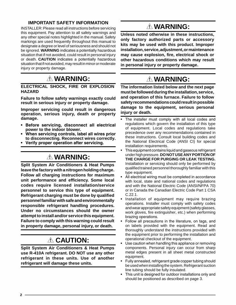
WarnIng:unless noted otherwise in these instructions, only factory authorized parts or accessory kits may be used with this product. Improper installation, service, adjustment, or maintenance may cause explosion, fire, electrical shock or other hazardous conditions which may result in personal injury or property damage.
WarnIng:the information listed below and the next page must be followed during the installation, service, and operation of this furnace. Failure to follow safety recommendations could result in possible damage to the equipment, serious personal injury or death.
• The installer must comply with all local codes andregulations which govern the installation of this type of equipment. Local codes and regulations take precedence over any recommendations contained in these instructions. Consult local building codes and the National Electrical Code (ANSI CI) for special installation requirements.
• Thisequipmentcontainsliquidandgaseousrefrigerantunder high pressure. Do not usE anY PortIon oF thE chargE For PurgIng or lEaK tEstIng.Installation or servicing should only be performed by qualified trained personnel thoroughly familiar with this type equipment.
• Allelectricalwiringmustbecompletedinaccordancewith local, state and national codes and regulations and with the National Electric Code (ANSI/NFPA 70) or in Canada the Canadian Electric Code Part 1 CSA C.22.1.
• Installation of equipment may require brazingoperations. Installer must comply with safety codes and wear appropriate safety equipment (safety glasses, work gloves, fire extinguisher, etc.) when performing brazingoperations.
• Followallprecautions in the literature,ontags,andon labels provided with the equipment. Read and thoroughly understand the instructions provided with the equipment prior to performing the installation and operational checkout of the equipment.
• Usecautionwhenhandlingthisapplianceorremovingcomponents. Personal injury can occur from sharp metal edges present in all sheet metal constructed equipment.
• Fullyannealed,refrigerantgradecoppertubingshouldbe used when installing the system. Refrigerant suction line tubing should be fully insulated.
• Thisunitisdesignedforoutdoorinstallationsonlyandshould be positioned as described on page 3.
IMPortant saFEtY InForMatIonINSTALLER: Please read all instructions before servicing this equipment. Pay attention to all safety warnings and any other special notes highlighted in the manual. Safety markings are used frequently throughout this manual to designate a degree or level of seriousness and should not be ignored. WarnIngindicatesapotentiallyhazardoussituation that if not avoided, could result in personal injury or death. cautIon indicates a potentially hazardoussituation that if not avoided, may result in minor or moderate injury or property damage.

3
unIt InstallatIongeneral InformationSplit system series air conditioners and heat pumps are designed only for outdoor rooftop or ground level installations. These units have been tested for capacity and efficiency in accordance with AHRI Standards and will provide many years of safe and dependable comfort, providing they are properly installed and maintained. Abuse, improper use, and/or improper maintenance can shortenthelifeoftheapplianceandcreateunsafehazards.
Toachieveoptimumperformanceandminimizeequipmentfailure, it is recommended that periodic maintenance be performed on the unit. The ability to properly perform maintenance on this equipment requires certain mechanical skills and tools.
before You Install the unit√ The cooling load of the area to be conditioned must be
calculated and a system of the proper capacity selected. It is recommended that the area to be conditioned be completely insulated and vapor sealed.
√ Check the electrical supply and verify the power supply is adequate for unit operation. The system must be wired and provided with circuit protection in accordance with local building codes. If there is any question concerning the power supply, contact the local power company.
√ The indoor section (air handler, furnace, etc) should be installed before routing the refrigerant tubing. Refer to the indoor unit's installation instructions for installation details.
√ All units are securely packed at the time of shipment and upon arrival should be carefully inspected for damage prior to installing the equipment at the job site. Verify coil fins are straight. If necessary, comb fins to remove flattened or bent fins. Claims for damage (apparent or concealed) should be filed immediately with the carrier.
√ Please consult your dealer for maintenance information and availability of maintenance contracts. Please read all instructions before installing the unit.
locating the Equipment• Surveythejobsitetodeterminethebestlocationfor
mounting the outdoor unit.• Overhead obstructions (Figure 1), poorly ventilated
areas, and areas subject to accumulation of debris should be avoided.
• Sufficientclearanceforunobstructedairflowthroughtheoutdoor coil must be maintained in order to achieve rated performance. See Figure 1 for minimum clearances to obstructions.
• Considerationshouldbegiventoavailabilityofelectricpower, service access, noise, and shade.
Packaging removalTo prevent damage to the tubing connections, carefully remove the carton and user’s manual from the equipment. Discard the shipping carton.
ground levelGround level installations must be located according to local building codes or ordinances and these requirements:• Clearancesmustbeinaccordancewiththoseshown
in Figure 1.• Asuitablemountingpad (mustbeprovidedandbe
separate from the building foundation. The pad must be level and strong enough to support the unit’s weight. The slab height must be a minimum of 2” (5 cm) above grade and with adequate drainage. See Figure 1.
rooftop• The method of mounting should be designed so that it
does not overload roof structures or transmit noise to the interior of the structure. The roof must be structurally capable of handling the weight of the unit.
• Full perimeter support is required under the unit. Support must be made of weather resistant materials and installed prior to unit installation.
• Thesupportmustbebuilttoraisetheunit6"abovethe roof.
Figure 1. clearance requirements
2” Mounting Pad
48”
24" for Service Access
12" or 18”See Note
12" or 18”See Note
DO NOTOBSTRUCT
TOP OF UNIT
NOTE: Units require full perimeter clearances.Installer must maintain 18” between two units
or 12” between single unit and structure.
6” from Buildingor Structure
4
connecting refrigerant tubing between the Indoor & outdoor unit
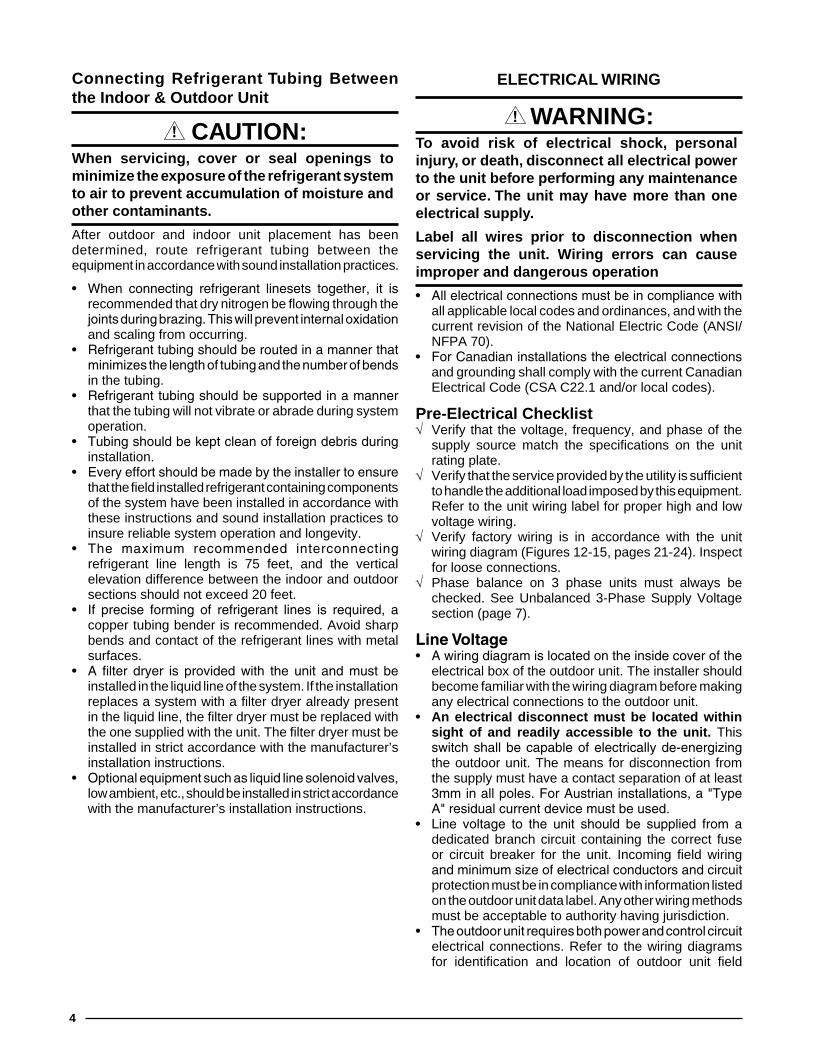
cautIon:When servicing, cover or seal openings to minimize the exposure of the refrigerant system to air to prevent accumulation of moisture and other contaminants.
After outdoor and indoor unit placement has been determined, route refrigerant tubing between the equipment in accordance with sound installation practices.
• When connecting refrigerant linesets together, it isrecommended that dry nitrogen be flowing through the jointsduringbrazing.Thiswillpreventinternaloxidationand scaling from occurring.
• Refrigeranttubingshouldberoutedinamannerthatminimizesthelengthoftubingandthenumberofbendsin the tubing.
• Refrigeranttubingshouldbesupportedinamannerthat the tubing will not vibrate or abrade during system operation.
• Tubingshouldbekeptcleanofforeigndebrisduringinstallation.
• Everyeffortshouldbemadebytheinstallertoensurethat the field installed refrigerant containing components of the system have been installed in accordance with these instructions and sound installation practices to insure reliable system operation and longevity.
• The maximum recommended interconnectingrefrigerant line length is 75 feet, and the vertical elevation difference between the indoor and outdoor sections should not exceed 20 feet.
• If precise forming of refrigerant lines is required, acopper tubing bender is recommended. Avoid sharp bends and contact of the refrigerant lines with metal surfaces.
• A filter dryer is provided with the unit and must beinstalled in the liquid line of the system. If the installation replaces a system with a filter dryer already present in the liquid line, the filter dryer must be replaced with the one supplied with the unit. The filter dryer must be installed in strict accordance with the manufacturer’s installation instructions.
• Optionalequipmentsuchasliquidlinesolenoidvalves,low ambient, etc., should be installed in strict accordance with the manufacturer’s installation instructions.
ElEctrIcal WIrIng
WarnIng:to avoid risk of electrical shock, personal injury, or death, disconnect all electrical power to the unit before performing any maintenance or service. the unit may have more than one electrical supply.
label all wires prior to disconnection when servicing the unit. Wiring errors can cause improper and dangerous operation
• Allelectricalconnectionsmustbeincompliancewithall applicable local codes and ordinances, and with the current revision of the National Electric Code (ANSI/NFPA 70).
• ForCanadianinstallationstheelectricalconnectionsand grounding shall comply with the current Canadian Electrical Code (CSA C22.1 and/or local codes).
Pre-Electrical checklist√ Verify that the voltage, frequency, and phase of the
supply source match the specifications on the unit rating plate.
√ Verify that the service provided by the utility is sufficient to handle the additional load imposed by this equipment. Refer to the unit wiring label for proper high and low voltage wiring.
√ Verify factory wiring is in accordance with the unit wiring diagram (Figures 12-15, pages 21-24). Inspect for loose connections.
√ Phase balance on 3 phase units must always be checked. See Unbalanced 3-Phase Supply Voltage section (page 7).
LineVoltage• Awiringdiagramislocatedontheinsidecoverofthe
electrical box of the outdoor unit. The installer should become familiar with the wiring diagram before making any electrical connections to the outdoor unit.
• an electrical disconnect must be located within sight of and readily accessible to the unit. This switchshallbecapableofelectricallyde-energizingthe outdoor unit. The means for disconnection from the supply must have a contact separation of at least 3mminallpoles.ForAustrianinstallations,a"TypeA"residualcurrentdevicemustbeused.
• Line voltage to the unit should be supplied from adedicated branch circuit containing the correct fuse or circuit breaker for the unit. Incoming field wiring andminimumsizeofelectricalconductorsandcircuitprotection must be in compliance with information listed on the outdoor unit data label. Any other wiring methods must be acceptable to authority having jurisdiction.
• Theoutdoorunitrequiresbothpowerandcontrolcircuitelectrical connections. Refer to the wiring diagrams for identification and location of outdoor unit field

5
wiring interfaces. Make all electrical connections in accordance with all applicable codes and ordinances.
• Overcurrentprotectionmustbeprovidedatthebranchcircuitdistributionpanelandsizedasshownontheunitrating label and according to applicable local codes. See the unit rating plate for minimum circuit ampacity and maximum overcurrent protection limits.
• Providepowersupplyfortheunitinaccordancewiththeunit wiring diagram, and the unit rating plate. Connect the line-voltage leads to the terminals on the contactor inside the control compartment.
• Useonlycopperwireforthelinevoltagepowersupplyto this uni. Use proper code agency listed conduit and a conduit connector for connecting the supply wires to the unit. Use of rain tight conduit is recommended.
• 208/230Voltunitsareshippedfromthefactorywiredfor 230 volt operation. For 208V operation, remove the lead from the transformer terminal marked 240V and connect it to the terminal marked 208V.
• Optionalequipmentrequiringconnectiontothepoweror control circuits must be wired in strict accordance of the NEC (ANSI/NFPA 70), applicable local codes, and the instructions provided with the equipment.
Thermostat/LowVoltageConnections• Thermostatconnectionsshouldbemadeinaccordance
with the instructions supplied with the thermostat and the indoor equipment.
• Theoutdoorunitisdesignedtooperatefroma24VACClass II control circuit. The control circuit wiring must comply with the current provisions of the NEC (ANSI/NFPA 70) and with applicable local codes having jurisdiction.
• Thelowvoltagewiresmustbeproperlyconnectedtothe units low voltage terminal block.
• The thermostat should be mounted about 5 feetabove the floor on an inside wall. DO NOT install the thermostat on an outside wall or any other location where its operation may be adversely affected by radiant heat from fireplaces, sunlight, or lighting fixtures, and convective heat from warm air registers or electrical appliances. Refer to the thermostat manufacturer’s instruction sheet for detailed mounting and installation information.
grounding
WarnIng:the unit cabinet must have an uninterrupted or unbroken electrical ground to minimize personal injury if an electrical fault should occur. Do not use gas piping as an electrical ground!
This unit must be electrically grounded in accordance with local codes or, in the absence of local codes, with the National Electrical Code (ANSI/NFPA 70) or the CSA C22.1 Electrical Code. Use the grounding lug provided in the control box for grounding the unit.
Example:
AB = 451VBC = 460VAC = 453V
2. Determine the average voltage in the power supply.
3. Determine the maximum deviation:
4. Determine percent of voltage imbalance by using the results from steps 2 & 3 in the following equation.
max voltage deviationfrom average voltage
= 100 xaverage voltage
% Voltage Imbalance
= 1.32%6
454100 x
Example:
1. Measure the line voltages of your 3-phase power supply where it enters the building and at a location that will only be dedicated to the unit installation (at the units circuit protection or disconnect).
Unbalanced3-PhaseSupplyVoltageVoltage unbalance occurs when the voltages of all phases of a 3-phase power supply are no longer equal. This unbalance reduces motor efficiency and performance. Some underlying causes of voltage unbalance may include: Lack of symmetry in transmission lines, large single-phase loads, and unbalanced or overloaded transformers. A motor should never be operated when a phase imbalance in supply is greater than 2%. Perform the following steps to determine the percentage of voltage imbalance:
In this example, the measured line voltages were 451, 460, and 453. The average would be 454 volts (451 + 460 + 453 = 1,364 / 3 = 454).
The amount of phase imbalance (1.32%) is satisfactory since the amount is lower than the maximum allowable 2%. Please contact your local electric utility company if your voltage imbalance is more than 2%.
Example:From the values given in step 1, the BC voltage (460V) is the greatest difference in value from the average:
460 - 454 = 6454 - 451 = 3454 - 453 = 1
Highest Value

6
notE: On 3 phase air handler models only - If blower is spinning opposite of arrow direction, shut off the main power to the unit and switch any two field wires at the disconnect. Do not alter unit wiring.
Short Cycle Protection1. Operate the system in cooling mode and observe the
temperature setting of the thermostat. Gradually raise theset-pointtemperatureuntiltheunitde-energizes.
2. Immediately lower the set point temperature of the thermostat to its original setting and verify that the indoorblower isenergizedandoutdoorunitremainsde-energized.
3. After approximately 5 minutes, verify the outdoor unit energizesandthetemperatureofthedischargeairiscooler than the room temperature.
System Cooling1. Set the thermostat’s system mode to COOL and the
fan mode to AUTO. Gradually lower the thermostat temperature setpoint below room temperature and verifytheoutdoorunitandindoorblowerenergize.
2. Verify blower wheel is spinning in direction indicated by arrow. Feel the air being circulated by the indoor blower and verify that it is cooler than ambient temperature. Listen for any unusual noises. If unusual sounds occur, determine the source of the noise and correct as necessary.
3. Verify HI and LO refrigerant pressures. notE: If refrigerant pressures are abnormal and the
compressor is rotating backwards, shut off main power to the unit and switch any two field wires at the disconnect. Do not alter unit wiring.
4. Allow the system to operate for several minutes and then set the temperature selector above room temperature. Verify the fan and compressor cycle off with the thermostat. notE: The blower should also stop unless fan switch is set to the ON position.
System Heating1. Set the thermostat's system mode to HEAT and the
temperature mode to below room temperature.2. Verify the outdoor unit and indoor fan stop running. After
5 minutes, increase the temperature on the thermostat to it's maximum setting.
3. Verifytheoutdoorunitandindoorblowerenergize.Feelthe air being circulated by the indoor blower and verify that it is warmer than ambient temperature. Listen for any unusual noises. If unusual sounds occur, determine the source of the noise and correct as necessary.
Defrost cycle timerThe defrost cycle timer controls the time interval of the hot gas defrost after the defrost sensor closes. It is located in the lower left corner of the defrost control board on the of the control panel. Three interval settings are available: 30, 60, and 90 minutes. Time setting selection is dependent on the climate where the unit is being installed.
ReverseRotationVerificationAfter making all of the power connections to the unit, the rotation of the compressor must be checked. If the rotation is in the wrong direction, the compressor will make an abnormally loud noise. To check the rotation perform the following steps:
1. Make sure the outside power disconnect is in the OFF position.
2. Set the indoor thermostat to a set point that will call for cooling.
3. Retun to the outside power disconnect and switch it to the ON position. If the compressor is making an abnormally loud noise, immediately switch the outside power disconnect to the OFF position.
4. Switch any two of the three power leads at the power connections to the unit.
5. SetReturn to the outside power disconnect and swith it to the ON position.
6. Verify that the compressor is now running properly.
start uP & aDjustMEntsPre-start check list√ Verify the unit is level and has sufficient clearances for
unobstructed airflow.√ Verify the outdoor coil and top of the unit are free from
obstructions and debris, and all equipment access/control panels are in place.
√ Verify that the line voltage power leads are securely connected and the unit is properly grounded.
√ Verify that the low voltage wires are securely connected to the correct leads on the low voltage terminal strip.
√ Verify that the power supply branch circuit overcurrent protectionissizedproperly.
√ Verify that the thermostat is wired correctly.
start-up Procedures
WarnIng:this unit is equipped with a crankcase heater. allow 24 hours prior to continuing the start up procedures to allow for heating of the refrigerant compressor crankcase. Failure to comply may result in damage and could cause premature failure of the system. this warning should be followed at initial start up and any time the power has been removed for 12 hours or longer.
Air Circulation - Indoor Blower1. Set the thermostat system mode on OFF and the fan
mode to ON.2. Verify the blower runs continuously. Check the air delivery
at the supply registers and adjust register openings for balanced air distribution. If insufficient air is detected, examine ductwork for leaks or obstructions.
3. Set the thermostat fan mode to AUTO and verify the blower stops running.

7
• Indryclimates,a90minutesettingisrecommended.• Inmoistclimates,a30minutesettingisrecommended.
To set the cycle timer, place the timing pin on the defrost control board to the desired time interval post.
notE: All units are shipped from the factory with the default time setting of 30 minutes. Longer settings are recommended for drier climate areas and shorter time intervals are recommended for moist climate areas. Maximum heating performance can be acheived by setting the time to 90 minutes.
Defrost control boardOperational Information• Terminalsr - rc must have 24±V present between
them in order for the time delay and defrost sequences to be operational.
• Ajumperbetweenthet2 - DFt test pins will communicate to the board that the defrost T-stat is closed (if the compressor is running). The defrost thermostat tells the board whether a defrost cycle needs to be started or terminated. notE: The defrost T-stat is closed at 32° F or below and is open at 68° F or above, but it’s state is unknown if the temperature is between 32° F and 68° F.
• With the DFT closed, the unit will run for 30/60/90minutes in heat mode and then defrost the outdoor coil. The defrost will turn off the outdoor fan, turn on the compressor and raise the coil temperature to 68° F. This will open the DFT and terminate the defrost. If the DFT does not open the defrost will end after 10 minutes.
• Toover-ridethedefrostboardandinitiateafasterdefrosttest in 5, 10 or 15 seconds as determined by the 30, 60 or 90 minute defrost pin settings (factory setting is 30 minutes), jumper the tEst terminal to the c (common) terminal while the compressor is in heat mode.– This will bypass the compressor off delay when the
unit goes into defrost test and if left in defrost test, the delay will be bypassed when the test is terminated by the processor. notE: If the jumper is removed before the test is over, the processor will perform the remainder of a normal defrost. See bullett 2 above.
• To switch from no-delay to delay, remove the pin from the no - delay pin location and shift it to the delay pin location. The delay/no-delay pin concerns compressor operation during defrosts. The default setting is delay.– Reciprocating compressors should only use this
setting in conjunction with an approved hard start kit.
– Scroll compressors that have noise issues while going into or coming out of defrost should use this 30 second delay to reduce the defrost noise.
– Manually initiating a defrost will cause the compressor to run continually when entering defrost.
Normal defrost operationTo test normal defrost operation when the temperature is above 35° F, jumper r to DFt on the board and allow the unit to run for 30 minutes. Defrost will continue until the r to DFt jumper is removed or for 10 minutes. Remove the jumper.
The 5 minute time delay feature can be shortened 1 time to 1 second by jumping the test to c terminal. Remove the jumper and repeat as desired.
notE: If jumper is left on the test to common pins permanently, the defrost cycle will become inoperable.
Defrost Test Procedure1. Jumper t2 to DFt at the test terminals.2.Withunitrunninginheatmode,shortthetEst terminal
to the common terminal near it. This will speed up the board and cause it to enter defrost mode in 5/10/15 seconds depending on the defrost time selection. Compressor delay will not function during speed-up.
3. This test will end in 5 seconds if the tEst-common short is not removed.
4. Remove both the short and the t2 to DFt jumper to terminate the defrost cycle. The 30 second compressor delay should operate normally.
5. Test is complete, reset thermostat to home owner preference.
anti short cycle timer testThe 5 minute time delay feature can be bypassed or shortened to 1 second by jumping the test to c terminal.
notE: If jumper is left on the test to common pins permanently, the defrost cycle will become inoperable.
refrigerant charging
WarnIng:split system air conditioners & heat Pumps leave the factory with a nitrogen holding charge. Follow all charging instructions for maximum unit performance and efficiency. some local codes require licensed installation/service personnel to service this type of equipment. refrigerant charging must be done by qualified personnel familiar with safe and environmentally responsible refrigerant handling procedures. under no circumstances should the owner attempt to install and/or service this equipment. Failure to comply with this warning could result in property damage, personal injury, or death.
After refrigerant line connections are completed, it is required that you leak check and evacuate the indoor section and all line connections (using proper methods) beforefinalizingthefullsystemrefrigerantcharge.

8
• Toachieveratedcapacityandefficiency,thecompressormust be exposed to refrigerant for at least 24 hours prior to running and then the compressor must be run for a minimum of 12 hours.
• Coolingmodechargingchartsareapplicableonlytomatched assemblies of NORDYNE equipment and listed airflows for the indoor coil. Outdoor units with non-AHRI lsited indoor coils are not recommended and deviations from rated airflows or non-listed combinations may require modification to the expansion device and refrigerant charging procedures for proper and efficient system operation. Refer to Table 1 for correct restrictor sizesandTables2-17(pages10-15)todeterminetheideal amount of sub-cooling for a given liquid pressure.
• Therefrigerantchargecanbecheckedandadjustedthrough the service ports provided external to the outdoor unit. Use only gage line sets which have a “Schrader” depression device present to actuate the valve. A common suction port for heating mode charging is included and located on the compressor access panel above the outdoor unit service valves.
• HeatModeVerificationTables(Tables18-25,pages17 - 19) are provided for quick reference when the unit is in heating mode and for the inspection of the liquid line pressures and temperatures.
Charging the Unit in AC Mode with Outdoor Temperatures Above 55° F (for optimized sub-cooling of 10° F to 12° F)1. With the systemoperatingat steady-state,measure
the liquid refrigerant pressure (in PSIG) at the outdoor unit service valve.
2. Measure the liquid refrigerant temperature (in Fahrenheit) at the service valve.
3. Determine the required liquid refrigerant pressure. Refer to Tables 2 - 17 (pages 10 - 15).• IfthepressuremeasuredinStep1isgreaterthan
the required liquid refrigerant pressure determined in Step 3, then there is too much charge in the system. Remove refrigerant and repeat Steps 1 through 3 until the system is correctly charged.
• IfthepressuremeasuredinStep1islessthantherequired liquid refrigerant pressure determined in Step 3, there is too little charge in the system. Add refrigerant and repeat Steps 1 through 3 until the system is correctly charged.
unIt MaIntEnancE
WarnIng:to prevent electrical shock, personal injury, or death, disconnect all electrical power to the unit before performing any maintenance or service. the unit may have more than one electrical supply.
Proper maintenance is important to achieve optimum performance from the heat pump. The ability to properly perform maintenance on this equipment requires certain mechanical skills and tools. If you do not possess these skills, contact your dealer for maintenance. Consult your local dealer about the availability of maintenance contracts. Routine maintenance should include the following:• Inspectandcleanorreplaceairfiltersatthebeginning
of each heating and cooling season, or more frequently if required.
• Inspecttheoutdoorcoilatthebeginningofeachcoolingseason. Remove any debris. Clean the outdoor coil and louvers as necessary using a mild detergent and water. Rinse thoroughly with water.
• Inspecttheelectricalconnectionsfortightnessatthebeginning of each heating and cooling season. Service as necessary.
cautIon:the unit should never be operated without a filter in the return air system. replace disposable filters with the same type and size.
• Donotaddadditionaloiltomotorsunequippedwithoiltubes. The compressor is hermetically sealed at the factory and does not require lubrication.
table 1. orifice usage for split system air conditioners & heat Pumps
Model
restrictorsize (Inch)
system charger-410a (oz.)
Indooroutdoor
(heat Pumps)a/c h.P.
2 Ton 0.057 0.049 65 752 1/2 Ton 0.064 0.057 68 78
3 Ton 0.069 0.061 70 824 Ton 0.077 0.064 88 1005 Ton 0.083 0.066 93 105

9
coMPonEnt FunctIons
high Pressure switch (hPs) - A high-pressure switch is factory-installed and located in the compressor discharge line internal to the outdoor unit. The switch is designed to de-energizethesystemwhenveryhighpressuresoccurduring abnormal conditions. Under normal conditions, the switch is closed. If the discharge pressure rises above 575psig,thentheswitchwillopenandde-energizetheoutdoor unit. The switch will close again once the liquid pressure decreases to 460 psig. Please note that the switchinterruptsthethermostatinputstotheunit.Whenthe switch opens and then closes, there will be a 5 minute shortcyclingdelaybeforetheoutdoorunitwillenergize.
low Pressure switch (lPs) - A low-pressure switch is factory-installed in select models only. If provided, this located in the suction line internal to the outdoor unit. The switch is designed to protect the compressor from a loss of charge. Under normal conditions, the switch is closed. If the suction pressure falls below 5 psig, then the switch willopenandde-energize theoutdoorunit.Theswitchwill close again once the suction pressure increases above 20 psig. Please note that the switch interrupts the thermostatinputstotheunit.Whentheswitchopensandthen closes, there will be a 5 minute short cycling delay beforetheoutdoorunitwillenergize.
rEPlacEMEnt PartsReplacement parts are available through all Nordyne distributors. Please have the complete model and serial number of the unit when ordering replacement parts.
Electrical:Capacitors Temperature Limit SwitchesCompressors ThermostatsContactors Time Delay RelaysPressure Switches TransformersRelays
Motors:Blower MotorFan Motorcomponents:Blower Assembly Fan GrilleCabinet Panels Filter/DriersExpansion Valves

10
rEFrIgErant chargIng tablEs - coolIng MoDE onlYapplication notes on the use of cooling mode charging tables
notEs:
1. All pressures are listed psig and all temperatures in °F2. Discharge temperatures GREATER than charted values
indicate an UNDERCHARGED system.3. Discharge temperatures LESS than charted values
indicate an OVERCHARGED system.
• this equipment’s cooling system contains refrigerant under high pressure. always use safe and environmentally sound methods when handling refrigerant handling or servicing the unit. review the factory literature and safety warnings prior to servicing.
• Whenrepairingsystemleaks,alwaysuseanitrogen(inert)gastoprotecttherefrigerantsystemandpressurecheck the repair before re-charging. Always replace the filter-dryers when performing any repair to the refrigeration system with one capable of acid removal. After completing the repairs, evacuate the system to 350 - 500 microns and weigh in the refrigerant to the amount specified on the unit rating label.
• Chargingtablesarevalidforavarietyof indoor,returnairconditionsandaremostinfluencedbytheoutdoorambient temperature, outdoor fan operation and the unit operating voltage. Before using these charts, make sure the unit is in a stable operating mode. As shown in Tables 2 - 17 (pages 10 - 15), the ideal system sub-cooling can vary over the range of operation. Reference the tables to determine the ideal amount of sub-cooling for a given liquid pressure. Units charged to other values will not perform at the rated unit efficiency (EER) or rated Coefficient of Performance (COP) in heating mode.
• Toinspectasystemsoperationusingqualityinstruments,matchthemeasuredliquidtemperaturetotheunitschart. The measured liquid pressure reading should be within 3% of the tables value for most installations.
• Forsystemsthatareoperatingwithmorethana5%deviation,inspecttheunitforthepropervoltageandphasebalance and the refrigeration system for leaks.
• Unitsthatareoperatingatlessthen95%ofthenominalvoltageorwitha2%phaseimbalancemayseeamoresignificant deviation than the amount stated above.
• Do not use the tables in systems that have a fan cycling under low-ambient control. Refer to the low-ambient kit instructions for more information. (If applicable)
lEgEnD
Shaded boxes indicate flooded conditions. Rated design values. The suction pressure will be lower than design value if outdoor air flow, entering dry bulb, or entering wet bulb temperatures are lower than design.
table 2. air conditioner & heat Pump charging table (3 ton units) - orifice Matches
aIr conDItIonEr & hEat PuMP rEFrIgErant chargIng tablEsthrEE PhasE unIts
suc. Press.
outDoor tEMPEraturE (° F)
70 75 80 85 90 95 100 105liq.
Press.Dis.
temp.liq.
Press.Dis.
temp.liq.
Press.Dis.
temp.liq.
Press.Dis.
temp.liq.
Press.Dis.
temp.liq.
Press.Dis.
temp.liq.
Press.Dis.
temp.liq.
Press.Dis.
temp.124126 301 139128 302 151 327 146130 304 162 329 156 353 150132 303 184 331 165 356 159 380 157 402 157134 304 200 332 184 358 170 383 163 406 164 429 162136 333 198 359 184 385 172 410 172 433 168 455 166138 361 198 387 185 412 182 437 175 460 172 482 172140 389 199 414 191 439 184 464 178 487 177142 416 201 442 194 466 188 491 183144 444 204 469 197 494 192146 471 207 496 201148 499 210
11
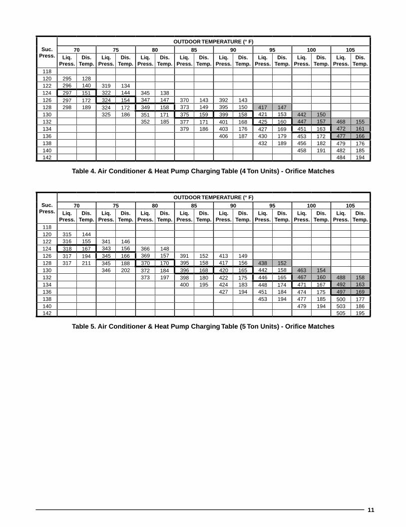
table 4. air conditioner & heat Pump charging table (4 ton units) - orifice Matches
table 5. air conditioner & heat Pump charging table (5 ton units) - orifice Matches
suc. Press.
outDoor tEMPEraturE (° F)
70 75 80 85 90 95 100 105liq.
Press.Dis.
temp.liq.
Press.Dis.
temp.liq.
Press.Dis.
temp.liq.
Press.Dis.
temp.liq.
Press.Dis.
temp.liq.
Press.Dis.
temp.liq.
Press.Dis.
temp.liq.
Press.Dis.
temp.118120 295 128122 296 140 319 134124 297 151 322 144 345 138126 297 172 324 154 347 147 370 143 392 143128 298 189 324 172 349 158 373 149 395 150 417 147130 325 186 351 171 375 159 399 158 421 153 442 150132 352 185 377 171 401 168 425 160 447 157 468 155134 379 186 403 176 427 169 451 163 472 161136 406 187 430 179 453 172 477 166138 432 189 456 182 479 176140 458 191 482 185142 484 194
suc. Press.
outDoor tEMPEraturE (° F)
70 75 80 85 90 95 100 105liq.
Press.Dis.
temp.liq.
Press.Dis.
temp.liq.
Press.Dis.
temp.liq.
Press.Dis.
temp.liq.
Press.Dis.
temp.liq.
Press.Dis.
temp.liq.
Press.Dis.
temp.liq.
Press.Dis.
temp.118120 315 144122 316 155 341 146124 318 167 343 156 366 148126 317 194 345 166 369 157 391 152 413 149128 317 211 345 188 370 170 395 158 417 156 438 152130 346 202 372 184 396 168 420 165 442 158 463 154132 373 197 398 180 422 175 446 165 467 160 488 158134 400 195 424 183 448 174 471 167 492 163136 427 194 451 184 474 175 497 169138 453 194 477 185 500 177140 479 194 503 186142 505 195

12
table 6. air conditioner & heat Pump charging table (2 ton units) - orifice Matches
table 7. air conditioner charging table (2.5 ton units) - orifice Matches
suc. Press.
outDoor tEMPEraturE (° F)
70 75 80 85 90 95 100 105liq.
Press.Dis.
temp.liq.
Press.Dis.
temp.liq.
Press.Dis.
temp.liq.
Press.Dis.
temp.liq.
Press.Dis.
temp.liq.
Press.Dis.
temp.liq.
Press.Dis.
temp.liq.
Press.Dis.
temp.129131 276 126133 278 138 300 131135 279 149 302 141 323 135137 279 170 304 151 326 143 346 140 366 139139 280 187 305 168 328 153 349 146 370 147 389 144141 306 182 330 167 352 153 373 155 393 150 412 148143 331 180 354 166 377 162 397 157 416 154 435 153145 356 180 379 170 401 163 421 160 440 158147 381 181 403 172 425 165 444 164149 406 182 428 175 449 169151 430 184 452 178153 454 187155
suc. Press.
outDoor tEMPEraturE (° F)
70 75 80 85 90 95 100 105liq.
Press.Dis.
temp.liq.
Press.Dis.
temp.liq.
Press.Dis.
temp.liq.
Press.Dis.
temp.liq.
Press.Dis.
temp.liq.
Press.Dis.
temp.liq.
Press.Dis.
temp.liq.
Press.Dis.
temp.123
125 297 101
127 298 112 321 115
129 300 123 324 125 347 127
131 301 134 326 135 350 136 373 140 395 146
133 302 151 328 145 353 141 376 146 399 153 422 156
135 329 160 355 155 380 150 403 161 426 163 448 166
137 357 168 382 163 407 167 430 169 453 172 475 176
139 384 177 409 175 434 175 457 178 480 182
141 411 186 436 185 461 185 485 187
143 439 195 463 194 488 195
145 466 204 491 203
147 493 212
149
aIr conDItIonEr & hEat PuMP rEFrIgErant chargIng tablEssInglE PhasE unIts

13
table 9. air conditioner & heat Pump charging table (3 ton units) - orifice Matches
suc. Press.
outDoor tEMPEraturE (° F)
70 75 80 85 90 95 100 105liq.
Press.Dis.
temp.liq.
Press.Dis.
temp.liq.
Press.Dis.
temp.liq.
Press.Dis.
temp.liq.
Press.Dis.
temp.liq.
Press.Dis.
temp.liq.
Press.Dis.
temp.liq.
Press.Dis.
temp.125127 294 82129 295 93 317 101131 296 105 319 111 342 117133 299 110 322 121 345 125 368 133 391 141135 299 127 325 128 349 128 372 139 395 149 418 154137 326 142 351 142 376 142 399 157 422 161 445 166139 353 156 378 154 403 162 426 167 449 172 472 178141 380 169 405 170 430 173 454 178 477 184143 407 181 432 183 457 186 482 190145 435 193 460 195 484 198147 462 205 487 207149 489 216151
suc. Press.
outDoor tEMPEraturE (° F)
70 75 80 85 90 95 100 105liq.
Press.Dis.
temp.liq.
Press.Dis.
temp.liq.
Press.Dis.
temp.liq.
Press.Dis.
temp.liq.
Press.Dis.
temp.liq.
Press.Dis.
temp.liq.
Press.Dis.
temp.liq.
Press.Dis.
temp.119121 303 106123 304 117 328 119125 306 128 330 129 354 130127 307 139 332 139 356 139 380 143 403 148129 308 156 334 149 360 144 383 149 407 155 430 157131 336 164 362 158 387 153 410 163 434 164 457 166133 363 172 389 165 415 169 438 170 461 172 484 175135 391 180 417 177 442 176 466 178 489 181137 419 188 444 186 469 185 493 187139 447 196 472 194 497 194141 474 204 500 203143 502 212145
table 9. air conditioner & heat Pump charging table (4 ton units) - orifice Matches

14
HeaTPUmPVeRifiCaTionTaBLeS-HeaTingmodeonLy
• read all notes and warnings for the cooling-mode charging tables prior to using these heating-mode charge verification tables. always use safe and environmentally sound methods when handling refrigerant handling or servicing the unit. review the factory literature and safety warnings prior to servicing.
• Whenrepairingsystemleaks,alwaysuseanitrogen(inert)gastoprotecttherefrigerantsystemandpressurecheck the repair before re-charging. Always replace the filter-dryers when performing any repair to the refrigeration system with one capable of acid removal. After completing the repairs, evacuate the system to 350 - 500 microns and weigh in the refrigerant to the amount specified on the unit rating label.
• Before using Tables 18 - 25 (pages 17-19), determine the outdoor ambient temperature and the return air temperature to the unit. Locate the appropriate location on the units verification table based on those measurements to determine the ideal liquid line pressure and temperature. Verify the outdoor fan and compressor are running and the outdoor coil is free from frost accumulation. Also verify the system is not operating in defrost mode before inspecting the system.
• Always use quality instruments that are in good working order to measure the actual operating point of the refrigeration system. The liquid line temperature should be within 2 degrees of the ideal value and the pressure should be within 2%.
• The most reliable way of verifying the system is at the correct charge is to evacuate the system and weigh in the charge to the amount shown on the rating label. However, if an inspection with these verification tables does not line up with the values shown and the ambient temperature is above 50˚ F, then a more accurate way to inspect the system for proper charge is with the cooling mode charging tables. Switch the unit into cooling mode and allowittooperateandstabilizeforafewminutestheninspecttheunitoperationwiththecoolingmodetablesandprocedures.
before changing the unit charge, always inspect the following items first:1. Inspect the liquid line temperature on the inlet and outlet of the filter dryers. If it is the factory dryer and in good
condition there should be no temperature difference. If the temperature difference is larger than 5˚, replace the filter dryer with one that is bi-directional and has acid removal capability. Refer to the unit RPL for the recommended partnumberandsize.
2. Inspect the units input voltage. Units operating at less than 95% of the nominal voltage may deviate more from the chart then previously stated.
3. Inspect the input voltage for a phase imbalance. Units with greater then a 2% disparity will not operate at the rated performance.
4. Verify that the unit filters are installed and are clean. The pressure drop across the filters should not exceed 0.08 in-W.C.
5. Inspect the indoor coil, indoor blower and blower motor for cleanliness, clogging, and proper operation.6. Inspect the system for leaks. If any leaks are detected, repair them immediately. Re-inspect the return air and
ambient temperatures and verify that the correct system point on the verification chart was selected.
Do not use the tables in systems that have the fan cycling under a low-ambient control. Low-ambient controls are for cooling operation. In heating mode, the low ambient control should be disabled. Unless the unit is in defrost mode, the outdoor fan should always operate in conjunction with the compressor.
application notes on the use of heating-mode charging tables:
notEs:
1. All pressures are listed psig and all temperatures in °F2. Discharge temperatures greater than charted values
indicate an undercharged system.
lEgEnD
Shaded boxes indicate flooded conditions. Rated design values. Suction pressure will vary from design value if outdoor air flow, entering dry bulb, or entering wet bulb temperatures vary.

15
tab
le 2
0. h
eat
Pu
mp
ch
arg
ing
tab
le (
3 to
n u
nit
s) -
ori
fice
Mat
ches
ou
tD
oo
r t
EM
PE
ra
tu
rE
(°
F)
010
2030
4050
60s
uc.
Pre
ss.
liq
.P
ress
.D
is.
tem
p.
su
c.P
ress
.l
iq.
Pre
ss.
Dis
.te
mp
.s
uc.
Pre
ss.
liq
.P
ress
.D
is.
tem
p.
su
c.P
ress
.l
iq.
Pre
ss.
Dis
.te
mp
.s
uc.
Pre
ss.
liq
.P
ress
.D
is.
tem
p.
su
c.P
ress
.l
iq.
Pre
ss.
Dis
.te
mp
.s
uc.
Pre
ss.
liq
.P
ress
.D
is.
tem
p.
2725
115
141
269
154
5528
715
769
305
160
8330
916
696
323
175
109
337
184
2825
814
942
275
152
5629
215
570
308
158
8431
616
397
330
170
110
344
178
2926
514
743
281
150
5729
715
371
312
156
8532
316
098
337
166
111
351
172
3027
214
544
287
148
5830
115
172
316
154
8633
015
799
344
161
112
358
165
3127
914
345
293
146
5930
614
973
319
152
8733
715
410
035
115
711
336
515
932
286
141
4629
914
460
311
147
7432
315
088
344
151
101
358
152
114
372
153
3329
313
947
305
142
6131
614
575
327
148
8935
114
910
236
514
811
537
914
7
tab
le 1
8. h
eat
Pu
mp
ch
arg
ing
tab
le (
4 to
n u
nit
s) -
ori
fice
Mat
ches
ou
tD
oo
r t
EM
PE
ra
tu
rE
(°
F)
010
2030
4050
60s
uc.
Pre
ss.
liq
.P
ress
.D
is.
tem
p.
su
c.P
ress
.l
iq.
Pre
ss.
Dis
.te
mp
.s
uc.
Pre
ss.
liq
.P
ress
.D
is.
tem
p.
su
c.P
ress
.l
iq.
Pre
ss.
Dis
.te
mp
.s
uc.
Pre
ss.
liq
.P
ress
.D
is.
tem
p.
su
c.P
ress
.l
iq.
Pre
ss.
Dis
.te
mp
.s
uc.
Pre
ss.
liq
.P
ress
.D
is.
tem
p.
2425
416
038
274
161
5229
416
166
314
162
7832
316
788
345
177
9836
618
7
2526
115
839
280
159
5329
815
967
317
160
7933
016
489
352
172
9937
318
1
2626
815
640
285
157
5430
315
768
321
158
8033
716
190
359
168
100
380
175
2727
515
441
291
155
5530
815
569
325
156
8134
415
991
366
164
101
387
169
2828
215
242
297
153
5631
315
370
328
154
8235
115
692
373
159
102
394
162
2928
915
043
303
151
5731
815
171
332
152
8335
815
393
380
155
103
401
156
3029
614
844
309
149
5832
214
972
336
150
8436
515
094
387
150
104
408
150
tab
le 1
9. h
eat
Pu
mp
ch
arg
ing
tab
le (
5 to
n u
nit
s) -
ori
fice
Mat
ches
ou
tD
oo
r t
EM
PE
ra
tu
rE
(°
F)
010
2030
4050
60s
uc.
Pre
ss.
liq
.P
ress
.D
is.
tem
p.
su
c.P
ress
.l
iq.
Pre
ss.
Dis
.te
mp
.s
uc.
Pre
ss.
liq
.P
ress
.D
is.
tem
p.
su
c.P
ress
.l
iq.
Pre
ss.
Dis
.te
mp
.s
uc.
Pre
ss.
liq
.P
ress
.D
is.
tem
p.
su
c.P
ress
.l
iq.
Pre
ss.
Dis
.te
mp
.s
uc.
Pre
ss.
liq
.P
ress
.D
is.
tem
p.
2526
016
237
279
163
4929
816
460
318
165
7232
316
984
336
176
9534
918
326
267
160
3828
516
150
303
162
6132
216
373
330
166
8534
317
196
356
176
2727
415
839
291
159
5130
816
062
325
161
7433
716
486
350
167
9736
317
028
281
156
4029
715
752
313
158
6332
915
975
344
161
8735
716
398
370
164
2928
815
441
303
155
5331
815
664
333
157
7635
115
888
364
158
9937
715
830
295
152
4230
915
354
322
154
6533
615
577
358
155
8937
115
410
038
415
231
302
150
4331
415
155
327
152
6634
015
378
365
152
9037
814
910
139
114
6
hE
at
Pu
MP
rE
Fr
IgE
ra
nt
ch
ar
gIn
g t
ab
lE
s -
th
rE
E P
ha
sE
un
Its

16
tab
le 2
1. h
eat
Pu
mp
ch
arg
ing
tab
le (
2 to
n u
nit
s) -
ori
fice
Mat
ches
ou
tD
oo
r t
EM
PE
ra
tu
rE
(°
F)
010
2030
4050
60s
uc.
Pre
ss.
liq
.P
ress
.D
is.
tem
p.
su
c.P
ress
.l
iq.
Pre
ss.
Dis
.te
mp
.s
uc.
Pre
ss.
liq
.P
ress
.D
is.
tem
p.
su
c.P
ress
.l
iq.
Pre
ss.
Dis
.te
mp
.s
uc.
Pre
ss.
liq
.P
ress
.D
is.
tem
p.
su
c.P
ress
.l
iq.
Pre
ss.
Dis
.te
mp
.s
uc.
Pre
ss.
liq
.P
ress
.D
is.
tem
p.
3323
914
647
264
155
6128
816
575
312
174
8832
218
310
134
119
011
335
919
834
246
144
4826
915
362
293
163
7631
617
289
329
180
102
348
186
114
366
192
3525
314
249
275
151
6329
816
177
320
170
9033
617
710
335
518
111
537
318
536
260
140
5028
114
964
302
159
7832
316
891
343
174
104
362
177
116
380
179
3726
713
851
287
147
6530
715
779
327
166
9235
017
110
536
917
211
738
717
338
274
136
5229
314
566
312
155
8033
116
493
357
169
106
376
168
118
394
167
3928
113
453
299
143
6731
715
381
334
162
9436
416
610
738
316
311
940
116
1
tab
le 2
3. h
eat
Pu
mp
ch
arg
ing
tab
le (
2.5
ton
un
its)
- o
rifi
ce M
atch
es
030K
ou
tD
oo
r t
EM
PE
ra
tu
rE
(°
F)
010
2030
4050
60s
uc.
Pre
ss.
liq
.P
ress
.D
is.
tem
p.
su
c.P
ress
.l
iq.
Pre
ss.
Dis
.te
mp
.s
uc.
Pre
ss.
liq
.P
ress
.D
is.
tem
p.
su
c.P
ress
.l
iq.
Pre
ss.
Dis
.te
mp
.s
uc.
Pre
ss.
liq
.P
ress
.D
is.
tem
p.
su
c.P
ress
.l
iq.
Pre
ss.
Dis
.te
mp
.s
uc.
Pre
ss.
liq
.P
ress
.D
is.
tem
p.
3321
818
247
252
185
6028
618
873
320
191
8733
419
510
135
320
211
537
120
9
3422
518
048
258
183
6129
118
674
323
189
8834
119
210
236
019
711
637
820
2
3523
217
849
264
181
6229
518
475
327
187
8934
819
010
336
719
311
738
519
6
3623
917
650
270
179
6330
018
276
331
185
9035
518
710
437
418
911
839
219
0
3724
617
451
276
177
6430
518
077
334
183
9136
218
410
538
118
411
939
918
4
3825
317
252
281
175
6531
017
878
338
181
9236
918
110
638
818
012
040
617
8
3926
017
053
287
173
6631
517
679
342
179
9337
617
810
739
517
512
141
317
2

17
tab
le 2
4. h
eat
Pu
mp
ch
arg
ing
tab
le (
3 to
n u
nit
s) -
ori
fice
Mat
ches
ou
tD
oo
r t
EM
PE
ra
tu
rE
(°
F)
010
2030
4050
60s
uc.
Pre
ss.
liq
.P
ress
.D
is.
tem
p.
su
c.P
ress
.l
iq.
Pre
ss.
Dis
.te
mp
.s
uc.
Pre
ss.
liq
.P
ress
.D
is.
tem
p.
su
c.P
ress
.l
iq.
Pre
ss.
Dis
.te
mp
.s
uc.
Pre
ss.
liq
.P
ress
.D
is.
tem
p.
su
c.P
ress
.l
iq.
Pre
ss.
Dis
.te
mp
.s
uc.
Pre
ss.
liq
.P
ress
.D
is.
tem
p.
3022
517
444
254
175
5728
317
570
313
176
8432
917
997
354
185
110
379
191
3123
217
245
260
173
5828
817
371
317
174
8533
617
698
361
180
111
386
184
3223
917
046
266
171
5929
317
172
320
172
8634
317
399
368
176
112
393
178
3324
616
847
272
169
6029
816
973
324
170
8735
017
010
037
517
111
340
017
234
253
166
4827
816
761
303
167
7432
816
888
357
168
101
382
167
114
407
166
3526
016
449
284
165
6230
716
575
331
166
8936
416
510
238
916
211
541
416
036
267
162
5028
916
363
312
163
7633
516
490
371
162
103
396
158
116
421
154
tab
le 2
5. h
eat
Pu
mp
ch
arg
ing
tab
le (
4 to
n u
nit
s) -
ori
fice
Mat
ches
ou
tD
oo
r t
EM
PE
ra
tu
rE
(°
F)
010
2030
4050
60s
uc.
Pre
ss.
liq
.P
ress
.D
is.
tem
p.
su
c.P
ress
.l
iq.
Pre
ss.
Dis
.te
mp
.s
uc.
Pre
ss.
liq
.P
ress
.D
is.
tem
p.
su
c.P
ress
.l
iq.
Pre
ss.
Dis
.te
mp
.s
uc.
Pre
ss.
liq
.P
ress
.D
is.
tem
p.
su
c.P
ress
.l
iq.
Pre
ss.
Dis
.te
mp
.s
uc.
Pre
ss.
liq
.P
ress
.D
is.
tem
p.
3225
817
343
282
178
5430
618
465
330
189
7834
519
592
375
201
106
405
207
3326
517
144
288
176
5531
118
266
333
187
7935
219
293
382
196
107
412
200
3427
216
945
294
174
5631
518
067
337
185
8035
918
994
389
192
108
419
194
3527
916
746
300
172
5732
017
868
341
183
8136
618
695
396
187
109
426
188
3628
616
547
306
170
5832
517
669
344
181
8237
318
496
403
183
110
433
182
3729
316
348
311
168
5933
017
470
348
179
8338
018
197
410
178
111
440
176
3830
016
149
317
166
6033
517
271
352
177
8438
717
898
417
174
112
447
170

18
ElEctrIcal DIagraMs
Figure 2. Wiring Diagram for single Phase air conditioners
Single Phase
1. Couper le courant avant de faire letretien.2. Employez uniquement des conducteurs en cuivre.3. Ne convient pas aux installations de plus de 150 volt a la terre.
710388B(Replaces 710388A)
0109
WIRING DIAGRAMSplit System Air Conditioner (Outdoor Section)NOTES:1. Disconnect all power before servicing.2. For supply connections use copper conductors only.3. Not suitable on systems that exceed 150 volts to ground.4. For replacement wires use conductors suitable for 105 deg C.5. For ampacities and overcurrent protection, see unit rating plate.6. Connect to 24 vac/40ca/class 2 circuit. See furnace/airhandler installation instructions for control circuit and optional relay/transformer kits.7. Anti-Short Cycle Timer (ASCT) may or may not be installed in the unit. If desired, ASCT is factory installed on select models only or may be field installed as shown using manufacturer’s approved kit. If not present, connect Yellow and Black wires per Note 6.
FIELD WIRING
LEGEND:
LOW VOLTAGEHIGH VOLTAGE ¢710388B¤CC - Contactor Coil
CCH - Crankcase HeaterHPS - High Pressure Switch
208/230V
CC
ASCT
ASCT(SEE NOTE 7)
H
C
F
CCH(OPTIONAL)
R
CS
S
CR
L2
T2
COMPRESSORCONTACTS
L1
T1
COMPRESSOR
OUTDOOR FANMOTOR
24 VOLT FIELDCONNECTIONS HPS
HPS
T2
T1T3
ASCT(SEE
NOTE 7)
GROUNDINGSCREW
L1 L2 GND
T1 T2L1 L2
OUTDOORFAN MOTOR
C
S
DUALCAPACITOR
R
3
1
2
STARTCAPAC
STARTRELAY
BLACK
BLUE
ORANGE
YELLOW
CONTACTOR
YELLOW
BLACK
RED
CRANKCASEHEATER
(OPTIONAL)
YELLOW BLACK
SEE NOTE 6
RED ORYELLOW
BLACK
RED ORRED BLACK
BLACK ORBLK WHT
C
S
R
YELLOWOR
YELLOWBLACK
RED OR RED BLACK
H
C
F

19
Figure 3. Wiring Diagram for three Phase air conditioners
1. C
ou
per
e le
co
ura
nt
avan
t d
e fa
ire
letr
etie
n.
2. E
mp
loye
z u
niq
uem
ent
des
co
nd
uct
eurs
en
cu
lvre
.
7108
640
(Rep
lace
s 70
3766
B)
1208
FIE
LD W
IRIN
G
LEG
EN
D:
LOW
VO
LTA
GE
HIG
H V
OLT
AG
E
WIR
ING
DIA
GR
AM
Sp
lit S
yste
m A
ir C
on
dit
ion
er (
Ou
tdo
or
Sec
tio
n)
380
/ 42
0V T
hre
e P
has
e -
50/6
0 H
zN
OT
ES
:1.
Dis
con
nec
t al
l po
wer
bef
ore
ser
vici
ng
.2.
Fo
r su
pp
ly c
on
nec
tio
ns
use
co
pp
er c
on
du
cto
rs o
nly
.3.
Fo
r re
pla
cem
ent
wir
es u
se c
on
du
cto
rs s
uit
able
for
105
C.
4. F
or
sup
ply
wir
e am
pac
itie
s an
d o
verc
urr
ent
pro
tect
ion
, see
un
it r
atin
g p
late
.5.
Co
nn
ect
to 2
4 va
c/40
va/c
lass
2 c
ircu
it.
See
fu
rnac
e/ai
r h
and
ler
inst
alla
tio
n in
stru
ctio
ns
for
con
tro
l cir
cuit
an
d
op
tio
nal
rel
ay/t
ran
sfo
rmer
kit
s.
¢7108644¤
CC
SC
R
L1 L2 L3 N
HP
S
Out
door
Fan Mot
or
24 V
OLT
FIE
LD
CO
NN
EC
TIO
NSCom
pres
sor
Com
pres
sor
Con
tact
s
T3
T2
T1
Cap
acito
r
CC
- C
ON
TAC
TOR
CO
IL
HP
S -
HIG
H P
RE
SS
UR
E S
WIT
CH
T1
T2
L1L2
T3
L3
GN
D
T3 T1
T2
C
S R
L1L2
L3N
CO
MP
RE
SS
OR
OU
TD
OO
R F
AN
MO
TOR
TE
RM
INA
L B
LOC
K
(380
/420
V U
NIT
S O
NLY
)
CONTACTOR
HIG
H P
RE
SS
UR
E
SW
ITC
H
GR
OU
ND
ING
LU
G
TH
RE
E P
HA
SE
FIE
LD S
UP
PLY
BLU
E
CA
PAC
ITO
R
BLA
CK
RE
D
YE
LLO
W
SE
E N
OT
E 5
OR
AN
GE
BLA
CK
Y/B
LAC
K
Y/B
LAC
K
BLACK
YE
LLO
W

20
Figure 4. Wiring Diagram for single Phase heat Pumps
Out
door
Fan
Mot
or
R
C
CCC HF
Dua
lC
apac
itor
(Sin
gle
Pha
se)
Fie
ld S
uppl
y
L1G
rdL2
Gro
undi
ngS
crew
C
S
T1
T2
L1L2
HP
S
Con
tact
or
R
Sta
rt
Cap
acito
r
Sta
rt R
elay
52
htiw
woll eYhsa
H kcal B
Com
p
Low
V
olta
geTe
rmin
als
See
N
ote
6
Def
rost
The
rmos
tat
TE
RM
INA
L O
R G
RA
Y W
IRE
OD
T(S
elec
t M
odel
s O
nly)
T2
DF
TT
ES
TT
1T
2 C Y O W2 R
DF
T E
C Y O W2 R E
DF
1D
F2
Bla
ckB
lack R
ever
sing
Val
veS
olen
oid
S
CC
Def
rost
Con
trol B
oard
1
CC
H
Bla
ck
Red
or
Red
Bla
ck
Yel
low
or Y
ello
w B
lack B
lackB
lack
or
Bla
ck W
hite
Ora
nge
Red
Red
Yel
low
Bla
ck
Blu
e
Yel
low
Bla
ckB
lack
Bla
ck
Blu
e
Bla
ck
Yellow
esahP elgniS)noitceS roodtu
O( pmuP tae
H metsyS tilpS
WIR
ING
DIA
GR
AM
NO
TE
S:
1. D
isco
nn
ect
all p
ow
er b
efo
re s
ervi
cin
g.
2. F
or
sup
ply
co
nn
ecti
on
s u
se c
op
per
co
nd
uct
ors
on
ly.
3. N
ot
suit
able
on
sys
tem
s th
at e
xcee
d 1
50 v
olt
s to
gro
un
d4.
Fo
r re
pla
cem
ent
wir
es u
se c
on
duc
tors
su
itab
le f
or
105˚
C.
5. F
or
amp
acit
ies
and
ove
rcu
rren
t p
rote
ctio
n, s
ee u
nit
rat
ing
pla
te.
6. C
on
nec
t to
24
vac/
40va
/cla
ss 2
cir
cuit
. S
ee f
urn
ace/
air
han
dle
r
inst
alla
tio
n in
stru
ctio
ns
for
con
tro
l cir
cuit
an
d o
pti
on
al
r
elay
/tra
nsf
orm
er k
its.
Def
rost
Bo
ard
Op
erat
ion
:
Clo
sin
g d
uri
ng
def
rost
.Rat
ing
: 1
Am
p.M
ax.
Op
ens
du
rin
g d
efro
st.R
atin
g:
2HP
at
230
Vac
Max
.
Wit
h D
FT
clo
sed
an
d “
Y”
clo
sed
, co
mp
ress
or
run
tim
e is
acc
um
ula
ted
. O
pen
ing
of
DF
T d
uri
ng
def
rost
or
inte
rval
per
iod
res
ets
the
inte
rval
to
0.
CC
- C
on
tact
or
Co
ilC
CH
- C
ran
kcas
e H
eate
rD
FT
- D
efro
st T
her
mo
stat
HP
S -
Hig
h P
ress
ure
Sw
itch
RV
S -
Rev
ersi
ng
Val
ve S
ole
no
id*
- H
ard
Sta
rt K
it F
ield
Inst
alle
dO
DT
- O
utd
oo
r T
her
mo
stat
1. C
ou
per
le c
ou
ran
t av
ant
de
fair
e le
tret
ien
.2.
Em
plo
yez
un
iqu
emen
t d
es c
on
du
cteu
rs e
n c
uiv
re.
3. N
e co
nvi
ent
pas
au
x in
stal
lati
on
s d
e p
lus
de
150
volt
a la
ter
re.
7105
07-D
(Rep
lace
s 71
0507
-C)
05/1
1
FIE
LD W
IRIN
G
LEG
EN
D:
LOW
VO
LTA
GE
HIG
H V
OLT
AG
E
Dua
l C
apac
itor
H C F
CC
HC
om
pre
sso
rC
on
tact
s
Co
mp
ress
or
Ou
tdo
or
Fan
Mo
tor
R
C
S
L1
T1
L2
T2
E
Def
rost
C
ontr
ol
Boa
rd
DF
TO
DT
(Sel
ect
Mo
del
s O
nly
)
Co
ntr
ol
Logi
c
DF
1D
F2
DF
T
1
2
3
1 2 3 4
4
1
R W2
O Y C T2
T1
R W2 O Y C
RV
S
HP
S
208/
230V C
C
R
C
S

21
1. C
ou
per
le c
ou
ran
t av
ant
de
fair
e le
tret
ien
.2.
Em
plo
yez
un
iqu
emen
t d
es c
on
du
cteu
rs e
n c
uiv
re.
7108
660
(Rep
lace
s 71
0448
0)M
MY
Y
FIE
LD W
IRIN
G
LEG
EN
D:
LOW
VO
LTA
GE
HIG
H V
OLT
AG
E
WIR
ING
DIA
GR
AM
Sp
lit S
yste
m H
eat
Pu
mp
(O
utd
oo
r S
ecti
on
) N
OT
ES
:1.
Dis
con
nec
t al
l po
wer
bef
ore
ser
vici
ng
.2.
Fo
r su
pp
ly c
on
nec
tio
ns
use
co
pp
er c
on
du
cto
rs o
nly
.3.
Fo
r re
pla
cem
ent
wir
es u
se c
on
du
cto
rs s
uit
able
for
105
C.
4. F
or
sup
ply
wir
e am
pac
itie
s an
d o
verc
urr
ent
pro
tect
ion
, see
un
it r
atin
g p
late
.5.
Co
nn
ect
to 2
4 va
c/40
va/c
lass
2 c
ircu
it.
See
fu
rnac
e/ai
r h
and
ler
inst
alla
tio
n
inst
ruct
ion
s fo
r co
ntr
ol c
ircu
it a
nd
op
tio
nal
rel
ay/t
ran
sfo
rmer
kit
s.6.
A ju
mp
er w
ire
is p
rovi
ded
if H
PS
is n
ot
pro
vid
ed.
380
/ 420
V -
Th
ree
Ph
ase
- 50
Hz
¢710866@¤
T1
T2
L1L2
T3
L3
T3 T1
T2
C
S R
EDFTRRW2OOYCT2T1
DF1
DF2
L1L2
L3N
GN
DT
HR
EE
PH
AS
E F
IELD
SU
PP
LY
DEFROST CONTROL BOARD
RE
VE
RS
ING
VA
LVE
SO
LEN
OID
DE
FR
OS
TS
EN
SO
R
OU
TD
OO
RFA
N M
OTO
R
CO
MP
RE
SS
OR
CO
NTA
CTO
R
GR
OU
ND
ING
LUG
TE
RM
INA
LB
LOC
K(3
80/4
20V
UN
ITS
ON
LY)
CA
PAC
ITO
R
CC
H
HP
S
YE
LLO
W/B
LAC
K
YE
LLO
W/B
LAC
K
BLA
CK
BLA
CK
RE
D
RE
D
BLA
CK
BLA
CK
BLU
E
OR
AN
GE
RE
D
YE
LLO
W
SE
LEC
T M
OD
ELS
S
EE
NO
TE
6
DF
T -
Def
rost
The
rmos
tat
RV
S -
Rev
ersi
ng V
alve
Sol
enoi
dC
C
- C
onta
ctor
coi
lC
CH
- C
rank
case
Hea
ter
(if e
quip
ped)
OD
T -
Out
door
The
rmos
tat
(
sele
ct m
odel
s on
ly)
HP
S -
Hig
h P
ress
ure
Sw
itch
(
sele
ct m
odel
s on
ly)
Wit
h D
FT
clo
sed
an
d “
Y”
clo
sed
, co
mp
ress
or
run
ti
me
is a
ccu
mu
late
d. O
pen
ing
o
f D
FT
du
rin
g d
efro
st o
rin
terv
al p
erio
d r
eset
s th
e in
terv
al t
o 0
.
Clo
ses
du
rin
g d
efro
st.
Rat
ing
: 1 A
mp
. Max
.O
pen
s d
uri
ng
def
rost
.R
atin
g: 2
HP.
at
230
Vac
Max
.C
lose
d w
hen
“Y
” is
on
.O
pen
wh
en “
Y”
is o
ff.
Pro
vid
es o
ff d
elay
tim
eo
f 5
min
. wh
en “
Y”
op
ens.
1 32
5G
rou
nd
on
loca
tio
n p
rovi
ded
in
sid
e co
mp
ress
or
term
inal
box
.
4
L1
L2
L3
N
1
2
1
4
3
C
R
S
Co
mp
ress
or
Mo
tor
T1
T2
RV
S
R CYW2
OED
FT
R W2 O Y C T2
T1
DF
T
CO
NT
RO
LL
OG
IC
DF
2D
F1
CC
Cap
acit
or
T3T2
T1
CC
H (
If E
qu
ipp
ed)
Ou
tdo
or
Fan
Mo
tor
T3
Def
rost
Co
ntr
ol B
oar
d
Lo
w V
olt
age
Term
inal
s
Def
rost
Bo
ard
Op
erat
ion
:
5 HP
S
Figure 5. Wiring Diagram for three Phase heat Pumps

22

23

InstallatIon / PErForMancE chEcK lIst
rEFrIgEratIon sYstEM
Wasunitgiven24hrwarmupperiodfor crankcase heaters?
YES NO
Stage-1 Liquid Pressure (high side) _______________________
Stage-1 Suction Pressure (low side) _______________________
Has the owner’s information been reviewed with the customer?
YES NO
Has the Literature Package been left with the unit?
YES NO
ElEctrIcal sYstEM
Electrical connections tight? YES NO
Line voltage polarity correct? YES NO
Rated Voltage: ___________________________________ VOLTS
L1-L2 Volts: _____________________________________ VOLTS
L1-L3 Volts: _____________________________________ VOLTS
L2-L3 Volts: _____________________________________ VOLTS
Avg. Volts: ______________________________________ VOLTS
Max. deviation of voltagefrom avg. volts: ___________________________________ VOLTS
% Volt imbalance: ________________________________ VOLTS
Blower Motor HP: ________ Sheave Setting ___________# Turns
Has the thermostat been calibrated? YES NO
Is the thermostat level? YES NO
Is the heat anticipator setting correct? (If Applicable)
YES NO
Specifications & illustrations subject to change without notice or incurring obligations.O' Fallon MO | Printed in U.S.A. (02/12)
InstallatIon aDDrEss:
CITY ________________________ STATE ________________
UNIT MODEL # ________________________________________
UNIT SERIAL # _______________________________________
Unit Installed Minimum clearances per Figure 1 (page 3)?
YES NO
InstallEr naME:
CITY _______________________ STATE ________________
708517b (Replaces 708517A)