Installation and Operating Instructions SINAMICS G180
218
Installation and Operating Instructions SINAMICS G180
-
Upload
khangminh22 -
Category
Documents
-
view
4 -
download
0
Transcript of Installation and Operating Instructions SINAMICS G180

Installation and Operating Instructions SINAMICS G180

SINAMICS
Installation and Operating Instructions SINAMICS G180
Operating Instructions
Translation of the original instructions 08/2019 4BS0751-008
Introduction 1
Safety information 2
Description 3
Preparations for use 4
Installation 5
Electrical connection 6
Commissioning 7
Operation 8
Maintenance 9
Spare parts 10
Diagnostics, faults and warnings
11
Service & Support A
Quality documents B
Technical data C
List of abbreviations D

Siemens AG Digital Industries Postfach 48 48 90026 NÜRNBERG GERMANY
Document order number: 4BS0751 Ⓟ 08/2019 Subject to change
Copyright © Siemens AG 2019. All rights reserved
Legal information Warning notice system
This manual contains notices you have to observe in order to ensure your personal safety, as well as to prevent damage to property. The notices referring to your personal safety are highlighted in the manual by a safety alert symbol, notices referring only to property damage have no safety alert symbol. These notices shown below are graded according to the degree of danger.
DANGER indicates that death or severe personal injury will result if proper precautions are not taken.
WARNING indicates that death or severe personal injury may result if proper precautions are not taken.
CAUTION indicates that minor personal injury can result if proper precautions are not taken.
NOTICE indicates that property damage can result if proper precautions are not taken.
If more than one degree of danger is present, the warning notice representing the highest degree of danger will be used. A notice warning of injury to persons with a safety alert symbol may also include a warning relating to property damage.
Qualified Personnel The product/system described in this documentation may be operated only by personnel qualified for the specific task in accordance with the relevant documentation, in particular its warning notices and safety instructions. Qualified personnel are those who, based on their training and experience, are capable of identifying risks and avoiding potential hazards when working with these products/systems.
Proper use of Siemens products Note the following:
WARNING Siemens products may only be used for the applications described in the catalog and in the relevant technical documentation. If products and components from other manufacturers are used, these must be recommended or approved by Siemens. Proper transport, storage, installation, assembly, commissioning, operation and maintenance are required to ensure that the products operate safely and without any problems. The permissible ambient conditions must be complied with. The information in the relevant documentation must be observed.
Trademarks All names identified by ® are registered trademarks of Siemens AG. The remaining trademarks in this publication may be trademarks whose use by third parties for their own purposes could violate the rights of the owner.
Disclaimer of Liability We have reviewed the contents of this publication to ensure consistency with the hardware and software described. Since variance cannot be precluded entirely, we cannot guarantee full consistency. However, the information in this publication is reviewed regularly and any necessary corrections are included in subsequent editions.
Installation and Operating Instructions SINAMICS G180 Operating Instructions, 08/2019, 4BS0751-008 3
Table of contents
1 Introduction ............................................................................................................................................. 9
1.1 About these instructions............................................................................................................ 9
1.2 Validity ...................................................................................................................................... 9
1.3 Text format features .................................................................................................................. 9
1.4 Presentation of the display buttons in the operating instructions ........................................... 10
1.5 Specific features ..................................................................................................................... 10
2 Safety information ................................................................................................................................. 13
2.1 The five safety rules ................................................................................................................ 13
2.2 Use of tested, certified and Siemens-approved components ................................................. 14
2.3 Areas that are potentially and particularly hazardous ............................................................. 15
2.4 Notes for operator protection .................................................................................................. 16
2.5 Notes on liquid cooling ............................................................................................................ 19
2.6 Safety precautions when handling anti-freeze ........................................................................ 20
2.7 Standards and guidelines for proper use of inverters ............................................................. 21
2.8 Plant safety ............................................................................................................................. 22
2.9 Security information ................................................................................................................ 23
2.10 Components that can be destroyed by electrostatic discharge (ESD) ................................... 24
2.11 Electromagnetic fields ............................................................................................................. 26
2.12 Radio telephones and mobile telephones .............................................................................. 27
2.13 Note regarding fiber-optic cables ............................................................................................ 28
2.14 Protecting/fusing the external 230 V AC control voltage ........................................................ 28
2.15 Residual risks .......................................................................................................................... 29
3 Description ............................................................................................................................................ 31
3.1 Updating inverter software or instructions .............................................................................. 31
3.2 Order numbers / Type designations ....................................................................................... 31
3.3 Accessories ............................................................................................................................. 37 3.3.1 Use of tested, certified and Siemens-approved components ................................................. 37 3.3.2 Peripheral boards 1 to 4, -A95, option G02 to G05 ................................................................ 37 3.3.2.1 General information about the peripheral boards 1 to 4 ......................................................... 37 3.3.2.2 Electronic shutdown for "Safe halt" / PTC inputs .................................................................... 39 3.3.2.3 "Safe torque off" with single circuit trip ................................................................................... 42 3.3.2.4 "Safe torque off" with two circuit version ................................................................................. 43 3.3.2.5 Switchover, single circuit <-> two circuit tripping .................................................................... 43 3.3.2.6 Checking the "Safe halt" function ........................................................................................... 45

Table of contents
Installation and Operating Instructions SINAMICS G180 4 Operating Instructions, 08/2019, 4BS0751-008
3.3.2.7 PTC inputs for motor PTC thermistor..................................................................................... 47 3.3.3 Brake transistor and brake resistor ........................................................................................ 49 3.3.3.1 Dimensioning the brake resistor ............................................................................................ 49 3.3.3.2 Connecting the brake resistor ................................................................................................ 49 3.3.4 Parameter overview ............................................................................................................... 50 3.3.5 "Factory settings" application ................................................................................................. 50 3.3.6 Protective cover IP21 for compact and compact Plus devices .............................................. 51 3.3.7 Main switch "Q 2T..." or "W 2T..." .......................................................................................... 52 3.3.8 DC link terminals for compact devices ................................................................................... 52 3.3.9 External display ...................................................................................................................... 54 3.3.10 RFI suppression filter, category C1 (class B) ........................................................................ 55 3.3.11 Strengthened du/dt filter ......................................................................................................... 55 3.3.12 Sine-wave filter....................................................................................................................... 55 3.3.13 Additional mains power protection chokes ............................................................................ 55 3.3.14 Optional fieldbus connection .................................................................................................. 56 3.3.14.1 PROFIBUS DP ....................................................................................................................... 56 3.3.14.2 PROFINET IO ........................................................................................................................ 57 3.3.14.3 Modbus RTU .......................................................................................................................... 60 3.3.14.4 Modbus TCP .......................................................................................................................... 63 3.3.15 Pre-switch mode power supply 300 W .................................................................................. 65 3.3.16 Water cooling ......................................................................................................................... 66 3.3.16.1 General information about water cooling ............................................................................... 66 3.3.16.2 Direct water cooling diagram ................................................................................................. 67 3.3.16.3 Connecting water cooling ....................................................................................................... 68 3.3.16.4 Venting the water cooling ....................................................................................................... 68 3.3.16.5 Decommissioning and shutdown ........................................................................................... 69 3.3.16.6 Cooling water additives for the closed inverter cooling with cooling unit (optional) ............... 69
4 Preparations for use .............................................................................................................................. 71
4.1 Transporting inverter .............................................................................................................. 71
4.2 Storage of the inverters .......................................................................................................... 74
4.3 EMC ....................................................................................................................................... 75 4.3.1 Install and connect in accordance with EMC. ........................................................................ 75 4.3.2 Examples for correct EMC connection .................................................................................. 76 4.3.3 Radio interference class ........................................................................................................ 78 4.3.4 EMC environment category ................................................................................................... 79
4.4 Realizing operation in the explosion-protected zone ............................................................. 80
5 Installation ............................................................................................................................................ 83
5.1 Installing inverter - General notes .......................................................................................... 83
5.2 Installing compact devices ..................................................................................................... 84
5.3 Protective cover IP21 for compact and compact Plus devices .............................................. 85
5.4 Installing cabinet units ............................................................................................................ 86
5.5 Mounting an external display (option) .................................................................................... 88

Table of contents
Installation and Operating Instructions SINAMICS G180 Operating Instructions, 08/2019, 4BS0751-008 5
6 Electrical connection ............................................................................................................................. 91
6.1 General information about the electrical connection .............................................................. 91
6.2 Protecting the inverter ............................................................................................................. 92
6.3 Circuit breaker ......................................................................................................................... 92
6.4 Connecting control cable ........................................................................................................ 93
6.5 Line supply connection ........................................................................................................... 93 6.5.1 Suitable supply line configurations ......................................................................................... 93 6.5.2 Dimensioning mains power cables ......................................................................................... 94 6.5.3 RCD circuit breaker ................................................................................................................. 94 6.5.4 Connecting mains power cable to the inverter ....................................................................... 95 6.5.5 Inverter connection for different pulse operation .................................................................... 96 6.5.6 Adjusting the line voltage at the inverter ................................................................................. 97
6.6 Motor connection .................................................................................................................... 98 6.6.1 Motor selection ........................................................................................................................ 98 6.6.2 Coil load .................................................................................................................................. 99 6.6.3 Motor voltage and type of circuit ............................................................................................. 99 6.6.4 Dimensioning motor cables .................................................................................................. 100 6.6.5 Dimensioning maximum motor cable length ......................................................................... 100 6.6.6 Connecting motor cable ........................................................................................................ 102 6.6.7 Connecting the PTC thermistor of the motor to the inverter ................................................. 102
6.7 External control voltage ........................................................................................................ 103 6.7.1 Use of external control voltage ............................................................................................. 103 6.7.2 Connecting the external 230 V AC control voltage ............................................................... 103 6.7.2.1 Protecting/fusing the external 230 V AC control voltage ...................................................... 103 6.7.2.2 Switching over the hardware to an external 230 V AC control voltage ................................ 104 6.7.2.3 Preparations for accessing the "switching power supply" board .......................................... 104 6.7.2.4 Connecting the external 230 V AC for compact devices ...................................................... 111 6.7.2.5 Control voltage 230 V AC for cabinet units ........................................................................... 111 6.7.3 Connecting the external 24 V DC control voltage ................................................................. 112 6.7.3.1 Protecting/fusing the external 24 V DC control voltage ........................................................ 112 6.7.3.2 Switching over the hardware to an external 24 V DC control voltage .................................. 113
7 Commissioning ................................................................................................................................... 115
7.1 Checks without mains power supply and without motor ....................................................... 115
7.2 Checks with mains power supply and without motor ............................................................ 117
7.3 Checks with mains power supply and with motor ................................................................. 121
7.4 Checking with motor coupled to the work machine .............................................................. 122
8 Operation ............................................................................................................................................ 123
8.1 Operation .............................................................................................................................. 123 8.1.1 Function of the inverter display ............................................................................................. 123 8.1.2 Switching the unit on and off ................................................................................................. 125 8.1.3 Setting the language ............................................................................................................. 125 8.1.4 Setting the date and time ...................................................................................................... 126 8.1.5 Setting the level of detail of the inverter menu ..................................................................... 126 8.1.6 Inverter operating commands ............................................................................................... 126 8.1.7 Configuring operating sources .............................................................................................. 128

Table of contents
Installation and Operating Instructions SINAMICS G180 6 Operating Instructions, 08/2019, 4BS0751-008
8.1.8 Invoking mode configurations .............................................................................................. 128 8.1.9 Communication Options ....................................................................................................... 129 8.1.10 Meaning of the abbreviations for operating functions .......................................................... 130 8.1.11 "P-fieldbus" function ............................................................................................................. 130 8.1.12 "P-DIGITAL OUTPUTS" function ......................................................................................... 131 8.1.13 "P-ANALOG OUTPUTS" function ........................................................................................ 131 8.1.14 Operation of several inverters on one PC ............................................................................ 131 8.1.15 Communication via PROFINET IO ...................................................................................... 132 8.1.15.1 Communication services and port numbers used for PROFINET IO .................................. 132 8.1.15.2 Overview .............................................................................................................................. 133 8.1.15.3 Network security................................................................................................................... 134 8.1.15.4 Separation between production and office networks ........................................................... 134 8.1.15.5 Network segmentation with SCALANCE S .......................................................................... 135
8.2 Standard mode settings ....................................................................................................... 135 8.2.1 Operation "std siss" .............................................................................................................. 135 8.2.2 Operation "std sisd".............................................................................................................. 136 8.2.3 Operation "std dids" ............................................................................................................. 137 8.2.4 Operation "std didd" ............................................................................................................. 138
8.3 NAMUR mode settings ........................................................................................................ 138 8.3.1 Operation according to NAMUR defaults ............................................................................. 138 8.3.2 Operation according to "Namur 1" ....................................................................................... 139 8.3.3 Operation according to "Namur 2" ....................................................................................... 140 8.3.4 Operation according to "Namur 3" ....................................................................................... 141 8.3.5 Operation according to "Namur 4" ....................................................................................... 142 8.3.6 Operation according to "Namur 5" ....................................................................................... 143 8.3.7 Operation according to "Namur 6" ....................................................................................... 144
8.4 Controlling the external connections of the inverter............................................................. 145 8.4.1 Function of the control cable terminals ................................................................................ 145 8.4.2 Protective separation according to EN 61800-5-1 ............................................................... 145 8.4.3 Sub-D and USB connections and DIL switches ................................................................... 148 8.4.4 USB interface ....................................................................................................................... 149 8.4.5 DIL switches "S1" and "S2" .................................................................................................. 149 8.4.6 Connecting encoders ........................................................................................................... 151 8.4.7 Connect the PC via USB at -X50B....................................................................................... 153 8.4.8 Connecting a PC to -X51 via RS 232................................................................................... 154 8.4.9 Connection for optional external display with RS 485 ......................................................... 155
8.5 Special functions .................................................................................................................. 156 8.5.1 Protective functions .............................................................................................................. 156 8.5.2 Multiple function of the analog and digital inputs ................................................................. 160
8.6 Setpoint channel and closed-loop control ............................................................................ 164 8.6.1 Specifying source for speed setpoint ................................................................................... 164
8.7 Parameterization .................................................................................................................. 164 8.7.1 Principle of operation of the configuration ........................................................................... 164 8.7.2 Protecting parameters against modification ......................................................................... 166 8.7.3 Configuration using the inverter display ............................................................................... 166 8.7.4 More documentation about parameterization ...................................................................... 167

Table of contents
Installation and Operating Instructions SINAMICS G180 Operating Instructions, 08/2019, 4BS0751-008 7
8.8 Examples / Applications ........................................................................................................ 168 8.8.1 "Standard" application ........................................................................................................... 168 8.8.1.1 Standard control cable terminals .......................................................................................... 168 8.8.1.2 Control cable terminals "peripheral board 1" ........................................................................ 169 8.8.1.3 Control cable terminals "peripheral board 2" ........................................................................ 169 8.8.1.4 Control cable terminals "peripheral board 3" ........................................................................ 170 8.8.1.5 Control cable terminals "peripheral board 4" ........................................................................ 171 8.8.1.6 Operation setting for the "Standard" application ................................................................... 171 8.8.1.7 Assignment of the digital inputs ............................................................................................ 172 8.8.1.8 Assignment of the digital outputs .......................................................................................... 172 8.8.1.9 Assignment of the analog inputs ........................................................................................... 172 8.8.1.10 Assignment of the analog outputs ........................................................................................ 173 8.8.1.11 Input "Safe torque off" / PTC thermistor inputs on peripheral board .................................... 173 8.8.2 "Namur" application .............................................................................................................. 175 8.8.2.1 Control cable terminals for the "Namur" application ............................................................. 175 8.8.2.2 Control cable terminals "peripheral board 4" ........................................................................ 176 8.8.2.3 Operation setting of the "Namur" application ........................................................................ 178 8.8.2.4 Assignment of the relay outputs ........................................................................................... 178 8.8.2.5 Assignment of the analog inputs ........................................................................................... 179 8.8.2.6 Assignment of the analog outputs ........................................................................................ 179 8.8.2.7 Input "Mandatory mains power isolation" / PTC thermistor inputs on peripheral board ....... 179
9 Maintenance ....................................................................................................................................... 181
9.1 Maintenance and servicing ................................................................................................... 181
9.2 Replacing compact device .................................................................................................... 182
9.3 Replacing fans for the compact device ................................................................................. 183
9.4 Maintenance and service of water cooling (option) .............................................................. 183
9.5 Decommissioning .................................................................................................................. 183
10 Spare parts ......................................................................................................................................... 185
10.1 Non-approved spare parts .................................................................................................... 185
10.2 Spare parts ........................................................................................................................... 185
11 Diagnostics, faults and warnings ......................................................................................................... 187
11.1 Reading event log ................................................................................................................. 188
A Service & Support ............................................................................................................................... 189
A.1 Contacts in Ruhstorf an der Rott location (Germany) ........................................................... 190
B Quality documents .............................................................................................................................. 191

Table of contents
Installation and Operating Instructions SINAMICS G180 8 Operating Instructions, 08/2019, 4BS0751-008
C Technical data ..................................................................................................................................... 193
C.1 Conformity ............................................................................................................................ 193
C.2 Technical data for transportation ......................................................................................... 194
C.3 Technical data for storage ................................................................................................... 194
C.4 Technical data for operation ................................................................................................ 195
C.5 Frame sizes of compact units .............................................................................................. 196
C.6 Frame sizes of cabinet units ................................................................................................ 198
C.7 Tightening torques for power cables .................................................................................... 201
C.8 Technical data of the control cable terminals ...................................................................... 201
C.9 Technical data and identification of the PTC thermistor input at peripheral boards 2 and 4 .................................................................................................................................... 203
C.10 Technical data of the direct water cooling ........................................................................... 204
C.11 Permissible substance values for the cooling water ............................................................ 205
C.12 Threshold values for fan control system .............................................................................. 206
C.13 Derating ................................................................................................................................ 206 C.13.1 Current derating ................................................................................................................... 206 C.13.2 Voltage derating ................................................................................................................... 209
D List of abbreviations ............................................................................................................................. 211
Index ................................................................................................................................................... 213

Installation and Operating Instructions SINAMICS G180 Operating Instructions, 08/2019, 4BS0751-008 9
Introduction 1 1.1 About these instructions
These Operating Instructions describe the device and provide you with information about handling it - from the initial shipment up to disposal. Keep these instructions for later use.
Read these Operating Instructions and comply with the information provided in them. In this way you can ensure safe, problem-free operation and a long service life.
Safety information and handling-related warnings are provided in these Operating Instructions. For your own safety, the safety of other persons and to avoid material damage, carefully follow these instructions when carrying out any work.
If you have suggestions for improving the document, please contact our Service Center.
1.2 Validity This document is applicable for SINAMICS G180 T7 (not capable of energy recovery), Order No. "6SE01...", from software version 11C0242/CL83
1.3 Text format features
Text format features You can find the following text format features in these instructions:
1. Handling instructions are always formatted as a numbered list. Always perform the steps in the order given.
● Lists are formatted as bulleted lists.
– Lists on the second level are hyphenated.
Note
The note provides you with additional information about the product itself, handling the product - and the relevant documentation.

Introduction 1.4 Presentation of the display buttons in the operating instructions
Installation and Operating Instructions SINAMICS G180 10 Operating Instructions, 08/2019, 4BS0751-008
1.4 Presentation of the display buttons in the operating instructions
Table 1- 1 Presentation of the display buttons in the text
Button on the inverter display Presentation in the text
<On>
<Off>
<P>
<S>
<I>
<ENTER>
<up arrow>
<down arrow>
1.5 Specific features The following text formats are used in this operating manual.

Introduction 1.5 Specific features
Installation and Operating Instructions SINAMICS G180 Operating Instructions, 08/2019, 4BS0751-008 11
Display buttons
Table 1- 2 Display of special markings
Description in the text Meaning <Arrow up> Press the button on the control panel once. <Arrow up_ Arrow up> Press the button on the control panel twice. <S+I> Press both buttons simultaneously.
Display text "P-SYSTEM DATA"
Text shown in the control panel display is presented like this.
If you must branch into a menu, then the text is shown as follows: "P-MACHINE POWER CONV/P-speed default/t-accel.". "P-MACHINE POWER CONV" symbolizes the main menu, "P-speed default" the submenu and "t-accel." the parameter. In this case, you parameterize the accelerating time in the corresponding menu. Several submenus can be nested.

Introduction 1.5 Specific features
Installation and Operating Instructions SINAMICS G180 12 Operating Instructions, 08/2019, 4BS0751-008

Installation and Operating Instructions SINAMICS G180 Operating Instructions, 08/2019, 4BS0751-008 13
Safety information 2 2.1 The five safety rules
For your personal safety and in order to prevent material damage it is essential that you adhere to all the safety notices contained in your product documentation. Pay particular attention to the safety notices on the product itself. When working on the equipment, always observe the following five safety rules as defined by EN 50110-1 "Working in a voltage-free state". Apply the five safety rules in the sequence stated before starting work.
Five safety rules 1. Disconnect the system.
Disconnect the auxiliary circuits, for example anti-condensation heating.
Wait until the capacitors have discharged.
2. Lockout to protect against reconnection.
3. Make sure that the equipment is de-energized and in a no-voltage condition.
4. Ground and short-circuit.
5. Cover or enclose adjacent components that are still live.
When you have finished working on the equipment, apply the measures in reverse order.
DANGER
High voltages
Potentially fatal voltages occur when this equipment is in operation which can remain present even after the inverter is switched off.
High voltages cause death, serious injury or material damage if the safety instructions are not observed or if the equipment is handled improperly. • Ensure that only qualified and authorized personnel perform work on the inverter. • Always observe the five safety rules specified above whenever you are carrying out any
work on the device.

Safety information 2.2 Use of tested, certified and Siemens-approved components
Installation and Operating Instructions SINAMICS G180 14 Operating Instructions, 08/2019, 4BS0751-008
2.2 Use of tested, certified and Siemens-approved components Observe the following instructions if you would like to integrate your own components in the system.
WARNING
Components which are not approved
It is dangerous to use components which are not tested, not certified and not approved by Siemens. This can result in death, serious injury or material damage. • Use only components which are tested, certified and approved by Siemens.

Safety information 2.3 Areas that are potentially and particularly hazardous
Installation and Operating Instructions SINAMICS G180 Operating Instructions, 08/2019, 4BS0751-008 15
2.3 Areas that are potentially and particularly hazardous Certain areas in the inverter can represent a hazard during operation. The diagram highlights these areas that represent a potential hazard.
Observe the following safety notices and comply with all rules and instructions.
① Stopping the inverter via the display or by means of external control devices does not discon-
nect the inverter from the line voltage. ② When you press the EMERGENCY OFF button, this does not mean that the converter is volt-
age-free immediately. ③ Danger due to hazardous voltages when the cabinet doors are open. ① These voltages can remain due to self-excitation if the connection to the motor is not removed.
Some surfaces in the inverter are hot during operation and for some time afterwards. Fans in the inverter can continue to rotate after the unit has been switched off.
⑤ After disconnection of the line voltage, hazardous voltages can persist in the DC link (with current-source DC link converters: in the commutation capacitors) or from external or auxiliary power sources after the converter has been disconnected from the line voltage. Depending on parameter settings and connection of external control devices, the inverter can start up automatically when the line voltage is connected.
Figure 2-1 Areas that are potentially and particularly hazardous

Safety information 2.4 Notes for operator protection
Installation and Operating Instructions SINAMICS G180 16 Operating Instructions, 08/2019, 4BS0751-008
WARNING
Live components
During operation and shortly after the system has been switched off with the EMERGENCY OFF button, high voltages are still present in the converter and its components. These voltages may remain if the connection to the motor is not removed or grounded. This danger exists with permanent-magnet synchronous motors and synchronous motors which are not de-excited immediately. These voltages may remain if the connection to the motor is not removed or grounded. High voltages cause death or serious injury if the safety instructions are not observed or if the equipment is handled improperly.
Never open the covers or doors when the system is in operation or while the DC link capacitors are still discharging (in the case of current-source DC link inverters: commutation capacitors). The DC link capacitors (commutation capacitors) can take up to 10 minutes to discharge (or 5 minutes with compact devices) after the EMERGENCY OFF button is actuated.
WARNING
Automatic startup
Depending on parameter settings and connection of external control devices, the inverter can start up automatically when the line voltage is connected. This can result in death, serious injury or material damage.
Confirm whether or not your system is capable of automatic starting and, if appropriate, take measures to ensure personal safety and operational readiness at the driven machine.
2.4 Notes for operator protection Read the following information about personal protection.
The device complies with the safety requirements according to EN 61800-5-1 and UL 508 C.
Specialist personnel Ensure that any transport, installation, operation or maintenance work is carried out by qualified, trained staff. The minimum qualification must be that of an electrician in accordance with EN 50110 "Operation of electrical systems".
For the purpose of these basic safety instructions, "skilled technical personnel" means people who are familiar with the installation, mounting, commissioning and operation of the product. They must be properly qualified for the tasks with which they are charged. Qualified personnel must also be thoroughly familiar with all the safety-related instructions and measures described in the product documentation.
Safety information 2.4 Notes for operator protection
Installation and Operating Instructions SINAMICS G180 Operating Instructions, 08/2019, 4BS0751-008 17
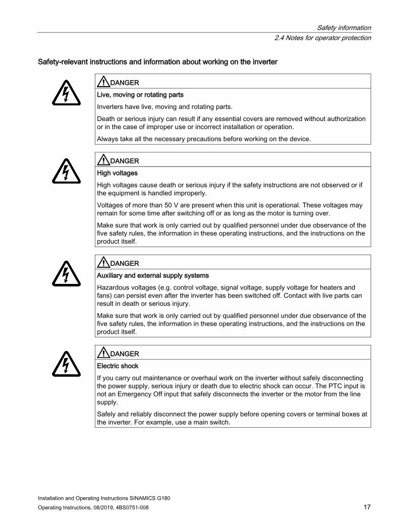
Safety-relevant instructions and information about working on the inverter
DANGER
Live, moving or rotating parts
Inverters have live, moving and rotating parts.
Death or serious injury can result if any essential covers are removed without authorization or in the case of improper use or incorrect installation or operation.
Always take all the necessary precautions before working on the device.
DANGER
High voltages
High voltages cause death or serious injury if the safety instructions are not observed or if the equipment is handled improperly.
Voltages of more than 50 V are present when this unit is operational. These voltages may remain for some time after switching off or as long as the motor is turning over.
Make sure that work is only carried out by qualified personnel under due observance of the five safety rules, the information in these operating instructions, and the instructions on the product itself.
DANGER
Auxiliary and external supply systems
Hazardous voltages (e.g. control voltage, signal voltage, supply voltage for heaters and fans) can persist even after the inverter has been switched off. Contact with live parts can result in death or serious injury.
Make sure that work is only carried out by qualified personnel under due observance of the five safety rules, the information in these operating instructions, and the instructions on the product itself.
DANGER
Electric shock
If you carry out maintenance or overhaul work on the inverter without safely disconnecting the power supply, serious injury or death due to electric shock can occur. The PTC input is not an Emergency Off input that safely disconnects the inverter or the motor from the line supply.
Safely and reliably disconnect the power supply before opening covers or terminal boxes at the inverter. For example, use a main switch.

Safety information 2.4 Notes for operator protection
Installation and Operating Instructions SINAMICS G180 18 Operating Instructions, 08/2019, 4BS0751-008
DANGER
High voltages
Electrical accidents including electric shock occur when general safety instructions for working on the device are not observed. Death, serious injury or material damage will result.
Please note the following information for your safety: • Keep to the five safety rules at all times and at every stage of work. • Always disconnect the equipment before working on it. • Leave the covers in place during normal operation and keep the cabinet doors closed. • Do not use any instrumentation if you know it is defective or damaged. • Secure the main circuit breaker in the OFF position so that it cannot be reconnected, for
example by removing the switch unit when working on a connected motor or the feeder cable to the motor.
• Ground the inverter cabinet and installed devices properly to ensure that no accessible parts of the device are energized (live) or connected in any way to another dangerous voltage source.
• Use an earthing spider for grounding purposes. Read the information provided in the section "Safety instructions regarding maintenance and repairs" in "Maintenance and servicing" in your operating instructions.
• Wear personnel protective gear such as goggles, ear protection and helmet to protect yourself against injury.
• Always follow the national regulations and local specifications when working on the equipment.
DANGER
DC link capacitor discharge time
After the mains voltage has been switched off, high voltages still persist in the DC link capacitors. These cause death or serious injury if the safety instructions are not observed or if the equipment is handled incorrectly.
The DC link capacitors require up to 10 minutes (5 minutes for compact units) before they are discharged to a safe value (< 60 V).
After you have switched off the mains voltage, do not touch the device or carry out any maintenance work or repair work until the discharge time of 10 minutes (5 minutes for compact devices) have elapsed. Measure the voltage once the discharge time has elapsed.

Safety information 2.5 Notes on liquid cooling
Installation and Operating Instructions SINAMICS G180 Operating Instructions, 08/2019, 4BS0751-008 19
CAUTION
Hot surfaces
Certain components (e.g. the heat sink or filter reactor) can become very hot during operation. These components can remain hot for a long time after operation.
The optional anti-condensation heating is activated when the inverter is not operating and the limit value set at the temperature control is reached. Once activated, the anti-condensation heating can generate a great deal of heat.
Contact with hot surfaces can cause injuries (such as burns to the skin).
Never touch hot components just after you have switched off the inverter. Always take the appropriate precautions before touching any components.
2.5 Notes on liquid cooling
Follow the safety instructions for liquid-cooled inverters.
WARNING
Electric shock as a result of defective cooling liquid system
Short circuits can develop in electrical installations when liquid escapes from cooling circuits. This can result in death, serious injury or material damage. • Note the technical data of the liquid cooling system. This data is provided in Chapter
"Technical data of the direct water cooling (Page 204)" and the technical data sheet. • Observe the information in Chapter "Permissible substance values for the cooling water
(Page 205)". • Observe the information in Chapter "Water cooling (Page 66)". • Protect the cooling liquid circuits against excess pressure, e.g. by installing a relief
valve. • Make sure that the pipework installation and pressure testing procedures comply with
local safety regulations and national safety guidelines.

Safety information 2.6 Safety precautions when handling anti-freeze
Installation and Operating Instructions SINAMICS G180 20 Operating Instructions, 08/2019, 4BS0751-008
2.6 Safety precautions when handling anti-freeze
CAUTION
Physical injury caused by burns or poisoning is possible
Antifreeze is harmful to health. Inhalation or swallowing can lead to burns or poisoning.
Observe the following health and safety precautions when handling antifreeze: • Do not inhale vapors. • Keep the antifreeze away from food and beverages. • Wear protective gloves and safety goggles. • Avoid contact with skin and eyes.
NOTICE
Leaking antifreeze has a corrosive effect and may cause short-circuits.
When a connection is disconnected in the cooling circuit, antifreeze can escape and drip down onto lower areas. These areas can corrode and therefore cause short-circuits.
Whenever you disconnect a connection in the cooling circuit, cover lower areas. Thoroughly remove antifreeze from areas that it has come into contact with and clean. Completely remove all residues.
NOTICE
Impurities in the cooling circuit can cause converter modules to fail
When carrying out any work on the cooling circuit, ensure that no impurities (e.g. dust, sand, fluff, chips, etc.) are able to enter the cooling circuit. Make sure that all containers and hoses, with which you handle the antifreeze are clean and are exclusively used for the antifreeze.

Safety information 2.7 Standards and guidelines for proper use of inverters
Installation and Operating Instructions SINAMICS G180 Operating Instructions, 08/2019, 4BS0751-008 21
First aid measures The following table lists the first aid measures:
Table 2- 1 Antifreeze: First aid measures
Event Measure Wetted clothing Remove clothing immediately. Skin contact Wash off immediately with plenty of water. Eye contact Rinse thoroughly and immediately with plenty of water and seek medical
advice. If swallowed If the affected person is completely conscious, immediately induce vomit-
ing. In any case, consult a doctor.
In addition, observe the provisions of the EC safety data sheet in accordance with 91/155/EEC, as well as the generally applicable first aid rules.
2.7 Standards and guidelines for proper use of inverters
Inverters are components designed for installation in electrical systems or machines. Commissioning of the inverters is prohibited until one of the following two conditions is verifiably fulfilled.
● The machine complies with the requirements of the following directives:
– Machinery Directive 2006/42/EG
– EMC Directive 2014/30/EU
● The electrical installation complies with the requirements of the following directives:
– Low-Voltage Directive 2014/35/EU
– EMC Directive
The inverters comply with the requirements of the Low-Voltage Directive 2014/35/EU and the EMC Directive 2014/30/EU.
To ensure that this equipment functions perfectly and safely, observe the following:
● Transportation in accordance with proper procedures
● Proper storage
● Proper installation and assembly
● Careful operation
● Careful maintenance
The unit must only be used for the applications specified in the catalog and only in conjunction with devices and components recommended and approved by Siemens.

Safety information 2.8 Plant safety
Installation and Operating Instructions SINAMICS G180 22 Operating Instructions, 08/2019, 4BS0751-008
Note
Familiarize yourself with the local safety requirements and national safety guidelines and always observe them.
2.8 Plant safety Read the following information about safeguarding the equipment.
DANGER
Unsecured installation site
This inverter is intended for use in industrial power installations and machines. Accidents can occur if the equipment is not used for the intended purpose, is incorrectly operated, is inadequately maintained or can be accessed by unauthorized persons. Death, serious injury or material damage will result.
Secure the installation site against unauthorized access when using the inverter outside industrial areas using suitable equipment (e.g. safety fences) and corresponding signage. Install the inverter in a suitable area to which only properly trained personnel have access.
Procedure You are responsible for the safety of the system. You must ensure that the following requirements are fulfilled:
● Basic planning and all the work involved in transporting, assembling, installing, commissioning, maintaining and repairing the equipment is only carried out by qualified personnel or personnel supervised by responsible skilled technicians.
● The operating instructions and the complete product documentation are always available when carrying out any work.
● The technical data and specifications regarding the permissible installation, connection, environmental, and operating conditions are observed consistently.
● The system-specific installation and safety regulations are observed and measures are taken to ensure personal safety.
● It is prohibited for unqualified persons to work on these devices or in their vicinity.
The product documentation, especially the operating instructions, and the notices on the unit itself therefore contain only the information required by qualified personnel to use the installations or machines for their intended purpose.
Safety information 2.9 Security information
Installation and Operating Instructions SINAMICS G180 Operating Instructions, 08/2019, 4BS0751-008 23
Note Siemens Service Centers
The services and support provided by the Siemens service centers are recommended for planning, installation, commissioning, and servicing work.
Note Engineering information
Systems in which the inverters are installed must be fitted with additional monitoring and safety devices in order to comply with safety requirements (e.g. equipment and product safety law, accident prevention regulations).
2.9 Security information Siemens provides products and solutions with industrial security functions that support the secure operation of plants, systems, machines and networks.
In order to protect plants, systems, machines and networks against cyber threats, it is necessary to implement – and continuously maintain – a holistic, state-of-the-art industrial security concept. Siemens’ products and solutions constitute one element of such a concept.
Customers are responsible for preventing unauthorized access to their plants, systems, machines and networks. Such systems, machines and components should only be connected to an enterprise network or the internet if and to the extent such a connection is necessary and only when appropriate security measures (e.g. firewalls and/or network segmentation) are in place.
For additional information on industrial security measures that may be implemented, please visit https://www.siemens.com/industrialsecurity.
Siemens’ products and solutions undergo continuous development to make them more secure. Siemens strongly recommends that product updates are applied as soon as they are available and that the latest product versions are used. Use of product versions that are no longer supported, and failure to apply the latest updates may increase customer’s exposure to cyber threats.
To stay informed about product updates, subscribe to the Siemens Industrial Security RSS Feed under https://www.siemens.com/industrialsecurity.

Safety information 2.10 Components that can be destroyed by electrostatic discharge (ESD)
Installation and Operating Instructions SINAMICS G180 24 Operating Instructions, 08/2019, 4BS0751-008
WARNING
Unsafe operating states resulting from software manipulation
Software manipulations (e.g. viruses, trojans, malware or worms) can cause unsafe operating states in your system that may lead to death, serious injury, and property damage. • Keep the software up to date. • Incorporate the automation and drive components into a holistic, state-of-the-art
industrial security concept for the installation or machine. • Make sure that you include all installed products into the holistic industrial security
concept. • Protect files stored on exchangeable storage media from malicious software by with
suitable protection measures, e.g. virus scanners.
WARNING
Malfunctions of the machine as a result of incorrect or changed parameter settings
As a result of incorrect or changed parameterization, machines can malfunction, which in turn can lead to injuries or death. • Protect the parameterization (parameter assignments) against unauthorized access. • Handle possible malfunctions by taking suitable measures, e.g. emergency stop or
emergency off.
2.10 Components that can be destroyed by electrostatic discharge (ESD)
ESD guidelines
Material damage caused by electrostatic discharge.
Electronic components can be destroyed in the event of improper handling, transport, storage, and shipping.
Pack the electronic components in appropriate ESD packaging; e.g. ESD foam, ESD packaging bags and ESD transport containers.
Safety information 2.10 Components that can be destroyed by electrostatic discharge (ESD)
Installation and Operating Instructions SINAMICS G180 Operating Instructions, 08/2019, 4BS0751-008 25
To protect your equipment against damage, follow the instructions given below.
● Avoid physical contact with electronic components. If it is essential that you perform work on these components, you must wear one of the following pieces of protective gear:
– Grounded ESD wrist strap
– ESD shoes or ESD shoe grounding strips if there is also an ESD floor.
● Do not place electronic components close to data terminals, monitors or televisions. Maintain a minimum clearance to the screen (> 10 cm).
● Electronic components should not be brought into contact with electrically insulating materials such as plastic foil, plastic parts, insulating table supports or clothing made of synthetic fibers.
● Bring components into contact only with ESD-compliant materials, e.g. ESD tables, ESD surfaces, ESD packaging.
● Only carry out measurements on the components if one of the following conditions is met:
– The measuring device is grounded with a protective conductor, for example.
– The measuring head of a floating measuring device has been discharged directly before the measurement.
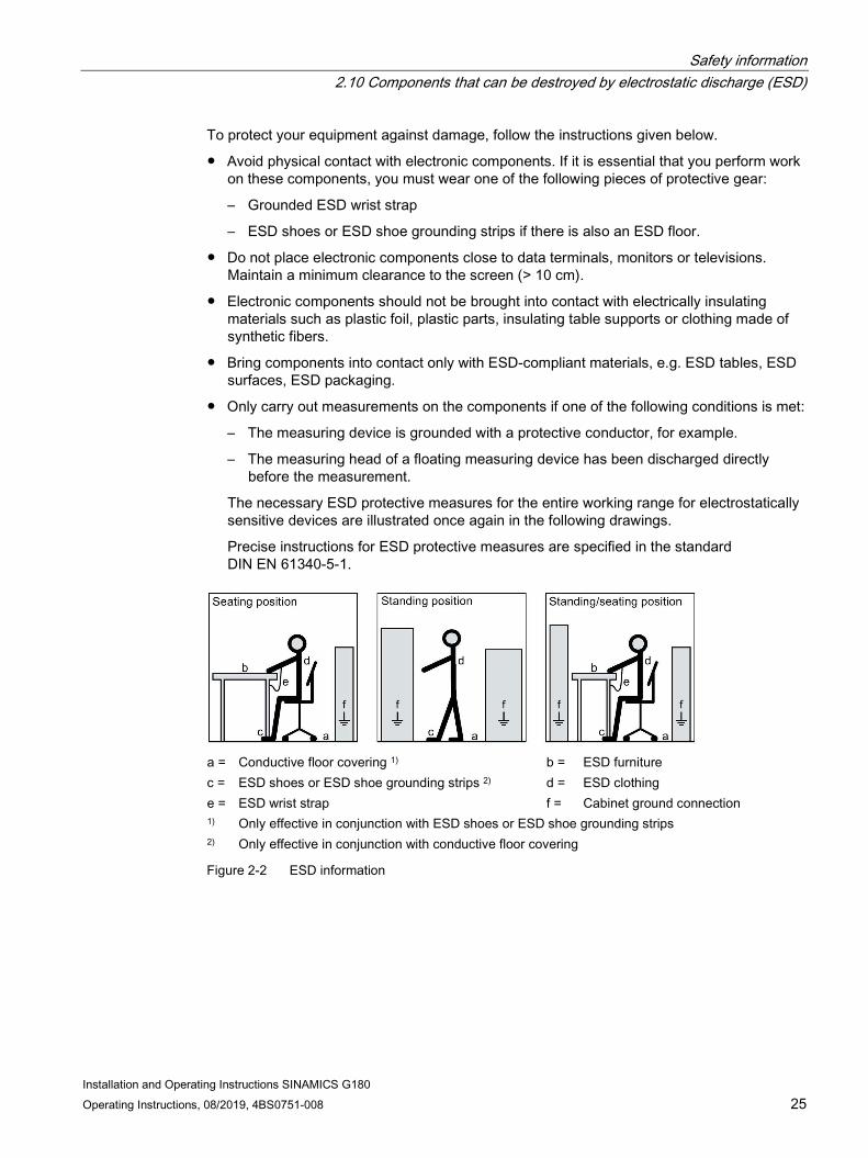
The necessary ESD protective measures for the entire working range for electrostatically sensitive devices are illustrated once again in the following drawings.
Precise instructions for ESD protective measures are specified in the standard DIN EN 61340-5-1.
a = Conductive floor covering 1) b = ESD furniture c = ESD shoes or ESD shoe grounding strips 2) d = ESD clothing e = ESD wrist strap f = Cabinet ground connection 1) Only effective in conjunction with ESD shoes or ESD shoe grounding strips 2) Only effective in conjunction with conductive floor covering
Figure 2-2 ESD information

Safety information 2.11 Electromagnetic fields
Installation and Operating Instructions SINAMICS G180 26 Operating Instructions, 08/2019, 4BS0751-008
2.11 Electromagnetic fields
WARNING
Electromagnetic fields "electro smog"
Electromagnetic fields are generated when electrical equipment (e.g. transformers, inverters, motors etc.) is operated.
Electromagnetic fields can interfere with electronic devices, which could cause them to malfunction. For example, the operation of heart pacemakers can be impaired, potentially leading to damage to a person's health or even death. It is therefore forbidden for persons with heart pacemakers to enter these areas.
The plant operator is responsible for taking appropriate measures (labels and hazard warnings) to adequately protect operating personnel and others against any possible risk.
● Observe the relevant nationally applicable health and safety regulations. In Germany, "electromagnetic fields" are subject to regulations BGV B11 and BGR B11 stipulated by the German statutory industrial accident insurance institution.
● Display adequate hazard warning notices.
● Place barriers around hazardous areas.
● Take measures, e.g. using shields, to reduce electromagnetic fields at their source.
● Make sure that personnel are wearing the appropriate protective gear.

Safety information 2.12 Radio telephones and mobile telephones
Installation and Operating Instructions SINAMICS G180 Operating Instructions, 08/2019, 4BS0751-008 27
2.12 Radio telephones and mobile telephones
Safety instructions
CAUTION
Radio telephones
If you use radio communication equipment > 2 W in close proximity to the inverter, damage to equipment of the type specified below can occur and possibly result in physical injuries to personnel: • Missing pulses during inverter operation can occur. • Defects of the power elements can occur. • The inverter can shut down. • Contactors can chatter. • Interference on binary outputs.
Do not use radio telephones > 2 W in close proximity to the device.
Radio telephones with lower outputs must not be used at a distance of less than 1 m from the inverter.
CAUTION
Mobile telephones
The use of mobile telephones near the inverter when it is in operation can result in the generation of erroneous pulses and possibly give rise to physical injuries to personnel.
Switch off mobile telephones when you are near the device.

Safety information 2.13 Note regarding fiber-optic cables
Installation and Operating Instructions SINAMICS G180 28 Operating Instructions, 08/2019, 4BS0751-008
2.13 Note regarding fiber-optic cables Fiber-optic cable systems are used in some inverters. Please observe the following warning.
Figure 2-3 Photography prohibited
CAUTION
Erroneous pulses in fiber-optic cables
Erroneous pulses in fiber-optic cables caused by camera flash lights can result in malfunction and damage to the inverter and motor and potentially result in injury to personnel.
It is not permissible to photograph inverters with fiber-optic cable systems using a camera flash light when they are in operation! Only photograph these types of inverters when they are in a no-voltage state.
2.14 Protecting/fusing the external 230 V AC control voltage
WARNING
External control voltage without fuse protection
If you use an external control voltage without suitable protection (e.g. fuses), then overloads and short-circuits can occur. This can result in death, serious injury or material damage.
The device may only be operated with a protected external control voltage. Note the following recommendation.
Install one of the following options to protect the external control voltage:
● Miniature fuse in accordance with EN 60127: 2 A … 6 A, slow, maximum 150 VA
● Miniature circuit-breaker: 2 A … 6 A, characteristic D, maximum 150 VA

Safety information 2.15 Residual risks
Installation and Operating Instructions SINAMICS G180 Operating Instructions, 08/2019, 4BS0751-008 29
2.15 Residual risks According to the EU Machinery Directive, machine manufacturers / plant operators must conduct a risk assessment of their machine. Plant operators must conduct a risk assessment of their plant. In particular, pay attention to "General Principles" of the EC Machinery Directive.
Pay attention to the following residual risks:
1. Unintentional movement of driven machine parts
Unintentional movements of driven machine parts can occur during commissioning, operation, maintenance, and repair, e.g. from the following causes:
– Hardware defects and/or software errors in the sensors, controllers, actuators, and connection technology
– Response times of the controller and drive
– Operating and/or environmental conditions outside of the specification
– Condensation/conductive contamination
– Parameterization, programming, cabling, and installation errors
– Use of radio devices/cellular phones in the immediate vicinity of the controller
– External influences/damage
2. High temperatures and emissions
A fault can occur as a result of the following, for example:
– Component malfunctions
– Software errors
– Operating and/or environmental conditions outside of the specification
– External influences/damage
A fault can, for example, have the following consequences both inside and outside the drive:
– Extraordinarily high temperatures, including open fires as a result of the fault
– Emissions of light, noise, particles or gases
Converters with open type/IP20 degree of protection must be installed in an electrical room or a comparable environment.
3. Hazardous shock voltages
Hazardous shock voltages can result from the following causes, for example:
– Component malfunctions
– Influence during electrostatic charging
– Induction of voltages in moving motors
– Operating and/or environmental conditions outside of the specification
– Condensation/conductive contamination
– External influences/damage

Safety information 2.15 Residual risks
Installation and Operating Instructions SINAMICS G180 30 Operating Instructions, 08/2019, 4BS0751-008
4. The release of substances and emissions that are harmful to the environment
Improper operation or the improper disposal of components can harm the environment.
Note Compliance with the RoHS II Directive
SINAMICS G180 devices comply with the requirements of Directive 2011/65/EU on the restriction of the use of certain hazardous substances in electrical and electronic devices (RoHS II).
5. Hazard caused by electrical, magnetic, and electromagnetic fields
Electrical, magnetic and electromagnetic fields generated in operation that can pose a risk to people with a pacemaker, implants, or metal replacement joints, etc., if they are too close to the converter.
6. Damage from pressure build-up during electric arcs in the event of a fault
If the building has not been designed correctly for the drive in terms of how it has been dimensioned, damage can result from the pressure that can possibly build up inside.
7. Dangerous electric arcs during internal faults
The drives are designed according to the relevant IEC standards and have been tested in line with strict type-testing procedures. They were developed and manufactured so that there is a very low probability of internal faults occurring. However, internal faults cannot be completely ruled out.
WARNING
Dangerous electric arcs during internal faults
Defects such as damage to components, overvoltages, or loose parts, as well as exceptional operating statuses, can cause a failure within the enclosure. This can result in an internal electric arc. If an electric arc occurs and people are nearby, this could lead to death, serious physical injury, and damage to property. • Ensure that only qualified personnel perform work on the drive. • Observe the safety and operating instructions in this documentation and on labels at the
drive for all work on the drive.

Installation and Operating Instructions SINAMICS G180 Operating Instructions, 08/2019, 4BS0751-008 31
Description 3 3.1 Updating inverter software or instructions
These operating instructions are valid for SINAMICS G180, software version 11C0242/CL83 and higher.
Procedure 1. At the inverter display, check the current software version of the inverter in menu "I-
INVERTER DATA/Version".
2. If the inverter software version is higher than the version in the operating manual, download the current version of the manual from here (http://www.siemens.com).
3. If the inverter software is no longer current, then update the inverter software using the "IMS" software.
Contact the Service Center of Siemens in Ruhstorf (Page 190) for more detailed information.
3.2 Order numbers / Type designations The inverters have the following types of identification:
● Order number
● Short designation
● Type code
● Other version designation

Description 3.2 Order numbers / Type designations
Installation and Operating Instructions SINAMICS G180 32 Operating Instructions, 08/2019, 4BS0751-008
Order number e.g. 6SE0100-1AG31-0AA7
What the icons mean: Example Designation Option Meaning 6SE01 1st - 5th position: device type,
product group 6SE01 SINAMICS G180
0 6th position: Mechanical design 0 Compact device with air cooling 4 Cabinet with compact units 7 Cabinet unit with water cooling 8 Cabinet unit with air cooling
0 7th position: Unassigned 0 all SINAMICS G180 industrial inverters - 1 8th position: Harmonic effects on
power system 0 Not relevant for cabinet 1 6-pulse input 2 12-pulse input 3 18-pulse input 4 24-pulse input
A 9th position: Number of systems connected in parallel
A Compact unit B Single device with system management C Multiple device with 2 parallel circuits D Multiple device with 3 parallel circuits E Multiple device with 4 parallel circuits F Not relevant for cabinet G Multiple device with 5 parallel circuits H Multiple device with 6 parallel circuits J Multiple device with 7 parallel circuits K Cabinet with one compact unit L Cabinet with 2 identical compact units M Cabinet with 3 identical compact units N Cabinet with 4 identical compact units P Cabinet with 5 identical compact units Q Cabinet with 6 identical compact units Y Cabinet with different compact units

Description 3.2 Order numbers / Type designations
Installation and Operating Instructions SINAMICS G180 Operating Instructions, 08/2019, 4BS0751-008 33
Example Designation Option Meaning G 10th position: Supply voltage A 230 ... 415 V 3 AC TN/TT, 50 ... 60 Hz
B Restricted application: 230 ... 415 V 3 AC IT, 50 ... 60 Hz C 230 ... 500V 3 AC TN/TT, 50 ... 60 Hz D 230 ... 500 V 3 AC IT, 50 ... 60 Hz G 230 ... 600/690 V 3 AC 1) TN/TT, 50 ... 60 Hz H 230 ... 600/690 V 3 AC 1) IT, 50 ... 60 Hz J 850 … 950 … 990 V 3 AC K 1000 V 3 AC L Independent of voltage M 1140 V 3 AC
3 11th position: Multiplier for output current
0 * 0.01 1 * 0.1 2 * 1 3 * 10 4 * 100
1 12th + 13th position: First two digits of output current
… Two positions for approximate specification of output current, e.g.: 11th position = 3, 12th position = 8, 13th position = 2 means: Output current approx. 10 * 82 = 820 A. In the case of cabinets containing multiple compact units, the output current of the largest compact unit must be specified. It is not permis-sible to state the digit 9 here. If the rated current of a inverter is 940 A, for example, the order number positions for the out-put current must be reduced. ⇒ 11th position = 3, 12th position = 8, 13th position = 8. This can mean that the order number of the next smaller unit is reduced as well. If it had, for example, an output current of 890 A. ⇒ 11th position = 3, 12th position = 8, 13th position = 7
- 0
A 14th position: Option module A IEC, EN U NRTL-certified (by TÜV) and/or UL-certified
A 15th position: Customer or sector design
A Standard B Customized design xyz1 C Customized design xyz2
7 16th position: Version / release number
7 Version/release number T..7
1 With an NRTL unit ("U" in 14th position of order number), the voltage range ends at maximum 600 V, otherwise at 690 V.

Description 3.2 Order numbers / Type designations
Installation and Operating Instructions SINAMICS G180 34 Operating Instructions, 08/2019, 4BS0751-008
Short designation e.g. T 07-30 / 400 / 12 / 6
The short designation specifies the following details:
● Inverter development date
● Continuous shaft output of the connected motor for four-pole motors operating up to 50 Hz
● Rated supply voltage
● Number of pulses used
What the icons mean:
Table 3- 1 Example for short designation
Example Meaning T SINAMICS G180 07 Modification status 30 Continuous shaft output [kW] of the connected motor 400 Rated supply voltage [V] 12/6 Pulse operation Input /Output If this information is missing, then it is a 6 / 6-pulse inverter.
Type code e.g. 2T 2 A- 0 7 4 0 0- 055
The type code describes the inverter type in more detail. Always state the type code as well as the serial number and other rating plate data for enquiries to the factory.
What the icons mean: Example Designation Option Meaning 2R Device type 2R 4-quadrant voltage-source DC link inverter SINAMICS G180 2T Device type 2T SINAMICS G180 voltage-source DC link inverter
2x Cabinet unit system with one or more inverters. The attainable shaft outputs of all installed inverters are added together.
2 Degree of protection 1 IP00 2 IP20 3 IP21 6 IP 54 7 IP55 9 Other

Description 3.2 Order numbers / Type designations
Installation and Operating Instructions SINAMICS G180 Operating Instructions, 08/2019, 4BS0751-008 35
Example Designation Option Meaning A - Number of pulses in the input A 6-pulse input
F 12-pulse input K 18-pulse input L 24-pulse input
0 Mechanical design 0 Compact device with air cooling 2 Compact device Plus with air cooling 3 Compact device with water cooling 7 Cabinet unit with water cooling 8 Cabinet unit with air cooling 9 Special version
7 Modification status 5 Modification status 5 6 Modification status 6 7 Modification status 7
4 Mains voltage 4 400 V unit 5 500 V unit 6 690 V unit 9 950 V unit
0 Number of parallel line-converter systems
0 Single device without system management 1 Single device with system management 2 ... 7 Multiple device with corresponding number of parallel systems
and system management units 0- Number of parallel machine-
converter systems 0 Single device without system management 1 Single device with system management 2 … 7 Multiple device with corresponding number of parallel systems
and system management units 055 Achievable shaft output [kW] for
continuous output current … If the first position is 9, the other two digits show the power in
kW * 100.
Other version designation e.g. A type code O B D I M 4
The other version designation of the inverter consists of the type code and seven other characters. This designation is specified on the rating plate. It is used in commercial written communication and is as follows:
Example Designation Option Meaning A Accessories A Standard accessories
D Accessories with bypass for mains operation with direct activation N Accessories according to NAMUR Guideline NE37 with Test-Normal
switch Q Accessories with main switch, external handle W Accessories with main switch, internal handle S Accessories with main switch, main contactor, EMERGENCY STOP in
door and local/remote switch
Description 3.2 Order numbers / Type designations
Installation and Operating Instructions SINAMICS G180 36 Operating Instructions, 08/2019, 4BS0751-008
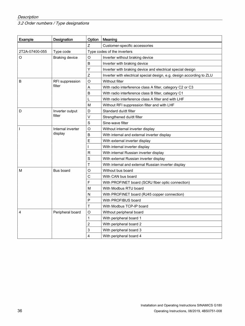
Example Designation Option Meaning Z Customer-specific accessories
2T2A-07400-055 Type code Type codes of the inverters O Braking device O Inverter without braking device
B Inverter with braking device Y Inverter with braking device and electrical special design Z Inverter with electrical special design, e.g. design according to ZLU
B RFI suppression filter
O Without filter A With radio interference class A filter, category C2 or C3 B With radio interference class B filter, category C1 L With radio interference class A filter and with LHF M Without RFI suppression filter and with LHF
D Inverter output filter
D Standard du/dt filter V Strengthened du/dt filter S Sine-wave filter
I Internal inverter display
O Without internal inverter display B With internal and external inverter display E With external inverter display I With internal inverter display R With internal Russian inverter display S With external Russian inverter display T With internal and external Russian inverter display
M Bus board O Without bus board C With CAN bus board F With PROFINET board (SCRJ fiber optic connection) M With Modbus RTU board N With PROFINET board (RJ45 copper connection) P With PROFIBUS board T With Modbus TCP-IP board
4 Peripheral board O Without peripheral board 1 With peripheral board 1 2 With peripheral board 2 3 With peripheral board 3 4 With peripheral board 4

Description 3.3 Accessories
Installation and Operating Instructions SINAMICS G180 Operating Instructions, 08/2019, 4BS0751-008 37
3.3 Accessories
3.3.1 Use of tested, certified and Siemens-approved components Observe the following instructions if you would like to integrate your own components in the system.
WARNING
Components which are not approved
It is dangerous to use components which are not tested, not certified and not approved by Siemens. This can result in death, serious injury or material damage. • Use only components which are tested, certified and approved by Siemens.
3.3.2 Peripheral boards 1 to 4, -A95, option G02 to G05
3.3.2.1 General information about the peripheral boards 1 to 4 Motherboards:
Peripheral board AO
Peripheral board DI/DO

Description 3.3 Accessories
Installation and Operating Instructions SINAMICS G180 38 Operating Instructions, 08/2019, 4BS0751-008
Daughter board: Example:
Peripheral board PTC thermistor
Peripheral board 4
There are 4 peripheral board versions as option. These comprise a motherboard peripheral board AO or peripheral board DI/DO and daughter board peripheral board PTC thermistor. Either one motherboard alone can be installed - or in combination with the daughter board.
The inverter functionality is expanded using a peripheral board. 1 version of the peripheral board can be installed in each inverter.
The functionality of the possible versions is listed in the following table.
Table 3- 2 Configuration of the peripheral boards
Peripheral board 1
Peripheral board 2
Peripheral board 3
Peripheral board 4
2 PTC thermistor inputs, motor temperature monitoring for motors in haz-ardous areas • ATEX-certified once according to:
DIN EN ISO 13849-1:2015, Cat. 2, PL c or DIN EN 61508-1:2010, SIL 1
• One for warning
- X - X
1 digital input "Safe torque off", STO, acc. to DIN EN ISO 13849-1:2015, Cat. 2, PL c or DIN EN 61508-1:2010, SIL 2 in conjunction with an additional digital input (2 circuit) acc. to DIN EN ISO 13849-1:2015, Cat. 3, PL d or DIN EN 61508-1:2010, SIL 2
- - X X
9 digital inputs (DI) - - X X 3 relay outputs (DO) - - X X 2 analog outputs (AO) X X X X Power supply unit, 24 V, 300 mA - - X X

Description 3.3 Accessories
Installation and Operating Instructions SINAMICS G180 Operating Instructions, 08/2019, 4BS0751-008 39
Peripheral boards 2 and 4 are, in addition to the motherboard peripheral board AO or peripheral board DI/DO is also equipped with a daughter board peripheral board PTC thermistor, which accommodates the circuit for PTC thermistor inputs.
The connection diagram of these versions can be found in Chapter "Control cable terminals, peripheral board 1 (Page 169)".
Use the digital inputs and the analog outputs of the peripheral board corresponding to the inputs and outputs on the main terminal block. You can find additional information in Chapter "Standard control cable terminals (Page 168)".
Configure the three relay outputs corresponding to the relay outputs of the main terminal block. For additional information regarding electrical (galvanic) isolation, refer to Chapter "Protective separation in accordance with EN 61800-5-1 (Page 145)".
3.3.2.2 Electronic shutdown for "Safe halt" / PTC inputs
Standards for electronic shutdown The electronic shutdown complies with the following standards:
● DIN EN ISO 13849-1:2015, Safety of Machinery; Safety-Related Parts of Control Systems - Part 1: General principles for design
● DIN EN ISO 13849-2:2012, Safety of Machinery; Safety-Related Parts of Control Systems - Part 2: Validation
● EN 50495:2010, Safety devices required for the safe functioning of equipment with respect to explosion risks
● DIN EN 60947-8:2013, Low-voltage switchgear and controlgear – Part 8: Tripping units for integrated thermal protection (PTC) for rotating electrical machines
● DIN EN 61508-1: 2010, Functional safety of electrical/electronic/programmable electronic safety-related systems – Part 1: General requirements
● DIN EN 61508-2: 2010, Functional safety of electrical/electronic/programmable electronic safety-related systems – Part 2: Requirements placed on safety-related electrical/electronic/programmable electronic systems
● IEC 61800-5-2:2016 - Adjustable-speed electrical power drive systems – Part 5-2: Requirements placed on safety – Functional safety
● IEC 62061:2005 + A1:2012, Safety of machinery – Functional safety of safety-related electrical, electronic and programmable electronic control systems
● IEC 62061-A2:2015, Safety of machinery – Functional safety of safety-related electrical, electronic and programmable electronic control systems; Revision 2

Description 3.3 Accessories
Installation and Operating Instructions SINAMICS G180 40 Operating Instructions, 08/2019, 4BS0751-008
General information about electronic shutdown Using the electronic shutdown concept of the inverter, a system without main contactor can be shut down. This also applies to motors operating in Hazardous Zone 1. In the case of a fault, the inverter electronically interrupts the power supply to the motor.
NOTICE
Malfunctions
If the inverter is used in safety-relevant applications with visible transport damage, malfunctions and damage to property can occur. • Do not use inverters with visible transport damage. • Peripheral boards 2/3/4 with safety-related inputs and an ATEX motor temperature
monitoring must always be replaced using certified, original parts. Only replace parts after prior consultation with the factory.
• Use the "Safe torque off" function of the inverter for induction and synchronous motors. If two additional faults occur in the power section, for synchronous motors, this can result in residual rotation. The residual rotation angle can be maximum 180°. Calculate the residual rotation angle from 360° / number of poles n. Take into account residual rotation in your design. This does not apply to induction motors.
WARNING
Shutdown only when safety circuits are opened
The inverter is only shut down with the "Safe torque off" function as long as shutdown is initiated by opening the appropriate safety circuits. If the safety circuits are reclosed, safe shutdown is no longer given; this applies, even if the inverter does not immediately restart.

Description 3.3 Accessories
Installation and Operating Instructions SINAMICS G180 Operating Instructions, 08/2019, 4BS0751-008 41
Shutdown concept ATEX motor temperature monitoring
Principle of operation
Peripheral board 2 / 4 evaluates the motor temperature sensed using a PTC thermistor. The board guarantees safety and reliability as a result of the integrated short-circuit detection and sensor cable. Function "Safe torque off" of peripheral boards 3 / 4 and function "ATEX motor temperature monitoring" utilize the same shutdown path:
Figure 3-1 Electronic shutdown concept
The inverter control processes the peripheral board signal. In the event of excessive motor temperature, or the function "Safe torque off" response, then the inverter inhibits the firing signals of the IGBTs. The power supply for the driver stages is also switched off. These two switch-off paths ensure that the power infeed to the motor is immediately interrupted. This rules out any additional motor temperature rise or that the motor is operated. You can only reset the inverter or switch it on again if the motor has cooled down sufficiently.
If the power fails, then the inverter safely interrupts the power feed to the motor as firing signals are no longer transferred. If a fault was active at the moment of power failure, the inverter remains in a fault condition, also after power returns.

Description 3.3 Accessories
Installation and Operating Instructions SINAMICS G180 42 Operating Instructions, 08/2019, 4BS0751-008
Risk comparison
In order to rule out possible risks in advance, a risk analysis according to EN 1050 or DIN EN ISO 14121 (draft standard) has been performed for the shutdown path. This analysis concluded that the risk of loss of the shutdown function is small due to the redundant design of the shutdown route and the use of reliable components. However, no general risk assessment was performed as this is usually dependent on many customer-specific parameters. This must be taken into account for the implementation and operation of a system. When compared to shutdown using contactors, only the additional hazard occurs as a result of the risk of dangerous shock currents in the inverter.
Due to the redundant design, it is even achieved that the shutdown is still ensured even if a fault in the electronic shutdown route occurs. As components proven in operation are also used, the inverter is in compliance with DIN EN ISO 13849-1:2015, Category 2, PL c or DIN EN 61508-1:2010, SIL 1.
WARNING
Danger of explosion in the case of deactivated shutdown
In principle, the shutdown function can be deactivated by connecting an appropriate resistor instead of the PTC thermistor to the control cable terminals.
3.3.2.3 "Safe torque off" with single circuit trip The control cable terminals -X2:19, -X2:20 provide a safety-oriented input for safe torque off to DIN EN ISO 13849-1:2015, Category 2, PL c or DIN EN 61508-1:2010, SIL 2. This input safely prevents starting the machine. Use this input, for example for safe shutdown in the case of servicing work on the machine. When using the input, remove the jumper inserted between the control cable terminals -X2:19, -X2:20.
The "Safe torque off" function and the ATEX-certified PTC thermistor input have a redundant switch-off path in the inverter. The implementation is performed using hardware. A relay in the power unit of the inverter disconnects the power supply of the IGBT driver. A second circuit, also via hardware, produces a controller block. Both switch-off paths are based on the closed-circuit principle, i.e. a failure of the control voltage results in redundant shutdown of the inverter.
WARNING
Electric shock
If you carry out maintenance or overhaul work on the inverter without safely disconnecting the power supply, serious injury or death due to electric shock can occur. The input for "Safe torque off" is not an Emergency Off input which safely disconnects the inverter or the motor from the mains power supply.
Safely and reliably disconnect the power supply before opening covers or terminal boxes at the inverter. For example, use a main switch.

Description 3.3 Accessories
Installation and Operating Instructions SINAMICS G180 Operating Instructions, 08/2019, 4BS0751-008 43
3.3.2.4 "Safe torque off" with two circuit version In the inverter, you can also initiate the "Safe torque off" function using two safety circuits. You must connect one circuit as NC contact at terminals -X2:19/:20 (just the same as for a single-circuit trip). You must connect the second circuit as NC contact at terminals -X2:24/:3.
In the 2-circuit version, "Safe torque off" complies with requirements according to DIN EN ISO 13849-1:2015, Category 3, PL d or DIN EN 61508-1:2010 SIL 2
NOTICE
Malfunctions
Carefully ensure that the "Safe torque off" function in the inverter is configured for a two-circuit trip.
3.3.2.5 Switchover, single circuit <-> two circuit tripping The safety-related "Safe torque off" function in the inverter is purely based on a hardware-related shutdown of the power section. The corresponding input circuits only act on the two shutdown paths in the inverter via the hardware circuit.
NOTICE
Bail switch S3
Just bail switch S3 on peripheral board DI/DO determines whether the "Safe torque off" function is initiated through one or two channels.
The software is not relevant for the safety analysis. It only serves to provide display and information relating to the "Safe torque off" function. However, in order to commission the inverter, you must appropriately set parameter "P-INVERTER DATA/STO".

Description 3.3 Accessories
Installation and Operating Instructions SINAMICS G180 44 Operating Instructions, 08/2019, 4BS0751-008
Bail switch S3 on peripheral board DI/DO With the bail switch, you define as to whether in addition the second shutdown circuit should be activated at terminal X2:24 - or not. Bail switch S3 open: single-circuit trip, only via X2:19/:20 Bail switch S3 closed: two-circuit trip, additionally via X2:24/:3
Figure 3-2 Position of the bail switch S3 on peripheral board DI/DO
Parameter "P-INVERTER DATA/STO" Using this parameter, you tell the inverter software as to whether you are using using the "Safe torque off" function with single-circuit or two-circuit trip. The parameter is not relevant for the actual safety-related shutdown via the two shutdown paths in the inverter. Parameter "STO = X2:20": single-circuit trip, only via X2:19/:20 Parameter "STO = X2:20/24": two-circuit trip, additionally via X2:24/:3

Description 3.3 Accessories
Installation and Operating Instructions SINAMICS G180 Operating Instructions, 08/2019, 4BS0751-008 45
3.3.2.6 Checking the "Safe halt" function
Procedure Test the shutdown function for the operation of the "Safe torque off" function. Proceed as follows: 1. Check the setting of the bail switch S3 on peripheral board DI/DO:
• open: for single-circuit trip • closed: for two-circuit trip
2. Connect power to the inverter. 3. Check parameter "P-INVERTER DATA/STO":
• "X2:20": for single-circuit trip • "X2:20/24": for two-circuit trip
4. It is advantageous if you track the "Status" inverter actual value. You can either do this in the display, if you parameterize this actual value temporarily in the 4th status line or in the IMS, if you are connected with a PC.
5. If required, enter the necessary switch-on commands so that the inverter is at least in the ready state, i.e. "status = Rdy.f.work". The "READY" LED is lit.
6. (Simultaneously) open the safety circuit(s), that is/are connected as follows: • For single-circuit trip at -X2:19/:20. • For a two-circuit trip, additionally at –X2:24/:3. The inverter switches into the "Switch interlock" status, the "READY" LED goes dark. The "Safe torque off" "active" message is displayed.
7. Attempt to exit the state by pressing "RESET". It is not permissible that the inverter exits the "Switch interlock" state. The message "Safe torque off" "active" must remain active.
8. Connect the safety circuit(s) at –X2:19/:20 and possibly at –X2:24/:3. The inverter initially stays in the "Switch interlock" state; however, the display changes to "!! OFF2 !!" "After STO act.".

Description 3.3 Accessories
Installation and Operating Instructions SINAMICS G180 46 Operating Instructions, 08/2019, 4BS0751-008
9. Depending on the setting of parameter "P-INVERTER DATA/P-Monitoring/STO" to: • "Store"
The inverter remains in the "Switch interlock" state with the display "!! OFF 2 !!" "After STO act.". Press "RESET" of the inverter. The inverter exits the "Switch interlock" state.
• "Auto.reset" The inverter automatically exits the "Switch interlock" state.
The inverter starts to test both shutdown paths, "Test safe torque off" "running" is dis-played - assuming that the required conditions are satisfied. This means that terminal -X2:8 must be controlled - and if a line contactor is being used - this line contactor must be closed. If the required conditions are still not available, then the inverter waits until the appropri-ate conditions are available, then performs the test before the inverter is switched on. The test takes several seconds.
10. If the test is successfully completed, then the inverter is again in the initial state. If the test results in a fault, then the inverter changes into the "Fault" status. The "FAULT" LED lights up, and the display changes to "!! Inverter fault !!" "Test safe torque off". In this case, it is crucial that you contact the factory.
Additional test if you use a single-circuit trip: 11. Open terminal input -X2:24 if a signal is connected.
The inverter either does not display a response, or it may only display a response that is parameterized for input -X2:24, independent of the "Safe torque off" function. It is not permissible that it changes into the "Fault" state with the following displays: • "!! Fault !!" "Safe torque off trig". • "!! Inverter !!" "Test safe torque off". • "!! Fault !!" "S7 inactive". In cases such as these, check the setting. Either switch S3 and/or the parameters are set to the two-circuit trip.
Additional test if you use a two-circuit trip: 12. Only open the safety circuit at -X2:24/:3.
The inverter changes into the "Fault" state. The "FAULT" LED lights up. The display changes to "!! Fault !!" "Safe torque off trig".
13. Reconnect the safety circuit to -X2:24/:3 and acknowledge the fault. The inverter tests the shutdown paths according to step 9. and 10.
14. Only open the safety circuit at -X2:19/:20. The inverter changes into the "Fault" state. The "FAULT" LED lights up. The display changes to "!! Fault !!" "Safe torque off trig".
15. Reconnect the safety circuit at -X2:19/:20 and acknowledge the fault. The inverter changes into the "Switch interlock" state. The inverter displays message "!! OFF 2 !!" "After STO act.".

Description 3.3 Accessories
Installation and Operating Instructions SINAMICS G180 Operating Instructions, 08/2019, 4BS0751-008 47
16. Depending on parameter "P-INVERTER DATA/P-Monitoring/STO", you must acknowledge again. See Step 9.
17. The inverter tests the shutdown paths according to step 9. and 10.
Resolving problems
For an incorrect setting at the bail switch S3 on Peripheral board DI/DO and/or parameter "P-INVERTER DATA/STO" result in the following different responses. Recheck the settings. Test step Different response Incorrect setting 12 The inverter either displays no response -
or just that response that is parameter-ized for input -X2:24, independent of the "Safe torque off" function.
You have neither set switch S3 nor the parameter to the two-circuit trip.
The inverter changes into state "Fault" with display "!! Fault !!" "S7 inactive"
You have set switch S3 to the two-circuit trip and the parameter to single-circuit trip ("X2:20").
The inverter changes into state "Fault" with display "!! Inverter fault !!" "Test safe torque off".
You have set switch S3 to the single-circuit trip and the parameter to two-circuit trip ("X2:20/24").
14 The inverter changes into the "Switch interlock" state, the "READY" LED goes dark. The "Safe torque off" "active" mes-sage is displayed on the inverter display.
You have either only set the parameter or simultaneously also switch S3 to the single-circuit trip.
For all additional deviations when checking the "Safe torque off" function, it is crucial that you contact a service station or the factory.
Note
The inverter tests the two shutdown paths: • After the "Safe torque off" function is tripped. • After acknowledging the fault "!! Inverter fault !!" "Test safe torque off". • After acknowledging the ATEX motor temperature monitoring "!! Fault !!" "Thermistor
X3:90/91". • Each time the control voltage is switched on (supply for the various boards). • If the test is initiated using parameter "P-EXTRAS/Test STO/PTC".
3.3.2.7 PTC inputs for motor PTC thermistor The peripheral boards 2 / 4 provide two PTC thermistor inputs at the control cable terminals -X3:90-93 for the motor temperature monitoring. When using the inputs, remove the 100 Ω resistor connected there.
Peripheral board 1 and peripheral board 3 have control cable terminals for the PTC inputs. However, there is no evaluation board. No monitoring is made if you connect PTC thermistors.

Description 3.3 Accessories
Installation and Operating Instructions SINAMICS G180 48 Operating Instructions, 08/2019, 4BS0751-008
Test the PTC thermistors as described below. Consult the factory if the shutdown does not function.
Inverters without a peripheral board provide PTC thermistor inputs at control cable terminals -X2:27-28. If the peripheral board 2 or 4 is fitted, connect the PTC thermistors of the motor to control cable terminal -X3.
This has the following advantages:
● Sensor short-circuit monitoring
● Protective separation of the PTC thermistor inputs from all other inputs up to a rated voltage of 690 V. The control cable terminals -X2:27/28 provide protective separation from the electronics, but no separation from the other inputs.
● Input -X3:90-91 is ATEX-certified according to PTB 07 ATEX 3057 for motors located in hazardous zones.
● Redundant shutdown route, realized using hardware.
Checking the PTC thermistor shutdown function Test the shutdown function before commissioning the board. Proceed as follows:
1. Replace the 100 Ω resistor at the control cable terminals -X3:90/91 by a potentiometer with at least 10 kΩ Set a value of approx. 100 Ω.
2. Ensure that 24 V is applied at control cable terminal -X2:8. When required, jumper -X2:8 and -X2:3.
3. Connect power to the inverter so that the "READY" LED on the display lights up.
4. Increase the resistance at the potentiometer. The inverter must go to "FAULT" at the latest for "3,8 kΩ":
– LED "READY" goes dark.
– The red "FAULT" LED is lit.
– The inverter display shows fault message "!! Fault !! PTC thermistor -X3:90/91".
5. At this instant in time, it is not permissible that the inverter is switched on by pressing the <On> key on the display.
6. Acknowledge the error, e.g. using the <S+I> buttons on the display. When acknowledging, the inverter checks the two redundant shutdown paths.
– If, after acknowledgment, the inverter returns to "READY" and a fault is no longer displayed, then the test has been successfully completed.
– If the inverter remains at "FAULT", and the following is shown in the display "!! Inverter fault !! Test PTC -X3:90/91" then one of the shutdown paths is not functioning correctly. In this case, please contact the factory.
7. If the inverter is ready again, then rotate the potentiometer towards 0 Ω. At the latest at a resistance of 15 Ω the short-circuit monitoring of the sensor circuit responds. Follow the description under points four and five.
8. The safety function is checked automatically when the inverter control voltage returns and when the fault is acknowledged after a test.

Description 3.3 Accessories
Installation and Operating Instructions SINAMICS G180 Operating Instructions, 08/2019, 4BS0751-008 49
3.3.3 Brake transistor and brake resistor During motor operation the electrical power flow is from the inverter to the motor. During generator operation the electrical power flow is from the motor to the inverter.
Example: braking flywheels.
The DC link current reverses the direction. The standard version of the inverter cannot feed energy back into the system. Kinetic energy can be converted into dissipated heat in braking operation. Approx. 10% braking torque is available in the upper speed range. A braking torque of up to 50% without additional equipment is achieved in the medium and lower speed ranges by oversaturation of the motor. With the brake transistor accessory, the same braking as driving torque is available. The energy occurring is converted to heat using a pulsed transistor. Also connect an external brake resistor.
WARNING
Risk of fire
If the clearance between the resistors and the neighboring components is selected too small, fire can occur due to overheating. This can result in death, serious injury or material damage. • Maintain a minimum clearance of 200 mm.
3.3.3.1 Dimensioning the brake resistor Select a resistance value of at least that stated in the technical data. This value corresponds to the minimum value that can be set. The maximum value is calculated from the following equation:
R = (1.57 × Umains)² / Pbrake
3.3.3.2 Connecting the brake resistor 1. Using the device designation on the rating plate of the device, check whether you have a
device with the "brake resistor" option. The designation must be ...2T..-.....-...B....
For more detailed information about the designation, refer to Chapter "Order numbers / Type designations (Page 31)".
2. Connect the external braking resistor at terminals -X1:R and -X1:UD2+.
3. Use shielded cables with concentric protective conductor or shielded cables to connect the brake resistor. Connect the shield where the cable enters the inverter.
4. Set parameter "P-INVERTER DATA/Brake" to "On".
5. Set the rated resistor power under "/P-BrakeRes." and the resistance value under "/R-BrakeRes.". In this way, you prevent overloading of the resistor.

Description 3.3 Accessories
Installation and Operating Instructions SINAMICS G180 50 Operating Instructions, 08/2019, 4BS0751-008
CAUTION
Incorrect parameter settings
If you parameterize the resistance data incorrectly, you can destroy the brake transistor or the brake resistor which can result in injury to personnel. • Input the correct data in the inverter.
Install the resistors so that the perforated plate is on the bottom, top and the front sides. The connection box can be provided on the left or the right side.
If you require several resistors for series or parallel connection, install the resistors next to each other. This also applies for wall mounting.
3.3.4 Parameter overview A more detailed overview of all parameters can be found in the "IMS" software or in the parameterization guide. You can find both on the Internet (http://www.siemens.com).
3.3.5 "Factory settings" application Saved device settings which have been made during the internal factory device inspection can be found in this application. For example, these can be special data for the motor or also a complete parameter configuration.

Description 3.3 Accessories
Installation and Operating Instructions SINAMICS G180 Operating Instructions, 08/2019, 4BS0751-008 51
3.3.6 Protective cover IP21 for compact and compact Plus devices
Figure 3-3 Canopy IP21
All compact units have degree of protection IP20. The canopy with degree of protection IP21 is available as an accessory for all compact and compact Plus units. The canopy is 5 mm wider on both sides than the inverter. Take account of this clearance for the alignment. Leave the outlet area at the front clear.
Proceed as follows to install the canopy supplied loose:
1. Screw the inverter without canopy onto a mounting plate. Do not tighten the top two mounting screws completely.
2. Slide the cover under the not yet completely tightened mounting screws.
3. Tighten the mounting screws completely.
With degree of protection IP21, the type code changes from 2T2A.....-... to 2T3A.....-... .

Description 3.3 Accessories
Installation and Operating Instructions SINAMICS G180 52 Operating Instructions, 08/2019, 4BS0751-008
3.3.7 Main switch "Q 2T..." or "W 2T..." Inverters can optionally be purchased with a main switch as switch disconnector. The manual operation of the switch is on the inside for the "W" version. The switch is strictly a maintenance switch. The switch can only be operated when the corresponding covers for compact units or doors for cabinet units are opened.
The switch can be manually operated from the outside for the "Q" version. The handle can be blocked in the zero position with up to three padlocks. The switch is thus protected against being switched on again. The padlocks are not included in the delivery.
For this option, the following dimensions are produced for the individual frame sizes:
Table 3- 3 Main switch option for different frame sizes
BG K1 … BG K4 Standard device dimensions only BG K5 Option "Q" / "W" is not possible. BG K51 For this frame size you can integrate option "Q" / "W". BG K6 In this case, option "Q" / "W" is only possible in a cabinet system
2X…. BG K6 BG S1 … BG S3 No different dimensions than standard device
CAUTION
Serious injury and material damage caused by arcs
If the mains power supply cable is not properly connected to the main switch for the "Q" / "W" option, destruction due to arcs can occur. • Connect the mains power supply line to the main switch properly. • Follow the connection instructions supplied by the manufacturer of the main switch. The
instructions can be found in the unit or inside the door in the cabinet pocket.
3.3.8 DC link terminals for compact devices
Features DC link terminals –X1:UD+2 and –X1:UD-2 are always available for the small inverters up to 2T2A07400-030 for 400 V or up to 2T2A07500-037 for 500 V. These can be optionally purchased for all larger inverters. The inverters have to be connected using the DC link if you want to establish a DC group. Only implement a DC group if you want to operate one drive in the generator mode.
Example: Test station with load apparatus. In this case only the losses are supplied via the network. The generated energy is routed via the DC link. Refer to the following graphic for the electrical design:

Description 3.3 Accessories
Installation and Operating Instructions SINAMICS G180 Operating Instructions, 08/2019, 4BS0751-008 53
Figure 3-4 DC group
Please observe the following:
● Inverter 1 and Inverter 2 must be the same type.
● Connect both inverters to the line supply using a common infeed.
● Operate the line infeed current of each inverter at maximum 75 % of the rated current.
● The line supply connecting cables from –K1:2, 4, 6 to both inverters must be the same length and have the same cross-section.
● You can use a normal cable to connect the DC link, e.g. H07VK in the cabinet, or NYY outside the cabinet.

Description 3.3 Accessories
Installation and Operating Instructions SINAMICS G180 54 Operating Instructions, 08/2019, 4BS0751-008
● Design the cross section according to the current load.
– DC link current = 1.3xmains current.
– Lay both lines parallel with as small as possible distance from each other.
– Bind the H07VK cables together using cable ties.
● For both inverters, set parameter "P-INVERTER DATA/Brake" from "Off" to "R-Supply".
– Use a braking device if the complete drive for braking flywheels can operate as generator for both inverters.
– In this case, parameterize the inverter with braking resistor to "On".
NOTICE
Destruction of the inverter
If you use one of the following configurations without first consulting the factory, then the inverter could be destroyed: • Two different inverters • More than two inverters • More than 75% mains power feed • Only one mains power connection. • DC network for cabinet units.
Check the design with DC network exactly. Consult the factory for this.
3.3.9 External display An external display can optionally be connected. The external display with the item number L0296033 has the same functionality as the internal display.
Additional information is provided in Chapters "Connection for optional external display with RS 485 (Page 155)" and "Installing an external display (Page 88)".

Description 3.3 Accessories
Installation and Operating Instructions SINAMICS G180 Operating Instructions, 08/2019, 4BS0751-008 55
3.3.10 RFI suppression filter, category C1 (class B) If necessary, use an RFI suppression filter, category C1 (class B), in the inverters. More detailed information is provided in Chapter "EMC (Page 75)".
From the unit designation you can identify whether you have a unit with the option RFI suppression filter category C1 (class B). In this case, the rating plate is stamped as follows ".2...-.....-....B....". More detailed information is provided in Chapter "Order numbers / Type designations (Page 31)".
The dimensions are unchanged for compact devices. The dimensions of cabinet units increase if an RFI suppression filter category C1 (class B) is installed. Additional data is provided in the unit documentation.
3.3.11 Strengthened du/dt filter A strengthened du/dt filter is available as an option.
See also Dimensioning maximum motor cable length (Page 100)
3.3.12 Sine-wave filter Note the following information when using a sine-wave filter
A sine-wave filter is available as an option for the motor power supply. It must be noted that sine-wave filters are only designed for the nominal clock frequency. Therefore, parameter "f-pulse min" under "P-MACHINE POWER CONV/P-MSC data" must always be set to the rated clock frequency!
NOTICE
Overheating of the sine-wave filter
If the clock frequency drops to below the nominal clock frequency of the sine-wave filter, the filter can overheat. The equipment will be damaged as a result. • Always set parameter "f-pulse min" under "P-MACHINE POWER CONV/P-MSC data" to
the rated clock frequency!
3.3.13 Additional mains power protection chokes You can expand an inverter to include an additional line protection choke. Use an additional choke if the input side mains power shows a large unbalanced load due to different voltage on L1, L2 and L3 or if the mains power or if the mains power already has harmonics. In this case, please contact the Service Center.

Description 3.3 Accessories
Installation and Operating Instructions SINAMICS G180 56 Operating Instructions, 08/2019, 4BS0751-008
3.3.14 Optional fieldbus connection
3.3.14.1 PROFIBUS DP You can purchase a PROFIBUS board as accessory. The PROFIBUS board is installed under the grey plastic cover. The board can be retrofitted. You recognize from the description "… Type code _ _ _ _ P _" on the rating plate that a PROFIBUS board has been integrated.
More details about the board and the PROFIBUS parameters can be found in the separate PROFIBUS description.
① PROFIBUS connection ② Switch for terminating resistor ③ PROFIBUS address, settable ④ LED "bus diagnostics" ⑤ LED "Offline" ⑥ Unused LED ⑦ LED "Online"
Figure 3-5 PROFIBUS board
Table 3- 4 PROFIBUS board - external elements
Component Function LED "Status" (only just visible under the grey cover)
Flashing red at different frequencies Hardware fault on the PROFIBUS board: Con-tact the service department.
Flashing green at 1 Hz, 0.5 s on, 0.5 s off
PROFIBUS board initialization OK
Flashing green at 2 Hz, 0.25 s on, 0.25 s off
Error when initializing the PROFIBUS board: Contact the service department.
LED "Online" This green LED lights if the bus connection is OK. LED "Offline" This red LED lights if the bus connection is interrupted. Check the external bus configuration. PROFIBUS connection Sub-D socket for PROFIBUS

Description 3.3 Accessories
Installation and Operating Instructions SINAMICS G180 Operating Instructions, 08/2019, 4BS0751-008 57
Component Function Switch for terminating resistor
A bus line must be terminated with a terminating resistor. Note that a terminating resistor can also be present in the connector and select the switch position accordingly. Switch up = resistor On. Only one terminating resistor is permitted at the end of a PROFIBUS line.
Settable PROFIBUS address
The PROFIBUS address is set using the software as follows: The value 0 ... 125 can be set under "P-INTERFACE/P-fieldbus/P-PB/PN/Modbus/P-Profibus/BUS address". If you enter a value of 0, then the address is set using the hardware. In this case, set an address in the range 0 to 99 using a screwdriver.
LED "bus diagnostics" Flashing at 1 Hz, 0.5 s On, 0.5 s Off Error in the input/output configuration Flashing at 2 Hz, 0.25 s On, 0.25 s Off Error in the length of the PROFIBUS telegram Flashing at 4 Hz, 0.12 s On, 0.12 s Off Error when initializing PROFIBUS Off No bus fault
3.3.14.2 PROFINET IO You can purchase a PROFINET board as accessory; it can also be retrofitted. This is installed under the grey plastic cover. It is available in two versions: with Ethernet or alternatively with fiber optic sockets.
Based on the designation on the rating plate, you can identify whether or which of these two boards is installed. The designation "… Type code _ _ _ _ N _" means Ethernet CU (RJ45) connection and "… Type code _ _ _ _ F _" means fiber optic (SCRJ) connection (see: Order numbers / Type designations (Page 31))
Note Risk of confusion relating to the LEDs
The "Network status" display (NS), as well as the "Module status" display (MS) comprises a green and a red LED. The "Link / Activity / Speed" (L/A/S) display comprises a green and a yellow LED.
In the following, the term "LED" summarizes the two LEDs in the display mentioned in the corresponding context.
As the two LEDs are close to one another, there is a risk of confusion, especially for the network status and module status LEDs.

Description 3.3 Accessories
Installation and Operating Instructions SINAMICS G180 58 Operating Instructions, 08/2019, 4BS0751-008
PROFINET board with CU connection - RJ45 connector, option code: N
① Ethernet RJ45 socket: Port 1 ② Ethernet RJ45 socket: Port 2 ③ NS: "Network status" display ④ MS: "Module status" display ⑤ L/A/S: "Link / Activity / Speed" display: Port 1 ⑥ L/A/S: "Link / Activity / Speed" display: Port 2
Figure 3-6 PROFINET board: Version with Ethernet sockets
PROFINET board with FO connection - SCRJ connector, option code: F
① SCRJ fiber optic socket: Port 1 ② SCRJ fiber optic socket: Port 2 ③ NS: "Network status" display ④ MS: "Module status" display ⑤ L/A/S: "Link / Activity / Speed" display: Port 1 ⑥ L/A/S: "Link / Activity / Speed" display: Port 2
Figure 3-7 PROFINET board: Version with fiber optic sockets

Description 3.3 Accessories
Installation and Operating Instructions SINAMICS G180 Operating Instructions, 08/2019, 4BS0751-008 59
Note Suitable fiber types
HCS as well as APF cables (POF) are suitable for connecting to the fiber optic sockets.
Typical cable lengths are up to 100 m (HCS) or up to 50 m (POF).
Table 3- 5 PROFINET board - external elements
Component Function NS "Network status" display
Off Offline No power supply or no connection with the IO controller
Green, lit Online (status: RUN)
Connection established with the IO controller, IO controller in the RUN state
Flashing green (1 Hz)
Online (status: STOP)
Connection established with the IO controller, IO controller in the STOP state or IO data error
Flashing green (3x at 1 Hz)
Flashing Flashes three times in order to identify the slave in the network.
Red, lit Fatal event Critical, internal error This display occurs in conjunction with a red "Module status" LED.
Flashing red (1 Hz)
Error, station name
A station name has not been assigned (factory setting).
Flashing red (2 Hz)
Error, IP address An IP address has not been assigned (factory setting).
Flashing red (3 Hz)
Error, configura-tion
The reference configuration (expected identification) differs from the actual configuration (real identification) of the system.
MS "Module status" display
Off Not initialized No power supply voltage or module in the SETUP or NW_INIT state
Green, lit Normal operating sequence
The module has exited the NW_INIT state.
Flashing green (1 Hz)
Diagnostic event(s)
At least one diagnostics event is active.
Red, lit Exception error Device in the EXCEPTION state Fatal event Fatal internal event.
This display occurs in conjunction with a red "Network status" LED.
Flashes red/green alternating
Firmware update Do not switch off the module. Switching off the module during the update can result in permanent dam-age.

Description 3.3 Accessories
Installation and Operating Instructions SINAMICS G180 60 Operating Instructions, 08/2019, 4BS0751-008
Component Function L/A/S "Link / Activity / Speed" display (port 1 + port 2)
Off No connection No communication Green, lit Connection with
100 Mbit Ethernet connection established, but no communication.
Green, flickering Activity with 100 Mbit
Ethernet connection established and active communication.
Yellow, lit Connection with 10 Mbit
Ethernet connection established, but no communication.
Yellow, flickering Activity with 10 Mbit
Ethernet connection established and active communication.
3.3.14.3 Modbus RTU You can purchase a Modbus board as an accessory. The Modbus board is installed under the plastic cover. The board can be retrofitted. You recognize from the description "… Type code _ _ _ _ M _" on the rating plate that a Modbus board has been integrated.
① Modbus connection ② Switch for terminating resistor ③ DIL switches 1 ... 7: Modbus address, configurable ④ DIL switches 8, 1, 2: baud rate, configurable ⑤ DIL switches 3, 4: parity, configurable ⑥ DIL switch 5: interface type, configurable ⑦ LED "Status Hardware Settings" ⑧ LED "Bus ready" ⑨ LED "Processing" ⑩ LED "Bus error"
Figure 3-8 Modbus board

Description 3.3 Accessories
Installation and Operating Instructions SINAMICS G180 Operating Instructions, 08/2019, 4BS0751-008 61
Table 3- 6 Modbus board - external elements
Component Function LED "Status Hardware Settings"
Red, lit DIL switches are set to "not active" status (all set to "off" or impermissible values)
Green, lit DIL switch settings changed by software. OFF DIL switch settings are used and are OK.
LED "Bus ready" Green, lit bus OK, normal operation Red, lit Bus error, timeout OFF Board has not been correctly initialized
LED "Processing" Flashing green Board receives a request and produces a response OFF Board is not currently processing any requests
LED "Bus error" Red, lit Bus error OFF Normal operation or circuit board not initialized
Modbus connection Sub-D female connector for Modbus Switch for terminating resistor
A bus line must be terminated with a terminating resistor. A terminating resistor can be fitted in the connector. Select the switch position accordingly. Switch up = resistor On
Available Modbus ad-dresses
You can set the Modbus address using the software as follows: A value of 0 ... 247 can be set under "P- INTERFACE/P-fieldbus/P-PB/PN/Modbus/P-Modbus RTU/BUS address". If you enter a value of 0, then the address is set using the hardware. In this case, set a binary address from 1 to 127 with the DIL switches. (Switch 1 is MSB, switch 7 is LSB)
Configurable baud rate
You can set the baud rate using the software under "P- INTERFACE/P-fieldbus/P-PB/PN/Modbus/P-Modbus RTU/baud rate". If you enter a value of 0 under "P-INTERFACE/P-fieldbus/P-PB/PN/Modbus/P-Modbus RTU/BUS address" then the baud rate is set using the hardware. Set the binary baud rate according to the following list: • 000: not available • 001: 1200 • 010: 2400 • 011: 4800 • 100: 9600 • 101: 19,200 (standard for RTU) • 110: 38,400 • 111: 57,600

Description 3.3 Accessories
Installation and Operating Instructions SINAMICS G180 62 Operating Instructions, 08/2019, 4BS0751-008
Component Function Configurable parity
You can set the parity using the software under "P- INTERFACE/P-fieldbus/P-PB/PN/Modbus/P-Modbus RTU/parity". If you enter a value of 0 under "P-INTERFACE/P-fieldbus/P-PB/PN/Modbus/P-Modbus RTU/BUS address" then the parity is set using the hardware. Set the binary parity according to the following list: • 00: not available • 01: none (standard for RTU) • 10: even • 11: odd
Configurable interface type
Set this switch according to the interface you want to use. • 0: RS 485 • 1: RS 232
LED "Status" (above the DIL switches, only visible if the blue cover is removed)
Flashing red at different frequencies
Hardware error on the Modbus board: Contact the service de-partment.
Flashing green at 1 Hz, 0.5 s on, 0.5 s off
Initialization of the Modbus board OK
Flashing green at 2 Hz, 0.25 s on, 0.25 s off
Initialization of the Modbus board has errors: Contact the ser-vice department.
Table 3- 7 Pin assignment of the Modbus connection with Sub-D connector
Pin Designation Function Enclosure Shield Cable shield 1 - Not used 2 RS 232 - TX Signal (transmit) 3 RS 232 - RX Signal (receive) 4 - Not used 5 GND Signal ground 6 + 5 V Supply voltage 7 RS 485 D0 - 8 RS 485 D1 - 9 - Not used Modbus connection Sub-D

Description 3.3 Accessories
Installation and Operating Instructions SINAMICS G180 Operating Instructions, 08/2019, 4BS0751-008 63
3.3.14.4 Modbus TCP You can purchase a Modbus TCP board as an accessory. The Modbus board is installed under the plastic cover. The board can be retrofitted. You recognize from the description "… Type code _ _ _ _ T _" on the rating plate that a Modbus TCP board has been integrated.
Figure 3-9 Modbus TCP board
(1) Internal bus connection (2) Ethernet connection socket RJ45 (3) Configuration switch (4) Anybus Watchdog (5) Status LEDs
Figure 3-10 Modbus TCP board
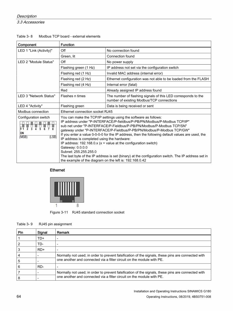
Description 3.3 Accessories
Installation and Operating Instructions SINAMICS G180 64 Operating Instructions, 08/2019, 4BS0751-008
Table 3- 8 Modbus TCP board - external elements
Component Function LED 1 "Link (Activity)" Off No connection found
Green, lit Connection found LED 2 "Module Status" Off No power supply
Flashing green (1 Hz) IP address not set via the configuration switch Flashing red (1 Hz) Invalid MAC address (internal error) Flashing red (2 Hz) Ethernet configuration was not able to be loaded from the FLASH Flashing red (4 Hz) Internal error (fatal) Red Already assigned IP address found
LED 3 "Network Status" Flashes n times The number of flashing signals of this LED corresponds to the number of existing Modbus/TCP connections
LED 4 "Activity" Flashing green Data is being received or sent Modbus connection Ethernet connection socket RJ45 Configuration switch
You can make the TCP/IP settings using the software as follows: IP address under "P-INTERFACE/P-fieldbus/P-PB/PN/Modbus/P-Modbus TCP/IP" sub net under "P-INTERFACE/P-Fieldbus/P-PB/PN/Modbus/P-Modbus TCP/SN" gateway under "P-INTERFACE/P-Fieldbus/P-PB/PN/Modbus/P-Modbus TCP/GW" If you enter a value 0-0-0-0 for the IP address, then the following default values are used, the IP address is completed using the hardware: IP address: 192.168.0.x (x = value at the configuration switch) Gateway: 0.0.0.0 Subnet: 255.255.255.0 The last byte of the IP address is set (binary) at the configuration switch. The IP address set in the example of the diagram on the left is: 192.168.0.42
Ethernet
Figure 3-11 RJ45 standard connection socket
Table 3- 9 RJ45 pin assignment
Pin Signal Remark 1 TD+ - 2 TD- - 3 RD+ - 4 - Normally not used; in order to prevent falsification of the signals, these pins are connected with
one another and connected via a filter circuit on the module with PE. 5 - 6 RD- - 7 - Normally not used; in order to prevent falsification of the signals, these pins are connected with
one another and connected via a filter circuit on the module with PE. 8 -

Description 3.3 Accessories
Installation and Operating Instructions SINAMICS G180 Operating Instructions, 08/2019, 4BS0751-008 65
3.3.15 Pre-switch mode power supply 300 W
General information The pre-switch mode power supply is used to supply switch-mode power supplies and fans from the DC link of converters or a comparable PC source (e.g.: UPS) The power supply can be used to buffer the line supply for a short period of time.
Designation Material number
PC board pre-switch mode power supply 300W L0329237 (main PC board with small mounted PC board L0329239)
Inputs Rated input voltage UD+/UD-
250 ... 1300 V DC (switched on above 150 V, switched off < 100 V and > 1500 V)
External supply -X1 230 V AC (is switched-on, if 300 V DC < 250 V, switched off for > 270 V)
Control voltage, fan -X32 Controlling the fan voltage X11 with 0 V/15 V/24 V (10 ... 15 ... 19 V > 12 V, 20 ... 24 ... 30 V ... > 24 V)
Outputs SNT 300 V X4 fan 24 V
300 V ± 25 V/1 A/300 W (basic insulation) 24 V ± 2 V/8 A/192 W (protective separation) X11:1, 2: fan (0 V/12 V/24 V) X11:1, 3: +24 V DC
Max. output power 300 W Dimensions (L * W * H) weight ambient temperature
200 * 120 * 40 mm 0.8 kg -20 ... 60 °C
Figure 3-12 PC board of the pre-switch mode power supply (pre SMPS 300W)

Description 3.3 Accessories
Installation and Operating Instructions SINAMICS G180 66 Operating Instructions, 08/2019, 4BS0751-008
3.3.16 Water cooling
3.3.16.1 General information about water cooling Cabinet units can optionally be purchased with water cooling. From the type designation 2T..-7… you can identify that a unit is equipped with water cooling. Water cooling is adapted to the existing conditions, Further information can be found in the order-related documentation.
The "Water cooling" section describes the design of the direct water cooling with open cooling circuit. Recooling of the coolant is not performed. Provide corresponding cooling of the water on-site.

Description 3.3 Accessories
Installation and Operating Instructions SINAMICS G180 Operating Instructions, 08/2019, 4BS0751-008 67
3.3.16.2 Direct water cooling diagram
Structure
(A) Components in the inverter cabinet (B) Components provided by the customer ① Ventilation ② Air / water heat exchanger with fan for interior ③ Electromagnetic valve NC ④ Electromagnetic valve NO ⑤ Stop valve, regulation of the flow rate ⑥ Flow rate regulation valve ⑦ Filter ⑧ Bypass - The version is optional
Figure 3-13 Diagram - Direct water cooling

Description 3.3 Accessories
Installation and Operating Instructions SINAMICS G180 68 Operating Instructions, 08/2019, 4BS0751-008
3.3.16.3 Connecting water cooling
Procedure ● Connect the water cooling to the three low-pressure hoses which are installed approx. 2
m above the bottom edge of the cabinet. The hoses are labeled as follows:
– Inlet
– Return flow
– Ventilation
● Install a fine filter with approx. 50 µm mesh size upstream of the inverter at the installation site.
3.3.16.4 Venting the water cooling
Procedure ● If counterpressure builds up in the return line, vent the water cooling.
● Also vent the water cooling if it is operated in an enclosed system.
1. Before venting the system, switch off the inverter and lock it out so that it cannot be switched on again.
2. Open the solenoid valve +H1.K2-Y1 to vent the water cooler.
Proceed as follows:
– Open the isolating blade terminals +H1.K1-X5(or X4):12 and …:13.
– At terminals +H1.K1-X5(or X4):11 and …:14 connect a 230 V AC auxiliary power supply.
– Open the water supply.
– Open the manual valve +H1.K2-Y3 to vent until no more air exits. The valve is located on the top side at the back on the left.
● Hose bushings and hose clamps are required to establish the connection:
Table 3- 10 Hose sizes
Hose sizes ½ " ¾ " 1 " 1 ½ " Hose outer diameter 24 mm 30 mm 37 mm 51 mm

Description 3.3 Accessories
Installation and Operating Instructions SINAMICS G180 Operating Instructions, 08/2019, 4BS0751-008 69
3.3.16.5 Decommissioning and shutdown
Procedure ● Empty the water cooling system if the inverter is decommissioned or is out of operation
for longer periods of time. You can find further information in the documentation 4BS0698.
● Note that putrefaction products are produced if the cooling water does not flow and that damage due to frost occurs if the unit is stored at temperatures below 0 °C.
NOTICE
Frost damage
Material damage can occur if the water cooling is exposed to frost without being drained.
Drain the system in order to avoid damage. Disconnect the hoses from the connection points. Proceed as described for the venting. For complete purging, blow compressed air into the supply hose while the venting valve is closed until no more water exits.
The water cooling system is empty when the inverters are shipped from the manufacturer's plant.
3.3.16.6 Cooling water additives for the closed inverter cooling with cooling unit (optional)
Use a cooling water additive for the closed cooling system of the inverter. Siemens recommends the agent "Antifrogen N" made by Clariant as a cooling water additive. The concentration of this additive can be adjusted to provide the required level of frost protection. A minimum concentration of 20 % by volume provides anti-freeze protection down to -10 °C. An Antifrogen / water mixture of 1:2 provides anti-freeze protection down to -20 °C.
Unpolluted water mixed with a minimum concentration of 20 % by volume Antifrogen N prevents the growth of microorganisms and the formation of algae.
If you need more detailed information and recommendations regarding cooling water additives, then refer to your order-specific inverter documentation. For further information, please refer to document 4BS0698.

Description 3.3 Accessories
Installation and Operating Instructions SINAMICS G180 70 Operating Instructions, 08/2019, 4BS0751-008

Installation and Operating Instructions SINAMICS G180 Operating Instructions, 08/2019, 4BS0751-008 71
Preparations for use 4 4.1 Transporting inverter
Procedure ● Persons operating cranes and fork-lift trucks must be appropriately qualified.
● Only use approved, undamaged and adequately dimensioned lifting equipment. Check the equipment before using it.
● Observe the information in Chapter "Technical data for transportation (Page 194)".
WARNING
Falling loads
If you are standing under a suspended load, then you are at risk of injury if the load falls off the hoisting gear. This can result in death, serious injury or material damage.
Never stand in the area beneath a suspended load.
WARNING
Accidents during transport and when lifting
This can result in death, serious injury or material damage.
Carefully observe the transport instructions in this document as well as the generally valid accident prevention regulations – especially BGI 556. Always wear personnel protective gear such as protective footwear and gloves and a helmet.
The inverters are packaged by the manufacturer so that they can be transported by truck.
NOTICE
Damage to inverters during transport
The inverters can be damaged if they are incorrectly transported. Observe the environmental conditions for transport provided in the technical data.

Preparations for use 4.1 Transporting inverter
Installation and Operating Instructions SINAMICS G180 72 Operating Instructions, 08/2019, 4BS0751-008
● Transport compact devices with cardboard packaging horizontally and cabinet equipment with plastic bubble wrap upright on wooden pallet.
● Inverters are highly sensitive electronic devices. Pay attention to the stickers and warnings on the packaging.
● Only transport the equipment with modern, air suspension trucks on asphalt roads. If you cannot comply with these conditions, package the devices in accordance with the special requirements. Consult the factory for this, for example for marine packaging.
● Never lift the compact devices at the plastic cover, but always from below according to the following diagrams.
Lifting compact devices - wrong
Lifting compact devices - correct
NOTICE
Damage to inverters during transport
When returning the unit, only transport it in the original packaging as otherwise the unit could be damaged during transport which means that the warranty becomes null and void.
CAUTION
Risk of injury when lifting heavy loads
Compact units, depending on the type, from frame size K3, weigh more than 30 kg. Do not try to manually lift devices more than 30 kg.

Preparations for use 4.1 Transporting inverter
Installation and Operating Instructions SINAMICS G180 Operating Instructions, 08/2019, 4BS0751-008 73
Figure 4-1 Lifting with a crane

Preparations for use 4.2 Storage of the inverters
Installation and Operating Instructions SINAMICS G180 74 Operating Instructions, 08/2019, 4BS0751-008
Figure 4-2 Transport with forklift
4.2 Storage of the inverters ● Only store the equipment in a dry storage area with undamaged packaging.
● Observe the information in Chapter "Technical data for storage (Page 194)".
NOTICE
Destruction of the inverters as a result of improper storage
Observe the environmental conditions for storage stated in the technical specifications. The inverters will be destroyed if you store them outdoors. Store the inverters in enclosed, dry rooms.

Preparations for use 4.3 EMC
Installation and Operating Instructions SINAMICS G180 Operating Instructions, 08/2019, 4BS0751-008 75
WARNING
Injury due to explosion of capacitors
If the unit has been stored for longer than two years, the DC link capacitors can explode during commissioning. Reform the DC link capacitors if the unit has been stored for longer than two years. Contact the factory to determine what measures must be taken.
4.3 EMC
4.3.1 Install and connect in accordance with EMC. Note the following rules regarding the installation and connection of inverters:
● Connect the cable shield over a wide area and with low inductance. Placing the shield over bundles of wires has practically no shield effect.
● If you also want to use the shield as PE conductor, then connect the shield twice.
– For EMC reasons, connect the shield through a low inductive connection with the largest possible surface area.
– Use a plait when connecting to the PE rail as protective measure.
● For signal lines with Sub-D male or female connector, place the shield over the Sub-D connector or socket. When connecting an external display at -X51, you must also connect the shield at the entry point to the housing. See also Chapters "External display (Page 54)", "Mounting an external display (option) (Page 88)" and "Connection for optional external display with RS 485 (Page 155)".
● Install cables in such a way that there are no crossovers between control cables and power cables. If you cannot prevent a crossover on the cable ducts, then make the crossover at an angle of 90°.
● Ensure that all metallic parts of the switch cabinet are surface-connected with good conductivity. Connections with paint layer are not permitted.
– Use contact disks or galvanized plates.
– When connecting the switch cabinet door to the switch cabinet, use grounding straps that are as short as possible
● Connect all circuit breakers, relays, solenoid valves etc. in the switch cabinet to RC interference suppressors.
– Do not use any diodes or varistors.
– Install the protective circuit directly on the relevant coil.

Preparations for use 4.3 EMC
Installation and Operating Instructions SINAMICS G180 76 Operating Instructions, 08/2019, 4BS0751-008
● Twist unshielded wires. This particularly includes analog signals of the same power circuit i.e. supply and return wires.
Keep the area between supply and return wires as small as possible in order to avoid unnecessary loop antennas.
● Separate the power cables connected to the inverter input and connected to the inverter output by spacing them or by using grounded separating plates.
● You may interrupt the shielding of power cables by installing components such as output contactors, reactors, sine filters, etc. Mount the components on a galvanized sheet. The sheet simultaneously provides shielding for the incoming and outgoing motor wires.
4.3.2 Examples for correct EMC connection You can see below some examples of expert connection of shielded cables at compact units.
If you would also like to apply cable shields with metal cable ties or metal clamps, install shielding buses for cabinet devices. Cable entry on a compact device with shield connection using metallic cable ties
Cable entry of small control lines with shield on the case and signal lines with shield on the Sub-D connector
Correct connection for EMC - Variant 1
Correct connection for EMC - Variant 2
① Line or control connection from approx. 10 mm outside diameter
② Control cable up to approx. 10 mm outside diameter
③ Signal cable
You can also use EMC threaded connections instead of the metal cable ties. In this case, remove the sheet metal with the cable tie lugs.

Preparations for use 4.3 EMC
Installation and Operating Instructions SINAMICS G180 Operating Instructions, 08/2019, 4BS0751-008 77
① Signal cable ② Control cable ③ Motor and power supply cable
Figure 4-3 EMC - wiring overview

Preparations for use 4.3 EMC
Installation and Operating Instructions SINAMICS G180 78 Operating Instructions, 08/2019, 4BS0751-008
① Cable tie ② Place with insulation removed ③ Contact clip ④ Shielding bus
Figure 4-4 Shield connection for cabinet devices
Figure 4-5 Shield connection for cable type NYCWY
4.3.3 Radio interference class You can read the radio interference class of the inverter at the version designation of the rating rate or from the order confirmation. You can find additional information in Chapter "Order numbers / Type designations (Page 31)".
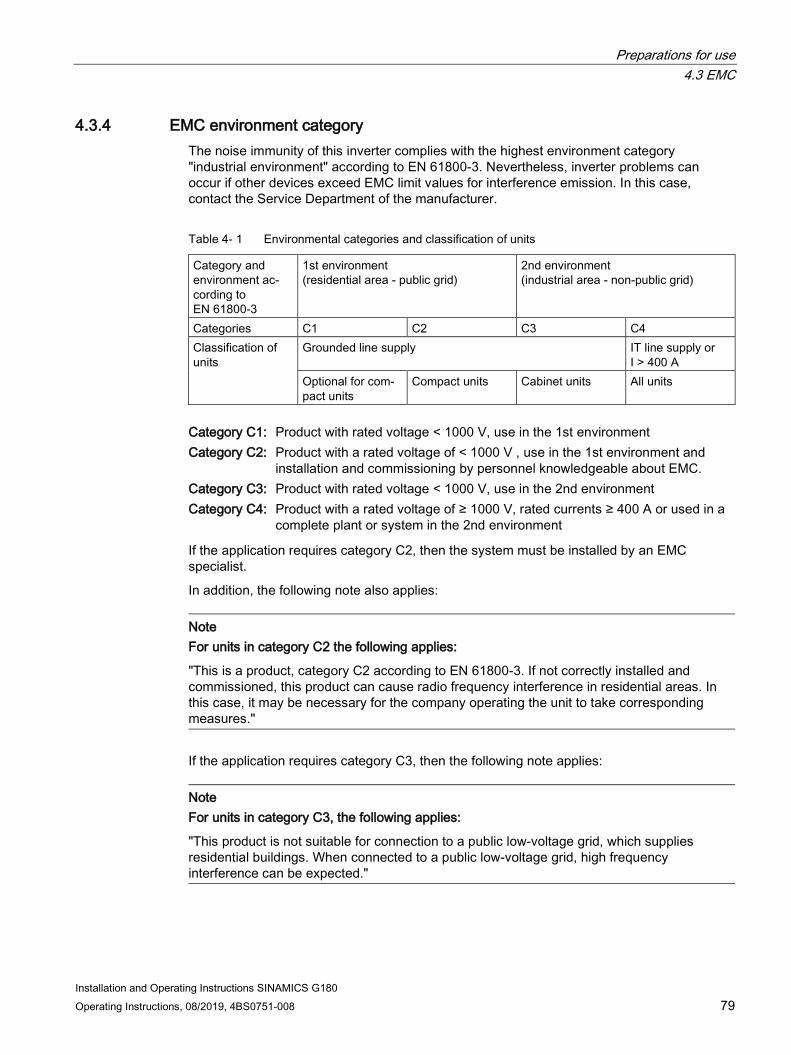
Preparations for use 4.3 EMC
Installation and Operating Instructions SINAMICS G180 Operating Instructions, 08/2019, 4BS0751-008 79
4.3.4 EMC environment category The noise immunity of this inverter complies with the highest environment category "industrial environment" according to EN 61800-3. Nevertheless, inverter problems can occur if other devices exceed EMC limit values for interference emission. In this case, contact the Service Department of the manufacturer.
Table 4- 1 Environmental categories and classification of units
Category and environment ac-cording to EN 61800-3
1st environment (residential area - public grid)
2nd environment (industrial area - non-public grid)
Categories C1 C2 C3 C4 Classification of units
Grounded line supply IT line supply or I > 400 A
Optional for com-pact units
Compact units Cabinet units All units
Category C1: Product with rated voltage < 1000 V, use in the 1st environment Category C2: Product with a rated voltage of < 1000 V , use in the 1st environment and
installation and commissioning by personnel knowledgeable about EMC. Category C3: Product with rated voltage < 1000 V, use in the 2nd environment Category C4: Product with a rated voltage of ≥ 1000 V, rated currents ≥ 400 A or used in a
complete plant or system in the 2nd environment
If the application requires category C2, then the system must be installed by an EMC specialist.
In addition, the following note also applies:
Note For units in category C2 the following applies:
"This is a product, category C2 according to EN 61800-3. If not correctly installed and commissioned, this product can cause radio frequency interference in residential areas. In this case, it may be necessary for the company operating the unit to take corresponding measures."
If the application requires category C3, then the following note applies:
Note For units in category C3, the following applies:
"This product is not suitable for connection to a public low-voltage grid, which supplies residential buildings. When connected to a public low-voltage grid, high frequency interference can be expected."
Preparations for use 4.4 Realizing operation in the explosion-protected zone
Installation and Operating Instructions SINAMICS G180 80 Operating Instructions, 08/2019, 4BS0751-008
4.4 Realizing operation in the explosion-protected zone
Inverters in hazardous zones
WARNING
Explosion hazard
If you operate the inverter in hazardous zones, explosions can occur which cause property damage, serious injuries or death. Only operate the inverter in safe, non-hazardous areas.
Motor in the Ex-Zone Motors connected to the inverter can be operated in the hazardous zone. Also observe the following conditions:
● Ensure that the motor is approved for inverter operation and that it has a corresponding rating plate for inverter operation.
● Ensure that the motor is approved for the Ex-Zone. Also check the motor rating plate.
● Ensure that the motors are equipped with PTC sensors according to DIN 44081 or DIN 44082 as well as IEC 60034-11-2 Type A (EN 60947-8 and VDE 0660-303). Connect these PTC thermistors to the peripheral board -X3:90 to 94. This is how you protect the motor against an inadmissible temperature rise due to overload according to DIN EN 60079-14/ VDE 0165-1 and EN 50281-1-1 (dust EX).
● Observe the safety regulations for use concerning motors in the Ex-Zones e or d. Directives 94/9/EG and EN 60079-14 regulate this use.
● Ensure that the motor is now only operated in the intended speed control range. Under "P-MOTOR DATA" and "P-DRIVE DATA" enter the values stated on the motor rating plate for "fmin" and "fmax" .
● Do not exceed the maximum motor cable length, otherwise impermissible voltage increases can occur. You can find more detailed information in Chapter "Motor connection (Page 98)".
● Ensure that Ex e-motors are tested for increased safety together with the inverter at the manufacturer's factory. The system must not be operated without the test report.
● In the case of Ex e and Ex n motors, set the values for "I contin.", "I short" and "t short" to the values stated by the manufacturer. Do not change these values again without consulting the motor manufacturer.
● Protect inverter-fed motors in the hazardous zones using PTC thermistors. An evaluation circuit for the motor PTC thermistor is integrated in the "peripheral board 2 / 4" option for this. More detailed information can be found in the section "Peripheral boards 1 to 4" (Page 37). The inverter is electronically shutdown.

Preparations for use 4.4 Realizing operation in the explosion-protected zone
Installation and Operating Instructions SINAMICS G180 Operating Instructions, 08/2019, 4BS0751-008 81
Safety during shutdown The risk analysis according to EN 1050 or DIN EN ISO 14121 (draft standard) showed that in comparison to the shutdown using contactors, only the additional hazard due to dangerous shock currents occurred in the inverter.
Due to the redundant design of the electronic shutdown route, it is achieved that the shutdown is still ensured even if a fault in the electronic shutdown route itself occurs.
As components proven in operation are used, the inverter complies with DIN EN ISO 13849-1:2015 category 2, PL c.
● If you do not use this electronic shutdown, the motor PTC thermistors must be routed via ATEX-certified thermistor evaluation units, e.g. CALOMAT® CK140 … CK145.
● If you use CALOMAT® devices, you must use a line contactor on the input side.
– In this case, loop the contact of the CALOMAT® directly into the coil circuit of the line contactor.
● Otherwise, connect the line contactor according to the description of the main contactor function in Chapter "Protective functions (Page 156)".

Preparations for use 4.4 Realizing operation in the explosion-protected zone
Installation and Operating Instructions SINAMICS G180 82 Operating Instructions, 08/2019, 4BS0751-008

Installation and Operating Instructions SINAMICS G180 Operating Instructions, 08/2019, 4BS0751-008 83
Installation 5 5.1 Installing inverter - General notes
● Install the inverter so that clean and dry cooling air can enter and leave without obstruction.
● Maintain the cooling air clearances stated in the dimension drawing.
● Read the degree of protection of the device off the rating plate.
● Note the following information about the degrees of protection:
Device Version Degree of protection accord-ing to EN 60529
NEMA type
Compact Standard IP20 Open Type Option IP21 Open Type Cabinet/ 2X cabinet units Standard IP21 NEMA1* Option IP23 NEMA1* Option IP41 NEMA1* Option IP43 NEMA1* Option IP54 NEMA1* Option IP55 NEMA1* * Higher NEMA types on request
Open Type
The compact devices are designed in accordance with degree of protection IP20 acc. to EN 60529 and as open-type devices acc. to UL 50. This ensures protection against electric shocks. To ensure protection against mechanical stress and climatic conditions too, the components should only be operated in housing/cabinets/rooms that fulfill the requirements stipulated in EN 60529 and are designed as enclosure types according to UL 50 (at least NEMA 1).
NOTICE
Dirt
If you do not protect the device against large accumulation of dust, high concentration of chemically active harmful substances, mold formation or the penetration by vermin, this can result in damage to and failure of the device.
Take suitable measures to protect the unit against these environmental influences. Observe the specified environmental conditions in the technical data.

Installation 5.2 Installing compact devices
Installation and Operating Instructions SINAMICS G180 84 Operating Instructions, 08/2019, 4BS0751-008
5.2 Installing compact devices
Procedure ● Install the compact devices directly in a control room or install compact devices in a
switch cabinet.
● When installed in a control cabinet, carefully note that the inverter cooling is not designed for any counter air pressure.
● If you use switch cabinets with filters, provide corresponding cabinet fans for the equalization.
We recommend the following procedure when mounting the compact unit to walls or panels: 1. Prepare the holes for the four fixing screws. Refer to the technical data for the relevant
dimensions.
2. Screw in the two lower screws until they have taken a firm grip.
3. Lift the compact unit, if required using suitable lifting equipment, onto the two lower screws. The hole in the upper center of the base plate can be used to lift the unit using a hook.
4. Press the compact unit against the panel and tighten the upper two fixing screws.
5. And finally tighten the two lower screws.
To remove, first release the lower screws, then the upper screws and lift the unit from the panel.

Installation 5.3 Protective cover IP21 for compact and compact Plus devices
Installation and Operating Instructions SINAMICS G180 Operating Instructions, 08/2019, 4BS0751-008 85
5.3 Protective cover IP21 for compact and compact Plus devices
Figure 5-1 Canopy IP21
All compact units have degree of protection IP20. The canopy with degree of protection IP21 is available as an accessory for all compact and compact Plus units. The canopy is 5 mm wider on both sides than the inverter. Take account of this clearance for the alignment. Leave the outlet area at the front clear.
Proceed as follows to install the canopy supplied loose:
1. Screw the inverter without canopy onto a mounting plate. Do not tighten the top two mounting screws completely.
2. Slide the cover under the not yet completely tightened mounting screws.
3. Tighten the mounting screws completely.
With degree of protection IP21, the type code changes from 2T2A.....-... to 2T3A.....-... .
Installation 5.4 Installing cabinet units
Installation and Operating Instructions SINAMICS G180 86 Operating Instructions, 08/2019, 4BS0751-008
5.4 Installing cabinet units ● Install cabinet units on level mounting shelves. Wall mounting is permitted.
● If no clearances are stated in the dimension drawing of the order documentation, cabinets can be arranged next to each other.
● Provide the corresponding openings for the cable entry.
● Ensure that the cabinet frame is resting on the floor.
● If the cable opening is very large, anchoring to the floor increases the safety.
● If larger units have been separated for transport, make all the connections at the separation points again.
NOTICE
Overheating
If you do not remove the transport rails installed on the canopy before commissioning, the inverter can be damaged due to overheating.
Remove the transport rails before commissioning.
Canopy
Install the protective covers on the top of the cabinet. Proceed as follows:
1. Remove any transport rails present. Keep these for later transport.
2. Screw four bolts into the threads provided on the inverter cabinet.
3. Put on the cover and firmly screw on the cover using the screws provided.
NOTICE
Foreign bodies in the cabinet
If you drop washers or screws into the cabinet during installation, this can result in destruction of the device.
Ensure that no washers or screws fall into the device.
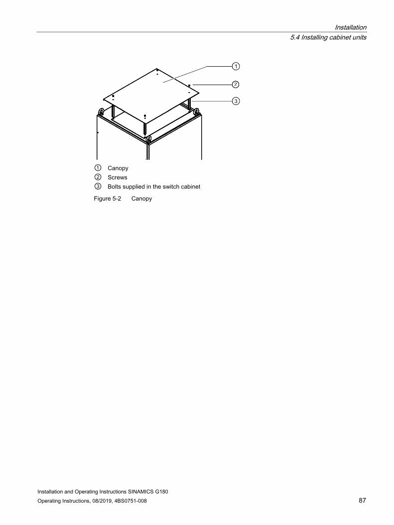
Installation 5.4 Installing cabinet units
Installation and Operating Instructions SINAMICS G180 Operating Instructions, 08/2019, 4BS0751-008 87
① Canopy ② Screws ③ Bolts supplied in the switch cabinet
Figure 5-2 Canopy

Installation 5.5 Mounting an external display (option)
Installation and Operating Instructions SINAMICS G180 88 Operating Instructions, 08/2019, 4BS0751-008
5.5 Mounting an external display (option) The external display with the item number L0296033 has the same functionality as the internal display. You can connect the display to the inverter at two connectors:
● At the RJ-10 connection -X26, and only for installation in the control cabinet with a maximum cable length of 5 m.
● At the 9-pin D-sub connector -X51 and with a supplementary 24 V voltage supply for a maximum cable length of 1000 m.
Procedure Use the display in control panels or doors. Note the following dimensions for the opening:
Width × height [mm]: 138+1 × 92+0.8
The degree of protection is IP54.
① Contrast setting
Figure 5-3 Dimension drawing - External display
Connection for installation in the switch cabinet door with maximum 5 meters connection cable length Use the connecting cable with item number L0330600.
1. Shorten the cable to the required length.
2. Connect up the cables using end sleeves as illustrated in the diagram below.

Installation 5.5 Mounting an external display (option)
Installation and Operating Instructions SINAMICS G180 Operating Instructions, 08/2019, 4BS0751-008 89
Figure 5-4 Display - Installation in switch cabinet door
Connection for external installation with maximum 1.000 meters connection cable length
Figure 5-5 Display - external installation
Use shielded connection cables.
The connecting cable shield must be connected to the shield support provided at the entry point in the housing through the largest possible surface area (for grounding purposes).

Installation 5.5 Mounting an external display (option)
Installation and Operating Instructions SINAMICS G180 90 Operating Instructions, 08/2019, 4BS0751-008

Installation and Operating Instructions SINAMICS G180 Operating Instructions, 08/2019, 4BS0751-008 91
Electrical connection 6 6.1 General information about the electrical connection
Please note the following regarding the electrical connection.
● When installing cables and selecting the cabling materials, make sure that you provide adequate isolation between circuits of different voltage classes (DVC), e.g. by using cables with reinforced insulation or by routing cables in separate cable ducts.
● Make sure that the cables are mechanically secured, e.g. using cable ties, against accidental disconnection.
For detailed information about cabling and connections, please refer to EN 61800-5-1, Chapter 4.3.8.
Note
Familiarize yourself with the local safety requirements and national safety guidelines, and always observe them.
NOTICE
Use of aluminum cables at unsuitable terminals
If you connect aluminum cables to terminals which are not suitable for the purpose, corrosion will develop. The equipment will be damaged as a result.
Use special cable lugs which are designed for connecting aluminum and copper.
Please contact the Siemens Service (Page 189) for advice about box terminals.

Electrical connection 6.2 Protecting the inverter
Installation and Operating Instructions SINAMICS G180 92 Operating Instructions, 08/2019, 4BS0751-008
6.2 Protecting the inverter When protecting the inverter a distinction must be made between the two cases.
Procedure when the motor has approximately the same rating as the inverter (Imot ≥ 0.5 * IFI)
● Protect the inverter against short circuits.
● Take the fuse value from the technical data, or select the next larger gL fuse based on the continuous inverter input current stamped on the type plate.
● Install a gL fuse or circuit breaker upstream of the inverter.
● When using a circuit breaker, set the thermal release to 1.2x the continuous inverter input current as stamped on the type plate and the magnetic release to the lowest possible value between 1.5 and 2x the value of the continuous inverter input current.
– Only use circuit breakers without time grading (time discrimination).
– The break time of the circuit breaker in the case of a short circuit must be less than 8 ms.
Procedure when the motor has a significantly lower rating than the inverter (Imot < 0.5 * IFI)
● Protect the inverter against short circuits.
● Dimension the fuse value as follows: Ifuse < 2 * Imot. Use the next lower standard fuse value than calculated.
● Parameterize inverter parameter "P-INVERTER DATA/I contin." as a maximum to the fuse value.
● Install a gL fuse or circuit breaker upstream of the inverter.
● When using a circuit breaker, set the thermal release to 2x the rated motor current as stamped on the rating plate, and the magnetic release to the lowest possible value between 1.5 and 2x the value of the continuous inverter input current.
– The break time of the circuit breaker in the case of a short circuit must be less than 8 ms.
6.3 Circuit breaker In order to safely disconnect the inverter from the line supply, install a main switch or a circuit breaker upstream of the inverter.
The main switch or the circuit breaker must be capable of carrying at least 1.2x the rated inverter current. The switching capacity of the main switch or the circuit breaker must correspond to the short-circuit current of the line supply system.

Electrical connection 6.4 Connecting control cable
Installation and Operating Instructions SINAMICS G180 Operating Instructions, 08/2019, 4BS0751-008 93
6.4 Connecting control cable ● Connect the control cables as described in Chapter "Communication Options
(Page 129)", or according to the equipment documentation supplied.
● Use shielded, twisted pair cables for the connection of signal lines in order to increase the signal quality.
● When selecting cables and conductors and installing them, it is essential that you observe the information provided in Chapter "Protective separation according to EN 61800-5-1 (Page 145)".
● Instructions for EMC-compliant installation is provided in Chapter "Install and connect in accordance with EMC. (Page 75)".
● "You can find additional information about control cable terminals in Chapter "Technical data of the control cable terminals (Page 201)".
6.5 Line supply connection
6.5.1 Suitable supply line configurations The converters are suitable for the following line supply types:
Table 6- 1 SINAMICS G180 T7 and appropriate line supply types
Line voltage Type designation Line system type 400 V 2T..-..40.-… TT or TN line system, grounded 500 V 2T..-..50.-… TT, TN or IT line system, grounded or not grounded 690 V 2T..-..60.-… TT, TN or IT line system, grounded or not grounded
Table 6- 2 SINAMICS G180 R7 and appropriate line system types
Line voltage Type designation Line system type 400 V 2R..-87400-… TT or TN line system, grounded 690 V 2R..-87600-… TT or TN line system, grounded
WARNING
Explosion of the Y capacitors
If you operate units, category C1, C2 or C3 (radio interference suppression class A or B) with type designation "2T..-.....-....A/B...." on ungrounded mains power supplies, then this can destroy the Y capacitors at the line supply input. Serious injury and death can occur. Only use units without RFI suppression filter with the type designation "2T..-.....-....O...." on an ungrounded mains power supply. IT mains power supplies are not grounded.

Electrical connection 6.5 Line supply connection
Installation and Operating Instructions SINAMICS G180 94 Operating Instructions, 08/2019, 4BS0751-008
6.5.2 Dimensioning mains power cables
Dimensioning ● Voltage stress
Use cables with adequate voltage strength; we recommend at least U0/U = 0.6/1 kV.
● Current load
– Dimension the cable cross section according to the applicable standards, e.g. VDE 0298.
– Determine the current rating for the mains power cable according to the inverter input current stamped on the type plate.
● Precaution against injury due to indirect contact Use an overcurrent protection device with additional potential equalization on the motor in order to avoid injuries due to indirect contact.
● Protective earth conductor Due to the high leakage currents of the unit (> 3.5 mA), one or more of the following conditions must be fulfilled for fixed connection of the protective earth conductor:
– The protective earth conductor must have a cross section of at least 10 mm2 Cu or 16 mm2 Al
– Automatic tripping of the power supply in the event of interruption of the protective earth conductor
– Installation of an additional terminal for a second protective earth conductor with the same cross section as the original protective earth conductor
6.5.3 RCD circuit breaker
WARNING
High voltages
This product can cause a direct current in the protective earth conductor. When a residual current device (RCD) or a residual current monitor (RCM) is used for protection in the event of direct or indirect contact, only an RCD or RCM of type B is permissible on the power supply side of this product.

Electrical connection 6.5 Line supply connection
Installation and Operating Instructions SINAMICS G180 Operating Instructions, 08/2019, 4BS0751-008 95
● If you are using an RCD circuit breaker, then as a result of the high capacitive discharge currents, use an RCD circuit breaker with a high cut-off current. The leakage current basically depends on the type, length and laying of the motor cable.
– Use at least a 500 mA RCD circuit breaker for inverter outputs up to approx. 100 kW.
– Use at least a 1 A RCD circuit breaker for inverter outputs above 100 kW.
– The RCD circuit breakers used must be of type B "sensitive to all current types" with this label:
6.5.4 Connecting mains power cable to the inverter You do not need any N conductor.
Procedure ● Only connect the inverter using a permanently installed connecting cable. Refer to the
following table for the possible connection cross-sections for compact devices. The connection cross-sections for cabinet units can be found in the technical data provided in the inverter documentation.
● Observe the switch manufacturer instructions when connecting cables directly at the main switch. These instructions are provided in the circuit diagram pocket in the inverter cabinet. If necessary, special equipment cable lugs must be used in order to be able to utilize the connection spaces available.
Table 6- 3 Conductor cross-sections for compact devices
Frame size Flexible cable Rigid cable BG K1 0,2 - 6 mm² 0,2 - 10 mm² BG K2 4 - 16 mm² 2,5 - 25 mm² BG K3 0,75 - 35 mm² 0,75 - 50 mm² BG K4 2,5 - 120 mm² 2,5 - 120 mm² BG K5 2,5 - 120 mm² 2,5 - 120 mm² BG K51 2,5 - 120 mm² 2,5 - 120 mm² BG K6 50 - 240 mm² 50 - 240 mm²
● Connect the mains power cables L1-L2-L3 to terminals U1, V1, W1 of terminal strip -X1 of the inverter: Refer to the technical data for the correct tightening torques for the power cable connection.

Electrical connection 6.5 Line supply connection
Installation and Operating Instructions SINAMICS G180 96 Operating Instructions, 08/2019, 4BS0751-008
NOTICE
Destruction due to nonsymmetrical current distribution
In the case of inverters with higher pulse numbers, the rectifier can be destroyed as a result of the non-symmetrical current distribution. Pay attention to symmetrical current distribution. Use the same cable types and lengths as well as the same connection technology for every mains power connection. Route all cables on the same or a comparable route so that the cable temperatures are the same.
6.5.5 Inverter connection for different pulse operation Inverters equipped with inputs with higher pulse numbers are available for higher outputs from approx. 500 kW; these inputs result in lower mains harmonics.
Connect the inverter to the mains power supply depending on the number of pulses used:
Table 6- 4 Mains connection dependent on the number of pulses used
Number of pulses used
Can be recog-nized in the type code:
Connection at the inverter at –X1:U1, V1, W1
6 2T.A-… Three phases 12 2T.F-… Two secondary transformer systems each with three phases, i.e. a
total of six phases. Both systems must be phase offset by 30°, e.g. using the transformer vector group Dy5d6.
18 2T.K-… Three secondary transformer systems each with three phases, i.e. a total of nine phases. The three systems must each be phase offset by 20°, e.g. using the transformer vector group Dy0y+20y-20.
24 2T.L-… Four secondary transformer systems each with three phases, i.e. a total of twelve phases. The four systems must each be phase offset by 15°, e.g. using two transformers with the vector groups Dy5,25d6,25 and Dy4,75d5,75.
The type code can be found on the rating plate.

Electrical connection 6.5 Line supply connection
Installation and Operating Instructions SINAMICS G180 Operating Instructions, 08/2019, 4BS0751-008 97
6.5.6 Adjusting the line voltage at the inverter The inverters are suitable for different mains voltages: If your unit is different from the respective nominal line voltages of 400 V, 500 V or 690 V, you must adjust the mains voltage at the inverter.
1. Set parameter "P-INVERTER DATA/V mains nom." to your mains voltage.
2. Set the mains voltage on the device:
– No adjustment is necessary for compact units with a width of 165 mm or 225 mm.
– In the case of compact units with a width of 350 mm or 500 mm, you reconnect the jumpers according to the following table:
Rated voltage [V] Voltage tolerance [V] Necessary jumpers 230 184 … 265 1-2 / 4-8 400* 320 … 460 1-6 / 7-8 460 368 … 529 1-5 / 7-8 500* 408 … 587 1-3 / 7-8 / 4-5 575 464 … 667 1-2 / 7-8 / 3-6 690 552 … 794 1-2 / 7-8 / 4-5 *One of these values is preset.
The voltage tolerances specified in the table indicate the permissible voltage range of the fan power supply and not the permissible tolerances for the power connection of the device.

Electrical connection 6.6 Motor connection
Installation and Operating Instructions SINAMICS G180 98 Operating Instructions, 08/2019, 4BS0751-008
① Jumpers for rated voltage preselection ② Terminals -X101 and -X102 for an external control voltage ③ Terminal for preselection of the control voltage setting
• View as in the picture: Internal power supply • Cable connected at connector -X200 : Power supply via terminals -X101 and -X102
Figure 6-1 Jumpers and terminals at the inverter
If a transformer is installed in a cabinet unit, the transformer connections must be changed to the correct mains voltage.
6.6 Motor connection
6.6.1 Motor selection Three-phase asynchronous motors or three-phase synchronous motors can be used for your inverter. The use of several motors simultaneously is permitted.
● The total of the motor outputs must not exceed the inverter output. You may operate smaller and larger motors in parallel on one inverter.
● Take into account during the motor dimensioning that additional losses in the motor are produced by the non-sine shaped motor current.
● Note that a motor without external ventilation will be cooled less at speeds less than the rated speed. Therefor, consult the motor manufacturer for the dimensioning of the motor.
● When using Siemens motors, refer to the list "UN03/UN04 Drehstrommotoren für drehzahlverstellbare Antriebe" to find the relevant inverter output.

Electrical connection 6.6 Motor connection
Installation and Operating Instructions SINAMICS G180 Operating Instructions, 08/2019, 4BS0751-008 99
6.6.2 Coil load
Note High voltage peaks caused by switching edges
The switching edges generated by the inverter at the inverter output additionally stress the motor insulation. This results in high voltage peaks.
If you carefully observe the notes in this chapter, then peak voltages not exceeding 1560 V occur at the motor. Motors specially designed for inverter operation do not represent a problem. Contact the motor manufacturer if you wish to connect older motors, or motors that are not suitable for inverter operation.
For explosion-protected motors, carefully ensure that the specified peak voltage at the motor is precisely maintained.
6.6.3 Motor voltage and type of circuit Operate the motor in the "star" or "delta" connection corresponding to the inverter parameterization.
In most cases, the motor voltage parameterized at the inverter is identical with the mains voltage. Check parameter "P-MOTOR DATA/V motor" to identify what has been parameterized.

Electrical connection 6.6 Motor connection
Installation and Operating Instructions SINAMICS G180 100 Operating Instructions, 08/2019, 4BS0751-008
6.6.4 Dimensioning motor cables ● Voltage load
Use cables with adequate voltage strength; we recommend at least V0/V = 0.6 kV/1 kV.
● Current load
– Dimension the cable cross section according to the applicable standards, e.g. VDE 0298.
– Determine the current of the motor cable according to the inverter output current, which you can find on the rating plate.
● To comply with EMC directives, use cables with EMC shield - or at least cables with concentric protective earth conductor, type NYCWY.
● For multi-system devices, connect the same number of motor cables at each system.
See Chapter "Install and connect in accordance with EMC. (Page 75)".
WARNING
Capacitive leakage currents
An increased current can flow in the motor cable shield as a result of capacitive leakage currents. This can cause the cable to overheat. This can result in death, serious injury or material damage.
Use a shield cross section that is, as a minimum, half the line conductor cross-section: For a thinner shield or for a shield manufactured out of steel braiding, route a PE conductor, which, as a minimum, is half of the line conductor cross-section in parallel with the motor cable.
6.6.5 Dimensioning maximum motor cable length The maximum cable length is determined by the following factors:
● Peak voltage at the motor
– All converters are equipped with a du/dt filter. The filter limits the voltage increase time on the motor to > 0.5 µs.
– A motor peak voltage of 1,560 V is maintained for the maximum cable lengths stated in the table.
● Inverter load
– The capacitive load of the inverter increase with increasing cable length and/or increasing number of parallel cables.
– The parameterizable inverter clock frequency influences the converter load. If you configure the minimum possible clock frequency, the inverter load then reduces so that a larger cable length can be connected.

Electrical connection 6.6 Motor connection
Installation and Operating Instructions SINAMICS G180 Operating Instructions, 08/2019, 4BS0751-008 101
Table 6- 5 Typical maximum motor cable lengths for different converter versions
Device type standard version 2T..-.....-.....D...
Version with strengthened du/dt filter
2T..-.....-.....V... Cable type Cable type
NYCWY NYY NYCWY NYY Compact devices 400 V 2T..-(0…3)5400-... connected to line supplies up to 400 V
200 m 300 m 350 m 450 m
Compact devices 400 V 2T..-(0…3)5400-... connected to line supplies > 400 V
150 m 200 m 300 m 350 m
Cabinet units 400 V 2T..-(7…8)(5…6)40.-... connected to line supplies up to 400 V
- - 300 m 350 m
Cabinet units 400 V 2R..-874..-...
150 m 200 m 300 m 350 m
Compact devices 500 V 2T..-(0…3)5500-...
- - 300 m 350 m
Cabinet units 500 V 2T..-(7…8)(5…6)50.-...
- - 250 m 300 m
Compact devices 690 V 2T..-(0…3)5600-...
150 m 200 m 300 m 300 m
Cabinet units 690 V 2T..-(7…8)(5…6)60.-...
100 m 140 m 250 m 300 m
Cabinet units 690 V 2R..-876..-...
150 m 200 m 300 m 350 m
The data in the table specifies the typical cable length in the sense of the distance between the motor and the converter when parameterizing the standard clock cycle frequency. Larger distances are also possible for individual types. Contact the factory for precise values if you are in the limit range or if there is a long distance between the motor and converter.
NOTICE
Damage to the converter output filter
If you lay too many wires in parallel for the motor cable, the capacitive current in the motor cable can increase unacceptably and destroy the converter output filter. In the case of operation with several motors or parallel wiring of motor cables, the maximum possible distance between converter and motor is reduced. Cabinet units are suitable for wiring in parallel. Contact the factory for the precise values. Reduce the number of parallel wires to permissible values.

Electrical connection 6.6 Motor connection
Installation and Operating Instructions SINAMICS G180 102 Operating Instructions, 08/2019, 4BS0751-008
NOTICE
Destruction of the motor or the converter output filter
If you exceed the maximum motor cable length, this can destroy the motor or the converter output filter. Consult the factory for longer motor cables.
NOTICE
Winding or bearing damage
If you use motors which are not designed for converter operation, premature winding or bearing damage can occur. Consult the motor manufacturer to find out whether the motor is suitable for converter operation. Please bear in mind that IEC 60034-17 is applicable to motors that are designed for line operation but are operated with a converter. Smaller values for the peak voltage apply here. Dimension the cable lengths after consultation with the manufacturer.
6.6.6 Connecting motor cable Connect the motor to terminals U2, V2, W2 of terminal strip -X1 of the inverter.
Connect the motor cable shield to the shield supports provided through the largest possible surface area. The other alternative is to use EMC glands both at the motor and the inverter. If you use the cable shield as protective conductor, then you must connect this to the protective conductor connection so that it can conduct the appropriate current.
Refer to the technical data for the correct tightening torques for the power cable connection.
6.6.7 Connecting the PTC thermistor of the motor to the inverter ● Connect the PTC thermistor of non-explosion-protected motors without peripheral board 2
/ 4 to terminals 27, 28 - 58 of control cable terminal block -X2.
● If peripheral board 2 / 4 is installed, connect the PTC thermistor to terminals 90 to 94 of control cable terminal block -X3. For additional information, refer to the description of the accessories.
● Use a shielded cable to connect the PTC thermistor. Connect the shield to the shield support provided at the entry to the housing through the largest possible surface area. Observe the minimum cross section of the PTC thermistor cable in Chapter "Technical data and identification of the PTC thermistor input at peripheral boards 2 and 4 (Page 203)".

Electrical connection 6.7 External control voltage
Installation and Operating Instructions SINAMICS G180 Operating Instructions, 08/2019, 4BS0751-008 103
6.7 External control voltage
6.7.1 Use of external control voltage In normal operation, the inverter generates the control voltage from the DC link voltage.
Use external control voltage in the following cases:
● For main contactor on the line voltage side
● If the display should also function when no mains voltage is present
● If the inverter should resume operation approx. 3 s faster than without external control voltage in the case of brief mains power failures. The initialization time of approx. 3 s does not apply in the case of external supply.
6.7.2 Connecting the external 230 V AC control voltage
6.7.2.1 Protecting/fusing the external 230 V AC control voltage
WARNING
External control voltage without fuse protection
If you use an external control voltage without suitable protection (e.g. fuses), then overloads and short-circuits can occur. This can result in death, serious injury or material damage.
The device may only be operated with a protected external control voltage. Note the following recommendation.
Install one of the following options to protect the external control voltage:
● Miniature fuse in accordance with EN 60127: 2 A … 6 A, slow, maximum 150 VA
● Miniature circuit-breaker: 2 A … 6 A, characteristic D, maximum 150 VA

Electrical connection 6.7 External control voltage
Installation and Operating Instructions SINAMICS G180 104 Operating Instructions, 08/2019, 4BS0751-008
6.7.2.2 Switching over the hardware to an external 230 V AC control voltage ● Switch over the inverter from the internal control voltage from the DC link to an external
control voltage.
Procedure ● Change over the white connector on the "switched-mode power supply" board from -X2
for "internal" to-X5 for "external".
Switching power supply with connector on internal control voltage
Switching power supply with connector on external control voltage
6.7.2.3 Preparations for accessing the "switching power supply" board
Preparing compact devices with size up to 165 mm This instruction is applicable for compact devices up to a size of 165 mm with the identifier 2T..-07400-011 or 2T..-07500-015.
Procedure
1. Unscrew the blue cover at the screw above -X25 and lift up the cover.
2. Turn the two screws of the grey cover underneath by 90° and lift up the cover.
3. Undo all screws for the right-hand side panel which are visible from outside and one internal nut in the connection area. Lift off the side panel.
4. Replug the connector.
5. Reassemble in the inverse order.

Electrical connection 6.7 External control voltage
Installation and Operating Instructions SINAMICS G180 Operating Instructions, 08/2019, 4BS0751-008 105
Preparing compact devices with size up to 225 mm This instruction is applicable for compact units up to a size of 225 mm with the identifier 2T..-07400-015 or 2T..-07500-037.
Procedure
1. Turn the four fixing screws of the gray cover through 90° and lift up the cover.
2. Unscrew the blue cover at the screw above -X25 and lift up the cover.
3. Turn the four fixing screws of the swivel section by 90°, swivel the swivel section to the right and clip the swivel section to the side panel according to the picture below.
4. Replug the connector.
5. Reassemble in the inverse order.
Compact frame size 165 mm long
Compact frame size 225 mm long

Electrical connection 6.7 External control voltage
Installation and Operating Instructions SINAMICS G180 106 Operating Instructions, 08/2019, 4BS0751-008
Preparing compact devices with frame size K4 with 400 V or 500 V This instruction applies to compact units with the frame size K4 with L × W 775 × 350 mm and 400 V or 500 V rated voltage.
Procedure
1. Turn the four fixing screws of the gray cover through 90° and lift up the cover.
2. Unscrew the blue cover at the screw above -X25 and lift up the cover.
3. Remove the cover above the motor connection terminals.
4. Remove the "fan power supply" board with the five fine-wire fuses. Undo the four screws and unplug the cable for this.
5. The "switched-mode power supply" board is located below with a white connector and the sockets -X2 for "internal" and -X5 for "external".
6. Insert the connector into "external".
7. Reassemble in the inverse order.
Figure 6-2 Compact device frame size K4
Note Occurrence of malfunctions
Malfunctions can occur if you change over the connection of the sockets -X100 / 200 for "external" / "internal" on the upper "fan power supply" board. Leave this connection in its original configuration.
Electrical connection 6.7 External control voltage
Installation and Operating Instructions SINAMICS G180 Operating Instructions, 08/2019, 4BS0751-008 107
Providing compact devices with the frame size K4 with 690 V This instruction applies to compact units with frame size K4 with L × W 775 × 350 mm and 690 V rated voltage.
Procedure
1. Turn the four fixing screws of the gray cover through 90° and lift up the cover.
2. Unscrew the blue cover at the screw above -X25 and lift up the cover.
3. Remove the cover above the motor connection terminals.
4. On the "fan supply" board with the five miniature fuses, change over the connector from socket -X100 to -X200.
5. Reassemble in the inverse order.
Note Occurrence of malfunctions
Malfunctions can occur if you change over the connection of sockets -X2 / 5 for "external" / "internal" on the "switched-mode power supply" board. Leave this connection on "external".
Providing compact devices with frame size K5/51 with 400 V or 500 V These instructions apply to compact units with frame size K5 or 51 with L × W (1125 or 1538)×350 mm and 400 V or 500 V rated voltage.
Procedure
1. Turn the four fixing screws of the gray cover through 90° and lift up the cover.
2. Unscrew the blue cover at the screw above -X25 and lift up the cover.

Electrical connection 6.7 External control voltage
Installation and Operating Instructions SINAMICS G180 108 Operating Instructions, 08/2019, 4BS0751-008
3. Turn the four fixing screws of the swivel section by 90°, swivel the swivel section to the right and clip the swivel section to the side panel according to the picture.
Figure 6-3 Compact unit with frame size K5 with opened control electronics
4. Remove the "fan power supply" board with the five fine-wire fuses. Undo the four screws and unplug the cable for this.
5. The "switched-mode power supply" board is located below with a white connector and the sockets -X2 for "internal" and -X5 for "external".
6. Insert the connector into "external".
7. Reassemble in the inverse order.
Note Occurrence of malfunctions
Malfunctions can occur if you change over the connection of the sockets -X100 / 200 for "external" / "internal" on the upper "fan power supply" board. Leave this connection in its original configuration.

Electrical connection 6.7 External control voltage
Installation and Operating Instructions SINAMICS G180 Operating Instructions, 08/2019, 4BS0751-008 109
Providing compact devices with the frame size K5/51 with 690 V These instructions apply to compact units with frame size K5 or 51 with L × W (1125 or 1538) × 350 mm and 690 V rated voltage.
Procedure
1. Turn the four fixing screws of the gray cover through 90° and lift up the cover.
2. Unscrew the blue cover at the screw above -X25 and lift up the cover.
3. Turn the four fixing screws of the swivel section by 90°, swivel the swivel section to the right and clip the swivel section to the side panel.
4. On the "fan supply" board with the five miniature fuses, change over the connector from socket -X100 for "internal" to -X200 for "external".
5. Reassemble in the inverse order.
Note Occurrence of malfunctions
Malfunctions can occur if you change over the connection of sockets -X2 / 5 for "external" / "internal" on the "switched-mode power supply" board. Leave this connection on "external".
Preparing compact devices with frame size K6 with 400 V or 500 V This instruction applies to compact units with the frame size K6 with L × W 1125×500 mm and 400 V or 500 V rated voltage.
Procedure
1. Turn the four fixing screws of the gray cover through 90° and lift up the cover.
2. Unscrew the blue cover at the screw above -X25 and lift up the cover.
3. Turn the four fixing screws of the swivel section by 90°, swivel the swivel section to the right and clip the swivel section to the side panel.
4. The "switched-mode power supply" board is located below with a white connector and the sockets -X2 for "internal" and -X5 for "external".
5. Insert the connector into "external".
6. Reassemble in the inverse order.
Note Occurrence of malfunctions
Malfunctions can occur if you change over the connection of the sockets -X100 / 200 for "external" / "internal" on the upper "fan power supply" board. Leave this connection in its original configuration.

Electrical connection 6.7 External control voltage
Installation and Operating Instructions SINAMICS G180 110 Operating Instructions, 08/2019, 4BS0751-008
Providing compact devices with the frame size K6 with 690 V This instruction applies to compact units with frame size K6 with L × W 1125×500 mm and 690 V rated voltage.
Procedure
1. Turn the four fixing screws of the gray cover through 90° and lift up the cover.
2. Unscrew the blue cover at the screw above -X25 and lift up the cover.
3. Turn the four fixing screws of the swivel section by 90°, swivel the swivel section to the right and clip the swivel section to the side panel.
4. The "fan power supply" board with five fine-wire fuses and the "switching power supply" board are underneath.
5. On the "fan supply" board, change over the connector from socket -X100 for "internal" to -X200 for "external".
6. Reassemble in the inverse order.
Note Occurrence of malfunctions
Malfunctions can occur if you change over the connection of sockets -X2 / 5 for "external" / "internal" on the "switched-mode power supply" board. Leave this connection on "external".

Electrical connection 6.7 External control voltage
Installation and Operating Instructions SINAMICS G180 Operating Instructions, 08/2019, 4BS0751-008 111
6.7.2.4 Connecting the external 230 V AC for compact devices
Procedure ● Connect the external control voltage to the terminals 101 (L1) and 102 (N).
Figure 6-4 Connection for external control voltage
Use the following connection values:
Table 6- 6 Connection values for external control voltage
Maximum cross section 2.5 mm² Fuse protection • Miniature fuse in accordance with EN 60127: 2 A … 6 A, slow, maxi-
mum 150 VA • Miniature circuit-breaker: 2 A … 6 A, characteristic D, maximum 150 VA
Voltage 230 V + 15 % - 20 % Frequency 47 Hz … 63 Hz
For compact units with frame size K4, terminals 101 and 102 are located on a board under the plastic cover above the motor terminals.
6.7.2.5 Control voltage 230 V AC for cabinet units Cabinet units access the control voltage for the electronics from the control transformer. Further information can be found in the wiring diagram of the unit.

Electrical connection 6.7 External control voltage
Installation and Operating Instructions SINAMICS G180 112 Operating Instructions, 08/2019, 4BS0751-008
6.7.3 Connecting the external 24 V DC control voltage
6.7.3.1 Protecting/fusing the external 24 V DC control voltage
NOTICE
External control voltage without fuse protection
If you use an external control voltage without suitable protection (e.g. fuses), then overloads and short-circuits can occur. Material damage can result.
The device may only be operated with a protected external control voltage. Note the following recommendation.
Install one of the following options to protect the external control voltage:
● Miniature fuse in accordance with EN 60127: 6 A, slow acting, maximum 100 VA
● Miniature circuit-breaker: 6 A, characteristic D, maximum 100 VA

Electrical connection 6.7 External control voltage
Installation and Operating Instructions SINAMICS G180 Operating Instructions, 08/2019, 4BS0751-008 113
6.7.3.2 Switching over the hardware to an external 24 V DC control voltage ● Change the converter from internal control voltage via the DC link to external control
voltage.
● Replace the PC board switch mode power supply L0353151 by PC board SNT24V L0353161.
Procedure
Connect the external control voltage to the terminals 1 (0 V) and 2 (+24 V).
Figure 6-5 Connection for external control voltage
Use the following connection values: Maximum cross section 2.5 mm² Protection • Miniature fuse in accordance with EN 60127: 6 A, slow acting,
maximum 100 VA • Miniature circuit-breaker: 6 A, characteristic D,
maximum 100 VA
Voltage +24 V DC ±15 %

Electrical connection 6.7 External control voltage
Installation and Operating Instructions SINAMICS G180 114 Operating Instructions, 08/2019, 4BS0751-008

Installation and Operating Instructions SINAMICS G180 Operating Instructions, 08/2019, 4BS0751-008 115
Commissioning 7
Perform the commission according to the following instructions.
To operate the inverter, read Chapter "Operation (Page 123)".
Use the commissioning instructions for commissioning a standard inverter application. Information for special applications can be found in the corresponding sections. Contact the Service Stations of the manufacturer if necessary.
Use the provided commissioning service if required. Contact the Service Center (Page 189) for a commissioning quotation.
7.1 Checks without mains power supply and without motor
WARNING
Injury due to explosion of capacitors
If the unit has been stored for longer than two years, the DC link capacitors can explode during commissioning. Reform the DC link capacitors if the unit has been stored for longer than two years. Contact the factory to determine what measures must be taken.
Checking the connections 1. Check all the connections at the inverter.
– Check whether all connections match the documentation.
– For every control cable, check whether it is firmly connected.
2. Check whether the power connections have been connected with the correct torque.
Refer to the torques listed in the torque table in Chapter "Tightening torques for power cables (Page 201)".
3. Also check the internal power connections for units with more than 160 kW.
The connections can slacken during long transport.

Commissioning 7.1 Checks without mains power supply and without motor
Installation and Operating Instructions SINAMICS G180 116 Operating Instructions, 08/2019, 4BS0751-008
Checking the applied voltages 1. Check what voltage is present at the control cable terminals of -A1-X2.
– A voltage of 32 V to 250 V must only be present at the top green terminals and/or at terminal 37.
– All other terminals must be supplied with a maximum voltage of 32 V.
2. Compare the mains voltage you will connect with what is stamped on the inverter type plate.
You will find detailed information in the following table.
3. For cabinet units, identifier 2T..-8....-..., also reconnect the fan transformer -T4 to the rated mains voltage and check whether the transformer is connected to the correct voltage.
– Compact units, identifier 2T..-0....-..., supply the fans via the DC link.
– Thus, there is no configuration work for you.
Table 7- 1 Voltage range of the different device types
Device Type designation according to rating plate
Mains voltage range
400 V compact unit 2T..-0.40.-... 230 V … 500 V 400 V cabinet unit 2T..-8.40.-... 230 V … 415 V 500 V unit 2T..-..50.-... 230 V … 500 V 690 V unit 2T..-..69.-... 400 V … 690 V
Hardware settings ● Set the DIL switches S1 and S2 as required.
You can find more detailed information in Chapter "DIL switches "S1" and "S2" (Page 149)".
Performing insulation test 1. Take the necessary safety precautions such as covering neighboring system parts etc.
2. Connect terminals U1, V1, W1, U2, V2, W2.

Commissioning 7.2 Checks with mains power supply and without motor
Installation and Operating Instructions SINAMICS G180 Operating Instructions, 08/2019, 4BS0751-008 117
3. For compact devices, detach the internal yellow-green wire from the connection point for PE.
Figure 7-1 Insulation test
4. In the case of cabinet units, remove the "output filter" board -A9 or disconnect its ground connection.
5. You can find the board at motor terminals -X0:U2, V2, W2.
6. In the case of the "radio interference Class A" option, also disconnect the input side radio interference suppression capacitor -C10 from the line connection busbar at -X0:U1, V1, W1 or the main switch.
7. Perform the test with maximum DC 500 V for a maximum of 2 minutes between the U1, V1, W1, U2, V2, W2 jumper and the enclosure.
8. After completion of the test, connect the output voltages U, V, W with PE.
9. Undo the above actions.
7.2 Checks with mains power supply and without motor The load-dependent actual values, e.g. "I-motor", "T-motor" or "P-motor" are also displayed without motor. They are 0 in this case.
● Perform the following tests and configurations without motor connection. This prevents damage to the motor in the case of errors.
If tests without motor are not possible, then perform the tests with motor.
● The "peripheral board 2 / 4" option which can be recognized from the last position of the type designation on the rating plate has safety-oriented inputs.
Check these inputs according to the description ""Safe torque off" with single circuit trip (Page 42)".

Commissioning 7.2 Checks with mains power supply and without motor
Installation and Operating Instructions SINAMICS G180 118 Operating Instructions, 08/2019, 4BS0751-008
Selecting application and mode ● It is not necessary to select an application for inverters which have been fitted with a
signal controller at the factory.
● The parameter assignment is adapted in the factory when the unit is being tested and is stored under menu "P-DRIVE DATA/A" in the "Factory parameters" application.
● Select the required application under "P-DRIVE DATA/A", and select the required operation mode under "P-OPERATION/Opr.".
– Use the associated wiring diagram in the Appendix for this. The "Standard" application is set as the default at the factory.
– You can find additional information in Chapter ""Standard" application (Page 168)".
● If you would like to make other changes to the parameters, these changes can be made at this point.
In this case, parameter "P-DRIVE DATA/A = standard" changes to "P-DRIVE DATA/A = specific".
Note
Loss of all configured values
If you select other applications before the changed parameters have been saved, all values already set will be lost. Save the changed parameters before selecting other applications.
Checking mains voltage parameters 1. Set your rated mains voltage in menu item "P-INVERTER DATA/V mains nom.".
If necessary, set the controller / fan transformer correctly.
2. You can find additional information in Chapter "Line supply connection (Page 93)".

Commissioning 7.2 Checks with mains power supply and without motor
Installation and Operating Instructions SINAMICS G180 Operating Instructions, 08/2019, 4BS0751-008 119
Adapting motor data 1. Under "P-MOTOR DATA/" first set the closed-loop control version of the inverter or the
"Motor type"
You can enter the following control variants:
● "async_SVC": Asynchron Space Vector Control, vector control
– For applications that are not special, use standard three-phase motors suitable for inverter operation.
– Use the rating plate data for parameterization purposes if the motor is to be operated with the inverter.
● "async_FOC": Asynchron Field Oriented Control, field-oriented control
– For this function, use a tachogenerator directly on the motor shaft which meets the required conditions. You can find more detailed information in Chapter "Sub-D and USB connections and DIL switches (Page 148)".
– The load machine and the required dynamics determine the maximum required impulses per revolution which the tacho should have.
– Use at least 1,024 pulses / 360°. If you increase the dynamics, then also increase the number of impulses, e.g. to 2,048 or 4,096. Use a tacho with larger number of impulses for smaller flywheels.
Set the following parameters in the control version "async_FOC" under "P-MOTOR DATA/":
1. Under "/Motor type", set "asyn_FOC",
2. Select the tacho type used for "/Encoders".
3. Set the number of pulses per motor revolution under "/Pulses/360".
4. When entering the rating plate motor data, also set the precise motor no-load current under "/I idle".
– Read the rated speed /n motor from the rating plate.
– Specify the no-load current in the operating mode "async_SVC", in mains operation or ask the motor manufacturer for this value.
5. Always perform "Auto-Tuning".
6. Select the menu level "Expert" in order to reach the "P-CONTROL PARAMETER" menu item.
– Adjust the optimum control behavior of your system for load change and speed change under "P-CONTROL PARAMETER".
– In rated operation, set the values for "/P sp.ctr." and "/Tr sp.ctr.".

Commissioning 7.2 Checks with mains power supply and without motor
Installation and Operating Instructions SINAMICS G180 120 Operating Instructions, 08/2019, 4BS0751-008
Speed regulator circuit - optimally configured
Speed regulator circuit - too short Tr ctrl.
Speed regulator circuit - too high P ctrl.
The following applies to all motors:
● Enter the rating plate parameters of the motor for sine mode.
● This data can be found on the motor rating plate.

Commissioning 7.3 Checks with mains power supply and with motor
Installation and Operating Instructions SINAMICS G180 Operating Instructions, 08/2019, 4BS0751-008 121
Configuring drive data Specify the speed limits and the direction of the output rotating field in the menu item "P-DRIVE DATA".
1. Determine the minimum output frequency of the rotating output field for a minimum setpoint value with the "/fmin" value. The "/fmax" value specifies the upper speed limit. More detailed information is provided in Chapter "Motor connection (Page 98)".
2. Set the rotation direction under "/Rotation":
– "CW" or "CCW" specifies the rotary field as clockwise or counterclockwise.
– "Both" means that the rotary field depends on the polarity of the setpoint value and can be changed using the terminal block command "Reversing".
3. Set the rate of the speed default (speed setpoint) change under "P-SPEED DEFAULT/t-accel." and "P-SPEED DEFAULT/t-decel.".
Checking all inputs and outputs 1. Check whether signals arrive correctly at all inputs and outputs.
You can simulate all data except load-dependent data.
2. Under "P-EXTRAS/Menu" set the value for the menu level to "Standard", in order to increase the number of accessible parameters and thus be able to make further parameter adjustments.
7.3 Checks with mains power supply and with motor Perform the following tests and configurations with an uncoupled motor. This prevents damage to the work machine in the case of errors. If test with uncoupled motor are not possible, perform the tests with coupled motor. However, increased caution is thereby required.
Performing auto tuning You can match the connected motor to the inverter under "P-MOTOR DATA/Auto-Tuning".
● Select the "Yes" option and press the "Apply" button.
– The inverter transmits a measurement signal to the motor.
– Based on the measured values, the inverter calculates the instantaneous total resistance of the motor winding and motor feeder cable.
Checking the direction of rotation 1. Check the rotation direction at low speed directly at the motor.
2. In the case of "Rotation" = "both", check the direction for both directions of rotation.
Commissioning 7.4 Checking with motor coupled to the work machine
Installation and Operating Instructions SINAMICS G180 122 Operating Instructions, 08/2019, 4BS0751-008
Checking the vibration 1. Carry out slowly the complete speed control range. Observe the motor in doing so.
– If vibrations occur at a certain speed, contact the motor manufacturer for advice. If required, you can suppress this frequency.
2. In menu "P-DRIVE DATA/fno1" and " P-DRIVE DATA/fno2", suppress two frequency bands with a minimum and a maximum value, which will then no longer be used by the drive under steady-state operating conditions.
7.4 Checking with motor coupled to the work machine Perform the following tests with the driven machine. The measurement should be taken at the highest possible output frequency and load. Consult the factory fin the case of large difference.
Symmetry of mains and motor current 1. Measure the mains current and the motor current using a current clamp meter. The
measured value deviates from the displayed value on the screen depending on the type and quality of the current clamp meter.
2. Ensure that the same current flows in all three mains power phases with a maximum deviation of 5% of the inverter rated current. You thus detect whether damaging imbalance of the mains voltage is present.
3. The same applies in all motor phases with a maximum deviation of 2%. In the case of cables laid in parallel, also check the current distribution to the individual conductors. Here, you recognize insufficiently clamped connections and also damage to the motor.
Checking load-dependent measured values ● Check the motor current with the couple work machine.
● Check whether the motor current on the display in stationary operation, i.e. without acceleration or braking, exceeds the motor current on the rating plate.
Documenting measured values, saving parameter file Document all measured values from the commissioning in a measurement report and save the parameters of the inverter with the "IMS" software.

Installation and Operating Instructions SINAMICS G180 Operating Instructions, 08/2019, 4BS0751-008 123
Operation 8 8.1 Operation
8.1.1 Function of the inverter display
Figure 8-1 Inverter display
The display is used for operating and monitoring the inverter.
LEDs "READY", "RUN" and "FAULT" indicate the actual status of the inverter.
The following data can be read on the plain text display:
● The actual values of the inverter, e.g. motor current
● All parameters
● All stored error messages

Operation 8.1 Operation
Installation and Operating Instructions SINAMICS G180 124 Operating Instructions, 08/2019, 4BS0751-008
The inverter is operated using the display buttons as follows:
Table 8- 1 Inverter operation using the display buttons
"Inverter On"
"Inverter Off"
The buttons for "Inverter On" and "Inverter Off" are only active if you select the appropriate self-holding as "Operating source".
Use buttons <Arrow down> or <Arrow up> to navigate in the menu. You specify the speed setpoint by pressing the buttons twice. This function is only active if the setpoint has been set in the configuration. Use these buttons as well to select individual actual values such as, e.g. "n-Motor".
You reach the actual values menu or one actual value menu level higher by pressing this button.
Press the <Return> button to branch into a submenu to unlock a parameter so that it can be changed and then lock it again.
If you press the <S> button, you return to the status display with the actual values.
Acknowledge pending errors by pressing the <S+I> buttons simultaneously.
Press <P> to enter the parameterization menu or to reach a higher parameter menu level.

Operation 8.1 Operation
Installation and Operating Instructions SINAMICS G180 Operating Instructions, 08/2019, 4BS0751-008 125
8.1.2 Switching the unit on and off Read the information in Chapter "Safety information (Page 13)" before you switch on the unit.
WARNING
Automatic startup
Depending on parameter settings and connection of external control devices, the inverter can start up automatically when the mains voltage is connected. The motor and coupled machine can start moving unexpectedly. This can result in death, serious injury or material damage.
Confirm whether or not your system is capable of automatic starting and, if appropriate, take measures to ensure personal safety and operational readiness at the driven machine.
Startup
1. If your inverter is supplied with an external control voltage from an external or auxiliary power supply, then switch this supply on first.
2. Switch on the line voltage.
3. Start up the inverter using the control command <On> or enter the On command via an external control device (if one is connected).
Shutdown
1. Stop the inverter using the control command <Off> or enter the Off command via an external control device (if one is connected).
2. If you want to isolate the inverter and bring it into a no-voltage condition, then disconnect the line supply and any connected external or auxiliary power sources.
8.1.3 Setting the language The inverter has two display languages.
1. Press <S> for approx. 2 seconds to switch the display language.
2. Press <S> again for approx. 2 seconds to switch back to the original display language.
You can download further display languages using the PC tool "IMS":
1. Launch the PC tool "IMS" and connect the inverter to the PC.
2. Select a language using the software "IMS" under "Online functions, Transfer language...".
Note Loss of a display language
Every new display language transmitted to the inverter overwrites one of the existing languages.

Operation 8.1 Operation
Installation and Operating Instructions SINAMICS G180 126 Operating Instructions, 08/2019, 4BS0751-008
8.1.4 Setting the date and time The correct device time facilitates faster troubleshooting. Faults that occur in operation are saved to an event memory with the associated date and time. Set the actual time and date under "P-EXTRAS/Date" or "Time".
● The current time of the testing date is set as CET at the factory.
● Winter and Summer time are not taken into account.
8.1.5 Setting the level of detail of the inverter menu In menu "P-EXTRAS", set the level of detail of the inverter menu in order to change the number of visible menus and parameters, therefore increasing overall transparency.
8.1.6 Inverter operating commands The inverter is operated using various inputs, such as control cable terminal block inputs, control words via fieldbus, signal generators etc. Further information can be found under "Configuring operating sources (Page 128)"
The commands have the following functions:
● "Controller release"
The power unit in the inverter, consisting of IGBTs, is only active when controller is enabled. As well as the options for releasing the controller by software, control cable terminal -A1-X2:8 must also be activated. If you deactivate this function, the output semiconductor is blocked immediately and the motor coasts to a stop.
● "Speed on"
Use this command for controlled shutdown of a motor. The motor passes through a brake ramp during shutdown. The inverter is immediately ready for a restart after the braking.
● "Reset"
Acknowledge an active error using the "Reset" command. The inverter also takes into account a shutdown using functions "Emerg. stop" or "Off1" and "Off2".
● "Off1 (NC)" and "Off2 (NC)"
– Initiate controlled braking with the "Off1" command. This command is initiated by software. Initiate an immediate block with the "Off2" command. An optional main contactor drops out. Acknowledge the inverter before restarting using the "Reset" command. When restarting, the inverter must first be pre-charged.
– Controlling "Off1" and "Off2" via the control cable terminal strip is realized using an NC (normally closed) contact.

Operation 8.1 Operation
Installation and Operating Instructions SINAMICS G180 Operating Instructions, 08/2019, 4BS0751-008 127
● "Emerg. stop (NC) OFF3"
– Initiate controlled braking along the "Emerg. stop braking ramp" with the "Off3" command. This command is initiated by software. The inverter shuts down after braking. An optional main contactor drops out. Acknowledge the inverter before restarting using the "Reset" command.
– Controlling "Emerg. stop (NC)" via the control cable terminal strip is realized using an NC contact.
This function is not safety-related in the sense of DIN EN ISO 13849-1:2015. If you must realize a safety-relevant "Emerg. stop" function according to IEC/EN 60204, stop category one, then control this input and a main contactor via an appropriate safety relay, e.g. type 3TK2827... from Siemens.
WARNING
Non-safety-related "Emerg. stop (NC) OFF3" function
If you use the "Emerg. stop (NC) OFF3" function without an additional safety relay in the input and for a main contactor, then the motor will not be shut down in a safety-related way. This can result in death, serious injury or material damage.
For a safety-related "Emergency stop" function according to IEC/EN 60204, stop category one, use a safety relay for the input and main contactor, e.g. type 3TK2827....
● "int.ctrl.inhib."
If you have realized the operating functions using controls, e.g. ON / OFF button, this command causes a shutdown using controller lock without deactivating the controls. No new ON command is necessary for the restart.
● "int. speed off"
This command has the same function as "int.ctrl.inhib."; however, it results in controlled braking down to zero speed. All controls are maintained.
● "Reversing"
– If you enter value "both" in menu item "P-DRIVE DATA/Rotation", then you can activate the "Reversing" command. When activated, the inverter changes the rotating output field. In doing so, the motor is braked in a controlled way on the brake ramp to zero speed. Afterwards, it is accelerated to the configured setpoint value in the opposite direction. If the value "both" is not set, the drive goes to the configured minimum speed.
– If the drive does not start despite the presence of setpoint value and operating commands, check whether the reverse function is activated and at the same time only one rotation direction is enabled.
● "Motor potentiometer"
Similarly to a mechanical motor potentiometer, you can change the setpoint value using the <up arrow> and <down arrow> buttons. The position of the motor potentiometer is stored in the case of power failure.

Operation 8.1 Operation
Installation and Operating Instructions SINAMICS G180 128 Operating Instructions, 08/2019, 4BS0751-008
8.1.7 Configuring operating sources ● Assign the functions mentioned above to the desired operating source.
– You can configure operating sources for "Local", using internal display, "Remote", using control cable terminal strip -X2 and "Bus".
● Using command "Op.-source" in menu "P- INTERFACE/Op.-source", set your preselection for the on-off commands.
● If you wish to toggle between "Local" and "Remote", then initiate the switchover using a completed configuration under "P-OPERATION/Opr.", or change the setting "P-PARAMETER SWITCH".
● Select the Reset source for the Reset command under "P-INTERFACE".
– If you would like to activate the reset independently of the operating source changeover, then set "Global". The reset is then possible at all operating sources.
8.1.8 Invoking mode configurations Call the completed operating configuration under "P-OPERATION/Opr.". Settings for the controls and the parameter switches are automatically made in these configurations.
For each selection, there is an associated connection plan and a specified mode of functioning of the display buttons and digital inputs. You can find additional details in Chapter "Standard mode settings (Page 135)".
Changes in menu "P-OPERATION/" result in the addition of "spec." under "P-OPERATION/Opr." as information that something has been changed from the default setting.

Operation 8.1 Operation
Installation and Operating Instructions SINAMICS G180 Operating Instructions, 08/2019, 4BS0751-008 129
8.1.9 Communication Options
Figure 8-2 Communication Options

Operation 8.1 Operation
Installation and Operating Instructions SINAMICS G180 130 Operating Instructions, 08/2019, 4BS0751-008
8.1.10 Meaning of the abbreviations for operating functions The following abbreviations exist for the operating options of "Controller block" and "Speed On" via display or control cable terminal block:
● "siss"
● "sisd"
● "dids"
● "didd"
The letters have the following meanings:
● "s" designates the static setting. The default for "On" us performed via a permanent contact.
● "d" designates the dynamic setting. The defaults for "On" and "Off" are performed via an On-button or Off-button.
● "i" designates the internal display. The operation is performed using the <On> and <Off> buttons.
The individual positions in the abbreviation have the following meaning:
1st position: Controller block for "local", e.g. "s" for static via control cable terminal block
2nd position: Speed On for "local", e.g. "i" for internal display via <On> and <Off> buttons
3rd position: Controller block for "remote", e.g. "s" for static via terminal block
4th position: Speed On for "remote", e.g. "d" for dynamic via control cable terminal block
You can change the operating source from "local", this corresponds to the inverter display, to "remote"; this in turn corresponds to control cable terminal strip –X2. To do this, apply a voltage of 24 V to the terminal -X2:12.
The operation settings "Namur 1" to "Namur 6" designate the different variations of the operation options according to the NAMUR specification.
8.1.11 "P-fieldbus" function You select the basic fieldbus settings using the parameters in menu "P-fieldbus". Using "Rct. BUS" and "Time-out t", you set whether the converter should respond when the fieldbus connection is interrupted - and if it should, then after which time.
Additional notes are provided in Chapter "Optional fieldbus connection (Page 56)".

Operation 8.1 Operation
Installation and Operating Instructions SINAMICS G180 Operating Instructions, 08/2019, 4BS0751-008 131
8.1.12 "P-DIGITAL OUTPUTS" function The inverter provides at least four relays and two LEDs. In the "P-DIGITAL OUTPUTS" menu, you can select the signal which should actuate the respective relay or LED from a list ("Bitpool"). More outputs might be available depending on the variants and quantity of installed power sections.
8.1.13 "P-ANALOG OUTPUTS" function The inverter has two electrically isolated analog outputs. Depending on the type of connected measuring instrument, the output signal is automatically set to a +20 mA current source or to a +10 V voltage source. Input the following in the "P-ANALOG OUTPUTS" menu:
● Which signals should be output?
● What is the full-scale value of your display instrument?
● Should a 4 mA addition or a different value be added?
● Should a center point increase be output for the presentation of bipolar signals?
8.1.14 Operation of several inverters on one PC It is possible to operate several inverters simultaneously with one PC using the PC tool "IMS". This is possible either via the RS 485 serial interface or the optional PROFIBUS or PROFINET fieldbus interfaces.
● For RS 485: You require an appropriate interface converter from Ethernet or USB to RS 485, and you must establish an RS 485 bus connection between the relevant inverters (-X51) and the interface converter. You must set the baud rate for all devices to the same value, and the participant address of the inverter to different values ≥ 3. You must be able to access the interface converter via the Ethernet network or it must be connected to the PC via USB.
● For PROFIBUS: You require the appropriate interface converter from Ethernet or USB to PROFIBUS (manufacturer: Softing) and you must connect this with the relevant PROFIBUS line. You must set your control system for this PROFIBUS line so that you accept an additional Class 2 master in the communication. When establishing the connection, the interface inverter must be set to a free bus address and the given baud rate.
● For PROFINET: You must establish a bus connection between the relevant inverters (via port 1 or port 2 of the particular PROFINET board) and the Ethernet interface of the PC. All participants must have a unique IP address and be located in the identical subnet.

Operation 8.1 Operation
Installation and Operating Instructions SINAMICS G180 132 Operating Instructions, 08/2019, 4BS0751-008
8.1.15 Communication via PROFINET IO
8.1.15.1 Communication services and port numbers used for PROFINET IO The PROFINET boards of the SINAMICS G180 converter support the communication protocols listed in the following table. You require this information to match the security measures (e.g. a firewall) to protect the automation system to the protocols being used.
Layers and protocols Report Port number (2) Link layer
(4) Transport layer Description
PROFINET protocols DCP Discovery and Configura-tion Protocol
Not relevant (2) Ethernet II, Ethertype 0x8892 DCP is used by PROFINET to deter-mine PROFINET devices and to facili-tate the basic fundamental settings. DCP uses the special Multicast-MAC address: 01-0E-CF-00-00-0x, whereby x = 0: Identify and x = 1: Hello
LLDP Link Layer Discovery Protocol
Not relevant (2) Ethernet II, Ethertype 0x88CC
LLDP is used by PROFINET to deter-mine and manage relationships be-tween the various PROFINET devices. LLDP uses the special Multicast-MAC address: 01-80-C2-00-00-0E
MRP Media Redundancy Proto-col
Not relevant (2) Ethernet II, Ethertype 0x88E3 MRP facilitates the control of redun-dant communication paths through a ring topology. MRP uses the special Multicast-MAC address: 01-15-4E-00-00-0x, whereby x = 1: MC_Test and x = 2: MC_Control
PROFINET IO data Not relevant (2) Ethernet II, Ethertype 0x8892 PROFINET IO-telegrams are used to transfer IO data cyclically between PROFINET IO-Controller and IO-Devices via Ethernet.
PROFINET RT Unicast 34962 (4) UDP For PROFINET RT Unicast, the data packets to be sent are sent to an indi-vidual participant.
PROFINET RT Multicast 34963 (4) UDP For PROFINET RT Multicast, the data packets to be sent are sent to a group of participants.
PROFINET Context Man-ager
34969 (4) UDP The PROFINET Context Manager provides a Endpoint-Mapper to estab-lish an application relationship (PROFINET AR).

Operation 8.1 Operation
Installation and Operating Instructions SINAMICS G180 Operating Instructions, 08/2019, 4BS0751-008 133
Report Port number (2) Link layer (4) Transport layer
Description
PROFINET RPC Remote Procedure Call
53247 (4) UDP The PROFNET RPC manages acyclic communication messages, which are received via UDP.
Internet protocols FTP File Transfer Protocol
20 21
(4) TCP This protocol allows access to the FTP Server of the PROFINET board.
DHCP Dynamic Host Configura-tion Protocol
67 68
(4) UDP This protocol facilitates the assignment of the network configuration to the Clients through a Server.
http Hypertext Transfer Proto-col
80 (4) TCP This protocol allows access to the Web Server of the PROFINET board.
SNMP Simple Network Manage-ment Protocol
161 (4) UDP This protocol allows network manage-ment data to be read out and set.
ARP Address Resolution Pro-tocol
Not relevant (2) Ethernet II, Ethertype 0x0806 This protocol allows the physical ad-dress of the network access layer to be determined for a network address of the Internet layer.
SMTP Simple Mail Transfer Pro-tocol
49152 (4) UDP This protocol allows the PROFINET board to send emails.
SNTP Simple Network Time Protocol
123 (4) UDP This protocol allows the clock, inte-grated in the converter, to synchronize with a time server.
Secure HICP Secure Host IP Configura-tion Protocol
3250 (4) UDP This protocol allows the Anybus IPcon-fig Utitility to change settings of the PROFINET board, for example the IP address, the subnet mask or deacti-vate/activate DHCP.
Internal protocol 3001 (default) 1024 - 3149 (can be parameter-ized)
(4) TCP This protocol allows communication to be established between the PROFINET board and the Inverter Management Software.
8.1.15.2 Overview Network security includes all measures taken to plan, implement and monitor security in networks. This includes the control of all interfaces, e.g. between the office network and plant network, or remote maintenance access via the Internet.

Operation 8.1 Operation
Installation and Operating Instructions SINAMICS G180 134 Operating Instructions, 08/2019, 4BS0751-008
8.1.15.3 Network security SINAMICS must only be used in a secure and trustworthy network with a firewall. Note the information in chapter "Network segmentation (Page 135)".
8.1.15.4 Separation between production and office networks One important protective measure for your automation or drive system is the strict separation of the production networks and the other company networks. This separation creates protection zones for your production networks.
Note
The products described in this manual must only be operated in defined protection zones.
Separation by means of a firewall system In the simplest scenario, separation is achieved by means of an individual firewall system which controls and regulates communication between networks.
Separation via a DMZ network In the more secure variant, the coupling is established via a separate DMZ (demilitarized zone) network. In this case, direct communication between the production network and the company network is completely prevented by firewalls and only takes place indirectly via servers in the DMZ network.
Note
The production networks should also be divided into separate automation cells in order to protect critical communication mechanisms.
General security measures Adhere to the general security measures even within protection zones, e.g. the use of a virus scanner or the reduction of points of attack.
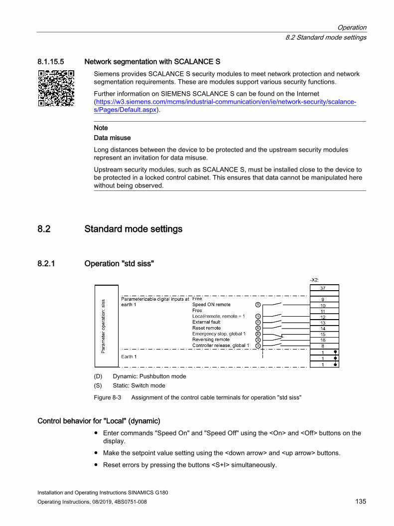
Operation 8.2 Standard mode settings
Installation and Operating Instructions SINAMICS G180 Operating Instructions, 08/2019, 4BS0751-008 135
8.1.15.5 Network segmentation with SCALANCE S Siemens provides SCALANCE S security modules to meet network protection and network segmentation requirements. These are modules support various security functions.
Further information on SIEMENS SCALANCE S can be found on the Internet (https://w3.siemens.com/mcms/industrial-communication/en/ie/network-security/scalance-s/Pages/Default.aspx).
Note Data misuse
Long distances between the device to be protected and the upstream security modules represent an invitation for data misuse.
Upstream security modules, such as SCALANCE S, must be installed close to the device to be protected in a locked control cabinet. This ensures that data cannot be manipulated here without being observed.
8.2 Standard mode settings
8.2.1 Operation "std siss"
(D) Dynamic: Pushbutton mode (S) Static: Switch mode
Figure 8-3 Assignment of the control cable terminals for operation "std siss"
Control behavior for "Local" (dynamic) ● Enter commands "Speed On" and "Speed Off" using the <On> and <Off> buttons on the
display.
● Make the setpoint value setting using the <down arrow> and <up arrow> buttons.
● Reset errors by pressing the buttons <S+I> simultaneously.

Operation 8.2 Standard mode settings
Installation and Operating Instructions SINAMICS G180 136 Operating Instructions, 08/2019, 4BS0751-008
Control behavior for "Remote" (static) ● Control the operation of "Speed on" using a switch at -X2:10.
● Enter the setpoint via control cable terminal block -X2 with analog setpoint value 1.
● When required use the reversing input -X2:16.
"Local" and "Remote" operation ● "Emergency stop (NC)": If you open the contact at -X2:15, the drive decelerates down to
0 speed along the braking ramp for an emergency stop. The inverter clears all self-holding (latching) functions.
● "Reset" (NO): Reset errors and "Emergency stop" using a 24 V pulse at -X2:14.
● "Controller release, static" (NC) -X2:8: Enable the inverter using a permanent contact. The drive coasts to a stop if you open the contact. The inverter clears all self-holding (latching) functions.
8.2.2 Operation "std sisd"
(D) Dynamic: Pushbutton mode (S) Static: Switch mode
Figure 8-4 Assignment of the control cable terminals for operation of "std sisd"
Operation different from "std siss" The operation "Speed On" for "Remote" operation is dynamic.
Start the drive with an NO (normally open) contact at -X2:11. You change the inverter speed to 0 with an NC (normally closed) contact at -X2:10.

Operation 8.2 Standard mode settings
Installation and Operating Instructions SINAMICS G180 Operating Instructions, 08/2019, 4BS0751-008 137
8.2.3 Operation "std dids"
(D) Dynamic: Pushbutton mode (S) Static: Switch mode
Figure 8-5 Assignment of the control cable terminals for operation "std dids"
Control behavior for "Local" (dynamic) ● Enter the command "Speed On" and "Speed Off" using the <On> and <Off> buttons on
the display.
● Make the setpoint value setting using the <down arrow> and <up arrow> buttons.
● Reset errors by pressing the buttons <S+I> simultaneously.
Control behavior for "Remote" (static) ● Control the operation of "Speed on" using a switch at -X2:10. Enter the setpoint via
control cable terminal block -X2 with analog setpoint value 1.
● When required use the reversing input -X2:16.
"Local" and "Remote" operation ● "Emergency stop (NC)": If you open the contact at -X2:15, the drive decelerates down to
0 speed along the braking ramp for an emergency stop. The inverter clears all self-holding (latching) functions.
● "Reset" (NO): Reset errors and "Emergency stop" using a 24 V pulse at -X2:14.
● "Controller release dynamic": Enable the inverter using a normally open contact at -X2:9. The drive coasts to a stop if you open the contact at -X2:8. The inverter clears all self-holding (latching) functions.

Operation 8.3 NAMUR mode settings
Installation and Operating Instructions SINAMICS G180 138 Operating Instructions, 08/2019, 4BS0751-008
8.2.4 Operation "std didd"
(D) Dynamic: Pushbutton mode (S) Static: Switch mode
Figure 8-6 Assignment of the control cable terminals for operation "std didd"
Operation different from "std dids" The operation "Speed On" for "Remote" operation is dynamic.
Start the drive with an NO (normally open) contact at -X2:11. Change the inverter speed to 0 with an NC (normally closed) contact at -X2:10.
8.3 NAMUR mode settings
8.3.1 Operation according to NAMUR defaults If you activate the control cable terminal -X2:9 with 24 V, then the operation source and the setpoint input are switched from "Test" to "Normal" using a parameter switch.
You can connect the up and down buttons of a motor potentiometer function to control cable terminals -X2:12 and -X2:13. If you wish to use the motor potentiometer, under "P-PARAMETER SWITCH/P-ParamSwitch 11/AV" set the alternative value to "MPoti". The motor potentiometer function is now valid in "Normal" operation and not valid in test operation.
"Reset" (NO): Reset faults and "Emerg. stop" using a 24 V pulse at -X2:14

Operation 8.3 NAMUR mode settings
Installation and Operating Instructions SINAMICS G180 Operating Instructions, 08/2019, 4BS0751-008 139
8.3.2 Operation according to "Namur 1"
(D) Dynamic: Pushbutton mode (S) Static: Switch mode
Figure 8-7 Assignment of the control cable terminals for operation "Namur 1"
Control behavior for "test" (dynamic) ● Enter the command "Controller release" and "CTRL.OFF" using the <On> and <Off>
buttons on the display.
● Make the setpoint value setting using the <down arrow> and <up arrow> buttons.
● Reset errors by pressing the buttons <S+I> simultaneously. The locking and the OUT input on the control cable terminal block reset the control.
Control behavior for "normal" (static) ● Control the operation of the controller release with a switch (NO) at -X2:10. Enter the
setpoint via control cable terminal block -X2 with analog setpoint value 1.
● When required use the reversing input (NO) -X2:16.
"Test" and "Normal" operation ● "Interlocking" (NC): The controller inhibit is activated if you open the contact at -X2:15.
The drive coasts to a stop and cannot be restarted. "Interlocking" is shown on the inverter display.
● "Off" (NC): You activate the controller inhibit if you remove the 24 V signal at -X2:11.

Operation 8.3 NAMUR mode settings
Installation and Operating Instructions SINAMICS G180 140 Operating Instructions, 08/2019, 4BS0751-008
8.3.3 Operation according to "Namur 2"
(D) Dynamic: Pushbutton mode (S) Static: Switch mode
Figure 8-8 Assignment of the control cable terminals for operation "Namur 2"
Operation different than "Namur 1" The operation of the controller inhibit for "Normal" operation is dynamic.
● Start the drive with an NO (normally open) contact at -X2:10.
● You inhibit the inverter with a normally closed contact at -X2:11.

Operation 8.3 NAMUR mode settings
Installation and Operating Instructions SINAMICS G180 Operating Instructions, 08/2019, 4BS0751-008 141
8.3.4 Operation according to "Namur 3"
(D) Dynamic: Pushbutton mode (S) Static: Switch mode
Figure 8-9 Assignment of the control cable terminals for operation "Namur 3"
Control behavior for "test" (dynamic) ● Enter the commands "Speed On" and "Speed Off" using the <On> and <Off> buttons on
the display.
● Make the setpoint value setting using the <down arrow> and <up arrow> buttons.
● Reset errors by pressing the buttons <S+I> simultaneously. The locking and the OUT input on the control cable terminal block reset the control.
Control behavior for "normal" (static) ● Control the operation of the speed with a switch (NO) at -X2:10. Enter the setpoint via
control cable terminal block -X2 with analog setpoint value 1.
● When required use the reversing input (NO) -X2:16.
"Test" and "Normal" operation ● "Interlocking" (NC): The controller inhibit is activated if you open the contact at -X2:15.
The drive coasts to a stop and cannot be restarted. "Interlocking" is shown on the inverter display.
● "Off" (NC): You issue the command for "Speed Off" if you remove the 24 V signal at -X2:10.

Operation 8.3 NAMUR mode settings
Installation and Operating Instructions SINAMICS G180 142 Operating Instructions, 08/2019, 4BS0751-008
8.3.5 Operation according to "Namur 4"
(D) Dynamic: Pushbutton mode (S) Static: Switch mode
Figure 8-10 Assignment of the control cable terminals for operation "Namur 4"
Operation different than "Namur 3" The operation "Speed On" for "Normal" operation is dynamic.
● Start the drive with a normally open contact at -X2:10.
● Issue the command "Speed Off" using an NC contact at -X2:11.

Operation 8.3 NAMUR mode settings
Installation and Operating Instructions SINAMICS G180 Operating Instructions, 08/2019, 4BS0751-008 143
8.3.6 Operation according to "Namur 5"
(D) Dynamic, button mode (S) Static, switch mode
Figure 8-11 Assignment of the control cable terminals for operation "Namur 5"
Control behavior for "test" (dynamic) ● Enter the commands "Speed On" and "Speed Off" using the <On> and <Off> buttons on
the display.
● Make the setpoint value setting using the <down arrow> and <up arrow> buttons.
● Reset errors by pressing the buttons <S+I> simultaneously.
Control behavior for "normal" (static) ● Control the operation of the speed with a switch (NO) at -X2:10. Enter the setpoint via
control cable terminal block -X2 with analog setpoint value 1.
● When required use the reversing input (NO) -X2:16.
"Test" and "Normal" operation ● "Interlocking" (NC): The controller inhibit is activated if you open the contact at -X2:15.
The drive coasts to a stop and cannot be restarted. "Interlocking" is shown on the inverter display. If the contact is closed again, you must restart the inverter in the test mode.
● "Off" (NC): You issue the command for "Speed Off" if you remove the 24 V signal at -X2:10.
● If you close the contact "Interlocking" or "Off" again during the braking phase, the drive accelerates immediately to the set setpoint value.

Operation 8.3 NAMUR mode settings
Installation and Operating Instructions SINAMICS G180 144 Operating Instructions, 08/2019, 4BS0751-008
8.3.7 Operation according to "Namur 6"
(D) Dynamic: Pushbutton mode (S) Static: Switch mode
Figure 8-12 Assignment of the control cable terminals for operation "Namur 6"
Operation different than "Namur 5" The operation "Speed On" for "Normal" operation is dynamic.
● Start the drive with a normally open contact at -X2:10.
● Issue the command "Speed Off" using an NC contact at -X2:11.

Operation 8.4 Controlling the external connections of the inverter
Installation and Operating Instructions SINAMICS G180 Operating Instructions, 08/2019, 4BS0751-008 145
8.4 Controlling the external connections of the inverter
8.4.1 Function of the control cable terminals
Figure 8-13 Control cable terminals
The control cable terminals are used to connect control cables for exchanging signals. For more detailed information about the function of control cable terminals, refer to Chapter "Standard mode settings (Page 135)". The function of the control cable terminals, with the exception of input -X2:8 for hardware shutdown, is dependent on the parameterization.
8.4.2 Protective separation according to EN 61800-5-1
WARNING
High voltages
If you connect peripheral devices which do not conform to this insulation concept, equipment damage might occur as a result of inadequate insulation. This can result in death, serious injury or material damage.
Connect devices and cables to the control cable terminals only if they conform to the relevant voltage class (DVC) described in this section.

Operation 8.4 Controlling the external connections of the inverter
Installation and Operating Instructions SINAMICS G180 146 Operating Instructions, 08/2019, 4BS0751-008
Control and power circuits have protective separation between them according to EN 61800-5-1. The following graphics show the principle structure:
Figure 8-14 Overview of external connections and voltage classes

Operation 8.4 Controlling the external connections of the inverter
Installation and Operating Instructions SINAMICS G180 Operating Instructions, 08/2019, 4BS0751-008 147
① Potential for output (PTC) (-X3) max. 690 V DVC C ② Potential for digital outputs (-X2:37-42) max. 250 V DVC C
Potential for digital outputs (-X2:30,31) max. 250 V DVC C Potential for digital outputs (-X2:32,33) max. 250 V DVC C Potential for digital outputs (-X2:34-36) max. 250 V DVC C Potential for digital outputs (-X2:43-45) max. 250 V DVC C Potential for digital outputs (-X2:46-47) max. 250 V DVC C Potential for digital outputs (-X2:48-49) max. 250 V DVC C
③ Potential for digital inputs (-X2:1-26) DVC A Potential for ETV (ETV = input isolating amplifier, analog inputs -X2:27-29,50-58, HTL tachometer -X101)
DVC A
Potential for ATV (output isolating amplifier, analog outputs -X2:60-67,70-71) DVC A Potential for control electronics/CB08 (inverter electronics, ext. Display -X26, sin/cos-tacho -X25, USB-B -X50B)
DVC A
Potential for RS485 (ext. display/RS232 -X51) DVC A ④ Potential SELV, safety extra-low voltage in accordance with EN 60950-1 (BUS
circuit boards) DVC A
Figure 8-15 Insulation concept
DVC (Decisive Voltage Class) is the classification of the voltage range used to determine protective measures against electric shock hazards
Table 8- 2 Limit values of the DVC according to EN 61800-5-1
DVC Working voltage limits
Alternating voltage (rms value)
Alternating voltage (peak value)
Direct voltage (average value)
A 25 V 35,4 V 60 V B 50 V 71 V 120 V C 1.000 V 4.500 V 1.500 V D > 1.000 V > 4.500 V > 1.500 V
See Chapter "Technical data of the control cable terminals (Page 201)" for more detailed information on the control cable terminals.

Operation 8.4 Controlling the external connections of the inverter
Installation and Operating Instructions SINAMICS G180 148 Operating Instructions, 08/2019, 4BS0751-008
8.4.3 Sub-D and USB connections and DIL switches The following illustration clarifies the position of the Sub-D connections and DIL switches.
① S1.1 … S1.4: Hardware setting ② -X25: SIN-COS/TTL speed encoder ③ -X50B: USB for PC with software "IMS": ④ -X51: RS 485 for an external operator panel. In addition, it is also possible to communicate at
this interface via RS 232, e.g. with "IMS". ⑤ -X101: HTL speed encoder ⑥ -X26: Additional RS 485 interface, not isolated. This is the standard interface for connecting the
external operator panel (for local installation in the cabinet door only).
Figure 8-16 Interfaces at the converter

Operation 8.4 Controlling the external connections of the inverter
Installation and Operating Instructions SINAMICS G180 Operating Instructions, 08/2019, 4BS0751-008 149
8.4.4 USB interface
CAUTION
Non-isolated USB interfaces
The USB interface -X50B is not electrically isolated. The connection of a grounded device can cause an equipment or converter defect and consequentially pose the risk of physical injury.
Devices that are connected, e.g. laptop with IMS, must have basic insulation between the USB interface and ground. In this case, the devices must offer this option, e.g. suitable for battery operation or the original power supply without ground connection.
NOTICE
No supply with a power source of limited output
When the connected device is overloaded, the USB interface can develop defects. The equipment will be damaged as a result.
The USB interface is a service interface only and not a general IT data interface in accordance with standard IEC/EN/UL 60950-1.
8.4.5 DIL switches "S1" and "S2"
Switch "S1"
Table 8- 3 Functions - DIL switch "S1"
Switch Function Factory setting S1:1 ON: configuration possible
OFF: parameterization blocked 1
S1:2 ON: general fault in the open-circuit principle, OFF: general fault in the closed-circuit principle, control cable terminals -X2:34 … 36
0
S1:3 ON: Complete initialization OFF:
0
S1:4 ON: flashing in conjunction with S1:3 = ON OFF:
0
Note Remote flashing
DIL switches S1:1 and S1:4 must be set to "ON" for remote flashing.

Operation 8.4 Controlling the external connections of the inverter
Installation and Operating Instructions SINAMICS G180 150 Operating Instructions, 08/2019, 4BS0751-008
Switch "S2"
① Gray cover ② -X26 for an external operator panel ③ Control cable terminal block -X2
Figure 8-17 DIL switch "S2"
The first four switches, S2: 1 / 2 / 3 / 4, define the voltage range for analog input 2, control cable terminal -X2:54:
Table 8- 4 DIL switch "S2" - can be used to set the voltage range
S2: 1 2 3 4 Voltage range -X2:54 0 0 0 1 0 V … ± 250 V 0 0 1 0 0 V … ± 132 V 0 1 0 0 0 V … ± 72 V 1 0 0 0 0 V … ± 50 V 0 0 0 0 0 V … ± 10 V
Switch S2: 5 / 6 / 7 configures the analog input AI 2 as a current/voltage input, PTC thermistor input, KTY84-130 input or PT100 input.
Table 8- 5 DIL switch "S2" - possible settings for AI 2
S2: 5 6 7 Function Control cable terminal 1 X 0 Current input -X2:53 - -X2:51 0 0 0 PTC thermistor input -X2:53 - -X2:51 0 1 0 KTY84 130 input -X2:53 - -X2:51 0 1 1 PT100 input -X2:53 - -X2:51 X X X Voltage input -X2:54 - -X2:51

Operation 8.4 Controlling the external connections of the inverter
Installation and Operating Instructions SINAMICS G180 Operating Instructions, 08/2019, 4BS0751-008 151
Switch S2: 8 / 9 / 10 configures the analog input AI 1 as a current/voltage input, PTC thermistor input, KTY84-130 input or PT100 input.
Table 8- 6 DIL switch "S2" - possible settings for AI 1
S2: 8 9 10 Function Control cable terminal 1 X 0 Current input -X2:50 - -X2:51 0 0 0 PTC thermistor input -X2:50 - -X2:51 0 1 0 KTY84 130 input -X2:50 - -X2:51 0 1 1 PT100 input -X2:50 - -X2:51 X X X Voltage input, only 0 V ... ± 10 V -X2:52 - -X2:51
8.4.6 Connecting encoders An encoder is required for field-oriented control only, the standard control works without an encoder.
Note Unwanted operating state
If you do not connect up the encoder cables correctly, the loss of the encoder signal can give rise to unwanted operating states in the inverter control system.
Connecting a sincos encoder to -X25 All encoder signals have a voltage level of 1 VSS.
The encoder connection on the motor side is designed as a socket. For this version, the manufacturer provides a complete encoder cable, e.g. ERN 387 from the company Heidenhain, Item No. 0278599 with a length of 10 meters. You can also purchase an adapter cable, Item No. 0278581. Contact to the inverter manufacturer about other encoder cables.
The encoder is connected at the inverter using a socket connector.
● Only use this encoder for field-oriented control with a speed accuracy < 1 %.
● Connect the encoder mechanically rigid to the motor.

Operation 8.4 Controlling the external connections of the inverter
Installation and Operating Instructions SINAMICS G180 152 Operating Instructions, 08/2019, 4BS0751-008
● Do not place any gearbox between encoder and motor.
Figure 8-18 Sincos encoder at -X25
● Use twisted pair cables for the same encoder tracks, e.g. A + / A -.
● Connect the cable shields at both ends - at the encoder and inverter connectors.
Connecting a TTL encoder to -X25 All encoder signals have a voltage level compliant with RS 422.
A socket connector, high density is used to connect to the inverter.
● Only use this encoder for field-oriented control with a speed accuracy < 1 %.
● Connect the encoder mechanically rigid to the motor.
● Do not place any gearbox between encoder and motor.
Figure 8-19 TTL encoder at -X25
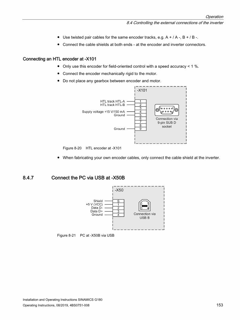
Operation 8.4 Controlling the external connections of the inverter
Installation and Operating Instructions SINAMICS G180 Operating Instructions, 08/2019, 4BS0751-008 153
● Use twisted pair cables for the same encoder tracks, e.g. A + / A -, B + / B -.
● Connect the cable shields at both ends - at the encoder and inverter connectors.
Connecting an HTL encoder at -X101 ● Only use this encoder for field-oriented control with a speed accuracy < 1 %.
● Connect the encoder mechanically rigid to the motor.
● Do not place any gearbox between encoder and motor.
Figure 8-20 HTL encoder at -X101
● When fabricating your own encoder cables, only connect the cable shield at the inverter.
8.4.7 Connect the PC via USB at -X50B
Figure 8-21 PC at -X50B via USB

Operation 8.4 Controlling the external connections of the inverter
Installation and Operating Instructions SINAMICS G180 154 Operating Instructions, 08/2019, 4BS0751-008
Connect USB socket -X50B to a USB port of your notebook. Use a standard cable that is not longer than 3 m.
CAUTION
Personal injury caused by a defective device or inverter
When connecting-up, carefully observe the information provided in Chapters "USB interface (Page 149)" and "Protective separation according to EN 61800-5-1 (Page 145)".
The version of the installed IMS software must be "Z24" or higher. The USB connection feature is not available in earlier versions.
In menu "Options/drivers", select the USB driver.
8.4.8 Connecting a PC to -X51 via RS 232
Figure 8-22 PC at -X51 via RS 232
NOTICE
Damage to the inverter electronics or the PC
The pins of socket -X51 are assigned signals other than those shown here. Do not use a standard cable that is completely assigned as otherwise the inverter electronics or the PC could be damaged. Only use cables where only the required pins are assigned.
Further information about connecting PC and inverter, etc. can be found in the help in the software "IMS".
● Connect the cable shield at both sides on the Sub-D housing.

Operation 8.4 Controlling the external connections of the inverter
Installation and Operating Instructions SINAMICS G180 Operating Instructions, 08/2019, 4BS0751-008 155
If you want to use the "IMS" software to change the inverter parameters, the parameter "P-INTERFACE/Para-Source" must be set to "Global" or "RS485". "Global" is the default setting.
● Using the "IMS" software, configure which COM port the cable on the PC will be connected to.
– The default setting is COM1.
● Select the configuration under "Options/Drivers/RS232-485-Driver".
8.4.9 Connection for optional external display with RS 485 You have the option of connecting an external display at -X51 or at -X26. The connection assignment for an external display with RS 485 is shown in the following diagrams.
Figure 8-23 External display connected at -X51
In order to be able to issue commands via an external display connected at -X51 to the inverter, set the corresponding command source in the parameter assignment to "RS 485".
Figure 8-24 External display connected at -X26
The -X26 interface is only suitable for an external display, for instance installed in the cabinet door.
In order to be able to issue commands via an external display connected at -X26 to the inverter, set the corresponding command source in the parameter assignment to "internal".

Operation 8.5 Special functions
Installation and Operating Instructions SINAMICS G180 156 Operating Instructions, 08/2019, 4BS0751-008
8.5 Special functions
8.5.1 Protective functions
Main contactor If you install a main contactor in your application, this can be controlled using the inverter software.
In this case, the coil is controlled via a digital output. Feedback from the normally open contact of the main contactor is realized via digital input -X2:8.
You can provide the main contactor on the mains power side, NS in short, or on the motor side, MS in short. Parameter "P-INV. BEHAVIOUR/MCfunc" specifies when the main contactor is switched and where the main contactor must be installed.
Example: Shutdown only in the case of an error, installation on the mains power or motor side.
The following settings are possible:
Table 8- 7 Contactor functions for different parameters
The protection is ON for ... "MCfunc" "Fault" "OFF 1" "Controller release"
no internal controller voltage
"Speed On" no internal speed off
"LinC no fault" No - - - "LinC rdy.f.op" No No - - "LinC rel.f.op" No No Yes - "LineC operat." No No Yes Yes "MotC no fault" No - - - "MotC rdy.f.op" No No - - "MotC rel.f.op" No No Yes - "MotC operat." No No Yes Yes

Operation 8.5 Special functions
Installation and Operating Instructions SINAMICS G180 Operating Instructions, 08/2019, 4BS0751-008 157
Line contactor The inverter controls its own line contactor. Note that the supply voltage for the control electronics is tapped before the main contactor. You can find additional information in Chapter "Connecting the external 230 V AC for compact devices (Page 111)". Perform the wiring in accordance with the following plan:
Figure 8-25 Line contactor function

Operation 8.5 Special functions
Installation and Operating Instructions SINAMICS G180 158 Operating Instructions, 08/2019, 4BS0751-008
Table 8- 8 Line contactor functions
Terminal / compo-nent
Function
-F1 External control voltage fuse protection -F2 Inverter power unit fuse protection -K1 Input side main contactor
Design recommendation: AC1 current of the contactor is at least the inverter input current 101, 102 External control voltage for the 230 V inverter 41, 42 Digital output for the main contactor control U1, V1, W1 Mains power connection switched via main contactor 8 Main contactor feedback input 55 24 V DC supply voltage 1, 51 Jumper for ground connection U2, V2, W2 Motor connection
NOTICE
Coil currents in excess of 1 A at contact 41/42
If you load the contact 41/42 with coil currents of more than 1 A, the contact can be destroyed.
In the case of coil currents of more than 1 A, connect an auxiliary relay between terminal 41/42 and the main contactor coil.
Make the following settings in order to activate the main contactor function:
● The preselection for the inputs/outputs for the control must be as follows:
– "P-DRIVE DATA/A = Namur" or
– "P-DIGITAL OUTPUTS/Relay 2 = main contactor" and "P-OPERATION/Cont. feedback = X2:8"
● For "P-INV. BEHAVIOUR/MCfunc" the setting "LinC…" must be entered.

Operation 8.5 Special functions
Installation and Operating Instructions SINAMICS G180 Operating Instructions, 08/2019, 4BS0751-008 159
Motor contactor The inverter controls the contactor at the inverter output.
● Perform the activation as for the line contactor.
● Different than for the line contactor, for "P-INV. BEHAVIOUR/MCfunc" as value select the parameters that have "MS" as prefix for motor contactor.
● Dimension the output side contactor according to the AC3 current.
● Perform the wiring in accordance with the following plan:
Figure 8-26 Motor contactor function

Operation 8.5 Special functions
Installation and Operating Instructions SINAMICS G180 160 Operating Instructions, 08/2019, 4BS0751-008
Table 8- 9 Motor contactor functions
Terminal / component Function -K11 Output side main contactor
Design recommendation: AC3 current of the contactor is at least the inverter output current
41, 42 Digital output for the main contactor control U1,V1,W1 Mains connection 8 Main contactor feedback input 55 24 V DC supply voltage 1 und 51 Jumper for ground connection U2, V2, W2 Motor connection
8.5.2 Multiple function of the analog and digital inputs
Analog inputs 1 and 2 The analog inputs have several functions:
● Under "P-ANALOG INPUTS/Analog input 1/AI-function", you can set the value from "Analog" to "PTC", "KTY84" or "PT100".
● Under "P-ANALOG INPUTS/Analog input 2/AI-function" you can set analog input 2 from "Analog" to "PTC", "KTY84" or "PT100".
● Also adjust the corresponding DIL switches of the -S2 switch row on board CB08
● You can find more detailed information in Chapter "DIL switches "S1" and "S2" (Page 149)".
The following functions are now available: ● "Analog":
The analog input operates as a voltage input at control cable terminals -X2:52-51 / 54-51 or as a current input at control cable terminals -X2:50-51 / 53-51 The value is available as "AI 1" or "AI 2" for further processing.
● "PTC": The analog input operates as a PTC thermistor input at control cable terminals -X2:50-51 / 53-51. The PTC thermistor state is available for further processing as selection bit "PTC AI 1" or " PTC AI 2".
● "KTY84": The analog input operates as a direct input for a KTY84-130 temperature sensor at control cable terminals -X2:50-51 / 53-51. The measured temperature is available as an analog value under "T-AI1" or "T-AI 2" for further processing.
● "PT100": The analog input operates as a direct input for a PT100 temperature sensor at control cable terminals -X2:50-51 / 53-51. The measured temperature is available as an analog value under "T-AI1" or "T-AI 2" for further processing.
Any analog input can only be used for one function. It is not possible to use several functions simultaneously for one input.

Operation 8.5 Special functions
Installation and Operating Instructions SINAMICS G180 Operating Instructions, 08/2019, 4BS0751-008 161
Digital inputs -X2:27 and -X2:28 as PTC thermistor inputs The digital inputs are interpreted as a normal digital input for control with a 24 V signal. If these control cable terminals are wired to 10 V potential using a PTC thermistor sensor, these function automatically as PTC thermistor monitoring inputs. The selection bits "PTC X2:27" and "PTC X2:28" indicate the PTC thermistor status. However, do this it is mandatory that you have set parameter "P-PULSE INPUT/Mode = inactive".
NOTICE
Unsuitable evaluation unit
The inverter can be damaged if the PTC thermistor for explosion proof motors or for safe isolation is not evaluated using an ATEX-certified, safely isolated evaluation unit or the peripherals board.
Use an ATEX-certified, safely isolated evaluation unit or the peripherals board for safe operation.
Digital inputs -X2:27, -X2:28 and -X2:29 as frequency or tachometer inputs These digital inputs can be used as a frequency or tachometer input, for example, in the following way.
● The field-oriented control at input -X25 / -X101 is not possible, e.g. if the n-sensor is installed on the machine and there is a gearbox between machine and motor.
● Only one simple proximity switch with e.g. four impulses per revolution is available. The resolution for the field-oriented regulation is too small in this case. It is suitable for displays or more precise speed regulation.
● You connect a frequency-dependent setpoint generator of the type used for mining applications, for example.
Example applications for the digital inputs as frequency inputs:
● Proximity switch with NAMUR output or with PNP-3 wire output
● Two-channel digital tachometer with HTL output
In order that you can use these inputs as frequency or tachometer input, you must select the required evaluation function using parameter "P-PULSE INPUT/Mode". Independent of the selected evaluation function, as a result, inputs -X2:27 to :29 are assigned, and are no longer available as digital inputs. The digital input bits in the bit pool X2:27, X2:28 and X2:29 are connected to a fixed value of "0". Likewise, the bits in the bit pool for the PTC evaluation "PTC X2:27" and "PTC X2:28" are connected to 0. These can no longer be used. Possible warnings and faults that are obtained that can be parameterized, for example "MotorWindingTemp." must be resolved by making the appropriate parameter change, e.g. setting to "inactive".

Operation 8.5 Special functions
Installation and Operating Instructions SINAMICS G180 162 Operating Instructions, 08/2019, 4BS0751-008
Proximity switch with NAMUR output or with PNP-3 wire output
Figure 8-27 PNP speed sensor
Figure 8-28 NAMUR speed sensor
Assumption: sensor produces four impulses per revolution for four-pole motor, nmax = 1500 rpm.
Note the following:
This speed is available for further processing as "Tacho act" from 0 rpm to 1500 rpm and as "Pulse act" from 0 % to 100 %.
● Connection according to connection diagram. You must connect the tachometer signal at terminal -X2:27. You must keep terminal -X2:28 free, and control terminal -X2:29 with 24 V (e.g. jumper from -X2:29 to -X2:55) for an evaluation as 1-track tachometer or as frequency evaluation. Bit pool bits "X2:27" to "X2:29", "PTC X2:27" and "PTC X2:28" are permanently set to "0".
● Parameterize the following:
– At f ≠ 20 kHz: 1500 rpm / 60 s × 4 pulses = 100 Hz.
Select the following values for the respective parameters:
Table 8- 10 parameter setting for speed sensor
Parameter Value "P-PULSE INPUT/Mode" "Tacho 1-track" "P-PULSE INPUT/Max-plse." "1,500 rpm" "P-PULSE INPUT/Pulses/360" "4"

Operation 8.5 Special functions
Installation and Operating Instructions SINAMICS G180 Operating Instructions, 08/2019, 4BS0751-008 163
Set the following parameters if a frequency value is needed for the further processing:
Table 8- 11 parameter setting for speed sensor with frequency value
Parameter Value "P-PULSE INPUT/Mode" "f < 20 kHz" "P-PULSE INPUT/Max-plse." "100 Hz" "P-PULSE INPUT/Pulses/360" "4"
The frequency is available for further processing as "Freq.act." from 0 Hz to 100 Hz and as "Pulse act" from 0 % to 100 %.
NPN sensors cannot be used.
Two-channel digital tachometer with HTL output
Figure 8-29 Digital tachometer, two-channel, HTL level
Assumption: digital tachometer produces 1,024 impulses per revolution for four-pole motor, nmax = 1500 rpm
Note the following:
● Connection according to connection diagram. You must keep input -X2:29 free. Bit pool bits "X2:27" to "X2:29", "PTC X2:27" and "PTC X2:28" are permanently set to 0.
● Check the frequency in the range from 20 kHz to 205 kHz: 1500 rpm / 60 s × 1024 impulses = 25.6 kHz
Select the following values for the respective parameters:
Table 8- 12 parameter setting for digital tachometer
Parameter Value "P-PULSE INPUT/Mode" "Tacho 2-track" "P-PULSE INPUT/Max-plse." "1,500 rpm" "P-PULSE INPUT/Pulses/360" "1,024"
The speed is available for further processing as "Tacho act" from 0 rpm to 1500 rpm and as "Pulse act" from 0 % to 100 %.
Operation 8.6 Setpoint channel and closed-loop control
Installation and Operating Instructions SINAMICS G180 164 Operating Instructions, 08/2019, 4BS0751-008
Set the following values for the respective parameters if a frequency value is needed for the further processing:
Table 8- 13 parameter setting for digital tachometer with frequency value
Parameter Value "P-PULSE INPUT/Mode" "f > 20 kHz" "P-PULSE INPUT/Max-plse." "25,600 Hz" "P-PULSE INPUT/Pulses/360" "1024"
The frequency is available for further processing as "Freq.act." from 0 Hz to 25.6 kHz and as "Pulse act" from 0 % to 100 %.
8.6 Setpoint channel and closed-loop control
8.6.1 Specifying source for speed setpoint Specify under "P-SPEED DEFAULT/n Set source" the setpoint source to which the inverter must respond, e.g. including:
● "Internal" using <up arrow> or <down arrow> of the display
● "AI 1" via analog input 1 of the control terminal block -X2
● "BUS 1" as control word via the optional fieldbus connection
8.7 Parameterization
8.7.1 Principle of operation of the configuration
NOTICE
Incorrect parameter settings
The inverter and other connected components can be damaged or destroyed if the parameter settings are incorrect.
Only qualified personnel may change parameters; the instructions in the Operating Manual and the technical data of the inverter and connected components must be carefully observed.
Parameterization is based on the principle - Input → Processing → Output. Many functions in plain text are available in the bit pool for the input. You always have the selection from the bit
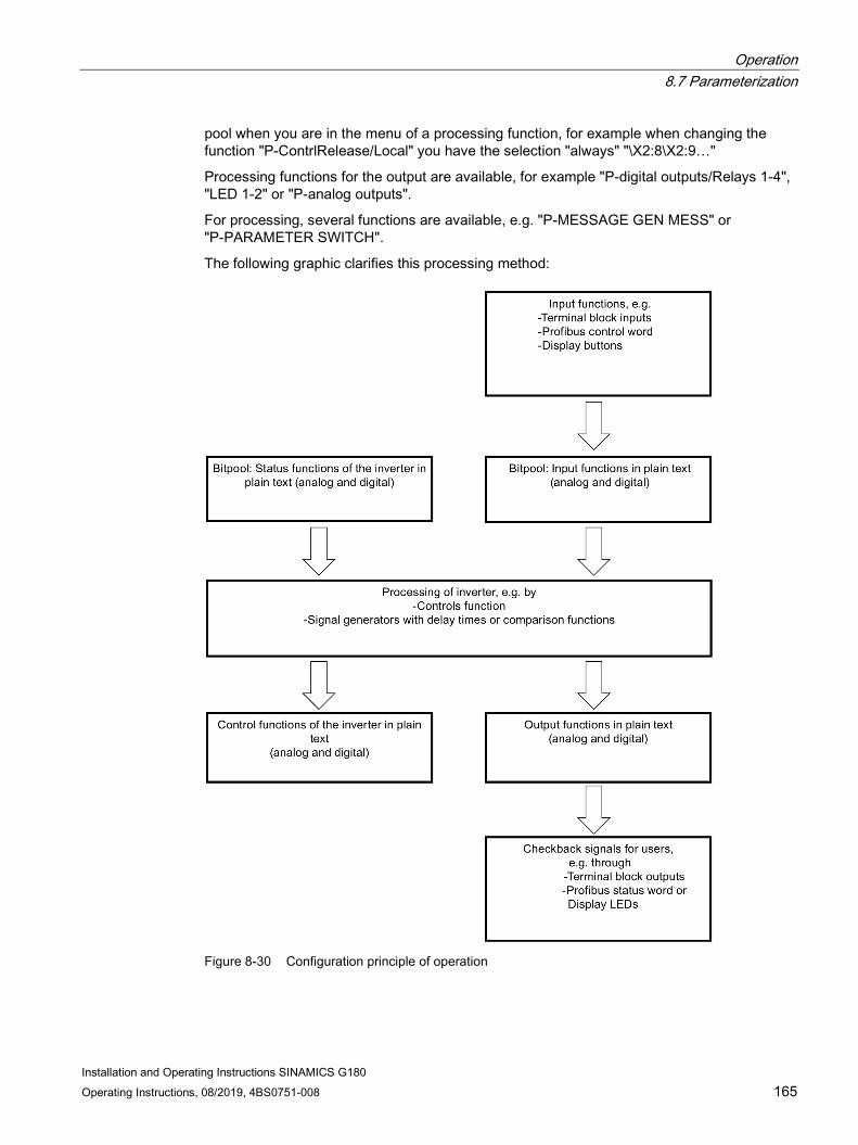
Operation 8.7 Parameterization
Installation and Operating Instructions SINAMICS G180 Operating Instructions, 08/2019, 4BS0751-008 165
pool when you are in the menu of a processing function, for example when changing the function "P-ContrlRelease/Local" you have the selection "always" "\X2:8\X2:9…"
Processing functions for the output are available, for example "P-digital outputs/Relays 1-4", "LED 1-2" or "P-analog outputs".
For processing, several functions are available, e.g. "P-MESSAGE GEN MESS" or "P-PARAMETER SWITCH".
The following graphic clarifies this processing method:
Figure 8-30 Configuration principle of operation

Operation 8.7 Parameterization
Installation and Operating Instructions SINAMICS G180 166 Operating Instructions, 08/2019, 4BS0751-008
8.7.2 Protecting parameters against modification
WARNING
Undesirable machine response
The machine can respond undesirably as a result of incorrect or modified parameterization of the inverter. This can result in death, serious injury or material damage. • Protect the parameterization (parameter assignments) against unauthorized access. • Read and carefully follow the instructions in this document and all of the relevant
documents. • If necessary, contact our Service Center (Page 189).
You can configure all parameters of the inverter in the delivery state using the internal control panel or via an RS 232 connection to a PC running the "IMS" software.
If you would like that the inverter should only be configured from one location, you can set this under "P-INTERFACE/Para-source".
If you would like to no longer allow any parameter changes, you must set the DIL switch S1.1 to "Off". The precise position of this DIL switch is described in Chapter "Sub-D and USB connections and DIL switches (Page 148)".
8.7.3 Configuration using the inverter display 1. You reach the configuration menu by pressing the button <P>. The display "P-DRIVE
DATA" is shown in the first line.
2. Individual menu items can be selected using <up arrow> and <down arrow>. For example, you reach "P-INTERFACE" using the <down arrow>.
3. When "P-DRIVE DATA" is displayed, press <Return> in order to display the submenu of "P-DRIVE DATA". The first parameter of "P-DRIVE DATA" "fmin" is shown in the second line.
4. If you again press <Return>, then in the 2nd line a black bar is displayed between the parameter name and value. This means that the parameter is unlocked, and you can enter a new value for the parameter using <Arrow up> or <Arrow down>.
5. If you press <Return> again, then the black bar disappears again. This indicates that the parameter is again locked. Some parameters are accepted with the lock; others are already accepted when the value is changed.
6. Press <Arrow up> or <Arrow down> to reach other parameters or submenus. Press <Return> to reach submenus. Press <P> to go one level higher in the menu structure.
You can then use the same principle of operation in any other menu.

Operation 8.7 Parameterization
Installation and Operating Instructions SINAMICS G180 Operating Instructions, 08/2019, 4BS0751-008 167
8.7.4 More documentation about parameterization You can find further documentation relating to parameterization on the Internet at www.siemens.com (http://www.siemens.com)

Operation 8.8 Examples / Applications
Installation and Operating Instructions SINAMICS G180 168 Operating Instructions, 08/2019, 4BS0751-008
8.8 Examples / Applications
8.8.1 "Standard" application
8.8.1.1 Standard control cable terminals

Operation 8.8 Examples / Applications
Installation and Operating Instructions SINAMICS G180 Operating Instructions, 08/2019, 4BS0751-008 169
① Global = functional for "Local" and "Remote" ② If you use these inputs, remove the jumper. ③ As long as "P-INTERFACE/Reset-Source" is set to "Global", all reset sources are always effective. ④ Max. current load of the control voltages:
• +24 V DC, potential 2: 300 mA • +15 V DC, potential 2: 150 mA ±10 mA This voltage can supply a speed encoder connected at terminal -X101.
⑤ Remove both these jumpers if you are using peripheral boards 3 / 4. The supply is realized via -X2:1/3.
Figure 8-31 Control cable terminals for the "Standard" application
8.8.1.2 Control cable terminals "peripheral board 1"
Figure 8-32 Control cable terminals for the "peripheral board 1" option
8.8.1.3 Control cable terminals "peripheral board 2"
① PTC inputs, suitable for motors in hazardous zones or non-hazardous zones ③ Remove the 100 Ω resistor if these control cable terminals are in use.
Figure 8-33 Control cable terminals for the "peripheral board 2" option

Operation 8.8 Examples / Applications
Installation and Operating Instructions SINAMICS G180 170 Operating Instructions, 08/2019, 4BS0751-008
8.8.1.4 Control cable terminals "peripheral board 3"
② Remove the jumper if these control cable terminals are in use. ④ -X2:3: Four-way distribution terminal for 24 V, -X2:17, 18: Not assigned ⑤ In the case of an equipped peripheral board 3 / 4, the supply of the digital inputs -X2:8 … 16 is changed over. The
digital inputs are supplied from -X2:1/3 instead of -X2:51/55.
Figure 8-34 Control cable terminals for the "peripheral board 3" option

Operation 8.8 Examples / Applications
Installation and Operating Instructions SINAMICS G180 Operating Instructions, 08/2019, 4BS0751-008 171
8.8.1.5 Control cable terminals "peripheral board 4"
① PTC inputs, suitable for motors in hazardous zones or non-hazardous zones ② Remove the jumper if these control cable terminals are in use. ③ Remove the 100 Ω resistor if these control cable terminals are in use. ④ -X2:3: Four-way distribution terminal for 24 V, -X2:17, 18: Not assigned ⑤ In the case of an equipped peripheral board 3 / 4, the supply of the digital inputs -X2:8 … 16 is changed over. The
digital inputs are supplied from -X2:1/3 instead of -X2:51/55.
Figure 8-35 Control cable terminals for the "peripheral board 4" option
8.8.1.6 Operation setting for the "Standard" application The mode setting for the "Standard" application is "siss". You can find more detailed information in Chapter "Standard mode settings (Page 135)".

Operation 8.8 Examples / Applications
Installation and Operating Instructions SINAMICS G180 172 Operating Instructions, 08/2019, 4BS0751-008
8.8.1.7 Assignment of the digital inputs Terminal -X2:13 External fault input. In the case of actuation with 24 V, this results in an error shut-
down with storage. Terminal -X2:29 External warning. In the case of actuation with 24 V, this results in a warning without
storage. Terminal -X2:27 Connect a motor PTC thermistor for the motor monitoring here. If the sensor is trig-
gered, a "Motor overtemperature " shutdown is performed, which is stored. You can find more detailed information in Chapter "Multiple function of the analog and digital inputs (Page 160)". In the case of the "peripheral board 2 / 4" option, connect the PTC thermistor connector to the peripheral board.
Terminal -X2:28 Connect another motor PTC thermistor for the motor monitoring here. If the sensor responds, then a warning is issued with "!! Prewarning !! Motor overtemperature" is output, which is not stored. You can find more detailed information in Chapter "Multiple function of the analog and digital inputs (Page 160)". In the case of the "peripheral board 2 / 4" option, connect the PTC thermistor connector to the periph-eral board.
In the case of the "peripheral board 3 / 4" option
The digital inputs are set to inactive and can thus be freely used for other configura-tions.
8.8.1.8 Assignment of the digital outputs Relay 1, terminal -X2:37, 38, 39 The "Ready" message as changeover contact in the open-circuit principle is available
here. Ready for operation means that the inverter has no faults and the DC link is precharged.
Relay 2, terminal -X2:41, 42 The message "Working" is output here. Relay 3, terminal -X2:30, 31 All warnings which are generated in board CB08 are signaled here in the open-circuit
principle. Example: The message "!! Prewarning !! Inverter overtemp." Relay 4, terminal -X2:32, 33 - Relay outputs, terminal -X2:34, 35, 36
Inverter fault All faults which cause the inverter to shut down are signaled here with a changeover contact in the closed-circuit principle.
In the case of the "peripheral board 3 / 4" option, terminals -X2:43 … 49
Messages "PTC X3:90", "X2:9" and "Speed zero" are active.
8.8.1.9 Assignment of the analog inputs ● Analog input one, terminal -X2:50, 51, 52:
– You apply your speed setpoint to these terminals which is effective in the "Remote" mode.
– You can use the terminal 50 as current input or the terminal 52 as voltage input. The terminal 51 is the ground connection.
– The input ranges from 0 mA to 20 mA or from 0 V to 10 V is proportional to the output frequency from 0 Hz to 50 Hz.
● Analog input two, terminal -X2:53 and -X2:54:
– Equivalent, additional analog input.
Operation 8.8 Examples / Applications
Installation and Operating Instructions SINAMICS G180 Operating Instructions, 08/2019, 4BS0751-008 173
8.8.1.10 Assignment of the analog outputs ● Isolated terminal -X2:62, 63:
An output signal of 4 mA to 20 mA is present here. This corresponds to a motor current from zero up to a unit-dependent value.
● Isolated terminal -X2:60, 61: This output provides a speed signal. A value from 4 mA to 20 mA is set as default value. This corresponds to a motor speed from 0 to 1500 rpm.
● Terminal -X2:64, 67: For the "peripheral board 1 ... 4" option, the torque and the power are available at these terminals. A value from 4 mA to 20 mA is set as default value. The corresponding value as real variable depends on the power and is stored in the software "IMS".
8.8.1.11 Input "Safe torque off" / PTC thermistor inputs on peripheral board ● Terminal -X2:19/:20:
These terminals are dedicated for triggering the "Safe torque off" function. This input is jumpered in the default setting. If you wish to use the "Safe torque off" function, then you must remove this jumper and connect an NC contact of the switching element that triggers the function.
● Terminal -X2:24
This terminal can be configured as a second trigger circuit for the "Safe torque off" function. The DIP-FIX switch (bail switch) -S3 on the peripheral board determines whether the "Safe torque off" function is controlled through one or two circuits. -S3 closed means through two circuits. To use this input as second circuit for the "Safe torque off" function, you must connect terminal -X2:24 with -X2:3 using an NC contact of the appropriate switching element.
● Terminal -X3:90/:91:
This input is used for motor temperature monitoring certified according to ATEX. If you wish to use this monitoring function, then you must remove the existing resistor and connect the appropriate motor PTC thermistor.
NOTICE
Peripheral board 2 or 4 is required for monitoring
The monitoring function is only available if the required peripheral board 2 or peripheral board 4 is inserted in the SINAMICS G180 If the peripheral board 1 or peripheral board 3 is installed, then although the terminals are available, there is no evaluation. There is no monitoring.

Operation 8.8 Examples / Applications
Installation and Operating Instructions SINAMICS G180 174 Operating Instructions, 08/2019, 4BS0751-008
● Terminal -X3:92/:93:
This input is used as prewarning for the motor temperature monitoring. If you wish to use this function, then you must remove the existing resistor, and connect the appropriate prewarning motor PTC thermistor.
NOTICE
Peripheral board 2 or 4 is required for monitoring
The monitoring function is only available if the required peripheral board 2 or peripheral board 4 is inserted in the SINAMICS G180 If the peripheral board 1 or peripheral board 3 is installed, then although the terminals are available, there is no evaluation. There is no monitoring.
Detailed information More detailed information is provided in Chapter "Peripheral boards 1 to 4, -A95, option G02 to G05 (Page 37)".

Operation 8.8 Examples / Applications
Installation and Operating Instructions SINAMICS G180 Operating Instructions, 08/2019, 4BS0751-008 175
8.8.2 "Namur" application
8.8.2.1 Control cable terminals for the "Namur" application

Operation 8.8 Examples / Applications
Installation and Operating Instructions SINAMICS G180 176 Operating Instructions, 08/2019, 4BS0751-008
① "Global" = functional for "Test" and "Normal" ② If you use these inputs, remove the jumper. ③ As long as "P-INTERFACE/Reset-Source" is set to "Global", all reset sources are always effective. ④ Max. current load of the control voltages:
• + 24 V DC, potential 2: 300 mA • + 15 V DC, potential 2: 150 mA ± 10 mA This voltage can also supply a speed encoder connected at terminal -X101.
Figure 8-36 Control cable terminals for the "Namur" application
8.8.2.2 Control cable terminals "peripheral board 4"
NOTICE
Non-compliance with NAMUR guideline NE-37
The NAMUR guideline NE-37 is only completely implemented with the "peripheral board 4" option.

Operation 8.8 Examples / Applications
Installation and Operating Instructions SINAMICS G180 Operating Instructions, 08/2019, 4BS0751-008 177
① PTC inputs, suitable for motors in the Ex-zone or Non-Ex-Zone ② If you use these inputs, remove the jumper. ③ If you use these inputs, remove the 100 Ω resistor. ④ -X2:3: Four-way distribution terminal for 24 V, -X2:17, 18: For Emergency Off input ⑤ In the case of equipped peripheral board 3 / 4, the supply of the digital inputs -X2:8 to 16 is changed over. The
digital inputs are now supplied from -X2:1/3 instead of -X2:51/55.
Figure 8-37 Control cable terminals for "peripheral board 4" application
This application fulfills the requirements concerning the terminal assignment and the inverter functions which have been developed by the "Normengemeinschaft für Mess- und Regelungstechnik", in short NAMUR. These specifications can be found in the NAMUR NE37 guideline.
Perform the wiring of the terminal block in accordance with the terminal plan. Remove the factory-installed jumpers according to the "Standard" application if the respective application requires this.

Operation 8.8 Examples / Applications
Installation and Operating Instructions SINAMICS G180 178 Operating Instructions, 08/2019, 4BS0751-008
8.8.2.3 Operation setting of the "Namur" application The mode setting for the NAMUR application is "Namur 1". Refer to Chapter "NAMUR mode settings (Page 138)" for more detailed information.
8.8.2.4 Assignment of the relay outputs ● Terminal -X2:41, 42:
You can control the main contactor using these terminals. The main contactor function is not activated in the software for the NAMUR application. More detailed information is provided in Chapter "Protective functions (Page 156)".
● Terminal -X2:37, 39: All warnings which are acquired in board CB08 are signaled here with a changeover contact in the open-circuit principle, e.g. message "!! Prewarning !! Inverter overtemp.".
● Terminal -X2:30, 31: The "Rdy.f.work" message as normally open contact is available here. Rdy.f.work means that the inverter has no faults and the DC link is pre-charged.
● Terminal -X2:32, 33: The contact closes if the motor is turning.
● Terminal -X2:34 … 36: "Inverter fault" All faults which cause the inverter to shut down are signaled here with a changeover contact in the closed-circuit principle.
● Terminal -X2:43 … 49: In the case of the "peripheral board 4" option: then messages "PTC X3:90", "X2:9" and "Speed zero" are active here.

Operation 8.8 Examples / Applications
Installation and Operating Instructions SINAMICS G180 Operating Instructions, 08/2019, 4BS0751-008 179
8.8.2.5 Assignment of the analog inputs ● Terminal: -X2:50 ... 52:
– Apply the speed setpoint which is active in normal operation to these terminals.
– You can use the terminal 50 as current input or the terminal 52 as voltage input. The terminal 51 is the ground connection.
– The input ranges from 0 mA to 20 mA or from 0 V to 10 V is proportional to the output frequency from 0 Hz to 50 Hz.
● Terminal: -X2:53, 54:
– The signal for the speed actual value feedback can be supplied to this input. The values 0 mA to 20 mA at terminal 53 and 0 V to 10 V or up to 180 V at terminal 54 are preset.
– You can connect an analog motor tachometer to these terminals.
– More detailed information is provided in Chapter "DIL switches "S1" and "S2" (Page 149)".
– You can use the signal in the software for limit value comparisons or as display.
8.8.2.6 Assignment of the analog outputs ● Isolated terminal -X2:62, 63:
An output signal of 4 mA to 20 mA is present here. This corresponds to a motor current from zero up to a unit-dependent value.
● Isolated terminal -X2:60, 61: This output provides a speed signal. A value from 4 mA to 20 mA is set as default value. This corresponds to a motor speed from 0 up to 1500 rpm.
● Option "Peripheral board 4": The torque and power are available at terminals -X2:64 … 67. A value from 4 mA to 20 mA is set as default value. The corresponding value as real variable depends on the power and is stored in the software "IMS".
8.8.2.7 Input "Mandatory mains power isolation" / PTC thermistor inputs on peripheral board More detailed information is provided in Chapter "Peripheral boards 1 to 4, -A95, option G02 to G05 (Page 37)".

Operation 8.8 Examples / Applications
Installation and Operating Instructions SINAMICS G180 180 Operating Instructions, 08/2019, 4BS0751-008

Installation and Operating Instructions SINAMICS G180 Operating Instructions, 08/2019, 4BS0751-008 181
Maintenance 9 9.1 Maintenance and servicing
For your personal safety and in order to prevent material damage it is essential that you carefully follow the instructions provided in Chapter "Safety information (Page 13)", especially Chapter "Notes for operator protection (Page 16)", and all safety-related instructions in your product documentation. Pay particular attention to the safety notices on the product itself.
There is an appropriate maintenance schedule for each device type. We recommended that maintenance is carried out at least once per year. For further information, please contact the Service Center, see "Service & Support" (Page 189).
Retighten all screw connections at regular intervals. Depending on utilization, the installed fans each have a service life of between 5 and 10 years. The service life of the lithium battery on the board CB08 is 10 years. The electrolyte capacitors are designed for a service life of 20 years.
● Service the device after 5 years in accordance with a specified maintenance schedule.
● Check and clean the equipment and air filter mats (if present) depending on the accumulation of dust.

Maintenance 9.2 Replacing compact device
Installation and Operating Instructions SINAMICS G180 182 Operating Instructions, 08/2019, 4BS0751-008
9.2 Replacing compact device
Procedure Proceed as follows if a compact device must be replaced completely:
① Screws - device replacement ② Screws - fan replacement
Figure 9-1 Bottom view of compact device
1. Undo the device replacement screws on the outside.
2. Unscrew the cover at the front.
3. Slacken both the nuts of the cable entry plate in the upper connection space near the cover.
4. Disconnect the power cables.
5. Unplug the controller wiring connector.
6. Release the fastener on the mounting plate by only slackening the screws at the bottom.
7. Lift the inverter upward so that the cabling remains with the cable entry plate.
8. Install the new inverter in inverse sequence.
Observe the instructions for transporting inverters in Chapter "Transporting inverter (Page 71)".

Maintenance 9.3 Replacing fans for the compact device
Installation and Operating Instructions SINAMICS G180 Operating Instructions, 08/2019, 4BS0751-008 183
9.3 Replacing fans for the compact device
Procedure All internal inverter fans are mounted in the lower section of the inverter. Proceed as follows when removing:
1. Release the screws; wide inverters have more screws than narrow inverters.
2. Withdraw the complete fan plate downward. The fan is connected using a connector.
3. Replace the defective fan on the fan plate that has been removed.
4. Mount again in the inverse sequence.
9.4 Maintenance and service of water cooling (option)
Visual inspection As part of the inspection of the complete system, Siemens recommends that the water cooling parts are visually inspected every 6 months and a leakage check performed.
Perform the following checks on an annual basis:
● Check that all of the hose clamps and valve connections that can be accessed are securely seated.
● Perform a visual inspection of the hoses (where these are visible) for tears, cracks or other damage.
We expect an average lifetime of 10 years for the hoses when the specified environmental conditions are complied with. Values must be taken from the documentation.
You can find further information in the documentation 4BS0698 AL for water cooling systems.
9.5 Decommissioning The device components used have no PCB and BeO.
Dispose of the equipment in accordance with the applicable regulations and also with respect to electrolyte capacitors.
If you want to decommission a device, please contact the Service Center.

Maintenance 9.5 Decommissioning
Installation and Operating Instructions SINAMICS G180 184 Operating Instructions, 08/2019, 4BS0751-008

Installation and Operating Instructions SINAMICS G180 Operating Instructions, 08/2019, 4BS0751-008 185
Spare parts 10 10.1 Non-approved spare parts
Damage due to non-authorized spare parts Using non-approved spare parts can affect the function of the equipment and damage it. Third-party spare parts and unapproved spare parts may not meet the requirements.
● Only use spare parts that have been approved by the manufacturer.
10.2 Spare parts To request spare parts, please contact the Siemens sales office responsible for your region. You can find an overview of the Siemens contact partners in your region here (Page 189).
Always indicate the part number and - if known - the order number of the spare part required.
You can find the order number as follows:
● The device label is attached to or next to each component. Find out which item code the required spare part has. The parts list provided specify the part number and, where appropriate, the article number corresponding to the equipment identifier.
● For inquiries by email, send a photo of the product, spare part and nameplate if possible.
Use Spares on Web (www.siemens.com/sow) to obtain ordering information about spare parts.

Spare parts 10.2 Spare parts
Installation and Operating Instructions SINAMICS G180 186 Operating Instructions, 08/2019, 4BS0751-008

Installation and Operating Instructions SINAMICS G180 Operating Instructions, 08/2019, 4BS0751-008 187
Diagnostics, faults and warnings 11
For your personal safety and in order to prevent material damage it is essential that you carefully follow the instructions provided in Chapter "Safety information (Page 13)", and especially Chapter "Notes for operator protection (Page 16)". Comply with all safety-related instructions in your product documentation. Pay particular attention to the safety notices on the product itself.
Every inverter is subject to individual inspection and warm up at the factory. Therefore, errors in the device during the initial commissioning can be almost ruled out. In most cases, faults usually originate from the peripherals such as incorrect wiring or missing agreement for the respective application.
The most frequent causes of errors during the initial commissioning are shown below:
Table 11- 1 Error causes and rectification
Errors Possible causes Fault rectification All three LEDs on the display, i.e. "READY", "RUN" and "FAULT" are off (dark).
There is no voltage at the inverter.
Measure the control voltage at -X5 (see the order-specific customer documentation)
LED "READY" is lit. LEDs "RUN" and "FAULT" are off (dark) The inverter cannot be started.
The On command does not arrive.
Trace the path to the inverter.
The On command you se-lected is not preselected.
Check the parameter assignment.
- Has the "Local" or "Remote" option been configured correctly?
LED "RUN" is lit. LEDs "READY" and "FAULT" are off (dark) The inverter / motor does not oper-ate satisfactorily.
- Have you commissioned the drive system as de-scribed in Chapter "Commissioning (Page 115)"?
- Perform the "Auto-Tuning" again.
LED "FAULT" is lit. LEDs "READY" and "RUN" are off (dark)
- The error message is shown on the display in plain text. You can also invoke the event log. You can find additional information in Chapter "Reading event log (Page 188)". Siemens provides a list with all messages which are shown on the display and possible remedies on the Internet.

Diagnostics, faults and warnings 11.1 Reading event log
Installation and Operating Instructions SINAMICS G180 188 Operating Instructions, 08/2019, 4BS0751-008
11.1 Reading event log If a fault occurs, the event log of the inverter stores the following data:
● Which error has occurred?
● With parallel-connected inverters: In which system has the fault occurred?
● Data and time of the error event
● Various actual values such as, e.g. setpoint, motor current, motor voltage, motor frequency etc.
These data are stored for the last 64 errors. The event number 01 is the most recent error.
Procedure Read the event log using the "IMS" software.
You can also read these data on the display. Proceed as follows:
1. Press <I> and then the <down arrow> until "I-MEMORY" is shown on the screen.
2. Press <Return> to go to the first event, e.g. "I-MEMORY/01:Flt>undervoltage". When you press <Return> again, then you can see all of the data saved for this event.
3. Press <S> to return.
Read out all data of the last event using the software "IMS" before you contact the Service Center for assistance with an error message. In this way, you significantly simplify the error localization.

Installation and Operating Instructions SINAMICS G180 Operating Instructions, 08/2019, 4BS0751-008 189
Service & Support A
Technical questions or additional information
If you have any technical queries or you require additional information, please contact Technical Support (https://support.industry.siemens.com/cs/sc?nId=2090&lc=en-WW). Please have the following data ready: • Type • Serial number You can find this data on the rating plate.
Contact person
If you wish to request on-site service or order spare parts, please contact your local office. This office will contact the responsible service center on your behalf. You can find your contact person in the relevant contact da-tabase: www.siemens.com/yourcontact (www.siemens.com/yourcontact)

Service & Support A.1 Contacts in Ruhstorf an der Rott location (Germany)
Installation and Operating Instructions SINAMICS G180 190 Operating Instructions, 08/2019, 4BS0751-008
A.1 Contacts in Ruhstorf an der Rott location (Germany) Siemens AG
Hans-Loher-Straße 32 94099 Ruhstorf
Germany
+49 8531 39 554 24-hour hotline: +49 8531 39 222 0.06 €/min. from land lines of the German Telekom, mobile phone prices may differ).
+49 8531 39 569
Technical support: [email protected] Spare parts: [email protected] Repair: [email protected]
Spare parts on the Internet:
Spares on Web (www.siemens.com/sow)

Installation and Operating Instructions SINAMICS G180 Operating Instructions, 08/2019, 4BS0751-008 191
Quality documents B
You can find the quality documents here:
Siemens Industry Online Support (SIOS) (https://support.industry.siemens.com/cs/ww/en/ps/13228/cert)

Quality documents
Installation and Operating Instructions SINAMICS G180 192 Operating Instructions, 08/2019, 4BS0751-008

Installation and Operating Instructions SINAMICS G180 Operating Instructions, 08/2019, 4BS0751-008 193
Technical data C
Read the technical data of this device on the rating plate.
Compact units with the type designation 2T?A-0… up to 2T?A-3… have two rating plates. One of these is on the outside of the left side panel and the other is on the inside of the left side panel.
In the case of cabinet units, the rating plate is in the cabinet in which the display is installed. You can see the rating plate on the top left after opening the cabinet door.
You can find additional technical data of the inverter in the Internet with the Configurator for drive technology (https://eb.automation.siemens.com/goos/catalog/Pages/ProductData.aspx?regionUrl=/de&tree=CatalogTree&nodeid=10028832&autoOpenConfigId=7&kmat=SD&autoopen=false&language=en&activetab=#topAnch&activetab=config&) .
You can also find the "DT Configurator" here (www.siemens.com) using the search function.
Other lists and instructions The following descriptions can be downloaded from the website of the manufacturer:
● Operating instructions
● Parameterization instructions
● Message text on the display, for example error messages
● Inverter Management Software (IMS)
● GSD files for PROFIBUS and PROFINET
C.1 Conformity The SINAMICS G180 meets the requirements of the following directives:
● EMC Directive No. 2014/30/EU
● Machinery Directive 2006/42/EC
● RoHS 2 Directive No. 2011/65/EU
The CE declaration of conformity for the SINAMICS G180 is issued in line with these directives.

Technical data C.2 Technical data for transportation
Installation and Operating Instructions SINAMICS G180 194 Operating Instructions, 08/2019, 4BS0751-008
C.2 Technical data for transportation Carefully observe the following environmental conditions for transport according to EN 60721-3-2:
Environmental conditions when transporting the inverter Climatic conditions Class 2K3 acc. to EN 60721-3-2 Atmospheric pressure 700 mbar … 1060 mbar, corresponds to max. 3000 m above sea level Ambient temperature - 25 °C … + 70 °C Humidity rating Maximum relative humidity if the temperature of the inverter slowly increases by
40 K: 95 % Maximum relative humidity if the device is brought immediately from - 25 °C to + 30 °C: 95 % Maximum absolute humidity if the device is brought immediately from + 70 °C to + 15 °C: 60 g/m3
Mechanical conditions Class 2M2 according to EN 60721-3-2 Vibration load - Deflection - Acceleration
3.1 mm at 5 ... 9 Hz 10 m/s² at 9 ... 200 Hz
Shock load - Acceleration
100 m/s² at 11 ms
Chemical conditions Class 2C2 according to EN 60721-3-2 Biological conditions Class 2B1 according to EN 60721-3-2
C.3 Technical data for storage Carefully observe the following environmental conditions for storage according to EN 60721-3-1:
Environmental conditions when storing the inverter Climatic conditions Class 1K4 acc. to EN 60721-3-1 for the temperature
Class 1K3 acc. to EN 60721-3-1 for the relative humidity Atmospheric pressure 860 mbar … 1060 mbar, corresponds to max. 1000 m above sea level Ambient temperature - 25 °C … + 70 °C Humidity rating 5 % … 95 %, 1 g/m³ … 29 g/m³ Mechanical conditions Class 1M2 according to EN 60721-3-1 Vibration load - Deflection - Acceleration
1.5 mm at 5 ... 9 Hz 5 m/s² at 9 ... 200 Hz
Shock load - Acceleration
40 m/s² at 22 ms
Environmental class/ Chemical conditions
Class 1C2 according to EN 60721-3-1
Organic/biological conditions Class 1B1 according to EN 60721-3-1

Technical data C.4 Technical data for operation
Installation and Operating Instructions SINAMICS G180 Operating Instructions, 08/2019, 4BS0751-008 195
C.4 Technical data for operation Make sure that the following environmental conditions for operation are fulfilled.
The inverters are designed for indoor installation.
● Class 3K3 environmental conditions in accordance with EN 60721
● Pollution degree 2
● Overvoltage category 3
● Degree of protection IP20 for compact units
● Degree of protection IP21 for cabinet units
Environmental conditions when operating the inverter Climatic conditions Class 3K3 according to EN 60721-3-3 Atmospheric pressure 860 mbar … 1060 mbar, corresponds to max. 1000 m above sea level 1) Ambient temperature 0 °C … + 40 °C 1) Humidity rating 5 % … 95 %, 1 g/m³ … 25 g/m³ Mechanical conditions Class 3M4 acc. to EN 60721-3-3 Vibration load - Deflection - Acceleration
0.075 mm at 10 ... 58 Hz 10 m/s² at 58 ... 200 Hz
Shock load - Acceleration
100 m/s² at 11 ms
Chemical conditions Class 3C2 according to EN 60721-3-3 Biological conditions Class 3B1 according to EN 60721-3-3 1) The units can be operated under different environmental conditions if derating is applied.
For further information, refer to Chapter "Derating (Page 206)". For further technical data, refer to the technical data sheet.
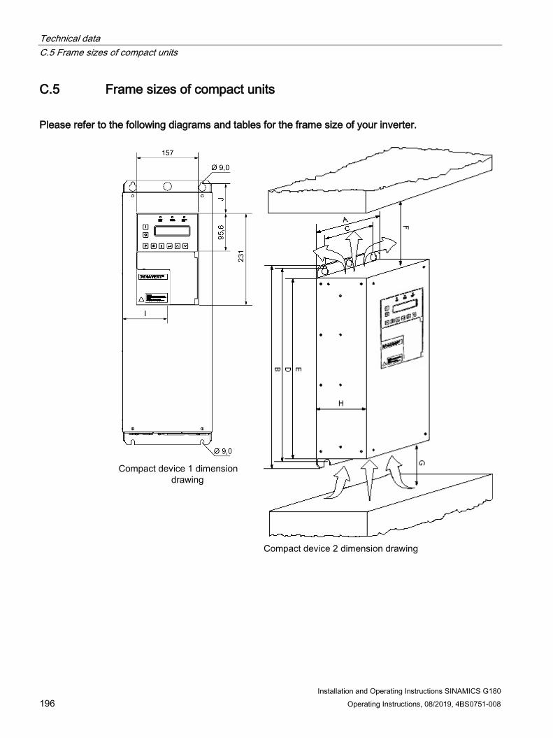
Technical data C.5 Frame sizes of compact units
Installation and Operating Instructions SINAMICS G180 196 Operating Instructions, 08/2019, 4BS0751-008
C.5 Frame sizes of compact units
Please refer to the following diagrams and tables for the frame size of your inverter.
Compact device 1 dimension
drawing
Compact device 2 dimension drawing

Technical data C.5 Frame sizes of compact units
Installation and Operating Instructions SINAMICS G180 Operating Instructions, 08/2019, 4BS0751-008 197
Table C- 1 Dimensions of the different inverters in mm
Inverter type A B C D E F1) G2) H I J BG3) 2T2A-07400-002 … 2T2A-07400-005 2T2A-07500-002 … 2T2A-07500-007
165 465 125 450 410 100 200 320 82.5 22.5 BG K1
2T2A-07400-007 … 2T2A-07400-011 2T2A-07500-011 … 2T2A-07500-015
165 565 125 550 510 100 200 320 82.5 22.5 BG K2
2T2A-07400-015 … 2T2A-07400-030 2T2A-07500-022 … 2T2A-07500-037 2T2A-07600-007 2T2A-07600-011 2T2A-07600-015 2T2A-07600-022
225 665 175 650 610 100 200 320 112.5 75 BG K3
2T2A-07400-037 … 2T2A-07400-055 2T2A-07500-045 … 2T2A-07500-075 2T2A-07600-030 … 2T2A-07600-075
350 775 300 750 710 100 200 320 255 70 BG K4
2T2A-07400-075 … 2T2A-07400-110 2T2A-07500-090 … 2T2A-07500-132 2T2A-07600-090 … 2T2A-07600-132
350 1,125 300 1,100 1,060 100 200 320 255 70 BG K5
2T2A-27400-075 … 2T2A-27400-110 2T2A-27500-090 … 2T2A-27500-132 2T2A-27600-090 … 2T2A-27600-132
350 1,538 300 1,490 1,460 100 200 345 255 70 BG K51
2T2A-07400-132 … 2T2A-07400-160 2T2A-07500-160 … 2T2A-07500-200 2T2A-07600-160 … 2T2A-07600-200
500 1,125 400 1,100 1,060 100 200 320 405 70 BG K6
1) F = cooling air discharge area: Do not block this area. 2) G = cooling air intake area: Do not block this area. 3) BG = frame size

Technical data C.6 Frame sizes of cabinet units
Installation and Operating Instructions SINAMICS G180 198 Operating Instructions, 08/2019, 4BS0751-008
C.6 Frame sizes of cabinet units
Please refer to the following table for the frame size of your converter.
Table C- 2 Converter types and associated frame sizes
Converter type Frame size 2R3A-87400-030 … 2R3A-87600-030 FS S1 2T3A-87401-200 … 2T3A-87401-315 2T3A-87501-250 … 2T3A-87501-400 2T3A-87601-250 … 2T3A-87601-400 2R3A-87400-055 … 2R3A-87600-055
FS S2
2T3A-87401-400 2T3A-87501-500 2T3A-87601-500
FS S21
2T3A-87401-500 … 2T3A-87401-630 2T3A-87501-560 … 2T3A-87501-800 2T3A-87601-560 … 2T3A-87601-910
FS S3
The corresponding dimension drawings can be found in the following illustrations.
Figure C-1 Dimension drawing FS S1

Technical data C.6 Frame sizes of cabinet units
Installation and Operating Instructions SINAMICS G180 Operating Instructions, 08/2019, 4BS0751-008 199
Figure C-2 Dimension drawing FS S2
Figure C-3 Dimension drawing FS S21

Technical data C.6 Frame sizes of cabinet units
Installation and Operating Instructions SINAMICS G180 200 Operating Instructions, 08/2019, 4BS0751-008
Figure C-4 Dimension drawing FS S3

Technical data C.7 Tightening torques for power cables
Installation and Operating Instructions SINAMICS G180 Operating Instructions, 08/2019, 4BS0751-008 201
C.7 Tightening torques for power cables Please refer to the table below for the torques for tightening power cable connections.
Observe the information in Chapter "Electrical connection (Page 91)".
Table C- 3 Tightening torques for terminal and lug connections
Terminal UK6N, 8.2 mm wide
Terminal UK35, 15.2 mm wide
M6 M8 M10 M12 M16
1.5 … 1.8 Nm 3.2 … 3.7 Nm 9 Nm 22 Nm 44 Nm 75 Nm 106 Nm
Table C- 4 Tightening torques for switch and contactor connections
M3 / 3.5 M4 M6 M8 M10 M12 1.2 Nm 1.8 Nm 4 Nm 6 Nm 20 Nm 45 Nm
C.8 Technical data of the control cable terminals Red pins avoid mixing up the connectors. The control cable terminals are plug-in connections. You can unplug the plugged-in connections when disconnected from the power supply.
When selecting cables and conductors and installing them, it is essential that you observe the information provided in Chapter "Connecting control cable (Page 93)" and "Protective separation according to EN 61800-5-1 (Page 145)".
The control cable terminals are color-coded:
● The green terminals on the far left contain all relay outputs and the optocoupler inputs at a separate potential.
● The black terminals contain the potential-free analog inputs and digital inputs which are electrically separated the same as the analog inputs.
● The white terminals contain the electrically separated analog outputs.
All external voltages can be connected together for controlling a PCS or PLC. To do this, jumper the ground terminals -X2:1 with -X2:51 and -X2:51 with -X2:71.
If you control the inverter using different devices, potential displacements occur which depend on the cable length used. Remove the jumpers for longer cables.

Technical data C.8 Technical data of the control cable terminals
Installation and Operating Instructions SINAMICS G180 202 Operating Instructions, 08/2019, 4BS0751-008
Technical data of the control cable terminals Conductor cross-section –X2 rigid / flexible: 0.5 mm² … 2.5 mm² Relay outputs -X2:30 … 42 5 V … 250 V AC / 1 A, 15 AC
5 V … 30 V DC / 1 A > 30 V … 60 V DC / 120 mA > 60 V … 250 V DC / 60 mA
With peripheral board 3 or 4 only: Relay outputs -X2:43 … 49
Minimum switching load: 12 V / 100 mA
Digital inputs -X2:8 ... 16 Low: -3 V … +5 V High: 13 V … 32 V Floating Typically 12 mA for High
Digital input safe torque off (only with peripheral board 3 or 4): -X2:20
Low: -3 V … +5 V High: 13 V … 32 V Floating Typically 12 mA for High Response time: ≤ 5 ms
Analog inputs -X2:50 … 53 Voltage input 0 V … ± 10 V, 200 kΩ Terminal 52 and 54 or current input 0 mA or 4 mA*) … ± 20 mA, 100 Ω, Terminals 50 and 53
Supply voltages on potential of the analog inputs for diverse sensors:
Terminal 55: 24 V DC, max. 300 mA Terminal 56: 15 V DC, max. 150 mA Terminal 57: 10 V DC, max. 10 mA Terminal 58: -10 V DC, max. 10 mA
Digital inputs –X2:27, 28 Low: -3 V … +5 V High: 13 V … 32 V Floating on potential of the analog inputs Typically 2.4 mA for High Direct connection of PTC thermistors Reference potential for PTC thermistor: Terminal -X2:58 (-10 V). The voltage over the PTC thermistor is approx. 2.5 V Can also be used as f or n input.
Digital input -X2:29 Low: -3 V … +5 V, high: 13 V … 32 V Floating on potential of the analog inputs, typically 2.4 mA for High Can also be used as f or n input
Analog outputs -X2:60 … 63 With automatic changeover current or voltage, floating: Load < 300 Ω: 0 mA or 4 mA*) … 20 mA Load > 1 kΩ: 0 V … 10 V
Supply voltages on potential of the analog outputs:
Terminal 70: 24 V DC, max. 300 mA
*) 0 mA or 4 mA can be parameterized.

Technical data C.9 Technical data and identification of the PTC thermistor input at peripheral boards 2 and 4
Installation and Operating Instructions SINAMICS G180 Operating Instructions, 08/2019, 4BS0751-008 203
C.9 Technical data and identification of the PTC thermistor input at peripheral boards 2 and 4
PTC thermistor input - Data Application For temperature monitoring of explosion-protected motors, type of protection "In-
creased safety" EX e according to DIN EN 50019 VDE 0170/0171 and "flameproof enclosure" Ex d according to DIN EN 50018 VDE 0170/0171 as well as normal mo-tors outside a hazardous zone
Identification EX II (2) G [Ex d] [Ex e] [Ex n] EX II (2) D [EX tb] [Ex tc]
maximum number of sensors 6 sensors according to DIN VDE 0660 Teil 303 OK state < 1.5 kΩ … 1.8 kΩ Overtemperature message > 3.2 kΩ … 3.8 kΩ Short-circuit in the sensor circuit < 15 Ω … 25 Ω Measuring circuit load < 5 mW for R = 1.5 kΩ Voltage in the sensor circuit < 2 V for R = 1.5 Ω Current in the sensor circuit < 1.5 mA for R = 1.5 kΩ Voltage for measuring sensor break
11.6 V
Current for short-circuited sensor circuit
1.45 mA
Response time ≤ 75 ms Electrical design Protective separation for 690 V to the other circuits according to EN 50178,
EN 61800-5-1
Maximum cable length for PTC thermistor sensor circuit: Cross-section 2.5 mm² 2 × 500 m Cross-section 1.5 mm² 2 × 300 m Cross-section 0.5 mm² 2 × 100 m
The PTC input can be used for monitoring motors in hazardous zones. It is not permissible that the inverter itself is installed in a hazardous zone.
The PTC thermistor evaluation function can be deactivated by an internal switch. For this reason, perform the test described in Chapter "PTC inputs for motor PTC thermistor (Page 47)". If the result of the test is negative, contact the Service Center for advice.

Technical data C.10 Technical data of the direct water cooling
Installation and Operating Instructions SINAMICS G180 204 Operating Instructions, 08/2019, 4BS0751-008
C.10 Technical data of the direct water cooling
Technical data
Inverter type Frame size 2T3A-77401-200 … 2T3A-77401-315 2T3A-77501-250 … 2T3A-77501-400 2T3A-77601-250 … 2T3A-77601-400
BG S2
2T3A-77401-400 2T3A-77501-500 2T3A-77601-500
BG S21
2T3A-77401-500 … 2T3A-77401-630 2T3A-77501-560 … 2T3A-77501-800 2T3A-77601-560 … 2T3A-77601-910
BG S3
If you connect several inverters in parallel, the technical data is multiplied according to the number of systems. The water flow rate for type 2T 6 A-7 5 69 4-925 with four inverter systems is e.g. 4×2000 l/h.
The water-cooled units BG S1 to BG S21 have the same cabinet width as the air-cooled units.
In the case of units with frame size S3, the cabinet width when compared to the air-cooled version increases as follows:
Increased cabinet width for water cooling Units with one system 200 mm Units with two or three systems 400 mm Units with four systems 600 mm
Water cooling - Ambient conditions Frame size BG S2, BG S21, BG S3 Degree of protection IP55
IP54 with operator panel in the door Water quality Industrial water, see Chapter "Permissible substance values for the cooling water
(Page 205)" Permissible coolant temperature +10 °C … +25 / 30°C (depends on the power, see inverter documentation) Permissible ambient temperature In operation: +1 °C … +55 °C
Water cooling - Water pressure and amount of water Frame size BG S2 BG S2/21 BG S3 Water flow rate [l/h] 720 1200 2000 Min. operating pressure [bar] 1 1 2.5 Max. operating pressure [bar] 6 6 6 Pressure loss [approx. bar] 0.5 0.7 1.4 Test pressure [bar] 10 10 10

Technical data C.11 Permissible substance values for the cooling water
Installation and Operating Instructions SINAMICS G180 Operating Instructions, 08/2019, 4BS0751-008 205
Water cooling - Connection hoses Frame size BG S2 BG S2/21 BG S3 Inlet DN "…^…" 13 ^ ½ " 13 ^ ½ " 19 ^ ¾ " Return DN "…^… 13 ^ ½ " 13 ^ ½ " 19 ^ ¾ " Venting DN "…^…" 13 ^ ½ " 13 ^ ½ " 13 ^ ½ " Cabinet height [mm] 2000 2200 2200
C.11 Permissible substance values for the cooling water
Permissible substance values for the cooling water (process water and de-ionized water) for inverter cooling with open standard cooling without a cooling system.
Material: Stainless steel, material number: 1.4301; 1.4571
Permissible values for stainless steel material Water temperature +10 ... +30 (+35) °C pH value 7 ... 8 Total hardness 6 ... 20 °dH Carbonate hardness 3 ... 10 °dH Total dissolved solids 105 °C < 500 mg / l Free carbon dioxide < 1 mmol / l Chlorides < 150 mg / l Sulfates 500 mg / l Nitrates < 10 mg / l Nitrites 0 mg / l Phosphates < 0.5 mg / l Ammonium NH4 < 0.5 mg / l Ammonia 0 mg / l Silicon (SiO2 crystalline) < 10 mg / l Free CO2 (p value) < 15 mg / l Iron < 0.2 mg / l Hydrogen sulfide < 1 mg / l Suspended solids < 50 μm < 10 mg / l Conductivity < 3000 µS/cm Oxygen 8 ... 12 mg / l

Technical data C.12 Threshold values for fan control system
Installation and Operating Instructions SINAMICS G180 206 Operating Instructions, 08/2019, 4BS0751-008
C.12 Threshold values for fan control system The fan control system detects the three following states: OFF, SLOW and FAST.
● OFF: The fans are OFF if the unit is not switching and all relevant temperatures are below the thresholds for FAST.
● SLOW: The fans operate slowly if the unit is turned on (= is switching) and all relevant temperatures are below the thresholds for FAST.
● FAST: The fans operate fast if one of the relevant temperatures is higher than the threshold for FAST irrespective of whether or not the unit is turned on.
Table C- 5 Threshold values for fan control system
Fan fast slow off Clock enable -- Yes No Parameter "P-INVERTER DATA/fan"
= fast = slow = T-contrl.
Reactor prewarning Yes No No "T-CPU" ≥ 70 °C ≤ 70 °C (-5 °C) ≤ 50 °C (-5 °C) "T-cabin. max" ≥ 47 °C ≤ 47 °C (-5 °C) ≤ 10 °C (-5 °C) "T-heat max" ≥ 50 °C ≤ 50 °C (-10 °C) ≤ 10 °C (-5 °C) "T-diff. max" ≥ 7 / 9 °C 1) ≤ 7 / 9 °C 1) (-2 °C) ≤ 7 / 9 °C 1) (-2 °C) "T-rectif. max" ≥ 55 °C ≤ 55 °C (-5 °C) ≤ 55 °C (-5 °C) 1) Air/water cooled
() Where relevant, values in brackets should be seen as switching hysteresis.
C.13 Derating
C.13.1 Current derating The devices and the associated system components are rated for an ambient temperature of 40 °C and installation altitudes of up to 1000 m above sea level.
The following tables specify the permissible output currents as a function of the installation altitude and ambient temperature.
Note also the information in Chapter "Voltage derating (Page 209)".
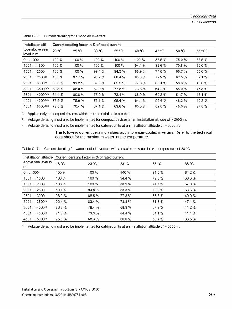
Technical data C.13 Derating
Installation and Operating Instructions SINAMICS G180 Operating Instructions, 08/2019, 4BS0751-008 207
Table C- 6 Current derating for air-cooled inverters
Installation alti-tude above sea level in m
Current derating factor in % of rated current
20 °C 25 °C 30 °C 35 °C 40 °C 45 °C 50 °C 55 °C1)
0 … 1000 100 % 100 % 100 % 100 % 100 % 87.5 % 75.0 % 62.5 % 1001 … 1500 100 % 100 % 100 % 100 % 94.4 % 82.6 % 70.8 % 59.0 % 1501 … 2000 100 % 100 % 99.4 % 94.3 % 88.9 % 77.8 % 66.7 % 55.6 % 2001 … 25002) 100 % 97.7 % 93.2 % 88.4 % 83.3 % 72.9 % 62.5 % 52.1 % 2501 … 30002) 95.3 % 91.2 % 87.0 % 82.5 % 77.8 % 68.1 % 58.3 % 48.6 % 3001 … 35002)3) 89.8 % 86.0 % 82.0 % 77.8 % 73.3 % 64.2 % 55.0 % 45.8 % 3501 … 40002)3) 84.4 % 80.8 % 77.0 % 73.1 % 68.9 % 60.3 % 51.7 % 43.1 % 4001 … 45002)3) 78.9 % 75.6 % 72.1 % 68.4 % 64.4 % 56.4 % 48.3 % 40.3 % 4501 … 50002)3) 73.5 % 70.4 % 67.1 % 63.6 % 60.0 % 52.5 % 45.0 % 37.5 % 1) Applies only to compact devices which are not installed in a cabinet
2) Voltage derating must also be implemented for compact devices at an installation altitude of > 2000 m. 3) Voltage derating must also be implemented for cabinet units at an installation altitude of > 3000 m.
The following current derating values apply to water-cooled inverters. Refer to the technical data sheet for the maximum water intake temperature.
Table C- 7 Current derating for water-cooled inverters with a maximum water intake temperature of 28 °C
Installation altitude above sea level in m
Current derating factor in % of rated current
18 °C 23 °C 28 °C 33 °C 38 °C
0 … 1000 100 % 100 % 100 % 84.0 % 64.2 % 1001 … 1500 100 % 100 % 94.4 % 79.3 % 60.6 % 1501 … 2000 100 % 100 % 88.9 % 74.7 % 57.0 % 2001 … 2500 100 % 94.8 % 83.3 % 70.0 % 53.5 % 2501 … 3000 98.0 % 88.5 % 77.8 % 65.3 % 49.9 % 3001 … 35001) 92.4 % 83.4 % 73.3 % 61.6 % 47.1 % 3501 … 40001) 86.8 % 78.4 % 68.9 % 57.9 % 44.2 % 4001 … 45001) 81.2 % 73.3 % 64.4 % 54.1 % 41.4 % 4501 … 50001) 75.6 % 68.3 % 60.0 % 50.4 % 38.5 % 1) Voltage derating must also be implemented for cabinet units at an installation altitude of > 3000 m.

Technical data C.13 Derating
Installation and Operating Instructions SINAMICS G180 208 Operating Instructions, 08/2019, 4BS0751-008
Table C- 8 Current derating for water-cooled inverters with a maximum water intake temperature of 30 °C
Installation altitude above sea level in m
Current derating factor in % of rated current
20 °C 25 °C 30 °C 35 °C 40 °C
0 … 1000 100 % 100 % 100 % 81.6 % 57.7 % 1001 … 1500 100 % 100 % 94.4 % 77.1 % 54.5 % 1501 … 2000 100 % 100 % 88.9 % 72.6 % 51.3 % 2001 … 2500 100 % 96.2 % 83.3 % 68.0 % 48.1 % 2501 … 3000 100 % 89.8 % 77.8 % 63.5 % 44.9 % 3001 … 35001) 94.7 % 84.7 % 73.3 % 59.9 % 42.3 % 3501 … 40001) 88.9 % 79.5 % 68.9 % 56.2 % 39.8 % 4001 … 45001) 83.2 % 74.4 % 64.4 % 52.6 % 37.2 % 4501 … 50001) 77.5 % 69.3 % 60.0 % 49.0 % 34.6 % 1) Voltage derating must also be implemented for cabinet units at an installation altitude of > 3000 m.
Table C- 9 Current derating for water-cooled inverters with a maximum water intake temperature of 35 °C
Installation altitude above sea level in m
Current derating factor in % of rated current
25 °C 30 °C 35 °C 40 °C 0 … 1000 100 % 100 % 100 % 70.7 % 1001 … 1500 100 % 100 % 94.4 % 66.8 % 1501 … 2000 100 % 100 % 88.9 % 62.9 % 2001 … 2500 100 % 100 % 83.3 % 58.9 % 2501 … 3000 100 % 95.3 % 77.8 % 55.0 % 3001 … 35001) 100 % 89.8 % 73.3 % 51.9 % 3501 … 40001) 97.4 % 84.4 % 68.9 % 48.7 % 4001 … 45001) 91.1 % 78.9 % 64.4 % 45.6 % 4501 … 50001) 84.9 % 73.5 % 60.0 % 42.4 % 1) Voltage derating must also be implemented for cabinet units at an installation altitude of > 3000 m.

Technical data C.13 Derating
Installation and Operating Instructions SINAMICS G180 Operating Instructions, 08/2019, 4BS0751-008 209
C.13.2 Voltage derating The compact units are designed according to minimum air clearances at up to 2000 m above sea level, and the cabinet units according to minimum air clearances at up to 3000 m above sea level. Derating is only required above altitudes of 2000 m respectively 3000 m above sea level (only applicable for the basic unit 1)).
Since the air clearances in the inverter cannot be changed, this factor must be taken into account in the voltage derating calculation.
Table C- 10 Voltage derating for compact units
Installation altitude above sea level in m Voltage derating factor in % of rated voltage 0 … 2000 100 % 2001 … 2500 93.4 % 2501 … 3000 87.7 % 3001 … 3500 81.9 % 3501 … 4000 77.5 % 4001 … 4500 71.9 % 4501 … 5000 67.6 %
Table C- 11 Voltage derating for cabinet units (is only applicable for the basic device 1))
Installation altitude above sea level in m Voltage derating factor in % of rated voltage 0 … 3000 100 % 3001 … 3500 93.9 % 3501 … 4000 88.5 % 4001 … 4500 82.4 % 4501 … 5000 77.0 %
1) When installing options, it is possible that the permissible installation altitude is further restricted, or a voltage derating results in a lower value. This must be checked on a case-by-case basis.

Technical data C.13 Derating
Installation and Operating Instructions SINAMICS G180 210 Operating Instructions, 08/2019, 4BS0751-008

Installation and Operating Instructions SINAMICS G180 Operating Instructions, 08/2019, 4BS0751-008 211
List of abbreviations D
ARM "Acorn Risc Machine": Microprocessor architecture ATEX "Atmosphère explosible": Synonym for the two EC explosion protection Directives: ATEX Product Directive
94/9/EC and ATEX Safety Directive 1999/92/EC ASM Induction machine BeO beryllium oxide: toxin. Relevant for the disposal BGR Health and safety at work regulations BGV Regulations of the German Trade Association CD "Compact Disc": Optical storage medium for digital storage of music and data. CB08 Control electronics board DASM Dual-fed induction machine DIL "Dual In-Line Package": Type of packaging (Package) for electronic components DSP Digital signal processor DVC "Decisive Voltage Class": Classification of the voltage range used to determine protective measures against
electric shock hazards ESD Electrostatically Sensitive Devices EMF Electromotive force EMC Electromagnetic compatibility EN "Europäische Norm": European standards are rules that have been ratified by one of the three European
standardization committees. Ex Explosion-proof area FOC Field-oriented control FRT "Fault Ride Trough": FI Frequency inverter GSD "General Station Description", original "device master data": One data format for PROFIBUS and PROFINET
devices IEC "International Electrotechnical Commission": Standards committee for electrical engineering HVRT "High Voltage Ride Trough": IGBT "Insulated Gate Bipolar Transistor": Type of power semiconductor IMS "Inverter Management Software": You can also parameterize the inverter with this software using a PC, save
parameter sets, etc. You can download the software at no cost from the manufacturer's website. LED "Light Emitting Diode", Light Emitting Diode LHF "Line Harmonics Filter": Reduces the low-frequency line harmonics of 6-pulse rectifier circuits LSB "Least Significant Bit": Least significant bit of a binary number LVRT "Low Voltage Ride Trough": A voltage dip is ridden through MLFB "Maschinenlesbare Fabrikate Bezeichnung": Product Order No. MSB "Most Significant Bit": Most significant bit of a binary number MSC Machine-side converter NAMUR originally "Normenarbeitsgemeinschaft für Meß- und Regeltechnik in der chemischen Industrie": International
user association for automation in the process industry

List of abbreviations
Installation and Operating Instructions SINAMICS G180 212 Operating Instructions, 08/2019, 4BS0751-008
NC "Normally Closed", NC contact NO "Normally Opened", NO contact LSC Line-side converter NRTL "Nationally Recognized Testing Laboratory": American testing facilities that provide product safety testing and
certification services to manufacturers NYY, NYCWY
Cable types
PCB polychlorinated biphenyls: toxins. Relevant for the disposal. PELV "Protective Extra Low Voltage", protective extra-low voltage (PELV). previously function extra-low voltage with
safe isolation PMM permanent magnet machine PERM Permanent-magnet synchronous motors PL Specification of the Performance Level according to DIN EN ISO 13849-1:2015 PCS Process control system PPO Parameter process data object: Part of a PROFIBUS profile PTC "Positive Temperature Coefficient", Positive Temperature Coefficient: PTC thermistor RS 232, RS 485, RS 422
standards for serial interfaces
RTU "Remote Terminal Unit": Remote terminal unit SELV "Safety Extra Low Voltage": Safety extra low voltage PLC Programmable Logic Controller STW Control word Sub-D Actually "D-Sub": common type of a connector system for data connections SVC "Space Vector Control": space vector modulation, a technique to control rotating electrical machinery based
on pulse width modulation. TCP "Transmission Control Protocol": a network protocol TÜV "Technischer Überwachungsverein": A body that carries out technical safety checks as prescribed by national
laws or regulations UL "Underwriters Laboratories": certification organization for product safety in the USA USB "Universal Serial Bus": Serial bus system UPS Uninterruptible power supply VDE Association for Electrical, Electronic & Information Technologies De-ionized water
Fully de-ionized water
ZLU Supplementary supply agreements for inverter drives in power plants ZSW Status word

Installation and Operating Instructions SINAMICS G180 Operating Instructions, 08/2019, 4BS0751-008 213
Index
A Analog inputs, 160 Analog outputs, 131 Antifreeze
First aid measures, 21 Application
Factory settings, 50
B Brake transistor, 49 Braking resistor, 49
C Canopy, 51, 85 Commissioning, 115 Components that can be destroyed by electrostatic discharge (ESD)
Guidelines, 24 Configuration, 164 Connecting the control cables, 93 Connection
external control voltage, 103 Line supply, 93 Motor, 98
Contactor functions, 156 Contacts, 190 Control cable terminals, 145, 201
Namur, 176 Standard, 169
Control voltage, 103 Protecting, 28, 103
Coolant Safety precautions, 20
Cooling water, 205 Additives, 69
D DC link terminals, 52 Default setting, 50 Derating, 206
Current derating, 206
Derating according to installation altitude, 206 Temperature derating, 206 Voltage derating, 209
Digital inputs, 161 Digital outputs, 131 Display, 123
External, 54 installing, 88
DMZ network, 134 du/dt filter, 55
E Electrical installation, 92 electronic shutdown, 39 Erroneous pulses, 27, 28 external control voltage, 103 external display, 54, 88
F Fan, 206 Fiber-optic cables, 28 Filter
du/dt, 55 Mains power protection, 55 RFI suppression, 55 Sinusoidal, 55
Firewall, 134 First aid
Antifreeze, 21 Five safety rules, 13 Flashlight, 28 Fuse, 92
G Grounding
ESD shoe grounding strips, 25
I Inputs
Analog, 160 Digital, 161
Index
Installation and Operating Instructions SINAMICS G180 214 Operating Instructions, 08/2019, 4BS0751-008
Installation, 83 Cabinet unit, 86 Compact unit, 84 Electrical, 92 external display, 88 Mechanical, 83
M Main switches, 52 Mains connection, 93 Mains power protection choke, 55 Maintenance, 181, 181 MLFB, 31 Mobile telephones, 27 Modbus board, 60, 63 More information, 189 Motor connection, 98
O On-site service, 189 Operation, 123 Operation settings
NAMUR, 138 Standard, 135
Order number, 31 Outputs
Analog, 131 Digital, 131
P Parameter
Overview, 50 PROFIBUS board, 56 PROFINET board, 57 Protecting the inverter, 92 Protection zone, 134 PTC inputs, 47 PTC thermistor inputs, 47
R Radio telephones, 27 RFI suppression filter, 55
S Safe torque off, 39, 42
Safety precautions Coolant, 20
Safety rules, 13 Service Center
Ruhstorf, 190 Setpoint source, 164 Setting mains voltage, 97 shutdown, electronic, 39 Sine-wave filter, 55 Software
Update, 31 Spare parts, 189, 190
Contact person, 185 Spares On Web, 185
Storage, 74 Switch disconnectors, 52
T Technical data
Control cable terminals, 201 Inverter, 193
Technical support, 190 Technical Support, 189 Threshold values
Fan, 206 Transport, 71 Type code, 31 Type designation, 31
W Water cooling, 66, 67
Maintenance, 183 Technical data, 204