Operating Instructions - Shearwater Research
91
Operating Instructions
-
Upload
khangminh22 -
Category
Documents
-
view
2 -
download
0
Transcript of Operating Instructions - Shearwater Research

Operating Instructions

Operating Instructions
Page 2 Doc. 15001-SI-RevE (2021-07-26)
Table of ContentsTable of Contents ��������������������������������������������������������������� 2Conventions Used in this Manual ����������������������������������������������������� 4
1. Introduction ..................................................51�1� Notes on this manual ������������������������������������������������������������������� 61�2� Modes Covered by this Manual ������������������������������������������������ 6
2. Basic Operation ............................................72�1� Turning On ����������������������������������������������������������������������������������������72�2� Buttons ���������������������������������������������������������������������������������������������� 82�3� Changing between Modes ��������������������������������������������������������� 92�4� Owner Information Screen �������������������������������������������������������� 92�5� Function Button ����������������������������������������������������������������������������� 9
3. Dive Mode Interface ...................................103�1� Default Dive Setup �����������������������������������������������������������������������103�2� Dive Mode Differentiation ���������������������������������������������������������103�3� Main Screen Layout ���������������������������������������������������������������������� 113�4� Detailed Descriptions ����������������������������������������������������������������� 123�5� Info Screens ������������������������������������������������������������������������������������163�6� Info Screen Descriptions ����������������������������������������������������������� 173�7� Home Screen Customization �������������������������������������������������� 223�8� Alerts������������������������������������������������������������������������������������������������23
4. Safety and Decompression Stops .......... 254�1� Safety Stops ����������������������������������������������������������������������������������254�2� Decompression Stops ���������������������������������������������������������������26
5. Decompression and Gradient Factors ... 275�1� Decompression Information Accuracy �������������������������������28
6. Example Dives ........................................... 296�1� OC Rec Example Dive ���������������������������������������������������������������296�2� OC Tec Example Dive ����������������������������������������������������������������306�3� CC Example Dive �������������������������������������������������������������������������326�4� Gauge Mode ����������������������������������������������������������������������������������35
7. Freedive Mode ........................................... 367�1� Default Freediving Layout �������������������������������������������������������367�2� Freediving Info Screens ������������������������������������������������������������ 377�3� Freediving Sets ���������������������������������������������������������������������������� 37
8. Dive Tools ...................................................408�1� Compass ���������������������������������������������������������������������������������������� 408�2� Tag Log �������������������������������������������������������������������������������������������428�3� Reset Average Depth�����������������������������������������������������������������428�4� Test Alerts ��������������������������������������������������������������������������������������428�5� Deco Planner ���������������������������������������������������������������������������������438�6� NDL Planner ����������������������������������������������������������������������������������458�7� Air Integration (AI) ���������������������������������������������������������������������468�8� What is AI? ������������������������������������������������������������������������������������468�9� Basic AI Setup ������������������������������������������������������������������������������478�10� AI Displays �������������������������������������������������������������������������������������508�11� Sidemount AI �������������������������������������������������������������������������������� 528�12� Using Multiple Transmitters �����������������������������������������������������538�13� SAC calculations ��������������������������������������������������������������������������548�14� GTR calculations ��������������������������������������������������������������������������55
9. Watch Mode ............................................... 569�1� Date And Time �����������������������������������������������������������������������������569�2� Watch Tools �����������������������������������������������������������������������������������569�3� Watch Face Colors ���������������������������������������������������������������������58
10. Menus .......................................................... 5910�1� Main Menu ��������������������������������������������������������������������������������������59
11. Settings Reference .................................... 6611�1� Dive Settings Menu���������������������������������������������������������������������6611�2� Deco Menu ��������������������������������������������������������������������������������������7111�3� Gases ����������������������������������������������������������������������������������������������� 7211�4� Set Points ��������������������������������������������������������������������������������������� 7311�5� AI ������������������������������������������������������������������������������������������������������� 7411�6� Compass ����������������������������������������������������������������������������������������7611�7� Display ��������������������������������������������������������������������������������������������� 7711�8� Watch �����������������������������������������������������������������������������������������������7911�9� General ��������������������������������������������������������������������������������������������80
12. Firmware Update and Log Download ..... 8112�1� Shearwater Cloud Desktop ������������������������������������������������������8112�2� Shearwater Cloud Mobile ���������������������������������������������������������83
13. Teric Strap .................................................. 84
14. Charging ..................................................... 84
15. Troubleshooting ........................................ 86

Operating Instructions
Page 3 Doc. 15001-SI-RevE (2021-07-26)
15�1� Warnings and Information Displays �������������������������������������8615�2� AI Connection problems ����������������������������������������������������������87
16. Storage and Maintenance ........................ 8816�1� AMOLED Burn In �������������������������������������������������������������������������88
17. Servicing ..................................................... 88
18. Glossary ...................................................... 88
19. Teric Specifications ................................... 89
20. Regulatory Information............................90

Operating Instructions
Page 4 Doc� 15001-SI-RevE (2021-07-26)
Conventions Used in this Manual
These conventions are used to highlight important information:
INFORMATION
Information boxes contain useful tips for getting the most out of your Teric�
CAUTION
Caution boxes contain important instructions on operating the Teric�
WARNING
Warning boxes contain critical information that may affect your personal safety�
This computer has bugs. Although we haven’t found them all yet, they are there. It is certain that there are things that this computer does that either we didn’t think about, or planned for it to do something different. Never risk your life on only one source of information. Use a second computer or tables. If you choose to make riskier dives, obtain the proper training and work up to them slowly to gain experience.
This computer will fail. It is not whether it will fail but when it will fail. Do not depend on it. Always have a plan for how to handle failures. Automatic systems are no substitute for knowledge and training.
No technology will keep you alive. Knowledge, skill, and practiced procedures are your best defense (except for not doing the dive, of course).
WARNING
This computer is capable of calculating deco stop requirements. These
calculations are at best a guess of real physiological decompression
requirements. Dives requiring staged decompression are substantially
more risky than dives that stay well within no-stop limits.
Diving with rebreathers and/or diving mixed gases and/or performing
staged decompression dives and/or diving in overhead environments
greatly increases the risk associated with scuba diving.
YOU REALLY ARE RISKING YOUR LIFE WITH THIS ACTIVITY.
DANGER

Operating Instructions
Page 5 Doc� 15001-SI-RevE (2021-07-26)
Features
• Vivid full color 1�39” AMOLED display• Rugged stainless steel bezel and sapphire crystal• Crush proof to 200m / 650ft • 5 independently configurable diving modes• 2 customizable layouts for every dive mode• 5 customizable gases in every SCUBA mode • Any combination of Oxygen, Nitrogen and Helium
(Air, Nitrox,Trimix)• Full decompression and CCR Support• Bühlmann ZHL-16C with gradient factors• No lockout for violating deco stops• CNS Tracking• Quick NDL and full decompression planner built in• Simultaneous wireless pressure monitoring of up
to 4 cylinders• Sidemount support• Gas density tracking• Tilt compensated digital compass with multiple
display options• Dedicated Freedive Mode• Customizable auditory and vibration alerts• High-speed depth sampling• 3 watch faces available in 15 colors• Bluetooth Dive log uploading to Shearwater Cloud• Free firmware updates
1. IntroductionThe Shearwater Teric is an advanced dive computer for all types of diving�
Please take the time to read this manual� Your safety may depend on your ability to read and understand the Teric displays�
Diving involves risk and education is your best tool for managing this risk�
Do not use this manual as a substitute for proper dive training and never dive beyond your training� What you don’t know can hurt you�
Watch the video: Teric Introduction

Operating Instructions
Page 6 Doc. 15001-SI-RevE (2021-07-26)
1.2. Modes Covered by this Manual
This manual provides operating instructions for the Teric in Watch Mode as well as five Dive Modes:
• Open Circuit Recreational (OC Rec)• Open Circuit Technical (OC Tec)• Closed Circuit / Bail Out (CC/BO)• Gauge • Freedive
Some features of the Teric only apply to certain dive modes. Look for the corresponding mode icons throughout the manual to help distinguish which features are available in the various modes.
If not otherwise indicated, features described are applicable in all dive modes.
Change the Dive Mode from the Dive Settings menu� See details on page 66�
1.1. Notes on this manual
This manual contains cross-references between sections to make it easier to navigate�
Underlined text indicates the presence of a link to another section�
Do not change any settings on your Teric without understanding the consequence of the change. If you are unsure, consult the appropriate section of the manual for reference�
This manual is not a substitute for proper training�
OCBOCCFD
OCBOCCFDGA
OCBOCC
OC Tec
OC Rec
Firmware Version: V19
This manual corresponds to firmware version V19�
Feature changes may have been made since this release and might not be documented here�
Check the release notes on Shearwater.com for a complete list of changes since the last release.

Operating Instructions
Page 7 Doc. 15001-SI-RevE (2021-07-26)
2. Basic Operation
2.1. Turning On
To turn the Teric On, press any button�
Auto-onThe Teric will automatically turn-on and enter dive mode when submerged underwater� This is based on pressure increase and not on the presence of water� When auto-on is activated, the Teric will enter the last configured dive mode�
Auto-on DetailsThe Teric turns on automatically and enters dive mode when the absolute pressure is greater than 1100 millibar (mbar)�
For reference, normal sea level pressure is 1013 mbar and 1 mbar of pressure corresponds to approximately 1 cm (0�4”) of water� So, when at sea level, the Teric will automatically turn-on and enter dive mode when about 0�9 m (3 ft) underwater�
If at higher altitude, then the Teric auto-on will occur at a deeper depth� For example, when at 2000 m (6500 ft) altitude the atmospheric pressure is only about 800 mbar� Therefore, at this altitude the Teric must be submerged underwater by 300 mbar to reach an absolute pressure of 1100 mbar� This means the auto-on occurs at about 3 m (10 ft) underwater when at an altitude of 2000 m�
Do Not Rely On The Auto-On Feature
This feature is supplied as a backup for when you forget to turn on your Teric or forget to place it in dive mode�
Shearwater recommends turning your computer on manually and entering dive mode before each dive to confirm proper operation and to double check battery status and setup�

Operating Instructions
Page 8 Doc� 15001-SI-RevE (2021-07-26)
2.2. Buttons
All Teric operations are simple single button presses�
Don’t worry about remembering all the button rules below� Button hints make using the Teric easy�
MENU Button (Lower Left)From the main screen > Brings up the menuIn a menu > Moves down to the next menu item
INFO Button (Lower Right)From the main screen > Cycles through info screensIn a menu > Exits back to the previous menu or main screen
LIGHT button (Upper Left)From the main screen > Cycles brightness levelsIn a menu > Moves up to the next menu item
FUNCTION Button (Upper Right)From the main screen > Configurable shortcutIn a menu > Selects menu item
FUNC (Upper Right)
LIGHT(Upper Left)
MENU(Lower Left)
INFO (Lower Right)
Button HintsWhen in a menu, button hints label each button:
In the example above, the hints tell us:• Use LIGHT to move up a menu item• Use MENU to move down a menu item• Use FUNC to select a menu item• Use INFO to go back to the home screen
Button Hint Icons:
Dive
Watch Tools
Gases ✘Gases
UP
DOWN
NEXT
SELECT
HOME
CANCEL
SAVE
SELECTUP
DOWN HOME
PREVIOUS
Deco
Deco Model ZHL16C+GF
GF Conserv. High 35/75
Last Stop 3 m
BACK

Operating Instructions
Page 9 Doc� 15001-SI-RevE (2021-07-26)
2.3. Changing between Modes
The two primary modes are Watch Mode and Dive Mode� Watch Mode is only available at the surface�
Switching to Dive Mode
To change from Watch Mode to Dive Mode manually, press the Menu button and select Dive from the main menu�
Dive Mode will automatically be triggered when a dive starts�
Changing dive modes is covered on page 66�
Switching to Watch Mode
To change from Dive Mode to Watch Mode, press the Menu button and select Watch from the main menu�
By default, the Teric will not automatically revert back to Watch Mode� This behaviour can be modified in the display Timeouts menu� See page 78�
Dive
Watch Tools
2.4. Owner Information Screen
Upon entering Dive Mode, the owner information screen will be displayed for 15 seconds or until any button is pressed�
Owner and contact information can be changed in the User Info menu (page 80)�
This display also confirms the current alert notification settings and tests the alerts� Alert notification settings can be changed in the top-level Alerts menu (page 69)�
2.5. Function Button
The function (upper right) button is a customizable shortcut that makes accessing your most used functions on the Teric a little easier�
The function button can be customized independently for every mode of operation�
For Watch Mode, the function button can be customized in Settings > Watch�
For each dive mode, the function button can be customized in Settings > Dive�
PSI
DECO20 2 14
T11850
O2/He21/00
ft min
TTS.0 0ft
mh342SURFACE
OC
21%
mh342SURFACE
NDL TTS----
FDOC
Watch
Select Gas
Owner:SCUBA SteveContact:555-123-4567
Beep: OFF Vib: ON

Operating Instructions
Page 10 Doc� 15001-SI-RevE (2021-07-26)
3. Dive Mode Interface
3.1. Default Dive Setup
The Teric comes pre-configured for recreational diving�
The default dive mode for the Teric is Open Circuit Recreational (OC Rec) displayed with the “Big” screen layout�
As a quick reference, a diagram of the default diving display is shown below�
Many attributes of this default mode are shared with the other dive modes� The following sections go into detail about each screen element�
See the OC Rec Example Dive on page 29 for a walk through of how this screen changes through all phases of a dive�
42:18
.0 18m
21%
NDL TTS2156OC Rec
!
Battery Indicator
Depth
Dive Mode Ascent Rate
No Deco Limit
Time To Surface
Alert Indicator
Dive Time
Active Gas
OC Rec mode with Big screen layout
3.2. Dive Mode Differentiation
Each dive mode is designed to best suit a particular type of diving�
OC RecDesigned for use during recreational,no-decompression diving activities� • Nitrox Only - no helium• Safety Stops• Enhanced warnings
OC TecDesigned for use during technical diving activities including planned decompression� • Full Trimix• No Safety stops• TTS permanently on screen in Big layout
CC/BO Designed for use with a closed circuit rebreather� • Fast switching from closed circuit to open circuit
(BO) operating modes�• Separate customizable home screens for CC and
BO�
GaugeGauge Mode turns the Teric into a simple depth and time display (a�k�a� a bottom timer)� See page 35�• No tissue tracking• No decompression information
FreediveOptimized for use while freediving� See page 36�• Freediving sets�
Change the Dive Mode from the Dive Settings menu� See details on page 66�
Watch the video: User Interface

Operating Instructions
Page 11 Doc� 15001-SI-RevE (2021-07-26)
Standard layout
The Standard screen layout has four rows and gives the most information on the screen at the expense of font size�
The Top, Bottom, and Deco row content are reserved for the most critical information and are fixed, while pressing the INFO button scrolls through additional data in the Info row�
The Info row can be customized with up to three pieces of information� Read mode about Home Screen Customization on page 22�
In OC Rec mode, the right Deco Row information slot can also be customized, just like the Info Row�
The Standard screen layout is the default layout for OC Tec and CC/BO�
3.3. Main Screen Layout
The Teric has two different screen layouts available in every dive mode, Big and Standard�
Change the Screen layout from the Dive Settings Menu� See details on page 66�
Big layout
42:18
.0 24m
21%
NDL TTS412 6
Top Row Depth, Mode & Ascent Rate
Info Row NDL, TTS & Deco Info
Bottom Row Dive Time
m38.
BAR
6
23 19:
DECO6 2 14
T1127
O2/He21/00
m min
TTS6
!
Top Row Depth, Mode & Ascent Rate
Deco Row NDL, TTS
Info Row Customizable
Bottom Row Dive Time
The Big screen layout provides the largest font size at the expense of on screen information�
The top and bottom row contents are reserved for the most critical information and are fixed, while pressing the INFO button scrolls through additional data in the Info row�
In some modes, the right Info row slot can be customized� Read mode about Home Screen Customization on page 22�
The Big screen layout is the default layout for OC Rec, Freedive, and Gauge mode�

Operating Instructions
Page 12 Doc� 15001-SI-RevE (2021-07-26)
3.4. Detailed Descriptions
The Top Row
The top row shows depth, ascent rate, battery and mode information�
DepthDisplayed to one decimal place in feet or meters�
Note: If the depth shows a Flashing Red zero or shows at depth at the surface, then the depth sensor needs service�
Ascent Rate Display Shows how fast you are currently ascending graphically and numerically�
1 arrow per 3 meters per minute (mpm) or 10 feet per minute (fpm) of ascent rate�
Note: Deco calculations assume 10mpm (33fpm) ascent rate�
6ft125. 7
m 32.
12
20
6WHITE when less than 9 mpm / 30 fpm (1 to 3 arrows)
YELLOW when greater than 9 mpm / 30 fpm and less than 18 mpm / 60 fpm (4 or 5 arrows)
FLASHING RED when greater than 18 mpm / 60 fpm (6 arrows)
Freedive Mode Ascent / Descent Rate DisplayFreedivers ascend much faster than SCUBA divers� So, ascent rate in Freedive Mode is measured in feet per second (fps) or meters per second (mps) rather than feet per minute or meters per minute�
In Freedive Mode, 1 arrow per 1 fps / 0�3 mps�
Descent rate is displayed in addition to ascent rate in Freedive Mode�
Read more about Freedive Mode on page 36�
Battery IconThe battery icon is shown on the surface but disappears when diving� If low or critical then the battery icon will appear while diving�
Dive Mode IndicatorThe dive mode indicator is only shown at the surface (except CC & BO mode)�
WHITE when battery charge is OK
YELLOW when battery needs to be charged�
RED when battery must be charged immediately�
OCBO
OCBOCC
OCBOCCFD
OCBOCCFDGA
OC Rec
OC Tec
Open Circuit Recreational (OC REC)
Open Circuit Technical (OC TEC)
Closed Circuit
Bailout (Available in CC/BO mode)
Freedive Mode
Gauge Mode
m 26.1TTS
6OC TecNDL
OCBOCCFD
0.9
0.4

Operating Instructions
Page 13 Doc� 15001-SI-RevE (2021-07-26)
Deco Clear Counter
Safety Stop Counter
Time-To-Surface (TTS)
The time-to-surface slot can be customized in OC Rec mode� See Page 65 for more details�
The Deco Row
The Deco Row is only shown in the Standard layout, however, the Deco row information described below is shown on the first page of the info row in the Big layout�
No Decompression Limit (NDL)
Deco Stop Depth and TimeOnce Mandatory decompression is required, NDL will be replaced by decompression information�
By default the Teric uses a 3m (10ft) last deco stop depth� You may perform your last deco stop deeper if you wish - deco calculations will remain accurate� If you choose to do this, depending on your breathing gas, the predicted time-to-surface may be shorter than the actual TTS since off-gassing may occur slower than the algorithm expects� There is also an option to set the last stop to 6m (20ft)�
See the Decompression Stops section on page 26for details�
20NDL
5NDL
The time remaining, in minutes, at the current depth until decompression stops will be necessary�
Displays in Yellow when the NDL is less than 5 minutes�
125DECO
6 2O2/He
m minThe shallowest depth to which you can ascend and how long to hold that stop�
42 0CLEAR1:14
In OC Tec and CC/BO mode, the deco clear counter appears in the DECO box and counts up from zero to show for how long your decompression has been clear�
42 0SAFETY 3:22
In OC Rec mode, the safety stop counter counts down automatically when in the safety stop range� Displays “Clear when the safety stop has completed�
See the Safety Stops section on page 25 for details�
12514T1
min
TTS23
The time-to-surface in minutes� This is the current time to ascend to the surface including the ascent plus all required deco stops and safety stops�
125O2/He
TTS23
NDL21 21
.0 0ftSTOPWATCH
SURFACE
Deep
19:16
FD
CLEARSAFETY
Important!
All decompression information including Deco Stops, NDL, and Time to surface are predictions that assume:
• Ascent rate of 10mpm / 33fpm• Decompression stops will be followed• All programmed gases will be used as
appropriate
Read more about Decompression and Gradient Factors on page 27�
Operating Instructions
Page 14 Doc� 15001-SI-RevE (2021-07-26)
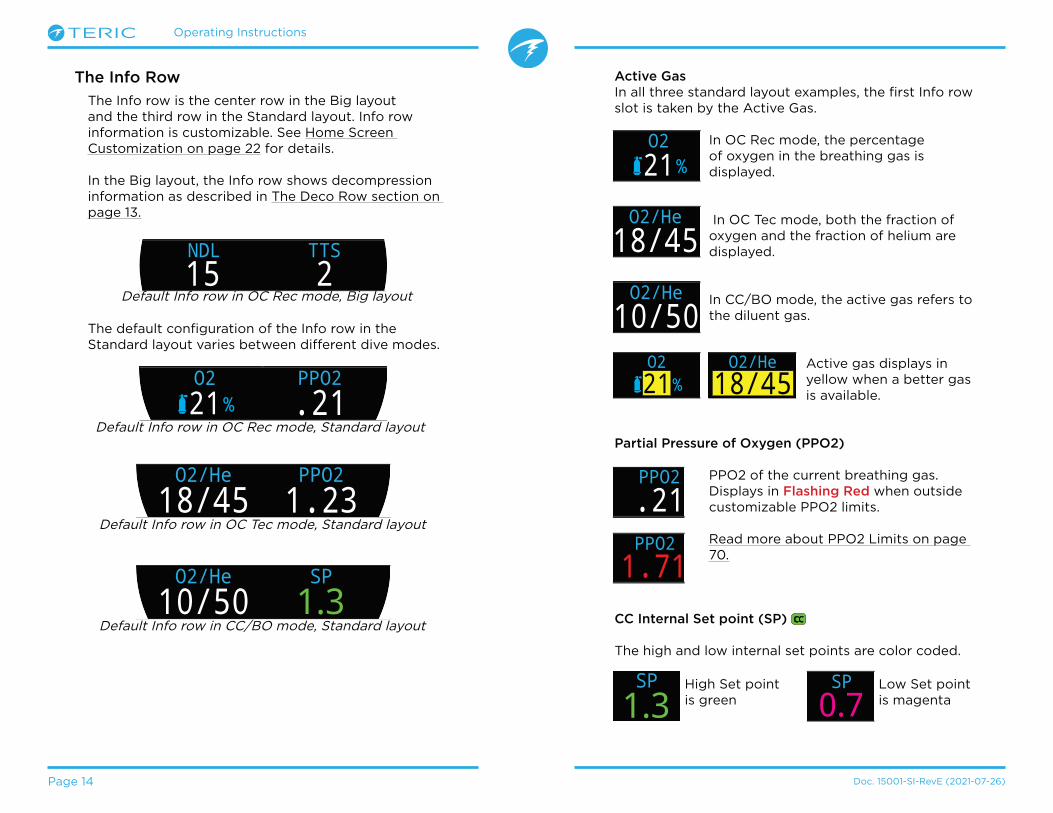
The default configuration of the Info row in the Standard layout varies between different dive modes�
The Info Row
The Info row is the center row in the Big layout and the third row in the Standard layout� Info row information is customizable� See Home Screen Customization on page 22 for details�
In the Big layout, the Info row shows decompression information as described in The Deco Row section on page 13�
O221%
58 27 1m minPPO2.21
19 22:O2/He18/45
58 27 1m minPPO21.23
19 22:O2/He10/50
58 27 1m min
19 22:1.3SP
Default Info row in CC/BO mode, Standard layout
Default Info row in OC Rec mode, Standard layout
Default Info row in OC Tec mode, Standard layout
Active GasIn all three standard layout examples, the first Info row slot is taken by the Active Gas�
In OC Rec mode, the percentage of oxygen in the breathing gas is displayed�
In OC Tec mode, both the fraction of oxygen and the fraction of helium are displayed�
In CC/BO mode, the active gas refers to the diluent gas�
Active gas displays in yellow when a better gas is available�
Partial Pressure of Oxygen (PPO2)
PPO2 of the current breathing gas� Displays in Flashing Red when outside customizable PPO2 limits�
Read more about PPO2 Limits on page 70�
\\
CC Internal Set point (SP)
The high and low internal set points are color coded�
O221%
58 27 1m minPPO2.21
19 22:O2/He18/45
58 27 1m minPPO21.23
19 22:O2/He10/50
58 27 1m min
19 22:1.3SP
O221%
58 27 1m minPPO2.21
19 22:
O2/He18/45
58 27 1m minPPO21.23
19 22:
MODCNS%11m min
PPO2.21271
SURFACEMODCNS
%11m min
PPO21.71271
SURFACE
O2/He10/50
58 27 1m min
19 22:1.3SP O2/He
10/5058 27 1m min
19 22:0.7SPHigh Set point
is greenLow Set point is magenta
OCBOCC
42:18
.0 60 ft
21%
NDL TTS21522OC Rec
!Default Info row in OC Rec mode, Big layout

Operating Instructions
Page 15 Doc� 15001-SI-RevE (2021-07-26)
The Bottom Row
Dive Time
The current length of the dive in minutes and seconds
Surface Interval
When on the surface, the Dive Time is replaced by a surface interval display�
Shows the minutes and seconds since the end of your last dive�
Above one hour, the surface interval is displayed in hours and minutes� Above 4 days, the surface interval is displayed in days�
42 18:185021/00
42:18ft103.6 4:57
21%
!
1753 20450SURFACE
mh341218/45
0.7
1753 20450SURFACE
mh341218/45
0.7
Bottom Row, OC Rec Mode on a dive
Bottom Row, CC/BO Mode at the surface
Alternate Active Gas and Set point Location
When the info row is not displaying the active breathing gas (or diluent), or the current internal set point, these values are displayed in the bottom row�
The alternate active gas location is at the very bottom of the computer display�
The alternate set point location is at the far right of the bottom row�
Notification Setting Icon
Indicates what notifications are turned on� Only available at the surface�
Alert Indicator
Indicates there is a persistent warning condition�
When the computer detects a dangerous situation, such as high PPO2, a warning is triggered� The large primary warning can be dismissed, but for some critical situations this alert icon will persist until the condition that caused the warning is resolved� See the Alerts section on page 23 for more information�
Beep Only
Silenced
Beep and Vibrate
Vibrate Only
42:18ft103.6 4:57
21%
!
The surface interval resets when decompression tissues are cleared�

Operating Instructions
Page 16 Doc� 15001-SI-RevE (2021-07-26)
3.5. Info Screens
Info screens provide more information than is available on the main screen�
From the main screen, the INFO (bottom right) button steps through info screens�
When all info screens have been viewed, pressing INFO again will return to the main screen�
Pressing the MENU (bottom left) button will also return to the home screen at any time�
Info screens also automatically time-out after 10 seconds, returning to the home screen� This prevents critical NDL, DECO and TTS information from being hidden for an extended period�
When using the Standard layout, the AI, compass, and Tissues Info screens do not automatically time out�
Note that although these screens are generally representative of the Teric display, info screen content varies for each mode� For example, decompression related info screens are not available in gauge mode�
LAST DIVE30.7 26:57m
m min
SURFACEm min
BAR
T1120 B
AR
T298
SURFACENEN 24�
m min
SURFACEMAX AVG
43.3ft103.6 ft
m min
SURFACEMODCNS
%11m min
PPO2.21271
SURFACEm minGF
35/75GF9922% 136%
SurfGF
SURFACEm minΔ+5+8
@+520
CEIL26
SURFACEm min
SURFACE
TISSUES
TEMP21 49
BATTERY%�C
m min
SURFACEmBar SURF1013
mBar NOW2564
m min
SURFACETIME2:31
EOD2:43
m min
SURFACE
10:26
.534m
21%
NDL TTS10 4
m59.3
O2/He18/45
DECO58 27 1m minPPO21.23
19 22:
TTS
m59.3
O2/He18/45
DECO58 27 1m minPPO21.23
19 22:
TTSm59.3
DECO58 27 1m 1m 1min
TTS 27
19 22:
Press the INFO button (bottom right), to step through Info Screens
Return to Main Screen by:•Pressing MENU button•Stepping past last screen•Waiting 10 Seconds (most screens)
Big layout Info row location
Standard layout Info row location

Operating Instructions
Page 17 Doc� 15001-SI-RevE (2021-07-26)
3.6. Info Screen Descriptions
Last Dive Info
Maximum depth and dive time from the last dive� Only available at the surface�
Air Integration (AI)
Only available if AI feature is turned on� The contents of the AI info line will automatically adapt to the current setup� Some examples include:
More information on AI features, limitations, and displays can be found in “Air Integration (AI)” on page 46�
LAST DIVE30.7 26:57m
m min
SURFACE
m min
BAR
T1120
SURFACE
T1 Only
m min
BAR
T1120 1.1
SAC T1 GTRT145
SURFACE
T1 & GTR/SAC
m min
BAR
T1120 B
AR
T298
SURFACE
T1 & T2
m minT1120
T298
GTR 45SAC1.1SURFACE
T1, T2 & GTR/SAC
Compass
Marked headings appear in green while reciprocal headings are shown in red� Green arrows point in the direction of your mark when off course by 5˚ or more�
Compass info row will not time out in Standard layout� It is only available when compass feature is turned on�
See section 8�1 for more information on compass calibration and use�
Maximum Depth
The maximum depth of the current dive� When not diving, displays the maximum depth of the last dive
Average DepthDisplays the average depth of the current dive, updated once per second� When not diving, displays the average depth of the last dive�
Maximum Operating Depth
In OC mode MOD is the maximum allowable depth of the current breathing gas as determined by PPO2 limits�
In CC mode, MOD is the maximum depth of the diluent�
Displays in Flashing Red when exceeded�
Read more about PPO2 Limits on page 70�
NEN 24�
m min
SURFACE
MAX AVG13.3m31.6 m
m min
SURFACE
MODCNS%11m min
PPO2.2157
SURFACE
MAX AVG13.3m31.6 m
m min
SURFACE
m 67.0
T1 92T2 111
T3 196T4 206
DECOm min
23 19:18/45
TTS5739 1
T1, T2, T3, & T4

Operating Instructions
Page 18 Doc� 15001-SI-RevE (2021-07-26)
Partial Pressure of Oxygen in Diluent
DilPO2 displays the partial pressure of oxygen in the diluent gas PPO2� Displays in Flashing Red when outside customizable PPO2 Limits�
When performing a manual diluent flush, you can check this value to see what the expected PPO2 will be
at the current depth�
CNS Toxicity Percentage
Central Nervous System oxygen toxicity loading percentage� Turns Yellow when greater than 90%� Turns Red when greater than 150%�
The CNS percentage is calculated continuously, even when on the surface and turned off� When deco tissues are reset, the CNS will also be reset�
The CNS value (short for Central Nervous System Oxygen Toxicity) is a measure of how long you have been exposed to elevated partial pressures of oxygen (PPO2) as a percentage of a maximum allowable exposure� As PPO2 goes up, the maximum allowable exposure time goes down� The table we use is from the NOAA Diving Manual (Fourth Edition)� The computer linearly interpolates between these points and extrapolates beyond them when necessary� Above a PPO2 of 1�65 ATA, the CNS rate increases at a fixed rate of 1% every 4 seconds�
During a dive the CNS never decreases� When back at the surface, a half-life of elimination of 90 minutes is used� So for example, if at the end of the dive the CNS was 80%, then 90 minutes later it will be 40%� In 90 more minutes it will be 20%, etc� Typically after about 6 half-life times (9 hours), everything is back close to equilibrium (0%)�
MODCNS%11m min
PPO2.21271
SURFACEMODCNS
%101m min
PPO2.21271
SURFACE
MODCNS%11m min
DilPO2.21271
SURFACEMODCNS
%11m min
DilPO21.77271
SURFACE
Gradient Factor
The deco conservatism value when the deco model is set to GF� The low and high gradient factors control the conservatism of the Bühlmann GF algorithm� See “Clearing up the Confusion About Deep Stops” by Erik Baker for more information�
GF99
The current gradient factor as a percentage (i�e� super-saturation percent gradient)
0% means the leading tissue super-saturation is equal to ambient pressure� Displays “On Gas” when tissue tension is less than the inspired inert gas pressure�
100% means the leading tissue super-saturation is equal to the original M-Value limit in the Bühlmann ZHL-16C model�
GF99 is displayed in Yellow when the current gradient factor modified M-Value (GF High) is exceeded�
GF99 is displayed in Red when 100% (un-modified M-Value) is exceeded�
SurfGF
The surfacing gradient factor expected if the diver instantaneously surfaced�
SurfGF colour is based on the current GF (GF99)� If the current GF is greater than GF High, SurfGF will be displayed in Yellow� If the current gradient factor is greater than 100%, SurfGF will be displayed in Red.
m minGF
35/75GF9922% 136%
SurfGF
SURFACE
m minGF
35/75GF9922% 136%
SurfGF
SURFACE
m minGF
35/75GF9922% 136%
SurfGF
SURFACE
OCBOCC

Operating Instructions
Page 19 Doc� 15001-SI-RevE (2021-07-26)
Ceiling
The current decompression ceiling not rounded to the next deeper stop increment� (i�e� not a multiple of 10ft or 3m)
@+5
“At plus 5” is the TTS if remaining at the current depth for 5 more minutes� This can be used as a measure of how fast you are on-gassing or off-gassing�
Δ+5
The predicted change in TTS if you were to stay at the current depth for 5 more minutes�
A positive “Delta plus 5” indicates that you are on-gassing the leading tissue while a negative number indicates that you are off-gassing the leading tissue�
Temperature
The current temperature in degrees Celsius or degrees Fahrenheit� Temperature units can be set in the Display settings menu�
Battery
The Teric’s remaining battery level expressed as a percentage�
Displays in yellow when battery is low and needs to be recharged� Displays in red when battery is critically low and must be recharged immediately�
m minΔ+5+8
@+520
CEIL8
SURFACE
m minΔ+5+8
@+520
CEIL26
SURFACE
m minΔ+5+8
@+520
CEIL26
SURFACE
TEMP21 49
BATTERY%�C
m min
SURFACE
TEMP21 49
BATTERY%�C
m min
SURFACE
Pressure
The pressure in millibars� Two values are shown, the surface (surf) pressure and the current (now) pressure�
Note that typical pressure at sea level is 1013 millibar, although it may vary with the weather (barometric pressure)� For example, in a low pressure system surface pressure may be as low as 980 millibar, or as high as 1040 millibar in a high pressure system�
For this reason, the PPO2 displayed on the surface may not exactly match the FO2 (fraction of O2), although the displayed PPO2 is still correct�
The surface pressure is set based on the lowest pressure the Teric sees in the 10 minutes prior to the start of a dive� Therefore, altitude is automatically accounted for and no special altitude setting is required�
Time
In a 12 or 24 hour format� Time format can be changed in the watch settings menu�
End of Dive Time (EOD)
This is similar to TTS but is expressed as a time of day�
The time of day at which you can expect to surface if you depart immediately, ascend at 10mpm or 33fpm, change gases when prompted, and perform all decompression stops as directed�
mBar SURF1013
mBar NOW2564
m min
SURFACE
TIME2:31
EOD2:43
m min
SURFACE
TIME2:31
EOD2:43
m min
SURFACE

Operating Instructions
Page 20 Doc� 15001-SI-RevE (2021-07-26)
Sample Tissue Bar GraphsTissues Bar Graph
The tissues bar graph shows the tissue compartment inert gas tissue tensions based on the Bühlmann ZHL-16C model�
The fastest tissue compartment is shown on the top, and the slowest on the bottom� Each bar is the combined sum of the nitrogen and helium inert gas tensions� Pressure increases to the right�
The vertical cyan line shows the inert gas inspired pressure� The yellow line is the ambient pressure� The red line is the ZHL-16C M-Value pressure�
Tissues that are supersaturated above ambient pressure are shown in yellow, and tissues that are supersaturated above the M-Value are shown in red�
Note that the scale for each tissue compartment is different� The reason the bars are scaled in this way is so that the tissues tensions can be visualized in terms of risk (i�e� how close they are as a percentage to Bühlmann’s original super- saturation limits)� Also, this scale changes with depth, since the M-Value line also changes with depth�
m min
SURFACE
TISSUES
m min
SURFACE
TISSUES
Inspired inert gas pressure
Ambient Pressure
Increasing Pressure
M-Value Pressure
16 tissue compartments{
m min
SURFACE
TISSUES
On surface (sat� with air)Note: Gas is 79% N
2 (21% O
2, or Air)
m min
SURFACE
TISSUES
Immediately after descent
Deep Stop
m min
SURFACE
TISSUES
On Gassing
m min
SURFACE
TISSUES
Last deco StopNote: Gas is now 50% O
2 and 50% N2
m min
SURFACE
TISSUES

Operating Instructions
Page 21 Doc� 15001-SI-RevE (2021-07-26)
Gas Density Display
The Gas Density display is only available as a customizable home screen and is not available in the info row�
For closed circuit diving, the gas density display turns yellow at 5�2 grams per liter and red at 6�3 grams per liter� No other warnings are generated�
For open circuit diving, the gas density display turns yellow at 6�3 grams per liter� No other warnings are generated�
You may be surprised at how shallow these warning colors appear�
Read more about why we chose these levels starting on page 66 here (recommendations on page 73):
Anthony, T.G and Mitchell, S.J. Respiratory physiology of rebreatherdiving. In: Pollock NW, Sellers SH, Godfrey JM, eds. Rebreathers and Scientific Diving. Proceedings of NPS/NOAA/DAN/AAUS June 16-19,2015 Workshop. Durham, NC; 2016.
DensityCNS%11m min
PPO2.211.3 g/L
SURFACEDensityCNS
%11m min
PPO2.215.3 g/L
SURFACEDensityCNS
%11m min
PPO2.216.4 g/L
SURFACE

Operating Instructions
Page 22 Doc� 15001-SI-RevE (2021-07-26)
3.7. Home Screen Customization
In the Standard layout, the Home screen (first page) Info Row is customizable with 1, 2 or 3 items�
Each Dive Mode’s home screen can be customized independently�
In Open Circuit Rec mode, the right slot of the Info Row and the right Deco Row slot in standard mode are also customizable�
Details about how to customize the Home screen can be found on page 67�
Home Screen
Reset
O2/He
OC TEC
# Values: 2PPO2
21/00 .21Back
Home Screen
Reset
OC TEC
# Values: 3
T1 �+5
Back
120T2980
m 0.0
T1 �+5120
T2980
DECOm min
TTSOC Tec
SURFACEmh3412
18/45
---- -
Home Screen
Reset
OC REC
T1120
NDL-- B
AR
Back
ft0.0
O2/He21/00
m min
DECO
PPO2.21
TTSOC Tec
SURFACEmh3412
-- - --
.00ft
21%
mh342SURFACE
NDL T1120-- B
AR
T1OCOC Rec
Home Screen Customization Options
Option Info Display
Current Gas
PPO2
CNS %
MOD
Gas Density
Deco Consrv
GF99
Ceiling
@+5
Δ+5
Tissues
Surf� GF
TTS
NDL
Set Point
Dil� PPO2
Max Depth
Avg� Depth
Option Info Display
TankPressure
Dual Tank Pressure
SAC
GTR
RTR
Tx & GTR
Tx & SAC
GTR & SAC
Time of Day
Date
Stopwatch
End of Dive
t@Max Depth
Temperature
Compass˚
Battery %
mBar Now
mBar Surf�
O2/He18/45
58 27 1m minPPO21.23
19 22:
O221%
58 27 1m minPPO2.21
19 22:MODCNS%11m min
PPO2.21271
SURFACE MODCNS%11m min
PPO2.21271
SURFACEMODCNS%11m min
PPO2.2157
SURFACE
m minGF
35/75GF9922% 136%
SurfGF
SURFACEm min
GF35/75
GF9922% 136%
SurfGF
SURFACEm min
Δ+5+8
@+520
CEIL8
SURFACEm min
Δ+5+8
@+520
CEIL26
SURFACE
m 0.0
T1 �+51753
T220450
DECOm min
TTSOC Tec
SURFACEmh3412
18/45
---- -
m min
SURFACE
TISSUES
m minGF
35/75GF9922% 136%
SurfGF
SURFACE125
14T1
min
TTS23
20NDL
O2/He10/50
58 27 1m min
19 22:1.3SP
MODCNS%11m min
DilPO2.21271
SURFACE MAX AVG13.3m31.6 m
m min
SURFACEMAX AVG13.3m31.6 m
m min
SURFACE
m min
BAR
T1120
SURFACE
m min
PSI
T11753 16PSI
min
SAC T1 GTRT145
SURFACE
m min
BAR
T1120 1.1
SAC T1 GTRT145
SURFACE
m minT1120
T298
GTR 45SAC1.1SURFACE
m minT1
1753T2
1422T1 120SAC1.1SURFACE
m minT1
1753T2
1422T1 120GTR 45SURFACE
TIME2:31
EOD2:43
m min
SURFACE
TIME2:31
EOD2:43
m min
SURFACE
.0 0ftMAX
ft103.6 4:57STOPWATCH
SURFACE
Deep
19:16
FD
TEMP21 49
BATTERY%�C
m min
SURFACE
TEMP21 49
BATTERY%�C
m min
SURFACE mBar SURF1013
mBar NOW2564
m min
SURFACEmBar SURF1013
mBar NOW2564
m min
SURFACE
DATEMAY-30
EOD2:43
m min
SURFACE
t@MAX12:14
EOD2:43
m min
SURFACE
Compass55�
EOD2:43
m min
SURFACE
m 67.0
T1 92T2 111
T3 196T4 206
DECOm min
23 19:18/45
TTS5739 1
m min
PSI
T11753 16PSI
min
SAC T1 RTRT117
SURFACE
DensityCNS%11m min
PPO2.211.3 g/L
SURFACE
Operating Instructions
Page 23 Doc� 15001-SI-RevE (2021-07-26)
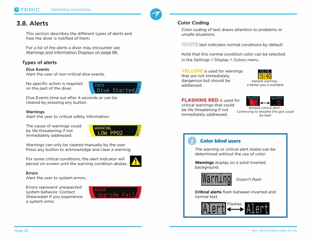
3.8. Alerts
This section describes the different types of alerts and how the diver is notified of them�
For a list of the alerts a diver may encounter see Warnings and Information Displays on page 86�
Types of alerts
Dive Events Alert the user of non-critical dive events�
No specific action is required on the part of the diver�
Dive Events time out after 4 seconds or can be cleared by pressing any button�
WarningsAlert the user to critical safety information�
The cause of warnings could be life threatening if not immediately addressed�
Warnings can only be cleared manually by the user� Press any button to acknowledge and clear a warning�
For some critical conditions, the alert indicator will persist on screen until the warning condition abates�
ErrorsAlert the user to system errors�
Errors represent unexpected system behavior� Contact Shearwater if you experience a system error�
Color Coding
Color coding of text draws attention to problems or unsafe situations�
WHITE text indicates normal conditions by default�
Note that this normal condition color can be selected
in the Settings > Display > Colors menu�
YELLOW is used for warnings that are not immediately dangerous but should be addressed�
FLASHING RED is used for critical warnings that could be life threatening if not immediately addressed�
ft125.6
O2/He21/00
PPO2.21
TTSOC
SURFACEmh3412
CLEAR
WARNINGLOW PPO2
NDL21 21
ft125.6
O2/He21/00
PPO2.21
TTSOC
SURFACEmh3412
CLEAR
INFODive Started
NDL21 21
ft125.6
O2/He21/00
PPO2.21
TTSOC
SURFACEmh3412
CLEAR
ERRORUpgrade Fail
NDL21 21
42:18ft103.6 4:57
21%
!
Sample warning -a better gas is available
Sample critical alert -Continuing to breathe this gas could
be fatal
Warning
AlertAlertFlashes
The warning or critical alert states can be determined without the use of color�
Color blind users
Warnings display on a solid inverted background�
Critical alerts flash between inverted and normal text�
Doesn't flash�
Operating Instructions
Page 24 Doc� 15001-SI-RevE (2021-07-26)
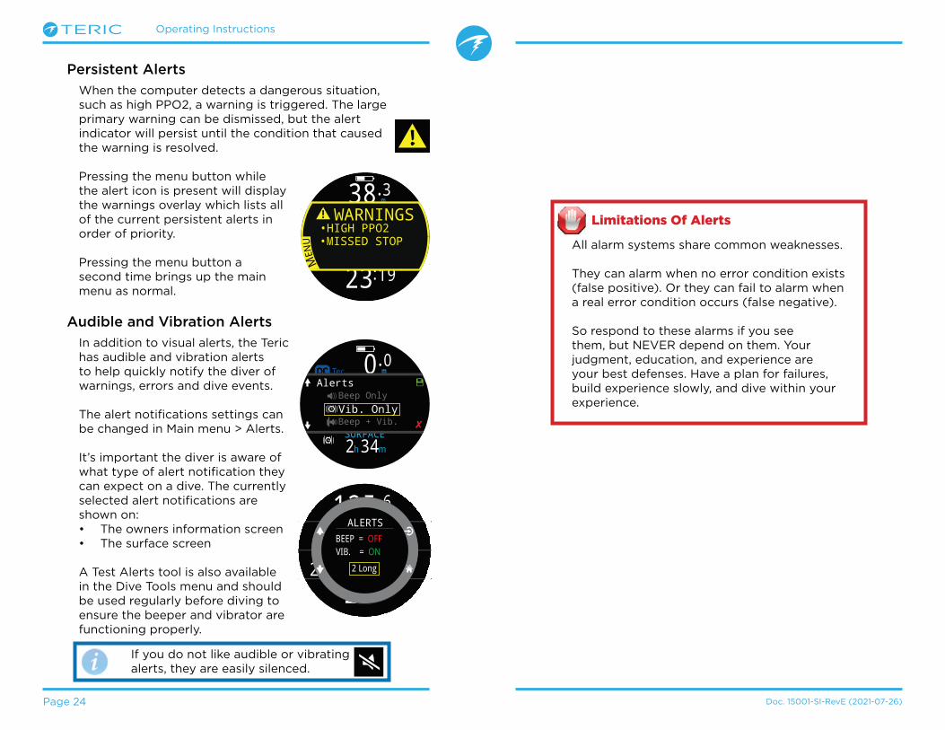
Persistent Alerts
When the computer detects a dangerous situation, such as high PPO2, a warning is triggered� The large primary warning can be dismissed, but the alert indicator will persist until the condition that caused the warning is resolved�
Pressing the menu button while the alert icon is present will display the warnings overlay which lists all of the current persistent alerts in order of priority�
Pressing the menu button a second time brings up the main menu as normal�
Audible and Vibration Alerts
In addition to visual alerts, the Teric has audible and vibration alerts to help quickly notify the diver of warnings, errors and dive events�
The alert notifications settings can be changed in Main menu > Alerts�
It’s important the diver is aware of what type of alert notification they can expect on a dive� The currently selected alert notifications are shown on:• The owners information screen• The surface screen
A Test Alerts tool is also available in the Dive Tools menu and should be used regularly before diving to ensure the beeper and vibrator are functioning properly�
Limitations Of Alerts
All alarm systems share common weaknesses�
They can alarm when no error condition exists (false positive)� Or they can fail to alarm when a real error condition occurs (false negative)�
So respond to these alarms if you see them, but NEVER depend on them� Your judgment, education, and experience are your best defenses� Have a plan for failures, build experience slowly, and dive within your experience�
42:18ft103.6 4:57
21%
!
m 38.3
O2/He21/00
PPO2.21
23 19:
TTS
MEN
U
! WARNINGS•HIGH PPO2•MISSED STOP
PSI
DECO20 2 14
T11850
O2/He21/00
ft min
TTSft
mh342SURFACE
OC
SURFACE
NDL TTS----
FDOCOC Tec 0 mAlerts
.0
✘
Beep Only
Beep + Vib.Vib. Only
ft125.6
23 19:
DECO20 214
T1O2/He21/00
ft
TTS
VIB. = ON
2 Long
BEEP = OFFALERTS
If you do not like audible or vibrating alerts, they are easily silenced�

Operating Instructions
Page 25 Doc� 15001-SI-RevE (2021-07-26)
4. Safety and Decompression StopsSafety and decompression stops are pauses inserted into the ascent to the surface in order to reduce the risk of decompression illness (DCI)�
4.1. Safety Stops
A safety stop is an optional stop added to all dives before surfacing� Safety stops can be set to fixed times of 3, 4, or 5 minutes, set to adapt based on dive conditions, or turned off completely� See Deco Settings�
The Teric does not do “deep safety stops”� That is, there are no extra stops added around 15m to 18m (50ft to 60ft) when ascending from a no-deco dive�
Safety stops always behave as follows:
Safety Stop RequiredOnce the depth exceeds 11m (35ft), a safety stop will be required� An alert will occur when in the safety stop depth range, shallower than 6m (20ft)�
Automatic CountdownCountdown begins once the depth becomes shallower than 6m (20ft )�
Countdown will continue while the depth remains in the range of 2�4m to 8�3m (7ft to 27ft)�
Countdown PausedIf the depth goes outside of the range 2�4m to 8�3m (7ft to 27ft), then the countdown pauses and the remaining time displays in yellow�
Safety Stop CompleteWhen the countdown reaches zero, the display changes to “Clear” and you are now clear to ascend to the surface�
Countdown ResetThe countdown will reset if the depth once again exceeds 11m (35ft)�
No Lockout for omitting
There is no lock-out or other penalty for omitting a safety stop, as they are optional�
If you ascend to the surface before the safety stop countdown finishes, the safety stop will appear paused, but this will disappear once the dive ends�
We recommend performing safety stops as planned as they offer a reduction in risk of DCI and take little time�
42 0SAFETY 3:22
.0 0ftSTOPWATCH
SURFACE
Deep
19:16
FD
CLEARSAFETY
42 03:22SAFETY
42 0
PAUSEDSAFETY
ft125.6
O2/He21/00
PPO2.21
TTSOC
SURFACEmh3412
CLEAR
INFOSafety Stop
NDL21 21
OC Rec
35ft /11m Safety Stop Required / Countdown Reset
20ft /6mCountdown Begins
27ft /8.3mCountdown Paused
7ft /2.4m
Countdown Resumed
Countdown Paused
Counting
Paused
Safety Stop Thresholds - Not to scale

Operating Instructions
Page 26 Doc� 15001-SI-RevE (2021-07-26)
4.2. Decompression Stops
Decompression stops are mandatory stops that must be followed in order to reduce the risk of decompression illness (DCI)
Decompression stops occur at fixed 10ft (3m) intervals�
Decompression stops display as follows:
Replaces NDLOnce the NDL reaches zero, deco stop information will replace it on the left side of the Deco Row in the Standard layout, or the left side of the info row home screen in the Big layout�
In OC Rec mode, the deco stop label appears in red as deco obligation is an emergency condition in recreational diving�
Deco Stops RequiredAn alert will indicate when Deco Stops are required
Do not dive beyond your training
Only perform decompression diving if you have received proper training to do so�
Diving with any type of overhead ceiling, whether in a cave or shipwreck, or from a decompression requirement, adds significant risk� Have a plan to handle failures and never rely solely on a single source of information�
Deco Stop ViolationIf you ascend shallower than a deco stop, but remain deeper than your current ceiling, stop info will display in yellow�
If you ascend shallower than your current ceiling, the display will flash red� Significant stop violations will result in a “MISSED STOP” alert�
Deco Stops CompleteIn OC Tec mode, once all decompression stops are complete, a “Deco Clear” dive info event will be triggered�
If enabled, the Deco Clear counter will begin counting up from zero�
In OC Rec mode, once all decompression stops are complete, the safety stop will begin counting down
If safety stops or the Deco Clear Counter is turned off, the display will say “Clear”�
There is no lock-out or other penalty for violating decompression stops�
The policy is to provide clear warnings that the decompression scheduled was violated, to allow you to make decisions based on your training�
This may include contacting your dive insurance provider, contacting the nearest recompression chamber, or performing first aid based on your training�
No Lockout for violating Deco Stops
125DECO
15 2O2/He
m min
ft125.6
O2/He21/00
PPO2.21
TTSOC
SURFACEmh3412
CLEAR
INFODeco Needed
NDL21 21
ft125.6
O2/He21/00
PPO2.21
TTSOC
SURFACEmh3412
CLEAR
INFODeco Clear
NDL21 21
125DECO
15 2O2/He
m min125DECO
O2/Hem min15 2
125DECO
15 2O2/He
m min
ft125.6
O2/He21/00
PPO2.21
TTSOC
SURFACEmh3412
CLEAR
WARNINGMISSED STOP
NDL21 21

Operating Instructions
Page 27 Doc� 15001-SI-RevE (2021-07-26)
5. Decompression and Gradient FactorsThe basic decompression algorithm used by this computer is Bühlmann ZHL-16C� It has been modified by the use of Gradient Factors that were developed by Erik Baker� We have used his ideas to create our own code to implement it� We would like to give credit to Erik for his work in education about decompression algorithms, but he is in no way responsible for the code we have written�
The computer implements Gradient Factors creating varied levels of conservatism� The levels of conservatism are pairs of number like 30/70� For a more detailed explanation of their meaning, please refer to Erik Baker’s excellent articles: “Clearing Up The Confusion About Deep Stops” and “Understanding M-values”� The articles are readily available on the web� You might also want to search for “Gradient Factors” on the web�
The default conservatism of the system depends on the dive mode�
For OC Rec mode the default conservatism setting is medium (40/85)�
For OC Tec and CC/BO modes where some decompression is presumed, the default is a more conservative 30/70� The system provides several settings that are more aggressive than the default�
Do not edit GF values until you understand the effects.
Graph from Erik Baker’s “Clearing Up The Confusion About Deep Stops”Pressure Graph: Gradient Factors
100% 80% 60% 40% 20% 0%
Ambient Pressure, absolute (increasing depth > )
Su
rface P
ress
ure
Linear function for gradual change in Gradient Factors
M-value Gradient
Co
mp
art
men
t in
ert
gas
pre
ssu
re, a
bso
lute
y
00 x
Am
bient
Pre
ssur
e Li
ne
M-v
alue
Lin
e GF Lo generates first stop
GF Hi (surfacing value) maintains safety margin
FirstStop
• A Gradient Factor is simply a decimal fraction (or percentage) of the M-value Gradient�
• Gradient Factors (GF) are defined from 0% to 100%�
• A Gradient Factor of 0% represents the ambient pressure line�
• A Gradient Factor of 100% represents the M-value line�
• Gradient Factors modify the original M-value equations for conservatism within the decompression zone�
• The lower Gradient Factor value (GF Lo) determines the depth of the first stop� Used to generate deep stops to the depth of the "deepest possible deco stop"
• The higher Gradient Factor value (GF Hi) determines the surfacing tissue supersaturation�

Operating Instructions
Page 28 Doc. 15001-SI-RevE (2021-07-26)
5.1. Decompression Information Accuracy
Decompression information displayed by this computer, including NDL, stop depth, stop time, and TTS are predictions� These values are continuously recalculated and will change with changing conditions� The accuracy of these predictions is dependent on several assumptions made by the decompression algorithm� It is important to understand these assumptions to ensure accurate decompression predictions�
It is assumed that the diver’s ascent rate is 10m/min (33ft/min)� Ascending significantly faster or slower than this will impact decompression obligations� It is also assumed that the diver is carrying and plans to use every gas that is currently turned on� Leaving gases that are not expected to be used turned on will result in inaccurate time to surface, decompression stop and decompression time information being displayed�
On ascent, it is assumed that the diver will perform decompression stops using the gas with the highest PPO2 below the OC Deco PPO2 value (default 1�61)� If there is a better gas available, the current gas will be displayed in yellow, indicating that a gas change is expected� The decompression prediction displayed always assumes that the best gas will be used� Even if the switch to a better gas has not been completed yet, decompression predictions will be displayed as if the switch is about to occur in the next 5 seconds�
Divers can encounter longer than expected decompression stops as well as inaccurate time to surface predictions if they fail to switch to a better gas when prompted by the computer�
Example: A diver on a decompression dive to 40m/131ft for 40 minutes with GF settings of 45/85 has two gases programmed into their computer and turned on: 21/00 & 99/00� The diver’s decompression schedule will be calculated based on breathing 21% oxygen for the descent, bottom and ascent phases of the dive until the diver ascends to 6m/20ft� At 6m/20ft the PPO2 of the 99/00 mix is 1�606 (less than 1�61), so it is the best decompression gas available�
Decompression information for the remaining stops will be calculated and displayed assuming the diver is going to switch to this better gas� This dive profile indicates these stops would be 8 minutes at 6m/20ft and 12 minutes at 3m/10ft� If the diver never makes the switch to 99/00, the computer will not allow them to surface until adequate off-gassing has occurred, but it will continue to assume the diver is about to make the gas switch and the decompression times given will be grossly inaccurate� The 6m/20ft stop will take 19 minutes to clear and the 3m/10ft stop will take 38 minutes to clear� That is a total time to surface difference of 37 minutes�
In a lost gas scenario or in the event a diver forgets to turn off a gas they are not carrying before a dive, gases can be turned off during the dive in Main menu -> Edit Gases�

Operating Instructions
Page 29 Doc. 15001-SI-RevE (2021-07-26)
6. Example Dives
6.1. OC Rec Example Dive
This is an example of displays that might be seen on a simple no-decompression dive in OC Rec Mode using the Big layout configuration�
1� Pre-Dive - This is the surface screen immediately before descending� At the surface, the cyan OC Rec icon is visible, the battery is shown to be about half full, and the alerts are set to sound and vibrate�
2� Descent - As we pass through 9 meters, the time-to-surface (TTS) shows one minute� This shows that the computer expects the diver to ascend at 10 meters per minute or 33 feet per minute� All decompression (and NDL) predictions are based on this assumed ascent rate� A safety stop is not included for dives shallower than 11m (35ft)�
3� Max Depth - The no-decompression limit starts off showing 99, but then starts to show smaller numbers as depth increases� The 3rd screen shows that we will go into deco in 10 minutes� A 5 minute safety stop is now included in the predicted TTS�
4� Low NDL - When the NDL goes below 5 minutes, it turns yellow indicating that we should begin making our ascent to avoid a decompression obligation
5� Ascent - As we ascend our NDL begins increasing again indicating that we can stay a bit longer at this shallower depth� The ascent rate indicator shows that we are ascending at about 6 mpm or 22 fpm�
6� Safety Stop - When we ascend shallower than 6m we are prompted to perform a safety stop� In this case the safety stop setting has been set to Adapt, and because of our deep profile, the countdown began at 5 minutes� A CLEAR indicator will inform us when the safety stop has been completed�
.0 0m
21%
mh342SURFACE
NDL TTS----
OCOC REC
2:26
.3 9m
21%
NDL TTS99 1
10:26
.533m
21%
NDL TTS10 9
18:32
.225m
21%
NDL TTS4 9
1� Pre-Dive 2� Descent
3� Max Depth 4� Low NDL
24:32
.913m
21%
NDL TTS7486
5� Ascent
34:21
.55m
21%
NDL TTS43:22
SAFETY
6� Safety Stop
Although safety stops are not mandatory, gas supply permitting, best practice is to perform a safety stop on every dive�
Operating Instructions
Page 30 Doc� 15001-SI-RevE (2021-07-26)
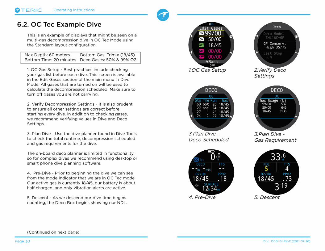
6.2. OC Tec Example Dive
This is an example of displays that might be seen on a multi-gas decompression dive in OC Tec Mode using the Standard layout configuration�
Max Depth: 60 meters Bottom Gas: Trimix (18/45)Bottom Time: 20 minutes Deco Gases: 50% & 99% O2
1� OC Gas Setup - Best practices include checking your gas list before each dive� This screen is available in the Edit Gases section of the main menu in Dive Mode� All gases that are turned on will be used to calculate the decompression scheduled� Make sure to turn off gases you are not carrying�
2� Verify Decompression Settings - It is also prudent to ensure all other settings are correct before starting every dive� In addition to checking gases, we recommend verifying values in Dive and Deco Settings�
3� Plan Dive - Use the dive planner found in Dive Tools to check the total runtime, decompression scheduled and gas requirements for the dive�
The on-board deco planner is limited in functionality, so for complex dives we recommend using desktop or smart phone dive planning software�
4� Pre-Dive - Prior to beginning the dive we can see from the mode indicator that we are in OC Tec mode� Our active gas is currently 18/45, our battery is about half charged, and only vibration alerts are active�
5� Descent - As we descend our dive time begins counting, the Deco Box begins showing our NDL�
(Continued on next page)
1�OC Gas Setup
ON
Edit Gases
50/0099/00
18/45
00/0000/00
ACT
OFF
OFF
ON
Back00
0m
0:
Deco
Deco Model ZHL16C+GF
GF Conserv. High 35/75
Last Stop 3 m
2�Verify DecoSettings
m 0.0
O2/He18/45
DECOm min
PPO2.18
TTSOC Tec
SURFACEmh3412
---- -
4� Pre-Dive
DECOOC
bot 20 60 18/45 asc 24 27 18/45 1 25 27 18/45 2 27 24 18/45
Stp Tme GasRun
3�Plan Dive - Deco Scheduled
Stp Tme GasRun
DECOOC
Gas Usage (L)99/00 53750/00 64618/45 3136
m 33.6
O2/He18/45
NDL5 4
PPO2.73
3 19:
TTS
5� Descent
3�Plan Dive - Gas Requirement

Operating Instructions
Page 31 Doc� 15001-SI-RevE (2021-07-26)
OC Tec Example Dive (cont.)
6� Max depth - Once NDL hits 0, deco stops will be needed� Stop requirements display in the deco box in place of the NDL� TTS has increased to include deco stop time�
7� Ascent - It is safe to ascend to 24 meters� 2 minutes must be spent at that deco stop� While ascending, the bar graph to the right of the depth shows the ascent rate (10 mpm)� All decompression predictions are made assuming an ascent rate of 10 meters per minute�
8� Gas Change - All decompression predictions are made assuming you will switch to the best available gas on ascent� At the 21m stop, the breathing gas turns yellow indicating that a better breathing gas is available� If the switch is not made, deco stop and time information will be inaccurate�
9� Missed Deco Stop - If you ascend shallower than the decompression ceiling the Deco information will flash red� If you fail to descend, a missed deco stop warning will be triggered and the Alert icon will appear� Acknowledge and clear the warning by pressing any button� Re-descend deeper than the stop depth to clear the flashing text and alert icon�
10� Deco Clear - Once all decompression obligation has been cleared, the deco clear counter begins counting up from zero�
End of example�
m 3.1
O2/He99/00
DECO
PPO21.30
63 47:Lorem ipsum
TTS1
CLEAR1:14
m59.3
O2/He18/45
DECO58 27 1m minPPO21.23
19 22:
TTSm42.4
O2/He18/45
DECO54 24 2m minPPO2.93
22 35:
TTS10
6� Max Depth 7� Ascent
m21.2
O2/He18/45
DECO44 21 1m minPPO2.56
28 14:
TTSm7.2
O2/He50/00
DECO22 9 6m minPPO2.86
40 33:
TTS
!
CLEAR
WARNINGMissed Deco Stop
8� Gas Change 9�Missed Deco Stop
10�Deco Clear

Operating Instructions
Page 32 Doc. 15001-SI-RevE (2021-07-26)
6.3. CC Example Dive
This is an example of displays that might be seen on a multi-gas decompression dive in CC/BO Mode using the Standard layout configuration�
Max Depth: 90 meters Diluent Gas: Trimix (10/50)Bottom Time: 20 minutes Bailout Gases: 14/55, 21%, 50%
1� CC Gas Setup - Best practices include checking your gas list before each dive� This screen is available in Edit Gases section of the main menu in CC mode� For this dive the only diluent gas is Trimix 10/50� (10% O2, 50% He, 40% N2)
2� OC Gas Setup - Several OC gases are required for this dive� If we switch to BO mode, we can use the Edit gases section of the main menu to define our bailout gases as well�
We will verify we are carrying sufficient bailout gas when we plan the dive�
3� Verify Decompression Settings - It is prudent to ensure all other settings are correct before starting every dive� In addition to checking gases, we recommend verifying values in Dive and Deco Settings�
4� Plan Dive - Use the dive planner found in Dive Tools to check the total runtime, decompression schedules and bailout gas requirements for the dive�
For closed circuit dives, two decompression schedules will be generated� A primary schedule for closed circuit deco, and a bailout decompression schedule�
The on-board deco planner is limited in functionality, so for complex dives we recommend using desktop or smart phone dive planning software�
(Continued on next page)
ON
BO Gases50/00
00/0000/00
ACT
OFF
OFF
21/0014/55
ON
Back00
0m
0:
ON
CC Gases10/50
00/0000/00
ACT
OFF
OFF
ACT
OFF
OFF
00/0000/00
Back00
0m
0:1� CC Gas Setup 2� OC Gas Setup
Deco
Deco Model ZHL16C+GF
GF Conserv. High 35/75
Last Stop 3 m
3� Verify Deco Settings
DECOCC
bot 20 90 10/50 asc 25 45 10/50 1 26 45 10/50 2 28 42 10/50
Stp Tme GasRun
4� Plan Dive -CC Scheduled
DECOBO
asc 23 66 14/55 asc 26 42 21/00 1 27 42 21/00 1 28 39 21/00
Stp Tme GasRun
4� Plan Dive -BO Scheduled
DECOBailout(BO)
50/00 1993732 21/00293 14/55
Gas Usage (L)
4� Plan Dive -Bailout GasRequirement

Operating Instructions
Page 33 Doc� 15001-SI-RevE (2021-07-26)
CC Example Dive (cont.)
m 0.0
MODCNS%0
DilPO2.10152
10/50
0.7
DECOm min
TTS
SURFACEmh1314
CC
---- -
5� Pre-Dive 6� Diluent Check
m 15.8
O2/He10/50
NDL52
0 37:
21.3
TTSCC
CLEAR
INFOAuto SP Up
SP
7� Automatic Set point Switch
m 46.3
O2/He10/50
NDL4
1 53:
51.3
TTSCC
SP
8� Decreasing NDL
m90.3
O2/He10/50
DECO 48 1m min
1 53:
921.3
TTSCC
SP
9� Bottom Time
m61.6
O2/He10/50
DECO 48 1m min
29 12:
961.3
TTS3CC
SP
10� Ascending to First Stop
Note on Hypoxic Diluents
Hypoxic diluents such as 10/50 in this example require special training since they can be deadly near the surface�
5� Pre-Dive - Prior to beginning the dive we can see from the mode indicator that we are in CC mode� Our active diluent gas is set to 10/50, our set point is 0�7, the Teric’s battery is about half charged, and only vibration alerts are active�
6� Diluent Check - Pressing INFO a few times brings up the info screen that shows the diluent PPO2� The red indicates the diluent is unsafe to breath directly�
This information can be viewed at any time to verify the diluent is safe or to check what the expected PPO2 will be when flushing with diluent at depth�
7� Automatic Set point Switch - The optional auto set point switch was enabled with a depth setting of 15m� So as we cross 15m on the descent, the set point automatically switches from 0�7 to 1�3�
8� Decreasing NDL - As we descend deeper, the NDL decreases� The TTS shows it will take 5 minutes to ascend to the surface at 10m/min (33ft/min)�
9� Bottom Time - We have completed the bottom time� The TTS indicates we have about 1�5 hours of decompression to do� The first stop will be at 48m for 1 minute�
10� Ascending to the First Stop - Here we are ascending at 3m/min� This is slower than the expected 10m/min ascent rate� This slow ascent has caused the TTS to rise, as most tissues are still on-gassing�
(Continued on next page)
m 0.0
O2/He10/50
DECOm min
0.7
TTS
SURFACEmh1314
CC
SP---- -

Operating Instructions
Page 34 Doc� 15001-SI-RevE (2021-07-26)
CC Example Dive (cont.)
11� First Deco Stop - The slow ascent has caused the first stop to clear before we reached it� This often happens with slow ascents�
12� A Problem Has developed - There is a problem with the O2 readings on the rebreather controller and the decision has been made to bail out� After physically switching the BOV or mouthpiece, the computer needs to be set to BO mode for proper deco calculations�
13� Bailout - One Press of the MENU button brings up “SWITCH CC -> BO” as the first menu item� Pressing SELECT (FUNC button) makes the change�
Note the Dive Mode indicator has changed to BO to indicate the bailout condition� The info row has also changed to reflect the customization settings for BO mode� The best BO gas was automatically selected, and the deco schedule has been adjusted based on the BO gases�
14� Gas Switch Required - We are now at 21m, having completed a few more deco stops� The gas is now displaying in yellow, indicating a better gas is available�
15� Gas Switch - Pressing MENU twice brings up the “SELECT GAS” option in the main menu, and pressing SELECT (FUNC button) enters it� The best gas will already be the initial selection, just press SELECT once more time to make it the active gas�
16� Deco Clear - Follow the deco stops until they have all cleared and the Deco Clear Counter begins counting up from zero�
End of example�
m30.4
O2/He10/50
DECO 30 2m min
42 33:
981.3
TTS
CC
CC BO>>SP 1.3 >> 0.7
11� First Deco Stop 12� A problem has developed
m30.4
O2/He21/00
DECO 30 2m min
PPO2.85
42 35:
92TTS
BO
13� Bailout
m21.2
O2/He21/00
DECO 21 5m min
PPO2.66
42 35:
80TTS
BO
14� Gas SwitchRequired
Select Gas
21/0050/00
14/55ACT
Back44
21m
42:15� Gas Switch
m45.3
O2/He10/50
DECO 45 1m min
34 27:
981.3
TTSCC
SP
m 3.1
O2/He50/00
DECO
PPO2.65
122 18:
TTSBO
1CLEAR3:14
16� Deco Clear
Operating Instructions
Page 35 Doc� 15001-SI-RevE (2021-07-26)
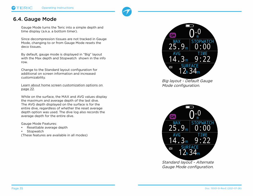
6.4. Gauge Mode
Gauge Mode turns the Teric into a simple depth and time display (a�k�a� a bottom timer)�
Since decompression tissues are not tracked in Gauge Mode, changing to or from Gauge Mode resets the deco tissues�`By default, gauge mode is displayed in “Big” layout with the Max depth and Stopwatch shown in the info row�
Change to the Standard layout configuration for additional on screen information and increased customizability�
Learn about home screen customization options on page 22�
While on the surface, the MAX and AVG values display the maximum and average depth of the last dive� The AVG depth displayed on the surface is for the entire dive, regardless of whether the reset average depth option was used� The dive log also records the average depth for the entire dive�
Gauge Mode Features:• Resettable average depth• Stopwatch(These features are available in all modes)
m0.0
AVG14.3
GA
m
mTIME9:220:00
STOPWATCH
SURFACEmh3412
MAX25.9
Big layout - Default Gauge Mode configuration�
m0.0
AVG14.3
GA
m
mTIME9:220:00
STOPWATCH
SURFACEmh3412
MAX25.9
Standard layout - Alternate Gauge Mode configuration�

Operating Instructions
Page 36 Doc. 15001-SI-RevE (2021-07-26)
7. Freedive ModeFreedive Mode optimizes the Teric for freediving�
Although many of the basic functions of the computer are the same as in other dive modes, Freedive Mode has several unique features that are covered in this section�
Since decompression tissues are not tracked in Freedive Mode, changing to or from Freedive Mode resets the deco tissues�
Free Dive Mode features:• High Speed depth sampling - 4 samples / second�• Fully customizable auditory and vibration alerts• Freedive focused Info screens• Quick Log Tagging
7.1. Default Freediving Layout
By default, Freedive Mode uses the Big layout� It shares most features with the other dive modes but has a few unique characteristics�
• Active Freediving Set shown beside Mode Indicator� • Last dive time and max depth on home screen• Ascent / descent shown in feet per second (fps) or
meters per second (mps) instead of fpm / mpm�
.0 0mMAX 16.2m
0:00LD 1:01STOPWATCH
SURFACE
Deep
19:16
0.5FD
Like in OC Rec and Gauge Mode, in Freedive Mode, the right home screen slot can be customized in the Big Layout�
WARNING
Breath-hold diving involves risks that are not obvious� Do not engage in these activities without proper training as well as a complete understanding and acceptance of the risks�
This manual is not a substitute for professional training�

Operating Instructions
Page 37 Doc� 15001-SI-RevE (2021-07-26)
7.2. Freediving Info Screens
Freedive Mode has a unique info screen sequence which can be seen on the right�
Max and average descent and ascent screens are only available in freediving mode (in either fps or mps)�
These values can also be added to the home screen in Freedive Mode�
.0 0mMAX 16.2m
0:00LD 1:01STOPWATCH
SURFACE
Deep
19:16
FD 0.5.0 0mmDeep 0Deep 0FD 0.5
SURFACE
19:16
NEN 24�
m min
SURFACE
TEMP21 49
BATTERY%�C
m min
SURFACEmBar SURF1013
mBar NOW2564
m min
SURFACETIME2:31
DATEJUN-02
m min
SURFACE
ms
MAX DESC.0.4 m
s0.4AVG DESC.
m min
SURFACE
ms
MAX ASC.0.4 m
s0.4AVG ASC.
m min
SURFACE
ms
MAX DESC.0.4 m
s0.4AVG DESC.
m min
SURFACE
fts
MAX ASC.1.3 ft
s1.3AVG ASC.
m min
SURFACE7.3. Freediving Sets
A freedive set is a collection of settings customized for a specific type of freediving�
The Teric supports 3 independently customizable sets� For each set, the user can customize the alerts activated during a dive as well as a handful of settings that will often change between activities� Fresh water in a pool vs salt water in the ocean for example�
See how to Edit Freedive Sets on page 63�
Freedive Mode info screen sequence:
Press the INFO button (bottom right), to step through Info Screens
Return to Main Screen by:•Pressing MENU button•Stepping past last screen•Waiting 10 Seconds
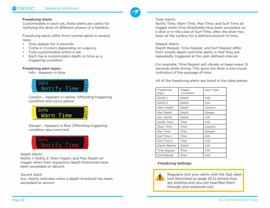
Operating Instructions
Page 38 Doc. 15001-SI-RevE (2021-07-26)
Freediving AlertsCustomizable in each set, these alerts are useful for notifying the diver of different phases of a freedive�
Freediving alerts differ from normal alerts in several ways� • Only appear for 4 seconds�• Come in 3 colors depending on urgency�• Fully customizable within a set�• Each has a customizable depth or time as a
triggering condition
Freediving alert types:Info - Appears in blue�
Caution - Appears in yellow� Offending triggering condition also turns yellow�
Danger - Appears in Red� Offending triggering condition also turns red�
Depth Alerts:Notify 1, Notify 2, Warn Depth, and Max Depth all trigger when their respective depth thresholds have been exceeded on decent�
Ascent Alert:Asc� Notify indicates when a depth threshold has been exceeded on ascent�
Regularly test your alerts with the Test Alert tool described on page 42 to ensure they are working and you can hear/feel them through your exposure suit�
.0 0ftMAX
ft103.6 4:57STOPWATCH
SURFACE
Deep
19:16
FD
CLEAR
InfoWarn Time
.0 0ftMAX
ft103.6 4:57STOPWATCH
SURFACE
Deep
19:16
FD
CLEAR
InfoNotify Time
.0 0ftMAX
ft103.6 4:57STOPWATCH
SURFACE
Deep
19:16
FD
CLEAR
INFONotify Time
Time Alerts:Notify Time, Warn Time, Max Time, and Surf Time all trigger when time thresholds have been exceeded on a dive or in the case of Surf Time, after the diver has been at the surface for a defined amount of time�
Repeat Alerts:Depth Repeat, Time Repeat, and Surf Repeat differ from simple depth and time alerts in that they are repeatedly triggered at the user-defined interval�
For example, Time Repeat will vibrate or beep every 15 seconds while diving� This gives the diver a non-visual indication of the passage of time�
All of the freediving alerts are listed in the table below:
Freediving Alert
Trigger Condition
Alert Type
Notify 1 Depth Info
Notify 2 Depth Info
Warn Depth Depth Caution
Max Depth� Depth Danger
Asc� Notify Depth Info
Notify Time Time Info
Warn Time Time Caution
Max Time Time Danger
Surf Time 1 Time Info
Surf Time 2 Time Info
Depth Repeat Depth Info
Time Repeat Time Info
Surf Repeat Time Info
Freediving Settings:

Operating Instructions
Page 39 Doc. 15001-SI-RevE (2021-07-26)
Customizable freediving settings include:• Water Type• Dive Start Depth• Dive End Depth• Dive Start Delay• Dive End Delay
These settings will very depending on the location and the type of freediving (ex� dynamic apnea vs� free immersion)� So, customizing them within a set, makes it much easier to move between freediving activities without needing to define each setting individually every time�
Note that delays are added back to / removed from dive statistics once the dive is underway� Depth and time information will be the same regardless of the start / end delays and depths�
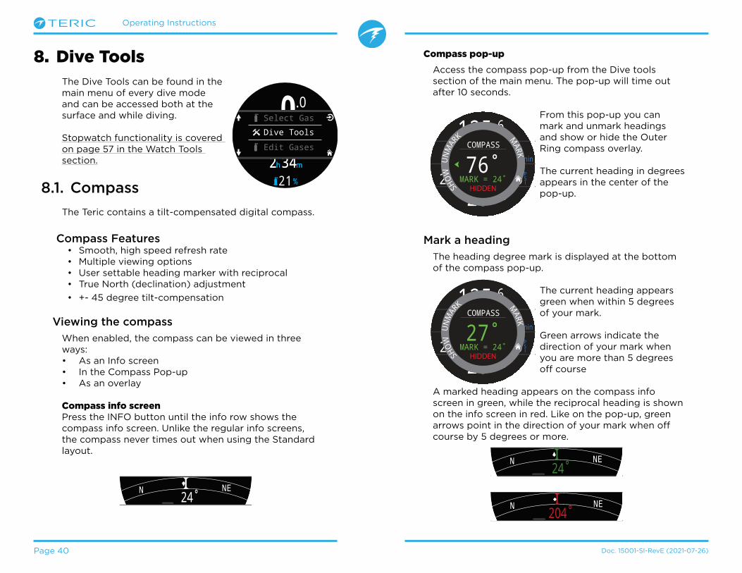
Operating Instructions
Page 40 Doc� 15001-SI-RevE (2021-07-26)
Compass pop-up
Access the compass pop-up from the Dive tools section of the main menu� The pop-up will time out after 10 seconds�
From this pop-up you can mark and unmark headings and show or hide the Outer Ring compass overlay�
The current heading in degrees appears in the center of the pop-up�
Mark a heading
The heading degree mark is displayed at the bottom of the compass pop-up�
The current heading appears green when within 5 degrees of your mark�
Green arrows indicate the direction of your mark when you are more than 5 degrees off course
A marked heading appears on the compass info screen in green, while the reciprocal heading is shown on the info screen in red� Like on the pop-up, green arrows point in the direction of your mark when off course by 5 degrees or more�
8. Dive ToolsThe Dive Tools can be found in the main menu of every dive mode and can be accessed both at the surface and while diving�
Stopwatch functionality is covered on page 57 in the Watch Tools section�
8.1. Compass
The Teric contains a tilt-compensated digital compass�
Compass Features• Smooth, high speed refresh rate• Multiple viewing options• User settable heading marker with reciprocal • True North (declination) adjustment
• +- 45 degree tilt-compensation
Viewing the compass
When enabled, the compass can be viewed in three ways:• As an Info screen• In the Compass Pop-up• As an overlay
Compass info screenPress the INFO button until the info row shows the compass info screen� Unlike the regular info screens, the compass never times out when using the Standard layout�
ft125.
PSI
6
23 19:
DECO20 214
T11850
O2/He21/00
ft min
TTS Compass
Mark = 257�
MARK
HID
E
UN
MAR
K
SHOW
U
NM
AR
K M
ARK
76�COMPASS
MARK = 24�HIDDEN
NEN 24�
m min
SURFACE
NEN 204�
m min
SURFACE
PSI
DECO20 2 14
T11850
O2/He21/00
ft min
TTS.0 0ft
mh342SURFACE
OC
21%
mh342SURFACE
NDL TTS----
FDOC
Dive Tools
Edit Gases
Select Gas
ft125.
PSI
6
23 19:
DECO20 214
T11850
O2/He21/00
ft min
TTS Compass
Mark = 257�
MARK
HID
E
UN
MAR
K
SHOW
U
NM
AR
K M
ARK
27�COMPASS
MARK = 24�HIDDEN
NEN 24�
m min
SURFACE

Operating Instructions
Page 41 Doc� 15001-SI-RevE (2021-07-26)
Outer Ring Compass Overlay The compass overlay can show north and your marked heading at all times�
Select “Show” on the compass pop-up to display the compass overlay�
When enabled, a red north arrow and green heading marker will remain at the edge of the screen tracking their marks�
When the overlay is enabled, green arrows at the top of the display indicate the direction of your mark when more than 5 degrees off course�
ft125.6
23 19:
DECO20 214
T1O2/He21/00
ft
TTS
N
HID
E
U
NM
AR
K M
ARK
90�COMPASS
MARK = 92�
N
m59.3
O2/He18/45
DECO58 27 1m minPPO21.23
19 22:
TTS
N
Compass Limitations
It is important to understand some compass limitations before use�
Calibration:The digital compass needs regular calibration� This can be done in the Settings > Compass menu and takes only one minute� See the compass sub-section of the Settings Menu Reference on page 76 for compass calibration instructions�
Interference:Metal objects, permanent magnets, and other sources of magnetic interference such as electric motors should be kept away from the compass� We recommend comparing the compass accuracy to a known good compass with and without the interfering object in place to see if it has an effect�
Shipwrecks may interfere with the compass reading and so the compass function should not be used near or inside of a shipwreck� Use the same discretion and training as you would with a traditional compass�
Magnetic declination (also called magnetic variation) is the difference between magnetic and true north� This can be compensated in the Compass Setup menu using the declination setting� The magnetic declination varies around the world, so it will need to be readjusted when traveling�
Magnetic inclination (or magnetic dip) is how much the Earth’s magnetic field points up or down� The Teric’s compass automatically compensates for this angle� However, in some locations (near the poles) the inclination angle can exceed 80° (i�e� the magnetic field points almost directly up or down), in which case the specified accuracy may not be met�
Check compass calibration before diving
Check compass calibration:1� Place the Teric on a flat surface,
away from metal objects�2� Mark a heading�3� Rotate the computer 180 degrees�4� Ensure the compass is pointing at the
reciprocal heading�
See page 76 for compass calibration instructions�

Operating Instructions
Page 42 Doc. 15001-SI-RevE (2021-07-26)
8.4. Test Alerts
The Test Alerts pop-up provides a quick way to ensure your alerts are working and that you are able to feel them through your exposure suit�
Use the up and down arrows to select an alert and press select to test it�
The Test Alerts pop-up should be used regularly if you use vibration or auditory notifications� Note, this feature only tests the different alerts that may occur during a dive� Which alert activates in each Warning, Info, or Error situation is not customizable with the exception of Freediving Alerts (page 38)�
8.2. Tag Log
The tag log feature is useful for marking a point of interest in the dive log for later review� These tags will appear in the dive log when uploaded to your phone or personal computer�
Basic tag titles are available from the tag log pop-up to help distinguish tags�
The tag log pop-up will time out after 10 seconds�
8.3. Reset Average Depth
This feature is useful if you would like to get a sense of the average depth of a particular phase of a dive, such as the bottom, or deco phase� Reset Average Depth is available in every dive mode�
ft125.
PSI
6
23 19:
DECO20 214
T11850
O2/He21/00
ft min
TTSOC
!
NavPointDanger
InterestTAG
ft125.6
23 19:
DECO20 214
T1O2/He21/00
ft
TTS
VIB. = ON
2 Long
BEEP = OFFALERTS
2 Long
NegativePositiveClick
2 Short1 ShortAlertAlarm
1 Long3 Short
3 Long
Caution
Although vibration and auditory alerts are very useful, never rely on them for your safety� Electromechanical devices can and will eventually fail�
Always be proactively aware of your depth, no-decompression limit, gas supply, and other critical dive data� You are ultimately responsible for your own safety�

Operating Instructions
Page 43 Doc. 15001-SI-RevE (2021-07-26)
When used during a diveComputes the decompression profile assuming the ascent will begin immediately� There are no settings to enter� (RMV is last used value)
LimitationsThe Teric Deco Planner is intended for simple dives� Multi-level dives are not supported�
The Deco Planner does not provide thorough validation of the profile� For example, it does not check for nitrogen narcosis limitations, gas usage limitations, CNS percentage violations, or isobaric counter-diffusion risks due to sudden helium switches�
The user is responsible for ensuring a safe profile is followed�
8.5. Deco Planner
Introduction• Calculates decompression profiles for simple
dives�• Calculates gas consumption based on RMV• In closed-circuit (CC) mode, also calculates open-
circuit bail-out (BO)
The Teric’s deco planner is best suited to decompression diving� For no-decompression diving, use the quick NDL Planner described on page 45�
SetupThe planer uses the current gases programmed into the Teric in the current dive mode, as well as the current GF low/high settings� Deco profile is computed for the current Dive Mode (CC or OC)�
When used on the surfaceEnter the expected surface interval, bottom depth, bottom time, respiratory minute volume (RMV) and Set Point (closed-circuit only)�
Note: Residual tissue loading (and CNS%) from recent dives will be used in calculating the profile
When the correct values are entered, select “Run Plan” and confirm decompression settings and starting CNS�
Important!
The Teric’s Deco Planner makes the following assumptions:• Descent rate is 18m/min (60ft/min) and
the ascent rate is 10m/min (33ft/min)�• For OC, the gas in use will be the gas with
the highest PPO2 within the PPO2 limits�• For CC, the diluent in use will be the gas
with the highest PPO2 within PPO2 limits�• The planner will use the configured last
stop depth�• For CC, the PPO2 is constant for the entire
dive�• The RMV is the same while diving as
during deco
Read more about PPO2 Limits on page 65�
DECORUN PLAN
45 30Starts in now
14
Depth m min
BackRMV 1.3SP
Ready to PlanDECO
GF:
Last Stop:
Start CNS:
30/70
3m
0%

Operating Instructions
Page 44 Doc. 15001-SI-RevE (2021-07-26)
Results Screens
The results are given in tables showing:
Stop Depth In meters (or feet)
Tme Stop Time In minutes
Run Run Time In minutes
Gas Gas Used %O2/%He
The first few rows will show the bottom time (bot) and the ascent legs (asc) to ascend to the first stop� Multiple ascent legs may be shown if gas switches are needed
If more than 2 stops are needed, the results will be split onto several screens� Scroll down to step through the screens�
For CC/BO dives there will be two schedules, one for each operating mode�
DECOCC
bot 30 45 10/50 asc 33 21 10/50 1 34 21 10/50 2 36 18 10/50
Stp Tme GasRun
DECOCC
2 38 15 10/50 3 41 12 10/50 5 46 9 10/50 7 53 6 10/50
Stp Tme GasRun
A summary screen shows the total dive time, the time spent on deco and final CNS% after the last page of the decompression schedule�
DECOCC
Run: 63 min Deco: 33 min CNS 35 %
Next to Plan BO
CC Summary
DECOBailout(BO)
asc 33 18 36/00 1 34 18 36/00 2 36 15 36/00 3 39 12 36/00
Stp Tme GasRun
DECOBailout(BO)
5 44 9 36/00 7 51 6 99/00 11 62 3 99/00
Stp Tme GasRun
For OC or BO profiles, a total gas consumption report is also given�
DECOBailout(BO)
99/00 357490 32/00
Gas Usage (L)
If no decompression is required, no table will be shown� Instead, the total No-Decompression-Limit (NDL) time in minutes, at the given maximum depth will be reported� Also, the gas quantity required to surface (bailout in CC) will be reported�
DECOCC
No Deco Stops. Total NDL at 18ft
BO gas quantity is 129 min.
is 48 Liters.

Operating Instructions
Page 45 Doc. 15001-SI-RevE (2021-07-26)
8.6. NDL Planner
The No-Decompression Limit (NDL) Planner is a quick way to determine how much bottom time is available without the need for decompression stops�
A surface interval duration from none up to 1 day can be applied to account for expected off-gassing�
The results are a list of depths, along with the NDL time at that depth and the best of the programmed gases to use at that depth� Only programmed gases are used�
Depth NDL Gas
33m 13min 32%
24m 35min 36%27m 25min 36% 30m 16min 32%
NDL
Next divein 1h00m
NDL
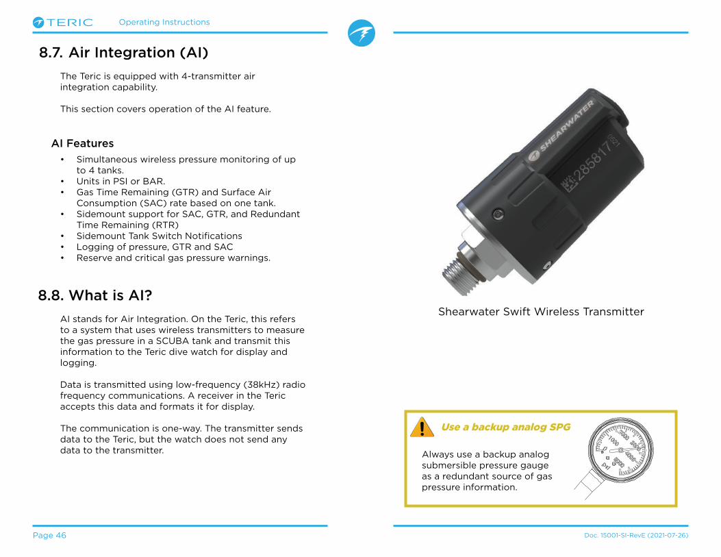
Operating Instructions
Page 46 Doc� 15001-SI-RevE (2021-07-26)
8.7. Air Integration (AI)
The Teric is equipped with 4-transmitter air integration capability�
This section covers operation of the AI feature�
AI Features
• Simultaneous wireless pressure monitoring of up to 4 tanks�
• Units in PSI or BAR�• Gas Time Remaining (GTR) and Surface Air
Consumption (SAC) rate based on one tank� • Sidemount support for SAC, GTR, and Redundant
Time Remaining (RTR)• Sidemount Tank Switch Notifications• Logging of pressure, GTR and SAC• Reserve and critical gas pressure warnings�
8.8. What is AI?
AI stands for Air Integration� On the Teric, this refers to a system that uses wireless transmitters to measure the gas pressure in a SCUBA tank and transmit this information to the Teric dive watch for display and logging�
Data is transmitted using low-frequency (38kHz) radio frequency communications� A receiver in the Teric accepts this data and formats it for display�
The communication is one-way� The transmitter sends data to the Teric, but the watch does not send any data to the transmitter�
Use a backup analog SPG
Always use a backup analog submersible pressure gauge as a redundant source of gas pressure information�
Shearwater Swift Wireless Transmitter

Operating Instructions
Page 47 Doc� 15001-SI-RevE (2021-07-26)
8.9. Basic AI Setup
This section will get you started with the basics of AI on the Teric� Advanced setup and detailed descriptions will be covered in later sections�
Install the Transmitter
Before using the AI system, you will need to install one or more transmitters on a scuba tank first stage regulator�
The transmitter must be installed on a first stage port labeled “HP” (high pressure)� Use a first stage regulator with at least two HP ports, so that a backup analog submersible pressure gauge (SPG) can be used�
Position the transmitter such that it is on the same side of your body as you wear your Teric handset (FIGURE 5)� Range is limited to approximately 1 m (3 ft)�
A high-pressure hose may be used to relocate the transmitter for better reception or convenience� Use hoses rated for a working pressure of 300 Bar (4500 PSI) or higher�
Range
3 ft (1 m)
Range
3 ft (1 m)
Some transmitters require a wrench (11/16” or 17mm) to tighten or loosen
Avoid hand tightening or loosening unless otherwise specified by the transmitter manufacturer, as this may damage the transmitter�
The Shearwater Swift transmitter can be installed without tools�
A backup SPG is recommended
Install transmitter on 1st stage HP portInstall transmitter on the same side of your body as the handset� Range is approximately 3 feet (1 m)�

Operating Instructions
Page 48 Doc� 15001-SI-RevE (2021-07-26)
Turn on the Transmitter
Turn on the transmitter by opening the tank valve� The transmitter will automatically wake up when it detects pressure�
Pressure data is transmitted approximately every 5 seconds�
Turn off the Transmitter
To turn off the transmitter, close the tank valve and purge the second stage regulator to drain pressure from the hoses� The transmitter will automatically power down after 2 minutes of no applied pressure�
Enable AI on the Teric
On the Teric, navigate to the Settings > AI menu� Change the AI Mode setting to On.
Pair the Transmitter
Each transmitter has a unique serial number etched on its body� All communications are coded with this number so that the source of each pressure reading can be identified�
Settings
AI|Off
Gases
Compass|On
AI
AI Mode On
Tx|Off
When AI Mode is set to Off, the AI sub-system is completely powered down and does not consume any power� When on, the AI system increases power consumption by approximately 10%�
Note that AI is never on when the Teric is in watch mode�
More information about settings in the AI Settings menu can be found on page 74�
Tx
T1|123456
T2|Off
T1
Serial285817
Rated207 BAR
T1 On
Pair the transmitter by going to the Tx Setup menu option, and selecting T1� Turn on T1, then enter the 6-digit transmitter serial number into the T1 Serial #setting� You only need to set this once, as it will be permanently saved in the settings memory�
More information about settings in the T1 & T2 Settings menu can be found on page 74�

Operating Instructions
Page 49 Doc� 15001-SI-RevE (2021-07-26)
Check that your tank valve is open
Always take a few breaths from your regulator or purge your regulator’s second stage while monitoring your tank pressure for a full 10-15 seconds prior to entering the water to ensure your tank valve is turned on.
If the fi rst stage regulator is charged but the tank valve has been closed, the breathing gas available to the diver will decrease rapidly and within a few breaths the diver will face an “out of air“ situation. Unlike an analog gauge, the air pressure reported on the Teric will only update every 5 seconds, so the pressure reported by the Teric must be monitored for longer than that (we suggest 10-15 seconds) to ensure the tank valve is open.
Including a regulator purge test followed by 10-15 seconds of air pressure monitoring before entering the water as part of your pre-dive safety check is a good way to mitigate this risk.
Add an AI display to the home screen
AI information is automatically displayed as an info screen when the AI feature is enabled, however, the main screen will not show AI information until manually added�
In OC Rec mode, when using the Big layout, the right Info Row slot can be customized to show AI information�
Home Screen
Reset
OC REC
T1120
NDL-- B
AR
Back
.00ft
21%
mh342SURFACE
NDL T1120-- B
AR
T1OCOC Rec
In any SCUBA mode, when using the Standard layout, the info row can be customized extensively to show AI information�
Home Screen
Reset
OC TEC
# Values: 3
T1 �+5
Back
120T2980
m 0.0
T1 �+5120
T2980
DECOm min
TTSOC Tec
SURFACEmh3412
18/45
---- -
Use the Settings > Dive > Home Screen menu to add an AI display to your home screen�
Find more information about Home Screen Customization on page 22�

Operating Instructions
Page 50 Doc� 15001-SI-RevE (2021-07-26)
8.10. AI Displays
There are several types of display field that are used to display AI information: 1) Tank Pressure 2) SAC 3) GTR 4) RTR (sidemount only) 5) Mini combination display
These displays can be viewed in two ways: 1) Added to a customizable zone on the home screen 2) Most can be viewed on the AI info screen�
Renaming Transmitters
Transmitter titles can be customized in the transmitter setup menu� This makes it easier to keep track of which transmitter is reporting which cylinder pressure�
Each transmitter title has 2 characters that apply to all AI displays� The following options are available�
First Character: T, S, B, O, or D
Second Character: 1, 2, 3, or 4
Renaming is for display purposes only� There is no relationship between a transmitter title and gas fraction for decompression calculation purposes�
m min
BAR
T1120
SURFACE
m min
BAR
T1120 1.1
SAC T1 GTRT145
SURFACE
m min
PSI
T11753 16PSI
min
SAC T1 GTRT145
SURFACE
m minT1120
T298
GTR 45SAC1.1SURFACETank
PressureGas Time
RemainingSurface Air
ConsumptionMini
Combination
Tank Pressure Display
The pressure displays are the most fundamental AI displays, showing pressure in the current units (PSI or Bar)�
Normal Pressure Display:
Low Pressure warnings:
Reserve Pressure thresholds can be managed in the AI settings� See page 74 for details�
No Communication Warnings:
Low Transmitter Battery Warnings:
m min
PSI
T11753SURFACE
m min
BAR
T1170
SURFACEm min
PSI
T1682
SURFACE
PSI Display
BarDisplay
ReservePressure
m min
BAR
T129
SURFACE
CriticalPressure
I
T1
3042PS
I3042PS
COMMSAlternates
I
T1
----PS
I----PS
Alternates COMMS
I3042PS
I
T1
3042PS
Low BatAlternates
I3042PS
I
T1
3042PS
Low BatAlternates
No communication for 30 to 90 seconds
No communication for more than 90 seconds
Transmitter battery should be replaced soon
Transmitter battery should be replaced immediately
m 67.0
S1 D1 196130
S2145O2 206
DECOm min
23 19:18/45
TTS5739 1
4-tank sidemount
configuration

Operating Instructions
Page 51 Doc� 15001-SI-RevE (2021-07-26)
GTR Display
The Gas Time Remaining display shows the time, in minutes, that you could stay at the current depth until a direct ascent to the surface at a speed of 33 feet/min (10 m/min) would result in surfacing with the reserve gas pressure remaining�
The Value is displayed in yellow when less than or equal to 5 minutes� The value is displayed in red when less than or equal to 2 minutes�
GTR can only be based on a single tank or when sidemount is selected, with 2 tanks of identical volume�
The title indicates which transmitter is being used for the GTR calculations in a dark gray font� “SM” indicates that Sidemount GTR is selected�
When on the surface, the GTR displays “---”� GTR is not shown when decompression stops are needed, and will display “deco”.
SAC data from the first 30 seconds of each dive is discarded� It then takes an additional few minutes to calculate the average SAC� Therefore, for the first few minutes of each dive, the GTR will display “wait”, until enough data has been collected to begin making GTR predictions�
More information on how GTR is calculated can be found in the GTR calculations section on page 51�
m min
PSI
T11753 16PSI
min
SAC T1 GTRT145
SURFACE
m min
PSI
T11753 16PSI
min
SAC T1 GTRT15
SURFACE
m min
PSI
T11753 16PSI
min
SAC T1 GTRT12
SURFACE
GTRwait
T1
GTR T1
---No GTRon surface
At start of dive, wait for data to stabilize
The title indicates which transmitter is being used for the SAC calculations in a dark gray font� “SM” indicates that Sidemount SAC is selected�
The tank(s) included in the SAC calculation are selected in the AI Setup menu (page 74)�
During the first few minutes of a dive the SAC value is not available, while the initial data is being collected for averaging calculations� The SAC display will show “wait” during this time�
SAC Display
The Surface Air Consumption (SAC) display shows the average rate of pressure change over the last two minutes, normalized to as if at 1 ATA pressure� Depending on the current units setting, SAC is either displayed in PSI/minute or Bar/minute�
SAC can be displayed for a single tank, or for a sidemount configuration of two tanks of identical volume�
On surface, SAC is average from last dive
The average SAC from your last dive is shown when on the surface� When a dive ends, you may notice the SAC value suddenly changes� This is because the SAC display changes from showing the SAC over the last two minutes (when in dive mode) to showing the average SAC for the whole dive�
m min
PSI
T11753 16PSI
min
SAC T1 GTRT145
SURFACEm min
PSI
T11753 1.1BAR
min
SAC SM GTRT145
SURFACE
SACwait
T1
Note that SAC in pressure per minute is NOT transferable between tanks of different sizes�

Operating Instructions
Page 52 Doc� 15001-SI-RevE (2021-07-26)
AI Setting
Mini Display
T1 & T2
T3 & T4
GTR & RTR
RTR Display (Sidemount Only)
The Redundant Time Remaining (RTR) display indicates how much gas time remains if calculated only using the pressure of the sidemount tank with less pressure (i�e� all gas in the higher pressure tank was lost)�
All of the same rules apply to RTR as they do to GTR and it is calculated in exactly the same way�
The title indicates the tank that is currently being used for the RTR calculation in dark grey�
Mini Combination Displays
A miniature combination display packs more information into a smaller space, at the expense of font size�
GTR, RTR, and SAC will not have information available about what tank they are referencing due to space constraint�
m min
PSI
T11753 16PSI
min
SAC T1 RTRT117
SURFACE
AI Setting
Mini Display
Tx & GTR
Tx & SAC
GTR & SAC
m minT1120
T298
GTR 45SAC1.1SURFACE
m minT1
1753T2
1422T1 120SAC1.1SURFACE
m minT1
1753T2
1422T1 120GTR 45SURFACE
m minT1120
T298
GTR 45RTR 19SURFACE
m minT1
1753T2
1422T3 197T4 188SURFACE
m minT1
1753T2
1422T1 120T2 111SURFACE
8.11. Sidemount AI
The Teric offers some features that make gas tracking more convenient while sidemount diving� These include:
- Sidemount tank switch notifications- Sidemount SAC calculations- Sidemount GTR and RTR
All sidemount features are enabled in the AI setup menu by setting the GTR/SAC option to the desired SM combination�
Sidemount Tank Switch Notifications
When the sidemount feature is enabled switch notifications will appear as a green box around the tank you should be breathing from� This provides a subtle reminder to switch tanks when the difference between tank pressures rises above the SM Switch setting�
The switch notification setting has a range of 7 bar - 69 bar or 100 PSI - 999 PSI�
AI
GTR/SAC SM:T1+T2SM Switch 21 BAR
TX|T1 T2
m 33.6
T1 GTR 35120
T2145RTR 15
NDL
23 19:21/00
TTS45
Use Identical Tanks For Sidemount
Sidemount features were designed assuming the sidemount tanks are of identical volume. This removes the need to enter tank volumes into the computer, simplifying the user interface and reducing the chances of input errors.
Do not use sidemount AI features with tanks of diff ering volumes.

Operating Instructions
Page 53 Doc. 15001-SI-RevE (2021-07-26)
8.12. Using Multiple Transmitters
When using multiple transmitters, best reception reliability will be attained by using transmitters with different transmission intervals or by using transmitters with active collision avoidance such as the Shearwater Swift Transmitter�
When two transmitters of the same transmission interval are used, the potential exists for their communication timing to become synchronized� When this occurs, data dropouts may result and could last up to 20 minutes or more�
Legacy Shearwater transmitters of different colors have different transmit timing� This reduces communication collisions that could potentially cause a loss of connection�
When using more than two transmitters, Shearwater recommends using the Swift transmitter which actively ‘listens’ for other transmitters in the vicinity and dynamically alters transmit timing to avoid interference�
There is no defined upper limit to the number of Swift transmitters that can be run concurrently� For more details, see the Swift Operating Instructions Manual�
Using Multiple Transmitters With The Same Transmission Interval May Result in Lost Comms
When using more than one transmitter, use transmitters with adaptive collision avoidance or legacy transmitters of different colors to prevent interference (see above).
Sidemount SAC and GTR
Sidemount SAC and GTR are calculated the same way as single tank SAC and GTR except the tank pressures are pooled prior to each calculation� Essentially the two tanks are treated as one large tank�
Sidemount SAC and GTR calculations are dependent on the assumption that both sidemount tanks are of identical volume�
Note that SAC rate is not transferable between tanks of differing volumes� You must convert SAC to RMV for comparing gas consumption across different tank configurations�
For the purposes of RMV calculations using sidemount SAC, follow the same procedure outlined for a single tank in the SAC calculations section on page 54, but add all of the relevant tank attributes together as if you were using a single large tank� Total volume = Volume
Tank 1 + Volume
Tank 2
Total rated pressure = Rated presureTank 1
+ Rated pressureTank 2

Operating Instructions
Page 54 Doc. 15001-SI-RevE (2021-07-26)
8.13. SAC calculations
Surface Air Consumption (SAC) is the rate of change of tank pressure, normalized as if at 1 atmosphere of pressure� The units are either PSI/minute or Bar/minute�
The Teric calculates SAC averaged over the last two minutes� The data from the first 30 seconds of a dive are discarded to ignore the extra gas that is typically used during this time (inflating BCD, wing, or dry suit)�
SAC vs RMV
Since SAC is simply based on rate of tank pressure change, the calculations do not need to know the tank size� However, this means that the SAC is NOT transferable to tanks of a different size�
Contrast this to respiratory minute volume (RMV) which is the volume of gas your lungs experience per minute, measured in Cuft/min or L/min� The RMV describes your personal breathing rate, and is therefore independent of tank size�
Why SAC instead of RMV?
Since RMV has the desirable property of being transferable between tanks of different sizes, it seems to be the better choice on which to base GTR calculations� However, the main drawback of using RMV is that it requires setting up tank size correctly for each tank� Such setup is easy to forget and is also easy to setup incorrectly�
SAC has the great property of not requiring any setup, making it the simplest and most reliable choice� The drawback is that it is not transferable between tanks of different sizes�
SAC Formula
The SAC is calculated as follows:
The time samples are taken 2 minutes apart, and Pamb,ATA is the average ambient pressure (i�e� depth) over this time frame�
Since the Teric displays and logs SAC, the formula for calculating RMV from SAC is useful� Knowing your RMV can help with planning dives using tanks of various sizes�
Calculating RMV from SAC - Imperial units
In the imperial system, tank sizes are described using two values; capacity in Cuft at a rated pressure in PSI�
For example, a common tank size is 80 Cuft at 3000 PSI�
To convert SAC in [PSI/minute] to RMV in [Cuft/minute], calculate how many Cuft are stored per PSI, then multiply this by the SAC to get RMV�
For example, a SAC of 23 PSI/min with an 80 Cuft 3000 PSI tank would be an RMV of (23 x (80/3000)) = 0�61 Cuft/min�
Calculating RMV from SAC - Metric units
In the metric system, tank sizes are described using a single number, the tank’s physical size in liters [L]� This is how much gas could be stored at a pressure of 1 Bar, so effectively the units of tank size are [L/Bar]�
This makes converting SAC to RMV easy� When using metric units, simply multiply the SAC by tank size�
For example, a SAC of 2�1 Bar/min with a 10 L tank would be an RMV of (2�1 x 10) = 21 L/min�
= ( 1)− ( 2)
2 − 1,
⁄
( ) = [ ] [ ] = [ ]
, = [ ]

Operating Instructions
Page 55 Doc. 15001-SI-RevE (2021-07-26)
8.14. GTR calculations
Gas Time Remaining (GTR) is the time in minutes that can be spent at the current depth until a direct ascent to the surface at a rate of 10 m/min (33 feet/min) would result in surfacing with the reserve pressure� This is calculated using the current SAC value�
Safety stops and decompression stops are not considered by the GTR calculations�
To calculate GTR, start with the known tank pressure, Ptank� The remaining gas pressure, Premaining, is determined by subtracting off the reserve pressure and the pressure used for the ascent�
Premaining = Ptank - Preserve - Pascent , all tank pressures in [PSI] or [Bar]
Knowing Premaining, divide this by the SAC adjusted to the current ambient pressure to get GTR in minutes�
GTR = Premaining / (SAC x Pamb,ATA)
Why aren’t safety stops included?
Safety stops aren’t included to simplify the meaning of GTR, and make it consistent across operating modes that do not include safety stops�
Managing enough gas for a safety stop is quite simple, especially since they require a relatively small amount of gas� For example, consider if your SAC was 1�4 Bar/min (20 PSI/min)� At a depth of 4�5m/15ft, the pressure is 1�45 ATA� So a 3 minute safety stop would use 1�4 x 1�45 x 3 = 6�1 Bar (87 PSI) of gas� This small amount of gas is
easy to factor into the reserve pressure setting�
Why is GTR limited to no deco?
Currently, Shearwater does not believe that GTR is the proper tool for decompression dives, especially those involving multiple gases� This isn’t to say AI in general
is not a good fit for all technical diving, but the GTR function becomes increasingly complex to manage and understand when multiple gases are used�
Overall, the required complexity of menus and setup burden on the user would result in a system prone to mistakes and accidental misuse, and not fitting with Shearwater’s design philosophies�
Gas management is an incredibly important and also complex activity, especially for technical diving� Education, training, and planning are critical for proper gas management for technical dives� Shearwater feels that a convenience feature such as GTR is not a good application of technology in this case, as its complexity and potential for misuse would outweigh its utility�
No compensation for ideal gas law deviations
Note that all SAC and GTR calculations assume that the ideal gas law is valid� This is a good approximation up to about 207 Bar (3000 PSI)� Above this pressure, the change in gas compressibility as pressure increases becomes a noticeable factor� This is mainly an issue for European divers using 300 Bar cylinders� The end result is early in the dive, when pressures are above 207 Bar/3000 PSI, the SAC is over-estimated, resulting in under-estimation of GTR (although this is the good way to err, as it is more conservative)� As the dive progresses and pressure drops, this problem rectifies itself and the numbers become more accurate�
Operating Instructions
Page 56 Doc� 15001-SI-RevE (2021-07-26)
9. Watch ModeIn Watch Mode, the Teric’s screen will always remain on for ease of use�
The Teric can be configured to automatically turn off to preserve battery either if it detects no motion, or if it detects no button presses�
For more information about timeout options, see Timeouts on page 78�
9.2. Watch Tools
All of the basic watch features can be found in the Watch Tools menu�
The watch tools can be accessed from the main menu in Watch Mode�
This section covers the
details of the watch tools�
Alarms
Two independent alarms can be set�
Each alarm can be scheduled to go off:• Once• Everyday• Weekdays• Weekends
Each alarm has 4 notification options:• Beeping• Vibrating• Beeping & Vibrating• Visual Only
Alarms do not share notification settings with dive mode alerts
When an alarm is triggered, press either left button to cancel the alarm or either right button to snooze the alarm�
Snooze duration can be set in the Alarms Menu�
Settings
Watch
Display
General
Watch
12-hourTime Format
11:59 PMTime
2021-JUN-21Date
Dive
Watch Tools
Alerts
Alarm 1
C A N C E L S N O O Z E121721
PM
Alarm 1
OnAlarm 1
12:17 PMTime
EverydayDays
AI and compass features are never on in watch mode� There is no need to turn them off to preserve battery when using the Teric as a watch�
9.1. Date And Time
On the Teric, the date, time and other watch settings can be set in the Settings > Watch menu�
Details about Watch settings can be found in the Settings Menu Reference section on page <?>�
Editing time resets stopwatch and timers� Alarms are not affected�

Operating Instructions
Page 57 Doc� 15001-SI-RevE (2021-07-26)
Timer
The Teric’s timer can be edited to count down up to 10 hours�
Press EDIT (bottom left button) to modify the countdown length, or the notification type�
The countdown time and notification setting for the timer are shown in gray at the bottom of the timer screen�
Press the “+1” to add 1 minute to the countdown�
Press any button to Dismiss the DONE Notification�
The timer will run in the background and the DONE notification will sound even if the watch is “turned off”�
Timer
STOP
+1
RE
SET
8:550:10:00+01
h mm ssTimer
Beep+Vib0:10:00
✘
Timer
START
EDIT
RE
SET
10:000:10:00
Timer Before Start Edit Timer
Timer Running
Timer
DISM
ISS
DI
SMIS
S
0:10:00DONE
Timer DONE
Stopwatch
The Stopwatch is universal throughout the Teric� A stopwatch started in Watch Mode will continue in any diving mode until it is stopped�
The stopwatch appears on the home screen by default in gauge and Freedive Mode, but any dive mode can be customized to include it�
The stopwatch has a 10 millisecond resolution and will run for up to 24 hours in the background, even if the Teric is “turned off”�
When non-zero, the stopwatch can be reset� If running when reset, it continues running, counting up again from 0� If stopped when reset, then it is set to 0 and remains stopped�
STOPWATCH
STOP
RE
SET
7:33STOPWATCH
START
RE
SET
7:33
While running, the word “Stopwatch” appears in Green�
When stopped, the word “Stopwatch” appears in Red�
.0 0mMAX
m 32.6 4:57STOPWATCH
SURFACE
Deep
19:16
FD
Stopwatch appears by default in freediving and gauge mode�
Stopwatch can be added to home screen in any mode�
m 32.9
2:46STOPWATCH
6 6m min
DECO
18/4523 19:
TTS21
MAXm 38.2

Operating Instructions
Page 58 Doc. 15001-SI-RevE (2021-07-26)
Flashlight
The flashlight simply turns the Teric screen on full brightness to provide an emergency source of light� It
is only useful in the darkest of rooms or caves�
Watch Faces
Three watch faces are available for the Teric: Analog, Digital and Orbits�
The active watch face can be selected in the Watch Tools menu, or by default, it can be toggled by the function button in Watch Mode�
Each watch face can be displayed with various amounts of information�
Information levels can be quickly toggled by pressing the Info button�
9.3. Watch Face Colors
15 different watch face colors are available allowing over 100 possible watch face appearances�
Watch face colors can be selected in Settings > Display > Colors�
ft125.
PSI
6
23 19:
DECO20 214
T11850
O2/He21/00
ft min
TTSOC 23
!
N
MON07
ft125.
PSI
6
23 19:
DECO20 214
T11850
O2/He21/00
ft min
TTSOC 23
!
N
DATEMon 28
mbar1013
BATTERY93%
SURFACE9h 04m
: 31AM
ft125.
PSI
6
23 19:
DECO20 214
T11850
O2/He21/00
ft min
TTSOC 23
!
N
Analog
Digital
Orbits
Settings
Display|ft/F
Watch
Compass
Display
�FTemp Units
Colors
Brightness
ft125.
PSI
6
23 19:
DECO20 214
T11850
O2/He21/00
ft min
TTSOC 23
!
N
Over 100 possible watch face appearances can be created by selecting the watch face, information level, and watch face color�
1010
MON-28
35
1010
35
1010
: 31AM
MON-28
ft125.
PSI
6
23 19:
DECO20 214
T11850
O2/He21/00
ft min
TTSOC 23
!
N
: 31AM

Operating Instructions
Page 59 Doc� 15001-SI-RevE (2021-07-26)
Menu items by mode:
WATCH OC REC OC TEC
Dive Watch Watch
Watch Tools Select Gas Select Gas
Alerts Dive Tools Dive Tools
Log Edit Gases Edit Gases
Bluetooth Alerts Alerts
Settings (s) Log Log
Off Bluetooth Bluetooth
Home Settings Settings
Off Off
Home Home
CC/BO GAUGE FREEDIVE
Watch Watch Watch
CC >> BO Dive Tools Change FD Set
SP 0�7 >> 1�3 Alerts Edit FD Set
Select Gas Log Dive Tools
Dive Tools Bluetooth Alerts
Edit gases Settings Log
Set Points Off Bluetooth
Alerts Home Settings
Log Off
Bluetooth Home
Settings
Off
Home
10. MenusMenus perform actions and allow settings to be changed�
All menus show button hints allowing easy navigation�
If no buttons are pushed for 1 minute, the menu system will time-out, returning to the main screen� Anything that had been previously saved will be retained� Anything that was in the middle of editing will be discarded�
10.1. Main Menu
All Teric menus can be accessed from the main menu which can be brought up on any home screen by pressing the menu button�
Main menu items differ substantially by mode, as well as at the surface versus on a dive� The most commonly used menu items are placed at the top of the main menu to reduce button presses�
Main menu items are listed to the right by mode in the order they appear� In the following section each item will be covered in detail�
Note: Items in blue cells are only available at the surface�
Adaptive Menus
Only menus necessary for the current mode are shown� This keeps operation simple, prevents mistakes, and reduces buttons presses�
Dive
Watch Tools

Operating Instructions
Page 60 Doc� 15001-SI-RevE (2021-07-26)
Dive / Watch
Toggles between the selected Dive Mode and Watch Mode�
Only available at the surface�
Watch Tools
Only available in Watch Mode� All of the basic watch features including:• Alarms• Timer• Stopwatch• Flashlight• Watch Face Selection
See Watch Tools details on page 56�
Dive Tools
Available in all dive modes both at the surface andduring a dive� Dive tools include• Compass• Stopwatch• Tag Log• Dive Plan• NDL Plan• Reset Average Depth• Test Alerts
Not all tools are available in every mode� For example the dive planners are not available in Freedive Mode�
See Dive Tools details on page 40�
Dive
Watch Tools
Switch to CC/BO
Depending on the current computer setting, this selection will show as either “CC >> BO” or “BO >> CC”�
Selecting this menu item will toggle the Teric to the displayed mode for decompression calculations� When switching to Bail Out while diving, the most appropriate Bail Out gas will become the breathing gas for calculations�
At this point, the diver may want to switch to a different gas, but since the diver may have other things to deal with, the computer will make a “best guess” of which gas the diver would choose�
Switch Set point (SP 0.7 >> 1.3)
CC mode calculates decompression for an unconnected rebreather� Set points are switched in the computer to approximate the rebreather set point�
During a dive the Switch Set point menu item will be the first item displayed in the main menu, since the “Watch” displays are disabled when diving�
Pressing SELECT when this menu item is displayed changes the PPO2 set point from the low set point to the high set point or vice-versa� To redefine the PPO2 value of a set point, use Main Menu > Set points�
The switch set point menu item performs a manual switching of the PPO2 set point� In the Set Pointsmenu, the Teric can be setup to automatically perform set point switches at programmable depths� However, the Switch set point menu item is always available in CC mode to provide manual control�
m30.4
O2/He10/50
DECO 30 2m min
42 33:
981.3
TTS
CC
CC BO>>SP 1.3 >> 0.7
m30.4
O2/He10/50
DECO 30 2m min
42 33:
981.3
TTS
CC
CC BO>>SP 1.3 >> 0.7
Select Gas
OCBOCC
OCBOCC

Operating Instructions
Page 61 Doc� 15001-SI-RevE (2021-07-26)
Select Gas
This menu item allows you to pick a gas from the gases you have created� The selected gas will be used either as the breathing gas in open circuit mode, or the diluent in closed circuit mode�
Gases are always sorted from most to least oxygen content�
Scroll up and down to select the desired diluent/gas, then press the SELECT button to select that diluent/gas�
An ‘ACT’ symbol will appear next to the currently active gas�
A gas that is off will be shown in Magenta, but can still be selected� It will be turned on automatically if it is selected�
Gases that are programmed but turned off are not used in decompression calculations�
Radio Station Gases
Select Gas
21/0050/00
14/55ACT
Back44
21m
42:
m30.4
O2/He10/50
DECO 30 2m min
42 33:
981.3
TTS
CC
SP 1.3 >> 0.7Select Gas
Dive Tools
The Teric CC/BO system maintains two sets of gases - one for open circuit and one for closed circuit�
The way they operate is very similar to the way car radios work with AM and FM stations�
When you are listening to an FM station and you push a station selection button, it will take you to another FM station� If you add a new station, it will be an FM station�
Similarly, if you are in the AM mode, adding or deleting a station would add or delete an AM station�
With radio station gases, when you are in open circuit, adding, deleting or selecting a gas will refer to an open circuit gas� Just like the FM stations are selected when your radio is in FM mode, the closed circuit gases are available in the closed circuit mode� When you switch to open circuit, the gases available will be open circuit gases�
Gases will not turn off automatically
Selecting a new gas will turn that gas on if it is off , but gases will never turn off automatically.
It is important to turn off all gases you are not carrying and plan to use on the dive in the Edit Gas menu to ensure you receive accurate decompression information.

Operating Instructions
Page 62 Doc� 15001-SI-RevE (2021-07-26)
Edit Gases
The Edit Gases function allows you to set up 5 gases for each of the 4 SCUBA modes:• OC Rec• OC Tec• CC/BO• Bailout
You must be in the mode you plan to use to edit gases for that mode�
For each gas, you can turn the gas on and off and select the percentage of oxygen and helium in the gas� The remainder is assumed to be nitrogen�
In OC Rec mode, only oxygen fraction can be edited� Trimix is unavailable in OC Rec mode�
Scroll through the gas list using the arrow keys and select the gas you wish to edit� The gas contents are edited one digit at a time� The yellow box shows the digit being edited�
Note: The “Act” denotes the active gas. You cannot delete the active gas. If you try, it will generate an error. You can edit it, but cannot set both the O2 and HE to 00.
Set Points
The Set Points menu is available in CC and BO mode on the surface and while diving� This menu allows you to define the high and low set point�
Values from 0�4 to 1�5 are permitted�
m30.4
O2/He10/50
DECO 30 2m min
42 33:
981.3
TTS
Edit GasesDive Tools
Alerts
ON
Edit Gases
50/0099/00
18/45
00/0000/00
ACT
OFF
OFF
ON
Back00
0m
0:
OCBOCC
m30.4
O2/He10/50
DECO 30 2m min
42 33:
981.3
TTSEdit Gases
AlertsSet Points
m30.4
O2/He10/50
DECO 30 2m min
42 33:
981.3
TTSEdit Low SP
Edit High SPBack
Change Freedive (FD) Set
Use this menu item to change between freedive sets�
OCBOCCFD
m0.0
O2/He10/50
DECO 30 2m min 98
1.3
TTS
SURFACEmh1314
Watch
Change FD SetEdit FD Set
m0.0
O2/He10/50
DECO 30 2m min 98
1.3
TTS
SURFACEmh1314
1:DeepChange FD Set
2:Pool3:Rep. ✘
Turn off gases you are not carrying
The decompression algorithm assumes that the diver is carrying and plans to use every gas that is currently turned on� Leaving gases that are not expected to be used turned on will result in inaccurate time to surface, decompression stop and decompression time information being displayed�

Operating Instructions
Page 63 Doc� 15001-SI-RevE (2021-07-26)
Freediving alert types:Info - Appears in blue�
Warning - Appears in yellow�
Danger - Appears in Red
Edit Freedive (FD) Set
Use this menu item to edit the current freedive set�
OCBOCCFD
m30.4
O2/He10/50
DECO 30 2m min
42 33:
981.3
TTSChange FD Set
Edit FD SetDive Tools
Set 1
Alerts
Name
Settings
Deep
A freedive set is a collection of settings customized for a specific type of freediving�
NameAllows the user to rename the freediving set� A FD Set Name can be up to four characters in length and appears next to the Freediving mode indicator when at the surface�
Default freediving sets are:• Deep• Pool• Repetitive (Rep�)
Freediving AlertsThe freediving alert settings for the current Freedive Set can be defined here�
Freediving alerts are triggered by depth or time�
All Freediving alerts appear on the screen for 4 seconds or until they are cleared� Additionally each alert can have a custom auditory and vibration notification assigned to them�
.0 0ftMAX
ft103.6 4:57STOPWATCH
SURFACE
Deep
19:16
FD
Regularly test your alerts with the Test Alert tool described on page 42 to ensure they are working and you can hear/feel them through your exposure suit�
Freediving Alert
Trigger Condition
Alert Type
Notify 1 Depth Info
Notify 2 Depth Info
Warn Depth Depth Caution
Max Depth� Depth Danger
Asc� Notify Depth Info
Notify Time Time Info
Warn Time Time Caution
Max Time Time Danger
Surf Time 1 Time Info
Surf Time 2 Time Info
Depth Repeat Depth Info
Time Repeat Time Info
Surf Repeat Time Info
.0 0ftMAX
ft103.6 4:57STOPWATCH
SURFACE
Deep
19:16
FD
CLEAR
InfoWarn Time.0 0ftMAX
ft103.6 4:57STOPWATCH
SURFACE
Deep
19:16
FD
CLEAR
InfoNotify Time
.0 0ftMAX
ft103.6 4:57STOPWATCH
SURFACE
Deep
19:16
FD CLEAR
INFONotify Time
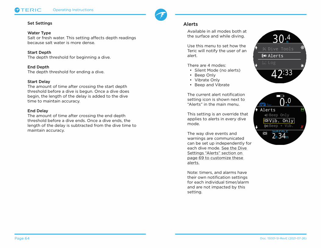
Operating Instructions
Page 64 Doc� 15001-SI-RevE (2021-07-26)
Set Settings
Water TypeSalt or fresh water� This setting affects depth readings because salt water is more dense�
Start DepthThe depth threshold for beginning a dive�
End DepthThe depth threshold for ending a dive�
Start DelayThe amount of time after crossing the start depth threshold before a dive is begun� Once a dive does begin, the length of the delay is added to the dive time to maintain accuracy�
End DelayThe amount of time after crossing the end depth threshold before a dive ends� Once a dive ends, the length of the delay is subtracted from the dive time to maintain accuracy�
Alerts
Available in all modes both at the surface and while diving�
Use this menu to set how the Teric will notify the user of an alert�
There are 4 modes:• Silent Mode (no alerts)• Beep Only • Vibrate Only• Beep and Vibrate
The current alert notification setting icon is shown next to “Alerts” in the main menu�
This setting is an override that applies to alerts in every dive mode�
The way dive events and warnings are communicated can be set up independently for each dive mode� See the Dive Settings “Alerts” section on page 69 to customize these alerts�
Note: timers, and alarms have their own notification settings for each individual timer/alarm and are not impacted by this setting�
m30.4
O2/He10/50
DECO 30 2m min
42 33:
981.3
TTSDive ToolsAlertsLog
PSI
DECO20 2 14
T11850
O2/He21/00
ft min
TTSft
mh342SURFACE
OC
SURFACE
NDL TTS----
FDOCOC Tec 0 mAlerts
.0
✘
Beep Only
Beep + Vib.Vib. Only

Operating Instructions
Page 65 Doc� 15001-SI-RevE (2021-07-26)
Bluetooth
Bluetooth is used for both firmware uploading and dive log downloading�
Use this option to initialize Bluetooth on your dive computer�
Log
The on-board log can store about 400 hours of dive logs at the default 10 second log rate of the computer in OC Rec mode�
Scroll up and down on the first page of the log to see a list of all of your dives�
Select a dive (Top right button) to pan through dive detail screens�
Scroll up and down inside the dive detail screens to change the dive�
Log contents:• Dive Number• Dive Date and Time• Max Depth• Average Depth• Dive Time• Temperature Graph• Starting and ending
tank pressures• SAC• Dive Mode• Surface interval• Surface pressure• Deco Settings• Start & end CNS
Log Options
The Log options menu allows you to set the next log number to match your lifetime dive count�
From here you can also delete and restore deleted logs�
Wait Connect2 : 50
43m 56min
LOG
#35 MAY-25Log Options
#34 MAY-22 28m 25min
#35
14m
DEPTH
MAY-2514:58
MAX28mAV 25min
m0.0
O2/He10/50
DECO 30 2m min 98
1.3
TTS
SURFACEmh1314
Bluetooth
Settings
Log
Off
The “Off” item puts the computer to sleep� While sleeping, the screen is blank, but the tissue contents are maintained for repetitive diving�
The “Off” menu item will not appear during a dive in any mode� It will also not appear after a dive until the dive End Dive Delay Time has expired or the dive has been ended manually to allow for a continuation dive�
End Dive
The “End Dive” menu item allows you to manually end the dive before the End Dive Delay has expire� This is useful if you have set a particularly long End Dive Delay and want to access the surface only features of the Teric quickly following a dive�

Operating Instructions
Page 66 Doc� 15001-SI-RevE (2021-07-26)
11. Settings ReferenceThe Settings menu can be accessed from the Teric’s main menu when at the surface�
Dive Mode
There are 5 available dive modes:
• OC Tec• OC Rec (default)• CC/BO• Gauge
(e�g� bottom timer mode)• Freedive
When changing to or from Gauge or Freedive Mode, the decompression tissues are cleared� This is because when in these modes the Teric does not know what gas you are breathing, and therefore cannot track inert gas loading� Plan repetitive dives accordingly�
For more information on which mode to choose, see Dive Mode Differentiation on page 10�
Layout
The Layout menu item in the dive settings menu is used to select between the 2 available layouts: Big & Standard�
m0.0
O2/He10/50
DECO 30 2m min 98
1.3
TTS
SURFACEmh1314
Settings
Bluetooth
Off
11.1. Dive Settings Menu
The first menu item within the settings menu is the Dive Settings Menu� This menu item also conveniently shows the current dive mode in gray�
All of the settings in the Dive Settings Menu are isolated to the Dive Mode in which they were set�
So, if you customize your layout, home screen, and function button for OC Rec, then switch to OC Tec, when you switch back, your original OC Rec settings will be preserved�
Settings
Dive|OC Rec
Deco|40/85
Dive
Dive Mode
Home Screen
OC Rec
LayoutBig
4 44
Dive Mode
CC/BOOC Tec
GaugeFreedive
OC Rec
✘
Dive
Dive Mode
Home Screen
OC Rec
LayoutBig
4 44
Layout
BigStandard
✘
Like all of the other settings in the dive settings menu, this option is isolated to the dive mode in which it was set�
See the Main Screen Layout section on page 11 for details about the different dive modes�

Operating Instructions
Page 67 Doc� 15001-SI-RevE (2021-07-26)
Home screen
This option is used to customize the Info row on the Home screen�
The Standard layout allows customization of the entire first page of the Info row�
Pick the number of elements you would like in the info row, then proceed to select which information you would like displayed in each position�
The Big layout (default for OC Rec mode) allows for customization of the right info row slot only because the left slot is taken by NDL which cannot be permanently obscured�
Note that in OC Tec and CC/BO modes, there is no customization available in the Big layout because we feel TTS should not be permanently obscured while decompression diving�
SELECT the right slot to bring up the list of options� Use the arrows to scroll through the available options� Press SELECT again to choose an option�
Dive
LayoutBig
Home Screen
FUNC ButtonCompass
Home Screen
Reset
OC REC
TTSNDL-- --
Back
Home Screen
Reset
OC REC
TTSNDL-- --
Choose DisplayNDL
SAC
T2 PressureT1 PressureAI
GTR
.00ft
21%
mh342SURFACE
NDL T1120-- B
AR
T1OCOC Rec
Home Screen
Reset
OC TEC
# Values: 3
T1 �+5
Back
120T2980
m 0.0
T1 �+5120
T2980
DECOm min
TTSOC Tec
SURFACEmh3412
18/45
---- -
In CC/BO mode there is a separate Home screen menu item for each CC and BO� This allows you to optimize your bailout screen layout in advance, minimizing button pushes during an emergency�
A complete list of Home Screen Customization options can be found on page 22�
Top-Right Disp
In OC Rec mode, the right Deco row slot of the standard layout can be customized like the Info row Home Screen�
All of the same customization options are available for this location�
Watch the video: Home Screen Configuration
OC Rec

Operating Instructions
Page 68 Doc� 15001-SI-RevE (2021-07-26)
In dive modes the FUNC button options are:
FUNC Setting Description
Switch SPToggles between high and low set points�
Switch > BOChanges dive mode to bail out�
Switch > CCChanges dive mode to closed circuit�
Select Gas Opens the gas select menu
Compass Opens Compass pop-up
Deco Plan Opens Dive planner
StopwatchOpens the Stopwatch pop-up
Tag Log Opens Tag Log pop-up
Home ScreenQuick return to home screen
Rst Av Depth Resets average depth
No Action No shortcut assigned
FUNC Button
The function button (top right button) can be customized in every mode to act as a shortcut to your most commonly used tool�
Use the FUNC Button menu item in dive settings to choose the function button shortcut�
OCBO
OC Tec
OCBOCC
OCBOCC
OCBO
OCBOCC
Dive
BO Home
BO FUNC Butt.
CC FUNC Butt.Switch > BO
Select Gas 4 44
CC FUNC Butt.
Select GasSwitch > BO
CompassDeco Plan
Switch SP
✘
In CC/BO mode there is a separate function button shortcut for each CC and BO� This allows you to optimize computer’s operation in advance, minimizing button pushes during an emergency�
Some options are only available in specific dive modes� Look for the corresponding mode icon indicating which mode each option is available in� No mode icons indicate the option is available in all dive modes�
OC Rec
OC Tec
OCBO
OCBOCC
OC Rec

Operating Instructions
Page 69 Doc. 15001-SI-RevE (2021-07-26)
Water Type
Water type (salinity) affects how the measured pressure is converted to depth� Settings:
• Fresh• EN13319• Salt
Density of freshwater and saltwater differ by about 3%� Saltwater, being denser, will display a shallower depth for the same measured pressure versus the Fresh setting�
The EN13319 value is between Fresh and Salt� It is from the European CE standard for dive computers, and is the Teric’s default value�
End Dive delay
Sets the time to wait after surfacing before ending the current dive�
This value can be set from 10 seconds to 10 minutes� Default is 10 seconds�
This value can be set to a longer time if you want brief surface intervals connected together into one dive� Some instructors use a longer end dive delay when teaching courses� Alternatively, a shorter time can be used to exit dive mode more quickly upon surfacing�
Log Rate
Sets how often dive samples are added to the Teric’s log� More samples will give a higher resolution dive log at the expense of log memory�
Default log rate in Freediving mode is 1 second� 10 seconds in every other mode�
Maximum log rate in Freedive Mode is 1/4 second�Maximum log rate in all other modes is 2 seconds�
Alerts
These settings allow you to modify your notification settings for warnings and dive events independently�
Dive
Log Rate10 s
Alerts
PPO2 Limits
Alerts
Warnings
Dive EventsBeep & Vib
Vibrate
Back
Note this is different from the top-level alerts menu� Those settings override these settings�
Like other attributes in the Dive Settings Menu, these alert settings are specific to the dive mode in which they were set�
There are 4 settings:• Visual only• Beep• Vibrate• Beep & Vibrate
For more information on the different types of alerts see the Alerts section on page 23�
For a list of alerts you might encounter see Warnings and Information Displays on page 86�
The Beeper setting changes the pitch of the Teric’s beeper� The High Pitch option is louder, but a Low Pitch setting is also available for those who have a difficult time hearing higher frequencies�
Operating Instructions
Page 70 Doc. 15001-SI-RevE (2021-07-26)
PPO2 Limits
This section allows changing of PPO2 limits�
All values are in absolute atmospheres [ATA] of pressure� (1 ATA = 1�013 Bar)
Bottom gas vs deco gas assumptionsWhen not in deco: The least oxygen rich mix that is turned on and all mixes with 40% O2 are assumed to be bottom gases� All other gases are assumed to be deco gases�
When in deco:Only the least oxygen rich mix is assumed to be a bottom gas� All other gases are assumed to be deco gases�
OC Low PPO2For all OC gases, PPO2 and the active gas display will flash red when the active gas is less than this value� (Default 0�18)
OC MOD PPO2This is the maximum allowable PPO2 during the bottom phase of the dive - Maximum Operating Depth� (Default 1�4)
For all OC bottom gases, PPO2 will turn yellow when within 0�03 of OC MOD PPO2�
Also for all OC bottom gases, PPO2 and the active gas display will flash red when PPO2 is more than 0�03 greater than OC MOD PPO2�
MODs of bottom gases are determined with this value�
Note: BO Mode never uses OC MOD PPO2
OC Deco PPO2All decompression predictions (Deco schedule and TTS) assume that the gas used for decompression at a given depth will be the gas with the highest PPO2 less than or equal to this value� (Default 1�61)
Suggested gas switches (when the current gas is displayed in yellow) are determined by this value� If you change this value, please be sure you understand its effect�
For example, if lowered to 1�50, then a switch to oxygen (99/00) will not be assumed at 6m/20ft�
PPO2 of all deco gases display in yellow when within 0�03 of OC DECO PPO2�
For all OC deco gases, PPO2 and the active gas flash red when PPO2 is more than 0�03 greater than OC DECO PPO2�
MODs of deco gases are determined with this value�
CC Low PPO2 PPO2 displays in flashing red when less than this value� (Default 0�40)
CC High PPO2PPO2 displays in flashing red when greater than this value� (Default 1�60)
Reset LimitsResets all PPO2 limits for this dive mode back to defaults�
Note: In both OC and CC mode, a “Low PPO2” or “High PPO2” alert is displayed when the limits are violated for more than 30 seconds�
WARNING
Do not change these values unless you fully understand the effect�

Operating Instructions
Page 71 Doc� 15001-SI-RevE (2021-07-26)
11.2. Deco Menu
The Deco Settings Menu provides options for adjusting the decompression algorithm�
Shown to the right of this item are the currently selected GF factors�
Like the Dive Settings Menu, any settings changed in this menu will only apply to the Dive Mode you are currently in�
Deco Model
This will just show ZHL16C+GF indicating that the Bühlmann ZHL-16 with gradient factors model is being used�
GF Conserv.
3 preset conservatism levels are available� In order of increasing conservatism:
• Low (45/95)• Med (40/85)• High (35/75)
Medium conservatism is the default setting for OC Rec mode�
A custom GF option is also available in every dive mode�
When Custom is selected, fields for editing GF Low and GF High will appear in the Deco Menu�
OC Tec and CC/BO modes have a custom default of 30/70�
For a more detailed explanation of the GF algorithm and the meaning of GF Low and GF High, please refer to Erik Baker’s excellent articles: Clearing Up The Confusion About “Deep Stops” and Understanding M-values� The articles are readily available on the web�
Also see the Decompression and Gradient Factors section on page 27�
Last Stop
Use this setting to identify where you plan to do your last decompression stop� The choices are 3m/10ft and 6m/20ft�
This setting makes TTS predictions more accurate by calculating according to planned last stop depth� It does not affect real time decompression calculations�
Rate of decompression is related to the partial pressure of inspired inert gas� If breathing a high fraction of inert gas, the last stop depth may make a significant difference to required decompression time� If breathing pure O2, last stop will depth make no difference as the fraction of inspired inert gas is zero�
This setting has no impact on safety stops� These are governed by the logic described in the Safety Stops section on page 25�
Settings
Dive|OC Rec
Deco|40/85
Gases
Deco
Deco Model
Last Stop
GF Conserv.Med 40/85
3 m
ZHL16C+GF
4 44
GF Conserv.
Med 40/85Low 45/95
High 35/75Custom ✘
Deco
GF Conserv.
GF High
GF Low40
85
Med 40/85

Operating Instructions
Page 72 Doc. 15001-SI-RevE (2021-07-26)
Safety Stops
The Safety Stop setting is only present in OC Rec Mode� It can be set to the following values:
• Off• 3 minutes• 4 minutes• 5 minutes• Adapt• Count Up
When using the Adapt setting, a 3 minute safety stop will be used, unless the dive exceeds 30m (100ft) or the NDL falls below 5 minutes, in which case a 5 minute safety stop is used�
Read more about Safety Stops on page 25�
Clear Counter
The Clear Counter setting is only available in OC Tec and CC/BO Dive Modes�
By default, the clear counter will count up from zero once decompression obligation has been cleared in OC Tec and CC/BO modes� It can be turned off here�
Read more about Decompression Stops on page 26
11.3. Gases
The Teric supports 5 programmable gases in OC Rec, OC Tec, CC, and BO dive modes�
This setting is the same as the Edit Gases item found in the main menu, but is conveniently located along with the other dive settings�
For a description of how to set each gas, please see the Edit Gases section on page 62�
In CC/BO mode, both the CC diluent and BO open circuit gas lists are directly accessible, eliminating the need to toggle between the two operating modes to check gases from the Edit Gases option in the main menu�
Note that OC Tec mode and BO mode share the same gas list� Editing one will edit the other�
OC Rec
OC Tec OCBOCC
Deco
Last Stop
Safety StopAdapt
3 m
Back
Deco
Last Stop
Clear CounterCount Up
3 m
Back
Settings
Deco|30/70
Gases
AI|T1
Edit Gases
ON 50/0099/0018/45
00/0000/00
ACT
OFF
OFF
ON
Back
Settings
Deco|30/70
CC Gases
BO Gases

Operating Instructions
Page 73 Doc. 15001-SI-RevE (2021-07-26)
11.4. Set Points
This menu item is only available in CC/BO mode
High & Low Set points
Like the Set Points selection in the main menu, this menu allows you to edit your High and Low set points�
Auto Set Point switch
SP Auto Up and SP Auto Down are also available in this menu to set up automatic set point switching� They can be configured to auto switch up only, down only, both, or neither�
Use SP Auto Up to set whether the up switch occurs automatically or manually�
Example:
Up: 0�7 > 1�3 Auto Up Depth = 21mDown: 1�3 > 0�7 Auto Down Depth = 5m
The dive starts at the 0�7 set point� As you descend past 21 m, the set point switches “up” to 1�3�
You finish your bottom time, then begin ascending� When you ascend above 5m, it switches “down” to 0�7�
When a switch is set to “Auto”, you can always manually override the setting at any time during the dive�
The automatic switches only occur when crossing the specified depth� Say for example, the switch up depth is set to 15m� You start the dive on the low set point, then as you descend past 15m, the set point automatically switches up to high� If at 24m you then manually switch back to the low set point, the set point will remain low� If you ascend shallower than 15m then re-descend deeper than 15m again, the automatic set point switch will occur again� The Teric enforces a 6m (20ft) gap between switch up and switch down depths to prevent rapid automatic switching between set points for small depth changes� The values 0�7 and 1�3 are shown as examples only� Other values for the low and high set point can be adjusted in the Set Points menu�
OCBOCCSettings
AI|Off
Set Points
BO Gases
Set Points
Low Set Point
SP Auto Up
High Set Point1.3
On
0.7
Set Points
SP Auto Up
SP Auto Down
Auto Up Depth021 m
On
On
If SP Auto Up is set to “On”, use Auto Up Depth to set the depth at which the auto switch occurs�
The menu options are the same for the down set point switch�
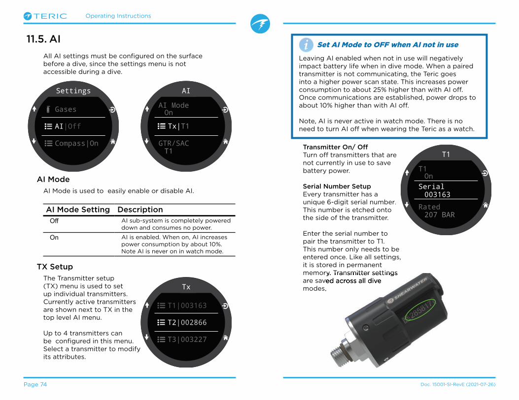
Operating Instructions
Page 74 Doc� 15001-SI-RevE (2021-07-26)
11.5. AI
All AI settings must be configured on the surface before a dive, since the settings menu is not accessible during a dive�
Transmitter On/ OffTurn off transmitters that are not currently in use to save battery power�
Serial Number SetupEvery transmitter has a unique 6-digit serial number.This number is etched onto the side of the transmitter�
Enter the serial number to pair the transmitter to T1� This number only needs to be entered once� Like all settings, it is stored in permanent memory� Transmitter settings are saved across all dive modes�
Set AI Mode to OFF when AI not in use
Leaving AI enabled when not in use will negatively impact battery life when in dive mode� When a paired transmitter is not communicating, the Teric goes into a higher power scan state� This increases power consumption to about 25% higher than with AI off� Once communications are established, power drops to about 10% higher than with AI off�
Note, AI is never active in watch mode� There is no need to turn AI off when wearing the Teric as a watch�
Settings
AI|Off
Gases
Compass|On
AI
AI Mode
GTR/SACT1
On
Tx|T1
AI Mode
AI Mode is used to easily enable or disable AI�
AI Mode Setting Description
Off AI sub-system is completely powered down and consumes no power�
On AI is enabled� When on, AI increases power consumption by about 10%� Note AI is never on in watch mode�
TX Setup
The Transmitter setup (TX) menu is used to set up individual transmitters� Currently active transmitters are shown next to TX in the top level AI menu�
Up to 4 transmitters can be configured in this menu� Select a transmitter to modify its attributes�
Tx
T2|002866
T3|003227
T1|003163
T1
T1
Rated
Serial003163
207 BAR
On
memory� Transmitter settings are saved across all dive modes�

Operating Instructions
Page 75 Doc. 15001-SI-RevE (2021-07-26)
Reserve PressureEnter the reserve pressure�
The valid range is 28 to 137 bar (400 to 2000 PSI)�
The reserve pressure setting is used for: 1) Low pressure warnings 2) Gas Time Remaining (GTR) calculations
A “Reserve Pressure” warning will be generated when the tank pressure falls below this setting�
A “Critical Pressure” warning will be generated when the tank pressure falls below the larger of 21 Bar (300 PSI) or half the reserve pressure�
For example, if reserve pressure is set to 48 BAR, the critical warning will occur at 24 BAR (48/2)� If the reserve pressure is set to 27 BAR, the critical warning will occur at 21 BAR�
RenameAllows the changing of the transmitters title as it appears on menus and screens throughout the dive computer� Two characters can be customized per tank� The options are:
First Character: T,S,B,O, or D�
Second Character: 1,2,3, or 4�
GTR/SAC
Gas Time Remaining (GTR) is the time in minutes that can be spent at the current depth and SAC rate until a direct ascent to the surface at a rate of 10 m/min (33 feet/min) would result in surfacing with the reserve pressure� The SAC rate is averaged over the last two minutes of diving for calculating GTR�
GTR/SAC is only based on one tank, or on two tanks in sidemount configuration� Note that for sidemount the tanks must be of identical volume for SAC to be accurate�
The GTR/SAC setting is also used for identifying sidemount mode� Selecting a SM option here will enable tank switch notifications�
GTR/SAC Setting
Description
Off GTR is disabled� SAC is also disabled�
T1, T2, T3, or T4
Selected Transmitter is used for GTR and SAC calculations�
SM:T1+T2(Or similar)
Combined SAC for selected transmitters will be calculated and used for GTR� Sidemount switch notifications will be enabled�
GTR and SAC displays are described in the AI Displays section on page 50�
Read more about Sidemount AI on page 52�
Read more about how SAC is calculated on page 54�
Read more about how GTR is calculated on page 55�
T1
Rated
Rename
Reserve
T1
048 BAR
207 BAR
AI
GTR/SAC SM:T1+T2SM Switch 21 BAR
TX|T1 T2

Operating Instructions
Page 76 Doc� 15001-SI-RevE (2021-07-26)
Settings
Display|m/�C
Compass|On
AI|T1
Compass
Enable
Declination
Outter RingHide
+0�
On
11.6. Compass
Enable
Disabling the compass will prevent it from being displayed in the info row� The display refresh rate can be reduced when the compass is not displayed on the screen, so disabling the compass allows a slight power savings (about 10%)�
The compass does not increase power consumption when not on-screen�
Outer Ring
Toggles the compass outer ring overlay� This can also be toggled from the compass pop-up� More details can be found in the compass pop-up section on page 40�
Tips for a good compass calibration
• Stay away from metal objects� For example, wrist watches, metal desks, boat decks, desktop computers, etc� can all interfere with the Earth’s magnetic field�
• Rotate to as many 3D positions as possible� Upside down, sideways, on edge, etc�
• Compare with another compass (not a smart phone as those are terrible) to check your calibration�
Declination
In most places, a compass does not point towards True North, but rather to Magnetic North� The difference in angle between these two directions is called the magnetic declination (also called magnetic variation), and varies around the world� The declination in your location can be found on maps or by searching on-line�
This setting can be set from -99° to +99°�
If you only need to match an uncompensated compass, or your navigation is all based on relative directions, then this setting is not necessary and can be left at 0°�
Calibrate
Calibration of the compass may be needed if the accuracy drifts over time or if a permanent magnet or ferromagnetic metal (e�g� iron or nickel) object is mounted very close to the Teric� To be calibrated out, such an object must be mounted with the Teric so that it moves along with the Teric Display�
Compare the Teric with a known good compass or fixed references to determine if calibration is needed� If comparing against fixed references, remember to consider the local deviation between Magnetic North and True North (declination)�
Calibration is typically not needed when traveling to different locations� The adjustment needed then is the True North (declination)�
When calibrating, rotate the Teric smoothly through as many 3D twists and turns as possible in 15 seconds� Keep metal and magnetic objects away during calibration� The calibration can also be reset back to the factory values� After calibration, it is recommended to compare the compass accuracy with a known good compass or fixed references�

Operating Instructions
Page 77 Doc. 15001-SI-RevE (2021-07-26)
Settings
Watch
Display|m/�C
Compass
Display
Depth Units
Temp. Units�C
Meters
Colors
Colors
ThemeSunlight
Customize
11.7. Display
Depth and temperature units are displayed in the display settings menu option�
Depth Units Configurable to Feet or Meters�
Temp. UnitsConfigurable to ˚F or ˚C�
Colors
Teric display colors can be changed for added contrast or visual appeal�
Themes4 preset color themes are available:
• Standard• Sunlight• Night• Predator
Themes apply presets that quickly change the overall look of the Teric UI�
In addition to these preset themes, the Teric’s color scheme can be extensively customized� Choose the “Standard” theme option to reset the colours to defaults�
Customize Colors
Values, Titles, Units, Menu text, and Watch Face colors can all be customized from this menu�
15 color options are available�
Color Options:
• White• Red• Green• Blue• Cyan• Magenta• Yellow• Orange• Pink• Lime• Pastel Green• Grapefruit• Ice• Violet• Purple
Customize
Values Color
Units Color
Titles ColorCyan
Cyan
White
Customize
Menu Color
Watch ColorWhite
White
Back

Operating Instructions
Page 78 Doc. 15001-SI-RevE (2021-07-26)
Brightness
Brightness
Include Off
# Levels2
No
High
Brightness
BrightnessThis setting does the same thing as the LIGHT (top right) Teric button
Screen brightness can be set to one of four fixed levels�
Options:Dim: Made specifically for cave conditions� Low: Second longest battery life�Med: Best mix of battery life and readability�High: Easiest readability, especially in bright sunlight�
# LevelsThis setting defines how many brightness levels are cycled through when pressing the LIGHT button� It also effects how many brightness levels are visible in the Brightness menu setting above�
Include OffThis setting determines if OFF is available as an option when the LIGHT button is pressed�
The battery life of the Teric is dramatically improved when “Off”� This is a convenient feature if you forget your Teric charger at home and are being judicious with battery consumption�
Timeouts
Advanced options for reducing power consumption�
Dive TimeoutDefines action upon dive mode timeout�Options: • to off• to watch
Dive TimeoutDefines timeout delay for dive mode� Options:• 5 min• 10 min• 15 min
Watch TimeoutDefines criteria for watch timeout to off�Options:• No motion• No button presses
Watch TimeoutDefines timeout delay for watch mode� Options: • 15 s• 30 s• 1 min• 5 min• 10 min• 20 min
Operating Instructions
Page 79 Doc. 15001-SI-RevE (2021-07-26)
Daylight Savings
Simply adds one hour to the time without needing to change the timezone�
FUNC Button
Set the Function button shortcut for Watch Mode�
FUNC button optionsThe function button has different options that can be independently set for each mode� In Watch Mode, there are eight function button options�
FUNC Setting Description
Watch Face(Default)
Cycles the watch face between Digital, Analog, and Orbits�
FlashlightTurns on the flashlight function
Alarms Brings up the alarms menu
StopwatchOpens the Stopwatch pop-up
Timer Opens the timer pop-up
Turn Off Turns Teric Off
No Action No shortcut assigned
UTC Time Zone Location
+13:00 Tonga
+12:00 Aukland
+11:00 Solomon Islands
+10:00 Sydney
+9:00 Tokyo
+8:30 North Korea
+8:00 China
+7:00 Bangkok
+6:00 Dhaka
+5:45 Nepal
+5:30 Mumbai
+5:00 Karachi
+4:30 Kabul
+4:00 Seychelles
+3:30 Tehran
UTC Time Zone Location
+3:00 Istanbul
+2:00 Cape Town
+1:00 Paris
0:00 London
-1:00 Azores
-3:00 Rio de Janeiro
-4:00 Halifax
-5:00 New York
-6:00 Mexico City
-7:00 Denver
-8:00 Los Angeles
-9:00 Anchorage
-10:00 French Polynesia
-11:00 American Samoa
Settings
General
Watch
Display|m/�C
11.8. Watch
Time FormatThere are two available options for time format:• 12-hours• 24-hours
Time
Time on the Teric is set here�
Date
Date on the Teric is set here�
Time Zone
Setting the time zone can make it easier to adjust the time while traveling� Consult the table below to find the UTC time for the location nearest you�

Operating Instructions
Page 80 Doc. 15001-SI-RevE (2021-07-26)
11.9. General
User Info
Use this menu to change the information presented on the Owner Info screen�
Battery
Quick ChargeWhen enabled Quick charge charges the watch a little bit faster� However, not all USB ports supply sufficient current for quick charge�
Quick Charge is disabled by default� If you’ve enabled quick charge and you’re having problems charging your Teric, disabling quick charge may help�
Defaults
This will reset all user changed options to factory settings and / or clear the tissues on the Teric� A reset to defaults cannot be reversed�
Note: This will not delete dive logs, or reset dive log numbers�
System Info
The System Info section lists the computer’s serial number as well as other technical information you may be asked to provide to tech support for troubleshooting purposes�
Settings
Home
General
Watch

Operating Instructions
Page 81 Doc� 15001-SI-RevE (2021-07-26)
12.1. Shearwater Cloud Desktop12. Firmware Update and Log Download
It is important to keep the firmware on your dive computer up to date� In addition to new features and improvements, firmware updates address important bug fixes�
There are two ways to update the firmware on your Teric: 1) With Shearwater Cloud Desktop 2) With Shearwater Cloud Mobile
Please note that Teric does not support the original Shearwater desktop application�
Connect to Shearwater Cloud DesktopOn your Teric, start Bluetooth by selecting the Bluetooth menu item from the main menu�
Upgrading the firmware resets decompression tissue loading� Plan repetitive dives accordingly�
During the update process, the screen may flicker or go blank for a few seconds
Ensure you have the most recent version of Shearwater Cloud Desktop� You can get it
here�
1
2
3
m0.0
O2/He10/50
DECO 30 2m min 98
1.3
TTS
SURFACEmh1314
Bluetooth
Settings
Log
In Shearwater Cloud Desktop:1� Click the connect icon to open the connect tab�2� Scan for Dive Computer3� Once you’ve connected the computer once, use
the Teric tab to connect faster next time
Wait Connect2 : 50
Shearwater Cloud Desktop Connect Tab

Operating Instructions
Page 82 Doc� 15001-SI-RevE (2021-07-26)
Once the Teric is connected, the connect tab will show a picture of the dive computer�
Download Dives
Select “Download Dives” from the connect tab�
A list of dives will be generated� and you can un-select any dive logs you don’t want to download, then press OK�
Shearwater Cloud Desktop will transfer the dives to your computer�
Shearwater Cloud Desk-top Connect Tab
Update Firmware
Select “Update Firmware” from the connect tab�
Shearwater Cloud Desktop will automatically select the latest available firmware�
When prompted, select your language and confirm the update�
The Teric screen will give percentile updates of receiving the firmware, and then the Personal Computer will read “Firmware successfully sent to the computer” on completion�
Firmware updates can take up to 15 minutes�
Select the dives you wish to download and press OK

Operating Instructions
Page 83 Doc� 15001-SI-RevE (2021-07-26)
12.2. Shearwater Cloud Mobile
Ensure you have the most recent version of Shearwater Cloud Mobile�
Download it from Google Play or the Apple App Store�
Connect to Shearwater Cloud MobileOn your Teric, start Bluetooth by selecting the Bluetooth menu item from the main menu�
m0.0
O2/He10/50
DECO 30 2m min 98
1.3
TTS
SURFACEmh1314
Bluetooth
Settings
Log
Wait Connect2 : 50
On Shearwater cloud mobile:1� Press the connect icon at the bottom of the screen2� Select your teric from the list of Bluetooth devices
Download Dives
Select “Download Dives”
A list of dives will be generated and you can un-select any dive logs you don’t want to download, then press OK�
Shearwater Cloud will transfer the dives to your smart phone�
Update Firmware
Once the Teric is connected to Shearwater cloud mobile, select “Update Firmware” from the connect tab�
Shearwater Cloud mobile will automatically select the latest available firmware�
When prompted, select your language and confirm the update�
The Teric screen will give percentile updates of receiving the firmware, and then the mobile app will read “Firmware successfully sent to the computer” on completion�
Firmware updates can take up to 15 minutes�

Operating Instructions
Page 84 Doc� 15001-SI-RevE (2021-07-26)
13. Teric StrapThe included Teric strap is a durable, stretchy silicone designed to grip a wet suit or dry suit without sliding around� Various strap options are available�
14. Charging
The Shearwater Teric charges wirelessly when mounted on the included dock and on some third party wireless Qi complaint chargers�
The Teric screen rotates 90 degrees for easy viewing of the time when the Teric is mounted on the charger�
The screen will turn off after 20 seconds to preserve the long term health of the screen and battery, but pressing any button will wake up the Teric so the time can be viewed�
The SUN button will adjust the screen brightness and the OFF button will turn the screen off�
Dive Mode functions are not available while the Teric is charging�
For extra length, use the included extender strap�
The strap is fastened to the Teric via stainless steel watch lugs which can be easily removed and replaced with two standard 1�5mm hex screwdrivers (included)�
The Teric is compatible with most 22mm off the shelf straps for additional customizability�
Additional lug screws are included in the box�
DO NOT OVER TORQUE LUG SCREWS Once it feels tight, stop screwing� Over torquing can damage screw threads�
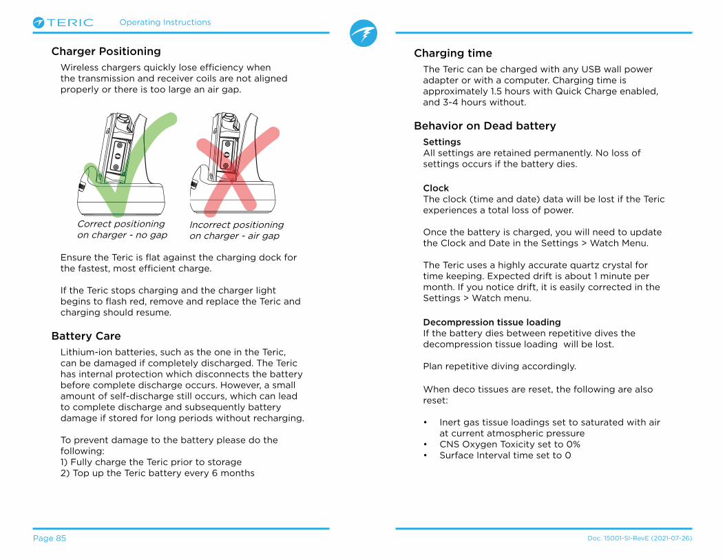
Operating Instructions
Page 85 Doc� 15001-SI-RevE (2021-07-26)
Ensure the Teric is flat against the charging dock for the fastest, most efficient charge�
If the Teric stops charging and the charger light begins to flash red, remove and replace the Teric and charging should resume�
Battery Care
Lithium-ion batteries, such as the one in the Teric, can be damaged if completely discharged� The Teric has internal protection which disconnects the battery before complete discharge occurs� However, a small amount of self-discharge still occurs, which can lead to complete discharge and subsequently battery damage if stored for long periods without recharging�
To prevent damage to the battery please do the following:1) Fully charge the Teric prior to storage2) Top up the Teric battery every 6 months
Charging time
The Teric can be charged with any USB wall power adapter or with a computer� Charging time is approximately 1�5 hours with Quick Charge enabled, and 3-4 hours without�
Behavior on Dead battery
SettingsAll settings are retained permanently� No loss of settings occurs if the battery dies�
ClockThe clock (time and date) data will be lost if the Teric experiences a total loss of power�
Once the battery is charged, you will need to update the Clock and Date in the Settings > Watch Menu�
The Teric uses a highly accurate quartz crystal for time keeping� Expected drift is about 1 minute per month� If you notice drift, it is easily corrected in the Settings > Watch menu�
Decompression tissue loadingIf the battery dies between repetitive dives the decompression tissue loading will be lost�
Plan repetitive diving accordingly�
When deco tissues are reset, the following are also reset:
• Inert gas tissue loadings set to saturated with air at current atmospheric pressure
• CNS Oxygen Toxicity set to 0%• Surface Interval time set to 0
Charger Positioning
Wireless chargers quickly lose efficiency when the transmission and receiver coils are not aligned properly or there is too large an air gap�
Correct positioning on charger - no gap
Incorrect positioning on charger - air gap
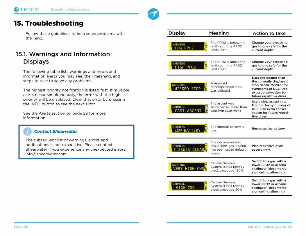
Operating Instructions
Page 86 Doc� 15001-SI-RevE (2021-07-26)
15. TroubleshootingFollow these guidelines to help solve problems with the Teric�
15.1. Warnings and Information Displays
The following table lists warnings and errors and information alerts you may see, their meaning, and steps to take to solve any problems�
The highest priority notification is listed first� If multiple alerts occur simultaneously, the error with the highest priority will be displayed� Clear that error by pressing the INFO button to see the next error�
See the Alerts section on page 23 for more information�
Display Meaning Action to take.0 0ftMAX
ft103.6 4:57STOPWATCH
SURFACE
Deep
19:16
FD
CLEAR
WARNINGLOW PPO2
The PPO2 is below the limit set in the PPO2 limits menu�
Change your breathing gas to one safe for the current depth..0 0ft
MAXft103.6 4:57
STOPWATCH
SURFACE
Deep
19:16
FD
CLEAR
WARNINGHIGH PPO2
The PPO2 is above the limit set in the PPO2 limits menu�
Change your breathing gas to one safe for the current depth.
.0 0ftMAX
ft103.6 4:57STOPWATCH
SURFACE
Deep
19:16
FD
CLEAR
WARNINGMISSED STOP
A required decompression stop was violated�
Descend deeper than the currently displayed stop depth. Monitor for symptoms of DCS. Use extra conservatism for future repetitive dives. .0 0ft
MAXft103.6 4:57
STOPWATCH
SURFACE
Deep
19:16
FD CLEAR
WARNINGFAST ASCENT
The ascent was sustained as faster than 10m/min (33ft/min)
Use a slow ascent rate. Monitor for symptoms of DCS. Use extra conser-vatism for future repeti-tive dives. .0 0ft
MAXft103.6 4:57
STOPWATCH
SURFACE
Deep
19:16
FD
CLEAR
WARNINGLOW BATTERY
The internal battery is low�
Recharge the battery.
.0 0ftMAX
ft103.6 4:57STOPWATCH
SURFACE
Deep
19:16
FD
CLEAR
WARNINGTISSUES CLEAR
The decompression tissue inert gas loading has been set to default levels�
Plan repetitive dives accordingly.
.0 0ftMAX
ft103.6 4:57STOPWATCH
SURFACE
Deep
19:16
FD
CLEAR
WARNINGVERY HIGH CNS
Central Nervous System (CNS) toxicity clock exceeded 150%
Switch to a gas with a lower PPO2 or ascend shallower (decompres-sion ceiling allowing).0 0ft
MAXft103.6 4:57
STOPWATCH
SURFACE
Deep
19:16
FD
CLEAR
WARNING HIGH CNS
Central Nervous System (CNS) toxicity clock exceeded 90%
Switch to a gas with a lower PPO2 or ascend shallower (decompres-sion ceiling allowing)
Contact Shearwater
The subsequent list of warnings, errors and notifications is not exhaustive� Please contact Shearwater if you experience any unexpected errors: info@shearwater�com

Operating Instructions
Page 87 Doc� 15001-SI-RevE (2021-07-26)
Display Meaning Action to takem min
BAR
T129
SURFACE +
.0 0ftMAX
ft103.6 4:57STOPWATCH
SURFACE
Deep
19:16
FD
CLEAR
WARNINGTI CRITICAL
Tank pressure has fallen below the critical pressure�
Be aware that gas is run-ning low. Begin to end your dive and perform a controlled ascent to the surface.
m min
PSI
T1682
SURFACE +.0 0ft
MAXft103.6 4:57
STOPWATCH
SURFACE
Deep
19:16
FD
CLEAR
WARNINGTI LOW PRESS
Tank pressure has fallen below the reserve pressure setting�
Be aware that gas is run-ning low. Begin to end your dive and perform a controlled ascent to the surface.
I
T1
3042PS
I3042PS
COMMSAlternates
I
T1
----PS
I----PS
Alternates COMMS
I3042PS
I
T1
3042PS
Low BatAlternates
I3042PS
I
T1
3042PS
Low BatAlternates .0 0ft
MAXft103.6 4:57
STOPWATCH
SURFACE
Deep
19:16
FD
CLEAR
WARNINGT1 LOW BATT
Low transmitter battery�
Replace the transmitter battery.
.0 0ftMAX
ft103.6 4:57STOPWATCH
SURFACE
Deep
19:16
FD
CLEAR
WARNINGDECO NEEDED
Decompression stops are required� OC Rec mode only�
Perform decompression stops as directed.
NDL is less than 5 minutes� OC Rec mode only�
Ascend soon to avoid decompression obliga-tion.
I
T1
----PS
I3042PS
No CommsAlternates No communications for
30 to 90 seconds�See AI Connection prob-lems on page 87
I
T1
3042PS
I3042PS
COMMSAlternates
I
T1
----PS
I----PS
Alternates COMMS
I3042PS
I
T1
3042PS
Low BatAlternates
I3042PS
I
T1
3042PS
Low BatAlternates
+.0 0ft
MAXft103.6 4:57
STOPWATCH
SURFACE
Deep
19:16
FD
CLEAR
WARNINGT1 LOST COMMS
No communications for 90+ seconds�
See AI Connection prob-lems on page 87
GTR T1
---GTR is not available when on the surface�
None. GTR will display during a dive.
Display Meaning Action to take
GTRwait
T1
GTR (and SAC) are not available for the first few minutes of a dive�
None. After a few minutes, enough data has been collected for display.
15.2. AI Connection problems
If you are seeing “No Comms” errors, follow these steps:
If the “No Comms” is persistent:
Check that the proper serial number is entered into the Tx Setup menu�Ensure the transmitter is turned on, by connecting it to a first stage and turning on the tank valve� Applying high pressure > 50 PSI (3�5 Bar) is the only way to turn on the transmitter� The transmitter will power off after 2 minutes of no pressure�Bring the handset within range (3ft / 1m) of the transmitter� Having the transmitter too close (less than 2 inches / 5 cm) can also cause communication loss�
If the “No Comms” is intermittent:
Search for sources of radio frequency (RF) interference, such as HID lights, scooters, or photo flashes� Try eliminating such sources to see if this solves the connection problem�• Check the distance from transmitter to handset�
If range related dropouts are occurring during diving, locating the transmitter on short length of high pressure hose is possible to decrease the transmitter to handset distance�
.0 0ftMAX
ft103.6 4:57STOPWATCH
SURFACE
Deep
19:16
FD
CLEAR
WARNINGLOW NDL

Operating Instructions
Page 88 Doc. 15001-SI-RevE (2021-07-26)
16. Storage and MaintenanceThe Teric dive computer and transmitter should be stored dry and clean�
Do not allow salt deposits to build up on your dive computer� Rinse your computer with fresh water to remove salt and other contaminants�
Do not wash under high pressure jets of water as it may cause damage to the depth sensor�
Do not use detergents or other cleaning chemicals as they may damage the dive computer� Allow to dry naturally before storing�
Store the dive computer and transmitter out of direct sunlight in a cool, dry and dust free environment� Avoid exposure to direct ultra-violet radiation and radiant heat�
16.1. AMOLED Burn In
One of our favorite features of the Teric is the high-contrast OLED screen� Unfortunately a trade-off with any OLED is the risk of burn in over time�
Burn in refers to a ghostly image that remains on the screen when the same screen content is displayed for a long time� We employ techniques to try and prevent burn in, but given the nature of a dive computer display, some burn in is inevitable�
Burn in is more likely when you use your Teric as a daily wear watch due to increased screen on time�
Things You Can Do To Reduce Burn In
• Reduce screen brightness• Adjust timeouts to turn off the display sooner• Remove info from the watch display
17. ServicingThere are no user serviceable parts inside the Teric or transmitters� Do not tighten or remove the faceplate screws� Clean with water ONLY� Any solvents may damage the Teric dive computer�
Service of the Shearwater Teric may only be done at Shearwater Research, or by any of our authorized service centers�
Contact Info@shearwater�com for service requests�
Evidence of tampering will void your warranty!
18. Glossary
CC - Closed circuit� Scuba diving using a rebreather
where exhaled gas is recirculated with carbon dioxide
removed�
GTR - Gas Time Remaining� The time, in minutes, that
can be spent at the current depth and SAC rate until a
direct ascent to the surface would result in surfacing
with the reserve tank pressure�
NDL - No Decompression Limit� The time, in
minutes, that can be spent at the current depth until
mandatory decompression stops will be required�
O2 - Oxygen gas�
OC - Open circuit� Scuba diving where gas is exhaled
into the water (i�e� most diving)�
PPO2 - Partial Pressure of Oxygen, sometimes PPO2�
RMV - Respiratory Minute Volume� Gas usage rate
measured as the volume of gas consumed, adjusted
as if at a pressure of one atmosphere� Units of Cuft/
minute or L/minute�
SAC - Surface Air Consumption� Gas usage rate
measured as the rate of tank pressure change,
adjusted as if at a pressure of one atmosphere (i�e�
surface pressure)� Units of PSI/minute or Bar/minute�
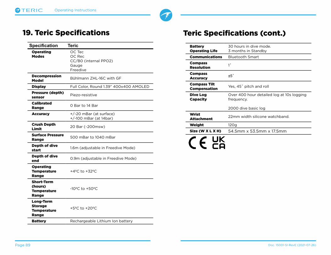
Operating Instructions
Page 89 Doc� 15001-SI-RevE (2021-07-26)
19. Teric Specifications
Specifi cation TericOperating Modes
OC TecOC RecCC/B0 (internal PPO2)GaugeFreedive
Decompression Model
Bühlmann ZHL-16C with GF
Display Full Color, Round 1�39” 400x400 AMOLED
Pressure (depth) sensor
Piezo-resistive
Calibrated Range
0 Bar to 14 Bar
Accuracy +/-20 mBar (at surface)+/-100 mBar (at 14bar)
Crush Depth Limit
20 Bar (~200msw)
Surface Pressure Range
500 mBar to 1040 mBar
Depth of dive start
1�6m (adjustable in Freedive Mode)
Depth of dive end
0�9m (adjustable in Freedive Mode)
Operating Temperature Range
+4ºC to +32ºC
Short-Term (hours) Temperature Range
-10ºC to +50ºC
Long-Term Storage Temperature Range
+5ºC to +20ºC
Battery Rechargeable Lithium Ion battery
Battery Operating Life
30 hours in dive mode�3 months in Standby
Communications Bluetooth Smart
Compass Resolution
1˚
Compass Accuracy
±5˚
Compass Tilt Compensation
Yes, 45˚ pitch and roll
Dive Log Capacity
Over 400 hour detailed log at 10s logging frequency�
2000 dive basic log
Wrist Attachment
22mm width silicone watchband�
Weight 120g
Size (W X L X H) 54�5mm x 53�5mm x 17�5mm
Teric Specifications (cont.)

Operating Instructions
Page 90 Doc. 15001-SI-RevE (2021-07-26)
20. Regulatory InformationA) USA-Federal Communications Commission (FCC)This equipment has been tested and found to comply with the limits for a Class B digital device, pursuant to Part 15 of FCC Rules� These limits are designed to provide reasonable protection against harmful interference in a residential installation� This equipment generates, uses, and can radiate radio frequency energy� If not installed and used in accordance with the instructions, it may cause harmful interference to radio communications� However, there is no guarantee that interference will not occur in a particular installation�
If this equipment does cause harmful interference to radio or television reception, which can be determined by tuning the equipment off and on, the user is encouraged to try and correct the interference by one or more of the following measures:• Reorient or relocate the receiving antenna• Increase the distance between the equipment and the receiver�• Connect the equipment to outlet on a circuit different from that to which the receiver is connected�• Consult the dealer or an experienced radio/TV technician for help�Any changes or modifications not expressly approved by the party responsible for compliance could void the user’s authority to operate the equipment�
Caution: Exposure to Radio Frequency Radiation.This device must not be co-located or operating in conjunction with any other antenna or transmitter�Teric Dive Computer Contains TX FCC ID: 2AA9B05Pelagic Pressure Systems Transmitter Contains TX FCC ID: MH8A
B) Canada - Industry Canada (IC)This device complies with RSS 210 of Industry Canada�Operation is subject to the following two conditions:(1) this device may not cause interference, and(2) this device must accept any interference, including interference that may cause undesired operation of this device�
L‘utilisation de ce dispositif est autorisée seulement aux conditions suivantes :(1) il ne doit pas produire d’interference, et(2) l’utilisateur du dispositif doit étre prêt à accepter toute interference radioélectrique reçu, même si celle-ci est susceptible de compromettre le fonctionnement du dispositif�
Caution: Exposure to Radio Frequency Radiation.The installer of this radio equipment must ensure that the antenna is located or pointed such that it does not emit RF field in excess of Health Canada limits for the general population; consult Safety Code 6, obtainable from Health Canada’s website�
Teric Dive Computer Contains TX IC: I2208A-05
C) EU and UK Conformance Statements• EC type examination conducted by: SGS Fimko Oy Ltd, O�O� Box 30 (Särkiniementie 3) 00211 Helsinki, Finland, Notified Body No� 0598�• UK EC type examination conducted by: SGS United Kingdom Ltd, Weston-super-Mare, BS22 6WA, UK, Approved Body No� 0120�• Gas pressure sensing components conform with EN250:2014- Respiratory equipment - requirements, testing and marking -clause 6�11�1 Pressure indicator for use with air, compliant with standard EN12021�• Depth and time measurements conform with EN13319:2000 - Diving Accessories - depth gauges and combined depth and time monitoring devices• Electromagnetic compatability conforms with EN61000-6-3:2007+A1:2011 - Radiated Emissions and EN61000-6-1:2007 - Electromagnetic Immunity• Declarations of Conformity are available at: https://www�shearwater�com/iso-9001-2015-certified/• Shearwater EU Representative: Machinery Safety, Compliance Services BV, Zwolsestraat 156, 2587 BW, The Hague, Netherlands�• Shearwater UK Representitive: Narked at 90 ltd� 15 Bentley court, Paterson Rd, Wellingborough, Northants, NN84BQ, United Kingdom�
ContactHeadquarters
100-10200 Shellbridge Way, Richmond, BC
V6X 2W7Tel: +1�604�669�9958info@shearwater�com
US Service CenterDIVE-Tronix, LLC.
Snohomish, WA, USA Tel: +1�858�775�4099
usaservice@shearwater�com
EU Service CenterNarked at 90 Ltd15 Bentley Court,
Paterson Rd,Wellingborough,Northants, UK
NN8 4BQ
Tel: +44�1933�681255info@narkedat90�com
Asia/Pac Service CenterRob Edward
Wellington, NZ Tel: +64�21�61535378
asiapacservice@shearwater�com

Operating Instructions
Page 91 Doc. 15001-SI-RevE (2021-07-26)
www.shearwater.com
www.facebook.com/DiveShearwater
www.youtube.com/shearwaterresearch