
Operating instructions - Orbitalum
56
Operating instructions For responsible bodies and persons using the machine Pipe Cutting and Beveling Machines GF 4 (AVM/MVM) GF 6 (AVM/MVM) RA 8 (AVM/MVM) RA 12 (AVM/MVM) Machine no.: Code 790 142 766 | EN | Translation of original operating instructions To work safely with this machine, please read through the operating instructions in full before initial operation. Retain the operating instructions for future reference.
-
Upload
khangminh22 -
Category
Documents
-
view
1 -
download
0
Transcript of Operating instructions - Orbitalum
Operating instructionsFor responsible bodies and persons using the machine
Pipe Cutting and Beveling Machines
GF 4 (AVM/MVM)GF 6 (AVM/MVM)RA 8 (AVM/MVM)RA 12 (AVM/MVM)
Machine no.:
Code
790
142
766
|
EN
| Tr
ansl
atio
n of
ori
gina
l op
erat
ing
inst
ruct
ions
To work safely with this machine, please read through the operating instructions in full before initial operation.Retain the operating instructions for future reference.

All rights reserved, in particular the rights of duplication and distribution as well as translation. Duplication and reproduction in any form (print, photocopy, microfilm or electronic) require the written permission of Orbitalum Tools GmbH.

(04.10.17) OC_GF_RA_BA_790142766_03_EN orbitalum tools GmbH, D-78224 Singen, www.orbitalum.com, Tel. +49 (0) 77 31 792-0 | 3
GF/RA | Operating instructions
1. About these instructions ......................................51.1 Warning messages .....................................51.2 Further symbols and displays .....................51.3 Abbreviations ............................................5
2. Information and safety instructions for the responsible body .................................................62.1 Requirements for the responsible body .......62.2 Using the machine .....................................6
2.2.1 Proper use .......................................62.2.2 Improper use ...................................62.2.3 Machine constraints .........................72.2.4 Shutting down the machine ..............7
2.3 Environmental protection/disposal .............72.3.1 Chips and gear lubricant oil .............72.3.2 Electric tools and accessories ..........72.3.3 Returning accumulators and
batteries ..........................................82.4 Basic safety instructions ............................82.5 Warning symbols .....................................11
3. Product design ...................................................123.1 Pipe Cutting and Beveling Machine GF 4 ...123.2 Pipe Cutting and Beveling Machine GF 6 ...133.3 Pipe Cutting and Beveling Machines
RA 8, RA 12 ..............................................143.4 Automatic Feed Module AVM ....................14
3.4.1 Description of the AVM buttons ......153.5 Manual Feed Module MVM .......................153.6 Accessories .............................................16
3.6.1 Saw blades and bevel cutters .........163.6.2 Aluminum clamping shells for
RA 8, RA 12 ....................................163.6.3 Set of stainless steel caps ..............163.6.4 Quick-mounting plate with screw
clamps ...........................................173.6.5 Special gear oil ..............................173.6.6 Saw blade lubricant GF TOP ............173.6.7 Saw blade lubricant GF LUB ............173.6.8 Warning symbols ...........................17
4. Features and scope of application .......................184.1 Features ..................................................184.2 Additional properties of the GF 4 and
GF 6 (AVM/MVM) ......................................194.3 Scope of application ................................21
4.3.1 Working range ...............................214.3.2 Materials .......................................21
5. Technical data ....................................................225.1 Pipe Cutting and Beveling Machines .........225.2 Line laser ...............................................23
6. Initial operation .................................................246.1 Checking the parts of delivery .................246.2 Included with the machine ........................24
7. Storage and transport ........................................257.1 Storage ....................................................25
7.1.1 Position of the cutter in the transport case ...............................25
7.2 Transport .................................................257.2.1 Transporting the GF 4, GF 6,
RA 8 (AVM/MVM) ...........................267.2.2 Transporting the RA 12 ..................26
8. Setup and assembly ...........................................278.1 Mounting the pipe cutter on the work
bench ......................................................278.1.1 Mounting the quick-mounting
plate on the workbench ..................278.1.2 Mounting the pipe cutter on the
quick-mounting plate .....................278.1.3 Pipe feeder (base and extension
unit, mobile workstation) ...............288.2 Mounting the line laser (only at GF 6
(AVM/MVM)) ............................................298.3 Replacing the batteries of the line laser ....298.4 GF 4 and GF 6: fitting the clamping jaws ....29
8.4.1 Fitting the clamping jaws ................308.5 Fitting the saw blade, bevel cutter,
additional cutters .....................................308.5.1 Inserting the saw blade or bevel
cutter ............................................318.5.2 Inserting the saw blade/bevel
cutter combination .........................318.6 Adjusting the pipe dimension ...................32
8.6.1 Saw blade without additional cutter ............................................32
8.6.2 Saw blade with additional cutter ............................................33
8.6.3 Adjusting the bevel cutter ..............348.7 Selecting the motor speed ........................35
8.7.1 Standard values for spindle speed and feed force level (AVM) ............................................35
9. Operation .........................................................369.1 Processing the pipe with AVM ...................37
9.1.1 Shutting down (even in an emergency) ....................................37
9.1.2 Initial operation .............................389.1.3 Cutting the pipe with AVM ..............389.1.4 Beveling the pipe with AVM ............399.1.5 Cutting and beveling pipes
simultaneously ..............................39
TABLE OF CONTENTS

4 | orbitalum tools GmbH, D-78224 Singen, www.orbitalum.com, Tel. +49 (0) 77 31 792-0 (04.10.17) OC_GF_RA_BA_790142766_03_EN
GF/RA | Operating instructions
9.2 Processing the pipe with MVM ................. 409.2.1 Shutting down (even in an
emergency) ................................... 409.2.2 Cutting the pipe with MVM ............ 409.2.3 Beveling the pipe with MVM ...........419.2.4 Cutting the pipe with MVM and
beveling it simultaneously ..............429.3 Processing the pipe manually ...................43
9.3.1 Shutting down (even in an emergency) ....................................43
9.3.2 Cutting the pipe manually ..............439.3.3 Beveling the pipe manually ........... 449.3.4 Cutting the pipe manually and
beveling it simultaneously ..............45
10. Servicing, maintenance, troubleshooting ........... 4610.1 Maintenance ........................................... 46
10.1.1 Line laser .......................................4710.2 Checking the oil level of the gear and
topping up ...............................................4710.3 Cleaning the slide guide ...........................4710.4 What to do if? – General trouble-
shooting ................................................. 4810.4.1 What to do in the event of tool
breakage ...................................... 4810.5 Error messages/trouble-shooting AVM .....4910.6 Servicing/customer service ......................50
11. EU declaration of conformity ...............................5111.1 GF 4, GF 6, RA 8, RA 12 (Standard/MVM) ...5111.2 GF 4 AVM, GF 6 AVM, RA 8 AVM,
RA 12 AVM ...............................................52

(04.10.17) OC_GF_RA_BA_790142766_03_EN orbitalum tools GmbH, D-78224 Singen, www.orbitalum.com, Tel. +49 (0) 77 31 792-0 | 5
GF/RA | Operating instructions About these instructions
1. ABOUT THESE INSTRUCTIONSTo allow quick understanding of these instructions and safe handling of the machine, all the warning messages, notes and symbols used in these instructions are presented here along with their meaning.
1.1 Warning messages
In these instructions, warning messages are used to warn you against the dangers of injury or material damage. Always read and observe these warning messages!
This is a warning symbol. It should warn you against dangers of injury. Follow all instructions which are identified with this safety symbol in order to avoid injuries or death.
Warning symbol Meaning
DANGER
Direct danger!Non-observance could result in death or critical injury.
[ Restrictions (if applicable). X Measures to prevent danger.
WARNING
Possible danger!Non-observance could result in serious injury.
[ Restrictions (if applicable). X Measures to prevent danger.
ATTENTION
Dangerous situation! X Non-observance could result in minor injuries.
ATTENTION Dangerous situation! X Non-observance could result in material damage.
1.2 Further symbols and displays
Symbol Meaning
IMPORTANTNOTE
Notes: Contain particularly important information for comprehension.
Instruction: You must take notice of this symbol.
1. Request for action in a sequence of actions: You have to do something here.
Single request for action: You have to do something here.
Conditional request for action: You have to do something here if the specified condition is met.
1.3 Abbreviations
Abbr. Meaning
GF, RA Pipe cutting and beveling machines
AVM Automatic Feed Module
MVM Manual Feed Module

6 | orbitalum tools GmbH, D-78224 Singen, www.orbitalum.com, Tel. +49 (0) 77 31 792-0 (04.10.17) OC_GF_RA_BA_790142766_03_EN
Information and safety instructions for the responsible body GF/RA | Operating instructions
2. INFORMATION AND SAFETY INSTRUCTIONS FOR THE RESPONSIBLE BODY
2.1 Requirements for the responsible body
Workshop/outdoor/field application: The responsible body is responsible for safety in the danger zone around the machine, and should allow only qualified personnel to enter the zone or operate the machine in the danger zone.Employee safety: The safety regulations described in chap. 2 must be observed and work must be carried out with safety in mind using the prescribed protective equipment.
2.2 Using the machine
2.2.1 Proper use
• The machine should be exclusively used for the cutting and beveling of materials and tube dimensions as specified in chap. 4.3, p. 21.
• The machines must only be operated using the voltage levels specified on the drive identification plate and in the "technical data" (see chap. 5, p. 22).
• Only use the motor GF07 (Code 790 142 460 and 790 142 463) as the drive for GF 4. Motor GF09 (Code 790 046 460 and 790 046 463) for RA 8 and RA 12.
• The drive motor may only be used in connection with the machine. • The Automatic and Manual Feed Module AVM/MVM may only be operated in combination with
the Orbitalum Tools pipe cutter GF 4, GF 6, RA 8 or RA 12.• For GF 4 AVM, GF 6 AVM, RA 8 AVM or RA 12 AVM: only the mains cable of the pipe cutter may
be connected to the socket of the AVM.• The machine may only be used on pipes and containers that are empty, unpressurized, do not
have explosive atmospheres and are not contaminated.
Proper use also includes the following:
• observing all safety instructions and warning messages included in these operating instructions• carrying out all inspection and maintenance work• sole use in the original condition with original accessories, spare parts and materials• processing only materials set out in the operating instructions
2.2.2 Improper use
• A use other than that defined under "proper use" or a use that goes beyond this or the specified constraints shall be considered improper use due to the potential risks involved.
• The responsible body shall be solely responsible for damages that arise through improper use and the manufacturer shall assume no liability whatsoever.
• No tools should be used that have not been authorized by the manufacturer for this machine.• The removal of safety equipment is not permitted. • Do not misuse the machine. • The machine is not intended for use by private consumers. • The technical values defined for normal operation must not be exceeded.• Do not use the machine as a drive for applications other than those listed under proper use
(chap. 2.2.1).

(04.10.17) OC_GF_RA_BA_790142766_03_EN orbitalum tools GmbH, D-78224 Singen, www.orbitalum.com, Tel. +49 (0) 77 31 792-0 | 7
GF/RA | Operating instructions Information and safety instructions for the responsible body
2.2.3 Machine constraints
• Keep your working area clean. Disorder or unlit working areas can lead to accidents.• The workplace can be in pipe preparation, in plant construction or in the plant itself.• A radial space requirement/freedom of movement of approx. 2 m around the machine is required for people.• Work lighting: min. 300 lux.• Operator age: at least 14 years old and without physical impairments. • Operated by one person.• Climate conditions: temperature range for machine operation: –15 °C to 40 °C (< 80% rel. humidity).• Only work with the machine in dry surroundings (not in misty, rainy or stormy conditions).
2.2.4 Shutting down the machine
Information on the EMERGENCY STOP or the shutting down function:For processing with AVM, see chap. 9.1.1, p. 37.For processing with MVM, see chap. 9.2.1, p. 40.For manual processing, see chap. 9.3.1, p. 43.
2.3 Environmental protection/disposal
2.3.1 Chips and gear lubricant oil
Dispose of chips and used gear lubricant oil according to the regulations.
2.3.2 Electric tools and accessories
Discarded electric tools and accessories contain large quantities of valuable raw and synthetic materials that can be recycled. Therefore:
• Electrical (electronic) devices that are marked with the symbol at the side may not be disposed of with household waste in accordance with EU regulations.
• By actively using the available return and collection systems, you actively contribute to the reuse, recycling and utilization of electrical (electronic) devices.
• Used electrical (electronic) devices contain parts that must be handled selectively according to EU regulations. Separate collection and selective treatment is the basis for environment-friendly disposal and the protection of human health.
• Appliances and products that you bought from us after August 13, 2005 will be disposed of in accordance with legal standards after they have been supplied to us at no cost.
• We may refuse to accept old appliances that pose a risk to human health or safety due to contamination produced during use.
• The end user is responsible for disposing of used appliances introduced to the market before August 13, 2005. Please contact a disposal center near you for this purpose.
• Important for Germany: our products may not be disposed of in municipal disposal sites as they are only used for industrial purposes.
(as per RL 2002/96/EC)

8 | orbitalum tools GmbH, D-78224 Singen, www.orbitalum.com, Tel. +49 (0) 77 31 792-0 (04.10.17) OC_GF_RA_BA_790142766_03_EN
Information and safety instructions for the responsible body GF/RA | Operating instructions
2.3.3 Returning accumulators and batteries
• Accumulators and batteries that are marked with the adjacent symbol may not be disposed of with household garbage as per EU Directive 91/157/EEC.
• In the case of accumulators and batteries containing hazardous materials the chemical sign for the heavy metal contained is specified below the refuse bin:
• Cd = Cadmium Hg = Mercury Pb = Lead• Valid for Germany: The end consumer is obliged to return defective or used accumulators
and batteries to the distributor or to the returning facilities set up to this purpose.
2.4 Basic safety instructions
The pipe cutting and beveling machine (hereinafter referred to as the GF 4, GF 6, RA 8 or RA 12 (AVM/MVM)) is a state-of-the-art machine designed for safe use. The risks involved in using the machine are described in the operat-ing instructions below. Using this machine in a way other than that described in these instructions can lead to serious physical injury and material damage.
Therefore:
• Observe warning messages at all times.• Keep complete documentation close by the machine.• Generally valid regulations for the prevention of accidents must be observed. • Observe country-specific regulations, standards and guidelines.• Always ensure that the machine is in good working order. Observe the maintenance information (see chap. 10.1, p. 46).• Only operate the machine if all the safety equipment such as the restart inhibitor, overload protection and chips
guard are in good working orderand the machine is firmly positioned. Check whether the substrate is able to take sufficient loads.
• Report any unusual machine behavior to the person responsible immediately.• Only use the dimensions and materials specified in these instructions. Other materials should be used only after
consulting with Orbitalum Tools customer service.• Use only original tools, spare parts, materials and accessories from Orbitalum Tools. • Repair and maintenance work on the electrical equipment may only be carried out by a qualified electrician.• At the end of each working cycle, before transportation, changing tools, cleaning and performing any maintenance,
adjustment or repair work, switch off the machine, allow it to run to a stop and pull the mains plug.• Do not carry the machine by the cable and do not use the machine to pull out the plug except in an emergency.
Protect the cable from heat, oil and sharp edges (chips).• During operation, keep hands away from the tools.• Check that the work piece is correctly clamped.• Switch on the machine only when the pipe has been clamped.• When working with the AVM: in case of danger, immediately press the EMERGENCY OFF button.• When working with the AVM, the AVM stops automatically after each cut. If you are working manually, switch off the
machine after each working cycle (ON/OFF switch of the pipe cutter) and allow the machine to run to a stop.• When working with the AVM, do not stand in the swiveling range while the automatic rotary housing is rotating).• When working with the AVM: the machine may only be operated with the AVM protective bar assembled (for
information on the protective bar, see chap. 3.4, p. 14).• Do not use the machine in wet surroundings. Only work in canopied surroundings.• In extreme conditions of use, conductive dust can settle inside the machine. For this reason and for better safety,
an on-site SPE-PRCD or ground-fault circuit is required between the mains network and the machine, to be installed and tested if necessary by a professional electrician.
• When working with the machine wear safety shoes (as per EN ISO 20345 at least S1), safety goggles (as per DIN EN 166 Class 2, basic strength S), snug-fitting safety gloves (as per DIN EN 388, Class 2 resistance to abrasion, cut resistance Class 3, tear resistance Class 2, perforation resistance Class 3 and as per EN 407 at least Performance level 1 against contact heat) and hearing protection (as per DIN EN 352-4 or comparable).
• Do not use click-in socket outlets and click-in power plugs (blue CEE power plugs) for power connection, otherwise the EMERGENCY STOP does not function. The user must check whether the power plug can be pulled out of the outlet by the cable (shutdown, see chap. 9.3.1, p. 43).

(04.10.17) OC_GF_RA_BA_790142766_03_EN orbitalum tools GmbH, D-78224 Singen, www.orbitalum.com, Tel. +49 (0) 77 31 792-0 | 9
GF/RA | Operating instructions Information and safety instructions for the responsible body
• Do not use angled power plugs.
NOTE The recommendations concerning "Personal protective equipment" only apply to the product being described. Other requirements resulting from the ambient conditions on-site or of other products, or from combining with other products, are not taken into account. These recommendations do not in any way release the responsible body (employer) from its statutory health and safety at work obliga-tions towards its employees.
DANGER
If the mains cable is damaged, live parts may cause death if touched directly!Fatal electric shock.
[ Keep the mains cable of the cutter motor away from the saw blade or bevel cutter. [ Do not let the cut-off pipe piece drop in an uncontrolled manner. [ Do not run the machine unattended. X Secure the falling pipe piece. X During processing, always keep an eye on the position of the mains cable. X Keep the machine clean. Always remove lubricant residues from the machine. X The electrical supply cable on the AVM may only be replaced by a qualified electrician.
DANGER
Damaged insulation!Fatal electric shock.
[ Do not screw any indicators or signs to the drive motor. X Use stickers.
DANGER
Damaged plug!Fatal electric shock.
[ Do not use adapter plugs with ground protected electrical tools. X The machine connector plug must fit the socket.
DANGER
Risk of danger through the use of the machine outdoors!Fatal electric shock.
[ Do not use the machine outdoors.
DANGER
Danger! The electrical motor can overheat with operation of less than 230 V network!Serious injury or death.
X Only use the machine in the specified temperature range.
DANGER
Grounded body!Fatal electric shock.
X Avoid contact with grounded surfaces such as tubes, heating, cookers or refrigerators.
DANGER
Loose/baggy clothing, long hair or jewelry can get caught in rotating machine parts!Serious injury or death.
X Wear tight-fitting clothing when using the machine. X Tie up long hair to prevent it from being caught.
DANGER
Safety components that are contaminated, worn or broken are defective!The failure of safety components can cause physical injury.
[ Do not misuse the cable, e.g. such as using it to suspend or carry the machine. X Replace defective safety components immediately and check them daily to ensure proper operation. X Replace defective mains cable immediately by a specialist. X Clean and perform maintenance on the machine after each use. X Keep cables away from heat, oil, sharp edges and moving equipment parts. X Inspect the machine daily for visible signs of damage or defects, and have them repaired by a
specialist if necessary.

10 | orbitalum tools GmbH, D-78224 Singen, www.orbitalum.com, Tel. +49 (0) 77 31 792-0 (04.10.17) OC_GF_RA_BA_790142766_03_EN
Information and safety instructions for the responsible body GF/RA | Operating instructions
WARNING
Flying parts/breaking tool!Diverse physical injuries and material damage.
[ Do not process the pipe while it is loose in the vice. [ Never use a damaged or deformed saw blade or bevel cutter. [ In the event of tool breakage with a new tool, do not enter the old cut because the tool can
break again (for details of what to do in the event of tool breakage, see chap. 10.4.1, p. 48). X Clamp the pipe to be cut into the vice. X Immediately replace worn-out tools. X Ensure that the cutting tools are correctly fitted. X Pipe dimension must be set correctly. During cutting, the saw blade must saw through the
entire pipe wall. X Avoid breaking tool through low (adequate) feed force, correct dimension (see chap. 8.6, p. 32)
and speed (see chap. 8.7, p. 35) settings. X Hold on to the motor unit tightly by the handle, and guide it with low (adequate) feed force
during the machining process.
WARNING
Falling objects or tilting and bending pipes!Irreversible crushing.
X Wear safety shoes (in accordance with EN ISO 20345, at least S1). X Place sufficient supports under the tube. X Transport the machine as shown in chap. 7.2, p. 25.
WARNING
Danger caused by vibration and unergonomic, monotonous work!Discomfort, tiredness and disruptions to the locomotor system.Limited ability to react, and cramps.
X Do relaxation exercises. X Ensure activity is varied. X Assume an upright, fatigue-free and comfortable body position during operation.
WARNING
Pressing the ON-OFF switch unintentionally!Diverse physical injuries and material damage.
X At the end of each working cycle, before transportation, changing tools, cleaning and perform-ing any maintenance, adjustment or repair work, switch off the machine, allow it to run to a stop and pull the mains plug.
WARNING
Dangerous laser radiation!The eye retina or eye vision can be impaired.
[ Do not look at the laser beam or view it using optical instruments. [ Do not point the laser beam at other people. [ Do not misuse the line laser and do not remove from the pipe cutter. X Ensure that the line laser is switched off during mounting/dismantling.
CAUTION!Use of controls or adjustments or performance of procedures other than those specified herein may result in hazardous radiation exposure.

(04.10.17) OC_GF_RA_BA_790142766_03_EN orbitalum tools GmbH, D-78224 Singen, www.orbitalum.com, Tel. +49 (0) 77 31 792-0 | 11
GF/RA | Operating instructions Information and safety instructions for the responsible body
2.5 Warning symbols
Observe all of the warnings and safety instructions affixed to the machines. The following labels also appear on the machine:
Image Type of machine Position on machine Meaning Code
GF 4 (AVM/MVM),GF 6 (AVM/MVM),RA 8 (AVM/MVM),RA 12 (AVM/MVM)
Motor, side INSTRUCTION: Wear safety goggles in ac-cordance with DIN EN 166, ear protection in accor-dance with DIN EN 352 and tight-fitting safety gloves in accordance with DIN EN 388 and EN 407.
Read the operating instructions.
790 086 200
GF 4 (AVM/MVM),GF 6 (AVM/MVM),RA 8 (AVM/MVM),RA 12 (AVM/MVM)
Chips guard, front WARNING: Danger of being injured by sharp cutting edges.
790 046 196
GF 4 (AVM/MVM) Directly on laser WARNING:Laser class I.
For Laser 790 142 125:
790 142 288 For Laser 790 142 135: 790 142 298*
GF 4 (AVM/MVM) Holder indicut (laser) WARNING:Dangerous laser radiation.
790 142 289
GF 6 (AVM/MVM) Directly on laser WARNING:Laser class I.
790 142 288
GF 6 (AVM/MVM) Slide housing WARNING:Dangerous laser radiation.
790 142 289
* Warning symbol with Code 790 142 298:

12 | orbitalum tools GmbH, D-78224 Singen, www.orbitalum.com, Tel. +49 (0) 77 31 792-0 (04.10.17) OC_GF_RA_BA_790142766_03_EN
Product design GF/RA | Operating instructions
3. PRODUCT DESIGNNOTE The chips guard is a safety component. The functionality of the chips guard must be checked daily.
The chips guard must be able to bend back into the original position (see figures) independently on all of the machines below.
3.1 Pipe Cutting and Beveling Machine GF 4
18
1
2
3
5
6
9
10
8
419
16
15
14
17
20
11
12
7
13
21
22
1. Star handle2. Laser beam pointer3. Cover plate4. Saw blade/bevel cutter5. Opening for meter rule6. Chips guard7. Identification plate/
machine number8. Slide block9. Motor10. Rotating-speed
indicator11. RPM regulator12. ON-OFF switch13. Handle14. Retainer for vice
handle/Holding fixture for length gauge
15. Mounting plate16. Multifunctional wrench/
vice handle17. Vice body18. Circular clamping jaws19. Slide jaw20. Slide housing 21. Holder indicut (laser)22. ON-OFF switch line
laser

(04.10.17) OC_GF_RA_BA_790142766_03_EN orbitalum tools GmbH, D-78224 Singen, www.orbitalum.com, Tel. +49 (0) 77 31 792-0 | 13
GF/RA | Operating instructions Product design
3.2 Pipe Cutting and Beveling Machine GF 6
1
2
5
8
10
11
7
4
18
12
15
17
6
9
3
14
1316
19
20
1. Star handle2. Cover plate3. Circular clamping jaws4. Saw blade/bevel cutter5. Chips guard6. Identification plate/
machine number7. Slide block8. Motor9. Rotating-speed
indicator10. RPM regulator11. ON-OFF switch12. Handle13. Mounting plate14. Retainer for vice
handle/Holding fixture for length gauge
15. Multifunctional wrench/vice handle
16. Vice body17. Laser beam pointer18. Slide jaw19. Slide housing 20. ON-OFF switch line
laser

14 | orbitalum tools GmbH, D-78224 Singen, www.orbitalum.com, Tel. +49 (0) 77 31 792-0 (04.10.17) OC_GF_RA_BA_790142766_03_EN
Product design GF/RA | Operating instructions
3.3 Pipe Cutting and Beveling Machines RA 8, RA 12
1
2
3
8
9
6
13
10
11
4
5
7
12
14
1. Star handle2. Cover plate3. Saw blade/bevel cutter4. Chips guard5. Identification plate/
machine number6. Mounting plate7. Rotating-speed
indicator8. RPM regulator9. ON-OFF switch10. Vice body11. Slide block12. Multifunctional wrench/
vice handle13. Motor14. Handle
3.4 Automatic Feed Module AVM
1
4
2
3
5
6
7
1. Display2. Start button3. Stop button 4. EMERGENCY STOP
button5. Buttons for the feed
force level6. Light barrier7. Protective bar

(04.10.17) OC_GF_RA_BA_790142766_03_EN orbitalum tools GmbH, D-78224 Singen, www.orbitalum.com, Tel. +49 (0) 77 31 792-0 | 15
GF/RA | Operating instructions Product design
3.4.1 Description of the AVM buttons
Display: If the control unit is connected to the power supply, the display shows the feed force level currently selected. A point is shown in the bottom right of the display to signal that the light barrier recognizes the reflector. The AVM can only be started with reflector recognition. If a fault occurs, this indicator blinks every second and displays F and a number from 1 to 6. For error messages/trouble-shooting, see chap. 10.5, p. 49.
Feed buttons: By pressing these buttons, it is possible to preset the desired feed force in 9 levels. If the device is ready for operation, these buttons may be pressed at any time to set the feed force level or to vary it during processing. If one of the buttons remains pressed by the user, the display runs in the direction select-ed by the user.
I START button: The machining process is initiated by pressing this button when the cutter motor is running. After start-up, this button serves no further function. It also has no function during a fault or while the soft-ware version is being displayed.
0 STOP button: Pressing this button during the machining process stops the feed and the cutter motor. The cutter motor then has to be returned to the starting position. By pressing the zero button the cutter motor can be turned back more easily. The cutter motor must not be running. As soon as a point lights up in the bottom right of the display the AVM can be restarted.
Calling up the current version of the AVM: The version is displayed when the / buttons are pressed simultaneously. The following sequence then flashes: S 2 0 0 H 1 2 3.The first letter, S stands for software, the next three letters stand for the software version, then there is an H for hardware and the three numbers that indicate the hardware version.Then the display returns to the last feed force level that was set.
EMERGENCY STOP buttonOnly press in an emergency. Pressing the EMERGENCY STOP button interrupts the power supply. Unlock the button to restart.
With error messages the O button can be used to switch off the AVM, the error then no longer appears in the display.
3.5 Manual Feed Module MVM
2
1
4
3
1. Gear2. Fastening screws 3. Gear drive with free-
wheel4. Hand wheel

16 | orbitalum tools GmbH, D-78224 Singen, www.orbitalum.com, Tel. +49 (0) 77 31 792-0 (04.10.17) OC_GF_RA_BA_790142766_03_EN
Product design GF/RA | Operating instructions
3.6 Accessories
Not included as standard.
WARNING
Danger presented by using poor-quality accessories and tools not approved by Orbitalum Tools!Diverse physical injuries and material damage.
X Use only original tools, spare parts, materials, and accessories from Orbitalum Tools.
3.6.1 Saw blades and bevel cutters
All saw blades and bevel cutters are specially developed for Orbitalum Tools pipe cutters to endure maximum strain and have a maximum tool life. 4 different saw blades and bevel cutters are available for different uses:
Workable pipe materials Al Mild steel, Cu, CuNi, CuZn, CuSn
INOX, V2A, V4A, 304, 316 (L)
Ti, Duplex,Inconel
Economy range for low and non-alloy steels and cast iron pipes
* *
Performance range for high-alloy steels (stainless steel)
* *
High-Performance range for high-performance materials and high-alloy steels
* * *
Premium range especially made for stainless steel applications with extra long durability
*
Please see our latest product catalog for a large selection of saw blades and bevel cutters.
3.6.2 Aluminum clamping shells for RA 8, RA 12
For deformation-free clamping of thin-walled pipes. The aluminum clamping shells are produced for specific customers. When ordering, please indicate the outside diameter and/or inside diam-eter and the wall thickness of the pipe to be processed.4 cylinder screws and 1 set of clamping shells are included.When ordering clamping shells for RA 8, you also receive 1 drilling jig for assembling clamping shells and 2 cylinder screws for the drilling jig. Other dimensions are available.
Please see our latest product catalog for a large selection of aluminum clamping shells.
3.6.3 Set of stainless steel caps
For GF 4 and GF 6 (AVM/MVM). Prevents contact corrosion between tube and clamping parts.The stainless steel caps are supplied as standard with the GF 4 and GF 6 (AVM/MVM).
Article Version CodeSet of stainless steel caps for GF 4 right + left 790 142 241Set of stainless steel caps for GF 6 right + left 790 143 200

(04.10.17) OC_GF_RA_BA_790142766_03_EN orbitalum tools GmbH, D-78224 Singen, www.orbitalum.com, Tel. +49 (0) 77 31 792-0 | 17
GF/RA | Operating instructions Product design
3.6.4 Quick-mounting plate with screw clamps
For quick mounting of the machine on work benches.Ideal for frequent changes of location.
Article CodeQuick-mounting base plate for GF 4, GF 6, GFX 6.6, RA 4, RA 6, RA 8, RA 41 Plus 790 042 027
3.6.5 Special gear oil
For all GF and RA machines.
Article Version CodeSpecial gear oil Bottle, 250 ml 790 041 030
3.6.6 Saw blade lubricant GF TOP
Synthetic high-performance lubricant for cutting and beveling machines. Increases the tool life of the saw blade. Compliant with the NSF H2 food approval. The screwable brush guarantees an easy and uniform application of lubricant on the saw blade.
Article Version CodeSaw blade lubricant GF TOP Tube, 180 g 790 060 228
3.6.7 Saw blade lubricant GF LUB
Chlorine-free high-performance lubricant for cutting and beveling. Increases the tool life of the saw blade. This ecologically cutting compound is the environmentally friendly replacement for ROCOL: just with a new name and improved quality.GF LUB meets the latest environmental directives and ecological standards.
Article Version CodeSaw blade lubricant GF LUB Tube, 160 ml 790 041 016
3.6.8 Warning symbols
Overview of warning symbols with order numbers, see chap. 2.5, p. 11.

18 | orbitalum tools GmbH, D-78224 Singen, www.orbitalum.com, Tel. +49 (0) 77 31 792-0 (04.10.17) OC_GF_RA_BA_790142766_03_EN
Features and scope of application GF/RA | Operating instructions
4. FEATURES AND SCOPE OF APPLICATION
4.1 Features
The pipe cutters are distinguished by the following characteristics:
• Enhanced safety due to stationary pipe – rotating tool.• A restart inhibit function prevents the machine from starting in an uncontrolled way after it has been re-connected
to the electric mains or after the voltage supply has been re-established following a power failure.• Self-centering clamping system.• Low-maintenance gear with oil lubrication.• Saw motor with RPM control and ergonomically optimized motor for more secure operator position.• Burr-free cutting surface and deformation-free pipe cross-section.• Cold machining process.• Quick cutting process.• Production of standardized welding bevels.• Cutting of pipe elbows.• Quick tool change.• Plug connection with quick-disconnect coupler: for easy and comfortable replacement of the power cable.
Also prevents cables from twisting.• Working without getting tired when cutting and beveling pipes with larger pipe dimensions and thicker walls.• Laser beam for optically marking the cutting area (for GF 4 and GF 6 AVM/MVM only).• Locking mechanism of the slide housing prevents unauthorized usage and theft (for GF 4 and GF AVM/MVM only).
Additional properties of the GF 4 AVM, GF 6 AVM, RA 8 AVM or RA 12 AVM:
• The intelligent control system of the AVM monitors the feed force continuously depending on the torque and the parameter settings.
• The operator position guarantees the best possible protection against hot chips flying around.• Advancing the pipe cutter in a usual way by operating the handle of the pipe cutter motor is always possible
(e.g. when cutting thin-walled pipes).
(04.10.17) OC_GF_RA_BA_790142766_03_EN orbitalum tools GmbH, D-78224 Singen, www.orbitalum.com, Tel. +49 (0) 77 31 792-0 | 19
GF/RA | Operating instructions Features and scope of application
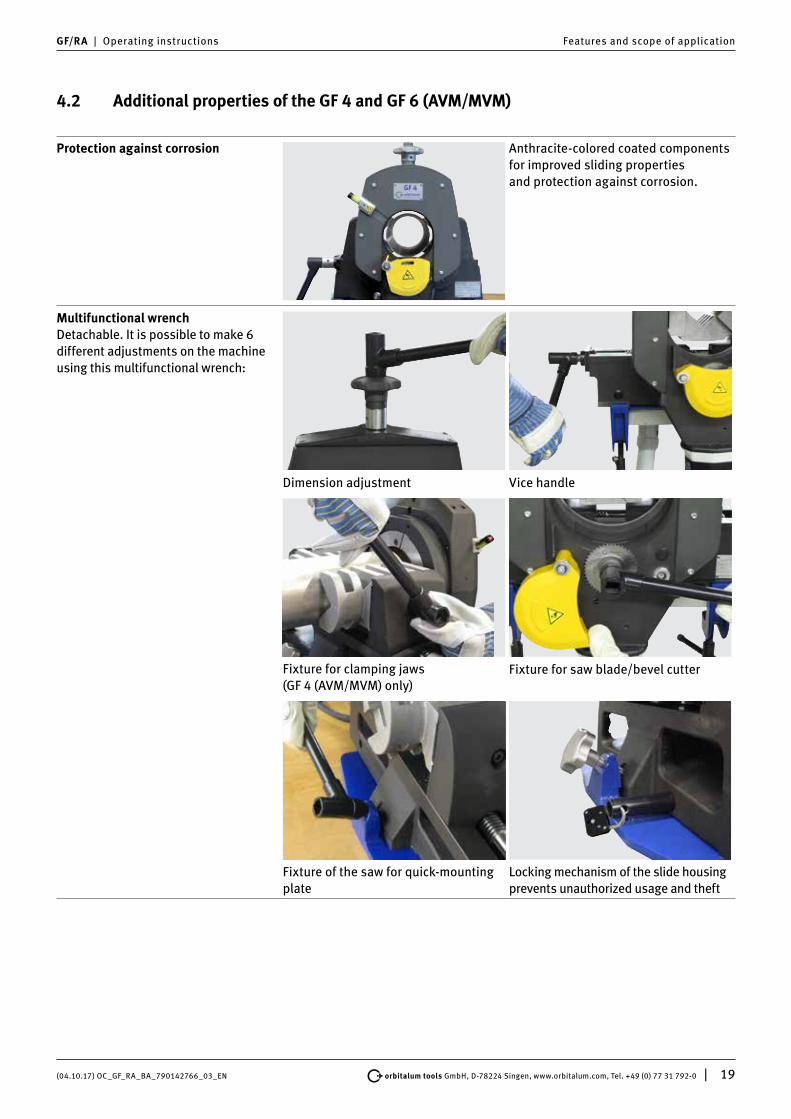
4.2 Additional properties of the GF 4 and GF 6 (AVM/MVM)
Protection against corrosion Anthracite-colored coated componentsfor improved sliding propertiesand protection against corrosion.
Multifunctional wrench Detachable. It is possible to make 6 different adjustments on the machine using this multifunctional wrench:
Dimension adjustment Vice handle
Fixture for clamping jaws (GF 4 (AVM/MVM) only)
Fixture for saw blade/bevel cutter
Fixture of the saw for quick-mounting plate
Locking mechanism of the slide housing prevents unauthorized usage and theft

20 | orbitalum tools GmbH, D-78224 Singen, www.orbitalum.com, Tel. +49 (0) 77 31 792-0 (04.10.17) OC_GF_RA_BA_790142766_03_EN
Features and scope of application GF/RA | Operating instructions
Line laser to display cut-off point To mark the cut-off point on the pipe. Ideal for checking whether the pipe is adjusted to the desired cut-off point. A red line that marks the cut-off point appears on the clamped pipe once the red button on the line laser has been pressed. If necessary, the pipe position can be corrected until the desired cut-off point is marked.
Reversible clamping jaws The reversible clamping jaws are a standard feature of the GF 4 and GF 6 (AVM/MVM). Turning the clamping jaws allows the following pipe diameters to be processed:Machine Pipe OD
[mm]Pipe OD [inch]
GF 4 (AVM/MVM) 12 - 56 /20 - 120
0.472 - 2.205 /0.787 - 4.724
GF 6 (AVM/MVM) 21.3 - 106 /106 - 168.3
0.839 - 4.173 / 4.173 - 6.626
Clamping jaw assembly, see chap. 8.4, p. 29.
Plug connection with quick- disconnect coupler
For easy and comfortable replacement of power cables.
Optimized chip guard Optimized chip guard protects against flying chips and comes with a meter rule slot for measuring the pipe length (GF 4 only).
Stainless steel clamping attachment Ideal for processing stainless steelpipes. For protection against contactcorrosion.

(04.10.17) OC_GF_RA_BA_790142766_03_EN orbitalum tools GmbH, D-78224 Singen, www.orbitalum.com, Tel. +49 (0) 77 31 792-0 | 21
GF/RA | Operating instructions Features and scope of application
4.3 Scope of application
4.3.1 Working range
Type of machine GF 4 (AVM/MVM)
GF 6 (AVM/MVM)
RA 8 (AVM/MVM)
RA 12 (AVM/MVM)
Pipe OD/pipe elbow OD* [mm] 12 - 120 21.3 - 168.3 114 - 230 157 - 325
[inch] 0.472 - 4.724 0.839 - 6.626 4.488 - 9.055 6.181 - 12.795
Wall thickness (depends on material)**
[mm] 1 - 9 1.5 - 15 2 - 10 2 -10
[inch] 0.039 - 0.354 0.059 - 0.591 0.079 - 0.394 0.079 - 0.394
Pipe ID min. (Saw blade Ø 63 mm/2.480")
[mm] 21 30 137 190
[inch] 0.827 1.181 5.394 7.480
Pipe ID min. (Saw blade Ø 68 mm/2.677")
[mm] 16 25 132 185
[inch] 0.630 0.984 5.197 7.283
Pipe ID min. (Saw blade Ø 80 mm/3.150")
[mm] 4 13 120 173
[inch] 0.157 0.512 4.724 6.811
Pipe ID min. (Saw blade Ø 100 mm/3.937")
[mm] – 0 100 153
[inch] – 0 3.937 6.024
Pipe ID min. (Saw blade Ø 110 mm/4.331")
[mm] – 0 – –
[inch] – 0 – –
* The pipe elbows can only be separated with the GF 4 and GF 6 (AVM/MVM).** With automatic cutting process. Greater wall thicknesses possible through manual feed or through another cut-off point (depending on the
diameter of the saw blade). Special clamping shells (accessory) may be necessary for thin pipe wall thicknesses.*** max. wall thickness: 7.5 mm (0.296 inch).
4.3.2 Materials
• High-quality steel (any Cr and Mo content)• High-quality stainless steel (any Cr and Mo content)• High-quality steel (Cr < 12% and Mo < 2.5%; Cr < 20% and Mo = 0%): case hardened steels, high-speed steels,
tempering steels, bearing steels, tool steels• Black and galvanized steel pipe• General structural steel• Annealed cast iron pipe (GGG)• Aluminum• Brass• Copper• Plastics (PE, PP, PVDE, PVC)

22 | orbitalum tools GmbH, D-78224 Singen, www.orbitalum.com, Tel. +49 (0) 77 31 792-0 (04.10.17) OC_GF_RA_BA_790142766_03_EN
Technical data GF/RA | Operating instructions
5. TECHNICAL DATA5.1 Pipe Cutting and Beveling Machines
Type of machine GF 4 (AVM/MVM)
GF 6 (AVM/MVM)
RA 8 (AVM/MVM)
RA 12 (AVM/MVM)
Dimensions (lxwxh) [mm] 680 x 325 x 480 920 x 352.7 x 574 778 x 485 x 430 940 x 592 x 374
[inch] 26.8 x 12.8 x 18.9 36.2 x 13.9 x 22.6 30.6 x 19.1 x 16.9 37.0 x 23.3 x 14.7
Dimensions (lxwxh) with AVM
[mm] 810 x 325 x 480 972 x 352.7 x 574 918 x 485 x 430 1.070 x 592 x 374
[inch] 31.9 x 12.8 x 18.9 38.3 x 13.9 x 22.6 36.1 x 19.1 x 16.9 42.1 x 23.3 x 14.7
Dimensions (lxwxh) with MVM
[mm] 780 x 325 x 480 920 x 352.7 x 574 788 x 485 x 430 1.090 x 592 x 374
[inch] 30.7 x 12.8 x 18.9 36.2 x 13.9 x 22.6 31.0 x 19.1 x 16.9 42.9 x 23.3 x 14.7
Machine weight approx.* [kg] 55.0 92.7 102.5 138.6
[lbs] 121.2 204.4 225.9 305.6
Machine weight approx.* with AVM
[kg] 64.5 101.7 110.0 146.1
[lbs] 142.2 224.2 242.5 322.1
Machine weight approx.* with MVM
[kg] 60.0 97.8 104.6 140.7
[lbs] 132.2 215.6 230.6 310.2
Versions, 1 phase AC [V,Hz] 230 V, 50/60 Hz 230 V, 50/60 Hz 230 V, 50/60 Hz 230 V, 50/60 Hz
[V,Hz] 120 V, 50/60 Hz 120 V, 50/60 Hz 120 V, 50/60 Hz 120 V, 50/60 Hz
Power without AVM [kW] 1.8 1.8 1.8 1.8
[HP] 2.41 2.41 2.41 2.41
Power with AVM [kW] 1.9 1.9 1.9 1.9
[HP] 2.54 2.54 2.54 2.54
Power AVM [kW] 0.05 0.05 0.05 0.05
[HP] 0.07 0.07 0.07 0.07
Protection class Double-insulated according to Class II, DIN EN 60745-1
Protection class with AVM Double-insulated according to Class I, EN 60204-1
Protection class with MVM Double-insulated according to Class II, DIN EN 60745-1
Tool speed [rpm] 40 - 215 40 - 215 40 - 215 40 - 215
Slide housing speed with AVM
[rpm] 0.1 - 3.9 0.3 - 3.5 0.1 - 2.3 0.1 - 1.8
Slide housing torque max. with AVM
[Nm] 101 353 165 210
Sound pressure level at the workplace approx.**
[dB (A)] 79 79 79 79
Vibration level [m/s2] < 2.5 in accordance with DIN EN 28662, Part 1
Mains fuse by customer [A] 16 16 16 16
* Weight without packaging and accessories. ** The sound pressure level was measured under normal operating conditions in accordance with EN 23741.

(04.10.17) OC_GF_RA_BA_790142766_03_EN orbitalum tools GmbH, D-78224 Singen, www.orbitalum.com, Tel. +49 (0) 77 31 792-0 | 23
GF/RA | Operating instructions Technical data
5.2 Line laser
Component for the GF 4 and GF 6 (AVM/MVM) only.
Dimensions (lxb) [mm] 68 x 15
[inch] 2.7 x 0.59
Weight [g] 30
[lbs] 0.012
Power, Total Emitted [mW] 5
[HP] 5x10⁻⁶
Power for Classification [µW] < 390
Beam range [m] 1
[inch] 39.37
Wave length [nm] 650
Operating voltage [V DC] 2.8 to 4.5
Operating current [mA] 20
Operating temperature [°C] -10 to 40
Storage temperature [°C] -40 to 80
Laser class Class 1
Battery type 2 x LR44 / AG13
24 | orbitalum tools GmbH, D-78224 Singen, www.orbitalum.com, Tel. +49 (0) 77 31 792-0 (04.10.17) OC_GF_RA_BA_790142766_03_EN
Initial operation GF/RA | Operating instructions
6. INITIAL OPERATION
6.1 Checking the parts of delivery
• Check delivery for completeness and damage caused by transport.• Report any missing parts or damage caused by transport to your supplier immediately.
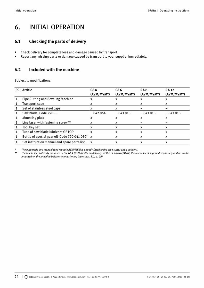
6.2 Included with the machine
Subject to modifications.
PC Article GF 4 (AVM/MVM*)
GF 6 (AVM/MVM*)
RA 8 (AVM/MVM*)
RA 12 (AVM/MVM*)
1 Pipe Cutting and Beveling Machine x x x x1 Transport case x x x x1 Set of stainless steel caps x x – –1 Saw blade, Code 790 ... ...042 064 ...043 018 ...043 018 ...043 0181 Mounting plate x x x x1 Line laser with fastening screw** x x – –1 Tool key set x x x x1 Tube of saw blade lubricant GF TOP x x x x1 Bottle of special gear oil (Code 790 041 030) x x x x
1 Set instruction manual and spare parts list x x x x
* The automatic and manual feed module AVM/MVM is already fitted to the pipe cutter upon delivery.** The line laser is already mounted at the GF 4 (AVM/MVM) on delivery. At the GF 6 (AVM/MVM) the line laser is supplied separately and has to be
mounted on the machine before commissioning (see chap. 8.2, p. 29).

(04.10.17) OC_GF_RA_BA_790142766_03_EN orbitalum tools GmbH, D-78224 Singen, www.orbitalum.com, Tel. +49 (0) 77 31 792-0 | 25
GF/RA | Operating instructions Storage and transport
7. STORAGE AND TRANSPORT7.1 Storage
ATTENTION
Incorrect machine storage!Diverse physical injuries and material damage.
X Store the machine in its original crate in a dry environment.
NOTE For GF 4, GF 6, RA 8 or RA 12 with AVM/MVM: The automatic and manual feed module AVM/MVM is already fitted to the pipe cutter upon delivery.
7.1.1 Position of the cutter in the transport case
GF 4 (AVM/MVM) GF 6 (AVM/MVM) RA 8, RA 12 (AVM/MVM)
NOTE The accessories in the GF 6 (AVM/MVM) must be taken out of the transportation case before the frame is removed.
7.2 Transport
DANGER
Fatal electric shock! X Before transportation or changing the workplace, allow the machine to run to a stop and pull the
mains plug.
WARNING
During transportation, the ON/OFF switch may unintentionally be activated causing the machineto start up!Diverse physical injuries and material damage.
X Before transportation or changing the workplace, allow the machine to run to a stop and pull the mains plug.
WARNING
Heavy weight when transporting the pipe cutters!Danger of being injured through overstraining.
X Transport pipe cutters over long stretches with corresponding lifting aids.

26 | orbitalum tools GmbH, D-78224 Singen, www.orbitalum.com, Tel. +49 (0) 77 31 792-0 (04.10.17) OC_GF_RA_BA_790142766_03_EN
Storage and transport GF/RA | Operating instructions
7.2.1 Transporting the GF 4, GF 6, RA 8 (AVM/MVM)
1. Loosen the hexagon bolt (1) on the quick-mounting plate.2. Guide suitable transport straps through the pipe cutter slide housing. 3. Carefully lift the cutter at the straps and insert in the assembled quick-mounting plate on the side.4. Bolt the pipe cutter securely in place on the mounting plate with the hexagon bolt (1).
1
7.2.2 Transporting the RA 12
1. Suspend the crane hooks in the catch (2), lift and insert in the assembled quick-mounting plate on the side.2. Bolt the pipe cutter securely in place on the mounting plate with the hexagon bolt (1).
2
1

(04.10.17) OC_GF_RA_BA_790142766_03_EN orbitalum tools GmbH, D-78224 Singen, www.orbitalum.com, Tel. +49 (0) 77 31 792-0 | 27
GF/RA | Operating instructions Setup and assembly
8. SETUP AND ASSEMBLYNOTE The steps described in chap. 8 are the same for all GF and RA versions.
8.1 Mounting the pipe cutter on the workbench
Mount the pipe cutter together with the vice, either:
• on the quick-mounting plate (see chap. 8.1.1 for assembly), or• on the quick-mounting plate with screw clamps (plate is clamped directly to the workbench without pre-drilling).
8.1.1 Mounting the quick-mounting plate on the workbench
1. Mark and punch the bolt holes on the workbench. Use the quick-mounting plate as a template.
2. Drill Ø 13 mm holes.3. Fasten the quick-mounting plate with screws.
8.1.2 Mounting the pipe cutter on the quick-mounting plate
�1. Only insert the pipe cutter in the assembled quick-
mounting plate on the side with the help of a crane or a similar lifting tool.
2. Bolt the pipe cutter securely in place with the hexa-gon bolt.

28 | orbitalum tools GmbH, D-78224 Singen, www.orbitalum.com, Tel. +49 (0) 77 31 792-0 (04.10.17) OC_GF_RA_BA_790142766_03_EN
Setup and assembly GF/RA | Operating instructions
8.1.3 Pipe feeder (base and extension unit, mobile workstation)
When using the Orbitalum Tools pipe feeder base unit, the pipe cutter is directly fitted to the mounting plate of the base unit without special accessories (special accessories, code no. 790 068 051).
NOTE We recommend supporting pipes longer than 1 m with one of the pipe feeders listed below (all special accessories).
Pipe feeder base unit (Code 790 068 051) Pipe feeder extension unit (Code 790 068 061) Mobile Workstation (Code 790 068 071)

(04.10.17) OC_GF_RA_BA_790142766_03_EN orbitalum tools GmbH, D-78224 Singen, www.orbitalum.com, Tel. +49 (0) 77 31 792-0 | 29
GF/RA | Operating instructions Setup and assembly
8.2 Mounting the line laser (only at GF 6 (AVM/MVM))
NOTE In order to protect the line laser against transportation damage it is supplied separately at the GF 6 (AVM/MVM) and has to be mounted on the machine before commissioning. We recommend dismantling the line laser before every transportation of the machine.
1. Take the Indicut line laser (1) out of the packaging and insert it together with the Plexiglas pane into the provided opening (2) of the line laser holder at the machine.
2. Switch on the line laser and align it. The line of the laser has to be at a right angle to the pipe axis.3. Carefully tighten the threaded pin M6x5 (3) (Code 445 001 210) of the line laser holder using an Allen key
(Code 024 387 003).
2
1 3
8.3 Replacing the batteries of the line laser
It is not allowed to open, modify or to remove protective covers or housings except for battery change. Observe the maintenance instructions (see chap. 10.1.1, p. 47).
1. Loosen the threaded pin M6x5 (3) (Code 445 001 210) of the laser holder by using Allen key (Code 024 387 003) to remove the laser from the cover plate.
2. Unscrew the line laser and replace the batteries (4) (Pack with 10 button cells, 1.5 V = Code 790 142 124). 3. Screw the parts of the line laser together.4. Place the line laser back into the holder, align and retighten with the threaded pin M6x5 (3).
3
4
8.4 GF 4 and GF 6: fitting the clamping jaws
Clamping jaw characteristics, see chap. 4.2, p. 19.

30 | orbitalum tools GmbH, D-78224 Singen, www.orbitalum.com, Tel. +49 (0) 77 31 792-0 (04.10.17) OC_GF_RA_BA_790142766_03_EN
Setup and assembly GF/RA | Operating instructions
8.4.1 Fitting the clamping jaws
1. Loosen the hexagon bolt (1) on the side of the vice of the GF 4 using a multifunctional wrench (2) and on the GF 6 with an SW8 socket head key.
2. Insert the clamping jaws.3. Tighten hexagon bolts (1).
1 2
8.5 Fitting the saw blade, bevel cutter, additional cutters
WARNING
When switching the motor on, the pipe cutter may revolve around the pipe automatically.Diverse physical injuries and material damage.
[ In their home position, the saw blade or bevel cutter must not touch the pipe. X Make sure that the slide housing is in the home position when the cutting process starts. X Clamp the pipe to be cut into the vice. X Pull off the hand wheel from the spindle before the slide housing starts rotating. X Before switching the motor on, make sure that the gap between the saw blade/bevel cutter and
the pipe is sufficient, and that the pipe is securely clamped in the vice. X Place sufficient supports under the tube.
WARNING
Flying parts/breaking tool!Diverse physical injuries and material damage.
[ Do not process the pipe while it is loose in the vice. [ Never use a damaged or deformed saw blade or bevel cutter. [ In the event of tool breakage with a new tool, do not enter the old cut because the tool can
break again (for details of what to do in the event of tool breakage, see chap. 10.4.1, p. 48). X Clamp the pipe to be cut into the vice. X Immediately replace worn-out tools. X Ensure that the cutting tools are correctly fitted. X Pipe dimension must be set correctly. During cutting, the saw blade must saw through the
entire pipe wall. X Avoid breaking tool through low (adequate) feed force, correct dimension (see chap. 8.6, p. 32)
and speed (see chap. 8.7, p. 35) settings. X Hold on to the motor unit tightly by the handle, and guide it with low (adequate) feed force
during the machining process.
ATTENTION Damage to material! [ When using an additional cutter, only use the special Orbitalum Tools clamping plate (code 790
046 188); not the clamping plate supplied as standard with the cutters. [ Never use a damaged or deformed saw blade or bevel cutter. X The saw blade or bevel cutter must be free from chips and dirt. X Only use original tools by Orbitalum Tools. X Mount the saw blade/bevel cutter or additional cutter with the inscription facing you.
The teeth will then be pointing in the correct direction.

(04.10.17) OC_GF_RA_BA_790142766_03_EN orbitalum tools GmbH, D-78224 Singen, www.orbitalum.com, Tel. +49 (0) 77 31 792-0 | 31
GF/RA | Operating instructions Setup and assembly
IMPORTANT Before fitting the saw blade or bevel cutter: Move the slide (9) all the way down using the hand wheel (8).
8.5.1 Inserting the saw blade or bevel cutter
1. Turn the chip guard (1) down for approx. 90°.2. Loosen the hexagon nut (4). Remove the clamping plate (3) and the saw blade (2).3. Clean the saw blade shaft (6) and vicinity with a brush.4. Fit the saw blade (2) or bevel cutter and the clamping plate (3).5. Tighten the hexagon nut (4) a fraction.6. Move the saw chip guard (1) back to its original position.
8
9
7 66
NOTE Make sure that the felt ring (7) is on the locking sleeve.
8.5.2 Inserting the saw blade/bevel cutter combination
1. Turn the chip guard (1) down for approx. 90°.2. Loosen the hexagon nut (5). Remove the clamping plate and the saw blade.3. Clean the saw blade shaft (6) and vicinity with a brush.4. Fit the additional cutter (2), the saw blade (3) and the special clamping plate (4).5. Tighten the hexagon nut (5) a fraction.6. Move the saw chip guard (1) back to its original position.
7 6
6
NOTE Make sure that the felt ring (7) is on the locking sleeve.

32 | orbitalum tools GmbH, D-78224 Singen, www.orbitalum.com, Tel. +49 (0) 77 31 792-0 (04.10.17) OC_GF_RA_BA_790142766_03_EN
Setup and assembly GF/RA | Operating instructions
8.6 Adjusting the pipe dimension
NOTE We recommend supporting pipes longer than 1 m with a pipe feeder or extension unit (see chap. 8.1.3, p. 28).
8.6.1 Saw blade without additional cutter
1. Turn the slide with saw blade all the way down using the hand wheel (1).2. Insert the pipe so that it almost reaches the saw blade (3) and tighten using the multifunctional wrench (4).
14
3
3. Use the handle to turn the motor upwards for about 30° (clockwise) until the saw blade is in cutting position.4. Turn the hand wheel (1) until the teeth of the saw blade (3) protrude about 1 to 2 mm (0.039 - 0.079 inch) inside the
pipe (2).5. If desired, perform a test cut (cutting the pipe, see chap. 9.1.3, p. 38 for machines with AVM, chap. 9.2.2, p. 40
for machines with MVM and chap. 9.3.2, p. 43 for working without AVM/MVM), check the cut result and readjust the hand wheel (1) if necessary.
6. Turn the motor back to its home position. When working with the AVM: Hold down the STOP button (6), and pivot the motor back into the normal position.
130°3
������
�
�
6
NOTE Scale of the hand wheel: a readjustment by one graduation mark results in a radial feed or bevel alteration of 0.1 mm (0.004 inch), for the GF 6 of 0.2 mm (0.008 inch).

(04.10.17) OC_GF_RA_BA_790142766_03_EN orbitalum tools GmbH, D-78224 Singen, www.orbitalum.com, Tel. +49 (0) 77 31 792-0 | 33
GF/RA | Operating instructions Setup and assembly
8.6.2 Saw blade with additional cutter
1. Turn the slide with the saw blade and additional cutter (2) all the way down using the hand wheel (1).2. Insert the pipe so that it almost reaches the additional cutter (2) and tighten using the multifunctional wrench (4).
14
2
3. Use the handle to turn the motor upwards for about 30° until the saw blade is in cutting position.4. Turn the hand wheel (1) until the teeth of the additional cutter (2) cover the wall thickness of the pipe.5. If desired, perform a test cut (Cutting and beveling the pipe, see chap. 9.1.5, p. 39 for machines with AVM,
chap. 9.2.4, p. 42 for machines with MVM and chap. 9.3.4, p. 45 for working without AVM/MVM), check the cut and bevel and readjust the hand wheel (1) if necessary.
6. Turn the motor back to its home position. When working with the AVM: Hold down the STOP button (6), and pivot the motor back into the normal position.
130°2
�
6
NOTE Scale of the hand wheel: a readjustment by one graduation mark results in a radial feed or bevel alteration of 0.1 mm (0.004 inch), for the GF 6 of 0.2 mm (0.008 inch).

34 | orbitalum tools GmbH, D-78224 Singen, www.orbitalum.com, Tel. +49 (0) 77 31 792-0 (04.10.17) OC_GF_RA_BA_790142766_03_EN
Setup and assembly GF/RA | Operating instructions
8.6.3 Adjusting the bevel cutter
1. Turn the slide with the bevel cutter (2) all the way down using the hand wheel (1).2. Insert the pipe so that it almost reaches the bevel cutter (2). The pipe must not project over the cutter.
Tighten using the multifunctional wrench (3).
13
2
3. Use the handle to turn the motor upwards for about 30° until the bevel cutter is in beveling position.4. Turn the hand wheel (1) until the teeth of the bevel cutter (2) cover the wall thickness of the pipe and the desired
beveling position is reached.5. If desired, perform a test bevel (beveling the pipe, see chap. 9.1.4, p. 39 for machines with AVM, chap. 9.2.3, p. 41
for machines with MVM and chap. 9.3.3, p. 44 for working without AVM/MVM), check the bevel and readjust the hand wheel (1) if necessary.
6. Turn the motor back to its home position. When working with the AVM: Hold down the STOP button (6), and pivot the motor back into the normal position.
130°2
�
6
NOTE Scale of the hand wheel: a readjustment by one graduation mark results in a radial feed or bevel alteration of 0.1 mm (0.004 inch), for the GF 6 of 0.2 mm (0.008 inch).

(04.10.17) OC_GF_RA_BA_790142766_03_EN orbitalum tools GmbH, D-78224 Singen, www.orbitalum.com, Tel. +49 (0) 77 31 792-0 | 35
GF/RA | Operating instructions Setup and assembly
8.7 Selecting the motor speed
NOTE Select low power speed for tough and high-strength materials and large wall thickness.
8.7.1 Standard values for spindle speed and feed force level (AVM)
Pipe material RPM control setting (1) Spindle speed (rpm) Force feed level AVM*
High-alloy high-quality steels 1 - 2 40 - 65 L - 2
Low-alloy high-quality steels 2 - 4 150 L - 4
Structural steel 4 - 6 215 5 - 9
* The feed force level and spindle speed may be varied depending on the thickness and diameter of the pipe wall.
IMPORTANT NOTES
REGARDING AVM
X When first starting to process the pipe with the AVM, a low feed force level is recommended which may be increased later. Higher levels result in a higher chip production and possibly also in a higher wear of tools. The intelligent control system of the AVM monitors the feed force continuously depending on the torque and the parameter settings.
X When cutting thin-walled pipes (wall thickness 3 - 5 mm), always start with level 1 and select a higher level afterwards.
X Select the feed force level (L - 9) using the / buttons on the AVM display (for standard values, see the table above).
1

36 | orbitalum tools GmbH, D-78224 Singen, www.orbitalum.com, Tel. +49 (0) 77 31 792-0 (04.10.17) OC_GF_RA_BA_790142766_03_EN
Operation GF/RA | Operating instructions
9. OPERATION
DANGER
Machine start-up due to unintentional pressing of the ON/OFF switch!Fatal electric shock.Diverse physical injuries and material damage.
X At the end of each working cycle, before transportation, changing tools, cleaning and performing any maintenance, adjustment or repair work, switch off the machine, allow it to run to a stop and pull the mains plug.
DANGER
When the slide housing is rotating, excess lubricant can get into the motor unit!Fatal electric shock.
X Remove excess lubricant from the machine after every step.
DANGER
Unexpected start-up!Serious injury or death.
X Before connecting the machine to the power supply, check the on/off switch is switched off.
DANGER
Loose/baggy clothing, long hair or jewelry can get caught in rotating machine parts!Serious injury or death.
X Wear tight-fitting clothing when using the machine. X Tie up long hair to prevent it from being caught.
WARNING
Flying parts/breaking tool!Diverse physical injuries and material damage.
[ Do not process the pipe while it is loose in the vice. [ Never use a damaged or deformed saw blade or bevel cutter. [ In the event of tool breakage with a new tool, do not enter the old cut because the tool can
break again (for details of what to do in the event of tool breakage, see chap. 10.4.1, p. 48). X Clamp the pipe to be cut into the vice. X Immediately replace worn-out tools. X Ensure that the cutting tools are correctly fitted. X Pipe dimension must be set correctly. During cutting, the saw blade must saw through the
entire pipe wall. X Avoid breaking tool through low (adequate) feed force, correct dimension (see chap. 8.6, p. 32)
and speed (see chap. 8.7, p. 35) settings. X Hold on to the motor unit tightly by the handle, and guide it with low (adequate) feed force
during the machining process.
WARNING
Risk of machine and pipe falling!Irreversible crushing.
X Check the machine's position and secure it so it cannot fall. X Place sufficient supports under the tube.
WARNING
Trapped fingers between the vice/clamping shell and pipe!Irreversible crushing.
[ Do not insert fingers between the vice/clamping shell and pipe!
WARNING
Body parts can fit between the cutting tools and the pipe!Serious injury.
[ Do not place body parts between the cutting tools and the pipe.
WARNING
Flying, hot and sharp-edged chips, pipe surfaces, cutting edges and tools!Danger of injury to eyes and hands.
[ Do not reach into the rotating tool during working. [ Never work without the saw chip guard mounted. X Wear recommended protective clothing. X At the end of each working cycle switch off the machine, allow it to run to a stop and pull the
mains plug. Remove chips with tightfitting safety gloves (in accordance with DIN EN 388 and EN 407) using suitable tools (e.g. tongs or screwdriver).
X Make sure the chips guard is working.

(04.10.17) OC_GF_RA_BA_790142766_03_EN orbitalum tools GmbH, D-78224 Singen, www.orbitalum.com, Tel. +49 (0) 77 31 792-0 | 37
GF/RA | Operating instructions Operation
ATTENTION
Restarting the machine following blockage!Diverse physical injuries and material damage.
X In the event of a blockage, always disconnect the machine from the power supply before clearing it. X If necessary, remove any tensioned parts before restarting the machine.
ATTENTION
Vapors when working with lubricants!Damage to lungs, skin and the environment.
X Only use original lubricant recommended by Orbitalum Tools.
9.1 Processing the pipe with AVM
For more information on pipe processing with MVM, see from chap. 9.2, p. 40.For manual operation without AVM or MVM, see from chap. 9.3, p. 43.
IMPORTANT Only operate AVM in combination with the Orbitalum Tools pipe cutters GF 4, GF 6, RA 8 or RA 12. [ Do not connect any other devices to the socket of the AVM.
9.1.1 Shutting down (even in an emergency)
DANGER
EMERGENCY STOP function not available by unplugging the power plug!Diverse physical injuries and material damage.
[ Do not use angled power plugs. [ Do not use click-in socket outlets and click-in power plugs (blue CEE power plugs) for power
connection, otherwise the EMERGENCY STOP does not function. The user must check whether the power plug can be pulled out of the outlet by the cable.
X Only use original Orbitalum Tools parts. X Ensure free access to the power plug.
IMPORTANT EMERGENCY STOP button (12) on the AVM: Only press in an emergency. Pressing the EMERGENCY STOP button (13) interrupts the power supply. Unlock the button to restart.
12
13
X Activate by switching the ON/OFF toggle switch (13). If the ON/OFF toggle switch (13) fails to work, remove the plug from the socket or vacate the danger zone as quickly as possible and then remove the plug.

38 | orbitalum tools GmbH, D-78224 Singen, www.orbitalum.com, Tel. +49 (0) 77 31 792-0 (04.10.17) OC_GF_RA_BA_790142766_03_EN
Operation GF/RA | Operating instructions
9.1.2 Initial operation
1
1. Connect the pipe cutter to the socket (1) of the AVM.2. Connect the mains cable of the AVM to the main
power supply.
9.1.3 Cutting the pipe with AVM
IMPORTANT If the pipe cutter was out of operation for a relatively long time: X Swivel the cutter motor by 180°. X Switch on the AVM and the pipe cutter (see chap. 9.1.2, p. 38), let the cutter motor run for
about 10 seconds.This relubricates all gear components.
1. Adjust the pipe dimension (see chap. 8.6, p. 32). 2. Adjust the saw blade to the pipe dimension (see chap. 8.6, p. 32).3. If necessary, tighten the hexagon nut of the saw blade fixture a fraction (see from chap. 8.5, p. 30).4. Adjust the spindle speed and the feed force level (for standard values, (see chap. 8.7.1, p. 35).5. Push the pipe through the vice up to the desired length and clamp it securely.
Support pipes longer than 1 m using a pipe feeder (see chap. 8.1.3, p. 28).
IMPORTANT Pull off the vice handle from the spindle before the slide housing starts rotating.
6. Apply saw blade lubricant to the saw blade: Recommendation:
• up to 2": at least every 3 cuts,• over 2" and with chrome and high-quality steel pipes: prior to every cut.
NOTE Use only saw blade lubricant (no oils) from Orbitalum Tools (e.g. GF LUB or GF TOP). Keep the machine clean. Always remove residue from lubricant from the machine.
NOTE For continuous operation: after cutting loosen the hexagon nut on the saw blade to avoid damage caused by tension.
7. Switch pipe cutter on. 8. Press the START button.
This starts the pipe processing. The cutter automatically shuts off after the complete cut has been made.

(04.10.17) OC_GF_RA_BA_790142766_03_EN orbitalum tools GmbH, D-78224 Singen, www.orbitalum.com, Tel. +49 (0) 77 31 792-0 | 39
GF/RA | Operating instructions Operation
9.1.4 Beveling the pipe with AVM
IMPORTANT If the pipe cutter was out of operation for a relatively long time: X Swivel the cutter motor by 180°. X Switch on the AVM and the pipe cutter (see chap. 9.1.2, p. 38), let the cutter motor run for
about 10 seconds.This relubricates all gear components.
1. Adjust the pipe dimension (see chap. 8.6, p. 32). 2. Adjust the bevel cutter to the pipe dimension (see chap. 8.6, p. 32).3. If necessary, tighten the hexagon nut of the bevel cutter fixture a fraction (see from chap. 8.5, p. 30).4. Adjust the spindle speed and the feed force level (for standard values (see chap. 8.7.1, p. 35).5. Push the pipe through the vice up to the desired length and clamp it securely.
Support pipes longer than 1 m using a pipe feeder (see chap. 8.1.3, p. 28).
IMPORTANT Pull off the vice handle from the spindle before the slide housing starts rotating.
6. Apply saw blade lubricant to the bevel cutter: Recommendation:
• up to 2": at least every 3 cuts,• over 2" and with chrome and high-quality steel pipes: prior to every cut.
NOTE Use only saw blade lubricant (no oils) from Orbitalum Tools (e.g. GF LUB or GF TOP). Keep the machine clean. Always remove residue from lubricant from the machine.
NOTE For continuous operation: after beveling, loosen the hexagon nut on the bevel cutter to avoid damage caused by tension.
7. Switch pipe cutter on. 8. Press the START button.
This starts the pipe processing. The cutter automatically shuts off after the correct bevel has been cut.
9.1.5 Cutting and beveling pipes simultaneously
• Pipes with a wall thickness of up to 7 mm (0.276 inch) can be simultaneously cut and beveled.• If using an additional cutter, the cutter motor has to be turned around the pipe more slowly than during normal cut-
ting, as two tools are being used at the same time. The procedure is the same as described in chap. 9.1.3, p. 38.
NOTE • If necessary, lubricate the saw blade and the additional cutter again during work. • For continuous operation: after cutting, loosen the hexagon nut on the saw blade to avoid dam-
age caused by tension.• The evenness of the bevel height depends on the roundness of the pipe.

40 | orbitalum tools GmbH, D-78224 Singen, www.orbitalum.com, Tel. +49 (0) 77 31 792-0 (04.10.17) OC_GF_RA_BA_790142766_03_EN
Operation GF/RA | Operating instructions
9.2 Processing the pipe with MVM
For more information on pipe processing with AVM, see from chap. 9.1, p. 37.For manual operation without AVM or MVM, see from chap. 9.3, p. 43.
9.2.1 Shutting down (even in an emergency)
DANGER
EMERGENCY STOP function not available by unplugging the power plug!Diverse physical injuries and material damage.
[ Do not use angled power plugs. [ Do not use click-in socket outlets and click-in power plugs (blue CEE power plugs) for power
connection, otherwise the EMERGENCY STOP does not function. The user must check whether the power plug can be pulled out of the outlet by the cable.
X Only use original Orbitalum Tools parts. X Ensure free access to the power plug.
12
X Activate by switching the ON/OFF toggle switch (12). If the ON/OFF toggle switch (12) fails to work, remove the plug from the socket or vacate the danger zone as quickly as possible and then remove the plug.
9.2.2 Cutting the pipe with MVM
IMPORTANT If the pipe cutter was out of operation for a relatively long time: X Turn the cutter motor by 180°. X Switch the pipe cutter on and let it run for about 10 seconds.
This relubricates all gear components.
1. Adjust the pipe dimension (see chap. 8.6, p. 32). 2. Adjust the saw blade to the pipe dimension (see chap. 8.6.1, p. 32).3. If necessary, tighten the hexagon nut of the saw blade fixture a fraction (see from chap. 8.5, p. 30).4. Adjust the spindle speed (see chap. 8.7.1, p. 35).5. Push the pipe through the vice up to the desired length and clamp it securely.
Support pipes longer than 1 m using a pipe feeder (see chap. 8.1.3, p. 28).
IMPORTANT Pull off the vice handle from the spindle before the slide housing starts rotating.
6. Apply saw blade lubricant to the saw blade: Recommendation:
• up to 2": at least every 3 cuts,• over 2" and with chrome and high-quality steel pipes: prior to every cut.
(04.10.17) OC_GF_RA_BA_790142766_03_EN orbitalum tools GmbH, D-78224 Singen, www.orbitalum.com, Tel. +49 (0) 77 31 792-0 | 41
GF/RA | Operating instructions Operation
NOTE Use only saw blade lubricant (no oils) from Orbitalum Tools (e.g. GF LUB or GF TOP). Keep the machine clean. Always remove residue from lubricant from the machine.
NOTE For continuous operation: after cutting loosen the hexagon nut on the saw blade to avoid damage caused by tension.
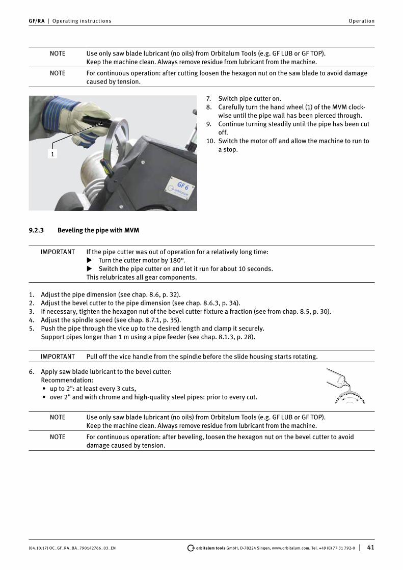
1
7. Switch pipe cutter on. 8. Carefully turn the hand wheel (1) of the MVM clock-
wise until the pipe wall has been pierced through. 9. Continue turning steadily until the pipe has been cut
off.10. Switch the motor off and allow the machine to run to
a stop.
9.2.3 Beveling the pipe with MVM
IMPORTANT If the pipe cutter was out of operation for a relatively long time: X Turn the cutter motor by 180°. X Switch the pipe cutter on and let it run for about 10 seconds.
This relubricates all gear components.
1. Adjust the pipe dimension (see chap. 8.6, p. 32). 2. Adjust the bevel cutter to the pipe dimension (see chap. 8.6.3, p. 34).3. If necessary, tighten the hexagon nut of the bevel cutter fixture a fraction (see from chap. 8.5, p. 30).4. Adjust the spindle speed (see chap. 8.7.1, p. 35).5. Push the pipe through the vice up to the desired length and clamp it securely.
Support pipes longer than 1 m using a pipe feeder (see chap. 8.1.3, p. 28).
IMPORTANT Pull off the vice handle from the spindle before the slide housing starts rotating.
6. Apply saw blade lubricant to the bevel cutter: Recommendation:
• up to 2": at least every 3 cuts,• over 2" and with chrome and high-quality steel pipes: prior to every cut.
NOTE Use only saw blade lubricant (no oils) from Orbitalum Tools (e.g. GF LUB or GF TOP). Keep the machine clean. Always remove residue from lubricant from the machine.
NOTE For continuous operation: after beveling, loosen the hexagon nut on the bevel cutter to avoid damage caused by tension.

42 | orbitalum tools GmbH, D-78224 Singen, www.orbitalum.com, Tel. +49 (0) 77 31 792-0 (04.10.17) OC_GF_RA_BA_790142766_03_EN
Operation GF/RA | Operating instructions
1
7. Switch pipe cutter on. 8. Carefully turn the hand wheel (1) of the MVM clock-
wise until the pipe wall has been pierced through. 9. Continue turning steadily until the pipe has been
beveled completely.10. Switch the motor off and allow the machine to run to
a stop.
9.2.4 Cutting the pipe with MVM and beveling it simultaneously
• Pipes with a wall thickness of up to 7 mm (0.276 inch) can be simultaneously cut and beveled.• If using an additional cutter, the cutter motor has to be turned around the pipe more slowly than during normal
cutting, as two tools are being used at the same time. The procedure is the same as described in chap. 9.2.2, p. 40.
NOTE • If necessary, lubricate the saw blade and the additional cutter again during work. • For continuous operation: after cutting, loosen the hexagon nut on the saw blade to avoid
damage caused by tension.• The evenness of the bevel height depends on the roundness of the pipe.

(04.10.17) OC_GF_RA_BA_790142766_03_EN orbitalum tools GmbH, D-78224 Singen, www.orbitalum.com, Tel. +49 (0) 77 31 792-0 | 43
GF/RA | Operating instructions Operation
9.3 Processing the pipe manually
For more information on pipe processing with AVM, see from chap. 9.1, p. 37.For more information on pipe processing with MVM, see from chap. 9.2, p. 40.
9.3.1 Shutting down (even in an emergency)
DANGER
EMERGENCY STOP function not available by unplugging the power plug!Diverse physical injuries and material damage.
[ Do not use angled power plugs. [ Do not use click-in socket outlets and click-in power plugs (blue CEE power plugs) for power
connection, otherwise the EMERGENCY STOP does not function. The user must check whether the power plug can be pulled out of the outlet by the cable.
X Only use original Orbitalum Tools parts. X Ensure free access to the power plug.
12
X Activate by switching the ON/OFF toggle switch (12). If the ON/OFF toggle switch (12) fails to work, remove the plug from the socket or vacate the danger zone as quickly as possible and then remove the plug.
9.3.2 Cutting the pipe manually
IMPORTANT If the pipe cutter was out of operation for a relatively long time: X Turn the cutter motor by 180°. X Switch the pipe cutter on and let it run for about 10 seconds.
This relubricates all gear components.
1. Adjust the pipe dimension (see chap. 8.6, p. 32). 2. Adjust the saw blade to the pipe dimension (see chap. 8.6.1, p. 32).3. If necessary, tighten the hexagon nut of the saw blade fixture a fraction (see from chap. 8.5, p. 30).4. Adjust the spindle speed (see chap. 8.7.1, p. 35).5. Push the pipe through the vice up to the desired length and clamp it securely.
Support pipes longer than 1 m using a pipe feeder (see chap. 8.1.3, p. 28).
IMPORTANT Pull off the vice handle from the spindle before the slide housing starts rotating.
6. Apply saw blade lubricant to the saw blade: Recommendation:
• up to 2": at least every 3 cuts,• over 2" and with chrome and high-quality steel pipes: prior to every cut.
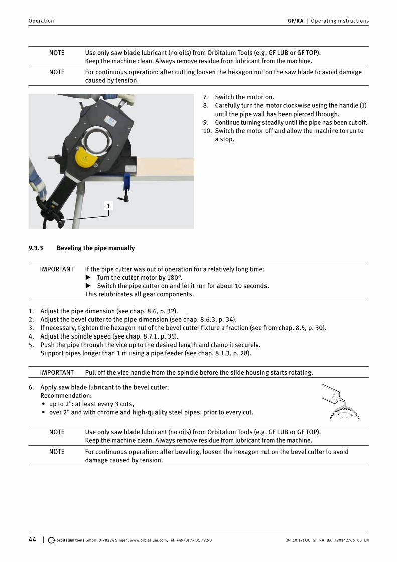
44 | orbitalum tools GmbH, D-78224 Singen, www.orbitalum.com, Tel. +49 (0) 77 31 792-0 (04.10.17) OC_GF_RA_BA_790142766_03_EN
Operation GF/RA | Operating instructions
NOTE Use only saw blade lubricant (no oils) from Orbitalum Tools (e.g. GF LUB or GF TOP). Keep the machine clean. Always remove residue from lubricant from the machine.
NOTE For continuous operation: after cutting loosen the hexagon nut on the saw blade to avoid damage caused by tension.
1
7. Switch the motor on.8. Carefully turn the motor clockwise using the handle (1)
until the pipe wall has been pierced through.9. Continue turning steadily until the pipe has been cut off.10. Switch the motor off and allow the machine to run to
a stop.
9.3.3 Beveling the pipe manually
IMPORTANT If the pipe cutter was out of operation for a relatively long time: X Turn the cutter motor by 180°. X Switch the pipe cutter on and let it run for about 10 seconds.
This relubricates all gear components.
1. Adjust the pipe dimension (see chap. 8.6, p. 32). 2. Adjust the bevel cutter to the pipe dimension (see chap. 8.6.3, p. 34).3. If necessary, tighten the hexagon nut of the bevel cutter fixture a fraction (see from chap. 8.5, p. 30).4. Adjust the spindle speed (see chap. 8.7.1, p. 35).5. Push the pipe through the vice up to the desired length and clamp it securely.
Support pipes longer than 1 m using a pipe feeder (see chap. 8.1.3, p. 28).
IMPORTANT Pull off the vice handle from the spindle before the slide housing starts rotating.
6. Apply saw blade lubricant to the bevel cutter: Recommendation:
• up to 2": at least every 3 cuts,• over 2" and with chrome and high-quality steel pipes: prior to every cut.
NOTE Use only saw blade lubricant (no oils) from Orbitalum Tools (e.g. GF LUB or GF TOP). Keep the machine clean. Always remove residue from lubricant from the machine.
NOTE For continuous operation: after beveling, loosen the hexagon nut on the bevel cutter to avoid damage caused by tension.

(04.10.17) OC_GF_RA_BA_790142766_03_EN orbitalum tools GmbH, D-78224 Singen, www.orbitalum.com, Tel. +49 (0) 77 31 792-0 | 45
GF/RA | Operating instructions Operation
1
7. Switch the motor on.8. Carefully turn the motor clockwise using the handle
(1) until the pipe wall has been pierced through.9. Continue turning steadily until the pipe has been
beveled completely.10. Switch the motor off and allow the machine to run to
a stop.
9.3.4 Cutting the pipe manually and beveling it simultaneously
• Pipes with a wall thickness of up to 7 mm (0.276 inch) can be simultaneously cut and beveled.• If using an additional cutter, the cutter motor has to be turned around the pipe more slowly than during normal
cutting, as two tools are being used at the same time. The procedure is the same as described in chap. 9.3.2, p. 43.
NOTE • If necessary, lubricate the saw blade and the additional cutter again during work. • For continuous operation: after cutting, loosen the hexagon nut on the saw blade to avoid
damage caused by tension.• The evenness of the bevel height depends on the roundness of the pipe.

46 | orbitalum tools GmbH, D-78224 Singen, www.orbitalum.com, Tel. +49 (0) 77 31 792-0 (04.10.17) OC_GF_RA_BA_790142766_03_EN
Servicing, maintenance, troubleshooting GF/RA | Operating instructions
10. SERVICING, MAINTENANCE, TROUBLESHOOTINGNOTE Some of the work mentioned depends a great deal on the use and on the ambient conditions. The
cycles specified are minimum specifications. In individual cases, differing maintenance cycles are possible. To ensure the safety of the machine, perform maintenance annually using an authorized service center with VDE testing. If the machine does not function as previously described, the ma-chine must also be sent into an authorized service center.
DANGER
Danger of death by electric shock!Non-observance could result in death or serious injury.
X At the end of each working cycle, before transportation, changing tools, cleaning and perform-ing any maintenance, adjustment or repair work, switch off the machine, allow it to run to a stop and pull the mains plug.
DANGER
Risk of electric shock due to poor electrics!Fatal electric shock.
X At the end of each working cycle, before transportation, changing tools, cleaning and perform-ing any maintenance, adjustment or repair work, switch off the machine, allow it to run to a stop and pull the mains plug.
X Repair and maintenance work on the electrical equipment may only be carried out by a quali-fied electrician.
10.1 Maintenance
Interval Activity
Before starting work X Remove chips and dirt from the saw blade. X Keep the vent holes free from chips. X Check the oil level of the gear and top up if necessary
(see chap. 10.2, p. 47). X Make sure that the felt ring (1) is on the locking sleeve,
replace if necessary. Felt ring for GF 4, GF 6, RA 8, RA 12: Code 790 046 168.
1
Every time the cutter is cleanedEvery time the tool is changed
[ Do not use compressed air to clean the area at the end of the shaft marked with an arrow as the rotary shaft seal may otherwise be damaged by chips.
X Use a cloth or brush to clean the end of the shaft.
Every week X Clean and oil:• The spindle of the hand wheel (1)• The sliding block (2)• The guide bush (3)• Vice tracks (4)• Vice spindle (5)
��
�
�
�

(04.10.17) OC_GF_RA_BA_790142766_03_EN orbitalum tools GmbH, D-78224 Singen, www.orbitalum.com, Tel. +49 (0) 77 31 792-0 | 47
GF/RA | Operating instructions Servicing, maintenance, troubleshooting
10.1.1 Line laser
X Own maintenance work on the laser is not permitted. X The laser is to be returned to the factory for any maintenance or repair work that may be required. X It is not allowed to open, modify or to remove protective covers or housings except for battery change.
10.2 Checking the oil level of the gear and topping up
The gears of the pipe cutters have an oil level indicator. The oil level should be visible in the middle of the inspec-tion glass.
1. Check the oil level through the inspection glass (2) and top up if necessary.
2. To top up: unscrew the oil filler screw (1). Fill with special Orbitalum Tools gear oil.
3. Re-insert and tighten the oil filler screw.
10.3 Cleaning the slide guide
WARNING
Danger of being injured by a not sufficiently secured slide! [ Never dismount the slide by pulling it downwards. X Always tighten the safety screw when assembling the slide.
1. Remove the safety screw (1).2. Turn the slide housing upwards by 180°.3. Turn the hand wheel (2) counterclockwise.4. Pull out the slide (3) with the motor upwards.5. Clean the guides of the slide housing and slide. Lightly lubricate both parts using HD 30 engine oil.6. Remount the slide. Insert and tighten the safety screw (1).
11
3
2
180°
Position of the safety screw for the GF 4 and GF 6 (AVM/MVM).
Position of the safety screw for the RA 6, RA 8, RA 12 (AVM/MVM).
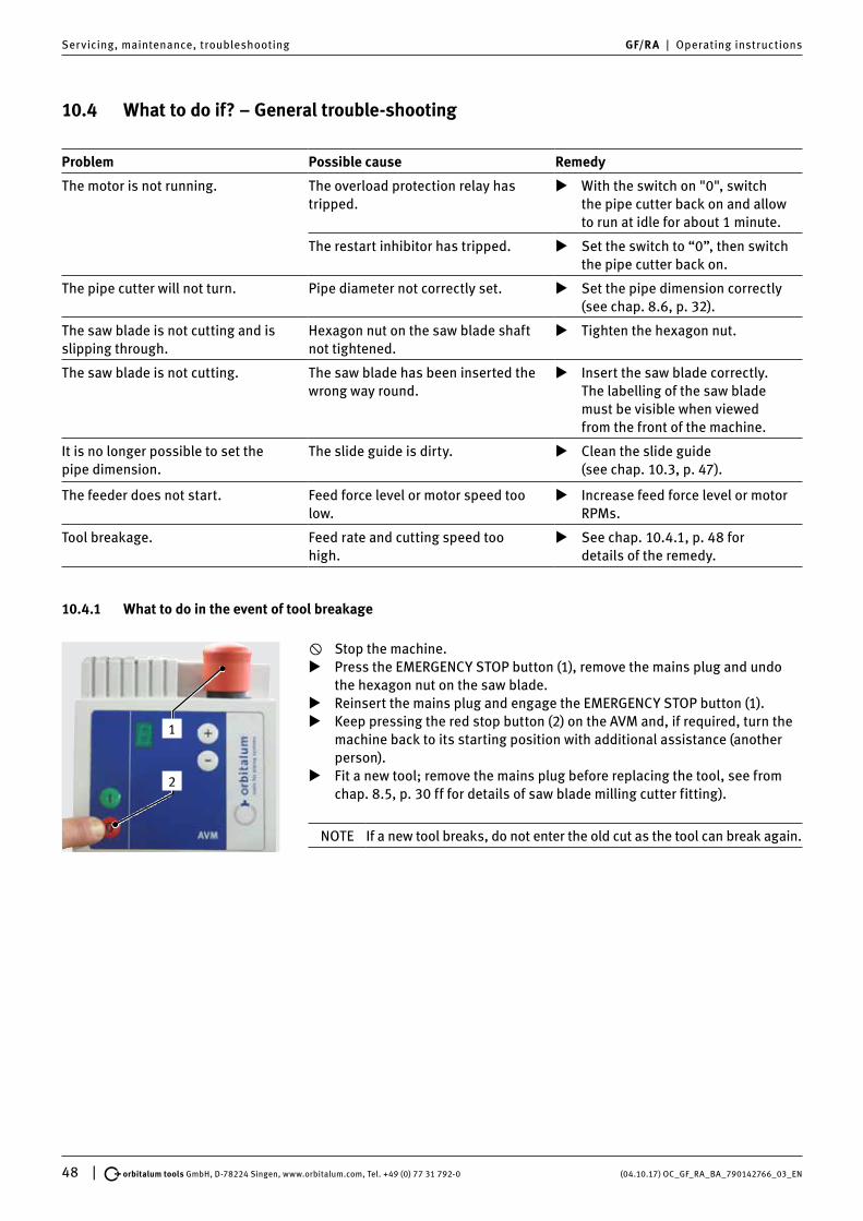
48 | orbitalum tools GmbH, D-78224 Singen, www.orbitalum.com, Tel. +49 (0) 77 31 792-0 (04.10.17) OC_GF_RA_BA_790142766_03_EN
Servicing, maintenance, troubleshooting GF/RA | Operating instructions
10.4 What to do if? – General trouble-shooting
Problem Possible cause Remedy
The motor is not running. The overload protection relay has tripped.
X With the switch on "0", switch the pipe cutter back on and allow to run at idle for about 1 minute.
The restart inhibitor has tripped. X Set the switch to “0”, then switch the pipe cutter back on.
The pipe cutter will not turn. Pipe diameter not correctly set. X Set the pipe dimension correctly (see chap. 8.6, p. 32).
The saw blade is not cutting and is slipping through.
Hexagon nut on the saw blade shaft not tightened.
X Tighten the hexagon nut.
The saw blade is not cutting. The saw blade has been inserted the wrong way round.
X Insert the saw blade correctly. The labelling of the saw blade must be visible when viewed from the front of the machine.
It is no longer possible to set the pipe dimension.
The slide guide is dirty. X Clean the slide guide (see chap. 10.3, p. 47).
The feeder does not start. Feed force level or motor speed too low.
X Increase feed force level or motor RPMs.
Tool breakage. Feed rate and cutting speed too high.
X See chap. 10.4.1, p. 48 for details of the remedy.
10.4.1 What to do in the event of tool breakage
1
2
[ Stop the machine. X Press the EMERGENCY STOP button (1), remove the mains plug and undo
the hexagon nut on the saw blade. X Reinsert the mains plug and engage the EMERGENCY STOP button (1). X Keep pressing the red stop button (2) on the AVM and, if required, turn the
machine back to its starting position with additional assistance (another person).
X Fit a new tool; remove the mains plug before replacing the tool, see from chap. 8.5, p. 30 ff for details of saw blade milling cutter fitting).
NOTE If a new tool breaks, do not enter the old cut as the tool can break again.

(04.10.17) OC_GF_RA_BA_790142766_03_EN orbitalum tools GmbH, D-78224 Singen, www.orbitalum.com, Tel. +49 (0) 77 31 792-0 | 49
GF/RA | Operating instructions Servicing, maintenance, troubleshooting
10.5 Error messages/trouble-shooting AVM
In case of faults concerning the AVM, the machine will stop automatically. The display will flash at 1-second intervals, alternately showing “F” and a figure from 1 to 6. Before restarting the AVM, it has to be disconnected from the mains supply by pressing the EMERGENCY OFF button or by pulling the mains plug.
Error message/fault Possible cause Remedy
Alert F1:Cutter motor overload.
Feed force level too high. X Select a lower feed force level.
Alert F2:Feed motor overload.
Feed force level too high. X Select a lower feed force level.
Pipe dimension not correctly set. X Set the pipe dimension correctly (see chap. 8.6, p. 32).
Chips between slide housing and pipe.
X Remove the chips.
The slide housing is running slug-gishly.
X Make the slide housing run smoothly.
Obstacle in the swiveling range. X Remove the obstacle.
Alert F3:The cutter motor stops during processing.
Power supply of the cutter motor interrupted.
X Check the connecting cable and the plug connections.
The overload protection relay of the cutter motor has tripped.
X With the switch on "0", switch the pipe cutter back on and allow to run at idle for about 1 minute.
Alert F4:Internal control error.
The processor is defective. X Contact the service department.
Alert F5:Overheating.
The temperature of the control system is too high.
X Self-regulating after cooling down.
Alert F6:Internal control error.
Wrong basic setting. X Contact the service department.
No alert:AVM does not start.
The cutter motor is not running or is not running long enough.
X The cutter motor must be running for at least 5 seconds before the AVM can be started.
The feed stops at the cut-in area. Blocking by chips. X Remove the chips.
Pipe dimension not correctly set. X Correct the adjustment.
Saw blade worn out. X Insert new saw blade.
The feed does not stop at the stop position.Display: No decimal point at the stop position.
Light barrier or reflector defective. X Replace the defective parts ( contact the service department, if necessary).
Light barrier or reflector dirty. X Clean the dirty parts.
After having remedied the cause of malfunction, the AVM has to be reconnected to the mains supply. After having switched off the cutter motor (to position "0"), it may be restarted.

50 | orbitalum tools GmbH, D-78224 Singen, www.orbitalum.com, Tel. +49 (0) 77 31 792-0 (04.10.17) OC_GF_RA_BA_790142766_03_EN
Servicing, maintenance, troubleshooting GF/RA | Operating instructions
10.6 Servicing/customer service
For ordering spare parts, refer to the separate spare parts list.For troubleshooting, please contact the branch responsible directly.
Please indicate the following details:
• Type of machine: – GF 4, GF 4 AVM or GF 4 MVM – GF 6, GF 6 AVM or GF 6 MVM – RA 8, RA 8 AVM or RA 8 MVM – RA 12, RA 12 AVM or RA 12 MVM• Machine no.: (see type plate)

(04.10.17) OC_GF_RA_BA_790142766_03_EN orbitalum tools GmbH, D-78224 Singen, www.orbitalum.com, Tel. +49 (0) 77 31 792-0 | 51
GF/RA | Operating instructions EU declaration of conformity
11. EU DECLARATION OF CONFORMITY11.1 GF 4, GF 6, RA 8, RA 12 (Standard/MVM)
EG-KonformitätserklärungDeclaration of conformityDichiarazione di conformitàDéclaration de conformitéDeclaración de conformidad
Orbitalum Tools GmbHJosef-Schüttler-Straße 1778224 Singen, DeutschlandTel.: +49 (0) 77 31 792-0Fax: +49 (0) 77 31 792-524
As in appendix II A of the EC Machinery Directive 2006/42/EC and the EMC Directive 2014/30/EU
Die Bauart der Maschine:The following product:Il seguente prodotto:Le produit suivant:El producto siguiente:
GF 4 Pipe Cutting and Beveling Machine*GF 4 MVM Pipe Cutting and Beveling Machine with Manual Feed Module*GF 6 Pipe Cutting and Beveling Machine*GF 6 MVM Pipe Cutting and Beveling Machine with Manual Feed Module*RA 8 Pipe Cutting and Beveling Machine*RA 8 MVM Pipe Cutting and Beveling Machine with Manual Feed Module*RA 12 Pipe Cutting and Beveling Machine*RA 12 MVM Pipe Cutting and Beveling Machine with Manual Feed Module*
Seriennummer:Series number:Numero di serie:Nombre de série:Número de serie:
Baujahr / Year / Anno / Année / Año:
ist entwickelt, konstruiert and gefertigt in Übereinstimmung mit folgenden EG-Richtlinien:was designed, constructed and manufactured in accordance with the following EC guidelines:è stata progettato costruito e commercializzato in osservanza delle seguenti Direttive:a été dessiné, produit et commercialisé selon les Directives suivantes:ha sido proyectado construido y comercializado bajo observación de las siguientes Directivas:
EG-Maschinen-Richtlinie 2006/42/EG (MaschR)EMV-Richtlinie 2014/30/EU
Folgende harmonisierte Normen sind angewandt:The following harmonized norms have been applied:Le seguenti norme armonizzate ove applicabili:Les normes suivantes harmonisées où applicables:Las siguientes normas armonizadas han sido aplicadas:
DIN EN ISO 13849-1: 2016.06DIN EN ISO 13849-2: 2010.06DIN EN ISO 12100: 2011.03DIN EN 1037: 2008.11DIN EN 62841-1: 2016.07
* including all accessories of Orbitalum Tools, e.g. the pipe feeder base and extension units, the mobile workstation, etc.
Authorised to compile the technical file is Mr. Gerd Riegraf, Orbitalum Tools GmbH, D-78224 Singen.
Singen, 03.08.2017 Markus TammManaging Director
Marcel FohBusiness Development Manager

52 | orbitalum tools GmbH, D-78224 Singen, www.orbitalum.com, Tel. +49 (0) 77 31 792-0 (04.10.17) OC_GF_RA_BA_790142766_03_EN
EU declaration of conformity GF/RA | Operating instructions
11.2 GF 4 AVM, GF 6 AVM, RA 8 AVM, RA 12 AVM
EG-KonformitätserklärungDeclaration of conformityDichiarazione di conformitàDéclaration de conformitéDeclaración de conformidad
Orbitalum Tools GmbHJosef-Schüttler-Straße 1778224 Singen, DeutschlandTel.: +49 (0) 77 31 792-0Fax: +49 (0) 77 31 792-524
As in appendix II A of the EC Machinery Directive 2006/42/EC and the EMC Directive 2014/30/EU
Die Bauart der Maschine:The following product:Il seguente prodotto:Le produit suivant:El producto siguiente:
GF 4 AVM Pipe Cutting and Beveling Machine with Automatic Feed Module*GF 6 AVM Pipe Cutting and Beveling Machine with Automatic Feed Module*RA 8 AVM Pipe Cutting and Beveling Machine with Automatic Feed Module*RA 12 AVM Pipe Cutting and Beveling Machine with Automatic Feed Module*
Seriennummer:Series number:Numero di serie:Nombre de série:Número de serie:
Baujahr / Year / Anno / Année / Año:
ist entwickelt, konstruiert and gefertigt in Übereinstimmung mit folgenden EG-Richtlinien:was designed, constructed and manufactured in accordance with the following EC guidelines:è stata progettato costruito e commercializzato in osservanza delle seguenti Direttive:a été dessiné, produit et commercialisé selon les Directives suivantes:ha sido proyectado construido y comercializado bajo observación de las siguientes Directivas:
EG-Maschinen-Richtlinie 2006/42/EG (MaschR)EMV-Richtlinie 2014/30/EU
Folgende harmonisierte Normen sind angewandt:The following harmonized norms have been applied:Le seguenti norme armonizzate ove applicabili:Les normes suivantes harmonisées où applicables:Las siguientes normas armonizadas han sido aplicadas:
DIN EN ISO 13849-1: 2016.06DIN EN ISO 13849-2: 2010.06DIN EN ISO 12100: 2011.03DIN EN 1037: 2008.11DIN EN 62841-1: 2016.07
* including all accessories of Orbitalum Tools, e.g. the pipe feeder base and extension units, the mobile workstation, etc.
Authorised to compile the technical file is Mr. Gerd Riegraf, Orbitalum Tools GmbH, D-78224 Singen.
Singen, 03.08.2017 Markus TammManaging Director
Marcel FohBusiness Development Manager

(04.10.17) OC_GF_RA_BA_790142766_03_EN orbitalum tools GmbH, D-78224 Singen, www.orbitalum.com, Tel. +49 (0) 77 31 792-0 | 53
GF/RA | Operating instructions


worldwide | sales + service
© O
rbit
alum
Too
ls G
mbH
| E
N
79
0 1
42
76
6_0
3 |
Rev
. 10
17 |
Pri
nted
in G
erm
any
We value your opinion! Please send us your comments and queries.
The ITW ORBITAL CUTTING & WELDING group provides global customers one source for the finest in pipe & tube cutting, beveling and orbital welding products.
Orbital cutting, beveling and welding machines for high-purity process piping.
Portable weld prep machine tools for industrial applications.
>> [email protected] >> www.orbitalum.com
>> [email protected] >> www.ehwachs.comFor more information about us >> www.itw-ocw.com
NORTH AMERICA
USA
E.H. Wachs600 Knightsbridge ParkwayLincolnshire, IL 60069 USATel. +1 847 537 8800Fax +1 847 520 1147Toll Free 800 323 8185
NORTHEASTSales, Service & Rental CenterE.H. Wachs 1001 Lower Landing Road, Suite 208Blackwood, New Jersey 08012 USATel. +1 856 579 8747Fax +1 856 579 8748
SOUTHEASTSales, Service & Rental CenterE.H. Wachs171 Johns Road, Unit AGreer, South Carolina 29650 USATel. +1 864 655 4771Fax +1 864 655 4772
WEST COASTSales, Service & Rental CenterE.H. Wachs5130 Fulton Drive, Unit JFairfield, California 94534 USATel. +1 707 439 3763Fax +1 707 439 3766
GULF COASTSales, Service & Rental CenterE.H. Wachs2220 South Philippe AvenueGonzales, LA 70737 USATel. +1 225 644 7780Fax +1 225 644 7785
HOUSTON SOUTHSales, Service & Rental CenterE.H. Wachs3414 Lilac Unit EPasadena, Texas 77505 USATel. +1 713 983 0784Fax +1 713 983 0703
CANADA
Wachs Canada LtdEastern Canada Sales, Service & Rental Center1250 Journey’s End Circle, Unit 5Newmarket, Ontario L3Y 0B9CanadaTel. +1 905 830 8888Fax +1 905 830 6050Toll Free: 888 785 2000
Wachs Canada LtdWestern Canada Sales, Service & Rental Center5411 82 Ave NWEdmonton, Alberta T6B 2J6CanadaTel. +1 780 469 6402Fax +1 780 463 0654Toll Free 800 661 4235
EUROPE
GERMANY
Orbitalum Tools GmbHJosef-Schuettler-Str. 1778224 SingenGermanyTel. +49 (0) 77 31 - 792 0Fax +49 (0) 77 31 - 792 500
UNITED KINGDOM
Wachs UKUK Sales, Rental & Service CentreUnits 4 & 5 Navigation ParkRoad One, Winsford Industrial EstateWinsford, Cheshire CW7 3 RLUnited Kingdom Tel. +44 (0) 1606 861 423Fax +44 (0) 1606 556 364
ASIA
CHINA
Orbitalum ToolsNew Caohejing InternationalBusiness CentreRoom 2801-B, Building BNo 391 Gui Ping RoadShanghai 200052ChinaTel. +86 (0) 21 52 30 37-51Fax +86 (0) 21 52 30 37-58
INDIA
ITW India Pvt. LtdSr.no. 234/235 & 245Plot no. 8, Gala #7Indialand Global Industrial ParkHinjawadi-Phase-1Tal-Mulshi, Pune 411057IndiaTel. +91 (0) 20 32 00 25 39Mob. +91 (0) 91 00 99 45 78
AFRICA & MIDDLE EAST
UNITED ARAB EMIRATES
Wachs Middle East & Africa OperationsPO Box 262543Free Zone South FZS 5, ACO6Jebel Ali Free Zone (South-5), Dubai United Arab EmiratesTel. +971 4 88 65 211Fax +971 4 88 65 212