CBX32MV - INSTALLATION INSTRUCTIONS
38
03/10 506274−01 *2P0310* *P506274-01* Page 1 E2010 Lennox Industries Inc. Dallas, Texas, USA NOTICE A thermostat is not included and must be ordered separately. D The Lennox icomfort Touchœ thermostat must be used in communicating applications. D In non−communicating applications, the Lennox ComfortSense ® 7000 thermostat may be used, as well as other non−communicating thermostats. In all cases, setup is critical to ensure proper system operation. Field wiring for both communicating and non− communicating applications is illustrated in diagrams, which begin on Page 12. WARNING Improper installation, adjustment, alteration, service or maintenance can cause personal injury, loss of life, or damage to property. Installation and service must be performed by a licensed professional installer (or equivalent) or a service agency. Shipping and Packing List Check unit for shipping damage. Consult last carrier immediately if damage is found. Package 1 of 1 contains the following: 1 ɦ Assembled air handler unit 2 ɦ Downflow shields (if required for downflow configuration only) 1 ɦ Drip shield (for −068 only) INSTALLATION INSTRUCTIONS Dave Lennox Signature ® Collection CBX32MV Units MULTI−POSITION AIR HANDLER 506274−01 03/10 Supersedes 02/10 RETAIN THESE INSTRUCTIONS FOR FUTURE REFERENCE Table of Contents Shipping and Packing List 1 . . . . . . . . . . . . . . . . . . . . . . CBX32MV Upflow/Downflow Unit Dimensions 2 . . . . CBX32MV Horizontal LH/RH Unit Dimensions 3 . . . . Model Number Identification 4 . . . . . . . . . . . . . . . . . . . . General 4 . . . . . . . . . . . . . . . . . . . . . . . . . . . . . . . . . . . . . . Installation Clearances 4 . . . . . . . . . . . . . . . . . . . . . . . . . Requirements 5 . . . . . . . . . . . . . . . . . . . . . . . . . . . . . . . . . Installing the Unit 5 . . . . . . . . . . . . . . . . . . . . . . . . . . . . . . Brazing Connections 8 . . . . . . . . . . . . . . . . . . . . . . . . . . . Installing the Condensate Drain 10 . . . . . . . . . . . . . . . . . Inspecting and Replacing Filters 11 . . . . . . . . . . . . . . . . . Sealing the Unit 11 . . . . . . . . . . . . . . . . . . . . . . . . . . . . . . . Field Control Wiring 12 . . . . . . . . . . . . . . . . . . . . . . . . . . . . Air Handler Control Button, Display and Jumpers 20 . . Target CFM Tables 24 . . . . . . . . . . . . . . . . . . . . . . . . . . . . Configuring Unit 27 . . . . . . . . . . . . . . . . . . . . . . . . . . . . . . . Error Code Recall Mode 34 . . . . . . . . . . . . . . . . . . . . . . . . Indoor Blower Test 35 . . . . . . . . . . . . . . . . . . . . . . . . . . . . . Checkout Procedures 35 . . . . . . . . . . . . . . . . . . . . . . . . . . Operation 36 . . . . . . . . . . . . . . . . . . . . . . . . . . . . . . . . . . . . Maintenance 36 . . . . . . . . . . . . . . . . . . . . . . . . . . . . . . . . . . Cabinet Insulation 36 . . . . . . . . . . . . . . . . . . . . . . . . . . . . . IMPORTANT INFORMATION TO INSTALLER A B D C E TOP CAP SHIPPING BRACKET (REPLACE SCREWS IN TOP CAP AFTER REMOVAL). HORIZONTAL DRAIN PAN (SEE UPFLOW APPLICATIONS ON PAGE 5 AND DOWNFLOW APPLICATIONS ON PAGE 8 ) BLOWER HOUSING SUPPORT PAD. REFRIGERANT LINE PLUGS (SEE BRAZING CONNECTION ON PAGE 8] . CONFIGURE/DETECTING ELECTRIC HEAT SECTION ON PAGE 24. SEE PAGE 15 FOR JUMPER AND LINK GUIDE. CHECK FOR AND REMOVE THE FOLLOWING ITEMS BEFORE OPERATING UNIT. IMPORTANT: CONFIGURATION OF AIR HANDLER CONTROL BOARD MUST BE CHECKED BEFORE START−UP TO ENSURE PROPER SYSTEM OPERATION. SEE JUMPER AND LINK GUIDE ON PAGE 15 AND CONFIGURING UNIT SECTION STARTING ON PAGE 28. Litho U.S.A.
-
Upload
khangminh22 -
Category
Documents
-
view
0 -
download
0
Transcript of CBX32MV - INSTALLATION INSTRUCTIONS
03/10 506274−01
�������� ����������Page 1
�2010 Lennox Industries Inc.Dallas, Texas, USA
NOTICEA thermostat is not included and must be orderedseparately.
� The Lennox icomfort Touch� thermostat must be usedin communicating applications.
� In non−communicating applications, the LennoxComfortSense® 7000 thermostat may be used, as wellas other non−communicating thermostats.
In all cases, setup is critical to ensure proper systemoperation.
Field wiring for both communicating and non−communicating applications is illustrated in diagrams,which begin on Page 12.
WARNINGImproper installation, adjustment, alteration, service ormaintenance can cause personal injury, loss of life, ordamage to property.
Installation and service must be performed by a licensedprofessional installer (or equivalent) or a service agency.
Shipping and Packing List
Check unit for shipping damage. Consult last carrierimmediately if damage is found.
Package 1 of 1 contains the following:
1 � Assembled air handler unit
2 � Downflow shields (if required for downflowconfiguration only)
1 � Drip shield (for −068 only)
INSTALLATIONINSTRUCTIONS
Dave Lennox Signature®
Collection CBX32MV Units
MULTI−POSITION AIR HANDLER506274−0103/10Supersedes 02/10
RETAIN THESE INSTRUCTIONS FOR FUTUREREFERENCE
Table of Contents
Shipping and Packing List 1. . . . . . . . . . . . . . . . . . . . . . CBX32MV Upflow/Downflow Unit Dimensions 2. . . . CBX32MV Horizontal LH/RH Unit Dimensions 3. . . . Model Number Identification 4. . . . . . . . . . . . . . . . . . . . General 4. . . . . . . . . . . . . . . . . . . . . . . . . . . . . . . . . . . . . . Installation Clearances 4. . . . . . . . . . . . . . . . . . . . . . . . . Requirements 5. . . . . . . . . . . . . . . . . . . . . . . . . . . . . . . . . Installing the Unit 5. . . . . . . . . . . . . . . . . . . . . . . . . . . . . . Brazing Connections 8. . . . . . . . . . . . . . . . . . . . . . . . . . . Installing the Condensate Drain 10. . . . . . . . . . . . . . . . . Inspecting and Replacing Filters 11. . . . . . . . . . . . . . . . . Sealing the Unit 11. . . . . . . . . . . . . . . . . . . . . . . . . . . . . . . Field Control Wiring 12. . . . . . . . . . . . . . . . . . . . . . . . . . . . Air Handler Control Button, Display and Jumpers 20. . Target CFM Tables 24. . . . . . . . . . . . . . . . . . . . . . . . . . . . Configuring Unit 27. . . . . . . . . . . . . . . . . . . . . . . . . . . . . . . Error Code Recall Mode 34. . . . . . . . . . . . . . . . . . . . . . . . Indoor Blower Test 35. . . . . . . . . . . . . . . . . . . . . . . . . . . . . Checkout Procedures 35. . . . . . . . . . . . . . . . . . . . . . . . . . Operation 36. . . . . . . . . . . . . . . . . . . . . . . . . . . . . . . . . . . . Maintenance 36. . . . . . . . . . . . . . . . . . . . . . . . . . . . . . . . . . Cabinet Insulation 36. . . . . . . . . . . . . . . . . . . . . . . . . . . . .
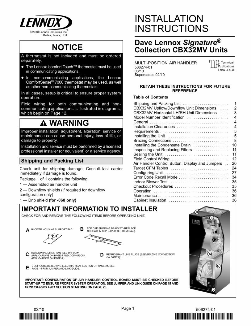
IMPORTANT INFORMATION TO INSTALLER
A B
DC
E
TOP CAP SHIPPING BRACKET (REPLACESCREWS IN TOP CAP AFTER REMOVAL).
HORIZONTAL DRAIN PAN (SEE UPFLOWAPPLICATIONS ON PAGE 5 AND DOWNFLOWAPPLICATIONS ON PAGE 8 )
BLOWER HOUSING SUPPORT PAD.
REFRIGERANT LINE PLUGS (SEE BRAZING CONNECTIONON PAGE 8] .
CONFIGURE/DETECTING ELECTRIC HEAT SECTION ON PAGE 24. SEEPAGE 15 FOR JUMPER AND LINK GUIDE.
CHECK FOR AND REMOVE THE FOLLOWING ITEMS BEFORE OPERATING UNIT.
IMPORTANT: CONFIGURATION OF AIR HANDLER CONTROL BOARD MUST BE CHECKED BEFORESTART−UP TO ENSURE PROPER SYSTEM OPERATION. SEE JUMPER AND LINK GUIDE ON PAGE 15 ANDCONFIGURING UNIT SECTION STARTING ON PAGE 28.
Litho U.S.A.
Page 2
506274 03
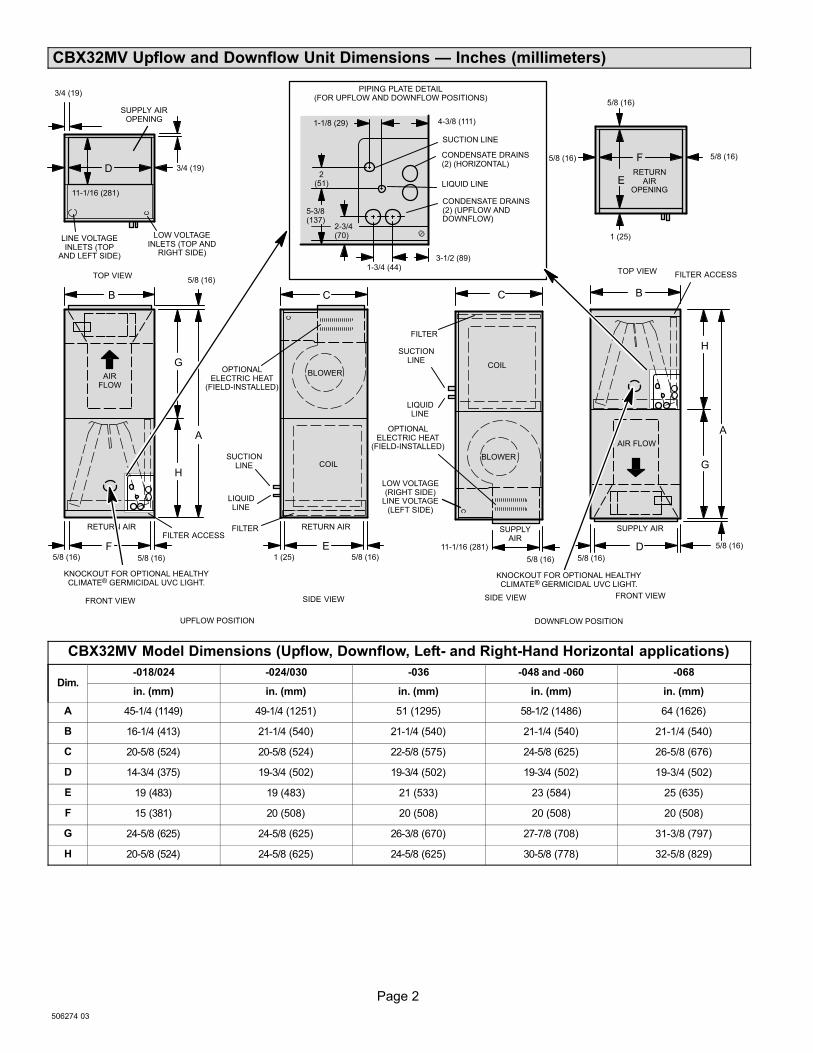
CBX32MV Upflow and Downflow Unit Dimensions � Inches (millimeters)
OPTIONALELECTRIC HEAT
(FIELD−INSTALLED)
AIRFLOW
LIQUIDLINE
SUCTIONLINE
SUPPLY AIROPENING
RETURN AIRFILTER
LOW VOLTAGEINLETS (TOP AND
RIGHT SIDE)
RETURN AIR
TOP VIEW
FRONT VIEW SIDE VIEW
BLOWER
PIPING PLATE DETAIL(FOR UPFLOW AND DOWNFLOW POSITIONS)
A
B C
11-1/16 (281)
D
F E
LIQUID LINE
SUCTION LINE
CONDENSATE DRAINS(2) (HORIZONTAL)
COIL
3/4 (19)
3/4 (19)
5/8 (16)5/8 (16) 1 (25)
5/8 (16)
1-3/4 (44)
2(51)
1-1/8 (29) 4-3/8 (111)
2-3/4(70)
5-3/8(137)
3-1/2 (89)
OPTIONALELECTRIC HEAT
(FIELD−INSTALLED) AIR FLOW
LIQUIDLINE
SUCTIONLINE
RETURNAIR
OPENING
SUPPLYAIR
FILTER
SUPPLY AIR
TOP VIEW
FRONT VIEWSIDE VIEW
BLOWER
A
BC
11-1/16 (281)
F
D
E
COIL
5/8 (16)5/8 (16)
5/8 (16)
5/8 (16)
5/8 (16)
LOW VOLTAGE(RIGHT SIDE)
LINE VOLTAGE(LEFT SIDE)
DOWNFLOW POSITION
1 (25)
UPFLOW POSITION
CONDENSATE DRAINS(2) (UPFLOW ANDDOWNFLOW)
FILTER ACCESS
FILTER ACCESS
H
G
H
G
LINE VOLTAGEINLETS (TOP
AND LEFT SIDE)
5/8 (16)
5/8 (16)
KNOCKOUT FOR OPTIONAL HEALTHYCLIMATE® GERMICIDAL UVC LIGHT.
KNOCKOUT FOR OPTIONAL HEALTHYCLIMATE® GERMICIDAL UVC LIGHT.
CBX32MV Model Dimensions (Upflow, Downflow, Left− and Right−Hand Horizontal applications)
Dim.−018/024 −024/030 −036 −048 and −060 −068
in. (mm) in. (mm) in. (mm) in. (mm) in. (mm)
A 45−1/4 (1149) 49−1/4 (1251) 51 (1295) 58-1/2 (1486) 64 (1626)
B 16−1/4 (413) 21−1/4 (540) 21-1/4 (540) 21-1/4 (540) 21−1/4 (540)
C 20−5/8 (524) 20−5/8 (524) 22-5/8 (575) 24-5/8 (625) 26−5/8 (676)
D 14−3/4 (375) 19−3/4 (502) 19-3/4 (502) 19-3/4 (502) 19−3/4 (502)
E 19 (483) 19 (483) 21 (533) 23 (584) 25 (635)
F 15 (381) 20 (508) 20 (508) 20 (508) 20 (508)
G 24−5/8 (625) 24−5/8 (625) 26-3/8 (670) 27-7/8 (708) 31−3/8 (797)
H 20−5/8 (524) 24−5/8 (625) 24-5/8 (625) 30-5/8 (778) 32−5/8 (829)
Page 3
CBX32MV SERIES
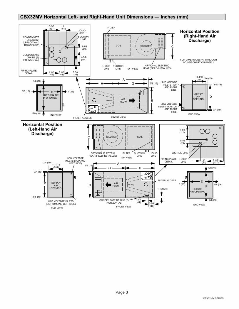
CBX32MV Horizontal Left− and Right−Hand Unit Dimensions � Inches (mm)
LIQUIDLINE
SUCTIONLINE
SUPPLYAIR
OPENING
FILTER
LOW VOLTAGEINLETS (BOTTOM
AND RIGHTSIDE)
TOP VIEW
FRONT VIEW
BLOWER
H
B
C
D
LIQUIDLINE
SUCTIONLINE
CONDENSATEDRAINS (2)
(UPFLOW ANDDOWNFLOW)
CONDENSATEDRAINS (2)
(HORIZONTAL)
COIL
3/4 (19)
3/4 (19)
1-1/2(38)
1-3/4(44)
5-3/4(46)
2(51)
1-1/8(29)
RETURN AIROPENINGF
E
5/8 (16)
5/8 (16)
5/8 (16)
END VIEW
AIRFLOW
OPTIONAL ELECTRICHEAT (FIELD−INSTALLED)
11-1/16(281)
LINE VOLTAGEINLETS (TOP
AND RIGHTSIDE)
5-3/8(137)
4-3/8(111)
LIQUIDLINE
SUCTIONLINE
SUPPLYAIR
OPENING
FILTER
LOW VOLTAGEINLETS (TOP AND
LEFT SIDE)
END VIEW
BLOWER
B
C
D
COIL
3/4 (19)
3/4 (19)
3/4 (19)
RETURNAIR OPENING
F
E
5/8 (16)
5/8 (16)
5/8 (16)
END VIEW
AIRFLOW
OPTIONAL ELECTRICHEAT (FIELD INSTALLED)
LINE VOLTAGE INLETS(BOTTOM AND LEFT SIDE)
Horizontal Position(Right-Hand Air
Discharge)
FILTER ACCESS
FILTER ACCESS
5-3/4(146)
1-1/2 (38)
1-3/4(44)
CONDENSATE DRAINS (2)(HORIZONTAL)
A5/8 (16)G
H
A5/8 (16)
G
1 (25)
1 (25)
11-1/16(281)
PIPING PLATEDETAIL
LIQUIDLINE
SUCTION LINE
2(51)
1-1/8(29)
5-3/8(137)
4-3/8(111)
PIPING PLATEDETAIL
Horizontal Position(Left-Hand Air
Discharge)
TOP VIEW
FRONT VIEW
3/4 (19)
END VIEW
FOR DIMENSIONS �A" THROUGH�H", SEE CHART ON PAGE 2.
Page 4
506274 03
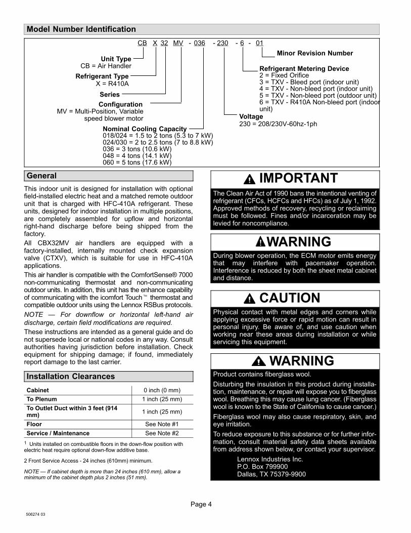
Model Number Identification
Refrigerant TypeX = R410A
230CB 32 036− 01
Series
Nominal Cooling Capacity018/024 = 1.5 to 2 tons (5.3 to 7 kW)024/030 = 2 to 2.5 tons (7 to 8.8 kW)036 = 3 tons (10.6 kW)048 = 4 tons (14.1 kW)060 = 5 tons (17.6 kW)
Minor Revision Number
ConfigurationMV = Multi−Position, Variable
speed blower motor
−X
Voltage230 = 208/230V−60hz−1ph
− −6
Refrigerant Metering Device2 = Fixed Orifice3 = TXV − Bleed port (indoor unit)4 = TXV − Non−bleed port (indoor unit)5 = TXV − Non−bleed port (outdoor unit)6 = TXV − R410A Non−bleed port (indoorunit)
MV
Unit TypeCB = Air Handler
General
This indoor unit is designed for installation with optionalfield−installed electric heat and a matched remote outdoorunit that is charged with HFC−410A refrigerant. Theseunits, designed for indoor installation in multiple positions,are completely assembled for upflow and horizontalright−hand discharge before being shipped from thefactory.
All CBX32MV air handlers are equipped with afactory−installed, internally mounted check expansionvalve (CTXV), which is suitable for use in HFC−410Aapplications.
This air handler is compatible with the ComfortSense® 7000non−communicating thermostat and non−communicatingoutdoor units. In addition, this unit has the enhance capabilityof communicating with the icomfort Touch� thermostat andcompatible outdoor units using the Lennox RSBus protocols.
NOTE � For downflow or horizontal left−hand air
discharge, certain field modifications are required.
These instructions are intended as a general guide and donot supersede local or national codes in any way. Consultauthorities having jurisdiction before installation. Checkequipment for shipping damage; if found, immediatelyreport damage to the last carrier.
Installation Clearances
Cabinet 0 inch (0 mm)
To Plenum 1 inch (25 mm)
To Outlet Duct within 3 feet (914mm)
1 inch (25 mm)
Floor See Note #1
Service / Maintenance See Note #2
1 Units installed on combustible floors in the down−flow position withelectric heat require optional down−flow additive base.
2 Front Service Access − 24 inches (610mm) minimum.
NOTE � If cabinet depth is more than 24 inches (610 mm), allow aminimum of the cabinet depth plus 2 inches (51 mm).
IMPORTANTThe Clean Air Act of 1990 bans the intentional venting ofrefrigerant (CFCs, HCFCs and HFCs) as of July 1, 1992.Approved methods of recovery, recycling or reclaimingmust be followed. Fines and/or incarceration may belevied for noncompliance.
WARNINGDuring blower operation, the ECM motor emits energythat may interfere with pacemaker operation.Interference is reduced by both the sheet metal cabinetand distance.
CAUTIONPhysical contact with metal edges and corners whileapplying excessive force or rapid motion can result inpersonal injury. Be aware of, and use caution whenworking near these areas during installation or whileservicing this equipment.
WARNINGProduct contains fiberglass wool.
Disturbing the insulation in this product during installa-tion, maintenance, or repair will expose you to fiberglasswool. Breathing this may cause lung cancer. (Fiberglasswool is known to the State of California to cause cancer.)
Fiberglass wool may also cause respiratory, skin, andeye irritation.
To reduce exposure to this substance or for further infor-mation, consult material safety data sheets availablefrom address shown below, or contact your supervisor.
Lennox Industries Inc.P.O. Box 799900Dallas, TX 75379−9900
Page 5
CBX32MV SERIES
WARNINGImproper installation of the air handler can result inpersonal injury or death.
Do not allow external combustion products or othercontaminants to enter the return air system or to bemixed with air that will be supplied to the living space.Use sheet metal screws and joint tape or duct mastic toseal return air system to air handler. In platforminstallations, the air handler should be sealed airtight tothe return air plenum. A door must never be used as aportion of the return air duct system. The base mustprovide a stable support and an airtight seal to the airhandler. Allow absolutely no sagging, cracks, gaps. etc.
For no reason should return and supply air duct systemsever be connected to or from other heating devices suchas a fireplace or stove. etc. Fire, explosion, carbonmonoxide poisoning, personal injury and/or propertydamage could result.
Requirements
In addition to conforming to manufacturer’s installationinstructions and local municipal building codes, installationof Lennox air handler units (with or without optional electricheat), MUST conform with the following National FireProtection Association (NFPA) standards:
� NFPA No. 90A � Standard for Installation of AirConditioning and Ventilation Systems
� NFPA No. 90B � Standard for Installation ofResidence Type Warm Air Heating and AirConditioning Systems
This unit is approved for installation clearance tocombustible material as stated on the unit rating plate.Accessibility and service clearances must takeprecedence over combustible material clearances.
Installing the Unit
CBX32MV units are factory−configured for upflow andhorizontal right−hand discharge installation. For downflow orhorizontal left−hand discharge, certain field modifications arerequired.
DISASSEMBLE AND REASSEMBLE AIR HANDLERUNIT
This unit consists of two sections which are shippedassembled from the factory. If necessary, the unit may bedisassembled to facilitate setting the unit. Follow the stepsbelow:
To disassemble:
1. Remove access panels.
2. Remove both blower and coil assemblies. This willlighten the cabinet for lifting.
3. Remove one screw from the left and right posts insidethe unit. Remove one screw from each side on theback of the unit. Unit sections will now separate.
To reassemble:
1. Align cabinet sections together.
2. Reinstall screws.
3. Replace blower and coil assemblies.
4. Replace access panel.
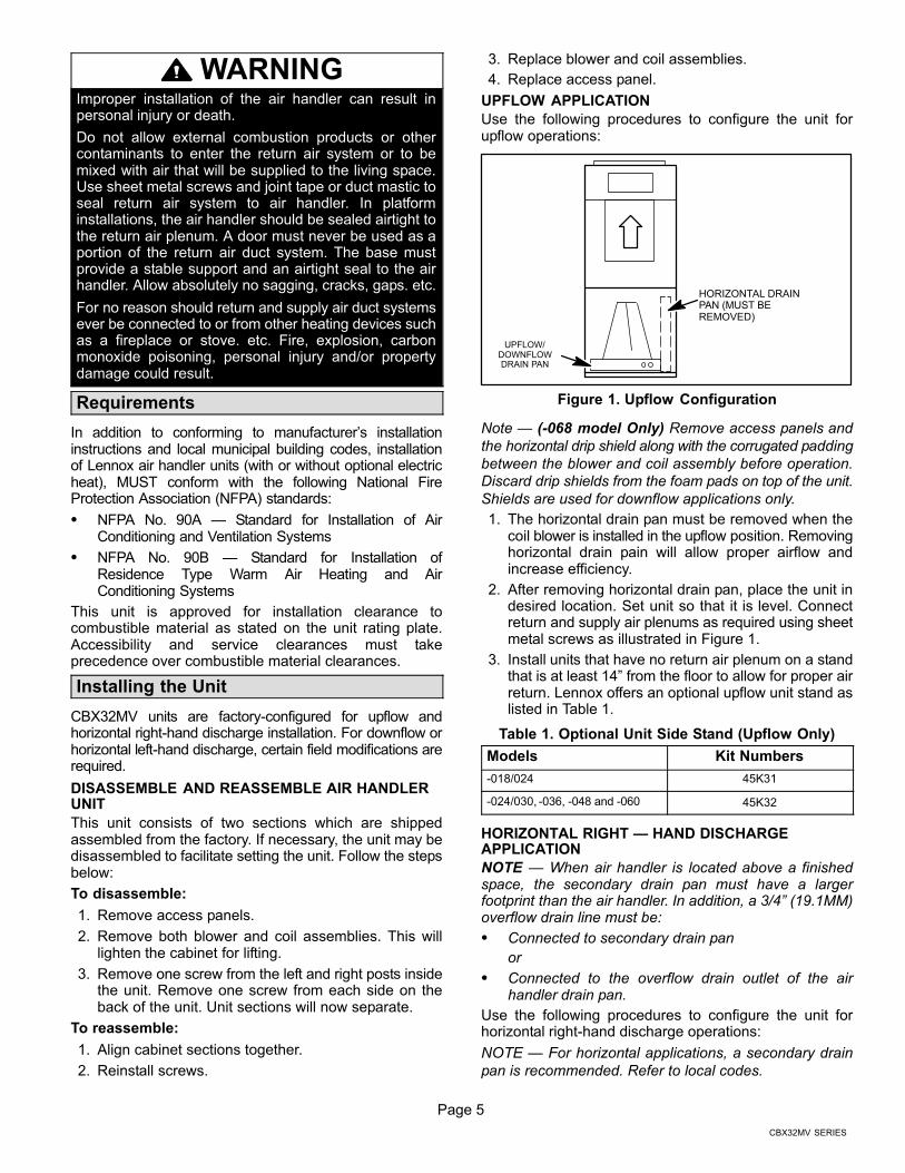
UPFLOW APPLICATION
Use the following procedures to configure the unit forupflow operations:
HORIZONTAL DRAINPAN (MUST BEREMOVED)
UPFLOW/DOWNFLOWDRAIN PAN
Figure 1. Upflow Configuration
Note � (−068 model Only) Remove access panels and
the horizontal drip shield along with the corrugated padding
between the blower and coil assembly before operation.
Discard drip shields from the foam pads on top of the unit.
Shields are used for downflow applications only.
1. The horizontal drain pan must be removed when thecoil blower is installed in the upflow position. Removinghorizontal drain pain will allow proper airflow andincrease efficiency.
2. After removing horizontal drain pan, place the unit indesired location. Set unit so that it is level. Connectreturn and supply air plenums as required using sheetmetal screws as illustrated in Figure 1.
3. Install units that have no return air plenum on a standthat is at least 14" from the floor to allow for proper airreturn. Lennox offers an optional upflow unit stand aslisted in Table 1.
Table 1. Optional Unit Side Stand (Upflow Only)
Models Kit Numbers
−018/024 45K31
−024/030, −036, −048 and −060 45K32
HORIZONTAL RIGHT � HAND DISCHARGEAPPLICATION
NOTE � When air handler is located above a finishedspace, the secondary drain pan must have a largerfootprint than the air handler. In addition, a 3/4" (19.1MM)overflow drain line must be:
� Connected to secondary drain pan
or
� Connected to the overflow drain outlet of the airhandler drain pan.
Use the following procedures to configure the unit forhorizontal right−hand discharge operations:
NOTE � For horizontal applications, a secondary drain
pan is recommended. Refer to local codes.

Page 6
506274 03
NOTE � (−068 Model Only) Before operating the unit,
remove access panels and the horizontal drip shield and
the corrugated padding between the blower and coil
assembly. Discard the corrugated padding and the
downflow drip shields from the foam pads on top of the unit.
NOTE � (−068 Model Only) Install the horizontal shield on
the front edge of the horizontal drain pan as illustrated in
Figure 2.
1. No further adjustment is necessary. Set unit so that it issloped 1/4 inch (6.35mm) towards the drain pan end ofthe unit.
NO ADJUSTMENT IS NECESSARY
HORIZONTAL DRIP SHIELD (−068MODELS)
UP−LOAD / DOWNFLOWDRAIN PAN
HORIZONTAL DRAINPAN
DOWNFLOW RAIL
Figure 2. Right−Hand Discharge Configuration
2. If the unit is suspended, the entire length of the cabinetmust be supported. If you use a chain or strap, use apiece of angle iron or sheet metal attached to the unit(either above or below) to support the length of thecabinet. Use securing screws no longer than 1/2 inch(12.7mm) to avoid damaging the coil or filter asillustrated in Figure 3. Use sheet metal screws toconnect the return and supply air plenums as required.
HORIZONTAL RIGHT−HAND DISCHARGEAPPLICATION IN HIGH HUMIDITY AREAS
For horizontal applications in high humidity areas removethe downflow rail closest to the drain pan.
To remove rail:
1. Remove the screws from the rail at the back of unit andat the cabinet support rail.
2. Remove the downflow rail then replace screws.
3. Seal around the exiting drain pipe, liquid line, andsuction line to prevent humid air from infiltrating intothe unit.
IMPORTANTWhen removing the coil, there is possible danger ofequipment damage and personal injury. Be careful whenremoving the coil assembly from a unit installed in right−or left−hand applications. The coil may tip into the drainpan once it is clear of the cabinet. Support the coil whenremoving it.
FRONT VIEW END VIEW
ANGLE IRON ORSHEET METAL
ELECTRICAL INLETCLEARANCE 4 IN. (102 MM)
1/2 IN. SCREWS MAXIMUM
Figure 3. Suspending Horizontal Unit
HORIZONTAL LEFT−HAND DISCHARGEAPPLICATION
Use the following procedures to configure the unit forhorizontal left−hand discharge operations:
NOTE � For horizontal applications, a secondary drain
pan is recommended. Refer to local codes.
NOTE � (−068 Model Only) Remove access panels and
horizontal drip shield from the corrugated padding
between the blower and coil assembly. Discard the
corrugated padding and the downflow drip shields from the
foam pads on top of the unit. (The shields are used for
downflow applications only.)
Page 7
CBX32MV SERIES
90ºBEND
CABINETSUPPORT
COIL SHOWN IN UPFLOW POSITION FOR EASYCONVERSION (LEFT−HAND AIR DISCHARGE)
TOP CAPSCREWS
DRAIN PANREINSTALLED
HERE
DRAIN PANSHIPPINGLOCATION
TOP CAP ROTATED TOCORRECT POSITION
���� DRAIN PLUGS ����REINSTALLED HERE REMOVED FROM HERE
BACK COILEND SEAL
TOP CAP
90ºBEND
ALIGN HOLES WITHHOLES IN COIL ENDPLATE.
INSTALL DRAIN PANBETWEEN TAB AND
EXTERIOR INNER WALL.
DETAIL A
DETAIL B
DETAIL C
HORIZONTAL DRIPSHIELD SCREW(FRONT COIL ENDSEAL)
FRONT VIEW
3/16" PLASTICPLUG (REAR COILEND SEAL)
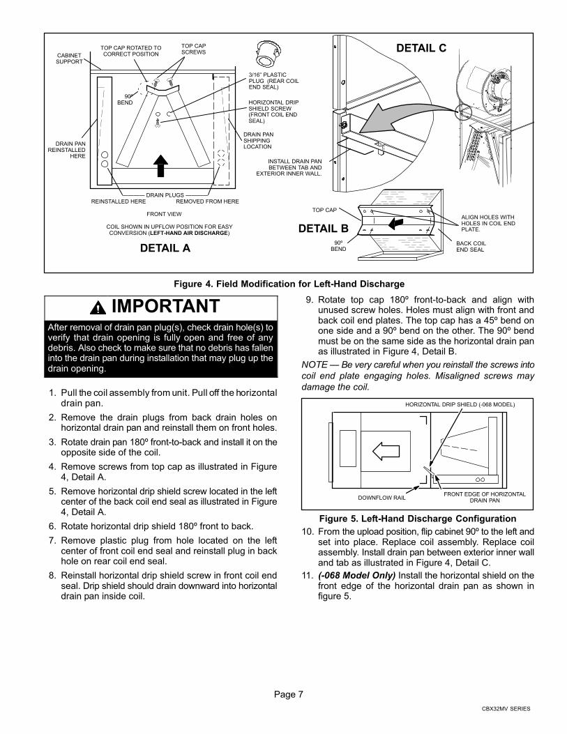
Figure 4. Field Modification for Left−Hand Discharge
IMPORTANTAfter removal of drain pan plug(s), check drain hole(s) toverify that drain opening is fully open and free of anydebris. Also check to make sure that no debris has falleninto the drain pan during installation that may plug up thedrain opening.
1. Pull the coil assembly from unit. Pull off the horizontaldrain pan.
2. Remove the drain plugs from back drain holes onhorizontal drain pan and reinstall them on front holes.
3. Rotate drain pan 180º front-to-back and install it on theopposite side of the coil.
4. Remove screws from top cap as illustrated in Figure4, Detail A.
5. Remove horizontal drip shield screw located in the leftcenter of the back coil end seal as illustrated in Figure4, Detail A.
6. Rotate horizontal drip shield 180º front to back.
7. Remove plastic plug from hole located on the leftcenter of front coil end seal and reinstall plug in backhole on rear coil end seal.
8. Reinstall horizontal drip shield screw in front coil endseal. Drip shield should drain downward into horizontaldrain pan inside coil.
9. Rotate top cap 180º front-to-back and align withunused screw holes. Holes must align with front andback coil end plates. The top cap has a 45º bend onone side and a 90º bend on the other. The 90º bendmust be on the same side as the horizontal drain panas illustrated in Figure 4, Detail B.
NOTE � Be very careful when you reinstall the screws into
coil end plate engaging holes. Misaligned screws may
damage the coil.
HORIZONTAL DRIP SHIELD (−068 MODEL)
DOWNFLOW RAILFRONT EDGE OF HORIZONTAL
DRAIN PAN
Figure 5. Left−Hand Discharge Configuration
10. From the upload position, flip cabinet 90º to the left andset into place. Replace coil assembly. Replace coilassembly. Install drain pan between exterior inner walland tab as illustrated in Figure 4, Detail C.
11. (−068 Model Only) Install the horizontal shield on thefront edge of the horizontal drain pan as shown infigure 5.
Page 8
506274 03
NOTE � For horizontal applications in high humidity
areas, remove the downflow rail closest to the drain pan.
To remove rail, remove screw from rail at back of unit and
at cabinet support rail. Remove downflow rail then replace
screws. Also, seal around the exiting drain pipe, liquid and
suction lines to prevent infiltration of humid air.
12. Knock out drain seal plate from access door. Secureplate to cabinet front flange with screw provided.
13. Flip access door and replace it on the unit.
14. Set unit so that it is sloped 1/4 inch (6.35mm) towardthe drain pan end of the unit. Connect return andsupply air plenums as required using sheet metalscrews.
15. If suspending the unit, it must be supported along theentire length of the cabinet. If using chain or strap, usea piece of angle iron or sheet metal attached to the unit(either above or below) so that the full length of thecabinet is supported. Use securing screws no longerthan 1/2 inch (12.7mm) to avoid damage to coil or filteras illustrated in Figure 3 on page 6. Connect returnand supply air plenums as required using sheet metalscrews.
DOWNFLOW APPLICATIONUse the installation instructions provided with thedownflow kit.
Table 2. Downflow Drip Shields (Tape Required) �Inches (Millimeters)
UnitsPartNumbers
Length Width
−018/024 Not Required Not Required Not Required
−024/030 LB−74274 15−7/8 (403)
4−43/64(119)
−036 LB−74272 17−7/8 (454)
−048, −060, and −068 LB−89864 19−7/8 (505)
Brazing Connections
WARNINGPolyol ester (POE) oils used with HFC−410A
refrigerant absorb moisture very quickly. It is very
important that the refrigerant system be kept closed as
much as possible. DO NOT remove line set caps or
service valve stub caps until you are ready to make
connections.
WARNINGDanger of fire. Bleeding the refrigerantcharge from only the high side may resultin the low side shell and suction tubingbeing pressurized. Application of abrazing torch while pressurized mayresult in ignition of the refrigerant and oilmixture − check the high and lowpressures before unbrazing.
WARNINGWhen using a high pressure gas such asdry nitrogen to pressurize a refrigerationor air conditioning system, use aregulator that can control the pressuredown to 1 or 2 psig (6.9 to 13.8 kPa).
CAUTIONBrazing alloys and flux contain materials which arehazardous to your health.
Avoid breathing vapors or fumes from brazingoperations. Perform operations only in well ventilatedareas.
Wear gloves and protective goggles or face shield toprotect against burns.
Wash hands with soap and water after handling brazingalloys and flux.
IMPORTANTTo prevent the build up of high levels of nitrogen whenpurging, be sure it is done in a well ventilated area. Purgelow pressure nitrogen (1 to 2 psig) through the refrigerantpiping during brazing. This will help to prevent oxidationand the introduction of moisture into a system.
Page 9
CBX32MV SERIES
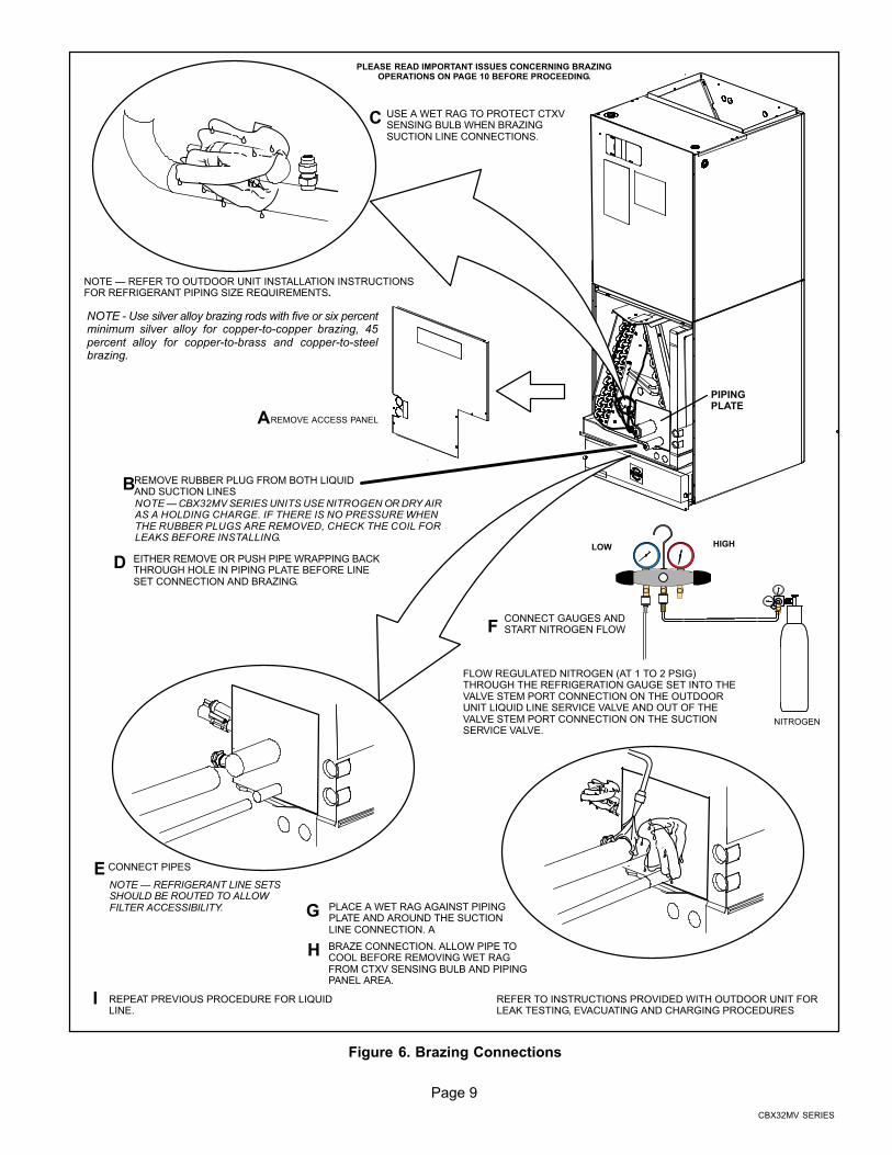
REMOVE ACCESS PANELA
REMOVE RUBBER PLUG FROM BOTH LIQUIDAND SUCTION LINES
B
USE A WET RAG TO PROTECT CTXVSENSING BULB WHEN BRAZINGSUCTION LINE CONNECTIONS.
C
NITROGEN
HIGHLOW
EITHER REMOVE OR PUSH PIPE WRAPPING BACKTHROUGH HOLE IN PIPING PLATE BEFORE LINESET CONNECTION AND BRAZING.
D
E CONNECT PIPES
FCONNECT GAUGES ANDSTART NITROGEN FLOW
G PLACE A WET RAG AGAINST PIPINGPLATE AND AROUND THE SUCTIONLINE CONNECTION. A
H BRAZE CONNECTION. ALLOW PIPE TOCOOL BEFORE REMOVING WET RAGFROM CTXV SENSING BULB AND PIPINGPANEL AREA.
I REPEAT PREVIOUS PROCEDURE FOR LIQUIDLINE.
NOTE � REFER TO OUTDOOR UNIT INSTALLATION INSTRUCTIONSFOR REFRIGERANT PIPING SIZE REQUIREMENTS.
NOTE � REFRIGERANT LINE SETSSHOULD BE ROUTED TO ALLOWFILTER ACCESSIBILITY.
NOTE � CBX32MV SERIES UNITS USE NITROGEN OR DRY AIRAS A HOLDING CHARGE. IF THERE IS NO PRESSURE WHENTHE RUBBER PLUGS ARE REMOVED, CHECK THE COIL FORLEAKS BEFORE INSTALLING.
REFER TO INSTRUCTIONS PROVIDED WITH OUTDOOR UNIT FORLEAK TESTING, EVACUATING AND CHARGING PROCEDURES
FLOW REGULATED NITROGEN (AT 1 TO 2 PSIG)THROUGH THE REFRIGERATION GAUGE SET INTO THEVALVE STEM PORT CONNECTION ON THE OUTDOORUNIT LIQUID LINE SERVICE VALVE AND OUT OF THEVALVE STEM PORT CONNECTION ON THE SUCTIONSERVICE VALVE.
PIPINGPLATE
PLEASE READ IMPORTANT ISSUES CONCERNING BRAZINGOPERATIONS ON PAGE 10 BEFORE PROCEEDING.
NOTE − Use silver alloy brazing rods with five or six percentminimum silver alloy for copper−to−copper brazing, 45percent alloy for copper−to−brass and copper−to−steelbrazing.
Figure 6. Brazing Connections
Page 10
506274 03
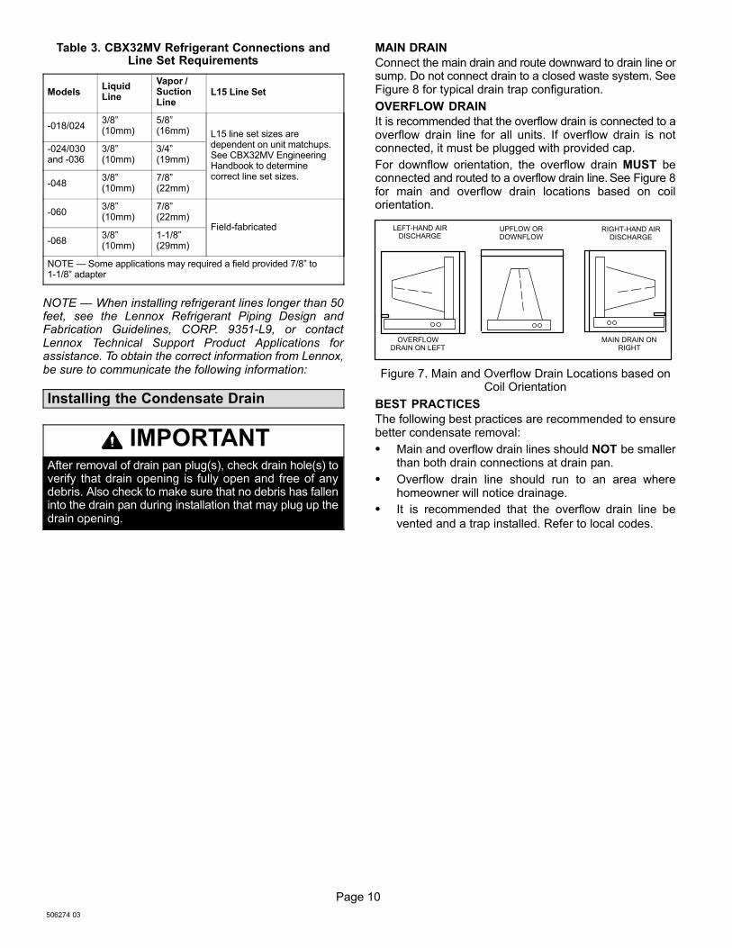
Table 3. CBX32MV Refrigerant Connections andLine Set Requirements
ModelsLiquidLine
Vapor /SuctionLine
L15 Line Set
−018/0243/8"(10mm)
5/8"(16mm) L15 line set sizes are
dependent on unit matchups.See CBX32MV EngineeringHandbook to determinecorrect line set sizes.
−024/030and −036
3/8"(10mm)
3/4"(19mm)
−0483/8"(10mm)
7/8"(22mm)
−0603/8"(10mm)
7/8"(22mm)
Field−fabricated
−0683/8"(10mm)
1−1/8"(29mm)
NOTE � Some applications may required a field provided 7/8" to1−1/8" adapter
NOTE � When installing refrigerant lines longer than 50feet, see the Lennox Refrigerant Piping Design andFabrication Guidelines, CORP. 9351−L9, or contactLennox Technical Support Product Applications forassistance. To obtain the correct information from Lennox,be sure to communicate the following information:
Installing the Condensate Drain
IMPORTANTAfter removal of drain pan plug(s), check drain hole(s) toverify that drain opening is fully open and free of anydebris. Also check to make sure that no debris has falleninto the drain pan during installation that may plug up thedrain opening.
MAIN DRAIN
Connect the main drain and route downward to drain line orsump. Do not connect drain to a closed waste system. SeeFigure 8 for typical drain trap configuration.
OVERFLOW DRAIN
It is recommended that the overflow drain is connected to aoverflow drain line for all units. If overflow drain is notconnected, it must be plugged with provided cap.
For downflow orientation, the overflow drain MUST beconnected and routed to a overflow drain line. See Figure 8for main and overflow drain locations based on coilorientation.
LEFT−HAND AIRDISCHARGE
MAIN DRAIN ONRIGHT
OVERFLOWDRAIN ON LEFT
UPFLOW ORDOWNFLOW
RIGHT−HAND AIRDISCHARGE
Figure 7. Main and Overflow Drain Locations based onCoil Orientation
BEST PRACTICES
The following best practices are recommended to ensurebetter condensate removal:
� Main and overflow drain lines should NOT be smallerthan both drain connections at drain pan.
� Overflow drain line should run to an area wherehomeowner will notice drainage.
� It is recommended that the overflow drain line be
vented and a trap installed. Refer to local codes.
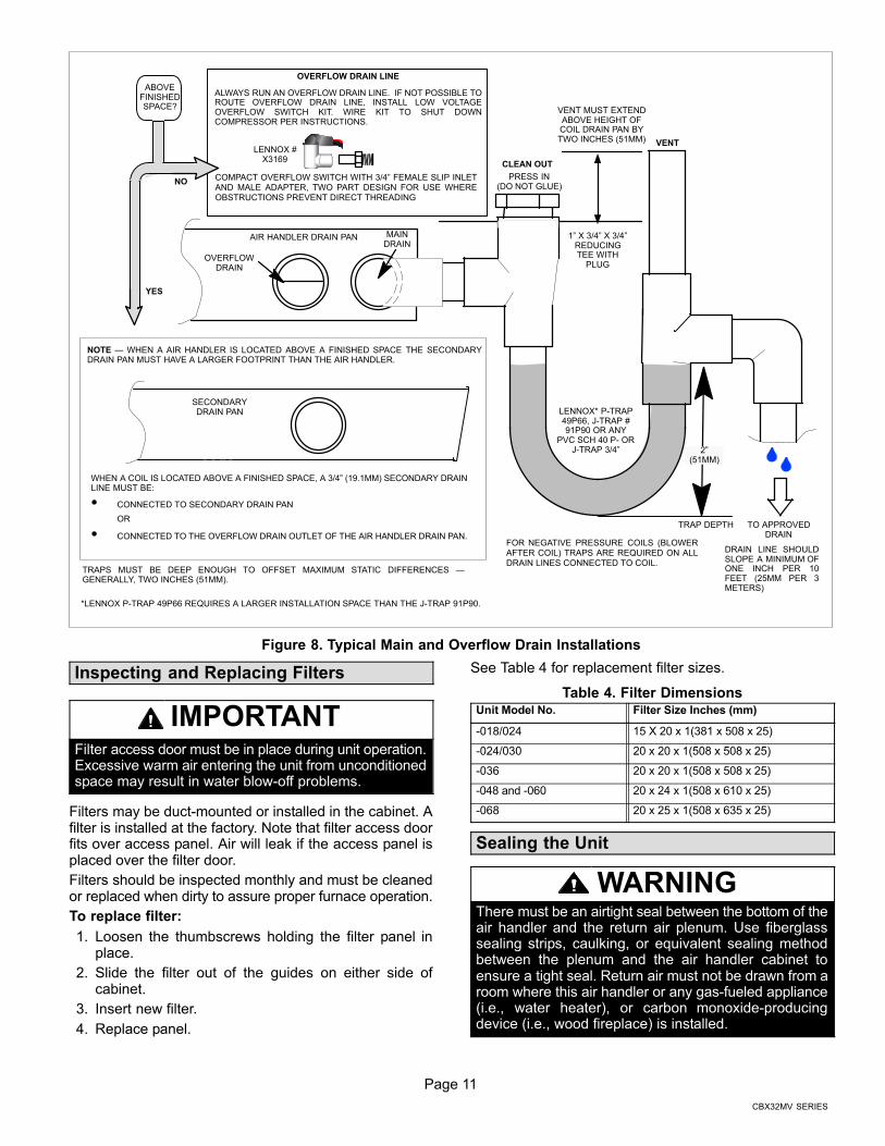
Page 11
CBX32MV SERIES
ABOVEFINISHEDSPACE?
OVERFLOW DRAIN LINE
ALWAYS RUN AN OVERFLOW DRAIN LINE. IF NOT POSSIBLE TOROUTE OVERFLOW DRAIN LINE, INSTALL LOW VOLTAGEOVERFLOW SWITCH KIT. WIRE KIT TO SHUT DOWNCOMPRESSOR PER INSTRUCTIONS.
NO
YES
LENNOX #X3169
CLEAN OUT
VENT
PRESS IN(DO NOT GLUE)
VENT MUST EXTENDABOVE HEIGHT OFCOIL DRAIN PAN BYTWO INCHES (51MM)
1" X 3/4" X 3/4"REDUCINGTEE WITH
PLUG
LENNOX* P−TRAP49P66, J−TRAP #91P90 OR ANY
PVC SCH 40 P− ORJ−TRAP 3/4"
OVERFLOWDRAIN
OPTIONALSAFETY
PAN
AIR HANDLER DRAIN PAN
WHEN A COIL IS LOCATED ABOVE A FINISHED SPACE, A 3/4" (19.1MM) SECONDARY DRAINLINE MUST BE:
� CONNECTED TO SECONDARY DRAIN PAN
OR
� CONNECTED TO THE OVERFLOW DRAIN OUTLET OF THE AIR HANDLER DRAIN PAN.
TRAPS MUST BE DEEP ENOUGH TO OFFSET MAXIMUM STATIC DIFFERENCES �GENERALLY, TWO INCHES (51MM).
DRAIN LINE SHOULDSLOPE A MINIMUM OFONE INCH PER 10FEET (25MM PER 3METERS)
NOTE � WHEN A AIR HANDLER IS LOCATED ABOVE A FINISHED SPACE THE SECONDARYDRAIN PAN MUST HAVE A LARGER FOOTPRINT THAN THE AIR HANDLER.
MAINDRAIN
TO APPROVEDDRAIN
FOR NEGATIVE PRESSURE COILS (BLOWERAFTER COIL) TRAPS ARE REQUIRED ON ALLDRAIN LINES CONNECTED TO COIL.
COMPACT OVERFLOW SWITCH WITH 3/4" FEMALE SLIP INLETAND MALE ADAPTER, TWO PART DESIGN FOR USE WHEREOBSTRUCTIONS PREVENT DIRECT THREADING
SECONDARYDRAIN PAN
2"(51MM)
TRAP DEPTH
*LENNOX P−TRAP 49P66 REQUIRES A LARGER INSTALLATION SPACE THAN THE J−TRAP 91P90.
Figure 8. Typical Main and Overflow Drain Installations
Inspecting and Replacing Filters
IMPORTANTFilter access door must be in place during unit operation.Excessive warm air entering the unit from unconditionedspace may result in water blow−off problems.
Filters may be duct−mounted or installed in the cabinet. Afilter is installed at the factory. Note that filter access doorfits over access panel. Air will leak if the access panel isplaced over the filter door.
Filters should be inspected monthly and must be cleanedor replaced when dirty to assure proper furnace operation.
To replace filter:
1. Loosen the thumbscrews holding the filter panel inplace.
2. Slide the filter out of the guides on either side ofcabinet.
3. Insert new filter.
4. Replace panel.
See Table 4 for replacement filter sizes.
Table 4. Filter DimensionsUnit Model No. Filter Size Inches (mm)
−018/024 15 X 20 x 1(381 x 508 x 25)
−024/030 20 x 20 x 1(508 x 508 x 25)
−036 20 x 20 x 1(508 x 508 x 25)
−048 and −060 20 x 24 x 1(508 x 610 x 25)
−068 20 x 25 x 1(508 x 635 x 25)
Sealing the Unit
WARNINGThere must be an airtight seal between the bottom of theair handler and the return air plenum. Use fiberglasssealing strips, caulking, or equivalent sealing methodbetween the plenum and the air handler cabinet toensure a tight seal. Return air must not be drawn from aroom where this air handler or any gas−fueled appliance(i.e., water heater), or carbon monoxide−producingdevice (i.e., wood fireplace) is installed.
Page 12
506274 03
Seal the unit so that warm air is not allowed into thecabinet. Warm air introduces moisture, which results inwater blow−off problems. This is especially important whenthe unit is installed in an unconditioned area.
Make sure the liquid line and suction line entry points aresealed with either the provided flexible elastomeric thermalinsulation, or field provided material (e.g. Armaflex,Permagum or equivalent). Any of the previously mentionmaterials may be used to seal around the main andauxiliary drains, and around open areas of electrical inlets.
Field Control Wiring
WARNINGElectric Shock Hazard.
Can cause injury or death.
Foil-faced insulation has conductive characteristics sim-ilar to metal. Be sure there are no electrical connectionswithin a ½" of the insulation. If the foil-faced insulationcomes in contact with electrical voltage, the foil couldprovide a path for current to pass through to the outermetal cabinet. While the current produced may not beenough to trip existing electrical safety devices (e.g.fuses or circuit breakers), the current can be enough tocause an electric shock hazard that could cause person-al injury or death.
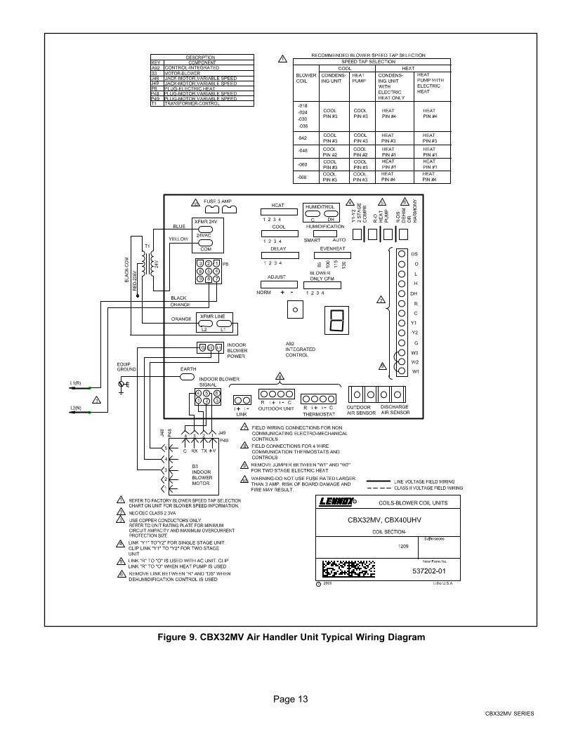
Wiring must conform to the current National Electric CodeANSI/NFPA No. 70, or Canadian Electric Code Part I, CSAStandard C22.1, and local building codes. Refer tofollowing wiring diagrams. See unit nameplate forminimum circuit ampacity and maximum over−currentprotection size.
WARNINGRun 24V Class II wiring only through specified low volt-age opening. Run line voltage wiring only through speci-fied high voltage opening. Do not combine voltage in oneopening.
Select the proper supply circuit conductors inaccordance with Tables 310−16 and 310−17 in theNational Electric Code, ANSI/NFPA No. 70 or Tables 1through 4 in the Canadian Electric Code, Part I, CSAStandard C22.1.
Separate openings have been provided for 24V lowvoltage and line voltage. Refer to the dimension illustrationof specific location.
CAUTIONUSE COPPER CONDUCTORS ONLY.
WIRING CONNECTIONS
1. Install line voltage power supply to unit from a properlycircuit breaker.
2. Ground unit at unit disconnect switch or to an earthground.
NOTE � Connect conduit to the unit using a proper
conduit fitting. Units are approved for use only with
copper conductors. A complete unit wiring diagram is
located on the back side of the unit’s access panel.
3. Install low voltage wiring from outdoor to indoor unitand from thermostat to indoor unit.
NOTE � For proper voltages, select control wiring gauge
per the charts on Page 18.
Page 13
CBX32MV SERIES
Figure 9. CBX32MV Air Handler Unit Typical Wiring Diagram
Page 14
506274 03
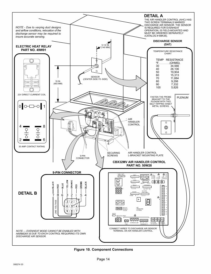
SENSOR(CENTER SIDE−T0 −SIDE)
9−PINCONNECTOR
SECURINGSCREWS
AIRHANDLERCONTROL
AIR HANDLER CONTROLL−BRACKET MOUNTING PLATE
19 IN.(483 MM)
5−1/2 IN.(140 MM)
9−PIN CONNECTOR
ELECTRIC HEAT RELAYPART NO. 49W91
22V DIRECT CURRENT COIL
30 AMP CONTACT RATING
FASTEN THE PROBEBRACKET TO THE
PLENUM WITH TWOSELF−TAPPING SHEET
METAL SCREWS.
CONNECT WIRES TO DISCHARGE AIR SENSORTERMINAL ON AIR HANDLER CONTROL.
PLENUM
CBX32MV AIR HANDLER CONTROLPART NO. 50W28
DISCHARGE SENSOR
(DAT)
TEMP RESISTANCEºF (OHMS)30 34,56640 26,10650 19,90460 15,31370 11,88480 9,29890 7,332100 5,826
DETAIL A
NOTE � EVENHEAT MODE CANNOT BE ENABLED WITHHARMONY III DUE TO EACH CONTROL REQUIRING ITS OWNDISCHARGE AIR SENSOR.
THE AIR HANDLER CONTROL (AHC) HASTWO SCREW TERMINALS MARKEDDISCHARGE AIR SENSOR. THE SENSORIS REQUIRED FOR EVENHEATOPERATION, IS FIELD−MOUNTED ANDMUST BE ORDERED SEPARATELY(CATALOG # 88K38).
DETAIL B
TEMPERATURE RESISTANCECHART
NOTE − Due to varying duct designsand airflow conditions, relocation of thedischarge sensor may be required toinsure accurate sensing.
Figure 10. Component Connections
Page 15
CBX32MV SERIES
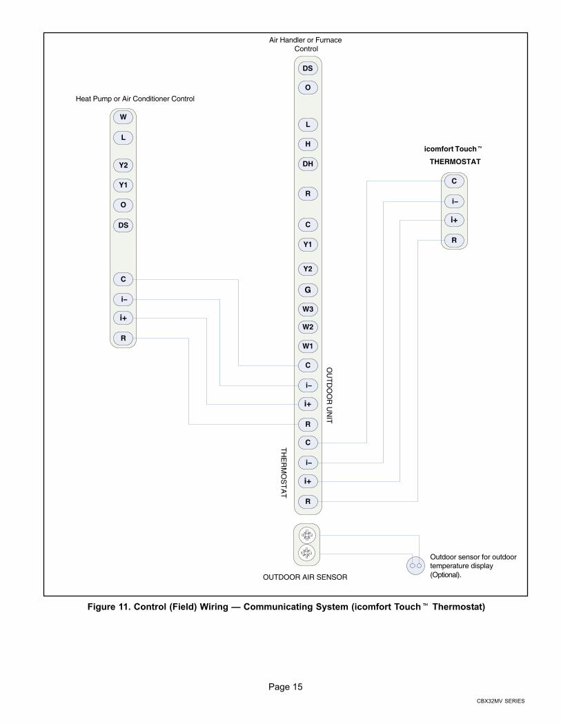
icomfort Touch�
THERMOSTAT
Air Handler or FurnaceControl
W3
H
O
C
L
Y2
DS
DH
G
R
Y1
W2
W1R
Y1
L
C
Heat Pump or Air Conditioner Control
Y2
i−
W
O
i+
DS
R
C
i−
i+
R
C
i−
i+
OU
TD
OO
R U
NIT
TH
ER
MO
ST
AT
R
C
i−
i+
Outdoor sensor for outdoor temperature display(Optional).OUTDOOR AIR SENSOR
Figure 11. Control (Field) Wiring � Communicating System (icomfort Touch� Thermostat)
Page 16
506274 03
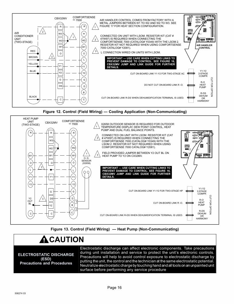
AIR HANDLER CONTROL COMES FROM FACTORY WITH AMETAL JUMPERS BETWEEN W1 TO W2 AND W2 TO W3. SEEFIGURE 17 FOR HEAT SECTION CONFIGURATION.
L CONNECTION WIRED ON UNITS WITH LSOM.
CUT ON−BOARD LINK R−DS WHEN DEHUMIDIFICATION TERMINAL IS USED.
CBX32MV COMFORTSENSE� 7000
AIRCONDITIONERUNIT(TWO−STAGE)
RED
BROWN
YELLOW
BLUE
BLACK
1
1
2
2
3
3
R
W3
W2
W1
O
Y1
Y2
G
DS
C
R
H
W2
W1
O
L
Y1
Y2
G
D
B
C
Y1−Y22−STAGECOMPR
R−OHEATPUMP
R−DSDEHUM
ORHARMONY
CU
T F
OR
OP
TIO
N
CUT ON−BOARD LINK Y1−Y2 FOR TWO−STAGE AC
DO NOT CUT ON−BOARD LINK R −O.
IMPORTANT � USE CARE WHEN CUTTING LINKS TOPREVENT DAMAGE TO CONTROL. SEE FIGURE 16,CBX32MV JUMP AND LINK GUIDE FOR FURTHERDETAILS.
AIR HANDLERCONTROL
CONNECTED ON UNIT WITH LSOM. RESISTOR KIT (CAT #47W97) IS REQUIRED WHEN CONNECTING THECOMFORTSENSE 7000 (CATALOG# Y0349) WITH THE LSOM 2.RESISTOR KIT NOT REQUIRED WHEN USING COMFORTSENSE7000 CATALOG# Y2081).
Figure 12. Control (Field Wiring) � Cooling Application (Non−Communicating)
HEAT PUMPUNIT
(TWO−STAGE) X2658 OUTDOOR SENSOR IS REQUIRED FOR OUTDOORTEMPERATURE DISPLAY, DEW POINT CONTROL, HEATPUMP AND DUAL FUEL BALANCE POINTS.
COMFORTSENSE� 7000
R R R
W3 H
W2W2
W1 W1 W1
OOO
LL
Y1Y1Y1
Y2Y2
GG
C C C
T
T
D
BY2
DS
O. D.SENSOR(X2658)
Y2OUTBL
1
1
CUT ON−BOARD LINK R −O.
CUT ON−BOARD LINK R−DS WHEN DEHUMIDIFICATION TERMINAL IS USED.
CUT ON−BOARD LINK Y1−Y2 FOR TWO−STAGE HP
2
2
3
3FIELD PROVIDED JUMPER BETWEEN Y2 OUT BL ONHEAT PUMP TO Y2 ON CX32MV.
CONNECTED ON UNIT WITH LSOM. RESISTOR KIT (CAT# 47W97) IS REQUIRED WHEN CONNECTING THECOMFORTSENSE 7000 (CATALOG# Y0349) WITH THELSOM 2. RESISTOR KIT NOT REQUIRED WHEN USINGCOMFORTSENSE 7000 CATALOG# Y2081).
Y1−Y22−STAGECOMPR
R−OHEATPUMP
R−DSDEHUM
ORHARMONY
CU
T F
OR
OP
TIO
N
CBX32MV
IMPORTANT � USE CARE WHEN CUTTING LINKS TOPREVENT DAMAGE TO CONTROL. SEE FIGURE 16,CBX32MV JUMP AND LINK GUIDE FOR FURTHERDETAILS.
Figure 13. Control (Field Wiring) � Heat Pump (Non−Communicating)
CAUTION
ELECTROSTATIC DISCHARGE(ESD)
Precautions and Procedures
Electrostatic discharge can affect electronic components. Take precautionsduring unit installation and service to protect the unit’s electronic controls.Precautions will help to avoid control exposure to electrostatic discharge byputting the unit, the control and the technician at the same electrostatic potential.Neutralize electrostatic charge by touching hand and all tools on an unpainted unitsurface before performing any service procedure
Page 17
CBX32MV SERIES
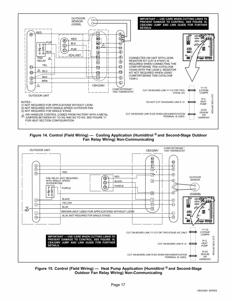
RED
YEL
BLU
BLK
BRN
COMFORTSENSE�7000 THERMOSTAT
OUTDOOR UNIT
PUR
OUTDOORSENSOR(X2658)
BLK
RED
BLK
PUR
EDA UNITFANRELAY
NOTES −/1\ NOT REQUIRED FOR APPLICATIONS WITHOUT LSOM/2\ NOT REQUIRED WITH SINGLE-SPEED OUTDOOR FAN/3\ NOT REQUIRED FOR SINGLE STAGE
T
T
D
DO NOT CUT ON−BOARD LINK R −O.
CUT ON−BOARD LINK R−DS WHEN DEHUMIDIFICATIONTERMINAL IS USED.
CUT ON−BOARD LINK Y1−Y2 FOR TWO−STAGE A/C
4
4AIR HANDLER CONTROL COMES FROM FACTORY WITH A METALJUMPERS BETWEEN W1 TO W2 AND W2 TO W3. SEE FIGURE 17FOR HEAT SECTION CONFIGURATION..
Y1−Y22−STAGECOMPR
R−OHEATPUMP
R−DSDEHUM
ORHARMONY
CU
T F
OR
OP
TIO
N
CBX32MV
IMPORTANT � USE CARE WHEN CUTTING LINKS TOPREVENT DAMAGE TO CONTROL. SEE FIGURE 16,CBX32MV JUMP AND LINK GUIDE FOR FURTHERDETAILS.
CONNECTED ON UNIT WITH LSOM.RESISTOR KIT (CAT # 47W97) ISREQUIRED WHEN CONNECTING THECOMFORTSENSE 7000 (CATALOG#Y0349) WITH THE LSOM 2. RESISTORKIT NOT REQUIRED WHEN USINGCOMFORTSENSE 7000 CATALOG#Y2081).
Figure 14. Control (Field Wiring) � Cooling Application (Humiditrol ® and Second−Stage OutdoorFan Relay Wiring) Non−Communicating
YELLOW
BLUE (NOT REQUIRED FOR SINGLE STAGE)
RED
BLACK
PURPLEPURPLE
BLACK
BLUE
RED
FAN RELAY (NOT REQUIREDWITH SINGLE−SPEEDOUTDOOR FAN)
OUTDOORSENSOR
(X2658)
COMFORTSENSE�7000 THERMOSTATCBX32MVOUTDOOR UNIT
CUT ON−BOARD LINK R −O.
CUT ON−BOARD LINK Y1−Y2 FOR TWO−STAGE A/C ONLY
CUT ON−BOARD LINK R−DS WHEN DEHUMIDIFICATIONTERMINAL IS USED.
T
T
BROWN (NOT USED FOR APPLICATIONS WITHOUT LSOM
Y1−Y22−STAGECOMPR
R−OHEATPUMP
R−DSDEHUM
ORHARMONY
CU
T F
OR
OP
TIO
N
IMPORTANT � USE CARE WHEN CUTTING LINKS TOPREVENT DAMAGE TO CONTROL. SEE FIGURE 16,CBX32MV JUMP AND LINK GUIDE FOR FURTHERDETAILS.
Figure 15. Control (Field Wiring) � Heat Pump Application (Humiditrol ® and Second−StageOutdoor Fan Relay Wiring) Non−Communicating
Page 18
506274 03
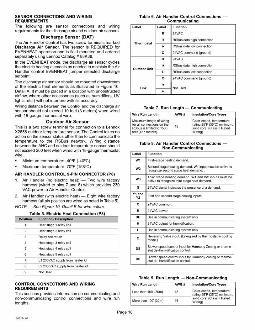
SENSOR CONNECTIONS AND WIRINGREQUIREMENTS
The following are sensor connections and wiringrequirements for the discharge air and outdoor air sensors.
Discharge Sensor (DAT)
The Air Handler Control has two screw terminals markedDischarge Air Sensor. The sensor is REQUIRED forEVENHEAT operation and is field mounted and orderedseparately using Lennox Catalog # 88K38.
In the EVENHEAT mode, the discharge air sensor cyclesthe electric heating elements as needed to maintain the AirHandler control EVENHEAT jumper selected dischargesetpoint.
The discharge air sensor should be mounted downstreamof the electric heat elements as illustrated in Figure 10,Detail A. It must be placed in a location with unobstructedairflow, where other accessories (such as humidifiers, UVlights, etc.) will not interfere with its accuracy.
Wiring distance between the Control and the discharge airsensor should not exceed 10 feet (3 meters) when wiredwith 18−gauge thermostat wire.
Outdoor Air SensorThis is a two screw terminal for connection to a LennoxX2658 outdoor temperature sensor. The Control takes noaction on the sensor status other than to communicate thetemperature to the RSBus network. Wiring distancebetween the AHC and outdoor temperature sensor shouldnot exceed 200 feet when wired with 18−gauge thermostatwire.
� Minimum temperature: −40ºF (−40ºC)
� Maximum temperature: 70ºF (158ºC)
AIR HANDLER CONTROL 9−PIN CONNECTOR (P8)
1. Air Handler (no electric heat) � Two wire factoryharness (wired to pins 7 and 8) which provides 230VAC power to Air Handler Control.
2. Air Handler (with electric heat) � Eight wire factoryharness (all pin position are wired as noted in Table 5).
NOTE � See Figure 10, Detail B for wire colors.
Table 5. Electric Heat Connection (P8)
Position Function / Description
1 Heat stage 1 relay coil
2 Heat stage 2 relay coil
3 Relay coil return
4 Heat stage 3 relay coil
5 Heat stage 4 relay coil
6 Heat stage 5 relay coil
7 L1 230VAC supply from heater kit
8 L2 230 VAC supply from heater kit
9 Not Used
CONTROL CONNECTIONS AND WIRINGREQUIREMENTS
This sections provides information on communicating andnon−communicating control connections and wire runlengths.
Table 6. Air Handler Control Connections �Communicating
Label Label Function
Thermostat
R 24VAC
i+ RSbus data high connection
i− RSbus data low connection
C 24VAC command (ground)
Outdoor Unit
R 24VAC
i+ RSbus data high connection
i− RSbus data low connection
C 24VAC command (ground)
Linki+
Not used.i−
Table 7. Run Length � Communicating
Wire Run Length AWG # Insulation/Core Types
Maximum length of wiringfor all connections on theRSbus is limited to 1500feet (457 meters).
18
Color−coded, temperaturerating 95ºF (35ºC) minimum,solid core. (Class II RatedWiring)
Table 8. Air Handler Control Connections �Non−Communicating
Label Function
W1 First−stage heating demand.
W2Second stage heating demand. W1 input must be active torecognize second stage heat demand. .
W3Third stage heating demand. W1 and W2 inputs must beactive to recognize third stage heat demand.
G 24VAC signal indicates the presence of a demand.
Y1 andY2
First and second stage cooling inputs.
C 24VAC common.
R 24VAC power.
DH Use in communicating system only
H 24VAC output for humidification.
L Use in communicating system only
OReversing Valve input. (Energized by thermostat in coolingmode.)
DSBlower speed control input for Harmony Zoning or thermo-stat de−humidification control.
DSBlower speed control input for Harmony Zoning or thermo-stat de−humidification control.
Table 9. Run Length � Non−Communicating
Wire Run Length AWG # Insulation/Core Types
Less than 100’ (30m) 18 Color−coded, temperaturerating 95ºF (35ºC) minimum,solid core. (Class II RatedWiring)More than 100’ (30m) 16
Page 19
CBX32MV SERIES
OUTDOORAIR SENSOR
HEAT
1 2 3 4
COOL
1 2 3 4
DELAY
1 2 3 4
ADJUST
NORM + −
HUMIDIFICATION
SMART AUTO
EVENHEAT
1 2 3 4
BLOWERONLY CFM
100
115
130
85
Y1−
Y2
2−S
TA
GE
CO
MP
R
R−
OH
EA
T
PU
MP
R−
DS
DE
HU
MOR
C
W1
W2
G
Y2
Y1
C
R
DH
H
L
O
DS
W3
FACTORYJUMPER
FUSE 3 AMP
XFMR 24V
24 VAC
COM
3
69
1
4
7
XFMR LINE
G
7−SEGMENT LED
DE
HU
MID
IFIC
AT
ION−
HA
RM
ON
Y L
INK
(JU
MP
ER
S R
to
DS
)
HE
AT
PU
MP
LIN
K
(JU
MP
ER
S R
to
O)
2−S
TA
GE
CO
MP
RE
SS
OR
LIN
K
(JU
MP
ER
S Y
1 to
Y2)
ON−B
OA
RD
LIN
KO
PT
ION
SE
LE
CT
ION
1
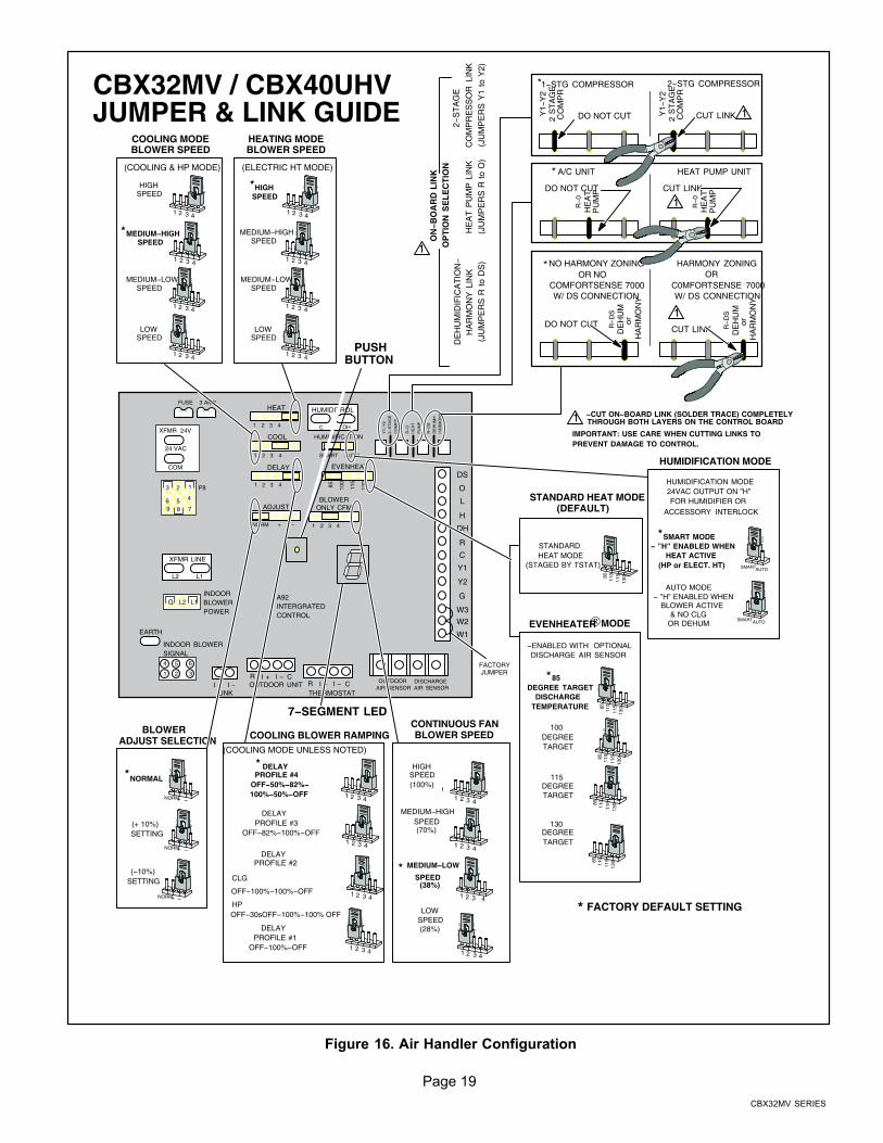
CBX32MV / CBX40UHV JUMPER & LINK GUIDE
−CUT ON−BOARD LINK (SOLDER TRACE) COMPLETELYTHROUGH BOTH LAYERS ON THE CONTROL BOARD1
COOLING BLOWER RAMPING
DELAYPROFILE #3
OFF−82%−100%−OFF
CLG
HP
DELAYPROFILE #2
DELAYPROFILE #1
OFF−100%−OFF
DELAYPROFILE #4
OFF−50%−82%−100%−50%−OFF
*(COOLING MODE UNLESS NOTED)
1 2 3 4
1 2 3 4
1 2 3 4
1 2 3 4
*
HUMIDIFICATION MODE
SMART MODE− ”H” ENABLED WHEN
HEAT ACTIVE (HP or ELECT. HT)
AUTO MODE − ”H” ENABLED WHEN
BLOWER ACTIVE & NO CLGOR DEHUM
HUMIDIFICATION MODE24VAC OUTPUT ON ”H”FOR HUMIDIFIER OR
ACCESSORY INTERLOCK
SMARTAUTO
SMARTAUTO
FACTORY DEFAULT SETTING*
COOLING MODEBLOWER SPEED
HIGHSPEED
MEDIUM−LOWSPEED
LOWSPEED
1 2 3 4
MEDIUM−HIGHSPEED
*
1 2 3 4
1 2 3 4
1 2 3 4
(COOLING & HP MODE)
STANDARD HEAT MODE
(STAGED BY TSTAT)
STANDARD HEAT MODE(DEFAULT)
8511
011
513
0
HEATING MODEBLOWER SPEED
*
(ELECTRIC HT MODE)
1 2 3 4
1 2 3 4
1 2 3 4
1 2 3 4
LOWSPEED
MEDIUM−LOWSPEED
MEDIUM−HIGHSPEED
HIGHSPEED
NORM+ −
NORM+ −
NORM+ −
BLOWERADJUST SELECTION
NORMAL
(+ 10%) SETTING
(−10%)SETTING
*
*
EVENHEATER® MODE
85DEGREE TARGET
DISCHARGETEMPERATURE
100DEGREETARGET
115DEGREETARGET
130DEGREETARGET
8511
011
513
0
−ENABLED WITH OPTIONALDISCHARGE AIR SENSOR
8511
011
513
0
8511
011
513
0
8511
011
513
0
PUSHBUTTON
HIGHSPEED(100%)
MEDIUM−HIGHSPEED(70%)
LOWSPEED(28%)
* MEDIUM−LOW
SPEED(38%)
1 2 3 4
1 2 3 4
1 2 3 4
1 2 3 4
CONTINUOUS FANBLOWER SPEED
IMPORTANT: USE CARE WHEN CUTTING LINKS TOPREVENT DAMAGE TO CONTROL.
2
58
P8
L1L2
L2 L1INDOORBLOWERPOWER
EARTH
INDOOR BLOWERSIGNAL4 5 6
1 2 3
A92INTERGRATEDCONTROL
OUTDOOR UNITLINK
I + I −I + I −R C
I + I −R CTHERMOSTAT
HUMIDITROL
DH
DISCHARGEAIR SENSOR
HA
RM
ON
Y
R−
DS
DE
HU
Mor
NO HARMONY ZONINGOR NO
COMFORTSENSE 7000W/ DS CONNECTION
DO NOT CUT
HARMONY ZONINGOR
C0MFORTSENSE 7000W/ DS CONNECTION
CUT LINK
HA
RM
ON
Y
R−
DS
DE
HU
Mor
HA
RM
ON
Y
1
A/C UNIT HEAT PUMP UNIT
R−
0H
EA
TP
UM
P
R−
0H
EA
TP
UM
P
1DO NOT CUT CUT LINK
2 S
TA
GE
CO
MP
R
1−STG COMPRESSOR 2−STG COMPRESSOR
Y1−
Y2
1DO NOT CUT CUT LINK
*
*
*
2 S
TA
GE
CO
MP
R
Y1−
Y2
OFF−100%−100%−OFF
OFF−30sOFF−100%−100% OFF
Figure 16. Air Handler Configuration
Page 20
506274 03
Air Handler Control Button, Display andJumpers
Use Figure 16 as reference for jumper settings. If any ofthe reference jumpers are missing, the Air Handler Controlwill display Error Code 130 as per Table 10, and the AirHandler Control will automatically use the factory defaultsetting show in Figure 16)
IMPORTANTBefore changing any clippable links or jumper settings,make sure the motor has completely stopped. Anychanges will not take place while the motor is running.
PUSH BUTTON
An on−board push button is provided for the purpose ofplacing the Air Handler Control in different operationmodes and can be used to recall stored error codes. Whenbutton is pushed and held, Air Handler Control will cyclethrough a menu of options depending on current operatingmode. Every three seconds a new menu item will bedisplayed. If the button is released while that item is shownon the display, Air Handler Control will enter displayedoperating mode, or execute defined operation sequencefor that menu option. Once all items on menu have beendisplayed the menu resumes from the beginning (if buttonis still held).
1. Press the diagnostic push button and hold it to cyclethrough a menu of options. Every five seconds a newmenu item will be displayed. Release the button whenthe desired mode is displayed.
2. When the solid �E" is displayed, the control enters the Error
Code Recall mode. Error Code Recall mode menu options:
No change
3. (displaying error history) remains in Error Code Recall mode;
solid �≡" exits Error Code Recall mode; and solid �c" clears
the error history. Must press button while flashing �c" is
displayed to clear error codes
4. When the solid �−" is displayed, the control enters the Field
Test mode. Field Test mode menu options: Solid �C" starts
pressure switch calibration; blinking �−" exits Field Test mode.
DISPLAY
An on−board single character LED display (see Figure 16for LED display location) indicates general system statusinformation such as mode of operation, indoor blower CFMand error codes. Multi−character strings are displayed withcharacter ON for one second, OFF for 0.5 seconds andone second pause between the character groups.
JUMPERS
Jumpers are used for non−communicating mode only.
1. Humidification � Controls the status of H terminalon the thermostat block. Configurations are as follows:
� If jumper is installed in SMART Humidificationposition (Default), H terminal is active if heatdemand is present and indoor blower isrunning.
� If jumper is installed in AUTO Humidificationposition, H terminal is energized wheneverindoor blower is running.
2. EvenHeat � Target Discharge Air Temperatureselection is used to set discharge air temperatures forEvenHeat operation.
NOTE − Optional Discharge Air Temperature Sensor,
Lennox Catalog # 88K38 is REQUIRED for EVENHEAT
operation and must be ordered separately.
3. Blower Only CFM � Used to select Indoor blowerCFM for continuous operation.
4. Heat � Used to select Indoor blower CFM forelectrical heat by placing the jumper in proper position.Actual CFM values for different air handler sizes areshown in Targeted CFM Tables starting on Page 24.
5. Cool � Used to select cooling indoor blower CFM byplacing the jumper in proper position. Actual CFMvalues for different air handler sizes are shown inTargeted CFM Tables starting on Page 24.
6. Adjust − Used to select the indoor blower CFMadjustment value by placing the jumper in appropriateposition.
� If NORM is selected, indoor blower runs atnormal speeds.
� If + is selected, indoor blower runs atapproximately 10% higher speed than NORMsetting.
� If − is selected, indoor blower runs atapproximately 10% lower speed than NORMsetting.
If the jumper is missing, the Air Handler Control willactivate the Configuration Jumper is Missing alarm inand will automatically use the default factory setting inTable 10. See Figure 16 for jumper configurations.Actual CFM values for different air handler sizes areshown in Targeted CFM Tables starting on Page 24.
7. Delay � Indoor blower cooling profile, delay forcooling and heat pump operations.
� When operating a heat pump, delay profiles 1and 2 are only applicable.
� When operating a heat pump, and profiles 3and 4 are selected, the Air Handler Control willdefault to profile 1.
If the jumper is missing, the Air Handler Control will
activate the Configuration Jumper is Missing alarm
and will automatically use the default factory setting in
Table 10. See Figure 16 for jumper configurations.
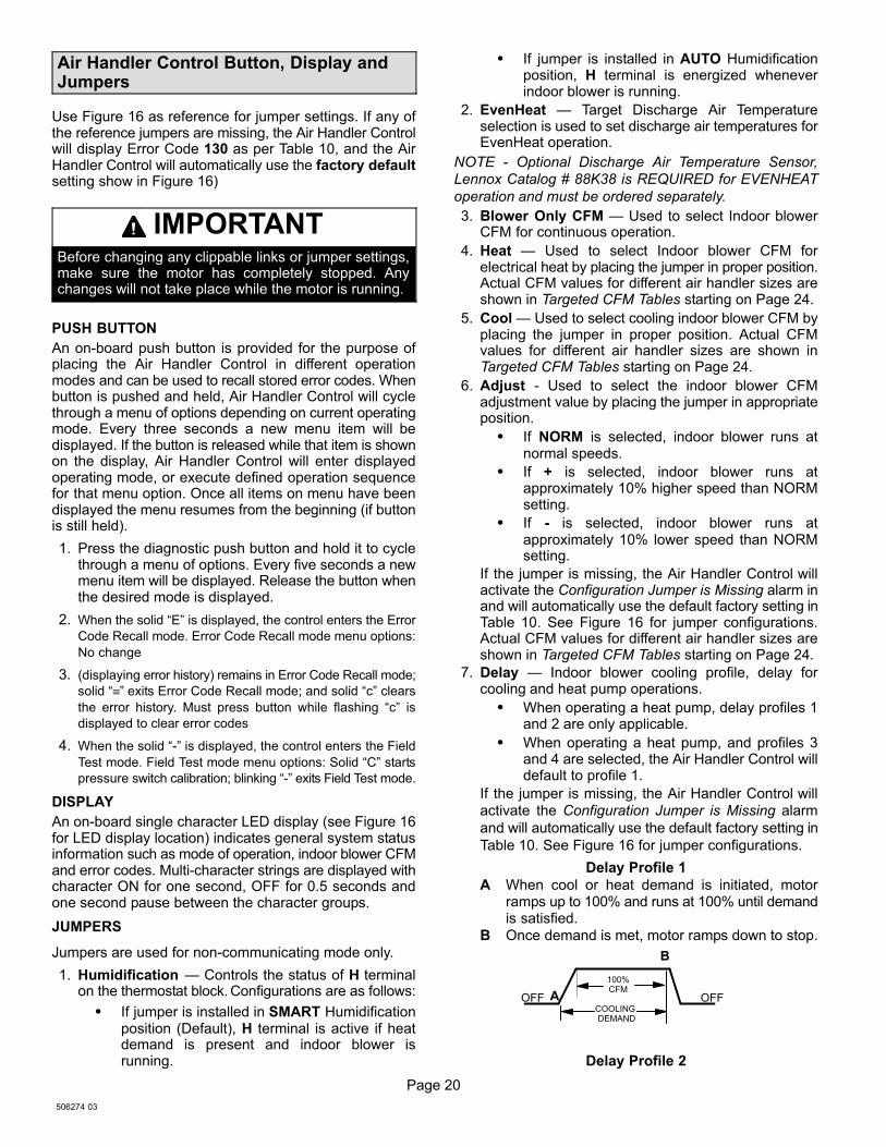
Delay Profile 1
A When cool or heat demand is initiated, motorramps up to 100% and runs at 100% until demandis satisfied.
B Once demand is met, motor ramps down to stop.
A
B
OFFOFF
100%CFM
COOLING DEMAND
Delay Profile 2
Page 21
CBX32MV SERIES
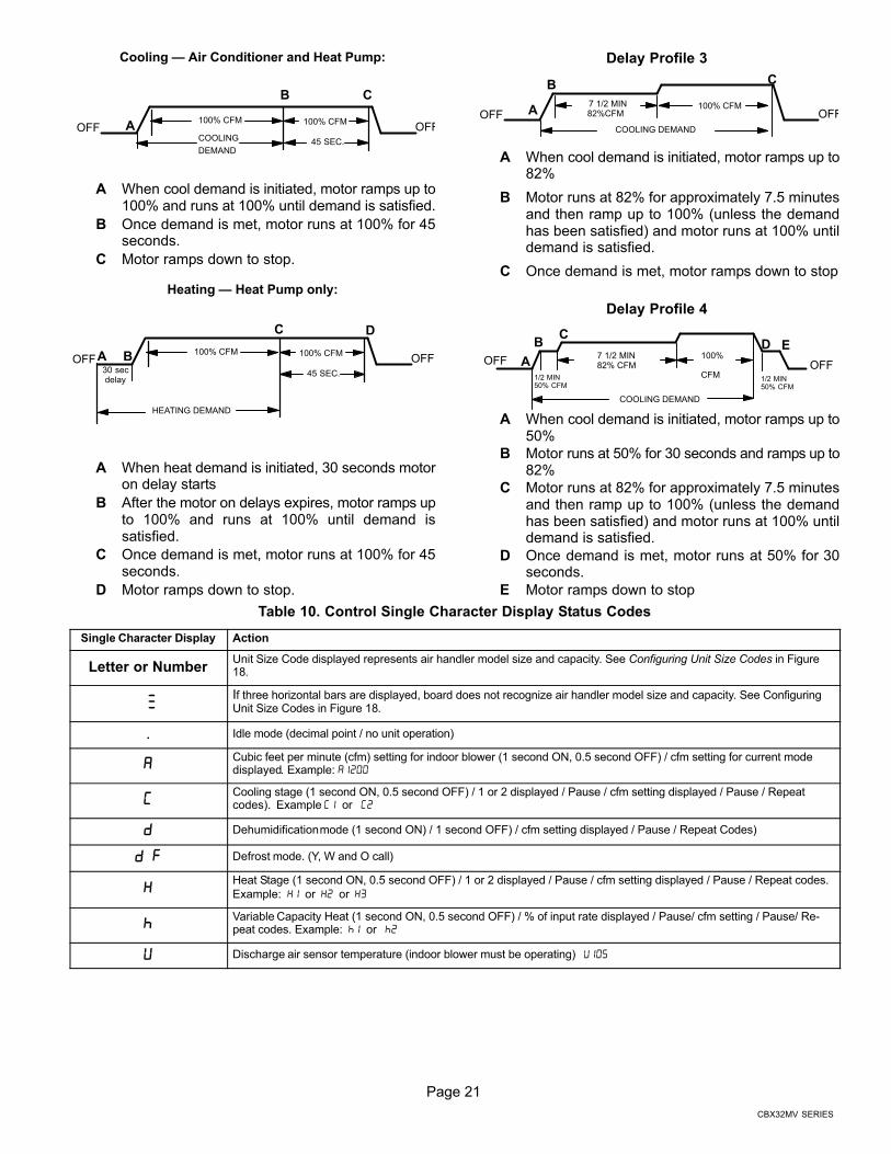
Cooling � Air Conditioner and Heat Pump:
A
B C
OFFOFF100% CFM 100% CFM
COOLING
DEMAND45 SEC.
A When cool demand is initiated, motor ramps up to100% and runs at 100% until demand is satisfied.
B Once demand is met, motor runs at 100% for 45seconds.
C Motor ramps down to stop.
Heating � Heat Pump only:
OFFOFF100% CFM 100% CFM
HEATING DEMAND
45 SEC.30 secdelay
A B
C D
A When heat demand is initiated, 30 seconds motoron delay starts
B After the motor on delays expires, motor ramps upto 100% and runs at 100% until demand issatisfied.
C Once demand is met, motor runs at 100% for 45seconds.
D Motor ramps down to stop.
Delay Profile 3
OFFOFF 82%CFM100% CFM
COOLING DEMAND
7 1/2 MINA
B C
A When cool demand is initiated, motor ramps up to82%
B Motor runs at 82% for approximately 7.5 minutesand then ramp up to 100% (unless the demandhas been satisfied) and motor runs at 100% untildemand is satisfied.
C Once demand is met, motor ramps down to stop
Delay Profile 4
OFFOFF
1/2 MIN50% CFM
COOLING DEMAND
7 1/2 MIN82% CFM
100%
CFM1/2 MIN50% CFM
B
A
CD E
A When cool demand is initiated, motor ramps up to50%
B Motor runs at 50% for 30 seconds and ramps up to82%
C Motor runs at 82% for approximately 7.5 minutesand then ramp up to 100% (unless the demandhas been satisfied) and motor runs at 100% untildemand is satisfied.
D Once demand is met, motor runs at 50% for 30seconds.
E Motor ramps down to stop
Table 10. Control Single Character Display Status Codes
Single Character Display Action
Letter or NumberUnit Size Code displayed represents air handler model size and capacity. See Configuring Unit Size Codes in Figure18.
���
If three horizontal bars are displayed, board does not recognize air handler model size and capacity. See ConfiguringUnit Size Codes in Figure 18.
.Idle mode (decimal point / no unit operation)
�Cubic feet per minute (cfm) setting for indoor blower (1 second ON, 0.5 second OFF) / cfm setting for current modedisplayed. Example: �����
�Cooling stage (1 second ON, 0.5 second OFF) / 1 or 2 displayed / Pause / cfm setting displayed / Pause / Repeatcodes). Example �� or ��
� Dehumidification mode (1 second ON) / 1 second OFF) / cfm setting displayed / Pause / Repeat Codes)
� � Defrost mode. (Y, W and O call)
�Heat Stage (1 second ON, 0.5 second OFF) / 1 or 2 displayed / Pause / cfm setting displayed / Pause / Repeat codes.
Example: �� or �� or �
�Variable Capacity Heat (1 second ON, 0.5 second OFF) / % of input rate displayed / Pause/ cfm setting / Pause/ Re-peat codes. Example: � or �
� Discharge air sensor temperature (indoor blower must be operating) ����
Page 22
506274 03
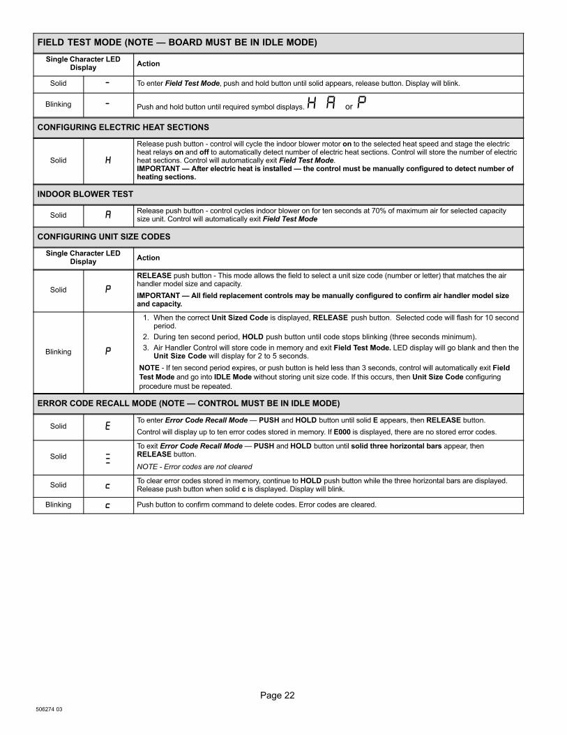
FIELD TEST MODE (NOTE � BOARD MUST BE IN IDLE MODE)
Single Character LEDDisplay
Action
Solid To enter Field Test Mode, push and hold button until solid appears, release button. Display will blink.
Blinking Push and hold button until required symbol displays. � � or
CONFIGURING ELECTRIC HEAT SECTIONS
Solid
Release push button − control will cycle the indoor blower motor on to the selected heat speed and stage the electricheat relays on and off to automatically detect number of electric heat sections. Control will store the number of electricheat sections. Control will automatically exit Field Test Mode. IMPORTANT � After electric heat is installed � the control must be manually configured to detect number ofheating sections.
INDOOR BLOWER TEST
Solid �Release push button − control cycles indoor blower on for ten seconds at 70% of maximum air for selected capacitysize unit. Control will automatically exit Field Test Mode
CONFIGURING UNIT SIZE CODES
Single Character LEDDisplay
Action
Solid �
RELEASE push button − This mode allows the field to select a unit size code (number or letter) that matches the airhandler model size and capacity.
IMPORTANT � All field replacement controls may be manually configured to confirm air handler model sizeand capacity.
Blinking �
1. When the correct Unit Sized Code is displayed, RELEASE push button. Selected code will flash for 10 secondperiod.
2. During ten second period, HOLD push button until code stops blinking (three seconds minimum).
3. Air Handler Control will store code in memory and exit Field Test Mode. LED display will go blank and then theUnit Size Code will display for 2 to 5 seconds.
NOTE − If ten second period expires, or push button is held less than 3 seconds, control will automatically exit Field
Test Mode and go into IDLE Mode without storing unit size code. If this occurs, then Unit Size Code configuring
procedure must be repeated.
ERROR CODE RECALL MODE (NOTE � CONTROL MUST BE IN IDLE MODE)
Solid �To enter Error Code Recall Mode � PUSH and HOLD button until solid E appears, then RELEASE button.
Control will display up to ten error codes stored in memory. If E000 is displayed, there are no stored error codes.
Solid
���
To exit Error Code Recall Mode � PUSH and HOLD button until solid three horizontal bars appear, thenRELEASE button.
NOTE − Error codes are not cleared
Solid To clear error codes stored in memory, continue to HOLD push button while the three horizontal bars are displayed.Release push button when solid c is displayed. Display will blink.
Blinking Push button to confirm command to delete codes. Error codes are cleared.

Page 23
CBX32MV SERIES
Table 11. Control Single Character Display Alert Codes (Communicating and Non−Communicating)
Alert Code Status of Air Handler
� ��� Device communications problem − No other devices on BUS (Communication system).
� ��� No 60 hertz power (Check voltage and frequency)
� ��� Low 24 volts (18 or less volts) − Control will restart if the error recovers.
� ���Unresponsive Device2 − Indicates a device on the RSbus is not responding to a message sent to it by another device.Error code is applicable to all communicating devices on the RSbus (thermostat, indoor and outdoor units). Normallyindicates a malfunctioning device.
� ���Active Subnet Controller Missing for > 180 seconds. This indicates a data connection has been lost between a commu-nicating device and the communicating thermostat. Device (indoor or outdoor unit) sends the alarm if no communica-tion is established between device and thermostat within three minutes.
� ��� Configuration jumper(s) is missing on board.
� ��� Non−volatile data corruption.
� ��� Failed Flash CRC check.
� ��� Outdoor air temperature sensor (OAS) out of range.
� ��� Indoor Blower communication failure − (includes indoor blower power outage)
� ���Incorrect air handler model size and capacity selected or wrong motor. Check for proper configuring under ConfiguringUnit Size Codes.
� ��� No air handler model size and capacity selected. Check for proper configuring under Configuring Unit Size Codes.
� ��� Indoor blower motor unable to start (seized bearing, stuck wheel, etc.).
� ��� Indoor blower motor over temperature (motor trip on internal protector)
� ��� Discharge air temperature sensor (DATS) out of range.
� ��� Restricted airflow � Indoor blower motor is running at a reduced CFM (cutback mode **)
� ��� Indoor and outdoor unit capacity mismatch.
� ���Global network connection error. This usually indicates there is a short or overladed resistance is to low) conditionbetween communicating indoor and thermostat units.
� ��� Jumper for second−stage cooling not removed.
� ��� Jumper for heat pump operation not removed.
� ��� Relay Y1 failure.
� ��� Relay Y2 failure.
� ���Heat call with non−configured or mis−configured electric heat. Check for proper configuring under Configuring ElectricHeat Stages.
� ��� Heat section / Stage 1 failed (Pilot relay contacts did not close or the relay coil in electric heat did not energizing)
� ��� Heat section / Stage 2 failed.
� ��� Heat section / Stage 3 failed.
� ��� Heat section / Stage 4 failed.
� ��� Heat section / Stage 5 failed.
� ��� Defrost out−of−control
Error codes 401 through 409 are only displayed when the Control’s L terminal is connected to a non−communicating outdoor unit’s LSOM device..
� ��� Compressor ran more than 18 hours in air conditioning mode.
� ��� Compressor system pressure trip.
� ��� Compressor short−cycling − running less than four minutes.
� ��� Compressor rotor locked.
� ��� Compressor open circuit.
� ��� Compressor open start circuit.
� ��� Compressor open run circuit.
� ��� Compressor contactor is welded.
� ��� Compressor low voltage.
** Cutback Mode � The variable speed motor has pre−set speed and torque limiters to protect the motor from damage caused by operating out of itsdesigned parameters (0 through 0.80 in. w.g. total external static pressure).
Page 24
506274 03
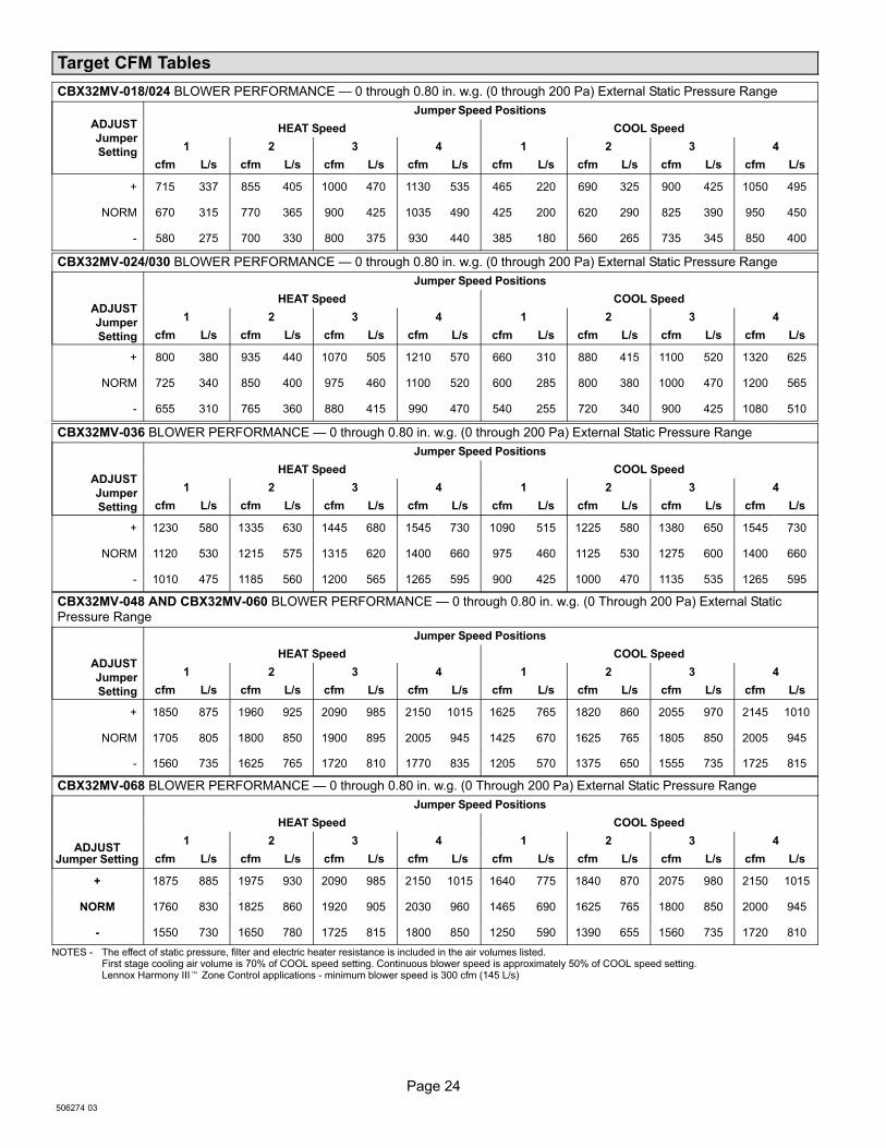
Target CFM Tables
CBX32MV-018/024 BLOWER PERFORMANCE � 0 through 0.80 in. w.g. (0 through 200 Pa) External Static Pressure Range
ADJUST
Jumper
Setting
Jumper Speed Positions
HEAT Speed COOL Speed
1 2 3 4 1 2 3 4
cfm L/s cfm L/s cfm L/s cfm L/s cfm L/s cfm L/s cfm L/s cfm L/s
+ 715 337 855 405 1000 470 1130 535 465 220 690 325 900 425 1050 495
NORM 670 315 770 365 900 425 1035 490 425 200 620 290 825 390 950 450
− 580 275 700 330 800 375 930 440 385 180 560 265 735 345 850 400
CBX32MV-024/030 BLOWER PERFORMANCE � 0 through 0.80 in. w.g. (0 through 200 Pa) External Static Pressure Range
ADJUST
Jumper
Setting
Jumper Speed Positions
HEAT Speed COOL Speed
1 2 3 4 1 2 3 4
cfm L/s cfm L/s cfm L/s cfm L/s cfm L/s cfm L/s cfm L/s cfm L/s
+ 800 380 935 440 1070 505 1210 570 660 310 880 415 1100 520 1320 625
NORM 725 340 850 400 975 460 1100 520 600 285 800 380 1000 470 1200 565
− 655 310 765 360 880 415 990 470 540 255 720 340 900 425 1080 510
CBX32MV-036 BLOWER PERFORMANCE � 0 through 0.80 in. w.g. (0 through 200 Pa) External Static Pressure Range
ADJUST
Jumper
Setting
Jumper Speed Positions
HEAT Speed COOL Speed
1 2 3 4 1 2 3 4
cfm L/s cfm L/s cfm L/s cfm L/s cfm L/s cfm L/s cfm L/s cfm L/s
+ 1230 580 1335 630 1445 680 1545 730 1090 515 1225 580 1380 650 1545 730
NORM 1120 530 1215 575 1315 620 1400 660 975 460 1125 530 1275 600 1400 660
− 1010 475 1185 560 1200 565 1265 595 900 425 1000 470 1135 535 1265 595
CBX32MV-048 AND CBX32MV-060 BLOWER PERFORMANCE � 0 through 0.80 in. w.g. (0 Through 200 Pa) External Static
Pressure Range
ADJUST
Jumper
Setting
Jumper Speed Positions
HEAT Speed COOL Speed
1 2 3 4 1 2 3 4
cfm L/s cfm L/s cfm L/s cfm L/s cfm L/s cfm L/s cfm L/s cfm L/s
+ 1850 875 1960 925 2090 985 2150 1015 1625 765 1820 860 2055 970 2145 1010
NORM 1705 805 1800 850 1900 895 2005 945 1425 670 1625 765 1805 850 2005 945
− 1560 735 1625 765 1720 810 1770 835 1205 570 1375 650 1555 735 1725 815
CBX32MV-068 BLOWER PERFORMANCE � 0 through 0.80 in. w.g. (0 Through 200 Pa) External Static Pressure Range
ADJUSTJumper Setting
Jumper Speed Positions
HEAT Speed COOL Speed
1 2 3 4 1 2 3 4
cfm L/s cfm L/s cfm L/s cfm L/s cfm L/s cfm L/s cfm L/s cfm L/s
+ 1875 885 1975 930 2090 985 2150 1015 1640 775 1840 870 2075 980 2150 1015
NORM 1760 830 1825 860 1920 905 2030 960 1465 690 1625 765 1800 850 2000 945
− 1550 730 1650 780 1725 815 1800 850 1250 590 1390 655 1560 735 1720 810
NOTES − The effect of static pressure, filter and electric heater resistance is included in the air volumes listed.First stage cooling air volume is 70% of COOL speed setting. Continuous blower speed is approximately 50% of COOL speed setting. Lennox Harmony III� Zone Control applications − minimum blower speed is 300 cfm (145 L/s)
Page 25
CBX32MV SERIES
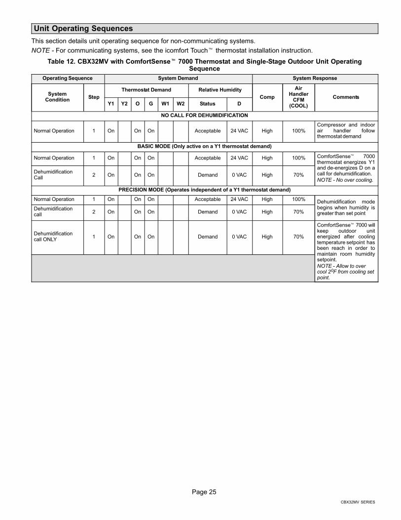
Unit Operating Sequences
This section details unit operating sequence for non−communicating systems.
NOTE − For communicating systems, see the icomfort Touch� thermostat installation instruction.
Table 12. CBX32MV with ComfortSense� 7000 Thermostat and Single−Stage Outdoor Unit OperatingSequence
Operating Sequence System Demand System Response
SystemCondition
Step
Thermostat Demand Relative Humidity
Comp
AirHandler
CFM(COOL)
Comments
Y1 Y2 O G W1 W2 Status D
NO CALL FOR DEHUMIDIFICATION
Normal Operation 1 On On On Acceptable 24 VAC High 100%Compressor and indoorair handler followthermostat demand
BASIC MODE (Only active on a Y1 thermostat demand)
Normal Operation 1 On On On Acceptable 24 VAC High 100% ComfortSense� 7000thermostat energizes Y1and de−energizes D on acall for dehumidification.
NOTE − No over cooling.
DehumidificationCall
2 On On On Demand 0 VAC High 70%
PRECISION MODE (Operates independent of a Y1 thermostat demand)
Normal Operation 1 On On On Acceptable 24 VAC High 100%Dehumidification modebegins when humidity isgreater than set point
Dehumidificationcall
2 On On On Demand 0 VAC High 70%
Dehumidificationcall ONLY
1 On On On Demand 0 VAC High 70%
ComfortSense� 7000 willkeep outdoor unitenergized after coolingtemperature setpoint hasbeen reach in order tomaintain room humiditysetpoint.
NOTE − Allow to overcool 20F from cooling setpoint.
Page 26
506274 03
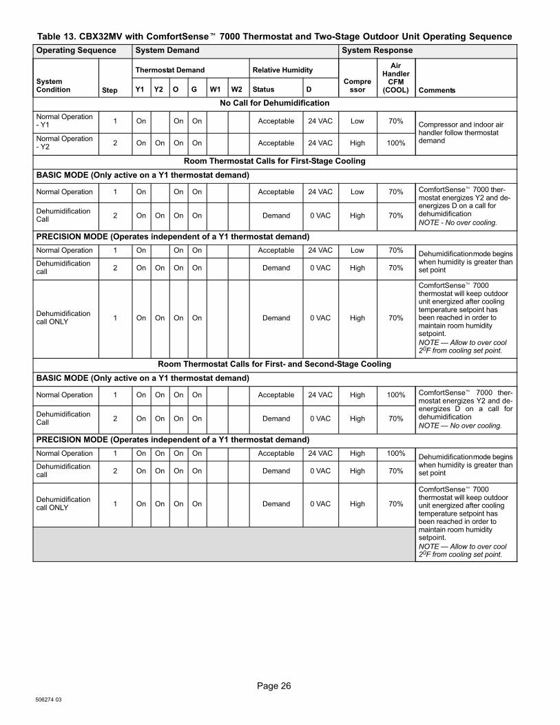
Table 13. CBX32MV with ComfortSense� 7000 Thermostat and Two-Stage Outdoor Unit Operating Sequence
Operating Sequence System Demand System Response
SystemCondition Step
Thermostat Demand Relative Humidity
Compressor
AirHandler
CFM(COOL) CommentsY1 Y2 O G W1 W2 Status D
No Call for Dehumidification
Normal Operation− Y1
1 On On On Acceptable 24 VAC Low 70%Compressor and indoor airhandler follow thermostatdemandNormal Operation
− Y22 On On On On Acceptable 24 VAC High 100%
Room Thermostat Calls for First−Stage Cooling
BASIC MODE (Only active on a Y1 thermostat demand)
Normal Operation 1 On On On Acceptable 24 VAC Low 70% ComfortSense� 7000 ther-mostat energizes Y2 and de−energizes D on a call fordehumidification
NOTE − No over cooling.
DehumidificationCall
2 On On On On Demand 0 VAC High 70%
PRECISION MODE (Operates independent of a Y1 thermostat demand)
Normal Operation 1 On On On Acceptable 24 VAC Low 70%Dehumidification mode beginswhen humidity is greater thanset point
Dehumidificationcall
2 On On On On Demand 0 VAC High 70%
Dehumidificationcall ONLY
1 On On On On Demand 0 VAC High 70%
ComfortSense� 7000thermostat will keep outdoorunit energized after coolingtemperature setpoint hasbeen reached in order tomaintain room humiditysetpoint.
NOTE � Allow to over cool20F from cooling set point.
Room Thermostat Calls for First− and Second−Stage Cooling
BASIC MODE (Only active on a Y1 thermostat demand)
Normal Operation 1 On On On On Acceptable 24 VAC High 100% ComfortSense� 7000 ther-mostat energizes Y2 and de−energizes D on a call fordehumidification
NOTE � No over cooling.
DehumidificationCall
2 On On On On Demand 0 VAC High 70%
PRECISION MODE (Operates independent of a Y1 thermostat demand)
Normal Operation 1 On On On On Acceptable 24 VAC High 100%Dehumidification mode beginswhen humidity is greater thanset point
Dehumidificationcall
2 On On On On Demand 0 VAC High 70%
Dehumidificationcall ONLY
1 On On On On Demand 0 VAC High 70%
ComfortSense� 7000thermostat will keep outdoorunit energized after coolingtemperature setpoint hasbeen reached in order tomaintain room humiditysetpoint.
NOTE � Allow to over cool20F from cooling set point.

Page 27
CBX32MV SERIES
Configuring Unit
This section identifies the requirements for configuring the air handler unit for unit size, heat mode selection and EvenHeat.
Air Handler Control Checkout
Power−up − Unit Size Code (Number or letter) displayed represents air handler model size andcapacity. If three horizontal bars displays, Air Handler Control (AHC) does not recognize unit size code(air handler model size and capacity).
AHCrecognizesUnit SizeCode?
Electricheat
Installed?
Finished
Which Heat Mode?
Refer to EVENHEAT Operation flow diagram, Air Handler orECB40 Electric Heat installation instructions.
W1 Call?
YesNo
Yes
No (Display AlarmCode 203)
Standard EVENHEAT
Refer to Heat Pump or CoolingSequence of Operation flowdiagrams, Air Handler or ECB40Electric Heat installationinstructions.
A call for electric heating first, second or third stage isinitiated when 24 VAC (R) is detected on W1, W2 andW3 inputs on AHC. (Factory mounted metal jumpersconnect W1/2 and W2/W3.)
At the completion of each heat section demand (W1,W2, and W3), the control board will immediatelyde−energize the corresponding pilot relay(s).
At the completion of all heating demands, the indoorblower will run for an additional 10 seconds beforede−energizing.
No
Yes
NOTE � If the call for lower heat section is removed,AHC will automatically de−energize higher heatsections.
Indoor blower will immediately start to delivery CFMas set by heating mode jumper on board withactivation of first electric heat pilot relay.
Pilot relays on board are energized one at a time.There is a minimum of 10 seconds delay betweenpilot relay activations.
After all electric heat installations, AHC must bemanually configured to detect number of heatsections. Refer to Configuring/Detecting electric heatsections flow diagram, Air Handler or ECB40 ElectricHeat installation
IMPORTANT � Field replacement controls may need to be manuallyconfigured to validate air handler unit size code.
Refer to Configuring Unit Size Codes flow diagram, Air Handler orECB40 Electric Heat installation instructions.
ONE (H1)
H1
TWO (H1−H2)
H1
H2
H2
THREE (H1−H3)
H1
H2
H3
FOUR (H1−H4)
H1 AND H2
H3
H4
FIVE (H1−H5)
H1 AND H2
H3 AND H4
H5
T−STAT CALL
W1
W2
W3
NUMBER OF HEAT SECTIONS DETECTED
NOTE − AHC will not recognize higher heat sectionscalls if lower heat section is not present.
���
RECOMMEND � USE FIGURE 16 AS A REFERENCE FOR SETTING JUMPER CONFIGURATIONS ON THE AIR HANDLER CONTROL.
Figure 17. Air Handler Control Checkout
Page 28
506274 03
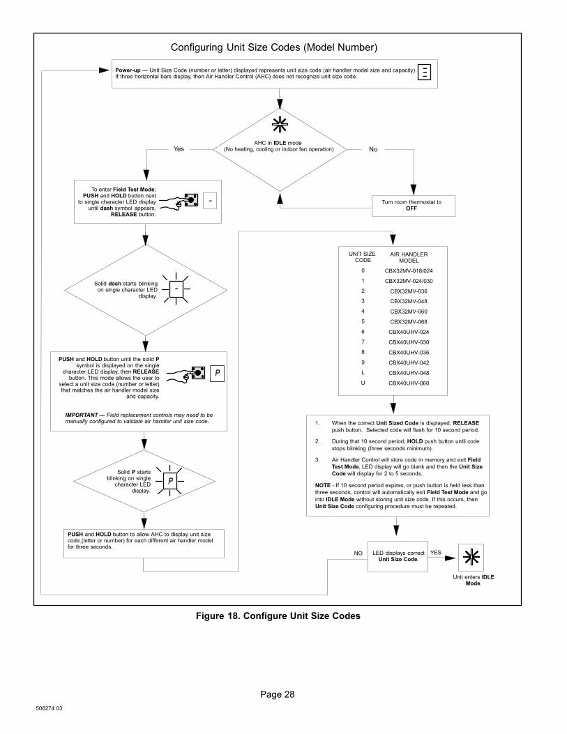
Configuring Unit Size Codes (Model Number)
Power−up � Unit Size Code (number or letter) displayed represents unit size code (air handler model size and capacity).If three horizontal bars display, then Air Handler Control (AHC) does not recognize unit size code.
AHC in IDLE mode (No heating, cooling or indoor fan operation)
To enter Field Test Mode;PUSH and HOLD button next
to single character LED displayuntil dash symbol appears,
RELEASE button.
Turn room thermostat toOFF
PUSH and HOLD button until the solid Psymbol is displayed on the single
character LED display, then RELEASEbutton. This mode allows the user to
select a unit size code (number or letter)that matches the air handler model size
and capacity.
Solid dash starts blinkingon single character LED
display.
Solid P startsblinking on single
character LEDdisplay.
PUSH and HOLD button to allow AHC to display unit sizecode (letter or number) for each different air handler modelfor three seconds.
Yes No
IMPORTANT � Field replacement controls may need to bemanually configured to validate air handler unit size code.
���
�
�
�
�
AIR HANDLERMODEL
CBX32MV−018/024
CBX32MV−024/030
CBX32MV−036
CBX32MV−048
CBX32MV−060
CBX32MV−068
CBX40UHV−024
CBX40UHV−030
CBX40UHV−036
CBX40UHV−042
CBX40UHV−048
CBX40UHV−060
UNIT SIZE CODE
0
1
2
3
4
5
6
7
8
9
L
U
1. When the correct Unit Sized Code is displayed, RELEASE
push button. Selected code will flash for 10 second period.
2. During that 10 second period, HOLD push button until code
stops blinking (three seconds minimum).
3. Air Handler Control will store code in memory and exit Field
Test Mode. LED display will go blank and then the Unit Size
Code will display for 2 to 5 seconds.
NOTE − If 10 second period expires, or push button is held less than
three seconds, control will automatically exit Field Test Mode and go
into IDLE Mode without storing unit size code. If this occurs, then
Unit Size Code configuring procedure must be repeated.
LED displays correctUnit Size Code.
Unit enters IDLEMode.
YESNO
Figure 18. Configure Unit Size Codes
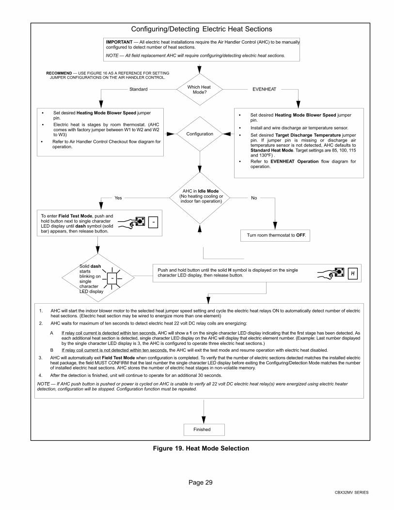
Page 29
CBX32MV SERIES
Configuring/Detecting Electric Heat Sections
IMPORTANT � All electric heat installations require the Air Handler Control (AHC) to be manuallyconfigured to detect number of heat sections.
Which Heat Mode?
� Set desired Heating Mode Blower Speed jumperpin.
Configuration
Standard EVENHEAT
AHC in Idle Mode (No heating cooling orindoor fan operation)
To enter Field Test Mode, push andhold button next to single characterLED display until dash symbol (solidbar) appears, then release button.
Turn room thermostat to OFF.
Yes
Solid dashstartsblinking onsinglecharacterLED display
Push and hold button until the solid H symbol is displayed on the singlecharacter LED display, then release button.
Finished
No
NOTE � All field replacement AHC will require configuring/detecting electric heat sections.
� Electric heat is stages by room thermostat. (AHCcomes with factory jumper between W1 to W2 and W2to W3)
� Refer to Air Handler Control Checkout flow diagram foroperation.
� Set desired Heating Mode Blower Speed jumperpin.
� Install and wire discharge air temperature sensor.
� Set desired Target Discharge Temperature jumperpin. If jumper pin is missing or discharge airtemperature sensor is not detected, AHC defaults toStandard Heat Mode. Target settings are 85, 100, 115and 130ºF) .
� Refer to EVENHEAT Operation flow diagram foroperation.
1. AHC will start the indoor blower motor to the selected heat jumper speed setting and cycle the electric heat relays ON to automatically detect number of electricheat sections. (Electric heat section may be wired to energize more than one element)
2. AHC waits for maximum of ten seconds to detect electric heat 22 volt DC relay coils are energizing:
A If relay coil current is detected within ten seconds, AHC will show a 1 on the single character LED display indicating that the first stage has been detected. Aseach additional heat section is detected, single character LED display on the AHC will display that electric element number. (Example: Last number displayedby the single character LED display is 3, the AHC is configured to operate three electric heat sections.)
B If relay coil current is not detected within ten seconds, the AHC will exit the test mode and resume operation with electric heat disabled.
3. AHC will automatically exit Field Test Mode when configuration is completed. To verify that the number of electric sections detected matches the installed electricheat package, the field MUST CONFIRM that the last number the single character LED display before exiting the Configuring/Detection Mode matches the numberof installed electric heat sections. AHC stores the number of electric heat stages in non−volatile memory.
4. After the detection is finished, unit will continue to operate for an additional 30 seconds.
�
��
NOTE � If AHC push button is pushed or power is cycled on AHC is unable to verify all 22 volt DC electric heat relay(s) were energized using electric heaterdetection, configuration will be stopped. Configuration function must be repeated.
RECOMMEND � USE FIGURE 16 AS A REFERENCE FOR SETTINGJUMPER CONFIGURATIONS ON THE AIR HANDLER CONTROL.
Figure 19. Heat Mode Selection
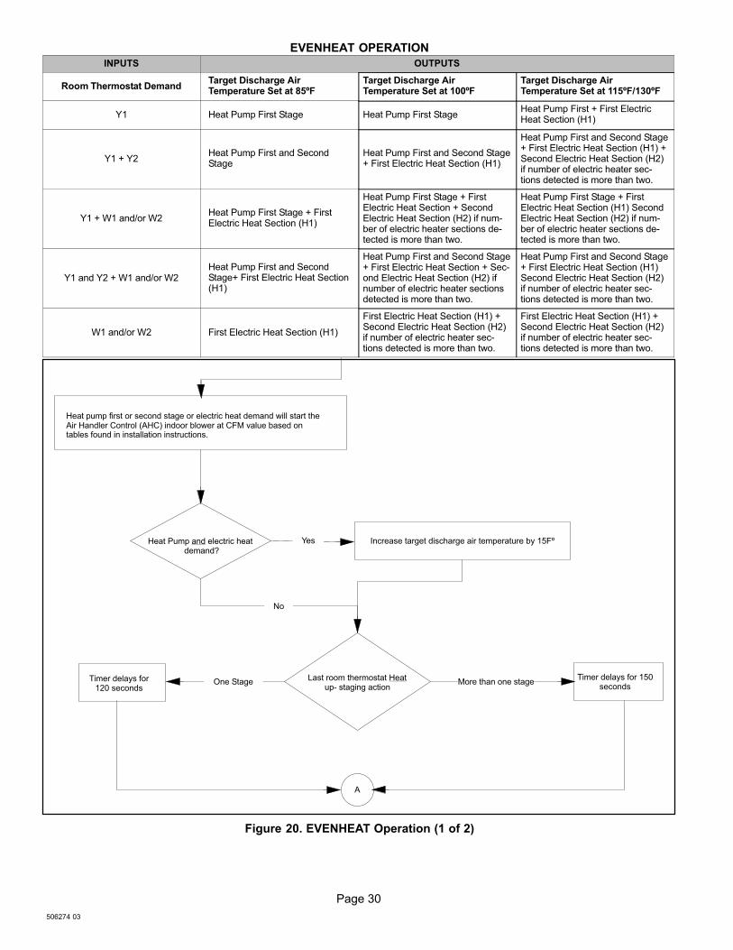
Page 30
506274 03
EVENHEAT OPERATION
INPUTS OUTPUTS
Room Thermostat DemandTarget Discharge AirTemperature Set at 85ºF
Target Discharge AirTemperature Set at 100ºF
Target Discharge AirTemperature Set at 115ºF/130ºF
Y1 Heat Pump First Stage Heat Pump First StageHeat Pump First + First ElectricHeat Section (H1)
Y1 + Y2Heat Pump First and SecondStage
Heat Pump First and Second Stage+ First Electric Heat Section (H1)
Heat Pump First and Second Stage+ First Electric Heat Section (H1) +Second Electric Heat Section (H2)if number of electric heater sec-tions detected is more than two.
Y1 + W1 and/or W2Heat Pump First Stage + FirstElectric Heat Section (H1)
Heat Pump First Stage + FirstElectric Heat Section + SecondElectric Heat Section (H2) if num-ber of electric heater sections de-tected is more than two.
Heat Pump First Stage + FirstElectric Heat Section (H1) SecondElectric Heat Section (H2) if num-ber of electric heater sections de-tected is more than two.
Y1 and Y2 + W1 and/or W2Heat Pump First and SecondStage+ First Electric Heat Section(H1)
Heat Pump First and Second Stage+ First Electric Heat Section + Sec-ond Electric Heat Section (H2) ifnumber of electric heater sectionsdetected is more than two.
Heat Pump First and Second Stage+ First Electric Heat Section (H1)Second Electric Heat Section (H2)if number of electric heater sec-tions detected is more than two.
W1 and/or W2 First Electric Heat Section (H1)
First Electric Heat Section (H1) +Second Electric Heat Section (H2)if number of electric heater sec-tions detected is more than two.
First Electric Heat Section (H1) +Second Electric Heat Section (H2)if number of electric heater sec-tions detected is more than two.
Heat pump first or second stage or electric heat demand will start theAir Handler Control (AHC) indoor blower at CFM value based ontables found in installation instructions.
Heat Pump and electric heat demand?
Increase target discharge air temperature by 15Fº
Last room thermostat Heatup− staging action
Timer delays for120 seconds
Timer delays for 150seconds
A
One Stage More than one stage
No
Yes
Figure 20. EVENHEAT Operation (1 of 2)
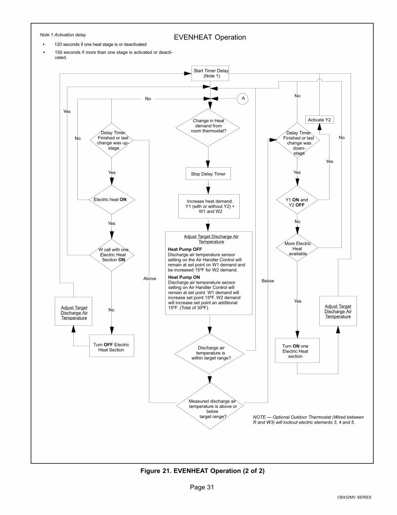
Page 31
CBX32MV SERIES
Discharge airtemperature is
within target range?
W call with oneElectric Heat Section ON
More ElectricHeat
available
A
Measured discharge air temperature is above or
below target range?
Electric heat ON
� 150 seconds if more than one stage is activated or deacti-vated.
EVENHEAT Operation
Start Timer Delay (Note 1)
Stop Delay Timer
Increase heat demand. Y1 (with or without Y2) +
W1 and W2
Discharge air temperature sensorsetting on Air Handler Control willremain at set point. W1 demand willincrease set point 15ºF. W2 demandwill increase set point an additional15ºF. (Total of 30ºF)
Delay Timer Finished or last change was up−
stage
Delay Timer Finished or last
change wasdown−stage
Above
Turn OFF ElectricHeat Section
Adjust TargetDischarge AirTemperature
Turn ON oneElectric Heat
section
Adjust TargetDischarge AirTemperature
NOTE � Optional Outdoor Thermostat (Wired betweenR and W3) will lockout electric elements 3, 4 and 5.
Y1 ON andY2 OFF
Activate Y2
Below
No
Yes
Note 1 Activation delay
� 120 seconds if one heat stage is or deactivated
No
No
No
No
No
Yes
Yes
Yes
Yes
Yes
Change in Heatdemand from
room thermostat?
Adjust Target Discharge AirTemperature
Heat Pump OFFDischarge air temperature sensorsetting on the Air Handler Control willremain at set point on W1 demand andbe increased 15ºF for W2 demand.
Heat Pump ON
Figure 21. EVENHEAT Operation (2 of 2)

Page 32
506274 03
Heat Pump Operation (Heating and Cooling)
Room thermostatcalls for first
stage?
Air Handler Control (AHC) receives inputs on Y1 terminal.
Y1 terminal on AHC is configured as input and passes signalfrom room thermostat to outdoor unit.
Y1 input to the AHC will control the indoor blower accordingto the cooling or heating mode blower speed, ramping andadjust selection jumper pins.
Air Handler Control (AHC) receives inputs on Y1 and O
terminals.
Y1 terminal on AHC is configured as input and passes signalfrom room thermostat to outdoor unit.
Y1 input to the AHC. Will control the indoor blower accordingto the cooling mode blower speed, ramping and adjustselection jumper pins.
Room thermostat calls forsecond stage?
Still calling for firststage?
Y2 terminal on AHC isconfigured as input andpasses signal fromroom thermostat tooutdoor unit.
Y2 terminal is an inputto the AHC. Theindoor blower will becontrolled accordingto the jumper pinselections.
Still calling for secondstage?
De−energize Y2 terminal on AHC. Indoorblower speed will reset to Y1 demand.
De−energize Y1 (and O in cooling) terminals on AHC.
De−energize indoor blower per ramping profile.
No
Yes
Cooling
Air Handler Control AHC) Indoor Blower Mode Speed and Profiles settings
1. Set Cooling Mode Blower Speed jumper pin . (Low and high indoor blower CFM settings are identical forcooling and heat pump)
2. Set Blower Adjust Selection jumper pin.3. Set Cooling Mode Blower Ramping jumper pin (Cooling calls − All ramping profiles are active) (Heating calls −
Only ramping profiles 1 and 2 are active. If profiles 3 or 4 are selected, AHC will default to profile 1)
A Profile 1 does not provide any ramping profiles.
B Profile 2 provides a 30 second indoor blower ON delay at the start of a heat pump heating demand. (45second indoor blower OFF delay)
4. Simultaneous Heat Pump and electric heat call: Indoor Blower will operate at the highest CFM requested bythe heat pump or the electric heat blower speed selection.
Single or Two−Stage Unit
1. AHC on−board link must be cut between Y1 and Y2 to allow two stage cooling operation.
Heating
NOTE � The outdoor unit control directly controls the outdoorunit operation.)
NOTE � The outdoor unit control directly controls theoutdoor unit operation.
NOTE � The outdoor unit controldirectly controls the outdoor unitoperation.)
NOTE � The outdoor unit control directly controlsthe outdoor unit operation.
NOTE � The outdoorunit control directlycontrols the outdoor unitoperation.)
YesYes
Yes
Yes
No
No
2. AHC on−board link must be cut between R and O to allow heat pump operation.
CUT ON−BOARD LINKY1−Y2 FORTWO−STAGE A/C
Y1−Y22−STAGECOMPR
R−OHEATPUMP
R−DSDEHUM
ORHARMONY
CU
T F
OR
OP
TIO
N
CUT ON−BOARDLINK R −O.
RECOMMEND � USE FIGURE 16 AS A REFERENCE FOR SETTINGJUMPER CONFIGURATIONS ON THE AIR HANDLER CONTROL.
IMPORTANT � USE CARE WHEN CUTTING LINKS TOPREVENT DAMAGE TO CONTROL. SEE FIGURE 16,CBX32MV JUMP AND LINK GUIDE FOR FURTHER
DETAILS.

Page 33
CBX32MV SERIES
Cooling Operation
Room thermostatcalls for first
stage?
Air Handler Control (AHC) receives inputs on Y1 terminal.
Y1 terminal on AHC is configured as input and passes signalfrom room thermostat to outdoor unit.
Y1 input to the AHC will control the indoor blower according to the cooling orheating mode blower speed, ramping and adjust selection jumper pins.
Room thermostat calls forsecond stage?
Still calling for firststage?
Y2 terminal on AHC is configuredas input and passes signal fromroom thermostat to outdoor unit.
Y2 terminal is aninput to the AHC.The indoor blowerwill be controlledaccording to thejumper pinselections.
Still calling for secondstage?
NOTE − The outdoor unit control directlycontrols the outdoor unit operation.
De−energize Y1 (and O in cooling) terminalson AHC.
De−energize indoor blower per rampingprofile.
No
Yes
AHC on−board link must be cut between Y1 and Y2 to allow 2 stagecooling operation.
Air Handler Control AHC) Indoor Blower Mode Speed and Profiles settings
1. Set Cooling Mode Blower Speed jumper pin.2. Set Cooling Mode Blower Ramping jumper pin.
3. Set Blower Adjust Selection jumper pin. Single or Two−Stage Unit
NOTE − The outdoor unit control directly controls the outdoorunit operation.
De−energize Y2 terminal on AHC. Indoorblower speed will reset to Y1 demand.
NOTE − The outdoor unit control directlycontrols the outdoor unit operation.
NOTE − The outdoor unit controldirectly controls the outdoor unitoperation.
YesYes
Yes
Yes
No
No
CUT ON−BOARD LINK Y1−Y2 FORTWO−STAGE A/C
Y1−Y22−STAGECOMPR
R−OHEATPUMP
R−DSDEHUM
ORHARMONY
CU
T F
OR
OP
TIO
NRECOMMEND � USE FIGURE 16 AS A REFERENCE FOR SETTINGJUMPER CONFIGURATIONS ON THE AIR HANDLER CONTROL.
IMPORTANT − Use care when cutting links to prevent damage tocontrol. See Figure 16, CBX32MV jump and link guide for furtherdetails.
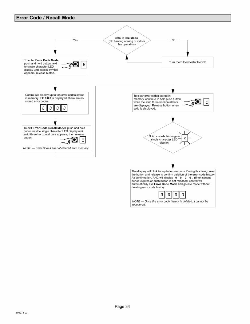
Page 34
506274 03
Error Code / Recall Mode
To enter Error Code Mode,push and hold button nextto single character LEDdisplay until solid E symbolappears, release button.
AHC in Idle Mode (No heating cooling or indoor
fan operation)
Turn room thermostat to OFF
Control will display up to ten error codes storedin memory. If E 0 0 0 is displayed, there are nostored error codes.
To exit Error Code Recall Model, push and holdbutton next to single character LED display untilsolid three horizontal bars appears, then releasebutton.
To clear error codes stored inmemory, continue to hold push buttonwhile the solid three horizontal barsare displayed. Release button whensolid is displayed.
Solid c starts blinking onsingle character LED
display.
The display will blink for up to ten seconds. During this time, pressthe button and release to confirm deletion of the error code history.As confirmation, AHC will display 0 0 0 0 . (If ten secondperiod expires or push button is not released, control willautomatically exit Error Code Mode and go into mode withoutdeleting error code history.
Yes No
NOTE � Once the error code history is deleted, it cannot berecovered.
NOTE � Error Codes are not cleared from memory.
�
� � � �
���
���
� � � �
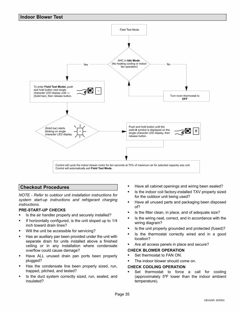
Page 35
CBX32MV SERIES
Indoor Blower Test
Field Test Mode
AHC in Idle Mode (No heating cooling or indoor
fan operation)
To enter Field Test Model, pushand hold button next singlecharacter LED display until �(Solid bar), then release button. Turn room thermostat to
OFF
(Solid bar) startsblinking on singlecharacter LED display.
Push and hold button until thesolid A symbol is displayed on thesingle character LED display, thenrelease button.
Control will cycle the indoor blower motor for ten seconds at 70% of maximum air for selected capacity size unit.Control will automatically exit Field Test Mode.
Yes No
��
�
Checkout Procedures
NOTE − Refer to outdoor unit installation instructions for
system start−up instructions and refrigerant charging
instructions.
PRE-START-UP CHECKS
� Is the air handler properly and securely installed?
� If horizontally configured, is the unit sloped up to 1/4
inch toward drain lines?
� Will the unit be accessible for servicing?
� Has an auxiliary pan been provided under the unit with
separate drain for units installed above a finishedceiling or in any installation where condensate
overflow could cause damage?
� Have ALL unused drain pan ports been properly
plugged?
� Has the condensate line been properly sized, run,
trapped, pitched, and tested?
� Is the duct system correctly sized, run, sealed, and
insulated?
� Have all cabinet openings and wiring been sealed?
� Is the indoor coil factory-installed TXV properly sized
for the outdoor unit being used?
� Have all unused parts and packaging been disposed
of?
� Is the filter clean, in place, and of adequate size?
� Is the wiring neat, correct, and in accordance with the
wiring diagram?
� Is the unit properly grounded and protected (fused)?
� Is the thermostat correctly wired and in a good
location?
� Are all access panels in place and secure?
CHECK BLOWER OPERATION
� Set thermostat to FAN ON.
� The indoor blower should come on.
CHECK COOLING OPERATION
� Set thermostat to force a call for cooling
(approximately 5ºF lower than the indoor ambienttemperature).
Page 36
506274 03
� The outdoor unit should come on immediately and the
indoor blower should start between 30 − 60 seconds
later.
� Check the airflow from a register to confirm that the
system is moving cooled air.
� Set the thermostat 5ºF higher than the indoor
temperature. The indoor blower and outdoor unitshould cycle off.
CHECK ELECTRIC HEATER (IF USED)
� Set thermostat to call for auxiliary heat (approximately
5°F above ambient temperature). The indoor blowerand auxiliary heat should come on together. Allow a
minimum of 3 minutes for all sequencers to cycle on.
� Set the thermostat so that it does not call for heat.
Allow up to 5 minutes for all sequencers to cycle off.
Operation
COOLING (COOLING ONLY OR HEAT PUMP)
When the thermostat calls for cooling, 24 volts is put on theblower time−delay relay coil. After a delay, the indoorblower relay energizes. The normally open contacts close,causing the indoor blower motor to operate. The circuitbetween R and Y is completed, closing the circuit to thecontactor in the outdoor unit, starting the compressor and
outdoor fan motor.
On heat pumps, circuit R and O energizes the reversingvalve, switching the valve to the cooling position. (Thereversing valve remains energized as long as thethermostat selector switch is in the COOL position.)
At the completion of the cooling demand and after therelay’s time-delay, the compressor and outdoor fan willcycle off.
HEATING (ELECTRIC HEAT ONLY)
When the thermostat calls for heat, the circuit between Rand W is completed, and the heat sequencer is energized.A time delay follows before the heating elements and theindoor blower motor come on. Units with a second heatsequencer can be connected with the first sequencer to W
on the thermostat subbase, or they may also be connectedto a second stage on the subbase.
HEATING (HEAT PUMP)
When the thermostat calls for heating, 24 volts is put on the
blower time−delay relay coil. After a delay, the normallyopen contacts close, causing the indoor blower motor tooperate. The circuit between R and Y is completed, closingthe circuit to the contactor in the outdoor unit, starting thecompressor and outdoor fan motor. Circuit R and Genergizes the blower relay, starting the indoor blower
motor.
If the room temperature should continue to fall, the circuitbetween R and W1 is completed by the second-stage heatroom thermostat. Circuit R−W1 energizes a heatsequencer. The completed circuit will energize
supplemental electric heat (if applicable). Units with a
second heat sequencer can be connected with the firstsequencer to W1 on the thermostat. They may also beconnected to a second heating stage W2 on the thermostatsubbase.
EMERGENCY HEAT (HEATING HEAT PUMP)
If the selector switch on the thermostat is set to theemergency heat position, the heat pump will be locked outof the heating circuit, and all heating will be electric heat (ifapplicable). A jumper should be placed between W2 and E
on the thermostat subbase so that the electric heat controlwill transfer to the first-stage heat on the thermostat. Thiswill allow the indoor blower to cycle on and off with theelectric heat when the fan switch is in the AUTO position.
Maintenance
DEALER
WARNINGElectric shock hazard. Can cause injuryor death. Before attempting to performany service or maintenance, turn theelectrical power to unit OFF at disconnectswitch(es). Unit may have multiple powersupplies.
WARNINGImproper installation, adjustment, alteration, service ormaintenance can cause personal injury, loss of life, ordamage to property.
Installation and service must be performed by a licensedprofessional installer (or equivalent) or a service agency.
Maintenance and service must be performed by a qualifiedinstaller or service agency. At the beginning of eachcooling season, the system should be checked as follows:
Outdoor Unit1. Outdoor unit fan motor is pre−lubricated and sealed.
No further lubrication is needed.
2. Visually inspect all connecting lines, joints and coils forevidence of oil leaks.
3. Check all wiring for loose connections.
4. Check for correct voltage at unit (unit operating).
5. Check amp draw on outdoor fan motor.
Motor Nameplate:_________ Actual:__________.
6. Inspect drain holes in coil compartment base andclean if necessary.
NOTE - If insufficient cooling occurs, the unit should begauged and refrigerant charge should be checked.
Outdoor CoilClean and inspect outdoor coil (may be flushed with awater hose). Ensure power is off before cleaning.
NOTE � It may be necessary to flush the outdoor coilmore frequently if it is exposed to substances which arecorrosive or which block airflow across the coil (e.g., peturine, cottonwood seeds, fertilizers, fluids that may containhigh levels of corrosive chemicals such as salts)

Page 37
CBX32MV SERIES
Sea Coast � Moist air in ocean locations can carry salt,which is corrosive to most metal. Units that are locatednear the ocean require frequent inspections andmaintenance. These inspections will determine thenecessary need to wash the unit including the outdoor coil.Consult your installing contractor for properintervals/procedures for your geographic area or servicecontract.
Indoor Unit1. Clean or change filters.
2. Lennox blower motors are prelubricated andpermanently sealed. No more lubrication is needed.
3. Adjust blower speed for cooling. Measure the pressuredrop over the coil to determine the correct blower CFM.Refer to the unit information service manual for pressuredrop tables and procedure.
4. Belt Drive Blowers − Check belt for wear and propertension.
5. Check all wiring for loose connections.
6. Check for correct voltage at unit. (blower operating)
7. Check amp draw on blower motor.
Motor Nameplate:_________ Actual:__________.
Indoor Coil1. Clean coil if necessary.
2. Check connecting lines, joints and coil for evidence ofoil leaks.
3. Check condensate line and clean if necessary.
Cabinet Insulation
IMPORTANTDAMAGED INSULATION MUST BE REPAIRED ORREPLACED before the unit is put back into operation. In-sulation loses its insulating value when wet, damaged,separated or torn.
Matt- or foil−faced insulation is installed in indoorequipment to provide a barrier between outside airconditions (surrounding ambient temperature and
humidity) and the varying conditions inside the unit. If theinsulation barrier is damaged (wet, ripped, torn orseparated from the cabinet walls), the surroundingambient air will affect the inside surface temperature of thecabinet. The temperature/humidity difference between theinside and outside of the cabinet can cause condensation
on the inside or outside of the cabinet which leads to sheetmetal corrosion and subsequently, component failure.
REPAIRING DAMAGED INSULATION
Areas of condensation on the cabinet surface are anindication that the insulation is in need of repair.
If the insulation in need of repair is otherwise in goodcondition, the insulation should be cut in an X pattern,peeled open, glued with an appropriate all−purpose glueand placed back against the cabinet surface, being carefulto not overly compress the insulation so the insulation canretain its original thickness. If such repair is not possible,
replace the insulation. If using foil-faced insulation, anycut, tear, or separations in the insulation surface must betaped with a similar foil−faced tape.
1. CUT INSULATION IN X PATTERN2. APPLY GLUE3. PRESS GLUED TABS AGAINST CABINET
GLUE −make sure there isfull coverage of glue on themetal or insulation so thereare no areas where airpockets may form whichcan lead to sweating.
Figure 22. Repairing Insulation
WARNINGElectric Shock Hazard.
Can cause injury or death.
Foil-faced insulation has conductive characteristicssimilar to metal. Be sure there are no electricalconnections within a ½" of the insulation. If the foil-facedinsulation comes in contact with electrical voltage, the foilcould provide a path for current to pass through to theouter metal cabinet. While the current produced may notbe enough to trip existing electrical safety devices (e.g.fuses or circuit breakers), the current can be enough tocause an electric shock hazard that could causepersonal injury or death.
HOMEOWNER
Cleaning of the outdoor unit’s coil should be performed bya trained service technician. Contact your dealer and setup a schedule (preferably twice a year, but at least once ayear) to inspect and service your outdoor unit. Thefollowing maintenance may be performed by thehomeowner.
Page 38
506274 03
CAUTIONPhysical contact with metal edges and corners whileapplying excessive force or rapid motion can result inpersonal injury. Be aware of, and use caution whenworking near these areas during installation or whileservicing this equipment.
IMPORTANTSprinklers and soaker hoses should not be installedwhere they could cause prolonged exposure to theoutdoor unit by treated water. Prolonged exposure of theunit to treated water (i.e., sprinkler systems, soakers,waste water, etc.) will corrode the surface of steel andaluminum parts and diminish performance and longevityof the unit.
Outdoor Coil
The outdoor unit must be properly maintained to ensure itsproper operation.
� Please contact your dealer to schedule proper
inspection and maintenance for your equipment.
� Make sure no obstructions restrict airflow to the
outdoor unit.
� Grass clippings, leaves, or shrubs crowding the unit
can cause the unit to work harder and use moreenergy.
� Keep shrubbery trimmed away from the unit and
periodically check for debris which collects around the
unit.
Routine Maintenance
In order to ensure peak performance, your system must beproperly maintained. Clogged filters and blocked airflowprevent your unit from operating at its most efficient level.
1. Air Filter � Ask your Lennox dealer to show youwhere your indoor unit’s filter is located. It will be eitherat the indoor unit (installed internal or external to thecabinet) or behind a return air grille in the wall orceiling. Check the filter monthly and clean or replaceit as needed.
2. Disposable Filter � Disposable filters should bereplaced with a filter of the same type and size.
NOTE � If you are unsure about the filter required for yoursystem, call your Lennox dealer for assistance.
3. Reusable Filter � Many indoor units are equippedwith reusable foam filters. Clean foam filters with amild soap and water solution; rinse thoroughly; allowfilter to dry completely before returning it to the unit orgrille.
NOTE � The filter and all access panels must be in placeany time the unit is in operation.
4. Electronic Air Cleaner � Some systems areequipped with an electronic air cleaner, designed toremove airborne particles from the air passing throughthe cleaner. If your system is so equipped, ask yourdealer for maintenance instructions.
5. Indoor Unit � The indoor unit’s evaporator coil isequipped with a drain pan to collect condensateformed as your system removes humidity from theinside air. Have your dealer show you the location ofthe drain line and how to check for obstructions. (Thiswould also apply to an auxiliary drain, if installed.)
Thermostat Operation
See the ComfortSense® 7000 or icomfort Touch�thermostat homeowner manual for instructions on how tooperate your thermostat.
Preservice Check
If your system fails to operate, check the following beforecalling for service:
� Verify room thermostat settings are correct.
� Verify that all electrical disconnect switches are ON.
� Check for any blown fuses or tripped circuit breakers.
� Verify unit access panels are in place.
� Verify air filter is clean.
� If service is needed, locate and write down the unit
model number and have it handy before calling.
Accessories
For update−to−date information, see any of the followingpublications:
� Lennox CBX32MV Engineering Handbook
� Lennox Product Catalog
� Lennox Price Book