Installation Instructions - Kingsman Fireplaces
30
Installation Instructions Model Number ZDV3624NB, ZDV3624LPB Zero Clearance Direct Vent Gas Fireplace Stock #’s: ZDV3624NB, ZDV3624LPB, are certified to: ANSI Z21.88-2009, CSA 2.33-2009 Printed in Canada May 16, 2010 3600-MAN This appliance may be installed in an aftermarket permanently located, manufactured home (USA only) or mobile home, where not prohibited by local codes. This appliance is only for use with the type of gas indicated on the rating plate. This appliance is not convertible for use with other gases, unless a certified kit is used. INSTALLER: Leave this manual with the appliance. CONSUMER: Retain this manual for future reference. Read this complete manual before beginning installation. These instructions must be kept with the unit for future reference. FOR YOUR SAFETY WARNING: If the information in these instructions is not followed exactly, a fire or explosion may result causing property damage, personal injury or loss of life. WARNING: Improper installation, adjustment, alteration, service or maintenance can cause property damage, personal injury or loss of life. Refer to this manual. Installation and service must be performed by a qualified installer, service agency or the gas supplier. Do not store or use gasoline or other flammable vapors and liquids in the vicinity of this or any other appliance. What to Do If You Smell Gas Do not try to light any appliance. Extinguish any open flame. Do not touch any electrical switch. Do not use any phone in your building. Immediately call your gas supplier from a neighbour’s phone. If you can not reach your gas supplier, call the fire department. A Division of R-Co. Inc. 2340 Logan Avenue Winnipeg, Manitoba, Canada R2R 2V3 Ph: (204) 632-1962
-
Upload
khangminh22 -
Category
Documents
-
view
3 -
download
0
Transcript of Installation Instructions - Kingsman Fireplaces

Installation InstructionsModel Number ZDV3624NB, ZDV3624LPB
Zero Clearance Direct Vent Gas Fireplace
Stock #’s: ZDV3624NB, ZDV3624LPB, are certified to: ANSI Z21.88-2009, CSA 2.33-2009
Printed in Canada May 16, 2010 3600-MAN
This appliance may be installed in an aftermarket permanently located, manufactured home (USA only) or mobilehome, where not prohibited by local codes.This appliance is only for use with the type of gas indicated on the rating plate. This appliance is not convertible foruse with other gases, unless a certified kit is used.
INSTALLER: Leave this manual with the appliance.CONSUMER: Retain this manual for future reference.
Read this complete manual before beginning installation.These instructions must be kept with the unit for future reference.
FOR YOUR SAFETY
WARNING: If the information in these instructions is not followed exactly, a fire or explosion may resultcausing property damage, personal injury or loss of life.
WARNING: Improper installation, adjustment, alteration, service or maintenance can cause propertydamage, personal injury or loss of life. Refer to this manual. Installation and service must be performed by aqualified installer, service agency or the gas supplier.
Do not store or use gasoline or other flammable vapors and liquids in the vicinity of this or any other appliance.
What to Do If You Smell GasDo not try to light any appliance.
Extinguish any open flame.Do not touch any electrical switch.
Do not use any phone in your building.Immediately call your gas supplier from a neighbour’s phone.
If you can not reach your gas supplier, call the fire department.
A Division of R-Co. Inc.2340 Logan Avenue
Winnipeg, Manitoba, Canada R2R 2V3Ph: (204) 632-1962

2
Why does my fireplace or stove give off odour?
It is normal for your fireplace to give off some odour. This is due to the curing of the paint, adhesives, siliconesand any undetected oil from the manufacturing process as well as the finishing materials used with the installa-tions (e.g. marble, tile and the adhesives used to adhere this product to the walls can react with heat and causeodours).
It is recommended that you burn your gas fireplace or stove for a minimum of four hours at a time with the fan offafter the curing of the paint has been completed. These odours can last upward to 40 hours of burn time, keepburning at a minimum of four hours per use until odours dissipate.
About curing of the paint
Your stove or fireplace has been painted with the highest quality silicone stove paint. This paint dries quickly in15-20 minutes when first applied at the factory. However, due to the high temperature silicone components, thepaint will cure when heat is applied to the appliance as it is first used. The following information applies to the curing process to get the paint fully hard and durable.
Fire the appliance four successive times for 10 minutes each firing and a 5 minute cool down between each. Beaware during log and firebox paint curing that a white deposit may be developing on the inside of the glassdoors. It is important to remove this white deposit from the glass doors with an appropriate cleaner to preventbuild-up (such as Windex or a commercial fireplace glass cleaner).
• Babies, small children, pregnant women and pets should leave the area during the cure phase.
• Ventilate well, open doors and windows.
• Do not touch during curing.
Noise coming from the fireplace?
• Noise caused by metal expanding and contracting as it heats up and cools down, similar to the sound pro-duced by a furnace or heating duct. This noise does not affect the operation or longevity of your fireplace.
• Different types and thicknesses of steel will expand and contract at different rates resulting in “cracking”and “ticking” sounds throughout the heating and cooling periods.
• You should also be aware that as temperatures change within the unit these sounds will likely re-occur.Again this is normal for steel fireboxes, and is not a defect.
Cleaning the Glass
During the first few fires, a white film may develop on the glass front, as part of the curing process. The glassshould be cleaned after the unit has cooled down or the film can bake on and become very difficult to remove.Use a non-abrasive cleaner and do not attempt to clean the glass while it is hot.
PRE-INSTALLATION QUESTIONS and ANSWERS

Mobile Home/Manufactured Housing Installation . . . . . . . . . . . . . . . . . . . . .4
Warnings, Installations & Operations . . . . . . . . . . . . . . . . . . . . . . . . . . . . . .5
Operations & Maintenance Instructions . . . . . . . . . . . . . . . . . . . . . . . . . . . .6
Installation Requirements for the Commonwealth of Massachusetts . . . . . .6
Locating your appliance . . . . . . . . . . . . . . . . . . . . . . . . . . . . . . . . . . . . . . . .7
Framing your gas fireplace . . . . . . . . . . . . . . . . . . . . . . . . . . . . . . . . . . . . .8-9
Mantels and Clearances . . . . . . . . . . . . . . . . . . . . . . . . . . . . . . . . . . . . . . . .9
Fan kit installation . . . . . . . . . . . . . . . . . . . . . . . . . . . . . . . . . . . . . . . . . . . .10
Brick Installation . . . . . . . . . . . . . . . . . . . . . . . . . . . . . . . . . . . . . . . . . . . . .11
General glass information . . . . . . . . . . . . . . . . . . . . . . . . . . . . . . . . . . . . . .12
Log Placement . . . . . . . . . . . . . . . . . . . . . . . . . . . . . . . . . . . . . . . . . . . . . .12
Log Placement Guides . . . . . . . . . . . . . . . . . . . . . . . . . . . . . . . . . . . . . .13-14
Gas Line Installation . . . . . . . . . . . . . . . . . . . . . . . . . . . . . . . . . . . . . . . . . .15
Millivolt system, lighting, & burner control . . . . . . . . . . . . . . . . . . . . . . . . . .16
Conversion Kit Instructions . . . . . . . . . . . . . . . . . . . . . . . . . . . . . . . . . . . . .17
Gas Conversion Kit for Top Convertible Pilot . . . . . . . . . . . . . . . . . . . . . . . .18
Trouble shooting the gas control system . . . . . . . . . . . . . . . . . . . . . . . . . . .19
Vent termination . . . . . . . . . . . . . . . . . . . . . . . . . . . . . . . . . . . . . . . . . . . . .20
IPI Electronic Ignition System . . . . . . . . . . . . . . . . . . . . . . . . . . . . . . . .21-25
IPI Lighting Instructions . . . . . . . . . . . . . . . . . . . . . . . . . . . . . . . . . . . . . . . .26
General vent installation information . . . . . . . . . . . . . . . . . . . . . . . . . . . . . .27
Back Vent . . . . . . . . . . . . . . . . . . . . . . . . . . . . . . . . . . . . . . . . . . . . . . . . . .28
Repair parts list . . . . . . . . . . . . . . . . . . . . . . . . . . . . . . . . . . . . . . . . . . .28-29
Kingsman Industries Gas Fireplace – Limited Warranty . . . . . . . . . . . . . . .30
Table of Contents

4
Mobile Home/Manufactured Housing Installation
This Direct Vent System Appliance must be installed in accordance with the manufacturer’s installation instructions and theManufactured Home Construction and Safety Standard Title 24 CFR, Part 3280, or the current Standard for Fire SafetyCriteria for Manufactured Home Installations, Sites, and Communities ANSI/NFPA 501A, and with CAN/CSA Z240 MHMobile Home Standard in Canada.
THE ZDV3624NB, ZDV3624LPB, ZDV3628N, ZDV3628LP, ZDV3632N and ZDV3632LP MAY BE INSTALLED IN MAN-UFACTURED (MOBILE) HOMES AFTER FIRST SALE IN THE USA. IN CANADA THE ZDV3628N, ZDV3628LP,ZDV3632N AND ZDV3632LP MAY BE INSTALLED IN MANUFACTURED (MOBILE) HOMES.
Please follow the current ANSI/NFPA 70 National Electrical Code in the USA and CAN/CSA C22.1 Canadian NationalElectrical Code in Canada.
An appliance must be grounded to the steel chassis of the home with 8 ga. copper wire using a serrated or star washer topenetrate paint or protective coating to insure grounding.
Use carriage bolt at the attachment point (see diagram above) to secure the appliance to the floor.
WARNING: Do not compromise the structural integrity of the manufactured home wall, floor orceiling, during installation of appliance or venting.
For required venting components see venting installation in appropriate section of this manual.
Certified for installation in a bedroom or bed/sitting room. In Canada must be installed with listed milli volt thermostat.In USA see local codes.
APPLIANCE MUST BE SECURED TO STRUCTUREUSING SUPPLIED NAIL TABS AND OR FASTEN TOFLOOR
USE EXISTING HOLE OR REMOVEEXISTING SCREW TO MOUNT GROUNDWIRE (FAN MOUNT HOLE OR OUTER WRAP SCREW)
GROUND WIRE FROM APPLIANCETO STEEL CHASSIS OF MOBILEHOME. USE 8 GA COPPER WIRE.
SERRATED ORSTAR WASHER

5
Warnings, Installations, and Operations
WARNINGFOR SAFE INSTALLATION AND OPERATION OF YOUR GAS FIREPLACE PLEASE NOTE THE FOLLOWING:1. Do not clean when the glass is hot.2. Do not use abrasive cleaners.3. Using a substitute glass will void all product warranties.4. For safe operation, glass doors must be closed.5. When purging the gas line, the glass front must be
removed.6. Do not strike or abuse glass. Take care to avoid breakage.7. Do not alter gas orifice.8. No substitute materials may be used other than factory
supplied components.9. This appliance gives off high temperatures and should be
located out of heavy traffic areas and away from furniture and draperies.10. Children and adults should be alerted to the hazards of the high surface temperatures of this appliance and should stay
away to avoid burns or ignition of clothing.11. Young children should be carefully supervised when they are in the same room as the appliance. Toddlers, young children
and others may be susceptible to accidental contact burns. A physical barrier is recommended if there are at risk individu-als in the house. To restrict access to a fireplace or stove, install an adjustable safety gate to keep toddlers, young childrenand other at risk individuals out of the room and away from hot surfaces.
12. Under no circumstances should any solid fuels (wood, paper) be used in this appliance.13. Under no circumstances should this appliance be modified. Any parts that have to be removed for servicing should be
replaced prior to operating this appliance.14. Any safety screen or guard removed for servicing an appliance must be replaced prior to operating the applicance.15. Installation and repair should be done by a qualified service person. The appliance should be inspected before use and at
least annually by a professional service person. More frequent cleaning may be required due to excessive lint from carpet-ing, bedding material, et cetera. It is imperative that control compartments, burners and circulating air passageways of theappliance be kept clean. Make sure that the gas valve and pilot light are turned off before you attempt to clean this unit.
16. Clothing or other flammable material should not be placed on or near the appliance. This appliance should not be used asa drying rack for clothing nor should Christmas stockings or decorations be hung from it.
17. Do not use this heater if any part has been under water. Immediately call a qualified service technician to inspect theheater and to replace any part of the control system and any gas control which has been under water.
18. Do not operate appliance unless completely installed as per installation instructions.19. Failure to position the parts in accordance with these diagrams or failure to use only parts specifically approved with this
appliance may result in property damage or personal injury.20. Do not operate appliance with the glass front removed, cracked or broken. Replacement of the glass should be done by a
licensed or qualified service person.21. The front of the fireplace gives off high temperatures that could ignite combustible material which is kept close to the front
of the unit.22. Ensure that power to the Fireplace is turned off before servicing.23. Do not operate this Fireplace without the glass front or with a broken glass.24. Improper installation, adjustment, alteration, service or maintenance can cause injury or property damage. Refer to the
owner’s information manual provided with this appliance. For assistance or additional information consult a qualifiedinstaller, service agency, or the gas supplier.
25. Operation of this appliance when not connected to a properly installed and maintained venting system or tampering withthe blocked vent shutoff system can result in carbon monoxide (CO) poisoning and possible death.
Installation RegulationsThis gas appliance must be installed by a qualified installer in accordance with local building codes, or in the absence of localcodes, with the current CAN/CGA-B149.1 Installation Code (in Canada) or the current National Fuel Gas Code Z223.1 wheninstalled in the United States.This appliance, when installed, must be electrically connected and grounded in accordance with local codes, or in the absence oflocal codes, with the current CSA C22.1 Canadian Electrical Code or with the national Electrical Code; ANSI/NFPA 70-1987 wheninstalled in the United States.

6
• Gas fired appliances may be used only for supplemental heat and/or decorative purposes and under no circumstances shallthey provide a primary heat source.
• This appliance must not be connected to a chimney flue serving a separate solid-fuel burning appliance.
NOTE: It is recommended that a Carbon Monoxide (CO) Detector be installed in or near bedrooms and on all levels of yourhome. Place a detector about 15ft [4.5m] outside the room that houses your gas appliance.
Certified for installation in a bedroom or bed/sitting room. In Canada must be installed with listed millivolt thermostat. In USA see local codes.
For safe installation and operation note the following:
• The Burner/Log Assembly has been engineered and permanently adjusted for proper flame control.
• Periodically remove the logs from the grate assembly and vacuum any loose particles from the grate and burner areas. SeeLog Placement page to remove logs. Vacuum burner parts and replace logs.
• Never use our gas fireplace as a cooking device.
• Label all wires prior to disconnection when servicing controls. Wiring errors can cause improper and dangerous operation.Verify proper operation after servicing.
In the Commonwealth of Massachusetts, the installer or service agent shall be a plumber or gas fitter licensed by theCommonwealth.
When installed in the Commonwealth of Massachusetts or where applicable codes; the unit shall be installed with a COdetector per the requirements listed below.
1. For direct-vent appliances, mechanical-vent heating appliances or domestic hot water equipment, where the bottom of thevent terminal and the air intake is installed below four feet above grade the following requirements must be satisfied:
A. If there is not one already present, on each floor level where there are bedroom(s), a carbon monoxide detector andalarm shall be placed in the living area outside the bedroom(s). The carbon monoxide detector shall comply with NFPA720 (2005 Edition).
B. A carbon monoxide detector shall be located in the room that houses the appliance or equipment and shall:
• Be powered by the same electrical circuit as the appliance or equipment such that only one service switch servicesboth the appliance and the carbon monoxide detector;
• Have battery back-up power;
• Meet ANSI./UL 2034 Standards and comply with NFPA 720 (2005 Edition); and
• Have been approved and listed by a Nationally Recognized Testing Laboratory as recognized under 527 CMR.
C. A Product-approved vent terminal must be used, and if applicable, a Product-approved air intake must be used.Installation shall be in strict compliance with the manufacturer’s instructions. A copy of the installation instructions shallremain with the appliance or equipment at the completion of the installation.
D. A metal or plastic identification plate shall be mounted at the exterior of the building, four feet directly above the locationof vent terminal. The plate shall be of sufficient size to be easily read from a distance of eight feet away, and read “GasVent Directly Below”
2. For direct-vent appliances, mechanical-vent heating appliances or domestic hot water equipment where the bottom of thevent terminal and the air intake is installed above four feet above grade the following requirements must be satisfied:
A. If there is not one already present, on each floor level where there are bedroom(s), a carbon monoxide detector andalarm shall be placed in the living area outside the bedroom(s). The carbon monoxide detector shall comply with NFPA720 (2005 Edition).
B. A carbon monoxide detector shall:
• Be located in the room that houses the appliance or equipment;
• Be either hard-wired or battery powered or both; and
• Shall comply with NFPA 720 (2005 Edition).
A Product-approved vent terminal must be used, and if applicable, a Product-approved air intake must be used. Installation shallbe in strict compliance with the manufacturer instructions. A copy of the installation instructions shall remain with the appliance orequipment at the completion of the installation.
For the state of Massachusetts a T-handle gas shut-off valve must be used on a gas appliance. This T-handle gas shut-offvalve must be listed and approved by the state of Massachusetts. This is in reference to the state of Massachusetts state codeCMR238.
Operations and Maintenance Instructions
Installation Requirements for the Commonwealth of Massachusetts

7
Locating your Appliance
(above grade)Installing with Back Vent
A - Flat on a wall D - As a room dividerB - Across the corner E - Flat on wall cornerC - As an island F - Exterior wall
Back Vent
339⁄32"
36"
3329⁄32"
171⁄16"
231⁄2"
301⁄4"
18”237⁄16"
163⁄8" 181⁄8"
ZDV3624B

8
Framing for your Gas FireplaceFraming Specifications1. Cold climate installation recommendation: When installing this fire-
place against non insulated exterior wall or chase, it is recom mendedthat the outer walls be insulated to conform to applicable insulationcodes. Drywall should be installed over insulation to prevent contactof insulation and unit.
2. Choose fireplace location and frame in accordance with the fireplaceframing dimensions specified (See Framing Diagrams). Bend nailingtabs forward on left and right of unit and place fireplace into framedenclosure. This allows for 1/2” in front of framing tabs for finishingmaterials.
3. Drywall or other material can extend flush with the appliance on thebottom, sides and top of fireplace.
4. When installing horizontal with a 90 degree bend maintain a minimumof two and a half (2.5”) inches above the bend in enclosures.
5. Hearth is not mandatory but is recommended for aesthetic purposes.Combustible floors cannot raise above the bottom of the fireplace.We recommend a non-combustible hearth projecting out 12”(305mm) or more in front of the fireplace.
34"
363⁄8"
17"
821⁄32" DIA. 11"
11"
TOP VIEW
Back Vent
36”
Back Vent Model OnlyOn horizontal venting, 1/4” riseper foot up to 3ft, over 3ft up tothe 5ft maximum horizontal run 11/2” rise per foot is needed.
It is recommended for Propane Horizontal Installations that the venting should be a minimum of one foot vertical off the fluebefore the elbow on any horizontal runs of one foot or greater. This allows for cleaner combustion and greatly reduces carboningand cleaning of glass. (Does not apply to Back Flue Models).
323⁄16”
141⁄64” 141⁄64”
451⁄2”
NAILINGTABS
4” minimum to 45
371⁄2”
231⁄2”

9
MantelsDepending on the depth of the fireplace mantel, it may be installed higher or lower fromthe top of the fireplace opening. See drawings for proper installation height of yourcombustible mantel. Non-combustible mantels may be installed at any height above thefireplace opening.
Non combustible materials such as brick, tile, etc. can extend up to or over the frontface of the fireplace (NO PORTION OF GRILL AREA OR DOOR AREAS CAN BECOVERED).
Combustible material can extend flush to unit up to the top, bottom and sides offireplace to stand-offs.
If slim line brass surround is used, brick, tiles or other NON-COMBUSTIBLE materialsmay extend past the front of unit giving a recessed appearance. For COMBUSTIBLEmaterials extending in front of fireplace consult (Mantel and Mantel Leg Drawings).
If wide brass surround is used finish materials must be flush with front of unit.
Note: When using paint or lacquer to finish the mantel, such paint or lacquer
must be heat resistant (250˚F) to prevent discoloration.
WARNING: Combustible objectsmust not be placed on a non-combustiblemantel unless the non-combustible mantelmeets the minimum height and widthrequire ments for a combustible mantel.
Mantel Leg Clearances
MantelsClearance to CombustiblesBack (from Standoffs) 0 inches/0 mm
Side (from standoffs) 0 inches/0 mm
Ceiling (from bottom of fireplace) 60 inches/150 cm
Floor 0 inches/0 mm
Top (from standoffs) 0 inches/0 mm
Top of 90 degree bend in MinimumEnclosure of 42 inches 51/2 inches/140 mm / All Vent Systems
Top of 90 degree bend inEnclosure over 42 inches 21/2 inches/64 mm / All Vent Systems
Top of Horizontal Pipe 11/2 inches/38 mm / All Vent Systems
Side & Bottom of Horizontal Pipe 1 inch/25.5mm / All Vent Systems
Vertical Vent Pipe 1 inch/25.5mm / Kingsman Vent Systems
Vertical Vent Pipe 11/4 inch/32mm /Simpson/AmeriVent/Selkirk Systems
(NOTE -Floor) if installing the appliance directly on carpeting or othercombustible materials other than wood flooring, the appliance shall beinstalled on a metal or wood panel, the full width and depth of theappliance. Carpet may extend 1/2 inch above the floor of appliance.Note: See Mantel Chart
10
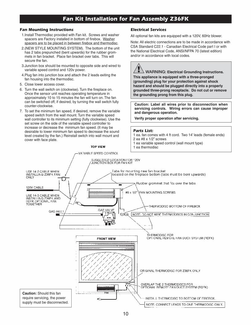
Fan Kit Installation for Fan Assembly Z36FK
Fan Mounting Instructions1.Install Thermodisc provided with Fan kit. Screws and washer
spacers are Factory installed in bottom of firebox. Washerspacers are to be placed in between firebox and thermodisc.
2.(NEW STYLE MOUNTING SYSTEM). The bottom of the unithas 2 tabs prepunched (bent upwards) for the rubber grom-mets in fan bracket. Place fan bracket over tabs. This willsecure the fan.
3.Junction box should be mounted to opposite side and wired tovariable speed control and 120v power.
4.Plug fan into junction box and attach the 2 leads exiting thefan housing into the thermodisc.
5. Close lower access cover.6. Turn the wall switch on (clockwise). Turn the fireplace on.
Once the sensor unit reaches operating temperature inapproximately 10 to 15 minutes the fan will turn on. The fancan be switched off, if desired, by turning the wall switch fullycounter-clockwise.
7. To set the minimum fan speed, if desired, remove the variablespeed switch from the wall mount. Turn the variable speedwall controller to its minimum setting (fully clockwise). Use theset screw on the side of the variable speed controller toincrease or decrease the minimum fan speed. (It may bedesirable to lower minimum fan speed to decrease the soundlevel created by the fan.) Reinstall switch into wall mount andcover with face plate.
Parts List:1 ea. fan comes with 4 ft cord. Two 14’ leads (female ends)2 ea #8 x 1/2” screws1 ea variable speed control (wall mount type)1 ea thermodisc
Electrical Services
All optional fan kits are equipped with a 120V, 60Hz blower.
Note: All electric connections are to be made in accordance withCSA Standard C22.1 - Canadian Electrical Code part I or withthe National Electrical Code, ANSI/NFPA 70 (latest edition)and/or in accordance with local codes.
WARNING: Electrical Grounding Instructions.
This appliance is equipped with a three-pronged
(grounding) plug for your protection against shock
hazard and should be plugged directly into a properly
grounded three-prong receptacle. Do not cut or remove
the grounding prong from this plug.
Caution: Label all wires prior to disconnection whenservicing controls. Wiring errors can cause improperand dangerous operation.
Verify proper operation after servicing.
Caution: Should this fanrequire servicing, the powersupply must be disconnected.
11
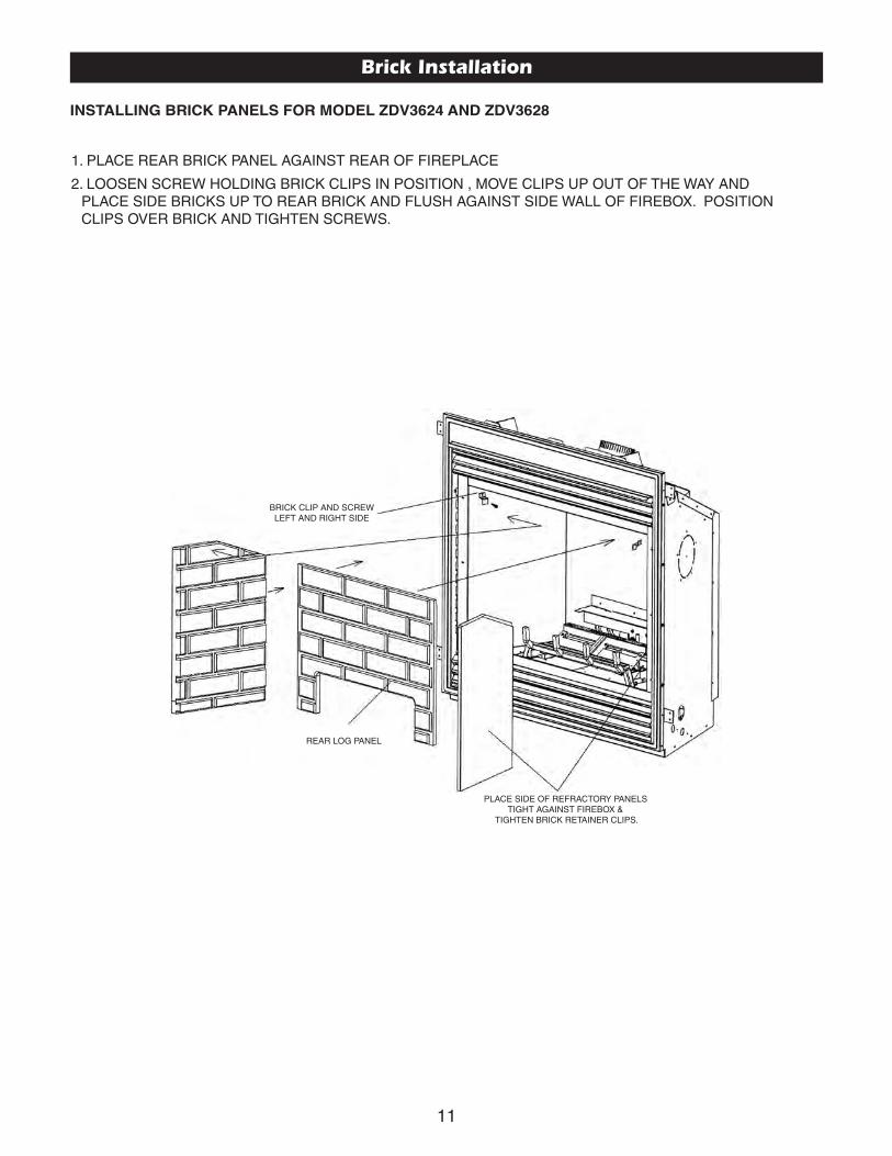
BRICK CLIP AND SCREW LEFT AND RIGHT SIDE
REAR LOG PANEL
PLACE SIDE OF REFRACTORY PANELSTIGHT AGAINST FIREBOX &
TIGHTEN BRICK RETAINER CLIPS.
1. PLACE REAR BRICK PANEL AGAINST REAR OF FIREPLACE
2. LOOSEN SCREW HOLDING BRICK CLIPS IN POSITION , MOVE CLIPS UP OUT OF THE WAY ANDPLACE SIDE BRICKS UP TO REAR BRICK AND FLUSH AGAINST SIDE WALL OF FIREBOX. POSITIONCLIPS OVER BRICK AND TIGHTEN SCREWS.
Brick Installation
INSTALLING BRICK PANELS FOR MODEL ZDV3624 AND ZDV3628

12
Appliance/Log Reference Chart/Log Placement
The following is a list of models and appropriate log sets that can be used with each model. It is important that the appropriatelog set is used with the correct model in order for the appliance to work properly.
Appliance LOGC42 LOGC43 LOGC44 LOGC60
ZDV3624NB or LPB ✔ ✔
General Glass Information
Glass Cleaning
It will be necessary to clean the glass periodically. During start-up, condensation, which is normal, forms on the inside of theglass and causes dust, lint etc. to cling to the glass surface.Also, initial paint curing can deposit a slight film on the glass. Itis therefore recommended that initially the glass be cleaned twoor three times with non-abrasive common household glasscleansers and warm water. After that, the glass should becleaned two or three times a season depending on the circum-stances.
Glass Replacement
REPLACEMENT GLASS FOR BOTH DIRECT VENT UNITS
Model Series ZDV3624 can use either tempered glass or Robaxceramic or coated Neaoceram glass. Must be 5mm thick.
Only Robax ceramic or coated Neaoceram glass may be usedfor replacement for model ZDV3628 and ZDV3632. Must be minimum 5mm thick.
To replace glass, clean all materials from door frame. Scrape offold silicone down to metal. Using a high heat silicone tempera-ture-resistant to 500°F (260°C) apply a continuous bead ofapproximately 1/32” to all four sides of frame and insert glasswith new gasket. Frame should be on flat surface, with a smallamount of weight pressing glass into silicone. Let dry approxi-mately 15 to 20 minutes. The door can be re-installed by revers-ing Steps 1 & 2. Use caution when removing broken glass,wear gloves.
Removal of the Glass Door
1. Remove the two screws located behind upper grill or unfastenlatches if so equipped.
2. To remove, pull frame forward and lift from bottom door retain-er channel.
Warning and Cautions.• Do not clean when the glass is hot.• Do not use abrasive cleaners.• Using a substitute glass will void all product
warranties.• Do not strike or abuse glass. Care must be
taken to avoid breakage of the glass.• Do not operate this fireplace without the glass
front or with a broken glass.

13
FIG
UR
E A
- Log set Em
ber kit and Crushed rock
FIG
UR
E B
- Rear log holder.
Ste
p (1
) Units are equipped w
ith screws or latches. To rem
oveglass door, either rem
ove screws or unfasten latches and lift
door off bottom door retainer.
Ste
p (2
) Rem
ove logs from carton and inspect each log.
Ste
p (3
) Verify to see that the em
ber plates (2 pcs) are between
front and back burner.
Ste
p (4
)B
reak glowing em
bers into thumbnail size. P
lace glow-
ing embers on to the surface of the front burner, to the surface of
the ember plates and over crossover to the sam
e height asem
ber plates. Height on front burner 1/2” to 3/4”. H
eight onem
ber plates 3/4” to 1”. Do not cover back air openings on
ember plates.
Ste
p (5
) Place front log over burner, against decorative
grate. Be sure that front log is tight up against the decorative
grate.
Em
berplate
Air
Opening
LOG
C42 - LO
G C
43 LOG
PLAC
EM
EN
T GU
IDE
LINE
S - FO
R M
OD
EL ZD
V3624B
(4-PIE
CE
LOG
SE
T)

14
Ste
p (6
)P
lace rear log on to the log retainer 1/2” away from
backof fireplace. (If refractory liner is used, m
ake sure refractory liner isinstalled first then back log is to be pushed up against it as tight as
Ste
p (7
)P
lace right crossover log across front and back logsusing the log placem
ent pin as a guide.
Ste
p (8
)P
lace left crossover log across front and back logsusing the log placem
ent pin as a guide.S
tep
(9) P
lace decorative moon rock on bottom
of fireplace tosim
ulate ash.D
O N
OT
PU
T A
NY
RO
CK
ON
BU
RN
ER
S!
Ste
p (1
0)
Purge lines and test pilot operation.
Ste
p (1
1) R
eplace glass door.
LOG
C42 - LO
GC
43 LOG
PLA
CE
ME
NT
(continued) - FO
R M
OD
EL Z
DV
3624B

15
Gas Line Installation
This gas appliance should be installed by a qualified installer in accordance withlocal building codes and with current CAN/CGA - B149.1 or .2 installation codesfor Gas Burning appliances and equipment in Canada and the National Fuel GasCode ANSI Z223 in the U.S.A.
1. The gas pipeline can be brought in through either the right or the left side of theappliance. A knockout is provided at either location to allow for the gas pipeinstallation and testing of any gas connection.
2. The gas control inlet is 3/8” NPT. Typical installation layout for rigid pipe is shownat right.
3. When using copper or flex connector, use only approved fittings. Always pro-vide a union so that gas line can be easily disconnected for burner or fan servic-ing. See gas specification for pressure details and ratings.
4. When a vertical section of gas pipe is required for the installation, a condensa-tion trap is needed. See CAN/CGA-B149.1 or .2 for code details.
5. For natural gas, a minimum of 3/8” iron pipe with gas minimum pressure of 4.5”w.c. must be used for supply from the gas meter. Consult with the local gas utilityif any questions arise concerning pipe sizes.
6. A 1/8” NPT plugged tappings are accessible for test gauge connection both onthe inlet and outlet of the gas valve.
7. Turn the gas supply ON and check for leaks. DO NOT USE OPEN FLAME FORTHIS PURPOSE. Use an approved leak testing solution.
8. The appliance and its individual shutoff valve must be disconnected from the gassupply piping system during any pressure testing of that system at test pres-sures in excess of 1/2 PSIG (3.5 KPa).
9. The appliance must be isolated from the gas supply piping system by closing itsindividual shutoff valve during any pressure testing of the gas supply piping sys-tem at test pressures equal to or less than 1/2 PSIG (3.5 KPa).
Note: The gas line connection may be made of 1/2” rigid pipe or anapproved flex connector. Since some municipalities have additionallocal codes, it is always best to consult your local authorities andthe current CAN/CGA - B149.1 or .2 installation code in Canada orthe National Fuel Gas code ANSI Z223.1 in the U.S.A.
Gas SpecificationsBack Flue Back Flue
Models ZDV3624NB ZDV3624LPBFuel Natural PropaneGas Control Millivolt adjustable Millivolt adjustableMaximum Input 24,000 BTU High 22,000 BTU HighMinimum Input 14,000 BTU Low 15,000 BTU LowMaximum Output 17,040 BTU 15,620 BTU
Orifice Size (0 - 4500 ft) #42 #53
Air Shutter .188 Fully OpenGas Inlet Size S.I.T. 820 Nova, 3/8” NPTGas Supply Pressure Minimum Normal MaximumNatural Gas 5.5” 7” 9”Liquid Propane 11” 11” 12”Manifold Pressure Natural Gas Liquid PropaneManifold Pressure High 3.5 IN. W.C./.87 KPa 10 IN. W.C./2.61 KPaManifold Pressure Low 1.6 IN. W.C./.40 KPa 6.3 IN. W.C./1.57 KPa
Important: Always check for gas leaks with a soap andwater solution. Do not use open flame for leak testing.
For the state of Massachusetts a T-handle gas shut-off valve mustbe used on a gas appliance. This T-handle gas shut-off valve must be
listed and approved by the state of Massachusetts. This is in refer-ence to the state of Massachusetts state code CMR238.
16
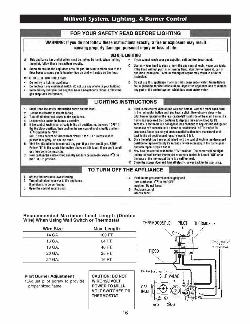
Millivolt System, Lighting, & Burner Control
Pilot Burner Adjustment1.Adjust pilot screw to provide
proper sized flame.
Recommended Maximum Lead Length (DoubleWire) When Using Wall Switch or Thermostat
Wire Size Max. Length
14 GA. 100 FT.
16 GA. 64 FT.
18 GA. 40 FT.
20 GA. 25 FT.
22 GA. 16 FT.
CAUTION: DO NOT
WIRE 120 VOLT
POWER TO MILLI-
VOLT SWITCHES OR
THERMOSTAT.
17
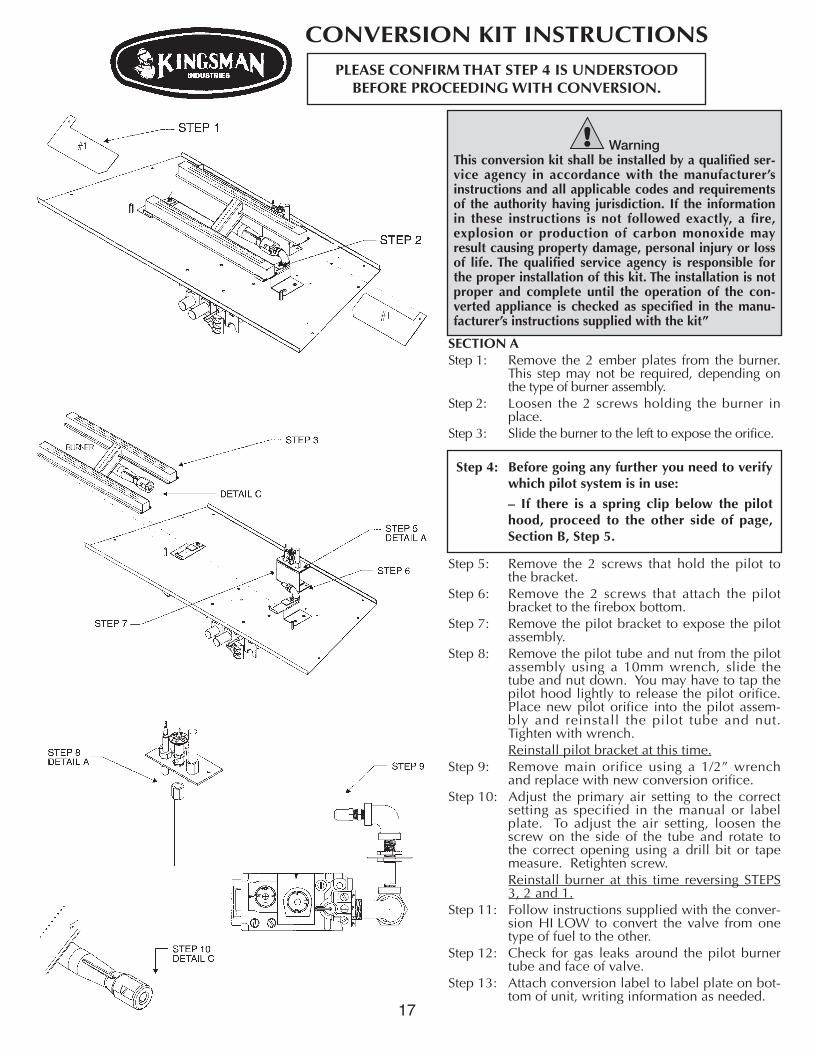
SECTION AStep 1: Remove the 2 ember plates from the burner.
This step may not be required, depending onthe type of burner assembly.
Step 2: Loosen the 2 screws holding the burner inplace.
Step 3: Slide the burner to the left to expose the orifice.
Step 5: Remove the 2 screws that hold the pilot tothe bracket.
Step 6: Remove the 2 screws that attach the pilotbracket to the firebox bottom.
Step 7: Remove the pilot bracket to expose the pilotassembly.
Step 8: Remove the pilot tube and nut from the pilotassembly using a 10mm wrench, slide thetube and nut down. You may have to tap thepilot hood lightly to release the pilot orifice.Place new pilot orifice into the pilot assem-bly and reinstall the pilot tube and nut.Tighten with wrench.Reinstall pilot bracket at this time.
Step 9: Remove main orifice using a 1/2” wrenchand replace with new conversion orifice.
Step 10: Adjust the primary air setting to the correctsetting as specified in the manual or labelplate. To adjust the air setting, loosen thescrew on the side of the tube and rotate tothe correct opening using a drill bit or tapemeasure. Retighten screw.Reinstall burner at this time reversing STEPS3, 2 and 1.
Step 11: Follow instructions supplied with the conver-sion HI LOW to convert the valve from onetype of fuel to the other.
Step 12: Check for gas leaks around the pilot burnertube and face of valve.
Step 13: Attach conversion label to label plate on bot-tom of unit, writing information as needed.
CONVERSION KIT INSTRUCTIONS
Step 4: Before going any further you need to verifywhich pilot system is in use:
– If there is a spring clip below the pilothood, proceed to the other side of page,Section B, Step 5.
PLEASE CONFIRM THAT STEP 4 IS UNDERSTOODBEFORE PROCEEDING WITH CONVERSION.
WarningThis conversion kit shall be installed by a qualified ser-vice agency in accordance with the manufacturer’sinstructions and all applicable codes and requirementsof the authority having jurisdiction. If the informationin these instructions is not followed exactly, a fire,explosion or production of carbon monoxide mayresult causing property damage, personal injury or lossof life. The qualified service agency is responsible forthe proper installation of this kit. The installation is notproper and complete until the operation of the con-verted appliance is checked as specified in the manu-facturer’s instructions supplied with the kit”

18
SSeeccttiioonn BBIInnssttaall llaattiioonn IInnssttrruuccttiioonnssGAS CONVERSION KIT FOR TOPCONVERTIBLE PILOT SERIES 019065X
SIT Group
Instructions for converting SIT 190 series pilot burner injection from NG to LPG and from NG to LPG Only.This information should be considered as supplemental to the Appliance Manufacturer’s Instructions.
WARNING!The installation of this conversion kit must only be undertaken by a qualifiedand certified gas appliance installer.
1 Shut off the gas supply to the appliance.
2 Allow the pilot burner to cool to room temperature.WARNING: Touching a hot pilot burner can result in injury.
3 The pilot hood is held in place by spring pressure.Remove the hood by pulling it directly up from the pilot bracket (1).
4 Insert a 5/32” or 4mm Allen wrench into the hexagonal key-way of theinjector (2), and rotate it counter clockwise until it is free of the injectorjournal (3).
5 Verify that the new injector is proper for the application. The injector sizeis stamped on the side of the injector near the top. LPG injectors have agroove machined around their circumference near the top, while NGinjectors do not have a groove (5).Refer to the Appliance Manufacturers instruction sheet for the properinjector size.
6 Insert the Allen wrench into the end of the injector. Then, insert into injec-tor journal, and rotate the injector clockwise until a torque of 9 in-lbs. isachieved.
7 Replace the pilot hood by aligning the tab on the base of the hood withthe slot in the side of the pilot journal, and push the hood down, directlyonto the pilot bracket (4). The hood must sit squarely on the bracket forproper operation. Check to insure that the hood is properly seated ontothe pilot bracket.
8 Proceed to Section A, Step 9.
WARNING!This conversion kit must only be applied as part of a conversion kit supplied by theappliance Manufacturer for the specific appliance, and type of gas being converted.
INSTALLER NOTICE. These instructions must be left with appliance.

19
Trouble Shooting The Gas Control System
NOTE: Before troubleshooting the gas control system, be sure external gas shut off is in the “On” position.
Problem Possible Causes Corrective ActionSpark igniter will not light. Defective or misaligned electrode Check for spark at electrode and pilot: if no spark and electrode
at pilot. wire is properly connected, replace igniter.
Defective igniter Using a match, light pilot. If pilot lights, turn off pilot and push the(push-button) red button again. If pilot will not light - check gap at electrode and
pilot should be 1/8” to 1/4” to have a strong spark.
Pilot will not stay lit after carefully Defective thermocouple Check pilot flame. Must impinge on generator and thermocouple.following lighting instructions. (flame switch where applicable) Clean and/or adjust pilot for maximum flame impingement on
generator and thermocouple. Replace thermocouple if pilot will not hold. (Hand tight 1/8 turn on replacement)
Defective valve magnet. Replace valve, if pilot won’t hold after the thermocouple is replaced.
Pilot burning, no gas to burner, Wall switch or wires Check wall switch and wires for proper connections. Jumper wireValve knob “ON”, Wall defective. across terminals at wall switch. If burner comes on, replace Switch “ON” defective wall switch. If okay, jumper wires, across wall switch
wires at valve. If burner comes on, wires are faulty or connections are bad.
Generator may not be generating Check generator with millivolt meter. Take reading at generator sufficient voltage. terminals of gas valve. Should read 325 millivolts minimum while
holding valve knob depressed in pilot position and wall switch “off” Replace faulty generator if reading is below specified minimum.
Plugged burner orifice. Check burner orifice for stoppage and remove.
Defective automatic valve Remove wall switch wires from gas valve. Install jumper wires operator. from top bottom terminals of gas valve. Turn valve on “ON”. If
main burner does not light, replace valve.
Frequent Pilot outage problem. Pilot flame may be too low or Clean and/or adjust pilot flame for maximum flame impingementblowing (high) causing the pilot on generator and thermocouple.safety to drop out.
Flame lifts off burner and goes out Inner 4” liner has come off flue Attach 4” liner to flue or termination using screws, silicone andin less than 30 seconds or termination, flame is starving clamps as stated in manual.
for oxygen
Flame lifts off burner on Improper installation of firebrick. Be sure to position firebrick against firebox walls and be sure toone side while the rest of Firebrick is likely leaning. use brick clips attached to the inner side of firebox.the flame remains lit.
WARNING: BEFORE DOING ANY GAS CONTROL SERVICE WORK, REMOVE THE GLASS FRONT.
20
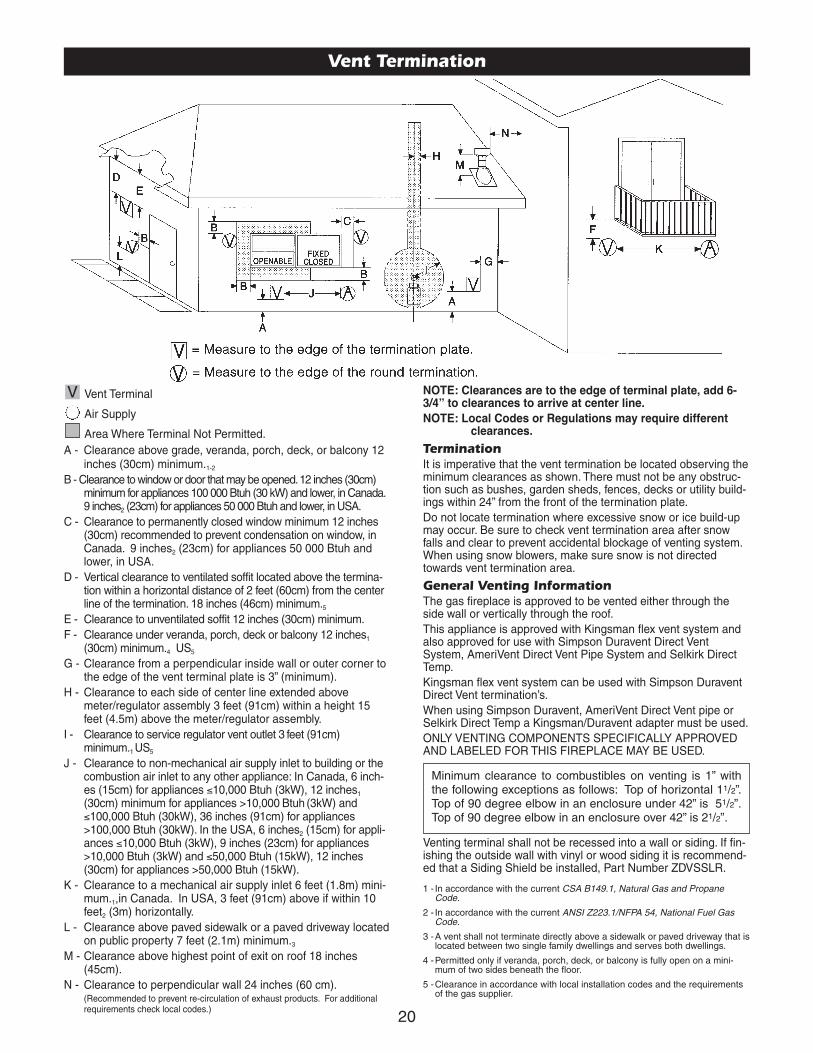
Vent Termination
NOTE: Clearances are to the edge of terminal plate, add 6-3/4” to clearances to arrive at center line.
NOTE: Local Codes or Regulations may require differentclearances.
TerminationIt is imperative that the vent termination be located observing theminimum clearances as shown. There must not be any obstruc-tion such as bushes, garden sheds, fences, decks or utility build-ings within 24” from the front of the termination plate.Do not locate termination where excessive snow or ice build-upmay occur. Be sure to check vent termination area after snowfalls and clear to prevent accidental blockage of venting system.When using snow blowers, make sure snow is not directedtowards vent termination area.
General Venting InformationThe gas fireplace is approved to be vented either through theside wall or vertically through the roof.This appliance is approved with Kingsman flex vent system andalso approved for use with Simpson Duravent Direct VentSystem, AmeriVent Direct Vent Pipe System and Selkirk DirectTemp.Kingsman flex vent system can be used with Simpson DuraventDirect Vent termination’s.When using Simpson Duravent, AmeriVent Direct Vent pipe orSelkirk Direct Temp a Kingsman/Duravent adapter must be used.ONLY VENTING COMPONENTS SPECIFICALLY APPROVEDAND LABELED FOR THIS FIREPLACE MAY BE USED.
Venting terminal shall not be recessed into a wall or siding. If fin-ishing the outside wall with vinyl or wood siding it is recommend-ed that a Siding Shield be installed, Part Number ZDVSSLR.
1 - In accordance with the current CSA B149.1, Natural Gas and PropaneCode.
2 - In accordance with the current ANSI Z223.1/NFPA 54, National Fuel GasCode.
3 -A vent shall not terminate directly above a sidewalk or paved driveway that islocated between two single family dwellings and serves both dwellings.
4 -Permitted only if veranda, porch, deck, or balcony is fully open on a mini-mum of two sides beneath the floor.
5 -Clearance in accordance with local installation codes and the requirementsof the gas supplier.
Minimum clearance to combustibles on venting is 1” withthe following exceptions as follows: Top of horizontal 11/2”.Top of 90 degree elbow in an enclosure under 42” is 51/2”.Top of 90 degree elbow in an enclosure over 42” is 21/2”.
Vent Terminal
Air Supply
Area Where Terminal Not Permitted.A - Clearance above grade, veranda, porch, deck, or balcony 12
inches (30cm) minimum.1-2
B - Clearance to window or door that may be opened. 12 inches (30cm)minimum for appliances 100 000 Btuh (30 kW) and lower, in Canada.9 inches2 (23cm) for appliances 50 000 Btuh and lower, in USA.
C - Clearance to permanently closed window minimum 12 inches(30cm) recommended to prevent condensation on window, inCanada. 9 inches2 (23cm) for appliances 50 000 Btuh andlower, in USA.
D - Vertical clearance to ventilated soffit located above the termina-tion within a horizontal distance of 2 feet (60cm) from the centerline of the termination. 18 inches (46cm) minimum.5
E - Clearance to unventilated soffit 12 inches (30cm) minimum.F - Clearance under veranda, porch, deck or balcony 12 inches1
(30cm) minimum.4 US5
G - Clearance from a perpendicular inside wall or outer corner tothe edge of the vent terminal plate is 3” (minimum).
H - Clearance to each side of center line extended abovemeter/regulator assembly 3 feet (91cm) within a height 15feet (4.5m) above the meter/regulator assembly.
I - Clearance to service regulator vent outlet 3 feet (91cm)minimum.1 US5
J - Clearance to non-mechanical air supply inlet to building or thecombustion air inlet to any other appliance: In Canada, 6 inch-es (15cm) for appliances ≤10,000 Btuh (3kW), 12 inches1
(30cm) minimum for appliances >10,000 Btuh (3kW) and≤100,000 Btuh (30kW), 36 inches (91cm) for appliances>100,000 Btuh (30kW). In the USA, 6 inches2 (15cm) for appli-ances ≤10,000 Btuh (3kW), 9 inches (23cm) for appliances>10,000 Btuh (3kW) and ≤50,000 Btuh (15kW), 12 inches(30cm) for appliances >50,000 Btuh (15kW).
K - Clearance to a mechanical air supply inlet 6 feet (1.8m) mini-mum.1,in Canada. In USA, 3 feet (91cm) above if within 10feet2 (3m) horizontally.
L - Clearance above paved sidewalk or a paved driveway locatedon public property 7 feet (2.1m) minimum.3
M - Clearance above highest point of exit on roof 18 inches(45cm).
N - Clearance to perpendicular wall 24 inches (60 cm).(Recommended to prevent re-circulation of exhaust products. For additionalrequirements check local codes.)
V

21
IPI Electronic Ignition System
Overview
The IPI system is an advanced burner controller thatprovides you with the option of having either aStanding-Pilot, or an intermittent igniting system. Thisalternating mode is controlled by the CPI/IPI Switch(Continuous Pilot Ignition/Intermittent Pilot Ignition)located on the IPI System Box. The difference betweena Standing-Pilot and an Intermittent-Pilot is in whetherthe pilot stays lit or shuts off:
In Standing-Pilot, the pilot assembly is lit by the IPIMain Module and continues to stay lit until 1) theCPI/IPI Switch is switched to the IPI position; 2) a lossof electrical power (battery and AC source), 3) theflame sensor loses its signal, 4) the fuel supply discon-tinues, or 5) the IPI Main Module malfunctions.
In the Intermittent-Pilot mode, the pilot shuts off whenthe appliance is not in use. The advantage of this modeis that fuel is not consumed when the fireplace is notoperating.
NOTE: In some jurisdiction, Intermittent-Pilot isrequired. That means the pilot cannot remain lit whenthe appliance is not operating.
Components
The core of the IPI system is the Main Module and theIPI Valve. With these two components the system isable to operate a gas fireplace. There are also othercomponents available to complement the IPI system.
IPI System Cover: Is essential in keeping the compo-nents at their proper operating temperatures. DO NOT
OPERATE THE APPLIANCE WITHOUT THIS
COVER.
Modulating Servo Motor: Is an add-on valve compo-nent that permits HI/LO functionality to be controlled bythe remote. Contrary to this feature is a Manual HI/LOControl Knob. The Modulating Servo Motor requiresthe Remote system to be present.
Backup Battery Pack: This component permits the IPI system to operate without the need for an external AC Adapterpower source. The advantage to using the battery backup is that in the case of a power failure, the appliance is still
operable.
Remote Receiver: This component provides the capability of controlling the appliance with a wireless remote trans-mitter. There are two switches to note on the receiver module:
The first switch on the Remote Receiver module is a 3-position slide switch. This switch is used to either manuallyturn the main burner ON, activate the receiver to begin communication with the transmitter, or turn the main burnercompletely OFF. The position of the slide switch designates these functions respectively.
The second is the small round pushbutton [PRG] used for programming the receiver to respond to a designatedremote. Therefore to program the system ensure that the transmitter is first turned OFF. Then, ensure that there issufficient electrical power going to the Receiver module and a fresh set of batteries in the transmitter. Now switch the
NOTE: In certain instances the IPI Main Module requires resetting. This can occur if the system is unable to ignitethe pilot or the main burner in the allotted time period. The IPI is programmed to lockout all commands. To reset thislockout you must deplete the system of all electrical power. This means to remove the batteries from the BatteryPack, remove the batteries from the Remote Receiver (if applicable), and disconnect the AC Adapter from the sys-tem. Leave the power off for approximately 25 seconds to clear its lockout.

22
the slide switch to the middle [REMOTE] position and then push the small pushbutton to begin programming. Bringthe transmitter close to the receiver and then press the power button [R] on the transmitter. An audible beep willsound to indicate the system is programmed and ready to be used.
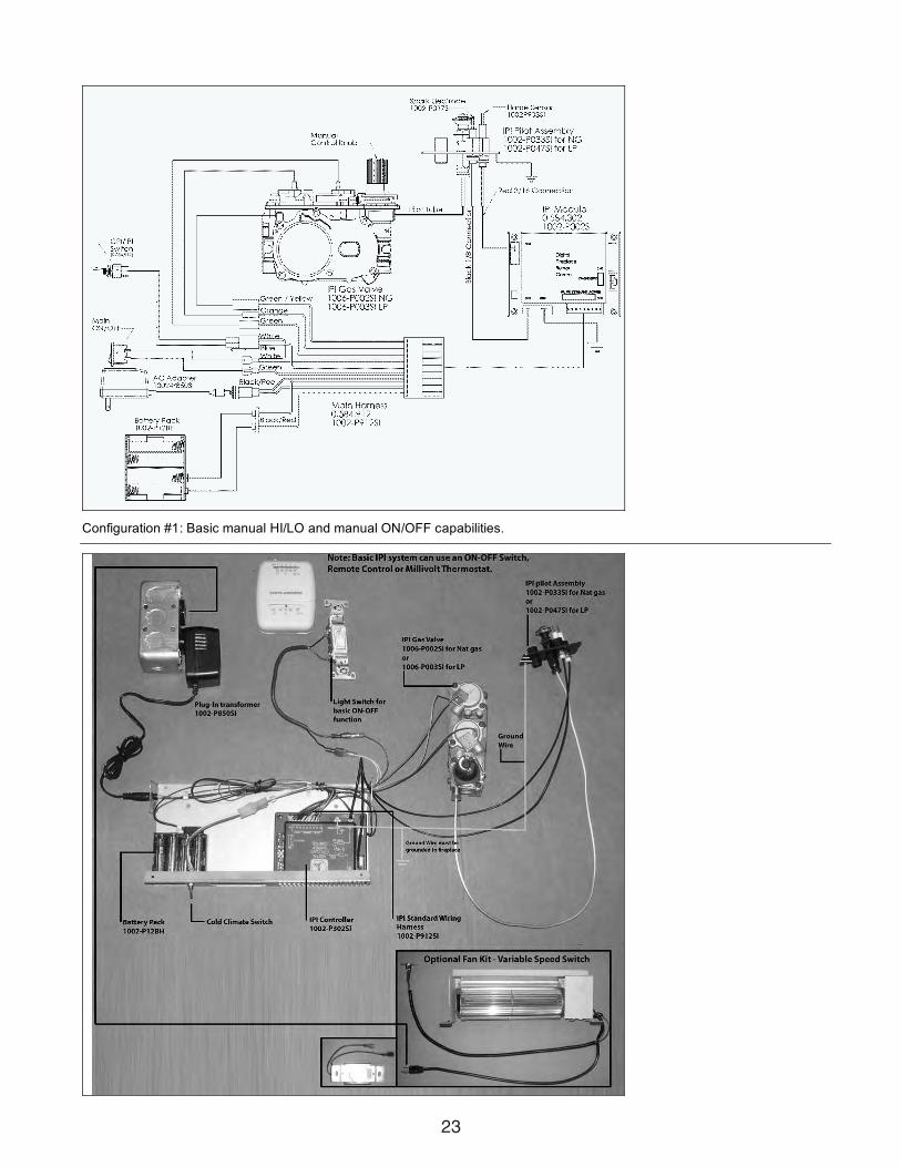
Electrical Supply in Series: The entire IPI system can be powered by asingle power source (i.e. by the AC Adapter). This is advantageous ifyou do not want to supply extra batteries. To achieve this simply con-nect the AC Adapter into the Remote Control wiring harness instead ofthe main IPI harness. From the Remote wiring harness, use its maleplug-in connector and connect it to the female plug-in in the main IPIharness. Now the circuit is complete. So the way it works is that electri-cal power is supplied to the Remote Receiver module and then pro-ceeds to the Main IPI module. Furthermore, note that a Backup BatteryPack is not required in this configuration. Instead, batteries in theRemote Receiver act as the backup supply.
NOTE: The Remote Receiver module can also be located outsideof the appliance to a maximum of 6ft away installed in a certifieddeep wall switch electrical box (2-3/4” depth). For this configurationan extension wiring harness (P/N: 1001-P904SI) is required.
23
Configuration #1: Basic manual HI/LO and manual ON/OFF capabilities.

24
Configuration #2: Remote ON/OFF and manual HI/LO capabilities. OPTIONAL: For units with remote HI/LO capabilities, a modu-lating servo is required to be installed on the valve. The connectors to this servo must be connected to the Remote Harness asshown in the figure above.

25
Configuration #3: Remote ON/OFF, variable HI/LO, and fan capabilities. Refer to the fan installation/removal section for fan installaConfiguration #3: Remote ON/OFF, variable HI/LO, and fan capabilities. Refer to the Fan Installation/Removal Guide section for fan installation.

26
IPI Lighting Instructions
WARNING
1. If you do not follow these instructions exactly, a fire or explosion may result causing property damage,personal injury or loss of life.
2. Always light the pilot whether for the first time or if the gas supply has ran out with the glass door opened orremoved.
FOR YOUR SAFETY READ BEFORE LIGHTING
A. This fireplace is equipped with an ignition device which automatically lights the pilot. Do not try to light by hand.
B. Before operating smell all around the fireplace area for gas and next to the floor because some gas is heavierthan air and will settle on the floor.
C. Do not use this fireplace if any part has been under water. Immediately call a qualified service technician toinspect the fireplace and replace any part of the control system and any gas control which has been under water
WHAT TO DO IF YOU SMELL GAS
1. Turn off all gas to the fireplace.
2. Open windows.
3. Do not try to light any appliance.
4. Do not touch any electric switch; do not use anyphone in your building.
5. Immediately call your gas supplier from a neighbor'sphone. Follow the gas supplier's instructions.
6. If you cannot reach your gas supplier, call the firedepartment.
LIGHTING INSTRUCTIONS
1. STOP! Read the above safety information on this label.
2. Remove batteries from Receiver and/or Battery Backup Pack.
3. Turn off all electric power to the fireplace.
4. This fireplace is equipped with an ignition device which automatically lights the pilot. Do not try to light the pilotby hand.
5. Open the glass door.
6. Turn manual shutoff valve clockwise to OFF position (located behind the access panel).
7. Wait five [5] minutes to clear out any gas. If you smell gas including near the floor, STOP! Follow "B" in the abovesafety information on this label. If you don’t smell gas go to the next step.
8. Turn manual shutoff valve counter-clockwise to ON position.
9. Close the glass door.
10. Turn on all electric power to the fireplace, and re-install batteries into the Transmitter/Receiver and/or BatteryBackup Pack.
11. Turn ON the switch that operates the Main Burner. If using a Remote Control refer to Remote Control OperationManual for activation.
TO TURN OFF GAS
1. Turn OFF all electric power to the fireplace if service is to be performed, including removing batteries from theRemote Transmitter/Receiver and/or Battery Backup Pack.
2. Access door inside the firebox must be removed to access the manual shutoff valve.
3. If alternate shut-off valve was installed it can be shutoff instead of going through the fireplace to access the fire-place shut off valve.

27
General Vent Installation InformationThis gas appliance is approved to be vented either through the side wall or vertically through the roof. Only
Kingsman Flex(Z-Flex)Venting Kits and components specifically approved and LABELED for this stove may
be used. This appliance is also approved for use with Simpson-Duravent Direct Vent system, Ameri-Vent Direct VentPipe System, ICC Excel Direct, Metal Fab Sure-Seal DV and Selkirk Direct Temp.
RIGID OR HARD PIPE
When using Simpson Duravent, AmeriVent pipe, ICC Excel Direct, Metal Fab Sure-Seal DV and or Selkirk DirectTemp a Duravent hardpipe adapter must be used (part # ZDVDFA for fireplaces and part # ZDVDKA for Stoves,
Serenity and ZDV3624B). Follow installation instructions provided by Simpson Duravent/AmeriVent/Selkirk DirectTemp, ICC Excel Direct, Metal Fab Sure-Seal DV for installation of pipe and adhere to the clearance to combustiblesprovided in this manual. Apply a bead of Mill Pac high temp sealant to all joints of pipes, adapters and termination,when using Kingsman Flex(Z-Flex)Venting venting and Simpson Duravent venting.
NOTE: Increase framing depth by one inch when using hardpipe.
Flex Pipe Venting
Kingsman Flex pipe is shipped in unexpanded length. When installing pipe expand the lengths. Pipe can be expand-ed to twice their lengths e.g. 4ft. to 8ft. Fully expand pipe and cut off excess.
Do not use more than 2 couplers to extend short pipes. Single sections are preferred in an installation attaching atthe fireplace and termination.
Place the spring spaces provided approximately every two feet to stabilize 4” flex in the center of 7” flex. When form-ing bends place spring in bend or before and after. (See Fig. 1).Horizontal runs require support metal straps every 2 feet. In off set installation support straps should be used to sta-bilize pipe.
Expand 4” and 7” flex pipe to the point that the 7” protrudes approximately 2 to 3 inches past outer wall and the 4”flex protrudes approximately 2 to 3 inches past the 7” flex. See Fig. 1. Attach the 4” pipe to the termination first andsecure with sealant and four screws then attach the 7” flex to the termination with caulking and four screws.Termination may then be moved back to the outer wall and attached to home screwing into the framing. Siliconearound termination to waterproof. If siding shield is going to be used attach this using same attaching hole as the topof termination after termination has been caulked for water proofing.Use Hi Temp Sealant
Apply a bead of mill pac high temp sealant to all joints and use four screws to secure each pipe at fireplace, termina-tion and any joint if joining any sections of pipe.
Warning: DO NOT mix parts from different systems unless stated in the manual.

28
Step 3Straight Back Venting. Measure wall thickness. If wall is thinnerthan (1Ft.) then 1 foot unexpanded length in ZDVHSK must beexpanded and cut. 7” should extend past outer wall approximate-ly 2” to 3” and 4” flex approximately 2” past the 7” flex that allowsenough room to secure pipe to termination with high heat millpacand 4 screws, then press termination back to outer wall andseal. Place spacer spring over 4” flex to stabilize it in the 7” flexif length is over a foot. Step 4
Cover Back Venting. Only one - 45˚ bend per installation. Installas per above length. May not exceed Figure 1 page 16 and mustbe cut to comply.Install wall thimble.Place fireplace into place and secure to floorwith nailing tabs.Step 5Mount vent termination, make sure 4” and 7” pipes are siliconed.Caulk around wall thimble to weatherproof.
Corner InstallationLocation
NOTE: When the fireplaceis installed cross cornerit is necessary to bendthe flex pipe. Use KitZDVHSK5.
Parts List
On horizontal venting, 1/4” rise per foot up to 3ft, over 3ftup to the 5ft maximum horizontal run 1 1/2” rise per foot isneeded.
WALL THIMBLE
COMBUSTIBLEWALL
54” MAXIMUM
5 FT MAXIMUM
TOPVIEW
SIDE WALL
Installation of Back VentsGeneral Back Vent Installation and SpecificationStraight Back max vent length 60” Vent Kit # ZDVHSK45˚ Corner Max Number of 45˚ Bends OneMax Vent Length after 45˚ Bend 54”
NOTE: Minimum clearance between vent pipes and com-
bustible materials is one inch or 25mm side and bottom. 1
1/2” top.
Step 1Locate vent opening on the wall. COMBUSTIBLE WALLS cut a11” x 11” (280mm x 280mm) minimum hole and frame as shown.NON-COMBUSTIBLE WALL hole opening must be 8.5”(216mm) in diameter. Install wall thimble for vent pipe routingthrough wall. See Fig. 3.Step 2Place fireplace into place and attach vent pipes, four inch (4”)first. Make sure pipes are pushed on securely. Seal with millpacsealant and secure with 4 screws/washers per pipe.
orZDVHSK5
Note: Venting Terminalsshall not be recessed intowall or siding. If finishingthe outside wall with vinylor wood siding it is recom-mended that a SidingShield be installed, PartNumber ZDVSSLR.
PART NO. DESCRIPTION
Fireplace Part NumbersZDV3624NB (Millivolt) Fireplace Heater Back Flue NG, ZDV3624NBE IPI) Tempered Glass, 24,000 BTU, BRA-MHA
75% efficient
ZDV3624LPB (Millivolt) Fireplace Heater Back Flue LP, ZDV3625LPE (IPI) Tempered Glass, 22,000 BTU, BRA-MHA
75% efficientFIREPLACE REQUIREMENTSGrillsZ36GBA Grill Kit - Classic Builder Antique BrassZ36GBC Grill Kit - Classic Builder ChromeZ36GBP Grill Kit - Classic Builder Polish BrassZ1GBL Grill Kit - Black Z1GAB Grill Kit - Antique BrassZ1GPB Grill Kit - Polish BrassZ36GCR Grill Kit - ChromeZ36PBL Panel Grill Kit - BlackLOG SETS: (Required for each unit)LOGC42 Log Set - 4 pce. - Classic Oak (ZDV3320,
3624/28, 4224/28 Series)LOGC43 Log Set - 4 pce. - Traditional Oak (ZDV3320,
3624/28, 4224/28 Series)Fireplace Accessories Options:Z36SAB Surround - Antique Brass
(Coverage New Style 34 1/2” H x 41 1/8” W)Z36SCR Surround - Chrome
(Coverage New Style 34 1/2” H x 41 1/8” W)Z36SPB Surround - Polish Brass
(Coverage New Style 34 1/2” H x 41 1/8” W)Z36SLAB Surround Slim Line - Antique Brass
(Coverage 34 1/4” H x 37 1/2” W)Z36SLCR Surround Slim Line - Chrome
(Coverage 34 1/4” H x 37 1/2” W)Z36SLPB Surround Slim Line - Polish Brass
(Coverage 34 1/4” H x 37 1/2” W)Z36SLBL Surround Slim Line - Gun Metal Black
(Coverage 34 1/4” H x 37 1/2” W)Z1ADBL Arch Door Frame - BlackZ36ADDX Arch Door Frame - Deluxe Black (352))Z36ADTH Arch Door Frame - Top Half Black (353T)Z36ADDA Arch Door Frame - Double Arch Black (354)Z36ADDD Arch Door Frame - Double Door Arch Black (355)Z1ADAB Arch Door Frame - Antique BrassZ36ADCR Arch Door Frame - ChromeZ1ADPB Arch Door Frame - Polish BrassRDFK Remote Duct Fan Kit
(for ZDV3628/ZDV3632 models only)Z36FK Fan Kit w/Variable Speed Wall MountControl (Temperature Sensing)Z1MT Thermostat Millivolt Wall MountZ80PT Thermostat Programmable Digital Millivolt
Wall Mount (1F80-40)Z1RC Remote Control Millivolt (On/Off with LED)
(Model I) ZART Remote Control Thermostat Millivolt (Model K)RMCBN Remote Control - Basic - Natural Gas
(On/Off, Hi/Lo Flame Adjustment)RMCBP Remote Control - Basic - Liquid Propane
(On/Off, Hi/Lo Flame Adjustment)DCHS Remote Control HeatshieldZ36RL Refractory Liner (3 piece)

29
PART NO. DESCRIPTION
1002-P047si Pilot Assembly (LP)1002-P033si Pilot Assembly (NG)1002-P089si Spark Electrode (Long)1002-P113si Electrode Flame Sensor (Long)1002-P302si IPI Ignition Board1002-P850si AC Wall Adapter1002-P12BH Battery Pack1002-P912si Wiring Harness1002-P166si Orifice Pilot (NG #62)1002-P168si Orifice Pilot (LP #35)1002-P013si Stepper Motor (NG)1002-P012si Stepper Motor (LP)1002-P016is Hi/Lo Regulator (NG)1002-P014si Hi/Lo Regulator (LP)Miscellaneous Parts1000-150GE #SILICONE GE RED IS806 #7361000-150MP #HI-TEMP MILL PAC SEALANT 8400991000-214 #PIEZO-IGNITER 1244-17 MARK 211000-215 #PAL NUT (18MMXI.5MM)BLK (1364.03)1000-218 #SWITCH IVORY (1451/001)1000-227 #COVER IVORY (86001/001)1000-255 #ORIFICE BRASS - (State Size)1000-EMBER #MOON ROCK6000-130 #EXPLOSION FELT GASKET2000-080 #THERMODISC 2450 (For Blower)2000-081 #BLOWER MOTOR QLN65/24001000-085 #CONTROL VARIABLE SPEED KBWC-13BV1000-306 THERMALCORD - ADHESIVE BACK FOR
DOOR FRAME1000-305 CERAMIC GLASS - FOR ALL ZDV36003600-311 TEMPERED GLASS - FOR ZDV3624 MODEL
PART NO. DESCRIPTION
Designer Doors for 36” Fireplaces - OperativeZ36DDA1BL Designer Door Arch - Series 1 - BlackZ36DDTA1A Trim - Antique for Designer Arch - Series 1Z36DDTA1C Trim - Chrome for Designer Arch - Series 1Z36DDTA1P Trim - Polish for Designer Arch - Series 1Z36DDS1BL Designer Door Straight - Series 1 - BlackZ36DDS2BL Designer Door Straight - Series 2 - BlackZ36DDS3BL Designer Door Straight - Series 3 - BlackZ36DDTS1A Trim - Antique for Designer Straight - Series 1Z36DDTS1C Trim - Chrome for Designer Straight - Series 1Z36DDTS1P Trim - Polish for Designer Straight - Series 1
Child Safety ScreensZ36CSS Child Safety Screen - 36” DV Fireplaces
Conversion Kit (Sit Valve Only)3624-CKLP LP Conversion Kit for ZDV3624 (Millivolt)3624-CKNG NG Conversion Kit for ZDV3624 (Millivolt)3624-CKLPI LP Conversion Kit for ZDV3624 (IPI)3624-CKNGI NG Conversion Kit for ZDV3624 (IPI)Replacement Burner Assembly Millivolt3624-BNGSI Burner Assembly - Natural Gas c/w Valve System
(ZDV3624N)3624-BLPSI Burner Assembly - Liquid Propane c/w Valve
System (ZDV3624LP)Valve System Parts MillivoltIf Serial Number is LESS than: ZDV3624LP - 8952 / ZDV3624N - 9154ZDV3624LPB - 360767 / ZDV3624NB - 360766 / ZDV3628LP - 3697ZDV3628N - 3698 / ZDV3630LP - 420371 / ZDV3630N - 4203721000-P136WR Thermopile GOAI-5241001-P035SI Electrode Sparker 915.035 SIT1001-P129SI Thermocouple 290.129 SIT unified1001-P157SI Orifice Pilot LP 977.157 SIT1001-P159SI Orifice Pilot NG 977.159 SIT1001-P508SI HT Cable 161001-P633SI Valve Nova LP Hi/Lo 08206331001-P634SI Valve Nova NG Hi/Lo 08206341001-P605SI Pilot Burner LP 190.605 unified SIT1001-P606SI Pilot Burner NG 190.606 unified SITValve System Parts - New Top convertible SIT (Millivolt)If Serial Number is GREATER than above1000-P136WR Thermopile GOAI-5241001-P069SI Electrode Sparker 915.069 TC SIT1001-P216SI Thermocouple 290.216 TC SIT 1001-P165SI Orifice Pilot NG 977.165 TC SIT1001-P167SI Orifice Pilot LP 977.167 TC SIT1001-P508SI HT Cable 161001-P633SI Valve Nova LP Hi/Lo 08206331001-P634SI Valve Nova NG Hi/Lo 08206341001-P713SI Pilot Burner LP 199.713 TC SIT1001-P714SI Pilot Burner NG 199.714 TC SITValve System Parts - IPI SystemElectronic Ignition/Remote Control IPIEGTRC Remote Control IPI (Thermostat)EGTMRCN Remote Control IPI (Thermostat/Modulating - NG)EGTMRCP Remote Control IPI (Thermostat/Modulating - LP)EGTFRCN Remote Control IPI
(Thermostat/Modulating/Fan - NG)EGTFRCP Remote Control IPI
(Thermostat/Modulating/Fan - LP)Electronic Ignition Replacement Parts IPI1002-P001si Valve IPI (NG; ON/OFF)1002-P002si Valve IPI (LP; ON/OFF)1006-P002si Valve IPI (NG; Hi/Lo)1006-P603si Valve IPI (LP; Hi/Lo)
Kingsman Fireplace VentingCatalogNumber DescriptionZDVHSK Horizontal Vent Starter Kit - 3 FT Length
Horizontal Vent Termination, Wall Thimble,36” Flex Pipe, Mill Pac, screws/washers, springs.
ZDVHSK5 Horizontal Vent Starter Kit - 5 FT LengthHorizontal Vent Termination, Wall Thimble,60” Flex Pipe, Mill Pac, screws/washers, springs.
FDVHT Horizontal Vent TerminationFDVHSQ Horizontal Square TerminationZDVST Horizontal Snorkel Termination
(34” Tall, 24” Center to Center)FDVHSC Safety Cage for Horizontal TerminationZDVVOS Offset SupportZDVWT Wall Thimble (Horizontal Venting)ZDVSS Siding ShieldZDVFK5 Flex Kit (4” & 7” Dia.) x 2.5’ (Unexpanded) 5’ ExpandedZDV4FC Flex Connector 4” DiameterZDV7FC Flex Connector 7” DiameterZDV4SS Spring 4” Standoff SpacerZDVHSKSQ Horizontal Square Termination Vent Starter Kit -
3 FT LengthHorizontal Vent Termination, Wall Thimble,Wall Thimble, 36” Flex Pipe, Mill Pac
FDVHSQ Horizontal Square Vent TerminationZDVSSLR Siding Shield - Large Return
BASIC ONE YEAR WARRANTYDuring the first year after installation, we will provide a replacement for any component part of your unit found to be defective in materials or workmanship, including labour costs. Repair work requires prior approval by Kingsman, labour costs are based on a predetermined rateschedule and any repair work must be done through an authorized Kingsman dealer.
LIMITED LIFETIME WARRANTYThe heat exchanger, combustion chamber and burner of every Kingsman product excluding the Outdoor Firepit are warranted against materials or workmanship during the period the product is owned by the original owner. The part to be replaced must be returned to our distributor in exchange for the replacement part. Any labor, material, freight and/or handling charges associated with any repair or replacement pursuant to this Limited Lifetime Warranty will not be covered by this warranty.
GENERAL TERMSIn lieu of providing a replacement part, we may, at our option, provide the distributor's component purchase price from us or a credit equal to the distributors component purchase price from us toward the purchase of any new unit which we distribute. If a credit is given in lieu of a replacement part, the rating plate from the unit being replaced must be submitted on a warranty claim, and the unit beingreplaced must be made available to our distributor for disposition.
In establishing the date of installation for any purpose, including determination of the starting date for the term of this Limited LifetimeWarranty, reasonable proof of the original installation date must be presented*, otherwise the effective date will be based upon the date ofmanufacture plus thirty (30) days.
We will not be responsible for and you, the user, will pay for: (a) damages caused by accident, abuse, negligence, misuse, riot, fire, flood,or Acts of God (b) damages caused by operating the unit where there is a corrosive atmosphere containing chlorine, fluorine, or any other damaging chemicals (other than in a normal residential environment) (c) damages caused by any unauthorized alteration or repair of the unit affecting its stability or performance (d) damages caused by improper matching or application of the unit or the unit's components(e) damages caused by failing to provide proper maintenance and service to the unit (f) any expenses incurred for erecting, disconnecting or dismantling the unit (g) parts or supplies used in connection with service or maintenance (h) damage repairs, inoperation or inefficiencyresulting from faulty installation or application (i) electricity or fuel costs or any increase in electricity or fuel cost whatsoever including additional or unusual use of supplemental electric heat.
We shall not be liable for any incidental, consequential, or special damages or expenses in connection with any use or failure of this unit. We have not made and do not make any representation or warranty of fitness for a particular use or purpose, and there is no implied conditionof fitness for a particular use or purpose. We make no express warranties except as stated in this Limited Lifetime Warranty. No one is authorizedto change this Limited Lifetime Warranty or to create for us any other obligation or liability in connections with this unit. Any implied warranties shall last for one year after the original installation. Some states and provinces do not allow the exclusion or limitation of incidental or consequential damages or do not allow limitations on how long an implied warranty or condition lasts, so the above limitations or exclu-sions may not apply to you. The provisions of this limited warranty are in additions to and not a modification of or subtraction from any statu-tory warranties and other rights and remedies provided by law.
Save this certificate. It gives you specific legal rights, and you may also have other rights which may vary from state to state and province to province.
In the event your unit needs servicing, contact your dealer or contractor who installed or serviced your unit. When requesting service, please have the model and serial number from each unit readily available. If your dealer needs assistance, the distributor is available for supportand we, in turn support the distributor's efforts.
Fill in the installation date and model and serial numbers of the unit in the space provided below and retain this limited warranty for your files.
Model No. Serial No. Date installed
Dealer or Contractor Name:*To receive advantage of your warranty, you must retain the original records that can establish the installation date of your unit.
LIMITED LIFETIME WARRANTY
This Limited Lifetime Warranty applies only while the unit remains at the site of the originalinstallation and only if the unit is installed inside the continental United States, Alaska, Hawaii,and Canada. The warranty applies only if the unit is installed and operated in accordance with the printed instructions and in compliance with applicable installation and building codes and good trade practices.
The Ultimate in Design, Engineering & Quality