Owner's Manual and Installation Instructions - InspectAPedia ...
33
Owner's Manual and Installation Instructions 29-Inch Wide ELECTRIC DRYERS IMPORTANT: Read and follow all safety and operating instructions before first use of this product. Sears, Roebuck and Co., Hoffman Estates, IL 60179 U.S.A. www.sears.com 3979089B PRINTED IN U.S.A. 12/01
-
Upload
khangminh22 -
Category
Documents
-
view
1 -
download
0
Transcript of Owner's Manual and Installation Instructions - InspectAPedia ...

Owner's Manual andInstallation Instructions
29-Inch WideELECTRIC DRYERS
IMPORTANT:Read and follow all safetyand operating instructionsbefore first use of this product.
Sears, Roebuck and Co., Hoffman Estates, IL 60179 U.S.A.www.sears.com
3979089B PRINTED IN U.S.A. 12/01

BEFORE USING YOUR NEW DRYER
KENMORE DRYER WARRANTY
DRYER SAFETY 4
INSTALLATION INSTRUCTIONS 6
DRYER USE 19
LAUNDRYTIPS 25
DRYER CARE 27
TROUBLESHOOTING 30
WE SERVICE WHAT WE SELL 32
Please read this manual. It will helpyou install and operate your newKenmore dryer in the most economicalway.
If you need more information about thecare and operation of Kenmore appliancescall your nearest Sears store. You willneed the complete model andserial numbers when requestinginformation. Your dryer's model andserial numbers are located on the Modeland Serial Number Plate.
Product Record
Use the space below to record the modelnumber and serial number of your newKenmore dryer.
Model No.
Serial No.
Date of Purchase
2
Model No. andSerial No. Plate
Keep this book and your SearsSalescheck (receipt) in a safeplace for future reference.

Full One Year Warranty onMechanical and Electrical Parts
For one year from the date of purchase,if this dryer is installed and operatedaccording to the instructions in thismanual, Sears will repair or replace anyof its mechanical or electrical parts if theyare defective in material or workmanship.
NOTE: Exhausting your dryer witha plastic vent may void this warranty.See "Installation Instructions" for thecomplete exhaust requirementsfor this dryer.
Warranty Restriction
If the dryer is subjected to other thanprivate family use, all warranty coverage iseffective for only 90 days.
Warranty Service
Warranty service is available by contactingyour nearest Sears Service Center in theUnited States.
This warranty applies only while this dryeris in use in the United States.
This warranty gives you specific legalrights, and you may also have other rightswhich vary from state to state.
Sears, Roebuck and Co., Dept. 817WA,Hoffman Estates, IL 60179,
For Sears Warranty information or 1ocontact a SearsService Cenler, please reference the service numberslocated on the back page of lhis manual.

Your safety and the safety of others are very important.
We have providedmany importantsafety messages inthis manual andon your appliance. Always read and obey all safety messages.
This is the safety alert symbol.This symbol alerts you topotential hazards that can killor hurtyou and others.All safety messages will followthe safety alert symboland either the word "DANGER" or 'WARNING."These words mean:
You can be killed or seriouslyinjured if you don't immediatelyfollow instructions.
You can be killed or seriouslyinjured if you don't followinstructions.
All safety messages will tellyou what the potentialhazard is, tell you howto reduce the chance of injury,and tell you what can happen if theinstructionsare not followed.
4

IMPORTANT SAFETY INSTRUCTIONS
WARNING : To reduce the risk of fire, electric shock, or injury to persons
when using the dryer, follow basic precautions, including the following:
• Read all instructions before usingthe dryer.
• Do not place items exposed to cook-ing oils in your dryer. Items contami-
nated with cooking oils may contributeto a chemical reaction that couldcause a load to catch fire.
• Do not dry articles that have been pre-viously cleaned in, washed in, soakedin, or spotted with gasoline, dry-cleaning solvents, other flammable, orexplosive substances as they give off
vapors that could ignite or explode.
• Do not allow children to play on or inthe dryer. Close supervision ofchildren is necessary when the dryeris used near children.
• Before the dryer is removed fromservice or discarded, remove the door
to the drying compartment.
• Do not reach into the dryer if the drumis moving.
• Do not install or store the dryer whereit will be exposed to the weather.
• Do not tamper with controls.
• Do not repair or replace any part ofthe dryer or attempt any servicingunless specifically recommended inthis Owner _ Manual or in
published user-repair instructionsthat you understand and have theskills to carry out.
• Do not use fabric softeners or
products to eliminate static unlessrecommended by the manufacturerof the fabric softener or product.
• Do not use heat to dry articlescontaining foam rubber or similarlytextured rubber-like materials.
• Clean lint screen before or aftereach load.
• Keep area around the exhaustopening and adjacent surroundingareas free from the accumulation
of lint, dust, and dirt.
• The interior of the dryer andexhaust vent should be cleaned
periodically by qualified servicepersonnel.
• See the "INSTALLATIONINSTRUCTIONS" section for
grounding requirements.
SAVE THESE INSTRUCTIONS

Tools and Parts Location Requirements
Check that you have everything neces-sary for correct installation. Properinstallation is your responsibility.
• flat-blade screwdriver
• adjustable wrench that opens to 1 in.or hex-head socket wrench (foradjusting dryer feet)level
wire stripper (direct wire installations)#2 Phillips screwdriversafety glassesduct tapecaulking gun and compound (forinstalling new exhaust vent)
• gloves• tin snips (new vent installations)
Parts supplied:Remove parts package from dryer drum.Check that all parts were included.
4 leveling legs
Parts needed:Check local codes, check existing electri-cal supply and venting and see"Electrical Requirements" and "VentingRequirements" before purchasing parts.
Mobile home installations require:• Metal exhaust system hardware avail-
able for purchase from your localSears store or Sears Service Center.
Explosion Hazard
Keep flammable materials and vapors,such as gasoline, away from dryer.
Place dryer at least 18 inches (46 cm)above the floor for a garageinstallation.
Failure to do so can result in death,explosion, or fire,
You will need• A location that allows for proper
exhaust installation. See "VentingRequirements."
• A separate 30 amp circuit.• A grounded electrical outlet located
within 2 ft (61 cm) of either side of thedryer. See "Electrical Requirements."
• A sturdy floor to support the total dryerweight of 200 Ibs (90.7 kg).
• A level floor with a maximum slope of1 in. (2.5 cm) under entire dryer. (Ifslope is greater than 1 in. [2.5 cm],install Extended Dryer Feet kit, PartNo. 279810.) Clothes may not tumbleproperly and dryers with automaticsensor cycles may not operatecorrectly if dryer is not level.
Do not operate or store your dryer in alocation with year-round temperaturesbelow 45°F (7°C). At lower temperatures,the dryer might not shut off at the end ofan automatic cycle. Drying times can beextended.
Install the dryer where it is protected fromwater and/or weather.
Check code requirements. Some codeslimit, or do not permit, installation of thedryer in garages, closets, mobile homes,or sleeping quarters. Contact your localbuilding inspector.
6

Installation ClearancesThe location must be large enough to fullyopen the dryer door.
Dryer Dimensions
1 Small Opening Side-Swing Doer
(110
273/1_"(69,05 c
\\ __ 29"_
3. Wide Opening Side-Swing Doer
\ 29,,__7(73.66 era)
2. Large Opening Side-Swing Door
22_/#*
*Most installations require a minimum 51_2in. (14 cm) clearance behind the dryerfor the exhaust vent with elbow. See"Venting Requirements."

8
Minimum installation spacing forrecessed area or closet installationThe dimensions shown following are forthe minimum spacing allowed.• Additional spacing should be
considered for ease of installation andservicing.
• Additional clearances might berequired for wall, door and floormoldings.
• Additional spacing of 1 in. (2.5 cm) onall sides of the dryer is recommendedto reduce noise transfer.
• For closet installation, with a door,minimum ventilation openings in thetop and bottom of the door arerequired. Louvered doors withequivalent ventilation openings areacceptable.
• Companion appliance spacing shouldalso be considered.
(46.7m_)JE
t"
(_)
o,o
m
m
_,5 t_11) _,5 crn) (69 O5 cm) (14 cm)
1 2
_3"
48 ,*z
1310=rn2)-
24,,z
1155crM) _-3"
3 _.e_)
1 RecessedArea2 Side view - closet or confined
area3 Closet door with vents
Mobile Home-Additional InstallationRequirementsThis dryer is suitable for mobile homeinstallations. The installation must con-form to the Manufactured HomeConstruction and Safety Standard, Title24 CFR, Part 3280 (formerly the FederalStandard for Mobile Home Constructionand Safety, Title 24, HUD Part 280)
Mobile home installations require:• Metal exhaust system hardware which
is available for purchase from yourlocal Sears store or Sears ServiceCenter.
• Special previsions must be made inmobile homes to introduce outside airinto the dryer. The opening (such as anearby window) should be at leasttwice as large as the dryer exhaustopening
Electrical RequirementsIt is your responsibility:• To contact a qualified electrical
installer.• To be sure that the electrical connec-
tion is adequate and in conformancewith the National Electrical Code,ANSl/NFPA 70-latest edition and alllocal codes and ordinances.
A copy of the above code standardscan be obtained from: National FireProtection Association, BatterymamhPark, Quincy, MA 02269.
• To supply the required 3 or 4 wire, sin-gle phase, 120/240-volt, 60-Hz., AC-only electrical supply (or 3 or 4 wire,120/208-volt electrical supply, if speci-fied on the serial/rating plate) on aseparate 30-amp circuit, fused on bothsides of the line. A time-delay fuse orcircuit breaker is recommended.Connect to an individual branch circuit.Do not have a fuse in the neutral orgrounding circuit.
• Do not use an extension cord.
• If codes permit and a separate groundwire is used, it is recommended that aqualified electrician determine that theground path is adequate.
Electrical Connection
To properly install your dryer, you mustdetermine the type of electrical connec-tion you will be using and follow theinstructions provided for it here.
• If local codes do not permit the con-nection of a cabinet ground connectorto the neutral wire, see "Optional 3-wireconnection" section.
• This dryer is manufactured with a 3-wire, cabinet-ground conductor con-nected to the NEUTRAL (white or cen-ter wire) of the wiring harness at theterminal block.
• Use a 4-wire conductor cord when thedryer is installed in a mobile home oran area where local codes do not per-mit grounding through the neutral.

If using a power supply cord:
Use a UL approved power supply cord kitmarked for use with clothes dryers, thekit should contain:
• A UL approved 30 amp power supplycord, rated 120/240 volt minimum. Thecord should be type SRD or SRDT andbe at least 4 ft (1.22 m) long. The wiresthat connect to the dryer must end inring terminals or spade terminals withupturned ends.
• A UL approved strain relief.If your outlet looks like this:
©4_wire receptacle (14_30R)
Then choose a 4-wire power supply cordwith ring or spade terminals and ULapproved strain relief. The 4-wire powersupply cord, at least 4 ft (1.22 m) long,must have 4, 10 gauge solid copperwires and match a 4-wire receptacle ofNEMA Type 14-30R. The ground wire(ground conductor) may be either greenor bare. The neutral conductor must beidentified by a white cover.
If your outlet looks like this:
©3_wire receptacle (10_30R)
Then choose a 3-wire power supply cordwith ring or spade terminals and ULapproved strain relief. The 3-wire powersupply cord, at least 4 ft (1.22 m) long,must have 3, No.-10 copper wires andmatch a 3-wire receptacle of NEMA Type10-30R.
If connecting by direct wire:Power supply cable must match powersupply (4-wire or 3-wire) and be:• Flexible armored or non-metallic
sheathed copper cable (with groundwire). All current-carrying wires mustbe insulated.
• 10 gauge solid copper wire (Do not usealuminum.)
• At least 4 ft (1.22 m) long
GROUNDING INSTRUCTIONS
• For a grounded, cord-connected dryer:This dryer must be grounded. In theevent of malfunction or breakdown,grounding will reduce the risk of electricshock by providing a path of least resis-tance for electric current. This dryeruses a cord having an equipment-grounding conductor and a groundingplug. The plug must be plugged into anappropriate outlet that is properlyinstalled and grounded in accordancewith all local codes and ordinances.
• For a permanently connected dryer:This dryer must be connected to agrounded metal, permanent wiringsystem, or an equipment-groundingconductor must be run with the circuitconductors and connected to the equip-ment-grounding terminal or lead on thedryer.
WARNING: Improper connectionof the equipment-grounding conductorcan result in a risk of electric shock.Check with a qualified electrician orservice representative or personnel ifyou are in doubt as to whether theappliance is properly grounded.Do notmodify the plug on the power supplycord: if it will not fit the outlet, have aproper outlet installed by a qualifiedelectrician.
SAVE THESE INSTRUCTIONS

Power Supply Cord
Electrical Connection
Direct Wire
Fire Hazard
Use a new UL approved 30 amppower supply cord.
Use a UL approved strain relief.
Disconnect power before makingelectrical connections.
Connect neutral wire (white or centerwire) to center terminal (silver).
Ground wire (green or bare wire)must be connected to green groundconnector.
Connect remaining 2 supply wires toremaining 2 terminals (gold).
Securely tighten all electricalconnections.
Failure to do so can result in death,fire, or electrical shock.
1. Disconnect power.2. Remove the hold-down screw and
terminal block cover.
! 2
Terminal block cover
External ground connectorCenter, silver-colored terminal_blockscrew
4. Hold_down screw location
E Neutral grounding wire (green/yellow)
6. Hole below terminal block opening
Fire Hazard
Use 10 gauge solid copper wire.
Use a UL approved strain relief.
Disconnect power before makingelectrical connections.
Connect neutral wire (white or centerwire) to center terminal (silver).
Ground wire (green or bare wire) mustbe connected to green groundconnector.
Connect remaining 2 supply wiresto remaining 2 terminals (gold).
Securely tighten all electricalconnections.
Failure to do so can result in death,fire, or electrical shock.
3, Assemble a 3/4 in. (1.9 cm) ULapproved strain relief (UL marking onstrain relief) into the hole below theterminal block opening. Tighten strainrelief screws just enough to hold thetwo clamp sections together. Putpower supply cord through the strainrelief. The strain relief should have atight fit with the dryer cabinet and bein a horizontal position.
4. Now complete installation followinginstructions for your type of electricalconnection:
4-wire (recommended)3-wire (if 4-wire is not available)
10

_E!ectricaJ_q_%nnec_jon__9_ _ops....................If your And you Go tohome has: will be Section:
connectingto:
4-wire receptacle A UL listed 4-wireNEMAType 14-30R 120/240volt connection:
minimum, 30amp., dryer Powerpower supply SupplyCordcord*
4-wire direct A fused 4-wiredisconnect or connection:circuit breakerbox* Direct Wire
3-wire receptacle A UL listed, 3-wire(NEMAtype 10-30R) 120/240 volt connection:
minimum, 30amp., dryer Power
Supplypower supply Cordcord*
3-wire direct A fused 3-wiredisconnect or connection:circuit breakerbox* Direct Wire
*If local codes do not permit theconnection of a frame-groundingconductor to the neutral wire, go to"Optional 3-wire connection" section.
4-wire connection: Power Supply Cord
IMPORTANT: A 4-wire connection isrequired for mobile homes and wherelocal codes do not permit the use of 3-wireconnections.
2
3 4
6
5 7
1.4-wire receptacle (NEMA type 14_30R)
2. 4-prong plug
3. Ground prong
4. Neutral prong
5. Spade terminals with upturned ends
6. 3/_ in. (1.9 cm) UL approved strain relief
7. Ring terminals
1. Remove center terminal block screw.
2. Remove appliance ground wire (greenwith yellow stripes) from externalground connector screw. Fasten itunder center, silver colored terminalblock screw.
1 2
0
3
1 External ground connector - Dottedline shows position of NEUTRALground wire before being moved tocenter terminal block screw
2 Center silver-colored terminal blockscrew
& Green/yellow wire of harness
3. Connect ground wire (green or bare)of power supply cord to extemalground conductor screw. Tightenscrew.
4. Connect neutral wire (white or centerwire) of power supply cord under cen-ter screw of the terminal block.
4 5
1. 3j_ in. (1.9 cm), ULqisted strain relief
2 Green wire of power supply cord orbare copper wire
3. External ground connector4. Center silver-colored terminal block
screw
5. Neutral wire (white)
6. Neutral grounding wire (green/yellow)
5. Connect the other wires to outer ter-minal block screws. Tighten screws.
6. Tighten strain relief screws.7. Insert tab of terminal block cover into
slot of dryer rear panel. Secure coverwith hold-down screw.
11

4-wire connection: Direct Wire
IMPORTANT: A 4-wire connection isrequired for mobile homes and wherelocal codes do not permit the use of 3-wire connections.
Direct wire cable must have 5 ft (1.52 m)of extra length so dryer can be moved ifneeded.
Strip 5 in. (12.7 cm) of outer coveringfrom end of cable, leaving bare groundwire at 5 in. (12.7 cm). Cut 1lj2 in. (3.8cm) from 3 remaining wires. Stripinsulation back 1 in. (2.5 cm). Bend endsof wires into a hook shape.
3.
4.
Connect ground wire (green or bare)of power supply cable to externalground conductor screw. Tightenscrew.Place the hooked end of the neutralwire (white or center wire) of powersupply cable under the center screwof terminal block (hook facing right).Squeeze hooked end together. Younow have the appliance ground wireand the neutral wire on the same ter-minal. Tighten screw.
54
When connecting to the terminal block,place the hooked end of the wire underthe screw of the terminal block (hookfacing right), squeeze hooked endtogether and tighten screw.
1. Remove center terminal block screw.2. Remove appliance ground wire (green
with yellow stripes) from externalground connector screw. Fasten itunder center, silver colored terminalblock screw.
1 2
©
12
3
1. External ground connector - Dottedline shows position of NEUTRALground wire before being moved tocenter terminal block screw
2. Center silver-colored terminal blockscrew
3. Green/yellow wire of harness
11.3/4 in. (1.9cm), UL-listed strain relief2. Green orbare copper wire of power
supply cord3. External ground connector4. Center silver-colored terminal block
screw5. Neutral wire (white)6. Neutral grounding wire (green/yellow)
5. Place the hooked ends of the otherpower supply cable wires under theouter terminal block screws (hooksfacing right). Squeeze hooked endstogether. Tighten screws.
!! !!
6. Tighten strain relief screws.7. Insert tab of terminal block cover into
slot of dryer rear panel. Secure coverwith hold-down screw.

Use where local codes permit con-necting cabinet-ground conductor toneutral wire:
1
l3
4 5
7 61.3-wire receptacle (NEMA type 10-30R)
2. 3-wire plug3. Neutral prong
4. Spade terminals with upturned ends5. 3/4 in. (1.9 cm) UL approved strain
relief
6. Ring terminals7. Neutral (white or center wire)
t. Loosen or remove center terminalblock screw.
2. Connect neutral wire (white or centerwire) of power supply cord to the cen-ter, silver colored terminal screw ofthe terminal block. Tighten screw.
1. Neutral grounding wire (green/yellow)
32 J_
S
/S
F_ _ ,............
1/ _.5
2. Extemal ground connector3. Center silver-colored terminal block
screw
4. Neutral wire (white)5. 3/4 in. (19 cm) UL-listed strain relief
3. Connect the other wires to outer ter-minal block screws. Tighten screws.
4. Tighten strain relief screws.5. Insert tab of terminal block cover into
slot of dryer rear panel. Secure coverwith hold-down screw.
3-wire connection: Direct Wire
Use where local codes permit con-necting cabinet-ground conductor toneutral wire.
Direct wire cable must have 5 ft (1.52 m)of extra length so dryer can be moved ifneeded.
Strip 31/2in. (8.9 cm) of outer coveringfrom end of cable. Strip insulation back 1in. (2.5 cm). If using 3-wire cable withground wire, cut bare wire even withouter covering. Bend ends of wires into ahook shape.
When connecting to the terminal block,place the hooked end of the wire underthe screw of the terminal block (hook fac-ing right), squeeze hooked end togetherand tighten screw.
1. Loosen or remove center terminalblock screw.
2. Place the hooked end of the neutralwire (white or center wire) of powersupply cable under the center screwof terminal block (hook facing right).Squeeze hooked end together.Tighten screw.
32
/
1. Neutral grounding wire (green/yellow)
2. External ground connector3 Center silver-colored terminal block
screw
4. Neutral wire (white)5. 3/4 in.(19 crn) UL-listed strain relief
13

3. Place the hooked ends of the otherpower supply cable wires under theouter terminal block screws (hooksfacing right). Squeeze hooked endstogether. Tighten screws.
!! !!
4. Tighten strain relief screws.5. Insert tab of terminal block cover into
slot of dryer rear panel. Secure coverwith hold-down screw.
Optional 3-wire connection
Use for direct wire or power supplycord where local codes do not permitconnecting cabinet-ground conductorto neutral wire.
1. Remove center terminal block screw.
2. Remove appliance ground wire (greenwith yellow stripes) from externalground connector screw. Connectappliance ground wire and the neutralwire (white or center wire) of powersupply cord/cable under center, silvercolored terminal block screw. Tightenscrew.
3. Connect the other wires to outer ter-minal block screws. Tighten screws.
!!!!
4. Tighten strain relief screws.5. Insert tab of terminal block cover into
slot of dryer rear panel. Secure coverwith hold-down screw.
6. Connect a separate copper groundwire from the external ground connec-tor screw to an adequate ground.
2
1. External ground connector2. Neutral grounding wire (green/yellow)
3. Neutral wire (white)
4. Grounding path determined by aqualified electrician
14

Venting Requirements
Fire Hazard
Use a heavy metal vent.
Do not use a plastic vent.Do not use a metal foil vent.
Failure to follow these instructionscan result in death or fire.
WARNING: To reduce the risk offire, this dryer MUST BE EXHAUSTEDOUTDOORS.
4 in. (10.2 cm) heavy metal exhaust ventand clamps must be used. DURASAFE TM
venting products are recommended andare available from your local Sears storeor Sears Service Center.
DURASAFE vent products can bepurchased from your dealer. Please ref-erence the service numbers located onthe back of the manual or visit ourInternet site at: www.sears.com.
• Do not exhaust the dryer into any gasvent, chimney, wall, ceiling, or aconcealed space of a building.
• Do not use an exhaust hood with amagnetic latch.
• Do not install flexible metal vent inenclosed walls, ceilings or floors.
• Do not use screws or other fasteningdevices that extend into the interior ofthe vent to secure vent.
IMPORTANT: Observe all governingcodes and ordinances.
Improper venting can cause moistureand lint to collect indoors, which mayresult in:
Moisture damage to woodwork,furniture,paint, wallpaper, carpets, etc.
Housecleaning problems and healthproblems.
Jse a heavy metal vent. Do not use plas-tic or metal foil vent.
Rigid metal vent is recommended to pre-vent crushing and kinking.
Flexible metal vent must be fully extend-ed and supported when the dryer is in itsfinal position. Remove excess flexiblemetal vent to avoid sagging and kinkingthat may result in reduced airflow.
An exhaust hood should cap the vent toprevent rodents and insects fromentering the home.
Exhaust hood must be at least 12 in.(30.5 cm) from the ground or any objectthat may be in the path of the exhaust(such as flowers, rocks or bushes, etc.).
If using an existing vent system, cleanlint from the entire length of the systemand make sure exhaust hood is notplugged with lint. Replace any plastic ormetal foil vent with rigid metal or flexiblemetal vent.
Use duct tape to seal all joints.
Plan Vent SystemTypical Exhaust InstallationsTypical installations vent the dryer fromthe rear of the dryer.
2
!I/- 3/ k
/
1. Dryer2. Elbow
3. Wall
4. Exhaust hood
5. Duct tape and clamps
6. Rigid metal or flexible metal vent
7. Vent length necessary to connectelbows
8. Exhaust outlet
15
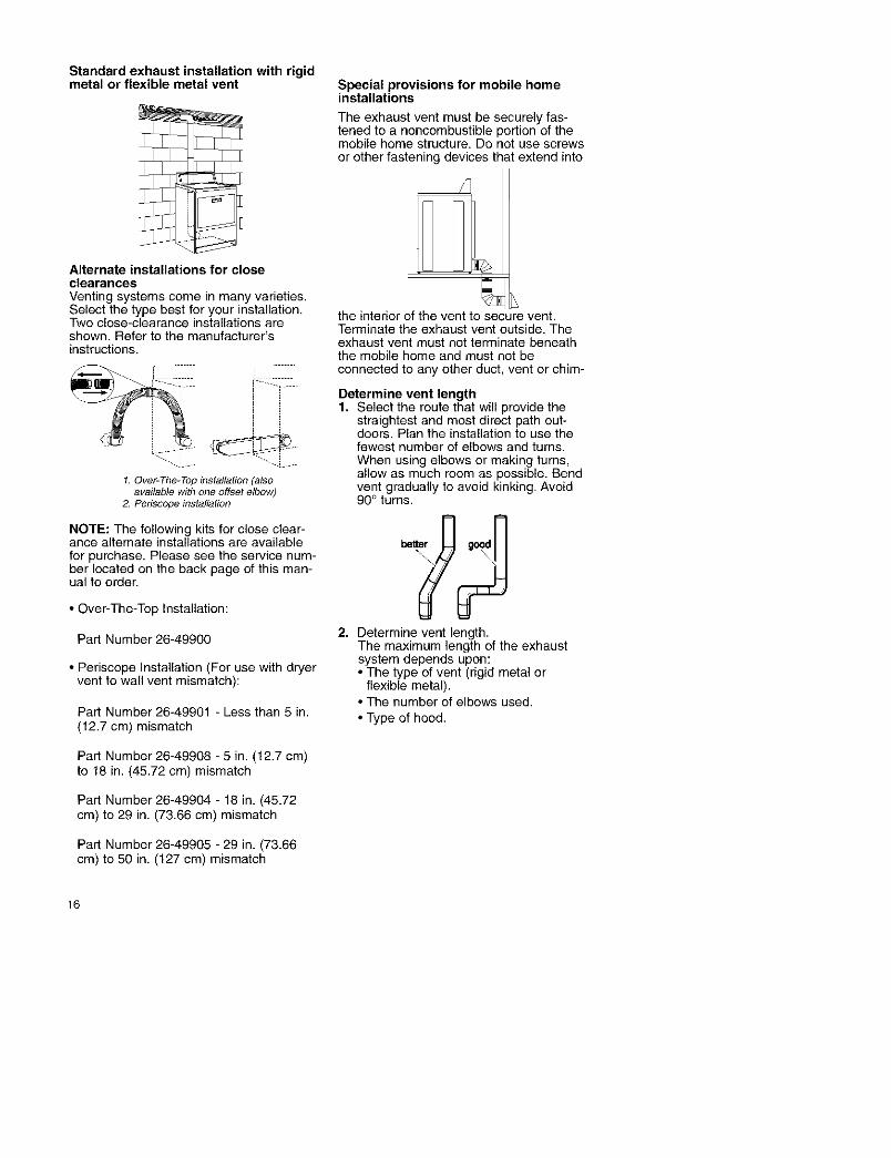
Standard exhaust installation with rigidmetal or flexible metal vent
Alternate installations for closeclearancesVenting systems come in many varieties.Select the type best for your installation.Two close-clearance installations areshown. Refer to the manufacturer'sinstructions.
1. Over-The-Top installation (alsoavailable with one offset elbow)
2. Periscope installation
NOTE: The following kits for close clear-ance altemate installations are availablefor purchase. Please see the service num-ber located on the back page of this man-ual to order.
• Over-The-Top Installation:
Part Number 26-49900
• Periscope Installation (For use with dryervent to wall vent mismatch):
Part Number 26-49901 - Less than 5 in.(12.7 cm) mismatch
Part Number 26-49908 - 5 in. (12.7 cm)to 18 in. (45.72 cm) mismatch
Part Number 26-49904 - 18 in. (45.72cm) to 29 in. (73.66 cm) mismatch
Part Number 26-49905 - 29 in. (73.66cm) to 50 in. (127 cm) mismatch
Special provisions for mobile homeinstallations
The exhaust vent must be securely fas-tened to a noncombustible portion of themobile home structure. Do not use screwsor other fastening devices that extend into
the interior of the vent to se{ ure vent.Terminate the exhaust vent outside. Theexhaust vent must not terminate beneaththe mobile home and must not beconnected to any other duct, vent or chim-
Determine vent length1. Select the route that will provide the
straightest and most direct path out-doors. Plan the installation to use thefewest number of elbows and turns.When using elbows or making tums,allow as much room as possible. Bendvent gradually to avoid kinking. Avoid90° turns.
2. Determine vent length.The maximum length of the exhaustsystem depends upon:• The type of vent (rigid metal or
flexible metal).• The number of elbows used.
• Type of hood.
16

Recommended hood styles are shownhere.
1
(10.2 cm)
1. Louvered hood style
2. Box hood style
The angled hood style (shown following)is acceptable.
4"
(10.2__
,ds 'm,See the exhaust vent length chart thatmatches your hood type for the maxi-mum vent lengths you can use.
Exhaust systems longer than specifiedwill:
• Shorten the life of the dryer.• Reduce performance, resulting in longer
drying times and increased energyusage.
3. Determine the number of elbows youwill need.NOTE: Do not use vent runs longerthan specified in Vent Length Chart.
Install Vent System1. (Optional) Put on safety glasses and
gloves.2. Install exhaust hood. Use caulking com-
pound to seal exterior wall openingaround exhaust hood.
3. Connect vent to exhaust hood. Ventmust fit inside exhaust hood. Securevent to exhaust hood with 4 in.(10.2 cm) clamp.
4. Run vent to dryer location. Use thestraightest path possible. See"Determine Vent Length." Avoid 90°rums. Use duct tape to seal all joints.
Install Leveling Legs
Excessive Weight HazardUse two or more people to moveand install dryer.Failure to do so can result in back
or other injury.
1. Place two of the carton corner postson the floor behind the back of thedryer. See illustration.
2. Firmly grasp the body of the dryer(not the top or console panel).
The chart below helps you determineyour maximum vent length based onthe number of 90 ° turns or elbows[rOUwill need and the type of vent
igid or flexible metal) and hood thatyou will use.
Vent Length Chart
Numberof Type of Boxor Angled90° turns vent Louvered hoodsor elbows hoods
0 Rigidmetal 64ft(20m) 58 ft(17,7m)36 ft (11m) 28 ft (8.5m)54 ft (16.5m) 48 ft (14.6m)
Flexible metal
1 Rigid metalFlexible metal
2 Rigid metalFlexible metal
3 Rigid metalFlexible metal
4 Rigid metal
Gently lay the dryer on the cardboardcorners.
3. Examine the leveling legs. Find thediamond marking.
31 ft (9.4m) 23 ft (7m) 4. Screw the legs into the leg holes by44ft (13.4m) 38 ft (11.6m) hand. Use a wrench to finish tuming27ft (8.2m) 19ft(5.8m) the legs until the diamond marking is35ft(1O.7m) 29ft(8.8m) no longer visible.25 ft (7.6m) 17 ft (5.2m)27 ft (8.2m) 21 ft (6.4m) 5, Stand the dryer up. Move it close to
its final location. Leave enough room............................................................. ..........to connect the exhaust vent.
17

Level DryerCheck the levelness of the dryer. Checklevelness first side-to-side, then front-to-back.
If the dryer is not level, prop up the dryerusing a wood block. Use a wrench toadjust the legs up or down and checkagain for levelness.
NOTE: It might be necessary to level thedryer again after it is moved into its finalposition.
Connect Vent1. Using a 4 in. (10.2 cm) clamp, con-
nect vent to exhaust outlet in dryer. Ifconnecting to existing vent, make surethe vent is clean. The dryer vent mustfit over the dryer exhaust outlet andinside the exhaust hood. Make surethe vent is secured to exhaust hoodwith a 4 in. (10.2 cm) clamp.
2. Move dryer into final position. Do notcrush or kink vent. Make sure dryer islevel.
Complete Installation1. Check to be sure all parts are now
installed. If there is an extra part, goback through the steps to see whichstep was skipped.
2. Check to be sure you have all ofyou r tools.
3. Dispose of all packaging materials.
4. Check the dryer's final location. Besure the vent is not crushed orkinked.
5. Check to be sure the dryer is level.(See "Level Dryer.")
6. Plug into a grounded outlet. Turnpower on.
7. Remove the blue protective film onthe console and any tape remainingon the dryer.
8. Read "Dryer Use."
g. Wipe the dryer drum interiorthoroughly with a damp cloth toremove any dust.
10. Set the dryer on a full heat cycle (notthe Air cycle) for 20 minutes andstart the dryer.If the dryer will not start, checkthe following:• Controls are set in a running or
"On" position.• Start button has been pushed
firmly.• Dryer is plugged into a grounded
outlet.
• Electrical supply is connected.• House fuse is intact and tight or
circuit breaker has not tripped.• Dryer door is closed.
11. When the dryer has been runningfor 5 minutes, open the dryer doorand feel for heat.If you do not feel heat, turn thedryer off and check the following:
• There may be 2 fuses or circuitbreakers for the dryer. Check tomake sure both fuses are intactand tight, or that both circuit break-ers have not tripped. If there is stillno heat, contact a qualified techni-cian.
NOTE: You may notice a burningodor when the dryer is first heated.This odor is common when theheating element is first used. Theodor will go away.
18

Explosion Hazard
Keep flammable materials andvapors, such as gasoline, awayfrom dryer.
Do not dry anything that has ever hadanything flammable on it (even afterwashing).Failure to follow these instructions canresult in death, explosion, or fire.
STARTING YOUR DRYER
To get the best drying results, you mustoperate your dryer properly. This sectiongives you this important information.
NOTE: The drawings in this section showthe basic features of all models coveredby this manual. Refer to the supplied"Feature Sheet" for your dryer's particularfeatures.
1. Clean lint screen.
2. Put laundry into dryer and shut door.
3. Set Cycle Selector Control (Timer) O,(see "Cycle Descriptions").
Fire Hazard
No washer can completelyremove oil.
Do not dry anything that has ever hadany type of oil on it (including cookingoils).
Items containing foam, rubber,or plastic must be dried on aclothesline or by using an Air Cycle.
Failure to follow these instructions canresult in death or fire.
4. Set FABRIC/TEMPERATUREControl (_, (see "Fabric/TemperatureControl"). Check clothes label formanufacturer's recommendations.
5. Press PUSH TO STARTButton (_. Be sure door is closed.
STOPPING/RESTARTINGYOUR DRYER
• To stop the dryer at any time, open dry-er door.
• To restart, press PUSH TO STARTButton. Be sure door is closed.
• If you wish to end your drying cycle, rumCycle Selector Control (Timer)to OFF.
19
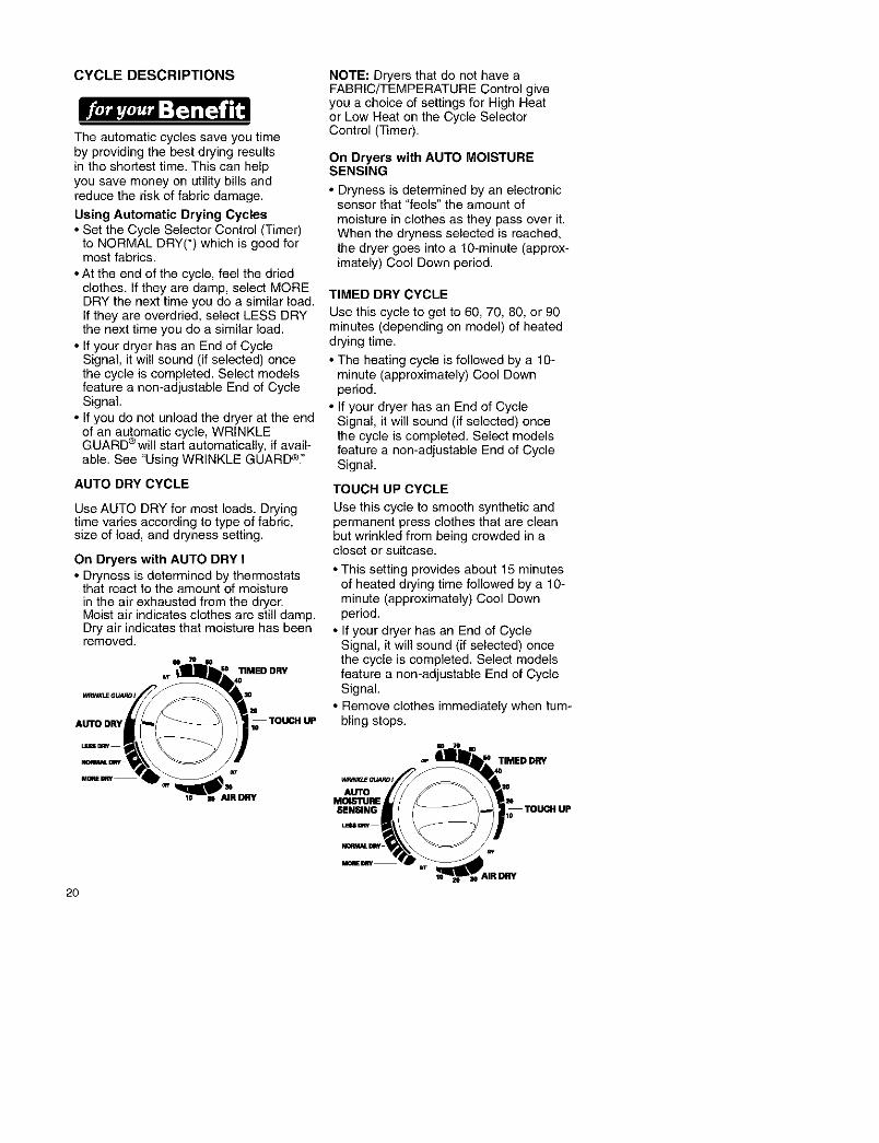
CYCLE DESCRIPTIONS
The automatic cycles save you timeby providing the best drying resultsin the shortest time. This can helpyou save money on utility bills andreduce the risk of fabric damage.
Using Automatic Drying Cycles• Set the Cycle Selector Control (Timer)
to NORMAL DRY(*) which is good formost fabrics.
• At the end of the cycle, feel the driedclothes. If they are damp, select MOREDRY the next time you do a similar load.If they are overdried, select LESS DRYthe next time you do a similar load.
• If your dryer has an End of CycleSignal, it will sound (if selected) oncethe cycle is completed. Select modelsfeature a non-adjustable End of CycleSignal.
• If you do not unload the dryer at the endof an automatic cycle, WRINKLEGUARD ®will start automatically, if avail-able. See "Using WRINKLE GUARD ®"
AUTO DRY CYCLE
NOTE: Dryers that do not have aFABRIC/TEMPERATURE Control giveyou a choice of settings for High Heator Low Heat on the Cycle SelectorControl (Timer).
On Dryers with AUTO MOISTURESENSING
• Dryness is determined by an electronicsensor that "feels" the amount of
moisture in clothes as they pass over it.When the dryness selected is reached,the dryer goes into a 10-minute (approx-imately) Cool Down period.
TIMED DRY CYCLE
Use this cycle to get to 60, 70, 80, or 90minutes (depending on model) of heateddrying time.
• The heating cycle is followed by a 10-minute (approximately) Cool Downperiod.
• If your dryer has an End of CycleSignal, it will sound (if selected) oncethe cycle is completed. Select modelsfeature a non-adjustable End of CycleSignal.
TOUCH UP CYCLE
Use AUTO DRY for most loads. Dryingtime varies according to type of fabric,size of load, and dryness setting.
On Dryers with AUTO DRY I• Dryness is determined by thermostats
that react to the amount of moisturein the air exhausted from the dryer.Moist air indicates clothes are still damp.Dry air indicates that moisture has beenremoved.
Use this cycle to smooth synthetic andpermanent press clothes that are cleanbut wrinkled from being crowded in acloset or suitcase.
• This setting provides about 15 minutesof heated drying time followed by a 1g-minute (approximately) Cool Downperiod.
• If your dryer has an End of CycleSignal, it will sound (if selected) once
= 70 _ the cycle is completed. Select models•_ " 11MEUDRY feature a non-adjustable End of Cycle
_,_Gu_. Signal.
,,_.,,_..,a_ (_ I • Remove clothes immediately when turn-
AUTO DRY lo TOUCH UP bling stops.
LESS[IRY
TIMED DRY
AUTOMDIS'_JRESENSING
2O

FABRIC/TEMPERATURE CONTROL
Proper use of this control helps ensurethat fabrics are dried at the righttemperature for maximum life.
Use this control to select the dryingtemperature that matches the fabricsin your load.
• Select LOW for delicate fabrics.Select HIGH for durable fabrics suchas sturdy work clothes or bath towels.
• The FABRIC/TEMPERATURE Control
will not work when the Cycle SelectorControl (Timer) is in the Air Dry Cycle.
FABRIC11_MPfS_AI1JRE
I_JiT / NORMAL /CASUAL PERM PRE88
MI_IUM klCqUM Hl_dt
The following table lists suggesteddryer settings and drying times forvarious loads. This is only a guide.Settings may require adjustmentdepending on the requirements ofyour load.
AUTOMATIC Drying TIMED DRYType of Load Setting Temp Setting**COTTONS AND LINENS
Extra Heavy - Bedspreads, mattress MORE DRY HIGH 70-80 min.pads, quilts
Heavyweight - Towels, jeans, corduroys, MORE DRY HIGH 50-60 min.work clothes
Medium Weight - Sheets, cotton underwear, NORMAL MEDIUM/HIGH 40-50 min.
diapers DRY or MEDIUM*Lightweight - Batistes, organdies, lingerie NORMAL DRY LOW 30-40 min.
PERMANENT PRESS, SYNTHETICS AND BLENDS
Heavyweight - Work clothes, jackets, NORMAL HIGH 40-50 min.raincoats DRY
Medium Weight - Shirts, play clothes, NORMAL MEDIUM/HIGH 30-40 min.sheets, slacks DRY or MEDIUM*
Lightweight - Lingerie, blouses, dresses LESS DRY MEDIUM or LOW* 20-30 min.KNITS
Heavyweight - Cotlons, rayons, blends, NORMAL HIGH 40-50 min.T-shirts, slacks, shirts DRY
Medium Weight - Synthetics (polyester, NORMAL MEDIUM/HIGH 30-40 min.acrylic, etc.), dress slacks, skirts, sweaters DRY or MEDIUM*
Lightweight - Synthetics (polyester, acrylic, LESS DRY LOW 20-30 min.
etc.) and blends, lingerie, blouses, dresses
*Use the lowest temperature setling available on your dryer.
**Reset time, as needed, to allow items to dry completely.
21

USING AIR DRY/AIR FLUFF
Using these cycles gives you all the ben-efits of hang drying with a shorter dryingtime.
Use the AIR DRY Cycle to get up to30 minutes of drying time in room tem-perature air. Use this setting for itemsthat will not tolerate heat such as plastics,rubber, and heat sensitive fabrics. Alsouse for airing and fluffing items such aspillows.
The AIR FLUFF Setting operates exactlylike the AIR DRY Cycle. This setting isavailable on models that de net have an
AIR DRY Cycle in the Cycle SelectorControl (Timer).
Iio 70
To use AIR FLUFF:
• Set Cycle Selector Control for thenumber of minutes you want in theTIMED DRY Cycle.
• Set FABRIC/Temperature Control to AIRFLUFE
• Set other options, press PUSH TOSTART Button.
Refer to the following chart for examplesof items that require drying without heat.Use the AIR DRY Cycle or AIR FLUFFSetting (depending on model), or placethe items on a line or rack to air dry.
OR
TIMEDDRY FABRIC;CARE11EMPERATURE
W_INKL_GUARDI F1ERMPRESS/CASUAL
AUTO ._,u.MOISTURE ULTRADEUCA11E II NORMAL
SENSING
B_ IJ_ LOW • O MEDIUM _EqH
LF.S6DflY
AIR FLUFF• • C'OITONINO._T TOWELS
_H
MOREDRY
AIR DRY Cycle/
Type of Load AIR FLUFF Setting
DELICATE FABRICS
Sheer curtains (2 or 3 panels), gauze, lace, etc. 20-30 min.(Use AIR DRY/AIR FLUFF if low heat is not available.)
20-30 min.RUBBER, PLASTIC, HEAT-SENSITIVE FABRICSFoam rubber - Pillows, padded bras, stuffed toys• Make sure coverings are securely stitched.• Shake and fluff pillows by hand several times during thecycle.• Make sure pillowsare completely dry. Foam rubber pillows
take a long time to dry.*Plastic - Shower curtains, tablecloths
Rubber-backed rugsOlefin, Polypropylene, Sheer nylon
20-30 min.40-50 min.10-20 min.
*Reset time, as needed, to allow these items to dry completely.
22

END OF CYCLE SIGNAL CONTROL USING WRINKLE GUARD ®
Your dryer sounds a signal whena drying cycle is finished.
The signal is helpful when you aredrying permanent press, synthetics,and other items. These items shouldbe removed from the dryer as soonas it stops in order to prevent wrinkles.
• On some models, the volume of thesignal can be adjusted.
END OF CYCLE SIGNAL
SlGP_L OFF 61GNAL ON
PUSH TO START BUTTON
Use this control to start the dryer.Be sure the dryer door is closed.
Opening the door stops the dryer. Itwill not start again until you close thedoor and press the PUSH TO STARTButton. Be sure the Cycle SelectorControl (Timer) is still on a dry setting.
EVENHEAT TM WITHAUTO MOISTURESENSING PLUS
EVENHEAT v with Auto Moisture SensingPlus is the only system that uses 2 differ-ent sensors to "understand" how fast a
load is drying and adjusts time and tem-perature for optimal fabric care.
This cycle uses 2 moisture-sensing stripsin the back of the dryer. When the stripsno longer "feel" any moisture in theclothes, the dryer automatically turns offto prevent overdrying and shrinking.
COOL DOWN
Approximately 10 minutes before the endof the AUTO DRY, AUTO MOISTURESENSING and TIMED DRY Cycles,clothes are tumbled without heat to helpreduce wrinkles and make clothes morecomfortable to handle.
WRINKLE GUARD ® helps keep your per-manent press items wrinkle free whenyou don't unload the dryer promptly at theend of the automatic cycle.
If you do not open the door at the endof the automatic cycle, WRINKLEGUARD ®will tumble the clothes withoutheat.
• On dryers with WRINKLE GUARD ® I,the dryer will tumble the clothescontinuously for about 30 minutesunless you open the dryer door.
• On dryers with WRINKLE GUARD ® III,periodic tumbling every 15 seconds willcontinue for about 21/2 hours unless youopen the dryer door.
• WRINKLE GUARD ® III has a
selectable ON/OFF Option. WhenWRINKLE GUARD ® Ill is set at OFF, thedryer stops after Cool Down and may beunloaded.
The End of Cycle Signal will soundafter each period of tumbling, unless itis off.
WRINKLE GUARD III
OFF ON
23

DRYER RACK
On some models, the dryer rack wasshipped on top of your dryer. Removeand discard shipping blocks before using.
Use the Dryer Rack for items that you donot want to tumble dry, such as sweaters.When you use the dryer rack, the heatedair inside the dryer flows in a concentrat-ed pattern to allow efficient and uniformdrying. Use TIMED DRY to select thedesired time.
To use the dryer rack:
1. Slide rear pegs into the dimples on theback wall of the dryer. Lower the frontlegs to rest on the dryer opening.
NOTE: Do not allow items to hang overthe edge of the rack.
3. Select a timed drying cycle and temperature, or an air cycle. Itemscontaining foam, rubber, or plasticmust be dried on a clothesline or byusing an air cycle.
4. Push the START button.
NOTE: The rack must be removed fornormal tumbling. Do not use theautomatic cycle with the dryer rack.
2. Put the wet items on top of the rack.Leave space between the items so aircan reach all the surfaces. Close thedoor.
This chart shows examples of items that can be rack-dried and the suggestedcycle, temperature setting, and drying time. Actual drying time will depend onthe amount of moisture items hold.
Rack Dry Cycle Temp Time
Wool Sweaters Timed Low 60
Block to shape and lay flaton the rack
Stuffed toys or pillows Timed Low 60Cotton or polyester fiber filled
Stuffed toys or pillows Air None 90Foam rubber filled (no heat)
Sneakers or canvas shoes Air None 90(no heat)
*(Minutes). Reset cycle to complete drying, if needed.
24

PREPARING CLOTHES SORTING CLOTHESFOR DRYING
Follow these recommendationsto help save on your utility bills andprolong the life of your garments.
• Refer to your Washer Owner's Manualfor proper washing techniques andadditional laundry tips.
DRYING TIPS
• Close zippers, snaps, and hooks toavoid snagging other items. Removeheat-sensitive trim that can be damagedby drying. Tie strings and sashes so theywill not tangle.
• Check garments for spots and stains leftafter washing. Do not tumble theseitems. Heat may permanently set stains.
•Check pockets before drying. Sharpor metal objects can damage yourdryer. Do not lay these objects onyour dryer, they can damage thefinish. Turn pockets of heaw itemsinside out for even drying.
• Place small items such as babysocks or hankies in laundry bag for easyremoval.
• Articles to be ironed should beremoved while still damp.
• Separate dark colors from light colors,colorfast from non-colorfast. Items prop-erly sorted by color for washingare usually properly sorted for drying.
• Separate heavy fabrics (denim,towels) from light fabrics (synthetics,permanent press).
• Separate lint givers (towels, chenille)from lint takers (corduroy, synthetics,permanent press). When possible,turn lint takers inside out.
25

CHOOSING LOAD SIZES
• Mix large items with small items.Load the dryer by the amount of spaceitems take up, not by their weight. Donot overload the dryer. Overcrowdingcauses uneven drying and wrinkling,and can cause items to wear out faster(because of pilling).
• You may need to rearrange large items(sheets, blankets, tablecloths) duringa cycle to reduce bailing or rolling up.
• For better tumbling action, when dryingonly a few small items, add one or twolint-free towels. This also prevents smalllightweight items from blocking airflow.
SUPER CAPACITY DRYERS
Heavy WorkClothes
4 jeans
4 workpants
4 workshirts
2 sweatshirts
2 sweat#ants
Towels Mixed Load
10 bath towels 3 sheets
10 hand towels (1 king, 2 twin)
14 wash cloths 4 pillowcases
3 shirts
3 blouses
9 T-shirts
9 shorts
10 handkerchiefs
USING DRYER
FABRIC SOFTENERS
Dryer fabric softeners are recommendedfor reducing static cling. Always followpackage instructions carefully.
• Put one fabric softener sheet on topof the load before starting the dryer.Do not add a fabric softener sheet after
the drying cycle has started. Instant heatcan cause the fabric softener to spotfabrics.
• Remove fabric softener stains bywetting the stains and rubbing them withliquid detergent or bar soap and rewash.
• Some fabric softeners can clog thelint screen and slow drying. Use fabricsofteners labeled as dryer safe.
SAVING ENERGY
• Sort load by fabric weight and type.
• Use the preset cycle settings to drymost loads.
• Dry full loads when possible. Do notoverdry.
• Avoid overloading dryer, adding wetitems to a partly dried load, or openingthe door unnecessarily.
• Shorten drying times by exhaustingdryer properly and cleaning exhaustvent and outside exhaust hood asneeded.
• Keep the lint screen clean.
• Use dryer where room air temperatureis above 45°F (7°C).
26

CLEANING YOUR DRYER
Proper care of your dryer can extend itslife and help you avoid costlyservice calls.
Explosion HazardUse nonflammable cleaner.
Failure to do so can result in death,explosion, or fire.
To clean dryer drum:
1. Make a paste with detergent and verywarm water and apply to a soft cloth.
2. Scrub area until all excess dye isremoved.
3. Wipe thoroughly with a damp cloth.
4. Tumble a lead of clean towels for 20minutes to dry.
NOTE: Garments that contain unstabledyes, such as denim blue jeans orbrightly colored cotton items, may discolorthe drum interior. These stains are netharmful to your dryer and will not stainfuture loads of clothes. It is helpful to dryunstable dye items inside out to preventdye transfer.
27

CLEANING THE LINT SCREEN
Remove Lint Before Every LoadThe lint screen is located on top of yourdryer. Remove lint before starting everyload. A screen blocked by lint canincrease drying time.
To clean:
1. Pull out lint screen.
2. Roll lintoff the screen with your fingers.Do not rinse or wash screen to removelint. Wet lint is hard to remove.
Wash Lint Screen As Needed
Laundry detergents and fabric softenerscan cause a residue buildup on the lintscreen. Wash the lint screen with a nylonbrush if it becomes clogged due to aresidue buildup.
To wash:
1. Wet both sides of lint screen with hotwater.
2. Wet a nylon brush with hot water andliquid detergent; scrub lint screen withthe brush to remove residue buildup.
3. Rinse lint screen with hot water.
4. Thoroughly dry lint screen with a cleantowel; replace in dryer.
3. Push the lint screen firmly back intoplace.
IMPORTANT:
• Do not run the dryer with the lint screenloose, damaged, blocked, or missing.Doing so can cause overheating anddamage to both the dryer and fabrics.
• Some towels made of synthetic fibersand natural fibers (polyester and cottonblends) may shed more lint than othertowels, causing your dryer's lint screento fill up faster. Be sure to remove lintfrom the lint screen before and afterdrying new towels.
28

REMOVING ACCUMULATED LINT
From Inside the Dryer Cabinet
Lint should be removed every 2 years, ormore often, depending on dryer usage.Cleaning should be done by a qualifiedperson.
From the Exhaust Vent
Lint should be removed every 2 years, ormore often, depending on dryer usage.
MOVING CARE
• Disconnect power.• Make sure leveling legs are secure
in dryer base.
• Use masking tape to secure dryer door.
VACATION CARE
• Disconnect power.• Wash lint screen.
TO CHANGE DRUM LIGHT
The dryer light automatically turns oninside the dryer drum when you open thedoor.
1. Unplug dryer or disconnect power.
2. Open the dryer door. Locate the lightbulb cover on the back wall of thedryer. Remove the screw located inthe lower right corner of the cover.Remove the cover.
3. Tum bulb couterclockwise. Replacethe bulb with a 10-watt appliance bulbonly. Replace the cover and securewith the screw.
4. Plug in dryer or reconnect power.
29

Most laundering problems are easily solved if you understand the cause. Using thetables below will save you time and money by helping you avoid unnecessary servicecalls.
Problem Possible Cause Solution
Not Drying Lint screen is clogged with lint. Clean lint screen.Satisfactorily Restrictedair movement.
Exhaust vent or outside
exhaust hood is clogged with lint.
Run dryer for 5-10 minutes. Holdhand under outside exhaust hood to
check air movement. If you do not feelair moving, clean exhaust system oflint or replace exhaust vent with rigidmetal or flexible metal vent(see "Installation Instructions").
Exhaust vent is crushed Replace with rigid metaI or flexibleor kinked, metal vent (see "Installation
Instructions").
One fuse is blown or circuit Replace fuse or reset breaker.breaker is tripped. The dryerwill appear to operate, butyou will not get any heat.
AIR DRY Cycle has been Select the right cycle for the typesselected, of garments being dried (see "Dryer
Use").
Load not contacting the Level dryer (see "Installationsensor strips and automatic Instructions").cycle ending early.
Fabric softener sheets Use only one softener sheet per loadblocking outlet grill, and only use it once.
Dryer located in room with Proper operation of dryer cyclestemperature below 45°R requires temperatures above 45°F (7°C)
Large amount of moisture Expect longer dry times with itemsin the load. that hold more moisture (cottons).
Cold rinse water used. Expect longer dry times, but you aresaving energy and reducing wrinkles.
Load too large and bulky to Separate load to tumble freely.dry quickly.
3O

Possible Cause Solution
Powercordnot firmlypluggedin.
Problem
DryerWillNot Run
Firmly plug in dryer. Use a new ULapproved 30 amp power supply cord.Replace fuses or reset breakers.Fuses blown or circuit
breakers tripped.Using a regular fuse. Replace with a time-delay fuse.
Dryer door not firmly closed. Close dryer door tightly,
START pad not pressed. Press START pad.
Cycle not selected. Select cycle and press START pad.
Lint in Load Lint screen is clogged. Clean lint screen. Check for airmovement.
Improper sorting. Sort lint givers from lint takersand by color.
Load is too big or heavy. Dry smaller loads so lint can becarried to the lint screen.
Load is overdried. Use correct dryer settings for fabric.Overdrying can cause lint-attractingstatic (see "Dryer Use").
Paper or tissue in pockets. Clean out pockets before drying.
Pilling being mistaken for lint. Pilling (surface fuzz) is caused bynormal wear and laundering.
Stains on Load Improper use of fabric softener Use fabric softener sheets in dryer.Addin washer, at beginning of cycle when load is cold.
Drying soiled items. Items need to be clean beforebeing dried.
Items Overdrying. Match dryer settings to fabric typeShrinking (see "Dryer Use").
Poor garment quality. Check quality of garment beforepurchasing.
Manufacturer's care label Follow fabric care label instructionsinstructions not followed, carefully.
Loads are Overloading. Dry smaller loads thatcan tumble freely.
Wrinkled Overdrying. Match dryer settings to fabric type(see "Dryer Use").
Load left in dryer at the Remove load as soon as tumblingend of cycle, stops.
Odors Have you recently been painting, If so, ventilate the area. When thestaining, or varnishing in the odors or fumes are gone from the area,area where you dryer is located? re-wash and dry clothing.
First use of dryer element. Odor will be gone after the first cycle.
Unusual Thumping of rollers when Thump will go away after 5 minutesSound dryer has had a period of of drying.
non-use.
31

Your purchase has added value because you can depend on Sears HomeCentral ®for service. With over 12,000 trained repair specialists and access to over 4.2 millionparts and accessories, we have the tools, parts, knowledge and skills te ensure ourpledge: We Service What We Sell.
Sears Maintenance Agreements
Your Kenmore appliance is designed, manufactured and tested te provide years ofdependable operation. Yet any major appliance may require service from time te time.The Sears Maintenance Agreement offers you an outstanding service program,affordably priced.
Sears Maintenance Agreements• Is your way te buy tomorrow's service at today's prices.
• Eliminates repair bills resulting from nermal wear and tear.• Provides fer nen-technical and instructional assistance.
• Even if you don't need repairs, provides an annual Preventive Maintenance Check,at your request, to ensure that your appliance is in proper running condition.
Some limitations apply. For more information, call 1-800-827-6655.
32

For repair of major brand appliances In your own home...no m_ter who made it,no matter who sold _
1-800-4,-MY-HOME _ Any_me,dayornight(1-aoo-4_-4_) (u.sA andCanada)
www.seers.com www.sears.ce
www.mara.com
1-888-SU-HOGAR _M(1-888-784-6427)
I
www.sear_.G8