
Owner's Manual - Polynominal.com
22
SYNTH VOL DOWN/S1 UP/S2 MIX GUITAR SYNTH Thank you for purchasing the Roland GK-2A divided pickup. Before using this unit, carefully read the sections entitled: • USING THE UNIT SAFELY (page 2–3) • IMPORTANT NOTES (page 7) These sections provide important information concerning the proper operation of the unit. Additionally, in order to feel assured that you have gained a good grasp of every feature provided by your new unit, Owner’s manual should be read in its entirety. The manual should be saved and kept on hand as a convenient reference. Owner’s Manual Copyright © 2000 Roland CORPORATION All rights reserved. No part of this publication may be reproduced in any form without the written permission of Roland CORPORATION.
-
Upload
khangminh22 -
Category
Documents
-
view
4 -
download
0
Transcript of Owner's Manual - Polynominal.com

SY
NT
HV
OL
DO
WN
/S1
UP
/S2
MIX
GUITAR
SYNTH
Thank you for purchasing the
Roland GK-2A
divided pickup.Before using this unit, carefully read the sections entitled:
• USING THE UNIT SAFELY (page 2–3)
• IMPORTANT NOTES (page 7)
These sections provide important information concerning the proper operation of the unit.
Additionally, in order to feel assured that you have gained a good grasp of every feature provided by your new unit, Owner’s manual should be read in its entirety. The manual should be saved and kept on hand as a convenient reference.
Owner’s Manual
Copyright © 2000 Roland CORPORATION
All rights reserved. No part of this publication may be reproduced in any formwithout the written permission of Roland CORPORATION.

USING THE UNIT SAFELY
001• Before using this unit, make sure to
read the instructions below, and the Owner’s Manual.
..................................................................................................002a• Do not open or perform any internal
modifications on the unit...................................................................................................003• Do not attempt to repair the unit, or
replace parts within it (except when this manual provides specific instruc-tions directing you to do so). Refer all servicing to your retailer, the nearest Roland Service Center, or an autho-rized Roland distributor, as listed on the "Information" page.
..................................................................................................004• Never use or store the unit in places
that are:• Subject to temperature extremes
(e.g., direct sunlight in an enclosed vehicle, near a heating duct, on top of heat-generating equipment); or are
• Damp (e.g., baths, washrooms, on wet floors); or are
• Humid; or are• Exposed to rain; or are• Dusty; or are• Subject to high levels of vibration.
..................................................................................................
007• Make sure you always have the unit
placed so it is level and sure to remain stable. Never place it on stands that could wobble, or on inclined surfaces.
..................................................................................................011• Do not allow any objects (e.g.,
flammable material, coins, pins); or liquids of any kind (water, soft drinks, etc.) to penetrate the unit.
..................................................................................................012d• Immediately turn the power off, and
request servicing by your retailer, the nearest Roland Service Center, or an authorized Roland distributor, as listed on the "Information" page when:• Objects have fallen into, or liquid
has been spilled onto the unit; or• The unit has been exposed to rain
(or otherwise has become wet); or• The unit does not appear to operate
normally or exhibits a marked change in performance.
..................................................................................................013• In households with small children, an
adult should provide supervision until the child is capable of following all the rules essential for the safe operation of the unit.
..................................................................................................
Used for instructions intended to alert the user to the risk of injury or material damage should the unit be used improperly.
* Material damage refers to damage or other adverse effects caused with respect to the home and all its furnishings, as well to domestic animals or pets.
Used for instructions intended to alert the user to the risk of death or severe injury should the unit be used improperly.
The ● symbol alerts the user to things that must be carried out. The specific thing that must be done is indicated by the design contained within the circle. In the case of the symbol at left, it means that the power-cord plug must be unplugged from the outlet.
The symbol alerts the user to important instructions or warnings.The specific meaning of the symbol is determined by the design contained within the triangle. In the case of the symbol at left, it is used for general cautions, warnings, or alerts to danger.
The symbol alerts the user to items that must never be carried out (are forbidden). The specific thing that must not be done is indicated by the design contained within the circle. In the case of the symbol at left, it means that the unit must never be disassembled.
2

This product complies with the requirements of European Directives EMC 89/336/EEC and LVD 73/23/EEC.
For EU Countries
014• Protect the unit from strong impact. (Do not drop it!)..................................................................................................
104• Try to prevent cords and cables from
becoming entangled. Also, all cords and cables should be placed so they are out of the reach of children.
..................................................................................................106• Never climb on top of, nor place heavy
objects on the unit.
..................................................................................................108c• Disconnect all cords coming from
external devices before moving the unit.
..................................................................................................118• Should you remove the parts of instal-
lation, make sure to put them in a safe place out of children's reach, so there is no chance of them being swallowed accidentally.
..................................................................................................
3

CONTENTS FEATURES
USING THE UNIT SAFELY.........2
FEATURES...............................4
GK-2A WARRANTY ................4
PANEL DESCRIPTIONS.............5
IMPORTANT NOTES................7
INSTALLATION .....................10INSTALLATION NOTES........................ 10
1. Attaching the Pickup Controller Unit..................... 12
Attaching the Divided Pickup with Holders....................................................12
Attaching the Divided Pickup with Double–sided Tape/Screws.................13
2. Attaching the Divided Pickup.......... 14
Attaching the Divided Pickup with double–sided tape ........................14
Attaching the Divided Pickup with Screws ............................................17
OPERATION .........................18How to connect the GK-2A .................. 18
SPECIFICATIONS...................20
Thank you for purchasing the Roland GK-2A, a sophisticated guitar pickup and dedicated synthesizer control system.When properly installed, the GK-2A can turn virtually any electric or acoustic guitar into a controller for Roland’s GR Guitar Synthesizers.
* Wherever [GR] is mentioned in this manual, it refers to either the Roland Guitar Synthesizer or the Roland V-Guitar System.
• The GK-2A system consists of a guitar-mounted Pickup and Control Unit used to drive a Roland GR Guitar Synthesizer.
• The GK-2A’s compact design allows it to be installed on just about any electric or acoustic guitar.
• The GK-2A’s controls give you easy access to the [GR]’s basic operating modes.
GK-2A WARRANTY Roland guarantees the GK-2A (and all included parts) to be free of defects in materials and workmanship. Contact your retailer or nearest Roland Service Center if repairs become necessary.
Roland cannot be responsible for any damage caused to your guitar or the GK-2A as a result of your attempt to install or remove the GK-2A. If you are not confident with your ability to properly install the Pickup or Controller unit (especially where drilling is involved), please contact your Roland retailer or nearest Roland Service Center.
4

PANEL DESCRIPTIONS
fig.01(1) Divided PickupThis Pickup detects the guitar’s string vibrations. Carefully install the Divided Pickup between the guitar’s bridge and the regular bridge pickup.
(2) SYNTH VOL (Volume) KnobThe functions provided by the SYNTH VOL knob will differ depending on the [GR] model you are using. Please refer to the owner’s manual for your [GR].
(3) Power IndicatorThis indicator lights when the [GR] and GK-2A are connected using the C-13A/B cable.
(4)Normal Guitar Input JackNormal output signals from an electric guitar are fed into the Controller Unit via this jack. Use the supplied guitar cord.
(5) GK ConnectorConnect the [GR] to this connector.
SYNTH VOL
DOWN/ S1 UP/ S2 MIX
GU
ITA
R
SY
NT
H
GK Connector(5)
Select Switch(6)
(8)S2 Switch
(7)S1 Switch
(1) Devided Pickup
(2) Synth Volume
(4) Normal Guitar Input Jack
(3)Power Indicator
Center Marker
Yoke
ControllerPickup
5

PANEL DESCRIPTIONS
(6) Select SwitchThe functions provided by the Select switches will differ depending on the [GR] model you are using. Please refer to the owner’s manual for your [GR].
(7) S1 Switch
(8) S2 SwitchThe functions provided by the S1/S2 switches will differ depending on the [GR] model you are using. Please refer to the owner’s manual for your [GR].
6

IMPORTANT NOTES
■ Sensitivity Adjustment• To properly drive the [GR] with the GK-2A,you must adjust the height of the Divided Pickup and the sensitivity of the [GR].These adjustments are very important if you want to take full advantage of the [GR]’s superior tracking ability.Please read the GK-2A and [GR] owner’s manuals.
■ C-13A/B cable• Be sure to use the C-13A/B cable to connect
the GK-2A to the [GR]. Using any other cable may cause unnecessary problems.
• The C-13A/B is a locking-type cable which cannot be disconnected unless it is unlocked.
fig.02-1
fig.02-2
• Before playing, be sure to wrap the cable around the guitar strap near the strap hook. This will eliminate any unnecessary strain on the cable or the GK-2A.
fig.03S
YN
TH
VO
L
DO
WN
/S1
UP
/S2
MIX
GUITAR
SYNTH
7

IMPORTANT NOTES
■ Divided Pickup• To avoid damage, be sure there is no
unnecessary strain on the cable that connects the Pickup and the Controller.
• Never bend, twist or otherwise place undue pressure on the Pickup. Be especially careful when removing it. Also, make sure no force is applied to the ‘yokes.’
fig.04-1
fig.04-2
fig.04-3
8

IMPORTANT NOTES
291a
In addition to the items listed under “USING THE UNIT SAFELY” on page 2–3, please read and observe the following:
Power Supply307• Before connecting this unit to other devices,
turn off the power to all units. This will help prevent malfunctions and/or damage to speakers or other devices.
Placement351• Using the unit near power amplifiers (or
other equipment containing large power transformers) may induce hum. To alleviate the problem, change the orientation of this unit; or move it farther away from the source of interference.
354a• Do not expose the unit to direct sunlight,
place it near devices that radiate heat, leave it inside an enclosed vehicle, or otherwise subject it to temperature extremes. Excessive heat can deform or discolor the unit.
355• To avoid possible breakdown, do not use the
unit in a wet area, such as an area exposed to rain or other moisture.
Maintenance401a• For everyday cleaning wipe the unit with a
soft, dry cloth or one that has been slightly dampened with water. To remove stubborn dirt, use a cloth impregnated with a mild, non-abrasive detergent. Afterwards, be sure to wipe the unit thoroughly with a soft, dry cloth.
402• Never use benzine, thinners, alcohol or
solvents of any kind, to avoid the possibility of discoloration and/or deformation.
Additional Precautions553• Use a reasonable amount of care when using
the unit’s buttons, sliders, or other controls; and when using its jacks and connectors. Rough handling can lead to malfunctions.
556• When connecting / disconnecting all cables,
grasp the connector itself—never pull on the cable. This way you will avoid causing shorts, or damage to the cable’s internal elements.
559b• When you need to transport the unit, pack it
in shock-absorbent material. Transporting the unit without doing so can cause it to become scratched or damaged, and could lead to malfunction.
9

INSTALLATION
Before installing the GK-2A , read the following “INSTALLATION NOTES.”INSTALLATION NOTES • Even when properly installed, the GK-2A
will not work with 12-string guitars, guitars with unusual or customized string setups, nylon-string guitars, gut-string guitars, or bass guitars.
• If your guitar has a tremolo arm (whammy bar), attach the arm before setting up the GK-2A.
• Before removing the tremolo arm from your guitar, set the Select Switch on the GK-2A to the “GUITAR” or “SYNTH” position.
• Adjust the neck (truss rod) and the height of the strings if necessary before installing the GK-2A.
• Try placing the Divided Pickup and the Controller Unit on the guitar to see if they are compatible before actually attaching them. First use the double–sided tape to ensure that there is no problem with installation, then secure the Controller with the screw provided.
• Double-sided tape or Velcro fasteners are unreliable for secure, long-term installation. Also, if the finish on your guitar is less than perfect, you may discover that the finish is also removed when you later remove the tape. The supplied adhesive tape is intended to be used only very temporarily, to help you determine the optimum position for the pickup. The Velcro fastener is meant for those who intend to frequently remove and reattach the GK-2A.
• If there is no room for the Divided Pickup between the guitar’s bridge pickup and the bridge itself, you would be better off modifying your guitar. (If possible, move a bridge pickup closer to the neck to make room for the Divided Pickup.)
10
INSTALLATION
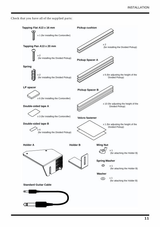
Check that you have all of the supplied parts:fig.05
Tapping Flat A13 x 16 mm
Tapping Pan A13 x 20 mm
Spring
LP spacer
Double-sided tape A
Double-sided tape B
x 1 (for installing the Contoroller)
x 2 (for installing the Divided Pickup)
x 2 (for installing the Divided Pickup)
x 6 (for installing the Contoroller)
x 3 (for installing the Contoroller)
x 4 (for installing the Divided Pickup)
Pickup cushion
Pickup Spacer A
Pickup Spacer B
Velcro fastener
x 2 (for installing the Divided Pickup)
x 5 (for adjusting the height of the Divided Pickup)
x 10 (for adjusting the height of the Divided Pickup)
x 1 (for adjusting the height of the Divided Pickup)
Holder A Holder B Wing Nut
Spring Washer
Washer
x 1 (for attaching the Holder B)
x 1 (for attaching the Holder B)
x 1 (for attaching the Holder B)
Standard Guitar Cable
11

INSTALLATION
1. Attaching the Pickup Controller Unit■ Attaching the Pickup Controller Unit with Holders
1. Remove two screws from the controller, then attach those screws to Holder “A.”
fig.10-1
2. Loose the guitar end pin. and insert the Holder “A.”
fig.10-2
3. Attach the Holder “B.”fig.10-3
4. Tighten the Holder “A”and “B” with Wing Nut, Spring Washer,Washer.
GK-2A
Holder A
Holder B WasherSpring Washer
Wing nut
12

INSTALLATION
■ Attaching the Pickup Controller Unit with Double–sided Tape/Screws
1. Place the Controller in an appropriate position on the guitar.
* Place the Controller where it does not interfere with your normal playing technique.
* Be sure that the positioning of the Controller Unit does not limit access to any of the guitar’s other controls or adjustments (a fine tuning control, for example).
* Position the Controller so you can comfortably operate the S1 and S2 switches.
* Be sure also that the positioning of the Controller Unit will not place undue strain on any of the connecting cables; Divided Pickup to Controller, guitar to Controller, or Controller to [GR].
* Make sure that the plugs of the GK-2A’s connection cables are well within the body of the guitar. This will help prevent damage to cables and connectors should the guitar bump against something.
2. Use the GK-2A as a template to mark the anchor point on the guitar. Then very carefully drill a hole into the guitar on the mark.
* The diameter of the hole should be about 2 mm (0.08 inches).
3. After attaching the double–sided tapes to the bottom of the Controller, secure the GK-2A with the supplied screw (flat-head, self-tapping).
* If your guitar is an arch-top (with a round body), the gap between the Controller and the guitar may make it difficult to secure the Controller. If this happens, attach the supplied LP spacers to the bottom of the Controller. The double–sided tapes and LP spacers should be attached to the three positions indicated as follows:
fig.06
fig.30e
* If you’d rather not drill a hole in your guitar, you can secure the Controller using double-sided tape or the Velcro fastener. However, by using such alternatives you risk having the device come loose during the worst possible moment (ie., a major solo!). Also, if the finish on your guitar is less than perfect, you may discover that the finish is also removed when you eventually remove the tape. The supplied tape is actually meant to be used only temporarily, while determining the best position to attach the Controller. The Velcro fastener is meant for those who intend to very frequently remove and reattach the GK-2A.
GK
-2A
MA
DE
INJA
PA
NS
YN
TH
VO
L
DO
WN
/S1
UP
/S2
MIX
GUITAR
SYNTH
Put the screw (flat-head) through this hole.
13

INSTALLATION
2. Attaching the Divided PickupThe Divided Pickup can be attached to your guitar using double–sided tape or screws. Attaching the Divided Pickup with screws requires a little more skill (and care), but it will allow you to easily adjust the height of the Divided Pickup later.
■ Attaching the Divided Pickup with double–sided tape
1. Place the Pickup as close to the bridge as possible, and center it with respect to the six strings.
(One set of ‘yokes’ (the actual sensors) should be directly under each string if possible.)
fig.07
* if your guitar has a tremolo arm (whammy bar), be sure the Pickup does not interfere with its operation.
* When using copper, brass or bronze wound strings, attach the Pickup about 15 mm (9/16”) from the bridge.
* Do not locate the Divided Pickup more than 20 mm (13/16”) from the bridge.
fig.08
* When viewed from the front, the strings do not necessarily need to be aligned perfectly with the center of the yokes. It’s all right as long as a string passes over some portion of its yoke.
fig.09
Carefully mark the position of the Pickup. (Depending on the finish of your guitar you may need to use felt-tipped pen or maybe even small pieces of masking tape, for example.)
* Be sure the Divided Pickup is correctly oriented: the cord from the Pickup should emerge from under the sixth string.
2. Be sure the neck (truss rod) and string height are set properly. Then tune each string.
maximum 20 mm
Front View Top View
14

INSTALLATION
3. Adjust the height of the Pickup by putting the supplied spacers under it (do not remove the backing from the tape yet!).
Use either of the pickup spacers (thick or thin) depending on the height of the Pickup.When using an arch-top guitar, put the Pickup cushion under the pickup spacers.
* When you attach the pickup to a guitar with curved surface, use two pickup cushions.
fig.10
* The pickup spacers and the pickup cushion are attached to the guitar with double–sided tape which will become thinner by 0.1 mm (0.004”) when the backing is removed. Therefore, when using several pickup spacers, you must set the height slightly higher to compensate.
The optimum position of the Pickup is where the distances between the Pickup and the strings is about 1.0 mm (0.04”) when the highest notes on the neck are fingered.
Check the height using the supplied clearance gauge. Adjust the height as necessary.
* If the height varies between the first and sixth strings, compensate by adding the appropriate half-width or one-third width spacers.
4. Remove the strings from your guitar.
5. Remove the backing from the tapes for the pickup cushion (if being used), the pickup spacers, and the Pickup, and carefully attach them to the bottom of the Pickup. Then carefully attach the Pickup to the guitar
6. Put the strings back on the guitar and tune them. Then carefully check the height of the Pickup with the clearance gauge.
Play the guitar (especially in the upper range) to be sure the strings do not touch the Pickup.
7. If the Divided Pickup is too high or too low...
(1) Remove the strings from the guitar.
(2) Very carefully remove the Pickup from the guitar.
* Please handle the Pickup gently. Because of its size and shape, the Pickup is very fragile. Bending or twisting it may cause it to damage the coil elements.
Carefully insert something thin and flat (like a table knife) under the Pickup from the sixth string side. Gently pry upwards.
fig.11
Pickup Spacer
Pickup Cushion
15

INSTALLATION
(3) Carefully remove the double–sided tape from the bottom of the Pickup as shown:
fig.12
(4) Adjust the height of the Pickup.If you wish to add a spacer, first remove the used double–sided tape, then add the new spacer. Remove the backing from the new spacer.If you need to remove a spacer, be sure to remove the spacers itself and the double–sided tape.
(5) Attach the double–sided tape to the bottom of the Pickup.
(6) Attach the Pickup to the upper side of the spacer that is applied to the guitar side.
(7) Put the strings back on the guitar and tune them properly. Again check the height of the Divided Pickup.
* Afterwards, you will need to adjust the Pickup sensitivity on the [GR]. If the signal level from the Divided Pickup is too high, lower the Pickup slightly.
HOW TO USE THE CLEARANCE GAUGEThe optimum distance between the Pickup and each string is about 1.0 mm when the highest notes on the neck are fingered. The supplied clearance gauge is 1.0 mm (0.04”) thick. As shown below, insert the clearance gauge between the Pickup and the strings. Adjust the Pickup height as necessary.fig.13
16

INSTALLATION
■ Attaching the Divided Pickup with ScrewsYou can also use screws to secure the Divided Pickup. Marking the position of the Pickup and checking the height is exactly the same as in “a. Attaching the Divided Pickup with double–sided tape”. Refer to that section before proceeding.
* When attaching the Divided Pickup with screws, you need a 13 mm space between the body of the guitar and the strings.
1. Place the Divided Pickup in the appropriate position. Carefully mark the location of the screw holes (at either end of the Pickup) on the guitar.
2. Remove the strings from the guitar.
3. Very carefully drill holes at the marked locations.
* The holes should be about 2 mm (0.08”) in diameter and approximately 2 to 3 mm deep.
* If the guitar is made of a hard wood (maple, rock maple, cherry, rosewood, etc.), make the holes slightly larger than 2 mm.
4. Place the supplied springs on the screws between the bottom of the Pickup and the guitar. Then tighten the screws:
fig.14
5. Put the strings back on the guitar and tune them properly.
6. Adjust the height of the Pickup.
Adjust the height of the Pickup by loosening or tightening the screws. Use the clearance gauge to set the proper Pickup height.
* Afterwards, you will need to adjust the Pickup sensitivity on the [GR]. If the signal level from the Divided Pickup is too high, lower the Pickup slightly.
17
OPERATION
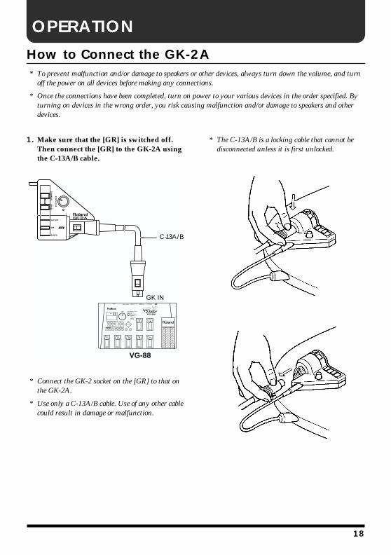
How to Connect the GK-2A* To prevent malfunction and/or damage to speakers or other devices, always turn down the volume, and turnoff the power on all devices before making any connections.
* Once the connections have been completed, turn on power to your various devices in the order specified. By turning on devices in the wrong order, you risk causing malfunction and/or damage to speakers and other devices.
1. Make sure that the [GR] is switched off. Then connect the [GR] to the GK-2A using the C-13A/B cable.
fig. 15
* Connect the GK-2 socket on the [GR] to that on the GK-2A.
* Use only a C-13A/B cable. Use of any other cable could result in damage or malfunction.
* The C-13A/B is a locking cable that cannot be disconnected unless it is first unlocked.
fig.02-1
fig.02-2
SY
NT
HV
OL
DO
WN
/S1
UP
/S2
MIX
GUITAR
SYNTH C-13A/B
VG-88
GK IN
18

OPERATION
* Before playing, be sure to wrap the cable around the guitar strap near the strap hook. This will eliminate any unnecessary strain on the cable or the GK-2A.
fig.03
2. Connect the large plug of the supplied (short) guitar cord to the output jack on the guitar, and the smaller plug to the Normal Guitar Input Jack on the Controller.
fig.17
* This connection is necessary not only for mixing the guitar’s straight sound with the synthesizer sound, but also for connecting the guitar’s ground and the GK-2A’s ground. Always make this connection whether you need the guitar’s straight sound or not.
3. Turn on the [GR].
The Power indicator on the Controller will light and you’re ready to go.
* The Power Indicator will not light unless...
(1) the GK-2A is connected to the [GR] using the C-13A/B and
(2) the [GR] is switched on.
SY
NT
HV
OL
DO
WN
/S1
UP
/S2
MIX
GUITAR
SYNTH
Cord the Normal Guitar
SY
NT
HV
OL
DO
WN
/S1
UP
/S2
MIX
GUITAR
SYNTH
19
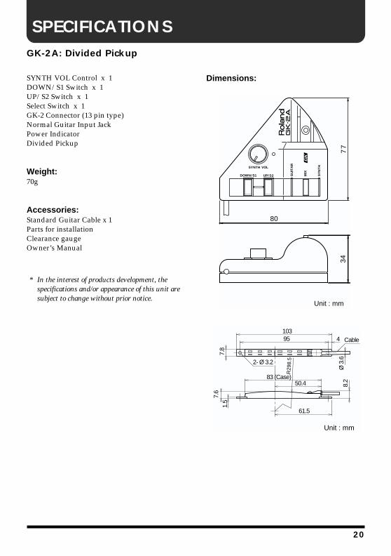
SPECIFICATIONS
GK-2A: Divided PickupSYNTH VOL Control x 1DOWN/S1 Switch x 1UP/S2 Switch x 1Select Switch x 1GK-2 Connector (13 pin type)Normal Guitar Input JackPower IndicatorDivided Pickup
Weight: 70g
Accessories:Standard Guitar Cable x 1Parts for installationClearance gaugeOwner’s Manual
* In the interest of products development, the specifications and/or appearance of this unit are subject to change without prior notice.
Dimensions: fig.18
fig.19
SYNTH VOL
DOWN/ S1 UP/ S2 MIX
GU
ITA
R
SY
NT
H
77
80
34
Unit : mm
103
7.8
R29
8.5
7.6
83 (Case)
95 4
61.5
Ø 3
.6Cable
8.2
1.5
50.4
Unit : mm
2- Ø 3.2
20

InformationWhen you need repair service, call your nearest Roland Service Center or authorized Roland distributor in your country as shown below.
As of May 15, 2001 (Roland)
ARGENTINAInstrumentos Musicales S.A.Florida 656 2nd Floor Office Number 206ABuenos AiresARGENTINA, CP1005TEL: (54-11) 4- 393-6057 BRAZILRoland Brasil LtdaRua San Jose, 780 Sala BParque Industrial San JoseCotia - Sao Paulo - SP, BRAZILTEL: (011) 4615 5666
CANADA Roland Canada Music Ltd.(Head Office)5480 Parkwood Way Richmond B. C., V6V 2M4 CANADA TEL: (0604) 270 6626
Roland Canada Music Ltd.(Toronto Office)Unit 2, 109 Woodbine Downs Blvd, Etobicoke, ONM9W 6Y1 CANADA TEL: (0416) 213 9707
MEXICOCasa Veerkamp, s.a. de c.v.Av. Toluca No. 323, Col. Olivar de los Padres 01780 Mexico D.F. MEXICOTEL: (525) 668 04 80
PANAMASUPRO MUNDIAL, S.A.Boulevard Andrews, Albrook,Panama City,REP. DE PANAMATEL: (507) 315-0101
U. S. A. Roland Corporation U.S.5100 S. Eastern AvenueLos Angeles, CA 90040-2938,U. S. A.TEL: (323) 890 3700
VENEZUELAMusicland Digital C.A.Av. Francisco de Miranda,Centro Parque de Cristal, Nivel C2 Local 20 CaracasVENEZUELATEL: (02) 285 9218
AUSTRALIA Roland Corporation Australia Pty., Ltd. 38 Campbell Avenue Dee Why West. NSW 2099 AUSTRALIA TEL: (02) 9982 8266 NEW ZEALAND Roland Corporation Ltd.32 Shaddock Street, Mount Eden, Auckland, NEW ZEALAND TEL: (09) 3098 715
HONG KONGTom Lee Music Co., Ltd. Service Division22-32 Pun Shan Street, Tsuen Wan, New Territories, HONG KONGTEL: 2415 0911
CHINABeijing Xinghai Musical Instruments Co., Ltd.6 Huangmuchang Chao Yang District, Beijing, CHINATEL: (010) 6774 7491
Shanghai Xingtong Acoustics Equipment CO.,Ltd.Rm.1108, No.2240 Pudong South Road Shanghai, CHINATEL: (021) 6873 4123
INDIARivera Digitec (India) Pvt. Ltd.409, Nirman Kendra Mahalaxmi Flats Compound Off. Dr. Edwin Moses Road, Mumbai-400011, INDIATEL: (022) 498 3079 INDONESIAPT Citra IntiRamaJ1. Cideng Timur No. 15J-150 Jakarta PusatINDONESIATEL: (021) 6324170
MALAYSIABENTLEY MUSIC SDN BHD140 & 142, Jalan Bukit Bintang 55100 Kuala Lumpur,MALAYSIATEL: (03) 2144-3333
PHILIPPINESG.A. Yupangco & Co. Inc.339 Gil J. Puyat AvenueMakati, Metro Manila 1200,PHILIPPINESTEL: (02) 899 9801
SINGAPORESwee Lee Company150 Sims Drive,SINGAPORE 387381TEL: 846-3676
TAIWANROLAND TAIWAN ENTERPRISE CO., LTD.Room 5, 9fl. No. 112 Chung Shan N.Road Sec.2, Taipei, TAIWAN, R.O.C.TEL: (02) 2561 3339 THAILANDTheera Music Co. , Ltd.330 Verng NakornKasem, Soi 2, Bangkok 10100, THAILANDTEL: (02) 2248821
BAHRAINMoon StoresBab Al Bahrain Road, P.O. Box 20077State of BAHRAINTEL: 211 005
VIETNAMSaigon Music138 Tran Quang Khai St., District 1Ho Chi Minh CityVIETNAMTEL: (08) 844-4068
JORDANAMMAN Trading Agency Prince Mohammed St. P.O. Box 825 Amman 11118 JORDANTEL: (06) 4641200 KUWAITEasa Husain Al-YousifiAbdullah Salem Street,Safat KUWAITTEL: 5719499 LEBANONA. Chahine & FilsP.O. Box 16-5857 Gergi Zeidan St. Chahine Building, AchrafiehBeirut, LEBANONTEL: (01) 335799 QATARAl Emadi Co. (Badie Studio & Stores)P.O. Box 62, DOHA QATARTEL: 4423-554 SAUDI ARABIAaDawliah Universal Electronics APLCorniche Road, Aldossary Bldg., 1st FloorSAUDI ARABIA
P.O.Box 2154, Alkhobar 31952SAUDI ARABIA TEL: (03) 898 2081 SYRIATechnical Light & Sound CenterKhaled Ibn Al Walid St.P.O. Box 13520Damascus - SYRIATEL: (011) 2235 384 TURKEY Barkat muzik aletleri ithalat ve ihracat Ltd StiSiraselviler cad.Guney is hani 84-86/6, Taksim. Istanbul. TURKEYTEL: (0212) 2499324 U.A.E.Zak Electronics & Musical Instruments Co. L.L.C.Zabeel Road, Al Sherooq Bldg., No. 14, Grand Floor DUBAI U.A.E.TEL: (04) 3360715
EGYPTAl Fanny Trading OfficeP.O. Box 2904, El Horrieh Heliopolos, Cairo, EGYPTTEL: (02) 4185531 REUNIONMaison FO - YAM Marcel25 Rue Jules Hermann,Chaudron - BP79 97 491Ste Clotilde Cedex,REUNION ISLANDTEL: 28 29 16 SOUTH AFRICAThat Other Music Shop (PTY) Ltd.11 Melle St., Braamfontein, JohannesbourgRepublic of SOUTH AFRICA
P.O.Box 32918, Braamfontein 2017 Republic of SOUTH AFRICATEL: (011) 403 4105
Paul Bothner (PTY) Ltd.17 Werdmuller Centre Claremont 7700 Republic of SOUTH AFRICA
P.O. Box 23032Claremont, Cape TownSOUTH AFRICA, 7735TEL: (021) 674 4030
CYPRUSRadex Sound Equipment Ltd.17 Diagorou St., P.O. Box 2046, Nicosia CYPRUSTEL: (02) 453 426
DENMARK Roland Scandinavia A/SNordhavnsvej 7, Postbox 880,DK-2100 CopenhagenDENMARK TEL: (039)16 6200 FRANCERoland France SA4, Rue Paul Henri SPAAK, Parc de l'Esplanade, F 77 462 St. Thibault, Lagny Cedex FRANCETEL: 01 600 73 500 FINLANDRoland Scandinavia As, Filial FinlandLauttasaarentie 54 BFin-00201 Helsinki, FINLANDTEL: (9) 682 4020 GERMANY Roland Elektronische Musikinstrumente HmbH.Oststrasse 96, 22844 Norderstedt, GERMANY TEL: (040) 52 60090
GREECESTOLLAS S.A.Music Sound Light155, New National Road26422 Patras, GREECETEL: 061-435400 HUNGARYIntermusica Ltd.Warehouse Area ‘DEPO’ Pf.83H-2046 Torokbalint, HUNGARYTEL: (23) 511011 IRELANDRoland IrelandAudio House, Belmont Court,Donnybrook, Dublin 4.Republic of IRELANDTEL: (01) 2603501
ITALYRoland Italy S. p. A. Viale delle Industrie 8, 20020 Arese, Milano, ITALYTEL: (02) 937-78300 NORWAYRoland Scandinavia Avd. Kontor NorgeLilleakerveien 2 Postboks 95 Lilleaker N-0216 Oslo NORWAYTEL: 273 0074 POLANDP. P. H. BrzostowiczUL. Gibraltarska 4.PL-03664 Warszawa POLANDTEL: (022) 679 44 19 PORTUGALTecnologias Musica e Audio, Roland Portugal, S.A.Cais Das Pedras, 8/9-1 Dto4050-465 PORTOPORTUGALTEL: (022) 608 00 60
RUSSIAMuTek3-Bogatyrskaya Str. 1.k.l107 564 Moscow, RUSSIA TEL: 095 169 5043
SPAINRoland Electronics de España, S. A. Calle Bolivia 239, 08020 Barcelona, SPAINTEL: (93) 308 1000
SWITZERLANDRoland (Switzerland) AGMusitronic AG Gerberstrasse 5, Postfach,CH-4410 Liestal, SWITZERLANDTEL: (061) 921 1615
SWEDEN Roland Scandinavia A/S SWEDISH SALES OFFICEDanvik Center 28, 2 tr. S-131 30 Nacka SWEDEN TEL: (08) 702 0020
UKRAINETIC-TACMira Str. 19/108P.O. Box 180 295400 Munkachevo, UKRAINETEL: (03131) 414-40 UNITED KINGDOM Roland (U.K.) Ltd.Atlantic Close, Swansea Enterprise Park, SWANSEASA7 9FJ, UNITED KINGDOMTEL: (01792) 700139
KOREACosmos Corporation1461-9, Seocho-Dong,Seocho Ku, Seoul, KOREATEL: (02) 3486-8855
AUSTRIARoland Austria GES.M.B.H.Siemensstrasse 4, P.O. Box 74,A-6063 RUM, AUSTRIATEL: (0512) 26 44 260 BELGIUM/HOLLAND/LUXEMBOURGRoland Benelux N. V.Houtstraat 3, B-2260, Oevel (Westerlo) BELGIUMTEL: (014) 575811
AFRICA
CHILEComercial Fancy ΙΙ S.A.Avenida Rancagua #0330Providencia Santiago, CHILETEL: 56-2-373-9100
URUGUAYTodo Musica S.A.Cuareim 1844, Montevideo,URUGUAY, CP11200TEL: 5982-924-2335
EUROPEAUSTRALIA/NEW ZEALAND
ASIA
CENTRAL/LATINAMERICA
NORTH AMERICA
MIDDLE EAST
AFRICA
EL SALVADOROMNI MUSIC75 Avenida Notre YY Alameda, Juan Pablo 2, No. 4010 San Salvador, EL SALVADORTEL: (503) 262-0788
ROMANIAFBS LINESPiata Libertatii 1,RO-4200 GheorghehiTEL: (066) 164-609
PARAGUAYDistribuidora De Instrumentos MusicalesJ.E. Olear y ESQ. Manduvira Edeficio, El Dorado Planta Baja Asuncion PARAGUAYTEL: 595-21-492147 PERUVIDEO Broadcast S.A.Portinari 199 (ESQ. HALS), San Borja, Lima 41,REP. OF PERUTEL: 51-14-758226
COSTA RICAJUAN Bansbach Instrumentos MusicalesAve.1. Calle 11, Apartado 10237,San Jose, COSTA RICATEL: (506)258-0211
CRISTOFORI MUSIC PTE LTDBlk 3014, Bedok Industrial Park E, #02-2148, SINGAPORE 489980TEL: 243 9555
IRANMOCO, INC.No.41 Nike St.Dr.Shariyati Ave.Roberoye Cerahe MirdamadTehran, IRANTEL: 285 4169
ISRAELHalilit P. Greenspoon & Sons Ltd.8 Retzif Ha'aliya Hashnya St.Tel-Aviv-Yafo ISRAELTEL: (03) 6823666