OWNER'S MANUAL - Unitron
36
Part No. 90-0127-00 Libertymarinecombi.p65 03/02/99 1 OWNER’S MANUAL FREEDOM Marine Series COMBI TM INVERTER/CHARGER ® INFORMATION IN THIS MANUAL IS SUBJECT TO CHANGE WITHOUT NOTICE MODEL 10 Part No. 81-1011-12 MODEL 15 Part No. 81-1511-12 MODEL 20 Part No. 81-2011-12 MODEL 25 Part No. 81-2511-12 MODEL 30 Part No. 81-3011-12
-
Upload
khangminh22 -
Category
Documents
-
view
2 -
download
0
Transcript of OWNER'S MANUAL - Unitron

Part No. 90-0127-00Libertymarinecombi.p65 03/02/99
1
OWNER’S MANUAL
FREEDOM Marine Series COMBI TM
INVERTER/CHARGER
®
INFORMATION IN THIS MANUAL IS SUBJECT TO CHANGE WITHOUT NOTICE
MODEL 10 Part No. 81-1011-12MODEL 15 Part No. 81-1511-12MODEL 20 Part No. 81-2011-12MODEL 25 Part No. 81-2511-12MODEL 30 Part No. 81-3011-12

Part No. 90-0127-00Libertymarinecombi.p65 03/02/99
2
SAFETY SUMMARY
Safety information for installation andoperation is contained throughout thismanual where it applies and is not includedin this summary.
Definitions:
Warning statements identify conditions orpractices which could result in personal injury,loss of life, damage to equipment or otherproperty.
Fuse Replacement For continued protectionagainst the possibility of fire, replace the fuseonly with a fuse of the specified voltage,current and type ratings.
Power Source To avoid damage, operate theequipment only within the specified AC (line)and DC (battery) voltages.
Servicing To reduce the risk of electric shockdo not open this unit. There are no userserviceable parts inside. Refer all service toqualified personnel.
The statements, specifications and instructions in this publication are believed to be correct. No warranty is made,expressed or implied by the seller or manufacturer with respect to any results or lack thereof from the use ofinformation in this publication and no liability is assumed for any direct or consequential damages, personal loss orinjury. All statements made herein are strictly to be used or relied on at the user’s risk. © 1999 Heart InterfaceCorporation. All rights reserved. Freedom and Combi trademarks are the sole property of Heart Interface Corporation.
Thank you for purchasing a Heart Interface Freedom Marine Series CombiTM
Inverter/Charger. Heart Interface takes pride in manufacturing quality products specificallydesigned to meet your power requirements.
Freedom Marine Combi Inverter/Chargers provide silent, efficient and reliable ACpower for a variety of applications. They feature “hands-free” operation, automatic 3-stagebattery charging and automatic AC transfer switching. For your convenience, service isavailable world-wide by qualified service centers.
If you have any questions about your Freedom Combi, please contact HeartInterface toll free: (800) 446-6180.
For technical support and additional information about Heart Interface products, visitour web site at www.heartinterface.com or send us e-mail:
Part No. 90-0127-00Libertymarinecombi.p65 03/02/99
3
Introduction . . . . . . . . . . . . . . . . . . . . . . . . . 4
Things You Should Know . . . . . . . . . . . . . 6Circuit Breaker ProtectionThermostat Controlled CoolingInverter Idle CircuitLow and High Battery ShutdownPower SharingTemperature Sensitive Charging
Operation . . . . . . . . . . . . . . . . . . . . . . . . . 8
echo~charge . . . . . . . . . . . . . . . . . . . . . . . . . 10
Optional Remote Control Panels . . . . . . . . .11
Batteries . . . . . . . . . . . . . . . . . . . . . . . . . . 12Battery TypesBattery InterconnectionBattery Bank Ratings and Sizing
Battery Charging . . . . . . . . . . . . . . . . . . . . 16Freedom Battery Chargers
Battery Charger Voltage Table . . . . . . . . . 20
Installation Precautions . . . . . . . . . . . . . . 21
Installation . . . . . . . . . . . . . . . . . . . . . . . . . 22Key Installation PointsGroundingNeutral BondingAC WiringAC InputAC OutputGround Fault Circuit InterruptersRemote Control WiringTSC Temperature Senstive ChargingDC WiringBattery Cable FusingPower ON Checks
TABLE OF CONTENTSTroubleshooting . . . . . . . . . . . . . . . . . . . . .31 LED Fault Status Things to Check
Glossary . . . . . . . . . . . . . . . . . . . . . . . . . . . .33
Specifications . . . . . . . . . . . . . . . . . . . . . . . . . 35
Warranty . . . . . . . . . . . . . . . . . . . . . . . . . . . . . 36
Specially designed for use in marine environment

Part No. 90-0127-00Libertymarinecombi.p65 03/02/99
4
This owner’s manual describes theFreedom Marine Series Combi
TM Inverter/
Chargers from Heart Interface. These unitsperform four distinct functions:
1. DC to AC power inverting.2. Automatic transfer switching betweeninverter power and incoming AC power.3. Automatic 3-Stage Battery charging plusmanual battery equalizing.4. Multiple battery bank charging.
• The inverter provides regulated 120 volt ACpower at a crystal controlled frequency from adeep cycle battery bank and is rated at:
Freedom 10 1000 watts Freedom 15 1500 watts Freedom 20 2000 watts Freedom 25 2500 watts Freedom 30 3000 watts
The output is a modified sine wave and iscompatible with most appliances, tools andother 120 VAC equipment. (Note: Certain laserprinters, breadmakers, digital clocks andsmall battery chargers may not operate onmodfied sinewave.) The idle mode reducesbattery power consumption when AC loads areremoved from the inverter output. High effi-ciency insures the longest possible battery lifebetween charges. All models are designed todeliver surge current for starting loads largerthan the continuous rating of the inverter.
INTRODUCTION• The internal transfer switch allows theFreedom Inverter/Charger to be connected toan external AC source and transfer the sourcepower through the unit directly to the loads.When the external AC power source isdisconnected, the transfer switch allowsautomatic switching of the loads back to theinverter.
The Freedom Inverter/Charger operatesas a self-contained backup power system, justadd batteries.
• Freedom battery chargers with temperaturesensitive charging (TSC) are electronicallycontrolled. The primary charge output currentis rated at 12 volts:
Freedom 10 50 Amps DC Freedom 15 75 Amps DC Freedom 20 100 Amps DC Freedom 25 130 Amps DC Freedom 30 140 Amps DC
They are designed to rapidly and optimallycharge wet cell, gel cell, or Absorbed GlassMat (AGM)** deep-cycle batteries. Batterycharging is automatically accomplished in 3stages: Bulk Charge, Acceptance Charge andFloat Charge. In most cases, no attention ormaintenance is required.
When using a Freedom or LINK remotecontrol panel, a manually engaged EqualizeCharge cycle is possible.
**Battery type selection is set on the front of the unitor with an optional remote (Remote Control Panel orLink Instrument).
Freedom Marine 20

Part No. 90-0127-00Libertymarinecombi.p65 03/02/99
5
Multiple Battery Bank ChargingMultiple battery bank charging is provided
through additional output from the built-inecho~charge. The echo~charge is used tocharge start or auxiliary batteries. This digitalecho~charge is current limited to 15 amps andfollows the 3-stage charge curve of theinverter/charger and battery setting of thehouse battery bank. The number of activeecho~charge outputs depends of the model ofthe inverter/charger.
INTRODUCTION
Model
Freedom 10Freedom 15Freedom 20Freedom 25Freedom 30
Multi-bank outputs
11122
echo~charge 1
echo~charge 2
Freedom Marine Inverter/Charger
Part No. 90-0127-00Libertymarinecombi.p65 03/02/99
6
Circuit Breaker ProtectionThe Freedom Inverter/Charger is
supplemental circuit breaker protected. TheINVERT/CHARGE breaker on the front of theunit protects against sustained inverter/chargerover current conditions.
This supplemental circuit breaker protectsthe output of the unit when operating in “InvertMode” and protects the internal battery chargercircuits when operating in “Charge Mode.”When an overcurrent condition occurs, thecircuit breaker is reset by pushing the buttonback in after the fault is removed. This circuitbreaker is not suitable for branch circuit pro-tection. To comply with NEC, additional branchcircuit rated breakers may be requiredbetween the output of the unit and the load.
Freedom 25 and 30 have two outputs.Both outputs are protected by the supplemen-tal circuit breaker when operating in “InvertMode.” During transfer/charge operation, theoutputs are protected by the circuit breakersfeeding the two inputs to the unit.
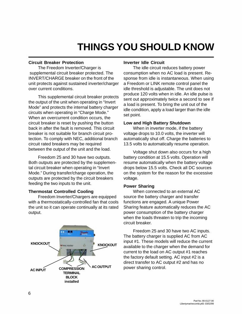
Thermostat Controlled CoolingFreedom Inverter/Chargers are equipped
with a thermostatically-controlled fan that coolsthe unit so it can operate continually at its ratedoutput.
THINGS YOU SHOULD KNOWInverter Idle Circuit
The idle circuit reduces battery powerconsumption when no AC load is present. Re-sponse from idle is instantaneous. When usinga Freedom or LINK remote control panel theidle threshold is adjustable. The unit does notproduce 120 volts when in idle. An idle pulse issent out approximately twice a second to see ifa load is present. To bring the unit out of theidle condition, apply a load larger than the idleset point.
Low and High Battery ShutdownWhen in inverter mode, if the battery
voltage drops to 10.0 volts, the inverter willautomatically shut off. Charge the batteries to13.5 volts to automatically resume operation.
Voltage shut down also occurs for a highbattery condition at 15.5 volts. Operation willresume automatically when the battery voltagedrops below 15.5 volts. Check all DC sourceson the system for the reason for the excessivevoltage.
Power SharingWhen connected to an external AC
source the battery charger and transferfunctions are engaged. A unique PowerSharing feature automatically reduces the ACpower consumption of the battery chargerwhen the loads threaten to trip the incomingcircuit breaker.
Freedom 25 and 30 have two AC inputs.The battery charger is supplied AC from ACinput #1. These models will reduce the currentavailable to the charger when the demand forcurrent to the load on AC output #1 reachesthe factory default setting. AC input #2 is adirect transfer to AC output #2 and has nopower sharing control.
AC INPUT COMPRESSIONTERMINAL
BLOCKinstalled
KNOCKOUT
AC OUTPUT
KNOCKOUT

Part No. 90-0127-00Libertymarinecombi.p65 03/02/99
7
The Power Sharing set point of each unithas a factory default setting. This can bechanged when using the Freedom or LINKremote control panel. Refer to the FreedomRemote Control Panel or LINK manual forinformation on Power Sharing setting andadjustment.
Temperature Sensitive Charging (TSC) When the supplied battery temperaturesensor is connected to the unit and thebatteries, the charge voltage is controlledbased on battery temperature. The chargeradjusts the charge voltage to the best levelinsuring safe charging for selected batterytype. Charge voltage regulation optimizes thebattery life cycle.
THINGS YOU SHOULD KNOWElectronic Protection
Fast-acting electronic circuits protectthe inverter from overloads and short circuits.Other protection includes a low and highbattery voltage cutoff and automatic shutdownif an over temperature condition occurs. Whenthe fault condition is corrected, the unit willautomatically reset. Example: removeoverload, charge batteries or allow to cool.
Battery
TSC Sensor
Freedom Marine Inverter/Charger
+
-
Part No. 90-0127-00Libertymarinecombi.p65 03/02/99
8
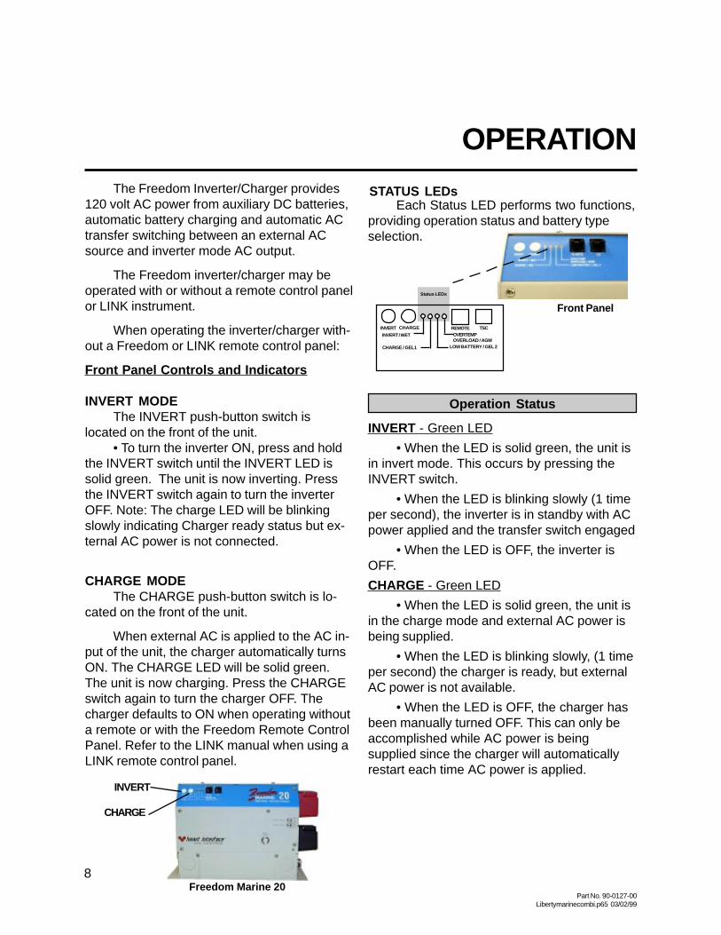
Operation Status
INVERT - Green LED
• When the LED is solid green, the unit isin invert mode. This occurs by pressing theINVERT switch.
• When the LED is blinking slowly (1 timeper second), the inverter is in standby with ACpower applied and the transfer switch engaged
• When the LED is OFF, the inverter isOFF.
CHARGE - Green LED
• When the LED is solid green, the unit isin the charge mode and external AC power isbeing supplied.
• When the LED is blinking slowly, (1 timeper second) the charger is ready, but externalAC power is not available.
• When the LED is OFF, the charger hasbeen manually turned OFF. This can only beaccomplished while AC power is beingsupplied since the charger will automaticallyrestart each time AC power is applied.
OPERATIONThe Freedom Inverter/Charger provides
120 volt AC power from auxiliary DC batteries,automatic battery charging and automatic ACtransfer switching between an external ACsource and inverter mode AC output.
The Freedom inverter/charger may beoperated with or without a remote control panelor LINK instrument.
When operating the inverter/charger with-out a Freedom or LINK remote control panel:
Front Panel Controls and Indicators
INVERT MODEThe INVERT push-button switch is
located on the front of the unit.• To turn the inverter ON, press and hold
the INVERT switch until the INVERT LED issolid green. The unit is now inverting. Pressthe INVERT switch again to turn the inverterOFF. Note: The charge LED will be blinkingslowly indicating Charger ready status but ex-ternal AC power is not connected.
CHARGE MODEThe CHARGE push-button switch is lo-
cated on the front of the unit.
When external AC is applied to the AC in-put of the unit, the charger automatically turnsON. The CHARGE LED will be solid green.The unit is now charging. Press the CHARGEswitch again to turn the charger OFF. Thecharger defaults to ON when operating withouta remote or with the Freedom Remote ControlPanel. Refer to the LINK manual when using aLINK remote control panel.
INVERT CHARGE REMOTE TSC
INVERT / WET
CHARGE / GEL1 LOW BATTERY / GEL 2
OVERTEMPOVERLOAD / AGM
Status LEDs
Front Panel
INVERT
CHARGE
Freedom Marine 20
Each Status LED performs two functions,providing operation status and battery typeselection.
STATUS LEDs

Part No. 90-0127-00Libertymarinecombi.p65 03/02/99
9
OPERATIONNOTE: When AC power is available, the
default setting for the charger is ON. If the unitwas manually turned OFF and AC power isinterrupted and becomes available again, thecharger will return to ON.
LOW BATTERY - Red LED
• When the LED is OFF the batteryvoltage is normal, between 10.5 and 15.0volts DC.
• When the LED is solid red, it indicates abattery warning condition, the battery voltage isbelow 10.5 volts DC or above 15.0 volts DC.
• When the LED is blinking slowly, (1 timeper second), a battery shutdown has occurred.The voltage is either below 10.0 volts DC orabove 15.5 volts DC.
• When the LED is blinking rapidly (5times per second), a potential problem in theDC system has been detected. Check yourbatteries, battery cables and DC loads.
OVERTEMP/OVERLOAD - Red LED
• When the LED is Off operation isnormal.
• When the LED is red, there is an overtemp or overload condition. Check forexcessive loads or short circuit on the outputof the inverter. Correct the condition and restartby pushing the INVERT switch.
• When the LED is blinking slowly (1 timeper second), an over current condition or ashort circuit has occurred. The system hasshut OFF and will not automatically restart.Correct the fault condition and manually restartthe system by pushing the INVERT switch.
LOW BATTERY & OVERTEMP/OVERLOAD- Red LEDs
When both LEDs are blinking, an ACbackfeed was detected. A backfeed
occurs when AC power from an externalsource is connected to the output of theinverter. Inspect wiring for possible input/outputwiring error. This condition must be correctedbefore further operation. A back feed will dam-age the unit and void the warranty.
• Battery type setup. To enter the batterytype select mode, press and hold the INVERTswitch for five seconds. The status LEDs willchange from indicating status information toOFF. Press the CHARGE switch once. One ofthe four LEDs will blink rapidly indicating theexisting battery type selection.
Battery Type Selection
Press the CHARGE switch again tochange the battery type. Continue to press un-til the desired battery type is selected. If theCHARGE switch is not pressed for 5 seconds,the unit will return to normal operation and thebattery type selection will have been made.Refer to page 20 for additional information onbattery type settings.
WET GEL 1 GEL 2 AGM
When the 12 volt input to the unit isdisconnected, the battery type setting is storedin non-volatile memory. When the unit isreconnected, the battery type selectionconveniently returns to the previous setting.
If installed with the Freedom or LINKremote control panel, the unit will be set upand controlled from the remote. Refer to theremote manual for more information.
INVERT CHARGE REMOTE TSC
INVERT / WET
CHARGE / GEL1 LOW BATTERY / GEL 2
OVERTEMPOVERLOAD / AGM
Status LEDs
Front Panel

Part No. 90-0127-00Libertymarinecombi.p65 03/02/99
10
OPERATION
Remote TSC
Overtemp
LowBattery
Freedom Marine 20
When a Freedom or LINK remote control panelis connected to the unit, the switch on the unitor on the remote may be used to turn the unitON/OFF. If the unit is turned ON using the frontpanel switch and then turned OFF using aRemote or LINK, the unit will not be completelyOFF. If the unit will not be used for an ex-tended period of time, turn the unit completelyOFF. The unit is completely OFF when theLED display on the unit is OFF.
TSC (Temperature Sensitive Charging)
This provides for the connection of asensor to measure battery temperature forcompensated charging. If no sensor isconnected the charge voltage levels are set todefaults based on battery type.
echo~chargeThe echo~charge feature is incorporated
in the Freedom Marine Inverter/Charger toenable multiple battery bank charging of thestart or auxiliary battery. Freedom 10, 15, 20have one active echo~charge output.Freedom 25, 30 have two active outputs.
The echo~charge automatically switchesOn/Off, charging an auxiliary or start batterywithout affecting the main house battery bank.The maximum charge current is 15 amps at14.4 volts.
The echo~charge is a voltage follower,following the 3-stage charge modes of theFreedom Marine Charger. The echo~chargesenses if the start battery needs charging anddiverts a portion of the charging current (up to15 amps) to the start battery. This method pro-tects the auxiliary battery from overcharging
echo~charge
NOTE: The charger will always follow thehouse battery setting, even if you mix the type ofbatteries in your house and start battery bank. Ifthe house battery bank is either GEL or AGM andthe start or auxiliary battery is wet/flooded, thecharger will follow the GEL or AGM voltage setting.
The echo~charge will turn ON anytime thehouse battery is above 13 volts, regardless of thecharging source.
OPTIONAL REMOTES
If using one of the remotes, refer to theinstallation instructions included with theremote.
and insures a long life of the battery.

Part No. 90-0127-00Libertymarinecombi.p65 03/02/99
11
LINK 2000The Link 2000 has the same features as
the Link 1000, providing inverter/chargercontrol and complete battery state-of-chargeinformation. It monitors two battery banks.
OPTIONAL REMOTE CONTROL PANELS
Remote Control PanelAn optional remote control panel is
available. The LED bar graphs on the remotecontrol panel show battery voltage and DCcurrent in both inverter and charger modes.
Easy to see red, yellow and green LEDsshow the battery state-of-charge. PowerSharing, charger ON/OFF, and inverter ON/OFF controls are provided. SET UP featuresinclude selection of Idle Threshold, BatteryType and Battery Capacity.
Advanced Remote Control PanelsLink Instruments
Advanced remote control panels are alsoavailable: the Link 1000, 2000 and 2000R.
LINK 1000Link 1000 controls the Freedom Inverter/
Charger and provides complete batterystate-of-charge information including DCvoltage, current, Amp-hours consumed, TimeRemaining and historical data for a singlebattery bank.
LINK 1000
LINK 2000
LINK 2000RThe Link 2000R adds the ability to
regulate an engine-driven alternator. Theprecision regulator in the LINK 2000R allowsthe alternator to be controlled as a 3-stagebattery charging system.
If a Link Instrument is used to control theinverter/charger, refer to the Link Owner’sManual for installation, setup and controlinformation.
Remote Control Panel

Part No. 90-0127-00Libertymarinecombi.p65 03/02/99
12
BATTERIES
BATTERY TYPESUse only deep-cycle batteries with your
Freedom Inverter/Charger. These fall into threebroad categories: wet cell, gel cell andAdvanced AGM (Absorbed Glass Mat)batteries.
Wet Cell BatteriesTrue deep-cycle wet cell batteries are
characterized by relatively thick internal platesthat are alloyed with antimony.
Common 12 volt marine/RV deep-cyclebatteries are acceptable. Golf cartbatteries perform well and may have alonger life. These 6 volt batteries must beused in series connected pairs. High qualitydeep-cycle batteries offer goodperformance and are available in a widevariety of sizes.
Wet cell batteries will give off gas as anatural result of charging and will experiencesome water loss. It is very important that theelectrolyte level be checked frequently andtopped off with distilled water when necessary.Follow the battery manufacturer’srecommendations for maintenance.
Never allow the top of the battery plates tobe exposed to air, as contamination of the cellwill result. Keep the top of batteries clean.Always provide adequate ventilation for thebattery storage compartment.
Do not use ordinary car batteries orengine starting batteries with your inverter/charger. Beware of any battery that is ratedonly in Cold Cranking Amps (CCA). This is arating which applies only to engine startingbatteries. In general, most wet cell batteriesthat are described as hybrid type batteries,suitable for either engine starting or deep-cycleapplications, are a compromise and will havelimited life if deeply discharged.

Part No. 90-0127-00Libertymarinecombi.p65 03/02/99
13
Beware of so-called maintenance-freewet cell batteries. These batteries havecalcium alloyed with the lead liquid. They aresealed and water can not be added. Do notconfuse them with true gel cell or AGMbatteries, they will not hold up well to deepdischarging and repeated cycling.
Gel Cell BatteriesGel cell batteries are lead-acid batteries
similar in many ways to the common wet cellbattery, but differences in the chemistry andconstruction provide some unique features.
• No Maintenance
• Low Self-Discharge Rate
• Low Internal Resistance
Even though gel cells are sealedbatteries, the battery compartment should stillbe ventilated.
Advanced AGM (Absorbed Glass Mat)Batteries
This battery is lead acid but maintenance-free. They hold the liquid electrolyte in asponge-like material. The performance issimilar to gel cell batteries. The charge pa-rameters are similar to wet cell batteries.
Battery SelectionThe most important feature to consider inmaking your battery selection is to select truedeep cycle batteries rated in Amp-hours (AH)and sized to match your power requirements.
BATTERY INTERCONNECTIONIn most cases, you will be using a bank of
two or more batteries with your inverter/charger. You may connect batteries together intwo configurations, series and paralleldepending on their voltage.
BATTERIESSeries Configuration
Connecting two batteries in series willdouble the voltage of the battery bank. Forinstance, two 6 volt batteries connected inseries will produce 12 volts. The Amp-hourcapacity of the battery bank will be the sameas each individual battery. Example, two 6 volt220 Amp-hour batteries in series will produceone 12 volt 220 Amp-hour battery bank.
Series
+
+
+
Series Increase Voltage
EACH BATTERYCAPACITY:
220AMP-HOURS
@ 6 VDC
TOTAL BATTERYBANK CAPACITY:
220AMP-HOURS@ 12 VDC
6V 6V
+ +
_ _
+
_12V INVERTER

Part No. 90-0127-00Libertymarinecombi.p65 03/02/99
14
Connecting two batteries in parallel willdouble the Amp-hour rating of the battery bank,while the voltage will be the same as eachindividual battery. Example, two 12 volt 105Amp-hour batteries in parallel will produce one12 volt 210 Amp-hour battery bank.
BATTERIES
Parallel
Parallel Increase Amp-hour Capacity
EACH BATTERYCAPACITY:
105AMP-HOURS@ 12 VDC
TOTAL BATTERYBANK CAPACITY:
210AMP-HOURS@ 12 VDC
Only similar batteries should beconnected together in one bank. Do notconnect old and new batteries together or wetand gel cell batteries together. In the abovedrawing, the load is connected to the positiveterminal of the first battery and the negativeterminal of the last battery. This practice helpsto balance the battery bank and is calledcross-connecting the battery bank.
Note : It is not advisable to connectbatteries of different case sizes or Amp-hourratings in the same battery bank.
Always use properly sized wire andterminals for your interconnecting batterycables. For size information refer to NECrequirements or contact your localelectrician.
BATTERY BANK RATINGS AND SIZINGDeep-cycle batteries are usually rated in
Amp-hours. The Amp-hour rating is based ona 20-hour discharge rate, therefore, a 100Amp-hour battery can deliver 5 Amps for 20hours. If the discharge rate is greater than 5Amps, the available Amp-hours are de-creased. For example, if the load is increasedto 100 Amps, only about 45 Amp-hours will beavailable at this rate of discharge.
Deep-cycle batteries can be dischargedabout 80% of capacity before damage occurs.Shallow cycling will result in much longerbattery life. Calculating a battery bank sizebased on 50% discharge cycling is generallyconsidered to be a good compromise betweenlong battery life and size.
++
12V 12V+ +
_ _
+12V INVERTER
_
Parallel Configuration
Part No. 90-0127-00Libertymarinecombi.p65 03/02/99
15
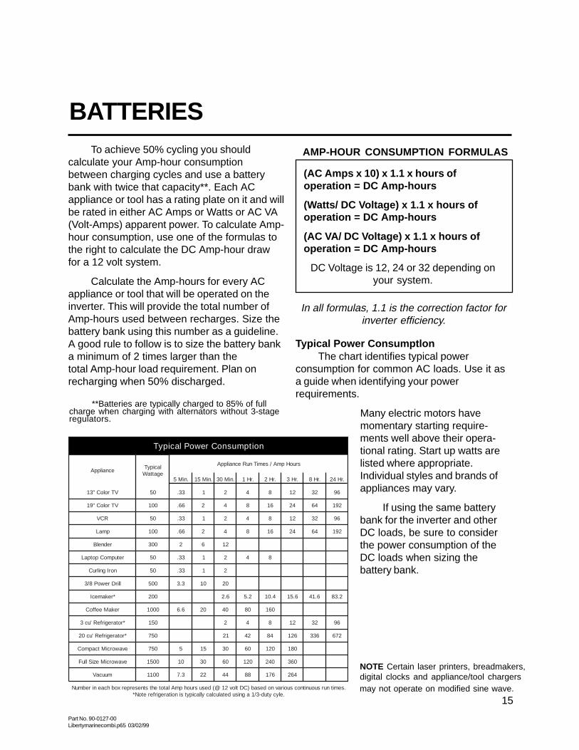
To achieve 50% cycling you shouldcalculate your Amp-hour consumptionbetween charging cycles and use a batterybank with twice that capacity**. Each ACappliance or tool has a rating plate on it and willbe rated in either AC Amps or Watts or AC VA(Volt-Amps) apparent power. To calculate Amp-hour consumption, use one of the formulas tothe right to calculate the DC Amp-hour drawfor a 12 volt system.
Calculate the Amp-hours for every ACappliance or tool that will be operated on theinverter. This will provide the total number ofAmp-hours used between recharges. Size thebattery bank using this number as a guideline.A good rule to follow is to size the battery banka minimum of 2 times larger than thetotal Amp-hour load requirement. Plan onrecharging when 50% discharged.
BATTERIES
(AC Amps x 10) x 1.1 x hours ofoperation = DC Amp-hours
(Watts/ DC Voltage) x 1.1 x hours ofoperation = DC Amp-hours
(AC VA/ DC Voltage) x 1.1 x hours ofoperation = DC Amp-hours
DC Voltage is 12, 24 or 32 depending onyour system.
**Batteries are typically charged to 85% of fullcharge when charging with alternators without 3-stageregulators.
Typical Power ConsumptlonThe chart identifies typical power
consumption for common AC loads. Use it asa guide when identifying your powerrequirements.
Many electric motors havemomentary starting require-ments well above their opera-tional rating. Start up watts arelisted where appropriate.Individual styles and brands ofappliances may vary.
If using the same batterybank for the inverter and otherDC loads, be sure to considerthe power consumption of theDC loads when sizing thebattery bank.
noitpmusnoCrewoPlacipyT
ecnailppAlacipyTegattaW
sruoHpmA/semiTnuRecnailppA
.niM5 .niM51 .niM03 .rH1 .rH2 .rH3 .rH8 .rH42
VTroloC"31 05 33. 1 2 4 8 21 23 69
VTroloC"91 001 66. 2 4 8 61 42 46 291
RCV 05 33. 1 2 4 8 21 23 69
pmaL 001 66. 2 4 8 61 42 46 291
rednelB 003 2 6 21
retupmoCpotpaL 05 33. 1 2 4 8
norIgnilruC 05 33. 1 2
llirDrewoP8/3 005 3.3 01 02
*rekamecI 002 6.2 2.5 4.01 6.51 6.14 2.38
rekaMeeffoC 0001 6.6 02 04 08 061
*rotaregirfeR'uc3 051 2 4 8 21 23 69
*rotaregirfeR'uc02 057 12 24 48 621 633 276
evaworciMtcapmoC 057 5 51 03 06 021 081
evaworciMeziSlluF 0051 01 03 06 021 042 063
muucaV 0011 3.7 22 44 88 671 462
.semitnursuounitnocsuoiravnodesab)CDtlov21@(desusruohpmAlatotehtstneserperxobhcaenirebmuN.elycytud-3/1agnisudetaluclacyllacipytsinoitaregirferetoN*
In all formulas, 1.1 is the correction factor forinverter efficiency.
AMP-HOUR CONSUMPTION FORMULAS
NOTE Certain laser printers, breadmakers,digital clocks and appliance/tool chargersmay not operate on modified sine wave.

Part No. 90-0127-00Libertymarinecombi.p65 03/02/99
16
Battery ChargingCompletely charging wet cell deep-cycle
batteries requires the battery voltage to beraised beyond what is known as the gassingpoint. This is the voltage at which the batterybegins to bubble and gas is given off. Ifcharging stops short of this point, sulfate is lefton the plates and deterioration of the batterybegins. The gassing point will vary with batterytemperature.
At 77 degrees F, the gassing point of a 12volt battery is about 14.0 volts.
AGM and Gel cell batteries must not becharged to their gassing point. In fact, highvoltage charging which gasses these batteriesis harmful to them. They typically require alower bulk charge voltage. Gel cell batteriesrequire a higher float voltage than wet cell bat-teries. Consult the battery manufacturer forspecifications.
BATTERY CHARGINGFreedom Battery Chargers
Freedom battery chargers are designedto overcome the limitations of conventionalchargers by utilizing 3 distinct charge stages,each designed for optimal charging of wet, gelcell and AGM deep-cycle batteries. Batterytype selection is made on the front panel of theinverter/charger or through the Remote ControlPanel or a Link Instrument. For moreinformation on battery type selection, see page9 or refer to the Remote Control Panel manual.

Part No. 90-0127-00Libertymarinecombi.p65 03/02/99
17
BATTERY CHARGING
Note : Freedom battery chargers are ONwhenever AC power is connected to thecharger input. The charger can be turned OFFusing the CHARGE switch on the front of theunit. This sequence will occur each timeexternal AC power is available. The chargercan be turned ON/OFF using the RemoteControl Panel or Link Instrumentation.
Each time the battery charger is engaged,the 3-stage charger proceeds automatically,resulting in an efficient complete charge andsafe battery maintenance. Use of the RemoteControl Panel or Link Instrument provides theability to periodically apply an equalizingcharge.
Refer to Remote Control Panel or theLink Instrument Owner’s Manual for moreinformation.
The battery charger stages are:Stage 1 - Bulk Charge During the bulk
charge stage most of the energy that has beenconsumed during discharge is returned to thebattery bank. This phase is engaged as soonas the battery charger is activated. Full ratedcharger current is delivered to the battery bankuntil the bulk charge voltage limit is reached.This results in a relatively rapid recharge.
Generally, a wet cell battery bank shouldnot be charged at a rate which exceeds 25% ofits capacity.

Part No. 90-0127-00Libertymarinecombi.p65 03/02/99
18
Gel cell and Advanced AGM batteries canaccept a higher rate of charge. Consult themanufacturer for specifications.
Stage 2 - Acceptance Charge Theacceptance stage immediately follows the bulkcharge stage. During this stage thebattery voltage is held constant at the bulkcharge voltage limit and the current graduallyramps down. During this stage the battery isaccepting its final amount of charge currentand the last of the sulfate on the plates isremoved.
The acceptance stage lasts until thecharge current reaches the transition point. Atimer will terminate the acceptance stage if thiscurrent level is not reached.
BATTERY CHARGING
Freedom 10Freedom 15Freedom 20Freedom 25Freedom 30
5 Ampere DC10 Ampere DC10 Ampere DC15 Ampere DC15 Ampere DC
ACCEPTANCE TO FLOAT TRANSITION POINTS*
Maximum acceptance time is 1 hour forwet and AGM cells and 3 hours for gel cells.Gel cell acceptance time can be longerbecause they are less likely to gas. Expect wetcell batteries to gas somewhat duringacceptance, this is a necessary part of thecharging process.
NOTE: The acceptance stage timer is notused when Link Instruments control thecharger. Refer to the Link Owner’s Manual.
Stage 3 - Float Charge When theacceptance stage is terminated, eitherbecause the charge current ramped down to
the battery voltage while it drifts down from theacceptance charge voltage limit. When itreaches the float voltage set point, the floatcharge stage is engaged.
The float charge stage holds the batteryvoltage constant at a preset voltage level,where it is safe for long term battery voltagemaintenance. During the float charge stage,the full output current of the battery charger isavailable to operate any DC appliances thatmay be on the system, while constantly main-taining the float charge voltage.
The battery charger remains in the floatcharge stage indefinitely until the charger isdisconnected from incoming AC power orturned OFF with the unit switch or with theRemote Control Panel or Link Instrumentation.
Stage 4 - Equalizing Charge This is theonly battery charger stage which is notengaged automatically. It must be manuallyinitiated each time. Applying an equalizingcharge is possible only with a Remote ControlPanel or Link Instrument.
Periodic equalizing is recommendedby most wet cell deep-cycle batterymanufacturers. There are no firm rules forhow often an equalizing charge should beapplied. Follow the battery manufacturer’srecommendations for equalizing.
*Factory Default Setting
the transition point or the timer engaged, thecharge current will shut off. The unit monitors

Part No. 90-0127-00Libertymarinecombi.p65 03/02/99
19
BATTERY CHARGINGThe equalizing charge is a timed, 8-hour
cycle. The cycle can be ended early by inter-rupting the AC power to the charger at anytime during the cycle. Equalizing should onlybe engaged after the batteries have been fullycharged by a normal battery charging cycle.
During this equalizing stage, the batteryvoltage will increase to the equalize voltage.This will cause the battery bank to gasprofusely and will accomplish the following:
1. Removal of residual sulfate. Each time abattery is cycled (discharged and charged), asmall amount of sulfate is left on the plates.Over time, this gradual build-up of sulfate willcompromise the performance of the battery.By applying an equalizing charge, the sulfate isreturned back to the electrolyte, raising thespecific gravity and fully exposing the activematerial of the plates.
2. Bring all cells to the same potential. Alllead-acid batteries are made up of individual 2volt cells. As the battery bank is cycled, slightdifferences in the cells result in different cellvoltages, affecting the overall chargeeffectiveness. Equalizing brings all cells to thesame voltage and the electrolyte in each cell tothe same specific gravity.
3. Mixing up of the electrolyte. Electrolyte inbattery cells tend to separate into layers of acidand water. The vigorous bubbling action of thebattery during equalizing serves to physicallymix the electrolyte. Refer to the RemoteControl Panel and Link Owner’s Manuals foradditional cautions on equalizing.
Note : Do not equalize gel cell batteries.
1. Do not equalize gel cell batteries.Check remote default settings.
2. Always monitor the equalize chargecycle. Provide proper ventilation forbattery fumes. Do not allow any sparksduring equalizing. If one or more cellsbegin to overflow, terminate the equalizecycle.
3. Check the battery electrolyte bothbefore and after the equalizing charge.Do not expose the battery plates to air.Leave the battery caps on whileequalizing. Top off after equalizing.
4. Remove all loads from the DCsystem before equalizing. Some DCloads may not tolerate the high chargevoltage.
5. With the Remote Control Panel thebattery state-of-charge LEDs sequenceduring equalizing. When the equalizationcycle is complete, the charge automati-cally goes to float and the green float LEDbattery status light is on. With LinkInstrumentation , the red charge LEDflashes during the equalizing cycle. Whenthe equalization cycle is complete, thecharger automatically goes to float and thegreen float LED is illuminated.
WARNINGS
Part No. 90-0127-00Libertymarinecombi.p65 03/02/99
20
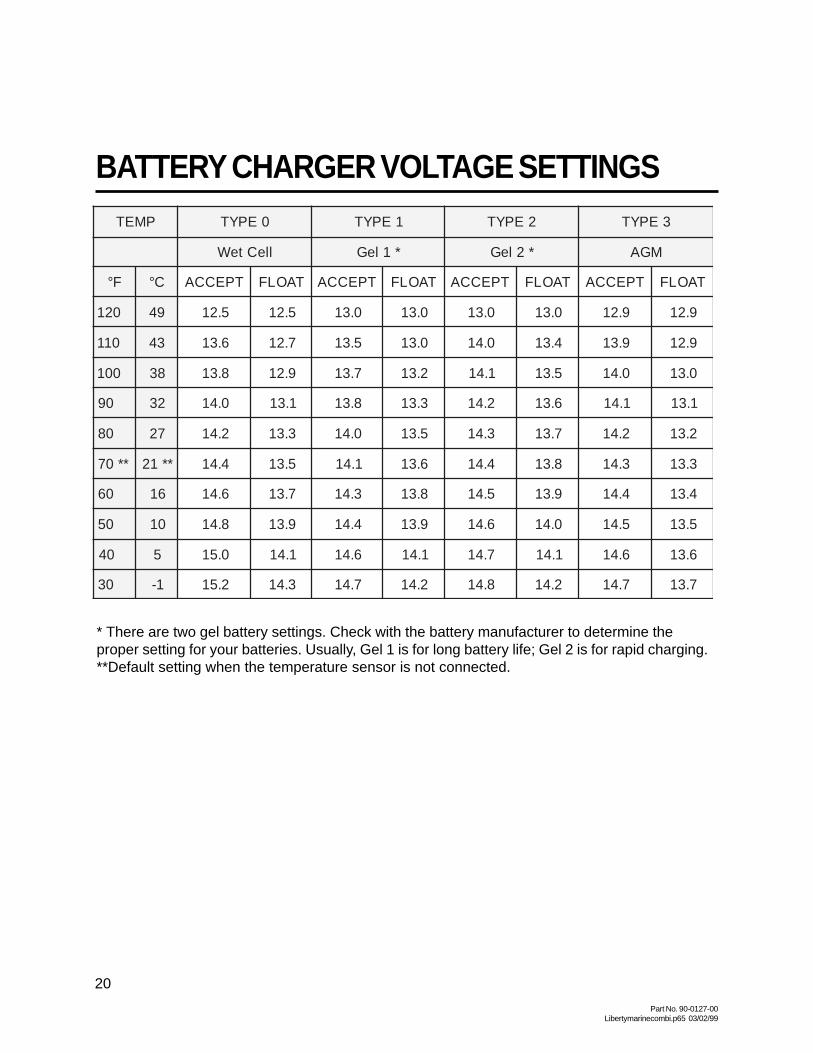
BATTERY CHARGER VOLTAGE SETTINGSPMET 0EPYT 1EPYT 2EPYT 3EPYT
lleCteW *1leG *2leG MGA
F° C° TPECCA TAOLF TPECCA TAOLF TPECCA TAOLF TPECCA TAOLF
021 94 5.21 5.21 0.31 0.31 0.31 0.31 9.21 9.21
011 34 6.31 7.21 5.31 0.31 0.41 4.31 9.31 9.21
001 83 8.31 9.21 7.31 2.31 1.41 5.31 0.41 0.31
09 23 0.41 1.31 8.31 3.31 2.41 6.31 1.41 1.31
08 72 2.41 3.31 0.41 5.31 3.41 7.31 2.41 2.31
**07 **12 4.41 5.31 1.41 6.31 4.41 8.31 3.41 3.31
06 61 6.41 7.31 3.41 8.31 5.41 9.31 4.41 4.31
05 01 8.41 9.31 4.41 9.31 6.41 0.41 5.41 5.31
04 5 0.51 1.41 6.41 1.41 7.41 1.41 6.41 6.31
03 1- 2.51 3.41 7.41 2.41 8.41 2.41 7.41 7.31
* There are two gel battery settings. Check with the battery manufacturer to determine theproper setting for your batteries. Usually, Gel 1 is for long battery life; Gel 2 is for rapid charging.**Default setting when the temperature sensor is not connected.

Part No. 90-0127-00Libertymarinecombi.p65 03/02/99
21
Before beginning the installation of yourFreedom Marine Inverter/Charger, read theowner’s manual. Disconnect all sources ofAC and DC power to prevent accidentalshock. Disable and secure all AC and DCautomatic starting and disconnect devices.CAUTION This equipment is not ignition
INSTALLATION PRECAUTIONS
protected and employs components thatcan produce arcs or sparks. To reduce therisk of fire or explosions, do not installin unvented compartments containingbatteries or flammable gasses or areasin which ignition-protected equipment isrequired.
CAUTION To reduce the risk of electric shockand prevent premature failure due to corro-sion, do not mount where exposed to rain,dripping or spray.
CAUTION To reduce the risk of fire, do notobstruct ventilation openings. Do not mountin a zero clearance compartment,overheating may result.
CAUTION Risk of electrical shock. BothAC & DC voltage sources areterminated inside this equipment. Beforeservicing disconnect all inputs and outputs.
Typical T ools NeededFlathead and Phillips ScrewdriversWrench for connecting battery cables (9/16”)Wire CuttersWire StrippersMisc. assortment of wire ties and connectors
Accessories Needed for Installation
Before beginning installation, unpack theinverter/charger, record the serial number onthe warranty card. Retain packing materials forfuture use.
Confirm that your shipping carton contains:
• Inverter/Charger• TSC temperature sensor with 15’ cable• Owners Manual• Warranty Card• DC Battery Cable Covers & Screws (4)• AC Access Cover plate & Screws (2)• Compression Terminal Block (2) Freedom 10,15,20 (4) Freedom 25 & 30 If any components are missing, contact Technical Support (800) 446-6180.WARNING
For continued protection against risk ofelectric shock, use only the ground-faultcircuit interrupter (GFCI) type receptaclesdetailed in this manual. Other types mayfail to operate properly when connected tothis inverter, resulting in a potential shockhazard.
Freedom Marine 20
• Fuse-UL Listed DC Rated slow blow fuse as required by NEC• Electrical wire (10 gauge) for AC input wiring Consult NEC for proper size for output wiring• Battery Cables with 3/8” ring terminal 1 positive, 1 negative Consult NEC for proper size• DC fuse cable• Mounting Bolts (4)• Strain Relief (2)

Part No. 90-0127-00Libertymarinecombi.p65 03/02/99
22
CAUTION Risk of electrical shock. Do notremove cover, no user serviceable partsinside. Refer servicing to qualified servicepersonnel.
The Freedom Combi is appropriate forinstallation in recreational and commercialmaritime applications.
It is recommended that installation becompleted by an authorized Heart Interfacetechnical dealer or experienced marineelectrcian.
Key Installation Points
1. The unit is designed to mount vertical(bulkhead) or horizontal (on a shelf).
2. Allow several inches of clearance aroundthe unit to permit a supply of fresh air to thecooling fan. Do not block any of the vents orlouvers. The thermostat controlled fan pulls airfrom outside the unit. It pulls air across theinternal components, particularly the trans-former and heat sinks, then out the fan vent.
3. Keep the inverter/charger out of theelements and out of direct contact withwater or spray. Failure to do so may result inpremature malfunction from corrosion and voidthe warranty.
4. Mount the unit as close to the batteriesas possible but not in the presence offlammable fumes or in an unvented batterycompartment. Keep the overall length of eachbattery cable less than 10 feet.
Note: For more information on inverterlocation selection refer American Boat andYacht Council (ABYC) recommendation A-25.Refer to Page 33.
INSTALLATION
5. Do not connect the inverter batterynegative cable to the vessel safetyground. Run the negative(-) cable directly tothe battery bank. If the positive (+) and negative(-) cables run parallel to each other, twist thecables together. This will minimize theinductive adverse effects of cable length. Besure the cable size meets with NECrequirements for your installation.
6. Make sure all wiring conforms to localand national electrical codes. If in doubt,consult ABYC, NEC, or a qualified marineelectrician.
7. To meet electrical codes, a UL Listed DCRated slow blow fuse must be installed in thepositive battery cable within 7 inches of thecurrent source. Unless the conductor isattached to the battery terminal, then it must bewithin 72 inches (ABYC standard). This fuse isintended to protect the battery and cablesagainst a short circuit. The inverter is protectedinternally and will not blow a properly sizedfuse.
8. Do not connect the battery until youhave read the remainder of the installationsection. Observe proper polarity whenconnecting batteries. Reverse DC polarity will
The Freedom Series is not DC reversepolarity protected. Be very careful toconnect the negative and positive cablescorrectly, otherwise damage will result andthe warranty will be void.
WARNING

Part No. 90-0127-00Libertymarinecombi.p65 03/02/99
23
result in damage to the unit and will void thewarranty. Use care when making the DCconnections.
9. Do not back-feed the AC output of theinverter with incoming AC power. Aback-feed occurs when AC power from shorepower or generator is connected to the outputof the inverter. This will damage the inverterand void the warranty. Remember that incoming AC must be fed only to the AC inputand never the AC output. Always check for ACvoltage before connecting wires to the ACoutput. Do NOT turn the inverter ON until allAC connections have been made. Back-feeding the inverter voids the warranty.
10. Do not connect the AC input to the ACoutput. This would be equivalent to pluggingthe battery charger into the inverter. This couldoccur if the unit’s AC output is connected tothe entire leg of a circuit breaker panel, then acircuit breaker on that leg is used to feed thebattery charger input. This will cause the unitto oscillate ON and OFF when the unit is ininverter mode.
11. Always use proper wire andconnectors. The proper battery cable size iscritical. Consult ABYC, UL, NEC or yourmarine electrician for recommended batterycable size. Considerable amperage flows inthe DC circuit. Use recommended cable termi-nated on each end with recommended ring ter-minal connectors. Be sure the connectors
INSTALLATIONare attached to the cable using a methodapproved by the connector manufacturer. Afterthe crimp is made, the barrel of the terminaland the first inch of the cable needs to be cov-ered in recommended heat shrink tubing.Carefully follow the manufacturer’s directionsto meet all requirements.
12. If installing in a system which includes anexisting battery charger or AC to DC converter,make sure these do not operate from theinverter output AC power. This sets up apower loop which, due to inefficiencies, willquickly drain the batteries.
Do not connect incoming AC from anysource to the AC output of the inverter.This is known as back-feeding and willdamage the unit and void the warranty.
WARNING
Freedom Marine 20
Battery Cable Covers
+ Positive
- Negative

Part No. 90-0127-00Libertymarinecombi.p65 03/02/99
24
INSTALLATIONNote: The battery cables are not
connected to the chassis lug of the unit.
Neutral BondingFor safety purposes and NEC code
requirements, the Freedom Combi unitinternally bonds the AC output neutral (white)to the AC output ground (green), when the unitis OFF or in the inverter mode. Whenincoming AC power is applied and the transferswitch is engaged, the internal neutral-to-ground bond is automatically lifted.
When external AC power is applied, thegrounding system is connected to the sourcepower ground, where neutral and earth groundare bonded together. This technique insuressafety in all conditions and conforms to therequirements of the NEC.
Freedom Marine 20 shown with Battery Covers off
Do not connect incoming AC from anysource to the AC output of the inverter/charger. This is known as back-feedingand will damage the unit and void thewarranty. The Over Temp/Overload andLow Battery LEDs will be blinking rapidly ifthis condition exists.
WARNING
Ground Lug
Grounding
For safety purposes, the chassis of theinverter/charger must be connected to your ACground system. Use 8 AWG bare copper orgreen insulated wire, strip one end and use ascrewdriver to secure it to the chassis groundbonding lug on the side of the unit. This wirewill connect to the ground in your AC electricalsystem. Make sure the connection is clean andtight.
The system AC ground compressionterminal blocks are shipped in the accessorypacket. These may be used to make theconnections in the wiring compartment. Thisterminal block is for the bare copper or greenground wires from the AC branch circuit supplyand to the AC loads or distribution panel. It isimportant that these AC input and AC outputground wires also connect to the AC groundbus in the circuit breaker panels. The com-pression terminal blocks are labeled Ground/green ( ), Neutral/white (N), Hot or Line/black(L).
Some installations require heavier chas-sis grounding wire. Refer to local and nationalelectrical codes.
Note: For additional information ongrounding refer to American Boat and YachtCouncil (ABYC) recommendation A-25.6.Refer to Page 33.

Part No. 90-0127-00Libertymarinecombi.p65 03/02/99
25
AC WiringDetermine which knockout(s) on the front
or side panels will be utilized and remove themfrom the inverter. Note: Only remove theknockout you will use to route the AC wiresleaving the other knockout(s) intact. Install astrain relief in knockout holes. Depending uponwhich model you have, there can be one ortwo AC inputs and one or two AC outputswithin the AC wiring compartment. The labelingfor the pigtails is on the front of the unit.
Conventional metal or plastic strain reliefsmay be used or 3/4 inch conduit fittings if thewiring will be routed through a conduit.
Appropriate wire gauges must be usedthroughout the installation. Refer to NECspecifications.
AC Input: All inputs from other ACsources must be protected by branch circuitrated breakers.
In the United States, no additional circuitbreakers are required between the inverter/charger and the loads if the AC input service tothe inverter/charger is protected by a 15 or 20ampere branch circuit rated breaker. This alsoapplies to Dual Input models (Freedom 25 and30) where the inputs may be 15 or 20 ampereseach. In Canada, 15 ampere branch circuit(s)maximum shall provide the service.
If a 30 ampere service supplies theinverter/charger, additional 20 ampere (15ampere in Canada) maximum branch circuit
INSTALLATIONrated breakers will be required between theinverter/charger AC output and the loads.
Feed the AC input wire(s) through theknockout and into the AC wiring compartment.Allow 6 inches of individual insulated black,white and green wire to work with. Stripapprox. 1/2 inch of insulation off eachconductor and connect to the compressionterminal block: Black to Black, White to White,and Green to Green.
You may chose to use butt splices (notincluded) to make the wire connections.
AC Output: Feed AC output wire group(s)through the knockout. Remember to allow 6inches of individual insulated black, white andgreen wire to work with. Strip 1/2 inch ofinsulation off each conductor and connect tothe compression terminal block: Black toBlack, White to White, and Green to Green.
Tug firmly on each connection to makesure they are secure. Later, if the unit is notoperating properly, check these connectionsfirst. Carefully tuck the wires into the AC wiringcompartment. Secure the cover plate over theelectrical compartment. The cover plate is inthe accessory package.
AC Electrical Wiring Compartment
AC INPUT COMPRESSIONTERMINAL
BLOCK Installed
KNOCKOUT
Ground/green ......... Green to Green
Neutral/white ...........N White to White
Hot or Line/black .....L Black to Black
KNOCKOUT
AC OUTPUT

Part No. 90-0127-00Libertymarinecombi.p65 03/02/99
26
DC Wiring DC wiring is generally very simple, the
positive (+, may be red for identification) andnegative (-, may be black or yellow foridentification) cables from the inverter/chargerterminal posts are connected to the house orauxiliary battery. Connection to the enginestarter battery is not recommended.
High current will pass through the DCwiring. All wires must be properly sized andall connections clean and tight. It isrecommended that the battery cable lengthdoes not exceed 10 feet.
Battery cables should be connected to theinverter/charger before any connections aremade to the battery. Follow the battery cablehardware stackup diagram.
• Bolt the negative (-) battery cable with a3/8” ring terminal to the negative (black -)terminal assembly on the side of the inverter.Tighten the battery terminal bolts to a torquevalue between 160 inch-pounds and 180 inch-pounds (100 inch-pounds for bronze). Securethe cover on the negative terminal (found in theaccessory package) before connecting thepositive cable.
INSTALLATION
Ground Fault Circult InterruptersTo conform to NEC regulations, certain
branch circuits must be equipped with aGround Fault Circuit Interrupter (GFCI).Consult the code or a qualified marineelectrician for details. Any such branch circuitsmust be protected by a branch circuit ratedbreaker consistent with the GFCI rating.Underwriters Laboratories has tested thefollowing GFCI, and its use is recommended.Receptacle Type:
Pass & SeymourCatalog Number 1591Rated: 15 Amps at 120 Volts AC
Remote Control WiringIf installing a remote panel, route the
remote cable and connect to the Remote jackon the front of the unit. Refer to the RemoteControl Panel or Link Owner’s Manual for moreinformation.
TSC Temperature SensorIf installing the TSC (Temperature
Sensitive Charging) sensor, connect the ringterminal end to a battery post, complete therouting of the RJ11 cable (15 feet supplied) andconnect the plug end to the TSC jack on thefront of the unit
Freedom Inverter/Chargers are not protected against DC reverse polarity. Be very careful to connect thenegative and positive cables correctly or damage will result and the warranty will be void.
WARNING
Battery CableHardware StackupDiagram
CAUTION Improper stackup may result inexcessive heat and damage to the unit.
TSC Jack
Freedom Marine 20 shown
Bolt
Lock Washer
Flat Washer
Battery Cable
Inverter/Charger
Part No. 90-0127-00Libertymarinecombi.p65 03/02/99
27
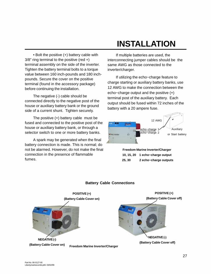
If multiple batteries are used, theinterconnecting jumper cables should be thesame AWG as those connected to theinverter/charger.
If utilizing the echo~charge feature tocharge starting or auxiliary battery banks, use12 AWG to make the connection between theecho~charge output and the positive (+)terminal post of the auxiliary battery. Eachoutput should be fused within 72 inches of thebattery with a 20 ampere fuse.
• Bolt the positive (+) battery cable with3/8” ring terminal to the positive (red +)terminal assembly on the side of the inverter.Tighten the battery terminal bolts to a torquevalue between 160 inch-pounds and 180 inch-pounds. Secure the cover on the positiveterminal (found in the accessory package)before continuing the installation.
The negative (-) cable should beconnected directly to the negative post of thehouse or auxiliary battery bank or the groundside of a current shunt. Tighten securely.
The positive (+) battery cable must befused and connected to the positive post of thehouse or auxiliary battery bank, or through aselector switch to one or more battery banks.
A spark may be generated when the finalbattery connection is made. This is normal; donot be alarmed. However, do not make the finalconnection in the presence of flammablefumes.
INSTALLATION
POSITIVE (+)
(Battery Cable Cover on)
Freedom Marine Inverter/Charger
NEGATIVE (-)
(Battery Cable Cover on)
POSITIVE (+)
(Battery Cable Cover off)
NEGATIVE (-)
(Battery Cable Cover off)
Battery Cable Connections
Auxiliary
or Start battery
Freedom Marine Inverter/Charger
10, 15, 20 1 echo~charge output
25, 30 2 echo~charge outputs
12 AWG
echo~charge 1echo~charge 2
S

Part No. 90-0127-00Libertymarinecombi.p65 03/02/99
28
FUSE HOLDER
FUSE
BATTERYCABLEINVERTER
CABLE
FLAT WASHER
NUT
LOCK WASHER
COMPRESSION / RING TERMINAL
INSTALLATION
Improper stack up of hardware will causeexcessive heat and fuse failure. Stack upas shown.
WARNING
+ (red)
EXPLODED VIEW
OF FUSE ASSEMBLY
+
_
FUSE HOLDER
FUSE
BATTERYCABLE
INVERTERCABLE
FLAT WASHER
LOCK WASHER
NUT
RING / RING TERMINAL
Battery Cable FusingA fuse is required by the NEC to protect
the battery and cables. A UL Listed DC ratedslow blow fuse must be installed in the positive(+) battery cable, within 72 inches of thebattery or within 7 inches of a positive bus orswitch.
Recommended Fuse: UL Listed Class TJLLN with a DC Rating. This fuse with fuseholder is available from your dealer or HeartInterface.
For Freedom 10 & 15200 Amp Fuse & Holder PN# 84-4155-00 (C/R)*200 Amp Fuse & Holder PN# 84-4158-00 (R/R)**200 Amp Fuse Only PN# 84-4157-00
For Freedom 20, 25, & 30300 Amp Fuse & Holder PN# 84-4156-00 (C/R)*300 Amp Fuse & Holder PN# 84-4154-00 (R/R)**300 Amp Fuse Only PN# 84-4151-00
* Compression / Ring Terminal** Ring / Ring Terminal

Part No. 90-0127-00Libertymarinecombi.p65 03/02/99
29
INSTALLATION
Follow these instructions to insure properstart up and confirm that the installation iscorrect.
1. Check to make sure Invert and Chargeare OFF. The INVERT LED should not beilluminated, the CHARGE LED should beblinking (charger ready but no external ACpower available). If using a Remote ControlPanel or a Link Instrument, make sure inverterand charger indicators are OFF.
2. Check battery polarity. If the unit wasconnected to the battery with reverse polarity,the unit will be damaged.
3. Check the battery voltage and ensureit is within proper range for the unit (10-15.5VDC).
Do not apply shore power orgenerator power without preforming thefollowing steps:
1. Test the inverter function: • With no loads connected to the output ofthe inverter, turn the INVERT Switch ON. TheINVERT LED should be solid green. If using aremote, turn ON the inverter with the switch onthe Remote Control Panel or LinkInstrument.
• The Freedom unit will produce a slightticking. If using a Remote Control Panel or LinkInstrument the INVERT LED will illuminate andthe voltage indicator will display the batteryvoltage. The DC Amps LED will not be lit be-cause the unit is in the idle mode.
• Add a load of 7 watts or more to the outputof the inverter. A 40 watt incandescent lightbulb will work fine. The DC Amps LEDs on theremote will indicate the DC draw from the bat-tery through the inverter.
Do not turn the inverter ON beforeeliminating any possibility of backfeed.
WARNING
• Leave the load connected and turn OFFthe INVERT mode by pressing the INVERTswitch or turn OFF the INVERT mode from theRemote Control Panel or Link Instrument.
2. Test the transfer function: • Be sure the unit is OFF, the INVERT andCHARGE LEDs are not illuminated. Applyshore power. If there is a back-feed in theinstallation, the unit will protect itself, the LOWBATTERY and OVERTEMP/OVERLOAD LEDwill both be blinking rapidly (5 times persecond). Do not proceed until the backfeedcondition has been corrected. • Once shore power has been applied to theunit, there will be approximately an 8 seconddelay. Then the unit should transfer shorepower and power the load. If this does nothappen, do not proceed. If the LOW BATTERYand OVERLOAD/OVERTEMP LEDs are blink-ing rapidly or if you are using a Remote ControlPanel or Link Instrument, check the panel for abackfeed indication. The panel will show anoverload condition. Eliminate the backfeedcondition.
Freedom Marine Inverter/Charger

Part No. 90-0127-00Libertymarinecombi.p65 03/02/99
30
• Testing for backfeed. If a backfeedcondition is indicated, disconnect from shorepower and disconnect the AC output wiresfrom the inverter. Make sure the inverter isOFF.Caution: Apply shore power and measure forvoltage between the black and white wires thatwere attached to the inverter output feeding theelectrical panel or loads, not the inverter outputwires. If there is voltage on these wires, abackfeed condition exists and must becorrected or damage will result.
3. Test the battery charger function: • With shore power applied and thetransfer switch engaged, the battery chargershould be in operation. The CHARGE LED willblink for 8 seconds. After the 8 seconds, theunit will enter the charge mode and the LEDwill be illuminated. (When using TemperatureSensitive Charging, this time may be longer.)
When AC is available, the unit will auto-matically default to charge mode without theoperator setting the unit in CHARGE mode. Itis necessary to press the CHARGE switchOFF, if you do not want to charge.
Verify the charger is working by using avolt meter. Use this same method on the startor auxiliary battery connected to theecho~charge to verify echo~charge operation.The battery voltage should gradually increase.If using a Remote Control Panel, DC AmpsLED indicates charger out-put and the DCVolts LED indicates an increase in batteryvoltage.
Note: The house battery bank must beabove 13.0 volts for the echo~charge to beoperational.
INSTALLATION • Turn the inverter ON, the green LEDshould blink. Remove shore power and theinverter should automatically pick up the ACload when shore power is removed.
Repeat the test for transfer and batterycharger with the generator if you have one.
Congratulations, you have completed asuccessful installation.
Freedom Marine Inverter/Charger
Note: For low power system shut downmode, both the INVERT and CHARGE LEDsmust be OFF.

Part No. 90-0127-00Libertymarinecombi.p65 03/02/99
31
TROUBLESHOOTING LED STATUSsutatSDEL sutatSnoitarepO setoN
TREVNI EGRAHC YRETTABWOL PMETREVODAOLREVO
neerGdiloS neerGgniknilB FFO FFO ontubydaerregrahC.gnitrevnI.elbaliavaCAlanretxe
lamroN
gniknilBneerG
neerGdiloS FFO FFO .ybdnatsnisiretrevnI.degrahcgniebsiyrettaB
tnerrucgnigrahc,lamroNsdeecxedaolCAfidetimil
.gnittesgnirahSrewoP
gniknilBneerG
FFO FFO FFO .ybdnatsinisiretrevnI.ffodenrutyllaunamregrahC
devomersirewopCAfIregrahceht,deilppaerdna
.NOnrutyllacitamotualliw
FFO neerGdiloS FFO FFO .gnigrahC.FFOretrevnI ybretrevniehtteseR.nottubTREVNIgnihsup
.knilbdluohsDEL
neerGdiloS neerGgniknilB deRdiloS * ontubydaerregrahC.gnitrevnIyrettaB.elbaliavaCAlanretxe
:gninraWegatloVV51>CDV<V01
egatlovyrettaB.gninraWnahteromro01nahtssel
stlov51
neerGdiloS neerGgniknilB * deRdiloS ontubydaerregrahC.gnitrevnI-revO.elbaliavaCAlanretxe
gninraWerutarepmet
.nwodtuhsretrevnI.gninraW
FFO neerGgniknilB gniknilBwolSdeR
* :nwodtuhsegatloVyrettaBV51>CDV<V01
.nwodtuhSretrevnInehwemuserlliwnoitarepO
stlov5.31sehcaeryrettab
FFO neerGgniknilB * gniknilBwolSdeR
lanretxeontubydaerregrahCregrahC.elbaliavarewopCA
nwodtuhSerutarepmet-revo
yllacitamotualliwnoitarepOsahtinuretfaemuser
nwoddelooc
FFO neerGgniknilB * gniknilBtsaFdeR
nwodtuhSdaolrevOretrevnI yllaunaM.daolCAecudeRmetsysehttratser
FFO neerGgniknilB gniknilBtsaFdeR
gniknilBtsaFdeR
tcerrocnI.nwodtuhSdeefkcaBgniriwCA
erofebgniriwniCAtcerroCehttratseryllaunaM.esu
.metsys
FFO neerGgniknilB gniknilBtsaFdeR
FFO elppiRyrettaB gninraW
.sutatsFFOroNOrehtieebdluoC*

Part No. 90-0127-00Libertymarinecombi.p65 03/02/99
32
TROUBLESHOOTING
melborP kcehCotsgnihT
tuptuOretrevnIoN
.seirettabegrahC.stlov01wolebdaolrednuegatlovyrettaB.1.esufCDnwolbrohctiwsyrettabnepo,snoitcennocyrettabesooL.2
.esufecalperrosnoitcennocnethgiT.rekaerbteserotni-hsuP.lenaptnorfnorekaerbtiucricdeppirT.3
noitalitnevetauqedanirosdaolevissecxe,noitidnoclamrehT.4.tnemtrapmocehtetalitneV.loocotwollA.gnitaehrevodesuac
detrohsrosdaolevissecxerofkcehc,tiucrictrohsrosdaolrevO.5.sdaoltcennocsiD.gniriw
retrevnIwoLegatloVtuptuO
tlovdradnatS.retemSMReurTasiretemtlovruoytahtmrifnoCyamdnaretrevniehtfomrofevawehtdaeryletaruccatonlliwsretem
tonsiretemSMReurTafI.stlov021ot09morferehwynadaertifi-blubthgiltnecsednacninafossenthgirbehtkcehc,elbaliava
.detalugerylreporpsiegatlovtuptuoeht,lamronsraeppa
tuptuOoNroelttiLyrettaBmorf
sregrahC
.snoitcennocCDdnaCAehthtobkcehc-gniriW.1tuptuoCDwolnitluserlliwtupniegatlovwol-egatlovtupniCA.2
005,3rednusrotarenegmorftuptuoregrahcdecudertcepxE.tnerruc.sttaw
.lenapetomeragnisufignitteserahsrewopkcehC.3ehtkcehc,ylkciuqgnigrahctonsiyrettabyrailixuAroretratSfI.4
ahtiwyrettabretratsehtdnayrettabesuohehtneewtebecnereffidlliwegrahc~ohceeht,stlov2.3nahtretaergsiecnereffidfI.retemtlov
otsnoitcennocllakcehC.yrettabtratsehtotdereviledygreneecuder.yrettabretratsdnaesuoheht
esuohehtdnayrettabtratsehtottuptuoygreneonsierehtfI.5ehtfonwodtuhslamrehta,stlov0.31evobasiegatlovyrettab
lliwegrahc~ohceehT.deruccosahegrahc~ohcelaudividni.levelefasaotsporderutarepmetehtnehwtratseryllacitamotua
nevOevaworciMwolSgnikooC
rewopretrevninorewolskoocyllamronlliwsnevoevaworciM.1CAkaepwolylthgilsasahtuptuoevawenisdeifidomehtesuaceb
.egatlovegatlovwoL.egatlovyrettabybdenimretedeblliwdeepsgnikooC.2
nahtiwknabyrettabehttroppuS.emitgnikoocdesaercninistluser.gnikoocrekciuqrofecruosgnigrahcrehtororotanretla
tsaFrowolSkcolClatigiD
riehteviredroesabemitlanretninayolpmerehtieskcolclatigiD.1siycneuqerfretrevniehT.mrofevawCAgnimocniehtmorfesabemitskaepforebmunehtstnuocrehtiekcolcehT.zH06tadetalugerllew
orezsessorcmrofevawehtsemitforebmunehtromrofevawehtnieromsistnevegnissorcorezehtstnuoctahtyrtiucricehT.stlov
enisdeifidoms’retrevniehtfoemitssorcorezregnolehT.ralupop.kcolcretsafanignitluser,gnikcolcelbuodesuacyamevaw

Part No. 90-0127-00Libertymarinecombi.p65 03/02/99
33
Alternating Current (AC) An electric currentthat reverses direction at regular intervals.Sources of alternating current are shorepower, generator power, inverter power orhousehold current.
American Boat & Yacht Council (ABYC)sets the standards for safe boating. FreedomMarine conforms to ABYC standards A-20“Battery Charging Devices” and A-25 “PowerInverters.” For standard information, contactABYC, 3069 Solomons Island Road,Edgewater, MD 21037-1416 (410)956-1050fax (410)956-2737.
Ampere (Amp, A) The unit of measure ofelectron flow rate of current through a circuit.
Ampere-hour (Amp-Hr., AH) A unit ofmeasure for a battery’s electrical storagecapacity, obtained by multiplying the current inamperes by the time in hours of discharge(Example: a battery which delivers 5 amperesfor 20 hours delivers 5 amperes times 20hours, or 100 Amp-Hr. of capacity.)
Ampere-Hour Capacity The ability of a fullycharged battery to deliver a specified quantityof electricity (Amp-Hr., AH) at a given rate(Amp, A) over a definite period of time (Hr.).The capacity of a battery depends upon anumber of factors such as: active material,weight, density, adhesion to grid, number,design and dimensions of plates, plate spacingdesign of separators, specific gravity andquantity of available electrolyte, grid alloys, finallimiting voltage, discharge rate, temperature,internal and external resistance, age and life ofthe battery (bank).
AGM (Absorbed Glass Mat) Battery A leadacid, maintenance-free battery.
AWG (American Wire Gauge) A standardused to measure the size of wire.
GLOSSARYCircuit An electric circuit is the path of anelectric current. A closed circuit has acomplete path. An open circuit has a broken ordisconnected path.
Circuit (Series) A circuit which has only onepath for the current to flow. Batteries arrangedin series are connected with the negative of thefirst to the positive of the second, negative ofthe second to the positive of the third, etc. Iftwo 6 Volt batteries of 50 ampere-hourscapacity are connected in series, the circuitvoltage is equal to the sum of the two batteryvoltages, or 12 Volts, and the ampere-hourcapacity of the combination is 50ampere-hours.
Circuit (Parallel) A circuit which providesmore than one path for current flow. A parallelarrangement of batteries (of like voltage andcapacity) would have all positive terminalsconnected to a conductor and all negativeterminals connected to another conductor. Iftwo 12 Volt batteries of 50 ampere-hourcapacity each are connected in parallel, thecircuit voltage is 12 Volts, and the ampere-hourcapacity of the combination is 100ampere-hours.
Combi Freedom CombiTM is a trademark ofHeart Interface to indicate a combinationinverter/charger.
Current The rate of flow of electricity or themovement rate of electrons along a conductor.It is comparable to the flow of a stream ofwater. The unit of measure for current isampere.
Cycle In a battery, one discharge plus onerecharge equals one cycle.
Direct Current (DC) Current that flowscontinuously in one direction such as that frombatteries, photovoltaics, alternators, chargersand DC generators.
Part No. 90-0127-00Libertymarinecombi.p65 03/02/99
34
Equalize Charge A controlled overcharge ofthe batteries which brings all cells up to thesame voltage potential, extends the battery life,restores capacity and mixes the electrolyte.This can only be done using the FreedomRemote Control Panel or a Link Instrument.
Gel Cell Battery A type of battery that uses agelled electrolyte solution. These batteries aresealed and are virtually maintenance-free. Notall sealed batteries are the gel cell type.
GFCI (Ground Fault Circuit Interrupter) Aprotective device that rapidly de-energizes acircuit when current to ground exceeds apredetermined value.
Ground The reference potential of a circuit. Inautomotive use, the result of attaching onebattery cable to the body or frame which isused as a path for completing a circuit in lieu ofa direct wire from a component. This methodis not suitable for connecting the negativecable of the inverter to ground. Instead, routethe cable directly to the negative terminal of thebattery.
LED (Light Emitting Diode) Indicator light.
LINK Instrument These panels monitor singleand dual battery banks. Some models provideremote management of Freedom Inverter/Chargers. Available in 4 models: LINK 10,LINK 20, LINK 1000, LINK 2000, LINK 2000R.
NEC National Electric Code. Contact NationalFire Protection Association, One BatterymarchPark, P.O. Box 9101, Quincy, MA 02269-9101(617)770-3000
Negative (-) Designating or pertaining toelectrical potential. The negative terminal is the
point from which electrons flow duringdischarge.
Ohm A unit for measuring electricalresistance.
Ohm’s Law Expresses the relationshipbetween Voltage (V) and Current (I) in anelectrical circuit with resistance (R). It can beexpressed as follows: V=IR. If any two of thethree values are known, the third value can becalculated by using the above formula.
Positive (+) Designating or pertaining toelectrical potential; opposite of negative. Thepositive battery terminal is the point whereelectrons return to the battery duringdischarge.
Power Sharing The feature of the charger toreduce its output when the AC power beingconsumed by the charger and external ACloads connected to the output of the inverterare in excess of the input breaker rating.
TSC Abbreviation for Temperature SensitiveCharging. The ability of the charger to adjust itscharging voltage based on the temperaturesensed at the battery bank if a temperatureprobe is used.
Volt The unit of measure for electric potential.
Watt The unit for measuring electrical power,i.e., the rate of doing work, in moving electronsby or against an electric potential.
Watt-Hour (Watt-HR, WH) The unit formeasuring electrical energy which equalsWatts x Hours.
Wet Cell Battery A type of battery that usesliquid as an electrolyte. The wet cell batteryrequires periodic maintenance; cleaning theconnections, checking the electrolyte level andperforming an equalization cycle.
GLOSSARY

Part No. 90-0127-00Libertymarinecombi.p65 03/02/99
35
SPECIFICATIONS2
1-0
1m
od
eer
F2
1-5
1m
od
eer
F2
1-0
2m
od
eer
F2
1-5
2m
od
eer
F2
1-0
3m
od
eer
F
re
bm
uN
tra
P2
1-1
10
1-1
82
1-1
15
1-1
82
1-1
10
2-1
82
1-1
15
2-1
82
1-1
10
3-1
8
eg
atl
oV
yret
ta
Bl
ani
mro
NC
DV
21
CD
V2
1C
DV
21
CD
V2
1C
DV
21
eg
na
Re
gat
lo
Vyr
ett
aB
CD
V5.
51-
01
CD
V5.
51-
01
CD
V5.
51-
01
CD
V5.
51-
01
CD
V5.
51-
01
tu
otu
Cyr
ett
aB
wo
LC
DV
5.0-
/+
01
CD
V5.
0-/
+0
1C
DV
5.0-
/+
01
CD
V5.
0-/
+0
1C
DV
5.0-
/+
01
eg
na
Re
gat
lo
Vt
up
nIC
AC
AV
03
1-0
9C
AV
03
1-0
9C
AV
03
1-0
9C
AV
03
1-0
9C
AV
03
1-0
9
noi
tal
ug
eR
yc
ne
uq
erF
ztr
au
Qz
H0
6r
o0
5d
etal
ug
eR
ztr
au
Qz
H0
6r
o0
5d
etal
ug
eR
ztr
au
Qz
H0
6r
o0
5d
etal
ug
eR
ztr
au
Qz
H0
6r
o0
5d
etal
ug
eR
ztr
au
Qz
H0
6r
o0
5d
etal
ug
eR
re
wo
Pt
upt
uO
su
ou
nit
no
Cr
etr
ev
nIA
V0
00
1A
V0
05
1A
V0
00
2A
V0
05
2A
V0
00
3
ep
ah
Se
va
We
va
We
niS
dei
fid
oM
ev
aW
eni
Sd
eifi
do
Me
va
We
niS
dei
fid
oM
ev
aW
eni
Sd
eifi
do
Me
va
We
niS
dei
fid
oM
re
wo
pe
gru
SC
As
pm
A0
3C
As
pm
A5
5C
As
pm
A0
7C
As
pm
A0
8C
As
pm
A0
9
niar
Dt
ner
ru
Cd
ao
Lo
NC
Ds
pm
A2
1.0
CD
sp
mA
21.
0C
Ds
pm
A2
1.0
CD
sp
mA
21.
0C
Ds
pm
A2
1.0
de
wol
lA
srot
ca
Fr
ew
oP
llA
llA
llA
llA
llA
yc
nei
ciff
Ed
ao
Lll
uF
%5
8%
68
%5
8%
78
%6
8
yc
nei
ciff
Ek
ae
P%
39
%3
9%
39
%3
9%
39
noi
tc
etor
Pe
gat
lo
Vyt
ilit
Ur
ed
nU/
re
vO
eg
atl
oV
ytil
itU
re
dn
U/r
ev
Oe
gat
lo
Vyt
ilit
Ur
ed
nU/
re
vO
eg
atl
oV
ytil
itU
re
dn
U/r
ev
Oe
gat
lo
Vyt
ilit
Ur
ed
nU/
re
vO
eg
atl
oV
yret
ta
Br
ed
nU/
re
vO
eg
atl
oV
yret
ta
Br
ed
nU/
re
vO
eg
atl
oV
yret
ta
Br
ed
nU/
re
vO
eg
atl
oV
yret
ta
Br
ed
nU/
re
vO
eg
atl
oV
yret
ta
Br
ed
nU/
re
vO
tiu
cri
c-tr
oh
Sti
ucr
ic-
tro
hS
tiu
cri
c-tr
oh
Sti
ucr
ic-
tro
hS
tiu
cri
c-tr
oh
S
re
ka
erB
tiu
cri
Cr
ek
aer
Bti
ucr
iC
re
ka
erB
tiu
cri
Cr
ek
aer
Bti
ucr
iC
re
ka
erB
tiu
cri
C
tn
err
uC
re
vO
tn
err
uC
re
vO
tn
err
uC
re
vO
tn
err
uC
re
vO
tn
err
uC
re
vO
erut
are
pm
eT
re
vO
erut
are
pm
eT
re
vO
erut
are
pm
eT
re
vO
erut
are
pm
eT
re
vO
erut
are
pm
eT
re
vO
eta
Re
gra
hC
CD
sp
mA
05
CD
sp
mA
57
CD
sp
mA
00
1C
Ds
pm
A0
31
CD
sp
mA
04
1
)e
do
Me
gra
hC
xa
M(t
ner
ru
Ct
up
nIC
AC
As
pm
A2
1C
As
pm
A6
1C
As
pm
A1
2C
As
pm
A6
2C
As
pm
A8
2
eg
atl
oV
egr
ah
Ckl
uB
CD
V2.
0-/
+4.
41
CD
V2.
0-/
+4.
41
CD
V2.
0-/
+4.
41
CD
V2.
0-/
+4.
41
CD
V2.
0-/
+4.
41
eg
atl
oV
ta
olF
CD
V2.
0-/
+5.
31
CD
V2.
0-/
+5.
31
CD
V2.
0-/
+5.
31
CD
V2.
0-/
+5.
31
CD
V2.
0-/
+5.
31
eg
atl
oV
egr
ah
Cg
nizi
la
uq
EC
DV
3.6
1C
DV
3.6
1C
DV
3.6
1C
DV
3.6
1C
DV
3.6
1
gni
gra
hC
evi
tis
ne
Ser
utar
ep
me
Ts
eY
se
Ys
eY
se
Ys
eY
stu
ptu
Oe
gra
hC
yret
ta
Byr
aili
xu
At
upt
uO
1t
upt
uO
1t
upt
uO
1st
upt
uO
2st
upt
uO
2
egr
ah
Cyr
ett
aB
yrai
lix
uA
eg
atl
oV/
tn
err
uC
CD
V4.
41
/A
51
CD
V4.
41
/A
51
CD
V4.
41
/A
51
CD
V4.
41
/A
51
CD
V4.
41
/A
51
le
na
ps
utat
Sk
niL
ro
eto
me
Rl
an
oit
pO
kni
Lr
oet
om
eR
la
noi
tp
Ok
niL
ro
eto
me
Rl
an
oit
pO
kni
Lr
oet
om
eR
la
noi
tp
Ok
niL
ro
eto
me
Rl
an
oit
pO
)s
bl(
th
gie
W.
sb
L4
3.
sb
L5
4.
sb
L5
4.
sb
L0
5.
sb
L0
5
)H
xW
xL(
sn
ois
ne
miD
"4/
3-7
x"2/
1-1
1x"
8/7-
31
"4/
3-7
x"2/
1-1
1x"
8/7-
31
"4/
3-7
x"2/
1-1
1x"
8/7-
31
"4/
3-7
x"2/
1-1
1x"
8/7-
31
"4/
3-7
x"2/
1-1
1x"
8/7-
31
Specifications subject to change without notice.
Part No. 90-0127-00Libertymarinecombi.p65 03/02/99
36
WARRANTY
© 1999 Heart Interface Corporation. All rights reserved.
Your Heart Interface Freedom MarineSeries CombiTM Inverter/Charger is underlimited warranty for 30 months from date ofpurchase.
Terms of this warranty are detailed onthe warranty registration card. Pleasecomplete this card and return it to HeartInterface to register your warranty.
If the unit requires service, contact HeartInterface by telephone. The service technicianwill ask for the model and serial number of yourunit. Please have this information ready.
Phone numbers: (253) 872-7225(800) 446-6180 (outside 253 area code)
A return authorization number will berequired on all returns. This number is issuedby the service technician and should be writtenon the outside of the packaging
You must ship the unit to Heart Interfaceor a field service center freight prepaid.