Installation Instructions - Triton Stormwater Solutions
20
Installation Instructions Triton Stormwater Solutions Chamber System for Stormwater Management Revised November 2019. Supersedes all previous installation manuals.
-
Upload
khangminh22 -
Category
Documents
-
view
1 -
download
0
Transcript of Installation Instructions - Triton Stormwater Solutions

Installation InstructionsTriton Stormwater Solutions Chamber System for Stormwater Management
Revised November 2019. Supersedes all previous installation manuals.
Triton Stormwater Solutions Chamber System for Stormwater Management Installation Manual
Call Triton SWS at 810.222.7652 for technical and product information or visit www.tritonsws.com1 |
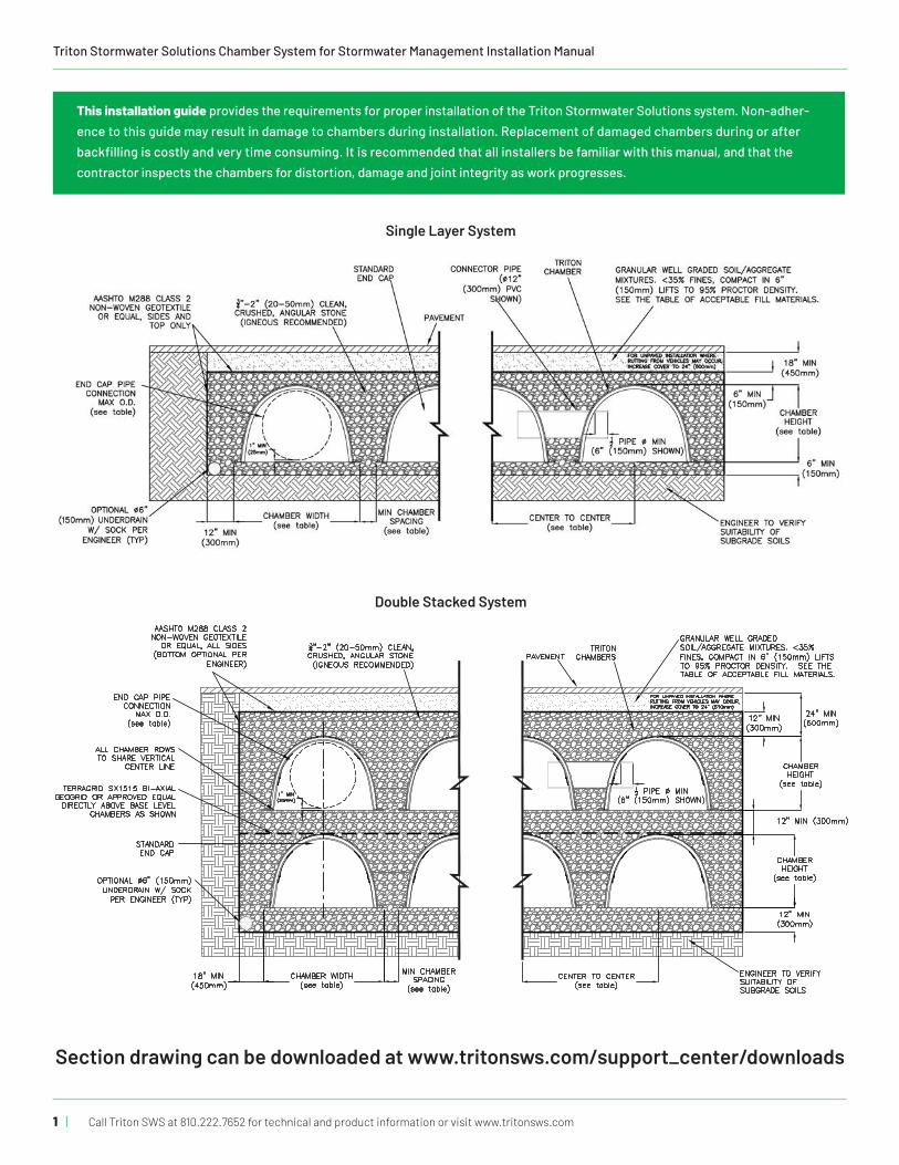
Single Layer System
Double Stacked System
Section drawing can be downloaded at www.tritonsws.com/support_center/downloads
This installation guide provides the requirements for proper installation of the Triton Stormwater Solutions system. Non-adher-ence to this guide may result in damage to chambers during installation. Replacement of damaged chambers during or after backfilling is costly and very time consuming. It is recommended that all installers be familiar with this manual, and that the contractor inspects the chambers for distortion, damage and joint integrity as work progresses.
CHAMBER WIDTH CHAMBER SPACING CENTER TO CENTER CHAMBER HEIGHT MAX END CAP CONNECTION
S29 59" (1499mm) 6.0" (150mm)*7.5" (190mm)
65.0" (1651mm)*66.5" (1690mm) 36" (914mm) 32" (813mm)
S22 55" (1397mm) 6.0" (150mm) 61.0" (1549mm) 35" (889mm) 30" (762mm)
C10 39.7" (1008mm) 6.0" (150mm) 45.7" (1161mm) 25" (635mm) 20" (508mm)
M6 33.6" (853mm) 6.0" (150mm) 39.6" (1006mm) 17.5" (445mm) 14" (356mm)
*7.5" (190mm) SPACING OF DISTRIBUTION ROWS IS REQUIRED ONLY WHEN A PERPENDICULAR MAIN HEADER ROW IS USED. IF AN INLINE MAIN HEADERROW IS USED, THEN MIN SPACING CAN BE 6" (150mm)
7600 EAST GRAND RIVER, STE.195BRIGHTON, MI 48114
PHONE: (810) 222-7652 ● FAX: (810) 222-1769WWW.TRITONSWS.COM
DOUBLE STACK CROSS SECTIONINFILTRATION
CONCEPTUAL PLAN DISCLAIMERTHIS GENERIC DETAIL DOES NOT ENCOMPASS THE SIZING, FIT, AND
APPLICABILITY OF THE TRITON CHAMBER SYSTEM FOR THIS SPECIFICPROJECT. IT IS THE ULTIMATE RESPONSIBILITY OF THE DESIGN ENGINEER
TO ASSURE THAT THE STORMWATER SYSTEM DESIGN IS IN FULLCOMPLIANCE WITH ALL APPLICABLE LAWS AND REGUALTIONS. TRITONPRODUCTS MUST BE DESIGNED AND INSTALLED IN ACCORDANCE WITH
TRITON'S MINIMUM REQUIREMENTS. TRITON STORMWATERSOLUTIONS DOES NOT APPROVE PLANS, SIZING, OR SYSTEM DESIGNS.THE DESIGN ENGINEER IS RESPONSIBLE FOR ALL DESIGN DECISIONS.
REVISED:TRITON - STANDARD DETAILS07-16-18 JWM
| 2Call Triton SWS at 810.222.7652 for technical and product information or visit www.tritonsws.com
> Before You Begin REQUIRED MATERIALS AND EQUIPMENT LIST• Acceptable 0.75" – 2" (20mm – 50mm) clean, crushed, angular
stone per, Tables 2 & 3 on page 9
• Acceptable fill materials per Table 3 on page 9
• Filter fabric, per Table 1 on page 8
• Triton SWS end caps & Triton SWS chambers
• Watch the Triton SWS Installation video at: http://www.tritonsws.com/video#video-double-stack
• Reciprocating saw with a tapered bi-metal blade, router, jig saw or an air saw (to custom cut end cap, side and top holes). *Portable air compressor and power source if using an air saw. A proper diameter hole saw works best.
• PVC distribution pipe, per engineer’s plan for connecting the Triton SWS system together
• Self-Expanding closed cell foams (e.g., Great Stuff™ Pond and Stone insulating foam) to seal all gaps
• OSHA compliance
• Stone bucket
• All equipment must not exceed the ground pressure limits listed in Table 4 on page 13
• Transit or laser
• Vibratory roller with maximum gross vehicle weight of 12,000 lbs. (5443 kg) and a maximum dynamic force of 20,000 lbs. (9072 kg). Also, a walk-behind plate compactor whose com-paction force does not exceed 2,500 lbs (10kN).
• Installer(s) should wear proper clothing, gloves, eye protec-tion and a dust mask when cutting.
• Review directions on all products to ensure proper installation
• 60" (1524mm) forks to unload pallets and rope to pull pallets to back of van.
• Fork pallet only. Do not lift stack by placing forks under product
• Remove all packaging, i.e., bands, stretch wrap, labels, and protective film, from product before installing them
• A minimum of a 3" (76mm) wide x 10' (3m) Web Sling with a choker load rating of 3,760 pounds (1705 kg) or more to lower product into trench
> Requirements for System Installation 1. Triton Stormwater Solutions LLC requires installing contrac-
tors to use and understand Triton SWS’ most current installa-tion instructions prior to beginning system installation.
All illustrations and photographs are examples of typical situations. Actual designs may vary. Be sure to follow the engineer’s drawings.
2. Triton SWS offers installation consultations to installing con-tractors. Contact Triton SWS at least 10 days prior to system installation to arrange a pre-installation consultation. Our representatives can answer questions, address comments and provide information about the Triton SWS’ chamber sys-tem’s installation requirements. Call 1-810-222-7652 or visit www.tritonsws.com to receive the most current version of our installation instructions.
3. Contact local underground utility companies or locating agency at least 3 days prior to construction.
4. All Triton SWS’ system designs must be certified by a regis-tered professional engineer.
5. Triton SWS’ requirements for systems with a pavement design (asphalt, concrete pavers, etc.): Minimum cover is 18" (457mm) not including pavement; maximum cover is 600" (15240mm) including pavement design. For installations that do not include pavement, where rutting from vehicles may oc-cur, minimum required cover is 24" (610mm) , maximum cover is 600" (15240mm).
6. The contractor must report any discrepancies with the sys-tem subgrade soil’s bearing capacity to the design engineer.
7. Check chambers for shipping damage prior to installation. Units that have been damaged must not be installed. Contact Triton SWS immediately upon discovery of any damage.
8. Filter fabric must be used as indicated in the engineer’s drawings.
9. To maintain row separation distances and prevent chamber displacement, place stone between chamber rows and around perimeter as required by the most current version of Triton SWS Installation Instructions.
10. Backfilling of the chamber system must be in accordance with the most current version of Triton SWS’ Installation Instruc-tions, listed on the lower left of the installation manual cover.
11. The contractor must refer to Triton SWS Installation Instruc-tions for Tables of Acceptable Vehicle Loads at various depths of cover. The contractor is responsible for preventing vehicles that exceed Triton SWS’ requirements from traveling across or parking over the stormwater system. Temporary fencing, warning tape and appropriately located signs are commonly used to prevent unauthorized vehicles from enter-ing sensitive construction areas.
12. The contractor must apply erosion and sediment control measures to protect the stormwater system during all phases of site construction, per local codes and design engineer’s specifications.
13. Remove all packaging, i.e., bands, stretch wrap, labels, and protective film, from product before installing them.

Triton Stormwater Solutions Chamber System for Stormwater Management Installation Manual
Call Triton SWS at 810.222.7652 for technical and product information or visit www.tritonsws.com3 |
> Requirements for Excavating and Preparing the Site
1. Excavate and level the designated area. Be sure to excavate at least one extra foot around the chamber perimeter to allow for proper fit and adequate compaction. (Bed dimensions are specified on engineer’s plan.)
2. Excavation must be free of standing water. Dewatering measures must be taken if required. Positive drainage of the excavation must be maintained.
3. Prepare the chamber bed’s subgrade soil as outlined in the engineer’s drawings.
4. Line trench walls with any of the acceptable AASHTO M288 class 2 Non-Woven geotextiles listed in table 1 on page 8. Overlap adjacent filter fabric by at least 2' (610mm) . Do not place filter fabric under the Triton SWS’ Chambers. The filter fabric will clog, restricting the infiltration rate of the field.
In conditions where the sub-soils may migrate up into the base stone, a geofabric may be necessary. Contact the civil engineer responsible for the project if you think this may oc-cur during the compaction of the stone.
5. Perforated pipe outlet underdrains may be designed within the one foot stone perimeter. Install perforated pipe outlet underdrains as required by the engineer’s drawings.
6. Place acceptable 0.75"– 2" (20mm – 50mm) clean, crushed, angular stone foundation material over the entire bottom sur-face of the bed (see Tables 2 & 3 on page 9 for stone require-ments). Refer to the engineer’s drawings for subgrade soil preparation and required stone foundation thickness.
7. Compact the stone using a vibratory roller with its full dy-namic force applied to achieve a flat surface.
> Requirements for System Installation 14. Triton SWS’ systems must be installed in accordance with
Triton Stormwater Solutions’ minimum requirements. Failure to do so will void the limited warranty.
15. Triton SWS’ product warranty is limited. See current product warranty for details on page 14. To acquire a copy call Triton SWS at 1-810-222-7652 or visit www.tritonsws.com.
16. For installation instructions for any additional structures or fittings not covered in these instructions, contact Triton SWS at 1-810-222-7652.
17. Supply Triton SWS and its distributor with the vehicle specifi-cations that will be used during the installation of the system 10 business days prior to start of installation for approval.
18. When light pole bases are located within the footprint of the system, prior to installation of the system, the electrical con-tractor must be consulted to ensure sufficient room has been provided for light pole base excavation.
Use a plate compactor to achieve a flat surface. Compaction of the embedment stone is necessary if the angular stone used is of nominal graded size less than 1.5" (40 mm). Compaction of the embedment stone is recommended when doing a double stack system so a flat surface is achieved for the installation of the upper system.

| 4Call Triton SWS at 810.222.7652 for technical and product information or visit www.tritonsws.com
> Requirements for Assembling Inlet PipesNOTE: Depending on the system’s design, it may be advantageous to lay out the inlet and outlet pipe systems prior to forming the bed of chambers.
1. Temporarily lay out the main header system according to the engineer’s drawings.
2. Stone foundation scour control measures such as splash pads, riprap, or geotextiles may be required by the design engineer. Locate and install scour control measures, per engineer’s draw-ings, if required.
3. Set first chamber of each row aligned with their inlet pipes, if applicable, or with the Main Header Row.
Per the engineer’s drawings, ensure that the minimum* clear spacing, measured between feet, is maintained between adja-cent rows. Separate chambers and inlet fittings, as necessary, to maintain the minimum separation distance between chamber rows.
> Requirements for Installing the ChambersTo begin building the chamber bed, orient the chambers so the end labeled with the build direction arrow is pointed in the direction of the build.
Maintain the minimum separation between chamber rows (measurement taken from the foot of chambers).
4. Pre-drill a hole large enough to use a saw listed on page 2 under the “Before you Begin” section. Cut an opening for the inlet pip-ing in the applicable end caps at the specified invert height.
NOTE: Inlet pipe openings may be cut anywhere on an end cap along the vertical centerline. To do this, take a short length of pipe and use a marker to draw an outline of the pipe on the end cap at the correct height or use the proper diameter guides on the face of the end cap to cut required hole.
5. Insert the distribution pipes into the end caps.
6. Once chamber spacing requirements are met, the header row system may be permanently assembled.
For more details on installing the Triton SWS’ Main Header Row system go to page 10.
* A wider spacing may be required, as indicated on the engineer’s drawings.
With the Build Direction Arrow nearest you, lower Chamber B over the last rib on Chamber A.
From the start of the first picture to the last picture it took the two men 8 seconds to install the three chambers they were carrying.

Triton Stormwater Solutions Chamber System for Stormwater Management Installation Manual
Call Triton SWS at 810.222.7652 for technical and product information or visit www.tritonsws.com5 |
> Requirements for Joining the ChambersAlthough not visible to the eye, a chamber’s end corrugations are sized differently to allow for an overlapping joint. To ensure proper joint fit, orient all chambers in the bed with their arrows pointing in the direction of the build.
Construct the chamber bed by joining the chambers lengthwise in rows. Attach chambers by overlapping the end corrugation of one chamber onto the end corrugation of the last chamber in the row. Be sure that chamber placement does not exceed the reach of the construction equipment used to place the stone.
Make sure that the chamber and end cap flanges are sitting on the base stone. Base stone must provide support under the prod-ucts. Also, make sure that the connecting joints are seated tightly together. The connecting joints should be tight and no gaps should be present.
NOTE: Do not overlap more than one corrugation.
> Requirements for Attaching the End CapsSlide the S29 end cap over the end of the last Chamber. The end caps sits on the outside of the Chamber rib and not on the inside.
Make sure that the S29 end cap is properly seated onto the chamber and that the flange of the end cap is not overlapping or resting on the side flange of the chamber. The end cap should not sit higher than the first full corrugation.
To install the S22, C10 and M6 end caps, lift the end of the chamber a few inches off the ground. With the curved face of the end cap facing outward, place the end cap up inside the chamber’s V rib. These end caps sit on the inside of the chamber rib and not on the outside.
Four self-tapping screws can be used to screw the end cap in place to keep it from shifting during the backfill process. The 4 screws can be equally spaced and drilled through the face of the end cap an 1.5”(38.1mm) from the outer edge. Ensure that all the screws pen-etrate the end cap and the last chamber V rib.
> Requirements for Placing Stone Over the ChambersClean, crushed, angular stone meeting the specifications in Tables 2 & 3 and Figure 1 on page 9 may be placed over the chambers with an excavator, pushed with a dozer or walked in with a stone conveyer boom. Each method has benefits and limitations. These three processes will be explained separately; however, there are some common requirements for each:
The minimum clear spacing must always be maintained between adjacent Triton SWS’ chamber rows and construction vehicle loads must not exceed the requirements of Table 4 on page 13.
Ensure that the stone is of mixed size consisting of 0.75” to 2” (19mm to 51mm) and meets the requirements listed on page 9 of this manual.
Improper installation. The flange of the chamber is not supported.
Improper installation. The connecting joint is not tight.
NOTE: End caps are required only at the beginning and the end of each row of chambers. (S29 Shown)

| 6Call Triton SWS at 810.222.7652 for technical and product information or visit www.tritonsws.com
Placing stone with an excavator is currently the most common method of placing stone over Triton SWS’ chambers. Its biggest limitation is the reach of the excavator arm. For larger beds, it is common practice to work across a bed by joining only a few rows of chambers and placing their angular stone embedment, the filter fabric and soil fill before moving onto the next few rows.
> Requirements for Placing Stone with an ExcavatorA bed may be built either parallel to or perpendicular to the chamber row’s direction with this process. The excavator typically works inside the excavation, leading the way across the bed. It is also possible for the excavator to work at grade over the recently placed chambers following the build across. If this process is used, it is required that the depth of cover between tops of chambers and the excavator’s tracks be the minimum required by Table 1 on page 8. No excavators shall be operated on the bed without at least 3 ft (1m) of cover above chambers.
1. Anchor chambers by ladling angular stone directly over the centerline of the chambers. Evenly distribute stone to mini-mize chamber movement while maintaining row separation distances.
2. After chambers are anchored, continue to place the stone, surrounding the chambers and filling the perimeter areas to a minimum of 6" (152mm) over the top of chambers. Stone column height should never differ by more than 12" (305mm) between adjacent chamber rows or between chamber rows and perimeter. Do not drive equipment over the chambers without minimum cover required by Table 4 on page 13.
3. Repeat steps 1 & 2 until all the chambers are laid to the di-mensions of the engineer’s drawing.
Installing embedment stone around chambers.
> Requirements for Placing Stone with a Telescoping Conveyer BoomTelescoping aggregate conveyer trucks are limited only by the range of the boom. Typical trucks have a boom range between 50’ (15m) to 130’ (40m). Booms can convey up to 360 cu ft (10m3 ) of stone per hour.
1. Anchor chambers by ladling angular stone directly over the centerline of the chambers. Evenly distribute stone to mini-mize chamber movement while maintaining row separation distances.
2. After chambers are anchored, continue to place the stone, surrounding the chambers and filling the perimeter areas to a minimum of 6" (152mm) over the top of chambers.
Do not drive equipment over the chambers without minimum cover required by Table 4 on page 13. As the stone is being placed over the system, the application of the stone over the products must not be stationary. The conveyer must be mov-ing, left and right, fore and aft, to ensure that the stone is not wearing away the product’s material. The stone must also be installed over the system evenly as described in this manual. The maximum height from which stone should be dropped onto the system should not exceed 3 ft (1 M).
3. Repeat steps 1 & 2 above until all the chambers are laid to the dimensions of the engineer’s approved drawings.
NOTE: Where site access is limited it is highly recommended to use a telescopic belt conveyor (telebelt) type of truck shown above.

Triton Stormwater Solutions Chamber System for Stormwater Management Installation Manual
Call Triton SWS at 810.222.7652 for technical and product information or visit www.tritonsws.com7 |
> Requirements for Backfilling the System1. Place the required angular stone over the entire bed area as
described in previous sections.
2. Line the trench walls with AASHTO M288 Class 2 non-woven filter fabric. Take the fabric from the perimeter and lay it over the top of the stone. The filter fabric must overlap at least 2' (610mm) where the edges of the fabric meet.
3. The first 12" (305mm) of fill material must meet the requirements of Table 3 on page 9. Backfill over the top of the filter fabric in lifts that do not exceed 6" (152mm). Distribute the fill with a construc-tion vehicle that meets the maximum wheel loads or ground pres-sure limits specified in Table 4 on page 13.
4. Compact each lift of backfill as specified in the engineer’s draw-ings. Triton SWS requires compacting to a minimum of 95% of the Standard Proctor density. Use a walk-behind or vibratory roller not to exceed a maximum gross vehicle weight of 12,000 lbs (5443kg) and a maximum dynamic force of 20,000 lbs (9072 kg).
5. Continue to backfill over the chamber bed in 6" (152mm) maxi-mum lifts until the specified grade is achieved. Triton SWS’ cover requirements are 18" (457mm) minimum and 600" (15240mm) maximum over the top of the chambers. For pavement sub-base or special fill requirements, see engineer’s drawings.
The backfill height differential should never differ by more than 12" (305mm) over adjacent chambers. Minimum cover heights must be met before vehicles are allowed on top of the system. Large rocks and organic matter such as roots, stumps, etc. must not be part of the backfill material. Refer to Table 3 on page 9 for Acceptable Cover Materials or contact the design engineer for approved fill types. Refer to the Backfill of Chamber-Empediment Stone drawing on page 15.

| 8Call Triton SWS at 810.222.7652 for technical and product information or visit www.tritonsws.com
> Acceptable Manhole Connection
> Acceptable GeotextilesTABLE 1 - Some Suitable Geotextiles
1 AASHTO M288 Class 2 Non-Woven Geotextile Application: Separation layer between angular stone cover and fill to prevent fines intrusion. 2 AASHTO M288 Class 1 Woven Geotextile Application: Stabilization layer for angular stone foundation to prevent scouring of the stone base during JetVac maintenance procedure, modest hydraulic flows maintained. Can also be used in place of the Triton SWS Sediment Floors at each inlet row and Main Header Row to prevent scouring of foundation stone.
MANUFACTURER AASHTO M288 CLASS 2 NON-WOVEN1 AASHTO M288 CLASS 1 WOVEN2
Amoco Fabrics and Fibers (Part of BP) ProPex 4506, ProPex 4508, ProPex 4551, ProPex 4552, ProPex 4553 ProPex 2006, ProPex 2016, ProPex 2004
BTL Inc. (Bend Tarp Liners) Style 801, 8 oz., GN200 PPL-20, PPL-24, PPL-36
Carthage Mills FX-60HS, FX-80HS FX-66
Terrafix Geosynthetics Inc. 360R, 400R, 420R 200W, 400W
GSE Lining Technology NW6, NW8 —
Maccaferri MacTex MX245, MacTex MX275 —
Mirafi Const. Products Mirafi 160N, Mirafi 180N Mirafi 600X, Filterweave 403, Filterweave 404, Geolon HP570, Geolon HP665m /geikib HP770
Pavco-Amanco NT 3000, NT 4000 TR 4000
SI Geosolution Geotex 601, Geotex 801 Geotex 315ST
TNS Advanced Tech. R060, R070, R080, R100 M 403
US Fabrics US 205NW-C US 315
Hanes Geo TeraTex N06, TeraTex N08 TeraTex HD
Triton Stormwater Solutions Chamber System for Stormwater Management Installation Manual
Call Triton SWS at 810.222.7652 for technical and product information or visit www.tritonsws.com9 |
CLEAN CRUSHED STONE DESCRIPTION CRITERIA
AcceptableAngular Stones have sharp edges and relatively plane sides with unpolished surfaces
Subangular Stones are similar to angular description but have rounded edges
UnacceptableSubrounded Stones have nearly plane sides but have well-rounded corners and edges
Rounded Stones have smoothly curved sides and no edges
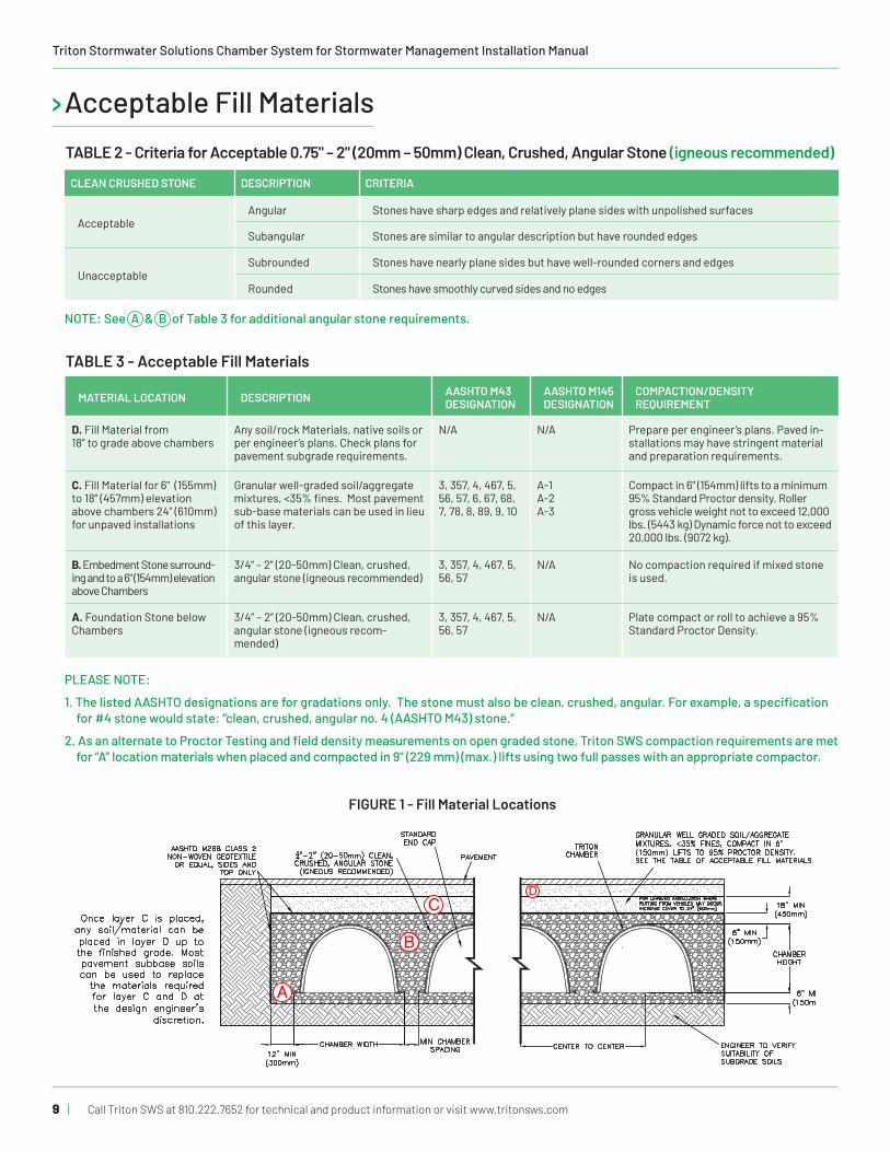
> Acceptable Fill MaterialsTABLE 2 - Criteria for Acceptable 0.75" – 2" (20mm – 50mm) Clean, Crushed, Angular Stone (igneous recommended)
TABLE 3 - Acceptable Fill Materials
MATERIAL LOCATION DESCRIPTION AASHTO M43 DESIGNATION
AASHTO M145 DESIGNATION
COMPACTION/DENSITY REQUIREMENT
D. Fill Material from 18” to grade above chambers
Any soil/rock Materials, native soils or per engineer’s plans. Check plans for pavement subgrade requirements.
N/A N/A Prepare per engineer’s plans. Paved in-stallations may have stringent material and preparation requirements.
C. Fill Material for 6" (155mm) to 18" (457mm) elevation above chambers 24” (610mm) for unpaved installations
Granular well-graded soil/aggregate mixtures, <35% fines. Most pavement sub-base materials can be used in lieu of this layer.
3, 357, 4, 467, 5, 56, 57, 6, 67, 68, 7, 78, 8, 89, 9, 10
A-1A-2A-3
Compact in 6" (154mm) lifts to a minimum 95% Standard Proctor density. Roller gross vehicle weight not to exceed 12,000 lbs. (5443 kg) Dynamic force not to exceed 20,000 lbs. (9072 kg).
B. Embedment Stone surround-ing and to a 6" (154mm) elevation above Chambers
3/4" – 2" (20-50mm) Clean, crushed, angular stone (igneous recommended)
3, 357, 4, 467, 5, 56, 57
N/A No compaction required if mixed stone is used.
A. Foundation Stone below Chambers
3/4” – 2” (20-50mm) Clean, crushed, angular stone (igneous recom-mended)
3, 357, 4, 467, 5, 56, 57
N/A Plate compact or roll to achieve a 95% Standard Proctor Density.
PLEASE NOTE:
1. The listed AASHTO designations are for gradations only. The stone must also be clean, crushed, angular. For example, a specification for #4 stone would state: “clean, crushed, angular no. 4 (AASHTO M43) stone.”
2. As an alternate to Proctor Testing and field density measurements on open graded stone, Triton SWS compaction requirements are met for “A” location materials when placed and compacted in 9" (229 mm) (max.) lifts using two full passes with an appropriate compactor.
FIGURE 1 - Fill Material Locations
NOTE: See A & B of Table 3 for additional angular stone requirements.
A
B
CD

| 10Call Triton SWS at 810.222.7652 for technical and product information or visit www.tritonsws.com
> Requirements for Assembling the Triton SWS’ Main Header Row System
1. Locate installed catch basin or mechanical filter. (Shown as item 1, figure 2.)
2. Determine length of main inlet pipe from catch basin or me-chanical filter to feed the Main Header Row. (Shown as item 2, figure 2.)
3. Temporarily lay out Triton SWS’ sediment floor according to the engineer’s drawings to determine installation location of the dumpster and/or sump bin assembly. (Shown as item 3, figure 2.) (If required.)
4. Once dumpster and/or sump bin location has been deter-mined, contractor can then excavate and install dumpster and/or sump bin assembly. (Shown as item 4, figure 2.) (If required.)
5. Install PERMANENT Triton SWS’ sediment floor according to engineer’s drawings. The sediment floor sections should be installed in the build direction indicated by the arrows on the surface of the floor sections. (Shown as item 5, figure 2.) When a dumpster assembly is present, it is recommended to start from the dumpster assembly and build the Main Header Row toward the inlet structure. Otherwise the build direction can start from inlet structure.
6. Install first chamber section and end cap in Main Header Row in the build direction indicated by the arrows on the top surface of each chamber. (Shown as item 6, figure 2.)
7. Install main inlet pipe(s) from catch basin or mechanical filter into the end cap of the first chamber section of the Main Header Row. (Shown as item 7, figure 2.)
NOTE: If main inlet pipe does not fit tightly into end cap, then wrap end of distribution pipe with geo-fabric to remove any slack to get a secure fit. Wrap geo-fabric ONLY on the outer wall of the distribution pipe, making sure not to obstruct any end of distribution pipes. You may also use self-expanding closed cell foam (e.g. Great Stuff™ Pond and Stone) to seal around the opening.
NOTE: If the end caps and Main Header Row’s chambers have not been cut at the factory, then cut end caps and chambers that will receive the distribution pipes BEFORE building into rows. This will assure proper fit and correct cutting locations and will also give adequate room to cut openings before the system is built.
NOTE: If any hole is cut 2” (51mm) larger than pipe O.D. then that product (I.E. chamber, end cap) must be replaced.
FIGURE 2
1
2
7
63
5
4
BUILD DIRECTION
BUILD DIRECTION

Triton Stormwater Solutions Chamber System for Stormwater Management Installation Manual
Call Triton SWS at 810.222.7652 for technical and product information or visit www.tritonsws.com11 |
> Requirements for Assembling the Triton SWS’ Main Header Row System (Cont.)
FIGURE 3 - Distribution Pipes
8. Continue with installation of chamber sections in the build direction indicated by the arrows on the top surface of each chamber to construct the Main Header Row. Chamber sec-tions should fit securely on top of the sediment floor. (Shown as item 8, figure 3.)
9. Once the Main Header Row has been installed onto the sedi-ment floor and the dumpster, install the O.D. manhole access drop (allowable sizes shown on standard detail sheet for Inspection/Direct Top MH connection). Use a jigsaw, recipro-cating, or air saw to cut the appropriate diameter opening to accept the manhole access drop. Attach four small galvanized angle brackets equally spaced approximately ONE (1) foot up from the end of the pipe. Use half inch screws on riser pipe to fasten the 4 small galvanized brackets. It is not necessary to screw the angle brackets to the Triton SWS’ chambers. The purpose of the angle brackets is to support the pipe until the backfill is placed. To help hold pipe in place during backfill, use the recommended spray foam (Great Stuff Pond & Stone) and dual-walled HDPE pipe for access port. Insert the bottom foot of pipe into the top porthole of the chamber and backfill. Attach top of riser pipe to a “Fernco Type” rubber cap, or to a cleanout cover assembly, as specified on the engineering drawings. Place an access casting in a concrete pad above, once all fill is placed, for risers in pavement. (Shown as item 9, figure 3.)
10. Locate and cut out specified side porthole diameters on all chambers of the Main Header Row (pre-drill large enough hole to insert blade for start of cut). (Shown as item 10, figure 3.)
11. Once all side portholes have been cut to the specified diam-eter, install all distribution pipes. (Shown as item 11, figure 3.)
NOTE: If distribution pipes do not fit tightly into side portholes, then wrap end of distribution pipe with geo-fabric to remove
any slack and get a secure fit. Wrap geo-fabric ONLY on the outer wall of the distribution pipe, making sure not to obstruct any end of distribution pipe, or you can also use self-expanding closed cell foam (e.g. Great Stuff™ Pond and Stone) to fill in the gaps.
12. Once all distribution pipes have been properly installed in the side portholes of the Main Header Row, set each chamber of each row aligned with their distribution pipes. Add self-expanding closed cell foam to seal gaps around pipe entering through the chambers and end caps. (Ensure that spacing between rows is per engineer drawings and that minimum spacing requirements are met.) Separate chambers and dis-tribution fittings as necessary to maintain the minimum clear space between chamber rows. Install the end cap onto the first section of each row of chambers in the drain field. With a jigsaw, reciprocating saw, or air saw cut an opening for the distribution pipe in the applicable end caps at the specified invert height to accept the distribution pipe. (See Figure 4.) Slide chamber with the installed end cap over the end of the distribution pipe. (See Figure 5.) Once chamber spacing re-quirements are met, the rest of the chambers making up the drain field can now be installed. (Shown as item 12, figure 3.) A minimum of 12" (305mm) spacing is required between Main Header Row and distribution row chambers.
13. Install end caps at the end of each chamber row. (Shown as item 13, figure 3.)
NOTE: End caps are required only at the beginning and end of each row of chambers
In the event that additional sediment floors, dumpster and/or sump bins are to be installed along with manhole access points refer to engineer’s drawings and call Triton SWS for further instructions (1-810-222-7652).
12
11
10
8
9
13
| 12Call Triton SWS at 810.222.7652 for technical and product information or visit www.tritonsws.com
> Requirements for Assembling the Triton SWS’ Main Header Row System (Cont.)
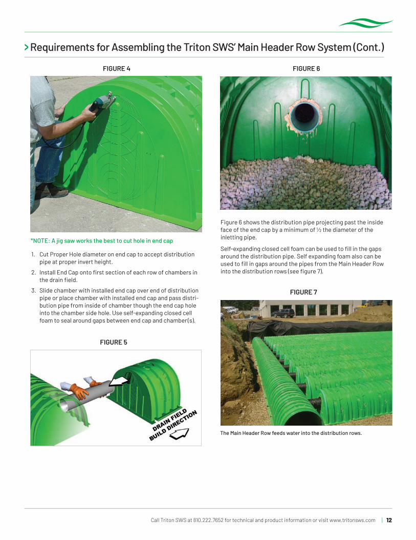
FIGURE 4 FIGURE 6
FIGURE 7
FIGURE 5
*NOTE: A jig saw works the best to cut hole in end cap
1. Cut Proper Hole diameter on end cap to accept distribution pipe at proper invert height.
2. Install End Cap onto first section of each row of chambers in the drain field.
3. Slide chamber with installed end cap over end of distribution pipe or place chamber with installed end cap and pass distri-bution pipe from inside of chamber though the end cap hole into the chamber side hole. Use self-expanding closed cell foam to seal around gaps between end cap and chamber(s).
Figure 6 shows the distribution pipe projecting past the inside face of the end cap by a minimum of ½ the diameter of the inletting pipe.
Self-expanding closed cell foam can be used to fill in the gaps around the distribution pipe. Self expanding foam also can be used to fill in gaps around the pipes from the Main Header Row into the distribution rows (see figure 7).
The Main Header Row feeds water into the distribution rows.

Triton Stormwater Solutions Chamber System for Stormwater Management Installation Manual
Call Triton SWS at 810.222.7652 for technical and product information or visit www.tritonsws.com13 |
TABLE 4 - Maximum Allowable Construction Vehicle Loads
Material Location
See Figure 1
Fill Depth over
Chambers in [mm]
Maximum Allowable Wheel Loads Maximum Allowable Track Loads(see note 6)
Maximum Allowable Roller Loads
Max Axle Load for Trucks
lbs [kN]
Max Wheel Load for Loaders
lbs [kN]
Track Widthin. [mm]
Max Ground Pressurepsf [kPa]
Max Drum Weight or Dynamic Force
lbs [kN]
D Final Fill Material
36" [900]Compacted 48,000 [213]
12" [305]18" [457]24" [610]30" [762]36" [914]
3863 [185]2652 [127]2088 [100]
1691 [81]1462 [70]
38,000 [169] Max Dynamic Force 20,000 lbs [53 kN]
C Initial Fill Material
24" [600]Compacted 48,000 [213] 16,000 [71]
12" [305]18" [457]24" [610]30" [762]36" [914]
2715 [130]1963 [94]1587 [76]1336 [64]1190 [57]
Roller gross vehicle weight not to exceed 12,000 lbs [53 kN]
Max Dynamic Force 20,000 lbs [53 kN]
24" [600]Loose/
Dumped48,000 [213] 16,000 [71]
12" [305]18" [457]24" [610]30" [762]36" [914]
2464 [118]1775 [85]1441 [69]1232 [59]1107 [53]
18" [450] 48,000 [213] 16,000 [71]
12" [305]18" [457]24" [610]30" [762]36" [914]
2211 [106]1628 [78]1342 [64]1166 [56]1045 [50]
B Embedment
Stone
12" [300] 16,000 [71] NOT ALLOWED
12" [305]18" [457]24" [610]30" [762]36" [914]
1690 [81]1219 [58]1111 [53]
1000 [48]924 [44]
6" [150] 8,000 [35] NOT ALLOWED
12" [305]18" [457]24" [610]30" [762]36" [914]
NOT ALLOWED
Walk-behind plate compactor whose compaction force does not exceed 2,500 lbs (10kN recommended)
TABLE 5 - Placement Methods and Descriptions
Material Location
See Figure 1
Placement Methods/ Restric-tions
Wheel Load Restrictions Track Load Restrictions Roller Load Restrictions
See Table 4 for Maximum Construction Loads
D Final Fill Material
A variety of placement methods may be used. All construction loads must not exceed the maximum limits in Table 4.
36” (900 mm) minimum cover required for dump trucks to dump over chambers.
Dozers to push parallel to rows until 36" (900mm) compacted cover is reached.4
Roller travel parallel to rows only until 36" (900 mm) compacted cover is reached.
CInitial Fill Material
Excavator positioned off bed is recommended. Small dozer or excavator are allowed as long as construction loads do not exceed maximum limits in Table 4.
Asphalt can be dumped into paver when compacted pavement subbase reaches 18” (450 mm) above top of chambers.
Small LGP track dozers & skid loaders allowed to grade cover stone with at least 6” (150 mm) stone under tracks at all times. Equipment must push parallel to rows at all times.
Use dynamic force of roller only after compacted fill depth reaches 12” (300 mm) over chambers. Roller travel parallel to chamber rows only.
B Embedment
Stone
No equipment allowed on bare chambers. Use excavator or stone conveyor positioned off bed or on foundation stone to evenly fill around all chambers to at least 6” (150mm) above the top of the chambers
No wheel loads allowed. Material must be placed outside the limits of the chamber bed.
No tracked equipment is allowed on chambers until a min. 6” (150 mm) cover stone is in place.
No rollers allowed.
A Foundation Stone
No restrictions. Contractor responsible for any conditions or requirements by others relative to subgrade bearing capacity, dewatering or protection of subgrade
NOTES:1. 36" (900 mm) of stabilized cover mate-
rials over the chambers is required for full dump truck travel and dumping.
2. During paving operations, dump truck axle loads on 18" (450 mm) of cover may be necessary. Precautions should be taken to avoid rutting of the road base layer, to ensure that compaction requirements have been met, and that a minimum of 18" (450 mm) of cover ex-ists over the chambers. Contact Triton SWS or its distributor for additional guidance on allowable axle loads dur-ing paving.
3. Ground pressure for track dozers is the vehicle operating weight divided by total ground contact area for both tracks. Excavators will exert higher ground pressures based on loaded bucket weight and boom extension.
4. Mini-excavators (< 8,000lbs/3628 kg) can be used with at least 12" (300 mm) of stone over the chambers and are limited by the maximum ground pres-sures in Table 4, based on a full bucket at maximum boom extension.
5. Storage of materials such as construc-tion materials, equipment, spoils, etc. should not be located over the Triton SWS system. The use of equipment over the Triton SWS system not cov-ered in Table 4 (ex. soil mixing equip-ment, cranes, etc) is limited. Please contact Triton SWS or its distributor for more information.
6. Allowable track loads based on vehicle travel only. Excavators shall not operate on chamber beds until the total backfill reaches 3 feet (900mm) over the entire bed.
> CONSTRUCTION GUIDE
Install non-woven geotextile over stone. Geotextile must overlap 12” (300mm) min. where edges meet. Compact each lift of backfill as specified in the site design engineer’s drawings. Roller to travel parallel with rows.

| 14Call Triton SWS at 810.222.7652 for technical and product information or visit www.tritonsws.com
> LIMITED WARRANTY of Triton Stormwater Solutions (“Triton SWS”): Products
It is recommended that the Triton SWS’ Products be installed and in the ground within 30 days of delivery at site to prevent onsite damage from equipment and to prevent theft.
NOTE:
Contact Triton SWS for Lifetime System Warranty Information
(A) This Limited Warranty (“Limited Warranty”) applies solely to the Triton SWS’ chambers and end caps manufactured for Triton SWS, and sold to the original purchaser (the “Purchaser”). The chambers and end caps are collectively referred to as the “Products.” This Limited Warranty is applicable only to Purchaser and there are no other intended beneficiaries of this Limited Warranty.
(B) The structural integrity of the Products, when installed strictly in accordance with the Triton SWS written installation instructions at the time of installation, are warranted to the Purchaser against defective materials and workmanship for five (5) years from the date of purchase (“Limited Warranty Period”). Should a defect appear in the Limited Warranty Period, the Purchaser shall provide Triton SWS with written notice of the alleged defect at Triton SWS’ corporate headquarters within ten (10) days of the discovery of the defect. The notice shall describe the alleged defect in reasonable detail. Triton SWS agrees to supply replacements for those Products deter-mined by Triton SWS to be defective and covered by this Limited Warranty. The supply of replacement Products is the sole remedy of the Purchaser for breaches of this Limited Warranty. Triton SWS’ liability specifically excludes the cost of removal and/or installation of the Products and/or replacement Products.
(C) THIS LIMITED WARRANTY IS PURCHASER’S EXCLUSIVE WARRANTY. THERE ARE NO OTHER WARRANTIES WITH RESPECT TO THE PRODUCTS, INCLUDING NO IMPLIED WARRANTIES OF MERCHANTABILITY OR OF FITNESS FOR A PARTICULAR PURPOSE.
(D) No representative of Triton SWS has the authority to change this Limited Warranty in any manner or to extend this Limited Warranty. This Limited Warranty does not apply to any person other than to the Purchaser.
(E) Under no circumstances shall Triton SWS be liable to the Purchaser or to any third party for product liability claims; claims arising from the design, shipment, or installation of the Products; or the cost of other goods or services related to the purchase and installa-tion of the Products. For this Limited Warranty to apply, the Products must be installed strictly in accordance with all site conditions required by state and local codes; all other applicable laws; and Triton SWS’ written installation instructions.
(F) THE LIMITED WARRANTY DOES NOT EXTEND TO INCIDENTAL, CONSEQUENTIAL, SPECIAL OR INDIRECT DAMAGES. TRITON SWS SHALL NOT BE LIABLE FOR PENALTIES OR LIQUIDATED DAMAGES, INCLUDING LOSS OF PRODUCTION AND PROFITS; LABOR AND MATERIALS; OVERHEAD COSTS; OR OTHER LOSS OR EXPENSE INCURRED BY THE PURCHASER OR ANY THIRD PARTY. SPECIFI-CALLY EXCLUDED FROM LIMITED WARRANTY COVERAGE ARE DAMAGE TO THE PRODUCTS ARISING FROM ORDINARY WEAR AND TEAR; ALTERATION, ACCIDENT, MISUSE, ABUSE OR NEGLECT; THE PRODUCTS BEING SUBJECTED TO VEHICLE TRAFFIC OR OTHER CONDITIONS, WHICH ARE NOT PERMITTED BY TRITON SWS’ WRITTEN SPECIFICATIONS OR INSTALLATION INSTRUCTIONS; FAILURE TO MAINTAIN THE MINIMUM GROUND COVERS SET FORTH IN THE INSTALLATION INSTRUCTIONS; THE PLACEMENT OF IMPROPER MATERIALS INTO THE PRODUCTS; FAILURE OF THE PRODUCTS DUE TO IMPROPER SITING OR IMPROPER SIZING; OR ANY OTHER EVENT NOT CAUSED BY TRITON SWS. THIS LIMITED WARRANTY REPRESENTS TRITON SWS’ SOLE LIABILITY TO THE PURCHASER FOR CLAIMS RELATED TO THE PRODUCTS, WHETHER THE CLAIM IS BASED UPON CONTRACT, TORT, OR OTHER LEGAL THEORY.
(G) Claims; Remedies. All claims made under this Limited Warranty shall be presented to Triton SWS in writing at Triton SWS’ corporate headquarters, 7600 Grand River, Ste. 195, Brighton, Michigan, 48114 no later than ten (10) days after Purchaser’s discovery of defects in the Products for which such claim is made. Any claim under this Limited Warranty that is not so presented to Triton SWS in writing within ten (10) days after discovery shall be deemed unconditionally waived. Triton SWS agrees to replace those Products determined by Triton SWS to be defective and covered by this Limited Warranty. The supply of replacement Products is the sole remedy of Pur-chaser for breaches of this Limited Warranty. Triton SWS’ liability specifically excludes the cost of removal of the replaced Products and/or installation of the replacement Products.

Triton Stormwater Solutions Chamber System for Stormwater Management Installation Manual
Call Triton SWS at 810.222.7652 for technical and product information or visit www.tritonsws.com15 |
Triton SWS products are covered by one or more U.S. and Foreign Patents Pending. Printed in U.S.A. © Copyright. All rights reserved. Triton Stormwater Solutions LLC, 2008
> Backfill of Chambers – Embedment Stone
Backfill chambers evenly. Stone column height should never differ by more than 12” (300 mm) between adjacent chamber rows or between chamber rows and perimeter.
Perimeter stone must be brought up evenly with chamber rows. Perimeter must be fully backfilled, with stone extended horizontally to the excavation wall.
UNEVEN BACKFILL EVEN BACKFILL PERIMETER NOT BACKFILLED PERIMETER FULLY BACKFILLED

| 16Call Triton SWS at 810.222.7652 for technical and product information or visit www.tritonsws.com
Non-recommended backfilling of system.
Backfilling the system in this manner could result in damage – not recommended.
Page 6, Items 1 and 6 state to “push stone in small piles as to not side load the chamber rows. Ensure stone fill between the chamber rows do not differ by more than 12” (305mm).”
Page 6, Item 5 states “never push embedment stone perpendicular to the chamber rows.”
Stone must be brought up evenly with chamber rows. Perimeter must be fully backfilled, with stone extending to the trench wall.
Inlet pipe needs to be installed and foamed as soon as possible before stone is place and Bobcat drives over this area. Remove end caps and inspect to see that there are no issues with the chambers as the Bobcat passes over the rows.
End of stone is even across the entire width of system. Must be equalized from side to side to lock stone.
Please make sure the stone is pushed over the system evenly. The end of the stone of the fill needs to be across the entire width of the system in order to lock into the sides of the trench and to keep from side loading the rows that don’t have any stone, as per page 6 of Install Manual. See lower left photo for proper example.

Triton Stormwater Solutions Chamber System for Stormwater Management Installation Manual
Call Triton SWS at 810.222.7652 for technical and product information or visit www.tritonsws.com17 |
The stone shown above is a nominal .75” (19.0mm) that had a lot of fines mixed in. Because it is not of mixed size and is of a smaller nominal size than what is called out for in the Triton SWS stone specification, this stone is not acceptable to use.
The stone shown above shows a mixture of clean, angular stone that ranges between .75” (9mm) to 2.0” (50mm) in size. This is an example of the specified stone that Triton SWS requires. Please refer to page 9 of this manual for further details.
The picture above shows the layout and name of the components of the Triton SWS system. For further information, please visit us at www.tritonsws.com/video.
As shown above, the use of a Telebelt truck is highly recommended. This type of truck will allow the placement of all the Triton SWS products, connecting pipes, fabric, inlets and prior to backfilling. These trucks can easily convey up to 360 cu. ft. (10.2m3) of stone per hour without any damage to the products. This is a quickest and safest way of backfilling the Triton SWS system.
> PROPER STONE USAGE

| 18Call Triton SWS at 810.222.7652 for technical and product information or visit www.tritonsws.com
Compaction of the stone over the system is always recommended when a double stack system is being installed so a flat surface for the upper system is achieved.
If using an excavator to cast the stone over the system, please make sure that you do not exceed the reach of the excavator. Ensure that the stone is evenly placed over the rows and that the stone column height never differs by more that 12” (300mm) between adjacent chambers rows or between chamber rows and perimeter. Refer to the Backfill of Chambers-Embedment Stone picture on page 15 of this manual.

Revised November 2019. Supersedes all previous installation manuals. IM_1100_01
Triton Stormwater Solutions Chamber System for Stormwater Management Installation Manual
COMPLETE STORMWATER SYSTEMS
INNOVATION TIMELINEFrom its founding, Triton Stormwater Solutions has been driven by a single focus: to solve problems of stormwater management through innovative engineering approaches and product development.
2004PROBLEM After watching uncontrolled water runoff in front of his house, Triton founder Joe Miskovich looked for ways to protect his property and nearby water features and found that no suitable options existed.
2007 SOLUTIONMiskovich invented the S29 Chamber and launched Triton Stormwater Solutions.
2008PROBLEMThe S29 Chamber was not meeting the needs of customers who had to deal with high water tables, shallow footprints or other storage challenges.
2010PROBLEMThe international market could not be easily serviced by existing chambers, because they did not fit efficiently into sea freight containers.
2015 PROBLEMThe stormwater market was turning to larger and larger chambers to achieve needed storage, which created new issues with installation in areas where stone costs are high.
2012SOLUTION Triton introduced the S22 Chamber, which maximized shipping efficiencies by modifying the design of the S29 to create an easily transported chamber that delivered cost-efficient stormwater storage.
2009SOLUTIONTriton introduced the M6 and C10 chambers, which reduced chamber heights to allow designs with shallow footprints. Thus, the benefits of underground storage can be realized in almost any environment.
MINI | Model: M-634" W x 17.5" H x 32" L 12 lbs 863.6mm x 44.5mm x 812.8mm 6.8 kg.
Bare Chamber Storage 5.6 cf (.16 m3) With 6" (160mm) Stone Above and Below 11.5 cf (.326 m3)
17.5"
COMPACT | Model: C-1040" W x 25" H x 32" L 15 lbs 1016mm x 635mm x 812.8mm 6.8 kg.
Bare Chamber Storage 9.8 cf (.28 m3) With 6" (160mm) Stone Above and Below 17.6 cf (.498 m3)
25"
MEGA | Model: S-2255" W x 35" H x 30" L 28 lbs 1397mm x 863.6mm x 762mm 12.7kg
Bare Chamber Storage 23.2 cf (.66 m3) With 6" (150mm) Stone Above and Below 33.8 cf (.96 m3)
35"
2019SOLUTIONTriton developed the revolutionary Vault System which matched or exceeded the largest volume chambers on the market, while maintaining the height of the S29 Chamber and offering system design flexibility never before seen in the market — all while requiring 70% less stone than comparable products!
810-222-7652 | tritonsws.com7600 Grand River • Suite 195 • Brighton, Michigan 48114
LIFETIME SYSTEM WARRANTY
VAULT41.28" W x 36" H x 41.28" L 50 lbs 1049mm x 1049mm x 914mm 22.7kg Bare Chamber Storage 28.79 cf (.82 m3)
Without Tray and 6" (150mm) Stone Above and Below 36.21 cf (1.025 m3)
With Tray and 6" (150mm) Stone Above and Below 43.78 cf (1.24 m3)
36"
ULTIMATE | Model: S-2959" W x 36" H x 35" L 37 lbs 1498.6mm x 914.4mm x 889mm 14.5 kg.
Bare Chamber Storage 29 cf (.82 m3) With 6" (160mm) Stone Above and Below 41.1 cf (1.161 m3)
36"