GENUINE PARTS INSTALLATION INSTRUCTIONS - Nissan ...
17
Page 1 of 15 999M2 W3005 Rev. 12/14/2020 Electronic Tailgate Lock Kit Nissan Titan 999M2-W3005 E B C D A F TOOLS REQUIRED: ● 1/4 in. or 3/8 in. Drive Socket Wrench ● 8mm Socket ● Torque wrench ● Phillips screw driver ● 10 mm Socket ● ● Wire Cutter ● 12 mm Socket PRE-INSTALLATION WARNINGS, CAUTIONS, CRITICAL STEPS, and NOTES: ● Dealer Installation Recommended. Instructions may refer to Service Manual. ● Installation requires special tool(s) GENUINE PARTS INSTALLATION INSTRUCTIONS APPLICATION: PART NUMBER: Service Part Number 24025 EZ04A DESCRIPTION: KIT CONTENTS: Item Qty. Part Description F1* 1 Hardware Kit 1 Tailgate Harness (24025 EZ04A part has black tailgate 6-pin conn) 1 Electronic Tailgate Lock 1 Tailgate Harness (24025 9FT1A part has white tailgate 6-pin conn) 24025 9FT1A *Either F1-or-F2 part will be in this kit. Either part can be used from kit even if mating vehicle side connector color does not match. Extension F2* E 1 Installation Instruction Replacement Template Contained in the 999M2-W3005 Kit C 1 Electronic Tailgate Lock main Harness D 1 Harness Assembly With Relay A B
-
Upload
khangminh22 -
Category
Documents
-
view
1 -
download
0
Transcript of GENUINE PARTS INSTALLATION INSTRUCTIONS - Nissan ...

Page 1 of 15 999M2 W3005 Rev. 12/14/2020
Electronic Tailgate Lock KitNissan Titan999M2-W3005
E
B CD
AF
TOOLS REQUIRED: ● 1/4 in. or 3/8 in. Drive Socket Wrench ● 8mm Socket ● Torque wrench● Phillips screw driver ● 10 mm Socket ● ● Wire Cutter ● 12 mm Socket
PRE-INSTALLATION WARNINGS, CAUTIONS, CRITICAL STEPS, and NOTES:● Dealer Installation Recommended. Instructions may refer to Service Manual.● Installation requires special tool(s)
GENUINE PARTS
INSTALLATION INSTRUCTIONS
APPLICATION:PART NUMBER:
Service Part Number
24025 EZ04A
DESCRIPTION:
KIT CONTENTS:
Item Qty. Part Description
F1*
1 Hardware Kit
1 Tailgate Harness (24025 EZ04A part has black tailgate 6-pin conn)
1 Electronic Tailgate Lock
1 Tailgate Harness (24025 9FT1A part has white tailgate 6-pin conn) 24025 9FT1A
*Either F1-or-F2 part will be in this kit. Either part can be used from kit even if mating vehicle side connector color does not match.
Extension
F2*
E 1 Installation Instruction Replacement Template
Contained in the999M2-W3005 KitC 1 Electronic Tailgate Lock main Harness
D 1 Harness Assembly With Relay
AB

Page 2 of 15 999M2 W3005 Rev. 12/14/2020
1) Apply parking brake2)
3)
a) b)
c)
4) Turn ignition switch to "ON" position5) Record the customer radio presets and other presets as required.
6) Put shift lever in "P" position for A/T and CVT or "1st" for M/T 7) Turn ignition switch to "OFF" position8) Use seat and floor protection.
Condition Switch Position Note
Vehicle Preparation:
CAUTION● Always confirm the ignition is in the "OFF" position before changing the switch condition.
Confirm vehicle is not in the default shipping state or "Inventory position" as shown below. Failure to confirm vehicle has been removed from this state will result in loss of normal vehicle operation.Locate Extended Storage Switch in cabin fuse block. Confirm it is in the "Customer" position. See below for reference.To remove transit mode (Fuse Block): 1. Remove fuse cover lid. 2. Push down shorting pin. 3. Ign On 2 times without starting the vehicle.
To remove transit mode (BCM): 1. Confirm ignition switch is in "OFF" position. 2. Simultaneously push the signal and wiper switch fully down for two (2) seconds.
NOTE: While in BCM Transit Mode, turn signal indicators will remain illuminated for one minute.
To return to transit mode for storage: 1. Ign Off. 2. Remove fuse cover lid. 3. Pull up shorting pin. 4. Assemble fuse cover lid. 5. Ign On 2 times without turn the vehicle on. 6. Confirm transit mode condition on meter
NOTE: Typical vehicle condition shown above. Switch is easily identifiable by the permanent, push-pull fuse holder. Actual position on the fuse block may vary, vehicle to vehicle.
Vehicle is delivered to the dealer Inventory ConditionTechnician performs PDI Customer Delivery Return to Inventory position after PDI.Customer test drives the vehicle Customer Delivery Return to Inventory position after test drive.Vehicle is being stored at the dealer Inventory ConditionVehicle is delivered to customer Customer DeliveryNOTE: The Extended Storage Switch is only an aid to improve battery life during vehicle storage at the dealer. If the Extended Storage Switch fuse ever needs service after vehicle delivery, discard the Extended Storage Switch and install the correct fuse in its place.
Preset 1 2 3 4 5 6
Page 3 of 15 999M2 W3005 Rev. 12/14/2020
INSTALLATION PROCEDURE: PRE-INSTALLATION CAUTIONS / NOTES
●
7)
8) Use seat and floor protection.9)
● Take care not to scratch or damage any component during the removal or re-installation process.● Trim pieces found to have witness marks or broken clips are not to be reinstalled.● Additional items in cargo area may need to be removed.● Always remove vehicle parts in the sequence they are shown, improper procedure can damage parts.● Store removed parts in a safe and protected manner.
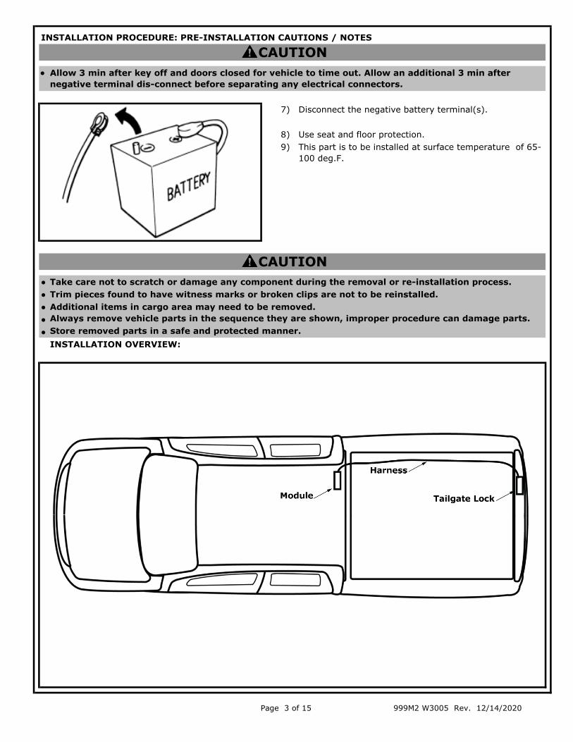
INSTALLATION OVERVIEW:
CAUTION
CAUTIONAllow 3 min after key off and doors closed for vehicle to time out. Allow an additional 3 min after negative terminal dis-connect before separating any electrical connectors.
This part is to be installed at surface temperature of 65-100 deg.F.
Disconnect the negative battery terminal(s).

Page 4 of 15 999M2 W3005 Rev. 12/14/2020
INSTALLATION PROCEDURE: (continued)
1)
2)
Note:
3)
4)
Remove 8 bolts and remove tailgate access panel. (Figure 1)
Set the cover aside with the tape facing up where the tape will not get dirty.
If tailgate is equipped with cover:a) Remove screws as in Step 1.b) Remove left and right push pin as shown in Fig.2. c) Remove cover and tailgate access panel.
If tailgate is equipped with rear view camera, disconnect and remove the existing tailgate harness and replace with the kit provided tailgate harness. (Figure 3)
Installation in reverse of removal.
Note:If tailgate not equipped with rear view camera, install the provided tailgate harness by following reverse of removal steps.
*** Notice ***If using part kit pn: 999T8 30005 on a 20MY vehicle the Tailgate Harness (24025 EZ04A/9FT1A) in the kit is not required. The tailgate harness included from any 999T8 30005 kit should be discarded for use on vehicles built from 2020 and beyond. All vehicles built begining in 2020 already have a tailgate harness which allows the Electronic Tailgate Lock actuator to be added.All 2020 model year vehicles and beyond should use the installation instructions for the 999T9 W3009 Kit.
Disconnect camera connector (if equipped). Disengage 2 XMAS tree clips. (Figure 4)
Notice:Tailgate Harnesses provided in this kit:24025 EZ04A part has black tailgate 6-pin conn-or-24025 9FT1A part has white tailgate 6-pin conn
-Either harness part is okay to use in the installation.
Fig. 2
Fig. 3
Fig. 1
Fig. 4
Camera Connector

Page 5 of 15 999M2 W3005 Rev. 12/14/2020
INSTALLATION PROCEDURE: (continued)
5)
6)
7)
Installation preparation:a)
b)
Remove original tailgate harness through hole under tailgate.
Replace with kitted tailgate harness. Installation is in reverse of removal.
Unclip body side plastic cover and disengage from opening. Pull out service length and disconnect inline connector from chassis harness.
Disengage clip and remove grommet.
Note:Clean mating surfaces of linkages with provided alcohol wipe and avoid any further oil contamination there.
8)Obtain Electronic Actuator assembly with upper adjustable linkage section attached with torque applied. (Figure 8)
Obtain lower adjustable linkage section and M4 x 0.7 x 8MM long socket head. Obtain cap screw with thread lock preapplied.
Fig. 6
Fig. 7
if. 8
Fig. 5
Clip Plastic Cover
Fig. 8
Upper adjustable link nesting fingerCAP
Screw
Lower Adjustable linkage Electronic
Actuator Assembly
Upper Linkage

Page 6 of 15 999M2 W3005 Rev. 12/14/2020
INSTALLATION PROCEDURE: (continued)
9)
NOTE:
10)
a)
b)
c)
NOTE:
NOTE:
d)
Hand assemble lower linkage to actuator assembly with provided CAP screw, finger tightening screw while allowing linkage to length adjust freely.
Pay special attention to orientation of the lower adjustable linkage. The nut will be pointing upward. The nesting finger in the upper actuator link is installed into the slot in the lower link as shown. (Figure 9) This assembly can be done off the vehicle.
Loosely position actuator link into position between bottom of plastic tailgate lock lever arm and top of key cylinder lock-rod, then reposition key lock cylinder into tailgate handle mechanism and hand tighten key cylinder lock screw.
Allow the actuator to lay in the tailgate rotated about 45° CW from its final installation location so that you can install the key lock cylinder and tighten its fastener.
With key cylinder lock-rod in position, torque M5 screw to (5-6.5 Nm) using 10mm socket and extension (Figure 10-C).
Install Electronic Actuator assembly onto Key Cylinder lock-rod:
Using 10mm socket and extension, remove key cylinder lock screw. (Figure 10)
Tilting key cylinder lock-rod off alignment peg, remove from slotted plastic tailgate lock lever arm, for ease of installation of electronic actuator. (Figure 10-B)
Pay special attention to orientation of linkage. Ensure M4 socket head CAP screw is pointing outward, so adjustable linkages can be operator adjusted and tightened, as shown (Figure 10-C) All of these features should be visable to the installer.
Fig. #cFig. 2Fig. 9
NestedFinger
Fig. 10-B
Fig. 10
Fig. 10-C

Page 7 of 15 999M2 W3005 Rev. 12/14/2020
INSTALLATION PROCEDURE: (continued)
Mounting Electronic Actuator:a)
b)
12)
NOTE:
13)
14) Move key cylinder lock pin with the key to unlock position (Actuator FULLY extended ) and let it rest there.
NOTE:The pin should again fully reach into the right most upper corner of the plastic tailgate lock lever arm as shown. (Figure 14)
Return key cylinder lock pin with the key to lock position (Actuator NOT extended ) and let it rest there.
Notice:The pin should fully reach into the left most corner of the plastic tailgate lock lever arm as shown, and stay there in a relaxed state. (Figure 13)
Move key cylinder lock pin by hand to unlock position (Actuator FULLY extended) and allow linkage to rest there.
Key cylinder lock pin should fully reach into the far right most upper corner of plastic tailgate lock lever arm, and actuator linkage should fully reach unlock position (as shown) and stay there in a relaxed state. (Figure 12)
Hold lever arm in place lightly to tighten M4 CAP screw with a 3MM Hex bit socket driver to (3 Nm +/- 0.5 Nm). (Figure 12).
11)Position actuator bracket CCW under tailgate bracket. Ensure holes on actuator bracket are aligned with predrilled holes on tailgate bracket.
Install two M5 screws to bracket using 8mm swivel socket. Tighten screws to (3.2 - 4.8 Nm.)(Figure 11)
Fig. #c
Fig. 2
Fig. 14
Fig.12
Fig. 13
Fig. 11
Tighten TwoScrews to Bracket
Top of Tailgate
Pin
Tighten to 3Nm

Page 8 of 15 999M2 W3005 Rev. 12/14/2020
INSTALLATION PROCEDURE: (continued)
Connecting harness to actuator.
a)
b)
c) Foam tape inline connectors, to prevent rattle within tailgate. (Fig. 16-C)
15)
16)
Cyclying with the key between unlock position (Actuator FULLY extended) and lock position (Actuator NOT extended). It should function easily and fully.
Key cylinder lock pin should easily traverse and then rest between (Unlock = Actuator FULLY extended) in right most corner of plastic tailgate lock lever arm, and (Lock = Actuator NOT extended) with plastic tailgate lock lever arm reaching into left most corner of plastic tailgate lock lever arm.
Notice: Once the alignment is completed: 1) The paint mark indicating the M4 CAP screw was torqued as specified. 2) Apply paint mark in a manner that bears a witness mark for the position/relationship of both parts at the time of assembly. (Figure 15)
Connect mating connector on tailgate actuator and secure harness with 8"cable tie. (Fig 16)
If tailgate is not equipped with rear view camera, bend unused camera connector back and secure with cable ties to tailgate harness as shown. (Fig. 16-B)
Fig. 16
Fig. 16-B
Fig. 16-C
Cable Tie
Cable Ties
Fig. 15
12

Page 9 of 15 999M2 W3005 Rev. 12/14/2020
INSTALLATION PROCEDURE: (continued)
NOTE:•
•
• Do not foam tape these inline connectors.
Fold down rear passenger seat.19)
17)
18) Cable tie harness to vehicle chassis harness using two 8" cable ties. (Figure 18)
Connect tailgate harness to the kit provided tailgate main harness (999M2 W3002).(Figure 17)
Do not secure either tailgate harness or kit provided tailgate main harness (999M2 W3002) for the first (200 mm = 8 inches) to the vehicle. Wire harness ends must be able to exist in vehicle if customer removes tailgate in normal operation. Length is required to allow customer to access connector from above. (Figure 18)
Secure inlines so they don't hang or bang around underbody.
Note:Route main harness along chassis harness as shown in fig 24. Only up until the back of the cab near the grommet.Do not secure with wire ties until step 24.
Fig. #cFig. 17
Fig. 18
Fig. 19
Cable Tie
Tailgateharness
Chassis
Tailgate harness
Tailgate main harness

Page 10 of 15 999M2 W3005 Rev. 12/14/2020
INSTALLATION PROCEDURE: (continued)
a)
21) Remove door trim seal and trim.a) Unclip lower D pillar trim. (Fig 21)b)
c) Unclip upper D-pillar trim. (Fig 21)
22)a)
b)
c)
Remove 6 pc panel clip and 2 bolts using 12mm socket. (Figure 22)
Vehicles equipped with a storage box:
Remove the under seat storage box, by loosening the retaining screws, using a 10mm hex socket.(Fig 20)
Pull section of rear passenger door seal out and lose up the trim panel. (Fig 21)
Note:Storage Box Screw Torque:8 N·m (0.82 kg-m, 71 in-lb) (Fig 20)
20)
Pull back panel for access to hole location with plastic grommet on rear of cab on lower passenger side. (Figures 22 and 22-B)
Accessing harness pass through hole.
Remove plastic grommet. (Figure 22-B)
Note: On Crew Cab (CC) & King Cab (KC)Seatback Striker Bolt Torque:23.5 N·m (2.4 kg-m, 17 Ft-lb) (Fig 22)
Fig. 22
Fig. 20
Screws
Fig. 22-B
Lower D-Pillar Trim
Upper D-pillar trim
Door seal
Fig. 21
Plastic grommet
Seatback

Page 11 of 15 999M2 W3005 Rev. 12/14/2020
INSTALLATION PROCEDURE: (continued)
23) Route harness into cab.a)
b)
c)
24) Securing tailgate main harness to chassis harness.a)
b)
25)
NOTE:
Locate the white vehicle pre wired connector behind upper D-pillar trim and break away, then cut black tape to pull the connector free. (Figure 25)
It is easier to get to the connector from the back of the trim.
Bundle excess harness above rear suspension to 6"-8" length and cable tie to chassis harness with two 12" zip ties. Trim excess zip tie. (Figure 24-B)
Run tailgate main harness with plastic grommet into cab. Ensure blue tape on harness is lined up with grommet.
Clean surface with alcohol wipe and apply two blue tapes to cover grommet and harness. Apply bottom tape first then top tape on top of bottom tape. Make sure tape is covering entire grommet.
Install edge biter clip to body panel to secure harness. (Figure 23)
Cable tie tailgate main harness every 6-8" to chassis harness. (Figure 24)
Begin at front, stop at position above rear suspension, then from rear and continue to step "b" below.
Fig. #cFig. 23
Fig. 24
Connector
Fig. 24-B
Fig. 25
Bottom tape
Top tape

Page 12 of 15 999M2 W3005 Rev. 12/14/2020
INSTALLATION PROCEDURE: (continued)
26) Connecting relay harness to vehicle pre-wire connector.a)
b)
NOTE:
27) Connect relay harness to tailgate main harness.a)
b)
c)
●
●
WARNING
Do not cable tie around the seat belt that is also located in this area. (Figures 27-through-29)Only cable tie between the relay harness and the body harness.
Connect relay harness 999M2 W3003 connector (Black RH02) to tailgate main harness connector (Black RH02). (Figures 27 - 29)
Peel back double sided tape on relay assembly and adhere to body panel. Apply 15 lbs. pressure for 30 seconds. (Figures 27 - 29)
Foam wrap inline connectors, secure with blue tape as shown and cable ties as necessary.(Figures 27 - 29)
NOTES: 1) Position of relay assembly on the Standard Cab (SC) is between the cabin vent and the passenger door as shown. Blue tape the main tailgate harness above and inboard of where it comes out of the back cabin panel grommet. Vertically bundle wrap and cable tie all remaining main tailgate harness wire slack, between the back cabin panel grommet and the upper blue tape piece as shown. (Figure 27) 2) Position of relay assembly on Crew Cab (CC) is just inboard of the cabin vent on the back cabin panel as shown. Tape single wire harness section horizontally below the cabin vent onto the back cabin panel. Vertically bundle wrap cable tie all remaining main tailgate harness wire slack, between the back cabin panel grommet and the upper blue tape piece as shown. (Figure 28) 3) Cut off all cable tie ends.
Connect relay harness 999M2 W3003 connector (white NS03) to tailgate pre wire connector (white NS03). Foam tape inline connectors before securing to body harness with cable tie. (Figures 26-28)
Route relay harness over the top of the rear pillar lower finisher trim panel. Secure to back cabin panel above and inboard of the threaded stud with blue tape provided in kit. (Figure 26)
Ensure harness is routed from above the vehicle prewire connector of the vehicle; to clear the top of the plastic rear pillar lower finisher trim panel as shown. (Figures 26 & 27)
Fig. 26
Fig. 28
Foam tapeInline Connectors
Blue tape in kit
Blue tape in kitFoam tapeInline Connectors
Add cable ties
Foam tapeInlineConnectors
Blue tape in kit
Add cable ties
Add cable ties
Relay Assembly
Relay Assembly
Blue tape in kit
Route wire overtrim edge
Rear PillarLower Finisher
Trim Panel
Crew Cab(CC)
Standard Cab (SC) Fig. 27

Page 13 of 15 999M2 W3005 Rev. 12/14/2020
INSTALLATION PROCEDURE: (continued)
●●
27)
28)
Connect relay harness to tailgate main harness. (Continued)
CAUTIONDo not cable tie the harness to the cabin vent. (Figures 27 - 29)Do not horizontally tape or bundle wrap cable tie any remaining main tailgate harness wire slack, below the rear panel studs which are located below the cabin vents. Otherwise it could show, under the installed rear panel trim, when the rear seat is in the raised position. (Figures 27 - 29)
For King Cab vehicles with rear seat delete option.
NOTES: 1) Position of relay assembly on King Cab (KC) is just inboard of the cabin vent as shown. Tape single harness wire, out of the relay assembly, horizontally below the cabin vent onto the back cabin panel. (Figure 29)
2) Bundle wrap cable tie all remaining main tailgate harness wire slack, between the back cabin panel grommet and the relay assembly as shown. (Figure 29)
a) Remove the rear panel finisher. (Figure 30)b) Remove spare tire tools storage box and lid. (Figure
Fig. 29
Blue tape in kit
Blue tape in kit
CableTies
Relay Assembly
King Cab(KC)
Foam tapeInline Connectors
Back cabin panel grommet
Fig. 30
Fig. 31

Page 14 of 15 999M2 W3005 Rev. 12/14/2020
INSTALLATION PROCEDURE: (continued)
●
●
29)
30)
Install the harness and relay assembly on King Cab with rear seat delete option as shown. (Figure 32)
b) Install the harness and relay assembly on King Cab (KC) as previously described. Step # 27, (Figure 29)
CAUTION
The rear floor spacer must be cut out to gain access to the rear panel access hole for the exterior harness to pass from the underbody into the cabin.
Use a suitable cutting tool such as a snap knife, fillet knife, or saw blade to cut a wedge out of the Styrofoam rear floor spacer. (Figure 31)
Connect relay harness to tailgate main harness. (Continued)
a)
Use a suitable cutting tool such as a snap knife, fillet knife, or saw blade to cut a wedge out of the Styrofoam rear floor spacer. (Figure 31)
● Notice that the Styrofoam rear floor spacer is blocking the rear panel access pass through hole. (Figure 31)
Fig. 32
Fig. 31
Cut through thesetwo (2) dotted lineswith your knife
52 mm
52 mm
88 mm

Page 15 of 15 999M2 W3005 Rev. 12/14/2020
FINAL INSPECTION:
Functional check system
Press key fob to lock and check tailgate is locked.
Press key fob to unlock all doors and check that tailgate is unlocked.
Reinstall back panel and 6pc push clip. See Figure 22.
Reinstall bracket and tighten 2 pcs bolt to (20.6 - 26.5 Nm). See Figure 22.
Reinstall upper trim panel and door seal and lower panel. See Figure 21.
If this is a Standard Cab vehicle: Reinstall rear under seat storage bin. See Figure 20.
If this is a King Cab vehicle with the rear seat delete option: a) Reinstall rear panel and tighten 3 screws to 28 Nm. See Figure 30. b) Reinstall storage box and lid and tighten 3 screws to 17 Nm. See Figure 31.
Reinstall tailgate access panel and rubber panel if applicable and tighten 11 screws to 1.7-2.0Nm. See Figures 1 and 2.
Operate the right rear seat seatbelt to ensure that it extends and retracts without any concerns and confirm that it is not restricted by this installation. See Figures 27-through-29.
If vehicle is equipped with rear view camera. Check rear camera is functional.

Template 999M2 W3005 Rev. 12/14/2020
INSTALLATION PROCEDURE: (continued)
NOTE:
Template for the wedge cut-out of the Styrofoam rear floor spacer
Print this template out normally at 100%.
Cut through this dottededge with knife
112 mm
Tape aroundStyrofoam here
Tape toStyrofoam here

Mechanization 999M2 W3005 Rev. 12/14/2020
Tailgate Lock