Foreword - Nissan Owners Club Kenya
337
GUID-00ED9476-C29F-43BF-BD48-ED56F6A1A395 Welcome to the growing family of new NISSAN owners. This vehicle has been delivered to you with confidence. It has been produced using the latest techniques and strict quality control. This manual was prepared to help you understand the operation and maintenance of your vehicle so that you may enjoy many kilometers (miles) of driving pleasure. Please read through this manual before operating your vehicle. A separate Warranty Information & Maintenance Book- let explains details about the warranties covering your vehicle. Your NISSAN dealer knows your vehicle best. When you require any service or have any questions, we will be glad to assist you with the extensive resources available for you. IMPORTANT SAFETY INFORMATION GUID-012356BA-0065-4B5B-B8C3-2B9E48177EE6 Reminders for safety! GUID-4B8749D0-AE59-4E17-A1F0-CFAE2CFB6A0A Follow these important driving rules to help ensure a safe and complete trip for you and your passengers! . NEVER drive under the influence of alcohol or drugs. . ALWAYS observe posted speed limits and never drive too fast for conditions. . ALWAYS use your seat belts and appropriate child restraint systems. Preteen children should be seated in the rear seat. . ALWAYS provide information about the proper use of vehicle safety features to all occupants of the vehicle. . ALWAYS review this Owner’s Manual for important safety information. When reading the manual GUID-094B08F0-A4F3-43C5-B422-53E6C0F7A79F This manual includes information for all options available on this model. Therefore, you may find some information that does not apply to your vehicle. All information, specifications and illustrations in this manual are those in effect at the time of printing. NISSAN reserves the right to change specifications or designs without notice and without obligation. MODIFICATION OF YOUR VEHICLE GUID-C7904191-9956-452D-AED4-7FD92766F3B6 This vehicle should not be modified. Modification could affect its performance, safety or durability, and may even violate governmental regulations. In addition, damage or performance problems resulting from modifications may not be covered under NISSAN warranties. Read first — then drive safely GUID-F1B3FE1B-9282-43C0-82AE-C66B447BEF76 Before driving your vehicle, read this Owner’s Manual carefully. This will ensure familiarity with controls and maintenance requirements, assisting you in the safe operation of your vehicle. Throughout this manual we have used the symbol followed by the word WARNING. This is used to indicate the presence of a hazard that could cause death or serious personal injury. To avoid or reduce the risk, the procedures must be followed precisely. The symbol followed by the word CAUTION is also used throughout this manual to indicate the presence of a hazard that could cause minor or moderate personal injury or damages to your vehicle. To avoid or reduce the risk, the procedures must be followed carefully. SIC0697 If you see this symbol, it means “Do not do this” or “Do not let this happen”. NOS1274 If you see a symbol similar to these in an illustration, it means the arrow points to the front of the vehicle. NOS1275 Arrows in an illustration that are similar to these indicate movement or action. NOS1276 Arrows in an illustration that are similar to these call attention to an item in the illustration. Foreword
-
Upload
khangminh22 -
Category
Documents
-
view
0 -
download
0
Transcript of Foreword - Nissan Owners Club Kenya

Black plate (3,1)
[ Edit: 2013/ 4/ 5 Model: C12-A ]
GUID-00ED9476-C29F-43BF-BD48-ED56F6A1A395
Welcome to the growing family of new NISSANowners. This vehicle has been delivered to you withconfidence. It has been produced using the latesttechniques and strict quality control.
This manual was prepared to help you understand theoperation and maintenance of your vehicle so that youmay enjoy many kilometers (miles) of driving pleasure.Please read through this manual before operating yourvehicle.
A separate Warranty Information & Maintenance Book-let explains details about the warranties covering yourvehicle.
Your NISSAN dealer knows your vehicle best. Whenyou require any service or have any questions, we willbe glad to assist you with the extensive resourcesavailable for you.
IMPORTANT SAFETY INFORMATIONGUID-012356BA-0065-4B5B-B8C3-2B9E48177EE6
Reminders for safety!GUID-4B8749D0-AE59-4E17-A1F0-CFAE2CFB6A0A
Follow these important driving rules to help ensure asafe and complete trip for you and your passengers!
. NEVER drive under the influence of alcoholor drugs.
. ALWAYS observe posted speed limits andnever drive too fast for conditions.
. ALWAYS use your seat belts and appropriatechild restraint systems. Preteen childrenshould be seated in the rear seat.
. ALWAYS provide information about theproper use of vehicle safety features to alloccupants of the vehicle.
. ALWAYS review this Owner’s Manual forimportant safety information.
When reading the manualGUID-094B08F0-A4F3-43C5-B422-53E6C0F7A79F
This manual includes information for all optionsavailable on this model. Therefore, you may find someinformation that does not apply to your vehicle.
All information, specifications and illustrations in thismanual are those in effect at the time of printing.NISSAN reserves the right to change specifications ordesigns without notice and without obligation.
MODIFICATION OF YOUR VEHICLEGUID-C7904191-9956-452D-AED4-7FD92766F3B6
This vehicle should not be modified. Modification couldaffect its performance, safety or durability, and mayeven violate governmental regulations. In addition,damage or performance problems resulting frommodifications may not be covered under NISSANwarranties.
Read first — then drive safelyGUID-F1B3FE1B-9282-43C0-82AE-C66B447BEF76
Before driving your vehicle, read this Owner’s Manualcarefully. This will ensure familiarity with controls andmaintenance requirements, assisting you in the safeoperation of your vehicle.
Throughout this manual we have used the symbolfollowed by the word WARNING. This is used
to indicate the presence of a hazard that could causedeath or serious personal injury. To avoid or reduce therisk, the procedures must be followed precisely.
The symbol followed by the word CAUTION isalso used throughout this manual to indicate thepresence of a hazard that could cause minor ormoderate personal injury or damages to your vehicle.To avoid or reduce the risk, the procedures must befollowed carefully.
SIC0697
If you see this symbol, it means “Do not do this” or“Do not let this happen”.
NOS1274
If you see a symbol similar to these in an illustration, itmeans the arrow points to the front of the vehicle.
NOS1275
Arrows in an illustration that are similar to theseindicate movement or action.
NOS1276
Arrows in an illustration that are similar to these callattention to an item in the illustration.
Foreword
Condition:

Black plate (4,1)
[ Edit: 2013/ 2/ 25 Model: K13-A ]
Bluetooth® is a trademark ownedby Bluetooth SIG, Inc. and li-censed to Clarion Co., Ltd. andDaewoo IS Corp.
*C 2013 NISSAN MOTOR CO., LTD.
Condition:

Black plate (2,1)

Black plate (1,1)
Illustrated table of contents 0
Safety — seats, seat belts and supplementalrestraint system 1
Instruments and controls
Pre-driving checks and adjustments
Monitor, Heater and air conditioner, and audiosystem
Starting and driving
In case of emergency
Appearance and care
Maintenance and do-it-yourself
Technical information
Index
2
3
4
5
6
7
8
9
10
Table ofContents
[ Edit: 2013/ 2/ 25 Model: K13-A ]Condition:

Black plate (2,1)

Black plate (5,1)
[ Edit: 2013/ 2/ 25 Model: K13-A ]
0 Illustrated table of contents
Seats, seat belts and supplemental restraint system (SRS) ........... 0-2Exterior front .................................................................................................. 0-3Exterior rear ................................................................................................... 0-5Passenger compartment ............................................................................ 0-7Instrument panel .......................................................................................... 0-8
Left-Hand Drive (LHD) model .......................................................... 0-8Right-Hand Drive (RHD) model (Type A) ....................................... 0-9Right-Hand Drive (RHD) model (Type B) ................................... 0-10
Right-Hand Drive (RHD) model (Type C) ................................. 0-11Meters and gauges ................................................................................. 0-12Engine compartment ............................................................................. 0-15
HR12DDR engine model .............................................................. 0-15HR12DE engine model .................................................................. 0-16HR15DE engine model .................................................................. 0-17K9K engine model ........................................................................... 0-18
Condition:

Black plate (6,1)
[ Edit: 2013/ 2/ 25 Model: K13-A ]
0-2 Illustrated table of contents
GUID-9F4D2D75-FC90-4B85-A981-539364187A6D
JVC0101X
1. Child restraint anchor point (for top tether strapchild restraint)* (Page 1-18)
2. Rear seat belts (P.1-7)
3. Supplemental curtain side-impact air bags*(P.1-25)
4. Head restraints (P.1-5)
5. Front seat belts (P.1-7)
6. Supplemental side-impact air bags* (P.1-25)
7. Supplemental front-impact air bags* (P.1-25)
8. Rear center seat belts (for three-point type seatbelts)* (P.1-7)
9. ISOFIX child restraint system* (P.1-17)
10. Rear seats (P.1-4)
— Child restraints (P.1-13)
11. Pre-tensioner seat belt system* (P.1-31)
12. Front seats (P.1-2)
*: if equipped
SEATS, SEAT BELTS ANDSUPPLEMENTAL RESTRAINTSYSTEM (SRS)
Condition:

Black plate (7,1)
[ Edit: 2013/ 2/ 25 Model: K13-A ]
GUID-4F29C80F-8CE1-4BF1-906C-3DF45BAC934D
JVC0469X
Type A
1. Recovery hook (P.6-13)
2. Engine hood (P.3-19)
3. Windshield
— Wiper and washer switch (P.2-37)
— Wiper replacement (P.8-21)
— Washer fluid (P.8-23)
4. Antenna* (P.4-19)
5. Windows (P.2-40)
6. Fog lights*
— Switch operation (P.2-36)
— Bulb replacement (P.8-29)
7. Front turn signal lights
— Switch operation (P.2-35)
— Bulb replacement (P.8-30)
8. Clearance lights (for Micra Active)
— Switch operation (P.2-33)
— Bulb replacement (P.8-29)
9. Clearance lights (except for Micra Active)
— Switch operation (P.2-33)
— Bulb replacement (P.8-29)
10. Headlights
— Switch operation (P.2-33)
— Bulb replacement (P.8-29)
11. Parking space measurement sensors* (P.5-34)
12. Tires
— Tires and wheels (P.8-42, P.9-8)
— Flat tire (P.6-2)
13. Side turn signal lights
— Switch operation (P.2-35)
— Bulb replacement (P.8-30)
14. Outside rearview mirrors (P.3-22)
15. Doors
— Keys (P.3-2)
— Door locks (P.3-5)
— Intelligent Key system* (P.3-9)
— Remote keyless entry system* (P.3-7)
— Security system* (P.3-17)
16. Child safety rear door lock (P.3-7)
*: if equipped
Illustrated table of contents 0-3
EXTERIOR FRONT
Condition:

Black plate (8,1)
[ Edit: 2013/ 2/ 25 Model: K13-A ]
0-4 Illustrated table of contents
JVC0450X
Type B
1. Recovery hook (P.6-13)
2. Engine hood (P.3-19)
3. Windshield
— Wiper and washer switch (P.2-37)
— Wiper replacement (P.8-21)
— Washer fluid (P.8-23)
4. Antenna (P.4-19)
5. Windows (P.2-40)
6. Front turn signal lights
— Switch operation (P.2-35)
— Bulb replacement (P.8-30)
7. Fog lights*
— Switch operation (P.2-36)
— Bulb replacement (P.8-29)
8. Clearance lights
— Switch operation (P.2-33)
— Bulb replacement (P.8-29)
9. Headlights
— Switch operation (P.2-33)
— Bulb replacement (P.8-29)
10. Tires
— Tires and wheels (P.8-42, P.9-8)
— Flat tire (P.6-2)
11. Side turn signal lights
— Switch operation (P.2-35)
— Bulb replacement (P.8-30)
12. Outside rearview mirrors (P.3-22)
13. Doors
— Keys (P.3-2)
— Door locks (P.3-5)
— Intelligent Key system* (P.3-9)
— Remote keyless entry system* (P.3-7)
— Security system* (P.3-17)
14. Child safety rear door lock (P.3-7)
*: if equipped
Condition:
Black plate (9,1)
[ Edit: 2013/ 2/ 25 Model: K13-A ]
GUID-5B9FAF64-0C18-4ABA-84B2-68CDBE51010C
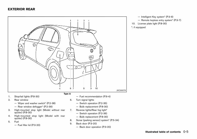
JVC0007X
Type A
1. Stop/tail lights (P.8-30)
2. Rear window
— Wiper and washer switch* (P.2-38)
— Rear window defogger* (P.2-39)
3. High-mounted stop light (Model without rearspoiler) (P.8-30)
4. High-mounted stop light (Model with rearspoiler) (P.8-30)
5. Fuel
— Fuel filler lid (P.3-20)
— Fuel recommendation (P.9-4)
6. Turn signal lights
— Switch operation (P.2-35)
— Bulb replacement (P.8-30)
7. Reverse lights/Rear fog light*
— Switch operation (P.2-36)
— Bulb replacement (P.8-30)
8. Sonar (parking sensor) system* (P.5-34)
9. Back door (P.3-20)
— Back door operation (P.3-20)
— Intelligent Key system* (P.3-9)
— Remote keyless entry system* (P.3-7)
10. License plate light (P.8-30)
*: if equipped
Illustrated table of contents 0-5
EXTERIOR REAR
Condition:

Black plate (10,1)
[ Edit: 2013/ 2/ 25 Model: K13-A ]
0-6 Illustrated table of contents
JVC0451X
Type B
1. Stop/tail lights (P.8-30)
2. Rear window
— Wiper and washer switch* (P.2-38)
— Rear window defogger* (P.2-39)
3. High-mounted stop light (Model without rearspoiler) (P.8-30)
4. High-mounted stop light (Model with rearspoiler) (P.8-30)
5. Fuel
— Fuel filler lid (P.3-20)
— Fuel recommendation (P.9-4)
6. Turn signal lights
— Switch operation (P.2-35)
— Bulb replacement (P.8-30)
7. Reverse lights
— Bulb replacement (P.8-30)
8. Sonar (parking sensor) system* (P.5-34)
9. Rearview camera for rearview monitor* (P. 4-2)
10. Rear fog light*
— Switch operation (P.2-36)
— Bulb replacement (P.8-30)
11. Back door (P.3-20)
— Back door operation (P.3-20)
— Intelligent Key system* (P.3-9)
— Remote keyless entry system* (P.3-7)
12. License plate light (P.8-30)
*: if equipped
Condition:

Black plate (11,1)
[ Edit: 2013/ 2/ 25 Model: K13-A ]
GUID-025177D1-6641-4E78-A6B5-38C0062346DC
JVC0102X
1. Tonneau board* (P.2-45)
2. Door armrest
— Power window switch* (P.2-40)
— Power door lock switch* (models with powerwindows) (P.3-6)
3. Fuse box (P.8-28)
4. Sun visor (P.2-45)
5. Sunshade* (P.2-42)
6. Room light (P.2-46, P.8-31)
7. Inside rearview mirror (P.3-21)
8. Rear cup holder (P.2-44)
9. Center console
— Heated seats switch* (P.1-3)
— Power door lock switch* (models withoutpower windows) (P.3-6)
10. Parking brake (P.3-24, P.8-18)
11. Shift lever
— Automatic Transmission (AT) (P.5-11)
— Continuously Variable Transmission (CVT)(P.5-14)
— Manual Transmission (MT) (P.5-17)
12. Front cup holder (P.2-44)
13. Glove box (P.2-44)
*: if equipped
Illustrated table of contents 0-7
PASSENGER COMPARTMENT
Condition:

Black plate (12,1)
[ Edit: 2013/ 2/ 25 Model: K13-A ]
0-8 Illustrated table of contents
GUID-98DDFB8E-C28C-4AF8-9161-BB7348069090
LEFT-HAND DRIVE (LHD) MODELGUID-8485E838-E199-4C0F-B363-975F75B28CC4
JVI0261X
Example
1. Vehicle Dynamic Control (VDC) OFF switch*(P.5-24) or Electronic Stability Program (ESP)OFF switch* (P.5-27)
2. Parking space measurement switch* (P.5-34)
3. Headlight, fog light* and turn signal switch(P.2-33)
4. Steering-wheel-mounted controls (left side)*
— Audio control* (P.4-63)
— Bluetooth® Hands-Free Phone System con-
trol (without navigation system)* (P.4-64)
— Bluetooth® Hands-Free Phone System con-trol (with navigation system)**
5. Driver’s front-impact air bag/Horn (P.1-25,P.2-40)
6. Meters and gauges (P.2-6)
7. Steering-wheel-mounted controls (right side)*
— Cruise control switches* (P.5-30)
— Speed limiter switches* (P.5-28)
8. Wiper and washer switch (P.2-37)
9. Center ventilator (P.4-5)
10. Rear window defogger switch* (P.2-39)
11. Hazard indicator flasher switch (P.6-2)
12. Heater and air conditioner* control (P.4-6)
13. Audio system* (P.4-11 or Navigation system**)
14. Passenger’s front-impact air bag* (P.1-25)
15. Upper instrument box* (P.2-44)
16. Side ventilator (P.4-5)
17. Headlight aiming control switch* (P.2-34)
18. Outside rearview mirror control switch* (P.3-22)
19. Fuel filler lid release handle (P.3-20)
20. Hood lock release handle (P.3-19)
21. Stop/Start System OFF switch* (P.5-23)
22. Tilting steering wheel lock lever (P.3-21)
23. Ignition switch (model without Intelligent Keysystem)/steering lock (P.5-5)
24. Push-button ignition switch (model with Intelli-gent Key system) (P.5-6)
25. Cup holder (P.2-44)
26. Shift lever
— Automatic Transmission (AT) model (P.5-11)
— Continuously Variable Transmission (CVT)model (P.5-14)
— Manual Transmission (MT) model (P.5-17)
27. Power outlet* (P.2-43) or USB/AUX connector(with navigation system)**
28. Glove box (P.2-44)
*: if equipped
**: Refer to the separate NISSAN Connect Owner’sManual (if equipped).
INSTRUMENT PANEL
Condition:

Black plate (13,1)
[ Edit: 2013/ 2/ 25 Model: K13-A ]
RIGHT-HAND DRIVE (RHD) MODEL (Type A)GUID-78858CCA-AACD-49C5-9B5E-3B2F2704C1E4
JVI0262X
Example
1. Side ventilator (P.4-5)
2. Upper instrument box* (P.2-44)
3. Passenger’s front-impact air bag* (P.1-25)
4. Audio system* (P.4-11 or Navigation system**)
5. Rear window defogger switch* (P.2-39)
6. Hazard indicator flasher switch (P.6-2)
7. Heater and air conditioner* control (P.4-6)
8. Center ventilator (P.4-5)
9. Wiper and washer switch (P.2-37) or Headlight,fog light and turn signal switch (P.2-33)
10. Steering-wheel-mounted controls (left side)*
— Audio control* (P.4-63)
— Bluetooth® Hands-Free Phone System con-trol (without navigation system)* (P.4-64)
— Bluetooth® Hands-Free Phone System con-trol (with navigation system)**
11. Meters and gauges (P.2-6)
12. Driver’s front-impact air bag*/Horn (P.1-25,P.2-40)
13. Steering-wheel-mounted controls (right side)*
— Cruise control switches* (P.5-30)
— Speed limiter switches* (P.5-28)
14. Headlight, fog light* and turn signal switch(P.2-33) or Wiper and washer switch (P.2-37)
15. Parking space measurement switch* (P.5-34)
16. Vehicle Dynamic Control (VDC) OFF switch*(P.5-24, P.5-25) or Electronic Stability Program(ESP) OFF switch* (P.5-27)
17. Fuse box (P.8-28)
18. Glove box (P.2-44)
19. Power outlet* (P.2-43) or USB/AUX connector(with navigation system)**
20. Shift lever
— Automatic Transmission (AT) model (P.5-11)
— Continuously Variable Transmission (CVT)model (P.5-14)
— Manual Transmission (MT) model (P.5-17)
21. Cup holder (P.2-44)
22. Push-button ignition switch (model with Intelli-gent Key system) (P.5-6)
23. Tilting steering wheel lock lever (P.3-21)
24. Ignition switch (model without Intelligent Keysystem)/steering lock (P.5-5)
25. Stop/Start System OFF switch* (P.5-23)
26. Hood lock release handle (P.3-19)
27. Fuel filler lid release handle (P.3-20)
28. Outside rearview mirror control switch* (P.3-22)
29. Headlight aiming control switch* (P.2-34)
*: if equipped
**: Refer to the separate NISSAN Connect Owner’sManual (if equipped).
Illustrated table of contents 0-9
Condition:

Black plate (14,1)
[ Edit: 2013/ 2/ 25 Model: K13-A ]
0-10 Illustrated table of contents
RIGHT-HAND DRIVE (RHD) MODEL (Type B)GUID-49CE9F94-E9C6-4D5D-A4A3-7B097C7E9802
JVI0170X
Example
1. Side ventilator (P.4-5)
2. Upper instrument box* (P.2-44)
3. Passenger’s front-impact air bag* (P.1-25)
4. Audio system* (P.4-11 or Navigation system**)
5. Rear window defogger switch* (P.2-39)
6. Hazard indicator flasher switch (P.6-2)
7. Heater and air conditioner* control (P.4-6)
8. Center ventilator (P.4-5)
9. Wiper and washer switch (P.2-37)
10. Steering-wheel-mounted controls (left side)*
— Audio control* (P.4-63)
— Bluetooth® Hands-Free Phone System con-trol (without navigation system)* (P.4-64)
— Bluetooth® Hands-Free Phone System con-trol (with navigation system)**
11. Meters and gauges (P.2-6)
12. Driver’s front-impact air bag*/Horn (P.1-25,P.2-40)
13. Steering-wheel-mounted controls (right side)*
— Cruise control switches* (P.5-30)
— Speed limiter switches* (P.5-28)
14. Headlight, fog light* and turn signal switch(P.2-33)
15. Outside rearview mirror control switch* (P.3-22)
16. Fuse box (P.8-28)
17. Glove box (P.2-44)
18. Power outlet* (P.2-43) or USB/AUX connector(with navigation system)**
19. Cup holder (P.2-44)
20. Shift lever
— Automatic Transmission (AT) model (P.5-11)
— Continuously Variable Transmission (CVT)model (P.5-14)
— Manual Transmission (MT) model (P.5-17)
21. Push-button ignition switch (model with Intelli-gent Key system) (P.5-6)
22. Tilting steering wheel lock lever (P.3-21)
23. Ignition switch (model without Intelligent Keysystem)/steering lock (P.5-5)
24. Hood lock release handle (P.3-19)
25. Fuel filler lid release handle (P.3-20)
26. Parking space measurement switch* (P.5-34)
27. Vehicle Dynamic Control (VDC) OFF switch*(P.5-24)
28. Headlight aiming control switch* (P.2-34)
*: if equipped
**: Refer to the separate NISSAN Connect Owner’sManual (if equipped).
Condition:

Black plate (15,1)
[ Edit: 2013/ 2/ 25 Model: K13-A ]
RIGHT-HAND DRIVE (RHD) MODEL (Type C)GUID-9BAFCD9F-77F5-47BB-BDFD-D12FA3B67B88
JVC0449X
Example
1. Side ventilator (P.4-5)
2. Upper instrument box* (P.2-44)
3. Passenger’s front-impact air bag* (P.1-25)
4. Audio system* (P.4-11)
5. Rear window defogger switch* (P.2-39)
6. Hazard indicator flasher switch (P.6-2)
7. Heater and air conditioner* control (P.4-6)
8. Center ventilator (P.4-5)
9. Wiper and washer switch (P.2-37)
10. Steering-wheel-mounted controls (left side)*
— Audio control* (P.4-63)
— Bluetooth® Hands-Free Phone System con-trol* (P.4-64)
11. Meters and gauges (P.2-6)
12. Driver’s front-impact air bag*/Horn (P.1-25,P.2-40)
13. Headlight, fog light* and turn signal switch(P.2-33)
14. Outside rearview mirror control switch* (P.3-22)
15. Fuse box (P.8-28)
16. Glove box (P.2-44)
17. USB/AUX connector* (P. 4-41, P. 4-48)
18. Power outlet* (P. 2-43)
19. Cup holder (P.2-44)
20. Shift lever
— Continuously Variable Transmission (CVT)model (P.5-14)
— Manual Transmission (MT) model (P.5-17)
21. Push-button ignition switch (model with Intelli-gent Key system) (P.5-6)
22. Tilting steering wheel lock lever (P.3-21)
23. Ignition switch (model without Intelligent Keysystem)/steering lock (P.5-5)
24. Hood lock release handle (P.3-19)
25. Fuel filler lid release handle (P.3-20)
26. Idling Stop OFF switch* (P. 5-19)
27. Headlight aiming control switch* (P.2-34)
*: if equipped
Illustrated table of contents 0-11
Condition:

Black plate (16,1)
[ Edit: 2013/ 2/ 25 Model: K13-A ]
0-12 Illustrated table of contents
GUID-065ED8FC-7483-4045-BD76-0E5802E9C7D3
JVC0453X
Type A
1. Speedometer (P.2-8)
2. Trip odometer reset switch/trip computer modeswitch (P.2-8)
3. Clock adjusting knob (P.2-42)
4. Automatic Transmission (AT) position indicator*(P.2-10, P.5-11)
5. Odometer/twin trip odometer/trip computer(P.2-8)/clock (P.2-42)
6. Fuel gauge (P.2-10)
*: if equipped
METERS AND GAUGES
Condition:

Black plate (17,1)
[ Edit: 2013/ 2/ 25 Model: K13-A ]
JVC0454X
Type B
1. Tachometer (P.2-10)
2. Speedometer (P.2-8)
3. Trip odometer reset switch/trip computer modeswitch (P.2-8)
4. Clock adjusting knob (P.2-42)
5. Automatic Transmission (AT)/Continuously Vari-able Transmission (CVT) position indicator*(P.2-10, P.5-11)/Cruise control and speed limit-er display* (P.5-30, P.5-28)
6. Odometer/twin trip odometer/trip computer(P.2-8)/clock (P.2-42)
7. Fuel gauge (P.2-10)
*: if equipped
Illustrated table of contents 0-13
Condition:

Black plate (18,1)
[ Edit: 2013/ 2/ 25 Model: K13-A ]
0-14 Illustrated table of contents
JVC0455X
Type C
1. Tachometer (P.2-10)
2. Speedometer (P.2-8)
3. Vehicle information display (P.2-10, P.2-20)
4. Trip odometer reset switch (P.2-8)
5. Automatic Transmission (AT)/Continuously Vari-able Transmission (CVT) position indicator*(P.2-10, P.5-11)
6. Odometer/twin trip odometer/clock (P.2-8)
*: if equipped
Condition:

Black plate (19,1)
[ Edit: 2013/ 2/ 25 Model: K13-A ]
GUID-095DCB79-DC2C-4D0E-9537-1ACFFB10F6C9
HR12DDR ENGINE MODELGUID-15DFFEDB-5D04-4613-8FE8-4FF21F03A9C1
JVO0032X
1. Brake and clutch* fluid reservoir (P.8-19,P.8-20)
— Right-Hand Drive (RHD) model
2. Engine drive belts (P.8-16)
3. Engine oil filler cap (P.8-11)
4. Air cleaner (P.8-21)
5. Brake and clutch* fluid reservoir (P.8-19,P.8-20)
— Left-Hand Drive (LHD) model
6. Fuse/fusible link box (P.8-27)
7. Window washer fluid reservoir (P.8-23)
8. Engine oil dipstick (P.8-11)
9. Radiator cap (P.8-9)
10. Battery (P.8-24)
11. Engine coolant reservoir (P.8-10)
*: For Manual Transmission (MT) Model
Illustrated table of contents 0-15
ENGINE COMPARTMENT
Condition:

Black plate (20,1)
[ Edit: 2013/ 2/ 25 Model: K13-A ]
0-16 Illustrated table of contents
HR12DE ENGINE MODELGUID-EEE0B27B-AFE5-494C-8F7A-24BC07449160
JVC0452X
1. Engine drive belts (P.8-16)
2. Brake and clutch* fluid reservoir (P.8-19,P.8-20)
— Right-Hand Drive (RHD) model
3. Engine oil filler cap (P.8-11)
4. Air cleaner (P.8-21)
5. Brake and clutch* fluid reservoir (P.8-19,P.8-20)
— Left-Hand Drive (LHD) model
6. Fuse/fusible link box (P.8-27)
7. Window washer fluid reservoir (P.8-23)
8. Engine oil dipstick (P.8-11)
9. Radiator cap (P.8-9)
10. Battery (P.8-24)
11. Engine coolant reservoir (P.8-10)
*: For Manual Transmission (MT) Model
Condition:

Black plate (21,1)
[ Edit: 2013/ 2/ 25 Model: K13-A ]
HR15DE ENGINE MODELGUID-BE6F299A-3379-4686-A8D8-F56ABA3A72F6
JVC0118X
1. Engine drive belts (P.8-16)
2. Brake and clutch* fluid reservoir (P.8-19,P.8-20)
— Right-Hand Drive (RHD) model
3. Engine oil filler cap (P.8-11)
4. Air cleaner (P.8-21)
5. Brake and clutch* fluid reservoir (P.8-19,P.8-20)
— Left-Hand Drive (LHD) model
6. Fuse/fusible link box (P.8-27)
7. Window washer fluid reservoir (P.8-23)
8. Engine oil dipstick (P.8-11)
9. Radiator cap (P.8-9)
10. Battery (P.8-24)
11. Engine coolant reservoir (P.8-10)
*: For Manual Transmission (MT) Model
Illustrated table of contents 0-17
Condition:

Black plate (22,1)
[ Edit: 2013/ 2/ 25 Model: K13-A ]
0-18 Illustrated table of contents
K9K ENGINE MODELGUID-8CE2311C-63B0-4636-A916-9EC2BD9653CF
SDI2711
1. Brake and clutch fluid reservoir (P.8-19, P.8-20)
2. Air cleaner (P.8-21)
3. Fuse/Fusible link holders (P.8-27)
4. Priming pump (P.8-16)
5. Window washer fluid reservoir (P.8-23)
6. Engine drive belts (P.8-16)
7. Engine oil filler cap (P.8-11)
8. Engine oil dipstick (P.8-11)
9. Engine coolant reservoir (P.8-10)
— Vehicle overheat (P.6-11)
10. Battery (P.8-24)
Condition:

Black plate (23,1)
[ Edit: 2013/ 2/ 25 Model: K13-A ]
1 Safety — seats, seat belts and supplementalrestraint system
Seats ............................................................................................................... 1-2Front seats .............................................................................................. 1-2Rear seats ............................................................................................... 1-4Head restraints (if equipped) ............................................................. 1-5Armrest (if equipped) ........................................................................... 1-6
Seat belts ...................................................................................................... 1-7Precautions on seat belt usage ........................................................ 1-7Child safety ............................................................................................. 1-8Pregnant women ................................................................................... 1-9Injured persons ...................................................................................... 1-9Center mark on seat belts .................................................................. 1-9Three-point type seat belts ................................................................ 1-9Two-point type seat belts (if equipped) ....................................... 1-12Seat belt maintenance ...................................................................... 1-13
Child restraints ......................................................................................... 1-13Precautions on child restraint usage .......................................... 1-13Universal child restraints for front seat and rear seats(for Europe and Ukraine) ............................................................... 1-14ISOFIX child restraint system (if equipped) ............................. 1-17Child restraint anchorage (if equipped) .................................... 1-18Child restraint installation using ISOFIX .................................... 1-19Child restraint installation using seat belt ................................. 1-21
Supplemental Restraint System (SRS) (if equipped) .................... 1-25Precautions on Supplemental Restraint System (SRS) ........ 1-25Supplemental air bag systems ..................................................... 1-29Pre-tensioner seat belt system (if equipped) ........................... 1-31Repair and replacement procedure ............................................ 1-32
Condition:

Black plate (24,1)
[ Edit: 2013/ 2/ 25 Model: K13-A ]
1-2 Safety — seats, seat belts and supplemental restraint system
GUID-0436B542-879E-4ABF-B2D7-322787F22D25
SSS0133A
WARNING:
. Do not drive and/or ride in the vehicle withthe seatback reclined. This can be danger-ous. The shoulder belt will not be properlyagainst the body. In an accident, you andyour passengers could be thrown into theshoulder belt and receive neck or otherserious injuries. You and your passengerscould also slide under the lap belt andreceive serious injuries.
. For the most effective protection while thevehicle is in motion, the seatback should beupright. Always sit well back in the seat andadjust the seat belt properly. (See “Seatbelts” (P.1-7).)
CAUTION:
When adjusting the seat positions, be sure notto contact any moving parts to avoid possibleinjuries and/or damages.
FRONT SEATSGUID-4D1E7B4E-F45E-48AA-B4C0-016C3D114635
WARNING:
Do not adjust the driver’s seat while driving sothat full attention may be given to vehicleoperation.
Manual seat adjustmentGUID-A841D004-994E-4CE4-9B43-88401CB148B9
WARNING:
After adjusting a seat, gently shake the seat toconfirm that the seat is locked securely. If theseat is not locked securely, it may movesuddenly and could cause the loss of control ofthe vehicle.
SEATS
Condition:

Black plate (25,1)
[ Edit: 2013/ 2/ 25 Model: K13-A ]
JVR0217X
Forward and backward:GUID-9E14C2E6-2E9C-4731-980B-C45B899B977B
1. Pull up the adjusting lever*1 .
2. Slide the seat to the desired position.
3. Release the adjusting lever to lock the seat inposition.
Reclining:GUID-9E14C2E6-2E9C-4731-980B-C45B899B977B
1. Pull up the adjusting lever*2 .
2. Tilt the seatback to the desired position.
3. Release the adjusting lever to lock the seatback inposition.
The reclining feature allows the adjustment of theseatback for occupants of different sizes to help obtainthe proper seat belt fit. (See “Seat belts” (P.1-7).)
The seatback may be reclined to allow occupants torest when the vehicle is parked.
Seat lifter (if equipped):GUID-9E14C2E6-2E9C-4731-980B-C45B899B977B
Pull up or push down the adjusting lever*3 to adjustthe seat height until the desired position is achieved.
Heated seats (if equipped)GUID-D36C2EDC-C2E9-421C-A77D-9679495487D3
SIC2770
The seats can be warmed by built-in heaters. Theswitches located on the center console can beoperated independently of each other.
1. Start the engine.
2. Select heat range.. For high heat, push the HI (High) side of the
switch*1 .. For low heat, push the LO (Low) side of the
switch*2 .
. The indicator light*3 will illuminate when lowor high is selected.
3. To turn off the heater, return the switch to the levelposition. Make sure the indicator light turns off.
The heater is controlled by a thermostat, automaticallyturning the heater on and off. The indicator light willremain on as long as the switch is on.
When the vehicle’s interior is warmed, or before youleave the vehicle, be sure to turn off the switch.
CAUTION:
. The battery could run down if the seat heateris operated while the engine is not running.
. Do not use the seat heater for extendedperiods or when no one is using the seat.
. Do not put anything on the seat whichinsulates heat, such as a blanket, cushion,seat cover, etc. Otherwise, the seat maybecome overheated.
. Do not place anything hard or heavy on theseat or pierce it with a pin or similar object.This may result in damage to the seat heater.
. Any liquid spilled on the heated seat shouldbe removed immediately with a dry cloth.
. When cleaning the seat, never use gasoline,thinner, or any similar materials.
. If any malfunctions are found or the heatedseat does not operate, turn the switch offand have the system checked by a NISSANdealer.
Safety — seats, seat belts and supplemental restraint system 1-3
Condition:

Black plate (26,1)
[ Edit: 2013/ 2/ 25 Model: K13-A ]
1-4 Safety — seats, seat belts and supplemental restraint system
REAR SEATSGUID-437AE5ED-D0FB-48A6-AAC6-03CA1D7D09A0
AdjustmentGUID-D2DC58C7-3096-4AFC-BECC-96E4D8B84335
WARNING:
. Never allow anyone to ride in the luggagearea or on the rear seats when they are inthe fold-down position. Use of these areasby passengers without proper restraintscould result in serious injury in an accidentor sudden stop.
. Do not fold down the rear seats whenoccupants are in the rear seat area or anyluggage is on the rear seats.
. Properly secure all luggage to help prevent itfrom sliding or shifting. Do not place lug-gage higher than the seatbacks.
. When returning the seatbacks to the uprightposition, be certain they are completelysecured in the latched position. If they arenot completely secured, passengers may beinjured in an accident or sudden stop.
Folding (Type A):GUID-9E14C2E6-2E9C-4731-980B-C45B899B977B
SSS0789
1. Store the seat belts in the proper position. (See“Three-point type seat belts” (P.1-9).)
2. Pull the knob to fold the seatback down.
Passing the seat belt through the path (if equipped):
JVR0006X
CAUTION:
. Fold down the rear seatback with the rearcenter seat belt passed through the path*Aon the seatback.
. When loading the luggage in the luggageroom, be careful not to scratch or damagethe seat belt.
If the rear seatback needs to be folded withoutpassing the seat belt through the path*A , besure to observe the following items.
. After returning the rear seatback to itsoriginal position, pass the seat belt throughthe path*A .
. When operating the seatback, be careful notto scratch or damage the seat belt.
Condition:

Black plate (27,1)
[ Edit: 2013/ 2/ 25 Model: K13-A ]
Folding (Type B):GUID-9E14C2E6-2E9C-4731-980B-C45B899B977B
JVR0007X
1. Secure the seat belt on the clip.
2. Pull up the knob*1 and fold the seatback down.
3. Pull the strap *2 and lift the rear of the seatcushion and the seatback.
Securing of the folded rear seat (if equipped):GUID-9E14C2E6-2E9C-4731-980B-C45B899B977B
JVR0008X
1. Remove the hook *1 from the anchor on theunderside of the cushion.
2. Secure the hook*2 on the stalk as illustrated.
WARNING:
. Never allow anyone to ride in the luggagearea or on the rear seats when they are inthe fold-down position. Use of these areasby passengers without proper restraintscould result in serious injury in an accidentor sudden stop.
. Do not fold down the rear seats whenoccupants are in the rear seat area or anyluggage is on the rear seats.
. Properly secure all luggage to help prevent itfrom sliding or shifting. Do not place lug-gage higher than the seatbacks.
. When returning the seatbacks to the uprightposition, be certain they are completelysecured in the latched position. If they arenot completely secured, passengers may beinjured in an accident or sudden stop.
. Head restraints should be adjusted properlyas they may provide significant protectionagainst whiplash injury. Always replace andadjust them properly if they have been
removed for any reason.
HEAD RESTRAINTS (if equipped)GUID-11A4B2B7-3A2F-4541-97C6-81111CF51199
SSS0287
WARNING:
Do not drive and/or ride in the vehicle with thehead restraint removed. This can be dangerous.Head restraints should be adjusted properly asthey may provide significant protection againstinjury in an accident. Check the height aftersomeone else uses the seat.
The proper adjustment of the head restraint is asillustrated.
Adjust the head restraint so that the head restraint’scenter is level with the center of the ears.
Safety — seats, seat belts and supplemental restraint system 1-5
Condition:

Black plate (28,1)
[ Edit: 2013/ 2/ 25 Model: K13-A ]
1-6 Safety — seats, seat belts and supplemental restraint system
AdjustmentGUID-D2BCC152-0C29-4A82-9C64-EAADE1FB59C4
SSS0288
1. Pull up the head restraint to raise to the properposition.
2. Push in the lock knob *1 and push down thehead restraint to lower to the proper position.
The rear head restraint (if equipped) should only beused in the notched stem positions. The lowest headrestraint position is the stowed position.
ARMREST (if equipped)GUID-71B3306C-F0A6-4C46-A2E7-9CAF89BBB64F
FrontGUID-B38464E9-F919-461C-89AD-A1F686A7B4F3
SSS0970
Pull the armrest down until it is horizontal.
Condition:

Black plate (29,1)
[ Edit: 2013/ 2/ 25 Model: K13-A ]
GUID-2EFFD13E-EFC3-484F-A5C7-BF2B9C98523D
PRECAUTIONS ON SEAT BELT USAGEGUID-71F040D1-F941-48AD-8BEC-D377E168D168
If you are wearing the seat belt properly adjusted andsitting upright and well back in the seat, chances ofbeing injured or killed in an accident and/or the severityof injury may be greatly reduced. NISSAN stronglyencourages you and all of your passengers to buckleup every time you drive, even if your seating positionincludes the supplemental air bag systems.
SSS0134A
SSS0136A
SSS0014 SSS0016
Safety — seats, seat belts and supplemental restraint system 1-7
SEAT BELTS
Condition:

Black plate (30,1)
[ Edit: 2013/ 2/ 25 Model: K13-A ]
1-8 Safety — seats, seat belts and supplemental restraint system
WARNING:
. Seatbelts are designed to bear upon thebony structure of the body, and should beworn low across the front of the pelvis or thepelvis, chest and shoulders, as applicable;wearing the lap section of the belt acrossthe abdominal area must be avoided. Ser-ious injury may occur if a seat belt is notworn properly.
. Position the lap belt as low and snug aspossible around the hips, not the waist. Alap belt worn too high could increase therisk of internal injuries in an accident.
. Do not allow more than one person to usethe same seat belt. Each belt assembly mustonly be used by one occupant; it is danger-ous to put a belt around a child being carriedon the occupant’s lap.
. Never carry more people in the vehicle thanthere are seat belts.
. Never wear seat belts inside out. Beltsshould not be worn with straps twisted.Doing so may reduce their effectiveness.
. Seatbelts should be adjusted as firmly aspossible, consistent with comfort, to providethe protection for which they have beendesigned. A slack belt will greatly reduce theprotection afforded to the wearer.
. Every person who drives or rides in thisvehicle should use a seat belt at all times.Children should be properly restrained in therear seat and, if appropriate, in a childrestraint system.
. Do not run the belt behind your back orunder your arm. Always route the shoulderbelt over your shoulder and across yourchest. The belt should be away from yourface and neck, but not falling off yourshoulder. Serious injury may occur if a seatbelt is not worn properly.
. No modifications or additions should bemade by the user which will either preventthe seat belt adjusting devices from operat-ing to remove slack, or prevent the seat beltassembly from being adjusted to removeslack.
. Care should be taken to avoid contamina-tion of the webbing with polishes, oils andchemicals, and particularly battery acid.Cleaning may safely be carried out usingmild soap and water. The belt should bereplaced if webbing becomes frayed, con-taminated or damaged.
. It is essential to replace the entire assemblyafter it has been worn in a severe impacteven if damage to the assembly is notobvious.
. All seat belt assemblies including retractorsand attaching hardware should be inspectedafter any collision by a NISSAN dealer. It isessential to replace the entire assemblyafter it has been worn in a severe impacteven if damage to the assembly is notobvious. NISSAN recommends that all seatbelt assemblies in use during a collision bereplaced unless the collision was minor andthe belts show no damage and continue tooperate properly.
. Seat belt assemblies not in use during acollision should also be inspected and, whennecessary, replaced if either damage orimproper operation is noted.
CHILD SAFETYGUID-0EDF4D59-9339-4F34-8CC3-5C059CD8A308
WARNING:
. Infants and children need special protection.The vehicle’s seat belts may not fit themproperly. The shoulder belt may come tooclose to the face or neck. The lap belt maynot fit over their small hipbones. In anaccident, an improperly fitted seat belt couldcause serious or fatal injury.
. Always use an appropriate child restraintsystem.
Children need adults to help protect them. They needto be properly restrained. The proper restraint dependson the child’s size.
Infants and small childrenGUID-F874539D-BF07-4E30-9724-A1BBD4664E5F
SSS0099
NISSAN recommends that infants and small childrenbe seated in a child restraint system. You shouldchoose a child restraint system that fits your vehicle
Condition:

Black plate (31,1)
[ Edit: 2013/ 2/ 25 Model: K13-A ]
and the child, and always follow the manufacturer’sinstructions for installation and use.
Large childrenGUID-82E17BFE-8C77-4F84-8B5D-5C9ECF85DB40
WARNING:
. Never allow children to stand or kneel onany seats.
. Never allow children in the luggage areawhile the vehicle is moving. A child could beseriously injured in an accident or suddenstop.
Children who are too large for a child restraint systemshould be seated and restrained by the seat belts thatare provided.
If the child’s seating position has a shoulder belt thatfits close to the face or neck, the use of a booster seat(commercially available) may help overcome this. Thebooster seat should raise the child so that the shoulderbelt is properly positioned across the top, middleportion of the shoulder and the lap belt is low on thehips. The booster seat should also fit the vehicle seat.Once the child has grown so that the shoulder belt isno longer on or near the face or neck of the child, usethe shoulder belt without the booster seat. In addition,there are many types of child restraint systemsavailable for larger children that should be used formaximum protection.
PREGNANT WOMENGUID-2934E8FD-892B-48B9-BF5D-7F4D8806C946
NISSAN recommends that pregnant women use seatbelts. The seat belt should be worn snug, and alwaysposition the lap belt as low as possible around thehips, not the waist. Place the shoulder belt over yourshoulder and across your chest. Never run the lap/shoulder belt over your abdominal area. Contact yourdoctor for specific recommendations.
INJURED PERSONSGUID-3DEC69F2-9359-473C-A918-01CCDE818F3C
NISSAN recommends that injured persons use seatbelts. Contact your doctor for specific recommenda-tions.
CENTER MARK ON SEAT BELTSGUID-AE7303B6-E2B9-47FF-B56E-1DA57461158F
Selecting correct set of seat beltsGUID-81AE2CC2-41C3-4ABA-BC06-EC384336CF2C
SSS0616
The center seat belt buckle*A or both the buckle andthe tongue *B are identified by the CENTER mark.The center seat belt tongue can be fastened only intothe center seat belt buckle.
THREE-POINT TYPE SEAT BELTSGUID-587D3870-B384-4ED3-9B46-1A5F84E2E683
Fastening seat beltsGUID-37885057-A75F-446F-839F-6D4B36780C01
SSS0292
WARNING:
The seatback should not be in a reclinedposition any more than needed for comfort. Seatbelts are most effective when the passenger sitswell back and straight up in the seat.
1. Adjust the seat. (See “Seats” (P.1-2).)
2. Slowly pull the seat belt out of the retractor andinsert the tongue into the buckle until you hear andfeel the latch engage.. The retractor is designed to lock during a
sudden stop or on impact. A slow pullingmotion permits the seat belt to move, andallows you some freedom of movement inthe seat.
. If the seat belt cannot be pulled from itsfully retracted position, firmly pull the beltand release it. Then smoothly pull the beltout of the retractor.
Safety — seats, seat belts and supplemental restraint system 1-9
Condition:

Black plate (32,1)
[ Edit: 2013/ 2/ 25 Model: K13-A ]
1-10 Safety — seats, seat belts and supplemental restraint system
SSS0467
3. Position the lap belt portion low and snug on thehips as shown.
4. Pull the shoulder belt portion toward the retractorto take up extra slack. Be sure the shoulder belt isrouted over your shoulder and is snug across yourchest.
Shoulder belt height adjustment (if equipped)GUID-83062340-ACA2-43E8-806F-AAAB9342A42E
SSS0351A
WARNING:
. The shoulder belt anchor height should beadjusted to the position best for you. Failureto do so may reduce the effectiveness of the
entire restraint system and increase thechance or severity of injury in an accident.
. The shoulder belt should rest on the middleof the shoulder. It must not rest against theneck.
. Be sure that the seat belt is not twisted inany way.
. Be sure that the shoulder belt anchor issecured by trying to move the shoulder beltanchor up and down after adjustment.
The shoulder belt anchor height should be adjusted tothe position best for you.
The belt should be away from your face and neck, butnot falling off your shoulder.
To adjust, pull the release button *1 and move theshoulder belt anchor to the proper position*2 , so thatthe belt passes over the center of the shoulder.
Release the button to lock the shoulder belt anchorinto position.
Unfastening seat beltsGUID-3C11CC3A-CF3D-4558-A2AD-A2E7FFF41769
Push the button on the buckle. The seat beltautomatically retracts.
Belt hookGUID-EEF454FF-D065-493D-9B95-9ED80C2F30CA
SSS1090
Hook the seat belt at the belt hook when folding downthe rear seat.
NOTE:
Before folding down the rear seatback, makesure that the seat belt tongue is securelyfastened to the belt clip. Also, make sure thatthe seat belt does not get caught in the seatbackwhen folding down the rear seat.
Checking seat belt operationGUID-EE4C779F-FDBB-4398-A2DB-5182A125ACA4
Seat belt retractors are designed to lock seat beltmovement:
. When the seat belt is pulled quickly from theretractor.
. When the vehicle slows down rapidly.
To increase your confidence in the seat belts, checkthe operation by grasping the shoulder belt and pullingforward quickly. The retractor should lock and restrictfurther belt movement. If the retractor does not lockduring this check, contact a NISSAN dealer immedi-ately.
Condition:

Black plate (33,1)
[ Edit: 2013/ 2/ 25 Model: K13-A ]
Rear center seat belt (if equipped)GUID-FF1750A3-673C-439B-BE92-3FB160B83584
SSS0391
The rear center seat belt has a connector tongue*1and a seat belt tongue*2 . Both the connector tongueand the seat belt tongue must be securely latched forproper seat belt operation.
SSS0241
WARNING:
. Always fasten the connector tongue and theseat belt in the order shown.
. Always make sure both the connector ton-gue and the seat belt tongue are securedwhen using the seat belt. Do not use it with
only the seat belt tongue attached. Thiscould result in serious personal injury incase of an accident or a sudden stop.
JVR0003X
Stowing rear center seat belt:GUID-9E14C2E6-2E9C-4731-980B-C45B899B977B
When folding down the rear seat, the rear center seatbelt can be retracted into a stowed position.
1. Hold the connector tongue*1 so that the seatbelt does not retract suddenly when the tongue isreleased from the connector buckle. Release theconnector tongue by inserting a suitable tool suchas key*2 into the connector buckle.
2. Retract the seat belt and store the seat belttongue and connector tongue on the stowedposition*3 .
WARNING:
. Do not unfasten the rear center seat beltconnector except when folding down therear seat.
. When returning the seatback, be sure toattach the rear center seat belt connector.
JVR0004X
Safety — seats, seat belts and supplemental restraint system 1-11
Condition:

Black plate (34,1)
[ Edit: 2013/ 2/ 25 Model: K13-A ]
1-12 Safety — seats, seat belts and supplemental restraint system
Attaching rear center seat belt:GUID-9E14C2E6-2E9C-4731-980B-C45B899B977B
Always be sure the rear center seat belt connectortongue and connector buckle are attached. Discon-nect only when folding down the rear seat.
To connect the buckle:
1. Pull the seat belt tongue and connector tonguefrom the stowed position*1 .
2. Pull the seat belt and secure the connector buckleuntil it clicks*2 .
The center seat belt connector tongue can be attachedonly into the rear center seat belt connector buckle.
To fasten the seat belt, see “Fastening seat belts” (P.1-9).
WARNING:
. When attaching the rear center seat beltconnector, be certain that the seatbacks arecompletely secured in the latched positionand the rear center seat belt connector iscompletely secured.
. If the rear center seat belt connector and theseatbacks are not secured in the correctposition, serious personal injury may resultin an accident or sudden stop.
JVR0006X
CAUTION:
Make sure to wear the rear center seat belt withthe seat belt passing through the path*A .
TWO-POINT TYPE SEAT BELTS (ifequipped)
GUID-2FB960F8-8B9C-45CE-BAE9-DE55ABB61FE5
Fastening seat beltsGUID-E896C968-617B-429B-94B3-487B6F28060F
SSS0448
WARNING:
The seatback should not be in a reclinedposition any more than needed for comfort. Seatbelts are most effective when the passenger sitswell back and straight up in the seat.
1. Insert the tongue into the buckle marked CENTERuntil you hear and feel the latch engage.
SSS0541
Condition:

Black plate (35,1)
[ Edit: 2013/ 2/ 25 Model: K13-A ]
2. Adjust the seat belt length. To shorten, hold thetongue and pull the upper belt as illustrated*1 .To lengthen, hold the tongue and pull the underbelt as illustrated*2 .
SSS0450
3. Position the lap belt portion low and snug on thehips as shown.
Unfastening seat beltsGUID-83362DBC-05D2-4411-A0F9-92FAFF26E5F2
Push the button on the buckle.
SEAT BELT MAINTENANCEGUID-3C96CF89-85AF-428C-8071-11B0DAEFED38
Periodically check that the seat belt and all the metalcomponents, such as buckles, tongues, retractors,flexible wires and anchors, work properly. If loose parts,deterioration, cuts or other damage on the seat beltwebbing is found, the entire seat belt assembly shouldbe replaced.
If dirt builds up in the shoulder belt guide of the seatbelt anchors, the seat belts may retract slowly. Wipethe shoulder belt guide with a clean, dry cloth.
To clean the seat belt webbing, apply a mild soapsolution or any solution recommended for cleaningupholstery or carpet. Then wipe with a cloth and allowthe seat belts to dry in the shade. Do not allow the seatbelts to retract until they are completely dry.
GUID-D1B3B6D7-C7D7-4753-91EE-75DF2C345A8F
PRECAUTIONS ON CHILD RESTRAINTUSAGE
GUID-84539F71-07B4-4992-B051-160D792D0591
SSS0099
WARNING:
. Infants and small children should never becarried on your lap. It is not possible for eventhe strongest adult to resist the forces of asevere accident. The child could be crushedbetween the adult and parts of the vehicle.Also, it is dangerous to put a seat beltaround a child being carried on the occu-pant’s lap.
. Infants and children need special protection.The vehicle’s seat belts may not fit themproperly. The shoulder belt may come tooclose to the face or neck. The lap belt maynot fit over their small hip bones. In anaccident, an improperly fitting seat beltcould cause serious or fatal injury.
. Infants and small children should always beplaced in an appropriate child restraintsystem while riding in the vehicle. Failureto use a child restraint system can result inserious injury or death.
. Child restraint systems specially designedfor infants and small children are availablefrom several manufacturers. When selectingany child restraint systems, place your childin the child restraint system and check thevarious adjustments to be sure that the childrestraint system is compatible with yourchild. Always follow the manufacturer’s in-structions for installation and use.
. NISSAN recommends that the child restraintsystem be installed in the rear seat. Accord-ing to accident statistics, children are saferwhen properly restrained in the rear seatrather than in the front seat.
. Follow all of the child restraint systemmanufacturer’s instructions for installationand use. When purchasing a child restraintsystem, be sure to select one which will fityour child and vehicle. It may not be possibleto properly install some types of childrestraint systems in your vehicle.
. For a front-facing child restraint system,check to make sure the shoulder belt doesnot fit close to child’s face or neck. If it does,put the shoulder belt behind the childrestraint system.
. Never install a rear-facing child restraintsystem in the front seat. An inflating supple-mental front-impact air bag could seriouslyinjure or kill your child. A rear-facing childrestraint system must only be used in therear seat.
. Adjustable seatbacks should be positionedto fit a child restraint system, but as uprightas possible.
Safety — seats, seat belts and supplemental restraint system 1-13
CHILD RESTRAINTS
Condition:

Black plate (36,1)
[ Edit: 2013/ 2/ 25 Model: K13-A ]
1-14 Safety — seats, seat belts and supplemental restraint system
. If the seat belt in the position where a childrestraint system is installed requires a lock-ing clip and if it is not used, injuries couldresult from a child restraint system tippingover during normal vehicle braking or cor-nering.
. After attaching a child restraint system, testit before you place the child in it. Tilt it fromside to side. Try to tug it forward and check ifit is held securely in place. The child restraintsystem should not move more than 25 mm (1in). If the restraint is not secure, tighten thebelt as necessary, or install the restraint inanother seat and test it again.
. Check the child restraint system in yourvehicle to be sure that it is compatible withthe vehicle’s seat belt system.
. If a child restraint system is not anchoredproperly, the risk of a child being injured in acollision or a sudden stop greatly increases.
. Improper use of a child restraint system canincrease the risk or severity of injury for boththe child and other occupants in the vehicle.
. Always use an appropriate child restraintsystem. An improperly installed child re-straint system could lead to serious injuryor death in an accident.
. When the child restraint system is not in use,keep it secured with the ISOFIX childrestraint system (if equipped) or a seat beltto prevent it from being thrown around incase of a sudden stop or accident.
NISSAN recommends that infants and small childrenbe seated in a child restraint system. You shouldchoose a child restraint system that fits your vehicleand always follow the manufacturer’s instructions for
installation and use. In addition, there are many typesof child restraint systems available for larger childrenthat should be used for maximum protection.
CAUTION:
Remember that a child restraint system left in aclosed vehicle can become very hot. Check theseating surface and buckles before placing yourchild in a child restraint system.
UNIVERSAL CHILD RESTRAINTS FORFRONT SEATAND REAR SEATS (for Europeand Ukraine)
GUID-D5C9B1DE-3E97-4308-9494-C83310B63EDB
When selecting any child restraint, keep the followingpoints in mind:
. Choose a child restraint that complies with thelatest European safety standard, ECE Regulation44.04.
. Place your child in the child restraint and checkthe various adjustments to be sure the childrestraint is compatible with your child. Alwaysfollow all of the recommended procedures.
. Check the child restraint in your vehicle to be sureit is compatible with vehicle’s seat belt system.
. Refer to the tables later in this section for a list ofthe recommended fitment positions and theapproved child restraints for your vehicle.
Condition:
Black plate (37,1)
[ Edit: 2013/ 2/ 25 Model: K13-A ]
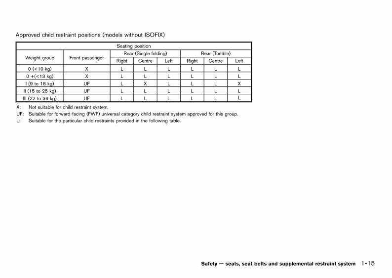
Approved child restraint positions (models without ISOFIX)GUID-4B47FC71-C923-4A4B-BA9B-60CBF9C83F5E
Seating position
Weight group Front passengerRear (Single folding) Rear (Tumble)
Right Centre Left Right Centre Left
0 (<10 kg) X L L L L L L
0 +(<13 kg) X L L L L L L
I (9 to 18 kg) UF L X L L L X
II (15 to 25 kg) UF L L L L L L
III (22 to 36 kg) UF L L L L L L
X: Not suitable for child restraint system.
UF: Suitable for forward-facing (FWF) universal category child restraint system approved for this group.
L: Suitable for the particular child restraints provided in the following table.
Safety — seats, seat belts and supplemental restraint system 1-15
Condition:

Black plate (38,1)
[ Edit: 2013/ 2/ 25 Model: K13-A ]
1-16 Safety — seats, seat belts and supplemental restraint system
List of approved child restraintsGUID-070BD51F-02D9-4526-A915-CE48597D6CFA
Weight group Name of CRS Facing position Category
0 to 13 kgBritax/ROMER BABY-
SAFERear-facing Universal
9 to 18 kg Britax/ROMER DUO plus Front-facing Universal
9 to 18 kg Fair GO/1S Front-facing Universal
15 to 36 kg Britax/ROMER Kid Front-facing Universal
Approved child restraint positions (models with ISOFIX)GUID-16DC236E-5C84-4D51-AAF9-693CBD62AC7C
The following restrictions are applied when using child restraints varying by infants weight and installation position(ISOFIX child restraint):
Weight group
Seating position
Rear outer
Carry-cotF ISO/L1 X
G ISO/L2 X
0 (<10 kg) E ISO/R1 X
0+ (<13 kg)
E ISO/R1 X
D ISO/R2 X
C ISO/R3 IL
I (9 to 18 kg)
D ISO/R2 X
C ISO/R3 IL
B ISO/F2 IUF
B1 ISO/F2X IUF, IL
A ISO/F3 IUF
II (15 to 25 kg) - X
III (22 to 36 kg) - X
X: Not suitable for child restraint system.
IUF: Suitable for forward-facing (FWF) universal category child restraint system approved for this group.
IL: Suitable for the particular ISOFIX category child restraint systems (CRS) provided in the following table.These ISOFIX CRS are those of the specific vehicle, restricted or semi-universal categories.
Condition:

Black plate (39,1)
[ Edit: 2013/ 2/ 25 Model: K13-A ]
List of approved child restraintsGUID-12703704-BED5-4EAC-AE9B-9CDEEF14A8EF
Weight group Size class Name of CRS Fixture of CRS Facing position Category
0 to 18 kg C Fair GO/1SISO/R3 supportframe (type A)
Rear-facing Semi-Universal
9 to 18 kg B1Britax/ROMERDUO plus
ISO/F2X toptether
Front-facing* Universal
*Front facing: from 2 years only with headrest.
WARNING:
In vehicles equipped with a side air bag system,do not let any infants or small children sit in thefront passenger’s seat as the air bag may causeserious injury in case of deployment during acollision.
NOTE:
Child restraints approved to ECE Regulation NO.44.04 are clearly marked with the categoriessuch as Universal, Semi-universal or ISOFIX.
ISOFIX CHILD RESTRAINT SYSTEM (ifequipped)
GUID-7DAC36F2-E2B9-493B-B926-2FCB2F3D83C1
Your vehicle is equipped with special anchor pointsthat are used with ISOFIX child restraint systems.
ISOFIX lower anchor point locationsGUID-A8304ACD-7914-45BF-924C-ABC30FC91996
The ISOFIX anchor points are provided to install childrestraints in the rear outboard seating positions only.Do not attempt to install a child restraint in thecenter position using the ISOFIX anchors.
SSS1046
ISOFIX label location
Safety — seats, seat belts and supplemental restraint system 1-17
Condition:

Black plate (40,1)
[ Edit: 2013/ 2/ 25 Model: K13-A ]
1-18 Safety — seats, seat belts and supplemental restraint system
SSS0637
ISOFIX lower anchor location
The ISOFIX anchors are located at the rear of the seatcushion near the seatback. A label is attached to theseatback to help you locate the ISOFIX anchors.
ISOFIX child restraint anchor attachmentsGUID-9DE17E3D-A48B-4832-8C7E-D39C3F2B3236
SSS0644
Anchor attachment
ISOFIX child restraints include two rigid attachmentsthat can be connected to two anchors located in theseat. With this system, you do not have to use a vehicleseat belt to secure the child restraint. Check your childrestraint for a label stating that it is compatible with theISOFIX child restraints. This information may also be inthe instructions provided by the child restraint manu-facturer.
ISOFIX child restraints generally require the use of atop tether strap or other anti-rotation devices such assupport legs. When installing ISOFIX child restraints,carefully read and follow the instructions in this manualand those supplied with the child restraints. (See“Child restraint installation using ISOFIX” (P.1-19).)
CHILD RESTRAINT ANCHORAGE (ifequipped)
GUID-9CBC9A3C-37A6-490D-BE0C-8F53A4EF3D3A
Your vehicle is designed to accommodate a childrestraint system on the rear seat. When installing achild restraint system, carefully read and follow theinstructions in this manual and those supplied with thechild restraint system.
WARNING:
. Child restraint anchorages are designed towithstand only those loads imposed bycorrectly fitted child restraints. Under nocircumstances are they to be used for adultseat belts, harnesses or for attaching otheritems or equipment to the vehicle.
. The child restraint top tether strap may bedamaged by contact with the cargo cover oritems in the luggage area. Remove the cargocover from the vehicle or secure it and anyluggage. Your child could be seriouslyinjured or killed in a collision if the toptether strap is damaged.
Anchorage locationGUID-B23FAAE8-F2E4-4ACA-9459-2381DF4D41E9
JVR0001X
The anchor points are located on the seat behind therear seats outboard seating positions.
JVR0009X
For Australia and New Zealand
The center anchorage (if equipped) is located on theback door opening.
Condition:

Black plate (41,1)
[ Edit: 2013/ 2/ 25 Model: K13-A ]
CHILD RESTRAINT INSTALLATION USINGISOFIX
GUID-BCBDE462-22A7-4AF3-BE55-6633F83BDD27
WARNING:
. Attach ISOFIX child restraints only at thespecified locations. For the ISOFIX loweranchor locations, see “ISOFIX child restraintsystem” (P.1-17). If a child restraint is notsecured properly, your child could be ser-iously injured or killed in an accident.
. Do not install child restraints that require theuse of a top tether strap to seating positionsthat do not have a top tether anchor.
. Do not secure a child restraint in the centerrear seating position using the ISOFIX loweranchors. The child restraint will not besecured properly.
. Inspect the lower anchors by inserting yourfingers into the lower anchor area andfeeling to make sure there are no obstruc-tions over the ISOFIX anchors, such as seatbelt webbing or seat cushion material. Thechild restraint will not be secured properly ifthe ISOFIX anchors are obstructed.
. Child restraint anchorages are designed towithstand only those loads imposed bycorrectly fitted child restraints. Under nocircumstance are they to be used for adultseat belts, harnesses or for attaching otheritems or equipment to the vehicle.
Installation on rear outboard seatsGUID-EBA567E6-B179-4045-AE2A-CE4765ED2602
Front-facing:GUID-9E14C2E6-2E9C-4731-980B-C45B899B977B
Be sure to follow the manufacturer’s instructions forthe proper use of your child restraint. Follow thesesteps to install a front-facing child restraint on the rearoutboard seats using ISOFIX:
SSS0646A
Steps 1 and 2
1. Position the child restraint on the seat*1 .
2. Secure the child restraint anchor attachments tothe ISOFIX lower anchors*2 .
3. The back of the child restraint should be securedagainst the vehicle seat back. If necessary, adjustor remove the head restraint to obtain the correctchild restraint fit. (See “Head restraints” (P.1-5).) Ifthe head restraint is removed, store it in a secureplace. Be sure to install the head restraint whenthe child restraint is removed. If the seatingposition does not have an adjustable headrestraint and it is interfering with the proper childrestraint fit, try another seating position or adifferent child restraint.
SSS0754A
Step 4
4. Shorten the rigid attachment to have the childrestraint firmly tightened; press downward *3and rearward*4 firmly in the center of the childrestraint with your knee to compress the vehicleseat cushion and seatback.
5. If the child restraint is equipped with a top tetherstrap, route the top tether strap and secure thetether strap to the tether anchor point. (See “Childrestraint anchorage” (P.1-18).)
6. If the child restraint is equipped with other anti-rotation devices such as support legs, use theminstead of the top tether strap following the childrestraint manufacturer’s instructions.
Safety — seats, seat belts and supplemental restraint system 1-19
Condition:

Black plate (42,1)
[ Edit: 2013/ 2/ 25 Model: K13-A ]
1-20 Safety — seats, seat belts and supplemental restraint system
SSS0755A
Step 7
7. Test the child restraint before you place the childin it*5 . Push the child restraint from side to sideand tug it forward to make sure that it is heldsecurely in place.
8. Check to make sure that the child restraint isproperly secured prior to each use. If the childrestraint is loose, repeat steps 3 through 7.
Rear-facing:GUID-9E14C2E6-2E9C-4731-980B-C45B899B977B
Be sure to follow the manufacturer’s instructions forthe proper use of your child restraint. Follow thesesteps to install a rear-facing child restraint on the rearoutboard seats using ISOFIX:
SSS0649A
Steps 1 and 2
1. Position the child restraint on the seat*1 .
2. Secure the child restraint anchor attachments tothe ISOFIX lower anchors*2 .
SSS0756A
Step 3
3. Shorten the rigid attachment to have the childrestraint firmly tightened; press downward *3and rearward*4 firmly in the center of the childrestraint with your hand to compress the vehicleseat cushion and seatback.
4. If the child restraint is equipped with a top tetherstrap, route the top tether strap and secure thetether strap to the tether anchor point. (See “Childrestraint anchorage” (P.1-18) .)
5. If the child restraint is equipped with other anti-rotation devices such as support legs, use theminstead of the top tether strap following the childrestraint manufacturer’s instructions.
SSS0757A
Step 6
6. Test the child restraint before you place the childin it*5 . Push the child restraint from side to sideand tug it forward to make sure that it is heldsecurely in place.
7. Check to make sure that the child restraint isproperly secured prior to each use. If the childrestraint is loose, repeat steps 3 through 6.
Condition:

Black plate (43,1)
[ Edit: 2013/ 2/ 25 Model: K13-A ]
CHILD RESTRAINT INSTALLATION USINGSEAT BELT
GUID-D2F6DA79-3BC2-497B-A19A-D27CCCA06FA2
Installation on rear outboard seats - seat beltswithout automatic locking mode
GUID-2745B2E8-E536-400E-AEB7-FCDE2FB2D5BB
WARNING:
. The three-point type seat belt on yourvehicle is not equipped with an automaticlocking mode retractor.
. The direction of the child restraint systemdepends on the type of the child restraintsystem and the size of the child.
If your vehicle is equipped with rear seat adjustment,note the following:
. Attach the child restraints after adjusting therear seats to the upright position.
. Do not recline the rear seats with the childrestraints attached to them.
Front-facing:GUID-9E14C2E6-2E9C-4731-980B-C45B899B977B
SSS0374A
If you must install a front-facing child restraint systemon the rear seat, follow these steps:
1. Position the front-facing child restraint system onthe rear seat.
Always follow the child restraint system manufac-turer’s instructions for installation and use.
2. Route the seat belt tongue through the childrestraint system and insert it into the buckle untilyou hear and feel the latch engage.
SSS0513
To prevent slack in the lap belt, it is necessary tosecure the shoulder belt in place with a lockingclip*A . Use the locking clip attached to the childrestraint system or one which is equivalent indimension and strength.
Be sure to follow the child restraint systemmanufacturer’s instructions for belt routing.
3. Test the child restraint system before you placethe child in it. Tilt it from side to side. Try to tug itforward and check if it is held securely in place.
4. Make sure that the child restraint system isproperly secured prior to each use.
Rear-facing:GUID-9E14C2E6-2E9C-4731-980B-C45B899B977B
SSS0375A
If you must install a rear-facing child restraint systemon the rear seat, follow these steps:
1. Position the rear-facing child restraint system onthe rear seat.
Always follow the child restraint system manufac-turer’s instructions for installation and use.
2. Route the seat belt tongue through the childrestraint system and insert it into the buckle untilyou hear and feel the latch engage.
SSS0513
To prevent slack in the lap belt, it is necessary tosecure the shoulder belt in place with a locking
Safety — seats, seat belts and supplemental restraint system 1-21
Condition:

Black plate (44,1)
[ Edit: 2013/ 2/ 25 Model: K13-A ]
1-22 Safety — seats, seat belts and supplemental restraint system
clip*A . Use the locking clip attached to the childrestraint system or one which is equivalent indimension and strength.
Be sure to follow the child restraint systemmanufacturer’s instructions for belt routing.
3. Test the child restraint system before you placethe child in it. Tilt it from side to side. Try to tug itforward and check if it is held securely in place.
4. Make sure that the child restraint system isproperly secured prior to each use.
Installation on rear center seat (2-point typeseat belt)- seat belts without automaticlocking mode
GUID-E8AB11EC-7449-4C6A-A48E-FD9CEBA5CE3B
WARNING:
. The rear center two-point type seat belt onyour vehicle is not equipped with an auto-matic locking mode retractor.
. The direction of the child restraint systemdepends on the type of the child restraintsystem and the size of the child.
Front-facing:GUID-9E14C2E6-2E9C-4731-980B-C45B899B977B
SSS0512
If you must install a front-facing child restraint systemon the rear center seat, follow these steps:
1. Position the front-facing child restraint system onthe rear center seat.
Always follow the child restraint system manufac-turer’s instructions for installation and use.
2. Route the seat belt tongue through the childrestraint system and insert it into the buckle untilyou hear and feel the latch engage.
SSS0513
Locking clip
3. To prevent slack in the lap belt, it is necessary tosecure the lap belt in place with a locking clip*A .Use the locking clip attached to the child restraintsystem, or one which is equivalent in dimensionsand strength.
Be sure to follow the child restraint systemmanufacturer’s instructions for belt routing.
4. Test the child restraint system before you placethe child in it. Tilt it from side to side. Try to tug itforward and check if it is held securely in place.
5. Make sure that the child restraint system isproperly secured prior to each use.
Rear-facing:GUID-9E14C2E6-2E9C-4731-980B-C45B899B977B
SSS0514
If you must install a rear-facing child restraint systemon the rear center seat, follow these steps:
1. Position the rear-facing child restraint system onthe rear center seat.
Always follow the child restraint system manufac-turer’s instructions for installation and use.
2. Route the seat belt tongue through the childrestraint system and insert it into the buckle untilyou hear and feel the latch engage.
Condition:

Black plate (45,1)
[ Edit: 2013/ 2/ 25 Model: K13-A ]
SSS0513
Locking clip
3. To prevent slack in the lap belt, it is necessary tosecure the lap belt in place with a locking clip*A .Use the locking clip attached to the child restraintsystem, or one which is equivalent in dimensionsand strength.
Be sure to follow the child restraint systemmanufacturer’s instructions for belt routing.
4. Test the child restraint system before you placethe child in it. Tilt it from side to side. Try to tug itforward and check if it is held securely in place.
5. Make sure that the child restraint system isproperly secured prior to each use.
Installation on front seat - seat belts without automatic locking modeGUID-48CF52C1-AED2-4536-89C6-01204BD1A763
SSS0300A
WARNING:
. Never install a rear-facing child restraint onthe front passenger’s seat when the frontpassenger’s air bag is equipped. Supple-mental front-impact air bags inflate withgreat force. A rear-facing child restraintcould be struck by the supplemental front-impact air bags in an accident and couldseriously injure or kill your child.
. Never install a child restraint system with atop tether strap on the front seat.
. NISSAN recommends that a child restraintsystem be installed on the rear seat. How-ever, if you must install a front-facing childrestraint system on the front passenger’sseat, move the passenger’s seat to therearmost position.
. Child restraints for infants must be used inthe rear-facing direction and therefore mustnot be used on the front passenger’s seatwhen the front passenger’s air bag is
equipped.
Front-facing:GUID-9E14C2E6-2E9C-4731-980B-C45B899B977B
SSS0627
If you must install a front-facing child restraint systemon the front seat, follow these steps:
1. Turn off the front passenger’s air bag using thefront passenger air bag switch. (See “Supple-mental air bag systems” (P.1-29)) Place theignition switch in the “ON” position and makesure that the front air bag status light on themeter illuminates (if equipped).
Safety — seats, seat belts and supplemental restraint system 1-23
Condition:

Black plate (46,1)
[ Edit: 2013/ 2/ 25 Model: K13-A ]
1-24 Safety — seats, seat belts and supplemental restraint system
2. Move the seat to the rearmost position*1 .
3. Adjust the head restraint to its highest position*2 .
4. Position the front-facing child restraint system onthe front passenger’s seat. It should be placed inthe front-facing direction only.
Always follow the child restraint system manufac-turer’s instructions for installation and use.
SSS0515
5. Route the seat belt tongue through the childrestraint system and insert it into the buckle untilyou hear and feel the latch engage.
SSS0513
Locking clip
6. To prevent slack in the lap belt, it is necessary tosecure the shoulder belt in place with a lockingclip*A . Use the locking clip attached to the childrestraint system, or one which is equivalent indimensions and strength.
Be sure to follow the child restraint systemmanufacturer’s instructions for belt routing.
7. Slide the seat forward so that the seat belt fullytightens the child restraint system.
8. Test the child restraint system before you placethe child in it. Tilt it from side to side. Try to tug itforward and check if it is held securely in place.
9. Make sure that the child restraint system isproperly secured prior to each use.
Condition:

Black plate (47,1)
[ Edit: 2013/ 2/ 25 Model: K13-A ]
GUID-F6CA8394-1D04-4410-A5A8-2B14D2841181
PRECAUTIONS ON SUPPLEMENTAL RE-STRAINT SYSTEM (SRS)
GUID-749BA495-5B96-4CB1-8651-DA27C70844A3
This Supplemental Restraint System (SRS) sectioncontains important information concerning the driver’sand passenger’s supplemental front-impact air bags.
Supplemental front-impact air bag system (ifequipped)
GUID-73246F1A-302B-4A23-AE5C-CFD64DB58165
This system can help cushion the impact force to thehead and chest area of the driver and/or frontpassenger in certain frontal collisions. The supple-mental front-impact air bag is designed to inflate on thefront where the vehicle is impacted.
Supplemental side-impact air bag system (ifequipped)
GUID-59B8B010-5D45-43A1-AEC8-E8AE2A43E094
This system can help cushion the impact force to thechest and pelvis areas of the driver and frontpassenger in certain side-impact collisions. Thesupplemental side-impact air bag is designed to inflateon the side where the vehicle is impacted.
Supplemental curtain side-impact air bagsystem (if equipped)
GUID-0EB7FC70-EFFC-4A87-BD48-55F59701D8F1
This system can help cushion the impact force to thehead of the driver and passengers in front and rearoutboard seating positions in certain side-impactcollisions. The supplemental curtain side-impact airbag is designed to inflate on the side where the vehicleis impacted.
The SRS is designed to supplement the accidentprotection provided by the driver’s seat belt and is notdesigned to substitute for it. The SRS can help savelives and reduce serious injuries. However, inflating airbags may cause abrasions or other injuries. Air bagsdo not provide protection to the lower body. Seat beltsshould always be correctly worn and the occupants
should always be seated a suitable distance away fromthe steering wheel. (See “Seat belts” (P.1-7).) The airbags inflate quickly in order to help protect theoccupants. The force of the air bags inflating canincrease the risk of injury if the occupants are too closeto, or are against, the air bag modules during inflation.
The air bags will deflate quickly after deployment.
The SRS operates only when the ignition switchis in the “ON” or “START” position.
When the ignition switch is in the “ON” position,the SRS air bag warning light illuminates forabout 7 seconds and then turns off. Thisindicates that the SRS is operational. (See“SRS air bag warning light” (P.1-28).)
Safety — seats, seat belts and supplemental restraint system 1-25
SUPPLEMENTAL RESTRAINTSYSTEM (SRS) (if equipped)
Condition:

Black plate (48,1)
[ Edit: 2013/ 2/ 25 Model: K13-A ]
1-26 Safety — seats, seat belts and supplemental restraint system
SSS0131A
SSS0132A
WARNING:
. The supplemental front-impact air bagsordinarily will not inflate in the event of aside impact, rear impact, rollover, or lowerseverity frontal collision. Always wear theseat belts to help reduce the risk or severityof injury in accidents.
. The seat belts and the supplemental front-impact air bags are most effective when youare sitting well back and upright in the seat.The front-impact air bags inflate with greatforce. If you are unrestrained, leaning for-
ward, sitting sideways, or out of position inany way, you are at greater risk of injury ordeath in an accident. You may also receiveserious or fatal injuries from the supple-mental front-impact air bag if you are upagainst it when it inflates. Always sit backagainst the seatback and as far away aspractical from the steering wheel. Alwaysuse the seat belts.
SSS0006
SSS0007
SSS0008
Condition:

Black plate (49,1)
[ Edit: 2013/ 2/ 25 Model: K13-A ]
SSS0009
SSS0099
SSS0100
WARNING:
. Never let children ride unrestrained orextend their hands or face out of thewindow. Do not attempt to hold them inyour lap or arms. Some examples of danger-ous riding positions are shown in theillustrations.
. Children may be severely injured or killedwhen the air bags inflate if they are notproperly restrained.
. Never install a rear-facing child restraintsystem in the front seat. An inflating supple-mental front-impact air bag could seriouslyinjure or kill your child. (See “Child re-straints” (P.1-13).)
SSS0059A
SSS0140
SSS0159
SSS0162
Safety — seats, seat belts and supplemental restraint system 1-27
Condition:

Black plate (50,1)
[ Edit: 2013/ 2/ 25 Model: K13-A ]
1-28 Safety — seats, seat belts and supplemental restraint system
WARNING:
. The supplemental side-impact air bags andsupplemental curtain side-impact air bagsordinarily will not inflate in the event of afront impact, rear impact, rollover, or lowerseverity side collision. Always wear the seatbelts to help reduce the risk or severity ofinjury in accidents.
. The seat belts and the supplemental side-impact air bags and supplemental curtainside-impact air bags are most effective whenyou are sitting well back and upright in theseat. The supplemental side-impact air bagsand supplemental curtain side-impact airbags inflate with great force. If you and yourpassengers are unrestrained, leaning for-ward, sitting sideways, or out of position inany way, you and your passengers are atgreater risk of injury or death in an accident.
. Do not allow anyone to place their hands,legs, or face near the supplemental side-impact air bags and supplemental curtainside-impact air bags on the sides of theseatback of the front seats or near the sideroof rails. Do not allow anyone sitting in thefront seats or rear outboard seats to extendtheir hands out of the windows or leanagainst the doors. Some examples of dan-gerous riding positions are shown in theillustrations.
. When sitting in the rear seats, do not holdonto the seatback of the front seats. If thesupplemental side-impact air bags and sup-plemental curtain side-impact air bags in-flate, you may be seriously injured. Beespecially careful with children, who should
always be properly restrained.
. Do not use seat covers on the front seat-backs. They may interfere with the supple-mental side-impact air bag inflations.
Pre-tensioner seat belt system (if equipped)GUID-4B10DA2C-CFE5-4D3F-93BA-2778B5E5CED7
The pre-tensioner seat belt system may activate withthe supplemental air bag system in certain types ofcollisions.
Working with the seat belt retractor and anchor, ithelps tighten the seat belt the instant the vehiclebecomes involved in certain types of collisions, helpingto restrain front seat occupants. (See “Pre-tensionerseat belt system” (P.1-31) .)
Air bag warning label (if equipped)GUID-6BC1147A-5E6A-473E-A4B6-CC1A6CC893CD
SSS1029
SRS air bag:GUID-9E14C2E6-2E9C-4731-980B-C45B899B977B
The warning label*1 is located on the surface of thepassenger’s sun visor.
SRS front-impact passenger air bag:GUID-9E14C2E6-2E9C-4731-980B-C45B899B977B
The warning label*2 (if equipped) is located on theside of the passenger’s side instrument panel.
This label warns you not to fit a rear-facing childrestraint system on the front passenger seat as such arestraint system used in this position could causeserious injury to the infant in case of air bagdeployment during a collision.
In vehicles equipped with a front-impact passenger airbag system, use a rear-facing child restraint systemonly on the rear seats. “Extreme Hazard! Do not use arearward facing child restraint on a seat protected byan airbag in front of it!"
When installing a child restraint system in your vehicle,always follow the child restraint system manufacturer’sinstructions for installation.
For additional information, see “Child restraints” (P.1-13).
SRS air bag warning lightGUID-B8092AA7-925A-4B11-A121-FE4218B6B4D3
SPA1097
The SRS air bag warning light, displaying in theinstrument panel, monitors the circuits for the air bagsystems, pre-tensioners and all related wiring.
When the ignition switch is in the “ON” or “START”
Condition:

Black plate (51,1)
[ Edit: 2013/ 2/ 25 Model: K13-A ]
position, the SRS air bag warning light illuminates forabout 7 seconds and then turns off. This indicates thatthe SRS air bag systems are operational.
If any of the following conditions occur, the air bagand/or pre-tensioner seat belt systems need servicing:
. The SRS air bag warning light remains on afterapproximately 7 seconds.
. The SRS air bag warning light flashes intermit-tently.
. The SRS air bag warning light does not illuminateat all.
Under these conditions, the air bag and/or pre-tensioner seat belt systems may not operate properly.They must be checked and repaired. Contact aNISSAN dealer immediately.
SUPPLEMENTAL AIR BAG SYSTEMSGUID-20DBDC92-C712-4C25-838B-6A4AEF6B013A
JVR0010X
1. Crash zone sensor
2. Supplemental front-impact air bag modules*
3. Supplemental side-impact air bag modules*
4. Supplemental curtain side-impact air bag mod-ules*
5. Supplemental curtain side-impact air bag in-flators*
6. Satellite sensors*
7. Pre-tensioner seat belt retractors*
8. Supplemental air bag diagnosis sensor unit
*: if equipped
WARNING:
. Do not place any objects on the steeringwheel pad. Do not place any objects be-tween the driver and steering wheel pad.Such objects may become dangerous pro-
Safety — seats, seat belts and supplemental restraint system 1-29
Condition:

Black plate (52,1)
[ Edit: 2013/ 2/ 25 Model: K13-A ]
1-30 Safety — seats, seat belts and supplemental restraint system
jectiles and cause injury if a supplementalair bag inflates.
. Immediately after inflation, several supple-mental air bag system components will behot. Do not touch them: you may severelyburn yourself.
. No unauthorized changes should be madeto any components or wiring of the supple-mental air bag systems. This is to preventaccidental inflation of the supplemental airbags or damage to the supplemental air bagsystems.
. Do not make unauthorized changes to yourvehicle’s electrical system, suspension sys-tem or front end structure. This could affectproper operation of the supplemental airbag systems.
. Tampering with the supplemental air bagsystems may result in serious personalinjury. Tampering includes changes to thesteering wheel by placing materials over thesteering wheel pad and above, and byinstalling additional trim materials aroundthe supplemental air bag systems.
. Work around and on the supplemental airbag systems should be done by a NISSANdealer. The SRS wiring should not bemodified or disconnected. Unauthorizedelectrical test equipment and probing de-vices should not be used on the supple-mental air bag systems.
. The SRS wiring harness connectors areyellow and/or orange for easy identification.
When the air bags inflate, a fairly loud noise may beheard, followed by the release of smoke. This smoke isnot harmful and does not indicate a fire. Care should
be taken not to inhale it, as it may cause irritation andchoking. Those with a history of a breathing conditionshould get fresh air promptly.
Supplemental front-impact air bag systemGUID-CE9AB5B4-2053-4986-85EC-DF3A4DBD2E92
The driver’s supplemental front-impact air bag islocated at the center of the steering wheel. Thepassenger’s supplemental front-impact air bag (ifequipped) is located at the instrument panel abovethe glove box.
The supplemental front-impact air bag system isdesigned to inflate in higher severity frontal collisions,although it may inflate if the forces in another type ofcollision are similar to those of a higher severity frontalimpact. It may not inflate in certain frontal collisions.Vehicle damage (or lack of it) is not always anindication of proper supplemental front-impact airbag system operation.
Front passenger air bag status light (ifequipped):
GUID-9E14C2E6-2E9C-4731-980B-C45B899B977B
SSS0909
The front passenger air bag status light is located onthe meter.
When the ignition switch is placed in the “ON”position, the front passenger air bag status lightilluminates for about 7 seconds and then turns off or
remains on depending on the front passenger air bagstatus.
. When the ignition switch is placed in the “ON”position and the front passenger air bag is active,the front passenger air bag status light will turn offafter approximately 7 seconds.
. When the front passenger air bag is turned offwith the front passenger air bag switch, the frontpassenger air bag status light will illuminate andremain on as long as the front passenger air bagswitch is in the “OFF” position.
If the front passenger air bag status light operates in away other than described above, the front passengerair bag may not function properly. Have the systemchecked, and if necessary repaired by a NISSANdealer promptly.
Front passenger air bag switch (if equipped):GUID-9E14C2E6-2E9C-4731-980B-C45B899B977B
SSS1031
The front passenger air bag can be turned off with thefront passenger air bag switch*A located inside ofthe glove box.
To turn off the front passenger air bag:
1. Place the ignition switch in the “OFF” position.
Condition:

Black plate (53,1)
[ Edit: 2013/ 2/ 25 Model: K13-A ]
2. Open the glove box and insert the key into thefront passenger air bag switch. For Intelligent Keyequipped models, see “Keys” (P.3-2).
3. Push and turn the key to the “OFF” position.
4. Place the ignition switch in the “ON” position. Thefront passenger air bag status light will illuminateand remain on.
To turn on the front passenger air bag:
1. Place the ignition switch in the “OFF” position.
2. Open the glove box and insert the key into thefront passenger air bag switch.
3. Push and turn the key to the “ON” position.
4. Place the ignition switch in the “ON” position. Thefront passenger air bag status light will illuminatethen turn off.
Supplemental side-impact air bag system (ifequipped)
GUID-BA599A21-4E78-4301-8FBD-A98B4F61FE73
SSS0978
The supplemental side-impact air bag is located at theoutside of the front seats’ seatbacks.
The supplemental side-impact air bag system isdesigned to inflate in higher severity side collisions,although it may inflate if the forces in another type of
collision are similar to those of a higher severity sideimpact. It may not inflate in certain side collisions.Vehicle damage (or lack of it) is not always anindication of proper supplemental side-impact air bagsystem operation.
Supplemental curtain side-impact air bagsystem (if equipped)
GUID-0A504D65-E768-491A-ADE8-F03D4840669C
The supplemental curtain side-impact air bag islocated at the roof rails.
The supplemental curtain side-impact air bag system isdesigned to inflate in higher severity side collisions,although it may inflate if the forces in another type ofcollision are similar to those of a higher severity sideimpact. It may not inflate in certain side collisions.Vehicle damage (or lack of it) is not always anindication of proper supplemental curtain side-impactair bag system operation.
PRE-TENSIONER SEAT BELT SYSTEM (ifequipped)
GUID-98FFDFDA-E983-4AFC-B3B0-20DCD6999855
WARNING:
. The pre-tensioner seat belt cannot be re-used after activation. It must be replacedtogether with the retractor and buckle as aunit.
. If the vehicle becomes involved in a collisionbut the pre-tensioner is not activated, besure to have the pre-tensioner systemchecked and, if necessary, replaced by aNISSAN dealer.
. No unauthorized changes should be madeto any components or wiring of the pre-tensioner seat belt system. This is to preventaccidental activation of the pre-tensionerseat belt or damage to the pre-tensioner
seat belt system.
. Work around or on the pre-tensioner seatbelt system should be done by a NISSANdealer. The SRS wiring should not bemodified or disconnected. Unauthorizedelectrical test equipment and probing de-vices should not be used on the pre-tensioner seat belt system.
. If you need to dispose of the pre-tensionerseat belt system, or scrap the vehicle,contact a NISSAN dealer. Correct pre-ten-sioner disposal procedures are set forth inthe appropriate NISSAN Service Manual.Incorrect disposal procedures could causepersonal injury.
The pre-tensioner seat belt system may activate withthe supplemental air bag system in certain types ofcollisions.
Working with the seat belt retractor, it helps tighten theseat belt when the vehicle becomes involved in certaintypes of collisions, helping to restrain front seatoccupants.
The pre-tensioner is encased with the front seat belt’sretractor and anchor. These seat belts are used thesame as conventional seat belts.
When the pre-tensioner seat belt activates, a fairly loudnoise may be heard, followed by the release of smoke.This smoke is not harmful and does not indicate a fire.Care should be taken not to inhale it, as it may causeirritation and choking. Those with a history of abreathing condition should get fresh air promptly.
Safety — seats, seat belts and supplemental restraint system 1-31
Condition:

Black plate (54,1)
[ Edit: 2013/ 2/ 25 Model: K13-A ]
1-32 Safety — seats, seat belts and supplemental restraint system
REPAIR AND REPLACEMENT PROCE-DURE
GUID-A794BB56-0E98-4D03-B707-2413C88EF4DC
WARNING:
. Once the air bags have been inflated, the airbag modules will not function and must bereplaced. The air bag modules must bereplaced by a NISSAN dealer. The inflatedair bag modules cannot be repaired.
. The air bag systems should be inspected bya NISSAN dealer if there is any damage tothe front end or side portion of the vehicle.
. If you need to dispose of the SRS or scrapthe vehicle, contact a NISSAN dealer. Cor-rect disposal procedures are set forth in theappropriate NISSAN Service Manual. Incor-rect disposal procedures could cause perso-nal injury.
The air bags are designed to activate on a one-time-only basis. As a reminder, unless the SRS air bagwarning light is damaged, the SRS air bag warninglight remains illuminated after inflation has occurred.The repair and replacement of the SRS should bedone only by a NISSAN dealer.
When maintenance work is required on the vehicle,information about the air bags and related parts shouldbe pointed out to the person performing the main-tenance. The ignition switch should always be in the“LOCK” position when working under the hood orinside the vehicle.
Condition:

Black plate (55,1)
[ Edit: 2013/ 2/ 25 Model: K13-A ]
2 Instruments and controls
Instrument panel .......................................................................................... 2-2Left-Hand Drive (LHD) model ............................................................ 2-2Right-Hand Drive (RHD) model (Type A) ....................................... 2-3Right-Hand Drive (RHD) model (Type B) ...................................... 2-4Right-Hand Drive (RHD) model (Type C) ...................................... 2-5
Meters and gauges ..................................................................................... 2-6Speedometer and odometer .............................................................. 2-8Trip computer (for Type A and B) .................................................... 2-9Tachometer (if equipped) ................................................................. 2-10Fuel gauge ........................................................................................... 2-10Automatic Transmission (AT)/Continuously VariableTransmission (CVT) position indicator (if equipped) ................ 2-10Engine start operation indicator (if equipped) ........................... 2-11
Warning/indicator lights and audible reminders ............................... 2-12Checking bulbs .................................................................................. 2-13Warning lights ..................................................................................... 2-13Indicator lights .................................................................................... 2-16Audible reminders .............................................................................. 2-18
Vehicle information display (if equipped) ........................................... 2-20Indicators for operation .................................................................... 2-20Warnings and alerts .......................................................................... 2-22Indicators for birthday and anniversary ......................................... 2-24Indicators for maintenance .............................................................. 2-25Indicators for Stop/Start System (if equippedfor Europe) .......................................................................................... 2-26Trip computer (for Type C) .............................................................. 2-26Stop/Start System (CO2 savings ) (if equippedfor Europe) .......................................................................................... 2-31Tire angle indicator (if equipped) .................................................. 2-31
Headlight and turn signal switch .......................................................... 2-33Headlight switch ................................................................................ 2-33
Battery saver system ...................................................................... 2-34Headlight aiming control (if equipped) ...................................... 2-34Turn signal switch ............................................................................ 2-35
Fog light switch (if equipped) .............................................................. 2-36Front fog lights ................................................................................. 2-36Rear fog light .................................................................................... 2-36
Wiper and washer switch ...................................................................... 2-37Windshield wiper and washer switch ........................................ 2-37Rain-sensing auto wiper system (if equipped) ........................ 2-38Rear window wiper and washer switch (if equipped) ........... 2-38
Defogger switch (if equipped) ............................................................. 2-39Horn ............................................................................................................ 2-40Windows .................................................................................................... 2-40
Manual windows (if equipped) ..................................................... 2-40Power windows (if equipped) ...................................................... 2-40
Sunshade (if equipped) ......................................................................... 2-42Clock ........................................................................................................... 2-42
Adjusting time ................................................................................... 2-42Power outlets (if equipped) .................................................................. 2-43Storages ..................................................................................................... 2-44
Glove box .......................................................................................... 2-44Upper instrument box (if equipped) ........................................... 2-44Card holder (if equipped) ............................................................. 2-44Cup holders ...................................................................................... 2-44Tonneau board (if equipped) ........................................................ 2-45
Sun visors .................................................................................................. 2-45Interior lights ............................................................................................. 2-46
Room light ......................................................................................... 2-46Front map lights (if equipped) ..................................................... 2-46
Condition:
>

Black plate (56,1)
[ Edit: 2013/ 2/ 25 Model: K13-A ]
2-2 Instruments and controls
GUID-9A1BE173-7B6F-4ACC-A816-0B8875E3621D
LEFT-HAND DRIVE (LHD) MODELGUID-A5A32430-6FF9-4B0D-8FA5-3C150634499F
JVI0261X
Example
1. Vehicle Dynamic Control (VDC) OFF switch* orElectronic Stability Program (ESP) OFF switch*
2. Parking space measurement switch*
3. Headlight, fog light* and turn signal switch
4. Steering-wheel-mounted controls (left side)*
— Audio control*
— Bluetooth® Hands-Free Phone System con-trol (without navigation system)*
— Bluetooth® Hands-Free Phone System con-trol (with navigation system)**
5. Driver’s front-impact air bag/Horn
6. Meters and gauges
7. Steering-wheel-mounted controls (right side)*
— Cruise control switches*
— Speed limiter switches*
8. Wiper and washer switch
9. Center ventilator
10. Rear window defogger switch*
11. Hazard indicator flasher switch
12. Heater and air conditioner* control
13. Audio system* or Navigation system**
14. Passenger’s front-impact air bag*
15. Upper instrument box*
16. Side ventilator
17. Headlight aiming control switch*
18. Outside rearview mirror control switch*
19. Fuel filler lid release handle
20. Hood lock release handle
21. Stop/Start System OFF switch*
22. Tilting steering wheel lock lever
23. Ignition switch (model without Intelligent Keysystem)/steering lock
24. Push-button ignition switch (model with Intelli-gent Key system)
25. Cup holder
26. Shift lever
— Automatic Transmission (AT) model
— Continuously Variable Transmission (CVT)model
— Manual Transmission (MT) model
27. Power outlet* or USB/AUX connector (withnavigation system)**
28. Glove box
*: if equipped
**: Refer to the separate NISSAN Connect Owner’sManual (if equipped).
INSTRUMENT PANEL
Condition:

Black plate (57,1)
[ Edit: 2013/ 2/ 25 Model: K13-A ]
RIGHT-HAND DRIVE (RHD) MODEL (Type A)GUID-3264683B-297B-45BB-9D83-9FFEC1293C9F
JVI0262X
Example
1. Side ventilator
2. Upper instrument box*
3. Passenger’s front-impact air bag*
4. Audio system* or Navigation system**
5. Rear window defogger switch*
6. Hazard indicator flasher switch
7. Heater and air conditioner* control
8. Center ventilator
9. Wiper and washer switch or Headlight, fog lightand turn signal switch
10. Steering-wheel-mounted controls (left side)*
— Audio control*
— Bluetooth® Hands-Free Phone System con-trol (without navigation system)*
— Bluetooth® Hands-Free Phone System con-trol (with navigation system)**
11. Meters and gauges
12. Driver’s front-impact air bag*/Horn
13. Steering-wheel-mounted controls (right side)*
— Cruise control switches*
— Speed limiter switches*
14. Headlight, fog light* and turn signal switch orWiper and washer switch
15. Parking space measurement switch*
16. Vehicle Dynamic Control (VDC) OFF switch* orElectronic Stability Program (ESP) OFF switch*
17. Fuse box
18. Glove box
19. Power outlet* or USB/AUX connector (withnavigation system)**
20. Shift lever
— Automatic Transmission (AT) model
— Continuously Variable Transmission (CVT)model
— Manual Transmission (MT) model
21. Cup holder
22. Push-button ignition switch (model with Intelli-gent Key system)
23. Tilting steering wheel lock lever
24. Ignition switch (model without Intelligent Keysystem)/steering lock
25. Stop/Start System OFF switch*
26. Hood lock release handle
27. Fuel filler lid release handle
28. Outside rearview mirror control switch*
29. Headlight aiming control switch*
*: if equipped
**: Refer to the separate NISSAN Connect Owner’sManual (if equipped).
Instruments and controls 2-3
Condition:

Black plate (58,1)
[ Edit: 2013/ 2/ 25 Model: K13-A ]
2-4 Instruments and controls
RIGHT-HAND DRIVE (RHD) MODEL (Type B)GUID-DA9C33E9-8FA4-4F97-BC6C-08FC81085954
JVI0170X
Example
1. Side ventilator
2. Upper instrument box*
3. Passenger’s front-impact air bag*
4. Audio system* or Navigation system**
5. Rear window defogger switch*
6. Hazard indicator flasher switch
7. Heater and air conditioner* control
8. Center ventilator
9. Wiper and washer switch
10. Steering-wheel-mounted controls (left side)*
— Audio control*
— Bluetooth® Hands-Free Phone System con-trol (without navigation system)*
— Bluetooth® Hands-Free Phone System con-trol (with navigation system)**
11. Meters and gauges
12. Driver’s front-impact air bag*/Horn
13. Steering-wheel-mounted controls (right side)*
— Cruise control switches*
— Speed limiter switches*
14. Headlight, fog light* and turn signal switch
15. Outside rearview mirror control switch*
16. Fuse box
17. Glove box
18. Power outlet* or USB/AUX connector (withnavigation system)**
19. Cup holder
20. Shift lever
— Automatic Transmission (AT) model
— Continuously Variable Transmission (CVT)model
— Manual Transmission (MT) model
21. Push-button ignition switch (model with Intelli-gent Key system)
22. Tilting steering wheel lock lever
23. Ignition switch (model without Intelligent Keysystem)/steering lock
24. Hood lock release handle
25. Fuel filler lid release handle
26. Parking space measurement switch*
27. Vehicle Dynamic Control (VDC) OFF switch*
28. Headlight aiming control switch*
*: if equipped
**: Refer to the separate NISSAN Connect Owner’sManual (if equipped).
Condition:

Black plate (59,1)
[ Edit: 2013/ 2/ 25 Model: K13-A ]
RIGHT-HAND DRIVE (RHD) MODEL (Type C)GUID-065E6B67-78E7-4588-9F89-185E447CFF29
JVC0449X
Example
1. Side ventilator
2. Upper instrument box*
3. Passenger’s front-impact air bag*
4. Audio system*
5. Rear window defogger switch*
6. Hazard indicator flasher switch
7. Heater and air conditioner* control
8. Center ventilator
9. Wiper and washer switch
10. Steering-wheel-mounted controls (left side)*
— Audio control*
— Bluetooth® Hands-Free Phone System con-trol*
11. Meters and gauges
12. Driver’s front-impact air bag*/Horn
13. Headlight, fog light* and turn signal switch
14. Outside rearview mirror control switch*
15. Fuse box
16. Glove box
17. USB/AUX connector*
18. Power outlet*
19. Cup holder
20. Shift lever
— Continuously Variable Transmission (CVT)model
— Manual Transmission (MT) model
21. Push-button ignition switch (model with Intelli-gent Key system)
22. Tilting steering wheel lock lever
23. Ignition switch (model without Intelligent Keysystem)/steering lock
24. Hood lock release handle
25. Fuel filler lid release handle
26. Idling Stop OFF switch*
27. Headlight aiming control switch*
*: if equipped
Instruments and controls 2-5
Condition:

Black plate (60,1)
[ Edit: 2013/ 2/ 25 Model: K13-A ]
2-6 Instruments and controls
GUID-05D4651C-F441-4B1D-B5E8-0EBF3F45564E
JVC0453X
Type A
1. Speedometer
2. Trip odometer reset switch/trip computer modeswitch
3. Clock adjusting knob
4. Automatic Transmission (AT) position indicator*
5. Odometer/twin trip odometer/trip computer/clock
6. Fuel gauge
*: if equipped
METERS AND GAUGES
Condition:

Black plate (61,1)
[ Edit: 2013/ 2/ 25 Model: K13-A ]
JVC0454X
Type B
1. Tachometer
2. Speedometer
3. Trip odometer reset switch/trip computer modeswitch
4. Clock adjusting knob
5. Automatic Transmission (AT)/Continuously Vari-able Transmission (CVT) position indicator*/Cruse control and speed limiter display*
6. Odometer/twin trip odometer/trip computer/clock
7. Fuel gauge
*: if equipped
Instruments and controls 2-7
Condition:

Black plate (62,1)
[ Edit: 2013/ 2/ 25 Model: K13-A ]
2-8 Instruments and controls
JVC0455X
Type C
1. Tachometer
2. Speedometer
3. Vehicle information display
4. Trip odometer reset switch
5. Automatic Transmission (AT)/Continuously Vari-able Transmission (CVT) position indicator*
6. Odometer/twin trip odometer/clock
*: if equipped
SPEEDOMETER AND ODOMETERGUID-8FAC352D-EC79-4B20-BD5F-70E05395000A
SpeedometerGUID-883793F3-A95A-44C1-BBC3-B0BD2768709D
The speedometer indicates the vehicle speed.
Odometer/Twin trip odometer (for Type A andB)
GUID-FB22D496-7DDA-4EBD-A679-67DC9BDEAAC8
SIC4427
Example
The odometer/twin trip odometer is displayed whenthe ignition switch is in the “ON” position.
The odometer *1 displays the total distance thevehicle has been driven.
The twin trip odometer *2 displays the distance ofindividual trips.
Changing twin trip odometer display:GUID-9E14C2E6-2E9C-4731-980B-C45B899B977B
Push the reset switch *3 to change the display asfollows:
TRIP A ? TRIP B ? Trip computer mode ? TRIP A
Resetting twin trip odometer:GUID-9E14C2E6-2E9C-4731-980B-C45B899B977B
Push the reset switch*3 for more than 1 second toreset the trip odometer to zero.
For trip computer information, see “Trip computer (forType A and B)” (P.2-9).
Condition:
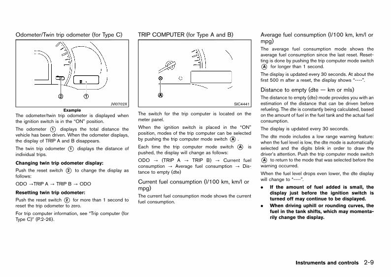
Black plate (63,1)
[ Edit: 2013/ 2/ 25 Model: K13-A ]
Odometer/Twin trip odometer (for Type C)GUID-12D67A79-3AE5-42DE-B2B2-599C2B1216D3
JVI0702X
Example
The odometer/twin trip odometer is displayed whenthe ignition switch is in the “ON” position.
The odometer *1 displays the total distance thevehicle has been driven. When the odometer displays,the display of TRIP A and B disappears.
The twin trip odometer *1 displays the distance ofindividual trips.
Changing twin trip odometer display:GUID-9E14C2E6-2E9C-4731-980B-C45B899B977B
Push the reset switch *2 to change the display asfollows:
ODO ?TRIP A ? TRIP B ? ODO
Resetting twin trip odometer:GUID-9E14C2E6-2E9C-4731-980B-C45B899B977B
Push the reset switch*2 for more than 1 second toreset the trip odometer to zero.
For trip computer information, see “Trip computer (forType C)” (P.2-26).
TRIP COMPUTER (for Type A and B)GUID-2070129D-E492-4809-8A3A-148BC6AAF3C0
SIC4441
The switch for the trip computer is located on themeter panel.
When the ignition switch is placed in the “ON”position, modes of the trip computer can be selectedby pushing the trip computer mode switch*A .
Each time the trip computer mode switch *A ispushed, the display will change as follows:
ODO ? (TRIP A ? TRIP B) ? Current fuelconsumption ? Average fuel consumption ? Dis-tance to empty (dte)
Current fuel consumption (l/100 km, km/l ormpg)
GUID-9C9714D9-4DFF-424C-9C27-19EAEBC4596D
The current fuel consumption mode shows the currentfuel consumption.
Average fuel consumption (l/100 km, km/l ormpg)
GUID-B17C3706-6A9C-4B8B-A965-C06BDCB2051D
The average fuel consumption mode shows theaverage fuel consumption since the last reset. Reset-ting is done by pushing the trip computer mode switch*A for longer than 1 second.
The display is updated every 30 seconds. At about thefirst 500 m after a reset, the display shows “----”.
Distance to empty (dte — km or mls)GUID-A66D9214-1769-43E1-BEBD-185191CBC970
The distance to empty (dte) mode provides you with anestimation of the distance that can be driven beforerefueling. The dte is constantly being calculated, basedon the amount of fuel in the fuel tank and the actual fuelconsumption.
The display is updated every 30 seconds.
The dte mode includes a low range warning feature:when the fuel level is low, the dte mode is automaticallyselected and the digits blink in order to draw thedriver’s attention. Push the trip computer mode switch*A to return to the mode that was selected before thewarning occurred.
When the fuel level drops even lower, the dte displaywill change to “----”.
. If the amount of fuel added is small, thedisplay just before the ignition switch isturned off may continue to be displayed.
. When driving uphill or rounding curves, thefuel in the tank shifts, which may momenta-rily change the display.
Instruments and controls 2-9
Condition:

Black plate (64,1)
[ Edit: 2013/ 2/ 25 Model: K13-A ]
2-10 Instruments and controls
Resetting displaysGUID-4EB1B5E4-22B9-48AD-816E-3D5A4320EC75
When the average fuel consumption or TRIP B isdisplayed, push the trip computer mode switch*A forlonger than 3 seconds. The display of average fuelconsumption and trip odometer (TRIP B only) will bereset at the same time.
TACHOMETER (if equipped)GUID-559BDB42-F10E-4B2D-A28F-0C2A332F2141
SIC4428
The tachometer indicates the engine speed in revolu-tions per minute (rpm).
Do not rev the engine into the red zone.
FUEL GAUGEGUID-57ADBDC4-29DF-4110-86A1-A5B1DC698958
SIC4429
Example of Type A and B
JVC0024X
Type C
For Type A and B: The fuel gauge*A indicates theapproximate fuel level in the tank when the ignitionswitch is in the “ON” position.
The gauge may move slightly during braking, turning,accelerating, or going up and down hills due tomovement of fuel in the tank.
The fuel gauge*A and the low fuel warning light inthe meter (if equipped) blink when the fuel level in thetank is getting low. Refuel as soon as it is convenient,before the gauge reads 0.
For Type C: The fuel gauge *B indicates the
approximate fuel level in the tank when the ignitionswitch is in the “ON” position.
The gauge may move slightly during braking, turning,accelerating, or going up and down hills due tomovement of fuel in the tank.
The low fuel warning light in the meter illuminates whenthe fuel level in the tank is getting low. Refuel as soonas it is convenient, before the gauge reads 0.
The arrow, , indicates the fuel filler lid is located onthe left side of the vehicle.
CAUTION:
Refuel before the gauge reads the empty (0)position.
AUTOMATIC TRANSMISSION (AT)/CON-TINUOUSLY VARIABLE TRANSMISSION(CVT) POSITION INDICATOR (if equipped)
GUID-4485F02E-8DF5-411D-85A8-69D3FF0B9053
JVC0031X
Example
The Automatic Transmission (AT)/Continuously Vari-able Transmission (CVT) position indicator *A in-dicates the shift lever position when the ignition switchis in the “ON” position.
Condition:

Black plate (65,1)
[ Edit: 2013/ 2/ 25 Model: K13-A ]
ENGINE START OPERATION INDICATOR (ifequipped)
GUID-AE020137-E185-4BCB-B970-81F7C4689AC2
JVC0030X
Example
The engine start operation indicator*A appears whenthe shift lever is in the “P” (Park) position. This indicatormeans that the engine will start by pushing the ignitionswitch with the brake pedal depressed. You can startthe engine directly in any position.
Instruments and controls 2-11
Condition:

Black plate (66,1)
[ Edit: 2013/ 2/ 25 Model: K13-A ]
2-12 Instruments and controls
GUID-583FCDCD-2A69-4905-BD87-9F7E7AFC2D21
Anti-lock Braking System (ABS) warninglight*
Speed [120 km/h (75 MPH)] warning light(for the Middle East)
Overdrive off indicator light*
Brake warning lightSupplemental Restraint System (SRS) airbag warning light*
Rear fog light indicator light*
Charge warning lightWater-in-fuel-filter warning light (diesel en-gine model)
Security indicator light*
Door open warning light*Vehicle Dynamic Control (VDC) warninglight (for Australia and New Zealand)
Slip indicator light (if equipped except forAustralia and New Zealand)
Electric power steering warning light Cruise control on indicator light* Speed limiter indicator light*
Engine oil pressure warning lightCruise control/speed limiter set indicatorlight*
SPORT mode indicator light*
High temperature warning light (red)Electronic Stability Program (ESP) off in-dicator light*
Stop/Start System indicator light (if equippedfor Europe)/Idling Stop System indicator light(for Hong Kong)
Intelligent Key system warning light* Front fog lights indicator light* Turn signals/hazard indicator lights
Low fuel warning light* Front passenger air bag status light*Vehicle Dynamic Control (VDC) off indicatorlight*Malfunction warning light (red) (diesel en-
gine model)Glow plug indicator light (diesel enginemodel)
Master warning light* High beam indicator light *: if equipped
P position selecting warning light* Low temperature indicator light (green)*
Seat belt warning light* Malfunction Indicator Light (MIL)
WARNING/INDICATOR LIGHTS ANDAUDIBLE REMINDERS
Condition:

Black plate (67,1)
[ Edit: 2013/ 2/ 25 Model: K13-A ]
CHECKING BULBSGUID-6B2E7D56-6805-453D-BBE4-446993010F90
With all doors closed, apply the parking brake, fastenthe seat belts and turn the ignition switch to the “ON”position without starting the engine. The followinglights will illuminate: , , , , .
If equipped, the following lights will illuminate brieflyand then turn off: or , , , , ,
(red), (green), , , , .
If any lights fail to illuminate, it may indicate a burned-out bulb or an open circuit in the electrical system.Have the system checked, and if necessary repaired,by a NISSAN dealer promptly.
Some indicators and warnings are also displayed onthe vehicle information display (if equipped) below thespeedometer. (See “Vehicle information display” (P.2-20).)
WARNING LIGHTSGUID-5264F48C-986F-4E23-AE6B-DA576DF89635
, Anti-lock Braking System (ABS)warning light (if equipped)
GUID-61E70005-EFE1-44DD-8E5C-F09206F141FF
When the ignition switch is in the “ON” position, theAnti-lock Braking System (ABS) warning light illumi-nates and then turns off. This indicates the ABS isoperational.
If the ABS warning light illuminates while the engine isrunning, or while driving, it may indicate the ABS is notfunctioning properly. Have the system checked by aNISSAN dealer promptly.
If an ABS malfunction occurs, the anti-lock function isturned off. The brake system then operates normally,but without anti-lock assistance. (See “Brake system”(P.5-38).)
Brake warning lightGUID-7DF2B916-3E15-413C-931A-EDDC481BE56B
WARNING:
. If the brake fluid level is below the minimummark on the brake fluid reservoir, do notdrive the vehicle until the brake system hasbeen checked by a NISSAN dealer.
. Even if you judge it to be safe, have yourvehicle towed because driving it could bedangerous.
. Depressing the foot brake pedal without theengine running and/or with a low brake fluidlevel could increase the stopping distanceand require greater pedal travel distanceand effort.
The brake warning light indicates the parking brakesystem operation, a low brake fluid level of the brakesystem and an Anti-lock Braking System (ABS)malfunction.
Parking brake warning indicator:GUID-9E14C2E6-2E9C-4731-980B-C45B899B977B
When the ignition switch is in the “ON” position, andthe parking brake is applied, the brake warning lightilluminates. When the parking brake is released, thebrake warning light turns off.
If the parking brake is not fully released, the brakewarning light remains on. Be sure that the brakewarning light has turned off before driving. (See“Parking brake” (P.3-24).)
Low brake fluid warning indicator:GUID-9E14C2E6-2E9C-4731-980B-C45B899B977B
If the brake warning light illuminates while the engine isrunning, or while driving, and the parking brake isreleased, it may indicate the brake fluid level is low.
When the brake warning light illuminates while driving,stop the vehicle safely as soon as possible. Stop the
engine and check the brake fluid level. If the brake fluidlevel is below the minimum mark on the reservoir, addbrake fluid as necessary. (See “Brake fluid” (P.8-19).)
If the brake fluid level is sufficient, have the brakesystem checked by a NISSAN dealer promptly.
Anti-lock Braking System (ABS) warning indi-cator (if equipped):
GUID-9E14C2E6-2E9C-4731-980B-C45B899B977B
When the parking brake is released and the brake fluidlevel is sufficient, if both the brake warning light and theAnti-lock Braking System (ABS) warning light illumi-nate, it may indicate the ABS is not functioningproperly. Have the brake system checked, and ifnecessary repaired, by a NISSAN dealer promptly.(See “Anti-lock Braking System (ABS) warning light”(P.2-13).)
Charge warning lightGUID-5918C362-3503-4B43-B7C7-60227FE2EA35
When the ignition switch is in the “ON” position, thecharge warning light illuminates. After starting theengine, the charge warning light turns off. Thisindicates the charging system is operational.
If the charge warning light illuminates while the engineis running, or while driving, it may indicate the chargingsystem is not functioning properly and may needservicing.
When the charge warning light illuminates whiledriving, stop the vehicle safely as soon as possible.Stop the engine and check the alternator belt. If thealternator belt is loose, broken or missing, the chargingsystem needs repair. (See “Drive belts” (P.8-16).)
If the alternator belt appears to be functioning correctlybut the charge warning light remains illuminated, havethe charging system checked by a NISSAN dealerpromptly.
Instruments and controls 2-13
Condition:

Black plate (68,1)
[ Edit: 2013/ 2/ 25 Model: K13-A ]
2-14 Instruments and controls
CAUTION:
Do not continue driving if the alternator belt isloose, broken or missing.
Door open warning light (if equipped)GUID-A945BF30-E9F8-4C61-8981-D20D80206FF5
When the ignition switch is in the “ON” position, thedoor open warning light illuminates if any of the doorsare open or not closed securely.
Electric power steering warning lightGUID-9CF8A311-4B25-4DDE-ADA1-9F6685083662
When the ignition switch is in the “ON” position, theelectric power steering warning light illuminates. Afterstarting the engine, the electric power steering warninglight turns off. This indicates the electric powersteering system is operational.
If the electric power steering warning light illuminateswhile the engine is running, it may indicate the electricpower steering system is not functioning properly andmay need servicing. Have the electric power steeringsystem checked by a NISSAN dealer.
When the electric power steering warning lightilluminates with the engine running, the power assistto the steering will cease operation but you will stillhave control of the vehicle. At this time, greatersteering efforts are required to operate the steeringwheel, especially in sharp turns and at low speeds.
(See “Electric power steering system” (P.5-37).)
Engine oil pressure warning lightGUID-1AA8B9F5-477E-4655-B1D2-3043C9EE3F84
When the ignition switch is in the “ON” position, theengine oil pressure warning light illuminates. Afterstarting the engine, the engine oil pressure warninglight turns off. This indicates that the oil pressuresensors in the engine are operational.
If the engine oil pressure warning light illuminates orblinks while the engine is running, it may indicate thatthe engine oil pressure is low.
Stop the vehicle safely as soon as possible. Stop theengine immediately and call a NISSAN dealer.
CAUTION:
. Running the engine with the engine oilpressure warning light illuminated couldcause serious damage to the engine.
. The engine oil pressure warning light is notdesigned to indicate a low oil level. The oillevel should be checked using the dipstick.(See “Engine oil” (P.8-11).)
High temperature warning light (red)GUID-CEFF5355-6131-4707-8E2C-1D54C1EF73BF
When the ignition switch is in the “ON” position, thehigh temperature warning light illuminates and thenturns off. This indicates that the high temperaturesensor in the engine coolant system is operational.
CAUTION:
If the high temperature warning light illuminateswhile the engine is running, it may indicate theengine temperature is extremely high.
Stop the vehicle safely as soon as possible.
If the vehicle is overheated, continuing vehicleoperation may seriously damage the engine.
(For the immediate action required, see “If yourvehicle overheats” (P.6-11).)
Intelligent Key system warning light (ifequipped)
GUID-56A1E0AA-7075-4F9D-9B49-72D282AB78D8
After the ignition switch is placed in the “ON” position,this light comes on for about 2 seconds and then turnsoff.
This light illuminates or blinks as follows:
. The light blinks in yellow when the door is closedwith the Intelligent Key left outside the vehicle andthe ignition switch in the “ACC” or “ON” position.Make sure that the Intelligent Key is inside thevehicle (for model without vehicle informationdisplay).
. The light blinks in green when the Intelligent Keybattery is running out of power. Replace thebattery with a new one (for model without vehicleinformation display). See “Battery” (P.8-24).
. The light illuminates in yellow when it warns of amalfunction with the electrical steering locksystem or the Intelligent Key system.
If the warning light illuminates in yellow while theengine is stopped, it may be impossible to free thesteering lock or to start the engine. If the light comeson while the engine is running, you can drive thevehicle. However in these cases, contact a NISSANdealer for repair as soon as possible.
Condition:

Black plate (69,1)
[ Edit: 2013/ 2/ 25 Model: K13-A ]
Low fuel warning light (if equipped)GUID-72A94653-6A5F-4D73-B89E-5F7C88CA89EA
The low fuel warning light illuminates when the fuellevel in the tank is getting low. Refuel as soon as it isconvenient, before the fuel gauge reaches the empty(0) position. There will be a small reserve of fuelremaining in the tank when the fuel gauge reaches theempty (0) position.
Malfunction warning light (red) (dieselengine model)
GUID-4CB99199-45E7-480A-84DB-F9EB0F337946
When the ignition switch is placed in the “ON”position, the malfunction warning light illuminates inred. This means that the system is operational. Afterstarting the engine, the warning light turns off.
For the orange Malfunction Indicator Light (MIL), see“Malfunction Indicator Light (MIL)” (P.2-17)for details.
If the malfunction warning light (red) illuminatescontinuously while the engine is running, it mayindicate an engine control system malfunction. Haveyour vehicle inspected by a NISSAN dealer. You do notneed to have your vehicle towed to the dealer.
CAUTION:
Continuing vehicle operation without properservicing of the engine control system couldlead to poor driveability, reduced fuel economy,and damage to the engine control system, whichmay affect the vehicle’s warranty coverage.
Master warning light (if equipped)GUID-BCA9EEB9-779C-47BA-8F59-643E98D0CA1D
When the ignition switch is in the “ON” position, themaster warning light illuminates if any of the followingare displayed on the vehicle information display.
. Seat belt warning
. NO KEY warning
. Low fuel warning
. Parking brake release warning
. Door/back door open warning
(See “Vehicle information display” (P.2-20).)
P position selecting warning light (ifequipped)
GUID-5CA43FDF-DEE7-4908-B1E5-9A05F772AF36
The warning light blinks in red when the ignition switchis pushed to stop the engine with the shift lever in anyposition except the “P” (Park) position.
If this warning appears, move the shift lever to the “P”(Park) position or push the ignition switch to the “ON”position.
An inside warning chime will also sound.
See “Intelligent Key system” (P.3-9).
Seat belt warning light (if equipped)GUID-44B316C4-59CE-42B5-B7CF-5F2E89943676
When the ignition switch is in the “ON” position, theseat belt warning light illuminates. The light willcontinue to illuminate until the driver’s seat belt isfastened. (See “Seat belts” (P.1-7).)
When the vehicle speed exceeds 15 km/h (10 MPH),the light will blink and the chime (if equipped) willsound unless the driver’s seat belt is securely fastened.The chime (if equipped) will continue to sound forabout 90 seconds until the seat belt is fastened.
Speed [120 km/h (75 MPH)] warninglight (for the Middle East)
GUID-164D8387-0E1A-4B81-A6DE-3AD03FE7689E
This light blinks when the vehicle speed goes overapproximately 120 km/h (75 MPH). Be sure to observethe speed limit in the area where you are driving.
Supplemental Restraint System (SRS)air bag warning light (if equipped)
GUID-39A615D9-5441-4252-9D10-8FF9E8413F2A
When the ignition switch is in the “ON” or “START”position, the Supplemental Restraint System (SRS) airbag warning light illuminates for about 7 seconds andthen turns off. This indicates that the SRS air bagsystem is operational.
If any of the following conditions occur, the SRS airbag system and/or pre-tensioner seat belt needservicing. Have the system checked, and if necessaryrepaired, by a NISSAN dealer promptly.
. The SRS air bag warning light remains illuminatedafter about 7 seconds.
. The SRS air bag warning light flashes intermit-tently.
. The SRS air bag warning light does not illuminateat all.
Unless checked and repaired, the SRS air bag systemand/or pre-tensioner seat belt may not functionproperly. (See “Supplemental Restraint System(SRS)” (P.1-25))
Water-in-fuel-filter warning light (dieselengine model)
GUID-334B8221-825D-4380-9EC9-74D8CC0E5D48
If the water-in-fuel-filter warning light illuminates whilethe engine is running, drain the water from the fuel filterpromptly. (See “Fuel filter (diesel engine model)” (P.8-16).)
Instruments and controls 2-15
Condition:

Black plate (70,1)
[ Edit: 2013/ 2/ 25 Model: K13-A ]
2-16 Instruments and controls
CAUTION:
Continuing vehicle operation without properlydraining could cause serious damage to theengine.
Vehicle Dynamic Control (VDC) warn-ing light (for Australia and New Zealand)
GUID-DF4EEA80-2D5A-474E-8FE8-42323F002FA7
When the ignition switch is in the “ON” position, theVDC warning light illuminates and then turns off. Thisindicates the Vehicle Dynamic Control (VDC) system isoperational.
The VDC warning light blinks when the VDC system isoperating.
When the warning light blinks while driving, the drivingcondition is slippery and the vehicle’s traction limit isabout to be exceeded.
If the VDC warning light illuminates while the engine isrunning or while driving, it may indicate the VDCsystem is not functioning properly and may needservicing. Have the system checked, and if necessaryrepaired, by a NISSAN dealer promptly.
If a malfunction occurs in the system, the VDC systemfunction will be canceled but the vehicle is stilldriveable.
See “Vehicle Dynamic Control (VDC) system (forAustralia and New Zealand)” (P.5-25).
INDICATOR LIGHTSGUID-E7E1D0DA-C7BC-4AEC-BECB-BC6C2889D949
Cruise control on indicator light (ifequipped)
GUID-E8AD90AA-FA63-42E2-837B-27A650598B9D
The cruise control on indicator light indicates theactivation of the cruise control system.
When the cruise control main switch is turned on, theindicator light will illuminate, indicating the cruisecontrol system is in the standby mode. (See “Cruisecontrol” (P.5-30).)
Cruise control/speed limiter set indi-cator light (if equipped)
GUID-52DC7665-3E72-4176-B1BD-EC2A427A4F8A
The cruise control/speed limiter set indicator lightindicates the status of the cruise control system.
When the vehicle speed is controlled by the cruisecontrol/speed limiter system, the indicator light illumi-nates.
If the cruise control/speed limiter set indicator lightblinks while the engine is running, or while driving, itmay indicate the cruise control/speed limiter system isnot functioning properly and may need servicing. Havethe system checked, and if necessary repaired, by aNISSAN dealer promptly. (See “Cruise control” (P.5-30) and “Speed limiter (if equipped for Europe)” (P.5-28).)
Electronic Stability Program (ESP) offindicator light (if equipped)
GUID-5B1E2FF6-A76D-44F8-A277-963170B663A1
The Electronic Stability Program (ESP) off indicatorlight illuminates when the ESP off switch is pushed tothe “OFF” position.
When the ESP off switch is pushed to the “OFF”position, the ESP system is turned off.
If the ESP off indicator light and slip indicator light
illuminate while the engine is running or while driving, itmay indicate the ESP system is not functioningproperly and may need servicing. Have the systemchecked, and if necessary repaired, by a NISSANdealer promptly. (See “Electronic Stability Program(ESP) System (if equipped for Europe)” (P.5-27).)
Front fog lights indicator light (ifequipped)
GUID-9A44D17F-B9A2-4373-9684-8F871146DC04
The front fog lights indicator light illuminates when thefront fog lights are on. (See “Fog light switch” (P.2-36).)
Front passenger air bag status light (ifequipped)
GUID-08851B47-1D3A-421E-B117-5EB5F7D91EDD
The front passenger air bag status light located on themeter will illuminate when the front passenger air bagis turned off with the front passenger air bag switch.When the front passenger air bag is turned on, thefront passenger air bag status light will turn off.
For more details, see “Supplemental Restraint System(SRS)” (P.1-25).
Glow plug indicator light (diesel enginemodel)
GUID-B695B756-4AEA-412B-B0FC-1DE5A2330402
When the ignition switch is in the “ON” position, theglow plug indicator light illuminates and turns off afterthe glow plugs have warmed up.
If the glow plugs have already warmed up, the glowplug indicator flashes briefly and then turns off.
Condition:

Black plate (71,1)
[ Edit: 2013/ 2/ 25 Model: K13-A ]
High beam indicator lightGUID-6AD3E899-FDC7-481A-BD65-60E4B3AA3DCC
The high beam indicator light illuminates when theheadlight high beam is “ON”. The indicator turns offwhen the low beam is selected. (See “Headlight andturn signal switch” (P.2-33).)
Low temperature indicator light (green)(if equipped)
GUID-01AC74EA-1DAC-4D0E-BBF9-AABC29CC3F5B
The low temperature indicator light illuminates whenthe engine coolant temperature is low.
When the ignition switch is in the “ON” position, thelow temperature indicator light illuminates and thenturns off after the engine coolant has warmed up.
If the low temperature indicator light stays illuminatedafter the engine has sufficiently warmed up, it mayindicate the low temperature sensor in the enginecoolant system is not functioning properly and mayneed servicing. Have the system checked, and ifnecessary repaired, by a NISSAN dealer promptly.
Malfunction Indicator Light (MIL)GUID-BE674D88-54F7-4265-8CFF-886BD4FC86C8
When the ignition switch is in the “ON” position, theMalfunction Indicator Light (MIL) illuminates. Afterstarting the engine, the MIL turns off. This indicatesthat the engine control system is operational.
If the MIL illuminates or blinks (if equipped) while theengine is running, it may indicate that the enginecontrol system is not functioning properly and mayneed servicing. Have the system checked, and ifnecessary repaired, by a NISSAN dealer promptly.
Malfunction Indicator Light (MIL) on steady:GUID-9E14C2E6-2E9C-4731-980B-C45B899B977B
An engine control system malfunction has beendetected. Have the vehicle checked, and if necessaryrepaired, by a NISSAN dealer promptly. You do notneed to have your vehicle towed to the dealer.
Malfunction Indicator Light (MIL) blinking (ifequipped):
GUID-9E14C2E6-2E9C-4731-980B-C45B899B977B
An engine misfire has been detected which maydamage the engine control system. Have the vehiclechecked, and if necessary repaired, by a NISSANdealer promptly.
To reduce or avoid possible damage to the enginecontrol system when the MIL illuminates or blinks:
. Avoid driving at speeds above 70 km/h (43 MPH).
. Avoid sudden acceleration or deceleration.
. Avoid going up steep uphill grades.
. Avoid carrying or towing unnecessary loads.
CAUTION:
. Continuing vehicle operation without properservicing of the engine control system couldlead to poor driveability, reduced fuel econ-omy, and damage to the engine controlsystem, which may affect the vehicle’swarranty coverage.
. Incorrect setting of the engine control sys-tem may lead to non-compliance of localand national emission laws and regulations.
Overdrive off indicator light (ifequipped)
GUID-944F6070-3237-447F-9576-73B4FA3A119B
The overdrive off indicator light illuminates when theoverdrive is turned OFF. (For the use of the overdriveoff switch, see “Driving with Automatic Transmission(AT)” (P.5-11).)
Rear fog light indicator light (ifequipped)
GUID-0CCC1373-52B3-4169-B4AC-F77981CC6D57
The rear fog light indicator light illuminates when therear fog light is on. (See “Fog light switch” (P.2-36).)
Security indicator light (if equipped)GUID-CD66D01C-63EB-44A9-B8EF-6B4B50F5750B
The security indicator light blinks when the ignitionswitch is in the “LOCK”, “OFF” or “ACC” position. Thisfunction indicates the security system equipped on thevehicle is operational.
If the security system is malfunctioning, this light willremain on while the ignition switch is in the “ON”position. (For additional information, see “Securitysystem” (P.3-17).)
Slip indicator light (if equipped exceptfor Australia and New Zealand)
GUID-D000E16B-3FC4-4D31-BEB2-1718482A5283
When the ignition switch is in the “ON” position, theslip indicator light illuminates and then turns off. Thisindicates that the Vehicle Dynamic Control (VDC)system or Electronic Stability Program (ESP) system isoperational.
The slip indicator light blinks when the VDC or ESPsystem is operating.
When the indicator light blinks while driving, the drivingcondition is slippery and the vehicle’s traction limit isabout to be exceeded.
If the VDC or ESP off indicator light and slip indicator
Instruments and controls 2-17
Condition:

Black plate (72,1)
[ Edit: 2013/ 2/ 25 Model: K13-A ]
2-18 Instruments and controls
light illuminate while the engine is running or whiledriving, it may indicate that the VDC or ESP system isnot functioning properly and may need servicing. Havethe system checked, and if necessary repaired, by aNISSAN dealer promptly. (See “Vehicle DynamicControl (VDC) system (if equipped except for Europe,Australia and New Zealand)” (P.5-24) or “ElectronicStability Program (ESP) System (if equipped forEurope)” (P.5-27).)
Speed limiter indicator light (ifequipped)
GUID-4D4FC51B-6C6F-4C0E-A01B-248FE13847E7
This light illuminates when the speed limiter mainswitch is pushed. The light turns off when the mainswitch is pushed again. When the speed limiter mainswitch indicator light illuminates, the speed limitersystem is operational. (See “Speed limiter (if equippedfor Europe)” (P.5-28).)
SPORT mode indicator light (ifequipped)
GUID-05216FDD-6A76-440B-A943-8260FD08D9A7
The SPORT mode indicator light illuminates when theSPORT mode is turned “ON”. (For the use of theSPORT mode switch, see “Driving with ContinuouslyVariable Transmission (CVT)” (P.5-14).)
Stop/Start System indicator light (ifequipped for Europe)/Idling Stop Systemindicator light (for Hong Kong)
GUID-6761E669-6280-4E12-86A1-C5EDCE3BFD80
For Europe:GUID-9E14C2E6-2E9C-4731-980B-C45B899B977B
The Stop/Start System indicator light illuminates in themeter when the Stop/Start System is activated.
The Stop/Start System indicator light blinks at a highspeed, when the engine hood is open (for CVTmodel).
The Stop/Start System indicator light blinks at a lowspeed, when the Stop/Start System is malfunctioning.
NOTE:. When the Stop/Start System indicator light
blinks at a high speed (twice approximatelyevery 1 second), be sure to close the enginehood. When the engine hood is open theengine will be in the normal stopped state.In this case, restart the engine with theignition switch (for CVT model).
. When the Stop/Start System indicator lightblinks at a low speed (once approximatelyevery 1 second), have the system checked,and if necessary repaired, by a NISSANdealer promptly.
For Hong Kong:GUID-9E14C2E6-2E9C-4731-980B-C45B899B977B
The Idling Stop System indicator light illuminates in themeter when the Idling Stop System is activated or is inthe ready state.
The Idling Stop System indicator light blinks at a highspeed when the engine hood is open.
The Idling Stop System indicator light blinks at a lowspeed, when the Idling Stop System is malfunctioning.
NOTE:. When the Idling Stop System indicator light
blinks at a high speed (twice approximatelyevery 1 second), be sure to check if theengine hood is open. When the engine hoodis opened the engine will be in the normalstopped state. In this case, restart theengine with the ignition switch.
. When the Idling Stop System indicator lightblinks at a low speed (once approximatelyevery 2 seconds), have the system checked,and if necessary repaired, by a NISSANdealer promptly.
. Even if the Idling Stop System indicator lightilluminates before stopping your vehicle, theIdling Stop System may not activate whenyou are driving on an uphill or downhillgrade, or when the steering wheel is oper-ated, etc.
Turn signals/hazard indicator lightsGUID-6EE4290D-BEFC-4A73-9975-3C4037D3AFFA
The turn signals/hazard indicator lights blink when theturn signal switch lever or hazard indicator flasherswitch is “ON”. (See “Headlight and turn signal switch”(P.2-33) or “Hazard indicator flasher switch” (P.6-2).)
, Vehicle Dynamic Control (VDC)off indicator light (if equipped)
GUID-65A9CA37-1529-4423-B427-C9F0FA7AD702
The Vehicle Dynamic Control (VDC) off indicator lightilluminates when the VDC off switch is pushed to the“OFF” position.
When the VDC off switch is pushed to the “OFF”position, the VDC system is turned off.
See “Vehicle Dynamic Control (VDC) system (ifequipped except for Europe, Australia and NewZealand)” (P.5-24) or “Vehicle Dynamic Control(VDC) system (for Australia and New Zealand)” (P.5-25).
AUDIBLE REMINDERSGUID-C6BA6293-35CE-4C05-B4D2-D83857E60DD8
Brake pad wear warningGUID-95BB0374-9023-4DA1-9C6D-91B67819496A
The disc brake pads have audible wear warnings.When a brake pad requires replacement, it will make ahigh pitched scraping sound when the vehicle is inmotion. This scraping sound will first occur only whenthe brake pedal is depressed. After more wear of thebrake pad, the sound will always be heard even if thebrake pedal is not depressed. Have the brakeschecked as soon as possible if the wear warning
Condition:

Black plate (73,1)
[ Edit: 2013/ 2/ 25 Model: K13-A ]
sound is heard.
Have the system checked, and if necessary repaired,by a NISSAN dealer promptly. (See “Brakes” (P.8-18).)
Intelligent Key buzzer (if equipped)GUID-A3C116B0-51F3-43FA-8DDD-CF7D42A4A0D5
The Intelligent Key buzzer sounds if any one of thefollowing improper operations is found.
. The ignition switch is not returned to the “LOCK”position when locking the doors.
. The Intelligent Key is left inside the vehicle whenlocking the doors.
. Any doors are not closed securely when lockingthe doors.
When the buzzer sounds, be sure to check both thevehicle and the Intelligent Key. (See “Intelligent Keysystem” (P.3-9).)
Key reminder chimeGUID-188EDC0B-0AB7-4D65-A246-6D3D8B486946
The key reminder chime will sound if any of thefollowing operations are detected:
Model with Intelligent Key system:
. The driver’s door is opened while the ignitionswitch is in the “ACC” position.
Model without Intelligent Key system:
. The driver’s door is opened while the key is left inthe ignition switch and the ignition switch is in the“OFF” position.
Light reminder chimeGUID-9FC44E6E-7613-4197-8417-8964A3CCDCB2
The light reminder chime will sound if the driver’s dooris opened while the headlight switch is in the or
position and the ignition switch is in the “ACC”,“OFF” or “LOCK” position.
Be sure to turn the light switch to the “OFF” positionwhen you leave the vehicle.
Parking brake reminder chimeGUID-C4A3DBC8-BD8D-452B-967F-A1A19E4550DA
The parking brake reminder chime will sound if thevehicle is driven at more than 7 km/h (4 MPH) with theparking brake applied. Stop the vehicle and release theparking brake.
Seat belt warning chime (if equipped)GUID-39E000B2-31F0-42D9-A7CE-5D7192454A67
When the vehicle speed exceeds 15 km/h (9 MPH),the chime will sound unless the driver’s seat belt issecurely fastened. The chime will continue to sound forabout 90 seconds until the seat belt is fastened.
Stop/Start System reminder buzzer (ifequipped for Europe)
GUID-5C7EEB82-FB79-4A20-8DF8-A26141DAFC81
The Stop/Start System reminder buzzer will sound ifthe engine hood is opened (for CVT and MTmodels) orthe driver’s door is opened or the driver’s seat belt isunfastened (for MT models) while the Stop/StartSystem is activated.
NOTE:. Be sure to close the engine hood. When the
engine hood is open, the engine will be inthe normal stopped state. In this case,restart the engine with the ignition switch(for CVT and MT models).
. Be sure to check that the driver’s seat belt isfastened and the driver’s door is closed.When the driver’s seat belt is unfastened orthe driver’s door is open, the engine will be
in the normal stopped state. In this case,restart the engine with the ignition switch(for MT model).
Idling Stop System reminder buzzer (for HongKong)
GUID-F640737D-7D4F-4E6C-99F9-18C5734B2930
The Idling Stop System reminder buzzer will sound ifthe engine hood is opened while the Idling StopSystem is activated.
NOTE:
Be sure to check if the engine hood is open.When the engine hood is opened the engine willbe in the normal stopped state. In this case,restart the engine with the ignition switch.
Reverse reminder chime (if equipped)GUID-4BFA22AB-1C0B-4923-AC2F-EEF769FBE1EF
The chime will sound inside the vehicle to remind thedriver if the selector lever is in the "R" (Reverse)position while the ignition switch is in the "ON"position. This is not a chime to remind people outsidethe vehicle.
Instruments and controls 2-19
Condition:

Black plate (74,1)
[ Edit: 2013/ 2/ 25 Model: K13-A ]
2-20 Instruments and controls
GUID-05C8F20F-F279-49D9-B956-536BDEF9B3EB
JVI0701X
The vehicle information display *1 displays thewarnings and information.
INDICATORS FOR OPERATIONGUID-792C4113-66B8-4ADF-954B-D21187DCAE43
JVI0266X
1. Engine start operation indicator (AT/CVTmodel)
GUID-2B3605D4-8EF0-4D50-945E-362460A00327
This indicator appears when the shift lever is in the “P”(Park) position.
This indicator means that the engine will start bypushing the ignition switch with the brake pedaldepressed. You can start the engine directly in anyposition.
2. Steering lock release malfunction indicatorGUID-0DCCBDEA-81D1-4178-BE01-89FFFCCB358C
This indicator appears when the steering wheel cannotbe released from the “LOCK” position.
If this indicator appears, push the ignition switch whilelightly turning the steering wheel right and left.
VEHICLE INFORMATION DISPLAY(if equipped)
Condition:

Black plate (75,1)
[ Edit: 2013/ 2/ 25 Model: K13-A ]
3. NO KEY warningGUID-96BB62AC-2200-4B36-9FD3-B3B7EC7AA12D
This warning appears in either of the followingconditions.
No key inside the vehicle:GUID-9E14C2E6-2E9C-4731-980B-C45B899B977B
The warning appears when the door is closed with theIntelligent Key left outside the vehicle and the ignitionswitch in the “ACC” or “ON” position. Make sure thatthe Intelligent Key is inside the vehicle.
Unregistered Intelligent Key:GUID-9E14C2E6-2E9C-4731-980B-C45B899B977B
The warning appears when the ignition switch ispushed from the “LOCK” position and the IntelligentKey cannot be recognized by the system. You cannotstart the engine with an unregistered key. Use theregistered Intelligent Key.
For more details, see “Intelligent Key system” (P.3-9).
4. SHIFT “P” warning (AT/CVT model)GUID-F2057362-B229-4E3B-B2A4-56F3E1C0FF6E
This warning appears when the ignition switch ispushed to stop the engine with the shift lever in anyposition except the “P” (Park) position.
If this warning appears, move the shift lever to the “P”(Park) position or push the ignition switch to the “ON”position.
An inside warning chime will also sound. (See“Intelligent Key system” (P.3-9).)
5. “PUSH” warning (AT/CVT model)GUID-C1DE98FC-BE65-4558-B11F-A89EDBAF5667
This warning appears when the shift lever is moved tothe “P” (Park) position with the ignition switch in the“ACC” position after the SHIFT “P” warning appears.
To push the ignition switch to the “OFF” position,perform the following procedure:
SHIFT “P” warning? (Move the shift lever to “P”)?PUSH warning ? (Push the ignition switch ?ignition switch position is turned to “ON”) ? PUSH
warning ? (Push the ignition switch ? ignitionswitch position is turned to “OFF”)
6. Intelligent Key battery discharge indicatorGUID-1A42D478-7517-4D42-AFF2-9888B51ACA72
This indicator appears when the Intelligent Key batteryis running out of power.
If this indicator appears, replace the battery with a newone. (See “Battery” (P.8-24).)
7. Engine start operation indicator (ManualTransmission models)
GUID-6AC7F331-F824-46F5-A199-734DA6CFE5B2
This indicator means that the engine will start bypushing the ignition switch with the clutch pedaldepressed.
8. Cruise control indicator (for Europe)GUID-B27B418D-C60A-4C90-89BC-6B5EA722BFA1
The cruise main switch indicator (CRUISE) is dis-played when the cruise control main switch is pushed.When the main switch is pushed again, the CRUISEindicator disappears. When the CRUISE indicator isdisplayed, the cruise control system is operational.
The cruise control set indicator (SET) is displayedwhile the vehicle speed is controlled by the cruisecontrol system. If the SET indicator blinks while theengine is running, it may indicate that the cruise controlsystem is not functioning properly. Have the systemchecked by a NISSAN dealer.
For more details, see “Cruise control” (P.5-30).
9. Speed limiter indicator (for Europe)GUID-8156F950-E362-4FAD-A932-7E690F0F4EC5
The speed limiter main switch indicator (LIMIT) isdisplayed when the speed limiter main switch ispushed. When the main switch is pushed again, theLIMIT indicator disappears.
The speed limiter set indicator (SET) is displayed whilethe speed limiter is activated.
For more details, see “Speed limiter (if equipped for
Europe)” (P.5-28).
10. Mechanical Key LOCK warning (ifequipped for Europe)
GUID-D36B4AFD-5F04-486C-8987-4C96573508C7
The warning appears when the ignition switch is left inthe “ACC” or “OFF” position instead of completelybeing turned to the “LOCK” position.
If this warning appears, turn the ignition switch to the“LOCK” position.
When the ignition switch is in the “ON” position, abuzzer will sound twice and the Mechanical Key LOCKwarning shows when the ignition switch is turned tothe “ACC” or “OFF” position. This is to warn the driverthat the ignition switch is not in the “LOCK” position.Make sure the shift lever is in the “P” (Park) position(for CVT model) or the shift lever is in the “N” (Neutral)position (for MT model) and then turn the ignitionswitch to the “LOCK” position.
CAUTION:
. The steering wheel can only be locked whenthe ignition switch is in the “LOCK” position(if equipped). Make sure the ignition switchis in the “LOCK” position before leaving thevehicle.
. The mechanical key can only be removed atthe “LOCK” position. Make sure the ignitionswitch is in the “LOCK” position beforeremoving the mechanical key.
For further details, see “Ignition switch (model withoutintelligent Key system)” (P.5-5).
Instruments and controls 2-21
Condition:

Black plate (76,1)
[ Edit: 2013/ 2/ 25 Model: K13-A ]
2-22 Instruments and controls
WARNINGS AND ALERTSGUID-B164AC8C-9293-4FFC-8CFD-F0AAEDB685B1
JVI0132X
Type A
Condition:

Black plate (77,1)
[ Edit: 2013/ 2/ 25 Model: K13-A ]
JVI0032X
Type B
1. Parking brake release warningGUID-57335818-B76A-42F8-BE44-AB3B7CFC1218
This warning appears when the vehicle speed is above7 km/h (4 MPH) and the parking brake is applied.
2. Low fuel warningGUID-27E51F56-4295-45CE-ABF8-097D2BEEC8AA
This warning appears when the fuel level in the tank isgetting low. Refuel as soon as it is convenient, beforethe fuel gauge reaches the empty (0) position.
There is a small reserve of fuel remaining in thetank when the fuel gauge reaches the empty (0)position.
3. Door/back door open warning (ignitionswitch is in the ON position)
GUID-019426D3-A7E7-4943-B477-A39DBFC85ABF
This warning appears if any of the doors or the backdoor is open or not closed securely. The vehicle iconindicates which door is open on the display. Make surethat all of the doors and the back door are closed.
4. “Time to rest” indicatorGUID-8EEC35FB-73CE-46FF-836D-E8F55851F409
This indicator appears when the set “time to rest”indicator activates. You can set the time for up to 6hours. (See “Trip computer (for Type C)” (P.2-26).)
5. Low outside temperature warningGUID-E37E33A8-7078-4B2B-A1C9-99FAF3CF86DB
This warning appears if the outside temperature is 38Cor below. The warning can be set not to be displayed.(See “Trip computer (for Type C)” (P.2-26).)
6. Seat belt warning lightGUID-0130B637-6B21-4A16-AAED-3D3335109719
When the ignition switch is in the “ON” position, theseat belt warning light illuminates. The light willcontinue to illuminate until the front seat belt isfastened. (See “Seat belts” (P.1-7).)
When the vehicle speed exceeds 15 km/h (10 MPH),the light will blink and the chime will sound unless thefront seat belt is securely fastened. The chime willcontinue to sound for about 90 seconds until the seatbelt is fastened.
7. Small light indicator warningGUID-B47993EC-5A57-4B07-BBB0-39C64D70D200
The small light indicator warning illuminates when thefront clearance lights, instrument panel lights, rearcombination lights and license plate lights are on. Theindicator warning turns off when the is turnedoff.
Instruments and controls 2-23
Condition:

Black plate (78,1)
[ Edit: 2013/ 2/ 25 Model: K13-A ]
2-24 Instruments and controls
8. Setting menu operation warningGUID-E0AC3B1D-1A87-419A-8699-9EC796B80DB7
The warning appears when you try to operate thesetting menu while driving. The setting menu can onlybe entered if the vehicle is stationary.
INDICATORS FOR BIRTHDAY AND ANNIVERSARYGUID-F848DF7E-D178-4E82-A8B2-25C3B7F89715
JVI0192X
Type A
JVI0191X
Type B
1. Birthday messageGUID-69B7147C-BEF0-4BC3-B1FD-E74F0116D327
This indicator appears when the set time comes. Youcan adjust the date of the message. (See “Tripcomputer (for Type C)” (P.2-26).)
2. Anniversary messageGUID-B2C1B9B5-03A1-40A2-8A1D-636B0F9581CA
This indicator appears when the set time comes. Youcan adjust the date of the message. (See “Tripcomputer (for Type C)” (P.2-26).)
Condition:

Black plate (79,1)
[ Edit: 2013/ 2/ 25 Model: K13-A ]
3. Wedding anniversary messageGUID-76E31A67-87FE-4D79-9455-CC7BAE728951
This indicator appears when the set time comes. Youcan adjust the date of the message. (See “Tripcomputer (for Type C)” (P.2-26).)
INDICATORS FOR MAINTENANCEGUID-D7469FEC-05E1-4AA1-9AD6-5654F979DF3F
JVI0131X
Type A
JVI0005X
Type B
1. Engine oil replacement indicatorGUID-F5609EBC-5C61-4AC7-A4C2-F73DF24F6185
This indicator appears when the set time comes forchanging the engine oil. You can set or reset thedistance for changing the engine oil. (See “Tripcomputer (for Type C)” (P.2-26).)
2. Oil filter replacement indicatorGUID-A44F7F6A-ECC7-4964-8A73-C9DE7407AB89
This indicator appears when the set time comes forreplacing the oil filter. You can set or reset the distancefor replacing the oil filter. (See “Trip computer (for TypeC)” (P.2-26).)
3. Tire replacement indicatorGUID-9AE0A031-515B-4AA7-95C8-F9F47741C65F
This indicator appears when the set time comes forreplacing tires. You can set or reset the distance forreplacing tires. (See “Trip computer (for Type C)” (P.2-26).)
4. “OTHER ( )” indicatorGUID-B3CCFFB7-8CD8-4F97-8355-78CA908949F6
This indicator appears when the set time comes forreplacing items other than the engine oil, oil filter andtires. You can set or reset the distance for replacing theitems. (See “Trip computer (for Type C)” (P.2-26).)
Instruments and controls 2-25
Condition:

Black plate (80,1)
[ Edit: 2013/ 2/ 25 Model: K13-A ]
2-26 Instruments and controls
INDICATORS FOR STOP/START SYSTEM(if equipped for Europe)
GUID-F085760D-2F5C-4B64-98A7-0C9E5AD1270C
JVI0267X
1. Engine stopGUID-6E212EA8-4A81-43D0-86E1-2051966CADDE
If the engine stops when the Stop/Start System isactivated, the message is shown.
2. Auto start deactivationGUID-7E4A0632-1731-4B06-BF84-50E2299118C5
If the engine stops when the Stop/Start System isactivated, and will not start automatically, the messageis shown.
3. System faultGUID-B74D45C6-95F5-4524-90F0-BA5F77A6F566
If the Stop/Start System is activated, but does notoperate correctly, the message is shown. Visit aNISSAN dealer or qualified workshop.
4. Stop/Start SystemGUID-A605A9BC-1DCC-4A21-BF80-3A8B4F9680D7
If the Stop/Start System is deactivated using the Stop/Start System OFF switch, the message is shown.
If the Stop/Start System is activated using the Stop/Start System OFF switch, the "STOP/START ON"message is shown.
TRIP COMPUTER (for Type C)GUID-7C2195B9-E377-47A2-8E3F-E0AF58C7CB6D
JVI0006X
Switches for the trip computer are located on the leftor right side of the combination meter panel. Tooperate the trip computer, push the switches as shownabove.
*A ENTER switch
*B NEXT switch
When the ignition switch is pushed to the ON position,modes of the trip computer can be selected bypushing the switch*A .
Each time the switch*A is pushed, the displaywill change as follows:
CO2 saved (if equipped) ? Current fuel consumption? Average fuel consumption and speed ? Elapsedtime and trip odometer (if equipped) ? Distance toempty ? Outside air temperature ? Idling stop (ifequipped) ? Setting ? Warning check
CO2 saved (if equipped)GUID-AE3844C1-CF7E-48B2-ACD7-499660689D17
JVI0268X
The CO2 saved mode shows the estimated quantity ofCO2 exhaust emissions prevented by the Stop/StartSystem every time the engine is automatically stopped.For more information, see “Stop/Start System (CO2savings ) (if equipped for Europe)” (P.2-31).
Condition:

Black plate (81,1)
[ Edit: 2013/ 2/ 25 Model: K13-A ]
Current fuel consumption (km/l or l/100 km orMPG)
GUID-DF2D5DFE-1563-4128-8589-4C441CB74876
JVI0160X
Type A
JVI0007X
Type B
The current fuel consumption mode shows the currentfuel consumption.
Average fuel consumption (km/l or l/100 kmor MPG) and speed (km/h or MPH)
GUID-076B4526-3029-4F2D-8F2B-3155049E369C
JVI0161X
Type A
JVI0008X
Type B
Fuel consumption:GUID-9E14C2E6-2E9C-4731-980B-C45B899B977B
The average fuel consumption mode shows theaverage fuel consumption since the last reset. Reset-ting is done by pushing the switch*B for longerthan 1 second. (The average speed is also reset at thesame time.)
The display is updated every 30 seconds. At about thefirst 500 m after a reset, the display shows “——”.
Speed:GUID-9E14C2E6-2E9C-4731-980B-C45B899B977B
The average speed mode shows the average vehiclespeed since the last reset. Resetting is done bypushing the switch*B for longer than 1 second.(The average fuel consumption is also reset at thesame time.)
The display is updated every 30 seconds. The first 30seconds after a reset, the display shows “——”.
Elapsed time and trip odometer (km orMILES)
GUID-FF43216B-E480-445A-BBAD-D789AC0AD97B
JVI0133X
Type A
JVI0033X
Type B
Instruments and controls 2-27
Condition:

Black plate (82,1)
[ Edit: 2013/ 2/ 25 Model: K13-A ]
2-28 Instruments and controls
Elapsed time ( ):GUID-9E14C2E6-2E9C-4731-980B-C45B899B977B
The elapsed time mode shows the time since the lastreset. The displayed time can be reset by pushing the
switch*B for longer than 1 second. (The tripodometer is also reset at the same time.)
Trip odometer ( )(if equipped):GUID-9E14C2E6-2E9C-4731-980B-C45B899B977B
The trip odometer mode shows the distance that thevehicle has been driven since the last reset. Resettingis done by pushing the switch*B for longer than1 second. (The elapsed time is also reset at the sametime.)
Distance to empty ( ) (km orMILES)
GUID-750D99E7-985A-4519-B59B-F6E8521578D9
JVI0134X
Type A
JVI0010X
Type B
The distance to empty (dte) mode provides you with anestimation of the distance that can be driven beforerefueling. The dte is constantly being calculated, basedon the amount of fuel in the fuel tank and the actual fuelconsumption.
The display is updated every 30 seconds.
The dte mode includes a low range warning feature. Ifthe fuel level is low, the warning is displayed on thescreen.
When the fuel level drops even lower, the dte displaywill change to “——”.
. If the amount of fuel added is small, thedisplay just before the ignition switch ispushed to the “OFF” position may continueto be displayed.
. When driving uphill or rounding curves, thefuel in the tank shifts, which may momenta-rily change the display.
Outside air temperature ( ) (8C) (ifequipped)
GUID-09A36A33-B7DE-41B6-A61F-8940BD25EC26
JVI0135X
Type A
JVI0012X
Type B
The outside air temperature is displayed in 8C in therange of −30 to 608C.
The outside air temperature mode includes a lowtemperature warning feature. If the outside air tem-perature is 38C or below, the warning “ICY” isdisplayed on the screen.
The outside temperature sensor is located in front ofthe radiator. The sensor may be affected by road orengine heat, wind directions and other driving condi-tions. The display may differ from the actual outside
Condition:

Black plate (83,1)
[ Edit: 2013/ 2/ 25 Model: K13-A ]
temperature or the temperature displayed on varioussigns or billboards.
Accumulated time and current saved fuelconsumption (ml (mililiter)) by Idling StopSystem (for Hong Kong)
GUID-A4E861F4-F056-4E13-A92A-3D2CAD863E0C
JVI0694X
Type A
JVI0695X
Type B
The switch*B is used in the setting mode toselect and decide a menu of Type A and B.
Accumulated time (Type A):GUID-9E14C2E6-2E9C-4731-980B-C45B899B977B
The Accumulated time mode shows the accumulatedtime Idling Stop System has been operated since thelast reset.
Resetting is done by pushing the switch*B forlonger than 1 second. (The saved fuel is also reset atthe same time.)
Current saved fuel consumption (Type A):GUID-9E14C2E6-2E9C-4731-980B-C45B899B977B
The Current saved fuel consumption mode shows thecurrent saved fuel consumption by Idling Stop Systemhas been operated since the last reset.
Accumulated time (Type B):GUID-9E14C2E6-2E9C-4731-980B-C45B899B977B
The Accumulated time mode shows the accumulatedtime Idling Stop System has been operated since thetime the ignition switch was turned ON.
Resetting is done by pushing the switch*B forlonger than 1 second. (The saved fuel is also reset atthe same time.)
Current saved fuel consumption (Type B):GUID-9E14C2E6-2E9C-4731-980B-C45B899B977B
The Current saved fuel consumption mode shows thecurrent saved fuel consumption by Idling Stop Systemhas been operated since the time the ignition switchwas turned ON. See “Idling Stop System (for HongKong)” (P.5-19).
Setting ( )GUID-EAF5FA5A-4FD8-474A-9048-49CA8600440A
JVI0136X
Type A
JVI0013X
Type B (example)
Setting cannot be made while driving. A mes-sage “Setting can only be operated whenstopped” is also displayed on the vehicleinformation display.
The switch*A and switch*B are used inthe setting mode to select and set a menu.
Instruments and controls 2-29
Condition:

Black plate (84,1)
[ Edit: 2013/ 2/ 25 Model: K13-A ]
2-30 Instruments and controls
SKIP ( ):GUID-9E14C2E6-2E9C-4731-980B-C45B899B977B
Push the switch *A to move to the warningcheck mode.
Push the switch*B to select other menus.
ALERT ( ):GUID-9E14C2E6-2E9C-4731-980B-C45B899B977B
The alert menu can be set to notify the following items.
. TIMER ( )
Select this submenu to specify when the "time torest" indicator activates.
. ICY ( )
Select this submenu to display the low outsidetemperature warning.
To return to the top page of the setting mode, select“BACK ( )”.
TIME SETTING (CURRENT TIME) ( ):GUID-9E14C2E6-2E9C-4731-980B-C45B899B977B
. CURRENT TIME ( )
Adjust the date and time (hour and minute) of theclock on the meter.
TIME SETTING (Birthday and Anniversary)( ):
GUID-9E14C2E6-2E9C-4731-980B-C45B899B977B
The birthday and anniversary message reminds you ofthe anniversary or a birthday the driver shouldremember.
. BIRTHDAY ( )
Select this submenu to adjust the date of theBirthday message.
. ANNIVERSARY ( )
Select this submenu to adjust the date of theAnniversary message.
Select the display image to set the desired displayimage of the Anniversary message.
. WEDDING DAY ( )
Select this submenu to adjust the date of thewedding day message.
MAINTENANCE ( ):GUID-9E14C2E6-2E9C-4731-980B-C45B899B977B
The maintenance intervals of the following items canbe set or reset for the reminders.
. OIL ( )
Select this submenu to set or reset the distancefor changing the engine oil.
. FILTER ( )
Select this submenu to set or reset the distancefor replacing the oil filter.
. TIRE ( )
Select this submenu to set or reset the distancefor replacing tires.
. OTHER ( )
Select this submenu and set or reset the distancefor replacing items other than the engine oil, oilfilter and tires.
To return to the top page of the setting mode, select“BACK ( )”.
OPTIONS (UNIT) (except for Hong Kong):GUID-9E14C2E6-2E9C-4731-980B-C45B899B977B
The option menu below can be set to your preference.
. UNIT
Select this submenu to choose the unit.
. LANGUAGE
Select this submenu to choose the displaylanguage.
. STOP/START (if equipped for Europe)
Select this submenu to choose the CO2 savingsor the engine stop time using the Stop/StartSystem.
(See “Stop/Start System (CO2 savings ) (ifequipped for Europe)” (P.2-31).)
To return to the top page of the setting mode, select“BACK ( )”.
Tire angle indicator ( ) (for Hong Kong):GUID-9E14C2E6-2E9C-4731-980B-C45B899B977B
Select this submenu to set the tire angle indicatorsystem.
(See “Tire angle indicator” (P.2-31).)
To return to the top page of the setting mode, select“BACK ( )”.
Warning checkGUID-99FEBBDF-0735-4343-9A00-9BEC7AD32698
JVI0137X
Type A
JVI0014X
Type B
To see if there are any of the following warnings andcorresponding details, select this menu.
Condition:

Black plate (85,1)
[ Edit: 2013/ 2/ 25 Model: K13-A ]
. Seat belt warning
. No key warning
. Low fuel warning
. Parking brake release warning
. Door/back door open warning
SKIP ( ):GUID-9E14C2E6-2E9C-4731-980B-C45B899B977B
Push the switch *A to move to the warningcheck mode.
Push the switch*B to select other menus.
ALERT ( ):GUID-9E14C2E6-2E9C-4731-980B-C45B899B977B
This item is available only when a warning is displayed.
Select this menu to see the details of warnings.
Resetting displaysGUID-6D8BC4A2-3F06-4C5E-AEE8-C7B06471B0EA
When the average fuel consumption, average speed,elapsed time is displayed, push the trip computermode switch *A for longer than 3 seconds. Thedisplay of average fuel consumption, average speed,elapsed time, trip odometer, accumulated time (forStop/Start System or Idling Stop System) and currentsaved fuel consumption (for Stop/Start System orIdling Stop System) will be reset at the same time.
STOP/START SYSTEM (CO2 savings ) (ifequipped for Europe)
GUID-D1BBB6EF-EB7D-4BAA-8BCB-4924807CFD6B
JVI0269X
Type A
JVI0270X
Type B
The CO2 savings and the engine stop time (for TypeB) using the Stop/Start System are kept in a submenu.
Trip Saving (Type A)GUID-2CC5C12D-1BB3-4964-A5DA-B9A8CDBCAC65
The Trip Saving mode shows the estimated CO2exhaust emissions prevented since last reset.
It is possible to reset using the [RESET] submenu thenpush the switch*A to set to zero.
NOTE:
The [Trip Saving] value is the same informationthat is displayed when the engine is automati-cally stopped by the Stop/Start System.
Total Saving (Type B)GUID-04F5D8E5-B496-4DD5-97D5-66766451DA89
The Total Saving mode shows:
. The estimated CO2 exhaust emissions prevented.
. The time that the engine has been stopped by theStop/Start System.
NOTE:
The [Total Saving] values cannot be reset andshow accumulated Stop/Start System informa-tion since the vehicle was built.
TIRE ANGLE INDICATOR (if equipped)GUID-8A06CDB1-5D4A-492A-B83C-DCCAF0D917C2
This system is designed so that the driver can checkthe direction and angle of the tire on the display whendriving the vehicle forward or backward. The display ofthe tire angle indicator can be set in the settings mode.
The tire angle indicator is displayed:
. when the indicator is set. It shows for about 20seconds.
. when the shift lever is shifted to the “R” positionfor at least one second.
Instruments and controls 2-31
Condition:

Black plate (86,1)
[ Edit: 2013/ 2/ 25 Model: K13-A ]
2-32 Instruments and controls
JVI0122X
1. The direction of the vehicle is indicated by theposition of the shift lever and the direction of thefront tire.
2. The angle of the steering wheel and itsmeasurement are indicated.
3. The direction of the front tire is indicated.
4. The vehicle is indicated.
Examples of displayGUID-6811BC5D-87B1-477C-AA0D-0380D0077541
JVI0158X
1. When steering to the left with the shift lever inthe "D" or "L" position, *1 indicates that thevehicle is being driven forward and to the left.
2. When steering to the left with the shift lever inthe "R" position,*2 indicates that the vehicle isbeing driven backward and to the left.
Tire angle indicator settingGUID-202F411B-E0DB-486C-96E4-651C00B17E89
SIC4713
To set the tire angle indicator, push the switch*Ato select a menu in the settings mode. Then push the
switch*B to set a menu.
Push the switch*A to select the “ON” or “OFF”setting in the tire angle settings mode.
ON: Set the tire angle indicator
OFF: Cancel the tire angle indicator
Condition:

Black plate (87,1)
[ Edit: 2013/ 2/ 25 Model: K13-A ]
GUID-5BB37F91-9258-47C0-9D55-FD4DE381D22F
HEADLIGHT SWITCHGUID-67D0CDD9-1592-47E5-818B-E5FF1DB95730
SIC3782
Type A
SIC3783
Type B
NISSAN recommends that you consult the localregulations concerning the use of lights.
AUTO position (if equipped)GUID-22F12490-0A3E-471B-888C-3008BDED2039
When the ignition switch is in the “ON” position andthe headlight switch is in the “AUTO” position, theheadlights, front clearance lights, instrument panellights, rear combination light, and other lights turn onautomatically depending on the brightness of thesurroundings.
The headlights will turn on automatically at twilight or in
rainy weather (when the windshield wiper is operatedcontinuously) (for Hong Kong).
When the ignition switch is turned to the “OFF”position, the lights will turn off automatically.
JVI0023X
CAUTION:
Do not place any objects on top of the sensor*A . The sensor senses the brightness level andcontrols the autolight function. If the sensor iscovered, it reacts as if it is dark, and theheadlights will illuminate.
positionGUID-A0D18317-0495-40D8-A9FA-EE2499F411D0
The position turns on the front clearance lights,instrument panel lights, rear combination lights andother lights.
positionGUID-4BF8CF8B-68B7-42A6-B422-1626246880E6
The position turns on the headlights in addition tothe other lights.
Headlight beamGUID-6D7A45E5-10CC-4D7B-A440-6285E4E6E276
SIC3785
To turn on the high beam, push the lever towards thefront position*1 .
To turn off the high beam, return the lever to the neutralposition*2 .
To flash the headlights, pull the lever towards therearmost position*3 . The headlights can be flashedeven when the headlights are not on.
Instruments and controls 2-33
HEADLIGHT AND TURN SIGNALSWITCH
Condition:

Black plate (88,1)
[ Edit: 2013/ 2/ 25 Model: K13-A ]
2-34 Instruments and controls
If equipped, when the lever is pulled towards therearmost position *3 after the ignition switch isplaced in the “OFF” or “LOCK” position, the headlightwill turn on and stay on for 30 seconds. The lever canbe pulled 4 times for up to 2 minutes.
Daytime light system (if equipped)GUID-7B0C9DCA-8BED-4EF1-B639-2EE198F7C26A
Even if the headlight switch is off, the daytime lightswill come on after starting the engine. However, youcannot change low beam to high beam when the lightswitch is off.
When the light switch is turned to the position,the headlight low beam will turn off.
BATTERY SAVER SYSTEMGUID-E752AA94-699E-48C0-B079-8F35CBAEDA85
The light reminder chime will sound if the driver’s dooris opened while the following improper operationsoccur:
. The headlight switch is in either the orposition, and the ignition switch in the “ACC”,“OFF” or “LOCK” position.
. The headlight switch is in the “AUTO” position andthe front or rear fog light (if equipped) is turned onwhile the ignition switch is in the “ACC”, “OFF” or“LOCK” position.
Be sure to turn the headlight switch to the “OFF”position when you leave the vehicle.
Type A
When the headlight switch is in the orposition while the engine is running, the lights willautomatically turn off after pushing the ignition switchto the “ACC”, “OFF” or “LOCK” position and openingthe driver’s side door.
When the headlight switch remains in either theor position after the lights automatically turn off,the lights will turn on when the engine is started.
Type B
If the doors are closed and locked with the remotecontroller, the Intelligent Key or the door requestswitch (if equipped) while the headlight switch is ineither the or position, the battery saverfunction will turn off the lights to prevent the batteryfrom being discharged. The lights will turn on when thedoors are being opened.
CAUTION:
Do not leave the lights on when the engine is notrunning for extended periods of time to preventthe battery from being discharged.
HEADLIGHT AIMING CONTROL (ifequipped)
GUID-296812EE-5594-4EEF-8AAB-8F7621ED7AA4
Manual typeGUID-9F8AA76B-756F-4978-A84C-8355B5128B81
SIC2275
The headlight aiming control operates when theignition switch is in the “ON” position and the headlightis on to allow the headlight axis to be adjustedaccording to the driving condition.
When driving with no heavy load/luggage or driving ona flat road, select the normal position “0”.
If the number of occupants and load/luggage in thevehicle changes, the headlight axis may become higherthan normal.
If the vehicle is traveling on a hilly road, the headlightsmay directly shine on the rearview and outside mirrorsof a vehicle ahead or the windshield of an oncomingvehicle, which may obscure other drivers’ vision.
To adjust to the proper aiming height, turn the switchaccordingly. The higher the number, designated on theswitch, the lower the headlight axis.
Select the switch position by referring to the followingsamples.
Condition:

Black plate (89,1)
[ Edit: 2013/ 2/ 25 Model: K13-A ]
Switch po-sition
Number offront seatoccupants
Number ofrear seatoccupants
Weight of load in lug-gage compartment
0 1 or 2No occu-pants
No load
1 2 3 No load
2 2 3
Approximately 48 kg(106 lb)
Approximately 70 kg(154 lb)*2
Approximately 42 kg(93 lb)*1
Approximately 73 kg(161 lb)*2
3 1No occu-pants
Approximately 279 kg(615 lb)
Approximately 292 kg(644 lb)*1
Approximately 306 kg(675 lb)*2
*1: For the Middle East
*2: For Hong Kong
TURN SIGNAL SWITCHGUID-A48819B7-4D37-40F2-84CC-68816DA64498
SIC3786
CAUTION:
The turn signal switch will not be cancelledautomatically if the steering wheel turning angledoes not exceed the preset amount. After theturn or lane change, make sure that the turnsignal switch is returned to its original position.
Turn signalGUID-F319319F-8F92-42FD-B933-C776FB771C44
To turn on the turn signals, move the lever up*1 ordown *2 towards the desired direction. When theturn is completed, the turn signal cancels automati-cally.
Lane change signalGUID-03C00EDE-3231-4420-91F3-C675D9AA06A3
To turn on the lane change signals, move the lever up
*1 or down*2 towards the desired direction.
If the lever is moved back right after moving up*1 ordown*2 , the light will flash 3 times (if equipped).
To cancel the flashing, move the lever to the oppositedirection.
Instruments and controls 2-35
Condition:

Black plate (90,1)
[ Edit: 2013/ 2/ 25 Model: K13-A ]
2-36 Instruments and controls
GUID-63FA561F-3282-4157-BDE2-5D5847A3652B
FRONT FOG LIGHTSGUID-98E65D94-5BD6-4A69-B8C4-31B3A682E698
SIC3811
Type A
SIC3813
Type B
To turn on the front fog lights, turn the fog light switchto the position with the headlight switch in the
or position.
To turn off the fog lights, turn the fog light switch to the“OFF” position.
When the headlight switch is in the “AUTO” position (ifequipped):
. Turning the fog light switch to the positionwill turn on the headlights, fog lights and the otherlights while the ignition switch is in the “ON”
position or the engine is running (if equipped).
REAR FOG LIGHTGUID-313B2835-BE2D-4215-9B77-D7CFA65293A0
SIC3812
Type A
SIC4066
Type B
SIC3814
Type C
For type A and C: To turn on the rear fog light, turn thefog light switch to the position. The switch returnsto the position automatically, and the rear fog lightwill illuminate with the front fog lights. Make sure the
indicator light on the instrument panel illuminates.
To turn off the rear fog light, turn the fog light switch tothe position again. Make sure the indicatorlight on the instrument panel turns off.
To turn off both the front and rear fog lights, turn thefog light switch to the “OFF” position.
When the headlight switch is in the “AUTO” position (ifequipped):
. Turning the fog light switch to the positionwill turn on the headlights, fog lights and the otherlights while the ignition switch is in the “ON”position or the engine is running.
The rear fog light should be used only when visibility isseriously reduced. [Generally, to less than 100 m (328ft)]
For type B: To turn on the rear fog light, turn the foglight switch to the position with the headlightswitch in the or position.
To turn off the fog light, turn the fog light switch to the“OFF” position.
FOG LIGHT SWITCH (if equipped)
Condition:

Black plate (91,1)
[ Edit: 2013/ 2/ 25 Model: K13-A ]
The rear fog light should be used only when visibility isseriously reduced. [Generally, to less than 100 m (328ft)]
GUID-D20927B3-F973-439C-960E-6F28665925F9
WARNING:
In freezing temperatures, the washer fluid mayfreeze on the windshield and obscure yourvision. Warm the windshield with the defoggerbefore you wash the windshield.
CAUTION:
. Do not operate the washer continuously forlonger than 30 seconds.
. Do not operate the washer if the windowwasher fluid reservoir is empty.
WINDSHIELD WIPER AND WASHERSWITCH
GUID-AEDFC30E-11F0-48D3-BA90-62AC95889A79
JVI0271X
Type A (example)
JVI0034X
Type B (example)
The windshield wiper and washer operate when theignition switch is in the “ON” position.
Wiper operationGUID-EB0AC42C-1BDB-426A-8BFA-B50C88148626
The lever position “INT” or “ ” *1 operates thewiper intermittently.
. If equipped, the intermittent operation can beadjusted by turning the adjustment control knob,(longer)*A or (shorter)*B .
. If equipped, the speed of the intermittent opera-tion varies depending on the vehicle speed.
The lever position “AUTO” *1 operates the rainsensing auto wiper system (if equipped). (See “Rain-sensing auto wiper system” (P.2-38).)
The lever position “LO” or “ ” *2 operates thewiper at low speed.
The lever position “HI” or “ ”*3 operates thewiper at high speed.
To stop the wiper operation, move the lever up to the“OFF” position.
The lever position “MIST” or “ ”*4 operates thewiper one sweep. The lever automatically returns to itsoriginal position.
Instruments and controls 2-37
WIPER AND WASHER SWITCH
Condition:

Black plate (92,1)
[ Edit: 2013/ 2/ 25 Model: K13-A ]
2-38 Instruments and controls
If the windshield wiper operation is interruptedby snow etc., the wiper may stop moving toprotect its motor. If this occurs, turn the wiperswitch to OFF and remove the snow etc. on andaround the wiper arms. In approximately 20seconds, turn the switch ON again to operatethe wiper.
Washer operationGUID-28CBE3D7-767D-498B-952D-579B3B37CDF2
To operate the washer, pull the lever toward the backof the vehicle*5 until the desired amount of washerfluid is spread on the windshield. The wiper willautomatically operate several times.
RAIN-SENSING AUTO WIPER SYSTEM (ifequipped)
GUID-52B2D3B7-83CA-4422-902D-E86D84A98787
SIC4018
Type A
SIC3909
Type B
The rain-sensing auto wiper system can automaticallyturn on the wipers and adjust the wiper speeddepending on the rainfall and the vehicle speed byusing the rain sensor located on the upper part of thewindshield.
To set the rain-sensing auto wiper system, push thelever down to the “AUTO” position*1 . The wiper willsweep once while the ignition switch is in the “ON”position.
The rain sensor sensitivity level can be adjusted byturning the knob toward the front*2 (High) or towardthe rear*3 (Low).
. High — High sensitive operation
. Low — Low sensitive operation
To turn the rain-sensing auto wiper system off, push upthe lever to the “OFF” position, or pull down the leverto the “ ” (LO) or “ ” (HI) position.
CAUTION:
Do not touch the rain sensor and around it whenthe wiper switch is in the “AUTO” position andthe ignition switch is in the “ON” position. Thewipers may operate unexpectedly and cause toan injury or a wiper damage.
. The rain-sensing auto wipers are intendedfor use during rain. If the switch is left in the“AUTO” position, the wipers may operateunexpectedly when dirt, fingerprints, oil filmor insects are stuck on or around the sensor.The wipers may also operate when exhaustgas or moisture affect the rain sensor.
. When the windshield glass is coated withwater repellent, the speed of the rain-sen-sing auto wipers may be higher even thoughthe amount of the rainfall is small.
. Be sure to turn off the rain-sensing autowiper system when you use a car wash.
. The rain-sensing auto wipers may not oper-ate if rain does not hit the rain sensor even ifit is raining.
REAR WINDOW WIPER AND WASHERSWITCH (if equipped)
GUID-1D522B0E-2391-481C-9C87-8770A4F08685
JVI0273X
Type A
Condition:

Black plate (93,1)
[ Edit: 2013/ 2/ 25 Model: K13-A ]
JVI0274X
Type B
If the rear window wiper operation is interruptedby snow etc., the wiper may stop moving toprotect its motor. If this occurs, turn the wiperswitch to OFF and remove the snow etc. on andaround the wiper arms. In approximately 1minute, turn the switch ON again to operatethe wiper.
The rear window wiper and washer operates when theignition switch is in the “ON” position.
Wiper operationGUID-4D840E2A-83F9-4741-B1FB-0311F6549763
The switch position “INT” *1 operates the wiperintermittently.
The switch position “ON” *2 operates the wipercontinuously.
To stop the wiper operation, turn the switch to the“OFF” position.
Reverse synchronization function (if equipped):GUID-9E14C2E6-2E9C-4731-980B-C45B899B977B
When the windshield wiper switch is on, moving theshift lever to the “R” (Reverse) position will operate therear window wiper.
Washer operationGUID-01ACEDAE-5F82-4D64-9F35-C2EBB8ACC361
To operate the washer, push the lever toward the frontof the vehicle*3 until the desired amount of washerfluid is spread on the rear window. The wiper willautomatically operate several times.
GUID-8A5FC510-FFE7-43A1-B572-96861440FC1D
SIC4127
Type A
SIC4145
Type B
The rear window defogger switch operates when theignition switch is in the “ON” position.
The defogger is used to reduce the moisture, fog orfrost on the rear window surface and outside doormirror surface (if equipped) to improve the rear view.
When the defogger switch*1 is pushed, the indicatorlight *2 illuminates and the defogger operates forapproximately 15 minutes. After the preset time haspassed, the defogger will turn off automatically.
To turn off the defogger manually, push the defoggerswitch again.
Instruments and controls 2-39
DEFOGGER SWITCH (if equipped)
Condition:

Black plate (94,1)
[ Edit: 2013/ 2/ 25 Model: K13-A ]
2-40 Instruments and controls
CAUTION:
. When operating the defogger continuously,be sure to start the engine. Otherwise, it maycause the battery to discharge.
. When cleaning the inner side of the window,be careful not to scratch or damage theelectrical conductors on the surface of thewindow.
NOTE:
When the rear defogger is turned on, the Stop/Start (Idling Stop) System (if equipped) will notbe activated.
GUID-88725DEA-E04A-4717-A561-70D9D4A5102C
SIC4434
The horn switch operates with the ignition switch inany position except when the battery is discharged.
When the horn switch is pushed and held, the horn willsound. Releasing the horn switch will cease the hornsound.
GUID-127D829A-E7F8-42D9-ADF2-94BD107378F3
MANUAL WINDOWS (if equipped)GUID-7FB86DCE-4FFC-4072-BBC2-329AFF8EDFFA
SIC4435
The side windows can be opened*1 or closed*2by turning the hand crank on each door.
POWER WINDOWS (if equipped)GUID-01A93BA4-CBEF-4971-A755-5D4C599AAF92
WARNING:
. Make sure that all passengers have theirhands, etc. inside the vehicle before operat-ing the power windows.
. Never leave children or adults who wouldnormally require the support of others alonein the vehicle. They could unknowinglyactivate switches or controls and inadver-tently become involved in an accident.
The power windows operate when the ignition switchis in the “ON” position.
To open a window, push down the power windowswitch.
To close a window, pull up the power window switch.
HORN WINDOWS
Condition:

Black plate (95,1)
[ Edit: 2013/ 2/ 25 Model: K13-A ]
Driver’s window switchGUID-557C2382-A9EE-422E-8BDD-91D9CE65F6A2
The driver’s switch, which is the main switch, cancontrol all windows.
Locking passengers’ windows:GUID-9E14C2E6-2E9C-4731-980B-C45B899B977B
JVI0036X
Front and rear type
When the lock button*1 is pushed in, the passen-gers’ windows cannot be operated.
To cancel the passengers’ windows lock, push the lockbutton*1 again.
Passenger’s window switchGUID-E10410C2-8231-46F0-9562-4D6AA1FDAE09
SIC2311
The passenger’s switch can control its correspondingwindow.
When the passengers’ windows lock button on thedriver’s switch is pushed in, the passenger’s switchcannot be operated.
Automatic functionGUID-726BC8CC-D87A-4552-ACE7-27F0800FF810
JVI0037X
Front and rear type
Automatic function is available for the switch that hasan mark on its surface.
The automatic function enables a window to fully openor close (if equipped) without holding the switch downor up.
To fully open the window, push the power windowswitch down to the second detent and release theswitch. To fully close the window (if equipped), pull thepower window switch up to the second detent andrelease the switch. The switch does not have to beheld during window operation.
To stop the window open/close operation during theautomatic function, push down or pull up the switch inopposite directions.
Window timer (if equipped):GUID-9E14C2E6-2E9C-4731-980B-C45B899B977B
The window timer allows the window switch to beoperated for 15 minutes even if the ignition switch isturned off and the key is removed. The window timerwill be cancelled when the corresponding door isopened or the preset time has expired.
Auto-reverse function (if equipped):GUID-9E14C2E6-2E9C-4731-980B-C45B899B977B
WARNING:
There is a small distance just before the closedposition which cannot be detected. Make surethat all passengers have their hands, etc. insidethe vehicle before closing the windows.
The auto-reverse function enables a window toautomatically reverse when something is caught inthe window as it is closing by the automatic function.When the control unit detects an obstacle, the windowwill be lowered immediately.
Depending on the environment or driving conditions,the auto-reverse function may activate if an impact orload similar to something being caught in the windowoccurs.
When power window switch does not oper-ate
GUID-A5CDA1AC-E8AF-473E-B390-068E5322A935
Some power window functions (automatic closefunction, auto-reverse function) will not operate asdescribed after the battery cable is disconnected andthe electrical supply is interrupted. Perform thefollowing procedure to initialize the power windowfunctions.
1. Turn the ignition switch to the "ON" position.
2. If the driver’s window is closed, open it completelyby operating the driver’s window switch.
Instruments and controls 2-41
Condition:

Black plate (96,1)
[ Edit: 2013/ 2/ 25 Model: K13-A ]
2-42 Instruments and controls
3. Pull up and hold the driver’s window switch toclose the driver’s window. Hold the switch forapproximately 3 seconds after the window hasbeen fully closed, and then release it.
4. Check if the power window functions operateproperly.
If you open or close the power window continuously, itmay cause the power window not to operate properly.Perform the above procedure.
If the power window functions do not operate properlyafter performing the above procedure, repeat thesteps. See a NISSAN dealer, if necessary, for checkingthe power window system.
GUID-B81D46D9-9A18-4BD9-8320-40118EC72878
WARNING:
Never allow hands, fingers, or any part of yourbody within operating range of the sunshade.You could be injured.
CAUTION:
. Do not place any heavy objects on the roofglass or surrounding area.
. Do not hang from the sunshade and/or thesunshade opening or hang any objects fromit. It may cause damage or deformation tothe sunshade.
. Close the sunshade when you leave thevehicle for extended periods of time toprevent the inside of the vehicle from reach-ing high temperatures.
JVI0020X
To open or close the sunshade, operate the knob*A .
To open the sunshade, slide it toward the rear of thevehicle*1 . To close, slide the sunshade toward thefront of the vehicle*2 .
GUID-C1828FF3-F90F-40D8-9E87-002BF7507265
If the battery cable is disconnected, the clock will resetits time and the correct time will not be indicated.Readjust the time.
For model with the vehicle information display, see“Vehicle information display” (P.2-20)
For the clock adjustment in the audio unit (if equipped).See “Audio system” (P.4-11).
ADJUSTING TIMEGUID-875C5465-043F-46E4-8C26-73F2C9976131
Meter display model (if equipped)GUID-2422041C-6D77-4B63-B1AD-EA7A676BF0A4
SIC4406
Example
The digital clock *2 in the meter displays the timewhen the ignition switch is in the “ON” position.
To display the clock, push the adjusting knob*1 . Toadjust the time, perform the following procedure.
1. Push the clock adjusting knob *1 for 1.5 or 3seconds or more to enter time adjust mode.
The hours display will start to flash.
2. Push the clock adjusting knob*1 to adjust thehour.
To advance the time, hold down the knob*1 .
3. Wait at least 3 or 5 seconds for the minute displayto flash.
SUNSHADE (if equipped) CLOCK
Condition:

Black plate (97,1)
[ Edit: 2013/ 2/ 25 Model: K13-A ]
4. Push the clock adjusting knob*1 to adjust theminutes.
To advance the time, hold down the knob*1 .
Wait at least 3 or 5 seconds for the seconddisplay “:” to flash.
5. Push the clock adjusting knob *1 to reset thesecond counter.
The selected values will be stored if no user input isdetected for 60 seconds, or can be reset by using theadjusting knob.
GUID-C2965550-0311-489C-8B9C-CFD193F1FC9F
SIC4436
The power outlet is for powering electrical accessoriessuch as cellular telephone.
CAUTION:
. The outlet and plug may be hot during orimmediately after use.
. This power outlet is not designed for usewith a cigarette lighter unit.
. Do not use with accessories that exceed a 12volt, 120W (10A) power draw. Do not usedouble adapters or more than one electricalaccessory.
. Use power outlets with the engine runningto avoid discharging the vehicle battery.
. Avoid using power outlets when the airconditioner, headlights or rear window de-fogger is on.
. Before inserting or disconnecting a plug, besure to turn off the power switch of electricalaccessory being used and the ignitionswitch.
. Push the plug in as far as it will go. If goodcontact is not made, the plug may overheator the internal temperature fuse may open.
. Do not allow water to contact the outlet.
. When not in use, be sure to close the cap.
Instruments and controls 2-43
POWER OUTLETS (if equipped)
Condition:

Black plate (98,1)
[ Edit: 2013/ 2/ 25 Model: K13-A ]
2-44 Instruments and controls
GUID-FD0F3D5F-1441-47BC-9137-C36059EBCE2B
WARNING:
. The storages should not be used whiledriving so full attention may be given tovehicle operation.
. Keep the storage lids closed while driving tohelp prevent injury in an accident or asudden stop.
GLOVE BOXGUID-60320544-C706-4B03-8BEA-7F2C2F2DFE89
SIC4407
Type A
To open the glove box, pull the handle.
To close, push the lid in until the lock latches.
JVI0692X
Type B
To open the glove box, turn the knob counterclockwise.
To close, push the lid in and turn the knob clockwise.
UPPER INSTRUMENT BOX (if equipped)GUID-4CCB6850-4930-4CFA-9E59-72463BE7FDBF
JVC0034X
To open the upper instrument box, push the button.
To close, push the lid down.
CARD HOLDER (if equipped)GUID-622AD1B8-E23B-4BED-9F71-27A9B76FC74A
JVI0018X
Slide a card in the card holder*A .
CUP HOLDERSGUID-4F9765C1-6833-4D1C-B56A-1C45E757AC87
CAUTION:
Avoid abrupt starting and braking especiallywhen the cup holder is being used to preventspilling the contents. If the contents are hot, theycould scald you or your passengers.
SIC4408
Front
STORAGES
Condition:

Black plate (99,1)
[ Edit: 2013/ 2/ 25 Model: K13-A ]
SIC4409
Rear
TONNEAU BOARD (if equipped)GUID-066B80CA-07F9-4301-8AFD-411B0EDF13B4
WARNING:
. Never put anything on the tonneau board, nomatter how small. Any object on it couldcause an injury in an accident or suddenstop.
. Do not leave the tonneau board in thevehicle with it disengaged from the holder.
The tonneau board keeps the luggage compartmentcontents hidden from the outside.
SIC4410
To remove the tonneau board:
1. Remove the straps *1 (if equipped) from theback door.
2. Remove the tonneau board from the tonneauboard holders*2 .
GUID-F01A2FB9-9F53-4785-BD2B-B717B1307C22
SPA1909
1. To block out glare from the front, swing down thesun visor*1 .
2. To block glare from the side, remove the sun visorfrom the center mount and swing it to the side*2 .
Instruments and controls 2-45
SUN VISORS
Condition:

Black plate (100,1)
[ Edit: 2013/ 2/ 25 Model: K13-A ]
2-46 Instruments and controls
GUID-4C0D2A70-C0C9-4D5D-B361-569295CE5004
CAUTION:
. Do not leave the light switch on when theengine is not running for extended periodsof time to prevent the battery from beingdischarged.
. Turn off the lights when you leave thevehicle.
JVI0022X
ROOM LIGHTGUID-D7DF7949-9D4C-418C-8630-20190B6A3A39
The room light*A has a three-position switch.
When the switch is in the on position *3 , the lightilluminates.
When the switch is in the center position*2 , the roomlight illuminates when a door is opened.
The interior light timer will keep the room light on for aperiod of time when:
. The key is removed from the ignition switch with alldoors closed (model without Intelligent Keysystem).
. The ignition switch is placed in the "OFF" orLOCK" position (model with Intelligent Key sys-tem).
. The driver’s door is unlocked without the key in theignition switch (model without Intelligent Keysystem).
. The doors are unlocked with the UNLOCK button(on the keyfob or Intelligent Key) or the requestswitch (model with Intelligent Key system) with theignition switch in the "LOCK" position.
. The driver’s door is opened and then closed withthe ignition switch in the "LOCK" position andwithout the key in the ignition switch.
The interior light timer will be cancelled when:
. The driver’s door is locked.
. The ignition switch is turned to the “ON” position.
When the switch is in the off position*1 , the roomlight does not illuminate, regardless of any condition.
FRONT MAP LIGHTS (if equipped)GUID-92D3364C-1C4E-4259-9E5C-51C59AEE75F2
To turn on the front map light*B (if equipped), pushthe on switch*2 , and the light illuminates. To turn off,push the off switch*1 .
Battery saver systemGUID-17D0E014-6645-431B-B7F9-7755D0FE1873
If any door is left open for a period of time with theroom light switch placed horizontally or the roomcontrol switch in the center position*2 , the room lightwill automatically turn off.
INTERIOR LIGHTS
Condition:

Black plate (101,1)
[ Edit: 2013/ 2/ 25 Model: K13-A ]
MEMO
Instruments and controls 2-47
Condition:

Black plate (102,1)
[ Edit: 2013/ 2/ 25 Model: K13-A ]
2-48 Instruments and controls
MEMO
Condition:

Black plate (103,1)
[ Edit: 2013/ 2/ 25 Model: K13-A ]
3 Pre-driving checks and adjustments
Keys ................................................................................................................. 3-2Key ............................................................................................................ 3-2NISSAN Anti-Theft System (NATS) key (if equipped) ................ 3-3Intelligent Key (if equipped) ............................................................... 3-3
Door locks ..................................................................................................... 3-5Super lock system (if equipped) ....................................................... 3-5Locking with key .................................................................................... 3-5Locking with inside lock knob ........................................................... 3-6Locking with power door lock switch (if equipped) .................... 3-6Vehicle speed sensing door lock mechanism (if equipped) ........ 3-6Auto door lock releasing mechanism (if equipped) ..................... 3-7Child safety rear door lock ................................................................. 3-7
Remote keyless entry system (if equipped) ......................................... 3-7Using remote keyless entry system (if equipped) ........................ 3-8
Intelligent Key system (if equipped) ....................................................... 3-9Operating range ................................................................................. 3-11Using intelligent Key system ........................................................... 3-11Battery saver system ......................................................................... 3-13Warning and audible reminders ..................................................... 3-13Trouble shooting guide ..................................................................... 3-14Using remote keyless entry function ............................................. 3-16
Security system (if equipped) .............................................................. 3-17Theft warning system ..................................................................... 3-17NISSAN anti-theft system (NATS) .............................................. 3-18
Hood ........................................................................................................... 3-19Opening hood .................................................................................. 3-19Closing hood .................................................................................... 3-19
Back door .................................................................................................. 3-20Opening back door ......................................................................... 3-20
Fuel filler lid ............................................................................................... 3-20Opening fuel filler lid ...................................................................... 3-20Fuel filler cap .................................................................................... 3-21
Steering wheel .......................................................................................... 3-21Mirrors ......................................................................................................... 3-21
Inside rearview mirror ..................................................................... 3-21Outside rearview mirrors ............................................................... 3-22Vanity mirrors (if equipped) ........................................................... 3-24
Parking brake ............................................................................................ 3-24Lever type .......................................................................................... 3-24
Condition:

Black plate (104,1)
[ Edit: 2013/ 2/ 25 Model: K13-A ]
3-2 Pre-driving checks and adjustments
GUID-C75D01DF-148E-4135-9693-1450B3DA5228
Your vehicle can only be driven with the keys specificto your vehicle. A key number plate is supplied withyour key. Record the key number and keep the keynumber plate in a safe place, except in the vehicle, incase of the need to duplicate the keys.
The key can only be duplicated using an original key orthe original key number. The key number is requiredwhen you have lost all of the keys and do not have theoriginal key to duplicate from. If the key is lost, or youneed extra keys, provide an original key or the keynumber to a NISSAN dealer.
CAUTION:
Do not leave the keys inside the vehicle whenleaving the vehicle.
KEYGUID-6FE055E7-6F32-42F3-8CE9-8E7C0D276615
SPA2342
Type A
Your vehicle is equipped with the following set of keys:
1 Master key (Molded)
2 Master key (Plate)
3 Key number plate
JVC0019X
Type B1 Master key
2 Master key (Plate)
3 Key number plate
SPA2405
Type C1. Master key
2. Key number plate
As many as 5 master keys with remote controller canbe registered and used with one vehicle.
KEYS
Condition:

Black plate (105,1)
[ Edit: 2013/ 2/ 25 Model: K13-A ]
NISSAN ANTI-THEFT SYSTEM (NATS*) KEY(if equipped)
GUID-A94A3319-45E7-4AE9-86A6-9B0FA1266D53
JVC0018X
Type A
Your vehicle is equipped with the following set of keys:
1 NATS key (Molded)
2 Key number plate
JVC0020X
Type B1 NATS key
2 NATS key (Molded)
3 Key number plate
JVI0017X
Type C1 NATS key
2 NATS key (Molded)
3 Key number plate
JVC0063X
Type D1 NATS key
2 Key number plate
Your vehicle can only be driven with the NATS keys,which are registered to your vehicle’s NATS compo-nents. As many as 5 NATS keys can be registered andused with one vehicle. The new keys must beregistered by a NISSAN dealer prior to use with theNATS of your vehicle. Since the registration processrequires erasing all memory in the NATS components
when registering new keys, be sure to take all NATSkeys that you have to the NISSAN dealer.
CAUTION:
Do not allow the NATS key, which contains anelectrical transponder, to come into contact withwater or salt water. This could affect the systemfunction.
*: Immobilizer
INTELLIGENT KEY (if equipped)GUID-0DD38A46-4869-4A07-AF43-3CCE5BEF3B2C
SPA2406
Type A (with panic alarm)
Pre-driving checks and adjustments 3-3
Condition:

Black plate (106,1)
[ Edit: 2013/ 2/ 25 Model: K13-A ]
3-4 Pre-driving checks and adjustments
SPA2502
Type B (without panic alarm)1. Intelligent Key (2)
2. Mechanical key (inside the Intelligent Key) (2)
3. Key number plate
Your vehicle can only be driven with the IntelligentKeys, which are registered to your vehicle’s IntelligentKey system components and NISSAN Anti-TheftSystem (NATS*) components. As many as 4 IntelligentKeys can be registered and used with one vehicle. Thenew keys must be registered by a NISSAN dealer priorto use with the Intelligent Key system and NATS of yourvehicle. Since the registration process requires erasingall memory in the Intelligent Key components whenregistering new keys, be sure to take all Intelligent Keysthat you have to the NISSAN dealer.
*: Immobilizer
CAUTION:
. Be sure to carry the Intelligent Key with you.Do not leave the vehicle with the IntelligentKey inside.
. Be sure to carry the Intelligent Key with youwhen driving. The Intelligent Key is a preci-sion device with a built-in transmitter. Toavoid damaging it, please note the follow-
ing.
— The Intelligent Key is water resistant;however, wetting may damage the In-telligent Key. If the Intelligent Key getswet, immediately wipe until it is com-pletely dry.
— Do not bend, drop or strike it againstanother object.
— If the outside temperature is below−108C (14 8F), the battery of the Intelli-gent Key may not function properly.
— Do not place the Intelligent Key for anextended period in a place where tem-peratures exceed 608C (1408F).
— Do not change or modify the IntelligentKey.
— Do not use a magnet key holder.
— Do not place the Intelligent Key nearequipment that produces a magneticfield such as a TV, audio equipmentand personal computers or cellularphones.
— Do not allow the Intelligent Key to comeinto contact with water or salt water,and do not wash it in a washingmachine. This could affect the systemfunction.
. If an Intelligent Key is lost or stolen, NISSANrecommends erasing the ID code of thatIntelligent Key. This will prevent the Intelli-gent Key from unauthorized use to unlockthe vehicle. For information regarding theerasing procedure, please contact a NISSAN
dealer.
Mechanical keyGUID-2E7FA911-EC4D-48F4-8249-E55A41B5EE2D
SPA2033
To remove the mechanical key, release the lock knob atthe back of the Intelligent Key.
To install the mechanical key, firmly insert it into theIntelligent Key until the lock knob returns to the lockposition.
Use the mechanical key to lock or unlock the doors.(See “Door locks” (P.3-5).)
Condition:

Black plate (107,1)
[ Edit: 2013/ 2/ 25 Model: K13-A ]
GUID-6329D829-9A26-4351-A954-DCDCEF998B78
WARNING:
. Always look before opening any doors, toavoid an accident with oncoming traffic.
. Never leave children or adults who wouldnormally require the support of others alonein the vehicle. They could unknowinglyactivate switches or controls and inadver-tently become involved in a serious accident.
SUPER LOCK SYSTEM (if equipped)GUID-AFBA3BDB-9E0B-427E-B8A0-660FF4EFB498
WARNING:
For Super Lock System equipped models, failureto follow the precautions below may lead tohazardous situations. Make sure the Super LockSystem activation is always safely conducted.
. When the vehicle is occupied, never lock thedoors with the remote keyless entry systemor the Intelligent Key system. Doing so willtrap the occupants, since the Super LockSystem prevents the doors from beingopened from the inside of the vehicle.
. Only operate the remote controller or theIntelligent Key lock button when there is aclear view of the vehicle. This is to preventanybody from being trapped inside thevehicle through the Supper Lock Systemactivation.
Locking the doors with the remote controller or theIntelligent Key “LOCK” button or the requestswitch will lock all doors and activate the Super LockSystem.
This means that none of the doors can be opened fromthe inside in order to prevent theft.
The system will be released when the door is unlockedwith the remote controller or the Intelligent Key“UNLOCK” button or the request switch.
The Super Lock System will not activate when thedoors are locked with the power door lock switch ormechanical key.
Emergency situationsGUID-8B35ECC9-0AE2-4F8F-841D-CCDA128D8269
If the Super Lock System is activated due to a trafficaccident or other unexpected circumstances while youare in the vehicle:
. Place the ignition switch to the “ON” position, theSuper Lock System will be released and all thedoors can be unlocked with the power door lockswitch. You can then open the doors.
. Unlock the door using the remote controller or theIntelligent Key. The Super Lock System will bereleased and you can open the door.
LOCKING WITH KEYGUID-B2AC1AF0-4BE8-4D1F-BA75-47A10861C73D
SPA2770
Type AGUID-8CB9E161-9B10-4650-98F7-84581649B81F
To lock the driver’s door or passenger’s door, insert thekey to the door cylinder located on the driver’s orpassenger’s side door and turn the key to the front ofthe vehicle*1 .
For locking the back door, see “Opening back door”(P.3-20).
To unlock the driver’s door or passenger’s door, turnthe key to the rear of the vehicle*2 .
For unlocking the back door, see “Opening back door”(P.3-20).
Type BGUID-9E8AC10A-995F-42DA-B697-BFF5D1FECBEC
To lock the door, insert the key to the door key cylinderlocated on the driver’s side door, and turn the key tothe front of the vehicle *1 . All doors including theback door will lock.
To unlock the door, turn the key to the rear of thevehicle *2 . All doors including the back door willunlock.
Type CGUID-1EFB0D81-BC33-4EC1-BADB-E1D55DA37E3E
To lock the driver’s door, insert the key to the doorcylinder located on the driver’s side door and turn thekey to the front of the vehicle*1 .
For locking other doors, use the power door lockswitch. (See “Locking with power door lock switch”(P.3-6).)
To unlock the driver’s door, turn the key to the rear ofthe vehicle*2 .
For unlocking other doors, use the power door lockswitch. (See “Locking with power door lock switch”(P.3-6).)
Pre-driving checks and adjustments 3-5
DOOR LOCKS
Condition:

Black plate (108,1)
[ Edit: 2013/ 2/ 25 Model: K13-A ]
3-6 Pre-driving checks and adjustments
LOCKING WITH INSIDE LOCK KNOBGUID-3F774D30-2D01-42C0-8EE4-A16F6FFE67D5
SPA2760
To lock the front doors, push the inside lock knob tothe lock position*1 , and then close the door whilepulling the door handle.
To lock the rear doors, push the inside lock knob to thelock position*1 and then close the door.
CAUTION:
. When locking the doors using the insidelock knob, be sure not to leave the key in thevehicle.
. When the key is in the ignition switch andthe driver’s door is open, the inside lockknob will not lock the door(s).
To unlock, pull the inside lock knob to the unlockposition*2 .
When the doors are locked, pulling the driver’s sidedoor handle will unlock the door (if equipped).
Right-Hand Drive (RHD) model (if equipped)GUID-39A02749-4FBC-4279-9269-4B96872F3438
SPA2709
To unlock and open the door, pull the inside doorhandle as illustrated.
The doors cannot be opened by using the inside doorhandle when the Super Lock System is activated.
LOCKING WITH POWER DOOR LOCKSWITCH (if equipped)
GUID-4755E6E2-C1A5-442E-9549-6893F7A28EEB
JVP0004X
JVP0003X
Power door lock switch (located on the center console)
To lock the doors, push the power door lock switch tothe lock position*1 .
CAUTION:
. When locking the doors using the powerdoor lock switch, be sure not to leave thekey in the vehicle.
. When the key is in the ignition switch andthe driver’s door is open, the power doorlock switch will not lock the doors.
To unlock, push the power door lock switch to theunlock position*2 .
VEHICLE SPEED SENSING DOOR LOCKMECHANISM (if equipped)
GUID-81CC8667-6C46-44DB-AC1F-B02A6FA591E6
All doors will be locked automatically when the vehiclespeed reaches 10 km/h (6 MPH). Once the lock hasbeen unlocked, while driving, the vehicle speedsensing door lock mechanism will not lock the dooragain unless one of the following is performed.
. Opening any doors.
. Placing the ignition switch in the “OFF” position.
Condition:

Black plate (109,1)
[ Edit: 2013/ 2/ 25 Model: K13-A ]
To activate or deactivate vehicle speedsensing door lock mechanism
GUID-3FD5880A-28BA-490F-8AED-DB15C62FEF74
To activate or deactivate the door lock mechanism,perform the following procedures.
1. Place the ignition switch in the “ON” position.
2. Within 20 seconds, push and hold the power doorlock switch to the “LOCK” position for 5 seconds.
3. The hazard indicator light will flash as follows if theswitching operation is successful:
. Twice — activated
. Once — deactivated
AUTO DOOR LOCK RELEASING ME-CHANISM (if equipped)
GUID-D527253F-FB3D-4747-9163-17A25858E9FB
All doors will be unlocked automatically when theignition switch moved “ON” to “OFF” position (modelswith Intelligent Key system).
All doors will be unlocked automatically when the keyis removed from the ignition switch (models withoutIntelligent Key system).
To activate or deactivate auto door lockreleasing mechanism
GUID-6A17B999-351A-4A33-AF10-5749C4E6C936
To activate or deactivate the auto door lock releasingmechanism, perform the following procedures.
1. Place the ignition switch in the “ON” position.
2. Within 20 seconds, push and hold the power doorlock switch to the “UNLOCK” position for 5seconds.
3. The hazard indicator light will flash as follows if theswitching operation is successful:
. Twice - activated
. Once - deactivated
CHILD SAFETY REAR DOOR LOCKGUID-0986FF0D-9422-4CAF-8C42-14F9F28D3042
SPA2037
The child safety rear door locks help prevent rear doorsfrom being opened accidentally, especially when smallchildren are in the vehicle.
When the levers are in the lock position*1 , the childsafety rear door locks engage and the rear doors canonly be opened by the outside door handles.
To disengage, move the levers to the unlock position*2 .
GUID-AB9D9832-0C84-48F9-87D0-32D48F1DB66B
The remote keyless entry system can operate all doorlocks (including the back door) using the remotecontroller. The remote controller can operate at adistance of approximately 1 m (3.3 ft) away from thevehicle. The operating distance depends upon theconditions around the vehicle.
As many as 5 remote controllers can be used with onevehicle. For information about the purchase and use ofadditional remote controllers, contact a NISSAN deal-er.
The remote controller will not function under thefollowing conditions:
. When the distance between the remote controllerand vehicle is more than approximately 1 m (3.3ft).
. When the remote controller battery is discharged.
. When the key is in the ignition switch.
CAUTION:
. When locking the doors using the remotecontroller, be sure not to leave the key in thevehicle.
. Do not allow the remote controller, whichcontains electrical components, to comeinto contact with water or salt water. Thiscould affect the system function.
. Do not drop the remote controller.
. Do not strike the remote controller sharplyagainst another object.
. Do not place the remote controller for anextended period in an area where tempera-tures exceed 608C (1408F).
. When the outside temperature is extremelylow, the remote keyless entry system may
Pre-driving checks and adjustments 3-7
REMOTE KEYLESS ENTRY SYSTEM(if equipped)
Condition:

Black plate (110,1)
[ Edit: 2013/ 2/ 25 Model: K13-A ]
3-8 Pre-driving checks and adjustments
not function properly.If a remote controller is lost or stolen, NISSANrecommends erasing the ID code of that remotecontroller from the vehicle. This may prevent theunauthorized use of the remote controller to unlockthe vehicle. For information regarding the erasingprocedure, contact a NISSAN dealer.
For information regarding the replacement of a battery,see “Remote controller battery” (P.8-25).
USING REMOTE KEYLESS ENTRY SYSTEM(if equipped)
GUID-35274937-2B71-4B94-85AE-D46CD414A11E
JVP0213X
Type A (with panic alarm)*1 LOCK button
*2 UNLOCK button
*3 PANIC button
*4 Battery indicator light
JVP0222X
Type B (without panic alarm)*1 LOCK button
*2 UNLOCK button
*3 Battery indicator light
Locking doorsGUID-8C821C75-5882-4F5D-92B3-F5C00BF68D94
1. Remove the key from the ignition switch.
2. Close all doors including the back door.
3. Push the “LOCK” button*1 on the remotecontroller.
4. All doors will be locked.
5. Operate door handles to confirm that the doorshave been securely locked.
CAUTION:
After locking the doors using the remote con-troller, be sure that the doors have been securelylocked by operating the door handles.
Unlocking doorsGUID-BA7CE6F7-D662-4681-9779-C9578A88199F
1. Push the “UNLOCK” button *2 on theremote controller.
2. All doors including the back door will be unlocked.
All doors will be locked automatically unless one of thefollowing operations is performed within 30 secondsafter pushing the “UNLOCK” button*2 on theremote controller while the doors are locked.
If during this 30-second time period, the “UNLOCK”button on the remote controller is pushed, all doors willbe locked automatically after another 30 seconds.
. Opening any doors.
. Inserting the key into the ignition switch.
Selecting door unlock mode (if equipped):GUID-9E14C2E6-2E9C-4731-980B-C45B899B977B
When you first receive the vehicle, the door unlockmode is set to unlock all the doors with one push of the“UNLOCK” button*2 . The door unlock modecan be switched to the selective door unlock mode,which unlocks the passenger’s doors at the secondpush of the “UNLOCK” button*2 .
Selective door unlock mode:
1. Push the “UNLOCK” button *2 on theremote controller.
2. The driver’s door unlocks.
3. Push the “UNLOCK” button *2 on theremote controller again.
4. All doors will be unlocked.
To switch to the selective door unlock mode, performthe following procedure.
Push the “LOCK” and “UNLOCK” buttonssimultaneously for more than 5 seconds.
Perform the same procedure to deactivate theselective door unlock mode.
Condition:

Black plate (111,1)
[ Edit: 2013/ 2/ 25 Model: K13-A ]
. When the selective door unlock mode is set, thehazard indicator flashes 3 times.
. When the all door unlock mode is set, the hazardindicator flashes once.
Using panic alarm (if equipped)GUID-D6763626-705A-45DA-ADCE-6C03E7A384E5
If you are near your vehicle and feel threatened, youmay activate the alarm to call attention as follows:
1. Push the “PANIC” button*3 on the remotecontroller for more than 0.5 second.
2. The theft warning alarm will stay on for 25seconds.
3. The panic alarm stops when:
. It has run for 25 seconds, or
. Any of the buttons on the remote controller arepushed. (Note: Panic button should be pushed formore than 0.5 second.)
Battery indicator lightGUID-B0D44796-0217-4BF1-8ECA-5F0B7DE7A3C2
The battery indicator light*4 (Type A) or*3 (Type B)illuminates when you push any button. If the light doesnot illuminate, the battery is weak or needs replace-ment. For information regarding replacement of abattery, see “Remote controller battery” (P.8-25).
Hazard indicator operation (if equipped)GUID-3E887246-B122-4252-A41B-AD8DFF22C927
When you lock or unlock the doors, the hazardindicator will flash as a confirmation.
. “LOCK”: The hazard indicator flashes once.
. “UNLOCK”: The hazard indicator flashes twice.
GUID-54B03DCC-AB84-434F-ABCA-E9795B0D4D6F
SPA2406
Type A (with panic alarm)
SPA2502
Type B (without panic alarm)1. Intelligent Key (2)
2. Mechanical key (inside the Intelligent Key) (2)
3. Key number plate
WARNING:
. Radio waves could adversely affect electricmedical equipment. Those who use a pace-maker should contact the electric medicalequipment manufacturer for the possibleinfluences before use.
. The Intelligent Key transmits radio waveswhen the buttons are pushed. The radio
waves may affect aircraft navigation andcommunication systems. Do not operate theIntelligent Key while on an airplane. Makesure the buttons are not operated uninten-tionally when the unit is stored during aflight.
The Intelligent Key system can operate all the door(including the back door) locks using the remotecontroller function or pushing the request switch onthe vehicle without taking the key out from a pocket orpurse. The operating environment and/or conditionsmay affect the Intelligent Key system operation.
Be sure to read the following before using theIntelligent Key system.
CAUTION:
. Be sure to carry the Intelligent Key with youwhen operating the vehicle.
. Never leave the Intelligent Key in the vehiclewhen you leave the vehicle.
. When the outside temperature is extremelylow, the Intelligent Key system may notfunction properly.
The Intelligent Key is always communicating with thevehicle as it receives radio waves. The Intelligent Keysystem transmits weak radio waves. Environmentalconditions may interfere with the operation of theIntelligent Key system under the following operatingconditions.
. When operating near a location where strongradio waves are transmitted, such as a TV tower,power station and broadcasting station.
. When in possession of wireless equipment, suchas a cellular telephone, transceiver, and CB radio.
Pre-driving checks and adjustments 3-9
INTELLIGENT KEY SYSTEM (ifequipped)
Condition:

Black plate (112,1)
[ Edit: 2013/ 2/ 25 Model: K13-A ]
3-10 Pre-driving checks and adjustments
. When the Intelligent Key is in contact with orcovered by metallic materials.
. When any type of radio wave remote control isused nearby.
. When the Intelligent Key is placed near an electricappliance such as a personal computer.
. When the vehicle is parked near a parking meter.
In such cases, correct the operating conditions beforeusing the Intelligent Key function or use the mechanicalkey.
Although the life of the battery varies depending on theoperating conditions, the battery’s life is approximately2 years. If the battery is discharged, replace it with anew one.
For information regarding replacement of a battery, see“Intelligent Key battery” (P.8-26).
Since the Intelligent Key is continuously receiving radiowaves, if the key is left near equipment which transmitsstrong radio waves, such as signals from a TV andpersonal computer, the battery life may becomeshorter.
To start the engine when the Intelligent Key battery isdischarged, see “Push-button ignition switch (modelwith Intelligent Key system)” (P.5-6). Replace thedischarged battery with a new one as soon aspossible.
Because the steering wheel is locked electrically,unlocking the steering wheel with the ignition switch inthe “LOCK” position is impossible when the vehiclebattery is completely discharged. In this case, unlock-ing the steering wheel would be also impossible. Payspecial attention that the vehicle battery is notcompletely discharged.
As many as 4 Intelligent Keys can be used with onevehicle. For information about the purchase and use ofadditional Intelligent Keys, contact a NISSAN dealer.
CAUTION:
. Do not allow the Intelligent Key, whichcontains electrical components, to comeinto contact with water or salt water. Thiscould affect the system function.
. Do not drop the Intelligent Key.
. Do not strike the Intelligent Key sharplyagainst another object.
. Do not change or modify the Intelligent Key.
. Wetting may damage the Intelligent Key. Ifthe Intelligent Key gets wet, immediatelywipe until it is completely dry.
. If the outside temperature is below −108C(148F), the battery of the Intelligent Key maynot function properly.
. Do not place the Intelligent Key for anextended period in an area where tempera-tures exceed 608C (1408F).
. Do not attach the Intelligent Key with a keyholder that contains a magnet.
. Do not place the Intelligent Key near equip-ment that produces a magnetic field, such asa TV, audio equipment and personal compu-ters or cellular phones.
If an Intelligent Key is lost or stolen, NISSANrecommends erasing the ID code of that IntelligentKey from the vehicle. This may prevent the unauthor-ized use of the Intelligent Key to operate the vehicle.For information regarding the erasing procedure,contact a NISSAN dealer.
The Intelligent Key function can be disabled. Forinformation about disabling the Intelligent Key function,contact a NISSAN dealer.
Condition:

Black plate (113,1)
[ Edit: 2013/ 2/ 25 Model: K13-A ]
OPERATING RANGEGUID-7E292D86-EFD4-4E00-AF4F-BED5FFEA42FA
SPA2038
The Intelligent Key functions can only be used whenthe Intelligent Key is within the specified operatingrange from the request switch*1 .
When the Intelligent Key battery is discharged orstrong radio waves are present near the operatinglocation, the Intelligent Key system’s operating rangebecomes narrower, and the Intelligent Key may notfunction properly.
The operating range is within 80 cm (31.50 in) fromeach request switch*1 .
If the Intelligent Key is too close to the door glass,handle or rear bumper the request switches may notfunction.
When the Intelligent Key is within the operating range,it is possible for anyone, even someone who does notcarry the Intelligent Key, to push the request switchand lock/unlock the doors.
USING INTELLIGENT KEY SYSTEMGUID-0057CA0E-D3B7-40DB-BEF7-568F9FFBFB67
SPA2408
The request switch will not function under the followingconditions:
. When the Intelligent Key is left inside the vehicle
. When the Intelligent Key is not within theoperational range
. When any door is open or not closed securely
. When the Intelligent Key battery is discharged
. When the ignition switch is in the “ACC” or “ON”position
SPA2407
. Do not push the door handle request switch withthe Intelligent Key held in your hand as illustrated.The close distance to the door handle will causethe Intelligent Key system to have difficultyrecognizing that the Intelligent Key is outside thevehicle.
. After locking the doors using the door handlerequest switch, make sure that the doors havebeen securely locked by operating the doorhandles.
. When locking the doors using the door handlerequest switch, make sure to have the IntelligentKey in your possession before operating the doorhandle request switch to prevent the IntelligentKey from being left in the vehicle.
. The door handle request switch is operational onlywhen the Intelligent Key has been detected by theIntelligent Key system.
. Do not pull the door handle before pushing thedoor handle request switch. The door will beunlocked but will not open. Release the doorhandle once and pull it again to open the door.
Pre-driving checks and adjustments 3-11
Condition:

Black plate (114,1)
[ Edit: 2013/ 2/ 25 Model: K13-A ]
3-12 Pre-driving checks and adjustments
Request switch locationsGUID-52365DD2-3AF3-44A0-AEC6-93A083C8517A
JVP0215X
JVP0216X
When you carry the Intelligent Key with you, you canlock or unlock all doors by pushing the door handlerequest switch (driver’s or front passenger’s) *A orback door request switch *B within the range ofoperation.
When you lock or unlock the doors, the hazardindicator will flash as a confirmation.
Locking doorsGUID-C9BDCA89-915E-40E4-B114-FA9EA318DB8B
1. Push the ignition switch to the “OFF” position.
2. Carry the Intelligent Key with you.
3. Close all doors.
4. Push the door handle request switch*A (driver’sor front passenger’s) or the back door requestswitch*B .
5. All doors and the back door will be locked.
6. The hazard indicator flashes once.
7. Operate door handles to confirm that the doorshave been securely locked.
Lockout protection:GUID-9E14C2E6-2E9C-4731-980B-C45B899B977B
To prevent the Intelligent Key from being accidentallylocked in the vehicle, lockout protection is equippedwith the Intelligent Key system.
. When the Intelligent Key is left in the vehicle andyou try to lock the door using the driver’s insidelock knob after getting out of the vehicle, all thedoors will unlock automatically and a chime willsound after the door is closed.
. When the Intelligent Key is left in the vehicle whilethe driver’s door is opened and you try to lock thedoor using the power door lock switch aftergetting out of the vehicle, an inside warning chimewill sound after the power door lock switch or thedriver’s inside lock knob is operated.
CAUTION:
The lockout protection may not function underthe following conditions:
. When the Intelligent Key is placed on top ofthe instrument panel.
. When the Intelligent Key is placed inside ofthe glove box.
. When the Intelligent Key is placed inside ofthe door pockets.
. When the Intelligent Key is placed on orunder the spare tire area.
. When the Intelligent Key is placed inside ornear metallic materials.
The lockout protection may function when theIntelligent Key is outside the vehicle but is tooclose to the vehicle.
Unlocking doorsGUID-A1A16FFD-3BD9-44CF-9882-FBB8D087CA93
All door unlock:GUID-9E14C2E6-2E9C-4731-980B-C45B899B977B
1. Carry the Intelligent Key with you.
2. Push the door handle request switch*A or backdoor request switch*B .
3. All doors and the back door will be unlocked.
4. The hazard indicator flashes twice.
If a door handle is pulled while unlocking the doors,that door may not be unlocked. Returning the doorhandle to its original position will unlock the door. If thedoor does not unlock, after returning the door handle,push the door handle request switch to unlock thedoor.
Selective door unlock mode:GUID-9E14C2E6-2E9C-4731-980B-C45B899B977B
1. Carry the Intelligent Key with you.
2. Push the door handle request switch (driver’s orfront passenger’s) *A or back door requestswitch*B .
3. The corresponding door will be unlocked.
Condition:

Black plate (115,1)
[ Edit: 2013/ 2/ 25 Model: K13-A ]
4. Push the door handle request switch (driver’s orfront passenger’s) *A or back door requestswitch*B again within 5 seconds.
5. All doors will be unlocked.
Switching door unlock mode (if equipped):GUID-9E14C2E6-2E9C-4731-980B-C45B899B977B
To switch the door unlock mode from one to another,see “Using remote keyless entry system” (P.3-8).
Automatic relock:GUID-9E14C2E6-2E9C-4731-980B-C45B899B977B
All doors will be locked automatically unless one of thefollowing operations is performed within 30 secondsafter pushing the request switch while the doors arelocked.
. Opening any doors.
. Pushing the ignition switch.
If during the preset time period the “UNLOCK”button on the Intelligent Key is pushed, all doors will belocked automatically after the next preset time.
BATTERY SAVER SYSTEMGUID-EAB42E7F-FC9B-41C3-9D25-102BDE1FB88C
When all the following conditions are met for a periodof time, the battery saver system will cut off the powersupply to prevent battery discharge.
. The ignition switch is in the “ACC” position, and
. All doors are closed, and
. The shift lever is in the “P” (Park) position(Automatic transmission/Continuously VariableTransmission model).
WARNING AND AUDIBLE REMINDERSGUID-B063A4EE-5D84-441F-8EB4-01BD9EBF8926
The Intelligent Key system is equipped with a functionthat is designed to minimize improper operations of theIntelligent Key and to help prevent the vehicle frombeing stolen.
Type A (model with vehicle information dis-play)
GUID-99B71BFD-368B-430F-B852-2DFF473A6623
The warning buzzer sounds and the warning displayappears on the dot matrix display (in the vehicleinformation display) when improper operations aredetected. See the troubleshooting guide on the nextpage. For warning and indicators on the vehicleinformation display, see “Vehicle information display”(P.2-20).
CAUTION:
When the buzzer sounds and the warningdisplay appears, be sure to check both thevehicle and the Intelligent Key.
Type B (model without dot matrix display)GUID-FBD0794B-E277-4C07-AE0F-F6CAB9BF85FB
A chime or beep sounds inside and outside the vehicleand a warning light illuminates or blinks.
See the troubleshooting guide on the next page and“Warning/indicator lights and audible reminders” (P.2-12).
Intelligent Key system warning light:
P position selecting warning light:
CAUTION:
When the chime or beep sounds or the warninglight illuminates or blinks, be sure to check boththe vehicle and the Intelligent Key.
Pre-driving checks and adjustments 3-13
Condition:

Black plate (116,1)
[ Edit: 2013/ 2/ 25 Model: K13-A ]
3-14 Pre-driving checks and adjustments
TROUBLE SHOOTING GUIDEGUID-E24EB79C-8A58-4F10-B2B1-8C3006C4D176
Symptom Possible cause Action to take
When pushing the ignition switch to stopthe engine
Type A: The SHIFT P warning appears onthe display and the inside warning chimesounds continuously or for a few sec-onds.Type B: The P position selecting warninglight in the meter and the inside warningchime sounds continuously (AutomaticTransmission and Continuously VariableTransmission models).
The shift lever is not in the “P” (Park)position.
Shift the shift lever to the “P” (Park)position.
When shifting the shift lever to the P(Park) position. (Automatic Transmissionand Continuously Variable Transmissionmodels)
The inside warning chime sounds con-tinuously.
The ignition switch is in the “ACC” or“ON” position.
Push the ignition switch to the “OFF”position.
When opening the driver’s door to getout of the vehicle
The inside warning chime sounds con-tinuously.
The ignition switch is in the “ACC”position.
Push the ignition switch to the “OFF”position.
When closing the door after getting outof the vehicle
Type A: The NO KEY warning appears onthe display, the outside chime sounds 3times and the inside warning chimesounds for a few seconds.Type B: The Intelligent Key systemwarning light in the meter blinks in yellow,the outside chime sounds 3 times andthe inside warning chime sounds for afew seconds.
The ignition switch is in the “ACC” or“ON” position.
Push the ignition switch to the “OFF”position.
Type A: The SHIFT P warning appears onthe display and the outside chime soundscontinuously.Type B: The P position selecting warninglight in the meter illuminates and theoutside chime sounds continuously(Automatic Transmission and Continu-ously Variable Transmission models).
The ignition switch is in the “ACC” or“OFF” position and the shift lever is not inthe “P” (Park) position.
Move the shift lever to the “P” (Park)position and push the ignition switch tothe “OFF” position.
When pushing the request switch or the“LOCK” button on the IntelligentKey to lock the door
The outside chime sounds for a fewseconds and all the doors unlock.
The Intelligent Key is inside the vehicle. Carry the Intelligent Key with you.
The ignition switch is in the “ACC” or“ON” position.
Push the ignition switch to the “OFF”position.
A door is not closed securely. Close the door securely.
Condition:

Black plate (117,1)
[ Edit: 2013/ 2/ 25 Model: K13-A ]
Symptom Possible cause Action to take
When pushing the door handle requestswitch to lock the door
The outside chime sounds for a fewseconds.
The Intelligent Key is inside the vehicle. Carry the Intelligent Key with you.
A door is not closed securely. Close the door securely.
When pushing the ignition switch to startthe engine
Type A: The Intelligent Key batteryindicator appears on the display.Type B: The Intelligent Key systemwarning light in the meter blinks in green.
The battery charge is low.Replace the battery with a new one. (See“Battery” (P.8-24).)
Type A: The NO KEY warning appears onthe display and the inside warning chimesounds for a few seconds.Type B: The Intelligent Key systemwarning light in the meter blinks in yellowand the inside warning chime sounds fora few seconds.
The Intelligent Key is not in the vehicle. Carry the Intelligent Key with you.
Pre-driving checks and adjustments 3-15
Condition:

Black plate (118,1)
[ Edit: 2013/ 2/ 25 Model: K13-A ]
3-16 Pre-driving checks and adjustments
USING REMOTE KEYLESS ENTRY FUNC-TION
GUID-D7DD2C27-DB02-4C14-9855-72C75BE1B433
Operating rangeGUID-41D04F4F-F132-486C-9458-BA65FA2C405D
SPA2252
Type A (with panic alarm)
SPA2045
Type B (without panic alarm)
It is possible to lock/unlock all doors including the backdoor using the remote keyless entry system. Theoperating distance depends upon the conditionsaround the vehicle. To securely operate the lock andunlock buttons, approach the vehicle to about 1 m (3.3ft) from the door.
The remote keyless entry system will not function underthe following conditions:
. When the Intelligent Key is not within theoperational range.
. When the Intelligent Key battery is discharged.
For information regarding the replacement of a battery,see “Battery” (P.8-24).
Locking doorsGUID-563449DF-CC39-466F-B274-BC462CD1D060
When you lock or unlock the doors including the backdoor, the hazard indicator will flash as a confirmation.
1. Place the ignition switch in the “OFF” position andcarry the Intelligent Key.
2. Close all doors (including the back door).
3. Push the “LOCK” button *1 on theIntelligent Key.
4. All doors will be locked.
5. Operate the door handles to confirm that thedoors have been securely locked.
CAUTION:
After locking the doors using the Intelligent Key,be sure that the doors have been securelylocked by operating the door handles.
Unlocking doorsGUID-FC5ACDE1-2F31-4C63-9746-BCF1A534980C
1. Push the “UNLOCK” button *2 on theIntelligent Key.
2. All doors (including the back door) will beunlocked.
All doors will be locked automatically unless one of thefollowing operations is performed within 30 secondsafter pushing the “UNLOCK” button on theIntelligent Key while the doors are locked. If during this
30-second time period, the “UNLOCK” button onthe Intelligent Key is pushed, all doors will be lockedautomatically after another 30 seconds.
. Opening any door or back door.
. Pushing the ignition switch.
Selecting door unlock mode (if equipped):GUID-9E14C2E6-2E9C-4731-980B-C45B899B977B
When you first receive the vehicle, the door unlockmode is set to unlock all the doors with one push of the“UNLOCK” button*2 . The door unlock modecan be switched to the selective door unlock mode,which unlocks the passenger’s doors at the secondpush of the “UNLOCK” button*2Selective door unlock mode:
1. Push the “UNLOCK” button *2 on theIntelligent Key.
2. The driver’s door unlocks.
3. Push the “UNLOCK” button *2 on theIntelligent Key again.
4. All doors will be unlocked.
To switch to the selective door unlock mode, performthe following procedure.
Push the “LOCK” and “UNLOCK” buttonssimultaneously for more than 5 seconds. Perform thesame procedure to deactivate the selective doorunlock mode.
. When the selective door unlock mode is set, thehazard indicator flashes 3 times.
. When the all door unlock mode is set, the hazardindicator flashes once.
Condition:

Black plate (119,1)
[ Edit: 2013/ 2/ 25 Model: K13-A ]
Using panic alarm (if equipped)GUID-76F2F34C-D427-4978-AD42-73F68D651FDF
If you are near your vehicle and feel threatened, youmay activate the alarm to call attention as follows:
1. Push the “PANIC” button *3 on theIntelligent Key for more than 0.5 second.
2. The theft warning alarm will stay on for 25seconds.
3. The panic alarm stops when:
. It has run for 25 seconds, or
. Any of the buttons on the Intelligent Key arepushed. (Note: Panic button should be pushed formore than 0.5 second.)
Hazard indicator operation (if equipped)GUID-3E887246-B122-4252-A41B-AD8DFF22C927
When you lock or unlock the doors, the hazardindicator will flash as a confirmation.
. “LOCK”: The hazard indicator flashes once.
. “UNLOCK”: The hazard indicator flashes twice.
GUID-D9223F4A-C4F7-4DF4-923C-4DF78DD063B5
Your vehicle is equipped with either or both of thefollowing security systems:
. Theft warning system
. NISSAN Anti-Theft System (NATS)*
(* immobilizer)
The security condition will be shown by the securityindicator light.
THEFT WARNING SYSTEMGUID-DD6E3CC0-5B1E-4CA5-8698-5B35C2258338
The theft warning system provides visual and audioalarm signals if parts of the vehicle are disturbed.
Security indicator lightGUID-073B545C-0620-45E1-B6A4-ADFF07C91CB8
SIC2045
The security indicator light is located in the meterpanel.
This light operates whenever the ignition switch is inthe “ACC”, “OFF” or “LOCK” position. This is normal.
How to activate the system:GUID-9E14C2E6-2E9C-4731-980B-C45B899B977B
1. Close all windows and push the ignition switch tothe “OFF” position.
The system can be activated even if thewindows are open.
2. Carry the Intelligent Key with you and get out ofthe vehicle.
3. Make sure the hood is closed. Close and lock alldoors with the door handle request switch, LOCK
button*1 on the Intelligent Key (If the dooris locked using the inside lock knob, the systemwill not be activated) or power door lock switch (Ifthe door is locked using the power door lockswitch with all the doors closed, the system willnot be activated. To activate the system, lock thedoor using the power door lock switch with any ofthe doors open, then close all the doors).
4. Confirm that the security indicator light comes on.The security indicator light stays on for approxi-mately 30 seconds. The vehicle security system isnow pre-armed. After approximately 30 secondsthe vehicle security system automatically shiftsinto the armed phase. The security light begins toflash once every approximately 3 seconds.
If, during this 30-second pre-arm time period, thedoor is unlocked with the door handle requestswitch, the “UNLOCK” button *2 on theIntelligent Key, the power door lock switch, or theignition switch is pushed to the “ACC” or “ON”position, the system will not arm.
Even when the driver and/or passengers are inthe vehicle, the system will activate with alldoors locked and ignition switch in the “LOCK”position. Push the ignition switch to the “ACC” or“ON” position to turn the system off.
Theft warning system operation:GUID-9E14C2E6-2E9C-4731-980B-C45B899B977B
The warning system will give the following alarm:
. The hazard indicator blinks and the horn soundsintermittently for approximately 30 seconds.
Pre-driving checks and adjustments 3-17
SECURITY SYSTEM (if equipped)
Condition:

Black plate (120,1)
[ Edit: 2013/ 2/ 25 Model: K13-A ]
3-18 Pre-driving checks and adjustments
. The alarm automatically turns off after approxi-mately 30 seconds. However, the alarm reacti-vates if the vehicle is tampered with again.
The alarm is activated by:
. Operating the door without using the IntelligentKey system.
. Opening the hood.
How to stop alarm:GUID-9E14C2E6-2E9C-4731-980B-C45B899B977B
. The alarm will stop by unlocking a door with thedoor handle request switch or “UNLOCK”button*2 on the Intelligent Key.
. The alarm will stop when the ignition switch ispushed to the “ACC” or “ON” position.
If the system does not operate as describedabove, have it checked by a NISSAN dealer.
NISSAN ANTI-THEFT SYSTEM (NATS)GUID-146D5E08-481D-4F27-9160-54A5B46F3FD6
The NISSAN Anti-Theft System (NATS) will not allowthe engine to start without the use of the registeredNATS key.
If the engine does not start using the registered NATSkey, it may be due to interference caused by:
. Another NATS key.
. Automated toll road device.
. Automated payment device.
. Other devices that transmit similar signals.
Start the engine using the following procedure:
1. Remove any items that may be causing theinterference away from the NATS key.
2. Leave the ignition switch in the “ON” position forapproximately 5 seconds.
3. Turn the ignition switch to the “OFF” or “LOCK”position, and wait approximately 10 seconds.
4. Repeat steps 2 and 3 again.
5. Start the engine.
6. Repeat the steps above until all possible inter-ferences are eliminated.
If this procedure allows the engine to start, NISSANrecommends placing the registered NATS key sepa-rate from other devices to avoid interference.
FCC WARNING:
Changes or modifications not expressly ap-proved by the party responsible for compliancecould void the user’s authority to operate theequipment.
This device complies with Part 15 of the FCCRules. Operation is subject to the following twoconditions; (1) This device may not cause harm-ful interference, and (2) this device must acceptany interference received, including interferencethat may cause undesired operation of thedevice.
Security indicator lightGUID-8BD5CF73-A6DC-4C4B-B5A1-B87AA750F0BA
SIC2045
The security indicator light is located on the meterpanel. It indicates the status of NATS.
The light operates whenever the ignition switch is in
the “LOCK”, “OFF” or “ACC” position. The securityindicator light indicates that the security systems onthe vehicle are operational.
If NATS is malfunctioning, this light will remain on whilethe ignition switch is in the “ON” position.
If the light remains on and/or the engine doesnot start, contact a NISSAN dealer for NATSservice as soon as possible. Be sure to bring allNATS keys that you have when visiting a NISSANdealer for service.
For Right-Hand Drive (RHD) model (for Europe):GUID-9E14C2E6-2E9C-4731-980B-C45B899B977B
If NATS is malfunctioning, the security indicator lightwill illuminate when the ignition switch is in the “ON”position. However, if the security indicator light turnsoff after 15 minutes, you can start the engine once.See a NISSAN dealer for NATS service as soon aspossible.
Condition:

Black plate (121,1)
[ Edit: 2013/ 2/ 25 Model: K13-A ]
GUID-D4BB903A-595E-4205-89D2-80046242DCF1
WARNING:
. The hood must be closed and latchedsecurely before driving. Failure to do socould cause the hood to fly open and resultin an accident.
. Never open the hood if steam or smoke iscoming from the engine compartment toavoid injury.
OPENING HOODGUID-A821C2A5-AC80-4D40-AE09-B346B03AEE55
JVP0217X
1. Pull the hood lock release handle *1 locatedbelow the instrument panel until the hood springsup.
2. Locate the lever *2 in between the hood andgrille and push the lever sideways with yourfingertips.
3. Raise the hood*3 .
4. Remove the support rod*4 and insert it into theslot*5 .
Hold the coated parts *A when removing orresetting the support rod. Avoid direct contactwith the metal parts, as they may be hotimmediately after the engine has been stopped.
CLOSING HOODGUID-69669184-677B-4A17-B774-7453B385BA17
1. While supporting the hood, return the support rodto its original position.
2. Slowly lower the hood to about 20 to 30 cm (8 to12 in) above the hood lock, then let it drop.
3. Make sure it is securely latched.
CAUTION:
Before closing the hood, be sure to release thesupport rod and store it in position. Otherwise,the support rod will be damaged.
Pre-driving checks and adjustments 3-19
HOOD
Condition:

Black plate (122,1)
[ Edit: 2013/ 2/ 25 Model: K13-A ]
3-20 Pre-driving checks and adjustments
GUID-6A83F9E6-259C-43C5-AA6D-8878430DF2EC
WARNING:
Make sure the back door has been closedsecurely to prevent it from opening while driving.Do not drive with the back door open. This couldallow dangerous exhaust gases to be drawn intothe vehicle.
OPENING BACK DOORGUID-32D7AA56-6179-4ABB-8C1A-64CD06C78A19
JVP0218X
For model with the door key cylinderGUID-5E18437A-B939-4C0B-99B0-C898389CCA35
The back door can be opened by pulling the openerhandle and pulling up the back door.
To close the back door, pull down until it securelylocks.
For model without the door key cylinderGUID-06F5CF44-0625-43B9-AD2C-822A6C4BCE36
To open the back door, unlock it with one of thefollowing operations, then pull the handle.
. Push the back door request switch (if equipped).(See “Intelligent Key system” (P.3-9).)
. Push the “UNLOCK” button on the Intelligent Key(if equipped). (See “Intelligent Key system” (P.3-9).)
. Push the “UNLOCK” button on the remotecontroller (if equipped). (See “Remote keylessentry system” (P.3-7).)
. Push the power door lock switch to the “UN-LOCK” position.
Locking with key (for model with the door keycylinder)
GUID-672D3D43-B688-42DA-9C02-B11CA1D98469
JVP0219X
To lock the back door, push it down firmly, insert thekey to the door key cylinder and turn the key clockwise*1 . To unlock the back door, turn the key counter-clockwise*2 .
GUID-4B0AFB4B-0985-4DC1-BD05-BDC00CD06FAB
WARNING:
. Fuel is extremely flammable and highlyexplosive under certain conditions. Youcould be burned or seriously injured if it ismisused or mishandled. Always stop theengine and do not smoke or allow openflames or sparks near the vehicle whenrefueling.
. Fuel may be under pressure. Turn the cap ahalf of a turn, and wait for any “hissing”sound to stop to prevent fuel from sprayingout and possibly causing personal injury.Then remove the cap.
. Use only an original equipment type fuelfiller cap as a replacement. It has a built-insafety valve needed for proper operation ofthe fuel system and emission control sys-tem. An incorrect cap can result in a seriousmalfunction and possible injury.
OPENING FUEL FILLER LIDGUID-3675D41F-3B6C-4AC9-9397-9C389B668864
SPA2336
To open the fuel filler lid, pull the fuel filler lid releasehandle.
BACK DOOR FUEL FILLER LID
Condition:

Black plate (123,1)
[ Edit: 2013/ 2/ 25 Model: K13-A ]
FUEL FILLER CAPGUID-2FB9F2E2-6253-4DF8-84F2-14190A983A66
SPA1755
The fuel filler cap is a ratcheting type. Turn the capcounterclockwise *1 to remove. Tighten the capclockwise *2 until ratchet clicks, more than twice,after refueling.
CAUTION:
If fuel is spilled on the vehicle body, flush it awaywith water to avoid paint damage.
GUID-5453F0B8-D410-4CA7-A949-FBD86D8DB593
WARNING:
Never adjust the steering wheel while driving sothat full attention may be given to vehicleoperation.
SPA2771
While pushing the lock lever down *1 , adjust thesteering wheel up or down *2 until the desiredposition is achieved.
Pull the lock lever up *3 firmly to lock the steeringwheel in place.
GUID-CC006B90-F29E-4A57-9A94-D1C309CD2F7B
WARNING:
Adjust the position of all mirrors before driving.Do not adjust the mirror positions while drivingso that full attention may be given to vehicleoperation.
INSIDE REARVIEW MIRRORGUID-A6AD716F-8008-4764-93F0-5619D7099387
SPA2447
While holding the inside rearview mirror, adjust themirror angles until the desired position is achieved.
Manual anti-glare typeGUID-3C508B7E-1DBA-4BE6-B936-29E1D58CEA26
SPA2143
Pull the adjusting lever *1 (if equipped) when the
Pre-driving checks and adjustments 3-21
STEERING WHEEL MIRRORS
Condition:

Black plate (124,1)
[ Edit: 2013/ 2/ 25 Model: K13-A ]
3-22 Pre-driving checks and adjustments
glare from the headlights of the vehicle behind youobstructs your vision at night.
Push the adjusting lever*2 (if equipped) during theday for the best rearward visibility.
Automatic anti-glare typeGUID-C2491CD0-1072-42DF-8816-F2E161FB7846
SPA2162
The inside rearview mirror is designed so that itautomatically changes reflection according to theintensity of the headlights of the vehicle following you.
The anti-glare system will be automatically turned onwhen you turn the ignition switch to the “ON” position.
When the system is turned on, the indicator light*Bwill illuminate and excessive glare from the headlightsof the vehicle behind you will be reduced.
Push the POWER ON/OFF button*A for 3 secondsto make the inside rearview mirror operate normally andthe indicator light will turn off. Push the POWER ON/OFF button again for 3 seconds to turn the system on.
When the shift lever is moved into the “R” (Reverse)position, the monitor display shows the view to the rearof the vehicle. (See “Rearview monitor” (P.4-2))
Do not hang any objects on the mirror or applyglass cleaner. Doing so will reduce the sensitiv-ity of the sensor *C , resulting in improper
operation.
OUTSIDE REARVIEW MIRRORSGUID-625A0D4E-FA57-4CAC-8F6D-38AF00300F0E
WARNING:
. Never touch the outside rearview mirrorswhile they are in motion. Doing so may pinchyour fingers or damage the mirror.
. Never drive the vehicle with the outsiderearview mirrors folded. This reduces rearview visibility and may lead to an accident.
. Objects viewed in the outside mirror arecloser than they appear. (if equipped)
. The picture dimensions and distance in theoutside mirrors are not real.
AdjustingGUID-C1653C3F-5237-471E-9FD6-F9612DE845AF
Remote control type (if equipped):GUID-9E14C2E6-2E9C-4731-980B-C45B899B977B
SPA2214
The outside rearview mirror remote control operateswhen the ignition switch is in the “ACC” or “ON”position.
1. Move the switch to select the right*1 or left*2mirror.
2. Adjust each mirror until the desired position isachieved*3 .
Lever control type (if equipped):GUID-9E14C2E6-2E9C-4731-980B-C45B899B977B
SPA2772
Adjust the mirror angles with the inside lever until thedesired position is achieved.
Condition:

Black plate (125,1)
[ Edit: 2013/ 2/ 25 Model: K13-A ]
Manual control type (if equipped):GUID-9E14C2E6-2E9C-4731-980B-C45B899B977B
SPA2140
Push on the mirror surface directly to adjust it to thedesired position.
Defogging (if equipped)GUID-E4A8ACF7-4C55-4E22-B906-BBA0A2AE3424
The outside rearview mirrors will be heated when therear window defogger switch is operated.
FoldingGUID-D0F896F0-4951-497B-9936-967BD9B589D1
Remote control type (if equipped):GUID-9E14C2E6-2E9C-4731-980B-C45B899B977B
SPA1732A
The outside rearview mirror remote control operateswhen the ignition switch is in the “ACC” or “ON”position.
The outside rearview mirrors automatically fold whenthe outside rearview mirror folding switch is pushed tothe “CLOSE” position *1 . To unfold, push to the“OPEN” position*2 .
CAUTION:
. Continuously performing the fold/unfoldoperation of the outside rearview mirrormay cause the switch to stop the operation.
. Do not touch the mirrors while they aremoving. Your hand may be pinched, and themirror may malfunction.
. Do not drive with the mirrors stored. You willbe unable to see behind the vehicle.
. If the mirrors were folded or unfolded byhand, there is a chance that the mirror willmove forward or backward during driving. Ifthe mirrors were folded or unfolded by hand,
be sure to adjust them again electricallybefore driving.
Automatic folding function with interlockingdoor lock (if equipped):
GUID-9E14C2E6-2E9C-4731-980B-C45B899B977B
JVC0025X
The outside rearview mirrors fold automatically byinterlocking door lock. The function can be used whilethe switch is in the “AUTO” position*2 .
. The outside rearview mirrors fold automaticallywhen the door is locked by the door handlerequest switch or the remote keyless entry system.
. The outside rearview mirrors unfold when theignition switch is placed in the “ACC” or “ON”position.
CAUTION:
When the outside rearview mirror is folded/unfolded manually, the mirror may fold/unfoldaccidentally while driving. Be sure to fold/unfoldthe outside rearview mirror by an electricaloperation after folding/unfolding manually.
Pre-driving checks and adjustments 3-23
Condition:

Black plate (126,1)
[ Edit: 2013/ 2/ 25 Model: K13-A ]
3-24 Pre-driving checks and adjustments
WARNING:
. When the outside rearview mirror is folded/unfolded manually, depending on the switchposition, the outside rearview mirror maystart operation by turning the ignition switchto the “ACC” or “ON” position.
. When unfolding the outside rearview mirrorwith the switch being in the “AUTO” position,the mirror will be unfolded further by turningthe ignition switch to the “ACC” or “ON”position.
To return its original position, fold the out-side rearview mirror once.
The outside rearview mirror remote control operateswhen the ignition switch is in the "ACC" or "ON"position.
The outside rearview mirrors automatically fold whenthe outside rearview mirror folding switch is pushed tothe "CLOSE" position *1 . To unfold, push to the"AUTO" position*2 .
CAUTION:
Continuously performing the fold/unfold opera-tion of the outside rearview mirror may causethe switch to stop the operation.
Manual control type (if equipped):GUID-9E14C2E6-2E9C-4731-980B-C45B899B977B
SPA1829
Fold the outside rearview mirror by pushing it towardthe rear of the vehicle.
VANITY MIRRORS (if equipped)GUID-62040C13-0F31-404E-9043-A41CBF49FFF6
SPA2192
To access the vanity mirror, pull the sun visor down andpull up the mirror cover.
GUID-1270336B-7D0F-482D-859E-9FC9C15EC04A
WARNING:
. Never drive the vehicle with the parkingbrake applied. The brake will overheat andfail to operate and will lead to an accident.
. Never release the parking brake from out-side the vehicle. If the vehicle moves, it willbe impossible to push the foot brake pedaland will lead to an accident.
. Never use the shift lever in place of theparking brake. When parking, be sure theparking brake is fully applied.
. Never leave children or adults who wouldnormally require the support of others alonein your vehicle. They could unknowinglyrelease the parking brake and inadvertentlybecome involved in a serious accident.
LEVER TYPEGUID-F0E891C5-0B89-484F-9430-FA8C83F6C86F
SPA2110
To apply the parking brake, pull the parking brake leverup*1 .
To release the parking brake, firmly depress and holdthe foot brake pedal. Pull up the parking brake leverslightly, push the button *2 and lower the lever
PARKING BRAKE
Condition:

Black plate (127,1)
[ Edit: 2013/ 2/ 25 Model: K13-A ]
completely*3 .
Before driving, be sure that the brake warning light hasturned off.
Pre-driving checks and adjustments 3-25
Condition:

Black plate (128,1)
[ Edit: 2013/ 2/ 25 Model: K13-A ]
3-26 Pre-driving checks and adjustments
MEMO
Condition:

Black plate (129,1)
[ Edit: 2013/ 2/ 25 Model: K13-A ]
4 Monitor, Heater and air conditioner, and audiosystem
Safety precautions ....................................................................................... 4-2Rearview monitor (if equipped) ................................................................ 4-2
How to read displayed lines .............................................................. 4-2Difference between predictive and actual distances ................... 4-3Mirror display operation ....................................................................... 4-4Operating tips ...................................................................................... 4-4
Ventilators ...................................................................................................... 4-5Side ventilators ...................................................................................... 4-5Center ventilators .................................................................................. 4-5
Heater and air conditioner (if equipped) ............................................... 4-6Operating tips (for automatic air conditioner) ............................... 4-6Manual air conditioner ......................................................................... 4-7Automatic air conditioner .................................................................... 4-9Servicing air conditioner .................................................................. 4-10
Audio system (if equipped) .................................................................... 4-11Audio operation precautions ........................................................... 4-11Antenna (if equipped) ....................................................................... 4-19
FM-AM radio with Compact Disc (CD) player (Type A) ........ 4-20FM-AM radio with Compact Disc (CD) player (Type B) ........ 4-24FM-AM radio with Compact Disc (CD) player (Type C) ........ 4-29FM-AM radio with Compact Disc (CD) player (Type D) ........ 4-33FM-AM radio with Compact Disc (CD) player (Type E) ........ 4-38FM-AM radio with Compact Disc (CD) player (Type F) ........ 4-44LW-MW-FM radio with compact disc (CD) player ................ 4-52LW-MW-FM radio with compact disc (CD) changer ............ 4-57FM-AM radio with Compact Disc (CD) player andnavigation (if equipped) ................................................................. 4-62Steering wheel switch for audio control (if equipped) ......... 4-63CD/USB memory care and cleaning .......................................... 4-63
Car phone or CB radio .......................................................................... 4-64Bluetooth® Hands-Free Phone System (if equipped for modelwithout navigation system) .................................................................... 4-64
Regulatory information .................................................................... 4-65CE statement .................................................................................... 4-65Hands-Free Phone System (Type A) ......................................... 4-65Hands-Free Phone System (Type B) ......................................... 4-71
Condition:

Black plate (130,1)
[ Edit: 2013/ 2/ 25 Model: K13-A ]
4-2 Monitor, Heater and air conditioner, and audio system
GUID-7AE370BF-999D-4876-9D22-6D4228886738
WARNING:
. Do not adjust the heater and air conditionercontrols or audio controls while driving sothat full attention may be given to vehicleoperation.
. If you noticed any foreign objects enteringthe system hardware, spilled liquid on thesystem, or noticed smoke or fumes comingout from the system, or any other unusualoperation is observed, stop using the systemimmediately and contact the nearestNISSAN dealer. Ignoring such conditionsmay lead to an accident, fire or electricshock.
. Do not disassemble or modify this system. Ifyou do, it may lead to an accident, fire, orelectric shock.
CAUTION:
Do not use the system when the engine is notrunning for extended periods of time to preventbattery discharge.
GUID-CC106B2E-5E79-42F8-99ED-0E1DA694C54F
When the shift lever is shifted into the “R” (Reverse)position, the monitor display shows a rearward viewfrom the vehicle.
The system is designed as an aid to the driver insituations such as slot parking or parallel parking.
Designs and items displayed on the screen may varydepending on the models.
WARNING:
. The rearview monitor is a convenience but itis not a substitute to check behind thevehicle when backing up. The driver isalways responsible for safety during parkingand other manoeuvres.
. Objects viewed in the rearview monitordiffer from actual distance because a wide-angle lens is used. Objects in the rearviewmonitor will appear visually opposite thanwhen viewed in the inside and outsiderearview mirrors.
. Make sure that the back door is securelyclosed when backing up.
. Underneath the bumper and the cornerareas of the bumper cannot be viewed onthe rearview monitor because of its mon-itoring range limitation.
. Do not put anything on the rearview camera.The rearview camera is installed above thelicense plate.
. When washing the vehicle with high-pres-sure water, be sure not to spray it around thecamera. Otherwise, water may enter thecamera unit causing water condensation onthe lens, a malfunction, fire or an electricshock.
. Do not strike the camera. It is a precisioninstrument. Otherwise, it may malfunction orcause damage resulting in a fire or anelectric shock.
CAUTION:
Do not scratch the camera lens when cleaningdirt or snow from the lens.
HOW TO READ DISPLAYED LINESGUID-22FC5EF2-EDAB-4FB9-BAFF-4419FCFDAA54
SAA2776
Guide lines which indicate the vehicle width anddistances to objects with reference to the bumper line
*A are displayed on the monitor.
Distance guide lines:
Indicate distances from the vehicle body.
. Red line*1 : approx. 0.5 m (1.5 ft)
. Yellow line*2 : approx. 1 m (3 ft)
. Green line*3 : approx. 2 m (7 ft)
. Green line*4 : approx. 3 m (10 ft)
Vehicle width guide lines*5 :
Indicate the vehicle width when backing up.
SAFETY PRECAUTIONS REARVIEW MONITOR (if equipped)
Condition:

Black plate (131,1)
[ Edit: 2013/ 2/ 25 Model: K13-A ]
DIFFERENCE BETWEEN PREDICTIVE ANDACTUAL DISTANCES
GUID-153C5CCE-162B-4DA9-B3AE-660211DD5D1F
Backing up on a steep uphillGUID-0392F0C9-7651-4856-B34B-662144B0FAF4
JVH0521X
When backing up the vehicle up a hill, the distanceguide lines and the vehicle width guide lines are showncloser than the actual distance. For example, thedisplay shows 1 m (3 ft) to the place *A , but theactual 1 m (3 ft) distance on the hill is the place*B .Note that any object on the hill is viewed in the monitorfurther than it appears.
Backing up on a steep downhillGUID-92619D00-D1C0-47EF-A5A7-D3E5AFE953C4
JVH0522X
When backing up the vehicle down a hill, the distanceguide lines and the vehicle width guide lines are shownfurther than the actual distance. For example, thedisplay shows 1 m (3 ft) to the place *A , but theactual 1 m (3 ft) distance on the hill is the place*B .Note that any object on the hill is viewed in the monitorcloser than it appears.
Backing up near a projecting objectGUID-7C76FA4A-2F94-47F8-A2F4-2F44E245F542
SAA3440
The vehicle may seem to nearly clear the object in thedisplay. However, the vehicle may hit the object if itprojects over the actual backing up course.
Monitor, Heater and air conditioner, and audio system 4-3
Condition:

Black plate (132,1)
[ Edit: 2013/ 2/ 25 Model: K13-A ]
4-4 Monitor, Heater and air conditioner, and audio system
Backing up behind a projecting objectGUID-A5D2128B-7D88-4CF6-8FC1-15B8CA729DA8
JVH0523X
The position*C is shown further than the position*Bin the display. However, the position*C is actually atthe same distance as the position *A . The vehiclemay hit the object when backing up to the position*Aif the object projects over the actual backing upcourse.
MIRROR DISPLAY OPERATIONGUID-AF482621-1924-4560-804D-C01890516316
SAA3341
Rearview monitor on/offGUID-DF911563-A6AE-4CF8-B1C7-82918B712666
The rearview monitor *C is displayed automaticallywhen the shift lever is moved to the “R” (Reverse)position.
To turn off the rearview monitor*C , push the POWERON/OFF button *A . The indicator light *B willilluminate in orange.
To return to the display the rearview monitor*C , pushthe POWER ON/OFF button *A again or turn theignition switch to the “OFF” position. The indicator light
*B will illuminate in green.
To set the rearview monitor to be always not displayed,push and hold the POWER ON/OFF button*A for12 seconds or more when the shift lever is in the “R”(Reverse) position. The indicator light*B turns off andthen turns back on in approximately 2 seconds.
Whenever the rearview monitor is off, by switching theignition switch to the “ON” position and then pressingthe POWER ON/OFF button*A while the shift leveris in the “R” (Reverse) position, the rearview monitorwill be displayed again on the mirror display.
Language select modeGUID-46C14C4F-0D35-49B6-A80E-4C226EDC5806
To change the language of the warning text displayedon the mirror display, push and hold the POWER ON/OFF button*A for 6 to 11 seconds when the shiftlever is in the “R” (Reverse) position. When thelanguage select screen is displayed push the POWERON/OFF button *A repeatedly until the preferredlanguage is displayed.
If the button is not pushed for approximately 5seconds, the language select mode will auto-matically return to the normal mode.
OPERATING TIPSGUID-0948ED57-AAA2-4673-B51F-E223BE3C9B9E
. When the view is switched, the display images onthe screen may be displayed with some delay.
. When the temperature is extremely high or low,the screen may not clearly display objects. This isnot a malfunction.
. When strong light is directly coming on thecamera, objects may not be displayed clearly.This is not a malfunction.
. Vertical lines may be seen in objects on thescreen. This is due to strong reflected light fromthe bumper. This is not a malfunction.
. The screen may flicker under fluorescent light. Thisis not a malfunction.
. The colors of objects on the rearview monitor maydiffer somewhat from the actual color of objects.This is not a malfunction.
. Objects on the monitor may not be clear in a darkenvironment. This is not a malfunction.
. If dirt, rain or snow accumulates on the camera,the rearview monitor may not display objectsclearly. Clean the camera.
Condition:

Black plate (133,1)
[ Edit: 2013/ 2/ 25 Model: K13-A ]
. Do not use alcohol, benzine or thinner to clean thecamera. This will cause discoloration. To clean thecamera, wipe with a cloth dampened with dilutedmild cleaning agent and then wipe with a dry cloth.
. Do not damage the camera as the monitor screenmay be adversely affected.
. Do not use wax on the camera window. Wipe offany wax with a clean cloth dampened with milddetergent diluted with water.
. While the shift lever is in the “R” (Reverse)position, the automatic anti-glare function is notoperated.
GUID-ED511BD4-6EFF-4D1A-B12F-A6879FABC44D
SIDE VENTILATORSGUID-7F24F3B8-1DC0-4F9A-88D8-6D77502FF95D
SAA3126
Adjust the air flow direction of the ventilators byopening, closing or rotating.
The side ventilators can be used for the side defogger.
CENTER VENTILATORSGUID-9331AEAD-EC42-4D11-9218-662CB099EF5E
Square typeGUID-35BC0F02-E5F4-4C20-B043-41D9DFB4AD28
JVH0018X
Open/close the ventilators by moving the control*1in either direction.
: This symbol indicates that the ventilators areclosed. Moving the side control in thisdirection will close the ventilators.
: This symbol indicates that the ventilators areopen. Moving the side control in thisdirection will open the ventilators.
Adjust the air flow direction of the ventilators by movingthe center knob *2 (up/down/left/right) until thepreferred position is achieved.
Monitor, Heater and air conditioner, and audio system 4-5
VENTILATORS
Condition:

Black plate (134,1)
[ Edit: 2013/ 2/ 25 Model: K13-A ]
4-6 Monitor, Heater and air conditioner, and audio system
Circle typeGUID-8676C787-D331-4BCD-B930-CCCED884CE0E
SAA3126
Adjust the air flow direction of the ventilators byopening, closing or rotating.
GUID-32171670-7746-42F3-A876-35BA3870933B
WARNING:
. The heater and air conditioner operate onlywhen the engine is running.
. Never leave children or adults who wouldnormally require the support of others alonein the vehicle. Pets should not be left aloneeither. They could unknowingly activateswitches or controls and inadvertently be-come involved in a serious accident andinjure themselves. On hot, sunny days,temperatures in a closed vehicle couldquickly become high enough to cause se-vere or possibly fatal injuries to people oranimals.
. Do not use the recirculation mode for longperiods as it may cause the interior air tobecome stale and the windows to fog up.
. Do not adjust the heating and air condition-ing controls while driving so that full atten-tion may be given to vehicle operation.
The heater and air conditioner operate when theengine is running. The air blower will operate when theignition switch is in the “ON” position even if theengine is turned off.
For model with Stop/Start System (if equippedfor Europe) or Idling Stop System (for HongKong):
The Stop/Start System or Idling Stop System will notstop the engine under the following conditions:
. The front defogger mode is on. (automatic airconditioner)
. The air flow control dial is in the front defoggerposition. (manual air conditioner)
. The rear window defogger mode is on.
While the engine is stopped by the Stop/Start Systemor Idling Stop System, taking one of the followingactions will automatically start the engine:
. Turn the front defogger mode on. (automatic airconditioner)
. Turn the air flow control dial to the front defoggerposition. (manual air conditioner for Europe)
. The air flow control dial is in the front defoggerposition and the fan speed control dial is on.(manual air conditioner for Hong Kong)
. Turn the rear window defogger mode on.
When the engine is stopped by the Stop/Start Systemor Idling Stop System, performance of the heater andair conditioner may be reduced to minimize the fuelconsumption. For the best heating and air conditioningperformance, restart the engine by pushing the Stop/Start System or Idling Stop System OFF switch. (See“Stop/Start System OFF switch” (P.5-23) or “IdlingStop OFF switch” (P.5-21).)
OPERATING TIPS (for automatic air condi-tioner)
GUID-D0A8C178-DC0D-4568-983C-AEE197F69A10
JVH0349X
HEATER AND AIR CONDITIONER (ifequipped)
Condition:

Black plate (135,1)
[ Edit: 2013/ 2/ 25 Model: K13-A ]
JVH0549X
Left-Hand Drive (LHD) model*
When the engine coolant temperature and outside airtemperature are low, the air flow from the foot outletsmay not operate. However, this is not a malfunction.After the coolant temperature warms up, the air flowfrom the foot outlets will operate normally.
The sensors*A and*B , located on the instrumentpanel, help maintain a constant temperature. Do notput anything on or around the sensors.
*: The illustration is for the Left-Hand Drive (LHD)model. For the Right-Hand Drive (RHD) model, thelayout will be the opposite.
MANUAL AIR CONDITIONERGUID-87DCBB8E-C762-4125-8CCF-6F24851A7047
JVH0545X
1. Rear window defogger switch (if equipped) (See“Defogger switch” (P.2-39).)
2. Fan speed control “ ” dial
3. “A/C” (Air Conditioner) button (if equipped)
4. Air flow control dial
5. Temperature control dial
6. Air intake lever (Outside air circulation “ ”/Air recirculation “ ”)
To turn off the heater and air conditioner, turn the fanspeed control “ ” dial to the “OFF” (0) position.
ControlsGUID-350631D1-842B-4058-A57A-CF9C03EE21DB
Outside air circulation:GUID-9E14C2E6-2E9C-4731-980B-C45B899B977B
Move the air intake lever to the “ ” position. The airflow is drawn from outside the vehicle.
Air recirculation:GUID-9E14C2E6-2E9C-4731-980B-C45B899B977B
Move the air intake lever to the “ ” position. The airflow is circulated inside the vehicle.
Air flow control:GUID-9E14C2E6-2E9C-4731-980B-C45B899B977B
Turn the air flow control dial to change the air flowmode.
— Air flows from the center and sideventilators.
— Air flows from the center and sideventilators and foot outlets.
— Air flows mainly from the foot outlets.
— Air flows from the defogger and footoutlets.
— Air flows mainly from the defogger outlets.
Fan speed control:GUID-9E14C2E6-2E9C-4731-980B-C45B899B977B
Turn the fan speed control “ ” dial clockwise toincrease the fan speed.
Turn the fan speed control “ ” dial counterclock-wise to decrease the fan speed.
Monitor, Heater and air conditioner, and audio system 4-7
Condition:

Black plate (136,1)
[ Edit: 2013/ 2/ 25 Model: K13-A ]
4-8 Monitor, Heater and air conditioner, and audio system
Temperature control:GUID-9E14C2E6-2E9C-4731-980B-C45B899B977B
Turn the temperature control dial to set the desiredtemperature. Turn the dial between the middle and theright position to select the hot temperature. Turn thedial between the middle and the left position to selectthe cool temperature.
Heater operationGUID-C1FA73F7-91C1-457B-9DDF-C2A78509BAE2
Heating:GUID-9E14C2E6-2E9C-4731-980B-C45B899B977B
This mode is used to direct heated air to the footoutlets.
1. Move the air intake lever to the “ ” position fornormal heating.
2. Turn the air flow control dial to the “ ” position.
3. Turn the fan speed control “ ” dial to thedesired position.
4. Turn the temperature control dial to the desiredposition between the middle and the hot (right)position.
Ventilation:GUID-9E14C2E6-2E9C-4731-980B-C45B899B977B
This mode directs outside air to the side and centerventilators.
1. Move the air intake lever to the “ ” position.
2. Turn the air flow control dial to the “ ” position.
3. Turn the fan speed control “ ” dial to thedesired position.
4. Turn the temperature control dial to the desiredposition.
Defrosting or defogging:GUID-9E14C2E6-2E9C-4731-980B-C45B899B977B
This mode directs the air to the defogger outlets todefrost/defog the windows.
1. Move the air intake lever to the “ ” position.
2. Turn the air flow control dial to the “ ” position.
3. Turn the fan speed control “ ” dial to thedesired position.
4. Turn the temperature control dial to the desiredposition between the middle and the hot (right)position.
5. Turn the side ventilators to the side windows todefrost or defog for a clear view to the sidemirrors.
. To remove frost from the outside surface of thewindshield quickly, turn the temperature controldial to the maximum hot position and the fanspeed control “ ” dial to the maximum position.
. If it is difficult to defog the windshield, turn the“A/C” button (if equipped) on.
Bi-level heating:GUID-9E14C2E6-2E9C-4731-980B-C45B899B977B
This mode directs cool air from the side and centervents and warm air from the foot outlets. When thetemperature control dial is turned to the maximum hotor cool position, the air between the ventilators and thefoot outlets is the same temperature.
1. Move the air intake lever to the “ ” position.
2. Turn the air flow control dial to the “ ” position.
3. Turn the fan speed control “ ” dial to thedesired position.
4. Turn the temperature control dial to the desiredposition.
Heating and defogging:GUID-9E14C2E6-2E9C-4731-980B-C45B899B977B
This mode heats the interior and defogs the windows.
1. Move the air intake lever to the “ ” position.
2. Turn the air flow control dial to the “ ” position.
3. Turn the fan speed control “ ” dial to thedesired position.
4. Turn the temperature control dial to the maximumhot (right) position.
5. Turn the side ventilators to the side windows todefrost or defog for a clear view to the sidemirrors.
Air conditioner operation (if equipped)GUID-D1F2A228-5D79-4DCC-9F91-CDD4640B76CF
The air conditioner system should be operated forapproximately 10 minutes at least once a month. Thishelps prevent damage to the air conditioner systemdue to the lack of lubrication.
Cooling:GUID-9E14C2E6-2E9C-4731-980B-C45B899B977B
This mode is used to cool and dehumidify the air.
1. Move the air intake lever to the “ ” position.
2. Turn the air flow control dial to the “ ” position.
3. Turn the fan speed control “ ” dial to thedesired position.
4. Push the “A/C” button on. (The “A/C” indicatorlight will illuminate.)
5. Turn the temperature control dial to the desiredposition between the middle and the cool (left)position.
. For quick cooling when the outside temperature ishigh, move the air intake lever to the “ ”position. Be sure to move the air intake lever to the“ ” position for normal cooling.
Condition:

Black plate (137,1)
[ Edit: 2013/ 2/ 25 Model: K13-A ]
. A visible mist may be seen coming from theventilators in hot, humid conditions as the air iscooled rapidly. This does not indicate a malfunc-tion.
Dehumidified heating:GUID-9E14C2E6-2E9C-4731-980B-C45B899B977B
This mode is used to heat and dehumidify the air.
1. Move the air intake lever to the “ ” position.
2. Turn the air flow control dial to the “ ” position.
3. Turn the fan speed control “ ” dial to thedesired position.
4. Push the “A/C” button on. (The “A/C” indicatorlight will illuminate.)
5. Turn the temperature control dial to the desiredposition between the middle and the hot (right)position.
Dehumidified defogging:GUID-9E14C2E6-2E9C-4731-980B-C45B899B977B
This mode is used to defog the windows anddehumidify the air.
1. Move the air intake lever to the “ ” position.
2. Turn the air flow control dial to the “ ” position.
3. Turn the fan speed control “ ” dial to thedesired position.
4. Push the “A/C” button on. (The “A/C” indicatorlight will illuminate.)
5. Turn the temperature control dial to the desiredposition.
6. Turn the side ventilators to the side windows todefrost or defog the side mirrors.
AUTOMATIC AIR CONDITIONERGUID-B3AA77E7-D921-4611-ACF8-63E1BEECFFDA
SAA2592
1. Front defogger “ ” button
2. Display
3. Rear window defogger “ ” button (See“Defogger switch” (P.2-39).)
4. “AUTO” button
5. Temperature control “ ”/“ ” buttons
6. Fan speed control “ +” and “ -”buttons
7. “OFF” button
8. “MODE” (air flow control) button
9. Air recirculation “ ” button
10. Outside air circulation “ ” button
11. “A/C” (Air Conditioner) button
Automatic operation (AUTO)GUID-8705A708-CB0A-4DB8-95A2-9E5BB932D63F
The AUTO mode may be used year-round as thesystem automatically controls constant temperature, airflow distribution and fan speed after the desiredtemperature is set manually.
To turn off the heater and air conditioner, push the“OFF” button.
Cooling and dehumidified heating:GUID-9E14C2E6-2E9C-4731-980B-C45B899B977B
1. Push the “AUTO” button. (“AUTO” will appear onthe display.)
2. If the “A/C” indicator light does not illuminate,push the “A/C” button. (The “A/C” indicator lightwill illuminate.)
3. Push the temperature control “ ”/“ ” but-ton to set the desired temperature.
4. If the indicator light on either the outside aircirculation “ ” button or the air recirculation“ ” button is illuminated, push and hold thebutton with the light illuminated to switch to theautomatic air intake control mode.
A visible mist may be seen coming from the ventilatorsin hot, humid conditions as the air is cooled rapidly.This does not indicate a malfunction.
Heating (A/C off):GUID-9E14C2E6-2E9C-4731-980B-C45B899B977B
1. Push the “AUTO” button. (“AUTO” will appear onthe display.)
2. If the “A/C” indicator light illuminates, push the“A/C” button. (The “A/C” indicator light will turnoff.)
Monitor, Heater and air conditioner, and audio system 4-9
Condition:

Black plate (138,1)
[ Edit: 2013/ 2/ 25 Model: K13-A ]
4-10 Monitor, Heater and air conditioner, and audio system
3. Push the temperature control “ ”/“ ” but-ton to set the desired temperature.
. Do not set the temperature lower than the outsideair temperature. Doing so may cause the tem-perature to not be controlled properly.
. If the windows fog up, use dehumidified heatinginstead of the A/C off heating.
Dehumidified defrosting/defogging:GUID-9E14C2E6-2E9C-4731-980B-C45B899B977B
1. Push the front defogger “ ” button. (The“ ” indicator light will illuminate.)
2. Push the temperature control “ ”/“ ” but-ton to set the desired temperature.
. To remove frost from the outside surface of thewindshield quickly, set the temperature to a hightemperature and the fan speed to the maximumlevel.
. After the windshield is cleared, push the frontdefogger “ ” button again. (The indicator lightwill turn off.)
. When the front defogger “ ” button is pushed,the air conditioner will automatically turn on whenthe outside air temperature is above −28C (288F)to defog the windshield. The air recirculation modewill automatically turn off. The outside air circula-tion mode “ ” will be selected to improve thedefogging performance.
Manual operationGUID-F044F738-8179-434A-B42F-6361C0461921
The manual mode can be used to control the heaterand air conditioner to your desired settings. (“MAN-UAL” will appear on the display.)
To turn off the heater and air conditioner, push the“OFF” button.
Fan speed control:GUID-9E14C2E6-2E9C-4731-980B-C45B899B977B
Push the fan speed control “ ”/“ ” button. Pushthe “ ” button to increase the fan speed. Push the“ ” button to decrease the fan speed.
Push the “AUTO” button to change the fan speed tothe automatic mode.
Air flow control:GUID-9E14C2E6-2E9C-4731-980B-C45B899B977B
Push the “MODE” button to change the air flow mode.
— Air flows from the center and side ventila-tors.
— Air flows from the center and side ventila-tors and foot outlets.
— Air flows mainly from the foot outlets
— Air flows from the defogger outlets and footoutlets.
Temperature control:GUID-9E14C2E6-2E9C-4731-980B-C45B899B977B
Push the temperature control “ ”/“ ” button toset the desired temperature. Push the “ ” button toincrease the temperature. Push the “ ” button todecrease the temperature.
Outside air circulation:GUID-9E14C2E6-2E9C-4731-980B-C45B899B977B
Push the outside air circulation “ ” button to drawthe air flow from outside the vehicle. (The “ ”indicator light will illuminate.)
Air recirculation:GUID-9E14C2E6-2E9C-4731-980B-C45B899B977B
Push the air recirculation “ ” button to circulate theair flow inside the vehicle. (The “ ” indicator lightwill illuminate.)
Automatic air intake control:GUID-9E14C2E6-2E9C-4731-980B-C45B899B977B
If the indicator light on either the outside air circulation“ ” button or the air recirculation “ ” button isilluminated, push and hold the button with the lightilluminated. (The indicator light will blink twice.) Theautomatic air intake control mode is set.
SERVICING AIR CONDITIONERGUID-EBA0C1E2-F64F-4D2D-98EA-1528B041DF19
WARNING:
The air conditioner system contains refrigerantunder high pressure. To avoid personal injury,any air conditioner service should be done onlyby an experienced technician with the properequipment.
The air conditioner system in your vehicle is chargedwith a refrigerant designed with the environment inmind.
This refrigerant will not harm the earth’s ozonelayer. However, it may contribute in a small part toglobal warming.
Special charging equipment and lubricant are requiredwhen servicing your vehicle’s air conditioner. Usingimproper refrigerants or lubricants will cause severedamage to the air conditioner system. (See “Airconditioner system refrigerant and lubricant” (P.9-5).)
A NISSAN dealer will be able to service yourenvironmentally friendly air conditioner system.
Condition:

Black plate (139,1)
[ Edit: 2013/ 2/ 25 Model: K13-A ]
Air conditioner filter (if equipped)GUID-54721F9E-94E1-4415-942D-E40E02F5EFE3
The air conditioner system is equipped with an airconditioner filter which collects pollen. To make surethe air conditioner heats defogs, and ventilatesefficiently, replace the filter according the specifiedmaintenance intervals listed in a separate maintenancebooklet. To replace the filter, contact a NISSAN dealer.
The filter should be replaced if the air flow decreasessignificantly or if windows fog up easily when operatingthe heater or air conditioner.
GUID-121E5959-8B59-469A-A2B2-CEC8C9953337
AUDIO OPERATION PRECAUTIONSGUID-FE28C7B7-A9FC-4E4E-8C0E-BFC08D6010D8
WARNING:
Do not adjust the audio system while driving sothat full attention may be given to vehicleoperation.
RadioGUID-5802243A-184F-45A1-84DE-A4B8AC50C97F
. Radio reception is affected by station signalstrength, distance from radio transmitter, build-ings, bridges, mountains and other externalinfluences. Intermittent changes in receptionquality normally are caused by these externalinfluences.
. Using a cellular phone in or near the vehicle mayinfluence radio reception quality.
Compact Disc (CD) playerGUID-68F3B02B-1FFC-4137-8E67-8B218FA1314A
. During cold weather or rainy days, the player maymalfunction due to the humidity. If this occurs,remove the CD from CD player and dehumidify orventilate the player completely.
. The player may skip while driving on rough roads.
. The CD player sometimes may not function whenthe passenger compartment temperature is ex-tremely high. Lower the temperature before use.
. Do not expose the CD to direct sunlight.
. CDs that are of poor quality, or are dirty,scratched, covered with fingerprints, or that havepin holes may not work properly.
. The following CDs may not work properly.
— Copy control compact discs (CCCD)
— Recordable compact discs (CD-R)
— Rewritable compact discs (CD-RW)
SAA0480
. Do not use the following CDs as they may causethe CD player to malfunction.
— 8 cm (3.1 in) discs (except for FM-AM Radiowith Compact Disc Player (Type B))
— CDs that are not round
— CDs with a paper label
— CDs that are warped, scratched or haveunusual edges.
— CD lens cleaner discs
. This audio system can only play prerecorded CDs.It has no capabilities to record or burn CDs.
Monitor, Heater and air conditioner, and audio system 4-11
AUDIO SYSTEM (if equipped)
Condition:

Black plate (140,1)
[ Edit: 2013/ 2/ 25 Model: K13-A ]
4-12 Monitor, Heater and air conditioner, and audio system
. If the CD cannot be played, one of the followingmessages will be displayed.
Check disc/CHK CD/CD ERROR Check Disk:
. Confirm that the CD is inserted correctly (the labelside is facing up, etc.).
. Confirm that the CD is not bent or warped and it isfree of scratches.
. Confirm that the disc is a CD and not a DVD.
. Confirm that the disc contains audio files.
Push eject/Eject CD/CD Ejecting...:
This is a malfunction due to the temperature inside theplayer is too high. Remove the CD by pushing theEJECT button, and after a short time reinsert the CD.The CD can be played when the temperature of theplayer returns to normal.
Unplayable (model with type A, B, C audio unit):
The file is unplayable in this audio system (only MP3 orWMA CD).
USB (Universal Serial Bus) (if equipped)GUID-5962C464-893B-4736-9FD6-1FBC2FF2C655
WARNING:
Do not connect or disconnect the USB devicewhile driving. Doing so can be a distraction. Ifdistracted you could lose control of your vehicleand cause an accident or serious injury.
CAUTION:
. Do not force the USB device into the USBport. Inserting the USB device tilted or up-side-down into the port may damage theUSB device and the port. Make sure that theUSB device is connected correctly into theUSB port.
. Do not grab the USB port cover (if equipped)when pulling the USB device out of the port.This could damage the port and the cover.
. Do not leave the USB cable in a place whereit can be pulled unintentionally. Pulling thecable may break the wire, USB device or theport.
. To avoid damage and loss of function whenusing a USB device, note the followingprecautions.
— Do not bend the cable excessively (40mm (1.6 in) radius minimum).
— Do not twist the cable excessively (morethan 180 degrees).
— Do not pull or drop the cable.
— Do not hit or press the USB port or USBdevice with hands, feet, or objects.
— Do not store objects with sharp edges inthe storage area where the cable isstored.
— Do not leave the USB device andattached devices in the vehicle compart-ment. When not in use for extendedperiods of time, store the cable and USBdevice in a clean, dust free environmentat room temperature and without directsun exposure.
— Do not use the cable for any otherpurposes than its intended use in thevehicle.
The vehicle is not equipped with a USB device. USBdevices should be purchased separately as necessary.
This system cannot be used to format USB devices. To
format a USB device, use a personal computer.
In some states/area, the USB device for the front seatsplays only sound without images for regulatoryreasons, even when the vehicle is parked.
This system supports various USB memory devices,USB hard drives and iPod players (if equipped). SomeUSB devices may not be supported by this system.
. Partitioned USB devices may not be playedcorrectly.
. Some characters used in other languages (Chi-nese, Japanese, etc.) are not displayed properlyon display. Using English language characterswith a USB device is recommended.
General notes for USB use:
. The USB device may not function when thepassenger compartment temperature is extremelyhigh. Lower the temperature before use.
. During cold weather or rainy days, the player maymalfunction due to humidity. If this occurs, removethe USB device and dehumidify or ventilate theUSB player completely.
. Do not connect a USB device if a connector,cable or USB port is wet. Allow the connector,cable, and USB port to dry completely beforeconnecting the USB device. (Wait for 24 hours ormore until it is dry.) If the connector and USB portare exposed to fluids other than water, evaporativeresidue may cause a short circuit between theconnector pins and USB port. In this case, replacethe cable and USB port. Otherwise damage to theUSB device and a loss of function may occur.
. If the cable is damaged (insulation cut, connectorscracked, contamination such as liquids, dust, dirt,etc. in the connectors), do not use the cable.Replace the cable with a new one.
Condition:

Black plate (141,1)
[ Edit: 2013/ 2/ 25 Model: K13-A ]
. Do not put a USB device in a location where staticelectricity occurs, electrical noise is generated orhot air from the air conditioner blows directly on it.Doing so may cause the data stored on the USBdevice to be corrupted.
Notes for iPod use (if equipped):
iPod is a trademark of Apple Inc., registered in the U.S.and other countries.
. Improperly plugging in the iPod may cause acheckmark to be displayed on and off (flickering).Always make sure that the iPod is connectedproperly.
. An iPod nano (1st Generation) may remain in fastforward or rewind mode if it is connected during aseek operation. In this case, please manually resetthe iPod.
. An iPod nano (2nd Generation) will continue tofast-forward or rewind if it is disconnected duringa seek operation.
. An incorrect song title may appear when the PlayMode is changed while using an iPod nano (2ndGeneration)
. Audiobooks may not play in the same order asthey appear on an iPod.
. Large video files cause slow responses in an iPod.The vehicle center display may momentarily blackout, but will soon recover.
. If an iPod automatically selects large video fileswhile in the shuffle mode, the vehicle centerdisplay may momentarily black out, but will soonrecover.
Bluetooth® Audio player (if equipped)GUID-1290AA2C-8C46-4510-BEB2-EE7D857CB85A
. Some Bluetooth® audio devices may not be usedwith this system. For detailed information aboutBluetooth® audio devices that are available for usewith this system, contact a NISSAN dealer.
. Before using a Bluetooth® audio system, the initialregistration process for the audio device isnecessary.
. Operation of the Bluetooth® audio system mayvary depending on the audio device that isconnected. Confirm the operation procedurebefore use.
. The playback of Bluetooth® audio will be pausedunder the following conditions. The playback willbe resumed after the following conditions arecompleted.
— while using a Hands-free phone
— while checking a connection with a cellularphone
. The in-vehicle antenna for Bluetooth® commu-nication is built in the system. Do not place theBluetooth® audio device in an area surrounded bymetal, far away from the system or in a narrowspace where the device closely contacts the bodyor the seat. Otherwise, sound degradation orconnection interference may occur.
. While a Bluetooth® audio device is connectedthrough the Bluetooth® wireless connection, thebattery power of the device may discharge quickerthan usual.
. This system is compatible with the Bluetooth® AVprofile (A2DP and AVRCP).
Bluetooth® is a trademark ownedby Bluetooth SIG, Inc., and li-censed to Daewoo IS Corp.
Compact Disc / USB memory device withMP3 or WMA (if equipped)
GUID-4B589A86-B59B-43D5-8BBD-29B138FC39CB
Explanation of terms:GUID-9E14C2E6-2E9C-4731-980B-C45B899B977B
. MP3 — MP3 is short for Moving Pictures ExpertsGroup Audio Layer 3. MP3 is the most well knowncompressed digital audio file format. This formatallows for near “CD quality” sound, but at afraction of the size of normal audio files. MP3conversion of an audio track from CD can reducethe file size by approximately 10:1 ratio (Sampling:44.1 kHz, Bit rate: 128 kbps) with virtually noperceptible loss in quality. MP3 compressionremoves the redundant and irrelevant parts of asound signal that the human ear doesn’t hear.
. WMA — Windows Media Audio (WMA) is acompressed audio format created by Microsoft asan alternative to MP3. The WMA codec offersgreater file compression than the MP3 codec,enabling storage of more digital audio tracks in thesame amount of space when compared to MP3sat the same level of quality.
. Bit rate — Bit rate denotes the number of bits persecond used by a digital music files. The size andquality of a compressed digital audio file isdetermined by the bit rate used when encodingthe file.
. Sampling frequency — The rate at which thesamples of a signal are converted from analog todigital (A/D conversion) per second.
. Multisession — Multisession is one of the methodsfor writing data to media. Writing data once to themedia is called a single session, and writing morethan once is called a multisession.
Monitor, Heater and air conditioner, and audio system 4-13
Condition:

Black plate (142,1)
[ Edit: 2013/ 2/ 25 Model: K13-A ]
4-14 Monitor, Heater and air conditioner, and audio system
. ID3/WMA Tag — The ID3/WMA tag is the part ofthe encoded MP3 or WMA file that containsinformation about the digital music file such assong title, artist, album title, encoding bit rate,track time duration, etc. ID3 tag information isdisplayed on the Album/Artist/Song title line onthe display.
* Windows® and Windows Media® are registeredtrademarks and trademarks in the United States ofAmerica and other countries of Microsoft Corporationof the USA.
Playback order:GUID-9E14C2E6-2E9C-4731-980B-C45B899B977B
SAA1025
Playback order chart
The music playback order of the CD with MP3 orWMA is as illustrated.
. The names of folders not containing MP3 or WMAfiles are not shown in the display.
. If there is a file in the top level of the disc, “RootFolder” is displayed.
. The playback order is the order in which the fileswere written by the writing software. Therefore,the files might not play in the desired order.
Condition:

Black plate (143,1)
[ Edit: 2013/ 2/ 25 Model: K13-A ]
Specification chart (model with type A, B, C audio unit):GUID-9E14C2E6-2E9C-4731-980B-C45B899B977B
Supported media CD, CD-R, CD-RW
Supported file systems
ISO9660 LEVEL1, ISO9660 LEVEL2, Romeo, JolietISO9660 Level 3 (packet writing) is not supported.Files saved using the Live File System component (on a Windows Vista-based computer)are not supported.
Supported versions*1
MP3
Version MPEG1, MPEG2, MPEG2.5
Sampling frequency 8 kHz - 48 kHz
Bit rate 8 kbps - 320 kbps, VBR*4
WMA*3
Version WMA7, WMA8, WMA9
Sampling frequency 32 kHz - 48 kHz
Bit rate 32 kbps - 192 kbps, VBR*4
Tag information (Song title and Artist name)ID3 tag VER1.0, VER1.1, VER2.2, VER2.3, VER2.4 (MP3 only)
WMA tag (WMA only)
Folder levelsFolder levels: 8, Folders: 255 (including route folder), Files: 512 (Max. 255 files for onefolder)
Displayable character codes*201: ASCII, 02: ISO-8859-1, 03: UNICODE (UTF-16 BOM Big Endian), 04: UNICODE(UTF-16 Non-BOM Big Endian), 05: UNICODE (UTF-8), 06: UNICODE (Non-UTF-16BOM Little Endian)
*1 Files created with a combination of 48 kHz sampling frequency and 64 kbps bit rate cannot be played.
*2 Available codes depend on what kind of media, versions and information are going to be displayed.
*3 Protected WMA files (DRM) cannot be played.
*4 When VBR files are played, the playback time may not be displayed correctly. WMA7 and WMA8 are not applied to VBR.
Monitor, Heater and air conditioner, and audio system 4-15
Condition:

Black plate (144,1)
[ Edit: 2013/ 2/ 25 Model: K13-A ]
4-16 Monitor, Heater and air conditioner, and audio system
Specification chart (model with type D, E, F audio unit):GUID-9E14C2E6-2E9C-4731-980B-C45B899B977B
Supported media CD, CD-R, CD-RW, USB2.0
Supported file systems
CD, CD-R, CD-RW: ISO9660 LEVEL1, ISO9660 LEVEL2, Romeo, Joliet* ISO9660 Level 3 (packet writing) is not supported.* Files saved using the Live File System component (on a Windows Vista-based computer) arenot supported.
USB memory device: FAT16, FAT32
Supported versions*1
MP3
Version MPEG1 Audio Layer 3
Sampling frequency 8 kHz - 48 kHz
Bit rate 8 kbps - 320 kbps, VBR*4
WMA*2
Version WMA7, WMA8, WMA9
Sampling frequency 32 kHz - 48 kHz
Bit rate 32 kbps - 192 kbps, VBR*4
Tag information (Song title and Artist name)ID3 tag VER1.0, VER1.1, VER2.2, VER2.3, VER2.4 (MP3 only)
WMA tag (WMA only)
Folder levels
CD, CD-R, CD-RW Folder levels: 8, Folders and files: 999 (Max. 255 files for one folder)
USB (model with type Daudio unit)
Folder levels: 8, Folders 255, Files: 65535 (Max. 999 files for one folder)Memory size: 4GB
USB (model with type E, Faudio unit)
Folder levels: 8, Folders 255, Files: 2500 (Max. 255 files for one folder)Memory size: 4GB
Displayable character codes*301: ASCII, 02: ISO-8859-1, 03: UNICODE (UTF-16 BOM Big Endian), 04: UNICODE (UTF-16Non-BOM Big Endian), 05: UNICODE (UTF-8), 06: UNICODE (Non-UTF-16 BOM LittleEndian), 07: SHIFT-JIS
*1 Files created with a combination of 48 kHz sampling frequency and 64 kbps bit rate cannot be played.
*2 Protected WMA files (DRM) cannot be played.
*3 Available codes depend on what kind of media, versions and information are going to be displayed.
*4 When VBR files are played, the playback time may not be displayed correctly.
Condition:

Black plate (145,1)
[ Edit: 2013/ 2/ 25 Model: K13-A ]
Troubleshooting guide (model with type A, B, C audio unit):GUID-9E14C2E6-2E9C-4731-980B-C45B899B977B
Symptom Cause and Countermeasure
Cannot play
Check if the disc was inserted correctly.
Check if the disc is scratched or dirty.
Check if there is condensation inside the player, and if there is, wait until the condensation is gone (about 1 hour) before using theplayer.
If there is a temperature increase error, the CD player will play correctly after it returns to the normal temperature.
If there is a mixture of music CD files (CD-DA data), MP3/WMA files on a CD, only the music CD files (CD-DA data) will be played.
Files with extensions other than “.MP3”, “.WMA”, “.mp3” or “.wma” cannot be played. In addition, the character codes and number ofcharacters for folder names and file names should be in compliance with the specifications.
Check if the disc or the file is generated in an irregular format. This may occur depending on the variation or the setting of MP3/WMAwriting applications or other text editing applications.
Check if the finalization process, such as session close and disc close, is done for the disc.
Check if the disc is protected by copyright.
Poor sound quality Check if the disc is scratched or dirty.
It takes a relatively long time beforethe music starts playing.
If there are many folder or file levels on the MP3/WMA disc, or if it is a multisession disc, some time may be required before the musicstarts playing.
Music cuts off or skipsThe writing software and hardware combination might not match, or the writing speed, writing depth, writing width, etc., might notmatch the specifications. Try using the slowest writing speed.
Skipping with high bit rate files Skipping may occur with large quantities of data, such as for high bit rate data.
Move immediately to the next songwhen playing.
When a non-MP3/WMA file has been given an extension of “.MP3”, “.WMA”, “.mp3, “.wma”, or when play is prohibited by copyrightprotection, there will be approximately 5 seconds of no sound and then the player will skip to the next song.
The songs do not play back in thedesired order.
The playback order is the order in which the files were written by the writing software, so the files might not play in the desired order.
Monitor, Heater and air conditioner, and audio system 4-17
Condition:

Black plate (146,1)
[ Edit: 2013/ 2/ 25 Model: K13-A ]
4-18 Monitor, Heater and air conditioner, and audio system
Troubleshooting guide (model with type D, E, F audio unit):GUID-9E14C2E6-2E9C-4731-980B-C45B899B977B
Symptom Cause and Countermeasure
Cannot play
Check if the disc or USB memory device was inserted correctly.
Check if the disc is scratched or dirty.
Check if there is condensation inside the player, and if there is, wait until the condensation is gone (about 1 hour) beforeusing the player.
If there is a temperature increase error, the player will play correctly after it returns to the normal temperature.
If there is a mixture of music CD files (CD-DA data) and compressed audio files on a CD, only the music CD files (CD-DAdata) will be played.
Files with extensions other than “.MP3 (.mp3)” or “.WMA (.wma)” cannot be played. In addition, the character codes andnumber of characters for folder names and file names should be in compliance with the specifications.
Check if the disc or the file is generated in an irregular format. This may occur depending on the variation or the setting ofcompressed audio writing applications or other text editing applications.
Check if the finalization process, such as session close and disc close, is done for the disc.
Check if the disc or USB memory device is protected by copyright.
Poor sound quality Check if the disc is scratched or dirty.
It takes a relatively long time before the musicstarts playing.
If there are many folder or file levels on the disc or USB memory device, some time may be required before the musicstarts playing.
Music cuts off or skipsThe writing software and hardware combination might not match, or the writing speed, writing depth, writing width, etc.,might not match the specifications. Try using the slowest writing speed.
Skipping with high bit rate files Skipping may occur with large quantities of data, such as for high bit rate data.
Move immediately to the next song when playing.If an unsupported compressed audio file has been given a supported extension like .MP3, or when play is prohibited bycopyright protection, the player will skip to the next song.
The songs do not play back in the desired order.The playback order is the order in which the files were written by the writing software, so the files might not play in thedesired order.
Random/Shuffle may be active on the audio system or on a USB memory device.
Condition:

Black plate (147,1)
[ Edit: 2013/ 2/ 25 Model: K13-A ]
ANTENNA (if equipped)GUID-70C6C263-ACF5-46D4-8F17-91DC5DA13F75
JVH0390X
Adjust the antenna angle for the best reception.
Removing antennaGUID-2D7BCF6A-4077-4BD0-ABA9-8BF62218818F
You can remove the antenna if necessary.
Hold the bottom of the antenna and remove by turningcounterclockwise.
To install the antenna, turn the antenna clockwise andtighten.
CAUTION:
. Be sure to fold down the antenna before thevehicle enters a garage with a low ceiling.
. Be sure that antenna is removed before thevehicle enters an automatic car wash.
Monitor, Heater and air conditioner, and audio system 4-19
Condition:

Black plate (148,1)
[ Edit: 2013/ 2/ 25 Model: K13-A ]
4-20 Monitor, Heater and air conditioner, and audio system
FM-AM RADIO WITH COMPACT DISC (CD) PLAYER (Type A)GUID-D510DEF2-289A-40B2-B1DD-B8A7DA5F87FE
SAA3122
1. MUTE button
2. FM radio band select button
3. AM radio band select button
4. CD button
5. AUX button
6. CD EJECT button
7. MENU button
8. SEEK/TRACK button
9. TUNE/FF(Forward)·REW(Rewind)/FOLDERbutton
10. SCAN button
11. RDM (Random) button
12. Power button/VOL (Volume) control knob
13. AUX IN (auxiliary input) jack
14. RPT (Repeat) button
15. AUTO.P (Automatic Preset) button
16. Radio memory buttons (1 - 6)
17. DISP (Display) button
Condition:


Black plate (150,1)
[ Edit: 2013/ 2/ 25 Model: K13-A ]
4-22 Monitor, Heater and air conditioner, and audio system
Loading:GUID-9E14C2E6-2E9C-4731-980B-C45B899B977B
Insert a CD into the slot with the label side facing up.The CD will be guided automatically into the slot andwill start playing. To stop playing, push the Powerbutton.
CAUTION:
Do not force the compact disc into the slot. Thiscould damage the player.
button:GUID-9E14C2E6-2E9C-4731-980B-C45B899B977B
When the button is pushed while a CD is loaded,the CD will start playing automatically.
button:GUID-9E14C2E6-2E9C-4731-980B-C45B899B977B
When the button is pushed while a CD with a titleis being played, the display will change as follows:
CD:
NOS2417
CD with MP3 or WMA:
NOS2418
SEEK/TRACK button:GUID-9E14C2E6-2E9C-4731-980B-C45B899B977B
When the button is pushed while a CD is beingplayed, the present track will be advanced and move tothe next track. Push the button several times toskip forward tracks. The CD will advance the numberof times the button is pushed. When the last track of
the CD is forwarded, the first track will be played.
When the button is pushed while a CD is beingplayed, the present track will start over from thebeginning of the current track. Push the buttonseveral times to skip back tracks. The CD will rewindthe number of times the button is pushed. When thefirst track of the CD is rewound, the last track will beplayed.
TUNE/FF·REW/FOLDER button:GUID-9E14C2E6-2E9C-4731-980B-C45B899B977B
When the or button is pushed and heldwhile a CD is being played, the CD will be played whileforwarding or rewinding. When the button is released,the CD will return to the normal play speed.
When the or button is pushed while a CDwith MP3 or WMA is being played, the first track in thenext or the previous folder will be played.
button:GUID-9E14C2E6-2E9C-4731-980B-C45B899B977B
When the button is pushed while a CD is beingplayed, the first 10 seconds of all the tracks will beplayed.
When the button is pushed again, the CD willreturn to normal play from the track which is playing.
(Repeat) button:GUID-9E14C2E6-2E9C-4731-980B-C45B899B977B
To change the play settings, push the button toselect the mode.
CD:
RPT DISC ? RPT TRACK
CD with MP3 or WMA:
RPT DISC ? RPT FOLDER ? RPT TRACK
RPT DISC:
All the tracks of the CD will be played continuously insequential order. The display indicates no symbolmark. While the button is pushed, the displayindicates “RPT DISC”.
RPT TRACK:
The selected track of the CD will be played con-tinuously. While the button is pushed, the displayindicates “RPT TRACK”.
RPT FOLDER:
All the tracks of selected folder will be playedcontinuously in sequential order (CD with MP3 orWMA only). While the button is pushed, thedisplay indicates “RPT FOLDER”.
(Random) button:GUID-9E14C2E6-2E9C-4731-980B-C45B899B977B
To change the play sequence, push the button toselect the mode.
CD:
RDM DISC ? RPT DISC
CD with MP3 or WMA:
RDM DISC ? RDM FOLDER ? RPT DISC
RPT DISC:
All the tracks of the CD will be played continuously insequential order. The display indicates no symbolmark. While the button is pushed, the displayindicates “RPT DISC”.
RDM DISC:
All the tracks or folders (CD with MP3 or WMA only) ofthe CD will be played continuously in random order.While the button is pushed, the display indicates“RDM DISC”.
Condition:

Black plate (151,1)
[ Edit: 2013/ 2/ 25 Model: K13-A ]
RDM FOLDER:
All the tracks of the selected folder will be playedcontinuously in random order (CD with MP3 or WMAonly). While the button is pushed, the displayindicates “RDM FOLDER”.
CD EJECT button:GUID-9E14C2E6-2E9C-4731-980B-C45B899B977B
To eject a CD, push the CD EJECT button.
When the button is pushed twice, the CD will beejected further, and the CD can be removed with ease.
If a CD is ejected by pushing the button, and it isnot taken out from the loading slot, the CD willautomatically be reloaded to the slot to protect the CD(12 cm discs only).
FM-AM radio operationGUID-DF096F53-6064-4D10-B87D-721A74E9E378
SAA3123
The audio system operates when the ignition switch isin the “ACC” or “ON” position.
/ button:GUID-9E14C2E6-2E9C-4731-980B-C45B899B977B
When the / button is pushed while the audiosystem is off, the audio system will turn on and theradio will turn on.
When the / button is pushed while anotheraudio source is playing, the another audio source willturn off and the radio will turn on.
To change the radio bands, push the / buttonuntil the desired band (FM1, FM2, AM) is displayed.
The FM stereo indicator, “ST” will display during FMstereo reception. When the stereo broadcast signal isweak, the radio will automatically change from stereoto monaural reception.
TUNE/FF·REW/FOLDER button:GUID-9E14C2E6-2E9C-4731-980B-C45B899B977B
When adjusting the broadcasting station frequencymanually, push the or button until the desiredfrequency is achieved.
When adjusting the broadcasting station frequencyautomatically, push the or button. When thesystem detects a broadcasting station, it will stop atthe station.
SEEK UP/DOWN button:GUID-9E14C2E6-2E9C-4731-980B-C45B899B977B
When adjusting the broadcasting station frequencyautomatically, push the button. When thesystem detects a broadcasting station, it will stop atthe station.
button:GUID-9E14C2E6-2E9C-4731-980B-C45B899B977B
When the button is pushed, the system will seekand stop at the detected broadcasting station for 5seconds, and then it will start to seek for the nextbroadcasting station.
Push the button in this 5-second period to stopseeking.
Radio memory button:GUID-9E14C2E6-2E9C-4731-980B-C45B899B977B
The audio system can store up to 12 FM stationfrequencies (for FM1 and FM2) and 6 AM stationfrequencies.
To store the station frequency:
1. Tune to the desired broadcasting station fre-quency by using the or button.
2. Push and hold a memory button (1 - 6) until abeep sounds.
3. The switch number and frequency will appear onthe display when the memory is stored properly.
4. Perform steps 1 - 3 for all other memory buttons.
Push a memory button (1 - 6) to select a desiredmemory.
If the battery cable is disconnected, or if the audio fuseblows, the radio memory will be erased. In such a case,reset the desired stations.
(Automatic Preset) button:GUID-9E14C2E6-2E9C-4731-980B-C45B899B977B
The audio system can store up to 6 FM stationfrequencies and 6 AM station frequencies.
To store the station frequency automatically, push andhold the button until a beep sounds. The stationwill be automatically stored in the “AUTO.P” memory.The display indicates “AP-**”.
Monitor, Heater and air conditioner, and audio system 4-23
Condition:

Black plate (152,1)
[ Edit: 2013/ 2/ 25 Model: K13-A ]
4-24 Monitor, Heater and air conditioner, and audio system
Push the button to select a desired memory.
FM-AM RADIO WITH COMPACT DISC (CD) PLAYER (Type B)GUID-DEAAE749-895D-46F1-A5DA-966300E348EA
JVH0003X
1. Sound preference button
2. TA (Traffic Announcement)/NEWS button
3. FM·AM band select button
4. CD button
5. AUX button
6. CD EJECT button
7. MENU button
8. SEEK/TRACK button
9. TUNE button
10. ENTER button
11. PHONE END/BACK button
12. POWER ON/OFF button/VOLUME controlknob
13. AUX IN (auxiliary input) jack
14. PHONE SEND button
15. PHONE BOOK button
16. Radio memory buttons
17. RPT (Repeat)/MIX (Mix play) button
Condition:

Black plate (153,1)
[ Edit: 2013/ 2/ 25 Model: K13-A ]
Anti-theft system (if equipped)GUID-7992F1A2-D71A-49A4-89B6-9A8B63656386
This unit can only be activated when the ignition switchfor NATS is in the “ACC” or “ON” position. Each radiois uniquely matched to the vehicle’s immobilizer andtherefore cannot be transferred to any other vehicle.
Audio main operationGUID-E4544D95-4AC4-49F3-8C6B-CF45CC7678F5
The audio system operates when the ignition switch isin the “ACC” or “ON” position.
POWER ON/OFF button:GUID-9E14C2E6-2E9C-4731-980B-C45B899B977B
To turn on the audio system, push the POWER ON/OFF button.
. The system will turn on in the mode, (radio or CD)which was used immediately before the systemwas turned off.
. If there is no CD loaded, the radio will be turnedon.
To turn off the audio system, push the POWER ON/OFF button.
Volume control:GUID-9E14C2E6-2E9C-4731-980B-C45B899B977B
To control the volume, turn the VOLUME control dial.
Turn the VOLUME control dial clockwise to make thesound louder.
Turn the VOLUME control dial counterclockwise tomake the sound quieter.
Sound preference button:GUID-9E14C2E6-2E9C-4731-980B-C45B899B977B
To enter the audio mode (radio or CD), push thebutton. When no CD is loaded, the audio system willautomatically switch to the radio mode.
To change the audio settings (BASS, TREBLE,FADER, BALANCE, EQ), push the button orENTER button to select the mode.
BASS ? TREBLE ? BALANCE ? FADER ? EQ ?
BASS
To adjust each audio setting, turn the VOL control dialclockwise or counterclockwise.
BASS: (−) to decrease / (+) to increase
TREB(LE): (−) to decrease / (+) to increase
BAL(ANCE): (R) to right balance / (L) to left balance
FADE(R): (F) to front fade / (R) to rear fade
EQ (Equalizer): Use this control to change the presetsound mode for CD play.
Turn the MENU/VOL dial clockwise or counterclock-wise. The mode will change as follows:
OFF Û ENHANCE
If the audio settings mode is unchanged for approxi-mately 8 seconds, the audio settings mode willautomatically return to the normal mode.
MENU button:GUID-9E14C2E6-2E9C-4731-980B-C45B899B977B
To configure the SPEED volume and BEEP settings,perform the following procedure:
1. Push the MENU button.
2. Turn the VOLUME dial clockwise or counter-clockwise. The display message will change asfollows:
PHONE SETUP ÛSPEED VOL Û CLOCK ÛBEEP Û PHONE SETUP
. When SPEED VOL appears on the display, brieflypush on the ENTER button then turn the VOLUMEdial clockwise or counterclockwise to adjust thelevel of the volume.
Adjusting the setting to 0 (zero) turns off thespeed volume feature. Increasing the speedvolume setting results in the audio volumeincreasing more rapidly with vehicle speed. Push
the ENTER button again to save the setting.
. When BEEP appears on the display, briefly pushthe ENTER button and then turn the VOLUME dialclockwise or counterclockwise to switch the beepsound on or off. Push the ENTER button again tosave the setting.
To configure Alternative Frequency, Regional andLanguage settings, perform the following procedure:
1. Push and hold the MENU button for at least 1.5seconds.
2. Turn the VOLUME dial clockwise or counter-clockwise. The display message will change asfollows:
AF Û REG Û LANGUAGE Û AF
. To activate or deactivate the AF and REG mode,briefly push on the ENTER button when AF orREG appears on the display and turn theVOLUME dial clockwise or counterclockwise toswitch between the off or on position. Afterselection, push the ENTER button to confirm thesettings.
— When the AF mode is enabled, the audio unitwill automatically re-tune to a stronger fre-quency if the radio signal becomes weak.
— When the REG mode is enabled, the audio unitwill maintain and hold the station which isbroadcasting local (regional) programmes.
. To change the display language, briefly push theENTER button when LANGUAGE appears on thedisplay then turn the VOLUME dial clockwise orcounterclockwise to select the appropriate lan-guage setting.
ENGLISH Û DUTCH Û FRENCH Û SPANISHÛ GERMAN Û ITALIAN Û PORTUGUESE ÛENGLISH
After selecting the desired language, push the
Monitor, Heater and air conditioner, and audio system 4-25
Condition:

Black plate (154,1)
[ Edit: 2013/ 2/ 25 Model: K13-A ]
4-26 Monitor, Heater and air conditioner, and audio system
ENTER button to exit the menu.
After the desired levels have been set, push the MENUbutton to exit the menu or wait at least for 10 secondswithout pressing any buttons.
Clock :GUID-9E14C2E6-2E9C-4731-980B-C45B899B977B
Clock display can be turned on and off, and clock canbe adjusted.
. When clock is not displayed
1. Turn the audio unit on by pushing the POWERON/OFF button.
2. Push the MENU button and turn the VOLUMEcontrol knob until “CLOCK” is displayed.
3. Push the ENTER button. (“CLOCK OFF” isdisplayed)
4. Turn the VOLUME control knob to turn the clockdisplay mode on. (“CLOCK ON” is displayed)
5. Push the ENTER button. The hour display will startflashing.
6. Turn the VOLUME control knob to adjust the time.
7. Push the ENTER button. The minute display willstart flashing.
8. Turn the VOLUME control knob to adjust the time.
9. Push the ENTER button to finish the clockadjustment.
. When clock is displayed
1. Turn the audio unit on by pushing the POWERON/OFF button.
2. Push the MENU button and turn the VOLUMEcontrol knob until “CLOCK” is displayed.
3. Push the ENTER button. (“CLOCK ON” isdisplayed.)
4. Perform steps 5 to 9 above to adjust the time.
AUX button:GUID-9E14C2E6-2E9C-4731-980B-C45B899B977B
The AUX IN jack is located on the audio unit. The AUXIN audio input jack accepts any standard analog audioinput such as from a portable cassette tape/CD player,MP3 player, laptop computers, etc.
Push the AUX button to play a compatible device whenit is plugged into the AUX IN jack.
Nissan strongly recommends using a stereo mini plugcable when connecting your music device to the audiosystem. Music may not play properly when a monauralcable is used.
CD player operationGUID-ABB6ED79-DF91-44C1-9FE5-85B2D4B17345
JVH0004X
The audio system operates when the ignition switch isin the “ACC” or “ON” position.
Loading:GUID-9E14C2E6-2E9C-4731-980B-C45B899B977B
Insert a CD into the slot with the label side facing up.The CD will be guided automatically into the slot andwill start playing. If the radio is already playing, it willautomatically turn off, and the CD will start playing.
CAUTION:
Do not force the CD into the slot. This coulddamage the player.
After loading the CD, the number of tracks and theplaytime will appear on the display.
8 cm (3.1 in) diameter CDs can be played withoutusing an adapter.
CD button:GUID-9E14C2E6-2E9C-4731-980B-C45B899B977B
When the button is pushed while the audiosystem is off and a CD is loaded, the audio system willturn on and a CD will start playing automatically. If theradio is already playing, it will automatically turn off andthe CD will start playing.
FF (Fast Forward), REW (Rewind)button :
GUID-9E14C2E6-2E9C-4731-980B-C45B899B977B
Push the or button while a CD is beingplayed to fast-forward or rewind through the track.When the button is released, the CD will return tonormal play speed.
TRACK UP/ DOWN button:GUID-9E14C2E6-2E9C-4731-980B-C45B899B977B
When the button is pushed while a CD is beingplayed, the present track will be advanced and move tothe next track. Push the button several times toskip forward tracks. The CD will advance the numberof times the button is pushed. When the last track ofthe CD is forwarded, the first track will be played.
When the button is pushed while a CD is beingplayed, the present track will start over from thebeginning. Push the button several times to skipback tracks. The CD will rewind the number of times
Condition:

Black plate (155,1)
[ Edit: 2013/ 2/ 25 Model: K13-A ]
the button is pushed. When the first track of the CD isrewound, the last track will be played.
Repeat/MIX button:GUID-9E14C2E6-2E9C-4731-980B-C45B899B977B
Push the button repeatedly to change the playmode as follows:
RPT (REPEAT) TRACK ? MIX DISC ? RPT(REPEAT) ALL
RPT TRACK: The CD player plays the current trackcontinuously.
RPT ALL: All the tracks on the CD will be played insequential order.
MIX DISC: All the tracks on the CD will be played in arandom order.
CD EJECT button:GUID-9E14C2E6-2E9C-4731-980B-C45B899B977B
When the button is pushed while a CD is loaded,the CD will be ejected.
When the button is pushed twice, the CD will beejected further, and the CD can be removed with ease.
If a CD is ejected by pushing the button, and it isnot taken out from the loading slot, the CD willautomatically be reloaded to the slot to protect the CD.
FM-AM radio operationGUID-62577150-AB9A-4822-B2C1-0903FBA292E8
JVH0004X
The audio system operates when the ignition switch isin the “ACC” or “ON” position.
FM-AM button:GUID-9E14C2E6-2E9C-4731-980B-C45B899B977B
When the button is pushed while the audiosystem is off, the audio system will turn on and theradio will turn on. When the button is pushedwhile CD is already operating, it will automatically turnoff, and the radio will turn on.
To change the radio bands, push the button untilthe desired band appears.
FM 1 ? FM 2 ? FM T ? MW ? LW
During FM reception, when the button is pushedfor longer than 1.5 seconds, stations are searched forand the 6 stations of the FM T band. The sound ismuted until the auto store operation is completed,upon which preset channel 1 is automatically tuned in.
TUNE button:GUID-9E14C2E6-2E9C-4731-980B-C45B899B977B
When adjusting the broadcasting station frequencymanually, push the button until the desiredfrequency is achieved.
The frequency changes in steps of 100 kHz on the FMband, 9 kHz on the MW band, and 3 kHz on the LWband.
SEEK button:GUID-9E14C2E6-2E9C-4731-980B-C45B899B977B
When adjusting the broadcasting station frequencyautomatically, push the button. When thesystem detects a broadcasting station, it will stop atthe station.
*1 *2 *3 *4 *5 *6 Radio memory buttons:GUID-9E14C2E6-2E9C-4731-980B-C45B899B977B
The audio system can store up to 18 FM stationfrequencies (six in each of FM 1, FM 2 and FM T), 6MW and 6 LW station frequencies.
To store the station frequency manually:
1. Tune to the desired broadcasting station fre-quency by using the orbutton.
2. Push and hold a radio memory button*1 -*6until a beep sounds. (The radio mutes when thememory button is pushed.)
3. The channel indicator will display and the radiomute disengages, indicating that the memory isstored properly.
4. Perform steps 1 - 3 for all other memory buttons.
If the battery cable is disconnected, or if the audio fuseblows, the radio memory will be erased. In such a case,reset the desired stations.
Monitor, Heater and air conditioner, and audio system 4-27
Condition:

Black plate (156,1)
[ Edit: 2013/ 2/ 25 Model: K13-A ]
4-28 Monitor, Heater and air conditioner, and audio system
Radio data system (RDS)GUID-4A9782F1-308C-4422-8258-DBF1D2A91C68
Alternative Frequency (AF):GUID-9E14C2E6-2E9C-4731-980B-C45B899B977B
. The AF function operates in the FM (radio) and CDmodes.
. When the AF mode is set to “ON” in the usersetup menu mode, the AF indicator illuminates.
For activation or deactivation details, see “Audio mainoperation” (P.4-25).
. Automatic switching function
This function compares the strengths of thesignals of all the stations on the AF list andselects the station with the optimum receptionconditions.
. Program Information (PI) search
Program Information (PI) search begins automati-cally if no suitable station is found with the aboveautomatic switching function. The PI searchfunction checks each RDS station with the samePI code. During this time the sound is muted and“PI SEARCH” is displayed. The PI search opera-tion stops when a suitable station is found. If nostation is found once all the frequencies have beensearched, the radio returns to the previousfrequency.
. Enhanced Other Network (EON) data update(This function also operates when the AFmode is off.)
When EON data is being received, this enablesautomatic retuning of other preset stations on thesame network. Also, network linked services canbe used. The EON indicator turns on during thereception of RDS EON stations in the FM mode.
RDS functions:GUID-9E14C2E6-2E9C-4731-980B-C45B899B977B
. Programme Service (PS) function (stationname display function)
When an RDS station is tuned in with seek ormanual tuning, the RDS data is received and theProgram Service (PS) name is displayed.
. Emergency broadcast interrupt function(ALARM INTERRUPTION — EBU SPEC FORINFO)
When the radio receives PTY code 31 (anemergency broadcast code), the sound is inter-rupted, the emergency broadcast is heard, and“PTY31 ALARM” is displayed. The volume level atthis time is the same as that for traffic announce-ments. Once the emergency broadcast is finished,the unit immediately returns to the previoussource.
. REG (Regional) mode
Some local radio stations are linked togetheraccording to their region because they only offerlimited coverage due to their limited number oftransmitters. If the signal from one station be-comes weak while you are driving around, RDSmode will switch to another local station in theregion with a stronger signal.
When the REG mode is activated in the FM bandand the radio receiver is tuned to a local radiostation, it will keep receiving this radio stationwithout switching to another local station. Foractivation or deactivation details, see “Audio mainoperation” (P.4-25).
Traffic Announcement (TA):GUID-9E14C2E6-2E9C-4731-980B-C45B899B977B
. The TA function operates in the FM and CDmodes.
. The TA mode is turned on or off when the TA/NEWS button is pushed for less than 2 seconds.
. The TA mode operates regardless of whether theAF mode is on or off.
. “TA ON” is displayed when the TA mode is turnedon, and the TA indicator turns on. “TA OFF” isdisplayed when the TA mode is turned off, and theTA indicator turns off.
The following function operates when the TA mode ison:
. Traffic announcement interrupt function
When a traffic announcement is received, theannouncement is tuned in and the volumeincreases to the set level.
Once the traffic announcement is finished, the unitreturns to the source which was set before thetraffic announcement started, and the volumereturns to the previous level. For EON stations,the radio is interrupted by another EON stationwith traffic announcements.
The traffic announcement interrupt mode iscancelled if the TA/NEWS button is pushedduring a traffic announcement. The TA modereturns to the standby mode and the audio unitreturns to the previous source.
News mode:GUID-9E14C2E6-2E9C-4731-980B-C45B899B977B
When the NEWS button or the TA/NEWS button ispushed for longer than 2 seconds in the FM mode, thenews function is activated. “NEWS” is displayed for 3seconds and the NEWS indicator appears on thedisplay.
When the news function is activated, the radio
Condition:

Black plate (157,1)
[ Edit: 2013/ 2/ 25 Model: K13-A ]
receives a news code from the FM broadcasting newsstation and the play mode will be interrupted. Once thenews broadcast is finished, the unit returns to theprevious mode.
In some countries or regions, this service is notavailable or the signal is too weak to be received.
1. News standby mode. The news standby mode can be activated in
the FM or CD mode.. A news interruption will be announced and
“NEWS” will be displayed when the radiodetects the news code from the tuned stationor EON stations. The display will then changeto the PS name of the interrupting station.
. When pushing the NEWS button or pushingthe TA/NEWS button for longer than 2seconds, the news standby mode is turnedoff and the indicator disappears from thedisplay.
2. News interruption mode. When the NEWS button or the TA/NEWS
button is pushed during the news interruptionmode, the radio returns to the previous source.However, the news standby mode is kept.
. When the button is pushed during thenews interruption mode, the radio changes tothe CD mode. However, the news standbymode is kept.
If the radio band is changed to the MW or LW,the news standby mode will be turned off.
FM-AM RADIO WITH COMPACT DISC (CD) PLAYER (Type C)GUID-19188120-A5DD-467A-9930-69AB282576B0
JVH0200X
1. MUTE button
2. FM·AM radio band select button
3. CD button
4. Radio memory buttons
5. AUX button
6. CD EJECT button
7. DISP button
8. SEEK/TRACK/FILE button
9. SCAN button
10. RDM (Random) button
11. RPT (Repeat) button
12. Power button/Volume control knob
13. AUX IN (auxiliary input) jack
14. AUTO.P (Automatic Preset) button
15. SCRL (Scroll) button
16. TUNE/FF (Forward)·REW (Rewind)/FOLDERbutton
Monitor, Heater and air conditioner, and audio system 4-29
Condition:


Black plate (159,1)
[ Edit: 2013/ 2/ 25 Model: K13-A ]
Loading:GUID-9E14C2E6-2E9C-4731-980B-C45B899B977B
Insert a CD into the slot with the label side facing up.The CD will be guided automatically into the slot andwill start playing. To stop playing, push the Powerbutton.
CAUTION:
Do not force the compact disc into the slot. Thiscould damage the player.
button:GUID-9E14C2E6-2E9C-4731-980B-C45B899B977B
When the button is pushed while a CD is loaded,the CD will start playing automatically.
button:GUID-9E14C2E6-2E9C-4731-980B-C45B899B977B
When the button is pushed while a CD with a titleis being played, the display will change as follows:
CD:
NOS2417
CD with MP3 or WMA:
NOS2418
SEEK/TRACK/FILE button:GUID-9E14C2E6-2E9C-4731-980B-C45B899B977B
When the button (located on the left side) ispushed while a CD is being played, the present trackwill be advanced and move to the next track. Pushthe button several times to skip forward tracks.The CD will advance the number of times the button is
pushed. When the last track of the CD is forwarded,the first track will be played.
When the button is pushed while a CD is beingplayed, the present track will start over from thebeginning of the current track. Push the buttonseveral times to skip back tracks. The CD will rewindthe number of times the button is pushed. When thefirst track of the CD is rewound, the last track will beplayed.
TUNE/FF·REW/FOLDER button:GUID-9E14C2E6-2E9C-4731-980B-C45B899B977B
When the or button (located on theright side) is pushed and held while a CD is beingplayed, the CD will be played while forwarding orrewinding. When the button is released, the CD willreturn to the normal play speed.
When the button or is pushed while aCD with MP3 or WMA is being played, the first track inthe next or the previous folder will be played.
button:GUID-9E14C2E6-2E9C-4731-980B-C45B899B977B
When the button is pushed while a CD is beingplayed, the first 10 seconds of all the tracks will beplayed.
When the button is pushed again, the CD willreturn to normal play from the track which is playing.
(Repeat) button:GUID-9E14C2E6-2E9C-4731-980B-C45B899B977B
To change the play settings, push the button toselect the mode.
CD:
RPT DISC ? RPT TRACK
CD with MP3 or WMA:
RPT DISC ? RPT FOLDER ? RPT TRACK
RPT DISC:
All the tracks of the CD will be played continuously insequential order. The display indicates no symbolmark. While the button is pushed, the displayindicates “RPT DISC”.
RPT TRACK:
The selected track of the CD will be played con-tinuously. While the button is pushed, the displayindicates “RPT TRACK”.
RPT FOLDER:
All the tracks of selected folder will be playedcontinuously in sequential order (CD with MP3 orWMA only). While the button is pushed, thedisplay indicates “RPT FOLDER”.
(Random) button:GUID-9E14C2E6-2E9C-4731-980B-C45B899B977B
To change the play sequence, push the button toselect the mode.
CD:
RDM DISC ? RPT DISC
CD with MP3 or WMA:
RDM DISC ? RDM FOLDER ? RPT DISC
RPT DISC:
All the tracks of the CD will be played continuously insequential order. The display indicates no symbolmark. While the button is pushed, the displayindicates “RPT DISC”.
RDM DISC:
All the tracks or folders (CD with MP3 or WMA only) ofthe CD will be played continuously in random order.While the button is pushed, the display indicates
Monitor, Heater and air conditioner, and audio system 4-31
Condition:

Black plate (160,1)
[ Edit: 2013/ 2/ 25 Model: K13-A ]
4-32 Monitor, Heater and air conditioner, and audio system
“RDM DISC”.
RDM FOLDER:
All the tracks of the selected folder will be playedcontinuously in random order (CD with MP3 or WMAonly). While the button is pushed, the displayindicates “RDM FOLDER”.
(Scroll) button:GUID-9E14C2E6-2E9C-4731-980B-C45B899B977B
When the title is displayed but it is a long one, thewhole title is not shown in the display. In this case,push the button to scroll the title. When the title isscrolled to the end of it, the display will stop movingand return to the first condition.
CD EJECT button:GUID-9E14C2E6-2E9C-4731-980B-C45B899B977B
To eject a CD, push the CD EJECT button.
When the button is pushed twice, the CD will beejected further, and the CD can be removed with ease.
If a CD is ejected by pushing the button, and it isnot taken out from the loading slot, the CD willautomatically be reloaded to the slot to protect the CD(12 cm discs only).
FM-AM radio operationGUID-BC953870-C001-41D4-AC35-4C73F86C5B83
JVH0201X
The audio system operates when the ignition switch isin the “ACC” or “ON” position.
Frequency range and step change (for Central/South America):
GUID-9E14C2E6-2E9C-4731-980B-C45B899B977B
To change the frequency range and step specificationof the radio, perform the following operations.
1. Turn the audio unit off by pushing the POWERbutton.
2. Turn the audio unit on by pushing the POWERbutton while pushing the radio memory buttons
and the button.
For Central/South America specification, the displayindicates “AM 530 kHz”.
For the other specification, the display indicates “AM531 kHz”.
If you experience difficulties in changing radio speci-fication, contact a NISSAN dealer.
button:GUID-9E14C2E6-2E9C-4731-980B-C45B899B977B
When the button is pushed while the audiosystem is off, the audio system will turn on and theradio will turn on.
When the button is pushed while another audiosource is playing, the another audio source will turn offand the radio will turn on.
To change the radio bands, push the button untilthe desired band is displayed.
. AM ? FM1 ? FM2
The FM stereo indicator, “ST” will display during FMstereo reception. When the stereo broadcast signal isweak, the radio will automatically change from stereoto monaural reception.
TUNE/FF·REW/FOLDER button:GUID-9E14C2E6-2E9C-4731-980B-C45B899B977B
When adjusting the broadcasting station frequencymanually, push the or button until thedesired frequency is achieved.
When adjusting the broadcasting station frequencyautomatically, push the or button.When the system detects a broadcasting station, itwill stop at the station.
SEEK button:GUID-9E14C2E6-2E9C-4731-980B-C45B899B977B
When adjusting the broadcasting station frequencyautomatically, push the button. When thesystem detects a broadcasting station, it will stop atthe station.
button:GUID-9E14C2E6-2E9C-4731-980B-C45B899B977B
When the button is pushed, the system will seekand stop at the detected broadcasting station for 5seconds, and then it will start to seek for the nextbroadcasting station.
Push the button in this 5-second period to stopseeking.
Radio memory button:GUID-9E14C2E6-2E9C-4731-980B-C45B899B977B
The audio system can store up to 12 FM stationfrequencies (for FM1 and FM2) and 6 AM stationfrequencies.
To store the station frequency:
1. Tune to the desired broadcasting station fre-quency by using the or button.
2. Push and hold a memory button (1 - 6) until abeep sounds.
Condition:

Black plate (161,1)
[ Edit: 2013/ 2/ 25 Model: K13-A ]
3. The switch number and frequency will appear onthe display when the memory is stored properly.
4. Perform steps 1 - 3 for all other memory buttons.
Push a memory button (1 - 6) to select a desiredmemory.
If the battery cable is disconnected, or if the audio fuseblows, the radio memory will be erased. In such a case,reset the desired stations.
(Automatic Preset) button:GUID-9E14C2E6-2E9C-4731-980B-C45B899B977B
The audio system can store up to 6 FM stationfrequencies and 6 AM station frequencies.
To store the station frequency automatically, push andhold the button until a beep sounds. The stationwill be automatically stored in the “AUTO.P” memory.The display indicates “AP-**”.
Push the button to select a desired memory.
FM-AM RADIO WITH COMPACT DISC (CD) PLAYER (Type D)GUID-C5B9C7A9-DA96-4C91-B937-719DE16695BA
JVH0504X
1. CD eject button
2. MENU button
3. AUTO.P/DISP button
4. SCAN button
5. FM/AM band select button
6. MEDIA button
7. SEEK button
8. TRACK button
9. TUNE button
10. FOLDER button
11. Power/VOL dial
12. RDM button
13. Radio memory buttons
14. AUX IN jack
15. RPT button
16. USB connector
Monitor, Heater and air conditioner, and audio system 4-33
Condition:

Black plate (162,1)
[ Edit: 2013/ 2/ 25 Model: K13-A ]
4-34 Monitor, Heater and air conditioner, and audio system
Audio main operationGUID-B1112647-F5F0-4652-A1A3-253CDEE1121E
The audio system operates when the ignition switch isin the “ACC” or “ON” position.
Power/VOL dial:GUID-9E14C2E6-2E9C-4731-980B-C45B899B977B
Power ON/OFF:
To turn on the audio system, push the dial.
. The system will turn on in the mode, which wasused immediately before the system was turnedoff.
. If a CD, a USB and/or an AUX device wasconnected when the system was turned off, and ifthe system was turned on again with the devicesdisconnected, the radio will turn on.
To turn off the audio system, push the dial.
Volume control:
To control the volume, turn the dial.
Turn the dial clockwise to make the sound louder.
Turn the dial counterclockwise to make the soundquieter.
MENU button:GUID-9E14C2E6-2E9C-4731-980B-C45B899B977B
To change the audio settings, push the button toselect the mode.
Push the button repeatedly until the desired modeappears on the display.
(Normal) ? BAS (Bass) ? TRE (Treble) ? BAL(Balance) ? FAD (Fader)? CLK (Clock) ? (Normal)
Push the / button or / button toadjust the audio settings.
BAS: (−) to decrease / (+) to increase
TRE: (−) to decrease / (+) to increase
BAL: (R) to right balance / (L) to left balance
FAD: (F) to front fade / (R) to rear fade
Once the audio settings are set to the desired level,push the button until the normal audio displayappears.
If no action is performed for approximately 5 seconds,the audio settings mode will automatically return to thenormal mode.
Clock display:GUID-9E14C2E6-2E9C-4731-980B-C45B899B977B
To display the clock on the screen, perform thefollowing operations.
1. Push the button repeatedly until “CLK ON” or“CLK OFF” appears on the display while the audiosystem is on.
2. Push the / button or / buttonto select “CLK ON”.
The clock display can be turned on or off temporarilyby pushing the button.
Clock adjustment:GUID-9E14C2E6-2E9C-4731-980B-C45B899B977B
To adjust the clock, turn the clock display on andperform the following operations.
1. Push the button while "CLK ON" is on thedisplay. The hour digits blink.
2. To adjust the hours, push the / button or/ button.
3. Push the button again. The minute digitsblink.
4. To adjust the minutes, push the / buttonor / button.
If no user input is detected for 5 seconds, or when thebutton is pushed, the clock setting mode will
automatically return to the normal mode.
MEDIA button:GUID-9E14C2E6-2E9C-4731-980B-C45B899B977B
Push this button to switch the mode to CD, USB oranother AUX device.
When the button is pushed with no deviceconnected, the audio system does not change modes.
AUX IN jack:GUID-9E14C2E6-2E9C-4731-980B-C45B899B977B
The AUX IN jack is located on the audio unit. The AUXIN audio input jack accepts any standard analog audioinput such as from a portable cassette tape player, CDplayer, digital audio player or laptop computer.
Push the button to play a compatible device whenit is plugged into the AUX IN jack.
NISSAN strongly recommends using a stereo miniplug cable when connecting your music device to theaudio system. Music may not play properly when amonaural cable is used.
WARNING:
Do not allow the cable or an external deviceconnected to the AUX terminal to affect yourdriving.
NOTE:. Depending on the external device, please
note that the volume may be louder orquieter than that of the external device.
. When the AUX contacts the plug of theconnector cable, noise may be heard.
. The connected external device cannot beoperated with the main audio system. Thevolume and sound quality can be adjusted.
Condition:

Black plate (163,1)
[ Edit: 2013/ 2/ 25 Model: K13-A ]
. The song title in the external device cannotbe displayed on the audio display.
. For the power source of the external device,use the special battery. The external devicecannot be charged with the AUX terminal.Noise may be heard if the CD, radio etc. isoperated while charging the battery with thepower socket of the vehicle.
CD player operationGUID-F9879A46-FDA9-4558-B27E-F03F51ED19A9
JVH0505X
The audio system operates when the ignition switch isin the “ACC” or “ON” position.
Loading:GUID-9E14C2E6-2E9C-4731-980B-C45B899B977B
Insert a CD into the slot with the label side facing up.The CD will be guided automatically into the slot andwill start playing. To stop playback, push the dial.
CAUTION:
Do not force the compact disc into the slot. Thiscould damage the player.
MEDIA button:GUID-9E14C2E6-2E9C-4731-980B-C45B899B977B
To play a CD, push the button repeatedly whilethe CD is loaded until the display changes to the CDmode.
SEEK/TRACK buttons:GUID-9E14C2E6-2E9C-4731-980B-C45B899B977B
Fast forward/Rewind:
When the or button is pushed and heldwhile a CD is being played, the CD will play while fastforwarding or rewinding.
When the button is released, the CD will return tonormal play speed.
Track up/down:
To play the next track, push the button while a CDis playing.
To play the previous track, push the button within2 seconds after the current track starts playing. Toreturn to the beginning of the current track, push the
button after the current track has played for atleast 2 seconds.
TUNE/FOLDER buttons (for CD withMP3/WMA):
GUID-9E14C2E6-2E9C-4731-980B-C45B899B977B
To skip to the next or previous folder, push the orbutton.
SCAN button:GUID-9E14C2E6-2E9C-4731-980B-C45B899B977B
When the button is pushed while a CD is beingplayed, the first 10 seconds of all the tracks will beplayed.
When the button is pushed again, the CD willreturn to normal play from the track which is playing.
RPT button:GUID-9E14C2E6-2E9C-4731-980B-C45B899B977B
Push the button to select the mode.
CD:
(Normal) ? RPT
CD with MP3 or WMA:
(Normal) ? Track RPT ? Folder RPT
Track RPT:
The selected track will play repeatedly.
Folder RPT (CD with MP3 or WMA only):
All the tracks in the selected folder will play repeatedlyin sequential order.
RDM button:GUID-9E14C2E6-2E9C-4731-980B-C45B899B977B
Push the button to select the mode.
CD:
(Normal) ? RDM
CD with MP3 or WMA:
(Normal) ? Folder RDM ? All RDM
Folder RDM:
All the tracks in the selected folder will play repeatedlyin random order.
All RDM:
All the tracks on the selected CD will play in randomorder.
CD Eject button:GUID-9E14C2E6-2E9C-4731-980B-C45B899B977B
To eject a CD, push the button.
When the button is pushed twice, the CD will beejected further and the CD can be removed with ease.
If a CD is ejected by pushing the button, and it is
Monitor, Heater and air conditioner, and audio system 4-35
Condition:

Black plate (164,1)
[ Edit: 2013/ 2/ 25 Model: K13-A ]
4-36 Monitor, Heater and air conditioner, and audio system
not taken out from the loading slot, the CD willautomatically be reloaded to the slot to protect the CD.
FM-AM radio operationGUID-2CABA29F-23D3-4B25-BAF4-520694DF93AE
JVH0505X
The audio system operates when the ignition switch isin the “ACC” or “ON” position.
FM/AM band select button:GUID-9E14C2E6-2E9C-4731-980B-C45B899B977B
When the button is pushed while the audiosystem is off, the audio system and the radio will turnon.
When the button is pushed while another audiosource is playing, the other audio source will turn offand the radio will turn on.
To change the radio bands, push the button untilthe desired band is displayed.
AM ? FM1 ? FM2
TUNE/FOLDER buttons:GUID-9E14C2E6-2E9C-4731-980B-C45B899B977B
When adjusting the broadcasting station frequencymanually, push the or button until thepreferred frequency is achieved.
SEEK/TRACK buttons:GUID-9E14C2E6-2E9C-4731-980B-C45B899B977B
To adjust the broadcasting station frequency auto-matically, push the or button. When thesystem detects a broadcasting station, it will stop atthat station.
SCAN button:GUID-9E14C2E6-2E9C-4731-980B-C45B899B977B
When the button is pushed, the system will seekand stop at the detected broadcasting station for 5seconds, and then it will start to seek for the nextbroadcasting station.
Push the button in this 5-second period to stopseeking.
(Radio memory) buttons:GUID-9E14C2E6-2E9C-4731-980B-C45B899B977B
The audio system can store up to 12 FM stationfrequencies (for FM1 and FM2) and 6 AM stationfrequencies.
To store the station frequency:
1. Tune to the desired broadcasting station fre-quency.
2. Push and hold a memory button ( - ) until abeep sounds.
3. The switch number and frequency will appear onthe display when the memory is stored properly.
4. Perform steps 1 - 3 for all other memory buttons.
Push a memory button ( - ) to select the desiredmemory.
If the battery cable is disconnected, or if the audio fuseblows, the radio memory will be erased. In this case,reset the desired stations.
AUTO.P/DISP button:GUID-9E14C2E6-2E9C-4731-980B-C45B899B977B
The audio system can store up to 6 FM stationfrequencies and 6 AM station frequencies.
To store the station frequency automatically, push andhold the button until a beep sounds. The stationwill be automatically stored in the “AUTO.P” memory.The display indicates “AUTO.P”.
Push the button to select a memory.
USB memory device operationGUID-F36722B8-C758-4C99-9504-BBF16449E7C0
JVH0505X
Audio main operation:GUID-9E14C2E6-2E9C-4731-980B-C45B899B977B
The USB outlet connector is located on the audio unit.Open the lid and connect a USB memory device intothe connector. The system switches to the USB modeautomatically.
If the system has been turned off while the USBmemory device was playing, pushing the dial willstart playback of the USB memory device.
If the USB memory device cannot be played, themessage “CHK USB” will be displayed.
Condition:

Black plate (165,1)
[ Edit: 2013/ 2/ 25 Model: K13-A ]
CAUTION:
. Do not force the USB memory device intothe USB port. Inserting the USB memorydevice tilted or upside down into the portmay damage the USB memory device and/orthe port. Make sure that the USB memorydevice is connected to the USB port cor-rectly. (Some USB devices come with a
mark as a guide. Make sure that themark is facing the correct direction beforeinserting the device.)
. Do not place objects near the USB memorydevice to prevent the objects from leaningon the USB memory device and the port.Pressure from the objects may damage theUSB memory device and/or the port.
MEDIA button:GUID-9E14C2E6-2E9C-4731-980B-C45B899B977B
When the button is pushed with the system offand the USB memory device is inserted, the systemwill turn on.
If another audio source is playing and a USB memorydevice is inserted, push the button repeatedlyuntil the display changes to the USB mode.
SEEK/TRACK buttons:GUID-9E14C2E6-2E9C-4731-980B-C45B899B977B
When the or button is pushed and heldwhile a USB memory device is being played, the USBmemory device will play while fast forwarding orrewinding. When the button is released, the USBmemory device will return to normal play speed.
When the or button is pushed while the USBmemory device is being played, the next track or thebeginning of the current track on the USB memory
device will be played.
TUNE/FOLDER buttons:GUID-9E14C2E6-2E9C-4731-980B-C45B899B977B
To change to another folder in the USB memorydevice, push the or button.
RPT button:GUID-9E14C2E6-2E9C-4731-980B-C45B899B977B
When the button is pushed while a USB memorydevice is being played, the play pattern can bechanged as follows.
(Normal) ? Track RPT ? Folder RPT ? (Normal)
RDM button:GUID-9E14C2E6-2E9C-4731-980B-C45B899B977B
When the button is pushed while a USB memorydevice is being played, the play pattern can bechanged as follows.
(Normal) ? Folder RDM ? All RDM ? (Normal)
SCAN button:GUID-9E14C2E6-2E9C-4731-980B-C45B899B977B
When the button is pushed while a USB memorydevice is being played, the first 10 seconds of all thetracks will be played.
When the button is pushed again, the USBmemory device will return to normal play from the trackwhich is playing.
Monitor, Heater and air conditioner, and audio system 4-37
Condition:

Black plate (166,1)
[ Edit: 2013/ 2/ 25 Model: K13-A ]
4-38 Monitor, Heater and air conditioner, and audio system
FM-AM RADIO WITH COMPACT DISC (CD) PLAYER (Type E)GUID-537DAEF8-6D11-45DA-A235-B326DFF97FFF
JVH0506X
1. Day/Night button
2. FM button
3. RPT button
4. MIX button
5. Radio memory buttons
6. A-Z button
7. AM button
8. CD eject button
9. CD button
10. Power/VOL dial
11. Rewind button
12. Fast Forward button
13. DISP button
14. SETUP button
15. Back button
16. TUNE/MENU/ENTER dial
17. AUX button
Condition:

Black plate (167,1)
[ Edit: 2013/ 2/ 25 Model: K13-A ]
Audio main operationGUID-678E2E1F-C725-4EBE-BB98-AF681C7A4933
The audio system operates when the ignition switch isin the “ACC” or “ON” position.
Power/VOL dial:GUID-9E14C2E6-2E9C-4731-980B-C45B899B977B
Power ON/OFF:
To turn on the audio system, push the dial.
. The system will turn on in the mode that was usedimmediately before the system was turned off.
. If a CD is inserted, or a USB and/or an AUXdevice is connected when the system is turned off,and if the system was turned on again with thedevices removed or disconnected, the radio willturn on.
To turn off the audio system, push the dial.
Volume control:
To control the volume, turn the dial.
Turn the dial clockwise to make the sound louder.
Turn the dial counterclockwise to make the soundquieter.
SETUP button:GUID-9E14C2E6-2E9C-4731-980B-C45B899B977B
To configure Audio, Clock, Language or Scroll direc-tion settings, perform the following procedure:
1. Push the button.
2. Push the dial.
3. Turn the dial clockwise or counterclockwise.The setting menu will be displayed in the followingorder:
Audio Û Clock Û Language Û Scroll Direction
After the desired levels have been set, either push thebutton repeatedly, push the button, or wait
for several seconds without pushing any buttons to exit
the menu screen.
Audio adjustments:GUID-9E14C2E6-2E9C-4731-980B-C45B899B977B
Push the button to enter the setup menu screenand then select “Audio”.
Each time the dial is pushed, the mode willchange as follows:
BASS ? TREBLE ? BALANCE ? FADE ? AUXVOL ? Audio (setup menu screen) ? BASS
Turn the dial clockwise or counterclockwise toadjust the following items and push the dial toconfirm.
Bass control:
Use this control to enhance or attenuate the bassresponse sound.
Treble control:
Use this control to enhance or attenuate the treble.
Balance control:
Use this control to adjust the balance of the volumebetween the left and right speakers.
Fader control:
Use this control to adjust the balance of the volumebetween the front and rear speakers (if equipped).
AUX VOL (Auxiliary volume) control:
Use this control to adjust the volume output from theauxiliary source.
Clock setting:GUID-9E14C2E6-2E9C-4731-980B-C45B899B977B
Push the button to enter the setup menu screenand then select “Clock”.
Turn the dial. The mode will change as follows:
Set Time Û ON/OFF Û Clock Format Û Set Time
Set Time:
Select “Set Time” and then adjust the clock as follows:
The hour display will start flashing. Turn the dial toadjust the hour and push the dial. The minutedisplay will start flashing. Turn the dial to adjustthe minute and push the dial to finish the clockadjustment.
ON/OFF:
Set the clock display to on or off when the audio unit isturned off. If set in the “ON” position, the clock will bedisplayed when the audio unit is turned off either bypushing the dial or when the ignition switch isplaced in the “OFF” position.
Clock Format:
Switch the clock display between 24-hour and 12-hour clock mode.
Language setting:GUID-9E14C2E6-2E9C-4731-980B-C45B899B977B
Push the button to enter the setup menu screenthen select “Language”.
Select the appropriate language and push thedial. Upon completion, the screen will automaticallyadopt the language setting.
Scroll direction:GUID-9E14C2E6-2E9C-4731-980B-C45B899B977B
Set the scrolling behavior of the dial to scroll UPor DOWN.
Day/Night button:GUID-9E14C2E6-2E9C-4731-980B-C45B899B977B
Push the button to switch the display brightnessbetween the daytime and nighttime modes.
Monitor, Heater and air conditioner, and audio system 4-39
Condition:

Black plate (168,1)
[ Edit: 2013/ 2/ 25 Model: K13-A ]
4-40 Monitor, Heater and air conditioner, and audio system
AUX button:GUID-9E14C2E6-2E9C-4731-980B-C45B899B977B
Push the button to play a compatible device whenit is connected.
CD player operationGUID-80E425E8-EB3D-4F08-8A79-A2D1ED6D6C24
JVH0507X
The audio system operates when the ignition switch isin the “ACC” or “ON” position.
Loading:GUID-9E14C2E6-2E9C-4731-980B-C45B899B977B
Insert a CD into the slot with the label side facing up.The CD will be guided automatically into the slot andwill start playing. After loading the CD, the number oftracks and the playtime will appear on the display.
CAUTION:
Do not force the CD into the slot. This coulddamage the player.
NOTE:. The CD player accepts normal audio CDs or
CDs containing MP3/WMA files.
. The audio unit will automatically detect if aCD containing MP3/WMA files is inserted,and “MP3CD” will be displayed.
. An error notification message will be dis-played when an incompatible disc is in-serted (e.g. DVD), or if the player cannotread the CD. Eject the disc and insertanother disc.
List view:GUID-9E14C2E6-2E9C-4731-980B-C45B899B977B
While the track is being played, push either thedial or the button to display the available tracks ina listed view mode. Turn the dial to select a trackfrom the list, or a track to start listening to, and thenpush the dial.
Quick search:GUID-9E14C2E6-2E9C-4731-980B-C45B899B977B
In the list view mode, a quick search can be performedto find a track from the list. Push the button, turnthe dial to the first alphabetic letter of the songtitle and then push the dial. When found, a list ofthe available songs will be displayed. Select a songand then push the dial to start playback.
CD button:GUID-9E14C2E6-2E9C-4731-980B-C45B899B977B
When the button is pushed while the audiosystem is turned off and a CD is loaded, the audiosystem will turn on and a CD will start playingautomatically. If the radio or AUX source mode isalready playing, it will automatically turn off and the CDwill start playing.
However, if a CD is not loaded, then a notificationmessage will be displayed and the audio unit willremain in the radio or AUX source mode.
Fast Forward/Rewind buttons:GUID-9E14C2E6-2E9C-4731-980B-C45B899B977B
Push and hold the / buttons to fast forwardor rewind through the track. When the button isreleased, the track will play at normal playing speed.
Track up/down:
By pushing the / buttons once, the track willskip forward to the next track or backward to thebeginning of the current track. Push the /buttons more than once to skip through the tracks.
Folder browsing:
If the recorded media contains folders with music files,pushing the / button will play the tracks ofeach folder in sequence.
To select a preferred folder:
1. Push the dial or button and a list oftracks in the current folder will be displayed.
2. Push the button.
3. Turn the dial to highlight the preferred folder.
4. Push the dial to access the folder. Push thedial again to start playing the first track or
turn the dial, and push the dial to selectanother track.
If the current selected folder contains sub folders, pushthe dial, a new screen with a list of sub folders willbe displayed. Turn the dial to highlight the subfolder and then push the dial to select. Select theroot folder item when songs are recorded additionallyin the root folder.
To return to the previous folder screen, push thebutton.
RPT button:GUID-9E14C2E6-2E9C-4731-980B-C45B899B977B
Push the button and the current track will beplayed continuously.
Condition:

Black plate (169,1)
[ Edit: 2013/ 2/ 25 Model: K13-A ]
MIX button:GUID-9E14C2E6-2E9C-4731-980B-C45B899B977B
Push the button and all the tracks will be played inrandom order.
DISP button:GUID-9E14C2E6-2E9C-4731-980B-C45B899B977B
While a CD with recorded music information tags (CD-text/ID3-text tags) is being played, the title of theplayed track is displayed. If the title information is notprovided then “Track” is displayed.
When the button is pushed repeatedly, furtherinformation about the track can be displayed alongwith the track title as follows:
CD:
Track time ? Artist ? Song ? Album ? Track time
CD with MP3/WMA:
Track time? Artist? Album? Folder name? Tracktime
Track details:
By pushing and holding the button, the displaywill show a detailed overview and after a few secondsit will return to the main display. Push the buttonbriefly to return to the main display immediately.
CD Eject button:GUID-9E14C2E6-2E9C-4731-980B-C45B899B977B
When the button is pushed while a CD is loaded,the CD will be ejected.
When the button is pushed twice, the CD will beejected further, so that the CD can be removed withease.
When the ignition switch is in the “OFF” or “LOCK”position it is possible to eject the CD currently beingplayed. However the audio unit will not be activated.
If a CD is ejected by pushing the button, and it isnot removed from the loading slot for some time, theCD will automatically be reloaded to the slot to protectthe CD.
FM-AM radio operationGUID-AB44D427-410B-43B3-B55F-23E489713FA7
The audio system operates when the ignition switch isin the “ACC” or “ON” position.
FM/AM buttons:GUID-9E14C2E6-2E9C-4731-980B-C45B899B977B
When the / button is pushed while the audiosystem is off, the audio system will turn on and theradio will turn on.
When the / button is pushed while anotheraudio source is playing, the other audio source will turnoff and the radio will turn on.
To change the radio band (FM1, FM2, or AM), push the/ button.
ENTER dial:GUID-9E14C2E6-2E9C-4731-980B-C45B899B977B
When adjusting the broadcasting station frequencymanually, turn the dial until the preferredfrequency is achieved.
Fast Forward/Rewind buttons:GUID-9E14C2E6-2E9C-4731-980B-C45B899B977B
When adjusting the broadcasting station frequencyautomatically, push the / button. When thesystem detects a broadcasting station, it will stop atthe station.
*1 *2 *3 *4 *5 *6 (Radio memory) buttons:GUID-9E14C2E6-2E9C-4731-980B-C45B899B977B
During radio reception, pushing the radio memorybutton for less than 2 seconds will select the storedradio station.
The audio system can store up to 18 FM stationfrequencies (six in each of FM 1, FM 2 and FM T) and 6AM station frequencies.
To store the station frequency manually:
1. Tune to the desired broadcasting station fre-quency by using the / button.
2. Push and hold a radio memory button*1 -*6until a beep sounds. (The radio mutes when thememory button is pushed.)
3. The channel indicator will display and the radiomute disengages, indicating that the memory isstored properly.
4. Perform steps 1 - 3 for all other memory buttons.
If the battery cable is disconnected, or if the audio fuseblows, the radio memory will be erased. If this occurs,reset the desired stations.
USB memory device operationGUID-8E460E2D-9E1B-4340-9B6F-53C238229B06
JVH0518X
Monitor, Heater and air conditioner, and audio system 4-41
Condition:
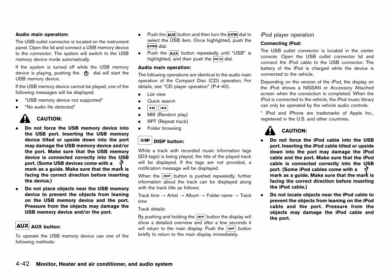
Black plate (170,1)
[ Edit: 2013/ 2/ 25 Model: K13-A ]
4-42 Monitor, Heater and air conditioner, and audio system
Audio main operation:GUID-9E14C2E6-2E9C-4731-980B-C45B899B977B
The USB outlet connector is located on the instrumentpanel. Open the lid and connect a USB memory deviceto the connector. The system will switch to the USBmemory device mode automatically.
If the system is turned off while the USB memorydevice is playing, pushing the dial will start theUSB memory device.
If the USB memory device cannot be played, one of thefollowing messages will be displayed.
. “USB memory device not supported”
. “No audio file detected”
CAUTION:
. Do not force the USB memory device intothe USB port. Inserting the USB memorydevice tilted or upside down into the portmay damage the USB memory device and/orthe port. Make sure that the USB memorydevice is connected correctly into the USBport. (Some USB devices come with amark as a guide. Make sure that the mark isfacing the correct direction before insertingthe device.)
. Do not place objects near the USB memorydevice to prevent the objects from leaningon the USB memory device and the port.Pressure from the objects may damage theUSB memory device and/or the port.
AUX button:GUID-9E14C2E6-2E9C-4731-980B-C45B899B977B
To operate the USB memory device use one of thefollowing methods:
. Push the button and then turn the dial toselect the USB item. Once highlighted, push the
dial.
. Push the button repeatedly until “USB” ishighlighted, and then push the dial.
Audio main operation:GUID-9E14C2E6-2E9C-4731-980B-C45B899B977B
The following operations are identical to the audio mainoperation of the Compact Disc (CD) operation. Fordetails, see “CD player operation” (P.4-40).
. List view
. Quick search
.
. MIX (Random play)
. RPT (Repeat track)
. Folder browsing
DISP button:GUID-9E14C2E6-2E9C-4731-980B-C45B899B977B
While a track with recorded music information tags(ID3-tags) is being played, the title of the played trackwill be displayed. If the tags are not provided, anotification message will be displayed.
When the button is pushed repeatedly, furtherinformation about the track can be displayed alongwith the track title as follows:
Track time? Artist? Album? Folder name? Tracktime
Track details:
By pushing and holding the button the display willshow a detailed overview and after a few seconds itwill return to the main display. Push the buttonbriefly to return to the main display immediately.
iPod player operationGUID-64BF1C53-C88A-43A7-97CD-7690A141CB38
Connecting iPod:GUID-9E14C2E6-2E9C-4731-980B-C45B899B977B
The USB outlet connector is located in the centerconsole. Open the USB outlet connector lid andconnect the iPod cable to the USB connector. Thebattery of the iPod is charged while the device isconnected to the vehicle.
Depending on the version of the iPod, the display onthe iPod shows a NISSAN or Accessory Attachedscreen when the connection is completed. When theiPod is connected to the vehicle, the iPod music librarycan only be operated by the vehicle audio controls.
* iPod and iPhone are trademarks of Apple Inc.,registered in the U.S. and other countries.
CAUTION:
. Do not force the iPod cable into the USBport. Inserting the iPod cable tilted or upsidedown into the port may damage the iPodcable and the port. Make sure that the iPodcable is connected correctly into the USBport. (Some iPod cables come with amark as a guide. Make sure that the mark isfacing the correct direction before insertingthe iPod cable.)
. Do not locate objects near the iPod cable toprevent the objects from leaning on the iPodcable and the port. Pressure from theobjects may damage the iPod cable andthe port.
Condition:

Black plate (171,1)
[ Edit: 2013/ 2/ 25 Model: K13-A ]
Compatibility:GUID-9E14C2E6-2E9C-4731-980B-C45B899B977B
The following models are supported:
. Third generation iPhone (Firmware versionIOS4/4.0)
. Fourth generation iPhone (Firmware versionIOS4/4.0)
. Fifth generation iPod (Firmware version 1.3)
. First generation iPod Classic (Firmware version1.1.1 or 1.1.2PC)
. Second generation iPod Classic (Firmware ver-sion 2.0.1)
. First generation iPod touch (Firmware version1.1.5 or 2.2.1)
. Second and third generation iPod touch (Firm-ware version 2.2.1 or IOS4/4.0.0)
. First generation iPod nano (Firmware version1.3.1)
. Second generation iPod nano (Firmware version1.1.3)
. Third generation iPod nano (Firmware version1.1.2PC or 1.1.3PC)
. Fourth generation iPod nano (Firmware version1.0.2 or 1.0.4)
. Fifth generation iPod nano (Firmware version 1.0.1or 1.0.2)
The iPod touch may not respond quickly to the systemin some cases.
Make sure that the iPod firmware is updated.
Operating tips:GUID-9E14C2E6-2E9C-4731-980B-C45B899B977B
. iPod Shuffle and iPod mini are not supported.
. Some iPod operations may not be available withthis system.
AUX button:GUID-9E14C2E6-2E9C-4731-980B-C45B899B977B
To operate the iPod use one of the following methods:
. Push the button and then turn the dial toselect for the USB item. Once highlighted, pushthe dial.
. Push the button repeatedly until “USB” ishighlighted and then push the dial.
Audio main operation:GUID-9E14C2E6-2E9C-4731-980B-C45B899B977B
Interface:
The interface for iPod operation shown on the audiosystem display is similar to the iPod interface. Use the
dial to play a track on the iPod.
The following items can be chosen from the menu listscreen.
. Playlists
. Artists
. Albums
. Tracks
. Genres
For further information about each item, see the iPodowner’s manual.
The following operations are identical to the audio mainoperation of Compact Disc (CD) operation. For details,see “CD player operation” (P.4-40).
. List view
. Quick search
.
. MIX (Random play)
. RPT (Repeat track)
. Folder browsing
DISP button:GUID-9E14C2E6-2E9C-4731-980B-C45B899B977B
While a track with recorded music information tags(ID3-tags) is being played, the title of the played trackis displayed. If the tags are not provided then anotification message is displayed.
When the button is pushed repeatedly, furtherinformation about the track can be displayed alongwith the track title as follows:
Track time? Artist? Album? Folder name? Tracktime
Track details:
By pushing and holding the button, the displaywill show a detailed overview and after a few secondsit will return to the main display. Push the buttonbriefly to return to the main display immediately.
Radio Broadcast data system (RBDS)GUID-8E4CE6FF-A2A8-41C7-ACC4-BC68BBF79935
The RBDS is a system through which encoded digitalinformation is transmitted by FM radio stations inaddition to the normal FM radio broadcasting. TheRBDS provides information services such as stationname, traffic information, and news.
NOTE:
In some countries or regions, some of theseservices may not be available.
RBDS functionsGUID-5957F70A-94A5-4413-82F4-F656DFBAA01B
Programme Service (PS) function (station namedisplay function):
GUID-9E14C2E6-2E9C-4731-980B-C45B899B977B
When an RBDS station is tuned in with seek or manualtuning, the RBDS data is received and the PS name isdisplayed.
Monitor, Heater and air conditioner, and audio system 4-43
Condition:

Black plate (172,1)
[ Edit: 2013/ 2/ 25 Model: K13-A ]
4-44 Monitor, Heater and air conditioner, and audio system
FM-AM RADIO WITH COMPACT DISC (CD) PLAYER (Type F)GUID-8F59B701-1CED-4805-A0EF-A54AEBCE075C
JVH0508X
1. Day/Night button
2. FM·AM band select button
3. RPT button
4. MIX button
5. Radio memory buttons
6. A-Z button
7. AUX button
8. CD eject button
9. CD button
10. Power/VOL dial
11. Rewind button
12. Fast Forward button
13. DISP button
14. SETUP button
15. Back button
16. TUNE/MENU/ENTER dial
17. Phone button
Condition:

Black plate (173,1)
[ Edit: 2013/ 2/ 25 Model: K13-A ]
Audio main operationGUID-C22EB9A0-95F3-4F43-9647-CAFCF131757E
The audio system operates when the ignition switch isin the “ACC” or “ON” position.
Power/VOL dial:GUID-9E14C2E6-2E9C-4731-980B-C45B899B977B
Power ON/OFF:
To turn on the audio system, push the dial.
. The system will turn on in the mode, which wasused immediately before the system was turnedoff.
. If a CD is inserted or a USB and/or an AUX deviceis connected when the system is turned off, and ifthe system is turned on again with the devicesremoved or disconnected, the radio will turn on.
To turn off the audio system, push the dial.
Volume control:
To control the volume, turn the dial.
Turn the dial clockwise to make the sound louder.
Turn the dial counterclockwise to make the soundquieter.
SETUP button:GUID-9E14C2E6-2E9C-4731-980B-C45B899B977B
To configure Audio, Clock, Bluetooth, Language orScroll direction settings, perform the following proce-dure:
1. Push the button.
2. Push the dial.
3. Turn the dial clockwise or counterclockwise.The setting menu will be displayed in the followingorder:
Audio Û Clock Û Bluetooth Û Language ÛScroll Direction
After the desired levels have been set, either push the
button repeatedly, push the button, or waitfor several seconds without pushing any buttons to exitthe menu screen.
Audio adjustments:GUID-9E14C2E6-2E9C-4731-980B-C45B899B977B
Push the button to enter the setup menu screenand then select “Audio”.
Each time the dial is pushed, the mode willchange as follows:
BASS ? TREBLE ? BALANCE ? FADE ? AUXVOL ? SPD VOL ? Audio (setup menu screen) ?BASS
Turn the dial clockwise or counterclockwise toadjust the following items and push the dial toconfirm.
Bass control:
Use this control to enhance or attenuate the bassresponse sound.
Treble control:
Use this control to enhance or attenuate the treble.
Balance control:
Use this control to adjust the balance of the volumebetween the left and right speakers.
Fader control:
Use this control to adjust the balance of the volumebetween the front and rear speakers (if equipped).
AUX VOL (Auxiliary volume) control:
Use this control to adjust the volume output from theauxiliary source.
SPD VOL (Speed volume) control:
This mode controls the volume output from thespeakers automatically in relation to vehicle speed.
Adjusting the setting to “0” (zero) turns off the speed
volume feature.
Clock setting:GUID-9E14C2E6-2E9C-4731-980B-C45B899B977B
Push the dial n to enter the setup menu screenand then select “Clock”.
Turn the dial, the mode will change as follows:
Set Time Û ON/OFF Û Clock Format Û Set Time
Set Time:
Select “Set Time” then adjust the clock as follows:
The hour display will start flashing. Turn the dial toadjust the hour and push the dial. The minutedisplay will start flashing. Turn the dial to adjustthe minute and push the dial to finish the clockadjustment.
ON/OFF:
Set the clock display to on or off when the audio unit isturned off. If set in the “ON” position, the clock will bedisplayed when the audio unit is turned off either bypushing the dial or when the ignition switch isplaced in the “OFF” position.
Clock Format:
Switch the clock display between 24-hour and 12-hour clock mode.
Language setting:GUID-9E14C2E6-2E9C-4731-980B-C45B899B977B
Push the button to enter the setup menu screenand then select “Language”.
Select the appropriate language and push thedial. Upon completion, the screen will automaticallyadopt the language setting.
Monitor, Heater and air conditioner, and audio system 4-45
Condition:

Black plate (174,1)
[ Edit: 2013/ 2/ 25 Model: K13-A ]
4-46 Monitor, Heater and air conditioner, and audio system
Scroll direction:GUID-9E14C2E6-2E9C-4731-980B-C45B899B977B
Set the scrolling behavior of the dial to scroll UPor DOWN.
Day/Night button:GUID-9E14C2E6-2E9C-4731-980B-C45B899B977B
Push the button to switch the display brightnessbetween the daytime and nighttime modes.
AUX button:GUID-9E14C2E6-2E9C-4731-980B-C45B899B977B
Push the button to play a compatible device whenit is connected.
CD player operationGUID-9E3BD738-DF2C-45E8-9081-0EF3477A579D
JVH0509X
The audio system operates when the ignition switch isin the “ACC” or “ON” position.
Loading:GUID-9E14C2E6-2E9C-4731-980B-C45B899B977B
Insert a CD into the slot with the label side facing up.The CD will be guided automatically into the slot andwill start playing. After loading the CD, the number oftracks and the playtime will appear on the display.
CAUTION:
Do not force the CD into the slot. This coulddamage the player.
NOTE:. The CD player accepts normal audio CDs or
CDs containing MP3/WMA files.
. The audio unit will automatically detect if aCD containing MP3/WMA files is inserted,and [MP3CD] will be indicated.
. An error notification message will be dis-played when an incompatible disc (e.g. DVD)is inserted, or if the player cannot read theCD. Eject the disc and insert another disc.
List view:GUID-9E14C2E6-2E9C-4731-980B-C45B899B977B
While the track is being played, push either thedial or the button to display the available tracks ina listed view mode. Turn the dial to select a trackfrom the list, or a track to start listening to, and thenpush the dial.
Quick search:GUID-9E14C2E6-2E9C-4731-980B-C45B899B977B
In the list view mode, a quick search can be performedto find a track from the list. Push the button, turnthe dial to the first alphabetic letter of the songtitle and then push the dial. When found, a list ofthe available songs will be displayed. Select, and pushthe dial to play the preferred track.
CD button:GUID-9E14C2E6-2E9C-4731-980B-C45B899B977B
When the button is pushed while the audiosystem is turned off and a CD is loaded, the audiosystem will turn on and a CD will start playingautomatically. If the radio or AUX source mode isalready playing, it will automatically turn off and the CD
will start playing.
However, if the CD is not loaded, then a notificationmessage will be displayed and the audio unit willremain in the radio or AUX source mode.
Fast Forward/Rewind buttons:GUID-9E14C2E6-2E9C-4731-980B-C45B899B977B
Push and hold the / buttons to fast forwardor rewind through the track. When the button isreleased, the track will play at normal playing speed.
Track up/down:
By pushing the / buttons once, the track willskip forward to the next track or backward to thebeginning of the current track. Push the /buttons more than once to skip through the tracks.
Folder browsing:
If the recorded media contains folders with music files,pushing the / button will play the tracks ofeach folder in sequence.
To select a preferred folder:
1. Push the dial or the button and a list oftracks in the current folder is displayed.
2. Push the button.
3. Turn the dial to highlight the preferred folder.
4. Push the dial to access the folder. Push thedial again to start playing the first track or
turn the dial, and push the dial to selectanother track.
If the current selected folder contains sub folders, pushthe dial, and a new screen with a list of subfolders will be displayed. Turn the dial to highlightthe sub folder then push the dial to access thesub-folder. Select the root folder item when songs arerecorded additionally in the root folder.
Condition:

Black plate (175,1)
[ Edit: 2013/ 2/ 25 Model: K13-A ]
To return to the previous folder screen, push thebutton.
RPT button:GUID-9E14C2E6-2E9C-4731-980B-C45B899B977B
Push the button and the current track will beplayed continuously.
MIX button:GUID-9E14C2E6-2E9C-4731-980B-C45B899B977B
Push the button and all the tracks will be played inrandom order.
DISP button:GUID-9E14C2E6-2E9C-4731-980B-C45B899B977B
While a CD with recorded music information tags (CD-text/ID3-text tags) is being played, the title of theplayed track is displayed. If the title information is notprovided then “Track” is displayed.
When the button is pushed repeatedly, furtherinformation about the track can be displayed alongwith the track title as follows:
CD:
Track time ? Artist ? Song ? Album ? Track time
CD with MP3/WMA:
Track time? Artist? Album? Folder name? Tracktime
Track details:
By pushing and holding the button will turn thedisplay will show a detailed overview and after a fewseconds will return to the main display. Push thebutton to return to the main display immediately.
CD Eject button:GUID-9E14C2E6-2E9C-4731-980B-C45B899B977B
When the button is pushed while a CD is loaded,the CD will be ejected.
When the button is pushed twice, the CD will beejected further, so that the CD can be removed withease.
When the ignition switch is in the “OFF” or “LOCK”position it is possible to eject the CD currently beingplayed. However the audio unit will not be activated.
If a CD is ejected by pushing the button, and it isnot removed from the loading slot for some time, theCD will automatically be reloaded to the slot to protectthe CD.
FM-AM radio operationGUID-1D5EBA5D-8833-4228-9AA7-EAA84E0CC287
The audio system operates when the ignition switch isin the “ACC” or “ON” position.
FM·AM button:GUID-9E14C2E6-2E9C-4731-980B-C45B899B977B
When the button is pushed while the audiosystem is turned off, the audio system will turn on andthe radio will turn on.
When the button is pushed while another audiosource is playing, the other audio source will turn offand the radio will turn on.
To change the radio band, push the button untilthe desired band appears.
FM 1 ? FM 2 ? FM T ? AM ? FM 1
During FM reception, when the button is pushedfor longer than 1.5 seconds, stations are searched forand the 6 stations of the FM T band are tuned in.During the search, the notification message “AUTO-STORE” appears in the display and the sound is muteduntil the autostore operation is completed, upon which
preset channel 1 is automatically tuned in.
ENTER dial:GUID-9E14C2E6-2E9C-4731-980B-C45B899B977B
When adjusting the broadcasting station frequencymanually, turn the dial until the preferredfrequency is achieved.
The frequency changes in steps of 100 kHz on the FMband and 9 kHz on the AM band.
Fast Forward/Rewind buttons:GUID-9E14C2E6-2E9C-4731-980B-C45B899B977B
When adjusting the broadcasting station frequencyautomatically, push the / button. When thesystem detects a broadcasting station, it will stop atthe station.
*1 *2 *3 *4 *5 *6 (Radio memory) buttons:GUID-9E14C2E6-2E9C-4731-980B-C45B899B977B
During radio reception, pushing the radio memorybutton for less than 2 seconds will select the storedradio station.
The audio system can store up to 18 FM stationfrequencies (six in each of FM 1, FM 2 and FM T) and 6AM station frequencies.
To store the station frequency manually:
1. Tune to the desired broadcasting station fre-quency by using the / button.
2. Push and hold a radio memory button*1 -*6until a beep sounds. (The radio mutes when thememory button is pushed.)
3. The channel indicator will display and the radiomute disengages, indicating that the memory isstored properly.
4. Perform steps 1 - 3 for all other memory buttons.
If the battery cable is disconnected, or if the audio fuseblows, the radio memory will be erased. If this occurs,
Monitor, Heater and air conditioner, and audio system 4-47
Condition:

Black plate (176,1)
[ Edit: 2013/ 2/ 25 Model: K13-A ]
4-48 Monitor, Heater and air conditioner, and audio system
reset the desired stations.
USB memory device operationGUID-9D1BEADF-3B18-4472-816C-1DE672CA4456
JVH0518X
Audio main operation:GUID-9E14C2E6-2E9C-4731-980B-C45B899B977B
The USB outlet connector is located on the instrumentpanel. Open the lid and connect a USB memory deviceinto the connector. The system will switch to the USBmemory device mode automatically.
If the system is turned off while the USB memorydevice is playing, pushing the dial will start theUSB memory device.
If the USB memory device cannot be played, one of thefollowing messages will be displayed.
. “USB memory device not supported”
. “No audio file detected”
CAUTION:
. Do not force the USB memory device intothe USB port. Inserting the USB memorydevice tilted or upside down into the portmay damage the USB memory device and/orthe port. Make sure that the USB memorydevice is connected correctly into the USBport. (Some USB devices come with a
mark as a guide. Make sure that the mark isfacing the correct direction before insertingthe device.)
. Do not place objects near the USB memorydevice to prevent the objects from leaningon the USB memory device and the port.Pressure from the objects may damage theUSB memory device and/or the port.
AUX button:GUID-9E14C2E6-2E9C-4731-980B-C45B899B977B
To operate the USB memory device use one of thefollowing methods:
. Push the button then turn the dial toselect the USB item. Once highlighted, push the
dial.
. Push the button repeatedly until USB ishighlighted, and then push the dial.
Audio main operation:GUID-9E14C2E6-2E9C-4731-980B-C45B899B977B
The following operations are identical to the audio mainoperation of the Compact Disc (CD) operation. Fordetails, see “CD player operation” (P.4-46).
. List view
. Quick search
.
. MIX (Random play)
. RPT (Repeat track)
. Folder browsing
DISP button:GUID-9E14C2E6-2E9C-4731-980B-C45B899B977B
While a track with recorded music information tags(ID3-tags) is being played, the title of the played trackis displayed. If the tags are not provided, a notificationmessage is displayed.
When the button is pushed repeatedly, furtherinformation about the track can be displayed alongwith the track title as follows:
Track time? Artist? Album? Folder name? Tracktime
Track details:
By pushing and holding the button the display willshow a detailed overview and after a few seconds itwill return to the main display. Push the buttonbriefly to return to the main display immediately.
iPod player operationGUID-FD81A5CF-6AA5-4626-B051-70BF7A4038A1
Connecting iPod:GUID-9E14C2E6-2E9C-4731-980B-C45B899B977B
The USB outlet connector is located in the centerconsole. Open the USB outlet connector lid andconnect the iPod cable to the USB connector. Thebattery of the iPod is charged while the device isconnected to the vehicle.
Depending on the version of the iPod, the display onthe iPod shows a NISSAN or Accessory Attachedscreen when the connection is completed. When theiPod is connected to the vehicle, the iPod music librarycan only be operated by the vehicle audio controls.
* iPod and iPhone are trademarks of Apple Inc.,registered in the U.S. and other countries.
CAUTION:
. Do not force the iPod cable into the USBport. Inserting the iPod cable tilted or up-side-down into the port may damage theiPod cable and the port. Make sure that theiPod cable is connected correctly into theUSB port. (Some iPod cables come with a
mark as a guide. Make sure that themark is facing the correct direction beforeinserting the iPod cable.)
Condition:

Black plate (177,1)
[ Edit: 2013/ 2/ 25 Model: K13-A ]
. Do not locate objects near the iPod cable toprevent the objects from leaning on the iPodcable and the port. Pressure from theobjects may damage the iPod cable andthe port.
Compatibility:GUID-9E14C2E6-2E9C-4731-980B-C45B899B977B
The following models are supported:
. Third generation iPhone (Firmware versionIOS4/4.0)
. Fourth generation iPhone (Firmware versionIOS4/4.0)
. Fifth generation iPod (Firmware version 1.3)
. First generation iPod Classic (Firmware version1.1.1 or 1.1.2PC)
. Second generation iPod Classic (Firmware ver-sion 2.0.1)
. First generation iPod touch (Firmware version1.1.5 or 2.2.1)
. Second and third generation iPod touch (Firm-ware version 2.2.1 or IOS4/4.0.0)
. First generation iPod nano (Firmware version1.3.1)
. Second generation iPod nano (Firmware version1.1.3)
. Third generation iPod nano (Firmware version1.1.2PC or 1.1.3PC)
. Fourth generation iPod nano (Firmware version1.0.2 or 1.0.4)
. Fifth generation iPod nano (Firmware version 1.0.1or 1.0.2)
The iPod touch may not respond quickly to the systemin some cases.
Make sure that the iPod firmware is updated.
Operating tips:GUID-9E14C2E6-2E9C-4731-980B-C45B899B977B
. iPod Shuffle and iPod mini are not supported.
. Some iPod operations may not be available withthis system.
AUX button:GUID-9E14C2E6-2E9C-4731-980B-C45B899B977B
To operate the iPod use one of the following methods:
. Push the button and then turn the dialfor the USB item. Once highlighted, push thedial.
. Push the button repeatedly until USB ishighlighted and then push the dial.
Audio main operation:GUID-9E14C2E6-2E9C-4731-980B-C45B899B977B
Interface:
The interface for iPod operation shown on the audiosystem display is similar to the iPod interface. Use the
dial to play a track on the iPod.
The following items can be chosen from the menu listscreen.
. Playlists
. Artists
. Albums
. Tracks
. Genres
For further information about each item, see the iPodowner’s manual.
The following operations are identical to the audio mainoperation of the Compact Disc (CD) operation. Fordetails, see “CD player operation” (P.4-46).
. List view
. Quick search
.
. MIX (Random play)
. RPT (Repeat track)
. Folder browsing
DISP button:GUID-9E14C2E6-2E9C-4731-980B-C45B899B977B
While a track with recorded music information tags(ID3-tags) is being played, the title of the played trackis displayed. If the tags are not provided then anotification message is displayed.
When the button is pushed repeatedly, furtherinformation about the track can be displayed alongwith the track title as follows:
Track time? Artist? Album? Folder name? Tracktime
Track details:
By pushing and holding the button the display willshow a detailed overview and after a few seconds itwill return to the main display. Push the buttonbriefly to return to the main display immediately.
Bluetooth® audio player operationGUID-32CAE781-FBA5-47D3-9B53-71EB8C92DC09
Regulatory information:GUID-9E14C2E6-2E9C-4731-980B-C45B899B977B
Bluetooth® is a trademark ownedby Bluetooth SIG, Inc., andlicensed to Daewoo IS Corp.
CE statement:GUID-9E14C2E6-2E9C-4731-980B-C45B899B977B
Hereby Daewoo IS Corp. declares that this system isin compliance with the essential requirements andother relevant provisions of Directive 1999/5/EC.
NSY0105
Monitor, Heater and air conditioner, and audio system 4-49
Condition:

Black plate (178,1)
[ Edit: 2013/ 2/ 25 Model: K13-A ]
4-50 Monitor, Heater and air conditioner, and audio system
NOTE:
The audio system only supports Bluetooth®
devices with AVRCP (Audio Video Remote Con-trol Profile) version 1.3, 1.0, or earlier.
Bluetooth® audio player setting:GUID-9E14C2E6-2E9C-4731-980B-C45B899B977B
To set up the Bluetooth® system with your preferreddevice, push the button and select Bluetooth®,and then push the dial or alternatively, push the
button. The following items are available:
. Pair Device
Bluetooth® devices can be paired with the system.A maximum of 5 devices can be registered.
. Select Device
Paired Bluetooth® devices are listed and can beselected for connection.
. Delete Device
A registered Bluetooth® device can be deleted.
. On/Off
If this setting is turned off, the connection betweenthe Bluetooth® devices and the in-vehicle Blue-tooth® module will be cancelled.
NOS2761
Pair Device:
1. Push the button. Select the Bluetooth® keyby turning the dial, and then push thedial.
You can register up to 5 different Bluetooth®
audio/cellular phone devices. However, you canonly use one device at a time. If you have 5different Bluetooth® devices, a newly registereddevice can only replace one of the alreadyregistered 5 existing paired devices. Use the“Delete Device” key to delete one of the existingpaired devices.
2. Select the “Pair Device” key.
The pairing procedure depends on the connecteddevice:. Cellular phone:
The message Ready to Pair Pin:1234 will bedisplayed.
. Audio device without PIN code:
The Bluetooth® connection will be automati-cally connected without any further input.
. Audio device with PIN code:
A new screen will appear. Assign the 4 digitPIN code by turning the dial to each digitof the code and pushing the dial toconfirm each digit. After the PIN code is input,select “Validate” and push the dial. TheBluetooth® connection will be made.
The 4-digit PIN code is provided with the audiodevice, see the owner’s manual of the audiodevice.
3. On Bluetooth® audio/cellular phone devices:
a. Check that Bluetooth® is turned on, on yourdevice.
b. Switch to the search mode for Bluetooth®
devices. If the search mode finds a device itwill be shown on the device display. Select MyCar.
c. Enter the number code shown on the relevantdevice with the device’s own keypad, and pushthe confirmation key on the device itself. Referto the relevant Bluetooth® device owner’smanual for further details.
When the device is successfully paired a notificationmessage will be displayed, and then the audio systemdisplay will return to the current audio source display.During connection the following status icons will bedisplayed (top left of the display): Signal strength( ), Battery status* ( ) and Bluetooth® “ON”( ).
*: If the low battery message comes on, the Bluetooth®
device must be recharged soon.
The pairing procedure and operation may varyaccording to device type and compatibility. See theowner’s manual of the Bluetooth® device for furtherdetails.
Select Device:
The paired device list shows which Bluetooth® audioor cellular phone devices have been paired orregistered with the Bluetooth® audio system. If the listcontains devices, select the appropriate device toconnect to the Bluetooth® audio system.
The following symbols indicate the capability of theregistered device:
. : cellular phone integration
. : Audio streaming (A2DP- Advanced AudioDistribution Profile)
Delete Device:
A registered device can be removed from the Blue-tooth® audio system. Select a registered device thenpush the button to confirm deletion.
Condition:

Black plate (179,1)
[ Edit: 2013/ 2/ 25 Model: K13-A ]
On/Off:
If Bluetooth® has been switched off, a notificationmessage On/Off appears when you select Bluetooth®
from the setup menu screen, or push the button.To turn the Bluetooth® signal on, push the dialand a follow up screen will appear. Select “On” andpush the dial to display the Bluetooth® settingsmenu screen.
Bluetooth® audio streaming main operation:GUID-9E14C2E6-2E9C-4731-980B-C45B899B977B
NOS2762
Turn the ignition switch to the “ACC” or “ON” position.If the audio system is turned off while the Bluetooth®
audio is playing, pushing the dial will startBluetooth® audio streaming.
AUX button:
To operate Bluetooth® audio streaming use one of thefollowing methods:
. Push the button, then turn the dial tohighlight BT Audio, and push the dial.
. Push repeatedly until BT Audio is highlighted,then push the dial.
The type of display,*A or*B , shown on the audiosystem can vary depending on the Bluetooth® versionof the device.
Fast Forward/Rewind buttons:
Fast Forward, Fast Reverse:
When the / button is pushed continuously,the track will be played at high speed. When the buttonis released, the track will be played at normal playingspeed.
Track up/down:
By pushing the / button once, the track willbe skipped forward to the next track or backward tothe beginning of the current played track. Push the
/ button more than once to skip through thetracks.
DISP button:
If the song contains music information tags (ID3-tags),the title of the played song will be displayed. If tags arenot provided, the display will not show any messages.
When the button is pushed repeatedly, furtherinformation about the song can be displayed alongwith the song title.
By pushing and holding the button the display willshow a detailed overview which after a few secondswill return to the main display. Push the buttonbriefly to return to the main display immediately.
Radio Broadcast data system (RBDS)GUID-6A4AA979-71C4-47F1-AF38-B21D4FDD2FF2
The RBDS is a system through which encoded digitalinformation is transmitted by FM radio stations inaddition to the normal FM radio broadcasting. TheRBDS provides information services such as stationname, traffic information, and news.
NOTE:
In some countries or regions, some of theseservices may not be available.
Alternative Frequency (AF) mode:GUID-9E14C2E6-2E9C-4731-980B-C45B899B977B
The AF mode operates in the FM (radio) mode.
. The AF mode operates both in the FM (radio) andCD mode (if FM was previously selected in theradio mode).
. The AF function compares signal strengths andselects the station with the optimum receptionconditions for the currently tuned-in station.
RBDS functionsGUID-4076D2F6-957E-4D0C-93F3-6A860E217BF1
Programme Service (PS) function (station namedisplay function):
GUID-9E14C2E6-2E9C-4731-980B-C45B899B977B
When an RBDS station is tuned in with seek or manualtuning, the RBDS data is received and the PS name isdisplayed.
Monitor, Heater and air conditioner, and audio system 4-51
Condition:

Black plate (180,1)
[ Edit: 2013/ 2/ 25 Model: K13-A ]
4-52 Monitor, Heater and air conditioner, and audio system
LW-MW-FM RADIO WITH COMPACT DISC (CD) PLAYERGUID-6A9CD14F-B6E3-4056-B506-430C33ADFEBB
SAA2379
1. MUTE button
2. POWER ON/OFF button
3. Sound preference button
4. FM band select button
5. AM band select button
6. Radio memory buttons
7. CD button
8. AUX button
9. TA (Traffic Announcement) button
10. MENU button
11. CD EJECT button
12. SEEK/TRACK button
13. MIX (Mix play) button
14. RPT (Repeat) button
15. VOLUME control/MENU select dial
16. ENTER button
17. AUX IN (auxiliary input) jack
18. NEWS button
19. TUNE/SEARCH button
Condition:

Black plate (181,1)
[ Edit: 2013/ 2/ 25 Model: K13-A ]
Anti-theft system (if equipped)GUID-0B1806B3-B3F3-454E-96F7-F01E3B55322A
This unit can only be activated when the ignition switchfor NATS is in the “ACC” or “ON” position.
Each radio is uniquely matched to the vehicle’simmobilizer and therefore cannot be transferred toany other vehicle.
Audio main operationGUID-0F37ACCE-50E0-4C87-94A7-2BA1849C6F2D
The audio system operates when the ignition switch isin the “ACC” or “ON” position.
POWER ON/OFF button:GUID-9E14C2E6-2E9C-4731-980B-C45B899B977B
To turn on the audio system, push the POWER ON/OFF button.
. The system will turn on in the mode, (radio or CD)which was used immediately before the systemwas last turned off.
. If there is no CD loaded, the radio will be turnedon.
To turn off the audio system, push the POWER ON/OFF button.
Volume control:GUID-9E14C2E6-2E9C-4731-980B-C45B899B977B
To control the volume, turn the VOLUME control dial.
Turn the VOLUME control dial clockwise to increasethe audio volume.
Turn the VOLUME control dial counterclockwise todecrease the audio volume.
Sound preference button:GUID-9E14C2E6-2E9C-4731-980B-C45B899B977B
To enter the audio mode (radio or CD), push thebutton.
To change the audio settings (BASS, TREBLE, FADE,BALANCE, EQ), push the button or ENTERbutton to select the mode.
BASS ? TREBLE ? BALANCE ? FADE ? EQ ?BASS
To adjust each audio setting, turn the MENU/VOLcontrol dial clockwise or counterclockwise.
BASS: (−) to decrease / (+) to increase
TREB(LE): (−) to decrease / (+) to increase
BAL(ANCE): (R) to adjust to the right / (L) to adjust tothe left
FADE(R): (F) to adjust to the front / (R) to adjust to therear
EQ (Equalizer): Use this control to change the presetsound mode for CD play.
Turn the MENU/VOL dial clockwise or counterclock-wise. The mode will change as follows:
OFF Û ENHANCE Û OFF
If the audio settings mode is unchanged for approxi-mately 5 seconds, the audio settings mode willautomatically return to the normal mode.
Clock display:GUID-9E14C2E6-2E9C-4731-980B-C45B899B977B
Turning on/off the clock display
To turn on or off the clock display, perform thefollowing operations.
1. Push the MENU button while the audio system ison.
2. Turn the VOLUME control dial until "CLOCK"appears on the display.
3. Push the ENTER button. ("CLOCK OFF" or"CLOCK ON" is displayed.)
4. To turn on the clock display, turn the VOLUMEcontrol dial till "CLOCK ON" is displayed. To turnoff the clock display, turn the VOLUME control dialtill "CLOCK OFF" is displayed, and push ENTER.
Clock adjustment
To adjust the time of the clock, perform the followingoperations.
1. Push the ENTER button while "CLOCK ON" isdisplayed.
2. The hour display will flash.
3. Turn the VOLUME control dial to adjust the hour.
4. Push the ENTER button. The minute display willflash.
5. Turn the VOLUME control dial to adjust theminute.
6. Push the ENTER button to complete the clockadjustment.
Mute button:GUID-9E14C2E6-2E9C-4731-980B-C45B899B977B
Push the MUTE button to mute the audio system.MUTE appears on the display. To unmute, use any oneof the following options:
. Push the MUTE button again.
. Turn the VOLUME control dial.
. Push the CD, FM or AM button.
. Push the AUX button.
AUX button:GUID-9E14C2E6-2E9C-4731-980B-C45B899B977B
The AUX IN jack is located on the audio unit. The AUXIN audio input jack accepts any standard analog audioinput such as from a portable cassette tape player, CDplayer, MP3 player or laptop computer.
Push the AUX button to play a compatible device whenit is plugged into the AUX IN jack.
NISSAN strongly recommends using a stereo miniplug cable when connecting your music device to theaudio system. Music may not play properly when a
Monitor, Heater and air conditioner, and audio system 4-53
Condition:

Black plate (182,1)
[ Edit: 2013/ 2/ 25 Model: K13-A ]
4-54 Monitor, Heater and air conditioner, and audio system
monaural cable is used.
CD player operationGUID-108C6D9A-02FF-45FA-9BBC-73B6407DEA62
SAA2380
The audio system operates when the ignition switch isin the “ACC” or “ON” position.
Loading:GUID-9E14C2E6-2E9C-4731-980B-C45B899B977B
Insert a CD into the slot with the label side facing up.The CD will be guided automatically into the slot andwill start playing. If the radio is already playing, it willautomatically turn off, and the CD will start playing.
CAUTION:
Do not force the CD into the slot. This coulddamage the player.
After loading the CD, the number of tracks and theplaytime will appear on the display.
CD button:GUID-9E14C2E6-2E9C-4731-980B-C45B899B977B
When the button is pushed while the audiosystem is off and a CD is loaded, the audio system willturn on and a CD will start playing automatically. If theradio is already playing, it will automatically turn off andthe CD will start playing.
/ FF (Fast Forward), REW (Rewind)button:
GUID-9E14C2E6-2E9C-4731-980B-C45B899B977B
Push and hold the FF or REW button while a CD isbeing played to fast-forward or rewind though thetrack. When the button is released, the CD will returnto the normal play speed.
/ TRACK UP/ DOWN button:GUID-9E14C2E6-2E9C-4731-980B-C45B899B977B
Push the track up button while a CD is being played toskip forward to the next track. The CD will advance thenumber of times the button is pushed. When the lasttrack of the CD is skipped, the first track will be played.
Push the track down button while a CD is being playedto start the present track again from the beginning.Push the track down button several times to skip backto the previous track. The CD will skip tracks backwardthe number of times the button is pushed. When thefirst track of the CD is skipped, the last track will beplayed.
Repeat button:GUID-9E14C2E6-2E9C-4731-980B-C45B899B977B
Push the button repeatedly to change the playmode as follows:
RPT (REPEAT) TRACK? RPT (REPEAT) ALL? RPT(REPEAT) TRACK
RPT TRACK:
The selected track will be played repeatedly.
RPT ALL:
All the tracks on the CD will be played in sequentialorder.
MIX button:GUID-9E14C2E6-2E9C-4731-980B-C45B899B977B
Push the button repeatedly to change the playmode as follows:
MIX DISC ? RPT (REPEAT) ALL ? MIX DISC
MIX DISC:
All the tracks on the CD will be played in a randomorder.
RPT ALL:
All the tracks on the CD will be played in sequentialorder.
CD EJECT button:GUID-9E14C2E6-2E9C-4731-980B-C45B899B977B
When the button is pushed while a CD is loaded,the CD will be ejected.
When the button is pushed twice, the CD will beejected further, and the CD can be removed easily.
If a CD is ejected by pushing the button, and it isnot taken out from the loading slot, the CD willautomatically be reloaded to the slot to protect the CD.
LW-MW-FM radio operationGUID-26B351F1-BF06-4FF6-8B60-4538B0FEB6F4
SAA2380
Condition:

Black plate (183,1)
[ Edit: 2013/ 2/ 25 Model: K13-A ]
The audio system operates when the ignition switch isin the “ACC” or “ON” position.
FM-AM button:GUID-9E14C2E6-2E9C-4731-980B-C45B899B977B
When the / button is pushed while the audiosystem is off, the audio system and the radio will turnon. When the / button is pushed while the CDplayer is already operating, it will automatically turn offand the radio will turn on.
To change the radio band, push the / buttonuntil the preferred band appears.
. For FM
FM 1 ? FM 2 ? FM T
. For AM
MW ? LW ? MW
During FM reception, when the button is pushedfor longer than 1.5 seconds, stations are searched forand the 6 stations of the FM T band. The sound ismuted until the auto store operation is completed,upon which preset channel 1 is automatically tuned in.
TUNE button:GUID-9E14C2E6-2E9C-4731-980B-C45B899B977B
When adjusting the broadcasting station frequencymanually, push the or button until thepreferred frequency is obtained.
The frequency changes in steps of 100 kHz on the FMband, 9 kHz on the MW band, and 3 kHz on the LWband.
SEEK button:GUID-9E14C2E6-2E9C-4731-980B-C45B899B977B
When adjusting the broadcasting station frequencyautomatically, push the or button. When thesystem detects a broadcasting station, it will stop atthat station.
*1 *2 *3 *4 *5 *6 Radio memory buttons:GUID-9E14C2E6-2E9C-4731-980B-C45B899B977B
The audio system can store up to 18 FM stationfrequencies (six in each of FM 1, FM 2 and FM T), 6MW and 6 LW station frequencies.
To store the station frequency manually:
1. Tune to the preferred broadcasting station fre-quency by using the orbutton.
2. Push and hold a radio memory button*1 -*6until a beep sounds. (The radio mutes when thememory button is pushed.)
3. The channel indicator will be displayed and theradio mute will be cancelled, indicating that thememory is stored properly.
4. Perform steps 1 - 3 for all other memory buttons.
If the battery cable is disconnected, or if the audio fuseblows, the radio memory will be erased. If this occurs,reset the desired stations.
Radio data system (RDS)GUID-237F0783-B830-4397-9033-EF65999545BA
Alternative Frequency (AF):GUID-9E14C2E6-2E9C-4731-980B-C45B899B977B
. The AF function operates in the FM (radio) and CDmodes.
. When the AF mode is set to “ON” in the usersetup menu mode, the AF indicator illuminates.
For activation or deactivation, use the MENU button.(Details are explained later in this section.)
. Automatic switching function
This function compares the strengths of thesignals of all the stations on the AF list andselects the station with the optimum receptionconditions.
. Program Information (PI) search
Program Information (PI) search begins automati-
cally if no suitable station is found with the aboveautomatic switching function. The PI searchfunction checks each RDS station with the samePI code. During this time the sound is muted and“PI SEARCH” is displayed. The PI search opera-tion stops when a suitable station is found. If nostation is found once all the frequencies have beensearched, the radio returns to the previousfrequency.
. Enhanced Other Network (EON) data update(This function also operates when the AFmode is off.)
When EON data is being received, this enablesautomatic retuning of other preset stations on thesame network. Also, network linked services canbe used. The EON indicator turns on duringreception of RDS EON stations in the FM mode.
RDS functions:GUID-9E14C2E6-2E9C-4731-980B-C45B899B977B
. Programme Service (PS) function (stationname display function)
When an RDS station is tuned in with seek ormanual tuning, RDS data is received and theProgram Service (PS) name is displayed.
. Emergency broadcast interrupt function(ALARM INTERRUPTION — EBU SPEC FORINFO)
When the radio receives PTY code 31 (anemergency broadcast code), the sound is inter-rupted, the emergency broadcast is heard, and“PTY31 ALARM” is displayed. The volume level atthis time is the same as that for traffic announce-ments. Once the emergency broadcast is finished,the unit immediately returns to the previoussource.
. REG (Regional) mode
Some local radio stations are linked together
Monitor, Heater and air conditioner, and audio system 4-55
Condition:

Black plate (184,1)
[ Edit: 2013/ 2/ 25 Model: K13-A ]
4-56 Monitor, Heater and air conditioner, and audio system
according to their region because they only offerlimited coverage due to their limited number oftransmitters. If the signal from one station be-comes weak while you are driving around, RDSmode will switch to another local station in theregion with a stronger signal.
When the REG mode is activated in the FM bandand the radio receiver is tuned to a local radiostation, it will keep receiving this radio stationwithout switching to another local station. Foractivation or deactivation, use the MENU button.(Details are explained later in this section.)
Traffic Announcement (TA):GUID-9E14C2E6-2E9C-4731-980B-C45B899B977B
. The TA function operates in the FM and CDmodes.
. The TA mode is turned on or off when the TAbutton is pushed for less than 2 seconds.
. The TA mode operates regardless of whether theAF mode is on or off.
. “TA ON” is displayed when the TA mode is turnedon, and the TA indicator turns on. “TA OFF” isdisplayed when the TA mode is turned off, and theTA indicator turns off.
The following function operates when the TA mode ison:
. Traffic announcement interrupt function
When a traffic announcement is received, theannouncement is tuned in and the volumeincreases to the set level.
Once the traffic announcement is finished, the unitreturns to the source which was set before thetraffic announcement started, and the volumereturns to the previous level. For EON stations,the radio is interrupted by another EON stationwith traffic announcements.
The traffic announcement interrupt mode is
cancelled if the TA button is pushed during atraffic announcement. The TA mode returns to thestandby mode and the audio unit returns to theprevious source.
News mode:GUID-9E14C2E6-2E9C-4731-980B-C45B899B977B
When the NEWS button is pushed for longer than 2seconds in the FM mode, the news function isactivated. “NEWS” is displayed for 3 seconds andthe NEWS indicator appears on the display.
When the news function is activated, the radioreceives a news code from the FM broadcasting newsstation and the play mode will be interrupted. Once thenews broadcast is finished, the unit returns to theprevious mode.
In some countries or regions, this service is notavailable or the signal is too weak to be received.
1. News standby mode. The news standby mode can be activated in
the FM or CD mode.. A news interruption will be announced and
“NEWS” will be displayed when the radiodetects the news code from the tuned stationor EON stations. The display will then changeto the PS name of the interrupting station.
. When pushing the NEWS button for longerthan 2 seconds, the news standby mode isturned off and the indicator disappears fromthe display.
2. News interruption mode. When the NEWS button is pushed during the
news interruption mode, the radio returns to theprevious source. However, the news standbymode is maintained.
. When the button is pushed during thenews interruption mode, the radio changes tothe CD mode. However, the news standbymode is maintained.
If the radio band is changed to the MW or LW,the news standby mode will be turned off.
MENU button:GUID-9E14C2E6-2E9C-4731-980B-C45B899B977B
To configure Alternative Frequency, Regional andLanguage settings, perform the following procedure:
1. Push and hold the MENU button for at least 1.5seconds.
2. Turn the VOLUME control dial clockwise orcounterclockwise. The display message willchange as follows:
AF Û REG Û LANGUAGE Û AF
. To activate or deactivate the AF and REG mode,briefly push the ENTER button when AF or REGappears on the display and turn the VOLUMEcontrol dial clockwise or counterclockwise toswitch between the off or on position. Afterselection, push the ENTER button to confirm thesettings.
— When the AF mode is enabled, the audio unitwill automatically re-tune to a stronger fre-quency if the radio signal becomes weak.
— When the REG mode is enabled, the audio unitwill maintain and maintain the station which isbroadcasting local (regional) programmes.
. To change the display language, briefly push theENTER button when LANGUAGE appears on thedisplay then turn the MENU/VOL dial clockwise orcounterclockwise to select the appropriate lan-guage setting.
ENGLISH Û DUTCH Û FRENCH Û SPANISH
Condition:

Black plate (185,1)
[ Edit: 2013/ 2/ 25 Model: K13-A ]
Û GERMAN Û ITALIAN Û PORTUGUESE ÛENGLISH
After selecting the preferred language, push theENTER button to exit the menu.
To configure the SPEED volume and BEEP settings,perform the following procedure:
1. Push the MENU button.
2. Turn the Volume control dial clockwise or counter-clockwise. The display message will change asfollows:
SPEED VOL Û CLOCK Û BEEP
. When SPEED VOL appears on the display, brieflypush the ENTER button then turn the VOLUMEcontrol dial clockwise or counterclockwise toadjust the level of the volume.
Adjusting the setting to 0 (zero) turns off thespeed volume feature. Increasing the speedvolume setting results in the audio volumeincreasing more rapidly with vehicle speed. Pushthe ENTER button again to save the setting.
. When BEEP appears on the display, briefly pushthe ENTER button and then turn the VOLUMEcontrol dial clockwise or counterclockwise toswitch the beep sound on or off. Push the ENTERbutton again to save the setting.
After the preferred levels have been set, push theMENU button to exit the menu or wait at least for 10seconds without pressing any buttons.
For clock adjustments, see “Audio main operation”(P.4-53).
LW-MW-FM RADIO WITH COMPACT DISC (CD) CHANGERGUID-09378FC5-F692-4F38-920E-B917215D1033
JVH0044X
1. CD LOAD button
2. POWER ON/OFF button
3. PHONE SEND button
4. TA (Traffic Announcement)/NEWS button
5. Radio band select button
6. Radio memory/CD select buttons
7. CD button
8. AUX button
9. Sound preference button
10. MENU button
11. CD EJECT button
12. SEEK/TRACK button
13. PHONE BOOK button
14. PHONE END/BACK button
15. VOLUME control/MENU select knob
16. ENTER button
Monitor, Heater and air conditioner, and audio system 4-57
Condition:

Black plate (186,1)
[ Edit: 2013/ 2/ 25 Model: K13-A ]
4-58 Monitor, Heater and air conditioner, and audio system
17. AUX IN (auxiliary input) jack
18. RPT (Repeat)/MIX (Mix play) button
19. TUNE/SEARCH button
Anti-theft system (if equipped)GUID-8F9676CC-8B9A-4A00-AA79-2C6C23138E02
This unit can only be activated when the ignition switchfor NATS is in the “ACC” or “ON” position.
Each radio is uniquely matched to the vehicle’simmobilizer and therefore cannot be transferred toany other vehicle.
Audio main operationGUID-1FB203B0-2837-457B-A593-36D3628B1DB7
The audio system operates when the ignition switch isin the “ACC” or “ON” position.
POWER ON/OFF button:GUID-9E14C2E6-2E9C-4731-980B-C45B899B977B
To turn on the audio system, push the POWER ON/OFF button.
. The system will turn on in the mode, (radio or CD)which was used immediately before the systemwas last turned off.
. If there is no CD loaded, the radio will be turnedon.
To turn off the audio system, push the POWER ON/OFF button.
Volume control:GUID-9E14C2E6-2E9C-4731-980B-C45B899B977B
To control the volume, turn the VOLUME control dial.
Turn the VOLUME control dial clockwise to increasethe audio volume.
Turn the VOLUME control dial counterclockwise todecrease the audio volume.
Sound preference button:GUID-9E14C2E6-2E9C-4731-980B-C45B899B977B
To enter the audio mode (radio or CD), push thebutton. When no CD is loaded, the audio system willautomatically switch to the radio mode.
To change the audio settings (BASS, TREBLE,FADER, BALANCE, EQ), push the button orENTER button to select the mode.
BASS ? TREBLE ? BALANCE ? FADER ? EQ ?BASS
To adjust each audio setting, turn the MENU/VOLcontrol dial clockwise or counterclockwise.
BASS: (−) to decrease / (+) to increase
TREB(LE): (−) to decrease / (+) to increase
BAL(ANCE): (R) to adjust to the right / (L) to adjust tothe left
FADE(R): (F) to adjust to the front / (R) to adjust to therear
EQ (Equalizer): Use this control to change the presetsound mode for CD play.
Turn the MENU/VOL dial clockwise or counterclock-wise. The mode will change as follows:
OFF Û ENHANCE Û OFF
If the audio settings mode is unchanged for approxi-mately 8 seconds, the audio settings mode willautomatically return to the normal mode.
Clock display:GUID-9E14C2E6-2E9C-4731-980B-C45B899B977B
Turning on/off the clock display
To turn on or off the clock display, perform thefollowing operations.
1. Push the MENU button while the audio system ison. ("PHONE SETUP" is displayed.)
2. Turn the VOLUME control knob until "CLOCK"appears on the display.
3. Push the ENTER button. ("CLOCK OFF" or"CLOCK ON" is displayed.)
4. To turn on the clock display, turn the VOLUMEcontrol knob till "CLOCK ON" is displayed. To turnoff the clock display, turn the VOLUME controlknob till "CLOCK OFF" is displayed, and pushENTER.
Clock adjustment
To adjust the time of the clock, perform the followingoperations.
1. Push the ENTER button while "CLOCK ON" isdisplayed.
2. The hour display will flash.
3. Turn the VOLUME control knob to adjust the hour.
4. Push the ENTER button. The minute display willflash.
5. Turn the VOLUME control knob to adjust theminute.
6. Push the ENTER button to complete the clockadjustment.
AUX button:GUID-9E14C2E6-2E9C-4731-980B-C45B899B977B
The AUX IN jack is located on the audio unit. The AUXIN audio input jack accepts any standard analog audioinput such as from a portable cassette tape player, CDplayer, MP3 player or laptop computer.
Push the AUX button to play a compatible device whenit is plugged into the AUX IN jack.
NISSAN strongly recommends using a stereo miniplug cable when connecting your music device to theaudio system. Music may not play properly when a
Condition:

Black plate (187,1)
[ Edit: 2013/ 2/ 25 Model: K13-A ]
monaural cable is used.
CD changer operationGUID-5C006A55-5D29-458D-B6B9-80DFFF96E98A
JVH0045X
The audio system operates when the ignition switch isin the “ACC” or “ON” position.
CD LOAD button:GUID-9E14C2E6-2E9C-4731-980B-C45B899B977B
When the button is pushed, the CD loading slotwill open and the loading position will be displayed.
Insert the CD into the slot with the label side facing up.The CD will be guided automatically into the slot andwill start playing. If the radio is already playing, it willautomatically turn off and the CD will start playing.
CAUTION:
. Do not force the compact disc into the slot.This could damage the player.
. Do not use 8 cm (3.1 in) discs.
After loading the CD, the slot number and CD track willappear on the display.
To load a CD in the CD changer:
1. Push the button for less than 1.5 seconds.
2. Select the loading slot by pushing the CD selectbutton. If no slot is selected, the CD changer willautomatically select an available slot.
3. Insert the CD into the slot.
To load 6 CDs in the CD changer:
1. Push the button for more than 1.5 seconds.
2. Insert a CD into the slot.
3. When the next loading slot number illuminates onthe display, insert the next CD into the slot.
To load 6 CDs in the CD changer:
1. Push the button for more than 1.5 seconds.
2. Insert the CD into the slot.
3. When the next loading slot number illuminates onthe display, insert the next CD into the slot.
The slot number indicator appears on the display whenthe CDs are loaded in the CD changer and the audiosystem is turned on.
CD PLAY button:GUID-9E14C2E6-2E9C-4731-980B-C45B899B977B
When the button is pushed while the audiosystem is off and CDs are loaded, the audio system willturn on and the CD will start to play automatically. If theradio is already operating, it will automatically turn offand the CD will start playing.
FF (Fast Forward), REW (Rewind)button:
GUID-9E14C2E6-2E9C-4731-980B-C45B899B977B
Push the (fast forward) or (rewind) buttonwhile a CD is being played to fast-forward or rewindthrough the track. When the button is released, the CDwill return to normal play speed.
TRACK UP/ DOWN button:GUID-9E14C2E6-2E9C-4731-980B-C45B899B977B
Push the button while a CD is being played toskip forward to the next track. The CD will skip tracksforward the number of times the button is pushed.When the last track of the CD is skipped, the first trackwill be played.
Push the button while a CD is being played tostart the present track again from the beginning. Pushthe button several times to skip back to theprevious track. The CD will skip tracks backward thenumber of times the button is pushed. When the firsttrack of the CD is skipped, the last track will be played.
*1 *2 *3 *4 *5 *6 CD select buttons:GUID-9E14C2E6-2E9C-4731-980B-C45B899B977B
To change to another CD loaded in the CD changer,push the corresponding CD select button. When a CDis selected, the selected CD will be automaticallyplayed from the first track.
RPT (Repeat)·MIX button:GUID-9E14C2E6-2E9C-4731-980B-C45B899B977B
Push the button repeatedly to change the playmode as follows:
RPT (REPEAT) TRACK ? RPT (REPEAT) DISC ?MIX DISC ? MIX ALL ? RPT (REPEAT) ALL ? RPT(REPEAT) TRACK
RPT TRACK:
The CD changer plays the current track con-tinuously.
RPT DISC:
The CD changer repeats the disc currently beingplaying.
MIX ALL:
Monitor, Heater and air conditioner, and audio system 4-59
Condition:

Black plate (188,1)
[ Edit: 2013/ 2/ 25 Model: K13-A ]
4-60 Monitor, Heater and air conditioner, and audio system
All the tracks on all of the CDs will be played in arandom order.
MIX DISC:
The CD changer plays all the tracks from onedisc once in a random order.
RPT ALL:
All the tracks of all the CDs will be playedcontinuously in sequential order.
CD EJECT button:GUID-9E14C2E6-2E9C-4731-980B-C45B899B977B
When the button is pushed for less than 1.5seconds while CDs are loaded, the previously playedCD will be ejected.
When the button is pushed for less than 1.5seconds while a CD is being played, the CD beingplayed will be ejected, and the next CD will be played.
When the button is pushed for more than 1.5seconds while CDs are loaded, all of the CDs in theCD changer will be ejected.
If a CD is ejected by pushing the button, and it isnot taken out from the loading slot within 15 seconds,the CD will automatically be reloaded into the slot toprotect the CD.
If an error message appears on the display, push thebutton.
When the ignition switch is in the “OFF” or “LOCK”position, it is possible to eject all the CDs. However,the audio unit will not be activated.
LW-MW-FM radio operationGUID-17A9BA34-7D79-4060-AC48-A430CAD55F06
JVH0045X
The audio system operates when the ignition switch isin the “ACC” or “ON” position.
FM-AM button:GUID-9E14C2E6-2E9C-4731-980B-C45B899B977B
When the button is pushed while the audiosystem is off, the audio system and the radio will turnon. When the button is pushed while the CDplayer is already operating, it will automatically turn offand the radio will turn on.
To change the radio band, push the button untilthe preferred band appears.
FM 1 ? FM 2 ? FM T ? MW ? LW
During FM reception, when the button is pushedfor longer than 1.5 seconds, stations are searched forand the 6 stations of the FM T band. The sound ismuted until the auto store operation is completed,upon which preset channel 1 is automatically tuned in.
TUNE button:GUID-9E14C2E6-2E9C-4731-980B-C45B899B977B
When adjusting the broadcasting station frequencymanually, push the button until the preferredfrequency is obtained.
The frequency changes in steps of 100 kHz on the FMband, 9 kHz on the MW band, and 3 kHz on the LWband.
SEEK button:GUID-9E14C2E6-2E9C-4731-980B-C45B899B977B
When adjusting the broadcasting station frequencyautomatically, push the button. When thesystem detects a broadcasting station, it will stop atthat station.
*1 *2 *3 *4 *5 *6 Radio memory buttons:GUID-9E14C2E6-2E9C-4731-980B-C45B899B977B
The audio system can store up to 18 FM stationfrequencies (six in each of FM 1, FM 2 and FM T), 6MW and 6 LW station frequencies.
To store the station frequency manually:
1. Tune to the preferred broadcasting station fre-quency by using the orbutton.
2. Push and hold a radio memory button*1 -*6until a beep sounds. (The radio mutes when thememory button is pushed.)
3. The channel indicator will be displayed and theradio mute will be cancelled, indicating that thememory is stored properly.
4. Perform steps 1 - 3 for all other memory buttons.
If the battery cable is disconnected, or if the audio fuseblows, the radio memory will be erased. If this occurs,reset the desired stations.
Condition:

Black plate (189,1)
[ Edit: 2013/ 2/ 25 Model: K13-A ]
Radio data system (RDS)GUID-67777254-BE04-4DA5-9C3C-300C65EE536A
Alternative Frequency (AF):GUID-9E14C2E6-2E9C-4731-980B-C45B899B977B
. The AF function operates in the FM (radio) and CDmodes.
. When the AF mode is set to “ON” in the usersetup menu mode, the AF indicator illuminates.
For activation or deactivation, use the MENU button.(Details are explained later in this section.)
. Automatic switching function
This function compares the strengths of thesignals of all the stations on the AF list andselects the station with the optimum receptionconditions.
. Program Information (PI) search
Program Information (PI) search begins automati-cally if no suitable station is found with the aboveautomatic switching function. The PI searchfunction checks each RDS station with the samePI code. During this time the sound is muted and“PI SEARCH” is displayed. The PI search opera-tion stops when a suitable station is found. If nostation is found once all the frequencies have beensearched, the radio returns to the previousfrequency.
. Enhanced Other Network (EON) data update(This function also operates when the AFmode is off.)
When EON data is being received, this enablesautomatic retuning of other preset stations on thesame network. Also, network linked services canbe used. The EON indicator turns on during thereception of RDS EON stations in the FM mode.
RDS functions:GUID-9E14C2E6-2E9C-4731-980B-C45B899B977B
. Programme Service (PS) function (stationname display function)
When an RDS station is tuned in with seek ormanual tuning, the RDS data is received and theProgram Service (PS) name is displayed.
. Emergency broadcast interrupt function(ALARM INTERRUPTION — EBU SPEC FORINFO)
When the radio receives PTY code 31 (anemergency broadcast code), the sound is inter-rupted, the emergency broadcast is heard, and“PTY31 ALARM” is displayed. The volume level atthis time is the same as that for traffic announce-ments. Once the emergency broadcast is finished,the unit immediately returns to the previoussource.
. REG (Regional) mode
Some local radio stations are linked togetheraccording to their region because they only offerlimited coverage due to their limited number oftransmitters. If the signal from one station be-comes weak while you are driving around, RDSmode will switch to another local station in theregion with a stronger signal.
When the REG mode is activated in the FM bandand the radio receiver is tuned to a local radiostation, it will keep receiving this radio stationwithout switching to another local station. Foractivation or deactivation, use the MENU button.(Details are explained later in this section.).
Traffic Announcement (TA):GUID-9E14C2E6-2E9C-4731-980B-C45B899B977B
. The TA function operates in the FM and CDmodes.
. The TA mode is turned on or off when the TA/NEWS button is pushed for less than 2 seconds.
. The TA mode operates regardless of whether theAF mode is on or off.
. “TA ON” is displayed when the TA mode is turnedon, and the TA indicator turns on. “TA OFF” isdisplayed when the TA mode is turned off, and theTA indicator turns off.
The following function operates when the TA mode ison:
. Traffic announcement interrupt function
When a traffic announcement is received, theannouncement is tuned in and the volumeincreases to the set level.
Once the traffic announcement is finished, the unitreturns to the source which was set before thetraffic announcement started, and the volumereturns to the previous level. For EON stations,the radio is interrupted by another EON stationwith traffic announcements.
The traffic announcement interrupt mode iscancelled if the TA/NEWS button is pushedduring a traffic announcement. The TA modereturns to the standby mode and the audio unitreturns to the previous source.
News mode:GUID-9E14C2E6-2E9C-4731-980B-C45B899B977B
When the NEWS button or the TA/NEWS button ispushed for longer than 2 seconds in the FM mode, thenews function is activated. “NEWS” is displayed for 3seconds and the NEWS indicator appears on thedisplay.
When the news function is activated, the radio
Monitor, Heater and air conditioner, and audio system 4-61
Condition:

Black plate (190,1)
[ Edit: 2013/ 2/ 25 Model: K13-A ]
4-62 Monitor, Heater and air conditioner, and audio system
receives a news code from the FM broadcasting newsstation and the play mode will be interrupted. Once thenews broadcast is finished, the unit returns to theprevious mode.
In some countries or regions, this service is notavailable or the signal is too weak to be received.
1. News standby mode. The news standby mode can be activated in
the FM or CD mode.. A news interruption will be announced and
“NEWS” will be displayed when the radiodetects the news code from the tuned stationor EON stations. The display will then changeto the PS name of the interrupting station.
. When pushing the TA/NEWS button for longerthan 2 seconds, the news standby mode isturned off and the indicator disappears fromthe display.
2. News interruption mode. When the TA/NEWS button is pushed during
the news interruption mode, the radio returns tothe previous source. However, the newsstandby mode is maintained.
. When the button is pushed during thenews interruption mode, the radio changes tothe CD mode. However, the news standbymode is maintained.
If the radio band is changed to the MW or LW,the news standby mode will be turned off.
MENU button:GUID-9E14C2E6-2E9C-4731-980B-C45B899B977B
To configure Alternative Frequency, Regional andLanguage settings, perform the following procedure:
1. Push and hold the MENU button for at least 1.5seconds.
2. Turn the MENU/VOL dial clockwise or counter-clockwise. The display message will change asfollows:
AF Û REG Û LANGUAGE Û AF
. To activate or deactivate the AF and REG mode,briefly push the ENTER button when AF or REGappears on the display and turn the MENU/VOLdial clockwise or counterclockwise to switchbetween the off or on position. After selection,push the ENTER button to confirm the settings.
— When the AF mode is enabled, the audio unitwill automatically re-tune to a stronger fre-quency if the radio signal becomes weak.
— When the REG mode is enabled, the audio unitwill maintain and maintain the station which isbroadcasting local (regional) programmes.
. To change the display language, briefly push theENTER button when LANGUAGE appears on thedisplay then turn the MENU/VOL dial clockwise orcounterclockwise to select the appropriate lan-guage setting.
ENGLISH Û DUTCH Û FRENCH Û SPANISHÛ GERMAN Û ITALIAN Û PORTUGUESE ÛENGLISH
After selecting the preferred language, push theENTER button to exit the menu.
To configure the SPEED volume and BEEP settings,perform the following procedure:
1. Push the MENU button.
2. Turn the MENU/VOL dial clockwise or counter-clockwise. The display message will change asfollows:
PHONE SETUP Û SPEED VOL Û CLOCK Û
BEEP Û PHONE SETUP
For phone operation, see “Bluetooth® Hands-FreePhone System (if equipped for model withoutnavigation system)” (P.4-64).
. When SPEED VOL appears on the display, brieflypush on the ENTER button then turn the MENU/VOL dial clockwise or counterclockwise to adjustthe level of the volume.
Adjusting the setting to 0 (zero) turns off thespeed volume feature. Increasing the speedvolume setting results in the audio volumeincreasing more rapidly with vehicle speed. Pushthe ENTER button again to save the setting.
. When BEEP appears on the display, briefly pushthe ENTER button and then turn the MENU/VOLdial clockwise or counterclockwise to switch thebeep sound on or off. Push the ENTER buttonagain to save the setting.
After the preferred levels have been set, push theMENU button to exit the menu or wait at least for 10seconds without pressing any buttons.
FM-AM RADIOWITH COMPACT DISC (CD)PLAYER AND NAVIGATION (if equipped)
GUID-3CD35F36-2CDC-49BE-A86A-02A0887F43E4
SAA2589
For details, see the separately provided NISSAN
Condition:

Black plate (191,1)
[ Edit: 2013/ 2/ 25 Model: K13-A ]
Connect Owner’s Manual.
STEERING WHEEL SWITCH FOR AUDIOCONTROL (if equipped)
GUID-40CA1AF7-B714-48E6-B8BC-A5690067503D
JVH0512X
Type A
JVH0005X
Type B1. SOURCE select switch
2. VOLUME control switch
3. Tuning switch
The audio system can be operated using the controlson the steering wheel.
SOURCE select switchGUID-811ED559-6CFC-4067-ADEC-74EDDB357DA7
Push the source select switch to change the mode toavailable audio source.
VOLUME control switchGUID-03CE7E4A-30F6-49F1-A221-5406070450BE
Push up or down the VOLUME control switch toincrease or decrease the volume.
Tuning switchGUID-D7D0D2AF-C58A-40AA-A161-00120358D27C
Memory change (radio):GUID-9E14C2E6-2E9C-4731-980B-C45B899B977B
Push the tuning switch for less than 1.5 seconds tochange the next or previous radio preset.
SEEK tuning (radio):GUID-9E14C2E6-2E9C-4731-980B-C45B899B977B
Push the tuning switch for more than 1.5 seconds toseek the next or previous radio station.
APS (Automatic Program Search) FF, APS REW(CD, USB, iPod®):
GUID-9E14C2E6-2E9C-4731-980B-C45B899B977B
Push the tuning switch for less than 1.5 seconds toreturn to the beginning of the present program or skipto the next program. Push several times to skip back orskip through programs.
This system searches for the blank intervals betweenselections. If there is a blank interval within oneprogram or there is no interval between programs,the system may not stop in the desired or expectedlocation.
Push the tuning switch for more than 1.5 seconds tofast forward or rewind through the track.
CD/USB MEMORY CARE AND CLEANINGGUID-626445F6-B0B9-49CA-AC1F-A3B0F19DEEE3
CDGUID-14B8AB6E-6497-4F00-90D4-FE1C6DC63C99
SAA0451
. Handle a disc by its edges. Never touch thesurface of the disc. Do not bend the disc.
. Always place the discs in the storage case whenthey are not being used.
. To clean a disc, wipe the surface from the centerto the outer edge using a clean, soft cloth. Do notwipe the disc using a circular motion.
Do not use a conventional record cleaner oralcohol intended for industrial use.
. A new disc may be rough on the inner and outeredges. Remove the rough edges by rubbing theinner and outer edges with the side of a pen orpencil as illustrated.
USB memory device (if equipped)GUID-7A78BF79-0F32-41D3-8678-81EEB2764082
. Do not touch the terminal portion of the USBmemory device.
. Do not place heavy objects on the USB memorydevice.
. Do not store the USB memory device in highlyhumid locations.
Monitor, Heater and air conditioner, and audio system 4-63
Condition:

Black plate (192,1)
[ Edit: 2013/ 2/ 25 Model: K13-A ]
4-64 Monitor, Heater and air conditioner, and audio system
. Do not expose the USB memory device to directsunlight.
. Do not spill any liquids on the USB memorydevice.
Refer to the USB memory device Owner’s Manual forthe details.
GUID-3312FB98-F728-4E43-8A1B-E7F3F96AD38B
When installing a CB, ham radio or a car phone in yourvehicle, be sure to observe the following cautions,otherwise the new equipment may adversely affect theEngine Control System and other electronic parts.
CAUTION:
. Keep the antenna as far away as possiblefrom the Electronic Control Module.
. Keep the antenna wire at least 20 cm (8 in)away from the Engine Control harnesses. Donot route the antenna wire next to anyharnesses.
. Adjust the antenna standing wave ratio asrecommended by the manufacturer.
. Connect the ground wire from the radiochassis to the body.
. For details, consult a NISSAN dealer.
NOTE:
For Europe:
For further information, visit the NISSAN website: www.nissan-europe.com. Select your coun-try from the list and go to the “SERVICES”menu.If not available on the web site, contact aNISSAN dealer.
GUID-C0019163-8F2F-4E73-8491-94964CD48309
WARNING:
. Use a phone after stopping your vehicle in asafe location. If you have to use a phonewhile driving, exercise extreme caution at alltimes so full attention may be given tovehicle operation.
. If a conversation in a moving vehicle re-quires you to take notes, pull off the road toa safe location and stop your vehicle beforedoing so.
CAUTION:
To avoid draining the vehicle battery, use aphone after starting the engine.
NOTE:
Wireless LAN (Wi-Fi) and the Bluetooth® func-tions share the same frequency band (2.4 GHz).Using the Bluetooth® and the wireless LANfunctions at the same time may slow down ordisconnect the communication and cause un-desired noise. It is recommended that you turnoff the wireless LAN (Wi-Fi) when using theBluetooth® functions.
For model with navigation system, see the separatelyprovided NISSAN Connect Owner’s Manual.
Your NISSAN is equipped with the Bluetooth® Hands-Free Phone System. If you are an owner of aBluetooth® enabled cellular phone, you can set upthe wireless connection between your cellular phoneand the in-vehicle phone module. With Bluetooth®
wireless technology, you can make or receive a hands-free telephone call with your cellular phone in thevehicle.
CAR PHONE OR CB RADIOBluetooth® HANDS-FREE PHONESYSTEM (if equipped for modelwithout navigation system)
Condition:

Black plate (193,1)
[ Edit: 2013/ 2/ 25 Model: K13-A ]
Once your cellular phone is paired to the in-vehiclephone module, no other phone connecting procedureis required. Your phone is automatically connected withthe in-vehicle phone module when the ignition switchis placed in the “ON” position with the paired cellularphone turned on and carried in the vehicle.
You can register up to 5 different Bluetooth® cellularphones to the in-vehicle phone module. However, youcan talk on only one cellular phone at a time.
Before using the Bluetooth® Hands-Free PhoneSystem, refer to the following notes.
. Set up the wireless connection between a cellularphone and the in-vehicle phone module beforeusing the system.
. Some Bluetooth® enabled cellular phones may notbe recognized by the in-vehicle phone module.
. You will not be able to use a Hands-free phoneunder the following conditions.
— Your vehicle is outside of the telephone servicearea.
— Your vehicle is in an area where it is difficult toreceive radio waves; such as in a tunnel, in anunderground parking garage, near a tall build-ing or in a mountainous area.
— Your cellular phone is locked to prevent it frombeing dialed.
When the radio wave condition is not ideal or ambientsound is too loud, it may be difficult for the other partyto hear your voice during a call. Please close thewindows if possible.
Do not place the cellular phone in an area surroundedby metal or far away from the in-vehicle phone moduleto prevent tone quality degradation and wirelessconnection disruption.
While a cellular phone is connected through theBluetooth® wireless connection, the battery power of
the cellular phone may discharge quicker than usual.The Bluetooth® Hands-Free Phone System cannotcharge cellular phones.
Refer to the cellular phone Owner’s Manual regardingthe telephone charges, cellular phone antenna andbody, etc.
This wireless hands-free system is based on Blue-tooth® technology.
. Frequency: 2402 MHz - 2480 MHz
. Output Power: 4.14 dBm EIRP
. Modulation: FHSS GFSK 8DPSK, p/4DQPSK
. Number of Channel: 79
. This wireless equipment cannot be used for anyservices related to safety due to the possibility ofradio interference
REGULATORY INFORMATIONGUID-25D0ACED-D43F-490A-8418-3E946C5DB1DC
Bluetooth® is a trademark ownedby Bluetooth SIG, Inc. and li-censed to Clarion Co., Ltd. andDaewoo IS Corp.
CE STATEMENTGUID-416E4A9B-CAB9-4F48-835D-F95D3FF6EC40
Hereby “Clarion Co., Ltd.” and Daewoo IS Corp.declares that this Bluetooth car kit AV System is incompliance with the essential requirements and otherrelevant provisions of Directive 1999/5/EC.
NSY0105
HANDS-FREE PHONE SYSTEM (Type A)GUID-AF80CC7C-7089-4082-A3CA-43A5828992D3
JVH0006X
For Europe
JVH0046X
For South Africa1. PHONE SEND button
2. PHONE END/BACK button
3. PHONE BOOK button
The following options can be selected:
. Paired list
. Pair phone
. Delete phone
. Bluetooth® connection
. Delete phone book
Monitor, Heater and air conditioner, and audio system 4-65
Condition:

Black plate (194,1)
[ Edit: 2013/ 2/ 25 Model: K13-A ]
4-66 Monitor, Heater and air conditioner, and audio system
. My number
Pairing procedureGUID-BF64A5E4-2BB9-4D3F-9303-CAE35D7CF83D
If you wish to make a Bluetooth® connection for thefirst time between your cellular phone and the Blue-tooth® system of the audio unit, perform the followingpairing procedure.
1. Place the ignition switch in the “ACC” position.
2. Switch on the audio system and your cellularphone.
For the vehicle:
1. Briefly push the MENU button.
2. Push the ENTER button.
3. Turn the MENU/VOL dial and select PAIR PHONEthen push the ENTER button.
4. The display shows READY TO PAIR then PASS-CODE=1234.
On the cellular phone:
1. Activate the Bluetooth® connection.
2. Activate the search mode for Bluetooth® equip-ment. Refer to the owner’s manual of your cellularphone for further details. If the search mode findsthe device, it will be shown on your cellular phonedisplay.
3. Select the device name MY CAR.
4. Enter the passcode number 1234 as shown onthe display of the audio unit with the keypad onyour cellular phone and then push the confirmationbutton on your cellular phone.
Action Screen display
Push briefly MENU button
; PHONE SETUP
Push ENTER
;
Turn VOLUME dial PAIR PHONE
;
Push ENTER READY TO PAIRPASSCODE=1234;
Your cellular phone setup:select MYCAR then enter
1234
;
If successful PAIRING OK
;
CONNECT OK
Mobile 1 *1
PAIR PHONE
Push for the mainscreen.
*1: Mobile name
Once the connection is finalized, the audio unit willautomatically register the cellular phone and the audiounit display shows PAIRING OK and CONNECTOK. Ifit fails to register, the display shows PAIRING FAILthen start the procedure, previously described, againor consult the owner’s manual of your cellular phone.
You can register up to 5 different Bluetooth® cellularphones. However, you can only use one cellular phoneat a time. If you have 5 different Bluetooth® cellularphones registered, a new cellular phone can onlyreplace one of the 5 existing paired phones. Use DELPHONE to delete one of the existing paired phones.
Paired phone listGUID-8FD4AF0F-878C-461C-8CBE-7AD191238321
The paired phone list shows which phones have beenpaired or registered with the Bluetooth® system. If thelist contains multiple phones then you can select theappropriate phone to connect with the Bluetooth®
system.
Action Screen display
Briefly pushMENU
; PHONE SETUP
Push ENTER
; PAIRED LIST
Push ENTER
; Mobile 1
Turn MENU/VOL dial
Mobile 2
;
Push ENTER PLEASE WAIT
;CONNECT OK
CONNECTFAIL
PAIRED LIST
Push forthe main screen.
In the above example procedure, “Mobile 2” will beconnected.
Condition:

Black plate (195,1)
[ Edit: 2013/ 2/ 25 Model: K13-A ]
Removing a paired phoneGUID-72778B53-BB5A-4C47-9A36-9C3D67C5246B
Deletes the connection between the Bluetooth®
system and the registered cellular phone.
Action Screen display
Briefly push MENU
; PHONE SETUP
Push ENTER
;
Turn MENU/VOL dial
; DEL PHONE
Push ENTER
; Mobile 1
Turn MENU/VOL dial Mobile 2
;
Push ENTER DELETE? <YES>
;
Push ENTER * DELETED
; DEL PHONE
Push for the mainscreen.
*: For the “Mobile 2” connection the screendisplays “DISCONNECTED”, followed by “Mo-bile 2”, then “DELETED”.
In the above example, “Mobile 2” will be deleted while“Mobile 1” remains connected to the system.
Bluetooth® activationGUID-BF05010A-DED3-472E-8F60-FACA65775EF5
Activates or deactivates the Bluetooth® function. Youwill need to activate the Bluetooth® function in order toenable your hands-free phone system (except in thepairing mode when it will be activated automatically).
Action Screen display
Push MENU
; PHONE SETUP
Push ENTER
;
Turn MENU/VOL dial BLUETOOTH
;
Push ENTER B’TOOTH <OFF>
;
Turn MENU/VOL dial B’TOOTH <ON>
;
Push ENTER BLUETOOTH
Push for the mainscreen.
Displaying MY NUMBERGUID-CC38BD46-1CC9-4826-BA29-BD5ACC75DAB8
If your cellular phone is equipped with the function, thephone number of the active cellular phone will bedisplayed on the hands-free phone system.
Delete phone book listGUID-80973A26-DCD9-46F6-82C2-AF0A9B4FD632
To delete all the contacts from the phone book,proceed as follows:
Action Screen display
Briefly push MENU
; PHONE SETUP
Push ENTER
;
Turn MENU/VOL dial DEL P.BOOK
;
Push ENTER DEL ALL? <NO>
;
Turn MENU/VOL dial DEL ALL? <YES>
;
Push ENTER DELETING
DELETED
DEL P.BOOK
Push for the mainscreen.
Phone bookGUID-AFB80D0F-6A98-40E1-B6FC-9F2C09FADD3E
When the phone book button is pushed, thefollowing options can be selected by turning theMENU/VOL dial in either direction.
. SEARCH
. Names (contact names)
. Speed dial mode [1Name (contact name)]
. DELETE NAME
. EDIT NAME
. ADD NAME
. Send name using Bluetooth® technology [ADD NAME]
. Send all the phone book entries in the cellularphone using Bluetooth® technology [DOWNLOAD]
Monitor, Heater and air conditioner, and audio system 4-67
Condition:

Black plate (196,1)
[ Edit: 2013/ 2/ 25 Model: K13-A ]
4-68 Monitor, Heater and air conditioner, and audio system
The phone book can store up to 250 names withnumbers and can be selected for calling. To add acontact to the phone book proceed as follows:
Action Screen display
Push with a long pushbutton
; ADD NAME
Push ENTER
; ENTER NAME
Turn MENU/VOL dial ABC
;Focus on “J”
IJK
Push ENTER
;
Turn MENU/VOL dialFocus on “O”
NOP
;
Push ENTER
;*1 *3 JO
Turn MENU/VOL dial OK
;
Push ENTER
; ENTER NUMBER
Push ENTER then turn MENU/VOL dial
1
; *2 *3
Push ENTER 123456789
;
Turn MENU/VOL dial
; OK
Push ENTER SAVED
NOTE:
In the above example the contact name JO andphone number 123456789 will be added.
*1: To insert special characters select the followingcharacter options A: Alphabetic characters, 1/2:Numerical characters, A: Latin characters and@: Symbol characters.
*2: Select the number then confirm your selectionby pushing the ENTER button, and then proceedlikewise for every number.
*3: To correct an entry, briefly push the buttonthen enter the correct details. To delete allcharacters push the button for more than 1second.
NOTE:
You can also store the name and the phonenumber in one of the six preset buttons on theaudio unit for frequently used phone numbers.
Transferring an entry to the phone book:GUID-9E14C2E6-2E9C-4731-980B-C45B899B977B
You can also send a name (contact) from a connectedcellular phone to the phone book using Bluetooth®
technology.
Action Screen display
Briefly push button
;
Turn MENU/VOL dial ADD NAME
;
Push ENTER SEND NAME
; *1 *2 JOE
Push ENTER
; *3 0123456789
Push ENTER SAVED YES
;
Push ENTER SAVED
; ADD NAME
Push for the main screen.
*1: The Bluetooth® icon will blink for 2 minutes.
*2: Send the name via the registered cellular phonewithin the 2 minutes.
*3: Phone number is displayed.
Transferring all phone book entries at the sametime:
GUID-9E14C2E6-2E9C-4731-980B-C45B899B977B
If your cellular phone is equipped with the function, youcan download all the phone book entries in the cellularphone to the hands-free system at the same time.
Action Screen display
Briefly push button
;
Turn MENU/VOL dial DOWNLOAD
;
Push ENTER
; APPEND?
Turn MENU/VOL dial OVERWRITE?
;
Push ENTERDOWNLOAD-
ING...
DOWNLOAD OK
DOWNLOAD
Push for the menuscreen.
Condition:

Black plate (197,1)
[ Edit: 2013/ 2/ 25 Model: K13-A ]
NOTE:. If you select APPEND, downloaded entries
will be saved in the available space withoutdeleting previously saved information in thehands-free system. If there is not enoughspace, the downloaded entries that exceedthe space available will not be saved andMEMORY FULL appears on the display.
. If you select OVERWRITE, the downloadedentries will be saved on top of the previouslysaved information. (The previously savedinformation will not be saved.) You can saveup to 250 entries. If you attempt to downloadmore than 250 entries, the remaining entrieswill not be saved and MEMORY FULLappears on the display.
EditGUID-54A2951A-B5B8-4161-862D-560E88062263
You can edit a name or phone number stored in thephone book.
Action Screen display
Push button
;
Turn MENU/VOL dial
; EDIT NAME
Push ENTER
;*1
Turn MENU/VOL dial JOE
;
Push ENTER
; JOE OK <@OKA>
Turn MENU/VOL dial
; Focus on “Y” JOE <XYZ>
Push ENTER
; *2*3 JOEY
Push for more than1.5 seconds to go to main
screen.
*1: Alternatively use the SEARCH mode to selectthe appropriate entry to edit.
— SEARCH appears on the display then push theENTER button.
— Select the first character of the name then pushthe ENTER button.
— The name should be displayed. If necessary, turnthe MENU/VOL dial to select the correct name.
*2: When the button is pushed briefly, thecursor will move one step backwards and thelast character will be deleted. To delete allcharacters push the button for more than 1second.
*3: If necessary, you can edit the telephone number.After editing the name, select OK then push theENTER button to confirm and edit the number asdescribed for name editing.
Delete a name:GUID-9E14C2E6-2E9C-4731-980B-C45B899B977B
To delete a name (contact) from the phone book,proceed as follows:
1. Briefly push the button.
2. Turn the MENU/VOL dial then select the DELETENAME.
3. Push the ENTER button.
4. Turn the MENU/VOL dial to the name that needsto be deleted then push the ENTER button.
5. The display will show DELETE? YES. If applicable,turn the MENU/VOL dial to select DELETE? NO.
6. The display will show the message DELETED.
The search mode can also be performed as follows:
1. Briefly push the button.
2. SEARCH appears on the display then push theENTER button.
3. Select the first character of the name then pushthe ENTER button.
4. The display will now show the name(s) beginningwith the corresponding character. If necessary,turn the MENU/VOL dial to select the correctname.
5. Push the ENTER button and the display will showDELETE? YES. If applicable, turn the MENU/VOLdial to select DELETE? NO.
6. To confirm the selection, push the ENTER button.
Speed dial buttons:GUID-9E14C2E6-2E9C-4731-980B-C45B899B977B
After entering the names and phone numbers, you canassign the six preset buttons to the most frequentlydialled phone numbers.
1. Push the button.
2. Select the name by turning the MENU/VOL dial orusing the search name mode.
3. Once found, push the assigned preset button untila confirmation beep is heard. The name and phonenumber are now stored under that button.
Hands-free phone controlGUID-B93C0DB4-53F9-4DD1-A870-91CEB3B4AA29
The hands-free mode can be operated using thetelephone button controls on the audio unit or on thesteering wheel.
Monitor, Heater and air conditioner, and audio system 4-69
Condition:

Black plate (198,1)
[ Edit: 2013/ 2/ 25 Model: K13-A ]
4-70 Monitor, Heater and air conditioner, and audio system
Initiating a call:GUID-9E14C2E6-2E9C-4731-980B-C45B899B977B
A call can be initiated using one of the followingmethods:
. redial
. phone book
. voice tag
. speed dial (preset buttons)
NOTE:
During the active call you can adjust the micro-phone volume by briefly pushing the MENUbutton then adjusting the volume by turningthe MENU/VOL dial within the value range of −2to +2. To confirm the entry, briefly push theENTER or button or wait for 10 seconds toreturn to the active call main screen.
Redial:GUID-9E14C2E6-2E9C-4731-980B-C45B899B977B
Use the redial mode to call the last number that wasdialled.
1. Briefly push the button.
2. Select REDIAL.
3. Push the ENTER or the button to redial thelast number.
Make a call from the phone book:GUID-9E14C2E6-2E9C-4731-980B-C45B899B977B
In order to dial a contact from the phone book, proceedas follows:
1. Push the button.
2. Turn the MENU/VOL dial and select the corre-spondent name.
3. Push the ENTER or the button in order to dialthe number.
Alternatively, you can use the search mode as follows:
1. Briefly push the button.
2. SEARCH appears on the display then push theENTER button.
3. Select the first character of the name then theENTER button.
4. The name should be displayed.
If necessary, turn the MENU/VOL dial to select thecorrect name.
5. Push the ENTER or button in order to dial thenumber.
Calling via voice tag:GUID-9E14C2E6-2E9C-4731-980B-C45B899B977B
If your cellular phone supports voice recognition, it ispossible to make a call via the voice tag instead ofmanual selection, provided the name and number ofyour contact has been previously marked and stored inthe phone book of your cellular phone. For details, seethe cellular phone manufacturer’s owner’s manual.
In order to dial via a voice tag, proceed as follows:
1. Push the button for more than 2 seconds.
2. The display shows SPEAK NOW.
3. Give your voice tag.
Say the voice tag clearly and normally in thedirection of the microphone (located in the ceilingin front of the rearview mirror).
4. If the voice tag is correct, the phone system willdial the corresponding number.
Make a call via speed dial:GUID-9E14C2E6-2E9C-4731-980B-C45B899B977B
To make a speed dial call using one of the assignedpreset buttons, proceed as follows:
1. Briefly push the button.
2. Push the corresponding preset button (1-6).
Alternatively, you can select the correspondingpreset number by turning the MENU/VOL dialinstead of pushing the preset button.
3. To confirm the selection, push the button tomake the call.
Receiving a callGUID-3B2568E4-EF9B-408C-A309-FA648AE9E84D
When receiving an incoming call, the display will showthe caller identification (or NO NUMBER) and you can:
. answer the call by briefly pushing the button.
. end the call after the conversation by pushing thebutton.
. reject the call by pushing the button.
Steering wheel switch for Bluetooth®GUID-6042BBB6-6991-4CA8-86F3-C3751FE5F330
SAA2594
The hands-free mode can be operated using thecontrols on the steering wheel.
Volume control switch:GUID-9E14C2E6-2E9C-4731-980B-C45B899B977B
The volume control switch allows you to adjust thevolume of the speakers by pushing the + or − buttons*1 .
Condition:

Black plate (199,1)
[ Edit: 2013/ 2/ 25 Model: K13-A ]
Telephone button:GUID-9E14C2E6-2E9C-4731-980B-C45B899B977B
The and buttons*2 allows you to:
. accept an incoming call by pushing thebutton.
. reject an incoming call by pushing the buttonduring the incoming call.
. end an active call by pushing the buttononce.
. redial the last outgoing call by pushing thebutton twice.
. make a speed dial call by pushing thebutton then push the scrolling (up/down) switch toscroll through the preset buttons for the storedphone numbers. To confirm the selection push the
button to make the call.
. make a call via voice dialling by pushing thebutton for more than 2 seconds then say
the voice tag clearly.
HANDS-FREE PHONE SYSTEM (Type B)GUID-0370979A-D4D1-421D-B957-4B77E149534F
JVH0519X
Buttons:
1. Phone button
2. A-Z button
3. ENTER dial
4. SETUP button
Microphone:
The microphone is located near the map light.
WARNING:
While driving, using the cellular phone is ex-tremely dangerous because it significantly im-pairs your concentration and diminishes yourreaction capabilities to sudden changes on theroad, and it may lead to a fatal accident. Thisapplies to all phone call situations such as whenreceiving an incoming call, during a phoneconversation, when calling through the phonebook search, etc.
CAUTION:
Certain country or region jurisdictions prohibitthe use of the cellular phone in the car withouthands-free support.
This chapter provides information about the NISSANhands-free phone system using a Bluetooth® connec-tion.
Bluetooth® is a wireless radio communication stan-dard. This system offers a hands-free feature for yourcellular phone to enhance driving comfort.
In order to use your cellular phone with the Bluetooth®
of the audio system, the cellular phone must first be setup. Once it has been set up, the hands-free mode isautomatically activated on the registered cellular phone(via Bluetooth®) when it comes into range.
A notification message appears on the audio displaywhen the phone is connected, when an incoming callis being received, as well as when a call is initiated.
When a call is active, the audio system, microphone
(located in the ceiling in front of the rearview mirror),and steering wheel switches enable hands-free com-munication.
If the audio system is in use at the time, the radio, CD,or AUX source mode will be muted and will stay muteduntil the active call has ended.
The Bluetooth® system may not be able to connectwith your cellular phone for the following reasons:
. The cellular phone is too far away from the vehicle.
. The Bluetooth® mode on the cellular phone hasnot been activated.
. The cellular phone has not been paired with theBluetooth® system of the audio unit.
. The cellular phone does not support Bluetooth®
technology (BTCore v1.2, Hands Free Profile v1.0and Object Push Profile v1.0).
NOTE:
For details, see the cellular phone’s owner’smanual.
Hands-free phone setupGUID-AD3A95BD-3F84-45D9-B2E5-32F97EED83EE
To set up the Bluetooth® system to pair with (connector register) a preferred cellular phone, push thebutton, select the Bluetooth® key, and then push the
dial. It is also possible to display the set up menudirectly by pushing the button.
. Pair Device
Bluetooth® cellular phones can be paired with thesystem. A maximum of 5 cellular phones can beregistered.
. Select Device
Paired Bluetooth® cellular phones are listed on thedisplay and can be selected for connection.
Monitor, Heater and air conditioner, and audio system 4-71
Condition:

Black plate (200,1)
[ Edit: 2013/ 2/ 25 Model: K13-A ]
4-72 Monitor, Heater and air conditioner, and audio system
. Delete Device
A registered Bluetooth® cellular phone can bedeleted.
. On/Off
If this setting is turned off, the connection betweenthe Bluetooth® devices and the in-vehicle Blue-tooth® module will be cancelled.
When successfully paired, a notification message willbe displayed. During the connection the followingstatus icons will be displayed (top left of display):Signal strength ( ), Battery status ( ) andBluetooth® ( ).
*: If the low battery message comes on, the Bluetooth®
device must be recharged soon.
Making a callGUID-5EDE54C4-3C12-4043-B578-F240AEE44DC7
The hands-free mode can be operated using thebutton on the audio system, or on the steering wheel.
Initiating a call:GUID-9E14C2E6-2E9C-4731-980B-C45B899B977B
A call can be initiated using one of the followingmethods:
. Redial
. Phone book
. Manual dialling
. Missed calls
. Dialled calls
. Received calls
Redial:
To redial or call the last number dialled, push thePhone button for more than 2 seconds.
Making a call from the phone book:
NOS2763
Once the Bluetooth® connection is made between theregistered cellular phone and the audio system, phonebook data will be transferred automatically to the audiosystem. The transfer may take a while before comple-tion.
The phone book data is available only when the phoneis connected to the system. The system downloads thelatest phone book data each time the phone isconnected.
To dial a contact from the phone book proceed asfollows:
1. Push the “Phone” button.
2. Turn the dial to scroll down to Phone Bookand then push the dial.
3. Scroll down through the list, select the appropriatecontact name (highlighted), and push thedial.
4. A screen will show the number to be dialled. Ifcorrect, push the dial again to dial thenumber.
If there are numbers assigned for the contact’s(home), (cellular phone) or (office), scrollto select the appropriate number to dial.
Alternatively, the quick search mode can be used asfollows:
1. Push the button.
2. Turn the dial for the first alphabetic ornumerical letter of the contact name. Once high-lighted, push the dial to select the letter.
3. The display will show the corresponding contactname(s). Where necessary, use the dialagain to scroll further for the appropriate contactname to call.
4. A screen will show the number to be dialled. Ifcorrect, push the dial again to dial thenumber.
Manually dialling a phone number:
NOS2764
WARNING:
Park the vehicle in a safe location, and apply theparking brake before making a call.
To dial a phone number manually use the audio systemdisplay (virtual keyboard pad) as follows:
1. Push the button, and turn the dial tohighlight “Call Number”.
2. Push the dial to select “Call Number”.
Condition:

Black plate (201,1)
[ Edit: 2013/ 2/ 25 Model: K13-A ]
3. Turn the dial to scroll along, and select eachnumber of the phone number. Once highlighted,push the dial after each number selection.
To delete the last number entered scroll to the “/”(Backspace) symbol, and once highlighted pushthe dial. The last number will be deleted.Pushing the dial repeatedly will delete eachsubsequent number.
4. After entering the last number, scroll to the “ ”.symbol, and push the dial, or push thebutton to dial the number.
Call lists:
A number from the dialled, received, or missed call listscan also be used to make a call.
. Dialled call
Use the dialled call mode to make a call which isbased on the list of outgoing (dialled) calls.
. Received call
Use the received call mode to make a call which isbased on the list of received calls.
. Missed call
Use the missed call mode to make a call which isbased on the list of missed calls.
1. Push the button, and select “Call Lists”.
2. Turn the dial to scroll to an item, and push thedial to select it.
3. Scroll to the preferred phone number and thenpush the dial, or push the button to dialthe number.
Receiving a callGUID-38C6DFB3-7609-4197-B484-90CDF2540710
NOS2771
When receiving an incoming call, the display will showthe caller’s phone number (or a notification messagethat the caller’s phone number cannot be shown):
. Answer the call by pushing the button briefly,or push the dial.
. End the call, after the conversation, by:
— Pushing the button briefly again.
— Pushing the dial when the “ ” symbolis highlighted.If “ ” is not highlighted, turn the dial to“ ” , and push the dial.
. Reject the call by selecting the “ ” symbol onthe screen using the dial and pushing the
dial to select it.
During a call:GUID-9E14C2E6-2E9C-4731-980B-C45B899B977B
During a call, by scrolling and pushing the dial,you can select the following options:
. “ ” — Use this item to enter numbers during acall. For example, if directed by an automatedphone system to dial an extension number thesystem will send the tone associated with theselected number.
. “ ” — Use this item (the transfer handsetcommand) to transfer the call from the audiosystem to your cellular phone.
To transfer the call back to hands-free via theaudio system select “ ”.
Steering wheel switch for Bluetooth®GUID-FA7A0A09-E0B4-4302-A45C-75A575A6C0C5
JVH0528X
1. Volume control switch
2. Phone send/end button
The hands-free mode can be operated using thecontrols on the steering wheel.
Volume control switch:GUID-9E14C2E6-2E9C-4731-980B-C45B899B977B
The volume control switch allows you to adjust thevolume of the speakers by pushing the + or − buttons.
Phone send/end button:GUID-9E14C2E6-2E9C-4731-980B-C45B899B977B
The and buttons can be used as follows.
. Push the button to accept an incoming call.
. Push the button to reject an incoming call.
. Push the button to end an active call.
. Push and hold the button to redial the lastoutgoing call.
Monitor, Heater and air conditioner, and audio system 4-73
Condition:

Black plate (202,1)
[ Edit: 2013/ 2/ 25 Model: K13-A ]
4-74 Monitor, Heater and air conditioner, and audio system
MEMO
Condition:

Black plate (203,1)
[ Edit: 2013/ 2/ 25 Model: K13-A ]
5 Starting and driving
Break-in schedule ........................................................................................ 5-3Before starting engine ................................................................................ 5-3Precautions when starting and driving ................................................... 5-3
Exhaust gas (carbon monoxide) ........................................................ 5-3Three-way catalyst (gasoline engine model) ................................. 5-4
Care when driving ....................................................................................... 5-5Engine cold start period ...................................................................... 5-5Loading luggage ................................................................................... 5-5Driving in wet conditions .................................................................... 5-5Driving in winter conditions ................................................................ 5-5
Ignition switch (model without intelligent Key system) ...................... 5-5Automatic Transmission (AT)/Continuously VariableTransmission (CVT) .............................................................................. 5-5Manual transmission (MT) .................................................................. 5-5Steering lock .......................................................................................... 5-6Key positions .......................................................................................... 5-6
Push-button ignition switch (model with IntelligentKey system) ................................................................................................... 5-6
Precautions on push-button ignition switch operation ............... 5-6Intelligent Key system .......................................................................... 5-6Steering lock .......................................................................................... 5-7Ignition switch positions ...................................................................... 5-8Intelligent Key battery discharge ....................................................... 5-8
Starting engine (model without Intelligent Key system) .................... 5-9Gasoline engine .................................................................................... 5-9Diesel engine ......................................................................................... 5-9
Starting engine (model with Intelligent Key system) ....................... 5-10Gasoline engine ................................................................................. 5-10Diesel engine ...................................................................................... 5-11
Driving vehicle ........................................................................................... 5-11Driving with Automatic Transmission (AT) ................................... 5-11Driving with Continuously Variable Transmission (CVT) .......... 5-14
Driving with Manual Transmission (MT) ..................................... 5-17Idling Stop System (for Hong Kong) .................................................. 5-19
Operating Idling Stop System ..................................................... 5-20Idling Stop OFF switch .................................................................. 5-21
Stop/Start System (if equipped for Europe) .................................... 5-21Normal operation ............................................................................. 5-21Stop/Start System display and indicators ................................ 5-22Precautions on Stop/Start ............................................................ 5-23Stop/Start System OFF switch ................................................... 5-23
Vehicle Dynamic Control (VDC) system (if equipped except forEurope, Australia and New Zealand) ................................................. 5-24
Vehicle Dynamic Control (VDC) OFF switch ........................... 5-25Vehicle Dynamic Control (VDC) system (for Australia andNew Zealand) ........................................................................................... 5-25
Vehicle Dynamic Control (VDC) OFF switch ........................... 5-26Electronic Stability Program (ESP) System (if equippedfor Europe) ................................................................................................ 5-27
Electronic Stability Program (ESP) OFF Switch ..................... 5-27Speed limiter (if equipped for Europe) .............................................. 5-28
Speed limiter operations ................................................................ 5-28Cruise control (if equipped) .................................................................. 5-30
Precautions on cruise control ...................................................... 5-30Cruise control operations .............................................................. 5-30
Parking ........................................................................................................ 5-32Sonar (parking sensor) system (if equipped) ................................... 5-34
Parking Sensor Indicator ............................................................... 5-34Parking space measurement operation (if equipped) ............ 5-35
Trailer towing ............................................................................................. 5-37Electric power steering system ............................................................ 5-37Brake system ............................................................................................ 5-38
Brake precautions ........................................................................... 5-38Brake assist (if equipped) ............................................................. 5-39
Condition:

Black plate (204,1)
[ Edit: 2013/ 2/ 25 Model: K13-A ]
Anti-lock Braking System (ABS) (if equipped) ................................. 5-39Using system ....................................................................................... 5-39Self-test feature .................................................................................. 5-39Normal operation ................................................................................ 5-40
Vehicle security ......................................................................................... 5-40
Cold weather driving ............................................................................... 5-40Battery ................................................................................................ 5-41Engine coolant ................................................................................. 5-41Tire equipment ................................................................................. 5-41Special winter equipment .............................................................. 5-41Parking brake .................................................................................... 5-41Corrosion protection ....................................................................... 5-41
Condition:

Black plate (205,1)
[ Edit: 2013/ 2/ 25 Model: K13-A ]
GUID-BE06C17C-419B-4EB4-AD19-8D688DDC9C3A
During the first 1,600 km (1,000 miles), follow theserecommendations to obtain maximum engine perfor-mance and ensure the future reliability and economy ofyour new vehicle. Failure to follow these recommenda-tions may result in shortened engine life and reducedengine performance.
. Do not drive at a constant speed, either fast orslow, for long periods of time.
. Do not run the engine over 4,000 rpm (HR12 orHR15 engine) or 2,500 rpm (K9K engine).
. Do not accelerate at full throttle in any gear.
. Do not start quickly.
. Do not brake hard as much as possible.
GUID-F7E5D977-5816-4216-A489-AC98F4CE6D92
WARNING:
The driving characteristics of your vehicle willchange remarkably by any additional load andits distribution, as well as by adding optionalequipment (trailer coupling, roof racks, etc.).Your driving style and speed must be adjustedaccording to the circumstances. Especially whencarrying heavy loads, your speed must bereduced adequately.
. Make sure the area around the vehicle is clear.
. Visually inspect tires for their appearance andcondition. Measure and check the tire pressure forproper inflation.
. Check that all windows and lights are clean.
. Adjust the seat and head restraint positions.
. Adjust the inside and outside rearview mirrorpositions.
. Fasten your seat belt and ask all passengers to dothe same.
. Check that all doors are closed.
. Check the operation of the warning lights whenthe ignition switch is turned to the “ON” position.
. Maintenance items in the “8. Maintenance and do-it-yourself” section should be checked periodi-cally.
GUID-B41A6172-5C67-4B9D-B83F-23644F56F6A3
WARNING:
. Never leave children or adults who wouldnormally require the support of others alonein your vehicle. Pets should not be left aloneeither. They could unknowingly activateswitches or controls and inadvertently be-come involved in a serious accident andinjure themselves. On hot, sunny days,temperatures in a closed vehicle couldquickly become high enough to cause se-vere or possibly fatal illness to people oranimals.
. Properly secure all luggage to help prevent itfrom sliding or shifting. Do not place lug-gage higher than the seatbacks. In a suddenstop or collision, unsecured luggage couldcause personal injury.
EXHAUST GAS (carbon monoxide)GUID-0830611A-0896-4314-BF19-062754C4851A
WARNING:
. Do not breathe exhaust gas; it containscolorless and odorless carbon monoxide.Carbon monoxide is dangerous. It can causeunconsciousness or death.
. If you suspect that exhaust fumes areentering the vehicle, drive with all windowsfully open, and have the vehicle inspectedimmediately.
. Do not run the engine in closed spaces suchas a garage.
. Do not park the vehicle with the enginerunning for an extended period of time.
Starting and driving 5-3
BREAK-IN SCHEDULE BEFORE STARTING ENGINE PRECAUTIONS WHEN STARTINGAND DRIVING
Condition:

Black plate (206,1)
[ Edit: 2013/ 2/ 25 Model: K13-A ]
5-4 Starting and driving
. Keep the back door closed while driving,otherwise exhaust gas could be drawn intothe passenger compartment. If you mustdrive with the back door open, follow theseprecautions:
— Open all the windows.
— Turn the air recirculation mode off andset the fan speed control to the highestlevel to circulate the air.
. If electrical wiring or other cable connec-tions must pass to a trailer through the sealof the back door or the body, follow themanufacturer’s recommendation to preventcarbon monoxide entry into the vehicle.
. If a special body or other equipment isadded for recreational or other usage, followthe manufacturer’s recommendation to pre-vent carbon monoxide entry into the vehicle.(Some recreational vehicle appliances suchas stoves, refrigerators, heaters, etc. mayalso generate carbon monoxide.)
. The exhaust system and body should beinspected by a qualified mechanic whenever:
— Your vehicle is raised while being ser-viced.
— You suspect that exhaust fumes areentering into the passenger compart-ment.
— You notice a change in the sound of theexhaust system.
— You have had an accident involvingdamage to the exhaust system, under-body, or rear of the vehicle.
THREE-WAY CATALYST (gasoline enginemodel)
GUID-A7DE8E42-9434-4DA7-ADE4-A0704FD9744D
WARNING:
. The exhaust gas and the exhaust system arevery hot. Keep people, animals and flam-mable materials away from the exhaustsystem components.
. Do not stop or park the vehicle overflammable materials such as dry grass,wastepaper or rags. They may ignite andcause a fire.
The three-way catalyst is an emission control deviceinstalled in the exhaust system. Exhaust gas in thethree-way catalyst is burned at high temperatures tohelp reduce pollutants.
CAUTION:
. Do not use leaded gasoline. (See “Recom-mended fuel/lubricants and capacities” (P.9-2).) Deposits from leaded gasoline seriouslyreduce the ability of the three-way catalystto help reduce exhaust pollutants and/ordamage the three-way catalyst.
. Keep your engine tuned up. Malfunctions inthe ignition, fuel injection, or electricalsystems may cause overrich fuel to flow intothe three-way catalyst, causing it to over-heat. Do not keep driving if the enginemisfires, or if noticeable loss of performanceor other unusual operating conditions aredetected. Have the vehicle inspectedpromptly by a NISSAN dealer.
. Avoid driving with an extremely low fuellevel. Running out of fuel could cause the
engine to misfire, damaging the three-waycatalyst.
. Do not race the engine while warming it up.
. Do not push or tow your vehicle to start theengine.
Condition:

Black plate (207,1)
[ Edit: 2013/ 2/ 25 Model: K13-A ]
GUID-F8498E1E-7260-4875-BC2A-1D6C8CB65F20
Driving your vehicle to fit the circumstances is essentialfor your safety and comfort. As a driver, you should bethe one who knows best how to drive in the givencircumstances.
ENGINE COLD START PERIODGUID-433AD7F9-C51C-4491-9497-AC23333C3B08
Due to the higher engine speeds, when the engine iscold, extra caution must be exercised when selecting agear during the engine warm-up period after startingthe engine.
LOADING LUGGAGEGUID-06EE7FD2-DD9B-48AD-AD9E-F9760691A0A2
Loads and their distribution and the attachment ofequipment (coupling devices, roof baggage carriers,etc.) will considerably change the driving character-istics of the vehicle. Your driving style and speed mustbe adjusted according to the circumstances.
DRIVING IN WET CONDITIONSGUID-07E1741E-BE69-40CF-AB0A-7193914F0198
. Avoid accelerating or stopping suddenly.
. Avoid sharp turning or lane changing suddenly.
. Avoid following too close to the vehicle in front.
When water covers the road surface with waterpuddles, small water streams, etc., reduce speed toprevent hydroplaning which can cause skidding andloss of control. Worn tires will increase this risk.
DRIVING IN WINTER CONDITIONSGUID-55AE4C54-BBAA-4239-AC0E-368FA0BE987D
. Drive cautiously.
. Avoid accelerating or stopping suddenly.
. Avoid sharp turning or lane changing suddenly.
. Avoid sudden steering.
. Avoid following too close to the vehicle in front.
GUID-11BE66E7-9D1B-4D19-8C54-69B15542917F
WARNING:
Never remove the key or turn the ignition switchto the “LOCK” position while driving. The steer-ing wheel will lock. This may cause the driver tolose control of the vehicle and could result inserious vehicle damage or personal injury.
AUTOMATIC TRANSMISSION (AT)/CON-TINUOUSLY VARIABLE TRANSMISSION(CVT)
GUID-E6B359FC-5408-4ECB-87F0-5A309167AA89
SSD0392
The ignition lock is designed so that the ignition switchcannot be turned to the “LOCK” position until the shiftlever is moved to the “P” (Park) position. When movingthe ignition switch to the “LOCK” position, to removethe key from the ignition switch, make sure the shiftlever is in the “P” (Park) position.
When the ignition switch cannot be turned to the“LOCK” position:
1. Move the shift lever to the “P” (Park) position.
2. Turn the ignition switch slightly in the “ON”direction.
3. Turn the ignition switch to the “LOCK” position.
4. Remove the key, if it is inserted in the ignitionswitch.
If the ignition switch is turned to the “LOCK” position,the shift lever cannot be moved from the “P” (Park)position. The shift lever can be moved if the ignitionswitch is in the “ON” position with the foot brake pedaldepressed.
The “OFF” position*1 is between the “LOCK” and“ACC” positions, although it is not marked on theignition switch.
MANUAL TRANSMISSION (MT)GUID-7A409D94-0BAB-478E-99B6-6BF9196E36BD
SSD0392
Type A
Starting and driving 5-5
CARE WHEN DRIVING IGNITION SWITCH (model withoutintelligent Key system)
Condition:

Black plate (208,1)
[ Edit: 2013/ 2/ 25 Model: K13-A ]
5-6 Starting and driving
SSD0503
Type B
The ignition switch includes a device that helpsprevent accidental removal of the key while driving.
The key can only be removed when the ignition switchis in the “LOCK” position.
Type B: To turn the ignition switch to the “LOCK”position from the “ACC” or “ON” position, turn the keyto the “OFF” position, push the key in, then turn the keyto the “LOCK” position.
The “OFF” position*1 is between the “LOCK” and“ACC” positions, although it is not labeled on theignition switch.
STEERING LOCKGUID-B79D811B-DB48-49A4-B0EE-34D13EDCA340
To lock steering wheelGUID-FCFEB02B-943D-4686-A4B0-CA3E9D810A64
1. Turn the ignition switch to the “LOCK” position.
2. Remove the key.
3. Turn the steering wheel 1/6 of a turn clockwisefrom the straight up position.
To unlock steering wheelGUID-A743404E-356D-4293-8839-A4BD9EE6DB46
1. Insert the key into the ignition switch.
2. Gently turn the ignition switch while rotating thesteering wheel slightly right and left.
KEY POSITIONSGUID-F9297A75-F084-4D72-A37F-A21E15C6928D
LOCK (0)GUID-6C6B58B5-E98F-4E68-8234-88630D5BEB94
The ignition key can only be removed at this position.
The steering lock can only be locked at this position.
OFF (1)GUID-711951C6-01CE-4BAA-A2A9-C22DF515B2E5
The engine is turned off with the steering wheelunlocked.
ACC (2)GUID-C6EAC595-9B36-41EB-BB71-8F344CD57839
The electrical accessory power activates without theengine turned on.
ON (3)GUID-7F2FB7AD-8580-462C-A2FC-44540A7340EA
The ignition system and the electrical accessory poweractivate without the engine turned on.
START (4)GUID-943AD409-77BB-4E96-B225-F98803755435
The engine starter activates and the engine will start.The ignition switch, when released, will automaticallyturn to the “ON” position.
CAUTION:
As soon as the engine has started, release theignition switch immediately.
GUID-5106BE37-098B-4B70-8AF0-F80991A1C9D6
PRECAUTIONS ON PUSH-BUTTON IGNI-TION SWITCH OPERATION
GUID-39123703-340D-4CBF-8909-71DDE48C4BE8
WARNING:
Do not operate the push-button ignition switchwhile driving the vehicle except in an emergency.(The engine will stop when the ignition switch ispushed 3 consecutive times or the ignitionswitch is pushed and held for more than 2seconds.) The steering wheel will lock and couldcause the driver to lose control of the vehicle.This could result in serious vehicle damage orpersonal injury.
Before operating the push-button ignition switch, besure to move the shift lever to the “P” (Park) position(for Automatic Transmission/Continuously VariableTransmission model) or the shift lever to the “N”(Neutral) position (for Manual Transmission model).
INTELLIGENT KEY SYSTEMGUID-D9A723C7-B5AF-4D6A-BF11-749DB3C059F1
The Intelligent Key system can operate the ignitionswitch without taking the key out from your pocket orbag. The operating environment and/or conditions mayaffect the Intelligent Key system operation. Someindicators and warnings for operation are displayedon the vehicle information display (if equipped) and/orin the meter. (See “Vehicle information display” (P.2-20) and “Warning/indicator lights and audible remin-ders” (P.2-12).)
CAUTION:
. Be sure to carry the Intelligent Key with youwhen operating the vehicle.
. Never leave the Intelligent Key inside thevehicle when you leave the vehicle.
PUSH-BUTTON IGNITION SWITCH(model with Intelligent Key system)
Condition:

Black plate (209,1)
[ Edit: 2013/ 2/ 25 Model: K13-A ]
. If the vehicle battery is discharged, theignition switch cannot be switched fromthe “LOCK” position, and if the steering lockis engaged, the steering wheel cannot bemoved. Charge the battery as soon aspossible. (See “Jump starting” (P.6-9).)
Operating rangeGUID-46C0E5E9-CA13-4ED3-9349-A70E14CFB689
SSD0436
The Intelligent Key can only be used for starting theengine when the Intelligent Key is within the specifiedoperating range*1 .
When the Intelligent Key battery is almost dischargedor strong radio waves are present near the operatinglocation, the Intelligent Key system’s operating rangebecomes narrower and may not function properly.
If the Intelligent Key is within the operating range, it ispossible for anyone, even someone who does not carrythe Intelligent Key, to push the ignition switch to startthe engine.
. The luggage room area is not included in theoperating range, but the Intelligent Key mayfunction.
. If the Intelligent Key is placed on the instrumentpanel, inside the glove box, door pocket or thecorner of the interior compartment, the Intelligent
Key may not function.
. If the Intelligent Key is placed near the door orwindow outside the vehicle, the Intelligent Keymay function.
Automatic transmission (AT)/ContinuouslyVariable Transmission (CVT) model
GUID-957EB82F-1A5E-4B31-B269-3BA742F81C13
The ignition lock is designed so that the ignition switchcannot be switched to the “LOCK” position until theshift lever is moved to the “P” (Park) position. Whenpushing the ignition switch to the “OFF” position, makesure the shift lever is in the “P” (Park) position.
Type A (model with dot matrix display):GUID-9E14C2E6-2E9C-4731-980B-C45B899B977B
When the ignition switch cannot be switched to the“LOCK” position:
1. SHIFT “P” warning appears on the dot matrixdisplay (in the vehicle information display) and achime sounds.
2. Move the shift lever to the “P” (Park) position.
3. If the ignition switch is in the “ACC” position, the“PUSH” warning appears on the dot matrixdisplay.
4. Push the ignition switch. The ignition switch isswitched to the “ON” position.
5. The “PUSH” warning appears again on the dotmatrix display.
6. Push the ignition switch. The ignition switch isswitched to the “OFF” position.
7. Open the door. The ignition switch will change tothe “LOCK” position.
For warnings and indicators on the Vehicle informationdisplay, see “Vehicle information display” (P.2-20).
Type B (model without dot matrix display):GUID-9E14C2E6-2E9C-4731-980B-C45B899B977B
1. Move the shift lever to the “P” (Park) position.
2. Push the ignition switch to the “OFF” position.
3. Open the door. The ignition switch will change tothe “LOCK” position.
If the ignition switch is switched to the “LOCK”position, the shift lever cannot be moved from the “P”(Park) position. The shift lever can be moved if theignition switch is in the “ON” position with the footbrake depressed.
STEERING LOCKGUID-2F58254E-F7F8-483C-94EB-A4433CF3D958
The ignition switch is equipped with an anti-theftsteering lock device.
To lock steering wheelGUID-EEEBBE44-96AA-4552-989C-C8364A16DAAC
1. Push the ignition switch to the “OFF” positionwhere the ignition switch position indicator will notilluminate.
2. Open or close the door. The ignition switch turnsto the “LOCK” position.
3. Turn the steering wheel 1/6 of a turn to the right orleft from the straight up position.
To unlock steering wheelGUID-E7243AC8-9F32-4B57-88C4-9F4592DA19D0
Push the ignition switch, and the steering wheel will beautomatically unlocked.
CAUTION:
. If the battery of the vehicle is discharged, thepush-button ignition switch cannot beswitched from the “LOCK” position.
. If the ignition switch position does notchange from the “LOCK” position, push theignition switch again while rotating the
Starting and driving 5-7
Condition:

Black plate (210,1)
[ Edit: 2013/ 2/ 25 Model: K13-A ]
5-8 Starting and driving
steering wheel slightly to the right and left.(See “Vehicle information display” (P.2-20).)
IGNITION SWITCH POSITIONSGUID-DD6A28B5-3A18-48D7-B6C0-6C80DD89B09D
SSD0859
When the ignition switch is pushed without depressingthe brake pedal (Automatic Transmission/ContinuouslyVariable Transmission model) or the clutch pedal(Manual Transmission model), the ignition switchposition will change as follows:
. Push once to change to “ACC”.
. Push two times to change to “ON”.
. Push three times to change to “OFF”.
. Push four times to return to “ACC”.
. Open or close any door to return to “LOCK” whenin the “OFF” position.
The indicator light *A on the ignition switch illumi-nates when the ignition switch is in the “ACC” or “ON”position.
LOCK positionGUID-C1277B7B-AB1A-4763-9CCE-D787592BC7B5
The ignition switch and steering lock can only belocked at this position.
The ignition switch will be unlocked when it is pushedto the “ACC” position while carrying the Intelligent Key.
ACC positionGUID-2A707D02-1676-4BC4-ABD1-C6A371D6ECB3
The electrical accessory power activates at thisposition without the engine turned on.
ON positionGUID-D2BC5C1D-79B3-4B54-A5A3-512B8F951FC2
The ignition system and the electrical accessory poweractivate at this position without the engine turned on.
OFF positionGUID-C919DC62-9BD4-432C-815A-E2497AFC659D
The engine is turned off with the steering wheelunlocked.
WARNING:
Never push the ignition switch to the “OFF”position while driving. The steering wheel maylock and cause the driver to lose control of thevehicle, resulting in serious vehicle damage orpersonal injury.
CAUTION:
Do not leave the vehicle for extended periods oftime when the ignition switch is in the “ACC” or“ON” position and the engine is not running.This can discharge the battery.
NOTE:
When the ignition switch is pushed while theStop/Start (Idling Stop) System (if equipped) isactivated, the ignition switch will be placed in
the "OFF" position.
INTELLIGENT KEY BATTERY DISCHARGEGUID-E439BD31-542C-4C76-868F-7B5005FB3FAF
SSD0860
If the battery of the Intelligent Key is discharged, orenvironmental conditions interfere with the IntelligentKey operation, start the engine according to thefollowing procedure:
1. Automatic Transmission (AT)/ContinuouslyVariable Transmission (CVT) model:
Move the shift lever to the “P” (Park) or “N”(Neutral) position.
Manual Transmission (MT) model:
Move the shift lever to the “N” (Neutral) position.
2. Firmly depress the brake pedal (Automatic Trans-mission/Continuously Variable Transmission mod-el) or the clutch pedal (Manual Transmissionmodel).
3. Touch the ignition switch with the Intelligent Keyas illustrated. (A chime will sound.)
4. Push the ignition switch while depressing thebrake pedal within 10 seconds after the chimesounds. The engine will start.
After step 3 is performed, when the ignition switch ispushed without depressing the brake pedal, the
Condition:

Black plate (211,1)
[ Edit: 2013/ 2/ 25 Model: K13-A ]
ignition switch position will change to “ACC”.
NOTE:. When the ignition switch is pushed to the
“ACC” or “ON” position or the engine isstarted by the above procedures, the Intel-ligent Key battery discharge indicator ap-pears (on the Vehicle information display) orthe Intelligent Key system warning light mayblink in yellow (on the meter) even if theIntelligent Key is inside the vehicle. This isnot a malfunction. To stop the warning lightfrom blinking, touch the ignition switch withthe Intelligent Key again.
. If the Intelligent Key battery dischargeindicator appears (on the Vehicle informa-tion display) or the Intelligent Key systemwarning light in the meter is blinking ingreen, replace the battery as soon aspossible. (See “Battery” (P.8-24).)
GUID-F3C623BE-87A8-45E1-84D8-1ACC85B1F10F
GASOLINE ENGINEGUID-1FCDE0B8-5394-4508-841F-302493AACAA5
1. Apply the parking brake.
2. Depress the foot brake pedal.
3. Automatic Transmission (AT)/ContinuouslyVariable Transmission (CVT) model:
Move the shift lever to the “P” (Park) or “N”(Neutral) position.
The starter is designed to operate only whenthe shift lever is in the proper position.
Manual Transmission (MT) model:
Move the shift lever to the “N” (Neutral) position,and depress the clutch pedal to the floor whilestarting the engine.
The starter is designed to not operate unlessthe clutch pedal is depressed.
4. Crank the engine with your foot off the acceleratorpedal by turning the ignition switch to the “START”position.
5. Immediately release the ignition switch when theengine starts. If the engine starts, but fails to run,repeat the above procedures.
If the engine is very hard to start in extremely coldor hot weather, depress the accelerator pedal andhold it to help start the engine.
CAUTION:
. Do not operate the starter for more than 15seconds at a time. If the engine does notstart, turn the ignition switch off and wait 10seconds before cranking the engine again.Otherwise, the starter could be damaged.
. If it becomes necessary to start the enginewith a booster battery and jumper cables,
the instructions and cautions contained inthe “6. In case of emergency” section shouldbe carefully followed.
6. Allow the engine to idle for at least 30 secondsafter starting the engine to warm-up. Drive atmoderate speeds for a short distance first,especially in cold weather.
CAUTION:
Do not leave the vehicle unattended while theengine is warming up.
DIESEL ENGINEGUID-A6AEE369-FE83-4D6D-82D2-BF95CCACE180
1. Apply the parking brake.
2. Depress the foot brake pedal.
3. Move the shift lever to the “N” (Neutral) position,and depress the clutch pedal to the floor whilestarting the engine.
4. Turn the ignition switch to the “ON” position andwait until the glow plug indicator light turnsoff.
5. Crank the engine with your foot off the acceleratorpedal by turning the ignition switch to the “START”position.
6. Immediately release the ignition switch when theengine starts. If the engine starts, but fails to run,repeat the above procedures.
CAUTION:
. Do not operate the starter for more than 20seconds at a time. If the engine does notstart, turn the ignition switch off and wait 20seconds before cranking the engine again.Otherwise, the starter could be damaged.
Starting and driving 5-9
STARTING ENGINE (model withoutIntelligent Key system)
Condition:

Black plate (212,1)
[ Edit: 2013/ 2/ 25 Model: K13-A ]
5-10 Starting and driving
. If it becomes necessary to start the enginewith a booster battery and jumper cables,the instructions and cautions contained inthe “6. In case of emergency” section shouldbe carefully followed.
7. Allow the engine to idle for at least 30 secondsafter starting the engine to warm-up. Drive atmoderate speeds for a short distance first,especially in cold weather.
CAUTION:
Do not leave the vehicle unattended while theengine is warming up.
GUID-550B631B-68A2-4F99-A948-04AAF8C3D969
GASOLINE ENGINEGUID-EAD13246-6BD8-48E1-AC5E-0F549108B776
1. Apply the parking brake.
2. Automatic Transmission (AT)/ContinuouslyVariable Transmission (CVT) model:
Move the shift lever to the “P” (Park) or the “N”(Neutral) position.
The starter is designed to operate only whenthe shift lever is in the proper position.
Manual Transmission (MT) model:
Move the shift lever to the “N” (Neutral) position.
The starter is designed to not operate unlessthe clutch pedal is fully depressed.
The Intelligent Key must be carried whenoperating the ignition switch.
3. Push the ignition switch to the “ON” position.Depress the brake pedal (AT/CVT model) or theclutch pedal (MT model) and push the ignitionswitch to start the engine.
To start the engine immediately, push and releasethe ignition switch while depressing the brakepedal or clutch pedal with the ignition switch inany position.
4. Immediately release the ignition switch when theengine starts. If the engine starts, but fails to run,repeat the above procedures.
If the engine is very hard to start in extremely coldor hot weather, depress the accelerator pedal andhold it. Push the ignition switch for up to 15seconds while holding. Release the acceleratorpedal when the engine starts.
CAUTION:
. As soon as the engine has started, releasethe ignition switch immediately.
. Do not operate the starter for more than 15seconds at a time. If the engine does notstart, push the ignition switch to the “OFF”position and wait 10 seconds before crank-ing the engine again. Otherwise, the startercould be damaged.
. If it becomes necessary to start the enginewith a booster battery and jumper cables,the instructions and cautions contained inthe “6. In case of emergency” section shouldbe carefully followed.
5. Allow the engine to idle for at least 30 secondsafter starting the engine to warm-up. Drive atmoderate speeds for a short distance first,especially in cold weather.
CAUTION:
Do not leave the vehicle unattended while theengine is warming up.
6. To stop the engine, move the shift lever to the “P”(Park) position (AT/CVT model) or move the shiftlever to the “N” (Neutral) position (MT model),apply the parking brake and push the ignitionswitch to the “OFF” position.
STARTING ENGINE (model withIntelligent Key system)
Condition:

Black plate (213,1)
[ Edit: 2013/ 2/ 25 Model: K13-A ]
DIESEL ENGINEGUID-AA26359D-8901-44E8-AFB1-AB2B2EB2C91F
1. Apply the parking brake.
2. Move the shift lever to the “N” (Neutral) position.
The starter is designed to not operate unlessthe clutch pedal is fully depressed.
The Intelligent Key must be carried whenoperating the ignition switch.
3. Push the ignition switch to the “ON” position andwait until the glow plug indicator light turns off.Depress the clutch pedal and push the ignitionswitch to start the engine.
To start the engine immediately, push and releasethe ignition switch while depressing the clutchpedal with the ignition switch in any position.
4. Immediately release the ignition switch when theengine starts. If the engine starts, but fails to run,repeat the above procedures.
If the engine is very hard to start in extremely coldor hot weather, depress the accelerator pedal andhold it. Push the ignition switch for up to 15seconds while holding. Release the acceleratorpedal when the engine starts.
CAUTION:
. As soon as the engine has started, releasethe ignition switch immediately.
. Do not operate the starter for more than 20seconds at a time. If the engine does notstart, push the ignition switch to the “OFF”position and wait 20 seconds before crank-ing the engine again. Otherwise, the startercould be damaged.
. If it becomes necessary to start the enginewith a booster battery and jumper cables,the instructions and cautions contained inthe “6. In case of emergency” section shouldbe carefully followed.
5. Allow the engine to idle for at least 30 secondsafter starting the engine to warm-up. Drive atmoderate speeds for a short distance first,especially in cold weather.
CAUTION:
Do not leave the vehicle unattended while theengine is warming up.
6. To stop the engine, move the shift lever to the “N”(Neutral) position, apply the parking brake andpush the ignition switch to the “OFF” position.
GUID-ED2CE400-2959-47E0-929D-D3D4E0A10EEC
DRIVING WITH AUTOMATIC TRANSMIS-SION (AT)
GUID-826D4175-8658-4B2C-BE5F-EBD4979CFB5F
The Automatic Transmission (AT) in your vehicle iselectronically controlled to produce maximum powerand smooth operation.
The recommended operating procedures for thistransmission are shown on the following pages. Followthese procedures for maximum vehicle performanceand driving enjoyment.
WARNING:
Do not downshift abruptly on slippery roads.This may cause a loss of control.
CAUTION:
. The cold engine idle speed is high, so usecaution when shifting the transmission intoa forward or reverse position before theengine has warmed up.
. Avoid revving up the engine while thevehicle is stopped. This could cause unex-pected vehicle movement.
. Never shift to either the “P” (Park) or “R”(Reverse) position while the vehicle is mov-ing. This could cause serious damage to thetransmission.
. Except in an emergency, do not shift to the“N” (Neutral) position while driving. Coast-ing with the transmission in the “N” (Neutral)position may cause serious damage to thetransmission.
. Start the engine in either the “P” (Park) or“N” (Neutral) position. The engine will notstart in any other position. If it does, have
Starting and driving 5-11
DRIVING VEHICLE
Condition:

Black plate (214,1)
[ Edit: 2013/ 2/ 25 Model: K13-A ]
5-12 Starting and driving
your vehicle checked by a NISSAN dealer.
. Shift into the “P” (Park) position and applythe parking brake when at a standstill forlonger than a short waiting period.
. Keep the engine at idling speed whileshifting from the “N” (Neutral) position toany driving position.
. When stopping the vehicle on an uphillgrade, do not hold the vehicle by depressingthe accelerator pedal. The foot brake pedalshould be depressed in this situation.
Starting vehicleGUID-A34F1624-34DA-4CC6-A351-F7663BEA2BEF
1. After starting the engine, fully depress the footbrake pedal before shifting the shift lever out of the“P” (Park) position.
2. Keep the foot brake pedal depressed and movethe shift lever to a driving position.
3. Release the parking brake, the foot brake pedal,and then gradually start the vehicle in motion.
The AT is designed so the foot brake pedalMUST be depressed before shifting from the “P”(Park) position to any driving position while theignition switch is in the “ON” position.
The shift lever cannot be moved out of the “P”(Park) position and into any of the other gearpositions if the ignition switch is turned to the“LOCK”, “OFF” or “ACC” position or if the key isremoved.
CAUTION:
. DEPRESS THE FOOT BRAKE PEDAL - Shift-ing the shift lever to “D”, “R”, “2” or “1”without depressing the foot brake pedalcauses the vehicle to move slowly when
the engine is running. Make sure the footbrake pedal is depressed fully and thevehicle is stopped before shifting the shiftlever.
. MAKE SURE OF THE SHIFT LEVER POSI-TION - Make sure the shift lever is in thedesired position. “D”, “2” and “1” are used tomove forward and “R” to back up.
. WARM UP THE ENGINE - Due to the higheridle speeds when the engine is cold, extracaution must be exercised when shifting theshift lever into the driving position immedi-ately after starting the engine.
Shifting gearGUID-5C3474C3-9514-4881-80AE-66E36F66FBD4
JVS0008X
Left-Hand Drive (LHD) model
JVS0009X
Right-Hand Drive (RHD) model
: Push the button*A while depressing thefoot brake pedal.
: Push the button*A .
: Just move the shift lever.
WARNING:
. Apply the parking brake if the shift lever is inany position while the engine is not running.Failure to do so could cause the vehicle tomove unexpectedly or roll away and result inserious personal injury or property damage.
. If the shift lever cannot be moved from the P(Park) position while the engine is runningand the foot brake pedal is depressed, thestop lights may not work. Malfunctioningstop lights could cause an accident injuringyourself and others.
After starting the engine, fully depress the foot brakepedal, push the shift lever button and move the shiftlever out of the P (Park) position.
If the ignition switch is the OFF or ACC position for anyreason while the shift lever is in any positions otherthan the P (Park) position, the ignition switch cannot
Condition:

Black plate (215,1)
[ Edit: 2013/ 2/ 25 Model: K13-A ]
be turned to the LOCK position.
If the ignition switch cannot be the LOCK position,perform the following steps:
1. Apply the parking brake.
2. Place the ignition switch in the ON position whiledepressing the foot brake pedal.
3. Move the shift lever to the P (Park) position.
4. Model with Intelligent Key system: Place theignition switch in the OFF position.
Model without Intelligent Key system: Place theignition switch in the LOCK position.
P (Park):GUID-9E14C2E6-2E9C-4731-980B-C45B899B977B
Use this position when the vehicle is parked or whenstarting the engine. Make sure that the vehicle iscompletely stopped and move the shift lever intothe P (Park) position. Apply the parking brake.When parking on a hill, apply the parking brake first,and then move the shift lever into the P (Park) position.
R (Reverse):GUID-9E14C2E6-2E9C-4731-980B-C45B899B977B
Use this position to back up. Make sure that the vehicleis completely stopped before selecting the R (Reverse)position.
N (Neutral):GUID-9E14C2E6-2E9C-4731-980B-C45B899B977B
Neither the forward nor reverse gear is engaged. Theengine can be started in this position. You may shift tothe N (Neutral) position and restart a stalled enginewhile the vehicle is moving.
D (Drive):GUID-9E14C2E6-2E9C-4731-980B-C45B899B977B
Use this position for all normal forward driving.
2 (Second gear):GUID-9E14C2E6-2E9C-4731-980B-C45B899B977B
Use this position for climbing hills or engine braking ondownhill grades.
1 (Low gear):GUID-9E14C2E6-2E9C-4731-980B-C45B899B977B
Use this position when climbing steep hills slowly ordriving slowly through deep snow, or for maximumengine braking on steep downhill grades.
Do not shift into the gears when the vehicle speedexceeds the following limits, otherwise the engine mayover-rev and cause engine damage.
Engine modelShift lever position
1 2
HR12DEkm/h (MPH) 45 (28) 90 (56)
HR15DEkm/h (MPH) 50 (30) 95 (60)
Overdrive switchGUID-7D0E15F2-00D5-43C2-BC45-EA894A6F5D44
JVS0013X
Left-Hand Drive (LHD) model
Each time the engine is started, the overdrive functionis automatically reset to “ON”.
“ON” position:GUID-9E14C2E6-2E9C-4731-980B-C45B899B977B
With the engine running and the shift lever in the “D”(Drive) position, the transmission upshifts into theoverdrive as vehicle speed increases.
Overdrive does not engage until the engine hasreached operating temperature.
“OFF” position:GUID-9E14C2E6-2E9C-4731-980B-C45B899B977B
For driving up and down long slopes where enginebraking is necessary, push the overdrive switch. Theoverdrive off indicator light in the meter panelilluminates.
When cruising at a low speed or climbing a gentleslope, you may feel uncomfortable shift shocks as thetransmission shifts into and out of the overdriverepeatedly. In this case, push the overdrive switch toturn the overdrive “OFF”.
When driving conditions change, push the overdriveswitch to turn the overdrive “ON”. The overdrive offindicator light will turn off.
Remember not to drive at high speeds for extendedperiods of time with the overdrive “OFF”. This reducesfuel economy.
Accelerator downshift - in D (Drive) positionGUID-9A4FB4A2-7ADC-4D2B-AC49-9E990E768116
For passing or climbing hills, depress the acceleratorpedal to the floor. This shifts the transmission downinto a lower gear, depending on the vehicle speed.
Shift lock releaseGUID-C5669C84-95D6-4B8C-85A8-3C7D02F9B4DD
If the battery is discharged, the shift lever may not bemoved from the “P” (Park) position even with the footbrake pedal depressed.
To move the shift lever, release the shift lock. The shiftlever can be moved to the “N” (Neutral) position.However, the steering wheel will be locked unless theignition switch is placed in the “ON” position. This
Starting and driving 5-13
Condition:

Black plate (216,1)
[ Edit: 2013/ 2/ 25 Model: K13-A ]
5-14 Starting and driving
allows the vehicle to be moved if the battery isdischarged.
JVS0014X
Right-Hand Drive (RHD) model
To release the shift lock, perform the followingprocedure
1. Models with Intelligent KEY system: Place theignition switch in the “OFF” or “LOCK” position.
Models without Intelligent KEY system: Place theignition switch in the “LOCK” position and removethe key.
2. Apply the parking brake.
3. Depress the shift lock release button.
4. Push and hold the shift lever button and move theshift lever to the “N” (Neutral) position whileholding down the shift lock release button.
5. Place the ignition switch to the “ON” position torelease the steering wheel lock.
The vehicle may be moved, by pushing, to the desiredlocation.
If the shift lever cannot be moved out of the “P” (Park)position, have a NISSAN dealer check the AT systemas soon as possible.
Fail-safeGUID-70726E5E-F30C-457F-B628-89E1EE84479B
When the fail-safe operation occurs, the AT will belocked in third gear.
If the vehicle is driven under extreme conditions,such as excessive wheel spinning and subse-quent hard braking, the fail-safe system may beactivated. This will occur even if all electricalcircuits are functioning properly. In this case,turn the ignition switch off and wait for 3seconds. Then turn the ignition switch back tothe “ON” position. The vehicle should return toits normal operating condition. If it does notreturn to its normal operating condition, have aNISSAN dealer check the transmission andrepair it if necessary.
DRIVING WITH CONTINUOUSLY VARI-ABLE TRANSMISSION (CVT)
GUID-7DB33ED5-E1EC-4DC7-9D8A-BB857680DFD7
The Continuously Variable Transmission (CVT) in yourvehicle is electronically controlled to produce maximumpower and smooth operation.
The recommended operating procedures for thistransmission are shown on the following pages. Followthese procedures for maximum vehicle performanceand driving enjoyment.
WARNING:
Do not downshift abruptly on slippery roads.This may cause a loss of control.
CAUTION:
. The cold engine idle speed is high, so usecaution when shifting the transmission intoa forward or reverse position before theengine has warmed up.
. Avoid revving up the engine while thevehicle is stopped. This could cause unex-pected vehicle movement.
. Never shift to either the “P” (Park) or “R”(Reverse) position while the vehicle is mov-ing. This could cause serious damage to thetransmission.
. Except in an emergency, do not shift to the“N” (Neutral) position while driving. Coast-ing with the transmission in the “N” (Neutral)position may cause serious damage to thetransmission.
. Start the engine in either the “P” (Park) or“N” (Neutral) position. The engine will notstart in any other position. If it does, haveyour vehicle checked by a NISSAN dealer.
. Shift into the “P” (Park) position and applythe parking brake when at a standstill forlonger than a short waiting period.
. Keep the engine at idling speed whileshifting from the “N” (Neutral) position toany driving position.
. When stopping the vehicle on an uphillgrade, do not hold the vehicle by depressingthe accelerator pedal. The foot brake pedalshould be depressed in this situation.
Starting vehicleGUID-10830AE3-53E9-4C49-8A46-50D0BF37D1E3
1. After starting the engine, fully depress the footbrake pedal before moving the shift lever out of the“P” (Park) position.
2. Keep the foot brake pedal depressed and movethe shift lever to a driving position.
3. Release the parking brake, the foot brake pedal,and then gradually start the vehicle in motion.
Condition:

Black plate (217,1)
[ Edit: 2013/ 2/ 25 Model: K13-A ]
The CVT is designed so the foot brake pedalMUST be depressed before shifting from the “P”(Park) position to any driving position while theignition switch is in the “ON” position.
The shift lever cannot be moved out of the “P”(Park) position and into any of the otherpositions if the ignition switch is placed in the“LOCK”, “OFF” or “ACC” position or if the key isremoved.
CAUTION:
. DEPRESS THE FOOT BRAKE PEDAL - Shift-ing the shift lever to “D”, “R” or “L” withoutdepressing the foot brake pedal causes thevehicle to move slowly when the engine isrunning. Make sure the foot brake pedal isdepressed fully and the vehicle is stoppedbefore shifting the shift lever.
. MAKE SURE OF THE SHIFT LEVER POSI-TION - Make sure the shift lever is in thedesired position. “D” and “L” are used tomove forward and “R” to back up.
. WARM UP THE ENGINE - Due to the higheridle speeds when the engine is cold, extracaution must be exercised when shifting theshift lever into the driving position immedi-ately after starting the engine.
JVS0011X
Left-Hand Drive (LHD) model
JVC0026X
Right-Hand Drive (RHD) model
: Push the button*A while depressing thefoot brake pedal.
: Push the button*A .
: Just move the shift lever.
ShiftingGUID-F0518EC1-210F-4737-A790-667D7F0C6B65
WARNING:
. Apply the parking brake if the shift lever is inany position while the engine is not running.Failure to do so could cause the vehicle tomove unexpectedly or roll away and result inserious personal injury or property damage.
. If the shift lever cannot be moved from the“P” (Park) position while the engine isrunning and the foot brake pedal is de-pressed, the stop lights may not work.Malfunctioning stop lights could cause anaccident injuring yourself and others.
After starting the engine, fully depress the foot brakepedal, push the shift lever button and move the shiftlever out of the “P” (Park) position.
If the ignition switch is placed in the “OFF” or “ACC”position for any reason while the shift lever is in anypositions other than the “P” (Park) position, the ignitionswitch cannot be placed in the “LOCK” position.
If the ignition switch cannot be placed in the “LOCK”position, perform the following steps:
1. Apply the parking brake.
2. Place the ignition switch in the “ON” positionwhile depressing the foot brake pedal.
3. Move the shift lever to the “P” (Park) position.
4. Models with Intelligent Key system:
Place the ignition switch in the “OFF” position.
Models without Intelligent Key system:
Place the ignition switch in the “LOCK” position.
Starting and driving 5-15
Condition:

Black plate (218,1)
[ Edit: 2013/ 2/ 25 Model: K13-A ]
5-16 Starting and driving
P (Park):GUID-9E14C2E6-2E9C-4731-980B-C45B899B977B
Use this position when the vehicle is parked or whenstarting the engine. Make sure that the vehicle iscompletely stopped and move the shift lever intothe “P” (Park) position. Apply the parking brake.When parking on a hill, first depress the foot brakepedal, apply the parking brake, and then move the shiftlever into the “P” (Park) position.
R (Reverse):GUID-9E14C2E6-2E9C-4731-980B-C45B899B977B
Use this position to back up. Make sure that the vehicleis completely stopped before selecting the “R”(Reverse) position.
N (Neutral):GUID-9E14C2E6-2E9C-4731-980B-C45B899B977B
Neither the forward nor reverse gear is engaged. Theengine can be started in this position. You may shift tothe “N” (Neutral) position and restart a stalled enginewhile the vehicle is moving.
D (Drive):GUID-9E14C2E6-2E9C-4731-980B-C45B899B977B
Use this position for all normal forward driving.
L (Low):GUID-9E14C2E6-2E9C-4731-980B-C45B899B977B
Use this position when climbing steep hills slowly ordriving slowly through deep snow, sand or mud, or formaximum engine braking on steep downhill grades.
SPORT mode switchGUID-831EB3E0-330F-44E6-9E2A-935D870A1FD9
JVC0027X
Right-Hand Drive (RHD) model
To select the SPORT mode, push the SPORT modeswitch with the shift lever in the “D” (Drive) position.The SPORT mode indicator light in the meterpanel illuminates. To turn off the SPORT mode, pushthe SPORT mode switch again. The SPORT modeindicator light will turn off. When the shift lever isshifted to any position other than “D”, the SPORTmode will be automatically turned off.
“OFF” position:GUID-9E14C2E6-2E9C-4731-980B-C45B899B977B
For normal driving and fuel economy, use the “OFF”position.
“ON” position:GUID-9E14C2E6-2E9C-4731-980B-C45B899B977B
For driving up or down long slopes where enginebraking is necessary, or for powerful acceleration, usethe “ON” position. The transmission will automaticallyselect a different gear ratio, allowing the engine toprovide high output.
When driving conditions change, push the switch toturn the SPORT mode off.
Remember not to drive at high speeds for extendedperiods of time with the SPORT mode in the “ON”position. This reduces fuel economy.
Accelerator downshift - in the “D” position -GUID-1B271593-A574-4815-9738-00C74E37A056
For passing or climbing hills, depress the acceleratorpedal to the floor. This shifts the transmission downinto a lower gear, depending on the vehicle speed.
Shift lock releaseGUID-087771B9-AE5C-47DB-A6F2-CA2DF8F7C0E5
JVC0028X
Right-Hand Drive (RHD) model
If the battery charge is low or discharged, the shiftlever may not be moved from the “P” (Park) positioneven with the brake pedal depressed and the shift leverbutton pushed.
To move the shift lever, perform the followingprocedure:
1. Model with Intelligent Key system:
Place the ignition switch in the “OFF” or “LOCK”position.
Model without Intelligent Key system:
Place the ignition switch in the “LOCK” position,and remove the key if it is inserted.
2. Apply the parking brake.
3. Depress the shift lock release button.
4. Push the shift lever button and move the shift leverto the “N” (Neutral) position while holding downthe shift lock release.
Condition:

Black plate (219,1)
[ Edit: 2013/ 2/ 25 Model: K13-A ]
5. Place the ignition switch in the “ON” position tounlock the steering wheel.
The vehicle may be moved to the desired location.
Replace the removed shift lock release cover after theoperation.
For model with Intelligent Key system: If the battery isdischarged completely, the steering wheel cannot beunlocked. Do not move the vehicle with the steeringwheel locked.
If the shift lever cannot be moved out of the “P” (Park)position, have a NISSAN dealer check the CVT systemas soon as possible.
WARNING:
If the shift lever cannot be moved from the “P”(Park) position while the engine is running andthe brake pedal is depressed, the stop lightsmay not work. Malfunctioning stop lights couldcause an accident injuring yourself and others.
High fluid temperature protection modeGUID-72D69A4F-20B1-4A4F-A0B0-A340C8ABB77F
This transmission has a high fluid temperature protec-tion mode. If the fluid temperature becomes too high(for example, when climbing steep grades in hightemperature with heavy loads, such as when towing atrailer), engine power and, under some conditions,vehicle speed will be decreased automatically toreduce the chance of transmission damage. Vehiclespeed can be controlled with the accelerator pedal,but engine and vehicle speed may be limited.
Fail-safeGUID-FE30EFD6-3B41-4747-8ECD-CD8D5D3FE6BC
When the fail-safe operation occurs, the CVT will notbe shifted to the selected driving position.
If the vehicle is driven under extreme conditions,such as excessive wheel spinning and subse-quent hard braking, the fail-safe system may beactivated. This will occur even if all electricalcircuits are functioning properly. In this case,place the ignition switch in the “OFF” positionand wait for 10 seconds. Then turn the ignitionswitch back to the “ON” position. The vehicleshould return to its normal operating condition.If it does not return to its normal operatingcondition, have a NISSAN dealer check thetransmission and repair it if necessary.
WARNING:
When the fail-safe operation occurs, vehiclespeed may be gradually reduced. The reducedspeed may be lower than other traffic, whichcould increase the chance of a collision. Beespecially careful when driving. If necessary, pullto the side of the road at a safe place and allowthe transmission to return to normal operation,or have it repaired if necessary.
DRIVING WITH MANUAL TRANSMISSION(MT)
GUID-94986118-DE97-476D-8073-CD9082003FF5
WARNING:
. Do not downshift abruptly on slippery roads.This may cause a loss of vehicle control.
. Do not over-rev the engine when shifting toa lower gear. This may cause a loss ofvehicle control or engine damage.
CAUTION:
. Do not rest your foot on the clutch pedalwhile driving. This may damage the clutchsystem.
. Fully depress the clutch pedal before shift-ing to help prevent transmission damage.
. Stop the vehicle completely before shiftinginto the “R” (Reverse) position.
. When the vehicle is stopped for a period oftime, for example waiting at stoplights, shiftto the “N” (Neutral) position and release theclutch pedal with the foot brake pedaldepressed.
. Do not shift to the "N" (Neutral) positionwhile driving. Doing so may result in anaccident due to loss of engine braking.
Starting and driving 5-17
Condition:

Black plate (220,1)
[ Edit: 2013/ 2/ 25 Model: K13-A ]
5-18 Starting and driving
Starting vehicleGUID-6522A6DD-EACA-4287-8F91-F52B7E8FF28C
1. After starting the engine, depress the clutch pedalto the floor and move the shift lever to the “1” (1st)or “R” (Reverse) position.
2. Slowly depress the accelerator pedal, releasingthe clutch pedal and parking brake at the sametime.
Shifting gearGUID-A54E0FD6-F94B-4469-8B26-E47E50C7AA33
SSD0084
To change gears, or when upshifting or downshifting,fully depress the clutch pedal, shift into the appropriategear, then slowly and smoothly release the clutchpedal.
To ensure smooth gear changes, fully depress theclutch pedal before operating the shift lever. If theclutch pedal is not fully depressed before thetransmission is shifted, a gear noise may be heard.Transmission damage could occur.
Start the vehicle in the “1” (1st) position and shift tothe “2” (2nd), “3” (3rd), “4” (4th) and “5” (5th) gear insequence according to the vehicle speed.
You cannot shift directly from the “5” (5th) position intothe “R” (Reverse) position. First shift into the “N”(Neutral) position, then shift into the “R” (Reverse)
position.
If it is difficult to move the shift lever into the “R”(Reverse) or “1” (1st) position, shift to the “N” (Neutral)position, and then release the clutch pedal once. Fullydepress the clutch pedal again and shift into “R” or “1”.
Suggested maximum speed in each gearGUID-E0E4461B-F5D4-409D-BCA6-C4A5F6920A72
Downshift to a lower gear if the engine is not runningsmoothly, or if you need to accelerate.
Do not exceed the maximum suggested speed (shownbelow) in any gear. For level road driving, use thehighest gear suggested for that speed. Always observeposted speed limits, and drive according to the roadconditions which will ensure safe operation. Do notover-rev the engine when shifting to a lower gear as itmay cause engine damage or loss of vehicle control.
HR12DE engine model (for Micra Active):GUID-9E14C2E6-2E9C-4731-980B-C45B899B977B
km/h (MPH)
1st 38 (24)
2nd 69 (43)
3rd 101 (63)
4th 128 (80)
5th — (—)
HR12DE engine model (for Thailand, Pakistan,Brunei, Australia and New Zealand):
GUID-9E14C2E6-2E9C-4731-980B-C45B899B977B
km/h (MPH)
1st 43 (27)
2nd 79 (49)
3rd 116 (72)
4th 157 (97)
5th — (—)
HR12DE engine model (for Europe):GUID-9E14C2E6-2E9C-4731-980B-C45B899B977B
km/h (MPH)
1st 51 (32)
2nd 93 (58)
3rd 137 (85)
4th 174 (108)
5th — (—)
HR12DE engine model (for Indonesia, Singa-pore):
GUID-9E14C2E6-2E9C-4731-980B-C45B899B977B
km/h (MPH)
1st 39 (24)
2nd 72 (45)
3rd 105 (66)
4th 143 (89)
5th — (—)
Condition:

Black plate (221,1)
[ Edit: 2013/ 2/ 25 Model: K13-A ]
HR12DE engine model (for Central and SouthAmerica, and Caribbean countries):
GUID-9E14C2E6-2E9C-4731-980B-C45B899B977B
km/h (MPH)
1st 39 (24)
2nd 71 (44)
3rd 105 (65)
4th 142 (88)
5th — (—)
HR12DE engine model (except for Thailand,Pakistan, Australia, New Zealand, Europe, In-donesia, Brunei, Singapore, Central and SouthAmerica, Caribbean countries and Micra Active):
GUID-9E14C2E6-2E9C-4731-980B-C45B899B977B
km/h (MPH)
1st 47 (29)
2nd 86 (53)
3rd 126 (78)
4th 160 (99)
5th — (—)
HR15DE engine model (for South Africa):GUID-9E14C2E6-2E9C-4731-980B-C45B899B977B
km/h (MPH)
1st 44 (27)
2nd 79 (49)
3rd 117 (73)
4th 158 (98)
5th — (—)
HR15DE engine model (for the Middle East,Lebanon and Jordan):
GUID-9E14C2E6-2E9C-4731-980B-C45B899B977B
km/h (MPH)
1st 43 (27)
2nd 79 (49)
3rd 116 (72)
4th 157 (97)
5th — (—)
HR12DDR engine model (for Europe):GUID-9E14C2E6-2E9C-4731-980B-C45B899B977B
km/h (MPH)
1st 47 (29)
2nd 86 (53)
3rd 127 (79)
4th 171 (106)
5th — (—)
K9K engine model:GUID-9E14C2E6-2E9C-4731-980B-C45B899B977B
km/h (MPH)
1st 36 (22)
2nd 65 (41)
3rd 92 (57)
4th 126 (78)
5th — (—)
GUID-F838129E-AA24-4C33-B684-4713AD9B8873
The Idling Stop System activates to prevent unneces-sary fuel consumption, exhaust emissions and noise.
. When you stop the vehicle, the engine is turnedoff automatically.
. When you start the vehicle again, the engine isturned on automatically.
CAUTION:
When the vehicle is moved (at approximately 2km/h or more) while the engine is stopped bythe system, such as on a downhill grade, theengine restarts automatically. To avoid an acci-dent, be sure to depress the brake pedal.
NOTE:
The Idling Stop System will not activate underthe following conditions:
. when the engine is kept idling without any drivingafter the engine is turned on.
. when the engine coolant temperature is low.
. when the battery capacity is low.
. when the battery temperature is low or extremelyhigh.
. when the vehicle is moved.
. when a negative pressure booster decreases.
. when the engine hood is opened with the enginerunning.
. when the engine is turned on with the engine hoodopen.
. when the driver’s seat belt is not fastened.
. when the driver’s door is open.
. when the steering wheel is operated.
. when the Idling Stop System indicator blinks at alow speed.
Starting and driving 5-19
IDLING STOP SYSTEM (for HongKong)
Condition:

Black plate (222,1)
[ Edit: 2013/ 2/ 25 Model: K13-A ]
5-20 Starting and driving
. when the accelerator pedal is depressed.
. when the shift lever is in the “R” (Reverse)position.
. when the fan speed control dial is in any positionother than “OFF” (0) while the air flow control dialis in the front defogger position (manual airconditioner).
. when the front defogger switch is on (automaticair conditioner).
. when the rear defogger switch is on.
. when the Idling Stop OFF switch is turned on.
. when the electric power steering warning light, theAnti-lock Braking System (ABS) warning light, orthe Vehicle Dynamic Control (VDC) warning light(if equipped) illuminates.
. when the brake pedal is not fully depressed.
. when stopping the vehicle on steep sloping roads.
. when the power consumption is large.
. when the vehicle is traveling at altitudes higherthan 2000 m (6562 ft).
NOTE:
It may take some time until the Idling StopSystem activates under the following conditions:
. when the battery is discharged.
. when the outside temperature is low.
. when the battery is replaced or the batteryterminal is disconnected for extended periodsand then reconnected.
NOTE:
The engine will not restart even if the brakepedal is released while the Idling Stop System isactivated under the following condition:
. when the shift lever is in the “P” (Park) position.
NOTE:
The engine will restart without releasing thebrake pedal while the Idling Stop System isactivated under the following conditions:
. when the Idling Stop OFF switch is pushed.
. when the fan speed control dial is in any positionother than “OFF” (0) while the air flow control dialis in the front defogger position (manual airconditioner).
. when the front defogger switch is set to “ON”(automatic air conditioner).
. when the rear defogger switch is set to “ON”.
. when the accelerator pedal is depressed.
. when the steering wheel is operated.
. when the battery capacity is low.
. when the power consumption is large.
. when the brake pedal is released on sloping roadsand the vehicle is moved.
. when the force to the brake pedal is reduced whilethe shift lever is in the “D” (Drive) or “N” (Neutral)position.
. when the shift lever is placed in the “L” (Low), “D”(Drive) or “R” (Reverse) position from the “N” or“P” position.
. when the negative pressure of the brake system isnot sufficiently applied by depressing the brakepedal several times.
. when the driver’s seat belt is released or thedriver’s door is open.
Use this system while waiting at stoplight, etc. Whenthe vehicle is stopped for long periods of time, turn offthe engine.
When the engine hood is opened with the Idling Stop
System on, the engine will be in the normal stoppedstate with the buzzer sounding. In this case, restart theengine with the ignition switch.
When the engine is stopped by the Idling StopSystem, heating, cooling and dehumidifying functionswill be deactivated. To avoid the air conditioningfunctions from being deactivated, turn off the IdlingStop mode by pressing the Idling Stop OFF switch.
OPERATING IDLING STOP SYSTEMGUID-68821D46-1BD2-4E1E-8925-798CDA03BCAA
NOTE:
The Idling Stop System indicator light illumi-nates in the meter while driving if any of theIdling Stop System conditions are met.. When the brake pedal is depressed to stop
the vehicle with the shift lever in the “D”(Drive) position, the engine will stop auto-matically.
. When you release your foot from the brakepedal, the engine will start automatically.
. The Idling Stop System indicator light and abuzzer will inform you of the Idling StopSystem status. For more details, see “Stop/Start System indicator light (if equipped forEurope)/Idling Stop System indicator light(for Hong Kong)” (P.2-18) or “Idling StopSystem reminder buzzer (for Hong Kong)”(P.2-19).
Condition:

Black plate (223,1)
[ Edit: 2013/ 2/ 25 Model: K13-A ]
IDLING STOP OFF SWITCHGUID-AA97CCF7-5331-46B5-B4CB-4843E06AB7CB
JVS0072X
The system can be temporarily deactivated by pressingthe Idling Stop OFF switch. Pressing the switch asecond time or restarting the engine by using theignition switch will reactivate the Idling Stop System.
. When the Idling Stop System is deactivated whilethe engine is running, the engine is prevented fromautomatically stopping.
. When the Idling Stop System is deactivated afterthe engine has been automatically stopped by theIdling Stop System, the engine will immediatelyrestart if suitable conditions are present. Theengine will then be prevented from automaticallystopping during the same journey.
. Whenever the Idling Stop System is deactivatedthe indicator light on the Idling Stop OFF switchilluminates. In this condition the Idling StopSystem cannot prevent unnecessary fuel con-sumption, exhaust emissions, or noise during yourjourney.
GUID-FA83C77F-7CB6-4222-B660-1852015F6107
The Stop/Start System is designed to preventunnecessary fuel consumption, exhaust emissions,and noise during a journey:
. When the vehicle comes to rest the engine isautomatically stopped.
. The engine is then automatically restarted beforeyou are ready to drive away.
CAUTION:
At the end of the journey the engine must bestopped and ignition switch be turned off. Lockthe vehicle as normal. Turning the ignition OFFwill shut down all electrical systems. Failure todo this may result in a flat battery.
NORMAL OPERATIONGUID-2F197927-FA87-4CD8-BFA3-5883AFA3970B
The Stop/Start System stops the engine and willautomatically restart the engine. The Stop/Startindicator light is shown in the meter.
The Stop/Start System will automatically stopthe engine when all the following conditionsare valid.
GUID-BC899F05-BFDE-4C26-8AEE-DA4C489C3539
For MT model
. The shift lever is in Neutral position.
. The clutch pedal is fully released.
. The vehicle speed is below about 2 km/h (1MPH).
. The driver’s seat belt is fastened.
. The Intelligent Key is in the vehicle.
. The driver’s door is closed.
For CVT model
. The shift lever is in the “D” (Drive) or “N” (Neutral)position.
. The brake pedal is depressed.
. The vehicle is stopped.
. The driver’s seat belt is fastened.
. The driver’s door is closed.
NOTE:
The following conditions must also be satisfiedbefore the engine is automatically stopped. Ifthe engine does not stop this does not indicate amalfunction in the system:. The engine coolant temperature is at normal
operating levels.
. The vehicle has driven some distance sinceengine start.
. The battery voltage and temperature arewithin normal levels.
. The hood is closed.
. The steering wheel is not being turned.
. The system is not in front defogger mode.(automatic air conditioner)
. The mode dial is not in front defogger mode.(manual air conditioner)
. The rear window defogger is not operated.
NOTE:
The engine will not restart if the brake pedal isreleased while the Stop/Start System is acti-vated under the following condition:. The shift lever is in the “P” (Park) position
(for CVT model).
Starting and driving 5-21
STOP/START SYSTEM (if equippedfor Europe)
Condition:

Black plate (224,1)
[ Edit: 2013/ 2/ 25 Model: K13-A ]
5-22 Starting and driving
When the Stop/Start System indicator light isdisplayed the engine starts running automa-tically under at least one of the followingconditions.
GUID-E33B418A-AF32-4F18-B644-0C2E46C0ABB8
. The clutch pedal is depressed (for MT model).
. The brake pedal is released with the shift lever inthe "D"(Drive) or "N"(Neutral) position (for CVTmodel).
. The shift lever is placed in the "L"(Low), "D"(Drive)or "R"(Reverse) position from the "N" or "P"position (for CVT model).
. The driver’s seat belt is unfastened, or the driver’sdoor is open (for CVT model).
. The brake pedal is repeatedly pressed (to maintainvehicle braking performance).
. The brake pedal is strongly depressed and thenreleased with the shift lever in the "P" (Park)position, resulting in decreased vacuum pressureof the brake booster (for CVT model).
. The battery voltage becomes low (due to electricalload from other vehicle systems like headlights,heaters, etc., or auxiliary devices connected to the12 volt socket inside the vehicle).
. The vehicle speed is above about 2 km/h (1MPH).
. The system is in front defogger mode. (automaticair conditioner)
. The mode dial is in front defogger mode. (manualair conditioner)
. The rear window defogger is operated.
NOTE:
The following conditions will prevent the Stop/Start System from automatically restarting theengine. Starting the engine by the ignitionswitch is then necessary:
. The driver’s seat belt is unfastened, ordriver’s door is open (for MT model).
. The hood is open.
The Stop/Start System is always engaged at the startof a journey (once the engine has been started). Theengine is automatically stopped and restarted duringthe journey if conditions are suitable.
STOP/START SYSTEM DISPLAY AND IN-DICATORS
GUID-4E859066-9222-4EE3-8B37-625F6D0E240A
Engine stopGUID-DEDDFDBC-E1A0-4A79-83BC-DD08CFBAED6B
JVS0071X
When the engine is stopped the information isdisplayed for a few seconds.
Vehicle information display:GUID-9E14C2E6-2E9C-4731-980B-C45B899B977B
1. Engine stop guidance
Instrument panel:GUID-9E14C2E6-2E9C-4731-980B-C45B899B977B
2. Stop/Start System indicator light
About the display, see “Vehicle information display”(P.2-20).
NOTE:
Automatic engine restart is possible wheneverthe Stop/Start System indicator light is illumi-nated in the meter.
CO2 savedGUID-7E168B68-CA45-4576-8C6F-8785E952C52A
JVS0073X
Whilst the engine remains stopped the vehicleinformation display shows the accumulated quantity(estimate) of carbon dioxide exhaust emissions pre-vented by the Stop/Start System.
Vehicle information display:GUID-9E14C2E6-2E9C-4731-980B-C45B899B977B
1. CO2 saved information
Instrument panel:GUID-9E14C2E6-2E9C-4731-980B-C45B899B977B
2. Stop/Start System indicator light
. Push and hold the button to reset the [CO2Saved] value.
. The display can be switched between Stop/StartSystem information and drive computer informa-tion by a short press of the button.
Condition:

Black plate (225,1)
[ Edit: 2013/ 2/ 25 Model: K13-A ]
System faultGUID-5DF94D02-8E96-4667-A59C-F21B8749F543
JVS0074X
When automatic restart is not possible the informationis displayed. The engine must be started by turning orpushing the ignition switch.
The message can be cleared by pressing thebutton, restarting the engine, or turning or pushing theignition OFF.
Key LOCK warningGUID-4C6CE898-770F-4674-B3F6-4FA9894132DA
JVS0081X
Type A
JVS0075X
Type B
The information is displayed and a buzzer sounded toremind the driver to turn the ignition OFF to avoid a flatbattery
The message can only be cleared by turning orpushing the ignition OFF (or restarting the engine).
PRECAUTIONS ON STOP/STARTGUID-3C5F989E-B374-460E-8257-4159FC0AAAAB
JVS0076X
The message is displayed when there may be some-thing wrong with the Stop/Start System. You areadvised to have the system checked by a NISSANdealer or qualified workshop.
Vehicle information display:
1. System fault warning
Instrument panel:
2. Stop/Start System indicator light
The message can be cleared by pressing thebutton.
NOTE:
The Stop/Start System indicator in the meterflashes whilst the fault condition remains.
STOP/START SYSTEM OFF SWITCHGUID-F5CA1734-9CDF-43CA-AC99-B087972C6173
JVS0072X
The system can be temporarily disengaged by press-ing the Stop/Start System OFF switch. Pressing thebutton a second time will re-engage the Stop/StartSystem.
. When the Stop/Start System is disengaged whilstthe engine is running, the engine is prevented fromautomatically stopping.
. When the Stop/Start System is disengaged afterthe engine has been automatically stopped by theStop/Start System, the engine will immediatelyrestart if suitable conditions are present asdescribed under NORMAL OPERATION. Theengine will then be prevented from automatically
Starting and driving 5-23
Condition:
Black plate (226,1)
[ Edit: 2013/ 2/ 25 Model: K13-A ]
5-24 Starting and driving
stopping during the same journey.
. Whenever the Stop/Start System is disengagedthe indicator light on the Stop/Start System OFFswitch illuminates. In this condition the Stop/StartSystem cannot prevent unnecessary fuel con-sumption, exhaust emissions, or noise during yourjourney.
NOTE:
The following messages may be displayed for afew seconds in the vehicle information displaywhen the Stop/Start System OFF switch ispressed.
More information about the Stop/Start System can bechecked using the [Settings] menu. (About the display,see “Vehicle information display” (P.2-20).)
GUID-F96F2864-4FC4-4EDF-9530-9AF8A917E701
WARNING:
. The VDC system is designed to help improvedriving stability but does not prevent acci-dents due to abrupt steering operation athigh speeds or due to careless or dangerousdriving techniques. Reduce vehicle speedand be especially careful when driving andcornering on slippery surfaces and alwaysdrive carefully.
. Do not modify the vehicle’s suspension. Ifsuspension parts such as shock absorbers,struts, springs, stabilizer bars, bushings andwheels are not NISSAN-approved or areextremely deteriorated, the VDC systemmay not operate properly. This could ad-versely affect vehicle handling performance,and the “VDC OFF” indicator or “SLIP”indicator or both indicator lights may illumi-nate.
. If brake related parts such as brake pads,rotors and calipers are not standard equip-ment or are extremely deteriorated, the“VDC OFF” indicator or “SLIP” indicator orboth indicator lights may illuminate.
. If engine related parts such as a muffler arenot standard equipment or are extremelydeteriorated, the “VDC OFF” indicator or“SLIP” indicator or both indicator lightsmay illuminate.
. When driving on extremely inclined surfacessuch as higher banked corners, the VDCsystem may not operate properly and the“VDC OFF” indicator or “SLIP” indicator orboth indicator lights may illuminate. Do notdrive on these types of roads.
. When driving on unstable surfaces such as aturntable, ferry, elevator or ramp, the “VDCOFF” indicator or “SLIP” indicator or bothindicator lights may illuminate. This is not amalfunction. Restart the engine after drivingonto a stable surface.
. If wheels or tires other than those recom-mended are used, the VDC system may notoperate properly and “VDC OFF” indicator or“SLIP” indicator or both indicator lights mayilluminate.
. The VDC system is not a substitute for wintertires or tire chains on a snowcovered road.
When accelerating or driving on slippery surfaces, thetires may spin or slide. With the Vehicle DynamicControl (VDC) system, sensors detect these move-ments and control the braking and engine output tohelp improve vehicle stability.
. When the VDC system is operating, the “SLIP”indicator in the instrument panel blinks.
. If the “SLIP” indicator blinks, the road conditionsare slippery. Be sure to adjust your speed anddriving to these conditions. Be sure to drivecarefully. (See “Slip indicator light (if equippedexcept for Australia and New Zealand)” (P.2-17)and “Vehicle Dynamic Control (VDC) off indicatorlight” (P.2-18).)
. Indicator light
If a malfunction occurs in the system, the “SLIP”and “VDC OFF” indicator lights illuminate in theinstrument panel. As long as these indicators areilluminated, the VDC system function is canceled.
The VDC system uses a Brake Limited Slip Differential(BLSD) function to improve vehicle traction. The BLSDsystem works when one of the driving wheels isspinning on a slippery surface. The BLSD system
VEHICLE DYNAMIC CONTROL (VDC)SYSTEM (if equipped except forEurope, Australia and New Zealand)
Condition:

Black plate (227,1)
[ Edit: 2013/ 2/ 25 Model: K13-A ]
brakes the spinning wheel, which distributes thedriving power to the other drive wheel. If the vehicleis operated with the VDC OFF switch pushed and theVDC system turned off, all VDC systems will be turnedoff. The BLSD system will still operate with the VDCsystem off. If the BLSD system is activated, the “SLIP”indicator light will blink and you may hear a clunk noiseand/or feel a pulsation in the foot brake pedal. This isnormal and is not an indication of a malfunction. Whilethe VDC system is operating, you may feel a pulsationin the foot brake pedal and hear a noise or feel avibration from under the hood. This is normal andindicates that the VDC system is working properly.
The VDC system computer has a built-in diagnosticfeature that tests the system each time you start theengine and move the vehicle at a low speed forward orbackward. When the self-test occurs, you may hear a“clunk” noise and/or feel a pulsation in the foot brakepedal. This is normal and is not an indication of amalfunction.
VEHICLE DYNAMIC CONTROL (VDC) OFFSWITCH
GUID-A27A29D3-3727-4957-BCED-5BF88952872D
SIC1881
The vehicle should be driven with the Vehicle DynamicControl (VDC) system ON for most driving conditions.
When the vehicle is stuck in mud or snow, the VDCsystem reduces the engine output to reduce wheelspin. The engine speed will be reduced even if theaccelerator is depressed to the floor. If maximumengine power is needed to free a stuck vehicle, turnthe VDC system off.
To turn off the Vehicle Dynamic Control (VDC) system,push the VDC OFF switch. The indicator light willilluminate.
Push the VDC OFF switch again or restart the engineto turn ON the system.
GUID-1CE921CF-0C35-469C-98F6-025CE0172659
WARNING:
. The VDC system is designed to help thedriver maintain stability but does not pre-vent accidents due to abrupt steering opera-tion at high speeds or by careless ordangerous driving techniques. Reduce vehi-cle speed and be especially careful whendriving and cornering on slippery surfacesand always drive carefully.
. Do not modify the vehicle’s suspension. Ifsuspension parts such as shock absorbers,struts, springs, stabilizer bars, bushings andwheels are not NISSAN recommended foryour vehicle or are extremely deteriorated,the VDC system may not operate properly.This could adversely affect vehicle handlingperformance, and the VDC warning lightmay illuminate.
. If brake related parts such as brake pads,rotors and calipers are not NISSAN recom-mended or are extremely deteriorated, theVDC system may not operate properly andthe VDC warning light may illuminate.
. If engine control related parts are notNISSAN recommended or are extremelydeteriorated, the VDC warning lightmay illuminate.
. When driving on extremely inclined surfacessuch as higher banked corners, the VDCsystem may not operate properly and theVDC warning light may illuminate. Donot drive on these types of roads.
. When driving on an unstable surface such asa turntable, ferry, elevator or ramp, the VDCwarning light may illuminate. This is not
Starting and driving 5-25
VEHICLE DYNAMIC CONTROL (VDC)SYSTEM (for Australia and NewZealand)
Condition:

Black plate (228,1)
[ Edit: 2013/ 2/ 25 Model: K13-A ]
5-26 Starting and driving
a malfunction. Restart the engine afterdriving onto a stable surface.
. If wheels or tires other than the NISSANrecommended ones are used, the VDCsystem may not operate properly and theVDC warning light may illuminate.
. The VDC system is not a substitute for wintertires or tire chains on a snow covered road.
The Vehicle Dynamic Control (VDC) system usesvarious sensors to monitor driver inputs and vehiclemotion. Under certain driving conditions, the VDCsystem helps to perform the following functions.
. Controls brake pressure to reduce wheel slip onone slipping drive wheel so power is transferred toa non slipping drive wheel on the same axle.
. Controls brake pressure and engine output toreduce drive wheel slip based on vehicle speed(traction control function).
. Controls brake pressure at individual wheels andengine output to help the driver maintain control ofthe vehicle in the following conditions:
— understeer (vehicle tends to not follow thesteered path despite increased steering input)
— oversteer (vehicle tends to spin due to certainroad or driving conditions).
The VDC system can help the driver to maintain controlof the vehicle, but it cannot prevent loss of vehiclecontrol in all driving situations.
When the VDC system operates, the VDC warninglight in the instrument panel flashes so note thefollowing:
. The road may be slippery or the system maydetermine some action is required to help thevehicle on the steered path.
. You may feel a pulsation in the brake pedal andhear a noise or vibration from under the hood. Thisis normal and indicates that the VDC system isworking properly.
. Adjust your speed and driving to the roadconditions.
If a malfunction occurs in the system, the VDC warninglight illuminates in the instrument panel. The VDCsystem automatically turns off.
The VDC OFF switch is used to turn off the VDCsystem. The VDC off indicator light illuminates toindicate the VDC system is off. When the VDC OFFswitch is used to turn off the system, the VDC systemstill operates to prevent one drive wheel from slippingby transferring power to a non slipping drive wheel.The VDC warning light flashes if this occurs. Allother VDC functions are off and the VDC warning light
will not flash. The VDC system is automaticallyreset to on when the ignition switch is placed in the“OFF” position then back to the “ON” position.
See “Vehicle Dynamic Control (VDC) warning light (forAustralia and New Zealand)” (P.2-16) and “VehicleDynamic Control (VDC) off indicator light” (P.2-18).
The computer has a built-in diagnostic feature thattests the system each time you start the engine andmove the vehicle forward or in reverse at a slow speed.When the self-test occurs, you may hear a “clunk”noise and/or feel a pulsation in the brake pedal. This isnormal and is not an indication of a malfunction.
VEHICLE DYNAMIC CONTROL (VDC) OFFSWITCH
GUID-941C52A4-286C-4DB0-AFFC-1563619EE044
SSD1153
The vehicle should be driven with the Vehicle DynamicControl (VDC) system ON for most driving conditions.
When the vehicle is stuck in mud or snow, the VDCsystem reduces the engine output to reduce wheelspin. The engine speed will be reduced even if theaccelerator is depressed to the floor. If maximumengine power is needed to free a stuck vehicle, turnthe VDC system off.
To turn off the Vehicle Dynamic Control (VDC) system,push the VDC OFF switch. The indicator light willilluminate.
Push the VDC OFF switch again or restart the engineto turn ON the system.
Condition:

Black plate (229,1)
[ Edit: 2013/ 2/ 25 Model: K13-A ]
GUID-0FAE2978-396B-4B69-ADBC-305CF72F2243
WARNING:
. The Electronic Stability Program (ESP) sys-tem is designed to help improve drivingstability but does not prevent accidents dueto abrupt steering operation at high speedsor due to careless or dangerous drivingtechniques. Reduce vehicle speed and beespecially careful when driving and corner-ing on slippery surfaces and always drivecarefully.
. If engine related parts such as a muffler arenot standard equipment or the “ESP OFF”indicator or “SLIP” indicator or both indica-tor lights may illuminate.
. Do not modify the vehicle’s suspension. Ifsuspension parts such as shock absorbers,struts, springs, stabilizer bars and bushingsare not NISSAN approved or are extremelydeteriorated the ESP system may not oper-ate properly. This could adversely affectvehicle handling performance, and the“ESP OFF” indicator or “SLIP” indicator orboth indicator lights may illuminate.
. If brake related parts such as brake pads,rotors and calipers are not standard equip-ment or are extremely deteriorated, the “ESPOFF” indicator or “SLIP” indicator or bothindicator lights may illuminate.
. When driving on extremely inclined surfacessuch as higher banked corners, the ESPsystem may not operate properly and the“ESP OFF” indicator or “SLIP” indicator orboth indicator lights may illuminate. Do notdrive on these types of roads.
. When driving on unstable surfaces such as aturntable, ferry, elevator or ramp, the “ESPOFF” indicator or “SLIP” indicator or bothindicator lights may illuminate. This is not amalfunction. Restart the engine after drivingonto a stable surface.
. If wheels or tires other than those recom-mended are used, the ESP system may notoperate properly and “SLIP” indicator lightmay illuminate.
. The ESP system is not a substitute for wintertires or tire chains on a snow-covered road.
. When the ESP system is operating, the “SLIP”indicator in the instrument panel blinks.
. If the “SLIP” indicator blinks, the road conditionsare slippery. Be sure to adjust your speed anddriving to these conditions. Be sure to drivecarefully. (See “Slip indicator light (if equippedexcept for Australia and New Zealand)” (P.2-17)and “Electronic Stability Program (ESP) offindicator light” (P.2-16).)
. Indicator light
If a malfunction occurs in the system, the “SLIP”and “ESP OFF” indicator lights illuminate in theinstrument panel. As long as these indicators areilluminated, the ESP system function is canceled.
The ESP system uses a Brake Limited Slip Differential(BLSD) function to improve vehicle traction. The BLSDsystem works when one of the driving wheels isspinning on a slippery surface. The BLSD systembrakes the spinning wheel, which distributes thedriving power to the other drive wheel. If the vehicleis operated with the ESP system turned off, all ESPsystem functions will be turned off.
The BLSD system and ABS will still operate with theESP system off. If the BLSD system is activated, the
“SLIP” indicator light will blink and you may hear aclunk noise and/or feel a pulsation in the brake pedal.This is normal and is not an indication of a malfunction.
While the ESP system is operating, you may feel apulsation in the brake pedal and hear a noise or feel avibration from under the hood. This is normal andindicates that the ESP system is working properly.
The ESP system computer has a built-in diagnosticfeature that tests the system each time you start theengine and move the vehicle at a low speed forward orbackward. When the self-test occurs, you may hear a“clunk” noise and/or feel a pulsation in the foot brakepedal. This is normal and is not an indication of amalfunction.
ELECTRONIC STABILITY PROGRAM (ESP)OFF SWITCH
GUID-FA65705E-C519-449E-8010-901C83F34F58
JVS0022X
The vehicle should be driven with the ElectronicStability Program (ESP) system on for most drivingconditions.
When the vehicle is stuck in mud or snow, the ESPsystem reduces the engine output to reduce wheelspin. The engine speed will be reduced even if theaccelerator is depressed to the floor. If maximumengine power is needed to free a stuck vehicle, turn
Starting and driving 5-27
ELECTRONIC STABILITY PROGRAM(ESP) SYSTEM (if equipped forEurope)
Condition:

Black plate (230,1)
[ Edit: 2013/ 2/ 25 Model: K13-A ]
5-28 Starting and driving
the ESP system off.
To turn off the ESP system, push the ESP OFF switchlocated on the lower side of the instrument panel.The indicator light will illuminate.
Push the ESP OFF switch again or restart the engineto turn on the system.
GUID-E4B23E71-BE78-446C-B2E6-E1777649C0A7
The speed limiter allows you to set the desired vehiclespeed limit. While the speed limiter is activated, thedriver can perform normal braking and acceleration,but the vehicle will not exceed the set speed.
WARNING:
. Always observe posted speed limits. Do notset the speed over them.
. Always confirm the setting status of thespeed limiter on the vehicle informationdisplay and instrument panel.
When the speed limiter is on, the cruise control cannotbe operated.
SPEED LIMITER OPERATIONSGUID-3846061C-6CD2-491B-A17E-85B78B8637C0
Except for HR12DDR engine model: The speed limitercan be set between 30 km/h and 170 km/h or 20 MPHand 105 MPH.
For HR12DDR engine model (for MT model): Thespeed limiter can be set between 30 km/h and 180km/h or 20 MPH and 112 MPH.
For HR12DDR engine model (for CVT model): Thespeed limiter can be set between 30 km/h and 170km/h or 20 MPH and 105 MPH.
The speed limiter set switches are located on thesteering wheel.
SSD0891
1. RES/+ switch
2. SET/− switch
3. CANCEL switch
4. Cruise control MAIN switch (For details, see“Cruise control” (P.5-30).)
5. Speed limiter MAIN switch
(When this switch is pushed, the speed limiterenters the standby mode. If the cruise controlsystem is on, the system will turn off and thespeed limiter enters the standby mode.)
Speed limiter display and indicators (Type Bmodel)
GUID-7FFB2EFF-CC39-4983-A020-783FC9244E73
JVS0019X
SPEED LIMITER (if equipped forEurope)
Condition:

Black plate (231,1)
[ Edit: 2013/ 2/ 25 Model: K13-A ]
The speed limiter operating condition is shown on thevehicle information display and instrument panel.
Vehicle information display:GUID-9E14C2E6-2E9C-4731-980B-C45B899B977B
1. LIMIT indicator
2. Set speed indicator
When the vehicle speed exceeds the set speed limit,the set speed indicator blinks and the acceleratorpedal operation will not work until the vehicle speedslows down to the set speed limit.
Instrument panel:GUID-9E14C2E6-2E9C-4731-980B-C45B899B977B
3. Speed limiter indicator light
4. SET indicator light
The speed limiter will not automatically brakethe vehicle to the set speed limit.
Speed limiter display and indicators (Type Cmodel)
GUID-46A78D73-3FA6-46E5-BEBC-10AFFFBE6F3A
JVS0025X
The speed limiter operating condition is shown on thevehicle information display and instrument panel.
Vehicle information display:GUID-9E14C2E6-2E9C-4731-980B-C45B899B977B
1. LIMIT indicator
2. SET indicator light
3. Set speed indicator
When the vehicle speed exceeds the set speed limit,the set speed indicator blinks and the acceleratorpedal operation will not work until the vehicle speedslows down to the set speed limit.
Instrument panel:GUID-9E14C2E6-2E9C-4731-980B-C45B899B977B
4. Speed limiter indicator light
The speed limiter will not automatically brakethe vehicle to the set speed limit.
Turning on speed limiterGUID-407B9770-D025-46F8-A1E6-B9F40D9E1DE2
Push the speed limiter MAIN switch. The speed limiterindicator (light) and the LIMIT indicators illuminate. Theset speed indicator shows “- - -”.
Setting speed limitGUID-C925D9B5-EDE5-41B2-83B9-C278ED3FDECF
1. Push the SET/− switch.. When the vehicle is stopped, the speed will be
set at 30 km/h or 20 MPH.. While driving, the speed limit will be set at the
current speed.
2. When the speed limit is set, the SET (indicatorlight) and the set speed indicators illuminate onthe vehicle information display and instrumentpanel (for Type B model).
Changing set speed limit:GUID-9E14C2E6-2E9C-4731-980B-C45B899B977B
Use either of the following operations to change thespeed limit.
. Push and hold the RES/+ or SET/− switch. Theset speed will increase or decrease by approxi-mately 10 km/h or 10 MPH.
. Push, then quickly release the RES/+ or SET/−switch. Each time you do this, the set speed willincrease or decrease by approximately 1 km/h or 1MPH.
Resuming preset speed limit:GUID-9E14C2E6-2E9C-4731-980B-C45B899B977B
Push the RES/+ switch. The SET indicator (light)illuminates, and the speed limiter will resume the lastset speed limit. If the vehicle is driven at a speed overthe last set speed limit, the set speed indicator willblink.
Canceling speed limitGUID-F503ED75-E45E-411A-BCD7-E621DB8FF464
To cancel the speed limiter, push the CANCEL switch.The SET indicator (light) will turn off. (The set speedindicator will remain on the display.)
If the accelerator pedal is fully depressed (beyond theresistance point), the speed limiter is temporarilysuspended and the vehicle speed may be controlledabove the set speed. (For Continuously VariableTransmission model: The transmission may downshiftinto a lower gear). The SET indicator (light) will remainon the instrument panel (for Type B model) or vehicleinformation display (for Type C model).
If the accelerator pedal returns to the resistance pointand the vehicle speed returns to the set speed, thespeed limiter will activate and limit vehicle speed.
When one of the following operations is performed, thespeed limiter will be canceled. The speed limiterindicator light, and the SET indicator (light) and theLIMIT indicator will turn off. These canceling methodswill erase the set speed limit memory.
. Push the speed limiter MAIN switch.
. Push the cruise control MAIN switch.
Starting and driving 5-29
Condition:

Black plate (232,1)
[ Edit: 2013/ 2/ 25 Model: K13-A ]
5-30 Starting and driving
Speed limiter malfunctionGUID-C39E8711-EE6C-4221-850A-2231CDF4D761
Type B model:GUID-9E14C2E6-2E9C-4731-980B-C45B899B977B
If the speed limiter malfunctions, the SET indicator lighton the instrument panel will blink. Turn the speedlimiter MAIN switch off and have the system checkedby a NISSAN dealer.
Type C model:GUID-9E14C2E6-2E9C-4731-980B-C45B899B977B
If the speed limiter malfunctions, the SET indicator onthe vehicle information display will blink. Turn thespeed limiter MAIN switch off and have the systemchecked by a NISSAN dealer.
GUID-CA276E64-38DA-4CCF-ADC4-3D4617C3E588
WARNING:
. Always observe the posted speed limits anddo not set the speed over them.
. Do not use the cruise control when drivingunder the following conditions. Doing socould cause a loss of vehicle control andresult in an accident.
— When it is not possible to keep thevehicle at a constant speed
— When driving in heavy traffic
— When driving in traffic that varies speed
— When driving in windy areas
— When driving on winding or hilly roads
— When driving on slippery (rain, snow, ice,etc.) roads
CAUTION:
On manual Transmission (MT) model, do notshift to the “N” (Neutral) position withoutdepressing the clutch pedal when the cruisecontrol is operated. Should this occur, depressthe clutch pedal and turn the cruise control MAINswitch off immediately. Failure to do so maycause engine damage.
PRECAUTIONS ON CRUISE CONTROLGUID-B1AE8EEF-7078-40AB-82DC-358EDB12995F
. If the cruise control system malfunctions, itcancels automatically. The SET indicator and thecruise control indicator light will blink to warn thedriver.
. If the engine coolant temperature becomesexcessively high, the cruise control system willbe canceled automatically.
. If the SET indicator and cruise control indicatorlight blink, turn off the cruise control MAIN switchand have the system checked by a NISSANdealer.
. The SET indicator and cruise control indicatorlight may blink when the cruise control MAINswitch is turned on while pushing the RES+, SET−, CANCEL switch. To properly set the cruisecontrol system, use the following procedures.
CRUISE CONTROL OPERATIONSGUID-DF60F09D-4F46-4C86-9D91-055490ADB31D
The cruise control allows driving at speeds above 40km/h (25 MPH) without keeping your foot on theaccelerator pedal.
The cruise control will automatically be canceled if thevehicle slows down more than approximately 13 km/h(8 MPH) below the set speed.
Moving the shift lever to the “N” (Neutral) position(Continuously Variable Transmission model) or depres-sing the clutch pedal (Manual Transmission model) willcancel the cruise control and the SET indicator willturn off.
The cruise control switches are located on the steeringwheel.
CRUISE CONTROL (if equipped)
Condition:

Black plate (233,1)
[ Edit: 2013/ 2/ 25 Model: K13-A ]
SSD0891
1. RES/+ switch
2. SET/− switch
3. CANCEL switch
4. Cruise control MAIN switch
5. Speed limiter MAIN switch (For details, see“Speed limiter (if equipped for Europe)” (P.5-28).)
Cruise control display and indicators (Type Bmodel)
GUID-2F9A21B0-2F26-44A2-A8D6-16BFD1BEC5DF
JVS0027X
The cruise control operating condition is shown on thevehicle information display and instrument panel.
Vehicle information display:GUID-9E14C2E6-2E9C-4731-980B-C45B899B977B
1. CRUISE indicator
2. Set speed indicator
Instrument panel:GUID-9E14C2E6-2E9C-4731-980B-C45B899B977B
3. Cruise control indicator light
4. SET indicator light
Cruise control display and indicators (Type Cmodel)
GUID-41DAD620-68D8-4B71-9E44-9DD56766EAD1
JVS0028X
Vehicle information display:GUID-9E14C2E6-2E9C-4731-980B-C45B899B977B
1. CRUISE indicator
2. SET indicator light
3. Set speed indicator light
Instrument panel:GUID-9E14C2E6-2E9C-4731-980B-C45B899B977B
4. Cruise control indicator light
Turning on cruise controlGUID-6BA37096-769E-40E3-8899-77AF6559A97F
Push the cruise control MAIN switch. The cruisecontrol indicator light illuminates. The set speedindicator shows “- - -”.
Setting cruising speedGUID-2F50812A-448F-4C9F-8BF3-E4122114865C
1. Accelerate to the desired speed.
2. Push the SET− switch and release it.
3. The SET indicator light and set speed indicatorilluminate on the meter panel and the vehicleinformation display.
4. Take your foot off the accelerator pedal.
The vehicle will maintain the set speed.
Passing another vehicle:GUID-9E14C2E6-2E9C-4731-980B-C45B899B977B
Depress the accelerator pedal to accelerate. Afterreleasing the accelerator pedal, the vehicle will returnto the previously set speed.
The vehicle may not maintain the set speed whengoing up or down steep hills. In such cases, drivewithout the cruise control.
Resetting to slower speed:GUID-9E14C2E6-2E9C-4731-980B-C45B899B977B
Use any one of the following methods to reset to aslower speed.
. Lightly tap the foot brake pedal. When the vehiclereaches the desired speed, push and release theSET− switch.
. Push and hold the SET− switch. When the vehiclereaches the desired speed, release the SET−switch.
. Quickly push and release the SET− switch. Thiswill reduce the vehicle speed by about 1 km/h or 1MPH.
Resetting to faster speed:GUID-9E14C2E6-2E9C-4731-980B-C45B899B977B
Use any one of the following methods to reset to afaster speed.
. Depress the accelerator pedal. When the vehiclereaches the desired speed, push and release theSET− switch.
Starting and driving 5-31
Condition:

Black plate (234,1)
[ Edit: 2013/ 2/ 25 Model: K13-A ]
5-32 Starting and driving
. Push and hold the RES+ switch. When thevehicle reaches the desired speed, release theRES+ switch.
. Quickly push and release the RES+ switch. Thiswill increase the vehicle speed by about 1 km/h or1 MPH.
Resuming at preset speed:GUID-9E14C2E6-2E9C-4731-980B-C45B899B977B
Push and release the RES+ switch.
The vehicle will resume the last set cruising speedwhen the vehicle speed is over 40 km/h (25 MPH).
Canceling cruising speedGUID-BD4D37C9-5C2C-4220-B1EB-BBC1BCD039CB
Use any one of the following methods to cancel the setspeed.
. Push the CANCEL switch. The SET indicator lightwill turn off.
. Tap the foot brake pedal. The SET indicator lightwill turn off.
. Push the cruise control MAIN switch. Both theSET and cruise indicator lights turn off.
GUID-B793299F-95F1-4615-A185-C5009A36E567
WARNING:
. Do not stop or park the vehicle overflammable materials such as dry grass,waste paper or rags. They may ignite andcause a fire.
. Safe parking procedures require that boththe parking brake be applied and the shiftlever placed in the “P” (Park) position(Automatic Transmission model/Continu-ously Variable Transmission model) or theshift lever placed in an appropriate gear(Manual Transmission model). Failure to doso could cause the vehicle to move unex-pectedly or roll away and result in anaccident.
. When parking the vehicle, make sure theshift lever is moved to the “P” (Park)position. The shift lever cannot be movedout of the “P” (Park) position withoutdepressing the foot brake pedal (AutomaticTransmission model/Continuously VariableTransmission model).
. Never leave the engine running while thevehicle is unattended.
. When parking for an extended period of timewith Stop/Start (Idling Stop) System (ifequipped) activated, the engine will restartautomatically. Never leave the vehicle withthe ignition switch in the “ON” position.
. Never leave children or adults who wouldnormally require the support of others alonein the vehicle. Pets should not be left aloneeither. They could unknowingly activateswitches or controls and inadvertently be-come involved in a serious accident and
injure themselves. On hot, sunny days,temperatures in a closed vehicle couldquickly become high enough to cause se-vere or possibly fatal illness to people andanimals.
PARKING
Condition:

Black plate (235,1)
[ Edit: 2013/ 2/ 25 Model: K13-A ]
SSD0488
Left-Hand Drive (LHD) model
SSD0489
Right-Hand Drive (RHD) model
1. Firmly apply the parking brake.
2. Automatic Transmission (AT)/Continuously Vari-able Transmission (CVT) model: Move the shiftlever to the “P” (Park) position.
Manual Transmission (MT) model: Move the shiftlever to the “R” (Reverse) position. When parkingon an uphill grade, move the shift lever to the “1”(1st) position.
3. To help prevent the vehicle from moving into trafficwhen parked on an incline, it is a good practice toturn the wheels as illustrated.
HEADED DOWNHILL WITH CURB*1Turn the wheels into the curb and move the vehicleforward until the curb side wheel gently touchesthe curb. Then apply the parking brake.
HEADED UPHILL WITH CURB*2Turn the wheels away from the curb and allow thevehicle to move back until the curb side wheelgently touches the curb. Then apply the parkingbrake.
HEADED UPHILL OR DOWNHILL, WITHOUTCURB*3Turn the wheels toward the side of the road so thevehicle will move away from the center of the roadif the vehicle moves. Then apply the parking brake.
4. Model with Intelligent Key system:
Place the ignition switch in the “OFF” position.
Model without Intelligent Key system:
Place the ignition switch in the “LOCK” positionand remove the key.
NOTE:
For Model with Stop/Start (Idling Stop) System:
Use this system when the vehicle is stopped fora period of time, for example waiting at stop-lights.
Stop the engine with the ignition switch whenparking, etc. for an extended period of time.
Starting and driving 5-33
Condition:

Black plate (236,1)
[ Edit: 2013/ 2/ 25 Model: K13-A ]
5-34 Starting and driving
GUID-0B8C906D-4D83-49A6-9547-446E8A1795EC
SSD0723
WARNING:
. The sonar (parking sensor) system is aconvenience but it is not a substitute forproper parking. Always look around andcheck that it is safe to do so before parking.Always move slowly.
. Read and understand the limitations of thesonar (parking sensor) system as containedin this section. Inclement weather may affectthe function of the sonar (parking sensor)system; this may include reduced perfor-mance or a false activation.
. This system is not designed to preventcontact with small or moving objects.
. The system is designed as an aid to thedriver in detecting large stationary objects tohelp avoid damaging the vehicle. The systemwill not detect small objects below thebumper, and may not detect objects closeto the bumper or on the ground.
. If your vehicle sustains damage to thebumper fascia, leaving it misaligned or bent,the sensing zone may be altered causing
inaccurate measurement of obstacles orfalse alarms.
CAUTION:
Keep the interior of the vehicle as quiet aspossible to hear the tone clearly.
When the ignition switch is in the “ON” position, thesonar (parking sensor) system is operational.
The sonar (parking sensor) system sounds a tone towarn the driver of obstacles near the bumper. Theparking sensor indicator will also appear in the vehicleinformation display. (See “Parking Sensor Indicator”(P.5-34)). The system detects rear obstacles when theshift lever is in the “R” (Reverse) position. The systemmay not detect objects at speeds above 10 km/h (6MPH) and may not detect certain angular or movingobjects.
The sonar (parking sensor) system detects obstaclesup to 1 m (3.3 ft) from the bumper with a decreasedcoverage area at the outer corners of the bumper,(refer to the illustration for approximate zone coverageareas). As you move closer to the obstacle, the rate ofthe tone increases. When the obstacle is less than 30
cm (11.8 in) away, the tone will sound continuously.
Keep the sonar sensors (located on the bumper fascia)free from snow, ice and large accumulations of dirt (donot clean the sensors with sharp objects). If thesensors are covered, it will affect the accuracy of thesonar (parking sensor) system.
If the sonar (parking sensor) system malfunc-tions, the beep sounds for 3 seconds when theshift lever is moved to the “R” (Reverse) position.Have the system checked by a NISSAN dealer.
PARKING SENSOR INDICATORGUID-91B967FD-83D8-4004-AB4B-C03CAF59B214
JVS0026X
*1 Parking sensor display
*A Corner sensor indicator
*B Center sensor indicator
With the sonar (parking sensor) system ON in the “R”(Reverse) position, when the corner/center sensors(sonar) detect obstacles near the bumper, a tone willsound and the parking sensor indicator will appear inthe vehicle information display*1 .
The parking sensor indicators *A and *B indicatethe position of the object and the distance to theobject with the rate of blinking.
When an object is detected, the indicator appears and
SONAR (parking sensor) SYSTEM (ifequipped)
Condition:

Black plate (237,1)
[ Edit: 2013/ 2/ 25 Model: K13-A ]
blinks (the tone sounds intermittently). When thevehicle moves closer to the object, the number of barsdecreases and the rate of blinking increases (the rateof the tone increases). When the corner of the vehicleis very close to the object, less than 30 cm (11.8 in)away, the number of bars decreases and the indicatorstops blinking (the tone sounds continuously).
PARKING SPACE MEASUREMENT OP-ERATION (if equipped)
GUID-D0D65601-6F70-41C5-BC03-748FD29E7F8C
System operationGUID-88315A6B-EBB2-49A8-98C0-E2E4B80BB77A
JVS0020X
Parking space measurement switch
*1 Parking space measurement switch
*2 ON indicator light
The system is intended to help the driver parallel parkeasily. When the system is activated by pressing theswitch, it informs the driver of parallel parkingavailability.
Press the switch *1 to turn on the parking spacemeasurement system.
JVS0030X
1. Select left or right to parallel park by operating theturn signal switch.
2. Drive the vehicle alongside the cars you willparallel park between at approximately 15 km/h (9MPH). Maintain approximately a one meter dis-tance between your vehicle and the one next toyour vehicle as illustrated*A .
3. When the parking space is measured, a beepsounds.
Starting and driving 5-35
Condition:

Black plate (238,1)
[ Edit: 2013/ 2/ 25 Model: K13-A ]
5-36 Starting and driving
JVS0031X
Measurement result:GUID-9E14C2E6-2E9C-4731-980B-C45B899B977B
The display indicating the measurement result *B(“OK”, “DIFFICULT” or “NOTADVISED” ) will appear inthe meter as illustrated.
CAUTION:
. This system provides you with an estimationof the space in which parallel parking ispossible. Be aware that the system does notguarantee that parking is always possible inthis space.
. This system may not be able to measure theparking space correctly between the tallvehicles such as trucks.
. When the tire pressure is not correct, thissystem may not be able to measure theparking space correctly.
. When replacing a tire with one other than agenuine NISSAN tire (the same size as theoriginal tire), have your vehicle adjusted byNISSAN dealer. If genuine NISSAN tires arenot used, the system cannot guaranteeaccurate measurement of the parking space.
. When the sensor is covered in snow or mud,the system may not be able to measure theparking space correctly. Always keep yoursensor clean.
JVS0029X
*1 Parking space measurement switch
*2 ON indicator light
Setting the level mode:GUID-9E14C2E6-2E9C-4731-980B-C45B899B977B
Depending on your driving level, the modes can beselected from the following.
. Amateur
. Normal
. Expert
To set the mode, perform the following procedure:
1. Push and hold the parking space measurementswitch*1 for at least 5 seconds. The buzzer thensounds for 5 seconds.
2. Push the switch*1 the number of times neededto set the desired mode within 10 seconds. After10 seconds, the buzzer sounds the number oftimes previously pushed.
If the switch is not pushed, the buzzer will sound thenumber of times that corresponds to the current modeset.
The mode can be selected to "Amateur", "Normal" and"Expert" by pushing the switch once to three timeswhile the buzzer sounds as follows:
. Push the switch once to select Amateur mode.
. Push the switch two times to select Normal mode.
. Push the switch three times to select Expert mode.
Each mode indicates the size of space in whichparking is possible as follows:
. The Amateur mode indicates the largest parkingspace.
. The Normal mode indicates the medium parkingspace.
. The Expert mode indicates the smallest parkingspace.
Condition:

Black plate (239,1)
[ Edit: 2013/ 2/ 25 Model: K13-A ]
System malfunctionGUID-392B155A-D8B0-4AA5-9F24-BE54C27DC64A
JVS0032X
If the “SYSTEM ERROR” display appears and/or theON indicator light on the parking space measurementswitch blinks, have the system checked by a NISSANdealer.
GUID-7573BD22-B96C-4CEE-B1D0-6B84012F9147
Your vehicle was designed to be used to carrypassengers and luggage. NISSAN does not recom-mend trailer towing, because it places additional loadson your vehicle’s engine, drivetrain, steering, braking,and other systems.
CAUTION:
Vehicle damage resulting from towing a trailer isnot covered by the warranty.
GUID-C0D56209-F4FF-42D8-B9FB-514E99ED3789
WARNING:
. If the engine is not running or is turned offwhile driving, the power assist for thesteering will not work. The steering will beharder to operate.
. When the electric power steering warninglight illuminates with the engine running, thepower assist for the steering will ceaseoperation. You will still have control of thevehicle but the steering will be harder tooperate.
The electric power steering system is designed toprovide power assist while driving to operate thesteering wheel with light force.
When the steering wheel is operated repeatedly orcontinuously while parking or driving at a very lowspeed, the power assist for the steering wheel will bereduced. This is to prevent overheating of the electricpower steering system and protect it from gettingdamaged. While the power assist is reduced, steeringwheel operation will become heavy. When thetemperature of the electric power steering systemgoes down, the power assist level will return to normal.Avoid repeating such steering wheel operations thatcould cause the electric power steering system tooverheat.
You may hear a fricative sound when the steeringwheel is operated quickly. However, this is not amalfunction.
If the electric power steering warning lightilluminates while the engine is running, it may indicatethe electric power steering system is not functioningproperly and may need servicing. Have the electricpower steering system checked by a NISSAN dealer.(See “Electric power steering warning light” (P.2-14).)
Starting and driving 5-37
TRAILER TOWING ELECTRIC POWER STEERINGSYSTEM
Condition:

Black plate (240,1)
[ Edit: 2013/ 2/ 25 Model: K13-A ]
5-38 Starting and driving
When the electric power steering warning lightilluminates with the engine running, the power assistfor the steering will cease operation. You will still havecontrol of the vehicle. However, greater steering effortis needed, especially in sharp turns and at low speeds.
GUID-C25737EF-56EA-467D-853B-730CA88564CA
The brake system has two separate hydraulic circuits. Ifone circuit malfunctions, you will still have brakingability at two wheels.
BRAKE PRECAUTIONSGUID-5ED7A9E3-DD89-4696-93AF-56B5DB3C0003
Vacuum assisted brakesGUID-245EE7F6-3D50-464D-A039-2DD804274920
The brake booster aids braking by using enginevacuum. If the engine stops, you can stop the vehicleby depressing the foot brake pedal. However, greaterfoot pressure on the foot brake pedal will be requiredto stop the vehicle. The stopping distance will belonger.
If the engine is not running or is turned off while driving,the power assisted brakes will not function. Brakingwill be harder.
WARNING:
Do not coast with the engine stopped.
When the brake pedal is depressed slowly and firmly,you may hear a clicking noise and feel a slightpulsation. This is normal and indicates that the BrakeAssist System is operating.
Using brakesGUID-6C148A06-8EF3-4376-A202-3C898260E0FA
Avoid resting your foot on the foot brake pedal whiledriving. This will overheat the brakes, wear out thebrake linings/pads faster, and increase fuel consump-tion.
To help reduce brake wear and to prevent the brakesfrom overheating, reduce speed and downshift to alower gear before going down a slope or long grade.Overheated brakes may reduce braking performanceand could result in loss of vehicle control.
While driving on a slippery surface, be careful whenbraking, accelerating or downshifting. Abrupt braking
or acceleration could cause the wheels to skid andresult in an accident.
Wet brakesGUID-F8A6E2E5-8884-4944-AC78-1DDCCC3675A6
When the vehicle is washed or driven through water,the brakes may get wet. As a result, your brakingdistance will be longer and the vehicle may pull to oneside during braking.
To dry the brakes, drive the vehicle at a safe speedwhile lightly depressing the foot brake pedal to heat upthe brakes. Do this until the brakes return to normal.Avoid driving the vehicle at high speeds until thebrakes function correctly.
Driving uphillGUID-B5D60729-09B7-4553-95E5-09E85613FEDC
When starting on a steep grade, it is sometimesdifficult to operate both the brake and clutch (forManual Transmission model). Apply the parking braketo hold the vehicle. Do not slip the clutch. When readyto start, slowly release the parking brake whiledepressing the accelerator pedal and releasing theclutch pedal.
Driving downhillGUID-4D5CC9CA-C086-4BF6-87EA-A672BD9EDBCE
The engine braking action is effective for controllingthe vehicle while descending hills. For Manual Trans-mission (MT) model, the shift lever should be placed inthe lower speed position prior to descending. ForAutomatic Transmission (AT) model, the “1” or “2”position should be selected. For Continuously VariableTransmission (CVT) model, the “L” position should beselected.
BRAKE SYSTEM
Condition:

Black plate (241,1)
[ Edit: 2013/ 2/ 25 Model: K13-A ]
BRAKE ASSIST (if equipped)GUID-C3D601A6-A2DC-4991-8022-BE0965B17AF6
When the force applied to the brake pedal exceeds acertain level, the Brake Assist is activated, generatinggreater braking force than a conventional brakebooster even with light pedal force.
WARNING:
The Brake Assist is only an aid to assist brakingoperation and is not a collision warning oravoidance device. It is the driver’s responsibilityto stay alert, drive safely and be in control of thevehicle at all times.
GUID-BE009EC4-2731-4731-B2AE-9274F7044201
WARNING:
. The Anti-lock Braking System (ABS) is asophisticated device, but it cannot preventaccidents resulting from careless or danger-ous driving techniques. It can help maintainvehicle control during braking on slipperysurfaces. Remember that stopping distanceson slippery surfaces will be longer than onnormal surfaces even with ABS. Stoppingdistances may also be longer on rough,gravel or snow covered roads, or if you areusing tire chains. Always maintain a safedistance from the vehicle in front of you.Ultimately, the driver is responsible forsafety.
. Tire type and condition may also affectbraking effectiveness.
— When replacing tires, install the speci-fied size of tires on all four wheels.
— When installing a spare tire, make surethat it is the proper size and type asspecified on the tire placard. (See “Tireplacard” (P.9-10).)
— For detailed information, see “Tires andwheels” (P.8-42).
The Anti-lock Braking System (ABS) controls thebrakes so the wheels do not lock during hard brakingor when braking on slippery surfaces. The systemdetects the rotation speed at each wheel and variesthe brake fluid pressure to prevent each wheel fromlocking and sliding. By preventing each wheel fromlocking, the system helps the driver maintain steeringcontrol and helps to minimize swerving and spinningon slippery surfaces.
USING SYSTEMGUID-5FEFFD5B-1E1D-4541-BDEC-F70AF3DC99D0
Depress the brake pedal and hold it down. Depressthe brake pedal with firm steady pressure, but do notpump the brakes. The ABS will operate to prevent thewheels from locking up. Steer the vehicle to avoidobstacles.
WARNING:
Do not pump the brake pedal. Doing so mayresult in increased stopping distances.
SELF-TEST FEATUREGUID-019A1CED-0122-4928-AA4B-48099F192A4E
The ABS includes electronic sensors, electric pumps,hydraulic solenoids and a computer. The computer hasa built-in diagnostic feature that tests the system eachtime you start the engine and move the vehicle at a lowspeed in forward or reverse. When the self-testoccurs, you may hear a “clunk” noise and/or feel apulsation in the brake pedal. This is normal and doesnot indicate a malfunction. If the computer senses amalfunction, it switches the ABS off and illuminates theABS warning light on the instrument panel. The brakesystem then operates normally, but without anti-lockassistance.
If the ABS warning light illuminates during the self-testor while driving, have the vehicle checked by aNISSAN dealer.
Starting and driving 5-39
ANTI-LOCK BRAKING SYSTEM(ABS) (if equipped)
Condition:

Black plate (242,1)
[ Edit: 2013/ 2/ 25 Model: K13-A ]
5-40 Starting and driving
NORMAL OPERATIONGUID-051206BD-FEE1-4302-AADE-4D27FFD055FF
The ABS operates at speeds above 5 to 10 km/h (3 to6 MPH). The speed varies according to road condi-tions.
When the ABS senses that one or more wheels areclose to locking up, the actuator rapidly applies andreleases hydraulic pressure. This action is similar topumping the brakes very quickly. You may feel apulsation in the brake pedal and hear a noise fromunder the hood or feel a vibration from the actuatorwhen it is operating. This is normal and indicates thatthe ABS is operating properly. However, the pulsationmay indicate that road conditions are hazardous andextra care is required while driving.
GUID-E637F9EA-B16B-4D4B-8989-3B12ED5C3918
When leaving your vehicle unoccupied:
. Always take the key with you - even when leavingthe vehicle in your own garage.
. Close all windows completely and lock all doors.
. Always park your vehicle where it can be seen.Park in a well lit area during the night.
. If the security system is equipped, use it - even fora short period.
. Never leave children or pets in the vehicleunattended.
. Never leave valuables inside the vehicle. Alwaystake valuables with you.
. Never leave the vehicle documents in the vehicle.
. Never leave articles on a roof rack. Remove themfrom the rack and keep and lock them in a safeplace such as inside the back door.
. Never leave the spare key in the vehicle.
GUID-6BE8FBA3-15D2-4067-BED0-4A209068D889
WARNING:
. Whatever the condition, drive with caution.Accelerate and decelerate with great care. Ifaccelerating or decelerating too fast, thedrive wheels will lose even more traction.
. Allow more stopping distance in cold weath-er driving. Braking should be started soonerthan on dry pavement.
. Keep at a greater distance from the vehiclein front of you on slippery roads.
. Wet ice (08C, 328F and freezing rain), verycold snow and ice can be slick and verydifficult to drive on. The vehicle will have alot less traction or grip under these condi-tions. Try to avoid driving on wet ice until theroad is salted or sanded.
. Watch for slippery spots (glaring ice). Thesemay appear on an otherwise clear road inshaded areas. If a patch of ice is seen ahead,brake before reaching it. Try not to brakewhile actually on the ice, and avoid anysudden steering maneuvers.
. Do not use cruise control on slippery roads.
. Snow can trap dangerous exhaust gas underyour vehicle. Keep snow clear of the exhaustpipe and from around your vehicle.
VEHICLE SECURITY COLD WEATHER DRIVING
Condition:

Black plate (243,1)
[ Edit: 2013/ 2/ 25 Model: K13-A ]
BATTERYGUID-E7A8831C-861E-4CA1-BD1C-B8A4CE00AC86
If the battery is not fully charged during extremely coldweather conditions, the battery fluid may freeze anddamage the battery. To maintain maximum efficiency,the battery should be checked regularly. For details,see “Battery” (P.8-24).
ENGINE COOLANTGUID-A87A71AB-E3D9-463A-B88C-56630F629BD4
If the vehicle is to be left outside without anti-freeze,drain the cooling system, including the engine block.Refill before operating the vehicle. For details, see“Changing engine coolant” (P.8-10).
TIRE EQUIPMENTGUID-0D64FA47-EDE9-481D-922A-3C990413C3C0
1. If you have snow tires installed on the front/rearwheels of your vehicle, they should be of the samesize, loading range, construction and type (bias,bias-belted or radial) as the rear/front tires.
2. If the vehicle is to be operated in severe winterconditions, snow tires should be installed on allfour wheels.
3. For additional traction on icy roads, studded tiresmay be used. However, some countries, provincesand states prohibit their use. Check local, stateand provincial laws before installing studded tires.
Skid and traction capabilities of studdedsnow tires, on wet or dry surfaces, may bepoorer than that of non-studded snow tires.
4. Snow chains may be used if desired. Make surethey are the proper size for the tires on yourvehicle and are installed according to the chainmanufacturer’s instructions. (See “Tire chains”(P.8-42).)
SPECIAL WINTER EQUIPMENTGUID-8C87CEB3-FE2A-4488-A369-70B86E4DDB5F
It is recommended that the following items be carriedin the vehicle during the winter:
. A scraper and stiff-bristled brush to remove iceand snow from the windows.
. A sturdy, flat board to be placed under the jack togive it firm support.
. A shovel to dig the vehicle out of snowdrifts.
PARKING BRAKEGUID-E4DAA9B1-767C-481D-ACB6-3B14007778F7
When parking in the area where the outside tempera-ture is below 08C (328F), do not apply the parkingbrake to prevent it from freezing. For safe parking:
. Place the shift lever in the “P” (Park) position(Automatic Transmission (AT)/Continuously Vari-able Transmission (CVT) model).
. Place the shift lever in the “1” (1st) or “R”(Reverse) position (Manual Transmission (MT)model).
. Securely block the wheels.
CORROSION PROTECTIONGUID-BB3B60D7-BA28-4375-89D7-CA78B31871D2
Chemicals used for road surface deicing are extremelycorrosive and will accelerate corrosion and thedeterioration of underbody components such as theexhaust system, fuel and brake lines, brake cables,floor pan and fenders.
In the winter, the underbody must be cleanedperiodically. For additional information, see“Corrosion protection” (P.7-5).
For additional protection against rust and corrosion,which may be required in some areas, consult aNISSAN dealer.
Starting and driving 5-41
Condition:

Black plate (244,1)
[ Edit: 2013/ 2/ 25 Model: K13-A ]
5-42 Starting and driving
MEMO
Condition:

Black plate (245,1)
[ Edit: 2013/ 2/ 25 Model: K13-A ]
6 In case of emergency
Hazard indicator flasher switch ................................................................ 6-2Flat tire ........................................................................................................... 6-2
Stopping vehicle ................................................................................... 6-2Preparing tools ...................................................................................... 6-2Changing flat tire (for model with spare tire) ................................ 6-3Repairing flat tire (for model with emergency tire puncturerepair kit) ................................................................................................. 6-6
Jump starting ................................................................................................ 6-9Push starting ............................................................................................. 6-10If your vehicle overheats ........................................................................ 6-11Towing your vehicle ................................................................................. 6-11
Towing precautions ......................................................................... 6-11Towing recommended by NISSAN ............................................. 6-12
Condition:

Black plate (246,1)
[ Edit: 2013/ 2/ 25 Model: K13-A ]
6-2 In case of emergency
GUID-BE653282-21EF-4712-85BE-F8F83E49F9ED
SIC2475
The hazard indicator flasher switch operates with theignition switch in any position except when the batteryis discharged.
The hazard indicator flasher is used to warn otherdrivers when you have to stop or park underemergency conditions.
When the hazard indicator flasher switch is pushed, allturn signal lights will flash. To turn off the hazardindicator flasher, push the hazard indicator flasherswitch again.
GUID-24B46F6D-6DFB-41EB-94FF-89CA5420853A
If you have a flat tire, follow the instructions as follows.
STOPPING VEHICLEGUID-F82E648B-352A-495D-AAE8-5110EB688C7F
WARNING:
. Be sure to apply the parking brake firmly.
. Be sure to move the shift lever to the “R”(Reverse) position (Manual Transmission(MT) model).
. Be sure to move the shift lever to the “P”(Park) position. (Automatic Transmission(AT)/Continuously Variable Transmission(CVT) model)
. Never change tires when the vehicle is on aslope, ice or slippery area. This is hazardous.
. Never change tires when the oncomingtraffic is close to your vehicle. Call forprofessional road assistance.
1. Safely move the vehicle off the road away fromtraffic.
2. Turn on the hazard indicator flasher lights.
3. Park on a level surface.
4. Apply the parking brake.
5. Automatic Transmission (AT)/Continuously Vari-able Transmission (CVT) model: Move the shiftlever to the “P” (Park) position.
Manual Transmission (MT) model: Move the shiftlever to the “R” (Reverse) position.
6. Turn off the engine.
7. Open the hood and set up the warning triangle (ifequipped):. To warn other traffic.
. To signal professional road assistance person-nel that you need assistance.
8. Have all passengers get out from the vehicle andstand in a safe place, away from other traffic andclear of the vehicle.
PREPARING TOOLSGUID-B5B1218E-5C18-4B1A-9B1D-E5D272149790
SCE0902
Raise the back door floor cover.
Your vehicle is equipped with either a spare tire or anemergency tire puncture repair kit. Carefully read theinstructions provided in the appropriate section.
HAZARD INDICATOR FLASHERSWITCH FLAT TIRE
Condition:

Black plate (247,1)
[ Edit: 2013/ 2/ 25 Model: K13-A ]
. For model with spare tire: See “Changing flat tire(for model with spare tire)” (P.6-3).
. For model with emergency tire puncture repair kit:See “Repairing flat tire (for model with emergencytire puncture repair kit)” (P.6-6).
CHANGING FLAT TIRE (for model with sparetire)
GUID-7AF80AB9-8680-49C3-86F9-7B6C9C5AA65A
SCE0913
Remove the jack, necessary tools and the spare tirefrom the storage area.
If spacers are equipped, remove them before removingthe spare tire.
Blocking wheelsGUID-829AECDE-D055-4A7F-8E7C-52F9E88267B4
MCE0001A
WARNING:
Be sure to block the appropriate wheel toprevent the vehicle from moving, which maycause personal injury.
Place suitable blocks*1 at both the front and back ofthe wheel diagonally opposite the flat tire toprevent the vehicle from moving when it is jacked up.
Removing wheel coverGUID-F360DEF0-D3CC-4086-9915-00F60CC4007D
SCE0630
Type A
SCE0637
Type B
Type A:GUID-9E14C2E6-2E9C-4731-980B-C45B899B977B
WARNING:
Never use your hands to remove the wheelcover. This may cause personal injury.
To remove the wheel cover, use the jack rod*1 asillustrated.
Apply cloth *2 between the wheel and jack rod toprevent damaging the wheel and wheel cover.
Type B:GUID-9E14C2E6-2E9C-4731-980B-C45B899B977B
Remove the center wheel cap as illustrated.
Removing tireGUID-AC9FA5DF-0E35-4BD5-8A14-4A93AE2C81A2
SCE0903
Jack-up points
In case of emergency 6-3
Condition:

Black plate (248,1)
[ Edit: 2013/ 2/ 25 Model: K13-A ]
6-4 In case of emergency
SCE0914
Floor jack-up point (rear)
For the rear, never jack up the vehicle at a locationother than the floor jack-up point that is specified.
WARNING:
. Be sure to read and follow the instructions inthis section.
. DO NOT GET UNDER A VEHICLE THAT ISSUPPORTED BY A JACK.
. Never use a jack which was not providedwith your vehicle.
. The jack, which is provided with your vehicle,is designed only to lift your vehicle during atire change. Do not use the jack providedwith your vehicle on other vehicles.
. Never jack up the vehicle at a location otherthan the jack-up point that is specified.
. Never lift the vehicle more than necessary.
. Never use blocks on or under the jack.
. Never start or run the engine while thevehicle is on the jack. The vehicle may movesuddenly, and this may cause an accident.
. Never allow passengers to remain in thevehicle while the tire is off the ground.
. Be sure to read the caution label attached tothe jack body before using.
Condition:

Black plate (249,1)
[ Edit: 2013/ 2/ 25 Model: K13-A ]
Jacking up vehicleGUID-AD0EA628-66DE-4106-9301-941D266A20DE
SCE0504
1. Place the jack directly under the jack-up point asillustrated so that the top of the jack contacts thevehicle at the jack-up point.
The jack should be placed on firm levelground.
2. Align the jack head between the two notcheslocated at the jack-up point of either the front orthe rear section.
3. Fit the groove of the jack head between thenotches as shown.
4. Loosen each wheel nut, counterclockwise, one ortwo turns with the wheel nut wrench.
Do not remove the wheel nuts until the tire isoff the ground.
5. Carefully raise the vehicle until the clearancebetween the tire and ground is achieved.
6. To lift the vehicle, securely hold the jack lever androd with both hands and turn the jack lever.
Removing tireGUID-FFA0175C-16AD-4679-BFC7-EDC03785107C
1. Remove the wheel nuts.
2. Remove the damaged tire.
CAUTION:
The tire is heavy. Be sure that your feet are clearfrom the tire and use gloves as necessary toavoid injury.
Installing spare tireGUID-A275BDB2-CC15-43EA-ADD5-F04791973386
SCE0576
WARNING:
. Never use wheel nuts which are not providedwith your vehicle. Incorrect wheel nuts orimproperly tightened wheel nuts may causethe wheel to become loose or come off. Thiscould cause an accident.
. Never use oil or grease on the wheel studsor nuts. This may cause the wheel nuts tobecome loose.
. The temporary-use spare tire is designed foremergency use only.
1. Clean any mud or dirt from the surface betweenthe wheel and hub.
2. Carefully put the spare tire on and tighten thewheel nuts with your fingers. Check that all thewheel nuts contact the wheel surface horizontally.
3. Tighten the wheel nuts alternately and evenly,more than 2 times in the sequence illustrated (*1-*4 ), with the wheel nut wrench, until they aretight.
4. Lower the vehicle slowly until the tire touches theground.
5. Tighten the wheel nuts securely, with the wheelnut wrench, in the sequence illustrated.
6. Lower the vehicle completely.
Tighten the wheel nuts to the specified torquewith a torque wrench as soon as possible.
Wheel nut tightening torque:108 N·m (11 kg-m, 80 ft-lb)
The wheel nuts must be kept tightened tospecification at all times. It is recommendedthat the wheel nuts be tightened to specificationat each lubrication interval.
In case of emergency 6-5
Condition:

Black plate (250,1)
[ Edit: 2013/ 2/ 25 Model: K13-A ]
6-6 In case of emergency
WARNING:
Retighten the wheel nuts when the vehicle hasbeen driven for 1,000 km (600 miles). (also incases of a flat tire, etc.)
Stowing damaged tire and toolsGUID-95F77D51-0936-4657-AAE7-1FFA757699C7
WARNING:
. Be sure that the tire, jack and tools used areproperly stored after use. Such items canbecome dangerous projectiles in an accidentor sudden stop.
. The temporary-use spare tire is designed foremergency use only.
1. Securely store the damaged tire, jack and toolsused in the storage area.
2. Replace the spare tire cover and the floor cover.
3. Close the back door.
REPAIRING FLAT TIRE (for model withemergency tire puncture repair kit)
GUID-D0EE414F-945A-41AA-B302-206031120911
The emergency tire puncture repair kit is supplied withthe vehicle instead of a spare tire. This repair kit mustbe used for temporarily fixing a minor tire puncture.After using the repair kit, see a NISSAN dealer as soonas possible for tire inspection and repair/replacement.
CAUTION:
. NISSAN recommends using only GenuineNISSAN Emergency Tire Sealant providedwith your vehicle. Other tire sealants maydamage the valve stem seal which can causethe tire to lose air pressure.
. Do not use the emergency tire puncturerepair kit provided with your vehicle on othervehicles.
. Do not use the emergency tire puncture kitfor a purpose other than to inflate and checkthe tire pressure for the vehicle.
. Use the emergency tire puncture kit only onDC12V.
. Keep water and dust off the emergency tirepuncture kit.
. Do not disassemble or modify the emer-gency tire puncture kit.
. Do not galvanize the emergency tire punc-ture kit.
. Do not use the emergency tire puncturerepair kit under the following conditions.Contact a NISSAN dealer or professionalroad assistance.
— when the sealant has passed its expira-tion date (shown on the label attachedto the bottle)
— when the cut or the puncture is approxi-mately 6 mm (0.25 in) or longer
— when the side of the tire is damaged
— when the vehicle has been driven with aconsiderable loss of air from the tire
— when the tire is completely displacedinside or outside the rim
— when the tire rim is damaged
— when two or more tires are flat
Getting emergency tire puncture repair kitGUID-B6E13148-6E43-4DC4-95FC-C420C3349127
SCE0895
Take out the emergency tire puncture repair kit fromthe back door. The repair kit consists of the followingitems:
*1 Tire sealant bottle
*2 Air compressor
*3 Speed restriction sticker
Before using emergency tire puncture repairkit
GUID-E1A41089-DC64-4DB7-B341-573467134588
. If any foreign object (for example, a screw or nail)is embedded in the tire, do not remove it.
. Check the expiration date of the sealant (shownon the label attached to the bottle). Never use asealant whose expiration date has passed.
Repairing tireGUID-0BDF41CB-1B07-43BA-8DDA-5F25BD5E79BF
WARNING:
Observe the following precautions when usingthe emergency tire puncture kit.
. Swallowing the compound is dangerous.Immediately drink as much water as possi-ble and seek prompt medical assistance.
Condition:

Black plate (251,1)
[ Edit: 2013/ 2/ 25 Model: K13-A ]
. Rinse well with lots of water if the com-pound comes into contact with skin or eyes.If irritation persists, seek prompt medicalattention.
. Keep the repair compound out of the reachof children.
. The emergency repair compound may causea malfunction of the air valve. Have the airvalve replaced as soon as possible.
SCE0867
1. Open the lid of the air compressor and take outthe speed restriction sticker, then put it in alocation where the driver can see it while driving.
CAUTION:
Do not put the speed restriction label on thesteering wheel pad, the speedometer or thewarning light locations.
SCE0868
2. Take the hose*1 and the power plug*2 out ofthe air compressor. Remove the cap of the bottleholder from the air compressor.
SCE0869
3. Remove the cap of the tire sealant bottle, andscrew the bottle clockwise onto the bottle holder.(Leave the bottle seal intact. Screwing the bottleonto the bottle holder will pierce the seal of thebottle.)
4. Remove the cap of the tire valve on the flat tire.
SCE0870
5. Remove the protective cap*A of the hose andscrew the hose securely onto the tire valve. Makesure that the pressure release valve *B issecurely tightened. Make sure that the air com-pressor switch is in the OFF ( ) position, andthen insert its power plug into the power outlet inthe vehicle.
In case of emergency 6-7
Condition:

Black plate (252,1)
[ Edit: 2013/ 2/ 25 Model: K13-A ]
6-8 In case of emergency
SCE0871
6. 6. Push the ignition switch to the “ACC” position.Then turn the compressor switch to the ON (−)position and inflate the tire up to the pressure thatis specified on the tire placard affixed to thedriver’s side center pillar if possible, or to theminimum of 180 kPa (26 psi). Turn the aircompressor off briefly in order to check the tirepressure with the pressure gauge.
If the tire is inflated to higher than the specifiedpressure, adjust the tire pressure by releasing airwith the pressure release valve. The cold tirepressures are shown on the tire placard affixed tothe driver’s side center pillar.
CAUTION:
. An incomplete connection between the hoseand tire valve causes air leakage or sealantscatter.
. Do not stand directly beside the damagedtire while it is being inflated because of therisk of the rupture. If there are any cracks orbumps, turn the compressor off immedi-ately.
. There is a possibility that the pressurereaches 600 kPa while the tire is beinginflated, but it is normal condition. Usuallythe pressure will drop in about 30 seconds.
. Do not operate the compressor for morethan 10 minutes.
If the tire pressure does not increase to 180 kPa(26 psi) within 10 minutes, the tire may beseriously damaged and the tire cannot berepaired with this tire repair kit. Contact aNISSAN dealer.
7. When the tire pressure is reaching the specifiedpressure or is at the minimum of 180 kPa (26 psi),turn the air compressor off. Remove the powerplug from the power outlet and quickly remove thehose from the tire valve. Attach the protective capand valve cap.
CAUTION:
Leave the tire sealant bottle on the bottle holderin order to prevent sealant from spilling out.
8. Immediately drive the vehicle for 10 minutes or 3km (2 miles) at a speed of 80 km/h (50 MPH) orless.
9. After driving, make sure that the air compressorswitch is in the OFF position, then screw the hosesecurely onto the tire valve. Check the tirepressure with the pressure gauge. The temporaryrepair is completed if the tire pressure does notdrop.
Make sure the pressure is adjusted to thepressure that is specified on the tire placardbefore driving.
10. If the tire pressure drops, repeat the steps from 5.If the pressure drops again or under 130 kPa (19psi), the tire cannot be repaired with this tire repairkit. Contact a NISSAN dealer.
CAUTION:
Do not reuse the tire sealant bottle or the hose.
For a new tire sealant bottle and hose, see aNISSAN dealer.
After repairing tireGUID-52CAAEB6-544F-47BF-B8AB-2A348A9FC39C
See a NISSAN dealer for tire repair/replacement assoon as possible.
Condition:

Black plate (253,1)
[ Edit: 2013/ 2/ 25 Model: K13-A ]
GUID-E4D85193-CD36-4C13-A769-57184268F3FB
WARNING:
. Incorrect jump starting can lead to a batteryexplosion. The battery explosion may resultin severe injury or death. It may also result indamage to the vehicle. Be sure to follow theinstructions in this section.
. Explosive hydrogen gas is always present inthe vicinity of the battery. Keep all sparksand flames away from the battery.
. Always wear suitable eye protection andremove rings, bracelets, and any other jew-elry whenever working on or near a battery.
. Never lean over the battery while jumpstarting.
. Never allow battery fluid to come intocontact with eyes, skin, clothes or thevehicle’s painted surfaces. Battery fluid is acorrosive sulfuric acid which can causesevere burns. If the fluid comes into contactwith anything, immediately flush the con-tacted area with plenty of water.
. Keep the battery out of the reach of children.
. The booster battery must be rated at 12volts. Use of an incorrectly rated battery willdamage your vehicle.
. Never attempt to jump start a frozen battery.It could explode and cause serious injury.
JVE0111X
HR12DDR engine model
JVE0112X
HR12DE and HR15DE engine model
JVE0113X
K9K engine model
1. If the booster battery is in another vehicle *B ,position the two vehicles*A and*B to bring thebatteries into close proximity to each other.
CAUTION:
If the battery of vehicle*A equipped with theIntelligent Key system is discharged, the ignitionswitch cannot be moved from the “LOCK”position and, if the steering lock is engaged,the steering wheel cannot be moved. Connectthe jumper cables to the booster vehicle *Bbefore turning the ignition switch and disenga-ging the steering lock.
2. Apply the parking brake.
3. Automatic Transmission (AT)/Continuously Vari-able Transmission (CVT) model: Move the shiftlever to the “P” (Park) position.
Manual Transmission (MT) model: Move the shiftlever to the “N” (Neutral) position.
4. Switch off all unnecessary electrical systems(headlights, heater, air conditioner, etc.).
5. Turn the ignition switch to the “LOCK” position.
6. Remove the vent caps, if equipped, on the battery.
7. Cover the battery with a firmly wrung out moistcloth to reduce the hazard of an explosion.
8. Connect the jumper cables in the sequence asillustrated (*1 ,*2 ,*3 ,*4 ).
CAUTION:
. Always connect positive+ to positive+ andnegative 7 to body ground, NOT to thebattery’s negative 7.
In case of emergency 6-9
JUMP STARTING
Condition:

Black plate (254,1)
[ Edit: 2013/ 2/ 25 Model: K13-A ]
6-10 In case of emergency
. Be sure that the jumper cables do not touchmoving parts in the engine compartment.
. Be sure that the jumper cable’s clamps donot contact any other metal.
9. Start the engine of the booster vehicle*B and letit run for a few minutes.
10. Depress the accelerator pedal of the boostervehicle*B at about 2,000 rpm.
11. Start the engine of the jumped vehicle*A in thenormal manner.
CAUTION:
. Never keep the starter motor engaged formore than 10 seconds. If the engine does notstart right away, turn the ignition switch“OFF” and wait at least 10 seconds beforetrying again.
. If the starter motor does not start by pushingthe ignition switch, push the ignition switchto the OFF position before trying again.
12. After the engine is started, carefully disconnectthe jumper cables in the opposite sequence fromthat illustrated (*4 ,*3 ,*2 ,*1 ).
13. Remove and dispose of the cloth as it may becontaminated with corrosive acid.
14. Replace the vent caps, if removed.
NOTE:. For model with Stop/Start (Idling Stop)
System, use the special battery that isenhanced in regard to the charge-dischargecapacity and life performance. Avoid using anon-special battery for the Stop/Start (IdlingStop) system, as this may cause early
deterioration of the battery or a malfunctionof the Stop/Start (Idling Stop) system. Forthe battery, it is recommended to useGenuine NISSAN parts. For more informa-tion, contact a NISSAN dealer.
. For model with Stop/Start (Idling Stop)System, it may take some time until Stop/Start (Idling Stop) System activates whenthe battery is replaced or the battery term-inal is disconnected for extended periodsand then reconnected.
GUID-818A8DA5-53AB-4D7C-8EC2-4D904BE854C1
Do not attempt to start the engine by pushing thevehicle.
CAUTION:
. Automatic Transmission (AT)/ContinuouslyVariable Transmission (CVT)/Manual Trans-mission (MT) model cannot be started bypushing. Attempting to do so may causedamage to the transmission.
. Three-way catalyst equipped model shouldnot be started by pushing. Attempting to doso may cause damage to the catalyst.
. Never try to start the engine by towing.When the engine starts, the forward surgecould cause the vehicle to collide with thetowing vehicle.
. Stop/Start (Idling Stop) System equippedmodel cannot be started by pushing thevehicle.
PUSH STARTING
Condition:

Black plate (255,1)
[ Edit: 2013/ 2/ 25 Model: K13-A ]
GUID-C9298AC9-81BF-4489-BAB5-7960058A83B6
WARNING:
. Never continue driving if your vehicle over-heats. Doing so could cause a vehicle fire.
. Never open the hood if steam is coming out.
. Never remove the radiator cap while theengine is hot. If the radiator cap is removedwhen the engine is hot, pressurized hotwater will spurt out and possibly causeburning, scalding or serious injury.
. If steam or coolant is coming from theengine, stand clear of the vehicle to preventgetting burned.
. Be careful not to allow your hands, hair,jewelry or clothing to come into contact with,or to get caught in the cooling fan or drivebelts. The engine cooling fan will start at anytime.
If your vehicle is overheating (indicated by the hightemperature indicator), or if you feel a lack of enginepower, detect unusual noise, etc., take the followingsteps:
1. Safely move the vehicle off the road away fromtraffic.
2. Turn on the hazard indicator flasher lights.
3. Apply the parking brake.
4. Automatic Transmission (AT)/Continuously Vari-able Transmission (CVT) model: Move the shiftlever to the “P” (Park) position.
Manual Transmission (MT) model: Move the shiftlever to the “N” (Neutral) position.
DO NOT STOP THE ENGINE.
5. Open all windows.
6. Turn off the air conditioner. Set the temperaturecontrol to maximum hot and fan control tomaximum speed.
7. Get out from the vehicle.
8. Visually inspect and listen for steam or coolantescaping from the radiator before opening thehood. Wait until no steam or coolant can be seenbefore proceeding.
9. Open the engine hood.
10. Visually inspect if the cooling fan is running.
11. Visually inspect the radiator and radiator hoses forleakage.
If the cooling fan is not running or the coolant isleaking, stop the engine.
12. After the engine cools down, check the coolantlevel in the reservoir with the engine running. Donot open the radiator cap.
13. Add coolant to the reservoir if necessary.
Have your vehicle inspected/repaired at a NISSANdealer.
GUID-8FA77F15-7C1E-4AD5-A5EB-CAF67686534E
When towing your vehicle, local regulations for towingmust be followed. Incorrect towing equipment coulddamage your vehicle. To assure proper towing and toprevent accidental damage to your vehicle, NISSANrecommends that you have professional road assis-tance personnel tow your vehicle. It is advisable tohave the professional road assistant carefully read thefollowing precautions.
TOWING PRECAUTIONSGUID-A0799369-1BB6-4E14-9D83-7762C2383337
. Be sure that the transmission, steering system andpowertrain are in working condition before towing.If any units are damaged, the vehicle must betowed using a dolly or flatbed tow truck.
. NISSAN recommends that your vehicle be towedwith the driving (front) wheels off the ground.
In case of emergency 6-11
IF YOUR VEHICLE OVERHEATS TOWING YOUR VEHICLE
Condition:

Black plate (256,1)
[ Edit: 2013/ 2/ 25 Model: K13-A ]
6-12 In case of emergency
TOWING RECOMMENDED BY NISSANGUID-6BE95DF9-946D-4CD6-A782-B9B7735487A2
Towing Two-Wheel Drive (2WD) modelGUID-803D2CC8-D00F-4E67-980A-2F9C265F1AED
SCE0613
SCE0614
NISSAN recommends that towing dollies be usedunder the front wheels when towing your vehicle or thevehicle be placed on a flatbed tow truck as illustrated.
Front wheels on the ground:GUID-9E14C2E6-2E9C-4731-980B-C45B899B977B
CAUTION:
Never tow Automatic Transmission (AT)/Con-tinuously Variable Transmission (CVT) modelwith the front wheels on the ground. Doing sowill cause serious and expensive damage to thedrivetrain.
Manual Transmission (MT) model:
1. Place the ignition switch in the “OFF” position.
2. Secure the steering wheel in a straight-aheadposition with rope or a similar device.
3. Move the shift lever to the “N” (Neutral) position.
4. Release the parking brake.
5. Attach safety chains whenever towing.
Rear wheels on the ground:GUID-9E14C2E6-2E9C-4731-980B-C45B899B977B
1. Place the ignition switch to the “OFF” position.
2. Secure the steering wheel in a straight-aheadposition with rope or a similar device.
3. Move the shift lever to the “N” (Neutral) position.
4. Release the parking brake.
5. Attach safety chains whenever towing.
All four wheels on the ground:GUID-9E14C2E6-2E9C-4731-980B-C45B899B977B
CAUTION:
Never tow AT/CVT model with all four wheels onthe ground. Doing so will cause serious andexpensive damage to the transmission.
Manual Transmission (MT) model:
1. Place the ignition switch in the “OFF” position.
2. Move the shift lever to the “N” (Neutral) position.
3. Release the parking brake.
Condition:

Black plate (257,1)
[ Edit: 2013/ 2/ 25 Model: K13-A ]
Freeing trapped vehicleGUID-ADCE0525-7CD3-4598-8D15-CC604F725BA2
WARNING:
. Never allow anyone to stand near the towingline during the pulling operation.
. Never spin the tires at high speed. This couldcause them to explode and result in seriousinjury. Parts of the vehicle could also over-heat and be damaged.
. Do not pull the vehicle using the rear hook.The rear hook is not designed to pull thevehicle out in the event that the vehiclebecomes trapped.
In the event that your vehicle’s tires become trapped insand, snow, or mud, and the vehicle is unable to freeitself without being pulled, use the recovery hooks.
. Use the recovery hooks only. Do not attach thepulling device to any other part of the vehicle body.Otherwise, the vehicle body may be damaged.
. Use the recovery hooks to free a vehicle only.Never tow a vehicle using only the recovery hooks.
. The recovery hooks are under tremendous stresswhen used to free a trapped vehicle. Always pullthe pulling device straight out from the vehicle.Never pull on the recovery hooks at an angle.
Front:GUID-9E14C2E6-2E9C-4731-980B-C45B899B977B
SCE0905
Type A (except for Sports version)
JVE0114X
Type B (except for Sports version)
In case of emergency 6-13
Condition:

Black plate (258,1)
[ Edit: 2013/ 2/ 25 Model: K13-A ]
6-14 In case of emergency
SCE0943
Type C (for Sports version)*1 Remove the hook cover from the bumper with a
suitable tool.
*2 Securely install the recovery hook as illustrated.(The hook is stored with the jacking tools.)
Make sure that the recovery hook is properly securedin its storage area after use.
Rear:GUID-9E14C2E6-2E9C-4731-980B-C45B899B977B
SCE0906
Rear
Do not use the hook to tow the vehicle.
Condition:

Black plate (259,1)
[ Edit: 2013/ 2/ 25 Model: K13-A ]
7 Appearance and care
Cleaning exterior .......................................................................................... 7-2Washing .................................................................................................. 7-2Removing spots ..................................................................................... 7-2Waxing ..................................................................................................... 7-2Glass ........................................................................................................ 7-2Underbody .............................................................................................. 7-3Wheels ..................................................................................................... 7-3Aluminum alloy wheels ........................................................................ 7-3Chrome parts ......................................................................................... 7-3
Cleaning interior .......................................................................................... 7-3Air fresheners ...................................................................................... 7-4Floor mats ............................................................................................. 7-4Glass ...................................................................................................... 7-4Seat belts ............................................................................................. 7-4
Corrosion protection .................................................................................. 7-5Most common factors contributing to vehicle corrosion .......... 7-5Environmental factors influence rate of corrosion ...................... 7-5To protect your vehicle from corrosion ......................................... 7-5
Condition:

Black plate (260,1)
[ Edit: 2013/ 2/ 25 Model: K13-A ]
7-2 Appearance and care
GUID-A77C087D-900E-4A4E-80BE-037972D8C097
In order to maintain the appearance of your vehicle, it isimportant to take proper care of it.
Whenever possible, park your vehicle inside a garageor in a covered area to minimize the chances ofdamaging the paint surface of your vehicle.
When it is necessary to park outside, park in a shadyarea or protect the vehicle with a body cover. Becareful not to scratch the paint surface whenputting on or removing the body cover.
WASHINGGUID-7A5C9CCB-C406-43B0-8AE8-73A6D9AA9E04
In the following instances, wash your vehicle as soonas possible to protect the paint surface:
. After a rainfall, which may cause the paint surfacedamage from acid rain.
. After driving on coastal roads, which may causerusting from the sea breeze.
. When contaminants such as soot, bird droppings,tree sap, metal particles or bugs get on the paintsurface.
. When dust or mud builds up on the paint surface.
1. Wash the vehicle surface with a wet sponge andplenty of water.
2. Clean the vehicle surface gently and thoroughlyusing a mild soap, a special vehicle soap or ageneral purpose dishwashing liquid mixed withclean, lukewarm (never hot) water.
CAUTION:
. Do not wash the vehicle with strong house-hold soap, strong chemical detergents, ga-soline or solvents.
. Do not wash the vehicle in direct sunlight orwhile the vehicle body is hot, as the paintsurface may become water-spotted.
. Avoid using tight-napped or rough cloths,such as washing mitts. Care must be takenwhen removing caked-on dirt or other for-eign substances so the paint surface is notscratched or damaged.
3. Rinse the vehicle thoroughly with plenty of cleanwater.
4. Use a dampened chamois to dry the paint surfaceand avoid leaving water spots.
When washing the vehicle, take care of the following:
. Inside flanges, joints and folds on the doors,hatches and hood are particularly vulnerable to theeffects of road salt. Therefore, these areas mustbe cleaned regularly.
. Be sure that the drain holes in the lower edge ofthe doors are not clogged.
. Spray water to the underbody and in the wheelwells to loosen the dirt and/or wash away roadsalt.
REMOVING SPOTSGUID-580F12F1-3340-4A1B-A2CB-A4A475D1F26A
Remove tar and oil spots, industrial dust, insects, andtree sap as quickly as possible from the paint surfaceto avoid lasting damage or staining. Special cleaningproducts are available at a NISSAN dealer or anyautomotive accessory store.
WAXINGGUID-98607117-B7AB-4078-A6E1-7C98FEB9B6A6
Regular waxing protects the paint surface and helpsmaintain a new vehicle appearance.
After waxing, polishing is recommended to removebuilt-up residue and to avoid a weathered appearance.
A NISSAN dealer can assist you in choosing theappropriate waxing products.
CAUTION:
. Wash your vehicle thoroughly and comple-tely before applying wax to the paint surface.
. Always follow the manufacturer’s instruc-tions supplied with the wax.
. Do not use a wax containing any abrasives,cutting compounds or cleaners that maydamage the vehicle finish.
Machine compounding or aggressive polishing on abase coat/clear coat paint finish may dull the finish orleave swirl marks.
GLASSGUID-AB04D60C-919E-4396-9580-4493B688FCA4
Use glass cleaner to remove smoke and dust film fromthe glass surfaces. It is normal for glass to becomecoated with a film after the vehicle is parked in the hotsun. Glass cleaner and a soft cloth will easily removethis film.
CLEANING EXTERIOR
Condition:

Black plate (261,1)
[ Edit: 2013/ 2/ 25 Model: K13-A ]
UNDERBODYGUID-C46936A0-4441-4040-BCD5-020BAF0C5E6E
In areas where road salt is used in the winter, it isnecessary to clean the vehicle’s underbody regularly inorder to prevent dirt and salt from building up andcausing the acceleration of corrosion on the under-body and suspension.
Before the winter and again in the spring, the under-seal must be checked and, if necessary, re-treated.
WHEELSGUID-1C377CC2-C9B7-4980-A137-E5F7FE28DAB2
. Wash the wheels when washing the vehicle tomaintain their appearance.
. Clean the inner side of the wheels when the wheelis changed or the underside of the vehicle iswashed.
. Do not use abrasive cleaners when washing thewheels.
. Inspect wheel rims regularly for dents or corrosion.This may cause loss of pressure or damage thetire bead.
. NISSAN recommends that the road wheels bewaxed to protect against road salt in areas whereit is used during winter.
ALUMINUM ALLOY WHEELSGUID-667A1F0B-2D2A-4C89-BCE4-40BB20EBFFD3
Wash the wheels regularly with a sponge dampened ina mild solution, especially during winter in areas whereroad salt is used.
The salt residue from road salt could discolor thewheels if it is not washed off regularly.
CAUTION:
Follow the directions below to avoid staining ordiscoloring the wheels:
. Do not use a cleaner that uses strong acid oralkali contents to clean the wheels.
. Do not apply wheel cleaners to the wheelswhen they are hot. The wheel temperatureshould be the same as ambient temperature.
. Rinse the wheel to completely remove thecleaner within 15 minutes after the cleaner isapplied.
CHROME PARTSGUID-7F1980BB-105C-491A-B18D-FF6FDF19E858
Clean all chrome parts regularly with a nonabrasivechrome polish to maintain the finish.
GUID-AE2B9367-8376-4149-A912-FE4B86A18061
Occasionally remove loose dust from the interior trim,plastic parts and seats using a vacuum cleaner or softbristled brush. Wipe the vinyl and leather surfaces witha clean, soft cloth dampened in mild soap solution,then wipe clean with a dry, soft cloth.
Regular care and cleaning is required in order tomaintain the appearance of the leather.
Before using any fabric protector, read the manufac-turer’s recommendations. Some fabric protectorscontain chemicals that may stain or bleach the seatmaterial.
Use a soft cloth dampened only with water to clean themeter and gauge lens covers.
CAUTION:
. Never use benzine, thinner or any similarmaterial.
. Small dirt particles can be abrasive anddamaging to leather surfaces and should beremoved promptly. Do not use saddle soap,car waxes, polishes, oils, cleaning fluids,solvents, detergents or ammonia-basedcleaners as they may damage the leathernatural finish.
. Never use fabric protectors unless recom-mended by the manufacturer.
. Do not use glass or plastic cleaner on meteror gauge lens covers. It may damage thelens covers.
Appearance and care 7-3
CLEANING INTERIOR
Condition:

Black plate (262,1)
[ Edit: 2013/ 2/ 25 Model: K13-A ]
7-4 Appearance and care
AIR FRESHENERSGUID-8F899471-CBA2-4765-B299-98721F7D5646
Most air fresheners use a solvent that could affect thevehicle interior. If you use an air freshener, take thefollowing precautions:
. Hanging-type air fresheners can cause permanentdiscoloration when they contact vehicle interiorsurfaces. Place the air freshener in a location thatallows it to hang free and not contact an interiorsurface.
. Liquid-type air fresheners typically clip on thevents. These products can cause immediatedamage and discoloration when spilled on interiorsurfaces.
Carefully read and follow the manufacturer’s instruc-tions before using air fresheners.
FLOOR MATSGUID-4810E21F-5021-4622-B71F-5A051C720E3E
The use of genuine NISSAN floor mats (if equipped)can extend the life of your vehicle carpet and make iteasier to clean the interior. Regardless of what matsare used, be sure they are fitted for your vehicle andare properly positioned in the foot well to preventinterference with pedal operation. Mats should bemaintained with regular cleaning and replaced if theybecome excessively worn.
Floor mat positioning aid (driver’s side)GUID-DB7F90C1-B643-4C30-91A1-CE38E820E9BA
SAI0034
This vehicle includes a front floor mat bracket*A toact as a floor mat positioning aid. NISSAN floor matshave been specially designed for your vehicle model.The driver’s floor mat has a grommet hole incorporatedin it.
Position the mat by placing the floor mat bracket hookthrough the floor mat grommet hole while centering themat in the foot area.
Periodically check that the mats are properly posi-tioned.
GLASSGUID-0637CC93-6C00-4FB3-9B3E-38B8365CC980
Use glass cleaner to remove smoke and dust film fromthe glass surfaces. It is normal for glass to becomecoated with a film after the vehicle is parked in the hotsun. Glass cleaner and a soft cloth will easily removethis film.
CAUTION:
When cleaning the inside of the windows, do notuse sharp-edged tools, abrasive cleaners orchlorine-based disinfectant cleaners. They coulddamage the electrical conductors, such as rear
window defogger elements.
SEAT BELTSGUID-94F1062A-B63C-489F-8A0F-054A2A8DE9E7
WARNING:
. Do not allow wet seat belts to roll up in theretractor.
. Never use bleach, dye or chemical solventsto clean the seat belts, since these materialsmay severely weaken the seat belt webbing.
The seat belts can be cleaned by wiping them with asponge dampened in a mild soap solution.
Allow the belts to dry completely in the shade beforeusing them. (See “Seat belts” (P.1-7).)
Condition:

Black plate (263,1)
[ Edit: 2013/ 2/ 25 Model: K13-A ]
GUID-BB5F2F79-ED1D-4E05-A70E-7022ABFD6943
MOST COMMON FACTORS CONTRIBUT-ING TO VEHICLE CORROSION
GUID-A3C3BB50-C081-4B87-B4D5-307975465C87
. The accumulation of moisture-retaining dirt anddebris in body panel sections, cavities, and otherareas.
. Damage to the paint surface and other protectivecoatings caused by gravel and stone chips orminor traffic accidents.
ENVIRONMENTAL FACTORS INFLUENCERATE OF CORROSION
GUID-E4868433-68FB-44A8-A33C-D6CC4ED7B3F5
MoistureGUID-9A0DD0C1-D8F8-4127-8C51-F6E2CF39EDC0
The accumulation of sand, dirt and water on the insidefloor of the vehicle can accelerate corrosion. Wet floorcarpet/floor mats will not dry completely inside thevehicle. They should be removed and completely driedto avoid floor panel corrosion.
Relative humidityGUID-3E21F1F4-F641-4A5D-8BE8-C071F445AE33
Corrosion will be accelerated in areas of high relativehumidity.
TemperatureGUID-EA04B1D5-C708-458C-BEE6-B9307BBB7CFE
High temperatures accelerate the rate of corrosion tothose parts which are not well ventilated.
Corrosion will also be accelerated in areas where thetemperatures stay above freezing.
Air pollutionGUID-E3D4FF06-88C0-4BF6-99E9-AE19EB1EBF3E
Industrial pollution, the presence of salt in the air incoastal areas, or heavy road salt use accelerates thecorrosion process. Road salt also accelerates thedisintegration of paint surfaces.
TO PROTECT YOUR VEHICLE FROMCORROSION
GUID-8755F125-D4A6-404F-A738-F8AE01450FCB
. Wash and wax your vehicle often to keep thevehicle clean.
. Always check for minor damage to the paintsurface and if any exists, repair it as soon aspossible.
. Keep the drain holes in the lower edge of thedoors open to avoid water accumulation.
. Check the vehicle underbody for accumulation ofsand, dirt or salt. If present, wash with water assoon as possible.
CAUTION:
. Never remove dirt, sand or other debris fromthe passenger compartment by washing itout with a hose. Remove dirt with a vacuumcleaner or broom.
. Never allow water or other liquids to come incontact with electronic components insidethe vehicle as this may damage them.
Chemicals used for road surface deicing are extremelycorrosive. They accelerate corrosion and deteriorationof underbody components such as the exhaust system,fuel and brake lines, brake cables, floor pan andfenders.
In the winter, the underbody must be cleanedperiodically.
For additional protection against rust and corrosion,which may be required in some areas, consult aNISSAN dealer.
Appearance and care 7-5
CORROSION PROTECTION
Condition:

Black plate (264,1)
[ Edit: 2013/ 2/ 25 Model: K13-A ]
7-6 Appearance and care
MEMO
Condition:

Black plate (265,1)
[ Edit: 2013/ 2/ 25 Model: K13-A ]
8 Maintenance and do-it-yourself
Maintenance requirements ........................................................................ 8-3Scheduled maintenance ...................................................................... 8-3General maintenance ........................................................................... 8-3Where to go for service ...................................................................... 8-3
General maintenance .................................................................................. 8-3Explanation of general maintenance items ..................................... 8-3Maintenance precautions .................................................................... 8-5
Engine compartment check locations .................................................... 8-6HR12DDR engine model .................................................................... 8-6HR12DE engine model ....................................................................... 8-7HR15DE engine model ....................................................................... 8-8K9K engine model ................................................................................ 8-9
Engine cooling system ............................................................................... 8-9Checking engine coolant level ....................................................... 8-10Changing engine coolant ................................................................. 8-10
Engine oil .................................................................................................... 8-11Checking engine oil level ................................................................. 8-11Changing engine oil and oil filter ................................................... 8-11Protect environment .......................................................................... 8-15
Fuel filter (diesel engine model) ........................................................... 8-16Draining water ..................................................................................... 8-16Bleeding fuel system ......................................................................... 8-16
Drive belts .................................................................................................. 8-16Spark plugs (gasoline engine model) ................................................. 8-17
Platinum-tipped spark plugs (if equipped) .................................. 8-17Iridium-tipped spark plugs (if equipped) ..................................... 8-18Nickel-tipped spark plugs (if equipped) ...................................... 8-18
Brakes .......................................................................................................... 8-18Checking parking brake ................................................................... 8-18Checking foot brake pedal .............................................................. 8-18Brake booster ..................................................................................... 8-19
Brake fluid .................................................................................................. 8-19Clutch fluid (if equipped) ....................................................................... 8-20Automatic Transmission Fluid (ATF) (if equipped) .......................... 8-20Continuously Variable Transmission (CVT) fluid(if equipped) .............................................................................................. 8-21Air cleaner filter ........................................................................................ 8-21Wiper blades ............................................................................................ 8-21
Windshield wiper blades ............................................................... 8-21Rear window wiper blade (if equipped) .................................... 8-22
Window washer fluid .............................................................................. 8-23Battery ........................................................................................................ 8-24
Vehicle battery .................................................................................. 8-24Remote controller battery .............................................................. 8-25Intelligent Key battery ..................................................................... 8-26
Fuses ........................................................................................................... 8-27Engine compartment ....................................................................... 8-27Passenger compartment ................................................................ 8-28
Lights .......................................................................................................... 8-29Headlights ......................................................................................... 8-29Exterior lights .................................................................................... 8-30Interior lights ..................................................................................... 8-31Light locations .................................................................................. 8-32Legal requirement to adjust headlight beam ............................ 8-39
Tires and wheels ...................................................................................... 8-42Tire inflation pressure ..................................................................... 8-42Types of tires .................................................................................... 8-42Tire chains ......................................................................................... 8-42Tire rotation ....................................................................................... 8-42Tire wear and damage ................................................................... 8-43Tire age .............................................................................................. 8-43Changing tires and wheels ........................................................... 8-43Wheel balance ................................................................................. 8-43
Condition:

Black plate (266,1)
[ Edit: 2013/ 2/ 25 Model: K13-A ]
Spare tire ............................................................................................. 8-43Emergency tire puncture repair kit (if equipped) ....................... 8-44
Condition:

Black plate (267,1)
[ Edit: 2013/ 2/ 25 Model: K13-A ]
GUID-1F13B6C9-26CF-424A-AC5B-62588BC50BC6
Some day-to-day and regular maintenance is essentialto maintain your vehicle’s good mechanical condition,as well as its emission and engine performance.
It is the owner’s responsibility to make sure that thespecified maintenance, as well as general mainte-nance, is performed.
As the vehicle owner, you are the only one who canensure that your vehicle receives the proper main-tenance care.
SCHEDULED MAINTENANCEGUID-11084C5E-0AD5-49F8-AF92-25AE67B25659
For your convenience, the required scheduled main-tenance items are described and listed in a separateWarranty Information and Maintenance booklet. Youmust refer to that booklet to ensure that necessarymaintenance is performed on your vehicle at regularintervals.
GENERAL MAINTENANCEGUID-A8CAED16-42EB-45DB-9D32-19B214F11D76
General maintenance includes those items whichshould be checked during normal day-to-day operationof the vehicle. They are essential if your vehicle is tocontinue to operate properly. It is your responsibility toperform these procedures regularly as prescribed.
Performing general maintenance checks requiresminimal mechanical skill and a few general automotivetools.
These checks or inspections can be done by yourself,a qualified technician, or if you prefer, your NISSANdealer.
WHERE TO GO FOR SERVICEGUID-F8E850C8-0FDF-405C-B4AE-ED4DFB44EFF1
If maintenance service is required or your vehicleappears to malfunction, have the systems checked andtuned by an authorised NISSAN dealer.
GUID-C2A0F1C1-663A-4D65-B1B7-DB7D7CF2DEC0
During normal day-to-day operation of the vehicle,general maintenance should be performed regularly asprescribed in this section. If you detect any unusualsounds, vibrations or smells, be sure to check for thecause or have a NISSAN dealer do it promptly. Inaddition, you should notify a NISSAN dealer if you thinkthat repairs are required.
When performing any checks or maintenance work,closely observe “Maintenance precautions” (P.8-5).
EXPLANATION OF GENERAL MAINTE-NANCE ITEMS
GUID-820A2B77-22FD-48E4-9218-E4766B888156
Additional information on the following itemswith “*” is found later in this section.
Outside vehicleGUID-EAC58004-D928-44E1-97BC-54E3C3E17F2E
The maintenance items listed here should be per-formed from time to time, unless otherwise specified.
Doors and engine hood:GUID-9E14C2E6-2E9C-4731-980B-C45B899B977B
Check that all doors and the engine hood operatesmoothly as well as the back door, trunk lid and hatch.Also make sure that all latches lock securely. Lubricateif necessary. Make sure that the secondary latch keepsthe hood from opening when the primary latch isreleased. When driving in areas using road salt orother corrosive materials, check lubrication frequently.
Lights*:GUID-9E14C2E6-2E9C-4731-980B-C45B899B977B
Clean the headlights on a regular basis. Make sure thatthe headlights, stop lights, tail lights, turn signal lights,and other lights are all operating properly and installedsecurely. Also check the aim of the headlights.
Maintenance and do-it-yourself 8-3
MAINTENANCE REQUIREMENTS GENERAL MAINTENANCE
Condition:

Black plate (268,1)
[ Edit: 2013/ 2/ 25 Model: K13-A ]
8-4 Maintenance and do-it-yourself
Tires*:GUID-9E14C2E6-2E9C-4731-980B-C45B899B977B
Check the pressure with a gauge often and alwaysprior to long distance trips. Adjust the pressure in alltires, including the spare, to the pressure specified.Check carefully for damage, cuts or excessive wear.
Tire rotation*:GUID-9E14C2E6-2E9C-4731-980B-C45B899B977B
In the case that Two-Wheel Drive (2WD) and front &rear tires are same size; Tires should be rotated every10,000 km (6,000 miles). Tires marked with directionalindicators can only be rotated between front and rear.Make sure that the directional indicators point in thedirection of wheel rotation after the tire rotation iscompleted.
In the case that Four-Wheel Drive (4WD) and front &rear tires are same size; Tires should be rotated every5,000 km (3,000 miles). Tires marked with directionalindicators can only be rotated between front and rear.Make sure that the directional indicators point in thedirection of wheel rotation after the tire rotation iscompleted.
In the case that front tires are different size from reartires; Tires cannot be rotated.
However, the timing for tire rotation may vary accordingto your driving habits and the road surface conditions.
Tire Pressure Monitoring System (TPMS) trans-mitter components (if equipped):
GUID-9E14C2E6-2E9C-4731-980B-C45B899B977B
Replace the TPMS transmitter grommet seal, valvecore and cap when the tires are replaced due to wearor age.
Wheel alignment and balance:GUID-9E14C2E6-2E9C-4731-980B-C45B899B977B
If the vehicle should pull to either side while driving ona straight and level road, or if you detect uneven orabnormal tire wear, there may be a need for wheelalignment. If the steering wheel or seat vibrates atnormal highway speeds, wheel balancing may be
needed.
Windshield:GUID-9E14C2E6-2E9C-4731-980B-C45B899B977B
Clean the windshield on a regular basis. Check thewindshield at least every six months for cracks or otherdamage. Repair as necessary.
Wiper blades*:GUID-9E14C2E6-2E9C-4731-980B-C45B899B977B
Check for cracks or wear if not functioning correctly.
Inside vehicleGUID-DD8F0F8C-7809-4CFD-8626-B312093E6B47
The maintenance items listed here should be checkedon a regular basis, such as when performing periodicmaintenance, cleaning the vehicle, etc.
Accelerator pedal:GUID-9E14C2E6-2E9C-4731-980B-C45B899B977B
Check the pedal for smooth operation and make surethat the pedal does not catch or require uneven effort.Keep the floor mats away from the pedal.
Brake pedal*:GUID-9E14C2E6-2E9C-4731-980B-C45B899B977B
Check the pedal for smooth operation and make surethat it attains the proper distance from the floor matwhen depressed fully. Check the brake boosterfunction. Be sure to keep the floor mats away fromthe pedal.
Parking brake*:GUID-9E14C2E6-2E9C-4731-980B-C45B899B977B
Check the parking brake operation regularly. Checkthat the lever (if equipped) or the pedal (if equipped)has the proper travel. Also make sure that the vehicle isheld securely on a fairly steep hill when only theparking brake is applied.
Seat belts:GUID-9E14C2E6-2E9C-4731-980B-C45B899B977B
Check that all parts of the seat belt system (forexample, buckles, anchors, adjusters and retractors)operate properly and smoothly, and are installedsecurely. Check the belt webbing for cuts, fraying,wear or damage.
Steering wheel:GUID-9E14C2E6-2E9C-4731-980B-C45B899B977B
Check for changes in the steering condition, such asexcessive play, hard steering or strange noises.
Warning lights and chimes:GUID-9E14C2E6-2E9C-4731-980B-C45B899B977B
Make sure that all warning lights and chimes areoperating properly.
Windshield defogger:GUID-9E14C2E6-2E9C-4731-980B-C45B899B977B
Check that the air comes out of the defogger outletsproperly and in good quantity when operating theheater or air conditioner.
Windshield wiper and washer*:GUID-9E14C2E6-2E9C-4731-980B-C45B899B977B
Check that the wipers and washer operate properlyand that the wipers do not streak.
Under hood and vehicleGUID-D12A259A-3DC8-4EDF-BD83-DBC9E2DD8F5F
The maintenance items listed here should be checkedperiodically (for example, each time you check theengine oil or refuel).
Battery*:GUID-9E14C2E6-2E9C-4731-980B-C45B899B977B
Except for maintenance free battery, check the fluidlevel in each cell. It should be between the “UPPER”and “LOWER” lines. Vehicles operated in hightemperatures or under severe conditions requirefrequent checks of the battery fluid level.
Brake (and clutch) fluid level(s)*:GUID-9E14C2E6-2E9C-4731-980B-C45B899B977B
For Manual Transmission (MT) model; make sure thatthe brake and clutch fluid levels are between the“MAX” and “MIN” lines on the reservoirs.
Except for Manual Transmission (MT) model; makesure that the brake fluid level is between the “MAX”and “MIN” lines on the reservoir.
Condition:

Black plate (269,1)
[ Edit: 2013/ 2/ 25 Model: K13-A ]
Engine coolant level*:GUID-9E14C2E6-2E9C-4731-980B-C45B899B977B
Check the coolant level when the engine is cold. Makesure that the coolant level is between the “MAX” and“MIN” lines on the reservoir.
Engine drive belt(s)*:GUID-9E14C2E6-2E9C-4731-980B-C45B899B977B
Make sure that drive belt(s) is/are not frayed, worn,cracked or oily.
Engine oil level*:GUID-9E14C2E6-2E9C-4731-980B-C45B899B977B
Check the level after parking the vehicle (on a levelground) and turning off the engine.
Fluid leaks:GUID-9E14C2E6-2E9C-4731-980B-C45B899B977B
Check under the vehicle for fuel, oil, water or other fluidleaks after the vehicle has been parked for a while.Water dripping from the air conditioner after use isnormal. If you should notice any leaks or if fuel fumesare evident, check for cause and have it correctedimmediately.
Windshield washer fluid*:GUID-9E14C2E6-2E9C-4731-980B-C45B899B977B
Check that there is adequate fluid in the reservoir.
MAINTENANCE PRECAUTIONSGUID-4B07BB5C-C255-4EA6-867E-D10AFAD16251
When performing any inspection or maintenance workon your vehicle, always take care to prevent seriousaccidental injury to yourself or damage to the vehicle.The following are general precautions which should beclosely observed.
WARNING:
. Park the vehicle on a level surface, apply theparking brake securely and block the wheelsto prevent the vehicle from moving. Movethe shift lever to the “P” (Park) position (AT/CVT model) or the shift lever to the “N”(Neutral) position (MT model).
. Be sure the ignition switch is in the “OFF” or“LOCK” position when performing any partsreplacement or repairs.
. Do not work under the hood while theengine is hot. Always turn off the engineand wait until it cools down.
. If you must work with the engine running,keep your hands, clothing, hair and toolsaway from moving fans, belts and any othermoving parts.
. It is advisable to secure or remove any looseclothing and any jewelry, such as rings,watches, etc. before working on your vehi-cle.
. If you must run the engine in an enclosedspace such as a garage, be sure there isproper ventilation for exhaust gases toescape.
. Never get under the vehicle while it issupported by a jack.
. Keep smoking materials, flame and sparksaway from fuel and the battery.
. Never connect or disconnect either thebattery or any transistorized componentconnector while the ignition switch is in the“ON” position.
. On gasoline engine models with the Multi-port Fuel Injection (MFI) system, the fuelfilter and fuel lines should be serviced by aNISSAN dealer because the fuel lines areunder high pressure even when the engine isturned off.
. Your vehicle is equipped with an automaticengine cooling fan. It may come on at anytime without warning, even if the ignition
switch is in the “OFF” position and theengine is not running. To avoid injury, alwaysdisconnect the negative battery cable beforeworking near the fan.
. Always wear eye protection whenever youwork on your vehicle.
. Never leave the engine or the transmissionrelated component harness connector dis-connected while the ignition switch is in the“ON” position.
. Avoid direct contact with used engine oil andcoolant. Improperly disposed engine oil,engine coolant, and/or other vehicle fluidscan hurt the environment. Always conform tolocal regulations for disposal of vehiclefluids.
This “8. Maintenance and do-it-yourself” sectionprovides instructions regarding only those items whichare relatively easy for an owner to perform.
You should be aware that incomplete or improperservicing may result in operating difficulties or ex-cessive emissions, and could affect your warrantycoverage. If in doubt about any servicing, have itdone by a NISSAN dealer.
Maintenance and do-it-yourself 8-5
Condition:

Black plate (270,1)
[ Edit: 2013/ 2/ 25 Model: K13-A ]
8-6 Maintenance and do-it-yourself
GUID-105EBB0F-E5E0-4526-8EEB-1A758DCC7B59
HR12DDR ENGINE MODELGUID-7A9317D6-E965-4B23-8062-F752C6680F7A
JVO0032X
1. Brake and clutch* fluid reservoir
— Right-Hand Drive (RHD) model
2. Engine drive belts
3. Engine oil filler cap
4. Air cleaner
5. Brake and clutch* fluid reservoir
— Left-Hand Drive (LHD) model
6. Fuse/fusible link box
7. Window washer fluid reservoir
8. Engine oil dipstick
9. Radiator cap
10. Battery
11. Engine coolant reservoir
*: For Manual Transmission (MT) Model
ENGINE COMPARTMENT CHECKLOCATIONS
Condition:

Black plate (271,1)
[ Edit: 2013/ 2/ 25 Model: K13-A ]
HR12DE ENGINE MODELGUID-2442AFF0-CAB4-4C53-AB76-76026ED017F7
JVC0452X
1. Engine drive belts
2. Brake and clutch* fluid reservoir
— Right-Hand Drive (RHD) model
3. Engine oil filler cap
4. Air cleaner
5. Brake and clutch* fluid reservoir
— Left-Hand Drive (LHD) model
6. Fuse/fusible link box
7. Window washer fluid reservoir
8. Engine oil dipstick
9. Radiator cap
10. Battery
11. Engine coolant reservoir
*: For Manual Transmission (MT) Model
Maintenance and do-it-yourself 8-7
Condition:

Black plate (272,1)
[ Edit: 2013/ 2/ 25 Model: K13-A ]
8-8 Maintenance and do-it-yourself
HR15DE ENGINE MODELGUID-73365A28-9617-4C19-A97A-1DF74615027A
JVC0118X
1. Engine drive belts
2. Brake and clutch* fluid reservoir
— Right-Hand Drive (RHD) model
3. Engine oil filler cap
4. Air cleaner
5. Brake and clutch* fluid reservoir
— Left-Hand Drive (LHD) model
6. Fuse/fusible link box
7. Window washer fluid reservoir
8. Engine oil dipstick
9. Radiator cap
10. Battery
11. Engine coolant reservoir
*: For Manual Transmission (MT) Model
Condition:

Black plate (273,1)
[ Edit: 2013/ 2/ 25 Model: K13-A ]
K9K ENGINE MODELGUID-7AB8BC2F-C54B-42FF-BE39-215291513983
SDI2711
1. Brake and clutch fluid reservoir
2. Air cleaner
3. Fuse/Fusible link holders
4. Priming pump
5. Window washer fluid reservoir
6. Engine drive belts
7. Engine oil filler cap
8. Engine oil dipstick
9. Engine coolant reservoir
10. Battery
GUID-A1C2ACAD-715B-48DC-9FB3-359730FE7131
WARNING:
. Never remove the radiator cap when theengine is hot. Serious burns could be causedby high-pressure fluid escaping from theradiator. Wait until the engine and radiatorcool down.
. Engine coolant is poisonous and should bestored carefully in marked containers out ofthe reach of children.
The engine cooling system is filled at the factory with ahigh-quality, year-round, anti-freeze coolant solution.The anti-freeze solution contains rust and corrosioninhibitors, therefore additional cooling system additivesare not necessary.
CAUTION:
. Never use any cooling system additives suchas radiator sealer. Additives may clog thecooling system and cause damage to theengine, transmission and/or cooling system.
. When adding or replacing coolant, be sureto use only Genuine NISSAN Engine Coolantor equivalent in its quality with the propermixture ratio. Examples of the mixture ratioare shown below:
Maintenance and do-it-yourself 8-9
ENGINE COOLING SYSTEM
Condition:

Black plate (274,1)
[ Edit: 2013/ 2/ 25 Model: K13-A ]
8-10 Maintenance and do-it-yourself
Outside temperaturedown to
Composition
8C 8F
Enginecoolant
(concentra-ted)
Deminera-lized or dis-tilled water
−15 5 30% 70%
−35 −30 50% 50%
Use Genuine NISSAN Engine Coolant or equivalent inits quality. Genuine NISSAN Engine Coolant is a pre-mixed (mixture ratio 50%) type coolant.
The use of other types of coolant solutions maydamage the engine cooling system.
The radiator is equipped with a pressure cap. Toprevent engine damage, use only a Genuine NISSANradiator cap or its equivalent when replacement isrequired.
CHECKING ENGINE COOLANT LEVELGUID-104E0393-2203-41F7-86F2-8B1B8AFF0D12
HR12DDR, HR12DE and HR15DE enginemodel
GUID-31D54BBA-C696-4A13-A2F0-C0C8A5B25739
SDI2571
HR12DDR, HR12DE and HR15DE engine
Check the coolant level in the reservoir when theengine is cold. If the coolant level is below the MINlevel*2 , add coolant up to the MAX level*1 . If thereservoir is empty, check the coolant level in theradiator when the engine is cold. If there isinsufficient coolant in the radiator, fill the radiator withcoolant up to the filler opening and also add it to thereservoir up to the MAX level*1 .
If the cooling system frequently requires cool-ant, have it checked by a NISSAN dealer.
K9K engine modelGUID-39DD31AF-D5FB-4E94-9FF0-107BF8A65BEF
SDI2712
K9K engine
Check the coolant level in the reservoir when theengine is cold. If the coolant level is below the MINlevel*2 , add coolant up to the MAX level*1 .
If the cooling system frequently requires cool-ant, have it checked by a NISSAN dealer.
CHANGING ENGINE COOLANTGUID-ACB50494-6DB3-463F-9F1D-5262BFAC77CA
Contact a NISSAN dealer if replacement is required.
Major engine cooling system repair should be per-formed by a NISSAN dealer. The service procedurescan be found in the appropriate NISSAN ServiceManual.
Improper servicing can result in reduced heaterperformance and engine overheating.
WARNING:
. To avoid being scalded, never change thecoolant when the engine is hot.
. Never remove the radiator cap when theengine is hot. Serious burns could be causedby high pressure fluid escaping from theradiator.
Condition:

Black plate (275,1)
[ Edit: 2013/ 2/ 25 Model: K13-A ]
. Avoid direct skin contact with used coolant.If skin contact is made, wash thoroughlywith soap or hand cleaner as soon aspossible.
. Keep coolant out of reach of children andpets.
Engine coolant must be disposed of properly. Checkyour local regulations.
GUID-8F1A0D6C-4AA2-4CD1-B6BD-AD8401C151B5
CHECKING ENGINE OIL LEVELGUID-5EEB94D4-2F6A-4CE2-9C2C-0FC29A70C671
SDI2572
HR12DDR, HR12DE and HR15DE engine
SDI2713
K9K engine
1. Park the vehicle on a level surface and apply theparking brake.
2. Start the engine and warm it up until the enginetemperature reaches the normal operating tem-perature (approximately 5 minutes).
3. Stop the engine.
4. Wait at least 10 minutes for the engine oil to drainback to the oil pan.
5. Remove the dipstick and wipe it clean.
6. Reinsert the dipstick all the way.
7. Remove the dipstick and check the oil level. Itshould be within the range*C .
8. If the oil level is below*A , remove the oil filler capand pour the recommended oil into the opening.Do not overfill*B .
For K9K engine model:
When filling the engine oil, do not removethe dipstick.
9. Recheck the oil level with the dipstick.
It is normal to add some oil between oilmaintenance intervals or during the break-inperiod, depending on the severity of operat-ing conditions.
CAUTION:
The oil level should be checked regularly.Operating your vehicle with an insufficientamount of oil can damage the engine, and suchdamage is not covered by warranty.
CHANGING ENGINE OIL AND OIL FILTERGUID-BE8C324A-D859-4863-B6BB-938109435039
WARNING:
. Used oil must be disposed of properly. Neverpour or dump oil into the ground, canals,rivers, etc. It should be disposed of at properwaste facilities. NISSAN recommends hav-ing your oil changed by a NISSAN dealer.
. Be careful not to burn yourself, as theengine oil may be hot.
. Prolonged and repeated contact with usedengine oil may cause skin cancer.
Maintenance and do-it-yourself 8-11
ENGINE OIL
Condition:

Black plate (276,1)
[ Edit: 2013/ 2/ 25 Model: K13-A ]
8-12 Maintenance and do-it-yourself
. Avoid direct skin contact with used oil. Ifcontacted, wash thoroughly with soap orhand cleaner and plenty of water as soon aspossible.
. Store used engine oil in marked containersout of the reach of children.
CAUTION:
Waste oil must be disposed of properly. Checkyour local regulations.
Engine oil replacement (HR12DDR, HR12DEand HR15DE engine models)
GUID-F6B512B4-CCD6-4DB1-B9B6-6F08E9078146
JVM0059X
HR12DDR engine model
SDI2578
HR12DE engine model
Condition:

Black plate (277,1)
[ Edit: 2013/ 2/ 25 Model: K13-A ]
JVM0001X
HR15DE engine model1. Oil filler cap
2. Oil drain plug
3. Oil filter
1. Park the vehicle on a level surface and apply theparking brake.
2. Start the engine and warm it up until the enginetemperature reaches the normal operating tem-perature (approximately 5 minutes).
3. Stop the engine.
4. Wait at least 10 minutes for the engine oil to drainback to the oil pan.
5. Place a large drain pan under the drain plug.
6. Remove the drain plug with a wrench.
7. Remove the oil filler cap and completely drain theoil.
If the oil filter is to be changed, remove andreplace it at this time. (See “Engine oil filterreplacement (HR12DDR, HR12DE and HR15DEengine models)” (P.8-13).)
8. Clean and reinstall the drain plug and new washer.Securely tighten the drain plug with a wrench. Donot use excessive force.
Drain plug tightening torque:29 to 39 N·m(3.0 to 4.0 kg-m, 22 to 29 ft-lb)
9. Refill the recommended engine oil and quantity.(See “Recommended fuel/lubricants and capaci-ties” (P.9-2).)
10. Securely install the oil filler cap.
11. Start the engine.
12. Check the drain plug for any sign of leakage.
13. Check the engine oil level according to the properprocedure. (See “Checking engine oil level” (P.8-11).)
Engine oil filter replacement (HR12DDR,HR12DE and HR15DE engine models)
GUID-C6576475-3FF6-49AD-B361-FC5BFCA06FA1
JVM0059X
HR12DDR engine model
Maintenance and do-it-yourself 8-13
Condition:

Black plate (278,1)
[ Edit: 2013/ 2/ 25 Model: K13-A ]
8-14 Maintenance and do-it-yourself
SDI2578
HR12DE engine model
JVM0001X
HR15DE engine model1. Oil filler cap
2. Oil drain plug
3. Oil filter
1. Park the vehicle on a level surface and apply theparking brake.
2. Turn the engine off.
3. Drain the engine oil according to the properprocedure. (See “Engine oil replacement(HR12DDR, HR12DE and HR15DE engine mod-els)” (P.8-12).)
4. Loosen the oil filter with an oil filter wrench.
Depending on the engine model, a special captype wrench may be required. See a NISSANdealer for more information.
5. Remove the oil filter by turning it by hand.
6. Wipe the engine oil filter mounting surface with aclean cloth.
Be sure to remove any old gasket remaining on themounting surface.
7. Apply the new engine oil to the gasket of the newoil filter.
8. Screw in the oil filter until a slight resistance is felt,and then tighten an additional 2/3 of turn tosecure the oil filter.
Oil filter tightening torque:15 to 20 N·m (11 to 14 ft-lb)
9. Refill the engine oil. (See “Engine oil replacement(HR12DDR, HR12DE and HR15DE engine mod-els)” (P.8-12).)
10. Start the engine and check for leakage around theoil filter. Correct as required.
11. Turn the engine off and wait several minutes.
12. Check the engine oil level according to the properprocedure. (See “Checking engine oil level” (P.8-11).)
Condition:

Black plate (279,1)
[ Edit: 2013/ 2/ 25 Model: K13-A ]
Engine oil and filter replacement (K9K enginemodel)
GUID-DB83B48C-F30F-4EEF-B4C0-FD3B0797231A
SDI2472
1. Oil drain plug
2. Oil filter
1. Place a large drain pan under the drain plug.
2. Remove the drain plug with a wrench.
3. Remove the oil filler cap and completely drain theoil.
If the oil filter is to be changed, remove andreplace it at this time.
CAUTION:
Waste oil must be disposed of properly. Checkyour local regulations.
4. Loosen the oil filter with an oil filter wrench.
5. Remove the oil filter by turning it by hand.
6. Wipe the entire oil filter mounting surface with aclean cloth.
Be sure to remove any old gasket remaining on themounting surface.
7. Apply new engine oil to the gasket on the new oilfilter.
8. Screw in the oil filter until a slight resistance is felt,and then tighten an additional 3/4 of a turn tosecure the filter.
Oil filter tightening torque:16 to 20 N·m (1.6 to 2.0 kg-m, 12 to 15 ft-lb)
9. Clean and reinstall the drain plug and new washer.Securely tighten the drain plug with a wrench. Donot use excessive force.
Drain plug tightening torque:16 to 24 N·m (1.6 to 2.4 kg-m, 12 to 18 ft-lb)
10. Refill the recommended engine oil and quantity.(See “Recommended fuel/lubricants and capaci-ties” (P.9-2).)
11. Securely install the oil filler cap.
12. Start the engine.
13. Check the drain plug and the oil filter for any signof leakage.
14. Dispose of the used oil in the proper manner.Check your local regulations.
15. Check the engine oil level according to the properprocedure. (See “Checking engine oil level” (P.8-11).)
After operationGUID-B636D33D-2A55-4466-A417-154FB64E0B77
1. Install the engine undercover (if removed) intoposition as the following steps.
a. Pull the center of each plastic clip out.
b. Hold the engine undercover into position.
c. Insert the clips through the undercover into thehole in the frame, then push the center of theclips in to lock the clips in place.
d. Screw in the bolts, then tighten them.
2. Lower the vehicle carefully to the ground.
PROTECT ENVIRONMENTGUID-70D58191-654F-487A-A9F7-F0B9E1A5A11B
It is illegal to pollute drains, watercourses and soil. Useauthorized waste collection facilities, including civilamenity sites and garages providing facilities fordisposal of used oil and used oil filters. If in doubt,contact your local authority for advice on disposal.
The regulations concerning the pollution of theenvironment will vary from country to country.
Maintenance and do-it-yourself 8-15
Condition:

Black plate (280,1)
[ Edit: 2013/ 2/ 25 Model: K13-A ]
8-16 Maintenance and do-it-yourself
GUID-F8E25F2F-D5E7-489B-B35D-7FF74949A5A9
DRAINING WATERGUID-B9D45125-1146-4229-82B2-EA8D65C78862
Drain water in the fuel filter according to themaintenance log shown in a separate maintenancebooklet.
If the water-in-fuel-filter warning light illuminateswhile the engine is running, there might be water in thefuel filter.
The fuel filter can be accessed after removing the fusebox and the battery from the vehicle. Therefore,NISSAN recommends that you contact a NISSANdealer for servicing.
BLEEDING FUEL SYSTEMGUID-0C668873-63BC-4FB3-96FC-C6B3486715B2
SDI2714
Bleed air out of the fuel system after refilling an emptyfuel tank by the following action:
1. Squeeze the priming pump *1 located in theengine compartment several times until there is asudden resistance felt in the pressure, then stop.
2. Crank the engine until it starts. Do not crank theengine for more than 30 seconds.
3. If the engine does not start, stop cranking andrepeat step 1 above.
4. If the engine does not operate smoothly after it hasstarted, race it two or three times.
GUID-D5513A04-F147-491F-9D18-0E041630971F
JVM0061X
HR12DDR engine1. Supercharger
2. Water pump
3. Alternator
4. Electromagnetic clutch
5. Crankshaft pulley
6. Drive belt auto-tensioner
7. Air conditioner compressor
FUEL FILTER (diesel engine model) DRIVE BELTS
Condition:

Black plate (281,1)
[ Edit: 2013/ 2/ 25 Model: K13-A ]
SDI2573
HR 12DE engine or HR 15DE engine1. Water pump
2. Alternator
3. Crankshaft pulley
4. Air conditioner compressor (with air compres-sor)
Idler pulley (without air compressor)
!: Tension checking point
SDI2484
K9K engine1. Crankshaft pulley
2. Drive belt auto-tensioner
3. Alternator
4. Air conditioner compressor
Be sure the ignition switch is in the “OFF” position.
Visually inspect each belt for signs of unusual wear,cuts, fraying or looseness. Check regularly for condi-tion and tension. If the belt is in poor condition or loose,have it replaced or adjusted by a NISSAN dealer.
GUID-92A84C7D-6108-472F-A763-D5C8758FD797
WARNING:
Be sure the engine and ignition switch are offand that the parking brake is applied.
Replace the spark plugs according to the maintenancelog shown in a separate maintenance booklet.
If replacement is required, contact a NISSAN dealer.
PLATINUM-TIPPED SPARK PLUGS (ifequipped)
GUID-67D1EBDC-20EC-44B7-9CC8-5ACE8DA65651
SDI2020
It is not necessary to replace the platinum-tipped sparkplugs as frequently as the conventional type of sparkplugs. These spark plugs are designed to last muchlonger than the conventional type of spark plugs.
CAUTION:
. Do not reuse the platinum-tipped sparkplugs by cleaning or re-gapping.
. Always replace with the recommended pla-tinum-tipped spark plugs.
Maintenance and do-it-yourself 8-17
SPARK PLUGS (gasoline enginemodel)
Condition:

Black plate (282,1)
[ Edit: 2013/ 2/ 25 Model: K13-A ]
8-18 Maintenance and do-it-yourself
IRIDIUM-TIPPED SPARK PLUGS (ifequipped)
GUID-8BA937DD-B355-4A8E-8BFA-06B53E7A7217
It is not necessary to replace the iridium-tipped sparkplugs as frequently as the conventional type of sparkplugs. These spark plugs are designed to last muchlonger than the conventional type of spark plug.
CAUTION:
. Do not reuse the iridium-tipped spark plugsby cleaning or re-gapping.
. Always replace with the recommended ir-idium-tipped spark plugs.
NICKEL-TIPPED SPARK PLUGS (ifequipped)
GUID-8E21ED3D-744A-42C3-A00C-C50FD2216AC9
It is not necessary to replace the nickel-tipped sparkplugs as frequently as the conventional type of sparkplugs. These spark plugs are designed to last muchlonger than the conventional type of spark plug.
CAUTION:
. Do not reuse the nickel-tipped spark plugsby cleaning or re-gapping.
. Always replace with the recommended nick-el-tipped spark plugs.
GUID-2AAD9157-74CE-4D3F-8F89-60DFE7728A29
CHECKING PARKING BRAKEGUID-F8EB871D-1A44-4C93-8130-2F7B3077030E
Lever typeGUID-405BE6ED-D4E1-4036-9E1F-4AA9BC8C4F87
SDI1447A
From the released position, pull the parking brake leverup slowly and firmly. If the number of clicks is out of therange listed, see a NISSAN dealer.
For Thailand, Indonesia, Singapore, Hong Kong,Brunei and Pakistan:
GUID-9E14C2E6-2E9C-4731-980B-C45B899B977B
9 to 10 clicksPulling force 196 N (20 kg, 44 lb)
For India:GUID-9E14C2E6-2E9C-4731-980B-C45B899B977B
8 to 9 clicks (for model with ABS or K9Kengine model)9 to 10 clicks (for model without ABS)Pulling force 196 N (20 kg, 44 lb)
For Australia and New Zealand:GUID-9E14C2E6-2E9C-4731-980B-C45B899B977B
11 to 12 clicksPulling force 196 N (20 kg, 44 lb)
Except for Thailand, Indonesia, Singapore, HongKong, Brunei, India, Australia, New Zealand andPakistan:
GUID-9E14C2E6-2E9C-4731-980B-C45B899B977B
8 to 9 clicksPulling force 196 N (20 kg, 44 lb)
CHECKING FOOT BRAKE PEDALGUID-8777542A-CF0B-4729-957A-B76CAA855437
DI1020MR
WARNING:
See a NISSAN dealer for a brake system check ifthe foot brake pedal height does not return tonormal.
With the engine running, check the distance *Abetween the upper surface of the pedal and the metalfloor. If it is out the range listed, see a NISSAN dealer.
*A : Depressing force490 N (50 kg, 110 lb)For Right-Hand Drive (RHD) model:— 80 mm (3.15 in) or moreFor Left-Hand Drive (LHD) model:— 72 mm (2.83 in) or more
BRAKES
Condition:

Black plate (283,1)
[ Edit: 2013/ 2/ 25 Model: K13-A ]
Self-adjusting brakesGUID-245F64E9-8436-4719-9D5F-C4E1A2AF13B9
Your vehicle is equipped with self-adjusting brakes.The brakes are adjusted by the foot brake pedaloperation.
Brake pad wear indicatorGUID-5ADD17EA-3156-454C-8666-EEF16AEA511F
The disc brake pads on your vehicle have audible wearindicators. When a brake pad requires replacement, itwill make a high pitched scraping or screeching soundwhen the vehicle is in motion. The noise will be heardwhether or not the foot brake pedal is depressed. Havethe brakes checked as soon as possible if the wearindicator sound is heard.
Under some driving or climate conditions, occasionalbrake squeaks, squeals or other noises may be heard.Occasional brake noise during light to moderate stopsis normal and does not affect the function orperformance of the brake system.
The rear drum brakes do not have audible wearindicators. Should you ever hear an unusually loudnoise from the rear drum brakes, have them checkedas soon as possible by a NISSAN dealer.
Proper brake inspection intervals should be followed.For additional information, see a separate maintenancebooklet.
BRAKE BOOSTERGUID-0BA807D2-E0F6-49AD-9C54-0CF1D368A8DB
Check the brake booster function as follows:
1. With the engine off, depress and release the footbrake pedal several times. When the foot brakepedal movement (distance of travel) remains thesame from one pedal application to the next,continue on to the next step.
2. While depressing the foot brake pedal, start theengine. The pedal height should drop a little.
3. With the foot brake pedal depressed, stop theengine. Keep the pedal depressed for about 30seconds. The pedal height should not change.
4. Run the engine for 1 minute without depressingthe foot brake pedal, then turn it off. Depress thefoot brake pedal several times. The pedal traveldistance will decrease gradually with each de-pression as the vacuum is released from thebooster.
If the brakes do not operate properly, have the brakeschecked by a NISSAN dealer.
GUID-BAD58A46-85E5-4ACC-BF8E-E0C57613B50E
WARNING:
. Use only new fluid from a sealed container.Old, inferior, or contaminated fluid maydamage the brake system. The use ofimproper fluids can damage the brakesystem and affect the vehicle’s stoppingability.
. Clean the filler cap before removing.
. Brake fluid is poisonous and should bestored carefully in marked containers outof the reach of children.
CAUTION:
Do not spill the fluid on painted surfaces. Thiswill damage the paint. If fluid is spilled, wash itoff with plenty of water immediately.
SDI0890
Check the fluid level in the reservoir. If the brake fluid isbelow the MIN line, the brake warning light willilluminate. Add brake fluid up to the MAX line. (Forrecommended types of brake fluid, see “Recom-mended fuel/lubricants and capacities” (P.9-2).)
If the brake fluid must be added frequently, the brake
Maintenance and do-it-yourself 8-19
BRAKE FLUID
Condition:

Black plate (284,1)
[ Edit: 2013/ 2/ 25 Model: K13-A ]
8-20 Maintenance and do-it-yourself
system should be thoroughly checked by a NISSANdealer.
GUID-C019411F-B25D-48BA-A473-6FF45A70E69B
WARNING:
. Use only new fluid from a sealed container.Old, inferior, or contaminated fluid maydamage the clutch system.
. Clean the filler cap before removing.
. Clutch fluid is poisonous and should bestored carefully in marked containers out ofthe reach of children.
CAUTION:
Do not spill the clutch fluid on painted surfaces.This will damage the paint. If clutch fluid isspilled, wash it off with plenty of water immedi-ately.
SDI0890
Check the fluid level in the reservoir. If the fluid isbelow the MIN line, add fluid up to the MAX line. (Forrecommended types of fluid, see “Recommended fuel/lubricants and capacities” (P.9-2).)
If the fluid must be added frequently, the clutch systemshould be thoroughly checked by a NISSAN dealer.
GUID-0254A583-67CB-4ED2-B306-9A323A29DF9F
Contact a NISSAN dealer if checking or replacementis required.
CAUTION:
. Use only Genuine NISSAN Matic S ATF. Donot mix with other fluids.
. Using automatic transmission fluid otherthan Genuine NISSAN Matic S ATF willcause deterioration in driveability and trans-mission durability, and may damage thetransmission, which is not covered by thewarranty.
CLUTCH FLUID (if equipped) AUTOMATIC TRANSMISSION FLUID(ATF) (if equipped)
Condition:

Black plate (285,1)
[ Edit: 2013/ 2/ 25 Model: K13-A ]
GUID-B9EC127A-F0DB-4981-8522-8B8C3A8233FA
Contact a NISSAN dealer if checking or replacementis required.
CAUTION:
. Use only the specified transmission fluid. Donot mix with other fluids. (See “Recom-mended fuel/lubricants and capacities”(P.9-2).)
. Using transmission fluid other than thespecified ones will cause deterioration indriveability and transmission durability, andmay damage the transmission, which is notcovered by the warranty.
GUID-87E89584-2DC0-4CEE-A088-8B2DEE73CD4B
The viscous paper type filter element should not becleaned and reused.
The dry paper type filter element may be cleaned andreused.
Replace the air cleaner filter according to the main-tenance log shown in a separate maintenance booklet.
Contact a NISSAN dealer if maintenance or replace-ment is required.
WARNING:
Operating the engine with the air cleaner filteroff can cause you or others to be burned. The aircleaner filter not only cleans the intake air, italso stops flame if the engine backfires. If the aircleaner filter is not installed and the enginebackfires, you could be burned. Never drive withthe air cleaner filter off. Be cautious working onthe engine when the air cleaner filter is off.
GUID-AC996BB0-2C92-436F-90E2-C09BB5A2356E
WINDSHIELD WIPER BLADESGUID-6B021785-6CA0-4728-B80F-AE33C2883017
CleaningGUID-3D864C7A-8CB9-40AB-A09E-FB4591B0DAFF
If the windshield does not become clear after using thewindshield washer or if the wiper blades chatter whenoperating the windshield wipers, wax or other materialsmay be on the windshield and/or wiper blades.
Clean the outside of the windshield surface with awasher solution or mild detergent. Your windshield isclean if beads do not form when rinsing with water.
Clean the blade by wiping it with a cloth soaked in awasher solution or a mild detergent. Rinse the bladewith water. If your windshield is still not clear aftercleaning the blades and using the wipers, replace theblades.
Maintenance and do-it-yourself 8-21
CONTINUOUSLY VARIABLETRANSMISSION (CVT) FLUID (ifequipped)
AIR CLEANER FILTER WIPER BLADES
Condition:

Black plate (286,1)
[ Edit: 2013/ 2/ 25 Model: K13-A ]
8-22 Maintenance and do-it-yourself
SDI1865
Be careful not to clog the washer nozzle*A . This maycause improper windshield washer operation. If thenozzle is clogged, remove any objects with a needle orsmall pin*B . Be careful not to damage the nozzle.
ReplacingGUID-427C7396-C347-4884-98C3-FFC3E5A736D9
SDI1803
1. Lift the wiper arm away from the windshield.
2. Push and hold the release tab*A , and then movethe wiper blade down the wiper arm to remove*1 .
3. Remove the wiper blade.
4. Insert the new wiper blade onto the wiper arm untilit clicks into place.
CAUTION:
. After wiper blade replacement, return thewiper arm to its original position. Otherwisethe wiper arm or the engine hood may bescratched and may cause damage.
. Worn windshield wiper blades can damagethe windshield and impair driver vision.
REAR WINDOW WIPER BLADE (ifequipped)
GUID-15E7A94C-027D-4638-9DE3-7C96474F6470
Contact a NISSAN dealer if checking or replacementis required.
Condition:

Black plate (287,1)
[ Edit: 2013/ 2/ 25 Model: K13-A ]
GUID-4AB38F7A-A5CA-452F-91D4-186DF478FE40
SDI2574
Type A
JVM0023X
Type B
WARNING:
Anti-freeze is poisonous and should be storedcarefully in marked containers out of the reachof children.
Type A: Check the fluid level in the window washerreservoir. If the fluid level is low, add window washerfluid up to the MAX level.
Type B: To check the fluid level, use your finger to plugthe center hole *1 of the cap/tube assembly, thenremove it from the reservoir. If there is no fluid in thetube, add fluid.
Add a washer solvent to the water for better cleaning.In the winter season, add a windshield washer anti-freeze. Follow the manufacturer’s instructions for themixture ratio.
Maintenance and do-it-yourself 8-23
WINDOW WASHER FLUID
Condition:

Black plate (288,1)
[ Edit: 2013/ 2/ 25 Model: K13-A ]
8-24 Maintenance and do-it-yourself
GUID-99C94756-DC23-4F00-8BCA-856A68AEB6CC
VEHICLE BATTERYGUID-ADC5D99D-AE07-4865-9B4A-A17559AF4EBA
SDI1573
WARNING:
Do not operate the vehicle if the fluid in thebattery is low. Low battery fluid can cause ahigher load on the battery which can generateheat, reduce battery life, and in some cases leadto an explosion.
BATTERY
Condition:

Black plate (289,1)
[ Edit: 2013/ 2/ 25 Model: K13-A ]
Checking battery fluid levelGUID-CA1B1717-B562-4E87-B9C9-4FC69CECC92E
DI0137MA
Type A
SDI1480
Type A
JVM0065X
Type B
Check the fluid level in each cell. The battery fluid levelshould be between the UPPER LEVEL *1 andLOWER LEVEL*2 lines.
If it is necessary to add fluid, add only demineralized/distilled water to bring the level to the indicator in eachfiller opening. Do not overfill.
1. Remove the cell plugs*A , if equipped.
2. Add demineralized/distilled water up to theUPPER LEVEL*1 line.
3. Replace and tighten the cell plugs.
. Vehicles operated in high temperatures or undersevere conditions require frequent checks of thebattery fluid level.
. Keep the battery surface clean and dry. Clean thebattery with a solution of baking soda and water.
. Make certain the terminal connections are cleanand securely tightened.
. If the vehicle is not to be used for more than 30days, disconnect the negative (−) battery terminalcable to prevent battery discharge.
. For a maintenance free battery (for Type B) it is notrequired to check the fluid level. However,NISSAN recommends to visually check the green
indicator*B status periodically. If the color of theindicator is changed, please contact a NISSANdealer as soon as possible.
For model with Stop/Start (Idling Stop) System, see“Jump starting” (P.6-9).
Jump startingGUID-E830FBF8-9364-4247-BF61-F9BCD5D7E57F
If jump starting is necessary, see “Jump starting” (P.6-9). If the engine does not start by jump starting or thebattery does not charge, the battery may have to bereplaced. Contact a NISSAN dealer for replacing thebattery.
REMOTE CONTROLLER BATTERYGUID-B3E93895-A2F5-4940-9A65-EA078A2B8D98
Battery replacementGUID-A5DFF26B-45F2-4B99-A517-9E54CD739812
CAUTION:
. Be careful not to allow children to swallowthe battery and removed parts.
. An improperly disposed battery can harmthe environment. Always confirm local reg-ulations for battery disposal.
. When changing batteries, do not let dust oroil get on the components.
. There is danger of explosion if lithiumbattery is incorrectly replaced. Replace onlywith the same or equivalent type.
Maintenance and do-it-yourself 8-25
Condition:

Black plate (290,1)
[ Edit: 2013/ 2/ 25 Model: K13-A ]
8-26 Maintenance and do-it-yourself
SDI2134A
To replace the battery:
1. Remove the screw*A .
2. Insert a small screwdriver into the slit of the corner*B and twist it to separate the upper part fromthe lower part. Use a cloth to protect the casing.
3. Replace the battery with a new one.
Recommended battery: CR1620 or equivalent. Do not touch the internal circuit and electric
terminals as doing so could cause a malfunc-tion.
. Make sure that the + side faces the bottom ofthe case*C .
4. Close the lid and install the screw securely.
5. Operate the buttons to check its operation.
See a NISSAN dealer if you need assistance forreplacement.
FCC WARNING:
Changes or modifications not expressly ap-proved by the party responsible for compliancecould void the user’s authority to operate theequipment.
This device complies with Part 15 of the FCCRules. Operation is subject to the following twoconditions; (1) This device may not cause harm-ful interference, and (2) this device must acceptany interference received, including interferencethat may cause undesired operation of thedevice.
INTELLIGENT KEY BATTERYGUID-A79BDCC8-A4CC-4112-8A6A-A0C4CEB67F0F
Battery replacementGUID-5AFBC148-3E0E-4011-9078-E34BF7B5816D
CAUTION:
. Be careful not to allow children to swallowthe battery and removed parts.
. An improperly disposed battery can harmthe environment. Always confirm local reg-ulations for battery disposal.
. When changing batteries, do not let dust oroil get on the components.
. There is danger of explosion if lithiumbattery is incorrectly replaced. Replace onlywith the same or equivalent type.
SDI2451
To replace the battery:
1. Release the lock knob at the back of the IntelligentKey and remove the mechanical key.
2. Insert a small screwdriver into the slit of the cornerand twist it to separate the upper part from thelower part. Use a cloth to protect the casing.
3. Replace the battery with a new one.. Recommended battery: CR2025 or equivalent. Do not touch the internal circuit and electric
terminals as doing so could cause a malfunc-tion.
Condition:

Black plate (291,1)
[ Edit: 2013/ 2/ 25 Model: K13-A ]
. Make sure that the + side faces the bottom ofthe case.
SDI2452
4. Align the tips of the upper and lower parts *1 ,and then push them together until it is securelyclosed*2 .
5. Operate the buttons to check its operation.
See a NISSAN dealer if you need assistance forreplacement.
GUID-3CA071ED-7E43-4C67-847E-E2B1782DB652
ENGINE COMPARTMENTGUID-6DD2F9A4-D2B8-4C1B-A3E3-736EA83379AA
JVM0271X
For checking and/or replacing, see a NISSAN dealer.
Fusible linksGUID-FABEDF21-2A06-4E44-AA16-1086C30B9732
If any electrical equipment does not operate and thefuses are in good condition, check the fusible links. Ifany of these fusible links are melted, replace only withgenuine NISSAN parts.
Maintenance and do-it-yourself 8-27
FUSES
Condition:

Black plate (292,1)
[ Edit: 2013/ 2/ 25 Model: K13-A ]
8-28 Maintenance and do-it-yourself
PASSENGER COMPARTMENTGUID-ADA3D086-C4F2-4473-984E-F580240619E3
SDI2576
For all models
JVC0023X
For Stop/Start (Idling Stop) System (if equipped)
CAUTION:
Never use a fuse of a higher or lower amperagerating than that specified on the fuse box cover.This could damage the electrical system orcause a fire.
If any electrical equipment does not operate, check foran open fuse.
1. Be sure the ignition switch is in the “OFF”position.
2. Be sure the headlight switch is in the “OFF”position.
3. Remove the fuse box cover *1 with a suitabletool.
4. Locate the fuse that needs to be replaced.
5. Remove the fuse using the fuse puller*2 .
SDI1754
6. If the fuse is open*A , replace it with a new fuse*B .
If the new fuse also opens, after installing, have theelectrical system checked, and if necessary repaired,by a NISSAN dealer.
Extended storage fuse switch (if equipped)GUID-23004034-5794-4207-937D-3E9E644CF19D
SDI2705
If any electrical equipment does not operate, removethe extended storage fuse switch and check for anopen fuse.
Condition:
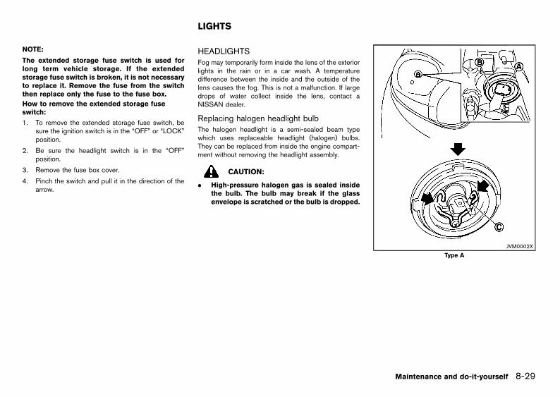
Black plate (293,1)
[ Edit: 2013/ 2/ 25 Model: K13-A ]
NOTE:
The extended storage fuse switch is used forlong term vehicle storage. If the extendedstorage fuse switch is broken, it is not necessaryto replace it. Remove the fuse from the switchthen replace only the fuse to the fuse box.
How to remove the extended storage fuseswitch:
GUID-9E14C2E6-2E9C-4731-980B-C45B899B977B
1. To remove the extended storage fuse switch, besure the ignition switch is in the “OFF” or “LOCK”position.
2. Be sure the headlight switch is in the “OFF”position.
3. Remove the fuse box cover.
4. Pinch the switch and pull it in the direction of thearrow.
GUID-A9786891-967B-4E5D-B254-BD0AEA44B6C2
HEADLIGHTSGUID-D443FAB0-D1E0-4FEF-97CE-A8E1AF34C408
Fog may temporarily form inside the lens of the exteriorlights in the rain or in a car wash. A temperaturedifference between the inside and the outside of thelens causes the fog. This is not a malfunction. If largedrops of water collect inside the lens, contact aNISSAN dealer.
Replacing halogen headlight bulbGUID-8FAAB6BB-DBBB-43B5-998B-E36C919D4BAB
The halogen headlight is a semi-sealed beam typewhich uses replaceable headlight (halogen) bulbs.They can be replaced from inside the engine compart-ment without removing the headlight assembly.
CAUTION:
. High-pressure halogen gas is sealed insidethe bulb. The bulb may break if the glassenvelope is scratched or the bulb is dropped.
JVM0002X
Type A
Maintenance and do-it-yourself 8-29
LIGHTS
Condition:

Black plate (294,1)
[ Edit: 2013/ 2/ 25 Model: K13-A ]
8-30 Maintenance and do-it-yourself
JVM0276X
Type B (example)
1. Disconnect the battery negative cable.
2. Disconnect the electrical connector*A from therear end of the bulb.
3. Pull off the rubber cap*B .
4. Push and turn the retaining pin*C to loosen it.
5. Remove the headlight bulb. Do not shake or rotatethe bulb when removing it.
6. Install the new bulb in the reverse order ofremoval.
CAUTION:
. When handling the bulb, do not touch theglass envelope.
. Use the same number and wattage asoriginally installed:
Halogen headlight modelHigh beam bulb: 60W (H4)Low beam bulb: 55W (H4)
. Do not leave the bulb out of the headlightreflector for a long period of time as dust,moisture and smoke may enter the headlightbody and affect the performance of theheadlight.
Aiming adjustment is not necessary if only the bulbsare replaced. When aiming adjustment is necessary,contact a NISSAN dealer.
EXTERIOR LIGHTSGUID-41757DAA-5563-407F-920A-8ABDF7A58431
Item Wattage (W)
Front turn signal light 21
Front clearance light 5
Front fog light (if equipped) 55
Side turn signal light 5
Rear combination lights
Turn signal light 21
Stop/Tail light LED* or 21/5
Reverse light (for Thailand,Brunei, Hong Kong andMicra for India)
16
Reverse light (except forThailand, Brunei, HongKong and Micra for India)
21
Rear fog light (if equipped) 21High-mounted stop light LED* or 16
License plate light 5
Condition:

Black plate (295,1)
[ Edit: 2013/ 2/ 25 Model: K13-A ]
INTERIOR LIGHTSGUID-DED7A3AD-46C8-4A5D-ADCC-3098DB04F1CA
Item Wattage (W)
Room light 5
Cargo light (if equipped) 5
*: See a NISSAN dealer for replacement.
Maintenance and do-it-yourself 8-31
Condition:

Black plate (296,1)
[ Edit: 2013/ 2/ 25 Model: K13-A ]
8-32 Maintenance and do-it-yourself
LIGHT LOCATIONSGUID-7C0B0CD8-3919-4C47-8B10-EE67946C8967
JVM0288X
Type A
1. Interior light
2. Front fog light (if equipped)
3. Front turn signal light
4. Clearance light (for Micra Active)
5. Clearance light (except for Micra Active)
6. Headlight
7. Side turn signal light
8. Stop/tail light
9. High-mounted stop light (Model without rearspoiler)
10. High-mounted stop light (Model with rearspoiler)
11. Rear turn signal light
12. Reverse light or Rear fog light (if equipped)*
13. License plate light
14. Cargo light (if equipped)
*: For the Left-Hand Drive (LHD) model. On the Right-Hand Drive (RHD) model, the rear fog light is locatedon the opposite side.
Condition:

Black plate (297,1)
[ Edit: 2013/ 2/ 25 Model: K13-A ]
JVM0273X
Type B
1. Interior light
2. Front turn signal light
3. Front fog light (if equipped)
4. Clearance light
5. Headlight
6. Side turn signal light
7. Stop/tail light
8. High-mounted stop light (Model without rearspoiler)
9. High-mounted stop light (Model with rearspoiler)
10. Rear turn signal light
11. Reverse light
12. Rear fog light (if equipped)
13. License plate light
14. Cargo light (if equipped)
Maintenance and do-it-yourself 8-33
Condition:


Black plate (299,1)
[ Edit: 2013/ 2/ 25 Model: K13-A ]
JVM0006X
Front fog light (if equipped) (Type A)
JVM0282X
Front fog light (if equipped) (Type B)
JVM0100X
Side turn signal light
Maintenance and do-it-yourself 8-35
Condition:

Black plate (300,1)
[ Edit: 2013/ 2/ 25 Model: K13-A ]
8-36 Maintenance and do-it-yourself
SDI2580
Rear combination light (Type A)
JVM0274X
Rear combination light (Type B)
JVM0275X
Rear combination light (Type C)
Condition:

Black plate (301,1)
[ Edit: 2013/ 2/ 25 Model: K13-A ]
JVC0014X
License plate light (Type A)
JVM0108X
License plate light (Type B)
JVM0008X
High-mounted stop light (model with rear spoiler)
CAUTION:
Do not reuse the packing on the back of thehigh-mounted stop light. When installing, thepacking must be replaced with a new one.
To replace the high-mounted stop light bulb:
1. Remove the light with a suitable tool.
2. Remove the bulb socket and then replace thebulb.
Maintenance and do-it-yourself 8-37
Condition:

Black plate (302,1)
[ Edit: 2013/ 2/ 25 Model: K13-A ]
8-38 Maintenance and do-it-yourself
3. Replace the packing*A .
4. Install in the reverse order of removal.
JVM0281X
Rear fog light (if equipped)
SDI2391
Room light
JVM0007X
Cargo light (if equipped)
To replace the cargo light bulb (if equipped):
1. Remove the light*A with a suitable tool.
2. Remove the cover*B .
3. Replace the bulb.
Condition:

Black plate (303,1)
[ Edit: 2013/ 2/ 25 Model: K13-A ]
LEGAL REQUIREMENT TO ADJUST HEADLIGHT BEAMGUID-78812B4F-7F9C-4017-9BEC-93FA11A6D702
For India (Micra Active)GUID-06BA61B4-97AA-4856-B244-78E2CD8BE973
JVM0289X
When the vehicle is driven in a country where thedriving lane is different to your home country, affix anopaque sticker on the headlight.
1. Turn the ignition switch to the "OFF" position andwait until the headlights cool down.
2. Prepare the stickers referring to the figure. Makethe stickers*A that will be affixed to the surface
of the right side headlight and the left sideheadlight.
NOTE:. Use an opaque material that prevents the
light from passing through it.. Note that transparent materials do not
work effectively.
3. Affix the sticker by aligning the corner*B of thesticker with the position of the mark *C that islocated on the surface of the headlight seen fromfront.
Affix the sticker as illustrated by aligning the mark*C with dividing lines*D and*E .
NOTE:Align the mark*C with the center markof the headlight bulb.
Maintenance and do-it-yourself 8-39
Condition:

Black plate (304,1)
[ Edit: 2013/ 2/ 25 Model: K13-A ]
8-40 Maintenance and do-it-yourself
For India (except for Micra Active)GUID-888C9AC4-68C5-4648-9FEC-AB6806625627
JVM0279X
When the vehicle is driven in a country where thedriving lane is different to your home country, affix anopaque sticker on the headlight.
1. Turn the ignition switch to the "OFF" position andwait until the headlights cool down.
2. Prepare the stickers referring to the figure. Makethe stickers*A that will be affixed to the surfaceof the right side headlight and the left sideheadlight.
NOTE:. Use an opaque material that prevents the
light from passing through it.. Note that transparent materials do not
work effectively.
3. Affix the sticker by aligning the corner*B of thesticker with the position of the mark *C that islocated on the surface of the headlight seen fromfront.
Affix the sticker as illustrated by aligning the mark*C with dividing lines*D and*E .
NOTE:Align the mark*C with the center markof the headlight bulb.
Condition:

Black plate (305,1)
[ Edit: 2013/ 2/ 25 Model: K13-A ]
For Thailand, Brunei and Hong KongGUID-B7C5B036-3820-4F38-851D-5B9F347E4C17
JVM0283X
When the vehicle is driven in a country where thedriving lane is different to your home country, affix anopaque sticker on the headlight.
1. Turn the ignition switch to the "OFF" position andwait until the headlights cool down.
2. Prepare the stickers referring to the figure. Makethe stickers*A that will be affixed to the surfaceof the right side headlight and the left sideheadlight.
NOTE:. Use an opaque material that prevents the
light from passing through it.. Note that transparent materials do not
work effectively.
3. Using a marker pen or similar, put a mark*C onthe surface of the headlight that will be used as aguide for attaching the sticker *A to the head-light. The mark*C is placed 36 mm (1.42 inch) or
46 mm (1.81 inch) to the left of the mark*D onthe surface of the headlight seen from front.
4. Affix the sticker by aligning the corner*B of thesticker with the position of the mark*C .
Affix the sticker as illustrated by aligning the mark*C with dividing lines*E .
NOTE:Align the mark*D with the center markof the headlight bulb.
Maintenance and do-it-yourself 8-41
Condition:

Black plate (306,1)
[ Edit: 2013/ 2/ 25 Model: K13-A ]
8-42 Maintenance and do-it-yourself
GUID-F72187C8-89ED-4710-956E-E4341A8FA160
If you have a flat tire, see “Flat tire” (P.6-2).
TIRE INFLATION PRESSUREGUID-C40CFB58-A8F9-48BE-BA18-71F031CC99DC
Periodically check the pressure of the tires, includingthe spare. An incorrect tire pressure may adverselyaffect tire life and vehicle handling. The tire pressureshould be checked when tires are COLD. Tires areconsidered COLD after the vehicle has been parkedfor 3 or more hours, or driven less than 1.6 km (1 mile).COLD tire pressures are shown on the tire placard.(For the location of the tire placard, see “Vehicleidentification” (P.9-9).)
Insufficient pressure can lead to an overheating of thetire and subsequent internal damage. At high speeds,this could result in tread separation and even burstingof the tire.
TYPES OF TIRESGUID-27228F9D-DFB0-4D5E-9DF9-03FE5C3D06AE
CAUTION:
When changing or replacing tires, be sure allfour tires are of the same type (that is, summer,all season or snow) and construction. A NISSANdealer may be able to help you with informationabout tire type, size, speed rating and avail-ability.
Replacement tires may have a lower speed rating thanthe factory equipped tires, and they may not match thepotential maximum vehicle speed. Never exceed themaximum speed rating of the tire.
All season tiresGUID-DD87A0AD-5E17-4A13-915A-F698EDAC11F2
NISSAN specifies all season tires on some models toprovide good performance all year, including snowyand icy road conditions. All season tires are identifiedby ALL SEASON and/or M&S on the tire sidewall.Snow tires have better snow traction than all seasontires and may be more appropriate in some areas.
Summer tiresGUID-6382C51B-A234-4E20-AD93-997195CD49A2
NISSAN specifies summer tires on some models toprovide superior performance on dry roads. Summertire performance is substantially reduced in snow andice. Summer tires do not have the tire traction ratingM&S on the tire sidewall.
If you plan to operate your vehicle in snowy or icyconditions, NISSAN recommends the use of snow orall season tires on all four wheels.
Snow tiresGUID-80A821D0-08B9-4332-ACB1-56AABF0AFEEA
If snow tires are needed, it is necessary to select tiresequivalent in size and load rating to the originalequipment tires. If you do not, it can adversely affectthe safety and handling of your vehicle.
Generally, snow tires have lower speed ratings thanfactory equipped tires and may not match the potentialmaximum vehicle speed. Never exceed the maximumspeed rating of the tire. If you install snow tires, theymust be the same size, brand, construction and treadpattern on all four wheels.
For additional traction on icy roads, studded tires maybe used. However, some states and provinces prohibittheir use. Check local, state and provincial laws beforeinstalling studded tires. Skid and traction capabilitiesof studded snow tires on wet or dry surfaces may bepoorer than that of non-studded snow tires.
TIRE CHAINSGUID-47CDAFAB-49F6-4E6E-A0A8-F462342F9414
Use of tire chains may be prohibited according tolocation. Check the local laws before installing tirechains. When installing tire chains, make sure that theyare of proper size for the tires on your vehicle and areinstalled according to the chain manufacturer’s in-structions.
Use chain tensioners when recommended by the tirechain manufacturer to ensure a tight fit. Loose end linksof the tire chains must be secured or removed toprevent the possibility of whipping action damage tothe fenders or underbody. If possible, avoid fullyloading your vehicle when using tire chains. In addition,drive at a reduced speed. Otherwise, your vehicle maybe damaged and/or vehicle handling and performancemay be adversely affected.
Tire chains must be installed only on the front wheelsand not on the rear wheels. Never install tire chains ona temporary-use spare tire (TEMPORARY USEONLY). Do not use the chains on dry roads.
TIRE ROTATIONGUID-6E878F7E-CE31-4E34-A3D5-FFF9045EA68D
SDI1662
NISSAN recommends that tires be rotated every10,000 km (6,000 miles). However, the timing for tirerotation may vary according to your driving habits and
TIRES AND WHEELS
Condition:

Black plate (307,1)
[ Edit: 2013/ 2/ 25 Model: K13-A ]
the road surface conditions. (For the tire replacement,see “Flat tire” (P.6-2).)
WARNING:
. After rotating the tires, adjust the tirepressure.
. Retighten the wheel nuts when the vehiclehas been driven for 1,000 km (600 miles)(also in cases of a flat tire, etc.).
. Do not include the temporary-use spare tirein tire rotation.
. Incorrect tire selection, fitting, care or main-tenance can affect vehicle safety with risk ofaccident and injury. If in doubt, consult aNISSAN dealer or the tire manufacturer.
TIRE WEAR AND DAMAGEGUID-5A269388-894E-4E58-9B8D-CFE690A05538
SDI1663
*1 Wear indicator
*2 Wear indicator location mark
Tires should be periodically inspected for wear,cracking, bulging or objects caught in the tread. Ifexcessive wear, cracks, bulging or deep cuts arefound, the tire should be replaced immediately.
The original tires have a built-in tread wear indicator.
When the wear indicator is visible, the tire should bereplaced.
Improper service of a spare tire may result in seriouspersonal injury. If it is necessary to repair the spare tire,contact a NISSAN dealer.
TIRE AGEGUID-DFA9E25C-CC99-432C-A6DB-AA62E3C177E4
Never use a tire over six years old, regardless ofwhether it has been used or not.
Tires degrade with age as well as with the vehicleusage. Have your tires checked and balanced often bya repair shop or, if you prefer, a NISSAN dealer.
CHANGING TIRES AND WHEELSGUID-C0B3C508-71BC-4CFC-B486-DDE4CE89EFC8
WARNING:
Do not install a deformed wheel or tire even if ithas been repaired. Such wheels or tires couldhave structural damage and could fail withoutwarning.
When replacing a tire, use the same size, speed ratingand load carrying capacity as originally equipped. (Forrecommended types and sizes of tires and wheels, see“Tires and wheels” (P.9-8).) The use of tires other thanthose recommended or the mixed use of tires ofdifferent brands, construction (bias, bias-belted, orradial), or tread patterns can adversely affect the ride,braking, handling, ground clearance, body-to-tireclearance, snow chain clearance, speedometer cali-bration, headlight aim and bumper height. Some ofthese effects may lead to accidents and could result inserious personal injury.
If the wheels are changed for any reason, alwaysreplace with wheels which have the same offsetdimension. Wheels of a different offset could causeearly tire wear, possibly degraded vehicle handling
characteristics and/or interference with the brakediscs/drums. Such interference can lead to decreasedbraking efficiency and/or early brake pad/shoe wear.
WHEEL BALANCEGUID-34BC8C97-8E90-4E06-AB49-3C0673B207F5
Unbalanced wheels may affect vehicle handling andtire life. Even with regular use, wheels can get out ofbalance. Therefore, they should be balanced asrequired.
SPARE TIREGUID-9AC9BD80-55EB-4CBB-B63E-70D3EA2D42DB
Conventional spare tireGUID-EB79F5C7-1A05-4F41-AB2C-9CBBB5E72163
A standard tire (the same size as the road wheels) issupplied with your vehicle.
Temporary-use spare tire (if equipped)GUID-0C44D597-A9E9-4D96-BA10-6DDBE77D9BD1
SDI1912
Spare tire label (if equipped)
Observe the following precautions if the spare tiremust be used, otherwise your vehicle could bedamaged or involved in an accident.
CAUTION:
. The spare tire should be used only foremergency. It should be replaced by thestandard tire at the first opportunity.
Maintenance and do-it-yourself 8-43
Condition:

Black plate (308,1)
[ Edit: 2013/ 2/ 25 Model: K13-A ]
8-44 Maintenance and do-it-yourself
. Drive carefully while the spare tire is in-stalled.
. Avoid sharp turns and abrupt braking whiledriving.
. Do not drive your vehicle at speeds fasterthan 80 km/h (50 MPH).
. Do not use tire chains on a spare tire. Tirechains will not fit properly on the spare tireand may cause damage to the vehicle.
. Tire tread of the spare tire will wear at afaster rate than the original tire. Replace thespare tire as soon as the tread wearindicators appear (except for India).
. Because the spare tire is smaller than theoriginal tire, ground clearance is reduced. Toavoid damage to the vehicle do not driveover obstacles. Also do not drive the vehiclethrough an automatic car wash since it mayget caught.
. Do not use the spare tire on other vehicles.
. Do not use more than one spare tire at thesame time.
EMERGENCY TIRE PUNCTURE REPAIR KIT(if equipped)
GUID-EE56F7D3-BCDA-4BE2-BEE1-75D118926F7D
The emergency tire repair kit is supplied to the vehicleinstead of a spare tire. The kit must be used fortemporarily fixing a minor tire puncture. After using therepair kit, see a NISSAN dealer as soon as possible fortire inspection and repair/replacement.
CAUTION:
Do not use the emergency tire repair kit underthe following conditions. Call a NISSAN dealeror professional road assistance.
. when the sealant has passed its expirationdate
. when the cut or the puncture is approxi-mately 6 mm (0.25 in) or longer
. when the side of the tire is damaged
. when the vehicle has been driven with aconsiderable loss of air from the tire
. when the tire is completely displaced insideor outside the rim
. when the tire rim is damaged
. when two or more tires are punctured
See “Flat tire” (P.6-2).
Condition:

Black plate (309,1)
[ Edit: 2013/ 2/ 25 Model: K13-A ]
MEMO
Maintenance and do-it-yourself 8-45
Condition:

Black plate (310,1)
[ Edit: 2013/ 2/ 25 Model: K13-A ]
8-46 Maintenance and do-it-yourself
MEMO
Condition:

Black plate (311,1)
[ Edit: 2013/ 2/ 25 Model: K13-A ]
9 Technical information
Recommended fuel/lubricants and capacities ..................................... 9-2Fuel recommendation ........................................................................... 9-4Recommended SAE viscosity number ............................................ 9-4Air conditioner system refrigerant and lubricant ........................... 9-5
Engine ............................................................................................................. 9-6Tires and wheels .......................................................................................... 9-8Dimensions .................................................................................................... 9-8When travelling or registering in another country ............................... 9-9Vehicle identification ................................................................................... 9-9
Vehicle identification plate .................................................................. 9-9Vehicle identification number (chassis number) ........................... 9-9Vehicle identification number (VIN) plate (if equipped) ........... 9-10Engine serial number ........................................................................ 9-10Certification label (if equipped) ...................................................... 9-10Tire placard .......................................................................................... 9-10Air conditioner specification label (if equipped) ........................ 9-11
Uniform tire quality grading (if equipped) ......................................... 9-11Treadwear .......................................................................................... 9-11Traction AA, A, B and C ............................................................... 9-11Temperature A, B and C ............................................................... 9-11
Radio approval number and information ............................................ 9-12For Europe ........................................................................................ 9-12For Croatia ........................................................................................ 9-12For Indonesia .................................................................................... 9-14For Thailand ...................................................................................... 9-14For Morocco ..................................................................................... 9-15For Jordan .......................................................................................... 9-15For South Africa ............................................................................... 9-15For the United Arab Emirates ....................................................... 9-16
Condition:

Black plate (312,1)
[ Edit: 2013/ 2/ 25 Model: K13-A ]
9-2 Technical information
GUID-B13A182C-B09A-4CDE-A46E-D81BBC10928E
The following are approximate capacities. The actual refill quantities may be slightly different. When refilling, follow the procedures instructed in the “8. Maintenance and do-it-yourself” section to determine the proper refill capacity.
Engine TypeApproximate Capacity
Recommended Fuel/LubricantsMetric Measure Imperial Measure
Fuel41 L 9 gal
See “Fuel recommendation” (P.9-4).
Engine oil (*1)
HR12DEHR15DE
including oil filter
3.0 L (except for Europeand CVT model for India)3.4 L (for Europe and CVT
model for India)
2-5/8 qt (except for Europeand CVT model for India)3 qt (for Europe and CVT
model for India)
(Gasoline engine)For Europe, Ukraine and South Africa:Genuine NISSAN engine oil (*2), (*3)API grade SL, SM or SN (*2)ILSAC grade GF-3, GF-4 or GF-5 (*2)ACEA A1/B1, A3/B3, A3/B4, A5/B5, C2 or C3 (*2)Except for Europe, Ukraine and South Africa:Genuine NISSAN engine oil (*2)API grade SL, SM or SN (*2)ILSAC grade GF-3, GF-4 or GF-5 (*2)
excluding oil filter
2.8 L (except for Europeand CVT model for India)3.2 L (for Europe and CVT
model for India)
2-1/2 qt (except for Europeand CVT model for India)2-7/8 qt (for Europe andCVT model for India)
HR12DDRincluding oil filter 3.9 L 3-3/8 qt
excluding oil filter 3.7 L 3-1/4 qt
K9Kincluding oil filter 4.4 L 3-7/8 qt (Diesel engine)
Genuine NISSAN engine oil (*2)ACEA B1/B5 (*2)excluding oil filter 4.2 L 3-3/4 qt
Cooling system (including reservoir tank capacity 0.7 L)
Genuine NISSAN Engine Coolant or equivalent in its quality (*4)
HR12DDRMT model 5.4 L 4-3/4 qt
CVT model 5.9 L 5-1/4 qt
HR12DE
MT model (for Thailand, Brunei, Sin-gapore and Pakistan)MT model (except for Thailand, Brunei,Singapore and Pakistan)
5.7 L
5.5 L
5 qt
4-7/8 qt
AT model 5.5 L 4-7/8 qt
CVT model (for Thailand)CVT model (except for Thailand)
5.8 L5.6 L
5-1/8 qt4-7/8 qt
HR15DEMT model 5.6 L 4-7/8 qt
AT model 6.0 L 5-1/4 qt
Cooling system (including reservoir tank capacity 1.0 L)
K9K MT model 7.6 L 6-3/4 qt
Automatic Transmission Fluid (ATF) — — Genuine NISSAN Matic S ATF (*5)
Continuously Variable Transmission (CVT) fluid — —
Except for Thailand, India, Brunei and Hong Kong:Genuine NISSAN CVT Fluid NS-2 (*6)For Thailand, India, Brunei and Hong Kong:Genuine NISSAN CVT Fluid NS-3 (*7)
Manual Transmission (MT) gear oil — —Genuine NISSAN Manual Transmission Fluid (MTF) HQ Multi 75W-85 orequivalent (*8)
Brake and clutch fluid — (*9) — Genuine NISSAN Brake Fluid or equivalent DOT 3 or DOT4 (*10)
RECOMMENDED FUEL/LUBRICANTS AND CAPACITIES
Condition:

Black plate (313,1)
[ Edit: 2013/ 2/ 25 Model: K13-A ]
Multi-purpose grease — — NLGI No. 2 (Lithium soap base)
Air conditioner system refrigerant — — HFC-134a (R-134a)
Air conditioner system lubricants — — NISSAN A/C System Oil Type R or equivalent
*1: The approximate capacities listed are for refilling during an engine oil change. For additional information, see “Changing engine oil and oil filter” (P.8-11).
*2: For additional information, see “Recommended SAE viscosity number” (P.9-4).
*3: NISSAN recommends Genuine NISSAN Ester oil available at a NISSAN dealer. Genuine NISSAN Ester oil is the best choice for optimum fuel economy.
*4: Use Genuine NISSAN Engine Coolant or equivalent in its quality, in order to avoid possible aluminum corrosion within the engine cooling system caused by the use of non-genuine engine coolant.
Note that any repairs for the incidents within the engine cooling system while using non-genuine engine coolant may not be covered by the warranty even if such incidents occurred duringthe warranty period.
*5: Using automatic transmission fluid other than Genuine NISSAN Matic S ATF will cause deterioration in driveability and automatic transmission durability, and may damage the automatictransmission, which is not covered by the warranty.
*6: Use only Genuine NISSAN CVT Fluid NS-2. Using transmission fluid other than Genuine NISSAN CVT Fluid NS-2 will damage the CVT, which is not covered by the warranty.
*7: Use only Genuine NISSAN CVT Fluid NS-3. Using transmission fluid other than Genuine NISSAN CVT Fluid NS-3 will damage the CVT, which is not covered by the warranty.
*8: If Genuine NISSAN Manual Transmission Fluid (MTF) HQ Multi is not available, API GL-4, Viscosity SAE 75W-85 may be used as a temporary replacement. However, use Genuine NISSAN Manual TransmissionFluid (MTF) HQ Multi as soon as it is available.
*9: Refill to the proper fluid level according to the instructions in the “8. Maintenance and do-it-yourself” section.
*10: For details, see the brake fluid reservoir cap or the caution label attached to the brake fluid reservoir or the underside of the hood. Never mix different types of fluids (DOT3 and DOT4).
Technical information 9-3
Condition:

Black plate (314,1)
[ Edit: 2013/ 2/ 25 Model: K13-A ]
9-4 Technical information
FUEL RECOMMENDATIONGUID-B5564F9E-E1BD-4463-BD82-FAE3B779AFED
Gasoline engine (model with three–waycatalyst)
GUID-3871D081-1FCE-45E8-8705-DB9AF5F31B99
CAUTION:
Do not use leaded gasoline. Using leaded gaso-line will damage the three-way catalyst.
Except for Europe, Ukraine, Sri Lanka and Thailand:Use UNLEADED REGULAR gasoline with an octanerating of at least 91 (RON).
For Europe, Ukraine and Sri Lanka: Use UNLEADEDPREMIUM gasoline with an octane rating of at least 95(RON).
If unleaded premium gasoline is not used, UNLEADEDREGULAR gasoline with an octane rating of at least 91(RON) may be used at slightly reduced performance.However, for maximum vehicle performance and thebest driveability, the use of unleaded premium gasolineis recommended.
For Thailand: Use UNLEADED REGULAR gasoline orgasohol (up to E20*) of at least 91 octane (RON).
*: Gasohol is alcohol blended gasoline. For example,“E20” is a mixture of approximately 20% fuel ethanoland 80% unleaded gasoline.
Diesel engine*GUID-EAE0C872-1467-4249-A889-C897C1BB507E
Use diesel fuel of at least 50 cetane.
* If two types of diesel fuel are available, usesummer or winter fuel properly according to thefollowing temperature conditions.
. Above −78C (208F) ... Summer type diesel fuel.
. Below −78C (208F) ... Winter type diesel fuel.
CAUTION:
. Do not use home heating oil, gasoline orother alternate fuels in your diesel engine.The use of those or adding those to dieselfuel can cause engine damage.
. Do not use summer fuel at temperaturesbelow −78C (208F). The cold temperatureswill cause wax to form in the fuel. As aresult, it may prevent the engine fromrunning smoothly.
RECOMMENDED SAE VISCOSITY NUM-BER
GUID-A2AF1986-D387-4EF8-9FDA-44B7DCB3EB0E
Gasoline engine oilGUID-86566ACA-B8D9-4A51-901D-3ADEAF0F52A7
STI0732
For Europe, Ukraine and India (CVT model):GUID-9E14C2E6-2E9C-4731-980B-C45B899B977B
5W-30 is preferable.
If 5W-30 is not available, select the viscosity,from the chart, that is suitable for the outsidetemperature range.
Condition:

Black plate (315,1)
[ Edit: 2013/ 2/ 25 Model: K13-A ]
For Hong Kong and Thailand:GUID-9E14C2E6-2E9C-4731-980B-C45B899B977B
0W-20 is preferable.
If 0W-20 is not available, select the viscosity,from the chart, that is suitable for the outsidetemperature range.
Except for Europe, Ukraine, Hong Kong, Thai-land and India (CVT model):
GUID-9E14C2E6-2E9C-4731-980B-C45B899B977B
10W-30 is preferable.
If 10W-30 is not available, select the viscosity,from the chart, that is suitable for the outsidetemperature range.
Diesel engine oilGUID-97A76D70-B984-441F-A054-0C6C5A1195E3
JVT0029X
5W-30 is preferable.
If 5W-30 is not available, select the viscosity,from the chart, that is suitable for the outsidetemperature range.
AIR CONDITIONER SYSTEM REFRIGER-ANT AND LUBRICANT
GUID-0E256FA3-C569-4D73-B23D-9DDC3D04F362
The air conditioner system of your vehicle must becharged with the refrigerant HFC-134a (R134a) andthe lubricant NISSAN A/C System Oil Type R orequivalents. Use of any other refrigerants or lubricantswill cause severe damage, and you may need toreplace your vehicle’s entire air conditioner system.
The release of refrigerants into the atmosphere isprohibited in many countries and regions. The refrig-erant HFC-134a (R-134a) in your vehicle will not harmthe Earth’s ozone layer. However, it may contribute in asmall part to the global warming effect. NISSANrecommends that the refrigerant be appropriatelyrecovered and recycled. Contact a NISSAN dealerwhen servicing the air conditioner system.
Technical information 9-5
Condition:

Black plate (316,1)
[ Edit: 2013/ 2/ 25 Model: K13-A ]
9-6 Technical information
GUID-DD158008-E84C-43D3-8D6A-567707C01CD5
Engine Model HR12DDR HR12DE HR15DE K9K
Type Gasoline, 4-cycle, DOHC Gasoline, 4-cycle, DOHC Gasoline, 4-cycle, DOHC Diesel, 4-cycle
Cylinder arrangement 3-cylinder, in-line 3-cylinder, in-line 4-cylinder, in-line 4-cylinder, in-line
Bore 6 Stroke mm (in) 78.0 6 83.6 (3.071 63.291)
78.0 6 83.6 (3.071 63.291)
78.0 6 78.4 (3.071 63.087)
76.0 6 80.5 (2.992 63.169)
Displacement cm3 (cu in) 1,198 (73.10) 1,198 (73.10) 1,498 (91.41) 1,461 (89.15)
Idle speed at the “N” (Neutral)position
rpm CVT: 775±50 CVT: 750±50
MT: 650±50MT: 800±50
MT: 750±50
MT: 750±50 (*1) (*3)MT: 860±50 (*2)(*6)(*7)(*9)AT: 775±50 (*6) AT: 700±50
Ignition timing (B.T.D.C.) CVT: 118±28MT: 118±28
CVT: 98±28MT: 128±28AT: 88±28
MT: 58±28(*7)AT: 58±28 —
Sparkplugs
Standard DILKAR7E11HS FXE20HR11 (*1)REA12WMB4 (*3)(*8)REA12MC4 (*4)(*6)(*7)(*9)DILKAR6A11 (*5)
REA12WMB4
—
Spark plug gap mm (in) 1.1 (0.043) 1.1 (0.043) 1.1 (0.043) —
Camshaft operation Timing chain Timing chain Timing chain Timing belt
Maximum vehicle speed (for Gulf standard models)*10
MT: km/h (MPH) — — 180 (112) —
AT: km/h (MPH) — — 170 (106) —
*1: For Thailand, Singapore (MT model), Indonesia (MT model) and Brunei
*2: For India, Australia and New Zealand
*3: For Europe
*4: For India (MT model), Australia, New Zealand, Singapore (AT model) and Indonesia (AT model)
*5: For Hong Kong
*6: For Pakistan and Ukraine
*7: For South Africa
*8: For India (CVT model)
ENGINE
Condition:

Black plate (317,1)
[ Edit: 2013/ 2/ 25 Model: K13-A ]
*9: Except for Thailand, Singapore (MT model), Indonesia (MT model), Brunei, India, Australia, New Zealand, Europe, Hong Kong, Pakistan, Ukraine and South Africa
*10: Gulf Standard regulation requires automobile manufacturers to indicate the maximum vehicle speed for applicable models. The maximum vehicle speed, listed above, isthe measured speed under certain testing conditions. The actual value may differ according to the vehicle usage and road and environmental conditions. NISSANrecommends you to ALWAYS observe posted speed limits and never drive too fast for conditions.
Technical information 9-7
Condition:

Black plate (318,1)
[ Edit: 2013/ 2/ 25 Model: K13-A ]
9-8 Technical information
GUID-D56298F0-8CEC-4A9B-8D8D-679DCE267643
Standard Spare*1
Tire size 155/80 R13 79S 155/80 R13 79S
165/70 R14 81S 165/70 R14 81ST115/70 D14 88MT105/70 D14 83M
175/60 R15 81H 165/70 R14 81S175/60 R15 81HT115/70 D14 88M
Size Offset mm (in)
Road wheel Steel 13 X 4-1/2B14X 4T
14 X 5-1/2J15X 5-1/2J
40 (1.57)40 (1.57)45 (1.77)50 (1.97)
Aluminum alloy wheel 15X 5-1/2J 50 (1.97)
*1: The tire puncture repair kit is supplied for Europe (if equipped).
For India:Tires & tubes fitted in the vehicle, as per clause 3(c) & 3(e) meet the requirement of BIS and comply with therequirements under the Central Motor Vehicle Rules (CMVR), 1989.
GUID-D7BCCAAE-9389-4A22-BE56-7E13A898AD02
Unit: mm (in)
Overall length 3,780 (148.8)3,801 (149.6)*1
Overall width 1,665 (65.6)1,675 (65.9)*2*3
Overall height 1,489 (58.6)*1*41,525 (60.0)*51,520 (59.9)*2*6*71,515 (59.6)*8
Front tread 1,470 (57.9)*91,460(57.5)*101,475 (58.1)*11
Rear tread 1,475 (58.1)*91,465(57.7)*101,485(58.5)*11
Wheelbase 2,435 (95.9)*122,440 (96.1)*132,450 (96.5)*14
*1: For Micra Active (for Sports version)
*2: For Europe (for model with side molding)
*3: For the Middle East (for model with side molding)
*4: For Micra Active (except for Sports version)
*5: For the Middle East (for model with ManualTransmission and without side molding)
*6: For South Africa and Thailand
*7: For the Middle East (except for model with ManualTransmission and without side molding)
*8: For Hong Kong
*9: For 165/70R14 tire model
*10: For 175/60R15 tire model
*11: For 155/80R13 tire model
*12: For Australia and New Zealand (for 175/60R15tire model)
TIRES AND WHEELS DIMENSIONS
Condition:

Black plate (319,1)
[ Edit: 2013/ 2/ 25 Model: K13-A ]
*13: For Europe, the Middle East, South Africa,Australia (except for 175/60R15 tire model) andNew Zealand (except for 175/60R15 tire model)
*14: Except for Europe, the Middle East, South Africa,Australia and New Zealand
GUID-AF0E899D-901C-4755-87C6-A7E1824CB4BF
When planning to travel in another country orregion, find out whether the fuel required for yourvehicle is available in that country or region. Using alow octane rated fuel may cause engine damage.Therefore, be sure that the required fuel is availablewherever you go. For additional information regardingrecommended fuel, see earlier in this section.
When transferring the registration of your vehi-cle to another country, state, province or district,contact the appropriate authorities to find out that thevehicle complies with the local legal requirements. Insome cases, a vehicle cannot meet the legal require-ments, and it may be necessary to modify the vehicle tomeet local laws and regulations. In addition, there maybe possibilities that a vehicle cannot be adapted incertain areas.
The laws and regulations for motor vehicle emissioncontrol and safety standards vary according to thecountry, state, province or district; therefore, thevehicle specification may differ.
When any vehicles are to be taken into anothercountry, state, province or district, its modifica-tion, transportation, registration, and any otherexpenses which may result, are the responsi-bility of the user. NISSAN is not responsible forany inconveniences that may result.
GUID-BC53638D-0649-4C5C-9189-54789373E894
STI0733
VEHICLE IDENTIFICATION PLATEGUID-1A37B794-7A07-4246-B1EA-8AA601B76515
The plate is affixed as shown*A .
Built date plate (for Australia and NewZealand)
GUID-62A806BB-AE03-47EE-B999-3D7A9D4D40CE
Built date is stamped on the vehicle identification plate.
The built date means the calendar month and the yearin which the body shell and power train subassembliesare conjoined and the vehicle is driven or moved fromthe production line.
VEHICLE IDENTIFICATION NUMBER(chassis number)
GUID-776BD794-27BE-4F2F-BC4A-77358E966975
The number is stamped as shown*B .
Technical information 9-9
WHEN TRAVELLING ORREGISTERING IN ANOTHERCOUNTRY
VEHICLE IDENTIFICATION
Condition:

Black plate (320,1)
[ Edit: 2013/ 2/ 25 Model: K13-A ]
9-10 Technical information
VEHICLE IDENTIFICATION NUMBER (VIN)PLATE (if equipped)
GUID-507AC254-14E9-498C-A8A2-D7A6C25A32CF
STI0457
The plate is affixed as shown.
ENGINE SERIAL NUMBERGUID-56A25893-4CB7-4641-9F7F-E93A141C8C1B
JVT0041X
HR12DDR engine
STI0734
HR12DE engine
JVT0003X
HR15DE engine
STI0662
K9K engine
The engine serial number is stamped on the engine as
shown.
CERTIFICATION LABEL (if equipped)GUID-D4097332-A4A8-48E3-A842-A9E5687B110F
STI0441
TIRE PLACARDGUID-70868081-D4CC-4937-88B0-384B959B6CD9
STI0494
The cold tire pressures are shown on the tire placardaffixed to the driver’s side center pillar.
Condition:

Black plate (321,1)
[ Edit: 2013/ 2/ 25 Model: K13-A ]
AIR CONDITIONER SPECIFICATION LABEL(if equipped)
GUID-7BC89934-DB14-4098-B54A-C05665B3CB24
STI0739
GUID-9A15291D-0792-451C-B6D3-8E9C61E398B6
Quality Grades: All passenger car tires must conformto local safety requirements in addition to thesegrades.
Quality grades can be found where applicable on thetire sidewall between tread shoulder and maximumsection width. For example:
Treadwear 200 Traction AA Temperature A
TREADWEARGUID-FA8F8C84-FDCF-46B8-A30A-7BCB7481E195
The treadwear grade is a comparative rating based onthe wear rate of the tire when tested under controlledconditions on a specified government test course. Forexample, a tire graded 150 would wear one and one-half (1 1/2) times as well on the government course asa tire graded 100. The relative performance of tiresdepends upon the actual conditions of their use,however, and may depart significantly from the normdue to variations in driving habits, service practicesand differences in road characteristics and climate.
TRACTION AA, A, B AND CGUID-2ABC335D-396A-470F-9485-06B1A6D4A230
The traction grades, from highest to lowest, are AA, A,B, and C. Those grades represent the tire’s ability tostop on wet pavement as measured under controlledconditions on specified government test surfaces ofasphalt and concrete. A tire marked C may have poortraction performance.
WARNING:
The traction grade assigned to this tire is basedon straight-ahead braking traction tests, anddoes not include acceleration, cornering, hydro-planing, or peak traction characteristics.
TEMPERATURE A, B AND CGUID-835ACB7A-FEF0-45B0-AE18-BBFFFE2405A8
The temperature grades are A (the highest), B, and C,representing the tire’s resistance to the generation ofheat and its ability to dissipate heat when tested undercontrolled conditions on a specified indoor laboratorytest wheel. Sustained high temperature can cause thematerial of the tire to degenerate and reduce tire life,and excessive temperature can lead to sudden tirefailure. The grade C corresponds to a level ofperformance which all passenger car tires must meetunder the local regulations. Grades B and A representhigher levels of performance on the laboratory testwheel than the minimum required by law.
WARNING:
The temperature grade for this tire is estab-lished for a tire that is properly inflated and notoverloaded. Excessive speed, under-inflation, orexcessive loading, either separately or in com-bination, can cause heat build-up and possibletire failure.
Technical information 9-11
UNIFORM TIRE QUALITY GRADING(if equipped)
Condition:

Black plate (322,1)
[ Edit: 2013/ 2/ 25 Model: K13-A ]
9-12 Technical information
GUID-038CD017-25ED-4B38-9D89-25D0B65EB66E
FOR EUROPEGUID-037870E7-FCB9-4C51-8914-1FE252DFC944
Remote keyless entry system (if equipped)GUID-CA7B260E-9299-4F6B-94CB-717421FE730E
Hereby, ALPS ELECTRIC CO.,LTD. declares thatthese Keyless and TPMS TUNER; model TWC1G124and Keyless Transmitter; model TWB1U761 are incompliance with the essential requirements and otherrelevant provisions of Directive 1999/5/EC.
CAUTION:
Do not exposed to excessive heat such assunshine, fire or the like.
CAUTION:
Danger of explosion if battery is incorrectlyreplaced. Replace only with the same or equiva-lent type.
NSY0105
Intelligent Key system (if equipped)GUID-B4D2E24C-416B-4A95-8364-15749AA51512
Hereby, ALPS ELECTRIC CO.,LTD. declares thatthese Passive Entry System(Hand Unit);modelTWB1G662, Passive Entry System(Tuner);modelTWC1G135, ANT ASSY-IMMOBILISER;modelTWK1A002 are in compliance with the essentialrequirements and other relevant provisions of Directive1999/5/EC.
CAUTION:
Do not exposed to excessive heat such assunshine, fire or the like.
CAUTION:
Danger of explosion if battery is incorrectlyreplaced. Replace only with the same or equiva-lent type.
NSY0105
NISSAN Anti-Theft System (NATS) immobili-zer
GUID-9DE53EF3-3B06-45F7-8E53-E0D042AA0649
Hereby, CalsonicKansei Corp. declares that this ANTASSY-IMMOBILISER;model MW1014 is in compli-ance with the essential requirements and otherrelevant provisions of Directive 1999/5/EC.
CAUTION:
Do not exposed to excessive heat such assunshine, fire or the like.
CAUTION:
Danger of explosion if battery is incorrectlyreplaced. Replace only with the same or equiva-lent type.
NSY0105
FOR CROATIAGUID-05061785-D03D-467D-9408-38EBBD1D23A9
Remote keyless entry system (if equipped)GUID-A4653F55-2AD9-43AC-96A3-EC648B20FA7D
JVT0008X
RADIO APPROVAL NUMBER ANDINFORMATION
Condition:

Black plate (323,1)
[ Edit: 2013/ 2/ 25 Model: K13-A ]
JVT0009X
NSY0105
Intelligent Key system (if equipped)GUID-D009300C-F4ED-4E93-94FE-28935E232F84
JVT0010X
JVT0011X
NSY0105
Technical information 9-13
Condition:

Black plate (324,1)
[ Edit: 2013/ 2/ 25 Model: K13-A ]
9-14 Technical information
NISSAN Anti-Theft System (NATS) immobili-zer
GUID-A0461F8C-3AAE-436F-B7C8-0CB8C4F0A1C9
JVT0012X
NSY0105
FOR INDONESIAGUID-B1DB6C4C-94CC-4C81-8839-AED42FDDF43F
Remote keyless entry system (if equipped)GUID-9A7F38A1-9EB1-4946-A056-363D0E27A161
JVT0013X
JVT0014X
NISSAN Anti-Theft System (NATS) immobili-zer
GUID-D1A68CF1-9ED9-460F-BE9A-B0C613FDE926
JVT0015X
FOR THAILANDGUID-1AAB97B5-B116-4FB9-AB2D-BABB003C387B
This telecommunication equipment conforms to NTCtechnical requirement.
. Remote keyless entry system (if equipped)
. Intelligent Key system (if equipped)
. NISSAN Anti-Theft System (NATS) (if equipped)
Condition:

Black plate (325,1)
[ Edit: 2013/ 2/ 25 Model: K13-A ]
FOR MOROCCOGUID-D17CD8E0-FB29-4C96-91F2-AFD398120A88
Remote keyless entry system (if equipped)GUID-C6863BD6-5478-4F13-9085-62D8A256268B
JVT0025X
JVT0108X
NISSAN Anti-Theft System (NATS) immobili-zer
GUID-49E13464-10CA-4A8B-BFB5-47474BD3EABE
JVT0026X
FOR JORDANGUID-282BC3DF-BB59-4F67-AF26-BB85C755D020
Remote keyless entry system (if equipped)GUID-9C1EA433-1511-43B4-B1EF-3518DC5E050C
Manufacturer:
ALPS ELECTRIC CO.,LTD.
Model:
TWC1G124
Type approval No.:
TRC/LPD/2008/125
NISSAN Anti-Theft System (NATS) immobili-zer
GUID-1C1E5688-2997-4DDB-9DD3-5435A448DB5C
Manufacturer:
Calsonic Kansei Corporation
Model:
MW1014
Type approval No.:
TRC/LPD/2009/86
FOR SOUTH AFRICAGUID-B46C26C9-D7DC-45FD-B013-93EB16BB335E
Remote keyless entry system (if equipped)GUID-61CF4BDF-C0FF-4EBF-AC3D-946E381F6B81
JVT0038X
JVT0039X
Technical information 9-15
Condition:

Black plate (326,1)
[ Edit: 2013/ 2/ 25 Model: K13-A ]
9-16 Technical information
NISSAN Anti-Theft System (NATS) immobili-zer
GUID-80CE0AA6-93A5-4A74-A10B-6B9DEC65753A
JVT0040X
FOR THE UNITED ARAB EMIRATESGUID-ECD0B127-15E0-4EFE-8081-87D317E1F62B
Remote keyless entry system (if equipped)GUID-F67B8B1C-6B27-45FE-B00F-208C6A7F9D0D
JVT0137X
Intelligent Key system (if equipped)GUID-858870C7-2E3C-43A9-AF59-B8CDF4AFACBB
JVT0134X
JVT0135X
NISSAN Anti-Theft System (NATS) immobili-zer
GUID-9DF9900A-E65C-45F8-BDD1-962F12097270
JVT0136X
Condition:

Black plate (327,1)
[ Edit: 2013/ 2/ 25 Model: K13-A ]
MEMO
Technical information 9-17
Condition:

Black plate (328,1)
[ Edit: 2013/ 2/ 25 Model: K13-A ]
9-18 Technical information
MEMO
Condition:


Black plate (335,1)
[ Edit: 2013/ 2/ 25 Model: K13-A ]
11 Epilogue
GUID-BABB18F1-74AB-4D16-BF40-1D693075D6D2
RECOMMENDED FUELGUID-52C91F1F-6FD8-4A0B-BCD1-A4584CB5A0B3
Gasoline engine (model with three–waycatalyst)
GUID-3871D081-1FCE-45E8-8705-DB9AF5F31B99
CAUTION:
Do not use leaded gasoline. Using leaded gaso-line will damage the three-way catalyst.
Except for Europe, Ukraine, Sri Lanka and Thailand:Use UNLEADED REGULAR gasoline with an octanerating of at least 91 (RON).
For Europe, Ukraine and Sri Lanka: Use UNLEADEDPREMIUM gasoline with an octane rating of at least 95(RON).
If unleaded premium gasoline is not used, UNLEADEDREGULAR gasoline with an octane rating of at least 91(RON) may be used at slightly reduced performance.However, for maximum vehicle performance and thebest driveability, the use of unleaded premium gasolineis recommended.
For Thailand: Use UNLEADED REGULAR gasoline orgasohol (up to E20*) of at least 91 octane (RON).
*: Gasohol is alcohol blended gasoline. For example,“E20” is a mixture of approximately 20% fuel ethanoland 80% unleaded gasoline.
Diesel engine*GUID-EAE0C872-1467-4249-A889-C897C1BB507E
Use diesel fuel of at least 50 cetane.
* If two types of diesel fuel are available, usesummer or winter fuel properly according to thefollowing temperature conditions.
. Above −78C (208F) ... Summer type diesel fuel.
. Below −78C (208F) ... Winter type diesel fuel.
CAUTION:
. Do not use home heating oil, gasoline orother alternate fuels in your diesel engine.The use of those or adding those to dieselfuel can cause engine damage.
. Do not use summer fuel at temperaturesbelow −78C (208F). The cold temperatureswill cause wax to form in the fuel. As aresult, it may prevent the engine fromrunning smoothly.
RECOMMENDED ENGINE OILGUID-37D4C2C2-5C70-42E6-8B4B-4B3A36768507
See “Recommended fuel/lubricants and capacities”(P.9-2).
Gasoline engineGUID-D7ACEF30-0C96-4F04-9BD9-2382BB82FEBA
For Europe, Ukraine and South Africa:
. Genuine NISSAN engine oil
. API grade SL, SM or SN
. ILSAC grade GF-3, GF-4 or GF-5
. ACEA A1/B1, A3/B3, A3/B4, A5/B5, C2 or C3
Except for Europe, Ukraine and South Africa:
. Genuine NISSAN engine oil
. API grade SL, SM or SN
. ILSAC grade GF-3, GF-4 or GF-5
Diesel engineGUID-CFB3E0F3-7A7D-4EDF-A15B-5C41922DE9B4
. Genuine NISSAN engine oil
. ACEA B1/B5
TIRE COLD PRESSUREGUID-352C9C99-FF9A-484B-82CF-AAC396929161
See the tire placard affixed to the driver’s side centerpillar.
GAS STATION INFORMATION
Condition:

Black plate (336,1)
[ Edit: 2013/ 2/ 25 Model: K13-A ]
GUID-A441EE5F-E33A-49A2-9B1A-EB5431A63E13
. In case of emergency ... (P.6-1)
(Flat tire, engine will not start, overheating, towing)
. How to start the engine ... (P.5-1)
. How to read the meters and gauges ... (P.2-1)
. Maintenance and do-it-yourself ... (P.8-1)
. Technical information ... (P.9-1)
QUICK REFERENCE
Condition:


![Predgovor [Foreword].](https://static.fdokumen.com/doc/165x107/63333df9ce61be0ae50e8cf4/predgovor-foreword-1681982858.jpg)