FOREWORD - NET
232
FOREWORD This manual is an essential part of your vehicle and should remain with the vehicle when resold or otherwise transferred to a new owner or operator. Please read this manual carefully before operating your new MARUTI SUZUKI and review the manual from time to time. It contains important information on safety, operation and maintenance. You are invited to avail the three Free Inspection Services as described in the manual. Three free inspection coupons are attached to this manual. Please show this manual to your dealer workshop while you take your MARUTI SUZUKI for any Service. To prolong the life of your vehicle and reduce maintenance cost, the periodic maintenance must be carried out accord- ing to “PERIODIC MAINTENANCE SCHEDULE” described in “INSPECTION AND MAINTENANCE” section of this man- ual. It is essential for preventing trouble and accidents to ensure your satisfaction and safety. Daily inspection and care as per “DAILY INSPECTION CHECKLIST” described in the “OPERATING YOUR VEHICLE” sec- tion of this manual is essential for prolong- ing the life of the vehicle and for safe driving. Vehicle and the available features/acces- sories therein should be used and plied by the owner/user in accordance with the applicable legal requirements. MARUTI SUZUKI INDIA LIMITED believes in conservation and protection of Earth’s natural resources. To that end, we encourage every vehicle owner to recycle, trade-in or properly dis- pose of, as appropriate, used Engine Oil, coolant and other fluids, batteries and tyres etc. MARUTI SUZUKI INDIA LIMITED All information in this manual is based on the latest product information avail- able at the time of publication. Due to improvements or other changes, there may be discrepancies between informa- tion in this manual and your vehicle. MARUTI SUZUKI INDIA LIMITED reserves the right to make production changes at any time, without notice and without incurring any obligation to make the same or similar changes to vehicles previously built or sold. This vehicle may not comply with stan- dards or regulations of other countries. Before attempting to register this vehi- cle in any other country, check all appli- cable regulations and make any neces- sary modifications.
-
Upload
khangminh22 -
Category
Documents
-
view
0 -
download
0
Transcript of FOREWORD - NET
FOREWORDThis manual is an essential part of yourvehicle and should remain with the vehiclewhen resold or otherwise transferred to anew owner or operator. Please read thismanual carefully before operating yournew MARUTI SUZUKI and review themanual from time to time. It containsimportant information on safety, operationand maintenance. You are invited to availthe three Free Inspection Services asdescribed in the manual. Three freeinspection coupons are attached to thismanual. Please show this manual to yourdealer workshop while you take yourMARUTI SUZUKI for any Service.To prolong the life of your vehicle andreduce maintenance cost, the periodicmaintenance must be carried out accord-ing to “PERIODIC MAINTENANCESCHEDULE” described in “INSPECTIONAND MAINTENANCE” section of this man-ual. It is essential for preventing troubleand accidents to ensure your satisfactionand safety.Daily inspection and care as per “DAILYINSPECTION CHECKLIST” described inthe “OPERATING YOUR VEHICLE” sec-tion of this manual is essential for prolong-ing the life of the vehicle and for safedriving.
Vehicle and the available features/acces-sories therein should be used and plied bythe owner/user in accordance with theapplicable legal requirements.
MARUTI SUZUKI INDIA LIMITED believesin conservation and protection of Earth’snatural resources.To that end, we encourage every vehicleowner to recycle, trade-in or properly dis-pose of, as appropriate, used Engine Oil,coolant and other fluids, batteries andtyres etc.
MARUTI SUZUKI INDIA LIMITED
All information in this manual is basedon the latest product information avail-able at the time of publication. Due toimprovements or other changes, theremay be discrepancies between informa-tion in this manual and your vehicle.MARUTI SUZUKI INDIA LIMITEDreserves the right to make productionchanges at any time, without notice andwithout incurring any obligation tomake the same or similar changes tovehicles previously built or sold.
This vehicle may not comply with stan-dards or regulations of other countries.Before attempting to register this vehi-cle in any other country, check all appli-cable regulations and make any neces-sary modifications.
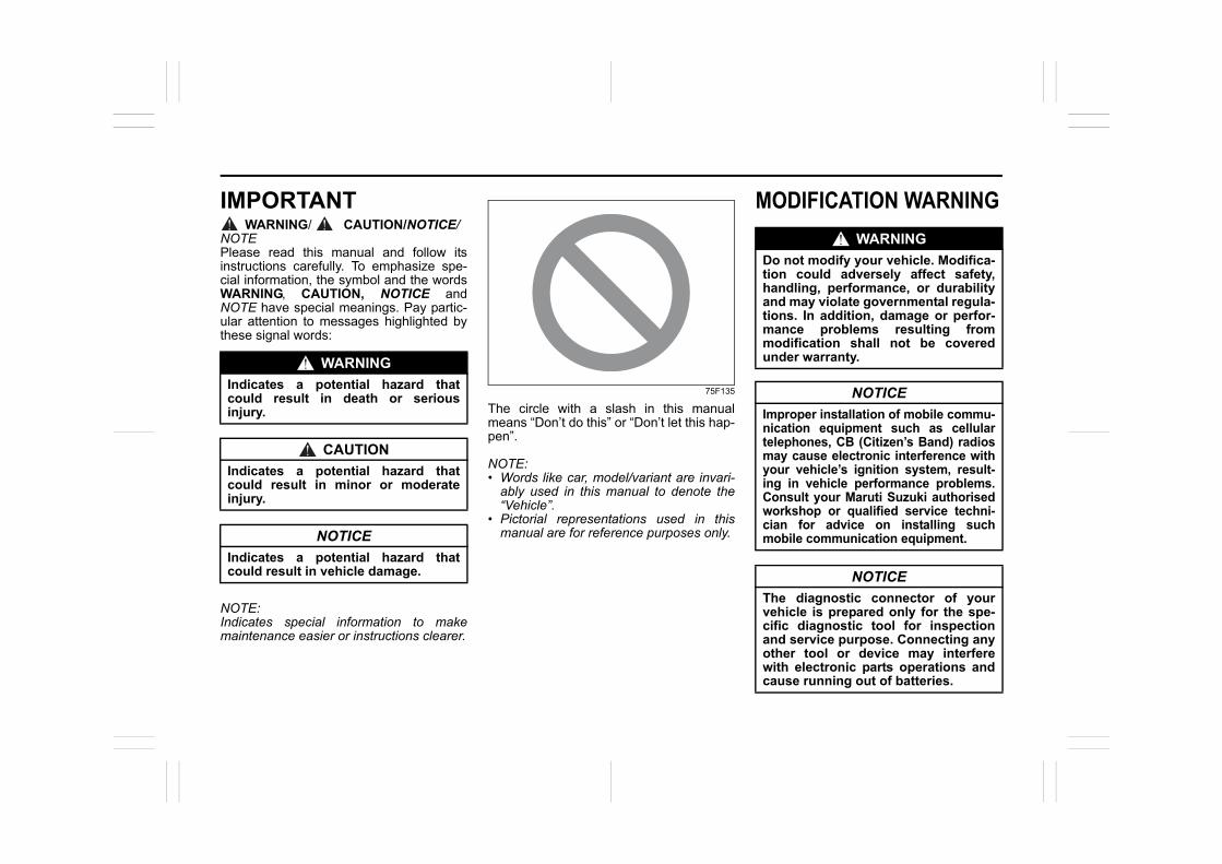
IMPORTANTWARNING/ CAUTION/NOTICE/
NOTEPlease read this manual and follow itsinstructions carefully. To emphasize spe-cial information, the symbol and the wordsWARNING, CAUTION, NOTICE andNOTE have special meanings. Pay partic-ular attention to messages highlighted bythese signal words:
NOTE:Indicates special information to makemaintenance easier or instructions clearer.
75F135
The circle with a slash in this manualmeans “Don’t do this” or “Don’t let this hap-pen”.
NOTE:• Words like car, model/variant are invari-
ably used in this manual to denote the“Vehicle”.
• Pictorial representations used in thismanual are for reference purposes only.
MODIFICATION WARNING
WARNING
Indicates a potential hazard thatcould result in death or seriousinjury.
CAUTION
Indicates a potential hazard thatcould result in minor or moderateinjury.
NOTICE
Indicates a potential hazard thatcould result in vehicle damage.
WARNING
Do not modify your vehicle. Modifica-tion could adversely affect safety,handling, performance, or durabilityand may violate governmental regula-tions. In addition, damage or perfor-mance problems resulting frommodification shall not be coveredunder warranty.
NOTICE
Improper installation of mobile commu-nication equipment such as cellulartelephones, CB (Citizen’s Band) radiosmay cause electronic interference withyour vehicle’s ignition system, result-ing in vehicle performance problems.Consult your Maruti Suzuki authorisedworkshop or qualified service techni-cian for advice on installing suchmobile communication equipment.
NOTICE
The diagnostic connector of yourvehicle is prepared only for the spe-cific diagnostic tool for inspectionand service purpose. Connecting anyother tool or device may interferewith electronic parts operations andcause running out of batteries.
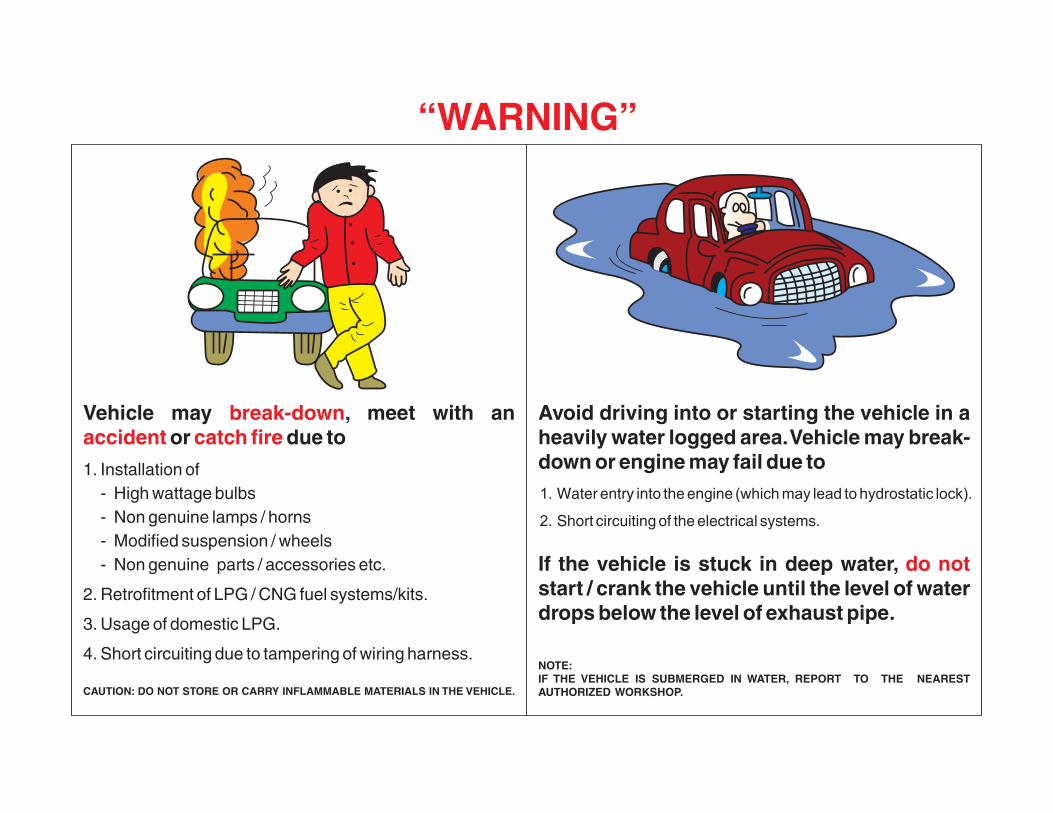
Vehicle may , meet with an or due to
1. Installation of- High wattage bulbs- Non genuine lamps / horns- Modified suspension / wheels- Non genuine parts / accessories etc.
2. Retrofitment of LPG / CNG fuel systems/kits.
3. Usage of domestic LPG.
4. Short circuiting due to tampering of wiring harness.
CAUTION: DO NOT STORE OR CARRY INFLAMMABLE MATERIALS IN THE VEHICLE.
break-downaccident catch fire
Avoid driving into or starting the vehicle in a heavily water logged area. Vehicle may break-down or engine may fail due to1. Water entry into the engine (which may lead to hydrostatic lock).
2. Short circuiting of the electrical systems.
If the vehicle is stuck in deep water, start / crank the vehicle until the level of water drops below the level of exhaust pipe.
NOTE:IF THE VEHICLE IS SUBMERGED IN WATER, REPORT TO THE NEAREST AUTHORIZED WORKSHOP.
do not
“WARNING”
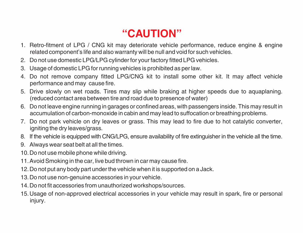
1. Retro-fitment of LPG / CNG kit may deteriorate vehicle performance, reduce engine & enginerelated component’s life and also warranty will be null and void for such vehicles.
2. Do not use domestic LPG/LPG cylinder for your factory fitted LPG vehicles.3. Usage of domestic LPG for running vehicles is prohibited as per law.4. Do not remove company fitted LPG/CNG kit to install some other kit. It may affect vehicle
performance and may cause fire.5. Drive slowly on wet roads. Tires may slip while braking at higher speeds due to aquaplaning.
(reduced contact area between tire and road due to presence of water)6. Do not leave engine running in garages or confined areas, with passengers inside. This may result in
accumulation of carbon-monoxide in cabin and may lead to suffocation or breathing problems.7. Do not park vehicle on dry leaves or grass. This may lead to fire due to hot catalytic converter,
igniting the dry leaves/grass.8. If the vehicle is equipped with CNG/LPG, ensure availability of fire extinguisher in the vehicle all the time.9. Always wear seat belt at all the times.10.Do not use mobile phone while driving.11.Avoid Smoking in the car, live bud thrown in car may cause fire.12.Do not put any body part under the vehicle when it is supported on a Jack.13.Do not use non-genuine accessories in your vehicle.14.Do not fit accessories from unauthorized workshops/sources.15.Usage of non-approved electrical accessories in your vehicle may result in spark, fire or personal
injury.
“CAUTION”

VIN:MODEL:
OWNERNAME & ADDRESS
VARIANT:
COLOUR:
ENGINE NO.: CONTACT NO.
KEY NO.: E-mail ID:
INVOICE DATE:SELLING DEALER NAME & CODE
ODOMETER READING KM
REGISTRATION NO.:
BATTERY MAKE:DEALER SHOWROOM ADDRESS & CONTACT NO. (STAMP)
BATTERY NO.:
BATTERY BATCH
TYRE MAKE BATCH CODE
Front Right
CONTACT NO. FOR SERVICE APPOINTMENT & SUPPORT
Front Left
Rear Right
Rear Left
Spare
For any assistance with regard to our product, please contact General Manager/Works Manager at any of our Dealer or Authorised workshop.For additional enquiry, you may contact our Regional Office or Service Department. The addresses and phone numbers are given in ServiceNetwork section of this Manual.
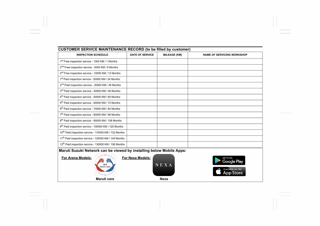
CUSTOMER SERVICE MAINTENANCE RECORD (to be filled by customer)INSPECTION SCHEDULE DATE OF SERVICE MILEAGE (KM) NAME OF SERVICING WORKSHOP
1st Free inspection service - 1000 KM / 1 Months
2nd Free inspection service - 5000 KM / 6 Months
3rd Free inspection service - 10000 KM / 12 Months
1st Paid inspection service - 20000 KM / 24 Months
2nd Paid inspection service - 30000 KM / 36 Months
3rd Paid inspection service - 40000 KM / 48 Months
4th Paid inspection service - 50000 KM / 60 Months
5th Paid inspection service - 60000 KM / 72 Months
6th Paid inspection service - 70000 KM / 84 Months
7th Paid inspection service - 80000 KM / 96 Months
8th Paid inspection service - 90000 KM / 108 Months
9th Paid inspection service - 100000 KM / 120 Months
10th Paid inspection service - 110000 KM / 132 Months
11th Paid inspection service - 120000 KM / 144 Months
12th Paid inspection service - 130000 KM / 156 Months
Maruti Suzuki Network can be viewed by installing below Mobile Apps:
For Arena Models; For Nexa Models;
Maruti care Nexa
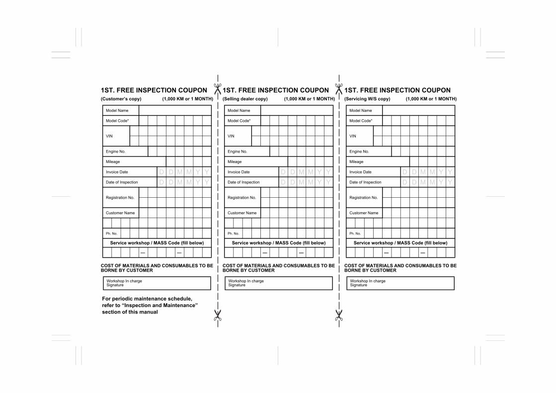
1ST. FREE INSPECTION COUPON (Customer’s copy) (1,000 KM or 1 MONTH)
COST OF MATERIALS AND CONSUMABLES TO BEBORNE BY CUSTOMER
1ST. FREE INSPECTION COUPON (Selling dealer copy) (1,000 KM or 1 MONTH)
COST OF MATERIALS AND CONSUMABLES TO BEBORNE BY CUSTOMER
1ST. FREE INSPECTION COUPON (Servicing W/S copy) (1,000 KM or 1 MONTH)
COST OF MATERIALS AND CONSUMABLES TO BEBORNE BY CUSTOMER
Model Name
Model Code*
VIN
Engine No.
Mileage
Invoice Date
Date of Inspection
Registration No.
Customer Name
Ph. No.
Service workshop / MASS Code (fill below)
Workshop In charge Signature
Model Name
Model Code*
VIN
Engine No.
Mileage
Invoice Date
Date of Inspection
Registration No.
Customer Name
Ph. No.
Service workshop / MASS Code (fill below)
Workshop In charge Signature
Model Name
Model Code*
VIN
Engine No.
Mileage
Invoice Date
Date of Inspection
Registration No.
Customer Name
Ph. No.
Service workshop / MASS Code (fill below)
Workshop In charge Signature
—— —— ——
For periodic maintenance schedule, refer to “Inspection and Maintenance” section of this manual
D D M M Y YD D M M Y Y
D D M M Y YD D M M Y Y
D D M M Y YD D M M Y Y
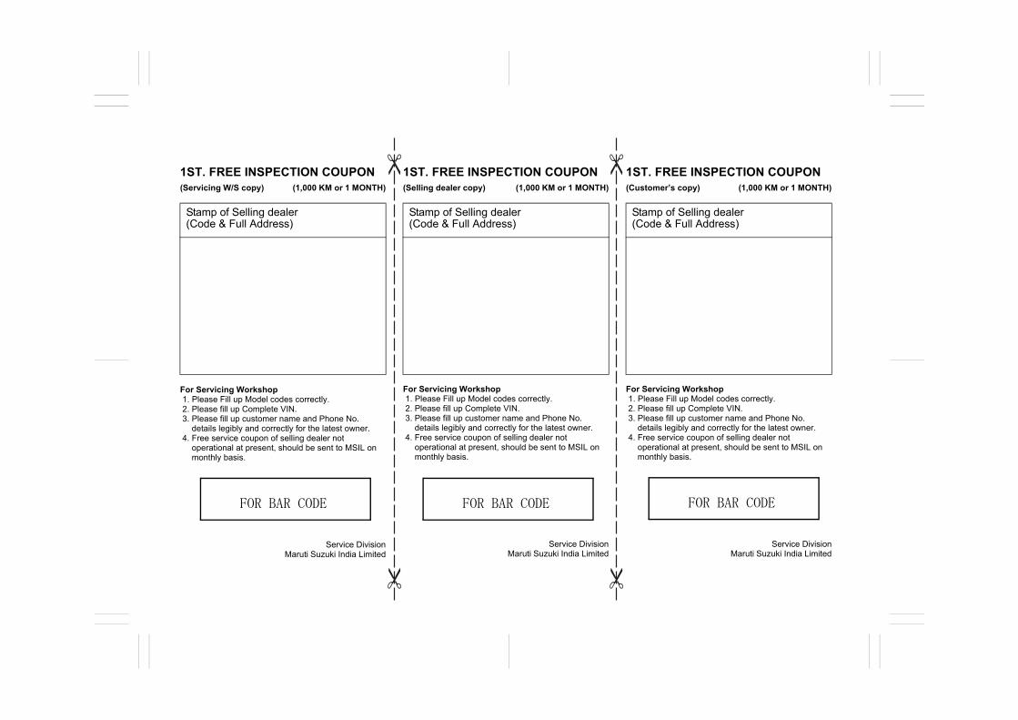
1ST. FREE INSPECTION COUPON (Servicing W/S copy) (1,000 KM or 1 MONTH)
For Servicing Workshop1. Please Fill up Model codes correctly.2. Please fill up Complete VIN. 3. Please fill up customer name and Phone No.
details legibly and correctly for the latest owner. 4. Free service coupon of selling dealer not
operational at present, should be sent to MSIL onmonthly basis.
Service Division Maruti Suzuki India Limited
1ST. FREE INSPECTION COUPON (Selling dealer copy) (1,000 KM or 1 MONTH)
For Servicing Workshop1. Please Fill up Model codes correctly.2. Please fill up Complete VIN. 3. Please fill up customer name and Phone No.
details legibly and correctly for the latest owner. 4. Free service coupon of selling dealer not
operational at present, should be sent to MSIL onmonthly basis.
Service Division Maruti Suzuki India Limited
1ST. FREE INSPECTION COUPON (Customer’s copy) (1,000 KM or 1 MONTH)
For Servicing Workshop1. Please Fill up Model codes correctly.2. Please fill up Complete VIN. 3. Please fill up customer name and Phone No.
details legibly and correctly for the latest owner. 4. Free service coupon of selling dealer not
operational at present, should be sent to MSIL onmonthly basis.
Service Division Maruti Suzuki India Limited
Stamp of Selling dealer (Code & Full Address)
Stamp of Selling dealer (Code & Full Address)
Stamp of Selling dealer (Code & Full Address)
FOR BAR CODE FOR BAR CODE FOR BAR CODE
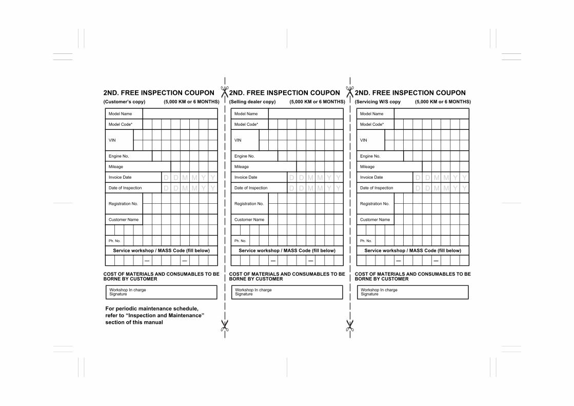
2ND. FREE INSPECTION COUPON (Customer’s copy) (5,000 KM or 6 MONTHS)
COST OF MATERIALS AND CONSUMABLES TO BEBORNE BY CUSTOMER
2ND. FREE INSPECTION COUPON (Selling dealer copy) (5,000 KM or 6 MONTHS)
COST OF MATERIALS AND CONSUMABLES TO BEBORNE BY CUSTOMER
2ND. FREE INSPECTION COUPON (Servicing W/S copy (5,000 KM or 6 MONTHS)
COST OF MATERIALS AND CONSUMABLES TO BEBORNE BY CUSTOMER
Model Name
Model Code*
VIN
Engine No.
Mileage
Invoice Date
Date of Inspection
Registration No.
Customer Name
Ph. No.
Service workshop / MASS Code (fill below)
Workshop In charge Signature
Model Name
Model Code*
VIN
Engine No.
Mileage
Invoice Date
Date of Inspection
Registration No.
Customer Name
Ph. No.
Service workshop / MASS Code (fill below)
Workshop In charge Signature
Model Name
Model Code*
VIN
Engine No.
Mileage
Invoice Date
Date of Inspection
Registration No.
Customer Name
Ph. No.
Service workshop / MASS Code (fill below)
Workshop In charge Signature
For periodic maintenance schedule, refer to “Inspection and Maintenance” section of this manual
—— —— ——
D D M M Y YD D M M Y Y
D D M M Y YD D M M Y Y
D D M M Y YD D M M Y Y
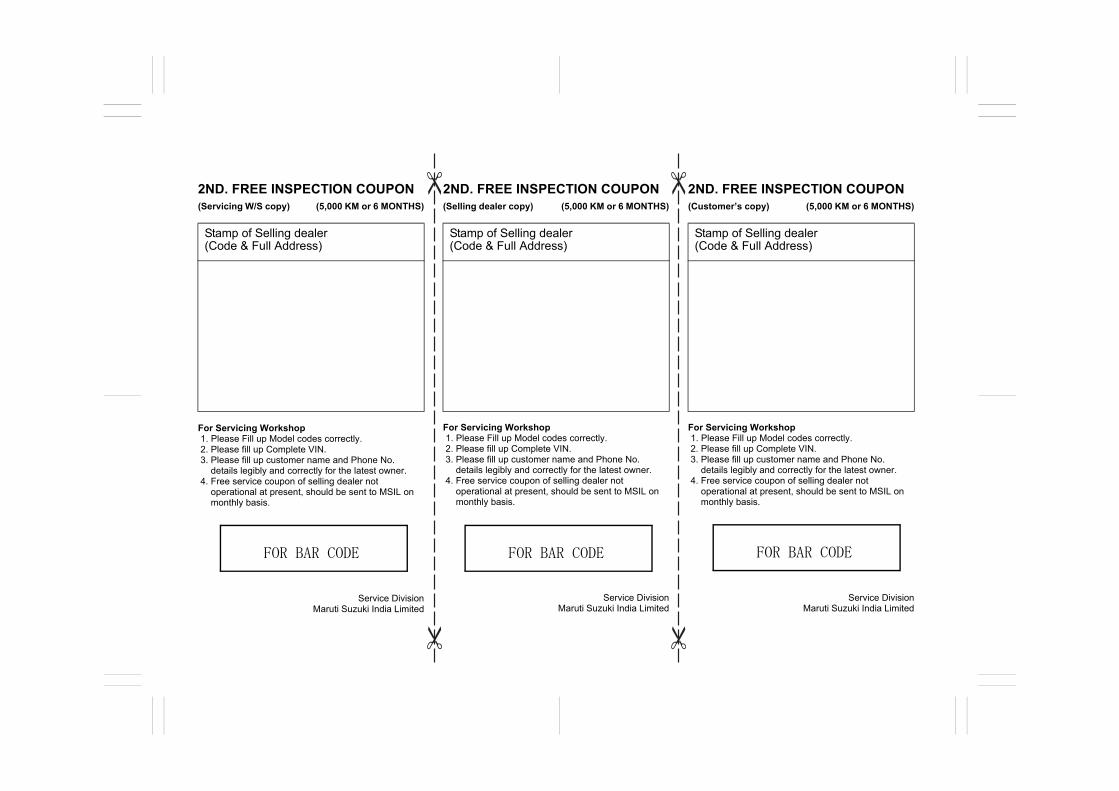
2ND. FREE INSPECTION COUPON (Servicing W/S copy) (5,000 KM or 6 MONTHS)
For Servicing Workshop1. Please Fill up Model codes correctly.2. Please fill up Complete VIN. 3. Please fill up customer name and Phone No.
details legibly and correctly for the latest owner. 4. Free service coupon of selling dealer not
operational at present, should be sent to MSIL onmonthly basis.
Service Division Maruti Suzuki India Limited
2ND. FREE INSPECTION COUPON (Selling dealer copy) (5,000 KM or 6 MONTHS)
For Servicing Workshop1. Please Fill up Model codes correctly.
2. Please fill up Complete VIN. 3. Please fill up customer name and Phone No.
details legibly and correctly for the latest owner. 4. Free service coupon of selling dealer not
operational at present, should be sent to MSIL onmonthly basis.
Service Division Maruti Suzuki India Limited
2ND. FREE INSPECTION COUPON (Customer’s copy) (5,000 KM or 6 MONTHS)
For Servicing Workshop1. Please Fill up Model codes correctly.2. Please fill up Complete VIN. 3. Please fill up customer name and Phone No.
details legibly and correctly for the latest owner. 4. Free service coupon of selling dealer not
operational at present, should be sent to MSIL onmonthly basis.
Service Division Maruti Suzuki India Limited
Stamp of Selling dealer (Code & Full Address)
Stamp of Selling dealer (Code & Full Address)
Stamp of Selling dealer (Code & Full Address)
FOR BAR CODE FOR BAR CODE FOR BAR CODE
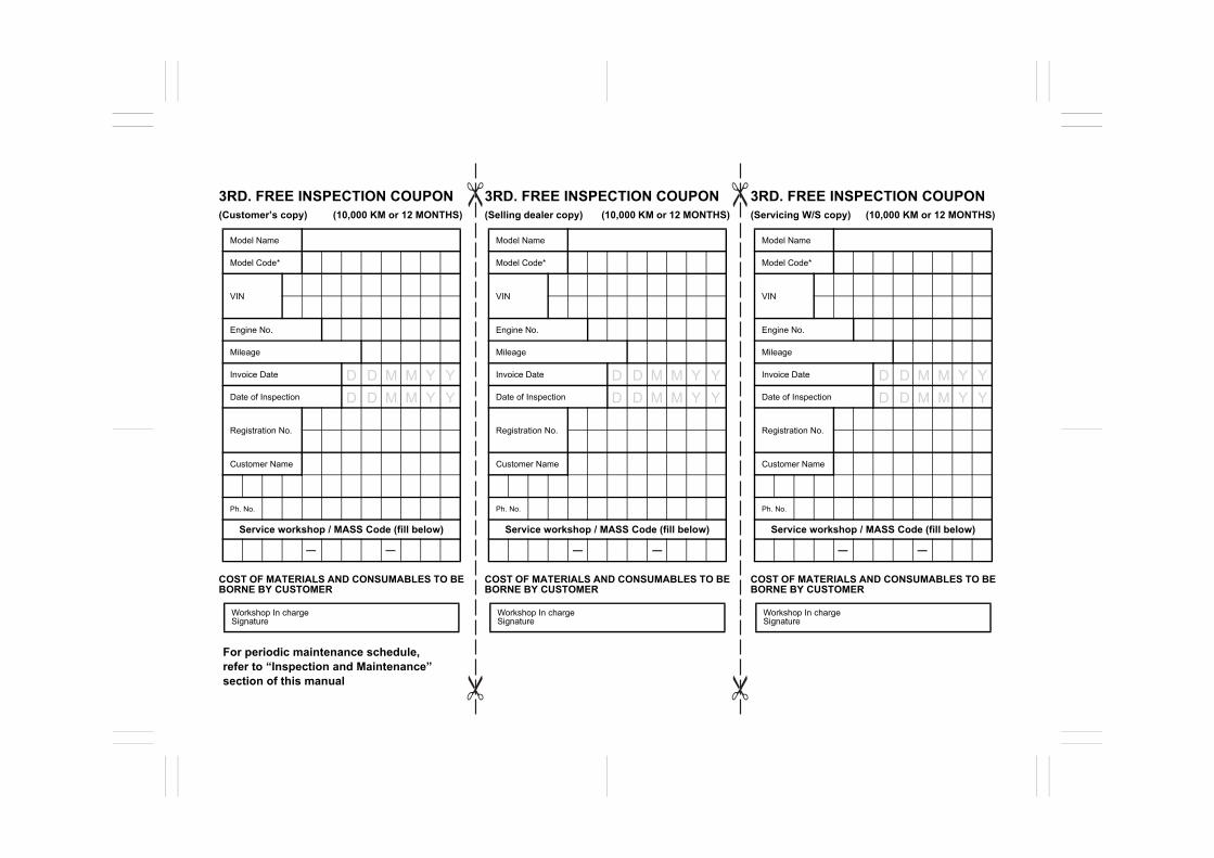
3RD. FREE INSPECTION COUPON (Customer’s copy) (10,000 KM or 12 MONTHS)
COST OF MATERIALS AND CONSUMABLES TO BEBORNE BY CUSTOMER
3RD. FREE INSPECTION COUPON (Selling dealer copy) (10,000 KM or 12 MONTHS)
COST OF MATERIALS AND CONSUMABLES TO BEBORNE BY CUSTOMER
3RD. FREE INSPECTION COUPON (Servicing W/S copy) (10,000 KM or 12 MONTHS)
COST OF MATERIALS AND CONSUMABLES TO BEBORNE BY CUSTOMER
Model Name
Model Code*
VIN
Engine No.
Mileage
Invoice Date
Date of Inspection
Registration No.
Customer Name
Ph. No.
Service workshop / MASS Code (fill below)
Workshop In charge Signature
Model Name
Model Code*
VIN
Engine No.
Mileage
Invoice Date
Date of Inspection
Registration No.
Customer Name
Ph. No.
Service workshop / MASS Code (fill below)
Workshop In charge Signature
Model Name
Model Code*
VIN
Engine No.
Mileage
Invoice Date
Date of Inspection
Registration No.
Customer Name
Ph. No.
Service workshop / MASS Code (fill below)
Workshop In charge Signature
—— —— ——
For periodic maintenance schedule, refer to “Inspection and Maintenance” section of this manual
D D M M Y YD D M M Y Y
D D M M Y YD D M M Y Y
D D M M Y YD D M M Y Y

3RD. FREE INSPECTION COUPON (Servicing W/S copy) (10,000 KM or 12 MONTHS)
For Servicing Workshop1. Please Fill up Model codes correctly.2. Please fill up Complete VIN. 3. Please fill up customer name and Phone No.
details legibly and correctly for the latest owner. 4. Free service coupon of selling dealer not
operational at present, should be sent to MSIL onmonthly basis.
Service Division Maruti Suzuki India Limited
3RD. FREE INSPECTION COUPON (Selling dealer copy) (10,000 KM or 12 MONTHS)
For Servicing Workshop1. Please Fill up Model codes correctly.
2. Please fill up Complete VIN. 3. Please fill up customer name and Phone No.
details legibly and correctly for the latest owner. 4. Free service coupon of selling dealer not
operational at present, should be sent to MSIL onmonthly basis.
Service Division Maruti Suzuki India Limited
3RD. FREE INSPECTION COUPON (Customer’s copy) (10,000 KM or 12 MONTHS)
For Servicing Workshop1. Please Fill up Model codes correctly.2. Please fill up Complete VIN. 3. Please fill up customer name and Phone No.
details legibly and correctly for the latest owner. 4. Free service coupon of selling dealer not
operational at present, should be sent to MSIL onmonthly basis.
Service Division Maruti Suzuki India Limited
Stamp of Selling dealer (Code & Full Address)
Stamp of Selling dealer (Code & Full Address)
Stamp of Selling dealer (Code & Full Address)
FOR BAR CODE FOR BAR CODE FOR BAR CODE

WARRANTY POLICY
Maruti Suzuki India Limited (hereinafter called “Maruti Suzuki”),warrants that each new Maruti Suzuki vehicle distributed in Indiaby Maruti Suzuki and sold by a Maruti Suzuki authorised dealerwill be free, under normal use and service, from any defects inmaterial and workmanship at the time of manufacture SUBJECTTO THE FOLLOWING TERMS AND CONDITIONS:
(1) Qualification:To qualify for this warranty the vehicle must be delivered by aMaruti Suzuki authorised dealer and set-up, and serviced by aMaruti Suzuki authorised workshop.
(2) Term:The term of the warranty shall be twenty-four (24) months or40,000 kilometers (whichever occurs first) from the date ofinvoice to the first owner.
(3) Maruti Suzuki Warranty Obligation:If any defect(s) should be found in a Maruti Suzuki vehicle withinthe term stipulated above, Maruti Suzuki’s only obligation is torepair or replace at its sole discretion any part shown to be defec-tive, with a new part or the equivalent at no cost to the owner forparts or labour, when Maruti Suzuki acknowledges that such adefect is attributable to faulty material or workmanship at the timeof manufacture. Such defective parts, which have been replaced,will become the property of Maruti Suzuki. The owner is responsi-ble for any repair or replacements which are not covered by thiswarranty. The decision of Maruti Suzuki shall be final & binding.
(4) Limitation:
This warranty shall not apply to:
(a) Normal maintenance service required other than the threefree services, including without limitation, oil and fluidchanges, Consumables, headlight aiming, fastener retighten-ing, wheel balancing, wheel alignment and tyre rotation,cleaning of injectors, adjustments of clutch and valve clear-ance.
(b) The normal wear of parts including without limitation, bulbs,tyres* and tubes, spark plugs, belts, hoses, filters, wiperblades, brushes, contact points, fuses, clutch disc, brakeshoes, brake pads, cable and all rubber parts (except oil sealand glass run).
(c) Any vehicle which has been used for competition, rallies orracing.
(d) Any repairs or replacement arising from accidents or colli-sion.
(e) Any defect/ damage caused by misuse, negligence, abnor-mal use, insufficient care, vandalism, theft, riot, fire, flooding -not limited to entry of water in the components resulting inengine seizure, hydrostatic lock, etc. or external damages tothe body/ components.
(f) Any damage resulting due to usage of adulterated fuel/ lubri-cants/ oil/ coolant/ fluids/ polishing products and fuel/ lubri-cants/ oil/ coolant/ fluids used other than those specified inthe Owner’s Manual.
(g) Any vehicle which has been modified or altered, includingwithout limitation, the installation of performance accessories,enlargements of lights, other changes and external/ conse-quential reasons.
(h) Any vehicle on which parts or accessories not approved byMaruti Suzuki (Non-MSGA, Non-MSGP) have been used.
(* - If there is a complaint related to tyre, the customer may contactrespective tyre manufacturer.)
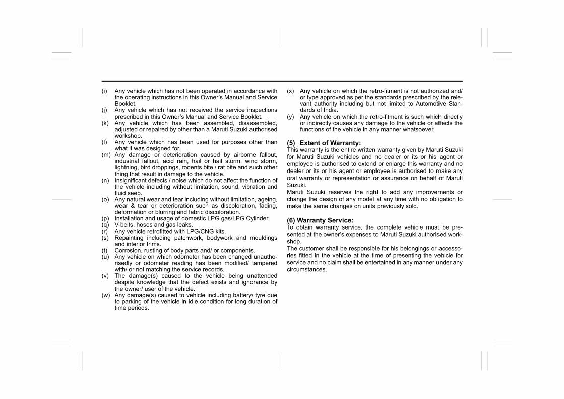
(i) Any vehicle which has not been operated in accordance withthe operating instructions in this Owner’s Manual and ServiceBooklet.
(j) Any vehicle which has not received the service inspectionsprescribed in this Owner’s Manual and Service Booklet.
(k) Any vehicle which has been assembled, disassembled,adjusted or repaired by other than a Maruti Suzuki authorisedworkshop.
(l) Any vehicle which has been used for purposes other thanwhat it was designed for.
(m) Any damage or deterioration caused by airborne fallout,industrial fallout, acid rain, hail or hail storm, wind storm,lightning, bird droppings, rodents bite / rat bite and such otherthing that result in damage to the vehicle.
(n) Insignificant defects / noise which do not affect the function ofthe vehicle including without limitation, sound, vibration andfluid seep.
(o) Any natural wear and tear including without limitation, ageing,wear & tear or deterioration such as discoloration, fading,deformation or blurring and fabric discoloration.
(p) Installation and usage of domestic LPG gas/LPG Cylinder.(q) V-belts, hoses and gas leaks.(r) Any vehicle retrofitted with LPG/CNG kits.(s) Repainting including patchwork, bodywork and mouldings
and interior trims.(t) Corrosion, rusting of body parts and/ or components.(u) Any vehicle on which odometer has been changed unautho-
risedly or odometer reading has been modified/ tamperedwith/ or not matching the service records.
(v) The damage(s) caused to the vehicle being unattendeddespite knowledge that the defect exists and ignorance bythe owner/ user of the vehicle.
(w) Any damage(s) caused to vehicle including battery/ tyre dueto parking of the vehicle in idle condition for long duration oftime periods.
(x) Any vehicle on which the retro-fitment is not authorized and/or type approved as per the standards prescribed by the rele-vant authority including but not limited to Automotive Stan-dards of India.
(y) Any vehicle on which the retro-fitment is such which directlyor indirectly causes any damage to the vehicle or affects thefunctions of the vehicle in any manner whatsoever.
(5) Extent of Warranty:This warranty is the entire written warranty given by Maruti Suzukifor Maruti Suzuki vehicles and no dealer or its or his agent oremployee is authorised to extend or enlarge this warranty and nodealer or its or his agent or employee is authorised to make anyoral warranty or representation or assurance on behalf of MarutiSuzuki.Maruti Suzuki reserves the right to add any improvements orchange the design of any model at any time with no obligation tomake the same changes on units previously sold.
(6) Warranty Service:To obtain warranty service, the complete vehicle must be pre-sented at the owner’s expenses to Maruti Suzuki authorised work-shop.The customer shall be responsible for his belongings or accesso-ries fitted in the vehicle at the time of presenting the vehicle forservice and no claim shall be entertained in any manner under anycircumstances.
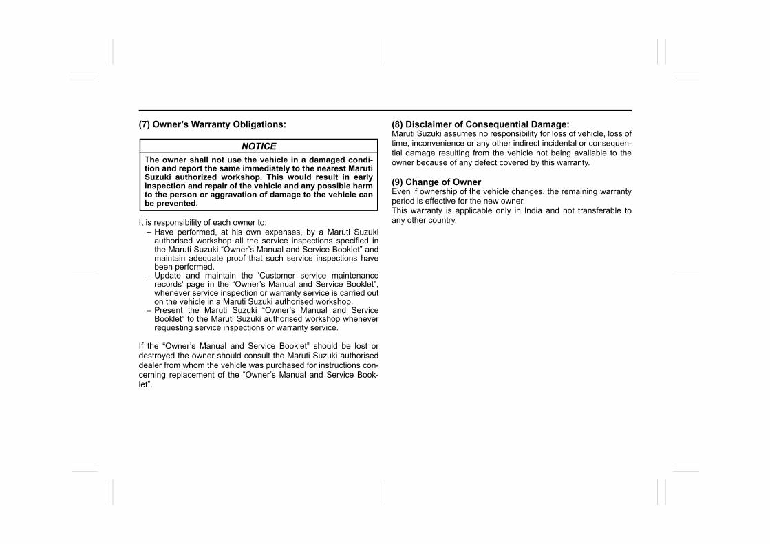
(7) Owner’s Warranty Obligations:
It is responsibility of each owner to:– Have performed, at his own expenses, by a Maruti Suzuki
authorised workshop all the service inspections specified inthe Maruti Suzuki “Owner’s Manual and Service Booklet” andmaintain adequate proof that such service inspections havebeen performed.
– Update and maintain the 'Customer service maintenancerecords' page in the “Owner’s Manual and Service Booklet”,whenever service inspection or warranty service is carried outon the vehicle in a Maruti Suzuki authorised workshop.
– Present the Maruti Suzuki “Owner’s Manual and ServiceBooklet” to the Maruti Suzuki authorised workshop wheneverrequesting service inspections or warranty service.
If the “Owner’s Manual and Service Booklet” should be lost ordestroyed the owner should consult the Maruti Suzuki authoriseddealer from whom the vehicle was purchased for instructions con-cerning replacement of the “Owner’s Manual and Service Book-let”.
(8) Disclaimer of Consequential Damage:Maruti Suzuki assumes no responsibility for loss of vehicle, loss oftime, inconvenience or any other indirect incidental or consequen-tial damage resulting from the vehicle not being available to theowner because of any defect covered by this warranty.
(9) Change of OwnerEven if ownership of the vehicle changes, the remaining warrantyperiod is effective for the new owner.This warranty is applicable only in India and not transferable toany other country.
NOTICE
The owner shall not use the vehicle in a damaged condi-tion and report the same immediately to the nearest MarutiSuzuki authorized workshop. This would result in earlyinspection and repair of the vehicle and any possible harmto the person or aggravation of damage to the vehicle canbe prevented.
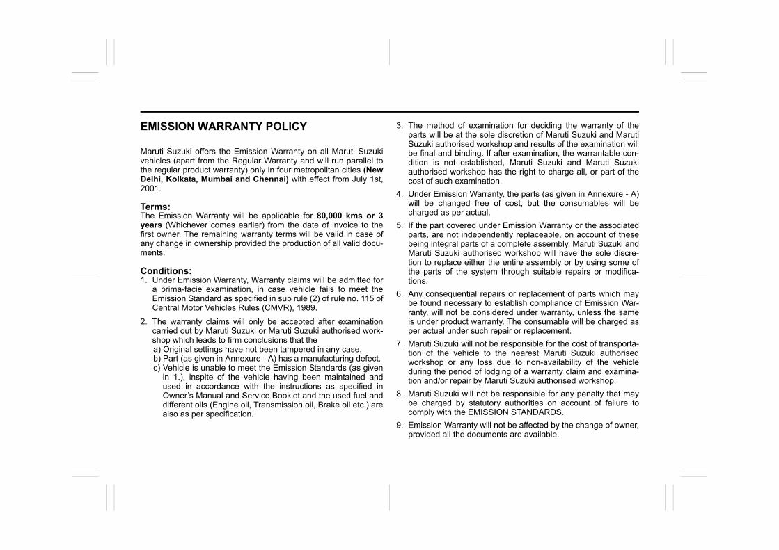
EMISSION WARRANTY POLICY
Maruti Suzuki offers the Emission Warranty on all Maruti Suzukivehicles (apart from the Regular Warranty and will run parallel tothe regular product warranty) only in four metropolitan cities (NewDelhi, Kolkata, Mumbai and Chennai) with effect from July 1st,2001.
Terms:The Emission Warranty will be applicable for 80,000 kms or 3years (Whichever comes earlier) from the date of invoice to thefirst owner. The remaining warranty terms will be valid in case ofany change in ownership provided the production of all valid docu-ments.
Conditions:1. Under Emission Warranty, Warranty claims will be admitted for
a prima-facie examination, in case vehicle fails to meet theEmission Standard as specified in sub rule (2) of rule no. 115 ofCentral Motor Vehicles Rules (CMVR), 1989.
2. The warranty claims will only be accepted after examinationcarried out by Maruti Suzuki or Maruti Suzuki authorised work-shop which leads to firm conclusions that thea) Original settings have not been tampered in any case. b) Part (as given in Annexure - A) has a manufacturing defect. c) Vehicle is unable to meet the Emission Standards (as given
in 1.), inspite of the vehicle having been maintained andused in accordance with the instructions as specified inOwner’s Manual and Service Booklet and the used fuel anddifferent oils (Engine oil, Transmission oil, Brake oil etc.) arealso as per specification.
3. The method of examination for deciding the warranty of theparts will be at the sole discretion of Maruti Suzuki and MarutiSuzuki authorised workshop and results of the examination willbe final and binding. If after examination, the warrantable con-dition is not established, Maruti Suzuki and Maruti Suzukiauthorised workshop has the right to charge all, or part of thecost of such examination.
4. Under Emission Warranty, the parts (as given in Annexure - A)will be changed free of cost, but the consumables will becharged as per actual.
5. If the part covered under Emission Warranty or the associatedparts, are not independently replaceable, on account of thesebeing integral parts of a complete assembly, Maruti Suzuki andMaruti Suzuki authorised workshop will have the sole discre-tion to replace either the entire assembly or by using some ofthe parts of the system through suitable repairs or modifica-tions.
6. Any consequential repairs or replacement of parts which maybe found necessary to establish compliance of Emission War-ranty, will not be considered under warranty, unless the sameis under product warranty. The consumable will be charged asper actual under such repair or replacement.
7. Maruti Suzuki will not be responsible for the cost of transporta-tion of the vehicle to the nearest Maruti Suzuki authorisedworkshop or any loss due to non-availability of the vehicleduring the period of lodging of a warranty claim and examina-tion and/or repair by Maruti Suzuki authorised workshop.
8. Maruti Suzuki will not be responsible for any penalty that maybe charged by statutory authorities on account of failure tocomply with the EMISSION STANDARDS.
9. Emission Warranty will not be affected by the change of owner,provided all the documents are available.
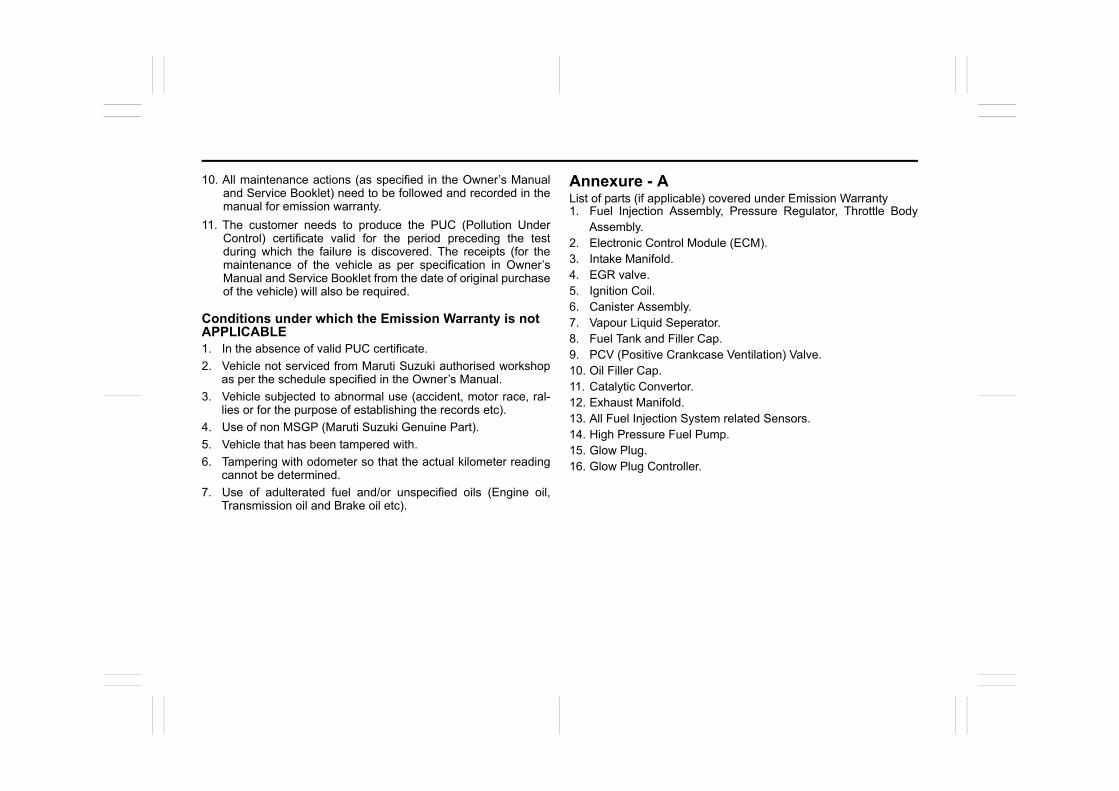
10. All maintenance actions (as specified in the Owner’s Manualand Service Booklet) need to be followed and recorded in themanual for emission warranty.
11. The customer needs to produce the PUC (Pollution UnderControl) certificate valid for the period preceding the testduring which the failure is discovered. The receipts (for themaintenance of the vehicle as per specification in Owner’sManual and Service Booklet from the date of original purchaseof the vehicle) will also be required.
Conditions under which the Emission Warranty is notAPPLICABLE1. In the absence of valid PUC certificate.
2. Vehicle not serviced from Maruti Suzuki authorised workshopas per the schedule specified in the Owner’s Manual.
3. Vehicle subjected to abnormal use (accident, motor race, ral-lies or for the purpose of establishing the records etc).
4. Use of non MSGP (Maruti Suzuki Genuine Part).
5. Vehicle that has been tampered with.
6. Tampering with odometer so that the actual kilometer readingcannot be determined.
7. Use of adulterated fuel and/or unspecified oils (Engine oil,Transmission oil and Brake oil etc).
Annexure - AList of parts (if applicable) covered under Emission Warranty1. Fuel Injection Assembly, Pressure Regulator, Throttle Body
Assembly.2. Electronic Control Module (ECM).3. Intake Manifold.4. EGR valve.5. Ignition Coil.6. Canister Assembly.7. Vapour Liquid Seperator.8. Fuel Tank and Filler Cap.9. PCV (Positive Crankcase Ventilation) Valve.10. Oil Filler Cap.11. Catalytic Convertor.12. Exhaust Manifold.13. All Fuel Injection System related Sensors.14. High Pressure Fuel Pump.15. Glow Plug.16. Glow Plug Controller.


69RH0-74E
TABLE OF CONTENTS FOR SAFE DRIVING 1
BEFORE DRIVING 2
OPERATING YOUR VEHICLE 3
DRIVING TIPS 4
OTHER CONTROLS AND EQUIPMENT 5
INSPECTION AND MAINTENANCE 6
EMERGENCY SERVICE 7
APPEARANCE CARE 8
SPECIFICATIONS 9
SERVICE NETWORK 10

FOR SAFE DRIVING
1
69RH0-74E
52D078S
FOR SAFE DRIVINGFloor mats (if equipped) ..................................................... 1-1Front seats ........................................................................... 1-1Rear seats ............................................................................ 1-3Seat belts and child restraint systems .............................. 1-4Supplemental restraint system (airbags) .......................... 1-18Exhaust gas warning .......................................................... 1-25
1-1
FOR SAFE DRIVING
69RH0-74E
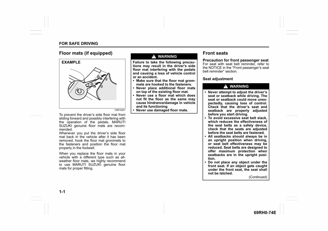
Floor mats (if equipped)
72M10201
To prevent the driver’s side floor mat fromsliding forward and possibly interfering withthe operation of the pedals, MARUTISUZUKI genuine floor mats are recom-mended. Whenever you put the driver’s side floormat back in the vehicle after it has beenremoved, hook the floor mat grommets tothe fasteners and position the floor matproperly in the footwell.
When you replace the floor mats in yourvehicle with a different type such as all-weather floor mats, we highly recommendto use MARUTI SUZUKI genuine floormats for proper fitting.
Front seats
Precaution for front passenger seatFor seat with seat belt reminder, refer tothe NOTICE in the “Front passenger’s seatbelt reminder” section.
Seat adjustment
EXAMPLE
WARNING
Failure to take the following precau-tions may result in the driver’s sidefloor mat interfering with the pedalsand causing a loss of vehicle controlor an accident.• Make sure that the floor mat grom-
mets are hooked to the fasteners.• Never place additional floor mats
on top of the existing floor mat.• Never use a floor mat which does
not fit the floor as the same maycause hindrance/damage in vehicleand its functioning
• Never use damaged floor mats.
WARNING
• Never attempt to adjust the driver’sseat or seatback while driving. Theseat or seatback could move unex-pectedly, causing loss of control.Check that the driver’s seat andseatback are properly adjustedbefore you start driving.
• To avoid excessive seat belt slack,which reduces the effectiveness ofthe seat belts as a safety device,check that the seats are adjustedbefore the seat belts are fastened.
• All seatbacks should always be inan upright position when driving,or seat belt effectiveness may bereduced. Seat belts are designed tooffer maximum protection whenseatbacks are in the upright posi-tion.
• Do not place any object under thefront seat. If an object gets caughtunder the front seat, the seat shallnot be latched.
(Continued)
1-2
FOR SAFE DRIVING
69RH0-74E
62SM01015
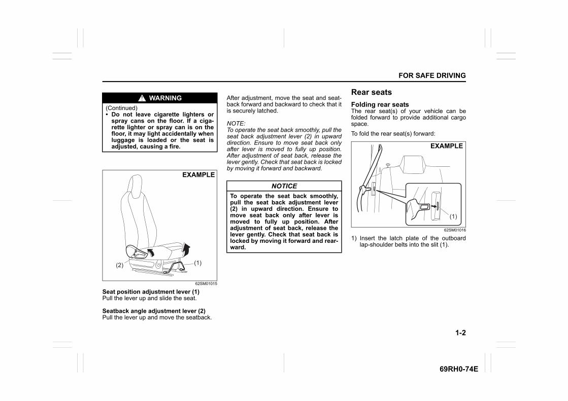
Seat position adjustment lever (1)Pull the lever up and slide the seat.
Seatback angle adjustment lever (2)Pull the lever up and move the seatback.
After adjustment, move the seat and seat-back forward and backward to check that itis securely latched.
NOTE:To operate the seat back smoothly, pull theseat back adjustment lever (2) in upwarddirection. Ensure to move seat back onlyafter lever is moved to fully up position.After adjustment of seat back, release thelever gently. Check that seat back is lockedby moving it forward and backward.
Rear seats
Folding rear seatsThe rear seat(s) of your vehicle can befolded forward to provide additional cargospace.
To fold the rear seat(s) forward:
62SM01016
1) Insert the latch plate of the outboardlap-shoulder belts into the slit (1).
WARNING
(Continued)• Do not leave cigarette lighters or
spray cans on the floor. If a ciga-rette lighter or spray can is on thefloor, it may light accidentally whenluggage is loaded or the seat isadjusted, causing a fire.
(2) (1)
EXAMPLE
NOTICE
To operate the seat back smoothly,pull the seat back adjustment lever(2) in upward direction. Ensure tomove seat back only after lever ismoved to fully up position. Afteradjustment of seat back, release thelever gently. Check that seat back islocked by moving it forward and rear-ward.
(1)
EXAMPLE
1-3
FOR SAFE DRIVING
69RH0-74E
62SM01010
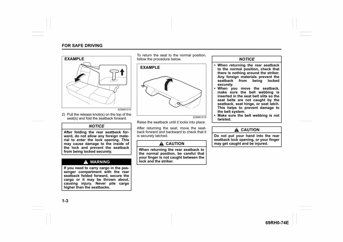
2) Pull the release knob(s) on the top of theseat(s) and fold the seatback forward.
To return the seat to the normal position,follow the procedure below.
62SM01019
Raise the seatback until it locks into place.
After returning the seat, move the seat-back forward and backward to check that itis securely latched.
NOTICE
After folding the rear seatback for-ward, do not allow any foreign mate-rial to enter the lock opening. Thismay cause damage to the inside ofthe lock and prevent the seatbackfrom being locked securely.
WARNING
If you need to carry cargo in the pas-senger compartment with the rearseatback folded forward, secure thecargo or it may be thrown about,causing injury. Never pile cargohigher than the seatbacks.
EXAMPLE
CAUTION
When returning the rear seatback tothe normal position, be careful thatyour finger is not caught between thelock and the striker.
EXAMPLE
NOTICE
• When returning the rear seatbackto the normal position, check thatthere is nothing around the striker.Any foreign materials prevent theseatback from being lockedsecurely.
• When you move the seatback,make sure the belt webbing isinserted in the seat belt slits so theseat belts are not caught by theseatback, seat hinge, or seat latch.This helps to prevent damage tothe belt system.
• Make sure the belt webbing is nottwisted.
CAUTION
Do not put your hand into the rearseatback lock opening, or your fingermay get caught and be injured.
1-4
FOR SAFE DRIVING
69RH0-74E
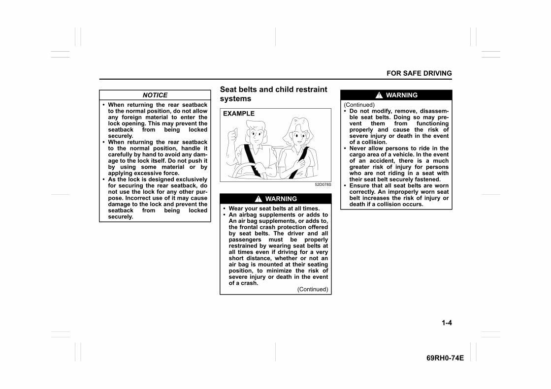
Seat belts and child restraint systems
52D078S
NOTICE
• When returning the rear seatbackto the normal position, do not allowany foreign material to enter thelock opening. This may prevent theseatback from being lockedsecurely.
• When returning the rear seatbackto the normal position, handle itcarefully by hand to avoid any dam-age to the lock itself. Do not push itby using some material or byapplying excessive force.
• As the lock is designed exclusivelyfor securing the rear seatback, donot use the lock for any other pur-pose. Incorrect use of it may causedamage to the lock and prevent theseatback from being lockedsecurely.
WARNING
• Wear your seat belts at all times.• An airbag supplements or adds to
An air bag supplements, or adds to,the frontal crash protection offeredby seat belts. The driver and allpassengers must be properlyrestrained by wearing seat belts atall times even if driving for a veryshort distance, whether or not anair bag is mounted at their seatingposition, to minimize the risk ofsevere injury or death in the eventof a crash.
(Continued)
EXAMPLE
WARNING
(Continued)• Do not modify, remove, disassem-
ble seat belts. Doing so may pre-vent them from functioningproperly and cause the risk ofsevere injury or death in the eventof a collision.
• Never allow persons to ride in thecargo area of a vehicle. In the eventof an accident, there is a muchgreater risk of injury for personswho are not riding in a seat withtheir seat belt securely fastened.
• Ensure that all seat belts are worncorrectly. An improperly worn seatbelt increases the risk of injury ordeath if a collision occurs.
1-5
FOR SAFE DRIVING
69RH0-74E
65D606 65D201A 65D199A
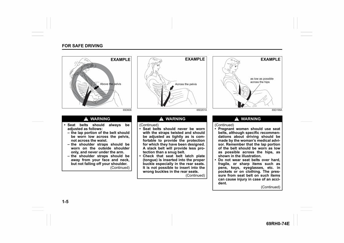
WARNING
• Seat belts should always beadjusted as follows:– the lap portion of the belt should
be worn low across the pelvis,not across the waist.
– the shoulder straps should beworn on the outside shoulderonly, and never under the arm.
– the shoulder straps should beaway from your face and neck,but not falling off your shoulder.
(Continued)
Above the pelvis
EXAMPLE
WARNING
(Continued)• Seat belts should never be worn
with the straps twisted and shouldbe adjusted as tightly as is com-fortable to provide the protectionfor which they have been designed.A slack belt will provide less pro-tection than a snug belt.
• Check that seat belt latch plate(tongue) is inserted into the properbuckle especially in the rear seats.It is not possible to insert into thewrong buckles in the rear seats.
(Continued)
Across the pelvis
EXAMPLE
WARNING
(Continued)• Pregnant women should use seat
belts, although specific recommen-dations about driving should bemade by the woman’s medical advi-sor. Remember that the lap portionof the belt should be worn as lowas possible across the hips, asshown in the illustration.
• Do not wear seat belts over hard,fragile, or sharp items such aspens, keys, eyeglasses, etc. inpockets or on clothing. The pres-sure from seat belt on such itemscan cause injury in case of an acci-dent.
(Continued)
as low as possible across the hips
EXAMPLE
1-6
FOR SAFE DRIVING
69RH0-74E
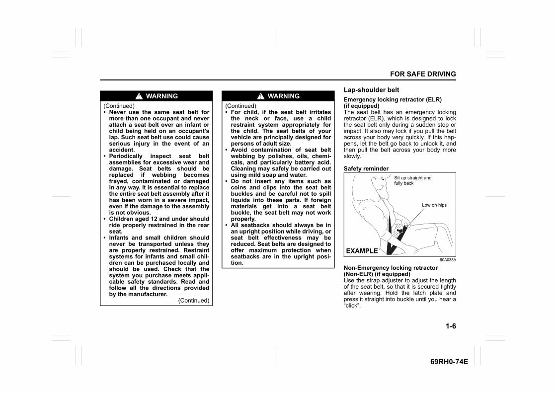
Lap-shoulder belt
Emergency locking retractor (ELR)(if equipped)The seat belt has an emergency lockingretractor (ELR), which is designed to lockthe seat belt only during a sudden stop orimpact. It also may lock if you pull the beltacross your body very quickly. If this hap-pens, let the belt go back to unlock it, andthen pull the belt across your body moreslowly.
Safety reminder
60A038A
Non-Emergency locking retractor (Non-ELR) (if equipped)Use the strap adjuster to adjust the lengthof the seat belt, so that it is secured tightlyafter wearing. Hold the latch plate andpress it straight into buckle until you hear a“click”.
WARNING
(Continued)• Never use the same seat belt for
more than one occupant and neverattach a seat belt over an infant orchild being held on an occupant’slap. Such seat belt use could causeserious injury in the event of anaccident.
• Periodically inspect seat beltassemblies for excessive wear anddamage. Seat belts should bereplaced if webbing becomesfrayed, contaminated or damagedin any way. It is essential to replacethe entire seat belt assembly after ithas been worn in a severe impact,even if the damage to the assemblyis not obvious.
• Children aged 12 and under shouldride properly restrained in the rearseat.
• Infants and small children shouldnever be transported unless theyare properly restrained. Restraintsystems for infants and small chil-dren can be purchased locally andshould be used. Check that thesystem you purchase meets appli-cable safety standards. Read andfollow all the directions providedby the manufacturer.
(Continued)
WARNING
(Continued)• For child, if the seat belt irritates
the neck or face, use a childrestraint system appropriately forthe child. The seat belts of yourvehicle are principally designed forpersons of adult size.
• Avoid contamination of seat beltwebbing by polishes, oils, chemi-cals, and particularly battery acid.Cleaning may safely be carried outusing mild soap and water.
• Do not insert any items such ascoins and clips into the seat beltbuckles and be careful not to spillliquids into these parts. If foreignmaterials get into a seat beltbuckle, the seat belt may not workproperly.
• All seatbacks should always be inan upright position while driving, orseat belt effectiveness may bereduced. Seat belts are designed tooffer maximum protection whenseatbacks are in the upright posi-tion.
Sit up straight and fully back
Low on hips
EXAMPLE

1-7
FOR SAFE DRIVING
69RH0-74E
60A040
To reduce the risk of sliding under the beltduring a collision, position the lap portionof the belt across your lap as low on yourhips as possible and adjust it to a snug fitby pulling the shoulder portion of the beltupward through the latch plate. The lengthof the diagonal shoulder strap adjusts itselfto allow freedom of movement.
All seat belts except rear centerAll seat belts except rear center are thelap-shoulder belt.
60A036
To fasten the seat belt, sit up straight andfar back into the seat, pull the latch plateattached to the seat belt across your bodyand press it straight into the buckle untilyou hear a “click”.
NOTE:If the seat belt cannot be pulled from itsfully retracted position, firmly pull the beltand release it. Then smoothly pull the beltout of the retractor.
62SM01017
NOTE:The word “CENTER” is marked on thebuckle for the rear center belt. The bucklesare designed so a latch plate cannot beinserted into the wrong buckle.
NOTICE
In case Non ELR belt, ensure that thebelt strap does not get caughtbetween door and seal area whileclosing the door.
Low on hips
EXAMPLE
EXAMPLE
EXAMPLE
1-8
FOR SAFE DRIVING
69RH0-74E
60A039
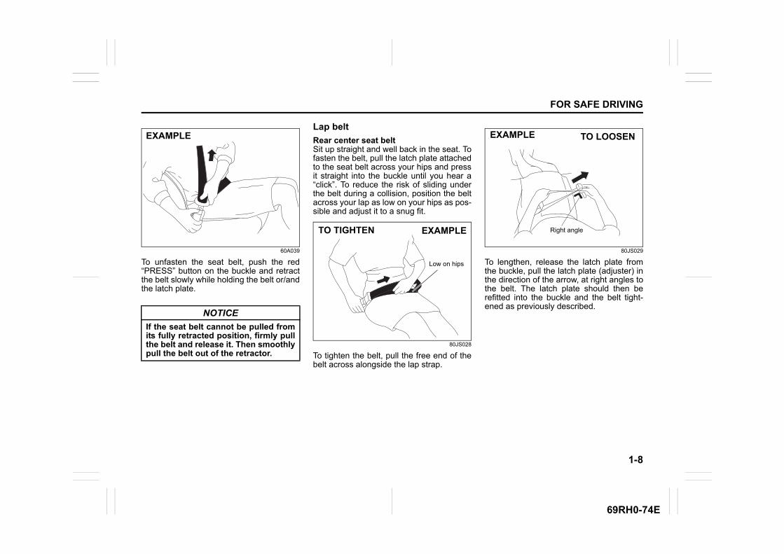
To unfasten the seat belt, push the red“PRESS” button on the buckle and retractthe belt slowly while holding the belt or/andthe latch plate.
Lap belt
Rear center seat beltSit up straight and well back in the seat. Tofasten the belt, pull the latch plate attachedto the seat belt across your hips and pressit straight into the buckle until you hear a“click”. To reduce the risk of sliding underthe belt during a collision, position the beltacross your lap as low on your hips as pos-sible and adjust it to a snug fit.
80JS028
To tighten the belt, pull the free end of thebelt across alongside the lap strap.
80JS029
To lengthen, release the latch plate fromthe buckle, pull the latch plate (adjuster) inthe direction of the arrow, at right angles tothe belt. The latch plate should then berefitted into the buckle and the belt tight-ened as previously described.
NOTICE
If the seat belt cannot be pulled fromits fully retracted position, firmly pullthe belt and release it. Then smoothlypull the belt out of the retractor.
EXAMPLE
TO TIGHTEN
Low on hips
EXAMPLE
TO LOOSEN
Right angle
EXAMPLE
1-9
FOR SAFE DRIVING
69RH0-74E
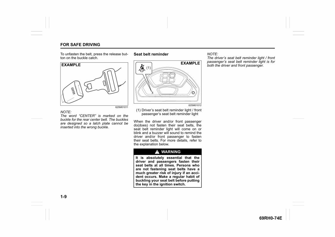
To unfasten the belt, press the release but-ton on the buckle catch.
62SM01011
NOTE:The word “CENTER” is marked on thebuckle for the rear center belt. The bucklesare designed so a latch plate cannot beinserted into the wrong buckle.
Seat belt reminder
62SM01012
(1) Driver’s seat belt reminder light / frontpassenger’s seat belt reminder light
When the driver and/or front passengerdo(does) not fasten their seat belts, theseat belt reminder light will come on orblink and a buzzer will sound to remind thedriver and/or front passenger to fastentheir seat belts. For more details, refer tothe explanation below.
NOTE:The driver’s seat belt reminder light / frontpassenger’s seat belt reminder light is forboth the driver and front passenger.EXAMPLE
WARNING
It is absolutely essential that thedriver and passengers fasten theirseat belts at all times. Persons whoare not fastening seat belts have amuch greater risk of injury if an acci-dent occurs. Make a regular habit ofbuckling your seat belt before puttingthe key in the ignition switch.
(1)EXAMPLE
1-10
FOR SAFE DRIVING
69RH0-74E
Driver’s seat belt reminderIf the driver’s seat belt remains unbuckledwhen the ignition switch is turned to “ON”position, the reminder works as follows:1) The driver’s seat belt reminder light will
come on.2) After the vehicle’s speed has reached
about 15 km/h, the driver’s seat beltreminder light will blink and a buzzerwill sound for about 95 seconds.
3) The reminder light will remain on untilthe driver’s seat belt is buckled.
If the driver has buckled his or her seat beltand later unbuckles the seat belt, thereminder system will be activated fromStep 1) or 2) according to the vehicle’sspeed. When the vehicle’s speed is lessthan 15 km/h, the reminder will start fromStep 1). When the vehicle’s speed is morethan 15 km/h, the reminder will start fromStep 2).The reminder will be automatically can-celed when the driver’s seat belt is buckledor the ignition switch is turned off.
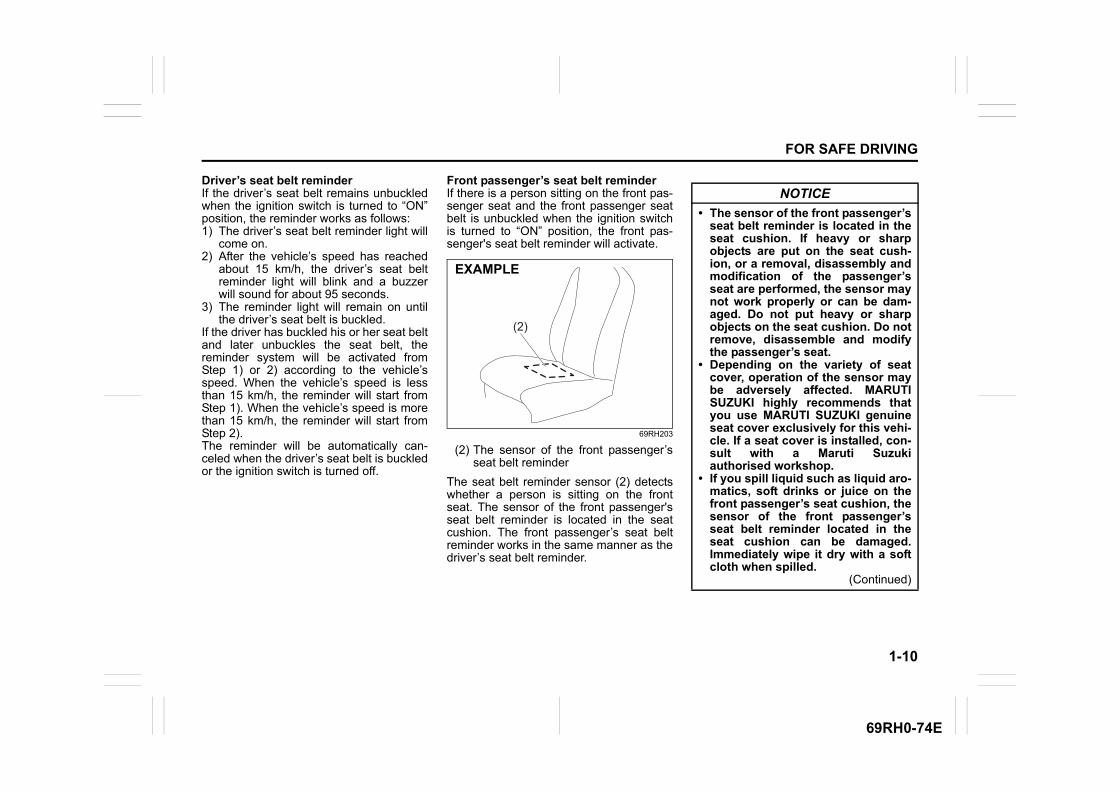
Front passenger’s seat belt reminderIf there is a person sitting on the front pas-senger seat and the front passenger seatbelt is unbuckled when the ignition switchis turned to “ON” position, the front pas-senger's seat belt reminder will activate.
69RH203
(2) The sensor of the front passenger’sseat belt reminder
The seat belt reminder sensor (2) detectswhether a person is sitting on the frontseat. The sensor of the front passenger'sseat belt reminder is located in the seatcushion. The front passenger’s seat beltreminder works in the same manner as thedriver’s seat belt reminder.
(2)
EXAMPLE
NOTICE
• The sensor of the front passenger’sseat belt reminder is located in theseat cushion. If heavy or sharpobjects are put on the seat cush-ion, or a removal, disassembly andmodification of the passenger’sseat are performed, the sensor maynot work properly or can be dam-aged. Do not put heavy or sharpobjects on the seat cushion. Do notremove, disassemble and modifythe passenger’s seat.
• Depending on the variety of seatcover, operation of the sensor maybe adversely affected. MARUTISUZUKI highly recommends thatyou use MARUTI SUZUKI genuineseat cover exclusively for this vehi-cle. If a seat cover is installed, con-sult with a Maruti Suzukiauthorised workshop.
• If you spill liquid such as liquid aro-matics, soft drinks or juice on thefront passenger’s seat cushion, thesensor of the front passenger’sseat belt reminder located in theseat cushion can be damaged.Immediately wipe it dry with a softcloth when spilled.
(Continued)

1-11
FOR SAFE DRIVING
69RH0-74E
NOTE:• If you put an object on the passenger’s
seat, the weight of the object will besensed by the sensor and the front pas-senger’s seat belt reminder light willcome on and then the interior buzzermay beep.
• If a child or a small sized person sits onthe front passenger’s seat or the cushionis put on the front passenger’s seat, theweight may not be sensed by the sensorand the interior buzzer may not beep.
Seat belt slit
62SM01016
Seat belt inspection
65D209S
Periodically inspect the seat belts if theywork properly and are not damaged.Check the webbing, buckles, latch plates,retractors, anchorages and guide loops.Replace any seat belts which do not workproperly or are damaged.
NOTICE
(Continued)• When sitting on the front passen-
ger’s seat, it is very important thatthe passenger sits upright, leaningagainst the seat backrest and cen-tered on the seat cushion in orderfor the seatbelt reminder system tofunction effectively. An occupantsitting improperly (slouches, turnssideways, sits forward or side-ways) may hamper the functioningof this system as it may not detectthe occupant.
NOTICE
• When you move a seatback, makesure the latch plate is inserted intothe slit (1) securely so the seatbelts are not caught by the seat-back, seat hinge, or seat latch. Thishelps prevent damage to the beltsystem.
• Make sure the belt webbing is nottwisted.
(1)
EXAMPLE EXAMPLE

1-12
FOR SAFE DRIVING
69RH0-74E
Child restraint systems
60G332
Following types of child restraint sys-tems are generally available:
Infant restraint – rear seat only
80JC007
Child restraint
80JC016
Booster seat
80JC008
WARNING
Inspect all seat belt assemblies afterany collision. Any seat belt assemblywhich was in use during a collision(other than a very minor one) shouldbe replaced, even if damage to theassembly is not obvious. Any seatbelt assembly which was not in useduring a collision must be replaced ifthe airbags and the seat belt preten-sioners (if equipped) activated. Theairbags, the pretensioners and theload limiter will only function once. Incase they did not activate, consultwith a Maruti Suzuki authorised work-shop.
EXAMPLE
EXAMPLE
EXAMPLE
EXAMPLE
1-13
FOR SAFE DRIVING
69RH0-74E
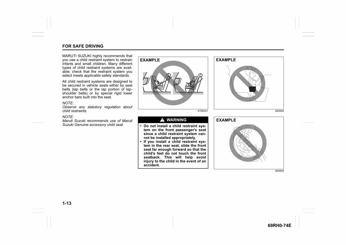
MARUTI SUZUKI highly recommends thatyou use a child restraint system to restraininfants and small children. Many differenttypes of child restraint systems are avail-able; check that the restraint system youselect meets applicable safety standards.
All child restraint systems are designed tobe secured in vehicle seats either by seatbelts (lap belts or the lap portion of lap-shoulder belts) or by special rigid loweranchor bars built into the seat.
NOTE:Observe any statutory regulation aboutchild restraints.
NOTE:Maruti Suzuki recommends use of MarutiSuzuki Genuine accessory child seat.
61M0241 65D608
65D609
WARNING
• Do not install a child restraint sys-tem on the front passenger's seatsince a child restraint system can-not be installed appropriately.
• If you install a child restraint sys-tem in the rear seat, slide the frontseat far enough forward so that thechild’s feet do not touch the frontseatback. This will help avoidinjury to the child in the event of anaccident.
EXAMPLE EXAMPLE
EXAMPLE
1-14
FOR SAFE DRIVING
69RH0-74E
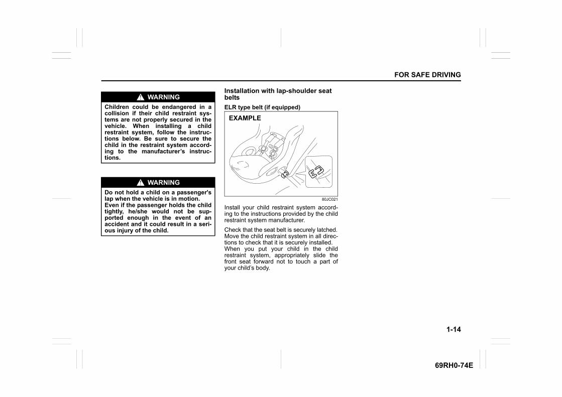
Installation with lap-shoulder seat belts
ELR type belt (if equipped)
80JC021
Install your child restraint system accord-ing to the instructions provided by the childrestraint system manufacturer.
Check that the seat belt is securely latched.Move the child restraint system in all direc-tions to check that it is securely installed.When you put your child in the childrestraint system, appropriately slide thefront seat forward not to touch a part ofyour child’s body.
WARNING
Children could be endangered in acollision if their child restraint sys-tems are not properly secured in thevehicle. When installing a childrestraint system, follow the instruc-tions below. Be sure to secure thechild in the restraint system accord-ing to the manufacturer’s instruc-tions.
WARNING
Do not hold a child on a passenger'slap when the vehicle is in motion. Even if the passenger holds the childtightly, he/she would not be sup-ported enough in the event of anaccident and it could result in a seri-ous injury of the child.
EXAMPLE
1-15
FOR SAFE DRIVING
69RH0-74E
Child restraint system
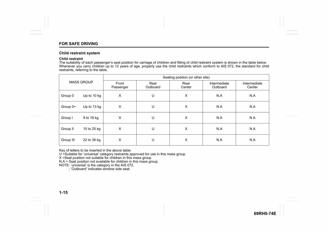
Child restraintThe suitability of each passenger’s seat position for carriage of children and fitting of child restraint system is shown in the table below.Whenever you carry children up to 12 years of age, properly use the child restraints which conform to AIS 072, the standard for childrestraints, referring to the table.
Key of letters to be inserted in the above table:U =Suitable for ‘universal’ category restraints approved for use in this mass groupX =Seat position not suitable for children in this mass groupN.A = Seat position not available for children in this mass group.NOTE: ‘universal’ is the category in the AIS 072. : ‘Outboard’ indicates window side seat.
MASS GROUPSeating position (or other site)
Front Passenger
Rear Outboard
Rear Center
Intermediate Outboard
Intermediate Center
Group 0 Up to 10 kg X U X N.A N.A
Group 0+ Up to 13 kg X U X N.A N.A
Group I 9 to 18 kg X U X N.A N.A
Group II 15 to 25 kg X U X N.A N.A
Group III 22 to 36 kg X U X N.A N.A
1-16
FOR SAFE DRIVING
69RH0-74E
Seat belt pretensioner system (if equipped)
69RH196
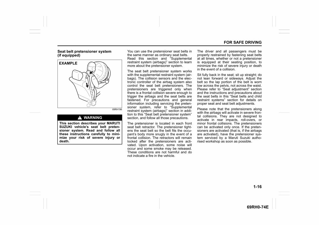
You can use the pretensioner seat belts inthe same manner as ordinary seat belts.Read this section and “Supplementalrestraint system (airbags)” section to learnmore about the pretensioner system.
The seat belt pretensioner system workswith the supplemental restraint system (air-bags). The collision sensors and the elec-tronic controller of the airbag system alsocontrol the seat belt pretensioners. Thepretensioners are triggered only whenthere is a frontal collision severe enough totrigger the airbags and the seat belts arefastened. For precautions and generalinformation including servicing the preten-sioner system, refer to “Supplementalrestraint system (airbags)” section in addi-tion to this “Seat belt pretensioner system”section, and follow all those precautions.
The pretensioner is located in each frontseat belt retractor. The pretensioner tight-ens the seat belt so the belt fits the occu-pant’s body more snugly in the event of afrontal collision. The retractors will remainlocked after the pretensioners are acti-vated. Upon activation, some noise willoccur and some smoke may be released.These conditions are not harmful and donot indicate a fire in the vehicle.
The driver and all passengers must beproperly restrained by fastening seat beltsat all times, whether or not a pretensioneris equipped at their seating position, tominimize the risk of severe injury or deathin the event of a collision.
Sit fully back in the seat; sit up straight; donot lean forward or sideways. Adjust thebelt so the lap portion of the belt is wornlow across the pelvis, not across the waist.Please refer to “Seat adjustment” sectionand the instructions and precautions aboutthe seat belts in this “Seat belts and childrestraint systems” section for details onproper seat and seat belt adjustments.
Please note that the pretensioners alongwith the airbags will activate in severe fron-tal collisions. They are not designed toactivate in rear impacts, roll-overs, orminor frontal collisions. The pretensionerscan be activated only once. If the preten-sioners are activated (that is, if the airbagsare activated), have the pretensioner sys-tem serviced by a Maruti Suzuki autho-rised workshop as soon as possible.
WARNING
This section describes your MARUTISUZUKI vehicle’s seat belt preten-sioner system. Read and follow allthese instructions carefully to mini-mize your risk of severe injury ordeath.
EXAMPLE
1-17
FOR SAFE DRIVING
69RH0-74E
The pretensioner system or the airbag sys-tem may not work properly if any of the fol-lowing conditions occurs.
• If the air bag light on the instrument clus-ter does not come on briefly, when theignition switch is turned to the “ON” posi-tion or the engine switch is pressed tochange the ignition mode to “ON”.
• If the air bag light comes on and stays onfor more than 10 seconds, when the igni-tion switch is turned to the “ON” positionor the engine switch is pressed tochange the ignition mode to “ON”.
• If the air bag light comes on while driv-ing.
Have both systems inspected by a MarutiSuzuki authorised workshop as soon aspossible.
Service on or around the pretensioner sys-tem components or wiring must be per-formed only by a Maruti Suzuki authorisedworkshop who is specially trained.Improper service could result in unin-tended activation of pretensioners or couldrender the pretensioner inoperative. Eitherof these two conditions may result in per-sonal injury.
To prevent damage or unintended activa-tion of the pretensioners, check that thebattery is disconnected and the ignitionswitch has been in “LOCK” position for atleast 90 seconds before performing anyelectrical service work on your MARUTISUZUKI vehicle.
Do not touch pretensioner system compo-nents or wiring. The wires are wrappedwith yellow tape or yellow tubing, and thecouplers are yellow. When scrapping yourMARUTI SUZUKI vehicle, ask a MarutiSuzuki authorised workshop, body repairshop, or scrap yard for assistance.
1-18
FOR SAFE DRIVING
69RH0-74E
Supplemental restraint system (airbags)
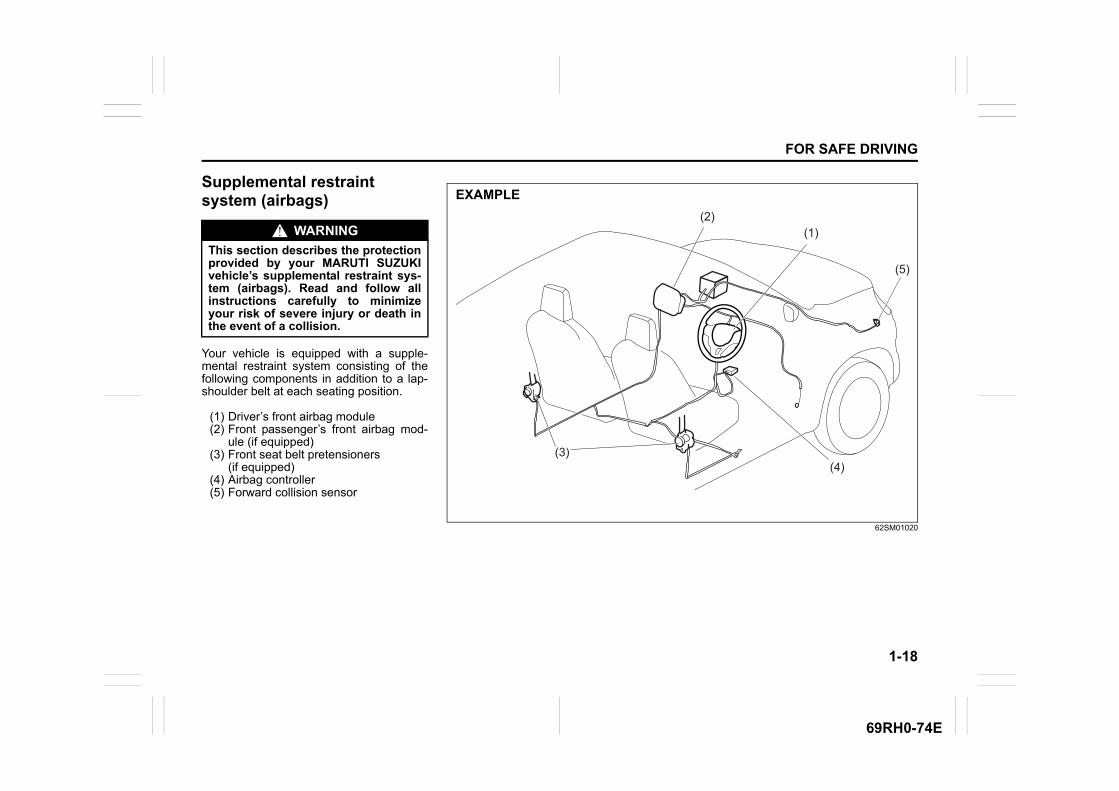
Your vehicle is equipped with a supple-mental restraint system consisting of thefollowing components in addition to a lap-shoulder belt at each seating position.
(1) Driver’s front airbag module(2) Front passenger’s front airbag mod-
ule (if equipped)(3) Front seat belt pretensioners
(if equipped)(4) Airbag controller(5) Forward collision sensor
WARNING
This section describes the protectionprovided by your MARUTI SUZUKIvehicle’s supplemental restraint sys-tem (airbags). Read and follow allinstructions carefully to minimizeyour risk of severe injury or death inthe event of a collision.
62SM01020
(5)
(1)(2)
(3)(4)
EXAMPLE
1-19
FOR SAFE DRIVING
69RH0-74E
AIRBAG warning light
63J030
If AIRBAG warning light on the instrumentcluster does not blink or come on when theignition switch is first turned to “ON” posi-tion, or comes on while driving, the airbagsystem (or the seat belt pretensioner sys-tem (if equipped)) may not work properly.Have the airbag system inspected by aMaruti Suzuki authorised workshop assoon as possible.
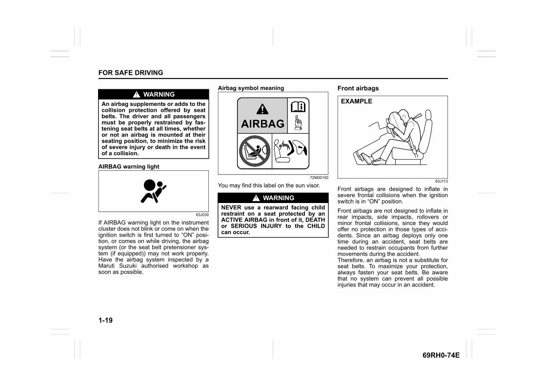
Airbag symbol meaning
72M00150
You may find this label on the sun visor.
Front airbags
63J113
Front airbags are designed to inflate insevere frontal collisions when the ignitionswitch is in “ON” position.
Front airbags are not designed to inflate inrear impacts, side impacts, rollovers orminor frontal collisions, since they wouldoffer no protection in those types of acci-dents. Since an airbag deploys only onetime during an accident, seat belts areneeded to restrain occupants from furthermovements during the accident.Therefore, an airbag is not a substitute forseat belts. To maximize your protection,always fasten your seat belts. Be awarethat no system can prevent all possibleinjuries that may occur in an accident.
WARNING
An airbag supplements or adds to thecollision protection offered by seatbelts. The driver and all passengersmust be properly restrained by fas-tening seat belts at all times, whetheror not an airbag is mounted at theirseating position, to minimize the riskof severe injury or death in the eventof a collision.
WARNING
NEVER use a rearward facing childrestraint on a seat protected by anACTIVE AIRBAG in front of it, DEATHor SERIOUS INJURY to the CHILDcan occur.
EXAMPLE
1-20
FOR SAFE DRIVING
69RH0-74E
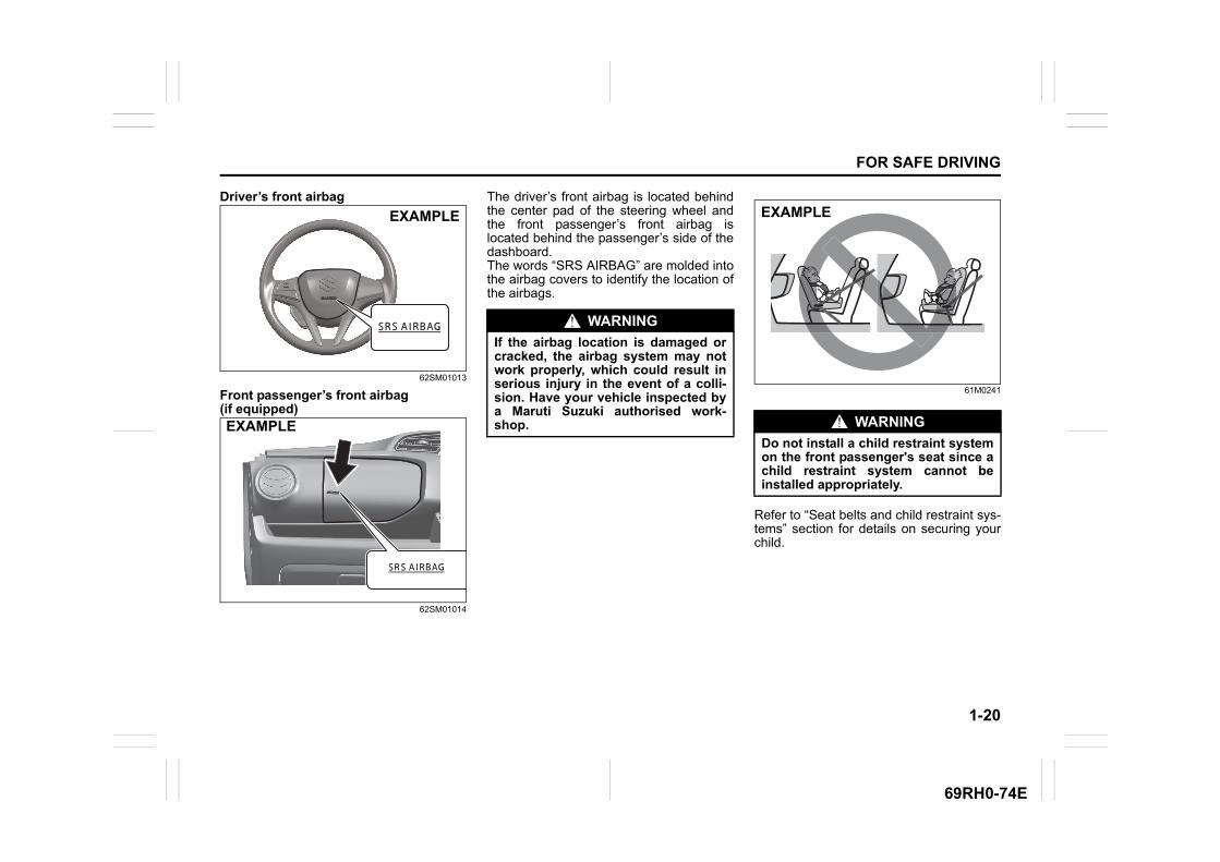
Driver’s front airbag
62SM01013
Front passenger’s front airbag (if equipped)
62SM01014
The driver’s front airbag is located behindthe center pad of the steering wheel andthe front passenger’s front airbag islocated behind the passenger’s side of thedashboard. The words “SRS AIRBAG” are molded intothe airbag covers to identify the location ofthe airbags.
61M0241
Refer to “Seat belts and child restraint sys-tems” section for details on securing yourchild.
EXAMPLE
EXAMPLE
WARNING
If the airbag location is damaged orcracked, the airbag system may notwork properly, which could result inserious injury in the event of a colli-sion. Have your vehicle inspected bya Maruti Suzuki authorised work-shop. WARNING
Do not install a child restraint systemon the front passenger's seat since achild restraint system cannot beinstalled appropriately.
EXAMPLE
1-21
FOR SAFE DRIVING
69RH0-74E
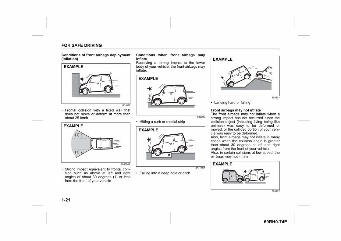
Conditions of front airbags deployment(inflation)
80J097
• Frontal collision with a fixed wall thatdoes not move or deform at more thanabout 25 km/h
80J098E
• Strong impact equivalent to frontal colli-sion such as above at left and rightangles of about 30 degrees (1) or lessfrom the front of your vehicle
Conditions when front airbags mayinflateReceiving a strong impact to the lowerbody of your vehicle, the front airbags mayinflate.
80J099
• Hitting a curb or medial strip
80J100E
• Falling into a deep hole or ditch
80J101
• Landing hard or falling
Front airbags may not inflateThe front airbags may not inflate when astrong impact has not occurred since thecollision object (including living being likeanimals) was easy to be deformed ormoved, or the collided portion of your vehi-cle was easy to be deformed.Also, front airbags may not inflate in manycases when the collision angle is greaterthan about 30 degrees at left and rightangles from the front of your vehicle. Also, in certain collisions at low speed, theair bags may not inflate.
80J102
EXAMPLE
(1)
(1)
EXAMPLE
EXAMPLE
EXAMPLE
EXAMPLE
EXAMPLE
1-22
FOR SAFE DRIVING
69RH0-74E
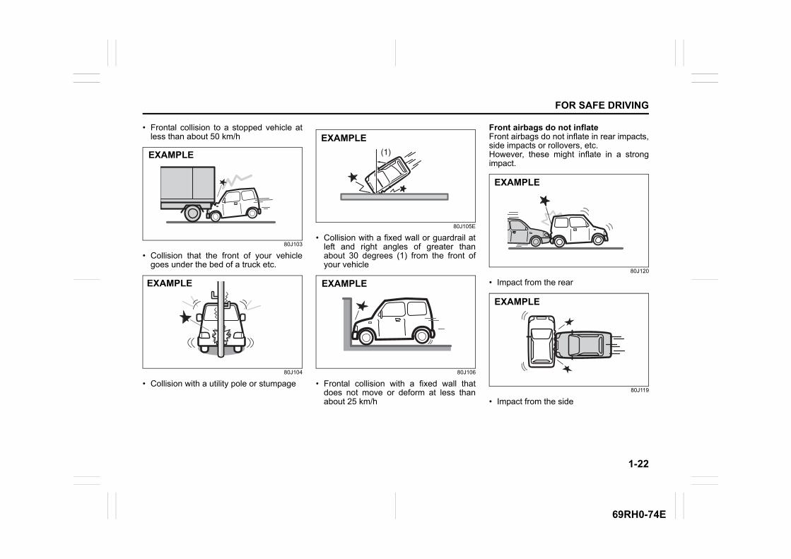
• Frontal collision to a stopped vehicle atless than about 50 km/h
80J103
• Collision that the front of your vehiclegoes under the bed of a truck etc.
80J104
• Collision with a utility pole or stumpage
80J105E
• Collision with a fixed wall or guardrail atleft and right angles of greater thanabout 30 degrees (1) from the front ofyour vehicle
80J106
• Frontal collision with a fixed wall thatdoes not move or deform at less thanabout 25 km/h
Front airbags do not inflateFront airbags do not inflate in rear impacts,side impacts or rollovers, etc.However, these might inflate in a strongimpact.
80J120
• Impact from the rear
80J119
• Impact from the side
EXAMPLE
EXAMPLE
(1)
EXAMPLE
EXAMPLE
EXAMPLE
EXAMPLE
1-23
FOR SAFE DRIVING
69RH0-74E
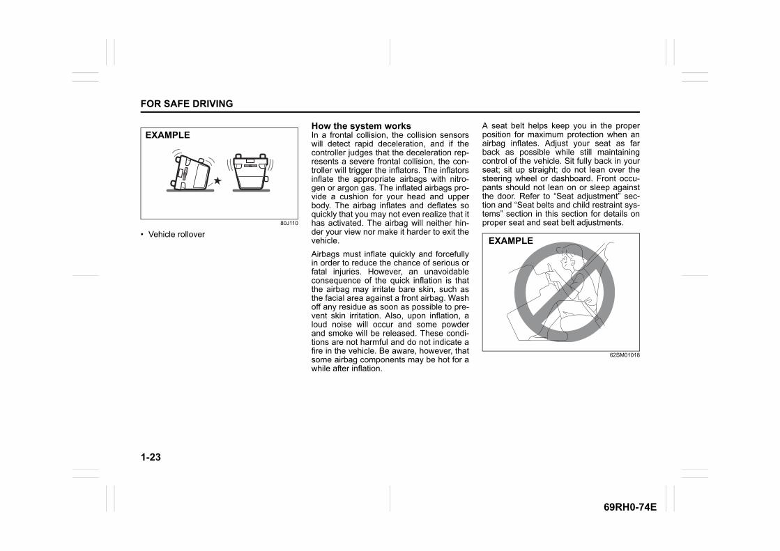
80J110
• Vehicle rollover
How the system worksIn a frontal collision, the collision sensorswill detect rapid deceleration, and if thecontroller judges that the deceleration rep-resents a severe frontal collision, the con-troller will trigger the inflators. The inflatorsinflate the appropriate airbags with nitro-gen or argon gas. The inflated airbags pro-vide a cushion for your head and upperbody. The airbag inflates and deflates soquickly that you may not even realize that ithas activated. The airbag will neither hin-der your view nor make it harder to exit thevehicle.
Airbags must inflate quickly and forcefullyin order to reduce the chance of serious orfatal injuries. However, an unavoidableconsequence of the quick inflation is thatthe airbag may irritate bare skin, such asthe facial area against a front airbag. Washoff any residue as soon as possible to pre-vent skin irritation. Also, upon inflation, aloud noise will occur and some powderand smoke will be released. These condi-tions are not harmful and do not indicate afire in the vehicle. Be aware, however, thatsome airbag components may be hot for awhile after inflation.
A seat belt helps keep you in the properposition for maximum protection when anairbag inflates. Adjust your seat as farback as possible while still maintainingcontrol of the vehicle. Sit fully back in yourseat; sit up straight; do not lean over thesteering wheel or dashboard. Front occu-pants should not lean on or sleep againstthe door. Refer to “Seat adjustment” sec-tion and “Seat belts and child restraint sys-tems” section in this section for details onproper seat and seat belt adjustments.
62SM01018
EXAMPLE
EXAMPLE
1-24
FOR SAFE DRIVING
69RH0-74E
Even though your vehicle is moderatelydamaged by a collision, it may not besevere enough to trigger front airbags toinflate. If your vehicle sustains any front-end or side damage, have the airbag sys-tem inspected by a Maruti Suzuki autho-rised workshop to ensure that it worksproperly.
Your vehicle is equipped with a diagnosticmodule which records information aboutthe airbag system if the airbags deploy in acollision. The module records informationabout overall system status, and whichsensors activated the deployment.
Servicing the airbag systemIf the airbags inflate, have the airbags andrelated components replaced by a MarutiSuzuki authorised workshop as soon aspossible.
If your vehicle ever gets in deep water andthe driver’s floor is submerged, the airbagcontroller could be damaged. If this hap-pens, ask a Maruti Suzuki authorisedworkshop to check the airbag system assoon as possible.
Special procedures are required for servic-ing or replacing an airbag. For that reason,only a Maruti Suzuki authorised workshopshould be allowed to service or replaceyour airbags. Remind anyone who ser-vices your MARUTI SUZUKI vehicle that ithas airbags.
Service on or around airbag componentsor wiring must be performed only by aMaruti Suzuki authorised workshop.Improper service could result in unin-tended airbag deployment or could renderthe airbag inoperative. Either of these twoconditions may result in severe injury.
To prevent damage or unintended inflationof the airbag system, check that the bat-tery is disconnected and the ignition switchhas been in “LOCK” position for at least 90seconds before performing any electricalservice work on your MARUTI SUZUKIvehicle. Do not touch airbag system com-ponents or wires. The wires are wrappedwith yellow tape or yellow tubing, and thecouplers are yellow for easy identification.
Scrapping a vehicle that has an uninflatedairbag can be hazardous. Ask a MarutiSuzuki authorised workshop, body repairshop or scrap yard for help with disposal.
WARNING
• The driver should not lean over thesteering wheel. The front passen-ger should not rest his or her bodyagainst the dashboard, or other-wise get too close to the dash-board. In these situations, the out-of-position occupant would be tooclose to an inflating airbag, andmay suffer severe injury.
• Do not attach any objects to, orplace any objects over, the steeringwheel or dashboard. Do not placeany objects between the airbag andthe driver or front passenger.These objects may interfere withairbag operation or may be pro-pelled by the airbag in the event ofa collision. Also, these objects maymove when you start moving vehi-cle or while vehicle is moving, theymay interfere with driver’s view orsafe driving. In each conditionsmay cause severe injury.
• Do not strike or apply significantlevels of impact to the airbag com-ponent areas. It can cause the air-bags to malfunction.
1-25
FOR SAFE DRIVING
69RH0-74E
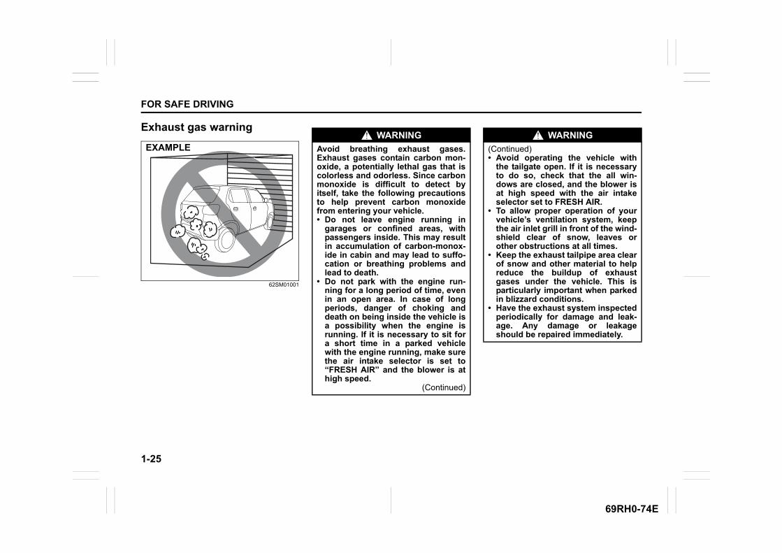
Exhaust gas warning
62SM01001
EXAMPLEWARNING
Avoid breathing exhaust gases.Exhaust gases contain carbon mon-oxide, a potentially lethal gas that iscolorless and odorless. Since carbonmonoxide is difficult to detect byitself, take the following precautionsto help prevent carbon monoxidefrom entering your vehicle.• Do not leave engine running in
garages or confined areas, withpassengers inside. This may resultin accumulation of carbon-monox-ide in cabin and may lead to suffo-cation or breathing problems andlead to death.
• Do not park with the engine run-ning for a long period of time, evenin an open area. In case of longperiods, danger of choking anddeath on being inside the vehicle isa possibility when the engine isrunning. If it is necessary to sit fora short time in a parked vehiclewith the engine running, make surethe air intake selector is set to“FRESH AIR” and the blower is athigh speed.
(Continued)
WARNING
(Continued)• Avoid operating the vehicle with
the tailgate open. If it is necessaryto do so, check that the all win-dows are closed, and the blower isat high speed with the air intakeselector set to FRESH AIR.
• To allow proper operation of yourvehicle’s ventilation system, keepthe air inlet grill in front of the wind-shield clear of snow, leaves orother obstructions at all times.
• Keep the exhaust tailpipe area clearof snow and other material to helpreduce the buildup of exhaustgases under the vehicle. This isparticularly important when parkedin blizzard conditions.
• Have the exhaust system inspectedperiodically for damage and leak-age. Any damage or leakageshould be repaired immediately.
BEFORE DRIVING
2
69RH0-74E
60G404
BEFORE DRIVINGKeys ...................................................................................... 2-1Door locks ............................................................................ 2-2Keyless entry system transmitter (if equipped) ............... 2-4Theft deterrent light (if equipped) ...................................... 2-6Windows .............................................................................. 2-7Mirrors .................................................................................. 2-8Instrument cluster ............................................................... 2-9Speedometer ....................................................................... 2-9Fuel gauge ........................................................................... 2-10Brightness control .............................................................. 2-10Information display ............................................................. 2-11Warning and indicator lights .............................................. 2-17Lighting control lever ......................................................... 2-22Headlight leveling knob ...................................................... 2-24Turn signal control lever .................................................... 2-24Hazard warning switch ....................................................... 2-25Windshield wiper and washer lever .................................. 2-26Horn ...................................................................................... 2-28Vehicle loading .................................................................... 2-28Trailer towing ....................................................................... 2-29
2-1
BEFORE DRIVING
69RH0-74E
Keys
54G489
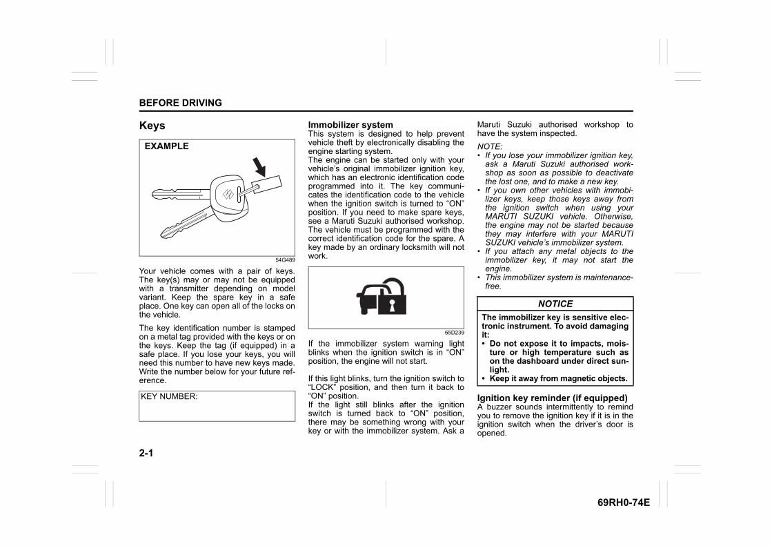
Your vehicle comes with a pair of keys.The key(s) may or may not be equippedwith a transmitter depending on modelvariant. Keep the spare key in a safeplace. One key can open all of the locks onthe vehicle.
The key identification number is stampedon a metal tag provided with the keys or onthe keys. Keep the tag (if equipped) in asafe place. If you lose your keys, you willneed this number to have new keys made.Write the number below for your future ref-erence.
Immobilizer system This system is designed to help preventvehicle theft by electronically disabling theengine starting system.The engine can be started only with yourvehicle’s original immobilizer ignition key,which has an electronic identification codeprogrammed into it. The key communi-cates the identification code to the vehiclewhen the ignition switch is turned to “ON”position. If you need to make spare keys,see a Maruti Suzuki authorised workshop.The vehicle must be programmed with thecorrect identification code for the spare. Akey made by an ordinary locksmith will notwork.
65D239
If the immobilizer system warning lightblinks when the ignition switch is in “ON”position, the engine will not start.
If this light blinks, turn the ignition switch to“LOCK” position, and then turn it back to“ON” position.If the light still blinks after the ignitionswitch is turned back to “ON” position,there may be something wrong with yourkey or with the immobilizer system. Ask a
Maruti Suzuki authorised workshop tohave the system inspected.
NOTE:• If you lose your immobilizer ignition key,
ask a Maruti Suzuki authorised work-shop as soon as possible to deactivatethe lost one, and to make a new key.
• If you own other vehicles with immobi-lizer keys, keep those keys away fromthe ignition switch when using yourMARUTI SUZUKI vehicle. Otherwise,the engine may not be started becausethey may interfere with your MARUTISUZUKI vehicle’s immobilizer system.
• If you attach any metal objects to theimmobilizer key, it may not start theengine.
• This immobilizer system is maintenance-free.
Ignition key reminder (if equipped)A buzzer sounds intermittently to remindyou to remove the ignition key if it is in theignition switch when the driver’s door isopened.
KEY NUMBER:
EXAMPLE
NOTICE
The immobilizer key is sensitive elec-tronic instrument. To avoid damagingit:• Do not expose it to impacts, mois-
ture or high temperature such ason the dashboard under direct sun-light.
• Keep it away from magnetic objects.
2-2
BEFORE DRIVING
69RH0-74E
Door locks
Side door locks
62SM02022
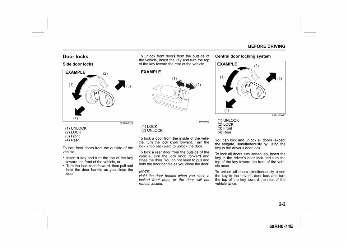
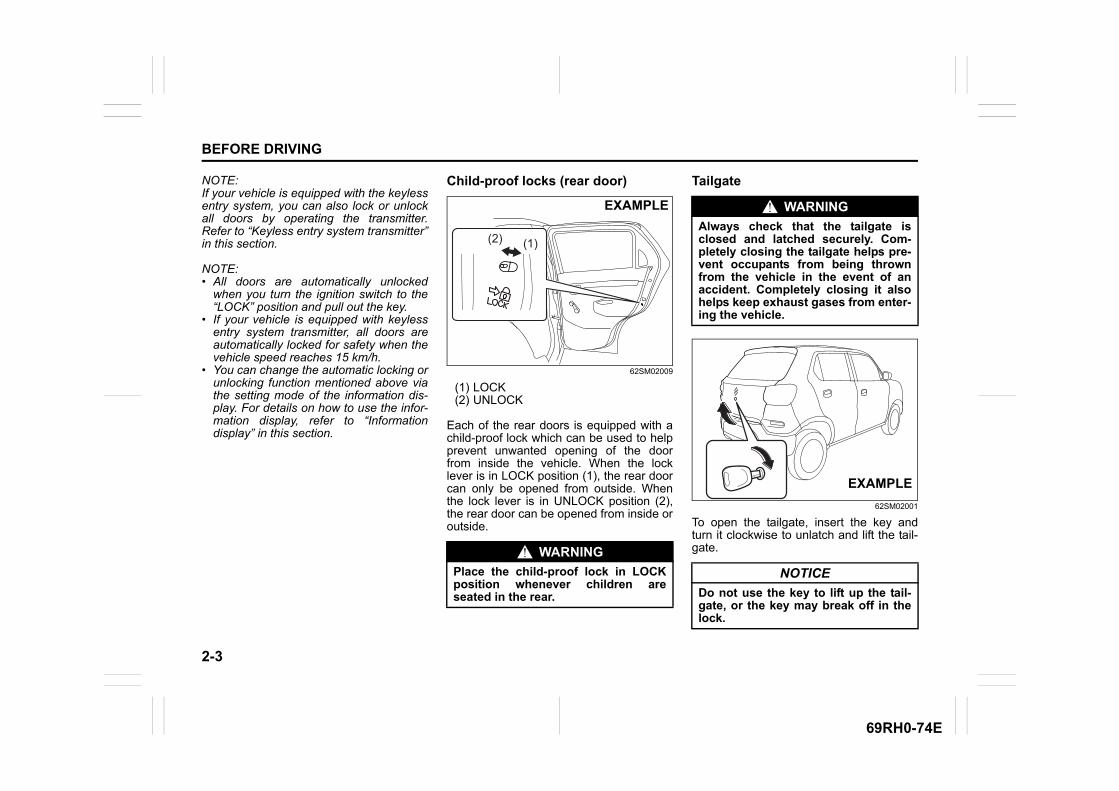
(1) UNLOCK(2) LOCK(3) Front(4) Rear
To lock front doors from the outside of thevehicle:
• Insert a key and turn the top of the keytoward the front of the vehicle, or
• Turn the lock knob forward, then pull andhold the door handle as you close thedoor.
To unlock front doors from the outside ofthe vehicle, insert the key and turn the topof the key toward the rear of the vehicle.
69RH002
(1) LOCK(2) UNLOCK
To lock a door from the inside of the vehi-cle, turn the lock knob forward. Turn thelock knob backward to unlock the door.
To lock a rear door from the outside of thevehicle, turn the lock knob forward andclose the door. You do not need to pull andhold the door handle as you close the door.
NOTE:Hold the door handle when you close alocked front door, or the door will notremain locked.
Central door locking system
62SM02022
(1) UNLOCK(2) LOCK(3) Front(4) Rear
You can lock and unlock all doors (exceptthe tailgate) simultaneously by using thekey in the driver’s door lock.
To lock all doors simultaneously, insert thekey in the driver’s door lock and turn thetop of the key toward the front of the vehi-cle once.
To unlock all doors simultaneously, insertthe key in the driver’s door lock and turnthe top of the key toward the rear of thevehicle twice.
(1)
(2)
(3)
(4)
EXAMPLE
(1)
(2)
EXAMPLE(1)
(2)
(3)
(4)
EXAMPLE
2-3
BEFORE DRIVING
69RH0-74E
NOTE:If your vehicle is equipped with the keylessentry system, you can also lock or unlockall doors by operating the transmitter.Refer to “Keyless entry system transmitter”in this section.
NOTE:• All doors are automatically unlocked
when you turn the ignition switch to the“LOCK” position and pull out the key.
• If your vehicle is equipped with keylessentry system transmitter, all doors areautomatically locked for safety when thevehicle speed reaches 15 km/h.
• You can change the automatic locking orunlocking function mentioned above viathe setting mode of the information dis-play. For details on how to use the infor-mation display, refer to “Informationdisplay” in this section.
Child-proof locks (rear door)
62SM02009
(1) LOCK(2) UNLOCK
Each of the rear doors is equipped with achild-proof lock which can be used to helpprevent unwanted opening of the doorfrom inside the vehicle. When the locklever is in LOCK position (1), the rear doorcan only be opened from outside. Whenthe lock lever is in UNLOCK position (2),the rear door can be opened from inside oroutside.
Tailgate
62SM02001
To open the tailgate, insert the key andturn it clockwise to unlatch and lift the tail-gate.WARNING
Place the child-proof lock in LOCKposition whenever children areseated in the rear.
(1)(2)
EXAMPLE WARNING
Always check that the tailgate isclosed and latched securely. Com-pletely closing the tailgate helps pre-vent occupants from being thrownfrom the vehicle in the event of anaccident. Completely closing it alsohelps keep exhaust gases from enter-ing the vehicle.
NOTICE
Do not use the key to lift up the tail-gate, or the key may break off in thelock.
EXAMPLE
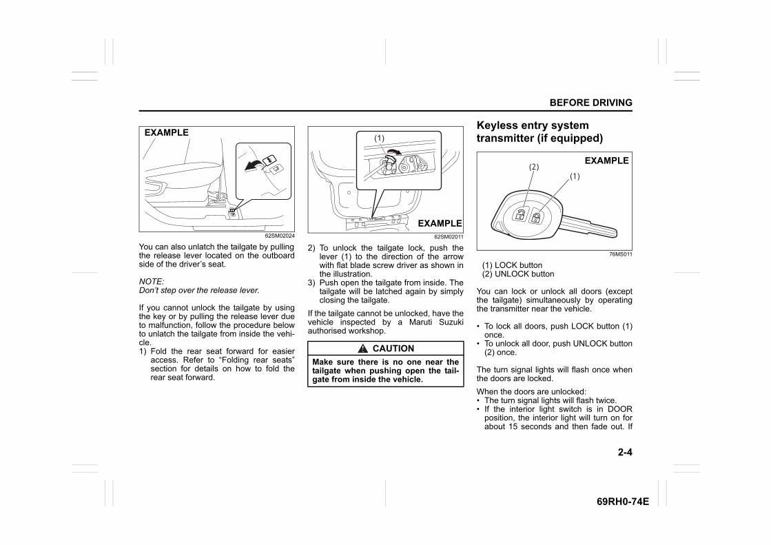
2-4
BEFORE DRIVING
69RH0-74E
62SM02024
You can also unlatch the tailgate by pullingthe release lever located on the outboardside of the driver’s seat.
NOTE:Don’t step over the release lever.
If you cannot unlock the tailgate by usingthe key or by pulling the release lever dueto malfunction, follow the procedure belowto unlatch the tailgate from inside the vehi-cle.1) Fold the rear seat forward for easier
access. Refer to “Folding rear seats”section for details on how to fold therear seat forward.
62SM02011
2) To unlock the tailgate lock, push thelever (1) to the direction of the arrowwith flat blade screw driver as shown inthe illustration.
3) Push open the tailgate from inside. Thetailgate will be latched again by simplyclosing the tailgate.
If the tailgate cannot be unlocked, have thevehicle inspected by a Maruti Suzukiauthorised workshop.
Keyless entry system transmitter (if equipped)
76MS011
(1) LOCK button(2) UNLOCK button
You can lock or unlock all doors (exceptthe tailgate) simultaneously by operatingthe transmitter near the vehicle.
• To lock all doors, push LOCK button (1)once.
• To unlock all door, push UNLOCK button(2) once.
The turn signal lights will flash once whenthe doors are locked.
When the doors are unlocked:• The turn signal lights will flash twice.• If the interior light switch is in DOOR
position, the interior light will turn on forabout 15 seconds and then fade out. If
EXAMPLE
CAUTION
Make sure there is no one near thetailgate when pushing open the tail-gate from inside the vehicle.
(1)
EXAMPLE
(1)(2)
EXAMPLE
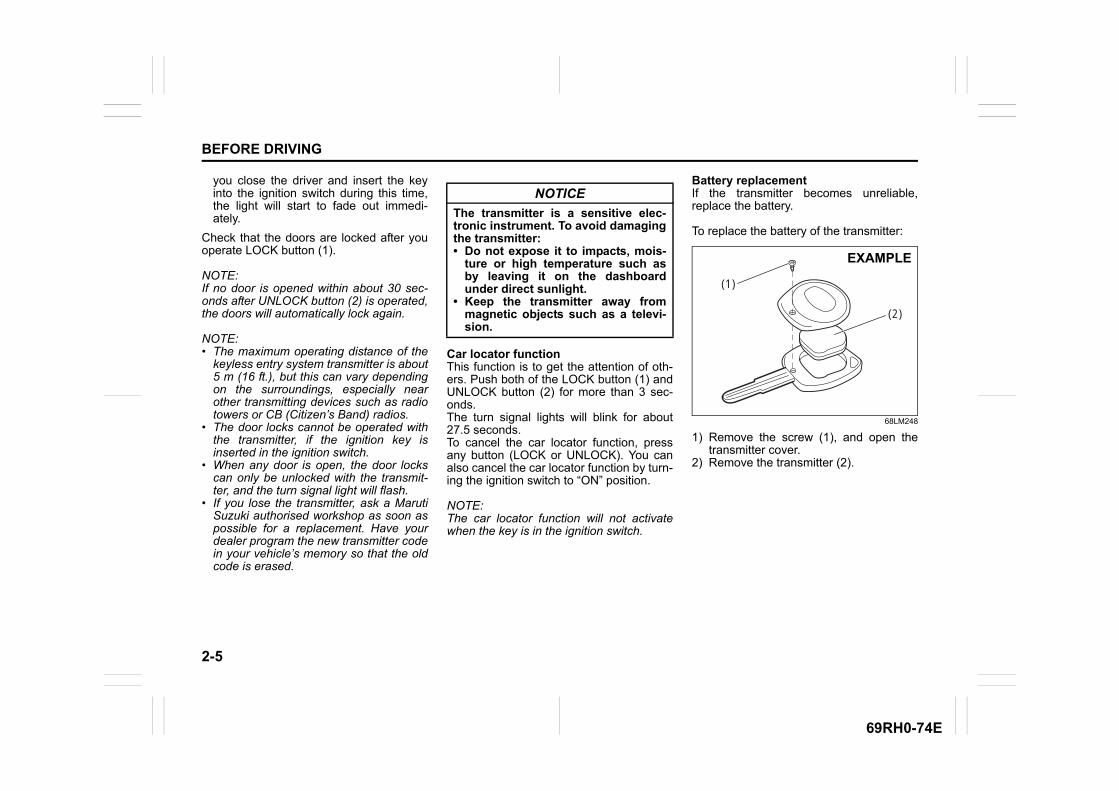
2-5
BEFORE DRIVING
69RH0-74E
you close the driver and insert the keyinto the ignition switch during this time,the light will start to fade out immedi-ately.
Check that the doors are locked after youoperate LOCK button (1).
NOTE:If no door is opened within about 30 sec-onds after UNLOCK button (2) is operated,the doors will automatically lock again.
NOTE:• The maximum operating distance of the
keyless entry system transmitter is about5 m (16 ft.), but this can vary dependingon the surroundings, especially nearother transmitting devices such as radiotowers or CB (Citizen’s Band) radios.
• The door locks cannot be operated withthe transmitter, if the ignition key isinserted in the ignition switch.
• When any door is open, the door lockscan only be unlocked with the transmit-ter, and the turn signal light will flash.
• If you lose the transmitter, ask a MarutiSuzuki authorised workshop as soon aspossible for a replacement. Have yourdealer program the new transmitter codein your vehicle’s memory so that the oldcode is erased.
Car locator functionThis function is to get the attention of oth-ers. Push both of the LOCK button (1) andUNLOCK button (2) for more than 3 sec-onds.The turn signal lights will blink for about27.5 seconds.To cancel the car locator function, pressany button (LOCK or UNLOCK). You canalso cancel the car locator function by turn-ing the ignition switch to “ON” position.
NOTE:The car locator function will not activatewhen the key is in the ignition switch.
Battery replacementIf the transmitter becomes unreliable,replace the battery.
To replace the battery of the transmitter:
68LM248
1) Remove the screw (1), and open thetransmitter cover.
2) Remove the transmitter (2).
NOTICE
The transmitter is a sensitive elec-tronic instrument. To avoid damagingthe transmitter:• Do not expose it to impacts, mois-
ture or high temperature such asby leaving it on the dashboardunder direct sunlight.
• Keep the transmitter away frommagnetic objects such as a televi-sion.
(1)
(2)
EXAMPLE
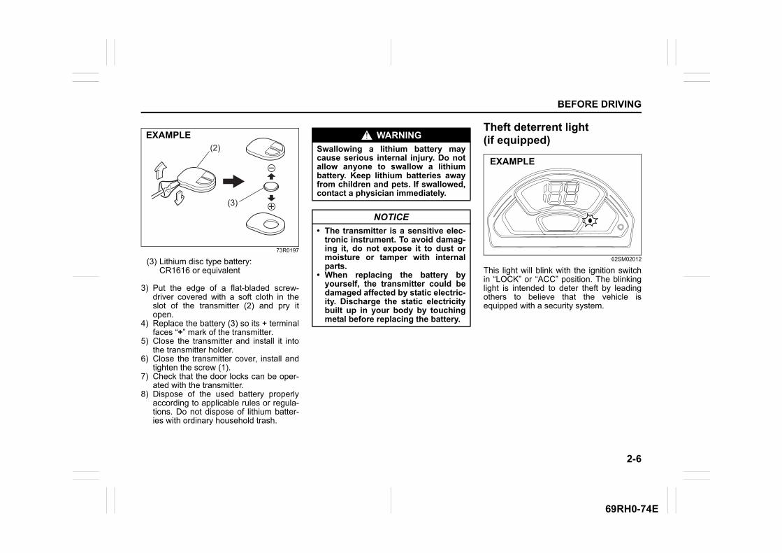
2-6
BEFORE DRIVING
69RH0-74E
73R0197
(3) Lithium disc type battery:CR1616 or equivalent
3) Put the edge of a flat-bladed screw-driver covered with a soft cloth in theslot of the transmitter (2) and pry itopen.
4) Replace the battery (3) so its + terminalfaces “+” mark of the transmitter.
5) Close the transmitter and install it intothe transmitter holder.
6) Close the transmitter cover, install andtighten the screw (1).
7) Check that the door locks can be oper-ated with the transmitter.
8) Dispose of the used battery properlyaccording to applicable rules or regula-tions. Do not dispose of lithium batter-ies with ordinary household trash.
Theft deterrent light (if equipped)
62SM02012
This light will blink with the ignition switchin “LOCK” or “ACC” position. The blinkinglight is intended to deter theft by leadingothers to believe that the vehicle isequipped with a security system.
(3)
(2)
EXAMPLE WARNING
Swallowing a lithium battery maycause serious internal injury. Do notallow anyone to swallow a lithiumbattery. Keep lithium batteries awayfrom children and pets. If swallowed,contact a physician immediately.
NOTICE
• The transmitter is a sensitive elec-tronic instrument. To avoid damag-ing it, do not expose it to dust ormoisture or tamper with internalparts.
• When replacing the battery byyourself, the transmitter could bedamaged affected by static electric-ity. Discharge the static electricitybuilt up in your body by touchingmetal before replacing the battery.
EXAMPLE
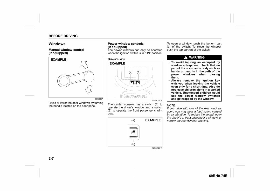
2-7
BEFORE DRIVING
69RH0-74E
Windows
Manual window control (if equipped)
60G010A
Raise or lower the door windows by turningthe handle located on the door panel.
Power window controls (if equipped)The power windows can only be operatedwhen the ignition switch is in “ON” position.
Driver’s side
62SM02014
The center console has a switch (1) tooperate the driver’s window and a switch(2) to operate the front passenger’s win-dow.
62SM02017
To open a window, push the bottom part(b) of the switch. To close the window,push the top part (a) of the switch.
NOTE:If you drive with one of the rear windowsopen, you may hear a loud sound causedby air vibration. To reduce the sound, openthe driver’s or front passenger’s window, ornarrow the rear window opening.
EXAMPLE
(2) (1)
EXAMPLE
EXAMPLE(a)
(b)
WARNING
• To avoid injuring an occupant bywindow entrapment, check that nopart of the occupant’s body such ashands or head is in the path of thepower windows when closingthem.
• Always remove the ignition keywith you when leaving the vehicleeven only for a short time. Also donot leave children alone in a parkedvehicle. Unattended children coulduse the power window switchesand get trapped by the window.
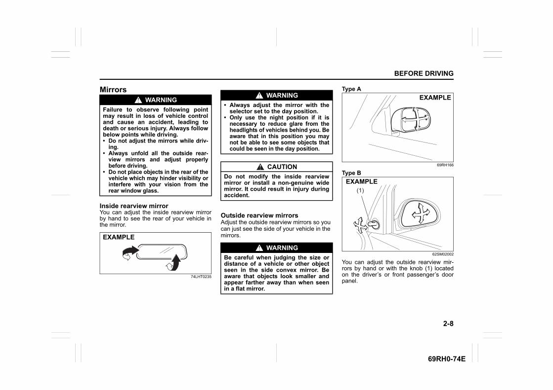
2-8
BEFORE DRIVING
69RH0-74E
Mirrors
Inside rearview mirrorYou can adjust the inside rearview mirrorby hand to see the rear of your vehicle inthe mirror.
74LHT0235
Outside rearview mirrorsAdjust the outside rearview mirrors so you can just see the side of your vehicle in the mirrors.
Type A
69RH166
Type B
62SM02002
You can adjust the outside rearview mir-rors by hand or with the knob (1) locatedon the driver’s or front passenger’s doorpanel.
WARNING
Failure to observe following pointmay result in loss of vehicle controland cause an accident, leading todeath or serious injury. Always followbelow points while driving.• Do not adjust the mirrors while driv-
ing.• Always unfold all the outside rear-
view mirrors and adjust properlybefore driving.
• Do not place objects in the rear of thevehicle which may hinder visibility orinterfere with your vision from therear window glass.
EXAMPLE
WARNING
• Always adjust the mirror with theselector set to the day position.
• Only use the night position if it isnecessary to reduce glare from theheadlights of vehicles behind you. Beaware that in this position you maynot be able to see some objects thatcould be seen in the day position.
CAUTION
Do not modify the inside rearviewmirror or install a non-genuine widemirror. It could result in injury duringaccident.
WARNING
Be careful when judging the size ordistance of a vehicle or other objectseen in the side convex mirror. Beaware that objects look smaller andappear farther away than when seenin a flat mirror.
EXAMPLE
(1)EXAMPLE
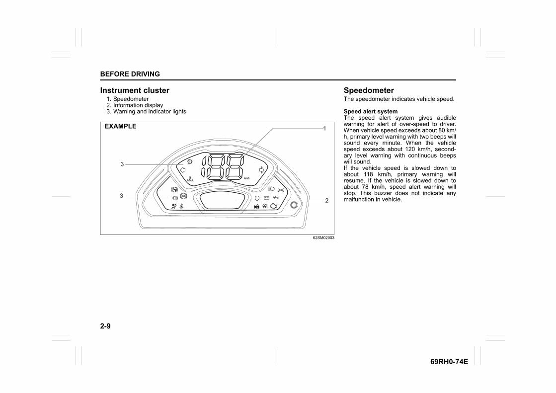
2-9
BEFORE DRIVING
69RH0-74E
Instrument cluster1. Speedometer2. Information display3. Warning and indicator lights
62SM02003
3
1
23
EXAMPLE
SpeedometerThe speedometer indicates vehicle speed.
Speed alert systemThe speed alert system gives audiblewarning for alert of over-speed to driver.When vehicle speed exceeds about 80 km/h, primary level warning with two beeps willsound every minute. When the vehiclespeed exceeds about 120 km/h, second-ary level warning with continuous beepswill sound. If the vehicle speed is slowed down toabout 118 km/h, primary warning willresume. If the vehicle is slowed down toabout 78 km/h, speed alert warning willstop. This buzzer does not indicate anymalfunction in vehicle.
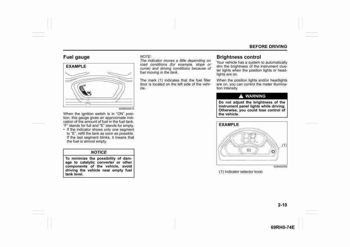
2-10
BEFORE DRIVING
69RH0-74E
Fuel gauge
62SM020015
When the ignition switch is in “ON” posi-tion, this gauge gives an approximate indi-cation of the amount of fuel in the fuel tank.“F” stands for full and “E” stands for empty.• If the indicator shows only one segment
to “E”, refill the tank as soon as possible.If the last segment blinks, it means thatthe fuel is almost empty.
NOTE:The indicator moves a little depending onroad conditions (for example, slope orcurve) and driving conditions because offuel moving in the tank.
The mark (1) indicates that the fuel fillerdoor is located on the left side of the vehi-cle.
Brightness controlYour vehicle has a system to automaticallydim the brightness of the instrument clus-ter lights when the position lights or head-lights are on.
When the position lights and/or headlightsare on, you can control the meter illumina-tion intensity.
62SM02005
(1) Indicator selector knob
NOTICE
To minimize the possibility of dam-age to catalytic converter or othercomponents of the vehicle, avoiddriving the vehicle near empty fueltank level.
EXAMPLE
(1)
WARNING
Do not adjust the brightness of theinstrument panel lights while driving.Otherwise, you could lose control ofthe vehicle.
(1)(i)
EXAMPLE

2-11
BEFORE DRIVING
69RH0-74E
69RH126
(2) Brightest(3) Initial setting(4) Dimmest
To switch the display indication to thebrightness control (i), select the indicationas shown in the illustration by pushing theindicator selector knob (1) when the posi-tion lights and/or headlights are on.
To change the brightness of the instrumentcluster lights, continue to hold in the indica-tor selector knob (1). The indication willchange as shown in the illustration. Theillumination gets dimmer then returns tothe brightest condition after it reaches thedimmest.
NOTE:• If you do not push the indicator selector
knob (1) within several seconds of acti-vating the brightness control, the bright-ness control display will be canceledautomatically.
Information display
62SM02004
(1) Indicator selector knob(2) Information display
When the ignition switch is in “ON” posi-tion, the information display shows the fol-lowing information.
Display (A)Gearshift indicator (if equipped)/Gear position indicator (for Auto Gear Shiftmodels)
Display (B)Odometer / Trip meter / Fuel consumption(if equipped) / Driving range (if equipped)
Display (C)Clock (if equipped)
Display (D)Fuel gauge
(i)
(2)
(4)
(3)
EXAMPLE
(1)
(2)
(A)(B)(C)(D)
EXAMPLE

2-12
BEFORE DRIVING
69RH0-74E
Gearshift indicator (if equipped)The display (A) shows the gearshift indica-tor.
62SM02006
Refer to “Gearshift indicator” in the“OPERATING YOUR VEHICLE” section.
Gear position indicator (for Auto Gear Shift models)The display (A) shows some of the follow-ing indications.
62SM02007
(3) Gear position(4) Manual mode indicator(5) Drive mode indicator
NOTE:For Auto Gear Shift models, when thegearshift lever position and the gear posi-tion indication in the information displayare unmatched, the indication will blink andthe interior buzzer will sound. Refer to“Auto Gear Shift” in the “OPERATINGYOUR VEHICLE” section for details.
Manual mode indicator When you are using the manual mode, thedisplay shows the manual mode indicator(4).
NOTE:The manual mode indicator will onlyappear when the gearshift lever is in “M”position.
Drive mode indicator When the gearshift lever is in “D” position,the display shows the drive mode indicator(5).
For details on how to use the transmission,refer to “Using transmission” in the “OPER-ATING YOUR VEHICLE” section.
Odometer / Trip meter / Fuel consumption (if equipped) / Driving range (if equipped)The display (B) shows one of the followingindications: odometer, trip meter A, tripmeter B, instantaneous fuel consumption(if equipped), average fuel consumption (ifequipped) or driving range (if equipped).
To switch the display indication (B), pushthe indicator selector knob (1) quickly.
EXAMPLE
(4) (5)(3) (3)
EXAMPLE

2-13
BEFORE DRIVING
69RH0-74E
62SM02016
(a) Odometer(b) Trip meter A(c) Trip meter B(d) Instantaneous fuel consumption
(if equipped)(e) Average fuel consumption
(if equipped)(f) Driving range (if equipped)
NOTE:• Indications will change when you push
and release a knob.• The display shows estimated values.
Indications may not be same as theactual values.
OdometerThe odometer records the total distancethe vehicle has been driven.
Trip meterThe trip meter can be used to measure thedistance traveled on short trips or betweenfuel stops.You can use the trip meter A or trip meter Bindependently.
To reset the trip meter to zero, push andhold the indicator selector knob (1) for awhile when the display shows the tripmeter.
NOTE:The indicated maximum value of the tripmeter is 9999.9. When you run past themaximum value, the indicated value willreturn to 0.0.
Instantaneous fuel consumption (if equipped)The display shows the value of instanta-neous fuel consumption only when thevehicle is moving.
Push the indicator selector knob (1).
(a)
(b)
(c)
(d)
(e)
(f)
EXAMPLE
WARNING
If you attempt to adjust the displaywhile driving, you could lose controlof the vehicle.Do not attempt to adjust the displaywhile driving.
NOTICE
Keep track of your odometer readingand check the maintenance sched-ule regularly for required services.Increased wear or damage to certainparts can result from failure to per-form required services at the propermileage intervals.

2-14
BEFORE DRIVING
69RH0-74E
NOTE:• The display does not show the value
unless the vehicle is moving.• The indicated maximum value of instan-
taneous fuel consumption is 50 km/l. Nomore than the maximum value will beindicated on the display even if theactual instantaneous fuel consumption ishigher.
• The indication on the display may bedelayed if fuel consumption is greatlyaffected by driving conditions.
• The display shows estimated values.Indications may not be the same asactual values.
Average fuel consumption (if equipped)If you previously selected average fuelconsumption setting, the display showsaverage fuel consumption from the lastreset to the present when the ignitionswitch is turned to “ON” position.
To reset the average fuel consumption tozero, push and hold the indicator selectorknob (1) for a while when the displayshows the average fuel consumption.
NOTE:When you reset the indication or reconnectthe negative (–) terminal to the battery, thevalue of average fuel consumption will beshown after driving for a while.
Driving range (if equipped)If you selected driving range the last timeyou drove the vehicle, the display indicates“---” for a few seconds and then indicatesthe current driving range when the ignitionswitch is turned to the “ON” position or theengine switch is pressed to change theignition mode to “ON”.
The driving range shown in the display isan indicative unit of the approximate dis-tance you can drive until the fuel gaugeindicates “E”, based on current driving con-ditions and the current fuel level in the fueltank.
When the low fuel warning light comes on,the display “---” will appear.
If the low fuel warning light comes on, fillthe fuel tank immediately regardless of thevalue of driving range shown in the display.
When you refuel, the driving range isupdated. However, if you only add a smallamount of fuel the correct value will not bedisplayed.
NOTE:• If you refuel when the ignition switch is in
the “ON” position or the ignition mode is“ON”, the driving range may not indicatethe correct value.
• When you reconnect the negative (–)terminal to the battery, the value of driv-ing range will be shown after driving for awhile.
• If there are substantial changes in thedriving pattern or vehicle usage, the dis-played range may vary significantly.
Clock (if equipped)The display (C) shows the time.
To set the clock, follow “Setting mode”instructions in this section.
NOTE:When you disconnect either of the termi-nals to the battery and keep it for a minute,the clock indication will be initialized.Change the indication again to your prefer-ence after the reconnection.
Fuel gaugeThe display (D) shows the fuel gauge.
Refer to “Fuel gauge” in this section.
WARNING
If you attempt to adjust the displaywhile driving, you could lose controlof the vehicle.Do not attempt to adjust the displaywhile driving.
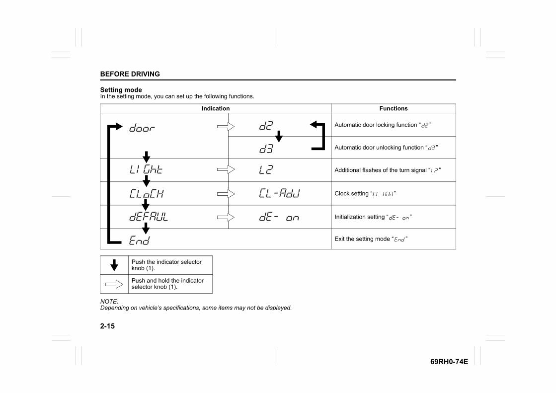
2-15
BEFORE DRIVING
69RH0-74E
Setting modeIn the setting mode, you can set up the following functions.
NOTE:Depending on vehicle’s specifications, some items may not be displayed.
Indication Functions
Automatic door locking function “ ”
Automatic door unlocking function “ ”
Additional flashes of the turn signal “ ”
Clock setting “ ”
Initialization setting “ ”
Exit the setting mode “ ”
Push the indicator selector knob (1).
Push and hold the indicator selector knob (1).
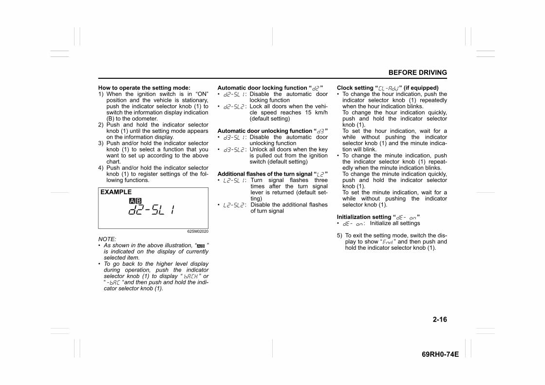
2-16
BEFORE DRIVING
69RH0-74E
How to operate the setting mode:1) When the ignition switch is in “ON”
position and the vehicle is stationary,push the indicator selector knob (1) toswitch the information display indication(B) to the odometer.
2) Push and hold the indicator selectorknob (1) until the setting mode appearson the information display.
3) Push and/or hold the indicator selectorknob (1) to select a function that youwant to set up according to the abovechart.
4) Push and/or hold the indicator selectorknob (1) to register settings of the fol-lowing functions.
62SM02020
NOTE:• As shown in the above illustration, “ ”
is indicated on the display of currentlyselected item.
• To go back to the higher level displayduring operation, push the indicatorselector knob (1) to display “ ” or“ “and then push and hold the indi-cator selector knob (1).
Automatic door locking function “ ” • : Disable the automatic door
locking function• : Lock all doors when the vehi-
cle speed reaches 15 km/h(default setting)
Automatic door unlocking function “ ”• : Disable the automatic door
unlocking function• : Unlock all doors when the key
is pulled out from the ignitionswitch (default setting)
Additional flashes of the turn signal “ ”• : Turn signal flashes three
times after the turn signallever is returned (default set-ting)
• : Disable the additional flashesof turn signal
Clock setting “ ” (if equipped)• To change the hour indication, push the
indicator selector knob (1) repeatedlywhen the hour indication blinks. To change the hour indication quickly,push and hold the indicator selectorknob (1). To set the hour indication, wait for awhile without pushing the indicatorselector knob (1) and the minute indica-tion will blink.
• To change the minute indication, pushthe indicator selector knob (1) repeat-edly when the minute indication blinks. To change the minute indication quickly,push and hold the indicator selectorknob (1). To set the minute indication, wait for awhile without pushing the indicatorselector knob (1).
Initialization setting “ ”• : Initialize all settings
5) To exit the setting mode, switch the dis-play to show “ ” and then push andhold the indicator selector knob (1).
EXAMPLE
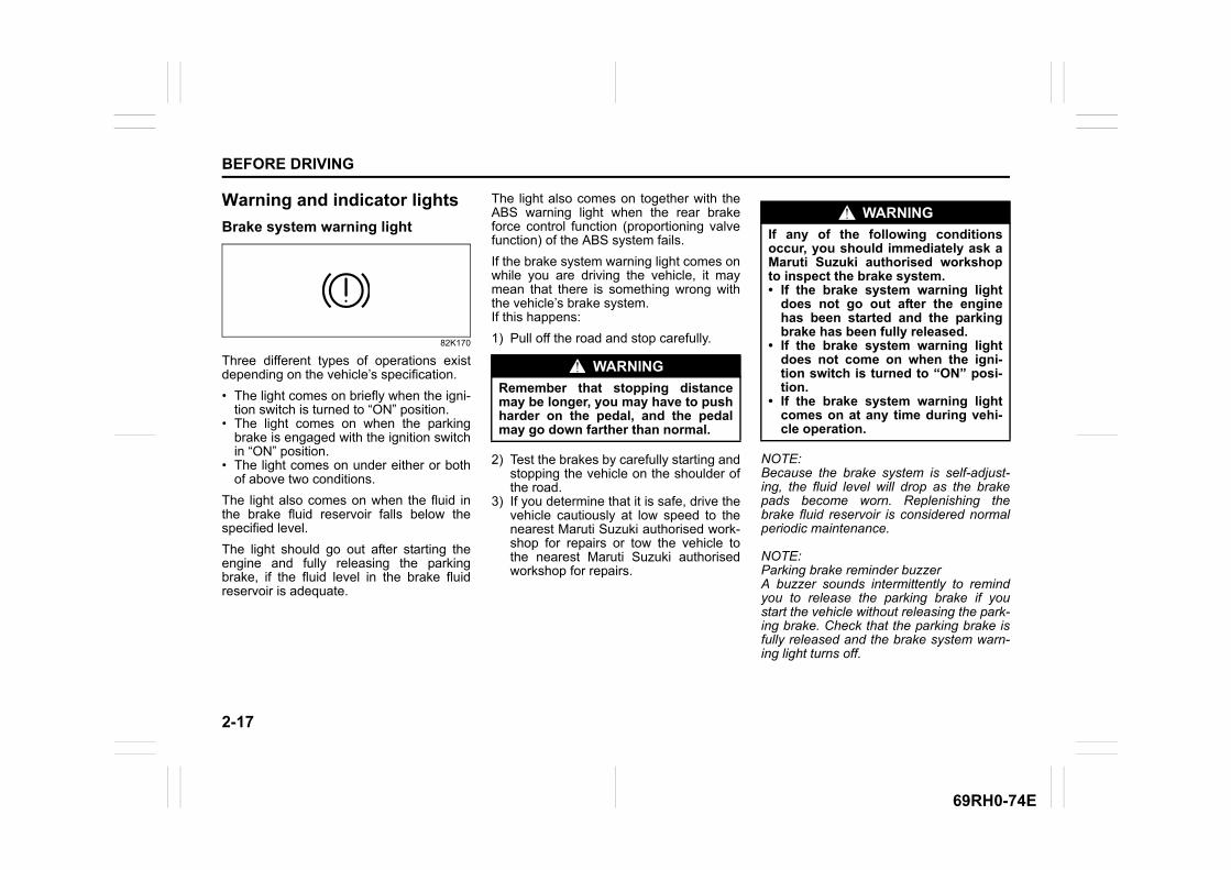
2-17
BEFORE DRIVING
69RH0-74E
Warning and indicator lights
Brake system warning light
82K170
Three different types of operations existdepending on the vehicle’s specification.
• The light comes on briefly when the igni-tion switch is turned to “ON” position.
• The light comes on when the parkingbrake is engaged with the ignition switchin “ON” position.
• The light comes on under either or bothof above two conditions.
The light also comes on when the fluid inthe brake fluid reservoir falls below thespecified level.
The light should go out after starting theengine and fully releasing the parkingbrake, if the fluid level in the brake fluidreservoir is adequate.
The light also comes on together with theABS warning light when the rear brakeforce control function (proportioning valvefunction) of the ABS system fails.
If the brake system warning light comes onwhile you are driving the vehicle, it maymean that there is something wrong withthe vehicle’s brake system. If this happens:
1) Pull off the road and stop carefully.
2) Test the brakes by carefully starting andstopping the vehicle on the shoulder ofthe road.
3) If you determine that it is safe, drive thevehicle cautiously at low speed to thenearest Maruti Suzuki authorised work-shop for repairs or tow the vehicle tothe nearest Maruti Suzuki authorisedworkshop for repairs.
NOTE:Because the brake system is self-adjust-ing, the fluid level will drop as the brakepads become worn. Replenishing thebrake fluid reservoir is considered normalperiodic maintenance.
NOTE:Parking brake reminder buzzerA buzzer sounds intermittently to remindyou to release the parking brake if youstart the vehicle without releasing the park-ing brake. Check that the parking brake isfully released and the brake system warn-ing light turns off.
WARNING
Remember that stopping distancemay be longer, you may have to pushharder on the pedal, and the pedalmay go down farther than normal.
WARNING
If any of the following conditionsoccur, you should immediately ask aMaruti Suzuki authorised workshopto inspect the brake system.• If the brake system warning light
does not go out after the enginehas been started and the parkingbrake has been fully released.
• If the brake system warning lightdoes not come on when the igni-tion switch is turned to “ON” posi-tion.
• If the brake system warning lightcomes on at any time during vehi-cle operation.

2-18
BEFORE DRIVING
69RH0-74E
Anti-lock brake system (ABS) warn-ing light
65D529
When the ignition switch is turned to “ON”position, this light comes on briefly so youcan check that the light is working.If the light stays on or comes on when driv-ing, there may be something wrong withthe ABS.
If this happens: 1) Pull off the road and stop carefully.2) Turn the ignition switch to “LOCK” posi-
tion and then start the engine again.
If the warning light comes on briefly andthen turns off, the system is normal. If thewarning light still stays on, something iswrong with the system.
If the light and the brake system warninglight stay on or come on simultaneouslywhen driving, your ABS system isequipped with the rear brake force controlfunction (proportioning valve function) andthere may be something wrong with boththe rear brake force control function andthe anti-lock function of the ABS system.
If one of the above occurs, have the sys-tem inspected by a Maruti Suzuki autho-rised workshop.If the ABS becomes inoperative, the brakesystem will function as an ordinary brakesystem that does not have this ABS sys-tem.
For details of ABS system, refer to “Anti-lock brake system (ABS)” in the “OPERAT-ING YOUR VEHICLE” section.
Oil pressure light
50G051
When the ignition switch is turned to “ON”position, this light comes on. When theengine is started, the light goes out. Thelight will come on and remain on if there isinsufficient oil pressure. If the light comeson when driving, pull off the road as soonas you can and stop the engine. Check the engine oil level and add oil ifnecessary. If there is enough oil, the lubri-cation system should be inspected by aMaruti Suzuki authorised workshop beforeyou drive the vehicle again.
Charging light
50G052
When the ignition switch is turned to “ON”position, this light comes on. When theengine is started, the light goes out. Thelight will come on and remain on if there issomething wrong with the battery chargingsystem. If the light comes on when theengine is running, the charging systemshould be inspected immediately by aMaruti Suzuki authorised workshop.
ABS
NOTICE
• If you operate the engine with thislight on, severe engine damage canresult.
• Do not rely on the oil pressure lightto indicate the need to add oil. Peri-odically check the engine oil level.
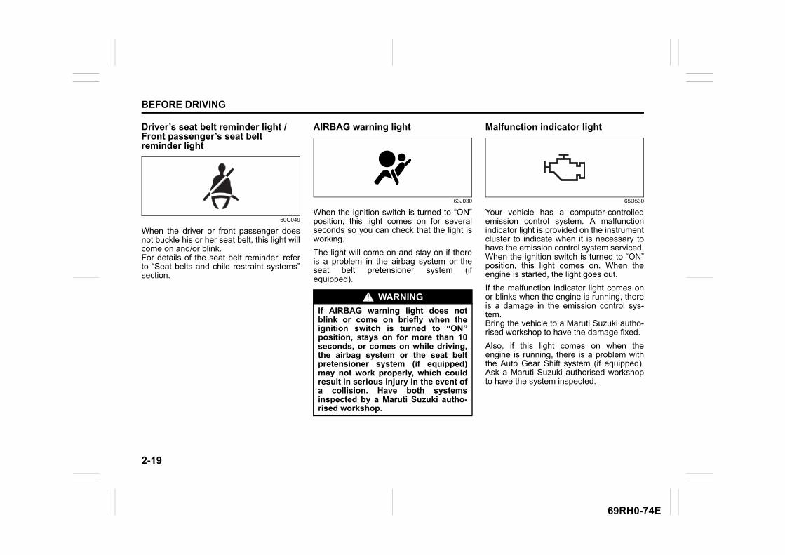
2-19
BEFORE DRIVING
69RH0-74E
Driver’s seat belt reminder light / Front passenger’s seat belt reminder light
60G049
When the driver or front passenger doesnot buckle his or her seat belt, this light willcome on and/or blink.For details of the seat belt reminder, referto “Seat belts and child restraint systems”section.
AIRBAG warning light
63J030
When the ignition switch is turned to “ON”position, this light comes on for severalseconds so you can check that the light isworking.
The light will come on and stay on if thereis a problem in the airbag system or theseat belt pretensioner system (ifequipped).
Malfunction indicator light
65D530
Your vehicle has a computer-controlledemission control system. A malfunctionindicator light is provided on the instrumentcluster to indicate when it is necessary tohave the emission control system serviced.When the ignition switch is turned to “ON”position, this light comes on. When theengine is started, the light goes out.
If the malfunction indicator light comes onor blinks when the engine is running, thereis a damage in the emission control sys-tem.Bring the vehicle to a Maruti Suzuki autho-rised workshop to have the damage fixed.
Also, if this light comes on when theengine is running, there is a problem withthe Auto Gear Shift system (if equipped).Ask a Maruti Suzuki authorised workshopto have the system inspected.
WARNING
If AIRBAG warning light does notblink or come on briefly when theignition switch is turned to “ON”position, stays on for more than 10seconds, or comes on while driving,the airbag system or the seat beltpretensioner system (if equipped)may not work properly, which couldresult in serious injury in the event ofa collision. Have both systemsinspected by a Maruti Suzuki autho-rised workshop.
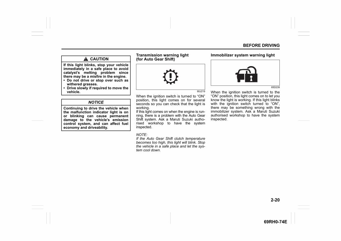
2-20
BEFORE DRIVING
69RH0-74E
Transmission warning light (for Auto Gear Shift)
80J219
When the ignition switch is turned to “ON”position, this light comes on for severalseconds so you can check that the light isworking.If this light comes on when the engine is run-ning, there is a problem with the Auto GearShift system. Ask a Maruti Suzuki autho-rised workshop to have the systeminspected.
NOTE:If the Auto Gear Shift clutch temperaturebecomes too high, this light will blink. Stopthe vehicle in a safe place and let the sys-tem cool down.
Immobilizer system warning light
65D239
When the ignition switch is turned to the“ON” position, this light comes on to let youknow the light is working. If this light blinkswith the ignition switch turned to “ON”,there may be something wrong with theimmobilizer system. Ask a Maruti Suzukiauthorised workshop to have the systeminspected.
CAUTION
If this light blinks, stop your vehicleimmediately in a safe place to avoidcatalyst’s melting problem sincethere may be a misfire in the engine.• Do not drive or stop over such as
withered grasses.• Drive slowly if required to move the
vehicle.
NOTICE
Continuing to drive the vehicle whenthe malfunction indicator light is onor blinking can cause permanentdamage to the vehicle’s emissioncontrol system, and can affect fueleconomy and driveability.
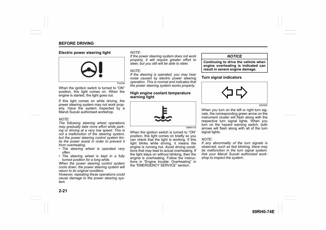
2-21
BEFORE DRIVING
69RH0-74E
Electric power steering light
79J039
When the ignition switch is turned to “ON”position, this light comes on. When theengine is started, the light goes out.
If this light comes on while driving, thepower steering system may not work prop-erly. Have the system inspected by aMaruti Suzuki authorised workshop.
NOTE:The following steering wheel operationsmay gradually take more effort while park-ing or driving at a very low speed. This isnot a malfunction of the steering system,but the power steering control system lim-its the power assist in order to prevent itfrom overheating.• The steering wheel is operated very
often.• The steering wheel is kept in a fully
turned position for a long while. When the power steering control systemcools down, the power steering system willreturn to its original condition.However, repeating these operations couldcause damage to the power steering sys-tem.
NOTE:If the power steering system does not workproperly, it will require greater effort tosteer, but you still will be able to steer.
NOTE:If the steering is operated, you may hearnoise caused by electric power steeringoperation. This is normal and indicates thatthe power steering system works properly.
High engine coolant temperature warning light
69RH179
When the ignition switch is turned to “ON”position, this light comes on briefly so youcan check that the light is working. If thislight blinks while driving, it means theengine is running hot. Avoid driving condi-tions that may lead to actual overheating. Ifthe light stays on without blinking, then theengine is overheating. Follow the instruc-tions in “Engine trouble: Overheating” inthe “EMERGENCY SERVICE” section.
Turn signal indicators
50G055
When you turn on the left or right turn sig-nals, the corresponding green arrow on theinstrument cluster will flash along with therespective turn signal lights. When youturn on the hazard warning switch, botharrows will flash along with all of the turnsignal lights.
NOTE:If any abnormality of the turn signals isobserved, such as fast blinking, there maybe malfunction in the turn signal system.Ask your Maruti Suzuki authorized work-shop to inspect the system.
NOTICE
Continuing to drive the vehicle whenengine overheating is indicated canresult in severe engine damage.
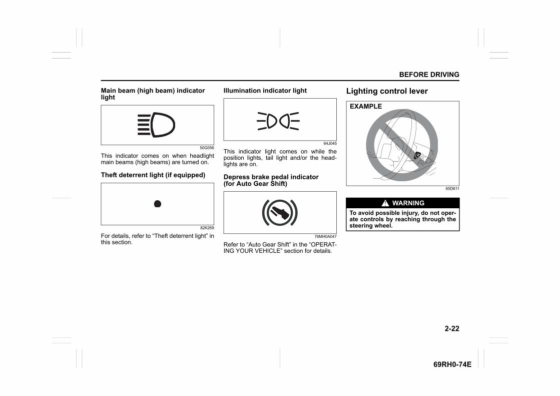
2-22
BEFORE DRIVING
69RH0-74E
Main beam (high beam) indicator light
50G056
This indicator comes on when headlightmain beams (high beams) are turned on.
Theft deterrent light (if equipped)
82K269
For details, refer to “Theft deterrent light” inthis section.
Illumination indicator light
64J045
This indicator light comes on while theposition lights, tail light and/or the head-lights are on.
Depress brake pedal indicator (for Auto Gear Shift)
76MH0A047
Refer to “Auto Gear Shift” in the “OPERAT-ING YOUR VEHICLE” section for details.
Lighting control lever
65D611
WARNING
To avoid possible injury, do not oper-ate controls by reaching through thesteering wheel.
EXAMPLE
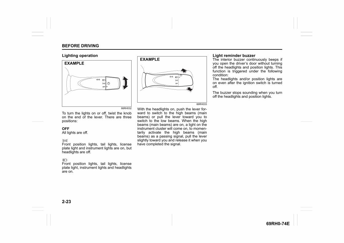
2-23
BEFORE DRIVING
69RH0-74E
Lighting operation
66RH032
To turn the lights on or off, twist the knobon the end of the lever. There are threepositions:
OFFAll lights are off.
Front position lights, tail lights, licenseplate light and instrument lights are on, butheadlights are off.
Front position lights, tail lights, licenseplate light, instrument lights and headlightsare on.
66RH033
With the headlights on, push the lever for-ward to switch to the high beams (mainbeams) or pull the lever toward you toswitch to the low beams. When the highbeams (main beams) are on, a light on theinstrument cluster will come on, to momen-tarily activate the high beams (mainbeams) as a passing signal, pull the leverslightly toward you and release it when youhave completed the signal.
Light reminder buzzerThe interior buzzer continuously beeps ifyou open the driver’s door without turningoff the headlights and position lights. Thisfunction is triggered under the followingcondition:The headlights and/or position lights areon even after the ignition switch is turnedoff.
The buzzer stops sounding when you turnoff the headlights and position lights.
EXAMPLEEXAMPLE

2-24
BEFORE DRIVING
69RH0-74E
Headlight leveling knob
62SM02021
Level the headlight beam according to theload condition of your vehicle by turningthis knob. Turn the knob anticlockwise tolower the beam and clockwise to raise thebeam.Align the marking (1) on the knob with themarking (2) provided on the dashboard forsetting the required knob position. Thechart below shows the appropriate knobposition for different vehicle load condi-tions.
For petrol model
For CNG model
Turn signal control lever
65D611
Turn signal operationWith the ignition switch in “ON” position,move the lever upward or downward toactivate the right or left turn signals.
3
21
4
3
21
4
(1)(2)
EXAMPLEVehicle Load
ConditionKnob
Position
Driver only 0
Driver + 1 passenger (in front seat) 0
Driver + 4 passengers, no cargo 2
Driver + 4 passengers, cargo added 2
Driver + full cargo 3
Vehicle Load Condition
KnobPosition
Driver only 0
Driver + 1 passenger (in front seat) 0
Driver + 1 passenger (in front seat) + 2 pas-sengers (in rear seat)
1
WARNING
To avoid possible injury, do not oper-ate controls by reaching through thesteering wheel.
EXAMPLE
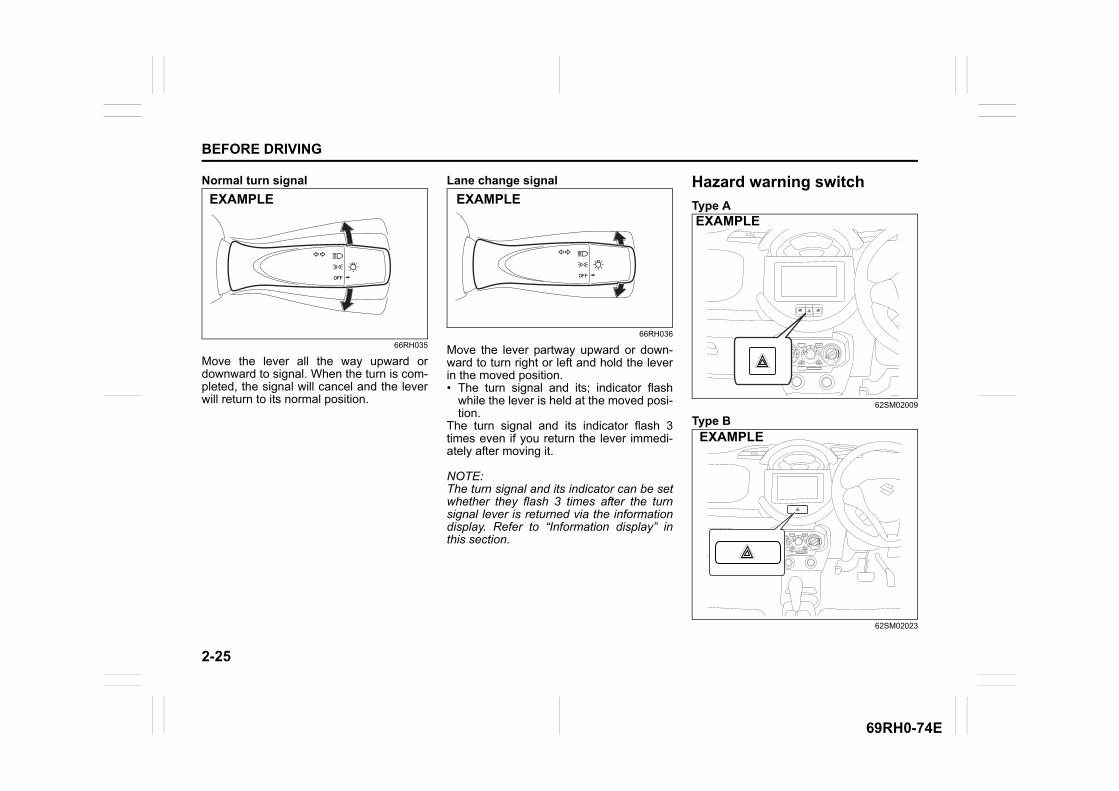
2-25
BEFORE DRIVING
69RH0-74E
Normal turn signal
66RH035
Move the lever all the way upward ordownward to signal. When the turn is com-pleted, the signal will cancel and the leverwill return to its normal position.
Lane change signal
66RH036
Move the lever partway upward or down-ward to turn right or left and hold the leverin the moved position.• The turn signal and its; indicator flash
while the lever is held at the moved posi-tion.
The turn signal and its indicator flash 3times even if you return the lever immedi-ately after moving it.
NOTE:The turn signal and its indicator can be setwhether they flash 3 times after the turnsignal lever is returned via the informationdisplay. Refer to “Information display” inthis section.
Hazard warning switch
Type A
62SM02009
Type B
62SM02023
EXAMPLE EXAMPLE
EXAMPLE
EXAMPLE

2-26
BEFORE DRIVING
69RH0-74E
Push in the hazard warning switch to acti-vate the hazard warning lights. All turn sig-nal lights and both turn signal indicatorswill flash simultaneously. To turn off thelights, push the switch again.Use the hazard warning lights to warnother drivers of possible risk of traffic haz-ard when you park your vehicle in case ofemergency.
Windshield wiper and washer lever
57L21128
Wiper and washer operationWhen the ignition switch is in “ON” posi-tion, you can use the wiper/washer lever.
When the wipers are under heavy loadsuch as covered by snow, the breaker willbe activated and the wipers will stop oper-ating to protect the wiper motor from over-heating.If the wiper stops during operation, do thefollowing methods.1) Stop the vehicle in a safe place, and
turn the engine off.2) Move the wiper lever to “OFF” position.3) Remove obstacles such as snow on the
wipers.4) After a while, when the temperature of
the wiper motor becomes low enough,the breaker will be reset automaticallyand the wipers will be able to use.
If you cannot use the wipers after a while,there may be another problem. Ask aMaruti Suzuki authorised workshop tohave the wipers inspected.
WARNING
To avoid possible injury, do not oper-ate controls by reaching through thesteering wheel.
EXAMPLE
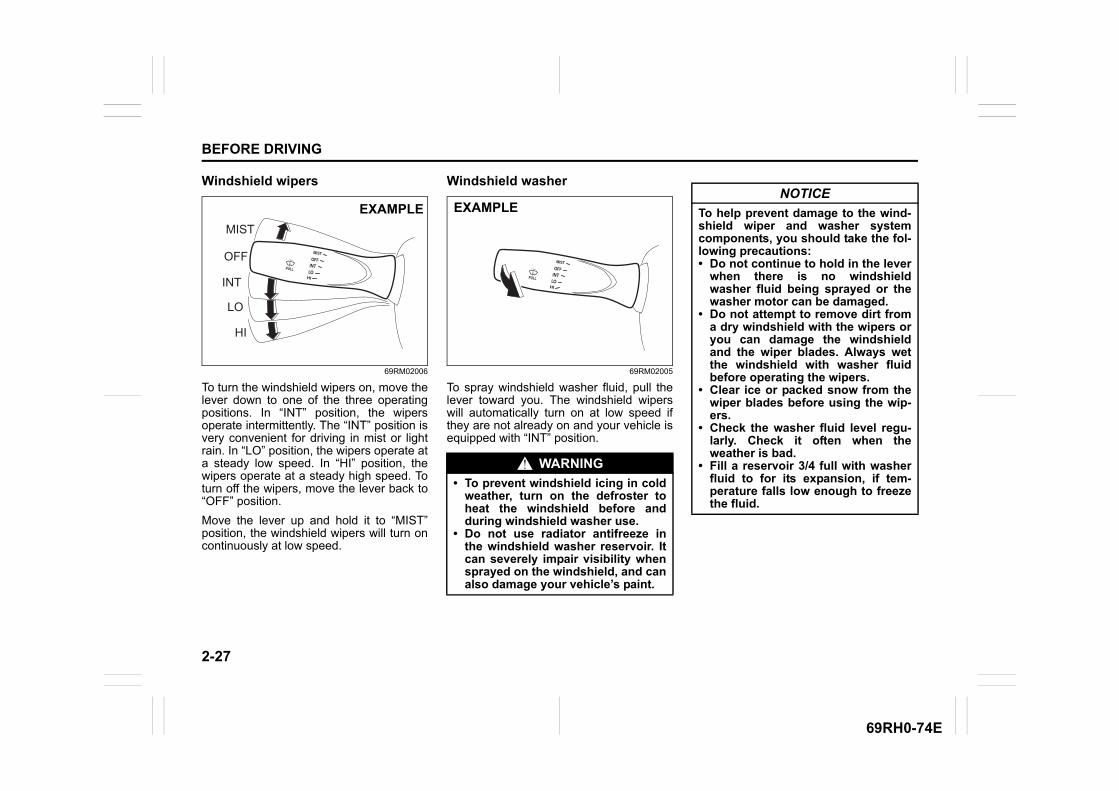
2-27
BEFORE DRIVING
69RH0-74E
Windshield wipers
69RM02006
To turn the windshield wipers on, move thelever down to one of the three operatingpositions. In “INT” position, the wipersoperate intermittently. The “INT” position isvery convenient for driving in mist or lightrain. In “LO” position, the wipers operate ata steady low speed. In “HI” position, thewipers operate at a steady high speed. Toturn off the wipers, move the lever back to“OFF” position.
Move the lever up and hold it to “MIST”position, the windshield wipers will turn oncontinuously at low speed.
Windshield washer
69RM02005
To spray windshield washer fluid, pull thelever toward you. The windshield wiperswill automatically turn on at low speed ifthey are not already on and your vehicle isequipped with “INT” position.
MIST
HI
OFF
LO
INT
EXAMPLE
WARNING
• To prevent windshield icing in coldweather, turn on the defroster toheat the windshield before andduring windshield washer use.
• Do not use radiator antifreeze inthe windshield washer reservoir. Itcan severely impair visibility whensprayed on the windshield, and canalso damage your vehicle’s paint.
EXAMPLENOTICE
To help prevent damage to the wind-shield wiper and washer systemcomponents, you should take the fol-lowing precautions:• Do not continue to hold in the lever
when there is no windshieldwasher fluid being sprayed or thewasher motor can be damaged.
• Do not attempt to remove dirt froma dry windshield with the wipers oryou can damage the windshieldand the wiper blades. Always wetthe windshield with washer fluidbefore operating the wipers.
• Clear ice or packed snow from thewiper blades before using the wip-ers.
• Check the washer fluid level regu-larly. Check it often when theweather is bad.
• Fill a reservoir 3/4 full with washerfluid to for its expansion, if tem-perature falls low enough to freezethe fluid.
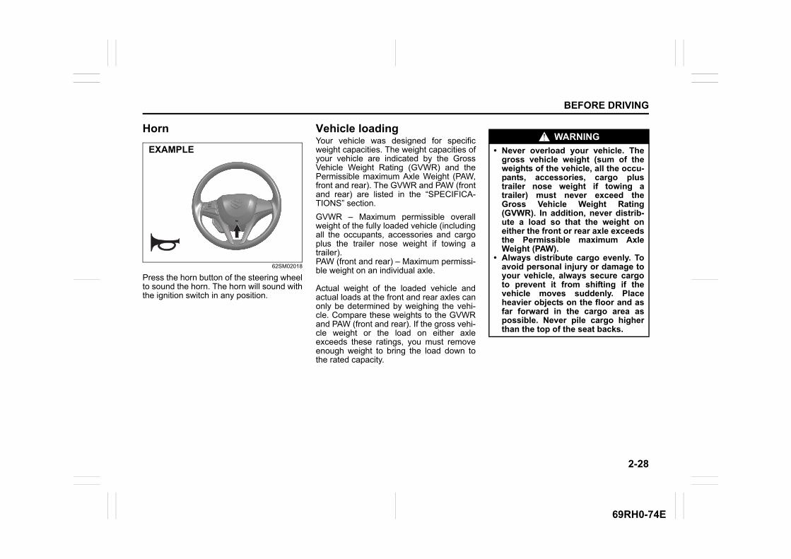
2-28
BEFORE DRIVING
69RH0-74E
Horn
62SM02018
Press the horn button of the steering wheelto sound the horn. The horn will sound withthe ignition switch in any position.
Vehicle loadingYour vehicle was designed for specificweight capacities. The weight capacities ofyour vehicle are indicated by the GrossVehicle Weight Rating (GVWR) and thePermissible maximum Axle Weight (PAW,front and rear). The GVWR and PAW (frontand rear) are listed in the “SPECIFICA-TIONS” section.
GVWR – Maximum permissible overallweight of the fully loaded vehicle (includingall the occupants, accessories and cargoplus the trailer nose weight if towing atrailer).PAW (front and rear) – Maximum permissi-ble weight on an individual axle.
Actual weight of the loaded vehicle andactual loads at the front and rear axles canonly be determined by weighing the vehi-cle. Compare these weights to the GVWRand PAW (front and rear). If the gross vehi-cle weight or the load on either axleexceeds these ratings, you must removeenough weight to bring the load down tothe rated capacity.
EXAMPLEWARNING
• Never overload your vehicle. Thegross vehicle weight (sum of theweights of the vehicle, all the occu-pants, accessories, cargo plustrailer nose weight if towing atrailer) must never exceed theGross Vehicle Weight Rating(GVWR). In addition, never distrib-ute a load so that the weight oneither the front or rear axle exceedsthe Permissible maximum AxleWeight (PAW).
• Always distribute cargo evenly. Toavoid personal injury or damage toyour vehicle, always secure cargoto prevent it from shifting if thevehicle moves suddenly. Placeheavier objects on the floor and asfar forward in the cargo area aspossible. Never pile cargo higherthan the top of the seat backs.

2-29
BEFORE DRIVING
69RH0-74E
Trailer towingYour vehicle was originally designed tocarry people and a normal amount ofcargo, not to tow a trailer.
62SM02025
EXAMPLE
OPERATING YOUR VEHICLE
3
69RH0-74E
60G408
OPERATING YOUR VEHICLEDaily inspection checklist .................................................. 3-1Engine oil consumption ..................................................... 3-2Ignition switch ..................................................................... 3-2Parking brake lever ............................................................. 3-5Pedal ..................................................................................... 3-6Starting engine .................................................................... 3-7Using transmission ............................................................. 3-8Gearshift indicator (if equipped) ........................................ 3-18Parking sensors .................................................................. 3-19Braking ................................................................................. 3-23

3-1
OPERATING YOUR VEHICLE
69RH0-74E
Daily inspection checklist
Before driving
62SM03001
1) Check that windows, mirrors, lights andreflectors are clean and unobstructed.
2) Visually check the tires for the followingpoints:
– the depth of the tread groove– abnormal wear, cracks and damage– loose wheel nuts– existence of foreign material such as
nails, stones, etc.Refer to “Tires” in the “INSPECTION ANDMAINTENANCE” section for details.3) Look for fluid and oil leakage.
NOTE:It is normal for water to drip from the airconditioning system after use.
4) Check that the hood is fully closed andlatched.
5) Check the headlights, turn signal lights,brake lights and horn for proper opera-tion.
6) Adjust the seat.7) Check the brake pedal and the parking
brake lever.8) Adjust the mirrors.9) Check that you and all passengers
have properly fastened your seat belts.10)Check that all warning lights come on
as the ignition switch is turned to “ON”position.
11)Check all gauges.12)Check that the brake system warning
light turns off when the parking brake isreleased.
Once a week, or each time you fill your fueltank or before a long distance driving (likehighway driving), perform the followingunder-hood checks:
1) Engine oil level2) Coolant level3) Brake fluid level4) Battery fluid (acid) level5) Windshield washer fluid level6) Hood latch operation
Pull the hood release handle inside thevehicle. Check that you cannot openthe hood all the way without releasingthe secondary latch. Close the hoodsecurely after checking for proper latchoperation. See the item “All latches,hinges and locks” of “Chassis, bodyand others” in “Maintenance schedule”in the “INSPECTION AND MAINTE-NANCE” section for lubrication sched-ule.
Once a month, or each time you fill yourfuel tank or before a long distance driving(like highway driving), check the tire pres-sure using a tire pressure gauge. Alsocheck the tire pressure of the spare tire.
EXAMPLE
WARNING
Check that the hood is fully closedand latched before driving. If it is not,it can fly up unexpectedly duringdriving, obstructing your view andresulting in an accident.
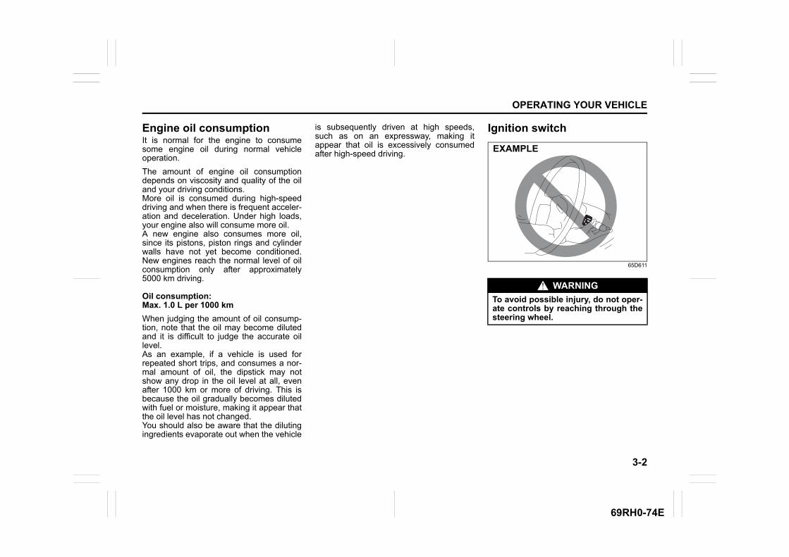
3-2
OPERATING YOUR VEHICLE
69RH0-74E
Engine oil consumptionIt is normal for the engine to consumesome engine oil during normal vehicleoperation.
The amount of engine oil consumptiondepends on viscosity and quality of the oiland your driving conditions.More oil is consumed during high-speeddriving and when there is frequent acceler-ation and deceleration. Under high loads,your engine also will consume more oil.A new engine also consumes more oil,since its pistons, piston rings and cylinderwalls have not yet become conditioned.New engines reach the normal level of oilconsumption only after approximately5000 km driving.
Oil consumption: Max. 1.0 L per 1000 km
When judging the amount of oil consump-tion, note that the oil may become dilutedand it is difficult to judge the accurate oillevel.As an example, if a vehicle is used forrepeated short trips, and consumes a nor-mal amount of oil, the dipstick may notshow any drop in the oil level at all, evenafter 1000 km or more of driving. This isbecause the oil gradually becomes dilutedwith fuel or moisture, making it appear thatthe oil level has not changed.You should also be aware that the dilutingingredients evaporate out when the vehicle
is subsequently driven at high speeds,such as on an expressway, making itappear that oil is excessively consumedafter high-speed driving.
Ignition switch
65D611
WARNING
To avoid possible injury, do not oper-ate controls by reaching through thesteering wheel.
EXAMPLE
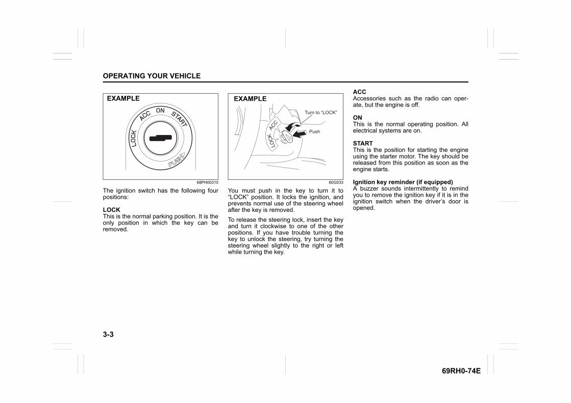
3-3
OPERATING YOUR VEHICLE
69RH0-74E
68PH00310
The ignition switch has the following fourpositions:
LOCKThis is the normal parking position. It is theonly position in which the key can beremoved.
60G033
You must push in the key to turn it to“LOCK” position. It locks the ignition, andprevents normal use of the steering wheelafter the key is removed.
To release the steering lock, insert the keyand turn it clockwise to one of the otherpositions. If you have trouble turning thekey to unlock the steering, try turning thesteering wheel slightly to the right or leftwhile turning the key.
ACCAccessories such as the radio can oper-ate, but the engine is off.
ONThis is the normal operating position. Allelectrical systems are on.
STARTThis is the position for starting the engineusing the starter motor. The key should bereleased from this position as soon as theengine starts.
Ignition key reminder (if equipped)A buzzer sounds intermittently to remindyou to remove the ignition key if it is in theignition switch when the driver’s door isopened.
EXAMPLE
LOC
KACC
Push
Turn to “LOCK”
EXAMPLE
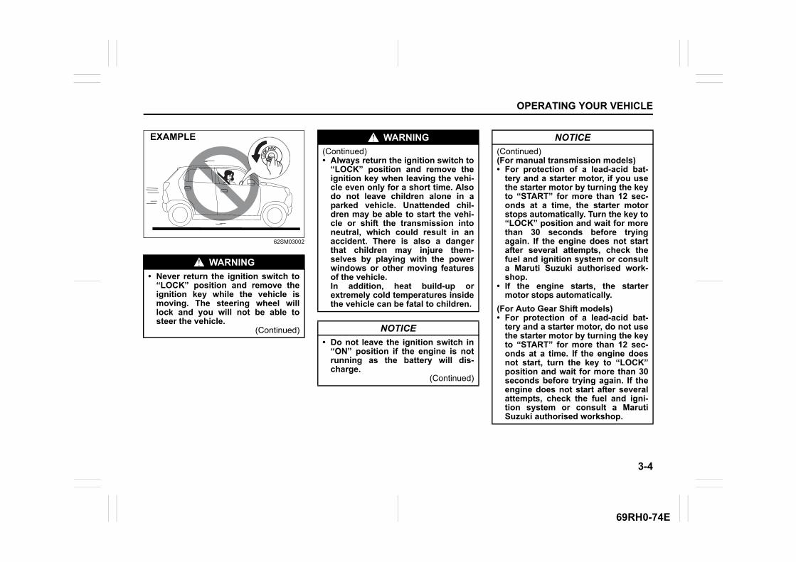
3-4
OPERATING YOUR VEHICLE
69RH0-74E
62SM03002
WARNING
• Never return the ignition switch to“LOCK” position and remove theignition key while the vehicle ismoving. The steering wheel willlock and you will not be able tosteer the vehicle.
(Continued)
EXAMPLE WARNING
(Continued)• Always return the ignition switch to
“LOCK” position and remove theignition key when leaving the vehi-cle even only for a short time. Alsodo not leave children alone in aparked vehicle. Unattended chil-dren may be able to start the vehi-cle or shift the transmission intoneutral, which could result in anaccident. There is also a dangerthat children may injure them-selves by playing with the powerwindows or other moving featuresof the vehicle. In addition, heat build-up orextremely cold temperatures insidethe vehicle can be fatal to children.
NOTICE
• Do not leave the ignition switch in“ON” position if the engine is notrunning as the battery will dis-charge.
(Continued)
NOTICE
(Continued)(For manual transmission models)• For protection of a lead-acid bat-
tery and a starter motor, if you usethe starter motor by turning the keyto “START” for more than 12 sec-onds at a time, the starter motorstops automatically. Turn the key to“LOCK” position and wait for morethan 30 seconds before tryingagain. If the engine does not startafter several attempts, check thefuel and ignition system or consulta Maruti Suzuki authorised work-shop.
• If the engine starts, the startermotor stops automatically.
(For Auto Gear Shift models)• For protection of a lead-acid bat-
tery and a starter motor, do not usethe starter motor by turning the keyto “START” for more than 12 sec-onds at a time. If the engine doesnot start, turn the key to “LOCK”position and wait for more than 30seconds before trying again. If theengine does not start after severalattempts, check the fuel and igni-tion system or consult a MarutiSuzuki authorised workshop.
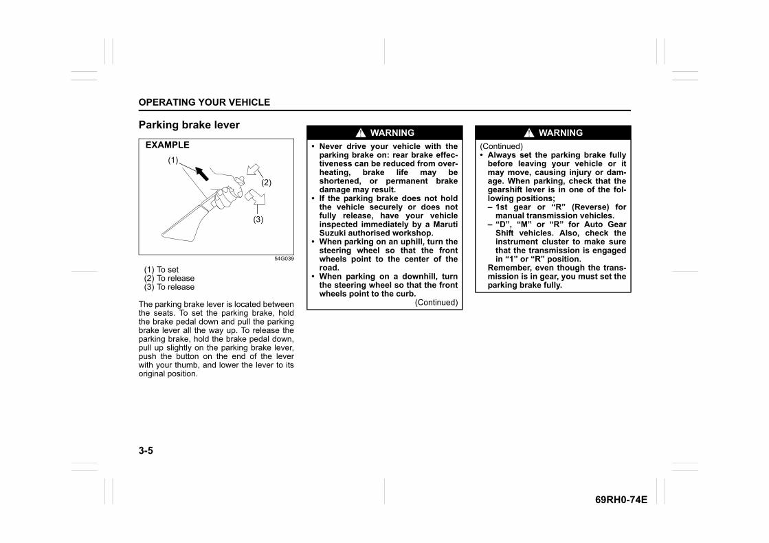
3-5
OPERATING YOUR VEHICLE
69RH0-74E
Parking brake lever
54G039
(1) To set(2) To release(3) To release
The parking brake lever is located betweenthe seats. To set the parking brake, holdthe brake pedal down and pull the parkingbrake lever all the way up. To release theparking brake, hold the brake pedal down,pull up slightly on the parking brake lever,push the button on the end of the leverwith your thumb, and lower the lever to itsoriginal position.
(1)
(2)
(3)
EXAMPLEWARNING
• Never drive your vehicle with theparking brake on: rear brake effec-tiveness can be reduced from over-heating, brake life may beshortened, or permanent brakedamage may result.
• If the parking brake does not holdthe vehicle securely or does notfully release, have your vehicleinspected immediately by a MarutiSuzuki authorised workshop.
• When parking on an uphill, turn thesteering wheel so that the frontwheels point to the center of theroad.
• When parking on a downhill, turnthe steering wheel so that the frontwheels point to the curb.
(Continued)
WARNING
(Continued)• Always set the parking brake fully
before leaving your vehicle or itmay move, causing injury or dam-age. When parking, check that thegearshift lever is in one of the fol-lowing positions;– 1st gear or “R” (Reverse) for
manual transmission vehicles.– “D”, “M” or “R” for Auto Gear
Shift vehicles. Also, check theinstrument cluster to make surethat the transmission is engagedin “1” or “R” position.
Remember, even though the trans-mission is in gear, you must set theparking brake fully.
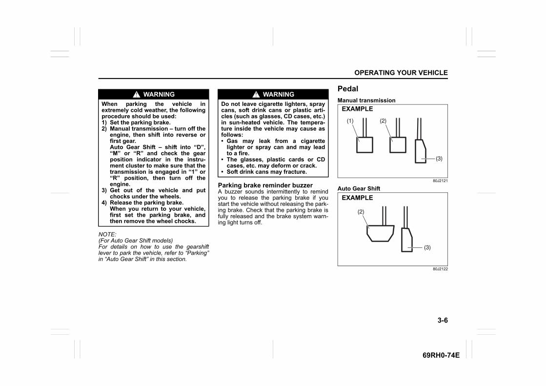
3-6
OPERATING YOUR VEHICLE
69RH0-74E
NOTE:(For Auto Gear Shift models)For details on how to use the gearshiftlever to park the vehicle, refer to “Parking”in “Auto Gear Shift” in this section.
Parking brake reminder buzzerA buzzer sounds intermittently to remindyou to release the parking brake if youstart the vehicle without releasing the park-ing brake. Check that the parking brake isfully released and the brake system warn-ing light turns off.
Pedal
Manual transmission
80J2121
Auto Gear Shift
80J2122
WARNING
When parking the vehicle inextremely cold weather, the followingprocedure should be used:1) Set the parking brake.2) Manual transmission – turn off the
engine, then shift into reverse orfirst gear. Auto Gear Shift – shift into “D”,“M” or “R” and check the gearposition indicator in the instru-ment cluster to make sure that thetransmission is engaged in “1” or“R” position, then turn off theengine.
3) Get out of the vehicle and putchocks under the wheels.
4) Release the parking brake. When you return to your vehicle,first set the parking brake, andthen remove the wheel chocks.
WARNING
Do not leave cigarette lighters, spraycans, soft drink cans or plastic arti-cles (such as glasses, CD cases, etc.)in sun-heated vehicle. The tempera-ture inside the vehicle may cause asfollows:• Gas may leak from a cigarette
lighter or spray can and may leadto a fire.
• The glasses, plastic cards or CDcases, etc. may deform or crack.
• Soft drink cans may fracture.
(2)(1)
(3)
EXAMPLE
(3)
(2)
EXAMPLE
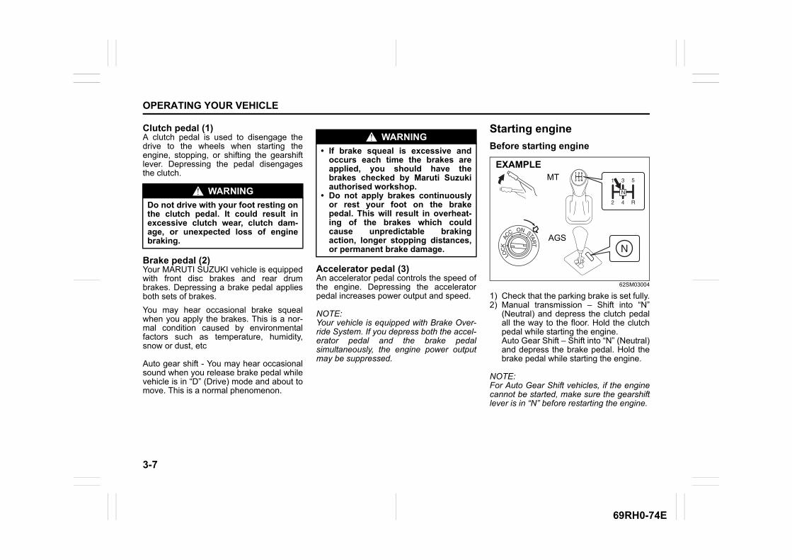
3-7
OPERATING YOUR VEHICLE
69RH0-74E
Clutch pedal (1)A clutch pedal is used to disengage thedrive to the wheels when starting theengine, stopping, or shifting the gearshiftlever. Depressing the pedal disengagesthe clutch.
Brake pedal (2)Your MARUTI SUZUKI vehicle is equippedwith front disc brakes and rear drumbrakes. Depressing a brake pedal appliesboth sets of brakes.
You may hear occasional brake squealwhen you apply the brakes. This is a nor-mal condition caused by environmentalfactors such as temperature, humidity,snow or dust, etc
Auto gear shift - You may hear occasionalsound when you release brake pedal whilevehicle is in “D” (Drive) mode and about tomove. This is a normal phenomenon.
Accelerator pedal (3)An accelerator pedal controls the speed ofthe engine. Depressing the acceleratorpedal increases power output and speed.
NOTE:Your vehicle is equipped with Brake Over-ride System. If you depress both the accel-erator pedal and the brake pedalsimultaneously, the engine power outputmay be suppressed.
Starting engine
Before starting engine
62SM03004
1) Check that the parking brake is set fully.2) Manual transmission – Shift into “N”
(Neutral) and depress the clutch pedalall the way to the floor. Hold the clutchpedal while starting the engine.Auto Gear Shift – Shift into “N” (Neutral)and depress the brake pedal. Hold thebrake pedal while starting the engine.
NOTE:For Auto Gear Shift vehicles, if the enginecannot be started, make sure the gearshiftlever is in “N” before restarting the engine.
WARNING
Do not drive with your foot resting onthe clutch pedal. It could result inexcessive clutch wear, clutch dam-age, or unexpected loss of enginebraking.
WARNING
• If brake squeal is excessive andoccurs each time the brakes areapplied, you should have thebrakes checked by Maruti Suzukiauthorised workshop.
• Do not apply brakes continuouslyor rest your foot on the brakepedal. This will result in overheat-ing of the brakes which couldcause unpredictable brakingaction, longer stopping distances,or permanent brake damage.
MT
AGS
EXAMPLE
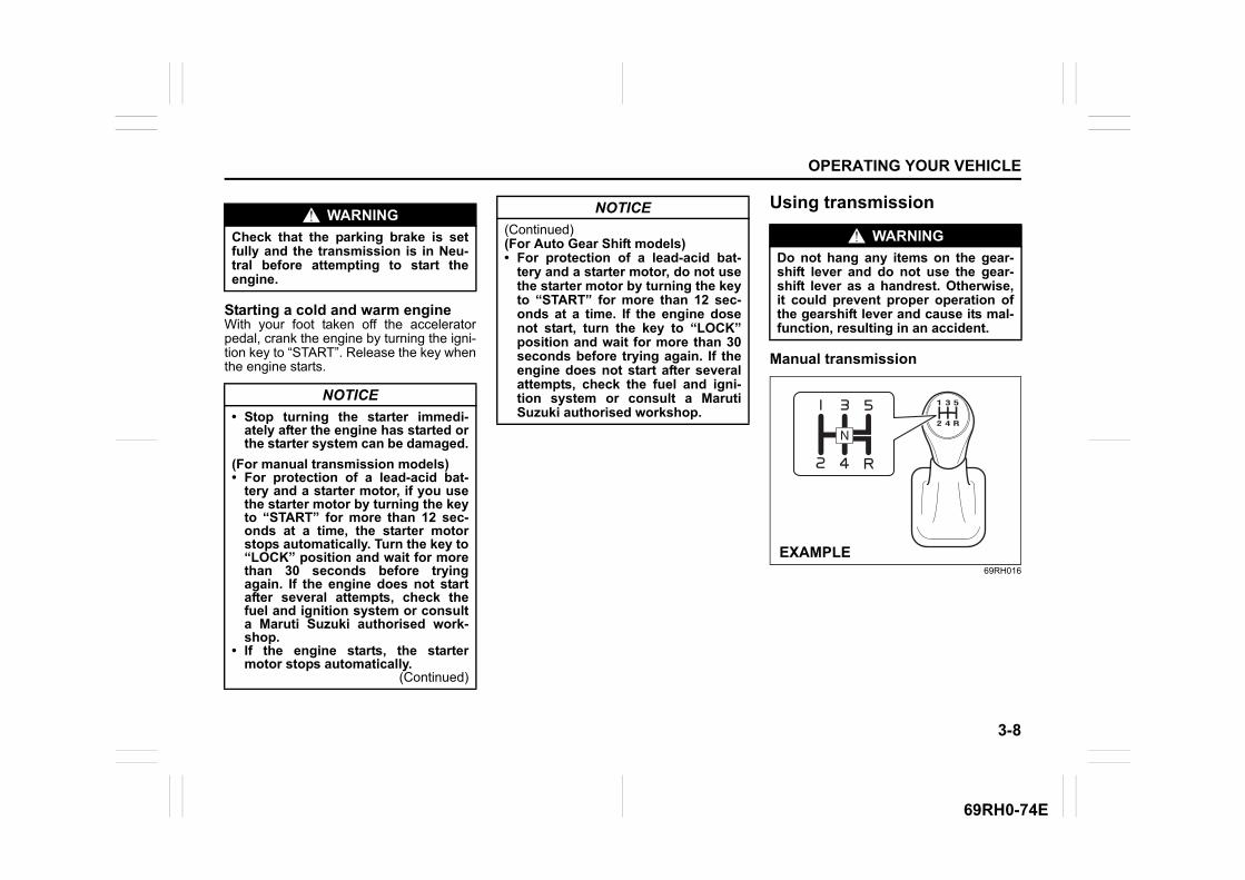
3-8
OPERATING YOUR VEHICLE
69RH0-74E
Starting a cold and warm engineWith your foot taken off the acceleratorpedal, crank the engine by turning the igni-tion key to “START”. Release the key whenthe engine starts.
Using transmission
Manual transmission
69RH016
WARNING
Check that the parking brake is setfully and the transmission is in Neu-tral before attempting to start theengine.
NOTICE
• Stop turning the starter immedi-ately after the engine has started orthe starter system can be damaged.
(For manual transmission models)• For protection of a lead-acid bat-
tery and a starter motor, if you usethe starter motor by turning the keyto “START” for more than 12 sec-onds at a time, the starter motorstops automatically. Turn the key to“LOCK” position and wait for morethan 30 seconds before tryingagain. If the engine does not startafter several attempts, check thefuel and ignition system or consulta Maruti Suzuki authorised work-shop.
• If the engine starts, the startermotor stops automatically.
(Continued)
NOTICE
(Continued)(For Auto Gear Shift models)• For protection of a lead-acid bat-
tery and a starter motor, do not usethe starter motor by turning the keyto “START” for more than 12 sec-onds at a time. If the engine dosenot start, turn the key to “LOCK”position and wait for more than 30seconds before trying again. If theengine does not start after severalattempts, check the fuel and igni-tion system or consult a MarutiSuzuki authorised workshop.
WARNING
Do not hang any items on the gear-shift lever and do not use the gear-shift lever as a handrest. Otherwise,it could prevent proper operation ofthe gearshift lever and cause its mal-function, resulting in an accident.
EXAMPLE
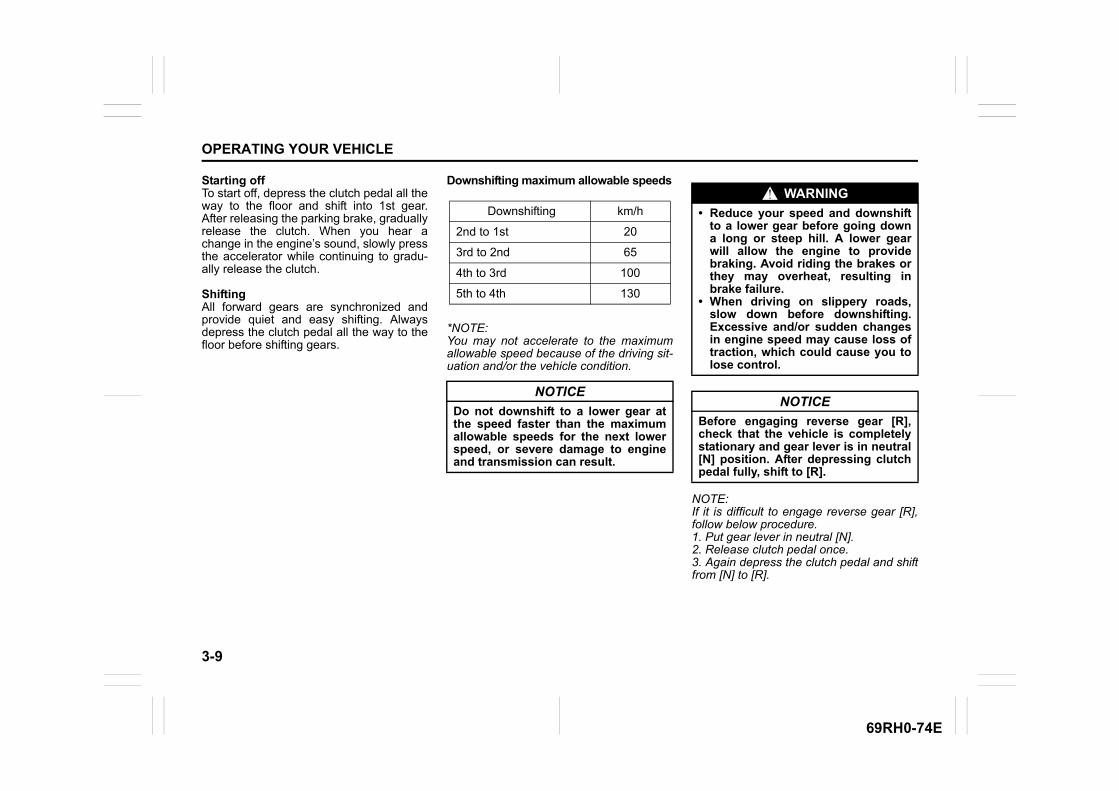
3-9
OPERATING YOUR VEHICLE
69RH0-74E
Starting offTo start off, depress the clutch pedal all theway to the floor and shift into 1st gear.After releasing the parking brake, graduallyrelease the clutch. When you hear achange in the engine’s sound, slowly pressthe accelerator while continuing to gradu-ally release the clutch.
ShiftingAll forward gears are synchronized andprovide quiet and easy shifting. Alwaysdepress the clutch pedal all the way to thefloor before shifting gears.
Downshifting maximum allowable speeds
*NOTE:You may not accelerate to the maximumallowable speed because of the driving sit-uation and/or the vehicle condition.
NOTE:If it is difficult to engage reverse gear [R],follow below procedure.1. Put gear lever in neutral [N].2. Release clutch pedal once.3. Again depress the clutch pedal and shiftfrom [N] to [R].
Downshifting km/h
2nd to 1st 20
3rd to 2nd 65
4th to 3rd 100
5th to 4th 130
NOTICE
Do not downshift to a lower gear atthe speed faster than the maximumallowable speeds for the next lowerspeed, or severe damage to engineand transmission can result.
WARNING
• Reduce your speed and downshiftto a lower gear before going downa long or steep hill. A lower gearwill allow the engine to providebraking. Avoid riding the brakes orthey may overheat, resulting inbrake failure.
• When driving on slippery roads,slow down before downshifting.Excessive and/or sudden changesin engine speed may cause loss oftraction, which could cause you tolose control.
NOTICE
Before engaging reverse gear [R],check that the vehicle is completelystationary and gear lever is in neutral[N] position. After depressing clutchpedal fully, shift to [R].
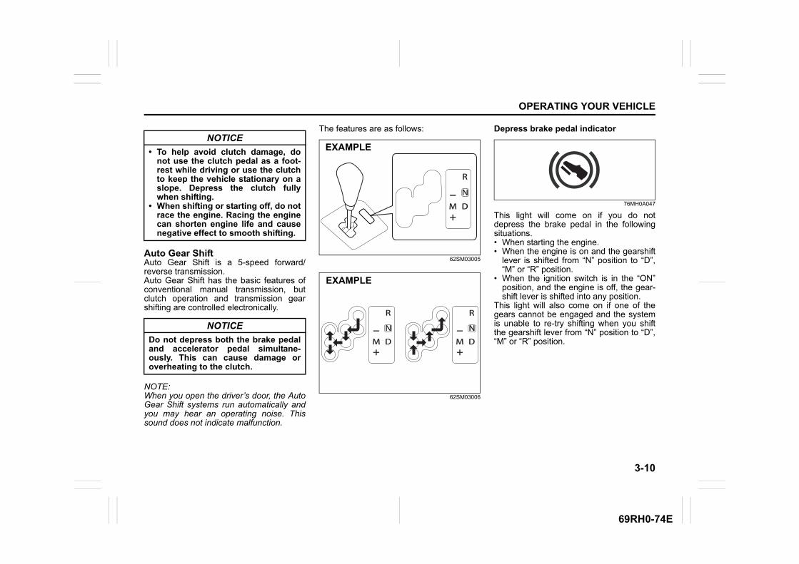
3-10
OPERATING YOUR VEHICLE
69RH0-74E
Auto Gear ShiftAuto Gear Shift is a 5-speed forward/reverse transmission.Auto Gear Shift has the basic features ofconventional manual transmission, butclutch operation and transmission gearshifting are controlled electronically.
NOTE:When you open the driver’s door, the AutoGear Shift systems run automatically andyou may hear an operating noise. Thissound does not indicate malfunction.
The features are as follows:
62SM03005
62SM03006
Depress brake pedal indicator
76MH0A047
This light will come on if you do notdepress the brake pedal in the followingsituations.• When starting the engine.• When the engine is on and the gearshift
lever is shifted from “N” position to “D”,“M” or “R” position.
• When the ignition switch is in the “ON”position, and the engine is off, the gear-shift lever is shifted into any position.
This light will also come on if one of thegears cannot be engaged and the systemis unable to re-try shifting when you shiftthe gearshift lever from “N” position to “D”,“M” or “R” position.
NOTICE
• To help avoid clutch damage, donot use the clutch pedal as a foot-rest while driving or use the clutchto keep the vehicle stationary on aslope. Depress the clutch fullywhen shifting.
• When shifting or starting off, do notrace the engine. Racing the enginecan shorten engine life and causenegative effect to smooth shifting.
NOTICE
Do not depress both the brake pedaland accelerator pedal simultane-ously. This can cause damage oroverheating to the clutch.
EXAMPLE
EXAMPLE
3-11
OPERATING YOUR VEHICLE
69RH0-74E
Starting the engineWhen starting the engine, always place thegearshift lever in the “N” position anddepress the brake pedal firmly. The enginecannot be started unless the gearshiftlever is in the “N” position and the brakepedal is depressed.
If you parked vehicle with gear engaged onlast time (if you can see “1” or “R”), shiftinto “N” (Neutral) and depress the brakepedal. Hold the brake pedal while startingthe engine. You can hear buzzer in shorttime.
NOTE:If you start the engine without the gearshiftlever in the “N” position, the gear positionindicator in the instrument cluster will blink.
Clutch operationYou can select either the Drive (D) mode orthe Manual (M) mode. Since this vehiclecontrols clutch operation electronically ineither mode, you do not need to operatethe clutch.
Creeping functionThis vehicle has a creeping function thathelps the vehicle to start smoothly byengaging the clutch. When the gearshiftlever is in any of the positions “D”, “M” or“R”, and you release your foot from thebrake pedal, the vehicle starts slowly with-out depressing the accelerator pedal.However, creep is not possible in manual(M) mode with 2nd gear engaged. Thecreeping function is disabled if youdepress the brake pedal or pull up theparking brake lever.
NOTE:If the driver’s door is opened and/or theparking brake lever is engaged with thegear in the “M”, “D” or “R” position, thecreeping function will not operate.
Parking and Stopping the vehicleAuto Gear Shift does not have a parkingposition. Park the vehicle with a gearengaged. Make sure that the gearshiftlever is “D”, “M”, or “R”. Also, check the instrument cluster to makesure that the transmission is engaged in“1” or “R” position.
Drive (D) modeWhen the Drive (D) mode is activated, themost appropriate gear position is automati-cally selected upon operation of the accel-erator pedal and variation of vehiclespeed.
Normal driving:1) Start the engine as instructed in “Start-
ing the engine” in this section.2) With your foot on the brake pedal, shift
the gearshift lever to the “D” position.When the gearshift lever is shifted tothe “D” position, the gear will be shiftedto 1st.
NOTE:• If 1st gear cannot be engaged even
though the gearshift lever has beenshifted from the “N” to the “D” position,the system will re-try shifting automati-cally. This will take some time, noisemay be heard from the gears, and shift-ing gear shock may occur. However,they do not indicate malfunction.
• The “N” indicator will flash, the depressbrake pedal indicator will come on and awarning buzzer (long pulse sound) willsound if any of the following casesoccur;– If you shift the gearshift lever from the
“N” to the “D” position without depress-ing the brake pedal
– If the system is unable to re-try shifting
NOTICE
The vehicle will become inoperative ifyou continue to operate the vehiclewith the gearshift lever in-betweeneach shift positions.
3-12
OPERATING YOUR VEHICLE
69RH0-74E
You should depress the brake pedal andshift the gearshift lever to “N” position,then shift to “D” again.
3) Release the parking brake and brakepedal.
4) Depress the accelerator pedal slowly.
Starting off on an uphill/downhill:
Uphill1) Apply the parking brake firmly so that
the vehicle does not roll backwards.2) Shift the gearshift lever to the “D” posi-
tion while depressing the brake pedal.Make sure that the gear position indica-tor in the instrumental cluster displays1st gear.
3) Release the brake pedal and depressthe accelerator pedal gradually, andwhen the vehicle starts to move,release the parking brake and depressthe accelerator pedal to start off.
WARNING
• While driving the vehicle, do notshift the gearshift lever to the “N”position. The engine brake may notwork and you may get involved inan accident. If you return the gear-shift lever from “N” to “D” becauseof unintended shifting, the gearposition will be shifted accordingto the current vehicle speed.
• Always keep your foot on the brakepedal while stopped with theengine running. This operation pre-vents the vehicle from moving dueto unintended activation of thecreeping function.
NOTICE
• If the gearshift lever cannot shiftinto any position, or the gear ischanged to “N” position automati-cally when the vehicle speedbecomes less than 10 km/h, theremay be a systematic malfunction.In this case, ask a Maruti Suzukiauthorised workshop to inspect theAuto Gear Shift system as soon aspossible.
• Do not operate the system asdescribed below. The life cycle ofthe clutch may be reduced.– Using the accelerator pedal to
hold the vehicle on an uphillslope with the gearshift lever inthe “D” or “M” position. If youperform this operation for a cer-tain period of time, a warningbuzzer will sound.
– Shifting the gearshift lever to the“D”, “M” or “R” position whileracing the engine.
– Driving at low speed using a highgear.
– Holding the vehicle on an uphillslope using the creeping func-tion. If you perform this operationfor a certain period of time, awarning buzzer will sound.
NOTICE
On an uphill slope, never hold thevehicle at a stop using only the accel-erator pedal or the creeping function.If you perform this operation for acertain period of time, a warningbuzzer will sound, and in some casesthe engine will stall. This can alsocause excessive damage to theclutch.
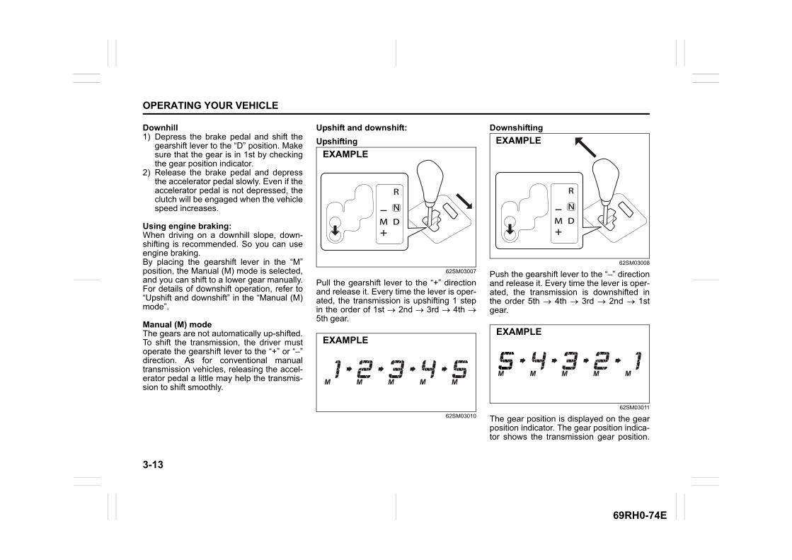
3-13
OPERATING YOUR VEHICLE
69RH0-74E
Downhill1) Depress the brake pedal and shift the
gearshift lever to the “D” position. Makesure that the gear is in 1st by checkingthe gear position indicator.
2) Release the brake pedal and depressthe accelerator pedal slowly. Even if theaccelerator pedal is not depressed, theclutch will be engaged when the vehiclespeed increases.
Using engine braking:When driving on a downhill slope, down-shifting is recommended. So you can useengine braking.By placing the gearshift lever in the “M”position, the Manual (M) mode is selected,and you can shift to a lower gear manually.For details of downshift operation, refer to“Upshift and downshift” in the “Manual (M)mode”.
Manual (M) modeThe gears are not automatically up-shifted.To shift the transmission, the driver mustoperate the gearshift lever to the “+” or “–”direction. As for conventional manualtransmission vehicles, releasing the accel-erator pedal a little may help the transmis-sion to shift smoothly.
Upshift and downshift:
Upshifting
62SM03007
Pull the gearshift lever to the “+” directionand release it. Every time the lever is oper-ated, the transmission is upshifting 1 stepin the order of 1st 2nd 3rd 4th 5th gear.
62SM03010
Downshifting
62SM03008
Push the gearshift lever to the “–” directionand release it. Every time the lever is oper-ated, the transmission is downshifted inthe order 5th 4th 3rd 2nd 1stgear.
62SM03011
The gear position is displayed on the gearposition indicator. The gear position indica-tor shows the transmission gear position.
EXAMPLE
EXAMPLE
EXAMPLE
EXAMPLE
3-14
OPERATING YOUR VEHICLE
69RH0-74E
Before starting off, always check the gearposition indicator to make sure that thetransmission is engaged in 1st or reverse,then depress the accelerator pedal.It is possible to start vehicle in 2nd gearusing manual mode, from stop condition.
NOTE:• Always use 1st gear while starting off on
an uphill slope otherwise you can dam-age the clutch.
• To downshift smoothly, the engine runsfast in some cases. This is done inten-tionally by the system and is not mal-function.
• When driving down a hill, downshift anduse the engine braking appropriately. Ifnecessary, continuous downshifting ispossible. However, if downshifting morethan 3 steps, gear shifting will take moretime.
• When the gear is shifting, a noise can beheard in some case. This is not malfunc-tion.
WARNING
• Be careful when accelerating,upshifting, downshifting or brakingon a slippery surface. Suddenacceleration or engine brakingcould cause the vehicle to spin orskid. While starting off on a slip-pery or snowy roads, please use2nd gear.
• To drive down a long or steep hill,reduce your speed and downshift.Remember, if you ride the brakesexcessively, they may overheat andfail.
• While driving the vehicle, do notshift the gearshift lever to “N” posi-tion. The engine brake may notwork and you may get involved inan accident. If you return the gear-shift lever from “N” to “M” becauseof unintended shifting, the gearposition will be shifted accordingto the current vehicle speed.
• Do not apply the parking brakewhile driving. Otherwise, it couldcause a skid and you may getinvolved in an accident.
NOTICE
• If the gearshift lever cannot shiftinto any position, or the gear ischanged to “N” position automati-cally when the vehicle speedbecomes less than 10 km/h, theremay be a systematic malfunction.In this case, ask a Maruti Suzukiauthorised workshop to inspect theAuto Gear Shift system as soon aspossible.
• The manual (M) mode does notupshift even if the engine speedreaches the rev-limit.
• The system will not allow shiftingup or down to a gear that wouldcause engine over-revving orunder-revving.
• If frequently driving at low speedusing a high gear position, the lifecycle of the clutch may be reduced.
• Frequent downshifting (more than3 positions consecutively) causesthe reduction of transmission life.
3-15
OPERATING YOUR VEHICLE
69RH0-74E
Starting off:1) Start the engine as instructed in “Start-
ing the engine” in this section.2) With your foot on the brake pedal, shift
the gearshift lever to the “M” position.When the gearshift lever is shifted tothe “M” position, the gear will be shiftedto 1st. Before starting off, always makesure that the intended gear is engagedby checking the gear position indicator,then depress the accelerator pedal.
NOTE:• If 1st gear cannot be engaged even
though the gearshift lever has beenshifted from the “N” to the “M” position,the system will re-try shifting automati-cally. This will take some time, noisemay be heard from the gears, and shift-ing gear shock may occur. However,they do not indicate malfunction.
• The “N” indicator will flash, the depressbrake pedal indicator will come on and awarning buzzer (long pulse sound) willsound if any of the following casesoccur;– If you shift the gearshift lever from the
“N” to the “M” position withoutdepressing the brake pedal
– If the system is unable to re-try shiftingYou should depress the brake pedal andshift the gearshift lever to “N” position,then shift to “M” position again a fewseconds later.
3) Release the parking brake and brakepedal. Depress the accelerator pedalslowly for smooth starting.
Starting off on an uphill/downhill slope:
Uphill1) Apply the parking brake firmly so that
the vehicle does not roll backwards.2) Shift the gearshift lever to the “M” posi-
tion while depressing the brake pedal.Make sure that the gear position indica-tor in the instrumental cluster displays1st gear.
3) Release the brake pedal and depressthe accelerator pedal gradually, andwhen the vehicle starts to move,release the parking brake and depressthe accelerator pedal to start off.
WARNING
Always keep your foot on the brakepedal while stopped with the enginerunning. These operations preventthe vehicle from starting due to unin-tended activation of the creepingfunction.
NOTICE
Do not operate the system asdescribed below. The life cycle of theclutch may be reduced.• Using the accelerator pedal to hold
the vehicle on an uphill slope oper-ation with the gearshift lever in the“M” or “D” position. If you performthis operation for a certain periodof time, a warning buzzer willsound.
• Shifting the gearshift lever to the“M”, “D” or “R” position while rac-ing the engine.
• Driving at low speed using a highgear.
• Stopping on a slope using thecreeping function. If you performthis operation for a certain periodof time, a warning buzzer willsound.
NOTICE
On an uphill slope, never hold thevehicle at a stop using only the accel-erator pedal or creeping function. Ifyou perform this operation for a cer-tain period of time, a warning buzzerwill sound, and in some cases theengine will stall. This can also causeexcessive damage to the clutch.In case the warning buzzer is on,shifting to 2nd gear will not be possi-ble in manual mode. Always use 1stgear while starting off on a uphillslope. Otherwise you may damagethe clutch.
3-16
OPERATING YOUR VEHICLE
69RH0-74E
Downhill1) Depress the brake pedal and shift the
gearshift lever to the “M” position.Check the gear position indicator tomake sure that the gear is in 1st.
2) Release the brake pedal and depressthe accelerator pedal slowly. Eventhough the accelerator pedal is notdepressed, the clutch will be engagedwhen the vehicle speed increases.
Backing upAfter the vehicle has stopped completely,depress the brake pedal and shift the gear-shift lever to the “R” position. Depress theaccelerator pedal slowly as when startingoff in 1st gear. Before backing up, makesure that reverse gear is selected bychecking the gear position indicator.
NOTE:• If reverse gear cannot be engaged even
though the gearshift lever has beenshifted from the “N” to the “R” position,the system will re-try shifting automati-cally. This will take some time, noisemay be heard from the gears, and shift-ing gear shock may occur. However,they do not indicate malfunction.
• The “N” indicator will flash, the depressbrake pedal indicator will come on and awarning buzzer (long pulse sound) willsound if any of the following casesoccur;
– If you shift the gearshift lever from the“N” to the “R” position without depress-ing the brake pedal
– If the system is unable to re-try shiftingYou should depress the brake pedal andshift the gearshift lever to “N” position,then shift to “R” position again a few sec-onds later.
• The system will not allow shifting to the“R” position if the vehicle speed is overabout 3 km/h. If the gearshift lever isoperated under this condition, the “N”indicator in the instrument cluster willblink. However, when the vehicle speeddrops below about 3 km/h, the gear willbe shifted to reverse. Make sure that thevehicle has stopped completely beforeshifting to the “R” position.
StoppingThe vehicle can be stopped by depressingthe brake pedal regardless of the gearposition. This is because the clutch is auto-matically disengaged to prevent the enginefrom stopping. • If the gearshift lever is in the “D” position,
the gear will be downshifted to 1st whenthe vehicle stops.
• If the gearshift lever is in the “M” posi-tion, the gear will be downshifted to 1stwhen the vehicle stops.
NOTICE
On a downhill slope, never hold thevehicle at a stop with gearshift leverin “R” position. If you perform thisoperation for a certain period of time,a warning buzzer will sound, and insome cases the engine will stall. Thiscan also cause excessive damage tothe clutch.
WARNING
• When stopping, for example, at atraffic light, be sure to depress thebrake pedal firmly. For your safety,apply the parking brake, too, whenstopping on a hill.
• When racing the engine, make surethat the gear is in the “N” positionby checking the gear position indi-cator. If the accelerator is operatedwith the gear in any other position,the vehicle may move resulting inan accident.
• Do not leave your vehicle unat-tended while the engine is running.
(Continued)

3-17
OPERATING YOUR VEHICLE
69RH0-74E
ParkingUnlike an automatic transmission, AutoGear Shift does not have a parking posi-tion. Park the vehicle with a gear engaged.1) Apply the parking brake firmly.2) While depressing the brake pedal, shift
the gearshift lever to the “R” position ona downhill slope, and to the 1st positionin the drive (D) mode or the “M” positionin the manual (M) mode on an uphillslope and confirm the gear position bychecking the gear position indicator.
3) Stop the engine.
NOTE:• After ignition is OFF, the gear in the
transmission does not change even ifyou shift the gearshift lever in any posi-tion with or without brake pedal pressed.Always shift the gearshift lever beforestopping the engine.
• Check the transmission gear position bylooking at the gear position indicator,then turn the ignition switch to “LOCK”position, to stop the engine. Release thebrake pedal after a few seconds.
• The ignition switch is turned to the“LOCK” position with the gear in 2nd,3rd, 4th or 5th. In this case, turn the igni-tion switch to “ON” position, and shift thegearshift lever in the “N” position, shift itto the “D” or “M” or “R” position, then turnthe ignition switch to “LOCK” position.
Parking cancelDepress the brake pedal, turn the ignitionswitch to “ON” position, and shift the gear-shift lever to the “N” position. The gear willbe disengaged.
Warning functionsA warning buzzer will sound or the indica-tor will blink under the following conditions.
WARNING
(Continued)• When leaving the vehicle, stop the
engine and park the vehicle with agear engaged. If you need to leavethe vehicle with the engine running,apply the parking brakes firmly,and shift the gearshift lever to the“N” position. Otherwise, the vehi-cle may move unexpectedly andmay cause an accident.
NOTICE
• On a slope, never hold the vehicleat a stop using only the acceleratorpedal or the creeping function. Ifyou perform this operation for acertain period of time, a warningbuzzer will sound, and in somecases the engine will stall. This canalso cause excessive damage tothe clutch.
• If the gearshift lever is operatedmore than necessary, the systemmay not allow operation of thegearshift for a certain period oftime, and the gear may not beshifted appropriately. Therefore, donot operate the gearshift lever if notnecessary.
WARNING
• If the gear is not engaged properlyand completely before the ignitionswitch is turned to “LOCK” posi-tion, the vehicle may not be parkedwith the gear engaged. Always con-firm the gear position by checkingthe gear position indicator whenparking.
• On a downhill slope, the gearshould be put in reverse, and in 1stgear on an uphill slope. Otherwise,the vehicle may move, and causean accident. If the gear is left in the“N” position, the vehicle cannot beparked with a gear engaged.
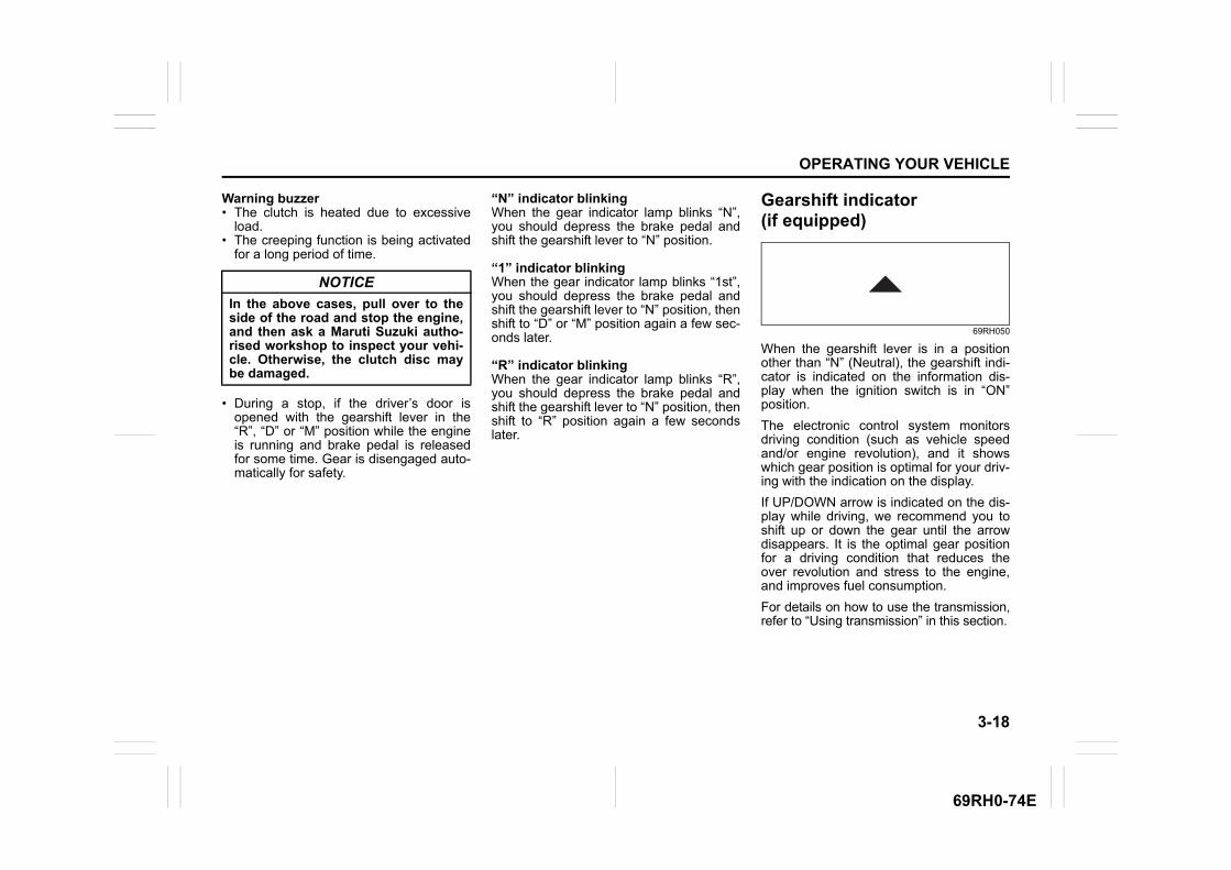
3-18
OPERATING YOUR VEHICLE
69RH0-74E
Warning buzzer• The clutch is heated due to excessive
load.• The creeping function is being activated
for a long period of time.
• During a stop, if the driver’s door isopened with the gearshift lever in the“R”, “D” or “M” position while the engineis running and brake pedal is releasedfor some time. Gear is disengaged auto-matically for safety.
“N” indicator blinkingWhen the gear indicator lamp blinks “N”,you should depress the brake pedal andshift the gearshift lever to “N” position.
“1” indicator blinkingWhen the gear indicator lamp blinks “1st”,you should depress the brake pedal andshift the gearshift lever to “N” position, thenshift to “D” or “M” position again a few sec-onds later.
“R” indicator blinkingWhen the gear indicator lamp blinks “R”,you should depress the brake pedal andshift the gearshift lever to “N” position, thenshift to “R” position again a few secondslater.
Gearshift indicator (if equipped)
69RH050
When the gearshift lever is in a positionother than “N” (Neutral), the gearshift indi-cator is indicated on the information dis-play when the ignition switch is in “ON”position.
The electronic control system monitorsdriving condition (such as vehicle speedand/or engine revolution), and it showswhich gear position is optimal for your driv-ing with the indication on the display.
If UP/DOWN arrow is indicated on the dis-play while driving, we recommend you toshift up or down the gear until the arrowdisappears. It is the optimal gear positionfor a driving condition that reduces theover revolution and stress to the engine,and improves fuel consumption.
For details on how to use the transmission,refer to “Using transmission” in this section.
NOTICE
In the above cases, pull over to theside of the road and stop the engine,and then ask a Maruti Suzuki autho-rised workshop to inspect your vehi-cle. Otherwise, the clutch disc maybe damaged.
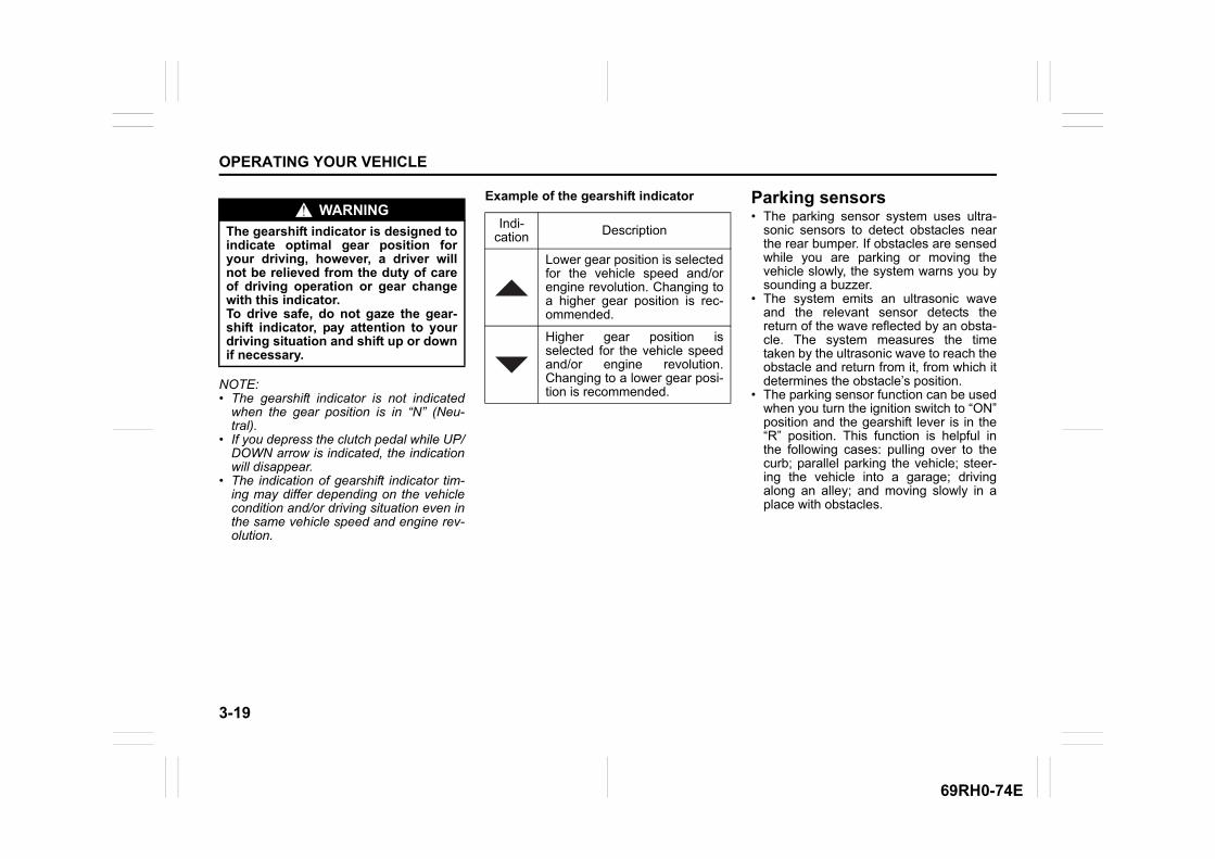
3-19
OPERATING YOUR VEHICLE
69RH0-74E
NOTE:• The gearshift indicator is not indicated
when the gear position is in “N” (Neu-tral).
• If you depress the clutch pedal while UP/DOWN arrow is indicated, the indicationwill disappear.
• The indication of gearshift indicator tim-ing may differ depending on the vehiclecondition and/or driving situation even inthe same vehicle speed and engine rev-olution.
Example of the gearshift indicator Parking sensors• The parking sensor system uses ultra-
sonic sensors to detect obstacles nearthe rear bumper. If obstacles are sensedwhile you are parking or moving thevehicle slowly, the system warns you bysounding a buzzer.
• The system emits an ultrasonic waveand the relevant sensor detects thereturn of the wave reflected by an obsta-cle. The system measures the timetaken by the ultrasonic wave to reach theobstacle and return from it, from which itdetermines the obstacle’s position.
• The parking sensor function can be usedwhen you turn the ignition switch to “ON”position and the gearshift lever is in the“R” position. This function is helpful inthe following cases: pulling over to thecurb; parallel parking the vehicle; steer-ing the vehicle into a garage; drivingalong an alley; and moving slowly in aplace with obstacles.
WARNING
The gearshift indicator is designed toindicate optimal gear position foryour driving, however, a driver willnot be relieved from the duty of careof driving operation or gear changewith this indicator.To drive safe, do not gaze the gear-shift indicator, pay attention to yourdriving situation and shift up or downif necessary.
Indi-cation Description
Lower gear position is selectedfor the vehicle speed and/orengine revolution. Changing toa higher gear position is rec-ommended.
Higher gear position isselected for the vehicle speedand/or engine revolution.Changing to a lower gear posi-tion is recommended.
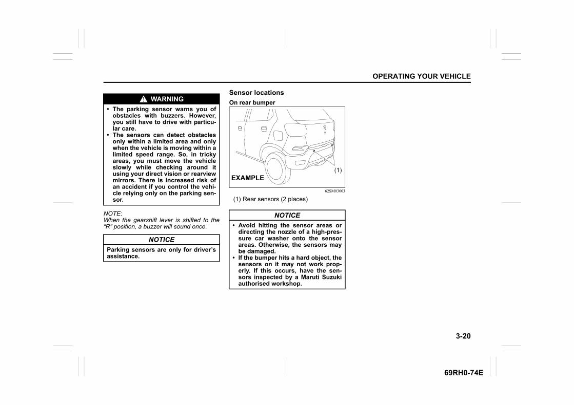
3-20
OPERATING YOUR VEHICLE
69RH0-74E
NOTE:When the gearshift lever is shifted to the“R” position, a buzzer will sound once.
Sensor locations
On rear bumper
62SM03003
(1) Rear sensors (2 places)
WARNING
• The parking sensor warns you ofobstacles with buzzers. However,you still have to drive with particu-lar care.
• The sensors can detect obstaclesonly within a limited area and onlywhen the vehicle is moving within alimited speed range. So, in trickyareas, you must move the vehicleslowly while checking around itusing your direct vision or rearviewmirrors. There is increased risk ofan accident if you control the vehi-cle relying only on the parking sen-sor.
NOTICE
Parking sensors are only for driver’sassistance.
NOTICE
• Avoid hitting the sensor areas ordirecting the nozzle of a high-pres-sure car washer onto the sensorareas. Otherwise, the sensors maybe damaged.
• If the bumper hits a hard object, thesensors on it may not work prop-erly. If this occurs, have the sen-sors inspected by a Maruti Suzukiauthorised workshop.
(1)EXAMPLE
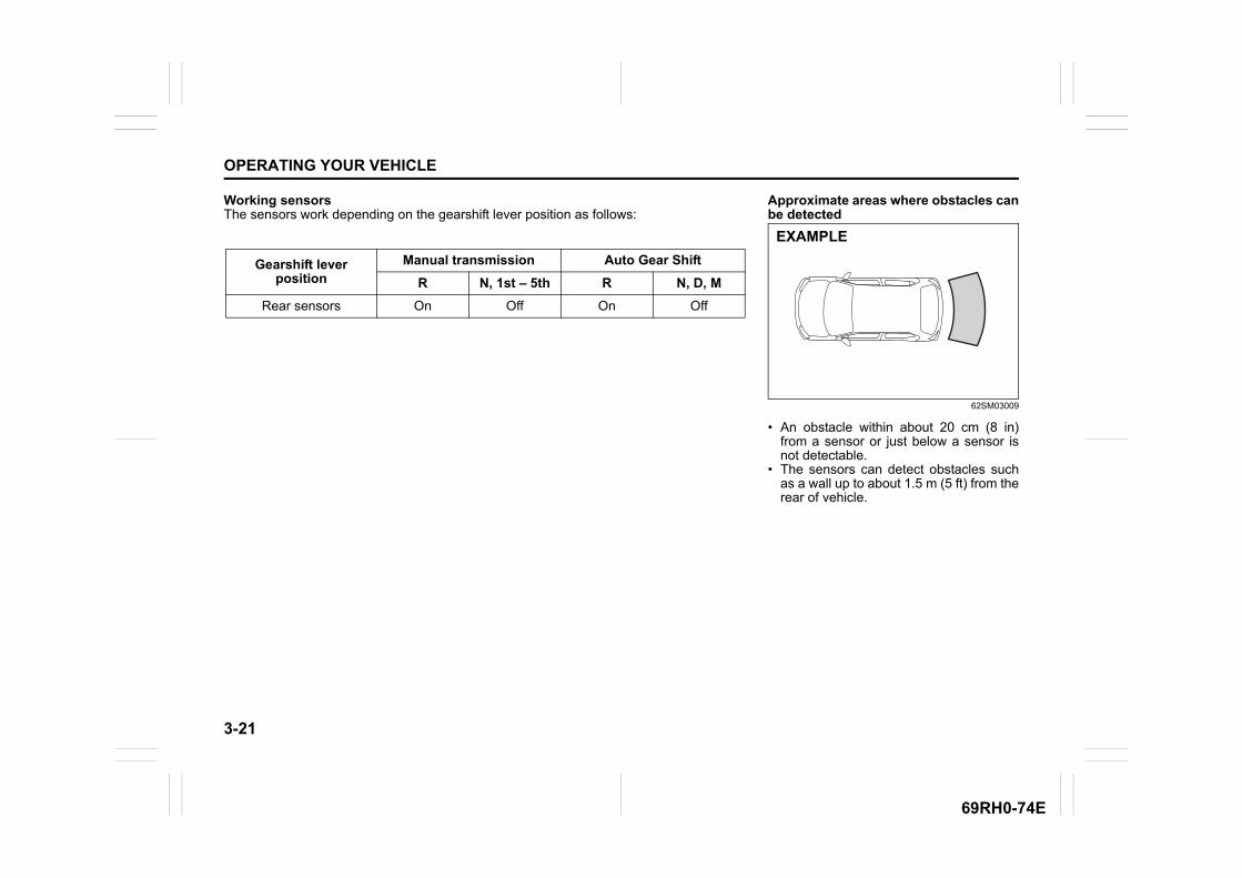
3-21
OPERATING YOUR VEHICLE
69RH0-74E
Working sensorsThe sensors work depending on the gearshift lever position as follows:
Gearshift leverposition
Manual transmission Auto Gear Shift
R N, 1st – 5th R N, D, M
Rear sensors On Off On Off
Approximate areas where obstacles canbe detected
62SM03009
• An obstacle within about 20 cm (8 in)from a sensor or just below a sensor isnot detectable.
• The sensors can detect obstacles suchas a wall up to about 1.5 m (5 ft) from therear of vehicle.
EXAMPLE
3-22
OPERATING YOUR VEHICLE
69RH0-74E
NOTE:• Thin poles or obstacles lower than the
sensors may become undetectable asthe vehicle moves closer to them even ifthey have been detected from longerdistances.
• The system may calculate the distanceto a road sign or similar obstacle to beshorter than the actual distance.
Obstacle indication by parking sensorUpon detecting an obstacle, the parkingsensor causes an interior buzzer to sound. • A buzzer located behind the rear seat
sounds when a sensor at the reardetects an obstacle.
• Warnings when obstacles such as wallare detected by sensors
Warning and indicator messagesIf there is a problem or warning regardingthe parking sensor system, a buzzerinforms it. Follow its instruction.The buzzer sounds intermittently. The indi-cated sensor is contaminated. Wipe itclean with a soft cloth. If the buzzer doesnot stop after wiping, there may be prob-lem with the parking sensor system. Haveyour vehicle inspected by a Maruti Suzukiauthorised workshop.
WARNING
Under the following conditions, theparking sensor system may not worknormally because the sensors cannotdetect obstacles correctly.
– Sensors are covered with mud,ice or other materials. (Suchmaterials must be removed fornormal operation.)
– Sensors are wet from watersplashes or heavy rain.
– Sensors are covered by a hand,sticker, accessory, etc.
– There is an accessory or otherobject attached within the sen-sor’s sensing area.
– Items such as tow hooks, com-mercially available corner poles,radio antenna, etc. are installedon the bumper.
– The height of the bumper ischanged due to alteration to thesuspension or other causes.
– The sensor areas are extremelyhot from direct sunlight or colddue to freezing weather.
– The vehicle is on a rough sur-face, slope, gravel road or grassfield.
– The vehicle is at a steep angle.(Continued)
WARNING
(Continued)– Sensors have intercepted ultra-
sonic noise from another vehi-cle’s horn, engine, air brakingsystem (large vehicles), or park-ing sensor.
– Obstacles are too close to thesensors.
– Sensors are at an angle to ahighly reflective object such asglass. (Ultrasonic waves are notreflected back from the obstacle.)
• Sensors may not be able to cor-rectly detect the following types ofobstacles:– Objects made of a thin material
such as wire netting and ropes – Square-shaped curbstones or
other objects with sharp edges – Tall objects with a large upper
part such as a road sign – Low-profile objects such as curb-
stones – Sound-absorbing objects such
as cotton and snow
Distance(approx.) Buzzer
100 – 150 cm(39 – 59 in)
Short beeps at shortintervals
60 – 100 cm(24 – 39 in)
Short beeps at veryshort intervals
Less than60 cm (24 in) Continuous beep
3-23
OPERATING YOUR VEHICLE
69RH0-74E
Braking
60G165S
The distance needed to bring any vehicleto a halt increases with the speed of thevehicle. The braking distance needed, forexample, at 60 km/h will be approximately4 times greater than the braking distanceneeded at 30 km/h. Start to depress thebrake pedal when there is plenty of dis-tance between your vehicle and the stop-ping point, and slow down gradually.
Power-assisted brakesYour vehicle has power-assisted brakes. Ifpower assistance is lost due to a stalledengine or other failures, the system is stillfully operational on reserve power and youcan bring the vehicle to a complete stop bypressing the brake pedal once and holdingit down. The reserve power is partly usedup when you depress the brake pedal andreduces each time the pedal is pressed.Apply smooth and even pressure to thepedal. Do not pump the brake pedal.
EXAMPLE
WARNING
If water gets into the brake devices,brake performance may become poorand unpredictable. After drivingthrough water or washing the under-side of the vehicle, test the brakeswhile driving at a slow speed to see ifthey have maintained their normaleffectiveness. If the brakes are lesseffective than normal, dry them byrepeatedly applying the brakes whiledriving slowly until the brakes haveregained their normal effectiveness.
WARNING
Even without reserve power in thebrake system, you can still stop thevehicle by pressing the brake pedalharder than normally required. How-ever, the stopping distance may belonger.
3-24
OPERATING YOUR VEHICLE
69RH0-74E
Anti-lock brake system (ABS)ABS will help you avoid skidding by elec-tronically controlling braking pressure. Itwill also help you maintain steering controlwhen braking on slippery surfaces or whenbraking hard.The ABS works automatically, so you donot need any special braking technique.Just push the brake pedal down withoutpumping. The ABS will operate wheneverit senses that the wheels are locking up.You may feel the brake pedal move a littlewhile the ABS is operating.
NOTE:• The ABS will not work if vehicle speed is
under about 9 km/h.• If the ABS system is activated, you may
hear a clunking noise and/or feel pulsat-ing in the brake pedal. This is normaland indicates that the brake fluid pres-sure is being controlled properly.
• You may hear an operation sound whenyou start the engine or after the vehiclebegins to move. This means that theabove systems are in the self-checkmode. This sound does not indicate amalfunction.
54MN069
(1) ABS warning light(2) Brake system warning light
WARNING
• On some types of loose surfaces(such as gravel, snow-coveredroads, etc.), the stopping distancerequired for a vehicle with ABSmay be slightly greater than theone required for a comparable vehi-cle with a conventional brake sys-tem. With a conventional brakesystem, skidding tires are able toplow the gravel or snow layer,shortening the stopping distance.ABS minimizes this resistanceeffect. Allow for extra stopping dis-tance when driving on loose sur-faces.
• On regular paved roads, some driv-ers may be able to obtain slightlyshorter stopping distances withconventional brake systems thanwith ABS.
• In both of the above conditions,ABS will still offer the advantage ofhelping you maintain directionalcontrol. However, remember thatABS will not compensate for badroad or weather conditions or poordriver judgment. Use good judg-ment and do not drive too fast.
(1) (2)
EXAMPLE
3-25
OPERATING YOUR VEHICLE
69RH0-74E
How ABS worksA computer continuously monitors wheelspeed. The computer compares thechanges in wheel speed when braking. Ifthe wheels slow suddenly, indicating askidding situation, the computer willchange braking pressure several timeseach second to prevent the wheels fromlocking. When you start your vehicle orwhen you accelerate after a hard stop, youmay hear a momentary motor or clickingnoise as the system resets or checks itself.
WARNING
• If the ABS warning light (1) on theinstrument cluster comes on andstays on while driving, there maybe a problem with the ABS system.Ask a Maruti Suzuki authorisedworkshop to inspect the ABS sys-tem immediately. If the ABS systembecomes inoperative, the brakesystem will function as an ordinarybrake system that has no ABS.
• If the ABS warning light (1) and thebrake system warning light (2) onthe instrument cluster simultane-ously stay on or come on whiledriving, both anti-lock function andrear brake force control function(proportioning valve function) ofthe ABS system may have failed. Ifso, the rear wheels may easily skidor the vehicle can even spin in theworst case when braking on a slip-pery road or when hard brakingeven on a dry paved road. Ask aMaruti Suzuki authorised workshopto inspect the ABS system immedi-ately. Drive carefully, avoiding hardbraking as much as possible.
WARNING
The ABS may not work properly iftires or wheels other than thosespecified in the owner’s manual areused. This is because the ABS worksby comparing changes in wheelspeed. When replacing tires orwheels, use only the size and typespecified in this owner’s manual.
DRIVING TIPS
4
69RH0-74E
60G409A
DRIVING TIPSRunning-in ........................................................................... 4-1Catalytic converter .............................................................. 4-1Improving fuel economy ..................................................... 4-2Highway driving .................................................................. 4-3Driving on hills .................................................................... 4-3Driving on slippery roads ................................................... 4-4Off-road driving ................................................................... 4-6When encountering a flooded area ................................... 4-6Do’s and Dont’s for safe driving......................................... 4-7Margin for safety .................................................................. 4-9
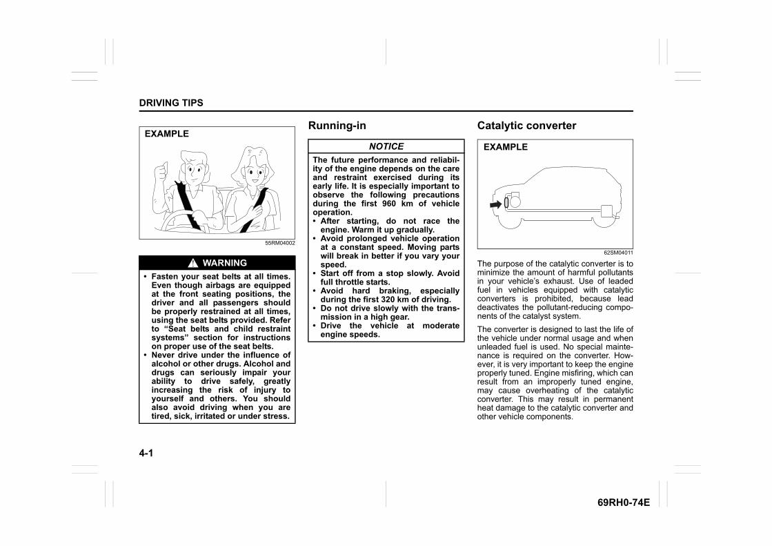
4-1
DRIVING TIPS
69RH0-74E
55RM04002
Running-in Catalytic converter
62SM04011
The purpose of the catalytic converter is tominimize the amount of harmful pollutantsin your vehicle’s exhaust. Use of leadedfuel in vehicles equipped with catalyticconverters is prohibited, because leaddeactivates the pollutant-reducing compo-nents of the catalyst system.
The converter is designed to last the life ofthe vehicle under normal usage and whenunleaded fuel is used. No special mainte-nance is required on the converter. How-ever, it is very important to keep the engineproperly tuned. Engine misfiring, which canresult from an improperly tuned engine,may cause overheating of the catalyticconverter. This may result in permanentheat damage to the catalytic converter andother vehicle components.
WARNING
• Fasten your seat belts at all times.Even though airbags are equippedat the front seating positions, thedriver and all passengers shouldbe properly restrained at all times,using the seat belts provided. Referto “Seat belts and child restraintsystems” section for instructionson proper use of the seat belts.
• Never drive under the influence ofalcohol or other drugs. Alcohol anddrugs can seriously impair yourability to drive safely, greatlyincreasing the risk of injury toyourself and others. You shouldalso avoid driving when you aretired, sick, irritated or under stress.
EXAMPLENOTICE
The future performance and reliabil-ity of the engine depends on the careand restraint exercised during itsearly life. It is especially important toobserve the following precautionsduring the first 960 km of vehicleoperation.• After starting, do not race the
engine. Warm it up gradually.• Avoid prolonged vehicle operation
at a constant speed. Moving partswill break in better if you vary yourspeed.
• Start off from a stop slowly. Avoidfull throttle starts.
• Avoid hard braking, especiallyduring the first 320 km of driving.
• Do not drive slowly with the trans-mission in a high gear.
• Drive the vehicle at moderateengine speeds.
EXAMPLE
4-2
DRIVING TIPS
69RH0-74E
62SM04002
Improving fuel economy
NOTE:Fuel economy (mileage) of the vehicle mayvary due to several factors i.e., drivinghabits - gear change pattern, usage of A.C,air pressure in the tyres, wind speed, trafficconditions, fuel quality- non adulteratedstandard fuel, maintenance of vehicle,road conditions, braking etc.
The following instructions will help youimprove fuel economy.
Avoid excessive idlingIf you are to wait for more than a minutewhile you are parked, stop the engine andstart it again later. When warming up acold engine, do not allow the engine to idleor apply full throttle until the engine hasreached operating temperature. Allow theengine to warm up by driving.
Avoid sudden accelerationSudden acceleration starting from rest orwhile driving will consume fuel unneces-sarily and shorten engine life. Start offslowly.
Avoid unnecessary stopsAvoid unnecessary deceleration and stop-ping. Try to maintain a slow, steady speedwhenever possible. Slowing down andthen accelerating again uses more fuel.
Keep a steady cruising speedDrive at a constant speed that road andtraffic conditions will permit.
NOTICE
To minimize the possibility of cata-lytic converter or other vehicle dam-age:• Maintain the engine in the proper
operating condition.• In the event of an engine malfunc-
tion, particularly one involvingengine misfire or other apparentloss of performance, have the vehi-cle serviced promptly.
• Do not turn off the engine or inter-rupt the ignition when the transmis-sion is in gear and the vehicle is inmotion.
• Do not try to start the engine bypushing or towing the vehicle, orcoasting down a hill.
• Do not idle the engine with anyspark plug wires disconnected orremoved, such as during diagnos-tic testing.
• Do not idle the vehicle for pro-longed periods if idling seemsrough or there are other malfunc-tions.
• Do not allow the fuel tank to getnear the empty level.
WARNING
Be careful where you park and drive;the catalytic converter and otherexhaust components can get veryhot. As with any vehicle, do not parkor operate this vehicle in areas wherecombustible materials such as drygrass or leaves can come in contactwith a hot exhaust system.
EXAMPLE
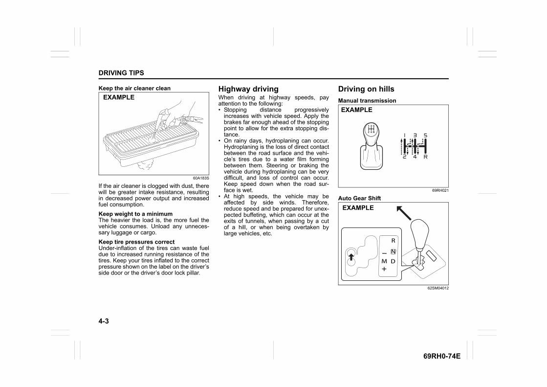
4-3
DRIVING TIPS
69RH0-74E
Keep the air cleaner clean
60A183S
If the air cleaner is clogged with dust, therewill be greater intake resistance, resultingin decreased power output and increasedfuel consumption.
Keep weight to a minimumThe heavier the load is, the more fuel thevehicle consumes. Unload any unneces-sary luggage or cargo.
Keep tire pressures correctUnder-inflation of the tires can waste fueldue to increased running resistance of thetires. Keep your tires inflated to the correctpressure shown on the label on the driver’sside door or the driver’s door lock pillar.
Highway drivingWhen driving at highway speeds, payattention to the following:• Stopping distance progressively
increases with vehicle speed. Apply thebrakes far enough ahead of the stoppingpoint to allow for the extra stopping dis-tance.
• On rainy days, hydroplaning can occur.Hydroplaning is the loss of direct contactbetween the road surface and the vehi-cle’s tires due to a water film formingbetween them. Steering or braking thevehicle during hydroplaning can be verydifficult, and loss of control can occur.Keep speed down when the road sur-face is wet.
• At high speeds, the vehicle may beaffected by side winds. Therefore,reduce speed and be prepared for unex-pected buffeting, which can occur at theexits of tunnels, when passing by a cutof a hill, or when being overtaken bylarge vehicles, etc.
Driving on hills
Manual transmission
69RH021
Auto Gear Shift
62SM04012
EXAMPLE
EXAMPLE
EXAMPLE
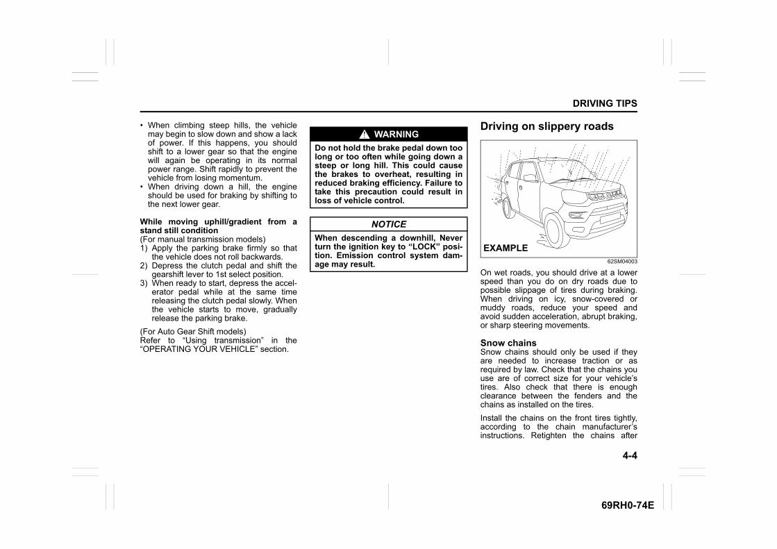
4-4
DRIVING TIPS
69RH0-74E
• When climbing steep hills, the vehiclemay begin to slow down and show a lackof power. If this happens, you shouldshift to a lower gear so that the enginewill again be operating in its normalpower range. Shift rapidly to prevent thevehicle from losing momentum.
• When driving down a hill, the engineshould be used for braking by shifting tothe next lower gear.
While moving uphill/gradient from astand still condition(For manual transmission models) 1) Apply the parking brake firmly so that
the vehicle does not roll backwards.2) Depress the clutch pedal and shift the
gearshift lever to 1st select position. 3) When ready to start, depress the accel-
erator pedal while at the same timereleasing the clutch pedal slowly. Whenthe vehicle starts to move, graduallyrelease the parking brake.
(For Auto Gear Shift models)Refer to “Using transmission” in the“OPERATING YOUR VEHICLE” section.
Driving on slippery roads
62SM04003
On wet roads, you should drive at a lowerspeed than you do on dry roads due topossible slippage of tires during braking.When driving on icy, snow-covered ormuddy roads, reduce your speed andavoid sudden acceleration, abrupt braking,or sharp steering movements.
Snow chainsSnow chains should only be used if theyare needed to increase traction or asrequired by law. Check that the chains youuse are of correct size for your vehicle’stires. Also check that there is enoughclearance between the fenders and thechains as installed on the tires.
Install the chains on the front tires tightly,according to the chain manufacturer’sinstructions. Retighten the chains after
WARNING
Do not hold the brake pedal down toolong or too often while going down asteep or long hill. This could causethe brakes to overheat, resulting inreduced braking efficiency. Failure totake this precaution could result inloss of vehicle control.
NOTICE
When descending a downhill, Neverturn the ignition key to “LOCK” posi-tion. Emission control system dam-age may result.
EXAMPLE
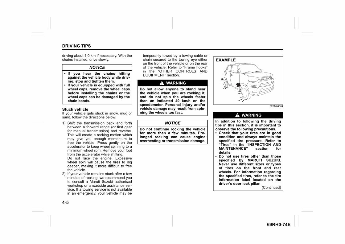
4-5
DRIVING TIPS
69RH0-74E
driving about 1.0 km if necessary. With thechains installed, drive slowly.
Stuck vehicleIf your vehicle gets stuck in snow, mud orsand, follow the directions below:
1) Shift the transmission back and forthbetween a forward range (or first gearfor manual transmission) and reverse.This will create a rocking motion whichmay give you enough momentum tofree the vehicle. Press gently on theaccelerator to keep wheel spinning to aminimum wheel rpm. Remove your footfrom the accelerator while shifting. Do not race the engine. Excessivewheel spin will cause the tires to digdeeper, making it more difficult to freethe vehicle.
2) If your vehicle remains stuck after a fewminutes of rocking, we recommend youto consult a Maruti Suzuki authorisedworkshop or a roadside assistance ser-vice. If a towing service is not availablein an emergency, your vehicle may be
temporarily towed by a towing cable orchain secured to the towing eye eitheron the front of the vehicle or on the rearof the vehicle. Refer to “Frame hooks”in the “OTHER CONTROLS ANDEQUIPMENT” section.
62SM04004
NOTICE
• If you hear the chains hittingagainst the vehicle body while driv-ing, stop and tighten them.
• If your vehicle is equipped with fullwheel caps, remove the wheel capsbefore installing the chains or thewheel caps can be damaged by thechain bands.
WARNING
Do not allow anyone to stand nearthe vehicle when you are rocking it,and do not spin the wheels fasterthan an indicated 40 km/h on thespeedometer. Personal injury and/orvehicle damage may result from spin-ning the wheels too fast.
NOTICE
Do not continue rocking the vehiclefor more than a few minutes. Pro-longed rocking can cause engineoverheating or transmission damage.
WARNING
In addition to following the drivingtips in this section, it is important toobserve the following precautions.• Check that your tires are in good
condition and always maintain thespecified tire pressure. Refer to“Tires” in the “INSPECTION ANDMAINTENANCE” section fordetails.
• Do not use tires other than thosespecified by MARUTI SUZUKI.Never use different sizes or typesof tires on the front and rearwheels. For information regardingthe specified tires, refer to the tireinformation label located on thedriver’s door lock pillar.
(Continued)
EXAMPLE
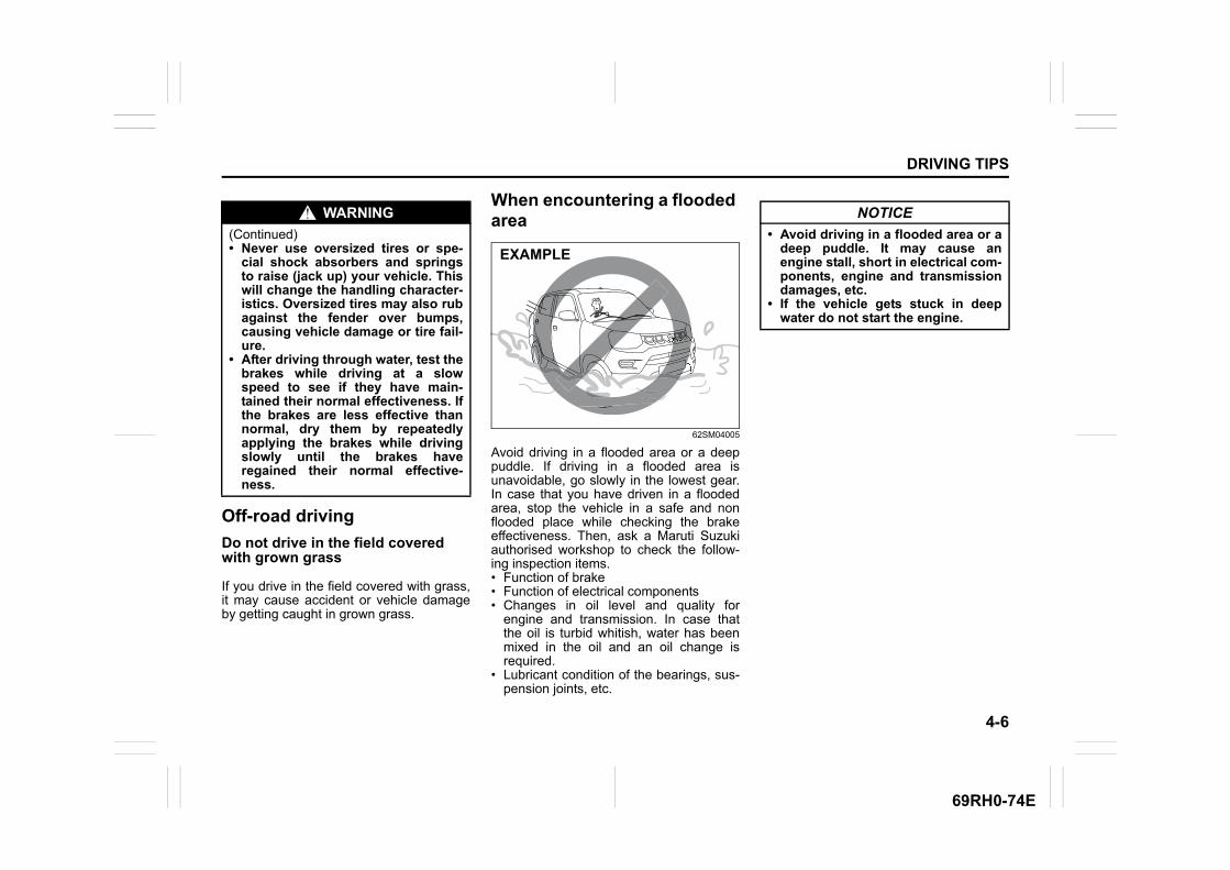
4-6
DRIVING TIPS
69RH0-74E
Off-road driving
Do not drive in the field covered with grown grass
If you drive in the field covered with grass,it may cause accident or vehicle damageby getting caught in grown grass.
When encountering a flooded area
62SM04005
Avoid driving in a flooded area or a deeppuddle. If driving in a flooded area isunavoidable, go slowly in the lowest gear.In case that you have driven in a floodedarea, stop the vehicle in a safe and nonflooded place while checking the brakeeffectiveness. Then, ask a Maruti Suzukiauthorised workshop to check the follow-ing inspection items.• Function of brake• Function of electrical components• Changes in oil level and quality for
engine and transmission. In case thatthe oil is turbid whitish, water has beenmixed in the oil and an oil change isrequired.
• Lubricant condition of the bearings, sus-pension joints, etc.
WARNING
(Continued)• Never use oversized tires or spe-
cial shock absorbers and springsto raise (jack up) your vehicle. Thiswill change the handling character-istics. Oversized tires may also rubagainst the fender over bumps,causing vehicle damage or tire fail-ure.
• After driving through water, test thebrakes while driving at a slowspeed to see if they have main-tained their normal effectiveness. Ifthe brakes are less effective thannormal, dry them by repeatedlyapplying the brakes while drivingslowly until the brakes haveregained their normal effective-ness.
EXAMPLE
NOTICE
• Avoid driving in a flooded area or adeep puddle. It may cause anengine stall, short in electrical com-ponents, engine and transmissiondamages, etc.
• If the vehicle gets stuck in deepwater do not start the engine.
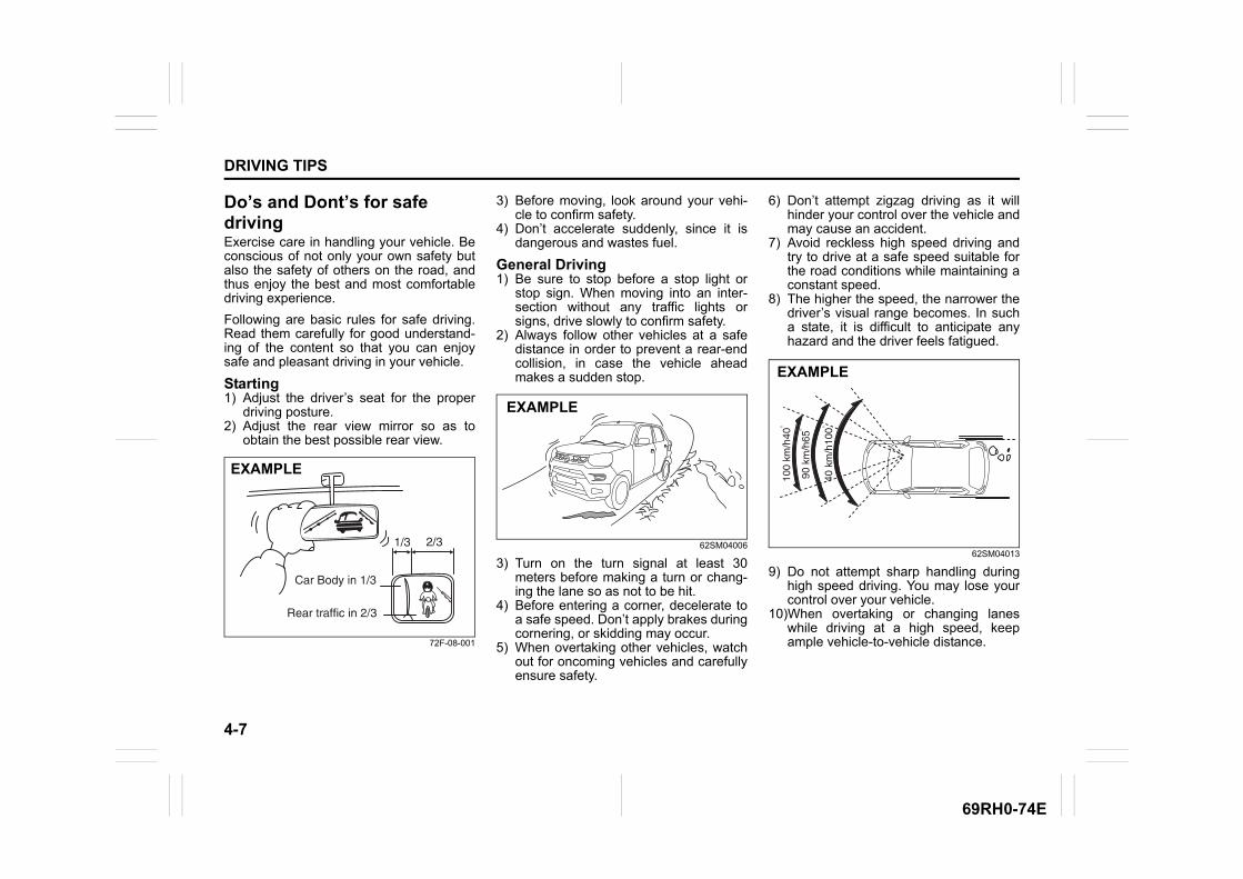
4-7
DRIVING TIPS
69RH0-74E
Do’s and Dont’s for safe drivingExercise care in handling your vehicle. Beconscious of not only your own safety butalso the safety of others on the road, andthus enjoy the best and most comfortabledriving experience.
Following are basic rules for safe driving.Read them carefully for good understand-ing of the content so that you can enjoysafe and pleasant driving in your vehicle.
Starting1) Adjust the driver’s seat for the proper
driving posture.2) Adjust the rear view mirror so as to
obtain the best possible rear view.
72F-08-001
3) Before moving, look around your vehi-cle to confirm safety.
4) Don’t accelerate suddenly, since it isdangerous and wastes fuel.
General Driving1) Be sure to stop before a stop light or
stop sign. When moving into an inter-section without any traffic lights orsigns, drive slowly to confirm safety.
2) Always follow other vehicles at a safedistance in order to prevent a rear-endcollision, in case the vehicle aheadmakes a sudden stop.
62SM04006
3) Turn on the turn signal at least 30meters before making a turn or chang-ing the lane so as not to be hit.
4) Before entering a corner, decelerate toa safe speed. Don’t apply brakes duringcornering, or skidding may occur.
5) When overtaking other vehicles, watchout for oncoming vehicles and carefullyensure safety.
6) Don’t attempt zigzag driving as it willhinder your control over the vehicle andmay cause an accident.
7) Avoid reckless high speed driving andtry to drive at a safe speed suitable forthe road conditions while maintaining aconstant speed.
8) The higher the speed, the narrower thedriver’s visual range becomes. In sucha state, it is difficult to anticipate anyhazard and the driver feels fatigued.
62SM04013
9) Do not attempt sharp handling duringhigh speed driving. You may lose yourcontrol over your vehicle.
10)When overtaking or changing laneswhile driving at a high speed, keepample vehicle-to-vehicle distance.
EXAMPLE
EXAMPLE
EXAMPLE
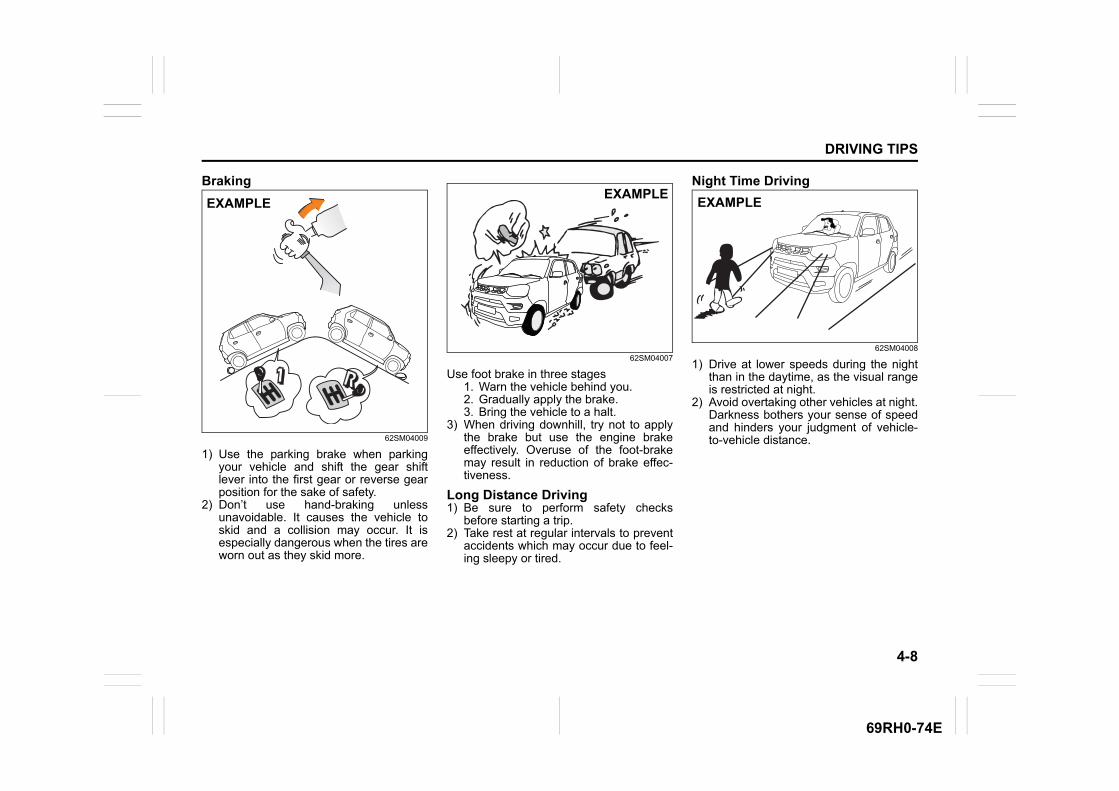
4-8
DRIVING TIPS
69RH0-74E
Braking
62SM04009
1) Use the parking brake when parkingyour vehicle and shift the gear shiftlever into the first gear or reverse gearposition for the sake of safety.
2) Don’t use hand-braking unlessunavoidable. It causes the vehicle toskid and a collision may occur. It isespecially dangerous when the tires areworn out as they skid more.
62SM04007
Use foot brake in three stages1. Warn the vehicle behind you.2. Gradually apply the brake.3. Bring the vehicle to a halt.
3) When driving downhill, try not to applythe brake but use the engine brakeeffectively. Overuse of the foot-brakemay result in reduction of brake effec-tiveness.
Long Distance Driving1) Be sure to perform safety checks
before starting a trip.2) Take rest at regular intervals to prevent
accidents which may occur due to feel-ing sleepy or tired.
Night Time Driving
62SM04008
1) Drive at lower speeds during the nightthan in the daytime, as the visual rangeis restricted at night.
2) Avoid overtaking other vehicles at night.Darkness bothers your sense of speedand hinders your judgment of vehicle-to-vehicle distance.
EXAMPLEEXAMPLE
EXAMPLE
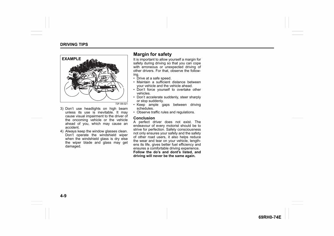
4-9
DRIVING TIPS
69RH0-74E
72F-08-021
3) Don’t use headlights on high beamunless its use is inevitable. It maycause visual impairment to the driver ofthe oncoming vehicle or the vehicleahead of you, which may cause anaccident.
4) Always keep the window glasses clean.Don’t operate the windshield wiperwhen the windshield glass is dry elsethe wiper blade and glass may getdamaged.
Margin for safetyIt is important to allow yourself a margin forsafety during driving so that you can copewith erroneous or unexpected driving ofother drivers. For that, observe the follow-ing.• Drive at a safe speed.• Maintain a sufficient distance between
your vehicle and the vehicle ahead.• Don’t force yourself to overtake other
vehicles.• Don’t accelerate suddenly, steer sharply
or stop suddenly.• Keep ample gaps between driving
schedules.• Observe traffic rules and regulations.
ConclusionA perfect driver does not exist. Theendeavour of every motorist should be tostrive for perfection. Safety consciousnessnot only ensures your safety and the safetyof other road users, it also helps reducethe wear and tear on your vehicle, length-ens its life, gives better fuel efficiency andensures a comfortable driving experience.Follow the do’s and dont’s listed, anddriving will never be the same again.
EXAMPLE

OTHER CONTROLS AND EQUIPMENT
5
69RH0-74E
60G407
OTHER CONTROLS AND EQUIPMENTFuel filler cap ....................................................................... 5-1Engine hood ........................................................................ 5-2Sun visor .............................................................................. 5-4Interior light ......................................................................... 5-4Accessory socket (if equipped) ......................................... 5-5AUX/USB socket (if equipped) ........................................... 5-6Assist grips .......................................................................... 5-6Glove box ............................................................................. 5-7Cup holder and storage area ............................................. 5-7Luggage compartment cover (if equipped) ...................... 5-8Frame hooks ........................................................................ 5-9Heating and air conditioning system (if equipped)........... 5-12Manual heating and air conditioning system (if equipped) ...5-13Radio antenna ..................................................................... 5-17Installation of radio frequency transmitters ..................... 5-17Audio system (if equipped) ................................................ 5-18

5-1
OTHER CONTROLS AND EQUIPMENT
69RH0-74E
Fuel filler cap
62SM05001
62SM05005
The fuel filler cap is located on the left rearside of the vehicle. The fuel filler door canbe unlocked by pulling up the opener leverlocated on the outboard side of the driver’sseat and locked by simply closing the door.
57L51093
To remove the fuel filler cap:1) Stop the engine and close all the doors
and window while refueling.2) Open the fuel filler door.3) Remove the cap by turning it counter-
clockwise.
62SM05006
62SM05007
EXAMPLE
EXAMPLE
CAUTION
Do not step over the release lever toavoid any damage.
Open Close
EXAMPLE
CAUTION
Remove the fuel filler cap slowly. Thefuel may be under pressure and mayspray out, causing injury.
(1)
(2)
(3)
(1)
EXAMPLE
(1) EXAMPLE
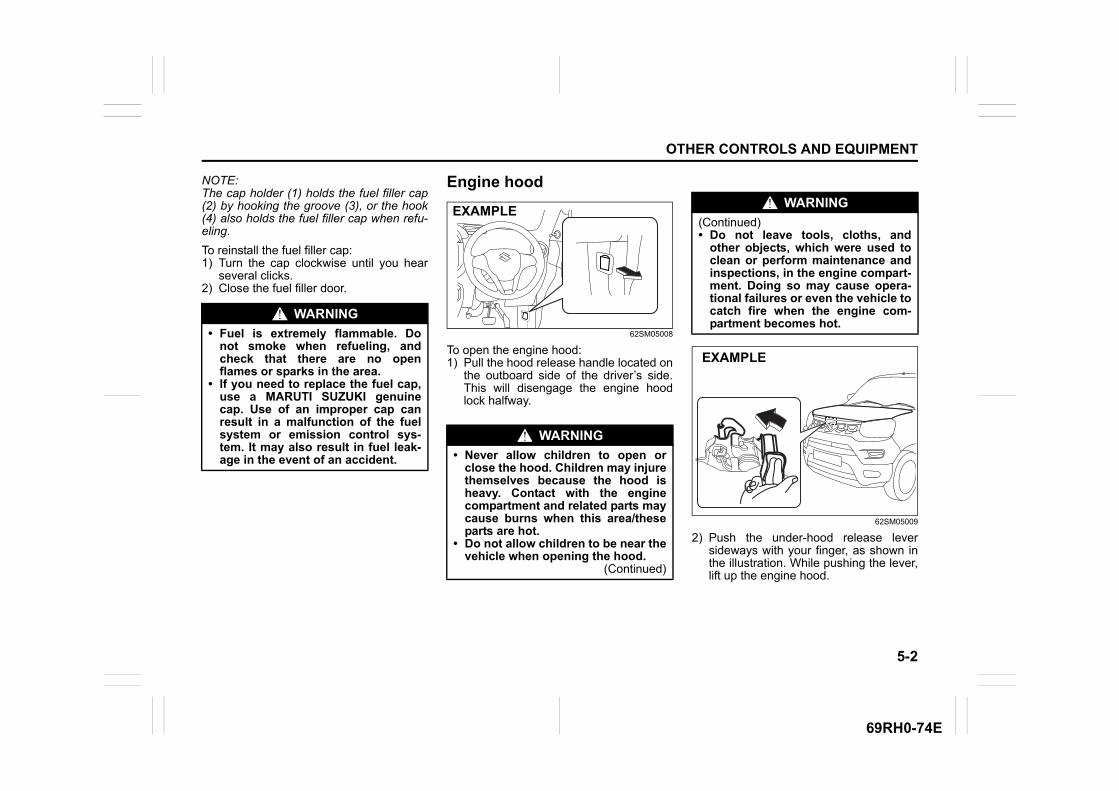
5-2
OTHER CONTROLS AND EQUIPMENT
69RH0-74E
NOTE:The cap holder (1) holds the fuel filler cap(2) by hooking the groove (3), or the hook(4) also holds the fuel filler cap when refu-eling.
To reinstall the fuel filler cap:1) Turn the cap clockwise until you hear
several clicks.2) Close the fuel filler door.
Engine hood
62SM05008
To open the engine hood:1) Pull the hood release handle located on
the outboard side of the driver’s side.This will disengage the engine hoodlock halfway.
62SM05009
2) Push the under-hood release leversideways with your finger, as shown inthe illustration. While pushing the lever,lift up the engine hood.
WARNING
• Fuel is extremely flammable. Donot smoke when refueling, andcheck that there are no openflames or sparks in the area.
• If you need to replace the fuel cap,use a MARUTI SUZUKI genuinecap. Use of an improper cap canresult in a malfunction of the fuelsystem or emission control sys-tem. It may also result in fuel leak-age in the event of an accident.
WARNING
• Never allow children to open orclose the hood. Children may injurethemselves because the hood isheavy. Contact with the enginecompartment and related parts maycause burns when this area/theseparts are hot.
• Do not allow children to be near thevehicle when opening the hood.
(Continued)
EXAMPLEWARNING
(Continued) • Do not leave tools, cloths, and
other objects, which were used toclean or perform maintenance andinspections, in the engine compart-ment. Doing so may cause opera-tional failures or even the vehicle tocatch fire when the engine com-partment becomes hot.
EXAMPLE
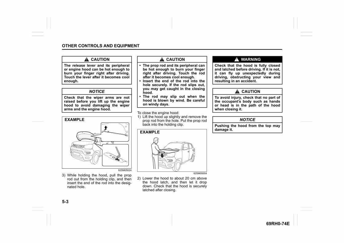
5-3
OTHER CONTROLS AND EQUIPMENT
69RH0-74E
62SM05024
3) While holding the hood, pull the proprod out from the holding clip, and theninsert the end of the rod into the desig-nated hole.
To close the engine hood:1) Lift the hood up slightly and remove the
prop rod from the hole. Put the prop rodback into the holding clip.
62SM05004
2) Lower the hood to about 20 cm abovethe hood latch, and then let it dropdown. Check that the hood is securelylatched after closing.
CAUTION
The release lever and its peripheralor engine hood can be hot enough toburn your finger right after driving.Touch the lever after it becomes coolenough.
NOTICE
Check that the wiper arms are notraised before you lift up the enginehood to avoid damaging the wiperarms and the engine hood.
EXAMPLE
CAUTION
• The prop rod and its peripheral canbe hot enough to burn your fingerright after driving. Touch the rodafter it becomes cool enough.
• Insert the end of the rod into thehole securely. If the rod slips out,you may get caught in the closinghood.
• The rod may slip out when thehood is blown by wind. Be carefulon windy days.
EXAMPLE
WARNING
Check that the hood is fully closedand latched before driving. If it is not,it can fly up unexpectedly duringdriving, obstructing your view andresulting in an accident.
CAUTION
To avoid injury, check that no part ofthe occupant’s body such as handsor head is in the path of the hoodwhen closing it.
NOTICE
Pushing the hood from the top maydamage it.
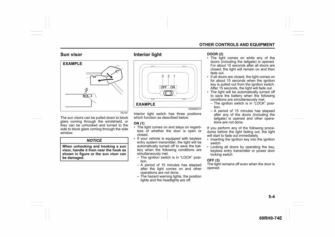
5-4
OTHER CONTROLS AND EQUIPMENT
69RH0-74E
Sun visor
79J161
The sun visors can be pulled down to blockglare coming through the windshield, orthey can be unhooked and turned to theside to block glare coming through the sidewindow.
Interior light
62SM05010
Interior light switch has three positionswhich function as described below:
ON (1)• The light comes on and stays on regard-
less of whether the door is open orclosed.
• If your vehicle is equipped with keylessentry system transmitter, the light will beautomatically turned off to save the bat-tery when the following conditions aresimultaneously met.– The ignition switch is in “LOCK” posi-
tion.– A period of 15 minutes has elapsed
after the light comes on and otheroperations are not done.
– The hazard warning lights, the positionlights and the headlights are off.
DOOR (2)• The light comes on while any of the
doors (including the tailgate) is opened.For about 15 seconds after all doors areclosed, the light will remain on and thenfade out.
• If all doors are closed, the light comes onfor about 15 seconds when the ignitionkey is pulled out from the ignition switch.After 15 seconds, the light will fade out.
• The light will be automatically turned offto save the battery when the followingconditions are simultaneously met.– The ignition switch is in “LOCK” posi-
tion.– A period of 15 minutes has elapsed
after any of the doors (including thetailgate) is opened and other opera-tions are not done.
If you perform any of the following proce-dures before the light fading out, the lightwill start to fade out immediately.• Inserting the ignition key into the ignition
switch• Locking all doors by operating the key,
keyless entry transmitter or power doorlocking switch
OFF (3)The light remains off even when the door isopened.
NOTICE
When unhooking and hooking a sunvisor, handle it from near the hook asshown in figure or the sun visor canbe damaged.
EXAMPLE
OFFOFF ONON
2 13
EXAMPLE
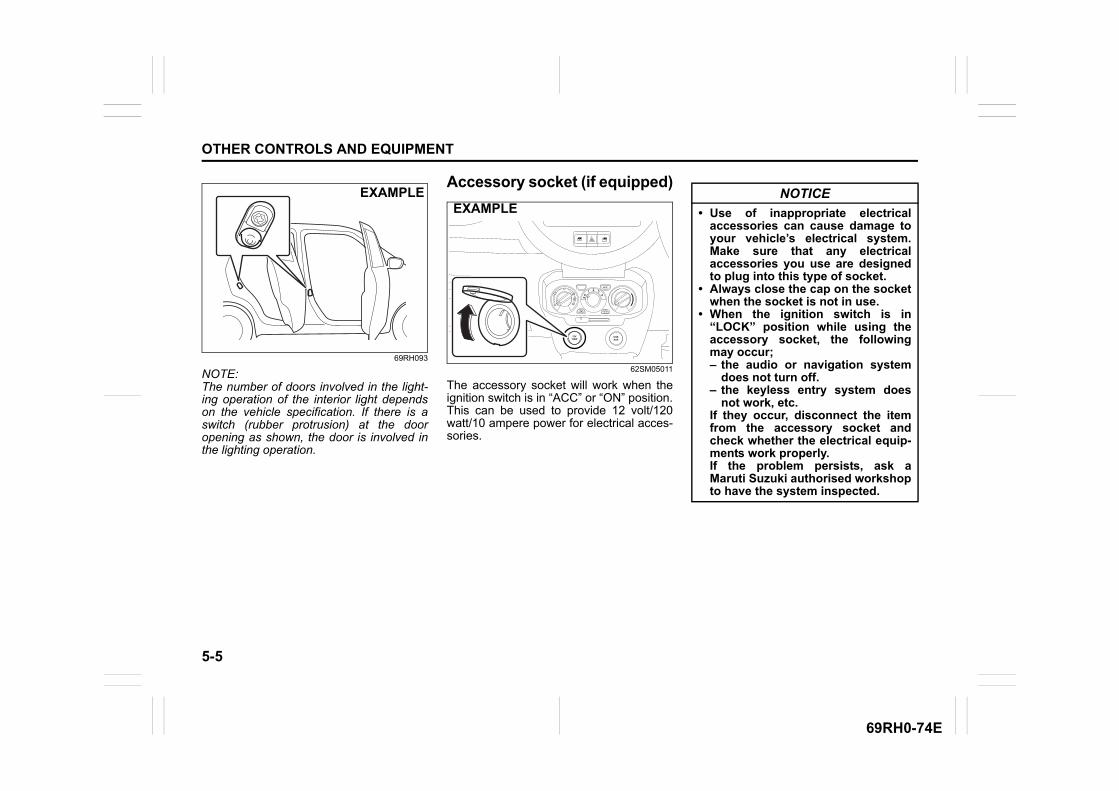
5-5
OTHER CONTROLS AND EQUIPMENT
69RH0-74E
69RH093
NOTE:The number of doors involved in the light-ing operation of the interior light dependson the vehicle specification. If there is aswitch (rubber protrusion) at the dooropening as shown, the door is involved inthe lighting operation.
Accessory socket (if equipped)
62SM05011
The accessory socket will work when theignition switch is in “ACC” or “ON” position.This can be used to provide 12 volt/120watt/10 ampere power for electrical acces-sories.
EXAMPLEEXAMPLE
USBAUX
12V120W
NOTICE
• Use of inappropriate electricalaccessories can cause damage toyour vehicle’s electrical system.Make sure that any electricalaccessories you use are designedto plug into this type of socket.
• Always close the cap on the socketwhen the socket is not in use.
• When the ignition switch is in“LOCK” position while using theaccessory socket, the followingmay occur;– the audio or navigation system
does not turn off.– the keyless entry system does
not work, etc.If they occur, disconnect the itemfrom the accessory socket andcheck whether the electrical equip-ments work properly.If the problem persists, ask aMaruti Suzuki authorised workshopto have the system inspected.
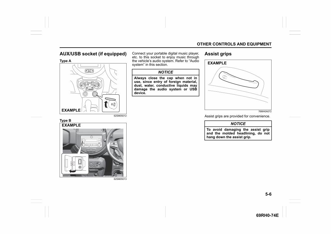
5-6
OTHER CONTROLS AND EQUIPMENT
69RH0-74E
AUX/USB socket (if equipped)
Type A
62SM05012
Type B
62SM05013
Connect your portable digital music player,etc. to this socket to enjoy music throughthe vehicle’s audio system. Refer to “Audiosystem” in this section.
Assist grips
76MH0A072
Assist grips are provided for convenience.
USBAUX
12V120W
EXAMPLE
MENU
TUNE / FLD VOL / PWR
AUX
MODEDISP/
EXAMPLE
NOTICE
Always close the cap when not inuse, since entry of foreign material,dust, water, conductive liquids maydamage the audio system or USBdevice.
NOTICE
To avoid damaging the assist gripand the molded headlining, do nothang down the assist grip.
EXAMPLE
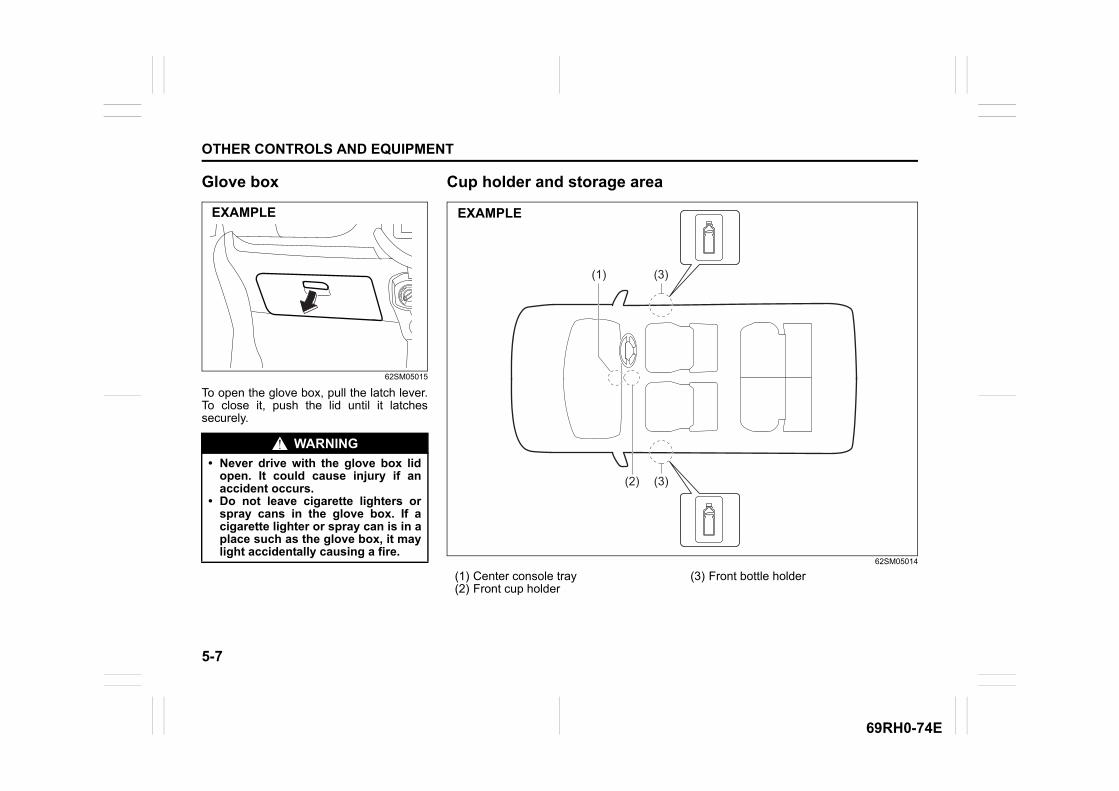
5-7
OTHER CONTROLS AND EQUIPMENT
69RH0-74E
Glove box
62SM05015
To open the glove box, pull the latch lever.To close it, push the lid until it latchessecurely.
WARNING
• Never drive with the glove box lidopen. It could cause injury if anaccident occurs.
• Do not leave cigarette lighters orspray cans in the glove box. If acigarette lighter or spray can is in aplace such as the glove box, it maylight accidentally causing a fire.
EXAMPLE
Cup holder and storage area
62SM05014
(1) Center console tray(2) Front cup holder
(3) Front bottle holder
(1)
(2)
(3)
(3)
(4)
(4)
EXAMPLE
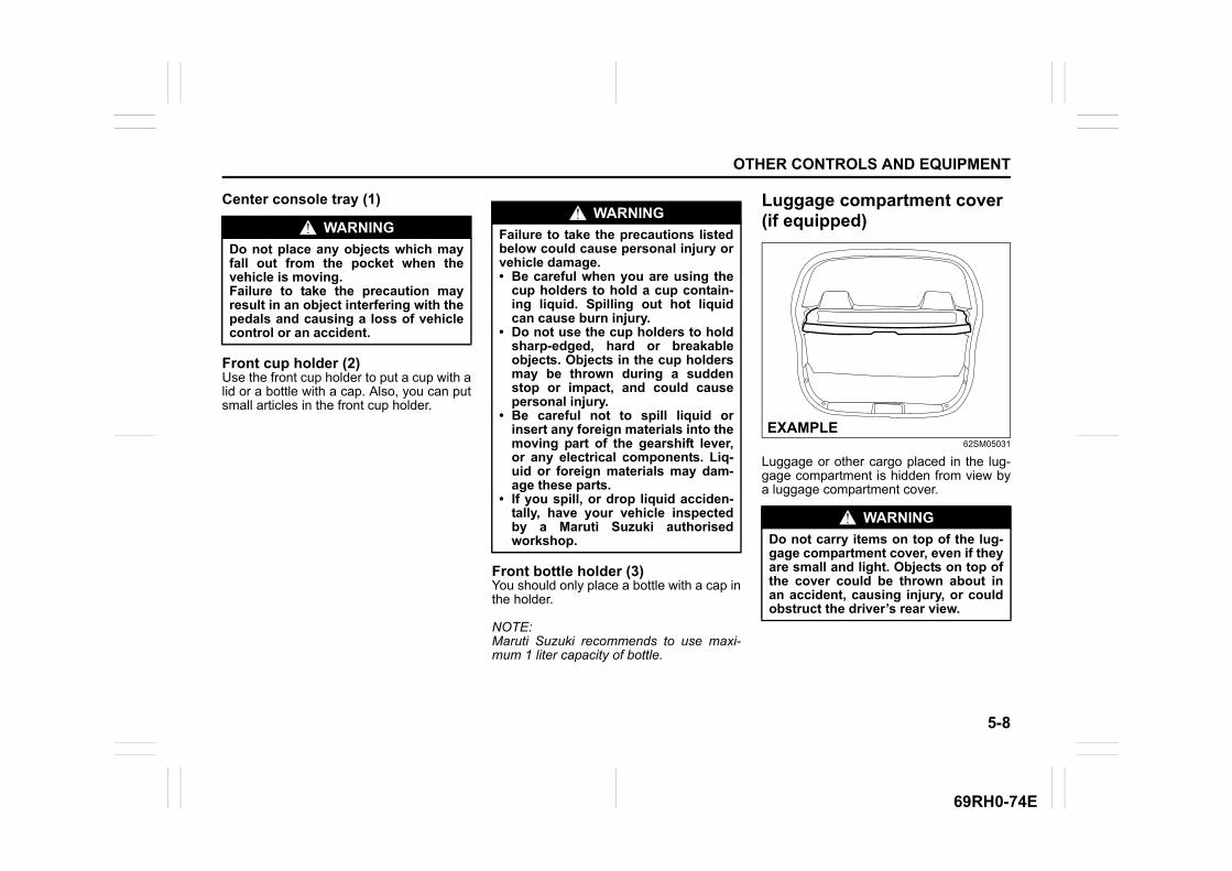
5-8
OTHER CONTROLS AND EQUIPMENT
69RH0-74E
Center console tray (1)
Front cup holder (2)Use the front cup holder to put a cup with alid or a bottle with a cap. Also, you can putsmall articles in the front cup holder.
Front bottle holder (3) You should only place a bottle with a cap inthe holder.
NOTE:Maruti Suzuki recommends to use maxi-mum 1 liter capacity of bottle.
Luggage compartment cover (if equipped)
62SM05031
Luggage or other cargo placed in the lug-gage compartment is hidden from view bya luggage compartment cover.
WARNING
Do not place any objects which mayfall out from the pocket when thevehicle is moving.Failure to take the precaution mayresult in an object interfering with thepedals and causing a loss of vehiclecontrol or an accident.
WARNING
Failure to take the precautions listedbelow could cause personal injury orvehicle damage.• Be careful when you are using the
cup holders to hold a cup contain-ing liquid. Spilling out hot liquidcan cause burn injury.
• Do not use the cup holders to holdsharp-edged, hard or breakableobjects. Objects in the cup holdersmay be thrown during a suddenstop or impact, and could causepersonal injury.
• Be careful not to spill liquid orinsert any foreign materials into themoving part of the gearshift lever,or any electrical components. Liq-uid or foreign materials may dam-age these parts.
• If you spill, or drop liquid acciden-tally, have your vehicle inspectedby a Maruti Suzuki authorisedworkshop.
WARNING
Do not carry items on top of the lug-gage compartment cover, even if theyare small and light. Objects on top ofthe cover could be thrown about inan accident, causing injury, or couldobstruct the driver’s rear view.
EXAMPLE
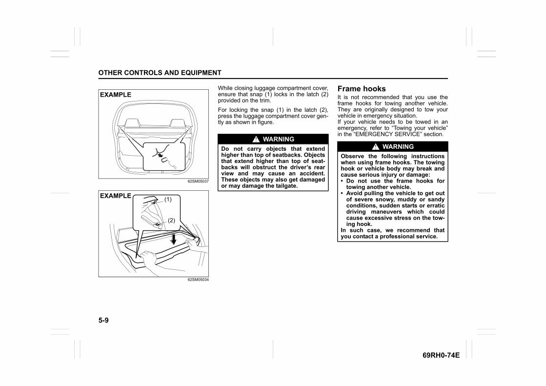
5-9
OTHER CONTROLS AND EQUIPMENT
69RH0-74E
62SM05037
62SM05034
While closing luggage compartment cover,ensure that snap (1) locks in the latch (2)provided on the trim.
For locking the snap (1) in the latch (2),press the luggage compartment cover gen-tly as shown in figure.
Frame hooksIt is not recommended that you use theframe hooks for towing another vehicle.They are originally designed to tow yourvehicle in emergency situation.If your vehicle needs to be towed in anemergency, refer to “Towing your vehicle”in the “EMERGENCY SERVICE” section.
EXAMPLE
(1)
(2)
EXAMPLE
WARNING
Do not carry objects that extendhigher than top of seatbacks. Objectsthat extend higher than top of seat-backs will obstruct the driver’s rearview and may cause an accident.These objects may also get damagedor may damage the tailgate.
WARNING
Observe the following instructionswhen using frame hooks. The towinghook or vehicle body may break andcause serious injury or damage:• Do not use the frame hooks for
towing another vehicle.• Avoid pulling the vehicle to get out
of severe snowy, muddy or sandyconditions, sudden starts or erraticdriving maneuvers which couldcause excessive stress on the tow-ing hook.
In such case, we recommend thatyou contact a professional service.
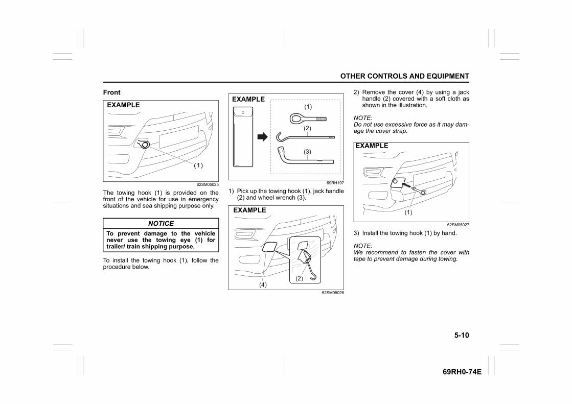
5-10
OTHER CONTROLS AND EQUIPMENT
69RH0-74E
Front
62SM05025
The towing hook (1) is provided on thefront of the vehicle for use in emergencysituations and sea shipping purpose only.
To install the towing hook (1), follow theprocedure below.
69RH197
1) Pick up the towing hook (1), jack handle(2) and wheel wrench (3).
62SM05026
2) Remove the cover (4) by using a jackhandle (2) covered with a soft cloth asshown in the illustration.
NOTE:Do not use excessive force as it may dam-age the cover strap.
62SM05027
3) Install the towing hook (1) by hand.
NOTE:We recommend to fasten the cover withtape to prevent damage during towing.
NOTICE
To prevent damage to the vehiclenever use the towing eye (1) fortrailer/ train shipping purpose.
(1)
EXAMPLE (1)
(2)
(3)
EXAMPLE
(4)(2)
EXAMPLE (1)
EXAMPLE
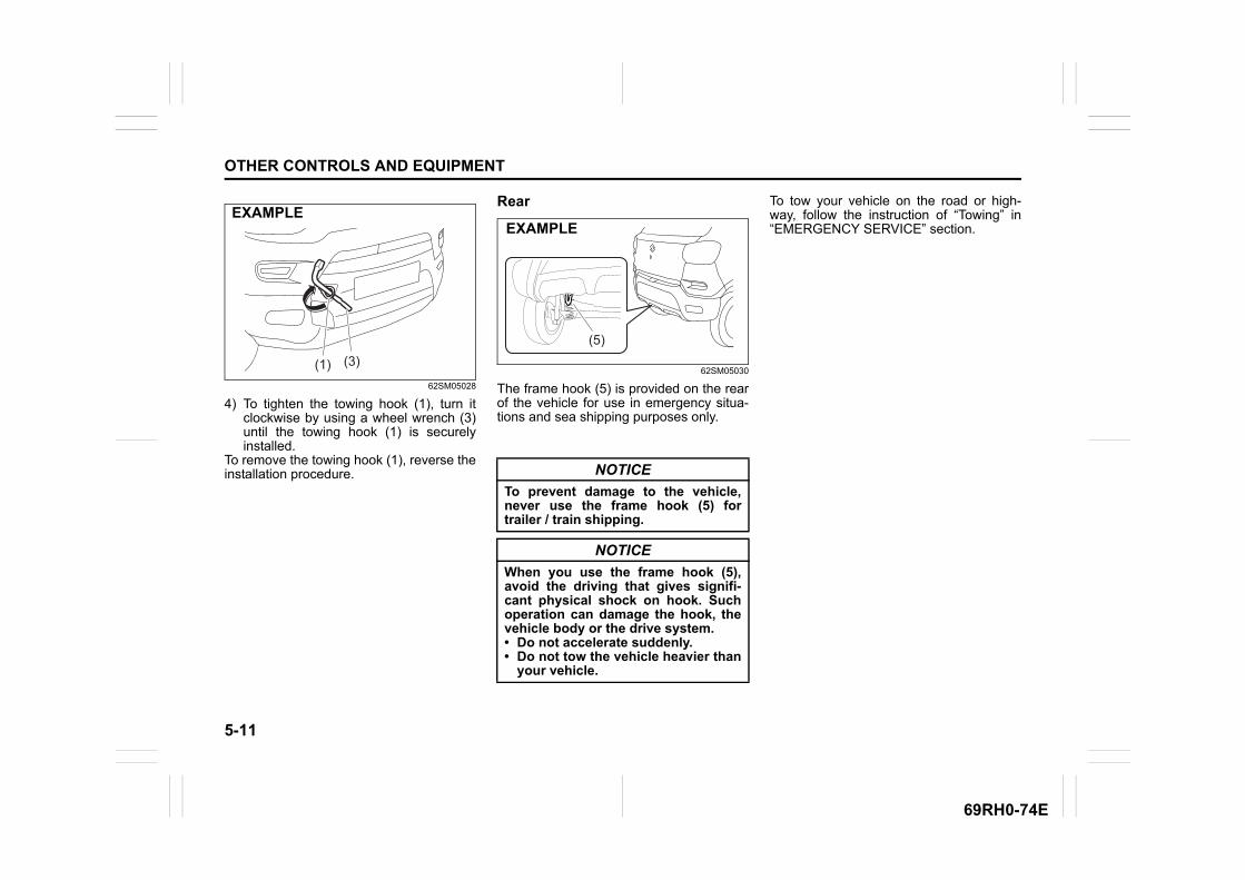
5-11
OTHER CONTROLS AND EQUIPMENT
69RH0-74E
62SM05028
4) To tighten the towing hook (1), turn itclockwise by using a wheel wrench (3)until the towing hook (1) is securelyinstalled.
To remove the towing hook (1), reverse theinstallation procedure.
Rear
62SM05030
The frame hook (5) is provided on the rearof the vehicle for use in emergency situa-tions and sea shipping purposes only.
To tow your vehicle on the road or high-way, follow the instruction of “Towing” in“EMERGENCY SERVICE” section.
(1) (3)
EXAMPLE
NOTICE
To prevent damage to the vehicle,never use the frame hook (5) fortrailer / train shipping.
NOTICE
When you use the frame hook (5),avoid the driving that gives signifi-cant physical shock on hook. Suchoperation can damage the hook, thevehicle body or the drive system. • Do not accelerate suddenly.• Do not tow the vehicle heavier than
your vehicle.
(5)
EXAMPLE
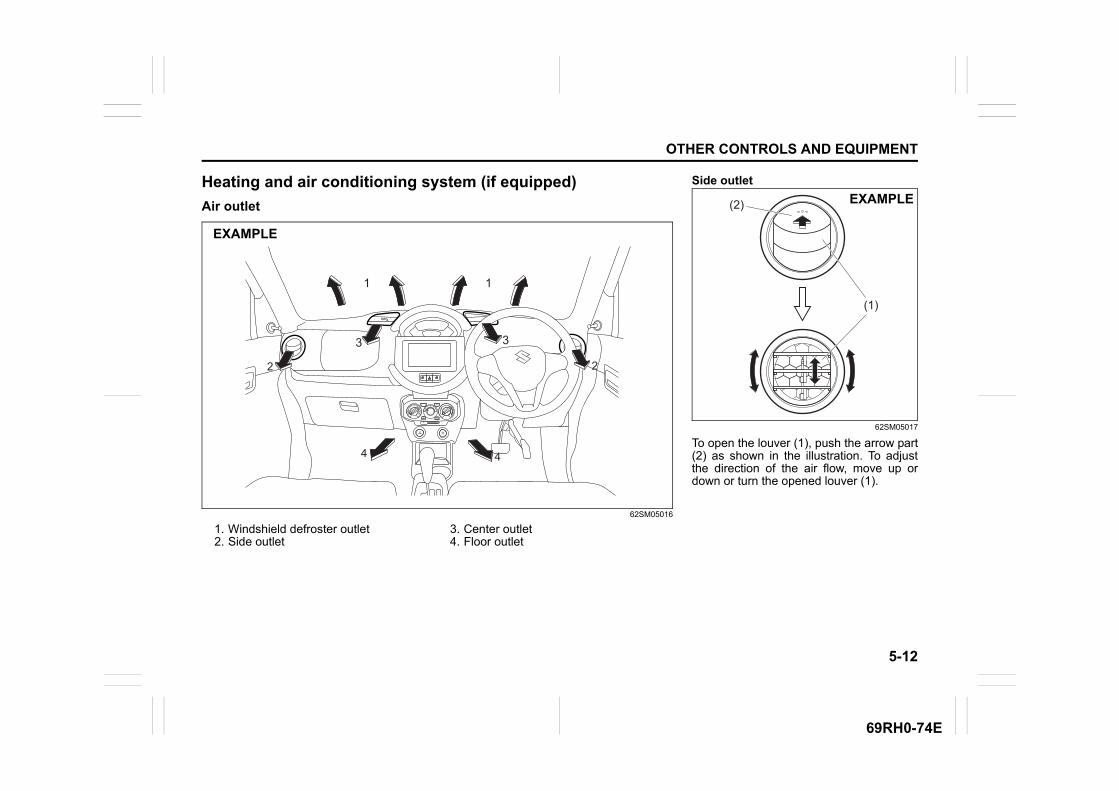
5-12
OTHER CONTROLS AND EQUIPMENT
69RH0-74E
Heating and air conditioning system (if equipped)
Air outlet
62SM05016
1. Windshield defroster outlet2. Side outlet
3. Center outlet4. Floor outlet
USBAUX
12V120W
2222
44 44
1 1
3333
EXAMPLE
Side outlet
62SM05017
To open the louver (1), push the arrow part(2) as shown in the illustration. To adjustthe direction of the air flow, move up ordown or turn the opened louver (1).
(2)
(1)
EXAMPLE
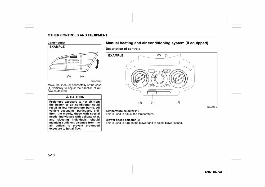
5-13
OTHER CONTROLS AND EQUIPMENT
69RH0-74E
Center outlet
62SM05029
Move the knob (3) horizontally or the case(4) vertically to adjust the direction of air-flow as desired.
CAUTION
Prolonged exposure to hot air fromthe heater or air conditioner couldresult in low temperature burns. Allvehicle occupants, particularly chil-dren, the elderly, those with specialneeds, individuals with delicate skin,and sleeping individuals, shouldmaintain sufficient distance from theair outlets to prevent prolongedexposure to hot airflow.
(3) (4)
EXAMPLEManual heating and air conditioning system (if equipped)
Description of controls
62SM05018
Temperature selector (1)This is used to adjust the temperature.
Blower speed selector (2)This is used to turn on the blower and to select blower speed.
(2) (5)
(1)(3) (4)
EXAMPLE

5-14
OTHER CONTROLS AND EQUIPMENT
69RH0-74E
Air flow selector (3)
75RM022
This selector is used to select the followingmode.
VENTILATION (a)
62SM05019
Temperature-controlled air comes out ofthe center and side air outlets.
BI-LEVEL (b)
62SM05020
Temperature-controlled air comes out ofthe floor outlets and cooler air comes outof the center and side outlets. When thetemperature selector (1) is in the fully coldposition or fully hot position, however, theair from the floor outlets and the air fromthe center and side outlets will be thesame temperature.
HEAT (c)
62SM05021
Temperature-controlled air comes out ofthe floor outlets and the side outlets, smallamount of air also comes out of the wind-shield defroster outlets.
HEAT & DEFROST (d)
62SM05022
Temperature-controlled air comes out ofthe floor outlets, the windshield defrosteroutlets and the side outlets.
DEFROST (e)
62SM05023
Temperature-controlled air comes out ofthe windshield defroster outlets and theside outlets.
(a)
(b)
(e)
(d)
(c) EXAMPLE
EXAMPLE
4 4
EXAMPLE
4 4
EXAMPLE
4 4
EXAMPLE
EXAMPLE

5-15
OTHER CONTROLS AND EQUIPMENT
69RH0-74E
Air intake selector (4)
62SM05033
This selector is used to select the followingmodes.
FRESH AIR (f)When this mode is selected by moving thelever to right, outside air is used.
RECIRCULATED AIR (g)When this mode is selected, the indicatorlight will come on, outside air is shut outand inside air is recirculated. This mode issuitable when driving through dusty or pol-luted air such as in a tunnel, or whenattempting to quickly cool down the interioror to reduce unwanted odor from enteringthe vehicle.
“FRESH AIR” and “RECIRCULATED AIR”are switched alternately each time the airintake selector is pushed.
NOTE:If you select RECIRCULATED AIR for anextended period of time, the air in the vehi-cle may become contaminated and thewindows tend to get misted. Therefore,you should occasionally select FRESHAIR.
75RM403
NOTE:The mark of “ ” (6)To clear fog on the windshield and/or theside windows quickly, set the air flowselector (3) to HEAT & DEFROST orDEFROST and air intake selector (4) toFRESH AIR. These positioning will clearthe fogged windshield and/or the side win-dows faster than the RECIRCULATEDAIR.
Air conditioning switch (if equipped) (5)To turn on the air conditioning system, setthe blower speed selector to a positionother than off and push in “A/C” switch.With this “A/C” switch operation, a indica-tor light will come on when the air condi-tioning system is on. To turn off the airconditioning system, push “A/C” switchagain.During operation of the air conditioner, youmay notice slight changes in enginespeed. These changes are normal, thesystem is designed so that the compressorturns on or off to maintain the desired tem-perature.
Less operation of the compressor resultsin better fuel economy.
System operating instructions
Natural ventilationSelect VENTILATION and FRESH AIR, thetemperature selector to the desired tem-perature position, and the blower speedselector to off. Fresh air will flow throughthe vehicle during driving.
Forced ventilationThe control settings are the same as fornatural ventilation except you set theblower speed selector to a position otherthan off.
(g) (f)EXAMPLE
(3)
(6)
EXAMPLE
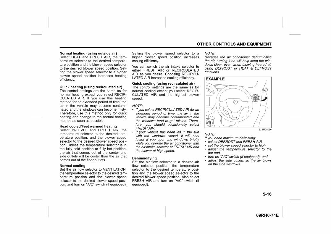
5-16
OTHER CONTROLS AND EQUIPMENT
69RH0-74E
Normal heating (using outside air)Select HEAT and FRESH AIR, the tem-perature selector to the desired tempera-ture position and the blower speed selectorto the desired blower speed position. Set-ting the blower speed selector to a higherblower speed position increases heatingefficiency.
Quick heating (using recirculated air)The control settings are the same as fornormal heating except you select RECIR-CULATED AIR. If you use this heatingmethod for an extended period of time, theair in the vehicle may become contami-nated and the windows can become misty.Therefore, use this method only for quickheating and change to the normal heatingmethod as soon as possible.
Head cooled/Feet warmed heatingSelect BI-LEVEL and FRESH AIR, thetemperature selector to the desired tem-perature position, and the blower speedselector to the desired blower speed posi-tion. Unless the temperature selector is inthe fully cold position or fully hot position,the air that comes out of the center andside outlets will be cooler than the air thatcomes out of the floor outlets.
Normal coolingSet the air flow selector to VENTILATION,the temperature selector to the desired tem-perature position and the blower speedselector to the desired blower speed posi-tion, and turn on “A/C” switch (if equipped).
Setting the blower speed selector to ahigher blower speed position increasescooling efficiency.
You can switch the air intake selector toeither FRESH AIR or RECIRCULATEDAIR as you desire. Choosing RECIRCU-LATED AIR increases cooling efficiency.
Quick cooling (using recirculated air)The control settings are the same as fornormal cooling except you select RECIR-CULATED AIR and the highest blowerspeed.
NOTE:• If you select RECIRCULATED AIR for an
extended period of time, the air in thevehicle may become contaminated andthe windows tend to get misted. There-fore, you should occasionally selectFRESH AIR.
• If your vehicle has been left in the sunwith the windows closed, it will coolfaster if you open the windows brieflywhile you operate the air conditioner withthe air intake selector at FRESH AIR andthe blower at high speed.
DehumidifyingSet the air flow selector to a desired airflow selector position, the temperatureselector to the desired temperature posi-tion and the blower speed selector to thedesired blower speed position. Also selectFRESH AIR and turn on “A/C” switch (ifequipped).
NOTE:Because the air conditioner dehumidifiesthe air, turning it on will help keep the win-dows clear, even when blowing heated airusing DEFROST or HEAT & DEFROSTfunctions.
62SM05036
NOTE:If you need maximum defrosting:• select DEFROST and FRESH AIR,• set the blower speed selector to high,• adjust the temperature selector to the
hot end,• turn on “A/C” switch (if equipped), and• adjust the side outlets so the air blows
on the side windows.
EXAMPLE

5-17
OTHER CONTROLS AND EQUIPMENT
69RH0-74E
MaintenanceIf you do not use the air conditioner for along period, such as during winter, it maynot give the best performance when youstart using it again. To help maintain opti-mum performance and durability of your airconditioner, it needs to be run periodically.Operate the air conditioner at least once amonth for one minute with the engineidling. This circulates the refrigerant and oiland helps protect the internal components.
NOTE:Your vehicle uses the air conditioningrefrigerant HFC-134a, commonly calledR-134a. R-134a replaced R-12 around1993 for automotive applications. Otherrefrigerants are available, including recy-cled R-12, but only R-134a should be usedin your vehicle.
Radio antenna
69RH201
The radio antenna on the roof is remov-able. To remove the antenna, turn it coun-terclockwise. To reinstall the antenna, turnit clockwise firmly by hand.
NOTE:Adjust the antenna angle to maximum foroptimum radio reception.
Installation of radio frequency transmittersWe recommend that you always ask aMaruti Suzuki authorised workshop aboutfrequency band, max output power,antenna position at vehicle and specificconditions for installation and/or use beforeinstalling a radio transmitter in your vehi-cle. Such equipments may cause the elec-tronic control system to malfunction if theyare incorrectly installed or they are notsuited for the vehicle.
NOTICE
Using the wrong refrigerant maydamage your air conditioning sys-tem. Use R-134a only. Do not mix orreplace the R-134a with other refrig-erants.
EXAMPLE
NOTICE
To avoid damage to the radioantenna:• Remove the antenna when using an
automatic car wash.• Remove the antenna when the
antenna hits anything such as alow ceiling in a parking garage orputting a car cover over your vehi-cle.
• If radio antenna angle is kept inlower position. There is possibilityof antenna hitting the roof whiledriving. Adjust the antenna angle tomaximum.
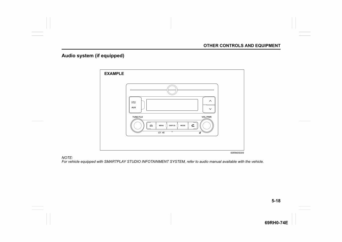
5-18
OTHER CONTROLS AND EQUIPMENT
69RH0-74E
Audio system (if equipped)
69RM05009
NOTE:For vehicle equipped with SMARTPLAY STUDIO INFOTAINMENT SYSTEM, refer to audio manual available with the vehicle.
MENU
TUNE / FLD VOL / PWR
AUX
MODEDISP/
EXAMPLE

5-19
OTHER CONTROLS AND EQUIPMENT
69RH0-74E
Safety information
Open source definitionThis Product includes following opensource software.mbedtls version 2.5.1
Copyright © 2006–2015, ARM Limited, All Rights ReservedSPDX-License-Identifier: Apache-2.0
Licensed under the Apache License, Ver-sion 2.0 (the “License”); you may not usethis file except in compliance with theLicense.You may obtain a copy of the License athttp://www.apache.org/licenses/LICENSE-2.0
Unless required by applicable law oragreed to in writing, software distributed
under the License is on an “AS IS” BASIS,WITHOUT WARRANTIES OR CONDI-TIONS OF ANY KIND, either express orimplied.See the License for specific language gov-erning permissions and limitations underthe License.
This file is part of mbed TLS (https://tls.mbed.org)
Please be noted that a portion of this soft-ware is made by changing or modifyingoriginal source files.
The Bluetooth® word mark and logo areregistered trademarks and are owned bythe Bluetooth SIG, Ink.
Stop using this unit and a Bluetooth®
ready device whenever requested. This unit shares the communication fre-quency with other private or public wirelesscommunication equipment such as a wire-less LAN and other wireless communica-tion radios. You should stop using this unit whenever you are notified that your unit disturbsother wireless communication immediately.
WARNING
If you pay too much attention tooperating the audio system or view-ing the audio system display whiledriving, an accident can occur. Ifyou set the sound volume too loud,it could prevent you from beingaware of road and traffic conditions.• Keep your eyes on the road and
your mind on the drive. Avoid pay-ing too much attention to operat-ing the audio system or viewingthe audio system display.
• Familiarize yourself with the audiosystem controls and operation ofthe audio system before driving.
• Preset your favorite radio stationsbefore driving so that you canquickly tune to them using thepresets.
• Set the sound volume to a levelthat will allow you to continue tobe aware of road and traffic condi-tions while driving.
NOTICE
• Avoid spraying or spilling of clear-ing solutions, perfumes, car fresh-eners, beverages, chemicals or anyliquids on the audio systemsurface. Also ensure that any liquiddoes not enter the system, it candamage the screen and the system.The warranty of the system will bevoid, if liquid ingress marks areobserved inside the system.
• Avoid exposure of the audio sys-tem to water or excessive moistureas it can cause electric shocks, fireor other damages.

5-20
OTHER CONTROLS AND EQUIPMENT
69RH0-74E
Basic operations
69RM05001
(1) “VOL/PWR” knob(2) “MODE” button(3) MICROPHONE (for handsfree)(4) “DISP/BACK” button(5) “MENU” button(6) “TUNE/FLD” knob(7) USB/AUX(8) SMARTPHONE DOCK CAP*(9) UP button
(10) DOWN button
* To open SMARTPHONE DOCK CAP (8), use the cap opener provided in MGA “SMART-PHONE DOCK”. Opening of SMARTPHONE DOCK CAP with any external object maycause damage to CAP.
MENU
TUNE / FLD VOL / PWR
AUX
MODEDISP/
(5) (4)(6) (2)
(10)
(9)(7)
(8)
(1)(3)
EXAMPLE
Turning on/off powerPress “VOL/PWR” knob (1) to turn on thepower. The unit starts to operate in the pre-vious mode that the power was turned off.• To turn off the power, press and hold
“VOL/PWR” knob (1) for about 2 sec-onds.
Adjusting the volumeTurn “VOL/PWR” knob (1).• Turning it clockwise increases the vol-
ume.• Turning it counterclockwise decreases
the volume.
Mute• Press “VOL/PWR” knob(1) to mute the
sound.• To cancel mute, press any button.
NOTE:For the purpose of safe driving, adjust theaudio volume to a level that allows you tohear sounds outside of the vehicle includ-ing car horns and particularly emergencyvehicle sirens.
Display & Back settingPress “DISP/BACK” button (4) to go backto the previous display when a list or menuscreen is displayed. On long pressing “DISP/BACK” button (4),tuner display will be turned OFF. Howeverall operations such as media playing etcwill be active. Display will be turned ON bypressing any button on audio unit, steering
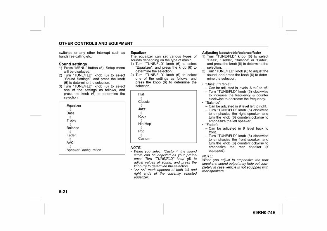
5-21
OTHER CONTROLS AND EQUIPMENT
69RH0-74E
switches or any other interrupt such ashandsfree calling etc.
Sound settings1) Press “MENU” button (5). Setup menu
will be displayed.2) Turn “TUNE/FLD” knob (6) to select
“Sound Settings”, and press the knob(6) to determine the selection.
3) Turn “TUNE/FLD” knob (6) to selectone of the settings as follows, andpress the knob (6) to determine theselection.
EqualizerThe equalizer can set various types ofsounds depending on the type of music.1) Turn “TUNE/FLD” knob (6) to select
“Equalizer”, and press the knob (6) todetermine the selection.
2) Turn “TUNE/FLD” knob (6) to selectone of the settings as follows, andpress the knob (6) to determine theselection.
NOTE:• When you select “Custom”, the sound
curve can be adjusted as your prefer-ence. Turn “TUNE/FLD” knob (6) toadjust values of sound, and press theknob (6) to determine the selection.
• “>> <<” mark appears at both left andright ends of the currently selectedequalizer.
Adjusting bass/treble/balance/fader1) Turn “TUNE/FLD” knob (6) to select
“Bass”, “Treble”, “Balance” or “Fader”,and press the knob (6) to determine theselection.
2) Turn “TUNE/FLD” knob (6) to adjust thesound, and press the knob (6) to deter-mine the selection.
• “Bass” / “Treble”:– Can be adjusted in levels -6 to 0 to +6.– Turn “TUNE/FLD” knob (6) clockwise
to increase the frequency & counterclockwise to decrease the frequency.
• “Balance”:– Can be adjusted in 9 level left to right.– Turn “TUNE/FLD” knob (6) clockwise
to emphasize the right speaker, andturn the knob (6) counterclockwise toemphasize the left speaker.
• “Fader”:– Can be adjusted in 9 level back to
front.– Turn “TUNE/FLD” knob (6) clockwise
to emphasize the front speaker, andturn the knob (6) counterclockwise toemphasize the rear speaker (ifequipped).
NOTE:When you adjust to emphasize the rearspeakers, sound output may fade out com-pletely in case vehicle is not equipped withrear speakers.
Equalizer
Bass
Treble
Balance
Fader
AVC
Speaker Configuration
Flat
Classic
Jazz
Rock
Hip-Hop
Pop
Custom
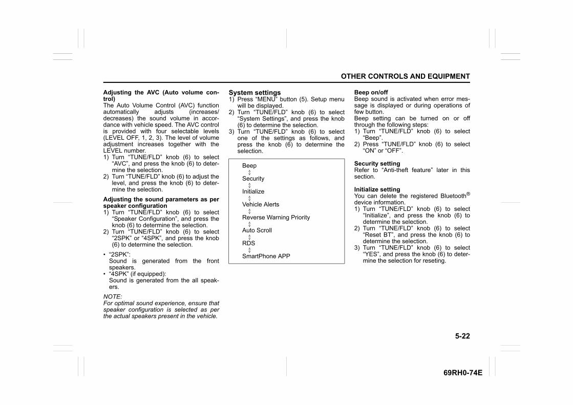
5-22
OTHER CONTROLS AND EQUIPMENT
69RH0-74E
Adjusting the AVC (Auto volume con-trol)The Auto Volume Control (AVC) functionautomatically adjusts (increases/decreases) the sound volume in accor-dance with vehicle speed. The AVC controlis provided with four selectable levels(LEVEL OFF, 1, 2, 3). The level of volumeadjustment increases together with theLEVEL number.1) Turn “TUNE/FLD” knob (6) to select
“AVC”, and press the knob (6) to deter-mine the selection.
2) Turn “TUNE/FLD” knob (6) to adjust thelevel, and press the knob (6) to deter-mine the selection.
Adjusting the sound parameters as perspeaker configuration1) Turn “TUNE/FLD” knob (6) to select
“Speaker Configuration”, and press theknob (6) to determine the selection.
2) Turn “TUNE/FLD” knob (6) to select“2SPK” or “4SPK”, and press the knob(6) to determine the selection.
• “2SPK”: Sound is generated from the frontspeakers.
• “4SPK” (if equipped):Sound is generated from the all speak-ers.
NOTE:For optimal sound experience, ensure thatspeaker configuration is selected as perthe actual speakers present in the vehicle.
System settings1) Press “MENU” button (5). Setup menu
will be displayed.2) Turn “TUNE/FLD” knob (6) to select
“System Settings”, and press the knob(6) to determine the selection.
3) Turn “TUNE/FLD” knob (6) to selectone of the settings as follows, andpress the knob (6) to determine theselection.
Beep on/offBeep sound is activated when error mes-sage is displayed or during operations offew button.Beep setting can be turned on or offthrough the following steps:1) Turn “TUNE/FLD” knob (6) to select
“Beep”.2) Press “TUNE/FLD” knob (6) to select
“ON” or “OFF”.
Security settingRefer to “Anti-theft feature” later in thissection.
Initialize settingYou can delete the registered Bluetooth®
device information.1) Turn “TUNE/FLD” knob (6) to select
“Initialize”, and press the knob (6) todetermine the selection.
2) Turn “TUNE/FLD” knob (6) to select“Reset BT”, and press the knob (6) todetermine the selection.
3) Turn “TUNE/FLD” knob (6) to select“YES”, and press the knob (6) to deter-mine the selection for reseting.
Beep
Security
Initialize
Vehicle Alerts
Reverse Warning Priority
Auto Scroll
RDS
SmartPhone APP

5-23
OTHER CONTROLS AND EQUIPMENT
69RH0-74E
Vehicle alerts settingYou can turn on or off the warning indica-tions related to vehicle system using thissetting. By default, this setting is ON for allalerts.1) Turn “TUNE/FLD” knob (6) to select
“Vehicle Alerts”, and press the knob (6)to determine the selection.
2) Turn “TUNE/FLD” knob (6) to selectone of the settings as follows, andpress the knob (6) to determine theselection.
3) Press “TUNE/FLD” knob (6) to select“ON” or “OFF”.
4) Following are the warning displayrelated to vehicle system:
• “Parking Brake Engaged”: This message will appear when the vehi-cle is moved without releasing the park-ing brake. Check that parking brake isfully released.
• “Seat Belt Open”:This message will appear when the vehi-cle is moving and driver has not fas-tened his seat belt.
• “Door Open”:This message will appear when any door(except tailgate) is open when the vehi-cle is moving.
• “Low Fuel”:This message will appear to remind to fillthe fuel. Fill the fuel immediately.
NOTE:If you push “DISP/BACK” button (4) whilethe warning and indicator messages is dis-played, the indication will disappear.
Reverse warning priority settingOn applying reverse, volume of audio sys-tem gets lowered. By default, this setting isON. This setting can be turned on or offthrough the following steps:1) Turn “TUNE/FLD” knob (6) to select
“Reverse Warning Priority”, and pressthe knob (6) to determine the selection.
2) Turn “TUNE/FLD” knob (6) to select“No” or “Yes”, and press the knob (6) todetermine the selection.
Auto scroll settingAuto scroll setting is ON by default. When playing the media files, if the filestext contains more characters, “>” mark willappear at the right end up the displayscreen and the display changes to the nextset of characters automatically.1) Turn “TUNE/FLD” knob (6) to select
“Auto Scroll”.2) Press “TUNE/FLD” knob (6) to select
“ON” or “OFF”.
RDS (Radio Data System) settingEnabling this setting displays the mes-sages transmitted by FM station. This set-ting is ON by default. You can choose toturn ON/OFF this setting through the fol-lowing steps:1) Turn “TUNE/FLD” knob (6) to select
“RDS”.2) Press “TUNE/FLD” knob (6) to select
“ON” or “OFF”.
NOTE:• Messages are displayed only when RDS
signal is included in FM radio waves.• The messages are displayed program
service name only.
Smartphone app settingRefer to section 5-49 for details aboutsmartphone application.Smartphone app can be used only whenapp setting is enable as ON. Refer to “Suzuki Smartplay Dock applica-tion” later in this section for details.1) Turn “TUNE/FLD” knob (6) to select
“SmartPhone APP”.2) Press “TUNE/FLD” knob (6) to select
“ON” or “OFF”.
NOTE:An Apple device can be connected ineither Bluetooth® or iPod mode. Blue-tooth® mode has higher priority over iPodMode. In case, you want to connect theApple device on iPod mode instead andchange Smartphone app setting to “OFF”.
Parking Brake Engaged
Seat Belt Open
Door Open
Low Fuel
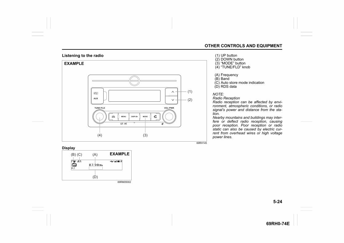
5-24
OTHER CONTROLS AND EQUIPMENT
69RH0-74E
Listening to the radio
69RH145
Display
69RM05002
MENU
TUNE / FLD VOL / PWR
AUX
MODEDISP/
(4) (3)
(1)
(2)
EXAMPLE
(D)
(B) (C) (A) EXAMPLE
(1) UP button(2) DOWN button(3) “MODE” button(4) “TUNE/FLD” knob
(A) Frequency(B) Band(C) Auto store mode indication(D) RDS data
NOTE:Radio ReceptionRadio reception can be affected by envi-ronment, atmospheric conditions, or radiosignal’s power and distance from the sta-tion.Nearby mountains and buildings may inter-fere or deflect radio reception, causingpoor reception. Poor reception or radiostatic can also be caused by electric cur-rent from overhead wires or high voltagepower lines.

5-25
OTHER CONTROLS AND EQUIPMENT
69RH0-74E
Selecting the band1) Press and hold “MODE” button (3) to
change to the list of available modes.2) Turn “TUNE/FLD” knob (4) to select
“FM” or “AM”, and press the knob (4) todetermine the selection.
NOTE:You can also switch the display insequence by short pressing the “MODE”button (3).
Seek tuningPress and hold UP button (1) or DOWNbutton (2) to start searching.The unit stops searching for a station at afrequency where a broadcast station isavailable.
Manual tuningTurn “TUNE/FLD” knob (4).The frequency being received is displayed.
Preset memory1) Tune to the desired station.2) Press “TUNE/FLD” knob (4) to change
the display to the preset channel list.3) To store the station, turn “TUNE/FLD”
knob (4) to select one of the channels,and press and hold the knob (4) todetermine the selection.
4) To select station from the preset chan-nel list, press “TUNE/FLD” knob (4) tochange the display to the preset chan-nel list.Turn “TUNE/FLD” knob (4) to selectone of the channels, and press theknob (4) to determine the selection.
NOTE:12 stations can be stored for FM, and 6stations can be stored for AM.In case a station is stored over an existingpreset station, previous data will be overid-den.
Auto store1) Press and hold “TUNE/FLD” knob (4) to
start searching when in FM/AM mode.Some stations in good reception willautomatically be stored to preset chan-nel list in order, starting from a stationwhose frequency is the lowest.
2) To select station from the preset chan-nel list, press “TUNE/FLD” knob (4) tochange the display to the preset chan-nel list while auto store mode indication(C) is displayed.
NOTE:• Auto Store can be cancelled by pressing
the “DISP/BACK” button.• When the auto store is performed, the
station previously stored in the memoryat the position is overwritten.
• 6 stations can be preset for FM-AS, and6 stations can be preset for AM-AS inauto store mode.
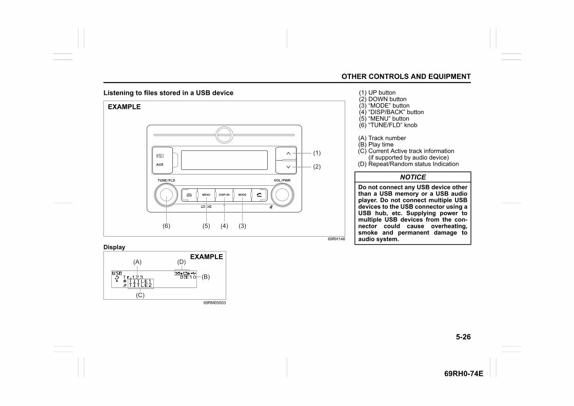
5-26
OTHER CONTROLS AND EQUIPMENT
69RH0-74E
Listening to files stored in a USB device
69RH146
Display
69RM05003
MENU
TUNE / FLD VOL / PWR
AUX
MODEDISP/
(6) (5) (4) (3)
(1)
(2)
EXAMPLE
(C)
(B)
(A) (D)EXAMPLE
(1) UP button(2) DOWN button(3) “MODE” button(4) “DISP/BACK” button(5) “MENU” button(6) “TUNE/FLD” knob
(A) Track number(B) Play time(C) Current Active track information
(if supported by audio device)(D) Repeat/Random status Indication
NOTICE
Do not connect any USB device otherthan a USB memory or a USB audioplayer. Do not connect multiple USBdevices to the USB connector using aUSB hub, etc. Supplying power tomultiple USB devices from the con-nector could cause overheating,smoke and permanent damage toaudio system.

5-27
OTHER CONTROLS AND EQUIPMENT
69RH0-74E
Selecting a USB device mode1) Press and hold “MODE” button (3) to
change the display.2) Turn “TUNE/FLD” knob (6) to select
“USB”, and press the knob (6) to deter-mine the selection.
NOTE:You can also switch the display insequence by short pressing the “MODE”button (3).
Selecting a folderPress twice “TUNE/FLD” (6) knob and thenturn “TUNE/FLD” (6) to select the desiredfolder.
Selecting a track• Press UP button (1) to listen to the next
track.• Press DOWN button (2) twice to listen to
the previous track.When DOWN button (2) is pressedonce, the track currently being playedwill start from the beginning again.
Fast forwarding/rewinding a track• Press and hold UP button (1) to fast for-
ward the track.• Press and hold DOWN button (2) to fast
rewind the track.• Releasing the button can stop the fast
forwarding/rewinding.
Repeat playback1) Press and hold “MENU” button (5) to
change the display.2) Turn “TUNE/FLD” knob (6) to select
“Repeat”.3) Press and rotate “TUNE/FLD” knob (6)
to select one of the settings as belowand then press “TUNE/FLD” knob (6) todetermine selection.
• FILEThe track currently being played will beplayed repeatedly.
• FOLDERAll the tracks in the folder currentlyselected will be played repeatedly.
Random playback1) Press and hold “MENU” button (5) to
change the display.2) Turn “TUNE/FLD” knob (6) to select
“Random”.3) Press and rotate “TUNE/FLD” knob (6)
to select one of the settings as belowand then press “TUNE/FLD” knob (6) todetermine selection.
• FOLDERThe tracks in the currently selectedfolder will be played in random order.
• ALLThe tracks in the connected USB devicewill be played in random order.
OFF
FILE
FOLDER
OFF
FOLDER
ALL
5-28
OTHER CONTROLS AND EQUIPMENT
69RH0-74E
Display changePress “DISP/BACK” button (4).Each time the button is pressed, displaywill change as follows:
NOTE:• “NO TITLE” will be displayed when there
is no text information in the file currentlybeing played.
• If text data contains more charactersthan the display area, “>” mark willappear at the right end.
Notes on USB device
Compatible USB devices• USB mass storage class
For details as to whether your USBmemory/USB audio is compatible withUSB mass storage class, please contactthe USB memory/USB audio manufac-turer.
• Audio fileMP3 (.mp3) / WMA (.wma) / AAC (.m4a) / AAC (.aac)
• File systemFAT 16/32, VFAT (supporting long filename)
• USB standard compatibility1.1/2.0 full speed
• Maximum current less than 2.1 A• If a USB hub or extension cable is con-
nected to the audio system, it may notbe recognized. In this case, directly con-nect the USB device to the audio sys-tem.
• Devices such as MP3 players/mobilephones/digital cameras may not berecognized as audio systems for playingmusic and 'USB READ ERROR' mes-sage may be displayed.
USB device connection• When connecting a USB device, make
sure that the connector is pushed all theway into the port present on audio sys-tem.
• Depending on the USB flash drive thatyou are using, (non-brand product, USBflash drive that has been externally dam-aged) it may disable connection orcause unstable operation.
• Do not leave the USB device for longperiods of time in places inside the vehi-cle where the temperature can rise toohigh.
• Back up any important data beforehand.We cannot accept responsibility for anylost data.
• It is recommended not to connect a USBdevice that contains data files other thanMP3/WMA format.
Playing MP3/WMA/AAC files on a USBdevice• Playback or display may not be possible
depending on the type of USB device inuse or the condition of the recording.
• Depending on the connected USB mem-ory, the files may be played in differentorder from the order that the files werestored.
• The DRM (Digital Rights Management)file cannot be played.
Folder name / Track title
File name / Track title
Album name (MP3, AAC only) / Track title
Artist name / Track title
5-29
OTHER CONTROLS AND EQUIPMENT
69RH0-74E
Compatible compression formatsMP3• Bit rate
MPEG1 Audio Layer III: 32 up to 320 kbpsMPEG2 Audio Layer III: 8 up to 160 kbpsMPEG2.5 Audio Layer III: 8 up to 160 kbpsVBR: up to 384 kbps (MAX.)
• Sampling frequencyMPEG1 Audio Layer III: 32/44.1/48 kHzMPEG2 Audio Layer III: 16/22.05/24 kHzMPEG2.5 Audio Layer III: 8/11.025/12 kHz
• ChannelStereo/Joint stereo/Dual channel/Monaural
• ID3 tagID3v1.x/ID3v2.x
WMA• Windows Media Audio Ver.7/Ver.8/Ver.9
Standard compliant• Bit rate: 32 up to 320 kbps• VBR: up to 384 kbps (MAX.)• Sampling frequency: 32/44.1/48 kHz• WMA tag: Ver.8.0• Channel: 2 Channels
AAC• Bit rate: 16 up to 320 kbps• VBR: up to 320 kbps (MAX.)• Sampling frequency: 32/44.1/48 kHz• AAC tag: iTunes m4a metadata
Maximum number of files/folders• Maximum number of files: 2500• Maximum number of files in a folder: 255• Maximum number of folders: 255
– Root folder and empty folder areincluded.
• Maximum depth of tree structure: 8
NOTICE
Never use “.mp3”, “.wma” or “.m4a”as a file name extension if it is not inthe MP3/WMA/AAC format file. Fail-ure to observe this may result indamage to the speaker due to noiseproduction.

5-30
OTHER CONTROLS AND EQUIPMENT
69RH0-74E
Listening to an iPod
69RH146
Display
69RH159
MENU
TUNE / FLD VOL / PWR
AUX
MODEDISP/
(6) (5) (4) (3)
(1)
(2)
EXAMPLE
(C)
(B)
(A) EXAMPLE
(1) UP button(2) DOWN button(3) “MODE” button(4) “DISP/BACK” button(5) “MENU” button(6) “TUNE/FLD” knob
(A) Track number(B) Play time(C) Current Active track information
(if supported by audio device)
Selecting an iPod mode1) Press and hold “MODE” button (3) to
change the display.2) Turn “TUNE/FLD” knob (6) to select
“iPod”, and press the knob (6) to deter-mine the selection.
NOTE:You can also switch the display insequence by short pressing the “MODE”button (3).
Selecting a track• Press UP button (1) to listen to the next
track.• Press DOWN button (2) twice to listen to
the previous track.When DOWN button (2) is pressedonce, the track currently being playedwill start from the beginning again.
5-31
OTHER CONTROLS AND EQUIPMENT
69RH0-74E
Fast forwarding/rewinding a track• Press and hold UP button (1) to fast for-
ward the track.• Press and hold DOWN button (2) to fast
rewind the track.• Releasing the button can stop the fast
forwarding/rewinding.
Repeat playback1) Press and hold “MENU” button (5) to
change the display.2) Turn “TUNE/FLD” knob (6) to select
“Repeat”.3) Press “TUNE/FLD” knob (6) to select
one of the settings as follows.
• FOLDERAll the tracks in the folder currentlyselected will be played repeatedly.
• SONG The track currently being played will beplayed repeatedly.
NOTE:Settings may be displayed depending onthe model of iPod.
Random playback1) Press and hold “MENU” button (5) to
change the display.2) Turn “TUNE/FLD” knob (6) to select
“Random”.3) Press “TUNE/FLD” knob (6) to select
one of the settings as follows.
• SONG The tracks in the iPod will be played inrandom order.
NOTE:Settings may be displayed depending onthe model of iPod.
Display changePress “DISP/BACK” button (4).Each time the button is pressed, displaywill change as follows:
NOTE:• “NO TITLE” will be displayed when there
is no text information in the file currentlybeing played.
• If text data contains more charactersthan the display area, “>” mark willappear at the right end.
Selecting a categoryCategories such as Artist, Album, Podcast,Genre, Audiobook, Playlist, Song may bedisplayed depending on the model of iPod.1) Press and hold “TUNE/FLD” knob (6) to
change the display.2) Turn “TUNE/FLD” knob (6) to select
one of the categories, and press theknob (6) to determine the selection.
OFF
FOLDER
SONG
OFF
SONG
Playlist name /Track title (Playlist mode only)
Artist name / Track title
Album name / Track title
Genre / Track title
5-32
OTHER CONTROLS AND EQUIPMENT
69RH0-74E
Notes on iPod/iPhone
Made for iPod/iPhone• iPod touch (6th generation)*• iPod touch (5th generation)*• iPod nano (7th generation)*• iPhone 8 Plus• iPhone 8• iPhone 7 Plus• iPhone 7• iPhone SE• iPhone 6s Plus• iPhone 6s• iPhone 6 Plus• iPhone 6• iPhone 5s• iPhone 5c• iPhone 5
* Some functions may not be availabledepending on the model of iPod.
iPod
69RH2011
• Made for Apple badge means that anaccessory has been designed to con-nect specifically to the Apple product(s)identified in the badge, and has beencertified by the developer to meet Appleperformance standards. Apple is notresponsible for the operation of thisdevice or its compliance with safety andregulatory standards.
• Please note that the use of this acces-sory with an Apple product may affectwireless performance.
• Apple, iPod touch, iPod nano, iPhone,and Lightning are trademarks of AppleInc., registered in the U.S. and othercountries.
NOTE:Please do not connect iPod accessorysuch as iPod remote control or head-phones while connecting the iPod with theunit. Unit may not operate correctly.
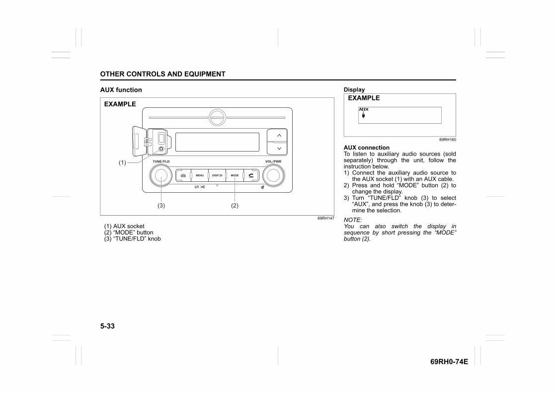
5-33
OTHER CONTROLS AND EQUIPMENT
69RH0-74E
AUX function
69RH147
(1) AUX socket(2) “MODE” button(3) “TUNE/FLD” knob
MENU
TUNE / FLD VOL / PWR
MODEDISP/
(3)
(1)
(2)
EXAMPLE
Display
69RH160
AUX connectionTo listen to auxiliary audio sources (soldseparately) through the unit, follow theinstruction below.1) Connect the auxiliary audio source to
the AUX socket (1) with an AUX cable.2) Press and hold “MODE” button (2) to
change the display.3) Turn “TUNE/FLD” knob (3) to select
“AUX”, and press the knob (3) to deter-mine the selection.
NOTE:You can also switch the display insequence by short pressing the “MODE”button (2).
EXAMPLE

5-34
OTHER CONTROLS AND EQUIPMENT
69RH0-74E
NOTE:• Please consult your place of purchase
for details about whether a given auxil-iary audio source can be connected andthe proper auxiliary cord to use.
• The volume and tone controls of theauxiliary audio source can be adjustedon the unit.
• In AUX mode, the volume which is set isdifferent from another mode.
CAUTION
• Before connection, mute the unit,and also keep the volume of theauxiliary audio source within arange that will not cause distortion.
• When the audio source is turnedoff, noise may be emitted. Be sureto turn off the unit or switch toanother mode before turning off theaudio source.
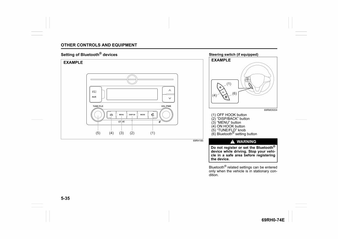
5-35
OTHER CONTROLS AND EQUIPMENT
69RH0-74E
Setting of Bluetooth® devices
69RH185
MENU
TUNE / FLD VOL / PWR
AUX
MODEDISP/
(5) (3)(4) (2) (1)
EXAMPLE
Steering switch (if equipped)
69RM05004
(1) OFF HOOK button(2) “DISP/BACK” button(3) “MENU” button(4) ON HOOK button(5) “TUNE/FLD” knob(6) Bluetooth® setting button
Bluetooth® related settings can be enteredonly when the vehicle is in stationary con-dition.
WARNING
Do not register or set the Bluetooth®
device while driving. Stop your vehi-cle in a safe area before registeringthe device.
(6)
(1)
(4)
EXAMPLE
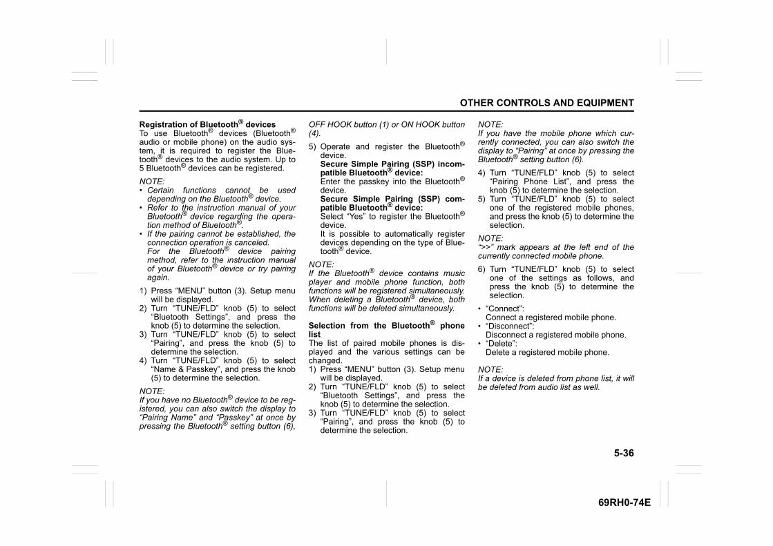
5-36
OTHER CONTROLS AND EQUIPMENT
69RH0-74E
Registration of Bluetooth® devicesTo use Bluetooth® devices (Bluetooth®
audio or mobile phone) on the audio sys-tem, it is required to register the Blue-tooth® devices to the audio system. Up to5 Bluetooth® devices can be registered.
NOTE:• Certain functions cannot be used
depending on the Bluetooth® device.• Refer to the instruction manual of your
Bluetooth® device regarding the opera-tion method of Bluetooth®.
• If the pairing cannot be established, theconnection operation is canceled. For the Bluetooth® device pairingmethod, refer to the instruction manualof your Bluetooth® device or try pairingagain.
1) Press “MENU” button (3). Setup menuwill be displayed.
2) Turn “TUNE/FLD” knob (5) to select“Bluetooth Settings”, and press theknob (5) to determine the selection.
3) Turn “TUNE/FLD” knob (5) to select“Pairing”, and press the knob (5) todetermine the selection.
4) Turn “TUNE/FLD” knob (5) to select“Name & Passkey”, and press the knob(5) to determine the selection.
NOTE:If you have no Bluetooth® device to be reg-istered, you can also switch the display to“Pairing Name” and “Passkey” at once bypressing the Bluetooth® setting button (6),
OFF HOOK button (1) or ON HOOK button(4).
5) Operate and register the Bluetooth®
device.Secure Simple Pairing (SSP) incom-patible Bluetooth® device:Enter the passkey into the Bluetooth®
device.Secure Simple Pairing (SSP) com-patible Bluetooth® device:Select “Yes” to register the Bluetooth®
device.It is possible to automatically registerdevices depending on the type of Blue-tooth® device.
NOTE:If the Bluetooth® device contains musicplayer and mobile phone function, bothfunctions will be registered simultaneously.When deleting a Bluetooth® device, bothfunctions will be deleted simultaneously.
Selection from the Bluetooth® phonelistThe list of paired mobile phones is dis-played and the various settings can bechanged.1) Press “MENU” button (3). Setup menu
will be displayed.2) Turn “TUNE/FLD” knob (5) to select
“Bluetooth Settings”, and press theknob (5) to determine the selection.
3) Turn “TUNE/FLD” knob (5) to select“Pairing”, and press the knob (5) todetermine the selection.
NOTE:If you have the mobile phone which cur-rently connected, you can also switch thedisplay to “Pairing” at once by pressing theBluetooth® setting button (6).
4) Turn “TUNE/FLD” knob (5) to select“Pairing Phone List”, and press theknob (5) to determine the selection.
5) Turn “TUNE/FLD” knob (5) to selectone of the registered mobile phones,and press the knob (5) to determine theselection.
NOTE:“>>” mark appears at the left end of thecurrently connected mobile phone.
6) Turn “TUNE/FLD” knob (5) to selectone of the settings as follows, andpress the knob (5) to determine theselection.
• “Connect”:Connect a registered mobile phone.
• “Disconnect”:Disconnect a registered mobile phone.
• “Delete”:Delete a registered mobile phone.
NOTE:If a device is deleted from phone list, it willbe deleted from audio list as well.
5-37
OTHER CONTROLS AND EQUIPMENT
69RH0-74E
Selection from the Bluetooth® audio listThe list of paired Bluetooth® audio is dis-played and the various settings can bechanged.1) Press “MENU” button (3). Setup menu
will be displayed.2) Turn “TUNE/FLD” knob (5) to select
“Bluetooth Settings”, and press theknob (5) to determine the selection.
3) Turn “TUNE/FLD” knob (5) to select“Pairing”, and press the knob (5) todetermine the selection.
NOTE:If you have the Bluetooth® audio whichcurrently connected, you can also switchthe display to “Pairing” at once by pressingthe Bluetooth® setting button (6).
4) Turn “TUNE/FLD” knob (5) to select“Pairing Audio List”, and press the knob(5) to determine the selection.
5) Turn “TUNE/FLD” knob (5) to selectone of the registered Bluetooth® audiodevices, and press the knob (5) todetermine the selection.
NOTE:“>>” mark appears at the left end of thecurrently connected Bluetooth® audio.
6) Turn “TUNE/FLD” knob (5) to selectone of the settings as follows, andpress the knob (5) to determine theselection.
• “Connect”:Connect a registered Bluetooth® audio.
• “Disconnect”:Disconnect a registered Bluetooth®
audio. • “Delete”:
Delete a registered Bluetooth® audio.
NOTE:If a device is deleted from audio list, it willbe deleted from phone list as well.
Managing paired devicesThe devices paired with the audio unit canbe managed from the “Bluetooth® settings”screen. You can connect one Bluetooth®
device as audio and another Bluetooth®
device as phone from registered Blue-tooth® devices simultaneously.
Change of passkey1) Press “MENU” button (3). Setup menu
will be displayed.2) Turn “TUNE/FLD” knob (5) to select
“Bluetooth Settings”, and press theknob (5) to determine the selection.
3) Turn “TUNE/FLD” knob (5) to select“Pairing”, and press the knob (5) todetermine the selection.
NOTE:If you have the Bluetooth® device whichcurrently connected, you can also switchthe display to “Pairing” at once by pressingthe Bluetooth® setting button (6).
4) Turn “TUNE/FLD” knob (5) to select“Edit Passkey”, and press the knob (5)to determine the selection.
5) Turn “TUNE/FLD” knob (5) to select anumber for the first digit, and press theknob (5) to determine the selection.Select and determine numbers for fromthe second to fourth digits in order inthe same manner.
6) Press “TUNE/FLD” knob (5) to deter-mine the passkey setting.
Automatic connection with the Blue-tooth® deviceIf the “BT Power” is set to “ON”, turning theignition switch to “ON” position will auto-matically connect the registered Blue-tooth® device.• With the automatic connection, the Blue-
tooth® device that was connected lastwill be prioritized.
1) Press “MENU” button (3). Setup menuwill be displayed.
2) Turn “TUNE/FLD” knob (5) to select“Bluetooth Settings”, and press theknob (5) to determine the selection.
3) Turn “TUNE/FLD” knob (5) to select“Initial Settings”, and press the knob (5)to determine the selection.
4) Turn “TUNE/FLD” knob (5) to select“BT Power”.
5) Press “TUNE/FLD” knob (5) to select“ON” or “OFF”.
NOTE:• When “BT Power” is set to “OFF”, the
audio system disconnects from the reg-istered Bluetooth® device.

5-38
OTHER CONTROLS AND EQUIPMENT
69RH0-74E
• If “BT Power” is set to “OFF”, the audiosystem will not automatically reconnectthe next time the ignition is switched on.
The device status will be displayed1) Press “MENU” button (3). Setup menu
will be displayed.2) Turn “TUNE/FLD” knob (5) to select
“Bluetooth Settings”, and press theknob (5) to determine the selection.
3) Turn “TUNE/FLD” knob (5) to select“Pairing”, and press the knob (5) todetermine the selection.
NOTE:If you have the Bluetooth® device whichcurrently connected, you can also switchthe display to “Pairing” at once by pressingthe Bluetooth® setting button (6).
4) Turn “TUNE/FLD” knob (5) to select“Device Information”, and press theknob (5) to determine the selection.The device name and address will bedisplayed.
Initialize Bluetooth® settingsIt is possible to initialize the Bluetooth®
settings.
1) Press “MENU” button (3). Setup menuwill be displayed.
2) Turn “TUNE/FLD” knob (5) to select“Bluetooth Settings”, and press theknob (5) to determine the selection.
3) Turn “TUNE/FLD” knob (5) to select“Initial Settings”, and press the knob (5)to determine the selection.
4) Turn “TUNE/FLD” knob (5) to select“Initialize BT”, and press the knob (5) todetermine the selection.
5) Turn “TUNE/FLD” knob (5) to select“YES”, and press the knob (5) to deter-mine the selection.
• Items to be initialized to default value:– BT Power– Talk Volume– Ring Volume
Notes on Bluetooth®
73R0209
• The Bluetooth® word mark and logos areregistered trademarks owned by Blue-tooth SIG, Inc. and any use of suchmarks by Panasonic Corporation isunder license. Other trademarks andtrade names are those of their respec-tive owners. This telecommunication equipment con-
forms to the requirements of the NationalTelecommunications Commission.
• Stop using this unit and a Bluetooth®
ready device whenever requested. Thisunit shares the communication fre-quency with other private or public wire-less communication equipment such asa wireless LAN and other wireless com-munication radios. You should stop using this unit immedi-ately whenever you are notified that yourunit disturbs other wireless communica-tion.
Profile• SSP (Secure Simple Pairing)• PBAP (Phone Book Access Profile)• OPP (Object Push Profile)• HFP (Hand-Free Profile)• A2DP (Advanced Audio Distribution Profile)• AVRCP (Audio/Video Remote Control Profile)• SPP (Serial Port Profile)
NOTE:• After the Audio system is turned ON, it
takes a few seconds to detect and set upBluetooth® related settings.
• For Bluetooth related issues, unpair,restart your smartphone and try again.
CAUTION
• Do not initialize the settings whiledriving. Stop your vehicle in a safearea before initializing the device.
• Initialize with caution. Initializedsettings cannot be restored.
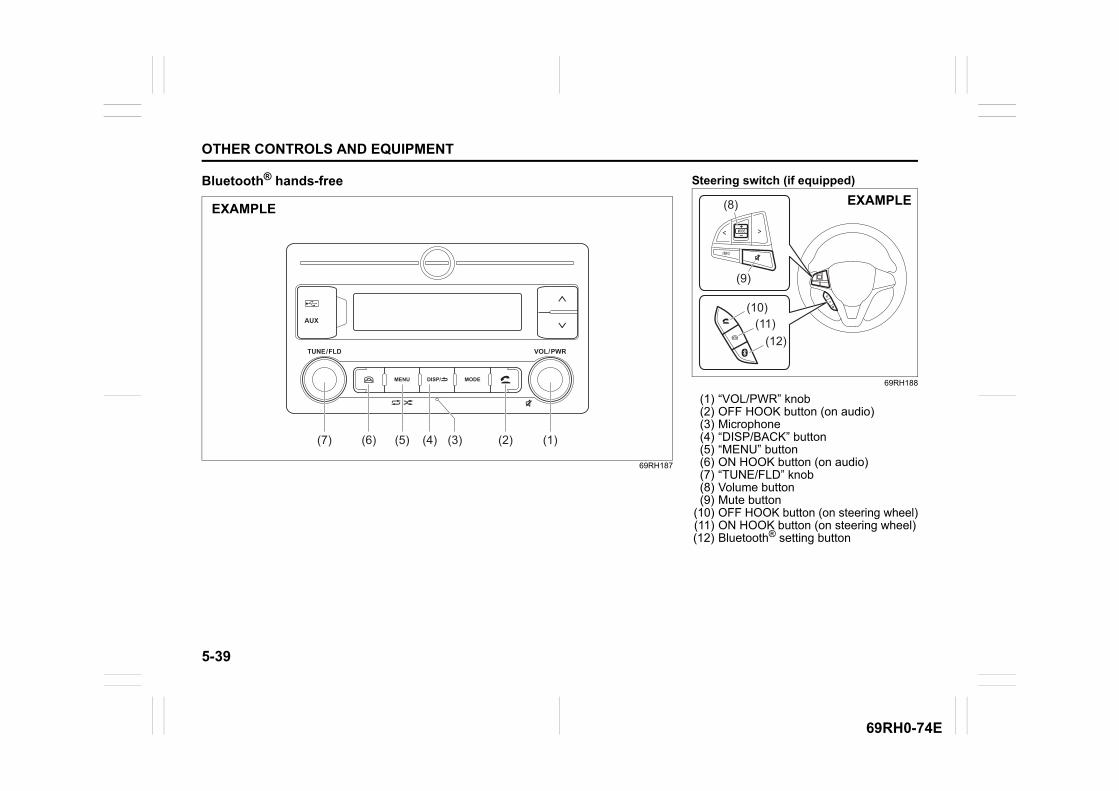
5-39
OTHER CONTROLS AND EQUIPMENT
69RH0-74E
Bluetooth® hands-free
69RH187
MENU
TUNE / FLD VOL / PWR
AUX
MODEDISP/
(7) (5)(6) (4) (3) (2) (1)
EXAMPLE
Steering switch (if equipped)
69RH188
(1) “VOL/PWR” knob(2) OFF HOOK button (on audio)(3) Microphone(4) “DISP/BACK” button(5) “MENU” button(6) ON HOOK button (on audio)(7) “TUNE/FLD” knob(8) Volume button(9) Mute button
(10) OFF HOOK button (on steering wheel)(11) ON HOOK button (on steering wheel)(12) Bluetooth® setting button
(9)
(8)
(11)(10)
(12)
EXAMPLE
5-40
OTHER CONTROLS AND EQUIPMENT
69RH0-74E
NOTE:• Please keep your phone volume low.
The person’s voice who you are talkingto may be heard outside of the vehicleand increase the voice echo. Whentalking on the phone, speak clearlytowards the microphone.
• In the following cases, your voice maynot be heard clearly by the person on theother line:– When driving on unpaved roads. (If
there is loud traffic noise.)– When driving at high speeds.– When driving with the window open.– If the air conditioner is blowing directly
towards the microphone.– When the sound of the air conditioner
fan is loud.
– When there is an adverse effect to thesound quality of the phone or networkthat you are using.
• The audio system may not functionunder the following conditions.– When the phone power is not turned
on.– When the mobile phone is out of ser-
vice.– When the mobile phone is not con-
nected.– When the mobile phone battery is low
• The Bluetooth®’s hands-free operation isdependent upon the mobile phone’scompatibility.
• The Bluetooth®’s hands-free perfor-mance is affected by the driving condi-tions of mobile phone networks,handsets and vehicles.
• The audio system’s performance may berestricted due to the model of yourmobile phone.
• Bluetooth®, phone battery level and net-work signal strength status are displayedonly when a phone is connected to thesystem.
• The information depends on statusreceived from the phone.
• The call, contact synchronization actionis controlled from the smartphone.
It is possible to register a mobile phoneand register the phone number to theaudio system as follows:• Up to 1,000 phone numbers can be
saved for every registered mobilephone.
• Up to 30 phone numbers of the latestcalls can be stored. (30 calls includingmissed, received and dialed call).– When the call history exceeds 30
calls, they are deleted from the oldestone first, and the latest call historyinformation is displayed in descend-ing order.
• Up to 6 phone numbers can be saved tothe speed dial list.
• When attempts to establish the pairingfail within 60 seconds, the connectingoperation will be canceled. Try to estab-lish the pairing again or refer to the man-ual of the phone in use for how toestablish the pairing with the phone.
Answer the phonePress OFF HOOK button (2) or (10).• When you press the ON HOOK button
(6) or (11) during an incoming call, youcan block the call. (Only for compatiblephone units)
NOTICE
• Do not leave your mobile phoneinside your vehicle. If the tempera-ture inside the vehicle increases, itmay damage your mobile phone.
• When disposing your vehicle, makesure to delete all personal informa-tion saved to the audio system.
• The following hands-free data mustbe deleted from the audio system.– Speed dial– Reception history/Incoming call
history– Bluetooth® phonebook data
To use the hands-free function with thisunit, it is required to register the phonein advance.
5-41
OTHER CONTROLS AND EQUIPMENT
69RH0-74E
NOTE:• If you receive a call from a registered
phone, the caller’s name will appear onthe screen.
• If you receive a call from an unregisteredphone, only the caller’s phone numberwill appear on the screen.
Hang up the phoneWhen the call is finished, press the ONHOOK button (6) or (11).
Call waitingWhen a phone call is interrupted by a sec-ond call, it is possible to hold the currentcall and answer the other incoming call.To talk to incoming call: • Press the OFF HOOK button (10) or (2).
The current call will be put on hold. • Every time you press OFF HOOK button
(10) or (2), the phone call will beswitched to the call which was put onhold.
• When the current call is completed, thecall which was put on hold will connect.
To refuse the incoming call:• Press the ON-HOOK button (11) or (6).
NOTE:This function can only be used with phoneunits that are compatible with call waiting.
Move call to Private modeIf you wish to move a call to private mode,press the “DISP/BACK” button (4).To move the call back to Handsfree mode,press the OFF/ON hook button.
Move call to Handsfree modeIf you wish to move the call back to Hands-free Mode, press the “ON/OFF HOOK”button.
Mute the reception volumePress “VOL/PWR” knob (1) or mute button(9).• To deactivate the mute volume, press
“VOL/PWR” knob (1) or mute button (9)again.
Adjust the reception volume• Turn “VOL/PWR” knob (1) during a call.
Turning it clockwise increases the vol-ume; turning it counterclockwisedecreases the volume.
• Press volume button (8) during a call.Pressing the button up increases the vol-ume; pressing the button downdecreases the volume.
NOTE:The volume and microphone sensitivitysettings vary depending on the specifica-tions of each mobile phone.
Adjust the ringtone volume• Turn “VOL/PWR” knob (1) during an
incoming call. Turning it clockwise increases the vol-ume; turning it counterclockwisedecreases the volume.
• Press volume button (8) during anincoming call. Pressing the button upincreases the volume; pressing the but-ton down decreases the volume.
Adjust the volume with the Bluetooth®
settings1) Press “MENU” button (5). Setup menu
will be displayed.2) Turn “TUNE/FLD” knob (7) to select
“Bluetooth Settings”, and press theknob (7) to determine the selection.
3) Turn “TUNE/FLD” knob (7) to select“Initial Settings”, and press the knob (7)to determine the selection.
4) Turn “TUNE/FLD” knob (7) to select“Talk volume” or “Ring volume”, andpress the knob (7) to determine theselection.
5) Turn “TUNE/FLD” knob (7) to adjust thevolume, and press the knob (7) todetermine the selection.
Make a callPress the OFF HOOK button (2) or (10) toenter the telephone mode.

5-42
OTHER CONTROLS AND EQUIPMENT
69RH0-74E
Use the phonebook1) Turn “TUNE/FLD” knob (7) to select
“Contacts”, and press the knob (7) todetermine the selection.
2) Turn “TUNE/FLD” knob (7) to select thedesired initials, and press the knob (7)to determine the selection.
3) Turn “TUNE/FLD” knob (7) to select thedesired name, and press the knob (7)to determine the selection.
4) Turn “TUNE/FLD” knob (7) to select thedesired phone number, and press theknob (7) or OFF HOOK button (2) or(10).
Use the call history1) Turn “TUNE/FLD” knob (7) to select
“Call Log”, and press the knob (7) todetermine the selection.
2) Turn “TUNE/FLD” knob (7) to select“All”, “Missed”, “Dialed” or “Received”,and press the knob (7) to determine theselection.
3) Turn “TUNE/FLD” knob (7) to select thedesired name or phone number, andpress the knob (7) or OFF HOOK but-ton (2) or (10).
Use the speed dial1) Turn “TUNE/FLD” knob (7) to select
“Speed Dial”, and press the knob (7) todetermine the selection.
2) Turn “TUNE/FLD” knob (7) to select thedesired name or phone number, andpress the knob (7) or OFF HOOK but-ton (2) or (10).
NOTE:Speed dial numbers must be registeredbefore this function can be used.
Transfer all contacts from your mobilephone1) Press “MENU” button (5). Setup menu
will be displayed.2) Turn “TUNE/FLD” knob (7) to select
“Bluetooth Settings”, and press theknob (7) to determine the selection.
3) Turn “TUNE/FLD” knob (7) to select“Dial”, and press the knob (7) to deter-mine the selection.
4) Turn “TUNE/FLD” knob (7) to select“Setup Contacts”, and press the knob(7) to determine the selection.
5) Turn “TUNE/FLD” knob (7) to select“Overwrite”, and press the knob (7) todetermine the selection.
6) Turn “TUNE/FLD” knob (7) to select“YES”, and press the knob (7) to deter-mine the selection.
Delete the registered phonebook1) Press “MENU” button (5). Setup menu
will be displayed.2) Turn “TUNE/FLD” knob (7) to select
“Bluetooth Settings”, and press theknob (7) to determine the selection.
3) Turn “TUNE/FLD” knob (7) to select“Dial”, and press the knob (7) to deter-mine the selection.
4) Turn “TUNE/FLD” knob (7) to select“Setup Contacts”, and press the knob(7) to determine the selection.
5) Turn “TUNE/FLD” knob (7) to select“Delete Contacts”, and press the knob(7) to determine the selection.
6) Turn “TUNE/FLD” knob (7) to select“YES”, and press the knob (7) to deter-mine the selection.
Delete the call history1) Press “MENU” button (5). Setup menu
will be displayed.2) Turn “TUNE/FLD” knob (7) to select
“Bluetooth Settings”, and press theknob (7) to determine the selection.
3) Turn “TUNE/FLD” knob (7) to select“Dial”, and press the knob (7) to deter-mine the selection.
4) Turn “TUNE/FLD” knob (7) to select“Setup Contacts”, and press the knob(7) to determine the selection.
5) Turn “TUNE/FLD” knob (7) to select“Delete Call Log”, and press the knob(7) to determine the selection.
6) Turn “TUNE/FLD” knob (7) to select“YES”, and press the knob (7) to deter-mine the selection.
Registration in speed dial1) Press “MENU” button (5). Setup menu
will be displayed.2) Turn “TUNE/FLD” knob (7) to select
“Bluetooth Settings”, and press theknob (7) to determine the selection.
5-43
OTHER CONTROLS AND EQUIPMENT
69RH0-74E
3) Turn “TUNE/FLD” knob (7) to select“Dial”, and press the knob (7) to deter-mine the selection.
4) Turn “TUNE/FLD” knob (7) to select“Add Speed Dial”, and press the knob(7) to determine the selection.
5) Turn “TUNE/FLD” knob (7) to select“Add/Modify”, and press the knob (7) todetermine the selection.
6) Turn “TUNE/FLD” knob (7) to select thedesired speed dial number, and pressthe knob (7) to determine the selection.
7) Turn “TUNE/FLD” knob (7) to select thedesired initials, and press the knob (7)to determine the selection.
8) Turn “TUNE/FLD” knob (7) to select thedesired name, and press the knob (7)to determine the selection.
9) Turn “TUNE/FLD” knob (7) to select thedesired Phone number, and press theknob (7) to determine the selection.
10)Turn “TUNE/FLD” knob (7) to select“YES”, and press the knob (7) to deter-mine the selection.
Deletion of speed dial1) Press “MENU” button (5). Setup menu
will be displayed.2) Turn “TUNE/FLD” knob (7) to select
“Bluetooth Settings”, and press theknob (7) to determine the selection.
3) Turn “TUNE/FLD” knob (7) to select“Dial”, and press the knob (7) to deter-mine the selection.
4) Turn “TUNE/FLD” knob (7) to select“Add Speed Dial”, and press the knob(7) to determine the selection.
5) Turn “TUNE/FLD” knob (7) to select“Delete”, and press the knob (7) todetermine the selection.
6) Turn “TUNE/FLD” knob (7) to select“Delete All” or “Delete Contact”, andpress the knob (7) to determine theselection.• If you select “Delete Contact”, select
the name for delete.7) Turn “TUNE/FLD” knob (7) to select
“YES”, and press the knob (7) to deter-mine the selection.
Automatic transfer of the phonebook/call historyWhen registering the mobile phone, youcan select to automatically transfer thephonebook and call history from yourdevice each time after phone is connected.Select according to the following steps.1) Press “MENU” button (5). Setup menu
will be displayed.2) Turn “TUNE/FLD” knob (7) to select
“Bluetooth Settings”, and press theknob (7) to determine the selection.
3) Turn “TUNE/FLD” knob (7) to select“Dial”, and press the knob (7) to deter-mine the selection.
4) Turn “TUNE/FLD” knob (7) to select“Setup Contacts”, and press the knob(7) to determine the selection.
5) Turn “TUNE/FLD” knob (7) to select“Auto Transfer”.
6) Press “TUNE/FLD” knob (7) to select“ON” or “OFF”.
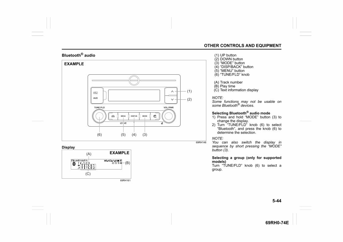
5-44
OTHER CONTROLS AND EQUIPMENT
69RH0-74E
Bluetooth® audio
69RH146
Display
69RH161
MENU
TUNE / FLD VOL / PWR
AUX
MODEDISP/
(6) (5) (4) (3)
(1)
(2)
EXAMPLE
(C)
(B)
(A) EXAMPLE
(1) UP button(2) DOWN button(3) “MODE” button(4) “DISP/BACK” button(5) “MENU” button(6) “TUNE/FLD” knob
(A) Track number(B) Play time(C) Text information display
NOTE:Some functions may not be usable onsome Bluetooth® devices.
Selecting Bluetooth® audio mode1) Press and hold “MODE” button (3) to
change the display.2) Turn “TUNE/FLD” knob (6) to select
“Bluetooth”, and press the knob (6) todetermine the selection.
NOTE:You can also switch the display insequence by short pressing the “MODE”button (3).
Selecting a group (only for supportedmodels)Turn “TUNE/FLD” knob (6) to select agroup.
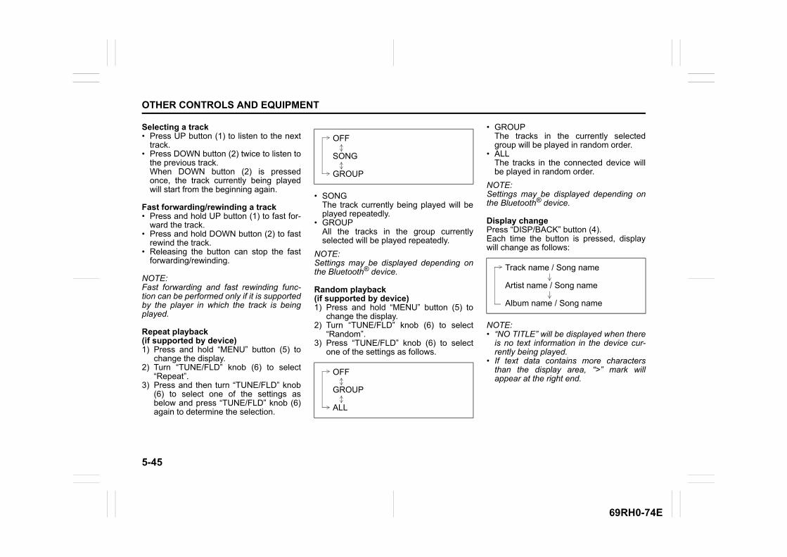
5-45
OTHER CONTROLS AND EQUIPMENT
69RH0-74E
Selecting a track• Press UP button (1) to listen to the next
track.• Press DOWN button (2) twice to listen to
the previous track.When DOWN button (2) is pressedonce, the track currently being playedwill start from the beginning again.
Fast forwarding/rewinding a track• Press and hold UP button (1) to fast for-
ward the track.• Press and hold DOWN button (2) to fast
rewind the track.• Releasing the button can stop the fast
forwarding/rewinding.
NOTE:Fast forwarding and fast rewinding func-tion can be performed only if it is supportedby the player in which the track is beingplayed.
Repeat playback (if supported by device)1) Press and hold “MENU” button (5) to
change the display.2) Turn “TUNE/FLD” knob (6) to select
“Repeat”. 3) Press and then turn “TUNE/FLD” knob
(6) to select one of the settings asbelow and press “TUNE/FLD” knob (6)again to determine the selection.
• SONGThe track currently being played will beplayed repeatedly.
• GROUPAll the tracks in the group currentlyselected will be played repeatedly.
NOTE:Settings may be displayed depending onthe Bluetooth® device.
Random playback(if supported by device)1) Press and hold “MENU” button (5) to
change the display.2) Turn “TUNE/FLD” knob (6) to select
“Random”. 3) Press “TUNE/FLD” knob (6) to select
one of the settings as follows.
• GROUPThe tracks in the currently selectedgroup will be played in random order.
• ALLThe tracks in the connected device willbe played in random order.
NOTE:Settings may be displayed depending onthe Bluetooth® device.
Display changePress “DISP/BACK” button (4).Each time the button is pressed, displaywill change as follows:
NOTE:• “NO TITLE” will be displayed when there
is no text information in the device cur-rently being played.
• If text data contains more charactersthan the display area, “>” mark willappear at the right end.
OFF
SONG
GROUP
OFF
GROUP
ALL
Track name / Song name
Artist name / Song name
Album name / Song name

5-46
OTHER CONTROLS AND EQUIPMENT
69RH0-74E
Disclaimer for Bluetooth® function• Depending on the mobile phone models,
some phones may not be compatiblefully or partially (some function may berestricted).
• Media playback and handsfree callingthrough third-party applications is notguaranteed and may have limited sup-port.
• Playback, display contents, connectivityor voice quality etc. may get affecteddepending on circumstances.
• After the ignition switch is turned to “ON”position the audio system takes few sec-onds to detect and connect to theBluetooth® device (if already paired).
• Make sure that you are aware of allapplicable local laws and accordinglyuse Bluetooth® device.
Steering switch (if equipped)Use the steering wheel button to operatethe basic functions of the audio system.
69RH142
(1) “MODE” button(2) Selection button
– Selecting the radio station– Selecting the track (USB (iPod),
Bluetooth® audio mode)(3) Mute button(4) Volume button
“MODE” button (1)Each time the button is pressed, the modewill change as follows:
Selection button (2)• FM, AM mode:
– Press “>” to transfer to the next presetchannel.
– Press “<” to transfer to the previouspreset channel.
– Press “>” for 1 second or longer, it willsearch for receivable stations at a highfrequency.
– Press “<” for 1 second or longer, it willsearch for receivable stations at a lowfrequency.
• USB (iPod), Bluetooth® audio mode:– Press “>” to transfer to the next song.
With the folder operation mode, it willtransfer to the next folder.
(2)(2)
(3)
(4) (1)EXAMPLE FM
AM
USB (iPod) (if equipped)
Bluetooth®
AUX (if equipped)

5-47
OTHER CONTROLS AND EQUIPMENT
69RH0-74E
– Press “<” to return to the beginning ofthe currently playing song. Pressing ittwice consecutively will return to theprevious song. With the folder operation mode, it willreturn to the previous folder.
– Press “>” for 1 second or longer tofast-forward the song. When the button is released, it willstop fast-forwarding.
– Press “<” for 1 second or longer torewind the song.Releasing the button can stop rewind-ing.
Mute button (3)• Hands-free/iPod mode:
Each time you press the button the mutewill switch from ON/OFF.
• USB mode:Press the button during playback to tem-porarily stop the playback.
Volume button (4)• Hands-free mode:
– Press “+” during an outgoing or ingo-ing call, the reception/ringtone soundwill increase.
– Press “–” during an outgoing or ingo-ing call, the reception/ringtone soundwill decrease.
– Press “+” during an outgoing call, theringtone sound will increase.
– Press “–” during an outgoing call, theringtone sound will decrease.
• Radio, USB (iPod), Bluetooth® audio,AUX mode: – Press “+”, the volume will increase. – Press “–”, the volume will decrease.
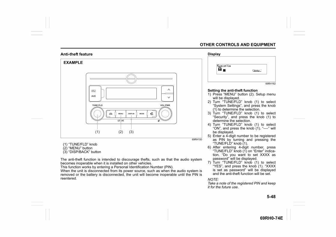
5-48
OTHER CONTROLS AND EQUIPMENT
69RH0-74E
Anti-theft feature
69RH150
(1) “TUNE/FLD” knob(2) “MENU” button(3) “DISP/BACK” button
The anti-theft function is intended to discourage thefts, such as that the audio systembecomes inoperable when it is installed on other vehicles.This function works by entering a Personal Identification Number (PIN).When the unit is disconnected from its power source, such as when the audio system isremoved or the battery is disconnected, the unit will become inoperable until the PIN isreentered.
MENU
TUNE / FLD VOL / PWR
AUX
MODEDISP/
(1) (2) (3)
EXAMPLE
Display
69RH162
Setting the anti-theft function1) Press “MENU” button (2). Setup menu
will be displayed.2) Turn “TUNE/FLD” knob (1) to select
“System Settings”, and press the knob(1) to determine the selection.
3) Turn “TUNE/FLD” knob (1) to select“Security”, and press the knob (1) todetermine the selection.
4) Turn “TUNE/FLD” knob (1) to select“ON”, and press the knob (1). “----” willbe displayed.
5) Enter a 4-digit number to be registeredas PIN by turning and pressing the“TUNE/FLD” knob (1).
6) After entering 4-digit number, press“TUNE/FLD” knob (1) on “Enter” indica-tion. “Do you want to set XXXX aspassword” will be displayed.
7) Turn “TUNE/FLD” knob (1) to select“YES”, and press the knob (1). “XXXXis set as password” will be displayedand the anti-theft function will be set.
NOTE:Take a note of the registered PIN and keepit for the future use.
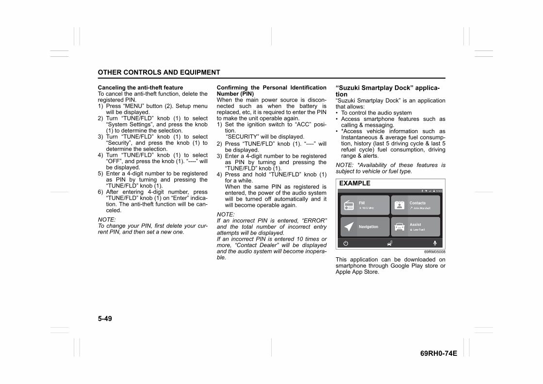
5-49
OTHER CONTROLS AND EQUIPMENT
69RH0-74E
Canceling the anti-theft featureTo cancel the anti-theft function, delete theregistered PIN.1) Press “MENU” button (2). Setup menu
will be displayed.2) Turn “TUNE/FLD” knob (1) to select
“System Settings”, and press the knob(1) to determine the selection.
3) Turn “TUNE/FLD” knob (1) to select“Security”, and press the knob (1) todetermine the selection.
4) Turn “TUNE/FLD” knob (1) to select“OFF”, and press the knob (1). “----” willbe displayed.
5) Enter a 4-digit number to be registeredas PIN by turning and pressing the“TUNE/FLD” knob (1).
6) After entering 4-digit number, press“TUNE/FLD” knob (1) on “Enter” indica-tion. The anti-theft function will be can-celed.
NOTE:To change your PIN, first delete your cur-rent PIN, and then set a new one.
Confirming the Personal IdentificationNumber (PIN)When the main power source is discon-nected such as when the battery isreplaced, etc, it is required to enter the PINto make the unit operable again. 1) Set the ignition switch to “ACC” posi-
tion.“SECURITY” will be displayed.
2) Press “TUNE/FLD” knob (1). “----” willbe displayed.
3) Enter a 4-digit number to be registeredas PIN by turning and pressing the“TUNE/FLD” knob (1).
4) Press and hold “TUNE/FLD” knob (1)for a while.When the same PIN as registered isentered, the power of the audio systemwill be turned off automatically and itwill become operable again.
NOTE:If an incorrect PIN is entered, “ERROR”and the total number of incorrect entryattempts will be displayed. If an incorrect PIN is entered 10 times ormore, “Contact Dealer” will be displayedand the audio system will become inopera-ble.
“Suzuki Smartplay Dock” applica-tion“Suzuki Smartplay Dock” is an applicationthat allows:• To control the audio system• Access smartphone features such as
calling & messaging.• *Access vehicle information such as
Instantaneous & average fuel consump-tion, history (last 5 driving cycle & last 5refuel cycle) fuel consumption, drivingrange & alerts.
NOTE: *Availability of these features issubject to vehicle or fuel type.
69RM05008
This application can be downloaded onsmartphone through Google Play store orApple App Store.
EXAMPLE
5-50
OTHER CONTROLS AND EQUIPMENT
69RH0-74E
NOTE:• For further information on compatible
phones and application download pro-cess, please refer to MARUTI SUZUKIwebsite.
• Application is compatible with smart-phones supporting iOS version 9.0,Android OS 5.0 and above.
• Since this audio allows pairing of 2devices on Bluetooth® simultaneously,application is supported on the phonewhich is paired through handsfree pro-file.
• Application services are subject tochange. It is recommended to install thelatest updates for optimal experience.
• Application functioning is dependent onmobile data carrier and smartphonehardware, OS performance.
• The smartphone manufacturers areresponsible for the content and functionsof smartphone applications. The device
merely provides the option to displayand operate these applications.
• If many apps are installed, your smart-phone might work slowly.
• For information on using smartphoneapplications, please read your smart-phone instruction manual.
WARNING
While driving, ensure adherence toall traffic regulations. Insufficientattention to the road and traffic maycause an accident. It is recom-mended to familiarize with the tutorialsection of application before actualusage.In vehicle running condition, theapplication can be used in landscapemode only.

5-51
OTHER CONTROLS AND EQUIPMENT
69RH0-74E
TroubleshootingWhen encountering a problem, check and follow the instructions below.If the described suggestions do not solve the problem, it is recommended to take the unit to a Maruti Suzuki authorised workshop.
Problem Possible cause Possible solution
Common
Unable to operate The security function is on.
When “SECURITY” is displayed, enter thePIN.When “Contact Dealer” is displayed, contact aMaruti Suzuki authorised workshop.
Unable to turn on the power (No sound is produced) Fuse is blown. Contact a Maruti Suzuki authorised workshop.
Radio
Much noise It may not be exactly tuned in to the station. Tune it in exactly to the station.
Unable to receive by auto tun-ing
There may be no station emitting signals pow-erful enough. Pick up a station by manual tuning.
USB
Playback does not start whenthe USB device is connected
There is no supported format file to play onthis unit. Check the file format.
The current consumption of the USB deviceexceeds 2.1 A.
Use a USB device with a current consumptionlower than 2.1 A.
Sound skips or noise produced Sound skipping may occur when playing VBR(Variable Bit Rate) files. It is not recommended to play VBR files.
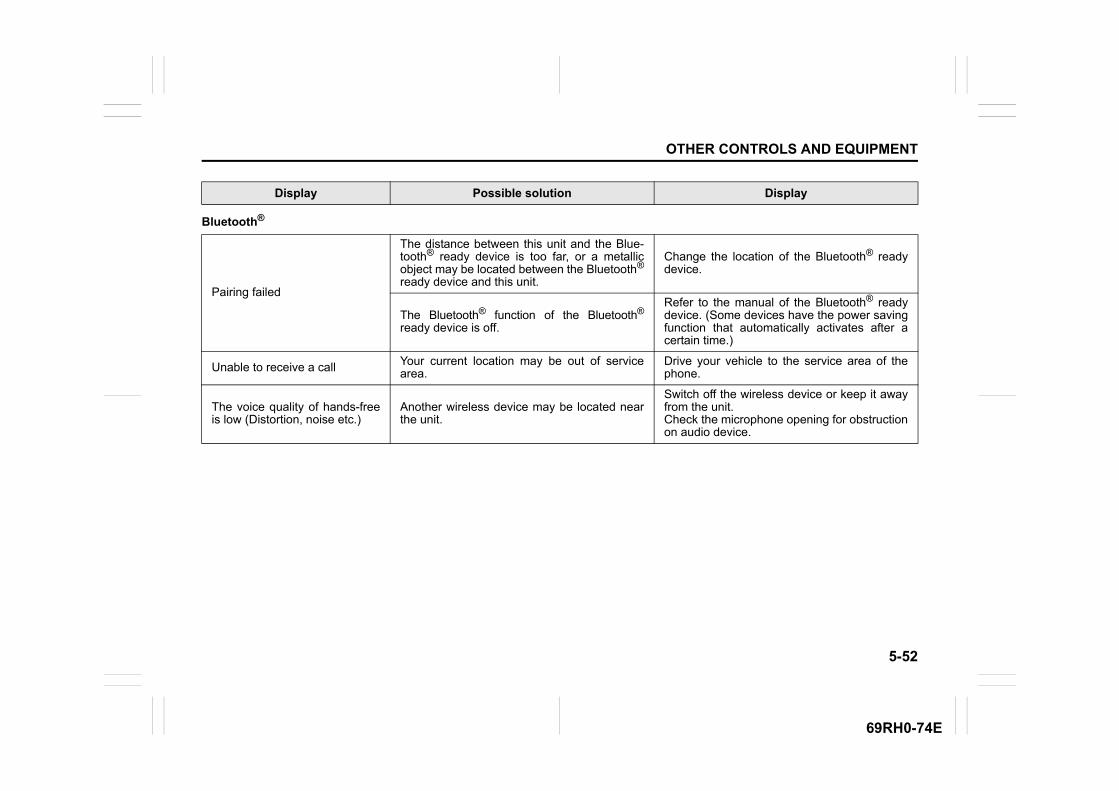
5-52
OTHER CONTROLS AND EQUIPMENT
69RH0-74E
Display Possible solution Display
Bluetooth®
Pairing failed
The distance between this unit and the Blue-tooth® ready device is too far, or a metallicobject may be located between the Bluetooth®
ready device and this unit.
Change the location of the Bluetooth® readydevice.
The Bluetooth® function of the Bluetooth®
ready device is off.
Refer to the manual of the Bluetooth® readydevice. (Some devices have the power savingfunction that automatically activates after acertain time.)
Unable to receive a call Your current location may be out of servicearea.
Drive your vehicle to the service area of thephone.
The voice quality of hands-freeis low (Distortion, noise etc.)
Another wireless device may be located nearthe unit.
Switch off the wireless device or keep it awayfrom the unit.Check the microphone opening for obstructionon audio device.
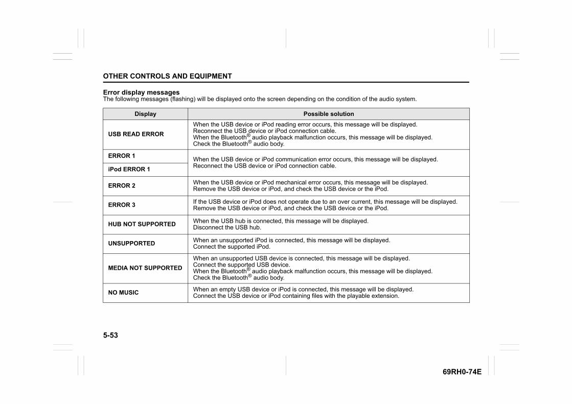
5-53
OTHER CONTROLS AND EQUIPMENT
69RH0-74E
Error display messagesThe following messages (flashing) will be displayed onto the screen depending on the condition of the audio system.
Display Possible solution
USB READ ERROR
When the USB device or iPod reading error occurs, this message will be displayed.Reconnect the USB device or iPod connection cable.When the Bluetooth® audio playback malfunction occurs, this message will be displayed.Check the Bluetooth® audio body.
ERROR 1When the USB device or iPod communication error occurs, this message will be displayed.Reconnect the USB device or iPod connection cable.
iPod ERROR 1
ERROR 2 When the USB device or iPod mechanical error occurs, this message will be displayed.Remove the USB device or iPod, and check the USB device or the iPod.
ERROR 3 If the USB device or iPod does not operate due to an over current, this message will be displayed.Remove the USB device or iPod, and check the USB device or the iPod.
HUB NOT SUPPORTED When the USB hub is connected, this message will be displayed.Disconnect the USB hub.
UNSUPPORTED When an unsupported iPod is connected, this message will be displayed.Connect the supported iPod.
MEDIA NOT SUPPORTED
When an unsupported USB device is connected, this message will be displayed.Connect the supported USB device.When the Bluetooth® audio playback malfunction occurs, this message will be displayed.Check the Bluetooth® audio body.
NO MUSIC When an empty USB device or iPod is connected, this message will be displayed.Connect the USB device or iPod containing files with the playable extension.
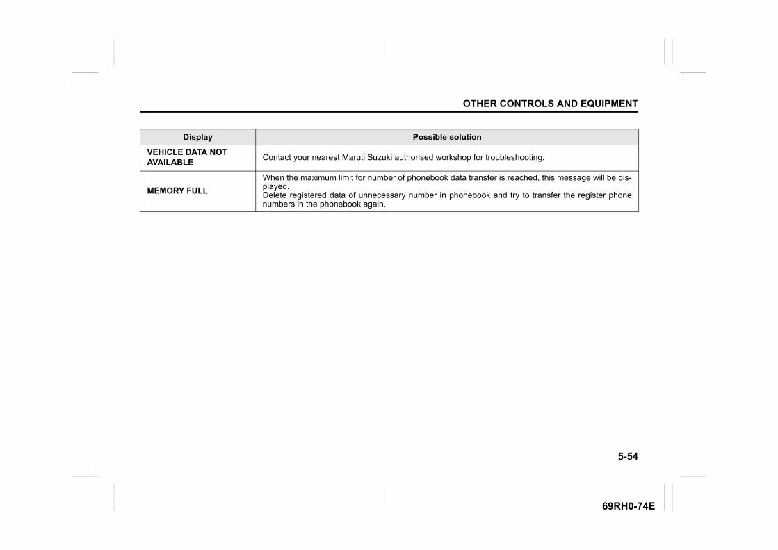
5-54
OTHER CONTROLS AND EQUIPMENT
69RH0-74E
Display Possible solution
VEHICLE DATA NOT AVAILABLE
Contact your nearest Maruti Suzuki authorised workshop for troubleshooting.
MEMORY FULL
When the maximum limit for number of phonebook data transfer is reached, this message will be dis-played.Delete registered data of unnecessary number in phonebook and try to transfer the register phonenumbers in the phonebook again.

5-55
OTHER CONTROLS AND EQUIPMENT
69RH0-74E
INSPECTION AND MAINTENANCE
6
69RH0-74E
62SM06000
INSPECTION AND MAINTENANCEMaintenance schedule ........................................................ 6-2Periodic maintenance schedule ........................................ 6-2Drive belt .............................................................................. 6-6Engine oil and filter ............................................................. 6-6 Engine coolant .................................................................... 6-10Air cleaner ............................................................................ 6-11Spark plugs .......................................................................... 6-12Gear oil ................................................................................. 6-13Clutch pedal (if equipped) .................................................. 6-15Fuel filter .............................................................................. 6-15Brakes .................................................................................. 6-15Steering ................................................................................ 6-17Tires ...................................................................................... 6-18Battery .................................................................................. 6-21Fuses .................................................................................... 6-22Headlight aiming ................................................................. 6-26Bulb replacement ................................................................ 6-26Wiper blades ........................................................................ 6-31Windshield washer fluid ..................................................... 6-33Air conditioning system (if equipped) ............................... 6-33

6-1
INSPECTION AND MAINTENANCE
69RH0-74E
62SM03001
WARNING
Take extreme care when working onyour vehicle to prevent accidentalinjury. Carefully observe the follow-ing precautions:• To prevent damage or unintended
activation of the airbag system orseat belt pretensioner system (ifequipped), check that the battery isdisconnected and the ignitionswitch has been in “LOCK” positionfor at least 90 seconds before per-forming any electrical service workon your MARUTI SUZUKI vehicle. Donot touch airbag system compo-nents, seat belt pretensioner system(if equipped) components or wires.
(Continued)
EXAMPLE WARNING
(Continued)The wires are wrapped with yellowtape or yellow tubing, and the cou-plers are yellow for easy identifica-tion.
• Do not leave the engine running ingarages or other confined areas.
• When the engine is running, keephands, clothing, tools, and otherobjects away from the fan and drivebelt. Even though the fan may notbe moving, it can automaticallyturn on without warning.
• When it is necessary to performservice work with the engine run-ning, check that the parking brakeis set fully and the transmission isin Neutral (for manual transmissionor Auto Gear Shift vehicles).
• Do not touch ignition wires or otherignition system parts when startingthe engine or when the engine isrunning, or you could receive anelectric shock.
• Be careful not to touch a hotengine, exhaust manifold andpipes, muffler, radiator and waterhoses.
• Do not allow smoking, sparks, orflames around fuel or the battery.Flammable fumes are present.
(Continued)
WARNING
(Continued)• Do not get under your vehicle if it is
supported only with the portablejack provided in your vehicle.
• Be careful not to cause accidentalshort circuits between the positiveand negative battery terminals.
• Keep used oil, coolant, and otherfluids away from children and pets.Dispose of used fluids properly;never pour them on the ground,into sewers, etc.
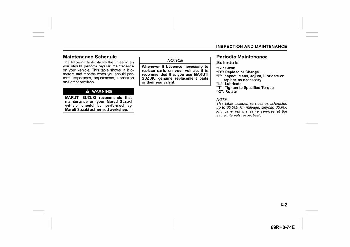
6-2
INSPECTION AND MAINTENANCE
69RH0-74E
Maintenance ScheduleThe following table shows the times whenyou should perform regular maintenanceon your vehicle. This table shows in kilo-meters and months when you should per-form inspections, adjustments, lubricationand other services.
Periodic Maintenance Schedule“C”: Clean“R”: Replace or Change“I”: Inspect, clean, adjust, lubricate or replace as necessary“L”: Lubricate“T”: Tighten to Specified Torque“O”: Rotate
NOTE:This table includes services as scheduledup to 80,000 km mileage. Beyond 80,000km, carry out the same services at thesame intervals respectively.
WARNING
MARUTI SUZUKI recommends thatmaintenance on your Maruti Suzukivehicle should be performed byMaruti Suzuki authorised workshop.
NOTICE
Whenever it becomes necessary toreplace parts on your vehicle, it isrecommended that you use MARUTISUZUKI genuine replacement partsor their equivalent.
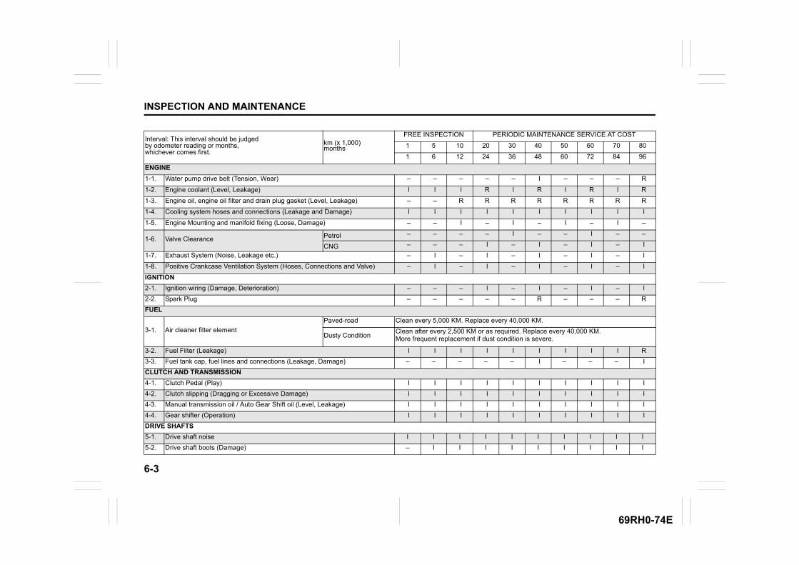
6-3
INSPECTION AND MAINTENANCE
69RH0-74E
Interval: This interval should be judged by odometer reading or months, whichever comes first.
km (x 1,000) months
FREE INSPECTION PERIODIC MAINTENANCE SERVICE AT COST
1 5 10 20 30 40 50 60 70 80
1 6 12 24 36 48 60 72 84 96
ENGINE
1-1. Water pump drive belt (Tension, Wear) – – – – – I – – – R
1-2. Engine coolant (Level, Leakage) l l l R l R l R l R
1-3. Engine oil, engine oil filter and drain plug gasket (Level, Leakage) – – R R R R R R R R
1-4. Cooling system hoses and connections (Leakage and Damage) l l l l l l l l l l
1-5. Engine Mounting and manifold fixing (Loose, Damage) – – I – I – I – I –
1-6. Valve Clearance Petrol – – – – I – – I – –
CNG – – – I – I – I – I
1-7. Exhaust System (Noise, Leakage etc.) – l – l – I – I – l
1-8. Positive Crankcase Ventilation System (Hoses, Connections and Valve) – l – l – I – I – l
IGNITION
2-1. Ignition wiring (Damage, Deterioration) – – – l – l – l – l
2-2. Spark Plug – – – – – R – – – R
FUEL
3-1. Air cleaner filter element
Paved-road Clean every 5,000 KM. Replace every 40,000 KM.
Dusty ConditionClean after every 2,500 KM or as required. Replace every 40,000 KM. More frequent replacement if dust condition is severe.
3-2. Fuel Filter (Leakage) I I I I I I I I I R
3-3. Fuel tank cap, fuel lines and connections (Leakage, Damage) – – – – – I – – – I
CLUTCH AND TRANSMISSION
4-1. Clutch Pedal (Play) I I I I I I I I I I
4-2. Clutch slipping (Dragging or Excessive Damage) l l l I l I l I l I
4-3. Manual transmission oil / Auto Gear Shift oil (Level, Leakage) l l l l l l l l l l
4-4. Gear shifter (Operation) I I I I I I I I I I
DRIVE SHAFTS
5-1. Drive shaft noise I I I I I I I I I I
5-2. Drive shaft boots (Damage) – I I I I I I I I I
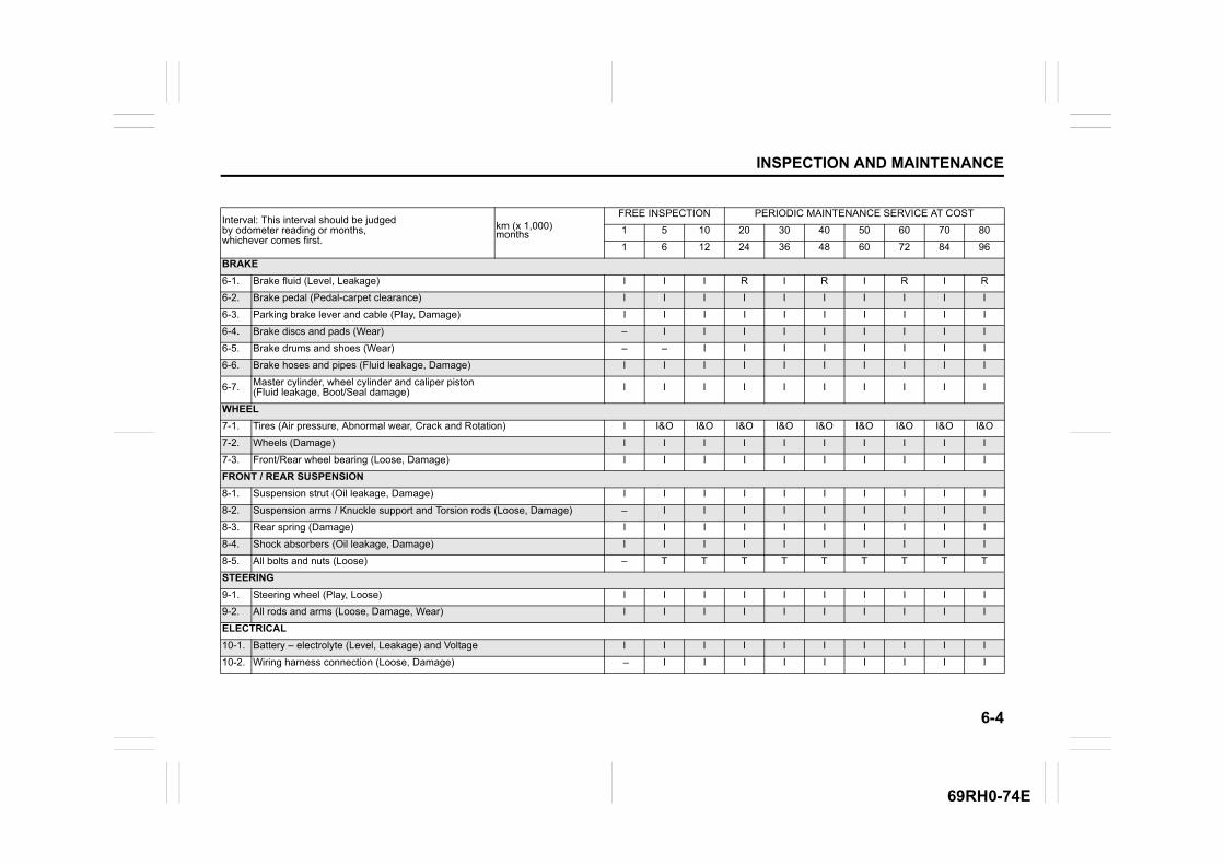
6-4
INSPECTION AND MAINTENANCE
69RH0-74E
Interval: This interval should be judged by odometer reading or months, whichever comes first.
km (x 1,000) months
FREE INSPECTION PERIODIC MAINTENANCE SERVICE AT COST
1 5 10 20 30 40 50 60 70 80
1 6 12 24 36 48 60 72 84 96
BRAKE
6-1. Brake fluid (Level, Leakage) I I I R I R I R I R
6-2. Brake pedal (Pedal-carpet clearance) I I I I I I I I I I
6-3. Parking brake lever and cable (Play, Damage) I I I I I I I I I I
6-4. Brake discs and pads (Wear) – I I I I I I I I I
6-5. Brake drums and shoes (Wear) – – I I I I I I I I
6-6. Brake hoses and pipes (Fluid leakage, Damage) I I I I I I I I I I
6-7. Master cylinder, wheel cylinder and caliper piston(Fluid leakage, Boot/Seal damage) I I I I I I I I I I
WHEEL
7-1. Tires (Air pressure, Abnormal wear, Crack and Rotation) I I&O I&O I&O I&O I&O I&O I&O I&O I&O
7-2. Wheels (Damage) I I I I I I I I I I
7-3. Front/Rear wheel bearing (Loose, Damage) I I I I I I I I I I
FRONT / REAR SUSPENSION
8-1. Suspension strut (Oil leakage, Damage) I I I I I I I I I I
8-2. Suspension arms / Knuckle support and Torsion rods (Loose, Damage) – I I I I I I I I I
8-3. Rear spring (Damage) I I I I I I I I I I
8-4. Shock absorbers (Oil leakage, Damage) I I I I I I I I I I
8-5. All bolts and nuts (Loose) – T T T T T T T T T
STEERING
9-1. Steering wheel (Play, Loose) I I I I I I I I I I
9-2. All rods and arms (Loose, Damage, Wear) I I I I I I I I I I
ELECTRICAL
10-1. Battery – electrolyte (Level, Leakage) and Voltage I I I I I I I I I I
10-2. Wiring harness connection (Loose, Damage) – I I I I I I I I I
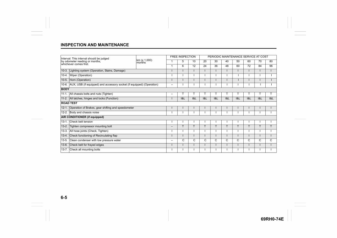
6-5
INSPECTION AND MAINTENANCE
69RH0-74E
Interval: This interval should be judged by odometer reading or months, whichever comes first.
km (x 1,000) months
FREE INSPECTION PERIODIC MAINTENANCE SERVICE AT COST
1 5 10 20 30 40 50 60 70 80
1 6 12 24 36 48 60 72 84 96
10-3. Lighting system (Operation, Stains, Damage) I I I I I I I I I I
10-4. Wiper (Operation) I I I I I I I I I I
10-5. Horn (Operation) I I I I I I I I I I
10-6. AUX, USB (if equipped) and accessory socket (if equipped) (Operation) – I I I I I I I I I
BODY
11-1. All chassis bolts and nuts (Tighten) – T T T T T T T T T
11-2. All latches, hinges and locks (Function) I I&L I&L I&L I&L I&L I&L I&L I&L I&L
ROAD TEST
12-1. Operation of Brakes, gear shifting and speedometer I I I I I I I I I I
12-2. Body and chassis noise I I I I I I I I I I
AIR CONDITIONER (if equipped)
13-1. Check belt tension I I I I I I I I I I
13-2. Tighten compressor mounting bolt – T T T T T T T T T
13-3. All hose joints (Check, Tighten) I I I I I I I I I I
13-4. Check functioning of Recirculating flap I I I I I I I I I I
13-5. Clean condenser with low pressure water – C C C C C C C C C
13-6. Check belt for frayed edges I I I I I I I I I I
13-7. Check all mounting bolts I I I I I I I I I I
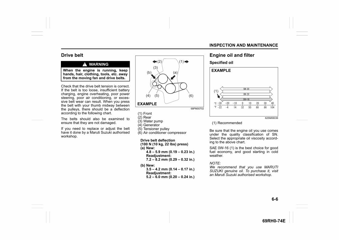
6-6
INSPECTION AND MAINTENANCE
69RH0-74E
Drive belt
Check that the drive belt tension is correct.If the belt is too loose, insufficient batterycharging, engine overheating, poor powersteering, poor air conditioning, or exces-sive belt wear can result. When you pressthe belt with your thumb midway betweenthe pulleys, there should be a deflectionaccording to the following chart.
The belts should also be examined toensure that they are not damaged.
If you need to replace or adjust the belthave it done by a Maruti Suzuki authorisedworkshop.
68PM00702
(1) Front(2) Rear(3) Water pump(4) Generator(5) Tensioner pulley(6) Air conditioner compressor
Drive belt deflection (100 N (10 kg, 22 lbs) press)(a) New:
4.8 – 5.9 mm (0.19 – 0.23 in.)Readjustment:7.2 – 8.2 mm (0.29 – 0.32 in.)
(b) New:3.5 – 4.2 mm (0.14 – 0.17 in.)Readjustment:5.2 – 6.0 mm (0.20 – 0.24 in.)
Engine oil and filter
Specified oil
62SM06036
(1) Recommended
Be sure that the engine oil you use comesunder the quality classification of SN.Select the appropriate oil viscosity accord-ing to the above chart.
SAE 0W-16 (1) is the best choice for goodfuel economy, and good starting in coldweather.
NOTE:We recommend that you use MARUTISUZUKI genuine oil. To purchase it, visitan Maruti Suzuki authorised workshop.
WARNING
When the engine is running, keephands, hair, clothing, tools, etc. awayfrom the moving fan and drive belts.
(4)
(b)(3)
(1)(2)
(a)
(6)(5)
EXAMPLE0W0W–1616
(1)
EXAMPLE
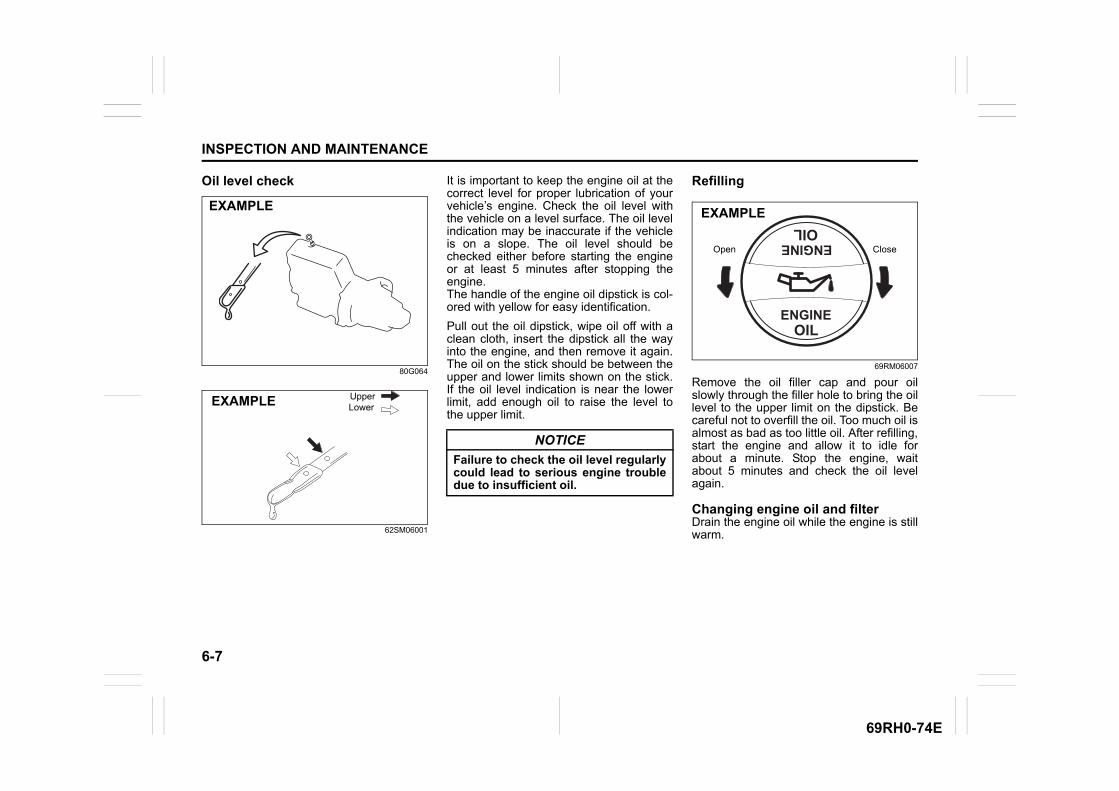
6-7
INSPECTION AND MAINTENANCE
69RH0-74E
Oil level check
80G064
62SM06001
It is important to keep the engine oil at thecorrect level for proper lubrication of yourvehicle’s engine. Check the oil level withthe vehicle on a level surface. The oil levelindication may be inaccurate if the vehicleis on a slope. The oil level should bechecked either before starting the engineor at least 5 minutes after stopping theengine.The handle of the engine oil dipstick is col-ored with yellow for easy identification.
Pull out the oil dipstick, wipe oil off with aclean cloth, insert the dipstick all the wayinto the engine, and then remove it again.The oil on the stick should be between theupper and lower limits shown on the stick.If the oil level indication is near the lowerlimit, add enough oil to raise the level tothe upper limit.
Refilling
69RM06007
Remove the oil filler cap and pour oilslowly through the filler hole to bring the oillevel to the upper limit on the dipstick. Becareful not to overfill the oil. Too much oil isalmost as bad as too little oil. After refilling,start the engine and allow it to idle forabout a minute. Stop the engine, waitabout 5 minutes and check the oil levelagain.
Changing engine oil and filterDrain the engine oil while the engine is stillwarm.
EXAMPLE
UpperLowerEXAMPLE
NOTICE
Failure to check the oil level regularlycould lead to serious engine troubledue to insufficient oil.
Open Close
EXAMPLE
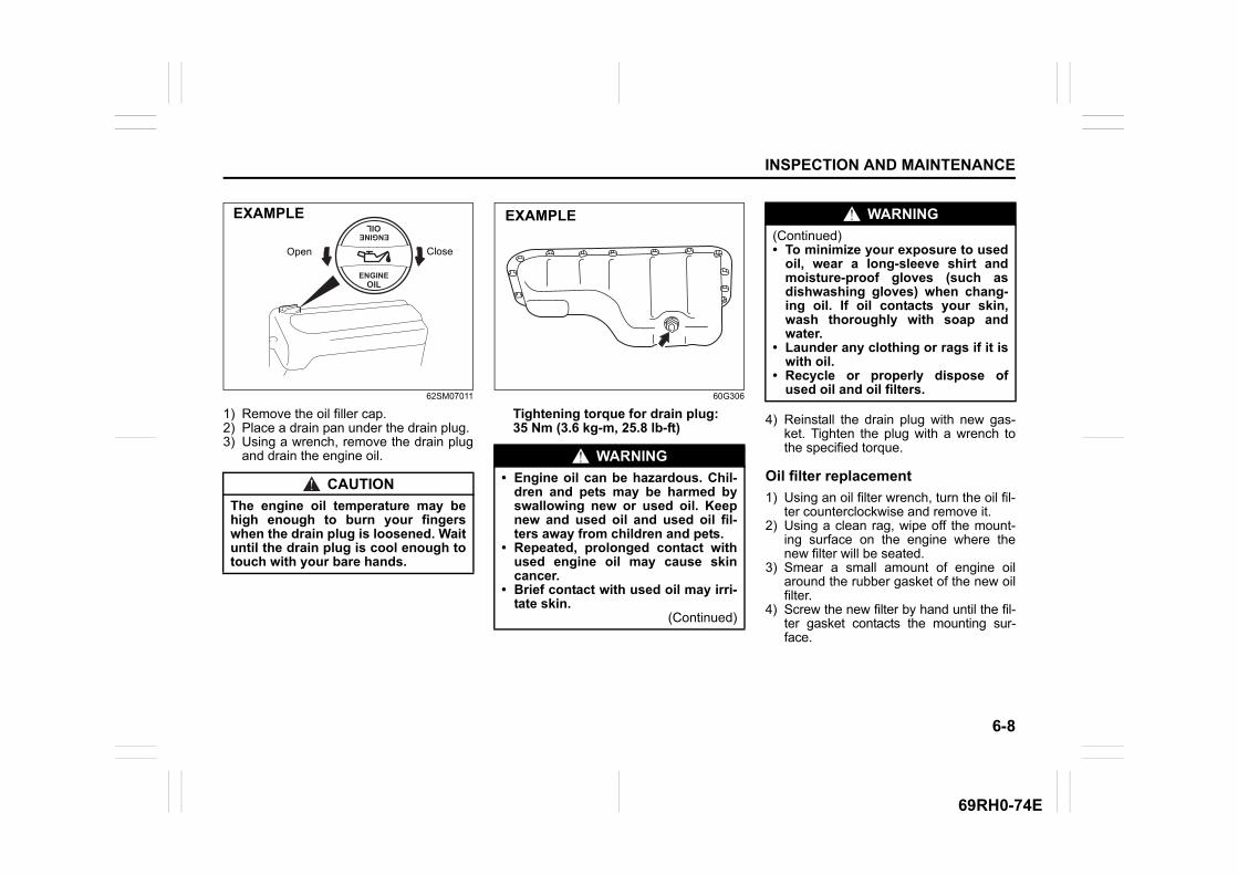
6-8
INSPECTION AND MAINTENANCE
69RH0-74E
62SM07011
1) Remove the oil filler cap.2) Place a drain pan under the drain plug.3) Using a wrench, remove the drain plug
and drain the engine oil.
60G306
Tightening torque for drain plug:35 Nm (3.6 kg-m, 25.8 lb-ft)
4) Reinstall the drain plug with new gas-ket. Tighten the plug with a wrench tothe specified torque.
Oil filter replacement
1) Using an oil filter wrench, turn the oil fil-ter counterclockwise and remove it.
2) Using a clean rag, wipe off the mount-ing surface on the engine where thenew filter will be seated.
3) Smear a small amount of engine oilaround the rubber gasket of the new oilfilter.
4) Screw the new filter by hand until the fil-ter gasket contacts the mounting sur-face.
CAUTION
The engine oil temperature may behigh enough to burn your fingerswhen the drain plug is loosened. Waituntil the drain plug is cool enough totouch with your bare hands.
Open Close
EXAMPLE
WARNING
• Engine oil can be hazardous. Chil-dren and pets may be harmed byswallowing new or used oil. Keepnew and used oil and used oil fil-ters away from children and pets.
• Repeated, prolonged contact withused engine oil may cause skincancer.
• Brief contact with used oil may irri-tate skin.
(Continued)
EXAMPLE WARNING
(Continued)• To minimize your exposure to used
oil, wear a long-sleeve shirt andmoisture-proof gloves (such asdishwashing gloves) when chang-ing oil. If oil contacts your skin,wash thoroughly with soap andwater.
• Launder any clothing or rags if it iswith oil.
• Recycle or properly dispose ofused oil and oil filters.
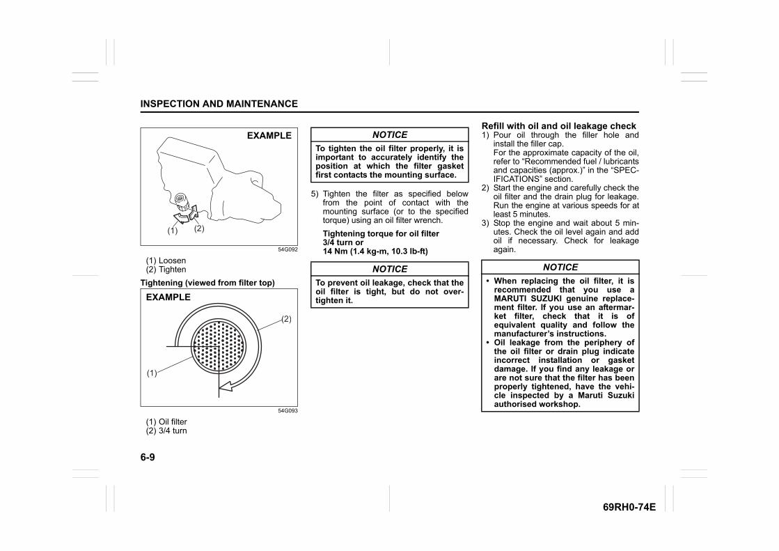
6-9
INSPECTION AND MAINTENANCE
69RH0-74E
54G092
(1) Loosen(2) Tighten
Tightening (viewed from filter top)
54G093
(1) Oil filter(2) 3/4 turn
5) Tighten the filter as specified belowfrom the point of contact with themounting surface (or to the specifiedtorque) using an oil filter wrench.
Tightening torque for oil filter3/4 turn or 14 Nm (1.4 kg-m, 10.3 lb-ft)
Refill with oil and oil leakage check1) Pour oil through the filler hole and
install the filler cap. For the approximate capacity of the oil,refer to “Recommended fuel / lubricantsand capacities (approx.)” in the “SPEC-IFICATIONS” section.
2) Start the engine and carefully check theoil filter and the drain plug for leakage.Run the engine at various speeds for atleast 5 minutes.
3) Stop the engine and wait about 5 min-utes. Check the oil level again and addoil if necessary. Check for leakageagain.
(1) (2)
EXAMPLE
(1)
(2)
EXAMPLE
NOTICE
To tighten the oil filter properly, it isimportant to accurately identify theposition at which the filter gasketfirst contacts the mounting surface.
NOTICE
To prevent oil leakage, check that theoil filter is tight, but do not over-tighten it.
NOTICE
• When replacing the oil filter, it isrecommended that you use aMARUTI SUZUKI genuine replace-ment filter. If you use an aftermar-ket filter, check that it is ofequivalent quality and follow themanufacturer’s instructions.
• Oil leakage from the periphery ofthe oil filter or drain plug indicateincorrect installation or gasketdamage. If you find any leakage orare not sure that the filter has beenproperly tightened, have the vehi-cle inspected by a Maruti Suzukiauthorised workshop.
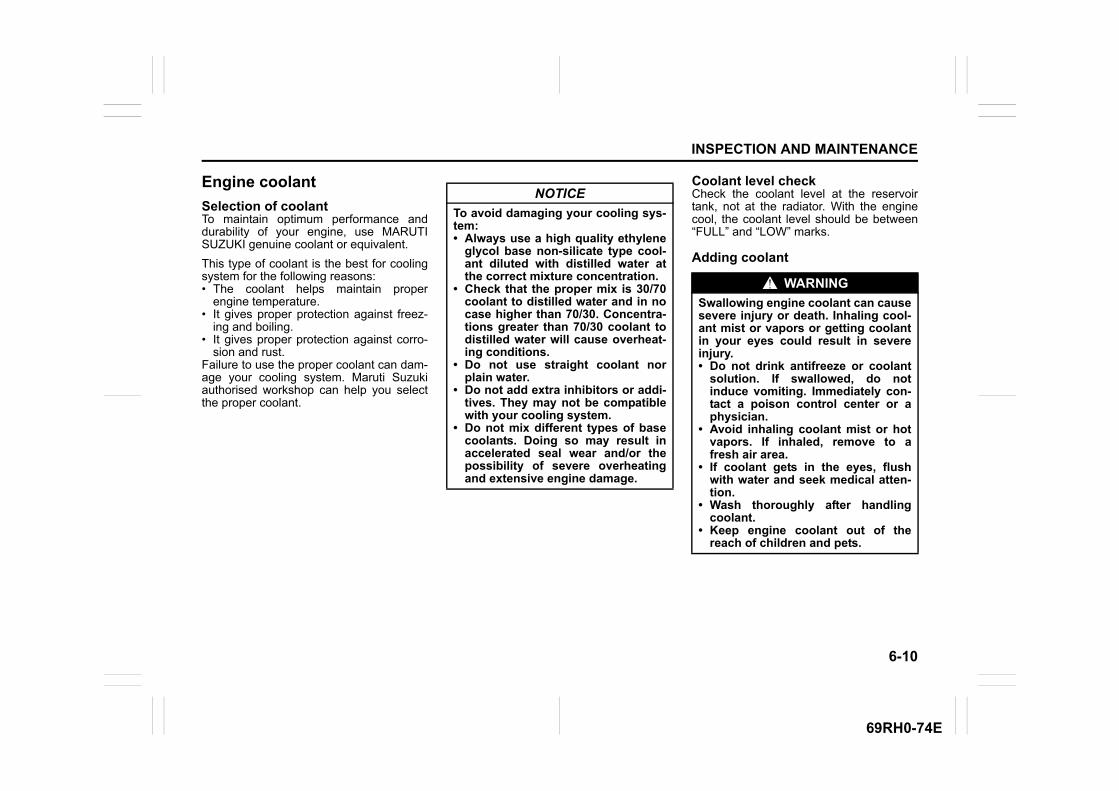
6-10
INSPECTION AND MAINTENANCE
69RH0-74E
Engine coolant
Selection of coolantTo maintain optimum performance anddurability of your engine, use MARUTISUZUKI genuine coolant or equivalent.
This type of coolant is the best for coolingsystem for the following reasons:• The coolant helps maintain proper
engine temperature.• It gives proper protection against freez-
ing and boiling.• It gives proper protection against corro-
sion and rust.Failure to use the proper coolant can dam-age your cooling system. Maruti Suzukiauthorised workshop can help you selectthe proper coolant.
Coolant level checkCheck the coolant level at the reservoirtank, not at the radiator. With the enginecool, the coolant level should be between“FULL” and “LOW” marks.
Adding coolant
NOTICE
To avoid damaging your cooling sys-tem:• Always use a high quality ethylene
glycol base non-silicate type cool-ant diluted with distilled water atthe correct mixture concentration.
• Check that the proper mix is 30/70coolant to distilled water and in nocase higher than 70/30. Concentra-tions greater than 70/30 coolant todistilled water will cause overheat-ing conditions.
• Do not use straight coolant norplain water.
• Do not add extra inhibitors or addi-tives. They may not be compatiblewith your cooling system.
• Do not mix different types of basecoolants. Doing so may result inaccelerated seal wear and/or thepossibility of severe overheatingand extensive engine damage.
WARNING
Swallowing engine coolant can causesevere injury or death. Inhaling cool-ant mist or vapors or getting coolantin your eyes could result in severeinjury.• Do not drink antifreeze or coolant
solution. If swallowed, do notinduce vomiting. Immediately con-tact a poison control center or aphysician.
• Avoid inhaling coolant mist or hotvapors. If inhaled, remove to afresh air area.
• If coolant gets in the eyes, flushwith water and seek medical atten-tion.
• Wash thoroughly after handlingcoolant.
• Keep engine coolant out of thereach of children and pets.
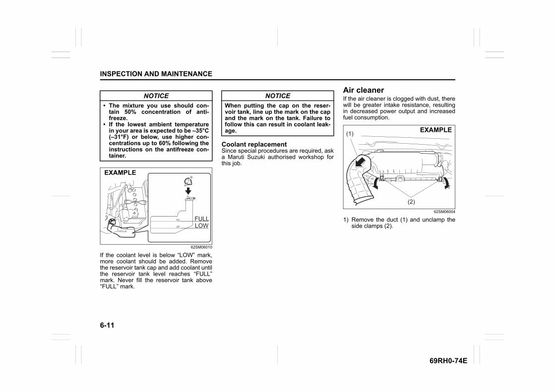
6-11
INSPECTION AND MAINTENANCE
69RH0-74E
62SM06010
If the coolant level is below “LOW” mark,more coolant should be added. Removethe reservoir tank cap and add coolant untilthe reservoir tank level reaches “FULL”mark. Never fill the reservoir tank above“FULL” mark.
Coolant replacementSince special procedures are required, aska Maruti Suzuki authorised workshop forthis job.
Air cleanerIf the air cleaner is clogged with dust, therewill be greater intake resistance, resultingin decreased power output and increasedfuel consumption.
62SM06004
1) Remove the duct (1) and unclamp theside clamps (2).
NOTICE
• The mixture you use should con-tain 50% concentration of anti-freeze.
• If the lowest ambient temperaturein your area is expected to be –35°C(–31°F) or below, use higher con-centrations up to 60% following theinstructions on the antifreeze con-tainer.
LOW
FULL FULLLOW
EXAMPLE
NOTICE
When putting the cap on the reser-voir tank, line up the mark on the capand the mark on the tank. Failure tofollow this can result in coolant leak-age. (1)
(2)
EXAMPLE
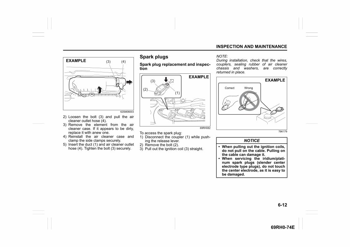
6-12
INSPECTION AND MAINTENANCE
69RH0-74E
62SM06003
2) Loosen the bolt (3) and pull the aircleaner outlet hose (4).
3) Remove the element from the aircleaner case. If it appears to be dirty,replace it with anew one.
4) Reinstall the air cleaner case andclamp the side clamps securely.
5) Insert the duct (1) and air cleaner outlethose (4). Tighten the bolt (3) securely.
Spark plugs
Spark plug replacement and inspec-tion
69RH082
To access the spark plug:1) Disconnect the coupler (1) while push-
ing the release lever.2) Remove the bolt (2).3) Pull out the ignition coil (3) straight.
NOTE:During installation, check that the wires,couplers, sealing rubber of air cleanerchassis and washers, are correctlyreturned in place.
78K179
(3) (4)EXAMPLE
(1)
(3)
(2)
EXAMPLE
NOTICE
• When pulling out the ignition coils,do not pull on the cable. Pulling onthe cable can damage it.
• When servicing the iridium/plati-num spark plugs (slender centerelectrode type plugs), do not touchthe center electrode, as it is easy tobe damaged.
Correct Wrong
EXAMPLE
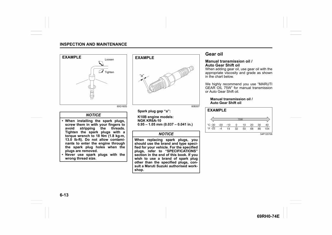
6-13
INSPECTION AND MAINTENANCE
69RH0-74E
60G160S 60B307
Spark plug gap “a”:
K10B engine models:NGK KR6A-100.95 – 1.05 mm (0.037 – 0.041 in.)
Gear oil
Manual transmission oil / Auto Gear Shift oilWhen adding gear oil, use gear oil with theappropriate viscosity and grade as shownin the chart below.
We highly recommend you use “MARUTIGEAR OIL 75W” for manual transmissionor Auto Gear Shift oil.
Manual transmission oil /Auto Gear Shift oil
54P120706
NOTICE
• When installing the spark plugs,screw them in with your fingers toavoid stripping the threads.Tighten the spark plugs with atorque wrench to 18 Nm (1.8 kg-m,13.0 lb-ft). Do not allow contami-nants to enter the engine throughthe spark plug holes when theplugs are removed.
• Never use spark plugs with thewrong thread size.
Loosen
Tighten
EXAMPLE
NOTICE
When replacing spark plugs, youshould use the brand and type speci-fied for your vehicle. For the specifiedplugs, refer to “SPECIFICATIONS”section in the end of this book. If youwish to use a brand of spark plugother than the specified plugs, con-sult a Maruti Suzuki authorised work-shop.
“a”
EXAMPLE
CFo
o -30-22
-20-4
-1014 32 50 68 86 104
0 10 20 30 40
75W
EXAMPLE
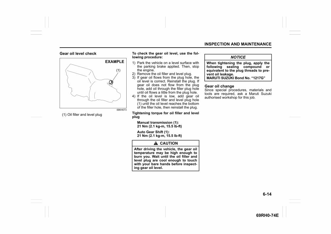
6-14
INSPECTION AND MAINTENANCE
69RH0-74E
Gear oil level check
68KH073
(1) Oil filler and level plug
To check the gear oil level, use the fol-lowing procedure:
1) Park the vehicle on a level surface withthe parking brake applied. Then, stopthe engine.
2) Remove the oil filler and level plug.3) If gear oil flows from the plug hole, the
oil level is correct. Reinstall the plug. Ifgear oil does not flow from the plughole, add oil through the filler plug holeuntil oil flows a little from the plug hole.
4) If the oil level is low, add gear oilthrough the oil filler and level plug hole(1) until the oil level reaches the bottomof the filler hole, then reinstall the plug.
Tightening torque for oil filler and levelplug
Manual transmission (1):21 Nm (2.1 kg-m, 15.5 lb-ft)
Auto Gear Shift (1):21 Nm (2.1 kg-m, 15.5 lb-ft)
Gear oil changeSince special procedures, materials andtools are required, ask a Maruti Suzukiauthorised workshop for this job.
(1)
EXAMPLE
CAUTION
After driving the vehicle, the gear oiltemperature may be high enough toburn you. Wait until the oil filler andlevel plug are cool enough to touchwith your bare hands before inspect-ing gear oil level.
NOTICE
When tightening the plug, apply thefollowing sealing compound orequivalent to the plug threads to pre-vent oil leakage.MARUTI SUZUKI Bond No. “1217G”
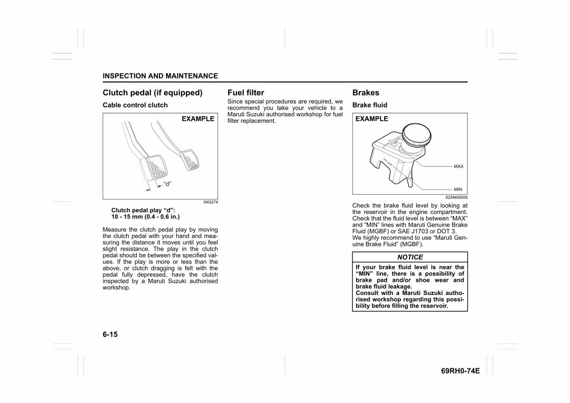
6-15
INSPECTION AND MAINTENANCE
69RH0-74E
Clutch pedal (if equipped)
Cable control clutch
54G274
Clutch pedal play “d”:10 - 15 mm (0.4 - 0.6 in.)
Measure the clutch pedal play by movingthe clutch pedal with your hand and mea-suring the distance it moves until you feelslight resistance. The play in the clutchpedal should be between the specified val-ues. If the play is more or less than theabove, or clutch dragging is felt with thepedal fully depressed, have the clutchinspected by a Maruti Suzuki authorisedworkshop.
Fuel filterSince special procedures are required, werecommend you take your vehicle to aMaruti Suzuki authorised workshop for fuelfilter replacement.
Brakes
Brake fluid
62SM06006
Check the brake fluid level by looking atthe reservoir in the engine compartment.Check that the fluid level is between “MAX”and “MIN” lines with Maruti Genuine BrakeFluid (MGBF) or SAE J1703 or DOT 3.We highly recommend to use “Maruti Gen-uine Brake Fluid” (MGBF).
“d”
EXAMPLE
NOTICE
If your brake fluid level is near the“MIN” line, there is a possibility ofbrake pad and/or shoe wear andbrake fluid leakage.Consult with a Maruti Suzuki autho-rised workshop regarding this possi-bility before filling the reservoir.
MIN
MAX
EXAMPLE
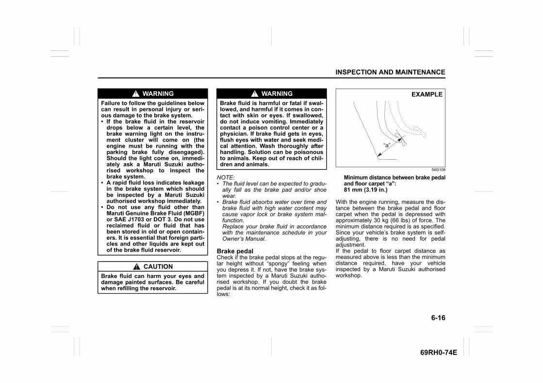
6-16
INSPECTION AND MAINTENANCE
69RH0-74E
NOTE:• The fluid level can be expected to gradu-
ally fall as the brake pad and/or shoewear.
• Brake fluid absorbs water over time andbrake fluid with high water content maycause vapor lock or brake system mal-function. Replace your brake fluid in accordancewith the maintenance schedule in yourOwner’s Manual.
Brake pedalCheck if the brake pedal stops at the regu-lar height without “spongy” feeling whenyou depress it. If not, have the brake sys-tem inspected by a Maruti Suzuki autho-rised workshop. If you doubt the brakepedal is at its normal height, check it as fol-lows:
54G108
Minimum distance between brake pedaland floor carpet “a”:81 mm (3.19 in.)
With the engine running, measure the dis-tance between the brake pedal and floorcarpet when the pedal is depressed withapproximately 30 kg (66 lbs) of force. Theminimum distance required is as specified.Since your vehicle’s brake system is self-adjusting, there is no need for pedaladjustment. If the pedal to floor carpet distance asmeasured above is less than the minimumdistance required, have your vehicleinspected by a Maruti Suzuki authorisedworkshop.
WARNING
Failure to follow the guidelines belowcan result in personal injury or seri-ous damage to the brake system.• If the brake fluid in the reservoir
drops below a certain level, thebrake warning light on the instru-ment cluster will come on (theengine must be running with theparking brake fully disengaged).Should the light come on, immedi-ately ask a Maruti Suzuki autho-rised workshop to inspect thebrake system.
• A rapid fluid loss indicates leakagein the brake system which shouldbe inspected by a Maruti Suzukiauthorised workshop immediately.
• Do not use any fluid other thanMaruti Genuine Brake Fluid (MGBF)or SAE J1703 or DOT 3. Do not usereclaimed fluid or fluid that hasbeen stored in old or open contain-ers. It is essential that foreign parti-cles and other liquids are kept outof the brake fluid reservoir.
CAUTION
Brake fluid can harm your eyes anddamage painted surfaces. Be carefulwhen refilling the reservoir.
WARNING
Brake fluid is harmful or fatal if swal-lowed, and harmful if it comes in con-tact with skin or eyes. If swallowed,do not induce vomiting. Immediatelycontact a poison control center or aphysician. If brake fluid gets in eyes,flush eyes with water and seek medi-cal attention. Wash thoroughly afterhandling. Solution can be poisonousto animals. Keep out of reach of chil-dren and animals.
“a”
EXAMPLE
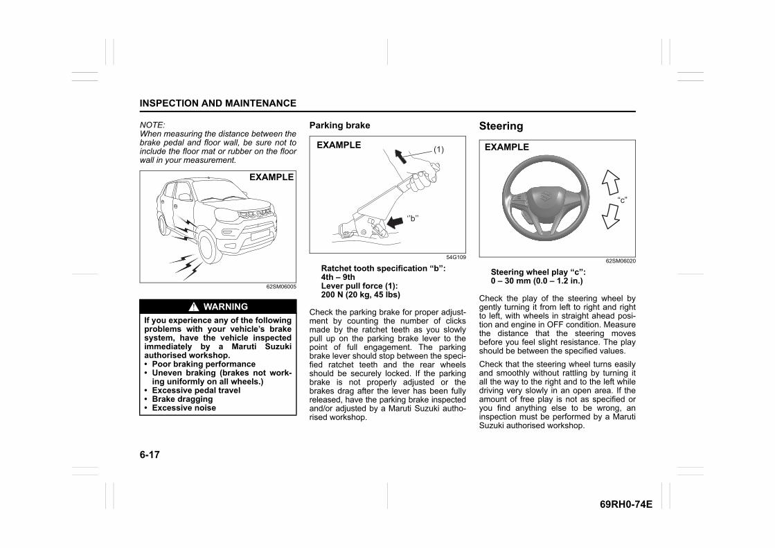
6-17
INSPECTION AND MAINTENANCE
69RH0-74E
NOTE:When measuring the distance between thebrake pedal and floor wall, be sure not toinclude the floor mat or rubber on the floorwall in your measurement.
62SM06005
Parking brake
54G109
Ratchet tooth specification “b”: 4th – 9thLever pull force (1):200 N (20 kg, 45 lbs)
Check the parking brake for proper adjust-ment by counting the number of clicksmade by the ratchet teeth as you slowlypull up on the parking brake lever to thepoint of full engagement. The parkingbrake lever should stop between the speci-fied ratchet teeth and the rear wheelsshould be securely locked. If the parkingbrake is not properly adjusted or thebrakes drag after the lever has been fullyreleased, have the parking brake inspectedand/or adjusted by a Maruti Suzuki autho-rised workshop.
Steering
62SM06020
Steering wheel play “c”: 0 – 30 mm (0.0 – 1.2 in.)
Check the play of the steering wheel bygently turning it from left to right and rightto left, with wheels in straight ahead posi-tion and engine in OFF condition. Measurethe distance that the steering movesbefore you feel slight resistance. The playshould be between the specified values.
Check that the steering wheel turns easilyand smoothly without rattling by turning itall the way to the right and to the left whiledriving very slowly in an open area. If theamount of free play is not as specified oryou find anything else to be wrong, aninspection must be performed by a MarutiSuzuki authorised workshop.
WARNING
If you experience any of the followingproblems with your vehicle’s brakesystem, have the vehicle inspectedimmediately by a Maruti Suzukiauthorised workshop.• Poor braking performance• Uneven braking (brakes not work-
ing uniformly on all wheels.)• Excessive pedal travel• Brake dragging• Excessive noise
EXAMPLE
(1)
‘’b’’
EXAMPLE
“c”
EXAMPLE
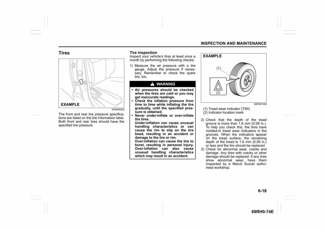
6-18
INSPECTION AND MAINTENANCE
69RH0-74E
Tires
62SM06008
The front and rear tire pressure specifica-tions are listed on the tire information label.Both front and rear tires should have thespecified tire pressure.
Tire inspectionInspect your vehicle’s tires at least once amonth by performing the following checks:
1) Measure the air pressure with a tiregauge. Adjust the pressure if neces-sary. Remember to check the sparetire, too.
68PM07009
(1) Tread wear indicator (TWI)(2) Indicator location mark
2) Check that the depth of the treadgroove is more than 1.6 mm (0.06 in.).To help you check this, the tires havemolded-in tread wear indicators in thegrooves. When the indicators appearon the tread surface, the remainingdepth of the tread is 1.6 mm (0.06 in.)or less and the tire should be replaced.
3) Check for abnormal wear, cracks anddamage. Any tires with cracks or otherdamage should be replaced. If any tiresshow abnormal wear, have theminspected by a Maruti Suzuki autho-rised workshop.
EXAMPLE
WARNING
• Air pressures should be checkedwhen the tires are cold or you mayget inaccurate readings.
• Check the inflation pressure fromtime to time while inflating the tiregradually, until the specified pres-sure is obtained.
• Never under-inflate or over-inflatethe tires. Under-inflation can cause unusualhandling characteristics or cancause the rim to slip on the tirebead, resulting in an accident ordamage to the tire or rim. Over-inflation can cause the tire toburst, resulting in personal injury.Over-inflation can also causeunusual handling characteristicswhich may result in an accident.
(1)
(2)
EXAMPLE
6-19
INSPECTION AND MAINTENANCE
69RH0-74E
4) Check for loose wheel nuts.5) Check that there are no nails, stones or
other objects sticking into the tires.
CAUTION
Hitting curbs and running over rockscan damage tires and affect wheelalignment. Have tires and wheelalignment checked periodically by aMaruti Suzuki authorised workshop.
WARNING
• Your MARUTI SUZUKI vehicle isequipped with tires which are allthe same type and size (Exceptspare tire, which may be dependenton vehicle variant). This is import-ant to ensure proper steering andhandling of the vehicle. Never mixtires of different size or type on thefour wheels of your vehicle. Thesize and type of tires used shouldbe only those approved by MARUTISUZUKI as standard or optionalequipment for your vehicle.
• Replacing the wheels and tiresequipped on your vehicle with cer-tain combinations of aftermarketwheels and tires can significantlychange the steering and handlingcharacteristics of your vehicle.Therefore, use only those wheeland tire combinations approved byMARUTI SUZUKI as standard oroptional equipment for your vehi-cle.
NOTICE
Replacing the original tires with tiresof a different size may result in falsespeedometer or odometer readings.Check with a Maruti Suzuki autho-rised workshop before purchasingreplacement tires that differ in sizefrom the original tires.
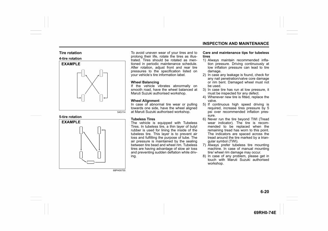
6-20
INSPECTION AND MAINTENANCE
69RH0-74E
Tire rotation
4-tire rotation
54G114
5-tire rotation
68PH00755
To avoid uneven wear of your tires and toprolong their life, rotate the tires as illus-trated. Tires should be rotated as men-tioned in periodic maintenance schedule.After rotation, adjust front and rear tirepressures to the specification listed onyour vehicle’s tire information label.
Wheel BalancingIf the vehicle vibrates abnormally onsmooth road, have the wheel balanced atMaruti Suzuki authorised workshop.
Wheel AlignmentIn case of abnormal tire wear or pullingtowards one side, have the wheel alignedat Maruti Suzuki authorised workshop.
Tubeless TiresThe vehicle is equipped with TubelessTires. In tubeless tire, a thin layer of butylrubber is used for lining the inside of thetubeless tire. This layer is to prevent airloss and fulfilling the purpose of tube. Theair pressure is maintained by the sealingbetween tire bead and wheel rim. Tubelesstires are having advantage of slow air lossand preventing sudden deflation while driv-ing.
Care and maintenance tips for tubelesstires1) Always maintain recommended infla-
tion pressure. Driving continuously atlow inflation pressure can lead to tiredamage.
2) In case any leakage is found, check forany nail penetration/valve core damageor rim bent. Damaged wheel must notbe used.
3) In case tire has run at low pressure, itmust be inspected for any defect.
4) Whenever new tire is fitted, replace thevalve.
5) If continuous high speed driving isrequired, increase tires pressure by 5psi over recommended inflation pres-sure.
6) Never run the tire beyond TWI (Treadwear indicator). The tire is recom-mended to be replaced when theremaining tread has worn to this point.The indicators are spaced across thetread around the tire marked by a trian-gular symbol (TWI).
7) Always prefer tubeless tire mountingmachine. In case of manual mountingtire/ wheel rim damage may occur.
8) In case of any problem, please get intouch with Maruti Suzuki authorisedworkshop.
EXAMPLE
EXAMPLE
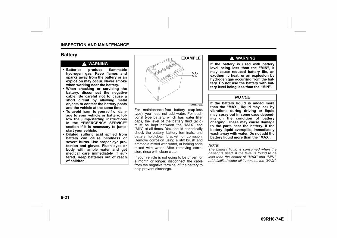
6-21
INSPECTION AND MAINTENANCE
69RH0-74E
Battery
76MM07005
For maintenance-free battery (cap-lesstype), you need not add water. For tradi-tional type battery, which has water fillercaps, the level of the battery fluid (acid)must be kept between the “MAX” and“MIN” at all times. You should periodicallycheck the battery, battery terminals, andbattery hold-down bracket for corrosion.Remove corrosion using a stiff brush andammonia mixed with water, or baking sodamixed with water. After removing corro-sion, rinse with clean water.
If your vehicle is not going to be driven fora month or longer, disconnect the cablefrom the negative terminal of the battery tohelp prevent discharge.
NOTE:The battery liquid is consumed when thebattery is used. If the level is found to beless than the center of “MAX” and “MIN”,add distilled water till it reaches the “MAX”.
WARNING
• Batteries produce flammablehydrogen gas. Keep flames andsparks away from the battery or anexplosion may occur. Never smokewhen working near the battery.
• When checking or servicing thebattery, disconnect the negativecable. Be careful not to cause ashort circuit by allowing metalobjects to contact the battery postsand the vehicle at the same time.
• To avoid harm to yourself or dam-age to your vehicle or battery, fol-low the jump-starting instructionsin the “EMERGENCY SERVICE”section if it is necessary to jump-start your vehicle.
• Diluted sulfuric acid spilled frombattery can cause blindness orsevere burns. Use proper eye pro-tection and gloves. Flush eyes orbody with ample water and getmedical care immediately if suf-fered. Keep batteries out of reachof children.
MAXMIN
EXAMPLE WARNING
If the battery is used with batterylevel being less than the “MIN”, itmay cause reduced battery life, anexothermic heat, or an explosion byhydrogen gas occurring from the bat-tery. Do not use the battery with bat-tery level being less than the “MIN”.
NOTICE
If the battery liquid is added morethan the “MAX”, liquid may leak byvibrations during driving or liquidmay spray out in some case depend-ing on the condition of batterycharging. These may cause damageto the parts near the battery. If thebattery liquid overspills, immediatelywash away with water. Do not add thebattery liquid more than the “MAX”.

6-22
INSPECTION AND MAINTENANCE
69RH0-74E
Replacement of the battery
68PM00711
To remove the battery:1) Disconnect the negative cable (1).2) Disconnect the positive cable (2).3) Remove the retainer nuts (3) and
remove the retainer (4).4) Remove the battery.
To install the battery:1) Install the battery in the reverse order of
removal.2) Tighten the bracket bolt and battery
cables securely.
NOTE:When the battery is disconnected, some ofthe vehicle’s function will be initialized and/or deactivated.These function are required to reset afterthe battery is reconnected.
FusesYour vehicle has three types of fuses, asdescribed below:
Main fuseThe main fuse takes current directly fromthe battery.
Primary fusesThese fuses are between the main fuseand individual fuses, and are for electricalload groups.
Individual fusesThese fuses are for individual electrical cir-cuits.
NOTE:• “Blank” indicates that fuse is not applica-
ble in the variant, even though name offuse might be available on cover of fusebox of your vehicle.
• Some fuse may not be applicable to yourvehicle according to the variant of vehicle,even though it is not mentioned as blank.
(1)
(2)
(3)
(4)
EXAMPLE
WARNING
Batteries contain toxic substancesincluding sulfuric acid and lead. Theycould have potential negative conse-quences for the environment andhuman health. Used battery must bedisposed or recycled according tothe local law and must not be dis-carded with ordinary householdwaste. Make sure not to tip over thebattery when you remove it from thevehicle. Otherwise, sulfuric acidcould run out and you might getinjury.
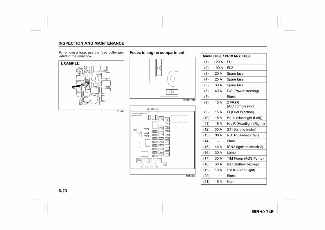
6-23
INSPECTION AND MAINTENANCE
69RH0-74E
To remove a fuse, use the fuse puller pro-vided in the relay box.
63J095
Fuses in engine compartment
62SM07012
69RH194
EXAMPLE
(2)
(1)
(6)(15)
(39) (38) (37)
(16)
(17)
(18)(19)(20)(21)
(22)
(24)(23)
(5)
(4)
(3)
(25)
(28)
(26)(27)
(29)(30)
(31)
(32)(33)(34)(35)
(7)
(8)(9)
(10)
(11)
(12)
(13)
(14)
FRONT
(36)
(40)
MAIN FUSE / PRIMARY FUSE
(1) 120 A FL1
(2) 100 A FL2
(3) 20 A Spare fuse
(4) 25 A Spare fuse
(5) 30 A Spare fuse
(6) 40 A P/S (Power steering)
(7) – Blank
(8) 10 A CPRSR (A/C compressor)
(9) 15 A FI (Fuel Injection)
(10) 15 A H/L L (Headlight (Left))
(11) 15 A H/L R (Headlight (Right))
(12) 30 A ST (Starting motor)
(13) 30 A RDTR (Radiator fan)
(14) – Blank
(15) 40 A IGN2 (Ignition switch 2)
(16) 30 A Lamp
(17) 30 A T/M Pump (AGS Pump)
(18) 30 A B/U (Battery backup)
(19) 10 A STOP (Stop Light)
(20) – Blank
(21) 15 A Horn

6-24
INSPECTION AND MAINTENANCE
69RH0-74E
The main fuse, primary fuses and some ofthe individual fuses are located in theengine compartment. If the main fuseblows, no electrical component will func-tion. If a primary fuse blows, no electricalcomponent in the corresponding loadgroup will function. When replacing themain fuse, a primary fuse or an individualfuse, use a MARUTI SUZUKI genuinereplacement.To remove a fuse, use the fuse puller pro-vided in the fuse box. The amperage ofeach fuse is shown in the back of the fusebox cover.
60G111
NOTE:Check that the fuse box always carriesspare fuses.
(22) 30 A BLW (Blower fan)
(23) – Blank
(24) 10 A ST SIG (Starting signal)
(25) – Blank
(26) – Blank
(27) – Blank
(28) – Blank
(29) – Blank
(30) – Blank
(31) 40 A ABS MOT (ABS motor)
(32) 25 A ABS SOL(ABS solenoid)
(33) – Blank
(34) 10 A T/M (Transmission)
(35) 10 A T/M2 (Transmission 2)
(36) 40 A IGN (Ignition switch)
(37) 5 A Spare fuse
(38) 10 A Spare fuse
(39) 15 A Spare fuse
(40) 7.5 A Spare fuse
OK
BLOWN
EXAMPLE
WARNING
If the main fuse or a primary fuseblows, have your vehicle inspectedby a Maruti Suzuki authorised work-shop. Always use a MARUTI SUZUKIgenuine replacement. Never use asubstitute such as a wire even for atemporary repair, or extensive electri-cal damage and a fire can result.
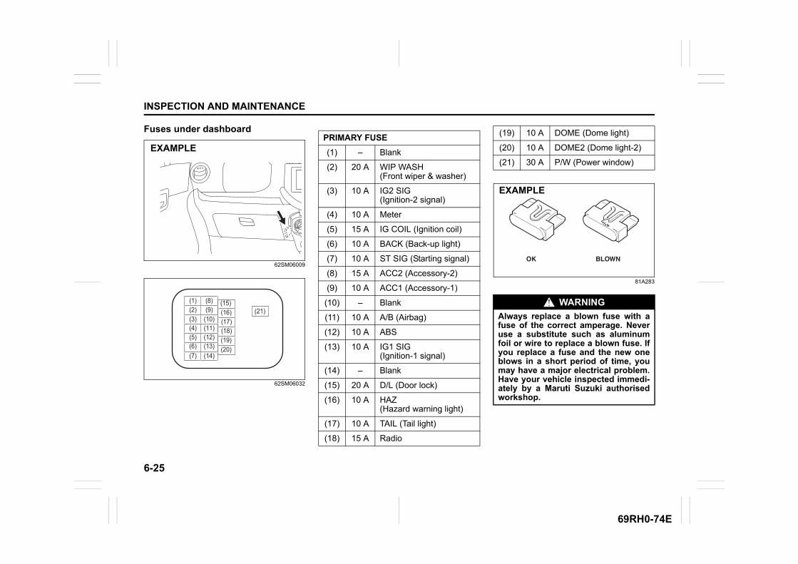
6-25
INSPECTION AND MAINTENANCE
69RH0-74E
Fuses under dashboard
62SM06009
62SM06032
81A283
EXAMPLE
(12)(11)(10)(9)(8)
(7)(6)(5)(4)(3)(2)(1)
(21)
(20)(19)(18)(17)(16)(15)
(14)(13)
PRIMARY FUSE
(1) – Blank
(2) 20 A WIP WASH (Front wiper & washer)
(3) 10 A IG2 SIG(Ignition-2 signal)
(4) 10 A Meter
(5) 15 A IG COIL (Ignition coil)
(6) 10 A BACK (Back-up light)
(7) 10 A ST SIG (Starting signal)
(8) 15 A ACC2 (Accessory-2)
(9) 10 A ACC1 (Accessory-1)
(10) – Blank
(11) 10 A A/B (Airbag)
(12) 10 A ABS
(13) 10 A IG1 SIG (Ignition-1 signal)
(14) – Blank
(15) 20 A D/L (Door lock)
(16) 10 A HAZ (Hazard warning light)
(17) 10 A TAIL (Tail light)
(18) 15 A Radio
(19) 10 A DOME (Dome light)
(20) 10 A DOME2 (Dome light-2)
(21) 30 A P/W (Power window)
WARNING
Always replace a blown fuse with afuse of the correct amperage. Neveruse a substitute such as aluminumfoil or wire to replace a blown fuse. Ifyou replace a fuse and the new oneblows in a short period of time, youmay have a major electrical problem.Have your vehicle inspected immedi-ately by a Maruti Suzuki authorisedworkshop.
BLOWNOK
EXAMPLE
6-26
INSPECTION AND MAINTENANCE
69RH0-74E
Headlight aimingSince special procedures are required, aska Maruti Suzuki authorised workshop forthis job.
Bulb replacement
NOTE:Mist may form on the lenses of exteriorlights (Headlight, Rear combination lightetc.) during or after driving in the rain orafter car washing. This is a natural phe-nomenon which occurs due to temperaturedifference between lamp inside and out-side. Temporary mist on the lens is not amalfunction and will not cause any discom-fort during vehicle driving.The mist would get cleared when the envi-ronmental condition change to sunny orwhen headlamp is kept on. However ifthere is water leakage inside the lamp,contact your Maruti Suzuki authorisedworkshop.
CAUTION
• Light bulbs can be hot enough toburn your finger right after turningoff lights. This is true especially forhalogen headlight bulbs. Replacethe bulbs after they become coolenough.
• The halogen headlight bulbs arefilled with pressurized halogen gas.They can burst and injure you ifthey are hit or dropped. Handlethem carefully.
• To avoid injury by sharp-edgedparts of the body, wear gloves anda long-sleeved shirt when replacinglight bulbs.
NOTICE
The oils from your skin may cause ahalogen bulb to overheat and burstwhen the lights are on. Grasp a newbulb with a clean cloth.
NOTICE
• Frequent replacement of a bulbindicates the need for an inspec-tion of the electrical system. Thisshould be carried out by yourMaruti Suzuki authorised work-shop.
• During bulb replacement alwaysuse same bulb number as used invehicle which is imprinted on thesaid bulb/unit and/or mentioned inSPECIFICATIONS.
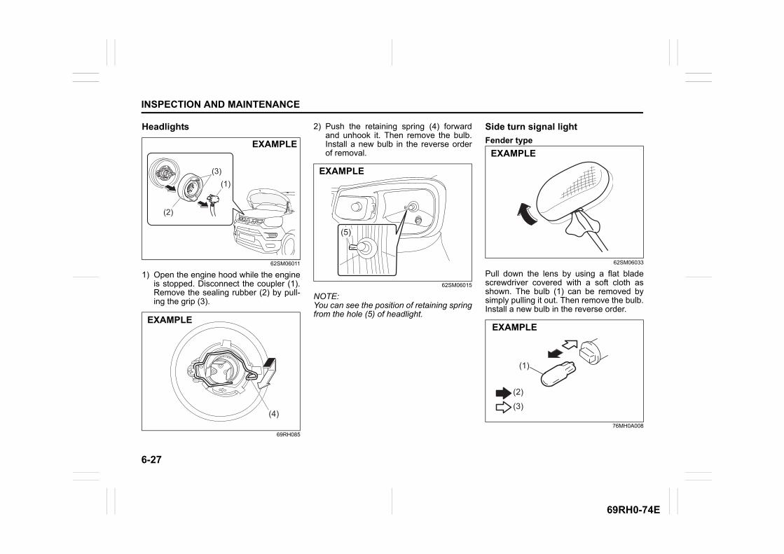
6-27
INSPECTION AND MAINTENANCE
69RH0-74E
Headlights
62SM06011
1) Open the engine hood while the engineis stopped. Disconnect the coupler (1).Remove the sealing rubber (2) by pull-ing the grip (3).
69RH085
2) Push the retaining spring (4) forwardand unhook it. Then remove the bulb.Install a new bulb in the reverse orderof removal.
62SM06015
NOTE:You can see the position of retaining springfrom the hole (5) of headlight.
Side turn signal light
Fender type
62SM06033
Pull down the lens by using a flat bladescrewdriver covered with a soft cloth asshown. The bulb (1) can be removed bysimply pulling it out. Then remove the bulb.Install a new bulb in the reverse order.
76MH0A008
(1)
(2)
(3)
EXAMPLE
(4)
EXAMPLE
(5)
EXAMPLE
EXAMPLE
(1)
(2)
(3)
EXAMPLE
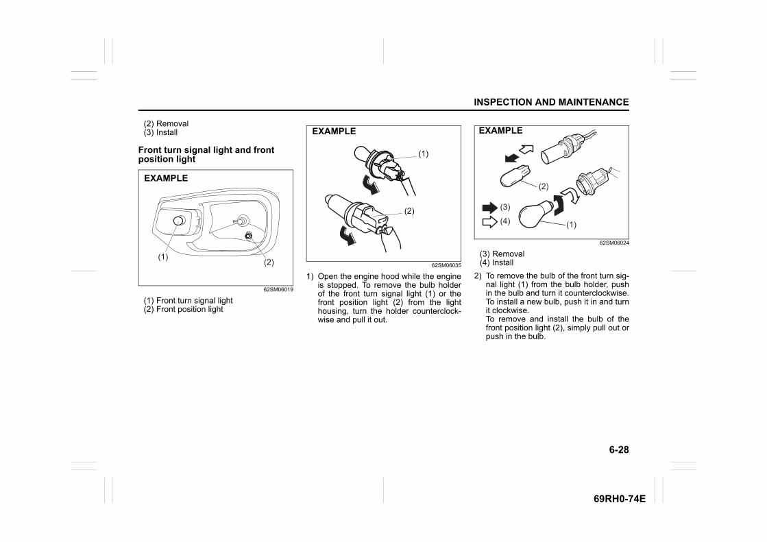
6-28
INSPECTION AND MAINTENANCE
69RH0-74E
(2) Removal(3) Install
Front turn signal light and front position light
62SM06019
(1) Front turn signal light(2) Front position light
62SM06035
1) Open the engine hood while the engineis stopped. To remove the bulb holderof the front turn signal light (1) or thefront position light (2) from the lighthousing, turn the holder counterclock-wise and pull it out.
62SM06024
(3) Removal(4) Install
2) To remove the bulb of the front turn sig-nal light (1) from the bulb holder, pushin the bulb and turn it counterclockwise.To install a new bulb, push it in and turnit clockwise.To remove and install the bulb of thefront position light (2), simply pull out orpush in the bulb.
(2)(1)
EXAMPLE
(2)
(1)
EXAMPLE
(2)
(1)
(3)
(4)
EXAMPLE
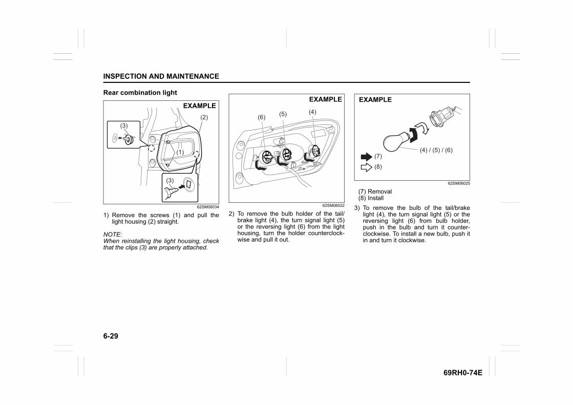
6-29
INSPECTION AND MAINTENANCE
69RH0-74E
Rear combination light
62SM06034
1) Remove the screws (1) and pull thelight housing (2) straight.
NOTE:When reinstalling the light housing, checkthat the clips (3) are properly attached.
62SM06022
2) To remove the bulb holder of the tail/brake light (4), the turn signal light (5)or the reversing light (6) from the lighthousing, turn the holder counterclock-wise and pull it out.
62SM06025
(7) Removal(8) Install
3) To remove the bulb of the tail/brakelight (4), the turn signal light (5) or thereversing light (6) from bulb holder,push in the bulb and turn it counter-clockwise. To install a new bulb, push itin and turn it clockwise.
(1)(1)
(2)
(3)
(3)
(1)
EXAMPLEEXAMPLE
(4)(5)(6)
(4) / (5) / (6)(7)
(8)
EXAMPLE

6-30
INSPECTION AND MAINTENANCE
69RH0-74E
License plate light
62SM06026
1) Turn the lens (1) counterclockwise toremove it.
62SM06027
2) To remove and install the bulb of thelicense plate light (2), simply pull out orpush in the bulb.
High-mount stop light
62SM06028
1) Open the tailgate, and pull the cover (1)straight as shown in the illustration.
69RH134
2) Remove the bulb holder as shown inthe illustration.
69RH086
(3) Removal(4) Install
3) To remove and install the bulb of thehigh-mount stop light (2), simply pull outor push in the bulb.
(1)
EXAMPLE
EXAMPLE
(2)
(1)
EXAMPLE
EXAMPLE
(2)
(3)
(4)
EXAMPLE
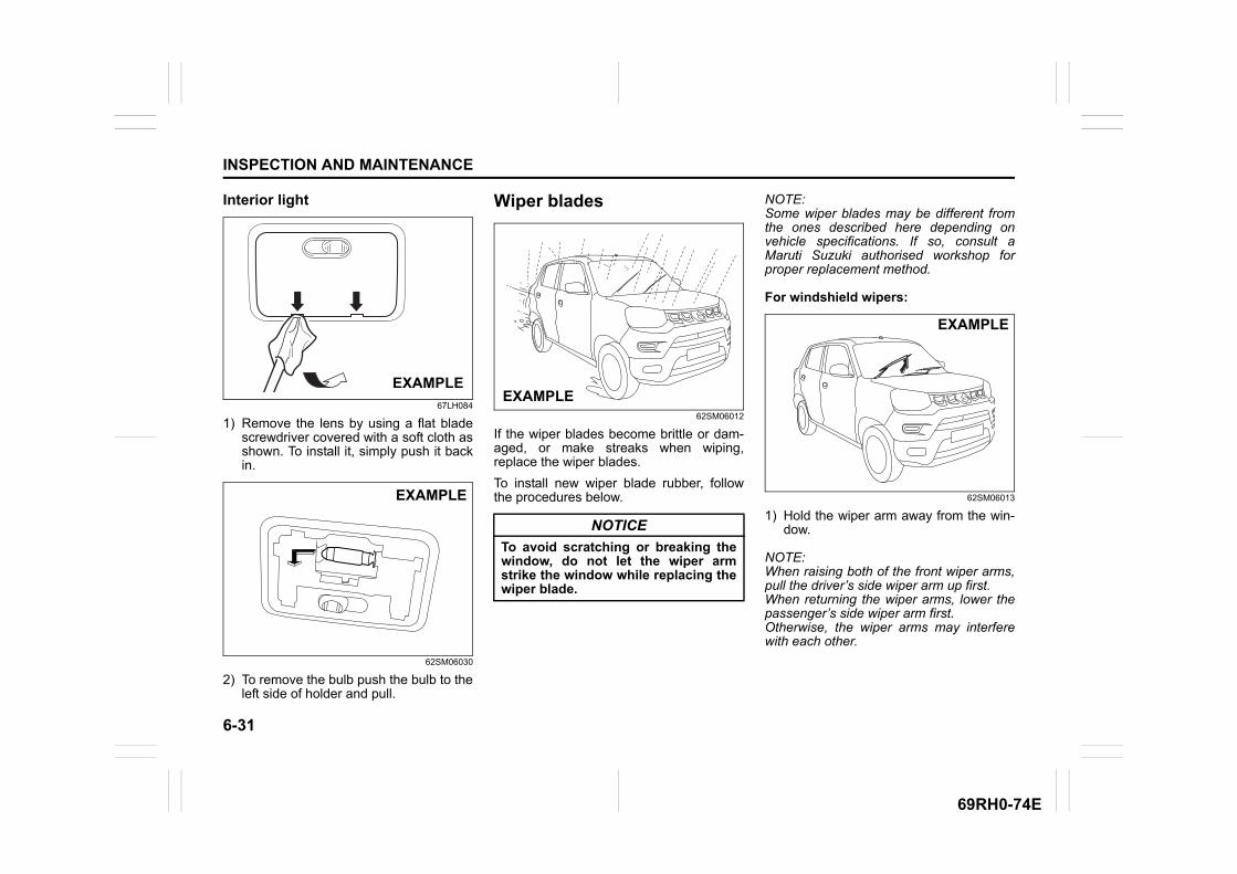
6-31
INSPECTION AND MAINTENANCE
69RH0-74E
Interior light
67LH084
1) Remove the lens by using a flat bladescrewdriver covered with a soft cloth asshown. To install it, simply push it backin.
62SM06030
2) To remove the bulb push the bulb to theleft side of holder and pull.
Wiper blades
62SM06012
If the wiper blades become brittle or dam-aged, or make streaks when wiping,replace the wiper blades.
To install new wiper blade rubber, followthe procedures below.
NOTE:Some wiper blades may be different fromthe ones described here depending onvehicle specifications. If so, consult aMaruti Suzuki authorised workshop forproper replacement method.
For windshield wipers:
62SM06013
1) Hold the wiper arm away from the win-dow.
NOTE:When raising both of the front wiper arms,pull the driver’s side wiper arm up first.When returning the wiper arms, lower thepassenger’s side wiper arm first.Otherwise, the wiper arms may interferewith each other.
EXAMPLE
EXAMPLE
NOTICE
To avoid scratching or breaking thewindow, do not let the wiper armstrike the window while replacing thewiper blade.
EXAMPLE
EXAMPLE
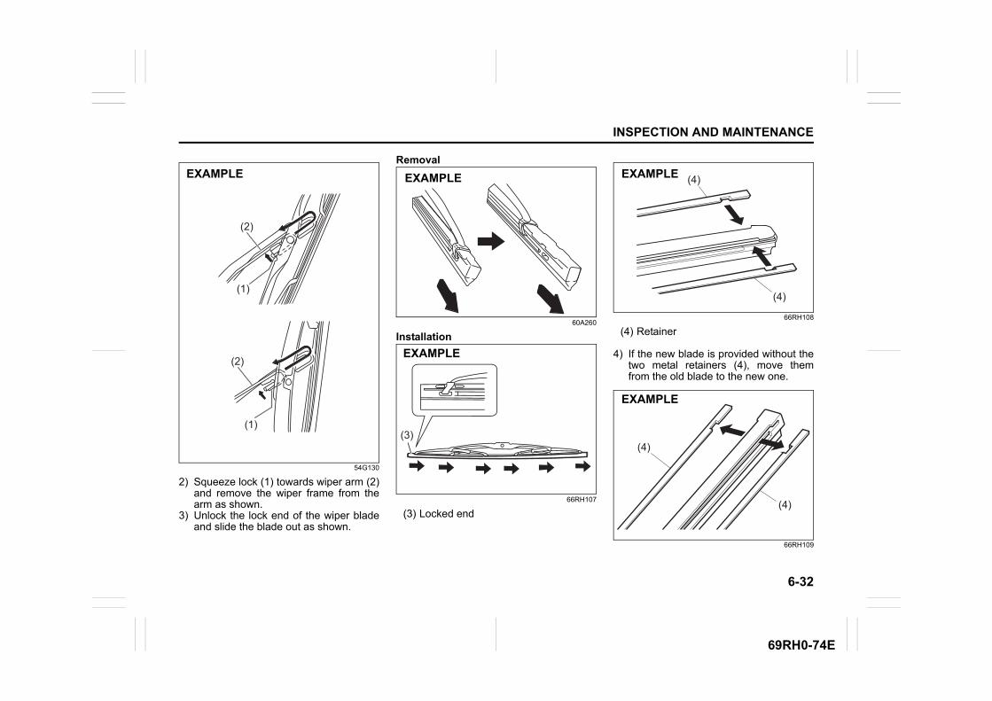
6-32
INSPECTION AND MAINTENANCE
69RH0-74E
54G130
2) Squeeze lock (1) towards wiper arm (2)and remove the wiper frame from thearm as shown.
3) Unlock the lock end of the wiper bladeand slide the blade out as shown.
Removal
60A260
Installation
66RH107
(3) Locked end
66RH108
(4) Retainer
4) If the new blade is provided without thetwo metal retainers (4), move themfrom the old blade to the new one.
66RH109
(2)
(2)
(1)
(1)
EXAMPLE EXAMPLE
(3)
(3)
EXAMPLE
(4)
(4)
EXAMPLE
(4)
(4)
EXAMPLE
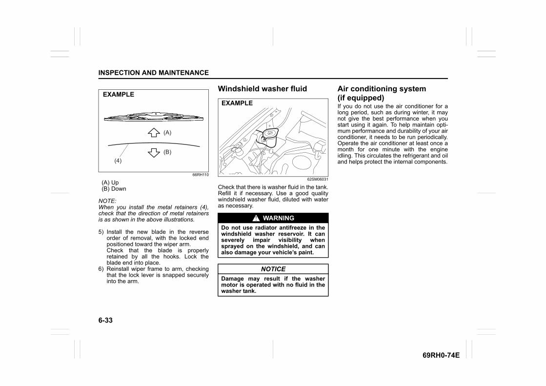
6-33
INSPECTION AND MAINTENANCE
69RH0-74E
66RH110
(A) Up(B) Down
NOTE:When you install the metal retainers (4),check that the direction of metal retainersis as shown in the above illustrations.
5) Install the new blade in the reverseorder of removal, with the locked endpositioned toward the wiper arm. Check that the blade is properlyretained by all the hooks. Lock theblade end into place.
6) Reinstall wiper frame to arm, checkingthat the lock lever is snapped securelyinto the arm.
Windshield washer fluid
62SM06031
Check that there is washer fluid in the tank.Refill it if necessary. Use a good qualitywindshield washer fluid, diluted with wateras necessary.
Air conditioning system(if equipped)If you do not use the air conditioner for along period, such as during winter, it maynot give the best performance when youstart using it again. To help maintain opti-mum performance and durability of your airconditioner, it needs to be run periodically.Operate the air conditioner at least once amonth for one minute with the engineidling. This circulates the refrigerant and oiland helps protect the internal components.(4)
(A)
(B)
EXAMPLE
WARNING
Do not use radiator antifreeze in thewindshield washer reservoir. It canseverely impair visibility whensprayed on the windshield, and canalso damage your vehicle’s paint.
NOTICE
Damage may result if the washermotor is operated with no fluid in thewasher tank.
EXAMPLE
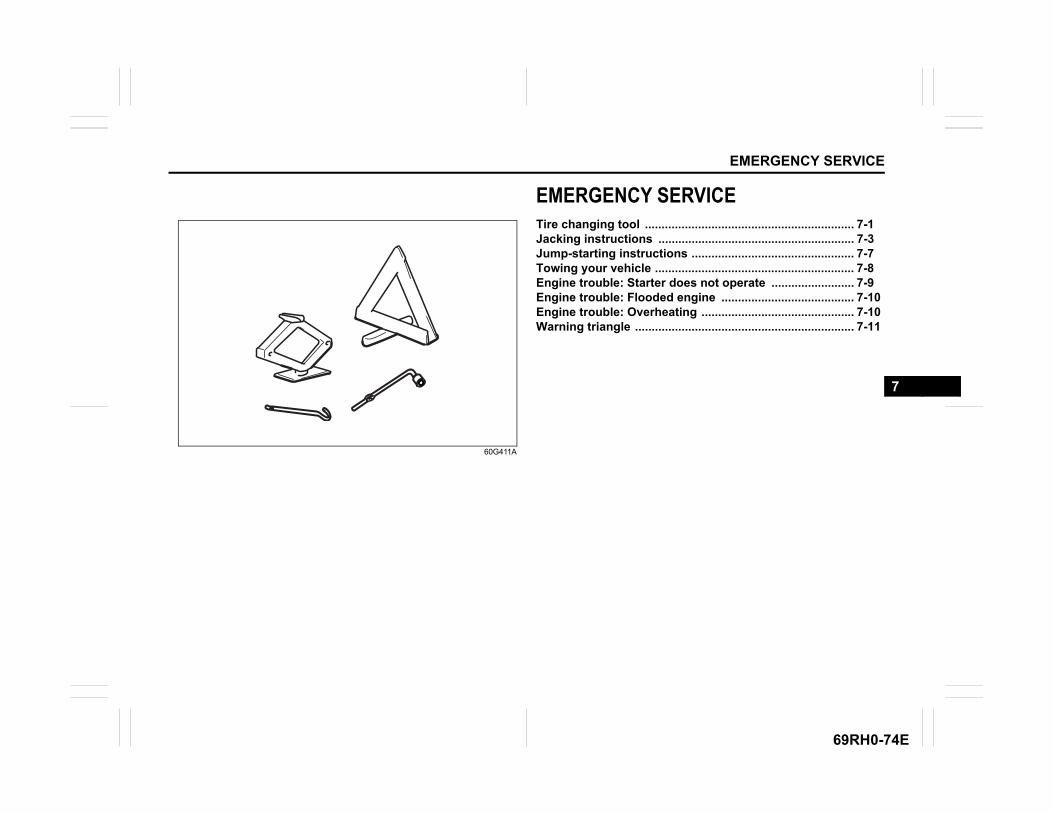
EMERGENCY SERVICE
7
69RH0-74E
60G411A
EMERGENCY SERVICETire changing tool ............................................................... 7-1Jacking instructions ........................................................... 7-3Jump-starting instructions ................................................. 7-7Towing your vehicle ............................................................ 7-8Engine trouble: Starter does not operate ......................... 7-9Engine trouble: Flooded engine ........................................ 7-10Engine trouble: Overheating .............................................. 7-10Warning triangle .................................................................. 7-11
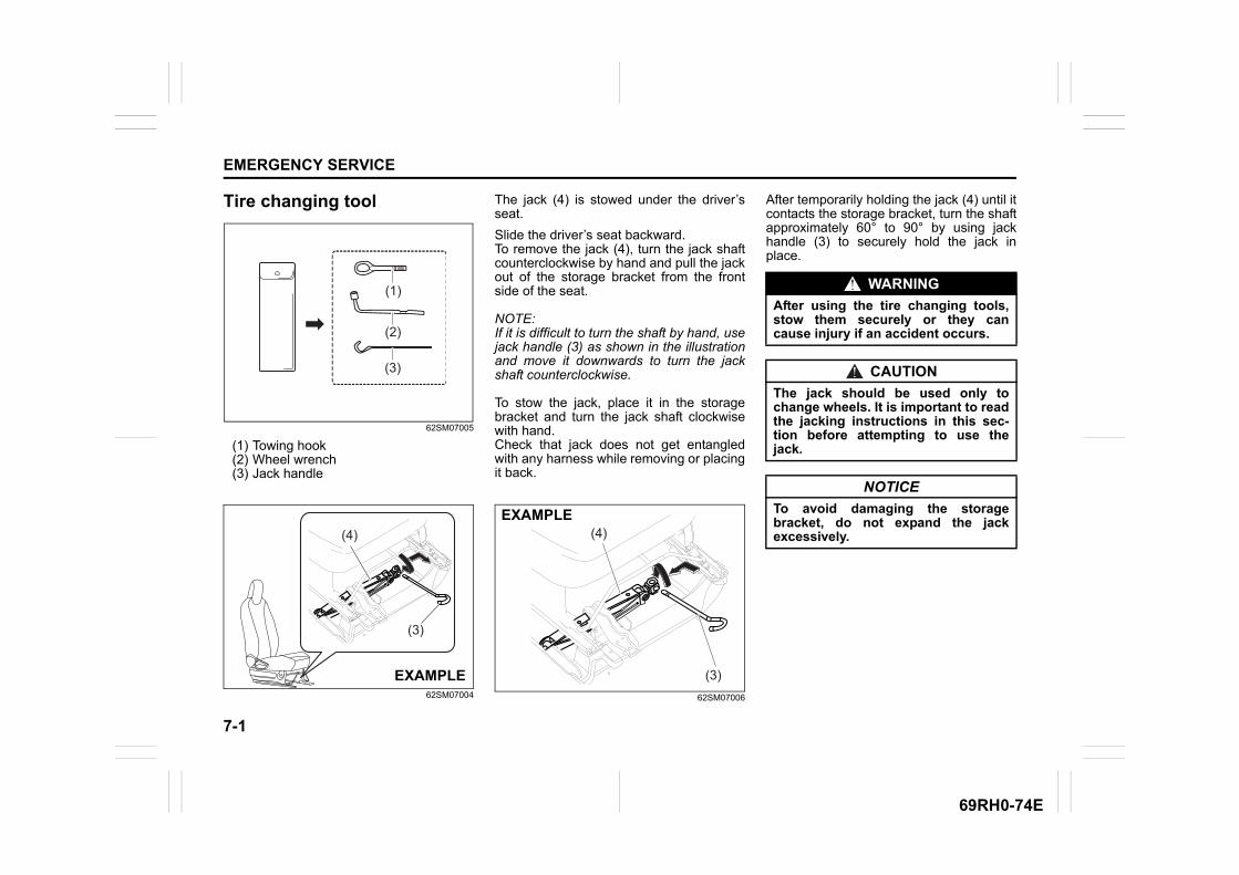
7-1
EMERGENCY SERVICE
69RH0-74E
Tire changing tool
62SM07005
(1) Towing hook(2) Wheel wrench(3) Jack handle
62SM07004
The jack (4) is stowed under the driver’sseat.
Slide the driver’s seat backward. To remove the jack (4), turn the jack shaftcounterclockwise by hand and pull the jackout of the storage bracket from the frontside of the seat.
NOTE:If it is difficult to turn the shaft by hand, usejack handle (3) as shown in the illustrationand move it downwards to turn the jackshaft counterclockwise.
To stow the jack, place it in the storagebracket and turn the jack shaft clockwisewith hand.Check that jack does not get entangledwith any harness while removing or placingit back.
62SM07006
After temporarily holding the jack (4) until itcontacts the storage bracket, turn the shaftapproximately 60° to 90° by using jackhandle (3) to securely hold the jack inplace.
(3)
(1)
(2)
(4)
(3)
EXAMPLE
(4)
(3)
EXAMPLE
WARNING
After using the tire changing tools,stow them securely or they cancause injury if an accident occurs.
CAUTION
The jack should be used only tochange wheels. It is important to readthe jacking instructions in this sec-tion before attempting to use thejack.
NOTICE
To avoid damaging the storagebracket, do not expand the jackexcessively.
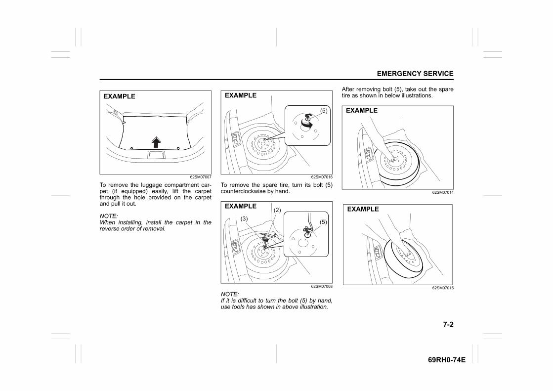
7-2
EMERGENCY SERVICE
69RH0-74E
62SM07007
To remove the luggage compartment car-pet (if equipped) easily, lift the carpetthrough the hole provided on the carpetand pull it out.
NOTE:When installing, install the carpet in thereverse order of removal.
62SM07016
To remove the spare tire, turn its bolt (5)counterclockwise by hand.
62SM07008
NOTE:If it is difficult to turn the bolt (5) by hand,use tools has shown in above illustration.
After removing bolt (5), take out the sparetire as shown in below illustrations.
62SM07014
62SM07015
EXAMPLE
(5)
EXAMPLE
(5)
(2)(3)
EXAMPLE
EXAMPLE
EXAMPLE
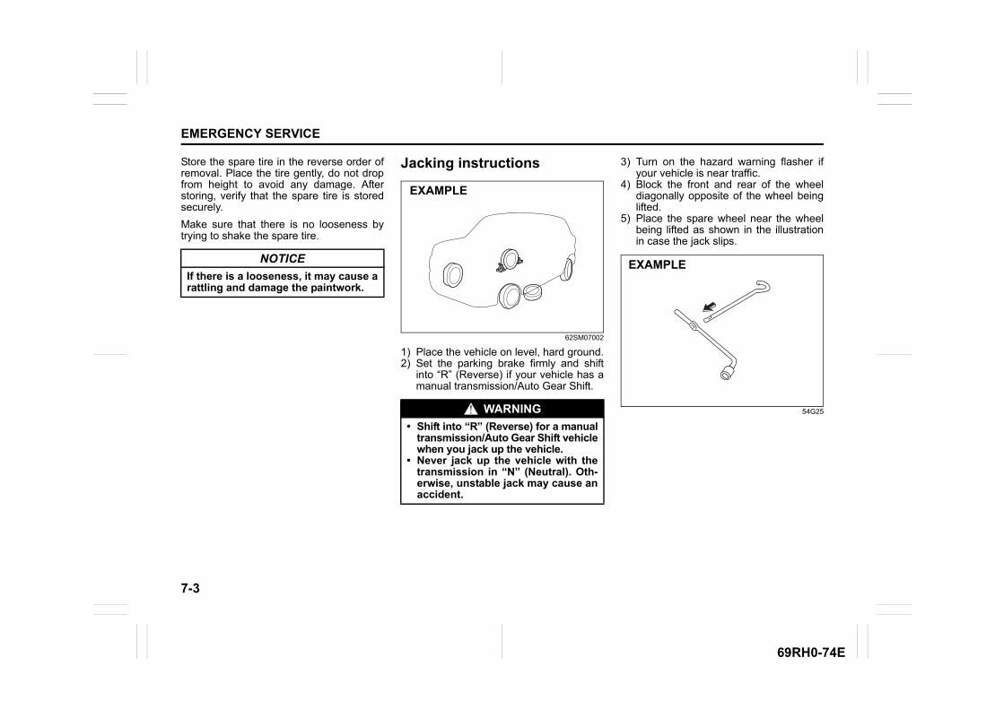
7-3
EMERGENCY SERVICE
69RH0-74E
Store the spare tire in the reverse order ofremoval. Place the tire gently, do not dropfrom height to avoid any damage. Afterstoring, verify that the spare tire is storedsecurely.
Make sure that there is no looseness bytrying to shake the spare tire.
Jacking instructions
62SM07002
1) Place the vehicle on level, hard ground.2) Set the parking brake firmly and shift
into “R” (Reverse) if your vehicle has amanual transmission/Auto Gear Shift.
3) Turn on the hazard warning flasher ifyour vehicle is near traffic.
4) Block the front and rear of the wheeldiagonally opposite of the wheel beinglifted.
5) Place the spare wheel near the wheelbeing lifted as shown in the illustrationin case the jack slips.
54G25
NOTICE
If there is a looseness, it may cause arattling and damage the paintwork.
WARNING
• Shift into “R” (Reverse) for a manualtransmission/Auto Gear Shift vehiclewhen you jack up the vehicle.
• Never jack up the vehicle with thetransmission in “N” (Neutral). Oth-erwise, unstable jack may cause anaccident.
EXAMPLE
EXAMPLE
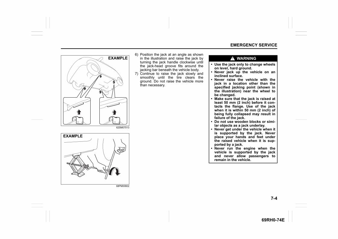
7-4
EMERGENCY SERVICE
69RH0-74E
62SM07013
68PM00802
6) Position the jack at an angle as shownin the illustration and raise the jack byturning the jack handle clockwise untilthe jack-head groove fits around thejacking bar beneath the vehicle body.
7) Continue to raise the jack slowly andsmoothly until the tire clears theground. Do not raise the vehicle morethan necessary.
EXAMPLE
EXAMPLE
WARNING
• Use the jack only to change wheelson level, hard ground.
• Never jack up the vehicle on aninclined surface.
• Never raise the vehicle with thejack in a location other than thespecified jacking point (shown inthe illustration) near the wheel tobe changed.
• Make sure that the jack is raised atleast 50 mm (2 inch) before it con-tacts the flange. Use of the jackwhen it is within 50 mm (2 inch) ofbeing fully collapsed may result infailure of the jack.
• Do not use wooden blocks or simi-lar objects as a jack underlay.
• Never get under the vehicle when itis supported by the jack. Neverplace your hands and feet underthe raised vehicle when it is sup-ported by a jack.
• Never run the engine when thevehicle is supported by the jackand never allow passengers toremain in the vehicle.
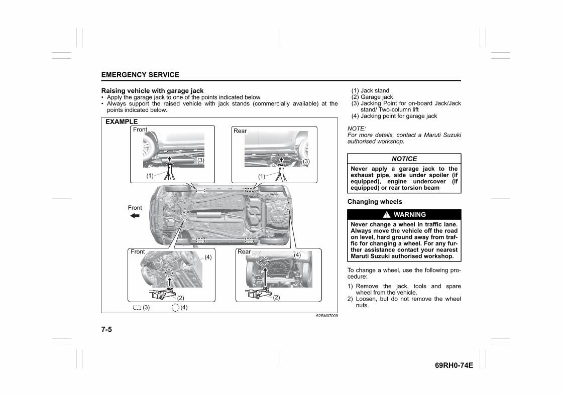
7-5
EMERGENCY SERVICE
69RH0-74E
Raising vehicle with garage jack• Apply the garage jack to one of the points indicated below.• Always support the raised vehicle with jack stands (commercially available) at the
points indicated below.
62SM07009
(4)
Front
(1)
(4)
(4)(2) (2)
(1)
(4)Front
Front Rear
Rear
(3)
(3)
(3)
EXAMPLE
(1) Jack stand(2) Garage jack(3) Jacking Point for on-board Jack/Jack
stand/ Two-column lift(4) Jacking point for garage jack
NOTE:For more details, contact a Maruti Suzukiauthorised workshop.
Changing wheels
To change a wheel, use the following pro-cedure:
1) Remove the jack, tools and sparewheel from the vehicle.
2) Loosen, but do not remove the wheelnuts.
NOTICE
Never apply a garage jack to theexhaust pipe, side under spoiler (ifequipped), engine undercover (ifequipped) or rear torsion beam
WARNING
Never change a wheel in traffic lane.Always move the vehicle off the roadon level, hard ground away from traf-fic for changing a wheel. For any fur-ther assistance contact your nearestMaruti Suzuki authorised workshop.
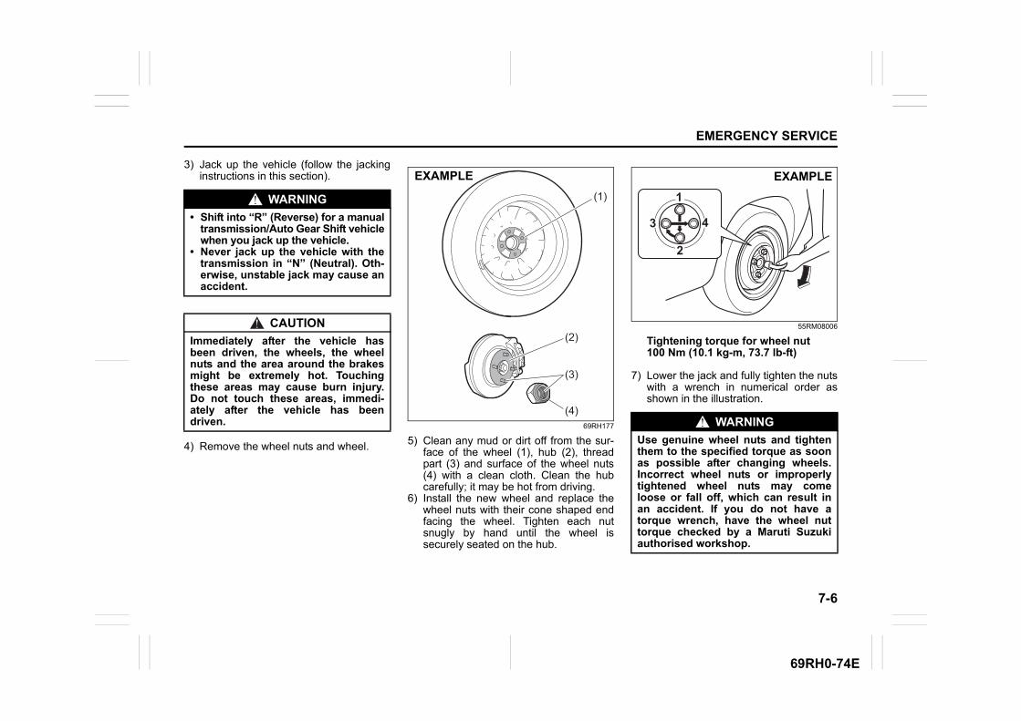
7-6
EMERGENCY SERVICE
69RH0-74E
3) Jack up the vehicle (follow the jackinginstructions in this section).
4) Remove the wheel nuts and wheel.
69RH177
5) Clean any mud or dirt off from the sur-face of the wheel (1), hub (2), threadpart (3) and surface of the wheel nuts(4) with a clean cloth. Clean the hubcarefully; it may be hot from driving.
6) Install the new wheel and replace thewheel nuts with their cone shaped endfacing the wheel. Tighten each nutsnugly by hand until the wheel issecurely seated on the hub.
55RM08006
Tightening torque for wheel nut100 Nm (10.1 kg-m, 73.7 lb-ft)
7) Lower the jack and fully tighten the nutswith a wrench in numerical order asshown in the illustration.
WARNING
• Shift into “R” (Reverse) for a manualtransmission/Auto Gear Shift vehiclewhen you jack up the vehicle.
• Never jack up the vehicle with thetransmission in “N” (Neutral). Oth-erwise, unstable jack may cause anaccident.
CAUTION
Immediately after the vehicle hasbeen driven, the wheels, the wheelnuts and the area around the brakesmight be extremely hot. Touchingthese areas may cause burn injury.Do not touch these areas, immedi-ately after the vehicle has beendriven.
(2)
(4)
(1)
(3)
EXAMPLE
WARNING
Use genuine wheel nuts and tightenthem to the specified torque as soonas possible after changing wheels.Incorrect wheel nuts or improperlytightened wheel nuts may comeloose or fall off, which can result inan accident. If you do not have atorque wrench, have the wheel nuttorque checked by a Maruti Suzukiauthorised workshop.
EXAMPLE

7-7
EMERGENCY SERVICE
69RH0-74E
Full wheel cover (if equipped)
62SM07010
Remove the full wheel cover by using jackhandle (1) covered with a soft cloth (2), asshown in the illustration.
54P000803
Ensure not to cover or foul the air valvewhile installing the full wheel cover.
Jump-starting instructions
1) Use only a 12-volt battery to jump-startyour vehicle. Position the good 12-voltbattery close to your vehicle so that thejump leads will reach both batteries.When using a battery installed onanother vehicle, check that two vehiclesdo not touch each other. Set the park-ing brakes fully on both vehicles.
2) Turn off all vehicle accessories, exceptthose necessary for safety reasons (forexample, headlights or hazard lights).
(1)
(2)
EXAMPLE
EXAMPLE
WARNING
• Never attempt to jump-start yourvehicle if the battery appears to befrozen. Batteries in this conditionmay explode.
• When making jump lead connec-tions, check that your hands andthe jump leads remain clear frompulleys, belts or fans.
• Batteries produce flammablehydrogen gas. Keep flames andsparks away from the battery or anexplosion may occur. Never smokewhen working near the battery.
• If the booster battery you use forjump-starting is installed in anothervehicle, check that the two vehiclesare not touching each other.
• If your battery discharges repeat-edly, for no apparent reason, haveyour vehicle inspected by a MarutiSuzuki authorised workshop.
• To avoid harm to yourself or dam-age to your vehicle or battery, fol-low the jump-starting instructionsbelow. If you are in doubt, call for qualifiedroad service.
NOTICE
Your vehicle should not be started bypushing or towing. This startingmethod could result in permanentdamage to the catalytic converter.Use jump leads to start a vehicle witha weak or discharged battery.

7-8
EMERGENCY SERVICE
69RH0-74E
54P000804
3) Connect jump leads as follows:
1. Connect one end of the first jumplead to the positive (+) terminal ofthe discharged battery (1).
2. Connect the other end to the positive(+) terminal of the booster battery(2).
3. Connect one end of the second jumplead to the negative (–) terminal ofthe booster battery (2).
4. Make the final connection to anunpainted, heavy metal part (i.e.engine mount bracket (3)) of theengine of the vehicle with the dis-charged battery (1).
4) If the booster battery you are using isfitted to another vehicle, start theengine of the vehicle with the boosterbattery. Run the engine at moderatespeed.
5) Start the engine of the vehicle with thedischarged battery.
6) Remove the jump leads in the exactreverse order in which you connectedthem.
Towing your vehicleIf you need to have your vehicle towed,contact a professional service. MarutiSuzuki authorised workshop can provideyou with detailed towing instructions.
(2)
(1)
(3)
EXAMPLE
WARNING
Never connect the jump lead directlyto the negative (–) terminal of the dis-charged battery, or an explosion mayoccur.
CAUTION
Connect the jump lead to the enginemount bracket securely. If the jumplead disconnects from the enginemount bracket because of vibrationat the start of the engine, the jumplead could be caught in the drivebelts.
NOTICE
Observe the following instructionswhen towing your vehicle.• To help avoid damage to your vehi-
cle during towing, proper equip-ment and towing procedures mustbe used.
• Using the frame hook, tow yourvehicle on paved roads for shortdistances at low speed.
7-9
EMERGENCY SERVICE
69RH0-74E
2-wheel drive (2WD) manual trans-mission or Auto Gear ShiftManual transmission vehicles or Auto GearShift vehicles may be towed using either ofthe following methods.
1) From the front, with the front wheelslifted and the rear wheels on theground. Before towing, check that theparking brake is released.
2) From the rear, with the rear wheelslifted and the front wheels on theground, provided the steering anddrivetrain are in operational condition.Before towing, check that transmissionis in neutral, the steering wheel isunlocked (the ignition key should be in“ACC” position), and the steering wheelis secured with a clamping devicedesigned for towing service.
Engine trouble: Starter does not operate1) Try turning the ignition switch to
“START” position with the headlightsturned on to determine the battery con-dition. If the headlights go excessivelydim or go off, it usually means thateither the battery is discharged or thebattery terminal contact is poor.Recharge the battery or correct batteryterminal contact as necessary.
2) If the headlights remain bright, checkthe fuses. If the reason for failure of thestarter is not obvious, there may be amajor electrical problem. Have the vehi-cle inspected by a Maruti Suzuki autho-rised workshop.
NOTICE
• The steering column is not strongenough to withstand shocks trans-mitted from the front wheels duringtowing. Always unlock the steeringwheel before towing.
• After shifting the Auto Gear Shiftgearshift lever to the “N” position,always check the gear positionindicator in the instrument clustershows the “N” position to makesure that the transmission is disen-gaged.If the transmission cannot be put inneutral, turn the key from the“LOCK” to the “ON” position, andmove the Auto Gear Shift gearshiftlever from “N” to “D”, “M” or “R”,then back to “N” again. Then turnthe key from the “ON” to the“LOCK” position. These proce-dures may help put the transmis-sion in neutral. If the transmissionstill cannot be put in neutral, youcannot tow the vehicle withoutusing a towing dolly.
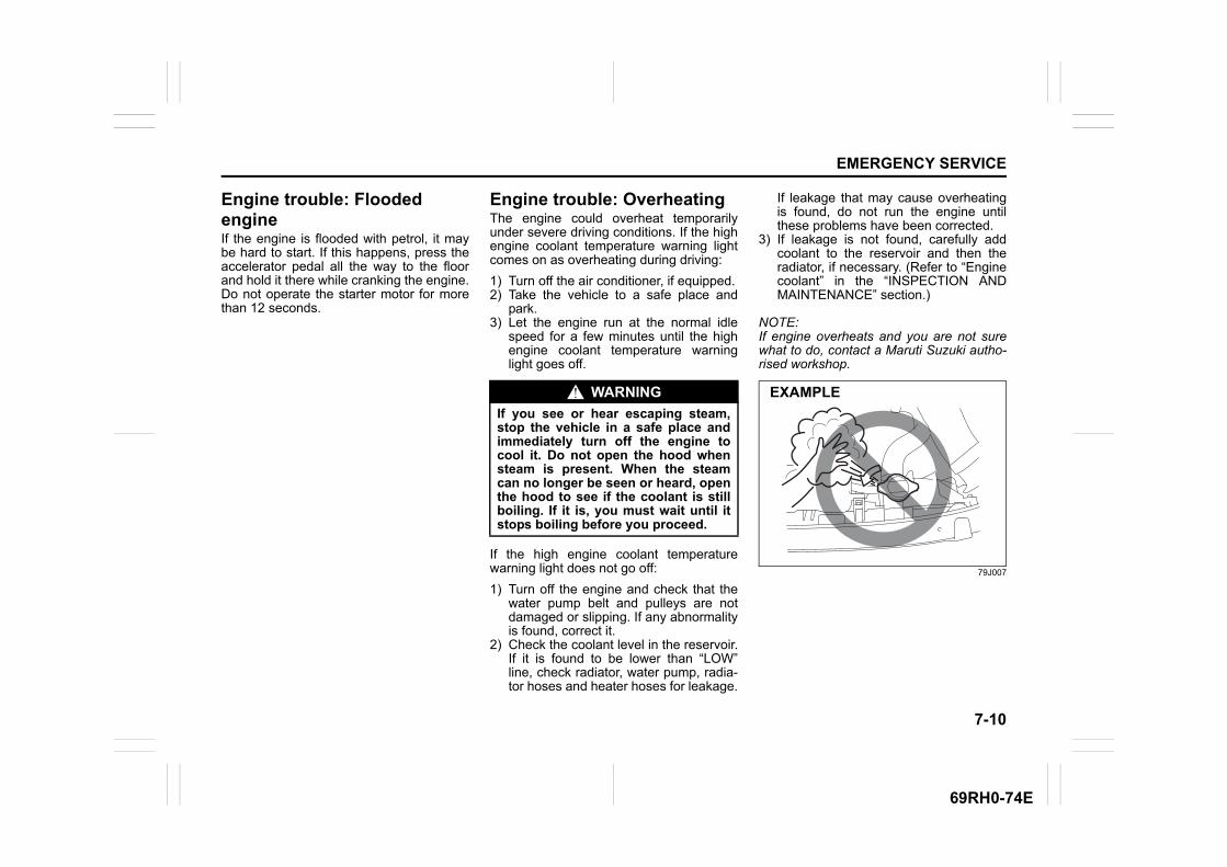
7-10
EMERGENCY SERVICE
69RH0-74E
Engine trouble: Flooded engineIf the engine is flooded with petrol, it maybe hard to start. If this happens, press theaccelerator pedal all the way to the floorand hold it there while cranking the engine.Do not operate the starter motor for morethan 12 seconds.
Engine trouble: OverheatingThe engine could overheat temporarilyunder severe driving conditions. If the highengine coolant temperature warning lightcomes on as overheating during driving:
1) Turn off the air conditioner, if equipped.2) Take the vehicle to a safe place and
park.3) Let the engine run at the normal idle
speed for a few minutes until the highengine coolant temperature warninglight goes off.
If the high engine coolant temperaturewarning light does not go off:
1) Turn off the engine and check that thewater pump belt and pulleys are notdamaged or slipping. If any abnormalityis found, correct it.
2) Check the coolant level in the reservoir.If it is found to be lower than “LOW”line, check radiator, water pump, radia-tor hoses and heater hoses for leakage.
If leakage that may cause overheatingis found, do not run the engine untilthese problems have been corrected.
3) If leakage is not found, carefully addcoolant to the reservoir and then theradiator, if necessary. (Refer to “Enginecoolant” in the “INSPECTION ANDMAINTENANCE” section.)
NOTE:If engine overheats and you are not surewhat to do, contact a Maruti Suzuki autho-rised workshop.
79J007
WARNING
If you see or hear escaping steam,stop the vehicle in a safe place andimmediately turn off the engine tocool it. Do not open the hood whensteam is present. When the steamcan no longer be seen or heard, openthe hood to see if the coolant is stillboiling. If it is, you must wait until itstops boiling before you proceed.
EXAMPLE
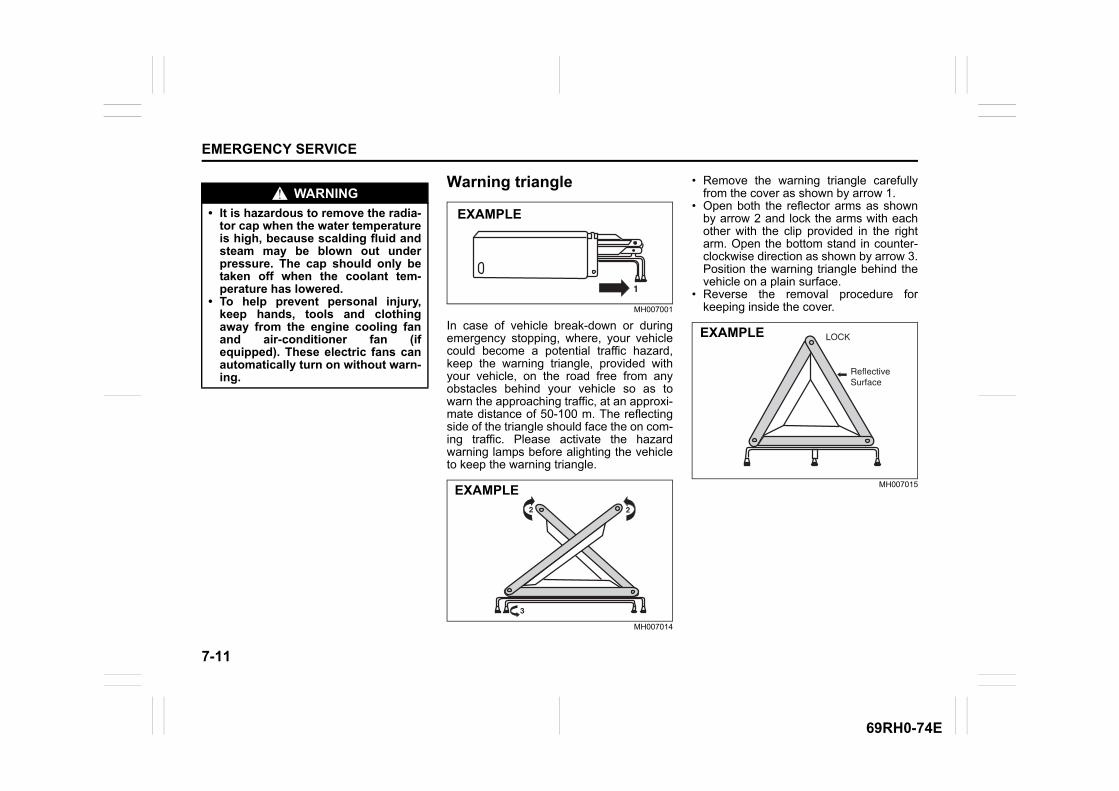
7-11
EMERGENCY SERVICE
69RH0-74E
Warning triangle
MH007001
In case of vehicle break-down or duringemergency stopping, where, your vehiclecould become a potential traffic hazard,keep the warning triangle, provided withyour vehicle, on the road free from anyobstacles behind your vehicle so as towarn the approaching traffic, at an approxi-mate distance of 50-100 m. The reflectingside of the triangle should face the on com-ing traffic. Please activate the hazardwarning lamps before alighting the vehicleto keep the warning triangle.
MH007014
• Remove the warning triangle carefullyfrom the cover as shown by arrow 1.
• Open both the reflector arms as shownby arrow 2 and lock the arms with eachother with the clip provided in the rightarm. Open the bottom stand in counter-clockwise direction as shown by arrow 3.Position the warning triangle behind thevehicle on a plain surface.
• Reverse the removal procedure forkeeping inside the cover.
MH007015
WARNING
• It is hazardous to remove the radia-tor cap when the water temperatureis high, because scalding fluid andsteam may be blown out underpressure. The cap should only betaken off when the coolant tem-perature has lowered.
• To help prevent personal injury,keep hands, tools and clothingaway from the engine cooling fanand air-conditioner fan (ifequipped). These electric fans canautomatically turn on without warn-ing.
EXAMPLE
EXAMPLE
EXAMPLE
APPEARANCE CARE
8
69RH0-74E
62SM08000
APPEARANCE CARECorrosion prevention .......................................................... 8-1Vehicle cleaning .................................................................. 8-2
8-1
APPEARANCE CARE
69RH0-74E
Corrosion preventionIt is important to take good care of yourvehicle to protect it from corrosion. Listedbelow are instructions for how to maintainyour vehicle to prevent corrosion. Pleaseread and follow these instructions carefully.
Important information about corro-sion
Common causes of corrosion
1) Accumulation of road salt, dirt, moistureor chemicals in hard-to-reach areas ofthe vehicle underbody or frame.
2) Chipping, scratches and any damage totreated or painted metal surfacesresulting from minor accidents or abra-sion by stones and gravel.
3) Any or all of the below mentionedpoints:
• Continuous exposure to sunlight • Hard water and sea water coming in
contact with vehicle. • Foot rubbing (skirting).
Environmental conditions which accel-erate corrosion1) Road salt, dust control chemicals, sea
air or industrial pollution will all acceler-ate the corrosion of metal.
2) High humidity will increase the rate ofcorrosion particularly when the tem-perature range is just above the freez-ing point.
3) Moisture in certain areas of a vehiclefor an extended period of time may pro-mote corrosion even though other bodysections may be completely dry.
4) High temperatures will cause an accel-erated rate of corrosion to parts of thevehicle which are not well-ventilated topermit quick drying.
This information illustrates the necessity ofkeeping your vehicle (particularly theunderbody) as clean and dry as possible. Itis equally important to repair any damageto the paint or protective coatings as soonas possible.
How to help prevent corrosion
Wash your vehicle frequentlyThe best way to preserve the finish on yourvehicle and to help avoid corrosion is tokeep it clean with frequent washing.Wash your vehicle at least once during thewinter and once immediately after the win-ter. Keep your vehicle, particularly theunderside, as clean and dry as possible.If you frequently drive on salted roads,your vehicle should be washed at leastonce a month during the winter. If you livenear the ocean, your vehicle should bewashed at least once a month throughoutthe year.
For washing instructions, refer to “Vehiclecleaning” section.
Remove foreign material depositsForeign material such as salts, chemicals,road oil or tar, tree sap, bird droppings andindustrial fall-out may damage the finish ofyour vehicle if it is left on painted surfaces.Remove these types of deposits as quicklyas possible. If these deposits are difficult towash off, an additional cleaner may berequired. Check that any cleaner you useis not harmful to painted surfaces and isspecifically intended for your purposes.Follow the manufacturer’s directions whenusing these special cleaners.
Repair finish damageCarefully examine your vehicle for damageto the painted surfaces. Should you findany chips or scratches in the paint, touchthem up immediately to prevent corrosionfrom starting. If the chips or scratches havegone through to the bare metal, have aqualified body shop make the repair.
Keep passenger and luggage compart-ments cleanMoisture, dirt or mud can accumulateunder the floor mats and may cause corro-sion. Occasionally, check under thesemats to ensure that this area is clean anddry. More frequent checks are necessary ifthe vehicle is used for off-road driving or inwet weather.Certain cargos such as chemicals, fertiliz-ers, cleaners, salts, etc. are extremely cor-rosive by nature. These products shouldbe transported in sealed containers. If they
8-2
APPEARANCE CARE
69RH0-74E
are spilled or leaked, clean and dry thearea immediately.
Store your vehicle in a dry, well-venti-lated areaPark your vehicle to save it from continu-ous exposure to direct sunlight.Do not park your vehicle in a damp, poorlyventilated area. If you often wash yourvehicle in the garage or if you frequentlydrive it in when wet, your garage may bedamp. The high humidity in the garagemay cause or accelerate corrosion. A wetvehicle may corrode even in a heatedgarage if the ventilation is poor.
Vehicle cleaning
62SM08001
Cleaning interior
Vinyl upholstery (Except front passen-ger seat)Prepare a solution of soap or mild deter-gent mixed with warm water. Apply thesolution to the vinyl with a sponge or softcloth and let it soak for a few minutes toloosen dirt.Rub the surface with a clean, damp clothto remove dirt and the soap solution. Ifsome dirt still remains on the surface,repeat this procedure.
Fabric upholstery (Except front passen-ger seat)Remove loose dirt with a vacuum cleaner.Using a mild soap solution, rub stainedareas with a clean damp cloth. To removesoap, rub the areas again with a clothdampened with water. Repeat this until thestain is removed, or use a commercial fab-ric cleaner for tougher stains. If you use afabric cleaner, carefully follow the manu-facturer’s instructions and precautions.
WARNING
Do not apply additional undercoatingor rust preventive coating on oraround exhaust system componentssuch as the catalytic converter andexhaust pipes. A fire could be startedif the undercoating substancebecomes overheated.
WARNING
When cleaning the interior or exteriorof the vehicle, do not use flammablesolvents such as lacquer thinners,petrol and benzene. Also, do not usecleaning materials such as bleachesand strong household detergents.The materials could cause personalinjury or damage to the vehicle.
EXAMPLE
8-3
APPEARANCE CARE
69RH0-74E
Vinyl/ Fabric upholstery (For front pas-senger seat)Do not use liquid for cleaning as it maypenetrate the fabric and damage the seatsensor.
Seat beltsClean seat belts with a mild soap andwater. Do not use bleach or dye on thebelts. They may weaken the fabric in thebelts.
Vinyl floor matsOrdinary dirt can be removed from vinylwith water or mild soap. Use a brush tohelp loosen dirt. After the dirt is loosened,rinse the mat thoroughly with water anddry it in the shade.
CarpetsRemove dirt and soil as much as possiblewith a vacuum cleaner. Using a mild soapsolution, rub stained areas with a cleandamp cloth. To remove soap, rub the areasagain with a cloth dampened with water.Repeat this until the stain is removed, oruse a commercial carpet cleaner fortougher stains. If you use a carpet cleaner,carefully follow the manufacturer’s instruc-tions and precautions.
Instrument panel and consoleRemove loose dirt with a vacuum cleaner.Gently wipe dirt off with a tightly squeezeddamp clean cloth. Repeat this until the dirtis removed.
CAUTION
• Do not spill liquid or semi-solid onthe front passenger's seat. If youspill it on the front passenger'sseat, immediately wipe it dry with asoft cloth. Contact of liquid withsensor may impact the function ofseat belt reminder sensor.
• Do not place any sharp or heavyobject on passenger seat whichcan penetrate through seat uphol-stery and can cause damage tosensor.

8-4
APPEARANCE CARE
69RH0-74E
Cleaning exterior
Caring for aluminum wheelsNOTE:• Do not use an acidic or alkaline deter-
gent, or a cleaner containing petroleumsolvent to wash aluminum wheels.These types of cleaner will cause per-manent spots, discoloration and crackson finished surfaces and damage to cen-ter caps.
• Do not use a bristle brush and soap con-taining an abrasive material. These willdamage finished surfaces.
Washing
Washing by hand
62SM08002
NOTICE
• Do not use chemical products thatcontain silicon to wipe electricalcomponents such as the air condi-tioning system, audio, navigationsystem, or other switches. Thesewill cause damage to the compo-nents.
• Liquid such as liquid aromatics,soft drinks or juice may cause dis-coloration, wrinkles, and crackingto resin-based parts and textiles.Immediately wipe it dry with tissuepaper or a soft cloth.
• Do not leave leather products withcolor, fur or vinyl products, etc. inyour vehicle for long periods. Itmay cause discoloration or deterio-ration of interior.
NOTICE
It is important that your vehicle bekept clean and free from dirt. Failureto keep your vehicle clean may resultin fading of the paint or corrosion tovarious parts of the vehicle body.
WARNING
• Never attempt to wash and waxyour vehicle with the engine run-ning.
• When cleaning the underside of thebody and fender, where there maybe sharp-edged parts, wear glovesand a long-sleeved shirt to protectyour hands and arms from beingcut.
• After washing your vehicle, care-fully test the brakes before drivingto check that they have maintainedtheir normal effectiveness.
EXAMPLE
8-5
APPEARANCE CARE
69RH0-74E
When washing the vehicle, park it in theplace where direct sunlight does not fall onit and follow the instructions below:1) Flush the underside of body and wheel
housings with pressurized water toremove mud and debris. Use plenty ofwater.
2) Rinse the body to loosen the dirt.Remove dirt and mud from the bodyexterior with running water. You mayuse a soft sponge or brush. Do not usehard materials which can scratch thepaint or plastic. Remember that theheadlight covers or lenses are made ofplastic in many cases.
3) Wash the entire exterior with a milddetergent or car wash soap using asponge or soft cloth. The sponge orcloth should be frequently soaked in thesoap solution.
4) Once the dirt has been completelyremoved, rinse off the detergent withrunning water.
5) Wipe off the vehicle body with a wetchamois or cloth and allow it to dry inthe shade.
6) Check carefully for damage to paintedsurfaces. If there is any damage, touchup the damage following the procedurebelow:1. Clean all damaged spots and allow
them to dry.2. Stir the paint and touch up the dam-
aged spots lightly using a smallbrush.
3. Allow the paint to dry completely.
Washing by an automatic car wash
Washing by a high-pressure cleaner
NOTICE
When washing the vehicle:• Avoid directing steam or hot water
of more than 80°C (176°F) on plas-tic parts.
• To avoid damaging engine compo-nents, do not use pressurizedwater in the engine compartment.
NOTICE
To avoid damage to the paint or plas-tic surface, do not wipe the dirt offwithout ample water. Follow theabove procedure.
NOTICE
When using a commercial car washproduct, observe the cautions speci-fied by the manufacturer. Never usestrong household detergents orsoaps.
NOTICE
• If you use an automatic car wash,check that your vehicle’s bodyparts, such as spoilers, cannot bedamaged. If you are in doubt, con-sult the car wash operator foradvice.
• Remove the antenna when using anautomatic car wash.
NOTICE
If you use a high-pressure cleaner,keep away the nozzle from your vehi-cle sufficiently.• Bringing the nozzle to your vehicle
too close or pointing the nozzle tothe opening of front grill or bumperetc. can cause damage and mal-function of the vehicle body andparts.
• Pointing the nozzle to the weather-strip of door glasses and doors canallow water to enter the cabin.
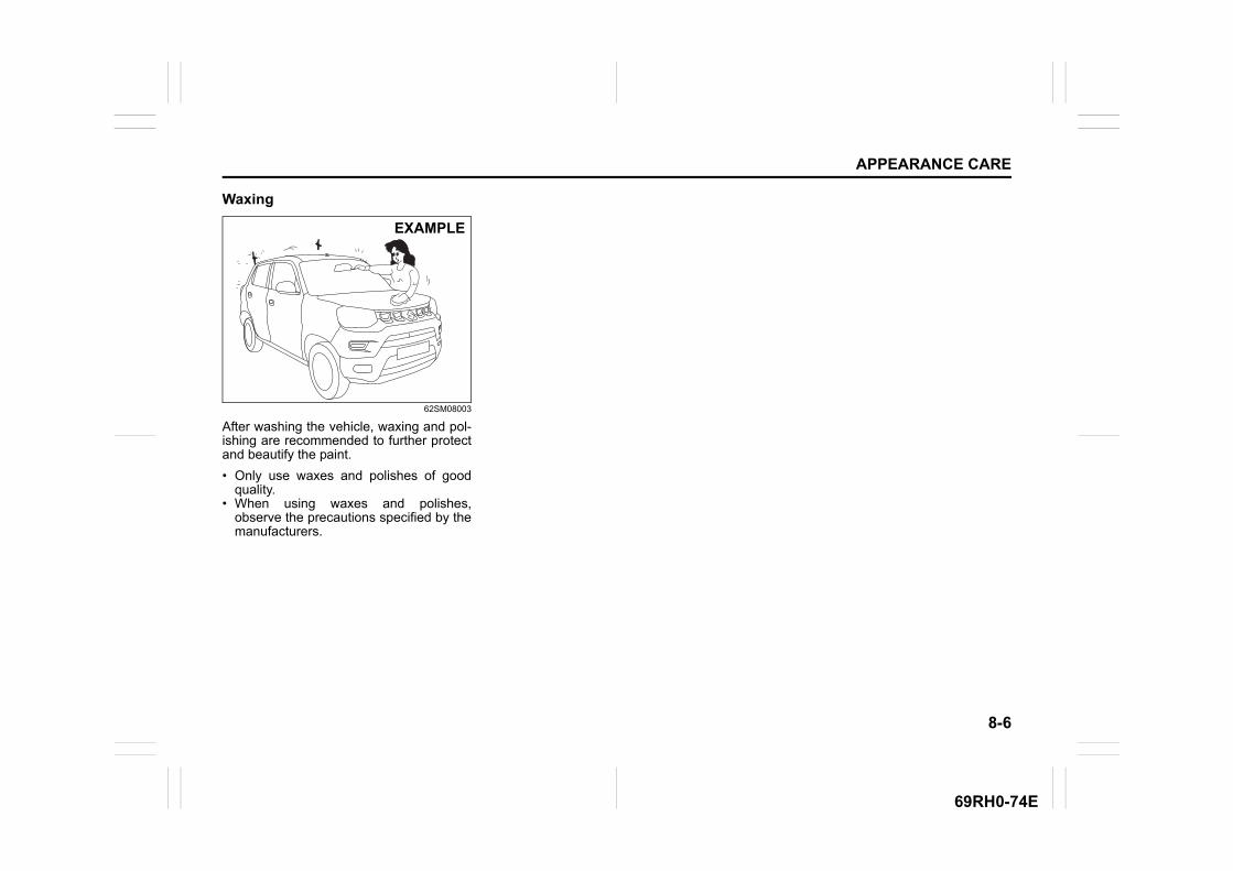
8-6
APPEARANCE CARE
69RH0-74E
Waxing
62SM08003
After washing the vehicle, waxing and pol-ishing are recommended to further protectand beautify the paint.
• Only use waxes and polishes of goodquality.
• When using waxes and polishes,observe the precautions specified by themanufacturers.
EXAMPLE
8-7
APPEARANCE CARE
69RH0-74E
SPECIFICATIONS
9
69RH0-74E
84MM01001
SPECIFICATIONSVehicle identification .......................................................... 9-1FASTag (if equipped) ........................................................... 9-2High Security Registration Plate (HSRP) ............................ 9-3Fuel ....................................................................................... 9-4Specifications ...................................................................... 9-5
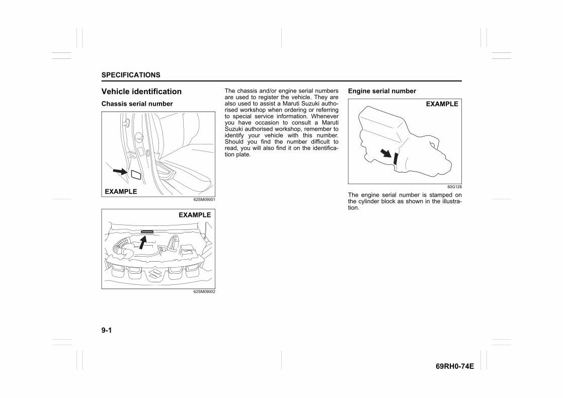
9-1
SPECIFICATIONS
69RH0-74E
Vehicle identification
Chassis serial number
62SM09001
62SM09002
The chassis and/or engine serial numbersare used to register the vehicle. They arealso used to assist a Maruti Suzuki autho-rised workshop when ordering or referringto special service information. Wheneveryou have occasion to consult a MarutiSuzuki authorised workshop, remember toidentify your vehicle with this number.Should you find the number difficult toread, you will also find it on the identifica-tion plate.
Engine serial number
60G128
The engine serial number is stamped onthe cylinder block as shown in the illustra-tion.
EXAMPLE
EXAMPLE
EXAMPLE
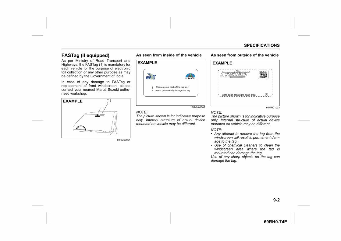
9-2
SPECIFICATIONS
69RH0-74E
FASTag (if equipped)As per Ministry of Road Transport andHighways, the FASTag (1) is mandatory foreach vehicle for the purpose of electronictoll collection or any other purpose as maybe defined by the Government of India.
In case of any damage to FASTag orreplacement of front windscreen, pleasecontact your nearest Maruti Suzuki autho-rised workshop.
69RM09001
As seen from inside of the vehicle
64MM01002
NOTE:The picture shown is for indicative purposeonly. Internal structure of actual devicemounted on vehicle may be different.
As seen from outside of the vehicle
64MM01003
NOTE:The picture shown is for indicative purposeonly. Internal structure of actual devicemounted on vehicle may be different.
NOTE:• Any attempt to remove the tag from the
windscreen will result in permanent dam-age to the tag.
• Use of chemical cleaners to clean thewindscreen area where the tag ismounted can damage the tag.
Use of any sharp objects on the tag candamage the tag.
(1)EXAMPLE
EXAMPLE
Please do not peel off the tag, as itwould permanently damage the tag!
EXAMPLE
4xxxx xxxx xxxx xxxx xxxx xxxx
Easy to Cruise
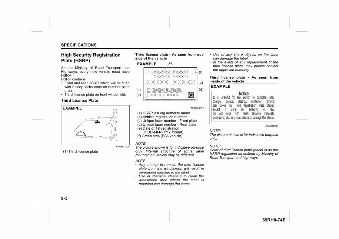
9-3
SPECIFICATIONS
69RH0-74E
High Security Registration Plate (HSRP)
As per Ministry of Road Transport andHighways, every new vehicle must haveHSRP.HSRP contains;• Front and rear HSRP, which will be fitted
with 2 snap-locks each on number platearea.
• Third license plate on front windshield.
Third License Plate
64MM01005
(1) Third license plate
Third license plate - As seen from out-side of the vehicle
72RM09002
(a) HSRP issuing authority name (b) Vehicle registration number (c) Unique laser number - Front plate (d) Unique laser number - Rear plate (e) Date of 1st registration (in DD-MM-YYYY format) (f) Green strip (BS6 vehicle)
NOTE:The picture shown is for indicative purposeonly. Internal structure of actual labelmounted on vehicle may be different.
NOTE:• Any attempt to remove the third license
plate from the windscreen will result inpermanent damage to the label.
• Use of chemical cleaners to clean thewindscreen area where the label ismounted can damage the same.
• Use of any sharp objects on the labelcan damage the label.
• In the event of any replacement of thethird license plate, may please contactthe approved authority.
Third license plate - As seen frominside of the vehicle
64MM01009
NOTE:The picture shown is for indicative purposeonly.
NOTE:Color of third license plate (back) is as perHSRP regulation as defined by Ministry ofRoad Transport and highways.
(1)EXAMPLE
RXXXXXXXXF R XXXXXXXX::
(a)
(b)
(c) (d)
(f)
(e) - -
EXAMPLE
It is unlawful for any person to duplicate, alter,change, deface, destroy, multilate, remove, tear down this Third Registration Plate Sticker, except if done by authority of law.Do not wipe with harsh abrasive materials,detergents, etc. as it may deface or damage this Sticker.
NoticeNoticeEXAMPLE
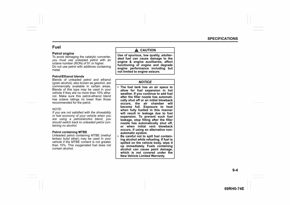
9-4
SPECIFICATIONS
69RH0-74E
Fuel
Petrol engineTo avoid damaging the catalytic converter,you must use unleaded petrol with anoctane number (RON) of 91 or higher.Do not use petrol with additives containingmetal.
Petrol/Ethanol blendsBlends of unleaded petrol and ethanol(grain alcohol), also known as gasohol, arecommercially available in certain areas.Blends of this type may be used in yourvehicle if they are no more than 10% etha-nol. Make sure this petrol-ethanol blendhas octane ratings no lower than thoserecommended for the petrol.
NOTE:If you are not satisfied with the driveabilityor fuel economy of your vehicle when youare using a petrol/alcohol blend, youshould switch back to unleaded petrol con-taining no alcohol.
Petrol containing MTBEUnleaded petrol containing MTBE (methyltertiary butyl ether) may be used in yourvehicle if the MTBE content is not greaterthan 15%. This oxygenated fuel does notcontain alcohol.
CAUTION
Use of spurious, low quality, adulter-ated fuel can cause damage to theengine & engine auxilliaries, affectfunctioning of engine and degradeengine performance including butnot limited to engine seizure.
NOTICE
• The fuel tank has an air space toallow for fuel expansion in hotweather. If you continue to add fuelafter the filler nozzle has automati-cally shut off or an initial blowbackoccurs, the air chamber willbecome full. Exposure to heatwhen fully fuelled in this mannerwill result in leakage due to fuelexpansion. To prevent such fuelleakage, stop filling after the fillernozzle has automatically shut off,or when initial vent blowbackoccurs, if using an alternative non-automatic system.
• Be careful not to spill fuel contain-ing alcohol while refueling. If fuel isspilled on the vehicle body, wipe itup immediately. Fuels containingalcohol can cause paint damage,which is not covered under theNew Vehicle Limited Warranty.
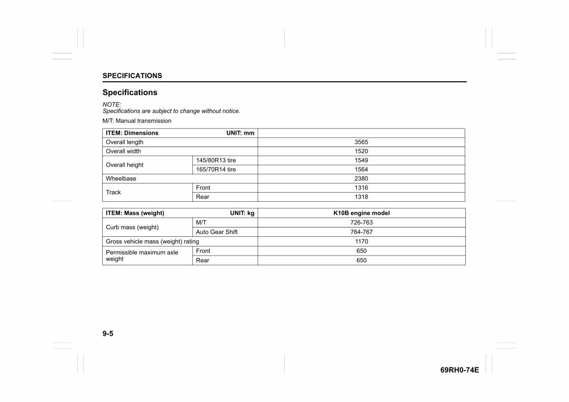
9-5
SPECIFICATIONS
69RH0-74E
Specifications
NOTE:Specifications are subject to change without notice.
M/T: Manual transmission
ITEM: Dimensions UNIT: mm
Overall length 3565
Overall width 1520
Overall height145/80R13 tire 1549
165/70R14 tire 1564
Wheelbase 2380
TrackFront 1316
Rear 1318
ITEM: Mass (weight) UNIT: kg K10B engine model
Curb mass (weight)M/T 726-763
Auto Gear Shift 764-767
Gross vehicle mass (weight) rating 1170
Permissible maximum axle weight
Front 650
Rear 650
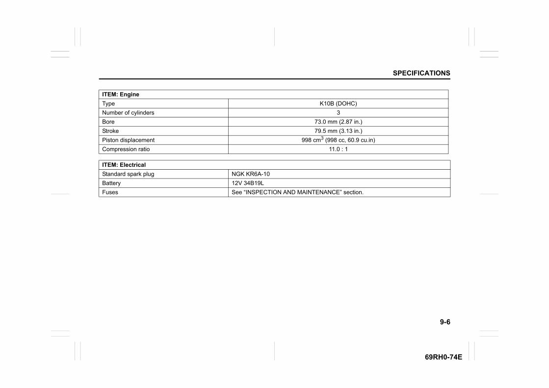
9-6
SPECIFICATIONS
69RH0-74E
ITEM: Engine
Type K10B (DOHC)
Number of cylinders 3
Bore 73.0 mm (2.87 in.)
Stroke 79.5 mm (3.13 in.)
Piston displacement 998 cm3 (998 cc, 60.9 cu.in)
Compression ratio 11.0 : 1
ITEM: Electrical
Standard spark plug NGK KR6A-10
Battery 12V 34B19L
Fuses See “INSPECTION AND MAINTENANCE” section.

9-7
SPECIFICATIONS
69RH0-74E
* If you cannot prepare tires with the specified load index rate and speed symbol, prepare tires with higher load index rate and speedsymbol.
**: The provision of different spare wheel is as per government notification/regulation (MORTH notification vide GSR 625 (E)).
ITEM: Lights WATTAGE BULB No.
Headlight 12V 60/55W H4
Position light 12V 5W W5W
Turn signal lightFront 12V 21W PY21W
Rear 12V 21W PY21W
Side turn signal light 12V 5W W5W
Tail/brake light 12V 21/5W P21/5W
High-mount stop light 12V 16W W16W
Reversing light 12V 21W P21W
License plate light 12V 5W W5W
Interior light 12V 10W C10W
ITEM: Wheels and tires
Tire size (front, rear and spare) 145/80R13 75S*,145/80R13 75T*,165/70R14 81S*
Rim size 145/80R13 tire: 13×4B165/70R14 tire: 14×5J
Tire size, spare**
For vehicle equipped with 145/80R13 tire 145/80R13 (Steel Wheel)
For vehicle equipped with 165/70R14 tire 165/70R14 (Steel Wheel)
Tire pressures For the specified tire pressure, see the tire information label located on thedriver’s door lock pillar.
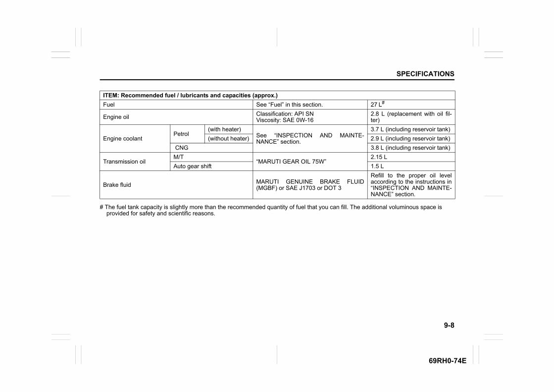
9-8
SPECIFICATIONS
69RH0-74E
# The fuel tank capacity is slightly more than the recommended quantity of fuel that you can fill. The additional voluminous space is provided for safety and scientific reasons.
ITEM: Recommended fuel / lubricants and capacities (approx.)
Fuel See “Fuel” in this section. 27 L#
Engine oil Classification: API SNViscosity: SAE 0W-16
2.8 L (replacement with oil fil-ter)
Engine coolantPetrol
(with heater)See “INSPECTION AND MAINTE-NANCE” section.
3.7 L (including reservoir tank)
(without heater) 2.9 L (including reservoir tank)
CNG 3.8 L (including reservoir tank)
Transmission oilM/T
“MARUTI GEAR OIL 75W”2.15 L
Auto gear shift 1.5 L
Brake fluid MARUTI GENUINE BRAKE FLUID(MGBF) or SAE J1703 or DOT 3
Refill to the proper oil levelaccording to the instructions in“INSPECTION AND MAINTE-NANCE” section.
9-9
SPECIFICATIONS
69RH0-74E
MEMO