Toyota RAV4 1994-2000 Foreword
71
Manual Name Pub. No. S 3S-FE Engine Repair Manual S TOYOTA RAV4 Chassis and Body Repair Manual S TOYOTA RAV4 Chassis and Body Repair Manual Supplement S TOYOTA RAV4 Electrical Wiring Diagram S TOYOTA RAV4 Electrical Wiring Diagram Supplement S TOYOTA RAV4 New Car Features S TOYOTA RAV4 Repair Manual For Collision Damage S Fundamental Painting Procedures S Fundamental Body Repair Procedures BRM024E BRM002E NCF108E BRM045E EWD234F EWD206Y RM454E RM395E FOREWORD This repair manual has been prepared to provide essential information on body panel repair methods (including cutting and welding operations, but excluding painting) for the TOYOTA RAV4 5-DOOR. Applicable models: SXA11 series This manual consists of body repair methods, exploded dia- grams and illustrations of the body components and other information relating to body panel replacement such as han- dling precautions, etc. However, it should be noted that the front fenders of the TOYOTA model is bolted on and require no welding. When repairing, don’t cut and join areas that are not shown in this manual. Only work on the specified contents to maintain body strength. Body construction will sometimes differ depending on specifi- cations and country of destination. Therefore, please keep in mind that the information contained herein is based on ve- hicles for general destinations. For the repair procedures and specifications other than colli- sion-damaged body components of the TOYOTA RAV 4 5-DOOR refer to the following repair manuals. If you require the above manuals, please contact your TO- YOTA Dealer. All information contained in this manual is the most up-to- date at the time of publication. However, specifications and procedures are subject to change without prior notice. TOYOTA MOTOR CORPORATION RM401E
-
Upload
radiocacat -
Category
Documents
-
view
0 -
download
0
Transcript of Toyota RAV4 1994-2000 Foreword

Manual Name Pub. No.
� 3S−FE Engine Repair Manual� TOYOTA RAV4 Chassis and Body Repair
Manual� TOYOTA RAV4 Chassis and Body Repair
Manual Supplement� TOYOTA RAV4 Electrical Wiring
Diagram� TOYOTA RAV4 Electrical Wiring
Diagram Supplement� TOYOTA RAV4 New Car Features� TOYOTA RAV4 Repair Manual
For Collision Damage� Fundamental Painting Procedures� Fundamental Body Repair Procedures
BRM024EBRM002E
NCF108EBRM045E
EWD234F
EWD206Y
RM454E
RM395E
FOREWORD
This repair manual has been prepared to provide essentialinformation on body panel repair methods (including cuttingand welding operations, but excluding painting) for theTOYOTA RAV4 5−DOOR.
Applicable models: SXA11 series
This manual consists of body repair methods, exploded dia-grams and illustrations of the body components and otherinformation relating to body panel replacement such as han-dling precautions, etc. However, it should be noted that thefront fenders of the TOYOTA model is bolted on and requireno welding.
When repairing, don’t cut and join areas that are not shown inthis manual. Only work on the specified contents to maintainbody strength.
Body construction will sometimes differ depending on specifi-cations and country of destination. Therefore, please keep inmind that the information contained herein is based on ve-hicles for general destinations.
For the repair procedures and specifications other than colli-sion−damaged body components of the TOYOTA RAV 45−DOOR refer to the following repair manuals.
If you require the above manuals, please contact your TO-YOTA Dealer.
All information contained in this manual is the most up−to−date at the time of publication. However, specifications andprocedures are subject to change without prior notice.
TOYOTA MOTOR CORPORATION
RM401E
mm in.
150250
5.919.84
QUARTER PANEL (CUT)
QUARTER PANEL
RH:LH:
1. Cut and join the parts at the location shown above.
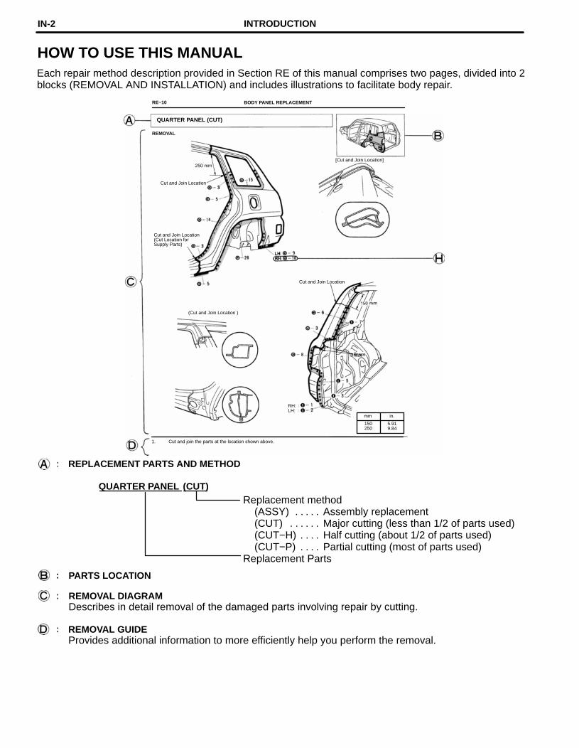
HOW TO USE THIS MANUALEach repair method description provided in Section RE of this manual comprises two pages, divided into 2blocks (REMOVAL AND INSTALLATION) and includes illustrations to facilitate body repair.
RE−10 BODY PANEL REPLACEMENT
REMOVAL
[Cut and Join Location]250 mm
Cut and Join Location
Cut and Join Location(Cut Location forSupply Parts)
Cut and Join Location
(Cut and Join Location )
Braze
REPLACEMENT PARTS AND METHOD
(CUT)Replacement method
(ASSY) Assembly replacement. . . . . (CUT) Major cutting (less than 1/2 of parts used). . . . . . (CUT−H) Half cutting (about 1/2 of parts used). . . . (CUT−P) Partial cutting (most of parts used). . . .
Replacement Parts
PARTS LOCATION
REMOVAL DIAGRAMDescribes in detail removal of the damaged parts involving repair by cutting.
REMOVAL GUIDEProvides additional information to more efficiently help you perform the removal.
INTRODUCTIONIN-2

mm in.
5 0.20
1. Before temporarily installing the new parts, applybody sealer to the wheel arch.
HINT:
1) Apply body sealer about 5 mm (0.20in.) from theflange, avoiding any oozing.
2) Apply sealer evenly, about 3 − 4 mm (0. 12 −0.16in.) in diameter.
3) For other sealing points, refer to section AR.
SYMBOLSSee page IN−4.
RH:LH:
BODY PANEL REPLACEMENT RE−11
INSTALLATION
Butt Weld
Body Sealer
Butt Weld
Butt weld
Body sealerBraze
about 5 mm
RH:LH:
2. Temporarily install the new parts and check the fitof the rear door, back door and rear combinationlight.
INSTALLATION DIAGRAMDescribes in detail installation of the new parts involving repair by welding and/or cutting, but ex-cluding painting.
INSTALLATION GUIDEProvides additional information to more efficiently help you perform the installation.
ILLUSTRATION OF WELD POINTSWeld method and panel position symbols.See page IN−5.
INTRODUCTION IN-3

SYMBOLS MEANING ILLUSTRATION
SAW CUT ORROUGH CUT
REMOVE BRAZE
(See page IN−5)
SPOT WELD ORMIG PLUG WELD
WELD POINTS
BRAZE
CONTINUOUS MIGWELD (BUTT WELDOR TACK WELD)
BODY SEALER
SYMBOLSThe following symbols are used in the Welding Diagrams in Section RE of this manual to indicate cuttingareas and the types of weld required.
INTRODUCTIONIN-4
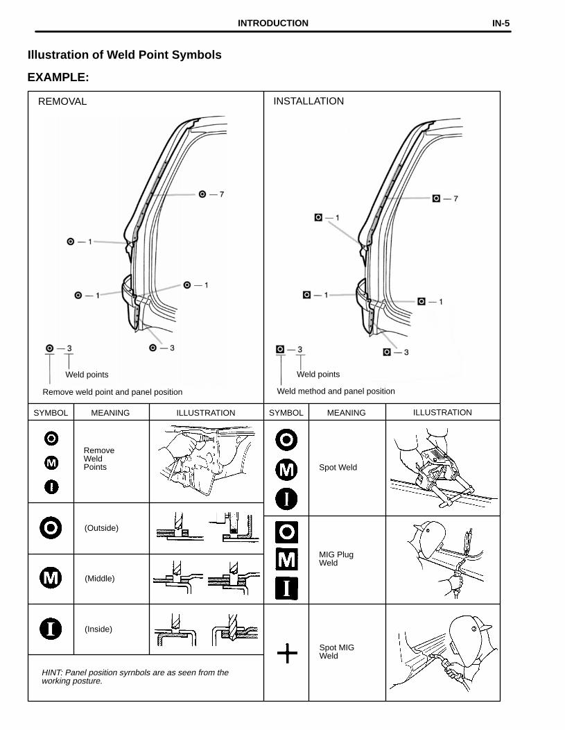
Remove weld point and panel position
Weld points
REMOVAL
Weld method and panel position
Weld points
INSTALLATION
SYMBOL MEANING ILLUSTRATION SYMBOL
Spot Weld
MEANING ILLUSTRATION
RemoveWeldPoints
(Outside)
MIG PlugWeld
(Middle)
(Inside)
Spot MIGWeld
HINT: Panel position syrnbols are as seen from theworking posture.
Illustration of Weld Point Symbols
EXAMPLE:
INTRODUCTION IN-5
Airbag SensorInflator
Sensor Lock Release Bolt Bag Steering Wheel PadSteering Wheel
Bolt Cap
Airbag Sensor
Inflator
Bag
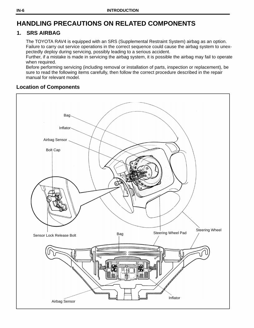
HANDLING PRECAUTIONS ON RELATED COMPONENTS1. SRS AIRBAG
The TOYOTA RAV4 is equipped with an SRS (Supplemental Restraint System) airbag as an option.Failure to carry out service operations in the correct sequence could cause the airbag system to unex-pectedly deploy during servicing, possibly leading to a serious accident.Further, if a mistake is made in servicing the airbag system, it is possible the airbag may fail to operatewhen required.Before performing servicing (including removal or installation of parts, inspection or replacement), besure to read the following items carefully, then follow the correct procedure described in the repairmanual for relevant model.
Location of Components
INTRODUCTIONIN-6

Component to be aligned Section of repair manual for relevant model
Front Wheels Suspension and Axle (SA) section
Rear Wheels Suspension and Axle (SA) section
1. Never disassemble the steering wheel pad assembly.
2. Do not subject the steering wheel pad to shocks or bring magnets close to it.
3. Do not expose the steering wheel pad to high temperatures or fire.
4. If grease, cleaner, oil or water gets on the steering wheel pad, promptly wipe it off with a dry cloth.
5. Do not drop the steering wheel pad. Never use a steering wheel pad which has been dropped.
6. Never install the steering wheel and pad in another vehicle.
7. When the steering wheel pad is removed, store it on a stable, flat place with the pad surface facing up-wards. Never place anything on top of the pad.
8. When work on the vehicle will produce too strong a shock, first loosen the sensor lock release bolt untilit turns freely and perform the work after sensor lock occurs.
9. Even in cases where the vehicle is in a low−impact accident where the airbag is not activated, alwayscheck the pad surface and airbag sensor part. If dents, cracks or deformation is visible, replace the air-bag with a new assembly.
10. When disposing of the vehicle or steering wheel, always deploy the airbag first.
11. The deployed inflator inside the steering wheel pad is hot, so dispose of it after it has been cooled byatmospheric air. Never apply water to cool it down.
2. BRAKE SYSTEM
The brake system is one of the most important safety components. Always follow the directions andnotes given in section BR of the repair manual for the relevant model year when handling brake systemparts.
3. DRIVE TRAIN AND CHASSISThe drive train and chassis are components that can have great effects on the running performanceand vibration resistance of the vehicle. After installing components in the sections listed in the tablebelow, perform alignments to ensure correct mounting angles and dimensions. Particularly accuraterepair of the body must also be done to ensure correct alignment.HINT: Correct procedures and special tools are required for alignment. Always follow the directionsgiven in the repair manual for the relevant model during alignment and section DI of this manual.
INTRODUCTION IN-7
Fuse Block
Engine ECU
R/B No. 5
J/B No. 1
J/B No. 4ABS ECU
Daytime RunningLight Relay (*1)
Door Look Control Relay
A/C Amplifier
J/B No. 3
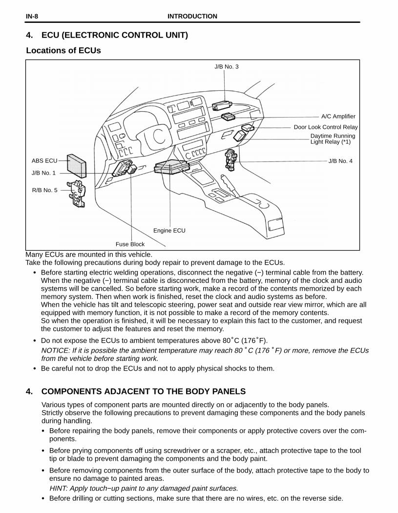
4. ECU (ELECTRONIC CONTROL UNIT)
Locations of ECUs
Many ECUs are mounted in this vehicle.Take the following precautions during body repair to prevent damage to the ECUs.
� Before starting electric welding operations, disconnect the negative (−) terminal cable from the battery.When the negative (−) terminal cable is disconnected from the battery, memory of the clock and audiosystems will be cancelled. So before starting work, make a record of the contents memorized by eachmemory system. Then when work is finished, reset the clock and audio systems as before.When the vehicle has tilt and telescopic steering, power seat and outside rear view mirror, which are allequipped with memory function, it is not possible to make a record of the memory contents.So when the operation is finished, it will be necessary to explain this fact to the customer, and requestthe customer to adjust the features and reset the memory.
� Do not expose the ECUs to ambient temperatures above 80°C (176°F).NOTICE: If it is possible the ambient temperature may reach 80 °C (176 °F) or more, remove the ECUsfrom the vehicle before starting work.
� Be careful not to drop the ECUs and not to apply physical shocks to them.
4. COMPONENTS ADJACENT TO THE BODY PANELS
Various types of component parts are mounted directly on or adjacently to the body panels.Strictly observe the following precautions to prevent damaging these components and the body panelsduring handling.� Before repairing the body panels, remove their components or apply protective covers over the com-
ponents.
� Before prying components off using screwdriver or a scraper, etc., attach protective tape to the tooltip or blade to prevent damaging the components and the body paint.
� Before removing components from the outer surface of the body, attach protective tape to the body toensure no damage to painted areas.HINT: Apply touch−up paint to any damaged paint surfaces.
� Before drilling or cutting sections, make sure that there are no wires, etc. on the reverse side.
INTRODUCTIONIN-8

GENERAL REPAIR INSTRUCTIONSWork Precautions
VEHICLE PROTECTIONWhen welding, protect thepainted surfaces, windows,seats and carpet with heat−resistant, fire−proof covers.
SAFETYNever stand in direct linewith the chain when usinga puller on the body orframe, and be sure to attach a safety cable.
SAFETY1. Before performing repair work, check
for fuel leaks. If a leak is found, be sureto close the opening totally.
2. If it is necessary to use a frame in thearea of the fuel tank, first remove thetank and plug the fuel line.
WRONG
Glass Cover
Safety Cable
Seat Cover
WRONG HAND TOOLSKeeping your hand toolsin neat order improveyour work efficiency.
SAFETY WORK CLOTHESIn addition to the usual mechanic’s wear, cap and safety shoes,the appropriate gloves, head protector, glasses, ear plugs, faceprotector, dust−prevention mask, etc. should be worn as thesituation demands.Dust−PreventionMask
Welder’sGlasses
EarPlugsFace
ProtectorBodyToolsStand
HeadProtectorEye
Protector
Welder’sGloves
SafetyShoes
INTRODUCTION IN-9

Proper and Efficient Work Procedures
REMOVAL
NUMBER OF SPOT WELDS AND PANEL POSITIONSThe number of spot welds and the panel positions to be removed are shown for your reference.HINT: See ”Symbols” on page IN−4, 5.
PRE−REMOVAL MEASURINGBefore removal or cutting opera-tions, take measurements in ac-cordance with the dimension dia-gram. Always use a puller tostraighten a damaged body orframe.
REMOVAL OF ADJACENT COMPONENTSWhen removing adjacent components, applyprotective tape to the surrounding body andyour tools to prevent damage.HINT: See ”Handling Precautions onRelated Components” on page IN−6.
CUTTING AREAAlways cut in a straightline and avoid reinforced area.
PRECAUTIONS FOR DRILLING ORCUTTINGCheck behind any area to be drilled orcut to insure that there are no hoses,wires, etc., that may be damaged.HINT: See ”Handling Precautions on Related Components” on page IN−6.
Cutting Okay
CornersReinforcement
WRONG
INTRODUCTIONIN-10
Thickness ofwelded portion Size of plug hole
1.0 (0.04) under 5 (0.20) φ over
1.0 (0.04) − 1.5 (0.06) 6.5 (0.26) φ over
1.5 (0.06) over 8 (0.31) φ over
REFERENCE: mm (in.)
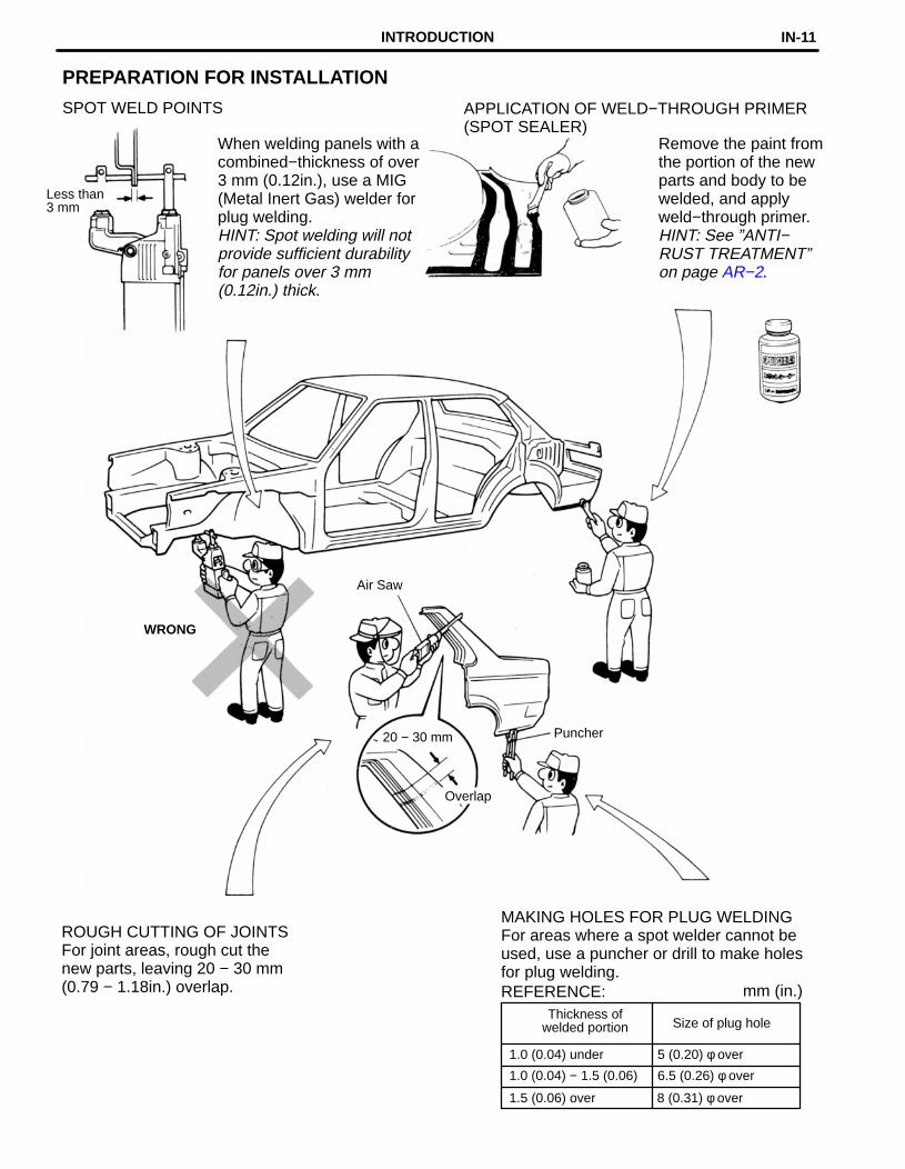
PREPARATION FOR INSTALLATION
SPOT WELD POINTS APPLICATION OF WELD−THROUGH PRIMER(SPOT SEALER)
When welding panels with acombined−thickness of over3 mm (0.12in.), use a MIG(Metal Inert Gas) welder forplug welding.HINT: Spot welding will notprovide sufficient durabilityfor panels over 3 mm(0.12in.) thick.
Less than3 mm
Remove the paint fromthe portion of the newparts and body to bewelded, and applyweld−through primer.HINT: See ”ANTI−RUST TREATMENT”on page AR−2.
Air Saw
WRONG
Puncher20 − 30 mm
Overlap
ROUGH CUTTING OF JOINTSFor joint areas, rough cut thenew parts, leaving 20 − 30 mm(0.79 − 1.18in.) overlap.
MAKING HOLES FOR PLUG WELDINGFor areas where a spot welder cannot beused, use a puncher or drill to make holesfor plug welding.
INTRODUCTION IN-11

New SpotLocations
POST−WELDING REFINISHING1. Always check the welded
spots to insure they are secure.
2. When smoothing out theweld spots with a discgrinder, be careful not togrind off too much as thiswould weaken the weld.
INSTALLATION
PRE−WELDING MEASUREMENTSAlways take measurements before installing underbody or engine components to insure correct assembly. After installation,confirm proper fit.
WELDING PRECAUTIONS1. The number of welding spots
should be as follows.Spot weld: 1.3 × No. ofmanufacturer‘s spots.Plug weld: More than No. of manufacturer’s plugs.
WRONG
WRONGOKAY2. Plug welding should be donewith a MIG (Metal Inert Gas)welder. Do not gas weld orbraze panels at areas otherthan specified.
Safety Glass
BodyMeasurementDiagrams
SPOT WELDING PRECAUTIONS1. The shape of the welding tip
point has an effect on thestrength of the weld.
2. Always insure that the seams and welding tip arefree of paint.
SPOT WELD LOCATIONSTry to avoid welding overprevious spots.
OldSpotLocations
Tip Cutter
INTRODUCTIONIN-12

ANTI−RUST TREATMENT
When replacing body panels, always apply body sealer, anti−rust agent or undercoat according to the re-quirements of your country.HINT: For further details, see the description given in Section AR of this manual.
BODY SEALERApply body sealer to therequired areas.
ANTI−RUST AGENT (WAX)Apply anti−rust agent to following sections.� Inside of the hems of the
doors and hood.
� Around the hinges of thedoors and hood.
� Inside of the welded partswith boxed cross−section.
Cartridge Type Tube Type
UNDERCOATApply undercoat to the underbody andwheel housings.
Spray GunUndercoating(Oil base)
Undercoating(Water base)
INTRODUCTION IN-13

SUPPORT POSITION
PANTOGRAPH JACK POSITION
CAUTION: Before jacking−up the rear and front, make sure the car is not carrying any extra weight.
Front Front crossmember. . . . . . . . Rear Rear axle beam. . . . . . . .
JACK POSITION
Front
VEHICLE LIFT AND SUPPORT LOCATIONS
Safety stand and swing arm type lift . . . . . . . . . . . . . . . . . . . . . . . . . . . . .
INTRODUCTIONIN-14

ABS Antilock Brake System
A/C Air Conditioner
assy assembly
ECT Electronic Controlled Transmission
ECU Electronic Control Unit
e.g. Exempli Gratia (for Example)
Ex. Except
FWD Front Wheel Drive Vehicles
4WD Four Wheel Drive Vehicles
in. inch
LH Left−hand
LHD Left−hand Drive
MIG Metal Inert Gas
M/Y Model Year
PPS Progressive Power Steering
RH Right−hand
RHD Right−hand Drive
SRS Supplemental Restraint System
w/ with
w/o without
ABBREVIATIONS USED IN THIS MANUALFor convenience, the following abbreviations are used in thismanual.
INTRODUCTION IN-15

GENERAL INFORMATION1. BASIC DIMENSIONS
(a) There are two types of dimensions in the diagram.(Three−dimensional distance)
� Straight−line distance between the centers of twomeasuring points.
(Two−dimensional distance)� Horizontal distance in forward/rearward between
the centers of two measuring points.
� The height from an imaginary standard line.
(b) In cases in which only one dimension is given, leftand right are symmetrical.
(c) The dimensions in the following drawing indicateactual distance. Therefore, please use the dimen-sions as a reference.
2. MEASURING(a) Basically, all measurements are to be done with a
tracking gauge. For portions where it is not possibleto use a tracking gauge, a tape measure should beused.
(b) Use only a tracking gauge that has no looseness inthe body, measuring plate, or pointers.
HINT:1. The height of the left and right pointers must be equal.
2. Always calibrate the tracking gauge before measuring orafter adjusting the pointer height.
3. Take care not to drop the tracking gauge or otherwiseshock it.
4. Confirm that the pointers are securely in the holes.
(c) When using a tape measure, avoid twists andbends in the tape.
(d) When tracking a diagonal measurement from thefront spring support inner hole to the suspensionmember upper rear installation hole, measurealong the front spring support panel surface.
Center−to−centerstraight−linedistance
Three−dimensionaldistance
Front Spring Support Inner Hole
Tape Measure
Along BodySurface
Front Suspension Member Rear SideUpper Installation Hole
Master Gauge
PointerPointer Looseness
Body LoosenessPlate Looseness
Two−dimensionaldistance
Center−to−centerHorizontal distance inforward/rearward
Vertical distancein lower surface
Vertical distancein center
Imaginary Standard Line
Wrong Correct
Pointer
BODY DIMENSIONSDI-2

HINT: For symbols, capital letters indicate right side of vehicle,small letters indicate left side of vehicle (Seen from rear).
K−k
1386(54.57)
552(21.73)
C−Korc−k
1494(58.82)
C−korc−K
(Three−D
imensional D
istance)
mm (in.)
Hole dia.
6 (0.24) nut
10 (0.39)
10 (0.39)
6 (0.24) nut
10 (0.39)
Name
Cooler condenser installation nut
Radiator support extension standard hole
Radiator support standard hole
Front bumper support installation nut
Front apron to cowl side member standard hole
Symbol
G, g
H, h
I, i
J
K, k
Hole dia.
6 (0.24) nut
11 (0.43)
6 (0.24) nut
13 (0.51)
18 (0.71)
Name
Front fender installation nut
Front spring support hole − inner
Front fender installation nut
Cowl top panel center mark
Front side member standard hole
Front side member standard hole
Symbol
A, a
B, b
C, c
D, d
E, e
F, f
BO
DY
DIM
EN
SIO
N D
RA
WIN
GS
EN
GIN
E C
OM
PAR
TM
EN
T
BO
DY
DIM
EN
SIO
NS
DI-3

1,140(44.88)
E−e
1,302(51.26)
F−f
Vehicle Dimensions Left ↔ Right
1,388(54.65)
G−g H−h
1,388(54.65)
I−i
1,388(54.65)
1,044(41.10)
J−j
1,188(46.77)
K−k
1,403(55.24)
L−l
1,541(60.67)
E−gore−G
1,586(62.44)
E−iore−I
E−kore−K
1,289(50.75)
1,754(69.06)
G−korg−K
1,585(62.40)
G−lorg−L
H−qorh−Q
1,628(64.09)
I−jori−J
1,626(64.02)
J−rorj−R
1,169(46.02)
1,497(58.94)
HINT: For symbols, capital letters indicate right side of vehicle,small letters indicate left side of vehicle (Seen from rear.)
K−lork−L
(Three−D
imensional D
istance)
mm (in.)
Hole dia.
13 (0.51)
13 (0.51)
Name
Rocker panel assembly mark
Rocker panel assembly mark
Roof side rail assembly mark
Center body pillar assembly mark
Center body pillar assembly mark
Rear door hinge installation hole
Rear door hinge installation hole
Symbol
H, h
I, i
J, j
K, k
L, l
M, m
N, n
Hole dia.
8 (0.31) nut
8 (0.31) nut
Name
Roof panel / front body pillar adjoining portion
Cowl top outer panel outside radius corner
Front door hinge installation nut
Front door hinge installation nut
Front body pillar assembly mark
Front body pillar assembly mark
Front body pillar assembly mark
Symbol
A, a
B, b
C, c
D, d
E, e
F, f
G, g
BO
DY
OP
EN
ING
AR
EA
S (S
ide View
−Front)
BO
DY
DIM
EN
SIO
NS
DI-4

Vehicle Dimensions Left ↔ Right
O−o
1,188(46.77)
P−p
1,388(54.66)
1,388(54.66)
Q−q R−r
1,049(41.30)
S−s
1,202(47.32)
1,404(55.28)
T−t
1,374(54.09)
O−soro−S
O−toro−T
1,541(60.67)
1,463(57.60)
P−torp−T
1,639(64.53)
Q−rorq−R
1,525(60.04)
S−tors−T
HINT: For symbols, capital letters indicate right side of vehicle,small letters indicate left side of vehicle (Seen from rear.)
mm (in.)
(Three−D
imensional D
istance)
Hole dia.Name
Roof side rail assembly mark
Quarter panel assembly mark
Quarter panel assembly mark
Symbol
R, r
S, s
T, t
Hole dia.Name
Center body pillar assembly mark
Center body pillar assembly mark
Rocker panel assembly mark
Symbol
O, o
P, p
Q, q
BO
DY
OP
EN
ING
AR
EA
S (S
ide View
−Rear)
BO
DY
DIM
EN
SIO
NS
DI-5
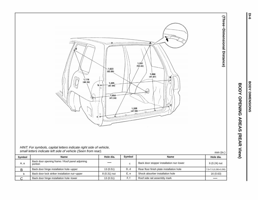
HINT: For symbols, capital letters indicate right side of vehicle,small letters indicate left side of vehicle (Seen from rear). mm (in.)
(Three−D
imensional D
istance)
Hole dia.
6 (0.24) nut
7.5×7.5 (0.295×0.295)
16 (0.63)
Name
Back door stopper installation nut−lower
Rear floor finish plate installation hole
Shock absorber installation hole
Roof side rail assembly mark
Symbol
c
D, d
E, e
F, f
Hole dia.
13 (0.51)
8 (0.31) nut
13 (0.51)
Name
Back door opening frame / Roof panel adjoiningportion
Back door hinge installation hole−upperBBack door lock striker installation nut−upper
C Back door hinge installation hole−lower
Symbol
A, a
b
BO
DY
OP
EN
ING
AR
EA
S (R
EA
R V
iew)
BO
DY
DIM
EN
SIO
NS
DI-6

HINT: For symbols, capital letters indicate right side of vehicle,small letters indicate left side of vehicle (Seen from rear).
(Two−D
imensional D
istance)
mm (in.)
Hole dia.
18 (0.71)
18 (0.71)
34×17.5 (1.34×0.689)
12.5 (0.492)
12.5 (4.492)
10 (0.39)
18 (0.71)
Name
Front floor under reinforcement standard hole
Rear floor side member standard hole
Strut bar installation hole−inner
Rear suspension member installation nut
Rear floor crossmember working hole No. 3
Rear floor crossmember standard hole
Rear side member standard hole
Symbol
G, g
H, h
I, i
J, j
K, k
L, l
M, m
Hole dia.
8 (0.31) nut
18 (0.71)
10 (0.39) nut
12 (0.47) nut
14 (0.55) nut
12 (0.47) nut
18 (0.71)
Name
Engine mounting member installation nut
Front side member standard hole
Engine mount installation nut−front
Engine mount installation nut
Front suspension crossmember installation nut
Front suspension crossmember installation nut−outer
Front floor under reinforcement standard hole
Symbol
A, a
B, b
C
c
D, d
E, e
F, f
UN
DE
R B
OD
Y
BO
DY
DIM
EN
SIO
NS
DI-7

Wheel Base 2,410 (94.88)
ImaginaryStandardLine
mm (in.)
(Two−D
imensional D
istance)
Hole dia.
10 (0.39) nut
18 (0.71)
18 (0.71)39×17.5 (1.34×0.689)
12.5 (0.492)
12.5 (0.492)
10 (0.39)
18 (0.71)
Name
Propeller shaft center support bearing installation nut
Front floor under reinforcement standard hole
Rear floor side member standard hole
Strut bar installation hole−inner
Rear suspension member installation nut
Rear floor crossmember working hole No. 3
Rear floor crossmember standard hole
Rear side member standard hole
Symbol
H, h
I, i
J, j
K, k
L, l
M, rn
N, n
O, o
Hole dia.
8 (0.31) nut
18 (0.71)
10 (0.39) nut
12 (0.47) nut
11 (0.43)
14 (0.55) nut
12 (0.47) nut
18 (0.71)
Name
Engine mounting member installation nut
Front side member standard hole
Engine mount installation nut−front
Engine mount installation nut
Front spring support hole−outer
Front suspension crossmember installation nut
Front suspension crossmember installation nut−outer
Front floor under reinforcement standard hole
Symbol
A, a
B, b
C
c
D, d
E, e
F, f
UN
DE
R B
OD
Y (C
ont’d)
G, g
BO
DY
DIM
EN
SIO
NS
DI-8

GENERAL INFORMATIONAnti−rust treatment is necessary before welding and before and after the painting process.
ANTI−RUST TREATMENT BEFORE WELDINGWeld−Through Primer(Spot Sealer)1. WELD−THROUGH PRIMER (SPOT SEALER) APPLICATION
For anti−corrosion measures, always apply the weld−through primer (spot sealer) to welding surfaces where the paint film has been removed.HINT: Apply the weld−through primer (spot sealer) so that it does not ooze out from the joining surfaces.
WELD−THROUGH PRIMER (SPOT SEALER)APPLICATION
ANTI−RUST TREATMENT BEFORE PAINTING PROCESS
Sealer Gum1. BODY SEALER APPLICATIONFor water−proofing and anti−corrosion measures,always apply the body sealer to the body panelseams and hems of the doors, hoods, etc.
BODY SEALER APPLICATION
2. UNDERCOAT APPLICATIONTo prevent corrosion and protect the body fromdamage by flying stones, always apply sufficientundercoat to the bottom surface of the under bodyand inside of the wheel housings.
UNDERCOAT APPLICATION
ANTI−RUST TREATMENTAR-2
Steel Metal
Undercoat (ED Primer)
Anti−Chipping Paint
Second Coat
Steel Metal
Undercoat (ED Primer)Second CoatTop Coat
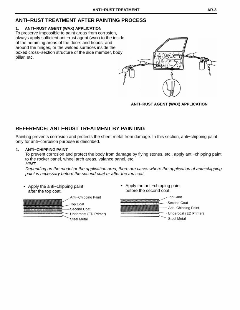
ANTI−RUST TREATMENT AFTER PAINTING PROCESS
1. ANTI−RUST AGENT (WAX) APPLICATIONTo preserve impossible to paint areas from corrosion,always apply sufficient anti−rust agent (wax) to the insideof the hemming areas of the doors and hoods, andaround the hinges, or the welded surfaces inside theboxed cross−section structure of the side member, bodypillar, etc.
ANTI−RUST AGENT (WAX) APPLICATION
REFERENCE: ANTI−RUST TREATMENT BY PAINTING
Painting prevents corrosion and protects the sheet metal from damage. In this section, anti−chipping paintonly for anti−corrosion purpose is described.
1. ANTI−CHIPPING PAINTTo prevent corrosion and protect the body from damage by flying stones, etc., apply anti−chipping paintto the rocker panel, wheel arch areas, valance panel, etc.HINT:Depending on the model or the application area, there are cases where the application of anti−chippingpaint is necessary before the second coat or after the top coat.
� Apply the anti−chipping paintbefore the second coat.
� Apply the anti−chipping paintafter the top coat.
Anti−Chipping Paint Top Coat
ANTI−RUST TREATMENT AR-3

BODY PANEL SEALING AREASHINT:1. Prior to applying body sealer, clean the area with a rag soaked in a grease, wax and silicone remover.
2. If weld−through primer was used, first wipe off any excess and coat with anti−corrosion primer beforeapplying body sealer.
3. Wipe off excess body sealer with a rag soaked in a grease, wax and silicone remover.
4. If body sealer is damaged by peeling, cracks, etc., be sure to repair as necessary.
Flat Surfacing
Flat Surfacing
ANTI−RUST TREATMENTAR-4

Flat Surfacing
Flat Surfacing
Flat Surfacing
ANTI−RUST TREATMENT AR-5

Flat Surfacing
Flat Surfacing
Flat Surfacing
ANTI−RUST TREATMENTAR-6
Flat SurfacingFlat Surfacing
Flat Surfacing
Flat Surfacing
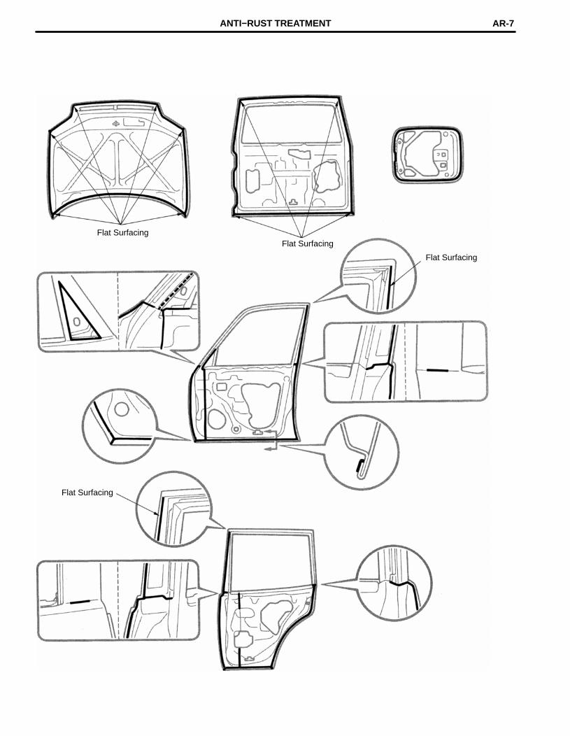
ANTI−RUST TREATMENT AR-7

BODY PANEL ANTI−RUST AGENT (WAX) APPLICATION AREASHINT:1. Whenever adjusting the doors and hoods, apply anti−rust agent (wax) around the hinges.
2. Even if partially repairing a part, apply anti−rust agent (wax) over the entire application area of the part.
3. Wipe off the anti−rust agent immediately with a rag soaked in a grease, wax and silicone remover, ifaccidently applied to other areas.
Fuel Filler Opening Rid Hinge
Hood Hinge
Back Door
Hood DoorDoor Hinge
ANTI−RUST TREATMENT AR-9

BODY PANEL UNDERCOATING AREASHINT:1. First wipe off any dirt, grease or oil with a rag soaked in a grease, wax and silicone remover.
2. Cover the surrounding areas with masking paper to avoid coating unnecessary areas. If other areas areaccidently coated, wipe off the coating immediately.
3. Apply the first coating of undercoat to all welded areas and panel joints, then apply a second coat overthe entire area.
4. Do not coat parts which become hot, such as the tailpipe, or moving parts, such as the propeller shaft.
5. Besides the locations described below, apply undercoating to all weld points under the body to insurecorrosion prevention.
6. Be sure to seal the edge of the flange of the member and bracket with undercoating.
7. If undercoat is damaged by peeling, cracks, etc., be sure to repair as necessary.
8. Before the undercoat apply sealer allowing rust prevention to be attained.
[Left Side]
[Right Side]
REFERENCE: Referring to the notes above, undercoating should be applied according to the specificationsfor your country.
ANTI−RUST TREATMENTAR-8

mm in.
1.14.25.35.56.36.47.27.9
0.0430.1650.2090.2130.2480.2520.2830.311
5.5 mm
5.3 mm
FIT STANDARDSAfter doors and the engine hood are installed, be sure to perform fit adjustment to prevent abnormal windnoise and ensure a good appearance.
4.2 mm
7.9 mm
5.5 mm
5.3 mm
6.3 mm
7.2 mm
1.1 mm
6.4 mm
mm (in.): Specified value
APPENDIXAP-2

FOAMED MATERIAL APPLICATION AREASThe sections shown in the figure below are filledwith foamed material to provide noise insulation.After repairing these sections or their peripheries,refill with foamed materials.HINT:1. Use the service holes located on the reverse
side of the body panel to refill with foamedmaterials.
2. When handling foamed material, follow thedirections of the material’s manufacturer.
APPENDIXAP-4

SILENCER SHEET INSTALLATION AREAS
Thickness of Asphalt Sheet
1.5 mm. . . . . . . . . . (0.059 in.)
1.5 mm. . . . . . . . . . (0.059 in.)
3.0 mm. . . . . . . . . . (0.118 in.)
APPENDIX AP-3

mm in
3080
1.183.15
CENTER BODY PILLAR (CUT)
REMOVAL
Cut and Join Location(Cut Location for Supply Parts)
[Cut and Join Location]
80 mm
30 mm
30 mm
Cut and Join Location
Cut and Join Location Cut and Join Location(Cut Location for Supply Parts)
[Cut and Join Location]
1. Cut and join the parts at the locations shownabove.
BODY PANEL REPLACEMENTRE-2

INSTALLATION
Butt Weld
Center Body Pillar Reinforcement
Center Body InnerPillar
Butt Weld
Butt Weld
Butt Weld
Butt Weld Butt Weld
2. Temporarily install the new parts and mea-sure each part in accordance with the bodydimension diagram.
3. Before welding the new parts, check the fit ofthe front door and rear door.
1. Before temporarily installing the new parts,weld the inner pillar and center pillar rein-forcement with standard points.
BODY PANEL REPLACEMENT RE-3

FRONT DOOR OUTER PANEL (ASSY)
REMOVAL
Positioning TapeBraze
BrazeInstallationPosition
Hemming Location
Disc Sander
2. After grinding off the hemming location, removethe outer panel.
1. Before removing the outer panel, make theinstallation position with a tape.
BODY PANEL REPLACEMENTRE-4

mm in.
10 0.39
INSTALLATION
Positioning Tape
Body sealerBraze
Braze
about 10mm
Do not close thedrain hole.
Body Sealer
Cloth Tape
30°
Hemming Tool
1. Before temporarily installing the new parts,apply body sealer to the side impact protec-tion beam and back side of the new parts.
HINT:1) Apply sealer evenly about 10 mm (0.39in.)
from the flange and 3mm (0.12in.) in diameterto the outer panel and apply just enough seal-er for the side impact protection beam tomake contact.
2) For other sealing points, refer to section AR.
2. Bend the flange hem about 30° with a ham-mer and dolly, then fasten tightly with a hem-ming tool.
HINT:1) Perform hemming in three steps, being careful
not to warp the panel.
2) If a hemming tool cannot be used, hem with ahammer and dolly.
BODY PANEL REPLACEMENT RE-5

REAR DOOR OUTER PANEL (ASSY)
REMOVAL
Positioning Tape Braze
BrazeInstallationPosition
Hemming Location
Disc Sander
2. After grinding off the hemming location, removethe outer panel.
1. Before removing the outer panel, make theinstallation position with a tape.
BODY PANEL REPLACEMENTRE-6

mm in.
10 0.39
INSTALLATION
Positioning TapeBraze
Braze
Body sealer
about 10mm
Do not close thedrain hole.
Body Sealer
Cloth Tape
30°
Hemming Tool
1. Before temporarily installing the new parts,apply body sealer to the side impact protec-tion beam and back side of the new parts.
HINT:1) Apply sealer evenly about l0 mm (0.39in.)
from the flange and 3mm (0.12in.) in diameterto the outer panel and apply just enough seal-er for the side impact protection beam tomake contact.
2) For other sealing points, refer to section AR.
2. Bend the flange hem about 30° with a ham-mer and dolly, then fasten tightly with a hem-ming tool.
HINT:1) Perform hemming in three steps, being careful
not to warp the panel.
2) If a hemming tool cannot be used, hem with ahammer and dolly.
BODY PANEL REPLACEMENT RE-7
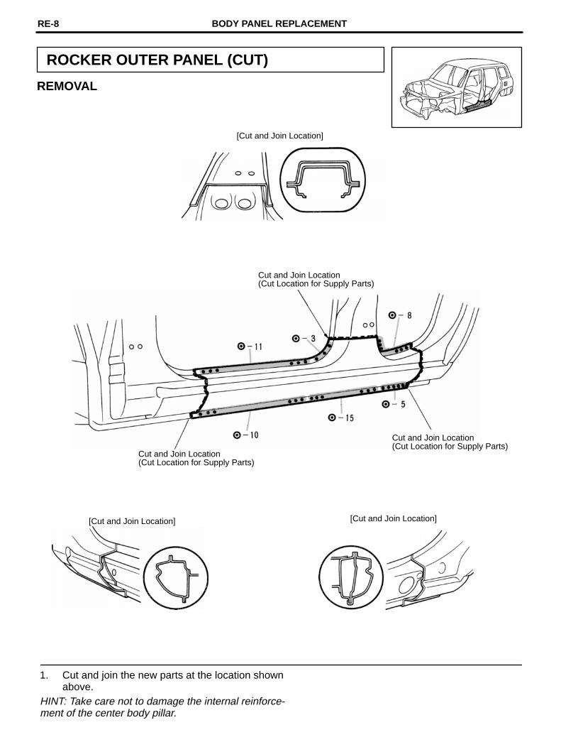
ROCKER OUTER PANEL (CUT)
REMOVAL
[Cut and Join Location]
Cut and Join Location(Cut Location for Supply Parts)
Cut and Join Location(Cut Location for Supply Parts)
Cut and Join Location(Cut Location for Supply Parts)
[Cut and Join Location][Cut and Join Location]
1. Cut and join the new parts at the location shownabove.
HINT: Take care not to damage the internal reinforce-ment of the center body pillar.
BODY PANEL REPLACEMENTRE-8

INSTALLATION
Butt Weld
Butt Weld
Butt Weld
1. Temporarily install the new parts and check thefit of the front door and rear door.
BODY PANEL REPLACEMENT RE-9

mm in.
150250
5.919.84
QUARTER PANEL (CUT)
REMOVAL
[Cut and Join Location]250 mm
Cut and Join Location
Cut and Join Location[Cut Location forsupply parts]
RH:LH:
Cut and Join Location
150 mm
[Cut and Join Location]
Braze
RH:LH:
1. Cut and join the parts at the location shownabove.
BODY PANEL REPLACEMENTRE-10

mm in.
5 0.20
INSTALLATION
Butt Weld
Body Sealer
Butt Weld
RH:LH:
Butt weld
Body sealerBraze
about 5 mm
RH:LH:
2. Temporarily install the new parts and checkthe fit of the rear door, back door and rearcombination light.
1. Before temporarily installing the new parts,apply body sealer to the wheel arch.
HINT:1) Apply body sealer about 5 mm (0.20in.) from
the flange, avoiding any oozing.2) Apply sealer evenly, about 3 − 4 mm (0.12 −
0.16in.) in diameter.3) For other sealing points, refer to section AR.
BODY PANEL REPLACEMENT RE-11

QUARTER PANEL (CUT−P)
REMOVAL
Cut and Join Location
RH:LH:
Braze
RH:LH:
1. Cut and join the parts at the location shownabove.
BODY PANEL REPLACEMENTRE-12

mm in.
5 0.20
Braze
INSTALLATION
Butt Weld
Body Sealer
RH:LH:
Body Sealer
about 5 mm
RH:LH:
1. Before temporarily installing the new parts,apply body sealer to the wheel arch.
HINT:1) Apply body sealer about 5 mm (0.20 in.) from
the flange, avoiding any oozing.2) Apply sealer evenly, about 3 − 4 mm (0.12 −
0.16 in.) diameter.3) For other sealing points, refer to section AR.
2. Temporarily install the new parts and check thefit of the rear door, back door and rear combina-tion light.
3. Before welding, cut the lining away from theweld seams a little.
BODY PANEL REPLACEMENT RE-13

QUARTER WHEEL HOUSING OUTER PANEL(ASSY): Right Side
REMOVAL (With the quarter panel removed.)
BODY PANEL REPLACEMENTRE-14

INSTALLATION
Assembly Mark
Assembly Mark
Quarter Wheel HousingBracket
2. Before welding the new parts, temporarilyinstall the quarter panel and check the fit.
1. Determine the position of the new parts by theassembly marks of the inner and outer panels.
BODY PANEL REPLACEMENT RE-15

QUARTER WHEEL HOUSING OUTER PANEL(ASSY): Left Side
REMOVAL (With the quarter panel removed.)
BODY PANEL REPLACEMENTRE-16

INSTALLATION
Assembly MarkAssembly Mark
Fuel Tank Protector Bracket
1. Determine the position of the new parts by theassembly marks of the inner and outer panels.
2. Before welding the new parts, temporarilyinstall the quarter panel and check the fit.
BODY PANEL REPLACEMENT RE-17

QUARTER PANEL EXTENSION (ASSY)
REMOVAL (With the quarter panel removed.)
BODY PANEL REPLACEMENTRE-18

INSTALLATION
BODY PANEL REPLACEMENT RE-19

mm in
80 3.15
BODY LOWER BACK PANEL (CUT)
REMOVAL
80mm
Cut and Join Location
1. Replace the Body Lower Back Reinforcement atthe same time.
BODY PANEL REPLACEMENTRE-20

INSTALLATION
Body Lower BackPanel Reinforcement
Butt Weld
2. Temporarily installing the new parts, check thefit of the back door.
1. Before temporarily installing the new parts,weld the body lower back panel and bodylower back panel reinforcement with stan-dard points.
BODY PANEL REPLACEMENT RE-21

mm in
130 5.12
REAR FLOOR INNER CROSSMEMBER (CUT)
130mm
REMOVAL (With the body lower back panel removed.)
130mm
Cut and JoinLocation
Cut and JoinLocation
BODY PANEL REPLACEMENTRE-22
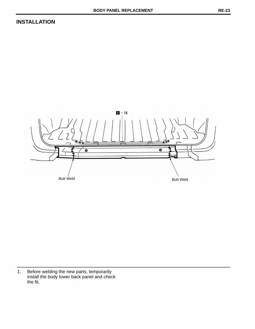
INSTALLATION
Butt WeldButt Weld
1. Before welding the new parts, temporarilyinstall the body lower back panel and checkthe fit.
BODY PANEL REPLACEMENT RE-23

REAR FLOOR PAN (ASSY)
Rear Floor Crossmember No. 1 Brace
REMOVAL (With the rear floor inner crossmemberremoved.)
RH:LH:
1. Replace the rear floor crossmember No.1brace at the same time.
BODY PANEL REPLACEMENTRE-24

INSTALLATION
RH:LH:
BODY PANEL REPLACEMENT RE-25

REAR FLOOR PAN EXTENSION (ASSY)
REMOVAL (With the quarter panel extension removed.)
BODY PANEL REPLACEMENTRE-26

INSTALLATION
BODY PANEL REPLACEMENT RE-27

REAR FLOOR SIDE REAR MEMBER (ASSY)
REMOVAL (With the rear floor pan extension and rearfloor inner crossmember removed.)
Rear Floor Inner Crossmember
1. After removing the rear floor inner cross-member, remove the rear floor side rearmember.
BODY PANEL REPLACEMENTRE-28

INSTALLATION
Butt Weld
1. Temporarily install the new parts and mea-sure each part in accordance with the bodydimension diagram.
2. Install the new parts of rear floor inner cross-member shown above.
BODY PANEL REPLACEMENT RE-29

ROOF PANEL (ASSY): Normal Roof
REMOVAL
BODY PANEL REPLACEMENTRE-30
INSTALLATION
Body Sealer
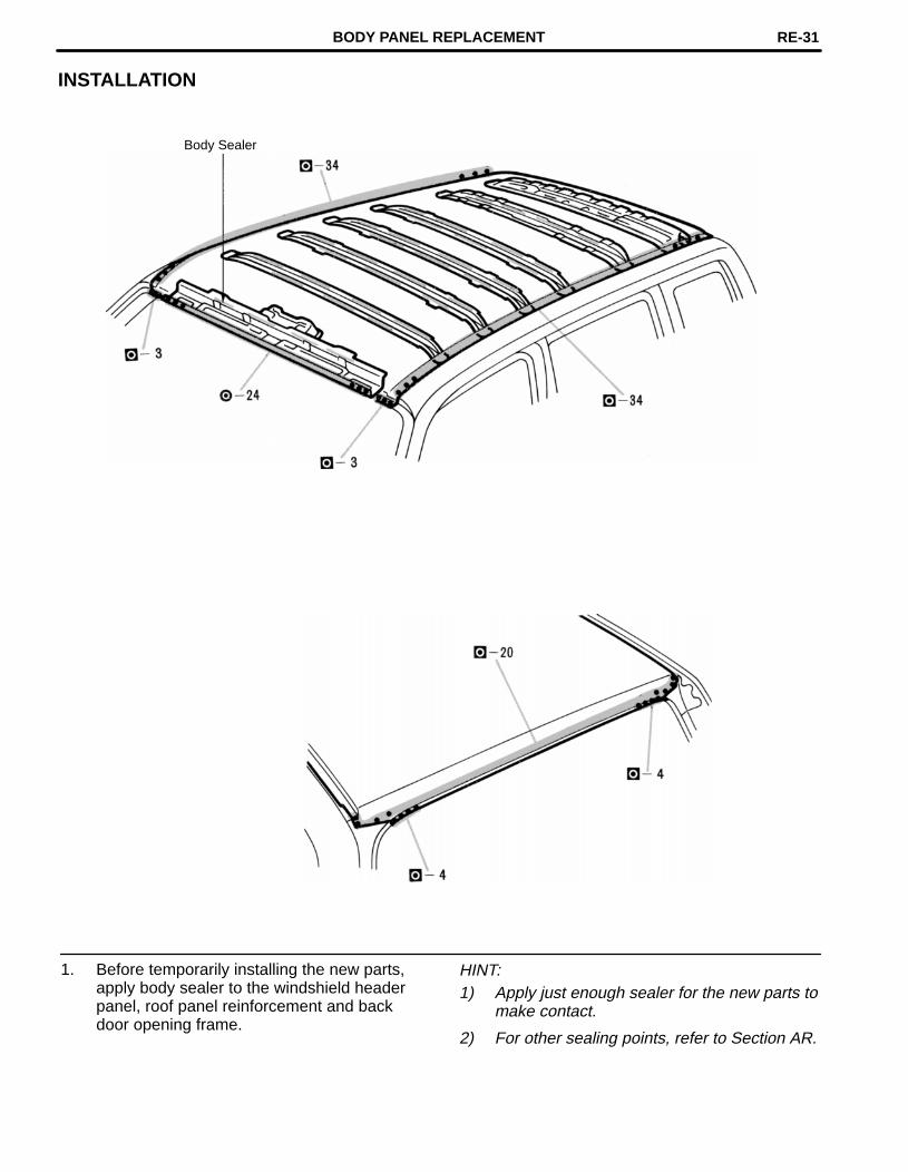
1. Before temporarily installing the new parts,apply body sealer to the windshield headerpanel, roof panel reinforcement and backdoor opening frame.
HINT:1) Apply just enough sealer for the new parts to
make contact.
2) For other sealing points, refer to Section AR.
BODY PANEL REPLACEMENT RE-31

ROOF PANEL (ASSY): Moon Roof
REMOVAL
BODY PANEL REPLACEMENTRE-32

INSTALLATION
Body Sealer
1. Before temporarily installing the new parts,apply body sealer to the windshield headerpanel, roof panel reinforcement and backdoor opening frame.
HINT:1) Apply just enough sealer for the new parts to
make contact.
2) For other sealing points, refer to Section AR.
BODY PANEL REPLACEMENT RE-33

CodeMaterialname
Heat* resistant
temperature limit °C (°F)
Resistance to alcohol or gasoline Notes
AASAcrylonitrileAcrylic Styrene
80(176)
Alcohol is harmless if appliedonly for short time in smallamounts (e.g., quick wiping toremove grease.)
Avoid gasoline andorganic or aromaticsolvents.
ABSAcrylonitrileButadiene Styrene
80(176)
Alcohol is harmless if appliedonly for short time in smallamounts (e.g., quick wiping toremove grease.)
Avoid gasoline andorganic or aromaticsolvents.
AESAcrylonitrileEthylene Styrene
80(176)
Alcohol is harmless if appliedonly for short time in smallamounts (e.g., quick wiping toremove grease).
Avoid gasoline andorganic or aromaticsolvents.
BMCBulkMouldingCompound
150(302)
Alcohol and gasoline areharmless.
Most solvents areharmless.
CABCelluloseAcetate
80(176)
Alcohol is harmless if appliedonly for short time in smallamounts (e.g., quick wiping toremove grease).
Avoid gasoline andorganic or aromaticsolvents.
EPDM 100(212)
EthylenePropylene
Alcohol is harmless.Gasoline is harmless if appliedonly for short time in smallamounts.
Most solvents areharmless but avoiddipping in gasoline,solvents, etc.
PAPolyamide(Nylon)
80(176)
Alcohol and gasoline areharmless. Avoid battery acid.
PBTPolybutyleneTerephthalate
160(320)
Alcohol and gasoline areharmless.
Most solvents areharmless.
PC Polycarbonate120
(248) Alcohol is harmless.
Avoid gasoline brakefluid, wax, wax removersand organic solvents.Avoid alkali.
PE Polyethylene80
(176) Alcohol and gasoline are harmless.Most solvents areharmless.
PETPolyethyleneTerephthalate
75(167)
Alcohol and gasoline areharmless. Avoid dipping in water.
HANDLING PRECAUTIONS1. The repair procedure for plastic body parts must conform with the type of plastic material.
2. Plastic body parts are identified by the codes in the following chart.
3. When repairing metal body parts adjoining plastic body parts (by brazing, frame cutting, welding,painting etc.), consideration must given to the property of the plastic.
*Temperatures higher than those listed here may result in material deformation during repair.
PLASTIC BODY PARTSPP-2

CodeMaterialname
Heat* resistant
temperature limit °C (°F)
Resistance to alcohol or gasoline Notes
PMMAPolymethylMethacrylate
80(176)
Alcohol is harmless if appliedonly for short time in smallamounts.
Avoid dipping or immers-ing in alcohol, gasoline,solvents, etc.
POMPolyoxymethylene(Polyacetal)
100(212)
Alcohol and gasoline areharmless.
Most solvents areharmless.
PP Polypropylene80
(176)Alcohol and gasoline areharmless.
Most solvents areharmless.
PPOModifiedPolyphenyleneOxide
100(212) Alcohol is harmless.
Gasoline is harmless ifapplied only for quickwiping to removegrease.
PS Polystyrene 60(140)
Alcohol and gasoline are harm-less if applied only for short timein small amounts.
Avoid dipping or immers-ing in alcohol, gasoline,solvents, etc.
PUR Polyurethane80
(176)
Alcohol is harmless if applied onlyfor very short time in small amounts(e.g., quick wiping to removegrease.)
Avoid dipping or immers-ing in alcohol, gasoline,solvents, etc.
PVCPolyvinylchloride(Vinyl)
80(176)
Alcohol and gasoline are harmless ifapplied only for short time in smallamounts (e.g., quick wiping to removegrease).
Avoid dipping or immers-ing in alcohol, gasoline,solvents, etc.
SANStyreneAcrylonitrile
80(176)
Alcohol is harmless if appliedonly for short time in smallamounts (e.g., quick wiping toremove grease.)
Avoid dipping or immers-ing in alcohol, gasoline,solvents etc.
SMCSheetMouldingCompound
180(356)
Alcohol and gasoline areharmless. Avoid alkali.
TPOThermoplasticOlefine
80(176)
Alcohol is harmless.Gasoline is harmless if appliedonly for short time in smallamounts.
Most solvents are harm-less but avoid dipping ingasoline, solvents,etc.
TPU ThermoplasticPolyurethane
80(176)
Alcohol is harmless if appliedonly for very short time in smallamounts (e.g., quick wiping toremove grease).
Avoid dipping or immers-ing in alcohol, gasoline,solvents, etc.
TSOPTOYOTASuperOlefine Polymer
80(176)
Alcohol and gasoline areharmless.
Most solvents areharmless.
UPUnsaturatedPolyester
110(233)
Alcohol and gasoline areharmless. Avoid alkali.
*Temperatures higher than those listed here may result in material deformation during repair.
PLASTIC BODY PARTS PP-3

LOCATION OF PLASTIC BODY PARTS
Quarter Vent Duct (PP)
Rear Door Outside Handle (PC)
Front Door Outside Handle (PC)
Outer Rear View Mirror (AAS)
Instrument Panel Safety Pad (PP)
Cowl Top Ventilator Louver (PP)
Radiator Grill (ABS)
Quarter Outside Moulding(TSOP)
Rear Door Outside Moulding (TSOP)Front Bumper Cover (TSOP)
Front Turn Signal Light (PMMA/PP) Front Door Outside Moulding (TSOP)
Front Fender Moulding (TSOP)
HINT:• Resin material differs with model./ Made up of 2 or more kinds of materials.
PLASTIC BODY PARTSPP-4

Center Pillar Lower Garnish (PP/PE)
Center Pillar Garnish (PP)
Back Door Trim Board (PP)
Front Pillar Garnish (PP)
Front Fender Liner (PE)
Quater Panel Mudguard (TPU)
Side Turn Signal Light (SAN/ABS)
Washer Jar (PP)
Front Fender Mudguard (TPU)
Radiator Reserve Tank (PP)
Engine Under Cover (PE)
HINT:• Resin material differs with model./ Made up of 2 or more kinds of materials.
PLASTIC BODY PARTS PP-5

Rear Combination Light (PMMA/PP)
Roof Side Inner Garnish (TSOP)Air Conditioner Unit (PP)
Heater Blower (PP)Rear Bumper Side Seal (PE)
Cowl Side Trim Board (PP)
Deck Trim Side Panel (TSOP)Front Door Outside Scuff Plate (PP/PE)
Back Door Outside Handle (PC)Rear Door Outside Scuff Plate (PP/PE)
Rear Bumper Piece (TSOP) Licence Plate Light (PC)
Reflex Reflector (PMMA/ABS)
HINT:• Resin material differs with model./ Made up of 2 or more kinds of materials.
PLASTIC BODY PARTSPP-6

mm in.
1011.51314
0.390.4530.510.55
Assembly Mark
14×11.5
10φ
13φ
10φ
10φ
10φ
Assembly Mark
10φ10φ
STANDARD BODY MARKS
Center MarkCenter Mark
Assembly Mark
Assembly Mark
Assembly Mark
BODY PANEL CONSTRUCTIONCN-2


![Predgovor [Foreword].](https://static.fdokumen.com/doc/165x107/63333df9ce61be0ae50e8cf4/predgovor-foreword-1681982858.jpg)