
CK22-O_M.pdf - FOREWORD
131
Congratulations, and welcome to the fabulous world of CK22 ownership, where serious work is made fun again! This versatile tractor is a culmination of the entire tractor and diesel knowledge gained by the Daedong Indus- trial Co.,LTD over the years since 1947 and has been designed with the finest materials and under rigid quality control standards set forth by the KIOTI Engineering Department. Knowledge of tractor operation is essential for many years of dependable service and reliability. To help new owner's familiarize themselves with the KIOTI CK22, it is the policy of KIOTI tractor to provide an owner's manual which includes helpful information about tractor safety, operation and maintenance. If the information you seek is not found in this manual, your KIOTI tractor dealer will be happy to help you. Please feel free to contact DAEDONG-IND.CO.,LTD. with your questions/concerns. FOREWORD
-
Upload
khangminh22 -
Category
Documents
-
view
0 -
download
0
Transcript of CK22-O_M.pdf - FOREWORD

Congratulations, and welcome to the fabulous world of CK22 ownership, where serious work is made funagain!
This versatile tractor is a culmination of the entire tractor and diesel knowledge gained by the Daedong Indus-trial Co.,LTD over the years since 1947 and has been designed with the finest materials and under rigid qualitycontrol standards set forth by the KIOTI Engineering Department.
Knowledge of tractor operation is essential for many years of dependable service and reliability. To help newowner's familiarize themselves with the KIOTI CK22, it is the policy of KIOTI tractor to provide an owner'smanual which includes helpful information about tractor safety, operation and maintenance. If the informationyou seek is not found in this manual, your KIOTI tractor dealer will be happy to help you.
Please feel free to contact DAEDONG-IND.CO.,LTD. with your questions/concerns.
FOREWORD

This manual includes information titled as WARNING, CAUTION, IMPORTANTand NOTE. These titles indicate the following:
SAFETY AND VEHICLE DAMAGE WARNING
NOTE
This indicates that interesting or helpful information is beingprovided.
CAUTION!!!!! This indicates that a condition may result in damage to your
vehicle or its equipment if the caution is not heeded. Follow theadvice provided with the caution.
WARNING
This indicates that a condition may result in harm, serious injuryor death to you or other persons if the warning is not heeded.Follow the advice provided with the warning.
!!!!!
This mark indicates emphasis on notable characteristics of work-ing procedures, and information about technology for easieroperation.IMPORTANT
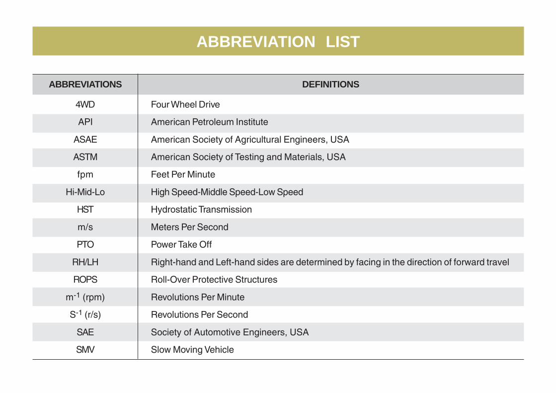
ABBREVIATION LIST
ABBREVIATIONS
4WD
API
ASAE
ASTM
fpm
Hi-Mid-Lo
HST
m/s
PTO
RH/LH
ROPS
m-1 (rpm)
S-1 (r/s)
SAE
SMV
DEFINITIONS
Four Wheel Drive
American Petroleum Institute
American Society of Agricultural Engineers, USA
American Society of Testing and Materials, USA
Feet Per Minute
High Speed-Middle Speed-Low Speed
Hydrostatic Transmission
Meters Per Second
Power Take Off
Right-hand and Left-hand sides are determined by facing in the direction of forward travel
Roll-Over Protective Structures
Revolutions Per Minute
Revolutions Per Second
Society of Automotive Engineers, USA
Slow Moving Vehicle

Various universal symbols have been used on the instruments and controls of your KIOTI tractor. Below is a listof the universal symbols and their meanings.
UNIVERSAL SYMBOLS
Fuel-Level
Engine Coolant-Temperature
Parking Brake
Battery Charging Condition
Engine Oil-Pressure
Turn Signal
Power Take-Off Clutch Control-ON Position
Power Take-Off Clutch Control-OFF Position
Differential Lock
Position Control-Lowered Position
Hazard Warning Lights
Headlight-Low Beam
Headlight-High Beam
Four-Wheel Drive-ON
Fast
Slow
Coolant
Preheat
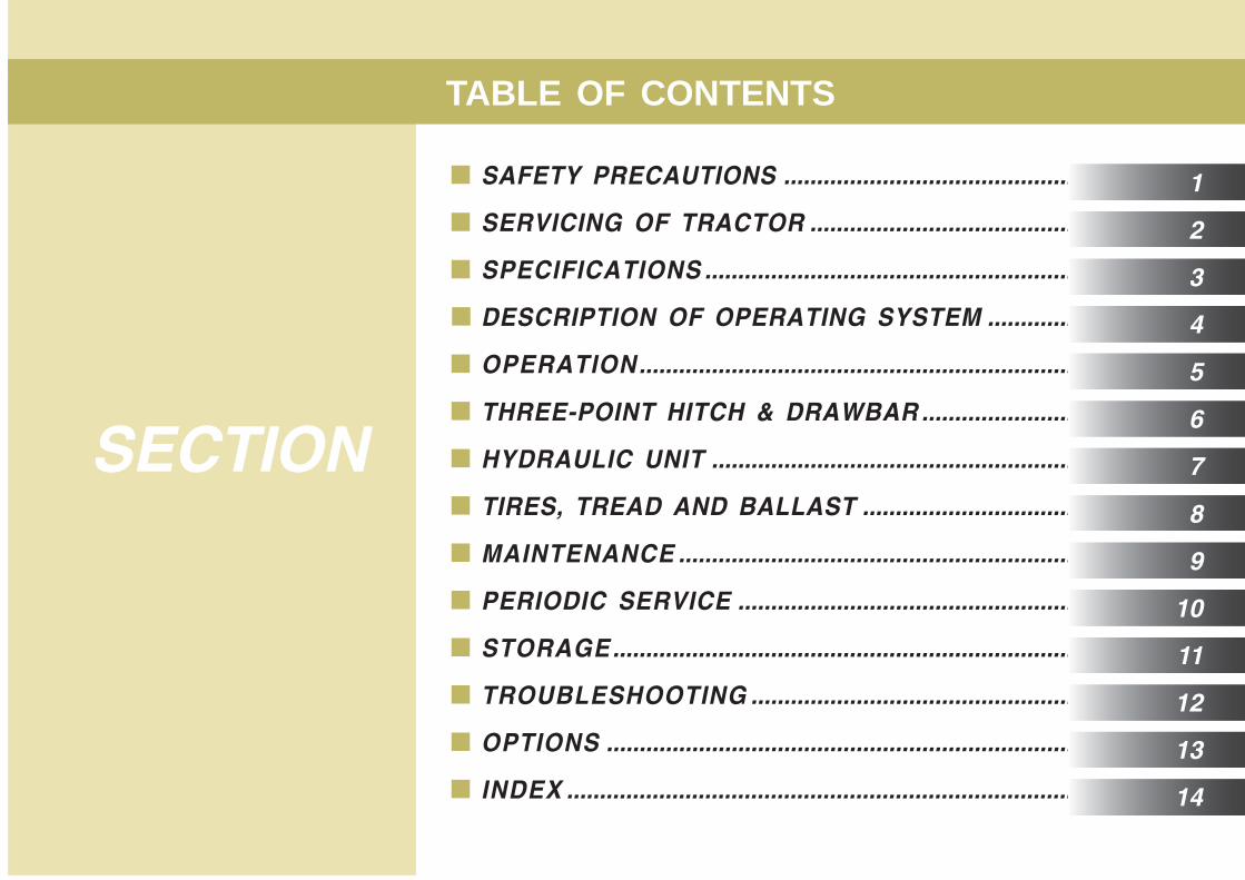
SAFETY PRECAUTIONS .............................................
SERVICING OF TRACTOR .........................................
SPECIFICATIONS .........................................................
DESCRIPTION OF OPERATING SYSTEM ..............
OPERATION...................................................................
THREE-POINT HITCH & DRAWBAR ........................
HYDRAULIC UNIT ........................................................
TIRES, TREAD AND BALLAST .................................
MAINTENANCE .............................................................
PERIODIC SERVICE ....................................................
STORAGE.......................................................................
TROUBLESHOOTING ..................................................
OPTIONS ........................................................................
INDEX ..............................................................................
TABLE OF CONTENTS
SECTION
1
2
3
4
5
6
7
8
9
10
11
12
13
14
1BEFORE OPERATING THE TRACTOR .................... 1-2
OPERATING THE TRACTOR .................................... 1-5
DRIVING THE TRACTOR ........................................... 1-8
PARKING THE TRACTOR ......................................... 1-9
OPERATING THE PTO ............................................. 1-10
USING 3-POINT HITCH............................................. 1-10
SERVICING THE TRACTOR .................................... 1-11
TRACTOR SAFETY LABELS................................... 1-14
SAFETY PRECAUTIONS
CK221-2
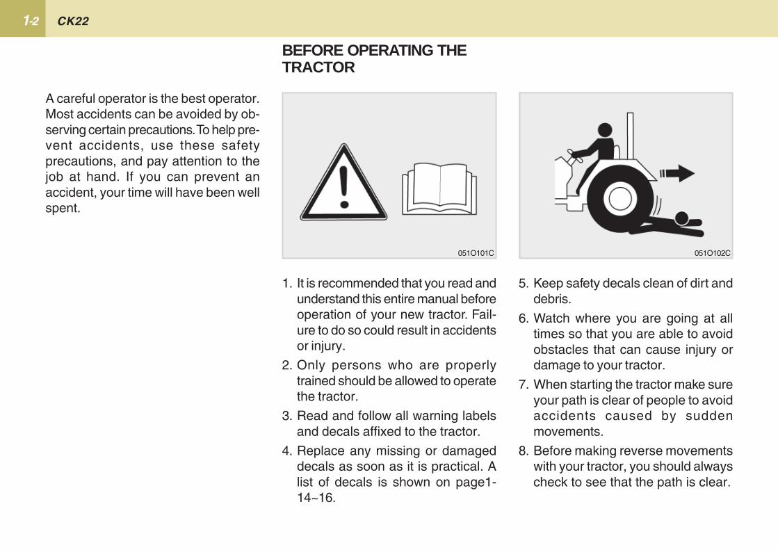
A careful operator is the best operator.Most accidents can be avoided by ob-serving certain precautions. To help pre-vent accidents, use these safetyprecautions, and pay attention to thejob at hand. If you can prevent anaccident, your time will have been wellspent.
BEFORE OPERATING THETRACTOR
5. Keep safety decals clean of dirt anddebris.
6. Watch where you are going at alltimes so that you are able to avoidobstacles that can cause injury ordamage to your tractor.
7. When starting the tractor make sureyour path is clear of people to avoidaccidents caused by suddenmovements.
8. Before making reverse movementswith your tractor, you should alwayscheck to see that the path is clear.
1. It is recommended that you read andunderstand this entire manual beforeoperation of your new tractor. Fail-ure to do so could result in accidentsor injury.
2. Only persons who are properlytrained should be allowed to operatethe tractor.
3. Read and follow all warning labelsand decals affixed to the tractor.
4. Replace any missing or damageddecals as soon as it is practical. Alist of decals is shown on page1-14~16.
051O101C 051O102C
1-3 SAFETY PRECAUTIONS
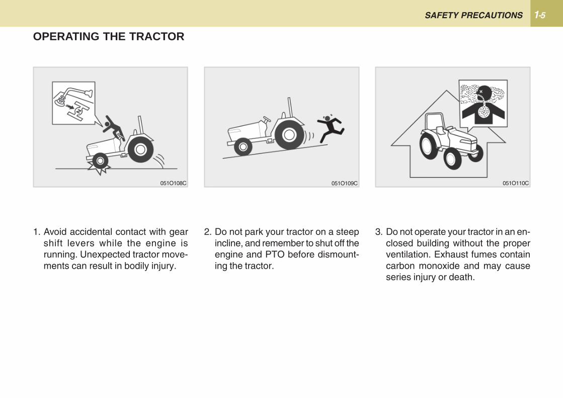
16. All persons using the tractor shouldhave knowledge of its proper op-eration and should read this manualcarefully.
17. Never get off the tractor without set-ting the parking brake, lowering theimplement to the ground and shut-ting of the tractor.
18. No alterations should be made toyour KIOTI tractor.
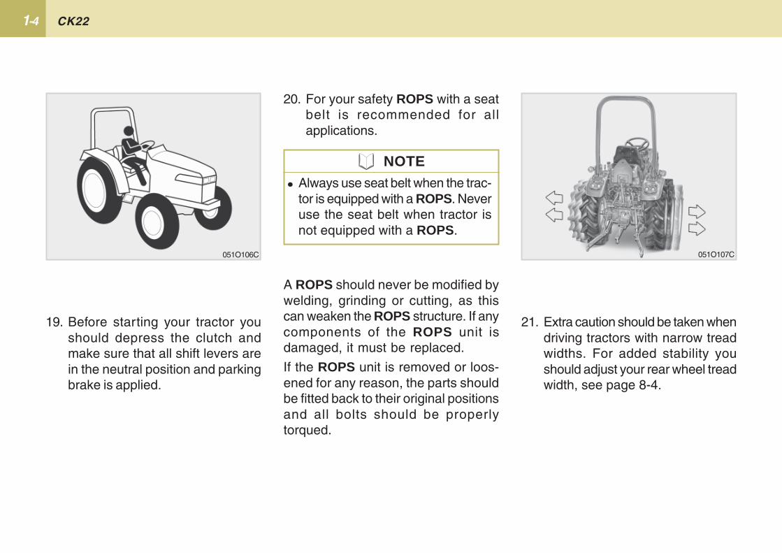
12. Never start the engine while stand-ing on the ground.
13. Only the operator should ride on thetractor unless a passenger seat isinstalled. Keep bystanders awayfrom the tractor while in operation.
14. When getting on and off the tractor,handholds and step plates shouldalways be used. This will help toprevent accidental slips trips andfalls.
15. Be sure to scrape off mud or soilfrom your shoes before mountingthe tractor.
051O103C 051O104C 051O105C
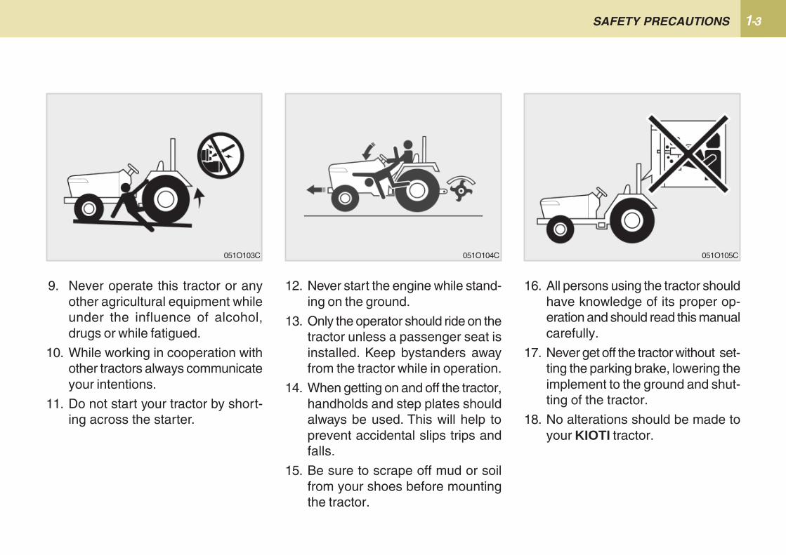
9. Never operate this tractor or anyother agricultural equipment whileunder the influence of alcohol,drugs or while fatigued.
10. While working in cooperation withother tractors always communicateyour intentions.
11. Do not start your tractor by short-ing across the starter.
CK221-4
A ROPS should never be modified bywelding, grinding or cutting, as thiscan weaken the ROPS structure. If anycomponents of the ROPS unit isdamaged, it must be replaced.
If the ROPS unit is removed or loos-ened for any reason, the parts shouldbe fitted back to their original positionsand all bolts should be properlytorqued.
� Always use seat belt when the trac-tor is equipped with a ROPS. Neveruse the seat belt when tractor isnot equipped with a ROPS.
21. Extra caution should be taken whendriving tractors with narrow treadwidths. For added stability youshould adjust your rear wheel treadwidth, see page 8-4.
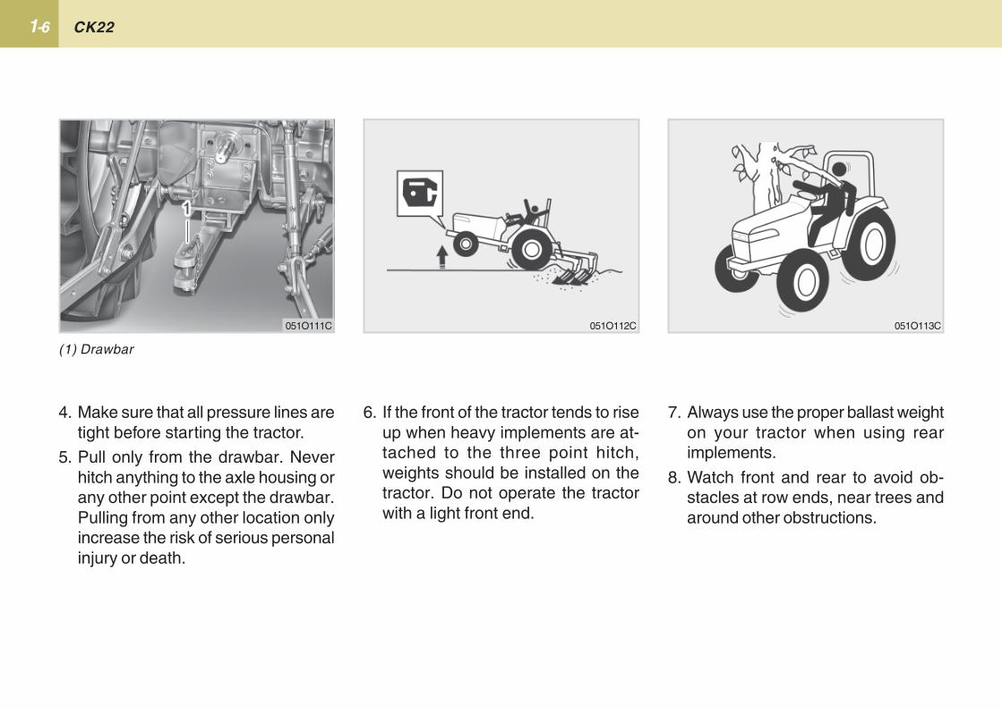
19. Before starting your tractor youshould depress the clutch andmake sure that all shift levers arein the neutral position and parkingbrake is applied.
20. For your safety ROPS with a seatbelt is recommended for allapplications.
051O106C
NOTE
051O107C
1-5 SAFETY PRECAUTIONS
1. Avoid accidental contact with gearshift levers while the engine isrunning. Unexpected tractor move-ments can result in bodily injury.
2. Do not park your tractor on a steepincline, and remember to shut off theengine and PTO before dismount-ing the tractor.
OPERATING THE TRACTOR
3. Do not operate your tractor in an en-closed building without the properventilation. Exhaust fumes containcarbon monoxide and may causeseries injury or death.
051O109C051O108C 051O110C
CK221-6
7. Always use the proper ballast weighton your tractor when using rearimplements.
8. Watch front and rear to avoid ob-stacles at row ends, near trees andaround other obstructions.
4. Make sure that all pressure lines aretight before starting the tractor.
5. Pull only from the drawbar. Neverhitch anything to the axle housing orany other point except the drawbar.Pulling from any other location onlyincrease the risk of serious personalinjury or death.
6. If the front of the tractor tends to riseup when heavy implements are at-tached to the three point hitch,weights should be installed on thetractor. Do not operate the tractorwith a light front end.
(1) Drawbar
051O111C 051O112C 051O113C
1-7 SAFETY PRECAUTIONS
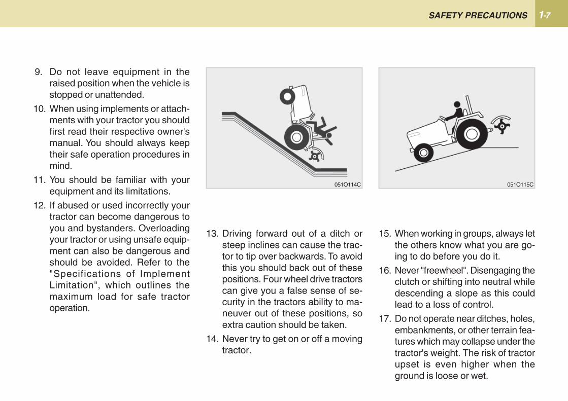
9. Do not leave equipment in theraised position when the vehicle isstopped or unattended.
10. When using implements or attach-ments with your tractor you shouldfirst read their respective owner'smanual. You should always keeptheir safe operation procedures inmind.
11. You should be familiar with yourequipment and its limitations.
12. If abused or used incorrectly yourtractor can become dangerous toyou and bystanders. Overloadingyour tractor or using unsafe equip-ment can also be dangerous andshould be avoided. Refer to the"Specifications of ImplementLimitation", which outlines themaximum load for safe tractoroperation.
15. When working in groups, always letthe others know what you are go-ing to do before you do it.
16. Never "freewheel". Disengaging theclutch or shifting into neutral whiledescending a slope as this couldlead to a loss of control.
17. Do not operate near ditches, holes,embankments, or other terrain fea-tures which may collapse under thetractor's weight. The risk of tractorupset is even higher when theground is loose or wet.
13. Driving forward out of a ditch orsteep inclines can cause the trac-tor to tip over backwards. To avoidthis you should back out of thesepositions. Four wheel drive tractorscan give you a false sense of se-curity in the tractors ability to ma-neuver out of these positions, soextra caution should be taken.
14. Never try to get on or off a movingtractor.
051O114C 051O115C
CK221-8
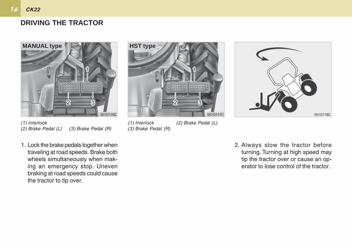
2. Always slow the tractor beforeturning. Turning at high speed maytip the tractor over or cause an op-erator to lose control of the tractor.
1. Lock the brake pedals together whentraveling at road speeds. Brake bothwheels simultaneously when mak-ing an emergency stop. Unevenbraking at road speeds could causethe tractor to tip over.
DRIVING THE TRACTOR
(1) Interlock(2) Brake Pedal (L) (3) Brake Pedal (R)
(1) Interlock (2) Brake Pedal (L)(3) Brake Pedal (R)
MANUAL type
051O118C051O117C051O116C
HST type
1-9 SAFETY PRECAUTIONS
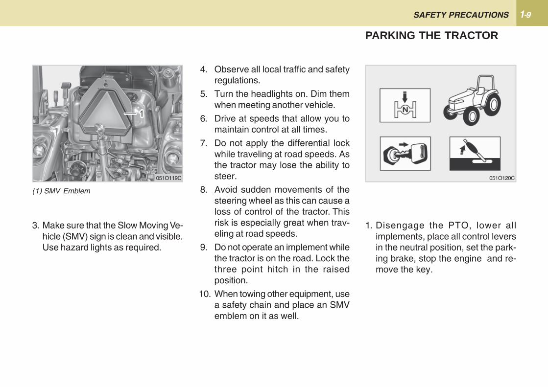
3. Make sure that the Slow Moving Ve-hicle (SMV) sign is clean and visible.Use hazard lights as required.
4. Observe all local traffic and safetyregulations.
5. Turn the headlights on. Dim themwhen meeting another vehicle.
6. Drive at speeds that allow you tomaintain control at all times.
7. Do not apply the differential lockwhile traveling at road speeds. Asthe tractor may lose the ability tosteer.
8. Avoid sudden movements of thesteering wheel as this can cause aloss of control of the tractor. Thisrisk is especially great when trav-eling at road speeds.
9. Do not operate an implement whilethe tractor is on the road. Lock thethree point hitch in the raisedposition.
10. When towing other equipment, usea safety chain and place an SMVemblem on it as well.
1. Disengage the PTO, lower allimplements, place all control leversin the neutral position, set the park-ing brake, stop the engine and re-move the key.
PARKING THE TRACTOR
(1) SMV Emblem
051O119C 051O120C
CK221-10
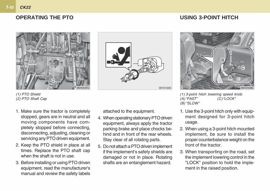
(1) 3-point hitch lowering speed knob(A) “FAST” (C)“LOCK”(B) “SLOW”
USING 3-POINT HITCH
1. Use the 3-point hitch only with equip-ment designed for 3-point hitchusage.
2. When using a 3-point hitch mountedimplement, be sure to install theproper counterbalance weight on thefront of the tractor.
3. When transporting on the road, setthe implement lowering control in the"LOCK" position to hold the imple-ment in the raised position.
(1) PTO Shield(2) PTO Shaft Cap
OPERATING THE PTO
1. Make sure the tractor is completelystopped, gears are in neutral and allmoving components have com-pletely stopped before connecting,disconnecting, adjusting, cleaning orservicing any PTO driven equipment.
2. Keep the PTO shield in place at alltimes. Replace the PTO shaft capwhen the shaft is not in use.
3. Before installing or using PTO drivenequipment, read the manufacturer'smanual and review the safety labels
051O122C051O121C 051O123C
attached to the equipment.
4. When operating stationary PTO drivenequipment, always apply the tractorparking brake and place chocks be-hind and in front of the rear wheels.Stay clear of all rotating parts.
5. Do not attach a PTO driven implementif the implement’s safety shields aredamaged or not in place. Rotatingshafts are an entanglement hazard.
1-11 SAFETY PRECAUTIONS
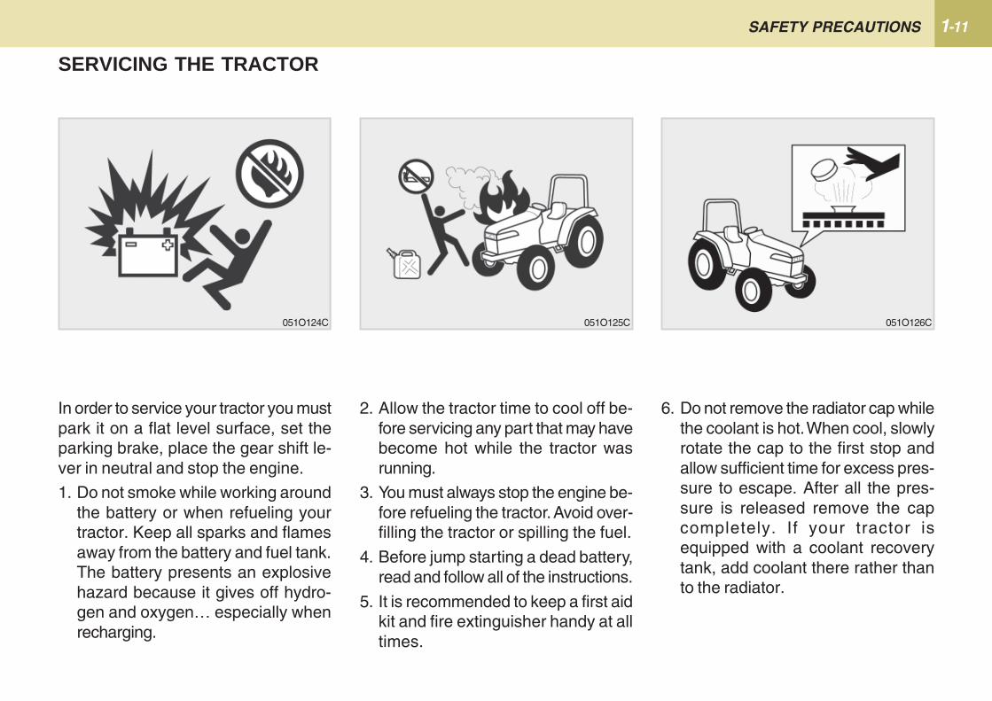
2. Allow the tractor time to cool off be-fore servicing any part that may havebecome hot while the tractor wasrunning.
3. You must always stop the engine be-fore refueling the tractor. Avoid over-filling the tractor or spilling the fuel.
4. Before jump starting a dead battery,read and follow all of the instructions.
5. It is recommended to keep a first aidkit and fire extinguisher handy at alltimes.
In order to service your tractor you mustpark it on a flat level surface, set theparking brake, place the gear shift le-ver in neutral and stop the engine.
1. Do not smoke while working aroundthe battery or when refueling yourtractor. Keep all sparks and flamesaway from the battery and fuel tank.The battery presents an explosivehazard because it gives off hydro-gen and oxygen… especially whenrecharging.
SERVICING THE TRACTOR
6. Do not remove the radiator cap whilethe coolant is hot. When cool, slowlyrotate the cap to the first stop andallow sufficient time for excess pres-sure to escape. After all the pres-sure is released remove the capcompletely. If your tractor isequipped with a coolant recoverytank, add coolant there rather thanto the radiator.
051O124C 051O125C 051O126C
CK221-12
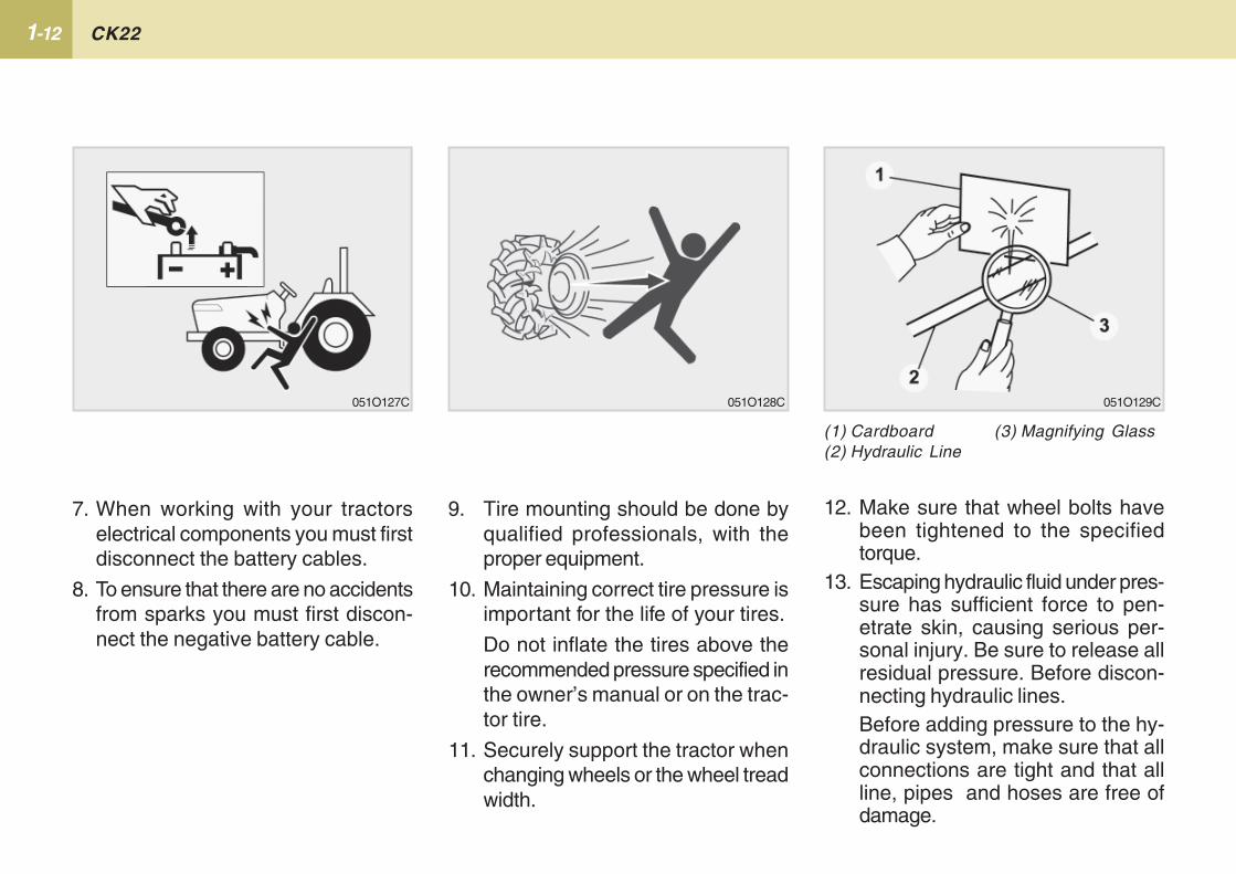
9. Tire mounting should be done byqualified professionals, with theproper equipment.
10. Maintaining correct tire pressure isimportant for the life of your tires.
Do not inflate the tires above therecommended pressure specified inthe owner’s manual or on the trac-tor tire.
11. Securely support the tractor whenchanging wheels or the wheel treadwidth.
(1) Cardboard (3) Magnifying Glass(2) Hydraulic Line
12. Make sure that wheel bolts havebeen tightened to the specifiedtorque.
13. Escaping hydraulic fluid under pres-sure has sufficient force to pen-etrate skin, causing serious per-sonal injury. Be sure to release allresidual pressure. Before discon-necting hydraulic lines.Before adding pressure to the hy-draulic system, make sure that allconnections are tight and that allline, pipes and hoses are free ofdamage.
7. When working with your tractorselectrical components you must firstdisconnect the battery cables.
8. To ensure that there are no accidentsfrom sparks you must first discon-nect the negative battery cable.
051O129C051O128C051O127C
1-13 SAFETY PRECAUTIONS
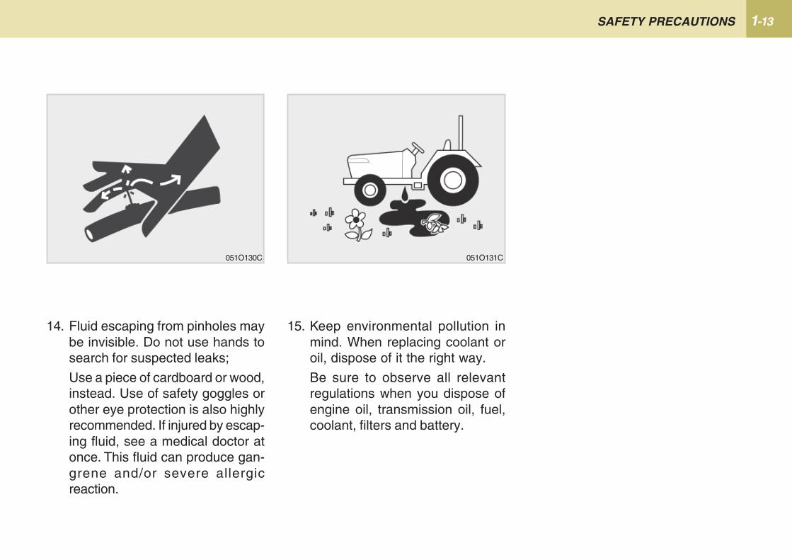
14. Fluid escaping from pinholes maybe invisible. Do not use hands tosearch for suspected leaks;
Use a piece of cardboard or wood,instead. Use of safety goggles orother eye protection is also highlyrecommended. If injured by escap-ing fluid, see a medical doctor atonce. This fluid can produce gan-grene and/or severe allergicreaction.
15. Keep environmental pollution inmind. When replacing coolant oroil, dispose of it the right way.
Be sure to observe all relevantregulations when you dispose ofengine oil, transmission oil, fuel,coolant, filters and battery.
051O130C 051O131C
CK221-14
051O132C
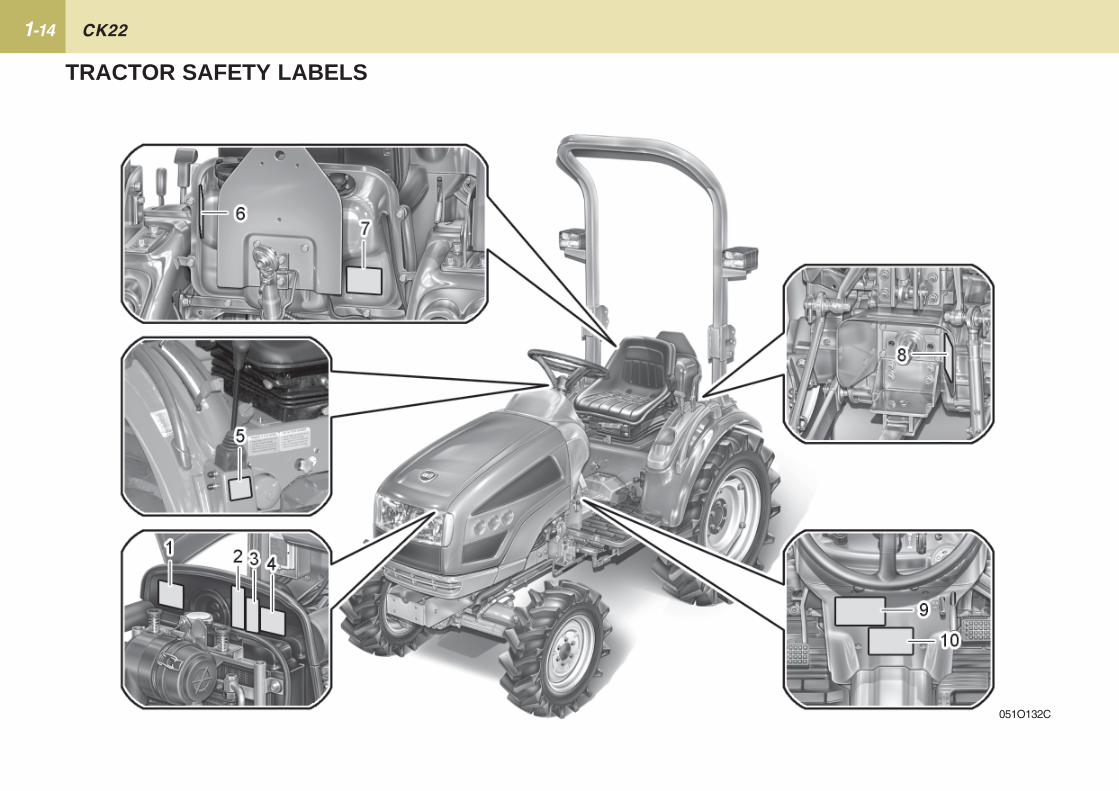
TRACTOR SAFETY LABELS
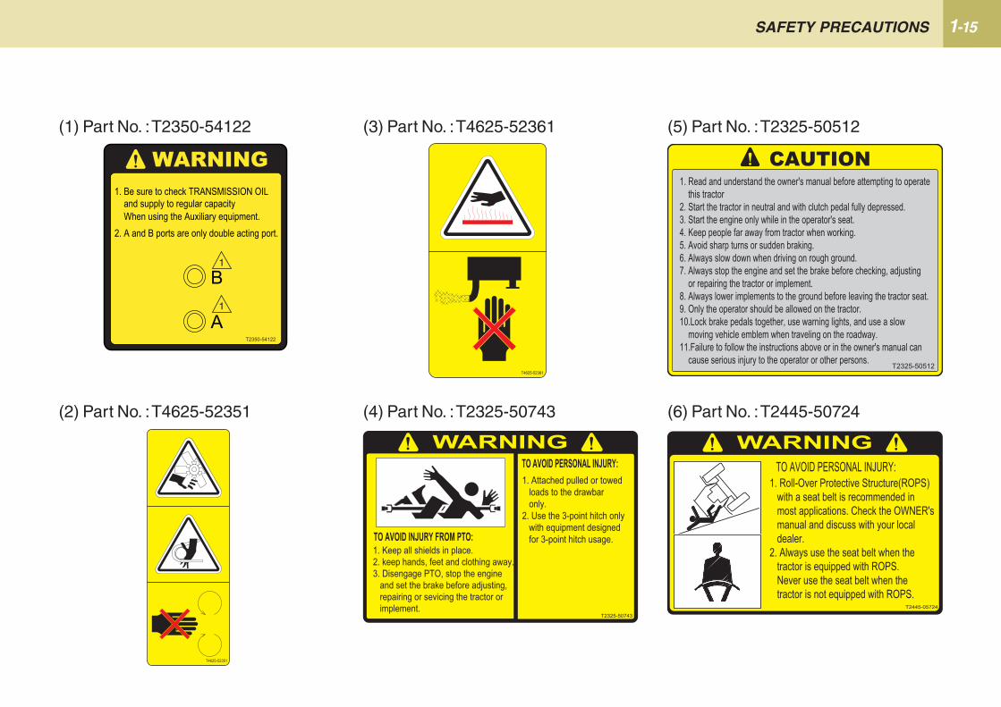
1-15 SAFETY PRECAUTIONS
(3) Part No. : T4625-52361
(2) Part No. : T4625-52351
(1) Part No. : T2350-54122
(4) Part No. : T2325-50743
(5) Part No. : T2325-50512
(6) Part No. : T2445-50724
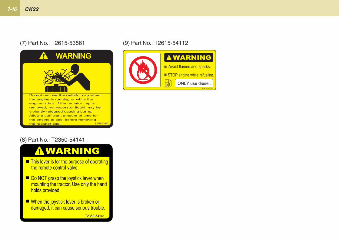
CK221-16
(9) Part No. : T2615-54112(7) Part No. : T2615-53561
(8) Part No. : T2350-54141
2SERVICING .................................................................. 2-2
SERVICING OF TRACTOR
2-2 CK22
SERVICING
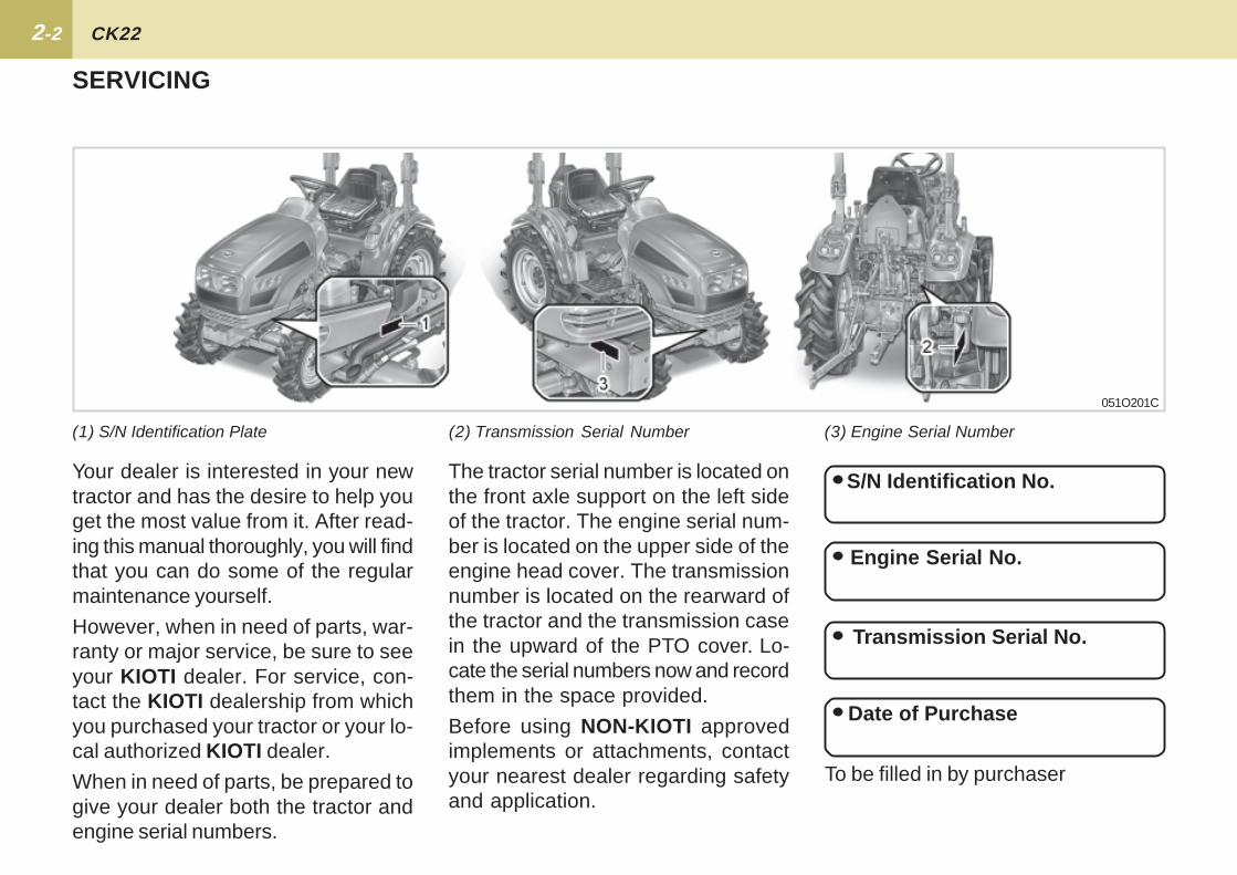
The tractor serial number is located onthe front axle support on the left sideof the tractor. The engine serial num-ber is located on the upper side of theengine head cover. The transmissionnumber is located on the rearward ofthe tractor and the transmission casein the upward of the PTO cover. Lo-cate the serial numbers now and recordthem in the space provided.
Before using NON-KIOTI approvedimplements or attachments, contactyour nearest dealer regarding safetyand application.
S/N Identification No.
Engine Serial No.
Transmission Serial No.
To be filled in by purchaser
Date of Purchase
051O201C
(1) S/N Identification Plate (2) Transmission Serial Number (3) Engine Serial Number
Your dealer is interested in your newtractor and has the desire to help youget the most value from it. After read-ing this manual thoroughly, you will findthat you can do some of the regularmaintenance yourself.
However, when in need of parts, war-ranty or major service, be sure to seeyour KIOTI dealer. For service, con-tact the KIOTI dealership from whichyou purchased your tractor or your lo-cal authorized KIOTI dealer.
When in need of parts, be prepared togive your dealer both the tractor andengine serial numbers.
3SPECIFICATIONS ........................................................ 3-2
IMPLEMENT LIMITATIONS ........................................ 3-4
TRAVELING SPEED .................................................... 3-5
SPECIFICATIONS
3-2 CK22
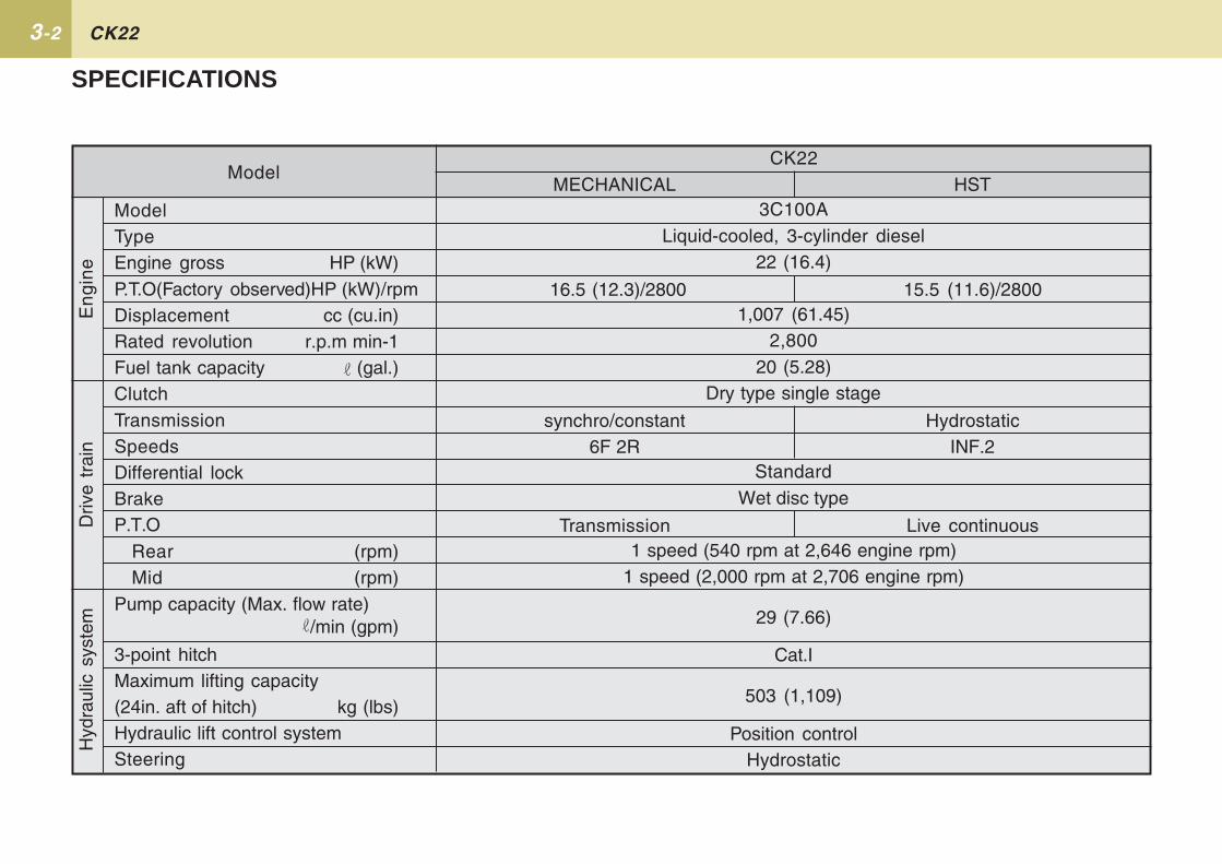
SPECIFICATIONS
HST
15.5 (11.6)/2800
HydrostaticINF.2
Live continuous
En
gin
e
Model
ModelTypeEngine gross HP (kW)P.T.O(Factory observed)HP (kW)/rpmDisplacement cc (cu.in)Rated revolution r.p.m min-1Fuel tank capacity (gal.)ClutchTransmissionSpeedsDifferential lockBrakeP.T.O
Rear (rpm)Mid (rpm)
Pump capacity (Max. flow rate)/min (gpm)
3-point hitchMaximum lifting capacity(24in. aft of hitch) kg (lbs)Hydraulic lift control systemSteering
CK22
Driv
e tr
ain
Hyd
raul
ic s
yste
m
MECHANICAL
16.5 (12.3)/2800
synchro/constant6F 2R
Transmission
3C100ALiquid-cooled, 3-cylinder diesel
22 (16.4)
1,007 (61.45)2,800
20 (5.28)Dry type single stage
StandardWet disc type
1 speed (540 rpm at 2,646 engine rpm)1 speed (2,000 rpm at 2,706 engine rpm)
29 (7.66)
Cat.I
503 (1,109)
Position controlHydrostatic
3-3 SPECIFICATIONS
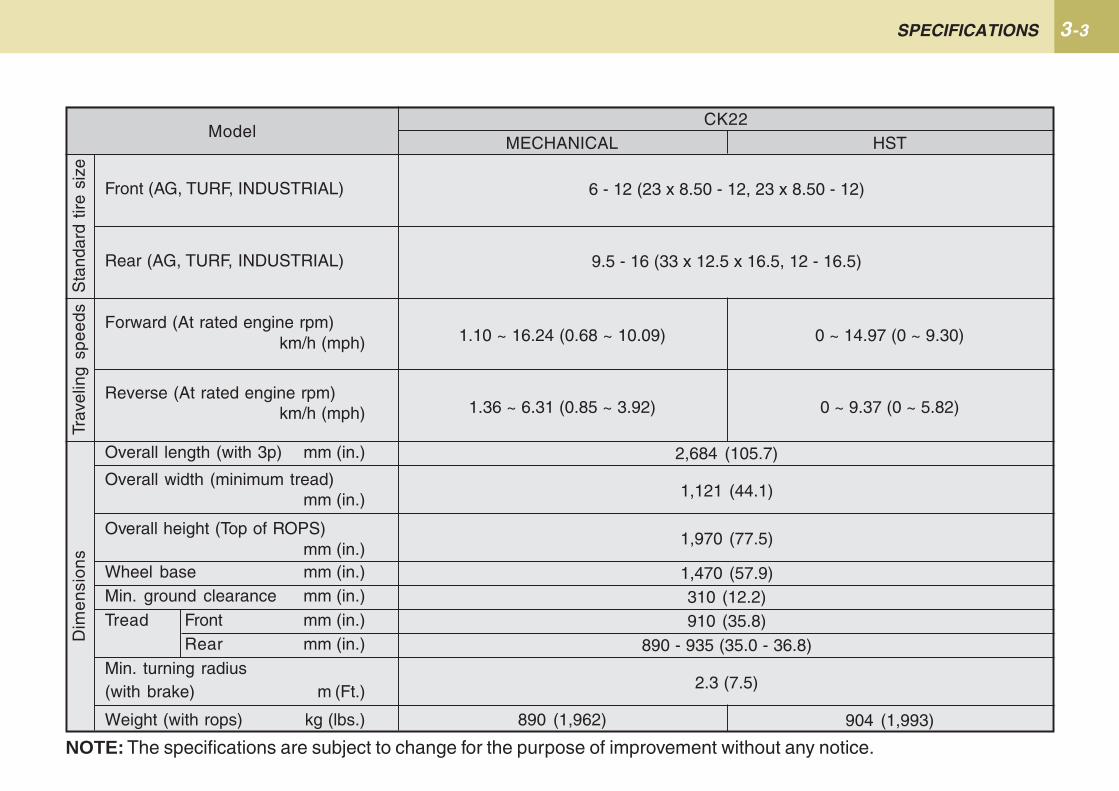
6 - 12 (23 x 8.50 - 12, 23 x 8.50 - 12)
9.5 - 16 (33 x 12.5 x 16.5, 12 - 16.5)
2,684 (105.7)
1,121 (44.1)
1,970 (77.5)
1,470 (57.9)310 (12.2)910 (35.8)
890 - 935 (35.0 - 36.8)
2.3 (7.5)
HST
0 ~ 14.97 (0 ~ 9.30)
0 ~ 9.37 (0 ~ 5.82)
904 (1,993)
MECHANICAL
1.10 ~ 16.24 (0.68 ~ 10.09)
1.36 ~ 6.31 (0.85 ~ 3.92)
890 (1,962)
Sta
ndar
d tir
e si
ze
Model
Front (AG, TURF, INDUSTRIAL)
Rear (AG, TURF, INDUSTRIAL)
Forward (At rated engine rpm)km/h (mph)
Reverse (At rated engine rpm)km/h (mph)
Overall length (with 3p) mm (in.)
Overall width (minimum tread)mm (in.)
Overall height (Top of ROPS)mm (in.)
Wheel base mm (in.)Min. ground clearance mm (in.)Tread Front mm (in.)
Rear mm (in.)Min. turning radius(with brake) m (Ft.)
Weight (with rops) kg (lbs.)
CK22
Trav
elin
g sp
eeds
Dim
ensi
ons
NOTE: The specifications are subject to change for the purpose of improvement without any notice.
3-4 CK22
IMPLEMENT LIMITATIONS
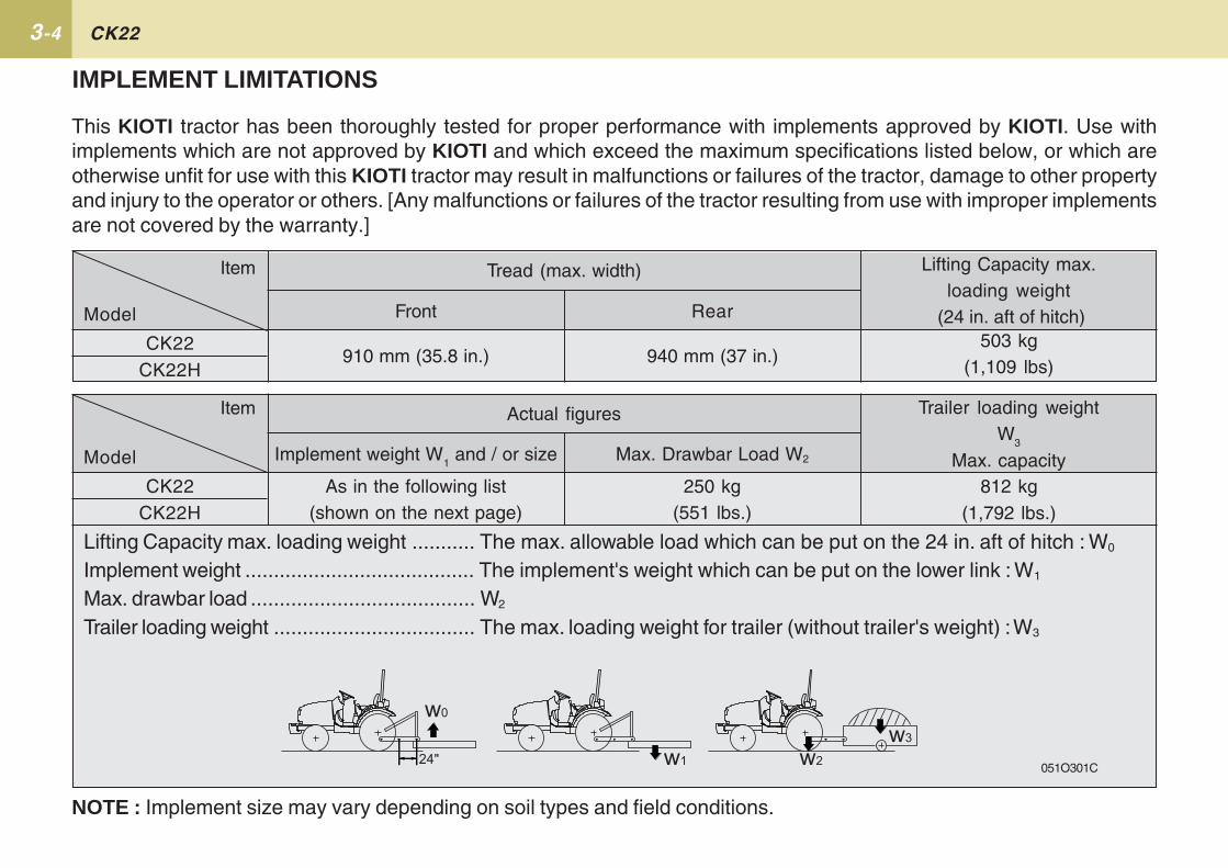
This KIOTI tractor has been thoroughly tested for proper performance with implements approved by KIOTI. Use withimplements which are not approved by KIOTI and which exceed the maximum specifications listed below, or which areotherwise unfit for use with this KIOTI tractor may result in malfunctions or failures of the tractor, damage to other propertyand injury to the operator or others. [Any malfunctions or failures of the tractor resulting from use with improper implementsare not covered by the warranty.]
NOTE : Implement size may vary depending on soil types and field conditions.
Lifting Capacity max. loading weight ........... The max. allowable load which can be put on the 24 in. aft of hitch : W0
Implement weight ........................................ The implement's weight which can be put on the lower link : W1
Max. drawbar load ....................................... W2
Trailer loading weight ................................... The max. loading weight for trailer (without trailer's weight) : W3
051O301C
Lifting Capacity max.loading weight
(24 in. aft of hitch)Front
910 mm (35.8 in.)CK22
CK22H
Tread (max. width)
503 kg(1,109 lbs)
Trailer loading weightW
3
Max. capacityMax. Drawbar Load W2
250 kg(551 lbs.)
Implement weight W1 and / or size
As in the following list(shown on the next page)
CK22CK22H
Actual figures
812 kg(1,792 lbs.)
Rear
940 mm (37 in.)
Model
Model
Item
Item
3-5 SPECIFICATIONS
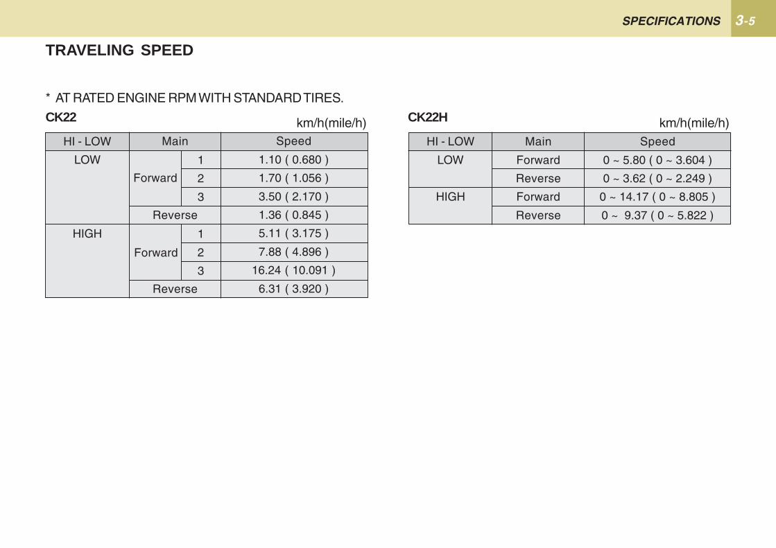
* AT RATED ENGINE RPM WITH STANDARD TIRES.
CK22
TRAVELING SPEED
CK22H
HI - LOW
LOW
HIGH
Main
Reverse
Reverse
Forward
1
2
3
1
2
3
Speed
1.10 ( 0.680 )
1.70 ( 1.056 )
3.50 ( 2.170 )
1.36 ( 0.845 )
5.11 ( 3.175 )
7.88 ( 4.896 )
16.24 ( 10.091 )
6.31 ( 3.920 )
km/h(mile/h) km/h(mile/h)HI - LOW
LOW
HIGH
Main
Forward
Reverse
Forward
Reverse
Speed
0 ~ 5.80 ( 0 ~ 3.604 )
0 ~ 3.62 ( 0 ~ 2.249 )
0 ~ 14.17 ( 0 ~ 8.805 )
0 ~ 9.37 ( 0 ~ 5.822 )
Forward

3-6 CK22
1219.2(48),1371.6(54)
1955.8(6.5) and below1524(60) and below
1193.8(47) and below1219.2(48) and below1524(60) and below1320.8(52),1524(60)1320.8(52),1524(60)1320.8(52),1524(60)
1219.2(48) and below1219.2(48),1524(60)
Implement
Loader
Backhoe with sub frameMid Mower
TillerBox BladeRear Blade
Rotary CutterBelt Guard
Chain GuardBale TransportCore Aerator
Remarks
Max. Bucket width mm(in)
Max. Diging depth mm(ft.in)Max. Cutting width mm(in)Max. Cutting width mm(in)Max. Cutting width mm(in)Max. Cutting width mm(in)Max. Cutting width mm(in)Max. Cutting width mm(in)Max. Cutting width mm(in)Max. Width mm(in)Max. Width mm(in)
RemarksOperating Capa.300kg(660lbs)and belowDo not use 3 point hitch backhoe
CK22 CK22H
4EXTERIOR VIEW ......................................................... 4-2
INSTRUMENT PANEL AND SWITCH ........................ 4-4
FOOT AND HAND CONTROLS ................................. 4-5
DESCRIPTION OF OPERATING SYSTEM
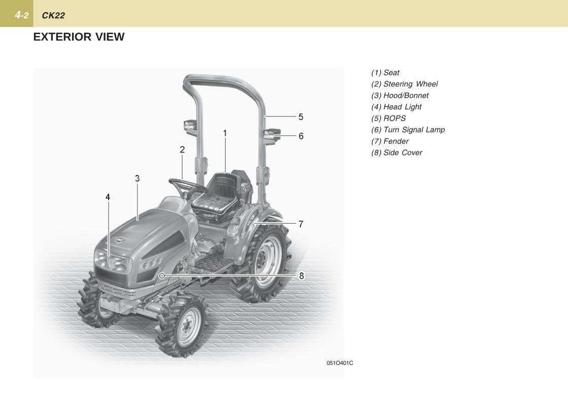
4-2 CK22
(1) Seat
(2) Steering Wheel
(3) Hood/Bonnet
(4) Head Light
(5) ROPS
(6) Turn Signal Lamp
(7) Fender
(8) Side Cover
051O401C
EXTERIOR VIEW
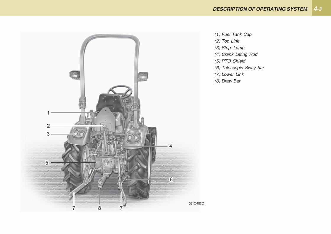
4-3DESCRIPTION OF OPERATING SYSTEM
(1) Fuel Tank Cap
(2) Top Link
(3) Stop Lamp
(4) Crank Lifting Rod
(5) PTO Shield
(6) Telescopic Sway bar
(7) Lower Link
(8) Draw Bar
051O402C

4-4 CK22
INSTRUMENT PANEL AND SWITCHES
051O403C
(1) Tachometer
(2) Fuel Gauge
(3) Coolant Temp. Gauge
(4) Left Turn Indicator
(5) Right Turn Indicator
(6) Turn Signal Switch & Light Switch
(7) Horn Switch(only EU)
(8) Key Switch
(9) Hazard Lamp Switch
(10) Engine Stop Knob

4-5DESCRIPTION OF OPERATING SYSTEM
FOOT AND HAND CONTROLS
CK22(AU)
051O404C
(1) Hand Throttle Lever
(2) Speed Set Lever
(3) Joystick Lever
(4) Clutch Pedal
(5) Brake Pedal (L)
(6) Brake Pedal (R)
(7) Main Gear Shift Lever
(8) Foot Throttle
(9) Position Control Lever
(10) Range Gear Shift Lever(Hi-Lo)
(11) Mid PTO Gear Shift Lever
(12) Rear PTO Gear Shift Lever
(13) Front Wheel Drive Lever
(14) Differential Lock Pedal
(15) 3-Point Hitch Lowering Speed Knob
4-6 CK22
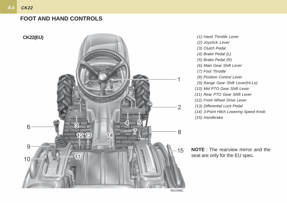
FOOT AND HAND CONTROLS
CK22(EU)
051O406C
(1) Hand Throttle Lever
(2) Joystick Lever
(3) Clutch Pedal
(4) Brake Pedal (L)
(5) Brake Pedal (R)
(6) Main Gear Shift Lever
(7) Foot Throttle
(8) Position Control Lever
(9) Range Gear Shift Lever(Hi-Lo)
(10) Mid PTO Gear Shift Lever
(11) Rear PTO Gear Shift Lever
(12) Front Wheel Drive Lever
(13) Differential Lock Pedal
(14) 3-Point Hitch Lowering Speed Knob
(15) Handbrake
NOTE : The rearview mirror and theseat are only for the EU spec.
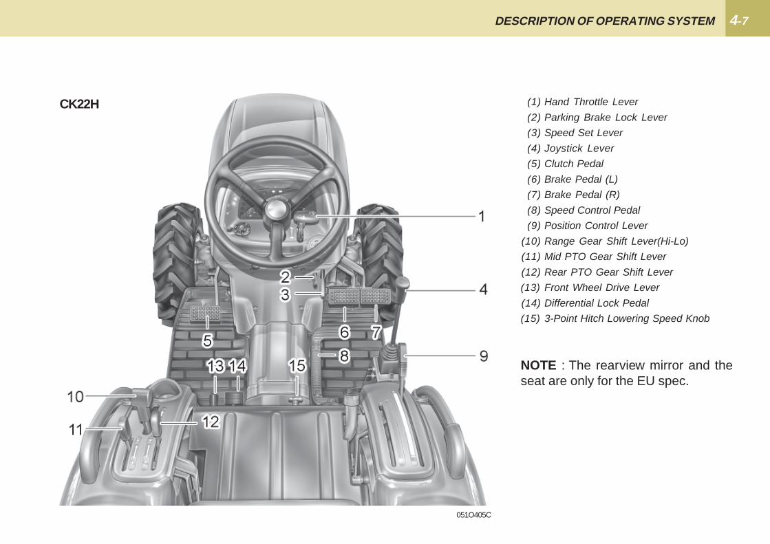
4-7DESCRIPTION OF OPERATING SYSTEM
(1) Hand Throttle Lever
(2) Parking Brake Lock Lever
(3) Speed Set Lever
(4) Joystick Lever
(5) Clutch Pedal
(6) Brake Pedal (L)
(7) Brake Pedal (R)
(8) Speed Control Pedal
(9) Position Control Lever
(10) Range Gear Shift Lever(Hi-Lo)
(11) Mid PTO Gear Shift Lever
(12) Rear PTO Gear Shift Lever
(13) Front Wheel Drive Lever
(14) Differential Lock Pedal
(15) 3-Point Hitch Lowering Speed Knob
CK22H
051O405C
NOTE : The rearview mirror and theseat are only for the EU spec.

5PRE-OPERATION ........................................................ 5-2
OPERATING NEW TRACTOR ................................... 5-3
OPERATING THE ENGINE ........................................ 5-4
OPERATING THE TRACTOR .................................. 5-11
OPERATION
5-2 CK22
- Walk around inspection.
- Check the engine oil level
- Check the transmission oil level
- Check the coolant level
- Clean the grill and radiator screen.
- Check the air cleaner and evacua-tor valve.
- Check the brake pedals and link-ages
- Check all dash gauges and indica-tors
- Check head lights, tail lights, and allworking lights.
- Check accessible wiring harness forany damage.
- Check the seat belt and ROPS fordamage.
- Refuel (See "daily check" in the pe-riodic service section)
- Check all danger and warning labels.
PRE-OPERATION
It is a good practice to know the con-dition of your tractor before you startit. You should perform a routine checkbefore each use.
CHECK ITEM
To avoid personal injury:� Be sure to check and service the
tractor on a level surface withthe engine shut off and the park-ing brake “ENGAGED”.
� Follow the refueling proceduresprovided in “DAILY CHECK” inperiodic service section.
� Familiarize yourself with alldanger, warning and cautionlabels. Maintain all labels intheir proper places in good leg-ible condition.
DAILY CHECK
!!!!! CAUTION
5-3 OPERATION
OPERATING NEW TRACTORCHANGING LUBRICATING OILFOR NEW TRACTORS
How a new tractor is handled and main-tained determines the life of the tractor.
A new tractor just off the factory pro-duction line has of course been, tested,but the various parts are not accus-tomed to each other, therefore careshould be taken to operate the tractorfor the first 50 hours at a slower speedand avoid excessive work or operationuntil the various parts become "broken-in." The manner in which the tractor ishandled during the "breaking-in" periodgreatly affects the life of your tractor.Therefore, to obtain the maximum per-formance and the longest life of thetractor, it is very important to properlybreak-in your tractor.
In handling a new tractor, the followingprecautions should be observed.
� You should not operate your tractorat full speed for the first fifty hoursof use.
� Avoid sudden starts and stops.
� In cold climates, allow your tractorplenty of time to warm up.
� Do not run the engine at speedsfaster than necessary.
� Use due caution when operating yourtractor on rough roads or terrain.
The above precautions are not limitedto new tractors only, but are a goodpractice for tractors regardless of theirage.
Special attention should be given tonew tractors lubrication oil. New partsare not accustomed to each other andare not broken in properly. Small metalgrit can develop in the lubricating sys-tem as metal parts begin to "break in"and continuous use of the contaminatedoil can cause damage and failure.
Therefore you should change thetractor's oil after the break-in period.
For further details of the oil change andservice schedule, see "maintenance"section.
5-4 CK22
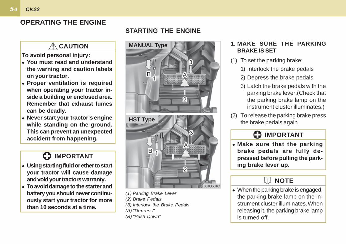
051O501C
(1) To set the parking brake;
1) Interlock the brake pedals
2) Depress the brake pedals
3) Latch the brake pedals with theparking brake lever.(Check thatthe parking brake lamp on theinstrument cluster illuminates.)
(2) To release the parking brake pressthe brake pedals again.
STARTING THE ENGINE
(1) Parking Brake Lever(2) Brake Pedals(3) Interlock the Brake Pedals(A) "Depress"(B) "Push Down"
1. MAKE SURE THE PARKINGBRAKE IS SET
� Using starting fluid or ether to startyour tractor will cause damageand void your tractors warranty.
� To avoid damage to the starter andbattery you should never continu-ously start your tractor for morethan 10 seconds at a time.
IMPORTANT
� Make sure that the parkingbrake pedals are fully de-pressed before pulling the park-ing brake lever up.
IMPORTANT
OPERATING THE ENGINE
To avoid personal injury:� You must read and understand
the warning and caution labelson your tractor.
� Proper ventilation is requiredwhen operating your tractor in-side a building or enclosed area.Remember that exhaust fumescan be deadly.
� Never start your tractor’s enginewhile standing on the ground.This can prevent an unexpectedaccident from happening.
!!!!! CAUTION
NOTE� When the parking brake is engaged,
the parking brake lamp on the in-strument cluster illuminates. Whenreleasing it, the parking brake lampis turned off.
HST Type
MANUAL Type
5-5 OPERATION
051O502C
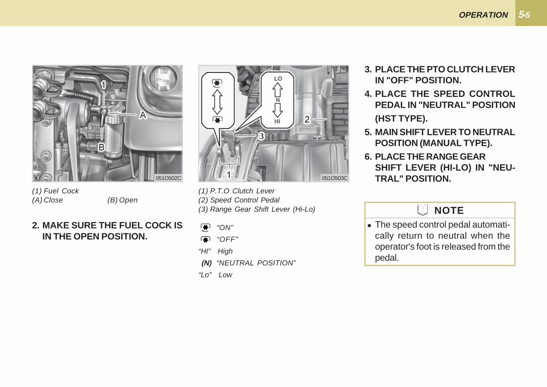
2. MAKE SURE THE FUEL COCK ISIN THE OPEN POSITION.
(1) Fuel Cock(A) Close (B) Open
3. PLACE THE PTO CLUTCH LEVERIN "OFF" POSITION.
4. PLACE THE SPEED CONTROLPEDAL IN "NEUTRAL" POSITION(HST TYPE).
5. MAIN SHIFT LEVER TO NEUTRALPOSITION (MANUAL TYPE).
6. PLACE THE RANGE GEARSHIFT LEVER (HI-LO) IN "NEU-TRAL" POSITION.
NOTE� The speed control pedal automati-
cally return to neutral when theoperator's foot is released from thepedal.
(1) P.T.O Clutch Lever(2) Speed Control Pedal(3) Range Gear Shift Lever (Hi-Lo)
“ON”
“OFF”
“HI” High
(N) “NEUTRAL POSITION”
“Lo” Low
051O503C
5-6 CK22
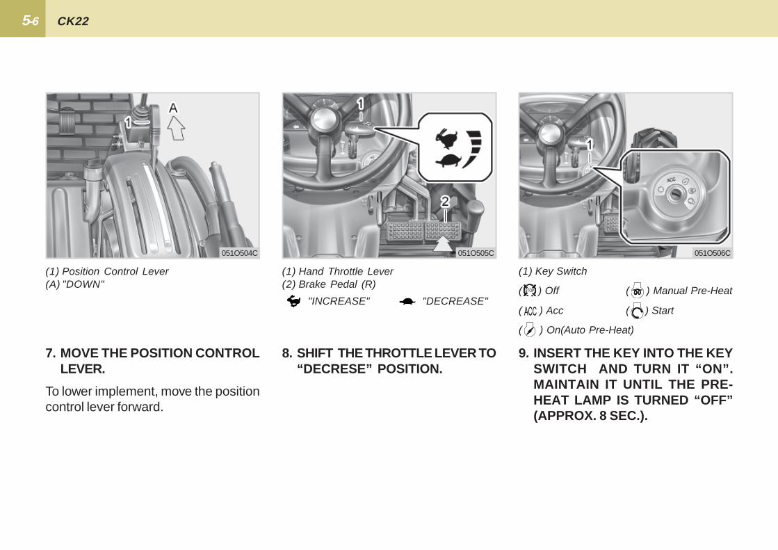
(1) Key Switch
( ) Off ( ) Manual Pre-Heat
( ) Acc ( ) Start
( ) On(Auto Pre-Heat)
051O504C
8. SHIFT THE THROTTLE LEVER TO“DECRESE” POSITION.
9. INSERT THE KEY INTO THE KEYSWITCH AND TURN IT “ON”.MAINTAIN IT UNTIL THE PRE-HEAT LAMP IS TURNED “OFF”(APPROX. 8 SEC.).
7. MOVE THE POSITION CONTROLLEVER.
To lower implement, move the positioncontrol lever forward.
(1) Position Control Lever(A) "DOWN"
(1) Hand Throttle Lever(2) Brake Pedal (R)
"INCREASE" "DECREASE"
051O505C 051O506C

5-7 OPERATION
10. TURN THE KEY TO “START” PO-SITION AND RELEASE WHENTHE ENGINE STARTS.
1. Be careful not to run the startingmotor longer than 10 seconds dueto its heavy current consumption.
2. If the tractor has not started in 10seconds stop operating the starter,wait 30 seconds and then repeat thestarting procedure.
3. Prior to restarting, be sure that theflywheel is completely stopped.
4. For manual preheating, turn and holdthe key from ON to preheat position.
� Only when the range shift lever inneutral position, the motor can bestarted (HST).
� Only with the shuttle lever in neu-tral position, the motor canbe started(Manual).
11. CHECK TO SEE THAT ALL THEWARNING LAMPS ON THE IN-STRUMENT CLUSTER TURN“OFF”.
(1) Headlight-High Beam Lamp(2) Battery Charge Warning Lamp(3) Parking Brake(4) Engine Oil Pressure Warning Lamp
051O507C
NOTE
5-8 CK22
051O508C
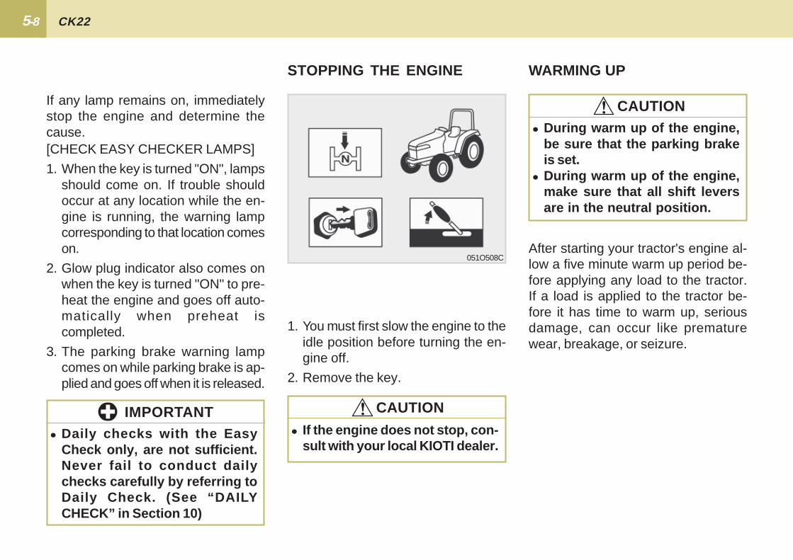
STOPPING THE ENGINE
1. You must first slow the engine to theidle position before turning the en-gine off.
2. Remove the key.
WARMING UP
� During warm up of the engine,be sure that the parking brakeis set.
� During warm up of the engine,make sure that all shift leversare in the neutral position.
[CHECK EASY CHECKER LAMPS]
1. When the key is turned "ON", lampsshould come on. If trouble shouldoccur at any location while the en-gine is running, the warning lampcorresponding to that location comeson.
2. Glow plug indicator also comes onwhen the key is turned "ON" to pre-heat the engine and goes off auto-matically when preheat iscompleted.
3. The parking brake warning lampcomes on while parking brake is ap-plied and goes off when it is released.
If any lamp remains on, immediatelystop the engine and determine thecause.
� Daily checks with the EasyCheck only, are not sufficient.Never fail to conduct dailychecks carefully by referring toDaily Check. (See “DAILYCHECK” in Section 10)
IMPORTANT
!!!!! CAUTION
!!!!! CAUTION
� If the engine does not stop, con-sult with your local KIOTI dealer.
After starting your tractor's engine al-low a five minute warm up period be-fore applying any load to the tractor.If a load is applied to the tractor be-fore it has time to warm up, seriousdamage, can occur like prematurewear, breakage, or seizure.
5-9 OPERATION
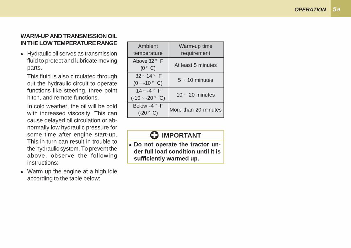
� Hydraulic oil serves as transmissionfluid to protect and lubricate movingparts.
This fluid is also circulated throughout the hydraulic circuit to operatefunctions like steering, three pointhitch, and remote functions.
In cold weather, the oil will be coldwith increased viscosity. This cancause delayed oil circulation or ab-normally low hydraulic pressure forsome time after engine start-up.This in turn can result in trouble tothe hydraulic system. To prevent theabove, observe the followinginstructions:
� Warm up the engine at a high idleaccording to the table below:
WARM-UP AND TRANSMISSION OILIN THE LOW TEMPERATURE RANGE
� Do not operate the tractor un-der full load condition until it issufficiently warmed up.
IMPORTANT
Ambienttemperature
Above 32 ° F(0 ° C)
32 ~ 14 ° F(0 ~ -10 ° C)
14 ~ -4 ° F(-10 ~ -20 ° C)
Below -4 ° F(-20 ° C)
Warm-up timerequirement
At least 5 minutes
5 ~ 10 minutes
10 ~ 20 minutes
More than 20 minutes

5-10 CK22
051O509C
JUMP STARTING
(1) Dead Battery (2) Jumper Cables(3) Helper Battery
the other vehicle to touch. Start thevehicle's engine after connecting thecables and let it run for a fewmoments. Turn off all accessories onboth vehicles. Then start the dis-abled tractor.
7. Disconnect the battery cables in theexact opposite order as they wereattached.
When jump starting the engine, followthe instructions below to safely startthe engine.
1. Use a battery of the same voltageas the disabled tractor battery tojump start the tractor. Locate thegood battery in a safe place wherethe jumper cables will reach.
2. Engage the parking brake of the trac-tor and shift the transmission gearto the neutral position.
3. Put on safety goggles and rubbergloves.
4. Attach the red clamp to the positiveterminal of the dead battery, and at-tach the other end to the positive ter-minal of the helper battery.
5. Clamp the black cable to the Enginehooks or other ground source and at-tach the other end to the negativecable of the helper battery.
6. If the helper battery is in anothervehicle, do not allow the tractor and
� Keep fire, spark, cigarette, etc.,from the battery.
� If the tractor battery is frozen,jump starting the engine isprohibited.
� Do not connect the (-) jumpercable to the negative(-) terminalof the discharged battery.
!!!!! CAUTION
� Use a ground away from thebattery
5-11 OPERATION
051O511C
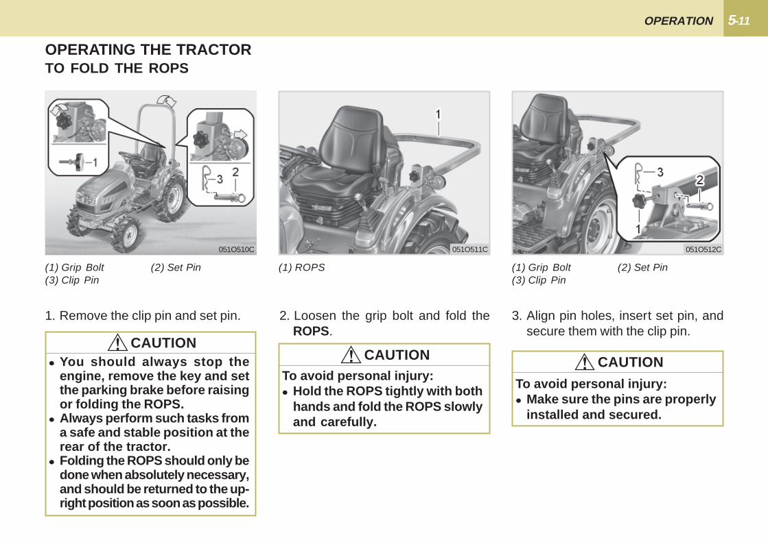
TO FOLD THE ROPS
(1) Grip Bolt (2) Set Pin(3) Clip Pin
(1) ROPS
1. Remove the clip pin and set pin. 2. Loosen the grip bolt and fold theROPS.
OPERATING THE TRACTOR
� You should always stop theengine, remove the key and setthe parking brake before raisingor folding the ROPS.
� Always perform such tasks froma safe and stable position at therear of the tractor.
� Folding the ROPS should only bedone when absolutely necessary,and should be returned to the up-right position as soon as possible.
!!!!! CAUTION
To avoid personal injury:� Hold the ROPS tightly with both
hands and fold the ROPS slowlyand carefully.
!!!!! CAUTION
051O512C
3. Align pin holes, insert set pin, andsecure them with the clip pin.
To avoid personal injury:� Make sure the pins are properly
installed and secured.
(1) Grip Bolt (2) Set Pin(3) Clip Pin
!!!!! CAUTION
051O510C
5-12 CK22
051O515C
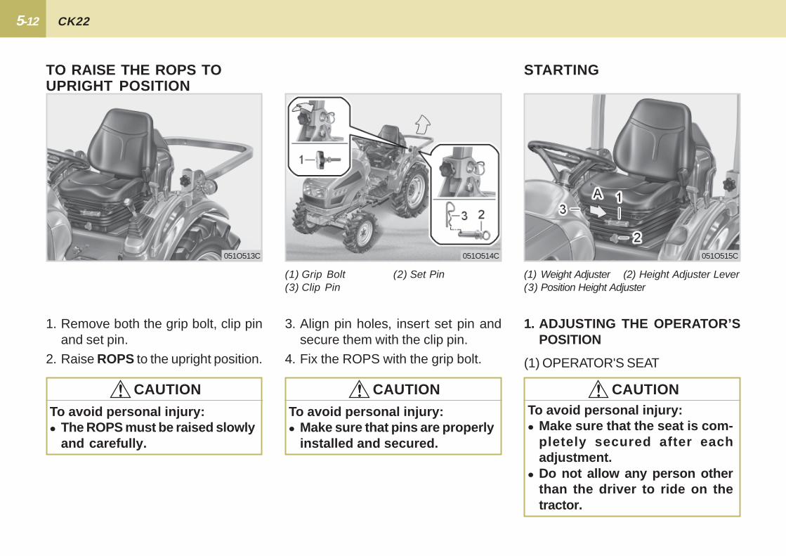
1. ADJUSTING THE OPERATOR’SPOSITION
(1) Weight Adjuster (2) Height Adjuster Lever(3) Position Height Adjuster
(1) OPERATOR'S SEAT
STARTING
To avoid personal injury:� Make sure that the seat is com-
pletely secured after eachadjustment.
� Do not allow any person otherthan the driver to ride on thetractor.
!!!!! CAUTION
051O513C 051O514C
TO RAISE THE ROPS TOUPRIGHT POSITION
1. Remove both the grip bolt, clip pinand set pin.
2. Raise ROPS to the upright position.
3. Align pin holes, insert set pin andsecure them with the clip pin.
4. Fix the ROPS with the grip bolt.
To avoid personal injury:� Make sure that pins are properly
installed and secured.
(1) Grip Bolt (2) Set Pin(3) Clip Pin
!!!!! CAUTION
To avoid personal injury:� The ROPS must be raised slowly
and carefully.
!!!!! CAUTION
5-13 OPERATION
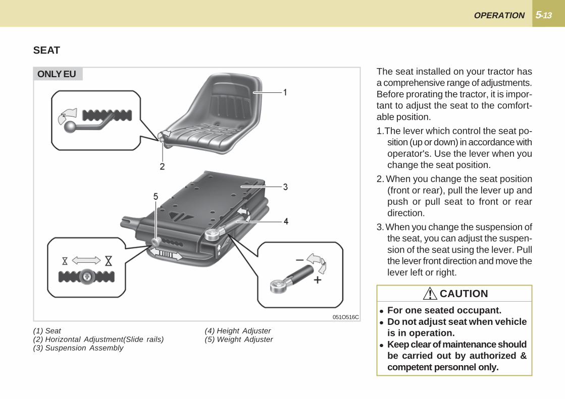
SEAT
(1) Seat(2) Horizontal Adjustment(Slide rails)(3) Suspension Assembly
(4) Height Adjuster(5) Weight Adjuster
051O516C
ONLY EU The seat installed on your tractor hasa comprehensive range of adjustments.Before prorating the tractor, it is impor-tant to adjust the seat to the comfort-able position.
1.The lever which control the seat po-sition (up or down) in accordance withoperator's. Use the lever when youchange the seat position.
2. When you change the seat position(front or rear), pull the lever up andpush or pull seat to front or reardirection.
3. When you change the suspension ofthe seat, you can adjust the suspen-sion of the seat using the lever. Pullthe lever front direction and move thelever left or right.
� For one seated occupant.� Do not adjust seat when vehicle
is in operation.� Keep clear of maintenance should
be carried out by authorized &competent personnel only.
!!!!! CAUTION
5-14 CK22
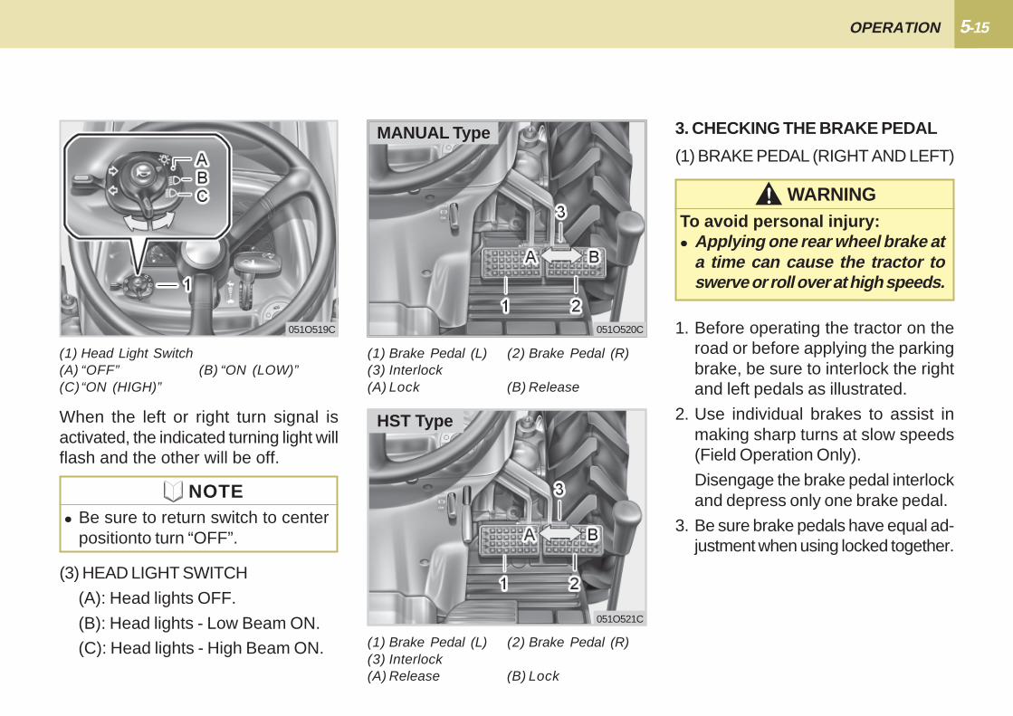
(1) HAZARD LIGHT SWITCH
When hazard light switch is pushed"ON", the hazard lights flash along withthe indicator on the instrument panel.Push the switch to "OFF" to turn flash-ers "OFF".
2. SELECTING LIGHT SWITCH PO-SITIONS
(1) Hazard / Turn Signal Indicator(2) Turn Signal Light Switch(3) Hazard Light Switch
051O518C051O517C
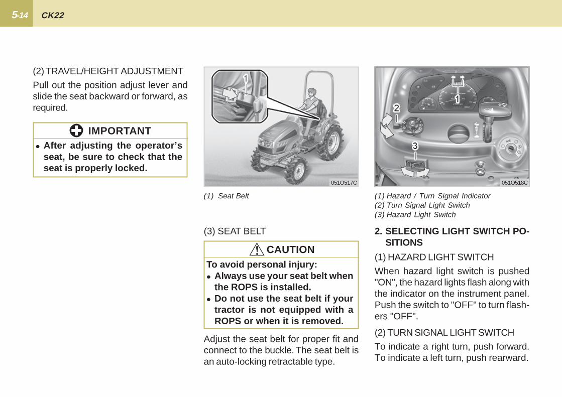
(2) TRAVEL/HEIGHT ADJUSTMENT
Pull out the position adjust lever andslide the seat backward or forward, asrequired.
(1) Seat Belt
Adjust the seat belt for proper fit andconnect to the buckle. The seat belt isan auto-locking retractable type.
(3) SEAT BELT
� After adjusting the operator’sseat, be sure to check that theseat is properly locked.
IMPORTANT
To avoid personal injury:� Always use your seat belt when
the ROPS is installed.� Do not use the seat belt if your
tractor is not equipped with aROPS or when it is removed.
!!!!! CAUTION
(2) TURN SIGNAL LIGHT SWITCH
To indicate a right turn, push forward.To indicate a left turn, push rearward.
5-15 OPERATION
HST Type
MANUAL Type
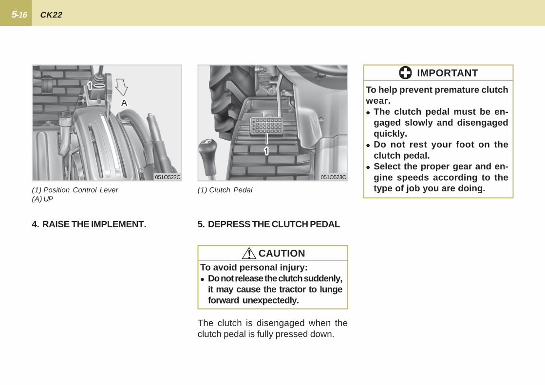
(1) Head Light Switch(A) “OFF” (B) “ON (LOW)”(C)“ON (HIGH)”
(3) HEAD LIGHT SWITCH
(A): Head lights OFF.
(B): Head lights - Low Beam ON.
(C): Head lights - High Beam ON.
051O521C
(1) Brake Pedal (L) (2) Brake Pedal (R)(3) Interlock(A) Lock (B) Release
(1) Brake Pedal (L) (2) Brake Pedal (R)(3) Interlock(A) Release (B) Lock
3. CHECKING THE BRAKE PEDAL
1. Before operating the tractor on theroad or before applying the parkingbrake, be sure to interlock the rightand left pedals as illustrated.
2. Use individual brakes to assist inmaking sharp turns at slow speeds(Field Operation Only).
Disengage the brake pedal interlockand depress only one brake pedal.
3. Be sure brake pedals have equal ad-justment when using locked together.
(1) BRAKE PEDAL (RIGHT AND LEFT)
WARNING!!!!!To avoid personal injury:� Applying one rear wheel brake at
a time can cause the tractor toswerve or roll over at high speeds.
051O520C051O519C
NOTE� Be sure to return switch to center
positionto turn “OFF”.
When the left or right turn signal isactivated, the indicated turning light willflash and the other will be off.
5-16 CK22
To help prevent premature clutchwear.� The clutch pedal must be en-
gaged slowly and disengagedquickly.
� Do not rest your foot on theclutch pedal.
� Select the proper gear and en-gine speeds according to thetype of job you are doing.
IMPORTANT
4. RAISE THE IMPLEMENT.
The clutch is disengaged when theclutch pedal is fully pressed down.
5. DEPRESS THE CLUTCH PEDAL
(1) Position Control Lever(A) UP
(1) Clutch Pedal
051O522C 051O523C
To avoid personal injury:� Do not release the clutch suddenly,
it may cause the tractor to lungeforward unexpectedly.
!!!!! CAUTION
5-17 OPERATION
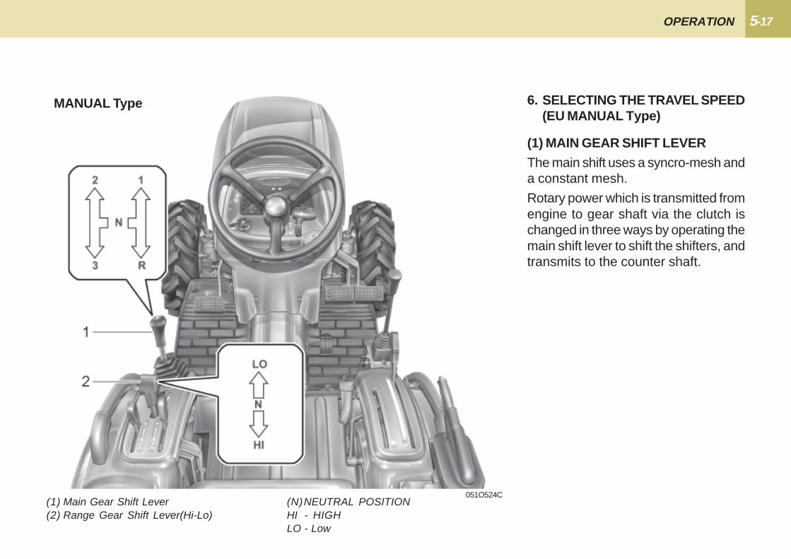
(1) Main Gear Shift Lever(2) Range Gear Shift Lever(Hi-Lo)
051O524C
MANUAL Type 6. SELECTING THE TRAVEL SPEED(EU MANUAL Type)
(1) MAIN GEAR SHIFT LEVERThe main shift uses a syncro-mesh anda constant mesh.
Rotary power which is transmitted fromengine to gear shaft via the clutch ischanged in three ways by operating themain shift lever to shift the shifters, andtransmits to the counter shaft.
(N)NEUTRAL POSITIONHI - HIGHLO - Low
5-18 CK22
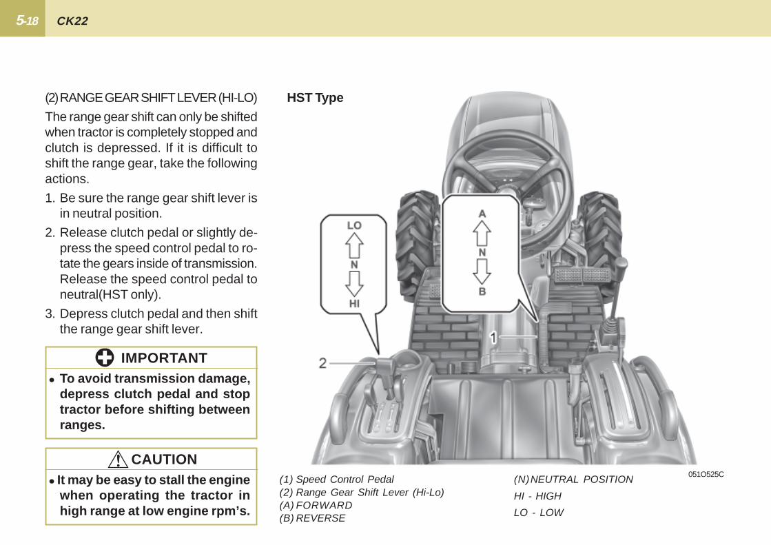
HST Type
051O525C
(2)RANGE GEAR SHIFT LEVER (HI-LO)
The range gear shift can only be shiftedwhen tractor is completely stopped andclutch is depressed. If it is difficult toshift the range gear, take the followingactions.
1. Be sure the range gear shift lever isin neutral position.
2. Release clutch pedal or slightly de-press the speed control pedal to ro-tate the gears inside of transmission.Release the speed control pedal toneutral(HST only).
3. Depress clutch pedal and then shiftthe range gear shift lever.
� To avoid transmission damage,depress clutch pedal and stoptractor before shifting betweenranges.
IMPORTANT
� It may be easy to stall the enginewhen operating the tractor inhigh range at low engine rpm’s.
!!!!! CAUTION(1) Speed Control Pedal(2) Range Gear Shift Lever (Hi-Lo)(A) FORWARD(B) REVERSE
(N)NEUTRAL POSITION
HI - HIGH
LO - LOW
5-19 OPERATION
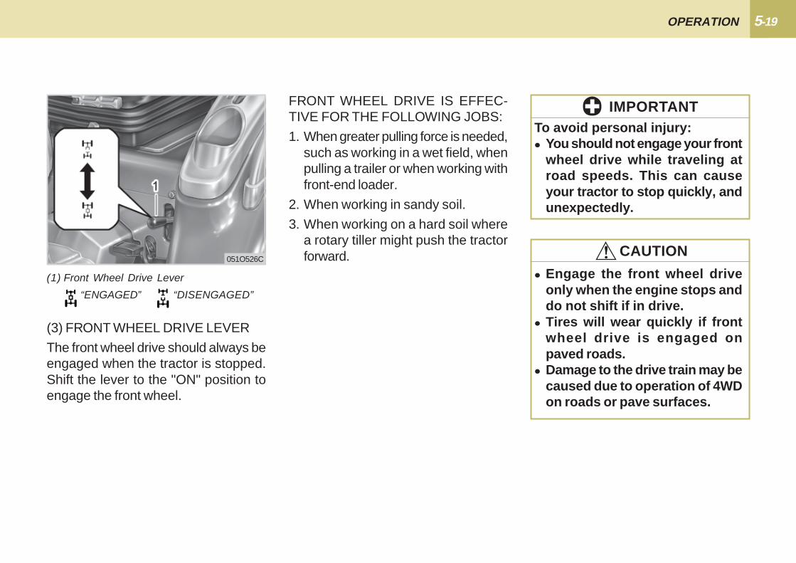
(3) FRONT WHEEL DRIVE LEVER
The front wheel drive should always beengaged when the tractor is stopped.Shift the lever to the "ON" position toengage the front wheel.
(1) Front Wheel Drive Lever
“ENGAGED” “DISENGAGED”
051O526C
FRONT WHEEL DRIVE IS EFFEC-TIVE FOR THE FOLLOWING JOBS:
1. When greater pulling force is needed,such as working in a wet field, whenpulling a trailer or when working withfront-end loader.
2. When working in sandy soil.
3. When working on a hard soil wherea rotary tiller might push the tractorforward.
To avoid personal injury:� You should not engage your front
wheel drive while traveling atroad speeds. This can causeyour tractor to stop quickly, andunexpectedly.
IMPORTANT
� Engage the front wheel driveonly when the engine stops anddo not shift if in drive.
� Tires will wear quickly if frontwheel drive is engaged onpaved roads.
� Damage to the drive train may becaused due to operation of 4WDon roads or pave surfaces.
!!!!! CAUTION
5-20 CK22
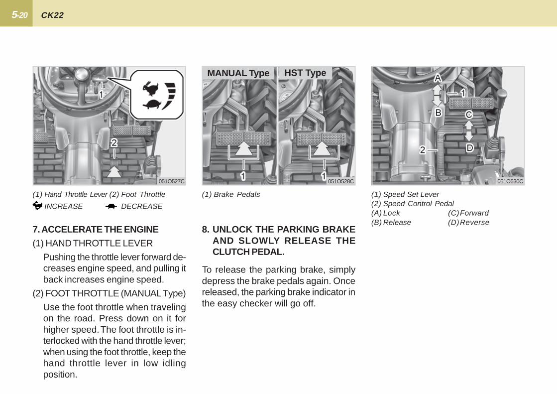
(1) Speed Set Lever(2) Speed Control Pedal(A) Lock (C)Forward(B) Release (D)Reverse
051O530C
(1) Brake Pedals
To release the parking brake, simplydepress the brake pedals again. Oncereleased, the parking brake indicator inthe easy checker will go off.
8. UNLOCK THE PARKING BRAKEAND SLOWLY RELEASE THECLUTCH PEDAL.
051O528C
HST TypeMANUAL Type
(1) Hand Throttle Lever (2) Foot Throttle
INCREASE DECREASE
7. ACCELERATE THE ENGINE(1) HAND THROTTLE LEVER
Pushing the throttle lever forward de-creases engine speed, and pulling itback increases engine speed.
(2) FOOT THROTTLE (MANUAL Type)
Use the foot throttle when travelingon the road. Press down on it forhigher speed. The foot throttle is in-terlocked with the hand throttle lever;when using the foot throttle, keep thehand throttle lever in low idlingposition.
051O527C
5-21 OPERATION
1. Forward pedal
Depress the control pedal with thetoe of your right foot to move forward.
2. Reverse pedal
Depress the pedal with the heel ofyour right foot to move backward.
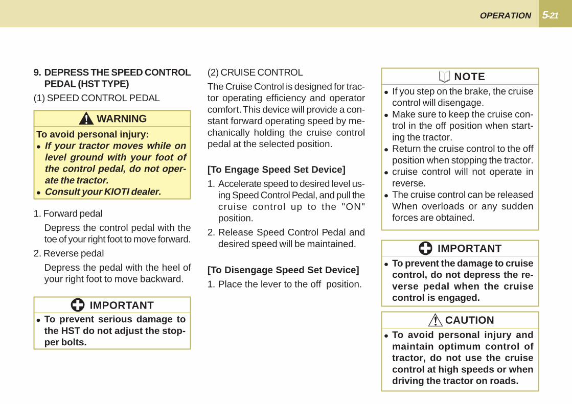
9. DEPRESS THE SPEED CONTROLPEDAL (HST TYPE)
(1) SPEED CONTROL PEDAL
WARNING!!!!!To avoid personal injury:� If your tractor moves while on
level ground with your foot ofthe control pedal, do not oper-ate the tractor.
� Consult your KIOTI dealer.
� To prevent serious damage tothe HST do not adjust the stop-per bolts.
IMPORTANT
(2) CRUISE CONTROL
The Cruise Control is designed for trac-tor operating efficiency and operatorcomfort. This device will provide a con-stant forward operating speed by me-chanically holding the cruise controlpedal at the selected position.
[To Engage Speed Set Device]1. Accelerate speed to desired level us-
ing Speed Control Pedal, and pull thecruise control up to the "ON"position.
2. Release Speed Control Pedal anddesired speed will be maintained.
[To Disengage Speed Set Device]1. Place the lever to the off position.
� To avoid personal injury andmaintain optimum control oftractor, do not use the cruisecontrol at high speeds or whendriving the tractor on roads.
!!!!! CAUTION
� To prevent the damage to cruisecontrol, do not depress the re-verse pedal when the cruisecontrol is engaged.
IMPORTANT
� If you step on the brake, the cruisecontrol will disengage.
� Make sure to keep the cruise con-trol in the off position when start-ing the tractor.
� Return the cruise control to the offposition when stopping the tractor.
� cruise control will not operate inreverse.
� The cruise control can be releasedWhen overloads or any suddenforces are obtained.
NOTE
5-22 CK22
1. Slow the engine to idle
2. Depress the clutch and brake pedal.(Manual model)
3. After the tractor has stopped, disen-gage the PTO, lower the implement,shift the transmission into neutral,release the clutch pedal and set theparking brake.
STOPPING
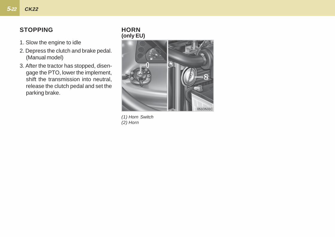
051O531C
HORN
(1) Horn Switch(2) Horn
(only EU)
5-23 OPERATION
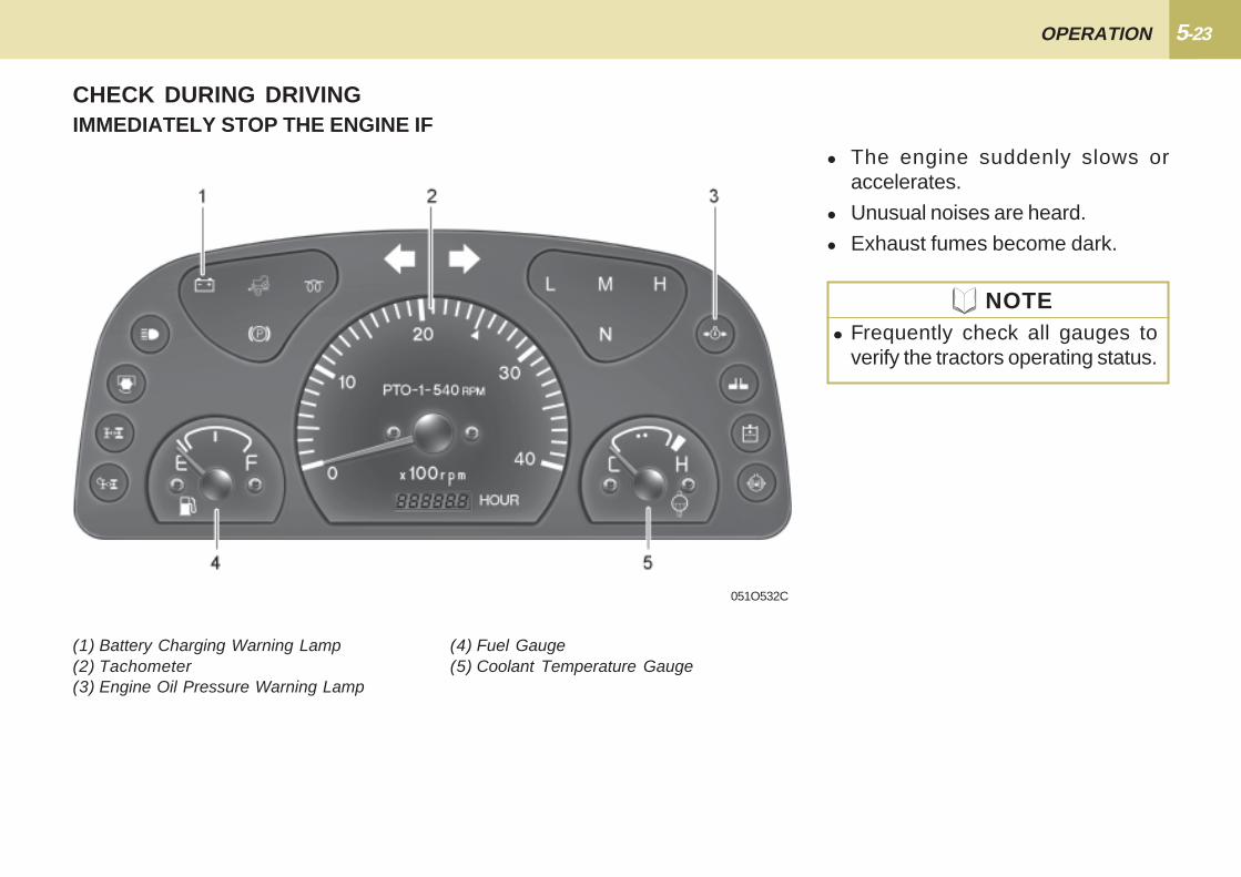
CHECK DURING DRIVINGIMMEDIATELY STOP THE ENGINE IF
� The engine suddenly slows oraccelerates.
� Unusual noises are heard.
� Exhaust fumes become dark.
051O532C
� Frequently check all gauges toverify the tractors operating status.
NOTE
(1) Battery Charging Warning Lamp(2) Tachometer(3) Engine Oil Pressure Warning Lamp
(4) Fuel Gauge(5) Coolant Temperature Gauge

5-24 CK22
If warning lamps come on while oper-ating the engine, immediately stop theengine and check for the cause.
Never operate the tractor while warn-ing lamps are on.
INSTRUMENT CLUSTER
(1) Headlight-High Beam Lamp(2) Battery Charging Warning Lamp(3) Parking Brake Lamp(4) Glow Plug Indicator(5) Left Turn Indicator(6) Tachometer
(7) Right Turn Indicator(8) Engine Oil Pressure Warning Lamp(9) Fuel Gauge(10) Hour-Meter Indicator(11) Coolant Temperature Gauge
051O533C

5-25 OPERATION
051O534C 051O535C 051O536C
When the key switch is turned "ON"this gauge indicates the temperature ofthe coolant. "C" is for cold, and "H" isfor hot.
“C”COLD “H”HOT
COOLANT TEMPERATUREGAUGE
To avoid personal injury:� Do not remove radiator cap un-
til coolant temperature is wellbelow its boiling point. Thenloosen cap slightly to the stopto relieve any pressure beforeremoving cap completely.
!!!!! CAUTION
TACHOMETER
The tachometer indicates the enginespeed and the 540rpm PTO operatingspeed.
The hour-meter indicates, in five digits,the hours that the tractor has beenoperated.
When the key switch is on, the fuelgauge indicates the fuel level.
Be careful not to empty the fuel tank.Otherwise air may enter the fuelsystem.
Should this happen, the system shouldbe bled(See "Bleeding Fuel System" inPeriodic Service Section).
FUEL GAUGE
“E” EMPTY “F” FULL

5-26 CK22
If the tractor engine oil pressure is be-low the specified ranges, the warninglamp will illuminate.
ENGINE OIL PRESSUREWARNING LAMP
If the battery of the generator is not fullycharged, the warning lamp illuminateson the instrument cluster. (Illuminationat KEY ON(START OFF) is normal)
BATTERY CHARGING WARN-ING LAMP
� In the event a warning indicatorlamp illuminates while operatingthe tractor, immediately shut theengine off and consult with yourKIOTI dealer.
NOTE
HEAD LIGHT HIGH BEAMPILOT LAMP
When head lights are turned to high,an indicator lamp will illuminate on thedash.
051O537C 051O538C 051O539C
5-27 OPERATION
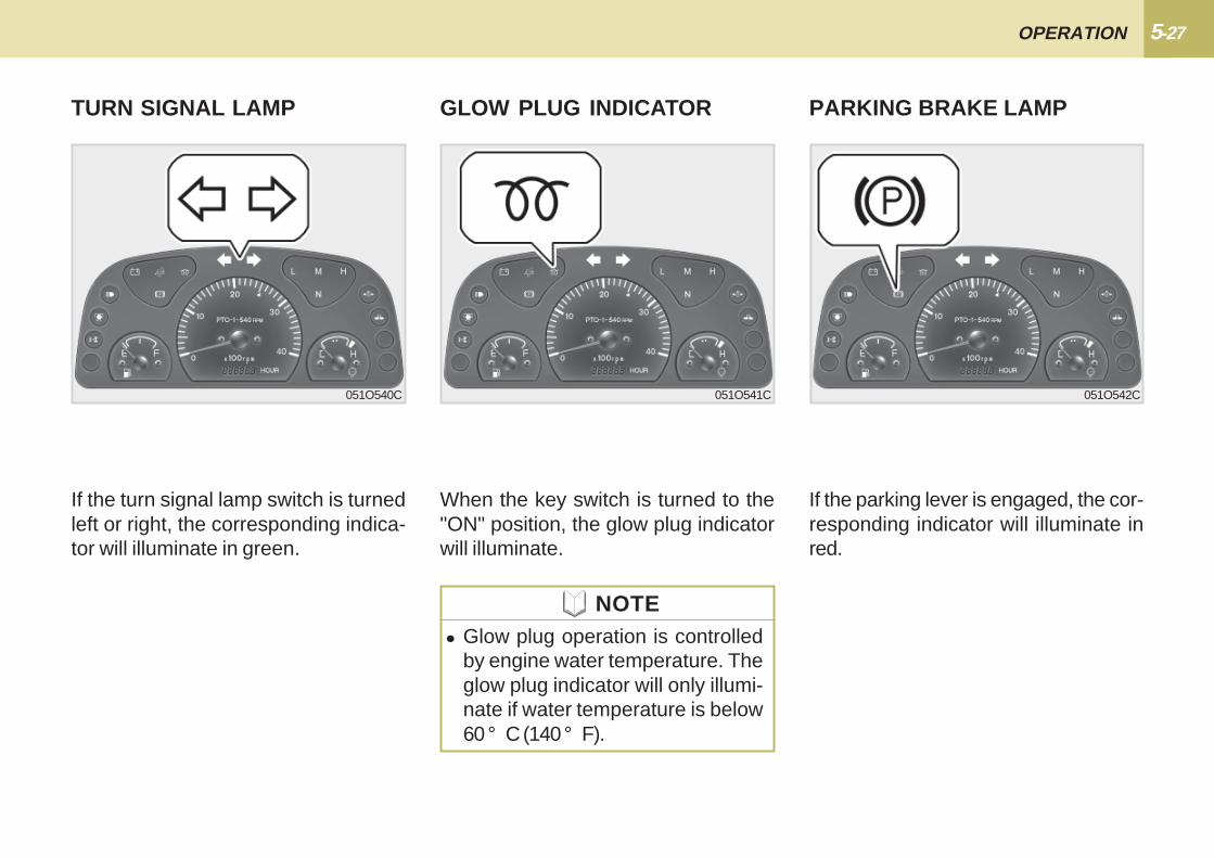
If the parking lever is engaged, the cor-responding indicator will illuminate inred.
PARKING BRAKE LAMPTURN SIGNAL LAMP GLOW PLUG INDICATOR
If the turn signal lamp switch is turnedleft or right, the corresponding indica-tor will illuminate in green.
When the key switch is turned to the"ON" position, the glow plug indicatorwill illuminate.
051O540C 051O541C 051O542C
� Glow plug operation is controlledby engine water temperature. Theglow plug indicator will only illumi-nate if water temperature is below60 ° C (140 ° F).
NOTE
5-28 CK22
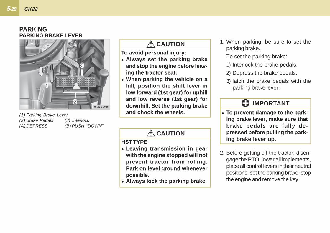
2. Before getting off the tractor, disen-gage the PTO, lower all implements,place all control levers in their neutralpositions, set the parking brake, stopthe engine and remove the key.
� To prevent damage to the park-ing brake lever, make sure thatbrake pedals are fully de-pressed before pulling the park-ing brake lever up.
IMPORTANT
1. When parking, be sure to set theparking brake.
To set the parking brake:
1) Interlock the brake pedals.
2) Depress the brake pedals.
3) latch the brake pedals with theparking brake lever.
PARKING BRAKE LEVER
(1) Parking Brake Lever(2) Brake Pedals (3) Interlock(A) DEPRESS (B) PUSH “DOWN”
PARKING
To avoid personal injury:� Always set the parking brake
and stop the engine before leav-ing the tractor seat.
� When parking the vehicle on ahill, position the shift lever inlow forward (1st gear) for uphilland low reverse (1st gear) fordownhill. Set the parking brakeand chock the wheels.
!!!!! CAUTION
051O543C
HST TYPE� Leaving transmission in gear
with the engine stopped will notprevent tractor from rolling.Park on level ground wheneverpossible.
!!!!! CAUTION
� Always lock the parking brake.
5-29 OPERATION
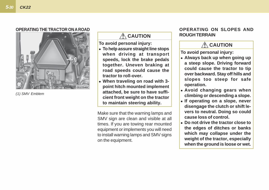
If one of the rear wheels should slip,use the differential lock. This will causeboth wheels to turn together. The dif-ferential lock is engaged only when thepedal is depressed.
OPERATING TECHNIQUES
(1) Differential Lock Pedal(A) Release to “DISENGAGE”(B) Press to “ENGAGE”
DIFFERENTIAL LOCK
WARNING!!!!!To avoid personal injury due toloss of steering control.� Do not operate the tractor at high
speeds with the differential lockengaged.
� Do not attempt to turn with thedifferential lock engaged.
� When using the differential lock,always slow the engine andpress the differential lock down.
� If the differential lock cannot bereleased in the above manner,step lightly on the brake pedalsalternately.
IMPORTANT
051O545C051O544C
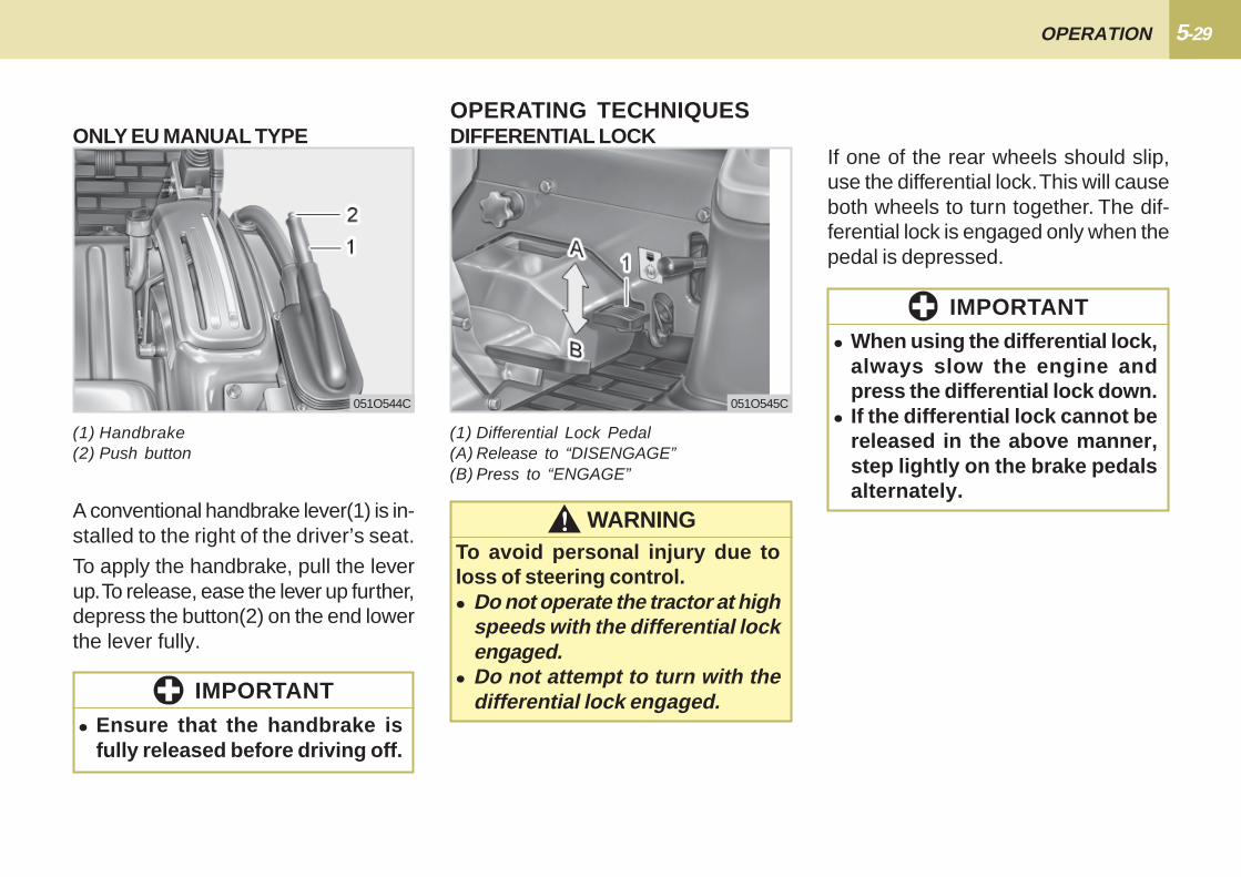
(1) Handbrake(2) Push button
A conventional handbrake lever(1) is in-stalled to the right of the driver’s seat.
To apply the handbrake, pull the leverup. To release, ease the lever up further,depress the button(2) on the end lowerthe lever fully.
� Ensure that the handbrake isfully released before driving off.
IMPORTANT
ONLY EU MANUAL TYPE
5-30 CK22
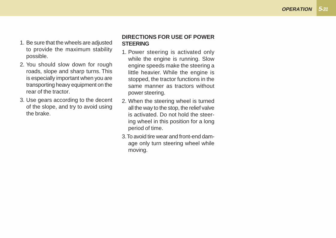
(1) SMV Emblem
OPERATING THE TRACTOR ON A ROAD
051O546C
Make sure that the warning lamps andSMV sign are clean and visible at alltimes. If you are towing rear mountedequipment or implements you will needto install warning lamps and SMV signson the equipment.
To avoid personal injury:� To help assure straight line stops
when driving at transportspeeds, lock the brake pedalstogether. Uneven braking atroad speeds could cause thetractor to roll-over.
� When traveling on road with 3-point hitch mounted implementattached, be sure to have suffi-cient front weight on the tractorto maintain steering ability.
!!!!! CAUTIONOPERATING ON SLOPES ANDROUGH TERRAIN
To avoid personal injury:� Always back up when going up
a steep slope. Driving forwardcould cause the tractor to tipover backward. Stay off hills andslopes too steep for safeoperation.
� Avoid changing gears whenclimbing or descending a slope.
� If operating on a slope, neverdisengage the clutch or shift le-vers to neutral. Doing so couldcause loss of control.
� Do not drive the tractor close tothe edges of ditches or bankswhich may collapse under theweight of the tractor, especiallywhen the ground is loose or wet.
!!!!! CAUTION
5-31 OPERATION
DIRECTIONS FOR USE OF POWERSTEERING1. Power steering is activated only
while the engine is running. Slowengine speeds make the steering alittle heavier. While the engine isstopped, the tractor functions in thesame manner as tractors withoutpower steering.
2. When the steering wheel is turnedall the way to the stop, the relief valveis activated. Do not hold the steer-ing wheel in this position for a longperiod of time.
3. To avoid tire wear and front-end dam-age only turn steering wheel whilemoving.
1. Be sure that the wheels are adjustedto provide the maximum stabilitypossible.
2. You should slow down for roughroads, slope and sharp turns. Thisis especially important when you aretransporting heavy equipment on therear of the tractor.
3. Use gears according to the decentof the slope, and try to avoid usingthe brake.

5-32 CK22
REAR PTO GEAR SHIFT LEVERPTO OPERATION
051O547C
1. The tractor has a 540 rpm speedposition.
2. PTO shifting needs clutch operation.Press the clutch pedal down com-pletely to stop the tractor movementand any PTO driven equipmentmovement before shifting the PTOgear shift lever.
� To avoid shock loads to the PTO,reduce engine speed when en-gaging the PTO, then open thethrottle to the recommendedspeed:
� To avoid damage of transmission,before shifting the PTO gear shiftlever, fully disengage the mainclutch.
(1) Mid PTO Gear Shift Lever(2) Rear PTO Gear Shift Lever
OFF ON
To avoid personal injury:� Disengage PTO, stop engine, and
allow all rotating components tocome to a complete stop beforeconnecting, disconnecting,adjusting, or cleaning any PTOdriven equipment.
!!!!! CAUTION
IMPORTANT
ModelEngine Speed min-1 (rpm)
ShaftPTO Speed min-1 (rpm)
CK222,646
6-Spline540
� There is a PTO-1 (540 rpm) indica-tor marked on the tachometer dial.
� Tractor engine will not start if PTOgear shift lever is in the engaged"ON" position.
NOTE
5-33 OPERATION
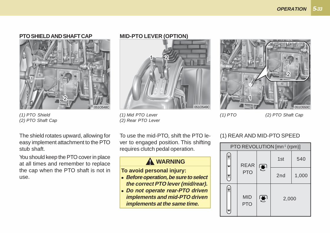
MID-PTO LEVER (OPTION)
051O549C
(1) PTO Shield(2) PTO Shaft Cap
PTO SHIELD AND SHAFT CAP
051O548C
The shield rotates upward, allowing foreasy implement attachment to the PTOstub shaft.
You should keep the PTO cover in placeat all times and remember to replacethe cap when the PTO shaft is not inuse.
(1) Mid PTO Lever(2) Rear PTO Lever
To use the mid-PTO, shift the PTO le-ver to engaged position. This shiftingrequires clutch pedal operation.
WARNING!!!!!To avoid personal injury:� Before operation, be sure to select
the correct PTO lever (mid/rear).� Do not operate rear-PTO driven
implements and mid-PTO drivenimplements at the same time.
(1) PTO (2) PTO Shaft Cap
(1) REAR AND MID-PTO SPEED
MIDPTO
PTO REVOLUTION [mn-1 (rpm)]
5401st
2,000
REARPTO
1,0002nd
051O550C
5-34 CK22
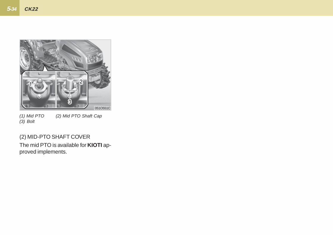
(2) MID-PTO SHAFT COVER
The mid PTO is available for KIOTI ap-proved implements.
(1) Mid PTO (2) Mid PTO Shaft Cap(3) Bolt
051O551C

6THREE-POINT HITCH & DRAWBAR ......................... 6-2
3-POINT HITCH ........................................................... 6-3
DRAWBAR .................................................................... 6-4
THREE-POINT HITCH & DRAWBAR
6-2 CK22
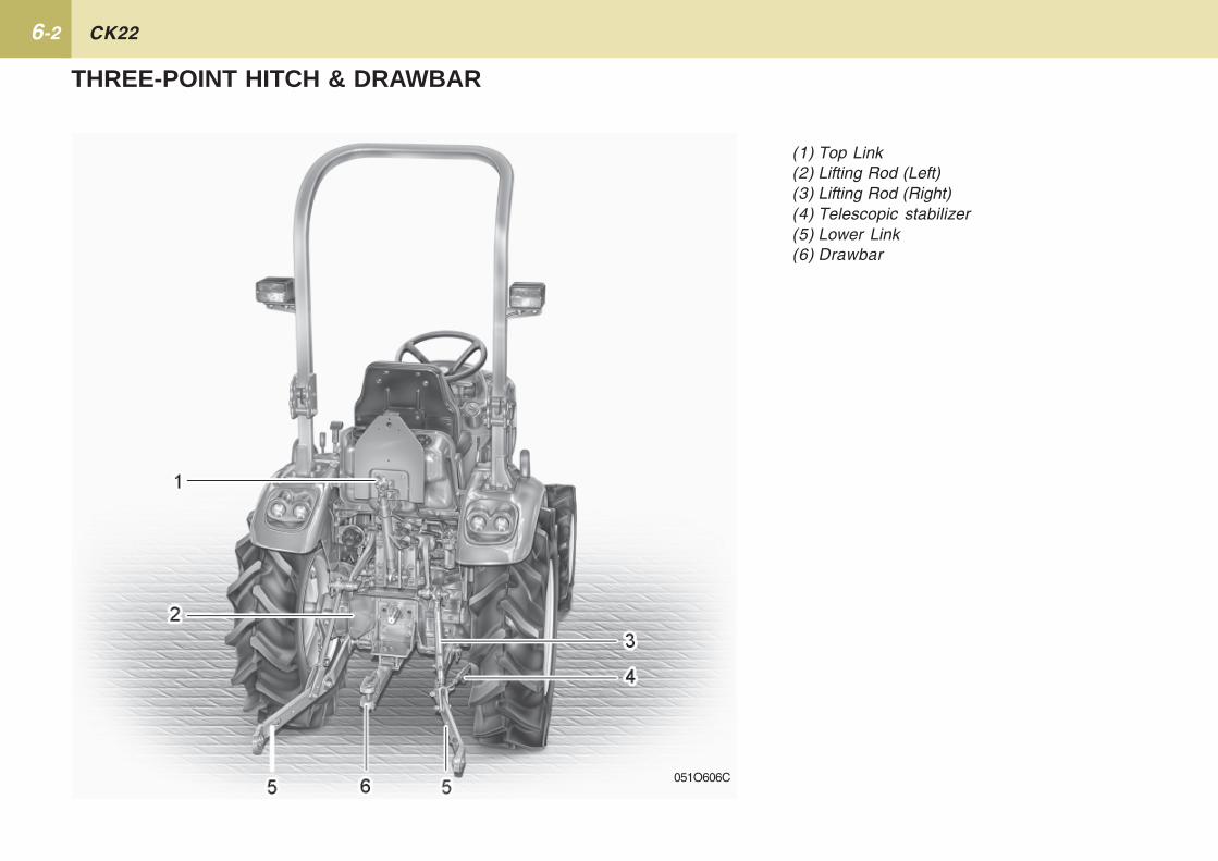
(1) Top Link(2) Lifting Rod (Left)(3) Lifting Rod (Right)(4) Telescopic stabilizer(5) Lower Link(6) Drawbar
051O606C
THREE-POINT HITCH & DRAWBAR

6-3 THREE-POINT HITCH & DRAWBAR
3-POINT HITCHMAKE PREPARATIONS FORATTACHING IMPLEMENT
SELECTING THE TOP LINK MOUNT-ING HOLES1. Adjust the angle of the implement to
the desired position by shortening orlengthening the top link.
2. The proper length of the top link var-ies according to the type of imple-ment being used.
DRAWBARRemove the drawbar if close mountedimplement is being attached.
ATTACHING AND DETACHING
(1) Nut(2) Lifting Rod (Right)(3) Lower Link
LIFTING ROD (RIGHT)Lift Rod - To adjust the horizontal posi-tion of the implement twist the turnbuckle on the right lift rod. Most imple-ments are designed to operate level.Set the position desired by tighteningthe set nut against the turn buckle.
� To avoid personal injury:Be sure to stop the engine.Do not stand between tractorand implement unless parkingbrake is applied.
� Before attaching or detachingimplement, locate the tractorand implement on a firm levelsurface.
� Whenever an implement orother attachment is connected tothe tractor 3-point hitch, checkfull range of operation forinterference, binding or P.T.Oseparation.
!!!!! CAUTION
051O603C051O602C
6-4 CK22
WARNING!!!!!
The drawbar load is rating is listed inthe "IMPLEMENT LIMITATIONS"section.
To avoid personal injury:� Never pull from the top link, the
rear axle or any point above thedrawbar. Doing so could causethe tractor to tip over rearwardcausing personal injury or death.
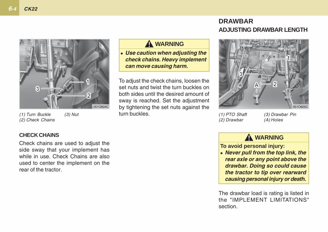
(1) PTO Shaft (3) Drawbar Pin(2) Drawbar (A) Holes
WARNING!!!!!� Use caution when adjusting the
check chains. Heavy implementcan move causing harm.
051O605C051O604C
(1) Turn Buckle (3) Nut(2) Check Chains
To adjust the check chains, loosen theset nuts and twist the turn buckles onboth sides until the desired amount ofsway is reached. Set the adjustmentby tightening the set nuts against theturn buckles.
CHECK CHAINSCheck chains are used to adjust theside sway that your implement haswhile in use. Check Chains are alsoused to center the implement on therear of the tractor.
DRAWBARADJUSTING DRAWBAR LENGTH
73-POINT HITCH CONTROL SYSTEM....................... 7-2
AUXILIARY HYDRAULICS ........................................... 7-5
HYDRAULIC UNIT
7-2 CK22
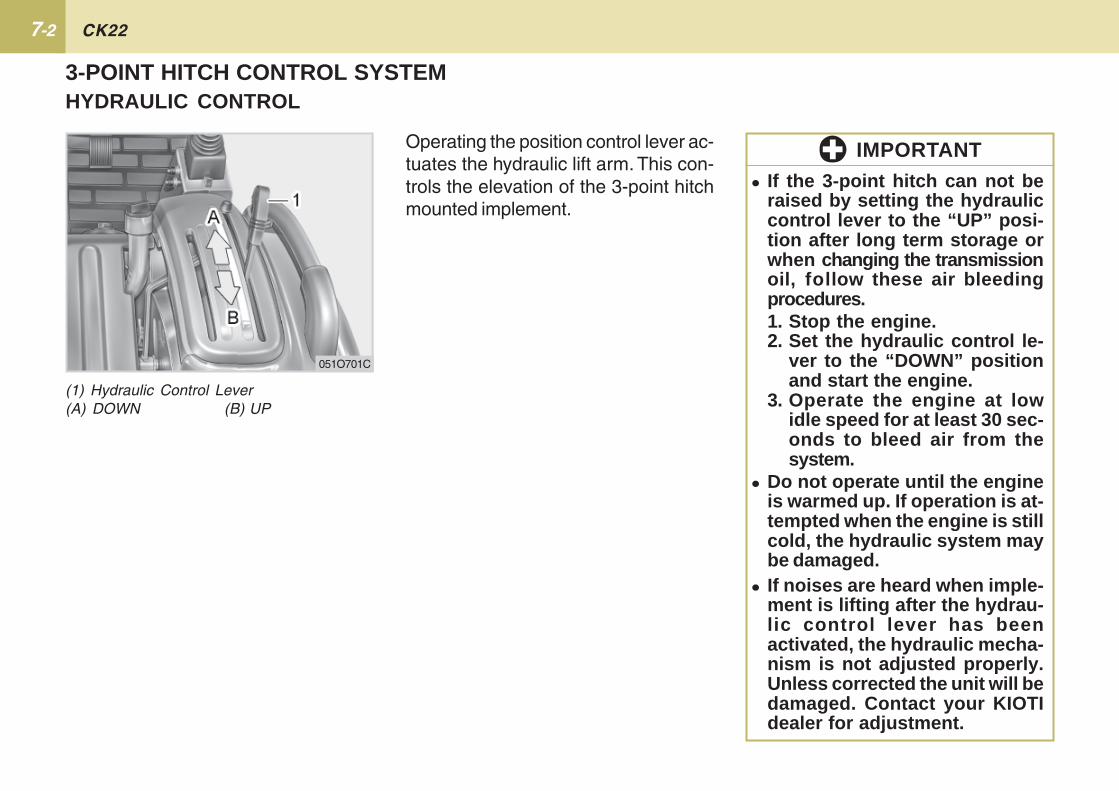
Operating the position control lever ac-tuates the hydraulic lift arm. This con-trols the elevation of the 3-point hitchmounted implement.
3-POINT HITCH CONTROL SYSTEMHYDRAULIC CONTROL
051O701C
� If the 3-point hitch can not beraised by setting the hydrauliccontrol lever to the “UP” posi-tion after long term storage orwhen changing the transmissionoil, follow these air bleedingprocedures.1. Stop the engine.2. Set the hydraulic control le-
ver to the “DOWN” positionand start the engine.
3. Operate the engine at lowidle speed for at least 30 sec-onds to bleed air from thesystem.
� Do not operate until the engineis warmed up. If operation is at-tempted when the engine is stillcold, the hydraulic system maybe damaged.
� If noises are heard when imple-ment is lifting after the hydrau-lic control lever has beenactivated, the hydraulic mecha-nism is not adjusted properly.Unless corrected the unit will bedamaged. Contact your KIOTIdealer for adjustment.
IMPORTANT
(1) Hydraulic Control Lever(A) DOWN (B) UP
7-3HYDRAULIC UNIT
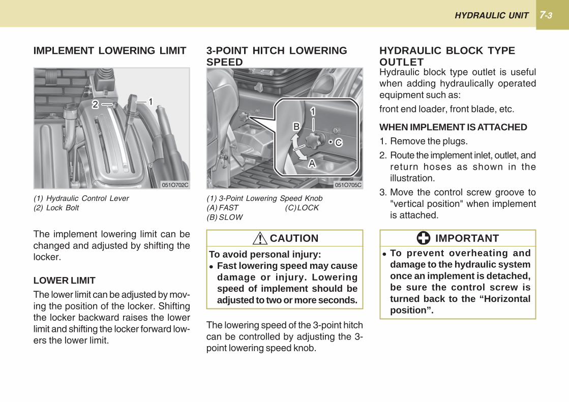
The lowering speed of the 3-point hitchcan be controlled by adjusting the 3-point lowering speed knob.
(1) 3-Point Lowering Speed Knob(A) FAST (C)LOCK(B) SLOW
3-POINT HITCH LOWERINGSPEED
051O705C051O702C
To avoid personal injury:� Fast lowering speed may cause
damage or injury. Loweringspeed of implement should beadjusted to two or more seconds.
!!!!! CAUTION
(1) Hydraulic Control Lever(2) Lock Bolt
IMPLEMENT LOWERING LIMIT
The implement lowering limit can bechanged and adjusted by shifting thelocker.
LOWER LIMITThe lower limit can be adjusted by mov-ing the position of the locker. Shiftingthe locker backward raises the lowerlimit and shifting the locker forward low-ers the lower limit.
Hydraulic block type outlet is usefulwhen adding hydraulically operatedequipment such as:
front end loader, front blade, etc.
WHEN IMPLEMENT IS ATTACHED1. Remove the plugs.
2. Route the implement inlet, outlet, andreturn hoses as shown in theillustration.
3. Move the control screw groove to"vertical position" when implementis attached.
HYDRAULIC BLOCK TYPEOUTLET
� To prevent overheating anddamage to the hydraulic systemonce an implement is detached,be sure the control screw isturned back to the “Horizontalposition”.
IMPORTANT
7-4 CK22
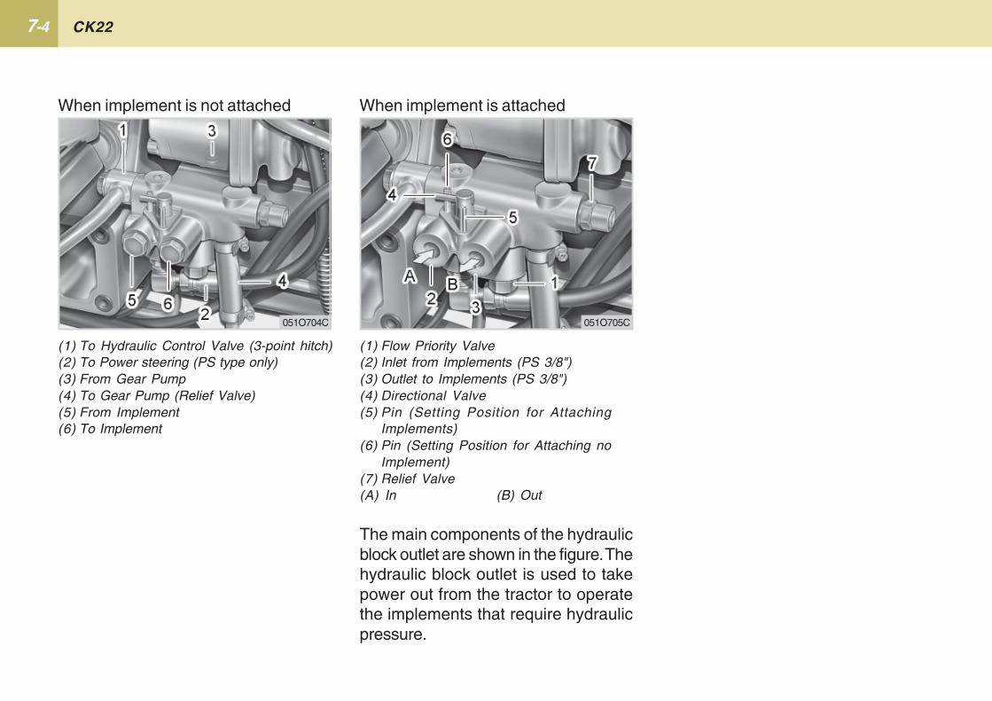
(1) Flow Priority Valve(2) Inlet from Implements (PS 3/8")(3) Outlet to Implements (PS 3/8")(4) Directional Valve(5) Pin (Setting Position for Attaching
Implements)(6) Pin (Setting Position for Attaching no
Implement)(7) Relief Valve(A) In (B) Out
When implement is not attached When implement is attached
(1) To Hydraulic Control Valve (3-point hitch)(2) To Power steering (PS type only)(3) From Gear Pump(4) To Gear Pump (Relief Valve)(5) From Implement(6) To Implement
The main components of the hydraulicblock outlet are shown in the figure. Thehydraulic block outlet is used to takepower out from the tractor to operatethe implements that require hydraulicpressure.
051O704C 051O705C
7-5HYDRAULIC UNIT
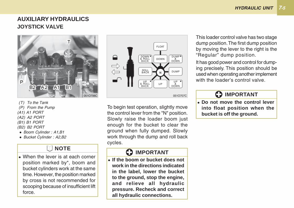
AUXILIARY HYDRAULICSJOYSTICK VALVE
To begin test operation, slightly movethe control lever from the "N" position.Slowly raise the loader boom justenough for the bucket to clear theground when fully dumped. Slowlywork through the dump and roll backcycles.
This loader control valve has two stagedump position. The first dump positionby moving the lever to the right is the“Regular” dump position.
It has good power and control for dump-ing precisely. This position should beused when operating another implementwith the loader’s control valve.
(T) To the Tank(P) From the Pump
(A1) A1 PORT(A2) A2 PORT(B1) B1 PORT(B2) B2 PORT � Boom Cylinder : A1,B1 � Bucket Cylinder : A2,B2
051O707C051O706C
� Do not move the control leverinto float position when thebucket is off the ground.
IMPORTANT
� If the boom or bucket does notwork in the directions indicatedin the label, lower the bucketto the ground, stop the engine,and relieve all hydraulicpressure. Recheck and correctall hydraulic connections.
IMPORTANT
FLOAT
DOWNDOWN& ROLLBACK
UP
ROLLBACK
UP& ROLLBACK
DUMP
DUMP&
DOWN
UP&
DOWN
� When the lever is at each cornerposition marked by*, boom andbucket cylinders work at the sametime. However, the position markedby cross is not recommended forscooping because of insufficient liftforce.
NOTE
7-6 CK22
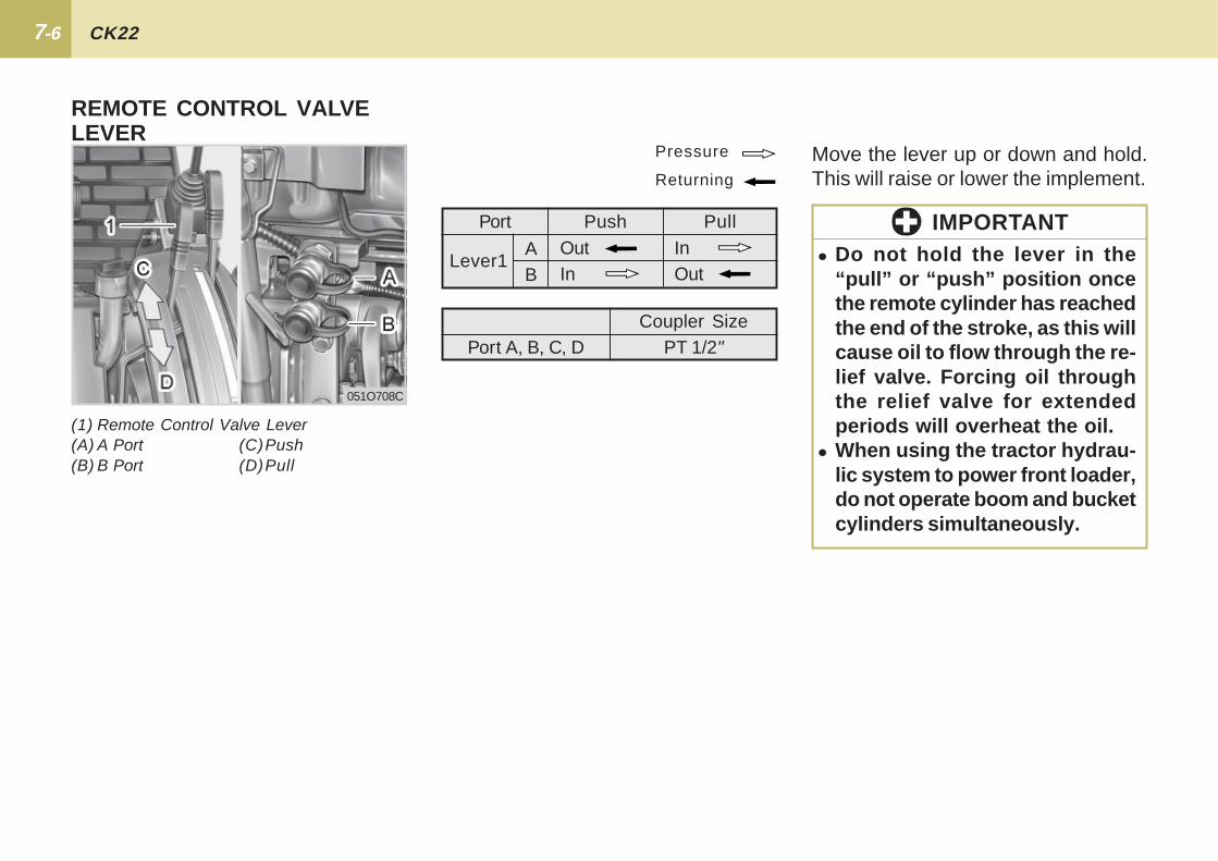
PullInOut
PushOutIn
Port
AB
Lever1
Pressure
Returning
� Do not hold the lever in the“pull” or “push” position oncethe remote cylinder has reachedthe end of the stroke, as this willcause oil to flow through the re-lief valve. Forcing oil throughthe relief valve for extendedperiods will overheat the oil.
� When using the tractor hydrau-lic system to power front loader,do not operate boom and bucketcylinders simultaneously.
IMPORTANT
Port A, B, C, DCoupler Size
PT 1/2"
Move the lever up or down and hold.This will raise or lower the implement.
(1) Remote Control Valve Lever(A) A Port (C)Push(B) B Port (D)Pull
REMOTE CONTROL VALVELEVER
051O708C
7-7HYDRAULIC UNIT
To avoid personal injury:� Stop the engine and relieve
pressure before connecting ordisconnecting lines.
� Do not use your hand to checkfor leaks.
CONNECTING1. Clean both couplers.
2. Remove dust plugs.
3. Insert the implement coupler to thetractor hydraulic coupler.
4. Pull the implement coupler slightlyto make sure couplers are firmlyconnected.
!!!!! CAUTION
DISCONNECTING1. Lower the implement first to the
ground to release hydraulic pressurein the hoses.
2. Clean the couplers.
3. Relieve pressure by moving hydrau-lic control levers with engine shut off.Pull the hose straight from the hy-draulic coupler to release it.
4. Clean oil and dust from the coupler,then replace the dust plugs.
� Your local KIOTI Dealer can sup-ply parts to adapt couplers to hy-draulic hoses.
NOTE
COUPLER CONNECTING ANDDISCONNECTING
8TIRES ........................................................................... 8-2
TREAD.......................................................................... 8-3
BALLAST ...................................................................... 8-4
TIRES, TREAD AND BALLAST
8-2 CK22
TIRES
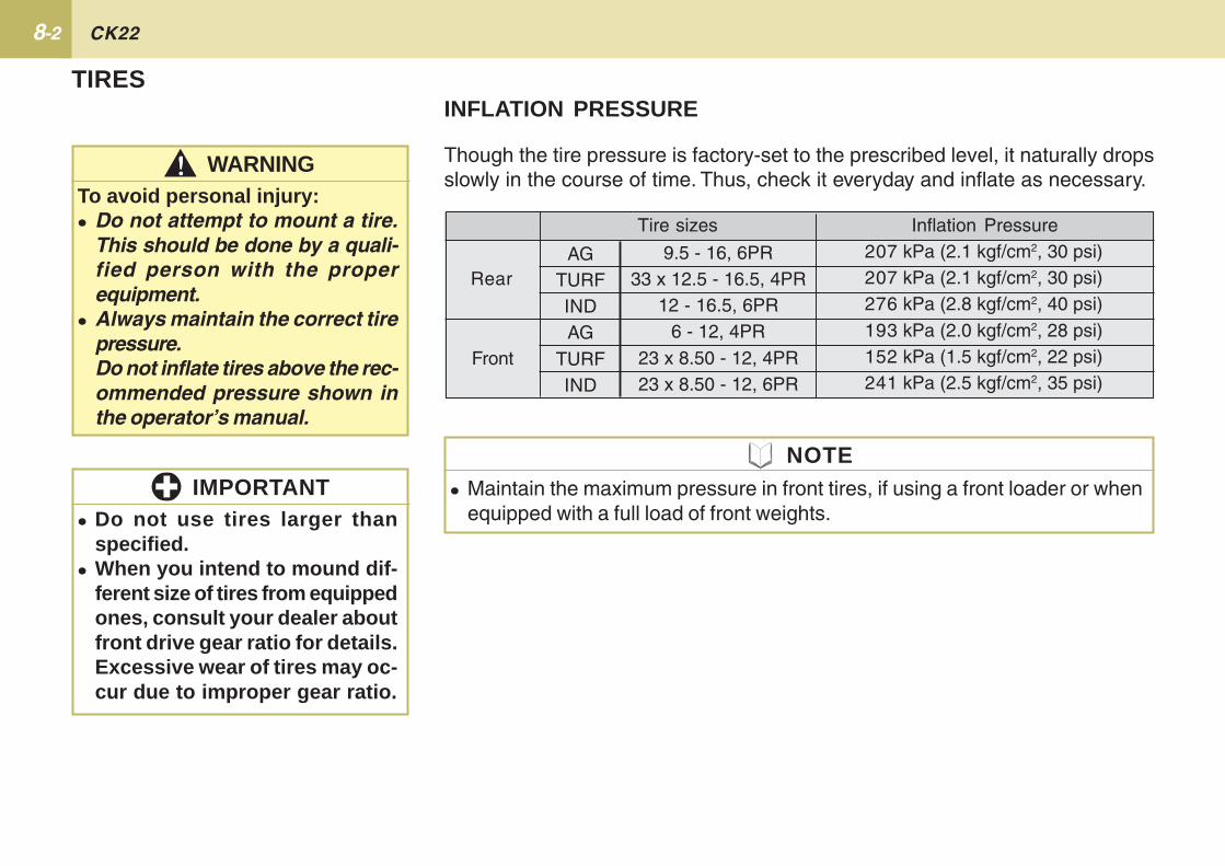
Though the tire pressure is factory-set to the prescribed level, it naturally dropsslowly in the course of time. Thus, check it everyday and inflate as necessary.
INFLATION PRESSURE
� Maintain the maximum pressure in front tires, if using a front loader or whenequipped with a full load of front weights.
NOTE
Inflation Pressure207 kPa (2.1 kgf/cm2, 30 psi)207 kPa (2.1 kgf/cm2, 30 psi)276 kPa (2.8 kgf/cm2, 40 psi)193 kPa (2.0 kgf/cm2, 28 psi)152 kPa (1.5 kgf/cm2, 22 psi)241 kPa (2.5 kgf/cm2, 35 psi)
Rear
Tire sizes
Front
9.5 - 16, 6PR33 x 12.5 - 16.5, 4PR
12 - 16.5, 6PR6 - 12, 4PR
23 x 8.50 - 12, 4PR23 x 8.50 - 12, 6PR
� Do not use tires larger thanspecified.
� When you intend to mound dif-ferent size of tires from equippedones, consult your dealer aboutfront drive gear ratio for details.Excessive wear of tires may oc-cur due to improper gear ratio.
IMPORTANT
WARNING!!!!!To avoid personal injury:� Do not attempt to mount a tire.
This should be done by a quali-fied person with the properequipment.
� Always maintain the correct tirepressure.Do not inflate tires above the rec-ommended pressure shown inthe operator’s manual.
AGTURFINDAG
TURFIND
8-3TIRES, TREAD AND BALLAST
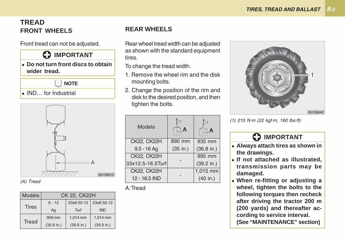
Front tread can not be adjusted.
TREAD
� Do not turn front discs to obtainwider tread.
IMPORTANT
FRONT WHEELS
Models
Tires
Tread
6 - 12
Ag
909 mm
(35.8 in.)
23x8.50-12
Turf
1,014 mm
(39.9 in.)
23x8.50-12
IND
1,014 mm
(39.9 in.)
CK 22, CK22H
(A) Tread
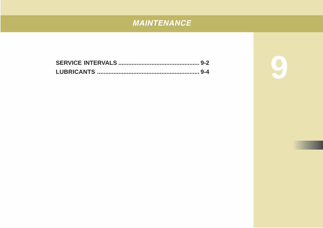
REAR WHEELS
Rear wheel tread width can be adjustedas shown with the standard equipmenttires.
To change the tread width.
1. Remove the wheel rim and the diskmounting bolts.
2. Change the position of the rim anddisk to the desired position, and thentighten the bolts.
(1) 215 N·m (22 kgf·m, 160 lbs·ft)
CK22, CK22H9.5 - 16 Ag
CK22, CK22H33x12.5-16.5Turf
CK22, CK22H12 - 16.5 IND
-
-
935 mm(36.8 in.)995 mm(39.2 in.)1,015 mm
(40 in.)
Models
890 mm(35 in.)
A: Tread
� Always attach tires as shown inthe drawings.
� If not attached as illustrated,transmission parts may bedamaged.
� When re-fitting or adjusting awheel, tighten the bolts to thefollowing torques then recheckafter driving the tractor 200 m(200 yards) and thereafter ac-cording to service interval.(See “MAINTENANCE” section)
IMPORTANT
051O804C
� IND… for Industrial
NOTE
051O801C

8-4 CK22
Weight should be added to the rearwheels only if it is needed to improvetraction or stability. The amount ofweight should directly correspond to thejob at hand and should be removedwhen not needed.
The weight should be added to the rearwheel weights.
REAR WHEEL WEIGHTSThe rear wheel weights can be attachedto the rear wheel. See your implementowner's manual for the proper amountof weight or consult your local KIOTIdealer.
FRONT END WEIGHTSFront end weights can be attached tothe front of the tractors frame. Youshould consult your implement owner'smanual for the required amount ofweight or contact your local KIOTIdealer for a recommendation.
REAR BALLASTBALLAST (OPTIONAL)FRONT BALLAST
(1) Front End Weights(2) Rear Wheel Weights
051O805C
To avoid personal injury:� Additional ballast will be
needed for transporting heavyimplements. When the imple-ment is raised, drive slowly overrough ground, regardless ofhow much ballast is used.
� Do not fill the front wheel withliquid to maintain steeringcontrol.
!!!!! CAUTION
� Never overload the tires.� Do not add more weight than is
necessary, or is indicated inchart.
IMPORTANT
� Do not overload tires.� Add no more weight than indi-
cated in chart.
IMPORTANT
Maximum weight17 kg X 3 Pieces
(112 lbs.)
Maximum weightper wheel
20 kg X 2 Pieces(88.2 lbs.)
9SERVICE INTERVALS ................................................. 9-2
LUBRICANTS .............................................................. 9-4
MAINTENANCE
9-2 CK22
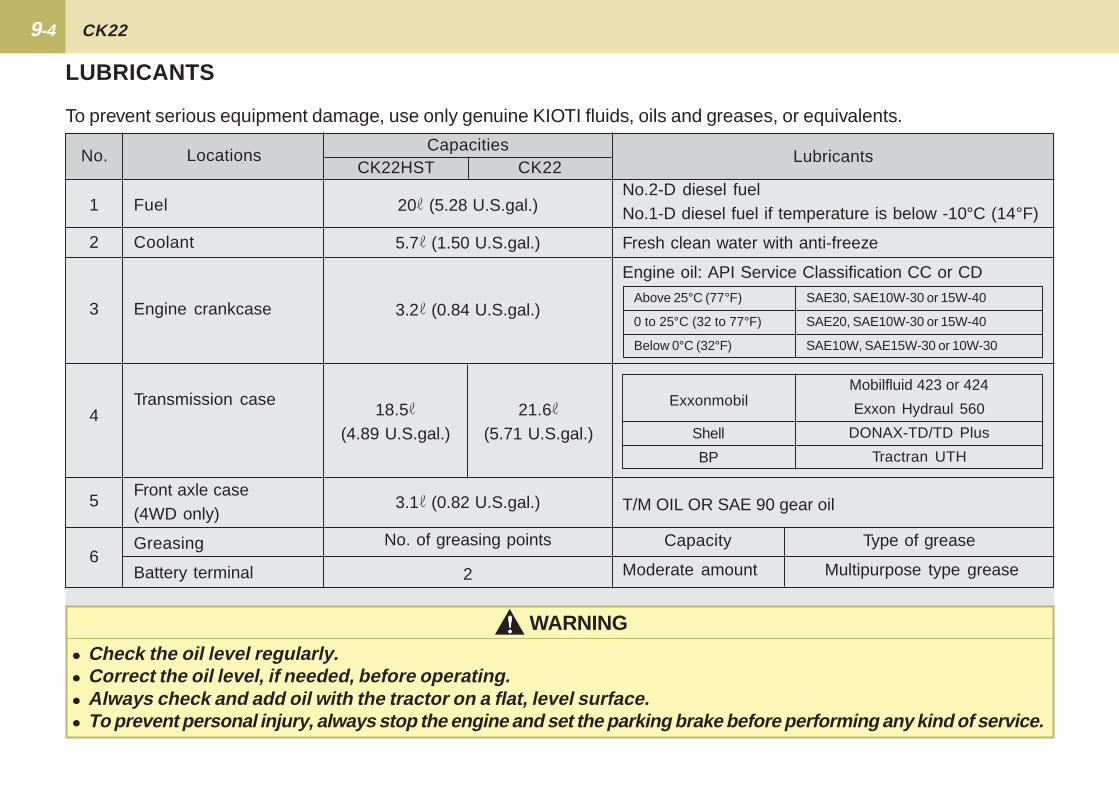
SERVICE INTERVALS
NO. PERIODPERIODICAL CHECK
1
2
3
4
5
6
7
8
9
10
11
12
13
14
15
16
17
18
Engine oil
Engine oil filter
Hydraulic oil filter
Transmission oil filter(HST)
Transmission fluid
Front axle case oil
GreasingEngine start system
Wheel bolt torque
Battery condition
Air cleaner element
Fuel filter element
Fan belt
Clutch
Brake
Adjusting front axle pivot
Radiator hose and clamp
Power steering oil line
REFERENCE
10-8
10-8
10-10
10-10
10-11
10-12
10-13
10-14
10-17
10-17
10-23
10-14
10-22
10-19
10-9
10-16
10-20
10-25
10-20
10-25
SINCE THEN
Every100Hr
Every200Hr
Every200Hr
Every200Hr
Every400Hr
Every400Hr
Every50Hr
Every50Hr
Every50Hr
Every100Hr
Every100Hr
Every1year
Every100Hr
Every400Hr
Every100Hr
Every100Hr
Every100Hr
Every200Hr
Every600Hr
Every2years
Every200Hr
Every2years
Change
Replace
Replace
Replace
Change
Change
-
Check
Check
Check
Clean
Replace
Check
Replace
Adjust
Adjust
Adjust
Adjust
Check
Change
Check
Replace
50 100 150 200 250 300 350 400 450 500 550 600 650 700 750 800

9-3MAINTENANCE
� The jobs indicated by � must be done after the first 50 hours of operation.
NO. PERIODPERIODICAL CHECK
19
20
21
22
23
24
25
26
27
28
29
REFERENCEPAGE
10-15
10-25
10-20
10-25
10-21
10-23
10-24
10-24
10-26
10-26
10-27
10-28
SINCE THEN
Every100Hr
Every2years
Every200Hr
Every2years
Every200Hr
Every800Hr
Every2years
Every2years
Service as
required
50 100 150 200 250 300 350 400 450 500 550 600 650 700 750 800
Check
Replace
Check
Replace
Adjust
Adjust
Flush
Change
Bleed
Drain
Replace
Replace
Adjust
IMPORTANT
Fuel line
HST oil line
Toe-in
Engine valve clearance
Cooling system
Coolant
Fuel system
Clutch housing water
Fuse
Light bulb
HST netural spring Every100Hr
9-4 CK22
LUBRICANTS
To prevent serious equipment damage, use only genuine KIOTI fluids, oils and greases, or equivalents.
Capacity
Moderate amount
Type of grease
Multipurpose type grease
T/M OIL OR SAE 90 gear oil
No. LocationsCapacities
Lubricants
Fuel
Coolant
Engine crankcase
Transmission case
Front axle case(4WD only)
Greasing
Battery terminal
No.2-D diesel fuelNo.1-D diesel fuel if temperature is below -10°C (14°F)
Fresh clean water with anti-freeze
Engine oil: API Service Classification CC or CD
CK22HST CK22
1
2
3
4
5
6
20 (5.28 U.S.gal.)
5.7 (1.50 U.S.gal.)
3.2 (0.84 U.S.gal.)
3.1 (0.82 U.S.gal.)
No. of greasing points
2
Above 25°C (77°F)
0 to 25°C (32 to 77°F)
Below 0°C (32°F)
SAE30, SAE10W-30 or 15W-40
SAE20, SAE10W-30 or 15W-40
SAE10W, SAE15W-30 or 10W-30
18.5(4.89 U.S.gal.)
21.6(5.71 U.S.gal.)
Exxonmobil
Shell
BP
Mobilfluid 423 or 424
Exxon Hydraul 560
DONAX-TD/TD Plus
Tractran UTH
WARNING!!!!!� Check the oil level regularly.� Correct the oil level, if needed, before operating.� Always check and add oil with the tractor on a flat, level surface.� To prevent personal injury, always stop the engine and set the parking brake before performing any kind of service.

10HOW TO OPEN THE HOOD .................................... 10-2
DAILY CHECK............................................................ 10-3
INITIAL 50 HOURS .................................................... 10-8
EVERY 50 HOURS ................................................... 10-13
EVERY 100 HOURS ................................................. 10-14
EVERY 200 HOURS ................................................. 10-20
EVERY 300 HOURS ................................................. 10-22
EVERY 400 HOURS ................................................. 10-23
EVERY 600 HOURS ................................................. 10-24
EVERY 800 HOURS ................................................. 10-24
EVERY 1 YEAR ........................................................ 10-24
EVERY 2 YEARS ...................................................... 10-25
SERVICE AS REQUIRED ........................................ 10-27
PERIODIC SERVICE

10-2 CK22
HOW TO OPEN THE HOODHOOD
(1) Knob (A) Pull
ENGINE COVER
051OA01C 051OA02C 051OA03C
To avoid personal injury from con-tact with moving parts:� Never open the hood or engine
side cover while the engine isrunning.
� Do not touch muffler or exhaustpipes while they are hot; severeburns could result.
!!!!! CAUTION
(1) Sider Cover (A) Push
To open the tractors hood you shouldfirst pull the knob to release the latch.
To remove the side cover.
It is not necessary to remove the sidecover to do daily check on your tractor.
(1) Hood Rod
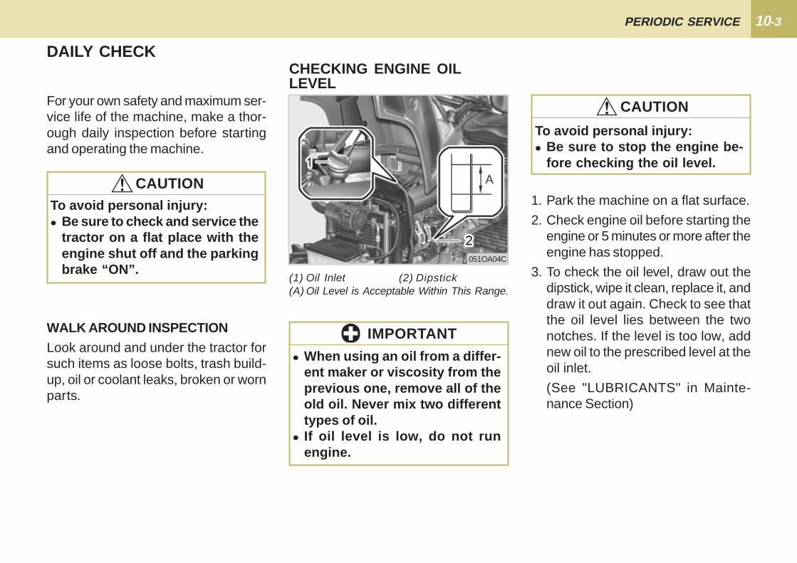
10-3PERIODIC SERVICE
DAILY CHECK
For your own safety and maximum ser-vice life of the machine, make a thor-ough daily inspection before startingand operating the machine.
WALK AROUND INSPECTIONLook around and under the tractor forsuch items as loose bolts, trash build-up, oil or coolant leaks, broken or wornparts.
1. Park the machine on a flat surface.
2. Check engine oil before starting theengine or 5 minutes or more after theengine has stopped.
3. To check the oil level, draw out thedipstick, wipe it clean, replace it, anddraw it out again. Check to see thatthe oil level lies between the twonotches. If the level is too low, addnew oil to the prescribed level at theoil inlet.
(See "LUBRICANTS" in Mainte-nance Section)
To avoid personal injury:� Be sure to stop the engine be-
fore checking the oil level.
CHECKING ENGINE OILLEVEL
(1) Oil Inlet (2) Dipstick(A) Oil Level is Acceptable Within This Range.
� When using an oil from a differ-ent maker or viscosity from theprevious one, remove all of theold oil. Never mix two differenttypes of oil.
� If oil level is low, do not runengine.
!!!!! CAUTION
051OA04C
To avoid personal injury:� Be sure to check and service the
tractor on a flat place with theengine shut off and the parkingbrake “ON”.
!!!!! CAUTION
IMPORTANT
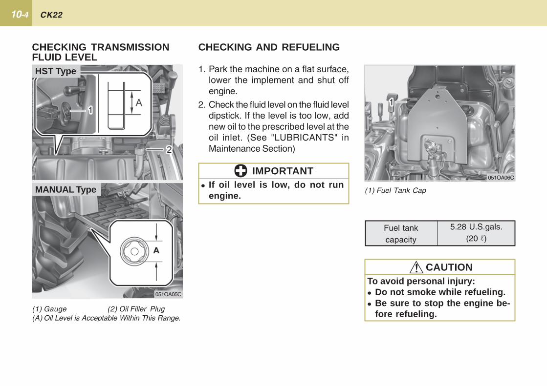
10-4 CK22
(1) Gauge (2) Oil Filler Plug(A) Oil Level is Acceptable Within This Range.
1. Park the machine on a flat surface,lower the implement and shut offengine.
2. Check the fluid level on the fluid leveldipstick. If the level is too low, addnew oil to the prescribed level at theoil inlet. (See "LUBRICANTS" inMaintenance Section)
(1) Fuel Tank Cap
Fuel tankcapacity
5.28 U.S.gals.(20 )
051OA06C
� If oil level is low, do not runengine.
IMPORTANT
To avoid personal injury:� Do not smoke while refueling.� Be sure to stop the engine be-
fore refueling.
!!!!! CAUTION
CHECKING TRANSMISSIONFLUID LEVEL
CHECKING AND REFUELING
051OA05C
HST Type
MANUAL Type

10-5PERIODIC SERVICE
1. Turn the key switch to "ON", checkthe amount of fuel by fuel gauge.
2. Fill fuel tank when fuel gauge shows1/4 or less fuel in tank.
3. Use for the winter season fuel at tem-peratures above 14 ° F (-10 ° C).
� Do not permit dirt or trash to getinto the fuel system.
� Be careful not to let the fuel tankbecome empty, otherwise airwill enter the fuel system, ne-cessitating bleeding before nextengine start.
� Be careful not to spill fuel duringrefueling. If spills occur, wipe itoff at once, as it may cause a fire.
� To prevent condensation (water)accumulation in the fuel tank,fill the tank before parkingovernight.
� During cold, damp periods of theyear or for tractors that sit for longperiods, adding a fuel supple-ment to disperse water and addlubricity is recommended.
IMPORTANT
� No.2-D is a distillate fuel of lower volatility for engines in industrial and heavymobile service. (SAE J313 JUN87)
� Grade of Diesel Fuel Oil According to ASTM D975.
NOTE
DistillationTemperatures, °F(°C) 90% Point
Min540(282)
Max640(338)
Viscosity Kine-matic cSt or mm2/s
at 104 °F(40°C)
Min1.9
Max4.1
Viscosity Saybolt,SUS at 100°F
(38°C)
Min32.6
Max40.1
sulfur,weight
%
Max0.50
CopperStrip
Corrosion
MaxNo.3
CetaneNumber
Min40
Flash Point,° F (° C)
Water and Sediment,volume %
Carbon Residue on, 10percent Residuum, %
Ash,weight %
Min125 (52)
Max0.05
Max0.35
Max0.01
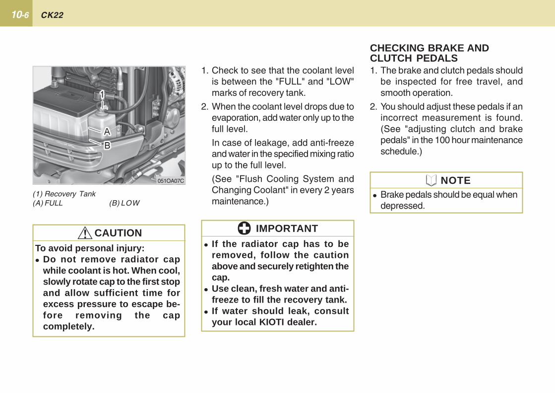
10-6 CK22
1. The brake and clutch pedals shouldbe inspected for free travel, andsmooth operation.
2. You should adjust these pedals if anincorrect measurement is found.(See "adjusting clutch and brakepedals" in the 100 hour maintenanceschedule.)
CHECKING BRAKE ANDCLUTCH PEDALS
� Brake pedals should be equal whendepressed.
1. Check to see that the coolant levelis between the "FULL" and "LOW"marks of recovery tank.
2. When the coolant level drops due toevaporation, add water only up to thefull level.
In case of leakage, add anti-freezeand water in the specified mixing ratioup to the full level.
(See "Flush Cooling System andChanging Coolant" in every 2 yearsmaintenance.)
(1) Recovery Tank(A) FULL (B) LOW
To avoid personal injury:� Do not remove radiator cap
while coolant is hot. When cool,slowly rotate cap to the first stopand allow sufficient time forexcess pressure to escape be-fore removing the capcompletely.
� If the radiator cap has to beremoved, follow the cautionabove and securely retighten thecap.
� Use clean, fresh water and anti-freeze to fill the recovery tank.
� If water should leak, consultyour local KIOTI dealer.
051OA07C
!!!!! CAUTION
NOTE
IMPORTANT
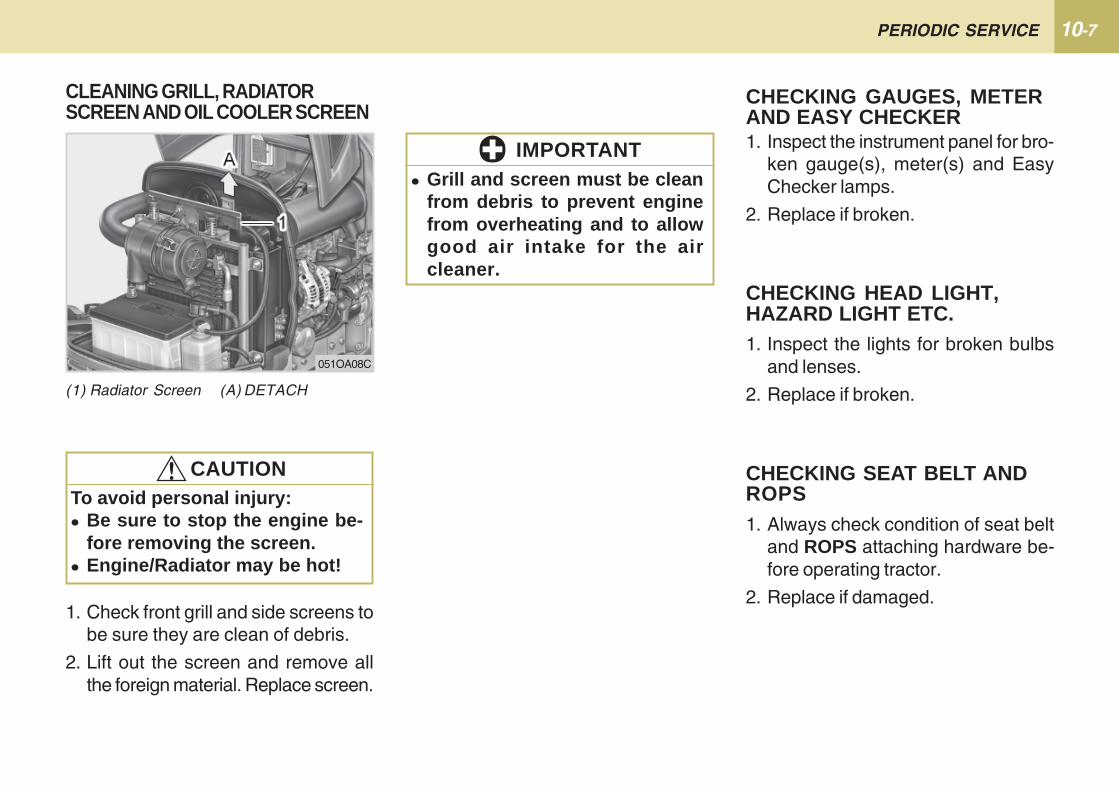
10-7PERIODIC SERVICE
1. Check front grill and side screens tobe sure they are clean of debris.
2. Lift out the screen and remove allthe foreign material. Replace screen.
1. Inspect the instrument panel for bro-ken gauge(s), meter(s) and EasyChecker lamps.
2. Replace if broken.
CHECKING HEAD LIGHT,HAZARD LIGHT ETC.1. Inspect the lights for broken bulbs
and lenses.
2. Replace if broken.
CHECKING SEAT BELT ANDROPS1. Always check condition of seat belt
and ROPS attaching hardware be-fore operating tractor.
2. Replace if damaged.
CHECKING GAUGES, METERAND EASY CHECKER
� Grill and screen must be cleanfrom debris to prevent enginefrom overheating and to allowgood air intake for the aircleaner.
(1) Radiator Screen (A) DETACH
CLEANING GRILL, RADIATORSCREEN AND OIL COOLER SCREEN
To avoid personal injury:� Be sure to stop the engine be-
fore removing the screen.� Engine/Radiator may be hot!
051OA08C
!!!!! CAUTION
IMPORTANT
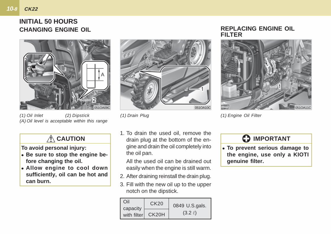
10-8 CK22
INITIAL 50 HOURSCHANGING ENGINE OIL
1. To drain the used oil, remove thedrain plug at the bottom of the en-gine and drain the oil completely intothe oil pan.
All the used oil can be drained outeasily when the engine is still warm.
2. After draining reinstall the drain plug.
3. Fill with the new oil up to the uppernotch on the dipstick.
(1) Oil Inlet (2) Dipstick(A) Oil level is acceptable within this range
(1) Drain Plug
To avoid personal injury:� Be sure to stop the engine be-
fore changing the oil.� Allow engine to cool down
sufficiently, oil can be hot andcan burn.
!!!!! CAUTION
051OA09C 051OA10C
(1) Engine Oil Filter
REPLACING ENGINE OILFILTER
� To prevent serious damage tothe engine, use only a KIOTIgenuine filter.
051OA11C
IMPORTANT
Oilcapacitywith filter
0849 U.S.gals.(3.2 )
CK20
CK20H
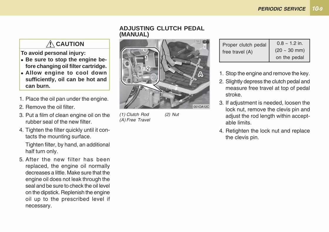
10-9PERIODIC SERVICE
1. Place the oil pan under the engine.
2. Remove the oil filter.
3. Put a film of clean engine oil on therubber seal of the new filter.
4. Tighten the filter quickly until it con-tacts the mounting surface.
Tighten filter, by hand, an additionalhalf turn only.
5. After the new filter has beenreplaced, the engine oil normallydecreases a little. Make sure that theengine oil does not leak through theseal and be sure to check the oil levelon the dipstick. Replenish the engineoil up to the prescribed level ifnecessary.
To avoid personal injury:� Be sure to stop the engine be-
fore changing oil filter cartridge.� Allow engine to cool down
sufficiently, oil can be hot andcan burn.
!!!!! CAUTION
ADJUSTING CLUTCH PEDAL(MANUAL)
Proper clutch pedalfree travel (A)
0.8 ~ 1.2 in.(20 ~ 30 mm)on the pedal
1. Stop the engine and remove the key.
2. Slightly depress the clutch pedal andmeasure free travel at top of pedalstroke.
3. If adjustment is needed, loosen thelock nut, remove the clevis pin andadjust the rod length within accept-able limits.
4. Retighten the lock nut and replacethe clevis pin.
(1) Clutch Rod (2) Nut(A) Free Travel
051OA12C
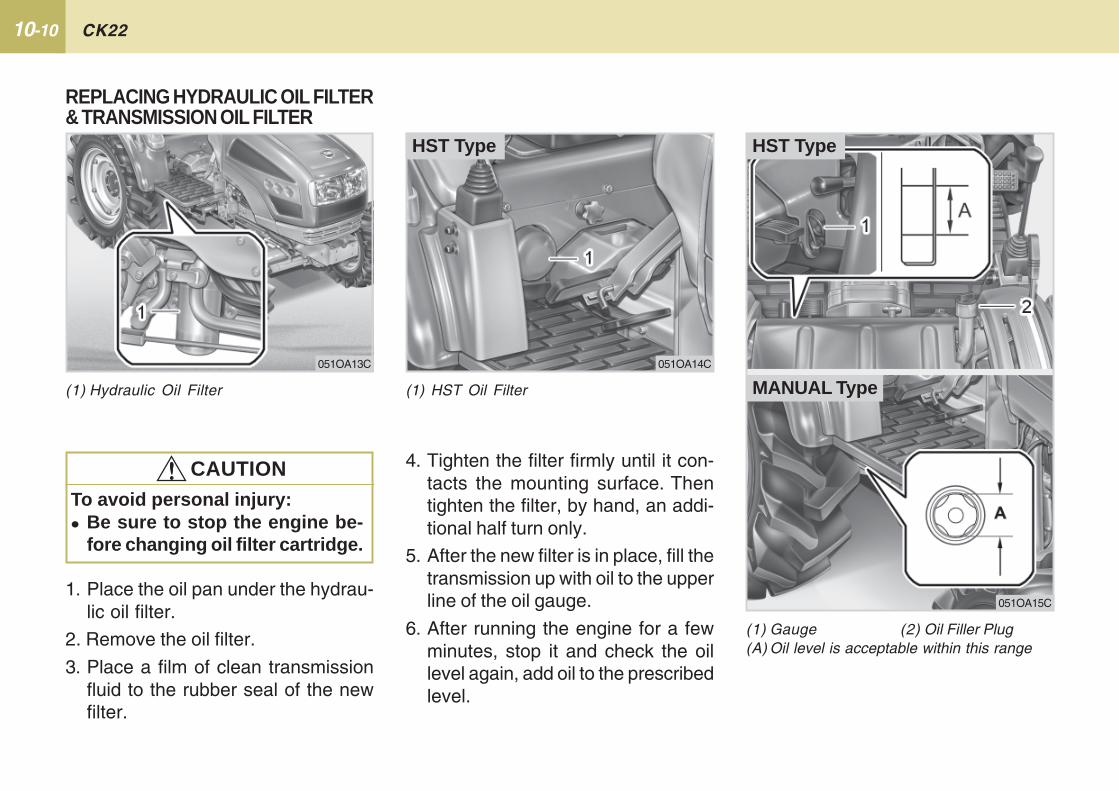
10-10 CK22
(1) HST Oil Filter
HST Type
051OA14C
4. Tighten the filter firmly until it con-tacts the mounting surface. Thentighten the filter, by hand, an addi-tional half turn only.
5. After the new filter is in place, fill thetransmission up with oil to the upperline of the oil gauge.
6. After running the engine for a fewminutes, stop it and check the oillevel again, add oil to the prescribedlevel.
(1) Gauge (2) Oil Filler Plug(A) Oil level is acceptable within this range
051OA15C
REPLACING HYDRAULIC OIL FILTER& TRANSMISSION OIL FILTER
1. Place the oil pan under the hydrau-lic oil filter.
2. Remove the oil filter.
3. Place a film of clean transmissionfluid to the rubber seal of the newfilter.
To avoid personal injury:� Be sure to stop the engine be-
fore changing oil filter cartridge.
!!!!! CAUTION
(1) Hydraulic Oil Filter
051OA13C
MANUAL Type
HST Type
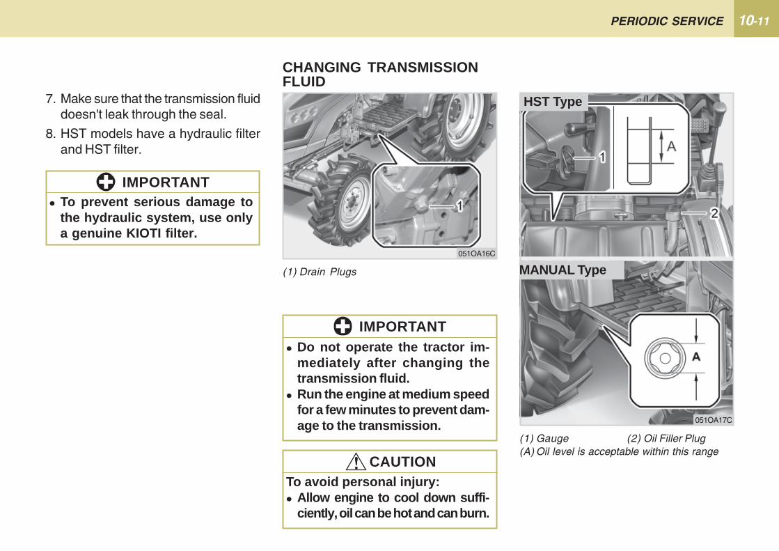
10-11PERIODIC SERVICE
(1) Drain Plugs
CHANGING TRANSMISSIONFLUID
051OA16C
To avoid personal injury:� Allow engine to cool down suffi-
ciently, oil can be hot and can burn.
!!!!! CAUTION
� Do not operate the tractor im-mediately after changing thetransmission fluid.
� Run the engine at medium speedfor a few minutes to prevent dam-age to the transmission.
IMPORTANT
7. Make sure that the transmission fluiddoesn't leak through the seal.
8. HST models have a hydraulic filterand HST filter.
� To prevent serious damage tothe hydraulic system, use onlya genuine KIOTI filter.
IMPORTANT
(1) Gauge (2) Oil Filler Plug(A) Oil level is acceptable within this range
051OA17C
MANUAL Type
HST Type
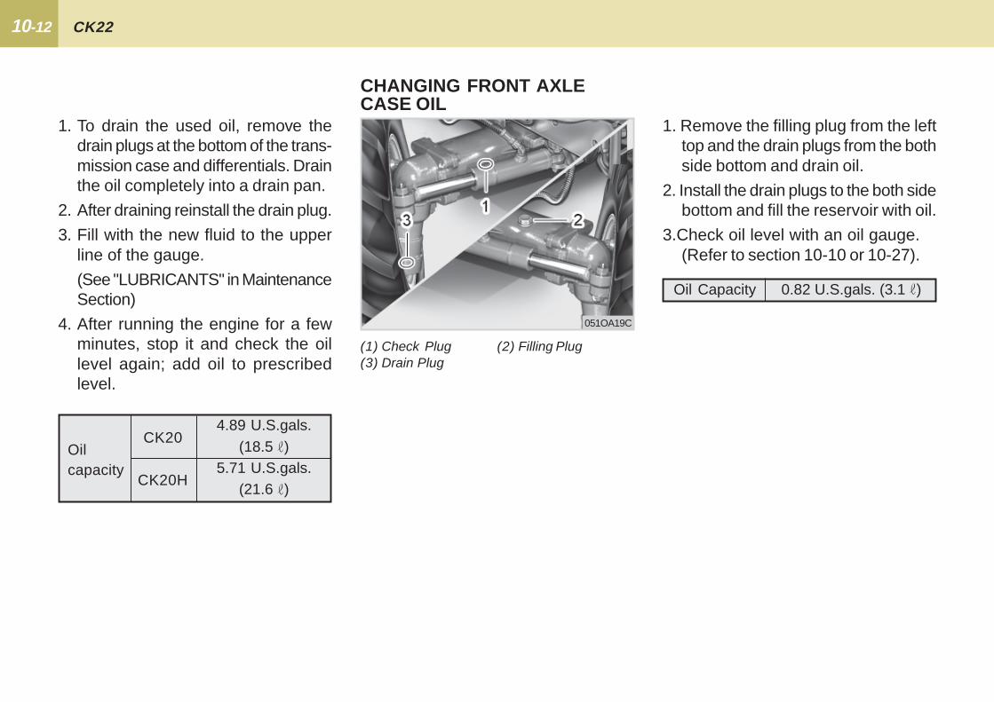
10-12 CK22
1. Remove the filling plug from the lefttop and the drain plugs from the bothside bottom and drain oil.
2. Install the drain plugs to the both sidebottom and fill the reservoir with oil.
3.Check oil level with an oil gauge. (Refer to section 10-10 or 10-27).
CHANGING FRONT AXLECASE OIL
(1) Check Plug (2) Filling Plug(3) Drain Plug
051OA19C
Oil Capacity 0.82 U.S.gals. (3.1 )
1. To drain the used oil, remove thedrain plugs at the bottom of the trans-mission case and differentials. Drainthe oil completely into a drain pan.
2. After draining reinstall the drain plug.
3. Fill with the new fluid to the upperline of the gauge.
(See "LUBRICANTS" in MaintenanceSection)
4. After running the engine for a fewminutes, stop it and check the oillevel again; add oil to prescribedlevel.
Oilcapacity
4.89 U.S.gals.(18.5 )
5.71 U.S.gals.(21.6 )
CK20
CK20H
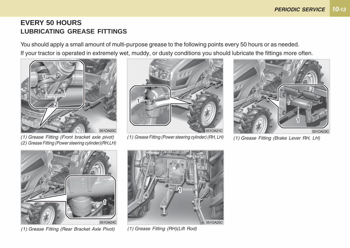
10-13PERIODIC SERVICE
EVERY 50 HOURSLUBRICATING GREASE FITTINGS
You should apply a small amount of multi-purpose grease to the following points every 50 hours or as needed.
If your tractor is operated in extremely wet, muddy, or dusty conditions you should lubricate the fittings more often.
(1) Grease Fitting (Front bracket axle pivot)(2) Grease Fitting (Power steering cylinder)(RH,LH)
(1) Grease Fitting (Brake Lever RH, LH)(1) Grease Fitting (Power steering cylinder) (RH, LH)
(1) Grease Fitting (RH)(Lift Rod)(1) Grease Fitting (Rear Bracket Axle Pivot)
051OA20C 051OA23C051OA21C
051OA24C 051OA25C
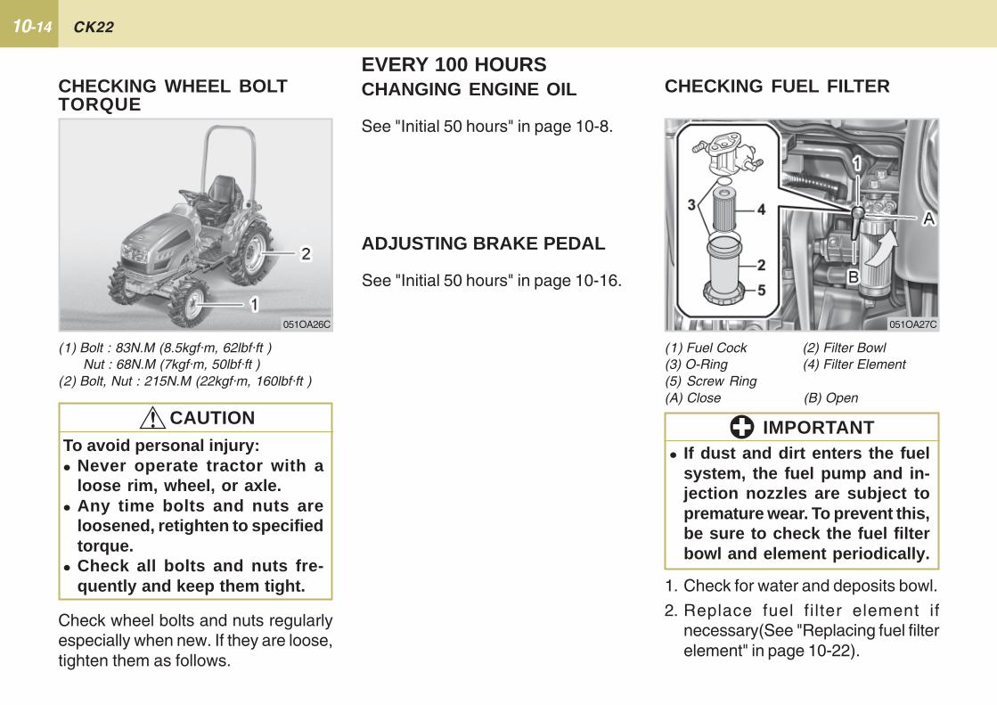
10-14 CK22
1. Check for water and deposits bowl.
2. Replace fuel filter element ifnecessary(See "Replacing fuel filterelement" in page 10-22).
� If dust and dirt enters the fuelsystem, the fuel pump and in-jection nozzles are subject topremature wear. To prevent this,be sure to check the fuel filterbowl and element periodically.
IMPORTANT
(1) Bolt : 83N.M (8.5kgf·m, 62lbf·ft ) Nut : 68N.M (7kgf·m, 50lbf·ft )(2) Bolt, Nut : 215N.M (22kgf·m, 160lbf·ft )
Check wheel bolts and nuts regularlyespecially when new. If they are loose,tighten them as follows.
CHECKING WHEEL BOLTTORQUE
To avoid personal injury:� Never operate tractor with a
loose rim, wheel, or axle.� Any time bolts and nuts are
loosened, retighten to specifiedtorque.
� Check all bolts and nuts fre-quently and keep them tight.
!!!!! CAUTION
051OA26C
EVERY 100 HOURSCHANGING ENGINE OIL
See "Initial 50 hours" in page 10-8.
ADJUSTING BRAKE PEDAL
See "Initial 50 hours" in page 10-16.
CHECKING FUEL FILTER
(1) Fuel Cock (2) Filter Bowl(3) O-Ring (4) Filter Element(5) Screw Ring(A) Close (B) Open
051OA27C
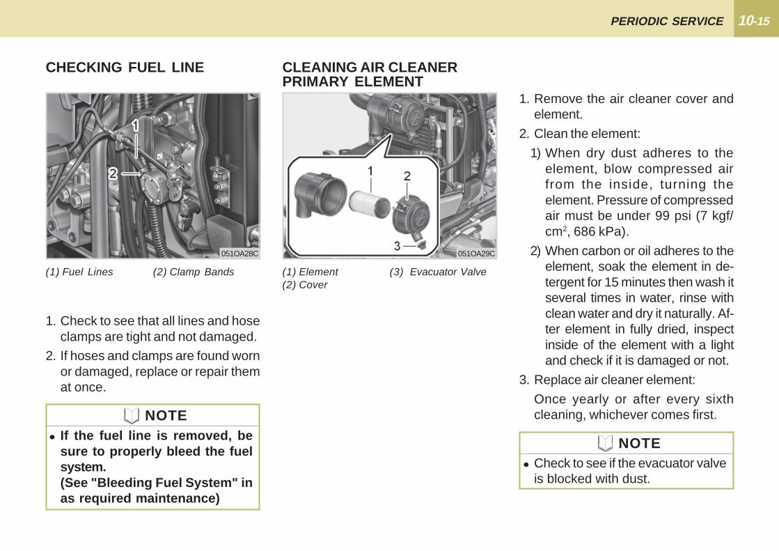
10-15PERIODIC SERVICE
(1) Fuel Lines (2) Clamp Bands
CHECKING FUEL LINE
1. Check to see that all lines and hoseclamps are tight and not damaged.
2. If hoses and clamps are found wornor damaged, replace or repair themat once.
051OA28C
(1) Element (3) Evacuator Valve(2) Cover
CLEANING AIR CLEANERPRIMARY ELEMENT
051OA29C
� Check to see if the evacuator valveis blocked with dust.
NOTE
1. Remove the air cleaner cover andelement.
2. Clean the element:
1) When dry dust adheres to theelement, blow compressed airfrom the inside, turning theelement. Pressure of compressedair must be under 99 psi (7 kgf/cm2, 686 kPa).
2) When carbon or oil adheres to theelement, soak the element in de-tergent for 15 minutes then wash itseveral times in water, rinse withclean water and dry it naturally. Af-ter element in fully dried, inspectinside of the element with a lightand check if it is damaged or not.
3. Replace air cleaner element:
Once yearly or after every sixthcleaning, whichever comes first.
� If the fuel line is removed, besure to properly bleed the fuelsystem.(See "Bleeding Fuel System" inas required maintenance)
NOTE
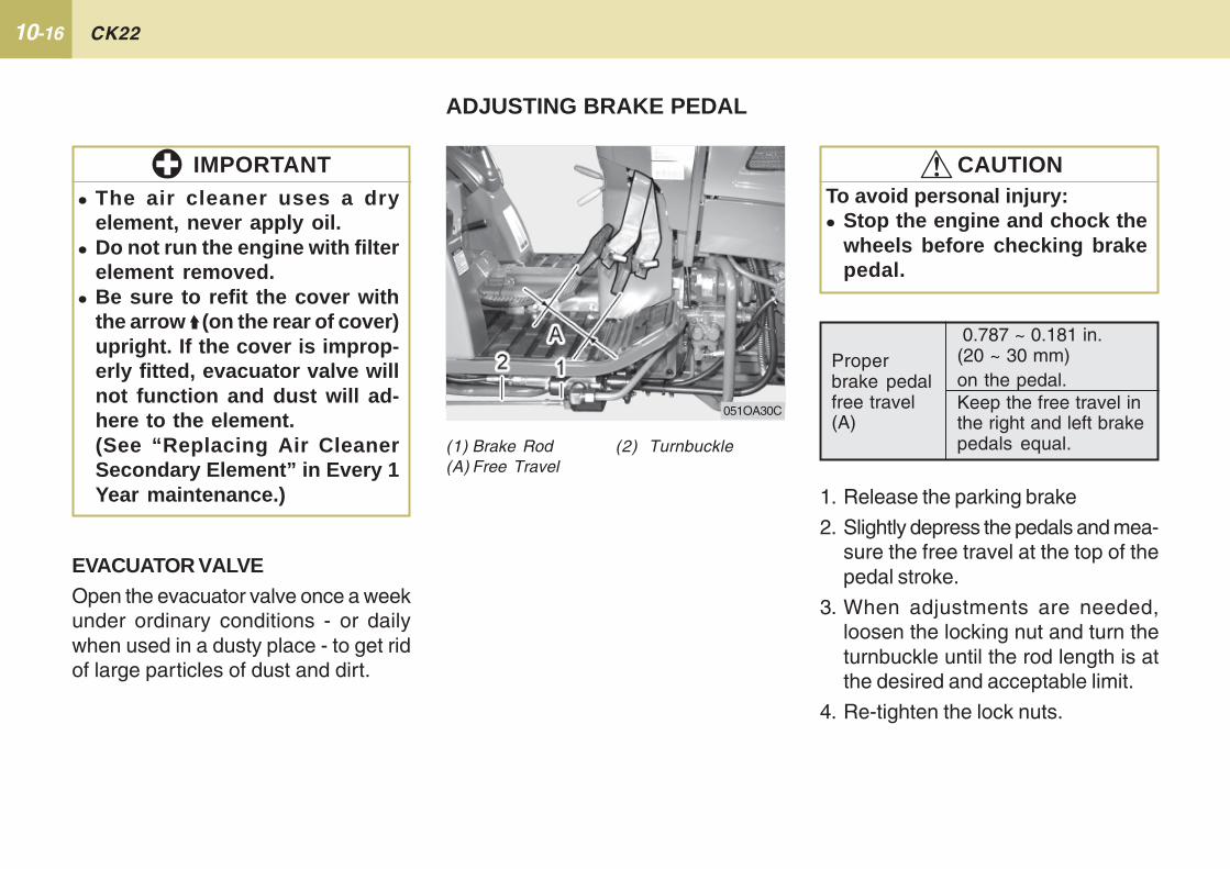
10-16 CK22
EVACUATOR VALVEOpen the evacuator valve once a weekunder ordinary conditions - or dailywhen used in a dusty place - to get ridof large particles of dust and dirt.
� The air cleaner uses a dryelement, never apply oil.
� Do not run the engine with filterelement removed.
� Be sure to refit the cover withthe arrow (on the rear of cover)upright. If the cover is improp-erly fitted, evacuator valve willnot function and dust will ad-here to the element.(See “Replacing Air CleanerSecondary Element” in Every 1Year maintenance.)
IMPORTANT
ADJUSTING BRAKE PEDAL
1. Release the parking brake
2. Slightly depress the pedals and mea-sure the free travel at the top of thepedal stroke.
3. When adjustments are needed,loosen the locking nut and turn theturnbuckle until the rod length is atthe desired and acceptable limit.
4. Re-tighten the lock nuts.
(1) Brake Rod (2) Turnbuckle(A) Free Travel
To avoid personal injury:� Stop the engine and chock the
wheels before checking brakepedal.
!!!!! CAUTION
Properbrake pedalfree travel(A)
0.787 ~ 0.181 in.(20 ~ 30 mm)on the pedal.Keep the free travel inthe right and left brakepedals equal.
MANUAL Type
051OA30C
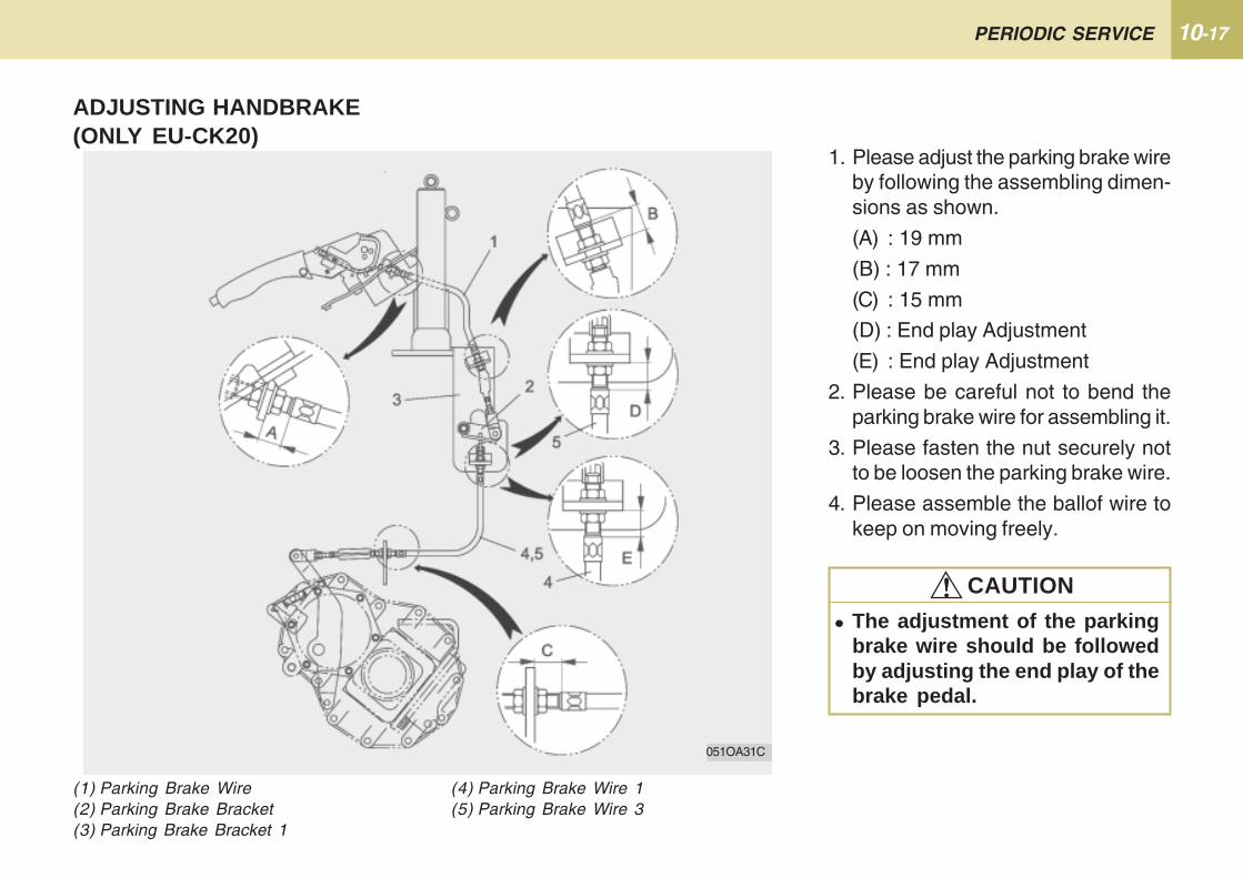
10-17PERIODIC SERVICE
(1) Parking Brake Wire(2) Parking Brake Bracket(3) Parking Brake Bracket 1
1. Please adjust the parking brake wireby following the assembling dimen-sions as shown.
(A) : 19 mm
(B) : 17 mm
(C) : 15 mm
(D) : End play Adjustment
(E) : End play Adjustment
2. Please be careful not to bend theparking brake wire for assembling it.
3. Please fasten the nut securely notto be loosen the parking brake wire.
4. Please assemble the ballof wire tokeep on moving freely.
� The adjustment of the parkingbrake wire should be followedby adjusting the end play of thebrake pedal.
!!!!! CAUTION
ADJUSTING HANDBRAKE(ONLY EU-CK20)
(4) Parking Brake Wire 1(5) Parking Brake Wire 3
051OA31C
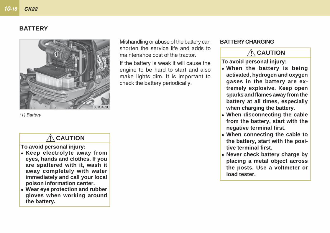
10-18 CK22
BATTERY CHARGING
(1) Battery
Mishandling or abuse of the battery canshorten the service life and adds tomaintenance cost of the tractor.
If the battery is weak it will cause theengine to be hard to start and alsomake lights dim. It is important tocheck the battery periodically.
051OA32C
To avoid personal injury:� Keep electrolyte away from
eyes, hands and clothes. If youare spattered with it, wash itaway completely with waterimmediately and call your localpoison information center.
� Wear eye protection and rubbergloves when working aroundthe battery.
!!!!! CAUTION
To avoid personal injury:� When the battery is being
activated, hydrogen and oxygengases in the battery are ex-tremely explosive. Keep opensparks and flames away from thebattery at all times, especiallywhen charging the battery.
� When disconnecting the cablefrom the battery, start with thenegative terminal first.
� When connecting the cable tothe battery, start with the posi-tive terminal first.
� Never check battery charge byplacing a metal object acrossthe posts. Use a voltmeter orload tester.
!!!!! CAUTION
BATTERY
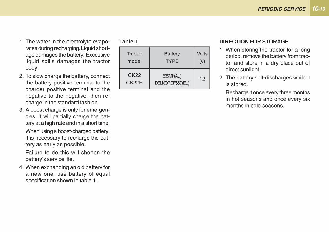
10-19PERIODIC SERVICE
1. The water in the electrolyte evapo-rates during recharging. Liquid short-age damages the battery. Excessiveliquid spills damages the tractorbody.
2. To slow charge the battery, connectthe battery positive terminal to thecharger positive terminal and thenegative to the negative, then re-charge in the standard fashion.
Tractor
model
Battery
TYPE
Volts
(v)
CK22
CK22H535MF(AU)
DELKOR DF65D(EU)12
DIRECTION FOR STORAGE1. When storing the tractor for a long
period, remove the battery from trac-tor and store in a dry place out ofdirect sunlight.
2. The battery self-discharges while itis stored.
Recharge it once every three monthsin hot seasons and once every sixmonths in cold seasons.
Table 1
3. A boost charge is only for emergen-cies. It will partially charge the bat-tery at a high rate and in a short time.
When using a boost-charged battery,it is necessary to recharge the bat-tery as early as possible.
Failure to do this will shorten thebattery's service life.
4. When exchanging an old battery fora new one, use battery of equalspecification shown in table 1.
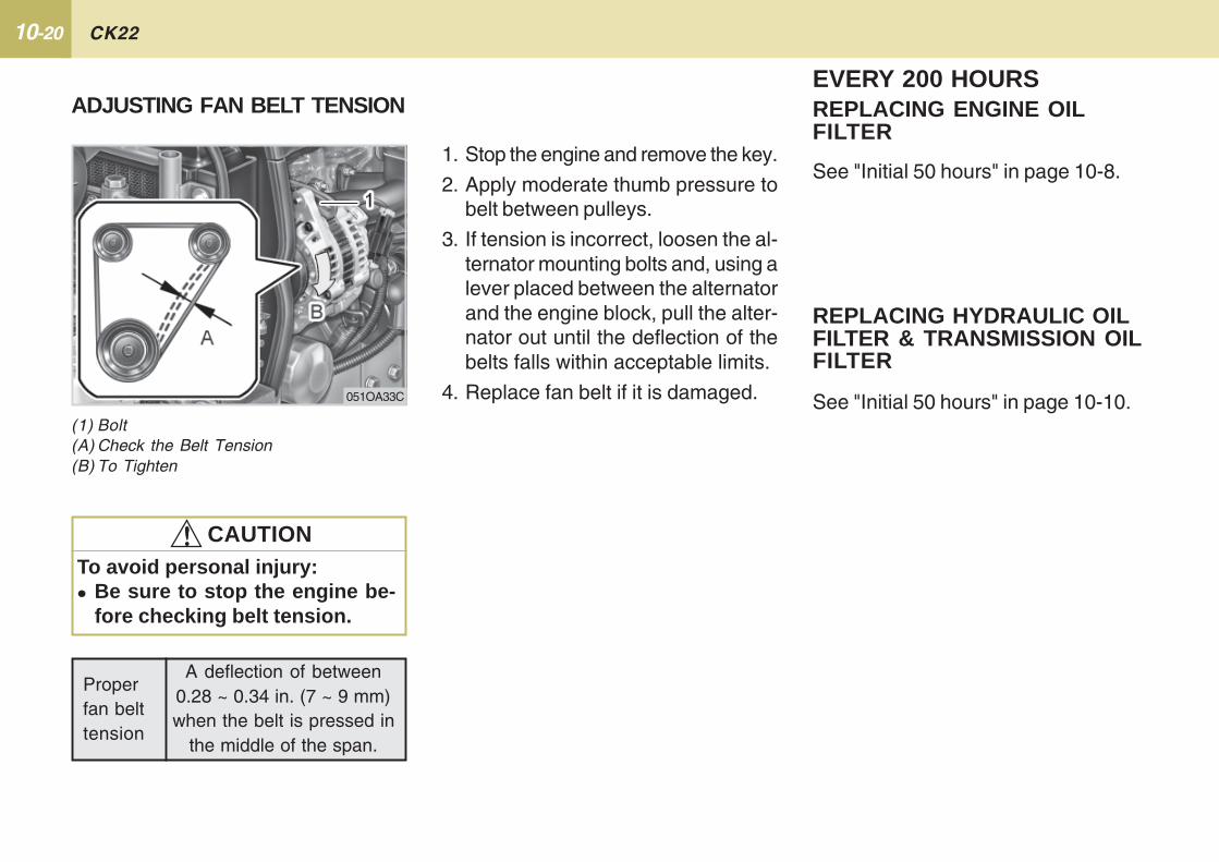
10-20 CK22
REPLACING HYDRAULIC OILFILTER & TRANSMISSION OILFILTER
EVERY 200 HOURSREPLACING ENGINE OILFILTER
Properfan belttension
A deflection of between0.28 ~ 0.34 in. (7 ~ 9 mm)when the belt is pressed in
the middle of the span.
1. Stop the engine and remove the key.
2. Apply moderate thumb pressure tobelt between pulleys.
3. If tension is incorrect, loosen the al-ternator mounting bolts and, using alever placed between the alternatorand the engine block, pull the alter-nator out until the deflection of thebelts falls within acceptable limits.
4. Replace fan belt if it is damaged.
To avoid personal injury:� Be sure to stop the engine be-
fore checking belt tension.
ADJUSTING FAN BELT TENSION
(1) Bolt(A) Check the Belt Tension(B) To Tighten
051OA33C
!!!!! CAUTION
See "Initial 50 hours" in page 10-8.
See "Initial 50 hours" in page 10-10.
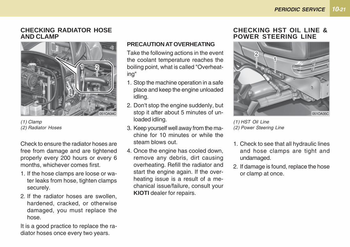
10-21PERIODIC SERVICE
Check to ensure the radiator hoses arefree from damage and are tightenedproperly every 200 hours or every 6months, whichever comes first.
1. If the hose clamps are loose or wa-ter leaks from hose, tighten clampssecurely.
2. If the radiator hoses are swollen,hardened, cracked, or otherwisedamaged, you must replace thehose.
It is a good practice to replace the ra-diator hoses once every two years.
PRECAUTION AT OVERHEATINGTake the following actions in the eventthe coolant temperature reaches theboiling point, what is called "Overheat-ing"
1. Stop the machine operation in a safeplace and keep the engine unloadedidling.
2. Don't stop the engine suddenly, butstop it after about 5 minutes of un-loaded idling.
3. Keep yourself well away from the ma-chine for 10 minutes or while thesteam blows out.
4. Once the engine has cooled down,remove any debris, dirt causingoverheating. Refill the radiator andstart the engine again. If the over-heating issue is a result of a me-chanical issue/failure, consult yourKIOTI dealer for repairs.
CHECKING RADIATOR HOSEAND CLAMP
(1) Clamp(2) Radiator Hoses
051OA34C
(1) HST Oil Line(2) Power Steering Line
CHECKING HST OIL LINE &POWER STEERING LINE
1. Check to see that all hydraulic linesand hose clamps are tight andundamaged.
2. If damage is found, replace the hoseor clamp at once.
051OA35C
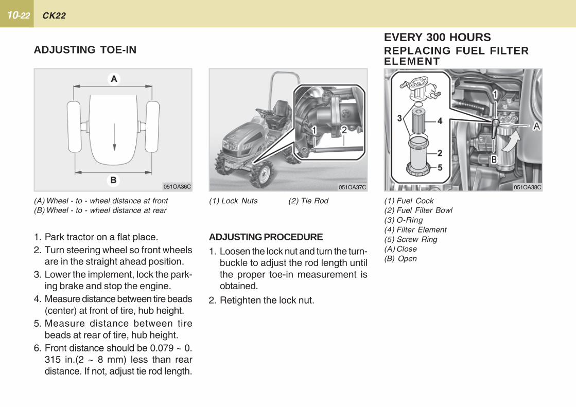
10-22 CK22
REPLACING FUEL FILTERELEMENT
(A) Wheel - to - wheel distance at front(B) Wheel - to - wheel distance at rear
ADJUSTING TOE-IN
(1) Lock Nuts (2) Tie Rod
ADJUSTING PROCEDURE1. Loosen the lock nut and turn the turn-
buckle to adjust the rod length untilthe proper toe-in measurement isobtained.
2. Retighten the lock nut.
1. Park tractor on a flat place.2. Turn steering wheel so front wheels
are in the straight ahead position.3. Lower the implement, lock the park-
ing brake and stop the engine.4. Measure distance between tire beads
(center) at front of tire, hub height.5. Measure distance between tire
beads at rear of tire, hub height.6. Front distance should be 0.079 ~ 0.
315 in.(2 ~ 8 mm) less than reardistance. If not, adjust tie rod length.
051OA37C
EVERY 300 HOURS
(1) Fuel Cock(2) Fuel Filter Bowl(3) O-Ring(4) Filter Element(5) Screw Ring(A) Close(B) Open
051OA38C051OA36C
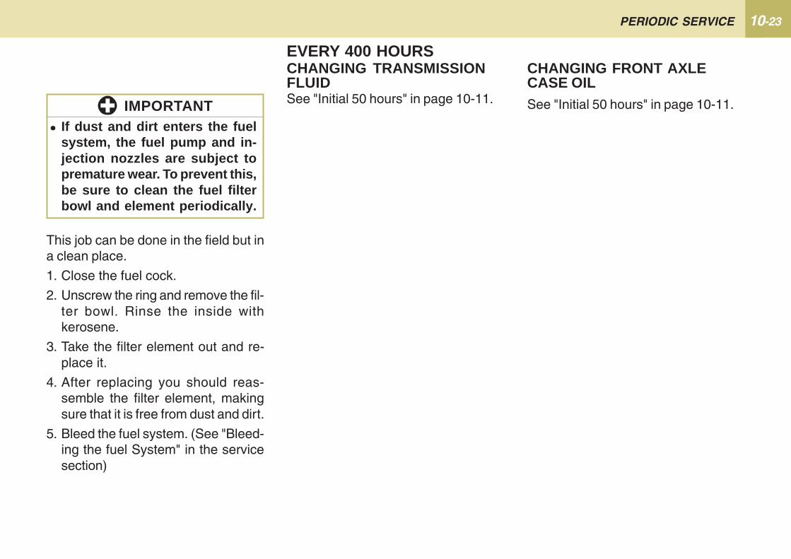
10-23PERIODIC SERVICE
CHANGING FRONT AXLECASE OIL
EVERY 400 HOURSCHANGING TRANSMISSIONFLUIDSee "Initial 50 hours" in page 10-11. See "Initial 50 hours" in page 10-11.
This job can be done in the field but ina clean place.
1. Close the fuel cock.
2. Unscrew the ring and remove the fil-ter bowl. Rinse the inside withkerosene.
3. Take the filter element out and re-place it.
4. After replacing you should reas-semble the filter element, makingsure that it is free from dust and dirt.
5. Bleed the fuel system. (See "Bleed-ing the fuel System" in the servicesection)
� If dust and dirt enters the fuelsystem, the fuel pump and in-jection nozzles are subject topremature wear. To prevent this,be sure to clean the fuel filterbowl and element periodically.
IMPORTANT

10-24 CK22
Consult your local KIOTI dealer for thisservice.
EVERY 800 HOURSADJUSTING ENGINEVALVE CLEARANCE
EVERY 600 HOURSADJUSTING FRONT AXLE PIVOT
(1) Lock Nut (2) Adjusting Screw
If the front axle pivot pin adjustment isnot correct, front wheel vibration canoccur causing vibration in the steeringwheel.
ADJUSTING PROCEDURELoosen the lock nut, tighten the adjust-ing screw all the way, and then loosenthe screw by 1/6 turn. Retighten thelock nut.
051OA39C
EVERY 1 YEARREPLACING AIR CLEANERELEMENT(See "Cleaning Air Cleaner Element" inevery 100 hours maintenance.)
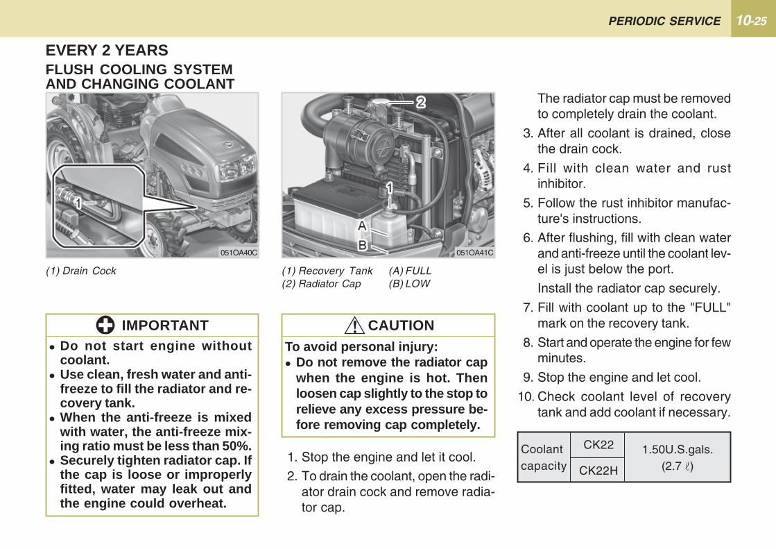
10-25PERIODIC SERVICE
(1) Recovery Tank (A) FULL(2) Radiator Cap (B) LOW
1. Stop the engine and let it cool.
2. To drain the coolant, open the radi-ator drain cock and remove radia-tor cap.
EVERY 2 YEARSFLUSH COOLING SYSTEMAND CHANGING COOLANT
(1) Drain Cock
051OA40C 051OA41C
To avoid personal injury:� Do not remove the radiator cap
when the engine is hot. Thenloosen cap slightly to the stop torelieve any excess pressure be-fore removing cap completely.
!!!!! CAUTION
Coolantcapacity
1.50U.S.gals.(2.7 )
CK22
CK22H
The radiator cap must be removedto completely drain the coolant.
3. After all coolant is drained, closethe drain cock.
4. Fill with clean water and rustinhibitor.
5. Follow the rust inhibitor manufac-ture's instructions.
6. After flushing, fill with clean waterand anti-freeze until the coolant lev-el is just below the port.
Install the radiator cap securely.
7. Fill with coolant up to the "FULL"mark on the recovery tank.
8. Start and operate the engine for fewminutes.
9. Stop the engine and let cool.
10. Check coolant level of recoverytank and add coolant if necessary.
� Do not start engine withoutcoolant.
� Use clean, fresh water and anti-freeze to fill the radiator and re-covery tank.
� When the anti-freeze is mixedwith water, the anti-freeze mix-ing ratio must be less than 50%.
� Securely tighten radiator cap. Ifthe cap is loose or improperlyfitted, water may leak out andthe engine could overheat.
IMPORTANT
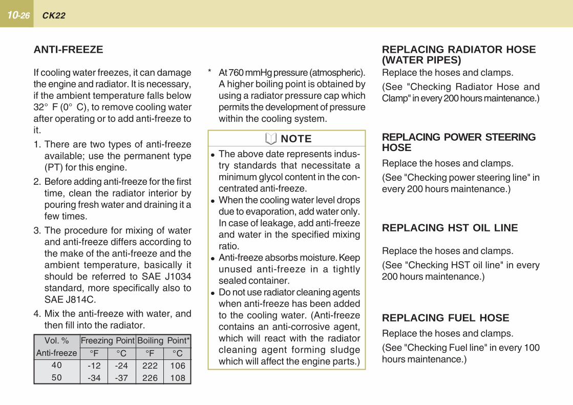
10-26 CK22
* At 760 mmHg pressure (atmospheric).A higher boiling point is obtained byusing a radiator pressure cap whichpermits the development of pressurewithin the cooling system.
If cooling water freezes, it can damagethe engine and radiator. It is necessary,if the ambient temperature falls below32° F (0° C), to remove cooling waterafter operating or to add anti-freeze toit.
1. There are two types of anti-freezeavailable; use the permanent type(PT) for this engine.
2. Before adding anti-freeze for the firsttime, clean the radiator interior bypouring fresh water and draining it afew times.
3. The procedure for mixing of waterand anti-freeze differs according tothe make of the anti-freeze and theambient temperature, basically itshould be referred to SAE J1034standard, more specifically also toSAE J814C.
4. Mix the anti-freeze with water, andthen fill into the radiator.
ANTI-FREEZE
Vol. %Anti-freeze
4050
Freezing Point
°C-24-37
°F-12-34
Boiling Point*
°C106108
°F222226
� The above date represents indus-try standards that necessitate aminimum glycol content in the con-centrated anti-freeze.
� When the cooling water level dropsdue to evaporation, add water only.In case of leakage, add anti-freezeand water in the specified mixingratio.
� Anti-freeze absorbs moisture. Keepunused anti-freeze in a tightlysealed container.
� Do not use radiator cleaning agentswhen anti-freeze has been addedto the cooling water. (Anti-freezecontains an anti-corrosive agent,which will react with the radiatorcleaning agent forming sludgewhich will affect the engine parts.)
NOTE
Replace the hoses and clamps.
(See "Checking Radiator Hose andClamp" in every 200 hours maintenance.)
REPLACING RADIATOR HOSE(WATER PIPES)
REPLACING HST OIL LINE
Replace the hoses and clamps.
(See "Checking HST oil line" in every200 hours maintenance.)
REPLACING FUEL HOSEReplace the hoses and clamps.
(See "Checking Fuel line" in every 100hours maintenance.)
REPLACING POWER STEERINGHOSEReplace the hoses and clamps.
(See "Checking power steering line" inevery 200 hours maintenance.)
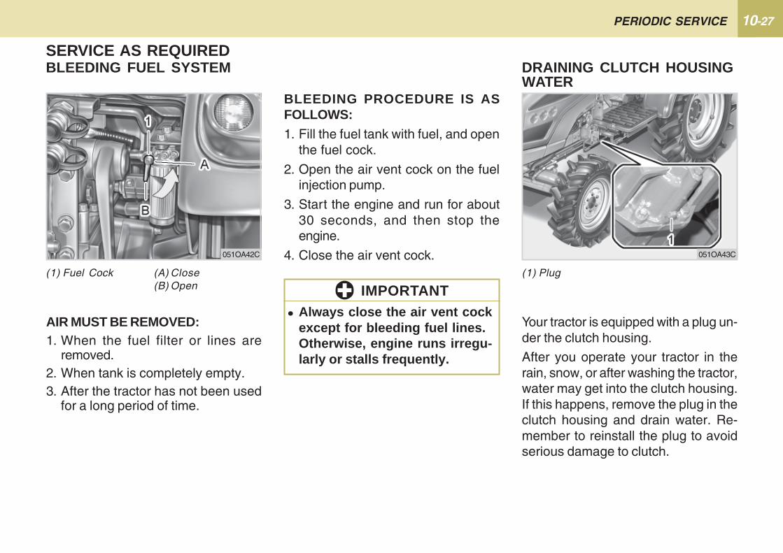
10-27PERIODIC SERVICE
SERVICE AS REQUIRED
AIR MUST BE REMOVED:1. When the fuel filter or lines are
removed.2. When tank is completely empty.3. After the tractor has not been used
for a long period of time.
Your tractor is equipped with a plug un-der the clutch housing.
After you operate your tractor in therain, snow, or after washing the tractor,water may get into the clutch housing.If this happens, remove the plug in theclutch housing and drain water. Re-member to reinstall the plug to avoidserious damage to clutch.
DRAINING CLUTCH HOUSINGWATER
BLEEDING FUEL SYSTEM
(1) Plug(1) Fuel Cock (A) Close(B) Open
051OA42C 051OA43C
BLEEDING PROCEDURE IS ASFOLLOWS:1. Fill the fuel tank with fuel, and open
the fuel cock.
2. Open the air vent cock on the fuelinjection pump.
3. Start the engine and run for about30 seconds, and then stop theengine.
4. Close the air vent cock.
� Always close the air vent cockexcept for bleeding fuel lines.Otherwise, engine runs irregu-larly or stalls frequently.
IMPORTANT
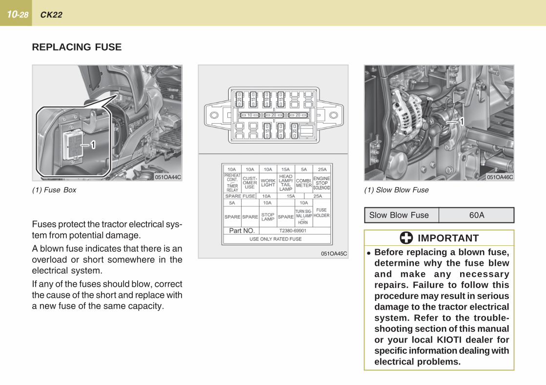
10-28 CK22
(1) Slow Blow Fuse
� Before replacing a blown fuse,determine why the fuse blewand make any necessaryrepairs. Failure to follow thisprocedure may result in seriousdamage to the tractor electricalsystem. Refer to the trouble-shooting section of this manualor your local KIOTI dealer forspecific information dealing withelectrical problems.
051OA46C
Slow Blow Fuse 60A
IMPORTANT051OA45C
Fuses protect the tractor electrical sys-tem from potential damage.
A blown fuse indicates that there is anoverload or short somewhere in theelectrical system.
If any of the fuses should blow, correctthe cause of the short and replace witha new fuse of the same capacity.
REPLACING FUSE
(1) Fuse Box
051OA44C

10-29PERIODIC SERVICE
1. Head lights and rear combination lights:
Take the bulb out of the light body and replace with a new one.
2. Other lights:
Detach the lens and replace the bulb.
REPLACING LIGHT BULB
PROTECTED CIRCUIT
CapacityLight35W / 35W55W / 60W55W / 60W
5W21W5W
21W / 5W21W21W
1.7W,3.4W(Charge Lamp)
Head Lights(AU)Head Lights(EU)Head Lights(EN)Tail Lights(AU)Stop Lights(AU)Front Position Lamps(EU)Stop Lights/Rear Position(EU)Turn signal LightsWork LightInstrument panel Light
123456789
10
No. Capacity Protected circuit
1
23456789
Heater Control/Timer RelayCustomer UseWork LightHead Lights/Tail LightComi MeterEngine Stop SolenoidStop LightsTurn Signal Lamp/HornFuse Holder
10A
10A10A15A5A
25A10A10A25A
11TRACTOR STORAGE ............................................... 11-2
REMOVING THE TRACTOR FROM STORAGE ..... 11-3
STORAGE
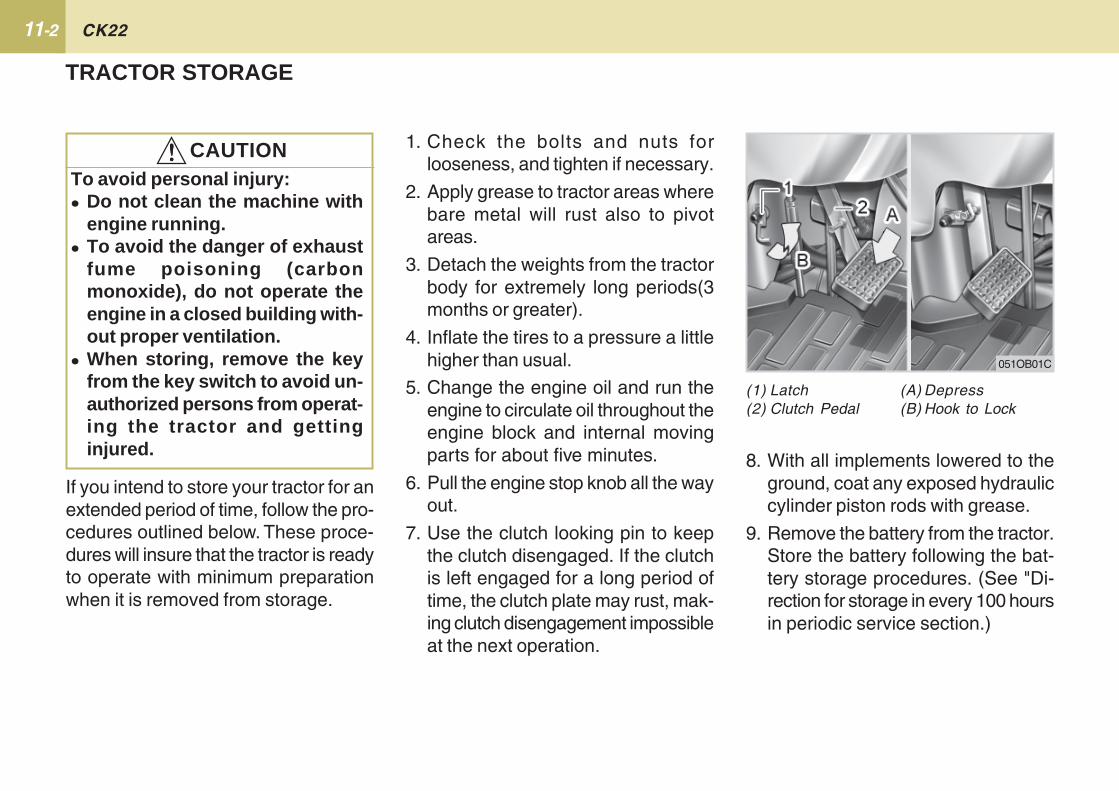
11-2 CK22
051OB01C
(1) Latch (A) Depress(2) Clutch Pedal (B) Hook to Lock
8. With all implements lowered to theground, coat any exposed hydrauliccylinder piston rods with grease.
9. Remove the battery from the tractor.Store the battery following the bat-tery storage procedures. (See "Di-rection for storage in every 100 hoursin periodic service section.)
If you intend to store your tractor for anextended period of time, follow the pro-cedures outlined below. These proce-dures will insure that the tractor is readyto operate with minimum preparationwhen it is removed from storage.
TRACTOR STORAGE
To avoid personal injury:� Do not clean the machine with
engine running.� To avoid the danger of exhaust
fume poisoning (carbonmonoxide), do not operate theengine in a closed building with-out proper ventilation.
� When storing, remove the keyfrom the key switch to avoid un-authorized persons from operat-ing the tractor and gettinginjured.
!!!!! CAUTION 1. Check the bolts and nuts forlooseness, and tighten if necessary.
2. Apply grease to tractor areas wherebare metal will rust also to pivotareas.
3. Detach the weights from the tractorbody for extremely long periods(3months or greater).
4. Inflate the tires to a pressure a littlehigher than usual.
5. Change the engine oil and run theengine to circulate oil throughout theengine block and internal movingparts for about five minutes.
6. Pull the engine stop knob all the wayout.
7. Use the clutch looking pin to keepthe clutch disengaged. If the clutchis left engaged for a long period oftime, the clutch plate may rust, mak-ing clutch disengagement impossibleat the next operation.
11-3STORAGE
1. Check the tire air pressure and in-flate the tires if they are low.
2. Jack the tractor up and remove thesupport blocks from under the frontand rear axles.
3. Install a fully charged battery.
4. Check the fan belt tension.
5. Check all fluid levels (engine oil,transmission / hydraulic oil, enginecoolant and any attachedimplements.)
6. Star t the engine. Observe allgauges. If all gauges are function-ing properly and reading normal,move the tractor outside. Onceoutside, park the tractor and let theengine idle for at least five minutes.Shut the engine off and walk aroundtractor and make a visual inspectionfor evidence of oil or water leaks.
7. With the engine fully warmed up, re-lease the parking brake and test thebrakes for proper adjustment as youmove forward. Adjust the brakes ifnecessary.
REMOVING THE TRACTORFROM STORAGE
10. Keep the tractor in a dry placewhere the tractor is sheltered fromrain. Cover the tractor.
11. Store the tractor indoors in a dryarea that is protected from sunlightand excessive heat. If the tractormust be stored outdoors, cover itwith a waterproof tarpaulin.
Jack the tractor up and place blocksunder the front and rear axles sothat all four tires are off the ground.Keep the tries out of direct sunlightand extreme heat(3 months orgreater).
� When washing the tractor, besure to stop the engine. Allowsufficient time for the engine tocool before washing.
� Cover the tractor after the muf-fler and the engine have cooleddown.
IMPORTANT
12ENGINE TROUBLESHOOTING ............................... 12-2
TROUBLESHOOTING
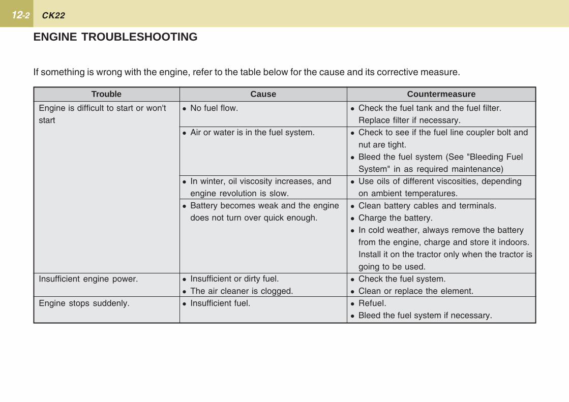
12-2 CK22
ENGINE TROUBLESHOOTING
If something is wrong with the engine, refer to the table below for the cause and its corrective measure.
Trouble Cause Countermeasure
Engine is difficult to start or won'tstart
Insufficient engine power.
Engine stops suddenly.
� No fuel flow.
� Air or water is in the fuel system.
� In winter, oil viscosity increases, andengine revolution is slow.
� Battery becomes weak and the enginedoes not turn over quick enough.
� Insufficient or dirty fuel.� The air cleaner is clogged.� Insufficient fuel.
� Check the fuel tank and the fuel filter.Replace filter if necessary.
� Check to see if the fuel line coupler bolt andnut are tight.
� Bleed the fuel system (See "Bleeding FuelSystem" in as required maintenance)
� Use oils of different viscosities, dependingon ambient temperatures.
� Clean battery cables and terminals.� Charge the battery.� In cold weather, always remove the battery
from the engine, charge and store it indoors.Install it on the tractor only when the tractor isgoing to be used.
� Check the fuel system.� Clean or replace the element.� Refuel.� Bleed the fuel system if necessary.
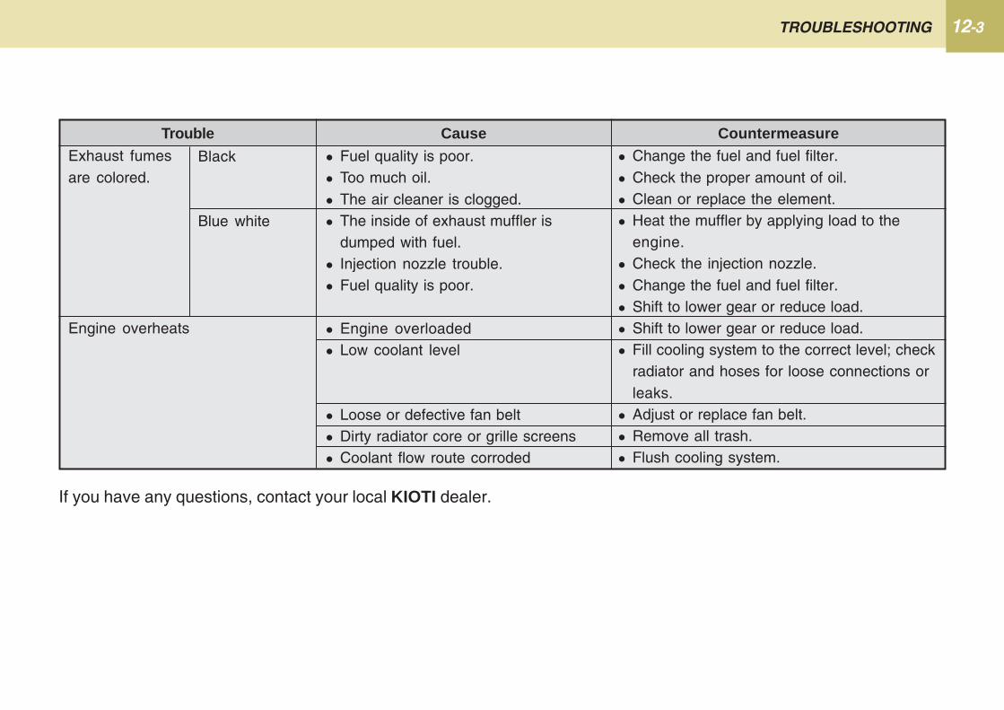
12-3TROUBLESHOOTING
If you have any questions, contact your local KIOTI dealer.
Black
Blue white
Trouble Cause Countermeasure� Change the fuel and fuel filter.� Check the proper amount of oil.� Clean or replace the element.� Heat the muffler by applying load to the
engine.� Check the injection nozzle.� Change the fuel and fuel filter.� Shift to lower gear or reduce load.� Shift to lower gear or reduce load.� Fill cooling system to the correct level; check
radiator and hoses for loose connections orleaks.
� Adjust or replace fan belt.� Remove all trash.� Flush cooling system.
� Fuel quality is poor.� Too much oil.� The air cleaner is clogged.� The inside of exhaust muffler is
dumped with fuel.� Injection nozzle trouble.� Fuel quality is poor.
� Engine overloaded� Low coolant level
� Loose or defective fan belt� Dirty radiator core or grille screens� Coolant flow route corroded
Exhaust fumesare colored.
Engine overheats

13OPTIONS ................................................................... 13-2
OPTIONS
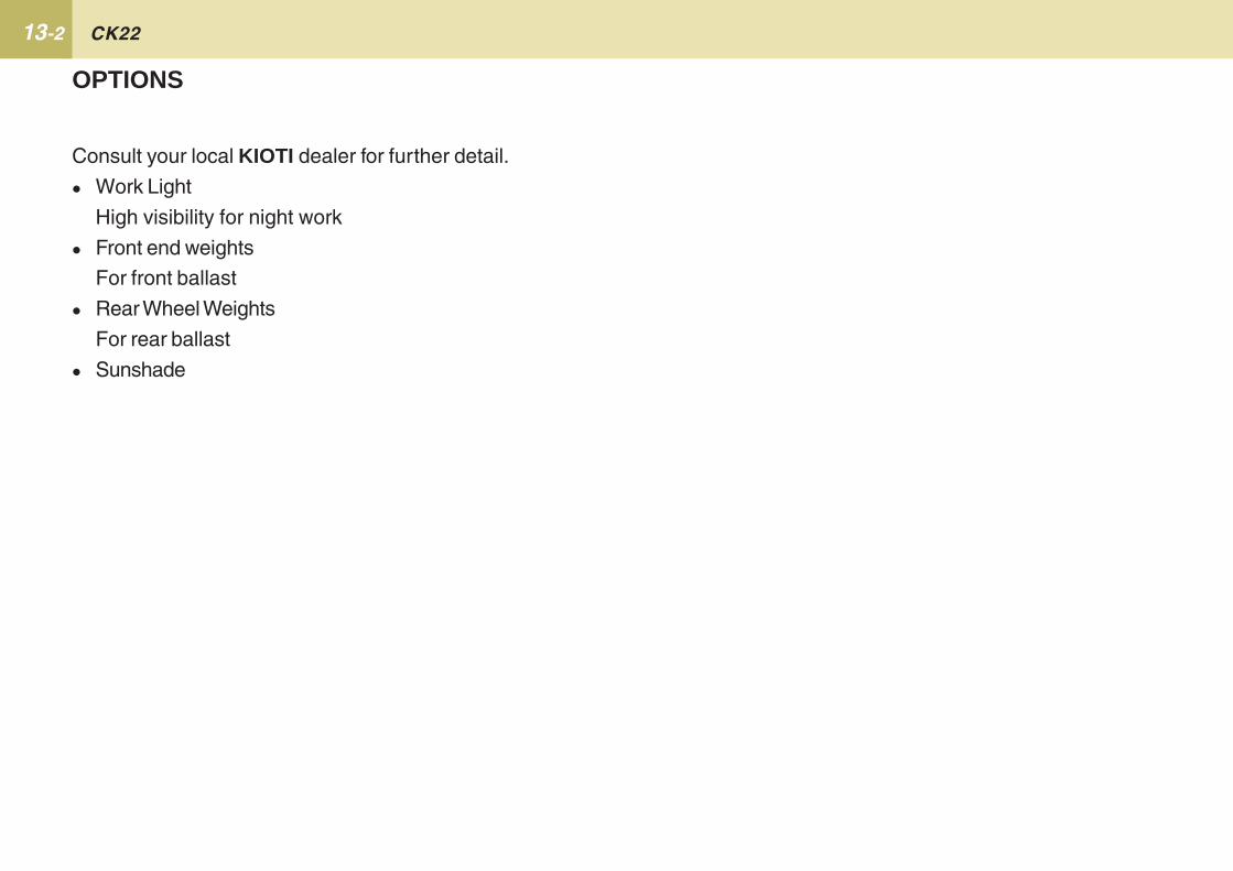
13-2 CK22
Consult your local KIOTI dealer for further detail.
� Work Light
High visibility for night work
� Front end weights
For front ballast
� Rear Wheel Weights
For rear ballast
� Sunshade
OPTIONS

14
INDEX
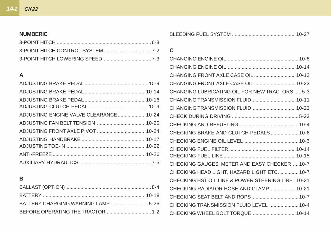
14-2 CK22
NUMBERIC3-POINT HITCH .................................................................... 6-3
3-POINT HITCH CONTROL SYSTEM .................................. 7-2
3-POINT HITCH LOWERING SPEED .................................. 7-3
AADJUSTING BRAKE PEDAL ..............................................10-9
ADJUSTING BRAKE PEDAL ........................................... 10-14
ADJUSTING BRAKE PEDAL ........................................... 10-16ADJUSTING CLUTCH PEDAL ...........................................10-9
ADJUSTING ENGINE VALVE CLEARANCE................... 10-24
ADJUSTING FAN BELT TENSION .................................. 10-20
ADJUSTING FRONT AXLE PIVOT .................................. 10-24
ADJUSTING HANDBRAKE ............................................. 10-17ADJUSTING TOE-IN ........................................................ 10-22
ANTI-FREEZE .................................................................. 10-26
AUXILIARY HYDRAULICS ................................................... 7-5
BBALLAST (OPTION) ............................................................. 8-4
BATTERY ......................................................................... 10-18
BATTERY CHARGING WARNING LAMP ...........................5-26
BEFORE OPERATING THE TRACTOR ................................ 1-2
BLEEDING FUEL SYSTEM ............................................. 10-27
CCHANGING ENGINE OIL ...................................................10-8
CHANGING ENGINE OIL ................................................ 10-14
CHANGING FRONT AXLE CASE OIL ............................. 10-12
CHANGING FRONT AXLE CASE OIL ............................. 10-23
CHANGING LUBRICATING OIL FOR NEW TRACTORS ..... 5-3
CHANGING TRANSMISSION FLUID .............................. 10-11
CHANGING TRANSMISSION FLUID .............................. 10-23
CHECK DURING DRIVING ................................................5-23
CHECKING AND REFUELING...........................................10-4
CHECKING BRAKE AND CLUTCH PEDALS ....................10-6
CHECKING ENGINE OIL LEVEL .......................................10-3
CHECKING FUEL FILTER ............................................... 10-14CHECKING FUEL LINE ................................................... 10-15
CHECKING GAUGES, METER AND EASY CHECKER ....10-7
CHECKING HEAD LIGHT, HAZARD LIGHT ETC. .............10-7
CHECKING HST OIL LINE & POWER STEERING LINE 10-21
CHECKING RADIATOR HOSE AND CLAMP ................. 10-21
CHECKING SEAT BELT AND ROPS..................................10-7
CHECKING TRANSMISSION FLUID LEVEL .....................10-4
CHECKING WHEEL BOLT TORQUE .............................. 10-14

14-3INDEX
CLEANING AIR CLEANER PRIMARY ELEMENT .......... 10-15
CHECKING FUEL FILTER ............................................... 10-14
CLEANING GRILL, RADIATOR SCREEN AND OIL COOLERSCREEN .............................................................................10-7
COOLANT TEMPERATURE GAUGE.................................. 5-25
COUPLER CONNECTING AND DISCONNECTING ........... 7-7
DDAILY CHECK ...................................................................... 5-2
DAILY CHECK .................................................................... 10-3
DRAINING CLUTCH HOUSING WATER ........................ 10-27
DRAWBAR ............................................................................ 6-4
DRIVING THE TRACTOR ..................................................... 1-8
EENGINE COVER .................................................................. 10-2
ENGINE OIL PRESSURE WARNING LAMP ......................5-26
ENGINE TROUBLESHOOTING ..........................................12-2
EVERY 1 YEAR ................................................................ 10-24
EVERY 100 HOURS ........................................................ 10-14
EVERY 2 YEARS ............................................................. 10-25
EVERY 200 HOURS ........................................................ 10-20
EEVERY3200 HOURS .................................................... 10-22
VERY 400 HOURS .......................................................... 10-23
EVERY 50 HOURS .......................................................... 10-13
EVERY 600 HOURS ........................................................ 10-24
EVERY 800 HOURS ........................................................ 10-24
EXTERIOR VIEW .................................................................. 4-2
FFLUSH COOLING SYSTEM AND CHANGING COOLANT 10-25
FOOT AND HAND CONTROLS ........................................... 4-5
FRONT BALLAST ................................................................. 8-5
FRONT WHEELS.................................................................. 8-3
FUEL GAUGE .....................................................................5-25
GGLOW PLUG INDICATOR ..................................................5-27
HHEAD LIGHT HIGH BEAM PILOT LAMP ............................5-26
HOOD .................................................................................10-2HORN .............................................................................. 10-22
HOW TO OPEN THE HOOD ...............................................10-2
HYDRAULIC CONTROL ...................................................... 7-2
14-4 CK22
IIMMEDIATELY STOP THE ENGINE IF ................................5-23
IMPLEMENT LIMITATIONS................................................... 3-4
IMPLEMENT LOWERING LIMIT ........................................... 7-3
INFLATION PRESSURE ....................................................... 8-2
INITIAL 50 HOURS .............................................................10-8
INSTRUMENT CLUSTER ..................................................5-24INSTRUMENT PANEL AND SWITCH .................................. 4-4
JJOYSTICK VALVE ................................................................. 7-5
JUMP STARTING................................................................5-10
LLUBRICANTS ....................................................................... 9-4
LUBRICATING GREASE FITTINGS ................................ 10-13
OOPERATING NEW TRACTOR .............................................. 5-3
OPERATING TECHNIQUES ...............................................5-29
OPERATING THE ENGINE ................................................... 5-4
OPERATING THE PTO .......................................................1-10
OPERATING THE TRACTOR ................................................ 1-5
OPERATING THE TRACTOR..............................................5-11
OPTIONS ............................................................................13-2
PPTO OPERATION ...............................................................5-32
PARKING ............................................................................5-28
PARKING BRAKE LAMP ....................................................5-27
PARKING THE TRACTOR .................................................... 1-9
PRE-OPERATION ................................................................. 5-2
RREAR BALLAST ................................................................... 8-4
REAR WHEELS .................................................................... 8-3
REMOTE CONTROL VALVE LEVER .................................... 7-6REMOVING THE TRACTOR FROM STORAGE .................11-3
REPLACING AIR CLEANER ELEMENT ......................... 10-24
REPLACING ENGINE OIL FILTER .....................................10-8
REPLACING ENGINE OIL FILTER .................................. 10-20
REPLACING FUEL FILTER ELEMENT ........................... 10-22
REPLACING FUEL HOSE ............................................... 10-26
REPLACING FUSE.......................................................... 10-28
REPLACING HST OIL LINE ............................................ 10-26
REPLACING HYDRAULIC OIL FILTER & TRANSMISSION OIL
14-5INDEX
FILTER ............................................................................. 10-10
REPLACING HYDRAULIC OIL FILTER & TRANSMISSION OILFILTER ............................................................................. 10-20
REPLACING LIGHT BULB .............................................. 10-29
REPLACING POWER STEERING HOSE ....................... 10-26
REPLACING RADIATOR HOSE (WATER PIPES) .......... 10-26
SSEAT ................................................................................ 10-27SERVICE AS REQUIRED ................................................ 10-26
SERVICE INTERVALS .......................................................... 9-2
SERVICING........................................................................... 2-2
SERVICING THE TRACTOR ............................................... 1-11
SPECIFICATIONS ................................................................. 3-2
STARTING ..........................................................................5-12
STARTING THE ENGINE ...................................................... 5-4
STOPPING ..........................................................................5-22
STOPPING THE ENGINE ..................................................... 5-8
TTACHOMETER ...................................................................5-24
THREE-POINT HITCH & DRAWBAR ................................... 6-2
TIRES.................................................................................... 8-2
TO FOLD THE ROPS ..........................................................5-11TO RAISE THE ROPS TO UPRIGHT POSITION ................5-12
TRACTOR SAFETY LABELS .............................................1-14
TRACTOR STORAGE ........................................................11-2
TRAVELING SPEED ............................................................. 3-5
TREAD .................................................................................. 8-3
TURN SIGNAL LAMP .........................................................5-27
UUSING 3-POINT HITCH ......................................................1-10
WWARMING UP ....................................................................... 5-8


![Predgovor [Foreword].](https://static.fdokumen.com/doc/165x107/63333df9ce61be0ae50e8cf4/predgovor-foreword-1681982858.jpg)