INSTALLATION INSTRUCTIONS for French Door - PGT ...
11
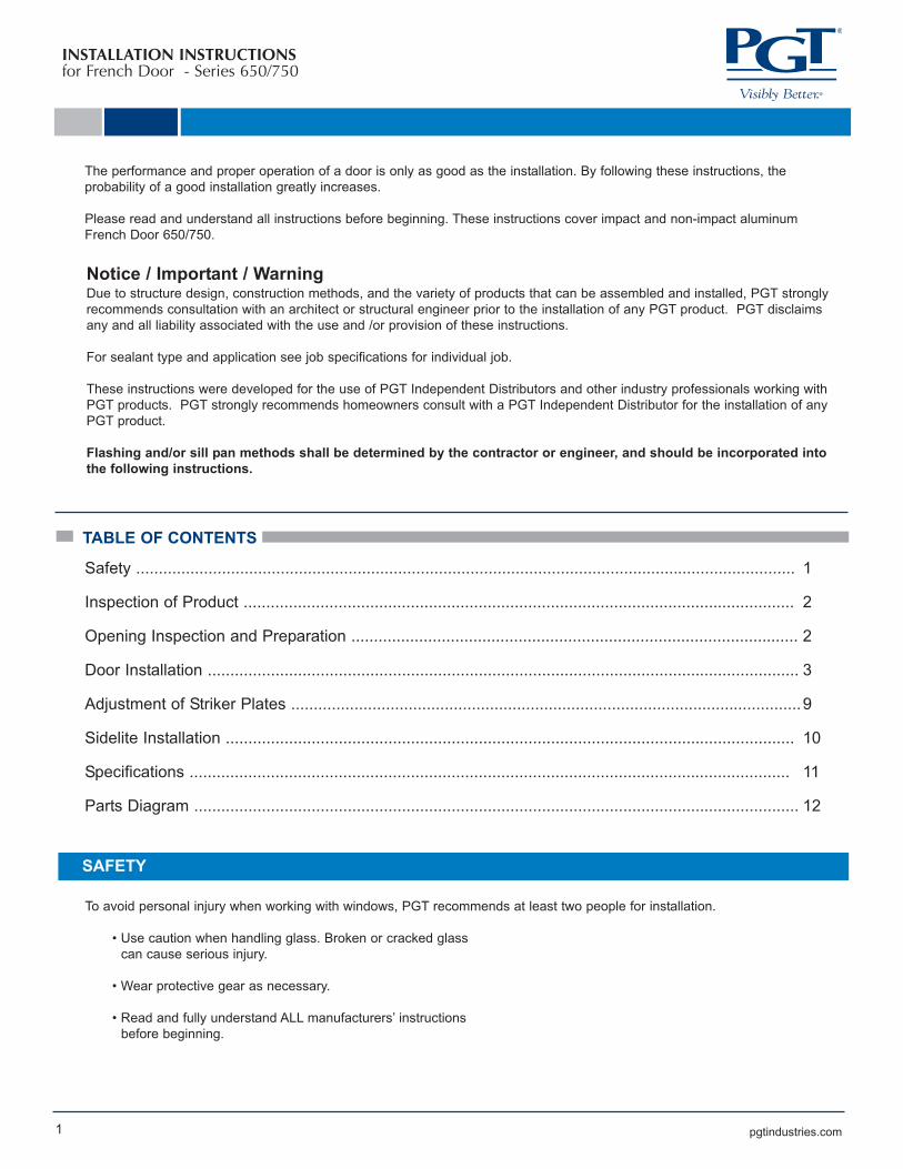
pgtindustries.com INSTALLATION INSTRUCTIONS for French Door - Series 650/750 1 Notice / Important / Warning Due to structure design, construction methods, and the variety of products that can be assembled and installed, PGT strongly recommends consultation with an architect or structural engineer prior to the installation of any PGT product. PGT disclaims any and all liability associated with the use and /or provision of these instructions. For sealant type and application see job specifications for individual job. These instructions were developed for the use of PGT Independent Distributors and other industry professionals working with PGT products. PGT strongly recommends homeowners consult with a PGT Independent Distributor for the installation of any PGT product. Flashing and/or sill pan methods shall be determined by the contractor or engineer, and should be incorporated into the following instructions. The performance and proper operation of a door is only as good as the installation. By following these instructions, the probability of a good installation greatly increases. Please read and understand all instructions before beginning. These instructions cover impact and non-impact aluminum French Door 650/750. Safety .................................................................................................................................................. 1 Inspection of Product .......................................................................................................................... 2 Opening Inspection and Preparation ................................................................................................... 2 Door Installation ................................................................................................................................... 3 Adjustment of Striker Plates ................................................................................................................. 9 Sidelite Installation .............................................................................................................................. 10 Specifications ..................................................................................................................................... 11 Parts Diagram ...................................................................................................................................... 12 TABLE OF CONTENTS SAFETY To avoid personal injury when working with windows, PGT recommends at least two people for installation. • Use caution when handling glass. Broken or cracked glass can cause serious injury. • Wear protective gear as necessary. • Read and fully understand ALL manufacturers’ instructions before beginning.
-
Upload
khangminh22 -
Category
Documents
-
view
2 -
download
0
Transcript of INSTALLATION INSTRUCTIONS for French Door - PGT ...
pgtindustries.com
INSTALLATION INSTRUCTIONSfor French Door - Series 650/750
1
Notice / Important / WarningDue to structure design, construction methods, and the variety of products that can be assembled and installed, PGT strongly
recommends consultation with an architect or structural engineer prior to the installation of any PGT product. PGT disclaims
any and all liability associated with the use and /or provision of these instructions.
For sealant type and application see job specifications for individual job.
These instructions were developed for the use of PGT Independent Distributors and other industry professionals working with
PGT products. PGT strongly recommends homeowners consult with a PGT Independent Distributor for the installation of any
PGT product.
Flashing and/or sill pan methods shall be determined by the contractor or engineer, and should be incorporated into
the following instructions.
The performance and proper operation of a door is only as good as the installation. By following these instructions, the
probability of a good installation greatly increases.
Please read and understand all instructions before beginning. These instructions cover impact and non-impact aluminum
French Door 650/750.
Safety .................................................................................................................................................. 1
Inspection of Product .......................................................................................................................... 2
Opening Inspection and Preparation ................................................................................................... 2
Door Installation ................................................................................................................................... 3
Adjustment of Striker Plates .................................................................................................................9
Sidelite Installation .............................................................................................................................. 10
Specifications ..................................................................................................................................... 11
Parts Diagram ...................................................................................................................................... 12
TABLE OF CONTENTS
SAFETY
To avoid personal injury when working with windows, PGT recommends at least two people for installation.
• Use caution when handling glass. Broken or cracked glass
can cause serious injury.
• Wear protective gear as necessary.
• Read and fully understand ALL manufacturers’ instructions
before beginning.
INSTALLATION INSTRUCTIONSfor French Door - Series 650/750
2 pgtindustries.com
INSPECTION OF PRODUCT
1. Inspect the product and take inventory of all parts and pieces prior to installation. (ex. slabs, paint, glass, sidelites, etc.)
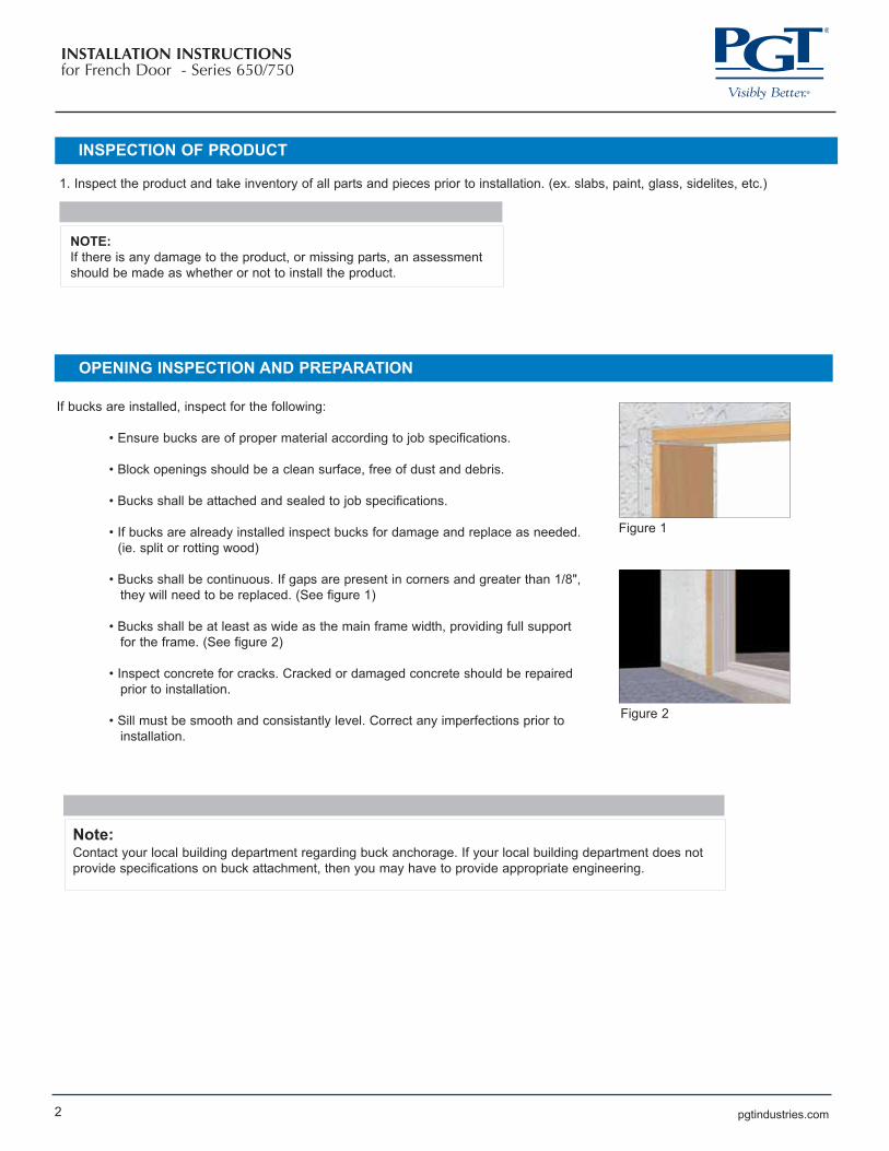
If bucks are installed, inspect for the following:
• Ensure bucks are of proper material according to job specifications.
• Block openings should be a clean surface, free of dust and debris.
• Bucks shall be attached and sealed to job specifications.
• If bucks are already installed inspect bucks for damage and replace as needed.
(ie. split or rotting wood)
• Bucks shall be continuous. If gaps are present in corners and greater than 1/8",
they will need to be replaced. (See figure 1)
• Bucks shall be at least as wide as the main frame width, providing full support
for the frame. (See figure 2)
• Inspect concrete for cracks. Cracked or damaged concrete should be repaired
prior to installation.
• Sill must be smooth and consistantly level. Correct any imperfections prior to
installation.
OPENING INSPECTION AND PREPARATION
NOTE:
If there is any damage to the product, or missing parts, an assessment
should be made as whether or not to install the product.
Note:Contact your local building department regarding buck anchorage. If your local building department does not
provide specifications on buck attachment, then you may have to provide appropriate engineering.
Figure 1
Figure 2
INSTALLATION INSTRUCTIONSfor French Door - Series 650/750
3 pgtindustries.com
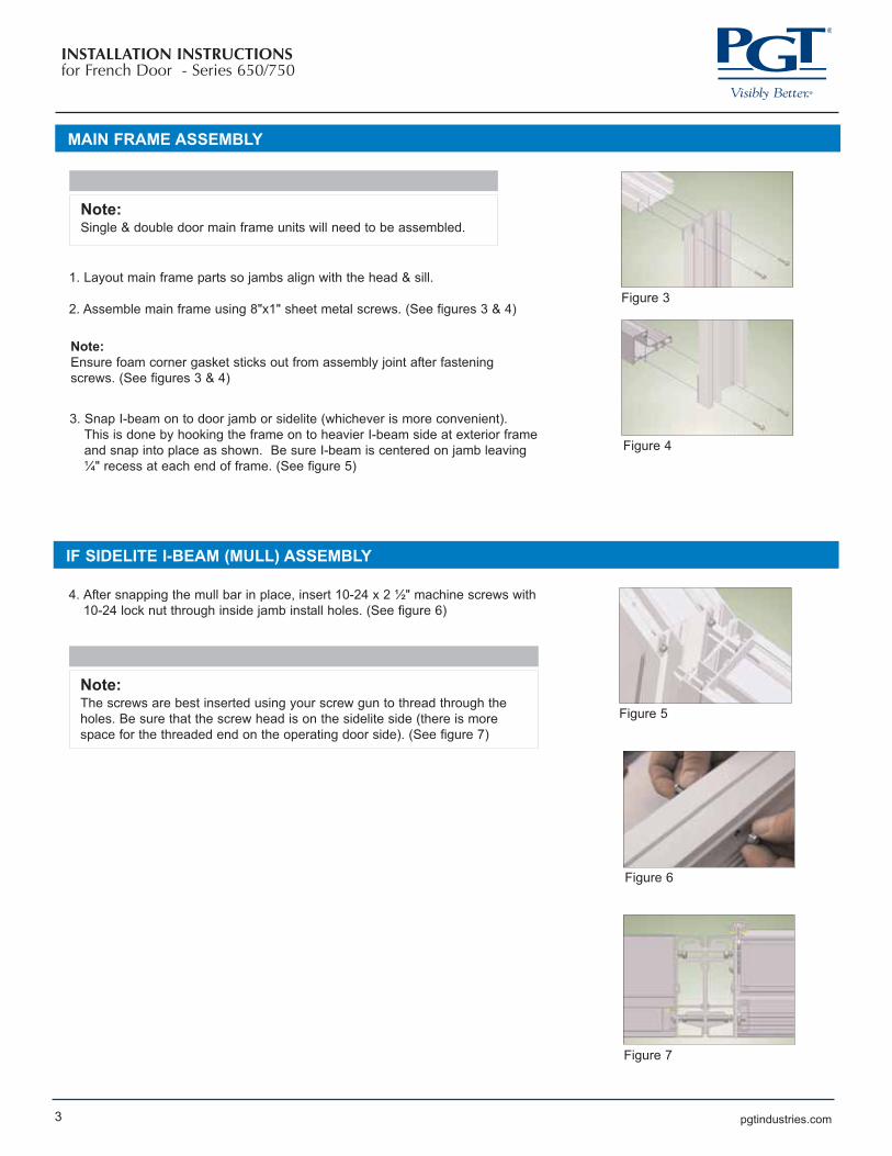
MAIN FRAME ASSEMBLY
Note:
Ensure foam corner gasket sticks out from assembly joint after fastening
screws. (See figures 3 & 4)
1. Layout main frame parts so jambs align with the head & sill.
2. Assemble main frame using 8"x1" sheet metal screws. (See figures 3 & 4)
Note: Single & double door main frame units will need to be assembled.
Figure 3
Figure 4
Figure 5
Figure 6
3. Snap I-beam on to door jamb or sidelite (whichever is more convenient).
This is done by hooking the frame on to heavier I-beam side at exterior frame
and snap into place as shown. Be sure I-beam is centered on jamb leaving
¼" recess at each end of frame. (See figure 5)
IF SIDELITE I-BEAM (MULL) ASSEMBLY
4. After snapping the mull bar in place, insert 10-24 x 2 ½" machine screws with
10-24 lock nut through inside jamb install holes. (See figure 6)
Note: The screws are best inserted using your screw gun to thread through the
holes. Be sure that the screw head is on the sidelite side (there is more
space for the threaded end on the operating door side). (See figure 7)
Figure 7

pgtindustries.com4
INSTALLATION INSTRUCTIONSfor French Door - Series 650/750
IF SINGLE DOOR JAMB AT I-BEAM MULL
5. Jamb backup cup must be removed when attaching to I-beam. Remove
three #8 undercut screws. Remove backup cup and replace the strike plate
using the same undercut screws, taking care not to strip the holes.
(See figure 8)
Figure 8
INSTALLATION PLATE ASSEMBLY
1. Installation plates are snapped into the jamb full length. The slots in the
install plate should align with the install screw locations. In some cases, the
install screw locations may have to be drilled through the plate after it is
snapped into the main frame jamb. (See figure 9)
Figure 9Note: Check for jamb leg projection inbetween two barbs as shown in installation
plate. (See figure 10)
2. Dry fitting the door before applying sealant to opening is necessary. Check
that the reveal is uniform and no greater than ¼" at head, jambs or sill.
(See figure 11)
Figure 10
Figure 12
MAIN FRAME INSTALLATION
1. After the main frame is dry fitted and there is proper clearance, run two (2)
beads of approved caulk in alignment with the 2nd and 3rd groove in the
bottom of the sill on the concrete. (See figure 12)
Note:
Be sure that the amount of sealant will fill the 2 cavities underneath the sill.
Always clean the concrete and mainframe before sealant is applied.
Figure 11
Note: A fenestration product should never by forced into an opening.
INSTALLATION INSTRUCTIONSfor French Door - Series 650/750
5 pgtindustries.com
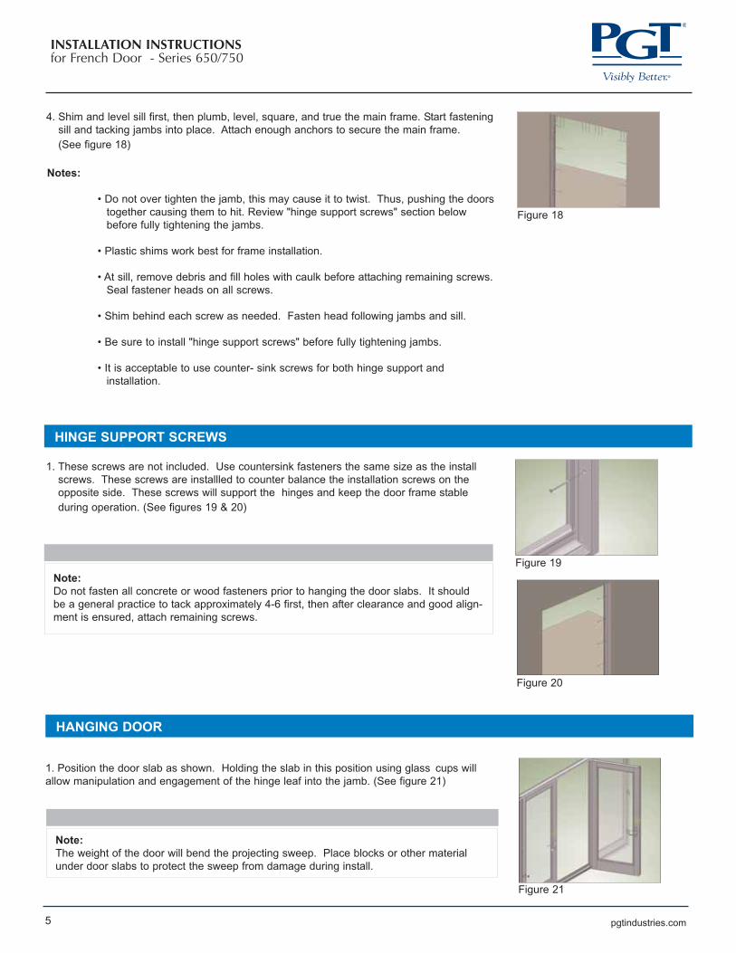
4. Shim and level sill first, then plumb, level, square, and true the main frame. Start fastening
sill and tacking jambs into place. Attach enough anchors to secure the main frame.
(See figure 18)
Notes:
• Do not over tighten the jamb, this may cause it to twist. Thus, pushing the doors
together causing them to hit. Review "hinge support screws" section below
before fully tightening the jambs.
• Plastic shims work best for frame installation.
• At sill, remove debris and fill holes with caulk before attaching remaining screws.
Seal fastener heads on all screws.
• Shim behind each screw as needed. Fasten head following jambs and sill.
• Be sure to install "hinge support screws" before fully tightening jambs.
• It is acceptable to use counter- sink screws for both hinge support and
installation.
HINGE SUPPORT SCREWS
1. These screws are not included. Use countersink fasteners the same size as the install
screws. These screws are installled to counter balance the installation screws on the
opposite side. These screws will support the hinges and keep the door frame stable
during operation. (See figures 19 & 20)
Note:
Do not fasten all concrete or wood fasteners prior to hanging the door slabs. It should
be a general practice to tack approximately 4-6 first, then after clearance and good align-
ment is ensured, attach remaining screws.
HANGING DOOR
1. Position the door slab as shown. Holding the slab in this position using glass cups will
allow manipulation and engagement of the hinge leaf into the jamb. (See figure 21)
Note:
The weight of the door will bend the projecting sweep. Place blocks or other material
under door slabs to protect the sweep from damage during install.
Figure 18
Figure 19
Figure 20
Figure 21
pgtindustries.com6
INSTALLATION INSTRUCTIONSfor French Door - Series 650/750
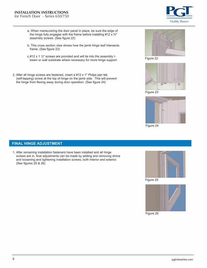
a. When maneuvering the door panel in place, be sure the edge of
the hinge fully engages with the frame before installing #12 x ¾"
assembly screws. (See figure 22)
b. This cross section view shows how the jamb hinge leaf intersects
frame. (See figure 23)
c.#12 x 1 ½" screws are provided and will tie into the assembly I-
beam or wall substrate where necessary for more hinge support.
2. After all hinge screws are fastened, insert a #12 x 1" Philps pan tek
(self-tapping) screw at the top of hinge on the jamb side. This will prevent
the hinge from flexing away during door operation. (See figure 24)
FINAL HINGE ADJUSTMENT
1. After remaining installation fasteners have been installed and all hinge
screws are in, final adjustments can be made by adding and removing shims
and loosening and tightening installation screws, both interior and exterior.
(See figures 25 & 26)
Figure 22
Figure 23
Figure 24
Figure 25
Figure 26
pgtindustries.com7
INSTALLATION INSTRUCTIONSfor French Door - Series 650/750
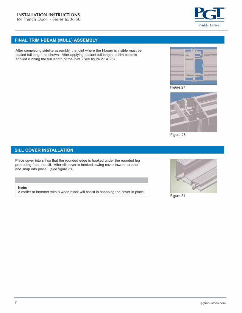
FINAL TRIM I-BEAM (MULL) ASSEMBLY
After completing sidelite assembly, the joint where the I-beam is visible must be
sealed full length as shown. After applying sealant full length, a trim piece is
applied running the full length of the joint. (See figure 27 & 28)
Figure 27
Figure 28
SILL COVER INSTALLATION
Place cover into sill so that the rounded edge is hooked under the rounded leg
protruding from the sill. After sill cover is hooked, swing cover toward exterior
and snap into place. (See figure 31)
Note:
A mallet or hammer with a wood block will assist in snapping the cover in place.Figure 31
pgtindustries.com8
INSTALLATION INSTRUCTIONSfor French Door - Series 650/750
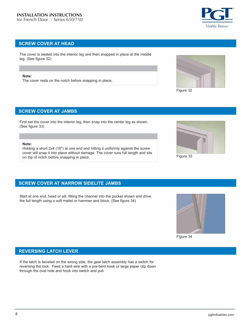
SCREW COVER AT HEAD
The cover is seated into the interior leg and then snapped in place at the middle
leg. (See figure 32)
Note:
The cover rests on the notch before snapping in place.
SCREW COVER AT JAMBS
First set the cover into the interior leg, then snap into the center leg as shown.
(See figure 33)
Note:
Holding a short 2x4 (18") at one end and hitting it uniformly against the screw
cover will snap it into place without damage. The cover runs full length and sits
on top of notch before snapping in place.
SCREW COVER AT NARROW SIDELITE JAMBS
Start at one end, head or sill, fitting the channel into the pocket shown and drive
the full length using a soft mallet or hammer and block. (See figure 34)
REVERSING LATCH LEVER
If the latch is beveled on the wrong side, the gear latch assembly has a switch for
reversing the lock. Feed a hard wire with a pre-bent hook or large paper clip down
through the oval hole and hook into switch and pull.
Figure 32
Figure 33
Figure 34

pgtindustries.com
INSTALLATION INSTRUCTIONSfor French Door - Series 650/750
9
SHOOT BOLT GUIDE ADJUSTMENT
1. Loosen screw approximately 1/4" to 3/8". Be careful not to back screw out
completely. If this happens, reinsert to a couple of threads. Grab pin using
needle nose pliers or similar tool. (See figures 36 & 37)
Note:
The door slab may need to be taken off if there is not enough space under the
slab. The active slab is at its loosest setting. To loosen inactive panel, three
serrations in the shootbolt guide must face opposite astragal. To tighten the
active slab, the serrations must face opposite astragal.
2. Rotate pin ½ turn (180 degrees). Slide back into square slot while re-aligning
the rod with the hole. (See figure 38)
3. Allow the guidepin to project slightly (1/16") from the sweep and re-tighten screw.
(See figure 39)
Note:
The lock is designed with a safety trigger (black button above the latch bolt). The door must be closed to engage this
button before the deadbolt or shoot bolts can be engaged.
The dead bolt can be engaged prior to lifting the handle and engaging the shoot bolts.
Lifting the handle upwards engages the shoot bolts into the head and sill of the door frame.
The deadbolt is engaged by rotating the thumb turn on the interior or the key on the exterior of the door.
Rotation of one quarter turn engages the dead bolt. When the shoot bolts and the deadbolts are properly engaged, the
handle will not rotate until the dead bolt is disengaged.
Figure 36
Figure 37
Figure 38
Figure 39

pgtindustries.com10
INSTALLATION INSTRUCTIONSfor French Door - Series 650/750
FINAL WORK NOTES
Note:
When hanging the door slab, be careful not to over torque hinge screws. Stainless steel alloys are softer than conventional
steel screws and the heads are prone to breakage.
Plastic shims work best for frame installation.
When sidelites are installed, seal the joint at the mull between the jambs, both interior and exterior.
pgtindustries.com11
INSTALLATION INSTRUCTIONSfor French Door - Series 650/750
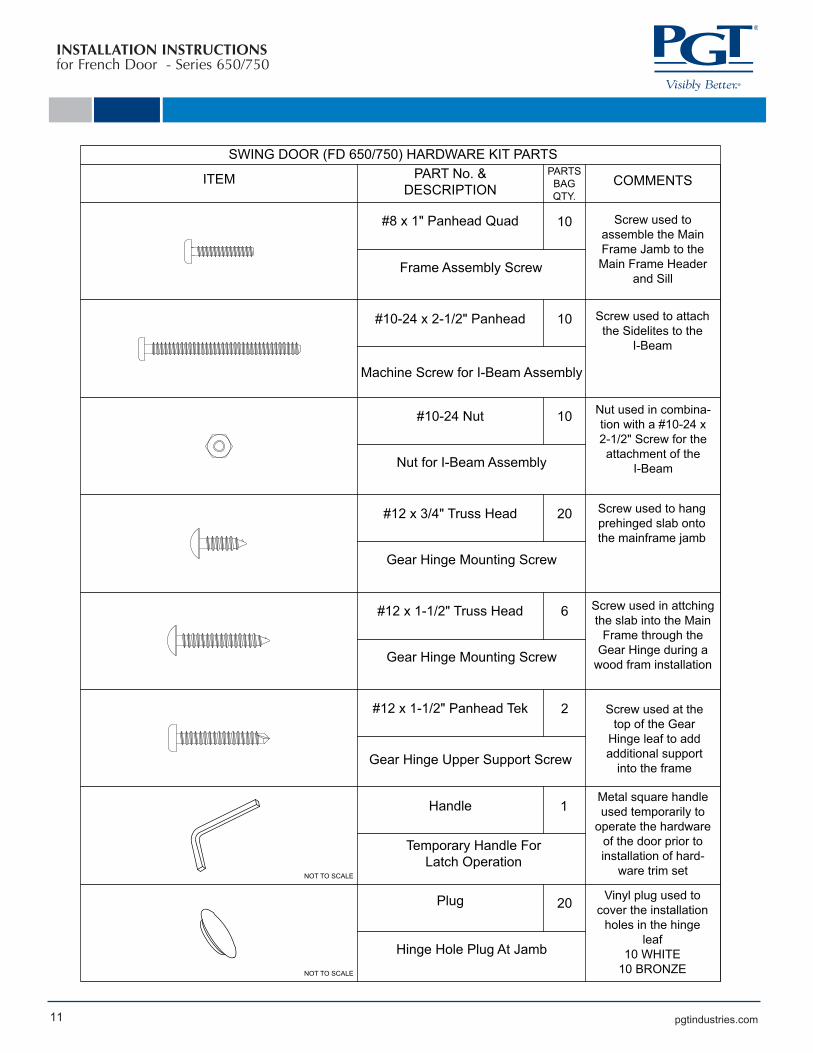
SWING DOOR (FD 650/750) HARDWARE KIT PARTSPART No. &
DESCRIPTIONPARTS
BAGQTY.
#8 x 1" Panhead Quad 10
Frame Assembly Screw
#10-24 x 2-1/2" Panhead 10
Machine Screw for I-Beam Assembly
#10-24 Nut 10
Nut for I-Beam Assembly
#12 x 3/4" Truss Head 20
Gear Hinge Mounting Screw
6
Gear Hinge Mounting Screw
#12 x 1-1/2" Panhead Tek 2
Gear Hinge Upper Support Screw
#12 x 1-1/2" Truss Head
Handle 1
Temporary Handle For Latch Operation
Plug 20
Hinge Hole Plug At Jamb
COMMENTS
Screw used to assemble the Main Frame Jamb to the Main Frame Header
and Sill
Vinyl plug used to cover the installation
holes in the hinge leaf
10 WHITE10 BRONZENOT TO SCALE
NOT TO SCALE
ITEM
Screw used to attach the Sidelites to the
I-Beam
Nut used in combina-tion with a #10-24 x 2-1/2" Screw for the attachment of the
I-Beam
Screw used to hang prehinged slab onto the mainframe jamb
Screw used in attching the slab into the Main
Frame through the Gear Hinge during a
wood fram installation
Screw used at the top of the Gear
Hinge leaf to add additional support
into the frame
Metal square handle used temporarily to
operate the hardware of the door prior to installation of hard-
ware trim set