INSTALLATION INSTRUCTIONS
12
INSTALLATION INSTRUCTIONS FOR COMBINING TWO GAS OR OIL FURNACES FOR PARALLEL OPERATIONS USING THE RCCU- COIL (HEATING AND AIR CONDITIONING) The following upflow furnaces may be used for this application: TO BE INSTALLED BY A QUALIFIED, LICENSED SERVICE PERSON. TO AVOID UNSATISFACTORY OPERATION OR DAM- AGE TO THE PRODUCT AND POSSIBLE UNSAFE CONDITIONS, INCLUDING ELECTRICAL SHOCK AND FIRE, THE INSTALLATION INSTRUCTIONS PROVIDED WITH THIS KIT MUST BE STRICTLY FOLLOWED AND THE PARTS SUPPLIED USED WITHOUT SUBSTITUTION. DAMAGE TO THE PRODUCT RESULTING FROM NOT FOLLOWING THE INSTRUCTIONS OR USING UNAUTHORIZED PARTS MAY BE EXCLUDED FROM THE MANUFACTURER’S WARRANTY COVERAGE. WARNING ! 92-41658-01-04 SUPERCEDES 92-41658-01-03 • (-)GPP, 80PJ, (-)GRJ, and 90RJ models using UTEC 1012-925 IFC require the twinning kit RXGP-F03. • Oil furnaces require the twinning kit RXOP-D25. • Twinning kits must be ordered as a separate item. FURNACE PREPARATION AND COIL/PLENUMS Cased Coil assemblies include upflow coil and insulated cabinet. 1. Unpack coil/plenum assembly, the blockoff channels, end pan- els, and transition. Inspect for damage. 2. 17 1 /2, 21, and 24 wide furnaces a. Set furnaces 1 1 /2 apart. Drill four 1/8 diameter holes and attach wide blockoff channel between the two furnaces with screws provided as shown in Figure 3. b. On 17 1 /2 wide furnaces use 7 x 20 end panels. Drill three 1/8 diameter holes and mount with screws supplied as shown in Figure 3. c. On 21 wide furnaces use 3 1 /2 x 20 end panels. Drill three 1/8 diameter holes and mount with screws supplied as shown in Figure 3. 3. 28 wide furnace (Oil) a. Drill four 1/8 diameter holes and attach narrow blockoff channel between the two furnaces with screws provided as shown in Figure 3. b. Assemble transition and install as shown in Figure 4. NOTE: No end panels or transition required for 24 wide gas or oil furnaces. 1. Set coil/plenum assembly on furnace with access cover toward flue outlet end of furnace. 2. Connect ductwork to plenum. Seal all joints around furnace, plenum and transition with duct tape. 3. Connect suction and liquid lines between coil and compres- sor/condenser section. Provide oil trap for suction line, if the vertical rise exceeds 3 ft. 4. Strap expansion valve sensing bulb to top of suction line on outside of cabinet. Be careful not to over tighten the clamps. See Figure 5. 5. Insulate sensing bulb and suction line. 6. The condensate drain is 3 /4 NPT. Provide a 3 trap and pitch the drain to an open sump. See Figure 5. To twin two furnaces, follow these instructions and the twinning wiring diagrams at the end of the service manual. IMPORTANT: Only twin furnaces with identical controls from the same manufacturer of control board. IMPORTANT: Only bottom returns can be used. No more than two furnaces can share the same supply and return. Furnaces must have same heating and blower capacity. Twinning furnaces must operate off the same phase of power. NOTE: The transformer of both furnaces must be in the same phase. NOTE: Twinning kit cannot be used for heat pump fossil fuel kit application. TURN OFF ELECTRIC POWER AT THE FUSE BOX OR SER- VICE PANEL BEFORE MAKING ANY ELECTRICAL CONNEC- TIONS; FAILURE TO DO SO COULD RESULT IN AN ELECTRI- 80% Gas Upflow (-)GPN/(-)GPP/80PJ-05*AUE (-)GPN/(-)GPP/80PJ-07*AUE (-)GPN/(-)GPP/80PJ-10*AME (-)GPN/(-)GPP/80PJ-10*BRJ (-)GPN/(-)GPP/80PJ-12*ARJ (-)GPN/(-)GPP/80PJ-15*ARJ Two-stage 80% Gas Upflow (-)GPK-05*AUE (-)GPK-07*AUE (-)GPK-07*AMG (-)GPK-10*AME (-)GPK-10*BRJ (-)GPK-12*ARJ (-)GPK-15*ARJ 90 Plus Gas Upflow (-)GRA/(-)GRJ/90RJ-06*MAE (-)GRA/(-)GRJ/90RJ-07*MAE (-)GRA/(-)GRJ/90RJ-07*YBG (-)GRA/(-)GRJ/90RJ-09*ZAJ (-)GRA/(-)GRJ/90RJ-10*ZAJ (-)GRA/(-)GRJ/90RJ-12*RAJ 6.5 & 7.5 ton Oil Furnaces (-)OBD-084QBE* (-)OBD-095QBE* (-)OBD-112QBG* (-)OBD-130RBJ* (-)OBD-150RBJ* Two-stage 90 Plus (-)GRK-06*MAE (-)GRK-07*MAE (-)GRK-07*YBG (-)GRK-09*ZAJ (-)GRK-10*ZAJ (-)GRK-12*RAJ 7.5 & 10 ton Oil Furnaces (-)OBD-130RBJ* (-)OBD-150RBJ* Recognize this symbol as an indication of Important Safety Information! ! WARNING !
-
Upload
khangminh22 -
Category
Documents
-
view
0 -
download
0
Transcript of INSTALLATION INSTRUCTIONS
INSTALLATION INSTRUCTIONSFOR COMBINING TWO GAS OR OIL FURNACES
FOR PARALLEL OPERATIONS USING THE RCCU- COIL(HEATING AND AIR CONDITIONING)
The following upflow furnaces may be used for this application:
TO BE INSTALLED BY A QUALIFIED, LICENSED SERVICE PERSON. TO AVOID UNSATISFACTORY OPERATION OR DAM-AGE TO THE PRODUCT AND POSSIBLE UNSAFE CONDITIONS, INCLUDING ELECTRICAL SHOCK AND FIRE, THEINSTALLATION INSTRUCTIONS PROVIDED WITH THIS KIT MUST BE STRICTLY FOLLOWED AND THE PARTS SUPPLIEDUSED WITHOUT SUBSTITUTION. DAMAGE TO THE PRODUCT RESULTING FROM NOT FOLLOWING THE INSTRUCTIONSOR USING UNAUTHORIZED PARTS MAY BE EXCLUDED FROM THE MANUFACTURER’S WARRANTY COVERAGE.
WARNING!
92-41658-01-04SUPERCEDES 92-41658-01-03
• (-)GPP, 80PJ, (-)GRJ, and 90RJ models using UTEC 1012-925 IFC require thetwinning kit RXGP-F03.
• Oil furnaces require the twinning kit RXOP-D25.• Twinning kits must be ordered as a separate item.
FURNACE PREPARATION AND COIL/PLENUMS
Cased Coil assemblies include upflow coil and insulated cabinet.
1. Unpack coil/plenum assembly, the blockoff channels, end pan-els, and transition. Inspect for damage.
2. 171⁄2�, 21�, and 24� wide furnaces
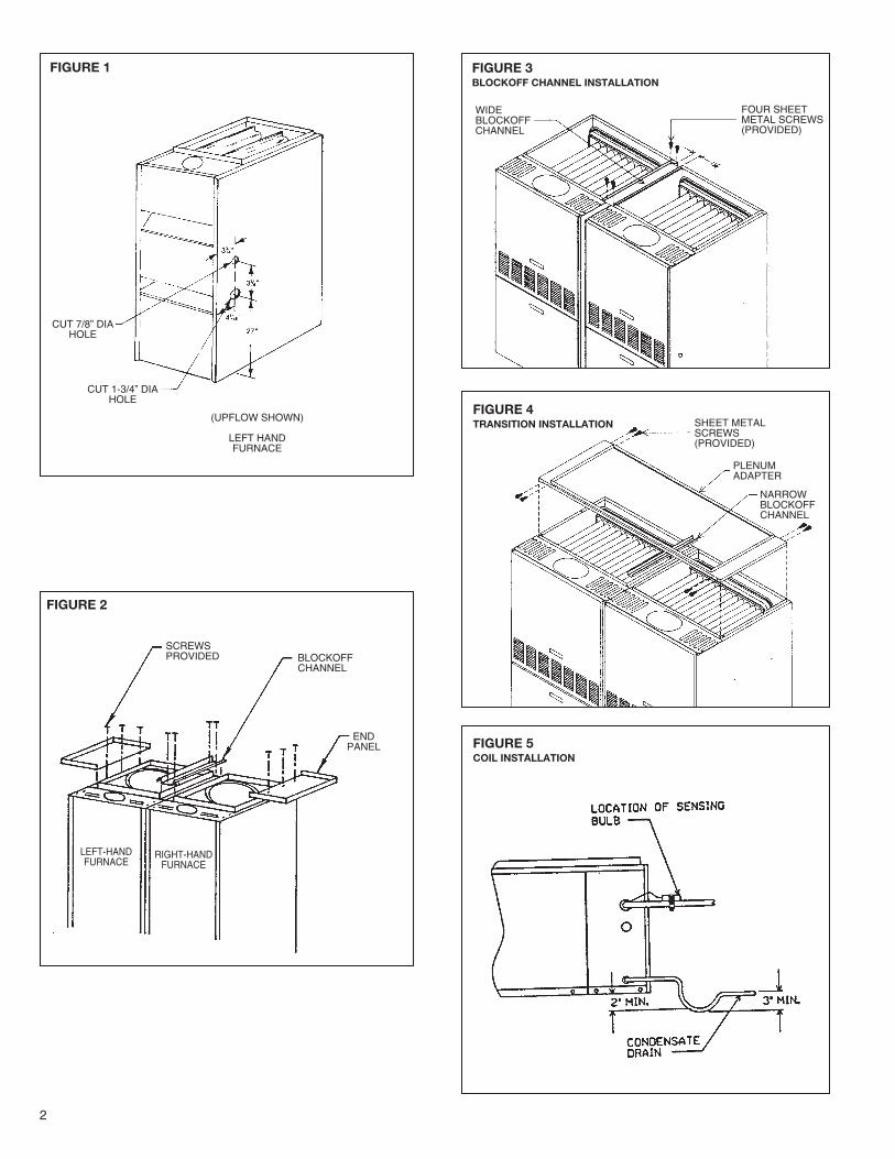
a. Set furnaces 11⁄2� apart. Drill four 1/8� diameter holes andattach wide blockoff channel between the two furnaces withscrews provided as shown in Figure 3.
b. On 171⁄2� wide furnaces use 7 x 20 end panels. Drill three1/8� diameter holes and mount with screws supplied asshown in Figure 3.
c. On 21� wide furnaces use 31⁄2 x 20 end panels. Drill three1/8� diameter holes and mount with screws supplied asshown in Figure 3.
3. 28� wide furnace (Oil)
a. Drill four 1/8� diameter holes and attach narrow blockoffchannel between the two furnaces with screws provided asshown in Figure 3.
b. Assemble transition and install as shown in Figure 4.
NOTE: No end panels or transition required for 24� wide gas or oilfurnaces.
1. Set coil/plenum assembly on furnace with access cover towardflue outlet end of furnace.
2. Connect ductwork to plenum. Seal all joints around furnace,plenum and transition with duct tape.
3. Connect suction and liquid lines between coil and compres-sor/condenser section. Provide oil trap for suction line, if thevertical rise exceeds 3 ft.
4. Strap expansion valve sensing bulb to top of suction line onoutside of cabinet. Be careful not to over tighten the clamps.See Figure 5.
5. Insulate sensing bulb and suction line.
6. The condensate drain is 3⁄4� NPT. Provide a 3� trap and pitchthe drain to an open sump. See Figure 5.
To twin two furnaces, follow these instructions and the twinningwiring diagrams at the end of the service manual.
IMPORTANT: Only twin furnaces with identical controls from thesame manufacturer of control board.
IMPORTANT: Only bottom returns can be used. No more thantwo furnaces can share the same supply and return. Furnacesmust have same heating and blower capacity. Twinning furnacesmust operate off the same phase of power.
NOTE: The transformer of both furnaces must be in the samephase.
NOTE: Twinning kit cannot be used for heat pump fossil fuel kitapplication.
TURN OFF ELECTRIC POWER AT THE FUSE BOX OR SER-VICE PANEL BEFORE MAKING ANY ELECTRICAL CONNEC-TIONS; FAILURE TO DO SO COULD RESULT IN AN ELECTRI-
80% Gas Upflow(-)GPN/(-)GPP/80PJ-05*AUE(-)GPN/(-)GPP/80PJ-07*AUE(-)GPN/(-)GPP/80PJ-10*AME(-)GPN/(-)GPP/80PJ-10*BRJ(-)GPN/(-)GPP/80PJ-12*ARJ(-)GPN/(-)GPP/80PJ-15*ARJ
Two-stage 80% GasUpflow(-)GPK-05*AUE(-)GPK-07*AUE(-)GPK-07*AMG(-)GPK-10*AME(-)GPK-10*BRJ(-)GPK-12*ARJ(-)GPK-15*ARJ
90 Plus Gas Upflow(-)GRA/(-)GRJ/90RJ-06*MAE(-)GRA/(-)GRJ/90RJ-07*MAE(-)GRA/(-)GRJ/90RJ-07*YBG(-)GRA/(-)GRJ/90RJ-09*ZAJ(-)GRA/(-)GRJ/90RJ-10*ZAJ(-)GRA/(-)GRJ/90RJ-12*RAJ
6.5 & 7.5 tonOil Furnaces(-)OBD-084QBE*(-)OBD-095QBE*(-)OBD-112QBG*(-)OBD-130RBJ*(-)OBD-150RBJ*
Two-stage 90 Plus(-)GRK-06*MAE(-)GRK-07*MAE(-)GRK-07*YBG(-)GRK-09*ZAJ(-)GRK-10*ZAJ(-)GRK-12*RAJ
7.5 & 10 tonOil Furnaces(-)OBD-130RBJ*(-)OBD-150RBJ*
Recognize this symbol as an indication of ImportantSafety Information!!
WARNING!
2
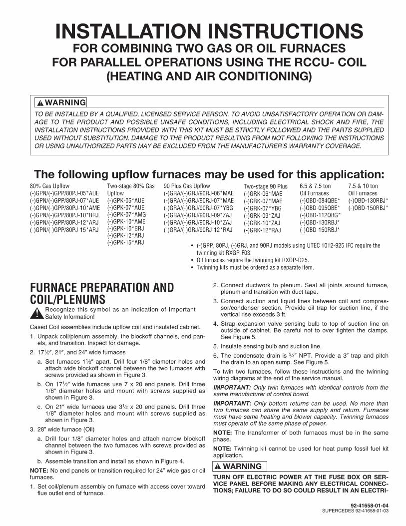
FIGURE 1
FIGURE 2
CUT 7/8” DIAHOLE
(UPFLOW SHOWN)
LEFT HANDFURNACE
CUT 1-3/4” DIAHOLE
SCREWSPROVIDED BLOCKOFF
CHANNEL
ENDPANEL
LEFT-HANDFURNACE
RIGHT-HANDFURNACE
FIGURE 3BLOCKOFF CHANNEL INSTALLATION
FIGURE 4TRANSITION INSTALLATION
FIGURE 5COIL INSTALLATION
SHEET METALSCREWS(PROVIDED)
PLENUMADAPTER
NARROWBLOCKOFFCHANNEL
FOUR SHEETMETAL SCREWS(PROVIDED)
WIDEBLOCKOFFCHANNEL
3
CAL SHOCK HAZARD, PROPERTY DAMAGE AND/OR PER-SONAL INJURY.
BOTH FURNACE CABINETS MUST BE PERMANENTLYGROUNDED. A GROUND SCREW IN THE JUNCTION BOX ISFOR THIS PURPOSE. GROUND CONNECTIONS MUST BECOMPLETED BEFORE MAKING LINE VOLTAGE CONNEC-TIONS. FAILURE TO DO SO COULD RESULT IN AN ELECTRI-CAL SHOCK HAZARD, PROPERTY DAMAGE AND/OR PER-SONAL INJURY. THE FURNACES MUST BE INSTALLED SOTHE ELECTRICAL COMPONENTS ARE PROTECTED FROMWATER.
ELECTRICAL POWER MUST BE SUPPLIED TO BOTH FUR-NACES FROM THE SAME SEPARATE BRANCH CIRCUIT,FAILURE TO DO SO COULD RESULT IN EXPOSING THEFURNACE CONTROLS TO AN OVER VOLTAGE (230 VAC)CONDITION. THIS COULD RESULT IN DESTRUCTION OFTHE CONTROL BOARDS, PROPERTY DAMAGE AND/ORPERSONAL INJURY.
L1 (HOT) AND NEUTRAL POLARITY MUST BE OBSERVEDWHEN MAKING FIELD CONNECTIONS TO THE FURNACES.FAILURE TO DO SO COULD RESULT IN A DIRECT SHORTVIA THE CONNECTION BETWEEN THE “EAC: TERMINALWHEN THE INDOOR BLOWER RELAY CLOSES. THIS COULDRESULT IN DESTRUCTION OF THE CONTROL BOARDS,PROPERTY DAMAGE AND/OR PERSONAL INJURY.
THE FURNACE MUST BE ON THE SAME BRANCH CIRCUITWITH ADEQUATE AMPACITY AND OVERCURRENT PROTEC-TIONS. DO NOT USE EXISTING LIGHTING OR OTHER CIR-CUITS.
NOTE: See the furnace rating plates for motor HP ratings, electri-cal characteristics, and amp draw.
NOTE: Use time delay fuses or circuit breakers.
All electrical work must conform with the requirements of localcodes and ordinances and the National Electric Code ANSI/NFPA– No. 70 latest edition or the Canadian Electrical Code Part 1 –CSA Standard C22.1 for Canadian installations.
GAS FURNACE TWINNINGA maximum of two furnaces may be installed side by side on acommon duct system and operate as one, or as first stage andsecond stage. The twinning procedure makes both furnaceblowers operate together, whether one or both furnaces are firing.One thermostat can control both units. This is necessary if the twofurnaces supply air for one 7-1/2 or 10 ton single stage coolingsystem.
To twin two furnaces, follow these instructions and the twinningwiring diagrams at the end of the service manual.
IMPORTANT: ONLY TWIN FURNACES WITH IDENTICAL CON-TROLS FROM THE SAME MANUFACTURER OF CONTROLBOARD.
IMPORTANT: ONLY BOTTOM RETURNS CAN BE USED. NOMORE THAN TWO FURNACES CAN SHARE THE SAME SUP-PLY AND RETURN. FURNACES MUST HAVE SAME HEATINGAND BLOWER CAPACITY. TWINNING FURNACES MUSTOPERATE OFF THE SAME PHASE OF POWER.
NOTE: The transformer of both furnaces must be in the samephase.
NOTE: The “OK” LED flashes if the twinning is not installed prop-erly. Hot surface ignition control boards flash “OK” LED continuallyif twinning kit or installed properly. Direct spark ignition controlboards flash the “OK” LED five (5) times, pause, and then flashfive (5) times again.
NOTE: Twinning kit cannot be used for heat pump fossil fuel kitapplication.
TURN OFF ELECTRIC POWER AT THE FUSE BOX OR SER-VICE PANEL BEFORE MAKING ELECTRICAL CONNECTIONS;FAILURE TO DO SO COULD RESULT IN AN ELECTRICALSHOCK HAZARD, PROPERTY DAMAGE AND/OR PERSONALINJURY.
BOTH FURNACE CABINETS MUST BE PERMANENTLYGROUNDED. A GROUND SCREW IN THE JUNCTION BOX ISFOR THIS PURPOSE. GROUND CONNECTIONS MUST BECOMPLETED BEFORE MAKING LINE VOLTAGE CONNEC-TIONS. FAILURE TO DO SO COULD RESULT IN AN ELECTRI-CAL SHOCK HAZARD, PROPERTY DAMAGE AND/OR PER-SONAL INJURY. THE FURNACES MUST BE INSTALLED SOTHE ELECTRICAL COMPONENTS ARE PROTECTED FROMWATER.
ELECTRICAL POWER MUST BE SUPPLIED TO BOTH FUR-NACES FROM THE SAME SEPARATE BRANCH CIRCUIT,FAILURE TO DO SO COULD RESULT IN EXPOSING THE FUR-NACE CONTROLS TO AN OVER VOLTAGE (230 VAC) CONDI-TION. THIS COULD RESULT IN DESTRUCTION OF THE CON-TROL BOARDS, PROPERTY DAMAGE AND/OR PERSONALINJURY.
L1 (HOT) AND NEUTRAL POLARITY MUST BE OBSERVEDWHEN MAKING FIELD CONNECTIONS TO THE FURNACES.FAILURE TO DO SO COULD RESULT IN A DIRECT SHORTVIA THE CONNECTION BETWEEN THE “EAC” TERMINALWHEN THE INDOOR BLOWER RELAY CLOSES. THIS COULDRESULT IN DESTRUCTION OF THE CONTROL BOARDS,PROPERTY DAMAGE AND/OR PERSONAL INJURY.
THE FURNACE MUST BE ON THE SAME BRANCH CIRCUITWITH ADEQUATE AMPACITY AND OVERCURRENT PROTEC-TION. DO NOT USE EXISTING LIGHTING OR OTHER CIR-CUITS.
NOTE: See the furnace rating plates for motor HP ratings, electri-cal characteristics, and amp draw.
NOTE: Use time delay fuses or circuit breakers.
All electrical work must conform with the requirements of localcodes and ordinances and the National Electric Code ANSI /NFPA–No. 70 latest edition or the Canadian Electrical Code Part 1– CSA Standard C22.1 for Canadian installations.
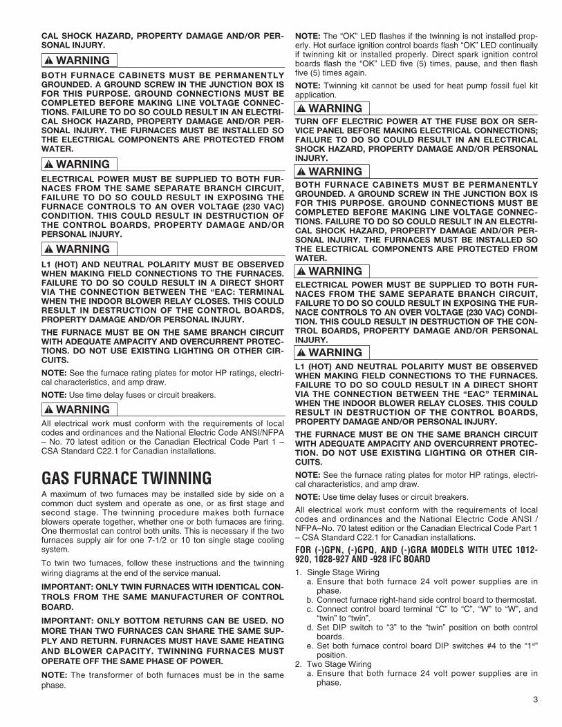
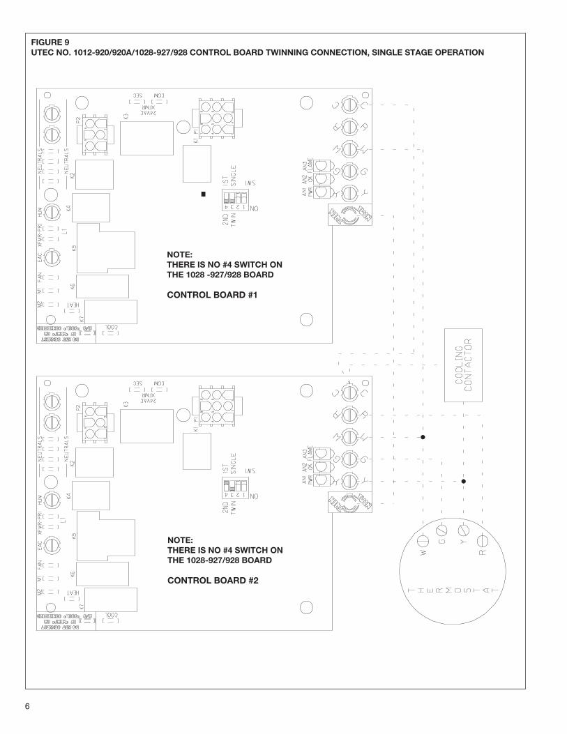
FOR (-)GPN, (-)GPQ, AND (-)GRA MODELS WITH UTEC 1012-920, 1028-927 AND -928 IFC BOARD1. Single Stage Wiring
a. Ensure that both furnace 24 volt power supplies are inphase.
b. Connect furnace right-hand side control board to thermostat.c. Connect control board terminal “C” to “C”, “W” to “W”, and
“twin” to “twin”.d. Set DIP switch to “3” to the “twin” position on both control
boards.e. Set both furnace control board DIP switches #4 to the “1st”
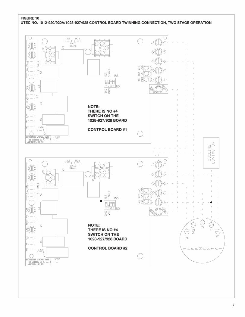
position.2. Two Stage Wiring
a. Ensure that both furnace 24 volt power supplies are inphase.
WARNING!
WARNING!
WARNING!
WARNING!
WARNING!
WARNING!
WARNING!
WARNING!
4
b. Connect furnace on the right-hand side control board termi-nal “W” to the “W1” terminal on the thermostat.
c. Connect furnace on the left-hand side control board terminal“W” to the “W2” terminal on the thermostat.
d. Connect control board terminals “C” to “C” and “TWIN” to“TWIN”.
e. Set DIP switch “3” to the “ON” position on both furnace con-trol boards.
f. Set furnace control board DIP switch #4 to the “1st” positionon the right-hand side furnace.
g. Set furnace control board DIP switch #4 to the “2nd” positionon the left-hand side furnace.
h. Set the thermostat heat anticipator for 0.1 amps on eachstage of heat.
NOTE: The UTEC 1028-927 and -928 controls use only switch #3for twinning. Connect the thermostat to the furnace intended to befirst stage. The other furnace automatically becomes secondstage.
IMPORTANT: A UTEC 1012-920A CONTROL CAN BETWINNED WITH A UTEC 1012-920 CONTROL.
INSTALLATION PROCEDURESInstall the furnaces side by side and connect to the common sup-ply and return duct system. Follow the furnace installation instruc-tions. Convert the right hand furnace to right side gas and electri-cal supply.
1. Install the two boxes from the kit in the furnace jackets usingthe screws provided before locating the furnaces. Remove theknockouts as required. Insert the snap bushings and plug but-tons while access is available.
2. Identify the furnaces as number 1 and 2 for wiring purposes.The wiring diagram arbitrarily shows furnace 1 on the left.
3. Turn off the electrical supply to both furnaces before makingany electrical connections.
4. Disconnect and remove the control transformer from furnace2. Remove the black and white line voltage transformer leadsfrom the “L1” and “neutral” terminals on control board 2.
Remove only the red and yellow transformer lead wires fromthe “24 VAC” and “COM” terminals.
5. Remove the black wires connecting the blower door switch(PBS) and “L1” on the control boards in furnaces 1and 2.
6. Install the switches from the kit in the boxes. Insert eachswitch in the rectangular mounting hole.
7. Install the line voltage interconnecting wires as shown in thewiring diagram. Route the wires out of the top hole in eachcontrol box and through the strain relief bushing.
a. The blue wires connect the original door switch 1, throughthe new door switch in furnace 2, and to terminal “L1” ofcontrol board 1.
b. Similarly, the yellow wires connect the original door switch2, through the new door switch in furnace 1 and to terminal“L1” of control board 2.
c. The red wire connects the two electronic air cleaner (EAC)screw terminals on both control boards.
d. Secure the line voltage wires with strain relief bushings atthe 7/8" dia. hole where they exit the control boxes.
8. Connect control power (24 VAC) from terminal board “R” infurnace 1 to the “24VAC” terminal (1/4" push on) on the con-trol board in furnace 2. Use the 4" piggyback terminated redwire and wire nut connector.
9. Connect control (24VAC) wires between thermostat terminals“W”, “Y”, “G” and “C” on furnace control boards 1 and 2.
10. Install a control thermostat (field supplied) according to itsinstructions to FURNACE 2.
IMPORTANT: ELECTRICAL POWER TO BOTH FURNACESMUST BE SHUT OFF WHEN WIRING THE THERMOSTAT. THEFURNACE CONTROL SYSTEM TERMINAL “C” (COMMON) ISCONNECTED TO THE (CABINET) GROUND AS PART OF THEFLAME SENSE CIRCUIT. ACCIDENTAL SHORTING OF THER-MOSTAT WIRES TO GROUND DURING INSTALLATION CANDAMAGE THE CONTROL TRANSFORMER.
11. Control voltage power (24 VAC) to the thermostat mustbe supplied from thermostat terminal “R” on the controlboard in furnace 2. Connect the thermostat to “W” (heat), “Y”(cool), and “G” (fan) that are now common to both furnaces asshown in the wiring diagram. Connect the remote compressorcontactor (CC) leads to terminals “Y” (cool) and “C” (common)that also are common to both furnaces.
If the thermostat has an adjustable heating anticipator, set itfor approximately 0.8 amps or the measured current amper-age. Do this after the furnaces are in operation.
12. Use the provided wire ties to secure the interconnecting andthermostat wiring in place to avoid contact with exposededges, moving parts, or service procedures. Field provideadditional materials, if required. Attach the wiring diagramfrom the kit to one furnace.
13. Replace the blower compartment doors and check that thedoors fit correctly. Adjust the fit if required to assure easyremoval and installation by the user when servicing air filters.
14. Complete the furnace installation and put the furnaces inoperation following the furnace installation and operatinginstructions.
Make all proper operational and safety checks. Remove the blow-er compartment doors individually and ensure that electrical powerto both furnaces is shut off when either door is off.
NOTE: This twinning kit cannot be used for heat pump fossil fuelkit applications.
NOTE: Two parallel condensing units may be used for twinningapplications by wiring the control circuits (4) in parallel.
FIGURE 6UTEC SINGLE STAGE TWINNING
FIGURE 7UTEC TWO STAGE TWINNING

UTEC 1012-925 IFC BOARDTWINNING INSTRUCTIONS (RXGP-F03)IMPORTANT: THIS KIT MAY ONLY BE USED WITH THE FOL-LOWING GAS FURNACE MODELS EQUIPPED WITH THEUTEC 1012-925 IFC.
(-)GPJ SERIES(-)GRJ SERIES
THESE INSTRUCTIONS ARE INTENDED AS AN AID TO QUALI-FIED, LICENSED SERVICE PERSONNEL FOR PROPERINSTALLATION, ADJUSTMENT, AND OPERATION OF THISPRODUCT. READ THESE INSTRUCTIONS THOROUGHLYBEFORE ATTEMPTING INSTALLATION OR OPERATION. FAIL-URE TO FOLLOW THESE INSTRUCTIONS MAY RESULT INIMPROPER INSTALLATION, ADJUSTMENT, SERVICE ORMAINTENANCE POSSIBLY RESULTING IN FIRE, ELECTRICALSHOCK, CARBON MONOXIDE POISONING, EXPLOSION, PER-SONAL INJURY OR PROPERTY DAMAGE.
Install the RXGP - F03 kit when twinning to assure that both indoorblowers run simultaneously and so that when either blower door isopened, both furnaces shut down. The kit contains additionalblower door switches, wiring connections, and other hardwareneeded to twin the above listed furnace models.
ELECTRICAL WIRING
TURN OFF ELECTRIC POWER AT THE FUSE BOX OR SER-VICE PANEL BEFORE MAKING ANY ELECTRICAL CONNEC-TIONS. FAILURE TO DO SO COULD RESULT IN AN ELECTRI-CAL SHOCK HAZARD, PROPERTY DAMAGE AND/OR PER-SONAL INJURY.
BOTH FURNACE CABINETS MUST BE PERMANENTLYGROUNDED. A GROUND SCREW IN THE JUNCTION BOX ISFOR THIS PURPOSE. GROUND CONNECTIONS MUST BECOMPLETED BEFORE MAKING LINE VOLTAGE CONNEC-TIONS. FAILURE TO DO SO COULD RESULT IN AN ELECTRI-CAL SHOCK HAZARD, PROPERTY DAMAGE AND/OR PER-SONAL INJURY. THE FURNACES MUST BE INSTALLED SOTHE ELECTRICAL COMPONENTS ARE PROTECTED FROMWATER.
ELECTRICAL POWER MUST BE SUPPLIED TO BOTH FUR-NACES FROM THE SAME SEPARATE BRANCH CIRCUIT.FAILURE TO DO SO COULD RESULT IN EXPOSING THE FUR-NACE CONTROLS TO AN OVER VOLTAGE (230 VAC) CONDI-TION. THIS COULD RESULT IN DESTRUCTION OF THE CON-TROL BOARDS, PROPERTY DAMAGE AND/OR PERSONALINJURY.
L1 (HOT) AND NEUTRAL POLARITY MUST BE OBSERVEDWHEN MAKING FIELD CONNECTIONS TO THE FURNACES.FAILURE TO DO SO COULD RESULT IN A DIRECT SHORTVIA THE CONNECTION BETWEEN THE “EAC” TERMINALSWHEN THE INDOOR BLOWER RELAY CLOSES. THIS COULDRESULT IN DESTRUCTION OF THE CONTROL BOARDS,PROPERTY DAMAGE AND/OR PERSONAL INJURY. The furnaces must be on the same branch circuit with adequateampacity and overcurrent protections. Do not use existing lightingor other circuits. NOTE: See the furnace rating plates for motor H.P. ratings, elec-trical characteristics, and amp draw.NOTE: Use time delay fuses or circuit breakers.NOTE: Use the wiring diagram when installing this twinning kit.
TWINNING KIT INSTRUCTIONSTwinning or parallel operation of two furnaces, installed side byside, connected by a common duct system and controlled by a sin-gle thermostat can be done with UTEC 1012-925 integrated furnacecontrols using this wiring kit. The addition of the two blower com-partment door interlock switches in this kit assures that all electricalpower to both furnaces is deenergized if either furnace blower com-partment door is not in place. The additional switch, located in theremote furnace is in series to the furnace electrical supply as shownin the wiring diagram included in kit. A line voltage connecting wirebetween the electronic air cleaner (EAC) terminals on both furnacecontrol boards assures simultaneous indoor blower operation. Theswitches, line voltage wiring and mounting materials are included inthis kit. The thermostat and low voltage (24 VAC) control wiringmaterials are normal field supplied items.
All electrical work must conform with the requirements of localcodes and ordinances and the National Electric Code ANSI /NFPA - No. 70 latest edition or the Canadian Electrical Code Part1 - CSA Standard C22.1 for Canadian installations.
5
WARNING!WARNING!
WARNING!
WARNING!
WARNING!
FIGURE 8COIL INSTALLATION
TABLE 1PARTS LIST - RXGP-F03 PARALLEL FURNACE KIT
Part No. Part Description Quantity
AE-61475-02 Junction Box 2AE-61476-02 Junction Box Cover 2AS-50240-41-TT Wire, Red, 16GA, 48� 1AS-50251-05-AD Wire, Red, 18GA, 4� 1AS-53397-41-JJ Wire, Blue, 18GA, 48� 2AS-76693-41-JJ Wire, Yellow, 18GA, 48� 245-17055-11 Bushing, Strain Relief 7/8� OD 245-17057-02 Bushing, Snap 7/8� OD x 3/4� ID 264-17606-01 Wire Tie, 8� 445-18058-07 Wire Connector, Yellow 145-18232-02 Plug Button (7/8� Dia.) 142-22692-01 Switch, Push Button (Cherry, 2
E69-08C - 10A)63-22338-03 Screw, Sheet Metal #8-18 x 1/4� B, 6
Hex Hd.63-22505-02 Screw, #10-32 x 3/8�, Hex Hd. 292-23521-04 Installation Instructions 190-23553-02 Wiring Diagram 1
MOTOR AMPS TOTAL AMPS CIRCUIT MAXIMUM FUSE ORH.P. AMPACITY CIRCUIT BREAKER SIZE
1/2 6.8 13.6 18.7 25
3/4 9.5 19.0 24.8 30
TABLE 2CIRCUIT PROTECTION SIZING
6
FIGURE 9UTEC NO. 1012-920/920A/1028-927/928 CONTROL BOARD TWINNING CONNECTION, SINGLE STAGE OPERATION
NOTE:THERE IS NO #4 SWITCH ONTHE 1028 -927/928 BOARD
CONTROL BOARD #1
NOTE:THERE IS NO #4 SWITCH ONTHE 1028-927/928 BOARD
CONTROL BOARD #2
7
FIGURE 10UTEC NO. 1012-920/920A/1028-927/928 CONTROL BOARD TWINNING CONNECTION, TWO STAGE OPERATION
NOTE:THERE IS NO #4SWITCH ON THE1028-927/928 BOARD
CONTROL BOARD #1
NOTE:THERE IS NO #4SWITCH ON THE1028-927/928 BOARD
CONTROL BOARD #2
8
6. Take 53� Red wire and connect to Kit Relay #3 and runthrough side of Kit J box on through holes “A” of right furnaceand “E” of left furnace. Continue through existing hole onblower shelf to inside of Blower J box. Disconnect blowerheating speed bundle. Connect Red from Kit Relay #3; Redfrom Safety Relay #5; and desired heating speed tap into onebundle.
7. Take 53� Purple with piggyback terminal and connect it to KitRelay Fan Terminal. Run through side of Kit J box on throughholes “A” of right furnace and “E” into left furnace. Continue onthrough existing hole in blower shelf into Blower J box andconnect to existing NO lead from Fan Timer that was discon-nected from heating speed tap bundle.
8. Take 76� Red wire and connect to Kit Relay #6. Run throughside of Kit J box and along right furnace blower shelf onthrough existing hole into Blower J box. Disconnect heatingspeed tap bundle and connect together Red from Kit Relay #6;Red from Safety Relay #5; and desired heating speed tap.
9. Take 76� Blue and connect to purple piggyback on Kit RelayFan Terminal. Run through Kit J box, along right furnace blow-er shelf, through existing hole into Blower J box and connectto existing Red wire from NO terminal of Fan Cycle Control.
10. Take 73� Orange, Green, and Brown and run through holes“B” of right furnace and “E” of left furnace. Connect to appro-priate terminals of Primary Controls.
CONDENSER UNIT WIRING1. Connect control wires of the condenser unit to the terminal “C”
and “Y” of the control transformer of the left hand furnace.Refer to the condensing unit’s instruction manual for the prop-er polarity of connection.
2. Refer to manufacturer’s installation instructions for properwiring of power to unit.
3. Test for functionality by cycling the thermostat.
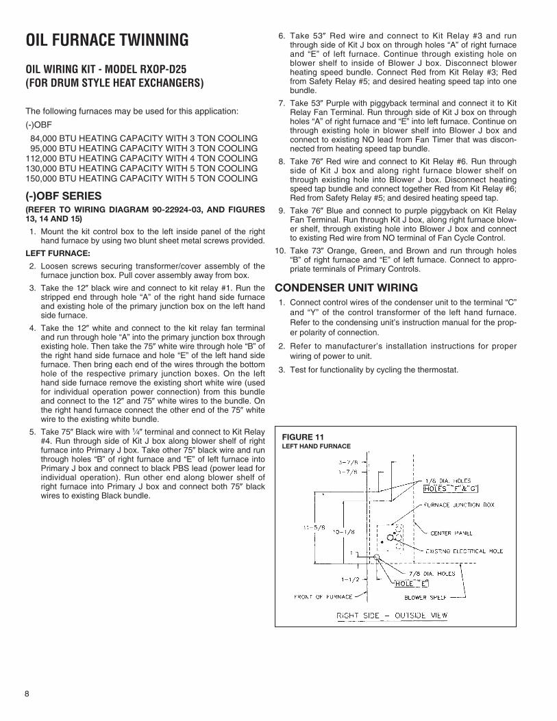
FIGURE 11LEFT HAND FURNACE
OIL FURNACE TWINNING
OIL WIRING KIT - MODEL RXOP-D25 (FOR DRUM STYLE HEAT EXCHANGERS)
The following furnaces may be used for this application:
(-)OBF
84,000 BTU HEATING CAPACITY WITH 3 TON COOLING95,000 BTU HEATING CAPACITY WITH 3 TON COOLING
112,000 BTU HEATING CAPACITY WITH 4 TON COOLING130,000 BTU HEATING CAPACITY WITH 5 TON COOLING150,000 BTU HEATING CAPACITY WITH 5 TON COOLING
(-)OBF SERIES(REFER TO WIRING DIAGRAM 90-22924-03, AND FIGURES13, 14 AND 15)
1. Mount the kit control box to the left inside panel of the righthand furnace by using two blunt sheet metal screws provided.
LEFT FURNACE:
2. Loosen screws securing transformer/cover assembly of thefurnace junction box. Pull cover assembly away from box.
3. Take the 12� black wire and connect to kit relay #1. Run thestripped end through hole “A” of the right hand side furnaceand existing hole of the primary junction box on the left handside furnace.
4. Take the 12� white and connect to the kit relay fan terminaland run through hole “A” into the primary junction box throughexisting hole. Then take the 75� white wire through hole “B” ofthe right hand side furnace and hole “E” of the left hand sidefurnace. Then bring each end of the wires through the bottomhole of the respective primary junction boxes. On the lefthand side furnace remove the existing short white wire (usedfor individual operation power connection) from this bundleand connect to the 12� and 75� white wires to the bundle. Onthe right hand furnace connect the other end of the 75� whitewire to the existing white bundle.
5. Take 75� Black wire with 1⁄4� terminal and connect to Kit Relay#4. Run through side of Kit J box along blower shelf of rightfurnace into Primary J box. Take other 75� black wire and runthrough holes “B” of right furnace and “E” of left furnace intoPrimary J box and connect to black PBS lead (power lead forindividual operation). Run other end along blower shelf ofright furnace into Primary J box and connect both 75� blackwires to existing Black bundle.
9
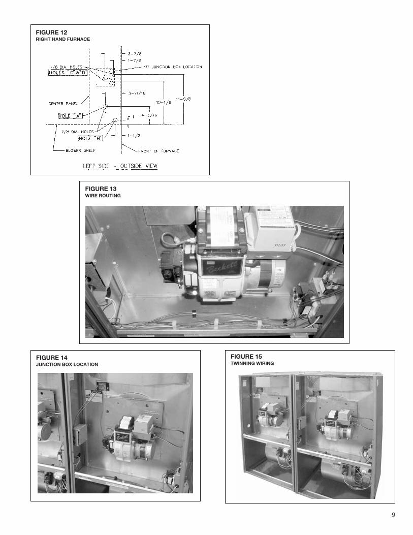
FIGURE 12RIGHT HAND FURNACE
FIGURE 13WIRE ROUTING
FIGURE 14JUNCTION BOX LOCATION
FIGURE 15TWINNING WIRING
10
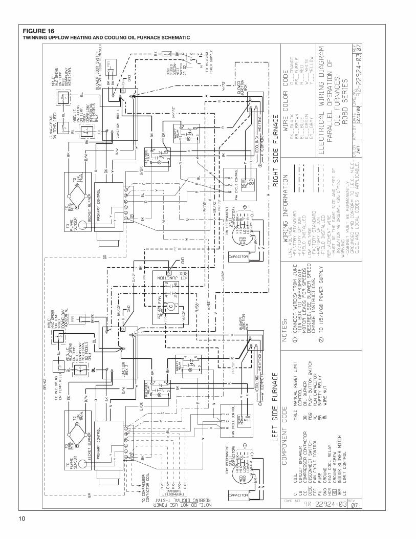
FIGURE 16TWINNING UPFLOW HEATING AND COOLING OIL FURNACE SCHEMATIC

11

12 CM 1205