Installation Instructions - Anchor Industries
31
Please read all assembly / installation instructions before the installation or removal of this product. ASEV 12-15 Rev. 1/17 Installation Instructions Anchor Structure - Event Series EC 5001 7701 Highway 41 N Evansville, IN 47725 Phone: 812-867-2421 Fax: 812-867-1429 1-800-544-4445 email: [email protected] www.anchorinc.com
-
Upload
khangminh22 -
Category
Documents
-
view
0 -
download
0
Transcript of Installation Instructions - Anchor Industries

Please read all assembly / installation instructions before the installation or removal of this product.
ASEV 12-15Rev. 1/17
Installation InstructionsAnchor Structure - Event Series
EC 5001
7701 Highway 41 NEvansville, IN 47725Phone: 812-867-2421
Fax: 812-867-14291-800-544-4445
email: [email protected]

2
Index
Introduction ............................................................................................................................ 3
Safety notes ......................................................................................................................... 3
EVENT Sizes and Configurations ........................................................................................4
Cable Configurations.............................................................................................................7
General Notes ......................................................................................................................6
Construction Tools ...............................................................................................................6
1 Squaring Tent and Setting Base Plates .......................................................................... 10
1.1 Squaring the Tent Layout ............................................................................................. 10
1.2 Setting Base Plates ...................................................................................................... 12
2 Assembling Arches .......................................................................................................... 14
2.1 Pre-assembly of Arch Components ............................................................................. 14
2.2 Assembly of Uprights and Rafters (& Rafter Extensions, if applicable) ....................... 14
2.3 Assembly of Cable Bracing .......................................................................................... 17
3 Erecting the Structure ...................................................................................................... 19
3.1 Preparation for Raising Arches .................................................................................... 19
3.2 Raising the End Arch (First Arch) ................................................................................. 19
3.3 Raising the Second Arch .............................................................................................. 19
3.4 Completing Installation of Uprights and Roof Cable Bracing ....................................... 22
3.5 Installing Gable End Framing ....................................................................................... 23
4 Installing Fabric Panels .................................................................................................... 25
4.1 Installing Mid Fabric Panels ......................................................................................... 25
4.2 Installing Gable End Fabric Panels .............................................................................. 26
4.3 Installing Optional Fabric Walls .................................................................................... 23
5 Dismantling ....................................................................................................................... 28
6 Routine Inspection and Maintenance ............................................................................. 29
6.1 Installation Period ......................................................................................................... 29
6.2 Visual Inspection of Components ................................................................................. 29
7 Specifications ……….………………………………………………………………………….. 30

3
IntroductionThe following instructions describe a logical plan for the construction and erection of the 10M to 25M Anchor Structure tent using the 220 x 100 x 4mm aluminum profi le for the uprights and rafters. Note that the standard 3M side height (up to 3.5M side height) may be constructed with-out knee braces, however, if the structure is modifi ed for the 3.5M side height, then knee braces must be used on all beams. See pages 4 thru 6 for confi gurations.
Please pay particular attention to the allowable X-cable patterns and the correct positioning of 6-holed and 4-holed baseplates shown in the manual. These patterns must be followed. Also please refer to the footprint drawings provided by Anchor Industries, Inc. These indicate the base load reactions that must be met by proper anchoring that is appropriate to the site and soil conditions in order for the unit to meet its engineering certifi cation under ASCE-7-10.
Always follow these instructions. Work from step to step. Do not skip any steps. There may be other steps necessary de-pending on your application. Be aware of these steps and pay close attention to the details needed.
PLEASE PAY SPECIAL ATTENTION TO SAFETY WARNINGS AND CAUTIONS FOR PREVENTION OF ACCIDENTS. Regarding the contents of this installation manual:The illustrations and photos are made to show clearly the construction and dismantling procedures and also for identifi cation of the components. Not all illustrations/photos correspond to the actual dimensions and size. Explanations and/or notes have been added to these illustrations/photos.If you have questions, please call your sales representative at the phone number listed on the front or back of this manual.
Safety Notes:• Please read through the installation manual completely before beginning your installation. Be sure the proper equipment
and safety precautions are in place.
• Consult your local utility locator service or the National Utility Locating Contractors Association (NULCA) prior to installa-tion.
• Prior to actual tent assembly, be sure to look up, down, above & below for obstacles, pipes, wires, trouble, etc.
• Be alert to avoid contact of frame sections with any overhead power lines near the site.
• Keep site clear of debris to avoid tripping, especially while carrying frame parts or bundles of fabric.
• When moving frame sections by hand, use proper lifting techniques to protect the back, and avoid pinching fi ngers while making hardware connections.
• The installation method described in the installation manual requires coordination of tasks between workers. A safe instal-lation is dependent on that coordination. Work cooperatively as a team.
• Be sure all pins and bolts are installed and secured correctly during assembly.
• Ensure that all purlin hooks are correctly seated in their rafter brackets.
• Cables must be tensioned as directed in the installation manual. Never remove cables except at time of disassembly of frame.
• Replace damaged or worn components with original Anchor components. Failure to use original Anchor components may void product warranties.
• To prevent injuries, wear suitable protective clothing such as hard hats, steel toed shoes, etc.
• Do not drag bundle of fabric on concrete, asphalt, or ground as this can cause damage to the fabric from abrasion through the bag.
• This tent is manufactured for use as a temporary structure. Evacuation is recommended if threatening or windy weather occurs. See caution on back page of this manual.
• Anchor recommends a factor of safety of at least 2X be used to resist all loads.

4
3.0 m
5.6 m
5.05 m
15 m
7.5 m
4.9 m 5.05 m
15 METER
15 METER
15-12 METER
1.5 m6.0 m
18 METER
3.0 m
6.1 m
5.05 m18 m
9.0 m
3.95 m 5.05 m
18 METER
3.95 m
7.5 m
1.5 m
18-15 METER
Splice size (typ.)
Gable end framing
Gable end framing Rafter size (typ.)
Splice size
Rafter size (typ.)
3.0 m
4.8 m
5 m
10 m
5 m
3.0 m
5.1 m
5.05 m
12 m
6.0 m
1.9 m 5.05 m
10 METER
EVENT SIZES AND CONFIGURATIONS
10 METER 12 METER
12 METER
Gable end framing Gable end
framing
Ridge brace on spliced 15m
NOTE: 3 METER UPRIGHTS THIS PAGE AND NEXT PAGE

5
20 METER
25 METER
5.05 m
5.05 m
20 m
25 m
10.0 m
10 m
7.5 m
10 m
7.5 m
4.95 m
4.98 m
5.05 m
5.05 m
20 METER
25 METER
4.95 m
4.95 m4.98 m
2.5 m
2.5 m
5 m
2.5 m
20-15 METER
25-20 METER
25-15 METER
Gable end framing
Gable end framing
Splice size
Splice size
Splice size
Rafter size (typ.)
Rafter size (typ.)
Rafter size (typ.)
EVENT SIZES AND CONFIGURATIONS (cont’d)
6.4 m
7.2 m
3.0 m
3.0 m

6
EVENT SIZES AND CONFIGURATIONSNOTE: 4 METER UPRIGHTS THIS PAGE
4.0 m
5.8 m
10 m
Knee Braces required all bays
Knee Braces required all bays
10 METER
4.0 m
6.1 m
12 m
12 METER
4.0 m
4.0 m
4.0 m
6.6 m
7.4 m
6.6 m
15 m
20 m
18 m
25 m
15 METER
20 METER
18 METER
25 METER
Knee Braces required all bays
Knee Braces required all bays
Knee Braces required all bays
Knee Braces required all bays
Ridge Brace required all bays
Ridge Brace required all bays
Ridge Brace required all bays
7.1 m
4.0 m

7
Side Elevations
Notes:
1. Upright and Roof Cable Bracing is required in the fi rst and last bays of the structure and additionally at not more than SIX open bays between braced bays.
2. All cables are 3/8” Galvanized 7 x 19 aircraft cable.
15m & Under
18m & 20m

8
General notesRead this manual thoroughly before beginning construction. If the steps are clear and the building components are identifi ed and ready, then begin assembly and follow the instructions step by step.
Pay attention to the safety warnings and regulations for prevention of accidents. Lack of knowledge and understanding of regulations can endanger the crew.
For best results and for safety, follow the sequence given.
A minimum of Six (6) installers are required for the assembly and erection of this tent.
Caution:Relevant safety features and standard specifi cations, according to OSHA safety standards, must be maintained. Construction laborers should be instructed about the possible dangers before construction begins. As stated above, a qualifi ed supervisor familiar with the proper assembly technique and required safety procedures should be present during the installation.
Construction ToolsInstallation and dismantling should be done the correct installation tools.
Special tools provided for installation:Diagonal Beam Brace (2) Measuring RodPurlin Forks Push Pole(3) Pull Ropes (3) R Clips
Other construction tools needed during installation and dismantling:(2) Mid Panel Guide (Optional) (3) Pull Ropes (25’ longer than tent width)(3) Folding Ladders equivalent to the Tent’s Eave Height(1) 17 mm combination wrench(2) 24mm combination wrenches(1) Tapered Centering tool(2) Sledge Hammers (12 lb.)(1) Power Stake Driver(10) Pieces of 4” x 4” x 18” wood blocks for Shims(1) Pair of Pliers(2) Measuring Tapes (30M)(2) Screw Drivers(1) Socket Set(1) Small Mallet(1) Cordless Drill(1) Stake Puller(1) Hand Truck (dolly)(1) Fork Lift with telescoping capabilities(1) String Line(1) LevelDrop clothsChalk/Spray paint
Pull Rope

9
Diagonal Beam Brace (2)
R Clip
Measuring Rod
Push Pole
Purlin Forks
Mid Panel Guide (2) (OPTIONAL)

10
Step 1: Squaring Tent and Setting Base Plates
1.1 Squaring the Tent Layout: The area in which the tent is to be installed should be as level as possible. Any deviation in the surface may result in difficulties when installing the tent. Consult the Local Code Official for required clearances and setbacks from any adjoining structures. Site the tent and establish the front and one side of the tent that will be used to square the first corner of the tent.
1.1.1 Stretch a string line along the tent’s length plus 2m past each end using stakes to establish the baseline A-B (side of tent) as shown in Figure 1.1a. The edges of side base plates must align with this string line.
1.1.2 From point A, measure 3 meters along the string line toward point B and mark this point D. See Figure 1.1b.
1.1.3 From point A, measure in the direction of Point C a distance of 4 meters. Mark on the ground an arch on a 4 meter radius from point A. See Figure 1.1b.
1.1.4 From point D, measure toward the arc just made in step 1.1.3 a distance of 5 meters. Mark on the ground anoth-er arc on a 5 meter radius from point D and intersecting with the first arc made in step 1.1.3. Where these two arcs intersect, mark this point E. See Figure 1.1b.
1.15 Stretch another string line along the tent’s front from point A toward point E. This string line will be 90 degrees to string line A-B. Without changing the angle, extend this string line 2m past width of tent to establish point C. Check to make sure the string line from A to C still passes thru the intersection of the two arcs at point E. This line establishes the front of the tent. See Figure 1.1c.
1.2 Setting Base Plates: Incorrect placement of base plates will create problems for the rest of the installation. Each hole of each base plate requires stakes for proper installation. IMPORTANT: Safety Tabs on all base plates must be oriented toward the interior of the tent. See Figure 1.2a. 6-Hole base plates use 48” stakes, 4-Hole and 2-Hole base plates use 31 1/2” stakes.
1.2.1 Starting at point A, place the outside corner of 6-Hole base plate #1 at point A, making sure the edges along the front and side of the base plate align with the front and side string lines, respectively. Anchor with two (2) stakes. See Figure 1.2a.
1.2.2 Connect the measuring rod with base plate L-Pin to base plate #1. Connect other end of the Measuring Rod to base plate #2 with base plate L-Pin. See Figure 1.2a.
1.2.3 Adjust base plate #2 so that the outer edge of the base plate is aligned with the string line and anchor with two (2) stakes.
1.2.4 Measure the width from the midpoint of base plate #1 to the midpoint of 6-Hole base plate #3 as shown in Figure 1.2b. While maintaining the center line distance, orient the front edge of base plate #3 with the front string line. Check the measurement again for the tent width between base plates #1 and #3 and anchor base plate #3 with two (2) stakes.
1.2.5 To locate 4-Hole base plate #4, remove the base plate L-Pin from base plate #1, lift the Measuring Rod and rotate about L-Pin in base plate #2 until it reaches the position of base plate #4. Adjust base plate #4 so that the outer edge of the base plate is aligned with the side string line and mount the Measuring Rod using the base plate L-Pin. See Figure 1.2c. Anchor the base plate with two (2) stakes. Repeat this procedure until all baseplates on this side are fixed. IMPORTANT: All cable braced bays require 6-Hole base plates.
1.2.6 To locate the 6-Hole base plate in-line with base plate #3 (designated as base plate #7 in Figure 1.2c), mount the Measuring Rod to base plate #3 and base plate #7 as described in step 1.2.5. Measure the width from the midpoint of base plate #2 to the midpoint of base plate #7 similar to that shown in Figure 1.2b. Anchor the base plate with two (2) stakes.
1.2.7 Repeat step 1.2.6 until all base plates on this side of the tent are anchored.
1.2.8 Finally, check the diagonal dimension at the midpoint of the four outer base plates. These dimensions should be equal. Once the diagonal dimensions have been verified, return to each base plate and install the remaining stakes. Stakes must be fully seated for proper installation.

11
Figure 1.1a
2m
2m
A
B
C
Tent Length
String Line
Tent Front
Tent Width
Tent Length
A
B
C
D
E
5m Arc
4m Arc
90º
Tent Front
3m
Figure 1.1b

12
1st Bay W
idth
Align edge of Base Plate with String Line.
Tent Side
Tent Width + 2m
A
B
C
E
String Line
90º
Figure 1.1c
Tent Front
6-hole
6-hole
Measuring Rod
Tent Side
Place corner of Base Plate #1 at Point A and align edges with string lines.
A
Measuring Rod
Base Plate L-Pin
Safety Tab
Point A
Important: Make certain the base plate safety tab is oriented toward the interior of the tent. Figure 1.2a

13
Figure 1.2b
Tape measureMeasuring point for estimating width.
6-hole base plate.
6-hole base plate.
6-hole base plate.
Figure 1.2c
Rotate Measuring Rod about pin in base plate 4
Tent Front
Cabled Bay

14
Step 2: Assembling Arches
2.1 Pre-assembly of arch components: Identify and layout all components according to Figure 2.1 for the entire structure. NOTE: Setting uprights and rafters on 4 x 4 wood blocking (or whatever blocking may be available) will make the insertion of the pins and bolts easier.
2.1.1 The following is a list of components required for each arch:
Quantity Description
2 Base Plate L-Pins 16mm x 230mm (9”) & R-Clips NOTE: 5/8” x 200mm (7 7/8”) L-Pins are used at the Gable End base plates (Quantity is one per upright)
2 Uprights
2 Base Plates
2 Rafter/Upright Pin with Flat 14mm x 140mm (5 1/2”)
4 (8) 16mm x 132mm (5 3/16”) Locking L-Pin with stop. (quantity in parenthesis is required if Rafter Extensions are used) NOTE: Also used at Gable End uprights.
1 Ridge Insert
2 Rafter Extensions (if applicable)
2.1.2 Identify and layout Pins with R-Clip (as required) as shown in Figure 2.1. 2.1.6 If laying out components for a cable braced bay, refer to Section 2.3 for substitute components required.
2.2 Assembly of Uprights and Rafters (and Rafter Extensions if applicable): The assembly of the arches is easier if working from one side to the opposite side.
2.2.1 Starting at Base Plate “1”, connect the bottom of the Upright Connection Insert to the Base Plate using the L-Pin as shown in Figure 2.2. The R-Clip will be inserted later when the Wall Ground Bars are installed. IMPORTANT: The short leg of the L-Pin must be turned down and behind the Safety Tab on the Base Plate to keep the L-Pin from sliding out.
2.2.2 Connect Rafter to the Upright Assembly by sliding the Rafter onto the slide connector on top of the upright. Secure the connection by inserting the Flat L-pin into the hole located inside the end of the rafter, see Figure 2.2a.
2.2.3 If installing Rafter Extensions, connect the Rafter Extension to the Rafter using Locking L-Pins. Ensure L-Pin is turned so the stop collar is locked behind tab on rafter. IMPORTANT: At the gable ends, the head of the pin must be on the exterior side of the rafter to minimize any snagging possibilities when installing the gable end fabric.
2.2.4 Insert Ridge Weldment into end of rafter and secure using Locking L-Pins. Ensure L-Pin is turned so the stop collar is locked behind tab on rafter. See Figure 2.2b. IMPORTANT: At the gable ends, the head of the pin must be on the exterior side of the rafter to minimize any snagging possibilities when installing the gable end fabric.
2.2.5 Complete the Arch assembly by connecting the opposite Rafter (or Rafter Extension) to the Ridge Weldment, Rafter Extension to Rafter (if applicable), Rafter to Upright and Upright to Base Plate according to steps 2.2.1 thru 2.2.4.
2.2.6 Assemble the remaining arches according to steps 2.2.1 thru 2.2.5.
2.2.7 When Ridge and Knee Braces are required as shown in the configuration drawing, insall as shown in Figures 2.2a & 2.2b.
R-Clip
Figure 2.2
L-Pin
Safety Tab
To inside of tent

15
1” x
32”
Sta
ke
Bas
epla
te (6
) ho
le
Dia
gona
l B
eam
Bra
ce
Upr
ight
Upr
ight
Bas
epla
te (2
) ho
le -
use
with
L-
pin
(5/8
”) &
R
Clip
L-P
in (1
6mm
)R
Clip
Raf
ter/U
prig
ht
Pin
w/F
lat
L-P
in -
16m
m
Dro
p-in
Gab
le
End
U
prig
hts
Gab
le
End
P
urlin
s
Lock
ing
L-P
in -
16m
m w
/Sto
p
Lock
ing
L-P
in -
16m
m w
/Sto
p
Inte
rmed
iate
P
urlin
sR
idge
/Eav
e P
urlin
Rid
ge/E
ave
Pur
lin Raf
ter
Rid
ge
Wel
dmen
t
Rid
ge B
race
(onl
y w
hen
req’
d)
Kne
e B
race
(onl
y w
hen
req’
d)
Gab
le U
prig
ht
Con
nect
or
Pla
te
Figure 2.1
Note: See pages 4 to 6 for actual confi guration of your structure. Shown for example here is a 25m.

16
Upright
Rafter/Upright Pin w/Flat. Place inside end of Rafter and down thru open hole and upright after upright is slid into slide fi tting.
Ridge Weldment
Wood Blocking(Typ.)
Rafter
Slide Fitting
Rafter
Figure 2.2a
Figure 2.2b
Locking L-Pin 16mm w/ Stop (typ.)
Locking L-Pin 16mm w/ Stop (typ.)
Ridge Brace (only when required)
Knee Brace (only when required)
Final position
Final position

17
2.3 Assembly of Cable Bracing: See Cable Configurations on page 7. Layout Cables in the appropriate bays. Install the cables so that the turn-buckles at the uprights are closest to the ground and at the roof cables are closest to the eave. For smooth installation, unscrew turnbuckles 3/4 of the way out, and keep threads lubricated. See Figure 2.3c. The cables have color coded labels; green labels indicate upright cables and blue labels indicate roof cables.
2.3.1 Remove the Eye-bolt from the Upright Cable Assembly (unhook from shackle). At the Upright Assembly on both sides of the cabled bays, insert the eye-bolt into the top hole of the upright. See Figure 2.3a. At the End Arch (first arch) the Eye-Bolt must face toward the ground (toward the second arch when raised) and on the second arch the Eye-Bolt must face upward, away from the ground (toward the first arch when raised). At all uprights connect the Upright Cable Assembly (end opposite turn-buckle) to each Eye-Bolt using the shackle provided; typical of four locations. The turn-buckle end must remain free until the arches are raised.
2.3.2 Remove the Eye-bolt from the Roof Cable Assembly (unhook from shackle at turnbuckle end). At End of Rafter on both sides of the cabled bays, insert the Eye-Bolt into the outermost hole. See Figure 2.3a. At the End Arch (first arch) the Eye-Bolt must face toward the ground (toward the second arch when raised) and on the second arch the Eye-Bolt must face upward, away from the ground (toward the first arch when raised). Do not attach cable until later.
2.3.3 Remove the Eye-bolt from the Roof Cable (unhook from shackle at end opposite turnbuckle). At the Ridge Weld-ment on both sides of the cabled bays, insert the Eye-bolt. See Figure 2.3b. At the End Arch (first arch) the Eye-Bolt must face toward the ground (toward the second arch when raised) and on the second arch the Eye-Bolt must face upward, away from the ground (toward the first arch when raised. Connect the Roof Cable Assembly (end opposite turn-buckle) to each Eye-Bolt using the shackle provided; typical of four locations. The turn-buckle end must remain free until the arches are raised.
2.3.4 For all cable braced bays the installation sequence will be similar to steps 2.3.1 thru 2.3.3.
Cables at Ridge on fully installed Structure.
Cables at Eave on fully installed Structure.

18
Figure 2.3aFigure 2.3b
Eyebolt, remove from shackle before insertion into top hole of Upright. Then reattach to cable.
Eyebolt, remove from shackle before inser-tion into Rafter. Do not reattach to cable until later.
Figure 2.3c
Eyebolts, remove from shackle before insertion into Rafter. Then reattach to cable.

19
Step 3: Erecting the Structure
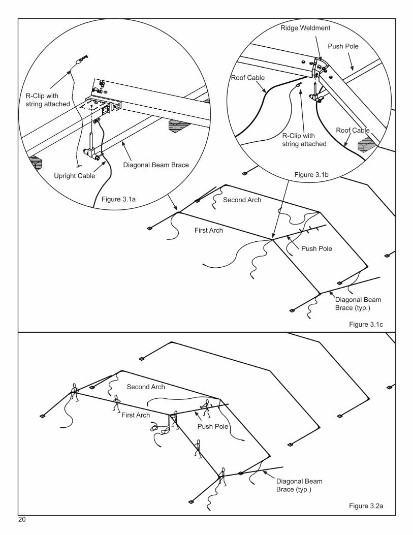
3.1 Preparation for Raising Arches: NOTE: The Diagonal Beam Braces and the Push Pole supplied in the instal-lation kit will be used during the raising of the first and second arches.3.1.1 Prior to raising the first arch connect the Diagonal Beam Braces to the uprights by inserting the top pin on the
Diagonal Beam Brace up through the second holes at top of the uprights as shown in Figure 3.1a. Secure to the upright by using an R-Clip with string attached (R-Clip must have open-end toward top of rafter).
IMPORTANT: Make sure the tube on the pinning end of the Diagonal Beam Brace is pointing upward as shown in Figure 3.2c, otherwise the bottom of the upright on the second arch may be damaged.
3.1.2 Lay both of the Diagonal Beam Braces along and outside the second arch base plates as shown in Figure 3.1c.
3.1.3 Connect Push pole to Ridge Weldment as shown in Figure 3.1b using R-Clip with string. (Similar to Diagonal Beam Brace Connection as described above).
3.1.4 Verify that the R-Clips for the base plate L-Pins are placed on the second arch base plates so they are readily
available to secure the pinning end of the Diagonal Beam Brace to the L-Pins once the first arch is raised.
3.2 Raising the End Arch (First Arch): Position three or more installers along the length of each rafter; one next to the ridge, one or more at push pole on ridge, one at midpoint of rafter and one at the eave as shown in Figure 3.2a. Note that more installers may be required for larger width structures. This method of raising the arches requires coordi-nation between workers for a safe installation. Use proper lifting techniques to protect the back by lifting with your legs.
3.2.1 Begin lifting the first arch in unison, being careful not to twist the arch. As the arch is lifted, the installers move toward the uprights while maintaining contact with the arch. NOTE: The Diagonal Beam Braces will drag along as the arch is lifted.
3.2.2 When the arch is nearly vertical and stable, one installer on each side can guide the tube on the pinning end of the Diagonal Beam Brace onto the base plate L-Pin of the second arch as shown in Figure 3.2c. Secure the Diagonal Beam Brace by installing the R-Clip.
3.2.3 IMPORTANT: Ensure that the pinning end of the Diagonal Beam Brace is slid away from under the bottom of the second arch uprights to allow clearance for the upright to pivot vertically when raising the second arch. If the pinning end of the Diagonal Beam Brace is underneath the bottom of the upright, the upright will be damaged when raising the second arch.
3.3 Raising the Second Arch: Position installers as recommended for the first arch. See note in steps 3.2.3 before raising the second arch.
3.3.1 Prior to raising the second arch, layout the eave, roof and ridge purlins in their respective position on the ground adjacent to the first arch. To help expedite the stability of the second arch, connect the curved hook end of the eave purlins to the brackets at the ends of the rafters on the first arch. The opposite end of the eave purlin can rest on the ground until the second arch is in the vertical position.
3.3.2 Raise the second arch as described in steps 3.2.1 for the first arch. When the arch is vertical, one installer on each side must swing the free end of the eave purlin, using the wide cradle purlin fork (supplied in the installation kit), to drop the eave hook into the bracket at the ends of the rafters on the second arch as shown in Figure 3.3a. Use the same technique and purlin fork to install the ridge purlin into the brackets at the ridges. Use the roof cables to help sway the arch and align the purlin hook with the ridge bracket.
3.3.3 Using the same technique with the narrow cradle purlin fork (supplied in the installation kit), install the remaining roof purlins, making sure that the curved hook on the roof purlin is properly engaged in the rafter bracket before swinging the opposite end in place as shown in Figure 3.3b.
3.3.4 The installation of the remaining arches will utilize the same technique described in steps 3.3.1 thru 3.3.3.
20
Figure 3.1c
Figure 3.2a
Figure 3.1a
Figure 3.1bDiagonal Beam Brace
Push Pole
Push Pole
Push Pole
Diagonal Beam Brace (typ.)
Diagonal Beam Brace (typ.)
Ridge Weldment
Upright Cable
Roof Cable
Roof Cable
R-Clip with string attached
R-Clip with string attached
First Arch
First Arch
Second Arch
Second Arch

21
Figure 3.2bFigure 3.2c
Diagonal Beam Brace (typ.)
Push Pole
L-PinR-Clip
First Arch
Second Arch
Diagonal Beam Brace
Install Curved Hook end of Purlin First, Angular end last.
Purlin Fork
Purlin Fork
Purlin
Eave Purlin
Eave Purlin
Purlins
Figure 3.3b
Figure 3.3a
Roof Cables hang-ing loose (typ.)
Upright Cables hanging loose (typ.)

22
3.4 Completing Installation of Upright and Roof Cable Bracing: Turnbuckles may need to be fully extended to attach cables. Refer to Figure 3.4 for cable configurations required for the Upright and Roof Cable Bracing.
3.4.1 The Upright Cables connect to the base plates by inserting an Eyebolt attached to the loose end of the cable assembly thru the hole in the base plate vertical tab as shown in Figure 3.4a. Secure the Eyebolt with the washer and nut provided. NOTE: The R-Clip provided will be used later to secure the wall ground rails at the End Arches if the gable end walls are installed. Adjust the tension of the cables using the turnbuckles, tension only enough to make frame stable. After the Upright Cables have been installed and tensioned, remove the Diagonal Beam Braces.
3.4.2 The Roof Cables connect to the Eye-Nuts at the rafter eaves by using the shackle attached to the loose end of the cable assembly. Adjust the tension of the cable using the turnbuckles. IMPORTANT: The Roof Cables must be installed below the Roof Purlins.
3.4.3 The installation of the remaining cable braced bays will utilize the same technique described in steps 3.4.1 and 3.4.2.
3.4.4 Before erecting additional arches, plumb the first bay of uprights by adjusting the tension of the upright cables until the uprights are vertically aligned. Next, adjust the roof cable to align the rafters vertically with the uprights. Once the first bay of framing is plumb, continue erecting remaining arches as described in steps 3.3.1 thru 3.3.3.
Figure 3.4
Figure 3.4a

23
3.5 Installing Gable End Framing: Refer to Event Sizes and Configurations, pages 4 to 6, for layout of Gable End framing for various tent widths and eave heights. NOTE: A ladder will be necessary to pin the top of the G.E. uprights to the end arches.
3.5.1 The following is a list of hardware required for each Gable End Upright:
Quantity Description1 Locking L-Pin with Stop (16mm x 132mm)
1 Gable End Base Plate L-Pins 5/8” x 200mm (7 7/8”) & R-Clip
1 Anchor Structure Gable Upright Base Plate
2 31 ½” Stakes
3.5.2 At the Center Uprights, (where required) connect the insert weldment at the top of the G.E. Upright to the hinge tube at the bottom of the Ridge Weldment using the Locking L-Pin with Stop. See Figure 3.5a. IMPORTANT: Pay attention that the collar on the L-pin is engaged in the safety latch bracket at top of upright.
3.5.3 At the Intermediate Uprights, first connect the G.E. Upright/Rafter Connecting Bracket to the Rafter as shown in Figure 3.5b. The heads of the bolts that are tightened to clamp the bracket to the rafter must be facing toward the interior of the tent. Make sure the bolts are tight. Connect the insert weldment at the top of the G.E. Upright to the hinge tube at the bottom of the G.E. Upright/Rafter Connecting Bracket using the 5/8” Swivel-Lock Pin. See Figure 3.5b. IMPORTANT: Pay attention that the collar on the L-pin is engaged in safety latch bracket at top of upright.
3.5.4 After the G.E. Uprights are connected to the arches, swing the G.E. Upright out from either side of vertical and insert the G.E. Base Plate into the bottom of the G.E. Upright. Swing the upright back to vertical. Adjust the G.E. Base Plate in or out to suit the adjoining grade and pin using the G.E. Base Plate L-Pin and R-Clip. See Figure 3.5a. IMPORTANT: Do not stake at this time.
3.5.6 Install the gable end eave purlins by pinning at one end and adjusting the telescoping end(s) so that the purlins fit properly between the G.E. Uprights. Corner Gable Purlin hooks over bracket on side upright bracket. See Fig-ure 3.5c.
3.5.8 Plumb the G.E. Uprights (both axes) and anchor the base plates. CAUTION: Do not damage the uprights or installation hardware when driving the stakes.

24Figure 3.5a
Locking L-Pin with Stop
Top of Intermediate Gable end Upright.
Top of Center Gable end Upright.
Cut-out for Ridge Brace.
Figure 3.5b
Ridge
Figure 3.5c
Connection for center gable end upright at ridge.
Connection for Corner Gable Purlin at Side Upright/rafter.
Gable End Base Plate L-Pin -5/8”
Telescoping end of Gable End Upright.
Telescoping end of Gable End Purlin
L-Pin - 16mm Drop-in
R-Clip
Gable End Base Plate
See Figure 3.5c

25
Step 4: Installing Fabric Panels
4.1 Installing Mid Fabric Panels: Install Mid Fabric Panels first. Before installing, verify that all stakes are fully seated and the cable braced bays are lightly tensioned. Use drop cloths (not included), pull ropes (supplied in Installation Kit) and ladders to assist installation. When possible, choose installation side based on wind direction and space around installa-tion area. Installation should be based on safety first.
4.1.1 Mid fabric panels should be fed into the rafters on the “downwind” side of the frame (fabric blowing away from the frame). This will prevent fighting the mid blowing against the frame and reduce the effort required to guide the mid into the kedar groove. Throw the snap ends of two pull ropes from the installation kit over the top of frame of one bay. CAUTION: Be certain area is clear so as not to strike anyone while throwing the pull ropes over the top.
4.1.2 Using a drop cloth, lay the mid fabric next to the bottom of the uprights on the snap side of the mid bay. Snap the pull ropes onto the web loops near each kedar edge. Mid should be loosely stacked to permit easy feeding into the channels. See Figure 4.1a. IMPORTANT: Use the third pull-rope as a pull-back rope. Snap this rope to one of the pull straps on the mid along with one of the pullropes. After the mid has been pulled up and over to the other side of the mid, remove this rope from the strap and snap to the other two pull-ropes. Using this pull-back rope, pull the pull-ropes back to the starting side of the frame and slide them over to the next bay. This step will save time in having to throw the pull-ropes over the frame again. CAUTION: Be certain at all times that fabric is not caught on any part of the frame to prevent damage to the fabric.
4.1.3 Using pull ropes, raise mid until the kedar is near the end of the rafter. With an installer on a ladder at each side of the mid, feed the kedars into the kedar channels of the rafters. Once both kedars are in the channels, continue to feed until the upper ends of the pull loops are even with the edge of the rafter.
4.1.4 Flip the tension pocket on top of the mid so it does not get caught on the purlins while pulling the mid through the frame. At this point, the kedars on both sides of the mid should be fed into the channel evenly. Feed each kedar into the channel for just a few more inches. There should be an installer at each installation end of the rafters to guide the kedar into the kedar channel at all times. To prevent a bind, be sure to start and stop pulling both ropes at the same time, and the same speed.
4.1.5 Using the pull ropes, slowly pull the mid up the rafter to within 2’-0” of the peak. Have the pullers reset their posi-tion to a location near the frame. Begin pulling the ropes at the same time to make sure the mid pulls smoothly over the ridge and down the other side of the frame. Stop pulling the mid before the kedar exits the channel on the rafter. The mid is in place.
4.1.6 Repeat steps 4.1.1 thru 4.1.5 for the remaining mids.
4.1.7 After all mids are in place, insert tension bars in tension pockets at both ends of all mids. Insert tension bar con-nector between tension bars and through tension strap loop. Tension mids until tight. Usually kedar will be near the end of the channel when mid is tight. Make sure the bottom pocket line on all mids are level. Add and/or release tension as necessary to adjust.
4.1.8 Mids are installed.
4.2 Installing Gable End Fabric Panels: Use drop cloths (not included), purlin fork and ladders to assist installation. Gable ends are made in two pieces and are inserted into the top channel of the gable end rafters.
4.2.1 Begin by locating the lace portion (either grommet side or loop side) of one of the two pieces. Be sure that the piece is right side out (pull ring will be on outside, FR/Warning label on inside).
4.2.2 Using the purlin fork, grab the ring with the end of the tool and push the kedar up through the channel until it is at the center of the ridge. See figure 4.2a. When both pieces of the gable end are installed in the channel and meet at the top, fasten the rings together with the carabiner and begin lacing from the peak down to the bottom of the gable end. Tie off the last loop. See figure 4.2b.

26
4.2.3 Insert tension bars into tension pocket at bottom of gable end. Insert tension bar connector between tension bars and through tension strap loop. Insert tension bar corner connectors at corners. See Figure 4.2c. Tension fab-ric until it is tight. Make sure the bottom pocket line on ends are level. Add and/or release tension as necessary to adjust.
4.2.4 Repeat steps 4.2.1 thru 4.2.3 for opposite gable end.
4.2.5 Gable Ends are installed.
4.2.6 Now Tension all cables fully.
4.3 Installing Optional Fabric Walls: Use drop cloths (not included) and ladders to assist installation. Walls are made in two pieces with FR/Warning labels on the inside, ground rail pockets on the outside. NOTE: Gable end wing walls are used at outer bays of the gable ends and there are right and left versions. Mid walls are used at center gable end bays and at all mid bays.
4.3.1 Start installing unlaced walls by inserting top of kedar into outside channel opening and slide upper portion of wall to top of upright. Then insert bottom of kedar into channel opening and slide kedar down to bottom of upright. Gather wall toward upright and start inserting wall tabs into channel of eave purlins. IMPORTANT: Gable end wall tabs insert into Outer Channel of the eave purlins and Mid wall tabs insert into Inner Channel.
4.3.2 After all tabs are inserted, walls may be laced from top to bottom. Tie off bottom long loop.
4.3.3 Insert Ground Rails into bottom pocket of all mid walls and secure to base plate L-Pins at all mid uprights as shown in Figure 4.3a.
4.3.4 Insert Ground Rails into top pockets of all gable end walls and secure to end of cable bracing eyebolt at base of gable end corner upright (Fig. 4.3a) and to Gable End Base Plate L-Pin.
Figure 4.1a
Figure 4.2a

27
Figure 4.2c
Tension Straps
Corner Upright
Tension Bars in Tension Pockets
Figure 4.3a
Corner Upright
Ground Rail (Side)
6-hole Baseplate
R-Clip
Ground Rail (Gable end)
Gable Wall Side Wall
Figure 4.2b

28
Step 5: Dismantling
For the dismantling of the tent follow the installation instructions in reverse. The basics of dismantling: (All fabric panels of the tent must be dry before removing and folding for storage.)
5.1 Remove all wall ground rails.
5.2 Remove the side and gable end walls, lay them on a drop cloth and fold. Return walls to cloth shipping bags provided.
5.3 At the gable ends, release the gable end web tensioners, remove the tension bars, unlace the gable end panels and remove onto a drop cloth and fold. Return to cloth shipping bags provided.
5.4 At the mid panels, release the web tensioners, remove the tension bars and pull out the mid panels onto a drop cloth and fold. Return to cloth shipping bags provided.
5.5 Pull the gable end upright stakes and remove the gable end purlins and uprights.
5.6 Remove upright and roof cables at one end bay. IMPORTANT: The cabling in the opposite end braced bay must remain.
5.7 Install push pole at peak of end arch. While workers stabilize the end arch, remove all roof, ridge and eave purlins. Lower the arch onto wood blocking to ease pin and bolt removal.
5.8 Continue removing purlins and lowering remaining arches until the last bay (two arches) remains.
5.9 Install the Diagonal Beam Braces as noted in Step 3.2 to secure the first arch and allow the cabling to be removed.
5.10 Once the Diagonal Beam Braces are secure, detach the roof and upright cables at the turnbuckle end. While workers stabilize the second arch, remove the remaining roof, ridge and eave purlins and lower the second arch. IMPORTANT: Ensure that the pinning end of the Diagonal Beam Brace is slid away from under the bottom of the second arch uprights to allow clearance for the upright to pivot when lowering the second arch. If the pinning end of the Diagonal Beam Brace is underneath the bottom of the upright, the upright will be damaged when lower-ing the second arch.
5.11 While workers stabilize the last arch, remove the Diagonal Beam Braces from the base plate pins at the second arch and lower the last arch.
5.12 Remove bolts and pins from the arch connectors and disassemble the arch components.
5.13 Remove L-Pins connecting the uprights to the base plates.
5.14 Remove all stakes from the base plates.
5.15 After dismantling, sort and load all building components as best integrates with your transportation and storing logistics.
5.16 Store fabric in a cool, dry area.
29
Step 6: Routine Inspection and Maintenance
6.1 Installation Period
6.1.1 The entire tent structure system shall be inspected at regular intervals, but not less than two times per permit use period to determine that the installation is maintained in accordance with Chapter 24 of the International Fire Code and as required by the local code official in the jurisdiction of the installation.
6.1.2 Re-tension cable bracing , re-tighten bolted connections and re-tension fabric panels as follows: - 24-hours after initial installation and every week thereafter - after hot periods - after periods of heavy rains - after periods of strong winds
6.1.3 Inspect all stakes to ensure they are fully engaged.
6.1.4 Ensure all FR/Warning labels are clearly visible.
6.1.5 Do Not allow the accumulation of snow or ice.6.1.6 Check for deformation or damage.
6.1.7 If there are any damaged parts, replace them immediately with new original parts.
6.2 Visual Inspection of Components
6.2.1 Routinely conduct a visual inspection after every use.
6.2.2 Inspect purlin hooks and brackets for excessive wear or damage.
6.2.3 Inspect cables for kinks or frays.
6.2.4 Inspect bolt and pin connections for excessive wear or damage.
6.2.5 Inspect kedar cords for excessive wear or damage.
6.2.6 Inspect kedar channels to ensure they are open and free of sharp edges and burrs.
6.2.7 Inspect wall tabs for excessive wear or damage.
6.2.8 Routinely clean all fabric panels. Always thoroughly dry before storing.

30
Step 7: Specifications
Clearspan Widths (meters): 10.0 / 12.0 / 15.0 / 18.0 / 20.0 / 25.0
Side Heights (meters): 3.0 / 4.0
Minimum Length: Minimum bays provided in a given structure should ensure that the structure length is greater than the structure width
Maximum Length: No Limit
Roof Pitch: 18 degrees
Bay Distance (meters): 5.0
Minimum number of Bays: 10M – 3 / 12M – 3 / 15M – 4 / 18M – 5 / 20M - 5 / 25M - 6
Extrusion Profiles (millimeters):- Uprights & Rafters 220 x 100- Gable End Uprights 130 x 70- Ridge, Eave & G.E. Purlins 130 x 70- Intermediate Roof Purlins 60 x 60
Rafter Extension Options: 15-12 / 18-15/ 20-15 / 25-20 / 25-15
Longest Components (meters): 9.8 (18.0 One-piece Rafter)
Main Frame Material: Aluminum 6061 – T6
Main Frame Finish: Anodized 204 R1
Connection Material: Steel, zinc plated or galvanizedConnection Type:- Ridge Internal Steel Weldment
- Splice Internal Aluminum Insert
Engineering Certification: In compliance with ASCE 7 – 10 for 115 mph, 3 second wind gust

31
Anchor products are of superior design and operate best within the parameters of these instructions. It is imperative that the instructions be carefully read and COMPLETELY FOLLOWED. Please read installation instructions before the installation or removal of this product. Installation instructions are available online at www.anchorinc.com or by calling 1-800-544-4445.
CAUTION:
1. For each installation, the installer is solely responsible for evaluating the site and the proper securing method determined. Some soils require different staking or securing than that provided with the tent. Due to this variety of soil conditions, these are the manufacturer’s suggested sequence of installation procedures. Anchor’s responsibility is limited to the manufacture of the tent parts and materials. We are not responsible for methods that installers may choose to erect and secure the tent to the ground.
2. The number of stakes suggested in the installation instructions do not necessarily meet all or any relevant codes on the site of the tent installation. The number of stakes suggested will, in many cases, keep the tent erected, however, due to various soil conditions; these stakes will be insuf cient to keep the tent secure in high winds. It is the tent installer’s responsibility, not the manufacturer, to determine the appropriate number of stakes to meet the necessary wind loads on the site. Regardless of the number of stakes we suggest, we make no representation or warranty as to whether this speci c number of stakes will meet the local tent code. Anchor does not, nor can it make any suggestions, representation, or warranties about the adequate staking required at each speci c installation site. Staking information provided in the installation instructions is not a suggestion about what is necessary to meet a site-speci c load.
For additional important information, consult: “The IFAI Procedural Handbook For the Safe Installation and Maintenance of Tentage” and the IFAI Pocket Guide “Pullout Capacity of Tent Stakes”, both available from the IFAI Tent Rental Division or on our website.
3. Inasmuch as the weather is unpredictable, good judgment and common sense must be incorporated within installation guidelines. It is the responsibility of the tent installer/maintainer to determine the severity of the weather, proper time and method of installation and/or erection and disassembly. Note: We recommend that snow and ice be removed from the tent surface as soon as possible because accumulation will damage the tent or fabric structure. Please consult with our Engineering Department about the maximum loads for each product.
This product has been manufactured for use as a temporary structure. For the safety of all occupants, evacuation is recommended if threatening weather occurs, or if there is any doubt concerning the safe use of this product.
4. Proper safety equipment should be used at all times to insure a safe installation and take down. We suggest a careful evaluation be made to determine safety equipment needed, such as hard hats, steel-toe shoes, safety glasses and other as required. It is our desire that all installations are safe. Please be aware of hidden dangers both underground, i.e., gas lines, water lines, electrical lines, etc. and above the tent such as power lines and telephone lines.
5. Anchor stands behind its products in accordance with its standard Terms and Conditions of sale. A copy of our Terms and Conditions of Sale can be obtained by contacting Anchor at the telephone number and/or address on this document.
EVANSVILLE, INDIANA
PHONE NUMBER812·867·2421
FAX NUMBER812·867·1429
28.2 03-04-09-R1