PFEIFER Allround Anchor Score every time ...
20
PFEIFER Allround Anchor 05/2019 Score every time ... PFEIFER SEIL- UND HEBETECHNIK GMBH DR.-KARL-LENZ-STRASSE 66 D-87700 MEMMINGEN PHONE Technical Support +49 83 31-937-345 Sales +49 83 31-937-231 FAX +49 83 31-937-342 E-MAIL [email protected] INTERNET www.pfeifer.info
-
Upload
khangminh22 -
Category
Documents
-
view
0 -
download
0
Transcript of PFEIFER Allround Anchor Score every time ...

PFEIFER Allround Anchor
05/2019
Score every time ...
PFEIFERSEIL- UND HEBETECHNIKGMBH
DR.-KARL-LENZ-STRASSE 66D-87700 MEMMINGENPHONE Technical Support +49 83 31-937-345 Sales +49 83 31-937-231FAX +49 83 31-937-342E-MAIL [email protected] www.pfeifer.info

22© 2018 Copyright, PFEIFER, 87700 Memmingen / Translation of the original operating instructions / Technical modifications and errors excepted. Status of 05/2019
Everything runs smoothly with the PFEIFER Allround Anchor …PFEIFER Allround Anchor for maximum user safety:
The new lifting anchor from PFEIFER rounds off the existing thread system as a genuine “all-rounder”. It combines the best of existing anchor variants and is suitable for installation in the most diverse precast concrete elements. In order to meet tomorrow‘s requirements today, the PFEIFER Allround Anchor has been tested to a particularly high safety level.Your project is guaranteed to score when it comes to speed and high user safety.
Wide range of applications• One anchor type for most applications
• Low stock keeping on account of there being only a few different anchor variants
• A suitable lifting key for every application
Rotation-symmetrical anchor foot• Hence shorter lengths in comparison
with other anchor variants
• Easy positioning/rotation of the anchor in the formwork
Robust round thread• No downtimes due to dirty or
damaged thread flanks
• High speed when screwing in due to short, smooth-running round thread
Trendsetting safety• Conforms to the technical directive VDI/BV-BS 6205
in interpretation of Directive 2006/42/EC
• Qualification on the basis of application-related test series with accredited testers
• Manufacturing monitoring through certified factory production control
• PFEIFER colour coding for clear assignment of combinable products from one manufacturer
Colour coding – thread system Size Rd 12 Size Rd 30
Size Rd 14 Size Rd 36
Size Rd 16 Size Rd 42
Size Rd 18 Size Rd 52
Size Rd 20 Size Rd 56
Size Rd 24 Size Rd 60
3© 2018 Copyright, PFEIFER, 87700 Memmingen / Translation of the original operating instructions / Technical modifications and errors excepted. Status of 05/2019
Thread System
Lifting Anchor
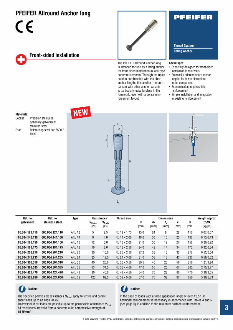
PFEIFER Allround Anchor long
The PFEIFER Allround Anchor long is intended for use as a lifting anchor for front-sided installation in wall-type concrete elements. Through the upset head in combination with the short anchor lengths this anchor – in com-parison with other anchor variants – is particularly easy to place in the formwork, even with a dense rein-forcement layout.
Advantages: • Especially designed for front-sided
installation in thin walls• Practically oriented short anchor
lengths for fewer disruptions in the component
• Economical as requires little reinforcement
• Simple installation and integration in existing reinforcement
Materials:Socket: Precision steel pipe
optionally galvanised/ stainless steel
Foot: Reinforcing steel bar B500 B black
Ref. no. galvanized
Ref. no. stainless steel
Type Resistances Thread size Dimensions Weight approx. zn/VA [kg/pc]
NR,adm [kN]
VR,adm [kN]
D [mm]
dF
[mm]ds
[mm]e
[mm]h
[mm]
05.004.123.110 005.004.124.110 ARL 12 5 2,5 Rd 12 x 1,75 15,0 24 8 22 110 0,07/0,07
05.004.143.130 005.004.144.130 ARL 14 8 4,0 Rd 14 x 2,00 18,0 30 10 25 130 0,13/0,13
05.004.163.150 005.004.164.150 ARL 16 12 6,0 Rd 16 x 2,00 21,0 36 12 27 150 0,20/0,22
05.004.183.175 005.004.184.175 ARL 18 16 8,0 Rd 18 x 2,50 24,0 42 14 34 175 0,32/0,34
05.004.203.210 005.004.204.210 ARL 20 20 10,0 Rd 20 x 2,50 27,2 38 16 35 210 0,52/0,54
05.004.243.235 005.004.244.235 ARL 24 25 12,5 Rd 24 x 3,00 31,0 38 16 43 235 0,59/0,62
05.004.303.310 005.004.304.310 ARL 30 40 20,0 Rd 30 x 3,50 39,5 46 20 56 310 1,21/1,26
05.004.363.385 005.004.364.385 ARL 36 63 31,5 Rd 36 x 4,00 47,0 55 25 67 385 2,15/2,27
05.004.423.470 005.004.424.470 ARL 42 80 40,0 Rd 42 x 4,50 54,0 70 28 80 470 3,30/3,55
05.004.523.650 005.004.524.650 ARL 52 125 62,5 Rd 52 x 5,00 67,0 70 32 97 650 5,90/6,33
NEW
Front-sided installation
Notice:
The specified permissible resistances NR,adm apply to tensile and parallel shear loads up to an angle of 45°. Transversal shear loads are possible up to the permissible resistances VR,adm. All resistances are valid from a concrete cube compressive strength of 15 N/mm².
Notice:
In the case of loads with a force application angle of over 12.5°, an additional reinforcement is necessary in accordance with Tables 4 and 5 (see page 5) in addition to the minimum surface reinforcement.
4© 2018 Copyright, PFEIFER, 87700 Memmingen / Translation of the original operating instructions / Technical modifications and errors excepted. Status of 05/2019
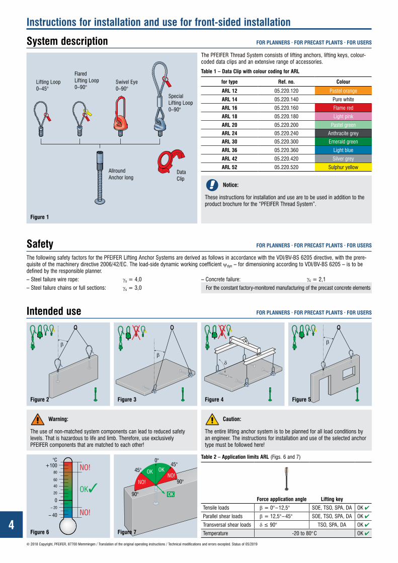
The PFEIFER Thread System consists of lifting anchors, lifting keys, colour-coded data clips and an extensive range of accessories.
Figure 1
Table 1 – Data Clip with colour coding for ARL
for type Ref. no. Colour
ARL 12 05.220.120 Pastel orange
ARL 14 05.220.140 Pure white
ARL 16 05.220.160 Flame red
ARL 18 05.220.180 Light pink
ARL 20 05.220.200 Pastel green
ARL 24 05.220.240 Anthracite grey
ARL 30 05.220.300 Emerald green
ARL 36 05.220.360 Light blue
ARL 42 05.220.420 Silver grey
ARL 52 05.220.520 Sulphur yellow
The following safety factors for the PFEIFER Lifting Anchor Systems are derived as follows in accordance with the VDI/BV-BS 6205 directive, with the prere-quisite of the machinery directive 2006/42/EC. The load-side dynamic working coefficient ψdyn – for dimensioning according to VDI/BV-BS 6205 – is to be defined by the responsible planner.– Steel failure wire rope: γs = 4,0 – Concrete failure: γc = 2,1 – Steel failure chains or full sections: γs = 3,0 For the constant factory-monitored manufacturing of the precast concrete elements
System description
Safety
Intended use
FOR PLANNERS · FOR PRECAST PLANTS · FOR USERS
FOR PLANNERS · FOR PRECAST PLANTS · FOR USERS
FOR PLANNERS · FOR PRECAST PLANTS · FOR USERS
Instructions for installation and use for front-sided installation
Caution:
The entire lifting anchor system is to be planned for all load conditions by an engineer. The instructions for installation and use of the selected anchor type must be followed here!
Warning:
The use of non-matched system components can lead to reduced safety levels. That is hazardous to life and limb. Therefore, use exclusively PFEIFER components that are matched to each other!
Figure 2 Figure 3 Figure 4 Figure 5
Figure 6 Figure 7
Table 2 – Application limits ARL (Figs. 6 and 7)
Force application angle Lifting key
Tensile loads β = 0° – 12,5° SOE, TSO, SPA, DA OK ✔
Parallel shear loads β = 12,5° – 45° SOE, TSO, SPA, DA OK ✔
Transversal shear loads δ ≤ 90° TSO, SPA, DA OK ✔
Temperature -20 to 80° C OK ✔
Notice:
These instructions for installation and use are to be used in addition to the product brochure for the “PFEIFER Thread System”.
Lifting Loop 0–45°
Flared Lifting Loop 0–90°
Swivel Eye 0–90°
Allround Anchor long
Special Lifting Loop 0–90°
Data Clip

5
dBr 0 – 30°
ds
L
Schrägzugbewehrung:Zusatzbewehrung, alle Abmessungen nach Tabelle 4
B500 Boder Edelstahl
δ
Radm
© 2018 Copyright, PFEIFER, 87700 Memmingen / Translation of the original operating instructions / Technical modifications and errors excepted. Status of 05/2019
FOR PLANNERS · FOR PRECAST PLANTS · FOR USERS
E ≤ Radm
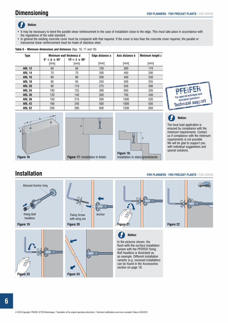
Dimensioning
Notice:
• All reinforcements listed in Table 3 refer to the local load application in the anchoring area.• The necessary reinforcement of the complete structural element must be defined by the responsible planner.• The minimum surface reinforcement is to be anchored in the area facing away from the load.• Already existing reinforcement can be counted towards the necessary minimum reinforcement according to Table 3.
Notice:
Determination of the stress E (fig. 8) according to VDI/BV-BS 6205.
Notice:
Fig. 11 shows the erection of a wall panel using a tilting table and the force application angle δ in case of transversal shear loads.
A transverse shear reinforcement only needs to be installed from a force application angle δ > 15°.
*2 Inspect reinforcing steel bars for cracks or damage after bending!
Notice: For simultaneous parallel and transversal shear loads only the transversal shear reinforcement as in Table 5 is required.
Figure 8
Figure 9 Figure 10
Figure 12 Figure 14Figure 13 Figure 15
Figure 11
Table 3 – Minimum surface and longitudinal reinforcement (figs. 9 and 10)
Type Minimum surface reinforcement Minimum longitudinal reinforcementItem Mesh type Mesh width b
[mm]Mesh height h
[mm]Item Quantity & bar ∅
[mm]
ARL 12 Pos. 1 Q188 300 450*1 – –ARL 14 Pos. 1 Q188 400 500*1 – –ARL 16 Pos. 1 Q188 400 500*1 – –ARL 18 Pos. 1 Q188 500 550*1 – –ARL 20 Pos. 1 Q188 550 550*1 – –ARL 24 Pos. 2 Q188 full surface – –ARL 30 Pos. 2 Q188 full surface – –ARL 36 Pos. 2 Q188 full surface Pos. 3 2 Ø 8ARL 42 Pos. 2 Q257 full surface Pos. 3 2 Ø 8ARL 52 Pos. 2 Q257 full surface Pos. 3 2 Ø 10
Table 4 – Parallel shear reinforcement in case of parallel shear loads with a force application angle of 12.5° ≤ δ < 45° (figs. 12 and 13)
Type ds dBr L12,5 – 30°
[mm]31 – 45° [mm]
12,5 – 30° [mm]
31 – 45° [mm]
[mm]
ARL 12 6 24 150ARL 14 6 24 200ARL 16 8 32 200ARL 18 8 32 250ARL 20 8 32 300ARL 24 10 40 300ARL 30 12 48 400ARL 36 12 14 48 56 550ARL 42 14 16 56 64 600ARL 52 16 20 64 90*2 750
Table 5 – Transversal shear reinforcement in case of transversal shear loads with a force application angle of 15° < δ ≤ 90° (figs. 11, 14 and 15)
Type ∅S1
[mm]
L
[mm]
h
[mm]
H
[mm]
D
[mm]
α
[°]
B
[mm]
∅S2
[mm]
ARL 12 6 270 23 35 24 15 280 8ARL 14 6 350 30 42 24 15 350 12ARL 16 8 420 33 49 32 15 400 12ARL 18 8 460 36 55 32 15 450 12ARL 20 10 490 44 64 40 15 490 14ARL 24 12 520 51 75 48 15 550 14ARL 30 12 570 68 92 48 15 580 16ARL 36 14 690 90 118 56 15 700 16ARL 42 16 830 111 143 64 15 850 20ARL 52 20 930 134 174 90*2 15 1000 20
*1 The specified mesh height h can be reduced by the planning of the back anchoring by an engineer (for example, mesh cages closed on both sides)
Angle of inclination Transversal shear loads perpendicular to the panel plane
B500 B or stainless steel
Transversal shear reinforcement: Additional reinforcement, all dimensions according to Table 5
Parallel shear reinforcement: Additional reinforcement, all dimensi-ons according to Table 4
B500 B or stainless steel
6© 2018 Copyright, PFEIFER, 87700 Memmingen / Translation of the original operating instructions / Technical modifications and errors excepted. Status of 05/2019
FOR PLANNERS · FOR PRECAST PLANTS · FOR USERSDimensioning
Figure 23 Figure 24
Notice:
• It may be necessary to bend the parallel shear reinforcement in the case of installation close to the edge. This must take place in accordance with the regulations of the valid standard.
• In general the existing concrete cover must be compared with that required. If the cover is less than the concrete cover required, the parallel or transversal shear reinforcement must be made of stainless steel.
Befestigungsschraubeohne Kopf
Allround-Anker lang
Fixierschraubemit Flügelmutter
Anker
FOR PLANNERS · FOR PRECAST PLANTS · FOR USERS
Table 6 – Minimum dimensions and distances (figs. 16, 17 and 18)
Type Minimum wall thickness d Edge distance a
[mm]
Axis distance b
[mm]
Minimum height z
[mm]0° < β ≤ 45°
[mm]15°< δ ≤ 90°
[mm]
ARL 12 60 60 150 300 170ARL 14 70 70 200 400 200ARL 16 80 80 200 400 230ARL 18 80 95 250 500 255ARL 20 90 110 275 550 300ARL 24 100 125 300 600 335ARL 30 120 140 350 700 430ARL 36 150 210 500 1000 535ARL 42 160 240 500 1000 630ARL 52 200 280 600 1200 850
Figure 16 Figure 17: Installation in lintelsFigure 18: Installation in stairs/grandstands
Figure 21 Figure 22
Notice:
The local load application is ensured by compliance with the minimum requirements. Contact us if compliance with the minimum requirements is not possible.We will be glad to support you with individual suggestions and special solutions.
Notice:
In the pictures shown, the flush-with-the-surface installation variant with the PFEIFER Fixing Bolt headless is illustrated as an example. Different installation variants (e.g. recessed installation) can be found in the Accessories section on page 18.
Installation
Allround Anchor long
Fixing Bolt headless
Fixing Screw with wing nut
Anchor
Figure 19 Figure 20
7© 2018 Copyright, PFEIFER, 87700 Memmingen / Translation of the original operating instructions / Technical modifications and errors excepted. Status of 05/2019
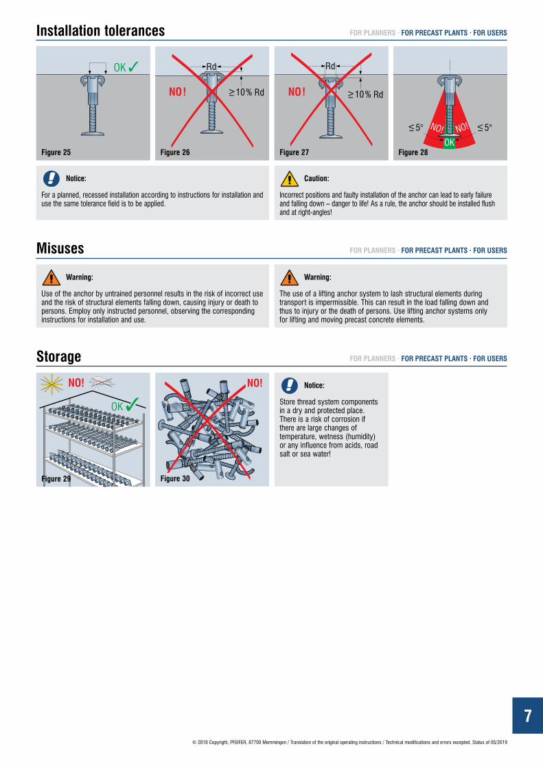
FOR PLANNERS · FOR PRECAST PLANTS · FOR USERSInstallation tolerances
Caution:
Incorrect positions and faulty installation of the anchor can lead to early failure and falling down – danger to life! As a rule, the anchor should be installed flush and at right-angles!
Figure 25
Figure 29
Figure 26
Figure 30
Figure 27 Figure 28
Misuses
Storage
FOR PLANNERS · FOR PRECAST PLANTS · FOR USERS
FOR PLANNERS · FOR PRECAST PLANTS · FOR USERS
Notice:
For a planned, recessed installation according to instructions for installation and use the same tolerance field is to be applied.
Notice:
Store thread system components in a dry and protected place. There is a risk of corrosion if there are large changes of temperature, wetness (humidity) or any influence from acids, road salt or sea water!
Warning:
Use of the anchor by untrained personnel results in the risk of incorrect use and the risk of structural elements falling down, causing injury or death to persons. Employ only instructed personnel, observing the corresponding instructions for installation and use.
Warning:
The use of a lifting anchor system to lash structural elements during transport is impermissible. This can result in the load falling down and thus to injury or the death of persons. Use lifting anchor systems only for lifting and moving precast concrete elements.

8© 2018 Copyright, PFEIFER, 87700 Memmingen / Translation of the original operating instructions / Technical modifications and errors excepted. Status of 05/2019
Notizen
www.pfeifer.info
Notes
9© 2018 Copyright, PFEIFER, 87700 Memmingen / Translation of the original operating instructions / Technical modifications and errors excepted. Status of 05/2019
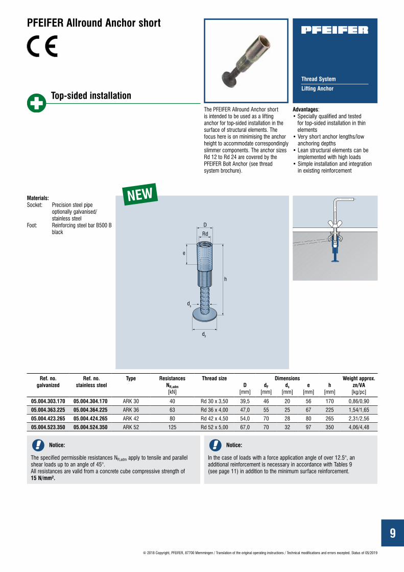
Thread System
Lifting Anchor
The PFEIFER Allround Anchor short is intended to be used as a lifting anchor for top-sided installation in the surface of structural elements. The focus here is on minimising the anchor height to accommodate correspondingly slimmer components. The anchor sizes Rd 12 to Rd 24 are covered by the PFEIFER Bolt Anchor (see thread system brochure).
Advantages: • Specially qualified and tested
for top-sided installation in thin elements
• Very short anchor lengths/low anchoring depths
• Lean structural elements can be implemented with high loads
• Simple installation and integration in existing reinforcement
NEW
Top-sided installation
PFEIFER Allround Anchor short
Materials:Socket: Precision steel pipe
optionally galvanised/ stainless steel
Foot: Reinforcing steel bar B500 B black
Ref. no. galvanized
Ref. no. stainless steel
Type Resistances Thread size Dimensions Weight approx. zn/VA [kg/pc]
NR,adm [kN]
D [mm]
dF
[mm]ds
[mm]e
[mm]h
[mm]
05.004.303.170 05.004.304.170 ARK 30 40 Rd 30 x 3,50 39,5 46 20 56 170 0,86/0,90
05.004.363.225 05.004.364.225 ARK 36 63 Rd 36 x 4,00 47,0 55 25 67 225 1,54/1,65
05.004.423.265 05.004.424.265 ARK 42 80 Rd 42 x 4,50 54,0 70 28 80 265 2,31/2,56
05.004.523.350 05.004.524.350 ARK 52 125 Rd 52 x 5,00 67,0 70 32 97 350 4,06/4,48
Notice:
The specified permissible resistances NR,adm apply to tensile and parallel shear loads up to an angle of 45°. All resistances are valid from a concrete cube compressive strength of 15 N/mm².
Notice:
In the case of loads with a force application angle of over 12.5°, an additional reinforcement is necessary in accordance with Tables 9 (see page 11) in addition to the minimum surface reinforcement.

10
β
© 2018 Copyright, PFEIFER, 87700 Memmingen / Translation of the original operating instructions / Technical modifications and errors excepted. Status of 05/2019
Table 7 – Data Clip with colour coding for ARK
The following safety factors for the PFEIFER Lifting Anchor Systems are derived as follows in accordance with the VDI/BV-BS 6205 directive, with the prerequisite of the machinery directive 2006/42/EC. The load-side dynamic working coefficient ψdyn – for dimensioning according to VDI/BV-BS 6205 – is to be defined by the responsible planner.– Steel failure wire rope: γs = 4,0 – Concrete failure: γc = 2,1– Steel failure chains or full sections: γs = 3,0 For the constant factory-monitored manufacturing of the precast concrete elements
System description
Safety
for type Ref. no. Colour
ARK 30 05.220.300 Emerald greenARK 36 05.220.360 Light blueARK 42 05.220.420 Silver greyARK 52 05.220.520 Sulphur yellow
The PFEIFER Thread System consists of lifting anchors, lifting keys, colour-coded data clips and an extensive range of accessories.
FOR PLANNERS · FOR PRECAST PLANTS · FOR USERS
FOR PLANNERS · FOR PRECAST PLANTS · FOR USERS
Instructions for installation and use for top-sided installation
Figure 31
Intended use FOR PLANNERS · FOR PRECAST PLANTS · FOR USERS
Table 8 – Application limits ARK (Figs. 33 and 34)
Caution:
The entire lifting anchor system is to be planned for all load conditions by an engineer. The instructions for installation and use of the selected anchor type must be followed here!
Warning:
The use of non-matched system components can cause reduced safety levels and hazards to life and limb. Use exclusively PFEIFER components that are matched to each other!
Figure 32
Figure 33Figure 34
Force application angle Lifting key
Tensile loads β = 0° – 12,5° SOE, TSO, SPA, DA OK ✔
Parallel shear loads β = 12,5° – 45° SOE, TSO, SPA, DA OK ✔
Parallel shear loads β > 45° *3 – NO!
Temperature -20 to 80° C OK ✔
*3 In the case of planned loads with a force application angle β > 45°, our professionals in the technical support are always at your disposal. Together with our team of technicians and engineers we can thus also implement individual applications. We look forward to your enquiry!
Notice:
These instructions for installation and use are to be used in addition to the product brochure for the “ PFEIFER Thread System”.
Lifting Loop 0–45°
Flared Lifting Loop 0–90°
Swivel Eye 0–90°
Allround Anchor short
Special Lifting Loop 0–90°
Data Clip
11
b
aa
d
dBr 0 – 30°
ds
Schrägzugbewehrung:Zusatzbewehrung, alle Abmessungen nach Tabelle 9
B500 Boder Edelstahl
L
Radm
© 2018 Copyright, PFEIFER, 87700 Memmingen / Translation of the original operating instructions / Technical modifications and errors excepted. Status of 05/2019
FOR PLANNERS · FOR PRECAST PLANTS · FOR USERSDimensioning
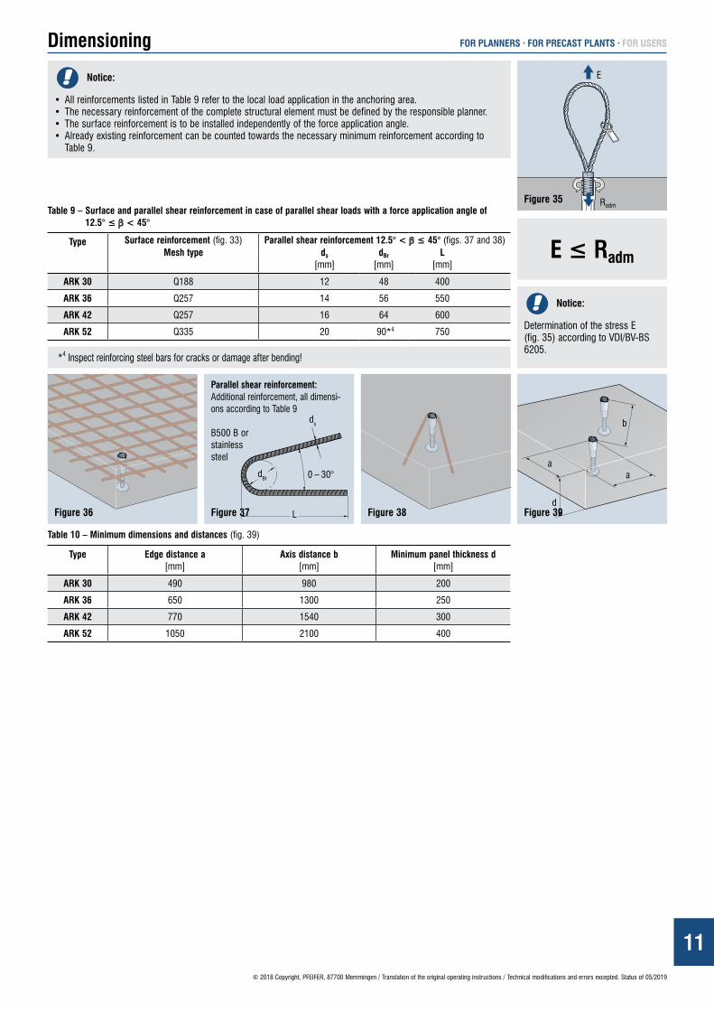
Notice:
• All reinforcements listed in Table 9 refer to the local load application in the anchoring area.• The necessary reinforcement of the complete structural element must be defined by the responsible planner.• The surface reinforcement is to be installed independently of the force application angle.• Already existing reinforcement can be counted towards the necessary minimum reinforcement according to
Table 9.
Figure 35
Figure 37Figure 36 Figure 38 Figure 39
Table 10 – Minimum dimensions and distances (fig. 39)
Type Edge distance a [mm]
Axis distance b [mm]
Minimum panel thickness d [mm]
ARK 30 490 980 200
ARK 36 650 1300 250
ARK 42 770 1540 300
ARK 52 1050 2100 400
Table 9 – Surface and parallel shear reinforcement in case of parallel shear loads with a force application angle of 12.5° ≤ β < 45°
Type Surface reinforcement (fig. 33) Parallel shear reinforcement 12.5° < β ≤ 45° (figs. 37 and 38)Mesh type ds
[mm]dBr
[mm]L
[mm]
ARK 30 Q188 12 48 400
ARK 36 Q257 14 56 550
ARK 42 Q257 16 64 600
ARK 52 Q335 20 90*4 750
*4 Inspect reinforcing steel bars for cracks or damage after bending!
E ≤ Radm
Notice:
Determination of the stress E (fig. 35) according to VDI/BV-BS 6205.
Parallel shear reinforcement: Additional reinforcement, all dimensi-ons according to Table 9
B500 B or stainless steel

12
Befestigungsschraubeohne Kopf
Allround-Anker kurz
© 2018 Copyright, PFEIFER, 87700 Memmingen / Translation of the original operating instructions / Technical modifications and errors excepted. Status of 05/2019
Figure 50
FOR PLANNERS · FOR PRECAST PLANTS · FOR USERSInstallation tolerances
Caution:
Incorrect positions and faulty installation of the anchor can lead to early failure and falling down – danger to life! As a rule, the anchor should be installed flush and at right-angles!
Figure 46 Figure 47 Figure 48 Figure 49
Notice:
For a planned, recessed installation according to instructions for installation and use the same tolerance field is to be applied.
Storage FOR PLANNERS · FOR PRECAST PLANTS · FOR USERS
Notice:
Store thread system components in a dry and protected place. There is a risk of corrosion if there are large changes of temperature, wetness (humidity) or any influence from acids, road salt or sea water!
Misuses FOR PLANNERS · FOR PRECAST PLANTS · FOR USERS
Warning:
Use of the anchor by untrained personnel results in the risk of incorrect use and the risk of structural elements falling down, causing injury or death to persons. Employ only instructed personnel, observing the corresponding instructions for installation and use.
Warning:
The use of a lifting anchor system to lash structural elements during trans-port is impermissible. This can result in the load falling down and thus to injury or the death of persons. Use lifting anchor systems only for lifting and moving precast concrete elements.
Installation FOR PLANNERS · FOR PRECAST PLANTS · FOR USERS
Figure 40 Figure 42
Figure 44
Figure 41 Figure 43
Figure 45
Notice:
In the pictures shown, the flush-with-the-surface installation variant with the PFEIFER Fixing Bolt headless is illustrated as an example. Different installation variants (e.g. recessed installation) can be found in the Accessories section on page 18.
Figure 51
Allround Anchor short
Fixing Bolt headless
Fixing Screw with wing nut
13© 2018 Copyright, PFEIFER, 87700 Memmingen / Translation of the original operating instructions / Technical modifications and errors excepted. Status of 05/2019
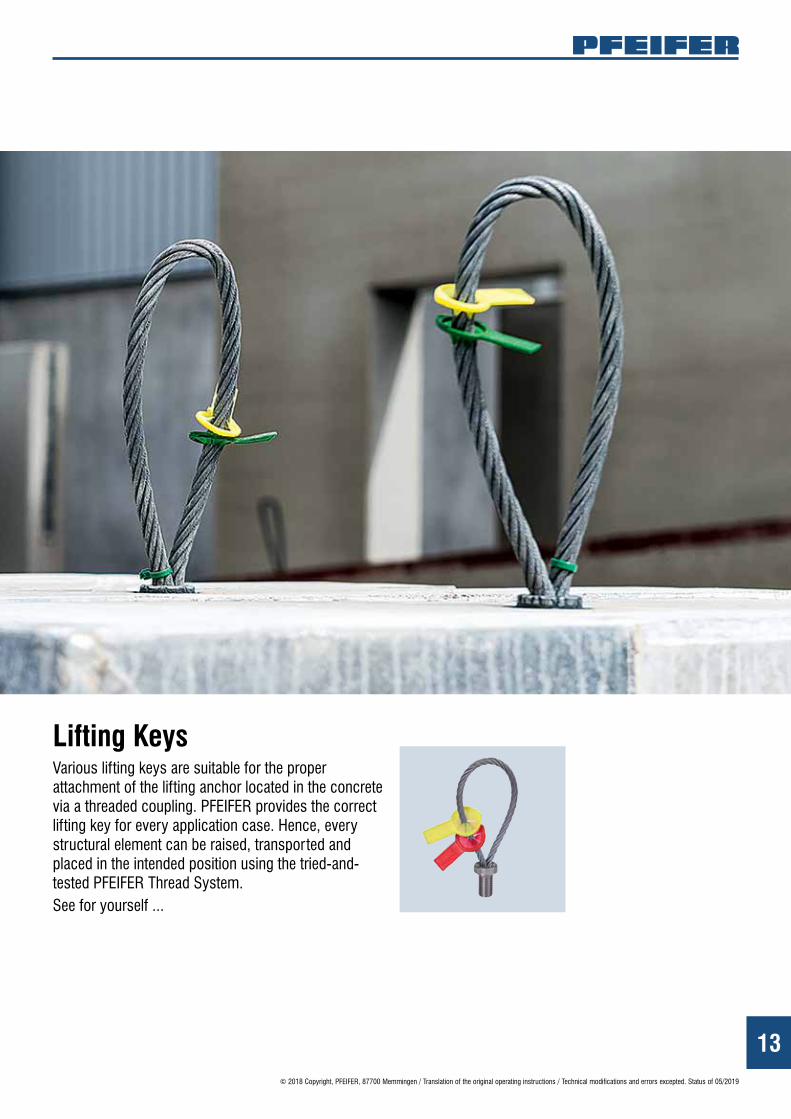
Lifting KeysVarious lifting keys are suitable for the proper attachment of the lifting anchor located in the concrete via a threaded coupling. PFEIFER provides the correct lifting key for every application case. Hence, every structural element can be raised, transported and placed in the intended position using the tried-and-tested PFEIFER Thread System.See for yourself ...

14© 2018 Copyright, PFEIFER, 87700 Memmingen / Translation of the original operating instructions / Technical modifications and errors excepted. Status of 05/2019
Lifting Keys
PFEIFER Lifting Loop SOE
• Usage range from 0–45° parallel shear loads
• Value for money through intelligent use of materials
• Robust round thread
• Safety through unambiguous colour coding
PFEIFER Lifting Loop waisted SOT
• Innovative through use in deep recesses
• Robust round thread
• Safety through unambiguous colour coding
PFEIFER Flared Lifting Loop TSO
• Flexible seamless application range from tensile to transversal shear loads
• Transverse shear loads possible on account of gentle deflection of the wire rope loop at the flared pressing
• Unique product on the market
• Value for money through intelligent use of materials
• Robust round thread
• Safety through unambiguous colour coding
15© 2018 Copyright, PFEIFER, 87700 Memmingen / Translation of the original operating instructions / Technical modifications and errors excepted. Status of 05/2019
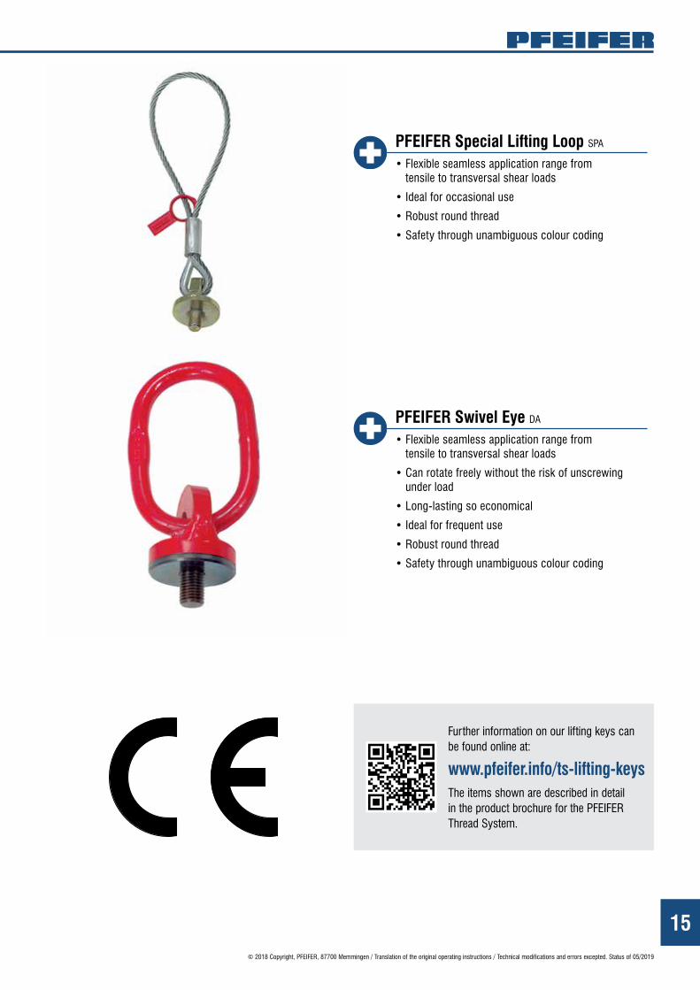
PFEIFER Special Lifting Loop SPA
• Flexible seamless application range from tensile to transversal shear loads
• Ideal for occasional use
• Robust round thread
• Safety through unambiguous colour coding
PFEIFER Swivel Eye DA
• Flexible seamless application range from tensile to transversal shear loads
• Can rotate freely without the risk of unscrewing under load
• Long-lasting so economical
• Ideal for frequent use
• Robust round thread
• Safety through unambiguous colour coding
Further information on our lifting keys can be found online at:
www.pfeifer.info/ts-lifting-keysThe items shown are described in detail in the product brochure for the PFEIFER Thread System.
16© 2018 Copyright, PFEIFER, 87700 Memmingen / Translation of the original operating instructions / Technical modifications and errors excepted. Status of 05/2019
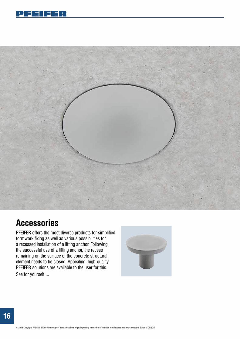
AccessoriesPFEIFER offers the most diverse products for simplified formwork fixing as well as various possibilities for a recessed installation of a lifting anchor. Following the successful use of a lifting anchor, the recess remaining on the surface of the concrete structural element needs to be closed. Appealing, high-quality PFEIFER solutions are available to the user for this.See for yourself ...
17© 2018 Copyright, PFEIFER, 87700 Memmingen / Translation of the original operating instructions / Technical modifications and errors excepted. Status of 05/2019
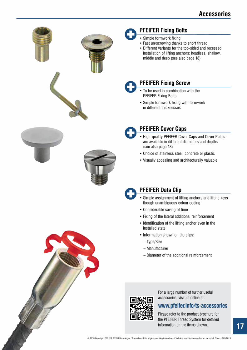
Accessories
PFEIFER Fixing Bolts• Simple formwork fixing • Fast un/screwing thanks to short thread • Different variants for the top-sided and recessed
installation of lifting anchors: headless, shallow, middle and deep (see also page 18)
PFEIFER Fixing Screw• To be used in combination with the
PFEIFER Fixing Bolts
• Simple formwork fixing with formwork in different thicknesses
PFEIFER Cover Caps• High-quality PFEIFER Cover Caps and Cover Plates
are available in different diameters and depths (see also page 18)
• Choice of stainless steel, concrete or plastic
• Visually appealing and architecturally valuable
PFEIFER Data Clip• Simple assignment of lifting anchors and lifting keys
though unambiguous colour coding
• Considerable saving of time
• Fixing of the lateral additional reinforcement
• Identification of the lifting anchor even in the installed state
• Information shown on the clips:
– Type/Size
– Manufacturer
– Diameter of the additional reinforcement
For a large number of further useful accessories, visit us online at:
www.pfeifer.info/ts-accessoriesPlease refer to the product brochure for the PFEIFER Thread System for detailed information on the items shown.

18© 2018 Copyright, PFEIFER, 87700 Memmingen / Translation of the original operating instructions / Technical modifications and errors excepted. Status of 05/2019
Combination possibilities FOR PLANNERS · FOR PRECAST PLANTS · FOR USERS
Installation by means of original accessories
Formwork fixing Usable Lifting Keys Possible closing/cap
Installed flush with the surface with headless fixing bolt or hex bolt.
Installed recessed 3–5 mm with fixing bolt shallow.
Installed recessed 10–15 mm with fixing bolt middle.
Installed recessed 30 mm with fixing bolt deep.
Installed recessed with magnetic disc or recess disc and fixing bolt middle.
Fixing Screw Formwork:WoodPlasticSteel
Fixing Bolt headless
Data Clip
Lifting Anchor
Fixing Screw Formwork:WoodPlasticSteel
Fixing Bolt shallow
Data Clip
Lifting Anchor
Fixing Screw Formwork:WoodPlasticSteel
Fixing Bolt middle
Data Clip
Lifting Anchor
Fixing Screw Formwork:WoodPlasticSteel
Fixing Bolt deep
Data Clip
Lifting Anchor
Fixing ScrewFormwork:WoodPlasticSteel
Fixing Bolt middle
Recess Disc
Magnetic Disc
Data Clip
Lifting Anchor
Außenstopfenklein
(Kunststoff)
Verschluss-schraube tief(Edelstahl)
Swivel Eye
Swivel Eye
Flared Lifting Loop
Flared Lifting Loop
Flared Lifting Loop
Flared Lifting Loop
Lifting Loop
Lifting Loop
Lifting Loop
Special Lifting Loop
External Cap small
(plastic)
External Cap small
(plastic)
External Cap small
(plastic)
External Cap small
(plastic)
External Cap short (plastic)
External Cap large (plastic)
Cover Plate concrete middle
Cover Plate (stainless steel/concrete large)
Cover Cap shallow
(stainless steel)
Cover Cap middle
(stainless steel)
Cover Cap deep
(stainless steel)
Special Lifting Loop

19© 2018 Copyright, PFEIFER, 87700 Memmingen / Translation of the original operating instructions / Technical modifications and errors excepted. Status of 05/2019
The manufacturer PFEIFER Seil- und Hebetechnik GmbH Dr.-Karl-Lenz-Straße 66 D-87700 Memmingen
edeclares that the load lifting attachments “PFEIFER Thread System” according to item 2d), consisting of the following system components:
PFEIFER Lifting Loop, Rd 12, 14, 16, 18, 20, 24, 30, 36, 42, 52 PFEIFER Flared Lifting Loop, Rd 16, 20, 24, 30, 36 PFEIFER Swivel Eye, Rd 12, 14, 16, 18, 20, 24, 30, 36, 42, 52, 56, 60 PFEIFER Special Lifting Loop, Rd 12, 14, 16, 18, 20, 24, 30, 36, 42, 52, 56, 60 PFEIFER Allround Anchor long, Rd 12, 14, 16, 18, 20, 24, 30, 36, 42, 52 PFEIFER Waved Anchor long, Rd 12, 14, 16, 18, 20, 24, 30, 36, 42, 52, 56, 60PFEIFER Bar Anchor, Rd 12, 14, 16, 18, 20, 24, 30, 36, 42, 52 PFEIFER Socket, Rd 12, 14, 16, 18, 20, 24, 30, 36, 42, 52 PFEIFER Waved Anchor short, Rd 12, 14, 16, 18, 20, 24, 30, 36, 42 PFEIFER Bolt Anchor, Rd 12, 14, 16, 18, 20, 24, 30 PFEIFER Allround Anchor short, Rd 30, 36, 42, 52 PFEIFER Flat Steel Anchor, Rd 12, 14, 16, 18, 20, 24, 30, 36, 42, 52 PFEIFER Bar Anchor cropped, Rd 20, 24, 30, 36, 42, 52 PFEIFER Repair Kit Rd 16, 20, 30
on the basis of their design and construction are compliant with the requirements of the directive 2006/42/EC of the European Parliament and the Council of 17th May 2006 concerning machines and with the amendment to the directive 95/16/EC (in short: EC machinery directive 2006/42/EC).
Applied harmonised standards– EN ISO 12100:2011-03
Safety of machinery – general design principles – risk assessment and risk reduction
Other applied standards or specifications– Directive VDI/BV-BS 6205:2012-04
Lifting anchors and lifting anchor systems for precast concrete elements Principles, dimensioning, applications
The person responsible for the creation and maintenance of the technical documentation is– Dipl.-Ing. Christoph Neef
Manager, Development Connecting and Lifting Systems, PFEIFER Seil- und Hebetechnik GmbH
PFEIFER Seil- und Hebetechnik GmbHMemmingen, 17.12.2018
Dipl.-Ing. Matthias Kintscher Dipl.-Ing. Christoph NeefBusiness Unit Manager, Connecting and Lifting Systems Manager, Development Connecting and Lifting Systems
EC Declaration of Conformityaccording to the EC machinery directive 2006/42/EC, appendix II 1A

05.1
9 AB
/LA
3981
81Co
ver:
© S
OMKK
U/Sh
utte
rsto
ck.c
om
The contact details of our locations and
sales partners can be found at
www.pfeifer.info/contacts-cls
We look forward to hearing from you!
Memmingen
Wrocław
Madrid
Budapest
Sibiu
Farsø
Nürnberg
Singapore
Dubai
Moscow
Barcelona
Praha
Riga
Chalezeule
Thame
Tallinn Kerava
This document is superseded when a new edition appears at www.pfeifer.info.
PFEIFERSEIL- UND HEBETECHNIKGMBH
DR.-KARL-LENZ-STRASSE 66D-87700 MEMMINGENPHONE Technical Support +49 83 31-937-345 Sales +49 83 31-937-231FAX +49 83 31-937-342E-MAIL [email protected] www.pfeifer.info