Service Instructions
48
1 DP 13 and 14 SEER PACKAGE HEAT PUMPS DP 13 and 14 PACKAGE COOLING HORIZONTAL MODELS WITH R-410A RSD6300011r3 April 2016 Service Instructions Copyright © 2013 - 2016 This manual is to be used by qualified, professionally trained HVAC technicians only. Daikin does not assume any responsibility for property damage or personal injury due to improper service procedures or services performed by an unqualified person.
-
Upload
khangminh22 -
Category
Documents
-
view
1 -
download
0
Transcript of Service Instructions

1
DP 13 and 14 SEER PACKAGE HEAT PUMPSDP 13 and 14 PACKAGE COOLING
HORIZONTAL MODELSWITH R-410A
RSD6300011r3April 2016
Service Instructions
Copyright © 2013 - 2016
This manual is to be used by qualified, professionally trained HVAC technicians only. Daikin doesnot assume any responsibility for property damage or personal injury due to improper serviceprocedures or services performed by an unqualified person.
2
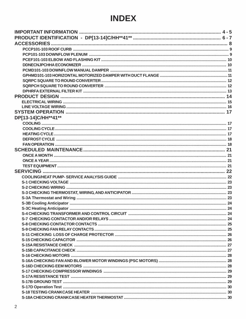
IMPORTANT INFORMATION ......................................................................................................... 4 - 5PRODUCT IDENTIFICATION - DP[13-14]C/HH**41** ................................................................. 6 - 7ACCESSORIES ................................................................................................................................... 8
PCCP101-103 ROOF CURB .......................................................................................................................................... 9PCP101-103 DOWNFLOW PLENUM ............................................................................................................................ 9PCEF101-103 ELBOW AND FLASHING KIT ............................................................................................................... 10DDNECNJPCHHA ECONOMIZER ................................................................................................................................ 10PCMD101-103 DOWNFLOW MANUAL DAMPER ........................................................................................................11GPHMD101-103 HORIZONTAL MOTORIZED DAMPER WITH DUCT FLANGE ............................................................11SQRPC SQUARE TO ROUND CONVERTER............................................................................................................... 12SQRPCH SQUARE TO ROUND CONVERTER ............................................................................................................ 12DPHRFA EXTERNAL FILTER KIT ............................................................................................................................... 13
PRODUCT DESIGN .......................................................................................................................... 14ELECTRICAL WIRING ................................................................................................................................................. 15LINE VOLTAGE WIRING .............................................................................................................................................. 16
SYSTEM OPERATION ...................................................................................................................... 17DP[13-14]C/HH**41**
COOLING .................................................................................................................................................................... 17COOLING CYCLE........................................................................................................................................................ 17HEATING CYCLE......................................................................................................................................................... 17DEFROST CYCLE ....................................................................................................................................................... 18FAN OPERATION ........................................................................................................................................................ 18
SCHEDULED MAINTENANCE......................................................................................................... 21ONCE A MONTH ......................................................................................................................................................... 21ONCE A YEAR ............................................................................................................................................................. 21TEST EQUIPMENT ...................................................................................................................................................... 21
SERVICING ....................................................................................................................................... 22COOLING/HEAT PUMP- SERVICE ANALYSIS GUIDE ................................................................................................ 22S-1 CHECKING VOLTAGE ........................................................................................................................................... 23S-2 CHECKING WIRING .............................................................................................................................................. 23S-3 CHECKING THERMOSTAT, WIRING, AND ANTICIPATOR .................................................................................... 23S-3A Thermostat and Wiring ..................................................................................................................................... 23S-3B Cooling Anticipator ........................................................................................................................................... 24S-3C Heating Anticipator ........................................................................................................................................... 24S-4 CHECKING TRANSFORMER AND CONTROL CIRCUIT ....................................................................................... 24S-7 CHECKING CONTACTOR AND/OR RELAYS ........................................................................................................ 24S-8 CHECKING CONTACTOR CONTACTS .................................................................................................................. 25S-9 CHECKING FAN RELAY CONTACTS ..................................................................................................................... 25S-11 CHECKING LOSS OF CHARGE PROTECTOR ................................................................................................... 26S-15 CHECKING CAPACITOR ..................................................................................................................................... 26S-15A RESISTANCE CHECK ....................................................................................................................................... 27S-15B CAPACITANCE CHECK ..................................................................................................................................... 27S-16 CHECKING MOTORS .......................................................................................................................................... 28S-16A CHECKING FAN AND BLOWER MOTOR WINDINGS (PSC MOTORS) ............................................................ 28S-16D CHECKING EEM MOTORS ............................................................................................................................... 28S-17 CHECKING COMPRESSOR WINDINGS ............................................................................................................. 29S-17A RESISTANCE TEST .......................................................................................................................................... 29S-17B GROUND TEST ................................................................................................................................................. 29S-17D Operation Test ................................................................................................................................................. 30S-18 TESTING CRANKCASE HEATER ........................................................................................................................ 30S-18A CHECKING CRANKCASE HEATER THERMOSTAT ........................................................................................... 30
INDEX

3
INDEXS-21 CHECKING REVERSING VALVE AND SOLENOID .............................................................................................. 30S-24 TESTING DEFROST CONTROL .......................................................................................................................... 31S-25 TESTING DEFROST THERMOSTAT.................................................................................................................... 31S-50 CHECKING HEATER LIMIT CONTROL(S) ........................................................................................................... 31S-52 CHECKING HEATER ELEMENTS ........................................................................................................................ 31S-100 REFRIGERATION REPAIR PRACTICE............................................................................................................... 32S-101 LEAK TESTING ................................................................................................................................................. 32S-102 EVACUATION..................................................................................................................................................... 32S-103 CHARGING ........................................................................................................................................................ 33S-104 CHECKING COMPRESSOR EFFICIENCY ......................................................................................................... 34S-108 SUPERHEAT ...................................................................................................................................................... 34S-109 CHECKING SUBCOOLING ................................................................................................................................ 35S-111 FIXED ORIFICE RESTRICTION DEVICES ......................................................................................................... 35S-112 CHECKING RESTRICTED LIQUID LINE ............................................................................................................ 36S-113 REFRIGERANT OVERCHARGE ......................................................................................................................... 36S-114 NON-CONDENSABLES ...................................................................................................................................... 36S-115 COMPRESSOR BURNOUT ................................................................................................................................ 39S-122 REVERSING VALVE REPLACEMENT................................................................................................................ 39S-200 CHECKING EXTERNAL STATIC PRESSURE .................................................................................................... 40S-201 CHECKING TEMPERATURE RISE ..................................................................................................................... 40
WIRING DIAGRAMS .......................................................................................................................... 41OT18-60A OUTDOOR THERMOSTAT ......................................................................................................................... 41OT18-60A OUTDOOR THERMOSTAT ......................................................................................................................... 42SINGLE PHASE HKR** HEAT KITS ............................................................................................................................ 43PCE* ECONOMIZER .................................................................................................................................................... 44
SPK* - SINGLE POINT WIRING KIT ........................................................................................................................... 45UNIT WIRING DIAGRAMS .......................................................................................................................................... 46

4
CONSUMER INFORMATION LINE - DAIKIN BRAND PRODUCTSTOLL FREE 1-855-770-5648 (U.S. only)
email us at: [email protected] us at: (713) 856-1821
(Not a technical assistance line for dealers.)
Outside the U.S., call 1-713-861-2500(Not a technical assistance line for dealers.)
Your telephone company will bill you for the call.
Pride and workmanship go into every product to provide our customers with quality products. It is possible, however, thatduring its lifetime a product may require service. Products should be serviced only by a qualified service technician whois familiar with the safety procedures required in the repair and who is equipped with the proper tools, parts, testinginstruments and the appropriate service manual. REVIEW ALL SERVICE INFORMATION IN THE APPROPRIATESERVICE MANUAL BEFORE BEGINNING REPAIRS.
IMPORTANT NOTICES FOR CONSUMERS AND SERVICERSRECOGNIZE SAFETY SYMBOLS, WORDS AND LABELS
WARNING
TO PREVENT THE RISK OF PROPERTY DAMAGE, PERSONAL INJURY, OR DEATH,DO NOT STORE COMBUSTIBLE MATERIALS OR USE GASOLINE OR OTHERFLAMMABLE LIQUIDS OR VAPORS IN THE VICINITY OF THIS APPLIANCE.
IMPORTANT INFORMATION
To locate an authorized servicer, please consult your telephone book or the dealer from whom you purchased thisproduct. For further assistance, please contact:
This unit should not be connected to, or used in conjunction with, any devices that are not design certified for use with thisunit or have not been tested and approved by Daikin. Serious property damage or personal injury, reduced unit performanceand/or hazardous conditions may result from use of devices that have not been approved or certified by Daikin.
ONLY PERSONNEL THAT HAVE BEEN TRAINED TO INSTALL, ADJUST, SERVICE OR REPAIR (HEREINAFTER, “SERVICE”) THE EQUIPMENT SPECIFIED IN THIS MANUAL SHOULD SERVICE THE EQUIPMENT. THE MANUFACTURER WILL NOT BE RESPONSIBLE FOR ANY INJURY OR PROPERTY DAMAGE ARISING FROM IMPROPER SERVICE OR SERVICE PROCEDURES. IF YOU SERVICE THIS UNIT, YOU ASSUME RESPONSIBILITY FOR ANY INJURY OR PROPERTY DAMAGE WHICH MAY RESULT. IN ADDITION, IN JURISDICTIONS THAT REQUIRE ONE OR MORE LICENSES TO SERVICE THE EQUIPMENT SPECIFIED IN THIS MANUAL, ONLY LICENSED PERSONNEL SHOULD SERVICE THE EQUIPMENT. IMPROPER INSTALLATION, ADJUSTMENT, SERVICING OR REPAIR OF THE EQUIPMENT SPECIFIED IN THIS MANUAL, OR ATTEMPTING TO INSTALL, ADJUST, SERVICE OR REPAIR THE EQUIPMENT SPECIFIED IN THIS MANUAL WITHOUT PROPER TRAINING MAY RESULT IN PRODUCT DAMAGE, PROPERTY DAMAGE, PERSONAL INJURY OR DEATH.

5
The successful development of hermetically sealed refrig-eration compressors has completely sealed the compressor'smoving parts and electric motor inside a common housing,minimizing refrigerant leaks and the hazards sometimes as-sociated with moving belts, pulleys or couplings.Fundamental to the design of hermetic compressors is amethod whereby electrical current is transmitted to the com-pressor motor through terminal conductors which passthrough the compressor housing wall. These terminals aresealed in a dielectric material which insulates them from thehousing and maintains the pressure tight integrity of the her-metic compressor. The terminals and their dielectric em-bedment are strongly constructed, but are vulnerable to care-less compressor installation or maintenance procedures andequally vulnerable to internal electrical short circuits causedby excessive system contaminants.
SAFE REFRIGERANT HANDLINGWhile these items will not cover every conceivable situation, they should serve as a useful guide.
In either of these instances, an electrical short between theterminal and the compressor housing may result in the lossof integrity between the terminal and its dielectric embed-ment. This loss may cause the terminals to be expelled,thereby venting the vaporous and liquid contents of the com-pressor housing and system.A venting compressor terminal normally presents no dangerto anyone, providing the terminal protective cover is properlyin place.If, however, the terminal protective cover is not properly inplace, a venting terminal may discharge a combination of
(a) hot lubricating oil and refrigerant(b) flammable mixture (if system is contaminated
with air)in a stream of spray which may be dangerous to anyone inthe vicinity. Death or serious bodily injury could occur.Under no circumstances is a hermetic compressor to be elec-trically energized and/or operated without having the terminalprotective cover properly in place.See Service Section S-17 for proper servicing.
IMPORTANT INFORMATION
WARNING
REFRIGERANTS ARE HEAVIER THAN AIR. THEY CAN "PUSH OUT" THEOXYGEN IN YOUR LUNGS OR IN ANY ENCLOSED SPACE. TO AVOIDPOSSIBLE DIFFICULTY IN BREATHING OR DEATH:•NEVER PURGE REFRIGERANT INTO AN ENCLOSED ROOM OR SPACE. BY LAW, ALL REFRIGERANTS MUST BE RECLAIMED.•IF AN INDOOR LEAK IS SUSPECTED, THOROUGHLY VENTILATE THE AREA BEFORE BEGINNING WORK.•LIQUID REFRIGERANT CAN BE VERY COLD. TO AVOID POSSIBLE FROST- BITE OR BLINDNESS, AVOID CONTACT WITH REFRIGERANT AND WEAR GLOVES AND GOGGLES. IF LIQUID REFRIGERANT DOES CONTACT YOUR SKIN OR EYES, SEEK MEDICAL HELP IMMEDIATELY.•ALWAYS FOLLOW EPA REGULATIONS. NEVER BURN REFRIGERANT, AS POISONOUS GAS WILL BE PRODUCED.
WARNING
SYSTEM CONTAMINANTS, IMPROPER SERVICE PROCEDURE AND/OR PHYSICALABUSE AFFECTING HERMETIC COMPRESSOR ELECTRICAL TERMINALS MAYCAUSE DANGEROUS SYSTEM VENTING.
WARNING
TO AVOID POSSIBLE INJURY, EXPLOSION OR DEATH, PRACTICE SAFEHANDLING OF REFRIGERANTS.
WARNING
TO AVOID POSSIBLE EXPLOSION, USE ONLY RETURNABLE (NOT DISPOSABLE)SERVICE CYLINDERS WHEN REMOVING REFRIGERANT FROM A SYSTEM.• ENSURE THE CYLINDER IS FREE OF DAMAGE WHICH COULD LEAD TO A LEAK OR EXPLOSION.• ENSURE THE HYDROSTATIC TEST DATE DOES NOT EXCEED 5 YEARS.• ENSURE THE PRESSURE RATING MEETS OR EXCEEDS 400 LBS.
WHEN IN DOUBT, DO NOT USE CYLINDER.
WARNING
TO AVOID POSSIBLE EXPLOSION:• NEVER APPLY FLAME OR STEAM TO A REFRIGERANT CYLINDER. IF YOU MUST HEAT A CYLINDER FOR FASTER CHARGING, PARTIALLY IMMERSE IT IN WARM WATER.• NEVER FILL A CYLINDER MORE THAN 80% FULL OF LIQUID REFRIGERANT.• NEVER ADD ANYTHING OTHER THAN R-22 TO AN R-22 CYLINDER OR R-410A TO AN R-410A CYLINDER. THE SERVICE EQUIPMENT USED MUST BE LISTED OR CERTIFIED FOR THE TYPE OF REFRIGERANT USED.• STORE CYLINDERS IN A COOL, DRY PLACE. NEVER USE A CYLINDER AS A PLATFORM OR A ROLLER.

PRODUCT IDENTIFICATION
6
The model number is used for positive identification of component parts used in manufacturing. Please use this number whenrequesting service or parts information.
D P 1 3 C H 2 4 4 1 A A
Brand Engineering D - Daikin Minor revision
Product Type Engineering P - Packaged Major revision
VoltageSEER 1 - 208/230 V single phase 60 Hz13 - 13 SEER 2 - 220/240 V single phase 50 Hz14 - Up to 14 SEER 3 - 208/230 V three phase 60 Hz15 - Up to 15 SEER 4 - 460 V three phase 60 Hz
5 - 380/415 V three phase 50 HzUnit TypeH - Heat Pump RefrigerantC - Air Conditioner 4 - R-410A
Configuration Tonnage NominalM - Multi-position 24 - 2 ton 42 - 3.5 tonH - Horizontal 30 - 2.5 ton 48 - 4.0 ton
36 - 3 ton 60 - 5 ton

PRODUCT IDENTIFICATION
7
Model # Package Cooling Description
DP13CH[24-60]41** Daikin Package Cooling up to 13 Seer R410A Horizontal electric cooling unit. Initial release of 208-230/1/60 single phase models.
DP14CH[24-60]41** Daikin Package Cooling up to 14 Seer R410A Horizontal electric cooling unit. Initial release of 208-230/1/60 single phase models.
DP14CH24-3041BBDP14CH3641AC
DP14CH42-6041BB
Daikin Package Cooling up to 14 Seer R410A Horizontal electric cooling unit, 208-230/1/60 single phase models. Converted Aluminum coils with 3/8" return bends/crossovers to Aluminum coils using 9mm return bends/crossovers.
DP14CH24-3041BCDP14CH3641AD
DP14CH42-6041BC
Daikin Package Cooling up to 14 Seer R410A Horizontal electric cooling unit, 208-230/1/60 single phase models. Release of models with access box removed.
Model # Package Heat Pump Description
DP13HH[24-60]41** Daikin Package Heat Pump up to 13 Seer R410A Horizontal heat pump unit. Initial release of 208-230/1/60 single phase models.
DP14HH[24-60]41** Daikin Package Heat Pump up to 14 Seer R410A Horizontal heat pump unit. Initial release of 208-230/1/60 single phase models.
DP14HH24-3641ACDP14HH42-6041BB
Daikin Package Heat Pump up to 14 Seer R410A Horizontal heat pump unit, 208-230/1/60 single phase models. Converted Aluminum coils with 3/8" return bends/crossovers to Aluminum coils using 9mm return bends/crossovers.
DP14HH24-3641ADDP14HH42-6041BC
Daikin Package Heat Pump up to 14 Seer R410A Horizontal heat pump unit, 208-230/1/60 single phase models. Release of models with access box removed.
DP14HH6041CADaikin Package Heat Pump up to 14 Seer R410A Horizontal heat pump unit, 208-230/1/60 single phase models. - Develop and release 14 SEER 5 Ton H model heat pump with new 7 mm condenser coil.

ACCESSORIES
8
CH70TG Manual Changeover Digital, Nonprogrammable 1 Heat - 1 CoolCHSATG Manual Changeover Mechanical, Nonprogrammable 1 Heat - 1 Cool
CHT18-60 Manual Changeover Mechanical, Nonprogrammable 1 Heat - 1 CoolCHT90-120 Manual Changeover Mechanical, Nonprogrammable 2 Heat - 2 Cool
CHTP18-60HD Manual Changeover Digital, Nonprogrammable 2 Heat - 1 CoolCT18-60 Manual Changeover Mechanical, Nonprogrammable Cool Only
THERMOSTATS
DP[13-14]CH/HH**41**
1213401 White Manual Changeover 5 + 2 Programming Digital 1 Heat - 1 Cool1213402 White Manual Changeover Nonprogrammable Digital 1 Heat - 1 Cool1213403 White Manual Changeover 7 Day Programming Digital 2 Heat - 1 Cool1213404 White Manual Changeover Nonprogrammable Digital 2 Heat - 1 Cool1213406 Beige Manual/Auto Changeover 5 + 2 Programming Digital 3 Heat - 2 Cool1213407 White Manual Changeover 5 + 2 Programming Digital 2 Heat - 2 Cool1213408 White Manual/Auto Changeover 7 Day Programming Digital 1 Heat - 1 Cool1213410 White Manual Changeover 5 + 2 Programming Digital 2 Heat - 1 Cool1213411 White Manual Changeover Nonprogrammable Digital 2 Heat - 2 Cool1213412 White Manual/Auto Changeover 7 Day Programming Digital 3 Heat - 2 Cool1213431 White Manual/Auto Changeover 7 Day Programming Digital 3 Heat - 2 Cool
THERMOSTATS
Part Number DescriptionPCCP101-103 14" Roof Curb for Daikin H- Series Package Unit All Chasis Requires PCP101-103
PCP101-103 Downflow Plenum Kit for Daikin H- Series Package Units All Chassis. Requires PCCP101-103
PCP101-103R8Downflow Plenum Kit for Daikin H- Series Package Units w/ R-8 Insulation Liner All Chassis. Requires PCCP101-103
PCMD101-103 Manual Damper for Daikin H-Series Package Units. Requires PCP101-103
PCMDM101-103 Motorized Damper for Daikin H- Series Package Units. Requires PCP101-103
GPHMD101-103 Horizontal Manual Damper for Daikin H- Series Package Unit Horizontal Applications All Chassis
SQRPCH101 Horizontal Square to Round Adapters for H- Series Package Unit 16"&14" Round.
SQRPCH102-103 Horizontal Square to Round Adapters for H- Series Package Unit 18"&14"
SQRPC101Downflow Square to Round Adapter for H- Series Package Unit 16" Rounds. Requires PCCP101-103 and PCP101-103
SQRPC102-103Downflow Square to Round Adapter for H- Series Package Unit 18" Rounds. Requires PCCP101-103 and PCP101-103
DPHFRA External Horizontal Filter Rack for Daikin M- and H- Series Package Units
PCEF101-103 Elbow & Flashing w/ R-8 Liner for Daikin H- Series Package Unit All Chassis
CDK36 3 Ton Concentric Duct Kit
CDK36515 3 Ton Flush Mount Concentric Duct Kit w/ Filter
CDK36530 3 Ton Step Down Concentric Duct Kit
CDK36535 3 Ton Step Down Concentric Duct Kit w/ Filter
CDK4872 4 - 6 Ton Concentric Duct Kit
CDK4872515 4 - 6 Ton Flush Mount Concentric Duct Kit w/ Filter
CDK4872530 4 - 6 Ton Step Down Concentric Duct KitCDK4872535 4 - 6 Ton Step Down Concentric Duct Kit w/ Filter
DDNECNJPCHHA Downflow Economizer H-Series Package Unit. Requires PCP101-103.
DHZECNJPGCHM Economizer H-Series Daikin Package Unit
ACCESSORIES - DP**C/DP**H**** MODELS

ACCESSORIES
9
PCCP101-103 ROOF CURB
PCP101-103 DOWNFLOW PLENUM(Use with PCCP Roof Curb)
64"
33"
26"
33"
59"
14" RoofCurb
31"
29 3/4"
29 3/8"
13"
13"
28 3/4"
37"
25 1/2"33"
1" Flange
DP[13-14]CH/HH**41A*

ACCESSORIES
10
A B C D E F
20 16.25 16 23.5 12.5 45.75
BA
F
D
E
C
DDNECNJPCHHA ECONOMIZER*(DOWNFLOW APPLICATIONS)
PCEF101-103 ELBOW AND FLASHING KIT
25"8"
4"
4"
3"
33"
25"
28"35"
DP[13-14]CH/HH**41A*
Model Used With
DDNECNJPCHHA
H-SERIES DAIKIN PACKAGE UNIT. REQUIRES PCP101-103

ACCESSORIES
11
PCMD101-103 DOWNFLOW MANUAL DAMPER*PCMDM101-103 DOWNFLOW MOTORIZED DAMPER*
*USED WITH PCP101-103 DOWNFLOW PLENUM
18"
29 3/4"
6"10"
12 1/8"
MODEL DESCRIPTION
PCMDH101-103 Manual Damper
PCMDM101-103 Motorzied Damper
DP[13-14]CH/HH**41A*DHZECNJPGCHM ECONOMIZER*(HORIZONTAL APPLICATIONS)
FILTER ACCESS
PANELA B C D E F G
PGEH101/102 25.25 18.125 18 16 10.375 13.75 16.125
PGEH103 35.25 18.125 18 16 15.875 18.25 16.125
D C
B
A
F
E
G
SHIPPED WITH 16 X 25 X 1" FILTER AND
14.5 X 15.5 MIST ELIMINATOR INSTALLED
Shipped with 16 x 25 x 1" Filter and 14.5 x 15.5 Mist Eliminator Installed
ECONOMIZER A B C D E F G
DHZECNJPGCHM 25.25 18.125 18 16 10.375 13.75 16.125

ACCESSORIES
12
SQRPC SQUARE TO ROUND CONVERTER(DOWNFLOW APPLICATIONS)
1 1/2"
29 1/2" 29 1/4"
RA
SA
1" FLANGES
SQRPC101 SQRP102-103SA 16" 18"RA 16" 18"
DP[13-14]CH/HH**41A*GPHMD101-103 HORIZONTAL MANUAL DAMPER WITH DUCT FLANGE
6"2"
12"
25 1
/4" 17"
17 1
/4"
18"8 1/4"

ACCESSORIES
13
14" x 25" x 2" FILTER
DPHFRA EXTERNAL FILTER KIT(HORIZONTAL APPLICATIONS)
SQRPCH SQUARE TO ROUND CONVERTER(HORIZONTAL APPLICATIONS)
OUTER FLANGE
STARTER FLANGE
BEAD
SQUARE TO ROUNDDUCT CONVERTER PANEL
SQRPCH-101 SQRPCH-102 SQRPCH-103 SQRPCH102-14 SQRPCH103-14A 15" 17" 17" 15" 15"B 15" 17" 17" 15" 15"C 17" 17" 19" 15" 15"D 22 1/2" 24 1/2" 24 1/2" 24 1/2" 24 1/2"
SUPPLY 14" 16" 16" 14" 14"RETURN 16" 16" 18" 14" 14"
A
B
2" SUPPLY
RETURN
C
D
2"
DP[13-14]CH/HH**41A*

PRODUCT DESIGN
14
LOCATION & CLEARANCES
NOTE: To ensure proper condensate drainage, unit must be in-stalled in a level position.
In installations where the unit is installed above ground leveland not serviceable from the ground (Example: Roof Topinstallations) the installer must provide a service platform forthe service person with rails or guards in accordance with localcodes or ordinances.
36"
36"
10"
UNIT
WALL36"
48” MIN.
DP[13-14]CH/DP[13-14]HH**41*
NOTE: Roof overhang should be no more than 36" andprovisions made to deflect the warm discharge air out from theoverhang.
Minimum clearances are required to avoid air recirculation andkeep the unit operating at peak efficiency.
WARNINGTO PREVENT POSSIBLE DAMAGE, THE UNIT SHOULDREMAIN IN AN UPRIGHT POSITION DURING ALLRIGGING AND MOVING OPERATIONS. TO FACILITATELIFTING AND MOVING IF A CRANE IS USED, PLACETHE UNIT IN AN ADEQUATE CABLE SLIDE.
Refer to Roof Curb Installation Instructions for proper curbinstallation. Curbing must be installed in compliance with theNational Roofing Contractors Association Manual.Lower unit carefully onto roof mounting curb. While riggingunit, center of gravity will cause condenser end to be lowerthan supply air end.
Roof Curb and Platform
DP[13-14]CH/DP[13-14]HH**41*
DPCH/DPHH Package Units are designed for outdoor installa-tions only in either residential or light commercial applications.
NOTE: To ensure proper condensate drainage, unit must beinstalled in a level position.The connecting ductwork (Supply and Return) can be connectedfor horizontal discharge airflow. In the down discharge applica-tions, a matching Platform/Roof Curb (PCCP) and DownflowPlenum (PCP101-103) is recommended for horizontal modelsonly.A return air filter must be installed behind the return air grille(s)or provision must be made for a filter in an accessible locationwithin the return air duct. The minimum filter area should notbe less than those sizes listed in the Specification Section.Under no circumstances should the unit be operated withoutreturn air filters.A 3/4" - 14 NPT drain connector is provided for removal of con-densate water from the indoor coil. In order to provide propercondensate flow, do not reduce the drain line size.Refrigerant flow control is achieved by use of restrictor orifices.These models use the FasTest Access Fitting System, with asaddle that is either soldered to the suction and liquid lines oris fastened with a locking nut to the access fitting box (core)and then screwed into the saddle. Do not remove the corefrom the saddle until the refrigerant charge has beenremoved. Failure to do so could result in property dam-age or personal injury.The single phase units use permanent split capacitors (PSC)design compressors. Starting components are therefore notrequired. A low MFD run capacitor assists the compressor tostart and remains in the circuit during operation.The outdoor fan motors are single phase capacitor type mo-tors.

PRODUCT DESIGN
15
Air for condensing (cooling) is drawn through the outdoor coilby a propeller fan, and is discharged vertically out the top ofthe unit. The outdoor coil is designed for .0 static. No addi-tional restriction (ductwork) shall be applied.Conditioned air is drawn through the filter(s), field installed,across the evaporator coil and back into the conditioned spaceby the indoor blower.
COMPRESSORSSome DPCH/DPHH series package units use the CompliantScroll compressor, instead of traditional reciprocating com-pressors. Still other models use reciprocating compressors.A scroll is an involute spiral which, when matched with a mat-ing scroll form as shown, generates a series of crescent shapedgas pockets between the two members.During compression, one scroll remains stationary (fixed scroll)while the other form (orbiting scroll) is allowed to orbit (but notrotate) around the first form.
As this motion occurs, the pockets between the two forms areslowly pushed to the center of the two scrolls while simulta-neously being reduced in volume. When the pocket reachesthe center of the scroll form, the gas, which is now at a highpressure, is discharged out of a port located at the center.During compression, several pockets are being compressedsimultaneously, resulting in a very smooth process. Both thesuction process (outer portion of the scroll members) and thedischarge process (inner portion) are continuous.Some design characteristics of the Compliant Scroll compres-sor are:• Compliant Scroll compressors are more tolerant of liquid
refrigerant.NOTE: Even though the compressor section of a Scrollcompressor is more tolerant of liquid refrigerant, continuedfloodback or flooded start conditions may wash oil from thebearing surfaces causing premature bearing failure.
• Compliant Scroll compressors use "POE" or polyolesteroil, which is NOT compatible with mineral oil based lubri-cant like 3GS. "POE" oil must be used if additional oil isrequired.
• Compliant scroll compressors perform "quiet" shutdownsthat allow the compressor to restart immediately withoutthe need for a time delay. This compressor will restart evenif the system has not equalized.
NOTE: Operating pressures and amp draws may differ fromstandard reciprocating compressors. This information canbe found in the unit's Technical Information Manual.
INDOOR BLOWER MOTORSome DPCH/DPHH model package units use a EEM blowermotor while others use the standard PSC type blower motor.The EEM motor is a 3 Phase brushless DC (single phase ACinput), ball bearing construction motor with an integral controlmodule with an internal FCC B EMI filter.The EEM motor is continuously powered with line voltage. Theswitched 24 volt control signal is controlled by the thermostatin the cooling and heat pump mode and the blower relay in theelectric heat mode.
ELECTRICAL WIRINGThe units are designed for operation at the voltages and hertzas shown on the rating plate. All internal wiring is complete.Ensure the power supply to the compressor contactor is broughtto the unit as shown on the supplied unit wiring diagram. The24V wiring must be connected between the unit control paneland the room thermostat.
WARNINGTO AVOID PERSONAL INJURY OR DEATH DUE TOELECTRIC SHOCK, WIRING TO THE UNIT MUST BEPROPERLY POLARIZED AND GROUNDED.
WARNING

PRODUCT DESIGN
16
LINE VOLTAGE WIRINGPower supply to the unit must be N.E.C. Class 1, and mustcomply with all applicable codes. The unit must be electricallygrounded in accordance with the local codes or, in their ab-sence, with the latest edition of the National Electrical Code,ANSI/NFPA No. 70, or in Canada, Canadian Electrical Code,C22.1, Part 1. A fused disconnected must be provided andsized in accordance with the unit minimum circuit ampacity.The best protection for the wiring is the smallest fuse or breakerwhich will hold the equipment on line during normal operationwithout nuisance trips. Such a device will provide maximumcircuit protection.
All line voltage connections must be made through weatherproof fittings. All exterior power supply and ground wiring mustbe in approved weather proof conduit. Low voltage wiring fromthe unit control panel to the thermostat requires coded cable.The unit transformer is connected for 230V operation. If theunit is to operate on 208V, reconnect the transformer primarylead as shown on the unit wiring diagram.If it is necessary for the installer to supply additional line volt-age wiring to the inside of the package unit, the wiring mustcomply with all local codes. This wiring must have a minimumtemperature rating of 105°C. All line voltage splices must bemade inside the unit or heat kit control box.

SYSTEM OPERATION
17
When the contacts of the room thermostat close, this closesthe circuit from R to Y and R to G in the unit.This energizes the compressor contactor and will energizethe indoor blower following the EBTDR 7 second fan on delayon models equipped with PSC type blower motors, and in-stantly on models equipped with EEM blower motors withthe EEM motor.When the thermostat is satisfied, it opens its contacts break-ing the low voltage circuit causing the compressor contactorto open and indoor fan to stop after the EBTDR 65 seconddelay on models equipped with PSC type blower motors,and after the programmed 60 second off delay on modelsequipped with EEM blower motors with the EEM motor.If the room thermostat fan selector switch should be set tothe "on" position then the indoor blower would run continu-ous rather than cycling with the compressor.
HEATING CYCLECooling Only Units
NOTE: The following only applies if the cooling only unit hasan approved electric heat kit installed for heating. If auxiliaryelectric heaters should be used, they may be controlled byoutdoor thermostats (OT18-60A or OT/EHR18-60A).
DPC Models with PSC Type Blower MotorsWith the thermostat set to the heat position and a call forheat, R to W will be energized. This will energize the electricheat sequencers. When the normally open contacts of theheat sequencers close, this will energize the electric resis-tance heat and also the 240 volt coil on the isolation relay inthe control panel. The normally open contacts of the isola-tion relay will close energizing the indoor blower motor throughthe normally closed contacts of the EBTDR.When the thermostat is satisfied, this breaks the circuit fromR to W. This will turn off the electric heaters, and the indoorblower after the programmed 60 second off delay on 5 tonunits with the EEM motor.
DPC Models Equipped with EEM Blower MotorsWith the thermostat set to the heat position and a call forheat, R to W will be energized. This will energize the electricheat sequencers and the EEM motor. The electric heat willbe energized through the normally open contacts of the elec-tric heat sequencers. The indoor blower will be energizedthrough W from the thermostat.When the thermostat is satisfied, this breaks the circuit fromR to W. This will turn off the electric heaters, and the indoorblower after the programmed 60 second off delay .
Heat Pump UnitsOn a call for first stage heat, the contacts of the room ther-mostat close. This energizes terminals R to Y and R to G,the low voltage circuit to the contactor is completed startingthe compressor and outdoor fan motor. This also energizesthe indoor blower through the normally open contacts of theEBTDR after a 7 second on delay on models equipped withPSC type blower motors, and instantly on models equippedwith EEM blower motors.
COOLINGThe refrigerant used in the system is R-410A. It is a clear,colorless, non-toxic and non-irritating liquid. R-410A is a 50:50blend of R-32 and R-125. The boiling point at atmosphericpressure is -62.9°F.A few of the important principles that make the refrigerationcycle possible are: heat always flows from a warmer to acooler body. Under lower pressure, a refrigerant will absorbheat and vaporize at a low temperature. The vapors may bedrawn off and condensed at a higher pressure and tempera-ture to be used again.The indoor evaporator coil functions to cool and dehumidifythe air conditioned spaces through the evaporative processtaking place within the coil tubes.Heat is continually being transferred to the cool fins and tubesof the indoor evaporator coil by the warm system air. Thiswarming process causes the refrigerant to boil. The heat re-moved from the air is carried off by the vapor.As the vapor passes through the last tubes of the coil, itbecomes superheated. That is, it absorbs more heat than isnecessary to vaporize it. This is assurance that only dry gaswill reach the compressor. Liquid reaching the compressorcan weaken or break compressor valves.The compressor increases the pressure of the gas, thus add-ing more heat, and discharges hot, high pressure superheatedgas into the outdoor condenser coil.In the condenser coil, the hot refrigerant gas, being warmerthan the outdoor air, first loses its superheat by heat trans-ferred from the gas through the tubes and fins of the coil. Therefrigerant now becomes saturated, part liquid, part vapor andthen continues to give up heat until it condenses to a liquidalone. Once the vapor is fully liquefied, it continues to give upheat which subcools the liquid, and it is ready to repeat thecycle.
COOLING CYCLECooling Only ModelsWhen the contacts of the room thermostat close, makingterminals R to Y and R to G, the low voltage circuit to thecontactor is completed starting the compressor and outdoorfan motor. This also energizes the indoor blower through thenormally open contacts of the EBTDR on models equippedwith PSC type blower motors, and through the blower relayon models equipped with EEM blower motors.When the thermostat is satisfied, breaking the circuit be-tween R to Y and R to G, the compressor and outdoor fanmotor will stop. The indoor blower will stop after the fan offdelay.If the room thermostat fan selector switch should be set tothe "on" position then the indoor blower would run continu-ous rather than cycling with the compressor.
Heat Pump ModelsAny time the room thermostat is switched to cool, the Oterminal is energized. This energizes the 24 volt coil on thereversing valve and switches it to the cooling position.
SYSTEM OPERATION DP[13-14]CH/HH**41A*

18
SYSTEM OPERATIONWhen the thermostat is satisfied, breaking the circuit be-tween R to Y and R to G, the compressor and outdoor fanmotor will stop. The indoor blower will stop after the EBTDR65 second off delay on models equipped with PSC type blowermotors, and after the programmed 60 second off delay onmodels equipped with EEM blower motors .When auxiliary electric heaters are used, a two stage heat-ing single stage cooling thermostat would be installed.Should the second stage heating contacts in the room ther-mostat close, which would be wired to W1 at the unit lowvoltage connections, this would energize the coil(s) of theelectric heat relay(s). Contacts within the relay(s) will close,bringing on the electric resistance heaters.If auxiliary electric heaters should be used, they may be con-trolled by outdoor thermostats (OT18-60A or OT/EHR18-60A).
Emergency Heat Mode (Heat Pumps)
NOTE: The following only applies if the unit has an approvedelectric heat kit installed for auxiliary heating.
DPH Models Equipped with PSC Type Blower MotorsWith the thermostat set to the emergency heat position anda call for 2nd stage heat, R to W1 will be energized. This willenergize the electric heat sequencers. When the normallyopen contacts of the heat sequencers close, this will ener-gize the electric resistance heat and also the 240 volt coil onthe isolation relay in the control panel. The normally opencontacts of the isolation relay will close energizing the indoorblower motor through the normally closed contacts of theEBTDR.
DPH Models Equipped with EEM Blower MotorsWith the thermostat set to the emergency heat position anda call for 2nd stage heat, R to W1 will be energized. This willenergize the electric heat sequencers and the EEM motor.The electric heat will be energized through the normally opencontacts of the electric heat sequencers. The indoor blowerwill be energized through W from the thermostat.
DEFROST CYCLEPackage Heat PumpsThe defrosting of the outdoor coil is jointly controlled by thedefrost control board and the defrost thermostat.
Solid State Defrost ControlDuring operation the power to the circuit board is controlledby a temperature sensor, which is clamped to a feeder tubeentering the outdoor coil. Defrost timing periods of 30, 60, or90 minutes may be selected by setting the circuit boardjumper to 30, 60, or 90 respectively. Accumulation of time forthe timing period selected starts when the sensor closes(approximately 32 + 2° F), and when the room thermostatcalls for heat. At the end of the timing period, the unit’sdefrost cycle will be initiated provided the sensor remainsclosed. When the sensor opens (approximately 60° F), thedefrost cycle is terminated and the timing period is reset. Ifthe defrost cycle is not terminated due to the sensor tem-perature, a twelve minute override interrupts the unit’s defrostperiod.
FAN OPERATIONContinuous Fan ModeModels Equipped with PSC Type Blower MotorsIf the thermostat calls for continuous fan, the indoor blowerwill be energized from the normally open contacts of theEBTDR after a 7 second delay.Anytime there is a call for continuous fan, the indoor blowerwill be energized through the normally open contacts of theEBTDR, regardless of a call for heat or cool.If the thermostat is not calling for heat or cool, and the fanswitch on the thermostat is returned to the automatic posi-tion, the fan will stop after a 65 second delay.
Continuous Fan ModeModels Equipped With EEM Blower MotorsIf the thermostat calls for continuous fan, the indoor blowerwill be energized from the G terminal of the thermostat to theEEM blower motor.If a call for heat or cool occurs during a continuous fan call,the EEM motor will always recognize the call for the highestspeed and ignore the lower speed call.If the thermostat is not calling for heat or cool, and the fanswitch on the thermostat is returned to the automatic posi-tion, the fan will stop after the programmed 60 second offdelay on units with the EEM motor.
DP[13-14]CH/HH**41A*

SYSTEM OPERATION
19
Typical Package Cooling
Restrictor Orifice Assembly in Cooling Operation
In the cooling mode the orifice is pushed into its seat forcing refrigerant to flow through the metered hole in the center of theorifice.
IndoorCoil
OutdoorCoil
ChatleffOrificeAssy

20
SYSTEM OPERATION
IndoorCoil
Accumulator
OutdoorCoil
Reversing Valve(Energized)
IndoorCoil
Accumulator
OutdoorCoil
Reversing Valve(De-Energized)
Typical Heat Pump System in Heating
Typical Heat Pump System in Cooling

SCHEDULED MAINTENANCE
21
The owner should be made aware of the fact, that, as with anymechanical equipment the Package Cooling and Heat Pumpunits require regularly scheduled maintenance to preserve highperformance standards, prolong the service life of the equip-ment, and lessen the chances of costly failure.In many instances the owner may be able to perform some ofthe maintenance; however, the advantage of a service con-tract, which places all maintenance in the hands of a trainedserviceman, should be pointed out to the owner.
WARNING
ONCE A MONTH1. Inspect the return filters of the evaporator unit and clean or
change if necessary.
NOTE: Depending on operation conditions, it may be necessaryto clean the filters more often. If permanent type filters areused, they should be washed with warm water, dried andsprayed with an adhesive according to manufacturersrecommendations.
2. When operating on the cooling cycle, inspect the conden-sate line piping from the evaporator coil. Make sure thepiping is clear for proper condensate flow.
ONCE A YEARQualified Service Personnel Only1. Clean the indoor and outdoor coils.2. Clean the casing of the outdoor unit inside and out.3. Motors are permanently lubricated and do not require oil-
ing. TO AVOID PREMATURE MOTOR FAILURE, DO NOTOIL.
4. Manually rotate the outdoor fan and indoor blower to besure they run freely.
5. Inspect the control panel wiring, compressor connections,and all other component wiring to be sure all connectionsare tight. Inspect wire insulation to be certain that it isgood.
6. Check the contacts of the compressor contactor. If theyare burned or pitted, replace the contactor.
7. Using a halide or electronic leak detector, check all pipingand etc. for refrigerant leaks.
8. Check the combustion chamber (Heat Exchanger) for soot,scale, etc. Inspect all burners for lint and proper position-ing.
9. Start the system, using the proper instrumentation checkgas inlet and manifold pressures, burner flame and microampsignal. Adjust if necessary.
10. Start the system and run both a Cooling & Heating Perfor-mance Test. If the results of the test are not satisfactory,see the "Service Problem Analysis" Chart of the possiblecause.
TEST EQUIPMENTProper test equipment for accurate diagnosis is as essentialas regular hand tools.The following is a must for every service technician and serviceshop:1. Thermocouple type temperature meter - measure dry bulb
temperature.2. Sling psychrometer- measure relative humidity and wet bulb
temperature.3. Amprobe - measure amperage and voltage.4. Volt-Ohm Meter - testing continuity, capacitors, and motor
windings.5. Accurate Leak Detector - testing for refrigerant leaks.6. High Vacuum Pump - evacuation.7. Electric Vacuum Gauge, Manifold Gauges and high vacuum
hoses - to measure and obtain proper vacuum.8. Accurate Electronic Scale - measure proper refrigerant
charge.9. Inclined Manometer - measure static pressure and pres-
sure drop across coils.Other recording type instruments can be essential in solvingabnormal problems; however, in many instances they may berented from local sources.Proper equipment promotes faster, more efficient service, andaccurate repairs with less call backs.

SERVICING
22
COOLING /HEAT PUMP- SERVICE ANALYSIS GUIDESERVICING
ComplaintSystem
Operating Pressures
POSSIBLE CAUSE
DOTS IN ANALYSISGUIDE INDICATE
"POSSIBLE CAUSE"
SYM
PTO
M
Sys
tem
will
not
sta
rt
Com
pres
sor w
ill no
t sta
rt - f
an ru
ns
Com
p. a
nd C
ond.
Fan
will
not s
tart
Evap
orat
or fa
n w
ill no
t sta
rt
Cond
ense
r fan
will
not
sta
rt
Com
pres
sor r
uns
- goe
s of
f on
over
load
Com
pres
sor c
ycle
s on
ove
rload
Sys
tem
runs
con
tinuo
usly
- litt
le c
oolin
g/ht
g
Too
cool
and
then
too
war
m
Not c
ool e
noug
h on
war
m d
ays
Cer
tain
are
as to
o co
ol, o
ther
s to
o wa
rm
Com
pres
sor i
s no
isy
Sys
tem
runs
- bl
ows
cold
air
in h
eatin
g
Uni
t will
not
term
inat
e de
frost
Unit
will
not d
efro
st
Low
suc
tion
pres
sure
Low
head
pre
ssur
e
Hig
h su
ctio
n pr
essu
re
Hig
h he
ad p
ress
ure
Test MethodRemedy
See
Ser
vice
Pro
cedu
re R
ef.
Power Failure • Test Voltage S-1Blown Fuse • • • Inspect Fuse Size & Type S-1Unbalanced Power, 3PH • • • Test Voltage S-1Loose Connection • • • Inspect Connection - Tighten S-2, S-3Shorted or Broken Wires • • • • • • Test Circuits With Ohmmeter S-2, S-3Open Fan Overload • • Test Continuity of Overload S-17AFaulty Thermostat • • • • Test continuity of Thermostat & Wiring S-3Faulty Transformer • • Check control circuit with voltmeter S-4Shorted or Open Capacitor • • • • • Test Capacitor S-15Internal Compressor Overload Open • ♦ Test Continuity of Overload S-17AShorted or Grounded Compressor • • Test Motor Windings S-17BCompressor Stuck • • • ♦ Use Test Cord S-17DFaulty Compressor Contactor • • • Test continuity of Coil & Contacts S-7, S-8Faulty Fan Control • Test continuity of Coil And Contacts S-7, S-9Open Control Circuit • Test Control Circuit with Voltmeter S-4Low Voltage • • • Test Voltage S-1Faulty Evap. Fan Motor • • ♦ Repair or Replace S-16Shorted or Grounded Fan Motor • • Test Motor Windings S-16A,DImproper Cooling Anticipator • • Check resistance of Anticipator S-3BShortage of Refrigerant • • ♦ • • Test For Leaks, Add Refrigerant S-101,103Restricted Liquid Line • • • • • Remove Restriction, Replace Restricted Part S-112Open Element or Limit on Elec. Heater ♦ ♦ Test Heater Element and Controls S-26,S-27Dirty Air Filter • • • • ♦ Inspect Filter-Clean or ReplaceDirty Indoor Coil • • • • ♦ Inspect Coil - CleanNot enough air across Indoor Coil • • • • ♦ Check Blower Speed, Duc t Stat ic Press, Filter S-200Too much air across Indoor Coil • ♦ • Reduce Blower Speed S-200Overcharge of Refrigerant • • • ♦ • • Recover Part of Charge S-113Dirty Outdoor Coil • • • ♦ • Inspect Coil - CleanNoncondensibles • • ♦ • Recover Charge, Evacuate, Recharge S-114Recirculation of Condensing Air • • • Remove Obstruction to Air FlowInfiltration of Outdoor Air • • • Check Windows , Doors , Vent Fans, Etc.Improperly Located Thermostat • • Relocate ThermostatAir Flow Unbalanced • • Readjust Air Volume DampersSystem Undersized • • Refigure Cooling LoadBroken Internal Parts • ♦ Replace Compressor S-115Broken Valves • • • • Test Compressor Ef ficiency S-104Inef ficient Compressor • ♦ • • Test Compressor Ef ficiency S-104Loose Hold-down Bolts • Tighten BoltsFaulty Reversing Valve • ♦ ♦ ♦ ♦ ♦ ♦ Replace Valve or Solenoid S-21, 122Faulty Defrost Control • ♦ ♦ ♦ ♦ ♦ ♦ Test Control S-24Faulty Defrost Thermostat ♦ ♦ ♦ ♦ ♦ ♦ ♦ Test Defrost Thermostat S-25Flowrator Not Seating Properly • • • Check Flowrator & Seat or Replace Flowrator S-111
• ♦
No Cooling Unsatisfactory Cooling/Heating
Cool ing or Heating Cycle (Heat Pump) Heating Cycle Only (Heat Pump)

SERVICING
23
S-1 CHECKING VOLTAGE
WARNING
1. Remove doors, control panel cover, etc. from unit beingtested.
With power ON:
2. Using a voltmeter, measure the voltage across terminalsL1 and L2 of the contactor for single phase units, and L3,for 3 phase units.
3. No reading - indicates open wiring, open fuse(s) no poweror etc. from unit to fused disconnect service. Repair asneeded.
4. With ample voltage at line voltage connectors, energizethe unit.
5. Measure the voltage with the unit starting and operating,and determine the unit Locked Rotor Voltage.Locked Rotor Voltage is the actual voltage available atthe compressor during starting, locked rotor, or a stalledcondition. Measured voltage should be above minimumlisted in chart below.To measure Locked Rotor Voltage attach a voltmeter tothe run "R" and common "C" terminals of the compres-sor, or to the T1 and T2 terminals of the contactor. Startthe unit and allow the compressor to run for several sec-onds, then shut down the unit. Immediately attempt torestart the unit while measuring the Locked Rotor Volt-age.
6. Should read within the voltage tabulation as shown. Ifthe voltage falls below the minimum voltage, check theline wire size. Long runs of undersized wire can causelow voltage. If wire size is adequate, notify the localpower company in regards to either low or high voltage.
Voltage Min. Max.460 437 506
208/230 198 253
Unit Supply Voltage
S-2 CHECKING WIRING
WARNING
1. Check wiring visually for signs of overheating, damagedinsulation and loose connections.
2. Use an ohmmeter to check continuity of any suspectedopen wires.
3. If any wires must be replaced, replace with comparablegauge and insulation thickness.
S-3 CHECKING THERMOSTAT, WIRING, ANDANTICIPATORS-3A THERMOSTAT AND WIRING
With power ON and thermostat calling for cooling.1. Use a voltmeter to verify 24 volts present at thermostat
wires C and R.2. If no voltage present, check transformer and transformer
wiring. If 24 volts present, proceed to step 3.3. Use a voltmeter to check for 24 volts at thermostat wires C
and Y.4. No voltage indicates trouble in the thermostat, wiring or
external transformer source.5. Check the continuity of the thermostat and wiring. Repair
or replace as necessary.
Indoor Blower MotorWith power ON:
1. Use a voltmeter to verify 24 volts present at thermostatwires C and R.
2. If no voltage present, check transformer and transformerwiring. If 24 volts present, proceed to step 3.

SERVICING
24
3. Set fan selector switch at thermostat to "ON" position.4. With voltmeter, check for 24 volts at wires C and G.5. No voltage, indicates the trouble is in the thermostat or
wiring.6. Check the continuity of the thermostat and wiring. Repair
or replace as necessary.
S-3B COOLING ANTICIPATORThe cooling anticipator is a small heater (resistor) in the ther-mostat. During the "off" cycle it heats the bimetal elementhelping the thermostat call for the next cooling cycle. Thisprevents the room temperature from rising too high before thesystem is restarted. A properly sized anticipator should main-tain room temperature within 1 1/2 to 2 degree range.The anticipator is supplied in the thermostat and is not to bereplaced. If the anticipator should fail for any reason, the ther-mostat must be changed.
S-3C HEATING ANTICIPATORThe heating anticipator is a wire-wound adjustable heater, whichis energized during the "ON" cycle to help prevent overheatingof the conditioned space.The anticipator is a part of the thermostat and if it should fail forany reason, the thermostat must be replaced. See the follow-ing for recommended heater anticipator setting.To determine the proper setting, use an amp meter to measurethe amperage on the "W" wire going to the thermostat.Use an amprobe as shown below. Wrap 10 turns of thermostatwire around the stationary jaw of the amprobe and divide thereading by 10.
10 TURNS OFTHERMOSTAT WIRE(From "W" on thermostat)
STATIONARY JAWOF AMPROBE
READS 4 AMPSCURRENT DRAWWOULD BE .4 AMPS
Checking Heat Anticipator Amp Draw
S-4 CHECKING TRANSFORMER ANDCONTROL CIRCUITA step-down transformer (208/240 volt primary to 24 volt sec-ondary) is provided with each package unit. This allows amplecapacity for use with resistance heaters.
WARNING
1. Remove control panel cover or etc. to gain access to trans-former.
With power ON:
2. Using a voltmeter, check voltage across secondary voltageside of transformer (R to C).
3. No voltage indicates faulty transformer, bad wiring, or badsplices.
4. Check transformer primary voltage at incoming line voltageconnections and/or splices.
5 If line voltage is present at the primary voltage side of thetransformer and 24 volts is not present on the secondaryside, then the transformer is inoperative. Replace.
S-7 CHECKING CONTACTOR AND/ORRELAYSThe compressor contactor and other relay holding coils arewired into the low or line voltage circuits. When the controlcircuit is energized the coil pulls in the normally open contactsor opens the normally closed contacts. When the coil is de-energized, springs return the contacts to their normal position.
WARNINGDISCONNECT POWER SUPPLY BEFORE SERVICING.
1. Remove the leads from the holding coil.2. Using an ohmmeter, test across the coil terminals.If the coil does not test continuous, replace the relay or con-tactor.
S-8 CHECKING CONTACTOR CONTACTS
WARNINGDISCONNECT POWER SUPPLY BEFORE SERVICING.

SERVICING
25
SINGLE PHASE1. Disconnect the wire leads from the terminal (T) side of the
contactor.2. With power ON, energize the contactor.
VOLT/OHMMETER
T1T2
L1L2
CC
Ohmmeter for testing holding coilVoltmeter for testing contacts
TESTING COMPRESSOR CONTACTOR(Single Phase)
3. Using a voltmeter, test across terminals.A. L1 to L2 - No voltage. Check breaker or fuses on
main power supply. If voltage present, proceed to stepB.
B. T1 to T2 - Meter should read the same as L1 to L2 instep A. If voltage readings are not the same as step A,replace contactor.
S-9 CHECKING FAN RELAY CONTACTSThe Electronic Blower Time Delay Relay is used on modelsequipped with PSC type blower motors.
WARNING
Checking EBTDR High Voltage Contacts1. With power off, remove wires from terminals NC, COM, and
NO.2. Using a VOM, check for resistance from NO to COM. Should
read open. Next, check for resistance from NC to COM.Should read closed.
3. If not as in steps 1 and 2, replace EBTDR.
Checking EBTDR Contact OperationWith power on:
1. Set the thermostat to the fan "on" position.2. Check for 24 volts at the C and G terminals of the EBTDR.3. If no voltage present, check fan circuit from thermostat. If
24 volts present, proceed to step 4.4. Using a VOM, check for line voltage from the purple wire at
the transformer (terminal 3 on 240 volt units, terminal 2 on208 volt units) to terminal NO on the EBTDR. Should readline voltage. If no voltage present, check line voltage wiringin unit. If line voltage present, proceed to step 5.
5. Using a VOM, check for line voltage from the purple wire atthe transformer (terminal 3 on 240 volt units, terminal 2 on208 volt units) to the COM terminal on the EBTDR. Shouldread line voltage. If not as above, replace EBTDR.
PSC Type Blower Motor Models Only
Heat pump and cooler models equipped with PSC type blowermotors have an isolation relay with a 240 volt holding coil inaddition to the EBTDR.
WARNINGDISCONNECT POWER SUPPLY BEFORE SERVICING.
Turn power off.
Testing relay holding coil1. Remove the leads from the holding coil terminals 1 and 3.2. Using an ohmmeter, test across the coil terminals 1 and 3.
If the coil does not test continuous, replace the relay.
Testing relay contacts
WARNINGDISCONNECT POWER SUPPLY BEFORE SERVICING.
Turn power off.1. Using a VOM, test resistance across relay terminals 2 and
4. Should read open.2. Turn power on.

SERVICING
26
3. Apply 240 volts to coil terminals 1 and 3.4. Using a VOM, check for 240 volts from terminals 3 and 1
of relay. Should read 240 volts. In no voltage, check wir-ing from heater kit to relay. If voltage present, proceed tostep 5.
5. Using a VOM, check for 240 volts from L1 at contactor toterminal 4 of relay. Should read 240 volts. Next check fromL1 at contactor to terminal 2 of relay. Should read 240volts.
If not as above, replace relay.
S-11 CHECKING LOSS OF CHARGEPROTECTOR(Heat Pump Models)The loss of charge protector senses the pressure in the liquidline and will open its contacts on a drop in pressure. The lowpressure control will automatically reset itself with a rise inpressure.The low pressure control is designed to cut-out (open) at ap-proximately 22 + 7 PSIG. It will automatically cut-in (close) atapproximately 50 + 7 PSIG.Test for continuity using a VOM and if not as above, replacethe control.
S-12 CHECKING HIGH PRESSURE CONTROL
HIGH VOLTAGE!Disconnect ALL power before servicingor installing this unit. Multiple powersources may be present. Failure to do somay cause property damage, personal injuryor death.
The high pressure control senses the pressure in the liquidline. If abnormally high discharge pressures develop, the con-tacts of the control open, breaking the control circuit before thecompressor motor overloads. This control is automatically re-set.1. Using an ohmmeter, check across terminals of high pres-
sure control, with wire removed. If not continuous, the con-tacts are open.
3. Attach a gauge to the access fitting on the liquid line.
With power ON:
WARNINGLINE VOLTAGE NOW PRESENT.
4. Start the system and place a piece of cardboard in front ofthe condenser coil, raising the condensing pressure.
5. Check pressure at which the high pressure control cuts-out.
If it cuts-out at 610 PSIG ± 10 PSIG, it is operating normally(See causes for high head pressure in Service Problem Analy-sis Guide). If it cuts out below this pressure range, replace thecontrol. The control should reset at 420 PSIG ± 25 PSIG.
S-15 CHECKING CAPACITORCAPACITOR, RUNA run capacitor is wired across the auxiliary and main wind-ings of a single phase permanent split capacitor motor. Thecapacitors primary function is to reduce the line current whilegreatly improving the torque characteristics of a motor. This isaccomplished by using the 90° phase relationship betweenthe capacitor current and voltage in conjunction with the motorwindings so that the motor will give two phase operation whenconnected to a single phase circuit. The capacitor also re-duces the line current to the motor by improving the powerfactor.
CAPACITOR, STARTSCROLL COMPRESSOR MODELSHard start components are not required on Scroll compressorequipped units due to a non-replaceable check valve located inthe discharge line of the compressor. However hard start kitsare available and may improve low voltage starting characteris-tics.This check valve closes off high side pressure to the compres-sor after shut down allowing equalization through the scrollflanks. Equalization requires only about one or two secondsduring which time the compressor may turn backwards.Your unit comes with a 180-second anti-short cycle to preventthe compressor from starting and running backwards.
MODELS EQUIPPED WITH A HARD START DEVICEA start capacitor is wired in parallel with the run capacitor toincrease the starting torque. The start capacitor is of the elec-trolytic type, rather than metallized polypropylene as used inthe run capacitor.

SERVICING
27
A switching device must be wired in series with the capacitorto remove it from the electrical circuit after the compressorstarts to run. Not removing the start capacitor will overheat thecapacitor and burn out the compressor windings.These capacitors have a 15,000 ohm, 2 watt resistor wiredacross its terminals. The object of the resistor is to dischargethe capacitor under certain operating conditions, rather thanhaving it discharge across the closing of the contacts withinthe switching device such as the Start Relay, and to reducethe chance of shock to the servicer. See the Servicing Sectionfor specific information concerning capacitors.
RELAY, STARTA potential or voltage type relay is used to take the start ca-pacitor out of the circuit once the motor comes up to speed.This type of relay is position sensitive. The normally closedcontacts are wired in series with the start capacitor and therelay holding coil is wired parallel with the start winding. Asthe motor starts and comes up to speed, the increase in volt-age across the start winding will energize the start relay hold-ing coil and open the contacts to the start capacitor.Two quick ways to test a capacitor are a resistance and acapacitance check.
S-15A RESISTANCE CHECK
WARNING
1. Discharge capacitor and remove wire leads.
WARNINGDISCHARGE CAPACITOR THROUGH A 20 TO 30 OHMRESISTOR BEFORE HANDLING.
Capac
itor
Volt / Ohm Meter
TESTING CAPACITOR RESISTANCE
2. Set an ohmmeter on its highest ohm scale and connectthe leads to the capacitor -A. Good Condition - indicator swings to zero and slowlyreturns to infinity. (Start capacitor will bleed resistor willnot return to infinity. It will still read the resistance of theresistor).B. Shorted - indicator swings to zero and stops there -replace.C. Open - no reading - replace. (Start capacitor would readresistor resistance).
S-15B CAPACITANCE CHECK
WARNINGDISCHARGE CAPACITOR THROUGH A 20 TO 30 OHMRESISTOR BEFORE HANDLING.
Using a hookup as shown below, take the amperage and volt-age readings and use them in the formula:
Capacitance (MFD) = 2650 X AmperageVoltage
VOLTMETER
CAPACITOR
AMMETER
15 AMPFUSE
TESTING CAPACITANCE

SERVICING
28
S-16 CHECKING MOTORSS-16A CHECKING FAN AND BLOWER MOTORWINDINGS (PSC MOTORS)Applies only to units with PSC MotorsThe auto reset fan motor overload is designed to protect themotor against high temperature and high amperage conditionsby breaking the common circuit within the motor, similar to thecompressor internal overload. However, heat generated withinthe motor is faster to dissipate than the compressor, allow atleast 45 minutes for the overload to reset, then retest.
WARNING
1. Remove the motor leads from its respective connectionpoints and capacitor (if applicable).
2. Check the continuity between each of the motor leads.3. Touch one probe of the ohmmeter to an unpainted end of
the motor frame (ground) and the other probe in turn toeach lead.
If the windings do not test continuous or a reading is obtainedfrom any lead to ground, replace the motor.
S-16D CHECKING EEM (ENERGY EFFICIENTMOTOR) MOTORSApplies only to units with EEM MotorsThe EEM Motor is a one piece, fully encapsulated, 3 phasebrushless DC (single phase AC input) motor with ball bearingconstruction. Unlike the ECM 2.3/2.5 motors, the EEM fea-tures an integral control module.
Note: The GE TECMate will not currently operate the EEMmotor.
1. Using a voltmeter, check for 230 volts to the motor connec-tions L and N. If 230 volts is present, proceed to step 2. If230 volts is not present, check the line voltage circuit tothe motor.
2. Using a voltmeter, check for 24 volts from terminal C toeither terminal 1, 2, 3, 4 or 5, depending on which tap isbeing used, at the motor. If voltage present, proceed tostep 3. If no voltage, check 24 volt circuit to motor.
3. If voltage was present in steps 1 and 2, the motor has failedand will need to be replaced.
Note: When replacing motor, ensure the belly band is betweenthe vents on the motor and the wiring has the proper drip loopto prevent condensate from entering the motor.
C L G N
1 2 3 4 5
High VoltageConnections
3/16"
Low Voltage Connections1/4”
EEM MOTOR CONNECTIONS
S-17 CHECKING COMPRESSOR WINDINGS
WARNINGHERMETIC COMPRESSOR ELECTRICAL TERMINALVENTING CAN BE DANGEROUS. WHEN INSULATINGMATERIAL WHICH SUPPORTS A HERMETIC COM-PRESSOR OR ELECTRICAL TERMINAL SUDDENLYDISINTEGRATES DUE TO PHYSICAL ABUSE OR AS ARESULT OF AN ELECTRICAL SHORT BETWEEN THETERMINAL AND THE COMPRESSOR HOUSING, THETERMINAL MAY BE EXPELLED, VENTING THE VAPOR AND LIQUID CONTENTS OF THE COMPRES-SOR HOUSING AND SYSTEM.
If the compressor terminal PROTECTIVE COVER and gasket(if required) is not properly in place and secured, there is aremote possibility if a terminal vents, that the vaporous andliquid discharge can be ignited, spouting flames several feet,causing potentially severe or fatal injury to anyone in its path.This discharge can be ignited external to the compressor if theterminal cover is not properly in place and if the dischargeimpinges on a sufficient heat source.Ignition of the discharge can also occur at the venting terminalor inside the compressor, if there is sufficient contaminant airpresent in the system and an electrical arc occurs as theterminal vents.

SERVICING
29
Ignition cannot occur at the venting terminal without the pres-ence of contaminant air, and cannot occur externally from theventing terminal without the presence of an external ignitionsource.Therefore, proper evacuation of a hermetic system is essen-tial at the time of manufacture and during servicing.To reduce the possibility of external ignition, all open flame,electrical power, and other heat sources should be extinguishedor turned off prior to servicing a system.If the following test indicates shorted, grounded or open wind-ings, see procedure S-19 for the next steps to be taken.
S-17A RESISTANCE TESTEach compressor is equipped with an internal overload.The line break internal overload senses both motor amperageand winding temperature. High motor temperature or amper-age heats the disc causing it to open, breaking the commoncircuit within the compressor on single phase units. The threephase internal overload will open all three legs.Heat generated within the compressor shell, usually due torecycling of the motor, high amperage or insufficient gas tocool the motor, is slow to dissipate, allow at least three to fourhours for it to cool and reset, then retest.
WARNING
1. Remove the leads from the compressor terminals.
WARNINGSEE WARNINGS S-17 BEFORE REMOVING COMPRES-SOR TERMINAL COVER.
2. Using an ohmmeter, test continuity between terminals S-R, C-R, and C-S, on single phase units or terminals T1, T2and T3, on 3 phase units.
S R
C
COMP
OHMMETER
TESTING COMPRESSOR WINDINGSIf either winding does not test continuous, replace the com-pressor.NOTE: If an open compressor is indicated allow ample timefor the internal overload to reset before replacing compressor.
S-17B GROUND TESTIf fuse, circuit breaker, ground fault protective device, etc., hastripped, this is a strong indication that an electrical problemexists and must be found and corrected. The circuit protectivedevice rating must be checked and its maximum rating shouldcoincide with that marked on the equipment nameplate.With the terminal protective cover in place, it is acceptable toreplace the fuse or reset the circuit breaker ONE TIME ONLYto see if it was just a nuisance opening. If it opens again, DONOT continue to reset.Disconnect all power to unit, making sure that all power legsare open.1. DO NOT remove protective terminal cover. Disconnect the
three leads going to the compressor terminals at the near-est point to the compressor.
WARNINGDAMAGE CAN OCCUR TO THE GLASS EMBEDDEDTERMINALS IF THE LEADS ARE NOT PROPERLYREMOVED. THIS CAN RESULT IN TERMINAL ANDHOT OIL DISCHARGING.
HI-POT
COMPRESSOR GROUND TEST2. Identify the leads and using a Megger, Hi-Potential Ground
Tester, or other suitable instrument which puts out a volt-age between 300 and 1500 volts, check for a ground sepa-rately between each of the three leads and ground (suchas an unpainted tube on the compressor). Do not use alow voltage output instrument such as a volt-ohmmeter.

SERVICING
30
3. If a ground is indicated, then carefully remove the com-pressor terminal protective cover and inspect for looseleads or insulation breaks in the lead wires.
4. If no visual problems indicated, carefully remove the leadsat the compressor terminals.Carefully retest for ground, directly between compressorterminals and ground.
5. If ground is indicated, replace the compressor.
S-17D OPERATION TESTIf the voltage, capacitor, overload and motor winding test fail toshow the cause for failure:
WARNING
1. Remove unit wiring from disconnect switch and wire a testcord to the disconnect switch.
NOTE: The wire size of the test cord must equal the line wiresize and the fuse must be of the proper size and type.2. With the protective terminal cover in place, use the three
leads to the compressor terminals that were disconnectedat the nearest point to the compressor and connect thecommon, start and run clips to the respective leads.
3. Connect good capacitors of the right MFD and voltage rat-ing into the circuit.
4. With power ON, close the switch.
WARNINGLINE VOLTAGE NOW PRESENT.
A. If the compressor starts and continues to run, thecause for failure is somewhere else in the system.
B. If the compressor fails to start - replace.The condition of the scroll flanks is checked in the followingmanner.
1. Attach gauges to the high and low side of the system.2. Start the system and run a “Cooling Performance Test.
If the test shows:a. Below normal high side pressure.b. Above normal low side pressure.c. Low temperature difference across coil.d. Low amp draw at compressor.
and the charge is correct, test the reversing valve if equipped(heat pump models only. See-S-21). If the reversing valvestest good, the compressor is faulty - replace the compressor.
S-18 TESTING CRANKCASE HEATER(OPTIONAL ITEM)
Note: Not all compressors use crankcase heaters.
The crankcase heater must be energized a minimum of twenty-four (24) hours before the compressor is operated.Crankcase heaters are used to prevent migration or accumula-tion of refrigerant in the compressor crankcase during the offcycles and prevents liquid slugging or oil pumping on start up.On some models, the crankcase heater is controlled by a crank-case heater thermostat that is wired in series with the crank-case heater.A crankcase heater will not prevent compressor damage dueto a floodback or over charge condition.
WARNINGDISCONNECT POWER SUPPLY BEFORE SERVICING.
1. Disconnect the heater lead wires.2. Using an ohmmeter, check heater continuity - should test
continuous, if not, replace.
S-18A CHECKING CRANKCASE HEATERTHERMOSTATNote: Not all models with crankcase heaters will have acrankcase heater thermostat.
1. Install a thermocouple type temperature test lead on thedischarge line adjacent to the crankcase heater thermo-stat.
2. Check the temperature at which the control closes its con-tacts by lowering the temperature of the control. The crank-case heater thermostat should close at 67°F ± 5°F.
3. Check the temperature at which the control opens its con-tacts by raising the temperature of the control. The crank-case heater thermostat should open at 85°F ± 5°F.
4. If not as above, replace control.
S-21 CHECKING REVERSING VALVE ANDSOLENOIDOccasionally the reversing valve may stick in the heating orcooling position or in the mid-position.When stuck in the mid-position, part of the discharge gas fromthe compressor is directed back to the suction side, resultingin excessively high suction pressure. An increase in the suc-tion line temperature through the reversing valve can also bemeasured. Check operation of the valve by starting the sys-tem and switching the operation from COOLING to HEATINGcycle.

SERVICING
31
If the valve fails to change its position, test the voltage (24V) atthe valve coil terminals, while the system is on the COOLINGcycle.If no voltage is registered at the coil terminals, check the op-eration of the thermostat and the continuity of the connectingwiring from the "O" terminal of the thermostat to the unit.If voltage is registered at the coil, tap the valve body lightlywhile switching the system from HEATING to COOLING, etc.If this fails to cause the valve to switch positions, remove thecoil connector cap and test the continuity of the reversing valvesolenoid coil. If the coil does not test continuous - replace it.If the coil test continuous and 24 volts is present at the coilterminals, the valve is inoperative - replace it.
S-24 TESTING DEFROST CONTROLNOTE: PCBDM133 defrost controls have a three (3)minute compressor off cycle delay.NOTE: The PCBDM133 defrost controls are shipped from thefactory with the compressor delay option selected. This willde-energize the compressor contactor for 30 seconds on defrostinitiation and defrost termination. If the jumper is set to Normal,the compressor will continue to run during defrost initiationand defrost termination. The control will also ignore the lowpressure switch connected to R-PS1 and PS2 for 5 minutesupon defrost initiation and 5 minutes after defrost termination.To check the defrost control for proper sequencing, proceed asfollows: With power ON; unit not running.1. Jumper defrost thermostat by placing a jumper wire across
the terminals "DFT" and "R" ("R-DFT" on PCBDM133) atdefrost control board.
2. Connect jumper across test pins on defrost control board.3. Set thermostat to call for heating. System should go into
defrost within 21 seconds.4. Immediately remove jumper from test pins.5. Using VOM check for voltage across terminals "C & O"
("O-RV" on PCBDM133). Meter should read 24 volts.6. Using VOM check for voltage across fan terminals DF1
and DF2 on the board. You should read line voltage (208-230 VAC) indicating the relay is open in the defrost mode.
7. Using VOM check for voltage across "W2" (W onPCBDM133) & "C" terminals on the board. You should read24 volts.
8. If not as above, replace control board.9. Set thermostat to off position and disconnect power before
removing any jumpers or wires.NOTE: Remove jumper across defrost thermostat before re-turning system to service.
S-25 TESTING DEFROST THERMOSTAT1. Install a thermocouple type temperature test lead on the
tube adjacent to the defrost control. Insulate the lead pointof contact.
2. Check the temperature at which the control closes its con-tacts by lowering the temperature of the control. It shouldclose at approximately 32°F ± 2°F.
3. Check the temperature at which the control opens its con-tacts by raising the temperature of the control. It shouldopen at approximately 60°F.
4. If not as above, replace control.
S-50 CHECKING HEATER LIMIT CONTROL(S)(OPTIONAL ELECTRIC HEATERS)Each individual heater element is protected with an automaticrest limit control connected in series with each element toprevent overheating of components in case of low airflow. Thislimit control will open its circuit at approximately 150°F. to160°F and close at approximately 110°F.
WARNINGDISCONNECT ELECTRICAL POWER SUPPLY.
1. Remove the wiring from the control terminals.2. Using an ohmmeter test for continuity across the normally
closed contacts. No reading indicates the control is open- replace if necessary. Make sure the limits are cool beforetesting.
IF FOUND OPEN - REPLACE - DO NOT WIRE AROUND.
S-52 CHECKING HEATER ELEMENTSOptional electric heaters may be added, in the quantities shownin the spec sheet for each model unit, to provide electric resis-tance heating. Under no condition shall more heaters than thequantity shown be installed.
WARNING
1. Disassemble and remove the heating element(s).2. Visually inspect the heater assembly for any breaks in the
wire or broken insulators.3. Using an ohmmeter, test the element for continuity - no
reading indicates the element is open. Replace as neces-sary.

SERVICING
32
S-100 REFRIGERATION REPAIR PRACTICE
DANGERALWAYS REMOVE THE REFRIGERANT CHARGE INA PROPER MANNER BEFORE APPLYING HEAT TOTHE SYSTEM.
These models use the FasTest Access Fitting System, with asaddle that is either soldered to the suction and liquid lines oris fastened with a locking nut to the access fitting box (core)and then screwed into the saddle. Do not remove the corefrom the saddle until the refrigerant charge has beenremoved. Failure to do so could result in property dam-age or personal injury.When installing a new core or reinstalling the core after re-moval, it is very important to note that before inserting the coreinto the saddle, the core and saddle must be free of debris andthe “O” Ring must have a thin coating of refrigerant oil appliedto it. The oil is to prevent the “O” Ring from being deformedwhen the core is tightened completely. The core should betorqued to 8 ft. lb.When repairing the refrigeration system:
WARNINGDISCONNECT ELECTRICAL POWER SUPPLY.
1. Never open a system that is under vacuum. Air and mois-ture will be drawn in.
2. Plug or cap all openings.3. Remove all burrs and clean the brazing surfaces of the
tubing with sand cloth or paper. Brazing materials do notflow well on oxidized or oily surfaces.
4. Clean the inside of all new tubing to remove oils and pipechips.
5. When brazing, sweep the tubing with dry nitrogen to pre-vent the formation of oxides on the inside surfaces.
6. Complete any repair by replacing the liquid line drier in thesystem, evacuate and charge.
At any time the system has been open for repair, the factoryinstalled liquid line filter drier must be replaced.
BRAZING MATERIALSCopper to Copper Joints - Sil-Fos used without flux (alloy of15% silver, 80% copper, and 5% phosphorous). Recommendedheat 1400°F.Copper to Steel Joints - Silver Solder used without a flux(alloy of 30% silver, 38% copper, 32% zinc). Recommendedheat - 1200°F.
S-101 LEAK TESTING(NITROGEN OR NITROGEN-TRACED)
WARNING
WARNING
Pressure test the system using dry nitrogen and soapy waterto locate leaks. If you wish to use a leak detector, charge thesystem to 10 psi using the appropriate refrigerant then usenitrogen to finish charging the system to working pressure,then apply the detector to suspect areas. If leaks are found,repair them. After repair, repeat the pressure test. If no leaksexist, proceed to system evacuation.For a system that contains a refrigerant charge and is sus-pected of having a leak, stop the operation and hold the explor-ing tube of the detector as close to the tube as possible, checkall piping and fittings. If a leak is detected, do not attempt toapply more brazing to the joint. Remove and capture the charge,unbraze the joint, clean and rebraze.For a system that has been newly repaired and does not con-tain a charge, connect a cylinder of refrigerant, through a gaugemanifold, to the liquid and suction line dill valves and/or liquidline dill valve and compressor process tube.NOTE: Refrigerant hoses must be equipped with dill valve de-pressors or special adaptor used. Open the valve on the cylin-der and manifold and allow the pressure to build up within thesystem. Check for and handle leaks, as described above.After the test has been completed, remove and capture theleak test refrigerant.
S-102 EVACUATION
WARNING

SERVICING
33
This is the most important part of the entire service procedure.The life and efficiency of the equipment is dependent upon thethoroughness exercised by the serviceman when evacuatingair (non-condensable) and moisture from the system.Air in a system causes high condensing temperature and pres-sure, resulting in increased power input and reduced perfor-mance.Moisture chemically reacts with the refrigerant and oil to formcorrosive hydrofluoric and hydrochloric acids. These attackmotor windings and parts, causing breakdown.The equipment required to thoroughly evacuate the system isa high vacuum pump, capable of producing a vacuum equiva-lent to 25 microns absolute and a thermocouple vacuum gaugeto give a true reading of the vacuum in the system.NOTE: Never use the system compressor as a vacuum pumpor run when under a high vacuum. Motor damage could occur.
WARNINGSCROLL COMPRESSORSDO NOT FRONT SEAT THE SERVICE VALVE(S) WITHTHE COMPRESSOR OPERATING IN AN ATTEMPT TOSAVE REFRIGERANT. WITH THE SUCTION LINE OFTHE COMPRESSOR CLOSED OR SEVERLY RESTRICT-ED, THE SCROLL COMPRESSOR WILL DRAW A DEEPVACUUM VERY QUICKLY. THIS VACUUM CAN CAUSEINTERNAL ARCING OF THE FUSITE RESULTING IN ADAMAGED OR FAILED COMPRESSOR.
LOW SIDEGAUGE
AND VALVE
HIGH SIDEGAUGE
AND VALVE
1. Connect the vacuum pump, vacuum tight manifold set withhigh vacuum hoses, thermocouple vacuum gauge and charg-ing cylinder as shown.
2. Start the vacuum pump and open the shut off valve to thehigh vacuum gauge manifold only. After the compoundgauge (low side) has dropped to approximately 29 inchesof vacuum, open the valve to the vacuum thermocouplegauge. See that the vacuum pump will blank-off to a maxi-mum of 25 microns. A high vacuum pump can only pro-duce a good vacuum if its oil is non-contaminated.
3. If the vacuum pump is working properly, close the valve tothe vacuum thermocouple gauge and open the high andlow side valves to the high vacuum manifold set. With thevalve on the charging cylinder closed, open the manifoldvalve to the cylinder.
4. Evacuate the system to at least 29 inches gauge beforeopening valve to thermocouple vacuum gauge.
5. Continue to evacuate to a minimum of 250 microns. Closevalve to vacuum pump and watch rate of rise. If vacuumdoes not rise above 1500 microns in three to five minutes,system can be considered properly evacuated.
6. If thermocouple vacuum gauge continues to rise and levelsoff at about 5000 microns, moisture and non-condensablesare still present. If gauge continues to rise a leak is present.Repair and re-evacuate.
7. Close valve to thermocouple vacuum gauge and vacuumpump. Shut off pump and prepare to charge.
S-103 CHARGING
WARNINGWARNING
CAUTION
Charge the system with the exact amount of refrigerant.Refer to the specification section or check the unit nameplatesfor the correct refrigerant charge.After completing airflow measurements and adjustments, theunit’s refrigerant charge must be checked. The unit comesfactory charged, but this charge is based on 400 CFM per tonat minimum ESP per AHRI test conditions (generally between.15 - .25 ESP). When air quantity or ESP is different thanabove, charge must be adjusted to the proper amount.

SERVICING
34
All package units are charged to the superheat method at thecompressor suction line (these are fixed orifice devices).For charging in the warmer months, 100F superheat at the com-pressor is required at conditions: 950F outdoor ambient (drybulb temperature), 800F dry bulb / 670F wet bulb indoor ambi-ent, approximately 50% humidity. This superheat varies whenconditions vary from the conditions described.A superheat charge chart is available for other operating condi-tions. Use it to provide the correct superheat at the conditionsthe unit is being charged at.After superheat is adjusted it is recommended to check unitsub-cooling at the condenser coil liquid line out. In most oper-ating conditions 12 + 40F of sub-cooling is adequate.An inaccurately charged system will cause future problems.1. Using a quality set of charging scales, weigh the proper
amount of refrigerant for the system. Allow liquid refrigerantonly to enter the high side.
2. After the system will take all it will take, close the valve onthe high side of the charging manifold.
3. Start the system and charge the balance of the refrigerantthrough the low side.NOTE: R410A should be drawn out of the storage con-tainer or drum in liquid form due to its fractionation proper-ties, but should be "Flashed" to its gas state before enter-ing the system. There are commercially available restric-tion devices that fit into the system charging hose set toaccomplish this. DO NOT charge liquid R410A into thecompressor.
4. With the system still running, close the valve on the charg-ing cylinder. At this time, you may still have some liquidrefrigerant in the charging cylinder hose and will definitelyhave liquid in the liquid hose. Slowly open the high sidemanifold valve and transfer the liquid refrigerant from theliquid line hose and charging cylinder hose into the suctionservice valve port. CAREFUL: Watch so that liquid refrig-erant does not enter the compressor.
Final Charge AdjustmentThe outdoor temperature must be 60°F or higher. Set theroom thermostat to COOL, fan switch to AUTO, and set thetemperature control well below room temperature.After system has stabilized per start-up instructions, comparethe operating pressures and outdoor unit amp draw to the num-bers listed in the technical manual. If pressures and amp draware too low, add charge. If pressures and amp draw are toohigh, remove charge. Check subcooling and superheat as de-tailed in the following section.5. With the system still running, remove hose and reinstall
both access fitting caps.6. Check system for leaks.Due to their design, Scroll compressors are inherently moretolerant of liquid refrigerant.
NOTE: Even though the compressor section of a Scroll com-pressor is more tolerant of liquid refrigerant, continued flood-back or flooded start conditions may wash oil from the bearingsurfaces causing premature bearing failure. S-104 CHECK-ING COMPRESSOR EFFICIENCY.The reason for compressor inefficiency is broken or dam-aged suction and/or discharge valves, or scroll flanks on Scrollcompressors, reducing the ability of the compressor to pumprefrigerant vapor.The condition of the valves or scroll flanks is checked in thefollowing manner.1. Attach gauges to the high and low side of the system.2. Start the system and run a Cooling Performance Test.If the test shows-⇒ Below normal high side pressure.⇒ Above normal low side pressure.⇒ Low temperature difference across coil.⇒ Low amp draw at compressor.-and the charge is correct. The compressor is faulty - replacethe compressor.
S-104 CHECKING COMPRESSOREFFICIENCYThe reason for compressor inefficiency is broken or damagedsuction and/or discharge valves, or scroll flanks on Scroll com-pressors, reducing the ability of the compressor to pump re-frigerant vapor.During the "OFF" cycle, the high side pressure bleeds to thelow side through the fixed orifice restriction device. Checkequalization time as follows:1. Attach a gauge manifold to the suction and liquid line ac-
cess fittings.2. Start the system and allow the pressures to stabilize.3. Stop the system and check the time it takes for the high
and low pressure gauge readings to equalize.If it takes more than seven (7) minutes to equalize, the restrictordevice is inoperative. Replace, install a liquid line drier, evacu-ate and recharge.
S-108 SUPERHEATCHECKING SUPERHEATRefrigerant gas is considered superheated whenever its tem-perature is higher than the saturation temperature correspond-ing to its pressure. The degree of superheat equals the de-grees of temperature increase above the saturation tempera-ture at existing pressure. See Temperature - Pressure Chart.

SERVICING
35
CAUTIONTo prevent personal injury, carefully connect anddisconnect manifold gauge hoses. Escaping liquidrefrigerant can cause burns. Do not vent refrigerantto atmosphere. Recover during system repairor final unit disposal.
1. Run system at least 10 minutes to allow pressure to sta-bilize.
2. Temporarily install thermometer on suction (large) linenear compressor with adequate contact and insulate forbest possible reading.
3. Refer to the superheat table provided for proper systemsuperheat. Add charge to lower superheat or recovercharge to raise superheat.
Superheat Formula = Suct. Line Temp. - Sat. Suct. Temp.
100 - - - 10 1095 - - 10 10 1090 - - 12 15 1885 - 10 13 17 2080 - 10 15 21 2675 10 13 17 25 2970 10 17 20 28 3265 13 19 26 32 3560 17 25 30 33 37
Ambient Condenser Inlet Temp (°F
Drybulb) 65 70 75
Return Air Temp. (°F Drybulb)
80 85
EXAMPLE:a. Suction Pressure = 143b. Corresponding Temp. °F. = 50c. Thermometer on Suction Line = 59°F.
To obtain the degrees temperature of superheat, subtract 50.0from 59.0°F.The difference is 9° Superheat. The 9° Superheat would fall inthe ± range of allowable superheat.
S-109 CHECKING SUBCOOLINGRefrigerant liquid is considered subcooled when its tempera-ture is lower than the saturation temperature corresponding toits pressure. The degree of subcooling equals the degrees oftemperature decrease below the saturation temperature at theexisting pressure.1. Attach an accurate thermometer or preferably a thermo-
couple type temperature tester to the liquid line close tothe pressure switch.
2. Install a high side pressure gauge on the liquid accessfitting.
3. Record the gauge pressure and the temperature of the line.4. Compare the hi-pressure reading to the "Required Liquid
Line Temperature" chart. Find the hi-pressure value on theleft column. Follow that line right to the column under thedesign subcooling value. Where the two intersect is therequired liquid line temperature.Alternately you can convert the liquid line pressure gaugereading to temperature by finding the gauge reading in Tem-perature - Pressure Chart and reading to the left, find thetemperature in the °F. Column.
5. The difference between the thermometer reading and pres-sure to temperature conversion is the amount of subcooling.
Subcooling Formula = Sat. Liquid Temp. - Liquid Line Temp.EXAMPLE:
a. Liquid Line Pressure = 417b. Corresponding Temp. °F. = 120°c. Thermometer on Liquid line = 109°F.
To obtain the amount of subcooling, subtract 109°F from 120°F.The difference is 11° subcooling. See the specification sheetor technical information manual for the design subcooling rangefor your unit.See R410A Pressure vs. Temperature chart.
S-111 FIXED ORIFICE RESTRICTIONDEVICESThe fixed orifice restriction device (flowrator) used in conjunc-tion with the indoor coil is a predetermined bore (I.D.).It is designed to control the rate of liquid refrigerant flow into anevaporator coil.The amount of refrigerant that flows through the fixed orificerestriction device is regulated by the pressure difference be-tween the high and low sides of the system.In the cooling cycle when the outdoor air temperature rises,the high side condensing pressure rises. At the same time,the cooling load on the indoor coil increases, causing the lowside pressure to rise, but at a slower rate.Since the high side pressure rises faster when the tempera-ture increases, more refrigerant flows to the evaporator, increas-ing the cooling capacity of the system.When the outdoor temperature falls, the reverse takes place.The condensing pressure falls, and the cooling loads on theindoor coil decreases, causing less refrigerant flow.If a restriction should become evident, proceed as follows:1. Recover refrigerant charge.2. Remove the orifice assembly and clean or replace.3. Replace liquid line drier, evacuate and recharge.

SERVICING
36
CHECKING EQUALIZATION TIMEDuring the "OFF" cycle, the high side pressure bleeds to thelow side through the fixed orifice restriction device. Checkequalization time as follows:1. Attach a gauge manifold to the suction and liquid line dill
valves2. Start the system and allow the pressures to stabilize.3. Stop the system and check the time it takes for the high
and low pressure gauge readings to equalize.If it takes more than seven (7) minutes to equalize, the restric-tion device is inoperative. Replace, install a liquid line drier,evacuate and recharge.
S-112 CHECKING RESTRICTED LIQUID LINEWhen the system is operating, the liquid line is warm to thetouch. If the liquid line is restricted, a definite temperaturedrop will be noticed at the point of restriction. In severe cases,frost will form at the restriction and extend down the line in thedirection of the flow.Discharge and suction pressures will be low, giving the ap-pearance of an undercharged unit. However, the unit will havenormal to high subcooling.If a restriction is located, replace the restricted part, replacedrier, evacuate and recharge.
S-113 REFRIGERANT OVERCHARGEAn overcharge of refrigerant is normally indicated by an exces-sively high head pressure.An evaporator coil, using an expansion valve metering device,will basically modulate and control a flooded evaporator andprevent liquid refrigerant from returning to the compressor.An evaporator coil, using a fixed orifice restrictor device(flowrator) metering device, could allow liquid refrigerant to re-turn to the compressor under extreme overcharge conditions. Also with a fixed orifice restrictor device (flowrator) meteringdevice, extreme cases of insufficient indoor air can cause icingof the indoor coil and liquid refrigerant to return to the compres-sor, but the head pressure would be lower.
There are other causes for high head pressure which may befound in the "Service Problem Analysis Guide."If other causes check out normal, an overcharge or a systemcontaining non-condensables would be indicated.If this system is observed:1. Start the system.2. Remove and capture small quantities of refrigerant as from
the suction line access fitting until the head pressure isreduced to normal.
3. Observe the system while running a cooling performancetest. If a shortage of refrigerant is indicated, then the sys-tem contains non-condensables.
S-114 NON-CONDENSABLESIf non-condensables are suspected, shut down the system andallow the pressures to equalize. Wait at least 15 minutes.Compare the pressure to the temperature of the coldest coilsince this is where most of the refrigerant will be. If the pres-sure indicates a higher temperature than that of the coil tem-perature, non-condensables are present.Non-condensables are removed from the system by first re-moving the refrigerant charge, replacing and/or installing liquidline drier, evacuating and recharging.

SERVICING
37
PSIG °F PSIG °F PSIG °F PSIG °F PSIG °F PSIG °F12 -37.7 114.0 37.8 216.0 74.3 318.0 100.2 420.0 120.7 522.0 137.614 -34.7 116.0 38.7 218.0 74.9 320.0 100.7 422.0 121.0 524.0 137.916 -32.0 118.0 39.5 220.0 75.5 322.0 101.1 424.0 121.4 526.0 138.318 -29.4 120.0 40.5 222.0 76.1 324.0 101.6 426.0 121.7 528.0 138.620 -36.9 122.0 41.3 224.0 76.7 326.0 102.0 428.0 122.1 530.0 138.922 -24.5 124.0 42.2 226.0 77.2 328.0 102.4 430.0 122.5 532.0 139.224 -22.2 126.0 43.0 228.0 77.8 330.0 102.9 432.0 122.8 534.0 139.526 -20.0 128.0 43.8 230.0 78.4 332.0 103.3 434.0 123.2 536.0 139.828 -17.9 130.0 44.7 232.0 78.9 334.0 103.7 436.0 123.5 538.0 140.130 -15.8 132.0 45.5 234.0 79.5 336.0 104.2 438.0 123.9 540.0 140.432 -13.8 134.0 46.3 236.0 80.0 338.0 104.6 440.0 124.2 544.0 141.034 -11.9 136.0 47.1 238.0 80.6 340.0 105.1 442.0 124.6 548.0 141.636 -10.1 138.0 47.9 240.0 81.1 342.0 105.4 444.0 124.9 552.0 142.138 -8.3 140.0 48.7 242.0 81.6 344.0 105.8 446.0 125.3 556.0 142.740 -6.5 142.0 49.5 244.0 82.2 346.0 106.3 448.0 125.6 560.0 143.342 -4.5 144.0 50.3 246.0 82.7 348.0 106.6 450.0 126.0 564.0 143.944 -3.2 146.0 51.1 248.0 83.3 350.0 107.1 452.0 126.3 568.0 144.546 -1.6 148.0 51.8 250.0 83.8 352.0 107.5 454.0 126.6 572.0 145.048 0.0 150.0 52.5 252.0 84.3 354.0 107.9 456.0 127.0 576.0 145.650 1.5 152.0 53.3 254.0 84.8 356.0 108.3 458.0 127.3 580.0 146.252 3.0 154.0 54.0 256.0 85.4 358.0 108.8 460.0 127.7 584.0 146.754 4.5 156.0 54.8 258.0 85.9 360.0 109.2 462.0 128.0 588.0 147.356 5.9 158.0 55.5 260.0 86.4 362.0 109.6 464.0 128.3 592.0 147.958 7.3 160.0 56.2 262.0 86.9 364.0 110.0 466.0 128.7 596.0 148.460 8.6 162.0 57.0 264.0 87.4 366.0 110.4 468.0 129.0 600.0 149.062 10.0 164.0 57.7 266.0 87.9 368.0 110.8 470.0 129.3 604.0 149.564 11.3 166.0 58.4 268.0 88.4 370.0 111.2 472.0 129.7 608.0 150.166 12.6 168.0 59.0 270.0 88.9 372.0 111.6 474.0 130.0 612.0 150.668 13.8 170.0 59.8 272.0 89.4 374.0 112.0 476.0 130.3 616.0 151.270 15.1 172.0 60.5 274.0 89.9 376.0 112.4 478.0 130.7 620.0 151.772 16.3 174.0 61.1 276.0 90.4 378.0 112.6 480.0 131.0 624.0 152.374 17.5 176.0 61.8 278.0 90.9 380.0 113.1 482.0 131.3 628.0 152.876 18.7 178.0 62.5 280.0 91.4 382.0 113.5 484.0 131.6 632.0 153.478 19.8 180.0 63.1 282.0 91.9 384.0 113.9 486.0 132.0 636.0 153.980 21.0 182.0 63.8 284.0 92.4 386.0 114.3 488.0 132.3 640.0 154.582 22.1 184.0 64.5 286.0 92.8 388.0 114.7 490.0 132.6 644.0 155.084 23.2 186.0 65.1 288.0 93.3 390.0 115.0 492.0 132.9 648.0 155.586 24.3 188.0 65.8 290.0 93.8 392.0 115.5 494.0 133.3 652.0 156.188 25.4 190.0 66.4 292.0 94.3 394.0 115.8 496.0 133.6 656.0 156.690 26.4 192.0 67.0 294.0 94.8 396.0 116.2 498.0 133.9 660.0 157.192 27.4 194.0 67.7 296.0 95.2 398.0 116.6 500.0 134.0 664.0 157.794 28.5 196.0 68.3 298.0 95.7 400.0 117.0 502.0 134.5 668.0 158.296 29.5 198.0 68.9 300.0 96.2 402.0 117.3 504.0 134.8 672.0 158.798 30.5 200.0 69.5 302.0 96.6 404.0 117.7 506.0 135.2 676.0 159.2
100 31.2 202.0 70.1 304.0 97.1 406.0 118.1 508.0 135.5 680.0 159.8102 32.2 204.0 70.7 306.0 97.5 408.0 118.5 510.0 135.8 684.0 160.3104 33.2 206.0 71.4 308.0 98.0 410.0 118.8 512.0 136.1 688.0 160.8106 34.1 208.0 72.0 310.0 98.4 412.0 119.2 514.0 136.4 692.0 161.3108 35.1 210.0 72.6 312.0 98.9 414.0 119.6 516.0 136.7 696.0 161.8110 35.5 212.0 73.2 314.0 99.3 416.0 119.9 518.0 137.0112 36.9 214.0 73.8 316.0 99.7 418.0 120.3 520.0 137.3
*Based on ALLIED SIGNAL Data
Pressure vs. Temperature ChartR-410A

SERVICING
38
LIQUID PRESSURE AT SERVICE VALVE (PSIG) 8 10 12 14 16 18
189 58 56 54 52 50 48195 60 58 56 54 52 50202 62 60 58 56 54 52208 64 62 60 58 56 54215 66 64 62 60 58 56222 68 66 64 62 60 58229 70 68 66 64 62 60236 72 70 68 66 64 62243 74 72 70 68 66 64251 76 74 72 70 68 66259 78 76 74 72 70 68266 80 78 76 74 72 70274 82 80 78 76 74 72283 84 82 80 78 76 74291 86 84 82 80 78 76299 88 86 84 82 80 78308 90 88 86 84 82 80317 92 90 88 86 84 82326 94 92 90 88 86 84335 96 94 92 90 88 86345 98 96 94 92 90 88354 100 98 96 94 92 90364 102 100 98 96 94 92374 104 102 100 98 96 94384 106 104 102 100 98 96395 108 106 104 102 100 98406 110 108 106 104 102 100416 112 110 108 106 104 102427 114 112 110 108 106 104439 116 114 112 110 108 106450 118 116 114 112 110 108462 120 118 116 114 112 110474 122 120 118 116 114 112486 124 122 120 118 116 114499 126 124 122 120 118 116511 128 126 124 122 120 118
REQUIRED SUBCOOLING TEMPERATURE (°F) REQUIRED LIQUID LINE TEMPERATURE
LIQUID PRESSUREAT ACCESS FITTING (PSIG)

SERVICING
39
S-115 COMPRESSOR BURNOUTWhen a compressor burns out, high temperature develops caus-ing the refrigerant, oil and motor insulation to decompose form-ing acids and sludge.If a compressor is suspected of being burned-out, attach arefrigerant hose to the liquid line dill valve and properly removeand dispose of the refrigerant.
NOTICE
Now determine if a burn out has actually occurred. Confirm byanalyzing an oil sample using a Sporlan Acid Test Kit, AK-3 orits equivalent.Remove the compressor and obtain an oil sample from thesuction stub. If the oil is not acidic, either a burnout has notoccurred or the burnout is so mild that a complete clean-up isnot necessary.If acid level is unacceptable, the system must be cleaned byusing the clean-up drier method.
CAUTIONDO NOT ALLOW THE SLUDGE OR OIL TO CONTACTTHE SKIN, SEVERE BURNS MAY RESULT.
NOTE: Daikin does NOT approve the flushing method us-ing R-11 refrigerant.Suction Line Drier Clean-Up MethodThe POE oils used with R410A refrigerant is an excellent sol-vent. In the case of a burnout, the POE oils will remove anyburnout residue left in the system. If not captured by the refrig-erant filter, they will collect in the compressor or other systemcomponents, causing a failure of the replacement compressorand/or spread contaminants throughout the system, damag-ing additional components.Install a suction line filter drier. This drier should be installed asclose to the compressor suction fitting as possible. The filtermust be accessible and be rechecked for a pressure drop afterthe system has operated for a time. It may be necessary touse new tubing and form as required.NOTE: At least twelve (12) inches of the suction line immedi-ately out of the compressor stub must be discarded due toburned residue and contaminates.1. Remove the liquid line drier and expansion valve.2. Purge all remaining components with dry nitrogen or car-
bon dioxide until clean.3 Install new components including liquid line drier.
4. Braze all joints, leak test, evacuate, and recharge system.5. Start up the unit and record the pressure drop across the
drier.6. Continue to run the system for a minimum of twelve (12)
hours and recheck the pressure drop across the drier. Pres-sure drop should not exceed 6 PSIG.
7. Continue to run the system for several days, repeatedlychecking pressure drop across the suction line drier. If thepressure drop never exceeds the 6 PSIG, the drier hastrapped the contaminants. Remove the suction line drierfrom the system.
8. If the pressure drop becomes greater, then it must be re-placed and steps 5 through 9 repeated until it does notexceed 6 PSIG.
NOTICE: Regardless, the cause for burnout must be deter-mined and corrected before the new compressor is started.
S-122 REVERSING VALVE REPLACEMENTRemove the refrigerant charge from the system.When brazing a reversing valve into the system, it is of ex-treme importance that the temperature of the valve does notexceed 250°F at any time.Wrap the reversing valve with a large rag saturated with wa-ter. "Re-wet" the rag and thoroughly cool the valve after eachbrazing operation of the four joints involved. The wet rag aroundthe reversing valve will eliminate conduction of heat to thevalve body when brazing the line connection.The use of a wet rag sometimes can be a nuisance. There arecommercial grades of heat absorbing paste that may be sub-stituted.After the valve has been installed, leak test, evacuate andrecharge.

SERVICING
40
S-200 CHECKING EXTERNAL STATICPRESSUREThe minimum and maximum allowable duct static pressure isfound in the Technical Information Manual.Too great of an external static pressure will result in insuffi-cient air that can cause icing of the coil, whereas too much aircan cause poor humidity control, and condensate to be pulledoff the evaporator coil causing condensate leakage. Too muchair can cause motor overloading and in many cases this con-stitutes a poorly designed system. To determine proper airmovement, proceed as follows:1. Using a draft gauge (inclined manometer) measure the static
pressure of the return duct at the inlet of the unit, (NegativePressure).
Supply
Return
Total External Static2. Measure the static pressure of the supply duct, (Positive
Pressure).3. Add the two readings together.NOTE: Both readings may be taken simultaneously and readdirectly on the manometer as shown in the illustration above, ifso desired.4. Consult proper table for quantity of air.If the external static pressure exceeds the minimum or maxi-mum allowable statics, check for closed dampers, dirty filters,undersized or poorly laid out ductwork.
S-201 CHECKING TEMPERATURE RISETemperature rise is related to the BTUH output of the unit andthe amount of air (CFM) circulated over the indoor coil.All units are designed for a given range of temperature increase.This is the temperature of the air leaving the unit minus thetemperature of the air entering the unit.The more air (CFM) being delivered through a given unit theless the rise will be; so the less air (CFM) being delivered, thegreater the rise. The temperature rise should be adjusted inaccordance to a given unit specifications and its external staticpressure.1. Take entering and leaving air temperatures.2. Select the proper speed tap from the unit's blower perfor-
mance data in the Technical Manual for the specific unit.3. Take motor amperage draw to determine that the motor is
not overloaded during adjustments.
SUPPLYT
RETURNT
RISE = SUPPLY -T RETURNT
Checking Temperature Rise

41
WIRING DIAGRAMS
HIG
H V
OLT
AG
E!D
ISC
ON
NEC
T A
LL P
OW
ER B
EFO
RE
SER
VIC
ING
OR
INST
ALL
ING
TH
ISU
NIT
. M
ULT
IPLE
PO
WER
SO
UR
CES
MAY
BE
PRES
ENT.
FA
ILU
RE
TOD
O S
O M
AY C
AU
SE P
RO
PER
TY D
AM
AG
E, P
ERSO
NA
L IN
JURY
OR
DEA
TH.
OT18-60A OUTDOOR THERMOSTAT
BLUE
WHITE
ORANGEGREEN
YELLOW
RED
SEE NOTE 1#18 GAUGE 7 WIRE
REQUIRED FOR HEAT PUMPS
PACKAGE SYSTEM WIRING DIAGRAM - 1 STAGE ELECTRIC HEAT
TYPICAL HPROOM THERMOSTAT
OUTDOOR THERMOSTATCLOSE ON TEMPERATURE FALL
12
Y O C W1 G R E
R
YY
R
GOO
G
WBR
BLBL
R
PACKAGE UNITLOW VOLTAGE JUNCTION BOX
BL
W2 C RY O W1 G E
TYPICAL HPROOM THERMOSTAT
12OUTDOOR THERMOSTAT
CLOSE ON TEMPERATURE FALL
PACKAGE UNITLOW VOLTAGE JUNCTION BOX
BLUE
BROWN
WHITE
ORANGE
GREEN
YELLOW
RED
SEE NOTE 1#18 GAUGE 8 WIREFOR HEAT PUMPS
PACKAGE SYSTEM WIRING DIAGRAM - 2 STAGE ELECTRIC HEATABOVE 10 KW
SEE NOTE 2
R
Y
G
OO
Y
G
R
BLBL
BRR
WBRW
NOTES:
1) "O" and "E" used on heat pumps only.2) Connect wire from terminal #1 on outdoor thermostat to the white wire on package units if single stage indoor thermostat is used.
Color CodesR - RedY - YellowBL - BlueBR - BrownO - OrangeW - WhiteG - Green
Wiring is subject to change. Always refer to the wiring diagram on the unit for the most up-to-date wiring.

42
WIRING DIAGRAMSH
IGH
VO
LTA
GE!
DIS
CO
NN
ECT
ALL
PO
WER
BEF
OR
E SE
RVI
CIN
G O
R IN
STA
LLIN
G T
HIS
UN
IT.
MU
LTIP
LE P
OW
ER S
OU
RC
ES M
AY B
E PR
ESEN
T. F
AIL
UR
E TO
DO
SO
MAY
CA
USE
PR
OPE
RTY
DA
MA
GE,
PER
SON
AL
INJU
RY O
R D
EATH
.
OT18-60A OUTDOOR THERMOSTAT
R
W2 C RY O W1 G E
TYPICAL H/PROOM THERMOSTAT
12
PACKAGE HEAT PUMP
LOW VOLTAGE JUNCTION BOX
BLUE
BROWN
WHITE
ORANGE
GREEN
YELLOW
RED
#18 GAUGE 8 WIRE
R
Y
G
OO
Y
G
R
BLBL
BR
WBRW
3BL
Y
PACKAGE SYSTEM WIRING DIAGRAM - HEAT PUMPS ONLY! TWO-STAGE ELECTRIC HEAT ABOVE 10 kW
For outdoor temperatures below 0° F with 50% or higher relative humidity,set outdoor thermostat at 0° FNOTE 1: OT18 #2 CAN BE CONNECTED BETWEEN W2 OF THERMOSTAT AND BROWN WIRE IF DESIRED.
COLOR CODESR --REDY --YELLOW
BR-BROWNO --ORANGEW -WHITEG --GREEN
BL-BLUE
OUTDOOR THERMOSTAT #1CLOSE ON TEMPERATURE FALL
BL12
OUTDOOR THERMOSTAT #2(IF USED, SEE NOTE 1)
Wiring is subject to change. Always refer to the wiring diagram on the unit for the most up-to-date wiring.

43
WIRING DIAGRAMS
HIG
H V
OLT
AG
E!D
ISC
ON
NEC
T A
LL P
OW
ER B
EFO
RE
SER
VIC
ING
OR
INST
ALL
ING
TH
ISU
NIT
. M
ULT
IPLE
PO
WER
SO
UR
CES
MAY
BE
PRES
ENT.
FA
ILU
RE
TOD
O S
O M
AY C
AU
SE P
RO
PER
TY D
AM
AG
E, P
ERSO
NA
L IN
JURY
OR
DEA
TH.
SINGLE PHASE HKR/HKP HEAT KIT
BK
BL
BK
L1 L2
BK
BK
HTR1TLHTR2
R
9
8
7
R
W
BLPU
TL
BK
5
6
3
4
PLM
BK
R
1
2
W
BK
L2L1
BK
R
R
RBK
R
HTR1 TL
6
8
9
7
2R
PU
4
5
3
BK
R
1PLM
ONE (1) ELEMENT ROWS TWO (2) ELEMENT ROWS
FL
M1
M2
FL
FL
M1
M2
M3
M4
5 KW 10 KW
L1
BK
BK
L2 L1 L2
R
Y
M1
M2
BK
R
Y
R
R1M4
RBK
M3
HTR3 TL
HTR2
HTR1 TL
TL
PU
M2R2
Y
M1BL
WBR
BLR
BK
R
BK
TLHTR1
BK
HTR4
HTR3
HTR2
BK R
9
7
8
L2L1 L1 L2
2
5
6
3
4
PLM
1
RM1Y
BK
M2
BL
W 6
BL
RBK
Y8
9
7
M6M5M3
R1
M4
RPU
M7
R2
M8
BL
TL
TL
TL
Y
BL
R
BK
RBL
BR4
5
3
2
BKPLM
1
THREE (3) ELEMENT ROWS FOUR (4) ELEMENT ROWS
FL
FL
FL
FL
FL
FL
FL
15 KW 20 KW
DP[13-14]CH/HH**41*
Wiring is subject to change. Always refer to the wiring diagram on the unit for the most up-to-date wiring.

44
WIRING DIAGRAMSH
IGH
VO
LTA
GE!
DIS
CO
NN
ECT
ALL
PO
WER
BEF
OR
E SE
RVI
CIN
G O
R IN
STA
LLIN
G T
HIS
UN
IT.
MU
LTIP
LE P
OW
ER S
OU
RC
ES M
AY B
E PR
ESEN
T. F
AIL
UR
E TO
DO
SO
MAY
CA
USE
PR
OPE
RTY
DA
MA
GE,
PER
SON
AL
INJU
RY O
R D
EATH
.
ECONOMIZER FOR DP[13-14]CH/HH**41*Wiring is subject to change. Always refer to the wiring diagram on the unit for the most up-to-date wiring.
DP[13-14]CH/HH**41*

45
WIRING DIAGRAMS
HIG
H V
OLT
AG
E!D
ISC
ON
NEC
T A
LL P
OW
ER B
EFO
RE
SER
VIC
ING
OR
INST
ALL
ING
TH
ISU
NIT
. M
ULT
IPLE
PO
WER
SO
UR
CES
MAY
BE
PRES
ENT.
FA
ILU
RE
TOD
O S
O M
AY C
AU
SE P
RO
PER
TY D
AM
AG
E, P
ERSO
NA
L IN
JURY
OR
DEA
TH.
20
8 /
24
0 /
1 /
60
A
AB
B
TO
EL
EC
TR
IC H
EA
T
AB
B
A
NO
TE
S:
1.
FO
R D
P13
/14
C U
NIT
S: A
= L
1 /
B =
L2
FO
R D
P1
3/1
4C
UN
ITS
: A =
L2
/ B
= L
12
. 4
5,
40
, 3
5,
& 3
0 A
MP
BR
EA
KE
RS
WIL
L
H
AV
E A
PU
RP
LE
WIR
E.
50
AN
D 6
0
A
MP
BR
EA
KE
RS
WIL
L H
AV
E B
LA
CK
WIR
E L
AB
EL
ED
WIT
H A
#3
LE
GE
ND
CC
B -
CO
MP
RE
SS
OR
C
IRC
UIT
BR
EA
KE
RS
PB
- S
ING
LE
PO
INT
BL
OC
K
GR
PU
/BK
-3
GR
BK
BK
BK
-3
BK
BK
BK
BK
SP
B
CC
B
01
40
G0
25
44
-A
TO
CO
NT
RO
L B
OX
SE
E N
OT
ES
1 &
2
BK
GR
CO
LO
R C
OD
EB
K -
----
----
----
-- B
LA
CK
GR
----
----
----
----
GR
EE
NB
R -
----
----
----
-- B
RO
WN
PU
---
----
----
----
PU
RP
LE
WH
---
----
----
---
WH
ITE
YL
----
----
----
---
YE
LL
OW
WIR
ING
CO
DE
FA
CT
OR
Y W
IRIN
GH
IGH
VO
LTA
GE
OP
TIO
NA
L H
IGH
VO
LTA
GE
FIE
LD
WIR
ING
HIG
H V
OLT
AG
E
GR
GR
GR
BK
BK
-3
BK
Wiring is subject to change. Always refer to the wiring diagram on the unit for the most up-to-date wiring.
SPK* - SINGLE POINT WIRING KIT

46
WIRING DIAGRAMSH
IGH
VO
LTA
GE!
DIS
CO
NN
ECT
ALL
PO
WER
BEF
OR
E SE
RVI
CIN
G O
R IN
STA
LLIN
G T
HIS
UN
IT.
MU
LTIP
LE P
OW
ER S
OU
RC
ES M
AY B
E PR
ESEN
T. F
AIL
UR
E TO
DO
SO
MAY
CA
USE
PR
OPE
RTY
DA
MA
GE,
PER
SON
AL
INJU
RY O
R D
EATH
.
Wiring is subject to change. Always refer to the wiring diagram on the unit for the most up-to-date wiring.
DP14CH[24-48]41**
2
3
NOTE #2
WH
NOTE #4
EM
TR
24V
208-240
CONTROL
208-240/1/60SUPPLY VOLTAGE
CCOMPC
S.A.
S
T1 R
L1
C
NOTE #4
H
F
RCC F
CM
T2 C
L2
BOX
HRCCF
C
YL
BR
PU
C
BK
PU
COMPCM
BR
BR
PLF
PU
BKYL
S
BKRD
BK
C R
LVJB
RD
BLBR
WHGR
YLR
CW2
W1G
Y
A
OS
MREH
T2
T1
RD
BL
NOTE #3
PUBL
GND
C
PU
BK
/
/
BL
BR
RDRD
BKBK
RD
YL
C G N
BL
BL
RD
RD
GR
GR
GR
EM
GR
SEE NOTE 2
++
1
L
3 12
R W2 W1 Y G C
4
5
6
C
SEE NOTE #2
IF USED
N
G
SEE UNIT RATING PLATE FOR TYPE AND SIZEOF OVER CURRENT PROTECTION
COMPONENT LEGEND
CCMCOMPEMGNDLVJBPLFRCCF
SATR
CONTACTORCONDENSER MOTORCOMPRESSOREVAPORATOR MOTOREQUIPMENT GROUNDLOW VOLTAGE JUNCTION BOXFEMALE PLUG / CONNECTORRUN CAPACITOR FOR^JCOMPRESSOR AND FANSTART ASSISTTRANSFORMER
WIRE CODEBK BLACKBL BLUEBR BROWNGR GREENOR ORANGEPU PURPLERD REDWH WHITEYL YELLOW
FACTORY WIRING LINE VOLTAGE LOW VOLTAGE OPTIONAL HIGH VOLTAGE
FIELD WIRING HIGH VOLTAGE LOW VOLTAGE
NOTES:
1. REPLACEMENT WIRE MUST BE SAME SIZE AND TYPE INSULATION AS ORIGINAL (AT LEAST 105°C) USE COPPER CONDUCTOR ONLY.2. TO CHANGE EVAPORATOR MOTOR SPEED MOVE WHITE AND YELLOW LEADS FROM EM "2" AND "3" TO "4" AND "5". IF BOTH LEADS ARE ENERGIZED, THE HIGHER SPEED SETTING IS USED.3. FOR 208 VOLT TRANSFORMER OPERATION MOVE PURPLE WIRES FROM TERMINAL 3 TO TERMINAL 2 ON TRANSFORMER.4. START ASSIST FACTORY EQUIPPED WHEN REQUIRED5. USE COPPER CONDUCTORS ONLY.++ USE N.E.C. CLASS 2 WIRE
EM C
SEE NOTE 5
YL
RDSA(IF USED) SEE NOTE 4
YL
WH
BK
PUWH
YL
BK

47
WIRING DIAGRAMS
HIG
H V
OLT
AG
E!D
ISC
ON
NEC
T A
LL P
OW
ER B
EFO
RE
SER
VIC
ING
OR
INST
ALL
ING
TH
ISU
NIT
. M
ULT
IPLE
PO
WER
SO
UR
CES
MAY
BE
PRES
ENT.
FA
ILU
RE
TOD
O S
O M
AY C
AU
SE P
RO
PER
TY D
AM
AG
E, P
ERSO
NA
L IN
JURY
OR
DEA
TH.
Wiring is subject to change. Always refer to the wiring diagram on the unit for the most up-to-date wiring.
DP14CH[48-60]41B*
NOTE #2
WH
NOTE #3
EM
TR
24V
208-240
3240
208-240/1/60SUPPLY VOLTAGE
CCOMPC
S.A.
S
T1 R
L1
C
NOTE #4
HF
RCC F
CM
T2 C
L2
HRCCF
FC
YL
BR
PU
2
24V
208TR
C
BK
1
PU
COMPCM
BR
BR
41
PLF
PU
BK YL
S
BKRD
BK
5
6
2
3
C R
LVJB
RD
BLBR
WHGR
YLR
CW2
W1G
Y
AT
O
TS
MREHT
T2
T1
RD
BL
NOTE #3
PUBL
L1
GND
C
L2
PU
BK
60
/
/1
042-802
7
8
9
BL
BR
208-240/1/60 0140G00871-C
RDRD
BKBK
RD
YL
C L G N1 2 3
BL
BL
RD
RD
GR
GR
GR
EM
GR
SEE NOTE 2
++
L
3 12
R W2 W1 Y G C
45
6
PLF
SEE NOTE #2
IF USED
THERMOSTAT
N
G
SEE UNIT RATING PLATE FOR TYPE AND SIZEOF OVER CURRENT PROTECTION
EM1 C
2 3
SEE NOTE 5
YL
RDSA(IF USED) SEE NOTE 4
YL
WH
BK
PU
4 5
WH
W H
YL
BK
HPS
CONTROLBOX
CHPS
++
COMPONENTLEGEND
BRCCHCMCOMPEBTDREMFCGNDLVJBPLFRCCF
SATRHPS
BLOWER INTERLOCK RELAYCONTACTORCRACKCASE HEATERCONDENSER MOTORCOMPRESSORELECTRONIC BLOWER TIME DELAY RELAYEVAPORATOR MOTORFAN CAPACITOREQUIPMENT GROUNDLOW VOLTAGE JUNCTION BOXFEMALE PLUG / CONNECTORRUN CAPACITORFORCOMPRESSORAND FANSTART ASSISTTRANSFORMERHIGH PRESSURE SWITCH
FACTORY WIRINGLINE VOLTAGELOW VOLTAGEOPTIONAL HIGHVOLTAGE
FIELD WIRINGHIGH VOLTAGELOW VOLTAGE
WIRE CODEBK BLACKBL BLUEBR BROWNGR GREENOR ORANGEPU PURPLERD REDWH WHITEYL YELLOW
NOTES:
1. REPLACEMENT WIRE MUST BE SAMESIZE AND TYPE INSULATION AS ORIGINAL(AT LEAST 105°C) USE COPPERCONDUCTOR ONLY.
2. TO CHANGE EVAPORATOR MOTOR SPEED REPLACE LEAD ON EBTDR"COM" WITHLEAD ON EBTDR "M1" OR "M2"
3. FOR208 VOLT TRANSFORMER OPERATION MOVE PURPLEWIRES FROM TERMINAL3 TERMINAL 2 ON TRANSFORMER.
4. START ASSIST FACTOR EQUIPED WHEN REQUIRED5. USE COPPER CONDUCTORS ONLY++ USE N.E.C. CLASS 2 WIRE
EQUIPMENT GROUND
FIELD GROUND
FIELD SPLICE
SWITCH (TEMP)
IGNITER
SWITCH (PRESS.)
OVERCURRENTPROT. DEVICE
JUNCTION
TERMINALINTERNALTO
INTEGRATED CONTROL
PLUG CONNECTION

48
WIRING DIAGRAMSH
IGH
VO
LTA
GE!
DIS
CO
NN
ECT
ALL
PO
WER
BEF
OR
E SE
RVI
CIN
G O
R IN
STA
LLIN
G T
HIS
UN
IT.
MU
LTIP
LE P
OW
ER S
OU
RC
ES M
AY B
E PR
ESEN
T. F
AIL
UR
E TO
DO
SO
MAY
CA
USE
PR
OPE
RTY
DA
MA
GE,
PER
SON
AL
INJU
RY O
R D
EATH
.
Wiring is subject to change. Always refer to the wiring diagram on the unit for the most up-to-date wiring.
SEE NOTE 2
SEE NOTE 3
EM
TR
208-240
3240
208-240/1/60SUPPLY VOLTAGE
CCOMPC
S.A.
S
T1 R
L1
DF1C
SEE NOTE 4
HF
RCCF
CM
HVDR
T2 C
DF2
L2
H
RCCF
FC
BR
PU
2
24V
208TR
C
BK
1
PU
COMP
CM
BR
BRPU
4 1
PLF
PU
BK YL
S
BKRD
BK
5
6
2
3
C R
LVJB
RD
OR
BLBR
WHGR
YLR
O
CW2
W1G
Y
AT
O
TS
MREHT
T2
T1
RD
BL
SEE NOTE 3
PUBL
L1
GND
C
L2
PUBK
60
/
/1
042-802
7
8
9
BL
BR
0140G01640-C
RDRD
BKBK
RD
PU
C L G N1 2 3
BL
BL
RD
GR
GRRD
EM
GR
SEE NOTE 2
DFT
RVC
++
L
1 32
N
G
NOTES:
1. REPLACEMENT WIRE MUST BE SAME SIZE AND TYPE INSULATION AS ORIGINAL (AT LEAST 105°C) USE COPPER CONDUCTOR ONLY.2. TO CHANGE EVAPORATOR MOTOR SPEED MOVE WHITE AND YELLOW LEADS FROM EM"2" AND "3" TO "4" AND "5". IF BOTH LEADS ARE ENERGIZED, THE HIGHER SPEED SETTING IS USED.3 FOR 208 VOLT TRANSFORMER OPERATION MOVE PURPLE WIRES FROM TERMINAL 3 TO TERMINAL 2 ON TRANSFORMER.4. START ASSIST FACTORY EQUIPPED WHEN REQUIRED5. USE COPPER CONDUCTORS ONLY ++ USE N.E.C. CLASS 2 WIRE6. CRANKCASE HEATER AND CRANKCASE HEATER SWITCH FACTORY EQUIPPED WHEN REQUIRED.7. DOUBLE POLE CONTACTOR SHOWN. SINGLE POLE CONTACTOR COULD BE FACTORY EQUIPPED AS AN ALTERNATE CONFIGURATION.8. COMMON SIDE OF CONTACTOR CAN NOT BE GROUNDED OR CONNECTED TO ANY OTHER COMMON (24V).
SEE NOTE 5
SASEE NOTE 4
RDYL
BK
OR
GR
4 5
HPS
CH
CHS
LPS
YL/PK PU
RDRDCHS
CH
GR
BK
BKBK
BK
PU
BKPU
PUBL/PKBL/PK
PU
R W2 O W1 Y G C
456
PLF
EM1 C
HPS
C
THERMOSTAT
2 3
SEE NOTE 2
24V
DC
DFT
Y
CRRVC
LPS
CNTR-PS1 PS2
R
WO
R-DFT DFTO-RV C-RV
YL
2 POLE ONLYSEE NOTE 7
PU
YL
BL
SEE NOTE 6
SEE NOTE 6
SEE NOTE 6RD
YL
RD
PU
WH
BL
OR
CONTROL BOX
YL
SEE NOTE 7
SEE NOTE 8
YL
WHWH
WH
BK
BK
BK
PU
PUPU
YL
RD
BL
YLOR
YL/PK
PS2
CCR C
Y
Y
R-P
S1
R-D
FT
DFT
0
CNTCCR
HVDR
LVDR
W
C-RV
0-RV
0
DF2
DF1
R
DC
GR
RD
RD
RD
WH
RD
YL
YL
WH
BK
BK
COMPONENT LEGENDCCCRCHCHSCMCOMPDCDFTEMGNDHVDRLPSLVDRLVJBPLFRVCRCCF
SATRHPS
CONTACTORCOMPRESSOR CONTACTOR RELAYCRACKCASE HEATERCRACKCASE HEATER SWITCHCONDENSER MOTORCOMPRESSORDEFROST CONTROLDEFROST THERMOSTATEVAPORATOR MOTOREQUIPMENT GROUNDHIGH VOLTAGE DEFROST RELAYLOW PRESSURE SWITCHLOW VOLTAGE DEFROST RELAYLOW VOLTAGE JUNCTION BOXFEMALE PLUG / CONNECTORREVERSING VALVE COILRUN CAPACITOR FORCOMPRESSOR AND FANSTART ASSISTTRANSFORMERHIGH PRESSURE SWITCH
FACTORY WIRING LINE VOLTAGE LOW VOLTAGE OPTIONAL HIGH VOLTAGE
FIELD WIRING HIGH VOLTAGE LOW VOLTAGE
WIRE CODEBK BLACKBL BLUEBR BROWNGR GREENOR ORANGEPU PURPLERD REDWH WHITEYL YELLOW
SEE UNIT RATING PLATE FOR TYPE AND SIZEOF OVER CURRENT PROTECTION
EQUIPMENT GROUND
FIELD GROUND
FIELD SPLICE
SWITCH (TEMP)
IGNITER
SWITCH (PRESS.)
OVERCURRENTPROT. DEVICE
JUNCTIONTERMINAL
INTERNAL TOINTEGRATED CONTROL
PLUG CONNECTION
++
DP14HH[24-60]41A*/B*