Instructions (PDF) - MonkMakes
36
-
Upload
khangminh22 -
Category
Documents
-
view
0 -
download
0
Transcript of Instructions (PDF) - MonkMakes


TABLE OF CONTENTS Parts ..........................................................................................................................3Making the Projects...................................................................................................4Getting Started...........................................................................................................7Project 1. Movement Alarm....................................................................................10Project 2. Lighthouse...............................................................................................12Project 3. Shout-o-meter..........................................................................................14Project 4. Thermometer...........................................................................................17Project 5. Fan Speed Controller...............................................................................20Project 6. Automatic Fan.........................................................................................24Project 7. Magic Music............................................................................................27The JavaScript Blocks Editor..................................................................................29Using MicroPython..................................................................................................31Troubleshooting.......................................................................................................32What Next?..............................................................................................................33Notes........................................................................................................................34MonkMakes.............................................................................................................36
Page 2

PARTS micro:bit, battery and USB lead are not included in this kit.Before you do anything else, check that your kit includes the following items:
Quantity
1 MonkMakes Speaker for micro:bit
(play sounds from your micro:bit)
1 MonkMakes Relay for micro:bit
(switch things on and off or control the brightness of a light or the speed of a motor)
1 MonkMakes Sensor Board for micro:bit
(sense sound, temperature and light)
1 Set of alligator clip leads (10 leads)
1 Small motor with fan
1 Single AA battery box (battery not included)
1 Light bulb and holder
Page 3
MAKING THE PROJECTS
SoftwareBefore connecting boards to your micro:bit install the program for the project onto the micro:bit. This makes sure that pins are correctly configured as inputs and outputs before you connect up the electronics.
This kit comes with programs for both the JavaScript Blocks Editor and for MicroPython. If you are new to programming, then the Blocks editor is the best place to start. If you want to use the MicroPython versions of the programs, then please see the section Using MicroPython later in this booklet.
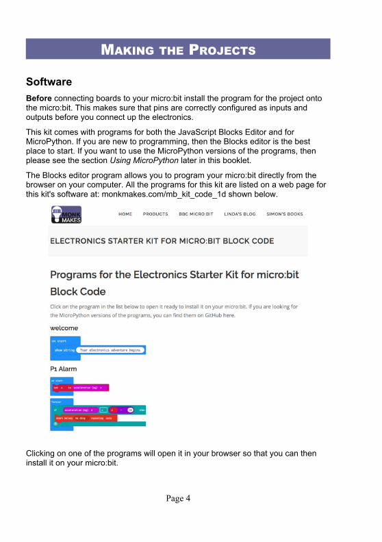
The Blocks editor program allows you to program your micro:bit directly from the browser on your computer. All the programs for this kit are listed on a web page for this kit's software at: monkmakes.com/mb_kit_code_1d shown below.
Clicking on one of the programs will open it in your browser so that you can then install it on your micro:bit.
Page 4
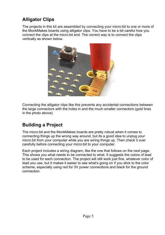
Alligator ClipsThe projects in this kit are assembled by connecting your micro:bit to one or more ofthe MonkMakes boards using alligator clips. You have to be a bit careful how you connect the clips at the micro:bit end. The correct way is to connect the clips vertically as shown below.
Connecting the alligator clips like this prevents any accidental connections between the large connectors with the holes in and the much smaller connectors (gold lines in the photo above)
Building a ProjectThe micro:bit and the MonkMakes boards are pretty robust when it comes to connecting things up the wrong way around, but its a good idea to unplug your micro:bit from your computer while you are wiring things up. Then check it over carefully before connecting your micro:bit to your computer.
Each project includes a wiring diagram, like the one that follows on the next page. This shows you what needs to be connected to what. It suggests the colors of lead to be used for each connection. The project will still work just fine, whatever color oflead you use, but it makes it easier to see what's going on if you stick to the color scheme, especially using red for 3V power connections and black for the ground connection.
Page 5

Page 6
GETTING STARTEDTo get you started with your kit, please follow the steps below. This does not use any of the MonkMakes add-on boards, so for now you don't need the alligator clips.
If you have already used your micro:bits for other things, you can probably skip this section.
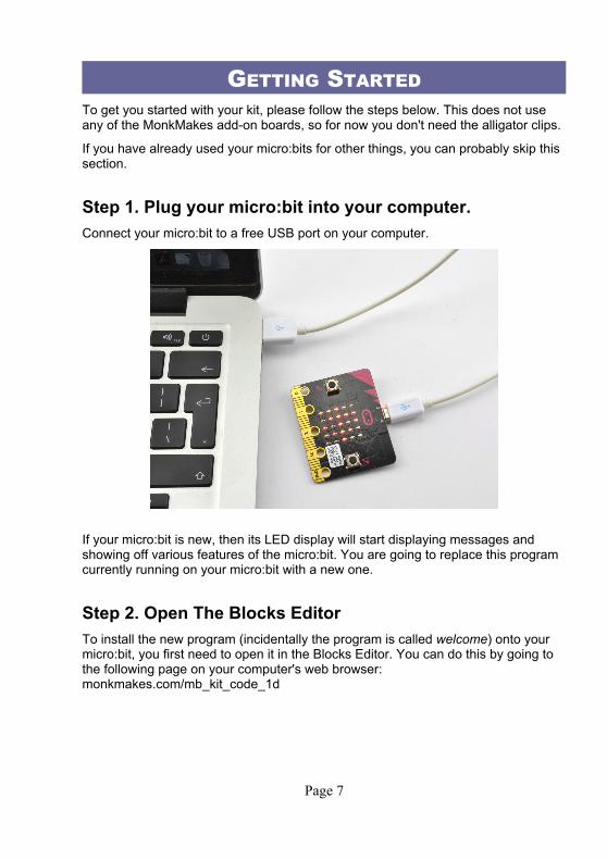
Step 1. Plug your micro:bit into your computer.Connect your micro:bit to a free USB port on your computer.
If your micro:bit is new, then its LED display will start displaying messages and showing off various features of the micro:bit. You are going to replace this program currently running on your micro:bit with a new one.
Step 2. Open The Blocks EditorTo install the new program (incidentally the program is called welcome) onto your micro:bit, you first need to open it in the Blocks Editor. You can do this by going to the following page on your computer's web browser: monkmakes.com/mb_kit_code_1d
Page 7

Click on the project called welcome. This is what you should see when you click on it.
Step 3. Install the ProgramNext, you are going to send the welcome program to the micro:bit.
Click on the “Download” link at the bottom of the page. This will download a file for the program ending in .hex. You will also see the prompt below.
As the prompt says, this hex file needs to be moved onto the micro:bit. The micro:bit will show up as a USB drive on your computer. In other words, you need to
Page 8
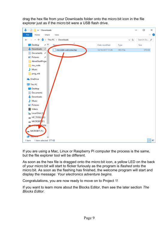
drag the hex file from your Downloads folder onto the micro:bit icon in the file explorer just as if the micro:bit were a USB flash drive.
If you are using a Mac, Linux or Raspberry Pi computer the process is the same, but the file explorer tool will be different.
As soon as the hex file is dragged onto the micro:bit icon, a yellow LED on the backof your micro:bit will start to flicker furiously as the program is flashed onto the micro:bit. As soon as the flashing has finished, the welcome program will start and display the message: Your electronics adventure begins.
Congratulations, you are now ready to move on to Project 1!
If you want to learn more about the Blocks Editor, then see the later section The Blocks Editor.
Page 9

PROJECT 1. MOVEMENT ALARM
The program uses the micro:bit's built in accelerometer to measure any force actingin the z dimension (vertically). If the micro:bit is lying completely flat this will be -1023, but when the micro:bit is picked up, the force will change.
When the program first starts, it saves the current acceleration reading in a variable called z. The forever loop then repeatedly checks the acceleration and if it has fallen from its initial value (z) by more than 50 the alarm is sounded.
Page 10
Try tweaking the number 50, to alter how sensitive the alarm is. You can also pick different tunes to play in the start melody block.
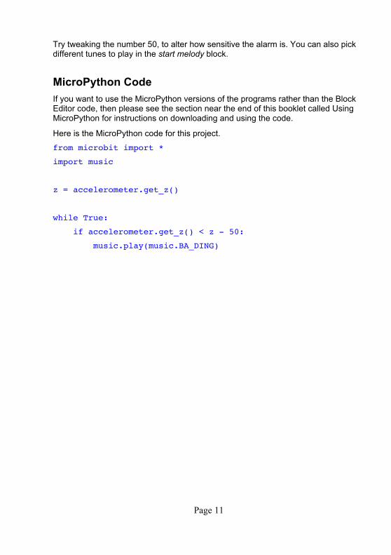
MicroPython CodeIf you want to use the MicroPython versions of the programs rather than the Block Editor code, then please see the section near the end of this booklet called Using MicroPython for instructions on downloading and using the code.
Here is the MicroPython code for this project.
from microbit import *
import music
z = accelerometer.get_z()
while True:
if accelerometer.get_z() < z - 50:
music.play(music.BA_DING)
Page 11
PROJECT 2. LIGHTHOUSE
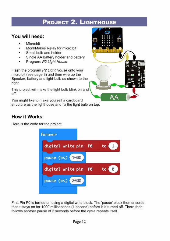
You will need:• Micro:bit• MonkMakes Relay for micro:bit• Small bulb and holder• Single AA battery holder and battery• Program: P2 Light House
Flash the program P2 Light House onto yourmicro:bit (see page 8) and then wire up theSpeaker, battery and light-bulb as shown to theright.
This project will make the light bulb blink on andoff.
You might like to make yourself a cardboardstructure as the lighthouse and fix the light bulb on top.
How it WorksHere is the code for the project.
First Pin P0 is turned on using a digital write block. The 'pause' block then ensures that it stays on for 1000 milliseconds (1 second) before it is turned off. There then follows another pause of 2 seconds before the cycle repeats itself.
Page 12

MicroPython CodeIf you want to use the MicroPython versions of the programs rather than the Block Editor code, then please see the section near the end of this booklet called Using MicroPython for instructions on downloading and using the code.
Here is the MicroPython code for this project.
from microbit import *
while True:
pin0.write_digital(1)
sleep(1000)
pin0.write_digital(0)
sleep(2000)
Page 13
PROJECT 3. SHOUT-O-METER
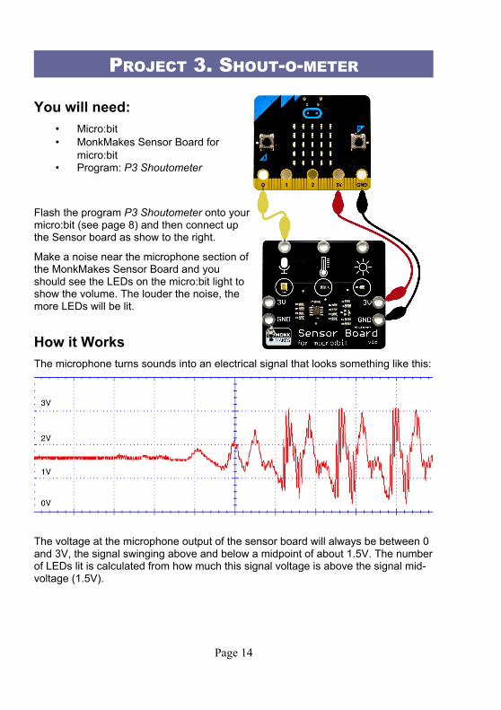
You will need:• Micro:bit• MonkMakes Sensor Board for
micro:bit• Program: P3 Shoutometer
Flash the program P3 Shoutometer onto yourmicro:bit (see page 8) and then connect upthe Sensor board as show to the right.
Make a noise near the microphone section ofthe MonkMakes Sensor Board and youshould see the LEDs on the micro:bit light toshow the volume. The louder the noise, themore LEDs will be lit.
How it WorksThe microphone turns sounds into an electrical signal that looks something like this:
The voltage at the microphone output of the sensor board will always be between 0 and 3V, the signal swinging above and below a midpoint of about 1.5V. The numberof LEDs lit is calculated from how much this signal voltage is above the signal mid-voltage (1.5V).
Page 14

Here is the code for the project:
The function analog read pin gives a number between 0 and 1023 depending on thevoltage at pin0. Since pin0 is connected to the microphone, the signal will vary between 0 and 1023 as the sound wave oscillates. 511 is subtracted from the reading to get the midpoint of the signal. This means that sometimes the result to be displayed by the plot bar graph block will be negative, but that doesn't matter as the bar graph plotter will just ignore those values.
The block plot bar graph lights more LEDs the bigger the number supplied to it. Theimage below shows the result of a particularly loud noise!
Page 15

MicroPython CodeIf you want to use the MicroPython versions of the programs rather than the Block Editor code, then please see the section near the end of this booklet called Using MicroPython for instructions on downloading and using the code.
Here is the MicroPython code for this project.
from microbit import *
def bargraph(a):
display.clear()
for y in range(0, 5):
if a > y:
for x in range(0, 5):
display.set_pixel(x, 4-y, 9)
while True:
sound_level = (pin0.read_analog() - 511) / 100
bargraph(sound_level)
Page 16
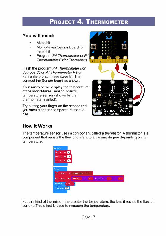
PROJECT 4. THERMOMETER
You will need:• Micro:bit• MonkMakes Sensor Board for
micro:bit• Program: P4 Thermometer or P4
Thermometer F (for Fahrenheit)
Flash the program P4 Thermometer (fordegrees C) or P4 Thermometer F (forFahrenheit) onto it (see page 8). Thenconnect the Sensor board as shown.
Your micro:bit will display the temperatureof the MonkMakes Sensor Board'stemperature sensor (shown by thethermometer symbol).
Try putting your finger on the sensor andyou should see the temperature start torise.
How it WorksThe temperature sensor uses a component called a thermistor. A thermistor is a component that resists the flow of current to a varying degree depending on its temperature.
For this kind of thermistor, the greater the temperature, the less it resists the flow of current. This effect is used to measure the temperature.
Page 17

The maths is necessary to convert the reading from the thermistor into a temperature in degrees C. If you would prefer the reading to be in degrees Fahrenheit then use the program P4 Thermometer F.
CalibrationIf you want to make your thermometer more accurate, this section will show you how to calibrate it.
To calculate the temperature whether in degrees F or C, the analog reading is first multiplied by a number (A) the result is then divided by another number (B) and then a positive or negative final number C is added to the result. To make your thermometer more accurate you can use the program P4 Calibrate to find the analog reading for two known temperatures (using a second thermometer) and thencalculate new values of A, B and C.
Step 1. Flash the program P4 Calibrate onto your micro:bit with the Sensor Board wired up as described above.
Step 2. Record the temperature (either in F or C) using a second thermometer placed close to the temperature sensor on the board. Then press button A and record the value displayed. You can write both these values in the table below as I have here, where the temperature in C was recoded as 18 degrees and the sensor reading 460.
Step 3. Wrap an ice cube in a plastic bag and hold it against both the temperature sensor on the Sensor Board and the second thermometer at the same time. Wait for 30 seconds and then record both the second thermometer reading and the reading displayed by the micro:bit (when you press button A). In this case the readings were 0 degrees C and 345. Write them in the table too.
Step 4. Calculate A, B and C using the formulas in the table:
Room temperature using thermometer (t1) *
Room temperature reading on Sensor (r1) )
Cold temperature using thermometer (t2)
Cold temperature reading on Sensor (r2) (
A = t1 – t2 *
B = r1 – r2 (
C = t2 – (A / B) * r2 – * ( ( (
Once you have the values of A, B and C, you can change these value in your block program.
Page 18

MicroPython CodeIf you want to use the MicroPython versions of the programs rather than the Block Editor code, then please see the section near the end of this booklet called Using MicroPython for instructions on downloading and using the code.
Here is the MicroPython code for the Centigrade version of this project.
from microbit import *
while True:
reading = pin1.read_analog()
temp_c = reading * 0.157 - 54
display.scroll(str(temp_c))
Page 19

PROJECT 5. FAN SPEED CONTROLLER
You will need:• Micro:bit• MonkMakes Relay for micro:bit• AA Battery holder and battery• Motor with fan attached• Program: P5 Fan Speed
Flash the program P5 Fan Speed onto yourmicro:bit (see page 8). Connect up thecomponents as shown to the right. Note itdoesn't really matter which way around themotor leads are connected. Reverse themand the motor direction will reverse.
The micro:bit display will show a numberbetween 0 and 9 indicating the fan's speed.Use button B (on the micro:bit) to increasethe speed and button A to decrease the speed.
How it WorksThis project uses the MonkMakes Relay to provide pulses of power of varying length to the motor.
The code is the most complicated so far. It uses quite a few variables that are defined in the on start block.
• min_power – This should be set to the minimum power output value that makes the motor just start to turn. This varies a bit between motors. Try the default value of 300, but if the motor doesn't turn when you press button B to set the speed to 1, you may need to increase this value to perhaps 400 or more.
• max_power – This is the maximum power, you can leave this as 1023
• power_step – This is the power range divided by 9 and will be the amount of power change that results from one step more of speed.
• Speed – The speed from 0 (off) to 9 (maximum)
The forever loop is used to continuously set the power level to match the speed. The case of the speed being 0 is treated as a special case, to set the power to 0, otherwise the motor may buzz without actually turning when the speed is 0.
Page 20

The on button pressed blocks are very similar to each other. The one for button A subtracts 1 from speed while making sure that speed does not fall below zero and then displays the new speed and uses analog write to set the power output of pin 0.The on button pressed for B does the same kind of thing, but adding 1 to speed.
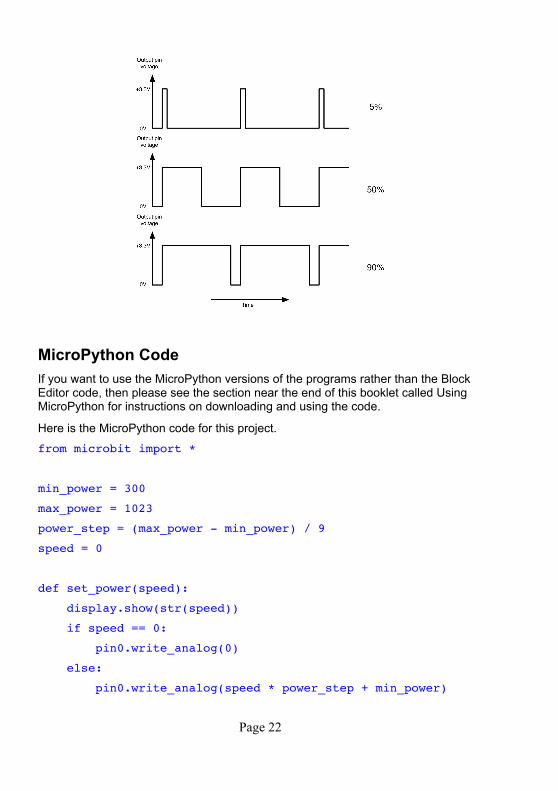
The method of controlling the power that analog write uses is called Pulse Width Modulation (PWM). It works by varying the duration of a series of pulses sent to the Relay.
If the pulse is only high for a very short time (say 5% of the time) then only a small amount of power is delivered to the motor so it will turn slowly. The more time the pulse is high, the more power is delivered to the motor and the faster it will turn.
Page 21
MicroPython CodeIf you want to use the MicroPython versions of the programs rather than the Block Editor code, then please see the section near the end of this booklet called Using MicroPython for instructions on downloading and using the code.
Here is the MicroPython code for this project.
from microbit import *
min_power = 300
max_power = 1023
power_step = (max_power - min_power) / 9
speed = 0
def set_power(speed):
display.show(str(speed))
if speed == 0:
pin0.write_analog(0)
else:
pin0.write_analog(speed * power_step + min_power)
Page 22
set_power(speed)
while True:
if button_a.was_pressed():
speed -= 1
if speed < 0:
speed = 0
set_power(speed)
elif button_b.was_pressed():
speed += 1
if speed > 9:
speed = 9
set_power(speed)
sleep(100)
Page 23
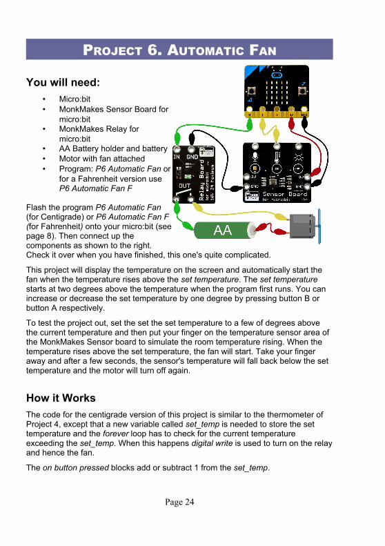
PROJECT 6. AUTOMATIC FAN
You will need:• Micro:bit• MonkMakes Sensor Board for
micro:bit• MonkMakes Relay for
micro:bit• AA Battery holder and battery• Motor with fan attached• Program: P6 Automatic Fan or
for a Fahrenheit version useP6 Automatic Fan F
Flash the program P6 Automatic Fan(for Centigrade) or P6 Automatic Fan F (for Fahrenheit) onto your micro:bit (seepage 8). Then connect up thecomponents as shown to the right.Check it over when you have finished, this one's quite complicated.
This project will display the temperature on the screen and automatically start the fan when the temperature rises above the set temperature. The set temperature starts at two degrees above the temperature when the program first runs. You can increase or decrease the set temperature by one degree by pressing button B or button A respectively.
To test the project out, set the set the set temperature to a few of degrees above the current temperature and then put your finger on the temperature sensor area of the MonkMakes Sensor board to simulate the room temperature rising. When the temperature rises above the set temperature, the fan will start. Take your finger away and after a few seconds, the sensor's temperature will fall back below the set temperature and the motor will turn off again.
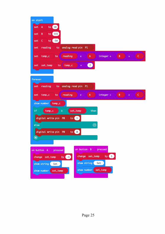
How it WorksThe code for the centigrade version of this project is similar to the thermometer of Project 4, except that a new variable called set_temp is needed to store the set temperature and the forever loop has to check for the current temperature exceeding the set_temp. When this happens digital write is used to turn on the relayand hence the fan.
The on button pressed blocks add or subtract 1 from the set_temp.
Page 24
Page 25
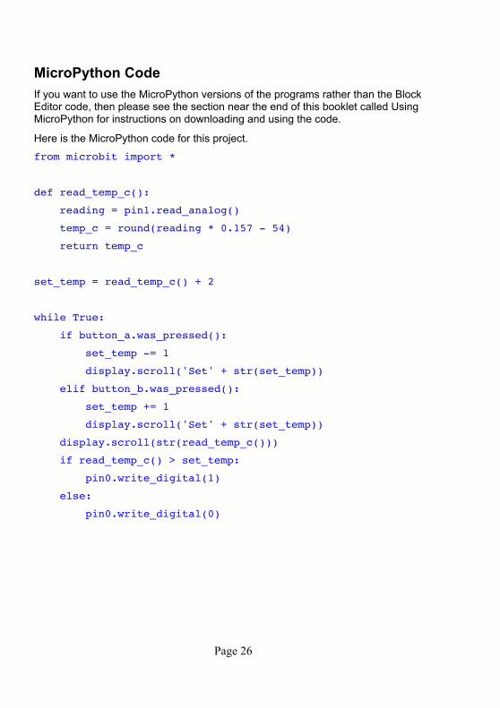
MicroPython CodeIf you want to use the MicroPython versions of the programs rather than the Block Editor code, then please see the section near the end of this booklet called Using MicroPython for instructions on downloading and using the code.
Here is the MicroPython code for this project.
from microbit import *
def read_temp_c():
reading = pin1.read_analog()
temp_c = round(reading * 0.157 - 54)
return temp_c
set_temp = read_temp_c() + 2
while True:
if button_a.was_pressed():
set_temp -= 1
display.scroll('Set' + str(set_temp))
elif button_b.was_pressed():
set_temp += 1
display.scroll('Set' + str(set_temp))
display.scroll(str(read_temp_c()))
if read_temp_c() > set_temp:
pin0.write_digital(1)
else:
pin0.write_digital(0)
Page 26
PROJECT 7. MAGIC MUSIC
You will need:• Micro:bit• MonkMakes Sensor Board for
micro:bit• MonkMakes Speaker for
micro:bit• Program: P7 Magic Music
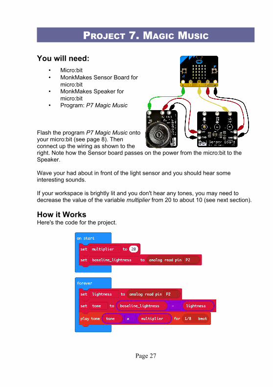
Flash the program P7 Magic Music ontoyour micro:bit (see page 8). Thenconnect up the wiring as shown to theright. Note how the Sensor board passes on the power from the micro:bit to the Speaker.
Wave your had about in front of the light sensor and you should hear some interesting sounds.
If your workspace is brightly lit and you don't hear any tones, you may need to decrease the value of the variable multiplier from 20 to about 10 (see next section).
How it WorksHere's the code for the project.
Page 27

The variable multiplier is initially set to 20. This is used to increase the value of the calculated light level to an audible frequency. So, if when you wave your hand in front of the light sensor, all you hear are clicks, then try increasing this value. On theother hand, if, as you move your hand closer to the light sensor, the pitch of the sound rises too high to be audible, try decreasing the value of multiplier to 10.
As the program starts, it reads the light level and stores it in the variable baseline_brightness. So, if you move your project to a brighter room, you will also need to click the micro:bit's Reset button so that it measures the brightness of the room again.
MicroPython CodeIf you want to use the MicroPython versions of the programs rather than the Block Editor code, then please see the section near the end of this booklet called Using MicroPython for instructions on downloading and using the code.
Here is the MicroPython code for this project.
from microbit import *
import music
multiplier = 20
baseline_lightness = pin2.read_analog()
while True:
lightness = pin2.read_analog()
tone = baseline_lightness - lightness
music.pitch(tone * multiplier)
sleep(100)
Page 28

THE JAVASCRIPT BLOCKS EDITORIf you want to modify one of the Block programs for the kit, you can do so by clicking on the either of the two Edit buttons.
Clicking on the Edit button will then open the project in the Blocks Editor.
Page 29
One really nice feature of the Blocks editor is that the image of a micro:bit on the leftof the screen is a virtual micro:bit that you can run your programs on before flashingthem onto the micro:bit. You can press its buttons with your mouse, it will display things and if you used the GPIO pins as digital outputs, it will even highlight them when you write to them. You can also click on GPIO pins to simulate digital and analog inputs. The middle section of the screen has different categories of blocks: Basic, Input, Music etc. where you can find blocks to put onto the right-hand ‘canvas’ area. You can also use the Search box just above the list of block categories if you are not sure where to find the block that you want. The Blocks editor actually generates code in the JavaScript programming language and if you click on the button “{} JavaScript” you can see the code that has been generated. Clicking on “Blocks” takes you back to the blocks view of things, which is much easier to follow.
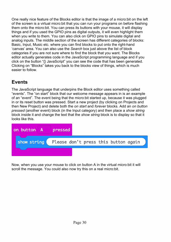
EventsThe JavaScript language that underpins the Block editor uses something called “events”. The “on start” block that our welcome message appears in is an example of an “event”. The event being that the micro:bit started up, because it was plugged in or its reset button was pressed. Start a new project (by clicking on Projects and then New Project) and delete both the on start and forever blocks. Add an on buttonpressed (another event) block (in the Input category) and then place a show string block inside it and change the text that the show string block is to display so that it looks like this.
Now, when you use your mouse to click on button A in the virtual micro:bit it will scroll the message. You could also now try this on a real micro:bit.
Page 30
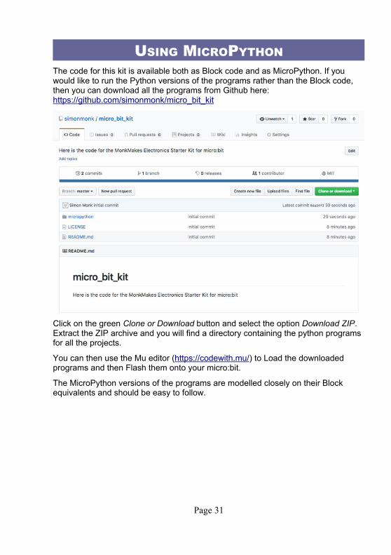
USING MICROPYTHONThe code for this kit is available both as Block code and as MicroPython. If you would like to run the Python versions of the programs rather than the Block code, then you can download all the programs from Github here: https://github.com/simonmonk/micro_bit_kit
Click on the green Clone or Download button and select the option Download ZIP. Extract the ZIP archive and you will find a directory containing the python programs for all the projects.
You can then use the Mu editor (https://codewith.mu/) to Load the downloaded programs and then Flash them onto your micro:bit.
The MicroPython versions of the programs are modelled closely on their Block equivalents and should be easy to follow.
Page 31
TROUBLESHOOTINGProblem: I can't flash a program onto my micro:bit
Solution: First check that the micro:bit's power LED is lit. If it isn't try a different USB port or USB lead. If the micro:bit is receiving power, but you can't see the micro:bit drive on your computer, then you may be using a 'power only' USB cable. Try a different cable.
Problem: The LED isn't lit on the MonkMakes Relay for micro:bit even though I think its connected correctly.
Solution: This is normal. The LED on the Relay will only light when the relay is activated.
Problem: The temperature projects are not very accurate.
Solution: Limitations of the temperature sensor and the Block code's math capabilities mean that the measured temperature is only an approximation. See the section in project 4 on Calibration to make your readings more accurate.
Problem: The project doesn't work, but I'm pretty sure I have the right program uploaded and all the wiring looks good. What can I do?
Solution: If you have checked everything and can't find a problem, then it is possible that one of the alligator leads is broken – this can happen if they are over-flexed. Try and think about which lead might be faulty. For example if the LED in theMonkMakes logo for the Sensor or Speaker are not lit, then try swapping out the power leads (3V and GND) from the micro:bit.
For other support questions, please check out the product's web page (http://monkmakes.com/mb_kit) and you can send support questions to [email protected]
Page 32

WHAT NEXT?
micro:bit ProgrammingIf you want to learn more about programming the micro:bit in Python, then you should consider buying Simon Monk's book 'Programming micro:bit: Getting Startedwith MicroPython', which is available from all major book sellers.
You can find out more about this and other books by Simon Monk (the designer of this kit) at: http://simonmonk.org or follow him on Twitter where he is @simonmonk2
Page 33
NOTES
Page 34

Page 35

MONKMAKESFor more information on this kit, the product's home page is here: https://monkmakes.com/mb_kit
As well as this kit, MonkMakes makes all sorts of kits and gadgets to help with your micro:bit and Raspberry Pi projects. Find out more, as well as where to buy here: https://monkmakes.com you can also follow MonkMakes on Twitter @monkmakes.
Page 36