Assembly Instructions - Wilwood
10
ASSEMBLY INSTRUCTIONS FOR 12 BOLT CHEVY WITH FACTORY C-CLIP AXLES* *For additional vehicle compatibility, visit www.wilwood.com REAR AXLE DISC / DRUM INTERNAL PARKING BRAKE KIT WITH 12.88” DIAMETER VENTED ROTOR (2.75 OFFSET) BASE PART NUMBER 140-12964 NOTE: Some cleaners may stain or remove the finish on brake system components. Test the cleaner on a hidden portion of the component before general use. WARNING IT IS THE RESPONSIBILITY OF THE PERSON INSTALLING ANY BRAKE COMPONENT OR KIT TO DETERMINE THE SUITABILITY OF THE COMPONENT OR KIT FOR THAT PARTICULAR APPLICATION. IF YOU ARE NOT SURE HOW TO SAFELY USE THIS BRAKE COMPONENT OR KIT, YOU SHOULD NOT INSTALL OR USE IT. DO NOT ASSUME ANYTHING. IMPROPERLY INSTALLED OR MAINTAINED BRAKES ARE DANGEROUS. IF YOU ARE NOT SURE, GET HELP OR RETURN THE PRODUCT. YOU MAY OBTAIN ADDITIONAL INFORMATION AND TECHNICAL SUPPORT BY CALLING WILWOOD AT (805) 388-1188, OR VISIT OUR WEB SITE AT WWW.WILWOOD.COM. USE OF WILWOOD TECHNICAL SUPPORT DOES NOT GUARANTEE PROPER INSTALLATION. YOU, OR THE PERSON WHO DOES THE INSTALLATION MUST KNOW HOW TO PROPERLY USE THIS PRODUCT. IT IS NOT POSSIBLE OVER THE PHONE TO UNDERSTAND OR FORESEE ALL THE ISSUES THAT MIGHT ARISE IN YOUR INSTALLATION. RACING EQUIPMENT AND BRAKES MUST BE MAINTAINED AND SHOULD BE CHECKED REGULARLY FOR FATIGUE, DAMAGE, AND WEAR. WARNING DO NOT OPERATE ANY VEHICLE ON UNTESTED BRAKES! SEE MINIMUM TEST PROCEDURE WITHIN ALWAYS UTILIZE SAFETY RESTRAINT SYSTEMS AND ALL OTHER AVAILABLE SAFETY EQUIPMENT WHILE OPERATING THE VEHICLE IMPORTANT • READ THE DISCLAIMER OF WARRANTY INCLUDED IN THE KIT www.wilwood.com DISC BRAKES SHOULD ONLY BE INSTALLED BY SOMEONE EXPERIENCED AND COMPETENT IN THE INSTALLATION AND MAINTENANCE OF DISC BRAKES READ ALL WARNINGS Need Additional Information? Use Your SmartPhone and Jump to Our Technical Tips Section on Our Web Site.
-
Upload
khangminh22 -
Category
Documents
-
view
2 -
download
0
Transcript of Assembly Instructions - Wilwood

ASSEMBLY INSTRUCTIONSFOR
12 BOLT CHEVY WITH FACTORY C-CLIP AXLES**For additional vehicle compatibility, visit www.wilwood.com
REAR AXLE DISC / DRUM INTERNAL PARKING BRAKE KITWITH 12.88” DIAMETER VENTED ROTOR (2.75 OFFSET)
BASE PART NUMBER
140-12964
NOTE: Some cleaners may stain or remove the finish on brake system components. Test the cleaner on a hidden portionof the component before general use.
WARNINGIT IS THE RESPONSIBILITY OF THE PERSON INSTALLING ANY BRAKE COMPONENT OR KIT TO DETERMINE THE SUITABILITY OF THE COMPONENT OR KIT FOR THAT PARTICULAR APPLICATION. IF YOU ARE NOT SURE HOW TO SAFELY USE THIS BRAKE COMPONENT OR KIT, YOU SHOULD NOT INSTALL OR USE IT. DO NOT ASSUME ANYTHING. IMPROPERLY INSTALLED OR MAINTAINED BRAKES ARE DANGEROUS. IF YOU ARE NOT SURE, GET HELP OR RETURN THE PRODUCT. YOU MAY OBTAIN ADDITIONAL INFORMATION AND TECHNICAL SUPPORT BY CALLING WILWOOD AT (805) 388-1188, OR VISIT OUR WEB SITE AT WWW.WILWOOD.COM. USE OF WILWOOD TECHNICAL SUPPORT DOES NOT GUARANTEE PROPER INSTALLATION. YOU, OR THE PERSON WHO DOES THE INSTALLATION MUST KNOW HOW TO PROPERLY USE THIS PRODUCT. IT IS NOT POSSIBLE OVER THE PHONE TO UNDERSTAND OR FORESEE ALL THE ISSUES THAT MIGHT ARISE IN YOUR INSTALLATION.
RACING EQUIPMENT AND BRAKES MUST BE MAINTAINED AND SHOULD BE CHECKED REGULARLY FOR FATIGUE, DAMAGE, AND WEAR.
WARNINGDO NOT OPERATE ANY VEHICLE ON UNTESTED BRAKES!
SEE MINIMUM TEST PROCEDURE WITHINALWAYS UTILIZE SAFETY RESTRAINT SYSTEMS AND ALL OTHER AVAILABLE SAFETY EQUIPMENT WHILE OPERATING THE VEHICLE
IMPORTANT • READ THE DISCLAIMER OF WARRANTY INCLUDED IN THE KIT
www.wilwood.com
DISC BRAKES SHOULD ONLY BE INSTALLED BY SOMEONE EXPERIENCED AND COMPETENT IN THE INSTALLATION AND
MAINTENANCE OF DISC BRAKESREAD ALL WARNINGS
Need Additional Information?Use Your SmartPhone andJump to Our Technical TipsSection on Our Web Site.
Exploded Assembly DiagramEXISTING AXLE, BEARING,FLANGE AND BOLTS
2
17
4
1
5
812
10
6
1511
9
7
14
13
16
3
GT SLOTPATTERN ROTOR
SRP DRILLED/SLOTTEDPATTERN ROTOR
4 PISTON
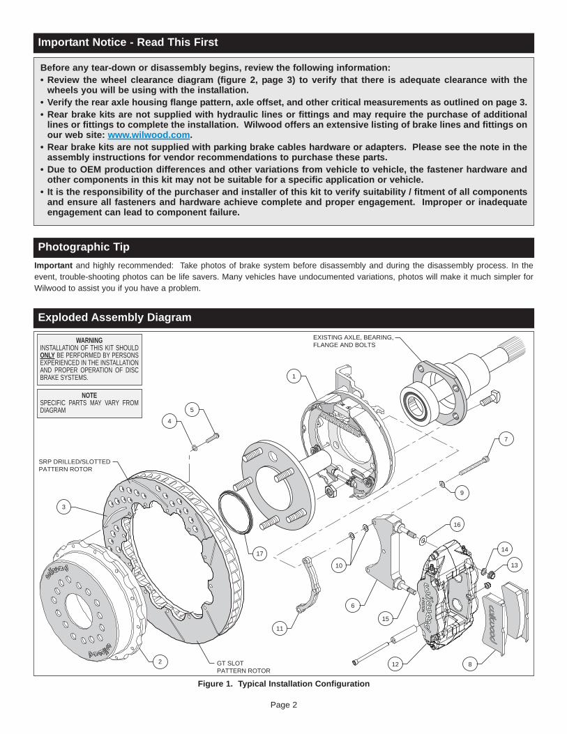
Figure 1. Typical Installation Configuration
Important Notice - Read This First
Before any tear-down or disassembly begins, review the following information:• Review the wheel clearance diagram (figure 2, page 3) to verify that there is adequate clearance with thewheels you will be using with the installation.• Verify the rear axle housing flange pattern, axle offset, and other critical measurements as outlined on page 3.• Rear brake kits are not supplied with hydraulic lines or fittings and may require the purchase of additionallines or fittings to complete the installation. Wilwood offers an extensive listing of brake lines and fittings onour web site: www.wilwood.com.• Rear brake kits are not supplied with parking brake cables hardware or adapters. Please see the note in theassembly instructions for vendor recommendations to purchase these parts.• Due to OEM production differences and other variations from vehicle to vehicle, the fastener hardware andother components in this kit may not be suitable for a specific application or vehicle.• It is the responsibility of the purchaser and installer of this kit to verify suitability / fitment of all componentsand ensure all fasteners and hardware achieve complete and proper engagement. Improper or inadequateengagement can lead to component failure.
Page 2
Photographic TipImportant and highly recommended: Take photos of brake system before disassembly and during the disassembly process. In theevent, trouble-shooting photos can be life savers. Many vehicles have undocumented variations, photos will make it much simpler forWilwood to assist you if you have a problem.
WARNINGINSTALLATION OF THIS KIT SHOULDONLY BE PERFORMED BY PERSONSEXPERIENCED IN THE INSTALLATIONAND PROPER OPERATION OF DISCBRAKE SYSTEMS.
NOTESPECIFIC PARTS MAY VARY FROMDIAGRAM

Installation of this kit should ONLY be performed by persons experienced in theinstallation and proper operation of disc brake systems. Before assembling theWilwood rear axle disc brake kit, double check the following items to ensure atrouble-free installation.
•Make sure this is the correct kit to fit the axle housing flange, not necessarily therear end make. Many times after market manufacturers put a different make ofaxle housing flange on the stock rear end housing (see Figure 5). Example; BigFord rear ends with Olds-Pontiac flanges, therefore, an Olds-Pontiac rear discbrake kit would be the correct kit to order. Also, shock clearance may be aproblem. They may have to be modified and/or relocated to clear the Wilwood kitafter final assembly.
•Inspect the package contents against the parts list to ensure that all componentsand hardware are included.
•Verify your wheel clearance using Figure 2.
•Verify The Following Measurements Before Assembly.• Bearing outside diameter.• Axle housing flange mounting pattern to pattern in bracket.• Stud pattern on axle flange to stud pattern in hat.• Axle center register diameter is 2.80”, Figure 3. This kit uses Wilwood’sremovable center register adapters. Rotors can either be centered on theaxle register, i.e. register-centric or centered on the wheel studs, i.e. stud-centric. Due to variations in wheel stud final diameters, register-centriccentering can be a more accurate method of centering the rotor to the axle.Wilwood offers various diameter adapters for purchase in addition to the onessupplied in this kit, see Table 1.
Figure 2. Wheel Clearance Diagram
CENTERLINE OFWHEEL
.50 (12,7) RADIUS
.20 (5,1)3.60 (91,4)
4.38(111,3)
7.40(188,0)
.22 (5,6)
CALIPER
WILWOOD ROTOR
WHEEL MOUNT SURFACE
NOTE: A MINIMUM OF .080” CLEARANCE MUST BE MAINTAINED BETWEEN THE WHEEL AND CALIPER IN ALL AREAS
1.10 (27,9) ROTOR THICKNESS
2.80 (71,1)CENTER REGISTRATION
Parts List
General Information
123
3A456789
101112
12A1314151617
1222
24242616
18222444
162
249-9774/75170-13540160-12961/62160-13543/44-BK240-11240230-8037249-9495/96230-13565150-8855K240-10191240-9609300-9505120-11782-BK120-11782-RD230-9183240-10190230-9078240-1159300-11337
Bracket Kit (pair, one each, left and right)Hat, 5 x 4.50/4.75/5.00, 1.95 offset, 12 x 8.75 Bolt CircleRotor, GT 1.10” Thk x 12.88” Dia, 12 x 8.75” Bolt Circle, Right & LeftRotor, SRP Drilled and Slotted, BlackWasher, .265 I.D. x .500 O.D. x .063 ThickBolt, 1/4-20 x .75 Long, 12 PointBracket Caliper Mounting (pair, one each, left and right)Bolt, 5/16-24 x 1.75 Long, SHCSPad, BP-10 Cpmpound, Axle SetWasher, .328 I.D. x .562 O.D. x .063 ThickShim, .015 ThickSpacer, Caliper BracketCaliper, Superlite 4RCaliper, Superlite 4R, RedNut, 3/8-24 Self-Locking, 12 PointWasher, .391 I.D. x .625 O.D. x.063 ThickStud, 3/8-16 x 3/8-24 x 2.50 Long (pre installed in bracket)Shim, .035 ThickAdapter, Rotor Registration
ITEM NO. PART NO. DESCRIPTION QTY
NOTES: P/N 230-8008 Rotor Bolt Kit, includes part numbers 230-8037 and 240-11240P/N 249-9632L/R Caliper Bracket Mounting Bolt Kit, includes P/N’s 230-9183, 230-9078, 240-1159, 240-10190 & 249-9495/96P/N 300-12965 Spacer Kit, includes part numbers 230-13565, 240-10191, 240-9609, 300-9505 and 300-11878Item 3A is an optional item and is included with the”-D” kits. Add “-D” to end of part number when ordering.Item 12A is an optional item and included with the “-R” kits. Add “-R” to end of part number when ordering.
Page 3

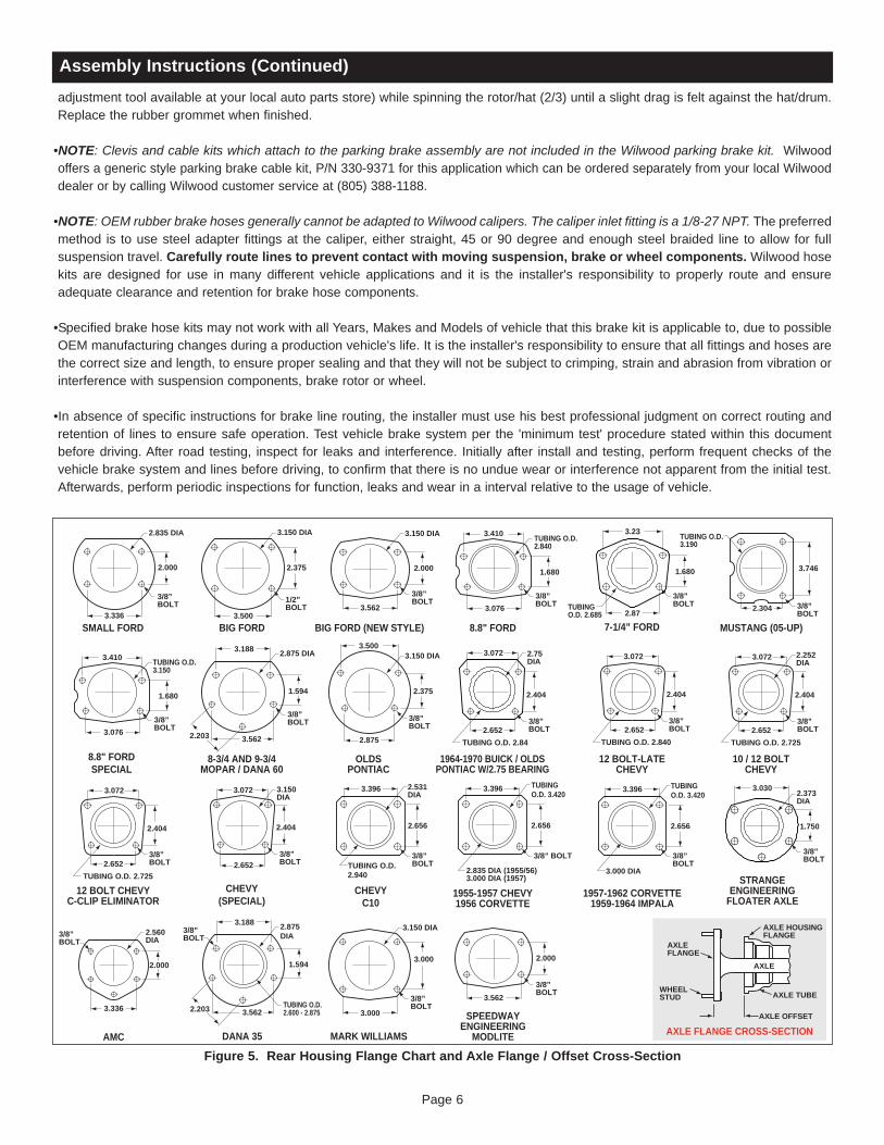
• Dimension from wheel side of axle flange to wheel side of axle housing flange (seeFigure 5, lower right hand corner). This dimension is critical to ensure properalignment of the rotor to the caliper, and should match offset given in the kitdescription.
• The Wilwood hat utilized in this kit is drilled for 1/2” diameter wheel studs. NOTE:Some OEM axles have 7/16” (0.44”) wheel axle studs. It is recommended that youupgrade to 1/2” studs. Dependent on the type of axle, this may be a simple studchange, or may require the services of a machine shop to perform.
•Maximum axle flange diameter must be no larger than 6.61” w/.050” x 45° chamfer,Figure 3.
Disassembly Instructions•Disassemble the original equipment rear brakes:
Raise the rear wheels off the ground and support the rear suspension according to the vehicle manufacturer’s instructions.
Remove the rear wheels and disassemble the drum brake assembly down to the bare axle.
Remove the axle shafts.
•Remove any nicks or burrs on the axle housing flange, as well as the axle flange, that may interfere with the installation of the newbrake components.
•Clean and de-grease the axle and axle housing flange.
Assembly Instructions (numbers in parenthesis refer to the parts list and Figure 1 on the preceding pages): CAUTION: All mounting boltsmust fully engage threaded holes.
•Orient the bracket assembly (1), as shown in Figure 1, and mount to the axle housing flange usingthe Original Equipment Manufacturer (OEM) bolts and nuts, Figure 1. Ensure that the bracketassembly backing plate fits flush against the axle housing flange. Apply red Loctite® 271 to theOEM bolt threads and torque to OEM specifications.
•Install the axle into the rear end housing.
•Orient the rotor (3) and the hat (2) as shown in Figure 1 and Photo 1. Attach rotor to hat usingbolts (5) and washers (4). Using an alternating sequence, apply red Loctite® 271 to the threads,and torque to 155 in-lbs. For an added measure of security, the bolts may be safety wired usingstandard 0.032 inch diameter stainless steel safety wire as shown in Figure 4. Please refer toWilwood’s data sheet DS-386 (available at www.wilwood.com/Pdf/DataSheets/ds386.pdf) forcomplete safety wire installation instructions.
General Information (Continued) and Disassembly Instructions
Figure 3. Axle FlangeMaximum Dimension
MAXIMUMDIA 6.61"TO FIT
WILWOODHAT
2.80”REGISTER
.050 X 45°CHAMFER
Page 4
Assembly Instructions
IMPORTANT:• To ensure maximum performance from your parking brake system, the cables must be routed as straight as
possible. Bends in the cable can significantly reduce efficiency and thus reduce pull force at the brake. Tight bends must be avoided with a minimum recommended bend radius of 6" to 8".
• Cables should be properly restrained to prevent "straightening" of bends when tension is applied. Restrain movement of cable by affixing the cable sheath to body or chassis by fitting cable clamps at various points over the length of cable or by using original equipment cable attachments points. The clamping method chosen will require that cable sheath be held tightly without movement, crushing or causing interference to the internal cable.
• Cables must be initially pre-stretched by multiple applications of the brake handle, then re-adjusted to correct tension.
Table 1. Center Register Adapters
This kit includes a 3.06” center I.D. hat or rotor assembly and a 2.80” hub register adapter ring to accommodate the installation of this kit on axles of either dimension. For axles with different center register diameters, please consult the table below for optional adapter ring sizes.
PART NO. REGISTER I.D. NOTENO ADAPTER USED300-11732300-11962300-11338300-11337300-11532300-11803300-11901300-11653300-11339
3.06”2.86”2.84”2.82”2.80”2.78”2.52”2.50”2.18”2.00”
ROTOR CENTER HOLE I.D.OPTIONALOPTIONALOPTIONALSUPPLIED WITH KITOPTIONALOPTIONALOPTIONALOPTIONALOPTIONAL (Machine to fit I.D.)

•Slide the rotor registration adapter (17) onto the axle register onthe axle flange with the smaller O.D. facing outward, Figure 1and Photo 2. Align the correct hole pattern in the rotor/hat (2/3)with the stud pattern on the axle flange and slide into place,Figure 1. NOTE: The hat must fit flush against the axle flange orexcessive rotor run out may result. Install three lug nuts (fingertight) to keep the rotor/hat assembly in place while continuingwith the installation. NOTE: Some OEM and after market axlescome with stud sizes larger than 0.50” diameter. Verify stud sizeand have a qualified machine shop drill the bolt circle of thehat/rotor to the correct stud size, if necessary.
•NOTE: Please reference the caution statement at the beginningof the assembly instructions. The caliper mount bracketassembly (6) should initially be installed with clean, dry threadson the mounting bolts. Orient the bracket as shown in Figure 1and Photo 3. Attach the bracket using bolts (7), flat washers (9),and spacer (11), Figure 1 and Photo 3. NOTE: End of boltshould not exceed inside face of insert. The bracket musttighten squarely against the back side of the bracket kitassembly. Inspect for interference from the axle flange. Initiallyplace two .015” thick shims (10) on each bolt between thebracket (6) and the spacer (11), Figure 1.
• Lubricate the caliper mounting studs (15) with lightweight oil.Initially place one .035” thick shim (16) on each stud between thecaliper and the bracket, as shown in Figure 1 and Photo 4.Mount the caliper (12) onto the bracket (6) using lock nuts (13)and washers (14), Figure 1. Temporarily tighten the lock nutsand view the rotor through the top opening of the caliper. Therotor should be centered in the caliper, Photo 5. If not, adjust byadding or subtracting shims (10) between the bracket and thespacer (11). Always use the same amount of shims on each ofthe three mounting bolts. Once the caliper alignment is correct,remove the bracket mounting bolts one at a time, apply redLoctite® 271 to the threads, and torque to 180 in-lb.
•Remove the caliper center bridge pad retainer bolt, nut, and tubefrom the caliper. Insert the brake pads (8) into the caliper, withthe friction material facing the rotor, Photo 6. Check that the topof the brake pad is flush with the outside diameter of the rotor,Photo 7. If not, adjust by adding or subtracting shims (16)between the caliper and the bracket. After the caliper pad heightis set, torque the caliper lock nuts (13) to 30 ft-lb. Secure thebrake pads in place with the center bridge pad retainer tube, bolt,and locknut. The locknut should be snug without play in the boltor tube. Be cautious not to over tighten.
•Temporarily install wheel and torque lug nuts to manufacturer’sspecification. Ensure that the wheel rotates freely without anyinterference.
•Before final installation of the wheel, install three lug nuts,remove the rubber grommet in the bracket kit assembly (1) andadjust the parking brake shoes outward (using a drum shoe
Assembly Instructions (Continued)
Page 5
BEGIN BY SLIDING THE 0.032" DIAMETER WIRE THROUGH TWO OF THE HOLES (LEFT) THAT ARE 180° APART. TWIST THE WIRE AS SHOWN (BELOW) USING SAFETY WIRE PLIERS. NOW SLIDE ONE WIRE THROUGH TWO OF THE HOLES (180° APART) AND WRAP THE OTHER WIRE AROUND THE BOLT. TWIST THE WIRES TOGETHER TO FORM A PIGTAIL. SEE DS-386 FOR COMPLETE DETAILS.
Figure 4. Safety Wire DiagramPhoto 1
Photo 2
SmallO.D.towardrotor/hat
Photo 3
Photo 4 Photo 5
Photo 7Photo 6
Assembly Instructions (Continued)
Page 6
Figure 5. Rear Housing Flange Chart and Axle Flange / Offset Cross-Section
2.000
2.835 DIA
3/8”BOLT
3.336SMALL FORD
2.375
3.150 DIA
1/2”BOLT
3.500BIG FORD
2.000
3.150 DIA
3/8”BOLT
3.562
BIG FORD (NEW STYLE)
3/8”BOLT
2.000
3.562
SPEEDWAYENGINEERING
MODLITE
3/8”BOLT
1.680
TUBING O.D.2.840
3.076
3.410
8.8" FORD
3/8”BOLT
1.680
TUBING O.D.3.150
3.076
3.410
8.8" FORDSPECIAL
8-3/4 AND 9-3/4MOPAR / DANA 60
3/8”BOLT
1.594
2.875 DIA
3.5622.203
3.188
2.000
2.560DIA
3.336
AMC
3/8”BOLT
3/8”BOLT
DANA 35
1.594
2.875DIA
TUBING O.D.2.600 - 2.8753.5622.203
3.188
3/8”BOLT
OLDSPONTIAC
2.375
3.150 DIA
2.875
3.500
CHEVY(SPECIAL)
3/8”BOLT
3.150DIA
2.404
2.652
3.072
3/8”BOLT
12 BOLT CHEVYC-CLIP ELIMINATOR
2.404
2.652
3.072
TUBING O.D. 2.725
3/8”BOLT
MARK WILLIAMS
3.000
3.150 DIA
3.000
3/8”BOLT
MUSTANG (05-UP)
3.746
TUBING O.D.3.190
2.304
AXLE FLANGE CROSS-SECTIONAXLE OFFSET
AXLE
AXLE HOUSINGFLANGE
AXLE TUBE
AXLEFLANGE
WHEELSTUD
TUBINGO.D. 3.420
1955-1957 CHEVY1956 CORVETTE
2.656
3.396
2.835 DIA (1955/56)3.000 DIA (1957)
3/8” BOLT
3/8”BOLT
2.404
2.652
3.072
TUBING O.D. 2.840
12 BOLT-LATECHEVY
TUBINGO.D. 3.420
1957-1962 CORVETTE1959-1964 IMPALA
2.656
3.396
3.000 DIA
3/8”BOLT
3/8”BOLT
10 / 12 BOLTCHEVY
2.404
2.652
3.072
TUBING O.D. 2.725
2.252DIA
3/8”BOLT
2.531DIA
CHEVYC10
2.656
3.396
TUBING O.D.2.940
3/8”BOLT
STRANGEENGINEERING
FLOATER AXLE
1.750
2.373DIA
3.030
3/8”BOLTTUBING
O.D. 2.685 2.87
7-1/4” FORD
3.23
1.680
2.75DIA
3/8”BOLT
1964-1970 BUICK / OLDSPONTIAC W/2.75 BEARING
2.404
2.652
3.072
TUBING O.D. 2.84
adjustment tool available at your local auto parts store) while spinning the rotor/hat (2/3) until a slight drag is felt against the hat/drum.Replace the rubber grommet when finished.
•NOTE: Clevis and cable kits which attach to the parking brake assembly are not included in the Wilwood parking brake kit. Wilwoodoffers a generic style parking brake cable kit, P/N 330-9371 for this application which can be ordered separately from your local Wilwooddealer or by calling Wilwood customer service at (805) 388-1188.
•NOTE: OEM rubber brake hoses generally cannot be adapted to Wilwood calipers. The caliper inlet fitting is a 1/8-27 NPT. The preferredmethod is to use steel adapter fittings at the caliper, either straight, 45 or 90 degree and enough steel braided line to allow for fullsuspension travel. Carefully route lines to prevent contact with moving suspension, brake or wheel components.Wilwood hosekits are designed for use in many different vehicle applications and it is the installer's responsibility to properly route and ensureadequate clearance and retention for brake hose components.
•Specified brake hose kits may not work with all Years, Makes and Models of vehicle that this brake kit is applicable to, due to possibleOEM manufacturing changes during a production vehicle's life. It is the installer's responsibility to ensure that all fittings and hoses arethe correct size and length, to ensure proper sealing and that they will not be subject to crimping, strain and abrasion from vibration orinterference with suspension components, brake rotor or wheel.
•In absence of specific instructions for brake line routing, the installer must use his best professional judgment on correct routing andretention of lines to ensure safe operation. Test vehicle brake system per the 'minimum test' procedure stated within this documentbefore driving. After road testing, inspect for leaks and interference. Initially after install and testing, perform frequent checks of thevehicle brake system and lines before driving, to confirm that there is no undue wear or interference not apparent from the initial test.Afterwards, perform periodic inspections for function, leaks and wear in a interval relative to the usage of vehicle.
Page 7
Additional Information and Recommendations
•NOTE: With the installation of after market disc brakes, the wheel track may change depending on the application. Check your wheeloffset before final assembly.
•Please read the following concerning balancing the brake bias on 4 wheel disc vehicles.This brake kit can be operated using the stock OEM master cylinder and proportioning system. However, as with most suspensionand tire modifications (from OEM specifications), changing the brakes may alter the front to rear brake bias. Rear brakes shouldnot lock up before the front. Brake system evaluation and tests should be performed by persons experienced in the installationand proper operation of brake systems. Evaluation and tests should be performed under controlled conditions. Start bymaking several stops from low speeds then gradually work up to higher speeds. Always utilize safety restraint systems whileoperating vehicle.
Use a Wilwood adjustable proportioning valve if necessary to achieve proper brake balance, or use a Wilwood brakepedal/balance bar assembly with dual master cylinders (requires custom mounting as used in fabricated chassis race cars). Abalance bar brake system permits incremental front to rear brake pressure adjustments.
•For optimum performance, fill and bleed the new system with Wilwood Hi-Temp° 570 grade fluid or EXP 600 Plus. For severe brakingor sustained high heat operation, use Wilwood EXP 600 Plus Racing Brake Fluid. Used fluid must be completely flushed from thesystem to prevent contamination. NOTE: Silicone DOT 5 brake fluid is NOT recommended for racing or performance driving.
•To properly bleed the brake system, begin with the caliper farthest from the master cylinder. Bleed the outboard bleed screw first, thenthe inboard. Repeat the procedure until all calipers in the system are bled, ending with the caliper closest to the master cylinder. If thecaliper is fitted with bleed screws on four corners, make sure the bottom bleed screws are tight. Only bleed from the top bleed screws.NOTE: When using a new master cylinder, it is important to bench bleed the master cylinder first.
•If the master cylinder is mounted lower than the disc brake calipers, some fluid flowback to the master cylinder reservoir may occur,creating a vacuum effect that retracts the caliper pistons into the housing. This will cause the pedal to go to the floor on the first strokeuntil it has “pumped up” and moved all the pistons out against the pad again. A Wilwood in-line 2 lb. Residual Pressure Valve installednear the master cylinder will stop the fluid flowback and keep the pedal firm and responsive.
•Test the brake pedal. It should be firm, not spongy, and stop at least 1 inch from the floor under heavy load.If the brake pedal is spongy, bleed the system again.
If the brake pedal is initially firm, but then sinks to the floor, check the system for leaks. Correct the leaks (if applicable) and thenbleed the system again.
If the brake pedal goes to the floor and continued bleeding of the system does not correct the problem, either air may be trappedin the system, or a master cylinder with increased capacity (larger bore diameter) may be required. Wilwood offers variouslightweight master cylinders with large fluid displacement capacities (custom fabricated mounting may be required).
Assembly Instructions (Continued)•Bleed the brake system. Reference the general information and recommendations below for proper bleeding instructions. Check thesystem for leaks after bleeding.
• Install the wheel and torque lug nuts to manufcaturer’s specification.

Page 8
Brake Testing
• Make sure pedal is firm: Hold firm pressure on pedal for several minutes, it should remain in position without sinking. If pedal sinks toward floor, check system for fluid leaks. DO NOT drive vehicle if pedal does not stay firm or can be pushed to the floor with normal pressure.
• At very low speed (2-5 mph) apply brakes hard several times while turning steering from full left to full right, repeat several times. Remove the wheels and check that components are not touching, rubbing, or leaking.
• Carefully examine all brake components, brake lines, and fittings for leaks and interference.
• Make sure there is no interference with wheels or suspension components.
• Drive vehicle at low speed (15-20 mph) making moderate and hard stops. Brakes should feel normal and positive. Again check for leaks and interference.
• Always test vehicle in a safe place where there is no danger to (or from) other people or vehicles.
• Always wear seat belts and make use of all safety equipment.
WARNING • DO NOT DRIVE ON UNTESTED BRAKESBRAKES MUST BE TESTED AFTER INSTALLATION OR MAINTENANCE
MINIMUM TEST PROCEDURE
Pad and Rotor Bedding
BEDDING STEPS FOR NEW PADS AND ROTORS – ALL COMPOUNDSOnce the brake system has been tested and determined safe to operate the vehicle, follow these steps for the bedding of all new padmaterials and rotors. These procedures should only be performed on a race track, or other safe location where you can safely andlegally obtains speeds up to 65 MPH, while also being able to rapidly decelerate.
• Begin with a series of light decelerations to gradually build some heat in the brakes. Use an on-and-off the pedal technique byapplying the brakes for 3-5 seconds, and then allow them to fully release for a period roughly twice as long as the deceleration cycle.If you use a 5 count during the deceleration interval, use a 10 count during the release to allow the heat to sink into the pads androtors.
• After several cycles of light stops to begin warming the brakes, proceed with a series of medium to firm deceleration stops tocontinue raising the temperature level in the brakes.
• Finish the bedding cycle with a series of 8-10 hard decelerations from 55-65 MPH down to 25 MPH while allowing a proportionaterelease and heat-sinking interval between each stop. The pads should now be providing positive and consistent response.
• If any amount of brake fade is observed during the bed-in cycle, immediately begin the cool down cycle. • Drive at a moderate cruising speed, with the least amount of brake contact possible, until most of the heat has dissipated from thebrakes. Avoid sitting stopped with the brake pedal depressed to hold the car in place during this time. Park the vehicle and allow thebrakes to cool to ambient air temperature.
COMPETITION VEHICLES• If your race car is equipped with brake cooling ducts, blocking them will allow the pads and rotors to warm up quicker and speed upthe bedding process.
• Temperature indicating paint on the rotor and pad edges can provide valuable data regarding observed temperatures during thebedding process and subsequent on-track sessions. This information can be highly beneficial when evaluating pad compounds andcooling efficiencies.
Page 9
Pad and Rotor Bedding (Continued)
POST-BEDDING INSPECTION – ALL VEHICLES• After the bedding cycle, the rotors should exhibit a uniformly burnished finish across the entire contact face. Any surface irregularitiesthat appear as smearing or splotching on the rotor faces can be an indication that the brakes were brought up to temperature tooquickly during the bedding cycle. If the smear doesn’t blend away after the next run-in cycle, or if chatter under braking results,sanding or resurfacing the rotors will be required to restore a uniform surface for pad contact.
PRE-RACE WARM UP• Always make every effort to get heat into the brakes prior to each event. Use an on-and-off the pedal practice to warm the brakesduring the trip to the staging zone, during parade laps before the flag drops, and every other opportunity in an effort to build heat inthe pads and rotors. This will help to ensure best consistency, performance, and durability from your brakes.
DYNO BEDDED COMPETITION PADS AND ROTORS• Getting track time for a proper pad and rotor bedding session can be difficult. Wilwood offers factory dyno-bedded pads and rotorson many of our popular competition pads and Spec 37 GT series rotors. Dyno-bedded parts are ready to race on their first warmup cycle. This can save valuable time and effort when on-track time is either too valuable or not available at all, Dyno-beddingassures that your pads and rotors have been properly run-in and are ready to go. Contact your dealer or the factory for moreinformation on Wilwood Dyno-Bedding services.
NOTE:NEVER allow the contact surfaces of the pads or rotors to be contaminated with brake fluid. Always use a catch bottle with a hose toprevent fluid spill during all brake bleeding procedures.

DS-966D REV DATE: 10-28-14
260-1874260-1876260-8419290-0632290-6209340-1285340-1287260-6764260-6765260-6766260-4893250-2406260-8555260-8556350-2038220-7056220-7699220-8307330-9371
Wilwood Residual Pressure Valve (2 lb for disc brakes)Wilwood Residual Pressure Valve (10 lb for drum brakes)Wilwood Proportioning ValveWilwood Racing Brake Fluid (Hi-Temp° 570) (12 oz)Wilwood Racing Brake Fluid (EXP 600 Plus) (16.9 oz)Wilwood Floor Mount Brake Pedal (with balance bar)Wilwood Swing Mount Brake Pedal (with balance bar)Wilwood 3/4 inch High Volume Aluminum Master CylinderWilwood 7/8 inch High Volume Aluminum Master CylinderWilwood 1 inch High Volume Aluminum Master Cylinder1-1/16 inch Tandem Master Cylinder (aluminum housing)Mounting Bracket Kit (tandem master cylinder)Wilwood 1 inch Aluminum Tandem Chamber Master CylinderWilwood 1-1/8 inch Aluminum Tandem Chamber Master Cylinder1971 - 1973 Pinto Rack and Pinion (new, not rebuilt)Flexline Kit, Universal, 14 Inch, DomesticFlexline Kit, Universal, 16 Inch, DomesticFlexline Kit, Universal, 18 Inch, DomesticCable Kit, Parking Brake, Universal
Associated Components
PART NO. DESCRIPTION
www.wilwood.com • E-mail Technical Assistance: [email protected] Disc Brakes • 4700 Calle Bolero, Camarillo, CA 93012 Phone 805 / 388-1188 • Fax 805 / 388-4938
Parking Brake
• Parking brake must be properly adjusted before use and must be manually readjusted for wear if parking brake handle or foot lever travel becomes excessive.
• The holding ability of the brake should be tested by stopping on a sloping surface and applying the parking brake while holding car with the hydraulic foot brake. This should be accomplished both facing up and down hill.
• Do not rely exclusively on the parking brake to hold the car; Curb wheels as recommended by the applicable diagram and put gear selector in park, or shift into first gear or reverse with a manual transmission.
• Diagram A - When parking facing downhill, turn front wheels towards the curb or right shoulder. This will keep from rolling into traffic if the brakes become disengaged.
• Diagram B - Turn the steering wheel to the left so the wheels are turned towards the road if you are facing uphill with a curb. The tires will catch the curb if the car rolls backward.
• Diagram C - When facing uphill without a curb, turn the wheels sharply to the right. If the vehicle rolls, it will go off the road rather than into traffic.
• When parking on a hill, always set the parking brake and move the gear selector into park, or shift into first or reverse gear if your vehicle has a manual transmission.
WARNING • PARKING BRAKE
DOWNHILLwith curb
Turn WheelsTo Curb
Diagram A
UPHILLwith curb
Turn WheelsFrom Curb
Diagram B
UPHILLwithout curb
Turn WheelsTo Right
Diagram C
Connect with Wilwood
Wilwood Social Forum Wilwood Facebook Wilwood Twitter Wilwood YouTube