Assembly Instructions - Hiwin
124
Assembly Instructions Linear Axes and Axis Systems HX www.hiwin.de Valid from serial no. HSN 000 000 000 1
-
Upload
khangminh22 -
Category
Documents
-
view
4 -
download
0
Transcript of Assembly Instructions - Hiwin

Assembly InstructionsLinear Axes and Axis Systems HX
www.hiwin.de
Valid from serial no. HSN 000 000 000 1

HIWIN GmbHBrücklesbünd 277654 OffenburgGermanyPhone +49 (0) 7 81 9 32 78 - 0Fax +49 (0) 7 81 9 32 78 - [email protected]
All rights reserved.Complete or partial reproduction is not permitted without our permission.
These assembly instructions are protected by copyright. Any reproduction, publication in whole or in part, modi-fication or abridgement requires the written approval of HIWIN GmbH.

Assembly InstructionsLinear Axes and Axis Systems HX
HX-01-1-EN-1806-MA
Contents
Contents
1. General information ........................................................41.1 About these assembly instructions 41.2 Depictions used in these assembly instructions 51.3 Warranty and liability 71.4 Manufacturer’s details 71.5 Copyright 71.6 Product monitoring 7
2. Basic safety notices ........................................................82.1 Intended use 82.2 Reasonably foreseeable misuse 82.3 Conversions and modifications 82.4 Residual risks 82.5 Personnel requirements 92.6 Protective equipment 92.7 Labels on the linear axis system 9
3. Bases of calculations .................................................... 103.1 Calculating the required drive torque for HT-B and HT-S 103.2 Calculating the service life 113.3 Maximum support spacing 13
4. Description of the linear axes and linear axis systems ...... 154.1 HM-B linear axis 154.2 HM-S linear axis 184.3 HD double axes 214.4 HS2 two-axis system 23
5. Options of the linear axes and linear axis systems ............ 255.1 Stroke length 255.2 Cover 265.3 Carriage 265.4 Limit switches 275.5 Positioning measuring system 285.6 Drive interfaces 325.7 Motor 335.8 Gear boxes (HM-B, HD, HS2) 335.9 Toothed belt (HM-B) 335.10 Spindle support (HM-S) 335.11 Energy chain 34
6. Transport and installation .............................................. 366.1 Delivery 366.2 Transport to the installation site 366.3 Requirements at the installation site 366.4 Storage 376.5 Unpacking and installing 37
7. Assembly and connection .............................................. 397.1 Assembling the linear axes, double axes and axis systems 417.2 Mounting the imposed load 467.3 Mounting the limit switches 487.4 Mounting the damping element 487.5 Setting the switching distance 497.6 Mounting the synchronous shaft on the HM-B linear axis/
HD double axis 507.7 Mounting the drive unit on the HM-B linear axis 517.8 Mounting the drive unit on the HM-S linear axis 597.9 Mounting the drive unit on the HD linear axis and
HS multi-axis system 657.10 Electrical connection 66
8. Maintenance and cleaning ............................................. 688.1 Lubrication 698.2 Cleaning the linear axis and linear axis system 738.3 Replacing the cover strip 738.4 Replacing the toothed belt 768.5 Replacing the synchronous shaft 798.6 Visual examination of electrical componentry 79
9. Faults .......................................................................... 809.1 Linear axis and linear axis system malfunctions 809.2 Motor malfunctions 819.3 Faults during operation with drive amplifier 81
10. Disassembly ................................................................. 82
11. Disposal ...................................................................... 84
12. Appendix 1: Accessories and spare parts ......................... 8512.1 Motor adapter of the HM-B linear axis 8512.2 Motor adapter of the HM-S linear axis 10112.3 Clamping profiles 11212.4 T nut 11312.5 Centring sleeve 11312.6 Groove cover 11412.7 Limit switch 11412.8 Extension cable for limit switch 11512.9 Damping element 11512.10 Positioning measuring system HIWIN MAGIC 11512.11 Cover strip 11612.12 Magnetic strip 11612.13 Cover strip deflection 11712.14 Buffer stop 11712.15 Separators for energy chain 11812.16 Journal for HM-B linear axis 11812.17 Toothed belt for linear axis HM-B 11812.18 Drive unit for HM-B linear axis 11912.19 Synchronous shaft 11912.20 HIWIN lubricants 12112.21 HIWIN grease nipples 121
13. Appendix 2: Declaration of Incorporation ....................... 122

4
Assembly InstructionsLinear Axes and Axis Systems HX
HX-01-1-EN-1806-MA
General information
1. General information
1.1 About these assembly instructionsThese assembly instructions are intended for planners, developers and operators of systems who plan for and install HM-B linear axes (with toothed belt drive), HM-S linear axes (with ballscrew), double axes HD (with toothed belt drive) and/or multi-axis systems HS as machine elements. They are also intended for persons who perform the following tasks in connec-tion with the above mentioned axes:
Transportation Assembly Electrical connection including connection to the higher-level control system Integration into a security system Retrofitting or upgrading Setup Commissioning Operation Maintenance Cleaning Troubleshooting and error elimination Shutdown, disassembly and disposal
Version Date Notes01-0 July 2017 Initial creation of this document
Table 1.1 Version management
1.1.1 Version management
1.1.2 RequirementsWe assume that
operating personnel are trained in the safe operation practices for HM-B/HM-S linear axes, HD double axes and/or HS multi-axis systems and have read and understood these assembly instructions in full;
maintenance personnel maintain and repair the HM-B/HM-S linear axes, HD double axes and/or HS multi-axis systems in such a way that they pose no danger to people, property or the environment.
1.1.3 AvailabilityThese assembly instructions must remain constantly available to all persons who work with or on the HM-B/HM-S linear axes, HD double axes and/or HS multi-axis systems.

5
Assembly InstructionsLinear Axes and Axis Systems HX
HX-01-1-EN-1806-MA
General information
1.2 Depictions used in these assembly instructions
1.2.1 InstructionsInstructions are indicated by triangular bullet points in the order in which they are to be carried out.Results of the actions carried out are indicated by ticks.
Example:Produce appropriate mounting holes on the mounting surface if not already present.Clean mounting surface and position linear axis on itWith the help of T nuts and clamping profiles fix the linear axis.
Linear axis is mounted.
1.2.2 ListsLists are indicated by bullet points.
Example:Linear axes must not be operated:
Outdoors In potentially explosive atmospheres …
1.2.3 Depiction of safety noticesSafety notices are always indicated using a signal word and sometimes also a symbol for the specific risk (see Section 1.2.4, “Symbols used”).The following signal words and risk levels are used:
Imminent danger!Noncompliance with the safety notices will result in serious injury or death!
DANGER!
Potentially dangerous situation!Noncompliance with the safety notices runs the risk of serious injury or death!
WARNING!
Potentially dangerous situation!Noncompliance with the safety notices runs the risk of slight to moderate injury!
CAUTION!
Potentially dangerous situation!Noncompliance with the safety notices runs the risk of damage to property or environmental pollution!
ATTENTION!

6
Assembly InstructionsLinear Axes and Axis Systems HX
HX-01-1-EN-1806-MA
General information
1.2.4 Symbols usedThe following symbols are used in these assembly instructions and on the linear axes:
Wear protective gloves!
Wear safety goggles!
Wear hearing protection!
Isolate before work!
Table 1.2 Warning signs
Table 1.3 Mandatory signs
1.2.5 Information
NOTE Describes general information and recommendations.
Warning of risk of hearing damage!
Warning of crushing!
Warning of danger from suspended loads!
Warning of dangerous electrical voltage!
Warning of cutting injuries!
Substance hazardous to the environment!

7
Assembly InstructionsLinear Axes and Axis Systems HX
HX-01-1-EN-1806-MA
General information
1.3 Warranty and liabilityThe manufacturer’s “General conditions of sale and delivery” apply.
1.4 Manufacturer’s details
Address HIWIN GmbH Brücklesbünd 2 D-77654 Offenburg
Phone +49 (0) 781 / 9 32 78 - 0Technical customer service +49 (0) 781 / 9 32 78 - 77Fax +49 (0) 781 / 9 32 78 - 90Technical customer service fax +49 (0) 781 / 9 32 78 - 97E-mail [email protected] www.hiwin.de
Table 1.4 Manufacturer’s details
1.5 CopyrightThese assembly instructions are protected by copyright. Any reproduction, publication in whole or in part, modification or abridgement requires the written approval of HIWIN GmbH.
1.6 Product monitoringPlease inform HIWIN, the manufacturer of the HM-B/HM-S linear axes, HD double axes and/or HS multi-axis systems of:
Accidents Potential sources of danger in the linear axes Anything in these assembly instructions which is difficult to understand

8
Assembly InstructionsLinear Axes and Axis Systems HX
HX-01-1-EN-1806-MA
Basic safety notices
2. Basic safety notices
This chapter serves to ensure the safety of everyone working with HM-B/HM-S linear axes, HD double axes and/or HS multi-axis systems and those who assemble, install, operate, maintain or disassemble them. Non-compliance with the following information results in dangerous working conditions.
WARNING!
2.1 Intended useThe HM-B/HM-S linear axis, HD double axes and/or HS multi-axis systems combine guiding and drive functions in the one compact unit. They are designed for the precise positioning in terms of time and location of fixed mounted loads within an automated system. It is specifically ideal for applications requiring high dynamic responses and precision. Also, with these linear axes and linear axis systems large travel distances can be realised. In the case of vertical assembly, a suitable clamp-ing or braking device must be provided in order to prevent unintended lowering of the load.All HM-B/HM-S linear axes, HD double axes and/or HS multi-axis systems may only be used for the intended purpose as described.
All HM-B/HM-S linear axis, HD double axis and/or HS multi-axis system sizes are subject to performance limits (see catalogue „Linear Axes and Axis Systems HX”). These performance limits may not be exceeded during operations.
HM-B/HM-S linear axes, HD double axes and/or HS multi-axis systems must not be operated in potentially explosive atmospheres.
The HM-B/HM-S linear axes, HD double axes and/or HS multi-axis systems may only be used and operated indoors. The HM-B/HM-S linear axes, HD double axes and/or HS multi-axis systems form part of a complete system. Personal
safety must therefore be safeguarded beyond the concept for this complete system. Proper use of the HM-B/HM-S linear axes, HD double axes and/or HS multi-axis systems includes observing the as-
sembly instructions and following the maintenance and repair specifications. Use of the HM-B/HM-S linear axes, HD double axes and/or HS multi-axis systems for any other purpose shall be consid-
ered improper use.
The HM-B/HM-S linear axes, HD double axes and/or HS multi-axis systems are delivered as a system (guiding/drive). Therefore observe the whole documentation for this system. The provided documentation may vary depending on the linear axis type.
2.2 Reasonably foreseeable misuseHM-B/HM-S linear axes, HD double axes and/or HS multi-axis systems must not be operated:
Outdoors In potentially explosive atmospheres
2.3 Conversions and modificationsConversions or modifications to the HM-B/HM-S linear axes, HD double axes and/or HS multi-axis systems are not permitted!
2.4 Residual risksDuring normal operation, there are no residual risks associated with the HM-B/HM-S linear axes, HD double axes and/or HS multi-axis systems because they form part of the complete system and the operator must safeguard personal safety beyond the concept for this complete system. Warnings about risks that may arise during maintenance and repair work are provided in the relevant sections.

9
Assembly InstructionsLinear Axes and Axis Systems HX
HX-01-1-EN-1806-MA
Basic safety notices
Activity QualificationNormal operation Trained personnelCleaning Trained personnelMaintenance Trained specialist personnel of the operator or manufacturerRepair Trained specialist personnel of the operator or manufacturerTransportation Trained personnelAssembly Trained specialist personnelDisassembly Trained specialist personnel
Table 2.1 Personnel requirements
Operating phase Personal protective equipmentNormal operation No persons may remain at the HM-B/HM-S linear axes, HD double axes and/
or HS multi-axis systems during normal operations. Persons near the HM-B/HM-S linear axes, HD double axes and/or HS multi-axis systems must wear the following personal protective equipment depending on the travel speed:
Safety shoes If necessary, hearing protection
All other operating phases (cleaning, maintenance, resetting, troubleshooting, repair)
The following personal protective equipment is needed for all other operatingphases of the HM-B/HM-S linear axes, HD double axes and/or HS multi-axis systems:
Safety shoes If necessary, safety gloves and safety goggles If necessary, hearing protection
Table 2.2 Personal protective equipment
Model No: HM060B155C1000S123A1BRID-No: 24-12345S/N: S-123456789Weight: 5kgMfg. date: 2015/03
HIWIN GmbHBrücklesbünd 277654 Offenburg
Fig. 2.1 Type plate (example only)
2.5 Personnel requirementsOnly authorised and competent persons may carry out work on the HM-B/HM-S linear axes, HD double axes and/or HS multi-axis systems! hey must be familiar with the safety equipment and regulations before starting work (see Table 2.1).
2.6 Protective equipment
2.6.1 Personal protective equipment
2.7 Labels on the linear axis systemThe HM-B/HM-S linear axes, HD double axes and/or HS multi-axis systems bear the labels depicted in the following.
2.7.1 Type plate

10
Assembly InstructionsLinear Axes and Axis Systems HX
HX-01-1-EN-1806-MA
Bases of calculations
3. Bases of calculations
The technical data and diagrams specific to each size can be found in the catalogue “Linear Axes and Axis Systems HX”.
3.1 Calculating the required drive torque for HT-B and HT-SThe maximum drive torque of the HM-B and HM-S axes is listed in the “Linear Axes and Axis Systems HX” catalogue and is based on the technical data of the drive elements (toothed belt or ballscrew). The motors and gears selected must be dimensioned so that the maximum drive torque is not exceeded during operations. The required drive torque is calculated ac-cording to formula F 3.1. In principle, all individual movements that the axis goes through in one cycle should be calculated and be compared with the limit values of the axis. Simplified, for preselecting the axis the required drive torque MA can be calculated from the movement with the highest load and be compared with the maximum drive torque of the axis.
F 3.1
F 3.2
MA = Mdyn + Mstat + Midle
Mdyn = +Jrot × a × 10r
Fx_dyn × r10
Mstat = Fx_stat × r10
Fx_stat = (mload + mcarriage) × g sin (A)
r = P2 × π
Fx_dyn = (mload + mcarriage) × a
MA Required drive torque [Ncm]Mdyn Dynamic drive torque [Ncm] (see Formula F 3.2)Mstat Static drive torque [Ncm] (see Formula F 3.5)Midle Idle torque [Ncm]
(see the axis’ technical data)
The dynamic drive torque Mdyn is calculated from the axis’ rotatory moment of inertia and the translationally moved mass.
The static drive torque Mstat takes into account the required drive torque to hold the load in a non-horizontal axis position.
Fig. 3.1 Angle A
Jrot Rotatory moment of inertia of axis [kgcm²] (see technical details of the axis, for HM-S: Jrot = Jrot at 0 stroke + Jrot stroke)
a Max. acceleration [m/s²]r Effective radius [mm] (see Formula F 3.4)Fx_dyn Dynamic feed force [N] (see Formula F 3.3)
mload Externally moved mass [kg]mcarriage Moved carriage mass [kg]
(see the axis’ technical data) P Feed constant (HM-B)/spindle lead (HM-S) [mm]
Fx_stat Gravitational force [N] Is exerted by the moving mass on the drive element in a non-horizontal arrangement
g Acceleration of gravity [m/s²]A Angle by which the linear axis deviates in travel
direction to the horizontal (see Fig. 3.1)
A
Travel direction
F 3.3
F 3.4
F 3.5
F 3.6

11
Assembly InstructionsLinear Axes and Axis Systems HX
HX-01-1-EN-1806-MA
Bases of calculations
3.2 Calculating the service lifeThe service life is defined as the total kilometre reading of the axis before the first signs of material fatigue on its compo-nents (excluding wearing parts). For HS multi-axis systems, the service life for each axis must be calculated separately.
3.2.1 Loading pointThe specified dynamic forces and torques are based on the carriage of the linear axis. The loading point is defined as the centre point of the carriage surface.
3.2.2 Forces and torques on the linear axisThe maximum dynamic forces and torques specified for each axis type may not be exceeded during operations.
Mx
MzFz
MyFy
Fig. 3.2 Illustration of forces and torques on the linear axis
3.2.3 Reference service life and comparable load factorIn the case of combined loads from multiple forces and torques, the comparable load factor fv is first calculated with the formula F 3.7. The comparable load factor can be used to determine the service life specific to the application from the diagrams (see Section 3.2.4). When fv = 1, the predefined reference service life is reached.
F 3.7 fv = + |Fy|
Fydynmax
|Fz|Fzdynmax
+ |Mx|Mxdynmax
+ |My|Mydynmax
+ |Mz|Mzdynmax
fv Comparable load factorFy Force acting along the Y axis [N]Fz Force acting along the Z axis [N]Mx Torque acting around the X axis [Nm]My Torque acting around the Y axis [Nm]Mz Torque acting around the Z axis [Nm]Fydynmax Maximum dynamic force along the Y axis [N]Fzdynmax Maximum dynamic force along the Z axis [N]Mxdynmax Maximum dynamic torque acting around the X axis [Nm]Mydynmax Maximum dynamic torque acting around the Y axis [Nm]Mzdynmax Maximum dynamic torque acting around the Z axis [Nm]

12
Assembly InstructionsLinear Axes and Axis Systems HX
HX-01-1-EN-1806-MA
Bases of calculations
Fig. 3.3 Characteristic service life curve HM040B, HM060B, HM080B, HM120B
When fv = 1, the predefined reference service life is reached.For more information, please contact HIWIN.
3.2.4 Characteristic service life curves
Characteristic service life curve for linear axes with toothed belt drive
0
0.5
1.0
1.5
2.0
2.5
3.0
0 20,000 40,000 60,000 80,000 100,000Guiding service life [km]
Comp
arable
load
facto
r fv
When fv = 1, the predefined reference service life is reached.For more information, please contact HIWIN.
When fv = 1, the predefined reference service life is reached.For more information, please contact HIWIN.
Characteristic service life curves for linear axes with ballscrew
Fig. 3.4 Characteristic service life curve HM040S
Fig. 3.5 Characteristic service life curve HM060S/HM080S
0
0.5
1.0
1.5
2.0
2.5
3.0
0 6,000 12,000 18,000 24,000 30,000 36,000Guiding service life [km]
Comp
arable
load
facto
r fv
0
0.5
1.0
1.5
2.0
2.5
3.0
0 7,500 15,000 22,500 30,000 37,500 45,000Guiding service life [km]
Comp
arable
load
facto
r fv

13
Assembly InstructionsLinear Axes and Axis Systems HX
HX-01-1-EN-1806-MA
Bases of calculations
When fv = 1, the predefined referenceservice life is reached.For more information, please contact HIWIN.
0
0.5
1.0
1.5
2.0
2.5
3.0
0 10,000 20,000 30,000 40,000 50,000 60,000Guiding service life [km]
Comp
arable
load
facto
r fv
3.3 Maximum support spacingDepending on how the linear axis is fixed, the body may undergo excessive bending, especially with large stroke lengths and high load capacities. This can be prevented when the axis body is mounted on multiple supports on a stable sub construc-tion. The maximum support spacing L is a function of the acting force and can be determined from the following diagrams. In the case of multi-axis systems, the masses of the moving axes must also be taken into account.
LL
Fz Fz
Fy
Maximum support spacing for the linear axis with toothed belt drive
0
500
1,000
1,500
2,000
2,500
3,000
500 1,500 2,0001,000 2,500 3,000
HM040B HM060B HM080B HM120B
Max. support spacing L [mm]
Force
F z [N
]
Fig. 3.6 Characteristic service life curve HM120S
Fig. 3.7 Illustration of maximum support spacing
Fig. 3.8 HM-B: Maximum support spacing as a function of the force Fz

14
Assembly InstructionsLinear Axes and Axis Systems HX
HX-01-1-EN-1806-MA
Bases of calculations
Fig. 3.9 HM-B: Maximum support spacing as a function of the force Fy
0
500
1,000
1,500
2,000
2,500
3,000
500 1,500 2,0001,000 2,500 3,000
HM040B HM060B HM080B HM120B
Max. support spacing L [mm]
Force
F y [N
]
Maximum support spacing for the linear axis with ballscrew
0
500
1,000
1,500
2,000
2,500
3,000
500 1,500 2,0001,000 2,500 3,000
HM040S HM060S HM080S HM120S
Max. support spacing L [mm]
Force
F z [N
]
0
500
1,000
1,500
2,000
2,500
3,000
500 1,500 2,0001,000 2,500 3,000
HM040S HM060S HM080S HM120S
Max. support spacing L [mm]
Force
F y [N
]
Fig. 3.10 HM-S: Maximum support spacing as a function of the force Fz
Fig. 3.11 HM-S: Maximum support spacing as a function of the force Fy

15
Assembly InstructionsLinear Axes and Axis Systems HX
HX-01-1-EN-1806-MA
Description of the linear axes and linear axis systems
4. Description of the linear axes and linear axis systems
4.1 HM-B linear axis
4.1.1 Field of applicationHIWIN HM-B linear axes with toothed belt drive are compact, flexible positioning modules. They are specifically ideal for applications requiring high dynamic responses and high speeds.
4.1.2 Ambient conditionsAmbient conditions during operation: 0 to +50 °CRelative air humidity during operation: complying with IEC60721-3-3, Class 3k3, non-condensingClimatic environmental conditions for transport and storage: ambient temperature: – 20 to + 50 °C, non-condensing Vacuum: it may not be operated in vacuum
4.1.3 Main components
[8]
[14] [12][13] [11]
[1] [5] [7][3][2] [4] [6] [10][9]
Fig. 4.1 Main components of the HM-B linear axis
Prevent condensation to avoid corrosion of the axis. NOTE

16
Assembly InstructionsLinear Axes and Axis Systems HX
HX-01-1-EN-1806-MA
Description of the linear axes and linear axis systems
4.1.4 Functional descriptionToothed belt drive linear axes combine guiding and drive functions in the one compact unit. The forces and torques generated by the moving load are transferred through the carriages into the linear guideway. The linear guideway also executes precise linear movements with two blocks per carriage. The movements themselves are executed over a toothed belt that is secured to the carriage and driven by an electric motor acting via a pulley.
Fig. 4.2 Functional principle of the HM-B linear axes
Pos. Description Pos. Description1 Axis body of aluminium 8 Carriage end piece2 Carriage 9 Stopping buffer3 Block 10 Drive block4 Grease nipple, 2 grease nipples on each side 11 Toothed belt pulley5 Profile rail 12 Limit switch6 Belt tightener 13 Toothed belt7 Threaded bar 14 Damping element
Table 4.1 Description of the main components of the HM-B linear axis

17
Assembly InstructionsLinear Axes and Axis Systems HX
HX-01-1-EN-1806-MA
Description of the linear axes and linear axis systems
4.1.5 Order code for linear axes HM-B
Order code for linear axes HM-B (continuation)
1) Detailed information upon request or in the assembly instructions “HIWIN MAGIC Positioning Measuring Systems”2) If no drive interface is selected, the order code ends at this position 3) Flange type for motor or for motor and gear box; all flange types can be found in Table 12.1 on Page 86 ff.
If no flange type is selected, the order code ends at this position4) Suitable gearboxes for HIWIN axes can be found in Section 5.8 on Page 33 5) Suitable HIWIN motors can be found in the catalogue “Drives and Servo Motors”
Clearance between two carriages [mm]:(One carriage only)
Motor 5)
Carriage length:S: ShortM: MediumL: Long
Gearbox 4)
Stroke length [mm]
Flange type 3)
Cover strip:N: Without cover stripC: With steel cover strip
N L RDrive interface 2):N: WithoutL: LeftR: Right
HM 060 B 155 N 0755 S 000
A N N R HW05 G0605 FRLS40
HIWIN linear module
Axis limit switches:N: Without limit switchesA: 2 × NC, 100 mm cable, plugC: 2 × NC, 4 m open cable endD: 2 × NO, 5 m open cable end
Size (profile width):040: 40 mm060: 60 mm080: 80 mm120: 120 mm
Toothed belt:N: Standard belt
Drive type:B: Toothed belt drive
Optional positioning measuring system 1):N: Without positioning measuring systemA: Positioning measuring system with
analogue signalD: Positioning measuring system with
digital signal
Feed constant [mm/rotation]:111: HM040B155: HM060B190: HM080B288: HM120B

18
Assembly InstructionsLinear Axes and Axis Systems HX
HX-01-1-EN-1806-MA
Description of the linear axes and linear axis systems
4.2 HM-S linear axis
4.2.1 Field of applicationHIWIN HM-S linear axes with ballscrew are compact, flexible positioning modules. They are specifically ideal for applications requiring high precision and high feed forces.
4.2.2 Ambient conditionsAmbient conditions during operation: 0 to +50 °CRelative air humidity during operation: complying with IEC60721-3-3, Class 3k3, non-condensingClimatic environmental conditions for transport and storage: ambient temperature: – 20 to + 50 °C, non-condensing Vacuum: it may not be operated in vacuum
4.2.3 Main components
[6] [7] [8][1]
[16] [15] [14][17] [12] [11][13]
[2] [3] [4] [5] [9] [10]
Fig. 4.3 Main components of the HM-S linear axis
Prevent condensation to avoid corrosion of the axis.NOTE

19
Assembly InstructionsLinear Axes and Axis Systems HX
HX-01-1-EN-1806-MA
Description of the linear axes and linear axis systems
Pos. Description Pos. Description1 Drive block 10 End plate2 Magnetic strip 11 Limit switch3 Steel cover strip 12 Stopping buffer4 Carriage 13 Threaded bar5 Grease nipple, 3 grease nipples on each side 14 Clamping element6 Cover strip deflection 15 Axis body of aluminium7 Carriage end piece 16 Profile rail8 Ballscrew 17 Block9 Clamp housing for cover strip
Table 4.2 Description of the main components of the HM-S linear axis
4.2.4 Functional descriptionBallscrew linear axes combine guiding and drive functions in the one compact unit. The forces and torques generated by the moving load are transferred through the carriages into the linear guideway. The linear guideway also executes precise linear movements with two blocks per carriage. The movements themselves are executed over a ballscrew whose spindle is driven by an electric motor. The ballscrew converts the motor’s rotations into linear motion of the nut secured firmly to the carriage.
Fig. 4.4 Functional principle of the HM-S linear axes

20
Assembly InstructionsLinear Axes and Axis Systems HX
HX-01-1-EN-1806-MA
Description of the linear axes and linear axis systems
4.2.5 Order code for linear axes HM-S
Order code for linear axes HM-S (continuation)
1) Detailed information upon request or in the assembly instructions “HIWIN MAGIC Positioning Measuring Systems”2) If no drive interface is selected, the order code ends at this position3) All flange types can be found in Table 12.10 on Page 101 ff.
If no flange type is selected, the order code ends at this position4) Suitable HIWIN motors can be found in the catalogue “Drives and Servo Motors”
Clearance between two carriages [mm]:(000: One carriage only)
Carriage length:S: ShortL: Long
Stroke length [mm]
Cover strip:N: Without coverC: With steel cover strip
HM 060 S 010 C 0755 L 000
HIWIN linear module
Size (profile width):040: 40 mm060: 60 mm080: 80 mm120: 120 mm
Drive type:S: Ballscrew
Spindle lead [mm]:005/010: HM040S005/010/016: HM060S 005/010/020: HM080S 010/020/032: HM120S
Motor 4)
Flange type of motor 3)
A N N R HW03 FRLS20
Axis limit switches:N: Without limit switchesA: 2 × NC, 100 mm cable, plugC: 2 × NC, 4 m open cable endD: 2 × NO, 5 m open cable end
Spindle supports:N: Without spindle supports1: One spindle support per side (HM060/080/120)2: Two spindle supports per side (HM060/080/120)3: Three spindle supports per side (HM060/080/120)
Optional positioning measuring system 1):N: Without positioning measuring systemA: Positioning measuring system with
analogue signalD: Positioning measuring system with
digital signal
Drive interface 2):N: WithoutS: Straight L: LeftR: RightA TopB: Bottom
N S L R A B

21
Assembly InstructionsLinear Axes and Axis Systems HX
HX-01-1-EN-1806-MA
Description of the linear axes and linear axis systems
4.3 HD double axes
4.3.1 Field of applicationHD double axes are suitable for applications where a single axis is inadequate owing to the torques exerted by or the size of the transported loads. HIWIN HD double axes are also ideal as a basis for multi-axis systems.
4.3.2 Ambient conditionsAmbient conditions during operation: 0 to +50 °CRelative air humidity during operation: complying with IEC60721-3-3, Class 3k3, non-condensingClimatic environmental conditions for transport and storage: ambient temperature: –20 to +50 °C, non-condensing Vacuum: it may not be operated in vacuum
4.3.3 Main components
[1] [1][2] [2]
[3]
Fig. 4.5 Main components of the HD double axis
Pos. Description Pos. Description1 Linear axis 3 Synchronous shaft2 Spacer profile
Table 4.3 Description of the main components of the HD double axis
Prevent condensation to avoid corrosion of the axis. NOTE

22
Assembly InstructionsLinear Axes and Axis Systems HX
HX-01-1-EN-1806-MA
Description of the linear axes and linear axis systems
4.3.4 Order code for double axes HD
Clearance between two carriages [mm]:(000: One carriage only)
Carriage length:S: ShortM: MediumL: Long
HD 2 N 1234 S 000
HIWIN double axis
Size (profile width of the individual axes):1: 40 mm2: 60 mm3: 80 mm4: 120 mm
Cover strip:N: Without cover stripC: With steel cover strip
Stroke length [mm]
Order code for double axes HD (continuation)
Motor 5)
Gear box 4)
A N 1234 R HW01 G0608 FRLS10205A4A
Axis limit switches:N: Without limit switchesA: 2 × NC, 100 mm cable, plugC: 2 × NC, 4 m open cable endD: 2 × NO, 5 m open cable end
Optional positioning measuring system 1):N: Without positioning measuring systemA: Positioning measuring system with
analogue signalD: Positioning measuring system with
digital signal
Distance between axes D [mm]
Flange type 3)
Drive interface 2):N: NoneL: LeftR: Right
N L R
1) Detailed information upon request or in the assembly instructions “HIWIN MAGIC Positioning Measuring Systems”2) If no drive interface is selected, the order code ends at this position3) All flange types can be found in Table 12.1 on Page 86 ff.
If no flange type is selected, the order code ends at this position4) Suitable gearboxes can be found in Section 5.8 on Page 33 5) Suitable HIWIN motors can be found in the catalogue “Drives and Servo Motors”

23
Assembly InstructionsLinear Axes and Axis Systems HX
HX-01-1-EN-1806-MA
Description of the linear axes and linear axis systems
4.4 HS2 two-axis system
4.4.1 Field of applicationHS2 two-axis systems are specifically suitable for 2D or single-plane movements and form the basis for three-axis systems.
4.4.2 Ambient conditionsAmbient conditions during operation: 0 to +50 °CRelative air humidity during operation: complying with IEC60721-3-3, Class 3k3, non-condensingClimatic environmental conditions for transport and storage: ambient temperature: –20 to +50 °C, non-condensing Vacuum: it may not be operated in vacuum
4.4.3 Main components
[2][1] [1] [3] [4] [5] [6]
[4][5][6][1][7][8]Fig. 4.6 Main components of the HS2 two-axis system
Pos. Description Pos. Description1 Linear axis 5 Energy chain connection2 Adaption angle 6 Energy chain support3 Support angle 7 Spacer profile4 Energy chain 8 Synchronous shaft
Table 4.4 Description of the main components of the HS2 two-axis system
Prevent condensation to avoid corrosion of the axis. NOTE

24
Assembly InstructionsLinear Axes and Axis Systems HX
HX-01-1-EN-1806-MA
Description of the linear axes and linear axis systems
4.4.4 Order code for two-axis systems HS2
Size of axis 2:1: HM040B2: HM060B3: HM080B
Gearbox, axis 2 3)
Axis 2 type:M: Linear module HM-B
Flange type of motor, axis 2 4)
Axis 2 identifier:Y
Gearbox, axis 1 3)
Size of axis 1:1: HD12: HD23: HD3
Flange type of motor, axis 1 2)
Drive interface 1)
N: Without drive adapter/ without energy chain
L: Drive adapter on left hand sideR: Drive adapter on right hand sideA: Without drive adapter,
drive interface on left hand sideB: Without drive adapter,
drive interface on right hand side
HS 2 2 X D 2 Y M 2
1000 0800 A 2 R HW01 G0608 HW02 G0608
HIWIN axis system
Stroke length of axis 1 [mm]
Number of axes:2
Stroke length of axis 2 [mm]
Size:1: HD1 + HM040B2: HD2 + HM060B3: HD3 + HM080B
Axis limit switches:N: Without limit switchesA: 2 × NC, 100 mm cable, plug
Axis 1 identifier:X
Energy chain:N: Without energy chain1: Energy chain on X-axis2: Energy chain on X-axis and on Y-axis
Axis 1 type:D: Double axis HD
Order code for two-axis systems HS2 (continuation)
RL
BA
N
1) If no drive interface is selected, the order code ends at this position 3) All flange types can be found in Table 12.1 on Page 86 ff.
“Gearbox, Axis 1” is applicable only when a flange type has been selected3) Suitable gearboxes can be found in Section 5.8 on Page 33 4) All flange types can be found in Table 12.1 on Page 86 ff.
If no drive interface is selected, the order code ends at this position

25
Assembly InstructionsLinear Axes and Axis Systems HX
HX-01-1-EN-1806-MA
Options of the linear axes and linear axis systems
5. Options of the linear axes and linear axis systems
5.1 Stroke lengthThe stroke lengths for the linear axes and linear axis systems can be set to the millimetre. The maximum stroke lengths depending on the series and size are listed in Table 5.1.
Please bear in mind that the maximum possible stroke is shorter with the following options: Longer carriages (carriage type M and L) Second carriage Type with cover strip (owing to required cover strip deflections) If necessary, spindle supports
Table 5.1 Maximum stroke
Drive element Axis Maximum stroke [mm]Toothed belt HM040B 3,000
HM060B 5,500
HM080B 5,500
HM120B 5,500
Ballscrew HM040S 1,200
HM060S 2,500
HM080S 2,500
HM120S 3,800
Double axis with toothed belt HD1 3,000
HD2 5,500
HD3 5,500
HD4 5,500
Toothed belt HS21-D-M X: 3,000 Y: 1,300
HS22-D-M X: 5,000 Y: 1,600
HS23-D-M X: 5,000 Y: 1,600
26
Assembly InstructionsLinear Axes and Axis Systems HX
HX-01-1-EN-1806-MA
Options of the linear axes and linear axis systems
5.2 CoverAn optional steel cover strip is available for all linear axis and double axis sizes. This cover strip is held in place with mag-netic strips to prevent contaminants from entering the axis’s interior. Bear in mind that the carriage is longer on axes with cover strip because of the required cover strip deflection.
5.3 CarriageThere are three optional carriage types available for the HM-B linear axis and the HD double axis (carriage type S, M, and L). There are two carriage types available for the HM-S linear axis (carriage type S and L). For the HS2 two-axis systems, the carriage type L in the X-axis and the carriage type M in the Y-axis are provided as standard. The threads for mounting the imposed load feature additional counterbores that can take centring sleeves.
Fig. 5.2 Carriage with mounting threads
The typical applications for each of the linear axes’ carriage lengths are:
Short carriage (S) For individual axes
Mid length carriage (M) For high torques (My, Mz) For use in gantry systems (primarily for Y-axis)
Long carriage (L) For very high torques (My, Mz) For use in gantry systems (primarily for X-axis)
The optional cover strip cannot be retrofitted.NOTE
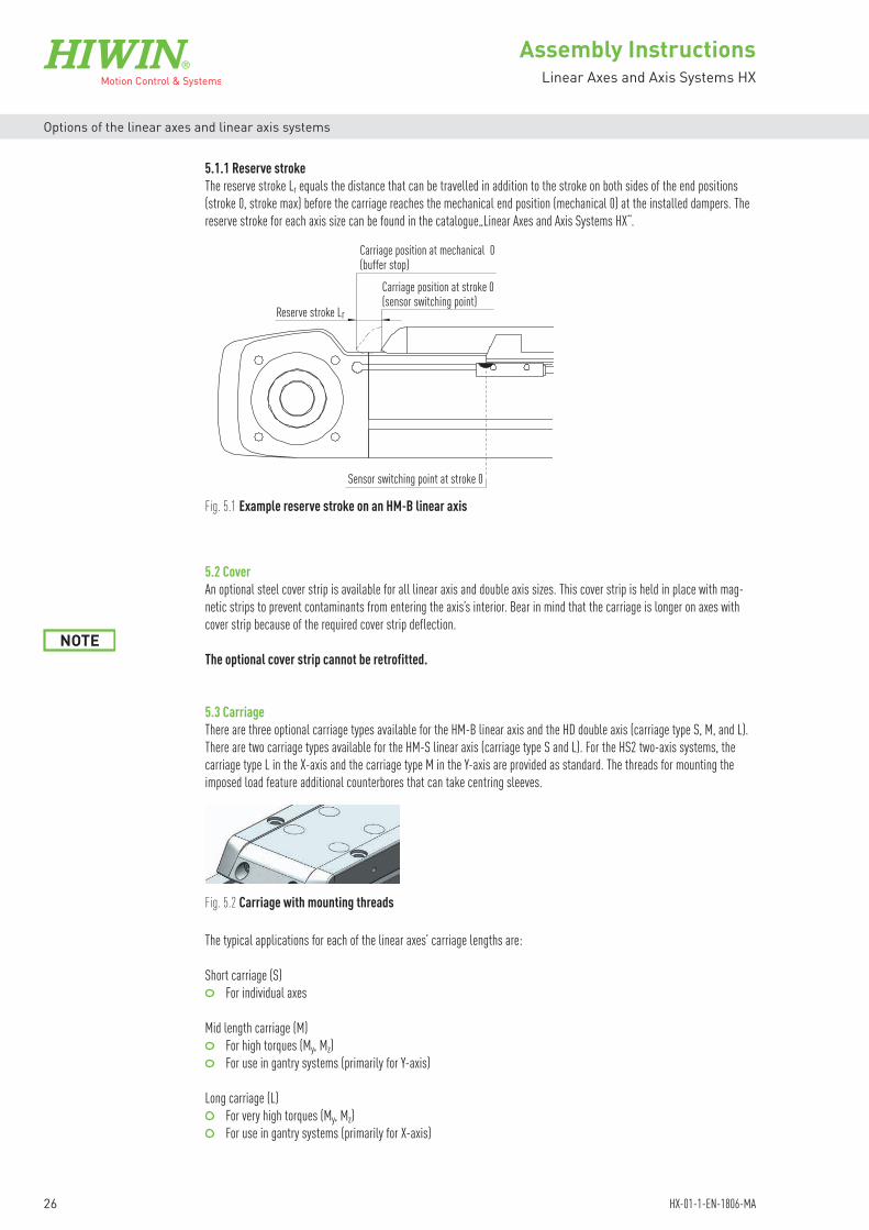
5.1.1 Reserve strokeThe reserve stroke Lr equals the distance that can be travelled in addition to the stroke on both sides of the end positions (stroke 0, stroke max) before the carriage reaches the mechanical end position (mechanical 0) at the installed dampers. The reserve stroke for each axis size can be found in the catalogue„Linear Axes and Axis Systems HX“.
Fig. 5.1 Example reserve stroke on an HM-B linear axis
Reserve stroke Lr
Carriage position at mechanical 0(buffer stop)
Carriage position at stroke 0(sensor switching point)
Sensor switching point at stroke 0

27
Assembly InstructionsLinear Axes and Axis Systems HX
HX-01-1-EN-1806-MA
Options of the linear axes and linear axis systems
Fig. 5.3 Carriage types S, M and L
5.4 Limit switchesThe linear axes feature two inductive PNP or proximity switches that signal the end positions of the travel distance. The limit switch cables can be routed either directly to the interface or into the mounting groove. The limit switches are available as N/C or N/O contacts, with or without plug.
5.4.1 Limit switch dimensions
Fig. 5.4 Limit switch dimensions
5.4.2 Limit switch specifications
Properties N/C contact (25-000786) N/C contact (25-000787) N/O contact (25-000788)Housing RectangularDimensions (W × H × D) 8 × 8 × 40 mmMax. sensing range 2 mmSwitching frequency 2,000 HzConnection type Cable with M8, 3-pin plug,
100 mmCable, 3-wire, 4 m Cable, 3-wire, 5 m
Output type PNPElectrical wiring DC 3-wireProtection class IP67, IP68 1)
1) According to EN 60529
Table 5.2 General features of the limit switches
8
Connection
LED indicator 270°
Threaded mounting hole
2.5
Ø 3.2
Ø 2.9
40 2010
4.5
8.1

28
Assembly InstructionsLinear Axes and Axis Systems HX
HX-01-1-EN-1806-MA
Options of the linear axes and linear axis systems
Mechanics/electronics N/C contact (25-000786) N/C contact (25-000787) N/O contact (25-000788)Supply voltage 10 to 30 VDCRipple ≤ 10 % 1)
Voltage drop ≤ 2 V 2)
Current consumption ≤ 10 mA 3)
Time delay before availability ≤ 100 msHysteresis 5 to 15 %Repeatability ≤ 2 % 4)
Temperature drift ±10 %EMC According to EN 60947-5-2Continuous current Ia ≤ 200 mACable material PVCShort-circuit protection YesReverse polarity protection YesPower-up pulse protection YesShock and vibration resistance 30 g, 11 ms/10 to 55 Hz, 1 mmAmbient operating temperature –25 °C to +75 °CHousing material Plastic, VISTAL®
Sensing face material Plastic, VISTAL®
UL-File-No. (certificate) NRKH.E3484981) Of Uv 2) At Ia max.3) Without load4) At constant voltage and temperature
Table 5.3 Mechanics/electronics of the limit switches
1 3
4 Pin assignment:1: Brown (+ supply voltage)3: Blue (0 V)4: Black (switching output)
Fig. 5.5 Connection diagram Fig. 5.6 Pin assignment of limit switch plug
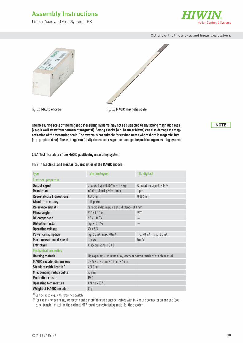
5.5 Positioning measuring systemThe HIWIN-MAGIC positioning measuring system is used when direct, higher-precision distance measurements are needed in addition to the servo drive’s encoder signal. The encoder housing is electrically shielded. The output signals can be either analogue or digital.The HIWIN-MAGIC positioning measuring system consists of the encoder (Fig. 5.7) and the magnetic scale (Fig. 5.8) as the measurement standard. It is assembled prior to delivery.
brn + Supply voltage
blk Switching output
blu 0 V
29
Assembly InstructionsLinear Axes and Axis Systems HX
HX-01-1-EN-1806-MA
Options of the linear axes and linear axis systems
Fig. 5.7 MAGIC encoder Fig. 5.8 MAGIC magnetic scale
The measuring scale of the magnetic measuring systems may not be subjected to any strong magnetic fields (keep it well away from permanent magnets!). Strong shocks (e.g. hammer blows) can also damage the mag-netization of the measuring scale. The system is not suitable for environments where there is magnetic dust (e.g. graphite dust). These things can falsify the encoder signal or damage the positioning measuring system.
NOTE
5.5.1 Technical data of the MAGIC positioning measuring system
Type 1 VPP (analogue) TTL (digital)Electrical propertiesOutput signal sin/cos, 1 VPP (0.85 VPP – 1.2 VPP) Quadrature signal, RS422Resolution Infinite, signal period 1 mm 1 µmRepeatability bidirectional 0.003 mm 0.002 mmAbsolute accuracy ± 20 µm/mReference signal 1) Periodic index impulse at a distance of 1 mmPhase angle 90° ± 0.1° el 90°DC component 2.5 V ± 0.3 V —Distortion factor Typ. < 0.1 % —Operating voltage 5 V ± 5 %Power consumption Typ. 35 mA, max. 70 mA Typ. 70 mA, max. 120 mAMax. measurement speed 10 m/s 5 m/sEMC class 3, according to IEC 801Mechanical propertiesHousing material High-quality aluminium alloy, encoder bottom made of stainless steelMAGIC encoder dimensions L × W × B: 45 mm × 12 mm × 14 mmStandard cable length 2) 5,000 mmMin. bending radius cable 40 mmProtection class IP67Operating temperature 0 °C to +50 °CWeight of MAGIC encoder 80 g1) Can be used e.g. with reference switch 2) For use in energy chains, we recommend our prefabricated encoder cables with M17 round connector on one end (cou-
pling, female), matching the optional M17 round connector (plug, male) for the encoder.
Table 5.4 Electrical and mechanical properties of the MAGIC encoder
30
Assembly InstructionsLinear Axes and Axis Systems HX
HX-01-1-EN-1806-MA
Options of the linear axes and linear axis systems
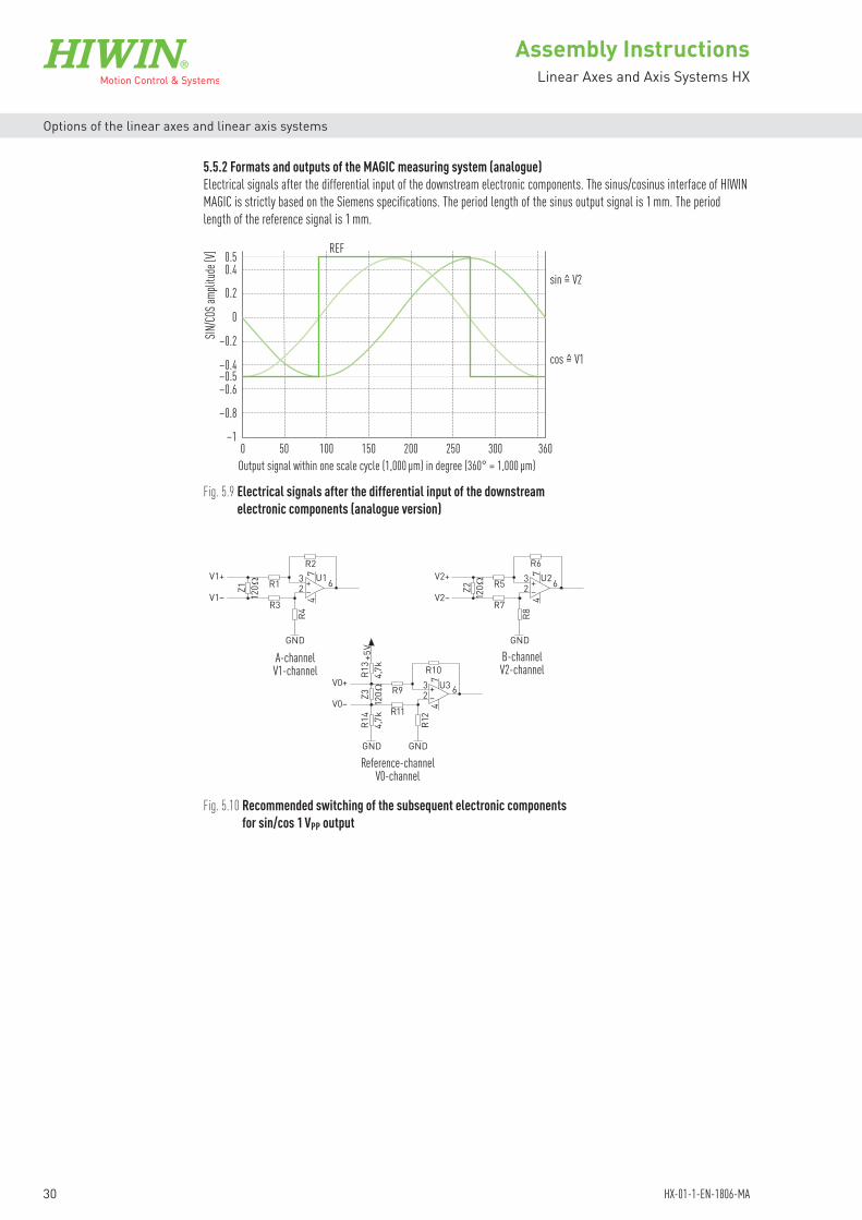
5.5.2 Formats and outputs of the MAGIC measuring system (analogue)Electrical signals after the differential input of the downstream electronic components. The sinus/cosinus interface of HIWIN MAGIC is strictly based on the Siemens specifications. The period length of the sinus output signal is 1 mm. The period length of the reference signal is 1 mm.
Fig. 5.9 Electrical signals after the differential input of the downstream electronic components (analogue version)
Fig. 5.10 Recommended switching of the subsequent electronic components for sin/cos 1 VPP output
cos = V1
sin = V2
0–1
–0.8
–0.6–0.5–0.4
–0.2
0
0.2
0.40.5
50
REF
100 150 200 250 300 360Output signal within one scale cycle (1,000 µm) in degree (360° = 1,000 µm)
SIN/CO
S amp
litude
[V]
A-channelV1-channel
B-channelV2-channel
Reference-channelV0-channel
GND
GND GND
GND
V1+
V1–
V0+
V0–
V2+
V2–
R44
7
47
32
32
6U1 6U2R2 R6
R5
R7
R8
R1
R3–+
473
2 –+
–+
120Ω
120Ω
120ΩZ1
Z3
Z2
R14
R12R11
R9 U3 6
R10R13 +
5V4,
7k4,
7k

31
Assembly InstructionsLinear Axes and Axis Systems HX
HX-01-1-EN-1806-MA
Options of the linear axes and linear axis systems
5.5.3 Formats and outputs of the MAGIC measuring system (digital)Digital TTL output: 90° phase shifted square signal in compliance with RS422 specification (according to DIN 66259); Recommended termination Z = 120 Ω; Differential output signal: A, Ā, B, B and Z, Z. As an option: single reference pulse and definition of a minimum pulse duration.
Fig. 5.11 Signals of the MAGIC encoder (TTL version)
Fig. 5.12 Recommended switching of the subsequent electronic components for digital TTL output
For more information, please refer to the assembly instructions “HIWIN MAGIC Positioning Measuring Systems”.
0°
Z-signal(Reference signal)
B-signal
A-signal
90° 180° 270° 360° 0°
A-channel B-channel
Reference-channel
GND
RS422
+5V
GND
RS422
+5V
GND
RS422
+5V
B
B– 120ΩZ1
A
A–
Z
Z–
120ΩZ0
120ΩZ2

32
Assembly InstructionsLinear Axes and Axis Systems HX
HX-01-1-EN-1806-MA
Options of the linear axes and linear axis systems
5.6 Drive interfacesThe HM-B linear axis allows the drive unit (coupling, also gears and/or motor) to be mounted on both sides of the drive blocks. Depending on the motor, delivery includes a coupling housing, a matching coupling, and an adapter plate for the motor and/ or gears.Possible drive interfaces:
Fig. 5.13 Drive interfaces of the HM-B linear axis
Fig. 5.14 Drive interfaces of the HM-S linear axis
Fig. 5.15 Drive interfaces of the HD double axis
Fig. 5.16 Drive interfaces of the HS2 two-axis system
N L R
N S L R A B
N: NoneL: LeftR: Right
N: NoneS: StraightL: LeftR: RightA: TopB: Bottom
N: Without drive adapter/without energy chainL: Drive adapter on left hand sideR: Drive adapter on right hand side
A: Without drive adapter, drive interface on left hand sideB: Without drive adapter, drive interface on right hand side
N: NoneL: LeftR: Right
On the HM-S linear axis, the drive is mounted in the spindle extension. Depending on the motor, delivery includes a coupling housing, a matching coupling, and an adapter plate for the motor. If fitted with a belt drive, the motor may also be swivelled through 180°, reducing effectively the overall length of the HM-S linear axis.Possible drive interfaces:
The double axis HD allows the drive unit (coupling, also gears and/or motor) to be mounted on the right hand and on the left hand side, in each case in the extension of the synchronous shaft. Depending on the motor, delivery includes a coupling housing, a matching coupling, and an adapter plate for the motor and/ or gears.Possible drive interfaces:
The two-axis system HS2 allows the drive unit and energy chain to be mounted on the right hand and on the left hand side. Drive unit and energy chain can be selected individually for each axis. Depending on the motor, delivery includes a coupling housing, a matching coupling, and an adapter plate for the motor and/ or gears.Possible drive interfaces:
N L R
RL BAN

33
Assembly InstructionsLinear Axes and Axis Systems HX
HX-01-1-EN-1806-MA
Options of the linear axes and linear axis systems
5.7 MotorWhen using HIWIN servo motors and/or drives, consult the information at www.hiwin.de:
Assembly and commissioning instructions “D2 Servo Drive” Catalogue „Drives and Servo Motors“
5.8 Gear boxes (HM-B, HD, HS2)Gears are used to adjust the motor speed and inertia. The linear axes come with a range of gear sizes of differing ratios. For the standard gear versions see Table 5.5
Table 5.5 Gear boxes for toothed belt axes HM-B, double axes HD and two-axis systems HS2
Linear axis Ratio i Gear box type 1)
HM040B HD1 HS21
3 PLE40-35 PLE40-58 PLE40-8
12 PLE40-12HM040B HM060B HD1, HS21 HD2, HS22
3 PLQE60-35 PLQE60-58 PLQE60-8
12 PLQE60-12HM060BHM080B HD2, HS22 HD3, HS23
3 PLQE80-35 PLQE80-58 PLQE80-8
12 PLQE80-12HM080BHM120B HD3, HS23 HD4
3 PLQE120-35 PLQE120-58 PLQE120-8
12 PLQE120-121) PLE and PLQE are registered trademarks of Neugart GmbH
5.9 Toothed belt (HM-B)The used toothed belts with steel tie beams are designed to transfer high torques. The rounded tooth geometry is designedfor uniform torque transfer. Also the uniform distribution of load minimises deformation in the teeth.
Advantages: Form fit, nonslip drive system High capacity Little space requirements Large speed range Low toothed belt tension No lubrication or maintenance Quiet running High efficiency (98 %)
5.10 Spindle support (HM-S)With long strokes at high speeds, the HM-S linear axis can reach the critical spindle speed. These must then be supported accordingly. HIWIN spindle axes (with the exception of the HM040S) allow up to three optional spindle supports to be fitted on each side of the carriage. The critical speeds for spindle support can be taken from the catalogue “Linear Axes and Axis Systems HX”.

34
Assembly InstructionsLinear Axes and Axis Systems HX
HX-01-1-EN-1806-MA
Options of the linear axes and linear axis systems
5.11 Energy chainOptional energy chains are available for the HS multi-axis systems. All directions of movement are supported and the chains can be installed on either the right or the left. The generously dimensioned energy chains provide enough space for the supply cables to be carried safely. They are extremely compact and achieve space savings when integrated into the system as a whole. For details of the different energy chain types and sizes, please see Table 5.6. The energy chains are perfectly matched to the attachable drive axis motors and can accommodate the space requirements of standard motor/signal cables. As well as this, they contain enough space for additional cables and hoses.
The upper run is self-supporting but there is a surface for the lower run that supports the energy chain as it unrolls. To prevent the cables and hoses from riding over each other, there is a partition in every second link. The connecting pieces are of a rigid design. Strain relief combs are fitted at both ends so that the cables and hoses can be secured with cable ties. To ensure that the energy chains are handled correctly, and that the cables and hoses are installed and secured properly, please observe the assembly instructions from the energy chain manufacturer.
General notes: For details of suitable motor and signal cables, please refer to the operating manual from the motor manufacturer. Observe the minimum bending radii (industrial standard 8 × D) specified for the cables and hoses, and the associated
service life that is to be anticipated. In the case of shielded cables, make sure the shields are resistant to bending. Low-friction and abrasion-resistant cable/hose sheaths should be used. To prevent cables and hoses with different outer sheaths from bonding, separate them with separators. Ensure twist-free installation of cables and hoses. Leave enough spare room (10 to 20 %, at least 1 mm) all the way around the cables and hoses, and allow for the lateral
expansion that occurs when hoses are pressurised. Make sure that the weight is distributed evenly/symmetrically. Ideally, heavy cables and hoses should be positioned at
the outer edges. Provide strain relief for cables and hoses at both ends so that they are located in the neutral zone when the energy chain
is in the extended position and can move freely within its radius. In the case of high acceleration values or if the cables have a wide variety of diameters, use additional separators where
applicable. Observe the maximum additional load from cables and hoses that is permitted based on the stroke (see Fig. 5.17 and
Fig. 5.18).
Table 5.6 Energy chain specifications
System Energy chain X-axis Energy chain Y-axisManufacturer ID 1)
Inside cross-section W × H [mm]
Bending radius [mm]
Manufacturer ID 1)
Inside cross-section W × H [mm]
Bending radius [mm]
HS21 2400.07.100.0 77 × 25 100 2400.05.075.0 57 × 25 75HS22 2600.07.100.0 75 × 35 100 2400.05.075.0 57 × 25 75HS23 2600.07.100.0 75 × 35 100 2400.07.100.0 77 × 25 100HS24 2600.10.125.0 100 × 35 125 2400.07.100.0 77 × 25 1001) Manufacturer: igus GmbH

35
Assembly InstructionsLinear Axes and Axis Systems HX
HX-01-1-EN-1806-MA
Options of the linear axes and linear axis systems
8.0
20.0
10.0
6.04.02.0
1.5
1.0
0.5
02,000 4,000 6,0000
Fill w
eight
[kg/m
]
Stroke [mm]
8.0
20.0
10.0
6.04.02.0
1.5
1.0
0.5
02,000 4,000 6,0000
Fill w
eight
[kg/m
]
Stroke [mm]
Fig. 5.17 Maximum permissible additional load as a function of the stroke, Series 2400 (source: igus)
Fig. 5.18 Maximum permissible additional load as a function of the stroke, Series 2600 (source: igus)

36
Assembly InstructionsLinear Axes and Axis Systems HX
HX-01-1-EN-1806-MA
Transport and installation
6. Transport and installation
6.1 Delivery
6.1.1 Delivery stateThe linear axes and linear axis systems are supplied fully assembled and function tested.
6.1.2 Scope of deliveryThe contents of delivery vary depending on the ordered model, accessories, and options.
6.2 Transport to the installation site
Damage to the linear axes/linear axis systems!The linear axis/linear axis system may be damaged by mechanical loading.Hoist the linear axes/linear axis systems only at the designated points (see Section 6.5)!For longer linear axes/linear axis systems, provide additional protection of the centre section! Ensure that the linear axes/linear axis systems do not bend as this could permanently damage accuracy!During transport, do not transport any additional loads on the linear axis/linear axis system!Provide heavy attachments with additional supports!
ATTENTION!
6.3 Requirements at the installation site
6.3.1 Ambient conditionsAmbient temperature + 5 °C to + 40 °C, non-condensingInstallation site flat, dry, vibration-freeAtmosphere not corrosive, not explosive, no vacuum
6.3.2 Safety equipment to be provided by the operatorPossible safety equipment/measures:
Personal protective equipment in accordance with UVV (German accident prevention regulations) Zero-contact protective equipment Mechanical protective equipment
The linear axes and linear axis systems are precision products and must be treated with care. Impacts of any kind may dam-age the axis. The result may be compromised running precision and service life. Transport the packaged product as close as possible to its installation site. Remove the packaging at this site only.
Danger of impacts and crushing! If the axes are moved/driven manually, injuries can be caused by moving axes and attachments (energy
chains, attachments installed by customer). Observe the applicable occupational health and safety regulations! Transport to the installation site only by qualified personnel!
CAUTION!
Danger from suspended loads or falling parts! Lifting heavy loads may damage your health! Only qualified personnel may assemble, install, and service the linear axes/linear axis systems!
Note the mass when transporting the parts. Use suitable hoisting gear! Observe the applicable occupational health and safety regulations when handling suspended loads! Hoist the linear axes/linear axis systems only at the designated points! Secure machinery and machine parts against tilting!
WARNING!

37
Assembly InstructionsLinear Axes and Axis Systems HX
HX-01-1-EN-1806-MA
Transport and installation
6.4 Storage Store the linear axes/linear axis systems in their transport packaging. Alternatively: Use packaging that secures the linear axes/linear axis systems against slipping, damage, and vibrations. Store the linear axes/linear axis systems in dry, frost free rooms only. Clean and protect used linear axes/linear axis systems before storage.
Remove packaging. To transport the linear axis, hoist it at the points designated A and B (see Fig. 6.1 and Fig. 6.2). The points A and B
should be a quarter of the axis’ overall length from each of its ends. Do not hoist the linear axis by its attachments. During transport, provide additional support for heavy attachments such
as the drive. Dispose of packaging in an environmentally friendly way.
The linear axes HM-B/HM-S, double axes HD and the multi-axis systems HS may only be installed and operated indoors.
NOTE
Warning! Health and environmental hazards! Contact with lubricants may cause irritation, poisoning, allergic reactions, and damage to the environment. Use only suitable, non-hazardous agents. Note the manufacturer’s safety data sheets!
Ensure proper disposal!
ATTENTION!
Fig. 6.1 Points A and B for hoisting and transporting, here on an HM-B linear axis
Point A
Point B
6.5 Unpacking and installing
6.5.1 Unpacking and installing the linear axes HM-B/HM-S

38
Assembly InstructionsLinear Axes and Axis Systems HX
HX-01-1-EN-1806-MA
Transport and installation
6.5.2 Unpacking and installing the double axes HD and axis systems HS Remove the protective film from the pallet and the transport securing device from the packaging. Prior to transport, secure all moving parts to prevent them from slipping. To transport the double axis/axis system, hoist it by the designated support points A, B, C and D (see Fig. 6.3). Use
suitable hoisting gear for this purpose, such as an underslung or gantry crane, crane slings and – depending on the dimensions – a lifting beam. The points A and B as well as C and D should be a quarter of the axis’ overall length from each of its ends.
Do not hoist the double axis/axis system by the spacer profiles, cross axis or attachments. During transport, provide additional support for heavy attachments such as the drive.
Fig. 6.3 Points A, B, C and D for hoisting and transporting, here on an two-axis system HS2
Do not remove the transportation safety devices from the axis system until after it has been transported and assembled properly (see Section 7.1)!
NOTE
Point D
Point C
Spacer profile
Cross axis
Point A
Point B
Fig. 6.2 Points A and B for hoisting and transporting, here on an HM-S linear axis
Point A
Point B

39
Assembly InstructionsLinear Axes and Axis Systems HX
HX-01-1-EN-1806-MA
Assembly and connection
7. Assembly and connection
Danger of impacts and crushing! Uncontrolled or manual carriage movements may cause injury. Isolating protective equipment must be provided for linear axis/linear axis system operations!
Only qualified personnel may be assigned to commissioning, setup, and troubleshooting!
WARNING!
Danger of impacts and crushing! Uncontrolled movements by the powered elements of the linear axis/linear axis system may cause injury. Controller design complying with DIN EN 12100. No start after
– power connected, reinstated! – troubleshooting! – machine stop!
WARNING!
Warning! Damage to hearing! The linear axes/linear axis systems can generate noise in excess of 70 dB(A) at high speeds. Hearing protection must be worn when high speed linear axes/linear axis systems generate noise greater
than 70 dB(A)!
CAUTION!
Danger from suspended loads or falling parts! Only qualified personnel may assemble, install, and service the linear axes/linear axis systems! Note the mass when transporting the parts. Use suitable hoisting gear!
Observe the applicable occupational health and safety regulations when handling suspended loads! Hoist the linear axes/linear axis systems only at the designated points! Secure machinery and machine parts against tilting! Secure the linear axes/linear axis systems as described in the instructions! When installing a vertical linear axis/linear axis system, provide support for the carriage during down-
times!
CAUTION!
Danger of impacts and crushing due to imposed load becoming detached! If the fastener is fastened incorrectly or fails, injuries can be caused by falling or flying parts. Your assembly must ensure that parts cannot detach even under high accelerations or constant vibra-
tions! Secure the imposed load as described in the assembly instructions!
CAUTION!
Danger of cutting injuries! Installing or removing the cover strip may cause cutting injuries. Only qualified personnel wearing appropriate protective equipment (gloves, goggles) may be assigned to
commissioning and setup!
WARNING!
Danger of impacts and crushing! If the axes are moved by the motor, injuries can be caused by moving axes and attachments (energy chains,
attachments installed by customer). Isolating protective equipment must be provided for linear axis/linear axis system operations! When installing a vertical linear axis/linear axis system, provide support for the carriage during down-
times!
CAUTION!

40
Assembly InstructionsLinear Axes and Axis Systems HX
HX-01-1-EN-1806-MA
Assembly and connection
Warning! Electric shock or burns by contact with live parts! Contact with live parts can result in injuries. If the customer installs cables incorrectly, the constant motion inside the energy chain can cause chafing
and expose the electrical contact points. Controller design complying with DIN EN 12100. No start after - power connected, reinstated! - troubleshooting! - machine stop! Only qualified personnel may install cabling! Only qualified personnel may work on electrical installations!
CAUTION!
Danger of injury!Rotation of the toothed belt pulley or the synchronous shaft during movement of the carriage(s) can result in fingers, hair or items of clothing getting caught and entangled. Isolating protective equipment must be provided for linear axis/linear axis system operations! Only qualified personnel may be assigned to commissioning, setup, and troubleshooting!
CAUTION!
Warning! Health and environmental hazards! Contact with lubricants may cause irritation, poisoning, allergic reactions, and damage to the environment. Use only suitable, non-hazardous agents. Note the manufacturer’s safety data sheets!
Ensure proper disposal!
ATTENTION!

41
Assembly InstructionsLinear Axes and Axis Systems HX
HX-01-1-EN-1806-MA
Assembly and connection
7.1 Assembling the linear axes, double axes and axis systemsThe HM-B/HM-S linear axis can be installed in any position. Fasteners must be applied to the axis’ aluminium profile. The HS axis systems cannot just be installed in any position. Technical clarification must be sought before mounting them overhead. If the HD double axis is mounted vertically at the side, spacers must be added to the synchronous shaft coupling (see Fig. 7.1). The axis, double axis and axis system can be secured to the mounting surface by means of clamping profiles (side grooves) or T nuts (grooves at bottom). Bear in mind that, depending on the installation position, the linear axis weight acts as an ad-ditional load and that the actually induced forces and torques must remain within the permitted range (see catalogue “Linear Axes and Axis Systems HX”).
FG
Fig. 7.1 Addition of a spacer when HD double axes are mounted vertically at the side
The axis’ aluminium profile has been extruded in compliance with EN 12020-2. NOTE
If higher running precision is required, the axis must be aligned and secured to a precision reference edge. NOTE
The spacer profiles of the HD double axis and HS multi-axis systems must not be removed until the axes have been secured with T nuts in accordance with Section 7.1.2 or with clamping profiles in accordance with Section 7.1.3.It may be necessary to remove the synchronous shaft first before removing the spacer profile. For further details, see Section 8.5.
NOTE
Please note the support spacing for each of the axis sizes (see Section 3.3, “Maximum support spacing”). Not only the end blocks may lie on the mounting surface.
The bolts must be secured to prevent them coming loose.
NOTE
NOTE
HM-B/HM-S linear axisWhen securing the HM-B/HM-S linear axis, mount the axis on a flat surface and make sure that the mounting points are aligned with each other so that the necessary flatness of 0.2 mm/m is achieved.
HD double axis and HS multi-axis systemWhen securing the HD double axis and the HS multi-axis system, mount the relevant axis system on a flat surface. Make sure that the mounting points are aligned with each other so that the necessary flatness of 0.2 mm/m and the necessary parallelism of 0.2 mm are achieved.
7.1.1 Reference surface accuracy requirements

42
Assembly InstructionsLinear Axes and Axis Systems HX
HX-01-1-EN-1806-MA
Assembly and connection
The T nuts to be used for each axis size are given in Table 7.1. In the case of single axes, the T nuts must be arranged as per Fig. 7.3 and Fig. 7.6 or Fig. 7.7; in the case of double axes and multi-axis systems, they must be arranged as per Fig. 7.4 and Fig. 7.6 or Fig. 7.7. Four T nuts (six for HM120 and HD4) must be used at each mounting point. The required number of T nuts depends on the external load. To calculate the required number, the load values listed in Table 7.1 (clamping force per T nut; permissible axial operating force in tension direction per T nut) must be taken into account. Don’t drop below the minimum number of T nuts specified in Table 7.1. The T nuts are to be positioned grouped in the form of mounting points as shown in Fig. 7.6 and Fig. 7.7. Make sure that each mounting point for itself transmits the external load safely. The distances between the mounting points are to be selected depending on the load situation. The recommended distances LNX listed in Table 7.1 are only reference values.
Note the hole spacing LNY when securing the linear axes and linear axis systems.
7.1.2 Assembly with T nuts
Drill mounting holes in the mounting surface (hole spacing listed in Table 7.1).Clean mounting surface and position linear axis on it. Swivel the T nut into the bottom groove.Secure the T nut with a small tightening torque on the bolts.Now tighten the bolts with the full tightening torques, proceeding in a crosswise manner.
The linear axis has now been installed.
LNY
FA
Precision requirements for all reference surfaces for securing the axis profile.
Level of accuracy required for all reference surfaces in order to secure the axis profiles
0.2 mm/m
0.2 mm/m
0.2 A
A
Y
X
Fig. 7.2 Flatness and parallelism requirements for mounting HD double axes and HS multi-axis systems
Fig. 7.3 Hole spacing for securing the linear axes with a T nut from below

43
Assembly InstructionsLinear Axes and Axis Systems HX
HX-01-1-EN-1806-MA
Assembly and connection
LNY LNYDNY
D
FA FA
Fig. 7.4 Hole spacing for securing the double axes HD with a T nut from below
Fig. 7.5 Permissible axial operating force in tension direction per slot nut (FA_perm.)
FA_perm.
Table 7.1 Minimum number of T nuts for securing the axis, and recommended spacing of mounting points on long axes
Size Minimum number of T nuts
LNY [mm]
DNY [mm]
Recommended distance LNX [mm]
Thread size
Screw tighten-ing torque [Nm]
Clamping force per T nut [N]
FA_perm. 1) [N]
Art. no. T nuts (10 pcs)
HM040/HD1 8 20 D + 20 400 M5 4.5 5,400 500 20-000529HM060/HD2 8 40 D + 20 600 M6 10.1 10,200 1,750 20-000531HM080/HD3 8 40 D + 40 800 M8 24.6 18,600 5,000 20-000534HM120/HD4 12 80 D + 40 1,200 M8 24.6 18,600 5,000 20-0005341) Permissible axial operating force in tension direction per T nut
LNX
L NY
LNX
L NY
Fig. 7.6 Securing with T nuts – HM040, HM060, HM080
Fig. 7.7 Securing with T nuts – HM120

44
Assembly InstructionsLinear Axes and Axis Systems HX
HX-01-1-EN-1806-MA
Assembly and connection
Observe the LSY hole spacing (Fig. 7.8) when securing linear axes, and the LSY and DSY hole spacings (Fig. 7.9) in the case of linear axis systems.
7.1.3 Mounting with clamping profiles
Precision requirements for all reference surfaces for securing the axis profile.
LSY
LB
FA
DSY
LSY
LB
LSY
LB
DFA FA
0.2 mm/m
The clamping profiles must always be attached in pairs to the left and right of the axis body (see Fig. 7.10 and Fig. 7.11). The required minimum number must be taken from Table 7.2. The required number of clamping profiles depends on the external load. To calculate the required number, the load values listed in Table 7.2 (clamping force per clamping profile; permissible axial operating force in tension direction per clamping profile) must be taken into account. Don’t drop below the minimum number of clamping profiles specified in Table 7.2. The distances between the mounting points are to be selected depending on the load situation. The recommended distances LSX listed in Table 7.2 are only reference values.
Drill mounting holes in the mounting surface (hole spacing listed in Table 7.2).Clean mounting surface and position linear axis on it. Swivel the clamping profile into the side groove.Secure the clamping profile with a small tightening torque on the bolts.Now tighten the bolts with the full tightening torques, proceeding in a crosswise manner.
The linear axis has now been installed.
Fig. 7.8 Hole spacing for the lateral securing of linear axes with clamping profiles
Fig. 7.9 Hole spacing for the lateral securing of double axes with clamping profiles

45
Assembly InstructionsLinear Axes and Axis Systems HX
HX-01-1-EN-1806-MA
Assembly and connection
Table 7.2 Minimum number of clamping profiles for securing the axis, and recommended spacing of mounting points on long axes
LSX
L SY
40
LSX
L SY
40 40
Fig. 7.10 Securing with clamping profiles – HM040, HM060, HM080
Fig. 7.11 Securing with clamping profiles – HM120
Size Min. number of clamping profiles
LSY [mm]
DSY [mm]
LB [mm]
Recom-mended distance LSX [mm]
Thread size
Screw tightening torque [Nm]
Clamping force per clamping profile [N]
FA_perm. 1) [N]
Art. no. clamping profiles (4 pcs)
HM040/HD1 4 55 D – 15 70 400 M5 4.9 4,700 200 20-000517HM060/HD2 4 80 D – 20 100 600 M6 6.4 5,500 500 20-000518HM080/HD3 4 100 D – 20 120 800 M8 18.5 11,400 1,200 20-000519HM120/HD4 4 140 D – 20 160 1,200 M8 18.5 17,000 2,400 20-0005201) Permissible axial operating force in tension direction per pair of clamping profiles

46
Assembly InstructionsLinear Axes and Axis Systems HX
HX-01-1-EN-1806-MA
Assembly and connection
Clean mounting surfaces at the carriage.Clean the mounting surface of the load.Position the load on the carriage of the linear axis.Tighten the mounting bolts crosswise.If necessary, use centring sleeves.Check the free movement of the load over the entire stroke.Lock the bolts.
7.2 Mounting the imposed loadThe spacings of the threaded holes for mounting the imposed load are identical for all drive options available to a size. Additional counterbores can take centring rings.
Size Thread size × depth Counterbore depth for centring sleeve [mm]
Counterbore diameter for centring sleeve [mm]
HM040 M5 × 10 1.5 Ø8 H7HM060 M6 × 12 1.5 Ø8 H7HM080 M8 × 16 2.0 Ø12 H7HM120 M10 × 22 2.0 Ø15 H7
Table 7.3 Threaded holes for securing the imposed load
Fig. 7.12 Securing the load with centring sleeves (HM-B)
Fig. 7.13 Securing the load with centring sleeves (HM-S)
The imposed load has now been installed.
Precision requirements for the imposed load’s mounting surface.0.02
If you are using HM-B linear axes and HD double axes with more than one carriage, only insert centring sleeves in one of the carriages.
NOTE

47
Assembly InstructionsLinear Axes and Axis Systems HX
HX-01-1-EN-1806-MA
Assembly and connection
Loosen the half shell coupling at one end of the synchronous shaft by undoing the clamping screws slightly. Keep alternating between the two clamping screws as you undo them to avoid overload. Once the carriage is able to move freely on this side of the double axis, the adapter plate can be mounted.
Mount the adapter plate on one of the carriages as described in Section 7.2. Adjust the second carriage in the axial direction so that the prepared mounting holes are perfectly aligned in the axial
direction.Mount the adapter plate on the second carriage as described in Section 7.2.Mount the synchronous shaft as described in Section 7.6.
7.2.1 Carriage synchronisation with double axesIf you are using an HD double axis and need to mount an adapter plate for the load above both carriages, the carriages must first be precisely aligned with each other in the axial direction.
Fig. 7.14 Mounting the adapter plate above both double axis carriages
The distance between axes may be subject to certain tolerances at right angles to the axial direction. Therefore, the mounting holes of the adapter plate for the second carriage should ideally take the form of elongated holes.
NOTE

48
Assembly InstructionsLinear Axes and Axis Systems HX
HX-01-1-EN-1806-MA
Assembly and connection
7.3 Mounting the limit switchesThe limit switches are available as an N/C or N/O contact. The limit switch can be secured directly in the limit switch groove (T groove) with the provided M3 bolts and nuts. The limit switches can be mounted on the left or right.
If necessary, remove the green decorative strip from the upper T groove.Push two nuts into the upper T groove through the notch at the drive block.Attach the limit switch with two bolts (in the case of axis size HM040, the spacer plate must also be installed between
the limit switch and axis, see Fig. 7.16). First leave the two bolts untightened.Push the limit switch to the required position, and press it up slightly.Tighten the bolts. The tightening torque is 0.5 Nm.
The limit switches have now been installed.
Fig. 7.15 Mounting the limit switch: HM060, HM080, HM120
Fig. 7.16 Mounting the limit switch: HM040
7.4 Mounting the damping elementThe damping element actuates the limit switches at the carriage’s two end positions (at stroke 0 and stroke max) and must be mounted on the same side as the limit switches.
Place the damping element at the carriage.Using the enclosed M3 bolts, secure the damping element loosely on the carriage.Align the damping element parallel to the carriage’s lower edge.
The damping element has now been pre-installed.
Fig. 7.17 Mounting the damping element

49
Assembly InstructionsLinear Axes and Axis Systems HX
HX-01-1-EN-1806-MA
Assembly and connection
7.5 Setting the switching distanceThe limit switches are inductive units and need a defined switching distance of 0.8 mm (±0.2 mm) to the damping element.
Move the carriage until the damping element is above a limit switch. Using a feeler gauge, align the damping element for a switching distance of 0.8 mm (±0.2 mm). Make sure in doing so that the damping element remains parallel to the carriage’s lower edge.
Tighten the bolts for the damping element. The tightening torque is 1 Nm.If a second limit switch has been installed: Move the carriage until the damping element is above the second limit
switch, and check with a feeler gauge that the switching distance is 0.8 mm (±0.2 mm). Correct where necessary until the switching distance is reached for both limit switches.
Route the limit switch cable into the lower groove. There the cable is protected under the groove cover. The groove cover is available separately, see Section 12.6.
The switching distance has now been set.
Fig. 7.18 Setting the switching distance with a feeler gauge, and tightening the bolts
Fig. 7.19 Mounting the limit switch: Routing the cables
50
Assembly InstructionsLinear Axes and Axis Systems HX
HX-01-1-EN-1806-MA
Assembly and connection
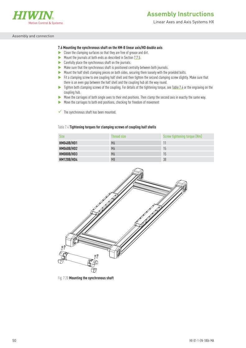
Size Thread size Screw tightening torque [Nm]HM040B/HD1 M6 11HM060B/HD2 M6 15HM080B/HD3 M6 15HM120B/HD4 M8 38
Table 7.4 Tightening torques for clamping screws of coupling half shells
Fig. 7.20 Mounting the synchronous shaft
7.6 Mounting the synchronous shaft on the HM-B linear axis/HD double axisClean the clamping surfaces so that they are free of grease and dirt.Mount the journals at both ends as described in Section 7.7.5.Carefully place the synchronous shaft on the journals.Make sure that the synchronous shaft is positioned centrally between both journals.Mount the half shell clamping pieces on both sides, securing them loosely with the provided bolts.Fit a clamping screw to one coupling half shell and then tighten the second clamping screw slightly. Make sure that
there is an even gap between the half shell and the coupling hub all the way round.Tighten both clamping screws of the coupling. For details of the tightening torque, see Table 7.4 or the engraving on the
coupling hub.Move the carriages of both single axes to their end positions. Then clamp the second axis in exactly the same way.Move the carriages to both end positions, checking for freedom of movement
The synchronous shaft has been mounted.
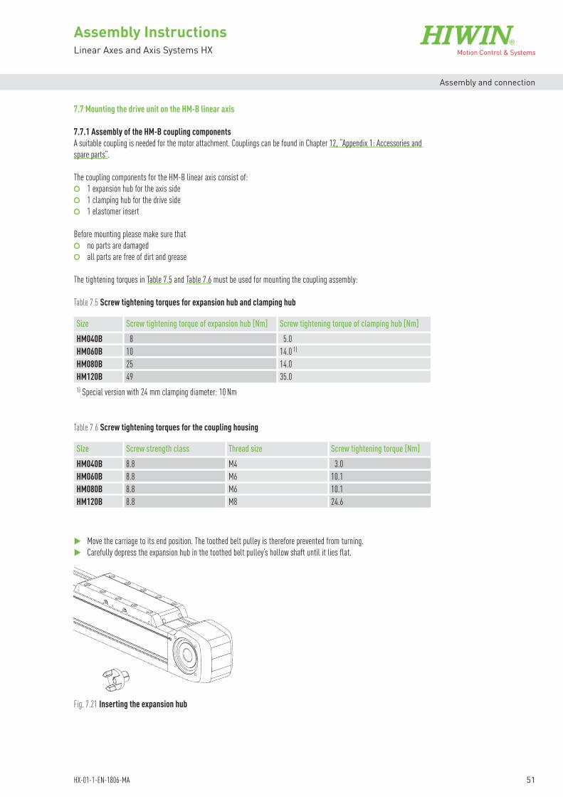
51
Assembly InstructionsLinear Axes and Axis Systems HX
HX-01-1-EN-1806-MA
Assembly and connection
7.7 Mounting the drive unit on the HM-B linear axis
7.7.1 Assembly of the HM-B coupling componentsA suitable coupling is needed for the motor attachment. Couplings can be found in Chapter 12, “Appendix 1: Accessories and spare parts”.
The coupling components for the HM-B linear axis consist of: 1 expansion hub for the axis side 1 clamping hub for the drive side 1 elastomer insert
Before mounting please make sure that no parts are damaged all parts are free of dirt and grease
The tightening torques in Table 7.5 and Table 7.6 must be used for mounting the coupling assembly:
Size Screw tightening torque of expansion hub [Nm] Screw tightening torque of clamping hub [Nm]HM040B 8 5.0HM060B 10 14.0 1)
HM080B 25 14.0HM120B 49 35.01) Special version with 24 mm clamping diameter: 10 Nm
SIze Screw strength class Thread size Screw tightening torque [Nm]HM040B 8.8 M4 3.0HM060B 8.8 M6 10.1HM080B 8.8 M6 10.1HM120B 8.8 M8 24.6
Table 7.5 Screw tightening torques for expansion hub and clamping hub
Table 7.6 Screw tightening torques for the coupling housing
Move the carriage to its end position. The toothed belt pulley is therefore prevented from turning.Carefully depress the expansion hub in the toothed belt pulley’s hollow shaft until it lies flat.
Fig. 7.21 Inserting the expansion hub

52
Assembly InstructionsLinear Axes and Axis Systems HX
HX-01-1-EN-1806-MA
Assembly and connection
The elastomer insert must be lightly preloaded and should have no backlash. If it can be mounted under too slight a pressure, it must be replaced. A small quantity of PU compatible grease can be applied to the elastomer insert for easier installation.
NOTE
At the centre of the expansion hub is an expanding mandrel that is used to secure the coupling. Secure the expansion hub with the tightening torque in Table 7.5.
Attach the elastomer insert to the expansion hub. Using four bolts, mount the coupling housing KB so that it lies flat.
Fig. 7.22 Mounting the expansion hub by tightening the expanding mandrel
Fig. 7.23 Attaching the elastomer insert and mounting the coupling housing KB on the HM-B linear axis
Push the clamping hub onto the elastomer insert until measurement L1 (see Table 7.7) is achieved.
Fig. 7.24 Adjusting the clamping hub distance in the direction of the motor on linear axis HM-B
L1
KB

53
Assembly InstructionsLinear Axes and Axis Systems HX
HX-01-1-EN-1806-MA
Assembly and connection
If the coupling is mounted without a coupling housing, the coupling distance L2 must be set in accordance with Fig. 7.25 and Table 7.8.
NOTE
L2
Fig. 7.25 Total length of HM-B coupling assembly
Axis type Coupling size L1 [mm]HM040B 14 10.0HM060B 19 14.0HM080B 24 16.5HM120B 28 16.7
Axis type L2 [mm]HM040B 27.5HM060B 41.0HM080B 46.0HM120B 48.0
Table 7.7 Adjusting the coupling distance based on measurement L1
Table 7.8 Adjusting the coupling distance based on measurement L2 when there is no coupling housing
7.7.2 Mounting the motor (without gears) Attach the motor adapter plate AM so that it lies flat. In doing so, note the position of the hole for the clamping hub’s
clamping bolt.Tighten the four bolts. See Table 7.9 for the tightening torques.
KB
AM
Fig. 7.26 Mounting the motor adapter plate AM (HM-B)

54
Assembly InstructionsLinear Axes and Axis Systems HX
HX-01-1-EN-1806-MA
Assembly and connection
Fig. 7.27 Bolting the motor to the HM-B linear axis
Take care to slide the motor on straight so that the preset L measurement does not change.NOTE
Remove the seal plugs from the hole on the side of the motor adapter plate AM.Apply the tightening torque in Table 7.5 to the clamping hub’s bolt through the hole.Insert the seal plug back in the hole.
The motor has now been assembled.
The manual for the used gears must be consulted for attaching the motor to the gears.NOTE
Fig. 7.28 Tightening the clamping hub on the motor shaft
KBAM
Secure the motor against falling.Place the motor flat on the motor adapter plate AM.Secure the motor in accordance with the manufacturer’s specifications.
Size Screw strength class Thread size Screw tightening torque [Nm]HM040B 8.8 M4 3.0HM060B 8.8 M6 10.1HM080B 8.8 M6 10.1HM120B 8.8 M8 24.6
Table 7.9 Tightening torques for the motor adapter plate AM

55
Assembly InstructionsLinear Axes and Axis Systems HX
HX-01-1-EN-1806-MA
Assembly and connection
7.7.3 Mounting the gears Attach the gear adapter plate AG so that it lies flat. In doing so, note the position of the hole for the clamping hub’s
clamping bolt.Tighten the four bolts. See Table 7.10 for the tightening torques.
Fig. 7.29 Mounting the gear adapter plate AG
Size Screw strength class Thread size Screw tightening torque [Nm]HM040B 8.8 M4 3.0HM060B 8.8 M6 10.1HM080B 8.8 M6 10.1HM120B 8.8 M8 24.6
Table 7.10 Tightening torques for the gear adapter plate AG
KB
AG
Secure the gears against falling.Place the gears flat on the gear adapter plate AG.Using four bolts, secure the gears in accordance with the manufacturer’s specifications.
Fig. 7.30 Bolting the gears to the linear axis
KBAG

56
Assembly InstructionsLinear Axes and Axis Systems HX
HX-01-1-EN-1806-MA
Assembly and connection
Remove the seal plugs from the hole on the gear adapter plate AG.Apply the tightening torque in Table 7.5 to the clamping hub’s bolt through the hole.Insert the seal plug back in the hole.
The gears have now been installed.
Fig. 7.31 Tightening the clamping hub on the gear shaft
The manual for the used gears must be consulted for attaching a motor to the gears.NOTE
KBAG
7.7.4 Mounting the motor on PLE/PLQE gears 1)
Loosen the gears’ clamping bolt so that you can later insert the motor shaft easily into the gears’ hollow shaft. The provided bush must be used for smaller motor shaft diameters.
Attach the motor gear adapter plate GM so that it lies flat on the gears. In doing so, note the position of the hole for the clamping hub’s clamping bolt.
Tighten the four bolts. See Table 7.11 for the tightening torques.
Fig. 7.32 Mounting the motor gear adapter plate GM (HM-B)
Gears
GM
Table 7.11 Tightening torques for motor gear adapter plates GM
Size Gears 1) Screw strength class Thread size × length Screw tightening torque [Nm]HM040B PLE040 8.8 M3 × 16 1.1HM060B PLQE060 8.8 M5 × 10 5.9HM080B PLQE080 8.8 M6 × 16 10.1HM120B PLQE120 8.8 M8 × 25 24.61) PLE and PLQE are registered trademarks of Neugart GmbH

57
Assembly InstructionsLinear Axes and Axis Systems HX
HX-01-1-EN-1806-MA
Assembly and connection
Whenever possible, turn the axis so that the vertical motor can be mounted from above.Place the motor flat on the motor gear adapter plate GM.Remove the headless screw from the hole on the side of the motor gear adapter plate GM.Apply the tightening torque in Table 7.12 to the clamping hub’s clamping bolt through the hole.Insert the headless screw back in the hole.
Fig. 7.33 Tightening the clamping hub on the motor shaft
Secure the motor in accordance with the manufacturer’s specifications.
Table 7.12 Tightening torques for the clamping bolt
Size Gears Screw strength class SWISK 1) Screw tightening torque [Nm]HM040B PLE040 8.8 2.5 2.0HM060B PLQE060 8.8 4.0 9.5HM080B PLQE080 8.8 5.0 16.5HM120B PLQE120 8.8 6.0 40.01) Hex socket size PLE and PLQE are registered trademarks of Neugart GmbH
The motor has now been installed.
The manual for the used gears must be consulted for attaching the motor to the gears. NOTE
Fig. 7.34 Bolting the motor to the HM-B linear axis with gears

58
Assembly InstructionsLinear Axes and Axis Systems HX
HX-01-1-EN-1806-MA
Assembly and connection
Fig. 7.35 Inserting the journal in the HM-B linear axis drive block
7.7.5 Mounting the journalThe journal presents an alternative interface for motors and encoders. It can be retrofitted to both sides of each drive block.
Size Screw Screw strength class Screw tightening torque [Nm]HM040B ISO 4762 M4 × 30 8.8 4.5HM060B ISO 4762 M6 × 45 8.8 10.0HM080B ISO 4762 M8 × 55 8.8 25.0HM120B ISO 4762 M10 × 60 8.8 55.0
Table 7.13 Tightening torques for the journal
Please make sure before mounting that no parts are damaged all parts are free of dirt and grease
Move the carriage to its end position. The toothed belt pulley is therefore prevented from turning.Carefully depress the journal in the toothed belt pulley’s hollow shaft until the expansion hub lies flat.Make sure that the journal flange lies flat. If necessary, use a light plastic hammer.
Fig. 7.36 Tightening the bolt on the journal
Apply the tightening torque in Table 7.13 to the bolt at the centre of the journal.

59
Assembly InstructionsLinear Axes and Axis Systems HX
HX-01-1-EN-1806-MA
Assembly and connection
7.8 Mounting the drive unit on the HM-S linear axis
7.8.1 Assembly of the HM-S coupling componentsA suitable coupling assembly is needed for the motor attachment. These can be found in Chapter 12, “Appendix 1: Acces-sories and spare parts”.
The coupling components for the HM-S linear axis consist of: 1 clamping hub for the axis side 1 elastomer insert 1 clamping hub for the drive side
Please make sure before mounting that no parts are damaged all parts are free of dirt and grease
The tightening torques in Table 7.14 and Table 7.15 must be used for mounting the coupling components:
Size Screw tightening torque for clamping hub [Nm]HM040S 1.9HM060S 5.0HM080S 14.0 1)
HM120S 14.01) Special version with 24 mm clamping diameter: 10 Nm
Size Screw strength class Thread size Screw tightening torque [Nm]HM040S 8.8 M4 3.0HM060S 8.8 M5 5.9HM080S 8.8 M6 10.1HM120S 8.8 M8 24.6
Table 7.14 Screw tightening torque for the clamping hub
Table 7.15 Screw tightening torque for the coupling housing
Attaching the coupling assembly:Carefully depress the clamping hub on the spindle’s journal. The clamping hub must have the following distances
(measurement d) from the locknut: HM040S: d = 5.5 mm (until serial no. HSN 0000000669: d = 3 mm) HM060S: d = 7.5 mm (until serial no. HSN 0000002990: d = 5 mm) HM080S: d = 0 mm (lying flat) HM120S: d = 4.5 mm (until serial no. HSN 0000002990: d = 0 mm, lying flat)
d
Fig. 7.37 Attaching the clamping hub to the HM-S linear axis drive journal

60
Assembly InstructionsLinear Axes and Axis Systems HX
HX-01-1-EN-1806-MA
Assembly and connection
HM040S/HM080S:Tighten the bolt on the clamping hub. See Table 7.14 for the tightening torque.HM060S/HM120S:First, place the screw on the 1st side on the clamping hub, then tighten the screw on the 2nd side and after that on the
1st side with the tightening torque shown in Table 7.12.
Depress the elastomer insert into the clamping hub.
Fig. 7.38 Tightening the clamping hub and depressing the elastomer insert
Fig. 7.39 Mounting the clamping hub and the coupling housing KB on the HM-S linear axis
L1
L2
Using four bolts, mount the coupling housing KB so that it lies flat. See Table 7.15 for the tightening torques.Push the clamping hub onto the elastomer insert until measurement L1 (see Table 7.16) has been achieved.
The elastomer insert must be lightly preloaded and should have no backlash. A small quantity of PU compatible grease can be applied to the elastomer insert for easier installation.
NOTE
Axis type Coupling size L1 [mm]HM040S 12 8.5HM060S 14 10.0HM080S 19 14.0HM120S 24 16.5
Table 7.16 Adjusting the coupling distance based on measurement L1
If the coupling is mounted without a coupling housing, the coupling distance L2 must be set in accordance with Fig. 7.40 and Table 7.18.
NOTE
Fig. 7.40 Total length of HM-S coupling assembly

61
Assembly InstructionsLinear Axes and Axis Systems HX
HX-01-1-EN-1806-MA
Assembly and connection
7.8.2 Mounting the motor Attach the motor adapter plate AM so that it lies flat. In doing so, note the position of the hole for the clamping hub’s
clamping bolt.Tighten the four bolts. See Table 7.18 for the tightening torques.
Fig. 7.41 Mounting the motor adapter plate AMKB
AM
Table 7.17 Adjusting the coupling distance based on measurement L2 when there is no coupling housing
Secure the motor against falling.Place the motor flat on the motor adapter plate AM.Fasten the motor in accordance with the manufacturer’s specifications.
Size Screw strength class Thread size Screw tightening torque [Nm]HM040S 8.8 M4 3.0HM060S 8.8 M5 5.9HM080S 8.8 M6 10.1HM120S 8.8 M8 24.6
Fig. 7.42 Bolting the motor to the HM-S linear axis
AM
Take care to slide the motor on straight so that the preset L measurement does not change. NOTE
Axis type L2 [mm]HM040S 34HM060S 32HM080S 50HM120S 58
Table 7.18 Tightening torques for the motor adapter plate AM

62
Assembly InstructionsLinear Axes and Axis Systems HX
HX-01-1-EN-1806-MA
Assembly and connection
Remove the seal plug from the hole on the side of the motor adapter plate AM.By moving the carriage, shift the clamping hub to the position in which the screw(s) of the clamping hub can be reached
through the bore.HM040S/HM080S:Tighten the clamping hub’s bolt through the bore with the tightening torque shown in Table 7.14.HM060S/HM120S:Tighten both screws of the clamping hub one after the other through the bore. First, position the screw on the 1st side,
then tighten the screw on the 2nd side and then on the 1st side with the tightening torque shown in Table 7.14.
Insert the seal plug back in the hole.
Fig. 7.43 Tightening the clamping hub on the motor shaft
The motor has now been installed.
7.8.3 Mounting the belt driveAlign the belt drive housing in the direction you want, and place it flat on the axis drive block.Tighten the four bolts. See Table 7.19. for the tightening torques. Secure the bolts.
Size Screw strength class Thread size × length Screw tightening torque [Nm]HM040S 8.8 M4 × 12 3HM060S 8.8 M5 × 12 6HM080S 8.8 M6 × 16 10HM120S 8.8 M8 × 20 25
Table 7.19 Belt drive housing mounting bolts
Fig. 7.44 Mounting the belt drive housing

63
Assembly InstructionsLinear Axes and Axis Systems HX
HX-01-1-EN-1806-MA
Assembly and connection
Size Motor flange mounting bolts Clamping boltStrength class
Thread size × length
Number [Pcs.]
Screw tightening torque [Nm]
Strength class
Thread size × length
HM040S/HM060S 8.8 M6 × 10 3 4 8.8 M4 × 20HM080S 8.8 M8 × 12 3 8 8.8 M4 × 30HM120S 8.8 M8 × 16 4 10 8.8 M6 × 25
Table 7.20 Motor flange mounting bolts and clamping bolt
Insert the motor flange [1] in the window provided in the housing.Tighten loosely the mounting bolts [2] for the motor flange.Push the motor flange towards the linear axis to the stop.Through the hole on the housing’s face side, turn the clamping screw [3] into the motor flange until the bolt’s head lies
flat.Mount the motor [4] through the back of the housing as depicted in Fig. 7.45. The length of the mounting bolts [5] for
the specific motor must not project by more than 0.5 mm into the housing.
Fig. 7.45 Mounting the motor flange, clamping bolt, and motor
[1][3]
[2]
[4]
[5] [1] Motor flange[2] Motor flange mounting bolts[3] Clamping bolt[4] Motor[5] Motor mounting bolts
Push the clamping set [7] for the pulley [6] to the stop on the axis side. Push the preassembled unit (clamping set and pulley) on the spindle axis’ [8] shaft end. Use a feeler gauge to confirm an adequate safety distance (according to Fig. 7.47) between the pulley and the housing.
Push the clamping set [9] for the pulley [10] to the stop on the motor side. Attach the preassembled unit (clamping set and pulley) to the motor shaft [11].
Use the feeler gauge to confirm an adequate safety distance between the pulley’s flanged wheel and the motor flange as depicted in Fig. 7.46.
Working in a criss-cross fashion and in 3 steps, tighten the clamping screws of the clamping sets to the tightening torque specified in Table 7.21 and Table 7.22.
Then repeat the process of tightening the clamping set clamping screws one after the other as per the tightening torques specified in Table 7.21 and Table 7.22.
First place the toothed belt over the motor-side pulley, then over the axis-side pulley.
Fig. 7.46 Mounting the pulleys and toothed belt
[6] Axis-side pulley[7] Axis-side pulley clamping set[8] Spindle axis shaft end[9] Motor-side pulley clamping set[10] Motor-side pulley[11] Motor shaft
[7]
[8][6]
[9][10][11]

64
Assembly InstructionsLinear Axes and Axis Systems HX
HX-01-1-EN-1806-MA
Assembly and connection
Linear axis [mm] Clamping bolt tightening torque [Nm]HM040S, HM060S, HM080S 1.2HM120S 9.7
Motor shaft diameter [mm] Clamping bolt tightening torque [Nm]6 – 12 1.214 – 15 2.116 – 19 4.920 9.722 – 32 17.0
Table 7.21 Clamping bolt tightening torques for axis side
Table 7.22 Clamping bolt tightening torques for motor side
Fig. 7.47 Safety distances between the (motor-side) pulley’s flanged wheel and motor flange and between (motor-side) pulley and housing
Motor flange
Motor
Axis
Pulley(motor-side)
Pulley(axis-side)
Housing wallHM040S/HM060S: 1,5 mmHM080S/HM120S: 2,5 mm
HM040S/HM060S: 1mmHM080S/HM120S: 1,5 mm
Make sure that the axes are not under load and the motor is disconnected from the power supply.Carefully tighten the clamping bolt [3] on the housing’s face side until the belt frequency ±10 % calculated with formula
F 7.1. This can be measured with a so called Trummeter, or belt tension meter, applied to the inside of the belt as shown in Fig. 7.48. Once the frequency is within the specified range, the mounting bolts [2] can be tightened on the motor flange (see Table 7.20). Secure the bolts.
Again check the preload. Tightening the bolts may change this slightly.

65
Assembly InstructionsLinear Axes and Axis Systems HX
HX-01-1-EN-1806-MA
Assembly and connection
LR
[3]
Size Belt drive type X [Nm/Hz2] LR [mm]HM040S V1 35 168.5HM060S V1 35 168.5
V2 52 201.5HM080S V1 181 236.0
V2 229 265.0HM120S V1 696 303.5
V2 887 343.0
Table 7.23 Factor for calculating the belt frequency
Place the cover plate over the belt drive.Apply a tightening torque of 1.0 Nm to the provided M3 × 6 rounded head screws.
The belt drive has now been installed.
Calculating the belt frequency
F 7.1 f = √ M
X
f Belt frequency [Hz]M Application-based motor drive torque [Nm]X Factor for calculating the belt frequency [Nm/Hz2]
(see Table 7.23)
7.9 Mounting the drive unit on the HD linear axis and HS multi-axis systemTo mount the drive unit, follow the assembly instructions for the single axes installed (HM-B: Section 7.7 from Page 51; HM-S, Section 7.8 from Page 59).
Fig. 7.48 Setting the belt frequency
Fig. 7.49 Mounting the belt drive cover plate

66
Assembly InstructionsLinear Axes and Axis Systems HX
HX-01-1-EN-1806-MA
Assembly and connection
7.10 Electrical connection
Danger from electrical voltage! If motors are incorrectly earthed, there is a danger of electric shock. Before connecting the electrical power supply, ensure that the linear axis/linear axis system is correctly
earthed via the PE rail in the switch cabinet!
DANGER!
Danger from electrical voltage! Electrical currents may flow even if the motor is not moving. Ensure that the linear axis/linear axis system is disconnected from the power supply before the electri-
cal connections are detached from the motors! After disconnecting the drive amplifier from the power supply, wait at least 5 minutes before touching
live parts or breaking connections! For safety reasons, measure the voltage in the intermediate circuit and wait until it has fallen below 40 V! Only qualified personnel may work on electrical installations!
DANGER!
7.10.1 Connecting the limit switchesThe pin assignment of the limit switch connector for variant A is shown in Fig. 7.51. For variants C and D (order codes: linear axes HM-B on Page 17, linear axes HM-S on Page 20, double axes HD on Page 22, two-axis systems HS2 on Page 24) with open cable ends, the wires must be connected according to Fig. 7.50.
1 3
4 Pin assignment:1: Brown (+ supply voltage)3: Blue (0 V)4: Black (switching output)
Fig. 7.50 Connection diagram
Fig. 7.51 Pin assignment of limit switch plug
The sensor is operated at a low voltage, so there is not normally any risk of injuries or fatalities from this alone.NOTE
Do not operate the sensor with a voltage other than the one specified. This can destroy it.NOTE
brn + Supply voltage
blk Switching output
blu 0 V

67
Assembly InstructionsLinear Axes and Axis Systems HX
HX-01-1-EN-1806-MA
Assembly and connection
7.10.2 Connection external positioning measuring system for HM-B and HM-SThe positioning measuring system HIWIN MAGIC is located on the side of the carriage. The cable length is 5 m. With open cable end.If the encoder is connected according to Table 7.24, the counting direction (with the encoder moving) is given according to the definitions in Fig. 7.52 and Fig. 7.53.If a positive counting direction in the opposite direction is desired, “A” must be exchanged with “B” and “Ā” with “B” when connecting to the electronic evaluation system.
Fig. 7.52 Positioning measuring system MAGIC – linear axes HM-B and HM-S
Counting direction
Fig. 7.53 Detailed view of positive direction of movement of the MAGIC encoder
Colour of the encoder cable SignalBrown 5 V power supplyWhite GND / 0 VGreen V1+ / AYellow V1– / ĀBlue V2+ / BRed V2– / BPurple Ref+ / ZGrey Ref– / Z
Shielding
Table 7.24 Cable and connector assignments
Further information can be found in the assembly instructions “HIWIN MAGIC Positioning Measuring Systems”
17.5
Pos. direction of movement (+)MAGIC on the right
Pos. direction of movement (+)MAGIC on the left
Details on the motor’s connections can be found in its operating instructions! NOTE
Details on the drive amplifier’s connections can be found in its operating instructions! NOTE
7.10.3 Connecting the motor
7.10.4 Connecting the drive amplifier

68
Assembly InstructionsLinear Axes and Axis Systems HX
HX-01-1-EN-1806-MA
Maintenance and cleaning
8. Maintenance and cleaning
Unauthorised repairs on the system!Unauthorised work on the system creates the risk of injuries and may invalidate the warranty. Only qualified personnel may assemble, install, and service the linear axes/linear axis systems!
CAUTION!
Tilting axes can cause crushing injuries! Secure machinery and machine parts against tilting!
CAUTION!
Danger of impacts and crushing! If the carriage is moved or started unintentionally, injuries may result! When installing a vertical linear axis/linear axis system, provide support for the carriage during down-
times! Controller design complying with DIN EN 12100. No start after:
- power connected, reinstated! - troubleshooting! - machine stop!
WARNING!
Falling axis or detached imposed load can cause impact and crushing injuries! Danger from high loads!
Use suitable hoisting gear! Secure the linear axis/linear axis system as described in the assembly instructions (see Section 7.1)! Secure the imposed load as described in the assembly instructions (see Section 7.2)!
CAUTION!
Danger of impacts and crushing! If the axes are moved/driven manually, injuries can be caused by moving axes and attachments (energy
chains, attachments installed by customer). Observe the applicable occupational health and safety regulations! Transport to the installation site only by qualified personnel!
CAUTION!
Warning! Electric shock or burns by contact with live parts! Contact with live parts can result in injuries. If the customer installs cables incorrectly, the constant motion inside the energy chain can cause chafing
and expose the electrical contact points. Controller design complying with DIN EN 12100. No start after: - power connected, reinstated! - troubleshooting! - machine stop! Only qualified personnel may install cabling! Only qualified personnel may work on electrical installations!
CAUTION!
Warning! Health and environmental hazards! Contact with lubricants may cause irritation, poisoning, allergic reactions, and damage to the environment. Use only suitable, non-hazardous agents. Note the manufacturer’s safety data sheets!
Ensure proper disposal!
ATTENTION!

69
Assembly InstructionsLinear Axes and Axis Systems HX
HX-01-1-EN-1806-MA
Maintenance and cleaning
Linear axis/linear axis system operations consume lubricant on a continuous basis. The product must be relubricated at regular intervals. Bear in mind that small quantities of lubricant can exit the lubrication system.
The following factors affect the lubrication intervals: Dust and dirt Operating temperatures Loads Vibration stress Permanently short positioning distances Rotary speeds
During maintenance:Secure the linear axis against being switched on without authorisation.Disconnect the power supply of the linear axis.Secure the linear axis against being switched back on without authorisation.
The cleaning and lubrication intervals must be observed without fail.Include these maintenance intervals in your maintenance schedule.
NOTE
Inadequate lubrication or the wrong lubricant increases wear and reduces the service life. NOTE
8.1 Lubrication
8.1.1 HM-B linear axis lubricationThe HM-B linear axis includes a linear guideway with two blocks that are initially lubricated prior to delivery. Relubrication is introduced through two grease nipples (one for each block) on both sides of the carriage.
The lubrication interval depends on the loading, speed, cycle time, and ambient conditions. Recommended lubrication intervals are listed in Table 8.1.
Damage from wrong lubricant!Using a wrong lubricant can cause damage to property and pollute the environment. Use the correct lubricant type (grease, oil) as specified in these assembly instructions!
ATTENTION!
Do not connect!
Work in progress
Site:Removal of shield solely by:

70
Assembly InstructionsLinear Axes and Axis Systems HX
HX-01-1-EN-1806-MA
Maintenance and cleaning
Size Block Lubricant Relubrication quantity [cm3]HM040B MGN15 Klüber ISOFLEX TOPAS AK 50 0.50HM060B QE15 G04 0.55HM080B QH20 G04 0.70HM120B QH30 G04 0.75
Table 8.1 Lubricant quantities for the linear guideway of the linear axes HM-B
8.1.2 HM-S linear axis lubricationThe HM-S linear axis includes a linear guideway with two blocks and a ballscrew that are initially lubricated prior to delivery. Relubrication is introduced through three grease nipples each on both sides of the carriage. The outer grease nipples are used to lubricate the blocks, the middle one the ballscrew.
Table 8.2 Lubricant quantities for the linear guideway of the linear axes HM-S
Size Block Lubricant Relubrication quantity [cm3]HM040S MGN15 Klüber ISOFLEX TOPAS AK 50 0.50HM060S QE15 G04 0.55HM080S QH20 G04 0.70HM120S QH30 G04 0.75
100
1,000
10,000
0 1 2 3 4
Lubri
catio
n inte
rval [
km]
fv
HM040BHM060B, HM080B, HM120B
Fig. 8.1 Load-dependent relubrication intervals for linear guideways of the linear axes HM-B
fv = Comparable load factor acc. to „F 3.7“ on Page 11

71
Assembly InstructionsLinear Axes and Axis Systems HX
HX-01-1-EN-1806-MA
Maintenance and cleaning
8.1.3 HD double axis lubricationIn the case of the HD double axis, each single axis installed must be lubricated separately as described in Section 8.1.1.
8.1.4 HS linear axis system lubricationHS linear axis systems must be lubricated in accordance with the lubrication specifications for the single axes installed.
Size Spindle diameter [mm]
Spindle lead [mm]
Lubricant Relubrication quantity [cm3]
Running performance [km]
HM040S 12 5 G04 0.19 10010 0.31
HM060S 16 5 G04 1.15 10010 0.9116 1.66
HM080S 20 5 G04 1.02 10010 1.1020 2.49
HM120S 32 10 G04 3.29 10020 4.5232 4.64
Table 8.3 Lubrication interval for the ballscrew
100
1,000
10,000
0 1 2 3 4
Lubri
catio
n inte
rval [
km]
fv
HM040SHM060S, HM080SHM120S
Fig. 8.2 Load-dependent relubrication intervals for linear guideways of the linear axes HM-S
fv = Comparable load factor acc. to „F 3.7“ on Page 11
The relubrication intervals can possibly be shortened under the following conditions. In such cases, please consult HIWIN: v > 3 m/s, a > 30 m/s2, contact with media, temperatures < 20 °C or > 30 °C, soiled ambient conditions.

72
Assembly InstructionsLinear Axes and Axis Systems HX
HX-01-1-EN-1806-MA
Maintenance and cleaning
Example lubrication of the linear guideway:Move the carriage to an arbitrary position.Apply the nozzle at right angles to a lube point on the side.Press the nozzle manually against the grease nipple.Discharge the required quantity of lubricant from the grease gun (see Table 8.1, Table 8.2 and Table 8.3).Repeat the process for all lube points on this carriage side.
The linear guideway has been lubricated.
Fig. 8.3 Example lubrication of the linear guideway
Use only lubricants that are in accordance with DIN 51825, KP2K of the consistency class NGLI2!NOTE
Ensure that only lubricants without solid lubricant particles (e.g. graphite or MoS2) are used!NOTE
For vertical installation, the relubricant quantity is increased by approx. 50 %. NOTE
Under special operating conditions (soiling, short stroke, installation type), the lubrication intervals must be adjusted from case to case.
NOTE
Each lube point features two grease nipples, one each on the left and right of the carriage. Relubrication can then be introduced on the left or right side of the carriage.
NOTE
8.1.5 Lubrication procedure
8.1.5.1 HIWIN lubricantsThe grease type G04 is recommended for the linear axis. HIWIN can also offer you a suitable grease gun with matching adapter (see Section 12.20).

73
Assembly InstructionsLinear Axes and Axis Systems HX
HX-01-1-EN-1806-MA
Maintenance and cleaning
8.2 Cleaning the linear axis and linear axis system
Thanks to their layout and optional cover strips, HM-B/HM-S linear axes are insensitive to penetration by contaminants and foreign particles. Nevertheless, the linear axis must be examined and its outside cleaned at regular intervals.
Note the following points when cleaning: Do not use compressed air. The surface is anodised and therefore only partially resistant to alkaline cleaning agents. Only neutral cleaning agents
may be used for cleaning. Regularly remove coarse particles from the surface. Ideal is a moistened, soft, and lint free cleaning cloth. The cover strip is exposed to friction and therefore abrasion. Remove the abrasion particles regularly.
8.3 Replacing the cover stripThe cover strip must be changed as soon as there are any signs of rippling and it can no longer be held in position by the magnetic strips. In this case, a sufficient sealing is no longer guaranteed.Undo the clamping screw of the cover strip clamp at both ends of the axis as shown in Fig. 8.10.Undo the carriage end piece screws. Remove the end pieces from both ends of all carriages (see Fig. 8.8).Undo the cover strip deflection screws. Remove the cover strip deflection from both ends of all carriages (see Fig. 8.6).Now remove the cover strip and the slide film by pulling them both out of the carriage profile.Use a soft, damp, lint-free cloth to remove any dirt from the cover strip clamp, carriage end piece, cover strip deflection
and slide film.Cut the new cover strip to the same length as the one that you have removed.Insert the cover strip through the upper opening in the carriage profile as shown in Fig. 8.4.Thread the cover strip deflection onto the cover strip at both ends of the carriage. Make sure that the cover strip deflec-
tion is correctly oriented as shown in Fig. 8.5.Hand-tighten the cover strip deflection screws.Push the slide film through the upper opening in the cover strip deflection as shown in Fig. 8.7 and align it centrally in
the longitudinal direction.Place the carriage end pieces on the cover strip deflection as shown in Fig. 8.8 and hand-tighten the mounting screws.Push the ends of the cover strip under the cover strip clamp on both sides. Make sure that the cover strip is aligned
centrally with the axis profile and that it is in contact with the magnetic strips across the entire length. Hand-tighten the clamping screws of the cover strip clamp (see Fig. 8.9 and Fig. 8.10).
Move the carriages to both end positions and check that the cover strip is seated correctly. If necessary, loosen the cover strip clamp screws again, realign the cover strip and then retighten the screws.
The new cover strip has been mounted.
Danger of cutting injuries! Installing or removing the cover strip may cause cutting injuries. Only qualified personnel wearing appropriate protective equipment (gloves, goggles) may be assigned to
commissioning and setup!
WARNING!
Warning! Health and environmental hazards! Contact with lubricants may cause irritation, poisoning, allergic reactions, and damage to the environment. Use only suitable, non-hazardous agents. Note the manufacturer’s safety data sheets!
Ensure proper disposal!
ATTENTION!

74
Assembly InstructionsLinear Axes and Axis Systems HX
HX-01-1-EN-1806-MA
Maintenance and cleaning
Fig. 8.4 Installing the cover strip in the carriage
Fig. 8.5 Cover strip deflection orientation
Fig. 8.6 Removing/mounting the cover strip deflection
Fig. 8.7 Mounting the slide film
Slide film
Cover strip

75
Assembly InstructionsLinear Axes and Axis Systems HX
HX-01-1-EN-1806-MA
Faults
Fig. 8.8 Removing/mounting the carriage end piece
Fig. 8.9 Installing the cover strip in the cover strip clamp on the HM-B (left) and HM-S (right)
Fig. 8.10 Installing/removing the cover strip clamp on/from the HM-B (left) and HM-S (right)

76
Assembly InstructionsLinear Axes and Axis Systems HX
HX-01-1-EN-1806-MA
Maintenance and cleaning
Table 8.4 Screws for the cover strip deflection
Table 8.5 Screws for the carriage end piece
Size Screw strength class Thread sizeHM040 8.8 M4HM060 8.8 M4HM080 8.8 M5HM120 8.8 M5
Size Screw strength class Thread sizeHM040 8.8 M3HM060 8.8 M3HM080 8.8 M3HM120 8.8 M4
8.4 Replacing the toothed belt
8.4.1 Removing the attachmentsTo remove the carriage end pieces and – where applicable – the cover strip deflections including the cover strip, proceed
as described in Section 8.3, “Replacing the cover strip”.To remove the drive elements, follow the steps described in Section 7.7, “Mounting the drive unit on the HM-B linear
axis”.
8.4.2 Removing the belt tighteners and toothed beltUndo the belt tightener clamping screws [1] (at both ends) and pull both belt tighteners out of the carriage.Undo the headless screws [2], and remove the clamping plate [3].Push the toothed belt sideways out of the belt tightener.
Pull the toothed belt out of the axis.Using a suitable tool (e.g. tin snips), cut the new toothed belt to the same length as the old one.
Fig. 8.11 Removing the belt tightener
[1][2] [3]

77
Assembly InstructionsLinear Axes and Axis Systems HX
HX-01-1-EN-1806-MA
Maintenance and cleaning
8.4.3 Removing the drive unitsUsing circlip pliers, remove the circlip [4] from each drive block housing on one side and push the drive units [5] out of
their bearing seats.
8.4.4 Mounting the new toothed beltPush the new toothed belt through the belt window of the drive unit from one side until it re-emerges from the belt
window on the other side.
Position the toothed belt so that the bearing seats are exposed and the drive units can be reinstalled.Push the drive units back into the bearing seats and reinstall the circlips.
Fig. 8.12 Removing the drive unit
Fig. 8.13 Inserting the toothed belt
[4][5]
[6]
8.4.5 Mounting the belt tightener
Risk of material damage due to accidental detachment! Only use the screws supplied by HIWIN! The strength classes, thread lengths and thread locking coatings have been
precisely matched to the axis requirements. The belt tightener clamping screws must not be readjusted more than five times.
ATTENTION!

78
Assembly InstructionsLinear Axes and Axis Systems HX
HX-01-1-EN-1806-MA
Maintenance and cleaning
Insert the toothed belt [6] sideways into the belt tightener and centre it inside the belt tightener. Make sure that all the teeth of the belt tightener are engaged.
Push the clamping plates [3] on the back of the toothed belt into the belt tightener and tighten the headless screws [2] to the torque specified in Table 8.6. Make sure that the tips of the headless screws are engaged in the centring holes of the clamping plates.
8.4.6 Adjusting the toothed belt preload
Insert the clamping screw [1] into the hole in the belt tightener and guide both belt tighteners into the designated slots on the carriage.
Screw in both belt tighteners until the heads of the clamping screws are fully inserted in the window of the carriage at both ends.
Set the distance between the carriage edge and the edge of the drive block housing to 200 mm as shown in Fig. 8.15.Use the clamping screws in the belt tightener [1] to increase the toothed belt preload until the correct span frequency
has been achieved in accordance with Table 8.7. Use a belt tension meter to measure the frequency across the back of the toothed belt. Follow the operating instructions for the belt tension meter used.
Fig. 8.14 Installing the toothed belt in the belt tightener
[6] [1] [3] [2]
Table 8.6 Tightening torques for headless screws of clamping plate
Size Thread size Screw tightening torque [Nm]HM040B M3 0.3HM060B M4 0.4HM080B M4 0.4HM120B M5 0.6
200
Fig. 8.15 Preloading the toothed belt

79
Assembly InstructionsLinear Axes and Axis Systems HX
HX-01-1-EN-1806-MA
Maintenance and cleaning
8.4.7 Mounting the attachmentsTo mount the carriage end pieces and – where applicable – the cover strip deflections including the cover strip, proceed
as described in Section 8.3, “Replacing the cover strip”.To mount the drive elements, follow the steps described in Section 7.7, “Mounting the drive unit on the HM-B linear
axis”.
Manually move the carriage from one end position to the other several times and check the span frequency again as described above. If the frequency is no longer within the specified range according to Table 8.7, correct the preload via the clamping screws again.
The new belt has been mounted.
Secure the synchronous shaft against falling.To remove this component, carefully undo the clamping screws of the half shell clamp at both ends. Keep alternating
between the clamping screws as you undo them to avoid overload.Fully remove the screws and coupling half shells to take off the synchronous shaft. For details of how to install the new
one, see Section 7.6.
The synchronous shaft has been replaced.
Table 8.7 Adjusting the span frequency
Size Lower span frequency value [Hz] Set span frequency value [Hz] Upper span frequency value [Hz]HM040B 108 121 133HM060B 144 162 177HM080B 140 156 171HM120B 133 149 163
8.5 Replacing the synchronous shaft
8.6 Visual examination of electrical componentry
Warning! Electric shock or burns by contact with live parts! Contact with live parts can result in injuries. If the customer installs cables incorrectly, the constant motion inside the energy chain can cause chafing
and expose the electrical contact points. Controller design complying with DIN EN 12100. No start after: – power connected, reinstated! – troubleshooting! – machine stop! Only qualified personnel may install cabling! Only qualified personnel may work on electrical installations!
CAUTION!

80
Assembly InstructionsLinear Axes and Axis Systems HX
HX-01-1-EN-1806-MA
Faults
9. Faults
9.1 Linear axis and linear axis system malfunctions
Fault Possible cause RemedyCarriage not moving Coupling slipping Check that coupling assembled correctly; check and
if necessary correct tightening torques on clamping bolts
Toothed belt not mounted or preloaded correctly
Mount and preload toothed belt correctly
Ballscrew catching or seizing Send axis to HIWIN for repairLoad too high Reduce load or drive accelerationSynchronous shaft clamp loose Check that the synchronous shaft coupling has been
assembled correctly. Check clamping screw tightening torques and make corrections as necessary
Carriage backlash and inaccurate positioning
Guiding or drive element backlash after a collision or from extreme effects (impacts, peak loads, etc.) from outside
Send axis to HIWIN for repair
Wrong toothed belt tension Apply correct preload to toothed belt
Table 9.1 Table of linear axis and linear axis system malfunctions
Danger of injury!Rotation of the toothed belt pulley or the synchronous shaft during movement of the carriage(s) can result in fingers, hair or items of clothing getting caught and entangled. Isolating protective equipment must be provided for linear axis/linear axis system operations! Only qualified personnel may be assigned to commissioning, setup, and troubleshooting!
CAUTION!
Danger of impacts and crushing! If the axes are moved by the motor, injuries can be caused by moving axes and attachments (energy chains,
attachments installed by customer). Isolating protective equipment must be provided for linear axis/linear axis system operations! When installing a vertical linear axis/linear axis system, provide support for the carriage during down-
times!
CAUTION!
Warning! Electric shock or burns by contact with live parts! Contact with live parts can result in injuries. If the customer installs cables incorrectly, the constant motion inside the energy chain can cause chafing
and expose the electrical contact points. Controller design complying with DIN EN 12100. No start after: – power connected, reinstated! – troubleshooting! – machine stop! Only qualified personnel may install cabling! Only qualified personnel may work on electrical installations!
CAUTION!

81
Assembly InstructionsLinear Axes and Axis Systems HX
HX-01-1-EN-1806-MA
Faults
Fault Possible cause Remedy
Table 9.1 Table of linear axis and linear axis system malfunctions (continuation)
9.2 Motor malfunctionsFor interpretation of faults and information on how to remedy them, see the motor’s operating instructions.
9.3 Faults during operation with drive amplifierFor interpretation of faults and information on how to remedy them, see the drive’s operating instructions.
Programmed absolute position changing
Toothed belt hopping Toothed belt preload too low —> retighten; axis drive torque too high —> reduce drive torque, and adjust drive control parameters to the application conditions
Coupling slipping Check and if necessary correct clamping bolt torques on coupling elements; check and if necessary reduce maximum transferred drive torque
Synchronous shaft clamp loose Check that the synchronous shaft coupling has been assembled correctly. Check clamping screw tightening torques and make corrections as necessary
Limit switch notworking
Switching distance too large Adjust switching distance to correct valueLimit switch defect or cable break Replace limit switchSignal not arriving at controller Check input cable to controller
Noise and vibrations at high speeds
Speed too high, or overcritical spindle axis speed
Reduce speed
Tensions in the system Install axis free of tension; check flatness of bearing surface and attached load
Wrong drive controller settings Retune, and adjust controller settings to the applica-tion conditions
Noise generated by guiding mechanisms
Lack of lubricant RelubricateDamage to guiding mechanisms, e.g. as a result of extreme impact on the carriage or extreme contamination
Send axis to HIWIN for repair
Motor load rising, controller shut-ting down owing to overload
Tensions in the system or lack of lubrication
Install axis free of tension; check flatness of bearing surface and attached load. Relubricate axis
Heavy contamination on the axis and internal guiding mechanisms
Clean axis, reinstate free movement of guiding and drive elements

82
Assembly InstructionsLinear Axes and Axis Systems HX
HX-01-1-EN-1806-MA
Disassembly
10. Disassembly
Danger from electrical voltage! Before and during assembly, disassembly and repair work, dangerous currents may flow. Work may only be carried out by a qualified electrician and with the power supply disconnected!
Before carrying out work on the linear axes/linear axis systems, disconnect the power supply and protect it from being switched back on!
DANGER!
Risk of crushing from carriages! Danger of injury from crushing and damage to the linear axes/linear axis systems caused by movement of the
carriage due to gravity, as the axes do not feature brakes in their standard version. Make sure that the carriage is secured against uncontrolled movement during downtimes!
WARNING!
Danger of impacts and crushing! If the axes are moved/driven manually, injuries can be caused by moving axes and attachments (energy
chains, attachments installed by customer). Observe the applicable occupational health and safety regulations when handling suspended loads! Transport to the installation site only by qualified personnel!
CAUTION!
Danger of impacts and crushing! If the carriage is moved or started unintentionally, injuries may result. When installing a vertical linear axis/linear axis system, provide support for the carriage during down-
times! Controller design complying with DIN EN 12100. No start after:
– power connected, reinstated! – troubleshooting! – machine stop!
WARNING!
Danger of cutting injuries! Installing or removing the cover strip may cause cutting injuries. Only qualified personnel wearing appropriate protective equipment (gloves, goggles) may be assigned to
commissioning and setup!
WARNING!
Danger from suspended loads or falling parts! Lifting heavy loads may damage your health! Only qualified personnel may assemble, install, and service the linear axes/linear axis systems!
Note the mass when transporting the parts. Use suitable hoisting gear! Observe the applicable occupational health and safety regulations when handling suspended loads! Hoist the linear axes/linear axis systems only at the designated points! Secure machinery and machine parts against tilting!
WARNING!
Warning! Electric shock or burns by contact with live parts! Contact with live parts can result in injuries. If the customer installs cables incorrectly, the constant motion inside the energy chain can cause chafing
and expose the electrical contact points. Controller design complying with DIN EN 12100. No start after: – power connected, reinstated! – troubleshooting! – machine stop! Only qualified personnel may install cabling! Only qualified personnel may work on electrical installations!
CAUTION!

83
Assembly InstructionsLinear Axes and Axis Systems HX
HX-01-1-EN-1806-MA
Disassembly
Disassembly steps: Disconnect the linear axis/double axis/multi-axis system from its power supply. Unscrew and remove the moved loads. Secure moving parts (e.g. carriage) against uncontrolled movements. Unscrew and remove the linear axis/double axis/multi-axis system.
The linear axis/double axis/multi-axis system has now been disassembled.
Tilting linear axes can cause crushing injuries! Secure machinery and machine parts against tilting!
CAUTION!
Warning! Health and environmental hazards! Contact with lubricants may cause irritation, poisoning, allergic reactions, and damage to the environment. Use only suitable, non-hazardous agents. Note the manufacturer’s safety data sheets!
Ensure proper disposal!
ATTENTION!

84
Assembly InstructionsLinear Axes and Axis Systems HX
HX-01-1-EN-1806-MA
Disposal
11. Disposal
FluidsLubricants Dispose of as hazardous waste in an environmentally friendly waySoiled cleaning cloths Dispose of as hazardous waste in an environmentally friendly wayLinear axis, double axis, multi-axis systemCabling, electrical components Dispose of as electrical wastePP components (e.g. energy chain) Dispose of separatelySteel components (e.g. profile rail) Dispose of separatelyAluminium components (e.g. profile, synchronous shaft)
Dispose of separately
Table 11.1 Disposal
Warning! Health and environmental hazards! Contact with lubricants may cause irritation, poisoning, allergic reactions, and damage to the environment. Use only suitable, non-hazardous agents. Note the manufacturer’s safety data sheets!
Ensure proper disposal!
ATTENTION!

85
Assembly InstructionsLinear Axes and Axis Systems HX
HX-01-1-EN-1806-MA
Appendix 1: Accessories and spare parts
12. Appendix 1: Accessories and spare parts
Our products are constantly subjected to technical changes and improvements. Please always quote the serial numbers of your linear axes when ordering replacement parts, accessories, and parts without article numbers. This will ensure that you receive the correct parts. The serial number can be found on the axis’ type plate.
12.1 Motor adapter of the HM-B linear axisThe adapter on the axis is a multi-part structure that simplifies the flange connections of all possible motors or gears.
The flange type set consists of the following parts: Coupling housing KB Coupling components Motor adapter plate AM or gear adapter plate AG and motor gear adapter plate 1) GM
The following sections list the dimensions for the coupling housing, motor adapter plate, and gear adapter plate.
Motor adapter of the linear axis with toothed belt drive (HM-B)
Coupling housing KB
Gear adapter plate AG
Motor adapter plate AMCoupling components
Motor gear adapter plate GM
Gear adapter plate AG: Axis–gear adapterMotor gear adapter plate GM: Gear–motor adapterMotor adapter plate AM: Axis–motor adapter
Fig. 12.1 Motor adapter of the HM-B linear axis
1) Not applicable to NG01–NG07

86
Assembly InstructionsLinear Axes and Axis Systems HX
HX-01-1-EN-1806-MA
Appendix 1: Accessories and spare parts
Gear adapter plate AG: Axis–gear adapterMotor gear adapter plate GM: Gear–motor adapterMotor adapter plate AM: Axis–motor adapter
Table 12.1 Order code for flange type 1) – HM-B linear axis and HD double axis
Drivemanufacturer/type
HM040B HM060B HM080B HM120BMotor only
With PLE40
With PLQE60
Motor only
With PLQE60
With PLQE80
Motor only
With PLQE80
With PLQE120
Motor only
With PLQE120
Gear box only NG01 NG02 NG03 NG04 NG05 NG06 NG07
HIW
IN FRLS200W HW03 HW03 HW05 HW05 HW10 FRLS400W HW03 HW03 HW05 HW05 HW10 FRMS750W HW06 HW06 HW08
B&R
8LSA24 BR02 BR02 BR07 8LSA25 BR02 BR02 BR02 BR07 8LSA33 BR03 2) BR03 2) BR04 BR04 BR13 8LSA34 BR03 2) BR03 2) BR04 BR04 BR04 BR13 8LSA35 BR03 2) BR03 2) BR04 BR04 BR04 BR13 8LSA43 BR05 BR10 8LSA44 BR05 BR10 8LSA45 BR05 BR10 8LSA46 BR10 8LSA53 BR12 2) 8LSA54 BR12 2) 8LSA55 BR12 2) 8LSA56 BR12 2) BR14 8LSA57 BR12 2) BR14 8LSA64 BR15 8LSA65 BR15
PLE and PLQE are registered trademarks of Neugart GmbH1) See order code on Page 172) Drive not suitable for Y axis of HIWIN HS multi-axis systems
Fig. 12.2 Motor adapter of the HD double axis
Coupling housing KB
Gear adapter plate AG
Motor adapter plate AMCoupling components
Motor gear adapter plate GM
Motor adapter of the double axis (HD)

87
Assembly InstructionsLinear Axes and Axis Systems HX
HX-01-1-EN-1806-MA
Appendix 1: Accessories and spare parts
Drivemanufacturer/type
HM040B HM060B HM080B HM120BMotor only
With PLE40
With PLQE60
Motor only
With PLQE60
With PLQE80
Motor only
With PLQE80
With PLQE120
Motor only
With PLQE120
B&R
8LSA66 BR15 8LSN43 BR06 2) BR11 8LSN44 BR06 2) BR11 8LSN45 BR06 2) BR11 8LSN46 BR11 8LSN54 BR12 2) BR14 8LSN55 BR12 2) BR14 8LSN56 BR12 2) BR14 8LSN57 BR14
Beck
hoff
AM8022 BE01 BE01 BE01 BE04 AM8023 BE01 BE01 BE01 BE04 AM8031 BE02 BE02 BE05 BE05 BE13 AM8032 BE03 BE05 BE05 BE05 BE09 AM8033 BE03 BE05 BE05 BE05 BE09 AM8531 BE02 BE02 BE05 BE05 BE05 BE09 AM8532 BE03 BE05 BE05 BE05 BE09 BE09 AM8533 BE03 BE05 BE05 BE05 BE09 BE09 AM8041 BE06 BE06 BE10 BE10 BE18AM8042 BE06 BE06 BE10 BE10 BE10 BE18AM8043 BE06 BE06 BE10 BE10 BE10 BE18AM8541 BE06 BE06 BE10 BE10 BE10 BE18AM8542 BE06 BE06 BE10 BE10 BE10 BE18AM8543 BE06 BE06 BE10 BE10 BE10 BE18AM8051 BE07 BE11 BE11 BE19AM8052 BE07 BE11 BE11 BE19AM8053 BE11 BE11 BE19AM8551 BE07 BE11 BE11 BE19AM8552 BE07 BE11 BE11 BE15 BE15AM8553 BE11 BE11 BE15 BE15AM8061 BE12 2) BE16AM8062 BE12 2) BE16AM8063 BE16AM8561 BE12 2) BE16AM8562 BE16AM8563 BE16AM8071 BE17 AM8072 BE17
Bosc
h
MSK030B BO02 BO02 BO02 BO09 MSK030C BO02 BO02 BO02 BO09 MSK040B BO03 2) BO03 2) BO05 BO05 BO05 BO10 MSK040C BO03 2) BO03 2) BO05 BO05 BO05 BO10 MSK043C BO04 2) BO05 BO05 BO05 BO10 MSK050B BO06 BO06 BO11 BO11 BO11 BO19MSK050C BO06 BO06 BO11 BO11 BO11 BO19
Table 12.1 Order code for flange type 1) – HM-B linear axis and HD double axis (continuation)
PLE and PLQE are registered trademarks of Neugart GmbH1) See order code on Page 172) Drive not suitable for Y axis of HIWIN HS multi-axis systems

88
Assembly InstructionsLinear Axes and Axis Systems HX
HX-01-1-EN-1806-MA
Appendix 1: Accessories and spare parts
Drivemanufacturer/type
HM040B HM060B HM080B HM120BMotor only
With PLE40
With PLQE60
Motor only
With PLQE60
With PLQE80
Motor only
With PLQE80
With PLQE120
Motor only
With PLQE120
Bosc
h
MSK060B BO08 2) BO13 BO13 BO21MSK060C BO08 2) BO13 BO13 BO21MSK061B BO07 2) BO07 2) BO12 BO12 BO12 BO20MSK061C BO07 2) BO07 2) BO12 BO12 BO12 BO20MSK070C BO15 2) BO18MSK070D BO15 2) BO18MSK070E BO18MSK071C BO15 2) BO18MSK071D BO15 2) BO18MSK071E BO18 MSK075C BO15 2) BO18MSK075D BO15 2) BO18MSK075E BO18 MSK076C BO14 2) BO14 2) BO17 BO17MSK100A BO14 2) BO14 2) BO17 BO17
Lenz
e
MCS06F LE01 LE01 LE04 LE04 LE11 MCS06I LE01 LE01 LE04 LE04 LE11 MCS09D LE02 2) LE02 2) LE05 LE05 LE05 LE08 MCS09F LE03 2) LE05 LE05 LE05 LE08 MCS09H LE03 2) LE05 LE05 LE05 LE08 LE08 MCS09L LE03 2) LE05 LE05 LE05 LE08 LE08 MCS12D LE06 2) LE06 2) LE09 LE09 LE09 LE15MCS12H LE06 2) LE06 2) LE09 LE09 LE09 LE15MCS12L LE07 2) LE09 LE09 LE09 LE15MCS14D LE10 2) LE10 2) LE16MCS14H LE10 2) LE10 2) LE13 LE13MCS14L LE12 2) LE13 LE13MCS14P LE12 2) LE13 LE13MCS19F LE14
Schn
eider
BSH0551 SE02 SE02 SE10 BSH0552 SE02 SE02 SE10 BSH0553 SE05 SE05 SE10 BSH0701 SE03 SE03 SE07 SE07 SE16 BSH0702 SE03 SE03 SE07 SE07 SE16 BSH0703 SE06 SE08 SE08 SE17 BSH1001 SE09 SE09 SE13 SE13 SE20BSH1002 SE09 SE09 SE13 SE13 SE13 SE20BSH1003 SE09 SE09 SE13 SE13 SE13 SE20BSH1004 SE14 SE14 SE21BSH1401 SE15 2) SE15 2) SE22BSH1402 SE15 2) SE15 2) SE19 SE19BSH1403 SE18 2) SE19 SE19BSH1404 SE19 BMH0701 SE03 SE03 SE07 SE07 SE07 SE16
Table 12.1 Order code for flange type 1) – HM-B linear axis and HD double axis (continuation)
PLE and PLQE are registered trademarks of Neugart GmbH1) See order code on Page 172) Drive not suitable for Y axis of HIWIN HS multi-axis systems

89
Assembly InstructionsLinear Axes and Axis Systems HX
HX-01-1-EN-1806-MA
Appendix 1: Accessories and spare parts
Drivemanufacturer/type
HM040B HM060B HM080B HM120BMotor only
With PLE40
With PLQE60
Motor only
With PLQE60
With PLQE80
Motor only
With PLQE80
With PLQE120
Motor only
With PLQE120
Schn
eider
BMH0702 SE03 SE03 SE07 SE07 SE07 SE16 BMH0703 SE04 SE04 SE08 SE08 SE08 SE12 BMH1001 SE09 SE09 SE13 SE13 SE13 SE20BMH1002 SE09 SE09 SE13 SE13 SE13 SE20BMH1003 SE09 SE09 SE13 SE13 SE13 SE20BMH1401 SE15 2) SE15 2) SE19 SE19BMH1402 SE15 2) SE15 2) SE19 SE19BMH1403 SE18 2) SE19 SE19
SEW
CMP40S SW02 SW02 SW06 CMP40M SW02 SW02 SW02 SW06 CMP50S SW03 SW03 SW07 SW07 SW15 CMP50M SW03 SW03 SW07 SW07 SW07 SW11 CMP50L SW04 SW07 SW07 SW07 SW11 CMP63S SW05 SW08 SW08 SW08 SW12 CMP63M SW05 SW08 SW08 SW08 SW12 SW12 CMP63L SW08 SW08 SW12 SW12 CMP71S SW09 SW13 SW13 SW20CMP71M SW09 SW13 SW13 SW20CMP71L SW13 SW13 SW20CMP80S SW14 CMP80M SW14 SW18CMP80L SW18CMP100S SW19 CMP100M SW19 CMP100L SW19 CMPZ71S SW09 2) SW13 SW13 SW20CMPZ71M SW09 2) SW13 SW13 SW17 SW17CMPZ71L SW13 SW13 SW17 SW17CMPZ80S SW14 2) SW18CMPZ80M SW14 2) SW18CMPZ80L SW18 CMPZ100S SW19 CMPZ100M SW19 CMPZ100L SW19
Sieme
ns
1FK7022 SM02 SM02 SM02 SM07 1FK7032 SM03 SM03 SM04 SM04 SM11 1FK7034 SM03 SM03 SM04 SM04 SM04 SM11 1FK7040 SM05 SM05 SM08 SM08 SM151FK7042 SM05 SM05 SM08 SM08 SM08 SM151FK7060 SM06 2) SM09 SM09 SM161FK7062 SM06 2) SM09 SM09 SM12 SM121FK7063 SM06 2) SM09 SM09 SM12 SM121FK7080 SM10 2) SM13 1FK7081 SM10 2) SM13
Table 12.1 Order code for flange type 1) – HM-B linear axis and HD double axis (continuation)
PLE and PLQE are registered trademarks of Neugart GmbH1) See order code on Page 172) Drive not suitable for Y axis of HIWIN HS multi-axis systems

90
Assembly InstructionsLinear Axes and Axis Systems HX
HX-01-1-EN-1806-MA
Appendix 1: Accessories and spare parts
Drivemanufacturer/type
HM040B HM060B HM080B HM120BMotor only
With PLE40
With PLQE60
Motor only
With PLQE60
With PLQE80
Motor only
With PLQE80
With PLQE120
Motor only
With PLQE120
Table 12.1 Order code for flange type 1) – HM-B linear axis and HD double axis (continuation)
PLE and PLQE are registered trademarks of Neugart GmbH1) See order code on Page 172) Drive not suitable for Y axis of HIWIN HS multi-axis systems
Sieme
ns
1FK7083 SM10 2) SM13 1FK7084 SM10 2) SM13 1FK7100 SM14 1FK7101 SM14 1FK7103 SM14 1FK7105 SM14

91
Assembly InstructionsLinear Axes and Axis Systems HX
HX-01-1-EN-1806-MA
Appendix 1: Accessories and spare parts
LKB Length of coupling housing, see Table 12.2LAG Gear adapter plate length, see Table 12.4LG Length of gear box, see Table 12.6LGM Motor gear adapter plate length, see Table 12.5
HM-B linear axis with gear box
LKB LAG LGMLG
Fig. 12.4 HM-B linear axis motor connection with gears
The overall width of the belt axis depends on the following factors: Adaptor materials (coupling housing KB, motor adapter plate AM, gear adapter plate AG, motor gear adapter plate GM) Gear box Motor
LKB Length of coupling housing, see Table 12.2LAM Motor adapter plate length, see Table 12.3
HM-B linear axis without gear box
Fig. 12.3 HM-B linear axis motor connection without gears
LKB LAM

92
Assembly InstructionsLinear Axes and Axis Systems HX
HX-01-1-EN-1806-MA
Appendix 1: Accessories and spare parts
12.1.1 Coupling housing KB for HM-B linear axis
LF
LKB
Fig. 12.5 Coupling housing KB for HM-B linear axis
Coupling housing for LF [mm] LKB [mm] Article numberHM040B 47 14.7 25-000798HM060B 69 23.2 25-000799HM080B 84 24.1 25-000800HM120B 118 25.0 25-000801
Table 12.2 Dimensions of coupling housing KB for HM-B linear axis
12.1.2 Motor adapter plate AM for HM-B linear axis without gears
LF
LAM
Fig. 12.6 Motor adapter plate AM for HM-B linear axis without gears
Linear axis
Manufacturer Motors LF [mm]
LAM [mm]
Article number
HM040B B&R 8LSA25 58 25 25-0004038LSA33, 8LSA34, 8LSA35 82 31 25-000411
Beckhoff AM8022D, AM8022E, AM8023E, AM8023F 55 22 25-000402AM8031D, AM8031F, AM8531D, AM8531F 70 31 25-000407
Bosch MSK030B, MSK030C 54 22 25-000401MSK040B, MSK040C 82 31 25-000405
HIWIN FRLS200W, FRLS400W 60 31 25-000404Lenze MCS06F41, MCS06F60, MCS06I41, MCS06I60 62 25 25-000406
MCS09D41, MCS09D60 82 31 25-000411Schneider BSH0701, BSH0702, BMH0701, BMH0702 62 25 25-000406
BMH0703 70 31 25-000407SEW CMP40M 54 22 25-000401
CMP50S, CMP50M 62 25 25-000406
Table 12.3 Motor adapter plate AM for HM-B linear axis without gears

93
Assembly InstructionsLinear Axes and Axis Systems HX
HX-01-1-EN-1806-MA
Appendix 1: Accessories and spare parts
Table 12.3 Motor adapter plate AM for HM-B linear axis without gears (continuation)
Linear axis
Manufacturer Motors LF [mm]
LAM [mm]
Article number
HM040B Siemens 1FK7022 55 22 25-0004021FK7032, 1FK7034 72 31 25-000408
HM060B Bosch MSK040B, MSK040C, MSK043B 82 27 25-000415MSK061B, MSK061C 116 37 25-000428MSK060B, MSK060C 116 47 25-000429
B&R 8LSA35, 8LSA34 86 27 25-0004238LSA43, 8LSA44, 8LSA45 100 37 25-0004268LSN43, 8LSN44, 8LSN45 116 37 25-000430
Beckhoff AM8032D, AM8032E, AM8032H, AM8033E, AM8033F, AM8033J, AM8531F, AM8532D, AM8532E, AM8532H, AM8533E, AM8533F, AM8533J
70 27 25-000418
AM8041D, AM8041E, AM8041H, AM8042E, AM8042F, AM8042J, AM8043E, AM8043H, AM8043K, AM8541D, AM8541E, AM8541H, AM8542E, AM8542F, AM8542J, AM8543E, AM8543H, AM8543K
87 37 25-000424
AM8051E, AM8051G, AM8051K, AM8052F, AM8052J, AM8052L, AM8551E, AM8551G, AM8551K, AM8552F, AM8552J, AM8552L
104 47 25-000427
HIWIN FRMS750W 80 37 25-000421Lenze MCS09D41, MCS09D60, MCS09F38, MCS09F60,
MCS09H41, MCS09H60, MCS09L41, MCS09L5186 27 25-000423
MCS12D20, MCS12D41, MCS12H15, MCS12H35 116 37 25-000430Schneider BMH0701, BMH0702 72 21 25-000417
BMH0703 70 27 25-000418BSH1001, BSH1002, BSH1003, BMH1001, BMH1002, BMH1003
98 37 25-000425
SEW CMP50M, CMP50L 72 21 25-000417CMP63S, CMP63M, CMP63SL 86 27 25-000423CMP71S, CMP71M, CMPZ71S, CMPZ71M 116 47 25-000431
Siemens 1FK7034 72 27 25-0004191FK7040, 1FK7042 87 37 25-0004241FK7060, 1FK7062, 1FK7063 116 47 25-000431
HM080B Beckhoff AM8532D, AM8532E, AM8532H, AM8533E, AM8533F, AM8533J
73 27 25-000436
AM8042E, AM8042F, AM8042J, AM8043E, AM8043H, AM8043K, AM8541D, AM8541E, AM8541H, AM8542E, AM8542F, AM8542J, AM8543E, AM8543H, AM8543K
87 37 25-000441
AM8051E, AM8051G, AM8051K, AM8052F, AM8052J, AM8052L, AM8053G, AM8053K, AM8053N, AM8551E, AM8551G, AM8551K, AM8552F, AM8552J, AM8552L, AM8553G, AM8553K, AM8553N
100 51 25-000444
AM8061G, AM8061J, AM8061M, AM8062J, AM8062L, AM8062P, AM8561G, AM8561J, AM8561M
138 56 25-000453
B&R 8LSA43, 8LSA44, 8LSA45, 8LSA46 100 37 25-0004438LSA53, 8LSA54, 8LSA55, 8LSA56, 8LSA57, 8LSN54, 8LSN55, 8LSN56
142 51 25-000454
8LSN43, 8LSN44, 8LSN45, 8LSN46 116 37 25-000447Bosch MSK050B, MSK050C 98 37 25-000442
MSK061B, MSK061C 116 37 25-000445MSK060B, MSK060C 116 51 25-000446

94
Assembly InstructionsLinear Axes and Axis Systems HX
HX-01-1-EN-1806-MA
Appendix 1: Accessories and spare parts
Table 12.3 Motor adapter plate AM for HM-B linear axis without gears (continuation)
Linear axis
Manufacturer Motors LF [mm]
LAM [mm]
Article number
HM080B Bosch MSK076C, MSK100A 139 51 25-000451MSK70C, MSK70D, MSK70E, MSK71C, MSK71D, MSK75C, MSK75D
138 56 25-000453
Lenze MCS09H41, MCS09H60, MCS09L41, MCS09L51 86 26 25-000440MCS12D20, MCS12D41, MCS12H15, MCS12H35, MCS12L20, MCS12L41
116 37 25-000447
MCS14D15, MCS14D36, MCS14H15, MCS14H32 139 51 25-000452Schneider BSH1002, BSH1003, BMH1001, BMH1002, BMH1003 98 37 25-000442
BSH1004 100 51 25-000444BSH1401, BSH1402, BMH1401, BMH1402 139 51 25-000452
SEW CMP63M, CMP63L 86 27 25-000440CMP71S, CMP71M, CMP71L, CMPZ71S, CMPZ71M, CMPZ71L
116 51 25-000448
CMP80S, CMP80M, CMPZ80S, CMPZ80M 138 56 25-000453Siemens 1FK7042 87 37 25-000441
1FK7060, 1FK7062, 1FK7063 116 51 25-0004481FK7080, 1FK7081, 1FK7083, 1FK7984 138 56 25-000460
HM120B Beckhoff AM8553G, AM8553K, AM8553N 104 46 25-000456AM8062J, AM8062L, AM8062P, AM8063K, AM8063N, AM8063R, AM8561G, AM8561J, AM8561M, AM8562J, AM8562L, AM8562P, AM8563K, AM8563N, AM8563R,
138 56 25-000460
AM8071K, AM8071R, AM8072T 192 76 25-000466B&R 8LSA57, 8LSN54, 8LSN55, 8LSN56, 8LSN57 142 46 25-000461
8LSA64, 8LSA65, 8LSA66 190 46 25-000464Bosch MSK076C, MSK100A 140 46 25-000458
MSK70C, MSK70D, MSK70E, MSK71C, MSK71D, MSK75C, MSK75D, MSK75E
138 56 25-000460
Lenze MCS14H15, MCS14H32, MCS14L15, MCS14L32, MCS14P14 140 46 25-000459MCS19F14 190 56 25-000465
Schneider BSH1402, BSH1403, BSH1404, BMH1401, BMH1402, BMH1403
140 46 25-000459
SEW CMPZ71L 116 46 25-000457CMP80L, CMPZ80S, CMPZ80M, CMPZ80L 138 56 25-000460CMP100S, CMP100M, CMP100L, CMPZ100S, CMPZ100M, CMPZ100L
163 56 25-000463
Siemens 1FK7063 116 46 25-0004571FK7100, 1FK7101, 1FK7103, 1FK7105 192 76 25-0004661FK7080, 1FK7081, 1FK7083, 1FK7984 138 56 25-000460
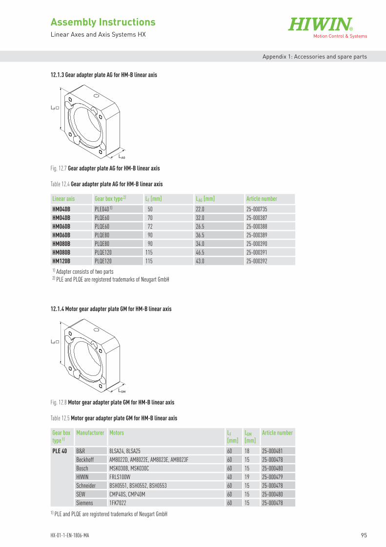
95
Assembly InstructionsLinear Axes and Axis Systems HX
HX-01-1-EN-1806-MA
Appendix 1: Accessories and spare parts
12.1.3 Gear adapter plate AG for HM-B linear axis
12.1.4 Motor gear adapter plate GM for HM-B linear axis
LF
LAG
LF
LGM
Fig. 12.7 Gear adapter plate AG for HM-B linear axis
Fig. 12.8 Motor gear adapter plate GM for HM-B linear axis
Linear axis Gear box type 2) LF [mm] LAG [mm] Article numberHM040B PLE040 1) 50 22.0 25-000735HM040B PLQE60 70 32.0 25-000387HM060B PLQE60 72 26.5 25-000388HM060B PLQE80 90 36.5 25-000389HM080B PLQE80 90 34.0 25-000390HM080B PLQE120 115 46.5 25-000391HM120B PLQE120 115 43.0 25-0003921) Adapter consists of two parts 2) PLE and PLQE are registered trademarks of Neugart GmbH
Table 12.4 Gear adapter plate AG for HM-B linear axis
Gear box type 1)
Manufacturer Motors LF [mm]
LGM [mm]
Article number
PLE 40 B&R 8LSA24, 8LSA25 60 18 25-000481Beckhoff AM8022D, AM8022E, AM8023E, AM8023F 60 15 25-000478Bosch MSK030B, MSK030C 60 15 25-000480HIWIN FRLS100W 40 19 25-000479Schneider BSH0551, BSH0552, BSH0553 60 15 25-000478SEW CMP40S, CMP40M 60 15 25-000480Siemens 1FK7022 60 15 25-000478
Table 12.5 Motor gear adapter plate GM for HM-B linear axis
1) PLE and PLQE are registered trademarks of Neugart GmbH

96
Assembly InstructionsLinear Axes and Axis Systems HX
HX-01-1-EN-1806-MA
Appendix 1: Accessories and spare parts
Gear box type 1)
Manufacturer Motors LF [mm]
LGM [mm]
Article number
Table 12.5 Motor gear adapter plate GM for HM-B linear axis (continuation)
PLQE60 B&R 8LSA24, 8LSA25 60 17.1 25-0004908LSA33, 8LSA34, 8LSA35 90 23.1 25-000487
Beckhoff AM8031D, AM8031F, AM8032D, AM8032E, AM8032H, AM8033E, AM8033F, AM8033J, AM8531D, AM8531F, AM8532D, AM8532E, AM8532H, AM8533E, AM8533F, AM8533J
70 23.1 25-000484
AM8022D, AM8022E, AM8023E, AM8023F 60 16 25-000482Bosch MSK040B, MSK040C, MSK043C 80 23.1 25-000489
MSK030B, MSK030C 60 16.0 25-000488HIWIN FRLS200W, FRLS400W 60 23.1 25-000486Lenze MCS06F41, MCS06F60, MCS06I41, MCS06I60 70 16.1 25-000483
MCS09D41, MCS09D60, MCS09F38, MCS09F60, MCS09H41, MCS09H60, MCS09L41, MCS09L51
90 23.1 25-000487
Schneider BSH0701, BSH0702, BMH0701, BMH0702 70 16.1 25-000483BSH0703, BMH0703 70 23.1 25-000484BSH0551, BSH0552, BSH0553 60 16 25-000482
SEW CMP50S, CMP50M, CMP50L 70 16.1 25-000483CMP63S, CMP63M 90 23.1 25-000487CMP40S, CMP40M 60 16 25-000488
Siemens 1FK7022 60 16 25-0004821FK7022, 1FK7032, 1FK7034 70 23.1 25-000485
PLQE80 B&R 8LSA33, 8LSA34, 8LSA35 90 21.2 25-000496Beckhoff AM8041D, AM8041E, AM8041H, AM8042E, AM8042F,
AM8042J, AM8043E, AM8043H, AM8043K, AM8541D, AM8541E, AM8541H, AM8542E, AM8542F, AM8542J, AM8543E, AM8543H, AM8543K
90 21.2 25-000493
AM8031D, AM8031F, AM8032D, AM8032E, AM8032H, AM8033E, AM8033F, AM8033J, AM8531D, AM8531F, AM8532D, AM8532E, AM8532H, AM8533E, AM8533F, AM8533J
80 21.2 25-000498
Bosch MSK050B, MSK050C 100 31.2 25-000492MSK040B, MSK040C, MSK043C 80 21.2 25-000497MSK061B, MSK061C 115 31.2 25-000500
HIWIN FRLS200W, FRLS400W 80 21.2 25-000494FRMS750W 80 31.2 25-000495
Lenze MCS09D41, MCS09D60, MCS09F38, MCS09F60, MCS09H41, MCS09H60, MCS09L41, MCS09L51
115 21.2 25-000499
MCS06F41, MCS06F60, MCS06I41, MCS06I60 80 21.2 25-000498MCS12D20, MCS12D41, MCS12H15, MCS12H35, MCS12L20, MCS12L41
115 31.2 25-000499
Schneider BSH1001, BSH1002, BSH1003, BMH1001, BMH1002, BMH1003
100 31.2 25-000492
BSH0701, BSH0702, BSH0703, BMH0701, BMH0702, BMH0703
80 21.2 25-000498
SEW CMP63S, CMP63M, CMP63L 90 21.2 25-000496CMP50S, CMP50M, CMP50L 80 21.2 25-000498
Siemens 1FK7032, 1FK7034 80 21.2 25-0004911FK7040, 1FK7042 90 21.2 25-000493
1) PLE and PLQE are registered trademarks of Neugart GmbH

97
Assembly InstructionsLinear Axes and Axis Systems HX
HX-01-1-EN-1806-MA
Appendix 1: Accessories and spare parts
Gear box type 1)
Manufacturer Motors LF [mm]
LGM [mm]
Article number
Table 12.5 Motor gear adapter plate GM for HM-B linear axis (continuation)
PLQE120 Beckhoff AM8041D, AM8041E, AM8041H, AM8042E, AM8042F, AM8042J, AM8043E, AM8043H, AM8043K, AM8541D, AM8541E, AM8541H, AM8542E, AM8542F, AM8542J, AM8543E, AM8543H, AM8543K
115 21.8 25-000504
AM8051E, AM8051G, AM8051K, AM8052F, AM8052J, AM8052L, AM8053G, AM8053K, AM8053N, AM8551E, AM8551G, AM8551K, AM8552F, AM8552J, AM8552L, AM8553G, AM8553K, AM8553N
115 31.8 25-000502
Bosch MSK060B, MSK060C 115 31.8 25-000509MSK061B, MSK061C 115 21.8 25-000508MSK076C, MSK100A 140 31.8 25-000506MSK050B, MSK050C 115 21.8 25-000501
Lenze MCS12D20, MCS12D41, MCS12H15, MCS12H35, MCS12L20, MCS12L41
115 21.8 25-000507
MCS14D15, MCS14D36, MCS14H15, MCS14H32, MCS14L15, MCS14L32, MCS14P14
140 31.8 25-000503
Schneider BSH1001, BSH1002, BSH1003, BMH1001, BMH1002, BMH1003
115 21.8 25-000501
BSH1401, BSH1402, BSH1403, BMH1401, BMH1402, BMH1403
140 31.8 25-000503
BSH1004 115 31.8 25-000502SEW CMP71S, CMP71M, CMP71L, CMPZ71S, CMPZ71M,
CMPZ71L115 31.8 25-000505
Siemens 1FK7060, 1FK7062, 1FK7063 115 31.8 25-0005051FK7040, 1FK7042 115 21.8 25-000504
1) PLE and PLQE are registered trademarks of Neugart GmbH

98
Assembly InstructionsLinear Axes and Axis Systems HX
HX-01-1-EN-1806-MA
Appendix 1: Accessories and spare parts
12.1.5 Gear boxesGear box 1) for the optimal transfer of motor torque to the toothed belt drive.
Fig. 12.9 Dimensional drawing of gear box
Table 12.6 Gear boxes for toothed belt axes HM-B
Linear axis Ratio i Ø H [mm] LG [mm] Gear box type Order codefor gear 2)
HM040B 3 40 48.5 PLE40-3 G04035 40 48.5 PLE40-5 G04058 40 48.5 PLE40-8 G0408
12 40 61.5 PLE40-12 G0412HM040BHM060B
3 60 63.0 PLQE60-3 G06035 60 63.0 PLQE60-5 G06058 60 63.0 PLQE60-8 G0608
12 60 75.5 PLQE60-12 G0612HM060BHM080B
3 80 83.5 PLQE80-3 G08035 80 83.5 PLQE80-5 G08058 80 83.5 PLQE80-8 G0808
12 80 101.0 PLQE80-12 G0812HM080BHM120B
3 115 124.5 PLQE120-3 G12035 115 124.5 PLQE120-5 G12058 115 124.5 PLQE120-8 G1208
12 115 152.5 PLQE120-12 G12121) Economy series PLE/PLQE from Neugart, registered trademarks of Neugart GmbH2) See order code on Page 17
LGØH
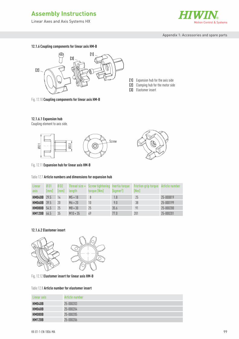
99
Assembly InstructionsLinear Axes and Axis Systems HX
HX-01-1-EN-1806-MA
Appendix 1: Accessories and spare parts
12.1.6 Coupling components for linear axis HM-B
[1] Expansion hub for the axis side[2] Clamping hub for the motor side[3] Elastomer insert
[2]
Screw
[1][3]
Fig. 12.10 Coupling components for linear axis HM-B
Table 12.7 Article numbers and dimensions for expansion hub
12.1.6.1 Expansion hubCoupling element to axis side.
Linear axis
Ø D1 [mm]
Ø D2 [mm]
Thread size × length
Screw tightening torque [Nm]
Inertia torque [kgmm2]
Friction grip torque [Nm]
Article number
HM040B 29.5 14 M5 × 18 8 1.8 25 25-000819HM060B 39.5 20 M6 × 20 10 9.0 38 25-000199HM080B 54.5 25 M8 × 30 25 35.6 91 25-000200HM120B 64.5 35 M10 × 35 49 77.0 201 25-000201
ØD1
ØD2
ØD1
ØD2
Fig. 12.11 Expansion hub for linear axis HM-B
12.1.6.2 Elastomer insert
Fig. 12.12 Elastomer insert for linear axis HM-B
Linear axis Article number HM040B 25-000203HM060B 25-000204HM080B 25-000205HM120B 25-000206
Table 12.8 Article number for elastomer insert

100
Assembly InstructionsLinear Axes and Axis Systems HX
HX-01-1-EN-1806-MA
Appendix 1: Accessories and spare parts
12.1.6.3 Clamping hubCoupling element to motor side.
Fig. 12.13 Clamping hub for linear axis HM-B
ØD2ØD1
Linear axis
Ø D1 [mm]
Ø D2 H7[mm]
Thread size × length
Screw tightening torque [Nm]
Friction grip torque [Nm]
Inertia torque [Nm]
Article number
HM040B 29.5 6.35 M4 × 12 5 11.1 2.58 25-0002148 M4 × 12 5 13.7 2.58 25-0002159 M4 × 12 5 15.2 2.57 25-000182
10 M4 × 12 5 16.6 2.56 25-00018311 M4 × 12 5 18.1 2.56 25-00018412 M4 × 12 5 19.5 2.54 25-00021614 M4 × 12 5 22.2 2.50 25-00018516 M4 × 12 5 24.8 2.43 25-000229
HM060B 40 9 M6 × 16 14 36.4 15.33 25-00021710 M6 × 16 14 40.5 15.29 25-00021811 M6 × 16 14 44.1 15.27 25-00018612 M6 × 16 14 47.7 15.24 25-00018714 M6 × 16 14 54.5 15.16 25-00018816 M6 × 16 14 62.3 15.07 25-00021919 M6 × 16 14 70.8 14.76 25-00018920 M6 × 16 14 73.9 14.63 25-00022024 M6 × 16 14 62 13.76 25-000221
HM080B 55 14 M6 × 20 14 57.6 59.82 25-00019019 M6 × 20 14 75.4 59.33 25-00019120 M6 × 20 14 78.8 59.17 25-00019224 M6 × 20 14 92.1 58.26 25-00019325 M6 × 20 14 95.3 57.94 25-00022228 M6 × 20 14 106.7 56.71 25-00022332 M6 × 20 14 117.1 54.40 25-000224
HM120B 65 19 M8 × 25 35 151.9 127.40 25-00019420 M8 × 25 35 158.9 127.24 25-00022524 M8 × 25 35 186.1 125.94 25-00019525 M8 × 25 35 192.7 125.94 25-00019628 M8 × 25 35 215.8 124.70 25-00022632 M8 × 25 35 237.2 122.23 25-00019735 M8 × 25 35 259.4 119.67 25-00022738 M8 × 25 35 237.4 116.34 25-000228
Table 12.9 Article numbers and specifications for clamping hub

101
Assembly InstructionsLinear Axes and Axis Systems HX
HX-01-1-EN-1806-MA
Appendix 1: Accessories and spare parts
12.2 Motor adapter of the HM-S linear axisThe adapter on the axis is a two-part structure that simplifies the flange connections of all possible motors.
The flange type set consists of the following parts: Coupling housing KB Coupling components Motor adapter plate AM or belt drive RT
The following sections list the dimensions for the coupling housing, motor adapter plate, and belt drive.
Belt drive RT: For deflecting the drive through 180°
Motor adapter plate AM: Axis–motor adapter
Motor adapter of the linear axis with ballscrew (HM-S)
Belt drive RT
Motor adapter plate AMCoupling housing KB
Coupling components
Fig. 12.14 Motor adapter of linear axis HM-S
Fig. 12.15 Motor adapter of linear axis HM-S with belt drive
Table 12.10 Order code for flange type 3) – HM-S linear axis
Drivemanufacturer/type
HM040S HM060S HM080S HM120SMotor only Motor only Motor only Motor only
HIW
IN
FRLS100W HW01 1) FRLS200W HW02 1) HW03 1) HW05 1) FRLS400W HW03 1) HW05 1) FRMS750W HW06 1) HW08 1)
B&R
8LSA24 BR01 1) BR02 1) 8LSA25 BR01 1) BR02 1) 8LSA33 BR03 2) BR04 2) 8LSA34 BR03 2) BR04 2) 8LSA35 BR03 2) BR04 2) 8LSA43 BR05 2) BR10 1)
1) Possible belt drive V12) Possible belt drive V23) See order code on Page 20

102
Assembly InstructionsLinear Axes and Axis Systems HX
HX-01-1-EN-1806-MA
Appendix 1: Accessories and spare parts
Table 12.10 Order code for flange type 3) – HM-S linear axis (continuation)
Drivemanufacturer/type
HM040S HM060S HM080S HM120SMotor only Motor only Motor only Motor only
B&R
8LSA44 BR10 1)
8LSA45 BR10 1)
8LSA46 BR10 2)
8LSA53 BR12 2)
8LSA54 BR12 2)
8LSA55 BR12 2)
8LSA56 BR11 2)
8LSN43 BR11 2)
8LSN44 BR11 2)
8LSN45 BR11 2)
8LSN54 BR12 2)
8LSN55 BR12 2)
Beck
hoff
AM8022 BE01 1) BE04 1) AM8023 BE01 1) BE04 1) AM8031 BE02 2) BE05 1) AM8032 BE05 1) BE09 1)
AM8033 BE05 1) BE09 1)
AM8531 BE02 2) BE05 1) BE09 1)
AM8532 BE05 1) BE09 1)
AM8533 BE05 1) BE09 1)
AM8041 BE06 2) BE10 1)
AM8042 BE06 2) BE10 1)
AM8043 BE10 1)
AM8541 BE06 2) BE10 1)
AM8542 BE06 2) BE10 1)
AM8543 BE10 1)
AM8051 BE07 2) BE11 1)
AM8052 BE11 1)
AM8551 BE07 2) BE11 1)
AM8552 BE11 1)
AM8061 BE12 2)
AM8561 BE12 2)
Bosc
h
MSK030B BO01 1) BO02 1) MSK030C BO02 1) MSK040B BO03 2) BO05 1) BO10 1)
MSK040C BO03 2) BO05 1) BO10 1)
MSK043C BO05 1) BO10 1)
MSK050B BO06 2) BO11 1)
MSK050C BO06 2) BO11 1)
MSK060B BO08 2) BO13 2)
MSK060C BO13 2)
MSK061B BO07 2) BO12 2)
MSK061C BO12 2)
MSK070C BO15 2)
MSK071C BO15 2)
1) Possible belt drive V12) Possible belt drive V23) See order code on Page 20

103
Assembly InstructionsLinear Axes and Axis Systems HX
HX-01-1-EN-1806-MA
Appendix 1: Accessories and spare parts
Table 12.10 Order code for flange type 3) – HM-S linear axis (continuation)
Drivemanufacturer/type
HM040S HM060S HM080S HM120SMotor only Motor only Motor only Motor only
Bosc
h MSK075C BO15 2)
MSK075C BO14 2)
Lenz
e
MCS06F LE01 2) LE04 1) MCS06I LE01 2) LE04 1) MCS09D LE02 2) LE05 2) LE08 1)
MCS09F LE05 2) LE08 1)
MCS09H LE08 1)
MCS09L LE08 1)
MCS12D LE06 2) LE09 2)
MCS12H LE09 2)
MCS14D LE10 2)
Schn
eider
BSH0551 SE01 1) SE02 1) BSH0552 SE01 1) SE02 1) BSH0701 SE03 2) SE07 1) BSH0702 SE03 2) SE07 1) BSH0703 SE08 1) BSH1001 SE09 2) SE13 1)
BSH1002 SE13 1)
BSH1003 SE13 1)
BSH1004 SE14 1)
BSH1401 SE15 2)
BMH0701 SE03 2) SE07 1) BMH0702 SE03 2) SE07 1) BMH0703 SE08 1) SE12 1)
BMH1001 SE09 2) SE13 1)
BMH1002 SE09 2) SE13 1)
BMH1003 SE13 1)
BMH1401 SE15 2)
SEW
CMP40S SW01 1) SW02 1) SW06 1) CMP40M SW02 1) SW06 1) CMP50S SW03 2) SW07 1) CMP50M SW07 1) SW11 1)
CMP50L SW07 1) SW11 1)
CMP63S SW08 2) SW12 1)
CMP63M SW12 1)
CMP63L SW12 1)
CMP71S SW13 2)
CMP71M SW13 2)
CMP71L SW13 2)
CMP80S SW14 2)
CMPZ71S SW13 2)
CMPZ71M SW13 2)
CMPZ71L SW13 2)
CMPZ80S SW14 2)
1) Possible belt drive V12) Possible belt drive V23) See order code on Page 20

104
Assembly InstructionsLinear Axes and Axis Systems HX
HX-01-1-EN-1806-MA
Appendix 1: Accessories and spare parts
Table 12.10 Order code for flange type 3) – HM-S linear axis (continuation)
Drivemanufacturer/type
HM040S HM060S HM080S HM120SMotor only Motor only Motor only Motor only
Sieme
ns1FK7022 SM01 1) SM02 1) 1FK7032 SM03 2) SM04 1) 1FK7034 SM03 2) SM04 1) 1FK7040 SM05 2) SM08 1)
1FK7042 SM05 2) SM08 1)
1FK7060 SM09 2)
1FK7062 SM09 2)
1FK7063 SM09 2)
1FK7080 SM10 2)
1FK7081 SM10 2)
1FK7083 SM10 2)
1) Possible belt drive V12) Possible belt drive V23) See order code on Page 20

105
Assembly InstructionsLinear Axes and Axis Systems HX
HX-01-1-EN-1806-MA
Appendix 1: Accessories and spare parts
HM-S linear axis without belt drive
HM-S linear axis with belt drive
Fig. 12.16 HM-S linear axis motor connection without belt drive
Fig. 12.17 HM-S linear axis motor connection with belt drive
LAM LKS
L RT
The overall length of the spindle axis depends on the following factors: Adapter materials (coupling housing KS, motor adapter plate AM) Belt drive RT Motor
LKS Length of coupling housing, see Table 12.11LAM Motor adapter plate length, see Table 12.12
LRT Belt drive length, see Table 12.13

106
Assembly InstructionsLinear Axes and Axis Systems HX
HX-01-1-EN-1806-MA
Appendix 1: Accessories and spare parts
LH
LBLKS
Fig. 12.18 Coupling housing KS for HM-S linear axis
Coupling housing for LB [mm] LH [mm] LKS [mm] Article numberHM040S 39.6 57.6 34 25-000305HM060S 59.6 75.0 32 25-000306HM080S 79.6 95.5 41 25-000307HM120S 119.6 141.9 50 25-000308
Table 12.11 Dimensions of coupling housing KS for HM-S linear axis
12.2.1 Coupling housing KS for HM-S linear axis
12.2.2 Motor adapter plate AM for HM-S linear axis
LF
LAM
Fig. 12.19 Motor adapter plate AM for HM-S linear axis
Linear axis
Manufacturer Motors LF [mm]
LAM [mm]
Article number
HM040S B&R 8LSA24, 8LSA25 58 24.5 25-000397Bosch MSK030B 54 20.5 25-000395HIWIN FRLS100W 42 24.5 25-000393
FRLS200W 60 30.0 25-000398Schneider BSH0551, BSH0552 55 20.5 25-000396SEW CMP40S 54 20.5 25-000395Siemens 1FK7022 55 20.5 25-000396
HM060S B&R 8LSA24, 8LSA25 58 25 25-0004038LSA33, 8LSA34, 8LSA35 82 31 25-000411
Beckhoff AM8022D, AM8022E, AM8023E, AM8023F 55 22 25-000402AM8031D, AM8031F, AM8531D, AM8531F 70 31 25-000407
Table 12.12 Motor adapter plate AM for HM-S linear axis

107
Assembly InstructionsLinear Axes and Axis Systems HX
HX-01-1-EN-1806-MA
Appendix 1: Accessories and spare parts
Linear axis
Manufacturer Motors LF [mm]
LAM [mm]
Article number
Table 12.12 Motor adapter plate AM for HM-S linear axis (continuation)
HM060S Bosch MSK030B, MSK030C 54 22 25-000401MSK040B, MSK040C 82 31 25-000405
HIWIN FRLS200W, FRLS400W 60 31 25-000404Lenze MCS06F41, MCS06F60, MCS06I41, MCS06I60 62 25 25-000406
MCS09D41, MCS09D60 82 31 25-000411Schneider BSH0551, BSH0552 55 22 25-000402
BSH0701, BSH0702, BMH0701, BMH0702 62 25 25-000406SEW CMP40S, CMP40M 54 22 25-000401
CMP50S 62 25 25-000406Siemens 1FK7022 55 22 25-000402
1FK7032, 1FK7034 72 31 25-000408HM080S B&R 8LSA33, 8LSA34, 8LSA35 86 27 25-000423
8LSA43 100 37 25-000426Beckhoff AM8022D, AM8022E, AM8023E, AM8023F 72 21 25-000413
AM8031D, AM8031F, AM8032D, AM8032E, AM8032H, AM8033E, AM8033F, AM8033J, AM8531D, AM8531F, AM8532D, AM8532E, AM8532H, AM8533E, AM8533F, AM8533J
70 27 25-000418
AM8041D, AM8041E, AM8041H, AM8042E, AM8042F, AM8042J, AM8541D, AM8541E, AM8541H, AM8542E, AM8542F, AM8542J,
87 37 25-000424
AM8051E, AM8051G, AM8051K, AM8551E, AM8551G, AM8551K
104 47 25-000427
Bosch MSK040B, MSK040C, MSK043C 82 27 25-000415MSK050B, MSK050C 98 37 25-000425MSK061B 116 37 25-000428MSK060B 116 47 25-000429
HIWIN FRLS200W, FRLS400W 72 27 25-000414FRMS750W 80 37 25-000421
Lenze MCS06F41, MCS06F60, MCS06I41, MCS06I60 72 21 25-000417MCS09D41, MCS09D60, MCS09F38, MCS09F60 86 27 25-000423MCS12D20, MCS12D41 116 37 25-000430
Schneider BSH0701, BSH0702, BMH0701, BMH0702 72 21 25-000417BSH0703, BMH0703 70 27 25-000418BSH1001, BMH1001, BMH1002, BMH1003 98 37 25-000425
SEW CMP40M 72 21 25-000412CMP63S 86 27 25-000423CMP50S, CMP50M, CMP50L 72 21 25-000417
Siemens 1FK7032, 1FK7034 72 27 25-0004191KF7040, 1FK7042 87 37 25-0004241FK7060 116 47 25-000431
HM120S B&R 8LSA43, 8LSA44, 8LSA45, 8LSA46 100 37 25-0004438LSN43, 8LSN44, 8LSN45, 8LNS46 116 37 25-0004478LSA53, 8LSA54, 8LSA55, 8LSN54, 8LSN55 142 51 25-000454
Beckhoff AM8032D, AM8032E, AM8032H, AM8033E, AM8033F, AM8033J, AM8531D, AM8531F, AM8532D, AM8532E, AM8532H, AM8533E, AM8533F, AM8533J
73 27 25-000436

108
Assembly InstructionsLinear Axes and Axis Systems HX
HX-01-1-EN-1806-MA
Appendix 1: Accessories and spare parts
Linear axis
Manufacturer Motors LF [mm]
LAM [mm]
Article number
Table 12.12 Motor adapter plate AM for HM-S linear axis (continuation)
HM120S Beckhoff AM8041D, AM8041E, AM8041H, AM8042E, AM8042F, AM8042J, AM8043E, AM8043H, AM8043K, AM8541D, AM8541E, AM8541H, AM8542E, AM8542F, AM8542J, AM8543E, AM8543H, AM8543K
87 37 25-000441
AM8051E, AM8051G, AM8051K, AM8052F, AM8052J, AM8052L, AM8551E, AM8551G, AM8551K, AM8552F, AM8552J, AM8552L
100 51 25-000444
AM8061G, AM8061J, AM8061M, AM8561G, AM8561J, AM8561M
138 56 25-000453
Bosch MSK040B, MSK040C, MSK043C 82 27 25-000433MSK050B, MSK050C 98 37 25-000442MSK061B, MSK061C 116 37 25-000445MSK060B, MSK060C 116 51 25-000446MSK70C, MSK71C, MSK75C 138 56 25-000453MSK076C 139 51 25-000451
HIWIN FRMS750W 80 37 25-000438Lenze MCS09D41, MCS09D60, MCS09F38, MCS09F60,
MCS09H41, MCS09H60, MCS09L41, MCS09L5186 27 25-000440
MCS12D20, MCS12D41, MCS12H15, MCS12H35 116 37 25-000447MCS14D15, MCS14D36 139 51 25-000452
Schneider BMH0703 73 27 25-000436BSH1001, BSH1002, BSH1003, BMH1001, BMH1002, BMH1003
98 37 25-000442
BSH1004 100 51 25-000444BSH1401, BMH1401 139 51 25-000452
SEW CMP50L 73 20 25-000435CMP63S, CMP63M, CMP63L 86 27 25-000440CMP71S, CMP71M, CMP71L, CMPZ71S, CMPZ71M, CMPZ71L
116 51 25-000448
CMP80S, CMPZ80S 138 56 25-000453Siemens 1FK7040, 1FK7042 87 37 25-000441
1FK7060, 1FK7062, 1FK7063 116 51 25-0004481FK7080, 1FK7081, 1FK7083 138 56 25-000453

109
Assembly InstructionsLinear Axes and Axis Systems HX
HX-01-1-EN-1806-MA
Appendix 1: Accessories and spare parts
12.2.3 Belt drive RT for HM-S linear axis
Table 12.13 Belt drive specifications
Fig. 12.20 Belt drive for HM-S linear axis
L HA
LA LB LRTL H
Linear axis Type 1) LH LB LRT LA LHA RatioHM040S V1 72 138.5 40 30 36.25 1HM060S V1 72 138.5 40 30 45.80 1
V2 102 171.5 40 30 45.80 1HM080S V1 102 197.0 51 39 61.40 1
V2 131 226.0 61 39 61.40 1HM120S V1 175 248.5 63 55 89.00 1
V2 175 288.0 73 55 89.00 11) The required type can be found in Table 12.10
Please bear in mind that the belt drive projects over the lower axis edge when: NOTE
Please bear in mind that the belt drive may project over the side of the axis when: NOTE
LH
2> LHA
Profile width (axis)2
LA >

110
Assembly InstructionsLinear Axes and Axis Systems HX
HX-01-1-EN-1806-MA
Appendix 1: Accessories and spare parts
12.2.4 Coupling components for linear axis HM-S
Fig. 12.21 Coupling components for linear modules HM040S and HM080S
12.2.4.1 Clamping hubMotor- and axis-side coupling element.
ØD2ØD1
Table 12.14 Article numbers and specifications for clamping hub
[1]
[1]
[2]
[1] Clamping hub (one for axis side, one for motor side) [2] Elastomer insert
[1] Clamping hub (one for axis side, one for motor side) [2] Elastomer insert
Fig. 12.22 Coupling components for linear modules HM060S and HM120S
[1]
[2][1]
Fig. 12.23 Clamping hub for linear axis HM-S
Linear axis
Ø D1 [mm]
Ø D2 H7 [mm]
Thread size and length
Screw tightening torque [Nm]
Friction grip torque [Nm]
Inertia torque [Nm]
Article number
HM040S 25.0 6.35 M3 × 12 1.9 5.2 1.43 25-0012558 M3 × 12 1.9 6.4 1.42 25-0009669 M3 × 12 1.9 7.1 1.41 25-001257
10 M3 × 12 1.9 7.8 1.40 25-00125811 M3 × 12 1.9 8.5 1.39 25-00125912 M3 × 12 1.9 9.1 1.38 25-00126014 M3 × 12 1.9 10.8 1.33 25-000967

111
Assembly InstructionsLinear Axes and Axis Systems HX
HX-01-1-EN-1806-MA
Appendix 1: Accessories and spare parts
12.2.4.2 Elastomer insert
Linear axis Article number HM040S 25-000202HM060S 25-000203HM080S 25-000204HM120S 25-000205
Table 12.15 Article number for elastomer insert
Fig. 12.24 Elastomer insert for linear axis HM-S
Linear axis
Ø D1 [mm]
Ø D2 H7 [mm]
Thread size × length
Screw tightening torque [Nm]
Friction grip torque [Nm]
Inertia torque [Nm]
Article number
Table 12.14 Article numbers and specifications for clamping hub (clamping hub)
HM060S 29.5 6.35 M4 × 12 5 13.2 2.69 25-0012628 M4 × 12 5 16.2 2.69 25-0012639 M4 × 12 5 18.0 2.68 25-001264
10 M4 × 12 5 19.7 2.67 25-00096811 M4 × 12 5 21.5 2.66 25-00126512 M4 × 12 5 23.1 2.65 25-00126614 M4 × 12 5 26.4 2.61 25-00096916 M4 × 12 5 29.5 2.55 25-001267
HM080S 40.0 9 M6 × 16 14 18.4 14.54 25-00126810 M6 × 16 14 20.3 14.53 25-00126911 M6 × 16 14 22.1 14.51 25-00127012 M6 × 16 14 23.8 14.48 25-00097014 M6 × 16 14 27.3 14.40 25-00127116 M6 × 16 14 30.6 14.28 25-00127219 M6 × 16 14 35.4 14.00 25-00097120 M6 × 16 14 36.9 13.87 25-00127324 M5 × 16 10 37.8 12.95 25-000972
HM120S 55.0 14 M6 × 20 14 54.3 58.33 25-00127419 M6 × 20 14 68.0 57.86 25-00097420 M6 × 20 14 71.1 57.71 25-00097324 M6 × 20 14 83.1 56.81 25-00127525 M6 × 20 14 86.0 56.50 25-00127628 M6 × 20 14 94.6 55.32 25-00127732 M6 × 20 14 105.6 53.03 25-000975
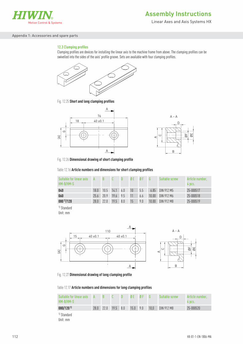
112
Assembly
Assembly InstructionsLinear Axes and Axis Systems HX
HX-01-1-EN-1806-MA
Appendix 1: Accessories and spare parts
12.3 Clamping profilesClamping profiles are devices for installing the linear axis to the machine frame from above. The clamping profiles can be swivelled into the sides of the axis’ profile groove. Sets are available with four clamping profiles.
Table 12.16 Article numbers and dimensions for short clamping profiles
Table 12.17 Article numbers and dimensions for long clamping profiles
Suitable for linear axis HM-B/HM-S
A B C D Ø E Ø F G Suitable screw Article number, 4 pcs.
040 18.0 10.5 14.1 6.0 10 5.5 6.85 DIN 912 M5 25-000517060 25.6 20.9 19.6 9.5 11 6.6 10.00 DIN 912 M6 25-000518080 1)/120 28.0 22.0 19.5 8.0 15 9.0 10.00 DIN 912 M8 25-0005191) StandardUnit: mm
Suitable for linear axis HM-B/HM-S
A B C D Ø E Ø F G Suitable screw Article number, 4 pcs.
080/120 1) 28.0 22.0 19.5 8.0 15.0 9.0 10,0 DIN 912 M8 25-0005201) Standard Unit: mm
Fig. 12.25 Short and long clamping profiles
Fig. 12.26 Dimensional drawing of short clamping profile
Fig. 12.27 Dimensional drawing of long clamping profile
(A) A ØEØF
D
B
C
G
18 40 ±0.176
A
A – A
A
(A) A ØEØF
D
B
A – A
C
G
15 40 ±0.1 40 ±0.1110
A
A

Assembly
113
Assembly InstructionsLinear Axes and Axis Systems HX
HX-01-1-EN-1806-MA
Appendix 1: Accessories and spare parts
12.4 T nutT nut for the frictional connection of the linear axis. Flexible fastening options through the grooves on the side and on the bottom of the axis profile. Sets are available with ten T nuts.
Table 12.18 Article numbers and dimensions for T nuts
Suitable for linear axis HM-B/HM-S A B C Article number, 10 pcs.040 3.0 11.5 M4 20-000528040 4.0 11.5 M5 20-000529060 4.5 17.0 M5 20-000530060 5.5 17.0 M6 20-000531080/120 7.5 23.0 M5 20-000532080/120 7.5 23.0 M6 20-000533080/120 7.5 23.0 M8 20-000534Unit: mm
C
BA
Ø D1Ø D2 A
12.5 Centring sleeveCentring sleeves that are inserted in the carriage’s mounting holes for precise, repeatable load bearing. Sets are available with ten centring sleeves.
Table 12.19 Article numbers and dimensions for centring sleeves
Suitable for linear axis HM-B/HM-S A Ø D1 Ø D2 Article number, 10 pcs.040 4 5.5 8 h6 25-000510060 4 6.5 8 h6 25-000511080 4 9.0 12 h6 25-000512120 4 11.0 15 h6 25-000513Unit: mm
Fig. 12.28 Dimensional drawing of T nut
Fig. 12.29 Dimensional drawing of centring sleeve

114
Assembly InstructionsLinear Axes and Axis Systems HX
HX-01-1-EN-1806-MA
Appendix 1: Accessories and spare parts
12.6 Groove coverCover for the fastening groove. Length: 2 m. Sets are available with five groove covers.
Linear axis HMB/HMS Article number, 5 pcs.040 25-000514060 25-000515080/120 25-000516
Table 12.20 Article numbers for groove covers
12.7 Limit switchThe inductive proximity switch is available in either a normally closed or a normally open version. The switch can be secured directly inside the switch profile groove using the fasteners supplied. The limit switch is supplied as standard with plug or open cable end.
Table 12.21 Limit switch options
Option Article numberLimit switch with 100 mm cable, plug (NC) 25-000786Limit switch with 4 m cable (NC) 25-000787Limit switch with 5 m cable (NO) 25-000788
Fig. 12.30 Groove cover for linear axes HM-B/HM-S
Fig. 12.31 Limit switch for linear axes HM-B/HM-S
For more information see Section 5.4.NOTE

115
Assembly InstructionsLinear Axes and Axis Systems HX
HX-01-1-EN-1806-MA
Appendix 1: Accessories and spare parts
Table 12.23 MAGIC encoder
Encoder Order code Article numberMAGIC encoder analogue MAGIC-T-AM5000L 8-08-0120MAGIC encoder digital MAGIC-T-DM5000L 8-08-0122For more information see Section 5.5
12.8 Extension cable for limit switchCable with 3-pin M8 round connector on the limit switch side and exposed wires on the other cable end.
4
31
Fig. 12.32 Extension cable for limit switch
Fig. 12.33 Damping element for linear axes HM-B/HM-S
Fig. 12.34 HIWIN MAGIC encoder
Table 12.22 Extension cable for limit switch
Length [m] Article number3 8-10-02755 8-10-02767 8-10-0277
10 8-10-027815 8-10-0279
12.9 Damping elementThe damping element is needed to switch the limit switches at both of the carriage’s end positions (at stroke 0 and stroke max). It can be attached on the left and right of the carriage. Set incl. fasteners.Article number: 25-000785
12.10 Positioning measuring system HIWIN MAGICMagnetic positioning measuring system consisting of encoder (with 5 m cable length and open cable end).

116
Assembly InstructionsLinear Axes and Axis Systems HX
HX-01-1-EN-1806-MA
Appendix 1: Accessories and spare parts
Cover strip suitable for linear axis Article number (3 m) Article number (6 m)HM040B/HM040S 25-000535 25-000536HM060B/HM060S 25-000537 25-000538HM080B/HM080S 25-000539 25-000540HM120B/HM120S 25-000541 25-000542
12.11 Cover stripThe steel cover strip is available in lengths of 3 m and 6 m.
Table 12.24 MAGIC magnetic scale
Magnetic scale Order codeMAGIC magnetic scale MAGIC-PS-B-XXXX 1)
1) XXXX = length [mm]
Fig. 12.35 HIWIN MAGIC magnetic scale
Fig. 12.36 Cover strip
Fig. 12.37 Magnetic strip
Suitable for linear table Article number (7.5 m)HM040B/HM040S 25-000168HM060B/HM060S 25-000543HM080B/HM080S 25-000543HM120B/HM120S 25-000543
12.12 Magnetic stripThe magnetic strip holds down the cover strip and is available in a length of 7.5 m.
Table 12.25 Article numbers for cover strip
Table 12.26 Article numbers for magnetic strip

117
Assembly InstructionsLinear Axes and Axis Systems HX
HX-01-1-EN-1806-MA
Appendix 1: Accessories and spare parts
Fig. 12.38 Cover strip deflection dimensions
Table 12.27 Cover strip deflection set article numbers
Cover strip deflection set for linear axis
B [mm] Cylinder-head screw Square nut Article number
HM040B/HM040S 40 DIN 7984 M4 × 30 — 25-000618HM060B/HM060S 40 DIN 7984 M4 × 45 DIN 562 M3 25-000619HM080B/HM080S 45 DIN 7984 M5 × 45 DIN 562 M3 25-000620HM120B/HM120S 60 DIN 912 M5 × 45 DIN 562 M4 25-000621
12.13 Cover strip deflectionThe cover strip deflection set consists of the following parts:
2 × cover strip deflection, each with2 × deflector housing2 × cover strip guide4 × cylinder-head screw4 × square nut (not applicable to HM040)
B
Cylinder-head screwSquare nut
Deflector housingCover strip guide
12.14 Buffer stopThe buffer stop serves as a mechanical limit.
Fig. 12.39 Buffer stop
Table 12.28 Article numbers for buffer stop
Buffer stop for linear axis Article numberHM040B/HM040S 25-000055HM060B/HM060S 25-000056HM080B/HM080S 25-000057HM120S 25-000058HM120B 25-000059
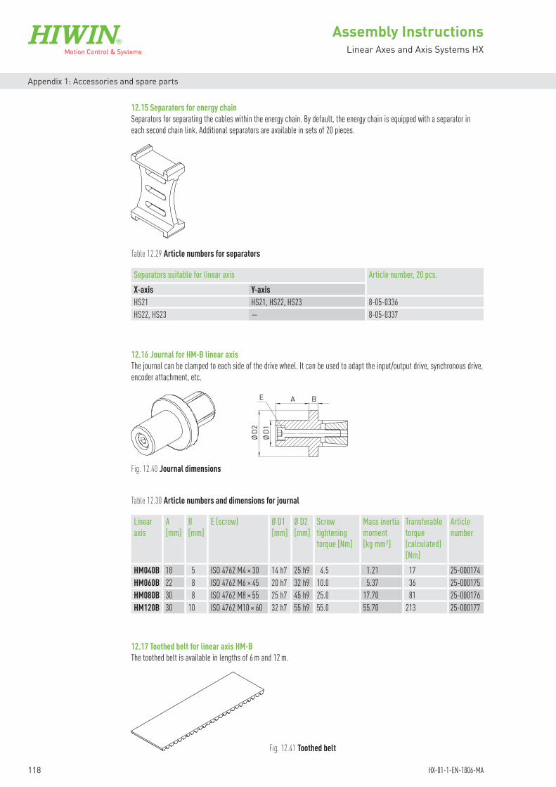
118
Assembly InstructionsLinear Axes and Axis Systems HX
HX-01-1-EN-1806-MA
Appendix 1: Accessories and spare parts
12.15 Separators for energy chainSeparators for separating the cables within the energy chain. By default, the energy chain is equipped with a separator in each second chain link. Additional separators are available in sets of 20 pieces.
Table 12.29 Article numbers for separators
Separators suitable for linear axis Article number, 20 pcs.X-axis Y-axisHS21 HS21, HS22, HS23 8-05-0336HS22, HS23 — 8-05-0337
12.16 Journal for HM-B linear axisThe journal can be clamped to each side of the drive wheel. It can be used to adapt the input/output drive, synchronous drive, encoder attachment, etc.
AE
ØD1
ØD2
B
Fig. 12.40 Journal dimensions
Table 12.30 Article numbers and dimensions for journal
Linear axis
A[mm]
B[mm]
E (screw) Ø D1[mm]
Ø D2[mm]
Screw tightening torque [Nm]
Mass inertia moment [kg mm²]
Transferable torque (calculated) [Nm]
Article number
HM040B 18 5 ISO 4762 M4 × 30 14 h7 25 h9 4.5 1.21 17 25-000174HM060B 22 8 ISO 4762 M6 × 45 20 h7 32 h9 10.0 5.37 36 25-000175HM080B 30 8 ISO 4762 M8 × 55 25 h7 45 h9 25.0 17.70 81 25-000176HM120B 30 10 ISO 4762 M10 × 60 32 h7 55 h9 55.0 55.70 213 25-000177
12.17 Toothed belt for linear axis HM-BThe toothed belt is available in lengths of 6 m and 12 m.
Fig. 12.41 Toothed belt
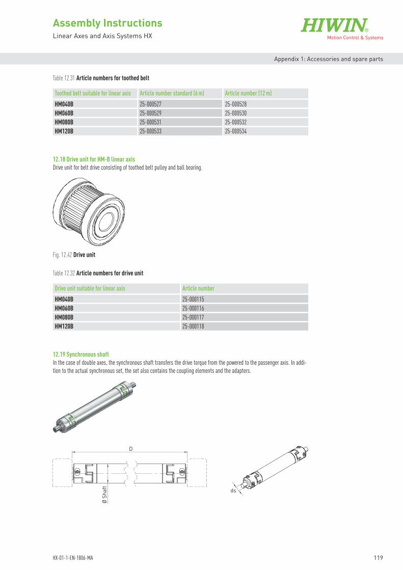
119
Assembly InstructionsLinear Axes and Axis Systems HX
HX-01-1-EN-1806-MA
Appendix 1: Accessories and spare parts
Table 12.31 Article numbers for toothed belt
Toothed belt suitable for linear axis Article number standard (6 m) Article number (12 m)HM040B 25-000527 25-000528HM060B 25-000529 25-000530HM080B 25-000531 25-000532HM120B 25-000533 25-000534
12.18 Drive unit for HM-B linear axisDrive unit for belt drive consisting of toothed belt pulley and ball bearing.
12.19 Synchronous shaftIn the case of double axes, the synchronous shaft transfers the drive torque from the powered to the passenger axis. In addi-tion to the actual synchronous set, the set also contains the coupling elements and the adapters.
Fig. 12.42 Drive unit
Table 12.32 Article numbers for drive unit
Drive unit suitable for linear axis Article numberHM040B 25-000115HM060B 25-000116HM080B 25-000117HM120B 25-000118
Ø Sh
aft
D
ds

120
Assembly InstructionsLinear Axes and Axis Systems HX
HX-01-1-EN-1806-MA
Appendix 1: Accessories and spare parts
12.19.1 Order code for synchronous shaft
12.19.2 SpacerIf not installed vertically, the synchronous shaft must be fitted with the spacer disc. This prevents metal-on-metal contact in the lower coupling.
Distance between axes D [mm]
Axis size:HM040BHM060BHM080BHM120B
HZS 50 HM060B 1000
HIWIN synchronous shaft
Shaft diameter [mm]:405080
Table 12.34 Article numbers for spacer
Suitable for double axis Suitable for synchronous shaft Article numberHD1/HM040B HZS40HM040B 25-000730HD2/HM060B HZS50HM060B 25-000731HD3/HM080B HZS50HM080B 25-000731HD4/HM120B HZS80HM120B 25-000733
Table 12.33 Dimensions of synchronous shaft
Suitable for double axis D min. D max. Ø shaft Ø dsHD1/HM040B 160 1,500 40 14HD2/HM060B 180 2,000 50 20HD3/HM080B 180 2,400 50 25HD4/HM120B 240 3,000 80 35Unit: mm

121
Assembly InstructionsLinear Axes and Axis Systems HX
HX-01-1-EN-1806-MA
Appendix 1: Accessories and spare parts
12.20 HIWIN lubricants
12.21 HIWIN grease nipplesGrease nipples suitable for linear axes and linear axis systems (all sizes).
Grease type Application Quantity unitG04 High speed Cartridge 400 g Can 1 kg
Article number: 20-000345 Article number: 20-000346
Table 12.35 Recommended HIWIN grease
Article no. Description Scope of delivery Comment20-000333 Grease gun GN-400C
incl. set of lubrication adapter and nozzles (see Fig. 12.43)
Grease gun GN-400-C consisting of: Grease gun Hydraulic coupling A1 suitable for conical grease
nipples acc. to DIN 71412, outer diameter 15 mm
Hollow mouthpiece A2 suitable for conical or ball grease nipples acc. to DIN 71412/DIN 3402, outer diameter 10 mm
Set of lubrication adapter and nozzles
Suitable for 400 g cartridge or direct filling
Table 12.36 Recommended HIWIN grease gun
Fig. 12.43 Grease gun GN-400C
Fig. 12.44 Art.-no. 20-000325 (standard) Fig. 12.45 Art.-no. 20-000538 (option)

122
Assembly InstructionsLinear Axes and Axis Systems HX
HX-01-1-EN-1806-MA
Appendix 2: Declaration of Incorporation
13. Appendix 2: Declaration of Incorporation
in the sense of the EC Machinery Directive 2006/42/EC, Annex II 1. B for partly completed machinery
The manufacturer: HIWIN GmbH, Brücklesbünd 2, D-77654 Offenburg
Documentation department: HIWIN GmbH, Brücklesbünd 2, D-77654 Offenburg
Description and identification of the partly completed machine:Product: Linear axes and linear axis systems HXType: HM040…, HM060…, HM080…, HM120…
HD1..., HD2..., HD3..., HD4... HS21..., HS22..., HS23...
Year of manufacture: from 2016
It is hereby declared that the following essential requirements of the Machinery Directive 2006/42/EC have been fulfilled.1.1.3, 1.1.5, 1.3.3, 1.3.4, 1.3.7, 1.3.9, 1.5.1, 1.5.8, 1.5.9, 1.6.2, 1.5.5, 1.1.2, 1.3.2, 1.5.4
Moreover, it is declared that the relevant technical documentation specified under Annex VII Part B has been compiled.It is hereby explicitly declared that the partly completed machine complies with all of the pertinent conditions in the following EC Directives.2006/42/EC EC Machinery Directive2014/30/EU Directive on electromagnetic compatibility (EMC)2011/65/EU RoHS Directive on the restriction of hazardous substances
A reference to the harmonised standards used, as referred to in Article 7(2)EN ISO 13732-1:2008 Ergonomics of the thermal environment – Methods for the assessment of human responses to
contact with surfaces – Part 1: Hot surfaces (ISO 13732-1:2008)EN ISO 12100:2010-11 Safety of machinery – General principles for design – Risk assessment and risk reduction
(ISO 12100:2010)EN 60204-1:2006/AC:2010 Safety of machinery – Electrical equipment of machines – Part 1: General requirements
The manufacturer or the authorised person undertakes to transmit, in response to a reasoned request by the national authori-ties, the relevant documentation on the partly completed machinery.
This is without prejudice to the intellectual property rights of the manufacturer!
Important note! The partly completed machinery may not be commissioned until it has been ascertained that the machinery into which this partly completed machinery is to be incorporated is compliant with the provisions of this Directive.
Offenburg, 01.06.2017
Werner Mäurer, Managing Director


Linear Actuators
Linear Motor Components
Linear Axes
Ballscrews Linear Motor Systems
Rotary Tables
Robots
Linear Guideways
Drives & Servo Motors
GermanyHIWIN GmbHBrücklesbünd 2D-77654 OffenburgPhone +49 (0) 7 81 9 32 78 - 0Fax +49 (0) 7 81 9 32 78 - [email protected]
TaiwanHeadquartersHIWIN Technologies Corp.No. 7, Jingke Road Taichung Precision Machinery ParkTaichung 40852, TaiwanPhone +886-4-2359-4510Fax [email protected]
TaiwanHeadquartersHIWIN Mikrosystem Corp.No. 6, Jingke Central Road Taichung Precision Machinery ParkTaichung 40852, TaiwanPhone +886-4-2355-0110Fax [email protected]
France HIWIN France s.a.r.l.20 Rue du Vieux BourgF-61370 EchauffourPhone +33 (2) 33 34 11 15Fax +33 (2) 33 34 73 [email protected]
ItalyHIWIN SrlVia Pitagora 4I-20861 Brugherio (MB)Phone +39 039 287 61 68Fax +39 039 287 43 [email protected]
PolandHIWIN GmbHul. Puławska 405a PL-02-801 WarszawaPhone +48 22 544 07 07Fax +48 22 544 07 [email protected]
SwitzerlandHIWIN Schweiz GmbHEichwiesstrasse 20CH-8645 JonaPhone +41 (0) 55 225 00 25Fax +41 (0) 55 225 00 [email protected]
SlovakiaHIWIN s.r.o., o.z.z.o.Mládežnicka 2101SK-01701 Považská BystricaPhone +421 424 43 47 77Fax +421 424 26 23 [email protected]
Czech RepublicHIWIN s.r.o.Medkova 888/11CZ-62700 BRNOPhone +42 05 48 528 238Fax +42 05 48 220 [email protected]
NetherlandsHIWIN [email protected]
AustriaHIWIN [email protected]
SloveniaHIWIN [email protected]
HungaryHIWIN [email protected]
ChinaHIWIN Corp.www.hiwin.cn
JapanHIWIN [email protected]
USAHIWIN [email protected]
KoreaHIWIN Corp.www.hiwin.kr
SingaporeHIWIN Corp.www.hiwin.sg
Linear Axes
HX-01-1-DE-1806-MA