
Assembly Instructions - Zeppelin Design Labs
74
THE PERCOLATOR ZEPPELINDESIGNLABS.COM • 2950 N. WESTERN, CHICAGO, IL 60618 Assembly Instructions 2 WATT TUBE AMPLIFIER KIT
-
Upload
khangminh22 -
Category
Documents
-
view
1 -
download
0
Transcript of Assembly Instructions - Zeppelin Design Labs

Avant-Garde
AUDIO & ELECTRONIC
Products
THE PERCOLATOR2 WATT TUBE AMPLIFIER ASSEMBLY INSTRUCTIONS
THE PERCOLATOR
ZEPPELINDESIGNLABS.COM • 2950 N. WESTERN, CHICAGO, IL 60618
Assembly Instructions 2 WATT TUBE AMPLIFIER KIT

2
THE PERCOLATOR2 Watt Tube Amplifier Kit Assembly InstructionsFor kits shipped after 1-November 2021. For earlier units, contact manufacturer.
INTRODUCTION ...................................................................................................... 3
CAUTIONS, WARNINGS, DANGERS ......................................................................... 3
BUILDING THE AMPLIFIER .......................................................................................... 4
WHAT YOU WILL NEED ......................................................................................... 4
WHAT’S IN THE BOX ............................................................................................. 5
POPULATING THE PRINTED CIRCUIT BOARD ............................................................ 9
LOADING THE CHASSIS ...................................................................................... 22
TESTING THE AMP .............................................................................................. 36
ASSEMBLING THE CHASSIS ................................................................................. 41
BUILDING THE CABINET ......................................................................................... 42
WHAT YOU WILL NEED ....................................................................................... 42
A WORD ON COUNTERSINkS ............................................................................ 43
ASSEMBLING THE BOX ........................................................................................ 44
FINISHING THE BOX ........................................................................................... 54
ASSEMBLING THE CABINET ................................................................................. 58
ASSEMBLING THE GRILL ....................................................................................... 59
COMPLETING THE HEAD ........................................................................................ 67
INSTALLING THE AMP .......................................................................................... 67
INSTALLING THE GRILL ......................................................................................... 68
USING YOUR NEW HEAD ...................................................................................... 69
CABINET TEMPLATES .............................................................................................. 70
© 2015, 2021 ZEPPELIN DESIGN LABS. NO PART OF THIS DOCUMENT MAY BE REPRODUCED WITHOUT WRITTEN PERMISSION FROM THE AUTHOR. ZEPPELIN DESIGN LABS TAkES NO RESPONSIBILITY FOR ANY DAMAGE OR HARM THAT MAY COME TO
ANYONE OR ANYTHING THROUGH THEIR PRODUCTS.
112321

3
INTRODUCTIONThanks for buying the Percolator single-tube, 2-watt guitar amplifier kit from Zeppelin Design Labs! We hope you will have fun assembling this kit, followed by many years of musical enjoyment. We think we’ve produced a pretty nice product, and we’d love to hear your feedback. Send an email, or post on the ZDL forum.
Note there is a serial number sticker on the chassis. Reference this serial number when and if you ever need to contact us for assistance.
The Percolator was designed around a single tube developed by GE in the early 1960’s under the brand name “Compactron.” Compactron tubes have multiple amplifier sections in one bottle. The tube in the Percolator has two triodes and one sharp cut-off pentode. That’s the same topology as the Fender Champ, but in one bottle! This tube was never intended to be used in an audio circuit (it was originally designed for use in various parts of a TV circuit), but it works and sounds great in a guitar amplifier. Since this tube is rarely, if ever, seen in guitar amps, it offers a rather unique tone.
Compactrons were developed in a time of fast technological growth. In the early 1960’s transistors were becoming more stable and practical for use in more demanding circuits. They also were much smaller and didn’t require as much power (via heating filaments). The tube market was being challenged and threatened by this new solid state competitor. The GE corporation (which was one of, if not the most prolific tube developers in the world at the time) was well invested in their miniature tube line and wasn’t too interested in making the transition to transistor development. So to compete with transistors and give tubes a few more years in the market, the engineers at GE developed the Compactron that could take the place of several tubes with just one bottle. It was the tube equivalent to the integrated circuit. They were mostly designed for use in the color TV market, but some of them did find their way into radios and hifi amps. Ampeg even used a Compactron in some of their preamp circuits. GE made a big push to promote and use these tubes in their products, but eventually transistors did win the technology battle and tubes were altogether replaced in televisions, leaving large stockpiles of unused Compactrons in warehouses. The last Compactrons were made in the early 1990’s and are still readily available today as “new old stock” (NOS) items. The Percolator, with its single Compactron tube, gives us a chance to re-purpose a piece of tube history, while offering unique tonality in this modern market.
CAUTIONS, WARNINGS, DANGERSThis is not a beginner’s electronics project! If you have not worked with line/high voltage electricity before do not attempt this project without qualified help. THIS THING CAN kILL YOU if you don’t know what you are doing. We expect that you know how to safely and properly solder electronics. If you have never soldered a circuit board before, you MUST practice on something simpler and safer! If you lack experience, build this kit with a qualified friend. Use common sense when soldering. Use safety glasses and don’t burn yourself or anything else. We also expect you to know how to use a digital multimeter (DMM). If you are not comfortable with using a DMM, either have an experienced friend help you, or learn how by watching some YouTube videos on using a multimeter.
4
There are two versions of power transformers that are available for the Percolator: The domestic 118V/60hz transformer for use in places that have 120V/60Hz wall power, and the international 230V/50Hz transformer for use in places that have 220V-240V/50Hz wall power. If you do not have the proper power transformer for the type of wall power you have available then you must use an external conversion transformer.
Amplifiers handle HIGH VOLTAGES, higher than what comes out of the wall outlet. If you do not know what you are doing or you screw up this project, you could expose yourself or others to DEADLY HIGH VOLTAGE! Amplifiers have devices in them called capacitors. Capacitors (or caps) store high-voltage electricity for a long time, hours after the unit is turned off. If you do not know what you are doing, and you handle the capacitors recklessly, YOU COULD kILL YOURSELF OR THE GUY NEXT TO YOU!
Zeppelin Design Labs LLC takes no responsibility for any harm that may come to anyone or anything through this product.
This instruction guide is full of CAUTIONS, WARNINGS, and DANGERS. These are actually three distinct things:
1. CAUTION indicates a potentially hazardous situation that, if not avoided, could result in minor or moderate injury, like cutting or burning your finger.
2. WARNING indicates a potentially hazardous situation that, if not avoided, could result in death or serious injury, like shocking yourself at a wall receptacle.
3. DANGER indicates an imminently hazardous situation that, if not avoided, will result in death or serious injury. This word is limited to use in the most extreme situations.
Once your amp is complete and safely installed in its cabinet, it is no more dangerous than a toaster. There is a warning label on the chassis reminding you and others of the hazards typical to any electric appliance; but while under construction, with the chassis open and the components exposed, this manual contains the warnings you need to stay safe!
BUILDING THE AMPLIFIERWHAT YOU WILL NEED
To build your Percolator, you will need the following:
1. Tools• Digital Multimeter, able to measure DC voltage, AC voltage, and Resistance• Screw Drivers
• #1 Phillips• #2 Phillips• #2 Phillips, with a short shaft• Small Straight
• Ruler, 6” or 12”, with markings at least to the 1/8”• A small awl, or metal poking probe• Soldering Iron (not a soldering gun, or a “cold heat” iron), good quality, 15-50 watt, with
a good medium or small sized tip, conical or “screwdriver” shape. One with a temperature control and a stand is best.

5
• Damp sponge or dry solder-cleaning pad• Wire stripper, to strip 18-gauge stranded and 20-gauge solid core wire• Flush cutters or small diagonal cutters• Needle-nose pliers• X-Acto knife, or razor blade• Solder sucker or solder braid – optional, but very handy if you have to remove / repair any
components!2. Supplies
• Solder, 60/40 rosin core, the smaller diameter the better (we prefer .031” or .80mm diameter). Make sure it’s good quality; we prefer kester brand, but the Radio Shack brand will work fine.
• Isopropyl alcohol, denatured alcohol, or rubbing alcohol3. Percolator kit (duh)
WHAT’S IN THE BOX
Table 1: Percolator Bill Of Materials (BOM) is a complete parts list of everything that should be present in your kit, followed by photos of each part. Print the BOM and carefully go through the kit, identifying every part. Note that some of the components are difficult to tell apart. Compare them carefully with the photos. Besides verifying that nothing is missing, this will acquaint you with the parts and their names. If ANYTHING is missing, first double-check: we double-checked before sealing the box at our lab! If it’s still missing, EMAIL US right away at [email protected]. Include your serial number (given via a sticker on the chassis) in your email. If we are reasonably convinced that we goofed and shorted your kit, we will get replacement parts in the mail to you as soon as possible. If you lose or damage anything, we will be glad to sell you replacements. The unusual or custom components can be ordered directly from us (contact [email protected]). For more common parts, like resistors, caps, or screws, you may just want to go to a local electronics or hardware store.
Figure 1: What’s In The Box?
TIP: Empty the parts of the kit onto a
cookie sheet or into a big fruit bowl, NOT onto the cluttered
workbench, or onto the living room carpet! This will protect you from
losing tiny parts.

6
Table 1: Percolator Bill Of MaterialsLoose in the box:
Part # Description Notes Qty
CA-50-02 Cabinet Top/Bottom Longer 2CA-55-02 Cabinet Side Shorter 2CB-10-01 Power Cable IEC 6’ 1CH-10-22 Chassis Top w/Nut Inserts 1CH-10-23 Chassis Base Plate w/Nut Inserts 1TX-10-20 Grill Cloth Black/Silver/Beige 1CA-30-01 Grill Frame Top/Bottom Longer 2CA-30-02 Grill Frame Side Shorter 2HD-30-02 Aluminum Handle 5-3/4” / 96mm 1PC-03-01 PCB Printed Circuit Board 1
PL-10-03 Percolator Face Label 1J3 Power Receptacle w/ Fuse 1T1 Power Transformer 1T2 Output Transformer 4W 1V1 Vacuum Tube NOS Compactron 6AF11 1
CA-50-02 CA-55-02 CB-10-01 CH-10-22 CH-10-23
TX-10-20 CA-30-01 CA-30-02 HD-30-02 PC-03-01
PL-10-03 J3 T1 T2 V1
7
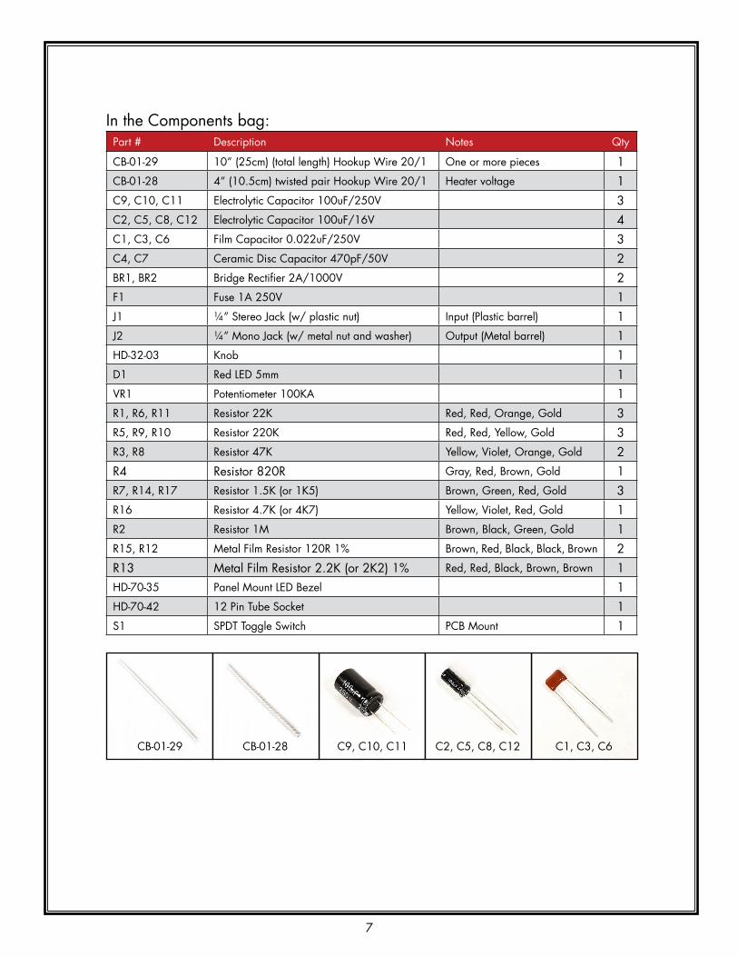
In the Components bag:Part # Description Notes Qty
CB-01-29 10” (25cm) (total length) Hookup Wire 20/1 One or more pieces 1CB-01-28 4” (10.5cm) twisted pair Hookup Wire 20/1 Heater voltage 1C9, C10, C11 Electrolytic Capacitor 100uF/250V 3C2, C5, C8, C12 Electrolytic Capacitor 100uF/16V 4C1, C3, C6 Film Capacitor 0.022uF/250V 3C4, C7 Ceramic Disc Capacitor 470pF/50V 2BR1, BR2 Bridge Rectifier 2A/1000V 2F1 Fuse 1A 250V 1J1 ¼” Stereo Jack (w/ plastic nut) Input (Plastic barrel) 1J2 ¼” Mono Jack (w/ metal nut and washer) Output (Metal barrel) 1HD-32-03 knob 1D1 Red LED 5mm 1VR1 Potentiometer 100kA 1R1, R6, R11 Resistor 22k Red, Red, Orange, Gold 3R5, R9, R10 Resistor 220k Red, Red, Yellow, Gold 3R3, R8 Resistor 47k Yellow, Violet, Orange, Gold 2R4 Resistor 820R Gray, Red, Brown, Gold 1R7, R14, R17 Resistor 1.5k (or 1k5) Brown, Green, Red, Gold 3R16 Resistor 4.7k (or 4k7) Yellow, Violet, Red, Gold 1R2 Resistor 1M Brown, Black, Green, Gold 1R15, R12 Metal Film Resistor 120R 1% Brown, Red, Black, Black, Brown 2R13 Metal Film Resistor 2.2k (or 2k2) 1% Red, Red, Black, Brown, Brown 1HD-70-35 Panel Mount LED Bezel 1HD-70-42 12 Pin Tube Socket 1S1 SPDT Toggle Switch PCB Mount 1
CB-01-29 CB-01-28 C9, C10, C11 C2, C5, C8, C12 C1, C3, C6

8
C4, C7 BR1, BR2 F1 J1 J2
HD-32-03 D1 VR1 R1, R6, R11 R5, R9, R10
R3, R8 R4 R7, R14, R17 R16 R2
In the Hardware bag: Part # Description Notes Qty
HD-50-01 Solder Lug 1CH-10-25 Isolation Fin 2HD-10-03 Foot 1/2”x1/4” 4HD-20-02 Rubber Grommet 4FA-22-21 keps Lock Nut M3 Grounding Lug 1FA-60-37 Philips Machine Screw – Pan head M3x6 PCB and Grounding Lug 13FA-69-37 Philips Wood Screw - Flat head #6x1-1/4” Cabinet 11FA-60-32 Philips Machine Screw - Pan head #6x1/4” Transformers, fins, chassis 12FA-60-36 Philips Machine Screw - Pan head #6x1” Installing the chassis into the cabinet 4FA-63-33 Philips Sheet Metal Screw - Pan head #6x3/8” Feet 4ST-10-23 Nylon Hex Standoff M3x12 6FA-90-30 Flat Washer, #6 Use with FA-60-36 4
R15, R12 R13 HD-70-35 HD-70-42 S1

9
HD-50-01 CH-10-25 HD-10-03 HD-20-02 FA-22-21
FA-60-37 FA-69-37 FA-60-32 FA-63-33 ST-10-23
FA-90-30 FA-60-36
POPULATING THE PRINTED CIRCUIT BOARDYour workspace should be well-lit, well-ventilated, and disposable; that is, don’t work on the nice dining room table! Work on a utility surface that you can burn, drill and scratch. A piece of ¼” tempered masonite, or a chunk of MDF, makes an excellent cover if you don’t have a utility work bench.
CAUTION: Solder fumes are not healthy for you. The fumes consist of vaporized flux, which can irritate your nose, lungs, and even your skin. You MUST work in a space where the air drifts away from you as you work, so fumes do not rise straight onto your face.
CAUTION: Solder residue usually contains lead, which is poisonous if you ingest it. Do not breathe the fumes, do not eat the supplies, wash your hands after you handle solder, and sweep and wipe up your work space after EVERY USE.
The printed circuit board (PCB) holds most of the components in this amp. Nearly all of the components will be installed on the “component side” of the board, which is the side that has the Zeppelin Design Labs logo on it. The other side of the board is called the “solder side”, which, as the name implies, is the side on which the legs of the components are soldered to the board. Proper technique for installing and soldering components to a circuit board is demonstrated in our assembly reference video, but there are several other great resources on YouTube under the search “soldering tutorial.” The general procedure consists of the following:

10
1. Install the part on the “component side” of the board, by threading the wire leads through the appropriate holes in the board. For your convenience, the board has silk screen outlines indicating where the components should be placed, along with text indicating the part number and often times the component value.
2. Hold the component in place with your finger and turn the board over.3. Gently bend the leads out at about 45 degrees to keep the component from falling out of its
holes.4. Install all of one type of component, bending each of the leads as they are installed.5. Flip the board over solder-side-up, and solder all of the components in one pass.6. Clip the leads off (with small diagonal cutters) right at the solder joint.
Let’s begin!1. Standoffs (Part # ST-10-23): Use 6 standoffs, 6 M3 screws (Part # FA-60-37), and 6 lock washers
(Part # FA-91-30). The plastic standoffs are installed on the solder side of the board, which means they are screwed in from the component side. The lock washer goes between the PCB and the standoff (not between the screw head and the PCB)1. Place the 6 standoffs in the locations indicated below2.
2. Resistors: The value of resistors are given by a series of colored stripes on their body. There are several tutorials on line describing how to decode these stripes, but we will identify each resistor for you by simply naming the stripe colors, and giving you the value and the part number. Figure 2: Component Values and Locations on the next page is a handy reference. If you are color blind or can’t see the stripes clearly, then you must use your digital multimeter to measure the resistance of each resistor.
1 2

11
The hole spacing of most of the resistors on the circuit board allows the leads to be (gently) bent 90 degrees at the body of the resistor3. This allows most resistors to slip into their holes very easily. Resistors R13 & R17 are exceptions to the normal hole spacing, so for those two components you’ll have to estimate where to bend the leads.
a. Start with the 22k resistors (R1, R6, R11), labeled RED, RED, ORANGE, GOLD. Compare to its picture in the BOM. Find their locations on the circuit board and install and bend the leads as described above4,5. Don’t solder any of them until all 17 resistors are installed; just bend the leads to keep them in their place.
3
4 5
Figure 2: Component Values and Locations
12
b. Continue with the 220k resistors (R5, R9, R10), labeled RED, RED, YELLOW, GOLD. c. Continue with the 1.5k (or 1k5) resistors (R7, R14, R17), labeled BROWN, GREEN, RED,
GOLD. R17 has a larger lead spacing than most of the other resistors so estimate where to bend the leads.
d. Continue with the 47k resistors (R3, R8), labeled YELLOW, VIOLET, ORANGE, GOLD.e. Continue with the 120 ohm (or 120R) resistors (R12, R15), which are blue in color and are
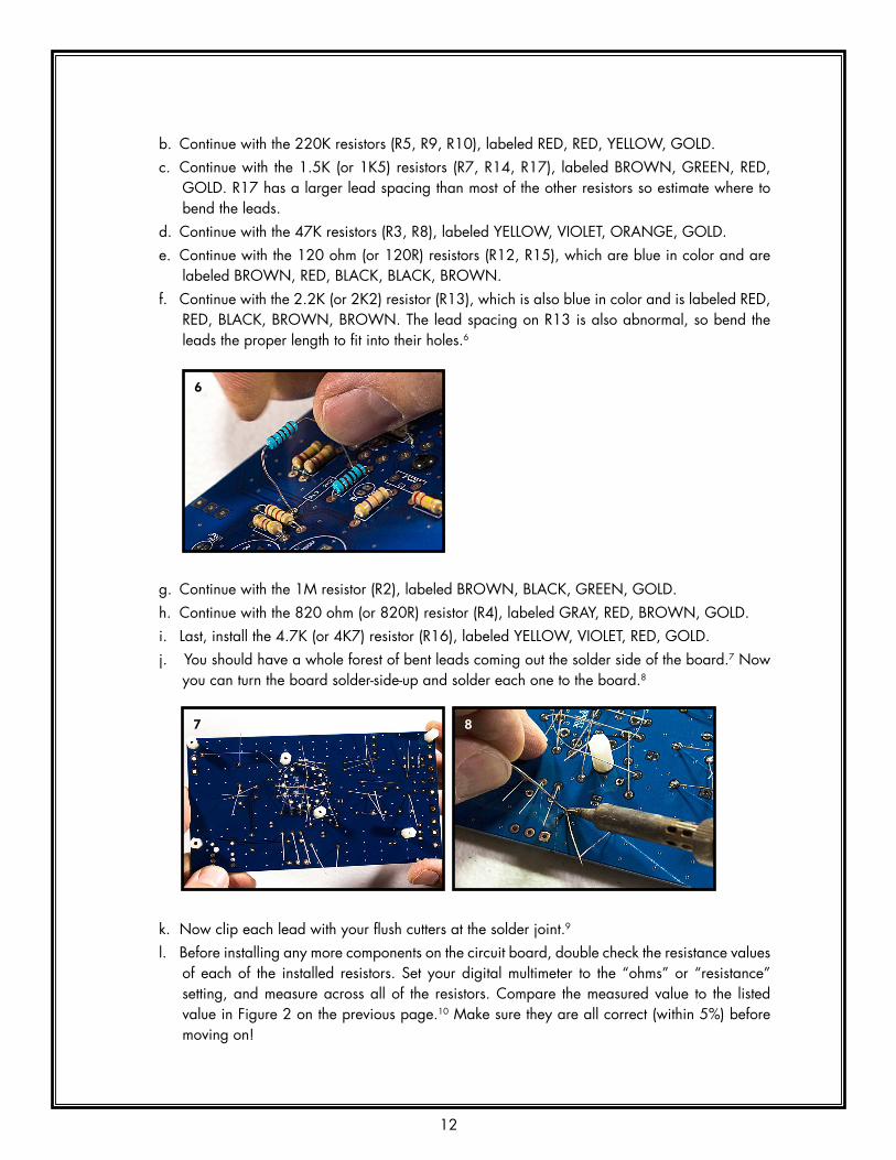
labeled BROWN, RED, BLACk, BLACk, BROWN. f. Continue with the 2.2k (or 2k2) resistor (R13), which is also blue in color and is labeled RED,
RED, BLACk, BROWN, BROWN. The lead spacing on R13 is also abnormal, so bend the leads the proper length to fit into their holes.6
g. Continue with the 1M resistor (R2), labeled BROWN, BLACk, GREEN, GOLD. h. Continue with the 820 ohm (or 820R) resistor (R4), labeled GRAY, RED, BROWN, GOLD. i. Last, install the 4.7k (or 4k7) resistor (R16), labeled YELLOW, VIOLET, RED, GOLD.j. You should have a whole forest of bent leads coming out the solder side of the board.7 Now
you can turn the board solder-side-up and solder each one to the board.8
k. Now clip each lead with your flush cutters at the solder joint.9
l. Before installing any more components on the circuit board, double check the resistance values of each of the installed resistors. Set your digital multimeter to the “ohms” or “resistance” setting, and measure across all of the resistors. Compare the measured value to the listed value in Figure 2 on the previous page.10 Make sure they are all correct (within 5%) before moving on!
6
7 8
9 10
13
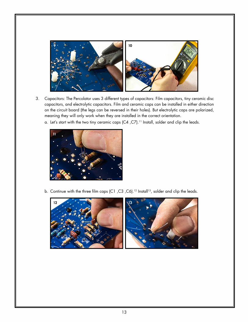
3. Capacitors: The Percolator uses 3 different types of capacitors: Film capacitors, tiny ceramic disc capacitors, and electrolytic capacitors. Film and ceramic caps can be installed in either direction on the circuit board (the legs can be reversed in their holes). But electrolytic caps are polarized, meaning they will only work when they are installed in the correct orientation.a. Let’s start with the two tiny ceramic caps (C4 ,C7).11 Install, solder and clip the leads.
b. Continue with the three film caps (C1 ,C3 ,C6).12 Install13, solder and clip the leads.
11
12 13
b. Continue with the 220k resistors (R5, R9, R10), labeled RED, RED, YELLOW, GOLD. c. Continue with the 1.5k (or 1k5) resistors (R7, R14, R17), labeled BROWN, GREEN, RED,
GOLD. R17 has a larger lead spacing than most of the other resistors so estimate where to bend the leads.
d. Continue with the 47k resistors (R3, R8), labeled YELLOW, VIOLET, ORANGE, GOLD.e. Continue with the 120 ohm (or 120R) resistors (R12, R15), which are blue in color and are
labeled BROWN, RED, BLACk, BLACk, BROWN. f. Continue with the 2.2k (or 2k2) resistor (R13), which is also blue in color and is labeled RED,
RED, BLACk, BROWN, BROWN. The lead spacing on R13 is also abnormal, so bend the leads the proper length to fit into their holes.6
g. Continue with the 1M resistor (R2), labeled BROWN, BLACk, GREEN, GOLD. h. Continue with the 820 ohm (or 820R) resistor (R4), labeled GRAY, RED, BROWN, GOLD. i. Last, install the 4.7k (or 4k7) resistor (R16), labeled YELLOW, VIOLET, RED, GOLD.j. You should have a whole forest of bent leads coming out the solder side of the board.7 Now
you can turn the board solder-side-up and solder each one to the board.8
k. Now clip each lead with your flush cutters at the solder joint.9
l. Before installing any more components on the circuit board, double check the resistance values of each of the installed resistors. Set your digital multimeter to the “ohms” or “resistance” setting, and measure across all of the resistors. Compare the measured value to the listed value in Figure 2 on the previous page.10 Make sure they are all correct (within 5%) before moving on!
6
7 8
9 10

14
c. Now for the tricky electrolytic caps. Note all the electrolytic capacitors have one leg that is longer than the other.14, 15 The longer leg is the positive side of the cap. The positive leg (the longer leg) goes in the square pad. PAY CLOSE ATTENTION TO THIS WHEN YOU ARE INSTALLING THESE CAPS! It is very easy to install one or more electrolytic caps backwards! If you do, the amp won’t work correctly! Double check Figure 2 for reference. Figure 2 also has “+” signs where the positive (longer) lead goes. The negative side of the caps have white stripes pointing to the negative lead.
d. Install all of the smaller electrolytic caps (C2 ,C5 ,C8 ,C12). Solder and clip the leads.16
e. Now install the three big electrolytic caps (C9 ,C10 ,C11).17 Solder and clip the leads18, but put one of these clipped leads aside for use in the next step.
WARNING: The big electrolytic caps (C9 ,C10 ,C11) are likely to explode if they are installed backwards, which could result in personal injury. Install in STRICT CONFORMANCE with these instructions!
14 15
16
17 18

15
4. Jumper wire: Use one of the leads that you just clipped off of the big electrolytic capacitors (C9, C10, or C11) as this jumper. Use your needle nose pliers to bend the lead in the shape of a staple.20 Install the jumper in the holes and solder the leads.21
5. Bridge rectifiers (Part # BR1, BR2): Bridge rectifiers have 4 leads and it is very important to make sure each lead goes in the correct hole. The only indication on the circuit board of how the rectifiers should be oriented is a square pad. The positive lead (the longest lead22, labeled with a “+”) goes in the square hole23. The other leads should line up properly with the other holes.
a. Install both BR1 and BR2 with this orientation. Solder and clip the leads.b. Before moving on, double check the orientation of the bridge rectifiers. Make sure the “+”
and “-” printed on the component are in the same orientation as the “+” and “-” on the circuit board.
20 21
22 23
24

16
6. Input jack (Part # J1): Remove the plastic nut from the input jack and put it aside until the next section. Snap the input jack into its holes on the circuit board.25 Make sure you solder the leads well.26 The leads are too short to cut on this component so don’t bother.
7. Potentiometer (Part # VR1): Remove the nut and washer from the shaft of the pot and put them aside until the next section. Install the potentiometer (“pot” for short) with the shaft facing away from the board. The leads are too short to bend out, so you just have to hold the pot while you solder at least one lead.27 It is very important to make sure all the leads are completely seated in their holes before soldering, otherwise the board won’t fit into the chassis properly. The leads are too short to cut on this component too.
8. Power switch (Part # S1): Carefully install the power switch on the PCB.28 Very gently guide the leads into the holes with your needle-nose pliers.29 This component switches high voltage, so make sure all the leads are making good connections with the board. Solder carefully and thoroughly. The front two pins may requre extra heat, as the switch body may act as a heat sink. After soldering, flip the switch a few times to make sure it feels solid.
25 26
27
28 29

17
9. LED (Part # D1): The LED (light emitting diode) is a polarized component, meaning it matters which way it goes into the holes. The long lead goes into the square hole.30, 31 If you do not install the LED correctly, the “Power On” light will not work. Install the LED so that the top of the LED stands about 7/8” (23mm) off the surface of the board.32 Solder the LED on the component side so it will be easier to switch later if you get it backwards.33 Clip the leads on the solder side of the board.
10. Feedback loop wire (Part # CB-01-29): Strip about 1/4” (6mm) of insulation from each end of the 10.5cm single stranded hookup wire.34 Solder one end of this wire to the FBL hole so the wire is emerging from the component side of the board.35, 36
30 31
32 33
34 35
36

18
11. 6cm Hookup wire (Part # CB10.4): Strip about 1/8” (3-4mm) of insulation from each end of the 6cm hookup wire. With your pliers bend both ends at a right angle.37 This wire goes on the solder side of the board, so flip the board over and install the wire where it goes (note the picture38). Solder it on the component side of the board.39
Now bend the wire along the surface of the board to make it follow the line printed on the board.
37 38
39

19
12. 10.5cm Twisted pair hookup wire (Part # CB-01-28): This wire is used to transmit the 6.3V heating filament voltage to the tube. Untwist about 1/4” (6-7mm) of each end of the twisted pair and straighten the ends out with your pliers.40 Strip off about 1/8” (3-4mm) insulation from each end of the two wires.41 On the solder side of the board, install the four stripped ends in the holes marked “HEATERS”.42 It doesn’t matter which wire goes into which of the two holes. Solder each of the four ends on the component side of the board.43, 44
40 41
42 43
44
20
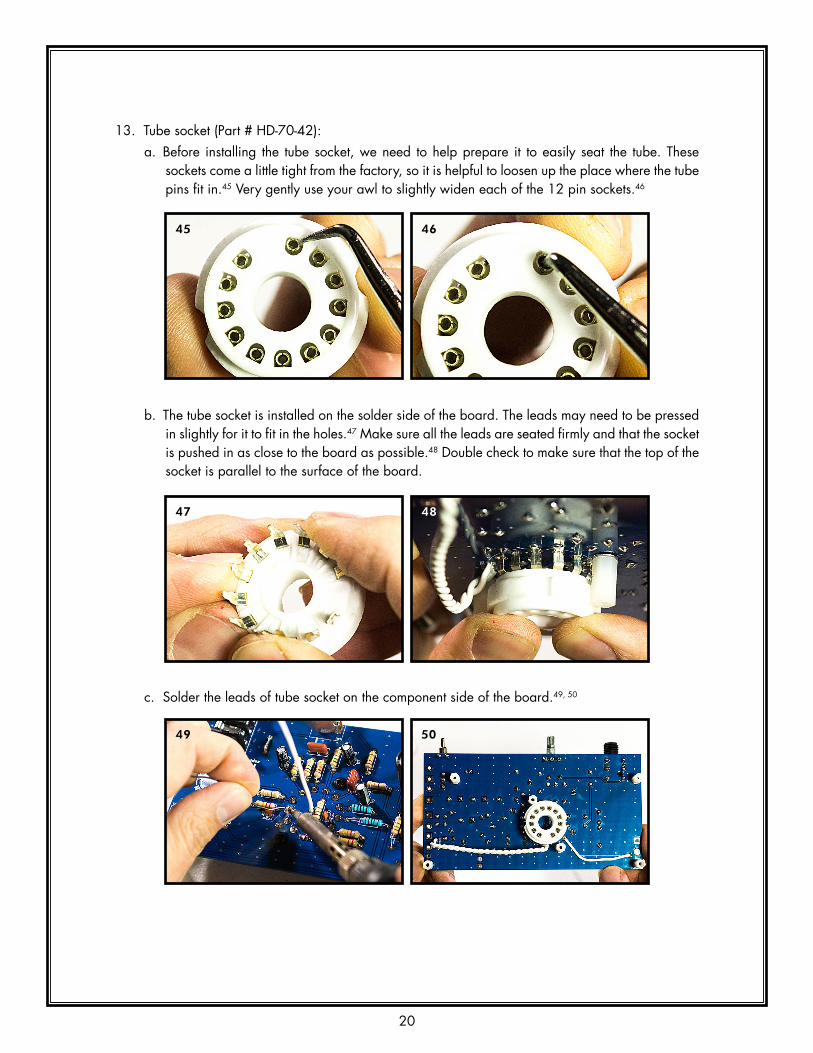
13. Tube socket (Part # HD-70-42): a. Before installing the tube socket, we need to help prepare it to easily seat the tube. These
sockets come a little tight from the factory, so it is helpful to loosen up the place where the tube pins fit in.45 Very gently use your awl to slightly widen each of the 12 pin sockets.46
b. The tube socket is installed on the solder side of the board. The leads may need to be pressed in slightly for it to fit in the holes.47 Make sure all the leads are seated firmly and that the socket is pushed in as close to the board as possible.48 Double check to make sure that the top of the socket is parallel to the surface of the board.
c. Solder the leads of tube socket on the component side of the board.49, 50
45 46
47 48
49 50

21
The circuit board is now complete! Double check all your solder joints and make sure everything is well soldered and making good connections. If anything looks at all sketchy, touch-up each solder joint. It’s much easier to fix a problem with the board now than once it is installed in the chassis. Once you are satisfied with the PCB, put it aside in a safe spot until the next section when it is installed it in the chassis.

22
LOADING THE CHASSISNote the chassis face with the big square hole is the BACk of the amp! Generally, hold the chassis with the back AWAY from you unless told otherwise! This will help avoid building the thing backwards.
1. Grommets: Pop the 4 rubber grommets (Part # HD-20-02) into the holes on top of the chassis as shown.51
2. Power Transformer (Part # T1): a. Cut the black wires coming from the power transformer to 4-5/16” (11cm).52 Put the black
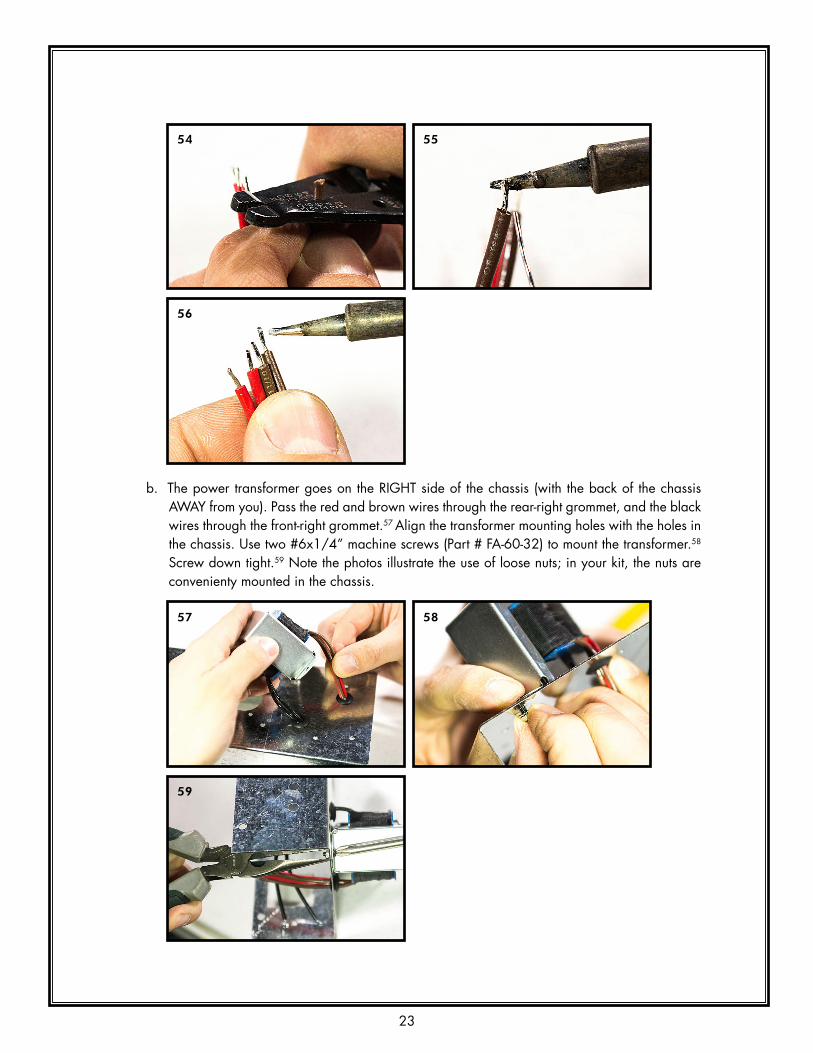
wires that you just cut aside because you will use them later. Cut the brown and red wires to 2-3/4” (7cm).53 Strip off about 3/16” (4-5mm) of insulation from each of the 6 wires.54 Twist together the tiny strands of wire on each of the stripped ends. Then “tin” the stripped part of each wire.55, 56 “Tinning” is the process of coating or filling a wire or connector contact with solder to make it easier to attach. It also helps to keep the tiny strands of wire from fraying out while you try to solder them. When you tin the transformer wires, make sure you do not use too much solder; otherwise the wire will be too thick to fit into the PCB holes later.
51 BACk
FRONT
RIGHTLEFT
54 55
56
52 53
23
b. The power transformer goes on the RIGHT side of the chassis (with the back of the chassis AWAY from you). Pass the red and brown wires through the rear-right grommet, and the black wires through the front-right grommet.57 Align the transformer mounting holes with the holes in the chassis. Use two #6x1/4” machine screws (Part # FA-60-32) to mount the transformer.58 Screw down tight.59 Note the photos illustrate the use of loose nuts; in your kit, the nuts are convenienty mounted in the chassis.
57 58
59
LOADING THE CHASSISNote the chassis face with the big square hole is the BACk of the amp! Generally, hold the chassis with the back AWAY from you unless told otherwise! This will help avoid building the thing backwards.
1. Grommets: Pop the 4 rubber grommets (Part # HD-20-02) into the holes on top of the chassis as shown.51
2. Power Transformer (Part # T1): a. Cut the black wires coming from the power transformer to 4-5/16” (11cm).52 Put the black
wires that you just cut aside because you will use them later. Cut the brown and red wires to 2-3/4” (7cm).53 Strip off about 3/16” (4-5mm) of insulation from each of the 6 wires.54 Twist together the tiny strands of wire on each of the stripped ends. Then “tin” the stripped part of each wire.55, 56 “Tinning” is the process of coating or filling a wire or connector contact with solder to make it easier to attach. It also helps to keep the tiny strands of wire from fraying out while you try to solder them. When you tin the transformer wires, make sure you do not use too much solder; otherwise the wire will be too thick to fit into the PCB holes later.
51 BACk
FRONT
RIGHTLEFT
54 55
56

24
c. Now you need to twist the wires. Twist the black wires together somewhat tightly, but do not over twist the wires near where they emerge from the transformer. You do not want to stress the wires near the transformer coil, because they can easily break on the inside of the transformer, and that would be very bad. Also twist the red wires together and the brown wires together in the same way (not too tight near the coil).60
3. Output Transformer (Part # T2): a. Cut all of the wires coming from the output transformer to 4” (10cm).61, 62 Strip off about
3/16” (4-5mm) of insulation from each of the four wires. Twist together the tiny strands of wire on each of the stripped ends and tin the stripped part of each wire.63 Don’t make the tinned wire too fat.
60
61 62
63

25
b. The output transformer goes on the LEFT side of the chassis. Pass the green and black wires through the left-rear grommet, and the blue and red wires through the front-left grommet.64 Screw the transformer down to the chassis, just like the power transformer, with two #6x1/4” machine screws (Part # FA-60-32)).65
c. Twist the green and black wires together, and twist the red and blue wires together, in the same way as the power transformer wires.66 Once again, be mindful not to over twist the wires close to the coil.
4. Fins (Part # CH-10-25) (2 pcs): These flank the tube socket and shield the tube from the magnetic fields from the transformers. Place them as shown, careful that they face the right way. If the fins look like the letter L, then the base of the L points towards the tube opening. Use four of the #6x1/4” machine screws (Part #FA-60-32) to attach the fins.67 Screw down tight.
64 65
66
67

26
5. Label (Part # PL-10-03): Clean the front of the chassis with a clean rag and some isopropyl alcohol.68 Clean it thoroughly, and then be careful NOT TO TOUCH the face AT ALL. The oil on your fingers will interfere with the bond of the label. Test fit the label, carefully centering all the holes. Tape one end of the label to the chassis with masking tape, then peel off and remove about half of the backing. Carefully set the label in place.69 Now remove the tape and the rest of the backing. Rub the label down firmly over the entire surface.
6. LED bezel (Part # HD-70-35): Install the plastic LED bezel into its hole on the front of the chassis (through the label).70 It goes in the hole to the right of the logo. It should easily snap into place.
7. Install the PCB (Part # PC-03-01): a. Flip the chassis over so the fins and transformers are resting on the table top, and the front of
the chassis is facing you. Bend all the transformer wires to the outside of the chassis so that they don’t get in the way of the placement of the PCB.71
70
71
68 69

27
b. Carefully place the circuit board in the chassis with the standoffs down (the standoffs resting on the top of the chassis) and the component side of the board up. The input jack side of the board should be closest to you. Slide the PCB forward as the input jack, pot, and switch fit through the holes on the front of the chassis and the tube socket is seated in its chassis hole.72 You may have to hold the board at an angle while sliding it forward to get everything to fit properly. Make sure all the transformer wires are between the front and back standoffs. The standoffs should line up with the screw holes on top of the chassis.
Affix the PCB to the chassis with six machine screws (Part #FA-60-37) placed through the chassis holes into the standoffs.73 Don’t over tighten or cross-thread these screws.
73
c. Place the washer and nut back on the pot, and snug down with your pliers.74 Place the plastic nut back on the input jack,75 and snug it down with your pliers. Do not over-tighten this nut or the label could start warping.
72
74 75

28
d. Use your needle nose pliers to bend the LED over to fit inside of the LED bezel on the front of the chassis.76 Be sure not to twist the LED or the leads might touch and short out against each other. Push the LED through the bezel until it snaps into place.
8. knob (Part # HD-32-03): Turn the pot all the way counter clockwise. Place the knob on the pot and align the white line on the knob to the position where you want the volume to be off (usually between 1:00 & 2:00, when the amp is upside down). Use a small flat screwdriver to tighten the set screw until the knob is tight.77 Now turn the knob all the way right and left through its travel. The line should be between 10:00 & 11:00 at the maximum clockwise position. If the extreme positions are not neatly symmetric, loosen the screw, adjust the knob, and re-tighten. It may take a few times of re-adjustment to get the knob/pot position where you want it.
9. Wiring the PCB: Once the PCB is affixed to the chassis you can attach the transformer wires. All of the wires will pass around the side of the PCB, and you will solder them on the component side of the board. a. Output transformer: Place the red wire into the square hole of P1, and then the blue wire to
the round hole of P1. Solder both connections.78
76
77
78

29
b. Power transformer: Place the black wires into the holes of P479; place the red wires into the holes of P280; and then place the brown wires into the holes of P3.81 In each pair, it does not matter which wire goes in which hole, but MAkE SURE YOU MATCH THE COLOR TO THE CORRECT NUMBER! Solder all the wires in their respective holes.
10. Grounding Wire (Part #CB-01-29): Cut a piece of hookup wire about 1-1/2” (4cm) long. Strip about 1/4” (6mm) of insulation off both ends. Bend a small hook in one stripped end of the wire.82 Thread the hook through the small hole on the grounding lug (Part #HD-50-01) and crimp it tight with your pliers.83 Solder that connection.84 Put this assembly aside until next step.
79 80
81
82 83
84
30
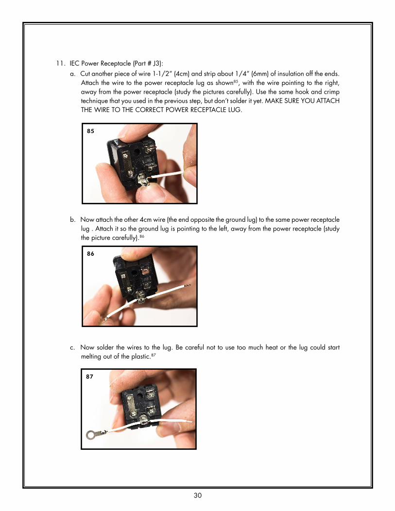
11. IEC Power Receptacle (Part # J3): a. Cut another piece of wire 1-1/2” (4cm) and strip about 1/4” (6mm) of insulation off the ends.
Attach the wire to the power receptacle lug as shown85, with the wire pointing to the right, away from the power receptacle (study the pictures carefully). Use the same hook and crimp technique that you used in the previous step, but don’t solder it yet. MAkE SURE YOU ATTACH THE WIRE TO THE CORRECT POWER RECEPTACLE LUG.
b. Now attach the other 4cm wire (the end opposite the ground lug) to the same power receptacle lug . Attach it so the ground lug is pointing to the left, away from the power receptacle (study the picture carefully).86
c. Now solder the wires to the lug. Be careful not to use too much heat or the lug could start melting out of the plastic.87
85
86
87

31
d. Bend both wires slightly forward and push the power receptacle through the chassis. BE SURE TO INSTALL IT WITH THE CORRECT SIDE UP.88 Once seated properly, you can gently bend the four retaining tabs of the power receptacle a little if you want to ensure a tighter fit.89
e. Place the wire without the ground lug into one of the 3 square ground pads on the PCB next to the power receptacle. Solder this wire in place on the component side of the board.90
f. Use your flat screwdriver to pry the fuse holder from the power receptacle.91 Pace the fuse (Part #F1) in the holder92 and slide it back into the power receptacle.93
88 89
90
91 92
93

32
12. Grounding Wire Revisited: Use the last M3x6 machine screw (Part #FA-60-37) and the M3 Lock Nut, (Part #FA-22-21) to attach the grounding lug to the back of the chassis as shown.94 Screw it down tight!
13. Wiring the IEC power receptacle:
WARNING: If you make a mistake here, you could expose yourself or others to electric shock. Double check all your connections.
a. Retrieve the lengths of wire that you cut off the power transformer earlier. Cut each of the two black wires to 4-1/4” (10.5cm) long.95 Strip about 3/16” (4-5mm) of insulation from each end of both wires.96 Tin each end (don’t use too much solder).
b. Now twist the two wires together, to within about 3/8” of each end.97 Solder one end of the pair to the holes labeled P5, IEC jack.98
94
95 96
97 98

33
c. Solder the other ends of the twisted black wires to the IEC power receptacle, to the two lugs shown in the picture.99 It doesn’t matter which wire goes to which lug, JUST MAkE SURE YOU SOLDER THEM TO THE CORRECT TWO LUGS! Mind the picture.100
14. Output jack (Part # J2): a. Remove the nut and washer from the output jack and install it on the back of the chassis.101
Orient the jack so the lugs are facing up, as in the picture. The washer goes on the outside of the jack, between the nut and the chassis.
b. With your needle nose pliers make a small hook in the stripped section of the feedback loop wire (the long wire attached to the middle of the circuit board, in the FBL hole). Hook the FBL wire on the “tip” lug of the output jack (note the picture below102, if you are not sure which is the correct lug).
c. Next attach the green wire from the output transformer to the same lug (the “tip” lug) as the FBL wire.102 Solder both wires to the lug.
99 100
101
102
34
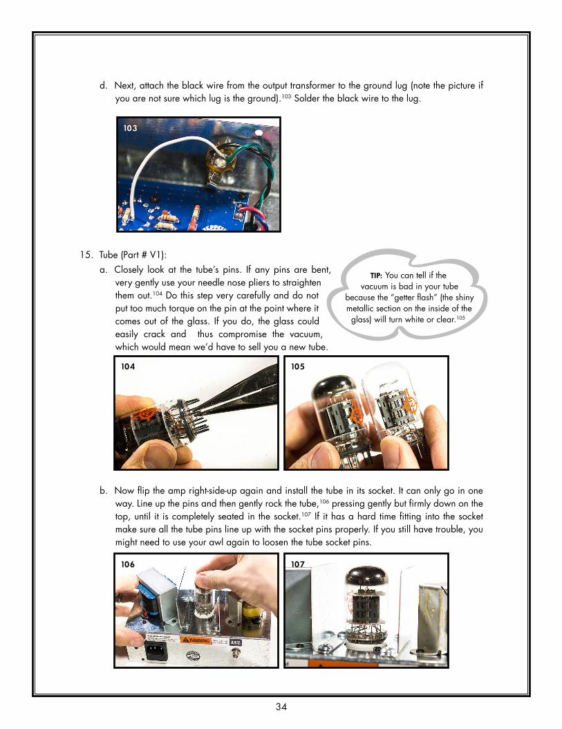
d. Next, attach the black wire from the output transformer to the ground lug (note the picture if you are not sure which lug is the ground).103 Solder the black wire to the lug.
15. Tube (Part # V1): a. Closely look at the tube’s pins. If any pins are bent,
very gently use your needle nose pliers to straighten them out.104 Do this step very carefully and do not put too much torque on the pin at the point where it comes out of the glass. If you do, the glass could easily crack and thus compromise the vacuum, which would mean we’d have to sell you a new tube.
b. Now flip the amp right-side-up again and install the tube in its socket. It can only go in one way. Line up the pins and then gently rock the tube,106 pressing gently but firmly down on the top, until it is completely seated in the socket.107 If it has a hard time fitting into the socket make sure all the tube pins line up with the socket pins properly. If you still have trouble, you might need to use your awl again to loosen the tube socket pins.
103
TIP: You can tell if the vacuum is bad in your tube
because the “getter flash” (the shiny metallic section on the inside of the glass) will turn white or clear.105
104 105
106 107

35

36
TESTING THE AMPThe testing process is done with the Percolator upside down. The transformers and fins should be resting on the bench top. Make sure none of the weight of the amp is resting on the glass bottle of the tube. If it is, put some blocks of wood under the transformers to jack the amp up a little bit.
A schematic of the amplifier is printed on the template sheet that came with the kit. This schematic is for reference in troubleshooting, should you have problems with the amp. DC test voltages are labeled in red on “Figure 3: Voltage Reference” on page 39. The test procedure will consist of systematically measuring these voltages to ensure that your amp is within spec. Print this diagram and write your measurements directly on it. You don’t have to know how to read a schematic to test these voltages, but you do need to know how to use your digital multimeter.
1. WITH THE AMP UNPLUGGED, double check all your wiring. Look closely at the pictures and make sure the wires on your amp are correctly positioned.108,109
2. WITH THE AMP UNPLUGGED from the wall, double check your solder joints. Closely examine every joint on the PCB and make sure they are good, solid connections.
3. Using a 1/4” speaker cable, plug the Percolator’s output jack into an 8 ohm speaker cabinet. ONLY USE AN 8 OHM CABINET WITH THIS AMPLIFIER. WHENEVER YOU APPLY POWER TO THIS AMP, MAkE SURE IT IS FIRST PLUGGED IN TO AN 8 OHM LOAD.
4. Make sure the Percolator’s power switch is in the off position (when the amp is upside down, the switch should be up).110 Plug the IEC power cable into the IEC power receptacle on the amp. Make sure NOTHING is touching any part of the amplifier that shouldn’t be, and then plug the power cable into the wall outlet.
WARNING! As soon as you plug in the Percolator, there is LINE VOLTAGE across some parts of the exposed circuit board. Touching the board could shock, injure, or kill you! NEVER TOUCH ANY PART OF THE CIRCUIT BOARD WHEN THE AMP IS PLUGGED INTO THE WALL!
108 109
110

37
5. Before you turn the power switch on, set your multimeter to test AC voltage. Measure the AC voltage across the IEC power receptacle as shown.111 Depending on several (mostly uncontrollable) factors, you should measure between 115VAC and 120VAC (or between 220VAC and 240VAC if you got the international power transformer). The amplifier was designed to use 118VAC from the wall outlet (230VAC for the international transformer), so the voltages listed in the test procedure are based on that. If your AC voltage reading is different than 118VAC (or 230VAC), then the voltage readings in the next few steps will be off proportionally. Theoretically, if the input voltage from the wall outlet is off by a certain percentage then all of the rest of the voltages in the amp will be off by the same percentage. The tolerances of the tube and the rest of the components can easily vary by 5%, so that could cause a bit of voltage fluctuation as well.
6. Set your digital multimeter to read DC voltage. In this amp, all DC voltages are measured with respect to ground, so the black probe of your multimeter should be held at ground potential. This amp has several places at ground potential that are good to put your black probe. Any of the vias (the tiny holes throughout the PCB) should work.112 Any one of the 3 square pads on the PCB under the IEC power receptacle will work.113 You could also use any place on the chassis, assuming the ground lug is making good contact with the chassis.114 keep the black probe on any of those places while making DC voltage measurements.
111
TIP: Use a test lead (a wire with small alligator
clips on both ends) to clip the negative (black) lead of your
multimeter to the grounded chassis. That will free up one hand.
TESTING THE AMPThe testing process is done with the Percolator upside down. The transformers and fins should be resting on the bench top. Make sure none of the weight of the amp is resting on the glass bottle of the tube. If it is, put some blocks of wood under the transformers to jack the amp up a little bit.
A schematic of the amplifier is printed on the template sheet that came with the kit. This schematic is for reference in troubleshooting, should you have problems with the amp. DC test voltages are labeled in red on “Figure 3: Voltage Reference” on page 39. The test procedure will consist of systematically measuring these voltages to ensure that your amp is within spec. Print this diagram and write your measurements directly on it. You don’t have to know how to read a schematic to test these voltages, but you do need to know how to use your digital multimeter.
1. WITH THE AMP UNPLUGGED, double check all your wiring. Look closely at the pictures and make sure the wires on your amp are correctly positioned.108,109
2. WITH THE AMP UNPLUGGED from the wall, double check your solder joints. Closely examine every joint on the PCB and make sure they are good, solid connections.
3. Using a 1/4” speaker cable, plug the Percolator’s output jack into an 8 ohm speaker cabinet. ONLY USE AN 8 OHM CABINET WITH THIS AMPLIFIER. WHENEVER YOU APPLY POWER TO THIS AMP, MAkE SURE IT IS FIRST PLUGGED IN TO AN 8 OHM LOAD.
4. Make sure the Percolator’s power switch is in the off position (when the amp is upside down, the switch should be up).110 Plug the IEC power cable into the IEC power receptacle on the amp. Make sure NOTHING is touching any part of the amplifier that shouldn’t be, and then plug the power cable into the wall outlet.
WARNING! As soon as you plug in the Percolator, there is LINE VOLTAGE across some parts of the exposed circuit board. Touching the board could shock, injure, or kill you! NEVER TOUCH ANY PART OF THE CIRCUIT BOARD WHEN THE AMP IS PLUGGED INTO THE WALL!
108 109
110

38
7. Turn on the power switch.
WARNING! As soon as you turn on the Percolator, there is HIGH VOLTAGE across several parts of the exposed circuit board. Touching the board could shock, injure or kill you! NEVER TOUCH ANY PART OF THE CIRCUIT BOARD WHEN THE AMP IS PLUGGED INTO THE WALL!
The red LED should immediately turn on115 (if it does, skip to the next step). If it doesn’t, then measure the junction of C12 and R17 (TP2 in “Figure 3: Voltage Reference” on page 39). It should read around 6.5VDC. If it does, it means you either installed the LED backwards, or you installed the wrong resistor in R17. Switch off the amp, unplug the power cable and fix the problem. If TP2 does not read around 6.5VDC (by a large percentage) double check C12 and/or BR2 to make sure they are in the proper orientation.
112 113
114
115

39
WARNING: Capacitors contain high-voltage electricity hours after the amp is unplugged! Handling the capacitor could shock or burn you! If you must remove or re-solder a capacitor, either let it sit unplugged overnight, or safely discharge it as described in the tip below.
8. Figure 3 has 11 DC test voltages (in red) with arrows pointing to the place on the circuit board where these voltages should be found. The points are numbered TP1 through TP11 (“TP” stands for “test point”). In the figure next to each voltage is a box for you to write down the voltage that you actually measure. Remember, you are measuring from ground (with the black probe) to the red point (with the red probe).116 Start on the left side of the board and work your way from point to point, writing down each voltage as you measure it. All the voltages should be fairly close to the printed value, but if the line voltage (from the wall outlet) is above or below 118 VAC (or 230VAC for the international version), then these voltages will be off by the same percentage. If any of these voltages are significantly off beyond this line voltage percentage, then it is very likely that one or more of the components are installed in the wrong place. Triple check the resistors, capacitors, and bridge rectifiers by visually inspecting each one. If they are all correct, then triple check each solder joint. If you make any changes, use your multimeter to re-test the voltages that were incorrect. If you have to get to the solder side of the board, you’ll have to unsolder all the transformer wires from the board, and remove the IEC receptacle, as well as unscrew the front panel components and stand off screws from the chassis.
Figure 3: Voltage Reference
TIP: To safely discharge a capacitor: Get a 1k-10k ohm,
2w resistor and solder or clip test leads to the resistor legs. Clip one
of the leads to the chassis, and clip the other lead to the positive side of the high-voltage cap. The cap will
discharge in a few seconds.

40
9. Once the voltages are all within spec, carefully plug your guitar (or harp mic) into the input jack, taking care not to touch the exposed circuit board. Make some noise.117 Turn up the volume. It should sound great!
116
TIP: If it turns out that you need to re-solder any of the
resistors, don’t bother removing the board from the chassis to get to the solder side, just solder them on the
component side of the board.
117

41
ASSEMBLING THE CHASSIS1. Turn the power switch off. Unplug any cables that are plugged in to the amp (power, speaker,
instrument). Carefully seat the chassis base plate (Part # CH-10-23) onto the inverted chassis.118 It is a snug fit.
2. Use the last four machine screws, #6x/4” (Part #FA-60-32), two in front119, two in back120, to secure the chassis to the base plate. Screw down tight.
That’s it! The electronics part of your amp is done. Good job. If you plan on installing the amp into the cabinet (a simple task), those notes are in the section “COMPLETING THE HEAD” on page 67. If you are not planning on using the cabinet provided, you are free to go rock out. See the “Percolator Owner’s Manual” on the Percolator product page at www.zeppelindesignlabs.com.
118
119 120

42
BUILDING THE CABINETWhile the amp is an intermediate to advanced electronics project, the cabinet is a beginner’s woodworking project. On the other hand, while the amp can be built in an hour, it takes several hours over several days to complete the cabinet! Take your time, be careful, and you should produce a lovely solid wood cabinet to be proud of.
We are going to show you how we make the pre-finished Percolator here in our lab. There are as many carpentry and finishing techniques as there are carpenters and finishers. If you prefer to do something differently, go for it. If you have an experienced friend to work on this with you, take his or her advice over ours.
WHAT YOU WILL NEED
To build the cabinet, you will need the following:
1. Tools• Drill: cordless, corded, or drill press• Drill bits: 1/16”, 9/64”, 3/16”• Orbital Sander (optional) or sanding block• Small router and 3/16” radius roundover bit, or other small detail bit (optional)• Countersink (see also text below)• #2 Phillips Screw Driver, short shaft• #2 Phillips Screw Driver• Awl, or nail and small hammer• Staple gun. We prefer electric or pneumatic, but manual will work fine.• Sharp pencil• 12” Ruler• Bar clamp, minimum 10” opening• Razor, X-Acto knife, or scissors• Speed square or carpenter square• Channel locks or large pliers• Heat gun, or very hot hair dryer
2. Supplies• Good quality wood glue such as TiteBond II or III• Masking tape• Good quality wood filler such as DAP Plastic Wood (optional)• Sandpaper, either discs for your orbital, or sheets for your block: 60, 120, 220, 320• Very small can of MinWax Dark Walnut Wood Finish #2716 (oil base stain)• Small can of MinWax Wipe-On Poly clear satin• A tiny bit of flat black paint, spray or can, or if you’re in a pinch, permanent black marker
(like a Sharpie) • Mineral spirits, for cleanup• Clean rags• A Percolator cabinet kit

43
A WORD ON COUNTERSINkS
The overall success of this project depends somewhat on your ability to accurately countersink the wood screws, so that the heads lie just below the surface of the wood, but no deeper. There are several ways to do this:
• buy a #6 pilot bit (9/64”) with matching fluted countersink and stop collar, or an all-in-one #6 pilot / counterbore / countersink tool
• buy a countersink bit• Use a ¼” drill bit in a drill press
The first (shown to the left) is our favorite: very accurate and easy to use. The second, a countersink bit (shown to the right), is next best. If you don’t do a lot of wood working, you may not want to invest in these tools. This leaves using a ¼” drill bit in a press. To do this, first drill through with
the 9/64” bit, then countersink with the ¼ bit, carefully and gradually adjusting the depth of plunge until the full
diameter of the bit just barely cuts into the wood. The screw should then pull the head down into the wood and just below the surrounding surface. Practice setting the depth on a scrap of pine until you like the results.
ALWAYS provide a 1/16” pilot in the holding piece of wood, and keep the clutch on your screw gun set low when driving, or the screws provided are likely to spin out or break.
CA-30-02
CA-30-01
HD-10-03
FA-63-33
TX-10-20
HD-30-12
CA-50-02
CA-55-02
FA-69-37

44
ASSEMBLING THE BOX1. Fitting the Wood Parts (Part # CA05). Note that the longer wood parts are the top and bottom
(Part # CA-55-02) and the shorter pieces (Part # CA-55-02) are the sides. Arrange the four pieces of wood as shown in the diagram. If you have a preference for the appearance of grain, color, knots, etc, flip the parts around this way and that until you like the way they look.121 Sometime, the wood exhibits blemishes on one side from the milling process. Face these toward the inside. They will be completely invisible and will have no effect on the quality of the cabinet.
2. With the pencil, label the parts where it won’t show, so you can easily fit them together again later. Put the labels towards the front of each piece.122
3. With scissors or blade, cut out the templates provided with your kit.123 If you ruin them, they also appear at the end of this document. Tape the templates to the top, the bottom and the right-hand side (as you face the front).124, 125 If the templates do not match the wood size PERFECTLY (it happens), line up the FRONT EDGE of the template to the FRONT EDGE of the wood, and center it along the length of the wood. Don’t worry about the REAR edge.
4. With the awl, or nail and a small hammer, carefully poke a hole into the wood at the center of each cross hairs.126 Remove the template from the right side,127, 128 flip it over and tape it face-down to the LEFT side and mark that piece as well.129 Take care when you do this that you create a PAIR of parts, not two IDENTICAL parts.130
121
122

45
NOTE: You don’t have to use the handle provided with your kit. You can use any handle you like, but in that case, check the hole spacing before you poke your marks in the cabinet top!
126 127
128 129
123 124
125

46
5. Stand up all four pieces of wood on their FRONT edges on your clean, smooth, flat work surface.131 Dry-fit them together. Use the bar clamp to snug the pieces together as shown.132 If your clamp has no plastic pads, DO NOT OVER-TIGHTEN or you’ll mar the wood. It just needs to be snug. Pick one corner and line up the pieces of wood as carefully and accurately as you can.133 Be sure the faces (the sides touching the table) are flush to each other at the joint.134 If the parts are not precisely the same width (it happens), they will be a tiny bit uneven on the back face (that is, the sides facing up). That’s okay; don’t worry about it – it’s the back. You can fix it later when finishing the cabinet.When you are satisfied with the alignment of one corner, tighten the clamp to secure the parts for drilling.
Take your time with this step. The overall neatness of your cabinet depends on getting this step right.
6. Fit your drill with the 1/16” bit, sticking out about 1-1/8”. These break easily; you may want to pick up a spare. At the corner you lined up, drill two holes at your marks, through the side and into the mated wood piece.135
131 132
133 134
135130

47
7. Continue to the other three corners, loosening the clamp and lining up the corners one by one. Drill a total of 8 holes.136
8. Disassemble the four pieces and lay them flat on your worktable with the outsides facing up. With an awl or hammer-and-nail, make small pilot holes about 1/4” deep in the corners of the bottom. (These are for the screws that will hold on the feet.) The template describes these as 1/16” blind holes 1/2” deep, but we have since found a nail hole is adequate.137 Note these are the four OUTER holes, nearest the corners.
9. With the 9/64” bit, or the combo drill / countersink bit, re-drill the eight small holes you made in the sides, plus 3 other holes as indicated on the templates: one more on each side, and one on the top. Do NOT countersink any holes on the cabinet BOTTOM, regardless of what the template and the illustrations indicate.
136
TIP: You will get cleaner holes on the inside of
the parts if you can drill straight through the cabinet parts into a
piece of plywood.
137
5. Stand up all four pieces of wood on their FRONT edges on your clean, smooth, flat work surface.131 Dry-fit them together. Use the bar clamp to snug the pieces together as shown.132 If your clamp has no plastic pads, DO NOT OVER-TIGHTEN or you’ll mar the wood. It just needs to be snug. Pick one corner and line up the pieces of wood as carefully and accurately as you can.133 Be sure the faces (the sides touching the table) are flush to each other at the joint.134 If the parts are not precisely the same width (it happens), they will be a tiny bit uneven on the back face (that is, the sides facing up). That’s okay; don’t worry about it – it’s the back. You can fix it later when finishing the cabinet.When you are satisfied with the alignment of one corner, tighten the clamp to secure the parts for drilling.
Take your time with this step. The overall neatness of your cabinet depends on getting this step right.
6. Fit your drill with the 1/16” bit, sticking out about 1-1/8”. These break easily; you may want to pick up a spare. At the corner you lined up, drill two holes at your marks, through the side and into the mated wood piece.135
131 132
133 134
135

48
TIP When you countersink, go easy, test-fit a screw, and deepen the countersink a little as necessary. The head should sit below the surface of the surrounding wood, but only just.
10. There is probably an error on the template on the BOTTOM. Use the 9/64” bit to drill the four inner holes on the bottom, the ones further in from the corners. Do NOT countersink them. NOTE: These holes are for mounting the chassis and need to be as accurate as possible. A drill press is great for this if you have one.138, 139
11. With the 3/16” bit, drill the two holes in the cabinet top for the handle screws.141
NOTE: If you use a handle other than the one provided, check the screw size before drilling these two holes in the cabinet top!
138 139
141

49
12. Inspect the inside faces of the wood pieces for splinters or “blowout”: bits of wood standing above the surrounding surface. Clean these off with a bit of 120-grit sandpaper.142
13. Re-assemble and dry fit the parts,143 with the front edges facing DOWN.144 Apply some wood glue to one end of the TOP. Smooth the glue with a stick until it uniformly coats the end.145 You don’t need much!
142
143 144
145
50
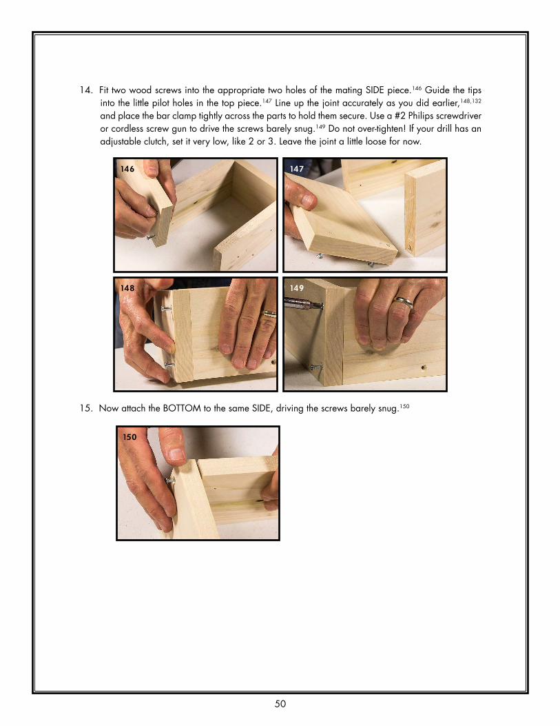
14. Fit two wood screws into the appropriate two holes of the mating SIDE piece.146 Guide the tips into the little pilot holes in the top piece.147 Line up the joint accurately as you did earlier,148,132 and place the bar clamp tightly across the parts to hold them secure. Use a #2 Philips screwdriver or cordless screw gun to drive the screws barely snug.149 Do not over-tighten! If your drill has an adjustable clutch, set it very low, like 2 or 3. Leave the joint a little loose for now.
15. Now attach the BOTTOM to the same SIDE, driving the screws barely snug.150
146 147
148 149
150

51
16. Now apply glue to the remaining exposed ends of both the TOP and BOTTOM.151 Fit four screws into the remaining SIDE and maneuver them into all four little pilot holes.152 Align one joint153 and tighten the bar clamp (not shown; very foolish of us to attempt this without the clamp). Carefully drive the two screws barely snug, then align the last joint, and set the last two screws, barely snug.154 See also our online video for proper placement of the bar clamp.
17. Check the box for overall squareness: press the face flat to the table; measure diagonally across the cabinet to see if it measures the same in both directions.155, 156 If necessary, install the bar clamp across the longer diagonal and gently tighten it to bring the box closer to square.157 Now tighten all eight screws.158 If any glue appears on the outside of the box, wipe it off with a rag dipped in warm water.
Let the cabinet sit for at least 4 hours for the glue to cure.159
151 152
153 154
155 156
157 158
159

52
18. If any joints are poorly mated, grind them flush with 60 or 80 grit sandpaper.160, 161
19. Edge Detail: If you want to apply a router detail, now’s the time. There’s only room for a small chamfer or roundover. (If you don’t want to use a router, you can achieve a similar look just with vigorous hand-sanding.) We use a 3/16” roundover bit with a bearing at the bottom.162 As you route each edge, be careful to orient the router so that you do not run the bearing across the screw heads.163 This will result in blemishes that could ruin your cabinet! Round over all the outside edges except the four back edges.
DANGER! Routers are dangerous, tricky machines that can do you a serious harm if misused. If you are unfamiliar with routers, get a friend to help you!
20. If there are chips, or gaps in your joints that you cannot live with, fill them with wood dough. LET THE WOOD DOUGH HARDEN THOROUGHLY BEFORE SANDING!!
160 161
162 163
164

53
That’s it! Congratulations. Take a break, and when you are ready (maybe tomorrow), we’ll sand and finish the box.
54
FINISHING THE BOXThere are lots of ways to apply a beautiful, durable finish to a solid wood box. Following is how we finish our cabinets here at the Lab. You may finish your Percolator any way you like. Please send us photos of your completed project for our gallery!
Your cabinet is made of top-grade solid poplar. This is a dense, very finely grained softwood. It is harder, more stable and more durable than pine. It is the wood of choice for all fine millwork that is destined to be painted, but properly prepared it stains nicely too.
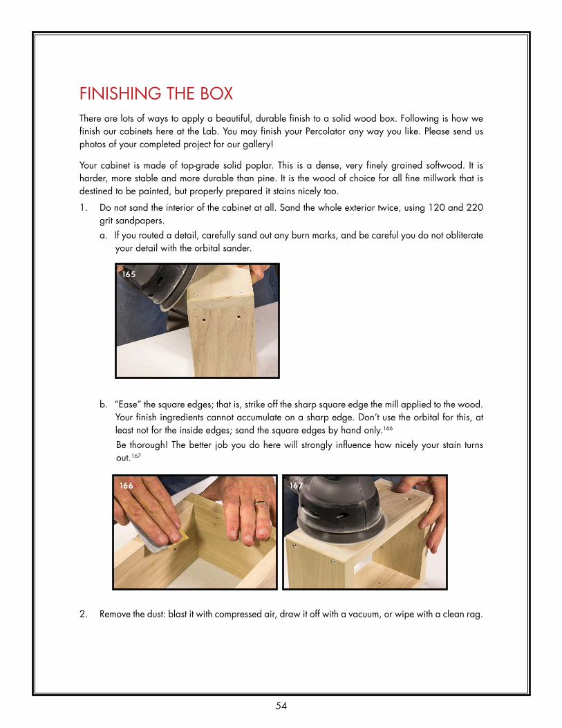
1. Do not sand the interior of the cabinet at all. Sand the whole exterior twice, using 120 and 220 grit sandpapers. a. If you routed a detail, carefully sand out any burn marks, and be careful you do not obliterate
your detail with the orbital sander.
b. “Ease” the square edges; that is, strike off the sharp square edge the mill applied to the wood. Your finish ingredients cannot accumulate on a sharp edge. Don’t use the orbital for this, at least not for the inside edges; sand the square edges by hand only.166
Be thorough! The better job you do here will strongly influence how nicely your stain turns out.167
2. Remove the dust: blast it with compressed air, draw it off with a vacuum, or wipe with a clean rag.
165
166 167

55
3. Apply a liberal coat of MinWax Dark Walnut Wood Finish #2716 with a rag.168 This is an oil-based stain, one of the easiest to use. Coat the entire cabinet inside and out,169, 170 then wipe it off again with a clean rag.171, 172 Rub it out thoroughly and carefully, leaving no fingerprints or streaks.173 Set the cabinet down on its back, propped up on a few pencils, or chopsticks, or triangular strips of wood. Let it dry for at least 4 hours!174
170 171
172 173
174
168 169

56
4. Use a clean rag to apply a coat of MinWax Wipe-On Poly Clear Satin.175 This is a remarkable product that is thick enough to provide a decent finish, but thin enough to soak straight into the wood without running or dripping. Pour a little product into a disposable metal or plastic cup, like the bottom inch cut from a soda can. Dip your rag and apply a generous coat to the whole cabinet, inside and out.176-178 Set it back down on its back to dry thoroughly, like, overnight.179
5. Very lightly hand sand the exterior of the cabinet with 320 grit sandpaper.180 Ignore the interior; it’s done. The finish is thin, so be careful you do not remove the poly and damage the stained wood underneath. You are trying to strike off the fuzzy grain raised in the finishing process so far. This sanding should produce a fine white powder that feels soft as velvet to the touch.181 Wipe it off with a clean cloth.182
177 178
179
175 176
180 181
182

57
4. Use a clean rag to apply a coat of MinWax Wipe-On Poly Clear Satin.175 This is a remarkable product that is thick enough to provide a decent finish, but thin enough to soak straight into the wood without running or dripping. Pour a little product into a disposable metal or plastic cup, like the bottom inch cut from a soda can. Dip your rag and apply a generous coat to the whole cabinet, inside and out.176-178 Set it back down on its back to dry thoroughly, like, overnight.179
5. Very lightly hand sand the exterior of the cabinet with 320 grit sandpaper.180 Ignore the interior; it’s done. The finish is thin, so be careful you do not remove the poly and damage the stained wood underneath. You are trying to strike off the fuzzy grain raised in the finishing process so far. This sanding should produce a fine white powder that feels soft as velvet to the touch.181 Wipe it off with a clean cloth.182
177 178
179
175 176
180 181
182
6. Clean up your work space as best you can. Remove all the dust from the cabinet and the work table. Sweep or vacuum the floor. It is dust in the air that affects the final finish.
7. Apply a second coat of Wipe-On Poly to the exterior. Allow to dry thoroughly.183, 184
8. At this point, if the box is beautiful and satiny-smooth, you are done. If it is still a little fuzzy or uneven, sand lightly with 320 grit sandpaper and apply a third light coat. Allow to dry thoroughly.
183 184

58
ASSEMBLING THE CABINET1. On the cabinet bottom, install the four little feet (Part # HD-10-03) with four little sheet metal
screws #6x3/8” (Part #FA-63-33) into the four little 1/16” holes near the corners.185 Do not over-tighten.
2. Use a short screw driver to install the handle,186 using the screws that came with it.187, 188
The cabinet is done!
185
186 187
188

59
ASSEMBLING THE GRILL1. Lay out the four wood pieces as shown.189
2. Apply a drop of glue to both ends of both long pieces. Spread it out to coat the entire end of the stick.190
3. Fit the pieces together and place a bar clamp across the width of the frame.191 Gently snug the clamp down on the frame just until you see glue squeezing out of all four corners.192 Wipe off the excess glue with a damp rag. Allow at least 4 hours for the glue to cure.
4. Remove the clamp. 5. Paint the inside surfaces, and one face, with flat black paint (or a permanent black marker).193, 194
Allow to dry completely.
189
190
191 192

60
6. Now it is time to put on the grill cloth. Attaching grill cloth in a way that looks nice is not an easy task. There are 2 goals to keep in mind when working with grill cloth: 1) keep the lines straight; nobody thinks crooked or wavy grill cloth looks good. 2) Make the grill cloth tight. Saggy grill cloth is almost as unattractive as wavy lines. There are several different techniques for accomplishing these two goals, but the process described here has worked well for us. If you aren’t confident about doing this step, call your local upholstery shop and they might be able to help you out. The first part of putting on grill cloth consists of folding the 4 sides while carefully following straight lines. a. Set the grill cloth face-down on the table. The face is the side with a distinct grid pattern and
broken black lines.195 Place the frame black-side-down neatly centered on the grill cloth.196 Align one of the long sides with one of the silver lines about an inch from the edge of the grill cloth. Remove the frame and fold the cloth over on the silver line and crease it the entire length of the grill cloth.197 The bent edge should be at a 90 degree angle.198
193 194
195 196
197 198

61
b. Place the frame back on the grill cloth (with the long edge against the fold) and line up one of the short sides with one of the black lines on the grill cloth about one inch away from the edge of the cloth.199 Remove the frame, and use scissors or a razor to cut the grill cloth along the folded crease to the chosen black line. DO NOT OVER CUT THIS LINE.200 Fold over the grill cloth at the black line and crease it the entire width of the cloth.201
c. Place the frame back on the cloth with the edges against the two folds. Now find the line on the grill cloth (one of the threads) that is parallel and closest to the other long side of the frame. Remove the frame and cut the grill cloth along the short folded crease to this new parallel line. Once again, DO NOT OVER CUT THIS LINE.202 Fold and crease the grill cloth on the new parallel line the entire length of the grill cloth.203, 204
199 200
201
202 203

62
d. With the frame resting between the 3 folds, find the line that is parallel and closest to remaining short side of the frame. Remove the frame and cut the grill cloth on each of the long-side folds up to this new line. ONCE AGAIN, DON’T OVER CUT.205, 206 Fold and crease along this line. 207, 208
7. While holding the frame (black side down) onto the grill cloth, turn the assembly around and look at the front. The edges of the grill cloth should wrap tightly around the frame, and all the lines on the cloth should be parallel or perpendicular to the frame sides. Check the straightness of the lines (in both directions) with your speed square and make sure the back of the grill cloth is flat against the front of the frame.209
204
205 206
207 208

63
8. Place the assembly face down on the table. While holding the grill cloth in its proper place, use your staple gun to put one staple in the middle of each side of the frame. Make sure the staple is right in the middle of the side in both directions (up/down and left/right).210
9. Re-examine the assembly to make sure the grill cloth lines are still straight (use your speed square)211 and check to make sure the back of the grill cloth is still tight against the face of the frame. If so, proceed with placing staples around the outside. Start in the middle of each side and move to the corners. Alternate sides with each staple. Make sure that all of the staples seat completely, or the frame may not fit into the amp cabinet. If some of the staples need to be pushed in further, you can use your channel locks to squeeze them in. Periodically check with your speed square that the lines are remaining straight (in both directions). Don’t worry about getting the grill cloth too tight on this step, just concern yourself with getting the lines straight. If you notice some of the lines are going crooked pull out the necessary staples and start over. Take your time and you will be pleased with the results.212-214
210
211 212
209

64
10. When you are done stapling and the lines are all straight, cut the surplus lengths of the grill cloth from the corners of the frame.215
11. Fold the remaining grill cloth over to the back of the frame and staple it down. Leave about 1/2” from the corners without any staples.216
12. At one corner of the frame, hold both corners of the grill cloth down, one on top of the other. Use your razor to cut a 45 degree line through both layers of cloth, from the corner of the frame.217 Remove both cut corners of grill cloth.218 Use one staple to hold down the grill cloth in the corner. Do this for the other 3 corners.219
213 214
215
216
217 218
219

65
13. Use a match or lighter to carefully singe the loose threads at the corners as shown.220 Move the flame quickly - grill cloth melts very fast.
WARNING: Open flames are dangerous, especially around flammable material such as grill cloth and wood. Use common sense.
220
10. When you are done stapling and the lines are all straight, cut the surplus lengths of the grill cloth from the corners of the frame.215
11. Fold the remaining grill cloth over to the back of the frame and staple it down. Leave about 1/2” from the corners without any staples.216
12. At one corner of the frame, hold both corners of the grill cloth down, one on top of the other. Use your razor to cut a 45 degree line through both layers of cloth, from the corner of the frame.217 Remove both cut corners of grill cloth.218 Use one staple to hold down the grill cloth in the corner. Do this for the other 3 corners.219
213 214
215
216
217 218
219
66
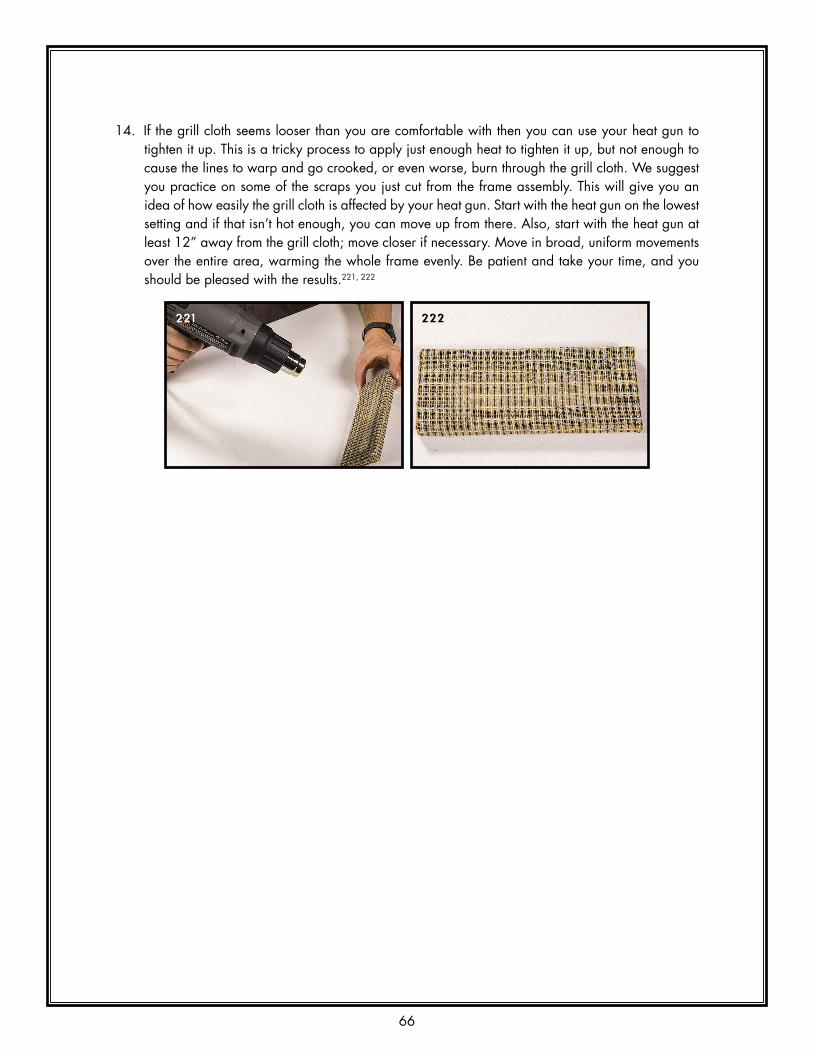
14. If the grill cloth seems looser than you are comfortable with then you can use your heat gun to tighten it up. This is a tricky process to apply just enough heat to tighten it up, but not enough to cause the lines to warp and go crooked, or even worse, burn through the grill cloth. We suggest you practice on some of the scraps you just cut from the frame assembly. This will give you an idea of how easily the grill cloth is affected by your heat gun. Start with the heat gun on the lowest setting and if that isn’t hot enough, you can move up from there. Also, start with the heat gun at least 12” away from the grill cloth; move closer if necessary. Move in broad, uniform movements over the entire area, warming the whole frame evenly. Be patient and take your time, and you should be pleased with the results.221, 222
221 222

67
COMPLETING THE HEAD
INSTALLING THE AMP1a. (Not illustrated) Place a #6 flat washer (Part # fA-90-30) over each of the four #6x1” machine
screws.1b. Place the cabinet upright on the table and carefully slip the amp in.223 It should be a pretty nice
slide-fit side-to-side. Looks nice, eh?
2. Carefully turn the amp over and stand it on-end, with the bottom facing you. Use one hand to hold the amp firmly in place against the cabinet bottom.224
3. Run a machine screw with washer (the photos show a different screw type) through one of the 9/64” holes in the cabinet bottom. Use a #2 Philips driver. If we all did our jobs well, the screws will line up perfectly with the holes in the chassis and will slip right in to the nuts. Install all 4 screws, and tighten.225, 226
223
224
225 226

68
INSTALLING THE GRILL1. Fit the grill frame into the front of the cabinet, above the amp. Push it in flush to the cabinet front.
It should be an easy fit side-to-side; it may be a tight fit up-and-down.2. Fit a 1/16” drill bit to stick about 1-1/8” out of your screw gun, or use your combo piloting bit.
Center the grill frame left and right. Carefully pass the bit through the countersunk hole in the cabinet top and drill a pilot hole in the frame. Next, drill the other two holes through the sides of the cabinet into the sides of the frame.227
3. Run a #6x1-1/4” wood screw (Part # FA-69-37) through the hole in the top of the cabinet and into the top of the grill frame. Repeat for the two side screws. Do not over-tighten the side screws; you just want to hold the frame in place, not pull it apart!228, 229
That’s it! You are done!! Congratulations.
227
228 229

69
USING YOUR NEW HEADFor information about using your new head please read “The Percolator Owner’s Manual,” available for download on the product page at the Zeppelin Design Labs website.

04
32
10 4321
9/6
4"
9/6
4"
9/6
4"
9/6
4"
9/6
4"
CABI
NET
SID
E5
THRO
UG
H H
OLE
S, 3
-STE
P PR
OCE
SS:
1/16
" PIL
OT
INTO
CA
BIN
ET T
OP
& B
OTT
OM
;1.
THRO
UG
H H
OLE
9/6
4";
2.CO
UN
TERS
INK
FOR
WO
OD
SCR
EW.
3. FLIP
TEM
PLA
TE O
VER
AN
D A
PPLY
FA
CE-D
OW
NTO
CA
BIN
ET L
EFT
SID
E.
REA
R
FRO
NT
BOTT
OM
TOP
VERI
FY T
HE
TEM
PLA
TE P
RIN
TS A
CCU
RATE
LYTO
FU
LL-S
IZE:
CH
ECK
BOTH
SCA
LES
WIT
HRU
LER.
MA
KE S
URE
PRI
NTE
R IS
SET
FO
R 10
0%
ZEP
PEL
IN D
ESIG
N LA
BS,
LLC
2950
N W
ESTE
RN
AVE
CH
ICA
GO
IL 6
0618
WW
W.Z
EPP
ELIN
DES
IGN
LAB
S.C
OM
REV.
DA
TE 1
/27/
2015
PAG
E 1
of 3
PERC
OLA
TOR
2W A
MP
FULL
SIZ
E D
RILL
ING
TEM
PLA
TES
© 2015 ZEPPELIN DESIGN LABS. NO PART OF THIS DOCUMENT MAY BE REPRODUCED WITHOUT WRITTEN PERMISSION FROM THE AUTHOR.
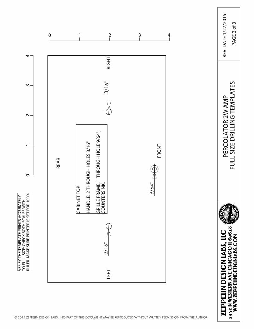
04
32
1
0 4321
"61/3
9/6
4"
"61/3
REA
R FRO
NT
CABI
NET
TO
P
HA
ND
LE: 2
TH
ROU
GH
HO
LES
3/16
"
GRI
LLE
FRA
ME,
1 T
HRO
UG
H H
OLE
9/6
4";
COU
NTE
RSIN
K.
VERI
FY T
HE
TEM
PLA
TE P
RIN
TS A
CCU
RATE
LYTO
FU
LL-S
IZE:
CH
ECK
BOTH
SCA
LES
WIT
HRU
LER.
MA
KE S
URE
PRI
NTE
R IS
SET
FO
R 10
0%
LEFT
RIG
HT
ZEP
PEL
IN D
ESIG
N LA
BS,
LLC
2950
N W
ESTE
RN
AVE
CH
ICA
GO
IL 6
0618
WW
W.Z
EPP
ELIN
DES
IGN
LAB
S.C
OM
REV.
DA
TE 1
/27/
2015
PAG
E 2
of 3
PERC
OLA
TOR
2W A
MP
FULL
SIZ
E D
RILL
ING
TEM
PLA
TES
© 2015 ZEPPELIN DESIGN LABS. NO PART OF THIS DOCUMENT MAY BE REPRODUCED WITHOUT WRITTEN PERMISSION FROM THE AUTHOR.

04
32
10 4321
9/6
4"
9/6
4"
1/1
6"
1/1
6"
1/1
6"
9/6
4"
9/6
4"
1/1
6"
CABI
NET
BO
TTO
M
FEET
: 4 B
LIN
D H
OLE
S 1/
16",
ABO
UT
1/2"
DEE
P.
CHA
SSIS
MO
UN
T: 4
TH
ROU
GH
HO
LES
9/64
",CO
UN
TERS
UN
K.
VERI
FY T
HE
TEM
PLA
TE P
RIN
TS A
CCU
RATE
LYTO
FU
LL-S
IZE:
CH
ECK
BOTH
SCA
LES
WIT
HRU
LER.
MA
KE S
URE
PRI
NTE
R IS
SET
FO
R 10
0%.
ZEP
PEL
IN D
ESIG
N LA
BS,
LLC
2950
N W
ESTE
RN
AVE
CH
ICA
GO
IL 6
0618
WW
W.Z
EPP
ELIN
DES
IGN
LAB
S.C
OM
REV.
DA
TE 1
/27/
2015
PAG
E 3
of 3
PERC
OLA
TOR
2W A
MP
FULL
SIZ
E D
RILL
ING
TEM
PLA
TES
© 2015 ZEPPELIN DESIGN LABS. NO PART OF THIS DOCUMENT MAY BE REPRODUCED WITHOUT WRITTEN PERMISSION FROM THE AUTHOR.