Assembly Instructions - Estrella AG
28
Professional Solutions in Glass Lining Assembly Instructions Facts for Fitters
-
Upload
khangminh22 -
Category
Documents
-
view
1 -
download
0
Transcript of Assembly Instructions - Estrella AG
Professional Solutions in Glass Lining
Assembly Instructions
Facts for Fitters

2

TERMINOLOGY Pipe System The assembly of pipes, fittings, valves, etc. within a (plant) installation. Pipe Section Part of a pipe system whose boundaries can easily be recognized or made recognizable Pipe Length Individual piece of pipe of any given length Component Individual part of a pipe system of any given shape and size, such as pipes, fittings, valves, spacers, flanges, expansion joints, etc.
Edition December 2006, Rev. 01/2021
3
All information and recommendations given in this publication are based on
many years of experience in the production and installation of glass
lined parts.
Nevertheless, particular operating conditions and unknown factors may
considerably affect the general knowledge, thus excluding any
warranty for our recommendations
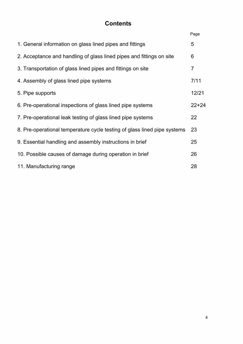
Contents
Page
1. General information on glass lined pipes and fittings 5 2. Acceptance and handling of glass lined pipes and fittings on site 6 3. Transportation of glass lined pipes and fittings on site 7 4. Assembly of glass lined pipe systems 7/11 5. Pipe supports 12/21 6. Pre-operational inspections of glass lined pipe systems 22+24 7. Pre-operational leak testing of glass lined pipe systems 22 8. Pre-operational temperature cycle testing of glass lined pipe systems 23 9. Essential handling and assembly instructions in brief 25 10. Possible causes of damage during operation in brief 26 11. Manufacturing range 28 4
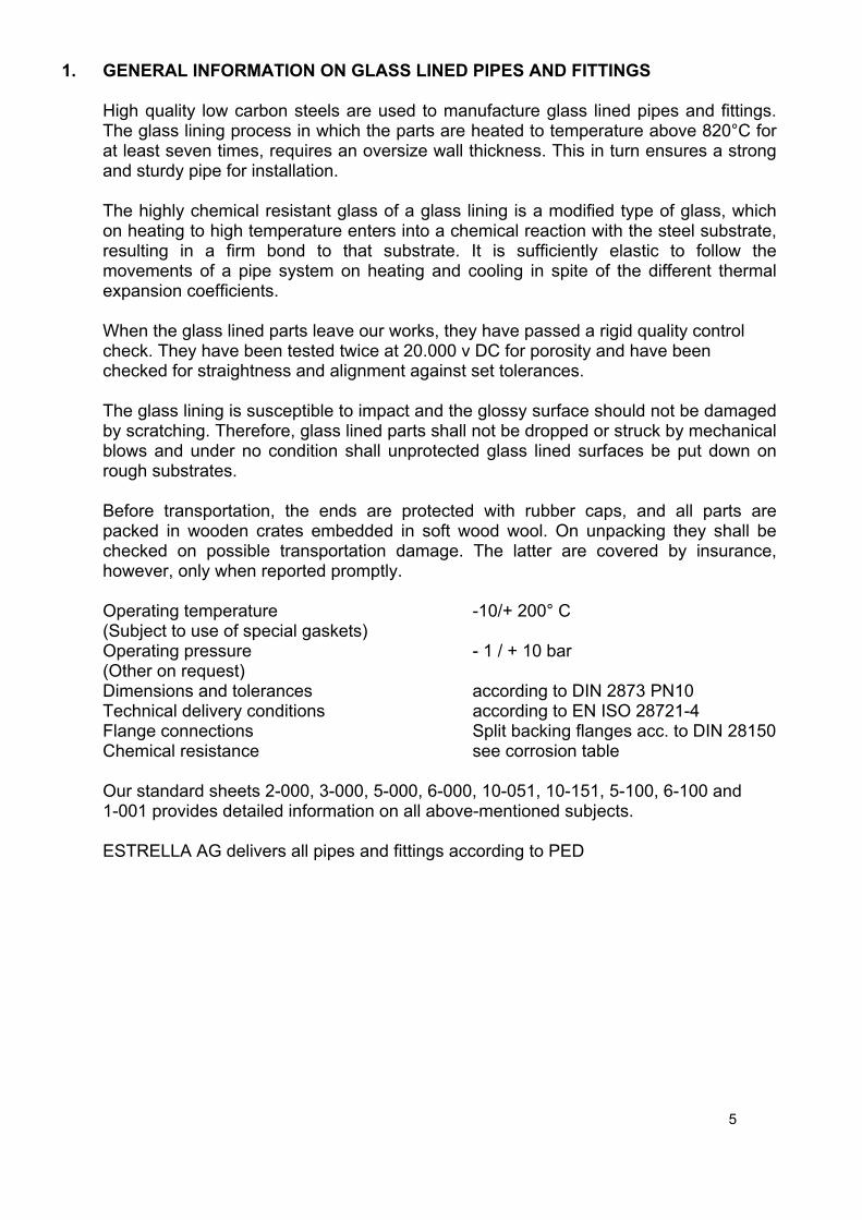
1. GENERAL INFORMATION ON GLASS LINED PIPES AND FITTINGS
High quality low carbon steels are used to manufacture glass lined pipes and fittings. The glass lining process in which the parts are heated to temperature above 820°C for at least seven times, requires an oversize wall thickness. This in turn ensures a strong and sturdy pipe for installation. The highly chemical resistant glass of a glass lining is a modified type of glass, which on heating to high temperature enters into a chemical reaction with the steel substrate, resulting in a firm bond to that substrate. It is sufficiently elastic to follow the movements of a pipe system on heating and cooling in spite of the different thermal expansion coefficients. When the glass lined parts leave our works, they have passed a rigid quality control check. They have been tested twice at 20.000 v DC for porosity and have been checked for straightness and alignment against set tolerances. The glass lining is susceptible to impact and the glossy surface should not be damaged by scratching. Therefore, glass lined parts shall not be dropped or struck by mechanical blows and under no condition shall unprotected glass lined surfaces be put down on rough substrates. Before transportation, the ends are protected with rubber caps, and all parts are packed in wooden crates embedded in soft wood wool. On unpacking they shall be checked on possible transportation damage. The latter are covered by insurance, however, only when reported promptly. Operating temperature -10/+ 200° C (Subject to use of special gaskets) Operating pressure - 1 / + 10 bar (Other on request) Dimensions and tolerances according to DIN 2873 PN10 Technical delivery conditions according to EN ISO 28721-4 Flange connections Split backing flanges acc. to DIN 28150 Chemical resistance see corrosion table Our standard sheets 2-000, 3-000, 5-000, 6-000, 10-051, 10-151, 5-100, 6-100 and 1-001 provides detailed information on all above-mentioned subjects. ESTRELLA AG delivers all pipes and fittings according to PED 5
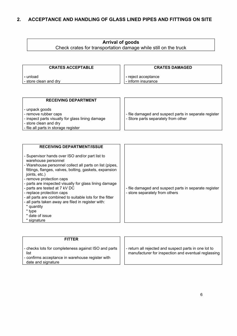
2. ACCEPTANCE AND HANDLING OF GLASS LINED PIPES AND FITTINGS ON SITE
Arrival of goods Check crates for transportation damage while still on the truck
CRATES ACCEPTABLE
- unload - store clean and dry
CRATES DAMAGED
- reject acceptance - inform insurance
RECEIVING DEPARTMENT
- unpack goods - remove rubber caps - inspect parts visually for glass lining damage - store clean and dry - file all parts in storage register
- file damaged and suspect parts in separate register - Store parts separately from other
RECEIVING DEPARTMENT/ISSUE
- Supervisor hands over ISO and/or part list to warehouse personnel - Warehouse personnel collect all parts on list (pipes, fittings, flanges, valves, bolting, gaskets, expansion joints, etc.) - remove protection caps - parts are inspected visually for glass lining damage - parts are tested at 7 kV DC - replace protection caps - all parts are combined to suitable lots for the fitter - all parts taken away are filed in register with: * quantity * type * date of issue * signature
- file damaged and suspect parts in separate register - store separately from others
FITTER
- checks lots for completeness against ISO and parts list - confirms acceptance in warehouse register with date and signature
- return all rejected and suspect parts in one lot to manufacturer for inspection and eventual reglassing
6
3. TRANSPORTATION OF GLASS LINED PIPES AND FITTINGS ON SITE
The fitter transports the parts which he has taken over to the assembly location, packed such that they cannot be damaged by impact.
Never remove protection rubber caps during transportation!
4. ASSEMBLY
When assembling glass lined pipe systems, it shall be taken into account that, due to high temperature process during lining, slight deformations of stub ends may occur. The allowable tolerances are set in DIN 2873.
Stress and shock free assembly of glass lined pipe systems is paramount We recommend the following procedure:
Step 1 Before assembling, the fitter checks each individual part for glass lining damage. Damaged and suspect parts shall not be installed.
Step 2 The first component of a pipe section is installed freely movable, i.e. such that it can be shifted and rotated in the best possible position, and suspended or supported in that position.
Step 3 The next component is now mounted to it, such that after placing of the gasket the faces of both stub ends are parallel to each other. This position can be obtained by rotating the components opposite each other. Piping components shall never be positioned oblique to each other as the edges of the stub end may damage the gaskets.
Step 4 The flange connection is tightened. The pipe section is then completed according to plan (ISO, piping plan, etc.), repeating Step 3 each time. In case the specified pipe lengths should exclude stress-free assembling of a pipe section, spacers shall be used to compensate the missing lengths. The variety of our spacer range enables assembling any required length. We recommend to have a certain number of spacers in excess. Small differences in lengths (< 5 mm) can be compensated by using an extra gasket.
Step 5 The appropriate type of support is then selected and mounted. Next, the piping section is aligned exactly and bolted up free of stresses. Each pipe section shall be mounted as intended, i.e. with fixed and sliding supports.
The allowable pipe support spans can be found in section 5.1.
Lateral forces due to pipe branches shall be compensated or absorbed by installing fixes supports.
Glass lined piping systems shall be mounted free of stresses. Any aligning or straightening by mechanical force is strictly forbidden.
7
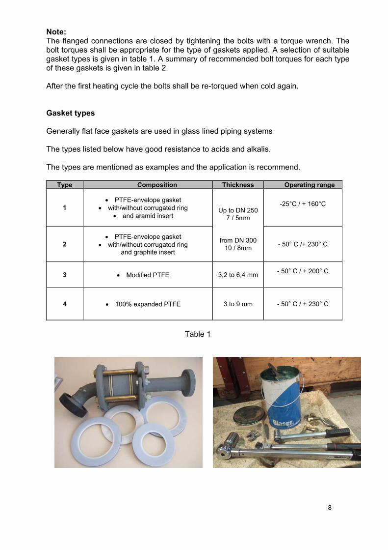
Note: The flanged connections are closed by tightening the bolts with a torque wrench. The bolt torques shall be appropriate for the type of gaskets applied. A selection of suitable gasket types is given in table 1. A summary of recommended bolt torques for each type of these gaskets is given in table 2. After the first heating cycle the bolts shall be re-torqued when cold again. Gasket types Generally flat face gaskets are used in glass lined piping systems The types listed below have good resistance to acids and alkalis. The types are mentioned as examples and the application is recommend.
Type Composition Thickness Operating range
1 PTFE-envelope gasket
with/without corrugated ring and aramid insert
Up to DN 250
7 / 5mm
from DN 300 10 / 8mm
-25°C / + 160°C
2 PTFE-envelope gasket
with/without corrugated ring and graphite insert
- 50° C /+ 230° C
3 Modified PTFE 3,2 to 6,4 mm - 50° C / + 200° C
4 100% expanded PTFE 3 to 9 mm - 50° C / + 230° C
Table 1
8
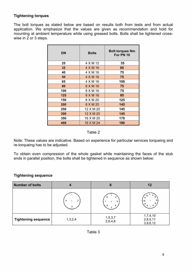
Tightening torques The bolt torques as stated below are based on results both from tests and from actual application. We emphasize that the values are given as recommendation and hold for mounting at ambient temperature while using greased bolts. Bolts shall be tightened cross-wise in 2 or 3 steps.
DN
Bolts
Bolt torques Nm
For PN 10
25 4 X M 12 35 32 4 X M 16 60 40 4 X M 16 75 50 4 X M 16 75 65 4 X M 16 100 80 8 X M 16 75
100 8 X M 16 75 125 8 X M 16 85 150 8 X M 20 125 200 8 X M 20 145 250 12 X M 20 145 300 12 X M 20 145 350 16 X M 20 170 400 16 X M 24 180
Table 2
Note: These values are indicative. Based on experience for particular services torqueing and re-torqueing has to be adjusted. To obtain even compression of the whole gasket while maintaining the faces of the stub ends in parallel position, the bolts shall be tightened in sequence as shown below: Tightening sequence
Number of bolts 4 8 12
Tightening sequence 1,3,2,4 1,5,3,7 2,6,4,8
1,7,4,10 2,8,5,11 3,9,6,12
Table 3
9
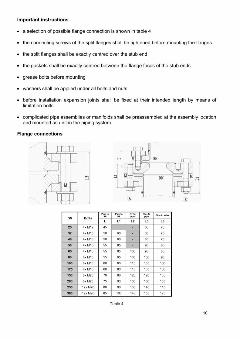
Important instructions a selection of possible flange connection is shown in table 4 the connecting screws of the split flanges shall be tightened before mounting the flanges the split flanges shall be exactly centred over the stub end the gaskets shall be exactly centred between the flange faces of the stub ends grease bolts before mounting washers shall be applied under all bolts and nuts before installation expansion joints shall be fixed at their intended length by means of
limitation bolts complicated pipe assemblies or manifolds shall be preassembled at the assembly location
and mounted as unit in the piping system Flange connections
DN Bolts
Pipe to RF
Pipe to RF
RF to pipe
Pipe to pipe
Pipe to valve
L L1 L2 L3 L3
25 4x M12 45 - 80 70
32 4x M16 50 60 - 85 75
40 4x M16 50 60 - 85 75
50 4x M16 55 65 - 95 80
65 4x M16 55 65 100 95 80
80 8x M16 55 65 100 100 90
100 8x M16 60 80 110 105 100
125 8x M16 60 80 110 105 100
150 8x M20 70 80 120 120 105
200 8x M20 75 90 130 130 105
250 12x M20 80 90 130 140 115
300 12x M20 85 100 140 155 125
Table 4
10

Recommendation Piping systems operating at elevated temperature in discontinuous or batch operations are subject to varying thermal elongations. Following as a consequence the gaskets are loaded resp. unloaded differently. To maintain the pressure on the gaskets by bolt torque at a constant level we recommend to install spring washers at the bolt connections. Principle The insertion of spring washers enables compensation of deviations in the piping system (setting of gaskets, expansion of screws) and assures a constant tightening. Lengths of screws according to specification 5-050 to 5-052 with regard to addition between the bracket (*). Possibilities of assembly
DN Screws (*) Type Washer size
25 4x M12 (+ 5) A D.23/12.2 X 1.5 32 4x M16 (+10) A D. 34/16.3 X 2.0 40 4x M16 (+10) A D. 34/16.3 X 2.0 50 4x M16 (+10) A D. 34/16.3 X 2.0
65 4x M16 (+10) A D. 34/16.3 X 2.0
80 8x M16 (+10) A D. 34/16.3 X 2.0
100 8x M16 (+10) A D. 34/16.3 X 2.0
125 8x M16 (+10) A D. 34/16.3 X 2.0
150 8x M20 (+ 5) B D.40/20.4 X 2.5
200 8x M20 (+10) C D.40/20.4 X 2.5
250 12x M20 (+10) C D.40/20.4 X 2.5
300 12x M20 (+10) C D.40/20.4 X 2.5
Table 5
11
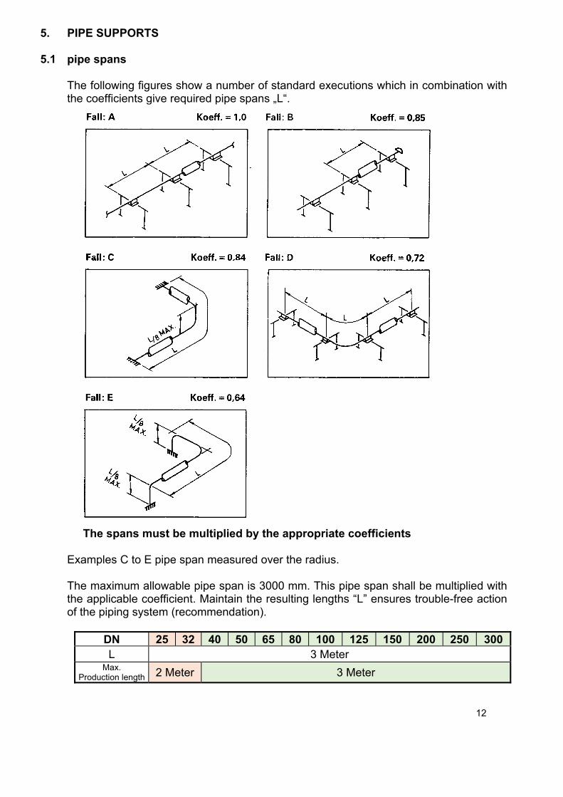
5. PIPE SUPPORTS 5.1 pipe spans
The following figures show a number of standard executions which in combination with the coefficients give required pipe spans „L“.
The spans must be multiplied by the appropriate coefficients
Examples C to E pipe span measured over the radius. The maximum allowable pipe span is 3000 mm. This pipe span shall be multiplied with the applicable coefficient. Maintain the resulting lengths “L” ensures trouble-free action of the piping system (recommendation).
DN 25 32 40 50 65 80 100 125 150 200 250 300L 3 Meter
Max. Production length 2 Meter 3 Meter
12
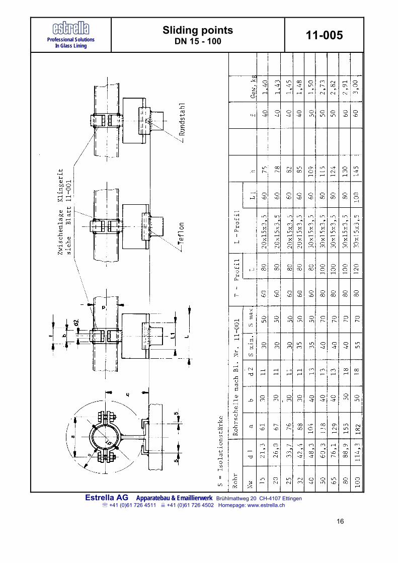
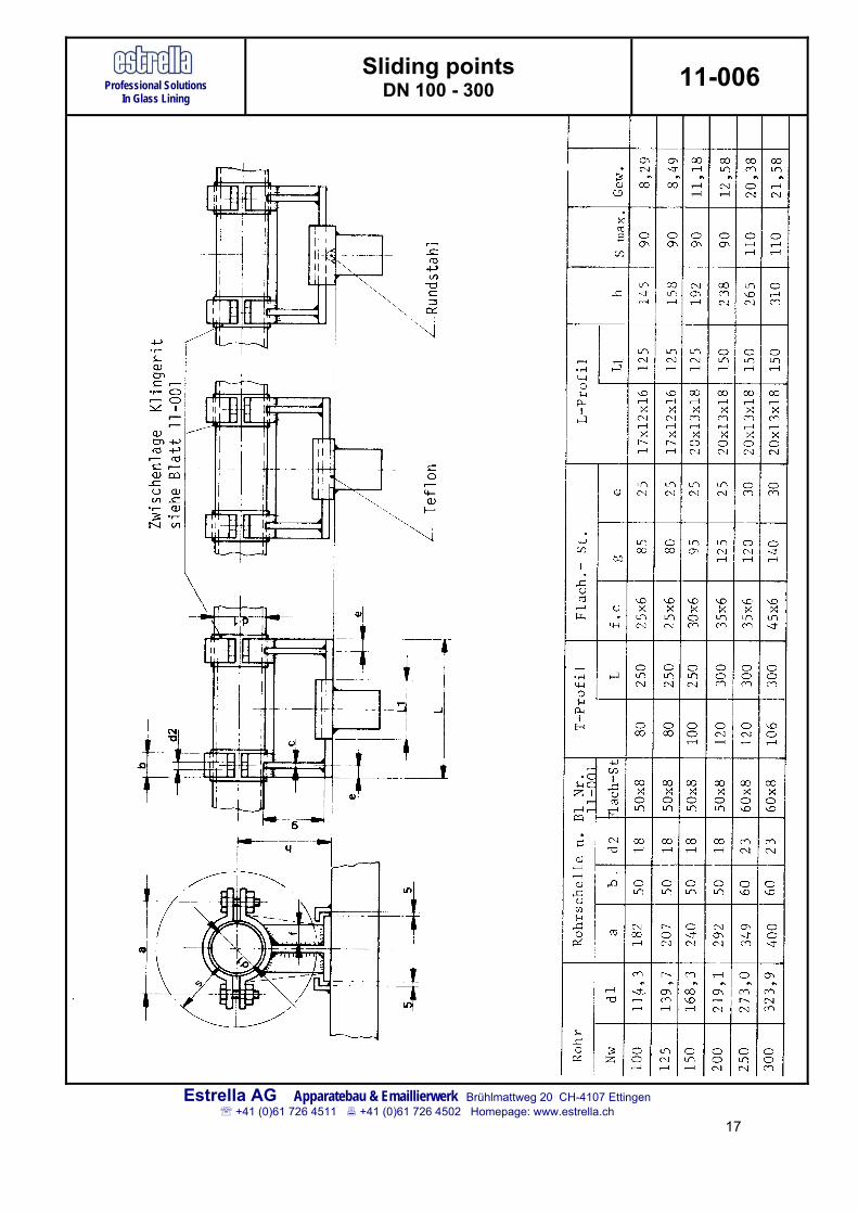
5.2 Pipe support constructions
Appropriate supports in sufficient numbers are essential! Maximum allowable pipe spans, determined as per section 5.1, shall at all times be observed. Support constructions are distinguished for the following cases: - fixed points - sliding points - hangers - valves - expansion joints The various tapes of brackets and supports with their constructional drawings are given in standard sheets 11-002, 11-003, 11-005, 11-006, 11-007, 11-008, 11-009 und 11-010.
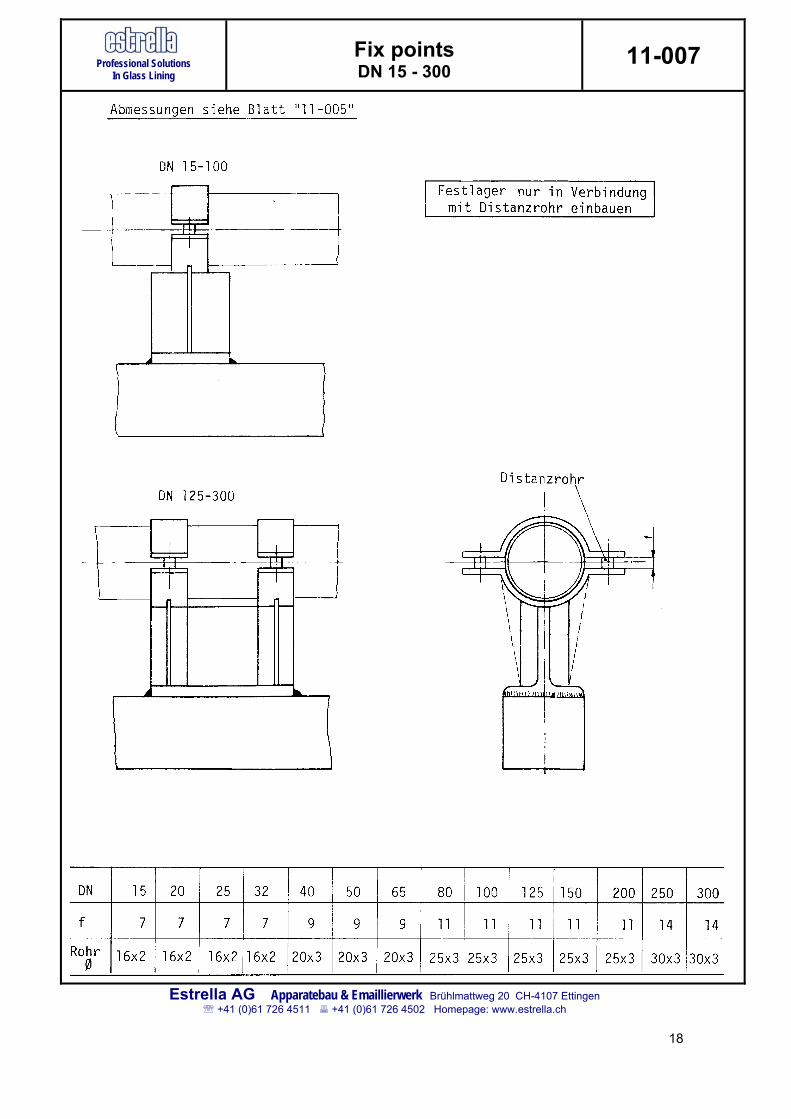
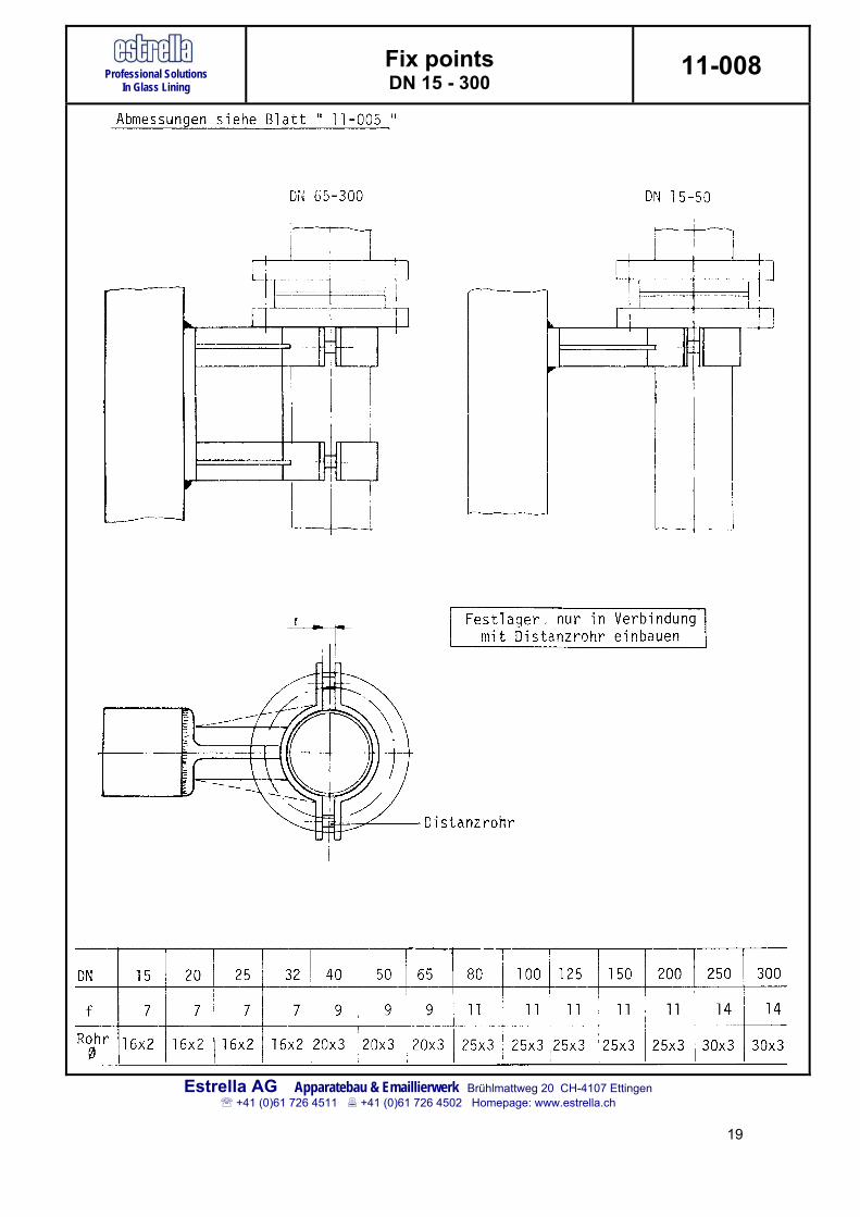
Important instruction
Each pipe section shall have one fixed point to ensure a well-defined expansion for that particular section
Nozzles of equipment and pumps are considered to be fixed points, unless they
exert a lateral force due to their own thermal expansion, in which case the support of the first pipe section shall be adapted.
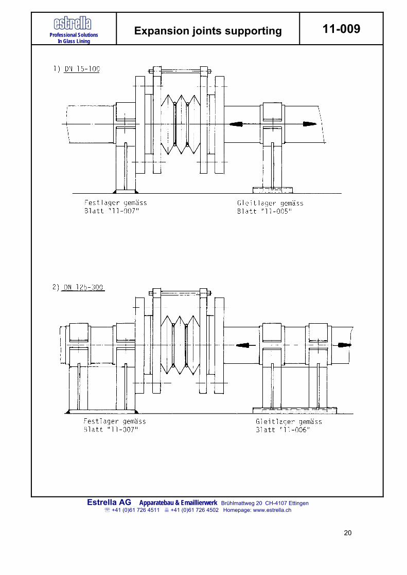
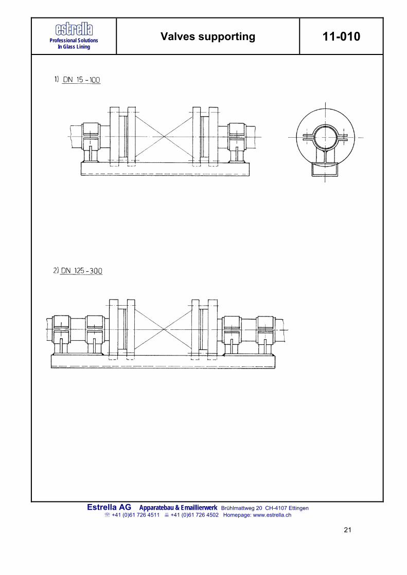
Each individual valve or valve manifold shall be supported independently Each expansion joint shall be installed with a fixed point at one end and a sliding
point at the other Fixed points shall be made such that they ensure free moving of the piping system Sliding points shall be made such that they ensure free moving of the piping system Brackets and supports shall be made such that they do not give rise to unforeseen
stresses in the piping system due to deviating dimensions Transitions through plant structures and walls with limited space are to be
considered as sliding supports and to be executed as such Soft inlays shall be placed between pipes and pipe clamps to prevent any
unforeseen stresses in the piping system No welding operations shall be carried out on glass lined pipes; all brackets,
supports and their auxiliary parts shall be executed for bolted constructions exclusively.
13
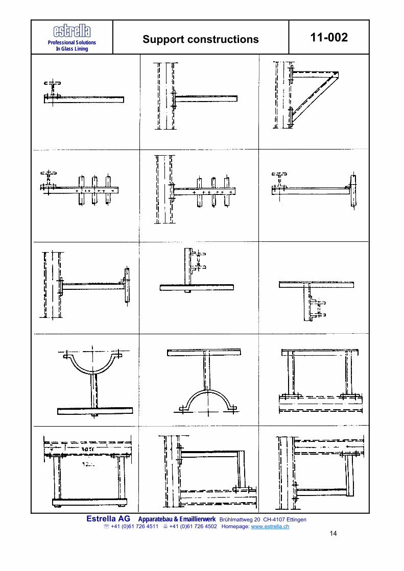
Professional Solutions In Glass Lining
Support constructions 11-002
Estrella AG Apparatebau & Emaillierwerk Brühlmattweg 20 CH-4107 Ettingen +41 (0)61 726 4511 +41 (0)61 726 4502 Homepage: www.estrella.ch
14

Professional Solutions In Glass Lining
Support constructions 11-003
Estrella AG Apparatebau & Emaillierwerk Brühlmattweg 20 CH-4107 Ettingen +41 (0)61 726 4511 +41 (0)61 726 4502 Homepage: www.estrella.ch
15
Professional Solutions In Glass Lining
Sliding points DN 15 - 100 11-005
Estrella AG Apparatebau & Emaillierwerk Brühlmattweg 20 CH-4107 Ettingen +41 (0)61 726 4511 +41 (0)61 726 4502 Homepage: www.estrella.ch
16
Professional Solutions In Glass Lining
Sliding points DN 100 - 300 11-006
Estrella AG Apparatebau & Emaillierwerk Brühlmattweg 20 CH-4107 Ettingen +41 (0)61 726 4511 +41 (0)61 726 4502 Homepage: www.estrella.ch
17
Professional Solutions In Glass Lining
Fix points DN 15 - 300
11-007
Estrella AG Apparatebau & Emaillierwerk Brühlmattweg 20 CH-4107 Ettingen +41 (0)61 726 4511 +41 (0)61 726 4502 Homepage: www.estrella.ch
18
Professional Solutions In Glass Lining
Fix points DN 15 - 300
11-008
Estrella AG Apparatebau & Emaillierwerk Brühlmattweg 20 CH-4107 Ettingen +41 (0)61 726 4511 +41 (0)61 726 4502 Homepage: www.estrella.ch
19
Professional Solutions In Glass Lining
Expansion joints supporting 11-009
Estrella AG Apparatebau & Emaillierwerk Brühlmattweg 20 CH-4107 Ettingen +41 (0)61 726 4511 +41 (0)61 726 4502 Homepage: www.estrella.ch
20
Professional Solutions In Glass Lining
Valves supporting 11-010
Estrella AG Apparatebau & Emaillierwerk Brühlmattweg 20 CH-4107 Ettingen +41 (0)61 726 4511 +41 (0)61 726 4502 Homepage: www.estrella.ch
21
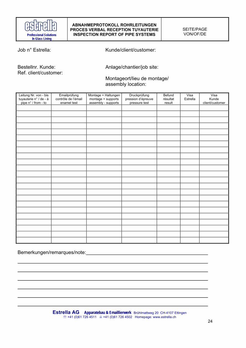
6. PRE-OPERATINAL INSPECTION OF GLASS LINED PIPE SYSTEMS
After completion of installation each piping section is visually inspected over its full length: - are all individual pipes lined out correctly? - are all flange connections bolted correctly? - are all supports installed correctly, i.e. complete and free moving? - are the envisaged pipe spans applied correctly? - are all valves secured correctly? - are all expansion joints supported and pre-set correctly ensuring their foreseen movement? - are there no lateral forces acting on the piping section? - is the piping section not jammed at any point? Each piping section is individually mentioned in the inspection report. The erection supervisor confirms the inspection results with date and signature, confirming that each individual piping section has been installed correctly and up to all prevailing technical standards. An example of the inspection report is shown on page 24
7. PRE-OPERATIONAL LEAK TESTING OF GLASS LINED PIPING SYSTEMS IN COLD CONDITION
ESTRELLA AG deliver all glass lined piping components according to PED. Therefore, a pressure test of the assembled piping system at full pressure is not required. It is sufficient to carry out a leak test with either water or air (0.2 - 0.3 bar). Leaking flange connections shall be tightened by bringing them at the required bolt torques in cold condition. 22
8. PRE-OPERATIONAL TEMPERATURE-CYCLE TESTING OF GLASS LINED PIPING SYSTEMS
Each piping system shall be heated to its operating temperature while being filled with liquid not containing any of the process chemicals. This serves to check whether the system operates properly in its supports, whether no expansion joints bend out, whether leaking flange connections occur. Obstructions to the free moving of the piping system are corrected while the system is at temperature. Leaking flange connections are marked. The piping systems is then cooled down to ambient temperature. The marked flange connections are inspected visually and the re-torqued to the required torque in cold condition. Finally, the installed strainers will be cleaned and in case they should be permanently installed during operation the strainer baskets will be reinstalled. The piping system is now full tight and fit for its intended chemical operation. Should leakages occur during operation they shall always be tightened in cold condition. Inspection reports As each step in the assembling operation also the testing should be recorded and countersigned. As a rule we check and record each piping section individually, see example of inspection report hereafter. 23
Professional Solutions
In Glass Lining
ABNAHMEPROTOKOLL ROHRLEITUNGEN
PROCES VERBAL RECEPTION TUYAUTERIE INSPECTION REPORT OF PIPE SYSTEMS
SEITE/PAGE VON/OF/DE
Job n° Estrella: Kunde/client/customer: Bestellnr. Kunde: Anlage/chantier/job site: Ref. client/customer: Montageort/lieu de montage/ assembly location: Leitung Nr. von - bis tuyauterie n° / de - à
pipe n° / from - to
Emailprüfung contrôle de l’émail
enamel test
Montage + Haltungenmontage + supports assembly - supports
Druckprüfung pression d’épreuve
pressure test
Befund résultat result
Visa Estrella
Visa Kunde
client/customer
Bemerkungen/remarques/note:
Estrella AG Apparatebau & Emaillierwerk Brühlmattweg 20 CH-4107 Ettingen +41 (0)61 726 4511 +41 (0)61 726 4502 Homepage: www.estrella.ch
24
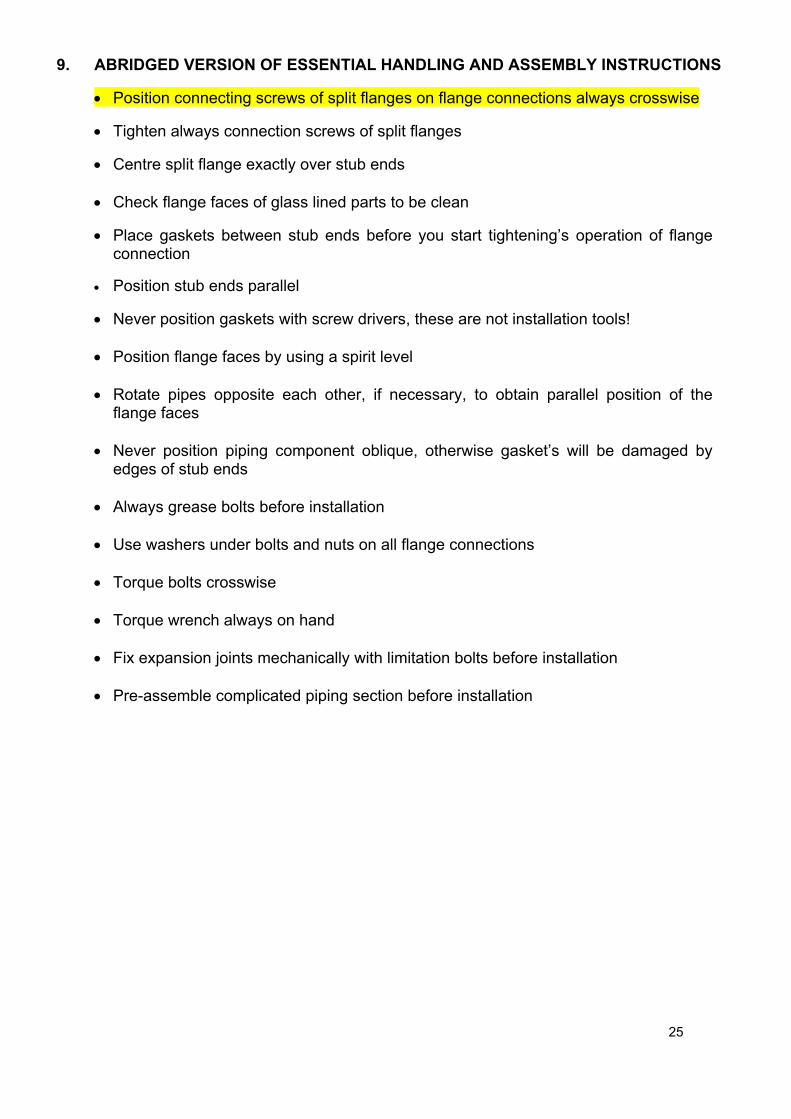
9. ABRIDGED VERSION OF ESSENTIAL HANDLING AND ASSEMBLY INSTRUCTIONS
Position connecting screws of split flanges on flange connections always crosswise
Tighten always connection screws of split flanges
Centre split flange exactly over stub ends
Check flange faces of glass lined parts to be clean
Place gaskets between stub ends before you start tightening’s operation of flange connection
Position stub ends parallel
Never position gaskets with screw drivers, these are not installation tools!
Position flange faces by using a spirit level
Rotate pipes opposite each other, if necessary, to obtain parallel position of the flange faces
Never position piping component oblique, otherwise gasket’s will be damaged by
edges of stub ends
Always grease bolts before installation
Use washers under bolts and nuts on all flange connections
Torque bolts crosswise
Torque wrench always on hand
Fix expansion joints mechanically with limitation bolts before installation
Pre-assemble complicated piping section before installation 25
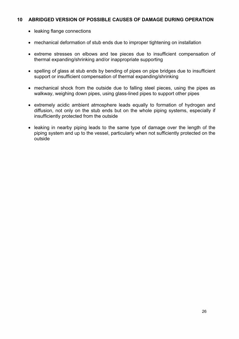
10 ABRIDGED VERSION OF POSSIBLE CAUSES OF DAMAGE DURING OPERATION
leaking flange connections
mechanical deformation of stub ends due to improper tightening on installation
extreme stresses on elbows and tee pieces due to insufficient compensation of thermal expanding/shrinking and/or inappropriate supporting
spelling of glass at stub ends by bending of pipes on pipe bridges due to insufficient
support or insufficient compensation of thermal expanding/shrinking
mechanical shock from the outside due to falling steel pieces, using the pipes as walkway, weighing down pipes, using glass-lined pipes to support other pipes
extremely acidic ambient atmosphere leads equally to formation of hydrogen and
diffusion, not only on the stub ends but on the whole piping systems, especially if insufficiently protected from the outside
leaking in nearby piping leads to the same type of damage over the length of the
piping system and up to the vessel, particularly when not sufficiently protected on the outside
26

27
Professional Solutions in Glass Lining
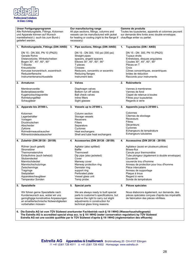
Unser Fertigungsprogramm Alle Rohrleitungsteile, Fittings, Kolonnen und Apparate können auf Wunsch mantelbeheizt (- auch bis zum Bund-) geliefert werden.
Our manufacturing range All pipe sections, fittings, columns and vessels can be manufactured with jacket for heating or cooling (right to the flange if necessary)
Gamme de produits Toutes les tuyauteries, appareils et colonnes peuvent sur demande être livrés avec double enveloppe; chauffage entier ou partiel.
1. Rohreitungsteile, Fittings (DIN /ANSI) DN 15 - DN 300, PN 10 (PN25) Gerade Rohre Distanzstücke, Winkelscheiben Bogen 30°, 45°, 60°, 90° T-Stücke Kreuzstücke Konusse konzentrisch, exzentrisch Reduzierflansche Instrumentenanschlussteile
1. Pipe sections, fittings (DIN /ANSI) DN 15 - DN 300, 150 psi (300 psi) Straight pipes spacers, angeld spacers Elbows 30°, 45°, 60°, 90° T-pieces Crosses Reducers, concentric or excentric Reducing flanges Instrument tees
1. Tuyauteries (DIN / ANSI) DN 15 - DN 300, PN 10 (PN25) Tuyaux droits Entretoises, disques angulaires Coudes 30°, 45°, 60°, 90° Pièces en T Croix Cônes concentriques, excentriques brides de réduction Raccords pour instruments
2. Armaturen Membranventile Bodenablassventile Kugelrückschlagventile Rohrleitungsfilter Schaugläser
2. Valves Diaphragm valves Bottom run off valves Ball check valves Inline filters Sight glasses
2. Robinetterie Vannes à membranes Vannes de fond Clapet de retenue à boules Filtres pour tuyauteries Regards à verre
3. Apparate bis 25'000 L Kolonnen Lagerbehälter Vorlagen Drucknutschen Abscheider Zyklone Rohrwärmeaustrauscher Röhrenbündelaustauscher
3. Vessels up to 25'000 L Column section Storage vessels Receivers Filters Separators Cyclones Heat exchangers Shell and tube heat exchangers
3. Appareils jusqu'à 25'000 L Colonnes Citernes de stockage Receveurs Filtres Décanteurs Cyclones Echangeurs de température Echangeurs tubulaires
4. Zubehör (DIN 28138 - 28159) Rührer (auch geteilt) Stromstörer Thermometerrohre Einlaufrohre (auch beheizt) Stutzendeckel Mannlochdeckel Mannlochschutzringe Zwischenringe Tragringe Siebplatten Apparateschaugläser Temperatur Sonden
4. Accessories (DIN 28138 - 28159) Agitator (also splitted) Baffle Thermowell Dip pipe (also jacketed) Cover Manway cover Manway protection ring Demister ring support ring Perforated plate Vessel glass unit Temp probe
4. Accessoires (DIN 28138 - 28159) Agitateur (aussi en plusieurs pièces) Brises-flux Canule pour thermomètre Tube plongeur (également à double enveloppe) Couvercle couvercle trou d'homme Anneau de protection pour trou d'homme Pièce intercalaire Anneau de supportage Plaque à trous Regard à verre Sonde de température
5. Spezialteile Wir führen gerne Spezialteile nach Kundenwunsch aus, wobei wir uns geringfügige konstruktive Anpassungen an emailliertechnische Notwendigkeiten vorbehalten müssen-
5. Special parts We are always ready to built special parts to customer's specifications, but reserve the right to carry out slight adjustments in construction for technical glass lining reasons.
5. Pièces spéciales Nous élaborons également, sur demande, des pièces spéciales conçues d'après les impératifs de fabrication des pièces vitrifiées.
6. Die Estrella AG ist vom TÜV Südwest anerkannter Fachbetrieb nach § 19 I WHG (Wasserhaushaltsgesetz) The Estrella AG is accredited special shop acc. to § 19 I WHG (water conservation regulation) by TÜV Südwest Estrella AG est une société qualifiée par le TÜV Südwest d'après § 19 I WHG (règlementation des effluents)
Estrella AG Apparatebau & Emaillierwerk Brühlmattweg 20 CH-4107 Ettingen +41 (0)61 726 4511 +41 (0)61 726 4502 Homepage: www.estrella.ch
28