Top of Pole Mount Assembly Instructions UPM 8X - General ...
8
Page 1 of 8 www.generalspecialtiesmfg.com 208-265-5244 Top of Pole Mount Assembly Instructions UPM 8X Standard stock tee socket sized for 6” schedule 40 or 80 pipe A. TEE SOCKET: 7” O.D. PIPE SOCKET TO FIT OVER 6” SCHEDULE 40 OR 80 STEEL PIPE B. CROSS PIECE: 2” X 2” X 3/16”, LENGTH IS 60”, SQ. TUBE – 2 PLACES C. LONGITUDINAL: 2” X 2” X 1/8”, LENGTH DEPENDENT ON MODULE USED, SQ. TUBE - 2 PLACES D. ALUMINUM RAILS: 3” X 1-1/2” X 3/16” UNIVERSAL T-SLOT EXTRUSION OR PUNCHED ALUMINUM ANGLE, LENGTH DEPENDENT ON MODULE USED – 4 PLACES Note: Number of panels may vary, length of rail may vary. Rev. 12/17
-
Upload
khangminh22 -
Category
Documents
-
view
1 -
download
0
Transcript of Top of Pole Mount Assembly Instructions UPM 8X - General ...

Page 1 of 8
www.generalspecialtiesmfg.com 208-265-5244
Top of Pole Mount Assembly Instructions
UPM 8X Standard stock tee socket sized for 6” schedule 40 or 80 pipe
A. TEE SOCKET: 7” O.D. PIPE SOCKET TO FIT OVER 6” SCHEDULE 40 OR 80 STEEL PIPE
B. CROSS PIECE: 2” X 2” X 3/16”, LENGTH IS 60”, SQ. TUBE – 2 PLACES
C. LONGITUDINAL: 2” X 2” X 1/8”, LENGTH DEPENDENT ON MODULE USED, SQ. TUBE - 2 PLACES
D. ALUMINUM RAILS: 3” X 1-1/2” X 3/16” UNIVERSAL T-SLOT EXTRUSION OR PUNCHED
ALUMINUM ANGLE, LENGTH DEPENDENT ON MODULE USED – 4 PLACES
Note: Number of panels may vary, length of rail may vary. Rev. 12/17
Page 2 of 8
www.generalspecialtiesmfg.com 208-265-5244
Box #1 (1) Tee Socket with Center Tube
Box #2 (2) Cross Pieces (5) Hardware bags
Bag#1 - Bolts for attaching aluminum angle brackets to rails. - Square head set bolts for Tee.
Bag#2 - Bolts and nuts for attaching crosspieces to longitudinals (use included square galvy
washers with these).
Bag#3 - U-bolts for attaching aluminum angle brackets to longitudinals (use included aluminum
angle brackets with these).
Bag#4 - Bolts and flat bar for attaching center tube end plates on Tee assembly to crosspieces.
Bag#5 - Instructions. - SS bolts and nuts for attaching panels to aluminum rails.
Shrink wrapped to crosspieces - Square galvy washers for crosspieces to longitudinals (use with bag #2). - Aluminum angle brackets for longitudinals to rails (use with bag#1 and #3).
Box #3 (2) Longitudinals
Box #4 (4) Aluminum Rails
Degree Indicator: A degree indicator sticker has been placed on the center tube and a dimple in the tee socket is where the line on the sticker should be pointed to establish the degree of tilt from horizontal for the array that you desire. This indicator is not 100% exact (due to printing differences and placement of the sticker) but will provide an estimate of the degree of incline for you. We hope that you appreciate this feature and that it makes adjusting your array easier.
COMPONENTS FOR THIS MOUNT
This shows the indicator on the center tube. Although difficult to see in this picture the arrow shows the location of the “dimple”.
Page 3 of 8
www.generalspecialtiesmfg.com 208-265-5244
Depth of Hole
Width of Square Hole /
Cubic Yards of concrete
needed
Diameter of Round Hole /
Cubic Yards of concrete
needed
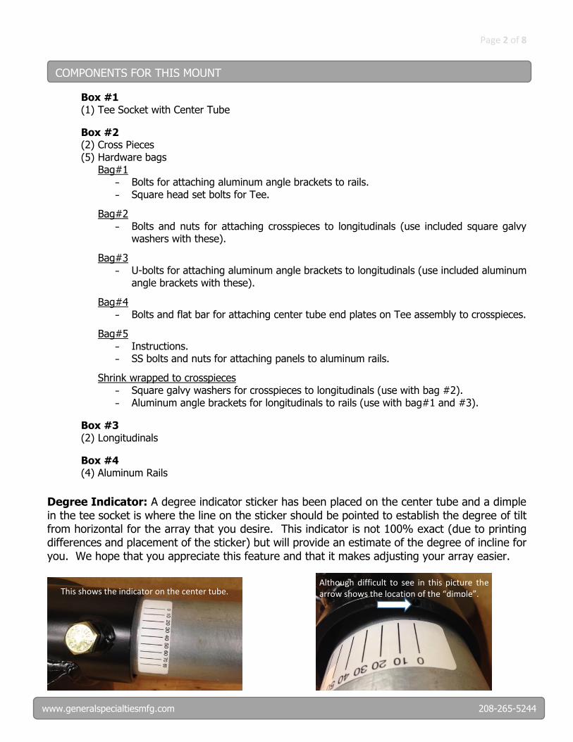
58” 32” / 1.27 CY 40" / 1.56 CY
Your building department may require the foundation for a PV array post mount to be designed by a structural engineer licensed in the state where the PV array is to be erected. This is required because failure of a post mount foundation may be a threat to the safety of people and property in its proximity. At a minimum, failure will result in costly damage to the PV modules. The foundation described here is suitable for most soil types, but no warranty of its suitability for your particular soil or wind conditions is offered or implied. If you are unable to dig holes of these dimensions because you encounter bed rock or if you have very loamy or loose sandy soil, (get the recommendation of a soil engineer or building department), then you may have to seek a design for an alternative foundation construction. For type and size of pole to install in concrete foundation, refer to chart below.
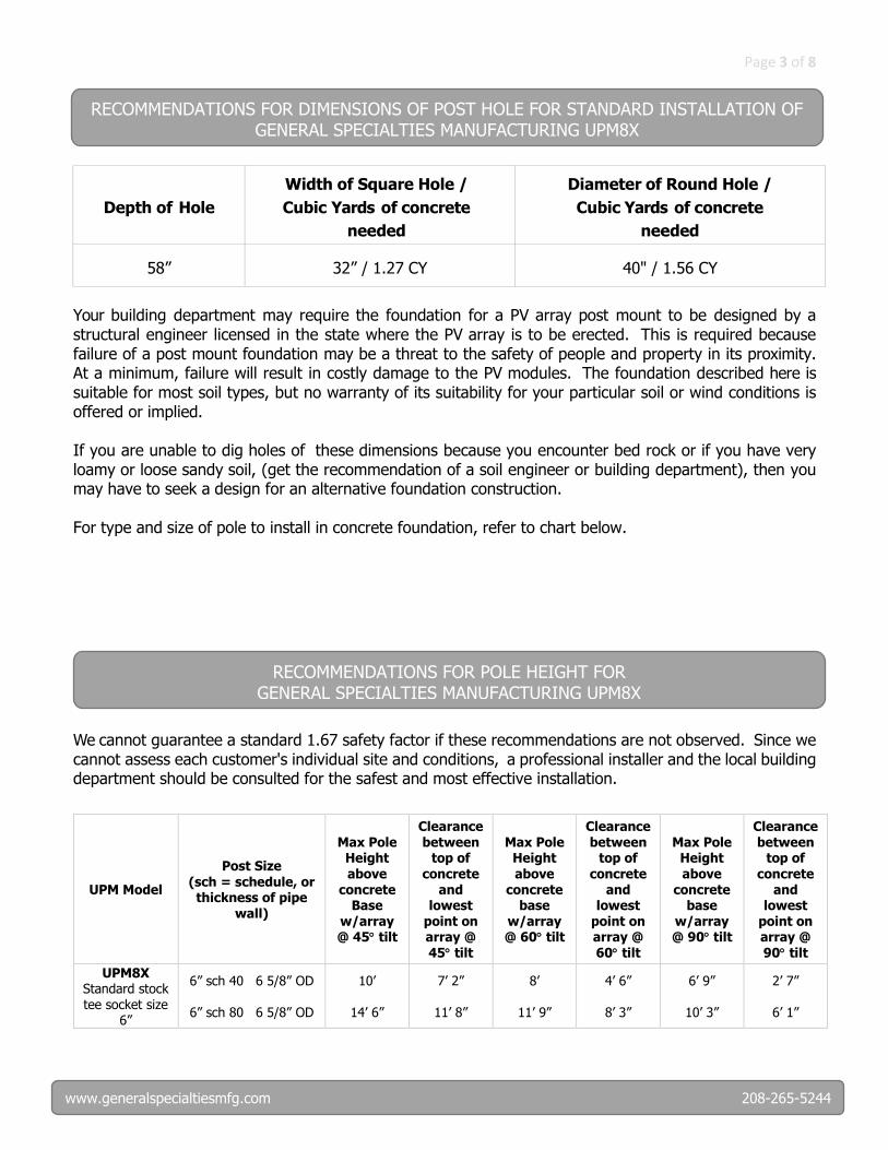
We cannot guarantee a standard 1.67 safety factor if these recommendations are not observed. Since we cannot assess each customer's individual site and conditions, a professional installer and the local building department should be consulted for the safest and most effective installation.
UPM Model
Post Size
(sch = schedule, or thickness of pipe
wall)
Max Pole Height
above concrete
Base w/array @ 45 tilt
Clearance between
top of
concrete and
lowest point on array @ 45 tilt
Max Pole Height
above concrete
base w/array @ 60 tilt
Clearance between
top of
concrete and
lowest point on array @ 60 tilt
Max Pole Height
above concrete
base w/array @ 90 tilt
Clearance between
top of
concrete and
lowest point on array @ 90 tilt
UPM8X Standard stock tee socket size
6”
6” sch 40 6 5/8” OD
6” sch 80 6 5/8” OD
10’
14’ 6”
7’ 2”
11’ 8”
8’
11’ 9”
4’ 6”
8’ 3”
6’ 9”
10’ 3”
2’ 7”
6’ 1”
RECOMMENDATIONS FOR DIMENSIONS OF POST HOLE FOR STANDARD INSTALLATION OF GENERAL SPECIALTIES MANUFACTURING UPM8X
RECOMMENDATIONS FOR POLE HEIGHT FOR GENERAL SPECIALTIES MANUFACTURING UPM8X

Page 4 of 8
www.generalspecialtiesmfg.com 208-265-5244
Finger tighten onto "Tee" end plates aluminum flat bar and straight 1/2" bolts. Place entire "Tee" assembly on top of post. The aluminum flat bar and straight 1/2" bolts are shown in Detail “A”. Tighten both set bolts and the four bolts on the top of the “Tee”.
Slide cross pieces into flat bar arrangement. Make sure locating lugs on cross pieces are facing in. See Detail “B” of locating lugs.
Place longitudinal tubes on top of cross pieces and bolt with square washers top and bottom.
ASSEMBLY INSTRUCTIONS
Page 5 of 8
www.generalspecialtiesmfg.com 208-265-5244
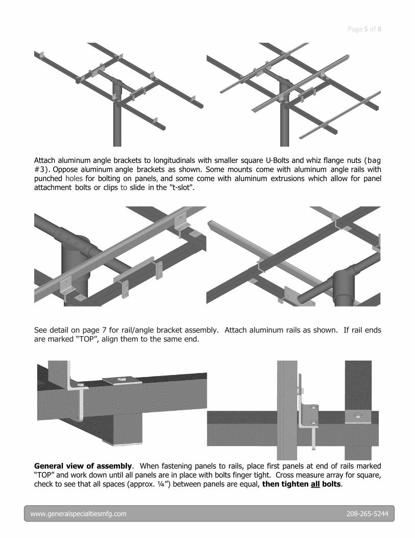
Attach aluminum angle brackets to longitudinals with smaller square U-Bolts and whiz flange nuts (bag #3). Oppose aluminum angle brackets as shown. Some mounts come with aluminum angle rails with punched holes for bolting on panels, and some come with aluminum extrusions which allow for panel attachment bolts or clips to slide in the "t-slot".
See detail on page 7 for rail/angle bracket assembly. Attach aluminum rails as shown. If rail ends are marked “TOP”, align them to the same end.
General view of assembly. When fastening panels to rails, place first panels at end of rails marked “TOP” and work down until all panels are in place with bolts finger tight. Cross measure array for square, check to see that all spaces (approx. ¼”) between panels are equal, then tighten all bolts.
Page 6 of 8
www.generalspecialtiesmfg.com 208-265-5244
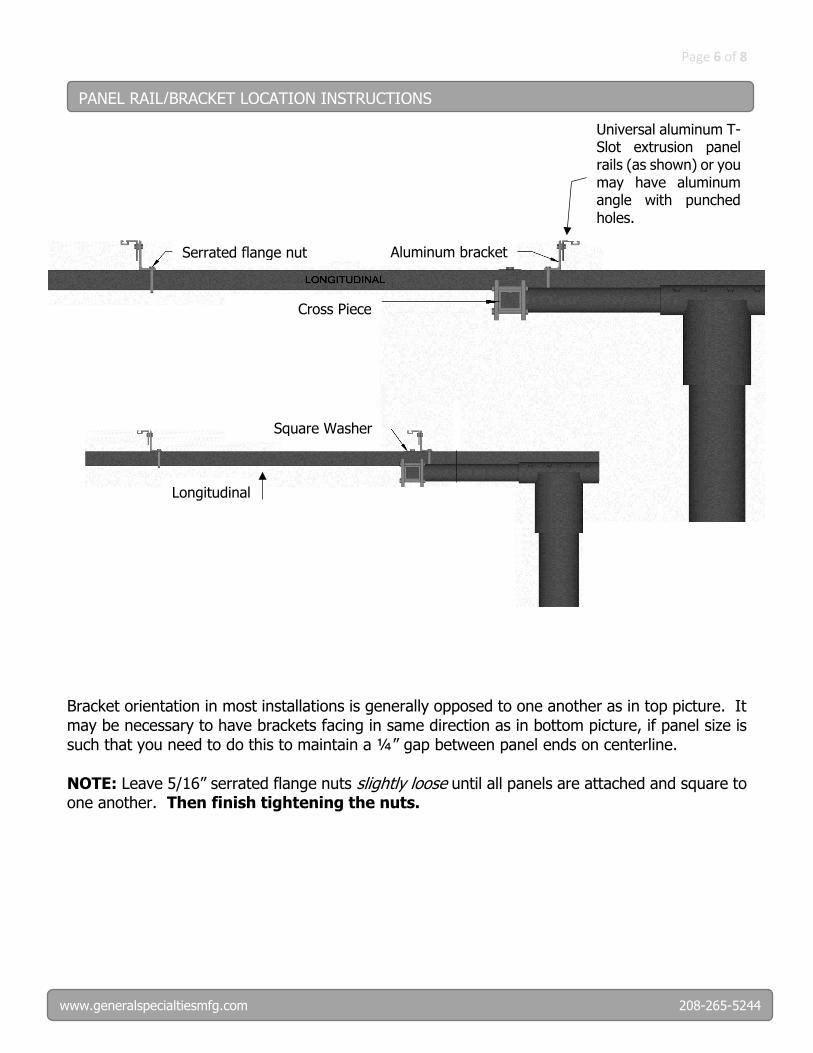
Bracket orientation in most installations is generally opposed to one another as in top picture. It may be necessary to have brackets facing in same direction as in bottom picture, if panel size is such that you need to do this to maintain a ¼” gap between panel ends on centerline.
NOTE: Leave 5/16” serrated flange nuts slightly loose until all panels are attached and square to one another. Then finish tightening the nuts.
PANEL RAIL/BRACKET LOCATION INSTRUCTIONS
Serrated flange nut Aluminum bracket
Cross Piece
Square Washer
Longitudinal
Universal aluminum T-Slot extrusion panel rails (as shown) or you may have aluminum angle with punched
holes.
Page 7 of 8
www.generalspecialtiesmfg.com 208-265-5244
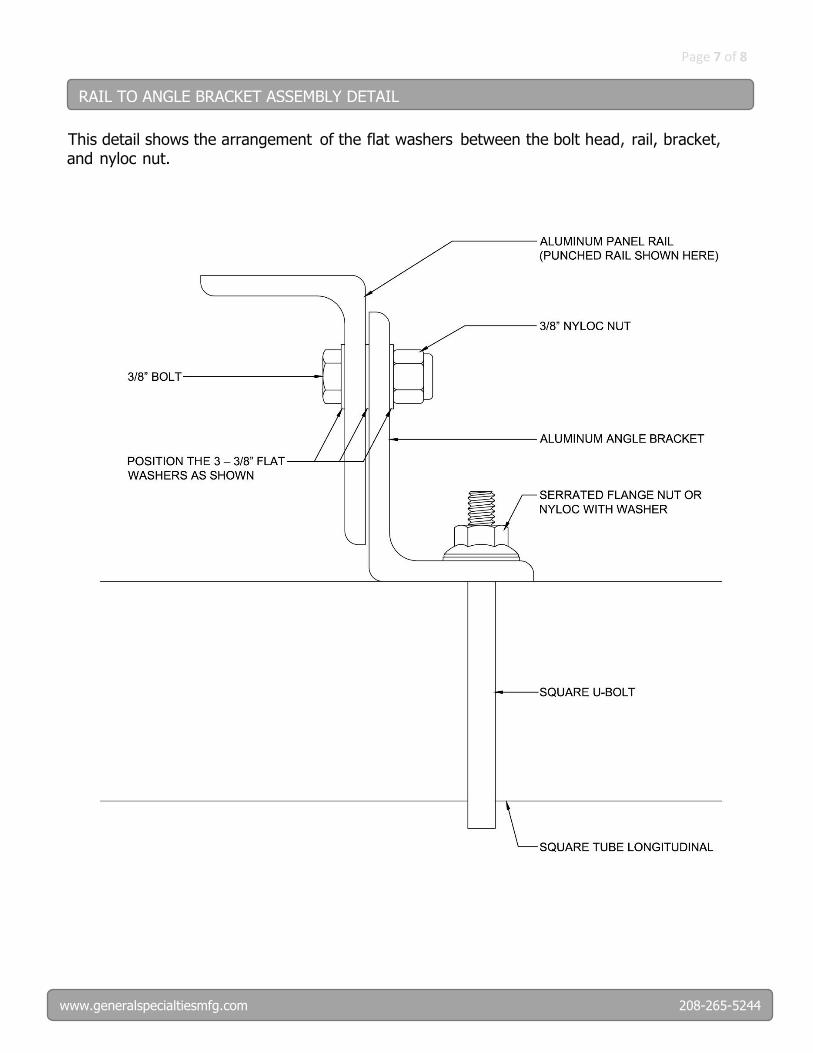
This detail shows the arrangement of the flat washers between the bolt head, rail, bracket, and nyloc nut.
RAIL TO ANGLE BRACKET ASSEMBLY DETAIL

Page 8 of 8
www.generalspecialtiesmfg.com 208-265-5244
WARNING!
Serious Injury or Property Damage
may occur if array shifts while adjusting
tilt angle without a safety line or winch
attached and secured!
DO NOT stand between post and lower side of the array while seasonally adjusting tilt angle.
AND
Tie a safety rope to top of array and wrap around car bumper
or heavy permanent object to control adjustment of array.
Tighten the set bolts on the Tee HARD when you are finished
adjusting.