Swivelpole's MaxisTM Pole Conversion System
6
Page 1 Maxis TM Pole Conversion Checklist IEC (October 12, 2020 1:14 PM) OVERVIEW The Maxis TM Pole Conversion System incorporates the use of: •Pole Conversion Tool Kit (for further information, refer to PCTK-01 Guide) •Maxis™ joint R1-M1, R2-M1 or R1-M2, R2-M2 The pole conversion tool clamps onto the rigid pole and safely supports the pole during a cold cut with a ratchet pipe cutter. There is no need for hot work permits. The pole top is lowered and the light fixture is disconnected at this point without the need to disturb the integrity of the existing wiring system. The Maxis™ joint slips onto the existing pole base. The new or existing pole top is inserted into the Maxis™ joint, with new LED fixture attached and terminated. All work takes place at platform level, eliminating the risks of working at heights. Drawings: Copies of client drawings are available online at swivelpole.com/maxis Ordering: Please email [email protected] Copyright and Patent: The Swivelpole™ and Maxis™ product range is protected worldwide by patents and registered designs owned by Swivelpole Group Pty Ltd and Exemplar Products Pty Ltd. Swivelpole's Maxis TM Pole Conversion System For safe and efficient conversion of rigid poles to lowering poles Conversion Re-using existing pole Conversion Renewing pole top Pole Conversion Tool Kit PCTK-01 Pole Conversion Tool Ratchet Pipe Cutter Oil Socket Wrench Marking Tool
-
Upload
khangminh22 -
Category
Documents
-
view
3 -
download
0
Transcript of Swivelpole's MaxisTM Pole Conversion System

Page 1 MaxisTM Pole Conversion Checklist IEC (October 12, 2020 1:14 PM)
OVERVIEW
The MaxisTM Pole Conversion System incorporates the use of:
• Pole Conversion Tool Kit (for further information, refer to PCTK-01 Guide)
• Maxis™ joint R1-M1, R2-M1 or R1-M2, R2-M2
The pole conversion tool clamps onto the rigid pole and safely supports the pole during a cold cut with a ratchet pipe cutter. There is no need for hot work permits.
The pole top is lowered and the light fixture is disconnected at this point without the need to disturb the integrity of the existing wiring system. The Maxis™ joint slips onto the existing pole base. The new or existing pole top is inserted into the Maxis™ joint, with new LED fixture attached and terminated.
All work takes place at platform level, eliminating the risks of working at heights.
Drawings: Copies of client drawings are available online at swivelpole.com/maxis
Ordering: Please email [email protected]
Copyright and Patent: The Swivelpole™ and Maxis™ product range is protected worldwide by patents and registered designs owned by Swivelpole Group Pty Ltd and Exemplar Products Pty Ltd.
Swivelpole's MaxisTM Pole Conversion System For safe and efficient conversion of rigid poles to lowering poles
ConversionRe-using
existing pole
Conversion Renewing pole top
Pole Conversion Tool KitPCTK-01
Pole Conversion Tool
Ratchet Pipe Cutter
Oil
Socket Wrench
Marking Tool

Page 2 MaxisTM Pole Conversion Checklist IEC (October 12, 2020 1:14 PM)
Plan the Conversion
Have a pre-start meeting to discuss what is involved in a conversion. Discuss the step by step checklist and understand each persons role in performing the steps. Nominate a team leader to oversee the conversion and to tick off each step on the check list as it has been performed. Additional copies can be printed online at swivelpole.com/maxis
For each pole, plan the direction the pole is to be lowered. Write ‘L’ (for left hand installation) or ‘R’ (for right hand installation) on pole. Determine correct installation of the pole conversion tool (PCT). The PCT can be installed either inside or outside of the guardrail. The PCT identification labels must always face the walkway and operator.
Check that the adequacy of each of the rigid pole connections to the handrail are in good condition.
Get organised by having all parts ready to install, including MaxisTM joint (refer to ordering information), pole conversion tool kit, new light fixture and tools* required for the job.
Ensure site procedures for work permits and electricity shut-off are followed. Determine if the area below is required to be barricaded off in case a tool is accidentally dropped.
Important
The Maxis joint adds 90mm [3.54in] to the height of the pole. Prior to proceeding to conversion, it is important to check if there is spare cable.
• If there is enough cable, only one cut is required.
• If there is not enough cable, a second cut is required.
• If R2-M1 or R2-M2 including new pole top is used, there may be enough cable as the pole top can be shortened.
As part of most MaxisTM conversions, a new LED fixture will be installed. If the existing pole has the incorrect fixture mount or if it is corroded or has a hole in it, a new pole top will be required. A good solution is to install the R2-M1 or R2-M2, which includes a new pole top, also available in aluminium, making it lighter.
Required tools*Pole Conversion Tool Kit (PCTK-01)19mm spanner5mm Allen keyElectrical tools
Left hand PCT install Right hand PCT install
Fig 1 Fig 2

Page 3 MaxisTM Pole Conversion Checklist IEC (October 12, 2020 1:14 PM)
Pole Conversion ChecklistMaxisTM joint conversionsMARKING THE CUT AND CLAMP POINTS *
* For freestanding poles, mark cut line 1000mm and upper clamp point 1385mm from the ground.
Step 1
Use the marking tool to mark the cut and clamp point.
Single Cut Option
Hold marking tool horizontally, resting Edge 'A' on top of the handrail, with Edge 'C' against the pole, follow along Edge 'B' and mark the cut. (Fig 3)
Marking PCT clamp position
Left Hand Side Installation: Rest Edge 'B' of the marking tool vertically against pole top, place Edge 'C' on the first cut mark and mark against Edge 'E' of the tool. (Fig 5)
Right Hand Side Installation: Rest Edge 'A' of the marking tool vertically against pole top, place Edge 'C' on the first cut mark and mark against Edge 'D' of the tool. (Fig 6)
Double Cut Option
If there is not enough cable and a second cut has been determined during pre-start meeting, follow the below marking instructions. Refer to Step 9 for second cut instructions.
Hold marking tool horizontally, resting Edge 'A' on top of the handrail, with Edge 'C' against the pole, follow along Edge 'B' and mark the bottom cut.
Hold marking tool Edge 'C' horizontally against pole top, lining up Edge 'A' with the first mark and mark a second cut above in line with Edge ‘B’.
Marking PCT clamp position
Left hand side installation: Rest Edge 'B' of the marking tool vertically against pole top, place Edge 'C' on the second cut mark and mark against Edge 'E' of the tool. (Fig 5)
Right hand side installation: Rest Edge 'A' of marking tool vertically against pole top, place Edge 'C' on the second cut mark and mark against Edge 'D' of the tool. (Fig 6)
Right hand side installation
Fig 6
Left hand side installation
Fig 5
Fig 3
Fig 4

Page 4 MaxisTM Pole Conversion Checklist IEC (October 12, 2020 1:14 PM)
Pole Conversion ChecklistMaxisTM joint conversionsINSTALLING THE POLE CONVERSION TOOL (PCT) 2 persons required for conversion.
Step 2
One person holds PCT near desired position inside the guardrail.
Second person attaches the lanyard to the guardrail and securely fasten the safety latch. (Fig 7)
Step 3
One person holds the PCT in the desired position for planned fixture lowering. Align the top edge of the upper PCT clamp with the top mark on the pole.
Second person locks the clamp in place ensuring the half-moon locator is seated correctly into the PCT clamp. (Fig 8)
Tighten clamp bolts firmly using socket wrench.
Step 4
Using the marking tool, check that the PCT centre hinge point is in line with the cut mark (top cut mark if two were marked in step 1). (Fig 9)
Align the ratchet pipe cutter blade to the cut mark. (Fig 10)
CUTTING THE POLE
Step 5
Apply 2 drops of multi-purpose oil to the blade.
Holding the ratchet pipe cutter horizontally, cut the pole using a 90-degree cutting motion. Avoid any downward pressure when cutting, as this could break the blade. (Fig 11)
When the pole has been cut through completely, remove the cutter by unscrewing the cog and spinning the ratchet.
Fig 7
Fig 8
Fig 9
Fig 10
Fig 11
Page 5 MaxisTM Pole Conversion Checklist IEC (October 12, 2020 1:14 PM)
Pole Conversion ChecklistMaxisTM joint conversions
Fig 12
Fig 13
Fig 14
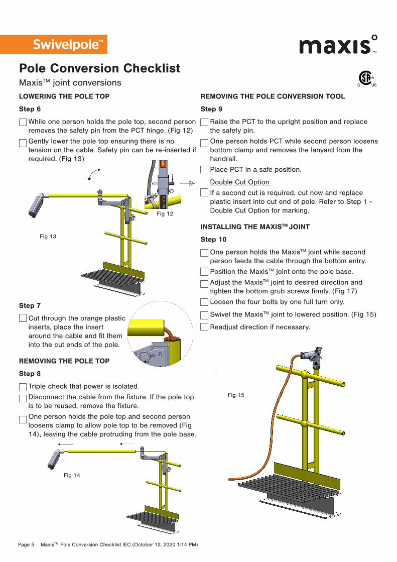
LOWERING THE POLE TOP
Step 6
While one person holds the pole top, second person removes the safety pin from the PCT hinge. (Fig 12)
Gently lower the pole top ensuring there is no tension on the cable. Safety pin can be re-inserted if required. (Fig 13)
Step 7
Cut through the orange plastic inserts, place the insert around the cable and fit them into the cut ends of the pole.
REMOVING THE POLE TOP
Step 8
Triple check that power is isolated.
Disconnect the cable from the fixture. If the pole top is to be reused, remove the fixture.
One person holds the pole top and second person loosens clamp to allow pole top to be removed (Fig 14), leaving the cable protruding from the pole base.
REMOVING THE POLE CONVERSION TOOL
Step 9
Raise the PCT to the upright position and replace the safety pin.
One person holds PCT while second person loosens bottom clamp and removes the lanyard from the handrail.
Place PCT in a safe position.
Double Cut Option
If a second cut is required, cut now and replace plastic insert into cut end of pole. Refer to Step 1 - Double Cut Option for marking.
INSTALLING THE MAXISTM JOINT
Step 10
One person holds the MaxisTM joint while second person feeds the cable through the bottom entry.
Position the MaxisTM joint onto the pole base.
Adjust the MaxisTM joint to desired direction and tighten the bottom grub screws firmly. (Fig 17)
Loosen the four bolts by one full turn only.
Swivel the MaxisTM joint to lowered position. (Fig 15)
Readjust direction if necessary.
Fig 15
Page 6 MaxisTM Pole Conversion Checklist IEC (October 12, 2020 1:14 PM)
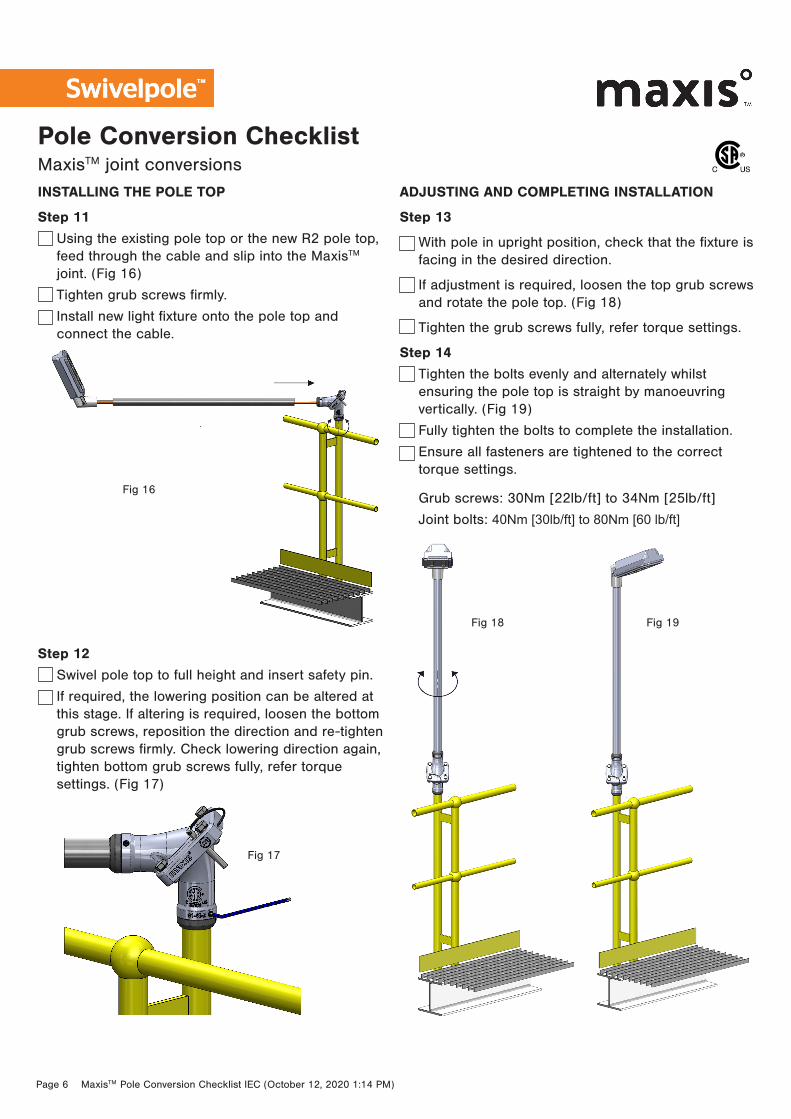
Pole Conversion ChecklistMaxisTM joint conversionsINSTALLING THE POLE TOP
Step 11
Using the existing pole top or the new R2 pole top, feed through the cable and slip into the MaxisTM joint. (Fig 16)
Tighten grub screws firmly.
Install new light fixture onto the pole top and connect the cable.
Step 12
Swivel pole top to full height and insert safety pin.
If required, the lowering position can be altered at this stage. If altering is required, loosen the bottom grub screws, reposition the direction and re-tighten grub screws firmly. Check lowering direction again, tighten bottom grub screws fully, refer torque settings. (Fig 17)
ADJUSTING AND COMPLETING INSTALLATION
Step 13
With pole in upright position, check that the fixture is facing in the desired direction.
If adjustment is required, loosen the top grub screws and rotate the pole top. (Fig 18)
Tighten the grub screws fully, refer torque settings.
Step 14
Tighten the bolts evenly and alternately whilst ensuring the pole top is straight by manoeuvring vertically. (Fig 19)
Fully tighten the bolts to complete the installation.
Ensure all fasteners are tightened to the correct torque settings.
Grub screws: 30Nm [22lb/ft] to 34Nm [25lb/ft]
Joint bolts: 40Nm [30lb/ft] to 80Nm [60 lb/ft]
Fig 16
Fig 17
Fig 18 Fig 19